Construction Technology of Monolithic Refractories - Nippon ...
Upload
khangminh22Category
view
8download
0
ACI 352.1R-11
Guide for Design of Slab-Column Connections in Monolithic
Concrete Structures
Reported by Joint ACI-ASCE Committee 352
Copyright American Concrete Institute Provided by IHS under license with ACI Licensee=University of Texas Revised Sub Account/5620001114, User=opioui, rty
Not for Resale, 01/26/2015 01:50:14 MSTNo reproduction or networking permitted without license from IHS
--`````,`,,`,`,,,,`,`,,`,,,`,`-`-`,,`,,`,`,,`---
daneshlink.com
Daneshlink.com

First PrintingMarch 2012
Guide for Design of Slab-Column Connections in Monolithic Concrete Structures
Copyright by the American Concrete Institute, Farmington Hills, MI. All rights reserved. This material may not be reproduced or copied, in whole or part, in any printed, mechanical, electronic, film, or other distribution and storage media, without the written consent of ACI.
The technical committees responsible for ACI committee reports and standards strive to avoid ambiguities, omissions, and errors in these documents. In spite of these efforts, the users of ACI documents occasionally find information or requirements that may be subject to more than one interpretation or may be incomplete or incorrect. Users who have suggestions for the improvement of ACI documents are requested to contact ACI via the errata website at www.concrete.org/committees/errata.asp. Proper use of this document includes periodically checking for errata for the most up-to-date revisions.
ACI committee documents are intended for the use of individuals who are competent to evaluate the significance and limitations of its content and recommendations and who will accept responsibility for the application of the mate-rial it contains. Individuals who use this publication in any way assume all risk and accept total responsibility for the application and use of this information.
All information in this publication is provided “as is” without warranty of any kind, either express or implied, includ-ing but not limited to, the implied warranties of merchantability, fitness for a particular purpose or non-infringement.
ACI and its members disclaim liability for damages of any kind, including any special, indirect, incidental, or con-sequential damages, including without limitation, lost revenues or lost profits, which may result from the use of this publication.
It is the responsibility of the user of this document to establish health and safety practices appropriate to the specific circumstances involved with its use. ACI does not make any representations with regard to health and safety issues and the use of this document. The user must determine the applicability of all regulatory limitations before applying the document and must comply with all applicable laws and regulations, including but not limited to, United States Occupational Safety and Health Administration (OSHA) health and safety standards.
Participation by governmental representatives in the work of the American Concrete Institute and in the develop-ment of Institute standards does not constitute governmental endorsement of ACI or the standards that it develops.
Order information: ACI documents are available in print, by download, on CD-ROM, through electronic subscription, or reprint and may be obtained by contacting ACI.
Most ACI standards and committee reports are gathered together in the annually revised ACI Manual of Concrete Practice (MCP).
American Concrete Institute38800 Country Club DriveFarmington Hills, MI 48331U.S.A.Phone: 248-848-3700Fax: 248-848-3701
www.concrete.org
ISBN 978-0-87031-760-6Copyright American Concrete Institute Provided by IHS under license with ACI Licensee=University of Texas Revised Sub Account/5620001114, User=opioui, rty
Not for Resale, 01/26/2015 01:50:14 MSTNo reproduction or networking permitted without license from IHS
--`````,`,,`,`,,,,`,`,,`,,,`,`-`-`,,`,,`,`,,`---
daneshlink.com
Daneshlink.com

This guide provides recommendations for determining proportions and details of monolithic reinforced and post-tensioned concrete slab-column connections.
Included are recommendations regarding appropriate uses of slab-column connections in structures resisting gravity and lateral forces; procedures for determination of connection load-carrying capacity; and reinforcement details to achieve adequate strength, ductility, and structural integrity. Recommendations are based
on a review of the literature for ultimate and serviceability limit states. A commentary is provided to clarify the recommendations and identify reference material. Design recommendations are set in standard type. Commentary is set in italics.
Keywords: connection; flat plate; flat slab; joint; lateral drift; post-tensioned; punching shear; seismic; shear reinforcement; slab-column.
CONTENTS
Chapter 1—Introduction and scope, p. 21.1—Introduction1.2—Scope
ACI 352.1R-11
Guide for Design of Slab-Column Connections in Monolithic Concrete Structures
Reported by Joint ACI-ASCE Committee 352
Mary Beth D. Hueste†
ChairThomas Kang†
Secretary
Sergio M. AlcocerJohn F. BonacciJames R. Cagley
Marvin E. CriswellJeffrey J. DragovichCatherine E. French
Luis E. GarcíaRussell Gentry
Theodor KrauthammerMichael E. KregerJames M. LaFave*
Douglas D. LeeDawn E. LehmanRoberto T. LeonCheng-Ming Lin
Donald F. MeinheitNilanjan MitraJack P. Moehle
Stavroula J. PantazopoulouGustavo J. Parra-Montesinos
Ian Robertson†
M. Saiid SaiidiJorge I. Segura
Bahram M. ShahroozMyoungsu ShinJohn W. WallaceJames K. Wight
Loring A. Wyllie Jr.
Consulting MembersHossam M. AbdouFariborz BarzegarHugh L. CottonFilip C. Filippou
David W. MitchellCharles F. Scribner
David Z. YankelevskyLiande Zhang
*Chair of editorial subcommittee †Member of editorial subcommittee
1
ACI Committee Reports, Guides, and Commentaries are intended for guidance in planning, designing, executing, and inspecting construction. This document is intended for the use of individuals who are competent to evaluate the significance and limitations of its content and recommendations and who will accept responsibility for the application of the material it contains. The American Concrete Institute disclaims any and all responsibility for the stated principles. The Institute shall not be liable for any loss or damage arising therefrom.
Reference to this document shall not be made in contract documents. If items found in this document are desired by the Architect/Engineer to be a part of the contract documents, they shall be restated in mandatory language for incorporation by the Architect/Engineer.
ACI 352.1R-11 supersedes ACI 352.1R-89 and was adopted and published March 2012.
Copyright © 2011, American Concrete Institute.All rights reserved including rights of reproduction and use in any form or by any
means, including the making of copies by any photo process, or by electronic or mechanical device, printed, written, or oral, or recording for sound or visual repro-duction or for use in any knowledge or retrieval system or device, unless permission in writing is obtained from the copyright proprietors.
Copyright American Concrete Institute Provided by IHS under license with ACI Licensee=University of Texas Revised Sub Account/5620001114, User=opioui, rty
Not for Resale, 01/26/2015 01:50:14 MSTNo reproduction or networking permitted without license from IHS
--`````,`,,`,`,,,,`,`,,`,,,`,`-`-`,,`,,`,`,,`---
daneshlink.com
Daneshlink.com

Chapter 2—Notation and definitions, p. 32.1—Notation2.2—Definitions
Chapter 3—Connection classifications, p. 43.1—General3.2—Connection classifications
Chapter 4—Design considerations, p. 84.1—Connection performance4.2—Types of actions on the connection4.3—Determination of connection forces
Chapter 5—Methods of analysis for determination of connection strength, p. 9
5.1—General principles and recommendations5.2—Connections without beams5.3—Connections with transverse beams5.4—Effect of openings5.5—Joint strength
Chapter 6—Reinforcement, p. 136.1—Slab reinforcement for moment transfer6.2—Joint recommendations6.3—Structural integrity reinforcement6.4—Anchorage of reinforcement
Chapter 7—Lateral drift, p. 207.1—General7.2—Lateral drift capacity
Chapter 8—Shear reinforcement, including for earthquake-resistant design, p. 22
8.1—General8.2—Types of shear reinforcement8.3—Shear strength of connections with shear
reinforcement
Chapter 9—References, p. 259.1—Referenced standards and reports9.2—Cited references
CHAPTER 1—INTRODUCTION AND SCOPE
1.1—IntroductionThe recommendations in this guide are for determining
connection proportions and details to provide adequate performance of cast-in-place reinforced concrete (RC) and post-tensioned concrete (PT) slab-column connections. The recommendations are written to satisfy serviceability, strength, and ductility requirements related to the intended functions of the connection.
Design of the connection between a slab and its supporting member requires consideration of both the joint and the portion of the slab, or slab and beams, immediately adja-cent to the joint. Several connection failures associated with inadequate performance of the slab adjacent to the joint have been reported (Engineering News-Record (ENR) 1956,
1971, 1973; Joint ACI-ASCE Committee 426 1974; Leyen-decker and Fattal 1977; Lew et al. 1982a,b; Rosenblueth and Meli 1986; Freyermuth 1989; Moehle 1996; Hueste and Wight 1997). However, no reported cases of connection failure due to distress within the joint have been identified. Some connection failures have occurred during construc-tion when young concrete slabs received loads from more than one floor as a consequence of shoring and reshoring (Agarwal and Gardner 1974; Lew et al. 1982a,b; Sbarounis 1984; ACI 347-05). The disastrous consequences of some failures, including total collapse of the structure, empha-size the importance of the design of the connection. These recommendations are intended to alert the designer to those aspects of behavior that should be considered in design of the connection and to suggest design procedures that will lead to adequate connection performance.
1.2—ScopeInformation and design recommendations have been
summarized by Joint ACI-ASCE Committee 426 (1974, 1977). This guide is an update of ACI 352.1R-89 (Joint ACI-ASCE Committee 352 1989), based on research information presented in references such as Moehle (1996); Moehle et al. (1988); Kang and Wallace (2005); ACI 318-08, Chapter 21; and Cheng et al. (2010). Modifications to the previous report include expanding the coverage to include slab-column connections with shear reinforcement, slab-column connections with post-tensioning reinforcement, and lateral drift capacity of both RC and PT slab-column connections.
These recommendations apply only to slab-column connections in monolithic concrete structures, with or without drop panels or column capitals, and using normal-weight or lightweight concrete. For strength calculation purposes, the specified concrete compressive strength should not be taken greater than 6000 psi (42 MPa). The recom-mendations are limited to slab-column connections with slab thickness ranging between 5 and 12 in. (125 and 300 mm); a slab span-to-thickness ratio varying from 20 to 45, except for slab-column connections with transverse beams; and a ratio of long-to-short cross-sectional column dimen-sions less than 4. The recommendations for PT slab-column connections are applicable only for monolithic concrete connections with unbonded post-tensioning tendons applying an average compressive stress in the concrete not less than 125 psi (0.86 MPa). Construction that combines slab-column and beam-column framing in orthogonal direc-tions at individual connections is included, but these recom-mendations are limited to issues related to the transfer of loads in the direction perpendicular to the beam axis. Slab-column framing systems are considered inappropriate as seismic-force-resisting systems assigned to high seismic design categories, but they are commonly used as frames not designated as part of the seismic-force-resisting system along with a stiffer seismic-force-resisting system, such as shear walls or beam-and-column moment-resisting frames.
These recommendations are limited to slab-column connections of cast-in-place RC and PT floor construction, including two-way ribbed floor slab construction (Meli and
American Concrete Institute Copyrighted Material—www.concrete.org
2 GUIDE FOR DESIGN OF SLAB-COLUMN CONNECTIONS IN MONOLITHIC CONCRETE STRUCTURES (ACI 352.1R-11)
Copyright American Concrete Institute Provided by IHS under license with ACI Licensee=University of Texas Revised Sub Account/5620001114, User=opioui, rty
Not for Resale, 01/26/2015 01:50:14 MSTNo reproduction or networking permitted without license from IHS
--`````,`,,`,`,,,,`,`,,`,,,`,`-`-`,,`,,`,`,,`---
daneshlink.com
Daneshlink.com
Rodriguez 1979) and slab-column connections with trans-verse beams. Recommendations are made elsewhere (ACI 352R-02) for connections in which framing is predominantly by action between beams and columns.
The recommendations do not consider slab-wall connec-tions, precast connections, or slabs-on-ground. Relevant information on these subjects may be found in ACI 360R-10, Schwaighofer and Collins (1977), Paulay and Taylor (1981), and Klemencic et al. (2006). Although structures having specified concrete compressive strength exceeding 6000 psi (42 MPa) are within the realm of this guide, the recommen-dations limit the assumed compressive strength for design to 6000 psi (42 MPa) because of the lack of test data on slab-column connections with higher-strength concrete.
Slab-column systems are generally inadequate as the seismic-force-resisting system of multi-story buildings assigned to high seismic design categories because of prob-lems associated with excessive lateral drift and inadequate shear and moment transfer capacity at the connections. For high seismic design categories, if designed according to these recommendations, slab-column systems may be used in multi-story construction in which earthquake-induced lateral forces are primarily carried by a stiffer seismic-force-resisting system. For low and moderate seismic design categories, slab-column systems may be adequate as the seismic-force-resisting system, provided the connection design recommendations in this guide are met.
CHAPTER 2—NOTATION AND DEFINITIONS
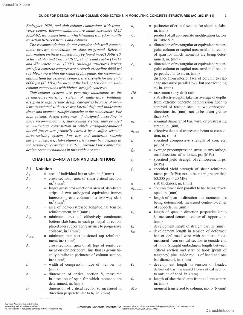
2.1—NotationAb = area of individual bar or wire, in.2 (mm2)Ac = cross-sectional area of shear-critical section,
in.2 (mm2)Acf = larger gross cross-sectional area of slab-beam
strips of two orthogonal equivalent frames intersecting at a column of a two-way slab, in.2 (mm2)
As = area of non-prestressed longitudinal tension reinforcement, in.2 (mm2)
Asm = minimum area of effectively continuous bottom slab bars, in each principal direction, placed over support for resistance to progressive collapse, in.2 (mm2)
As,min = minimum non-post-tensioned top reinforce-ment, in.2 (mm2)
Av = cross-sectional area of all legs of reinforce-ment on one peripheral line that is geometri-cally similar to perimeter of column section, in.2 (mm2)
b = width of compression face of member, in. (mm)
b1 = dimension of critical section bo measured in direction of span for which moments are determined, in. (mm)
b2 = dimension of critical section bo measured in direction perpendicular to b1, in. (mm)
bo = perimeter of critical section for shear in slabs, in. (mm)
Cv = product of all appropriate modification factors in Table 5.2.1.1
c1 = dimension of rectangular or equivalent rectan-gular column or capital measured in direction of span for which moments are being deter-mined, in. (mm)
c2 = dimension of rectangular or equivalent rectan-gular column or capital measured in direction perpendicular to c1, in. (mm)
ct = distance from interior face of column to slab edge measured parallel to c1, but not exceeding c1, in. (mm)
DR = maximum story-drift ratiod = slab effective depth, taken as average of depths
from extreme concrete compression fiber to centroid of tension steel in two orthogonal directions, in. (mm), not to be taken greater than 0.8h
db = nominal diameter of bar, wire, or prestressing strand, in. (mm)
dbeam = effective depth of transverse beam at connec-tion, in. (mm)
fc′ = specified compressive strength of concrete, psi (MPa)
fpc = average precompression stress in two orthog-onal directions after losses, psi (MPa)
fy = specified yield strength of reinforcement, psi (MPa)
fyt = specified yield strength of shear reinforce-ment, psi (MPa); not to be taken greater than 60,000 psi (420 MPa)
h = slab thickness, in. (mm)h(column) = column dimension parallel to bar being devel-
oped, in. (mm)l1 = length of span in direction that moments are
being determined, measured center-to-center of supports, in. (mm)
l 2 = length of span in direction perpendicular to l1, measured center-to-center of supports, in. (mm)
ld = development length of straight bar, in. (mm)ldh = development length in tension of deformed
bar or deformed wire with standard hook, measured from critical section to outside end of hook (straight embedment length between critical section and start of hook [point of tangency] plus inside radius of bend and one bar diameter), in. (mm)
ldt = development length in tension of headed deformed bar, measured from critical section to outside of head, in. (mm)
lv = length of shearhead arm from column center, in. (mm)
Mub = moment transferred to column, in.-lb (N·mm)
American Concrete Institute Copyrighted Material—www.concrete.org
GUIDE FOR DESIGN OF SLAB-COLUMN CONNECTIONS IN MONOLITHIC CONCRETE STRUCTURES (ACI 352.1R-11) 3
Copyright American Concrete Institute Provided by IHS under license with ACI Licensee=University of Texas Revised Sub Account/5620001114, User=opioui, rty
Not for Resale, 01/26/2015 01:50:14 MSTNo reproduction or networking permitted without license from IHS
--`````,`,,`,`,,,,`,`,,`,,,`,`-`-`,,`,,`,`,,`---
daneshlink.com
Daneshlink.com

Mub1, Mub2 = simultaneous moments transferred to column and acting about centroidal principal axes of shear-critical section, in.-lb (N·mm)
s = spacing between peripheral lines of shear reinforcement, in. (mm)
Vc = shear strength of concrete without modifica-tions in Table 5.2.1.1, lb (N)
Vmax = limiting value of allowed shear resistance, lb (N)
Vn = nominal shear strength, lb (N)Vo = design shear strength in absence of moment
transfer, lb (N)Vs = nominal shear strength provided by shear
reinforcement, lb (N)Vu = factored direct shear force acting on shear-
critical section, lb (N)Vug = factored shear force acting on shear-critical
section for two-way action due to gravity loads, corresponding to load combination specified in ACI 318-08, Section 21.13.6, lb (N)
VR = gravity shear ratiowu = factored uniformly distributed load, but not
less than two times the slab dead load, to be considered for resistance to progressive collapse, lb/ft2 (N/mm2)
α = coefficient in Eq. (5.2.1.2c)αs = coefficient in Eq. (5.2.1.1b)β = ratio of long-to-short dimensions of column
cross sectionβp = coefficient in Eq. (5.2.1.1c)εt = net tensile strain in extreme tension steel at
nominal strengthφ = strength reduction factorγf = factor used to determine unbalanced moment
transferred by flexure at slab-column connec-tions (ACI 318)
γv = factor used to determine unbalanced moment transferred by eccentricity of shear at slab-column connections (ACI 318)
ρ = reinforcement ratio of top slab reinforcement in one direction at the connection
ρ′ = reinforcement ratio of bottom slab reinforce-ment in one direction at the connection
2.2—DefinitionsACI provides a comprehensive list of definitions through
an online resource, “ACI Concrete Terminology” (http://terminology.concrete.org). Definitions provided herein complement that resource.
column—a vertical supporting element with a ratio of height-to-least lateral dimension exceeding 3 and with a ratio of long-to-short cross-sectional dimensions not exceeding 3.
column capital—a flared portion of the column immedi-ately below the slab and having effective plan dimensions assumed equal to the smaller of the actual dimensions and the part of the capital lying within the largest right circular
cone or pyramid with a 90-degree vertex that can be included within the outlines of the supporting column.
column strip—design strip with a width on each side of a column centerline equal to one-fourth of the span length transverse or parallel to the span, whichever is less. Column strip includes beams, if any.
connection—the joint plus adjacent regions of the slab and beams.
design story-drift ratio—the relative difference between design lateral displacements for the top and bottom of a story, divided by the story height.
direct shear—shear force transferred from slab to column.drop panel—a projection below the slab at the connec-
tion having thickness not less than one-fourth of the adjacent slab thickness and extending from the centerline of support in each direction not less than one-sixth of the span length measured from center-to-center of supports in that direction.
joint—the part of the column within the depth of the slab, including drop panel or shear cap, and having plan dimensions equal to those of the column at the intersection between the column and the bottom surface of the slab (drop panel or shear cap).
shear cap—a projection below the slab at the connection extending a minimum horizontal distance from the column face that is equal to the thickness of the projection below the slab soffit.
shear-critical section—a slab section assumed to extend around and near a column (at a connection) and at which shear capacity must be evaluated. A critical section has a depth d perpendicular to the plane of the slab and extending around the column. A critical section should be considered around the column so that its perimeter bo is a minimum, but it need not approach closer than lines at d/2 from the column face and parallel to the column boundaries. The critical section should be considered both within and outside the shear-reinforced region. For the purpose of defining the shear-critical section, a support of circular cross section may be replaced by a square support having an equal perimeter.
shear reinforcement—reinforcement provided to resist shear or diagonal tension stresses and increase the shear strength of the connection.
transfer moment—the unbalanced slab moment trans-ferred to the supporting element at a connection.
CHAPTER 3—CONNECTION CLASSIFICATIONS
3.1—GeneralConnection performance, particularly during an earth-
quake, is affected by joint behavior, including slip of rein-forcement embedded in the joint, and by the region of the slab, or slab and transverse beams, surrounding the joint. The joint definition is illustrated in Fig. 3.1a. In general, the region of slab that directly affects connection behavior extends from the joint face the greater of twice the develop-ment length of the largest slab bars or four times the slab thickness (Joint ACI-ASCE Committee 426 1977). A drop panel is used to reduce the minimum required slab thick-ness or the amount of top slab reinforcement over a column,
American Concrete Institute Copyrighted Material—www.concrete.org
4 GUIDE FOR DESIGN OF SLAB-COLUMN CONNECTIONS IN MONOLITHIC CONCRETE STRUCTURES (ACI 352.1R-11)
Copyright American Concrete Institute Provided by IHS under license with ACI Licensee=University of Texas Revised Sub Account/5620001114, User=opioui, rty
Not for Resale, 01/26/2015 01:50:14 MSTNo reproduction or networking permitted without license from IHS
--`````,`,,`,`,,,,`,`,,`,,,`,`-`-`,,`,,`,`,,`---
daneshlink.com
Daneshlink.com

and to increase the connection shear-critical section and consequently the shear strength. A shear cap is used solely to increase the shear strength at the connection.
The shear-critical section, used for determination of connection shear strength, is the same as that specified in ACI 318, although the definition has been modified to clarify that shear-critical sections for non-rectangular supports may be assumed to have a rectangular shape. The shear-critical sections for several support geometries are shown in Fig. 3.1b, including a typical rectangular interior connection (Fig. 3.1b(a)) and an interior connection with irregular geometry (Fig. 3.1b(b)). Punching shear strengths for connections with circular columns have been observed (Vanderbilt 1972) to exceed the punching shear strengths for connections with square columns having the same perim-eter; thus, it is conservative to represent circular columns by square columns having the same perimeter (Fig. 3.1b(c)). Two critical sections are defined for connections with drop panels or shear caps because failure may occur either through the thickened portion of the slab near the column or through the slab outside the drop panel or shear cap (Fig. 3.1b(d)). Shear-critical sections for exterior connec-tions depend on the slab edge distance from the face of the column, as shown in Fig. 3.1b(e) and Fig. 3.1b(f). Alterna-tive critical sections should be investigated at other locations that might result in reduced shear strength of a connection with shear reinforcement, as shown in Fig. 3.1b(g) and Fig. 3.1b(h) (Corley and Hawkins 1968; Hawkins and Corley 1974; Hanna et al. 1975).
The limitation on the aspect ratio of the column cross-section dimensions is illustrated in Fig. 3.1c. As the aspect ratio increases, behavior deviates from a column-slab connection behavior to a slab-wall connection behavior (Schwaighofer and Collins 1977). No recommendations for such connections are made in this guide. For more informa-tion about slab-wall connections, refer to Schwaighofer and
Collins (1977), Paulay and Taylor (1981), and Klemencic et al. (2006).
3.2—Connection classificationsConnections are classified according to geometry in
Section 3.2.1 and according to anticipated performance in Section 3.2.2.
3.2.1 A slab-column connection is an exterior connection if the distance from any discontinuous edge to the nearest support face is less than four times the slab thickness. An edge connection is an exterior connection for which a discon-tinuous edge is located adjacent to one support face only. A corner connection is an exterior connection for which discontinuous edges are located adjacent to two adjoining support faces. A vertical slab opening located closer than four times the slab thickness to the support face should be classified as a discontinuous edge if radial lines projecting from the centroid of the support area to the boundaries of the opening enclose a length of the shear-critical section that exceeds the adjacent support dimension. A connection not defined as an exterior connection is considered an interior connection. Regardless of the connection classification, the reduced shear-critical section should be investigated for openings up to 10 times the slab thickness away from the support face.
Openings or slab edges located close to the support inter-rupt the shear flow in the slab, induce moment transfer to supports, reduce available anchorage lengths, and reduce the effective joint confinement. The distance of four times the slab thickness is based on considerations related to strength of the slab near the support (Joint ACI-ASCE Committee 426 1977). Examples of edge connections, corner connec-tions, exterior connections, and interior connections with openings are shown in Fig. 3.2.1.
When classifying a connection as interior or exterior, the effect of openings on the shear-critical section should be
Fig. 3.1a—Joint in typical slab-column connections.
American Concrete Institute Copyrighted Material—www.concrete.org
GUIDE FOR DESIGN OF SLAB-COLUMN CONNECTIONS IN MONOLITHIC CONCRETE STRUCTURES (ACI 352.1R-11) 5
Copyright American Concrete Institute Provided by IHS under license with ACI Licensee=University of Texas Revised Sub Account/5620001114, User=opioui, rty
Not for Resale, 01/26/2015 01:50:14 MSTNo reproduction or networking permitted without license from IHS
--`````,`,,`,`,,,,`,`,,`,,,`,`-`-`,,`,,`,`,,`---
daneshlink.com
Daneshlink.com

Fig. 3.1b—Examples of shear-critical sections.
American Concrete Institute Copyrighted Material—www.concrete.org
6 GUIDE FOR DESIGN OF SLAB-COLUMN CONNECTIONS IN MONOLITHIC CONCRETE STRUCTURES (ACI 352.1R-11)
Copyright American Concrete Institute Provided by IHS under license with ACI Licensee=University of Texas Revised Sub Account/5620001114, User=opioui, rty
Not for Resale, 01/26/2015 01:50:14 MSTNo reproduction or networking permitted without license from IHS
--`````,`,,`,`,,,,`,`,,`,,,`,`-`-`,,`,,`,`,,`---
daneshlink.com
Daneshlink.com

considered. Where large openings are located closer than four times the slab thickness to the support face, the connec-tion may behave as an exterior connection, depending on the size and proximity of the opening. To approximately gauge the effect of the opening, radial lines are drawn from the centroid of the support area to the boundaries of the opening (Fig. 3.2.1(e) and Fig. 3.2.1(f)). If the length of the shear-critical section enclosed within the radial lines exceeds the adjacent support dimension, the connection is classified as an exterior connection. Regardless of connection clas-sification, however, it is conservatively recommended (ACI 318-08, Section 11.11.6) that openings within 10 times the slab thickness to a support face be evaluated using a reduced shear-critical section, even though this scenario would seldom control when considered using traditional approaches for slab openings (Joint ACI-ASCE Committee 326 (later 426) 1962). The aforementioned method of clas-sification for an exterior connection should not be used when applying Section 5.2.1.2(b). In the preceding, if there are no shear caps, a support should be interpreted as being the column plus the column capital, if present. If there are shear caps or drop panels, the effect of the opening should first be checked considering the column as the support, and then secondly considering the shear cap or drop panel as the support.
Where distances from the support face to openings and free edges exceed the aforementioned limits, the connection may be defined as interior. In such cases, the diameter of the longitudinal bars should be limited so that adequate devel-opment is available between the column and the opening or edge. Recommendations given elsewhere (Joint ACI-ASCE Committee 426 1977) suggest that bars should be selected so that the development length for a straight bar in tension from the column face is less than half the distance from the column face to the edge or opening.
3.2.2 A connection is classified as either Type 1 or Type 2 depending on the loading conditions of the connection as follows:
(a) Type 1: A connection between elements that are designed to satisfy ACI 318 strength, ductility, and service-
ability requirements, excluding Chapter 21, and that are not subjected to earthquake-induced inelastic deformations.
(b) Type 2: A connection between elements that are designed to satisfy ACI 318 strength, ductility, and service-ability requirements, including Chapter 21. Type 2 connec-tions that are not part of the seismic-force-resisting system are required to maintain gravity-load-carrying capacity under moderate-to-significant inelastic deformations. Type 2 connec-tions that are part of the seismic-force-resisting system are required to maintain sufficient strength to resist earthquake-induced force demands in addition to gravity loads under the presence of inelastic deformations.
The design recommendations for connections depend on the deformations implied for the design loading condi-tions. A Type 1 connection is any connection in a struc-
Fig. 3.1c—Limitation on column aspect ratio.
Fig. 3.2.1—Examples of exterior connections and connec-tions with openings.
American Concrete Institute Copyrighted Material—www.concrete.org
GUIDE FOR DESIGN OF SLAB-COLUMN CONNECTIONS IN MONOLITHIC CONCRETE STRUCTURES (ACI 352.1R-11) 7
Copyright American Concrete Institute Provided by IHS under license with ACI Licensee=University of Texas Revised Sub Account/5620001114, User=opioui, rty
Not for Resale, 01/26/2015 01:50:14 MSTNo reproduction or networking permitted without license from IHS
--`````,`,,`,`,,,,`,`,,`,,,`,`-`-`,,`,,`,`,,`---
daneshlink.com
Daneshlink.com

ture designed to resist gravity and lateral forces without deformations into the inelastic range for expected forces. Type 1 connections are typically defined as being part of an “ordinary” structural system or as not being part of the lateral-force-resisting system in an “intermediate” struc-tural system. Some local yielding of slab reinforcement may be acceptable for Type 1 connections. Slabs designed by conventional yield-line methods may be included in this category, except if required to resist loads as described for Type 2 connections.
A Type 2 connection is a connection between members that may undergo significant deformations into the inelastic range without punching failure. Typical examples of Type 2 connections are connections in intermediate moment-resisting frames or frames not designated as part of the seismic-force-resisting system designed according to ACI 318-08, Chapter 21. For structures assigned to high seismic design categories, a slab-column connection should be classified as Type 2 even though it may not be considered during design as part of the seismic-force-resisting system.
CHAPTER 4—DESIGN CONSIDERATIONS
4.1—Connection performanceThe connection should be proportioned for serviceability
and ultimate limit states to resist the actions and deforma-tions specified in this chapter.
4.2—Types of actions on the connection4.2.1 The design of the connection should account
for simultaneous effects of axial forces, shears, bending moments, and torsion applied to the connection as a conse-quence of self-weight, externally applied loads, ground motions, creep, shrinkage, temperature, and foundation movements. Loads occurring during construction, including post-tensioning, and during the service life should be considered.
The connection should be designed for the forces and deformations due to self-weight, externally applied loads, ground motions, post-tensioning, and time-dependent and temperature effects where they are significant. Unexpected foundation movements and differential settlements may affect the connection’s structural integrity. Effects of construction loads and early concrete strengths are of particular impor-tance for slabs without beams, as demonstrated by several catastrophic failures during construction (ENR 1956, 1971, 1973; Leyendecker and Fattal 1977; ACI 347-05). Effects of heavy construction equipment and of shoring and reshoring (Grundy and Kabaila 1963; Agarwal and Gardner 1974; Liu et al. 1985) should be considered. Special loading condi-tions should be evaluated during the construction stage, by a licensed design professional retained by the contractor, to avoid exceeding the load-carrying capacity of the slab-column connection as designed by the engineer-of-record. Effects of simultaneous bidirectional moment transfer should be considered in design of the connection, except that seismic lateral forces are generally not considered to act
simultaneously along both axes of the slab-column connec-tion for punching shear design.
4.2.2 Moment transfer about any of the two principal axes should be included in evaluating connection resistance. The moment should be taken about the centroidal principal axes of the shear-critical section defined in Section 3.2.
Moment transfer at a connection can increase the shear demand placed on a slab-column connection.
4.3—Determination of connection forces4.3.1 Forces on the connection may be determined by
any method satisfying requirements of equilibrium and geometric compatibility for the structure. Time-dependent effects should be evaluated.
4.3.2 For normal gravity loads, Section 4.3.1 may be satis-fied using the Direct Design Method, the Equivalent Frame Method of ACI 318-08, the Effective Slab Width Method, or the Finite Element Method of ASCE/SEI 41-06. For uniformly loaded slabs with nearly equal spans, with no more than 20 percent difference, slab shears at the connec-tion may be determined for loads within a tributary area bounded by panel centerlines; slab shears at first interior supports should not be taken less than 1.2 times the tribu-tary area values unless a compatibility analysis shows lower values are appropriate.
The design should account for the worst combinations of actions at the connection. Analysis for connection forces should consider at least (a) loads producing the maximum slab shear on the shear-critical section; and (b) loads producing the maximum transfer moment at the shear-crit-ical section.
Factored slab shear at the connection can be determined by procedures such as yield line and strip design methods (Johansen 1962; Park and Gamble 1980) and the equivalent frame method. However, in typical designs, simpler proce-dures such as the use of tributary areas are acceptable. The designer is cautioned, when using simplified procedures, that the actual shear at first interior supports is likely to be as much as 20 percent higher than the shears calculated using the tributary area (Hatcher et al. 1965; Criswell 1972) because of continuity effects. For cases with unequal spans, this increase may exceed 20 percent.
4.3.3 For lateral loads, effects of cracking, compatibility, and P-Δ effects should be considered. The lateral displace-ments may be determined in accordance with ACI 318-08, Section 8.8, and ASCE/SEI 41-06. The design story-drift ratio is due to the design lateral forces, wind or seismic, and must consider realistic lateral forces, P-Δ effects, inelastic deformations in members, and foundation movements, which can significantly affect lateral drift.
Cracking in the connection has been shown (Vander-bilt and Corley 1983; Mulcahy and Rotter 1983; Moehle and Diebold 1985) to reduce lateral-load stiffness below the stiffness calculated by elastic plate theory (Vanderbilt and Corley 1983; Darvall and Allen 1984). The reduction in stiffness can result in calculated lateral drift exceeding that anticipated by an uncracked elastic analysis. Effects of gravity loads on the deformed structure (P-Δ effects) are
American Concrete Institute Copyrighted Material—www.concrete.org
8 GUIDE FOR DESIGN OF SLAB-COLUMN CONNECTIONS IN MONOLITHIC CONCRETE STRUCTURES (ACI 352.1R-11)
Copyright American Concrete Institute Provided by IHS under license with ACI Licensee=University of Texas Revised Sub Account/5620001114, User=opioui, rty
Not for Resale, 01/26/2015 01:50:14 MSTNo reproduction or networking permitted without license from IHS
--`````,`,,`,`,,,,`,`,,`,,,`,`-`-`,,`,,`,`,,`---
daneshlink.com
Daneshlink.com
consequently amplified and may play an important role in the behavior and overall stability of slab-column frames. For information on methods of estimating reduced lateral-load stiffness, refer to Vanderbilt and Corley (1983), Moehle and Diebold (1985), Hueste and Wight (1997), Kang and Wallace (2005), ASCE/SEI 41-06, and ACI 318.
For Type 2 connections that are not part of the seismic-force-resisting system, only the moments due to gravity loads and due to volume change—for example, shortening of the slab due to shrinkage and creep—should be considered in the calculation of the factored slab moments (ACI 423.3R-05). The analysis method for determination of the slab flex-ural demand essentially permits yielding of slab flexural reinforcement under the design lateral deformations. It is, however, necessary that the connections maintain gravity load capacity without experiencing punching shear failure when subjected to the lateral drift demand of the overall structure. These lateral drift capacity recommendations are addressed in Chapter 7.
CHAPTER 5—METHODS OF ANALYSIS FOR DETERMINATION OF CONNECTION STRENGTH
5.1—General principles and recommendationsConnection strength may be determined by any method
that satisfies the requirements of equilibrium and geometric compatibility and that considers the strength of the adjoining members. Instead of a general analysis, the strength of the slab included at the connection may be determined according to Sections 5.2, 5.3, and 5.4. The joint strength may be deter-mined according to Section 5.5.
Methods of calculating strength of the slab at the connec-tion in shear and moment transfer have received consider-able attention in the literature. Available methods include applications of yield line theory, elastic plate theory, beam analogies, truss models, and others (Joint ACI-ASCE Committee 426 1974; Park and Islam 1976; Regan and Braestrup 1985; Alexander and Simmonds 1987, 2003; Simmonds and Alexander 1987; Reitman and Yankelevsky 1997; ACI SP-30(71); ACI SP-42(74)). The procedures in Sections 5.2, 5.3, and 5.4 provide acceptable estimates of connection strength with reasonable computational effort. The moment-transfer strength of a connection is limited to the sum of the strengths of columns above and below the joint; hence, connection strength should not be assumed to exceed this limiting value.
5.2—Connections without beamsThe connection should be proportioned to satisfy Sections
5.2.1 and 5.2.2.5.2.1 Slab shear at the connection5.2.1.1 Connections transferring shear—Shear strength
Vo is given by
V V V C V Vo n n v c s= = +φ , where
(5.2.1.1a)
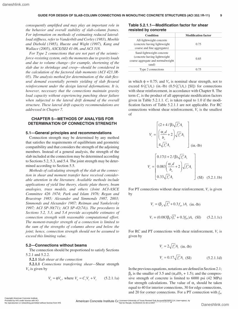
in which φ = 0.75; and Vn is nominal shear strength, not to exceed 6√fc′(Ac) (in.-lb) (0.5√fc′(Ac) [SI]) for connections with shear reinforcement, in accordance with Chapter 8. The term Cv is the product of all appropriate modification factors given in Table 5.2.1.1. Cv is taken equal to 1.0 if the modi-fication factors of Table 5.2.1.1 are not applicable. For RC connections without shear reinforcement, Vc is the smallest of
V
f A
d
bf A
f A
c
c c
s
oc c
c c
=
+ ′
+
′
′
( / )2 4
2
β
α
4 (in.-lb)
V
f A
d
bf A
f A
c
c c
s
oc c
c c
=
+ ′
+
′
′
0 17 1 2
2
. ( / )β
α
0.083
0.33
(SI) (5.2.1.1b)
For PT connections without shear reinforcement, Vc is given by
V f f Ac p c pc c= ′ +( . )β 0 3
(in.-lb)
Vc = (0.083βp√fc′ + 0.3fpc)Ac (SI) (5.2.1.1c)
For RC and PT connections with shear reinforcement, Vc is given by
V f Ac c c= ′2
(in.-lb)
V f Ac c c= ′0 17.
(SI) (5.2.1.1d)
In the previous equations, notations are defined in Section 2.1; βp is the smaller of 3.5 and (αsd/bo + 1.5); and the compres-sive strength of concrete is limited to 6000 psi (42 MPa) for strength calculations. The value of αs should be taken equal to 40 for interior connections, 30 for edge connections, and 20 for corner connections. For a PT connection with fpc
Table 5.2.1.1—Modification factor for shear resisted by concrete
Condition Modification factor
All-lightweight concrete(concrete having lightweight coarse and fine aggregates)
0.75
Sand-lightweight concrete(concrete having lightweight
coarse aggregate and normalweight sand)
0.85
Type 2 connections 0.75
American Concrete Institute Copyrighted Material—www.concrete.org
GUIDE FOR DESIGN OF SLAB-COLUMN CONNECTIONS IN MONOLITHIC CONCRETE STRUCTURES (ACI 352.1R-11) 9
Copyright American Concrete Institute Provided by IHS under license with ACI Licensee=University of Texas Revised Sub Account/5620001114, User=opioui, rty
Not for Resale, 01/26/2015 01:50:14 MSTNo reproduction or networking permitted without license from IHS
--`````,`,,`,`,,,,`,`,,`,,,`,`-`-`,,`,,`,`,,`---
daneshlink.com
Daneshlink.com

less than 125 psi (0.86 MPa), Vc should be calculated using Eq. (5.2.1.1b). The precompression stress in Eq. (5.2.1.1c) should not be taken greater than 500 psi (3.4 MPa).
Equation (5.2.1.1a) defines slab-column connection shear strength in the absence of moment transfer; its upper limit is the same as that required in Section 11.11.3 of ACI 318-08 when stirrup, bar, or wire shear reinforcement is used, which is slightly more conservative than the maximum value permitted by ACI 318-08 in Sections 11.11.4 and 11.11.5 for shearheads and headed shear stud reinforcement, respec-tively. The committee found no compelling reason to justify differentiating between designs using these different types of shear reinforcement. The presence of moment may result in increased shear demand. Therefore, when calculating the required moment strength, the designer is cautioned to consider the effects of potential sources of pattern loading.
Equations (5.2.1.1b) and (5.2.1.1c) are based on similar equations for two-way slab-column connection shear strength, as presented in ACI 318.
The maximum value of 4√fc′(in.-lb) (0.33√fc′ [SI]) for the concrete shear stress capacity given by Eq. (5.2.1.1b) exceeds the nominal shear stress capacity of 2√fc′ (in.-lb) (0.17√fc′ [SI]) used for beams or one-way slabs without shear reinforcement, largely because of the geometric confinement provided to the slab shear failure surface.
As the aspect ratio of the supporting column cross section increases, the confinement due to lateral compression along the long face diminishes. The term β in Eq. (5.2.1.1b) reflects the reduction in strength due to reduction in confine-ment. The term d/bo in Eq. (5.2.1.1b) is based subjectively on trends observed in Hawkins and Mitchell (1979) and Dilger and Ghali (1981). The use of these terms has been shown to provide conservative estimates for slab-column connec-tion concrete shear strength when compared to test results (Oliveira et al. 2004). Research on interior connections with stud shear reinforcement (Dilger and Ghali 1981) shows that the nominal strength decreases as the distance between the critical section and the column face increases. An evalu-ation of the data by ACI Committee 352 indicates that the reduction may also have been attributable to the increase in the ratio of the critical section dimension to slab depth.
The concrete shear strength Vc should be multiplied by each of the applicable modification factors in Table 5.2.1.1. The modification factors are meant to reflect how each variable individually affects shear strength. There is little experimental information to show that the effects are cumu-lative. This recommendation is therefore intended to provide a conservative estimate of connection strength.
Lightweight-aggregate concretes have been observed (Ivy et al. 1969) to exhibit lower shear strengths relative to normalweight concretes having the same compressive strength. The first two values given in Table 5.2.1.1 reflect this and have been shown to be slightly conservative when applied to high-strength lightweight concrete (Osman et al. 2000).
Connections subjected to significant flexural yielding have lower shear strengths than those failing in shear before flex-ural yielding (Kang and Wallace 2006; Kang et al. 2007).
Nominal concrete shear strength for this case is reduced by a factor of 0.75, which has been retained from the original committee report. This provision should be applied for all Type 2 connections.
The shear strengths given by Eq. (5.2.1.1b) and (5.2.1.1c) are written as a function of the square root of the concrete compressive strength. Research by Zsutty (1968) and Joint ACI-ASCE Committee 426 (1974) suggests that the rela-tion should be in terms of the cube root of concrete strength rather than the square root. Thus, the shear strengths given by Eq. (5.2.1.1b) and (5.2.1.1c) could be underestimated for concrete strengths exceeding 6000 psi (42 MPa).
The shear strength for PT connections given by Eq. (5.2.1.1c) considers the influence of slab precompression on shear strength. Generally, when the effective precompres-sion is below approximately 125 psi (0.86 MPa), the shear strength determined from Eq. (5.2.1.1c) is less than that calculated using Eq. (5.2.1.1b). Because the shear resistance offered by the vertical component of the post-tensioning tendons crossing the critical section is very sensitive to the actual location of the post-tensioning tendons, and the contribution to the total shear resistance is typically small for PT slabs, this term is omitted here, as recommended else-where (ACI 318; ACI 423.3R).
The shear strength equation for RC exterior connections is required to be used to determine the shear strength of PT exterior connections (ACI 318); however, tests (Trongtham and Hawkins 1977; Hawkins 1981; Kosut et al. 1985; Foutch et al. 1990; Long and Cleland 1993; Martinez-Cruzado et al. 1994; Gardner and Kallage 1998; Han et al. 2006) on PT exterior connections subjected to monotonic or reversed cyclic lateral loading have shown that the higher shear strengths calculated using Eq. (5.2.1.1c) were consistently lower than measured strengths; therefore, Eq. (5.2.1.1c) is also recommended for PT exterior connections (Kang et al. 2007, 2008).
The effect of slab restraint by structural walls and other structural elements on the shear strength of PT slab-column connections should be considered (ACI 318), for example, by using Eq. (5.2.1.1b) instead of Eq. (5.2.1.1c). Stiff walls or elements may restrain slab deformations due to shrinkage and creep that could in turn result in partial or complete loss of post-tensioning in the connection region.
The reduced value of 2√fc′ (in.-lb) (0.17√fc′ [SI]) for the concrete shear stress capacity given by Eq. (5.2.1.1d) is due to the influence of diagonal shear cracks formed when shear reinforcement resists a significant portion of the shear force (Park and Gamble 1980).
During construction, young concrete with compres-sive strength below the specified value may need to carry heavy loads. Low concrete strength has a greater effect on shear strength than flexural strength. Thus, there could be a tendency for connection shear failures. In checking resis-tance to construction loads that occur before the speci-fied concrete strength develops, it is important to use the concrete strength corresponding to the age at which the load occurs rather than the design strength.
American Concrete Institute Copyrighted Material—www.concrete.org
10 GUIDE FOR DESIGN OF SLAB-COLUMN CONNECTIONS IN MONOLITHIC CONCRETE STRUCTURES (ACI 352.1R-11)
Copyright American Concrete Institute Provided by IHS under license with ACI Licensee=University of Texas Revised Sub Account/5620001114, User=opioui, rty
Not for Resale, 01/26/2015 01:50:14 MSTNo reproduction or networking permitted without license from IHS
--`````,`,,`,`,,,,`,`,,`,,,`,`-`-`,,`,,`,`,,`---
daneshlink.com
Daneshlink.com

5.2.1.2 Connections transferring shear and moment—Any connection may be designed in accordance with Section 5.2.1.2(a). Connections satisfying the limitations of Section 5.2.1.2(b) or 5.2.1.2(c) may be designed by the procedures listed in those sections instead of the procedure in Section 5.2.1.2(a). All Type 2 connections should satisfy the recom-mendations of Section 5.2.1.2(d) or 5.2.1.2(e) in addition to Sections 5.2.1.2(a), 5.2.1.2(b), or 5.2.1.2(c), as applicable.
(a) A fraction of the transfer moment given by γfMub should be considered to be transferred by flexure within an effective slab width between lines that are 1.5 times the slab or drop panel thickness outside opposite faces of the column or capital, where Mub is the factored moment to be trans-ferred and
γ fb
b
=+
1
123
1
2 (5.2.1.2a)
In Eq. (5.2.1.2a), b1 is the dimension of the critical section bo measured in the direction of the span for which moments are determined; and b2 is the dimension of the critical section bo measured in the direction perpendicular to b1.
The remainder of the transfer moment γvMub should be resisted by eccentricity of shear about the centroid of the shear-critical section, where
γ γv f= −1
(5.2.1.2b)
The value of γf for RC interior connections may be increased by as much as 25 percent of its value from Eq. (5.2.1.2a), but not more than γf = 1.0, if the factored direct shear transferred to the column does not exceed 0.4φVc and the net tensile strain εt of the reinforcement at the nominal strength calculated for the slab width within lines 1.5h on each side of a column, including capital, is not less than 0.010.
The shear stresses due to moment transfer should be assumed to vary linearly about the centroid of the shear-critical section, as in the ACI eccentric shear stress model (ACI 318-08, Section 11.11.7). The algebraic sum of shear stresses due to direct shear and moment transfer should nowhere exceed the value of Vo/Ac.
(b) RC corner connections, and edge connections trans-ferring moments only perpendicular to the slab edge, may be assumed to have adequate shear strength if the factored direct shear transferred to the column does not exceed 0.75φVc at an edge support or 0.5φVc at a corner support, with Vc defined by Eq. (5.2.1.1b).
(c) Connections without shear reinforcement supported on rectangular columns having a ratio of long-to-short cross-sectional dimensions not exceeding 2 may be assumed to have adequate shear strength to transfer the factored connec-tion shear and moment when
V V M M bo u ub ub o≥ + +α( ) /1 2 (5.2.1.2c)
When bidirectional seismic loads are considered, only the greater Mub in the two principal directions should be included in Eq. (5.2.1.2c). For RC edge connections, moments perpendicular to the slab edge may be taken equal to zero in Eq. (5.2.1.2c) if Vu at an edge support does not exceed 0.75φVc, with Vc defined by Eq. (5.2.1.1b). The value of α should be taken equal to 5 for interior connections and 3.5 for edge connections.
(d) For Type 2 connections without shear reinforcement that are part of the seismic-force-resisting system, Vug should not exceed 0.4φVc for RC connections and 0.6φVc for PT connections, with Vc defined by Eq. (5.2.1.1b) and (5.2.1.1c), respectively, where Vug is the factored gravity shear force determined by the load combination 1.2D + 1.0L + 0.2S (ACI 318-08, Section 21.13.6). Alternatively, the design story-drift ratio of the structural system should not exceed the lateral drift capacity of the slab-column connection as defined in Chapter 7; otherwise, minimum shear reinforce-ment should be provided in accordance with Chapter 8.
(e) For Type 2 connections without shear reinforcement that are not designated as part of the seismic-force-resisting system, the algebraic sum of shear stresses due to direct shear and moment transfer in conjunction with the design story-drift ratio should not exceed the value of φVc/Ac, with Vc defined by Eq. (5.2.1.1b) or (5.2.1.1c). Alternatively, the design story-drift ratio of the structural system should not exceed the lateral drift capacity of the slab-column connec-tion as defined in Chapter 7; otherwise, minimum shear rein-forcement should be provided in accordance with Chapter 8.
Shear demand at a connection increases when moments are transferred simultaneously to the connection. Section 5.2.1.2 recommends several optional procedures for consid-ering the effects of moment transfer. The most general of the procedures, which can be applied to connections of any geometry and loading, is described in Section 5.2.1.2(a). However, connections can be designed with less compu-tational effort if they satisfy the loading and geometric requirements of Section 5.2.1.2(b) or 5.2.1.2(c).
The design method described in Section 5.2.1.2(a) is the same as the eccentric shear stress model embodied in ACI 318. It is assumed that shear stresses due to direct shear on the connection are uniformly distributed on the shear-crit-ical section. In addition, a portion of the unbalanced moment given by Eq. (5.2.1.2b) is resisted by a linear variation of shear stresses on the critical section; equations for shear-critical sections of any shape are provided in Appendix B of ACI 421.1R-08. The algebraic sum of shear stresses due to direct shear and moment transfer should not exceed the value of Vo/Ac. The portion of moment not carried by eccen-tric shear stresses is to be carried by slab flexural reinforce-ment according to Section 5.2.2. This method is described in detail elsewhere (ACI 318; Park and Gamble 1980). Usually, the procedure of Section 5.2.1.2(a) is more conser-vative than the procedure of Section 5.2.1.2(b) (Moehle 1988).
American Concrete Institute Copyrighted Material—www.concrete.org
GUIDE FOR DESIGN OF SLAB-COLUMN CONNECTIONS IN MONOLITHIC CONCRETE STRUCTURES (ACI 352.1R-11) 11
Copyright American Concrete Institute Provided by IHS under license with ACI Licensee=University of Texas Revised Sub Account/5620001114, User=opioui, rty
Not for Resale, 01/26/2015 01:50:14 MSTNo reproduction or networking permitted without license from IHS
--`````,`,,`,`,,,,`,`,,`,,,`,`-`-`,,`,,`,`,,`---
daneshlink.com
Daneshlink.com

For RC corner connections, and for RC edge connections transferring moment only perpendicular to the slab edge, a simple computational design procedure is given in Section 5.2.1.2(b). The procedure is based on research (Moehle 1988; Hwang and Moehle 1993) on slab-column edge and corner connections for which the outside face of the column is flush with the slab edge. For such connections, moment-transfer strength perpendicular to the slab edge is governed by slab flexural reinforcement within an effective transfer width and is not influenced significantly by shear on the connection. Failure apparently occurs when the connection moment reaches the flexural strength of slab reinforcement, or when the connection shear reaches the shear strength of the shear-critical section. In cases where moments induce yield in slab flexural reinforcement, shear failure can occur for shear less than that given by Eq. (5.2.1.1b) because of loss of in-plane restraint when the flexural reinforcement yields (Moehle 1988; Hwang and Moehle 1993; Kang and Wallace 2006). For that reason, an upper limit equal to three-fourths of the value given by Eq. (5.2.1.1b) is recom-mended. Recommendations for moment-transfer reinforce-ment are given in Section 5.2.2.
For rectangular interior connections or edge connections transferring moments parallel to the slab edge and having a ratio between long and short column dimensions less than or equal to 2, effects of moment transfer on shear strength can be accounted for by proportioning the connection to satisfy Section 5.2.1.2(c). Equation (5.2.1.2c) of that section essentially emulates, in algebraic form, the eccentric shear stress model described in Section 5.2.1.2(a). The form of Eq. (5.2.1.2c) was originally presented by Joint ACI-ASCE Committee 426 (1977), which recommended the equation for interior connections with a value of α equal to 5.2; the value of α has been simplified to 5 for interior connections. For RC edge connections transferring moment perpendicular to the slab edge, usually Vu is less than 0.75φVc, in which case moments perpendicular to the slab edge can be ignored in Eq. (5.2.1.2c). This equation should not be applied for connections not satisfying the requirement for column cross-section aspect ratio, in which case the eccentric shear stress model (ACI 318-08, Section 11.11.7) should instead be used.
Sections 5.2.1.2(d) and 5.2.1.2(e) should be applied to all connections without beams for which transfer of moments under significant inelastic deformations is anticipated. The recommendations are based on a review (Pan and Moehle 1989) of data reported (Hanson and Hanson 1968; Islam and Park 1976; Hawkins 1977; Morrison et al. 1983; Mulcahy and Rotter 1983; Zee and Moehle 1984; Moehle and Diebold 1985), which reveal that lateral displacement ductility of interior connections without shear reinforce-ment is inversely related to the level of shear on the connec-tion. Connections having shear exceeding the recommended value exhibited virtually no ductility under lateral loading. Based on experimental data (Kang and Wallace 2006; Kang et al. 2007), the maximum allowable factored gravity shear force for PT connections that are part of the seismic-force-resisting system can be increased from 0.4φVc to 0.6φVc.
For Type 2 connections not designated as part of the seismic-force-resisting system, model building codes (ASCE/SEI 7-10 and IBC-2009) require deformation compatibility checks. Slab-column connections should be able to resist the gravity loads at lateral displacements corresponding to the design-level earthquake required by the governing code for earthquake-resistant design. ACI 318 has incor-porated a simplified relationship between lateral displace-ment capacity and gravity shear ratio that can be used for deformation compatibility checks. That relationship is based on databases (Megally and Ghali 1994; Luo and Durrani 1995; Kang and Wallace 2006; Moehle 1996; Hueste et al. 2007; Kang et al. 2007) of lateral load tests on slab-column connections of the type used for typical slab-column frames assigned to moderate and high seismic design categories. Detailed recommendations for estimating lateral drift capacity are presented in Chapter 7.
An alternative approach is to develop a detailed model of the slab-column frame and subject it to the design lateral drift demand to calculate the connection shear stress demands. These demands should be compared with the capacity, considering the potential for shear strength degradation; for example, include Cv from Table 5.2.1.1. It should be noted that connection punching may still occur at a certain lateral drift ratio, and the type of failure could be brittle depending on the gravity shear ratio and the degree of shear strength degradation.
5.2.2 Slab flexure at the connection—Slab flexural rein-forcement should be provided to carry the moment trans-ferred to the connection in accordance with Section 6.1.1.
5.3—Connections with transverse beamsIf a connection has beams transverse to the span of the
slab, shear and moment-transfer strength of the connection may be determined according to Sections 5.3.1 and 5.3.2.
5.3.1 Shear strength is the smaller of the following:(a) Design shear strength limited by beam action with a
critical section extending across the entire slab width in a plane parallel to the beam and located a distance d from the face of the beam, where d is the slab effective depth. Design shear strength for this condition is calculated according to ACI 318 for beams.
(b) Design shear strength limited by the sum of design shear strengths of only transverse beams. Design shear strength of the transverse beams at a distance dbeam from the support face should be calculated in accordance with ACI 318 shear provisions, where dbeam is the beam effective depth.
5.3.2 Moment-transfer strength is the smaller of the following:
(a) Design flexural strength of the slab at the column face over a width equal to that of the column strip.
(b) Sum of the design flexural strength of the slab over a width equal to that of the column face and the design torsional strengths of the transverse beams.
The procedure described is based on concepts of the beam analogy, as presented in ACI SP-42 (74). The procedure assumes the shear strength is limited by either beam action
American Concrete Institute Copyrighted Material—www.concrete.org
12 GUIDE FOR DESIGN OF SLAB-COLUMN CONNECTIONS IN MONOLITHIC CONCRETE STRUCTURES (ACI 352.1R-11)
Copyright American Concrete Institute Provided by IHS under license with ACI Licensee=University of Texas Revised Sub Account/5620001114, User=opioui, rty
Not for Resale, 01/26/2015 01:50:14 MSTNo reproduction or networking permitted without license from IHS
--`````,`,,`,`,,,,`,`,,`,,,`,`-`-`,,`,,`,`,,`---
daneshlink.com
Daneshlink.com

in the slab or by development of the shear strengths of the beams at the side faces of the connection.
Flexural strength is limited by development of a flexural yield line across the slab column-strip width; in which case the transverse beams do not reach their design strengths (Fig. 5.3.2(a)), or by development of a yield surface around the connection that involves flexural yield of the slab and torsional yield of the transverse beams (Fig. 5.3.2(b)). Beam torsional strength should be calculated in accordance with ACI 318.
5.4—Effect of openingsWhen openings perpendicular to the plane of the slab are
located closer to a shear-critical section than 10 times the slab thickness, the effect of such openings should be taken into account. This may be done using a general analysis that satisfies requirements of equilibrium and compatibility. Instead of a general analysis, Section 5.2 or 5.3 should be followed, except that portions of the critical section enclosed within lines from the centroid of the support area to the extreme edges of the opening should be considered inef-fective. The eccentricity of the applied shear caused by the opening should also be taken into account, except where the ineffective length of the critical section is less than either d or half the length of the adjacent support face. The support should be considered as the column, including column capital, if the critical section under consideration is adjacent to the column, and should be considered as the shear cap or drop panel if the critical section under consideration is adja-cent to the shear cap or drop panel.
For PT connections, tendons should be continuous and should be deflected horizontally to pass around such open-ings. Openings may reduce or eliminate precompression in critical regions of PT connections, which should be consid-ered when openings are located within column strips.
Slab perforations and embedded service ducts disrupt the flow of flexural and shear stresses near the connection and generally result in decreased strength. The degree of influ-ence is a function of proximity and size of the disruption. Effects of slab perforations and of embedded service ducts are described in Hanson (1970).
5.5—Joint strength5.5.1 Axial compression—If the design compressive
strength of concrete in the column below the joint is less than or equal to 1.4 times that of the floor system, the joint strength in axial compression can be assumed equal to the column strength below the joint. Otherwise, axial strength should be determined according to ACI 318-08, Section 10.12. The column longitudinal reinforcement should be continuous through the joint, and the joint should be confined as specified in Section 6.2.2.
5.5.2 Shear—Calculations for joint shear strength in slab-column connections are not required unless there are trans-verse beams subjected to lateral load framing into a beam-column connection.
Joint ACI-ASCE Committee 352 is unaware of any reported cases of joint shear failure in flat slab or flat plate connec-tions. The absence of joint shear failures is likely attribut-able to two phenomena: (1) for slabs of usual proportions, the magnitudes of moment transfer that can be developed at a connection, and hence of joint shear, are relatively low; and (2) confinement afforded by the slab concrete enhances joint shear strength. More information regarding joint shear strength for the case of transverse beams framing into a beam-column connection may be found in ACI 352R-02.
CHAPTER 6—REINFORCEMENT
6.1—Slab reinforcement for moment transfer6.1.1 (a) Interior connections—Reinforcement required
in each direction at a connection to resist the moment γfMub should be placed within lines 1.5h on each side of a column, including capital, where Mub is the moment transferred to the column in each principal direction, h is the slab thick-ness including drop panel, and γf is the fraction of moment transferred by flexure (Section 5.2.1.2(a)). The reinforce-ment to resist the moment γfMub should not be less than half of the reinforcement in the column strip. The value of γf for RC interior connections may be increased by 25 percent of its value from Eq. (5.2.1.2a) if the factored direct shear transferred to the column does not exceed 0.4φVc and the net tensile strain εt of the flexural reinforcement at the nominal strength calculated for the slab width within lines 1.5h on each side of a column, including capital, is not less than 0.010. The reinforcement should be anchored to develop the tensile forces at the support face. Reinforcement placed to resist slab flexural moments or placed as structural integrity
Fig. 5.3.2—Unbalanced moment strength of connections with transverse beams.
American Concrete Institute Copyrighted Material—www.concrete.org
GUIDE FOR DESIGN OF SLAB-COLUMN CONNECTIONS IN MONOLITHIC CONCRETE STRUCTURES (ACI 352.1R-11) 13
Copyright American Concrete Institute Provided by IHS under license with ACI Licensee=University of Texas Revised Sub Account/5620001114, User=opioui, rty
Not for Resale, 01/26/2015 01:50:14 MSTNo reproduction or networking permitted without license from IHS
--`````,`,,`,`,,,,`,`,,`,,,`,`-`-`,,`,,`,`,,`---
daneshlink.com
Daneshlink.com

reinforcement (Section 6.3) may be assumed effective for moment transfer.
The optimum placement of reinforcement for moment transfer has not been clearly established by available experi-mental data. ACI 318 considers reinforcement placed within 1.5 times the slab thickness on both sides of the column to be effective in transferring the moment γfMub. In general, observed performance of connections designed by this procedure has been acceptable. ASCE/SEI 41-06 recom-mends increasing the effective transfer width to 2.5 times the slab or drop panel thickness on each side of a column for analytical modeling of moment-transfer strengths at RC interior connections and at RC exterior connections with moment about an axis perpendicular to the slab edge. Concentrating flexural reinforcement within the ACI 318 effective transfer width, and meeting the recommendations in Sections 6.1.4 and 6.1.5, improves the flexural transfer of γfMub (ACI 318) both in the service load range and at the ultimate limit state. Whether the reinforcement needed for moment transfer is placed entirely as top reinforcement, or whether some bottom reinforcement should be used, is less clear and requires judgment of the engineer. As guidance, consider the two extreme cases illustrated in Fig. 6.1.1a.
In Case A of Fig. 6.1.1a, the connection loading is domi-nated by a large balanced moment and small unbalanced, lateral load moment. In this case, the designer should place all the moment transfer reinforcement as top steel. In Case B of Fig. 6.1.1a, the connection is loaded by a small balanced moment and a large moment transfer due to lateral loads. This loading results in nearly equal slab moments of opposite sign on opposite sides of the column. Consequently, the total area of reinforcement recommended by Section 6.1.1(a) for moment-transfer should be divided equally between the top and bottom of the slab. Because the loading condition shown in Case B of Fig. 6.1.1a generally also involves moment
reversals, both the top and the bottom reinforcement should be continuous through the column.
(b) Exterior connections—For resistance to moment transfer parallel to the edge of edge connections, follow the recommendations of Section 6.1.1(a) for interior connections.
For resistance to moment transfer perpendicular to the edge, including corner connections, sufficient reinforce-ment should be placed within lines ct on each side of the column to resist the moment γfMub to be transferred to the column at the centroid of the shear-critical section, unless the edge is designed to transfer the torsion due to required slab reinforcement outside this width. For moment transfer perpendicular to the edge for RC connections, γf may be increased to 1.0 if the factored direct shear transferred to the column does not exceed 0.75φVc for edge connections and 0.5φVc for corner connections, as recommended in Section 5.2.1.2(b). The quantity ct is the distance from the interior face of the column to the slab edge measured parallel to c1, but not greater than c1 or less than 1.5h. In cases where the edge is designed for torsion, follow the recommendations of Section 6.1.1(a) for interior connections, except for adjust-ments to γf.
Experimental results (Zaghlool et al. 1973; Rangan and Hall 1984; Moehle 1988) indicate that slab reinforcement for moment transfer perpendicular to the edge is fully effec-tive in resisting the edge moment only if it is anchored within torsional yield lines projecting from the inside column face to the slab edge (Fig. 6.1.1b). Because of the large twist that occurs in the edge member after torsional yield, reinforce-ment beyond the projection of the yield line cannot be fully developed until large connection rotations occur. For the typical torsional yield line having a projection of approxi-mately 45 degrees, only that reinforcement within the width 2ct + c2 is considered effective for RC edge connections, as
Fig. 6.1.1a—Illustration of cases where balanced and unbalanced connection moments predominate.
American Concrete Institute Copyrighted Material—www.concrete.org
14 GUIDE FOR DESIGN OF SLAB-COLUMN CONNECTIONS IN MONOLITHIC CONCRETE STRUCTURES (ACI 352.1R-11)
Copyright American Concrete Institute Provided by IHS under license with ACI Licensee=University of Texas Revised Sub Account/5620001114, User=opioui, rty
Not for Resale, 01/26/2015 01:50:14 MSTNo reproduction or networking permitted without license from IHS
--`````,`,,`,`,,,,`,`,,`,,,`,`-`-`,,`,,`,`,,`---
daneshlink.com
Daneshlink.com
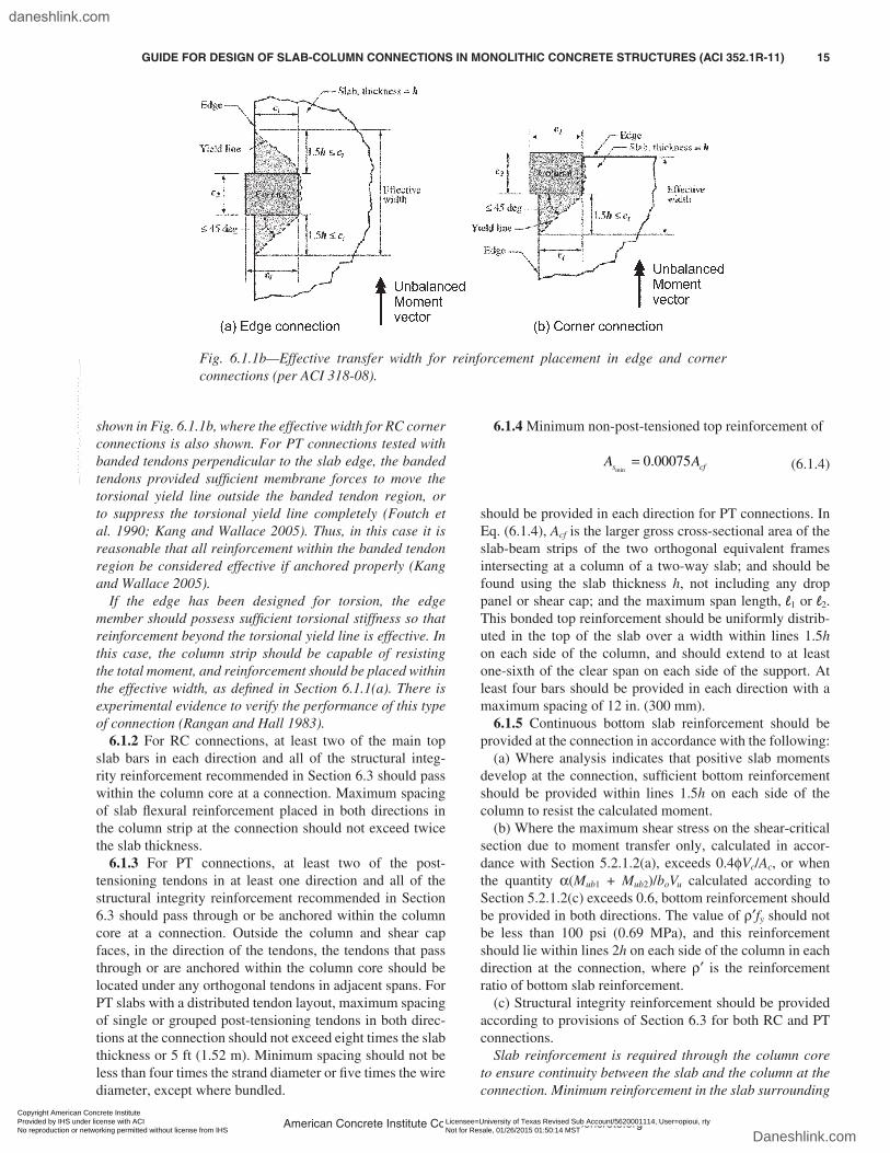
shown in Fig. 6.1.1b, where the effective width for RC corner connections is also shown. For PT connections tested with banded tendons perpendicular to the slab edge, the banded tendons provided sufficient membrane forces to move the torsional yield line outside the banded tendon region, or to suppress the torsional yield line completely (Foutch et al. 1990; Kang and Wallace 2005). Thus, in this case it is reasonable that all reinforcement within the banded tendon region be considered effective if anchored properly (Kang and Wallace 2005).
If the edge has been designed for torsion, the edge member should possess sufficient torsional stiffness so that reinforcement beyond the torsional yield line is effective. In this case, the column strip should be capable of resisting the total moment, and reinforcement should be placed within the effective width, as defined in Section 6.1.1(a). There is experimental evidence to verify the performance of this type of connection (Rangan and Hall 1983).
6.1.2 For RC connections, at least two of the main top slab bars in each direction and all of the structural integ-rity reinforcement recommended in Section 6.3 should pass within the column core at a connection. Maximum spacing of slab flexural reinforcement placed in both directions in the column strip at the connection should not exceed twice the slab thickness.
6.1.3 For PT connections, at least two of the post-tensioning tendons in at least one direction and all of the structural integrity reinforcement recommended in Section 6.3 should pass through or be anchored within the column core at a connection. Outside the column and shear cap faces, in the direction of the tendons, the tendons that pass through or are anchored within the column core should be located under any orthogonal tendons in adjacent spans. For PT slabs with a distributed tendon layout, maximum spacing of single or grouped post-tensioning tendons in both direc-tions at the connection should not exceed eight times the slab thickness or 5 ft (1.52 m). Minimum spacing should not be less than four times the strand diameter or five times the wire diameter, except where bundled.
6.1.4 Minimum non-post-tensioned top reinforcement of
A As cfmin
.= 0 00075 (6.1.4)
should be provided in each direction for PT connections. In Eq. (6.1.4), Acf is the larger gross cross-sectional area of the slab-beam strips of the two orthogonal equivalent frames intersecting at a column of a two-way slab; and should be found using the slab thickness h, not including any drop panel or shear cap; and the maximum span length, l1 or l2. This bonded top reinforcement should be uniformly distrib-uted in the top of the slab over a width within lines 1.5h on each side of the column, and should extend to at least one-sixth of the clear span on each side of the support. At least four bars should be provided in each direction with a maximum spacing of 12 in. (300 mm).
6.1.5 Continuous bottom slab reinforcement should be provided at the connection in accordance with the following:
(a) Where analysis indicates that positive slab moments develop at the connection, sufficient bottom reinforcement should be provided within lines 1.5h on each side of the column to resist the calculated moment.
(b) Where the maximum shear stress on the shear-critical section due to moment transfer only, calculated in accor-dance with Section 5.2.1.2(a), exceeds 0.4φVc/Ac, or when the quantity α(Mub1 + Mub2)/boVu calculated according to Section 5.2.1.2(c) exceeds 0.6, bottom reinforcement should be provided in both directions. The value of ρ′fy should not be less than 100 psi (0.69 MPa), and this reinforcement should lie within lines 2h on each side of the column in each direction at the connection, where ρ′ is the reinforcement ratio of bottom slab reinforcement.
(c) Structural integrity reinforcement should be provided according to provisions of Section 6.3 for both RC and PT connections.
Slab reinforcement is required through the column core to ensure continuity between the slab and the column at the connection. Minimum reinforcement in the slab surrounding
Fig. 6.1.1b—Effective transfer width for reinforcement placement in edge and corner connections (per ACI 318-08).
American Concrete Institute Copyrighted Material—www.concrete.org
GUIDE FOR DESIGN OF SLAB-COLUMN CONNECTIONS IN MONOLITHIC CONCRETE STRUCTURES (ACI 352.1R-11) 15
Copyright American Concrete Institute Provided by IHS under license with ACI Licensee=University of Texas Revised Sub Account/5620001114, User=opioui, rty
Not for Resale, 01/26/2015 01:50:14 MSTNo reproduction or networking permitted without license from IHS
--`````,`,,`,`,,,,`,`,,`,,,`,`-`-`,,`,,`,`,,`---
daneshlink.com
Daneshlink.com

the supporting column is necessary to control cracking. Concentrating reinforcement at the connection delays flex-ural yielding in the shear-critical zone and thus enhances connection shear strength (Hawkins 1977).
For designs where lateral loads are of sufficient magni-tude that positive slab moments are calculated at the column face, reinforcement should be provided in the column strip to resist the calculated moments (Case B in Fig. 6.1.1a). This can occur even in buildings with structural wall systems designed to resist lateral loads. For designs where moment transfer is of lesser magnitude, the total slab moment at the column face may be calculated to be negative (Case A in Fig. 6.1.1a). However, it is still possible that positive slab moments will develop near the column, and reinforcement (Section 6.1.5(b)) should be provided to resist this moment (Joint ACI-ASCE Committee 426 1977). At edge connections where the column is flush with the slab edge and the connec-tion is loaded by an unbalanced moment that produces tension at the top of the slab, Section 6.1.5(b) does not apply.
The recommendations for continuity and anchorage of bottom reinforcement presented in this guide differ from minimum requirements of many codes, for example — ACI 318. Minimum requirements of those codes, such as two integrity bars in each direction, without any minimum bar size requirement, could be potentially unconservative for many common design situations (Hawkins and Mitchell 1979; Mitchell and Cook 1984).
The recommendations for structural integrity tendons are based on ACI 318-08, Section 18.12.6, and the recommen-dations for minimum bonded reinforcement at PT connec-tions are based on research evaluated by Joint ACI-ASCE Committee 423 (1958), Smith and Burns (1974), Burns and Hemakom (1985), and Kosut et al. (1985).
6.1.6 Where bottom reinforcement is placed to satisfy Sections 6.1.5(a) or 6.1.5(b), the sum of the top and bottom reinforcement within lines 1.5h on each side of the column at a connection should not exceed three-fourths of the balanced reinforcement calculated for the slab section within lines 1.5h on each side of the column and of depth d, unless both the top and bottom flexural reinforcement can be developed in tension on a single face of the column.
The upper limit on the sum of continuous top and bottom reinforcement applies for cases where the column dimen-sion is insufficient to develop the reinforcement, according to Section 6.4.6. In the presence of significant moment transfer at such connections, a bar in tension due to flexural stresses on one face of the column may, because of inad-equate anchorage, also be in tension at the opposite face of the column. Thus, both the top and bottom reinforcement may be stressed in tension on a single face. To ensure that the extra tensile forces will not result in local crushing of slab concrete in the compression zone, the sum of top and bottom reinforcement ratios should not exceed three-fourths of the balanced ratio.
6.1.7 At discontinuous edges of exterior connections, all top slab reinforcement perpendicular to the edge should be anchored to develop the yield stress at the column face, and the edge should be reinforced to satisfy Sections 6.1.7(a)
or 6.1.7(b). All exterior PT connections should also satisfy Section 6.1.7(c).
(a) A beam should be provided having longitudinal rein-forcement and closed stirrups designed to resist the torsion transmitted from the discontinuous slab edge. The transverse reinforcement should extend a distance not less than four times the slab thickness from both sides of the column, and spacing should not exceed 0.5dbeam but need not be less than 0.75h, where dbeam is the beam effective depth and h is the slab thickness.
(b) An effective beam formed within the slab depth and reinforced by slab reinforcement should be provided. For this effective beam, within a distance not less than two times the slab thickness on both sides of the support, the top rein-forcement perpendicular to the edge should be spaced not more than 0.75h and should have a 180-degree hook with extension returning along the bottom face of the slab a distance not less than ld, as defined in Section 6.4.6. Instead of hooked bars, hairpin bars of diameter not less than that of the top slab bars may be inserted along the edge to overlap the top bars. At least four bars, of diameter not less than the diameter of the main slab bars, should be placed parallel to the discontinuous edge as follows: two of the bars should be top bars, one along the slab edge and one not less than 0.75c1 nor more than c1 from the slab edge; the other two bars should be bottom bars, placed so one bar is directly below each of the two top bars.
(c) For PT exterior connections, two horizontal bars should be placed parallel to the edge and immediately ahead of the tendon anchors. One of the bars should be placed above and the other below the plane of the tendons. Another pair of horizontal bars should be placed parallel to the edge and at a distance equal to three-eighths of the slab thick-ness in front of the tendon anchors. These additional hori-zontal bars should extend past the last tendon by at least ld or be anchored with a hook. At least one vertical bursting bar should be placed between the tendon anchors and outside the outermost tendon anchors.
At discontinuous edges, using spandrel beams can ensure adequate serviceability and torsional strength. Where span-drel beams are absent, the slab edge should be reinforced to act as a spandrel beam. The recommended slab edge rein-forcement is intended to control cracking. It is not intended that the slab edge without spandrel beams be designed for torsion. Additionally, the recommended edge reinforcement may be inadequate to act as a diaphragm chord. Typical examples of reinforcement at RC edge connections are shown in Fig. 6.1.7a.
For RC edge connections without beams, the bars running parallel to the slab edge should be placed, where practical, within the bars perpendicular to the edge or within the stir-rups, if present.
The additional reinforcement specified for PT edge connections is intended to resist bursting forces in front of tendon anchors and edge tensile forces between the anchors, and is shown in Fig. 6.1.7b.
American Concrete Institute Copyrighted Material—www.concrete.org
16 GUIDE FOR DESIGN OF SLAB-COLUMN CONNECTIONS IN MONOLITHIC CONCRETE STRUCTURES (ACI 352.1R-11)
Copyright American Concrete Institute Provided by IHS under license with ACI Licensee=University of Texas Revised Sub Account/5620001114, User=opioui, rty
Not for Resale, 01/26/2015 01:50:14 MSTNo reproduction or networking permitted without license from IHS
--`````,`,,`,`,,,,`,`,,`,,,`,`-`-`,,`,,`,`,,`---
daneshlink.com
Daneshlink.com

6.2—Joint recommendations6.2.1 Column longitudinal reinforcement—Column longi-
tudinal reinforcement passing through the joint should satisfy ACI 318-08, Sections 10.9.1 and 10.9.2. Offsets satisfying requirements of ACI 318 are permitted within the joint.
In addition, column reinforcement at joints of Type 2 connections should be distributed around the perimeter of the column core. The center-to-center spacing between adjacent longitudinal bars should not exceed the larger of 8 in. (200 mm) or one-third of the column cross-sectional dimension in the direction for which the spacing is being determined.
Researchers have reported the need for well-distributed longitudinal reinforcement to confine concrete (Sheikh and Uzumeri 1980). The recommendations for distribu-
tion of longitudinal reinforcement for Type 2 connections are intended to enhance column and joint ductility at the connection by improving column confinement.
6.2.2 Transverse reinforcement6.2.2.1 Type 1 connections—Joint transverse reinforce-
ment is not required for interior connections. For exterior connections, horizontal joint transverse reinforcement should be provided. Within the depth of the slab plus drop panel, this reinforcement should satisfy ACI 318-08, Section 7.10, with the following modifications:
(a) At least one layer of joint transverse reinforcement should be provided between the top and bottom slab longi-tudinal reinforcement.
(b) If the connection is part of the primary system for resisting nonseismic lateral loads, the center-to-center
Fig. 6.1.7a—Typical details at discontinuous edges.
American Concrete Institute Copyrighted Material—www.concrete.org
GUIDE FOR DESIGN OF SLAB-COLUMN CONNECTIONS IN MONOLITHIC CONCRETE STRUCTURES (ACI 352.1R-11) 17
Copyright American Concrete Institute Provided by IHS under license with ACI Licensee=University of Texas Revised Sub Account/5620001114, User=opioui, rty
Not for Resale, 01/26/2015 01:50:14 MSTNo reproduction or networking permitted without license from IHS
--`````,`,,`,`,,,,`,`,,`,,,`,`-`-`,,`,,`,`,,`---
daneshlink.com
Daneshlink.com

spacing of the joint transverse reinforcement should not exceed 8 in. (200 mm).
6.2.2.2 Type 2 connections—Column transverse rein-forcement above and below the joint should conform to ACI 318-08, Chapter 21.
For interior connections, transverse reinforcement is not required within the depth of the joint. For exterior connections, the column transverse reinforcement should be continued through the joint, with at least one layer of transverse reinforcement between the top and bottom slab reinforcement. Maximum spacing of transverse reinforce-ment within the slab depth should not exceed the smallest of (a) one-half the least column dimension; (b) eight times the smallest longitudinal bar diameter; or (c) 8 in. (200 mm). All hoop reinforcement should be closed with hooks at their ends of not less than 135 degrees. Where required, crossties should be provided at each layer of joint trans-verse reinforcement, and each crosstie end should engage a perimeter longitudinal bar. Single-leg crossties should have a 135-degree or greater bend on one end and the other end may have a standard 90-degree tie hook as defined in ACI 318-08, Section 7.1. If 90-degree hooks are used, those hooks should be placed at the interior face of the joint within the slab depth. All 135-degree hooks should have minimum extension not less than 3 in. (75 mm) or six hoop or tie bar diameters.
For Type 1 connections, joint confinement by transverse reinforcement within the joint is advised for exterior connec-tions where at least one face of the joint is not confined by the slab. Because the joint may be thin in elevation, the requirements of ACI 318 are modified to recommend at least one layer of transverse steel within the joint. An additional requirement is made for the more severe loading case where the slab-column framing resists lateral loads.
For Type 2 connections, the recommendations for trans-verse reinforcement are the same as those given by ACI 318 for columns in frames that are not part of the seismic-force-resisting system in regions of high seismic hazard,
and for frames in regions of moderate seismic hazard, as appropriate.
For interior connections, the slab provides adequate confinement. Column hoop reinforcement above and below the slab should conform to these recommendations.
Within the depth of the joint of exterior connections, column longitudinal bars should be restrained laterally by spirals or by ties per these recommendations, which can be more stringent than ACI 318.
6.3—Structural integrity reinforcementReinforcement at connections as described in Sections
6.3.1 and 6.3.2 should be provided to increase the resistance of the structural system to progressive collapse.
6.3.1 Connections without beams—At interior connec-tions, continuous bottom slab reinforcement passing within the column core in each principal direction should have an area not less than
Aw
fsmu
y
=0 5 1 2. l l
φ (6.3.1)
in which φ = 0.9. The quantity of reinforcement Asm may be reduced to two-thirds of that given by Eq. (6.3.1) for edge connections in the direction perpendicular to the slab edge, and to one-half of that given by Eq. (6.3.1) for corner connections in each principal direction. Where the calcu-lated values of Asm in a given direction differ for adjacent spans, the larger value should be used at that connection.
Catastrophic progressive collapses have occurred in slab-column structures (Vanderbilt 1972). Many of the failures happened during construction when young, relatively weak concrete was subjected to heavy construction loads. Proce-dures for considering the effects of construction loads have been described (Grundy and Kabaila 1963; Agarwal and Gardner 1974; Liu et al. 1985; ACI 347-05).
For Type 1 connections, the minimum bottom reinforce-ment given by Eq. (6.3.1) should be continuous through the
Fig. 6.1.7b—Additional reinforcement for PT edge connections.
American Concrete Institute Copyrighted Material—www.concrete.org
18 GUIDE FOR DESIGN OF SLAB-COLUMN CONNECTIONS IN MONOLITHIC CONCRETE STRUCTURES (ACI 352.1R-11)
Copyright American Concrete Institute Provided by IHS under license with ACI Licensee=University of Texas Revised Sub Account/5620001114, User=opioui, rty
Not for Resale, 01/26/2015 01:50:14 MSTNo reproduction or networking permitted without license from IHS
--`````,`,,`,`,,,,`,`,,`,,,`,`-`-`,,`,,`,`,,`---
daneshlink.com
Daneshlink.com

columns to reduce the likelihood of progressive collapse. This may be more stringent when compared with the minimum integrity steel of two bottom bars required by ACI 318.
For Type 2 connections, the design loading conditions may result in general yielding of the top slab reinforcement, bottom slab reinforcement, or both at the connection. Exper-imental data (Alexander and Simmonds 1987) indicate that under such conditions, the punching shear strength may be reduced considerably below the maximum possible value of 4√fc′Ac (in.-lb) (0.33Ac [SI]) permitted by ACI 318, thereby reducing the margin of safety against collapse. Thus, minimum continuous bottom reinforcement as provided by Eq. (6.3.1) is recommended to support the slab against a progressive failure.
Equation (6.3.1) was developed using the conceptual model of Fig. 6.3.1. In the model, the slab is supported after punching by bottom reinforcement draped over the support in the two directions. If, after punching and loss of the top steel cover, the bottom reinforcement is assumed to be sloped at an angle of 30 degrees with respect to the horizontal, then reinforcement passing through the column core and having an area equal to that given by Eq. (6.3.1) will be capable of supporting the load wu within a tributary area equal to l1l2. Identical expressions have been obtained by other investiga-tors using different interpretations of the basic mechanism, and the adequacy of Eq. (6.3.1) has been demonstrated by tests (Hawkins and Mitchell 1979; Mitchell and Cook 1984). The reductions permitted for corner and edge connections result in an equivalent area of reinforcement as provided for interior connections. For these exterior connections, l1 and l2 are intended to be the full span dimensions, not the tributary area dimensions.
It is noted that only bottom reinforcement is capable of significant post-punching resistance (Hawkins and Mitchell 1979; Robertson and Johnson 2006). To perform as intended, the bottom reinforcement should be continuous and it should be placed directly through the column and within the column core. As depicted in Fig. 6.3.1, top reinforcement is less effective than bottom reinforcement because it tends to split the top concrete cover.
For PT connections, post-tensioning tendons passing through the column core are often considered effective for supporting a slab after punching failure; however, to guard against progressive collapse due to the loss of a column, continuous bottom bonded reinforcement should be provided in accordance with Section 6.3.1.
The minimum recommended value of wu equal to twice the slab dead load is based on Agarwal and Gardner (1974), which indicates that the total load resisted by a connec-tion during construction may be approximately twice the slab dead load. Where calculations and field monitoring of construction loads indicate lower loads, the design may be based on lower loads.
6.3.2 Connections with beams6.3.2.1 If beam depths are less than two times the slab
depth at the support, Section 6.3.1 should be followed in both directions.
6.3.2.2 If beam depths are at least two times the slab depth at the support, adequate integrity is provided if ACI 318 is followed for the transverse beams, including minimum embedment of bottom bars in the support.
Even in structures having beams between supports, the value of well-anchored bottom bars as a provision directed at preventing progressive collapse is recognized, and it is therefore emphasized and encouraged in this section.
6.4—Anchorage of reinforcement6.4.1 General recommendations—Reinforcement should
be anchored on each side of the critical section by embed-ment length or end anchorage. At connections, the critical section for development of reinforcement is at the location of maximum bar stress. At connections in structures having rectangular bays, the critical section may be taken along a line intersecting the joint face and perpendicular to the direc-tion of the moment.
6.4.2 Recommendations for Type 1 connections—Rein-forcement at connections may be developed by using hooked or headed bars according to Sections 6.4.4 and 6.4.5, by using straight bars passing through the connection, or by using straight bars terminating at the connection according to Section 6.4.6.
6.4.3 Recommendations for Type 2 connections—Rein-forcement at connections may be developed by using hooked or headed bars according to Sections 6.4.4 and 6.4.5, except that all bars terminating in the joint should use a 90- or 180-degree hook anchored toward the middepth of the slab or a bar head within the transverse reinforcement of the joint. Alternatively, anchorage may be provided by straight bars passing through the connection according to Section 6.4.7. Straight bars should not be terminated within the slab region comprising the connection.
6.4.4 Hooked bars terminating at the connection—The development length ldh of a bar terminating in a standard hook is
ldh
y b
c
f d
f=
′
50 (in.-lb)
ldh
y b
c
f d
f=
′
4 2. (SI) (6.4.4)
Fig. 6.3.1—Model of connection during punching failure.
American Concrete Institute Copyrighted Material—www.concrete.org
GUIDE FOR DESIGN OF SLAB-COLUMN CONNECTIONS IN MONOLITHIC CONCRETE STRUCTURES (ACI 352.1R-11) 19
Copyright American Concrete Institute Provided by IHS under license with ACI Licensee=University of Texas Revised Sub Account/5620001114, User=opioui, rty
Not for Resale, 01/26/2015 01:50:14 MSTNo reproduction or networking permitted without license from IHS
--`````,`,,`,`,,,,`,`,,`,,,`,`-`-`,,`,,`,`,,`---
daneshlink.com
Daneshlink.com

with the following modifications:(a) The development length should be increased by 30
percent for lightweight concrete;(b) If transverse reinforcement in the joint is provided at
a spacing less than or equal to three times the diameter of the bar being developed, ldh may be reduced by 20 percent within the joint;
(c) For Type 1 connections, if side cover normal to the plane of the hook is not less than 2.5 in. (65 mm), and cover on the bar extension is not less than 2 in. (50 mm), ldh may be reduced by 30 percent;
(d) Hooks should be located in the column core within 2 in. (50 mm) from the back face of the confined core; and
(e) At exterior connections, slab reinforcement that passes outside the column core should be anchored in the core of the transverse beam or inside the slab reinforcement placed parallel to the slab edge.
In no case should the length ldh be less than 6 in. (150 mm) or 8db.
For most Type 1 and all Type 2 exterior connections, bars terminating at a connection are anchored using a standard hook or a head as defined by ACI 318 and ACI 352R. The tail extension of the hook should project toward the middepth of the joint. The development length given by Eq. (6.4.4) is similar to that required by ACI 318. The modifications are to be applied concurrently.
The same length is specified for Type 1 and Type 2 connections, based on the assumption that the effects of load reversals for Type 2 connections will be offset by more stringent recommendations for joint confinement. These confinement recommendations are equivalent to the benefits from increased concrete cover over the hook; hence, the modification of Section 6.4.4(c) is not applicable to Type 2 connections.
Where significant strain hardening of reinforcement is anticipated due to inelastic deformations, 1.25fy should be substituted for fy in Eq. (6.4.4).
6.4.5 Headed bars terminating at the connection—The development length ldt of a headed bar terminating at the connection is
l ldt dh=
3
4 (6.4.5)
with the following modifications:(a) Headed bars should meet ASTM A970-09, and the net
bearing area of the head should not be less than four times the bar area;
(b) The end of the head should be located in the column core within 2 in. (50 mm) from the back face of the confined core; and
(c) Headed bars extending parallel and adjacent to a free face of the joint should be provided according to ACI 352R-02, Section 4.5.3.3.
In no case should the length ldt be less than 6 in. (150 mm) or 8db.
The use of headed bars provides an alternative to conven-tional 90- or 180-degree hooked bars for anchoring slab bars in the slab-column joint, as well as in the slab or transverse beams at a connection. The details, such as the development length and location of a headed bar, are adapted from ACI 352R-02. The head size specification is determined based on research on headed bars terminating in beam-column joints where head size with a net bearing area of four times the bar area was provided (Chun et al. 2007).
6.4.6 Straight bars terminating at the connection—The development length ld for a straight bar terminating at a Type 1 connection should comply with ACI 318-08, Sections 12.2.1 through 12.2.4. The length ld should be increased by 30 percent for bars not terminating within the core of the column. For bars anchored partially within the column core, any portion of the embedment length not within the confined core should be increased by 25 percent.
The recommended development length is similar to that required by ACI 318. Where the bar is not contained within the core of the column, ld should be increased as recom-mended to account for the greater tendency for splitting when concrete cover is small. For Type 2 connections, straight bars should not terminate in the slab region comprising the connection.
6.4.7 Bars passing through the joint—For Type 2 connec-tions, all straight slab bars passing through the joint should be selected such that
h
d
fcolumn
b slab bars
y( )
( ) ,
≥ ≥1560 000
15
(in.-lb)
h
d
fcolumn
b slab
y( )
( bars)
≥ ≥15420
15
(SI) (6.4.7)
where h(column) is the column dimension parallel to the bar being developed. No special restrictions are made for column bars or for Type 1 connections.
Straight slab bars are likely to slip within a joint during repeated inelastic lateral load reversals (ACI 352R-02; Bertero et al. 1980). In slabs of usual thickness, defined in this report as ranging between 5 and 12 in. (125 and 300 mm), slip of reinforcement can result in a significant reduction of lateral load stiffness (Hawkins 1980). The recommended ratio between bar size and joint dimension is intended to limit, but not necessarily eliminate, slippage of these bars through the connection. The recommended ratio is also intended to avoid slab bars with an unusually large diameter and will not influence proportions in typical designs.
CHAPTER 7—LATERAL DRIFT
7.1—GeneralThis chapter provides alternate lateral drift recommenda-
tions for Type 2 connections without shear reinforcement that transfer shear and moment. Instead of the recommen-
American Concrete Institute Copyrighted Material—www.concrete.org
20 GUIDE FOR DESIGN OF SLAB-COLUMN CONNECTIONS IN MONOLITHIC CONCRETE STRUCTURES (ACI 352.1R-11)
Copyright American Concrete Institute Provided by IHS under license with ACI Licensee=University of Texas Revised Sub Account/5620001114, User=opioui, rty
Not for Resale, 01/26/2015 01:50:14 MSTNo reproduction or networking permitted without license from IHS
--`````,`,,`,`,,,,`,`,,`,,,`,`-`-`,,`,,`,`,,`---
daneshlink.com
Daneshlink.com
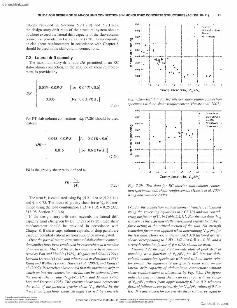
dations provided in Sections 5.2.1.2(d) and 5.2.1.2(e), the design story-drift ratio of the structural system should nowhere exceed the lateral drift capacity of the slab-column connection provided in Eq. (7.2a) or (7.2b), as appropriate, or else shear reinforcement in accordance with Chapter 8 should be used in the slab-column connections.
7.2—Lateral drift capacityThe maximum story-drift ratio DR permitted in an RC
slab-column connection, in the absence of shear reinforce-ment, is provided by
DR
VR VR
VR
=−
≤ <[ ]
≤ ≤
0 035 0 05 0 0 6
0 6
. . .
.0.005
for
for 11[ ] (7.2a)
For PT slab-column connections, Eq. (7.2b) should be used instead.
DR
VR VR
VR
=−
≤ <[ ]
≤ ≤
0 045 0 05
0 015
0 0 6
0 6
. .
.
.
.
for
for 11[ ] (7.2b)
VR is the gravity shear ratio, defined as
VR
V
Vug
c
=φ (7.2c)
The term Vc is calculated using Eq. (5.2.1.1b) or (5.2.1.1c), and φ is 0.75. The factored gravity shear force Vug is deter-mined using the load combination 1.2D + 1.0L + 0.2S (ACI 318-08, Section 21.13.6).
If the design story-drift ratio exceeds the lateral drift capacity limit DR, given by Eq. (7.2a) or (7.2b), then shear reinforcement should be provided in accordance with Chapter 8. If shear caps, column capitals, or drop panels are used, all potential critical sections should be investigated.
Over the past 40 years, experimental slab-column connec-tion studies have been conducted by researchers at a number of universities. Much of the earlier data have been summa-rized by Pan and Moehle (1989), Megally and Ghali (1994), Luo and Durrani (1995), and others such as Hawkins (1974), Kang and Wallace (2006), Hueste et al. (2007), and Kang et al. (2007). Researchers have noted that the maximum drift at which an interior connection will fail can be estimated from the gravity shear ratio (Vug/φVc) (Pan and Moehle 1988; Luo and Durrani 1995). The gravity shear ratio represents the value of the factored gravity shear Vug divided by the theoretical punching shear strength carried by concrete
(Vc) for the connection without moment transfer, calculated using the governing equations in ACI 318 and not consid-ering the factor of Cv in Table 5.2.1.1. For the test data, Vug is taken as the experimentally determined gravity load shear force acting at the critical section of the slab. No strength reduction factor was applied when determining Vug/φVc for the test data. However, in design, ACI 318 factored gravity shear corresponding to 1.2D +1.0L (or 0.5L) + 0.2S, and a strength reduction factor of φ = 0.75, should be used.
Figures 7.2a through 7.2d provide plots of peak drift at punching as a function of Vug/φVc for RC interior slab-column connection specimens with and without shear rein-forcement. The influence of the gravity shear ratio on the lateral drift capacity of slab-column connections without shear reinforcement is illustrated by Fig. 7.2a. The figure indicates that punching shear can occur for a large range of Vug/φVc values from approximately 0.1 to 0.9, whereas flexural failures occur primarily for Vug/φVc values of 0.3 or less. It is uncommon for the gravity shear ratio to be equal to
Fig. 7.2a—Test data for RC interior slab-column connection specimens with no shear reinforcement (Hueste et al. 2007).
Fig. 7.2b—Test data for RC interior slab-column connec-tion specimens with shear reinforcement (Hueste et al. 2007; Kang and Wallace 2008).
American Concrete Institute Copyrighted Material—www.concrete.org
GUIDE FOR DESIGN OF SLAB-COLUMN CONNECTIONS IN MONOLITHIC CONCRETE STRUCTURES (ACI 352.1R-11) 21
Copyright American Concrete Institute Provided by IHS under license with ACI Licensee=University of Texas Revised Sub Account/5620001114, User=opioui, rty
Not for Resale, 01/26/2015 01:50:14 MSTNo reproduction or networking permitted without license from IHS
--`````,`,,`,`,,,,`,`,,`,,,`,`-`-`,,`,,`,`,,`---
daneshlink.com
Daneshlink.com

or greater than one for typical designs and geometry of flat plate construction, even with shear reinforcement. Figure 7.2b indicates that larger drift ratios are possible when slab shear reinforcement is used. In particular, some RC slab-column specimens with shear reinforcement attained story drifts well over 3 percent before failure.
Figure 7.2c shows that, in general, the ACI 318 limits provide a lower bound to the RC slab-column connection test data, particularly for cases without shear reinforcement. Relatively few data points fall below the ACI 318 limits. Additional details for the data shown in Fig. 7.2a through 7.2c are summarized by Hueste et al. (2007).
Additional data indicate that the drift capacity at punching for PT slab-column connections is also strongly influenced by the gravity shear ratio (Kang and Wallace 2006; Kang et al. 2007). Figure 7.2d further shows that the ACI 318-08, Section 21.13.6, requirement for use of shear reinforcement in slab-column connections not designated as
part of the seismic-force-resisting system is conservative for PT connections, as has been noted previously for conven-tionally RC connections. The trend lines in Fig. 7.2d were derived from the databases of RC and PT specimens without shear reinforcement, using a linear least-squares fit method (Kang and Wallace 2006).
The trend lines suggest that PT connections can sustain higher lateral drift ratios before punching than comparable RC connections, without shear reinforcement and under a variety of loading types. The higher drift capacities are in part due to the larger span-to-thickness ratios (l1/h) used in PT slab-column construction, typically around 40, versus approximately 25 in RC construction. That increase makes PT systems more flexible than RC systems under lateral deformations, even though a PT slab is likely to be less cracked (Kang and Wallace 2006; Kang et al. 2007). The higher drift capacities are also due in part to the increase in the shear strength Vc of the slab-column connection resulting from the in-plane compressive stresses fpc generated by the post-tensioning tendons (Kang and Wallace 2006).
CHAPTER 8—SHEAR REINFORCEMENT, INCLUDING FOR EARTHQUAKE-RESISTANT DESIGN
8.1—GeneralWhen the factored shear stress on any portion of the shear-
critical section exceeds Vo/Ac, the connection should be modified to provide adequate shear capacity. The addition of shear reinforcement is an effective means for providing additional shear capacity. When the design story-drift ratio exceeds the lateral drift capacity DR, the connection also should be modified to enhance the ductility of the connection.
Research has shown that shear reinforcement consisting of properly anchored headed shear studs, multiple-leg stir-rups, bent-up bars, shearheads, or shearbands can increase the punching shear resistance of slabs at connections (Fig. 8.1a) (Corley and Hawkins 1968; Hawkins 1974; Hanna et al. 1975; Islam and Park 1976; Dilger and Ghali 1981; Broms 1990, 2007; Megally and Ghali 1994; Robertson et al. 2002; Pilakoutas and Li 2003; Kang and Wallace 2005; Ritchie and Ghali 2005; Gayed and Ghali 2006). The addi-tion of shear reinforcement has also been shown to increase the ductility of the connection when subjected to either monotonically increasing gravity load (Corley and Hawkins 1968; Hawkins 1974; Dilger and Ghali 1981; Broms 1990, 2007; Pilakoutas and Li 2003) or reversed cyclic lateral loads (Hanna et al. 1975; Islam and Park 1976; Dilger and Shatila 1989; Megally and Ghali 1994; Robertson et al. 2002; Kang and Wallace 2005, 2008). It is essential that shear reinforcement in the form of stirrups or vertical steel be adequately anchored at the top and bottom of the slab. Effective anchorage can be provided by hooking the bars around longitudinal reinforcement, or by mechanical anchorage at each end by means of a plate or head capable of developing the yield strength of the bars. The 90-degree bends at top and bottom of the vertical legs of a shearband provide effective anchorage without the need for longitu-dinal reinforcement in each bend (Fig. 8.1b). The punched
Fig. 7.2c—Comparison of ACI 318-08 limits with RC slab-column connection test data (Hueste et al. 2007).
Fig. 7.2d—Comparison of lateral drift capacity limits with RC and PT slab-column connection test data (Kang and Wallace 2006; Hueste et al. 2007; Kang et al. 2008).
American Concrete Institute Copyrighted Material—www.concrete.org
22 GUIDE FOR DESIGN OF SLAB-COLUMN CONNECTIONS IN MONOLITHIC CONCRETE STRUCTURES (ACI 352.1R-11)
Copyright American Concrete Institute Provided by IHS under license with ACI Licensee=University of Texas Revised Sub Account/5620001114, User=opioui, rty
Not for Resale, 01/26/2015 01:50:14 MSTNo reproduction or networking permitted without license from IHS
--`````,`,,`,`,,,,`,`,,`,,,`,`-`-`,,`,,`,`,,`---
daneshlink.com
Daneshlink.com

circular holes in shearbands provide additional anchorage along the length of the vertical legs (Kang and Wallace 2008).
8.2—Types of shear reinforcement8.2.1 Steel stirrups—Steel stirrups located in the slab
adjacent to the slab-column joint may be multiple-leg closed hoop, or continuous stirrups, as described in ACI 318-08, Section 11.11.3. Effective anchorage of the stirrups requires that each stirrup vertical leg engage a longitudinal reinforcing bar at both the top and bottom of the slab. In conjunction with stirrups, bent bars crossing the anticipated shear crack can be used.
Research has shown that the bent bar and stirrup combi-nation increases both the connection shear capacity and ductility (Hawkins 1974; Broms 1990, 2007).
8.2.2 Shearheads—Shearheads fabricated from structural steel sections can be designed to increase the shear capacity of the slab adjacent to a slab-column joint, as described in ACI 318-08, Section 11.11.4.
8.2.3 Shear studs—Headed studs oriented in the direction of the slab thickness can be designed to increase the connec-tion shear capacity and ductility of the slab adjacent to a slab-column joint. The area of the head should be sufficient to develop the yield strength of the stud with negligible slip at the anchorage.
Shear studs are usually prefabricated as a stud rail, where a number of studs are attached to a single plate, anchoring one end of the stud, while the opposite end is anchored with individual anchorage plates attached to the studs. Research has shown that effective anchorage is provided by a head with an area equal to 10 times the cross-sectional area of
Fig. 8.1a—Types of shear reinforcement (ACI 318; Kang and Wallace 2005; Broms 2007; Kang and Wallace 2008).
American Concrete Institute Copyrighted Material—www.concrete.org
GUIDE FOR DESIGN OF SLAB-COLUMN CONNECTIONS IN MONOLITHIC CONCRETE STRUCTURES (ACI 352.1R-11) 23
Copyright American Concrete Institute Provided by IHS under license with ACI Licensee=University of Texas Revised Sub Account/5620001114, User=opioui, rty
Not for Resale, 01/26/2015 01:50:14 MSTNo reproduction or networking permitted without license from IHS
--`````,`,,`,`,,,,`,`,,`,,,`,`-`-`,,`,,`,`,,`---
daneshlink.com
Daneshlink.com

the stud (Dilger and Ghali 1981; Megally and Ghali 1994). The use of such shear stud reinforcement in seismic design against punching shear failure is discussed in ACI 421.2R-10. Design guidelines presented in Section 8.3 of this guide for the connection shear strength and amount of shear rein-forcement near the column face may be more stringent than in ACI 421.2R-10. This is based on observations during seismic loading tests (Kang and Wallace 2006; Cheng et al. 2010).
8.2.4 Shearbands—Shearband reinforcement consists of thin steel strips with punched circular holes along the center-line. The thin steel strip can be bent into a variety of shapes. The pre-bent strips are placed over the uppermost layer of top slab bars around the slab-column joint. The strip thick-ness may range between 0.03 and 0.065 in. (0.75 to 1.75 mm), and the strip width may range from 0.75 to 1.25 in. (19 to 32 mm).
Shearbands (Fig. 8.1b) are usually pre-bent to fit over top bars in the slab. However, shearbands can be cut and bent on site to accommodate tolerances in the position of slab reinforcement already placed. Research has shown that shearbands are as effective as shear studs in improving the punching shear capacity and ductility of the connection under both gravity and cyclic lateral loads (Pilakoutas and Li 2003; Kang and Wallace 2008). Limitations on the shear-band cross-sectional dimensions are based on the range of parameters considered in laboratory testing.
8.3—Shear strength of connections with shear reinforcement
8.3.1 Punching shear strength—Slab punching shear strength at the connection is given by
V C V V Vo v c s= + ≤φ φ( ) max (8.3.1a)
where Vmax is the limiting value of the allowed shear resis-tance when shear reinforcement is used, specified as
V f Ac cmax = ′6
(in.-lb)
V f Ac cmax = ′0 5.
(SI) (8.3.1b)
When shear reinforcement is provided to increase shear capacity of the connection, the concrete contribution to the shear strength is given by Eq. (5.2.1.1d). Shear strength provided by shear reinforcement oriented perpendicular to the plane of the slab is given by
V
A f d
ss
v yt= (8.3.1c)
where Av is the cross-sectional area of all legs of reinforce-ment on one peripheral line that is geometrically similar to the perimeter of the column section; fyt is the yield stress of the shear reinforcement, not to be taken greater than 60,000 psi (420 MPa); d is the average distance from extreme compression fiber to the centroid of tension reinforcement in the two orthogonal directions; and s is the spacing between adjacent peripheral lines of shear reinforcement, determined in accordance with Section 8.3.3.
When shear reinforcement is provided, the ACI 318 nominal punching shear strength of a slab-column connec-tion is a combination of concrete and shear reinforce-ment capacities. For slab-column connections with shear reinforcement, shear strength of the connection should be checked at multiple locations: for example, (1) d/2 from the column face within the shear-reinforced region (column crit-ical section); and (2) d/2 outside the shear-reinforced region (outer critical section). Calculations required for the crit-ical section outside the shear-reinforced region are essen-tially the same as noted previously, except for the change in geometry of the critical section. It is noted that checking the punching shear strength is waived for Type 2 connec-tions that are not part of the lateral-force-resisting system if minimum shear reinforcement is provided according to Section 8.3.2, or if the story-drift ratio does not exceed the lateral drift capacity provided in Section 7.2.
When shear reinforcement is provided in RC connections, the shear strength Vo should not exceed 6φ√fc′Ac (in.-lb) (0.5φ√fc′Ac [SI]). However, shear reinforcement should be designed to carry all shear in excess of 2φ√fc′Ac (in.-lb) (0.17φ√fc′Ac [SI]).
8.3.2 Minimum shear reinforcement—When shear rein-forcement is provided to increase the shear capacity of a
Fig. 8.1b—Shearbands (Kang and Wallace 2008).
American Concrete Institute Copyrighted Material—www.concrete.org
24 GUIDE FOR DESIGN OF SLAB-COLUMN CONNECTIONS IN MONOLITHIC CONCRETE STRUCTURES (ACI 352.1R-11)
Copyright American Concrete Institute Provided by IHS under license with ACI Licensee=University of Texas Revised Sub Account/5620001114, User=opioui, rty
Not for Resale, 01/26/2015 01:50:14 MSTNo reproduction or networking permitted without license from IHS
--`````,`,,`,`,,,,`,`,,`,,,`,`-`-`,,`,,`,`,,`---
daneshlink.com
Daneshlink.com

connection or to waive the lateral drift capacity requirements, the term Vs defined by Eq. (8.3.1c) should not be less than 3.5√fc′Ac (in.-lb) (0.29√fc′Ac [SI]). The shear reinforcement should extend at least 4h, and 3h, away from, and perpendic-ular to the face of the support, drop panel, or column capital for RC connections and PT connections, respectively. Other-wise, shear reinforcement should be provided in accordance with ACI 421.1R-08.
Provisions for non-participating slab-column frames (ACI 318-08, Section 21.13) are suggested as a basis of minimum shear reinforcement requirements; however, these provisions are conservative and also applicable to Type 1 and 2 connections that are part of the lateral-force-resisting system. Minimum distances for extending shear reinforce-ment are to ensure that connection punching failure will not occur at the outer critical section before punching failure at the column critical section, even for a worst-case scenario. For PT connections with shear reinforcement, experimental studies (Dilger and Shatila 1989; Kang and Wallace 2005; Ritchie and Ghali 2005; Gayed and Ghali 2006; Kang et al. 2007) indicate that a minimum extended length of shear reinforcement from the column face can be reduced to 3h. The shear strength at the outer critical section of a PT connection is improved by in-plane precompression.
8.3.3 Reinforcement placement and detailing—For shear reinforcement, s should not exceed d/2. The first peripheral line of shear reinforcement should be located at s/2 from the column face. The number of studs or stirrup legs in each line of shear reinforcement around the column should be determined such that the distance between adjacent studs or stirrup legs along the first and second peripheral lines does not exceed 2d.
Any other relevant details of shear reinforcement should comply with ACI 318-08, Chapter 11, and ACI 421.1R-08, Appendix A.
Dynamic tests (Kang and Wallace 2005, 2006) on RC and PT flat-plate frames with shear studs showed shear strength degradation at the interface between the slab and the column, which has not been captured in quasi-static tests. Therefore, the recommendations for the location of the first and second peripheral lines of shear reinforcement are more stringent than required by ACI 318 and ACI 421.1R. In particular, the first line of shear reinforcement should be located at s/2 from the face of the column, considered the ideal location to intercept diagonal cracks near the column, whereas ACI 318 only requires this location to be less than or equal to d/2, potentially allowing a less effective place-ment of the shear reinforcement. The number of vertical legs in each line of shear reinforcement around the column depends in part on the spacing between adjacent vertical legs (Fig. 8.3.3).
The maximum lateral spacing of 2d along a peripheral line applies to both the first and second peripheral rows of shear reinforcement. This more stringent spacing provision is intended to prevent large slab portions near the column from being unreinforced in shear. In Eurocode 2 (EN 1992-1-1 [Comité Europeén de Normalisation 2004]), the effect of shear reinforcement spacing along a peripheral line is
accounted for in the calculation of the effective perimeter for determining the required extension of the shear reinforced area of slab. For connections with lateral spacing along a peripheral line exceeding 2d, the length of the critical perimeter could be significantly reduced. The use of shear reinforcement layouts that lead to lateral spacing less than 2d along each peripheral line is therefore considered more effective in Eurocode 2 (EN 1992-1-1 [Comité Europeén de Normalisation 2004]).
CHAPTER 9—REFERENCES
9.1—Referenced standards and reportsAmerican Concrete Institute318-08 – Building Code Requirements for Structural
Concrete and Commentary347-05 – Guide for Shoring / Reshoring of Concrete Multi-
story Buildings352R-02 – Recommendations for Design of Beam-Column
Connections in Monolithic Reinforced Concrete Structures
360R-10 – Guide to Design of Slabs-on-Ground421.1R-08 – Guide to Shear Reinforcement for Slabs421.2R-10 – Guide to Seismic Design of Punching Shear
Reinforcement in Flat Plates423.3R-05 – Recommendations for Concrete Members
Prestressed with Unbonded TendonsSP-30(71) – Cracking, Deflection, and Ultimate Load of
Concrete Slab SystemsSP-42(74) – Shear in Reinforced Concrete
American Society of Civil EngineersASCE/SEI 7-10 – Minimum Design Loads for Buildings
and Other StructuresASCE/SEI 41-06 – Seismic Rehabilitation of Existing
Buildings
Fig. 8.3.3—Example of shear reinforcement placement: Type 2 PT connection that is not designated as part of seismic-force-resisting system (Kang et al. 2008).
American Concrete Institute Copyrighted Material—www.concrete.org
GUIDE FOR DESIGN OF SLAB-COLUMN CONNECTIONS IN MONOLITHIC CONCRETE STRUCTURES (ACI 352.1R-11) 25
Copyright American Concrete Institute Provided by IHS under license with ACI Licensee=University of Texas Revised Sub Account/5620001114, User=opioui, rty
Not for Resale, 01/26/2015 01:50:14 MSTNo reproduction or networking permitted without license from IHS
--`````,`,,`,`,,,,`,`,,`,,,`,`-`-`,,`,,`,`,,`---
daneshlink.com
Daneshlink.com

ASTM InternationalA970-09/A970M-09 – Standard Specification for Headed
Steel Bars for Concrete Reinforcement
International Code CouncilIBC-2009 – International Building Code
9.2—Cited referencesAgarwal, R. K., and Gardner, N. J., 1974, “Form and Shore
Requirements for Multistory Flat Slab Type Building,” ACI Journal, Proceedings V. 71, No. 11, Nov., pp. 559-569.
Alexander, S. D. B., and Simmonds, S. H., 1987, “Ulti-mate Strength of Slab-Column Connections,” ACI Struc-tural Journal, V. 84, No. 3, May-June, pp. 255-261.
Alexander, S. D. B., and Simmonds, S. H., 2003, “Moment Transfer at Interior Slab-Column Connections,” ACI Struc-tural Journal, V. 100, No. 2, Mar.-Apr., pp. 197-202.
Bertero, V. V.; Popov, E. P.; and Forzani, B., 1980, “Seismic Behavior of Lightweight Concrete Beam-Column Subassemblages,” ACI Journal, Proceedings V. 77, No. 1, Jan., pp. 44-52.
Broms, C. E., 1990, “Shear Reinforcement for Deflection Ductility of Flat Plates,” ACI Structural Journal, V. 87, No. 6, Nov.-Dec., pp. 696-705.
Broms, C. E., 2007, “Flat Plates in Seismic Areas: Comparison of Shear Reinforcement Systems,” ACI Struc-tural Journal, V. 104, No. 6, Nov.-Dec., pp. 712-721.
Burns, N. H., and Hemakom, R., 1985, “Test of Post-Tensioned Flat Plate with Banded Tendons,” Journal of Structural Engineering, ASCE, V. 111, No. 9, Sept., pp. 1899-1915.
Cheng, M.-Y.; Parra-Montesinos, G. J.; and Shield, C. K., 2010, “Shear Strength and Drift Capacity of Fiber-Rein-forced Concrete Slab-Column Connections Subjected to Biaxial Displacements,” Journal of Structural Engineering, ASCE, V. 136, No. 9, Sept., pp. 1078-1088.
Chun, S. C.; Lee, S. H.; Kang, T. H.-K.; Oh, B.; and Wallace, J. W., 2007, “Mechanical Anchorage in Exterior Beam-Column Joints Subjected to Cyclic Loading,” ACI Structural Journal, V. 104, No. 1, Jan.-Feb., pp. 102-112.
Comité Européen de Normalisation, 2004, “Eurocode 2: Design of Concrete Structures — Part 1-1: General Rules and Rules for Buildings,” English Version, EN 1992-1-1:2004: E, Brussels, Belgium, 225 pp.
Corley, W. G., and Hawkins, N. M., 1968, “Shearhead Reinforcement for Slabs,” ACI Journal, Proceedings V. 65, No. 10, Oct., pp. 811-824.
Criswell, M. E., 1972, “Design and Testing of a Blast Resistant R/C Slab System,” Report No. N-72-10, U.S. Army Engineer Waterways Experiment Station, Vicksburg, MS, Nov.
Darvall, P., and Allen, F., 1984, “Lateral Load Effec-tive Width of Flat Plates with Drop Panels,” ACI Journal, Proceedings, V. 81, No. 6, Nov.-Dec., pp. 613-617.
Dilger, W. H., and Ghali, A., 1981, “Shear Reinforcement for Concrete Slabs,” Proceedings, ASCE, V. 107, ST12, Dec., pp. 2403-2420.
Dilger, W. H., and Shatila, M., 1989, “Shear Strength of Prestressed Concrete Edge Slab-Column Connections with and without Shear Stud Reinforcement,” Canadian Journal of Civil Engineering, V. 16, pp. 807-819.
ENR, 1956, “Flat Slab Breaks from Columns in Building,” Engineering News-Record, Oct. 11, pp. 24-25.
ENR, 1971, “Building Collapse Blamed on Design, Construction,” Engineering News-Record, July 15, p. 19.
ENR, 1973, “Collapse Kills Five and Destroys Large Portion of 26-Story Apartment Building,” Engineering News-Record, Mar. 8, p. 13, and subsequent articles on Mar. 15, p. 12, May 31, p. 13, and June 14, p. 15.
Foutch, D. A.; Gamble, W. L.; and Sunidja, H., 1990, “Tests of Post-Tensioned Concrete Slab-Edge Column Connections,” ACI Structural Journal, V. 87, No. 2, Mar.-Apr., pp. 167-179.
Freyermuth, C. L., 1989, “Structural Integrity of Build-ings Constructed with Unbonded Tendons,” Concrete Inter-national, V. 11, No. 3, Mar., pp. 56-63.
Gardner, N. J., and Kallage, M. R., 1998, “Punching Shear Strength of Continuous Post-Tensioned Concrete Flat Plates,” ACI Materials Journal, V. 95, No. 3, May-June, pp. 272-283.
Gayed, R. B., and Ghali, A., 2006, “Seismic-Resistant Joints of Interior Columns with Prestressed Slabs,” ACI Structural Journal, V. 103, No. 5, Sept.-Oct., pp. 710-719.
Grundy, P., and Kabaila, A., 1963, “Construction Loads on Slabs with Shored Formwork in Multistory Buildings,” ACI Journal, Proceedings V. 60, No. 12, Dec., pp. 1729-1738.
Han, S. W.; Kee, S.-H.; Park, Y.-M.; Lee, L.-H.; and Kang, T. H.-K., 2006, “Hysteretic Behavior of Exterior Connec-tions in Flat Plate Slab Systems,” Engineering Structures, V. 28, No. 14, Dec., pp. 1983-1996.
Hanna, S. N.; Mitchell, D.; and Hawkins, N. M., 1975, “Slab-Column Connections Containing Shear Reinforce-ment and Transferring High-Intensity Reversed Moments,” Report No. SM 75-1, University of Washington, Seattle, WA, Aug.
Hanson, J. M., 1970, “Influence of Embedded Service Ducts on Strength of Flat-Plate Structures,” Research and Development Bulletin No. RD005.01D, Portland Cement Association, Skokie, IL, 16 pp.
Hanson, N. W., and Hanson, J. M., 1968, “Shear and Moment Transfer between Concrete Slabs and Columns,” Journal, PCA Research and Development Laboratories, V. 10, No. 1, Jan., pp. 2-16.
Hatcher, D. S.; Sozen, M. A.; and Siess, C. P., 1965, “Test of a Reinforced Concrete Flat Plate,” Proceedings, ASCE, V. 91, ST5, Oct., pp. 205-231.
Hawkins, N. M., 1974, “Shear Strength of Slabs with Shear Reinforcement,” Shear in Reinforced Concrete, SP-42, V. 2, American Concrete Institute, Farmington Hills, MI, pp. 785-815.
Hawkins, N. M., 1977, “Seismic Response Constraints for Slab Systems,” Earthquake-Resistant Reinforced Concrete Building Construction, V. 3, University of California, Berkeley, CA, pp. 1253-1275.
American Concrete Institute Copyrighted Material—www.concrete.org
26 GUIDE FOR DESIGN OF SLAB-COLUMN CONNECTIONS IN MONOLITHIC CONCRETE STRUCTURES (ACI 352.1R-11)
Copyright American Concrete Institute Provided by IHS under license with ACI Licensee=University of Texas Revised Sub Account/5620001114, User=opioui, rty
Not for Resale, 01/26/2015 01:50:14 MSTNo reproduction or networking permitted without license from IHS
--`````,`,,`,`,,,,`,`,,`,,,`,`-`-`,,`,,`,`,,`---
daneshlink.com
Daneshlink.com
Hawkins, N. M., 1980, “Lateral Load Design Consid-eration for Flat Plate Structures,” Nonlinear Design of Concrete Structures, Study No. 14, University of Waterloo Press, Waterloo, ON, Canada, pp. 581-613.
Hawkins, N. M., 1981, “Lateral Load Resistance of Unbonded Post-Tensioned Flat Plate Construction,” PCI Journal, V. 26, No. 1, Jan.-Feb., pp. 94-115.
Hawkins, N. M., and Corley, W. G., 1974, “Moment Transfer to Columns in Slabs with Shearhead Reinforce-ment,” Shear in Reinforced Concrete, SP-42, V.2, American Concrete Institute, Farmington Hills, MI, pp. 847-879.
Hawkins, N. M., and Mitchell, D., 1979, “Progressive Collapse of Flat Plate Structures,” ACI Journal, Proceed-ings V. 76, No. 7, July, pp. 775-808.
Hueste, M. D., and Wight, J. K., 1997, “Evaluation of a Four-Story Reinforced Concrete Building Damaged during the Northridge Earthquake,” Earthquake Spectra, V. 13, No. 3, Aug., pp. 387-414.
Hueste, M. D.; Browning, J.; Lepage, A.; and Wallace, J. W., 2007, “Seismic Design Criteria for Slab-Column Connections,” ACI Structural Journal, V. 104, No. 4, July-Aug., pp. 448-458.
Hwang, S.-J., and Moehle, J. P., 1993, “An Experimental Study of Flat-Plate Structures Under Vertical and Lateral Loads,” Report No. UCB/EERC-93/03, Earthquake Engi-neering Research Center, Feb., 288 pp.
Islam, S., and Park, R., 1976, “Tests on Slab-Column Connections with Shear and Unbalanced Flexure,” Proceed-ings, ASCE, V. 102, ST3, Mar., pp. 549-568.
Ivy, C. B.; Ivey, D. L.; and Buth, E., 1969, “Shear Capacity of Lightweight Concrete Flat Slabs,” ACI Journal, Proceedings, V. 66, No. 6, June, pp. 490-493.
Johansen, K. W., 1962, Yield Line Theory, Cement and Concrete Association, London, UK, 181 pp.
Joint ACI-ASCE Committee 326 (later 426), 1962, “Shear and Diagonal Tension,” ACI Journal, Proceedings V. 59, No. 3, Mar., pp. 352-396.
Joint ACI-ASCE Committee 352, 1989, “Recommenda-tions for Design of Slab-Column Connections in Monolithic Reinforced Concrete Structures (ACI 352.1R-89),” Amer-ican Concrete Institute, Farmington Hills, MI, 26 pp.
Joint ACI-ASCE Committee 423, 1958, “Tentative Recommendations for Prestressed Concrete,” ACI Journal, Proceedings V. 54, No. 7, July, pp. 545-578.
Joint ACI-ASCE Committee 426, 1974, “The Shear Strength of Reinforced Concrete Members—Slabs,” Proceedings ASCE, V. 100, ST8, Aug., pp. 1543-1591.
Joint ACI-ASCE Committee 426, 1977, “Suggested Revi-sions to Shear Provisions for Building Codes,” ACI Journal, Proceedings, V. 74, No. 9, Sept., pp. 458-468.
Kang, T. H.-K., and Wallace, J. W., 2005, “Dynamic Responses of Flat Plate Systems with Shear Reinforce-ment,” ACI Structural Journal, V. 102, No. 5, Sept.-Oct., pp. 763-773.
Kang, T. H.-K., and Wallace, J. W., 2006, “Punching of Reinforced and Post-Tensioned Concrete Slab-Column Connections,” ACI Structural Journal, V. 103, No. 4, July-Aug., pp. 531-540.
Kang, T. H.-K., and Wallace, J. W., 2008, “Seismic Performance of Reinforced Concrete Slab-Column Connec-tions with Thin Plate Stirrups,” ACI Structural Journal, V. 105, No. 5, Sept.-Oct., pp. 617-625.
Kang, T. H.-K.; LaFave, J. M.; Robertson, I. N.; and Hawkins, N. M., 2007, “Post-Tensioned Slab-Column Connections—Drift Capacity at Punching of Connections Subjected to Lateral Loading,” Concrete International, V. 29, No. 4, Apr., pp. 61-68.
Kang, T. H.-K.; Robertson, I. N.; Hawkins, N. M.; and LaFave, J. M., 2008, “Recommendations for Design of Post-Tensioned Slab-Column Connections Subjected to Lateral Loading,” PTI Journal, V. 6, No. 1, Feb., pp. 45-59.
Klemencic, R.; Fry, J. A.; Hurtado, G.; and Moehle, J. P., 2006, “Performance of Post-Tensioned Slab-Core Wall Connections,” PTI Journal, V. 4, No. 6, Dec., pp. 7-12.
Kosut, G. M.; Burns, N. H.; and Winter, C. V., 1985, “Test of Four-Panel Post-Tensioned Flat Plate,” Journal of Structural Engineering, ASCE, V. 111, No. 9, Sept., pp. 1916-1929.
Lew, H. S.; Carino, N. J.; and Fattal, S. G., 1982a, “Cause of the Condominium Collapse in Cocoa Beach, Florida,” Concrete International, V. 4, No. 8, Aug., pp. 64-73. Also, Discussion, V. 5, No. 6, June 1983, pp. 58-61.
Lew, H. S.; Carino, N. J.; Fattal, S. G.; and Batts, M. E., 1982b, “Investigation of Construction Failure of Harbour Cay Condominium in Cocoa Beach, Florida,” Building Science Series No. 145, National Bureau of Standards, Washington, DC, Aug., 135 pp.
Leyendecker, E. V., and Fattal, S. G., 1977, “Investigation of the Skyline Plaza Collapse in Fairfax County, Virginia,” Building Science Series No. 94, National Bureau of Stan-dards, Washington, DC, Feb., 88 pp.
Liu, X.-L.; Chen, W.-F.; and Bowman, M. D., 1985, “Construction Loads on Supporting Floors,” Concrete Inter-national, V. 7, No. 12, Dec., pp. 21-26.
Long, A. E., and Cleland, D. J., 1993, “Post-Tensioned Concrete Flat Slabs at Edge Columns,” ACI Materials Journal, V. 90, No. 3, May-June, pp. 207-213.
Luo, Y. H., and Durrani, A. J., 1995, “Equivalent Beam Model for Flat-Slab Buildings—Part I: Interior Connec-tions,” ACI Structural Journal, V. 92, No. 1, Jan.-Feb., pp. 115-124.
Martinez-Cruzado, J. A.; Qaisrani, A.-N.; and Moehle, J. P., 1994, “Post-Tensioned Flat Plate Slab-Column Connec-tions Subjected to Earthquake Loading,” Proceedings, 5th National Conference on Earthquake Engineering, EERI, Chicago, IL, July, pp. 10-14.
Megally, S. H., and Ghali, A., 1994, “Design Consider-ations for Slab-Column Connections in Seismic Zones,” ACI Structural Journal, V. 91, No. 3, May-June, pp. 303-314.
Meli, R.; and Rodriguez, M., 1979, “Waffle Flat Plate-Column Connections under Alternating Loads,” Bulletin d’information No. 132, Comité Euro-International du Béton, Paris, France, Apr., pp. 45-52.
Mitchell, D., and Cook, W. D., 1984, “Preventing Progres-sive Collapse of Slab Structures,” Journal of Structural Engineering, ASCE, V. 110, No. 7, July, pp. 1513-1532.
American Concrete Institute Copyrighted Material—www.concrete.org
GUIDE FOR DESIGN OF SLAB-COLUMN CONNECTIONS IN MONOLITHIC CONCRETE STRUCTURES (ACI 352.1R-11) 27
Copyright American Concrete Institute Provided by IHS under license with ACI Licensee=University of Texas Revised Sub Account/5620001114, User=opioui, rty
Not for Resale, 01/26/2015 01:50:14 MSTNo reproduction or networking permitted without license from IHS
--`````,`,,`,`,,,,`,`,,`,,,`,`-`-`,,`,,`,`,,`---
daneshlink.com
Daneshlink.com

Moehle, J. P., 1988, “Strength of Slab-Column Edge Connections,” ACI Structural Journal, V. 85, No. 1, Jan.-Feb., pp. 89-98
Moehle, J. P., 1996, “Seismic Design Considerations for Flat-Plate Construction,” Mete A. Sozen Symposium, SP-162, J. K. Wight and M. E. Kreger, eds., American Concrete Institute, Farmington Hills, MI, pp. 1-34.
Moehle, J. P., and Diebold, J. W., 1985, “Lateral Load Response of Flat-Plate Frame,” Journal of Structural Engi-neering, ASCE, V. 111, No. 10, Oct., pp. 2149-2164.
Moehle, J. P.; Kreger, M. E.; and Leon, R., 1988, “Back-ground to Recommendations for Design of Reinforced Concrete Slab-Column Connections,” ACI Structural Journal, V. 85, No. 6, Nov.-Dec., pp. 634-644.
Morrison, D. G.; Hirasawa, I.; and Sozen, M. A., 1983, “Lateral-Load Tests of R/C Slab-Column Connections,” Journal of Structural Engineering, ASCE, V. 109, No. 11, Nov., pp. 2698-2714.
Mulcahy, J. F., and Rotter, J. M., 1983, “Moment Rota-tion Characteristics of Flat Plate and Column Systems,” ACI Journal, Proceedings V. 80, No. 2, Mar.-Apr., pp. 86-92.
Oliveira, D. R. C.; Regan, P. E.; and Melo, G. S. S. A., 2004, “Punching Resistance of RC Slabs with Rectangular Columns,” Magazine of Concrete Research, V. 56, No. 3, Apr., pp. 123-138.
Osman, M.; Marzouk, H.; and Helmy, S., 2000, “Behavior of High-Strength Lightweight Concrete Slabs under Punching Loads,” ACI Structural Journal, V. 97, No. 3, May-June, pp. 492-498.
Pan, A., and Moehle, J. P., 1989, “Lateral Displacement Ductility of Reinforced Concrete Slab-Column Connec-tions,” ACI Structural Journal, V. 86, No. 3, May-June, pp. 250-258.
Park, R., and Gamble, W. L., 1980, Reinforced Concrete Slabs, John Wiley & Sons, Inc., New York, 618 pp.
Park, R., and Islam, S., 1976, “Strength of Slab-Column Connections with Shear and Unbalanced Flexure,” Proceed-ings, ASCE, V. 102, ST9, Sept., pp. 1879-1901.
Paulay, T., and Taylor, R. G., 1981, “Slab Coupling of Earthquake Resisting Shear Walls, ACI Journal, Proceed-ings V. 78, No. 2, Mar., pp. 130-140.
Pilakoutas, K., and Li, X., 2003, “Alternative Shear Rein-forcement for Reinforced Concrete Flat Slabs,” Journal of Structural Engineering, ASCE, V. 129, No. 9, Sept., pp. 1164-1172.
Rangan, B. V., and Hall, A. S., 1983, “Moment and Shear Transfer between Slab and Edge Column,” ACI Journal, Proceedings V. 80, No. 3, May-June, pp. 183-191.
Rangan, B. V., and Hall, A. S., 1984, “Moment Redistribu-tion in Flat Plate Floors,” ACI Journal, Proceedings V. 81, No. 6, Nov.-Dec., pp. 601-608.
Regan, P. E., and Braestrup, M. W., 1985, “Punching Shear in Reinforced Concrete,” Bulletin d’Information No.
168, Comité Euro-International du Béton, Lausanne, Swit-zerland, Jan., 232 pp.
Reitman, M. A., and Yankelevsky, D. Z., 1997, “A New Simplified Model for Nonlinear RC Slabs Analysis,” ACI Structural Journal, V. 94, No. 4, July-Aug., pp. 399-408.
Ritchie, M., and Ghali, A., 2005, “Seismic-Resistant Connections of Edge Columns with Prestressed Slabs,” ACI Structural Journal, V. 102, No. 2, Mar.-Apr., pp. 314-324.
Robertson, I. N., and Johnson, G., 2006, “Cyclic Lateral Loading of Nonductile Slab-Column Connections,” ACI Structural Journal, V. 103, No. 3, May-June, pp. 356-364.
Robertson, I. N.; Kawai, T.; Lee, J.; and Enomoto, B., 2002, “Cyclic Testing of Slab-Column Connections with Shear Reinforcement,” ACI Structural Journal, V. 99, No. 5, Sept.-Oct., pp. 605-613.
Rosenblueth, E., and Meli, R., 1986, “The 1985 Earth-quake: Causes and Effects in Mexico City,” Concrete Inter-national, V. 8, No. 5, May, pp. 23-34.
Sbarounis, J. A., 1984, “Multistory Flat Plate Buildings,” Concrete International, V. 6, No. 2, Feb., pp. 70-77.
Schwaighofer, J., and Collins, M. P., 1977, “An Experi-mental Study of the Behavior of Reinforced Concrete Coupling Slabs,” ACI Journal, Proceedings V. 74, No. 3, Mar., pp. 123-127.
Sheikh, S. A., and Uzumeri, S. M., 1980, “Strength and Ductility of Tied Concrete Columns,” Proceedings, ASCE, V. 106, ST5, May, pp. 1079-1102.
Simmonds, S. H., and Alexander, S. D. B., 1987, “Truss Mode for Edge Column-Slab Connections,” ACI Structural Journal, V. 84, No. 4, July-Aug., pp. 296-303.
Smith, S. W., and Burns, N. H., 1974, “Post-Tensioned Flat Plate to Column Connection Behavior,” PCI Journal, V. 19, No. 3, May-June, pp. 74-91.
Trongtham, N., and Hawkins, N. M., 1977, “Moment Transfer to Columns in Unbonded Post-Tensioned Prestressed Concrete Slabs,” Report No. SM-77-3, Depart-ment of Civil Engineering, University of Washington, Seattle, WA, Oct.
Vanderbilt, M. D., 1972, “Shear Strength of Continuous Plates,” Proceedings, ASCE, V. 98, ST5, May, pp. 961-973.
Vanderbilt, M. D., and Corley, W. G., 1983, “Frame Anal-ysis of Concrete Buildings,” Concrete International, V. 5, No. 12, Dec., pp. 33-43.
Zaghlool, E.; Ramzy F.; and de Paiva, H. A. R., 1973, “Tests of Flat-Plate Corner Column-Slab Connections,” Proceedings, ASCE, V. 99, ST3, Mar., pp. 551-572.
Zee, H. L., and Moehle, J. P., 1984, “Behavior of Interior and Exterior Flat Plate Connections Subjected to Inelastic Load Reversals,” Report No. UCB/EERC-84/07, Earth-quake Engineering Research Center, University of Cali-fornia, Berkeley, CA, Aug., 130 pp.
Zsutty, T. C., 1968, “Beam Shear Strength Predictions by Analysis of Existing Data,” ACI Journal, Proceedings V. 65, No. 11, Nov., pp. 943-951.
American Concrete Institute Copyrighted Material—www.concrete.org
28 GUIDE FOR DESIGN OF SLAB-COLUMN CONNECTIONS IN MONOLITHIC CONCRETE STRUCTURES (ACI 352.1R-11)
Copyright American Concrete Institute Provided by IHS under license with ACI Licensee=University of Texas Revised Sub Account/5620001114, User=opioui, rty
Not for Resale, 01/26/2015 01:50:14 MSTNo reproduction or networking permitted without license from IHS
--`````,`,,`,`,,,,`,`,,`,,,`,`-`-`,,`,,`,`,,`---
daneshlink.com
Daneshlink.com

As ACI begins its second century of advancing concrete knowledge, its original chartered purpose remains “to provide a comradeship in finding the best ways to do concrete work of all kinds and in spreading knowledge.” In keeping with this purpose, ACI supports the following activities:
· Technical committees that produce consensus reports, guides, specifications, and codes.
· Spring and fall conventions to facilitate the work of its committees.
· Educational seminars that disseminate reliable information on concrete.
· Certification programs for personnel employed within the concrete industry.
· Student programs such as scholarships, internships, and competitions.
· Sponsoring and co-sponsoring international conferences and symposia.
· Formal coordination with several international concrete related societies.
· Periodicals: the ACI Structural Journal and the ACI Materials Journal, and Concrete International.
Benefits of membership include a subscription to Concrete International and to an ACI Journal. ACI members receive discounts of up to 40% on all ACI products and services, including documents, seminars and convention registration fees.
As a member of ACI, you join thousands of practitioners and professionals worldwide who share a commitment to maintain the highest industry standards for concrete technology, construction, and practices. In addition, ACI chapters provide opportunities for interaction of professionals and practitioners at a local level.
American Concrete Institute38800 Country Club DriveFarmington Hills, MI 48331U.S.A.Phone: 248-848-3700Fax: 248-848-3701
www.concrete.org
Copyright American Concrete Institute Provided by IHS under license with ACI Licensee=University of Texas Revised Sub Account/5620001114, User=opioui, rty
Not for Resale, 01/26/2015 01:50:14 MSTNo reproduction or networking permitted without license from IHS
--`````,`,,`,`,,,,`,`,,`,,,`,`-`-`,,`,,`,`,,`---
daneshlink.com
Daneshlink.com

Guide for Design of Slab-Column Connections in Monolithic Concrete Structures
The AMERICAN CONCRETE INSTITUTE
was founded in 1904 as a nonprofit membership organization dedicated to public service and representing the user interest in the field of concrete. ACI gathers and distributes information on the improvement of design, construction and maintenance of concrete products and structures. The work of ACI is conducted by individual ACI members and through volunteer committees composed of both members and non-members.
The committees, as well as ACI as a whole, operate under a consensus format, which assures all participants the right to have their views considered. Committee activities include the development of building codes and specifications; analysis of research and development results; presentation of construction and repair techniques; and education.
Individuals interested in the activities of ACI are encouraged to become a member. There are no educational or employment requirements. ACI’s membership is composed of engineers, architects, scientists, contractors, educators, and representatives from a variety of companies and organizations.
Members are encouraged to participate in committee activities that relate to their specific areas of interest. For more information, contact ACI.
www.concrete.org
Copyright American Concrete Institute Provided by IHS under license with ACI Licensee=University of Texas Revised Sub Account/5620001114, User=opioui, rty
Not for Resale, 01/26/2015 01:50:14 MSTNo reproduction or networking permitted without license from IHS
--`````,`,,`,`,,,,`,`,,`,,,`,`-`-`,,`,,`,`,,`---
daneshlink.com
Daneshlink.com
Copyright © 2022 FDOKUMEN