Facilitating User-System Interaction: The GAIA Interaction Agent
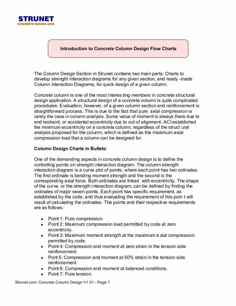
The Column Design Section in Strunet contains two main parts: Charts to develop strength interaction diagrams for any given section, and ready -made Column Interaction Diagrams, for quick design of a given column. Concrete column is one of the most interes ting members in concrete structural design application. A structural design of a concrete column is quite complicated procedures. Evaluation, however, of a given column section and reinforcement is straightforward process. This is due to the fact that pure axial compression is rarely the case in column analysis. Some value of moment is always there due to end restraint, or accidental eccentricity due to out of alignment. ACI established the minimum eccentricity on a concrete column, regardless of the struct ural analysis proposed for the column, which is defined as the maximum axial compression load that a column can be designed for. Column Design Charts in Bullets: One of the demanding aspects in concrete column design is to define the controlling points on strength interaction diagram. The column strength interaction diagram is a curve plot of points; where each point has two ordinates. The first ordinate is bending moment strength and the second is the corresponding axial force. Both ordinates are linked with eccentricity. The shape of the curve, or the strength interaction diagram, can be defined by finding the ordinates of major seven points. Each point has specific requirement, as established by the code, and thus evaluating the requirement of this poin t will result of calculating the ordinates. The points and their respective requirements are as follows:
• Point 1: Pure compression. • Point 2: Maximum compression load permitted by code at zero
eccentricity. • Point 3: Maximum moment strength at the maximum a xial compression
permitted by code. • Point 4: Compression and moment at zero strain in the tension side
reinforcement. • Pont 5: Compression and moment at 50% strain in the tension side
reinforcement. • Point 6: Compression and moment at balanced conditions. • Point 7: Pure tension.
STRUNETCONCRETE DESIGN AIDS
Introduction to Concrete Column Design Flow Charts
Strunet.com: Concrete Column Design V1.01 - Page 1
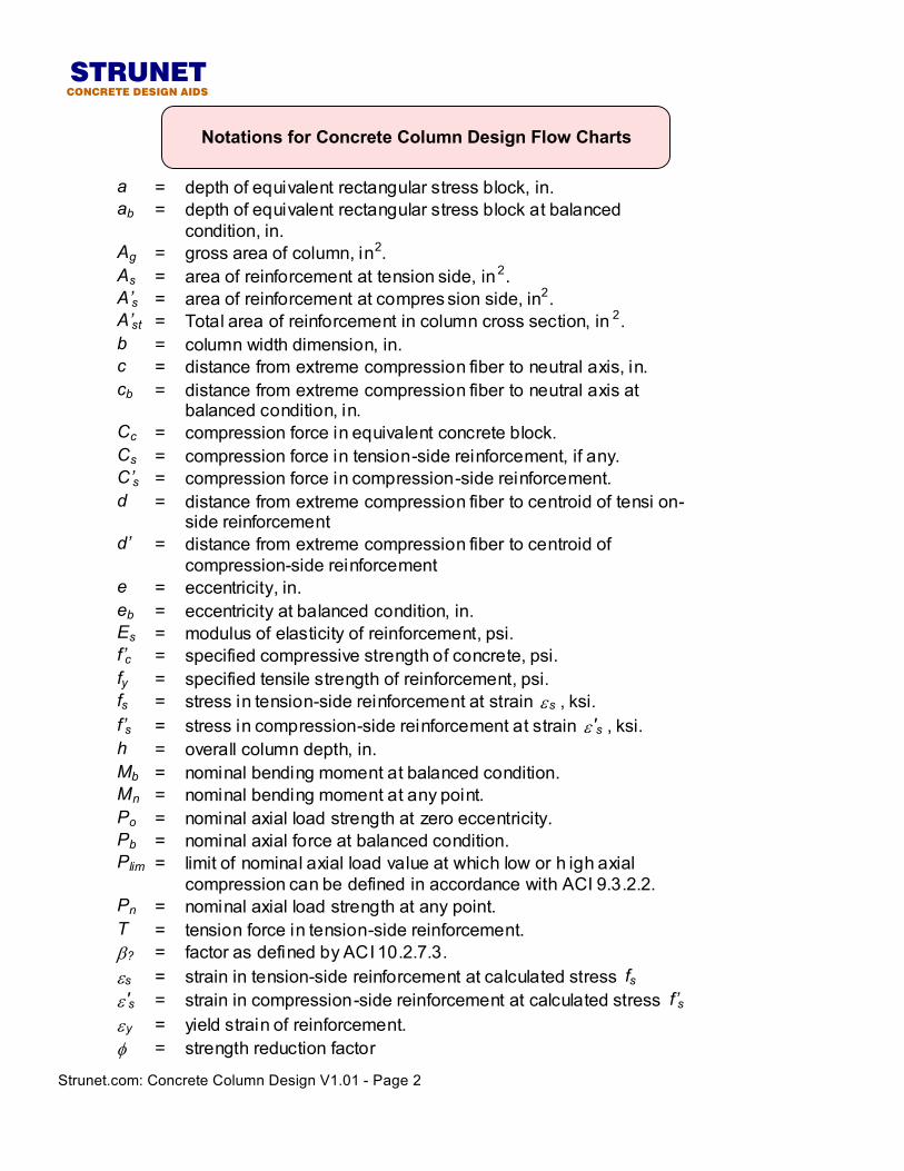
a = depth of equivalent rectangular stress block, in. ab = depth of equivalent rectangular stress block at balanced
condition, in. Ag = gross area of column, in2. As = area of reinforcement at tension side, in2. A’s = area of reinforcement at compres sion side, in2. A’st = Total area of reinforcement in column cross section, in 2. b = column width dimension, in. c = distance from extreme compression fiber to neutral axis, in. cb = distance from extreme compression fiber to neutral axis at
balanced condition, in. Cc = compression force in equivalent concrete block. Cs = compression force in tension-side reinforcement, if any. C’s = compression force in compression-side reinforcement. d = distance from extreme compression fiber to centroid of tensi on-
side reinforcement d’ = distance from extreme compression fiber to centroid of
compression-side reinforcement e = eccentricity, in. eb = eccentricity at balanced condition, in. Es = modulus of elasticity of reinforcement, psi. f’c = specified compressive strength of concrete, psi. fy = specified tensile strength of reinforcement, psi. fs = stress in tension-side reinforcement at strain εs , ksi. f’s = stress in compression-side reinforcement at strain ε 's , ksi. h = overall column depth, in. Mb = nominal bending moment at balanced condition. Mn = nominal bending moment at any point. Po = nominal axial load strength at zero eccentricity. Pb = nominal axial force at balanced condition. Plim = limit of nominal axial load value at which low or h igh axial
compression can be defined in accordance with ACI 9.3.2.2. Pn = nominal axial load strength at any point. T = tension force in tension-side reinforcement. β? = factor as defined by ACI 10.2.7.3. εs = strain in tension-side reinforcement at calculated stress fs ε 's = strain in compression-side reinforcement at calculated stress f’s εy = yield strain of reinforcement. φ = strength reduction factor
STRUNETCONCRETE DESIGN AIDS
Strunet.com: Concrete Column Design V1.01 - Page 2
Notations for Concrete Column Design Flow Charts
7
3
4
5
6
increasing φ
consistent φ
comp.control
tensioncontrol
balanced
pure tension
max. axial comp.
Axia
l Com
pres
sion
,φP n
Bending Moment, φMn
2
1
εs=0.0
εs=0.5εy
Strunet.com: Concrete Column Design V1.01 - Page 3
STRUNETCONCRETE DESIGN AIDS
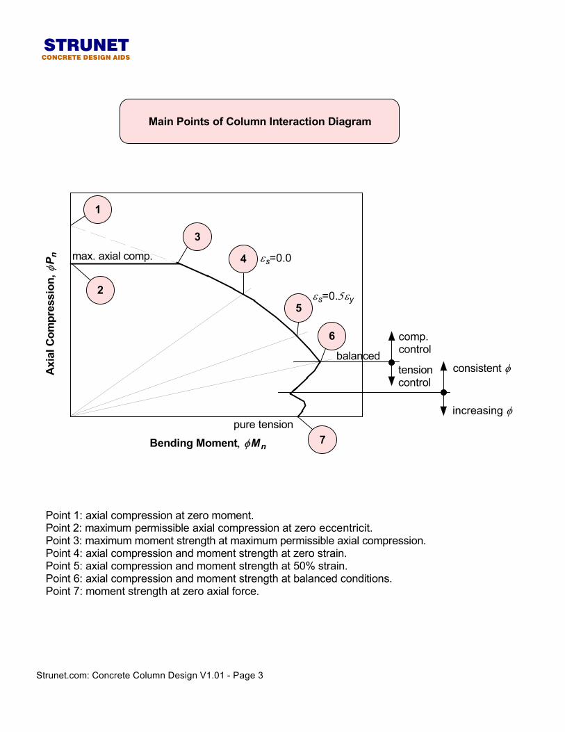
Main Points of Column Interaction Diagram
Point 1: axial compression at zero moment.Point 2: maximum permissible axial compression at zero eccentricit.Point 3: maximum moment strength at maximum permissible axial compression.Point 4: axial compression and moment strength at zero strain.Point 5: axial compression and moment strength at 50% strain.Point 6: axial compression and moment strength at balanced conditions.Point 7: moment strength at zero axial force.
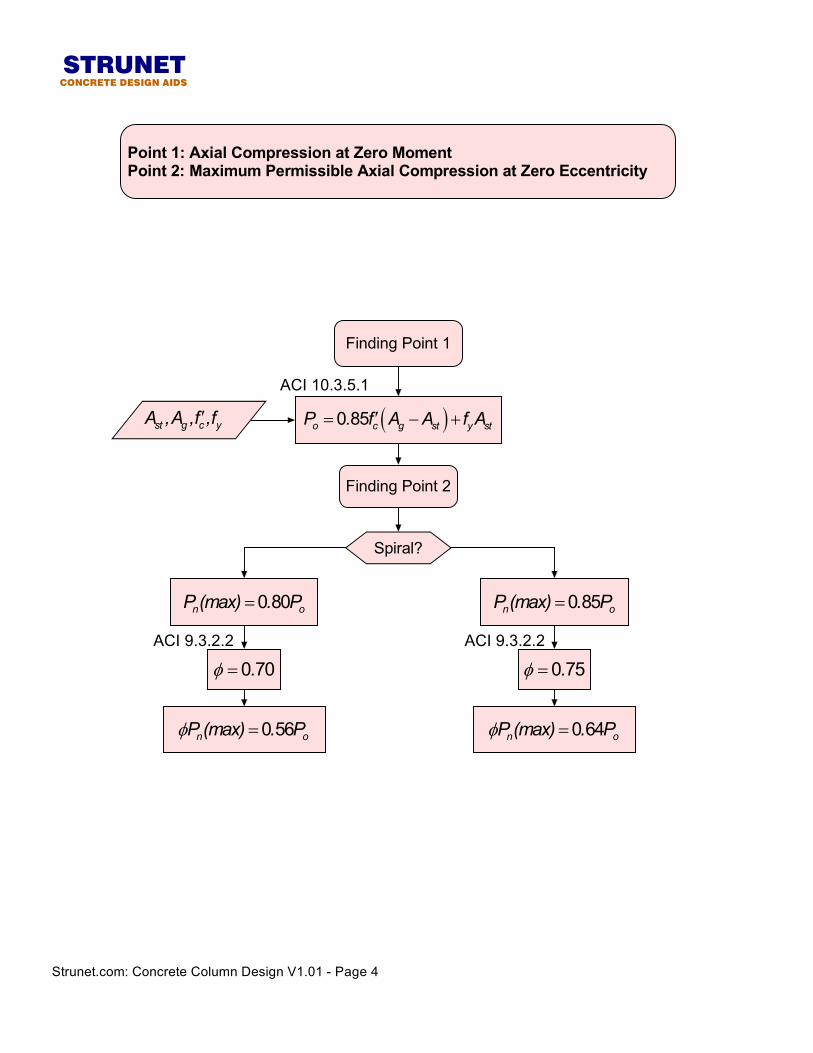
( )0 85o c g st y stP . f A A f A′= − +st g c yA ,A ,f ,f′
Spiral?
0 85n oP (max) . P=0 80n oP (max) . P=
0 75.φ =0 70.φ =
0 64n oP (max) . Pφ =0 56n oP (max) . Pφ =
Finding Point 1
Finding Point 2
ACI 10.3.5.1
ACI 9.3.2.2ACI 9.3.2.2
Strunet.com: Concrete Column Design V1.01 - Page 4
STRUNETCONCRETE DESIGN AIDS
Point 1: Axial Compression at Zero MomentPoint 2: Maximum Permissible Axial Compression at Zero Eccentricity
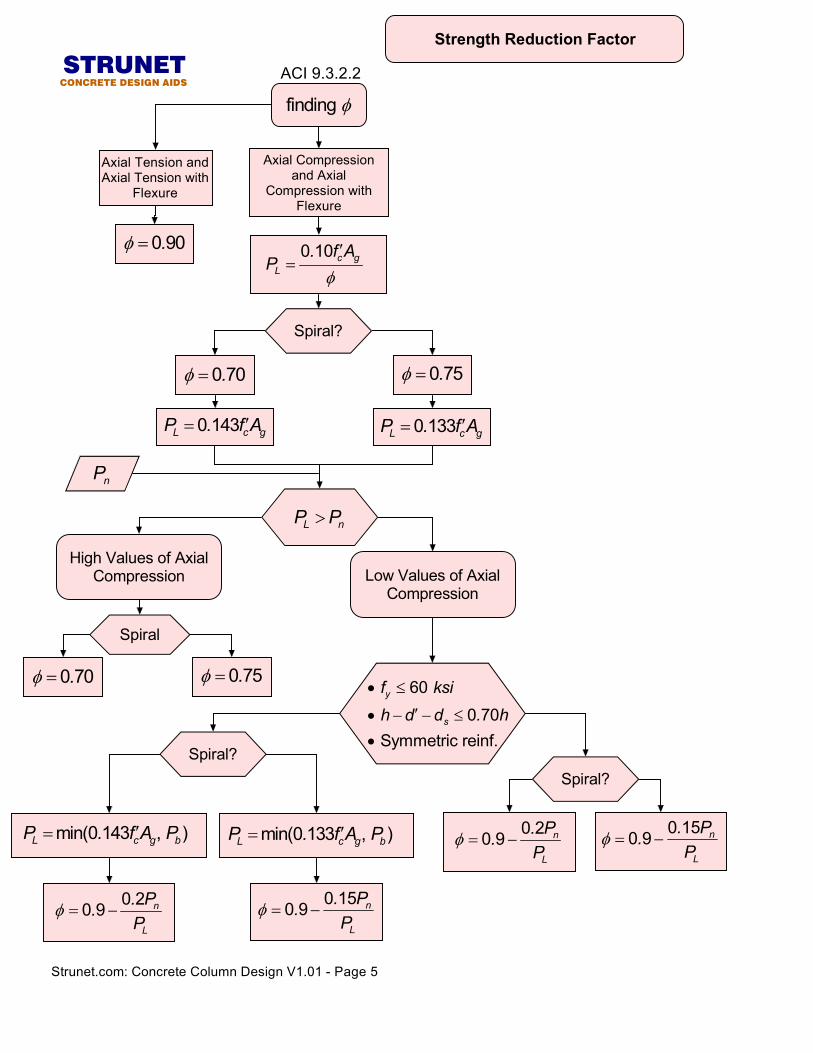
finding φ
Axial Tension andAxial Tension with
Flexure
0 90.φ =
Axial Compressionand Axial
Compression withFlexure
Spiral
0 75.φ =0 70.φ =
High Values of AxialCompression Low Values of Axial
Compression
60 0 70 Symmetric reinf.
y
s
f ksih d d . h
• ≤
′• − − ≤
•
0 150 9 n
L
. P.P
φ = −
0 10 c gL
. f AP
φ′
=
L nP P>
Spiral?
0 75.φ =0 70.φ =
0 133L c gP . f A′=
nP
Spiral?Spiral?
min(0 133 , )L c g bP . f A P′=min(0 143 , )L c g bP . f A P′= 0 20 9 n
L
. P.P
φ = −
ACI 9.3.2.2
0 143L c gP . f A′=
0 150 9 n
L
. P.P
φ = −0 20 9 n
L
. P.P
φ = −
Strunet.com: Concrete Column Design V1.01 - Page 5
STRUNETCONCRETE DESIGN AIDS
Strength Reduction Factor
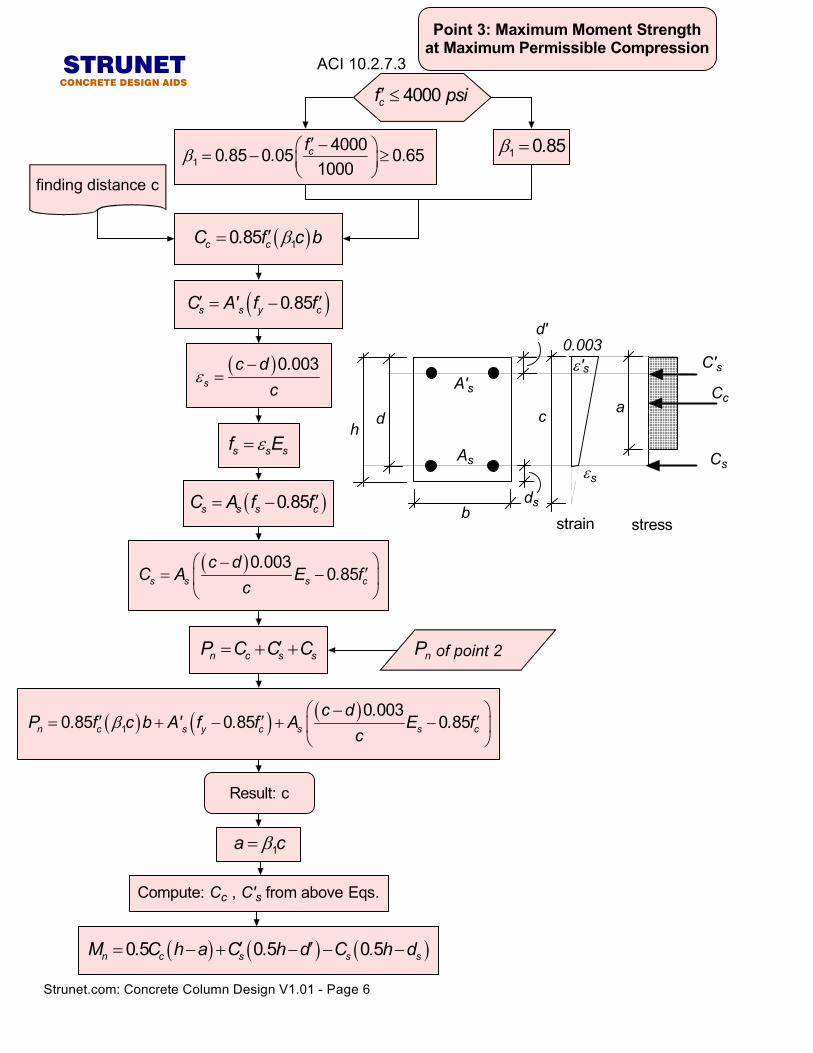
4000 cf psi′ ≤
1 0 85.β =1
40000 85 0 05 0 651000
cf. . .β′ − = − ≥
strain stress
Cc
C's0.003
c
b
ha
d'
εs
ε's
Cs
ds
A's
As
d
( )10 85c cC . f c bβ′=
( )0 003s
c d .c
ε−
=
( )0 85s s y cC A' f . f′ ′= −
( )0 85s s s cC A f . f ′= −
s s sf Eε=
( )0 0030 85s s s c
c d .C A E . f
c−
′= −
n c s sP C C C′= + +
( ) ( ) ( )1
0 0030 85 0 85 0 85n c s y c s s c
c d .P . f c b A' f . f A E . f
cβ
− ′ ′ ′= + − + −
of point 2nP
finding distance c
Result: c
( ) ( ) ( )0 5 0 5 0 5n c s s sM . C h a C . h d C . h d′ ′= − + − − −
1a cβ=
Compute: Cc , C's from above Eqs.
ACI 10.2.7.3
Strunet.com: Concrete Column Design V1.01 - Page 6
STRUNETCONCRETE DESIGN AIDS
Point 3: Maximum Moment Strengthat Maximum Permissible Compression
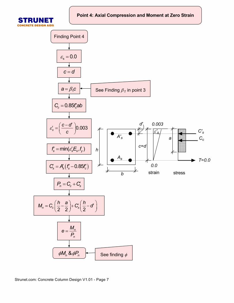
s 0 0.ε =
c d=
1a cβ=
min( )s s s yf E ,fε′ ′=
( )0 85s s s cC A f . f′ ′ ′ ′= −
n c sP C C′= +
n
n
MeP
=
2 2 2n c sh a hM C C d ′ ′= − + −
0 85c cC . f ab′=
0 003sc d .c
ε′− ′ =
See finding φ&n nM Pφ φ
Finding Point 4
See Finding β1 in point 3
T=0.0
d'
strain stress
Cc
C's
0.003
0.0
c=d
b
h
aε's
As
A's
Strunet.com: Concrete Column Design V1.01 - Page 7
STRUNETCONCRETE DESIGN AIDS
Point 4: Axial Compression and Moment at Zero Strain
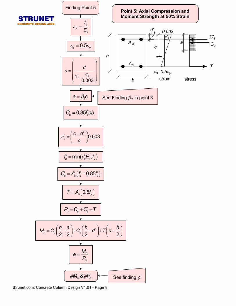
min( )s s s yf E ,fε′ ′=
( )0 85s s s cC A f . f′ ′ ′ ′= −
n c sP C C T′= + −
n
n
MeP
=
2 2 2 2n c sh a h hM C C d T d ′ ′= − + − + −
See finding φ&n nM Pφ φ
Finding Point 5
yy
s
fE
ε =
0 5s y.ε ε=
0 003sc d .c
ε′− ′ =
10 003
s
dc
.ε
= +
1a cβ= See Finding β1 in point 3
0 85c cC . f ab′=
( )0 5s yT A . f=
d'
T
strain stress
Cc
C's0.003
c
b
h
aε's
εs=0.5εy
As
A's
Strunet.com: Concrete Column Design V1.01 - Page 8
STRUNETCONCRETE DESIGN AIDS
Point 5: Axial Compression andMoment Strength at 50% Strain
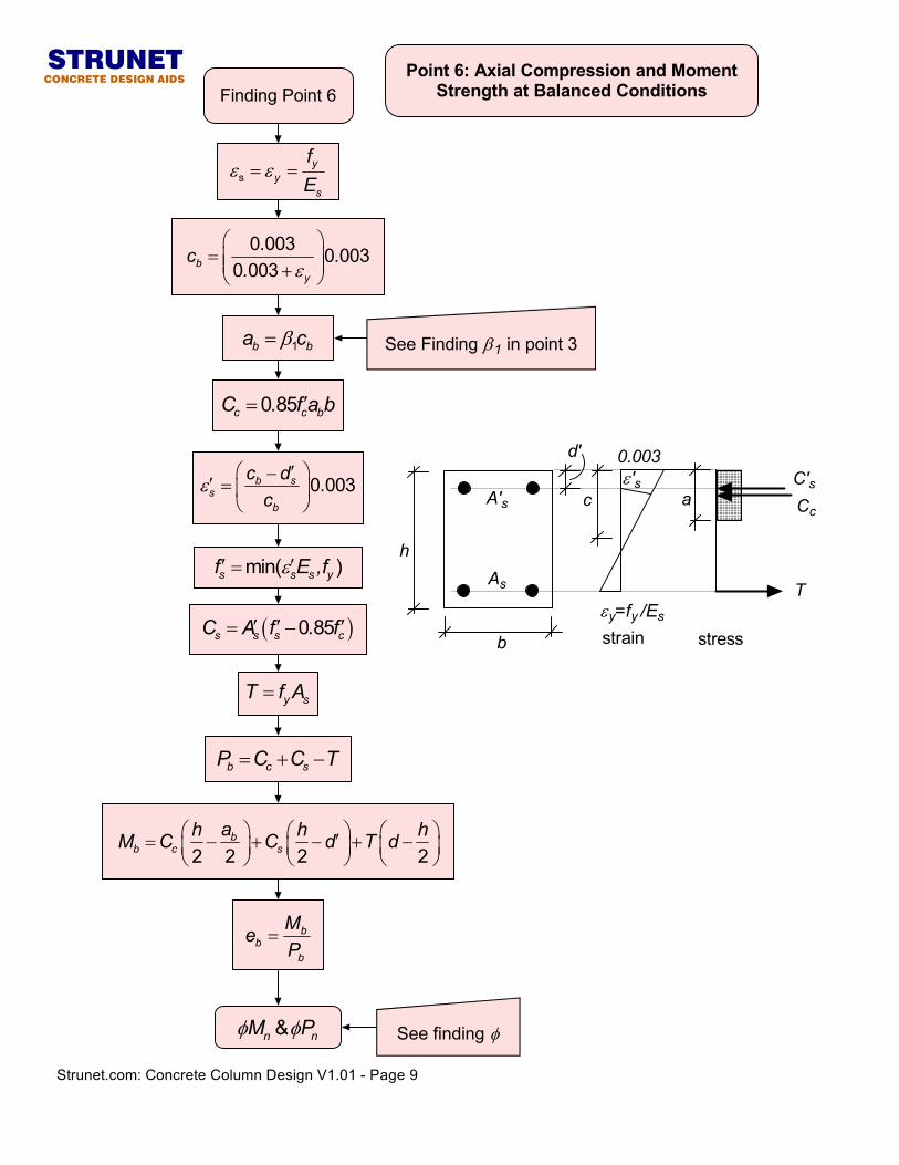
Finding Point 6
sy
ys
fE
ε ε= =
0 003 0 0030 003b
y
.c .. ε
= +
1b ba cβ=
( )0 85s s s cC A f . f′ ′ ′= −
y sT f A=
b c sP C C T= + −
2 2 2 2b
b c sah h hM C C d T d ′= − + − + −
bb
b
MeP
=
0 003b ss
b
c d .c
ε ′−′ =
0 85c c bC . f a b′=
min( )s s s yf E ,fε′ ′=
See Finding β1 in point 3
See finding φ&n nM Pφ φ
d'
T
strain stress
Cc
C's0.003
c
b
h
aε's
εy=fy /Es
As
A's
Strunet.com: Concrete Column Design V1.01 - Page 9
STRUNETCONCRETE DESIGN AIDS
Point 6: Axial Compression and MomentStrength at Balanced Conditions
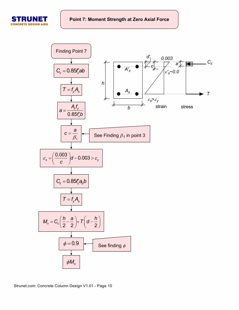
Finding Point 7
See finding φ
0 85c cC . f ab′=
y sT f A=
0 85s y
c
A fa
. f b=
′
1
acβ
=
0 003 0 003s y. d .c
ε ε = − >
0 85c c bC . f a b′=
y sT f A=
2 2 2n ch a hM C T d = − + −
0 9.φ =
nMφ
See Finding β1 in point 3
d'
T
strain stress
Cc0.003
c
b
h
a
ε's~0.0
εs>εy
As
A's
Strunet.com: Concrete Column Design V1.01 - Page 10
STRUNETCONCRETE DESIGN AIDS
Point 7: Moment Strength at Zero Axial Force
Copyright © 2022 FDOKUMEN