Column configurations of continuous heterogeneous extractive distillation
41
1 Column Configurations of Continuous Heterogeneous Extractive Distillation Ivonne RODRIGUEZ-DONIS 1 , Katalin PAPP 2 , Vincent GERBAUD 3 , Xavier JOULIA 3 , Endre REV 2 , Zoltan LELKES 2 1 Centro de Quimica Farmacéutica, Ave. 200 y 21 Atabey Apdo. 16042, Playa, C. Habana, Cuba 2 Chemical Engineering Department, Budapest University of Technology and Economics, Mőegyetem rkp. 3, H-1521 Budapest, Hungary 3 Le Laboratoire de Génie Chimique, UMR CNRS 5503, ENSIACET-UPS-CNRS, BP 1301, 5 rue Paulin Talabot, F-31106 Toulouse, France Accepted for publication in AIChE Journal, 53: 1982–1993, 2007 ABSTRACT Increasing regulations and constraints have renewed interest for more efficient distillation process in separating azeotropic mixtures and close boiling components. We investigate the feasibility of heterogeneous extractive distillation process in a continuous column considering several feed point strategies for the entrainer recycle stream and for the main azeotropic feed. Depending on these choices, the heterogeneous distillation column is composed of one, two or three column sections. A differential mass balance model enables to compute continuous liquid composition profiles of the rectifying, extractive and stripping sections. Unlike homogeneous extractive distillation, reflux policy composed by a single or both decanted liquid phases is considered as well as the external feeding influence on the composition of the top column liquid stream. Limiting operating conditions of key parameters like the entrainer/feed flowrate ratio and reflux ratio required to obtain a target top and bottom product compositions are obtained. For illustration, separation of acetonitrile – water mixture using butyl acetate as a heavy heterogeneous entrainer is selected. In this case, withdrawal of a saddle binary heteroazeotrope is the main difference of this process compared with the well known heterogeneous azeotropic distillation process where the top vapor product is the lower boiling point of the ternary system. Key words: continuous distillation, extractive distillation, heteroazeotropic distillation, feasibility, composition profile, top composition
-
Upload
independent -
Category
Documents
-
view
1 -
download
0
Transcript of Column configurations of continuous heterogeneous extractive distillation

1
Column Configurations of Continuous Heterogeneous Extractive Distillation
Ivonne RODRIGUEZ-DONIS1, Katalin PAPP
2, Vincent GERBAUD
3, Xavier JOULIA
3, Endre
REV2, Zoltan LELKES
2
1Centro de Quimica Farmacéutica, Ave. 200 y 21 Atabey Apdo. 16042, Playa, C. Habana, Cuba
2Chemical Engineering Department, Budapest University of Technology and Economics,
Mőegyetem rkp. 3, H-1521 Budapest, Hungary 3Le Laboratoire de Génie Chimique, UMR CNRS 5503, ENSIACET-UPS-CNRS, BP 1301, 5 rue
Paulin Talabot, F-31106 Toulouse, France
Accepted for publication in AIChE Journal, 53: 1982–1993, 2007
ABSTRACT
Increasing regulations and constraints have renewed interest for more efficient distillation process
in separating azeotropic mixtures and close boiling components. We investigate the feasibility of
heterogeneous extractive distillation process in a continuous column considering several feed point
strategies for the entrainer recycle stream and for the main azeotropic feed. Depending on these
choices, the heterogeneous distillation column is composed of one, two or three column sections. A
differential mass balance model enables to compute continuous liquid composition profiles of the
rectifying, extractive and stripping sections. Unlike homogeneous extractive distillation, reflux
policy composed by a single or both decanted liquid phases is considered as well as the external
feeding influence on the composition of the top column liquid stream. Limiting operating
conditions of key parameters like the entrainer/feed flowrate ratio and reflux ratio required to obtain
a target top and bottom product compositions are obtained. For illustration, separation of
acetonitrile – water mixture using butyl acetate as a heavy heterogeneous entrainer is selected. In
this case, withdrawal of a saddle binary heteroazeotrope is the main difference of this process
compared with the well known heterogeneous azeotropic distillation process where the top vapor
product is the lower boiling point of the ternary system.
Key words: continuous distillation, extractive distillation, heteroazeotropic distillation,
feasibility, composition profile, top composition

3
Introduction..........................................................................................................................................4
General heterogeneous extractive distillation column configuration ..................................................7
Feasibility methodology for continuous heterogeneous extractive distillation process. .....................7
The valid range for the liquid reflux composition xR and for the top liquid composition x0 ...............9
Computation of column section composition profiles .......................................................................11
Rectifying Column Section:...........................................................................................................12
Extractive Column Section ............................................................................................................12
Stripping Column Section..............................................................................................................12
Variants of Continuous Distillation Process with Heterogeneous Entrainers. Feasibility Study. .....13
Column configuration 1 .................................................................................................................13
Column configuration 2 .................................................................................................................13
Column configuration 3 .................................................................................................................14
Column configuration 4 .................................................................................................................15
Column configuration 5 .................................................................................................................15
Column configuration 6 .................................................................................................................16
Column configuration 7 .................................................................................................................16
Conclusions........................................................................................................................................17
Notation..............................................................................................................................................18
References ..........................................................................................................................................19

4
INTRODUCTION
The separation of azeotropic mixtures or close boiling components is a challenging task in many
chemical processes as it is impossible using a single conventional distillation column. Therefore,
many non-conventional distillation techniques have been proposed in the vast literature published in
the area and are described in several reference monographs.1-4
The most common alternatives
involve changing the operating pressure or adding a so called entrainer compound. The pressure
option is economically feasible only for mixtures very sensitive to pressure. Consequently, the
second alternative is the typical non conventional distillation process encountered in the industry
and concerns so called azeotropic and extractive distillation processes. Synthesis and design of
azeotropic and extractive distillation processes first depends on the miscibility of the entrainer with
at least one of the original components. The entrainer is considered as heterogeneous if it causes
liquid – liquid phase split over a range of compositions in the ternary phase diagram. Otherwise, the
entrainer is homogeneous. Heterogeneous entrainers provide a simple technique to cross a basic
distillation boundary and the total mass balance line can connect two streams placed in different
distillation regions. Unlike to the heterogeneous distillation process, homogeneous entrainers allow
only a feasible separation for the components limiting the same basic distillation region unless that
ternary system contains distillation boundaries with a significant curvature.1
Azeotropic and extractive distillation can be carried out in continuous or batch distillation
column. In the case of batch operation, only a few differences exist between the column
configuration needed to perform the azeotropic and extractive distillation process, especially when
homogeneous entrainer is used. Entrainer is always loaded into the still at the beginning of the
azeotropic distillation process while in extractive distillation, the entrainer must be fed continuously
at some tray of the column or into the still during the whole operation.5-8
Because the composition
of the liquid reflux and distillate are dissimilar when using heterogeneous entrainers,
heteroazeotropic batch distillation is usually considered like a self-sustained continuous feeding
process even if an amount of entrainer has to be added initially into the still. Therefore, similar
column configuration can be used to perform azeotropic and extractive heterogeneous batch
distillation mostly when fresh entrainer is fed at the top of the column.9-11
More column configurations and technological alternatives can be used when azeotropic and
extractive distillation process takes places in a continuous column depending on the strategy
selected for the recycle streams connecting several columns even for homogeneous entrainers.
Usually, a sequence of three connected continuous columns are used where the heterogeneous
column and its decanter is the target of the design and synthesis analysis. An entrainer recovery

5
column and a pre-concentrator are commonly associated with the heteroazeotropic column. Doherty
and coworkers12-13
made a critical analysis of heterogeneous azeotropic distillation process with
different entrainer recycle strategy because feasibility of this process heavily depends on where the
entrainer recycle stream returns to the heteroazeotropic column. More recently, Marquardt and
coworkers presented a shortcut design method based on the rectification body method14
to design
heterogeneous azeotropic distillation processes15
and extractive distillation columns16
.
Considering a high boiling entrainer, seven main configurations can be set for the
heteroazeotropic continuous column:
(1) The entrainer recycle is mixed to the azeotropic stream and fed at the same intermediate tray
of the column,
(2) The entrainer stream is fed to an intermediate tray of the column above the azeotropic feed
tray as is commonly used in homogeneous extractive distillation process,
(3) The entrainer is sent at the first top tray as a single external stream or mixed with the liquid
reflux stream,
(4) Both the entrainer and the main azeotropic streams are introduced at the first top tray of the
column, or mixed to the liquid reflux stream,
(5) The entrainer recycle stream is sent to the decanter whereas the main azeotropic feed is sent at
intermediate tray of the column,
(6) Similar to (5) but a part of the distillate product is also recycled to the decanter in order to
assure a liquid – liquid split in this vessel,
(7) The main azeotropic feed is introduced at the first top tray of the column or mixed to the liquid
reflux, and the entrainer recycle stream is returned directly to the decanter.
According to the literature, only configurations 1, 3 and 5 have earlier been studied involving
heterogeneous entrainer.2 The feasibility study has not been performed for the four remaining
configurations. In this article, a complete feasibility method is presented for the seven entrainer
recycle stream alternatives for the heteroazeotropic continuous distillation column. The selected
entrainer recycle strategy determines the number of sections of the column among three choices,
namely, a rectifying section always located above the entrainer feed, a stripping section below the
main azeotropic feed, and an extractive section located between both azeotropic and entrainer feeds.
Liquid composition profiles of each section are computed by using the mass balance in differential
form according to the model proposed by Lelkes et al.6 for a given operating conditions. In general,
the heterogeneous distillation process is considered as feasible if the liquid composition profile
inside a single column section or combined sections with two consecutive liquid composition

6
profiles intersecting at least once, goes from the bottom product composition to the column top tray
liquid composition.
Feasibility study of each entrainer recycle alternative is illustrated for the separation of
acetonitrile – water mixture at 1 atm by using butyl acetate as heterogeneous entrainer. Figure 1
shows the thermodynamic and topological features of the ternary system including the univolatility
curve acetonitrile/water, which were computed by using Simulis Thermodynamics®, a
thermodynamic property server available in various programming environments supporting COM
middleware, like Microsoft Excel.17
Liquid – liquid – vapor, liquid – vapor and liquid – liquid equilibrium are calculated with NRTL
model with binary interaction coefficients (Table 1) estimated from experimental data at
atmospheric pressure.18
Vapor pressure is computed according to the DIPPR database correlation.
The ternary diagram is divided in two basic distillation regions by an unstable separatrix connecting
the unstable homogeneous azeotrope of minimum boiling point acetonitrile – water and the saddle
heteroazeotrope water – butyl acetate. No ternary azeotrope is formed and the water and butyl
acetate pure component vertexes are stable nodes while the acetonitrile pure component vertex is a
saddle. One immiscibility gap spans through both distillation regions and the vapor line moves
along the unstable separatrix connecting the binary azeotropes. The univolatility curve acetonitrile-
water (αA-W = 1) begins at the homogeneous azeotrope and ends to the binary heterogeneous side
water – butyl acetate. Therefore, feeding of fresh solvent and additional liquid reflux of the
entrainer-rich phase or both liquid decanted phases provides the separation of the saddle binary
heteroazeotrope at the top of the column allowing the water-rich phase as distillate.10
Being able to
withdraw a saddle heteroazeotrope is the main difference of this separation comparing to the
conventional heterogeneous distillation process where an unstable heteroazeotrope is always drawn
at the top of the column. The zeotropic binary mixture acetonitrile - butyl acetate is then removed as
a bottom product and separated in pure components in a subsequent continuous distillation column
as shown in Figure 2.
The proposed feasibility methodology aims in determining the range of the design parameters
which matches with a general feasibility criterion for any of the seven configurations of continuous
heterogeneous extractive distillation process. If such design parameters are not found then the
process is infeasible with the specified column configuration. The same methodology can also be
used to find the limiting values of the design parameters ensuring feasibility but this issue is not
presented in this manuscript.

7
GENERAL HETEROGENEOUS EXTRACTIVE DISTILLATION COLUMN
CONFIGURATION
The general configuration for the heterogeneous distillation column is shown in Figure 3; taking
into account the seven configurations combining the entrainer recycle stream and the main
azeotropic feed. The heteroazeotropic distillation column is the aggregation of several parts among
(i) a condenser and a decanter together, (ii) a rectifying section from the top of the column down to
the entrainer recycle feed, (iii) an extractive section between the two feeds, and (iv) a stripping
section from the main azeotropic feed to the bottom, including the boiler. Choosing the main
azeotropic feed location (intermediate or column top) and the entrainer recycle strategy (mixed with
the azeotropic feed or with the top liquid reflux or sent to an intermediate column point of the
column or to the decanter) leads to any of the seven configurations described above considering that
feeding the entrainer below the main azeotropic feed is also meaningless in our case (we restrict to
the use of a heavy boiling entrainer). The most complex column configuration with 3 sections;
rectifying, extractive and stripping ones; is obtained when the main azeotropic feed and the
entrainer recycle stream are introduced at different intermediate points of the column (configuration
2).
Figure 4 displays a more detailed sketch of the composite (top column + condenser + decanter)
part considering the influence of the entrainer recycle FE and the azeotropic feed FF on the liquid
composition and flowrates involved in this column section. Subscripts T, D and I refer respectively
to a feed (FFT and or FET) supplied at the column top feed along with the liquid reflux
(configurations 3 and 4), mixed (FED) with the condensed vapor and sent to the decanter
(configurations 5, 6 and 7), or fed (FFI and or FEI) at an intermediate point of the column as a
combined or separate feeds (configurations 1 and 2).
FEASIBILITY METHODOLOGY FOR CONTINUOUS HETEROGENEOUS
EXTRACTIVE DISTILLATION PROCESS.
The feasibility methodology is based on the analysis of the liquid composition profile computed
for each column section for given operating parameters values. The process is feasible if the
specified product compositions at the top (xD) and the bottom (xW) of the column can be connected
by a single or by a composite composition profile. A single composition profile belongs to one
column section and a composite composition profile is composed by two or three column section
composition profiles connected at some punctual composition.
The x liquid composition profiles in each column section can be computed according to the

8
general differential model of Lelkes et al.6:
( ))()(L
V
dh
d *xyxy
x −±= (1)
Where V and L are the vapor and liquid flowrates within the column. The vapor composition y* in
equilibrium with x is computed by the liquid – vapor equilibrium relation y = K.x and the actual
vapor composition y is computed from the mass balance (the so-called operating line) valid in each
column section, depending on the chosen column configuration.
This is a continuous model derived via a truncated series expansion of a staged model. As a
differential model, it is well suited for the study of singularities (stable or unstable node, saddle) and
eventual boundaries of the liquid composition profile maps that may affect feasibility under various
operating conditions. Feasibility and limiting parameter values like minimum reflux which
supposes sometimes to assess intersection of composition profiles are also easier to assess with
continuous composition profiles from the differential model than with discrete composition profiles
from distillation line calculations as investigated in earlier works.19
The differential model is, however, neither related to theoretical or real stages, nor it is based on
mass transfer equations. It cannot be used to evaluate a finite number of stages within some column
section like with the distillation line calculations under higher than minimum reflux conditions.19
Finally, it contains the same driving force y-y* as occurs in the well-known NTU-HTU mass
transfer model.
The differential equation (1) is an initial value problem that should be solved by starting the
computation from a known liquid composition. The double sign ± shown in equation (1) is to be
actualized according to the direction (top down or bottom up) considering that column height h is
equal to zero at the top. Therefore, equation (1) must be used in computing the liquid composition
profile of a rectifying, extractive and stripping column section with an adequate definition of the
initial point for x, and the direction of the solution and the mass balance equation for y. The driving
force applied in equation (1) is to be understood at a given column height h. This is valid even at the
very top of the column. The composition of the vapor emerging from the column top y1, and the
imagined vapor composition that would be in equilibrium y* with the countercurrent liquid x0 are in
the same relation. Therefore, the composition of this countercurrent liquid x0 is a good candidate to
be an initial point for the higher (rectifying or extracting) column section and the equation is solved
top down. Otherwise, if the bottom composition xW is known then it can be directly applied as the
initial value, and equation (1) is solved bottom up in the lowest (stripping) column section keeping
a negative sign.
Thus, computation of the top (rectifying or extractive) column section composition profile should

9
be started from the composition of the liquid flowing on the top of the column if there are at least
two column sections. This is called ‘the top liquid composition’, and denoted by x0 (see Figure 3
and 4). The top liquid composition x0 is identical to the composition of the reflux stream xR if there
is not external feed mixed with the liquid reflux (FET =FFT=0). This xR, in turn, is identical to the
distillate composition xD if there is no liquid phase distribution into the decanter (homogeneous
case). This difference with homogeneous extractive distillation process is taken into account in the
feasibility methodology that we will describe below. If there is a liquid phase distribution then, the
composition of the reflux stream xR is determined by the compositions xD and xI of the distributed
liquid phases, and the reflux ratio R, together. Besides, if there is some external liquid feed sent to
the top of the column (either positive FFT or FET in Figure 4; configurations 3 and 4) then it should
be accounted as a feed mixed to the reflux stream. The top liquid composition x0 is then determined
by the mass balance of mixing the external feed stream to the reflux stream (envelope [c] in Figure
4).
Finally, if there are three sections in the column then the rectifying and stripping composition
profiles begin at xR and xW, respectively, whereas for exploring the range of potentially valid
extractive composition profiles (the intermediate column section) a series of composition profiles
should be computed started from several points in the composition triangle.
THE VALID RANGE FOR THE LIQUID REFLUX COMPOSITION xR AND
FOR THE TOP LIQUID COMPOSITION x0
The specified distillate composition xD lies on the component-rich side of the binodal curve at the
specified temperature Tdec. Thus, xD belongs to a distinct liquid-liquid equilibrium tie line at Tdec
(see Figure 1) which other end on the entrainer-rich side is noted xI. Since the distillate is produced
as (part of) one phase formed in the decanter, the gross composition xG in the decanter should lie on
this tie line (see Figure 4). Considering a possible P flowrate of the distillate product recycled along
an external entrainer feed FED to the decanter (or to the condenser), a mass balance around envelope
[a] in Figure 4 holds:
GGGEDDEED
1 xL)PFV(PFV ⋅=⋅++=⋅+⋅+⋅ xxxy (2)
When FED = 0 and P = 0, y1 = xG holds.
The reflux ratio R is defined by the usual ratio of LR to D flowrates. The actual value of R cannot
be smaller than the actual phase ratio, because phase I is totally refluxed and not mixed to the
distillate. LI / L
II is determined by xG:

10
iG
I
i
iDiG
II
I
L
L
xx
xx
−−= where 0)( iG
I
i ≠− xx (3)
The liquid reflux stream composition xR is constrained between xD and xI. The liquid – liquid
splitting ratio into the decanter ω is defined as LI / ( L
I + L
II ). For design purposes, L
II should not
be smaller than D. So, there is a maximum value of ωmax that matches with the condition LII = D:
−=
GL
D1maxω (4)
Part of LII can also be refluxed if ω<ωmax and, therefore, ( L
I / L
II ) is smaller than R. Thus, for a
given xG, and so a LI / L
II value, there is a lower bound to R:
II
I
L
LR ≥ (5)
The ratio LI to L
II may vary between 0 and infinity, and xR may vary between xD and x
I.
A feasibility study is performed while changing design parameters R and FE, we determine the
constraint on xG, xR, and x0, for a given R. Denote the flowrate of refluxed distillate product phase
by LIIR
; then from the definition of R, and from material balance, we get
( )IIRIIIIRI
R LLRDRLLL −⋅=⋅=+= (6)
By rearranging equation (5) and (6), LIIR
can be expressed:
>+
−⋅
==
II
IIII
II
I
IIR
L
LRif;
R1
LLRL
LRif;0
L (7)
The reflux composition xR by mass balance around the envelope [b] (Figure 4) is:
IIRI
D
IIRII
RLL
LL
+⋅+⋅= xx
x (8)
The two extremes of xR can be determined by taking the limits of the phase ratio. If phase I is
negligible compared to phase II then xR approaches xD by limit.
D0L/LR III xx =→
(9)
If the phase ratio LI to L
II approaches R (from below) then L
IIR approaches 0, and xR approaches
xI:
I
RL/LR III xx =→
(10)
Thus, the valid set of xR is the whole tie line xD – xI shown in Figure 1 and should be explored for
checking feasibility at a given R, even if the range of xG is constrained by the condition LII ≥ D.
The top liquid composition x0 depends on the column configuration, as explained below. Because

11
a possible external feed (FET or FFT) is mixed with the liquid reflux at the top of the column (see
Figure 4), x0 and xR are unlike. Based on the general mass balance according to envelope [c] in
Figure 4:
ETFT
EETFFTR0
FFDR
FFDR
++⋅⋅+⋅+⋅⋅= xxx
x (11)
The valid range of x0 is also determined by varying xR along the full length of the tie line xD – xI.
The two end-points of this straight line are:
ETFT
EETFFTDD
0FFDR
FFDR
++⋅⋅+⋅+⋅⋅= xxx
x (12)
ETFT
EETFFT
II
0FFDR
FFDR
++⋅⋅+⋅+⋅⋅= xxx
x (13)
If FFT = 0 and FET = 0, then x0 = xR and the valid range of x0 is the tie line xD – xI.
COMPUTATION OF COLUMN SECTION COMPOSITION PROFILES
Having in mind the general column configuration displayed in Figures 3 and 4, equation (1) can be
used to compute the liquid composition profile in each column section They depend on the
azeotropic feed flowrate (FF) and composition and (xF), the entrainer flow rate (FE) and
composition (xE), the recycled distillate flow rate to the decanter (P), the specified recovery ratio of
the primary key component A (ηA), the decanter temperature (Tdec), the entrainer-rich phase
composition (xI), the distillate composition (xD, component-rich phase composition), the operating
pressure (Pr), the reflux ratio (R).
Given these operating variables, the other overall operating parameters can be computed such as
vapor (V), distillate (D) and bottom product (W) flowrates, the bottom product composition (xW)
and the liquid flowrate in each column section: LR, LE and LW for the rectifying, extractive and
stripping section, respectively. These unknowns are determined by mass balance, taking into
account the combinations (condenser + decanter) in Figure 4 and around the whole column in
Figure 3:
A,D
A,FFA
x
xFD
⋅⋅=
η (composition mass balance for the primary key component A) (14)
DFDFFW TEF −=−+= (total mass balance) (15)
W
xDxF
W
xDxFxFx DTTDEEFFw
⋅−⋅=⋅−⋅+⋅= (component mass balance) (16)
Considering all the three column sections, the particular expressions for equation (1) for the

12
column sections are the following:
Rectifying Column Section:
The operating vapor y(x) can be computed from the mass balance around the column top section
involving the internal flows V and L=LR of the rectifying section and the external stream D,
resulting in the following equations:
V
DL)( DR xx
xy⋅+⋅= (17a)
DRDVLLR ⋅=−== 0 (Balance envelope [c] in Figure 4 with FFT = FET =0) (17b)
D)R(DLV ⋅+=+= 10 (Balance envelope [d]s in Figure 4 with FFT = FET = FED = 0) (17c)
Rstart xx = (17d)
Extractive Column Section
The operating vapor y(x) can be computed from the mass balance around the column intermediate
section involving the internal flows V and L=LE of the extractive section and the external streams D,
FEI, FFT, FET and FED, resulting in the following equations:
V
)FFF(FDL)( EEDETEIFFTDE xxxx
xy⋅++−⋅−⋅+⋅= (18a)
DFFFFVL EDETFTEIE −++++= (18b)
ETFTETFTR FFDRFFLL ++⋅=++=0 (balance envelope [c] in Figure 4) (18c)
EDETFT FFFDLV −−−+= 0 (balance envelope [d] in Figure 4) (18d)
Depending on the column configuration, xstart is either xR or x0, or a selected final point of the
stripping composition profile xW, or some other composition in the triangle.
Stripping Column Section
The operating vapor y(x) can be computed from the mass balance around the lowest column
section involving the internal flows V and L=LS of the stripping section and the bottom product W,
resulting in the following equations:
V
WL)( WS xx
xy⋅−⋅= (19a)
Where WVLS += (19b)
V is the previously calculated value for the rectifying (equation 14c) or extractive section

13
(equation 15c) and,
Wstart xx = (19c)
VARIANTS OF CONTINUOUS DISTILLATION PROCESS WITH
HETEROGENEOUS ENTRAINERS. FEASIBILITY STUDY.
The column configuration for heterogeneous distillation process depends on the selected strategy
for the entrainer recycle stream and the main azeotropic feed. Therefore, the seven configurations
mentioned above are considered. For all cases, the decanter temperature equals 25°C and the total
pressure equals 1 atm. Table 2 reports the operation conditions.
Column configuration 1
One may consider this case as mixing the entrainer recycle stream with the main azeotropic feed,
and leading this mixed feed to an intermediate point of the column (FFI and FEI > 0 and FFT = FET =
FED = P = 0 in Figure 3). Pham et al.19
studied the sensitivity of the design parameters by using this
column configuration for the separation of the binary mixture isopropanol – water with the addition
of benzene as an intermediate entrainer.
There is a stripping section and a rectifying section below and above the composed feed,
respectively. The process is feasible if the stripping composition profile intercepts at least one
rectifying composition profile. The possible rectifying composition profiles are computed top down
starting from valid values of x0 = xR for several decanter split ratios ω < ωmax which sets the x0
location on the liquid – liquid tie-line {xD; xI}. The stripping composition profile is computed
bottom up, starting from the unique xW.
For R=10, Figure 5 displays a map of rectifying composition profiles for several values of xR
placed on the appropriated liquid – liquid tie-line {xD; xI} at Tdec. The profile starting at xR = x
I
corresponds to ω=ωmax and the reflux of entrainer-rich phase is only considered. Otherwise, the
liquid reflux is composed by both decanted liquid phases. As seen in Figure 5, the feasibility
criterion is not satisfied for the chosen operating conditions.
Column configuration 2
Both the main azeotropic feed FFI and the entrainer recycle FEI feed are fed to different
intermediate points of the column, FEI above FFI. In this configuration, FFT = FET = FED = P = 0.
Compared to configuration 1, there is an additional extractive section between the two feeds. A

14
similar column configuration without decanter is a typical process applied for the separation of non-
ideal mixtures with homogeneous extractive continuous distillation.2 No initial point is known for
computing the possible extractive composition profiles. Hence, extractive composition profiles must
be computed from several compositions values as initial points selected inside the ternary diagram
(e.g. [0.4; 0.3; 0.3], [0.4; 0.2; 0.4], [0.4; 0.1; 0.5]).
The process is feasible if the stripping and any rectifying liquid composition profiles intercept or
are connected by at least one extractive composition profile.
Figure 6 shows that the feasibility criterion is now satisfied for the same operating conditions as
configuration 1. Thus, for the same operating conditions reported in Table 2, the heterogeneous
extractive distillation process is feasible with two separated external feeds, three column sections,
but not with one mixed feed and two column sections.
Column configuration 3
The main azeotropic feed FFI is fed to an intermediate point of the column whereas the entrainer
FET is sent at the first top tray of the column top or is mixed with the liquid reflux stream.
Compared to configuration 2, no rectifying section is present (FEI =FFT = FED = P = 0). Doherty and
coworkers12-13
established a design method and a new optimization procedure for this column
configuration by using the residue curve analysis applied to separate ethanol – water with benzene
and also using discrete tray by tray composition profiles.
The process is feasible if the stripping composition profile computed from the single xW intercepts
any extractive composition profile that reaches the valid x0 line computed from equations 12 and
13. This line can also be determined graphically by projecting the selected tie line (the range of
valid xR) toward the entrainer feed composition xE. Such a projection is shown in Figure 7.
Four extractive composition profiles are displayed in Figure 7. They all satisfy the feasibility
criterion. As it is usual20-21
, all extractive composition profiles finish at the same singular point
stable node Sn on the binary heterogeneous edge water – butyl acetate. It should also be noted that
interception of the extractive composition profiles and the liquid – liquid tie-line {xD = xII; x
I} at
Tdec takes place in a narrow composition range. Hence, the liquid – liquid splitting ratio ω range in
the decanter is limited, too. In conclusion, the process is feasible without a rectifying section,
considering the operating conditions reported in Table 1. Only two sections, extractive and
stripping, are necessary to perform the heterogeneous distillation process with this column
configuration.

15
Column configuration 4
Both feeds are mixed to the liquid reflux stream or they are introduced at the first top tray of the
column or along with the liquid reflux stream (Figure 8). Such a column has therefore a single
stripping section computed from xW. The line of valid x0 {x0I, x0
D} can be computed from equations
12 and 13 or determined graphically by first projecting the liquid – liquid tie-line toward the
entrainer composition xE similarly to the previous case (Figure 7), and then by projecting the
resultant straight line section toward the feed composition xF, as it is shown in Figure 8, for the
operating parameters displayed in Table 2.
The process is feasible with a single stripping column section if the stripping composition profile
starting from xW intersects the straight line section of x0.
As seen on figure 9 for three different operating conditions, the valid line of x0 expands when R
increases and moves towards E when FE increases. Feasibility is not ensured by increasing R
(variant B) but only for a large entrainer flowrate FET (variant C). In this case, the x0 line is closer to
the heterogeneous binary side water – butyl acetate and the composition of the entrainer in the
bottom product (x’W) is higher than the other variants (FET = 5)..
Column configuration 5
The main feed (FFI) is fed to an intermediate point of the column; the entrainer (FED) is fed to the
decanter or to the condenser. This is a conventional azeotropic distillation also applied to separate
non–ideal mixtures with heterogeneous entrainers (FFT = FEI = FET = P = 0). There is a stripping
section below the main feed and the upper section is conventionally a rectifying section. In practice
and in this paper, this rectifying section is considered as an extractive one because the heavy
entrainer is fed to the decanter. Studies on design and optimization of this column configuration
showed that such an entrainer recycle strategy usually demands higher reflux ratio.12
Rigorous
simulation of this case was also published22
, considering the separation of isopropanol – water with
benzene.
The stripping composition profile can be computed bottom up started from xW. On the other hand,
the possible extractive composition profiles can be computed top down, started from valid values of
xR determined from equation (8) In this case, we consider that xR is independent of the existence of
the top external feeds to the decanter. If there is some external feed applied to the condenser or the
decanter then it has a direct influence on the ratio of the phases in the decanter (ω), but it does not
influence xD and xI because they are only determined by the thermodynamic liquid – liquid
equilibrium in the decanter at Tdec. So, xR and x0 are equal and they are determined by the reflux

16
ratio and the liquid – liquid split ratio (ω) into the decanter.
The process is feasible if the striping composition profile intercepts at least one extractive
composition profile that reaches the selected liquid – liquid tie line.
The resulting mixture between the top vapor yT and the fixed FED=2 mol.s-1 provides a total
decanter composition xG on the specified liquid – liquid tie-line. Figure 10 shows that the process is
feasible with the operating conditions.
Column configuration 6
In a variant of configuration 5, some portion P of distillate with composition xD can be also mixed
back to the decanter (Figure 11). Therefore, in this column configuration, the main feed FFI, the
entrainer recycle stream FED and the distillate recycle P are all positive, whereas FFT = FEI = FET =
0.
Despite loosing some distillate flowrate, such strategy has some practical interest providing the
liquid – liquid splitting into the decanter when it can not be reached by simple addition of entrainer
recycle stream by using the others variants (that is xG lying in the homogeneous area and not
studied here because xG is always placed on the selected liquid – liquid tie - line). Similar to the
configuration 5, the heterogeneous distillation column has two sections: an extractive and a
stripping section above and below the main azeotropic feed FFI, respectively.
The process is feasible if the striping composition profile intercepts at least one extractive
composition profile that reaches the selected liquid – liquid tie-line.
Figure 11 shows that the process is again feasible. Compared to the former configuration (Figure
10), the decanter mass balance line links the composite composition of the mixture (P+FED) (instead
of xE) with the vapor top yT giving xG on the specified liquid – liquid tie-line. Note, the composition
of the top vapor stream yT has a lower water composition that is compensated by the distillate
recycle. Again, all extractive composition profiles finish at the same heterogeneous extractive node.
Column configuration 7
This column configuration is a combination of configurations 4 and 5 in order to provide a
feasible heterogeneous distillation process with a smaller (entrainer/azeotropic) flowrate ratio when
the main azeotropic stream is introduced at the column top (FFT) along with the reflux liquid. In this
case, the entrainer recycle stream FED is sent to the decanter (Figure 12). Therefore, FFI = FEI = FET
= P = 0. Similar to configuration 4, the heterogeneous distillation column has a single section. It
can be considered as a stripping or as an extractive column section. The addition of the main

17
azeotropic feed at the column top forces x0 not to be equal to xR even if FET = 0. The valid x0 line is
computed from equations 12 and 13 or can also be determined graphically by projecting the liquid –
liquid tie line (the range of valid xR) toward the feed composition, that is the azeotropic composition
of the original binary mixture acetonitrile – water (Figure 12).
The process is feasible if the striping composition profile intercepts the valid line of x0.
As seen in Figure 12, feasibility requires increasing both R and FED compared to the conditions of
configuration 5. But, with these new parameter set (variant B); the (entrainer/feed) flowrate ratio is
significantly lower than for configuration 4.
CONCLUSIONS
Feasibility of the separation of binary azeotropic mixtures A-B by continuous extractive
distillation process using a so-called heterogeneous entrainer is studied by considering heavy
boiling entrainer only. The main difference of this process compared with the well established
heterogeneous azeotropic distillation process is the removal as the overhead vapor of a saddle
heteroazeotrope instead of an unstable heteroazeotrope, thanks to the continuous feeding of the
entrainer. Seven alternative feeding strategies, four of which are new, were considered for the
entrainer recycle stream and the original azeotropic feed. Each alternative strategy defines a
particular configuration of the heterogeneous distillation column, notably in terms of different
column sections.
A short-cut method based on a general differential model was extended for the heterogeneous
extractive distillation in order to compute the rectifying, extractive, and stripping composition
profiles of each column configuration allowing the feasibility analysis for fixed operating
parameters. The overall process feasibility criterion is given by a connection point between all
liquid composition profiles belonging to the specified column configuration. In addition, extremes
of liquid composition profiles must be connected to expected purity composition for distillate and
bottom product. In the heterogeneous case, it requires a careful evaluation of the top liquid
composition x0 and the reflux composition xR depending on the recycling strategy.
A feasibility analysis of the seven configurations has been conducted for the separation of
acetonitrile – water mixture with butyl acetate as a heavy heterogeneous entrainer. This ternary
system exhibits a saddle binary heteroazeotrope water – butyl acetate that can be only drawn at the
column top if the heterogeneous entrainer is recycled to the column at specific location. If the
entrainer is sent to an intermediate tray of the column, the separation is performed with three
column sections (rectifying, extractive, and stripping) in the same manner as the homogeneous

18
extractive distillation process does (configuration 2). Furthermore, the rectifying section is not
necessary to the feasibility when the entrainer is recycled at the column top (in the decanter or along
with the liquid reflux) and the process is feasible with only two column sections (configurations 3,
5, 6). If both external streams are fed simultaneously at the same point of the column (intermediate
or top), the process is not feasible (configuration 1) or it requires extreme operating conditions
(configuration 4). Feasibility of the process with only a stripping section can be achieved by feeding
the entrainer recycle stream into the decanter (configuration 7), but a greater amount of entrainer
and greater reflux ratio are required than in the configuration cases where an extractive section also
exists.
The methodology used in this work can be applied to determine the limiting values of the
parameters enabling the separation to be feasible as it was shown.
NOTATION
Roman letters
D distillate flowrate
F feed flowrate
h column height
L internal liquid flowrate
P partial recycle flowrate
Pr operating pressure
R reflux ratio
T temperature
V internal vapor flowrate
W bottom flowrate
x liquid molar composition
y vapor molar composition
y* vapor molar composition in vapor liquid equilibrium with x
Greek letters
η recovery ratio
ω split ratio in the decanter
Superscript

19
I refers to entrainer rich phase in the decanter
II refers to entrainer lean phase in the decanter
R refers to reflux stream
Subscript
0 refers to the top liquid stream
1 refers to the top vapor stream
A refers to main component in distillate
B refers to the column bottom
D refers to the decanter
dec refers to the decanter
E refers to the entrainer feed
F refers to main feed
G refers to the stream entering the decanter
I refers to an intermediate position in the column
i refers to component i
R refers to the reflux stream
T refers to the column top
W refers to the residu stream
REFERENCES
1. Widagdo S, Seider WD. Azeotropic Distillation. AIChE J. 1996;42:96-130.
2. Perry RH, Green DW, Maloney JO. Perry’s Chemical Engineer’s Handbook. (Seventh edition).
New York: McGraw Hill, 1997.
3. Stichlmair JG, Fair JR. Distillation: Principles and Practice. New York: Wiley – VCH, 1998.
4. Doherty MF, Malone MF. Conceptual design of Distillation Systems. New York: McGraw-Hill
Chemical Engineering Series, 2001.
5. Lang P, Lelkes Z, Otterbein M, Benadda B, Modla G. Feasibility studies for batch extractive
distillation with a light entrainer. Comp Chem Eng., 1999;23, Suppl:S93-S96.

20
6. Lelkes Z, Lang P, Benadda B, Moszkowicz P. Feasibility of extractive distillation in a batch
rectifier. AIChE J, 1998;44:810-822.
7. Rev E, Lelkes Z, Varga V, Steger C, Fonyo Z. Separation of a minimum-boiling azeotrope in a
batch extractive rectifier with an intermediate-boiling entrainer. Ind Eng Chem Res.
2003;42:162-174.
8. Lelkes Z, Rev E, Steger C, Fonyo Z. Batch extractive distillation of maximal azeotrope with
middle boiling entrainer. AIChE J, 2002;44:2524-2536.
9. Rodríguez-Donis I, Gerbaud V, Joulia X. Feasibility of Heterogeneous Batch Distillation,
AIChE J. 2002;48:1168-1178.
10. Rodríguez-Donis I, Acosta-Esquijarosa J, Gerbaud V, Joulia X. Heterogeneous batch extractive
distillation of minimum boiling azeotropic mixtures. AIChE J. 2003;49:3074 – 3083.
11. Modla G, Lang P, Molnar K. Batch Heteroazeotropic Rectification of a Low Relative Volatility
Mixture under Continuous Entrainer Feeding: Feasibility Studies. CD-Rom Proceedings of 6th
World Congress of Chemical Engineering, Melbourne, Australia, 2001.
12. Pham HN, Doherty MF. Design and Synthesis of Heterogeneous Azeotropic Distillations - III.
Column Sequence. Chem Eng Sci. 1990;45:1845-1854.
13. Ryan PJ, Doherty MF. Design/optimization of ternary heterogeneous azeotropic distillation
sequences. AIChE J. 1989;35:1592-1601.
14. Bausa JR, Watzdorf V, Marquardt W. Shortcut Methods for Nonideal Multicomponent
Distillation: 1. Simple Columns. AIChE J. 1998;44:2181-2198.
15. Urdaneta RY, Bausa J, Bruggemann S, Marquardt W. Analysis and Conceptual Design of
Ternary Heterogeneous Azeotropic Distillation Processes, Ind Eng Chem Res. 2002;41:3849 -
3866.
16. Brüggemann S, Marquardt W. Shortcut methods for nonideal multicomponent distillation: 3.
Extractive distillation columns. AIChE J. 2004;50:1129-1149.

21
17. Prosim SA. http://www.prosim.net. 2003.
18. Acosta-Esquijarosa, J, Arce A, Rodil E, Soto A. Thermodynamic study on binary and ternary
mixture of acetonitrile – water – butyl acetate. Fluid Phase Equilibria. 2002;203:83-98.
19. Pham HN, Ryan PJ, Doherty MF. Design and minimum reflux for heterogeneous azeotropic
distillation columns. AIChE J. 1989;35:1585-1591.
20. Knapp JP, Doherty MF. Minimum entrainer flow for extractive distillation: a bifurcation
theoretic approach. AIChE J. 1994;40:243-268.
21. Frits ER, Lelkes Z, Fonyo Z, Rev E, Markot MCs. Finding limiting flows of batch extractive
distsillation with interval arithmetics. AIChE J. 2006;52:3100-3108.
22. Pallai I, Fonyó Z (eds.), Studies in computer-aided modelling, design and operation, part A:
Unit Operations, Amsterdam: Elsevier, 1992.

22
FIGURES ARE ALSO PROVIDED AS SEPARATED TIFF FILES
TABLES ARE FOUND AT THE END OF THE MANUSCRIPT, AFTER THE FIGURES.
FIGURE CAPTION
Figure 1. Thermodynamic and topological properties of the residue curve map of the
acetonitrile – water – butyl acetate mixture
Figure 2. Typical column sequence for the heterogeneous continuous distillation process. (A)
Pre-concentrator, (B) Heterogeneous Distillation Column, (C) Entrainer Recovery
Column.
Figure 3. Superstructure for the heterogeneous distillation column considering all
possibilities for both the entrainer recycle and the main azeotropic feed.
Figure 4. Combined options for entrainer recycle stream and the main azeotropic feed
stream in the top part of the heterogeneous column considering that they can be
supplied to the decanter or mixed with the reflux.
Figure 5. Map of rectifying composition profiles computed from several xR points, and the
stripping composition profile computed from xW, for the heterogeneous continuous
distillation (configuration 1).
Figure 6. Rectifying, extractive, and stripping liquid composition profiles for the
heterogeneous extractive continuous distillation process (configuration 2).
Figure 7. Stripping liquid composition profile and map of extractive composition profiles for
heterogeneous distillation using column configuration 3.
Figure 8. Projection of the valid line of x0 toward point xF for column configuration 4.
Figure 9. Stripping composition profile and line of valid value of x0 for variants A, B and C
for column configuration 4.
Figure 10. Stripping liquid composition profile and map of extractive composition profiles for
feeding the entrainer recycled stream into the decanter, and the main azeotropic
feed at an intermediate point of the column (configuration 5).
Figure 11. Stripping and extractive composition profiles when the main azeotropic stream is
fed at intermediate point of the column, and both the entrainer recycle stream and
a portion of distillate are sent to the decanter (configuration 6).
Figure 12. Stripping composition profile for column configuration 7 considering two
operating conditions: Variant A (FE=2, R=10) and Variant B (FE=6.5, R=30).

23
WATER (100 °C)
1
0.9
0.8
0.7
0.6
0.5
0.4
0.3
0.2
0.1
0
ACETONITRILE (81.6 °C)
1
0.9
0.8
0.7
0.6
0.5
0.4
0.3
0.2
0.1
0
n-BUTYL ACETATE (126 °C) 1 0.9 0.8 0.7 0.6 0.5 0.4 0.3 0.2 0.1 0
Residue curves
Residue curve boundary
αA-W = 1
V/L/L/E envelope
25°C L/L/E envelope
Vapor line
Liquid – liquid tie line
xI
xD
76.6°C [un]
91.6°C [s]
n-Butyl Acetate
(126°C) [sn]
Acetonitrile
(81.6°C) [sa]
Water
(100°C) [sn]
Figure 1. Thermodynamic and topological properties of the residue curve map of the
acetonitrile – water – butyl acetate mixture.
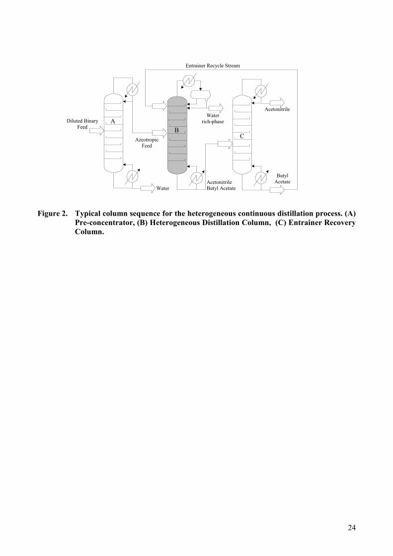
24
Diluted Binary
Feed
Water
Acetonitrile Butyl Acetate
Azeotropic Feed
Water
rich-phase
Acetonitrile
Butyl
Acetate
Entrainer Recycle Stream
A
B C
Figure 2. Typical column sequence for the heterogeneous continuous distillation process. (A)
Pre-concentrator, (B) Heterogeneous Distillation Column, (C) Entrainer Recovery
Column.

25
FE, xE
y1
x0
W, xW
Rectifying Section
FF, xF
D, xD
Stripping Section
Extractive Section
P, xD
[5,6,7]
[1,2,3,5,6]
[4,7]
[1]
[3,4]
[2]
[6]
0
1
N
Figure 3. Superstructure for the heterogeneous distillation column considering all
possibilities for both the entrainer recycle and the main azeotropic feed.

26
V, y1
LG, xG
x0
(FED,xE)
LI, xI
LII, xD
LR
[c] [b]
[d] [a]
xR
D, xD
L0
(FEI,xE)
(FET,xE)
(FFT,xF) P, xD
LIIR, xD
Figure 4. Combined options for entrainer recycle stream and the main azeotropic feed
stream in the top part of the heterogeneous column considering that they can be
supplied to the decanter or mixed with the reflux.

27
rectifying profiles
stripping profiles
total mass balance
xT
liquid –liquid tie-line
xI
xD
xxW
Figure 5. Map of rectifying composition profiles computed from several xR points, and the
stripping composition profile computed from xW, for the heterogeneous continuous
distillation (configuration 1).

28
SxW
rectifying profiles
stripping profiles
total balance line
extractive profiles
xT
xD
SS
liquid –liquid tie-line
xI
Figure 6. Rectifying, extractive, and stripping liquid composition profiles for the
heterogeneous extractive continuous distillation process (configuration 2).

29
stripping profiles
xo valid line
extractive profiles
Sn
xW
xT
xD
total mass balance
xI
liquid –liquid tie-line
x0D
x0I
Figure 7. Stripping liquid composition profile and map of extractive composition profiles for
heterogeneous distillation (configuration 3).

30
x0I
x0D
xI
xD
Figure 8. Projection of the valid line of x0 toward point xF for column configuration 4.

31
xo line FE=5, R=10
Stripping profile FE=5, R=10
xW
xD
xI
total mass balance
liquid –liquid tie-line
x0D
x0I
xT
VARIANT A
FE=5, R=10
Part of figure 9

32
xo line FE=5, R=30
Stripping profile FE=5, R=30
xW
xD
xI
total mass balance
liquid –liquid tie-line
xT
x0D
x0I
VARIANT B
FE=5, R=30
Part of figure 9

33
VARIANT A
FE=30, R=10
xo line FE=30, R=10
Stripping profile FE=30, R=10
xW
xD
xI
total mass balance
liquid –liquid tie-line
x0D
x0I
Figure 9. Stripping composition profile and line of valid value of x0 for variants A, B and C
for column configuration 4.

34
xT
stripping profiles
extractive profiles
decanter mass balance
xW
xD
xG
yT
total mass balance
liquid –liquid tie-line
xI
Figure 10. Stripping liquid composition profile and map of extractive composition profiles for
feeding the entrainer recycled stream into the decanter, and the main azeotropic
feed at an intermediate point of the column (configuration 5).

35
yT
xG
xW
xD
xT
xI
stripping profiles
extractive profiles
total mass balance
liquid –liquid tie-line
decanter mass balance
P+FED
Figure 11. Stripping and extractive composition profiles when the main azeotropic stream is
fed at intermediate point of the column, and both the entrainer recycle stream and
a portion of distillate are sent to the decanter (configuration 6).

36
xo line FE= 2, R= 10
yT
xG
xW
xT
xD
xI
stripping profiles
decanter mass balance
liquid –liquid tie-line
total mass balance
VARIANT A
FE=2, R=10
x0D
x0I
Part of figure 12

37
xo line FE= 6.5, R= 30
yT
xG
xT
xD
xI
stripping profiles
decanter mass balance
liquid –liquid tie-line
total mass balance
xW
x0D
x0I
VARIANT B
FE=6.5, R=30
Figure 12. Stripping composition profile for column configuration 7 considering two
operating conditions: Variant A (FE=2, R=10) and Variant B (FE=6.5, R=30).

38
TABLE CAPTION
Table 1. Binary coefficients for calculation of phase equilibria by using NRTL model
Table 2. Operating conditions for the heterogeneous extractive continuous distillation configurations

39
Table 1. Binary coefficients for calculation of phase equilibria by using NRTL model
L/L/V Aij
[cal/mol]
Aji
[cal/mol] αij 298K
L/L
Aij
[cal/mol]
Aji
[cal/mol] αij
A – B -236.4 1796.4 0.1 A – B 440.83 865.18 0.2
A – C 1710.94 -1180.02 0.1 A – C -212.12 -177.67 0.2
B – C 4696.44 -1114.22 0.1 B – C 2865.4 477.67 0.2

40
Table 2. Operating conditions for the heterogeneous extractive continuous distillation configurations.
[Configuration] and variant
Operating
parameters [1] [2] [3] [4] A [4] B [4] C [5] [6] [7] B
FFI (mol.s-1) 1.0 0.0 1.0 0.0
FFT (mol.s-1) 0.0 1.0 0.0 1.0
xF [0.6743; 0.3257; 0.0000]*
FEI (mol.s-1) 5.0 0.0
FET (mol.s-1) 0.0 5.0 30.0 0.0
FED (mol.s-1) 0.0 2.0 6.5
xE [0.0; 0.0; 1.0]*
FT (mol.s-1) 6.0 31.0 3.0 7.5
xT [0.1124; 0.0543; 0.8333]* [0.0217; 0.0105; 0.9677]* [0.2248; 0.1087; 0.6667]* [0.2143; 0.1505; 0.6351]* [0.0899; 0.0434; 0.8667]*
D (mol.s-1) 0.32
P (mol.s-1) 0.0 0.15 0
xD [0.0058; 0.9900; 0.0041]*
xI [0.0802; 0.1045; 0.8153]*
W (mol.s-1) 5.68 30.68 2.68 7.18
xW [0.1184; 0.0016; 0.8800]* [0.0219; 0.0003; 0.9778] [0.2509; 0.0033; 0.7458]* [0.0936; 0.0012; 0.9051]*
V (mol.s-1) 3.52 9.92 3.52 1.52 3.42
LG (mol.s-1) 3.52 9.92 3.52 3.52 3.67 9.92
ωωωωmax 0.9091 0.9677 0.9091 0.9091 0.9128 0.9677
LR (mol.s-1) 3.2 9.6 3.2 9.6
LE (mol.s-1) - 8.2 - - - 3.2 -
Lw (mol.s-1) 9.2 15.6 34.2 4.2 10.6
R 10.0 30.0 10.0 30.0

41
[Configuration] and variant
Operating
parameters [1] [2] [3] [4] A [4] B
FFI (mol.s-1) 1.0 0.0
FFT (mol.s-1) 0.0 1.0
xF [0.6743; 0.3257; 0.0000]*
FEI (mol.s-1) 5.0
FET (mol.s-1) 0.0 5.0
FED (mol.s-1) 0.0
xE [0.0; 0.0; 1.0]*
FT (mol.s-1) 6.0
xT [0.1124; 0.0543; 0.8333]* [0.0217; 0.0105; 0.9677]*
D (mol.s-1) 0.32
P (mol.s-1) 0.0
xD [0.0058; 0.9900; 0.0041]*
xI [0.0802; 0.1045; 0.8153]*
W (mol.s-1) 5.68
xW [0.1184; 0.0016; 0.8800]* [0.0219; 0.0003; 0.9778]
V (mol.s-1) 3.52 9.92
LG (mol.s-1) 3.52 9.92
ωωωωmax 0.9091 0.9677
LR (mol.s-1) 3.2 9.6
LE (mol.s-1) - 8.2 - -
Lw (mol.s-1) 9.2 15.6
R 10.0 30.0
*molar composition vector order is [acetonitrile; water; butyl acetate]