SUPERHEATED STEAM DISTILLATION FOR TREATMENT ...
122
Faculty of Science and Technology MASTER’S THESIS Study program/ Specialization: Environmental Technology/ Offshore Environmental Engineering Spring semester, 2014 Restricted access Writer: MATTHEW WINTERBOURNE ………………………………………… (Writer’s signature) Faculty supervisor: Professor Torleiv Bilstad External supervisor(s): Trond Aarestrup Thesis title: SUPERHEATED STEAM DISTILLATION FOR TREATMENT OF DRILL CUTTINGS CONTAMINATED WITH OIL BASED DRILLING FLUIDS Credits (ECTS): 30 ECTS Key words: Superheated, steam, distillation, offshore, drill cuttings, treatment, oil, gas, environmental discharge, retained oil on cuttings, environment al regulations, Dalton’s Law of Partial Pressures, Universal Gas Law, temperature, boiling point, immiscible, miscible, mixtures, vapor pressure, extraction Pages: 85 + enclosure: 23 Stavanger, June 26, 2014
-
Upload
khangminh22 -
Category
Documents
-
view
2 -
download
0
Transcript of SUPERHEATED STEAM DISTILLATION FOR TREATMENT ...

Faculty of Science and Technology
MASTER’S THESIS
Study program/ Specialization:
Environmental Technology/
Offshore Environmental Engineering
Spring semester, 2014
Restricted access
Writer:
MATTHEW WINTERBOURNE
…………………………………………
(Writer’s signature)
Faculty supervisor: Professor Torleiv Bilstad
External supervisor(s): Trond Aarestrup
Thesis title:
SUPERHEATED STEAM DISTILLATION FOR TREATMENT OF DRILL CUTTINGS
CONTAMINATED WITH OIL BASED DRILLING FLUIDS
Credits (ECTS): 30 ECTS
Key words:
Superheated, steam, distillation, offshore, drill
cuttings, treatment, oil, gas, environmental
discharge, retained oil on cuttings,
environmental regulations, Dalton’s Law of
Partial Pressures, Universal Gas Law,
temperature, boiling point, immiscible,
miscible, mixtures, vapor pressure, extraction
Pages: 85
+ enclosure: 23
Stavanger, June 26, 2014

SUPERHEATED STEAM DISTILLATION FOR
TREATMENT OF DRILL CUTTINGS
CONTAMINATED WITH OIL BASED DRILLING
FLUIDS
MATTHEW WINTERBOURNE
FACULTY OF SCIENCE AND TECHNOLOGY
DEPARTMENT OF MATHEMATICS AND NATURAL SCIENCE
OFFSHORE ENVIRONMENTAL ENGINEERING
2014
i
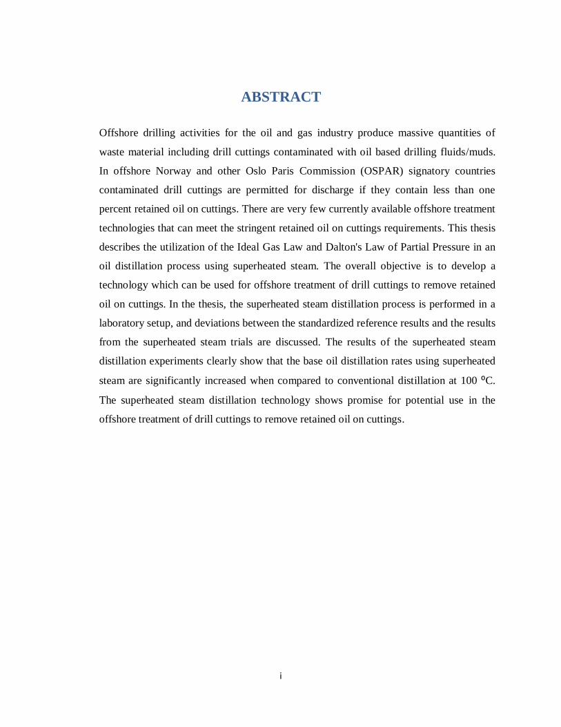
ABSTRACT
Offshore drilling activities for the oil and gas industry produce massive quantities of
waste material including drill cuttings contaminated with oil based drilling fluids/muds.
In offshore Norway and other Oslo Paris Commission (OSPAR) signatory countries
contaminated drill cuttings are permitted for discharge if they contain less than one
percent retained oil on cuttings. There are very few currently available offshore treatment
technologies that can meet the stringent retained oil on cuttings requirements. This thesis
describes the utilization of the Ideal Gas Law and Dalton's Law of Partial Pressure in an
oil distillation process using superheated steam. The overall objective is to develop a
technology which can be used for offshore treatment of drill cuttings to remove retained
oil on cuttings. In the thesis, the superheated steam distillation process is performed in a
laboratory setup, and deviations between the standardized reference results and the results
from the superheated steam trials are discussed. The results of the superheated steam
distillation experiments clearly show that the base oil distillation rates using superheated
steam are significantly increased when compared to conventional distillation at 100 ⁰C.
The superheated steam distillation technology shows promise for potential use in the
offshore treatment of drill cuttings to remove retained oil on cuttings.

ii
ACKNOWLEDGEMENT
I would like to express my deepest gratitude for the support and guidance provided by Trond
Aarestrup, Torleiv Bilstad and Evgenia Protasova throughout the entire process of writing my
master’s thesis. I would also like to acknowledge my girlfriend Ingrid Midtun for keeping me on
task and motivated during my thesis project. Last but not least I would like to acknowledge my
parents Gail and Tom Winterbourne for their unwavering support and love without them none of
this would have been possible.
iii
TABLE OF CONTENTS
ABSTRACT ............................................................................................................................................. i
ACKNOWLEDGEMENT ....................................................................................................................... ii
TABLE OF CONTENTS........................................................................................................................ iii
LIST OF FIGURES ................................................................................................................................ vi
LIST OF TABLES ................................................................................................................................. ix
NOMENCLATURE ................................................................................................................................ x
ABBREVIATIONS ............................................................................................................................... xii
1 CHAPTER ONE: INTRODUCTION ............................................................................................... 1
1.1 Problem of Offshore Drill Cuttings Contaminated with Oil Based Drilling Fluids/Muds ........... 1
1.2 Use of Superheated Steam Distillation for Offshore Treatment of Contaminated Drill Cuttings. 3
1.3 Objectives ................................................................................................................................ 3
2 CHAPTER TWO: OFFSHORE DRILL CUTTINGS THEORY ....................................................... 4
2.1 Offshore Drilling Process ......................................................................................................... 4
2.2 Drilling Muds/ Fluids ............................................................................................................... 6
2.3 Aqueous versus Non-Aqueous Drilling Muds/Fluids .............................................................. 10
2.4 Drill Cuttings ......................................................................................................................... 12
2.5 Drill Cutting Environmental Discharge Regulations ............................................................... 14
2.5.1 Norway and the North Sea .............................................................................................. 14
2.5.2 United States and the Gulf of Mexico ............................................................................. 15
2.5.3 Canada ........................................................................................................................... 16
2.5.4 Australia ......................................................................................................................... 16
2.5.5 Brazil ............................................................................................................................. 17
2.6 Conventional Drill Cuttings Treatment Technology ................................................................ 17
2.6.1 Shale shakers .................................................................................................................. 19
2.6.2 Hydro-cyclones .............................................................................................................. 21
2.6.3 Decanting Centrifuges .................................................................................................... 22
2.6.4 Cuttings Dryers .............................................................................................................. 23
2.7 Transport of Cuttings Onshore for Treatment ......................................................................... 24
iv
2.7.1 Rotary Kiln Thermal Desorption ..................................................................................... 26
2.7.2 Land Treatment Bioremediation ..................................................................................... 26
2.7.3 Solidification and Stabilization ....................................................................................... 27
2.8 Emerging Drill Cuttings Treatment Technology ..................................................................... 27
2.8.1 Thermomechanical Cuttings Cleaner (TCC) ................................................................... 27
2.8.2 Microwave Cuttings Treatment ....................................................................................... 29
2.8.3 Supercritical C Extraction .......................................................................................... 30
2.8.4 Liquefied Gas Extraction ................................................................................................ 30
2.8.5 Chemical Washing and Surfactants ................................................................................. 30
2.9 Cuttings Reinjection ............................................................................................................... 31
3 CHAPTER THREE: STEAM DISTILLATION THEORY............................................................. 32
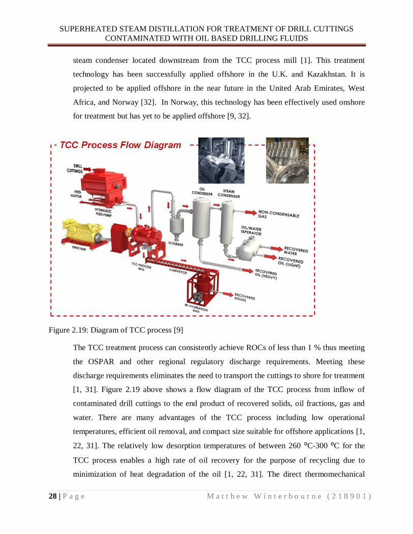
3.1 Temperature and Vapor Pressure Relationship ........................................................................ 32
3.2 Enthalpy of Vaporization ....................................................................................................... 33
3.3 Ideal Gas Law ........................................................................................................................ 35
3.4 Dalton’s Law of Partial Pressure ............................................................................................ 36
3.5 Distillation of Liquid Mixtures ............................................................................................... 37
3.5.1 Miscible Mixtures........................................................................................................... 37
3.5.2 Immiscible Mixtures ....................................................................................................... 39
3.6 Steam Distillation Description ................................................................................................ 41
3.7 History and Applications of Steam Distillation ....................................................................... 42
3.7.1 Fragrance Industry .......................................................................................................... 43
3.7.2 Food Industry ................................................................................................................. 43
3.7.3 Petrochemical Industry ................................................................................................... 43
3.8 Superheated Steam Uses and Applications Including Distillation ............................................ 43
4 CHAPTER FOUR: EXPERIMENTAL MATERIALS, METHODS, AND RESULTS ................... 45
4.1 Information on Oil Based Drilling Fluids Used for Experiments ............................................. 45
4.1.1 Chemical Composition and Molecular Formula of Base Oils .......................................... 45
4.1.2 Factors Affecting Vapor Pressure and Boiling Point of the Base Oils .............................. 47
4.1.3 SIPDRILL 2/0 ................................................................................................................ 48
4.1.4 CLAIRSOL NS .............................................................................................................. 48
4.2 Standardized Vapor Pressure versus Temperature Experiment ................................................ 49
4.2.1 Methods and Materials ................................................................................................... 50

v
4.2.2 Results ........................................................................................................................... 54
4.3 Superheated Steam Distillation Experiment ............................................................................ 58
4.3.1 Methods and Materials ................................................................................................... 58
4.3.2 Results ........................................................................................................................... 66
5 CHAPTER FIVE: DISCUSSION................................................................................................... 73
5.1 Standardized Vapor Pressure versus Temperature Discussion ................................................. 73
5.1.1 Phase I Experimental Results Discussion ........................................................................ 73
5.1.2 Phase II Experimental Results Discussion ....................................................................... 73
5.2 Superheated Steam Distillation Discussion ............................................................................. 74
5.2.1 Sipdrill 2/0 Experimental Results Discussion .................................................................. 74
5.2.2 Experiment One versus Experiment Two Discussion ...................................................... 75
5.2.3 Clairsol NS Experimental Results Discussion ................................................................. 76
5.2.4 Base Oil Molecular Weight Discussion ........................................................................... 77
5.2.5 Distillation Rate Discussion ............................................................................................ 78
5.2.6 Density Experiment Discussion ...................................................................................... 78
6 CHAPTER SIX: CONCLUSIONS AND FUTURE STUDIES ....................................................... 79
6.1 Conclusions from Standardized Vapor Pressure versus Temperature Rota Vapor Experiments 79
6.2 Conclusions from Superheated Steam Distillation Experiments .............................................. 79
6.3 Future Studies ........................................................................................................................ 79
REFERENCES...................................................................................................................................... 81
Appendix-1 ............................................................................................................................................ 86
Appendix-2 ............................................................................................................................................ 94
Appendix-3 ......................................................................................................................................... 102
Appendix-4 ......................................................................................................................................... 104
vi
LIST OF FIGURES Figure 1.1: Diagram showing the composition of hazardous waste produced and transported to shore from offshore
activities on the Norwegian shelf totaling 314,000 tons in 2012……………………………………………………...1
Figure 1.2: Graph showing tons of hazardous waste produced and transported to shore per year from oil and gas
activities on the Norwegian shelf………………………………………………………………………………………2
Figure 2.1: Drilling rig schematic……………………………………………………………………………………..5
Figure 2.2: Examples of offshore drill rigs………………………………………………………………………….....6
Figure 2.3: Illustration of down-hole drilling mud/fluid operations…………………………………………………...7
Figure 2.4: Classification of drilling muds/fluids……………………………………………………………………...7
Figure 2.5: Diagram of typical aqueous drilling mud/fluid on a weight percent basis………………………………...8
Figure 2.6: Diagram of typical non-aqueous drilling muds/fluids on a weight percent basis…………………………9
Figure 2.7: Clean drill cutting shown under 10 X microscope……………………………………………………….12
Figure 2.8: Drill cuttings exposed to oil based mud/fluid………………………………………………………….…13
Figure 2.9: Flow chart of drilling fluid and conventional drill cuttings separation technology……………………...18
Figure 2.10: Example of a conventional drill cuttings treatment system……………………………………………..19
Figure 2.11: Picture of shale shaker produced by MI-SWACO……………………………………………………...20
Figure 2.12: Schematic of shale shaker operational principle………………………………………………………..20
Figure 2.13: Schematic drawing of hydro-cyclone working principle……………………………………………….21
Figure 2.14: Illustration of hydro-cyclone inflow (feed) ,waste stream (Discard), and recycle stream (save)………22
Figure 2.15: Schematic drawing of decanting centrifuge working principle…………………………………………22
Figure 2.16: Schematic of vertical cuttings dryer working principle…………………………………………………23
Figure 2.17: Map showing offshore drill cuttings production platforms in red and onshore drill cutting treatment
bases in green…………………………………………………………………………………………………………25
Figure 2.18: Onshore rotary kiln thermal desorption unit for treatment of drill cuttings…………………………….26
Figure 2.19: Diagram of TCC process………………………………………………………………………………..28
Figure 2.20: Working principle drawing of experimental microwave drill cuttings treatment system……………...29
Figure 2.21: Illustration of drill cuttings reinjection system………………………………………………………….31
Figure 3.1: Illustration of increased vapor pressure due to heating………………………………………………….32
Figure 3.2: Graphical representation of the relationship between temperature and vapor pressure of a liquid…........33
vii
Figure 3.3: Linearized plot of vapor pressure versus temperature……………………………………………………34
Figure 3.4: Example of a steam distillation setup…………………………………………………………………….42
Figure 3.5: Relationship of pressure versus temperature for water and steam……………………………………….44
Figure 4.1: Structural representation of alkanes……………………………………………………………………...46
Figure 4.2: Photo of vacuum pump and control made by Vacuubrand for VWR model CVC 3000………………50
Figure 4.3: Photo of phase I rotary evaporator experimental setup…………………………………………………..51
Figure 4.4: Photo of experimental setup with high powered two stage vacuum pump………………………………52
Figure 4.5: Photo of pressure gauge (Thyracont Model VD85) associated with the high powered two stage vacuum
pump…………………………………………………………………………………………………………………..53
Figure 4.6: Photo of phase II experimental setup with long temperature probe……………………………………...53
Figure 4.7: Phase I plot of vapor pressure versus boiling point bath temperature for the base oil Sipdrill 2/0………54
Figure 4.8: Plot of phase I vapor pressure versus boiling point bath temperature for the base oil Clarisol NS……...55
Figure 4.9: Plot of phase I versus phase II results for the base oil Sipdrill 2/0………………………………………55
Figure 4.10: Plot of phase I versus phase II results for the base oil Clairsol NS……………………………………..56
Figure 4.11: Linearized plot of phase I and phase II results for Sipdrill 2/0…………………………………………57
Figure 4.12: Linearized plot of phase I and phase II results for Clarisol NS…………………………………………57
Figure 4.13: Photo of experimental setup for superheated steam distillation………………………………………...59
Figure 4.14: Photo of steam production unit in operation……………………………………………………………60
Figure 4.15: Photo of steam superheating unit with heat gun and temperature control unit for Heidolph 30001 hot
plate…………………………………………………………………………………………………………………...61
Figure 4.16: Photo of distillation unit………………………………………………………………………………...62
Figure 4.17: Photo of wire mesh housing built around distillation unit……………………………………………...63
Figure 4.18: Photo of wire mesh and aluminum foil housing built around distillation unit with heat gun…………..63
Figure 4.19: Photo of condensing unit of experimental setup………………………………………………………..64
Figure 4.20: Photo of graduated cylinder used to capture condensed vapors………………………………………..64
Figure 4.21: Photo of final experimental setup during operation…………………………………………………….65
Figure 4.22: Plot of Sipdrill 2/0 vapor pressure versus temperature results for superheated steam experiments 1 and 2
compared to standard Rota-vapor results……………………………………………………………………………..67
Figure 4.23: Plot of Clairsol NS vapor pressure versus temperature results for superheated steam experiments 1 and
2 compared to standard Rota-vapor results…………………………………………………………………………...67

viii
Figure 4.24: Plot of Sipdrill 2/0 experiment one results showing vapor pressure variation assuming different carbon
chain lengths………………………………………………………………………………………………………….68
Figure 4.25: Plot of Sipdrill 2/0 experiment two results showing vapor pressure variation assuming different carbon
chain lengths………………………………………………………………………………………………………….68
Figure 4.26: Plot of Clairsol NS experiment one results showing vapor pressure variation assuming different carbon
chain lengths…………………………………………………………………………………………………………69
Figure 4.27: Plot of Clairsol NS experiment two results showing vapor pressure variation assuming different carbon
chain lengths………………………………………………………………………………………………………….70
Figure 4.28: Plot of Sipdrill 2/0 distillation rates expressed as the volume ratio of oil/water produced in the distillate
as a function of temperature for experiments one and two…………………………………………………………...71
Figure 4.29: Plot of Clairsol NS distillation rates expressed as the volume ratio of oil/water produced in the distillate
as a function of temperature for experiments one and two…………………………………………………………...71

ix
LIST OF TABLES
Table 2.1 Distribution of drill cuttings waste disposal per year in tons for offshore Norway………………………24
Table 4.1: Results of density experiments for Sipdrill 2/0…………………………………………………………...72
Table 4.2: Results of density experiments for Clairsol NS…………………………………………………………...72

x
NOMENCLATURE
⁰C Temperature, degrees Celsius
C Carbon Dioxide
ΔHvap Enthalpy of Vaporization
ln P Natural Log of Vapor Pressure
Kelvin (1/T) Absolute Temperature in Kelvin
R Universal Gas Constant [8.314 J/(mol·K)]
C Y-intercept
T Temperature in Kelvin,
P Vapor Pressure
V Volume
n Number of moles
Pt Total Vapor Pressure above the Liquid Mixture
XA Mole fraction of Component “A”
nA Number of moles of “A”
nt Total Number of Moles
Partial Pressure of Component A ,
Total Vapor Pressure
Independent vapor pressure of pure component “A”
Independent vapor pressure of pure component “B”
Mass of Steam in the Vapor
Mass of oil in the vapor
Partial Pressure of steam
Partial Pressure of Oil
Molecular Weight of Steam
Molecular Weight of Oil
Mass Ratio of Oil Production Per Unit Water Production
xi
C Represents Carbons
H Represents Hydrogen
n Number of Carbons
mbar Millibar

xii
ABBREVIATIONS OSPAR Oslo Paris Commission
PAH Polycyclic Aromatic Hydrocarbons
SBM Synthetic Based Muds/Fluids
ROC Retained Oil on Cuttings
OCNS Offshore Chemical Notification Scheme
HOCNF Harmonized Offshore Chemical Notification Format
HQ Hazard Quotient
CHARM Chemical Hazard and Risk Management
BCF Bioaccumulation Factor
Acute L(E) Acute Toxicity Lethal Effect Concentration for 50 % of Test Subjects
USEPA United States Environmental Protection Agency
NPDES National Pollutant Discharge Elimination System
WBM Water Based Mud/Fluid
SBM Synthetic Based Mud/Fluid
OBM Oil Based Mud/Fluid
LC50 Acute Toxicity Lethal Concentration for 50 % of Test Subjects
EMOBM Enhanced Mineral Oil Based Mud/Fluid
EMP Environmental Management Plan
IBAMA Brazilian Institute of Environment and Renewable Natural Resources
OECD Organization for Economic Cooperation and Development
log Pow Bioaccumulation Potential
TCC Thermomechanical Cuttings Cleaner
BTEX Benzene, Toluene, Ethylbenzene, and Xylenes
MSDS Material Safety Data Sheet
GC-MS Gas chromatography-mass spectrometry
SUPERHEATED STEAM DISTILLATION FOR TREATMENT OF DRILL CUTTINGS
CONTAMINATED WITH OIL BASED DRILLING FLUIDS
1 | P a g e M a t t h e w W i n t e r b o u r n e ( 2 1 8 9 0 1 )
1 CHAPTER ONE: INTRODUCTION
1.1 Problem of Offshore Drill Cuttings Contaminated with Oil Based
Drilling Fluids/Muds
Offshore drilling activities for the oil and gas industry produce massive quantities of
waste material including drill cuttings contaminated with oil based drilling fluids/muds.
When drill cuttings become contaminated with oil based drilling fluids/muds they are
considered hazardous waste. All hazardous waste must be handled and disposed of
according to regional environmental regulatory standards. In offshore Norway and other
Oslo Paris Commission (OSPAR) signatory countries contaminated drill cuttings are
permitted for discharge if they contain less than one percent retained oil on cuttings [1].
There are very few currently available offshore treatment technologies that can meet the
stringent retained oil on cuttings requirements [1]. As a result, the contaminated drill
cuttings must be either transported to shore for treatment or reinjected into subterranean
geological formations for disposal [1]. According to the Norwegian Environment
Agency, in the year 2012 over 314,000 tons of hazardous waste was transported to shore
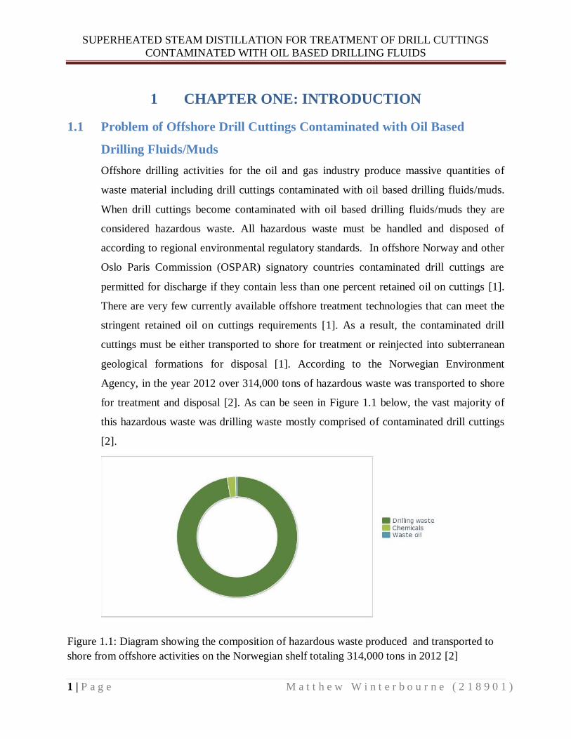
for treatment and disposal [2]. As can be seen in Figure 1.1 below, the vast majority of
this hazardous waste was drilling waste mostly comprised of contaminated drill cuttings
[2].
Figure 1.1: Diagram showing the composition of hazardous waste produced and transported to
shore from offshore activities on the Norwegian shelf totaling 314,000 tons in 2012 [2]

SUPERHEATED STEAM DISTILLATION FOR TREATMENT OF DRILL CUTTINGS
CONTAMINATED WITH OIL BASED DRILLING FLUIDS
2 | P a g e M a t t h e w W i n t e r b o u r n e ( 2 1 8 9 0 1 )
Between the years of 1997-2012 there has been a tremendous increase in the amount of
hazardous waste transported to shore in Norway as can be seen in Figure 1.2 below. This
increase in hazardous waste transfers to shore is due to several operational factors. The
driving factors include the increased use of oil based drilling fluids and problems
encountered with reinjection of contaminated drill cuttings into geological formations[2].
Figure 1.2: Graph showing tons of hazardous waste produced and transported to shore per year
from oil and gas activities on the Norwegian shelf [3]
Transport of contaminated drill cuttings to shore is both expensive and has significant
negative impacts on the environment. The equipment and ships used to transport the
waste produce large quantities of greenhouse gasses as well as nitrogen oxides, sulphur
oxides, ozone, and other air pollutants [3]. There is also a risk of spills and accidents
which could cause environmental damage to ecologically sensitive areas [3]. Transport to
shore involves many crane lifts and other potentially risky activities that could cause
health and safety impacts to personnel [3].
Reinjection poses its own set of risks including fracturing of the geological formation and
leakage of the contaminated drill cuttings and fluids into the environment [2]. In addition,
discharge of contaminated drill cuttings that do not meet the one percent retained oil on

SUPERHEATED STEAM DISTILLATION FOR TREATMENT OF DRILL CUTTINGS
CONTAMINATED WITH OIL BASED DRILLING FLUIDS
3 | P a g e M a t t h e w W i n t e r b o u r n e ( 2 1 8 9 0 1 )
cuttings requirements is both illegal and damaging to the benthic communities [4, 5]. The
effects of discharging contaminated drill cuttings are two fold and include both chemical
toxicity as well as physical burial of benthic communities [4, 5]. The development of an
effective offshore treatment technology that can meet the stringent environmental
retained oil on cuttings requirements is of utmost importance.
1.2 Use of Superheated Steam Distillation for Offshore Treatment of
Contaminated Drill Cuttings
There is limited published material on the use of superheated steam for distillation and it
has yet to be extensively investigated for extraction of oil based drilling fluids from drill
cuttings. Superheated steam distillation is a technology that could potentially be applied
offshore for the treatment of contaminated drill cuttings. This technology has many
advantages over conventional steam distillation including high thermal efficiency, high
steam dryness, low density, high heat storage capacity, lack of condensate formation, and
higher achievable distillation temperatures [6]. The predicted superheated steam
distillation rates calculated using the Ideal Gas Law and Dalton’s Law of Partial Pressure
are significantly higher than conventional steam distillation rates. The development of
such a technology could help solve the increasing problem of how to treat offshore
contaminated drill cuttings in order to meet stringent environmental discharge
regulations.
1.3 Objectives
This thesis describes the utilization of the Ideal Gas Law and Dalton's Law of Partial
Pressure in an oil distillation process using superheated steam. The overall objective is to
develop a technology which can be used for offshore treatment of drill cuttings to remove
retained oil on cuttings. In the thesis, the superheated steam distillation process is
performed in a laboratory setup, and deviations between the standardized reference
results and the results from the superheated steam trials are discussed. The reason why it
is of interest to investigate the use of superheated steam in such a process is because
according to the gas laws, oil distillation rates will be significantly increased compared to
normal steam distillation at 100 ⁰C.

SUPERHEATED STEAM DISTILLATION FOR TREATMENT OF DRILL CUTTINGS
CONTAMINATED WITH OIL BASED DRILLING FLUIDS
4 | P a g e M a t t h e w W i n t e r b o u r n e ( 2 1 8 9 0 1 )
2 CHAPTER TWO: OFFSHORE DRILL CUTTINGS
THEORY
2.1 Offshore Drilling Process
Drilling a well offshore involves several key components such as the drill rig, drill bit,
drilling fluids, and associated drill cuttings. Typically wells drilled offshore utilize a
continuous rotary drilling process whereby a rotating drill bit crushes and breaks rock at
the bottom of the hole. The continuous process is facilitated by the use of specially
designed drilling muds/fluids which carry away cuttings and lubricate the drill bit. The
offshore drill rig is a self-contained unit consisting of all machinery and equipment
necessary to drill a well. A typical offshore drill rig contains mud tanks, mud pump, shale
shaker, drilling derrick, draw-work, top drive, drill string, drill pipe, and associated
drilling equipment. Figure 2.1 below shows a basic drilling rig schematic with typical rig
equipment illustrated. The drilling derrick is the pyramidal structure that supports the
drill string and block and tackle system which is the main lifting system for drilling
operations. The draw-work is a large mechanical reel that is used to hoist cables through
the block and tackle system for heavy lifting operations such as adding drill pipe to the
drill string. The top drive rotates the drill string which transfers the rotational energy
down to the drill bit. The shale shaker is the primary treatment system used to separate
drill cuttings from drill mud/fluid. The drill cuttings then undergo further treatment to
remove contaminants and the valuable mud/fluid is recycled to the drilling process [7].

SUPERHEATED STEAM DISTILLATION FOR TREATMENT OF DRILL CUTTINGS
CONTAMINATED WITH OIL BASED DRILLING FLUIDS
5 | P a g e M a t t h e w W i n t e r b o u r n e ( 2 1 8 9 0 1 )
Figure 2.1: Drilling rig schematic [7]
Offshore drill rigs come in several different forms depending on operational needs and
environmental conditions. Figure 2.2 shows several examples of typical offshore drilling
rigs. The mobile drill rigs such as jack-up, drill-ship, and semisubmersible are generally
used for exploration well drilling while fixed platforms are used for development well
drilling [7]. A key factor differentiating offshore drill rigs from onshore drill rigs is the
limited space and weight restrictions offshore. Onshore operations have essentially no
space or weight restrictions and can therefore house extensive process and treatment
facilities. Offshore facilities in contrast must be designed to minimize footprint and
weight while maximizing efficiency and output. These design restrictions limit the
processing capability of offshore facilities often leading to product or waste being
shipped or piped to shore for further processing to meet requirements [1].

SUPERHEATED STEAM DISTILLATION FOR TREATMENT OF DRILL CUTTINGS
CONTAMINATED WITH OIL BASED DRILLING FLUIDS
6 | P a g e M a t t h e w W i n t e r b o u r n e ( 2 1 8 9 0 1 )
Figure 2.2: Examples of offshore drill rigs [7]
2.2 Drilling Muds/ Fluids
According to Encyclopaedia Britannica, the terms drilling mud and drilling fluid refer to
the same thing and can be used interchangeably [8]. Therefore, throughout this thesis the
terms drilling mud and drilling fluid refer to the same thing and are used interchangeably.
Drilling muds/fluids play an integral role in the offshore drilling process. The key
functions that they perform include cooling and lubrication of the drill bit/drill string,
transport and suspension of drill cuttings, stabilization of wellbore, controlling formation
pressure and preventing blowout, providing hydraulic energy transfer, and minimization
of formation damage [9]. Figure 2.3 below illustrates how drilling muds/fluids are
circulated through the drill string and up the well annulus in order to perform key
operational functions.

SUPERHEATED STEAM DISTILLATION FOR TREATMENT OF DRILL CUTTINGS
CONTAMINATED WITH OIL BASED DRILLING FLUIDS
7 | P a g e M a t t h e w W i n t e r b o u r n e ( 2 1 8 9 0 1 )
Figure 2.3: Illustration of down-hole drilling mud/fluid operations [10]
Figure 2.4: Classification of drilling muds/fluids [9].
Drilling muds/fluids are classified based on the composition of their base fluid either aqueous or
non-aqueous as shown in Figure 2.4. The aqueous category of drilling fluids/muds includes all
water based muds/fluids. Water based muds/fluids are made up of water mixed with weighting
agents bentonite clay and barite. Chemicals such as thinners, filtration control agents, lubrication
agents and others are added to water based mud/fluid to enhance drilling performance [10]. On a
weight percent basis, a typical water based mud/fluid will contain 76 % water, 15 % barite, 7 %
bentonite, and 1 % salts and other additives as shown in Figure 2.5 below [10].

SUPERHEATED STEAM DISTILLATION FOR TREATMENT OF DRILL CUTTINGS
CONTAMINATED WITH OIL BASED DRILLING FLUIDS
8 | P a g e M a t t h e w W i n t e r b o u r n e ( 2 1 8 9 0 1 )
Figure 2.5: Diagram of typical aqueous drilling mud/fluid on a weight percent basis [11]
Non-aqueous drilling fluids/muds are essentially emulsions of oil, diesel, mineral oil, or
synthetic hydrocarbons. Figure 2.6 below shows the typical composition of a non-
aqueous drilling fluid/mud on a weight percent basis. These non-aqueous fluids/muds are
broken down into three distinct groups based on aromatic content. Oil, diesel, and
conventional mineral oil based muds/fluids typically have high aromatic content and are
placed in group I. Low toxicity mineral oil based muds/fluids typically have medium
aromatic content and are placed in group II. Muds/fluids with low aromatic content for
example synthetic hydrocarbons and specially formulated mineral oils are placed in
group III [1].

SUPERHEATED STEAM DISTILLATION FOR TREATMENT OF DRILL CUTTINGS
CONTAMINATED WITH OIL BASED DRILLING FLUIDS
9 | P a g e M a t t h e w W i n t e r b o u r n e ( 2 1 8 9 0 1 )
Figure 2.6: Diagram of typical non-aqueous drilling muds/fluids on a weight percent basis [11]
Group I oil based muds/fluids are made from processed crude oil. Since these muds/fluids
are sourced from crude oil they contain hydrocarbon compounds such as olefins,
paraffins, polycyclic aromatic hydrocarbons (PAHs), and aromatics. Diesel oil based
muds/fluids normally have a PAH content between 2-4 % and conventional mineral oil
contains between 1-2 % PAH [10]. These oil based muds/fluids contain highly toxic
compounds such as fluorine, phenanthrene, biphenyls, alkylated benzenes and
naphthalene [1]. Drill cuttings exposed to group I oil based mud/fluid are typically not
permitted to be discharged into the environment unless treated to remove retained oil on
cuttings [10].
Group II muds/fluids are usually made up of low toxicity mineral oils derived from crude
oil. The PAH content of group II muds/fluids are significantly lower than group I
through the use of distillation techniques [10]. These muds/fluids typically have a PAH
content of between 0.001 % to 0.35 % [10]. The lower toxicity and low PAH content of
these muds/fluids make them a good alternative to group I based muds/fluids in certain
drilling applications[10].
Group III muds/fluids have a PAH of less than 0.001 % and are typically made from
synthetic based muds/fluids(SBM) and highly processed mineral oils [10]. SBMs are
made up of synthesized hydrocarbons such as paraffins, esters, and olefins [10]. These
compounds are created from the combination of pure chemicals and therefore lack many

SUPERHEATED STEAM DISTILLATION FOR TREATMENT OF DRILL CUTTINGS
CONTAMINATED WITH OIL BASED DRILLING FLUIDS
10 | P a g e M a t t h e w W i n t e r b o u r n e ( 2 1 8 9 0 1 )
of the impurities and PAHs typically found in muds/fluids derived from processed crude
oil. Another advantage of SBMs is their higher biodegradability and lower toxicity when
compared to traditional oil based muds/fluids [1]. Some oil producing regions allow the
offshore discharge of drill cuttings exposed to SBMs due to their low inherent
environmental impacts [1]. The other Group III muds/fluids are made from highly
processed mineral oil. These muds/fluids are derived from crude oil but the advanced
processing and distillation removes most of the contaminants and PAHS [10]. The
resulting drilling fluid has many characteristics resembling synthesized paraffins [10].
2.3 Aqueous versus Non-Aqueous Drilling Muds/Fluids
Aqueous drilling muds/fluids are generally less toxic, less expensive, more
environmentally friendly, and easier to dispose of after use than non-aqueous drilling
muds/fluids. Drill cuttings exposed to aqueous drilling muds/fluids can typically be
discharged without treatment whereas cuttings exposed to non-aqueous drilling
muds/fluids often require specialized treatment before disposal [10]. Despite the
numerous environmental advantages of aqueous drilling muds/fluids they cannot fulfill
all of the specialized drilling requirements needed in the offshore environment. The
inability of aqueous drilling muds/fluids to perform optimally under certain drilling
conditions is one of the main driving forces for the use of non-aqueous muds/fluids. Even
though aqueous muds/fluids are less expensive than non-aqueous muds/fluids this cost
savings is often nullified by lack of drilling performance [10].
There are numerous examples and situations where aqueous muds/fluids simply cannot
compare to the performance of non-aqueous muds/fluids. An example is when drilling in
clay or shale where the water component of the aqueous mud/fluid will interact with
these formations and cause increased resistance to the rotation of the drill pipe [10]. Non-
aqueous muds/fluids have far superior lubricating properties which reduce friction,
prevent drill pipe from sticking to the well bore, and enhance energy transfer to the drill
bit. These lubricating functions are critical when drilling horizontal or extended reach
wells due to the increased distances and risks of fracturing the well [10]. Non-aqueous
muds/fluids perform better at high temperatures greater than 350 ⁰C and typically are

SUPERHEATED STEAM DISTILLATION FOR TREATMENT OF DRILL CUTTINGS
CONTAMINATED WITH OIL BASED DRILLING FLUIDS
11 | P a g e M a t t h e w W i n t e r b o u r n e ( 2 1 8 9 0 1 )
lighter than aqueous muds/fluids. These characteristics are critical when drilling deep
wells or in geological formations susceptible to fracturing [10]. Other advantages of non-
aqueous muds/fluids include reduced hydrate formation, shorter drilling time per well and
reduced drilling waste [10]. Hydrate formation is reduced due to the lower water content
and chemical makeup of the non-aqueous mud/fluid. The amount of time used and the
quantity of waste produced per well is reduced due to better drilling performance of non-
aqueous muds/fluids in shale and clay formations. Interactions of aqueous muds/fluids
with these formations can cause the material surrounding the borehole to go into
suspension and contribute to drilling waste. These same interactions can cause significant
time delays due to reduced drilling efficiency and friction [10]. The recycle rates of non-
aqueous muds/fluids are much higher than those of aqueous muds/fluids due to the
decomposition of polymers and other components over time in aqueous muds/fluids [9].
This decomposition is exacerbated at high temperatures and pressures, therefore making
aqueous muds/fluids unsuitable for deep drilling where these conditions are
commonplace.
A combination of both mud/fluids types is typically used when drilling offshore wells.
This is done in order to balance the environmental and economic benefits of aqueous
muds/fluids with the superior drilling properties of the non-aqueous muds/fluids [10].
When both types of muds/fluids are used; the aqueous muds/fluids are typically used in
the upper portion of the well and the non-aqueous muds/fluids are used in the lower
portions of the well [10]. Aqueous muds/fluids are used in the upper portion of the well
because this section has lower pressure and temperature thus enabling these muds/fluids
to perform optimally. Non-aqueous muds/fluids are used once the temperatures and
pressures become too great for optimum performance of aqueous muds/fluids. In addition
to the lower portions of the well, non-aqueous muds/fluids are used when drilling through
shale or clay and under high incline situations [10]. This optimization of the use of both
muds/fluids translates into cost savings as well as increased drilling performance.

SUPERHEATED STEAM DISTILLATION FOR TREATMENT OF DRILL CUTTINGS
CONTAMINATED WITH OIL BASED DRILLING FLUIDS
12 | P a g e M a t t h e w W i n t e r b o u r n e ( 2 1 8 9 0 1 )
2.4 Drill Cuttings
As with any type of drilling operation used to create a bore-hole, material must be
excavated and removed. This excavated material is what is known as drill cuttings and its
composition is dependent on the subterranean geological formations present. Drill
cuttings are formed by the rotational motion of the drill bit at the bottom of the hole
which cuts and crushes rock into small pieces [10]. These drill cuttings are put into
suspension by drilling muds/fluids and are carried up the well annulus to the drill rig.
Figure 2.7 below shows a picture of clean drill cuttings under a 10 X microscope. As can
be seen in Figure 2.7 a large proportion of the drill cuttings are made up of different types
of shale and limestone. These sedimentary rocks typically make up a large proportion of
drill cuttings because they are often found in oil bearing formations. Other components of
drill cuttings can include sand, clay, fine silts, and pieces of rock the proportion of which
is dependent on the type of formation being drilled [10].
Figure 2.7: Clean drill cutting shown under 10 X microscope [9]

SUPERHEATED STEAM DISTILLATION FOR TREATMENT OF DRILL CUTTINGS
CONTAMINATED WITH OIL BASED DRILLING FLUIDS
13 | P a g e M a t t h e w W i n t e r b o u r n e ( 2 1 8 9 0 1 )
Clean drill cuttings are considered non-hazardous and are allowed for discharge.
However, once they come into contact with formation oil or non-aqueous drilling
muds/fluids they become a hazardous waste and must be treated accordingly[9]. Figure
2.8 below shows drill cuttings that have been exposed to non-aqueous oil based drilling
mud/fluid. As can be seen in Figure 2.8 once the drill cuttings are exposed to oil based
mud/fluid they take on a dark black/grey color similar to that of oil.
Figure 2.8: Drill cuttings exposed to oil based mud/fluid [9]
The extent to which formation oil or non-aqueous mud/fluid adheres to drill cuttings
depends on many factors including the composition, particle size, and porosity of the
exposed drill cuttings. Drill cuttings with small particle size have more surface area onto
which oil or non-aqueous mud/fluid can adhere than large particle sized drill cuttings.
Certain rock types such as those with high porosity have a higher propensity for oil
adhesion. Oil or non-aqueous mud/fluid can flow into pores within the drill cuttings and
become entrapped or attached to the pore surface. The viscosity, chemical composition,
and type of formation oil or non-aqueous mud/fluid that comes into contact with drill
cuttings can also affect the amount of oil retained on cuttings. Higher viscosity drilling

SUPERHEATED STEAM DISTILLATION FOR TREATMENT OF DRILL CUTTINGS
CONTAMINATED WITH OIL BASED DRILLING FLUIDS
14 | P a g e M a t t h e w W i n t e r b o u r n e ( 2 1 8 9 0 1 )
muds/fluids have a tendency to heavily coat and stick to drill cuttings yielding a higher
amount of oil retained on drill cuttings. This high viscosity also decreases the
effectiveness of solids separation equipment allowing oil and non-aqueous mud/fluid to
follow the drill cuttings in the solid waste stream [10]. Certain ions present in oil or non-
aqueous drilling fluids can interact with charges on the surface of drill cuttings causing a
positive attraction where oil becomes attached to the surface of drill cuttings. All of these
factors discussed contribute to the amount of retained oil on cuttings (ROC). The percent
ROC is one of the main parameters that environmental regulators use to control the
discharge of drill cuttings exposed to formation oil or non-aqueous mud/fluid [1].
2.5 Drill Cutting Environmental Discharge Regulations
Environmental regulators have established discharge limits on the percent by weight of
retained oil on cuttings. These limits were established in order to prevent negative effects
on the environment. Oily drill cuttings can have several negative environmental effects
particularly impacting benthic biota. These benthic communities bear the greatest impacts
because drill cuttings tend to settle to the bottom of the ocean in piles near the offshore
discharge point. These piles of drill cuttings have both physical and chemical effects on
the native populations. The chemical effects are due to the inherent toxicity of the oil
retained on the cuttings as well as biodegradation of the oil and subsequent oxygen
depletion. The physical effects are due to burial as well as changes in material size and
composition [10]. The goal of environmental regulators is to minimize these negative
environmental effects while still enabling exploitation of valuable oil resources. The
specific limits of percent ROC and regulatory strategies vary between oil producing
regions. This is due to various reasons such as geological conditions, environmental
sensitivity, available technology, and perceived risk to the environment. The following
section summarizes key environmental regulatory standards for discharge of drill cuttings
in several oil producing regions [1].
2.5.1 Norway and the North Sea
The key regulatory drivers for discharges to the North are the Offshore Chemical
Notification Scheme (OCNS), and the Oslo Paris Commissions (OSPAR) Harmonized
Offshore Chemical Notification Format (HOCNF). The HOCNF ranks offshore
SUPERHEATED STEAM DISTILLATION FOR TREATMENT OF DRILL CUTTINGS
CONTAMINATED WITH OIL BASED DRILLING FLUIDS
15 | P a g e M a t t h e w W i n t e r b o u r n e ( 2 1 8 9 0 1 )
chemicals based on their inherent hazard risk. Each chemical is assigned a Hazard
Quotient (HQ) determined through the use of a modeling system called CHARM
(Chemical Hazard and Risk Management) [1]. The key chemical properties that
contribute to a chemical’s HQ are its persistency (Half-life 50 days), bioaccumulation
factor (BCF >= 500), and toxicity (Acute L(E) = < 1 mg/L). Non-aqueous drilling
muds/fluids and formation oil fall under these guidelines and must be analyzed
accordingly to determine their specific HQ. Currently it is permitted to discharge into the
North Sea and Norwegian Sea drill cuttings contaminated with water based mud/fluid, oil
based mud/fluid or synthetic based mud/fluid as long as they contain less than 1 % ROC.
However, the retained oil must pass several tests that show it biodegrades within a
specified time period and does not bioaccumulate [1].
2.5.2 United States and the Gulf of Mexico
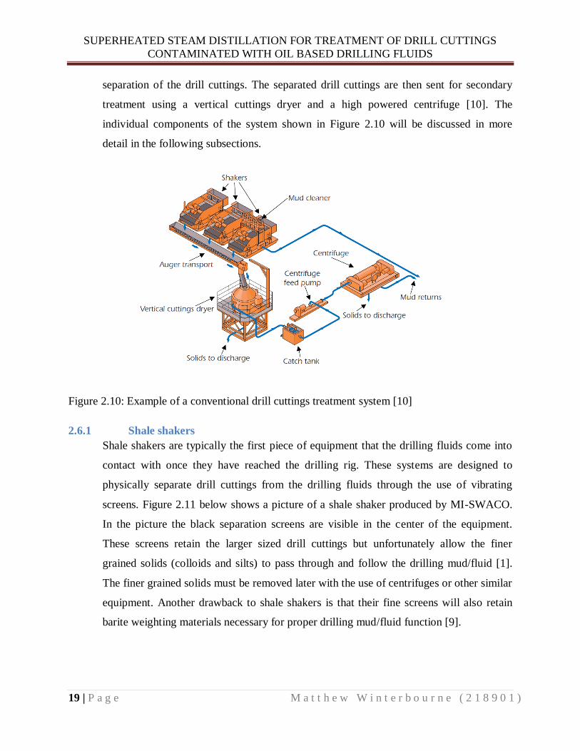
Discharge of drill cuttings in the Gulf of Mexico is administered by the United States
Environmental Protection Agency (USEPA) with the use of National Pollutant Discharge
Elimination System (NPDES) permits [1]. These NPDES permits specify the discharge
limitations of drill cuttings associated with water based mud/fluid (WBM), synthetic
based mud/fluid (SBM), and oil based mud/fluid (OBM). Drill cuttings associated with
WBM are permitted for discharge as long as they meet limits on free oil (Static sheen
test), cadmium (3 mg/kg), mercury (1 mg/kg) in stock barite, suspended particulate
toxicity (96 hour LC50 greater than 30,000 mg/kg) and discharge rate (1,000 bbl/h
maximum) [1]. All discharges must be a minimum of 4.8 km from shore and a minimum
of 1,000 m from biologically sensitive areas and ocean disposal sites [1]. Drill cuttings
associated with SBM must meet the same limits as WBM cuttings in addition they must
also meet limits relating to the base fluid and cuttings composition [1]. SBM cuttings
must not exceed 6.9 % internal olefins and/or 9.4 % esters retained base fluid on cuttings.
In addition, they must meet sediment toxicity standards and must meet limits on retained
formation oil on cuttings [1]. The SBM base fluid must comply with limits on
biodegradation rate, sediment toxicity, and PAH content [1]. Cuttings associated with
OBM or enhanced mineral oil based mud/fluid (EMOBM) are not permitted for discharge
in the U.S. [1].

SUPERHEATED STEAM DISTILLATION FOR TREATMENT OF DRILL CUTTINGS
CONTAMINATED WITH OIL BASED DRILLING FLUIDS
16 | P a g e M a t t h e w W i n t e r b o u r n e ( 2 1 8 9 0 1 )
2.5.3 Canada
In Canada, the offshore discharge of drilling mud/fluid and cuttings is governed by the
Offshore Waste Treatment Guidelines, 2010 [12]. This document establishes guidelines
for the management, evaluation, treatment, and monitoring of drilling muds/fluids and
cuttings. All drilling muds/fluids must be pre-evaluated for toxicity before they are
permitted to be used offshore in Canada. The use of WBM is encouraged and WBM is
permitted for discharge offshore without treatment. Operators must obtain a permit for
WBM discharge and must establish best management practices to reduce the total
volumes discharged. SBMs and EMOBMs are not permitted for discharge except for
small amounts retained on cuttings. As a result, these muds/fluids must be re-used,
injected into a well, or shipped to shore for processing and disposal [1]. Oil base
muds/fluids can only be used under extreme circumstances and are never permitted for
discharge [12].
Drill cuttings resulting from WBM operations are permitted for discharge without any
treatment. This is in contrast to drill cuttings exposed to SBM or EMOBM which should
be re-injected below the surface or shipped to shore for processing and disposal. If the
operator can prove that these disposal methods are not feasible, then drill cuttings must
be treated with the best available technology to meet discharge requirements [12]. The
discharge requirements for offshore Canada are based on a 48 hour weighted average
where the ROC must be less than 6.9 g of oil per 100 g of wet cuttings [12]. Drill
cuttings resulting from OBM operations are never permitted for discharge and must be
either re-injected below the surface or shipped to shore for processing and disposal [12].
2.5.4 Australia
In Australia, offshore drilling waste regulations are administered by the Department of
Industry and Resources. Operators must have an approved Environmental Management
Plan (EMP). The EMP includes justification for drilling mud/fluid selection,
environmental assessment of drilling mud/fluid to include bioaccumulation,
biodegradation and toxicity results, environmental monitoring plan, and a drilling waste
disposal plan [13]. Drill cuttings resulting from SBM operations are permitted for
discharge if the ROC is less than 10 % by dry weight or 6.9 % by wet weight [1].

SUPERHEATED STEAM DISTILLATION FOR TREATMENT OF DRILL CUTTINGS
CONTAMINATED WITH OIL BASED DRILLING FLUIDS
17 | P a g e M a t t h e w W i n t e r b o u r n e ( 2 1 8 9 0 1 )
Australia has also established restrictions on the borehole size that SBM drill cuttings
may be discharged from in order to encourage the use of WBM in larger upper bore
sections. SBM drill cuttings are only permitted for discharge if they are sourced from 12
¼ in diameter borehole or smaller. If OBM is to be used in lower well sections, then it
must have an aromatics content of less than 1 %. Cuttings associated with OBM may be
discharged if the ROC is less than 1 % [1].
2.5.5 Brazil
In Brazil, offshore drilling waste regulations are administered by the Brazilian Institute of
Environment and Renewable Natural Resources (IBAMA) [1]. OBM discharges are not
permitted in Brazil. However, drill cuttings associated with SBM are permitted for
discharge if they meet certain environmental performance criteria. These criteria include
biodegradability (OECD 306 method), toxicity ( Before and after drilling tests on
organisms from four different phyla), PAH content, and bioaccumulation potential (log
Pow) [1]. Cuttings associated with SBM must have a ROC of less than 6.9 % for paraffin
and olefin, less than 9.4 % for ester, and less than 1 % for formation oil [1]. All SBM
must contain less than 1 mg/kg mercury and less than 3 mg/kg cadmium in stock barite
[1]. No discharges are permitted to waters with depths of less than 60 m. At water depths
between 60-1000 m discharges are permitted if seabed and water column monitoring are
conducted [1]. No monitoring is required if discharges are to waters with depths greater
than 1000 m [1].
2.6 Conventional Drill Cuttings Treatment Technology
Conventional drill cuttings treatment technology can be divided into the primary
separation of drill cuttings from drilling fluids and the secondary treatment to remove
retained oil on cuttings. These systems aim to maximize the amount of valuable drilling
fluid that can be recycled to the drilling process [1]. Figure 2.9 below shows a flow chart
of the process where drilling fluids return topside to the oil rig for solids separation and
fluid recycling. From Figure 2.9 it can be seen that separated drill cuttings (referred to as
waste solids in Figure 2.9) have three options for disposal. These options include onshore
disposal, reinjection, or discharge to sea [1]. Typically, conventional drill cuttings
treatment cannot achieve the 1 % ROC required by OSPAR signatory countries for

SUPERHEATED STEAM DISTILLATION FOR TREATMENT OF DRILL CUTTINGS
CONTAMINATED WITH OIL BASED DRILLING FLUIDS
18 | P a g e M a t t h e w W i n t e r b o u r n e ( 2 1 8 9 0 1 )
discharge to sea. As a result, drill cuttings from these regions must be either reinjected or
transported to shore for treatment [1]. This is in contrast to other oil producing regions
with less stringent 6.9 % ROC requirements. These limits can be achieved through the
use of conventional drill cutting treatment technologies [1].
Figure 2.9: Flow chart of drilling fluid and conventional drill cuttings separation technology [10]
The type of solids control equipment used offshore depends on several factors such as the
local discharge regulations, the type of formation being drilled, the cuttings
characteristics, the size of the drill rig, and the type of drilling mud/fluid in operation [1].
Primary separation of drill cuttings from drilling fluids is typically accomplished through
the use of shale shakers, centrifuges, and hydro cyclones. Conventional secondary
treatment to remove retained oil on cuttings is most often done using cuttings dryers, high
powered centrifuges, and onshore thermal desorption plants [10]. Figure 2.10 below
shows a conventional combined primary and secondary drill cuttings treatment system.
The system uses a series of progressively finer screened shale shakers for primary
SUPERHEATED STEAM DISTILLATION FOR TREATMENT OF DRILL CUTTINGS
CONTAMINATED WITH OIL BASED DRILLING FLUIDS
19 | P a g e M a t t h e w W i n t e r b o u r n e ( 2 1 8 9 0 1 )
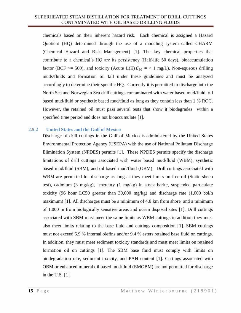
separation of the drill cuttings. The separated drill cuttings are then sent for secondary
treatment using a vertical cuttings dryer and a high powered centrifuge [10]. The
individual components of the system shown in Figure 2.10 will be discussed in more
detail in the following subsections.
Figure 2.10: Example of a conventional drill cuttings treatment system [10]
2.6.1 Shale shakers
Shale shakers are typically the first piece of equipment that the drilling fluids come into
contact with once they have reached the drilling rig. These systems are designed to
physically separate drill cuttings from the drilling fluids through the use of vibrating
screens. Figure 2.11 below shows a picture of a shale shaker produced by MI-SWACO.
In the picture the black separation screens are visible in the center of the equipment.
These screens retain the larger sized drill cuttings but unfortunately allow the finer
grained solids (colloids and silts) to pass through and follow the drilling mud/fluid [1].
The finer grained solids must be removed later with the use of centrifuges or other similar
equipment. Another drawback to shale shakers is that their fine screens will also retain
barite weighting materials necessary for proper drilling mud/fluid function [9].

SUPERHEATED STEAM DISTILLATION FOR TREATMENT OF DRILL CUTTINGS
CONTAMINATED WITH OIL BASED DRILLING FLUIDS
20 | P a g e M a t t h e w W i n t e r b o u r n e ( 2 1 8 9 0 1 )
Figure 2.11: Picture of shale shaker produced by MI-SWACO [14]
Figure 2.12 below shows a shale shaker schematic with arrows indicating the flow of
drilling fluids and separated cuttings. The vibrational motion of the shale shaker forces
the retained solids towards the exit of the machine where they are sent on for further
processing or disposal depending on the local regulations.
Figure 2.12: Schematic of shale shaker operational principle [15]

SUPERHEATED STEAM DISTILLATION FOR TREATMENT OF DRILL CUTTINGS
CONTAMINATED WITH OIL BASED DRILLING FLUIDS
21 | P a g e M a t t h e w W i n t e r b o u r n e ( 2 1 8 9 0 1 )
2.6.2 Hydro-cyclones
Hydro-cyclones are equipment designed to separate solids from drilling fluids through
the use of centrifugal forces [1, 16, 17]. Figure 2.13 contains a working principle
schematic of a hydro-cyclone showing the tangential inflow of drilling fluid and solids at
the conical end of the unit [1]. Injecting the mixture tangentially at the conical end causes
a rotational flow of the drilling fluids and solids.
Figure 2.13: Schematic drawing of hydro-cyclone working principle [16]
This rotational flow induces centrifugal forces on the components in the mixture. The
denser solid components are more influenced by the centrifugal forces than the lighter
drilling fluid components and are thus driven to the perimeter of the hydro-cyclone. At
the same time, the lighter components which are less influenced by the centrifugal forces
accumulate in the center [1]. The solid components exit the cylindrical bottom of the
hydro-cyclone and the lighter drilling fluid components exit the top of the hydro-cyclone
as shown in Figure 2.14 below [1, 17]. The advantages of the hydro-cyclones are that
they are robust, can handle large volumes, and do not contain complex moving parts. A
disadvantage of the hydro-cyclones is that they are governed by Stokes law and therefore
cannot efficiently separate solids of similar mass [17].

SUPERHEATED STEAM DISTILLATION FOR TREATMENT OF DRILL CUTTINGS
CONTAMINATED WITH OIL BASED DRILLING FLUIDS
22 | P a g e M a t t h e w W i n t e r b o u r n e ( 2 1 8 9 0 1 )
Figure 2.14: Illustration of hydro-cyclone inflow (feed) ,waste stream (Discard), and recycle
stream (save) [17]
2.6.3 Decanting Centrifuges
Decanting centrifuges are equipment designed to separate solids from drilling fluids
through the use of centrifugal forces [18]. The equipment produces strong centrifugal
forces by the rotation of a drum which causes higher density solid components to be
forced to the wall of the drum as shown in Figure 2.15 below [17, 18].
Figure 2.15: Schematic drawing of decanting centrifuge working principle [17]

SUPERHEATED STEAM DISTILLATION FOR TREATMENT OF DRILL CUTTINGS
CONTAMINATED WITH OIL BASED DRILLING FLUIDS
23 | P a g e M a t t h e w W i n t e r b o u r n e ( 2 1 8 9 0 1 )
These higher density solid components are then transported to the discharge port through
the use of a rotating auger [18]. The lower density drilling fluids collect in the pool
region shown in Figure 2.15 and are discharged at the opposite end of the decanting
centrifuge unit [1]. The advantage of decanting centrifuges is that they can separate
extremely fine solids due to the very high centrifugal forces generated [1]. A
disadvantage of the centrifuge is the complexity of the moving parts which can
necessitate significant maintenance and repair [1].
2.6.4 Cuttings Dryers
Cuttings dryers are typically used to process drill cuttings that have been separated by the
shale shakers [1]. The cutting are fed into the top of the dryer as shown in Figure 2.16
below and are then subjected to high centrifugal forces in a rotating basket lined with a
wire mesh [1]. The mesh retains the cuttings yet allows drilling fluids to pass through and
be recycled into the drilling process [1].
Figure 2.16: Schematic of vertical cuttings dryer working principle [19]
The dried solids are then discharged at the bottom of the unit as shown in Figure 2.16
above. A study of 72 wells is in the Gulf of Mexico by Jonston et al. found that the

SUPERHEATED STEAM DISTILLATION FOR TREATMENT OF DRILL CUTTINGS
CONTAMINATED WITH OIL BASED DRILLING FLUIDS
24 | P a g e M a t t h e w W i n t e r b o u r n e ( 2 1 8 9 0 1 )
average retained synthetic oil on cuttings level achieved with cuttings dyers was 4.93 %
[20]. This ROC level meets the offshore Canada and U.S. Gulf of Mexico limitations of
6.9 % but does not comply with the Norwegian and North Sea limitations of 1 % ROC
[1]. An advantage of cuttings dryers is that they are effective at significantly reducing the
ROC. A disadvantage is that cuttings dryers allow significant amounts of fine solids to
follow the recycled drilling fluids. These fine solids require dilution with added fluid thus
contributing to increased waste production [17].
2.7 Transport of Cuttings Onshore for Treatment
The drill cuttings waste management option of transport to shore has increased due to the
introduction of more stringent regulations on allowable ROC for discharge. Other
contributing factors to this trend are the increased use of oil based drilling fluids and
difficulties encountered with reinjection of drill cutting [3]. This trend can be seen in
table 2.1 below where tonnage of waste shipments to shore have increased significantly
between the years 2008 thru 2010 in Norway [21].
Table 2.1 Distribution of drill cuttings waste disposal per year in tons for offshore Norway [22]
The increase in transport to shore is due to the limited offshore treatment technologies
that can meet the strict ROC discharge limits [22]. Transport to shore involves loading
the drill cuttings into containers and then lifting them with a crane onto supply ships [9].
As shown in Figure 2.17 below, the supply ships transport the drill cuttings from the
offshore production platforms to the onshore treatment bases [9]. This transport process
involves many individual crane lifts which pose significant risks to the environment and
the health and safety of personnel due to the potential for accidents and spills [21]. A
drawback to the transport to shore option is that weather conditions can prevent supply

SUPERHEATED STEAM DISTILLATION FOR TREATMENT OF DRILL CUTTINGS
CONTAMINATED WITH OIL BASED DRILLING FLUIDS
25 | P a g e M a t t h e w W i n t e r b o u r n e ( 2 1 8 9 0 1 )
ships from being able to safely load the containers holding contaminated drill cuttings
[9].
Figure 2.17: Map showing offshore drill cuttings production platforms in red and onshore drill
cutting treatment bases in green [9]
New specially designed cuttings transport systems such as the “CleanCut” by MI Swaco
can significantly reduce the amount of crane lifts required [23]. This system uses
specially designed transport containers which can be loaded with a pump system from the
drill rig. This eliminates the majority of crane lifts required to lift containers from the
drill rig to the supply ship [23]. The contaminated drill cuttings are transported to shore
for treatment by rotary kiln, thermal desorption, bioremediation or other processes
discussed in the following subsections.

SUPERHEATED STEAM DISTILLATION FOR TREATMENT OF DRILL CUTTINGS
CONTAMINATED WITH OIL BASED DRILLING FLUIDS
26 | P a g e M a t t h e w W i n t e r b o u r n e ( 2 1 8 9 0 1 )
2.7.1 Rotary Kiln Thermal Desorption
Onshore rotary kiln desorption units are designed to remove retained oil on cuttings
through the use of controlled indirect heating of cuttings in a large rotating vessel [24].
Figure 2.18 below shows an example of an onshore rotary kiln thermal desorption unit.
Figure 2.18: Onshore rotary kiln thermal desorption unit for treatment of drill cuttings [25]
The volatilized vapor from the rotary kiln process is condensed and separated into base
oil and water fractions [1]. The advantages of the onshore rotary kiln process are that it
can process large volumes of cuttings, it can achieve ROC’s of less than 1 %, and the
recovered base oil can be recycled [24]. The disadvantages of the system are that they
require large footprints, they have high energy consumption, and have not been
successfully applied offshore [1].
2.7.2 Land Treatment Bioremediation
Land treatment of drill cuttings is a method that utilizes naturally occurring soil
microorganisms as well as biodegradation to reduce the oil content of contaminated drill
cuttings waste [26]. The soil microorganisms are able to metabolize the base oil and
organic compounds attached to the contaminated drill cuttings. The soil particles
physically and chemically bind to chemical pollutants associated with the drill cuttings
effectively locking them up and inhibiting their ability to leach [26]. The process involves
incorporating the contaminated drill cuttings into the soil and providing favorable
SUPERHEATED STEAM DISTILLATION FOR TREATMENT OF DRILL CUTTINGS
CONTAMINATED WITH OIL BASED DRILLING FLUIDS
27 | P a g e M a t t h e w W i n t e r b o u r n e ( 2 1 8 9 0 1 )
conditions that promote rapid metabolism of chemical pollutants[27]. The advantages of
land treatment of contaminated drill cuttings include the low cost, minimal energy
consumption, and high efficacy of the process. The disadvantages include large footprints
required, long process times, and unsuitability for use offshore [26].
2.7.3 Solidification and Stabilization
Solidification and stabilization is a method of drill cuttings treatment that involves
encapsulation in cement, silica or other suitable materials [1, 28, 29]. The encapsulation
of the drill cuttings waste locks the contamination in place and prevents dissolution and
migration of the pollutants to the surrounding environment [28]. The process involves
both physical and chemical stabilization of the contaminants associated with the drill
cuttings [1]. A disadvantage of this method is the production of large solid blocks of
encapsulated waste material. An improvement of the process has been developed which
involves the use of a C to produce smaller easier to handle granulated material [28,
30]. Advantages of this method include low costs and effectiveness at neutralizing the
contaminated drill cuttings. Disadvantages of the method include unsuitability for
offshore application, large volumes of solid waste that must be disposed of properly, and
the long term potential breakdown of the encapsulating material [1].
2.8 Emerging Drill Cuttings Treatment Technology
The following section discusses new emerging drill cuttings treatment technologies. The
majority of these new technologies are still in the research and development stage except
for the thermomechanical cuttings cleaner (TCC) which has been installed offshore [1].
These new technologies have the potential for offshore application once they have been
sufficiently tested and developed.
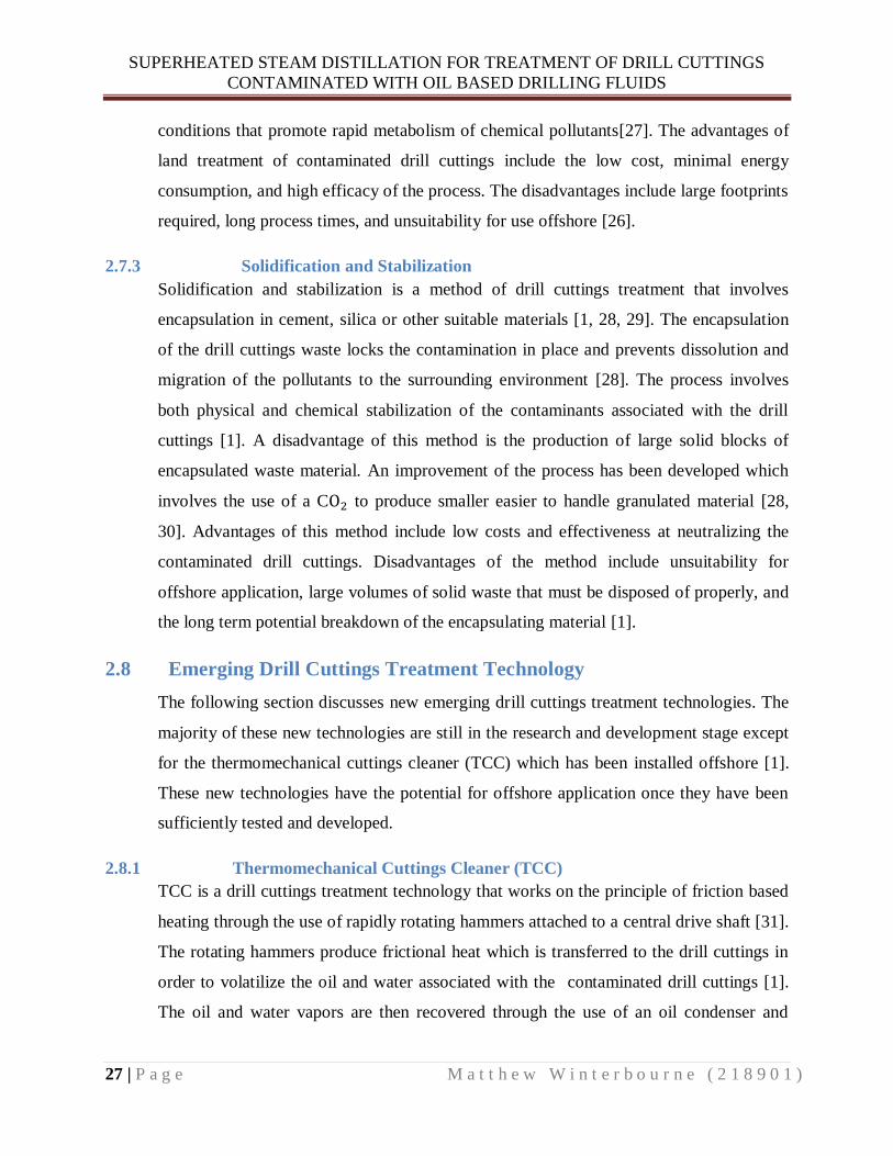
2.8.1 Thermomechanical Cuttings Cleaner (TCC)
TCC is a drill cuttings treatment technology that works on the principle of friction based
heating through the use of rapidly rotating hammers attached to a central drive shaft [31].
The rotating hammers produce frictional heat which is transferred to the drill cuttings in
order to volatilize the oil and water associated with the contaminated drill cuttings [1].
The oil and water vapors are then recovered through the use of an oil condenser and
SUPERHEATED STEAM DISTILLATION FOR TREATMENT OF DRILL CUTTINGS
CONTAMINATED WITH OIL BASED DRILLING FLUIDS
28 | P a g e M a t t h e w W i n t e r b o u r n e ( 2 1 8 9 0 1 )
steam condenser located downstream from the TCC process mill [1]. This treatment
technology has been successfully applied offshore in the U.K. and Kazakhstan. It is
projected to be applied offshore in the near future in the United Arab Emirates, West
Africa, and Norway [32]. In Norway, this technology has been effectively used onshore
for treatment but has yet to be applied offshore [9, 32].
Figure 2.19: Diagram of TCC process [9]
The TCC treatment process can consistently achieve ROCs of less than 1 % thus meeting
the OSPAR and other regional regulatory discharge requirements. Meeting these
discharge requirements eliminates the need to transport the cuttings to shore for treatment
[1, 31]. Figure 2.19 above shows a flow diagram of the TCC process from inflow of
contaminated drill cuttings to the end product of recovered solids, oil fractions, gas and
water. There are many advantages of the TCC process including low operational
temperatures, efficient oil removal, and compact size suitable for offshore applications [1,
22, 31]. The relatively low desorption temperatures of between 260 ⁰C-300 ⁰C for the
TCC process enables a high rate of oil recovery for the purpose of recycling due to
minimization of heat degradation of the oil [1, 22, 31]. The direct thermomechanical

SUPERHEATED STEAM DISTILLATION FOR TREATMENT OF DRILL CUTTINGS
CONTAMINATED WITH OIL BASED DRILLING FLUIDS
29 | P a g e M a t t h e w W i n t e r b o u r n e ( 2 1 8 9 0 1 )
heating of the TCC process eliminates the need for complex external heating sources and
minimizes the required energy input for desorption [31]. Some of the disadvantages of
the TCC process include maintenance issues, footprint and weight additions to the oil rig,
and complex moving parts [1, 9, 31].
2.8.2 Microwave Cuttings Treatment
Microwave drill cuttings treatment is a thermal desorption process that utilizes
microwaves to vaporize associated oil and water [1, 33]. Figure 2.20 below shows a
working principle drawing of a pilot scale microwave drill cuttings treatment system
[34].
Figure 2.20: Working principle drawing of experimental microwave drill cuttings treatment
system [34]
Microwave treatment systems work by heating water trapped in the pores of drill cuttings
into steam which in turn distills the associated oil through steam distillation [34]. The
advantage of microwave systems is that they directly heat the water components through
electromolecular interactions as opposed to conventional systems which work via
conduction or convection [34]. These systems are also relatively compact, efficient and
can achieve ROC levels of less than one percent [33, 34]. Disadvantages of this treatment
technology include the pretreatment requirements of the drill cuttings prior to

SUPERHEATED STEAM DISTILLATION FOR TREATMENT OF DRILL CUTTINGS
CONTAMINATED WITH OIL BASED DRILLING FLUIDS
30 | P a g e M a t t h e w W i n t e r b o u r n e ( 2 1 8 9 0 1 )
introduction to the system, as well as other improvements necessary before full scale
offshore applications [1, 33, 34].
2.8.3 Supercritical C Extraction
Supercritical C extraction is a drill cuttings treatment technology that involves heating
and pressurizing C above its critical pressure and temperature [1]. Under these
conditions the C behaves as a supercritical fluid and can be used as an effective
solvent to extract contaminants and oil from the drill cuttings waste [1]. The advantages
of this treatment technology include its inflammable nature, non-toxicity, and strong oil
extraction capabilities [35]. The disadvantages of this technology include the necessity of
extensive pressurization equipment and the need for further research and development
before full scale offshore applications [1].
2.8.4 Liquefied Gas Extraction
Liquefied gas extraction is a drill cuttings treatment technology that involves heating and
pressurizing hydrocarbon gases above their critical pressure and temperature [1, 36].
Typically the types of hydrocarbon gases used in this process include propane and butane
because they can be liquefied at low pressures and temperatures [1, 36]. Under these
conditions, the hydrocarbon gases behave as supercritical fluids and can be used as
solvents to extract contaminants and oil from the drill cuttings [1]. The advantages of this
treatment technology include the lower required supercritical pressures and temperatures
compared to C and achievable ROC values of less than one percent [1, 36]. A
disadvantage of this treatment technology is that it is still in the early stages of
development and needs significant research and development before offshore
implementation [1, 36].
2.8.5 Chemical Washing and Surfactants
Chemical washing and surfactants is a drill cuttings treatment technology that uses
anionic and nonionic surfactants to remove oil and contaminants from drill cutting waste
[1, 37]. The anionic and nonionic properties of the surfactants chemically interact with
and remove oil and contaminants attached to the surface of the drill cuttings [1, 37]. An
advantage of this treatment technology is that it has been proven effective for onshore
treatment of hydrocarbon contaminated soils [1, 37]. A disadvantage of this treatment

SUPERHEATED STEAM DISTILLATION FOR TREATMENT OF DRILL CUTTINGS
CONTAMINATED WITH OIL BASED DRILLING FLUIDS
31 | P a g e M a t t h e w W i n t e r b o u r n e ( 2 1 8 9 0 1 )
technology is that it needs significant research and development before offshore
implementation [1, 37].
2.9 Cuttings Reinjection
Cuttings reinjection is an offshore method used to dispose of drill cuttings waste by
injecting it into subterranean geological formations [1, 38]. The cuttings reinjection
process is shown in Figure 2.21 below. Before the drill cuttings waste can be injected it
must first be screened and made into slurry in order to ensure proper flow characteristics
during injection. This is accomplished by milling the drill cuttings into fine particles and
combining with seawater as shown in Figure 2.21 below [1, 38].
Figure 2.21: Illustration of drill cuttings reinjection system [39]
The drill cuttings slurry can then be injected into a suitable subterranean geological
formation for disposal [1, 38] . The advantages of this waste disposal method include
elimination of waste transport to shore, offshore disposal capabilities, cost savings, zero
discharge to the environment, and high capacity [1, 38]. The disadvantages of this
treatment technology include waste leakage from geological formations, potential for
spills and accidents, long term monitoring, equipment issues, and formation plugging [1,
38]. According to the Norwegian Environment Agency, the oil and gas industry has

SUPERHEATED STEAM DISTILLATION FOR TREATMENT OF DRILL CUTTINGS
CONTAMINATED WITH OIL BASED DRILLING FLUIDS
32 | P a g e M a t t h e w W i n t e r b o u r n e ( 2 1 8 9 0 1 )
experienced difficulties with cuttings reinjection in recent years 2009-2012 [3]. The
cuttings reinjection difficulties have resulted in an increase in the quantity of drill
cuttings waste being transported to shore as shown in Figure 1.2 above [3].
3 CHAPTER THREE: STEAM DISTILLATION THEORY
3.1 Temperature and Vapor Pressure Relationship
Vapor pressure can be defined as the pressure resulting from the vaporization of a liquid.
Evaporation of a liquid causes the formation of vapor which increases the surrounding
pressure. Increasing the temperature of a liquid increases the amount of kinetic energy
imparted to the liquid molecules. Once the molecules gain enough kinetic energy to break
free of the bonds holding the liquid together they can escape into vapor form [40]. Figure
3.1 below shows visually how increased temperature affects the vapor pressure of a liquid
in a closed container. The illustration on the right in Figure 3.1 shows how increased
temperature indicated by the thermometer translates into increased vapor molecules and
pressure.
Figure 3.1: Illustration of increased vapor pressure due to heating [41]
Vapor pressure in relation to temperature is a characteristic property of a liquid [40].
Every liquid will have a specific vapor pressure at a given temperature. The temperature
of a liquid at which the vapor pressure equals the surrounding pressure is known as the
boiling point. At the boiling point, bubbles of vapor form within the liquid and rise to the

SUPERHEATED STEAM DISTILLATION FOR TREATMENT OF DRILL CUTTINGS
CONTAMINATED WITH OIL BASED DRILLING FLUIDS
33 | P a g e M a t t h e w W i n t e r b o u r n e ( 2 1 8 9 0 1 )
surface where they escape into the surrounding environment. The temperature of a
boiling liquid will remain constant regardless of the amount of heat added. Any
additional heat applied to a boiling liquid will increase the boiling rate and vaporization
yet the temperature of the boiling liquid will remain constant [42]. Figure 3.2 below
shows the exponential relationship between temperature and vapor pressure of a liquid.
This non-linear relationship is due to vapor pressure’s dependence on the proportion of
liquid molecules with sufficient kinetic energy to escape the liquid which increases
exponentially with temperature [40].
Figure 3.2: Graphical representation of the relationship between temperature and vapor
pressure of a liquid [41]
3.2 Enthalpy of Vaporization
The amount of energy required to evaporate one mole of a liquid is defined as the
enthalpy of vaporization ΔHvap [42, 43]. The enthalpy of vaporization increases with the
strength of the bonds holding the liquid together. For example, water has hydrogen
bonding between molecules therefore it requires more energy to break these bonds than
liquids with no hydrogen bonding [43]. In order to calculate parameters such as enthalpy
of vaporization or vapor pressure at varying temperatures it is useful to linearize the

SUPERHEATED STEAM DISTILLATION FOR TREATMENT OF DRILL CUTTINGS
CONTAMINATED WITH OIL BASED DRILLING FLUIDS
34 | P a g e M a t t h e w W i n t e r b o u r n e ( 2 1 8 9 0 1 )
graph of vapor pressure versus temperature. This can be accomplished by graphing the
natural log of vapor pressure (ln P) versus the inverse of the absolute temperature in
Kelvin (1/T) as can be seen in Figure 3.3 below. The resulting graph yields a straight line
of Equation 3.1 and a slope equal to (−ΔHvap/R) [40].
Figure 3.3: Linearized plot of vapor pressure versus temperature [41]
Equation 3.1
In Equation 3.1 above, R is the universal gas constant [ 8.314 J/(mol·K)], C is the y-
intercept, T is the temperature in Kelvin, P is vapor pressure, and ΔHvap is the enthalpy
of vaporization [40]. Equation 3.1 is known as the Clausius-Clapeyron Equation which
can be rearranged into Equation 3.2 below to calculate ΔHvap when the vapor pressure
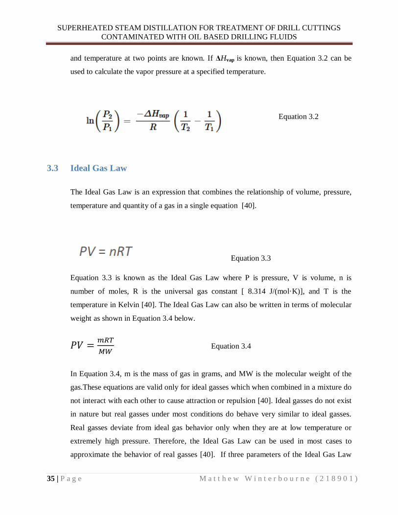
SUPERHEATED STEAM DISTILLATION FOR TREATMENT OF DRILL CUTTINGS
CONTAMINATED WITH OIL BASED DRILLING FLUIDS
35 | P a g e M a t t h e w W i n t e r b o u r n e ( 2 1 8 9 0 1 )
and temperature at two points are known. If ΔHvap is known, then Equation 3.2 can be
used to calculate the vapor pressure at a specified temperature.
Equation 3.2
3.3 Ideal Gas Law
The Ideal Gas Law is an expression that combines the relationship of volume, pressure,
temperature and quantity of a gas in a single equation [40].
Equation 3.3
Equation 3.3 is known as the Ideal Gas Law where P is pressure, V is volume, n is
number of moles, R is the universal gas constant [ 8.314 J/(mol·K)], and T is the
temperature in Kelvin [40]. The Ideal Gas Law can also be written in terms of molecular
weight as shown in Equation 3.4 below.
Equation 3.4
In Equation 3.4, m is the mass of gas in grams, and MW is the molecular weight of the
gas.These equations are valid only for ideal gasses which when combined in a mixture do
not interact with each other to cause attraction or repulsion [40]. Ideal gasses do not exist
in nature but real gasses under most conditions do behave very similar to ideal gasses.
Real gasses deviate from ideal gas behavior only when they are at low temperature or
extremely high pressure. Therefore, the Ideal Gas Law can be used in most cases to
approximate the behavior of real gasses [40]. If three parameters of the Ideal Gas Law
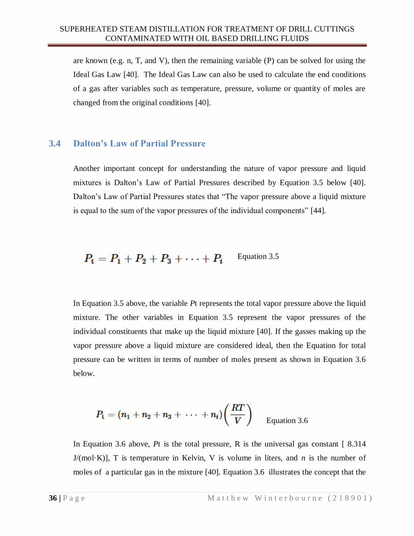
SUPERHEATED STEAM DISTILLATION FOR TREATMENT OF DRILL CUTTINGS
CONTAMINATED WITH OIL BASED DRILLING FLUIDS
36 | P a g e M a t t h e w W i n t e r b o u r n e ( 2 1 8 9 0 1 )
are known (e.g. n, T, and V), then the remaining variable (P) can be solved for using the
Ideal Gas Law [40]. The Ideal Gas Law can also be used to calculate the end conditions
of a gas after variables such as temperature, pressure, volume or quantity of moles are
changed from the original conditions [40].
3.4 Dalton’s Law of Partial Pressure
Another important concept for understanding the nature of vapor pressure and liquid
mixtures is Dalton’s Law of Partial Pressures described by Equation 3.5 below [40].
Dalton’s Law of Partial Pressures states that “The vapor pressure above a liquid mixture
is equal to the sum of the vapor pressures of the individual components” [44].
Equation 3.5
In Equation 3.5 above, the variable Pt represents the total vapor pressure above the liquid
mixture. The other variables in Equation 3.5 represent the vapor pressures of the
individual constituents that make up the liquid mixture [40]. If the gasses making up the
vapor pressure above a liquid mixture are considered ideal, then the Equation for total
pressure can be written in terms of number of moles present as shown in Equation 3.6
below.
Equation 3.6
In Equation 3.6 above, Pt is the total pressure, R is the universal gas constant [ 8.314
J/(mol·K)], T is temperature in Kelvin, V is volume in liters, and n is the number of
moles of a particular gas in the mixture [40]. Equation 3.6 illustrates the concept that the

SUPERHEATED STEAM DISTILLATION FOR TREATMENT OF DRILL CUTTINGS
CONTAMINATED WITH OIL BASED DRILLING FLUIDS
37 | P a g e M a t t h e w W i n t e r b o u r n e ( 2 1 8 9 0 1 )
pressure of a gas mixture at constant temperature and volume is only reliant on the total
number of moles of gas in the mixture [40].
3.5 Distillation of Liquid Mixtures
In general , liquid mixtures are classified as either miscible or immiscible [44]. The
difference between these mixtures is the extent to which the liquids dissolve within each
other. Miscible mixtures are made up of components that are completely soluble in each
other whereas immiscible mixtures are comprised of liquids that are insoluble within each
other [44]. An example of a miscible mixture is ethanol in water and an example of an
immiscible mixture is oil in water. Both types of mixtures follow Dalton’s Law of Partial
Pressures but they differ in the manner to which each component contributes its partial
pressure. As a result, their behavior under distillation varies greatly [44].
3.5.1 Miscible Mixtures
In miscible mixtures, the partial pressure contributed by a component is reliant on its
independently measured vapor pressure and its relative quantity within the mixture [44]
.The mole fraction of a component in a miscible mixture can be used to calculate its
partial pressure contribution to the vapor pressure above the mixture. A component’s
mole fraction can be found by dividing the number of moles of the component in the
mixture by the total number of moles in the mixture as shown in Equation 3.7 below [40].
Equation 3.7
Equation 3.7 above designates a component of a miscible mixture as “A”. In Equation
3.7, XA is the mole fraction of “A”, nA is the number of moles of “A”, and nt is the total

SUPERHEATED STEAM DISTILLATION FOR TREATMENT OF DRILL CUTTINGS
CONTAMINATED WITH OIL BASED DRILLING FLUIDS
38 | P a g e M a t t h e w W i n t e r b o u r n e ( 2 1 8 9 0 1 )
number of moles in the mixture [40]. The mole fraction of component “A” calculated in
Equation 3.7 can then be plugged into Raoult’s Law shown in Equation 3.8 below.
Raoult’s Law can then be used to calculate the partial pressure of the component within
the mixture [44].
Equation 3.8
In Equation 3.8 above, is the independently measured vapor pressure of pure
component “A”, is the mole fraction of “A”, and is the partial pressure of
component A in the mixture [40]. This means that the partial pressure of any component
in a mixture can be found by multiplying its mole fraction by its independent vapor
pressure [44]. Raoult’s Law can be combined with Dalton’s Law of Partial Pressure in
order to calculate the total vapor pressure above a miscible mixture as shown in Equation
3.9 below [44].
Equation 3.9
In Equation 3.9 above is the total vapor pressure above a miscible liquid mixture
made up of components “A” and “B” [44]. When a liquid mixture is heated, the partial
pressures of the components increase thereby increasing the total vapor pressure of the
mixture. If reaches the surrounding pressure, then the mixture will begin to boil
[44]. The boiling point of a miscible mixture will be between the boiling points of the
components making up the mixture [44]. Due to the nature of Raoult’s Law, the vapor
above a boiling miscible mixture will have a higher concentration of the component with
lower boiling point [44]. This phenomenon enables relatively easy separation of miscible
liquids using normal distillation. If the boiling points of the components making up the
mixture are too similar, then fractional distillation must be used to separate the mixture.
Fractional distillation involves modifying the normal distillation setup with a
fractionating column designed to increase the surface area that comes in contact with the

SUPERHEATED STEAM DISTILLATION FOR TREATMENT OF DRILL CUTTINGS
CONTAMINATED WITH OIL BASED DRILLING FLUIDS
39 | P a g e M a t t h e w W i n t e r b o u r n e ( 2 1 8 9 0 1 )
distilled vapor. The increased surface area enables the vapor to condense then re-vaporize
according to Raoult’s Law causing enrichment of a particular component [44].
3.5.2 Immiscible Mixtures
In contrast to miscible mixtures, the partial pressure contribution of a component in an
immiscible mixture is not reliant on its relative quantity within the mixture. Therefore,
the partial pressure contributed by a component is equal to its independently measured
vapor pressure [44]. Equation 3.10 below is an expression of Dalton’s Law for an
immiscible mixture made up of components “A” and “B” [44].
Equation 3.10
In Equation 3.10 above, is the total vapor pressure above an immiscible mixture,
is the independent vapor pressure of pure component “A”, and
is the independent
vapor pressure of pure component “B” [44]. The boiling point of an immiscible mixture
will be lower than the boiling point of any component within the mixture. This is a result
of Dalton’s Law where the individual vapor pressures of the components in the mixture
add together resulting in an overall higher vapor pressure. This higher vapor pressure
causes the mixture to reach the surrounding pressure faster than any of the components in
the mixture would have alone [44].
A component’s contribution to the vapor pressure of an immiscible mixture is
independent of its relative quantity in the mixture. Therefore, a component will contribute
the same amount of partial pressure to the total vapor pressure of the mixture regardless
of how much of the component is present [44]. Also, when a mixture reaches its boiling
point it does not matter which component contributes more partial pressure to the total
vapor pressure of the mixture [44].
In order for immiscible mixtures to obey Dalton’s Law they must be thoroughly mixed
so that all components have contact with the surrounding environment. If the mixture is
not thoroughly mixed, then layering can occur. When layering occurs, only one

SUPERHEATED STEAM DISTILLATION FOR TREATMENT OF DRILL CUTTINGS
CONTAMINATED WITH OIL BASED DRILLING FLUIDS
40 | P a g e M a t t h e w W i n t e r b o u r n e ( 2 1 8 9 0 1 )
component is exposed to the surrounding environment and the other component is
trapped beneath. In this case, the trapped component cannot contribute its partial
pressure to the total vapor pressure of the mixture. As a result, the mixture will not obey
Dalton’s Law and the vapor above the mixture will not contain the trapped component or
it will be greatly reduced [44].
Steam distillation is a process that takes advantage of Dalton’s Law of immiscible
mixtures in order to lower the boiling point of water insoluble substances. Oil is a
common water insoluble substance that can be distilled with steam. The high vapor
pressure of steam helps to significantly reduce the boiling point of the oil [44]. The
condensed vapor of the oil steam distillation will contain both oil and water in
proportions according to Dalton’s Law and the Ideal Gas Law. The Ideal Gas Law
(Equation 3.4) can be written in terms of partial pressures and rearranged to solve for the
mass of steam and the mass of oil in the distilled vapor as shown in the Equations below.
Equation 3.11
Equation 3.12
Equation 3.13
Equation 3.14
In the equations above, is the mass of steam in the vapor, is the mass of oil in the
vapor, is the partial pressure of steam, is the partial pressure of oil, is the
molecular weight of steam, and is the molecular weight of oil. Dividing Equation
3.14 by Equation 3.12 yields the mass ratio of oil production per unit water production as
shown in Equation 3.15 below. The terms V, T, and R cancel out when Equation 3.14 is

SUPERHEATED STEAM DISTILLATION FOR TREATMENT OF DRILL CUTTINGS
CONTAMINATED WITH OIL BASED DRILLING FLUIDS
41 | P a g e M a t t h e w W i n t e r b o u r n e ( 2 1 8 9 0 1 )
divided by Equation 3.12 because the steam distillation occurs at a standard temperature
and volume.
Equation 3.15
In Equation 3.15 above, is the mass ratio of oil production per unit water
production. If the steam distillation is carried out at sea level with an atmospheric
pressure of 1.013bar, then Dalton’s Law of Partial Pressure becomes Equation 3.16
below.
Equation 3.16
Solving Equation 3.16 for the partial pressure of steam yields Equation 3.17 shown
below.
Equation 3.17
Plugging in the partial pressure of stream ( ) from Equation 3.17 and the molecular
weight of steam (18g/mol) into Equation 3.15 yields Equation 3.18 below.
Equation 3.18
Equation 3.18 gives the mass ratio of oil production per unit water production in terms of
the oil’s partial pressure. This Equation can be solved for yielding the partial pressure
of oil in the steam distillation process.
3.6 Steam Distillation Description
Steam distillation is a method of extraction whereby the steam acts as an immiscible
component in an immiscible mixture. The method is used to distill water insoluble
substances with high boiling points such as oil. The advantage of steam distillation is the
reduction in boiling point temperature of the mixture. This is because all components
within the mixture contribute their individual pure vapor pressure to the overall vapor

SUPERHEATED STEAM DISTILLATION FOR TREATMENT OF DRILL CUTTINGS
CONTAMINATED WITH OIL BASED DRILLING FLUIDS
42 | P a g e M a t t h e w W i n t e r b o u r n e ( 2 1 8 9 0 1 )
pressure of the mixture. The components in the mixture exert their pure vapor pressure
because they obey Dalton’s law of Partial Pressure (Equation 3.5) [44, 45]. Figure 3.4
below shows an example of a steam distillation experimental setup.
Figure 3.4: Example of a steam distillation setup [45]
A typical steam distillation setup includes a steam production unit, a distillation unit, a
condensing unit, and a collection flask as shown in Figure 3.4 above [44, 45]. The steam
production unit is designed to produce a steady rate of steam for the distillation process.
The distillation unit is designed to maximize mixing of the immiscible mixture and
minimize heat loss for enhanced distillation performance. The condensing unit is
designed to efficiently cool and condense the vapors form the distillation unit. The
collection flask finally captures the condensed liquid exiting the condensing unit [44,
45].
3.7 History and Applications of Steam Distillation
Steam distillation has a long history of use in the food and fragrance industry. It also has
a more recent history of use in the petrochemical industry. The following subsections
briefly describe the applications and uses in these industries.

SUPERHEATED STEAM DISTILLATION FOR TREATMENT OF DRILL CUTTINGS
CONTAMINATED WITH OIL BASED DRILLING FLUIDS
43 | P a g e M a t t h e w W i n t e r b o u r n e ( 2 1 8 9 0 1 )
3.7.1 Fragrance Industry
Steam distillation is used in the fragrance industry for extraction of essential oils and
perfumes [45]. This process is well suited for extraction of fragrances because it is able to
preserve the integrity of the volatile compounds [46, 47]. Preservation of the chemical
integrity is critical in the formulation of fragrances and essential oils [46, 47]. Plant
materials which contain these chemical compounds are exposed to steam and the
condensed vapors are used in fragrance formulations [46, 47].
3.7.2 Food Industry
In the food industry steam distillation is used for de-acidification and deodorizing of
cooking fats and oils [48]. It is also used for extraction of flavoring and oils used for
culinary purposes [48]. Steam distillation is well suited for the food industry because it
enables purification and extraction of flavorings and oils without causing heat
degradation [48].
3.7.3 Petrochemical Industry
In the petrochemical industry steam distillation is used to strip various aromatic
hydrocarbons from refinery waste fluids [49, 50]. This process is advantageous because it
enables the effective extraction of Benzene, Toluene, Ethylbenzene, and Xylenes (BTEX)
and other aromatic contaminants at reduced temperatures [49, 50]. The steam acts as a
solvent to strip the targeted aromatics from the complex refinery liquid waste mixture
[49, 50].
3.8 Superheated Steam Uses and Applications Including Distillation
The three most common types of steam are unsaturated (wet) stream, saturated (dry)
steam and superheated steam. Unsaturated steam is a type of steam that contains
entrained water molecules that have not vaporized completely. Saturated steam is a type
of steam that forms at equilibrium when the pressure and temperature conditions are such
that water vaporizes at the same rate that it condenses [6]. The saturated steam conditions
are shown in Figure 3.5 as the solid black line curve that separates the pink (superheated)
region from the grey (solid) and blue (liquid) regions. This type of steam is referred to as

SUPERHEATED STEAM DISTILLATION FOR TREATMENT OF DRILL CUTTINGS
CONTAMINATED WITH OIL BASED DRILLING FLUIDS
44 | P a g e M a t t h e w W i n t e r b o u r n e ( 2 1 8 9 0 1 )
dry steam because it does not contain any non-vaporized water molecules [6].
Superheated steam is unsaturated or saturated steam that has been heated above the
saturated steam point. In Figure 3.5 below, the superheated steam is represented by the
pink region. The advantages of superheated steam include increased thermal efficiency,
high steam dryness, low density, high heat storage capacity, lack of condensate
formation, and higher achievable distillation temperatures [6]. Superheated steam is often
used for propulsion in turbines and pistons [6]. This is because superheated steam does
not form condensate droplets which can become projectiles that impact and damage
turbine blades and pistons [6]. Another application of superheated steam is in the
recovery of heavy oil reserves. The superheated steam is injected into the reservoir to
heat and stimulate flow of viscous heavy oil for recovery [51]. Superheated steam can
also be used for distillation of hydrocarbons due to its high thermal efficiency and high
achievable distillation temperatures [52].
Figure 3.5: Relationship of pressure versus temperature for water and steam [6]
SUPERHEATED STEAM DISTILLATION FOR TREATMENT OF DRILL CUTTINGS
CONTAMINATED WITH OIL BASED DRILLING FLUIDS
45 | P a g e M a t t h e w W i n t e r b o u r n e ( 2 1 8 9 0 1 )
4 CHAPTER FOUR: EXPERIMENTAL MATERIALS,
METHODS, AND RESULTS
4.1 Information on Oil Based Drilling Fluids Used for Experiments
Two different oil based drilling fluids were tested during the experimental portion of my
Master’s thesis. The base oils tested were SIPDRILL 2/0 manufactured by SIP LTD and
Clairsol NS manufactured by Petrochem Carless [53] [54].
4.1.1 Chemical Composition and Molecular Formula of Base Oils
The base oils tested are made from processed mineral oils that contain very low amounts
of aromatic hydrocarbons [10, 53, 54]. Mineral oils are derived from refined crude oil
and are mostly made up of the aliphatic compounds alkanes and isoalkanes [55, 56]. The
term aliphatic refers to a class of compounds that do not contain aromatic rings such as
benzene [55]. Alkanes are straight chain hydrocarbons made up entirely of single bonded
hydrogen and carbon atoms [55]. Isoalkanes are simple, branched alkanes of the form
shown in Figure 4.1 below [57]. The structures of isoalkanes are unique in that they only
contain single bonds at branch points, and at the branch points they contain at least two
methyl groups and one hydrogen atom [57]. The general molecular formula for alkanes
and isoalkanes is the same and is shown in Equation 4.1 below.
Equation 4.1
In Equation 4.1 above, C represents carbons, H represents hydrogen, and n is the number
of carbons. Alkanes have the highest ratio of hydrogen to carbon and therefore they are
referred to as saturated with regards to hydrogen [55]. Cycloalkanes are alkanes that
contain rings made of carbon atoms [55]. Figure 4.1 below shows an example of a
straight chain alkane, a branched isoalkane, and a simple, single ringed cycloalkane [58].

SUPERHEATED STEAM DISTILLATION FOR TREATMENT OF DRILL CUTTINGS
CONTAMINATED WITH OIL BASED DRILLING FLUIDS
46 | P a g e M a t t h e w W i n t e r b o u r n e ( 2 1 8 9 0 1 )
Figure 4.1: Structural representation of alkanes [58]
The general molecular formula for single ringed cycloalkanes is shown in Equation 4.2
below [55].
Equation 4.2
When comparing Equation 4.1 and 4.2 above; it is clear that the molecular formula for
single ringed cycloalkanes has two less hydrogens than the molecular formula for straight
chained or branched alkanes. This is a result of the formation of the ring which
necessitates the loss of two hydrogens [55]. Cycloalkanes containing more than one
carbon ring are called polycyclic [55]. The general molecular formula for polycyclic
compounds is shown in Equation 4.3 below [55].
Equation 4.3
In Equation 4.3 above, m is the number of rings in the compound and n is the number of
carbons. From Equation 4.3 it can be seen that increasing the number of rings causes a
decrease in the number of hydrogens in the compound. This results in polycyclic
compounds having a lower hydrogen to carbon ratio than straight chain alkanes [55].
The base oils tested can also contain very small amounts of alkenes and alkynes. Alkenes
are hydrocarbons which contain at least one double bond between carbons and alkynes
are hydrocarbons which contain at least one triple bond between carbons [55]. As a result
of the double bonding in alkenes, the amount of hydrogens in the molecular formula is
reduced by two per double bond as shown in Equation 4.4 below.
Equation 4.4

SUPERHEATED STEAM DISTILLATION FOR TREATMENT OF DRILL CUTTINGS
CONTAMINATED WITH OIL BASED DRILLING FLUIDS
47 | P a g e M a t t h e w W i n t e r b o u r n e ( 2 1 8 9 0 1 )
In Alkynes, the triple bonding of carbon causes a reduction of four hydrogens per triple
bond as shown in Equation 4.5 below.
Equation 4.5
In summary, the molecular formulas of the compounds making up the base oil samples
vary only in their relative number of hydrogens. Hydrogen has a molecular mass of only
1 g/mol which is twelve times less than the molecular mass of carbon at 12 g/mol [40].
As a result, the molecular mass of the base oil samples is most dependent on the number
of carbons contained in the oil [55]. The relative amounts of alkanes, cycloalkanes,
alkenes, and alkynes has less influence on the molecular mass of the oil than the than the
total number of carbons contained in the oil.
4.1.2 Factors Affecting Vapor Pressure and Boiling Point of the Base Oils
The relative strength of the intermolecular forces within the base oil has a significant
impact on the vapor pressure and boiling point of the oil [42]. Strong intermolecular
forces tightly bind the oil molecules together thus enabling few molecules to have
sufficient kinetic energy to break the bonds and escape into the gas phase [59]. This
phenomenon causes oils with strong intermolecular forces to have lower vapor pressure
and higher boiling points [59]. The boiling point is increased because it takes more
energy input to break the strong intermolecular forces holding the molecules together
[59]. In the case of the base oils, the longer the hydrocarbon chain the stronger the
intermolecular forces [60]. The reason for the increased intermolecular forces is due to
the hydrocarbon chain interlocking and meshing together creating stronger bonds [61].
The length of the hydrocarbon chain can be equated with the number of carbons
contained in the molecular formula of the base oil [60]. Shorter chained hydrocarbons do
not have these additional intermolecular forces. Therefore, they have higher vapor
pressure and lower boiling point than longer chained hydrocarbons [61]. These
differences in vapor pressures and boiling points are utilized in petroleum refineries to
separate hydrocarbons of varying carbon chain length [40].
SUPERHEATED STEAM DISTILLATION FOR TREATMENT OF DRILL CUTTINGS
CONTAMINATED WITH OIL BASED DRILLING FLUIDS
48 | P a g e M a t t h e w W i n t e r b o u r n e ( 2 1 8 9 0 1 )
4.1.3 SIPDRILL 2/0
The material safety data sheet (MSDS) for Sipdrill 2/0 located in Appendix-1 gives a
thorough description of the chemical, physical and toxicological attributes of this base
oil. The information of particular interest for the experimental portion of my master’s
thesis is the chemical composition, boiling point, vapor pressure, and relative density.
From the MSDS it can be seen that the chemical composition of Sipdrill 2/0 is made up
of 100 % aliphatic hydrocarbons that contain between ten and thirteen carbons yielding
an average of twelve carbons. Therefore, the molecular mass of the Sipdrill 2/0 can be
approximated by using the molecular formula for alkanes (Equation 4.1 above) and
assuming an average carbon content of twelve. The boiling point in the MSDS is given as
a range between 210-260 ⁰C due to the chemical composition of the base oil. The lighter
fractions of the oil boil at a lower temperature and the heavier fractions boil at a higher
temperature. The Sipdrill 2/0 is a distilled petroleum product therefore it can have
variations in composition depending on the refining process.
4.1.4 CLAIRSOL NS
The MSDS for Clairsol NS found in Appendix-2 contains the chemical, physical and
toxicological characteristics of this base oil. The information of particular interest is the
chemical composition, boiling point, vapor pressure, and relative density. The MSDS
lists the chemical composition of Clairsol NS as a hydrocarbon containing between
fourteen and eighteen carbons. The main chemical constituents are alkanes, isoalkanes,
and to a lesser extent cycloalkanes. The MSDS also lists an aromatic content of less than
two percent for Clairsol NS. Although the chemical composition of Clairsol NS is more
complex than Sipdrill 2/0, an estimation of molecular mass can still be found by using the
molecular formula for alkanes (Equation 4.1 above). The average carbon content of
sixteen carbons can be plugged into Equation 4.1 above to give an estimate of the
molecular mass. This molecular mass estimation may overestimate or underestimate the
actual mass. This is because the equation assumes the hydrocarbon is saturated with
regards to hydrogen which may or may not be the case for Clairsol NS. It also assumes
the oil is made up entirely of alkanes with sixteen carbons even though it could contain
up to eighteen carbons. The boiling point of Clairsol NS is given as a range between 230-
335 ⁰C. This is due to the oil’s composition which contains both shorter and longer chain

SUPERHEATED STEAM DISTILLATION FOR TREATMENT OF DRILL CUTTINGS
CONTAMINATED WITH OIL BASED DRILLING FLUIDS
49 | P a g e M a t t h e w W i n t e r b o u r n e ( 2 1 8 9 0 1 )
hydrocarbons. The relative density is also listed as a range between 0.780-0.920 g/
.This is because Clairsol NS is a distilled product which can vary in chemical
composition.
4.2 Standardized Vapor Pressure versus Temperature Experiment
Understanding the relationship between temperature and vapor pressure of a liquid gives
insight into predicting its behavior under varying conditions. This relationship was
established for the two base oils Clarisol NS and Sipdrill 2/0 in order to gain a better
understanding of their behavior under several temperature and pressure situations. The
results of these standardized tests can then be used to compare to the behavior of the oils
under superheated steam distillation conditions. If the superheated steam distillation
results follow the standardized test results, then they can be deemed valid. Of particular
interest is using Dalton’s Law of Partial Pressure and the Ideal Gas Law to determine the
vapor pressures of the base oil samples under superheated steam distillation conditions.
The vapor pressures calculated under superheated steam distillation conditions can then
be compared with the standardized vapor pressure versus temperatures results found in
the following lab.
The standardized vapor pressure versus temperature experiment was divided into two
phases referred to as phase I and phase II. The goal of both phases was to determine the
boiling point temperatures of the base oils at varying pressures. The boiling point
temperature is of particular interest because at the boiling point, the liquid vapor pressure
is equal to the surrounding pressure. Therefore, at the base oil’s boiling point
temperature, the applied surrounding pressure is equal to the vapor pressure of the base
oil. These experiments were accomplished with the use of a rotary vapor machine and
pump. This equipment enabled the surrounding pressure to be varied so that the
corresponding boiling point temperature could be measured. Phase I and phase II are
differentiated by the methods used to determine the boiling point temperatures of the base
oil samples. Phase I estimated the base oil boiling point temperature based on the heating
bath temperature. Phase II used a long temperature probe to determine the vapor
temperature of the base oil at its boiling point.

SUPERHEATED STEAM DISTILLATION FOR TREATMENT OF DRILL CUTTINGS
CONTAMINATED WITH OIL BASED DRILLING FLUIDS
50 | P a g e M a t t h e w W i n t e r b o u r n e ( 2 1 8 9 0 1 )
4.2.1 Methods and Materials
1 Rotary Evaporator: VWR by IKA model RV10
2 Vacuum pump and control: Vacuubrand for VWR CVC 3000
3 Hot Plate: Heidolph 30001
4 Temperature Control Unit for Hot Plate: Heidolph EKT 3001
5 Stainless Steel Cooking Pot
6 Thermometer
7 Two Stage Vacuum Pump: Model VE 215
8 Pressure Gauge: Thyracont Model VD85
9 Flasks: Round Bottom tempered Glass
10 Boiling Chips
11 Clarisol NS Oil Sample
12 Sipdrill 2/0 Oil Sample
13 Silicone oil for heating baths
Figure 4.2: Photo of vacuum pump and control made by Vacuubrand for VWR model CVC
3000

SUPERHEATED STEAM DISTILLATION FOR TREATMENT OF DRILL CUTTINGS
CONTAMINATED WITH OIL BASED DRILLING FLUIDS
51 | P a g e M a t t h e w W i n t e r b o u r n e ( 2 1 8 9 0 1 )
Figure 4.3: Photo of phase I rotary evaporator experimental setup
The phase I setup utilized the standard rotary evaporator machine connected to its
associated pump (Vacuubrand for VWR CVC 3000) as shown in Figures 4.2 and 4.3
above. The standard heating bath was replaced with a Heidolph 30001 hot plate and a
stainless steel cooking pot filled with silicone oil in order to achieve higher
temperatures. A sample of Sipdrill 2/0 was poured into a round bottomed sample flask
filled with several boiling chips such that 1/3 of the flask was filled with base oil
sample. The sample flask was then attached to the rotary evaporator machine and was
rotated and heated in the silicone oil bath. The Vacuubrand pump was then activated
and set to its minimum achievable pressure of 15 mbar. The sample was then heated
until it reached a visual boiling point and the corresponding bath temperature measured
using a mercury thermometer was noted. The visual boiling point was identified by
uniform formation of large vapor bubbles at the bottom of the base oil sample. Once the
boiling point bath temperature was noted at 15 mbar, the pressure was increased to 20
mbar and the corresponding boiling point bath temperature was noted. This procedure
was repeated for numerous pressures reaching a maximum of 500 mbar. The same

SUPERHEATED STEAM DISTILLATION FOR TREATMENT OF DRILL CUTTINGS
CONTAMINATED WITH OIL BASED DRILLING FLUIDS
52 | P a g e M a t t h e w W i n t e r b o u r n e ( 2 1 8 9 0 1 )
phase I experiment was also carried out on the Clarisol NS Oil Sample. In order to
achieve lower pressure, a high powered two stage vacuum pump was hooked up to the
standard rotary evaporator machine as shown in Figure 4.4 below. The high powered
pump was able to achieve a minimum pressure of 1.5 mbar as can be seen registered on
the screen of the pressure gauge in Figure 4.5 below. The boiling point bath
temperature of the two base oil samples were also measured at this low pressure of 1.5
mbar.
Figure 4.4: Photo of experimental setup with high powered two stage vacuum pump

SUPERHEATED STEAM DISTILLATION FOR TREATMENT OF DRILL CUTTINGS
CONTAMINATED WITH OIL BASED DRILLING FLUIDS
53 | P a g e M a t t h e w W i n t e r b o u r n e ( 2 1 8 9 0 1 )
Figure 4.5: Photo of pressure gauge (Thyracont Model VD85) associated with the high powered
two stage vacuum pump
The phase II setup involved modifying the rotary evaporator machine to include a long
temperature probe as can be seen in Figure 4.6 below.
Figure 4.6: Photo of phase II experimental setup with long temperature probe
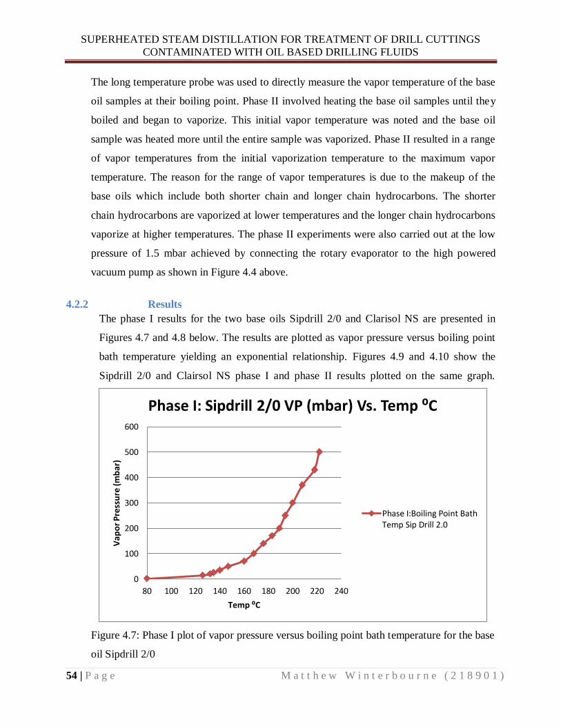
SUPERHEATED STEAM DISTILLATION FOR TREATMENT OF DRILL CUTTINGS
CONTAMINATED WITH OIL BASED DRILLING FLUIDS
54 | P a g e M a t t h e w W i n t e r b o u r n e ( 2 1 8 9 0 1 )
The long temperature probe was used to directly measure the vapor temperature of the base
oil samples at their boiling point. Phase II involved heating the base oil samples until they
boiled and began to vaporize. This initial vapor temperature was noted and the base oil
sample was heated more until the entire sample was vaporized. Phase II resulted in a range
of vapor temperatures from the initial vaporization temperature to the maximum vapor
temperature. The reason for the range of vapor temperatures is due to the makeup of the
base oils which include both shorter chain and longer chain hydrocarbons. The shorter
chain hydrocarbons are vaporized at lower temperatures and the longer chain hydrocarbons
vaporize at higher temperatures. The phase II experiments were also carried out at the low
pressure of 1.5 mbar achieved by connecting the rotary evaporator to the high powered
vacuum pump as shown in Figure 4.4 above.
4.2.2 Results
The phase I results for the two base oils Sipdrill 2/0 and Clarisol NS are presented in
Figures 4.7 and 4.8 below. The results are plotted as vapor pressure versus boiling point
bath temperature yielding an exponential relationship. Figures 4.9 and 4.10 show the
Sipdrill 2/0 and Clairsol NS phase I and phase II results plotted on the same graph.
Figure 4.7: Phase I plot of vapor pressure versus boiling point bath temperature for the base
oil Sipdrill 2/0
0
100
200
300
400
500
600
80 100 120 140 160 180 200 220 240
Vap
or
Pre
ssu
re (
mb
ar)
Temp ⁰C
Phase I: Sipdrill 2/0 VP (mbar) Vs. Temp ⁰C
Phase I:Boiling Point BathTemp Sip Drill 2.0

SUPERHEATED STEAM DISTILLATION FOR TREATMENT OF DRILL CUTTINGS
CONTAMINATED WITH OIL BASED DRILLING FLUIDS
55 | P a g e M a t t h e w W i n t e r b o u r n e ( 2 1 8 9 0 1 )
Figure 4.8: Plot of phase I vapor pressure versus boiling point bath temperature for the base
oil Clarisol NS
Figure 4.9: Plot of phase I versus phase II results for the base oil Sipdrill 2/0
0
50
100
150
200
250
300
350
400
100 120 140 160 180 200 220 240 260
Va
po
r P
ress
ure
(mb
ar)
Temp ⁰C
Phase I: Clarisol NS VP (mbar) Vs. Temp ⁰C
Phase I: Boiling Point BathTemp Clarisol NS
0
100
200
300
400
500
600
80 100 120 140 160 180 200 220 240
Vap
or
Pre
ssu
re (
mb
ar)
Temp ⁰C
Phase I Vs. Phase II Results: Sipdrill 2/0
Phase I: Boiling Point BathTemp Sip Drill 2.0
Phase II: Long Vapor TempProbe Sip Drill 2.0

SUPERHEATED STEAM DISTILLATION FOR TREATMENT OF DRILL CUTTINGS
CONTAMINATED WITH OIL BASED DRILLING FLUIDS
56 | P a g e M a t t h e w W i n t e r b o u r n e ( 2 1 8 9 0 1 )
Figure 4.10: Plot of phase I versus phase II results for the base oil Clairsol NS
Due to the limited amount of Phase II results, it was decided to linearize the phase II and
phase I results in order to compare their linear equations. The results have been linearized
by plotting the natural log of vapor pressure (ln P) versus the inverse of the absolute
temperature in Kelvin (1/T) as can be seen in Figures 4.11 and 4.12 below. The resulting
graph yields a straight line of Equation 3.1 and a slope equal to (−ΔHvap/R) [40]. The
phase II results are plotted together with the phase I results in order to show how closely
their linear equations resemble each other. The equations of the lines have been presented
in Figures 4.11 and 4.12 below because they can be used in further experiments to
determine the base oils enthalpy of vaporization ΔHvap or vapor pressure at varying
temperatures. In addition, all of the raw data and results for the phase I and phase II
experiments can be found in Appendix-3.
0
50
100
150
200
250
300
350
400
100 120 140 160 180 200 220 240 260
Vap
or
Pre
ssu
re (
mb
ar)
Temp ⁰C
Phase I Vs. Phase II Results: Clarisol NS
Phase I: Boiling Point BathTemp Clarisol NS
Phase II: Long Vapor TempProbe Clairsol NS

SUPERHEATED STEAM DISTILLATION FOR TREATMENT OF DRILL CUTTINGS
CONTAMINATED WITH OIL BASED DRILLING FLUIDS
57 | P a g e M a t t h e w W i n t e r b o u r n e ( 2 1 8 9 0 1 )
Figure 4.11: Linearized plot of phase I and phase II results for Sipdrill 2/0
Figure 4.12: Linearized plot of phase I and phase II results for Clarisol NS
y = -7228.1x + 20.943 R² = 0.9963
y = -6406.3x + 19.586 R² = 0.9943
0
1
2
3
4
5
6
7
0.002 0.0022 0.0024 0.0026 0.0028 0.003 0.0032
ln(V
ap
or
Pre
ssir
e) m
bar
1/Temp (K)
Linearized Phase I Vs. Phase II Results: Sipdrill 2/0
Phase I: Boiling Point BathTemp Sip Drill 2.0
Phase II: Long Vapor TempProbe Sip Drill 2.0
y = -8034x + 21.853 R² = 0.9962
y = -7548.5x + 20.784 R² = 0.9739 0
1
2
3
4
5
6
7
0.002 0.0022 0.0024 0.0026
ln(V
ap
or
Pre
ssir
e) m
bar
1/Temp (K)
Linearized Phase I Vs. Phase II Results: Clarisol NS
Phase I: Boiling Point BathTemp Clarisol NS
Phase II: Long Vapor TempProbe Clarisol NS

SUPERHEATED STEAM DISTILLATION FOR TREATMENT OF DRILL CUTTINGS
CONTAMINATED WITH OIL BASED DRILLING FLUIDS
58 | P a g e M a t t h e w W i n t e r b o u r n e ( 2 1 8 9 0 1 )
4.3 Superheated Steam Distillation Experiment
An experiment was developed in order to test the behavior of the base oils Sipdrill 2/0
and Clairsol NS under superheated steam distillation conditions. The setup included a
steam production unit, a steam superheating unit, a distillation unit, and a condensing
unit. The relative volumes of oil and water produced in the condensed distillate were
measured. The measured volumes were used in the Ideal Gas Law and Dalton’s Law of
Partial Pressure to calculate the vapor pressures of the base oils. The calculated vapor
pressures from these experiments were compared to the standardized Rota vapor
reference results.
4.3.1 Methods and Materials
1 Large stainless steel cooking pot and lid
2 Copper tubing 10 mm diameter
3 Fittings and connectors for copper tubing
4 Erlenmeyer flask 2 liter size
5 Two Hot Plates: Heidolph 30001
6 Temperature Control Unit for Hot Plate: Heidolph EKT 3001
7 Rubber stoppers
8 Three temperature probes
9 Three retort stands and clamps
10 Glass 3-way distillation connection adaptor 29/32
11 Round bottomed tempered glass flask
12 Boiling Chips and stir bars
13 Clarisol NS Oil Sample
14 Sipdrill 2/0 Oil Sample
15 Glass condenser
16 Glass Y-adaptor
17 Plastic neck clamps
18 Glass end adaptor for condenser
19 Graduated cylinder 100 ml size

SUPERHEATED STEAM DISTILLATION FOR TREATMENT OF DRILL CUTTINGS
CONTAMINATED WITH OIL BASED DRILLING FLUIDS
59 | P a g e M a t t h e w W i n t e r b o u r n e ( 2 1 8 9 0 1 )
20 Two heat guns
21 Drill
22 Galvanized steel wire mesh
23 Aluminum foil and wire
24 Fiberglass insulation
25 Electronic balance
The experimental setup shown in Figure 4.13 below was constructed in order to test the
behavior of base oils Clairsol NS and Sipdrill 2/0 under superheated steam distillation
conditions.
Figure 4.13: Photo of experimental setup for superheated steam distillation
The experimental setup shown in Figure 4.13 is comprised of the following four main
components, the steam production unit, the steam superheating unit, the distillation unit,
and the condensing unit. The steam production unit was designed to produce a steady rate
of steam through the use of an adjustable Heidolph 30001 hotplate. Stir bars and boiling
chips were added to the two liter Erlenmeyer flask in order to ensure controlled boiling of
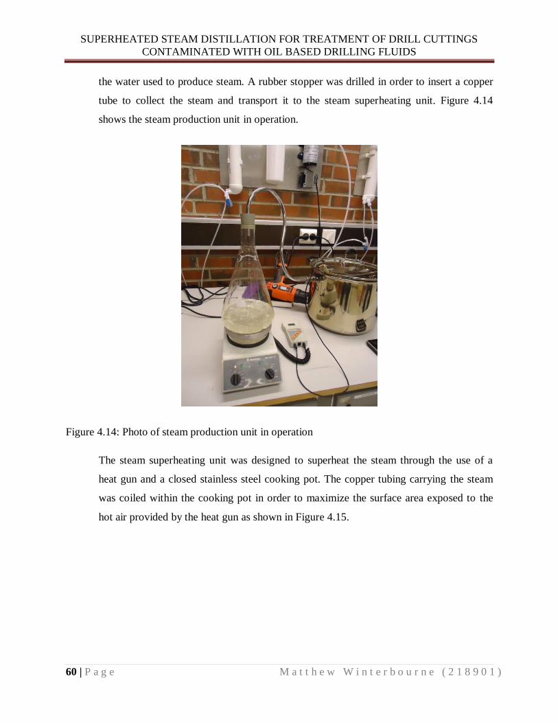
SUPERHEATED STEAM DISTILLATION FOR TREATMENT OF DRILL CUTTINGS
CONTAMINATED WITH OIL BASED DRILLING FLUIDS
60 | P a g e M a t t h e w W i n t e r b o u r n e ( 2 1 8 9 0 1 )
the water used to produce steam. A rubber stopper was drilled in order to insert a copper
tube to collect the steam and transport it to the steam superheating unit. Figure 4.14
shows the steam production unit in operation.
Figure 4.14: Photo of steam production unit in operation
The steam superheating unit was designed to superheat the steam through the use of a
heat gun and a closed stainless steel cooking pot. The copper tubing carrying the steam
was coiled within the cooking pot in order to maximize the surface area exposed to the
hot air provided by the heat gun as shown in Figure 4.15.

SUPERHEATED STEAM DISTILLATION FOR TREATMENT OF DRILL CUTTINGS
CONTAMINATED WITH OIL BASED DRILLING FLUIDS
61 | P a g e M a t t h e w W i n t e r b o u r n e ( 2 1 8 9 0 1 )
Figure 4.15: Photo of steam superheating unit with heat gun and temperature control unit for
Heidolph 30001 hot plate
The temperature within the steam superheating unit was measured using the temperature
control unit for the Heidolph 30001 hotplate as shown in Figure 4.15 above. The
temperature of the superheated steam leaving the unit was measured using a temperature
probe inserted into the copper steam tube. After the temperature reading, the superheated
steam was transported to the distillation unit shown in Figure 4.16 below. The distillation
unit was designed to provide thorough mixing of the superheated steam and oil sample in
order to maximize distillation efficiency. Superheated steam was injected at the bottom of
the flask containing the oil sample and was vigorously mixed using a stir bar. The oil and
steam mixture was heated with a hot plate in order to aid in the distillation process and
avoid heat loss. The temperature of the oil and steam mixture in the flask was measured
using a long temperature probe as shown in Figure 4.16 below. A temperature probe
located at the top of the distillation unit was used to measure the temperature of the
distilled vapor exiting the distillation unit as shown in Figure 4.16 below.

SUPERHEATED STEAM DISTILLATION FOR TREATMENT OF DRILL CUTTINGS
CONTAMINATED WITH OIL BASED DRILLING FLUIDS
62 | P a g e M a t t h e w W i n t e r b o u r n e ( 2 1 8 9 0 1 )
Figure 4.16: Photo of distillation unit
The four temperature probes mentioned previously were installed at various stages of the
experimental setup in order to assist in maintaining steady state conditions during the
distillation process.
Due to significant heat loss from the glass tubing of the distillation unit, it was decided to
insulate the unit with fiberglass building insulation. The fiberglass insulation was found
to be insufficient to prevent excessive heat loss. An effective solution was found by
building a wire mesh housing around the unit and covering it with aluminum foil as
shown in Figures 4.17 and 4.18 below. Hot air was then supplied into the housing with
the use of a heat gun as shown in Figure 4.18 below. This solution was very effective at
preventing heat loss and it enabled tighter control of steady state conditions during
distillation. The heat gun could be adjusted to either increase or decrease the heating rate
of the oil and steam mixture in the flask.

SUPERHEATED STEAM DISTILLATION FOR TREATMENT OF DRILL CUTTINGS
CONTAMINATED WITH OIL BASED DRILLING FLUIDS
63 | P a g e M a t t h e w W i n t e r b o u r n e ( 2 1 8 9 0 1 )
Figure 4.17: Photo of wire mesh housing built around distillation unit
Figure 4.18: Photo of wire mesh and aluminum foil housing built around distillation unit with
heat gun
The final component of the experimental setup was the condensing unit shown in Figure
4.19 below. The condensing unit consisted of a glass-jacketed water cooled condenser
that efficiently condensed the vapors from the distillation unit. The condensed vapors
were then collected in a 100 ml graduated flask as shown in Figure 4.20 below. The
relative volumes of oil and water could then me measured by visual inspection.

SUPERHEATED STEAM DISTILLATION FOR TREATMENT OF DRILL CUTTINGS
CONTAMINATED WITH OIL BASED DRILLING FLUIDS
64 | P a g e M a t t h e w W i n t e r b o u r n e ( 2 1 8 9 0 1 )
Figure 4.19: Photo of condensing unit of experimental setup
Figure 4.20: Photo of graduated cylinder used to capture condensed vapors
The experimental procedure involved first filling the flask in the distillation unit with a
sample of base oil and then heating it to around 95 ⁰C with vigorous stirring. It was
critical to keep the oil sample temperature below 100 ⁰C until the steam from the steam

SUPERHEATED STEAM DISTILLATION FOR TREATMENT OF DRILL CUTTINGS
CONTAMINATED WITH OIL BASED DRILLING FLUIDS
65 | P a g e M a t t h e w W i n t e r b o u r n e ( 2 1 8 9 0 1 )
production unit had been sufficiently heated and dried by the steam superheating unit. If
the steam was not completely dried, then small water droplets entrained in the steam
could flash boil explosively when they came in contact with oil above 100 ⁰C. While the
oil was slowly heated, the steam production unit was initiated and the steam superheating
unit was heated up. Once the steam temperature leaving the steam superheating unit was
safely above 100 ⁰C, then the oil sample could be heated above 100 ⁰C. The oil sample
was heated using a combination of the superheated steam, the hotplate under the sample
flask and the heat gun associated with the distillation housing. The cooling water for the
condensing unit was turned on at this stage in order to condense any vapors leaving the
distillation unit. A measurement of the distillate was taken once the experimental setup
had reached an equilibrium state for a period of time. An equilibrium state was
established once the four temperature probes throughout the process had stabilized. The
distillate separated into two distinct layers with the base oil on the top and water on the
bottom. Both volumes were visually measured using the graduated cylinder and the
results were noted. The experiment was repeated for both base oil samples and was
conducted over a range of temperatures. Figure 4.21 shows the final experimental setup
during operation.
Figure 4.21: Photo of final experimental setup during operation

SUPERHEATED STEAM DISTILLATION FOR TREATMENT OF DRILL CUTTINGS
CONTAMINATED WITH OIL BASED DRILLING FLUIDS
66 | P a g e M a t t h e w W i n t e r b o u r n e ( 2 1 8 9 0 1 )
In addition to the superheated steam distillation experiments, the density of the base oils
was also experimentally determined. The density of both Sipdrill 2/0 and Clairsol NS was
measured at 15 ⁰C and 30 ⁰C using a graduated cylinder and an electronic balance. These
temperatures were selected because the densities listed in the MSDS’s of the base oils
were measured at 15 ⁰C and the distillate from the superheated steam experiments was
measured at 30 ⁰C.
4.3.2 Results
All of the base oil vapor pressures for the superheated steam distillation experiments
were calculated using Equation 3.18 below.
Equation 3.18
Equation 3.18 was rearranged and solved for which was the vapor pressure of the oil
sample. The variable was the experimentally determined mass ratio of oil produced
per unit water in the distillate. The molecular weight of the oil was calculated using
Equation 4.1 below.
Equation 4.1
Equation 4.1 assumes that the base oils are composed entirely of alkanes which have the
highest hydrogen to carbon ratio. Figure 4.22 below shows the experimental results for
Sipdrill 2/0 assuming an average hydrocarbon length of twelve carbons for the molecular
mass calculation. In addition, Figure 4.23 below shows the experimental results for
Clairsol NS assuming an average hydrocarbon length of sixteen carbons for the molecular
mass calculation. Both Figures 4.22 and 4.23 show the results of the superheated steam
experiments one and two versus the standard Rota-vapor results.

SUPERHEATED STEAM DISTILLATION FOR TREATMENT OF DRILL CUTTINGS
CONTAMINATED WITH OIL BASED DRILLING FLUIDS
67 | P a g e M a t t h e w W i n t e r b o u r n e ( 2 1 8 9 0 1 )
Figure 4.22: Plot of Sipdrill 2/0 vapor pressure versus temperature results for superheated steam
experiments 1 and 2 compared to standard Rota-vapor results
Figure 4.23: Plot of Clairsol NS vapor pressure versus temperature results for superheated steam
experiments 1 and 2 compared to standard Rota-vapor results
Figures 4.24 and 4.25 below show the Sipdrill 2/0 superheated steam results for
experiments one and two. They also show the variation in vapor pressure assuming the
0
20
40
60
80
100
120
140
160
180
200
80 130 180 230
Vap
or
Pre
ssu
re (
mb
ar)
Temperature ⁰C
SIPDRILL 2/0 Experiment #1 Vs. Experiment #2 Results
Standard Rota-VaporResults
EXP #1 Steam DistillationC12 Results
Exp #2 Steam DistillationC12 Results
0
20
40
60
80
100
120
140
100 150 200 250
Vap
or
Pre
ssu
re (
mb
ar)
Temperature ⁰C
CLAIRSOL NS Experiment #1 Vs. Experiment #2 Results
Standard Rota-VaporResults
Exp #1 Steam DistillationC16 Results
Exp #2 Steam DistillationC16 Results

SUPERHEATED STEAM DISTILLATION FOR TREATMENT OF DRILL CUTTINGS
CONTAMINATED WITH OIL BASED DRILLING FLUIDS
68 | P a g e M a t t h e w W i n t e r b o u r n e ( 2 1 8 9 0 1 )
shortest, average, and longest carbon chain lengths listed in the MSDS for Sipdrill 2/0
found in Appendix-1.
Figure 4.24: Plot of Sipdrill 2/0 experiment one results showing vapor pressure variation
assuming different carbon chain lengths
Figure 4.25: Plot of Sipdrill 2/0 experiment two results showing vapor pressure variation
assuming different carbon chain lengths
0
50
100
150
200
80 130 180 230
Vap
or
Pre
ssu
re (
mb
ar)
Temperature ⁰C
Experiment #1 Comparison of SIPDRILL 2/0 Vapor Pressure Versus Temperature Results
Standard Rota-VaporResults
Steam Distillation C10Results
Steam Distillation C12Results
Steam Distillation C13Results
0
50
100
150
200
80 130 180 230
Vap
or
Pre
ssu
re (
mb
ar)
Temperature ⁰C
Experiment #2 Comparison of SIPDRILL 2/0 Vapor Pressure Versus Temperature Results
Standard Rota-VaporResults
Steam Distillation C10Results
Steam Distillation C12Results
Steam Distillation C13Results

SUPERHEATED STEAM DISTILLATION FOR TREATMENT OF DRILL CUTTINGS
CONTAMINATED WITH OIL BASED DRILLING FLUIDS
69 | P a g e M a t t h e w W i n t e r b o u r n e ( 2 1 8 9 0 1 )
Figures 4.26 and 4.27 below show the Clairsol NS superheated steam results for
experiments one and two. They also show the variation in vapor pressure assuming the
shortest, average, and longest carbon chain lengths listed in the MSDS for Clairsol NS
found in Appendix-2.
Figure 4.26: Plot of Clairsol NS experiment one results showing vapor pressure variation
assuming different carbon chain lengths
0
20
40
60
80
100
120
140
100 150 200 250
Vap
or
Pre
ssu
re (
mb
ar)
Temperature ⁰C
Experiment #1 Comparison of CLAIRSOL NS Vapor Pressure Versus Temperature Results
Standard Rota-VaporResults
Steam Distillation C14Results
Steam Distillation C16Results
Steam Distillation C18Results

SUPERHEATED STEAM DISTILLATION FOR TREATMENT OF DRILL CUTTINGS
CONTAMINATED WITH OIL BASED DRILLING FLUIDS
70 | P a g e M a t t h e w W i n t e r b o u r n e ( 2 1 8 9 0 1 )
Figure 4.27: Plot of Clairsol NS experiment two results showing vapor pressure variation
assuming different carbon chain lengths
Figures 4.28 and 4.29 below show the base oil distillation rates for Sipdrill 2/0 and
Clairsol NS during the superheated steam distillation experiments one and two. The
distillation rate is expressed as the volume ratio of oil produced per unit water in the
distillate as a function of temperature. The results of experiments one and two are
presented in Figure 4.28 for Sipdrill 2/0 and Figure 4.29 for Clairsol NS.
0
20
40
60
80
100
120
140
100 150 200 250
Vap
or
Pre
ssu
re (
mb
ar)
Temperature ⁰C
Experiment #2 Comparison of CLAIRSOL NS Vapor Pressure Versus Temperature Results
Standard Rota-VaporResults
Steam Distillation C14Results
Steam Distillation C16Results
Steam Distillation C18Results

SUPERHEATED STEAM DISTILLATION FOR TREATMENT OF DRILL CUTTINGS
CONTAMINATED WITH OIL BASED DRILLING FLUIDS
71 | P a g e M a t t h e w W i n t e r b o u r n e ( 2 1 8 9 0 1 )
Figure 4.28: Plot of Sipdrill 2/0 distillation rates expressed as the volume ratio of oil/water
produced in the distillate as a function of temperature for experiments one and two
Figure 4.29: Plot of Clairsol NS distillation rates expressed as the volume ratio of oil/water
produced in the distillate as a function of temperature for experiments one and two
0.000
0.500
1.000
1.500
2.000
2.500
100 120 140 160 180
Vo
lum
e R
atio
(m
l/m
l)
Temperature ⁰C
SIPDRILL 2/0 Exp1 Vs. Exp 2 Base Oil Distillation Rates
EXP #1 Oil/Water VolumeRatio
EXP #2 Oil/Water VolumeRatio
0.000
0.500
1.000
1.500
2.000
100 120 140 160 180 200 220
Vo
lum
e R
atio
(m
l/m
l)
Temperature ⁰C
Clairsol NS Exp1 Vs. Exp 2 Base Oil Distillation Rates
EXP #1 Oil/Water VolumeRatio
EXP #2 Oil/Water VolumeRatio

SUPERHEATED STEAM DISTILLATION FOR TREATMENT OF DRILL CUTTINGS
CONTAMINATED WITH OIL BASED DRILLING FLUIDS
72 | P a g e M a t t h e w W i n t e r b o u r n e ( 2 1 8 9 0 1 )
All of the data and vapor pressure calculations for the superheated steam distillation
experiments can be found in Appendix-4. The results of the density experiments for
Sipdrill 2/0 and Clairsol NS are presented in Tables 4.1 and 4.2 below. In addition, the
raw data and results from the oil density experiments can also be found in Appendix-4.
Table 4.1: Results of density experiments for Sipdrill 2/0
Density Experiment: SIPDRILL 2/0
Average
Density at
15⁰C (g/ml)
Average
Density at
30⁰C(g/ml)
Density at
15⁰C given
in MSDS
(g/ml)
Standard
deviation
of results
0.757 0.749 0.760 0.005
Table 4.2: Results of density experiments for Clairsol NS
Density Experiment: CLAIRSOL NS Average
Density at
15⁰C
(g/ml)
Average
Density at
30⁰C(g/ml)
Density at
15⁰C given
in MSDS
(g/ml)
Standard
deviation
of results
0.816 0.807 0.780-0.920 0.005
SUPERHEATED STEAM DISTILLATION FOR TREATMENT OF DRILL CUTTINGS
CONTAMINATED WITH OIL BASED DRILLING FLUIDS
73 | P a g e M a t t h e w W i n t e r b o u r n e ( 2 1 8 9 0 1 )
5 CHAPTER FIVE: DISCUSSION
5.1 Standardized Vapor Pressure versus Temperature Discussion
This section discusses the results of the standardized vapor pressure versus temperature
experiments. The discussion is divided into two subsections where the phase I and phase
II results are discussed in detail.
5.1.1 Phase I Experimental Results Discussion
The phase I results have some inherent error because they assume that the heating bath
temperature is equal to the temperature of the base oil sample at its boiling point. This
assumption is not completely accurate because of thermodynamic heat loss between the
silicone heating oil and the base oil sample. The heat from the silicone oil must transfer
through the glass sample flask and into the base oil. This process is highly complex and
difficult to model therefore a secondary method for measuring the base oil temperature at
boiling was developed in phase II.
5.1.2 Phase II Experimental Results Discussion
The phase II method eliminated this heat transfer error by directly measuring the base oil
vapor temperature with a long temperature probe. During phase II it was found that the
boiling point was a temperature range as opposed to a single temperature point. The
reason for the boiling temperature range is due to the composition of the base oil samples
which contain both shorter and longer chain hydrocarbons. The shorter chain
hydrocarbons boil at lower temperatures and the longer chain hydrocarbons boil at
slightly higher temperatures. In phase II, the Sip Drill 2/0 oil samples were heated until
the entire sample was vaporized and there was almost nothing left in the sample flask.
This was not possible with the Clarisol NS base oil possibly due to its composition which
includes longer chain hydrocarbons that do not vaporize easily.
The minimum vapor temperature which can be found in Tables 3 and 4 of Appendix-3 is
the temperature of the base oil vapor when vaporization was initiated. The maximum
vapor temperature which can also be found in Tables 3 and 4 of Appendix-3 is the

SUPERHEATED STEAM DISTILLATION FOR TREATMENT OF DRILL CUTTINGS
CONTAMINATED WITH OIL BASED DRILLING FLUIDS
74 | P a g e M a t t h e w W i n t e r b o u r n e ( 2 1 8 9 0 1 )
maximum base oil vapor temperature observed throughout the experiment. Generally, the
base oil vapor reached a maximum temperature and did not increase despite more heat
added to the sample. This follows the expected results as mentioned in the theory section
that a liquid at its boiling point will not increase in temperature despite increased heat
added.
In order to compare the phase I and phase II results it was necessary to take the average
of the phase II base oil vapor temperature range. The average yielded a single boiling
point temperature for phase II which could then be compared to the boiling point
temperature found in Phase I as can be seen in Figures 4.9 and 4.10 above. Based on the
close resemblance of phase I and phase II results, the assumption can be deemed
acceptable.
The amount of data points that could be obtained for phase II was limited by the heat
capacity of the silicon oil bath which began to smoke at high temperatures and had to be
stopped. Phase II required higher heating bath temperatures in order to produce sufficient
base oil vapor to obtain a temperature reading. Due to the limited amount of phase II data
available, it was decided to linearize the data yielding a linear relationship that could be
easily compared with phase I results as can be seen in Figures 4.11 and 4.12 above. The
linearized Phase I and Phase II results in Figures 4.11 and 4.12 correlate closely.
5.2 Superheated Steam Distillation Discussion
This section discusses the superheated steam distillation experimental results. The
discussion is divided into several subsections where the results are discussed in detail.
5.2.1 Sipdrill 2/0 Experimental Results Discussion
The Sipdrill 2/0 superheated steam distillation results closely correlate with the standard
vapor pressure versus temperature results henceforth referred to as the standard Rota-
vapor results. They both demonstrate a very similar exponential growth relationship as
shown in Figure 4.22 above. Although there is a close correlation of the results, the
superheated steam results are shifted slightly to the left of the standard Rota-vapor
results. This slight deviation could be due to errors incurred during the steam distillation

SUPERHEATED STEAM DISTILLATION FOR TREATMENT OF DRILL CUTTINGS
CONTAMINATED WITH OIL BASED DRILLING FLUIDS
75 | P a g e M a t t h e w W i n t e r b o u r n e ( 2 1 8 9 0 1 )
experiments or during the standard Rota-vapor experiments. A possible source of error in
the superheated steam distillation experiments could be from visually measuring the
relative volumes of oil and water produced in the distillate. It was difficult to determine
the exact interface between the oil and water for accurate volume measurements. This
error may have impacted the experimentally determined masses of oil and water in the
distillate. These values were used in the vapor pressure calculations, thus resulting in
potential deviations from the standard Rota-vapor results.
The other possible source of error came from the inherent error in the standard Rota-
vapor results. This inherent error is because the Rota-vapor results approximated the
temperature of the oil samples by assuming they were equal to the temperature of the
heating oil bath. This is not completely accurate due to the thermodynamic heat losses
between the heating oil bath and the oil samples. This error caused the temperatures
measured in the Rota-vapor results to be higher than the actual oil sample temperatures.
In the superheated steam distillation experiments, the oil vapor temperatures were
measured directly with a temperature probe. The direct measurement of the oil vapor
temperatures resulted in lower temperature values at a given vapor pressure when
compared to the standard Rota-vapor results. This resulted in a shift of the superheated
steam results to the left of the standard Rota-vapor results. The shift can be seen in both
the Sipdrill 2/0 results as well as the Clairsol NS results presented in Figures 4.22 and
4.23 above.
5.2.2 Experiment One versus Experiment Two Discussion
There is an observable leftward shift between the results of experiments one and two as
can be seen in Figures 4.22 and 4.23 above. The experiment two results for both Sipdrill
2/0 and Clairsol NS are shifted slightly to the left of the experiment one results. It was
observed in experiment one that the temperature of the oil vapor leaving the distillation
unit was higher than the oil in the distillation flask. This temperature variance was due to
superheating of the oil vapor after the distillation flask. The source of the superheating
was the heat gun associated with the insulation housing built around the distillation unit.
During experiment two an effort was made to reduce the superheating of the oil vapor.
SUPERHEATED STEAM DISTILLATION FOR TREATMENT OF DRILL CUTTINGS
CONTAMINATED WITH OIL BASED DRILLING FLUIDS
76 | P a g e M a t t h e w W i n t e r b o u r n e ( 2 1 8 9 0 1 )
This was accomplished by tight control of the heat gun to ensure that the temperature of
the oil in the distillation flask was always equal to or higher than the oil vapor
temperature. The reduction in superheating of the oil vapor caused the experiment two
results to have lower temperature values at a given vapor pressure when compared to
experiment one results. This resulted in the experiment two results shifting to the left of
the experiment one results as shown in Figures 4.22 and 4.23 above.
5.2.3 Clairsol NS Experimental Results Discussion
At lower temperatures, the Clairsol NS superheated steam results closely correlate with
the standard Rota vapor results as can be seen in Figure 4.23 above. The Clairsol NS
results begin to deviate from the standard Rota vapor results at temperatures above
roughly 170 ⁰C as shown in Figure 4.23 above. The possible reasons why the Clairsol NS
results deviate at high temperatures could be due to insufficient mixing and the presence
of heavier oil fractions. Clairsol NS contains longer chain hydrocarbons which possess
strong intermolecular forces. These heavier oil fractions are more resistant to distillation
and require higher energy input for vaporization. Towards the end of the experiment,
most of the lighter hydrocarbon fractions had vaporized leaving behind the heavier more
resistance hydrocarbons. The Rota vapor results do not reflect this phenomenon because
the Clairsol NS oil samples were not completely vaporized in the Rota vapor
experiments. At the end of the Rota vapor experiments there was still a small volume of
Clairsol NS oil sample left in the sample flask. This is in contrast to the superheated
steam distillation experiments which were run until all of the Clairsol NS was vaporized
and there was nothing left in the sample flask. The complete distillation of these heavier
fractions is evident by the deviation of the superheated steam results from the Rota vapor
results at high temperatures. This irregularity was not observed with the Sipdrill 2/0
results. The reason is because both the Sipdrill 2/0 superheated steam experiments and
the Rota vapor experiments were carried out until the base oil samples were completely
vaporized. Also, Sipdrill 2/0 has a more uniform composition of lighter fraction
hydrocarbons which are easier to distill and vaporize.

SUPERHEATED STEAM DISTILLATION FOR TREATMENT OF DRILL CUTTINGS
CONTAMINATED WITH OIL BASED DRILLING FLUIDS
77 | P a g e M a t t h e w W i n t e r b o u r n e ( 2 1 8 9 0 1 )
The incomplete mixing of the Clairsol NS and steam towards the end of the experiments
may also have contributed to the deviations from the standard Rota vapor results. At the
end of the experiments there was very little Clairsol NS left in the sample flask. As a
result, it was difficult to completely mix the steam and Clairsol NS. This incomplete
mixing reduced the effectiveness of the distillation process thereby contributing to the
deviations from the standard Rota-vapor results. The incomplete mixing effect was not as
pronounced in the Sipdrill 2/0 results. This is most likely due to the lighter chemical
composition and higher vapor pressure of the Sipdrill 2/0.
5.2.4 Base Oil Molecular Weight Discussion
For the purpose of calculating the molecular weights of the base oils, it was decided to
use the chemical compositions listed in the MSDSs for Clairsol NS and Sipdrill 2/0. Gas
chromatography-mass spectrometry (GC-MS) was not carried out on the base oils
because the results of such an analysis would be difficult to interpret due to the complex
compositions of the base oils. The chemical compositions and carbon contents listed in
the MSDS’s of the base oils were deemed sufficient to calculate the molecular weights of
the base oils. The molecular weights were calculated using Equation 4.1 which assumes
the base oils are composed entirely of alkanes. This molecular formula was used to
approximate the molecular weights because the base oils are primarily composed of
alkanes. The MSDS for Sipdrill 2/0 in Appendix-1 lists a chemical composition of one
hundred percent aliphatic hydrocarbons with between ten and thirteen carbons. Therefore,
the results presented in Figure 4.22 above show the vapor pressures for the superheated
steam results calculated assuming an average carbon content of twelve carbons. The
MSDS for Clairsol NS in Appendix-2 lists a chemical composition made up primarily of
alkanes with an aromatic content of less than two percent. The carbon content of Clairsol
NS is listed as a range between fourteen and eighteen carbons. Therefore, the vapor
pressures of the Clairsol NS superheated steam results in Figure 4.23 are calculated
assuming an average carbon content of sixteen carbons. Figures 4.24, 4.25, 4.26, and 4.27
above show how the calculated vapor pressures vary when different carbon contents
listed in the MSDS’s of the base oils are assumed. From these Figures it is clear that the

SUPERHEATED STEAM DISTILLATION FOR TREATMENT OF DRILL CUTTINGS
CONTAMINATED WITH OIL BASED DRILLING FLUIDS
78 | P a g e M a t t h e w W i n t e r b o u r n e ( 2 1 8 9 0 1 )
calculated vapor pressures do not vary significantly when different carbon contents are
assumed for the base oils in the vapor pressure calculations. Therefore, Figures 4.22 and
4.23 above are good approximations of the average base oil vapor pressures during the
superheated steam distillation experiments.
5.2.5 Distillation Rate Discussion
Figures 4.28 and 4.29 above clearly show that the base oil distillation rates using
superheated steam are significantly increased when compared to normal distillation at
100 ⁰C. From Figures 4.28 and 4.29 above it can be seen that the volume ratio of oil
produced per unit water in the distillate increases significantly at temperatures above 100
⁰C. This higher oil production per unit water definitively indicates an increased base oil
distillation rate when superheated steam is utilized. In Figures 4.28 and 4.29 above there
is an observable leftward shift of the experiment two results relative to the experiment
one results. This leftward shift is due to the reduction in superheating of the oil vapor
during experiment two as explained earlier. In addition, at temperatures above 190 ⁰C the
Clairsol NS results in Figure 4.29 above show deviation from the normal data trend. This
deviation is most likely due to insufficient mixing and the presence of heavier oil
fractions as discussed earlier.
5.2.6 Density Experiment Discussion
The results of the base oil density experiments are shown in Tables 4.1 and 4.2 above.
These results closely match the listed densities in the MSDSs for Sipdrill 2/0 and Clairsol
NS found in Appendices 1 and 2 respectively. The density results show that there was
very little variation between the densities measured at 15 ⁰C and those measured at 30 ⁰C.
The distillate collected at the end of the superheated steam experiments was measured to
be 30 ⁰C. Therefore, the base oil densities measured at 30 ⁰C during the density
experiments were used for the vapor pressure calculations.

SUPERHEATED STEAM DISTILLATION FOR TREATMENT OF DRILL CUTTINGS
CONTAMINATED WITH OIL BASED DRILLING FLUIDS
79 | P a g e M a t t h e w W i n t e r b o u r n e ( 2 1 8 9 0 1 )
6 CHAPTER SIX: CONCLUSIONS AND FUTURE STUDIES
6.1 Conclusions from Standardized Vapor Pressure versus Temperature
Rota Vapor Experiments
In conclusion, the standardized vapor pressure versus temperature Rota vapor data
obtained in the phase I experiments is comparable to the data found in phase II. This
conclusion is based upon the close correlation of the linearized graphical representation
of the phase I and phase II data. The equations representing the lines of the two data sets
are similar enough that they can be deemed analogous to each other. The close
resemblance of the phase I and phase II data means they can be used as standard
reference results in future experiments with the two base oils Sip Drill 2/0 and Clarisol
NS.
6.2 Conclusions from Superheated Steam Distillation Experiments
The base oil vapor pressures calculated using the Ideal Gas Law and Dalton’s Law of
Partial Pressure for the superheated steam experiments closely correlate with the
standardized Rota vapor reference results. There are some slight deviations of the
experimental results from the reference results but these deviations are considered minor.
The deviations from the reference results were due to differences in experimental
procedures applied in the superheated steam experiments as well as differences in the
chemical compositions of the base oils. The Clairsol NS results do not correlate as
closely with the reference results as do the Sipdrill 2/0 results. This is due to the effect of
up concentration of heavier distillation resistant components in the Clairsol NS towards
the end of the superheated steam experiments. The results of the superheated steam
distillation experiments clearly show that the base oil distillation rates using superheated
steam are significantly increased when compared to normal distillation at 100 ⁰C.
6.3 Future Studies
The results of the superheated steam distillation experiments show promise for potential
use in the offshore treatment of drill cuttings to remove retained oil on cuttings. The
SUPERHEATED STEAM DISTILLATION FOR TREATMENT OF DRILL CUTTINGS
CONTAMINATED WITH OIL BASED DRILLING FLUIDS
80 | P a g e M a t t h e w W i n t e r b o u r n e ( 2 1 8 9 0 1 )
superheated steam technology should be tested on actual drill cuttings contaminated with
drilling base oil. The results of such a future study will provide insight into the
effectiveness of this technology to remove retained oil on cuttings.

SUPERHEATED STEAM DISTILLATION FOR TREATMENT OF DRILL CUTTINGS
CONTAMINATED WITH OIL BASED DRILLING FLUIDS
81 | P a g e M a t t h e w W i n t e r b o u r n e ( 2 1 8 9 0 1 )
REFERENCES
1. Charles, M., et al., Offshore Drill Cuttings Treatment Technology Evaluation.
2. Agency, N.E., Waste from oil and gas activities / hazardous waste, 2012, State of the Environment Norway
3. Agency, N.E., Hazardous waste from oil and gas activities, 2012, State of the Environment Norway
4. Bryden, I.G. and L.J. Carles, Characterisation of Offshore Drill-Cuttings For Simulation Purposes.
5. Bryden, L.C.a.I. Establishing a Simulation Strategy for the Dispersion of Drill-Cuttings. in Proceedings of the Seventh (1997) International Offshore and Polar Engineering Conference 1997.
6. Company, T.A.s.S. Wet Steam vs. Dry Steam: The Importance of the Steam Dryness Fraction. Steam Theory 2014; Available from: http://www.tlv.com/global/TI/steam-theory/wet-steam-dry-steam.html.
7. Odland, J. Drilling and Wells. in OFF515 Offshore Field Development Course 2013. University of Stavanger Department of Mechanical and Structural Engineering and Material Science
8. Drilling Mud, in Encyclopaedia Britannica2014, Encyclopædia Britannica Inc.
9. Halliburton, T.B.i.c.w. Offshore Drilling Waste Management in Water Technology and Membranes Course 2013. University of Stavanger Norway
10. Producers, I.A.o.O.G., Environmental aspects of the use and disposal of non aqueous drilling fluids associated with offshore oil & gas operations, 2003.
11. Melton HR, S.J., Martin CR, Nedwed TJ, Mairs HL, and Raught DL. Offshore Discharge of Drilling Fluids and Cuttings - A Scientific Perspective on Public Policy. in Rio Oil and Gas Conference. 2000. Rio de Janiero, Brazil.
12. Board, C.-N.a.L.O.P., Offshore Wate Treatment Guidelines P.a.R.C. Division, Editor 15 December 2010: St. John's, NL, Canada
13. Environmental Division, P.B., Drilling Fluids Management D.o.I.a. Resource, Editor 2006.
14. MI, S. Solids Control, Cuttings Management & Fuluids Processing Drilling Environmental Solutions 2014 [cited 2014 April 18]; Available from: http://www.slb.com/services/miswaco/newsroom/catalogs.aspx.

SUPERHEATED STEAM DISTILLATION FOR TREATMENT OF DRILL CUTTINGS
CONTAMINATED WITH OIL BASED DRILLING FLUIDS
82 | P a g e M a t t h e w W i n t e r b o u r n e ( 2 1 8 9 0 1 )
15. Company, Z.J.M.L., Oilfield shale shaker working principle drawing 2014: Henan China
16. Yang, Q., et al., Solid/liquid separation performance of hydrocyclones with different cone combinations. Separation and Purification Technology, 2010. 74(3): p. 271-279.
17. Producers, C.A.o.P., Offshore Drilling Waste Management Review, February 2001.
18. Bouse, E., Chapter 13 - Centrifuges, in Drilling Fluids Processing Handbook, Asme, Editor. 2005, Gulf Professional Publishing: Burlington. p. 303-326.
19. Xian Brightway Energy Equipment Co., L., Solution of Drilling Waste: Vertical Cuttings Dryers, in Solids Control System, Technology April 17, 2014: Xi'an City, China.
20. Johnston, e.a., Controlling Synthetic-Based Drilling Fluid Discharges through the best management practices compliance alternative, in SPE International Conference on Health, Safety and Environment in Oil and Gas Exploration and Production 2004. p. 29-31.
21. Paulsen, J.E., et al., Drill Cuttings Disposal, Balancing Zero Discharge and Use of Best Available Technique, Society of Petroleum Engineers.
22. T. Bilstad, E.S.S., B. Jensen, T. Larsen, M. Toft, Offshore Drilling Waste Management, in 3rd International Conference on Industrial and Hazardous Waste Management2012: Crete, Greece.
23. MI, S., CleanCut Cuttings Collection and Transport System, 2003: Houston, Texas.
24. MI, S., Thermal Desorption Brochure 2013: Houston, Texas 25. Systems, V. Vulcan Indirect Electrically Heated Rotary Kiln with Vapor
Recorvery 2014; Available from: http://getavulcan.com/equipment/thermal-systems/components-2/rotary-kilns/vulcan-indirect-electrically-heated-rotary-kiln-with-vapor-recovery/.
26. Bleckmann, C.A., et al., Land Treatment of Oil-Based Drill Cuttings. 27. Sørheim, R., et al., Oily Drill Cuttings - From Waste to Resource. 28. Dariusz Knez, A.G., Jerzy Fijal, Lucyna Czekaj, Trends in the Drilling
Waste Management Acta Montanistica Slovaca 2006. 11(Special Issue 1): p. 80-83.
29. L. Quintero, J.L., S. Stocks-Fischer, Silica Micro-encapsulation Technology for Treatment of Oil and/or Hydrocarbon-contaminated Drill Cuttings, March 2001, Society of Petroleum Engineers

SUPERHEATED STEAM DISTILLATION FOR TREATMENT OF DRILL CUTTINGS
CONTAMINATED WITH OIL BASED DRILLING FLUIDS
83 | P a g e M a t t h e w W i n t e r b o u r n e ( 2 1 8 9 0 1 )
30. P. Page, G.S., D. Johnson, K. Bradshaw, H. Jones, Stabilisation of Oil Based Mud Drill Cuttings Using Accelerated Carbonation Technology, in The Seventh SPE International Conference on Health, Safety and Environment in Oil and Gas Exploration and ProductionMarch 2004: Calgary, Canada p. 29-31.
31. Murray, A.J., et al., Friction-Based Thermal Desorption Technology: Kashagan Development Project Meets Environmental Compliance in Drill-Cuttings Treatment and Disposal.
32. Alliance, T.W.M. Oil and Gas Waste Management Solutions. Achievements 2014; Available from: http://www.twma.co.uk/index.php.
33. Pereira, M.S., et al., Microwave treatment of drilled cuttings contaminated by synthetic drilling fluid. Separation and Purification Technology, 2014. 124(0): p. 68-73.
34. Robinson, J., et al., Microwave treatment of oil-contaminated drill cuttings at pilot scale.
35. Khanpour, R., et al., Removal of Contaminants from Polluted Drilling Mud Using Supercritical Carbon Dioxide Extraction. The Journal of Supercritical Fluids, (0).
36. S. Seaton, J.H. Recovery of Oil from Drilled Cuttings by Liquefied Gas Extraction. in SPE International Symposium on Oilfield Chemistry 2005. Houston, Texas, USA.
37. Junin, M.A.M.a.R., Potential of surfactant washing to solve drilling waste environmental problems offshore. Emirates Journal for Engineering Research, 2007. 12(2): p. 1-10.
38. A. Alba, F.F., A. Ovalle, and T. Shokanov, Environmentally Safe Waste Disposal: The Integration of Cuttings Collection, Transport, and Reinjection, in 2007 International Oil Conference and Exhibition 2007: Veracruz, Mexico
39. Reddoch, J., Why cuttings reinjection doesn't work everywhere - Or does it?, in World Oil2008, Drill Cuttings Disposal Co. : Houston. p. 69-70.
40. Bruce A. Averill, P.E., Chemistry : Principles, Patterns, and Applications. MasteringChemistry Ser. Vol. 1.0. 2006: Benjamin-Cummings Publishing Company
41. Hill, J.B. VAPOR PRESSURE AS A FUNCTION OF TEMPERATURE. 2012;
Available from: webs.wofford.edu/hilljb/CHEM124/Vapor Pressure.pdf.

SUPERHEATED STEAM DISTILLATION FOR TREATMENT OF DRILL CUTTINGS
CONTAMINATED WITH OIL BASED DRILLING FLUIDS
84 | P a g e M a t t h e w W i n t e r b o u r n e ( 2 1 8 9 0 1 )
42. Chemistry, P.D.o. General Chemistry Resources. 2012 March 24, 2014]; Available from: http://www.chem.purdue.edu/gchelp/liquids/boil.html.
43. Lowe, J.P. Variation of Vapor Pressure with Temperature June 1990. 44. Chemistry, U.o.W.D.o. Boiling Points and Distillation 2004 [cited 2014;
Available from: http://www.chem.wisc.edu/courses/342/Fall2004/Distillation.pdf.
45. Brown, D.P. The Theory and Practice of Steam Distillation 2013; Available from: http://www.docbrown.info/page07/equilibria8e.htm.
46. Fahrettin Gogus, M.Z.O., and Alastair C. Lewis, Superheated Water Extraction of Essential Oils of Origanum micranthum. Journal of Chromatographic Science, February 2005. 43.
47. Ozel, M.Z. and H. Kaymaz, Superheated water extraction, steam distillation and Soxhlet extraction of essential oils of Origanum onites. Anal Bioanal Chem, 2004. 379(7-8): p. 1127-33.
48. Manuel Cerpa, R.M., Maria Corcero, Roberta Ceriani, Antonio Meirelles, Juliana Prado, Patricia Leal, Thais Tekeuchi, M. Angela, A. Meireles, Extracting Bioactive Compounds for Food Products Theory and Applications Steam Distillation Applied to the Food Industry ed. A. Meireles. 2008: CRC Press
49. Kerton, F., Alternative Solvent for Green Chemistry 2009: RSC Publishing 50. Worrall, M. Beating BTEX Methods of Refinery Wastewater BTEX Control
and Improvements Made Hydrocarbon Engineering 2013. 51. Xu, A., et al., Mechanism of heavy oil recovery by cyclic superheated steam
stimulation. Journal of Petroleum Science and Engineering, 2013. 111(0): p. 197-207.
52. R. K. Lane, P.D.P., M.W. Adkins, and E. J. Eisenbraun, Laboratory Steam Distillation Using Electrically Generated Superheated Steam Journal of Chemical Education 1987. 64(4): p. 373.
53. Carless, P. Drilling Base Fluids. 2014; Available from: http://www.petrochemcarless.com/drilling-fluids.htm.
54. Fluids, S.I.M.o.S.O. SIPDRILL. 2014; Available from: http://www.sip.com/products/sipdrill/.
55. Reusch, W., Virtual Text of Organic Chemistry D.o. Chemistry, Editor 1999, Michigan State University
56. Solutions, G.I. API Base Oil Definitions. 2014; Available from: http://globalindustrialsolutions.net/base-oil-definition.php.

SUPERHEATED STEAM DISTILLATION FOR TREATMENT OF DRILL CUTTINGS
CONTAMINATED WITH OIL BASED DRILLING FLUIDS
85 | P a g e M a t t h e w W i n t e r b o u r n e ( 2 1 8 9 0 1 )
57. Gunawardena, G. OchemPal. Isoalkane 2009; Available from: http://science.uvu.edu/ochem/?page_id=225.
58. Burlingham, B., Functional Groups in R340: Survey of Organic Chemistry 2013, Indiana University Bloomington, IN
59. Ophardt, C.E., Virtual Chembook, 2003, Elmhurst College. 60. Al-Malah, K.I., Prediction of Normal Boiling Points of Hydrocarbons Using
Simple Molecular Properties. Journal of Advanced Chemical Engineering, 2013. 3: p. 9.
61. Agency, U.S.E.P. Hydrocarbons. Chemical Classes 2013; Available from: http://www.epa.gov/risk/expobox/chemicalclass/other-hydr.htm.

SUPERHEATED STEAM DISTILLATION FOR TREATMENT OF DRILL CUTTINGS
CONTAMINATED WITH OIL BASED DRILLING FLUIDS
86 | P a g e M a t t h e w W i n t e r b o u r n e ( 2 1 8 9 0 1 )
Appendix-1
Appendix-1: Material Safety Data Sheet for Base Oil – SIPDRILL 2/0

SUPERHEATED STEAM DISTILLATION FOR TREATMENT OF DRILL CUTTINGS
CONTAMINATED WITH OIL BASED DRILLING FLUIDS
87 | P a g e M a t t h e w W i n t e r b o u r n e ( 2 1 8 9 0 1 )

SUPERHEATED STEAM DISTILLATION FOR TREATMENT OF DRILL CUTTINGS
CONTAMINATED WITH OIL BASED DRILLING FLUIDS
88 | P a g e M a t t h e w W i n t e r b o u r n e ( 2 1 8 9 0 1 )

SUPERHEATED STEAM DISTILLATION FOR TREATMENT OF DRILL CUTTINGS
CONTAMINATED WITH OIL BASED DRILLING FLUIDS
89 | P a g e M a t t h e w W i n t e r b o u r n e ( 2 1 8 9 0 1 )

SUPERHEATED STEAM DISTILLATION FOR TREATMENT OF DRILL CUTTINGS
CONTAMINATED WITH OIL BASED DRILLING FLUIDS
90 | P a g e M a t t h e w W i n t e r b o u r n e ( 2 1 8 9 0 1 )

SUPERHEATED STEAM DISTILLATION FOR TREATMENT OF DRILL CUTTINGS
CONTAMINATED WITH OIL BASED DRILLING FLUIDS
91 | P a g e M a t t h e w W i n t e r b o u r n e ( 2 1 8 9 0 1 )

SUPERHEATED STEAM DISTILLATION FOR TREATMENT OF DRILL CUTTINGS
CONTAMINATED WITH OIL BASED DRILLING FLUIDS
92 | P a g e M a t t h e w W i n t e r b o u r n e ( 2 1 8 9 0 1 )

SUPERHEATED STEAM DISTILLATION FOR TREATMENT OF DRILL CUTTINGS
CONTAMINATED WITH OIL BASED DRILLING FLUIDS
93 | P a g e M a t t h e w W i n t e r b o u r n e ( 2 1 8 9 0 1 )

SUPERHEATED STEAM DISTILLATION FOR TREATMENT OF DRILL CUTTINGS
CONTAMINATED WITH OIL BASED DRILLING FLUIDS
94 | P a g e M a t t h e w W i n t e r b o u r n e ( 2 1 8 9 0 1 )
Appendix-2 Appendix-2: Material Safety Data Sheet for Base Oil – CLAIRSOL NS
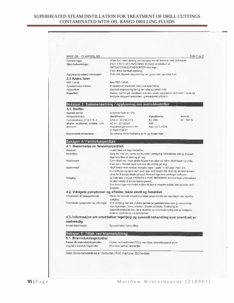
SUPERHEATED STEAM DISTILLATION FOR TREATMENT OF DRILL CUTTINGS
CONTAMINATED WITH OIL BASED DRILLING FLUIDS
95 | P a g e M a t t h e w W i n t e r b o u r n e ( 2 1 8 9 0 1 )

SUPERHEATED STEAM DISTILLATION FOR TREATMENT OF DRILL CUTTINGS
CONTAMINATED WITH OIL BASED DRILLING FLUIDS
96 | P a g e M a t t h e w W i n t e r b o u r n e ( 2 1 8 9 0 1 )

SUPERHEATED STEAM DISTILLATION FOR TREATMENT OF DRILL CUTTINGS
CONTAMINATED WITH OIL BASED DRILLING FLUIDS
97 | P a g e M a t t h e w W i n t e r b o u r n e ( 2 1 8 9 0 1 )
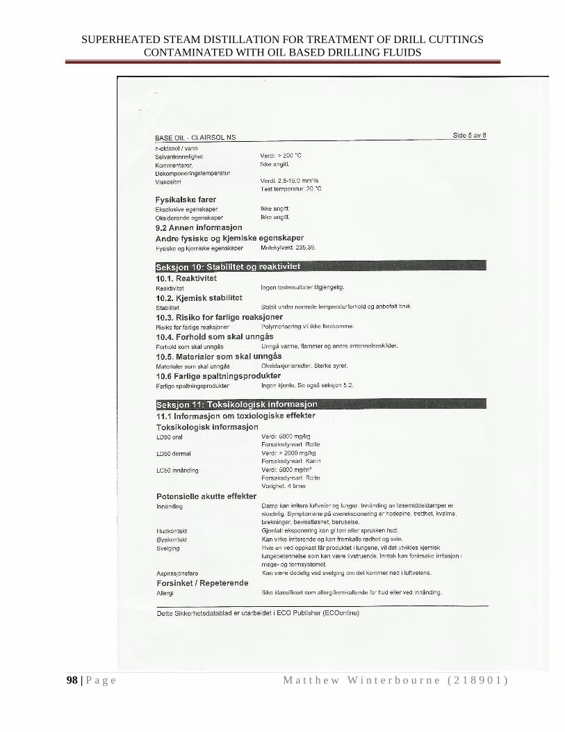
SUPERHEATED STEAM DISTILLATION FOR TREATMENT OF DRILL CUTTINGS
CONTAMINATED WITH OIL BASED DRILLING FLUIDS
98 | P a g e M a t t h e w W i n t e r b o u r n e ( 2 1 8 9 0 1 )

SUPERHEATED STEAM DISTILLATION FOR TREATMENT OF DRILL CUTTINGS
CONTAMINATED WITH OIL BASED DRILLING FLUIDS
99 | P a g e M a t t h e w W i n t e r b o u r n e ( 2 1 8 9 0 1 )
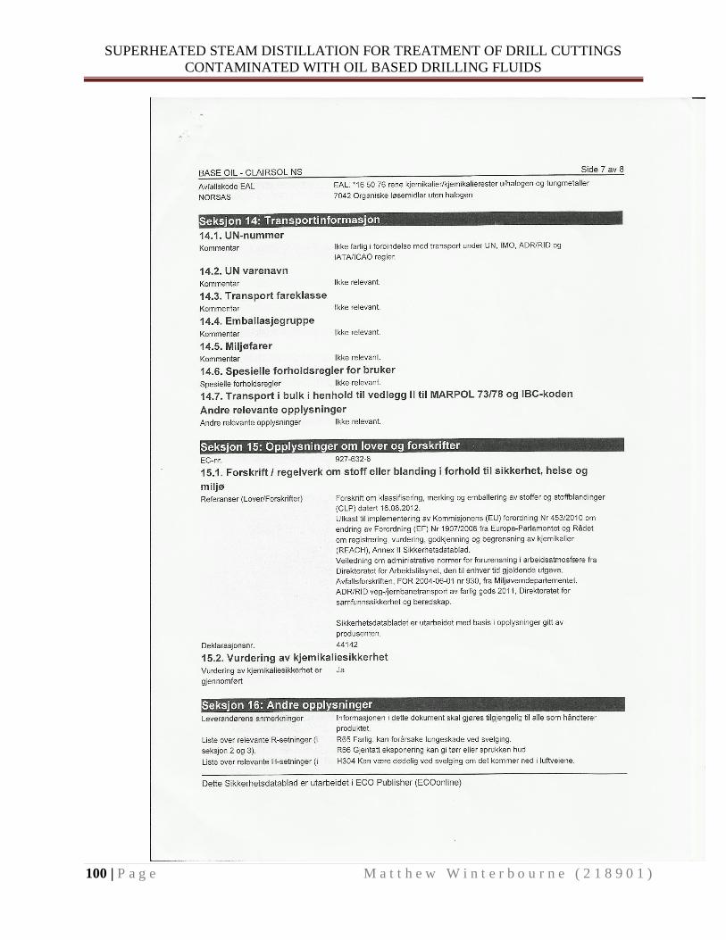
SUPERHEATED STEAM DISTILLATION FOR TREATMENT OF DRILL CUTTINGS
CONTAMINATED WITH OIL BASED DRILLING FLUIDS
100 | P a g e M a t t h e w W i n t e r b o u r n e ( 2 1 8 9 0 1 )

SUPERHEATED STEAM DISTILLATION FOR TREATMENT OF DRILL CUTTINGS
CONTAMINATED WITH OIL BASED DRILLING FLUIDS
101 | P a g e M a t t h e w W i n t e r b o u r n e ( 2 1 8 9 0 1 )

SUPERHEATED STEAM DISTILLATION FOR TREATMENT OF DRILL CUTTINGS
CONTAMINATED WITH OIL BASED DRILLING FLUIDS
102 | P a g e M a t t h e w W i n t e r b o u r n e ( 2 1 8 9 0 1 )
Appendix-3 Appendix -3 Table 1: Phase I vapor pressure versus temperature data for Sipdrill 2/0
Appendix-3 Table 2: Phase I vapor pressure versus temperature data for Clarisol NS

SUPERHEATED STEAM DISTILLATION FOR TREATMENT OF DRILL CUTTINGS
CONTAMINATED WITH OIL BASED DRILLING FLUIDS
103 | P a g e M a t t h e w W i n t e r b o u r n e ( 2 1 8 9 0 1 )
Appendix-3 Table 3: Phase II vapor pressure versus temperature data for Sipdrill 2/0
Appendix-3 Table 4: Phase II vapor pressure versus temperature data for Clarisol NS

SUPERHEATED STEAM DISTILLATION FOR TREATMENT OF DRILL CUTTINGS
CONTAMINATED WITH OIL BASED DRILLING FLUIDS
104 | P a g e M a t t h e w W i n t e r b o u r n e ( 2 1 8 9 0 1 )
Appendix-4 Appendix -4 Table 1: Sipdrill 2/0 experiment one data
Experiment #1 Steam Distillation: SIPDRILL 2/0
Trial # Steam + oil vapor temp ⁰C
Oil temp in flask ⁰C
Steam temp ⁰C
Copper coil pot temp ⁰C
Volume of oil distilled ml
Volume of water distilled ml
Volume Ratio
Oil/Water
1 107 99 146 170 5 40 0.125
2 110 110 183 204 11 89 0.124
3 116 108 190 206 15 85 0.176
4 126 116 195 210 8 30 0.267
5 138 120 195 210 29 71 0.408
6 138-162 166 196 212 20 20 1.000
7 165 166 196 212 13 7 1.857
8 170 180 198 213 27 13 2.077
9 171 180 198 213 23 10 2.300
10 172 180 198 213 60 28 2.143
Appendix -4 Table 2: Clairsol NS experiment one data
Experiment #1 Steam Distillation: CLAIRSOL NS
Trial #
Steam + oil vapor temp ⁰C
Oil temp in flask ⁰C
Steam temp ⁰C
Copper coil pot temp ⁰C
Volume of oil distilled ml
Volume of water distilled ml
Volume Ratio Oil/Water
1 111 106 185 208 2.5 47.5 0.053
2 117 116 185 216 3 50.5 0.059
3 120 124 186 216 3 27 0.111
4 133 138 189 215 5.5 34.5 0.159
5 146.5 148 198 214 8 27 0.296
6 159 156 198 217 7 18 0.389
7 176 174 198 214 10 15 0.667
8 178 178 198 214 16 24 0.667
9 194 184 198 214 10 10 1.000
10 195 186 198 214 15 15 1.000
11 202 200 198 214 13 12 1.083
12 202 200 198 214 16 14 1.143
13 203 202 198 214 17 13 1.308
14 203 202 198 214 37 23 1.609
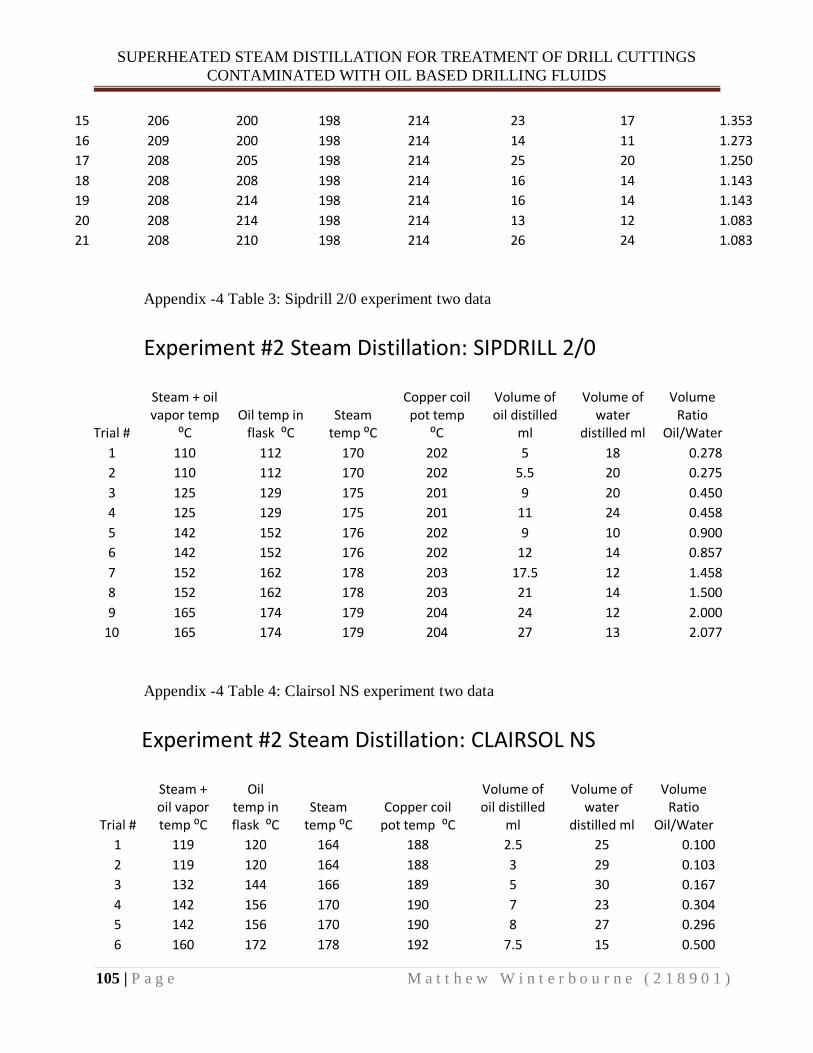
SUPERHEATED STEAM DISTILLATION FOR TREATMENT OF DRILL CUTTINGS
CONTAMINATED WITH OIL BASED DRILLING FLUIDS
105 | P a g e M a t t h e w W i n t e r b o u r n e ( 2 1 8 9 0 1 )
15 206 200 198 214 23 17 1.353
16 209 200 198 214 14 11 1.273
17 208 205 198 214 25 20 1.250
18 208 208 198 214 16 14 1.143
19 208 214 198 214 16 14 1.143
20 208 214 198 214 13 12 1.083
21 208 210 198 214 26 24 1.083
Appendix -4 Table 3: Sipdrill 2/0 experiment two data
Experiment #2 Steam Distillation: SIPDRILL 2/0
Trial #
Steam + oil vapor temp
⁰C Oil temp in
flask ⁰C Steam
temp ⁰C
Copper coil pot temp
⁰C
Volume of oil distilled
ml
Volume of water
distilled ml
Volume Ratio
Oil/Water
1 110 112 170 202 5 18 0.278
2 110 112 170 202 5.5 20 0.275
3 125 129 175 201 9 20 0.450
4 125 129 175 201 11 24 0.458
5 142 152 176 202 9 10 0.900
6 142 152 176 202 12 14 0.857
7 152 162 178 203 17.5 12 1.458
8 152 162 178 203 21 14 1.500
9 165 174 179 204 24 12 2.000
10 165 174 179 204 27 13 2.077
Appendix -4 Table 4: Clairsol NS experiment two data
Experiment #2 Steam Distillation: CLAIRSOL NS
Trial #
Steam + oil vapor temp ⁰C
Oil temp in flask ⁰C
Steam temp ⁰C
Copper coil pot temp ⁰C
Volume of oil distilled
ml
Volume of water
distilled ml
Volume Ratio
Oil/Water
1 119 120 164 188 2.5 25 0.100
2 119 120 164 188 3 29 0.103
3 132 144 166 189 5 30 0.167
4 142 156 170 190 7 23 0.304
5 142 156 170 190 8 27 0.296
6 160 172 178 192 7.5 15 0.500

SUPERHEATED STEAM DISTILLATION FOR TREATMENT OF DRILL CUTTINGS
CONTAMINATED WITH OIL BASED DRILLING FLUIDS
106 | P a g e M a t t h e w W i n t e r b o u r n e ( 2 1 8 9 0 1 )
7 160 172 178 192 8 16 0.500
8 160 172 178 192 11 20 0.550
9 177 180 178 196 9 11 0.818
10 177 180 178 196 16 19 0.842
11 177 180 178 196 14 16 0.875
12 191 196 206 243 11 10 1.100
13 191 196 206 243 16 14 1.143
14 191 196 206 243 22 19 1.158
15 198 208 196 231 19 21 0.905
16 198 208 196 231 8 13 0.615
17 202 215 210 236 7.5 7.5 1.000
Appendix -4 Table 5: Sipdrill 2/0 experiment one vapor pressure calculations

SUPERHEATED STEAM DISTILLATION FOR TREATMENT OF DRILL CUTTINGS
CONTAMINATED WITH OIL BASED DRILLING FLUIDS
107 | P a g e M a t t h e w W i n t e r b o u r n e ( 2 1 8 9 0 1 )
Appendix -4 Table 6: Clairsol NS experiment one vapor pressure calculations
Appendix -4 Table 7: Sipdrill 2/0 experiment two vapor pressure calculations

SUPERHEATED STEAM DISTILLATION FOR TREATMENT OF DRILL CUTTINGS
CONTAMINATED WITH OIL BASED DRILLING FLUIDS
108 | P a g e M a t t h e w W i n t e r b o u r n e ( 2 1 8 9 0 1 )
Appendix -4 Table 8: Clairsol NS experiment two vapor pressure calculations
Appendix -4 Table 9: Sipdrill 2/0 density experiment data
Appendix -4 Table 10: Clairsol NS density experiment data