Fractional Distillation & Characterization of Tire Derived ...
10
INTERNATIONAL JOURNAL of ENGINEERING TECHNOLOGIES-IJET Makhan Mia et al., Vol.3, No.1, 2017 1 Fractional Distillation & Characterization of Tire Derived Pyrolysis Oil Makhan Mia*, Ariful Islam*, Robiul Islam Rubel** ‡ , Mohammad Rofiqul Islam* * Department of Mechanical Engineering, Rajshahi University of Engineering & Technology, Rajshahi-6204, Bangladesh ** Department of Mechanical Engineering, Bangladesh Army University of Science & Technology, Saidpur Cantonment- 5311, Bangladesh ([email protected], [email protected], [email protected], [email protected]) ‡ Corresponding Author; Robiul Islam Rubel, Saidpur Cantonment-5311, Bangladesh, Tel: +088-1749-399-082, [email protected] Received: 03.01.2017 Accepted: 28.02.2017 Abstract- Energy is extracted recently from the waste products. Environmental pollutions are being minimized along with the addition of considerable amount of energy beside the conventional sources. The energy extracted from the waste leads a hope of alternative fuel for internal combustion engines as well as to meet other requirement. Common energy conversion method uses tire, wood, rubber to derived energy through pyrolysis. About 9.25% gaseous, 43% liquid, and 47% solid product are obtained from tire pyrolysis process at around 450°C temperature. The liquid fuel is directly used in the engines and that phase is a mixture of complex hydrocarbon. In this work Fractional Distillation, oxidative desulfurization and de-colorization for upgrading liquid product has been conducted. In fractional distillation 30%, 20%, 6.35%, 6%, 4.5%, and 1.3% by volume oils are obtained at over the temperature ranges- 121-180°C, 211-260°C, 71-120°C, 191-210°C, 181-190°C, and 40-70°C. Then by desulfurization around 54-58% sulphur was removed. For desulfurization hydrogen peroxide and formic acid (2:1 ratio) are used at constant temperature and magnetic stirring rate. The obtained fraction was characterized by elemental analyses, FT-IR techniques and compared with conventional diesel fuel. Sludge oil parts may be used as furnace oil which has higher calorific value than that of other conventional furnace oils. The rest of 40-70°C and 71-120°C oil parts may be used as alternative fuel like kerosene. Thus, the aim of the present study is to investigate the suitability of pyrolysis oil as an alternative fuel for IC engine. Keywords Pyrolysis, Fractional distillation, Tire pyrolysis oil, Upgrading and characterization. 1. Introduction The energy crisis and environmental degradation are the main problems in the present days due to growing population and rapid industrialization. Around the world, there are initiatives to replace gasoline and diesel fuel due to the impact of fossil fuel crisis and hike in oil price. Millions of dollars are being invested in the search for alternative fuels. The scrap tire is one of the common and important solid wastes all over the world including developing and semi developing country. Scrap tire production shows increasing trend due to increasing number of vehicle in both developed and underdeveloped countries [1]. Nearly one billion of waste vehicle tires are accumulated each year [2]. On the other hand, the disposal of waste tires from automotive vehicles appears complex. Degrading of scrap tires in the nature is difficult for many years. There are studies and available literature on pyrolysis of waste vehicles tires. Scrap tire disposing methods like landfill, reusing and burning can create serious hazards, especially in terms of human and environmental health. Thus, waste tire is required to keep under control without damaging the environment. One of the most favorable and effective disposing method is pyrolysis, which is environmental friendly and efficient way. Therefore, these valuable carbon compounds should be utilized by converting new and clean energies. Pyrolysis is the thermal fragmentation of solid substances in an airless environment. The products obtained with this process can be easily handled, stored and easy to transportation which increases the applicability of this method. Pyrolysis fluid can be used directly as fuel in boilers and can be used in internal combustion engines after modifications such as sulphur reduction and blending with diesel fuel. It is reported that pyrolysis oil of automobile tires contains 85.54% C, 11.28%
-
Upload
khangminh22 -
Category
Documents
-
view
0 -
download
0
Transcript of Fractional Distillation & Characterization of Tire Derived ...

INTERNATIONAL JOURNAL of ENGINEERING TECHNOLOGIES-IJET Makhan Mia et al., Vol.3, No.1, 2017
1
Fractional Distillation & Characterization of Tire
Derived Pyrolysis Oil
Makhan Mia*, Ariful Islam*, Robiul Islam Rubel**‡, Mohammad Rofiqul Islam*
* Department of Mechanical Engineering, Rajshahi University of Engineering & Technology, Rajshahi-6204, Bangladesh
** Department of Mechanical Engineering, Bangladesh Army University of Science & Technology, Saidpur Cantonment-
5311, Bangladesh
([email protected], [email protected], [email protected], [email protected])
‡ Corresponding Author; Robiul Islam Rubel, Saidpur Cantonment-5311, Bangladesh, Tel: +088-1749-399-082,
Received: 03.01.2017 Accepted: 28.02.2017
Abstract- Energy is extracted recently from the waste products. Environmental pollutions are being minimized along with the
addition of considerable amount of energy beside the conventional sources. The energy extracted from the waste leads a hope
of alternative fuel for internal combustion engines as well as to meet other requirement. Common energy conversion method
uses tire, wood, rubber to derived energy through pyrolysis. About 9.25% gaseous, 43% liquid, and 47% solid product are
obtained from tire pyrolysis process at around 450°C temperature. The liquid fuel is directly used in the engines and that phase
is a mixture of complex hydrocarbon. In this work Fractional Distillation, oxidative desulfurization and de-colorization for
upgrading liquid product has been conducted. In fractional distillation 30%, 20%, 6.35%, 6%, 4.5%, and 1.3% by volume oils
are obtained at over the temperature ranges- 121-180°C, 211-260°C, 71-120°C, 191-210°C, 181-190°C, and 40-70°C. Then by
desulfurization around 54-58% sulphur was removed. For desulfurization hydrogen peroxide and formic acid (2:1 ratio) are
used at constant temperature and magnetic stirring rate. The obtained fraction was characterized by elemental analyses, FT-IR
techniques and compared with conventional diesel fuel. Sludge oil parts may be used as furnace oil which has higher calorific
value than that of other conventional furnace oils. The rest of 40-70°C and 71-120°C oil parts may be used as alternative fuel
like kerosene. Thus, the aim of the present study is to investigate the suitability of pyrolysis oil as an alternative fuel for IC
engine.
Keywords Pyrolysis, Fractional distillation, Tire pyrolysis oil, Upgrading and characterization.
1. Introduction
The energy crisis and environmental degradation are
the main problems in the present days due to growing
population and rapid industrialization. Around the world,
there are initiatives to replace gasoline and diesel fuel due to
the impact of fossil fuel crisis and hike in oil price. Millions
of dollars are being invested in the search for alternative
fuels. The scrap tire is one of the common and important
solid wastes all over the world including developing and
semi developing country. Scrap tire production shows
increasing trend due to increasing number of vehicle in both
developed and underdeveloped countries [1]. Nearly one
billion of waste vehicle tires are accumulated each year [2].
On the other hand, the disposal of waste tires from
automotive vehicles appears complex. Degrading of scrap
tires in the nature is difficult for many years. There are
studies and available literature on pyrolysis of waste vehicles
tires. Scrap tire disposing methods like landfill, reusing and
burning can create serious hazards, especially in terms of
human and environmental health. Thus, waste tire is required
to keep under control without damaging the environment.
One of the most favorable and effective disposing method is
pyrolysis, which is environmental friendly and efficient way.
Therefore, these valuable carbon compounds should be
utilized by converting new and clean energies. Pyrolysis is
the thermal fragmentation of solid substances in an airless
environment. The products obtained with this process can be
easily handled, stored and easy to transportation which
increases the applicability of this method. Pyrolysis fluid can
be used directly as fuel in boilers and can be used in internal
combustion engines after modifications such as sulphur
reduction and blending with diesel fuel. It is reported that
pyrolysis oil of automobile tires contains 85.54% C, 11.28%

INTERNATIONAL JOURNAL of ENGINEERING TECHNOLOGIES-IJET Makhan Mia et al., Vol.3, No.1, 2017
2
H2, 1.92% O2, 0.84% S, and 0.42% N2 components [3].
Pyrolysis produces three principal products, such as pyrolytic
oil, gas and char. The quality and quantity of these products
depend upon the reactor temperature and design. In the
pyrolysis process, larger hydrocarbon chains break down at
certain temperatures in the absence of oxygen that gives end
products usually containing solids, liquids and gases.
Many studies have been done using systems such as
thermo-gravimetric analysis, fixed bed reactor, fluidized bed
pyrolysis unit, vacuum pyrolysis reactor and jet bed reactor,
among which vacuum pyrolysis reactor is easier and
effective. In addition, chemical products such as benzene,
toluene, xylene and limonene can be obtained from waste
vehicle tire pyrolysis liquid products [4-7]. The use of tire
pyrolysis oil as a substitute of diesel fuel is an opportunity in
minimizing the utilization of the natural resources. Isabel de
Marco Rotriguez et al. [8] studied the behaviour and
chemical analysis of tire pyrolysis oil. In their work it is
reported that tire oil is a complex mixture of organic
compounds of 5-20% carbons and with a higher proportion
of aromatics. The percentage of aromatics, aliphatic,
nitrogenized compounds, benzothiazol are also determined in
the tire pyrolysis oil at various operating temperatures of the
pyrolysis process [9]. Aromatics are found to be about 34.7%
to 75.6% when the operating temperature is varied between
300°C and 700°C, while aliphatic are about 19.8% to 59.2 %.
In the same work, an automatic distillation test is carried out
at 500 °C to analyze the potential use of tire pyrolysis oil as
petroleum fuels. It is observed that more than 30% of the tire
pyrolysis oil is easily distillable fraction with boiling points
between 70°C and 210°C, which is the boiling point range
specified for commercial petrol. On the other hand, 75% of
the pyrolytic oil has a boiling point under 370°C, which is
the upper limit specified for 95% of distilled product of
diesel oil. It was mentioned that distillation carried out
between 150°C and 370°C has a higher proportion of the
lighter and heavier products and a lower proportion of the
middle range of products than commercial diesel oil
structure. The influences of the distillation process on raw
pyrolytic fuel properties and on engine performance are
studied in a DI diesel engine by using different test fuels
which actually a blends of different pyrolytic tire oil and
diesel fuel.
The distillation process improved the fuel properties of
raw pyrolytic tire fuel, and the engine test results. The
viscosity and sulphur content of crude TPO are the two
parameters that influence the engine performance and
emissions. The high viscosity of the fuel will lead to
problems in the long run which include carbon deposit, oil
ring sticking etc. The high viscosity is due to its large
molecular mass and chemical showed that engine
performance and emissions can be improved by the
distillation process. The previous experimental works by the
authors [10-11] studied the effect of lower and higher
concentrations of the tire pyrolysis oil/diesel fuel blends on
the performance, emission and combustion characteristics of
a single cylinder, 4-stroke and water cooled, DI diesel engine
running. They reported that HC, NOX, CO and smoke
emissions usually increased with the increasing tire derived
fuel content in the diesel fuel blends. Furthermore, they
found that the increasing tire derived fuel content in the
diesel fuel blends increased the maximum combustion
pressure, rate of pressure rise and ignition delay. To
investigate a new source of petrol, kerosene and diesel like
fuel, study about the chemical and physical property of TPO
(Tire Pyrolytic Oil) is done. In this work a simplified
fractionation distillation column is used to drive oil from
waste tire. Again desulfurize, decolorize of pyrolysis oil is
done to prepare eco-friendly energy source compare to the
conventional diesel fuel.
2. Working Plant
A previously set pyrolysis plant shown in Fig. 1 is used
to collect the oil following the process chart in Fig. 2. Major
parts of the pyrolysis plant are:- (a) Reactor, (b)
Fractionating column, (c) 1st condenser, (d) CTPO-
Reservoir, (e) 2nd condenser, and (f) HQO-Reservoir.
2.1. Temperature distribution of tire pyrolysis plant
The temperature distribution is very important factor
for pyrolysis plant. Initially reactor temperature is 18ºC.
Then after every 30 minutes, temperature reading is recorded
during heating of the reactor. The reactor is heated at an
increasing rate up to first 120 minutes of running operation.
Then the next 120 minutes was maintained at constant
temperature near about 455ºC (± 5ºC). Then the portable
parts of the insulated side wall of reactor shield are removed
for cooling. Temperature distribution during the reactor
heating operation is presented in Fig. 3.
2.2. Performance of the plant
The performance data is collected during operating time
of pyrolysis plant presented in Table 1. The reactor
temperature becomes stagnant at 455ºC. The condenser
outlet is fixed at 20 Lit/min.
2.3. Pyrolysis products from pilot plant
In tire pyrolysis system liquid, char and gases products
are obtained. Pyrolytic liquid is the main products in
pyrolysis process. Char and gases are two by products which
may be used as fuel for reactor heating purpose. Several runs
are carried out by using prepared tire waste samples.
Fig. 1. Pyrolysis plant (for 200 kg scrap tire).

INTERNATIONAL JOURNAL of ENGINEERING TECHNOLOGIES-IJET Makhan Mia et al., Vol.3, No.1, 2017
3
Fig. 2. Process flow chart.
Fig. 3. Temperature distribution in reactor and reservoir with
time.
Table 1. Data collected from pyrolysis unit during operation
Reactor
tempt.
(ºC)
Reservoir
tempt.
(ºC)
Water
Inlet
tempts.
(ºC)
Water
outlet
tempts.
(ºC)
Condenser
water flow
rate
(Lit./min.)
18 18 18 18 20
93 18 18 18 20
309 18 18 21 20
444 48 19 22 20
455 53 20 24 20
455 54 20 25 20
455 54 20 25 20
455 54 20 25 20
455 54 20 25 20
455 54 20 25 20
455 54 20 25 20
The product distributions obtained from the pilot plant
experiments are presented in Table 2. In Table 3 the
properties of TPO is shown and comparison results is given
in Table 4.
Table 2. Product yields distribution of tire pyrolysis for
different sizes
Feed size
(cm)
Tire
feed
(Kg)
Product yield
Liquid Char
Higher
quality
oil
Gas
15×15×3 200 66 kg
(33%)
112 kg
(56%)
1.1kg
(0.55%) 10.45%
20×20×3 200 86 kg
(43%)
94 kg
(47%)
1.5kg
(0.75%) 9.25%
Table 3. Properties of diesel, crude TPO, TPO
Property Conventional
diesel
Crude
TPO TPO
Density (kg/ m3 ) 872.3 942.6 848.69
Viscosity (centi
poise) (at 30(ºC) 4 4.2 1.4
Calorific value
(MJ/kg) 44.832 41.5 42.37
Flash point (ºC) 65 40 45.7
Pour point (ºC) -30 to -40 -2 -6
Table 4. Comparing the properties of our TPO with a
reference book [12]
Property Conventional
Diesel
Crude
TPO TPO
Density (kg/ m3 ) 830 935 871
Viscosity (centi
poise)(at 40ºC) 2 3.2 1.7
Calorific value
(MJ/kg) 46.5 42.83 45.78
Flash point (ºC) 50 43 36
3. Fractional distillation
In common industrial jargon, distillation is used
sometimes to mean fractional, and not merely simple
distillation. Fractional distillation or fractionation however,
is in fact a special type of distillation, and as a separation
technique, is much more effective than simple distillation
and more efficient. In effect, fractionation is equivalent to a
series of distillations, where the separation is achieved by
successive distillations or repeated vaporization-
condensation cycles. Each vaporization-condensation cycle
makes for an equilibrium stage, commonly known as a
theoretical stage. A number of such theoretical stages may be

INTERNATIONAL JOURNAL of ENGINEERING TECHNOLOGIES-IJET Makhan Mia et al., Vol.3, No.1, 2017
4
required for the efficient fractionation and separation of the
vapor or liquid mixture. Fig. 4 shows a simple fractional
distillation column and its major parts are a. Electric heater,
b. Round cylindrical reactor, c. Column, d. Thermometer
adaptor, e. Condenser, and f. Oil collector.
Electric Heater: Electric heater was made by 3000 watt
nicrome wire.
Round Cylindrical Reactor: The distillation column
uses 8500 ml round cylindrical reactor. The height of the
reactor is 34.29 cm, inner diameter is 17.78 cm.
Column: Height of hollow column is 83.82 cm. A
number of general rules of thumb are used as a general guide
before carrying out the actual calculations, but these rules
often have exceptions.
Such rules as related to column diameter include the
following four rules given below [13].
a. The length to diameter ratio should be less than 30,
preferably below 20, and tower height is to be limited to 60
meters because of wind load and foundation concerns. If the
tower is higher than 60 m, then a design with smaller tray
spacing should be considered [14].
b. The ratio of tower diameter to random packing size is
greater than 10.
c. The tower diameter should be maintained at 1.2 meters at
the top for vapor disengagement.
d. The tower diameter should be maintained at 2 meters at
the bottom for liquid level and re-boiler return. In normal
practice, however, only one diameter is calculated for the
whole column. Different column diameters would only be
used where there is a considerable change in flow-rate.
Changes in liquid rate can be allowed for by adjusting the
liquid down comer areas [15]. If two or more diameters are
calculated, say for the top and bottom sections of the column,
then roughly speaking, when the difference in the calculated
diameters exceeds 20%, different diameters for the top and
bottom sections are likely to be economical and sections
having different diameters should be at least 600 cm (20 ft.)
in length. Otherwise the diameter should be uniform. The
preliminary column diameter would then be the larger of the
two calculated diameters [16].
Thermometer adopter: A small scale degree Celsius
thermometer is used in this column. A thermometer holder
holds this thermometer appropriate position which can give
appropriate result. For proper holding the thermometer M-
seal gum is used.
Condenser: For proper condensing purpose, a
condenser is used as libig condenser where tap water is
passing through it at moderate flow rate. During water flow
tap water pipe is connected below the condenser and exhaust
water pipe is above. The total length of condenser is 71.12
cm, outer diameter is 7.62 cm and inner diameter is 2 cm.
Oil collector: For different oil fraction collection, a
special oil collector which can give out the non-condensable
gases is used.
Insulation: Glass wool is an insulating material made
from fibers of glass arranged using a binder into a texture
similar to wool. The process traps many small pockets of air
between the glass, and these small air pockets result in high
thermal insulation properties. Glass wool is produced in rolls
or in slabs, with different thermal and mechanical properties.
It may also be produced as a material that can be sprayed or
applied in place, on the surface to be insulated [17].
3.1. Collection of crude TPO
TPO is collected from the university inventory as in Fig.
5. The pyrolysis was done in a fixed bed pyrolysis reactor in
a temperature range 350-400˚C. The setup includes a
condenser and fractionating column. Nitrogen gas was used
to maintain an inert environment. In this pyrolysis, an
automobile tire was cut into a number of pieces and the bead,
steel wires and fabrics were removed. Thick rubber portion at
the periphery of the tire is made into small chips like piece.
Fig. 4. Experimental set up for fractional distillation.
Fig. 5. Crude pyrolysis oil.
Fig. 6. Process flow chart of Fractional distillation.

INTERNATIONAL JOURNAL of ENGINEERING TECHNOLOGIES-IJET Makhan Mia et al., Vol.3, No.1, 2017
5
(a) (b)
Fig. 7. (a) Desulfurization of oil; (b) Separation of oil.
Fig. 8. Desulfurization and De-colorization of Fractionated
oil.
The tire chips are washed and dried before feeding in the
reactor unit. The chips feed is heated externally in absence of
oxygen in the reactor. During the pyrolysis, large molecules
of liquefied tires were converted into steam and rose out of
the rector at high temperature. Vapor of these products is
liquefied with the help of reactor condenser to obtain liquid
product.
3.2. Desulfurization of Fractionated oil
The desulfurization as presented in Fig. 7 of fractionated
oil has the following stages as mentioned in Fig. 8.
Oxidation stage: In this step 10% solution of a mixture
hydrogen peroxide and formic acid (2:1) is used. This
mixture has mild oxidizing effect and oxidized the sulfur,
which existing in the form of complex aromatic compound.
In this step major of sulfur compound is oxidized. Another
de-oxidation method may also be used but they have
negative effect on the hydrocarbon mixture of pyrolysis oil.
Extraction stage: Extraction step is another most
important step because in this step the oxygenated sulfur
compound is extracted by suitable solvent.
Fig. 9. Total upgraded oil yields from tire pyrolysis oil
(TPO).
Fig. 10. Upgraded oil from tire pyrolysis oil (TPO).
The solvent may be ethanol, methanol, acetone, N, N-
dimethyl formamide. But among this N, N-dimethyl
formamide is most effective for extraction of oxygenated
compound.
3.3. De-colorization of Fractionated oil
For further de-colorization thermally activated bentonite
powder is used by suitable 10g weighed per 100 ml oil
sample. Magnetic stirrer is used for mixing the oil with
bentonite powder. After filtration the filtrate oil color is
developed.
4. Results and Discussions
4.1. Upgrading by fractional distillation
During upgrading process pyrolytic liquid is fractionated
into seven parts by using distillation column as depicted in
Fig. 9. Here pyrolytic liquid was classified as 40-70°C, 71-
120°C, 121-180°C, 181-190°C, 191-210°C, 210-260°C, and
non-fractionated residue oil by using their boiling point
difference. Several successful runs were carried out by using
prepared raw pyrolysis liquid samples to obtain sufficient
amount of fractionated oil. The product distributions
obtained from the fractional distillation process are presented
in Table 5 and Fig. 10.
4.2. Characterization of upgraded pyrolysis oil
Pyrolytic liquids obtained under the maximum liquid
yield conditions are well mixed and homogenized prior to
INTERNATIONAL JOURNAL of ENGINEERING TECHNOLOGIES-IJET Makhan Mia et al., Vol.3, No.1, 2017
6
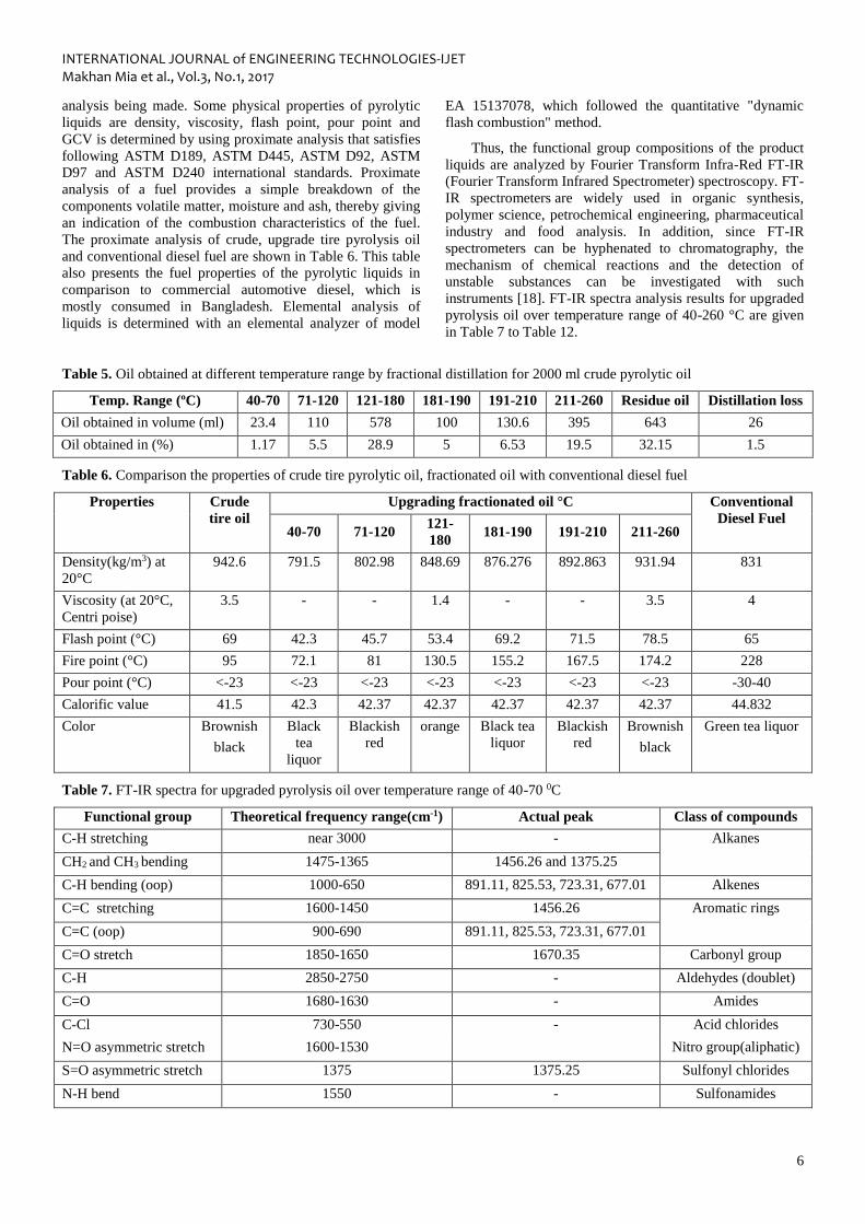
analysis being made. Some physical properties of pyrolytic
liquids are density, viscosity, flash point, pour point and
GCV is determined by using proximate analysis that satisfies
following ASTM D189, ASTM D445, ASTM D92, ASTM
D97 and ASTM D240 international standards. Proximate
analysis of a fuel provides a simple breakdown of the
components volatile matter, moisture and ash, thereby giving
an indication of the combustion characteristics of the fuel.
The proximate analysis of crude, upgrade tire pyrolysis oil
and conventional diesel fuel are shown in Table 6. This table
also presents the fuel properties of the pyrolytic liquids in
comparison to commercial automotive diesel, which is
mostly consumed in Bangladesh. Elemental analysis of
liquids is determined with an elemental analyzer of model
EA 15137078, which followed the quantitative "dynamic
flash combustion" method.
Thus, the functional group compositions of the product
liquids are analyzed by Fourier Transform Infra-Red FT-IR
(Fourier Transform Infrared Spectrometer) spectroscopy. FT-
IR spectrometers are widely used in organic synthesis,
polymer science, petrochemical engineering, pharmaceutical
industry and food analysis. In addition, since FT-IR
spectrometers can be hyphenated to chromatography, the
mechanism of chemical reactions and the detection of
unstable substances can be investigated with such
instruments [18]. FT-IR spectra analysis results for upgraded
pyrolysis oil over temperature range of 40-260 °C are given
in Table 7 to Table 12.
Table 5. Oil obtained at different temperature range by fractional distillation for 2000 ml crude pyrolytic oil
Temp. Range (ºC) 40-70 71-120 121-180 181-190 191-210 211-260 Residue oil Distillation loss
Oil obtained in volume (ml) 23.4 110 578 100 130.6 395 643 26
Oil obtained in (%) 1.17 5.5 28.9 5 6.53 19.5 32.15 1.5
Table 6. Comparison the properties of crude tire pyrolytic oil, fractionated oil with conventional diesel fuel
Properties Crude
tire oil
Upgrading fractionated oil °C Conventional
Diesel Fuel 40-70 71-120
121-
180 181-190 191-210 211-260
Density(kg/m3) at
20°C
942.6 791.5 802.98 848.69 876.276 892.863 931.94 831
Viscosity (at 20°C,
Centri poise)
3.5 - - 1.4 - - 3.5 4
Flash point (°C) 69 42.3 45.7 53.4 69.2 71.5 78.5 65
Fire point (°C) 95 72.1 81 130.5 155.2 167.5 174.2 228
Pour point (°C) <-23 <-23 <-23 <-23 <-23 <-23 <-23 -30-40
Calorific value 41.5 42.3 42.37 42.37 42.37 42.37 42.37 44.832
Color Brownish
black
Black
tea
liquor
Blackish
red
orange Black tea
liquor
Blackish
red
Brownish
black
Green tea liquor
Table 7. FT-IR spectra for upgraded pyrolysis oil over temperature range of 40-70 0C
Functional group Theoretical frequency range(cm-1) Actual peak Class of compounds
C-H stretching near 3000 - Alkanes
CH2 and CH3 bending 1475-1365 1456.26 and 1375.25
C-H bending (oop) 1000-650 891.11, 825.53, 723.31, 677.01 Alkenes
C=C stretching 1600-1450 1456.26 Aromatic rings
C=C (oop) 900-690 891.11, 825.53, 723.31, 677.01
C=O stretch 1850-1650 1670.35 Carbonyl group
C-H 2850-2750 - Aldehydes (doublet)
C=O 1680-1630 - Amides
C-Cl 730-550 - Acid chlorides
N=O asymmetric stretch 1600-1530 Nitro group(aliphatic)
S=O asymmetric stretch 1375 1375.25 Sulfonyl chlorides
N-H bend 1550 - Sulfonamides

INTERNATIONAL JOURNAL of ENGINEERING TECHNOLOGIES-IJET Makhan Mia et al., Vol.3, No.1, 2017
7
Table 8. FT-IR spectra for upgraded pyrolysis oil over temperature range of 71-120 0C
Functional group Theoretical frequency range (cm-1) Actual peak Class of compounds
C-H stretching near 3000 2958.80 Alkanes
CH2 and CH3 bending 1475-1365 1456.26 and 1377.17
C-H stretching greater 3000 - Alkenes
C-H bending (oop) 1000-650 817.82, 813.36, 677.01
C=C stretching 1600-1450 1494.83 Aromatic rings
C=C (oop) 900-690 817.82, 813.36, 677.01
C=O stretch 1850-1650 Carbonyl group
C-H 2850-2750 - Aldehydes
(doublet)
C-Cl 730-550 - Acid chlorides
N-H bend 1640-1560 1558.48 Secondary amines
N-H (oop) near 800 - Amines
N=O asymmetric stretch 1550-1490 1494.83 Nitro group
(aromatic)
S=O asymmetric stretch 1375 1377.17 Sulfonyl chlorides
Table 9. FT-IR spectra for upgraded pyrolysis oil over temperature range 121-180 0C
Functional group Theoretical frequency range (cm-1) Actual peak Class of compounds
C-H stretching near 3000 2973 Alkanes
CH2 and CH3 bending 1475-1365 1456.26 and 1377.17
C-H stretching greater 3000 3026.31 Alkenes
C-H bending (oop) 1000-650 889.18, 694.37 -
C=C stretching 1600-1450 1456.26 Aromatic rings
C=C (oop) 900-690 889.18, 694.37
C=O stretch 1850-1650 - Carbonyl group
C-H 2850-2750 - Aldehydes (doublet)
C=O 1680-1630 - Amides
C-Cl 730-550 - Acid chlorides
N-H bend 1640-1560 - Secondary amines
N-H (oop) near 800 - Amines
N=O asymmetric stretch 1600-1530 - Nitro group (aliphatic)
N=O asymmetric stretch 1550-1490 - Nitro group (aromatic)
S=O asymmetric stretch 1375 1377.17 Sulfonyl chlorides
N-H bend 1550 - Sulfonamides
S=O asymmetric 1350 - Sulfonic acids

INTERNATIONAL JOURNAL of ENGINEERING TECHNOLOGIES-IJET Makhan Mia et al., Vol.3, No.1, 2017
8
Table 10. FT-IR spectra for upgraded pyrolysis oil over temperature range 181-190 0C
Functional group Theoretical frequency range (cm-1) Actual peak Class of compounds
C-H stretching near 3000 2960.73 Alkanes
CH2 and CH3 bending 1475-1365 1456.26 and 1375.25
C-H stretching greater 3000 3016.67 Alkenes
C-H bending (oop) 1000-650 891.11, 823.60, 725.23
C=C stretching 1600-1450 1506.41 Aromatic ring
C=C (oop) 900-690 891.11, 823.60, 725.23
C=O stretch 1850-1650 1683.86 Carbonyl group
C-H 2850-2750 - Aldehydes (doublet)
N-H stretch 3475-3150 - Amides
C=O 1680-1630 -
C-Cl 730-550 725.23 Acid chlorides
N-H bend 1640-1560 1616.36 Secondary amines
N-H (oop) near 800 - Amines
N=O asymmetric stretch 1600-1530 - Nitro group(aliphatic)
N=O asymmetric stretch 1550-1490
S=O asymmetric stretch 1375 1375.25 Sulfonyl chlorides
N-H bend 1550 1506.41 Sulfonamides
Table 11. FT-IR spectra for upgraded pyrolysis oil over temperature range 191-210 0C
Functional Group Theoretical frequency range (cm-1) Actual peak Class of compounds
C-H stretching near 3000 2973 Alkanes
CH2 and CH3 bending 1475-1365 1456.25 and 1377.17
C-H stretching greater 3000 3016.67 Alkenes
C-H bending (oop) 1000-650 891.11, 821.68, 740.67, 690.52 Aromatic rings
C=C stretching 1600-1450 1506.41, 1456.26
C=C bending (oop) 900-690 891.11, 690.52 Carbonyl group
C=O stretch 1850-1650 1670.35
C-H 2850-2750 - Aldehydes (doublet)
C=O 1680-1630 - Amides
N-H stretch 3475-3150 - Acid chlorides
C-Cl stretch 730-550 -
N-H bend 1640-1560 - Secondary amines
N-H (oop) near 800 - Amines
N=O asymmetric stretch 1600-1530 1558.48 Nitro group
(aliphatic)
N=O asymmetric stretch 1550-1490 1506.41 Nitro group
(aromatic)
S=O asymmetric stretch 1375 1377.17 Sulfonyl chlorides
N-H bend 1550 - Sulfonamides

INTERNATIONAL JOURNAL of ENGINEERING TECHNOLOGIES-IJET Makhan Mia et al., Vol.3, No.1, 2017
9
Table 12. FT-IR spectra for upgraded pyrolysis oil over temperature range 211-260 0C
Functional group Theoretical frequency range (cm-1) Actual peak Class of compounds
C-H stretching near 3000 2956.87 Alkanes
CH2 and CH3 bending 1475-1365 1456.26 and 1375.25
C-H stretching greater 3000 3400 Alkenes
C-H bending (oop) 1000-650 -
C=C stretching 1600-1450 1558.48, 1506.41, 1456.2 Aromatic rings
C=C (oop) 900-690 730
C-O stretch 1260-1000 1197.79, 1122.57 Phenols
C=O stretch 1850-1650 1670.35 Carbonyl group
C-H 2850-2750 - Aldehydes (doublet)
C=O 1680-1630 1670.35 Amides
C-Cl 730-550 - Acid chlorides
C-O stretch 1300-900 11197.79, 1122.57 Anhydrides
N-H stretch 3500-3300 - Amines
N-H bend 1640-1560 1558.48 Secondary amines
N-H (oop) near 800 - Amines
N=O asymmetric stretch 1600-1530 1558.48 Nitro group(aliphatic)
N=O asymmetric stretch 1550-1490 1506.41
S=O asymmetric stretch 1375 1375.25 Sulfonyl chlorides
N-H bend 1550 - Sulfonamides
5. Conclusions and Recommendations
The physical and chemical characterizations of the
raw pyrolysis oil derived from light automotive tire waste
has been carried out and compared with conventional
fuels. The pyrolytic liquids obtained from pyrolysis of
automotive tire wastes, which are oily organic compounds,
appears dark-brown-color with a strong acrid smell.
Careful handling of the liquids is required since it reacts
easily with human skins, leaving permanent yellowish
brown marks and an acrid smell for a few days, which is
difficult to remove by detergent. No phase separation was
found to take place in the storage bottles. Experimental
consequences are summarized below-
a. Improved pyrolysis system is designed, so that
higher quality oil possible to separate from crude tire
pyrolysis oil reservoir.
b. Fractional distillation yields more pyro-oil in the
temperature range of 121-180°C.
c. The density of fractionated pyrolytic liquids is found
lower than that of the commercial diesel fuel and
also lower than that of heavy fuel oil.
d. The density of 40-70°C, 71-120°C, 121-180°C, 181-
190°C, 191-210°C, 211-260°C are 791.5, 802.98,
848.69, 876.276, 892.863, 931.94 (kg/m3) at 20 °C.
Where conventional diesel fuel has density 831 (kg/m3).
e. The viscosity of fractionated liquid products from
tire wastes is slightly lower than that of the diesel but
also much lower than that of heavy fuel oil. Low
viscosity of the liquids at 121-180°C and 211-260°C
are 1.4 and 3.5 Centri poise at 20°C and conventional
diesel fuel has viscosity 4.0 Centri poise at 27°C is a
favorable feature in the handling and transporting of
the liquid.
f. The flash point of the tire-derived crude liquid at 40-
70°C, 71-120°C, 121-180°C, 181-190°C, 191-
210°C, 211-260°C oils are 42.3°C, 45.7°C, 53.4°C,
69.2°C, 71.5°C 78.5°C obtained at 20°C and for
conventional diesel fuel 65°C obtained at 27°C. The
flash point is low when compared with petroleum-
refined fuels.
g. The fire point at 40-70°C, 71-120°C, 121-180°C,
181-190°C 191-210°C and 211-260°C oils are
72.1°C, 81°C, 130.5°C, 155.2°C, 167.5°C, 174.2°C
and conventional diesel fuel is 228°C, which is
greater than fractionated oil.
h. The pour point of the tire-derived liquids is -6 °C.
The calorific value of the upgraded tire oil is 42.37
MJ/Kg. The calorific value is high and comparable

INTERNATIONAL JOURNAL of ENGINEERING TECHNOLOGIES-IJET Makhan Mia et al., Vol.3, No.1, 2017
10
with that of a diesel fuel oil, indicating the potential
for the use of tire derived oils as fuel.
i. The upgraded fractionated oil has lower viscosity,
good spray quality and proper combustion with
compared to conventional fuel.
j. The pyrolytic liquids abundantly contain olefins,
specially limonene and light aromatics, whose have
higher market values as chemical feedstock than
their use as fuels.
Some steps may be taken to improve the oil grade. The
foregoing recommendations are-
a. Special glass made fractional column is
recommended for smooth or perfect operation as
metal has conductivity higher than glass.
b. The TPO has many impurities and odor, which
causes its use difficult. Further chemical and
physical treatment is required to remove this.
c. The color of TPO is not stable, it changes with time
as there some sludge remains. To prevent this
problem some further steps should be taken.
d. The unit production cost of pyrolysis oil and
upgrading by suitable method is analyzed suitably
for large scale production.
e. Finally, it may be concluded that the fractional
distillation can be run only under continuous
monitoring and consultancy support of a tire
pyrolysis specialist team.
Acknowledgement
The authors acknowledge the gratitude to Rajshahi
University of Engineering & Technology, Bangladesh for
the benevolent attitude such as mental support, guidance
and allowing using research labs.
References
[1] Scrap tire markets in the United States, 9th Biennial
Report, Rubber Manufacturers Association, May
2009.
[2] Rubber Manufacturers Association (RMA), Scrap Tire
Markets in the United States; 2005.
[3] A. M. Mastral, R. Murillo , M. S. Callen, and T.
Garcia, “Optimisation of scrap automotive tyres
recycling into valuable liquid fuels”, Resources,
Conservation and Recycling, Vol. 29, Issue 4, pp.
263–272, June 2000.
[4] A. M. Cunliffe, and P. T. Williams, “Composition of
oils derived from the batch pyrolysis of tyres”, Journal
of Analytical and Applied Pyrolysis, Vol. 44, Issue 2,
pp. 131–152, January 1998.
[5] P. T. Williams, and A. J. Brindle, “Temperature
selective condensation of tyre pyrolysisoils to
maximise the recovery of single ring aromatic
compounds”, Fuel, Vol. 82, Issue 9, pp. 1023–1031,
June 2003.
[6] S. Ucar, S. Karagoz, A. R. Ozkan, and J. Yanik,
“Evaluation of two different scrap tires ash
hydrocarbon source by pyrolysis”, Fuel, Vol. 84,
Issues 14–15, pp. 1884–1892, October 2005.
[7] C. Berrueco, E. Esperanza, F. J. Mastral, J. Ceamanos,
and P. Garcı´a-Bacaicoa, “Pyrolysis of waste tyres in a
atmospheric static-bed batch reactor”, Journal of
Analytical and Applied Pyrolysis, Vol. 74, Issues 1–2,
pp. 245–253, August 2005.
[8] Isabel de Marco Rodriguez, M. F. Laresgoiti, M. A.
Cabrero, A Torres, M. J. Chomón, and B. Caballero,
“Pyrolysis of scrap tyres”, Fuel Processing
Technology, Vol. 72, Issue 1, pp. 9–22, August 2001.
[9] M. R. Islam, M. N. Islam, N. N. Mustafi, M. A.
Rahim, and H. Haniu, “Thermal recycling of solid tire
wastes for alternative liquid fuel: the first
commercial step in Bangladesh”, Procedia
Engineering Vol. 56, pp. 573-582, 2013.
[10] S. Murugan, M. C. Ramaswamy, and G.
Nagarajan, A comparative study on the performance,
emission and combustion studies of a DI diesel engine
using distilled tire pyrolysis oil–diesel blends, Fuel,
Vol. 87, Issues 10–11, pp. 2111–2121, August 2008.
[11] S. Murugan, M. C. Ramaswamy, and G.
Nagarajan, The use of tire pyrolysis oil in diesel
engines, Waste Management, Vol. 28, Issue 12, pp.
2743–2749, December 2008.
[12] J. L. Humphrey, and G. E. Keller, Separation
Process Technology, New York: McGraw-Hill, 1997,
ch. 1.
[13] K. Kolmetz, W. K. Ng, S. H. Lee, T. Y. Lim, D.
R. Summers, and C. A. Soyza, “Optimize distillation
column design for improved reliability in operation and
maintenance”, 2nd Best Practices in Process Plant
Management, Kuala Lumpur, Malaysia, March 14-15,
2005.
[14] Distillation Column Selection and Sizing. KLM
Technology group, Available at:
www.klmtechgroup.com, 2011.
[15] R. K. Sinnott, Coulson & Richardson’s Chemical
Engineering, 4th ed., Vol. 6. Elsevier, 2006, pp. 564-
565.
[16] H. Z. Kister, Distillation design. New York:
McGraw-Hill Book Co., 1992, ch. 3.
[17] Uses and Benefits of Glass Wool,
https://storify.com/VarunSharma123/uses-and benefits-
of-glass-wool, 2016.
[18] How an FTIR Spectrometer Operates. Available
at:http://chemwiki.ucdavis.edu/Core/Physical_Chemistr
y/Spectroscopy/Vibrational_Spectroscopy/Infrared_Spe
ctroscopy/How_an_FTIR_Spectrometer_Operates,
2016.