
Column Revamps - Pro-Tek Process
86
www.chemengonline.com COLUMN REVAMPS • INDUSTRIAL DRYING VOL. 122 NO. 4 APRIL 2015 April 2015 04 An Insider’s Guide to Column Revamps Gas Analysis Size Reduction Focus on Compressors, Fans and Blowers Metals Recycling Rectangular Tanks Facts at Your Fingertips: Industrial Microorganisms Industrial Drying: Two-Part Feature Report page 38
-
Upload
khangminh22 -
Category
Documents
-
view
1 -
download
0
Transcript of Column Revamps - Pro-Tek Process

www.chemengonline.com
CO
LUM
N REVA
MPS • IN
DU
STRIAL D
RYING
V
OL. 122 N
O. 4 A
PRIL 2015
April 2015
04
An Insider’s Guide to Column Revamps
Gas Analysis
Size Reduction
Focus on Compressors,
Fans and Blowers
Metals Recycling
Rectangular Tanks
Facts at Your Fingertips: Industrial Microorganisms
Industrial Drying: Two-Part Feature Report
page 38

Simple.
Zeeco’s ultra-low NOx GLSF Enhanced Jet Flat Flame burner has earned rave
reviews for zero flame rollover, compact design, better turndown rates, and
reliable, long-lasting performance.
Our smokeless multi-point ground flares are customized for the flow,
pressure and gas composition your facility requires.
And while Zeeco is considered a breath of fresh air when it comes to
providing low-emissions combustion and environmental solutions, we also
take great pride in our aftermarket parts, service and rapid response team.
In short, ZEECO® products and services keep your operation in compliance,
keep your people safe, and keep plants simply running smoother.
Why Does the Ethylene Industry
Insist on Zeeco?
Experience the Power of Zeeco.
Burners • Flares • Thermal Oxidizers • Vapor Control Aftermarket: Parts, Service & Engineered Solutions
Explore our global locations at Zeeco.com/global
Zeeco, Inc. 22151 E 91st St.
Broken Arrow, OK 74014 USA +1 918 258 8551 [email protected]
©Zeeco, Inc. 2015
Global experience. Local expertise.
ZEECO GLSF Enhanced Jet Flat Flame Burner
Circle 24 on p. 78 or go to adlinks.chemengonline.com/56196-24

CHEMICAL ENGINEERING WWW.CHEMENGONLINE.COM APRIL 2015 1
April 2015 Volume 122 | no. 4
Cover Story38 Column Revamps: From Outside to Inside
Some of the many things to consider for this complex task
are presented here
In the News7 Chementator
Biomass pretreatment approach can reduce enzyme
requirements; Making bio-based PET monomer from furfural;
Scaleup for an alternative route to PC monomer; Making fuels from
almost any organic material; End-to-end demonstration of CO2-to-
ethanol process achieved; and more
16 Business News
Arkema to expand production of PEKK specialty polymer;
Perstorp starts up plasticizer plant extension; ABB to build
manufacturing site in Tennessee; AkzoNobel breaks ground on
alkoxylation facility; Evonik to acquire Monarch Chemicals; Total
acquires majority stake in plastics company Polyblend; and more
18 Newsfront New Frontiers in Metals Recycling
Precious and rare-earth metals are used in countless consumer products, and
advanced processes to efficiently recover these materials from waste present
promising alternative sources
24 Newsfront The Changing Face of Gas Analysis
Calibration-free, modular and automated gas analyzers provide benefits to the
chemical process industries (CPI)
Technical and Practical35 Facts at your Fingertips Industrial Microorganisms
This one-page reference provides information on important microorganisms
and their industrial applications
36 Technology Profile Onsite Enzyme Production
The column describes a process to manufacture the enzyme cellulase, which
can be used to produce ethanol from lignocellulosic biomass
48 Feature Report Part 1 Vacuum Drying Basics
Vacuum drying can be a useful tool for products that are heat-sensitive.
Here are some guidelines for the selection and use of various types of
vacuum dryers
56 Feature Report Part 2 Wastewater Sludge Centrifugation Before Drying
The decanter centrifuge is an important piece of equipment for sludge volume
reduction prior to thermal drying. Understanding centrifuge operation helps
manage drying energy costs
www.chemengonline.com
18
48
56
38
Burners • Flares • Thermal Oxidizers • Vapor Control Aftermarket: Parts, Service & Engineered Solutions
Explore our global locations at Zeeco.com/global
Global experience. Local expertise.
24

CHEMICAL ENGINEERING WWW.CHEMENGONLINE.COM APRIL 20152
61 Engineering Practice A Primer on Rectangular Tanks
This type of tank is often preferred to cylindrical tanks when space is limited.
Follow this guidance to calculate the relevant dimensions and ensure safe
construction
68 Solids Processing Increase Profits in Size-Reduction
Plants Material- and energy-balance models can help to identify potential
opportunities
Equipment and Services28 Focus Compressors, Fans and Blowers
This cooling fan is rated for use in explosive environments; This compact
gas compressor is designed for methane; Extreme-duty model extends this
family of blower heaters; Compress low-molecular-weight gases to high
pressures; Explosion-proof fan has an air-delivery rate of 4,450 ft3/min; Positive-
displacement blowers move process and cooling gas; and more
32 New Products
Integrated blowers save time and money; A new level sensor in hygienic design;
A mobile app for catalyst recommendations; These membrane modules now
boast a larger area; Isolate dust explosions with this updated line of equipment;
This disperser re-suspends densely packed, layered materials; Online boiler
cleaning with this shock-pulse machine; and more
Departments5 Editor’s Page Cybersecurity: Aligning Priorities
The results of a recent survey on cybersecurity reveal some interesting findings
for organizations across industry sectors
80 Economic Indicators
Advertisers76 Product Showcase
77 Classified
78 Reader Service
79 Ad Index
Chemical Connections Follow @ChemEngMag on Twitter
Join the Chemical Engineering MagazineLinkedIn Group
Visit us on www.chemengonline.com for Latest News, Web-exclusive articles, Information on the Nicholas Chopey Scholarship, Test your Knowledge Quizzes, Bookshelf and more
Coming in MayLook for: Feature Reports on Maintenance & Reliability; and Plant
Startups; A Focus on Particle-Size Analysis; A Facts at your
Fingertips on Catalysts; Engineering Practice articles on Flare Gas
Recovery; and Direct-Fired Heaters; News Articles on Petroleum Refining;
and Analyzers; and more
Cover: Rob Hudgins, photo courtesy of Fractionation Research Inc. (FRI)
28
32
24
61

FLEXICON® Flexible ScrewConveyors transport free- and non-free-flowing bulk solid materialsfrom large pellets to sub-micronpowders, including products thatpack, cake or smear, with noseparation of blends, dust-free at low cost. No bearings contactmaterial. Easy to clean quickly, thoroughly.
SWING-DOWN®, REAR-POSTand TWIN-CENTERPOST™Bulk Bag Fillers can fill one bulk bag per week or 20 per hour at the lowest cost per bag. Numerousperformance options. Available to industrial or sanitary standards.
BLOCK-BUSTER® Bulk Bag Conditionersloosen bulk materials that have solidifiedduring storage and shipment. Variable heightturntable positions bag for hydraulic rams with contoured conditioning plates to press bag on all sides at all heights.
TIP-TITE® Container Dumpersdump bulk material from drums(shown), boxes or other containersinto vessels up to 10 ft (3m) high.Dust-tight (shown) or open chutemodels improve efficiency and safety of an age-old task.
The FLEXICON® Lifetime PerformanceGuarantee* assures you of a successfulresult, whether you purchase one piece ofequipment or an engineered, automatedplant-wide system. From initial testing inlarge-scale laboratories, to single-sourceproject management, to after-sale support by a worldwide network of factory experts, you can trust your process—and your reputation—to Flexicon.
PNEUMATI-CON®
Pneumatic ConveyingSystems move a broadrange of bulk materialsover short or longdistances, between singleor multiple inlet anddischarge points in lowto high capacities.Available as dilute-phasevacuum or positivepressure systems, fullyintegrated with yourprocess.
CC
-1129
FLEXICON® ManualDumping Stations allowdust-free dumping of bulkmaterial from bags and othercontainers. Automatic reverse-pulse filter cleaning allowscontinuous, efficientoperation. Available with integral bag compactors for total dust containment.
BULK-OUT® BulkBag Dischargersunload free- andnon-free-flowingsolids from bulkbags automatically.Allows untying,discharging, retyingand collapsing ofbulk bags—alldust-free. Availablewith weighbatching controls.
FLEXI-DISC® Tubular CableConveyors gently slide fragilefoods and non-foods throughsmooth stainless steel tubingrouted horizontally, vertically or at any angle, over short or long distances, dust-free. Single or multiple inlets and outlets.
CONVEY DUMP UNLOAD
CONDITION FILL CONVEY
CONVEY SUCCEEDDUMP
©2014 Flexicon Corporation. Flexicon Corporation has registrations and pending applications for the trademark FLEXICON throughout the world.
*See full Lifetime Performance Guarantee for details.
USA
[email protected] 888 FLEXICON
CHILE
UK
AUSTRALIA
SINGAPORE
SOUTH AFRICA
+56 2 2415 1286+44 (0)1227 374710+61 (0)7 3879 4180+65 6778 9225+27 (0)41 453 1871
Circle 8 on p. 78 or go to adlinks.chemengonline.com/56196-08
Circle 17 on p. 78 or go to adlinks.chemengonline.com/56196-17

Editors Page
CHEMICAL ENGINEERING WWW.CHEMENGONLINE.COM APRIL 20155
Recently, a research report titled “Intelligence Driven Cyber Defense,” was issued by Ponemon Institute (Traverse City, Mich.; www.ponemon.org ) with the purpose of elucidating if and how organizations were improving their ability to re-
duce cyber-related risks. The report, which was sponsored by Lock-heed Martin (London; www.lockheedmartin.com), represents survey results of 678 U.S. information technology (IT) security practitioners, and points out a number of interesting findings.
A growing cross-industry problemAccording to the report, 75% of respondents said there had been an increase in the severity of cyber attacks experienced by their orga-nizations, and 68% said there had been an increase in frequency of these attacks. However, only 33% answered that their organizations were more effective in defending against cyber incidents than a year ago. In fact, 24% said their security posture was less effective and most (43%) said there was no change in the past year.
The respondents of the survey represent organizations in the chem-ical process industries (CPI; 24% were from a combination of energy, oil-and-gas, pharmaceutical and chemical sectors), financial services (21%), the Federal government (18%), healthcare (17%), utilities (16%) and other industries (4%). Cybersecurity is clearly an area of growing concern across industry sectors.
Key findingsOne of the key findings summarized in the report is that the greatest cyber threat is seen as coming from inside an organization. Most respondents (37%) chose “malicious insiders” as being of more con-cern than potential attacks from criminal (26%) or other sources.
Another interesting finding is that while more respondents cited “user awareness” (25%) and “supply chain” (24%) as potentially hav-ing a larger impact on security than risks posed by mobile (20%) and cloud devices (18%), they said that only a small amount of funding was going to those top two areas. A total of 19% of available budget was said to be spent on user awareness and supply chain combined, whereas a disproportionate amount of the budget was allocated to mobile-device and cloud security (combined, 61% of spending).
When asked to rank the most negative consequences of a cyber at-tack, the survey takers cited the top five as: lost intellectual property; reputation damage; disruption to business; productivity decline and damage to critical infrastructure.
Overall, insufficient resources or budget was considered the biggest impediment to achieving a stronger cybersecurity defense, which is particularly interesting in light of the fact that responders felt the avail-able budget was not being allocated to the areas of greatest need. The second largest barrier to better cybersecurity was said to be “insuf-ficient visibility of people and business processes,” and the third was lack of skilled personnel.
Taking the time to understand the potential areas of weakness in the complex cybersecurity arena can help organizations prioritize their resources. For ex-ample, one conclusion of this report, as one might expect, is to prioritize focus on the insider threat. ■
D orothy Lozowski, Editor in Chief
For more on cybersecurity, see Industrial Control Systems Security: The Owner-Operator’s Challenge, on www.chemengonline.com
Cybersecurity: Aligning priorities
HEADQUARTERS
88 Pine Street, 5th Floor, New York, NY 10005, U.S.Tel: 212-621-4900Fax: 212-621-4694
EUROPEAN EDITORIAL OFFICES
Zeilweg 44, D-60439 Frankfurt am Main, GermanyTel: 49-69-9573-8296 Fax: 49-69-5700-2484
CIRCULATION REQUESTS:
Tel: 847-564-9290Fax: 847-564-9453Fullfillment Manager; P.O. Box 3588, Northbrook, IL 60065-3588email: [email protected]
ADVERTISING REQUESTS: SEE P. 72
For reprints, licensing and permissions: Wright's Media, 1-877-652-5295, [email protected]
ACCESS INTELLIGENCE, LLC
JOHN CARSONJenike & Johanson, Inc.
DAVID DICKEYMixTech, Inc.
MUKESH DOBLEIIT Madras, India
HENRY KISTERFluor Corp.
GERHARD KREYSA (RETIRED)
DECHEMA e.V.
RAM RAMACHANDRAN(Retired) The Linde Group
EDITORIAL ADVISORY BOARD
PUBLISHER
MICHAEL GROSSMANVice President and Group [email protected]
EDITORS
DOROTHY LOZOWSKI
Editor in Chief
GERALD ONDREY (FRANKFURT)Senior [email protected]
SCOTT JENKINS
Senior Editor
MARY PAGE BAILEY
Assistant Editor
AUDIENCE DEVELOPMENT
SARAH GARWOODAudience Marketing [email protected]
JESSICA GRIERMarketing [email protected]
GEORGE SEVERINE
Fulfillment Manager
JEN FELLING List Sales, Statlistics (203) [email protected]
ART & DESIGN
ROB HUDGINSGraphic [email protected]
PRODUCTION
JOHN BLAYLOCK-COOKEAd Production [email protected]
INFORMATION
SERVICES
CHARLES SANDSDirector of Digital [email protected]
CONTRIBUTING EDITORS
SUZANNE A. [email protected]
CHARLES BUTCHER (U.K.)[email protected]
PAUL S. GRAD (AUSTRALIA)[email protected]
TETSUO SATOH (JAPAN)[email protected]
JOY LEPREE (NEW JERSEY)[email protected]
GERALD PARKINSON (CALIFORNIA) [email protected]
DON PAZOURChief Executive Officer
HEATHER FARLEYChief Operating Officer
ED PINEDOExecutive Vice President & Chief Financial Officer
MACY L. FECTOExec. Vice President, Human Resources & Administration
JENNIFER SCHWARTZSenior Vice President & Group PublisherAerospace, Energy, Healthcare
ROB PACIOREKSenior Vice President, Chief Information Officer
SYLVIA SIERRASenior Vice President, Customer Acquisition and Retention
ALISON JOHNSSenior Vice President, Digital Development
MICHAEL KRAUSVP, Production, Digital Media & Design
STEVE BARBERVice President, Financial Planning and Internal Audit
GERALD STASKOVice President/Corporate Controller
4 Choke Cherry Road, Second FloorRockville, MD 20850 www.accessintel.com

“From 1 to 300 HP. From New York
to New Delhi...”With our plants in India, China and the United States,
Ross is now the world’s #1 manufacturer of High Speed
Dispersers. For a multitude of applications from coatings
to chemicals and adhesives, no one can deliver the
production capacity you need as fast as we can.
Anywhere in the world.
Lokendra Singh, Director
Ross Process Equipment Pvt. Ltd.
Pune, Maharashtra, India
Whether you need 50 High Speed Dispersers at once –
as in the order shown here – or just one, every unit is
backed by Ross, the world leader in mixing and blending.
The incomparable Ross
High Speed Disperser.
See the Ross High Speed Disperser
now at dispersers.com.
Or call 1-800-243-ROSSScan to learn more.Free Tag Reader: http://gettag.mobi
Circle 20 on p. 78 or go to adlinks.chemengonline.com/56196-20

Chementator
Edited by:Gerald Ondrey
CHEMICAL ENGINEERING WWW.CHEMENGONLINE.COM APRIL 20157
Biomass is a recalci-trant, het-erogeneous
matrix of cellulose, hemicellulose and lignin that resists microbial and enzy-matic breakdown. Overcoming this recalcitrance is the major economic bar-rier to the conversion of biomass to sugars or other chemicals. Heat, acid and other chemicals are used in pretreatment steps to open the biomass structure so that it can be converted into fer-mentable sugars by enzymes.
Engineers at the University of California at Riverside (UCR; www.ucr.edu) have de-veloped a new pretreatment method (flow-sheet) that can reduce the need for enzymes in downstream steps. The technique, known as co-solvent-enhanced lignocellulosic frac-tionation (CELF), employs aqueous solutions of the polar, aprotic solvent tetrahydrofuran (THF) to enhance the effectiveness of the widely used dilute-acid pretreatment (flow-sheet). Using CELF, a substantial portion of the fermentable sugars in hemicellulose are recovered in solution, and about 90% of the lignin is removed from the biomass, explains research leader Charles Wyman, who is a professor in the UCR Chemical and Envi-ronmental Engineering Dept. and holds the
Ford Motor Company Chair in Environmental Engineering of the Center for Environmental Research and Technology in the Bourns Col-lege of Engineering at UCR. Further, the sol-ids left after removing so much of the hemi-cellulose and lignin “are readily converted to glucose at enzyme loadings about one-tenth or less of those needed for conventionally pretreated biomass (such as with dilute sul-furic acid),” he adds.
“THF appears to further catalyze hydrolysis of biomass by speeding hydrolysis reactions more than competing degradation reactions, and by generally promoting the breakage of lignin bonds,” says Wyman,
The research group published a paper in ChemSusChem describing the application of CELF to corn stover, an agricultural resi-due material, but Wyman says the group has also shown CELF’s effectiveness with poplar and red maple hardwoods.
Biomass pretreatment approach can reduce enzyme requirements
The research group of Yuya Tachibana at Gunma University (Gunma, Japan; greenpolymer.chem-bio.st.gunma-u.ac.jp) has developed a procedure for
the production of terephthalic acid (TPA), the monomer of the widely used thermoplastic polymer polyethylene terephthalate (PET), from the inedible biomass-derived starting material furfural. Alternative, commercially available bio-based PET is made from bio-based ethylene glycol (derived from bioetha-nol) and petroleum-based TPA, which is made from p-xylene, so the amount of biomass carbon content in the PET is only 20 wt.%. This new route to TPA offers the possibility for 100% bio-based carbon in PET.
The production process consists of six
steps: (1) oxidation of furfural to fumaric and maleic acids; (2) dehydration of the acids to maleic anhydride; (3) Diels-Alder (DA) reac-tion of anhydrous maleic acid and furan to the exo-DA adduct; (4) dehydration of the exo-DA adduct to phthalic anhydride; (5) hydrolysis of phthalic anhydride to dipotas-sium phthalate; and (6) transfer reaction and acidification of dipotassium phthalate to TPA. In laboratory trials, TPA was produced with 19% yield and 95–98% purity.
Tachibana says the group aims to improve the production process by reducing the number of steps to two, increasing the yield to 35–40% or even higher (50%). He says the use of bio-based TPA for plastics has the potential to fix approximately 970,000 ton/yr of CO2 in Japan.
Making bio-based PET monomer from furfural
(Continues on p. 13)
NANOCELLULOSE PILOT
Sappi Ltd. (Johannesburg;
South Africa; www.sappi.
com) will build a pilot-scale
plant for low-cost nanocel-
lulose (Cellulose NanoFi-
brils; CNF) production at
the Brightlands Chemelot
Campus (Sittard-Geleen,
the Netherlands; www.
brightlands.com). The pilot
plant will test the manufac-
turing of dry re-dispersible
CNF using the proprietary
technology developed by
Sappi and Edinburgh Napier
University. The pilot plant is
expected to be operational
within nine months.
The pilot plant is the precur-
sor for Sappi to consider the
construction of a commercial
CNF plant. Products pro-
duced using Sappi’s CNF will
be optimally suitable for con-
version in lighter and stronger
fiber-reinforced composites
and plastics, in food and
pharmaceutical applications,
and in rheology modifiers, as
well as in barrier and other
paper and coating applica-
tions, says the company.
MoS2 MONOLAYERS
Monolayers of molybdenum
disulfide (MoS2) are attract-
ing a lot of attention for their
atomic structure, which is
similar to that of the two-
dimensional carbon material
graphene, and for their abil-
ity to act as semiconductors
in single-layer sheets. Re-
searchers at the University
of Pennsylvania (Philadel-
phia; www.upenn.edu) have
developed a chemical vapor
deposition method that
results in highly crystalline
flakes of monolayer MoS2
at locations that can be
precisely controlled. Using
“seeds” of Mo-containing
materials that are placed
on a silicon substrate using
conventional photolithog-
raphy techniques, the pro-
Note: For more information, circle the 56-digit number on p. 78, or use the website designation.
H
H+
CELF pretreatment
THF recycle
THFBiomass
Sulfuric acid
Fresh water
Simultaneous saccharification and fermentation (SSF)
Calcium hydroxide
MicroorganismEnzymes
CO2
EthanolOH
Lignin Calcium sulfate
Wastewater
Washed biomass solids
Solids separation, washing, THF recoverylignin precipitation, and acid neutralization
Enz.
Microorg.
Source: UCR
CHEMICAL ENGINEERING WWW.CHEMENGONLINE.COM APRIL 20158
Adgex Ltd. (Sydney, Australia; www.adgex.com) is marketing a plant, tradenamed
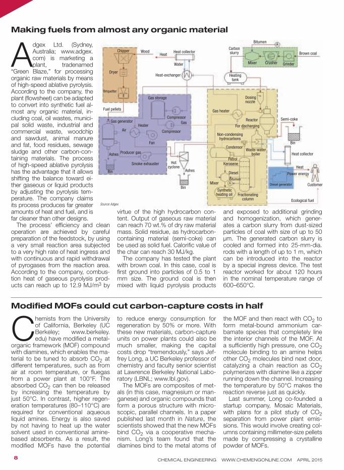
“Green Blaze,” for processing organic raw materials by means of high-speed ablative pyrolysis. According to the company, the plant (flowsheet) can be adapted to convert into synthetic fuel al-most any organic material, in-cluding coal, oil wastes, munici-pal solid waste, industrial and commercial waste, woodchip and sawdust, animal manure and fat, food residues, sewage sludge and other carbon-con-taining materials. The process of high-speed ablative pyrolysis has the advantage that it allows shifting the balance toward ei-ther gaseous or liquid products by adjusting the pyrolysis tem-perature. The company claims its process produces far greater amounts of heat and fuel, and is far cleaner than other designs.
The process’ efficiency and clean operation are achieved by careful preparation of the feedstock, by using a very small reaction area subjected to a very high rate of heat ingress and with continuous and rapid withdrawal of pyrogases from the reaction area. According to the company, combus-tion heat of gaseous pyrolysis prod-ucts can reach up to 12.9 MJ/m3 by
virtue of the high hydrocarbon con-tent. Output of gaseous raw material can reach 70 wt.% of dry raw material mass. Solid residue, as hydrocarbon-containing material (semi-coke) can be used as solid fuel. Calorific value of the char can reach 30 MJ/kg.
The company has tested the plant with brown coal. In this case, coal is first ground into particles of 0.5 to 1 mm size. The ground coal is then mixed with liquid pyrolysis products
and exposed to additional grinding and homogenization, which gener-ates a carbon slurry from dust-sized particles of coal with size of up to 50 µm. The generated carbon slurry is cooled and formed into 25-mm-dia. rods with a length of up to 1 m, which can be introduced into the reactor by a special ingress device. The test reactor worked for about 120 hours in the nominal temperature range of 600–650°C.
Making fuels from almost any organic material
Modified MOFs could cut carbon-capture costs in half
Chemists from the University of California, Berkeley (UC Berkeley; www.berkeley.edu) have modified a metal-
organic framework (MOF) compound with diamines, which enables the ma-terial to be tuned to absorb CO2 at different temperatures, such as from air at room temperature, or fluegas from a power plant at 100°F. The absorbed CO2 can then be released by increasing the temperature by just 50°C. In contrast, higher regen-eration temperatures (80–110°C) are required for conventional aqueous liquid amines. Energy is also saved by not having to heat up the water solvent used in conventional amine-based absorbents. As a result, the modified MOFs have the potential
to reduce energy consumption for regeneration by 50% or more. With these new materials, carbon-capture units on power plants could also be much smaller, making the capital costs drop “tremendously,” says Jef-frey Long, a UC Berkeley professor of chemistry and faculty senior scientist at Lawrence Berkeley National Labo-ratory (LBNL; www.lbl.gov).
The MOFs are composites of met-als (in this case, magnesium or man-ganese) and organic compounds that form a porous structure with micro-scopic, parallel channels. In a paper published last month in Nature, the scientists showed that the new MOFs bind CO2 via a cooperative mecha-nism. Long’s team found that the diamines bind to the metal atoms of
the MOF and then react with CO2 to form metal-bound ammonium car-bamate species that completely line the interior channels of the MOF. At a sufficiently high pressure, one CO2 molecule binding to an amine helps other CO2 molecules bind next door, catalyzing a chain reaction as CO2 polymerizes with diamine like a zipper running down the channel. Increasing the temperature by 50°C makes the reaction reverse just as quickly.
Last summer, Long co-founded a startup company, Mosaic Materials, with plans for a pilot study of CO2 separation from power plant emis-sions. This would involve creating col-umns containing millimeter-size pellets made by compressing a crystalline powder of MOFs.
Ecological fuel
Chipper
Dryer
Briquetter
Fuel pellets
WoodHeat
Heat collector
Water
Heat-exchanger
Gas storage
Gas generator
Air
Ashes
Bin
Bin
Bin
Producer gas
Smoke exhauster
Fan
Heater
Compressor
Compressor
Gas
Bitumen
Carbon slurry
Heating tank
Mixer Crusher Grinder
Brown coal
Gas heater
Dosing nozzle
Reactor
For discharging
Non-condensinghydrocarbons
Condensor
Hot cyclone
Ashes
Semi-coke
Waste-water boiler
PetrolKerosene
Diesel
BitumenMixer
Synthetic heating oil Fractionating
column
Diesel generator
Heat collector
Heat
Power energy
Customer
Source: Adgex

Circle 2 on p. 78 or go to adlinks.chemengonline.com/56196-02

CHEMICAL ENGINEERING WWW.CHEMENGONLINE.COM APRIL 201510
A catalyst for making aromatic hydrocarbons from biomass
A new catalyst that performs the direct and se-lective hydrogenolysis of the C–OH bond of substituted phenols and naphthols — two of the major components of lignin — has been
developed by professor Kyoko Nozaki and colleagues at the Dept. of Chemistry and Biotechnology, Univer-sity of Tokyo (Japan; www.park.itc.u-tokyo.ac.jp/no-zakilab). This is said to be the first report on the selec-tive cleavage of sp2-hybrid C–O bonds without also cleaving the aromatic rings of lignin-derived bio-oils. The researchers say the catalyst shows promise as a way to produce basic aromatic hydrocarbons, such as benzene, toluene and xylenes (BTX) amd phenols from lignin instead of petroleum.
The catalyst, which is based on hydroxycyclopentadi-enyl iridium complexes, has achieved a 99% yield of the corresponding arenes, when reacting a phenol with H2 (1 atm pressure) at 200°C. Maximum turnover numbers of 255 are also observed. Furthermore, the same cata-lysts were applied to the “unprecedented” selective hy-drogenolysis of the sp3-hybrid C–O bonds in aryl methyl ethers. Thus, the hydrodeoxygenation of vanillylacetone, a lignin model compound, produces alkylbenzenes as the major products via triple deoxygenation.
Scaleup for an alternative route to PC monomer
Earlier this year, Asahi Kasei Chemicals Corp. (Tokyo, Japan; www.asahi-kasei.co.jp/chemicals) has developed a new process for making diphe-nyl carbonate (DPC), a monomer used for mak-
ing polycarbonate (PC) resins. This new route to DPC uses only an alcohol, phenol and CO2 as feedstocks, and therefore increases the flexibility of the company’s phosgene-free PC process, which uses ethylene oxide (EO) as feedstock. The company plans to build a 1,000-ton/yr validation plant at its Mizushima Works (Kurashiki, Okayama, Japan), which is scheduled to start up in Janu-ary 2017, with support from Japan’s New Energy and Industrial Technology Development Organization (Kawa-saki, Japan; www.nedo.go.jp).
In 2002, Asahi Kasei Chemicals developed the world’s first phosgene-free process for making PC, using CO2 as feedstock (Chem. Eng., December 2005, p. 16), and has since licensed five plants in the world. Now, with the introduction of this new route to DPC, there is a greater freedom in the selection of a plant location since ethylene oxide is not required.
In the new process, an alcohol and CO2 are reacted over a new catalyst, which was developed by Asahi Kasei Chemicals, to produce dialkyl carbonate (DRC). In a sec-ond step, the DRC is reacted with phenol to give both DPC and the same alcohol that is used in the first step. Because that alcohol is recycled, only CO2 and phenol are needed as feedstock for making DPC. With fewer process steps, the new process is also more energy ef-ficient, enabling production costs to be reduced substan-tially, says the company.
Frankfurt am Main · 15 – 19 June 2015
Be informed. Be inspired. Be there.
➢ World Forum and Leading Show for the Process Industries
➢ 3,800 Exhibitors from 50 Countries
➢ 170,000 Attendees from 100 Countries
www.achema.de
Circle 6 on p. 78 or go to adlinks.chemengonline.com/56196-06

Commercial-scale production for bio-based levulinic acid
This summer, GFBiochemicals Green Future S.r.l. (Milan, Italy; www.gfbiochemicals.com) will start commercial-scale production of levulinic acid using its proprietary, continuous-production pro-
cess. The company says it will produce 2,000 metric tons per year (m.t./yr) at its plant in Caserta, Italy later this year, followed by scaleup to 4,000 m.t./yr in 2016 and then 8,000 m.t./yr by 2017. Initially, the feedtock for the pro-duction will be starch, but the company plans to switch to cellulose feedstock during 2016.
Recognized by the U.S. Dept. of Energy (Washington, D.C.; www.energy.gov) as one of the twelve future bio-based building-block chemicals, levulinic acid has poten-tial as a starting material for a wide number of compounds, with applications in pharmaceuticals, agrochemicals, fla-vors and fragrances and food additives, as well as resins and coatings, plasticizers, solvents and fuel additives.
A patented process makes stabilized proteins
XstalBio Ltd. (Glasgow, U.K.; www.xstalbio.com) has recently been issued a patent (US 8,932,715) covering the use of precipitation-stabilizing addi-tives for the manufacture of dry powders of thera-
peutic proteins, including monoclonal antibodies (mAbs). Compared to lyophilization, the XstalBio precipitation process offers advantages of speed, cost and dose-flex-ibility and it produces humidity- and temperature-stable powders that are much easier to handle than spray dried particles, says the company.
Applications in development include proven multiyear (more than 7 yr) intermediate storage of protein drugs as bulk dry powders, and production of high-concentration mAb solutions suitable for subcutaneous injection. The proprietary technology allows delicate protein drugs, un-stable in aqueous solution, to be rapidly and cost-effec-tively precipitated into very stable dry microparticles with full retention of bioactivity. XstalBio has exclusive rights to the patented technology and is developing a com-mercial process suitable for good manufacturing practice (GMP) manufacture of metric-ton-per-annum quantities of protein powder.
Lignin to adipic acid
A new study from the National Renewable Energy Laboratory (NREL; Golden, Colo.; www.nrel.gov) demonstrates the conversion of lignin-de-rived compounds to adipic acid, an important
precursor for making nylon and other chemicals. The new route offers a “greener” alternative to conventional methods (oxidation of cyclohexanol and cyclohexone with nitric acid), which generate nitrous oxide — a greenhouse gas.
Recently published in Energy & Environmental Science, the research demonstrates how lignin-derived compounds can first be converted to muconic acid via a biological pro-cess. Muconic acid can then be separated from the bio-logical culture and catalytically converted into adipic acid. A patent application has been filed on this research.
engineering for a better world
GEA Mechanical Equipment
Safe, compact and efficient: Whether gas-tight or
made of hastelloy C 276, our decanters reliably
prevent against explosion and corrosion respectively.
You need, we care.
GEA Westfalia Separator Group GmbH
Werner-Habig-Straße 1, 59302 Oelde, Germany
Phone: +49 2522 77-0, Fax: +49 2522 77-2828
[email protected], www.gea.com
reliability
care
Excellence Down to the Smallest DetailInnovative separation technology
CP-0
1-0
18
Circle 12 on p. 78 or go to adlinks.chemengonline.com/56196-12

CHEMICAL ENGINEERING WWW.CHEMENGONLINE.COM APRIL 201512
C
M
Y
CM
MY
CY
CMY
K
8x10.5 AD-PLASTO-1-22-2014.pdf 1 1/22/14 2:33 PM
Circle 18 on p. 78 or go to adlinks.chemengonline.com/56196-18

CHEMICAL ENGINEERING WWW.CHEMENGONLINE.COM APRIL 2015 13
C
M
Y
CM
MY
CY
CMY
K
8x10.5 AD-PLASTO-1-22-2014.pdf 1 1/22/14 2:33 PM
Circle 18 on p. 78 or go to adlinks.chemengonline.com/56196-18
Italian quality
Your vacuum drying specialist
[email protected] | italvacuum.com
Frankfurt (Germany), 15 - 19 JuneStand B44, Hall 4.0
Brilliant technology
Planex System:Multi-patented paddle vacuum
dryer with ZeroFriction® planetary movement eccentric agitator
Criox System:patented rotary
vacuum dryer/pulverizer
Multispray Cabinet Dryer:tray vacuum dryer
with extractable shelves
Saurus939:Vacuum pump with continuous
recovery of the solvents extracted
Circle 14 on p. 78 or go to adlinks.chemengonline.com/56196-14
cess can produce flakes of high-quality MoS2 material at predetermined locations, in contrast to existing tech-niques where the flakes are distributed randomly, and are of lower quality. The re-searchers hope the method will help allow future MoS2-based integrated circuitry and sensors.
SELF-CLEANING PAINTResearchers at University College London (UCL; U.K.; www.ucl.ac.uk) and Dalian University of Technology (China; http://en.dlut.edu.cn/) have developed a new paint that makes robust self-clean-ing surfaces. The coating can be applied to clothes, paper, glass and steel, and when combined with adhesives, maintains its self-cleaning properties after being wiped, scratched with a knife and scuffed with sandpaper.The study, published last month in Science, shows how the new paint made
Joule Unlimited (Bedford, Mass.; www.jouleunlimited.com) an-nounced recently that it has achieved end-to-end produc-
tion of ethanol from carbon dioxide and sunlight, using its specially designed photobioreactor and engineered cy-anobacteria. The full production runs occurred late last year at the compa-ny’s Hobbs, N.M. facility and ethanol from the process is undergoing further testing by German automaker Audi, a strategic partner of Joule.
Joule is planning to construct a larger-scale production plant that will produce 15 million gal/yr of ethanol from CO2 and will break ground in 2017. The facility may also produce a C11 molecule for diesel fuel that is currently also under development by the company.
In 2009, Joule initially demonstrated its “reverse combustion” process (diagram), in which strains of engineered cyanobacteria metabolize CO2 in the presence of sunlight and brackish water to produce ethanol and diesel, depending on the strain used.
Over the past year, Joule has improved its
process, both on the biocatalyst side and the process engineering side, explains David St. Angelo, senior vice president for engineering at Joule. Strain selection and further engi-neering of the cyanobacteria has improved the performance of the biocatalyst, St. Angelo says, and the company is doubling the size of its photobioreactor capsule, from 50 to 100 m in length. “The longer reactor is part of an effort to make a lower cost, robust continu-ous process. The capsule has been designed for a lower pressure drop across the reactor, and hence, lowered pumping costs.”
End-to-end demonstration of CO2-to-ethanol process achieved
Diesel
C02
Existing pathway optimized C02
3-phosphoglyerate (3PG)
Existing pathway
New ethanol pathway2 genes added
Metabolic switch
PyruvateAcetaldehycle Ethanol
Ethanol
Ethanol
Biomass
Disabled biomass creation
Existing pathway increased fl ux
New alkane pathway4 genes added
Acetyl CoA
C8,10,12 fatty acyl carrier protein (ACP)
C8,10,12 fatty acid
C8,10,12 aldehyde
C7,9,11 alkaline
(Continues on p. 14)
Source: Joule Unlimited

MOF material improves CO2-capture effectiveness
Engineering advanced
Simultaneous heat transfer and mass transfer model in column.
Good thinking.Feedback from our users is what inspires us to keep making CHEMCAD better. As a direct response to user need, many features like this one were added to our integrated suite of chemical process simulation software. That’s why we consider every CHEMCAD user part of our development team.
Get the whole story behind this user-inspired feature and learn more about how CHEMCAD advances engineering at chemstations.com/development.
CH
EMCAD 6.5.5
NO
W AVAILABLE
© 2015 Chemstations, Inc. All rights reserved. | CMS-4114 04/15
Circle 4 on p. 78 or go to adlinks.chemengonline.com/56196-04
from coated titanium diox-
ide nanoparticles can give a
wide-range of materials self-
cleaning properties, even
during and after immersion
in oil and following dam-
age to the surface. Different
coating methods were used
to create the water-repellent
surfaces, depending on the
material. A spray-gun was
used to coat glass and steel,
dip-coating for cotton wool
and a syringe to apply the
paint onto paper.
TILTING TREES HELPS
Willow trees growing at an
angle of 45 deg respond by
producing a sugar-rich ge-
latinous fiber, making up to
five times more sugar than
when grown normally. This is
the conclusion — important
for boosting biofuel yields —
of researchers from Imperial
College London (U.K.; www.
imperial.ac.uk), who used
X-ray micro-computed to-
mography (CT) to study the
growing plants. ❏
Industrial CO2 capture is currently done by absorption in liquid amines, such as mono-ethanolamine. However, absorption-based carbon capture carries a significant energy
penalty for regenerating CO2 in a stripping column — power plants can lose 20–30% of their energy output by capturing CO2 with conventional technology.
Researchers at New Mexico State Univ. (NMSU; Las Cruces; www.nmsu.edu) have in-vented novel metal-organic-framework (MOF) materials that selectively capture CO2 while cutting the energy penalty in half. Known as zeolitic imidazolate frameworks (ZIFs), the materials have surface areas an order of mag-
nitude higher than zeolites, and considerable thermal and chemical stability, explains proj-ect lead Nasser Khazeni, a Ph.D. candidate.
Khazeni synthesized a new subgroup of ZIFs that incorporates a ring carbonyl group in its organic counterpart. These materials separate CO2 from gas mixtures more selec-tively and have higher CO2-uptake capacities compared to similar structures, Nasser says.
In an industrial setting, the ZIF would be granulated and packed into an adsorption column, through which exhaust would pass, Nasser says. NMSU has filed for a patent and is seeking to license the invention. Industry sectors have shown interest, Nasser notes.
Last month, Hydro ASA (www.hydro.com) entered into a contract with Multiconsult (both Oslo, Norway; www.multionsult.no) for engineer-
ing services for Hydro’s planned pilot plant at Karmøy, Norway. The Karmøy pilot aims to verify what Hydro calls the world’s most energy- and climate-efficient electrolysis technology for aluminum production. The process being piloted is targeting a 15% re-duction in energy consumption per kilogram
of aluminum produced compared to the world average, says the company.
The full-scale pilot plant — costing an estimated NOK3.9 billion ($0.5 billion) — is planned to have a production capacity of 75,000 m.t./yr, with startup in the second half of 2017 at the earliest. The Multicon-sult contract covers the engineering design of demolition work, a new potroom, rectifier and transformer substations, power distribu-tion, infrastructure and support systems. ■
A new primary aluminum process to be piloted

Circle 22 on p. 78 or go to adlinks.chemengonline.com/56196-22
Engineering advanced
Simultaneous heat transfer and mass transfer model in column.
Good thinking.Feedback from our users is what inspires us to keep making CHEMCAD better. As a direct response to user need, many features like this one were added to our integrated suite of chemical process simulation software. That’s why we consider every CHEMCAD user part of our development team.
Get the whole story behind this user-inspired feature and learn more about how CHEMCAD advances engineering at chemstations.com/development.
CH
EMCAD 6.5.5
NO
W AVAILABLE
© 2015 Chemstations, Inc. All rights reserved. | CMS-4114 04/15

Business News
CHEMICAL ENGINEERING WWW.CHEMENGONLINE.COM APRIL 201516
LINEUP3M
ABB
AKZONOBEL
ALCOA
ARKEMA
ASAHI KASEI
BASF
BAYER
MATERIALSCIENCE
EVONIK
HONEYWELL
MANN+HUMMEL
MICRODYN-NADIR
PERSTORP
SASOL
SNC-LAVALIN
SOLVAY
SONOCO
THYSSENKRUPP
INDUSTRIAL SOLUTIONS
TOTAL
VERISK
WACKER
WOOD MACKENZIE
YARA
Plant WatchArkema to expand production of PEKK specialty polymer in the U.S. and FranceMarch 9, 2015 — Arkema (Colombes, France; www.arkema.com) plans to double production capacity for poly-ether-ketone-ketone (PEKK) polymer in France in the first half of 2016. Furthermore, the company plans to build a PEKK-production plant on its Mobile, Ala. site, which would be scheduled for startup in the second half of 2018.
Perstorp starts up plasticizer plant extension in SwedenMarch 5, 2015 — Perstorp Holding AB (Malmö, Sweden; www.perstorp.com) has successfully started up a new plant that produces key raw materials for the general-purpose PVC plasticizers, valeraldehyde and 2-propylheptanol, and associated chemicals at the company’s site in Stenugsund, Sweden. With this investment, Perstorp has boosted the site’s capacity by 150,000 metric tons per year (m.t./yr).
BASF expands its capacity for specialty amines in LudwigshafenMarch 4, 2015 — BASF SE (Ludwigshafen, Germany; www.basf.com) is significantly expanding its production capacity for about 20 specialty amines at its site in Ludwigshafen. The expanded facilities are planned to go onstream gradually by early 2017. The specialty amines are used for the manufacture of coatings, lubricants, crop-protection products and pharmaceuticals.
SNC-Lavalin awarded fluegas-treatment contract in RomaniaMarch 3, 2015 — SNC-Lavalin (Montreal, Que., Canada; www.snclavalin.com) has been awarded a contract for a new gas-emissions treatment facility at a nitrogen, phosphorus and potassium (NPK) fertilizer production plant in Târgu Mures, Romania. The facility will treat an estimated 183,000 Nm3/h of air from the NPK plant, which is expected to be fully operational in early 2016.
Wacker builds new production plant for specialty polymersMarch 3, 2015 — Wacker Chemie AG (Munich, Germany; www.wacker.com) is building a new €8-million plant for specialty monomers with a production capacity of 3,800 m.t./yr at its Burghausen, Germany site. The plant is scheduled for startup in the second quarter of 2015.
ABB to build manufacturing site in TennesseeMarch 3, 2015 — ABB (Zurich, Switzerland; www.abb.com) will invest $30 million in building a new
manufacturing site near Memphis, Tenn. The new facility will assemble products from across ABB’s low-voltage products portfolio, including breakers, switches and modular enclosures.
AkzoNobel breaks ground on alkoxylation facility in NingboMarch 2, 2015 — AkzoNobel (Amsterdam, the Netherlands; www.akzonobel.com) recently broke ground on a new alkoxylation facility at its site in Ningbo, China, bringing the company’s total investment in Ningbo to more than €400 million. This new facility will increase capacity by nearly 18,000 m.t./yr.
Solvay to build specialty polymers PEEK-production unit in U.S.February 24, 2015 — Solvay S.A. (Brussels, Belgium; www.solvay.com) is building a new unit at its Augusta, Ga. site to expand its production capacity of polyether etherketone (PEEK). The new unit is expected to come onstream in mid-2016 and, combined with an expansion already underway in Panoli, India, will raise Solvay’s total PEEK-resin production capacity to more than 2,500 m.t./yr.
ThyssenKrupp Industrial Solution wins order for Hungarian nitric-acid plantFebruary 20, 2015 — ThyssenKrupp Industrial Solutions AG (Essen, Germany; www. thyssenkrupp-industrial-solutions.com) has won a contract from fertilizer manufacturer Nitrogénmüvek Zrt for a nitric acid plant to be built at Pétfürdö, Hungary. The plant’s production capacity will be 1,150 m.t./d nitric acid, and completion is scheduled for 2017.
Yara and BASF to build ammonia plant in FreeportFebruary 19, 2015 — Yara International (Oslo, Norway; www.yara.com) and BASF will build an ammonia plant at BASF’s site in Freeport, Tex., which will be owned 68% by Yara and 32% by BASF. The total capital investment for the plant, which will have a capacity of 750,000 m.t./yr, is estimated at $600 million.
Honeywell to provide control-systems support for Sasol coal-to-liquids plantFebruary 17, 2015 — Honeywell (Morristown, N.J.; www.honeywell.com) will provide comprehensive services and support for the control systems of what is said to be the world’s largest coal-to-liquids (CTL) plant, Sasol’s synthetic fuels and chemicals complex in Secunda, South Africa.
Mergers & AcquisitionsEvonik to acquire Monarch CatalystsMarch 11, 2015 — Evonik Industries AG (Essen, Germany; www.evonik.com) has signed an agreement with India-based Monarch Catalyst

ChemiCal engineering www.Chemengonline.Com april 2015 17
Pvt. Ltd. to acquire 100% of the company’s shares. The transaction is expected to close during the first half of 2015.
Alcoa expands titanium, specialty offerings with RTI acquisitionMarch 10, 2015 — Alcoa Inc. (Pittsburgh, Pa.; www.alcoa.com) has signed a definitive agreement to acquire RTI International Metals, Inc., a supplier of titanium and specialty-metal products and services for the aerospace, defense, energy and medical-device markets. The transaction has an enterprise value of $1.5 billion.
Data analytics company Wood Mackenzie acquired by VeriskMarch 10, 2015 — Data analytics provider Verisk Analytics, Inc. (Jersey City, N.J.; www.verisk.com) has signed an agreement to acquire Wood Mackenzie (Edinburgh, Scotland; www.woodmac.com), an analytics provider for the chemical, energy and mining sectors, for around $2.8 billion.
Sonoco acquires majority stake in Brazilian packaging firmMarch 9, 2015 — Sonoco Products Co. (Hartsville, S.C.; www.sonoco.com), announced the signing of a definitive agreement to acquire a majority interest in Graffo Paranaense de Embalagens S/A (Graffo), a flexible packaging business located in Pinhais, Curitiba, Brazil. The transaction is expected to close in the second quarter of 2015.
Total acquires majority stake in plastics company PolyblendMarch 5, 2015 — Total S.A. (Paris, France; www.total.com) has acquired a majority 68% interest in Polyblend GmbH (www.polyblend.de; Bad Sobernheim, Germany), which manufactures plastics for the automotive industry. The transaction is aligned with Total’s strategy to develop higher-value polymers.
Bayer MaterialScience acquires composite materials specialistMarch 2, 2015 — Bayer MaterialScience AG (Leverkusen, Germany; www.materialscience.bayer.com) concluded the takeover of Thermoplast Composite GmbH (TCG; Langenfeld, Germany; www.thermoplast-composite.com), a producer of thermoplastic-fiber composites. Bayer MaterialScience plans to expand TCG’s production capacity in various locations, beginning in the Nuremberg metropolitan region.
Polypore business segments divested to Asahi Kasai and 3MFebruary 23, 2015 — Asahi Kasei Chemicals Corp. (Tokyo, Japan; www.asahi-kasei.co.jp) has entered into an agreement to acquire the Energy Storage business of Polypore International, Inc. (Charlotte, N.C.; www.polypore.net) for approximately $2.2 billion. In conjunction, Polypore also divested its Separations Media segment to 3M (St. Paul, Minn.; www.3m.com) for around $1 billion.
Mann+Hummel takes full ownership of Microdyn-NadirFebruary 17, 2015 — Microdyn-Nadir GmbH (Wiesbaden, Germany; www.microdyn-nadir.de), a membrane and module manufacturer, is now a 100% subsidiary of Mann+Hummel GmbH (Ludwigsburg, Germany; www.mann-hummel.com). With this transaction, Mann+Hummel increases its Microdyn-Nadir stake from 50 to 100%. ■ Mary Page Bailey
Do you have flows up to1,400 US GPM (320 m3/hr),heads up to 3,400 feet (1,000 m), pressures up to1,500 psig (100 bar),temperatures from 20˚F to 300˚F (-30˚C to 149˚C), and speeds up to 3,500 RPM? Then you need Carver Pump RS Series muscle!Designed for moderate to high pressure pumping applications, the RS isavailable in five basic sizes with overall performance to 1,000HP. As astandard, with a product lubricated radial sleeve bearing and two matchedangular contact ball bearings for thrust, it only takes a mechanical seal onthe low pressure, suction side to seal the pump. Optional features includeball bearings on both ends with an outboard mechanical seal, various sealflushing arrange ments and bearing frame cooling. These features make the RS ideally suited for Industrial and Process applications includingPressure Boost Systems, Boiler Feed, Reverse Osmosis, Desalination and Mine Dewatering. Whatever your application, let us build the muscle you need!
1970 Dodge Super Bee
RS Series
Creating Value.Carver Pump Company2415 Park AvenueMuscatine, IA 52761563.263.3410Fax: 563.262.0510www.carverpump.com
RS PM ad 010914_Layout 1 1/9/14 8:16 AM Page 1
Circle 3 on p. 78 or go to adlinks.chemengonline.com/56196-03

Newsfront
CHEMICAL ENGINEERING WWW.CHEMENGONLINE.COM APRIL 201518
Metal is all around us — we drink out of aluminum cans and eat with stainless-steel (or perhaps even silver) silverware. But we
may not give much thought to the platinum stored within our vehicles or the europium contained in our smartphone screens. We also may not consider what happens to these materials when they reach the end of their useful life. Potentially valuable product streams can be obtained if the precious and rare-earth metals contained in these products are efficiently recovered. This article will exam-ine some advanced techniques for recycling a variety of consumer products to recover precious metals, as well as the more elusive rare-earth metals.
Treating unique precious metalsPrecious metals are crucial in many diverse products and applications, and determin-ing the most efficient recycling processes for each material presents challenges. Umicore N.V. (Brussels, Belgium; www.umicore.com) operates a complex metals-recycling facility in Hoboken, Belgium, that treats approxi-mately 350,000 metric tons per year (m.t./yr) of industrial residues and other recyclable materials, including electronics waste (Figure 1), such as mobile phones and printed circuit boards (PCBs), and automotive and industrial
catalysts. The recycling process is unique, says Umicore communications and general services manager Marjolein Scheers, be-cause of the variety of materials handled and recovered — the process recovers 17 differ-ent metals, including precious metals, such as gold, silver and the platinum-group metals (PGMs) platinum, palladium and rhodium.
“The operation is designed so that raw ma-terials enter the process at the most optimal step,” explains Scheers. This is determined by the individual material’s physical proper-ties, analytical fingerprint and recovered value. The process begins with a smelter, where precious metals are separated from other metals. The smelter furnace applies a sub-merged-lance-combustion technology, which involves the injection of oxygen-enriched air into a molten-metal bath. Says Scheers: “Umicore is the only company to apply this technology on such a large scale with such a variety of materials.” Following the smelter are copper-leaching and electrowinning steps, after which the precious metals are collected in a residue that is further processed at an in-house refinery. According to the company, on average, over 95% of the metals contained in the feed can be recovered.
Umicore understands the complexity of re-cycling waste electrical and electronic equip-ment (WEEE), and in February of this year, received compliance certification by two Eu-ropean trade organizations (Eurometaux and the European Electronics Recyclers Associa-tion) for WEEE recycling. “As the recycling of WEEE wastes consists of various steps, such as collection, pre-processing and end-processing, it is logical that the efficiency and performance of the entire chain is monitored and evaluated,” says Scheers.
PGMs from autocatalystsOne major application for precious PGMs is in the catalytic converters in automobiles. When an automobile has reached the end of its use-
Precious and rare-earth metals are used in countless consumer products, and advanced processes
to efficiently recover these materials from waste present promising alternative sources
New Frontiers in Metals Recycling
IN BRIEFTREATING UNIQUE
PRECIOUS METALS
PGMS FROM
AUTOCATALYSTS
SAFER STRIPPING
RARE-EARTH METALS
COMMERCIAL FUTURE
FIGURE 1. Electronics waste — including discarded circuit boards and mobile phones — can contain many valuable materials
Umicore

CHEMICAL ENGINEERING WWW.CHEMENGONLINE.COM APRIL 201519
ful life, the PGMs contained within the catalytic converter can be recycled. BASF SE (Ludwigshafen, Germany; www.basf.com) operates three fa-cilities worldwide that recover PGMs (platinum, palladium and rhodium) from spent automobile catalysts (Fig-ure 2) in either ceramic or metallic converter systems. BASF’s process for recovering PGMs from ceramic converter systems is shown in Figure 3. Ceramics represent a larger-vol-ume market than metallic converters, and a recent expansion project at the company’s Cinderford, U.K. site more than doubled the site’s processing capacity for ceramic converters. The upgrades at Cinderford, which went onstream in February of this year, in-volved the installation of new milling and de-canning equipment.
A variety of factors drives demand for recovered PGMs. The recovered metals are used to supply BASF’s Mobile Emissions Catalysts business, which, says the company, means that they are then used in a new genera-tion of emissions-reduction catalysts. According to BASF, demand for these catalysts has increased in line with automotive production, along with “new and more restrictive automo-tive emissions regulations around the world.” In addition to the Cinderford location, BASF operates two autocat-alyst-recycling facilities in the U.S.The benefits of large-scale PGM recycling are evident, says the company, citing “the lower cost of recycling processes versus other metal sources (mining or open-market purchase), as well as the sustainability and environmental benefits of recovering metals from end-of-life materials that would other-wise end up in landfills.”
Safer strippingElectronics components, specifically PCBs, represent a very promising area for the recovery of precious
metals, as gold can be stripped from PCBs and recycled. Typical industrial gold-stripping processes utilize cya-nide or aqua regia (nitro-hydrochloric acid) solutions. UWin Nanotech Co. (New Taipei City, Taiwan; www.uwin-nano.com) has recently patented what is said to be more environmen-tally friendly, less toxic gold-stripping chemicals — UW-700 (sulfide solu-tion) and UW-860 (citrate solution). “Aqua regia is a highly corrosive solution, and cyanide is a very toxic solution,” UWin managing director Kenny Hsu explains, “whereas UW-700 is a neutral gold-stripping solu-tion, and is also highly selective.” For UW-860, Hsu elaborates, saying that the solution “is different from aqua regia because it doesn’t damage the plastic, ceramic, silicon, titanium or stainless-steel substrate.”
After treatment with UW-700, the gold is completely stripped from the PCB, while the remaining materials are left intact (Figure 4). The recovered gold is isolated and can be re-sold for use in optical-electrical, plating and decorative applications. According to the company, applying this technol-ogy to 1 m.t. of PCB waste from cel-lular phones can result in the extrac-tion of 400 g of gold.
Using these chemicals, the com-pany has developed modular, auto-matic gold-stripping machines (Figure 5), which have deployed commer-cially worldwide, including locations in Taiwan and Texas. The company is also collaborating with a mechanical manufacturer to develop new types of stripping machines. UWin has also developed technologies for selective stripping of other precious metals, including silver, palladium and in-dium. In January 2015, the company released UW-195, a cyanide-free platinum-stripping agent that is com-patible with stainless-steel, plastic or ceramic substrates.
Rare-earth metalsCompared to their precious-metal counterparts, and despite a growing demand, commercial recycling and recovery techniques remain elusive for the 17 rare-earth metals (REMs). China, in recent years, has become the world’s most significant source of REMs, but recent regulatory changes may lead to a global shortage, forcing manufacturers to seek new methods to obtain REMs, including recycling.
“Rare-earth elements really are not scarce in the world. You may find some of them in your own backyard,”
FIGURE 2. Spent automotive catalysts contain valuable precious metals, such as palladium, plati-num and rhodium
FIGURE 3. Recently expanded at BASF’s Cinderford site, this process recycles platinum-group metals from automotive catalysts for use in new mobile-emissions catalysts
Market grade material for resale
Consignment
weighed
Planning and preparation De-canning Extraction
of catalyst
Catalyst ground
into powder
Report of
analysis and
value of batch
relayed to client
Blending and sampling
Refining
Platinum Palladium Rhodium
Smelting
Accumulate optimum
batch size for smelting
Consignment
weighedSample sent
for analysis
Analysis
BASF
BASF

CHEMICAL ENGINEERING WWW.CHEMENGONLINE.COM APRIL 201520
explains Eric Peterson of the Idaho National Laboratory (INL; Idaho Falls, Idaho; www.inl.gov). “However, it is rare to find them in locations where they occur in reasonably high con-centrations that allow for economical mining of the materials.”
INL is part of the Critical Materials In-stitute (CMI; www.cmi.ameslab.gov), an Energy Innovation Hub sponsored by the U.S. Dept. of Energy through the Advanced Manufacturing Office. Comprised of national laboratories,
universities and companies at the forefront of REM research, CMI brings a four-tiered approach to tackling ad-vanced rare-earth projects, focusing on the development of more efficient separations, recovery and recycling processes, and alternative materials that can potentially serve as REM sub-stitutes, as well as bringing end-of-life awareness to manufacturers whose
products utilize rare-earth metals. While commercial technologies
do exist for recovering REMs, these processes have some shortcomings. “There are many technological ap-proaches that may make it possible to recover and recycle the elements,” says Peterson. “However, due to the specific chemistries of each of the rare-earth elements, it is necessary to develop approaches to recycle the elements independently.” Cur-rent commercial technologies may result in complex mixtures, which re-quire further purification before yield-ing a usable product. The economy of these technologies is also highly dependent on the market value for the recovered metals, as in the case of recycling cerium from automotive catalysts or fluidized catalytic crack-ing (FCC) catalysts.
CMI is developing a number of processes for recovering REMs from various sources, including electron-ics waste, phosphor powders from fluorescent lighting and LEDs and permanent magnets from com-
FIGURE 4. A comparison of printed circuit boards before (left) and after (right) stripping treatment illustrates that the gold is removed while the re-maining materials remain intact
FIGURE 5. Automatic gold-stripping machines allow for efficient treatment of printed curcuit boards
WHY MONITOR POWER INSTEAD OF JUST AMPS?
NO LOAD NO LOAD
Power is Linear-Equal Sensitivity
at Both Low and High Loads
No Sensitivity
For Low Loads
FULL LOAD FULL LOAD
PO
WER
AM
PS
WWW.LOADCONTROLS.COM
CALL NOW FOR YOUR FREE 30-DAY TRIAL 888-600-3247
PROTECT PUMPSDRYRUNNING•CAVITATION•BEARINGFAILURE•OVERLOAD
MONITOR PUMP POWER
•BestSensitivity•DigitalDisplay
TWO ADJUSTABLE SET POINTS
•RelayOutputs•AdjustableDelayTimers
4-20 MILLIAMP ANALOG OUTPUT
COMPACT EASY MOUNTING
Only3.25"x6.25"x2"•StarterDoor •Panel•Raceway •Wall
UNIQUE RANGE FINDER SENSOR
•WorksonWide-rangeofMotors•SimplifiesInstallation
PUMP POWER
PUMPING
VALVE CLOSING
VALVE OPENINGNO FLUID
Circle 16 on p. 78 or go to adlinks.chemengonline.com/56196-16
UWin UWin
CHEMICAL ENGINEERING WWW.CHEMENGONLINE.COM APRIL 201521
puter disc drives and wind turbines. “Phosphors are moving very quickly to the commercial scale,” says Pe-terson of CMI’s phosphor-recovery projects, which target fluorescent lamps as the source of phosphor powder. Phosphor powder can con-tain 5–25% by weight rare-earth ele-ments, such as europium or terbium, in a cerium-, yttrium- or lanthanum-phosphate matrix.
In one CMI project, a supercritical-fluids process selectively extracts rare-earth metals from the phosphor powders, which also contain mer-cury. “The economics of the process are aided by the recovery and isola-tion of the mercury that is also con-tained in the phosphor powder, plus the recovery of the glass, aluminum and steel,” INL’s Peterson explains. In another project, CMI’s main focus is concentrating the rare-earth oxides (REOs) in phosphor dust and sepa-rating out the non-REO materials via hydrometallurgical methods.
Perhaps the most promising REM-recovery process CMI has developed involves membrane solvent extrac-
tion. CMI has demonstrated and is licensing the process, and expects to see full-scale realization of the project in 2.5 years. This extraction process sets itself apart from other rare-earth recovery techniques in that a more dilute stream can be used for extrac-tion. A dispersion-free, supported, liquid-membrane solvent-extraction
process separates and recovers REMs, such as yttrium, europium, praseodymium and neodymium, from permanent magnets and halophos-phate phosphors. Operating under non-equilibrium conditions, the ex-traction process overcomes the sta-bility issues arising due to the gradual loss of extractant in normal solvent-extraction processes. Other REM-recovery projects in development at CMI include recovery of indium and
REOs from thin-film plasma display panels, recovery of overspray from coating processes, bioleaching using microorganisms and biosorption in an aqueous solution.
Since most of their processes uti-lize components of discarded con-sumer products, CMI recognizes that the ability to readily recover and
recycle REMs begins with the initial manufacture of the product. Involv-ing manufacturers, and emphasizing the importance of end-of-life consid-erations in manufacturing processes, eases the complexities of recycling these materials. For instance, if disc drives are manufactured so that the magnets are easily removable, recy-cling the REMs contained within be-comes a much less labor-intensive task. This will benefit the manufac-
INNOVATION
SUPERFRAC®
high performance trays
25 years delivering
exceptional
capacity AND eficiency.
YOU CAN RELY ON US.YOU CAN RELY ON US.™
United States (316) 828-5110 | Canada (905) 852-3381 | Italy +39 039 6386010 | Singapore +65-6831-6500
For a complete list of our ofices, visit our Web site. www.koch-glitsch.com
For related trademark information, visit http://www.koch-glitsch.com/ourcompany/pages/trademarks.aspx.This technology is protected by one or more patents in the USA. Other foreign patents may be relevant.
Circle 15 on p. 78 or go to adlinks.chemengonline.com/56196-15
“Rare-earth elements really are not scarce in the world.
You may find some of them in your own backyard,”
explains Eric Peterson of the Idaho National Laboratory

CHEMICAL ENGINEERING WWW.CHEMENGONLINE.COM APRIL 201522
View On Demand Webinars at
chemengonline.com/webcasts
FREE On Demand Webinars
Chemical Engineering magazine produces
webinars on topics of critical importance to the
chemical process industries. It’s not too late to
participate in a live webinar or download any of the on demand webinars at
chemengonline.com/webcast
turers, as well, through the in-creased avail-ability of recycled REMs, while decreasing the dependence on virgin materials.
Another group working to de-velop recycling processes for REMs is Sintef (Trondheim, Nor-way; www.sintef.no), as part of the “Value from Waste” consortium formed by various European research and technology organizations. Sintef’s work has targeted two main sources for REM recovery — nickel metal-hydride (NiMH) batteries and permanent magnets that contain neodymium (Nd) — focusing mainly on the use of high-temperature electrolysis for the direct extraction of REM alloys from magnets. Says Sintef senior research scien-tist Ana Maria Martinez, “This can be considered a direct electro-refining process, as it allows the extraction of a rare-earth alloy that can be used in the manufacture of new permanent magnets directly from the waste mate-rial.” Figure 6 shows a simplified model of the magnet-recycling process, which begins with the scrap material being placed into an anode compartment. Here, the REMs present in the magnets (typically Nd, but also dys-prosium, praseodymium or terbium) are anodically dis-solved in the form of rare-earth ions, which will deposit at the cathode as rare-earth alloys. Other elements present (such as transition metals) will remain at the anode as sludge.
“At the moment, the high-temperature electrolysis ap-proach has only been applied in the case of Nd-based permanent magnets,” comments Martinez, “but the method could be suited to any conductive rare-earth-containing material.” The technology was recently sub-mitted to the European Commission to receive economic support for demonstration in industrial environments. In addition to end-of-life Nd-containing magnets, the re-cycling process can be supplemented with the use of scrap from the manufacture of new magnets. According to Martinez, “This is seen as the most practical solution to start operating recycling plants effectively.”
Sintef’s process for recovering REMs from NiMH bat-teries involves pyrometallurgical refining. “This high-tem-perature approach is able to completely separate the valuable nickel-based alloys and REO concentrates from the negative electrodes of NiMH batteries,” says Marti-nez. The output material is subsequently fed into a high-temperature electrolysis process to produce a mixture of REMs, which can be used in new battery electrodes. As with Sintef’s magnet-recycling process, the next steps will be to extrapolate these technologies to other REM-containing waste streams.
Like CMI, Sintef recognizes the challenges associated
FIGURE 6. Rare-earth metals contained in perma-nent magnets can be recovered via high-tempera-ture electrolysis
Magnet scrap/waste
REM alloy
ElectrolyteT: 950–1,050°C
Power source
RE ions
Sintef

CHEMICAL ENGINEERING WWW.CHEMENGONLINE.COM APRIL 201523
with rare-earth recycling, emphasizing the importance of implementing efficient systems for obtaining usable REM-containing scrap. “The process of separating and collecting the magnets safely from end-of-life products not only requires a great deal of time and effort, but also uses acids and other chemicals,” says Martinez. “This re-sults in toxic liquid wastes, the disposal of which creates environmental and cost issues.” Once again, attention is brought to the limitations that initial manufacturing con-siderations can put on recycling.
Commercial futureOn the commercial front, some companies are developing REM-recycling processes. In France, Solvay S.A. (Brus-sels, Belgium; www.solvay.com) has demonstrated a pro-cess for recycling phosphor powders (containing lantha-num, cerium, terbium, yttrium, europium and gadolinium) from fluorescent light bulbs and lamps. At the company’s St. Fons site, the phosphor powders are separated from glass and other components and suspended in an aque-ous solution. In solution, the phosphor powders undergo a chemical reaction, further concentrating the REMs. After separating out the liquid and drying, the remaining REM-concentrate powder is then sent to another site, La Rochelle, which specializes in rare-earth purification.
At the 2014 Minerals, Metals and Materials Soci-ety Annual Meeting & Exhibition, Hitachi Ltd., (Tokyo, Japan; www.hitachi.com), through the company’s Yokohama Research Laboratory, announced a recy-cling process for permanent magnets that includes steps for the disassembly of scrap products, followed by pyrometallurgical recovery of neodymium and dysprosium using molten magnesium as an extrac-tion medium. It was reported that the company can process several kilograms of magnets per day using this technology.
Mining companies, as well, are acknowledging the im-portance of REM conservation, and are looking into tech-nologies to recover and recycle REMs from mining waste. In March of this year, Ucore Rare Metals Inc. (Bedford, Nova Scotia, Canada; www.ucore.com) secured exclu-sive rights to advanced molecular-recognition technol-ogy that can be used for REM separation and recycling. According to the company, this technology can recover more than 99% of the REM content in a stream. In Feb-ruary, Pele Mountain Resources (Toronto, Ont., Canada; www.pelemountain.com) announced a plan for the dedi-cated recycling of the REM-containing mineral monazite, from which neodymium and praseodymium, along with smaller amounts of other REMs, can be produced.
It seems that across the board, from miners to elec-tronics manufacturers to consumers, the importance of conserving rare-earth materials, as well as precious metals, is clear. Although recycling processes for REMs have not yet reached the level of efficiency and com-mercial feasibility of other metals-recycling techniques, the great deal of development work in the area is certainly promising. ■ Mary Page Bailey
WECARE
ABOUTMILLINGW W W . F R E W I T T. C O M
VISIT US AT THE INTERPHEX 2015 IN NEW YORK, USAFROM 21. - 23. APRIL 2015, BOOTH 2035
FREDRIVE DISCOVER A GLOBALLY UNIQUE
3-IN-1 MILLING SYSTEM!
Circle 10 on p. 78 or go to adlinks.chemengonline.com/56196-10
Circle 9 on p. 78 or go to adlinks.chemengonline.com/56196-09
Newsfront
CHEMICAL ENGINEERING WWW.CHEMENGONLINE.COM APRIL 201524
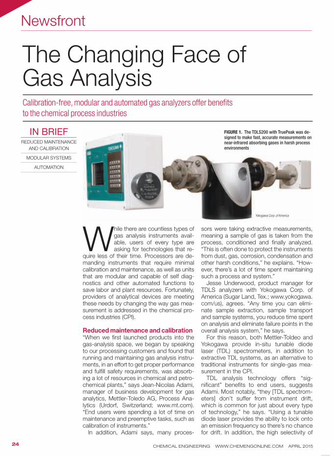
While there are countless types of gas analysis instruments avail-able, users of every type are asking for technologies that re-
quire less of their time. Processors are de-manding instruments that require minimal calibration and maintenance, as well as units that are modular and capable of self diag-nostics and other automated functions to save labor and plant resources. Fortunately, providers of analytical devices are meeting these needs by changing the way gas mea-surement is addressed in the chemical pro-cess industries (CPI).
Reduced maintenance and calibration“When we first launched products into the gas-analysis space, we began by speaking to our processing customers and found that running and maintaining gas analysis instru-ments, in an effort to get proper performance and fulfill safety requirements, was absorb-ing a lot of resources in chemical and petro-chemical plants,” says Jean-Nicolas Adami, manager of business development for gas analytics, Mettler-Toledo AG, Process Ana-lytics (Urdorf, Switzerland; www.mt.com). “End users were spending a lot of time on maintenance and preemptive tasks, such as calibration of instruments.”
In addition, Adami says, many proces-
sors were taking extractive measurements, meaning a sample of gas is taken from the process, conditioned and finally analyzed. “This is often done to protect the instruments from dust, gas, corrosion, condensation and other harsh conditions,” he explains. “How-ever, there’s a lot of time spent maintaining such a process and system.”
Jesse Underwood, product manager for TDLS analyzers with Yokogawa Corp. of America (Sugar Land, Tex.; www.yokogawa.com/us), agrees. “Any time you can elimi-nate sample extraction, sample transport and sample systems, you reduce time spent on analysis and eliminate failure points in the overall analysis system,” he says.
For this reason, both Mettler-Toldeo and Yokogawa provide in-situ tunable diode laser (TDL) spectrometers, in addition to extractive TDL systems, as an alternative to traditional instruments for single-gas mea-surement in the CPI.
TDL analysis technology offers “sig-nificant” benefits to end users, suggests Adami. Most notably, “they [TDL spectrom-eters] don’t suffer from instrument drift, which is common for just about every type of technology,” he says. “Using a tunable diode laser provides the ability to lock onto an emission frequency so there’s no chance for drift. In addition, the high selectivity of
Calibration-free, modular and automated gas analyzers offer benefits
to the chemical process industries
The Changing Face ofGas Analysis
IN BRIEFREDUCED MAINTENANCE
AND CALIBRATION
MODULAR SYSTEMS
AUTOMATION
FIGURE 1. The TDLS200 with TruePeak was de-signed to make fast, accurate measurements on near-infrared absorbing gases in harsh process environments
Yokogawa Corp. of America

US H E R I NG I N TH E N EXT 100 YEARS OF PROCE SS I N NOVATION
Since 1915, The Chem Show is where producers of chemicals, pharmaceuticals,
food and other processed products find the latest equipment and solutions
for their operations. Join us in New York City as we embark on a
new century of innovation in process technology.
2015 CHEM SHOWNOV 17-19 / JAVITS CENTER / NYC
E N DOR SE D BY
M E DIA PARTN E R
B ECOM E AN EXH I B ITOR
OR LEAR N MOR E:
CH E M S HOW.C OM
203-221-9232
Circle 5 on p. 78 or go to adlinks.chemengonline.com/56196-05
CHEMICAL ENGINEERING WWW.CHEMENGONLINE.COM APRIL 201526
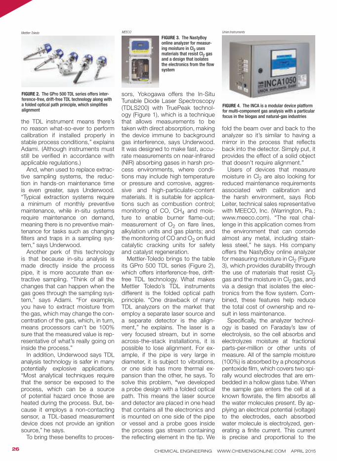
the TDL instrument means there’s no reason what-so-ever to perform calibration if installed properly in stable process conditions,” explains Adami. (Although instruments must still be verified in accordance with applicable regulations.)
And, when used to replace extrac-tive sampling systems, the reduc-tion in hands-on maintenance time is even greater, says Underwood. “Typical extraction systems require a minimum of monthly preventive maintenance, while in-situ systems require maintenance on demand, meaning there is no preventive main-tenance for tasks such as changing filters and traps in a sampling sys-tem,” says Underwood.
Another perk of this technology is that because in-situ analysis is made directly inside the process pipe, it is more accurate than ex-tractive sampling. “Think of all the changes that can happen when the gas goes through the sampling sys-tem,” says Adami. “For example, you have to extract moisture from the gas, which may change the con-centration of the gas, which, in turn, means processors can’t be 100% sure that the measured value is rep-resentative of what’s really going on inside the process.”
In addition, Underwood says TDL analysis technology is safer in many potentially explosive applications. “Most analytical techniques require that the sensor be exposed to the process, which can be a source of potential hazard once those are heated during the process. But, be-cause it employs a non-contacting sensor, a TDL-based measurement device does not provide an ignition source,” he says.
To bring these benefits to proces-
sors, Yokogawa offers the In-Situ Tunable Diode Laser Spectroscopy (TDLS200) with TruePeak technol-ogy (Figure 1), which is a technique that allows measurements to be taken with direct absorption, making the device immune to background gas interference, says Underwood. It was designed to make fast, accu-rate measurements on near-infrared (NIR) absorbing gases in harsh pro-cess environments, where condi-tions may include high temperature or pressure and corrosive, aggres-sive and high-particulate-content materials. It is suitable for applica-tions such as combustion control; monitoring of CO, CH4 and mois-ture to enable burner flame-out; measurement of O2 on flare lines, alkylation units and gas plants; and the monitoring of CO and O2 on fluid catalytic cracking units for safety and catalyst regeneration.
Mettler-Toledo brings to the table its GPro 500 TDL series (Figure 2), which offers interference-free, drift-free TDL technology. What makes Mettler Toledo’s TDL instruments different is the folded optical path principle. “One drawback of many TDL analyzers on the market that employ a separate laser source and a separate detector is the align-ment,” he explains. The laser is a very focused stream, but in some across-the-stack installations, it is possible to lose alignment. For ex-ample, if the pipe is very large in diameter, it is subject to vibrations, or one side has more thermal ex-pansion than the other, he says. To solve this problem, “we developed a probe design with a folded optical path. This means the laser source and detector are placed in one head that contains all the electronics and is mounted on one side of the pipe or vessel and a probe goes inside the process gas stream containing the reflecting element in the tip. We
fold the beam over and back to the analyzer so it’s similar to having a mirror in the process that reflects back into the detector. Simply put, it provides the effect of a solid object that doesn’t require alignment.”
Users of devices that measure moisture in Cl2 are also looking for reduced maintenance requirements associated with calibration and the harsh environment, says Rob Leiter, technical sales representative with MEECO, Inc. (Warrington, Pa.; www.meeco.com). “The real chal-lenge in this application comes from the environment that can corrode almost any metal, including stain-less steel,” he says. His company offers the NastyBoy online analyzer for measuring moisture in Cl2 (Figure 3), which provides durability through the use of materials that resist Cl2 gas and the moisture in Cl2 gas, and via a design that isolates the elec-tronics from the flow system. Com-bined, these features help reduce the total cost of ownership and re-sult in less maintenance.
Specifically, the analyzer technol-ogy is based on Faraday’s law of electrolysis, so the cell absorbs and electrolyzes moisture at fractional parts-per-million or other units of measure. All of the sample moisture (100%) is absorbed by a phosphorus pentoxide film, which covers two spi-rally wound electrodes that are em-bedded in a hollow glass tube. When the sample gas enters the cell at a known flowrate, the film absorbs all the water molecules present. By ap-plying an electrical potential (voltage) to the electrodes, each absorbed water molecule is electrolyzed, gen-erating a finite current. This current is precise and proportional to the
FIGURE 2. The GPro 500 TDL series offers inter-ference-free, drift-free TDL technology along with a folded optical path principle, which simplifies alignment
Mettler-Toledo
FIGURE 3. The NastyBoy online analyzer for measur-ing moisture in Cl2 uses materials that resist Cl2 gas and a design that isolates the electronics from the flow system
MEECO
FIGURE 4. The INCA is a modular device platform for multi-component gas analysis with a particular focus in the biogas and natural-gas industries
Union Instruments

CHEMICAL ENGINEERING WWW.CHEMENGONLINE.COM APRIL 201527
amount of absorbed water. It is, therefore, an exact, direct measure-ment of the water vapor present in the sample gas.
An added bonus of this technol-ogy, according to Leiter, is that the electrolytic cells used do not require calibration in this application, which greatly reduces labor time and costs associated with calibration.
Modular systems“In the chemical industry there are many combustible gases that occur as byproducts of production pro-cesses,” says Torsten Haug, man-aging director of Union Instruments GmbH (Karlsruhe, Germany; www.union-instruments.com). “The tradi-tional way to deal with this is flaring the gas with a flare stack. The future will likely see us using these gases for energy production in combus-tion processes. Therefore, it is im-portant to know the gas properties which are influencing the combus-tion processes.”
For this reason, he says, the mar-ket needs a variety of instruments that offer high reliability and easy maintenance, such as automatic calibration and validation functions. Instruments such as BTU analyzers or online measurement of the Wobbe index, heating value, air demand and gas density for all fuel gases and flare gases, will be needed, as well as a variety of sensors with different measuring ranges. Non-dispersive infrared (NDIR) sensors, electrochemical sensors, paramag-netic sensors and acoustic cells will all be needed, and sometimes sev-eral may be needed for a single ap-plication, he says.
In response, his company offers INCA (Figure 4), which is a modular device platform for multi-compo-
nent gas analysis with a particular focus in the biogas and natural gas industries. It is similar to modular construction systems, with blocks for active gas sampling and gas pro-cessing, as well as sensors, control-lers, data processing and commu-nication combined to form reliable analysis systems.
“The standardized modules enable a variety of customized solutions for specific analysis tasks and com-bine optimal analysis results for less
cost,” Haug says. “The user benefits from the convenience of the modular system, in which individual compo-nents can be replaced directly in the field. When equipped accordingly, INCA enables sequential switchover of the measuring technology to dif-ferent sample gas streams from up to ten measuring points, for example such as sampling from multiple fer-menters in biogas plants.”
AutomationAnalyzers that are smaller and smarter are becoming increasingly sought after, as well, says Hank Braly, vice president of sales and marketing with Baseline, a MOCON company (Lyons, Colo.; www.base-line.com). “Processors want an in-strument that can take care of itself via automated calibration against known standards, diagnostics and the ability to connect remotely over the Internet so that we can remotely diagnose, service and make adjust-ments to instruments located in the
field,” he says.At the same time, he adds, reduc-
ing the size of the devices is also a goal. “A lot of these instruments are being incorporated into systems with other components, so we are reducing the size of our analyzers. Both the smaller size and automated functions are being made possible due to the increase in processing capabilities of microprocessors that allow us to provide more continuous diagnostics and more sophisticated ways of handling the data.”
In addition to offering automatic and remote calibration, Baseline’s Series 9100 gas chromatograph for single- and multi-gas monitor-ing (Figure 5), contains integrated software, eliminating the need for an additional computer. Data collection is in universal text format with user-
definable data export utilities for re-ports and chromatograms.
Similarly, the company’s fully au-tomated Series 9000 Hydrocarbon Analyzer (Figure 6) also offers an automatic calibration feature that enhances the long-term analyti-cal stability of the instrument. Au-tomatic flame-ionization detector (FID) ignition, automatic shutoff sample, fuel and combustion air, remote operation via RS-232 and Ethernet, and software that allows for remote monitoring and control are also featured.
Whether your gas analysis need is for reduced maintenance, modular instrumentation or automated sys-tems, or any combination of these characteristics, it is likely that ana-lyzer manufacturers are developing a measurement device that will meet your requirements to reduce the labor and other plant resources that were once associated with taking gas measurements. ■
Joy LePree
FIGURE 5. The Series 9100 gas chromatograph for single- and multi-gas monitoring contains integrated software, eliminating the need for an additional computer
Baseline, a MOCON company
FIGURE 6. The fully automated Series 9000 Hydrocarbon Analyzer offers an automatic calibra-tion feature that enhances long-term stability
Baseline, a MOCON company
“Any time you can eliminate sample extraction, sample
transport and sample systems, you reduce time spent
on analysis and eliminate failure points in the overall
analysis system.” Jesse Underwood, Yokogawa

Focus
CHEMICAL ENGINEERING WWW.CHEMENGONLINE.COM APRIL 201528
This cooling fan is rated for use in explosive environmentsThe Ametek Rotron MIL-901XP fan (photo) will not create an igni-tion source in potentially explosive environments, so it is suitable for use in both indoor and outdoor applications where potentially ex-plosive or flammable gases, vapor or dusts may be present, says the manufacturer. Specificially, it meets UL, NEC and ANSI hazardous-use standards. This fan has an ambient operating temperature range of –54 to 70°C. And with permanently lu-bricated, steel ball bearings, it has a rated life in excess of 200,000 h, ensuring reliability during continu-ous operations. — Ametek Rotron, Woodstock, N.Y.www.rotron.com
Extreme-duty model extends this family of blower heatersThe CXH-XD blower heater (photo) is designed to withstand corrosive and wet environments and is ATEX-certified. It extends the capabilities of the company’s CXH-A units, by providing either primary or supple-mentary heating (for comfort or freeze protection) in areas that are classified as hazardous locations. CXH-XD enhancements include a corrosion-resistant, coated heat exchanger, optional 316 stainless- steel and epoxy-coated frames, as well as a corrosion-resistant and washdown-rated fan motor. With these added capabilities, this unit is suitable for use in onshore and offshore drilling platforms, pump houses, power-generating sta-tions, water and wastewater plants, chemical storage facilities, pipeline-metering stations and more, says the company. The use of heavy-duty magnetic contactors and a low-voltage transformer simplifies installation. The CXH-XD model comes with power ratings from 3 to 35 kW, which provides heat out-
puts to 119,420 Btu/h. It is offered for three-phase voltages starting at 240 V, while an optional 690-V design is also available. — Chromalox, Pittsburgh, Pa.www.chromalox.com
These compact gas compressors handle methaneThis company’s GG-VSD lubricated gas screw compressors (photo) are designed for dry biomethane and methane applications requir-ing pressure to 16 bars (232 psia). These single-stage compressors are both water cooled and directly driven. The use of a variable-speed drive and a highly efficient rotor profile allows these compressors to maximize flow while minimizing horsepower requirements, and this helps to regulate capacity and keep the inlet pressure constant during operation. The single-stage com-pressor design is frame-mounted and compact, making it easy to install with minimal floor-space re-quirements. The GG-VSD com-pressors comply with ATEX Zone 1 2 design requirements, says the manufacturer.— Atlas Copco North America, Pine Brook, N.J.www.atlascopco.com
Compress low-molecular-weight gases to high pressuresThis company’s single-shaft, vertical-split-casing turbocompres-sors are designed to handle a wide range of process gases for both onshore and offshore oil-and-gas applications that require ultra-high pressure processing, including the production of liquefied natural gas (LNG). The STC-SV compressors can handle volume flows from 150 to 280,000 ft3/min (250 to 480,000 m3/h), and produce a discharge pressure up to 1,000 bars (14,500 psi), making them ideal for applica-tions involving hydrocracking, syn-thesis gas or gas storage and injec-
Compressors, Fans and Blowers
Note: For more information, circle the 3-digit number on p. 78, or use the website designation.
Ametek Rotron
Chromalox
Atlas Copco
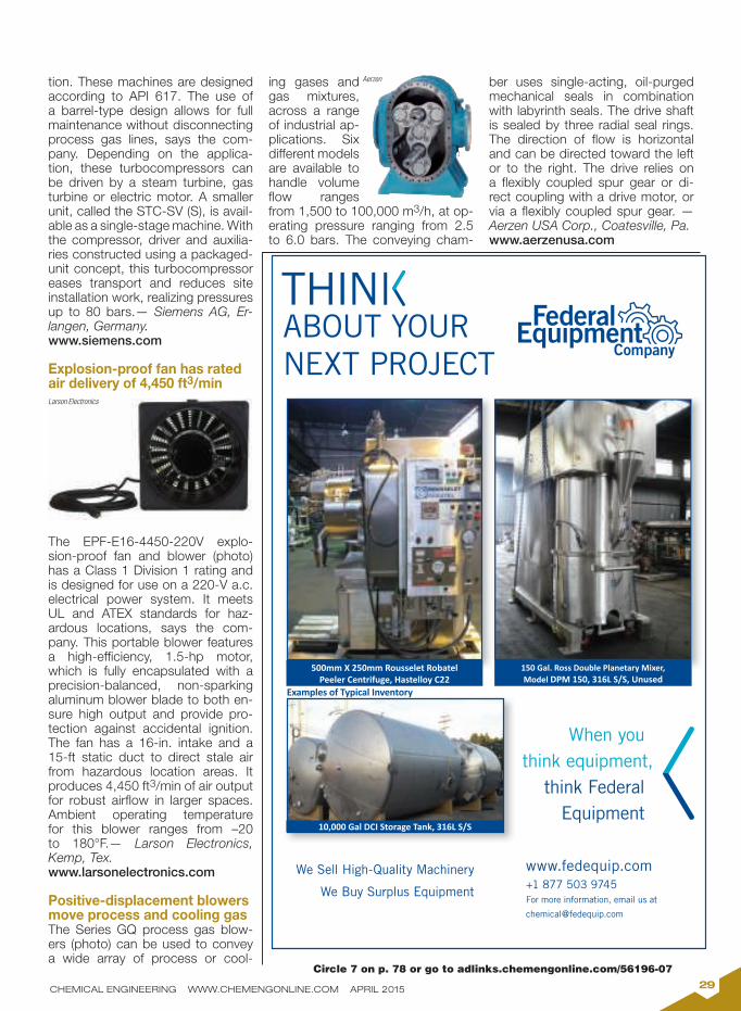
CHEMICAL ENGINEERING WWW.CHEMENGONLINE.COM APRIL 201529
tion. These machines are designed according to API 617. The use of a barrel-type design allows for full maintenance without disconnecting process gas lines, says the com-pany. Depending on the applica-tion, these turbocompressors can be driven by a steam turbine, gas turbine or electric motor. A smaller unit, called the STC-SV (S), is avail-able as a single-stage machine. With the compressor, driver and auxilia-ries constructed using a packaged-unit concept, this turbocompressor eases transport and reduces site installation work, realizing pressures up to 80 bars.— Siemens AG, Er-langen, Germany.www.siemens.com
Explosion-proof fan has rated air delivery of 4,450 ft3/min
The EPF-E16-4450-220V explo-sion-proof fan and blower (photo) has a Class 1 Division 1 rating and is designed for use on a 220-V a.c. electrical power system. It meets UL and ATEX standards for haz-ardous locations, says the com-pany. This portable blower features a high-efficiency, 1.5-hp motor, which is fully encapsulated with a precision-balanced, non-sparking aluminum blower blade to both en-sure high output and provide pro-tection against accidental ignition. The fan has a 16-in. intake and a 15-ft static duct to direct stale air from hazardous location areas. It produces 4,450 ft3/min of air output for robust airflow in larger spaces. Ambient operating temperature for this blower ranges from –20 to 180°F.— Larson Electronics, Kemp, Tex.www.larsonelectronics.com
Positive-displacement blowers move process and cooling gasThe Series GQ process gas blow-ers (photo) can be used to convey a wide array of process or cool-
ing gases and gas mixtures, across a range of industrial ap-plications. Six different models are available to handle volume flow ranges from 1,500 to 100,000 m3/h, at op-erating pressure ranging from 2.5 to 6.0 bars. The conveying cham-
ber uses single-acting, oil-purged mechanical seals in combination with labyrinth seals. The drive shaft is sealed by three radial seal rings. The direction of flow is horizontal and can be directed toward the left or to the right. The drive relies on a flexibly coupled spur gear or di-rect coupling with a drive motor, or via a flexibly coupled spur gear. — Aerzen USA Corp., Coatesville, Pa.www.aerzenusa.com
10,000 Gal DCI Storage Tank, 316L S/S
150 Gal. Ross Double Planetary Mixer,
Model DPM 150, 316L S/S, Unused
500mm X 250mm Rousselet Robatel
Peeler Centrifuge, Hastelloy C22
Examples of Typical Inventory
We Sell High-Quality Machinery
We Buy Surplus Equipment
www.fedequip.com
+1 877 503 9745
For more information, email us at
ABOUT YOUR
NEXT PROJECT
When you
think equipment,
think Federal
Equipment
Circle 7 on p. 78 or go to adlinks.chemengonline.com/56196-07
Larson Electronics
Aerzen

CHEMICAL ENGINEERING WWW.CHEMENGONLINE.COM APRIL 201530
Reciprocating air compressor has built-in backup capacityThe Duplex reciprocating air com-pressors feature two individual compressor pumps and two mo-tors mounted on a single tank, ensuring 100% built-in backup or additional air power for larger-capacity applications. The Duplex is ideal for applications where available power does not allow for a single larger compressor, says the company. Its relatively compact size also makes it ideal for use in tight spaces. Manufac-tured from durable cast iron, the unit is designed to provide auto-matic duplexing of or alternating of compressors, depending on com-pressed air reqruiements. It pro-vides 175-psig maximum operat-ing pressure for applications that require high air capacity and pres-sure. It also features an ASME-coded receiver tank, a mounted and wired magnetic starter and alternator panel, and automatic start/stop controls. Optional vi-bration isolators are available.— Ingersoll Rand, Davidson, N.C.www.ingersollrand.com
Rugged air compressors are built to move
The Mobilair Series portable air compressors (photo) is available to provide a source of compressed air for onsite use. These units pro-vide capacities from 50 to 1,200 ft3/min, in pressures from 100 to 145 psig (with selected models available to provide pressure to 205 psig). The diesel-driven air compressors have a large-capac-ity fuel tank, which provides ex-tended operation — more than 10 h of run time — and has a large filler neck with overflow protec-tion for safe, easy filling. These mobile units are constructed from durable, industrial-grade materi-als that resist rust and corrosion, and they are designed to minimize noise. Towable compressors fea-ture torsion bar suspension, over-
sized tires and a height-adjustable tow bar for reliable road handling. — Kaeser Compressors, Freder-icksburg, Va.www.kaeser.com
Sealless compressors avoid process gas contamination
This company’s PPI Diaphragm Compressors are hermetically sealed, positive-displacement machines that completely iso-late lubricants from the process gas. This sealless design (which is devoid of any dynamic seals) are designed for applications that require leak-free, contamination-free operation. One specific unit, the Sundyne Series 7L Diaphragm Compressor (photo), is available in single- and two-stage configu-rations. This compressor has a maximum working pressure of 6,250 psi, with a maximum motor size of 200 hp and 149 kW.With a maximum displacement of 110.9 ft3/min, the compressor has a max-imum speed range of 250 to 350 rpm, and a maximum discharge temperature of 450°F (232°C). All Sundyne PPI diaphragm compres-sors can be custom packaged for specific applictions requiring API-618 standards.— Sundyne, Arvada, Colo.www.syndyne.com
Rotary positive blowers can be custom engineeredThis company’s M-D Pneumatics rotary positive blowers and blower packages are designed for use in wastewater-treatment facilities and other industrial applications. The treatment of wastewater re-quires large volumes of oxygen to be delivered to aeration tanks or ponds, to support the growth of microorganisms that consume organic matter. Such facilities also require blowers to support
Circle 11 on p. 78 or go to adlinks.chemengonline.com/56196-11
Kaeser Compressors
Sundyne
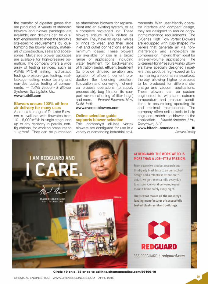
CHEMICAL ENGINEERING WWW.CHEMENGONLINE.COM APRIL 201531
the transfer of digester gases that are produced. A variety of standard blowers and blower packages are available, and designs can be cus-tom engineered to meet the facility’s site-specific requirements by cus-tomizing the blower design, materi-als of construction, seals and acces-sories. Multistage blower packages are available for high-pressure op-eration. The company offers a wide array of testing services, such as ASME PTC-9 testing, hydrostatic testing, pressure-gas testing, seal-leakage testing, noise testing and non-destructive testing of compo-nents. — Tuthill Vacuum & Blower Systems, Springfield, Mo.www.tuthill.com
Blowers ensure 100% oil-free air delivery for many usesA complete range of Tri-Lobe Blow-ers is available with flowrates from 10–15,000 m3/h in single stage, and up to any capacity in parallel con-figurations, for working pressures to 1 kg/cm2. They can be purchased
as standalone blowers for replace-ment into an existing system, or as a complete packaged unit. These blowers ensure 100% oil-free air delivery. They have no vanes, valves or rings to wear, and their large inlet and outlet connections ensure minimum losses. These blowers are available for use in a broad range of applications, including water treatment (for backwashing of filtration beds), effluent treatment (to provide diffused aeration and agitation of effluent), cement pro-duction (for blending aeration, fluidization and conveying), chemi-cal process operations (to supply process air), bag filtration (to sup-port reverse cleaning of filter bags) and more. — Everest Blowers, New Delhi, Indiawww.everestblowers.com
Online selection guide supports blower selectionThis company’s oil-less vortex blowers are configured for use in a variety of demanding industrial envi-
ronments. With user-friendly opera-tor interface and compact design, they are designed to reduce ongo-ingmaintenance requirements. The E-Series High Flow Vortex Blowers are equipped with cup-shaped im-pellers that generate air via non-interference and single-path air compression, making them ideal for large-air-volume applications. The G-Series High Pressure Vortex Blow-ers have specially designed impel-lers that produce high-speed air by maintaining an optimal vane surface, thereby allowing higher pressures to be produced for different dis-charge and vacuum applications. These blowers can be custom engineered to withstand extreme temperature and pressure condi-tions, to ensure long operating life and minimal maintenance. The company offers online tools to help engineers match the blower to the application.— Hitachi America, Ltd., Tarrytown, N.Y.www.hitachi-america.us n
Suzanne Shelley
AT REDGUARD, THE WORK WE DO IS
MORE THAN A JOB—IT’S A PASSION.
From extensive product research and
third-party blast tests to an unmatched
design and a relentless attention to
detail, we go the extra mile every day
to ensure your—and our—employees
make it home safely every night.
ュat’s what makes us the industry’s
leading manufacturer of successfully
tested blast-resistant buildings.
Circle 19 on p. 78 or go to adlinks.chemengonline.com/56196-19

New Products
CHEMICAL ENGINEERING WWW.CHEMENGONLINE.COM APRIL 201532
Integrated blowers save time and moneyThese new compact rotary blow-ers (photo) are supplied connection-ready with integrated mains power supply equipment and monitoring, including all sensors and star-delta starter, or with a frequency converter to enable flexible speed control. The range BB69C through FB791C rotary blowers deliver from 0.5 to 74 m3/min at up to 1,000 mbarg, or 500 mbar (partial vacuum), and are suitable for applications such as pneumatic con-veying of powdered goods, water treatment, or wherever the generation of blowing air is required from a com-pact and efficient unit. The complete system packages are CE- and EMC- certified, which means less work for both the operator and system pro-vider in terms of planning, installa-tion, certification, documentation and commissioning. — HPC Compressed Air Systems, Burgess Hill, U.K.www.hpccompressors.co.uk
A new level sensor in a hygienic designFor sanitary applications, this manu-facturer has developed a magneto-strictive level sensor in hygienic design. The model FLM-H sensor (photo), is certified in accordance with 3A Sani-tary Standards, and measures level in tanks and vessels with an accuracy of less than 0.5 mm. The level is de-tected continuously, regardless of any physicochemical changes of state in the media, such as foaming or boiling effects. Based on the float principle, the device even operates reliably with clean- and steam-in-place (CIP/SIP) processes. The 4–20-mA output of the sensor (also available with HART protocol) transmits the signal over long distances. The sensor is also suitable for SIL 2 (IEC 61508) instal-lations. — WIKA Alexander Wiegand SE & Co. KG, Klingenberg, Germanywww.wika.com
A mobile app for catalyst recommendationsThis company has launched its Cata-lytic Reaction Guide (CRG) as a free mobile application (app), which pro-vides users mobile access to catalyst recommendations on over 150 chem-
ical reactions in the area of homoge-neous, heterogeneous and asymmet-ric catalysis. Users can easily view and search a full product listing with streamlined technical support, take advantage of an efficient quotation request process, and obtain contact information for a complete services offering. In addition to catalyst rec-ommendations, the app features a convenient Chemical Abstracts Ser-vice searchable product listing and relevant literature references. The in-terface is fully customizable through a user profile that synchronizes data with other devices for easy tracking of recommendations and details. — Johnson Matthey Catalysis and Chiral Technologies, West Deptford, N.J.www.jmcct.com/crg
This pelletizer incorporates a number of featuresThe Primo 200E (photo) is said to be particularly well-suited for the com-pounding of thermoplastic master-batches with throughputs of up to 1.5 ton/h. The Primo 200E is a single-side mounted, dry-cut strand pelletizer with an extra-large cutting width of 200 mm. Its unique cutting geometry — with the shortest, unguided length between the feed rollers and cut — permits optimal straight cutting of both hard, abrasive and very soft, flexible plastic strands. The pellet dimensions can be changed very quickly thanks to an optional automatic pellet-length adjustment system. — Automatik Pel-letizing Systems, a subsidiary of Maag — a Dover Corporation company, Oberglatt, Switzerlandwww.maag.com
These membrane modules now boast a larger areaThis manufacturer has increased the membrane area of its Bio-Cel BC400 by 4%, and thus changes the name to BC416 (photo). The increase in mem-brane area allows for an optimization of the crossflow, as well as enabling an increased packing density. These changes will also be implemented with the BC100 (soon to be called Bio-Cel BC104) modules throughout the course of 2015. — Microdyn-Na-dir GmbH, Wiesbaden, Germanywww.microdyn-nadir.de
HPC Compressed Air Systems
WIKA Alexander Wiegand SE & Co.
Automatik Pelletizing Systems
Microdyn-Nadir

CHEMICAL ENGINEERING WWW.CHEMENGONLINE.COM APRIL 201533
A new silicone resin for water-repellent wood coatingsPresented at the European Coatings Show (Nuremberg, Germany; April 21–23), the new silicone-resin emulsion Sil-res WH is based on a new silicone resin, and can be used as a hydrophobizing wood-impregnating agent or as an addi-tive in wood stains. Wood impregnated with Silres WH is protected against dampness, moisture and the subse-quent damage caused by fungi and in-sects for an exceedingly long time. The company is also showcasing a binder from its new Primus line for high-value outdoor applications. Primis AF 1000, the line’s first product, combines organic and inorganic components, enabling the formulation of bright, highly durable exte-rior paints with reduced dirt pick-up. — Wacker Chemie AG, Munich, Germanywww.wacker.com
This glass flowmeter now has a 4–20-mA output optionWith the new option “WIM”, a 4–20-mA electrical output signal is now available for the variable-area flowmeter VA40 (photo). While the flowrate with these glass devices could previously be read only locally, the 4–20-mA output op-tion allows for transmission of the mea-sured value for control or evaluation purposes. With VA40 WIM version, the height of the float is converted into an electrical signal via a Hall sensor chain. This signal can be used for a PLC/DCS, or to record the measured value over a certain period with a data logger. Along with each VA40 WIM, the manufacturer supplies the calibration curve, allowing the customer to assign the exact flow value to any current value. — Krohne Messtechnik GmbH, Duisburg, Germanywww.krohne.com
Gas analysis in natural gas and biogas plantsInca (photo) is a modular device plat-form for multicomponent gas analysis with a particular focus in the biogas and natural-gas industries. Similar to a modular construction system, blocks for active-gas sampling, gas process-ing, as well as sensors, controller, data processing and communication are combined to form robust and reliable analysis systems. The standardized modules enable a variety of custom-
ized solutions for specific analysis tasks and combine optimal analysis results with a favorable cost position. When equipped accordingly, Inca enables sequential switchover of the measur-ing technology to different sample-gas streams from up to ten measuring points, for example, for sampling from multiple fermenters in biogas plants. A variety of sensors with different mea-suring ranges are available for the de-vices, including NDIR sensors (for CH4 and CO2), electrochemical sensors (for O2, H2S and H2), paramagnetic sen-sors (for O2) and acoustic cells (for specific density). — Union Instruments GmbH, Karlsruhe, Germanywww.union-instruments.com
Datasheet-management platform with GHS-specific enhancementsOnline-SDS 9.0 is the newest avail-able version of this company’s ap-plication for managing chemical and safety datasheets (SDS). This latest edition features enhancements de-signed to improve the accessibility and usefulness of compliance information stored within the platform. With haz-ard classification information chang-ing rapidly across the world due to the Globally Harmonized System (GHS) for the Classification and Labelling of Chemicals, this online application pro-vides easily accessible navigation and tracking of metrics, such as volume of SDS per location and the volume of new products added or removed per month. Other improvements in-clude new export options for product data and streamlined report pages. — 3E Co., Carlsbad, Calif.www.3ecompany.com
Isolate dust explosions with this updated line of equipmentThe Exkop combutible-dust-explosion isolation system (photo) provides safe and economic explosion, spark and flame-front isolation. The Exkop system is now available for an expanded range of applications, including those with re-duced explosion pressures and larger diameters than were previously served. The pinch valves protect interconnected equipment via the high-speed closure of a fast-acting food-grade elastomer hose. — Rembe, Inc., Charlotte, N.C.www.rembe.us
Krohne Messtechnik
Union Instruments
Rembe

CHEMICAL ENGINEERING WWW.CHEMENGONLINE.COM APRIL 201534
A programmable module enables pre-configured pump parametersThe Intelligent Metering Pump (photo) incorporates an Electronic Program-ming Module (EPM) memory chip on which parameters can be pre-con-figured. This makes replacement of a drive simple, quick and accurate. Users can simply insert the EPM chip from a previous drive into the new one with no downtime. When the EPM-equipped drive is used on a line containing multiple drives with identical setup, programming the en-tire line takes just minutes. Various accessories can easily be connected to the drive via the control terminals on the terminal strip inside the con-troller. A control module is also avail-able as an option, but it is not needed when accessories are wired directly to the terminal strip. — Seepex Inc., Enon, Ohiowww.seepex.com
This disperser re-suspends densely packed, layered materialsThis company’s bowtie dispers-ers (photo) are designed for mixing heavy pastes and viscous liquids, with handling capability of viscosities up to several hundred thousand cen-tipoise. Driven by an explosion-proof inverter-duty motor, the bowtie agi-tator creates a very uniform consis-tency without running at high speeds. This type of mixer is also suitable for re-suspending dense materials that have packed into layers during stor-age or transit. An air-oil hydraulic lift raises and lowers the agitator into the vessel. Safety limit switches prevent operation of the mixer while in the raised position or without a vessel in place. All wetted parts are 304 stain-less steel. — Charles Ross & Son Co., Hauppauge, N.Y.www.mixers.com
Online boiler cleaning with this shock-pulse machineThe Shock Pulse Generator (photo) automatically generates shock pulses, providing continuous boiler cleaning in a number of applications, including waste-to-energy plants, industrial boilers, sludge-incinera-tion plants, coal-fired power plants, black liquor boilers, filters, spray ab-
sorbers and cement kilns. The small and compact design makes it easy to install in existing and new plants. The Shock Pulse Generator’s online boiler-cleaning technology reduces standstill periods, increasing overall boiler efficiency. — Explosion Power GmbH, Lenzburg, Switzerlandwww.explosionpower.ch
A leak-tight barb fitting for handling liquids and gasesThe patent-pending Easy Port Capped Barb Fitting (photo) is a sampling port designed for liquids and gases under vacuum conditions or in low-pressure applications. Unlike standard barb fit-tings, the Easy Port includes a leak-tight, screw-on cap to seal the barb between uses. The cap also protects the barb from contamination and damage, and is tethered, so it can-not be dropped or lost. Made with tough, fiber-reinforced nylon for high strength, these barb fittings are also ultraviolet (UV) protected. The fittings’ heavy walls help to reduce heat loss and freezing. — QED Environmental Systems, Inc., Ann Arbor, Mich.www.qedenv.com
A large-capacity sunshade for shielding multiple instrumentsThe CubeShade (photo) is a large, cube-shaped sunshade for process instrumentation that shields equip-ment, such as electronic monitoring systems, explosion-proof junction boxes or analyzer installations, from solar radiation. The CubeShade’s pro-tective cover measures 600 × 550 × 500 mm, providing a large shaded environment that can accommodate and protect large or multiple instru-ments, as well as simplifying main-tenance access. The CubeShade is constructed entirely from glass-fiber reinforced, sheet-molding compound (SMC). The material’s advantages in-clude a high resistance to UV light and corrosion from salt and common pet-rochemicals, as well as a low thermal conductivity, which helps to prevent the transfer of heat-generating solar radation into the shaded area. — Intertec Instrumentation Ltd., Sarnia, Ont., Canadawww.intertec-inst.com ■Gerald Ondrey and Mary Page Bailey
Seepex
Explosion Power
Charles Ross & Son Co.
QED Environmental Systems
Intertec Instrumentation

Facts At Your Fingertips
CHEMICAL ENGINEERING WWW.CHEMENGONLINE.COM APRIL 201535
Evidence for human use of mi-croorganisms in the production of valuable goods extends back
thousands of years. Over the ensuing centuries, the use of microbes in in-dustrial processes has grown steadily, and continues today. This one-page reference provides information on the diversity of industrial processes that utilize microbes, including examples of microbe-dependent products.
Metabolic products
Traditionally, microbes used in fer-mentation processes have been naturally occurring strains of bacteria and molds that carry out a specific metabolic reaction on a substrate. In the last 25 years, industrial microbes have increasingly been mutant strains engineered to selectively synthesize maximized amounts of various meta-bolic intermediates. The products of an industrial microbial process can be divided into two broad classes: pri-mary metabolites (produced within the microbes’ major metabolic pathways and essential for microbes’ function), and secondary metabolites (byprod-ucts of metabolism that may not be critical to the microbes’ function).
Desirable properties
Desirable qualities for effective micro-organisms in industrial use include the following:
Ability to grow in culture•Genetic stability•Ability to efficiently produce a tar-•get product in a short time periodLimited need for additional growth •factorsUtilization of a wide range of low-•cost and readily available carbon sourcesAmenability to genetic engineering•Non-pathogenicity•Readily harvested from the fermen-•tation processLimited production of byproducts •to simplify purification Production of spores or other re-•productive cells (to allow inocula-tion into large fermenters)Ability to protect itself from con-•tamination by other microbes
Relatively large cell size, to allow •faster settling or simpler filtering
Microbe types
Industrial microorganisms generally fall into one of the following catego-ries: yeasts, fungi (other than yeast), algae, bacteria, archaea and viruses.Algae. The term algae refers to an extremely diverse group of eukary-otes (organisms with defined cellular nuclei), strains of which are used in-dustrially in the production of biofu-els, such as biodiesel, and in waste-water treatment, among other uses.Bacteria. Among the earliest life forms, bacteria are prokaryotes (lacking defined nuclei) with stagger-ing metabolic diversity. Industrially, many different bacterial species are used in a wide range of processes from biofuels to pharmaceuticals.Archaea. Similar in many ways to bacteria, archaea constitute a sepa-rate class of organisms with distinct metabolic pathways and unique bio-chemistry. Archaea find limited indus-trial use, but are used in biogas pro-duction, sewage treatment and as a
source of heat-tolerant enzymes.Fungi. A family of eukaryotes that includes yeasts, molds and mush-rooms, fungi have long been used to produce antibiotics in industry.Yeast. Likely the oldest domesti-cated microorganism, yeast is a sin-gle-celled eukaryote best known in-dustrially for producing ethanol from sugars by fermentation.Viruses. Viruses can be used as de-livery vectors for introducing genetic material into other cells.
Key industrial microbe species
Saccharomyces cerevisiae• (yeast for brewing and bread-making)Escherichia coli• (bacteria for re-combinant proteins and others)Aspergillus niger• (fungus for manu-facturing citric acid and enzymes)Clostridium butyclicum• (bacteria used in soured milk and cheeses)Xanthomonas campestri• (bacteria that produces xanthan gum)Deinococcus radiorans• (bacteria for soil and water remediation) n
For a list of reference material, view the online version of this column at www.chemengonline.com
Industrial MicroorganismsDepartment Editor: Scott Jenkins
TABLE 1. SELECTED INDUSTRIAL APPLICATIONS THAT DEPEND ON MICROORGANISMS
AND CORRESPONDING PRODUCTS
Application Example products or processes
Food and beverage production
Yeast is used in beer brewing and wine making; Fungi and bacteria are used in the manu-facuture of dairy foods, including cheese, yogurt, sour cream, cottage cheese and others; Various microbes are use in making pickled products, soy sauce, sauerkraut, kim chee and other fermented foods
Wastewater treatment
Industrial and municipal wastewater can be treated with mixed microbial populations to remove suspended solids, dissolved organic compounds and to oxidize ammonia
Bioremediation Naturally occurring bacteria, fungi and algae have been used to remove pollutants, such as polycyclic aromatic hydrocarbons, halogenated hydrocarbons, heavy metals and oth-ers, from soil
Biocatalysis Microbes are used to produce specific enzymes, such as lipases, amylases, DNA poly-merases, serine proteases and others, which are then used to catalyze other reactions
Biofuel production
Bacteria, yeast and algae have been used to manufacture bioethanol and biodiesel as transportation fuels, as well as biomethane and bio-derived hydrogen
Bio-based chemical pro-duction
Engineered bacteria and algae have been used to manufacture organic intermediate chemicals and solvents, such as acetone, bio-butanol, ethanol, lactic acid, succinic acid, butanediol, propanediol, butadiene and others
Pharmaceutical production
Bacteria and fungi have been used to produce several classes of antibiotics, antifungals, chemotherapeutic agents, enzymes, proteins, nucleic acids and vaccines
Biopolymers A number of polymers, such as polyhydroxyalkanoates (PHA), polyesters, polysaccharides and polyamides are synthesized with the help of microorganisms
Bioleaching Bacteria have been used to extract metal ions (including gold, copper and cobalt) from ores, especially low-grade ores, as well as from sludges and wastes
Biobleaching Microbes have been used to remove lignins from wood pulp in the paper industry
Food additives Bacteria and fungi have been used to manufacture a wide range of food additives, such as polyhydric alcohols (erythritol, mannitol, and so on), citric acid, xanthan gum, vitamin C and other vitamins, as well as flavors and colors
Genetic enginering
Viruses have been used as delivery vectors to insert genetic material into other cells

Technology Profile
CHEMICAL ENGINEERING WWW.CHEMENGONLINE.COM APRIL 201536
Onsite Enzyme Production
By Intratec Solutions
Enzymes are proteins synthe-sized in living cells that act as biocatalysts for specific reactions. However, enzymes
must be applied under mild condi-tions, since they lose their catalytic ac-tivity when subjected to heat, organic solvents or strong acids and bases.
Enzymes are industrially produced from the fermentation of microorgan-isms, but they can also be obtained from plant and animal sources. They offer high specificity and selectivity for reactions and substrates, and can produce enantiopure compounds (in contrast to chemical syntheses, which usually produce racemic mixtures).
Enzymes are applied in the produc-tion of food, fine chemicals and phar-maceuticals. In addition, they are used in washing processes, as well as for a wide range of analytical purposes. Alternatively, enzyme technology has been developed to improve sustain-able processes that produce existing products using novel raw materials, such as biomass.
The processA typical process for onsite enzyme production through fermentation is de-scribed below, using the enzyme cel-lulase as an example. Cellulase is used in the hydrolysis of lignocellulosic mate-rial in biomass-based processes, such as the production of cellulosic ethanol. Cellulase is industrially produced by a fungus in an aerobic fermentation in the presence of a cellulase-production inducer (Figure 1). The process shown was compiled from a technical report published by the National Renewable
Energy Laboratory (NREL; Golden, Colo.; www.nrel.gov).Medium preparation. Glucose feed-stock is mixed with water and a small quantity of cellulase, which converts part of the glucose to sophorose, a cellulase-production inducer.Pre-fermentation. The fermentation inoculum is prepared in a batch pre-fermentation step, which occurs in four trains with three pre-fermenters each, into which part of the glucose medium, nutrients and air are fed.Fermentation. The fermentation step is conducted in nine fermenters, which are fed with the fermentation inoculum, culture medium, nutrients and air. The fermentation is a fed-batch process, in which, after the depletion of nutrients caused by cell growth, glucose me-dium is fed to the reactors, allowing continuous enzyme production. After fermentation, the cellulase-containing broth can be directly fed to the hydroly-sis section of a cellulosic ethanol facil-ity, since the high temperature applied in this operation is sufficient to inacti-vate the microorganism.
Economic evaluationAn economic evaluation of the pro-cess was conducted based on data
from Q2 2014. The following assump-tions were considered:
A cellulase production unit con-•structed in the same complex as a cellulosic ethanol facility located on the U.S. Gulf CoastOnsite enzyme production unit man-•ufactures 5,200 ton/yr of cellulase Storage and utility facilities were not •consideredTotal fixed investment for the con-
struction of this unit was estimated at about $40 million.
Global perspectiveCellulase enzyme is applied to hydro-lyze lignocellulosic biomass, which is used as feedstock in the production of cellulosic ethanol (Figure 2). In this way, cellulosic ethanol costs are highly related to enzyme costs.
Initially, enzyme costs were too high, so cellulosic ethanol was not cost-competitive with corn-based ethanol. Currently, many advances in enzyme technology have been achieved, low-ering enzyme costs in cellulosic etha-nol by both enzyme production-cost reduction and enzyme efficiency en-hancement. In addition, onsite pro-duction allows the manufacture of the desired enzyme at lower costs, since some downstream operations present in a standalone enzyme unit (such as purification, formulation and storage), as well as transportation of the en-zyme product, are not necessary. n
For more on industrial enzymes, see “Tunable En-zymes and the Leaner, Greener CPI” in the January
2015 issue of Chem. Eng. at www.chemengonline.com
Editor’s Note: The content for this column is supplied by In-tratec Solutions LLC (Houston; www.intratec.us) and edited by Chemical Engineering. The analyses and models presented are prepared on the basis of publicly available and non-confidential information. The content represents the opinions of Intratec only. More information about the methodology for preparing analysis can be found, along with terms of use, at www.intratec.us/che.
1) Medium tank
2) Nutrients tank
3) Pre-fermentation
compressor
4) Pre-fermenters
5) Fermentation
compressor
6) Fermenters
CW Cooling water
Glucose
water
AirCW
1
2
4
5
6
3 CW
Nutrients
Cellulase
Cellulase
broth
Air
FIGURE 1. The process diagram shows onsite cellulase enzyme production
FIGURE 2. A typical cellulosic ethanol production process is shown here
Pretreat-ment
Enzymatic hydrolysis
Fermenta-tion
DistillationCellulosic ethanol
Lignocellulosic biomass
Cellulase
Solid residues
25139
Topics Include:
» Seven Tools for Project Success
» Pressure-Vessel Quality Control Requirements
» Compressible Fluid Flow Calculation Methods
» Quick Pipe and Duct Flow Calculations
» Mass Transfer in Fermentation Scaleup
» Implementing a Corrosion- Under-Insulation Program
» Protecting Against Compressor Pulsations
» Integrally Geared Compressors in the CPI » Overcoming Solids Caking with Flow Aid
» Piping-System Leak Detection and Monitoring for the CPI
» Unlocking the Secrets of Plate-and-Frame Heat Exchangers » Industrial Control Systems Security: The Owner-Operator’s Challenge
» Fine Tune the Design of Sour-water Strippers Using Rate-based Simulation
» Combining the use of Rupture Discs with Relief Valves » Control Valve Selection: True Cost Savings Are Available
» A Primer on Reverse Osmosis Technology
» New Horizons For Dividing Wall Columns
» Advanced Control Methods for Combustion
» Magnetically Driven Pumps: An overview
» Modern Water-Treatment Challenges
» Challenges of Drying Sticky Wastewater Sludge
» Pressure Transmitter Basics: Selection Guidelines
» Pressure Transmitter Basics: DP Transmitters
» Reactive Chemistry in the CPI
» Burner Inspection and Maintenance
» Critical Connections Demand Certain » Bulk solids: Operating Direct-Contact Heat Exchangers
» Achieving Excellence in Energy Effi ciency
» Improve Your Contingency Estimates for More Realistic Project Budgets
» Solids Handling: Using Flowsheet Simulation to Improve Process Design
» Fire-Water Pumps for CPI Facilities
Now Available:
Chemical Engineering Features Report Guidebook- 2014
Find this and other related reference
material at store.chemengonline.com
Feature Reports
2014 Compilation
25139
Chemical Engineering’s Feature Reports provide
concise, factual information that aids in solving
real problems. The practical, how-to orientation
of these articles ensures that they can be directly
applied to chemical engineers’ daily jobs. Each
article applies to a relatively broad section of
the chemical process industries as opposed to
focusing on just one niche.

CHEMICAL ENGINEERING WWW.CHEMENGONLINE.COM APRIL 201538
Petroleum refineries, chemical-pro-cessing plants, natural-gas purifica-tion plants and other facilities in the chemical process industries (CPI) all
contain columns. These columns perform distillations [1], regenerations, strippings and absorptions. Column diameters range from 12 in. to 50 ft, and column heights range from 10 to 350 ft.
Prior to about 1970, the majority of the column work performed in the U.S. was the building and installation of new, grass roots, columns. Subsequent to that, the workload shifted, with many existing columns being revamped to achieve performance improve-ments or maintenance targets. When col-umns are revamped, some columns are re-vamped on the outside; some, on the inside (Figure 1); and some, both.
Associated with columns are heat ex-changers, reboilers, condensers, receivers, pumps, valves, tanks and instrumentation. Most column revamps necessarily include evaluations and modifications of this ancil-lary equipment.
Unfortunately for us, no two real column revamps are identical. They are never easy. And column revamps cannot be boiled down to a step-by-step procedure that can be ap-plied to most columns. Instead, this article presents some of the many considerations that are involved in column revamps.
Trays and packingsToday, globally, approximately one half of columns are equipped with trays and the other half contain packings [2]. The pack-ings can be random or structured. For many
Mike ResetaritsSeparations ConsultantTim ReBeauGallop Field ServicesTerry ThurberFractionation Research Inc.
Some of the many things to consider for this complex task are presented here
Column Revamps: From Outside to Inside
IN BRIEFTRAYS AND PACKING
REVAMP TARGETS
MECHANICAL
CONSIDERATIONS
LEVELNESS
GAMMA SCANNING
LARGER COLUMNS
TIDE MARKS
INSPECTIONS
SAFETY
FIGURE 1. Revamping a column is a major undertaking

CHEMICAL ENGINEERING WWW.CHEMENGONLINE.COM APRIL 201539
years, the performance of trays was consid-ered to be more predictable than packing. Around 1980, however, work by Fraction-ation Research Inc. (FRI; Stillwater, Okla.; www.fri.org), and others, showed that suc-cessful packing performance usually hinges on proper liquid distribution above packed beds. At about that same time, sheet-metal structured packing was invented, and such packing sometimes showed advantages over both random packings and trays.
When compared to trays, the biggest ad-vantage attributable to packings is lower pressure drops. This is particularly true with columns that are operating at pressures below atmospheric. As an example, prior to about 1985, most ethylbenzene-styrene vacuum columns were trayed. Many of those columns were soon revamped with struc-tured packings to reduce the pressure drops across the columns, to reduce the bottom temperatures and to reduce renegade po-lymerization. Generally, the pressure drop across a bed of structured packing is about one-sixth of that across a stack of trays hav-ing the same total height.
On the other hand, there are certainly some services where packing seems to be inapplicable. High-pressure distillation columns, where pure products are being targeted, have resisted the packing “revolu-tion.” Trays perform better, and much more predictably, in such columns where the vol-umetric liquid-to-vapor ratios are high. Re-garding such packed columns, some dis-tillation theoreticians contend that the high liquid rates are causing vapor to back-mix downward. Some theoreticians contend that the low surface tensions of the liquid phases cause tiny liquid droplets to be sheared off easily from the downward-flow-ing liquid films; those droplets are entrained
detrimentally upwards in such columns.Random packings (for instance, Pall rings)
are still very viable in many columns. Ran-dom packings are easy to install and have low pressure drops. Their optimum perfor-mance depends upon the liquid distributors that are feeding the packed beds. Good liq-uid distribution is also, of course, required with structured packings.
Regardless of the tower internals, foul-ing is never good. With trays, some parts get plugged up and are no longer capable of passing liquid or vapor. With packings, distributors become plugged and liquid distributions become non-optimum. Struc-tured packings are much more prone to fouling than random packings, because the metal sheets of structured packings are very tightly spaced.
The companies that develop and sell trays and packings have been very successful at improving the performances of those mass-transfer products. Subsequent to about 1960, there have been four generations of trays as follows:
Crossflow•Augmented crossflow•Counterflow•Cocurrent flow•Generally, each generation had a higher
capacity. Some generations exhibit higher efficiencies than others.
Some practitioners divide the history of random packings into four generations. First came Raschig rings and Berl sad-dles; then, Pall rings and Intalox saddles; then, proprietary rings from several ven-dors; and then, high-performance rings from several vendors.
Structured packings had the following history:
FIGURE 2. Sometimes the column bottlenecks the unit FIGURE 3. Sometimes the ancillary equipment bottlenecks the unit
Column Column
Condenser Condenser
Pump Pump
Reboiler Reboiler

CHEMICAL ENGINEERING WWW.CHEMENGONLINE.COM APRIL 201540
Gauze•Corrugatedandtexturedsheetmetal•High-capacitycorrugatedandtextured•sheetmetalHigh-capacitystructuredpackingsgener-
ally exhibit about 20%more capacity than“conventional”sheet-metalstructuredpack-ings,withnolossinefficiency.Allofthesenewgenerationsoftrays,ran-
dompackingsandstructuredpackingshavemade it easily possible, at times, to makelargeimprovementsincolumnperformanceswithrelativelyeasycolumnrevamps.Manycolumnrevampsincludethechang-
ing out of the column internals. Thesechange-outscanbedividedintothefollow-ingbroadcategories:1.Traysreplacetrays2.Traysreplacepacking3.Packingreplacespacking4.PackingreplacestraysWhen trays replace packings, it is usu-
allybecause thepackingperformancehas
beendisappointing.Whenpackingreplacestrays,itisusuallyinpursuitofreducedpres-suredrops.
Revamp targetsSome columns are revamped on the out-side. Old insulation is removed. The baretower is sand-blasted, re-paintedand thenreinsulated.Suchwork is required toprop-erlyaddresscorrosionunderinsulation(CUI),which is an increasing safety problemwiththeagedandagingcolumnsofthewesternworld.Afterpainting,someofthesecolumnsareleftuninsulated.Thisallowsforeasyde-terminationsoffuturemetal-thicknesslossesalmosteverywhereonthecolumnshell.Somecolumnsare revampedon the in-
side,which is theprimary topicof thisar-ticle.Thepossibletargetsofsuchrevampsarethefollowing:Replacement,inkind,ofold,corrodedor•plugged,internalsIncreasedcapacity•Improvedseparation(betterpurities,•recoveriesorboth)Reducedenergyconsumption•Insomecases,acolumn’sservice(keysep-
aration)ischangedcompletely.Sucharevampcanprovetobeparticularlychallenging.Asimple replacementofold internals re-
quiresthatdetailsofthoseinternalsareavail-ableviadrawingsorpurchaseorders(POs).SuchdrawingsandPOsoftenprove tobeoutdated, and wrong. Whenever possible,beforesucharevamp,thetowershouldbeenteredtoascertainexactlywhatispresentlyresidinginsidethetower.Alloftheotherrevamptargetsrequirethe
performance of process simulationswork.Many such computer programs are avail-ablecommercially.Fordistillationcolumns,“simple” programs employing equilibriumstages, or “theoretical trays,” suffice. Car-bon-dioxideabsorbersandregeneratorsareacompletelydifferentcase.Suchcolumnsoften exhibit and require very few equilib-riumstages.Forexample,acarbon-dioxideabsorbermightrequire0.8,or3.2,equilib-rium stages. For such columns, computerprograms that utilize the rate-based (ap-proach to equilibrium) calculation strategywillgivemoresatisfyingresults.Some engineers might argue that a re-
vamp targetingasimplecapacity increasedoesnotrequireaprocesssimulation.Thisis not true. The highest volumetric flow-rates inside a tower are rarely determin-ablefromsimplemassbalancesofthefeedand product streams. Volumetric flowrate
FIGURE 4. Attainment of purity and recovery target depend upon the number of equilibrium stages and the reflux ratio
FIGURE 5. A simple revamp can yield a feedrate increase and there are times when a complex revamp can yield a larger feedrate increase [2]
Equilibriumstages
High purity/recovery
Low purity/recovery
Reflux ratio
Complex revamp
Simple revamp
Original column
Equilibriumstages
Reflux ratio
Feedrate

CHEMICAL ENGINEERING WWW.CHEMENGONLINE.COM APRIL 201541
bulges occur inside columns. Also, stage-by-stage densities, viscosities and surface tensions are required. Feed flashes might cause the above-feed tray or packing layer to be the most congested. Old, original, process simulations often prove to be mislead-ing when employed to evaluate current processing conditions.
Computer simulations of columns will also help to identify bottlenecks in the columns’ ancillary equipment. Too often, columns are revamped with su-perior internals, and eventually, it may be determined that the old internals were not bottlenecking the unit; the problem might have been reboiler circuitry pip-ing, an under-sized reflux pump, or con-denser cooling water temperature, and so on [3]. Figure 2 illustrates a tower that is bottlenecked by its internals (trays or packings). Figure 3 demonstrates that the ancillary equipment often bottle-necks performance.
The target of some column revamps is an improved separation. Maybe a top product needs to be more pure. Maybe the losses of that product, out the bottom of the tower, need to be decreased. The pursuit of such targets absolutely requires the performance of process simulation work. Such work will
sometimes include a multiplicity of feed cases, such as near-term, future, worst-case, best-case or other scenario. A se-rious revamp study usually begins with a simulation of the existing operation. In a perfect world, a perfect vapor-liquid equilibrium (VLE) thermodynamic model is employed in that simulation. A some-what imperfect model can suffice as long as the number of equilibrium stages being exhibited by the existing, old trays or packings is reasonable. For example, a process simulation showing that 130 theoretical trays are being exhibited by 100 actual trays is not reasonable. The VLE model is probably wrong and a pro-cess simulation of the future conditions should not be trusted. For this particular example, a process simulation showing that 90 theoretical trays are being ex-hibited is reasonable. That VLE model is possibly “good enough.”
The target of some column revamps is energy reduction. Figure 4 applies to distillation columns. Two curves show the well-known distillation relation-ship between the number of equilib-rium stages (NES) and the reflux ratio. The y-axis of this graph could be re-labeled as number of theoretical trays (NTT). The present x-axis shows reflux ratio, but this axis could be changed to show energy consumption. Both of the curves of Figure 4 show that as the staging in a column is increased, the energy requirement decreases. There are minima, however, on staging and on reflux ratio. Figure 4 includes two curves, one for an easy separa-tion and one for a difficult separation. As expected, the latter requires more
FIGURE 6. Columns contain nozzles for feeds and draws and also manholes for human entry [2]
FIGURE 7. Trays can be changed out on a one-for-one basis, or revamps can be more complex
To condenser
Reflux
Manhole
Manhole
Manhole
Feed
20
10
1
From reboiler
To reboiler
Original rings
Original rings
Revamp rings
Revamp rings
1-for-1 revamp 3-for-2 revamp

CHEMICAL ENGINEERING WWW.CHEMENGONLINE.COM APRIL 201542
stages, more energy or both.Most importantly, Figure 4 shows that en-
ergy consumption can be reduced with more staging. More staging can be obtained with more trays, more-efficient trays, more pack-ing or more-efficient packing. One way to place more trays or more packing in a col-umn is to increase the height of the column. Indeed, sometimes, the head is cut off of an old column and a new spool piece is added to the shell to increase the column’s height.
Usually, however, increased staging is achieved as follows:
Adding trays by decreasing tray spacings, 1. for example, 100 trays at 24-in. spac-ings are replaced by 150 trays at 16-in. spacingsReplacing random packing with more-effi-2. cient (that is, smaller) packing elementsReplacing structured packing with more-3. efficient (that is, higher-surface area) struc-tured packingIn all of these cases, the new trays or the
new packings must be capable of handling the new internal flowrates, without flooding.
Figure 5 is a three-dimensional graph. The datum labeled “original column” shows the “as is” operating point. A feedrate increase could be achieved with a simple revamp, for example, higher capacity trays or higher ca-pacity packings. Assuming that there were no changes in the tray or packing efficiencies after the simple revamp, the column would be operating at a higher reflux rate, but the same reflux ratio. With a simple revamp, the staging in the column is not changed.
Now imagine a complex revamp — for example, the replacement of 100 trays with 150 trays. Assuming a tray efficiency of 80%, the number of equilibrium stages supplied by the trays would be increased from 80 to 120. This has a large impact on the requisite reflux ratio, as shown in Figures 4 and 5. The re-duced reflux ratio leads to a decrease in the reflux rate, a decrease in the reboiler boil-up and decreases in the internal vapor and liq-uid flowrates. The reduced internal flowrates
make it possible to increase the feedrate to the column, as shown in the datum labeled “complex revamp.” Similarly, high-efficiency packings could replace less-efficient pack-ings to achieve the benefits of a complex column revamp.
Mechanical considerationsFigure 6 shows a very short distillation col-umn with only 20 trays. Included is a feed nozzle half-way up the column. Process sim-ulation work on any distillation column shows that there is an optimum feed point location, where energy consumption is minimized. That optimum location could be in the upper half or the lower half of the column. During some distillation column revamps, the feed location is changed. The obvious way to move a column’s feed point is to add a new nozzle to the column. This is not always easy. Another way to change a feed location is to use the old, original feed nozzle and then run a pipe up or down through a set of trays (or packings) and then terminate that pipe with horizontal distributor piping at the optimum feed location. Primarily, this internal piping strategy avoids welding a new nozzle to the outside of an old column.
An explosion that occurred in 1984 in Lemont, Ill., served as a wake-up call to global column-revamp practitioners. When welding work is performed on “old” pres-sure vessels, that work must be followed by local or total heat treating (stress relief). Such heat treating is expensive when per-formed correctly.
In columns, trays are supported by rings. With a new column, those rings are often welded to the inside of the column while the column is in the fabrication shop. Eventually, the column is shipped to the production site and the column is erected.
Imagine a column with 100 rings and 100 trays. Imagine a scenario wherein the 100 trays are going to be replaced by 150 trays. This is sometimes called a “three-for-two revamp” and is shown in Figure 7. One op-tion is to use many of the existing rings and then to weld many new rings to the inside of the column [4]. This welding will necessitate heat treating. Another option is to support new rings using old rings and vertical posts. As shown in Figure 8, FRI demonstrated the post-supporting strategy of new rings in one of its test towers. This strategy avoids the necessity for heat treating, because the new rings and posts are not welded directly to the shell of the pressure vessel.
Referring back to Figure 6, most columns contain manholes. These manholes allow
FIGURE 8. New tray rings can be welded to tower walls or they can be supported using posts that are attached to the old rings
Source: FRI

CHEMICAL ENGINEERING WWW.CHEMENGONLINE.COM APRIL 201543
humans to enter columns for inspection, maintenance and revamp work. Figure 9 is a photograph (side view) of one of FRI’s manholes. The inside dimensions (IDs) of column manholes are of extreme impor-tance when planning a revamp and when designing parts for trays and for packing distributors. The parts must, of course, fit through the manhole, and then the parts must be “rotate-able” into vertical orienta-tions, for transporting downward inside the
column. Similarly, large blocks of structured packing must fit inside the open manholes. In some cases, large parts of trays and dis-tributors are broken down, in the planning and drawing stages, into sub-parts. For ex-ample, a large central tray downcomer might be designed and fabricated as two pieces. In some cases, column-revamp work is fa-cilitated by cutting the tops off of columns and then reattaching those tops after the re-vamp work is completed. Very unfortunately, the history of global column-revamp work includes numerous cases where tray and packing parts did not fit into columns after those parts were designed, fabricated and delivered to revamp sites.
LevelnessSome old and new columns are not perfectly straight, or upright. Long column shells are fabricated in pieces. Sometimes when the shell pieces are welded together, the column makes a slight turn. Additionally, long shells can become bowed, especially if left in a hor-izontal position in the sun for too long. Once a long column is erected, that is, uprighted, it is difficult to see if the column is bowed, es-pecially because of the column’s insulation, ladders, platforms and piping hook-ups. On the other hand, if a column is not perfectly upright, that can often be seen from about 100 yards away. A column that is off vertical by only 1 deg can be seen by eye.
Columns that are not perfectly vertical usually have rings that are not perfectly hori-zontal. When trays or packing distributors are placed upon those rings, those trays and distributors are prone to malperfor-mances — sometimes not meeting process targets. It is also, of course, possible that the rings were installed improperly in the shell fabrication shops. Tray and packing vendors, engineering companies and oper-
ating companies all have standards regard-ing ring levelness tolerances. Usually, larger tolerances are allowed at larger diameters. It is very important that tray and distributor installation companies adhere to these lev-elness tolerances, regardless of how difficult they sometimes appear to be. In worst-case scenarios, shims can be employed on the rings to install trays and distributors with-out significant out-of-levelness. Again, very unfortunately, the history of global column-
revamp work contains numerous cases where non-horizontal trays and distributors performed poorly.
Gamma scanningBefore initiating serious column revamp work, a column should be gamma-scanned especially at processing conditions near its flood point. Gamma scanning can identify the location of any hydraulic bottlenecks in trayed or packed columns. Once the loca-tion has been identified, tray and packing engineers, especially from the vendor com-panies, can determine the reason that the hydraulic bottleneck is occurring. Column flooding is often defined as “liquid can-not get down the column.” When column flooding occurs, there are many possible reasons including excessive vapor traffic and excessive liquid traffic. Column flood-ing usually initiates at a single vertical point in a column. Because the full liquid stream is not getting past that point, the section of the column beneath the bottleneck is often starved of liquid. At the same time, the sec-tion of the column above the bottleneck is accumulating liquid. This starvation and accumulation are observable in thorough top-to-bottom gamma scans. Reboiler and condenser circuitry should also be scanned at those rates where a column appears to be flooded. Also, premature flooding is often attributable to solids and plugging. Sometimes, column internals can simply be cleaned, rather than replaced.
Larger columnsIn 1985, the number of global columns over 300 ft in height could have been counted on one hand. Today, several global columns are approaching 350 ft in height.
In 1985, a propylene column 15 ft in diame-ter was considered to be “huge.” Today, pro-
Before initiating serious column revamp work, a column should
be gamma-scanned especially at processing conditions near its
flood point.

CHEMICAL ENGINEERING WWW.CHEMENGONLINE.COM APRIL 201544
pylene columns 30 ft in diameter have been commissioned and are being designed.
A column that is 30 ft in diameter has four times the cross-sectional area of a 15-ft-dia. column. As a result, with large-diameter trayed and packed towers, the possibilities for liquid and vapor maldistributions are greatly increased. With trays, for example, long liquid-flow path lengths help to create hydraulic gradients in the froths. In response to the froth height differences, vapor streams have a natural tendency to flow through the deck areas having the shortest froth heights. As a worst-case scenario, vapor crossflow channeling (VCC) can occur [5] and tray ef-ficiencies can suffer.
Again, very large trays have very large deck areas. Such areas are particularly prone to froth stagnations, or even retrograde (back-wards) froth flow. If properly designed and specified, push valves on those deck areas can keep the froths moving toward the out-let weirs.
Regarding packing, the difficulties asso-ciated with the attainment of perfect liquid distributions at the tops of packed beds are increased appreciably with very large column cross-sectional areas. Some companies, in-cluding vendors, insist that all liquid distribu-tors be tested with water at vendor company test stands.
The bottom line is that, with trayed and packed towers, malperformances are more likely to occur before and after column re-vamp work, when tower diameters are ex-tremely large.
Very large and very tall columns bring up other issues. Revamping such towers dur-ing 30-day turnarounds is often excessively challenging. A multiplicity of teams, and
work elevations, are required. Each team requires an observer/coordinator at each manhole and also its own on-the-ground assistants to keep parts moving down and up the tower.
Tide marksAs trays and packings are being removed from a tower, those trays, packings and packing distributors need to be examined before they are discarded or reused. Be-sides plugging, one of the first things to look for is metal thinning due to corrosion. Some services are particularly prone to acid build-ups, and acids eat away at met-als, including column shells. Sometimes, so-called “tide marks” can be seen on the inside walls of trayed columns that have been running for many years. Those tide marks show froth heights, and maybe froth height differences. Figure 10 is a photo-graph from one of FRI’s kettle reboilers [6]. Tide marks are clearly evident on the inside walls of that kettle. In this case, those tide marks indicate the average depth of the boiling pool.
Final post-revamp inspectionsAfter any revamp, there comes a point in time when a column is ready for a final inspection, before the manhole covers are closed and the column is buttoned up. This inspection should always involve a member of the com-pany that owns and operates the column.
Trays are usually equipped with manways that allow workers and inspectors to climb vertically through tray stacks. Multi-pass crossflow trays, such as four-pass and six-pass trays, are usually equipped with multiple vertical manway paths. The down-comers and anti-jump baffles of multi-pass trays make it impossible to inspect an entire freshly installed tray from just a single set of vertical manways. Such multi-pass trays require that each set of vertical manways be climbed through so that every area and volume of a freshly installed tray can be in-spected before those manways and column manholes are closed.
It is, of course, impossible to climb vertically through a bed of packing, whether random or structured. Nevertheless, it often happens that liquid distributors are positioned at the same elevations as column manholes. It is therefore easily possible to inspect most packing distributors before the manholes are buttoned up.
All findings of column inspections need to be thoroughly documented, including in-spector names and dates.
FIGURE 9. Column manholes allow humans and equipment to enter
Source: FRI

CHEMICAL ENGINEERING WWW.CHEMENGONLINE.COM APRIL 201545
Safety considerationsGeneral. There are many people who per-form column revamps very regularly. There are other people who become involved in such work only occasionally, or even just once in a career. These people include en-gineers, technicians, mechanics, welders, electricians and so on. The next few para-graphs are particularly for the people who are not already experienced, and expert, at column revamp safety aspects.
Ultimately, you are responsible for your own safety. At the plant, you are in your shoes. Only you go where you go. You should not expect to have an experienced safety expert at your side everywhere that you go at a plant during a column revamp.
The first people to talk to regarding col-umn revamp safety are the safety profes-sionals and the experienced veterans (engi-neers and technicians) where you work. Your company has, or should have, procedures
and policies regarding plant visits. Training classes will possibly be needed. Paperwork will need to be attended to, earnestly. A sec-ond group of people to talk to are the safety professionals and experienced veterans at the plant. This includes engineers, outside technicians and board operators. On an in-creasing basis, plants are providing safety training to first-time entrants to those plants. This training can last an hour or as long as three days. Sometimes, tests will need to be taken at the plant, to assure everybody that you are fully ready to encounter all of the known and potential hazards that are pres-ent near and in columns during revamps.OSHA standards. There are several applica-ble federal Occupational Safety and Health Administration (OSHA; Washington, D.C.) standards. Certain states and localities have their own standards and these must, and should, be adhered to also. Among the ap-plicable federal standards are the following:
OSHA Standard 29 CFR 1910.146 applies to entry into confined spaces. During a col-umn revamp, some people need to enter the column. Those people need to know what was processed in the column. Were there any poisons or dangerous hydrocarbons or chemicals? Is the column properly blanked off so that those chemicals have no possibil-ity to reenter the column? Has the appropri-ate equipment been locked out and tagged out (LOTO)? It should be assumed, by the
way, that all valves leak. Has the column been steamed out? Aired out? Is the oxygen content going to be monitored continuously while the vessel is occupied?
Regarding entry to any confined space, a key player is the attendant, sometimes called the “hole watch,” who is usually posi-tioned outside of any manhole where people enter the column. Nobody enters the column without the attendant’s full permission and knowledge. The attendant logs all entries and exits. The attendant has many other respon-sibilities, including the blowing of an air horn if any dangers arise outside of the column, and, the contacting of rescue personnel if anything goes wrong inside the column. The attendant must sometimes prevent the res-cue team from rushing into the column if the rescue team might possibly suffer the same calamity as what brought the team to the column in the first place. Very unfortunately, a large fraction of confined-space rescues
involve fatalities and the rescue teams end up focusing on body retrievals. Most impor-tantly, the attendant should be regarded as “the boss.”
OSHA Standard 29 CFR 1910 also in-cludes chapters regarding falls and fall-protection equipment. Falls are the most common cause of work-related injuries and deaths. Climbing up and down the outside of a column involves the risk of falling. Climbing up and down inside the column involves the same risk. As was stated previously, some of these newer columns are 350 ft tall. Body belts, harnesses, deceleration devices, lan-yards, lifelines, arrest systems, ropes, lad-ders and scaffolds are all available to make the climbs safe.
OSHA Standard 1910.132 applies to per-sonal protective equipment (PPE). For column revamp work, the following are regarded as possibly applicable PPE: hard hats, gloves, safety glasses with side shields, steel-toed boots, shields, barriers, respiratory devices and flame-resistant clothing. Anybody who wears PPE needs to be trained regarding the PPE. PPE should always be regarded as the last line of defense against injury. To avoid PPE coming into play at a revamp site, engineering controls, policies and proce-dures need to be in place, and adhered to. For example, platforms on the sides of col-umns have guardrails and toe guards. These are intended to prevent people or untethered
Falls are the most common cause of work-related injuries and
deaths.

CHEMICAL ENGINEERING WWW.CHEMENGONLINE.COM APRIL 201546
equipment from falling off of the platforms. If equipment does somehow fall from a plat-form, hard hats being worn by the people underneath will lessen the injuries, if any, sus-tained by those people. The first line of de-fense is the guard rails and the toe guards.Safety – policies and procedures. LOTO stands for “lock out tag out” and is a policy and a procedure whereby energy sources (potential, kinetic, pneumatic, radiation, elec-tric and so on) are totally isolated from hu-mans. Dangerous machines are shut off and cannot be restarted easily. Hazardous power sources are isolated and made inoperative often via padlocks. Associated with those padlocks are cardboard or plastic tags that are easily seen and that identify the source of the padlocks. When two or more companies or subcontractors need to be protected from an accidental restart of those machines, it is sometimes required that those two or more companies each add their own padlocks to the machine.
JHA stands for “job hazard analysis” and can be applied to any small or large project. Via a JHA, the hazards associated with a project are identified. The means by which the dangers are eliminated, or reduced to reasonable levels, are listed and enacted. Most JHAs ultimately involve at least one multi-person meeting where the listed haz-ards and actions are discussed openly.
MOC stands for “memorandum of change.” Any change to a unit’s piping and instrumentation diagram (P&ID) or proce-dures needs to be preceded by an MOC, which should also involve an open discus-sion between many parties. MOCs, including the appropriate costs, ultimately need to be approved by management before a change or changes are actually effected. Once such
changes have occurred, the unit’s process flow diagrams (PFDs) and P&IDs need to be updated to include the changes. All operat-ing units must have up-to-date PFDs and P&IDs while those units are operating.
PSSR stand for “pre-startup safety re-view.” After a unit has been modified, and before the blinds are removed, the valves are opened and the pumps are restarted, a meeting should be held to determine whether the unit is truly totally ready to be placed back into service. Among the ques-tions that need to be answered is this one: Have all affected employees been apprised or trained regarding the changes that have been made to the unit?Miscellaneous. Column owners or operators rarely do their own revamp work. Some ven-dors of tower internals have field service or-ganizations at their disposal. Otherwise, there are very experienced companies that perform such work.
Before any column can be entered by hu-mans it must be steamed-out, especially to remove chemicals that adhere to the column wall and the column internals — subsequent to the pump-out. Every column and service is different. Some columns are steamed for 24 h, whereas others require three full days. Thereafter, air movers are required to es-tablish breathable atmospheres and to pre-vent air from becoming dangerously stale. Thereafter, the column is still not ready for full entry. Workers with respiratory equip-ment should peer carefully into the column and take samples of any liquids or solids (for instance, deposits) that are found. Those samples require analyses. For example, pyrophoric compounds, such as polybuta-diene, are sometimes in evidence in olefin plant depropanizers, even after long steam-outs. It sometimes takes a full week, after shutdown, for some columns to be totally ready for human entries.
Column revamp work, especially for those people who do not get involved in it routinely, is very tiring. For example, when climbing up the outside of a column, a worker’s arms be-come fatigued before the legs. On very rare occasions, with very tall columns, special scaffolds are erected and those special scaf-folds are equipped with elevators. Revamp workers who have such elevators at their disposal should consider themselves lucky.
When first entering any plant, notice should be taken of the wind sock and the wind di-rection. If anything goes wrong in a nearby operating unit, know where to go to avoid any harmful vapors, including smoke.
Column revamps can occur anywhere and
FIGURE 10. Tide marks can
sometimes be found inside
of old vessels, in this case, a
kettle reboiler
Source: FRI

CHEMICAL ENGINEERING WWW.CHEMENGONLINE.COM APRIL 201547
during any season. Dress appropriately. Wind speeds near the tops of columns can easily be twice those at ground level. Wherever you go when you are at a plant, somebody must know where you are.
Whenever two or more teams are work-ing at different elevations inside a column, means must be in place to assure that work-ers lower in the column are not struck by ob-jects that fall by accident from above. The fact that all of the people inside the column are wearing hard hats is insufficient. Nets can be strung horizontally inside columns to protect the lower workers.
New plants have manholes that are nomi-nally 24 in. in diameter. Older plants often have manholes that have IDs of only 17 in. Some humans simply will not fit through such small manholes, especially when they are wearing full safety gear. Then, even if those people fit through those manholes, rescue difficulties are exacerbated.
People who enter columns, and especially tall columns, for the first time sometimes be-come petrified — and even dysfunctional. Attendants must keep an eye out for such people and such people should not be al-lowed to enter columns until they can dem-onstrate that their fears are under control.
Structured packing has been known to catch fire in dozens of columns [7]. Usually, sparks and slag from welding ignite depos-its on the structured packing sheets and then the burning spreads to the sheet metal. Once these fires begin, they are very diffi-cult to stop. Some revamp companies and some operating companies insist that struc-tured packings be removed from a column before any welding work is performed above those packings.General. Very unfortunately, some injuries are permanent. Like they said at IBM — think! Like one of DuPont’s safety programs — Take Two minutes before embarking on even the smallest of new adventures. Seek the advice and assistance of safety professionals and experienced veterans, including board operators and outside technicians. Some of those people have made safety-related mistakes and are eager to tell you about those mistakes. While at the plant, never be lulled into a false sense of security. Expect the unexpected — and “unexpect” the expected.
It has been estimated that there are 100,000 columns in the world. Many of them have already been revamped. All of them are targets for potential future revamps. If you become involved in one, or some, of those revamps, be totally prepared. Be safe. ■
Edited by Gerald Ondrey
AcknowledgementsThe authors express their gratitude to the many staff members of Gallop Field Services and Fractionation Research Inc. who con-tributed to the material of this article.
References1. Resetarits, M.R. and Lockett, M.J., Distillation, “Encyclopedia of
Physical Science and Technology,” 3rd Ed., Vol. 4, Academic Press Inc., 2002, pp. 547–559.
2. Gorak, A. and Olujic, Z., “Distillation: Equipment and Processes,” 1st. Ed.. Elsevier Publishing, Chapter 2 — Distillation Trays; Chapter 3 — Random Packings; and Chapter 4 — Structured Packings, 2014.
3. Kister, H.Z., “Distillation Troubleshooting,” AIChE: Wiley-Interscience, Hoboken, N.J., 2006.
4. Resetarits, M.R., Agnello, J., Lockett, M.J. and Kirkpatrick, H.L., “Retraying increases C3 splitter column capacity,” Oil and Gas Jour-nal, June 6, 1988, pp. 54–59.
5. Kister, H., Can valve trays experience vapor cross-flow channeling?, The Chem. Engineer, June 10, 1993, p. 18.
6. Resetarits, M.R., Cai, T.J., Chambers, S., Pless, L. and Carlson, R., Gamma Scanning of a Kettle Vapor Line, AIChE Fall Meeting, Oct. 30, 2012.
7. FRI Design Practices Committee, Causes and Prevention of Packing Fires, Chem. Eng., July 2007, pp. 33–42.
AuthorsMike Resetarits consults in the areas of dis-tillation, absorption and extraction, having worked in those areas for 40 years (Email: [email protected]). He has appreciable Expert Witness experience. He began his ca-reer in separations with Union Carbide Corp. He then worked for UOP and then Koch-Glitsch and then as an independent consul-tant. From 2008 until 2014, Resetarits served as technical director at Fractionation Re-
search Inc. (FRI) in Stillwater, Okla. He holds a B.S.Ch.E from SUNY at Buffalo and an M.S.Ch.E. from Northwestern University. He also holds an M.B.A. from Canisius College.
Tim ReBeau is vice president and co-owner of Gallop Tower Field Service (TFS; 1602 Mooney Rd. Houston, TX 77093; Phone: 281-449-1051; Fax: 281-449-4241 Email: tim.rebeau@ gallopcgi.com). He currently oversees the esti-mating and sales departments for tray and pack-ing installations, welding and revamp projects for distillation columns. He has 20 years of experi-ence, beginning his career at Cana-Tex (1995–2005) and, after purchase by Sulzer Chemtech
(2005–2010), continued there until 2010. In 2010, ReBeau and busi-ness partner Mike Mitchell started the TFS division of Gallop, which is dedicated to tower internals installations and revamps.
Terry Thurber is currently the Safety Focal Point at Fractionation Research, Inc. (FRI; 424 S. Squires St., Suite 200, Stillwater, OK 74074; Phone: 405-385-0354; Fax: 405-385-0357; Email: [email protected]). He has worked in both the pipeline transportation and storage, and process system sides, of the energy industry. He has been involved in well over one hundred permit-required confined space entries as either an atten-
dant, entrant, entry supervisor, program auditor, or trainer. He is certified through OSHA Training Institute to conduct training of OSHA 10 and OSHA 30 classes and he is also a certified safety and health official.

Feature Report
CHEMICAL ENGINEERING WWW.CHEMENGONLINE.COM APRIL 201548
IN BRIEFDRYING PRINCIPLES
VACUUM-DRYER
ADVANTAGES
VACUUM-DRYER
OPERATION
OPTIONS
MICROWAVE VACUUM
DRYING
FREEZE DRYING
HYBRID TECHNOLOGIES
APPLICATIONS
PROCESS OPTIMIZATION
Vacuum drying can be a useful tool for solid products that are heat-sensitive. Here are some guidelines for the selection and use of various types of vacuum dryers
Drying is an essential unit operation in a variety of chemical process industries (CPI) sectors. Food, pharmaceutical, chemical, plastic,
timber, paper and other industries use dry-ing equipment to eliminate moisture during product processing. Most dryers are classi-fied as direct dryers, where hot air (at near atmospheric pressure) is used to supply the heat to evaporate water or other solvents from the product. Another important dryer category, vacuum dryers, involves the use of a reduced-pressure atmosphere to surround the product.
Drying is among the most energy-intensive unit operations, due to the high latent heat of vaporization of water and the inherent ineffi-ciency of using hot air as the (most common) drying medium. Depending on the specific product attributes required, different indus-try sectors require different types of drying technology. Drying high-value products that are likely to be heat-sensitive, such as food, pharmaceuticals and biological products, demands special attention. When dried by convection at higher temperatures, these heat-sensitive products degrade, change color and appearance and have lower vita-min or nutrient content. Vacuum dryers offer an alternate path. This article discusses the operation and selection of vacuum dryers, and provides examples of applications in which vacuum drying is used.
Drying principlesDrying involves two distinct drying periods, known as the constant drying period and the falling drying period (Figure 1). Drying occurs when liquid is vaporized by supplying heat to the wet feedstock. The liquid removed by the drying process could be either free moisture (unbound) or bound within the structure of the solid. The unbound moisture, normally
present as a liquid film on the surface of a solid particle, is easily evaporated, while the bound moisture could be found within the solid material, trapped in the microstruc-ture of the solid. In this case, the moisture must travel to the surface to be evaporated. When a solid product is subjected to drying, removal of unbound and bound moisture de-pends on the rates at which these two pro-cesses proceed. Removal of unbound mois-ture depends on external conditions of air or gas temperature, flow, humidity, area of ex-posed surface and pressure. The movement of bound moisture depends on the nature of the product being dried and the extent of moisture within the product.
Unbound moisture normally is removed by evaporation and vaporization. Raising the temperature facilitates the evaporation and air draws the moisture away. If the product being dried is heat-sensitive, then the temperature at which evaporation occurs (at the boiling point of water or other solvent) can be reduced by lowering the pressure with a vacuum.
Vacuum-drying advantagesVacuum drying is a viable technology that has been used successfully for many years in the pharmaceutical, food, plastic and textile industries, among others in the CPI.
Vacuum Drying: Basics and Application
Dilip M. ParikhDPharma Group
Part 1
FIGURE 1: Drying processes involve two distinct phases
Drying cycle time (t )
Pre-heating
periodConstant
drying period
Falling
drying period
Moi
sture
con
tent
()
k
o
i

CHEMICAL ENGINEERING WWW.CHEMENGONLINE.COM APRIL 201549
A major advantage to vacuum dry-ing is its energy conservation — less energy is needed for drying, cutting down on the economic and environ-mental costs associated with drying a product for storage, sale or other purposes. Vacuum-drying pro-cesses also tend to work faster than other drying methods, cutting down on processing times, which can be important in some facilities where products are being moved through quickly. Another advantage of drying materials in this way is a less dam-aging drying process. Some materi-als can experience problems at high
temperatures, such as developing hard, leathery crusts from heat ex-posure during the drying process. Vacuum drying tends to retain the integrity of the original item without damaging it with heat. For foods and pharmaceuticals, this can be valu-able, as other drying processes can degrade quality and make the food less appealing or affect potency of heat-sensitive drug products.
Using vacuum-drying equipment also reduces risks to workers. With other types of drying equipment, there are vented fumes and particles that can potentially be hazardous and
require operators to wear personal protective equipment. With a vacuum dryer, ventilation does not occur, and personnel working near the dryer are safer. It is also possible to recover the precipitated moisture collected dur-ing the drying for further use.
Vacuum-drying operationThe majority of dryers are of the di-rect (or convective) type, where hot air is used both to supply the heat for evaporation and to carry away the evaporated moisture from the product. Notable exceptions are freeze and vacuum dryers, which are used almost exclusively for dry-ing heat-sensitive products. Vacuum dryers tend to be significantly more expensive than dryers that operate near atmospheric pressure.
Vacuum drying is a process in which materials are dried in a re-duced pressure environment, which lowers the heat needed for rapid drying. Vacuum dryers offer low-temperature drying of thermolabile materials and are suitable for solvent recovery from solid products con-taining solvents. Heat is usually sup-plied by passing steam or hot water through hollow shelves (Figure 2). Drying temperatures can be care-fully controlled and, for the major part of the drying cycle, the mate-rial remains at the boiling point of the wetting agent. Drying times are long, usually about 12 to 48 h. Un-like a direct-heat dryer — in which the material is immersed directly into the heating media (usually a hot gas
FIGURE 2: Vacuum tray dryers are common for laboratory and pilot-scale work FIGURE 3: Traditional blenders can be modified to be used as vacuum dryers (Source Patterson Kelley)
TABLE 1. SELECTION CRITERIA FOR THE INDIRECT DRYERS [1]
Dryer type Plate Drum Tumbling Vibrating Conical Thin
film
Paddle Mixer-
kneader
Requirements
Continuous 1 1 1 4 1 1 1
Discontinuous 4 4 1 4 1 1 1
Vacuum 1 2 1 1 1 1
Large surface area and volume
2 3 3 3 2 1 2 1
High specific capacity
2 1 3 1 2 1 2 1
Materials
Friable 1 4 1 1 1 2 1 1
Fluid 4 1 4 4 4 1 3 1
Viscous/pasty 4 1 4 4 4 4 3 1
Crusty 4 4 4 4 4 3 2 1
Processing
Mechanical 1 1 1 3 1 2 2 2
Thermal 2 3 3 2 2 3 3 3
1 = ideal, 2 = good, 3 = sometimes suitable, 4 = not suitable

CHEMICAL ENGINEERING WWW.CHEMENGONLINE.COM APRIL 201550
stream) and is dried by convection — a vacuum dryer is an indirect-heat dryer (Table 1). That is, the heat is transferred to the material as it con-tacts the dryer’s heated surface, dry-ing the material by conduction.
Understanding this distinction is essential for grasping the advan-tages and limitations of vacuum dry-ing, as well as for selecting a vacuum dryer that efficiently and economi-cally achieves process goals.
To understand how vacuum op-eration can aid drying, consider the following equation, which represents a simplified drying theory:
Q = U A ∆T (1)
Where Q is the total heat (in British thermal units, Btu), U is the over-all heat-transfer coefficient (in Btu/ft2/°F), A is the effective heat trans-fer surface area (in ft2), and ∆T is the temperature difference between the liquid’s boiling point (that is, its vapor-ization temperature) and the heating media’s temperature (in °F). The pro-cess goal is to achieve an effective heat transfer (Q) to the material so that its liquid content is vaporized.
Most often, the material’s prop-erties and the dryer type effectively establish the U and A values for the process. So the process-efficiency objective should be to maximize the ∆T value, in order to increase the Q value. By controlling atmo-spheric pressure, the vacuum dryer increases the effective ∆T for a given process. It reduces the boiling point (vaporization temperature) required for removing the liquid.
Effective ∆T can be significantly in-creased by controlling pressure and
heat to the dryer, facilitating faster dry-ing than at normal atmospheric pres-sure. Hence, heat-sensitive materials such as foods, pharmaceuticals and antibiotics can be dried with vacuum drying with shorter drying times and at lower temperatures. The closed system also offers the advantage of handling reactive compounds or haz-ardous solvents in the product being dried. The vacuum dryer safely con-tains and condenses the hazardous vapors from such substances without any threat to the workplace environ-ment or to the outside atmosphere.
Vacuum drying is predominantly operated as a batch unit operation. However, a vacuum-drying unit can also be integrated as part of a con-tinuous process. In those cases, proper control of the feed and dis-charge materials is critical, along with proper process-control parameters.
Limitations of vacuum dryers are generally related to the heat-transfer mode of the equipment. A vacuum
dryer’s upper temperature limit (typi-cally about 600°F) is lower than that of a direct-heat dryer. The rate at which material temperature can be raised in a vacuum dryer is also limited. This is because the indirect-heat dryer is limited by the surface area available for heat transfer, unlike a direct-heat dryer, which is limited only by the hot-gas volume in the drying chamber. The vacuum pump is primarily responsible for the vac-uum level inside the dryer.
Vacuum drying optionsMost vacuum dryers are adapted from solids blenders. The two princi-pal types of vacuum dryers are tum-ble and agitated. A number of tradi-tional blenders can be modified for use as vacuum processors (Figures 3, 4 and 5). Guidelines for selecting general and vacuum dryers are given in Tables 1–3.Tray dryers. The most common dryer for laboratory and small-scale
FIGURE 4: Vacuum-drying systems for solvent-based products employ condensers to collect solvents (Source: Patterson Kelley)
FIGURE 5: This double-cone blender is another example of modified vacuum dryer (Source: Paul O. Abbé)
Circulating pump
Feed in
Coolant out
Vacuum condenser
Centrifugal solids separator
Condensate receiver
VACUUM EQUIPMENT
Vacuum pump
Liquid feed pump
Vacuum filter Intensifier bar
Expansion tank
Manifold
Air separator
Heat exchanger Steam in
Condensate out
Coolant in
Coolant outCooling exchanger
Rotating connector
Condensate water
Heat source
Rotating connector
Frame TankFilter Seal seat Vacuum valve
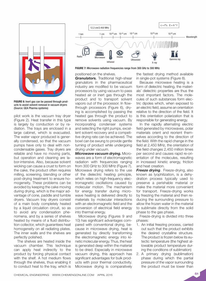
CHEMICAL ENGINEERING WWW.CHEMENGONLINE.COM APRIL 201551
pilot work is the vacuum tray dryer (Figure 2). Heat transfer in this type is largely by conduction or by ra-diation. The trays are enclosed in a large cabinet, which is evacuated. The water vapor produced is gener-ally condensed, so that the vacuum pumps have only to deal with non-condensable gases. Tray dryers are reliable and have no moving parts, but operation and cleaning are la-bor-intensive. Also, because solvent wicking can cause a crust to form on the cake, the product often requires milling, screening, blending or other post-drying treatment to ensure ho-mogeneity. These problems can be avoided by keeping the cake moving during drying, which is the major ad-vantage of cone, paddle and tumble dryers. Vacuum tray dryers consist of a main body completely heated by a liquid circulation circuit, so as to avoid any condensation phe-nomena, and by a series of shelves heated by means of a fluid distribu-tion collector, which guarantees heat homogeneity on all radiating plates. The inner walls and the shelves are perfectly polished.
The shelves are heated inside the vacuum chamber. This technique can apply heat indirectly to the product by forcing physical contact with the shelf. A hot medium flows through the shelves, thus enabling it to conduct heat to the tray, which is
positioned on the shelves.Granulators. Traditional high-shear granulators in the pharmaceutical industry are modified to be vacuum processors by using vacuum to pass heated air or inert gas through the product and to transport solvent vapors out of the processor. In flow-through processors (Figure 6), dry-ing is accomplished by passing the heated gas through the product to remove solvents using vacuum. By incorporating condenser systems and selecting the right pumps, excel-lent solvent recovery and a competi-tive drying rate can be achieved. The bowl can be swung to provide gentle turning of product while undergoing drying under vacuum.Microwave vacuum drying. Micro-waves are a form of electromagnetic radiation with frequencies ranging from 300 GHz to 300 MHz (Figure 7). Microwave drying refers to the use of the dielectric heating principle, which relies on high-frequency elec-tromagnetic oscillations caused by molecular motion. The mechanism for energy transfer during micro-wave heating is delivered directly to materials by molecular interactions with an electromagnetic field and the conversion of electrical field energy into thermal energy.
Microwave drying (Figures 9 and 10) has significant advantages com-pared with conventional drying, be-cause in microwave drying, heat is generated by directly transforming the electromagnetic energy into ki-netic molecular energy. Thus, the heat is generated deep within the material to be dried. Especially in microwave vacuum drying, this approach has significant advantages for bulk prod-ucts with poor thermal conductivity. Microwave drying is comparatively
the fastest drying method available in single-pot systems (Figure 8).
Because microwave heating is a form of dielectric heating, the materi-als’ dielectric properties are thus the most important factors. The mole-cules of such substances form elec-tric dipoles which, when exposed to an electric field, assume an orientation relative to the direction of the field. It is this orientation polarization that is responsible for generating energy.
In the rapidly alternating electric field generated by microwaves, polar materials orient and reorient them-selves according to the direction of the field. With the rapid change in the field at 2,450 MHz, the orientation of the field changes 2,450 million times per second and causes rapid re-ori-entation of the molecules, resulting in increased kinetic energy, friction and heat creation. Freeze drying. Freeze-drying, also known as lyophilization, is a dehy-dration process typically used to preserve a perishable material or make the material more convenient for transport. Freeze-drying works by freezing the material and then re-ducing the surrounding pressure to allow the frozen water in the material to sublimate directly from the solid phase to the gas phase.
Freeze-drying is divided into three phases:
An initial freezing process, carried 1. out such that the product exhibits the desired crystalline structure. The product is frozen below its eu-tectic temperature (the highest al-lowable product temperature dur-ing the conditions of sublimation)A primary drying (sublimation) 2. phase during which the partial pressure of the vapor surrounding the product must be lower than
FIGURE 6: Inert gas can be passed through prod-ucts to assist solvent removal in vacuum dryers (Source: GEA Pharma systems)
FIGURE 7: Microwave radiation frequencies range from 300 GHz to 300 MHz
Gamma ray
Wavelength1 km 1 cm 10-8 cm 10-4 cm 10-2 cm 10-8 cm 10-8 cm
12.2 cm/2.450 MHzc = f* E = h * f
Radio Microwave
Infrared
VisibleUltraviolet
X-ray
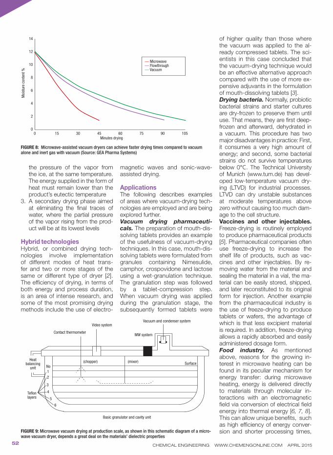
CHEMICAL ENGINEERING WWW.CHEMENGONLINE.COM APRIL 201552
the pressure of the vapor from the ice, at the same temperature. The energy supplied in the form of heat must remain lower than the product’s eutectic temperatureA secondary drying phase aimed 3. at eliminating the final traces of water, where the partial pressure of the vapor rising from the prod-uct will be at its lowest levels
Hybrid technologiesHybrid, or combined drying tech-nologies involve implementation of different modes of heat trans-fer and two or more stages of the same or different type of dryer [2]. The efficiency of drying, in terms of both energy and process duration, is an area of intense research, and some of the most promising drying methods include the use of electro-
magnetic waves and sonic-wave-assisted drying.
ApplicationsThe following describes examples of areas where vacuum-drying tech-nologies are employed and are being explored further.Vacuum drying pharmaceuti-
cals. The preparation of mouth-dis-solving tablets provides an example of the usefulness of vacuum-drying techniques. In this case, mouth-dis-solving tablets were formulated from granules containing Nimesulide, camphor, crospovidone and lactose using a wet-granulation technique. The granulation step was followed by a tablet-compression step. When vacuum drying was applied during the granulation stage, the subsequently formed tablets were
of higher quality than those where the vacuum was applied to the al-ready compressed tablets. The sci-entists in this case concluded that the vacuum-drying technique would be an effective alternative approach compared with the use of more ex-pensive adjuvants in the formulation of mouth-dissolving tablets [3]. Drying bacteria. Normally, probiotic bacterial strains and starter cultures are dry-frozen to preserve them until use. That means, they are first deep-frozen and afterward, dehydrated in a vacuum. This procedure has two major disadvantages in practice: First, it consumes a very high amount of energy; and second, some bacterial strains do not survive temperatures below 0°C. The Technical University of Munich (www.tum.de) has devel-oped low-temperature vacuum dry-ing (LTVD) for industrial processes. LTVD can dry unstable substances at moderate temperatures above zero without causing too much dam-age to the cell structure. Vaccines and other injectables. Freeze-drying is routinely employed to produce pharmaceutical products [5]. Pharmaceutical companies often use freeze-drying to increase the shelf life of products, such as vac-cines and other injectables. By re-moving water from the material and sealing the material in a vial, the ma-terial can be easily stored, shipped, and later reconstituted to its original form for injection. Another example from the pharmaceutical industry is the use of freeze-drying to produce tablets or wafers, the advantage of which is that less excipient material is required. In addition, freeze-drying allows a rapidly absorbed and easily administered dosage form. Food industry. As mentioned above, reasons for the growing in-terest in microwave heating can be found in its peculiar mechanism for energy transfer: during microwave heating, energy is delivered directly to materials through molecular in-teractions with an electromagnetic field via conversion of electrical field energy into thermal energy [6, 7, 8]. This can allow unique benefits, such as high efficiency of energy conver-sion and shorter processing times,
FIGURE 8: Microwave-assisted vacuum dryers can achieve faster drying times compared to vacuum alone and inert gas with vacuum (Source: GEA Pharma Systems)
FIGURE 9: Microwave vacuum drying at production scale, as shown in this schematic diagram of a micro-wave vacuum dryer, depends a great deal on the materials’ dielectric properties
Minutes drying
Basic granulator and cavity unit
— Microwave— Flowthrough— Vacuum
Moi
sture
con
tent
%
0 15 30 45 60 75 90 105
14
12
10
8
6
4
2
0
Teflon layers
Heat balancing
unit No
1
2
3
4
5
6
Contact thermometer
Video system
(chopper) (mixer)
MW system
Vacuum and condenser system
Surface

CHEMICAL ENGINEERING WWW.CHEMENGONLINE.COM APRIL 201553
thus leading to reductions in manu-facturing costs due to energy saving (microwave heating can be a tool of process intensification). By combin-ing vacuum with microwave as the source of thermal energy, a product is dried faster and at a lower tem-perature, thus avoiding damage to the product.
By using pulsed-microwave vac-uum drying, researchers have been able to dry cranberries [9]. Research-ers have microwave-vacuum-dried mint leaves and compared the pro-cess with air drying [10]. The effective moisture diffusivity was significantly increased when microwave drying was applied under vacuum condi-tions, compared with hot-air drying. For color, the microwave-vacuum-dried mint leaves were light green/yellow, whereas the hot-air-dried mint leaves were dark brown.Plastics production. The plastics industry uses vacuum to remove moisture from engineered plastics. If the moisture is not extracted from pel-lets before melt processing, streaks, bubbles, burning, brittleness and other critical defects in the molded or extruded parts can occur. Emerging areas. Recently, there has been an increased level of inter-est in developing drying technolo-gies as alternatives to lyophilization in the formulation of proteins as dry powders. Mannitol is often added to dried protein formulations as the bulking agent because it has the tendency to crystallize rapidly from aqueous solutions.
Vacuum-drying hybrid technolo-gies are being investigated to over-come some of the issues associated
with the process of lyophilization. These limitations include long pro-cessing times (typically 3–5 d), ex-pensive setup and maintenance of the lyophilization plants, and, most of all, the steps inherent in freeze-drying can lead to instabilities in the protein structure. Due to the complex structural properties, proteins have a tendency to denature and undergo irreversible aggregation during vari-ous processing steps of drying [4].
Optimizing drying processesTo optimize vacuum-dryer perfor-mance, it is important to adjust the peripheral equipment to match the specific needs of the drying opera-tion. This equipment includes the dryers’ heating and cooling system, dust filters, condensers and vac-
uum pumps. Condensers are used mostly to recover process solvents, which are evaporated during drying. They are typically shell-and-tube type surface condensers, arranged either vertically or horizontally. Con-densate collection can be measured and combined with a mass balance to allow indirect, realtime monitoring of product moisture during the dry-ing process.Drying efficiency. To increase the efficiency of drying processes, em-phasis has recently been placed on the development of new technolo-gies that use alternative sources of energy to enhance the heat trans-fer between the product and heat source (for example, microwave, ra-diofrequency and infrared radiation). New technologies can also intensify
FIGURE 10: Microwave vacuum dryers can help avoid damaging food products (Source: Bohle)
TABLE 3. VACUUM DRYING APPLICATION IN FOOD INDUSTRY
Products Dryer type Comment Reference
Strawberries and carrots
Microwave Preliminary drying studies 11
Pistachios Vacuum-infrared modeling 12
Eggplants Vacuum Drying characteristics studies 13
Probiotics Ultrasonic vacuum spray dryer Making highly viable probiotics 14
Chilis Combined microwave-vacuum rotary drum dryer
Experimental studies 15
Cranberries Microwave-vacuum dryer Energy use and efficiency studies 9
Cranberries Microwave-vacuum dryer Evaluation of quality 9A
Fruits and veg-etables
Microwave vacuum dryer Drying systems in agricultural production
16
Food (general) Microwave Microwave applications in ther-mal food processing
17
TABLE 2. QUANTITATIVE INFORMATION NEEDED TO ARRIVE AT A SUITABLE DRYER [20]
Dryer throughput; mode of feedstock production (batch versus continuous)•
Physical, chemical and biochemical properties of the wet feed, as well as desired product specifications; •expected variability in feed characteristics
Upstream and downstream processing operations•
Moisture content of the feed and product•
Drying kinetics; moist solid sorption isotherms•
Quality parameters (physical, chemical, biochemical)•
Safety aspects (fire hazard and explosion hazards, toxicity)•
Value of the product•
Need for automatic control•
Toxicological properties of the product•
Turndown ratio, flexibility in capacity requirements•
Type and cost of fuel, cost of electricity•
Environmental regulations•
Space in plant•

CHEMICAL ENGINEERING WWW.CHEMENGONLINE.COM APRIL 201554
the dehydration rate without increas-ing the amount of heat supplied to the product (for example, organic solvents, ultrasonic waves). Some of these technologies have already been developed and tested for use in freeze-drying foods [18].Selection of dryers. Determining which vacuum dryer is best for a par-ticular application (Table 4) depends in part on knowing a solid material’s moisture content. In addition, it is im-portant to understand the material’s particle characteristics, because these characteristics can vary in un-expected ways at different moisture levels. For instance, a filter cake con-taining 40% moisture can flow better than one with 15% moisture. For this reason, end-users of dryer technol-ogy should expect dryer manufac-turers to test solid materials before determining which dryer type is best capable of handling it.
Several dryer types (or drying sys-tems) may be equally suited (techni-cally and economically) for a given application. A careful evaluation of as many of the possible factors affecting the selection will help reduce the num-ber of options. For a new application (a new product or new process), it is important to follow a careful proce-dure leading to the choice of dryers.
Vacuum operation also eases the recovery of solvents by direct con-densation, thus alleviating possible serious environmental problems. Dust recovery is simpler, so that vac-uum dryers are especially suited for drying toxic, dusty products, which must not be entrained in gases. Fur-thermore, vacuum operation lowers
the boiling point of the liquid being removed, thus allowing the drying of heat-sensitive solids at relatively fast rates. Dryer selection can have a major impact on product quality, par-ticularly in the case of thermally sen-sitive materials, such as foodstuffs.Fuzzy logic. The use of a fuzzy ex-pert system as an aid in the prelimi-nary selection of a batch dryer can be a helpful tool. This incorporates a novel “multiple goal” approach in which different facets, such as dryer type, single versus multiple dryers, and atmospheric versus vacuum operation, are determined indepen-dently [19]. n
Edited by Scott Jenkins
References: 1. Ekneet Kaur Sahnia, Bodhisattwa Chaudhuria, Contact
drying: A review of experimental and mechanistic model-ing Approaches. International Journal of Pharmaceutics 434, pp. 334– 348. 2012.
2. Kudra, T., and Mujumdar, A.S., “Advanced Drying Tech-nologies,” Marcel Dekker, Inc., NY, 2002.
3. Formulation Design and Optimization of Mouth Dissolve Tablets of Nimesulide Using Vacuum Drying Technique (Mukesh Gohel, et.al. AAPS PharmSciTech 2004; 5 (3) Article 36 (http://www.aapspharmscitech.org), 2004.
4. Vikas K. Sharma and Devendra S. Kalonia. Effect of Vacuum Drying on Protein-Mannitol Interactions: The Physical State of Mannitol and Protein Structure in the Dried State, AAPS PharmSciTech 2004; 5 (1) Article 10 (http://www.aapspharmscitech.org), 2004
5. Roberto Pisano,Davide Fissore, Antonello A. Barresi, and Massimo Rastelli, AAPS PharmSciTech, 14 (3), Septem-ber 2013.
6. D. Acierno, A.A. Barba, M. d'Amore, Heat transfer phe-nomena during processing materials with microwave en-ergy, Heat and Mass Transfer 40 pp. 413–420, 2004.
7. A. Dalmoro, A.A. Barba, G. Lamberti, M. d'Amore, in-tensifying the microencapsulation process: ultrasonic atomization as an innovative approach, European Jour-nal of Pharmaceutics and Biopharmaceutics 80, pp. 471–477, 2012.
8. Decarueau, R.V. and Peterson, R.A, 1986. “Microwave Processing and Engineering,” Ellis Horwood, England. 1986.
9. Yongsawatdigul, J. and S. Gunasekaran, S. Microwave-
vacuum drying of cranberries: Part 1. Energy use and efficiency, J. of Food Processing and Preservation 20, 121–143, 1996.
9A. J. Yongsawatdigul and Gunasekaran, Microwave–Vac-uum drying of cranberries: Quality Evaluation. J. of Food Processing and Preservation, 20, pp. 145–156, 1996.
10. Nantawan Therdthai, Weibiao Zhou, J. of Food Engi-neering 91, pp. 482–489, 2009.
11. Viboon Changrue, G.S. Vijaya Raghavan, Yvan Gariépy and Valérie Orsat, Microwave vacuum dryer setup and preliminary drying studies on strawberries and carrots, Journal of Microwave Power & Electromagnetic Energy, 41 (2), 2007.
12. Ahmad Kouchakzadeh, Kourosh Haghighi, Modeling of vacuum-infrared drying of pistachios; Agric. Eng. Int: CIGR Journal, Open access at http://www.cigrjournal.org, 13 (3), September 2011.
13.Long Wu, Takahiro Orikasa, Yukiharu Ogawa, Akio Tagawa, “Vacuum drying characteristics of eggplants,” Faculty of Horticulture, Chiba University, 648, Matsudo, Matsudo, Chiba, Japan.
14.David Semyonov, Ory Ramon, Eyal Shimoni, Using ultra-sonic vacuum spray dryer to produce highly viable dry probiotics, LWT Food Science and Technology 44, pp. 1,844–1,852, 2011.
15.Weerachai Kaensup, Suracbate Cbutima and Somcbai Wongwises; Experimental study on drying of chili in a combined microwave-ratary drum dryer. King Mongkut’s University of technology, Bangkok, Thailand
16. Nona Ghanaat et al., Investigating of microwave Vacuum drying system of agricultural productions: Fruits and Veg-etables; MAGNT report (ISSN.1444-8939 , Vol 2 (5) pp. 392-397, published online, August 25, 2014.
17. Mohamed Shaheen et al., Microwave Applications, In “Thermal Food Processing” Chapter 1, accessed at http://dx.doi.org/10.5772/48716.
18. R. Pisano; D. Fissore; and A.A. Barresi. Sustainable freeze drying in the pharmaceutical and food industry. In E. Tsotsas and A.S. Mujumdar (eds.); “Modern Drying Technology, Volume 5: Process Intensification,” Wiley-VCH Verlag GmbH & Co. KGaA, Weinheim, Germany, pp. 131–161.
19. Haitham M.S., Lababidi, C., G.J. Baker, An expert sys-tem for dryer selection using fuzzy logic; Computers & Chemical Engineering, 23, Supplement, pp. S691–S694, June 1999.
20. Mujumdar, A. (ed.), “Handbook of Industrial Drying,” 2nd ed., Marcel Dekker, 1995.
21. Cox, D., Using a batch vacuum dryer to protect workers, the environment, and heat-sensitive materials. Powder
and Bulk Engineering, pp. 40–46, 1991.
AuthorDilip M. Parikh is president of the pharmaceutical technology devel-opment and consulting group DP-harma Group Inc. (Ellicott City, MD 21042; Email: [email protected]). As an industrial pharmacist, Parikh has more than 35 years of experience in product develop-ment, manufacturing, plant opera-tions and process engineering at
various major pharmaceutical companies in Canada and the U.S. Prior to starting DPharma Group, he held the position of vice president of operations and technol-ogy at Synthon Pharmaceuticals in North Carolina and vice president and general manager at Atlantic Phar-maceuticals Services in Maryland. He is the editor of “Handbook of Pharmaceutical Granulation” 3rd ed. He has authored several book chapters and articles on various pharmaceutical technologies, including quality by design, process assessment and contract manufac-turing. He has been an invited speaker at scientific conferences worldwide on solid-dosage technologies development and manufacturing.
TABLE 4. SUGGESTED VACUUM DRYER SELECTION APPROACH [21]
1 What is the batch size you want to process?
2 Consider which dryer type will drive up the temperature difference between your material and the heating media (∆T)
3 Determine the moisture (or liquid) content of your product to be dried, as well as the nature of that liquid (water or solvents)
4 Determine bound liquid and un-bound liquid is in the product
5 Based on the liquid, determine the vapor pressure profile with the temperature to be used
6 What is final product specification regarding percentage of liquid remaining in the product?
7 What utilities are available in the plant?
8 Consult a reputable dryer manufacture, discuss the product and determine the budget
9 Perform tests on your product in the dryer manufacturer’s facility
• Electronic notifi cation of monthly updates
• All annual data archives (1947 to present)• Monthly data archives (1970 to present)• Option to download in Excel format

Feature Report
CHEMICAL ENGINEERING WWW.CHEMENGONLINE.COM APRIL 201556
IN BRIEFDECANTER CENTRIFUGE
LAB SIMULATION OF
COMPACTION
GOVERNING
PARAMETERS
COMBINED SYSTEM
The decanter centrifuge is an important piece of equipment for sludge volume reduction prior to thermal drying. Understanding centrifuge operation helps manage drying energy costs
Consecutive mechanical dewater-ing and thermal drying are integral parts of sludge management, low-ering the sludge volume that needs
to be disposed of or further treated. Because drying is an energy-intensive unit operation, the mechanical pre-concentration of the sol-ids is a prerequisite.
The economic necessity for sludge-volume reduction in the chemical process indus-tries (CPI) as a way to manage downstream sludge-handling costs was discussed previ-ously (Chem. Eng., Sept. 2014, pp. 51–54 [1]). Because dewatering prior to drying is such an important stage in the sludge-vol-ume-reduction process — the drier the sludge solids, the less costly the next drying stage — this article discusses sludge dewatering with a solid-bowl decanter centrifuge, one of the most frequently used types of equipment for mechanical dewatering of sludge.
The high energy consumption of sludge dryers is primarily due to the latent heat of evaporation of water, which is equal to 2,260 kJ/kg at 100 °C. To first raise the water tem-perature from, for instance, 25°C to 100°C, an additional 314 kJ/kg is required. This means that at 100% efficiency, the minimum heat requirement to evaporate the sludge’s
water is 2,574 kJ/kg or 715 kWh/m³ of evap-orated water. In industrial dryers, the specific energy consumption varies between the lat-ter and 1,400 kWh/m3 water evaporated [2]. The specific power consumption, however, for conventional thickening technology is in the order of magnitude of only 1 kWh/m³ of wastewater slurry treated [3], which makes mechanical solid/liquid separation about 1,000 times less energy-intensive than ther-mal drying. Within the global decanter-centri-fuge application market in terms of machines sold, the market share for sludge dewater-ing is one of the largest with a 35% share in 2000 [4].
Decanter centrifugeThe basic idea of centrifugal solid-liquid sep-aration is simple — apply centrifugal force to a mixture of materials with different densities, and the heavier substance (solid, or a denser liquid) will be thrown further outward, result-ing in separation [5].
The solid-bowl decanter centrifuge used to dewater waste sludge is constructed of an external solid bowl and an internal Archi-
Wastewater Sludge Centrifugation Before Drying
Bart PeetersMonsanto Europe
FIGURE 1. This schematic diagram shows a sludge decanter centrifuge (adapted from Andritz), with a spin tube — used in the laboratory to simulate cake compaction — superimposed
Part 2
Cake
Effluent weirs
Sludge feed
Pool depth
Bowl (rotor)
Centrate
Helical screw conveyor
Conical section (beach)
Lab spin tube test Water squeezed out of compacting sludgeCompacting sludge

CHEMICAL ENGINEERING WWW.CHEMENGONLINE.COM APRIL 201557
medean screw conveyor mounted horizontally (Figure 1). Both rotate in the same direction, with the helical screw rotating at a slightly different speed to the bowl (ranging from 1 to 5 rpm), which allows the solids to be transported. The conditioned sludge is pumped via a stationary, central feed pipe into the hollow shaft of the rotating screw conveyor. The sludge moves through ports in the cylindrical (clarification) part of the bowl. Because of the centrifugal field (up to 3,500 times earth’s accelera-tion due to gravity) as result of the spinning bowl (typically in the range from 2,500 to 3,500 rpm) the heavier sludge flocs move radially outward to the inner bowl wall, while the lighter water remains pooled on top of the sedimented solids (Figure 1). The clarified water flows spirally along the helix of the screw conveyor in the di-rection of the liquid discharge ports. This centrate then overflows the ef-fluent weirs at the cylindrical end of the centrifuge, similar to river water flowing over a dam.
In the meantime, the sedimented sludge solids are continuously scraped by the screw conveyor to-ward the solids discharge ports at the opposite, conical end of the bowl. The sludge follows a complicated cork-screw motion as it is pushed along the helical channel formed by adjacent conveyor blades [6]. During its 10- to 15-minute transport in the machine, the sludge is dewatered in two steps, filtration and expression [7]. During the first filtration stage, water is withdrawn from the sludge to the point where the sludge solids start to make contact with one an-other, resulting in an initial solid pres-sure and the expression phase starts [7]. Throughout the second and more important expression stage, the orig-inal loosely packed solid structure is compressed to yield a much denser state as a result of the centrifugal compaction stress [3].
The solids in the underlying lay-ers (solids closest to the inner bowl wall) of the cake under formation experience compressive forces due to the pressure from the weight of the overlying solids (the solids clos-est to the axis of the centrifuge). The compressive stress is trans-ferred downward to the cake layers more adjacent to the inner bowl wall throughout the continuous linked
network of solids. In this way, the sludge cake is further consolidated.
When sludge solids closer to the inner bowl wall get more compressed over time, simultaneously, these sol-ids end up at a larger distance from the center of rotation. As a conse-quence, the rotational radius for the overlying sludge particles grows as well, and, hence, the force they exert on the lower (underlying) solids increases accordingly. This in turn compresses the lower sludge layer again, and so on [8]. This dynamic process continues until equilibrium is reached for any height in the com-pacted sludge cake.
As a result of the cumulative solids stress exerted on the cake layer clos-est to the inner bowl wall, the per-cent dry substance (%DS) is highest in this underlying layer, whereas the cake segment at the surface (closest to the axis of the centrifuge) remains less packed and has a significantly (~10%) lower DS [9]. On average, the cake discharged typically has a dry-ness ranging from 20 to 30% DS, de-pending on the sludge composition.
Concomitantly with the cake com-paction, the interstitial water trapped inside the sludge cake is expelled from the dense structure [7]. The water in the sludge matrix flows slowly upward through narrow chan-nels, away from the inner bowl wall (that is, in the opposite direction to the movement of the consolidating solids), toward the upper cake layer, which is less compact and conse-quently more permeable [8]. Water removal from the sludge, by increas-ing the compressive stress on the flocs, resembles squeezing water from a sponge [7]. The compaction of the sludge and the resulting ex-pressed water atop the consolidated sludge is illustrated in Figure 2.
The described dewatering mecha-nism via compaction (for sludge and other compressible biotic materials) is totally different than the deliquor-ing mechanism via drainage of drain-able solids (such as PVC, PVAC or PVOH polymer grains). In these ap-plications, the pool of liquid lies sig-nificantly below the solids-spillover point in contrast to the case of sludge dewatering where a large pool depth is pursued (Figure 1). Drainable sol-ids get their deliquoring in a decanter centrifuge mainly when the (under the pool formed) cake is lifted out of
the liquor pool and emerges on the dry beach where drainage starts, eventually combined with a displace-ment washing of the solids [10].
Compaction simulation“Often, simple laboratory studies can provide valuable insight into the physical and chemical mechanisms at work in your process, and extra lab effort can prevent grief during scaleup” [11], and this certainly ap-plies also for sludge dewatering in decanter centrifuges.
The author has developed a labo-ratory protocol that allows the de-tailed study of sludge centrifugation under controlled laboratory condi-tions [12]. In short, conditioned and pre-thickened sludge is put in a spin tube (Figure 2, right) and centrifuged. Included in the conditioning stage are the addition of cationic polymer (discussed below), as well as the ap-plication of a certain vast amount of shearing on the flocculated sludge. Then, after the sludge is centrifuged in the laboratory for a standard 45 min., the water that has squeezed out of the cake (Figure 2, left) is de-canted. In the laboratory, it was de-cided to study the compaction at quasi-equilibrium conditions [14] — in the decanter centrifuge, the time required for full cake consolidation is much longer than the cake retention time of 10–15 min.
Next, the compacted sludge cake is removed layer by layer with a laboratory spoon and the dryness of each layer is determined (%DSi; illustrated at the left side of Figure 3). Together with the recorded mass of each cake segment (wi) and the cake segment’s radial distance from the axis of rotation (Ri), the solids compaction stress (Ps) on an under-lying cake layer can, based on the contributions from all the overlying cake layers, approximately be cal-culated as follows [12]:
(1)
where N represents the speed of ro-tation and A is the surface area of the layer (from the spin tube). The com-paction curves are obtained then
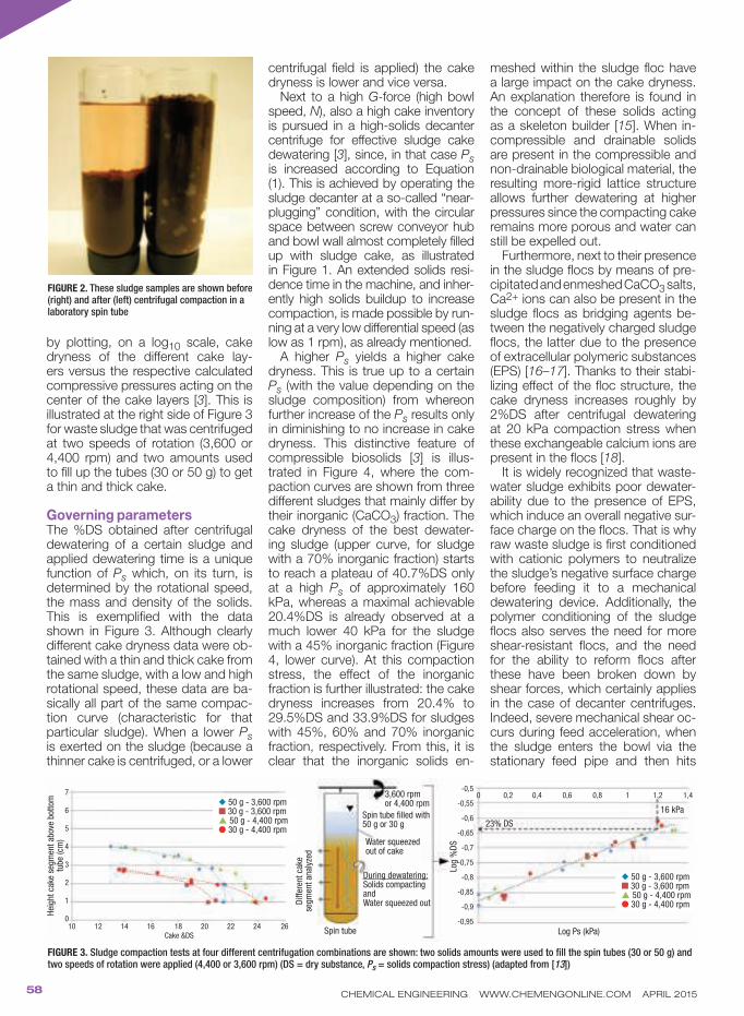
CHEMICAL ENGINEERING WWW.CHEMENGONLINE.COM APRIL 201558
by plotting, on a log10 scale, cake dryness of the different cake lay-ers versus the respective calculated compressive pressures acting on the center of the cake layers [3]. This is illustrated at the right side of Figure 3 for waste sludge that was centrifuged at two speeds of rotation (3,600 or 4,400 rpm) and two amounts used to fill up the tubes (30 or 50 g) to get a thin and thick cake.
Governing parameters The %DS obtained after centrifugal dewatering of a certain sludge and applied dewatering time is a unique function of Ps which, on its turn, is determined by the rotational speed, the mass and density of the solids. This is exemplified with the data shown in Figure 3. Although clearly different cake dryness data were ob-tained with a thin and thick cake from the same sludge, with a low and high rotational speed, these data are ba-sically all part of the same compac-tion curve (characteristic for that particular sludge). When a lower Ps is exerted on the sludge (because a thinner cake is centrifuged, or a lower
centrifugal field is applied) the cake dryness is lower and vice versa.
Next to a high G-force (high bowl speed, N), also a high cake inventory is pursued in a high-solids decanter centrifuge for effective sludge cake dewatering [3], since, in that case Ps is increased according to Equation (1). This is achieved by operating the sludge decanter at a so-called “near-plugging” condition, with the circular space between screw conveyor hub and bowl wall almost completely filled up with sludge cake, as illustrated in Figure 1. An extended solids resi-dence time in the machine, and inher-ently high solids buildup to increase compaction, is made possible by run-ning at a very low differential speed (as low as 1 rpm), as already mentioned.
A higher Ps yields a higher cake dryness. This is true up to a certain Ps (with the value depending on the sludge composition) from whereon further increase of the Ps results only in diminishing to no increase in cake dryness. This distinctive feature of compressible biosolids [3] is illus-trated in Figure 4, where the com-paction curves are shown from three different sludges that mainly differ by their inorganic (CaCO3) fraction. The cake dryness of the best dewater-ing sludge (upper curve, for sludge with a 70% inorganic fraction) starts to reach a plateau of 40.7%DS only at a high Ps of approximately 160 kPa, whereas a maximal achievable 20.4%DS is already observed at a much lower 40 kPa for the sludge with a 45% inorganic fraction (Figure 4, lower curve). At this compaction stress, the effect of the inorganic fraction is further illustrated: the cake dryness increases from 20.4% to 29.5%DS and 33.9%DS for sludges with 45%, 60% and 70% inorganic fraction, respectively. From this, it is clear that the inorganic solids en-
meshed within the sludge floc have a large impact on the cake dryness. An explanation therefore is found in the concept of these solids acting as a skeleton builder [15]. When in-compressible and drainable solids are present in the compressible and non-drainable biological material, the resulting more-rigid lattice structure allows further dewatering at higher pressures since the compacting cake remains more porous and water can still be expelled out.
Furthermore, next to their presence in the sludge flocs by means of pre-cipitated and enmeshed CaCO3 salts, Ca2+ ions can also be present in the sludge flocs as bridging agents be-tween the negatively charged sludge flocs, the latter due to the presence of extracellular polymeric substances (EPS) [16–17]. Thanks to their stabi-lizing effect of the floc structure, the cake dryness increases roughly by 2%DS after centrifugal dewatering at 20 kPa compaction stress when these exchangeable calcium ions are present in the flocs [18].
It is widely recognized that waste-water sludge exhibits poor dewater-ability due to the presence of EPS, which induce an overall negative sur-face charge on the flocs. That is why raw waste sludge is first conditioned with cationic polymers to neutralize the sludge’s negative surface charge before feeding it to a mechanical dewatering device. Additionally, the polymer conditioning of the sludge flocs also serves the need for more shear-resistant flocs, and the need for the ability to reform flocs after these have been broken down by shear forces, which certainly applies in the case of decanter centrifuges. Indeed, severe mechanical shear oc-curs during feed acceleration, when the sludge enters the bowl via the stationary feed pipe and then hits
FIGURE 2. These sludge samples are shown before (right) and after (left) centrifugal compaction in a laboratory spin tube
FIGURE 3. Sludge compaction tests at four different centrifugation combinations are shown: two solids amounts were used to fill the spin tubes (30 or 50 g) and two speeds of rotation were applied (4,400 or 3,600 rpm) (DS = dry substance, Ps = solids compaction stress) (adapted from [13])
◆ 50 g - 3,600 rpmn 30 g - 3,600 rpm▲ 50 g - 4,400 rpml 30 g - 4,400 rpm
◆ 50 g - 3,600 rpmn 30 g - 3,600 rpm▲ 50 g - 4,400 rpml 30 g - 4,400 rpm
Heig
ht
cake s
egm
ent
above
bott
om
tu
be (
cm)
7
6
5
4
3
2
1
010 12 14 16 18 20 22 24 26
Cake &DS
During dewatering:Solids compactingand Water squeezed outD
iffe
rent
cake
segm
ent
analy
zed
Spin tube
3,600 rpm or 4,400 rpm
-0,5
-0,55
-0,6
-0,65
-0,7
-0,75
-0,8
-0,85
-0,9
-0,95
Spin tube filled with 50 g or 30 g
Log Ps (kPa)
Water squeezed out of cake
0 0,2 0,4 0,6 0,8 1 1,2 1,4
Log %
DS
23% DS
16 kPa

CHEMICAL ENGINEERING WWW.CHEMENGONLINE.COM APRIL 201559
the rotating feeding chamber in the hollow screw conveyor (at very high speed) and, next, the water pool, bringing the new incoming sludge feed suddenly to high centrifugal ac-celeration [3]. For the shear intensive decanter centrifuge applications, non-linear polymers with higher mo-lecular weight and higher degree of structure, with cross-linking between the polymer chains, have been de-veloped. Clearly, the most appropri-ate polymer (and its optimal dosing) needs to be evaluated for a particular sludge prior to testing it in the field at the full-scale centrifuge (or, at least, the number of commercially available polymers needs to be funneled to a smaller number before going to real-life). This can be accomplished by means of the bench-scale spin tube
test described previously. A typical polymer dosing is in the range of 5 to 20 kg polymer active substance per ton of DS.
Prior to the polymer addition, sludge conditioning with polyalu-miniumchloride (PACl) can be justi-fied in case the sludge compaction proceeds in the machine to the dryness range where the partially dewatered sludge comes into its sticky phase [1]. Without the stick-iness-mitigating effect of the PACl, the screw conveyor can experience serious torque issues due to the pasty sludge cake, resulting in the choking of the decanter, seriously hampering its proper working. PACl addition is shown to almost com-pletely eliminate the stickiness of sludge [19].
Combined system Figure 5 shows the flow scheme from a centrifuge-dryer system where both unit operations are com-bined in one compact and enclosed system [14, 20]. Briefly, the sludge is dewatered in the decanter centrifuge (as described above), whereupon the discharged cake lumps are im-mediately disintegrated by impact on a cone surrounding the cake-discharge ports. The resulting solids spray is flash-dried and entrained by a hot gas stream, and a few seconds later, ~95% DS solids are separated in a cyclone.
The huge benefit of this approach is that it has a very simple layout without any need for intermediate storage or conveying of the dewatered sludge cake before feeding it to the next drying stage. In contrast, most in-dustrial sludge-handling installations have a separate dewatering step (a belt filter press or centrifuge, for in-stance), wherein the resulting cake is then temporarily stored and further conveyed to a standalone sludge dryer. To avoid having the sludge in the dryer equipment go through its sticky phase, the final dried material is recycled and back-mixed with the dewatered cake. This way, the %DS of the blended dryer feed is brought typically beyond 70%DS and from that point, it becomes crumbly and conveyable. In disc, paddle and thin-film dryers, the sticky issues need to be addressed by designing the dryer with high-torque capabilities. The design of the internal rotor is impor-tant to overcome the sticky phase in these dryers [21].
The continuous transition from centrifugation to flash drying (Fig-ure 5) makes the combined system unique, but it is also its proverbial Achilles’ heel. This is because a seri-ous but inherent drawback lies in the fact that the sludge cake leaving the centrifuge is literally never seen, and thus never analyzed. The system resembles a “black box,” where liq-uid sludge is pumped in, and when everything goes well, dry-dust sol-ids come out. Information on the in-between product (cake) is lacking, which makes process optimization difficult. Tests like the previously de-scribed spin tube test, to simulate at laboratory scale the compaction oc-curring at full-scale, can help. n
Edited by Scott Jenkins
FIGURE 4. Sludges with different levels of inorganic substances can show variable compaction curves
FIGURE 5. A sludge centrifuge and dryer system can be housed in one enclosed machine
Dried solids (~95%DS)
Log Ps [kPa]
Log %
DS
-0,3
-0,4
-0,5
-0,6
-0,7
-0,8
-0,9
0 0,5 1 1,5 2 2,5
33.9 %DS
29.5 %DS
20.4 %DS
40.7 %DS
1.6 (Ps = 40 kPa) 2.2 (Ps = 40 kPa)
70% inorganic fraction
60% inorganic fraction
45% inorganic fraction
Decanter centrifuge
1. Sludge is mechanically dewatered
2. Cake is smashed upon impact
with a stationary impact cone
3. Hot drying gas stream dries and
carries the sludge particles
4. Dried solids are
separated from
the gas stream
Dryer
Waste sludge (~2%DS)
PACI
Cationicpolymer
Centrate
Centrifuge cyclone chamber
Impact cone
Cake (20 to 30% DS)
Hot drying gas
Cyclone
CHEMICAL ENGINEERING WWW.CHEMENGONLINE.COM APRIL 201560
References1. Peeters, B., Dewil, R., Smets, I., Challenges of dry-
ing sticky wastewater sludge, Chem. Eng., Sept. 2014, pp. 51–54.
2. Bennamoun, L., Arlabosse, P., Léonard, A., Review on fundamental aspect of application of drying process to wastewater sludge, Renewable and Sus-tainable Energy Reviews 28, pp. 29–43, 2013.
3. Leung, W.W.-F., “Industrial Centrufugation Technol-ogy,” New-York: McGraw-Hill Inc., 1998.
4. Records, A., Sutherland, K.S., “Decanter Centrifuge Handbook,” New York: Elsevier Advanced Technol-ogy, 2001.
5. Moir, D.N. Sedimentation centrifuges: know what you need, Chem. Eng., March 1988, pp. 42–51.
6. Leung, W.W.-F., Torque requirement for high-solids centrifugal sludge dewatering, Filtration and Sepa-ration 35, pp. 883–887, 1998.
7. Novak, J.T., Dewatering of sewage sludge, Drying Technology 24, pp. 1,257–1,262, 2006.
8. Curvers, D. Saveyn, H., Scales, P.J., Van der Meeren, P., A centrifugation method for the assess-ment of low pressure compressibility of particulate suspensions, Chemical Engineering Journal 148, pp. 405–413, 2009.
9. Leung, W.W.-F., Dewatering biosolids sludge with VariGateTM Decanter centrifuge, In: Proceedings of the 2000 annual AFS conference, Anaheim, Calif., July 25–26, 2000.
10. Peeters, B., Weis, S., Relationship between pool depth and internal washing on the beach of a solid bowl decanter centrifuge, Filtration and Separation 41, pp. 36–40, 2004.
11. McConville, F.X., A bit of extra lab effort can pre-vent grief during scaleup, Chem. Eng. May 2006,
pp. 38–41.
12. Peeters, B. Dewil, R., Van Impe, J., Vernimmen, L., Meeusen, W., Smets, I.Y., Polyelectrolyte flocculation of waste activated sludge in decanter centrifuge ap-plications: lab evaluation by a centrifugal compac-tion test, Environmental Engineering Science 28, pp. 765–773, 2011.
13. Peeters, B., Vernimmen, L., Meeusen, W., Lab pro-tocol for a spin tube test, simulating centrifugal compaction of activated sludge, Filtration 9, pp. 205–217, 2009.
14. Peeters, B., Effect of activated sludge composition on its dewaterability and sticky phase, Ph.D. disser-tation, KU Leuven (Belgium), p. 280, 2011.
15. Zhao, Y.Q., Enhancement of alum sludge dewater-ing capacity by using gypsum as skeleton builder, Colloids Surf. A Physiochem. Eng. Asp. 2011, pp. 205–212, 2002.
16. Peeters, B., Herman, S., Monitor cations in CPI wastewater for better performance, Chem. Eng. May 2007, pp. 56–62.
17. Peeters, B., Dewil, R., Lechat, D., Smets, I.Y., Quan-tification of the exchangeable calcium in activated sludge flocs and its implication to sludge settleabil-ity, Separation and Purification Technology 83, pp. 1–8, 2011.
18. Peeters B., Dewil, R., Vernimmen, L., Smets, I.Y., Understanding the role of the two calcium pools on centrifugal dewaterability of sludge to avoid sticki-ness problems in centrifuge-dryers, Filtration 13, pp. 103–112, 2013.
19. Peeters, B., Dewil, R., Vernimmen, L., Van den Bogaert, B., Smets, I.Y., Addition of polyalumini-umchloride (PACl) to waste activated sludge to mitigate the negative effects of its sticky phase in dewatering-drying operations, Water Research 47, pp. 3,600–3,609, 2013.
20. Peeters, B., Mechanical dewatering and thermal drying of sludge in a single apparatus, Drying Tech-nology 28, pp. 454–459, 2010.
21. Arlabosse, P., Ferrasse, J.-H., Lecomte, D., Crine, M., Dumont, Y., Léonard, A., Efficient sludge thermal processing: from drying to thermal valorization. In: E. Tsotsas, A.S. Mujumdar, Eds., “Modern Drying Technology, Volume 4: Energy Savings,” Wiley-VCH Verlag & Co., Weinheim, Germany, 2011.
AuthorBart Peeters is a manufacturing technologist at Monsanto Europe N.V. (Haven 627, Scheldelaan 460, 2040 Antwerp, Belgium; Phone: +32 3 568 5762; Email: [email protected]), where he has been working since 1998. He first served as a process improvement engineer at East-man’s PVB polymer manufactur-
ing plant on site, until 2004. Since then, he has been working at the environmental department of the com-pany, with particular responsibilities in improving the wastewater treatment plant and the combined sludge centrifuge-dryer installation. Peeters is a Six Sigma Master Black Belt and is also the Six Sigma program leader at the Monsanto Antwerp site. While working at Monsanto’s WWTP, he obtained his Ph.D. in engineer-ing from the KU Leuven (Belgium) in 2011 on the re-search topic “Effect of activated sludge composition on its dewaterability and sticky phase.” Prior to that, he received his M.S.Ch.E. degree in 1998 from the KU Leuven, plus his M.Bio.Ch.E. degree in 1996 from the university college De Nayer. He is the author of 20 pa-pers in scientific journals, technical magazines and in-ternational conferences.
More and more, business in the Chemical Process Industries (CPI) is not local, it’s global. To keep up with this rapidly evolving marketplace, you need a magazine that covers it all, not just one country or region, not just one vertical market, but the entire CPI. With editorial offices around the world, Chemical Engineering is well-positioned to keep abreast of all the latest innovations in the equipment, technology, materials, and services used by process plants worldwide. No other publication even comes close.
To subscribe or learn more about membership, please visit www.chemengonline.com/subscribe
www.chemengonline.com
Written for engineers, by engineerswww.chemengonline.com
Fun
da
men
tals o
F Hig
H-sH
ear
disper
sers • H
eat excH
an
ger
s
VO
L. 1
22 N
O. 2
FE
BR
UA
RY
2015
02
•
Fundamentals of High-Shear Dispersers
February2015
page 40
Heat Exchangers: Two-Part Feature ReportAdvances in 3-D PrintingFocus on Industrial Housekeeping
Facts at Your Fingertips: Dimensionless Numbers
Valves for Extreme Service
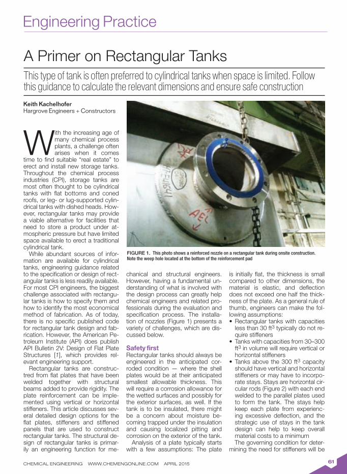
Engineering Practice
CHEMICAL ENGINEERING WWW.CHEMENGONLINE.COM APRIL 201561
With the increasing age of many chemical process plants, a challenge often arises when it comes
time to find suitable “real estate” to erect and install new storage tanks. Throughout the chemical process industries (CPI), storage tanks are most often thought to be cylindrical tanks with flat bottoms and coned roofs, or leg- or lug-supported cylin-drical tanks with dished heads. How-ever, rectangular tanks may provide a viable alternative for facilities that need to store a product under at-mospheric pressure but have limited space available to erect a traditional cylindrical tank.
While abundant sources of infor-mation are available for cylindrical tanks, engineering guidance related to the specification or design of rect-angular tanks is less readily available. For most CPI engineers, the biggest challenge associated with rectangu-lar tanks is how to specify them and how to identify the most economical method of fabrication. As of today, there is no specific published code for rectangular tank design and fab-rication. However, the American Pe-troleum Institute (API) does publish API Bulletin 2V: Design of Flat Plate Structures [1], which provides rel-evant engineering support.
Rectangular tanks are construc-tred from flat plates that have been welded together with structural beams added to provide rigidity. The plate reinforcement can be imple-mented using vertical or horizontal stiffeners. This article discusses sev-eral detailed design options for the flat plates, stiffeners and stiffened panels that are used to construct rectangular tanks. The structural de-sign of rectangular tanks is primar-ily an engineering function for me-
chanical and structural engineers. However, having a fundamental un-derstanding of what is involved with the design process can greatly help chemical engineers and related pro-fessionals during the evaluation and specification process. The installa-tion of nozzles (Figure 1) presents a variety of challenges, which are dis-cussed below.
Safety firstRectangular tanks should always be engineered in the anticipated cor-roded condition — where the shell plates would be at their anticipated smallest allowable thickness. This will require a corrosion allowance for the wetted surfaces and possibly for the exterior surfaces, as well. If the tank is to be insulated, there might be a concern about moisture be-coming trapped under the insulation and causing localized pitting and corrosion on the exterior of the tank.
Analysis of a plate typically starts with a few assumptions: The plate
is initially flat, the thickness is small compared to other dimensions, the material is elastic, and deflection does not exceed one half the thick-ness of the plate. As a general rule of thumb, engineers can make the fol-lowing assumptions:
Rectangular tanks with capacities •less than 30 ft3 typically do not re-quire stiffenersTanks with capacities from 30–300 •ft3 in volume will require vertical or horizontal stiffenersTanks above the 300 ft• 3 capacity should have vertical and horizontal stiffeners or may have to incorpo-rate stays. Stays are horizontal cir-cular rods (Figure 2) with each end welded to the parallel plates used to form the tank. The stays help keep each plate from experienc-ing excessive deflection, and the strategic use of stays in the tank design can help to keep overall material costs to a minimumThe governing condition for deter-
mining the need for stiffeners will be
A Primer on Rectangular Tanks
This type of tank is often preferred to cylindrical tanks when space is limited. Follow this guidance to calculate the relevant dimensions and ensure safe construction
Keith Kachelhofer
Hargrove Engineers + Constructors
FIGURE 1. This photo shows a reinforced nozzle on a rectangular tank during onsite construction. Note the weep hole located at the bottom of the reinforcement pad

CHEMICAL ENGINEERING WWW.CHEMENGONLINE.COM APRIL 201562
the height of the tank. As the height of the tank increases, so does the static pressure on the tank. In turn, the size and quantity of structural steel beams required for reinforce-ment will increase. The key to an economical design is a final tank design that uses the lightest-gage plate material while still providing sufficient reinforcement to ensure needed rigidity.
The size and number of stiffeners depends on the thickness of the tank wall and the spacing of the stiffeners. There is a tradeoff between the plate thickness and the number of stiffen-ers added to the plate. For instance, there could be a cost savings asso-ciated with reducing the plate thick-ness, but the savings may be offset by the labor required to install plate stiffeners. There are two methods of reinforcing the plate — through the use of vertical or horizontal stiffeners.
The method of horizontal reinforce-ment is a more direct procedure. Reinforcement incorporating vertical stiffeners requires an assumption of the shell plate thickness and spacing between the stiffeners, which can be an iterative process.
Figure 3 shows a rectangular tank with a top rim stiffener and two verti-cal stiffeners. Since the plates used to construct the tank are flat, they in-herently are not rigid structures when transverse static loads are imposed on the surface. Therefore, structural beams must be attached in order to keep the plates from experiencing excessive deflection. Areas of par-ticular concern are the regions of un-supported plate that exist between the tank corners and between the stiffeners themselves. It is here that the design engineer can combine the properties of the tank wall with those of the selected stiffener (Fig-
ure 4) to develop a composite beam, which will have a higher structural rigidity than just the structural mem-ber alone. A common method is to consider a section of steel plate hav-ing an equal distance between stiff-eners.
Determining the spacing between vertical stiffeners is an iterative pro-cess. An initial assumption is made for the stiffener spacing followed by a mathematical evaluation of the plate deflection and stress. The antici-pated plate deflection and stress are associated with published constants, which are a function of the ratio of the sides of the plate. Depending on how the plate is statically supported, these constants (along with the ratio of the sides) and specifically tai-lored formulas can be used to deter-mine the plate deflection and bend-ing stress.
If the deflection is excessive (that is, greater than one half of the plate thickness) and stress is greater than the values published in Table 1, then the stiffeners must be spaced more closely together.
Figure 5 shows a rectangular tank with a top rim stiffener and one hori-zontal (intermediate) stiffener. The advantage of this design is that the intermediate stiffener is located in proximity to where the average load is acting on the surface plane. One stiffener can be attached at the point of loading and act as a beam with a uniform distributed load. The design incorporating horizontal stiffeners is a more direct and simplified approach as opposed to making assumptions with vertical stiffeners.
Tanks incorporating stiffeners can use a wide range of structural shapes, including angle, channel or structural T's. When using a struc-tural angle for reinforcement at the top, the angle can be oriented with the toe out where one face of the angle is oriented against the shell plate. But the intermediate stiffener needs to be attached with the toe facing into the tank wall (one face of the angle oriented outward) to in-crease structural rigidity, as shown in Figure 6.
Stiffeners are attached to the tank wall by using either continuous fillet welds or stitch welds. For top stiffen-ers, the inner fillet weld must be con-tinuous (Figure 7) in order to keep the product from becoming trapped
FIGURE 2. Cylindrical rods are welded to parallel plates to minimize deflection, as shown here. The use of stays is beneficial when the outside stiffeners are too large
FIGURE 3. Shown here is a rectangular tank with vertical stiffeners. Note the region of unsupported plate between the vertical stiffeners
Rectangular tank
"Stay"
"Stay" or connecting rod
Tank shell plate
Vertical stiffener
Top stiffener
H
Region of unsupported plate

CHEMICAL ENGINEERING WWW.CHEMENGONLINE.COM APRIL 201563
or seeping between the tank wall and the stiffener. The welds outside of the wetted surface can be stitch welds. Stitch welds (Figure 8) require less labor and use less deposited weld metal. For most applications, a ¼-in. fillet weld is sufficient with weld lengths ranging from 2 to 3 in. and the welds spaced anywhere from 6–10 in. apart.
The corners of the tank walls are regions of high stress due to the dis-continuity between the two adjoin-ing plates. Thus, the corner joints will require reinforcement or full pen-etration welds. Figure 9 shows two corner joint designs that are com-monly used during fabrication of rectangular tanks.
A third option is to use a formed corner on the tank shell plate with a full penetration weld, as shown in Figure 10. This is a preferred method for small tanks that use lighter-gauge steel walls (in the range of 10-gauge plate to 1/4-in. plate). The plate is easy to form and the welds are economical.
Adding nozzles to the designNozzles installed in rectangular tanks are typically not subjected to high static head pressures, therefore the
connection of the nozzle to the tank shell can typically be completed with a fillet weld on the outside of the tank and a fillet weld on the inside of the tank. Typically, there is no need for additional nozzle reinforcement. However, if the nozzle is connected to any rotating equipment, such as pump suction piping, then the tank nozzles should be installed using full penetration welds, followed with a capping fillet weld, as shown in Figure 11.
Since the inherent geometry of the plate does not permit excessive loadings, dynamic equipment should not be suspended directly from the tank nozzles. If mixers and side-wall agitators are to be installed on the tank shell, then a third-party engi-neering firm should perform finite el-ement analysis on the tank shell and nozzle to ensure adequate reinforce-ment of the nozzle and shell plate. If unsure as to the need for reinforce-ment, then the recommendations of API 650, Section 5.7, can be applied [2]. API 650 recommends that open-ings in tank shells that are larger than an NPS 2 flanged or threaded nozzle be reinforced, as shown in Figure 1. All shell-opening connec-
tions that require reinforcement (for example, nozzles, manholes, and cleanout openings) must be at-tached by welds that fully penetrate the shell, according to API 650.The minimum cross-sectional area of the required reinforcement must not be less than the product of the vertical diameter of the hole cut into the shell and the nominal plate thickness. The cross-sectional area of the reinforce-ment shall be measured vertically, coincident with the diameter of the opening. Table 5.6(a)(b) in API 650 provides recommendations for re-inforcement plate dimensions. Be sure to add a 1/4-in. NPT weep hole in the bottom of the reinforcement pad (Figure 1) to provide the access needed to check for any potential leaks behind the pad.
The bottom plate thickness can be 1/4-in. or 3/8–in. nominal thick-ness, assuming the plate is entirely supported by a concrete pad. The bottom plate needs to extend be-yond the shell plate with sufficient distance to incorporate anchor bolts if desired. Since most rectangular tank geometry is not subjected to high overturning moments, anchor bolts may not be required.
FIGURE 4. Structural engineers will incorporate a region of the shell plate into the reinforcement calculation to help reduce the size of the rein-forcement beam and reduce cost
FIGURE 5. A rectangular tank is shown with a top stiffener and an intermediate stiffener located at 43% of the height of the tank wall, measured from the bottom of the tank
TABLE 1. ALLOWABLE DESIGN STRESS FOR PLATE MATERIAL, PSI
Material Grade Design Temperature
100oF 150oF 200oF 250oF 300oF
SA283 C 15,700 15,700 15,700 15,700 15,700
SA36 16,600 16,600 16,600 16,600 16,600
SA516-70 20,000 20,000 20,000 20,000 20,000
SA240-304 20,000 20,000 20,000 20,000 18,900
SA240-304L 16,700 16,700 16,700 16,700 16,700
SA240-316 20,000 20,000 20,000 20,000 20,000
SA240-316L 16,700 16,700 16,700 16,700 16,700
The shaded region indicates an area of
tank shell plate that structural engineers
will use in reinforcement calculations
Y Y
X
X
Intermediate
stiffener
Top stiffener
H
0.43HRegion of unsupported plate

CHEMICAL ENGINEERING WWW.CHEMENGONLINE.COM APRIL 201564
If a roof plate is required, then sev-eral factors must be considered. Will the roof be permanently attached to the top stiffener or will it be bolted? If the top of the tank is made to be re-moved, then its weight is very impor-tant. Be sure to provide lifting lugs to facilitate maintenance. The size of the tank and the need for access for plant operations and maintenance will determine if the plate needs to be designed for personnel working on the surface.
API 650 recommends a minimum of 45 lb/ft2 for combined dead load and live loads. This should be suf-ficient to allow a person to walk on the roof without excessive de-flection. For applications that may have hot vapors above the liquid level, it might be prudent to include a corrosion allowance for the inside
of the plate.The same design procedures that
are used for roof plates are also used for side plates. First, find a ratio of sides where there is a minimal amount of deflection and check the plate stress. Like the vertical stiff-eners used for the tank walls, the stiffeners for the roof plate will need to be selected for deflection and stress. For removable roof plates, a general recommendation is to start with 3/16–in. or 1/4-in. plate incor-porating channel sections, plate or angle attached, with the X-X axis parallel to the roof plates, as shown in Figure 13.
Calculation methodologyThere is a simplified method for deter-mining the required shell-plate thick-ness and the required beam sizes that can be used by CPI engineers. The procedure yields results that are both dependable and conservative. As with most design processes, the first step is to determine the volume of product that needs to be stored. Based upon the available real estate in the plant, the geometry of the tank then needs to be established. Know-ing the required volume of the tank, the length of one side can be deter-mined using Equation (1):
w = V3
�
�
(1)
Where:w = the length of one side of the tank, ftV = the required volume for storage, ft3
The preferred ratio of sides is: 1.5w for the longer side and 0.67w for the shorter side, with the relationships shown in Equations (2) and (3):
LL = 1.5w (2)
LS = 0.67w (3)
Where:LL = the length of the long wall, ftLS = the length of the short wall, ft
Next, determine the hydrostatic force on the inside surface of the shell plate. This process involves funda-mental statics, where the load im-posed on the tank varies linearly with the depth of the fluid (Figure 12).
The pressure at the top of the plate is equal to zero, and the maximum pressure is at the bottom of the tank. To be conservative, the maximum pressure will be used for determin-ing plate deflection and stress using Equation (4):
pmax
= h
�
�
(4)
Where: = density of the fluid, lb/in.3
h = maximum height of the fluid, in.
The longest wall will govern the de-sign for the tank shell, since this will provide the largest area of the plate that will be subjected to hydrostatic forces. Hydrostatic forces act per-pendicular to the surface. The pres-sure the fluid exerts on the tank walls depends upon its depth. In the case
FIGURE 6. Proper orientation of the top stiffener and the intermediate stiffener using angled stiff-eners is shown here. The stiffener shown at the top is oriented with the "toe" out, while the inter-mediate stiffener is oriented with the "toe" in. The intermediate stiffener is stronger with the "toe-in" orientation where a region of the tank plate can be used to resist deflection
FIGURE 7. This figure shows top stiffener detail with a cover plate. Note the channel is oriented on the X-X (strong) axis. See Figure 13 for details
FIGURE 8. On this tank, structural reinforce-ment is provided by a horizontal 'T' shape that is stitch-welded to the side wall of a rectangular stainless steel tank
TABLE 2. MODULUS OF ELASTICITY, E
Material Grade Design Temperature
100oF 200oF 300oF 400oF 500oF
Carbon steel 29.3 x 10⁶ 28.6 x 10⁶ 28.1 x 10⁶ 27.5 x 10⁶ 27.0 x 10⁶
Austenitic stainless 28.3 x 10⁶ 27.6 x 10⁶ 27.0 x 10⁶ 26.5 x 10⁶ 25.8 x 10⁶
Continuous
weld
Tank shell
plate
Acceptable configuration
for top stiffener to accept
a tank lid/roof plate
Stitch weld
Continuous weld
Tank
wall
Stitch weld
Cover plate
Top stiffener
Preferred angle orienta-
tion for intermediate
stiffener, toe-in

CHEMICAL ENGINEERING WWW.CHEMENGONLINE.COM APRIL 201565
of water, there is 1 lb of pressure for every 2.31 ft of depth. The force on the shell plate can be calculated using Equation (5):
Fr =
1
20.036
lb
in.3
h2
( ) S.G.( )
�
�
(5)
Where:h = the maximum height of the fluid level, in.Fr = the resultant force, lb/in.S.G. = the specific gravity of the fluid stored (that is, the ratio of a specific fluid density to the density of water), dimensionless
The use of a horizontal intermedi-ate stiffener located between the top stiffener and the bottom of the tank is the simplest approach. It is recommended that the intermediate stiffener be located at 0.43H from the bottom of the tank [7] where H is the height of the tank wall (Figure 5).
The next step is to determine the required plate thickness, using Equation (6):
treqd = 0.3 h( )
0.036 S.G.( )(h)
a
�
�
(6)
Where:S.G. = the specific gravity of the fluid stored, dimensionless = the allowable bending stress for the steel plate, psih = the maximum height of the fluid level, in.
Table 1 provides a list of common steel alloys and their respective bending stresses. Table 2 provides the modulus of elasticity of various grades of steel at various tempera-tures. The modulus of elasticity is a number that measures an object’s resistance to being deformed elasti-cally when a force is applied.
If the tank is in a corrosive envi-ronment, then an appropriate corro-sion allowance needs to be added to the required plate thickness. The most common corrosion allowances range from 1/16 to 3/16 in.
The next step is to determine the required moment of inertia for the stiffener located at the top of the tank (this is shown in Figure 5). In-ertia is a measure of a body’s abil-ity to resist movement, bending or rotation. The moment of inertia is a measure of a beam’s stiffness in rela-tion to its cross-section. As a beam’s moment of inertia increases, its abil-ity to bend decreases. For flat plate, channel, structural T and angle, the highest moment of inertia is located on the X-X axis as shown in Figure 13. The minimum required moment of inertia for the top stiffener beam can be found using Equation (7):
Itop =
0.06Fr( ) LL4
( )
192 E( ) tnom( )
�
�
(7)
Where:LL = length of the longest tank wall, in.E = modulus of elasticity, psitnom = the nominal thickness of plate to be used, in.
The minimum required moment of inertia for the intermediate stiffener located between the top stiffener and the tank bottom can be deter-mined using Equation (8):
Iint
=
0.3Fr( ) LL4
( )
192 E( ) tnom( )
�
�
(8)
Be sure to convert your wall length from feet to inches when using Equa-tions (7) and (8) in order to maintain consistent units. The top and inter-mediate stiffeners can be any variety of structural shapes, such as chan-nels, T-shapes or angles. Figure 13 shows examples of common struc-tural shapes that can be used for stiffeners. For smaller tanks, struc-tural angles are the most economical option, and they provide a surface onto which a cover plate or lid can be bolted or welded. Larger tanks will typically incorporate larger struc-tural members, such as channels. The structural member must have a moment of inertia that is greater than what was calculated above for the top and intermediate stiffeners. The mechanical properties of structural members can be found online at the Engineers Edge website [8].
When selecting a structural mem-ber from the tables online provided in Ref. 8, it is imperative to select a mo-ment of inertia on the X-X axis of the beam, as shown in Figure 13. This is typically denoted as Ixx where I is the moment of inertia of the shape and the subscript X-X represents the moment of inertia about the X-X axis. When possible, try to use the same structural member for both the top
FIGURE 9. Two corner joint designs are shown here. The preferred method is the use of a reinforce-ment angle with continuous fillet welds
FIGURE 10. The preferred corner joint for light-gauge plate ranging from 10GA to 1/4-in. nominal thickness. Forming the corners and providing one full penetration weld helps to strengthen the cor-ner and minimize plate distortions during welding
TABLE 3. PLATE CONSTANTS FOR RECTANGULAR PLATES WITH ALL EDGES FIXED AND
UNIFORM DISTRIBUTED LOAD
W/H 1.00 1.20 1.40 1.60 1.80 2.00 Infinity
0.1386 0.1794 0.2094 0.2286 0.2406 0.2472 0.2500
0.0138 0.0188 0.0226 0.0251 0.0267 0.0277 0.0284
Tank wall
Tank wall
Continuous weld
Continuous weld
Continuous weld
Reinforcement angleFull penetration weld
Continuous weld
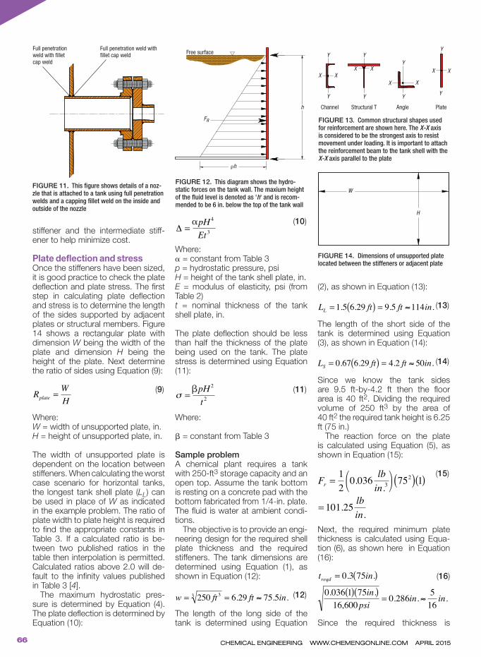
CHEMICAL ENGINEERING WWW.CHEMENGONLINE.COM APRIL 201566
CHEMICAL ENGINEERING WWW.CHEMENGONLINE.COM APRIL 201566
stiffener and the intermediate stiff-ener to help minimize cost.
Plate deflection and stressOnce the stiffeners have been sized, it is good practice to check the plate deflection and plate stress. The first step in calculating plate deflection and stress is to determine the length of the sides supported by adjacent plates or structural members. Figure 14 shows a rectangular plate with dimension W being the width of the plate and dimension H being the height of the plate. Next determine the ratio of sides using Equation (9):
Rplate =
W
H
�
�
(9)
Where:W = width of unsupported plate, in.H = height of unsupported plate, in.
The width of unsupported plate is dependent on the location between stiffeners. When calculating the worst case scenario for horizontal tanks, the longest tank shell plate (LL) can be used in place of W as indicated in the example problem. The ratio of plate width to plate height is required to find the appropriate constants in Table 3. If a calculated ratio is be-tween two published ratios in the table then interpolation is permitted. Calculated ratios above 2.0 will de-fault to the infinity values published in Table 3 [4].
The maximum hydrostatic pres-sure is determined by Equation (4). The plate deflection is determined by Equation (10):
=
pH4
Et3
�
�
(10)
Where: = constant from Table 3p = hydrostatic pressure, psiH = height of the tank shell plate, in.E = modulus of elasticity, psi (from Table 2)t = nominal thickness of the tank shell plate, in.
The plate deflection should be less than half the thickness of the plate being used on the tank. The plate stress is determined using Equation (11):
=
pH2
t2
�
� (11)
Where:
= constant from Table 3
Sample problemA chemical plant requires a tank with 250-ft3 storage capacity and an open top. Assume the tank bottom is resting on a concrete pad with the bottom fabricated from 1/4-in. plate. The fluid is water at ambient condi-tions.
The objective is to provide an engi-neering design for the required shell plate thickness and the required stiffeners. The tank dimensions are determined using Equation (1), as shown in Equation (12):
w = 250 ft33
= 6.29 ft 75.5in.
�
�
(12)
The length of the long side of the tank is determined using Equation
(2), as shown in Equation (13):
LL = 1.5 6.29 ft( ) = 9.5 ft 114in.
�
�
(13)
The length of the short side of the tank is determined using Equation (3), as shown in Equation (14):
LS = 0.67 6.29 ft( ) = 4.2 ft 50in.
�
�
(14)
Since we know the tank sides are 9.5 ft-by-4.2 ft then the floor area is 40 ft2. Dividing the required volume of 250 ft3 by the area of 40 ft2 the required tank height is 6.25 ft (75 in.)
The reaction force on the plate is calculated using Equation (5), as shown in Equation (15):
Fr =
1
20.036
lb
in.3
752
( ) 1( ) =
�
�
1( ) = 101.25lb
in.
�
�
(15)
Next, the required minimum plate thickness is calculated using Equa-tion (6), as shown here in Equation (16):
treqd = 0.3 75in.( )
�
�
in.)0.036 1( ) 75in.( )
16,600psi= 0.286in.
5
16in.
�
�
(16)
Since the required thickness is
FIGURE 11. This figure shows details of a noz-zle that is attached to a tank using full penetration welds and a capping fillet weld on the inside and outside of the nozzle
FIGURE 12. This diagram shows the hydro-static forces on the tank wall. The maxium height of the fluid level is denoted as 'h' and is recom-mended to be 6 in. below the top of the tank wall
FIGURE 13. Common structural shapes used for reinforcement are shown here. The X-X axis is considered to be the strongest axis to resist movement under loading. It is important to attach the reinforcement beam to the tank shell with the X-X axis parallel to the plate
FIGURE 14. Dimensions of unsupported plate located between the stiffeners or adjacent plate
Full penetration
weld with fillet
cap weld
Full penetration weld with
fillet cap weldFree surface
FR
h
Y
Channel Structural T Angle Plate
Y Y YY
XX
W
H
X
X
XX
X
X
Y
Y
Y
h

CHEMICAL ENGINEERING WWW.CHEMENGONLINE.COM APRIL 2015
above 1/4-in. then assume 5/16-in. plate. The required moment of inertia for the top stiffener beam is calculated using Equation (7), as shown in Equation (17):
Itop =
0.06( ) 101.25lb
in.
114in.( )4
192 2.93x10⁶ psi( ) 0.3125in.( )
�
�
= 0.583in.4
�
�
(17)
Use an angle 2.5 in. × 2.5 in. × 0.25 in., with a moment of inertia Ixx= 0.703 in.4
Next, calculate the required moment of inertia of the inter-mediate stiffener using Equa-tion (8), as shown below in Equation (18):
Iint
=
0.3( ) 101.25lb
in.
114in.( )4
�
�
192 2.93x10⁶ psi( ) 0.3125in.( )
= 2.918in.4
�
�
.
(18)
Use an angle 4 in. × 4 in. × 1/4 in. with a moment of inertia Ixx = 3.04 in.4 or use a C4 × 5.4 channel (this is a designation of the American Inst. of Steel Construction; Details can be found in [6]), with a moment of inertia Ixx = 3.85 in.4
Check the plate deflection below the intermediate stiffener. This area of plate will experience the highest pressure acting on the plate. Determine the pressure using Equation (4), as shown in Equation (19):
p = 0.036lb
in.3
72in.( ) = 2.59psi
�
�
(19)
Note: the fluid height is assumed to be 72 in.
The ratio of plate dimensions is determined using Equation (9), as shown in Equation (20):
Rplate =
W
0.43H=
9.5 ft
2.68 ft= 3.53
�
�
(20)
Remember that the recommended location of the intermediate stiffener [7] is 0.43H, which is 2.68 ft (32.25 in.) from the bottom of the tank.
The plate deflection is determined using Equation (10), as shown below in Equation (21):
=
0.0284( ) 2.59psi( ) 32.25 in( )4
= 0.088
�
�
2.93x10⁶ psi( ) 0.3125in.( )3
in )
= 0.088 in.
�
�
.
(21)
The plate deflection is less than 0.156 in. so the plate thickness is determined to be sufficient. Finally, the plate stress can be de-termined from Equation (11), as shown in Equation (22):
=
0.25( ) 2.59psi( ) 32.25 in( )4
0.3125in.( )2
= 6
�
�
in)
= 6,896 psi
�
�
(22)
The plate stress is below the pub-lished plate stress in Table 1 so the tank design can be considered to be safe. n Edited by Suzanne Shelley
References1. API Bulletin 2V, Design of Flat Plate Structures, 3rd Ed.,
June 2004.
2. API Standard 650, Welded Tanks for Oil Storage, 12th Ed., March 2013.
3. Megyesy, Eugene F., “Pressure Vessel Handbook, 10th Ed.,” Pressure Vessel Publishing, 1995, pp. 213–219.
4. Young, Warren C., “Roark’s Formulas for Stress & Strain, 6th Ed.,” McGraw-Hill, 1989, pp. 458–465.
5. Moss, Dennis R., “Pressure Vessel Design Manual, Third Ed.,” Gulf Professional Publishing, 2004, pp. 227–233.
6. American Inst. Of Steel Construction, "Manual of Steel Construction – Allowable Stress Design," 9th Ed., 1989.
7. Mahajan, Kanti K., “Design of Process Equipment, Selected Topics, 2nd Ed.,” Pressure Vessel Handbook Publishing, Inc., 1985, pp. 267-280.
8. Engineers Edge website: www.engineersedge.com/structural_shapes_menu.shtml
AuthorKeith Kachelhofer is the process engineering leader at Hargrove Engineers + Construc-tors (30 Park of Commerce Way, Suite 100, Savannah, GA 31405; Phone: 912-508-0846; Email: [email protected]). He holds a degree in me-chanical engineering technology from Southern Polytechnic Uni-
versity in Marietta, Ga. Kachelhofer has over twenty years of experience with ASME vessels and API tanks and has authored two previous articles in Chemical Engineering. He is a registered Professional Engineer in Georgia, South Carolina, North Carolina, Virginia, West Virginia, New York, Delaware, Maine, Ohio and Utah.
We live process engineeringand special manufacturing
www.sms-vt.com
Your partner in developing new products and processes
Buss-SMS-Canzler
Buss-SMS-Canzler GmbH
Kaiserstraße 13-15 • 35510 Butzbach • GermanyTel: +49 60 33 - 85 - 0 • Fax: +49 60 33 - 85 - 249
E-Mail: [email protected]
Molecular
Distillationwith Short Path Evaporators
for effective thermal separation
of heat sensitive products
under high vacuum of min.
0,001 mbar (a)
Circle 25 on p. 78 or go to adlinks.chemengonline.com/56196-25

Solids Processing
CHEMICAL ENGINEERING WWW.CHEMENGONLINE.COM APRIL 201568
The processing of mined minerals in aboveground facilities relies on several energy-
intensive unit operations, such as comminution, screen-ing and material transport. Crushing operations typically produce a wide distribution of product rock sizes. This arti-cle demonstrates that select-ing a crusher that is able to produce a narrower size-dis-tribution profile can not only reduce power consumption (by minimizing the need for recycle), but can substantially increase revenue and profit margins as well, by maxi-mizing the production of the higher-value fractions. The same strategy can also be applied to solids-processing operations in other process industries, such as catalyst manufacturing, cement manufactur-ing, coal-based chemicals produc-tion, production of rock phosphate, and for steam-generation systems that use lump coal as the fuel.
Material- and energy-balance models provide a simple and ef-fective tool to identify and quantify such opportunities. An illustrative example is provided below.
Watching energy useHistorically, the production of a mineral commodity has been perceived as two distinct stages: 1) mining to extract the commodity from the ground; and 2) processing the commodity to convert it into a market-able end product. The ex-ample used in this article is based on the author’s experience in quick-lime
production plants, but the lessons learned are generically applicable to all unit operations that involve size reduction.
The mining and minerals industry is a major energy consumer — fuels are required for excavation and rock-
moving equipment, while electric power is consumed during rock and ore processing for size reduction (crushing and grinding), size grad-ing (screening), conveying (material transport) and other operations (Fig-ure 1).
Increase Profits in Size-Reduction Plants
Material- and energy-balance models can help to identify potential opportunities
Jimmy Kumana
Kumana & Associates
FIGURE 1. The average specific energy required for the size reduction varies by the mineral type
Kumana & Associates
Speci
fic
com
min
ution e
nerg
y,
kW
h/t
pro
duct
100,000
1,000
10
0
Gold
Silv
er
Moly
bdenum
Lithiu
mC
opper
Merc
ury
Nic
kel
Tungst
en
Zin
cM
ica
Asb
est
os
Lead
Titaniu
mR
are
eart
hVerm
iculit
eFlo
urs
par
Cem
ent
Ars
enic
Alu
min
um
Iron o
reK
aolin
Phosp
hate
Talc
Bari
teB
ento
nite
Gyp
sum
Feld
spar
Manganese
Pota
ssiu
mC
alc
ium
Baro
nPerl
itC
hro
miu
mC
oal
Pum
ice
Dia
tom
ite
Sto
ne
Com
mon c
lay
Fire
cla
yC
era
mic
aU
raniu
mS
alt
Sili
con
Gra
vel
Sand
The ability to obtain sharper product-distribution profiles during size-reduction efforts can help to significantly im-prove the profit margin of the facility
Reprinted with permission from [1]

CHEMICAL ENGINEERING WWW.CHEMENGONLINE.COM APRIL 201569
On the basis of production vol-ume, coal and limestone aggre-gate production are the two domi-nant processes that employ these energy-intensive unit operations to process the commodities once they are mined. Today, three-quarters of the crushed stone production in the U.S. is limestone and dolomite, fol-lowed by, in descending order of ton-nage: granite, traprock, sandstone and quartzite, miscellaneous stone, marble, slate, calcareous marl, shell, volcanic cinder and scoria.
Limestone is found in sedimen-tary deposits, and is composed mostly of the mineral calcite; it comprises about 15% of the earth’s sedimentary crust. Limestone is a widely used building block in the con-struction industry and is the principal raw material from which aggregate, cement, lime and building stone are made. For the purposes of this article, limestone will be used as a representative of all crushed rock.
The aggregates industry serves as an excellent example of how these three main unit operations — size reduction, screening and convey-ing — can be optimized on an inte-grated basis. The focus should be on modeling the aggregate produc-tion process as a whole, rather than on individual crushing, grinding, or conveying operations. Process descriptionRocky minerals are mined using explosives and quarrying. Large boulders are typically transported by a font-end loader to primary jaw crushers that break the rock into 6–8-in. stones. Further size re-duction is done in multiple stages using gyratory crushers, impact crushers and cone crushers, with intermediate transport usually via a conveyor belt.
After crushing, the rock material or final product (as in the case of lime and cement) may be further reduced in size in grinding mills. There are a variety of different grinding mills, in-cluding rod and ball mills, semiauto-genous (SAG) mills and autogenous mills. In the grinding mills, the impact of the minerals grinding against each
other and against the steel balls in the mill breaks down the size of the minerals even further. The milling pro-cess also includes vibrating screens that sort the crushed material into the desired size fractions.
A review of basic statisticsThe probability distribution function (PDF) of crushed rock size tends to follow a “normal” (also called Gauss-ian) distribution, which is described by Equation (1):
f x( ) =1
2exp x µ( )
2
22[ ] (1)
Where:μ = the mean or expected value (and also the median and mode) of pa-rameter x = the standard deviation of x (de-fined as the square root of the vari-ance 2)t = (x – μ)/If μ = 0 and = 1, then the distri-bution is called the standard normal distribution.
FIGURE 2. The flowsheet shows the major operations that are used in a typical quarrying operation
FIGURE 3. Shown here is the frequency distribution function for parameter x, under various combinations of mean and variance
Reprinted with permission from [ 7]
Via conveyor or dumptruck to stockpiles
Chute Primary crusher
Vibrating feeder
Scalpings
Primary conveyor
Primary stockpile
Feeder conveyor
Surge bin
Surge bin
Secondary cone crusher
Screen
Screen
Blinding stockpile
Recycled oversize
Tertiary cone crusher
Quaternary cone crusher
μ=0 2=0.2 ——μ=0 2=1.0 ——μ=0 2=5.0 ——μ=-2 2=0.5 ——
Final screens
Product bins
f(x
)
1.0
0.8
0.6
0.4
0.2
0.0
–5 –4 –3 –2 –1 0 1 2 3 4 5X

CHEMICAL ENGINEERING WWW.CHEMENGONLINE.COM APRIL 201570
Graphical representations of the parameter x with various types of normal distributions are shown in Figure 3. The red curve is a standard normal distribution. If the variance is reduced, a narrower distribution with a higher peak is obtained, as shown by the blue curve. If the mean μ has a non-zero value, then the curve shifts to the left or right, as shown by the green curve.
The cumulative distribution func-tion (CDF) of the normal distribu-tion, usually denoted with the capi-tal Greek letter , is the integral, as shown in Equation 2:
x( ) =
1
2e
t2/ 2
x
dt (2)
It should be noted that Equation (2 )is not integrable explicitly in terms of algebraic functions, and must be solved numerically using pub-lished tables.
Figure 4 shows the cumulative particle-size distribution of mixtures with varying values of μ and . Fig-ure 3 shows the actual frequency distribution for the same mix-tures. Both figures actually convey the same information, but in differ-ent formats.
In reality, size distribution will not be quite Gaussian, because the minimum size cannot be negative, and real data seldom follow the smooth lines shown in the idealized figures above. In large part, the dis-crepancy is due to the shape of the size-reduced rocks — because it is impossible to represent the size of non-spherical particles with a sin-gle dimensional value. Neverthe-less, the method described here provides a sufficiently good ap-proximation for practical purposes, and certainly helps the engineer to think clearly about the design is-sues at hand.
Most reputable manufacturers will publish the cumulative product size distribution that is achievable for var-ious models of their crushers (Figure 5 shows an example), as an aid to design engineers seeking to select the most suitable model.
An illustrative exampleThe simple generic size-reduction circuit shown in Figure 6 demon-strates certain design concepts and principles in a generalized way, and should not be construed as being representative of any particular exist-ing plant.
In this example, a simple ma-terial-balance model was devel-oped to estimate the benefits of choosing a crusher that produces a sharper size distribution (that is, with a lower standard deviation) of crushed limestone rock product sizes (Figures 7 and 8). The exist-ing crusher is designated Design A and the proposed new crusher is designated Design B.
Power was correlated versus feed capacity using data from the bro-chure of a jaw crusher manufacturer [2] for nominal 8-in. feed (defined as 80% of mass being less than 8 in. in dia.). The correlation is shown in Equation (3):
Consumed kW = 0.00047 tons /h( )2
h( )2
+ 0.00263 tons /h( ) 0.073
(3)
Conveying power is a function of many parameters, the most sig-nificant being load, length, con-veyor layout (that is, the number of changes in elevation and direction), and the incline angle. The calculation is rather complex [3–5] but for any specific layout, the power consump-tion can be expressed in simplified form using Equation (4):
kW = 0.75HP = A + mW( )L (4)
Where:A and m = machine- and layout-de-pendent dimensional constantsW = the mass of material being transported, ton/hL = the length of the conveyor, ft (as-sumed to be 400 ft and 500 ft, re-spectively, for the conveyors 1 and 2 represented in Figure 6).
FIGURE 4. This figure shows the cumulative distribution function (CDF) for
parameter x, under the same conditions were used as in Figure 3
FIGURE 6. This conceptual flow diagram shows the typical steps involved in a size-reduction (comminu-tion) process
FIGURE 5. Shown here is an example of cumulative product size-distribution data for various models of jaw crushers from the same manufacturer (in this case, Terex; www.terex.com)
μ=0 2=0.2 ——
μ=0 2=1.0 ——
μ=0 2=5.0 ——
μ=-2 2=0.5 ——
NOTE: CSS = Closed Side Setting, which is the minimum distance between the crushing surfaces at the product discharge outlet
—— 200—— 175—— 165—— 150—— 140—— 125—— 114—— 100—— 88—— 75
(x
)
% P
assi
ng
1.0
0.8
0.6
0.4
0.2
0.0
100
90
80
70
60
50
40
30
20
10
0
-5 -4 -3 -2 -1 0 1 2 3 4 5X
0 50 100 150 200 250 300 350Sieve size, mm
Fines (waste)
1 2 3
4
5
Conveyor 2
Conveyor 1Feed
hopperCrusher Screen
Overs
Product

CHEMICAL ENGINEERING WWW.CHEMENGONLINE.COM APRIL 201571
Strictly speaking, the constants A and m should be different for each section of the conveyor, but for sim-plicity we will assume that they are the same, with A = 0.0375, and m = 0.0625 when W is in tons/h and L is in ft.
Now, the material balance can be calculated (some iteration may be re-quired for the recycle rate of overs),
as can the power consumption for the two cases.
Tables 2 and 3 show the material balances for designs A and B, for the flowsheet of Figure 6. The crusher and conveyor power consump-tion associated with each stream is also shown.
It can be seen from the compari-son in Table 4 that while the energy
intensity of Design B is lower by 22%, the primary financial benefit actually derives from higher sales revenue that results when production is shifted from the lower-value frac-tion (fines) to the higher-value middle fraction of final crushed product. The simulation model also reveals that it is much more economic to re-cycle the “overs” fraction for making more high-value middle fraction than to sell it as a low-value product on the market.
For the assumed ex-factory prod-uct prices and power costs (that is, exclusing transportation and distribution costs and middleman profits), the profit-improvement potential from employing a crusher with a sharper probability-distribu-tion curve is significant (8%), which could help to justify the capital cost associated with replacing the existing unit. Of course, if the site has different product prices, the potential increased profit could be higher or lower.
Due to the particular design of this circuit — despite the 22% energy-savings potential — the overall im-pact of this upgrade on plant operat-ing costs is minimal. However, if the conveyor lengths were longer and the inclines greater, then the reduc-tion on power costs could have had a more significant impact on the bot-tom line.
Although this example uses an admittedly oversimplified model, it does provide important insights into the key drivers of economics in plants where size-reduction op-erations are a dominant portion of operating costs. Actual design and optimization should be carried out
FIGURE 7. Comparing the frequency size distributions of product from crusher designs A and B clearly shows that Design B, with the same mean but lower variance, will have more material (the area under the curve) in the desired size range compared to Design A
FIGURE 8. This figure uses the same data as Figure 7, but plotted as cumulative weight percent on the Y-axis. It also shows that the fraction of product in the desired size range (from 1 to 4 in. dia) is 84-10 = 74% of the feed for Design B, versus 76-15 = 61% for Design A
TABLE 1. CRUSHER PRODUCT SIZE DISTRIBUTION DATA FOR THE ILLUSTRATIVE EXAMPLE
Assumptions Size Value
Capacity 150 ton/h range, in. $/ton
Feed rock size 8 in. fines < 1 4
Power cost 9 cents/kWh middle 1–4 20
Operating time 4,200 h/yr overs >4 9
TABLE 2. MATERIAL BALANCE AND POWER CONSUMPTION FOR DESIGN A
Crusher Design A
Stream number 1 2 3 4 5
Bulk (>12 in.) 135 0 0 0 0
Overs (>4 in.) 14 50.9 0 50.9 0
Product (1–4 in.) 2 122.2 120.0 2.1 0
Fines ( < 1 in.) 0 30.5 1.2 0.5 28.8
Total, ton/h 150 203.6 121.2 53.6 28.8
Trial recycle 53.6
Size distribution, assumed
Bulk (>12 in.) 90% 0% 0% 0% 0%
Overs (>4 in.) 9% 25% 0% 95% 0%
Product (1–4 in.) 1% 60% 99% 4% 0%
Fines ( < 1 in.) 0% 15% 1% 1% 100%
100% 100% 100% 100% 100%
Power consumption
Crusher, HP 26.6 0
Conveyor, HP 12.7 3.7
Total power, kW 29.5 2.8
Power cost, $/h 2.7 0.2
$1,000/yr 11.1 1.0
A = Existing B = Proposed new
A = Existing B = Proposed new
Crushed product size distributions Cumulative product size distributions
35
30
25
20
15
10
5
0
120
100
80
60
40
20
0
Frequency
of
size
, %
Frequency
of
size
, %
0 2 4 6 8 10 12Normal size, in.
-2 0 2 4 6 8 10 12Normal size, in.
Desired size range Desired size range

CHEMICAL ENGINEERING WWW.CHEMENGONLINE.COM APRIL 201572
using more rigorous simulations, as described in Ref. 6.
Closing thoughtsThe illustrative example provided in this article highlights four important truisms:
The ability to obtain sharper prod-1. uct-distribution profiles in size-reduction operations can signifi-cantly improve the profit margins of the facilityEven simplified material balance 2. models are an effective tool to help engineers gain insight into areas of potential improvement, and to assess the economic im-pact of capital improvementsWhile energy savings for crushing 3. and grinding circuits may be high in relative percentage terms, the value of optimizing the product mix has a far greater positive im-pact on overall plant economicsFor new plant designs, the 4. method described here can help the engineer to select the opti-mum crusher and screen com-bination for various, alternative plant-ayout options
Cost-effective energy conservation should be a performance goal for all manufacturing operations. His-torically, most companies turn their attention to economic optimization only after the product has become
“mature” and has become a com-modity — when it becomes impor-tant to protect profit margins in the face of price competition. Unfortu-nately, by then it is often too late, because competitors may have not only achieved parity, but may have even gained some technological edge through innovation. By ignor-ing the opportunity to optimize the process design, complacent com-panies leave open a gaping hole for their rivals to acquire a competitive edge through the development of a more energy-efficient process with lower costs. n
Edited by Suzanne Shelley
References1. Ballantyne, G.R., Powell, M.S., and Tiang, M., Proportion
of Energy Attributable to Comminution, 11th Mill Opera-tors’ Conference, Hobart, Tasmania, Australia, October 29–31, 2012.
2. JW Series Jaw Crushers, Corporate brochure, Terex Corp., Westport, CT, USA (www.terex.com).
3. “Belt Conveyors for Bulk Materials, 6th Ed.,” Chap. 6, Conveyor Equipment Manufacturers Assn.; www.cema-net.org, 2007.
4. “Conveyor Handbook,” Chap. 3, Fenner Dunlop Co., West Footscray, Australia, 2009.
5. Recommendations for Constructing and Calculating Con-veyor Belts, Corporate brochure, Forbo Siegling GmbH, Hannover, Germany, www.forbo-siegling.com, 2013.
6. Using Mine-to-Mill Technology to Optimize Crushed Stone Production, U.S. Dept. of Energy, Industrial Technologies Program; www.eere.energy.gov; 2006.
7. Quarrying Process and Quarry Products, Whitepaper published by Northstone (NI) Ltd., Belfast, Northern Ire-land, U.K., Accessed at: www.northstonematerials.com/downloads.
AuthorJimmy Kumana is the CEO of Kumana & Associates (3642 Robinson Rd., Hous-ton, TX 77459; Phone: 281-437-5906; Email: [email protected]), a consulting firm he founded in 1997, specializing in process integration (pinch analysis) techniques for en-ergy and water optimization. Kumana holds an MS.Ch.E. degree from the University of
Cincinnati. He has more than 35 years of experience working for both manufacturing and engineering-con-struction companies. Kumana and his company have provided consulting services to major corporations worldwide, including Amoco (BP), ConocoPhillips, Du-pont, Mitsubishi, Monsanto (Solutia), Occidental Petro-leum, PetroChina, SABIC, SASOL, Saudi Aramco,Trinidad Cement, Union Carbide (Dow), the Electric Power Re-search Institute, Enron, Southern California Gas, and Xcel Energy, as well as to the U.S. Dept. of Energy, Natu-ral Resources Canada, the World Bank, and the U.N.. He has authored or co-authored more than 70 technical papers and book chapters, and regularly teaches courses on pinch analysis, energy efficiency in the pro-cess industries and related subjects.
TABLE 3. MATERIAL BALANCE AND POWER CONSUMPTION FOR DESIGN B
Stream number 1 2 3 4 5
Bulk (>12 in.) 135 0 0 0 0
Overs (>4 in.) 14 26.7 0 26.7 0
Product (1–4 in.) 2 133.6 132.5 1.1 0
Fines ( < 1in.) 0 17.8 1.3 0.3 16.2
Total, ton/h 150 178.1 133.8 28.1 16.2
Trial recycle 28.1
Size distribution, assumed
Bulk (>12 in.) 90% 0 0% 0% 0%
Overs (>4 in.) 9% 15% 0% 95% 0%
Product (1–4 in.) 1% 75% 99% 4% 0%
Fines ( < 1 in.) 0% 10% 1% 1% 100%
100% 100% 100% 100% 100%
Power consumption
Crusher, HP 20.4 0
Conveyor, HP 11.1 1.9
Total power, kW 23.7 1.4
Power cost, $/h 2.1 0.1
$1,000/yr 8.9 0.5
TABLE 4. COMPARISON OF ECONOMICS FOR CRUSHER DESIGNS A AND B
Design A Design B Difference%$ton/h $/h ton/h $/h
Main product 121.2 2,425 133.8 2,676 10.4
Fines 28.8 115 16.2 65 -43.8
Total flow 150 2,540 150 2,741 7.9
kW $/h kW $/h D, %
Crusher power 29.5 2.7 23.7 2.1 -19.8
Conveyor power 2.8 0.2 1.4 0.1 -47.5
Total 32.3 2.9 25.1 2.3 -22.2
Intensity, kWh/ton 0.215 n/a 0.167 n/a -22.2
Marginal profit, $/h 2,536.8 2,738.3 7.9
• Aboveground and Underground
• Chemical Resistance of Thermoplastics• Heat Transfer: System Design II• Adsorption• Flowmeter Selection• Specialty Metals• Plus much, much more…
• Conservation Economics: Carbon Pricing Impacts• Distillation Tray Design• Burner Operating Characteristics• Measurement Guide for Replacement Seals• Steam Tracer Lines and Traps• Positive Displacement Pumps• Low-Pressure Measurement for Control Valves• Creating Installed Gain Graphs


CHEMICAL ENGINEERING WWW.CHEMENGONLINE.COM APRIL 201574
FreDrive
The FreDrive is a unique and new milling design. In no time up to five different grinding heads can be attached, either for primary crushing, de-agglomeration, granulation, fine grind-ing or control screening on the base module, which combines the control and drive portions. Changeover to a new grinding process takes little time; simply loosen the Tri-Clamp.
FreDrive is able to mill sticky, hard or crystalline powder with widely varying product characteristics gently and problem-free, providing good, flowable powder into the processes. All applications that require a screening mill (including ATEX zones 0/20 and 1/21) are covered.
NEW: The new mill concept opens up completely new paths. The FreDrive is mounted on a mobile lifter that meets all stan-dards of the pharmaceutical industry, and is very flexible. The user has the option to dock the mill anywhere in the production area to bring the device to the desired height with a touch of a button, and to easily integrate into an existing or new system.
Frewitt Switzerland www.frewitt.com
Interphex – Booth 2035
Hayward Z Series
Solenoid Diaphragm Metering Pumps
Revolutionary new line of metering pumps for chemical dosing systems and corrosive environments features just one design and footprint with front fac-ing controls and tube connections for easy and flexible installation. Avail-able with analog or digital controls, the Z Series covers flow rates ranging from 1 gph to 14 gph in just three pump sizes, offers stroke rates from 120 to 300 strokes/minute to cover all application needs, and is backed by an exclusive 2 year warranty.
Hayward Flow Control www.haywardflowcontrol.com

CHEMICAL ENGINEERING WWW.CHEMENGONLINE.COM APRIL 201575
Gas and Liquid Pumps forHazardous Media and Locations
KNF offers gas and liquid diaphragm pumps with explosion-proof motors for use in chemical processing, petrochemical refining, and other safety-critical applications. These durable pumps are suited for HAZLOC Class 1/Division 1/Groups C & D (gas and liquid) and Division 2/Groups A, B, C & D (liquid) locations. UL/CSA approved, and available in corrosion-resis-tant versions. ATEX compliant pumps also available. All KNF diaphragm pumps are contamination and maintenance-free; liquid pumps are self-priming, and can run dry without dam-age. Pumps designed to performance needs, with spec-driven configurations, materials, motors, and other options available through engineer-to-engineer consultation.
KNF Neuberger, Inc. www.knfusa.com/exproof
TO SUBSCRIBE TO THE HOT PRODUCTS E-LETTER, PLEASE CONTACT
JESSICA GRIER • [email protected]
'S PREMIUM PRODUCT
SHOWCASE FOR THE LATEST
PRODUCTS AND TECHNOLOGIES IN
THE CHEMICAL ENGINEERING INDUSTRY.

CHEMICAL ENGINEERING WWW.CHEMENGONLINE.COM APRIL 201576
Product Showcase
Circle 201 on p. 78 or go toadlinks.chemengonline.com/56196-201
Advertise in the Buyers' Guide
Buyers' Guide 2016
Contact:
Diane Burleson
Tel: 512-337-7890
Fax: 512-213-4855
Email: [email protected]
Process
Technology
Pelleting
www.akahl.de
Software
Recruitment
Circle 242 on p. 76 or go toadlinks.chemengonline.com/56196-242
Circle 244 on p. 78 or go to adlinks.chemengonline.com/56196-244Circle 243 on p. 78 or go to
adlinks.chemengonline.com/56196-243
Busch LLC has immediate openings for Applications Engineers with a BSME/BSCHE and 3+ years
of experience. Learn more and apply here: www.buschusa.com

CHEMICAL ENGINEERING WWW.CHEMENGONLINE.COM APRIL 2015 77
Circle 247 on p. 78 or go toadlinks.chemengonline.com/56196-247
KnightHawk EngineeringSpecialists in design, failure analysis
and troubleshooting of staticand rotating equipmentwww.knighthawk.com
Contact Jim Salter 281-282-9200
KnightHawk EngineeringSpecialists in design, failure analysis
and troubleshooting of staticand rotating equipmentwww.knighthawk.com
Contact Jim Salter 281-282-9200Visit us at Chemshow Booth #245
Circle 246 on p. 78 or go toadlinks.chemengonline.com/56196-246
SS 304,316,317, Alloy20, Monel, ChromeMoly, Titanium, Brass, Steel, Duplex, A105... IN STOCK, MADE IN USA
JOHN R. ROBINSON INC.Phone #[email protected]
HEAT EXCHANGER TUBE PLUGS
Circle 241 on p. 78 or go toadlinks.chemengonline.com/56196-241
Tell Us What You Have For Sale
We Buy Equipment!We Are “Sniffing Out”
Quality Process Equipment
> Ribbon Blenders> Double Cone Dryers> Twin Shell Blenders> Paddle Mixers> Turbulizers> Tanks, Silos, Reactors> Screeners and more...
or call: 855-714-8359www.aaronequipment.com/sniff
AE_ChemEngineering_MAR2015.qxp_Layout 1 2/10/15 9:48 PM Page 1
GET CONNECTED TODAYwww.chemengonline.com
Circle 250 on p. 78 or go toadlinks.chemengonline.com/56196-250
Circle 245 on p. 78 or go toadlinks.chemengonline.com/56196-245
Indeck Power Equipment Company847.541.8300
Indeck can custom designand build for you too!
Emergency Service
Emerg
ency Service24HR
TrailerMounted80K-395 PSI
75K SH-750 PSI75K-395 PSI70K-395 PSI70K-350 PSI70K-350 PSI
60K SH-750 PSI60K-395 PSI40K-395 PSI40K-350 PSI36K-300 PSI30K-300 PSI24K-300 PSI24K-300 PSI
250,000-800 PSI / 750 Deg. F.180,000-750 PSI / 750 Deg. F.165,000-1025 PSI / 850 Deg. F.165,000-395 PSI150,000-750 PSI / 750 Deg. F.135,000-750 PSI / 750 Deg. F.120,000-350 PSI120,000-350 PSI120,000-725 PSI / 750 Deg. F.110,000-395 PSI90,000-395 PSI75,000-750 PSI / 750 Deg. F.75,000-395 PSI70,000-395 PSI70,000-350 PSI70,000-350 PSI60,000-750 PSI / 750 Deg. F.50,000-395 PSI40,000-750 PSI30,000-395 PSI20,000-1600 PSI10-1,000 HP - 15-250 PSI
800.446.3325Lease • Rental • Sale
Available ImmediatelyBOILERS
Circle 251 on p. 78 or go toadlinks.chemengonline.com/56196-251
WABASH SELLS & RENTSBoilers
20,000 - 400,000 #/Hr.Diesel & Turbine Generators
50 - 25,000 KWGears & Turbines
25 - 4000 HPWe stock large inventories of:
Air Pre-Heaters • Economizers • DeaeratorsPumps • Motors • Fuel Oil Heating and Pump Sets
Valves • Tubes • Controls • CompressorsPulverizers • Rental Boilers & Generators24/7 Fast Emergency Service
800-704-2002Phone: 847-541-5600 Fax: 847-541-1279
www.wabashpower.com
POWER EQUIPMENT CO.444 Carpenter Ave., Wheeling, IL 60090wabash
New & Used Equipment
Circle 252 on p. 78 or go toadlinks.chemengonline.com/56196-252
HEAT EXCHANGERSLiquid Cooled
Air Cooled
▼
▼
FOR GASES & LIQUIDS!Talk Directly with Design Engineers!
Blower Cooling Vent Condensing
(952) 933-2559 [email protected]
Circle 248 on p. 78 or go toadlinks.chemengonline.com/56196-248
Circle 249 on p. 78 or go toadlinks.chemengonline.com/56196-249
1-800-243-ROSSwww.DualShaftMixers.com
Scan to learn more & get a free quote.
Free Tag Reader: http://gettag.mobi
DUAL SHAFTMIXERS
New 50, 100 & 200 gal. mixers in stock!
ADVERTISE IN THE CLASSIFIED
Contact Diane BurlesonTel: 512-337-7890Fax: 512-213-4855
Email:[email protected]
xx_CHE_xx0115_CLASS.indd 77 3/20/15 1:46:03 PM

New Product Information
CHEMICAL ENGINEERING WWW.CHEMENGONLINE.COM APRIL 201578
FREE PRODUCT INFO (please answer all the questions)
YOUR INDUSTRY
01 Food & Beverages
02 Wood, Pulp & Paper
03 Inorganic Chemicals
04 Plastics, Synthetic Resins
05 Drugs & Cosmetics
06 Soaps & Detergents
07 Paints & Allied Products
08 Organic Chemicals
09 Agricultural Chemicals
10 Petroleum Refining,
Coal Products
11 Rubber & Misc. Plastics
12 Stone, Clay, Glass, Ceramics
13 Metallurgical & Metal Products
14 Engineering, Design & Construction
Firms
15 Engineering/Environmental Services
16 Equipment Manufacturer
17 Energy incl. Co-generation
18 Other———————————
JOB FUNCTION
20 Corporate Management
21 Plant Operations incl. Maintenance
22 Engineering
23 Research & Development
24 Safety & Environmental
26 Other———————————
EMPLOYEE SIZE
28 Less than 10 Employees
29 10 to 49 Employees
30 50 to 99 Employees
31 100 to 249 Employees
32 250 to 499 Employees
33 500 to 999 Employees
34 1,000 or more Employees
YOU RECOMMEND, SPECIFY,
PURCHASE
(please circle all that apply)
40 Drying Equipment
41 Filtration/Separation Equipment
42 Heat Transfer/Energy Conservation
Equipment
43 Instrumentation & Control Systems
44 Mixing, Blending Equipment
45 Motors, Motor Controls
46 Piping, Tubing, Fittings
47 Pollution Control Equipment & Systems
48 Pumps
49 Safety Equipment & Services
50 Size Reduction & Agglomeration Equip-
ment
51 Solids Handling Equipment
52 Tanks, Vessels, Reactors
53 Valves
54 Engineering Computers/Software/
Peripherals
55 Water Treatment Chemicals & Equip-
ment
56 Hazardous Waste Management Sys-
tems
57 Chemicals & Raw Materials
58 Materials of Construction
59 Compressors
Fax this page back to 800-571-7730
JustFAXit!Fill out the form and circle or write in the number(s) below, cut it out, and fax it to 800-571-7730.
www.chemengonline.com/adlinksGo on the Web and fill out the online reader service card.
1
2
3
4
5
6
7
8
9
10
11
12
13
14
15
16
17
18
19
20
21
22
23
24
25
26
27
28
29
30
31
32
33
34
35
36
37
38
39
40
41
42
43
44
45
46
47
48
49
50
51
52
53
54
55
56
57
58
59
60
61
62
63
64
65
66
67
68
69
70
71
72
73
74
75
76
77
78
79
80
81
82
83
84
85
86
87
88
89
90
91
92
93
94
95
96
97
98
99
100
101
102
103
104
105
106
107
108
109
110
111
112
113
114
115
116
117
118
119
120
121
122
123
124
125
126
127
128
129
130
131
132
133
134
135
136
137
138
139
140
141
142
143
144
145
146
147
148
149
150
151
152
153
154
155
156
157
158
159
160
161
162
163
164
165
166
167
168
169
170
171
172
173
174
175
176
177
178
179
180
181
182
183
184
185
186
187
188
189
190
191
192
193
194
195
196
197
198
199
200
201
202
203
204
205
206
207
208
209
210
211
212
213
214
215
216
217
218
219
220
221
222
223
224
225
226
227
228
229
230
231
232
233
234
235
236
237
238
239
240
241
242
243
244
245
246
247
248
249
250
251
252
253
254
255
256
257
258
259
260
261
262
263
264
265
266
267
268
269
270
271
272
273
274
275
276
277
278
279
280
281
282
283
284
285
286
287
288
289
290
291
292
293
294
295
296
297
298
299
300
301
302
303
304
305
306
307
308
309
310
311
312
313
314
315
316
317
318
319
320
321
322
323
324
325
326
327
328
329
330
331
332
333
334
335
336
337
338
339
340
341
342
343
344
345
346
347
348
349
350
351
352
353
354
355
356
357
358
359
360
361
362
363
364
365
366
367
368
369
370
371
372
373
374
375
376
377
378
379
380
381
382
383
384
385
386
387
388
389
390
391
392
393
394
395
396
397
398
399
400
401
402
403
404
405
406
407
408
409
410
411
412
413
414
415
416
417
418
419
420
421
422
423
424
425
426
427
428
429
430
431
432
433
434
435
436
437
438
439
440
441
442
443
444
445
446
447
448
449
450
451
452
453
454
455
456
457
458
459
460
461
462
463
464
465
466
467
468
469
470
471
472
473
474
475
476
477
478
479
480
481
482
483
484
485
486
487
488
489
490
491
492
493
494
495
496
497
498
499
500
501
502
503
504
505
506
507
508
509
510
511
512
513
514
515
516
517
518
519
520
521
522
523
524
525
526
527
528
529
530
531
532
533
534
535
536
537
538
539
540
541
542
543
544
545
546
547
548
549
550
551
552
553
554
555
556
557
558
559
560
561
562
563
564
565
566
567
568
569
570
571
572
573
574
575
576
577
578
579
580
581
582
583
584
585
586
587
588
589
590
591
592
593
594
595
596
597
598
599
600
If number(s) do not appear above,
please write them here and circle:
Name Title
Company
Address
City State/Province Zip/Postal Code
Country\ Telephone Fax
Email | | | | | | | | | | | | | | | | | | | | | | | | | | | | | | | | | | | | | | | | | | |
✁
International
Petra Trautes
Chemical Engineering
Zeilweg 44
D-60439 Frankfurt am Main
Germany
Phone: +49-69-58604760
Fax: +49-69-5700-2484
Email: [email protected]
Austria, Czech Republic, Benelux,
Eastern Europe, Germany, Scandinavia,
Switzerland, United Kingdom
Dipali Dhar
Chemical Engineering
88 Pine Street, 5th floor, New York, NY 10005
Tel: 718-263-1162
E-mail: [email protected]
India
Katshuhiro Ishii
Chemical Engineering
Ace Media Service Inc., 12-6, 4-chome Nishiiko,
Adachi-ku, Tokyo 121, Japan
Tel: 81-3-5691-3335; Fax: 81-3-5691-3336
E-mail: [email protected]
Japan
Ferruccio Silvera
Chemical Engineering
Silvera Pubblicita
Viale Monza, 24 Milano 20127, Italy
Tel: 39-02-284-6716;
Fax: 39-02-289-3849
E-mail: [email protected]/www.silvera.it
Andorra, France, Gibraltar, Greece,
Israel, Italy, Portugal, Spain
Rudy Teng
Sales Representative
Chemical Engineering;
8F-1 #181 Wulin Road
Hsinchu 30055 Taiwan
Tel: +86 13818181202, (China),
+886 921322428 (Taiwan)
Fax: +86 21 54183567
E-mail: [email protected]
Asia-Paciic, Hong Kong, People’s
Republic of China, Taiwan
North America
Terry Davis
Sales Director
Chemical Engineering
2276 Eastway Rd., Decatur, GA 30033
Tel: 404-634-5123; Fax: 832-201-8823 E-mail: [email protected]
Alabama, Canada, Connecticut, Delaware, Georgia, Idaho,
Kentucky, Latin America, Maine, Maryland, Massachusetts,
Mississippi, Montana, Nebraska, New Hampshire, New Jersey,
New York, North and South Carolina, North and South Dakota,
Ohio, Oregon, Pennsylvania, Rhode Island, Tennessee, Utah,
Vermont, Virginia, Washington D.C., West Virginia, Wyoming
Diane Burleson
Inside Sales Manager
Chemical Engineering;
11000 Richmond Ave, Suite 690,
Houston, TX 77042
Tel: 512-337-7890
E-mail: [email protected]
Product Showcase,
Literature Reviews,
Classiied Display Advertising
Dan Gentile
District Sales Manager
Tel: 512-918-8075
E-mail:
Alaska, Hawaii, Illinois,
Indiana, Iowa, Michigan,
Minnesota, Wisconsin,
Jason Bullock
District Sales Manager
Chemical Engineering
8325 Broadway, Ste. 202/PMB 261 Pearland,
TX 77581
Tel: 281-485-4077; Fax: 281-485-1285
E-mail: [email protected]
Arizona, Arkansas, California,
Colorado, Florida, Kansas, Louisiana,
Missouri, Nevada, New Mexico,
Oklahoma, Texas, Washington
or go to
Advertising Sales Representatives

CHEMICAL ENGINEERING WWW.CHEMENGONLINE.COM APRIL 201579
Advertisers Index
✁ Abbe, Paul O. ...................... 22D1-855-789-9827
adlinks.chemengonline.com/56196-01
Bluebeam Software, Inc. ..........9adlinks.chemengonline.com/56196-02
Buss-SMS-Canzler GmbH .....6749 60 33-85-0
adlinks.chemengonline.com/56196-25
Carver Pump ...........................171-563-263-3410
adlinks.chemengonline.com/56196-03
Chemshow 2015 ....................251-203-221-9232
adlinks.chemengonline.com/56196-05
Chemstations ......................... 14adlinks.chemengonline.com/56196-04
Dechema E.V. ........................ 10adlinks.chemengonline.com/56196-06
Federal Equipment Co. ..........291-877-503-9745
adlinks.chemengonline.com/56196-07
Flexicon Corporation ................31-888-FLEXICON
adlinks.chemengonline.com/56196-08
Fluid Metering ........................231-800-223-3388
adlinks.chemengonline.com/56196-09
Frewitt Fabrique de Machines SA ....................23, 74
adlinks.chemengonline.com/56196-10
Gamajet .................................30adlinks.chemengonline.com/56196-11
GEA Westfalia Separator Group GmbH ..................................... 1149 2522 77-0
adlinks.chemengonline.com/56196-12
Hayward Flow Control ... 13D, 741-888-429-4635
adlinks.chemengonline.com/56196-13
*Italvacuum ........................... 13Iadlinks.chemengonline.com/56196-14
KNF Neuberger, Inc. ..............75
Koch-Glitsch .......................... 211-316-828-5110
adlinks.chemengonline.com/56196-15
Load Controls ........................201-888-600-3247
adlinks.chemengonline.com/56196-16
Paharpur Cooling Towers .........491-33-4013 3000
adlinks.chemengonline.com/56196-17
*Plast-O-Matic Valves, Inc. ... 12I1-973-256-3000
adlinks.chemengonline.com/56196-18
RedGuard .............................. 311-855-REDGUARD
adlinks.chemengonline.com/56196-19
Ross, Charles & Son Company .................................61-800-243-ROSS
adlinks.chemengonline.com/56196-20
Spectrum Chemical Co. ..................FOURTH COVER1-800-395-6723
adlinks.chemengonline.com/56196-21
Turbomachinery Laboratory ... 15adlinks.chemengonline.com/56196-22
Wyssmont Company .......... 22D1-201-947-4600
adlinks.chemengonline.com/56196-23
Zeeco, Inc. ......SECOND COVER1-918-258-8551
adlinks.chemengonline.com/56196-24
Advertiser .............Page numberPhone number Reader Service #
Advertiser .............Page numberPhone number Reader Service #
Advertiser .............Page numberPhone number Reader Service #
Classiied Index April 2015Advertiser Page numberPhone number Reader Service #
Ross, Charles & Son Company ............................... 771-800-243-ROSS
adlinks.chemengonline.com/56196-249
Vesconite Bearings ................ 7727 11 616 11 11
adlinks.chemengonline.com/56196-250
Wabash Power Equipment Co. ....................... 771-800-704-2002
adlinks.chemengonline.com/56196-251
Xchanger, Inc. ........................ 771-952-933-2559
adlinks.chemengonline.com/56196-252
Advertiser Page numberPhone number Reader Service #
Aaron Equipment Company ... 771-855-714-8359
adlinks.chemengonline.com/56196-241
Amandus Kahl GmbH & Co. KG ................................76
adlinks.chemengonline.com/56196-201
Applied e-Simulators Software .................................76
adlinks.chemengonline.com/56196-242
Busch LLC .............................76adlinks.chemengonline.com/56196-243
Heat Transfer Research, Inc./HTRI .......................................76
adlinks.chemengonline.com/56196-244
Indeck Power Equipment Co. 771-800-446-3325
adlinks.chemengonline.com/56196-245
John R. Robinson, Inc. ........... 771-800-726-1026
adlinks.chemengonline.com/56196-246
KnightHawk Engineering ........ 771-281-282-9200
adlinks.chemengonline.com/56196-247
Micromold Products............... 771-914-338-8840
adlinks.chemengonline.com/56196-248
April 2015; VOL. 122; NO. 4
Chemical Engineering copyright @ 2015 (ISSN 0009-2460) is published monthly by Access Intelligence, LLC, 4 Choke Cherry Road, 2nd Floor, Rockville, MD, 20850. Chemical Engineering Executive, Editorial, Advertising and Publication Offices: 88 Pine Street, 5th Floor, New York, NY 10005; Phone: 212-621-4674, Fax: 212-621-4694. Subscription rates: $149.97 U.S. and U.S. possessions, $166.97 Canada, and $292 International. $20.00 Back issue & Single copy sales. Periodicals postage paid at Rockville, MD and additional mailing offices. Postmaster: Send address changes to Chemical Engineering, Fulfillment Manager, P.O. Box 3588, Northbrook, IL 60065-3588. Phone: 847-564-9290, Fax: 847-564-9453, email: [email protected]. Change of address, two to eight week notice requested. For information regarding article reprints, please contact Wright’s Media, 1-877-652-5295, [email protected]. Contents may not be reproduced in any form without written permission. Canada Post 40612608. Return undeliverable Canadian Addresses to: IMEX Global Solutions, P.O. BOX 25542, LONDON, ON N6C 6B2
FOR ADDITIONAL NEWS AS IT DEVELOPS, PLEASE VISIT WWW.CHEMENGONLINE.COM
Advertiser's Product Showcase . . . . . . . . . . . . . . 76
Computer Software . . . . . . . 76
Equipment, New & Used . . . 77
Recruitment . . . . . . . . . . . . . 76
Diane Burleson
Chemical Engineering, 11000 Richmond Ave, Houston, TX 77042
E-mail: [email protected] Tel: 512-337-7890
Send Advertisements and Box replies to:
* International Edition
See bottom of opposite page
for advertising
sales representatives'
contact information

Economic Indicators
CHEMICAL ENGINEERING WWW.CHEMENGONLINE.COM APRIL 201580
CURRENT BUSINESS INDICATORS LATEST PREVIOUS YEAR AGO
CPI output index (2000 = 100) ____________________________________________________ Feb.'15 = 92.9 Jan.'15 = 92.9 Dec.'14 = 93.5 Feb.'14 = 89.3
CPI value of output, $ billions _____________________________________________________ Jan.'15 = 1,835.6 Dec.'14 = 1,924.3 Nov.'14 = 2,024.2 Jan.'14 = 2,146.8
CPI operating rate, % __________________________________________________________ Feb.'15 = 77.7 Jan.'15 = 77.7 Dec.'14 = 78.3 Feb.'14 = 75.4
Producer prices, industrial chemicals (1982 = 100) ____________________________________ Feb.'15 = 241.8 Jan.'15 = 246.4 Dec.'14 = 271.0 Feb.'14 = 298.6
Industrial Production in Manufacturing (2002=100)* ____________________________________ Feb.'15 = 101.3 Jan.'15 = 101.5 Dec.'14 = 101.8 Feb.'14 = 98.0
Hourly earnings index, chemical & allied products (1992 = 100) ____________________________ Feb.'15 = 156.6 Jan.'15 = 158.3 Dec.'14 = 157.3 Feb.'14 = 157.1
Productivity index, chemicals & allied products (1992 = 100) ______________________________ Feb.'15 = 107.0 Jan.'15 = 108.2 Dec.'14 = 107.2 Feb.'14 = 106.6
CPI OUTPUT INDEX (2000 = 100) CPI OUTPUT VALUE ($ BILLIONS) CPI OPERATING RATE (%)
CURRENT TRENDS
The preliminary value for the January
2015 CE Plant Cost Index (CEPCI;
top; most recent available) edged down-
ward from the previous month’s value
for the fourth consecutive month. The
first calculated value for 2015 sits only
0.11% higher than the year-earlier value,
the smallest gap between current and
year-earlier values in more than a year.
Also, the annual average for 2014 was
calculated at 576.1. This total is higher
than the annual value for the previous
year (567.3), but still below the 2012 an-
nual average (584.6).
CHEMICAL ENGINEERING PLANT COST INDEX (CEPCI)
(1957-59 = 100) Jan. '15Prelim.
Dec. '14Final
Jan. '14Final
CE Index ______________________________________________ 573.4 575.7 572.8
Equipment ____________________________________________ 694.9 698.8 695.6
Heat exchangers & tanks _________________________________ 636.5 642.5 632.6
Process machinery _____________________________________ 663.5 662.8 657.5
Pipe, valves & fittings ____________________________________ 868.9 872.2 883.5
Process instruments ____________________________________ 407.3 410.7 412.7
Pumps & compressors ___________________________________ 948.7 943.4 928.7
Electrical equipment ____________________________________ 513.9 515.2 515.9
Structural supports & misc ________________________________ 758.0 765.8 762.3
Construction labor _______________________________________ 322.2 322.1 318.1
Buildings _____________________________________________ 547.2 546.4 537.7
Engineering & supervision _________________________________ 321.2 319.1 323.1
Starting with the April 2007 Final numbers, several of the data series for labor and compressors have been converted to
accommodate series IDs that were discontinued by the U.S. Bureau of Labor Statistics
Annual Index:
2007 = 525.4
2008 = 575.4
2009 = 521.9
2010 = 550.8
2011 = 585.7
2012 = 584.6
2013 = 567.3
2014 = 576.1
*Due to discontinuance, the Index of Industrial Activity has been replaced by the Industrial Production in Manufacturing index from the U.S. Federal Reserve Board.
Current business indicators provided by Global Insight, Inc., Lexington, Mass.
Download the CEPCI two weeks sooner at www.chemengonline.com/pci
���������
�
�
�
�
�
�
�
�
70
72
74
76
78
80
1800
1900
2000
2100
2200
2300
J F M A M J J A S O N D J F M A M J J A S O N D J F M A M J J A S O N D
75
80
85
90
95
100
500
525
550
575
600
625
J F M A M J J A S O N D
2013 2014 2015
The Economic Indicators department includes current industry trends and the Plant Cost Index. As one of the most valued sections in the magazine, your ad is guaranteed to reach decision makers each month. Contact your sales representative to secure this spot.
EXCLUSIVE AD SPACE AVAILABLE!Feature your marketing message
chemengonline.com/mediakit
JASON BULLOCK
[email protected] DAVIS
DAN GENTILE
[email protected] TRAUTES

Order your copy today by visiting store.chemengonline.com
This guidebook contains how-to engineering articles formerly published in Chemical Engineering. The
articles in Volume 2 provide practical engineering recommendations for process operators faced with the
challenge of treating inlet water for process use, and treating industrial wastewater to make it suitable for
discharge or reuse.
There is a focus on the importance of closed-loop or zero-discharge plant design, as well as the selection,
operation and maintenance of membrane-based treatment systems; treating water for use in recirculated-
water cooling systems; managing water treatment to ensure trouble-free steam service; designing stripping
columns for water treatment; and more.
Table of Contents
� Process Water Treatment – Challenges and Solutions
� Water Reuse and Conservation in the CPI
� Strategies to Minimize Wastewater Discharge
� Strategies for Water Reuse
� Wastewater: A Reliable Water Resource
� Membranes for Process Water Reuse
� Strategies for Controlling Membrane Fouling
� Fact at Your Fingertips: Membranes
� Facts at Your Fingertips: Membrane Configurations
� Facts at Your Fingertips: Controlling Membrane Fouling
� Biodegradation and Testing of Scale Inhibitors
� Keeping Cooling Water Clean
� Caring for Cooling Water Systems
� Purifying Coke-Cooling Wastewater
� Non-Chemical Water Treatment
� CPI Water and Steam Chemistry
� Designing Steam Stripping Columns for Wastewater
Process Water and Wastewater Treatment
and Reuse Guidebook- Volume 2
Now Available in the Chemical Engineering Store:
20611

To learn more about Spectrum go to:
www.SpectrumChemical.com/SpecTV
Spectrum® Brand Chemicals are in Pharmaceuticals, Cosmetics,
Food and Industries where High Purity Chemicals are Required.
Also Available from VWR International and Fisher Scientific and
other Domestic and International Distributors.
Jacob Javits Convention Center, NYC
Visit Spectrum’s Booth #1042, April 21st - 23rd-2015
Circle 21 on p. 78 or go to adlinks.chemengonline.com/56196-21