Column Design
110
Lecture - Design of Columns CEN 347
Transcript of Column Design
Lecture - Design of ColumnsCEN 347
Introduction
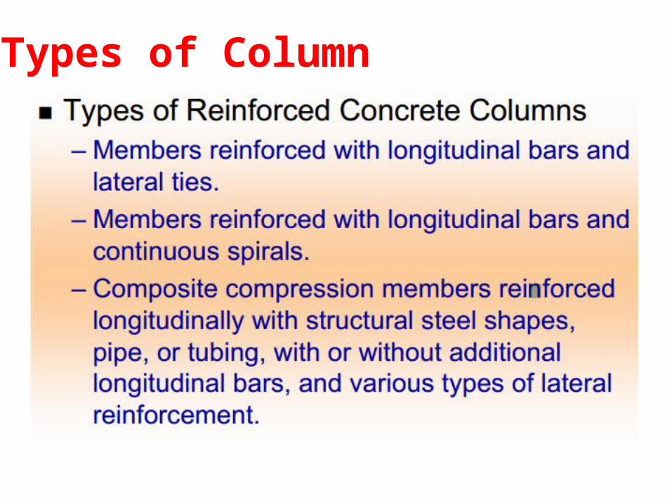
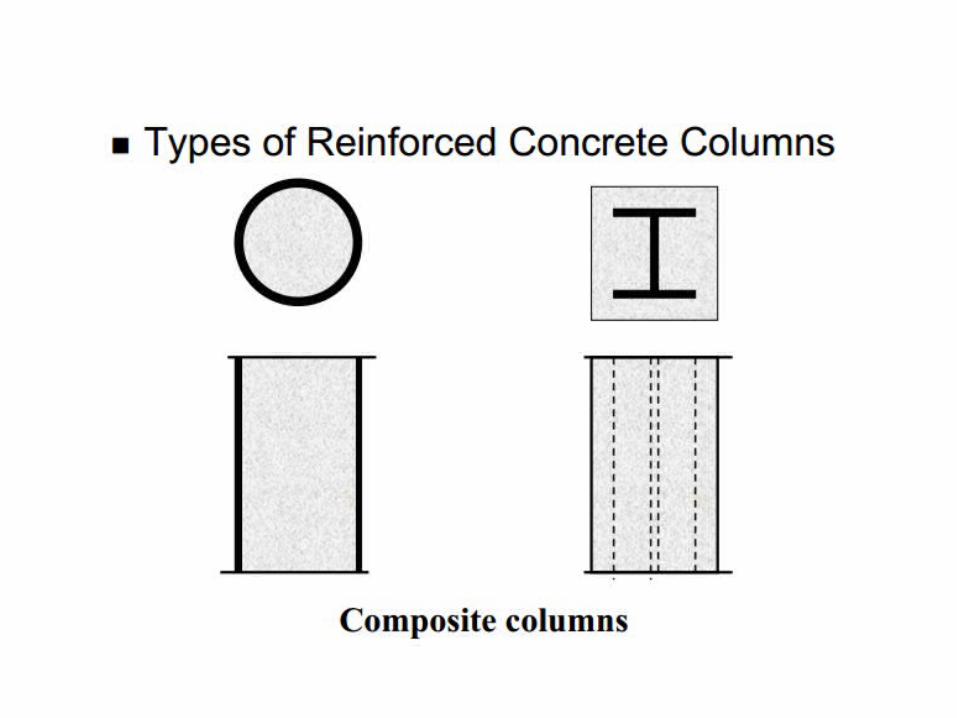
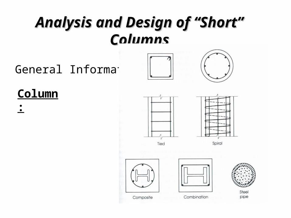
Types of Column
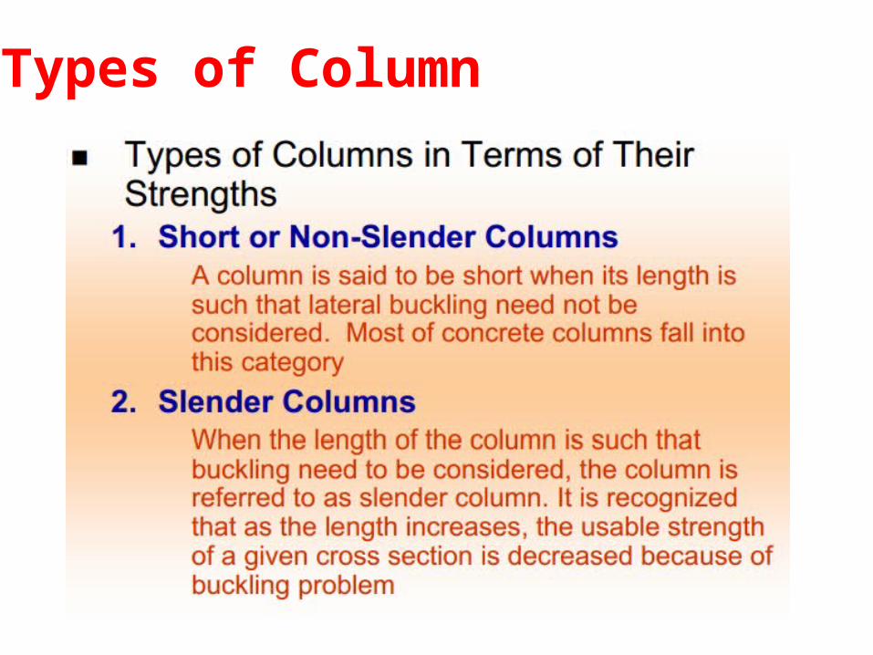
Types of Column
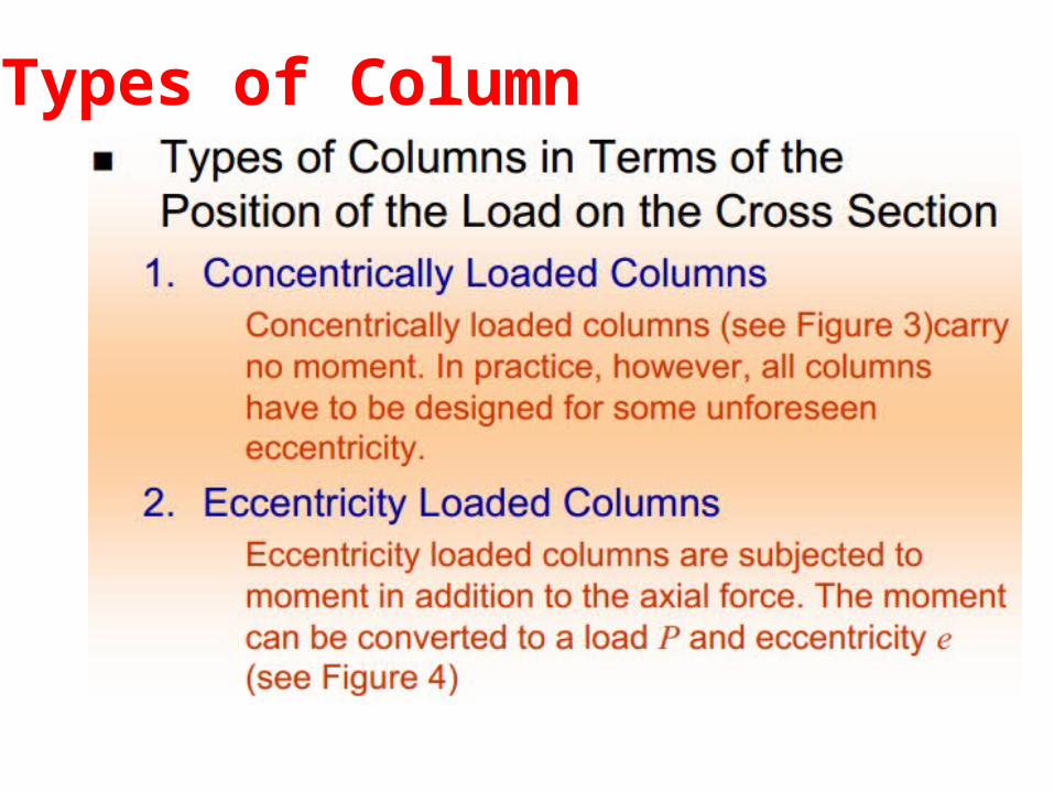
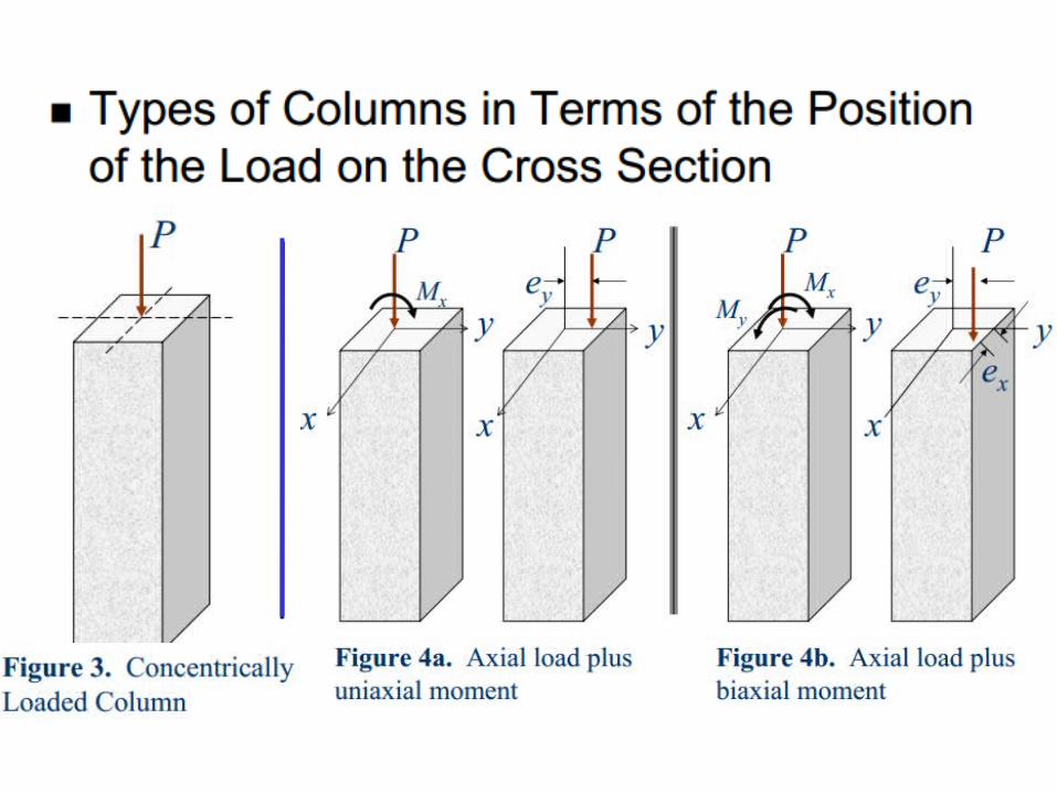
Types of Column
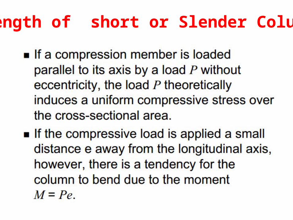
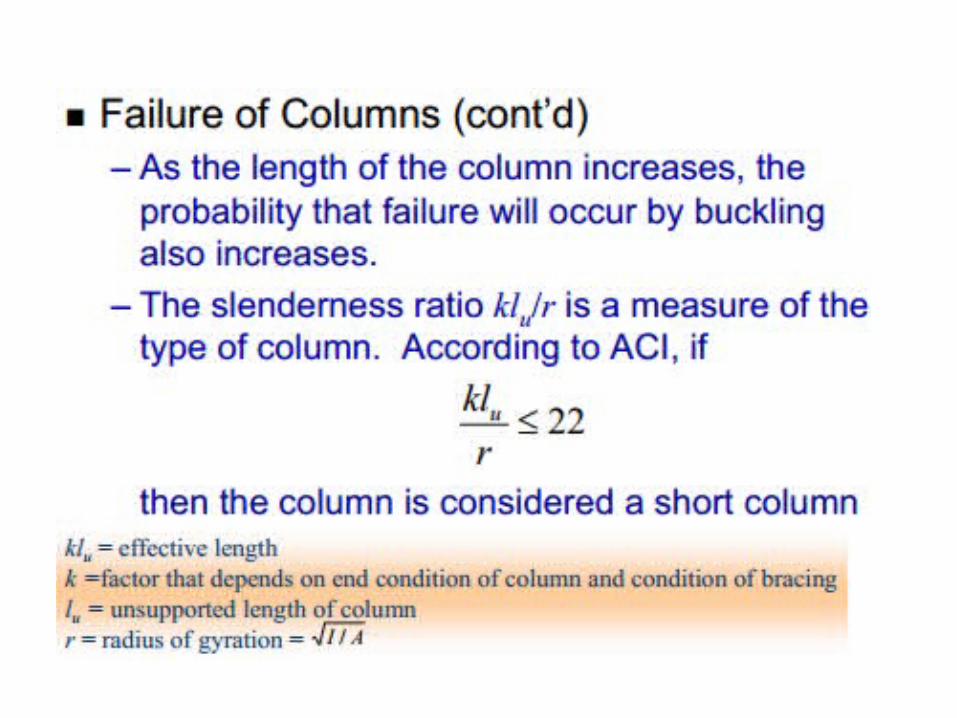
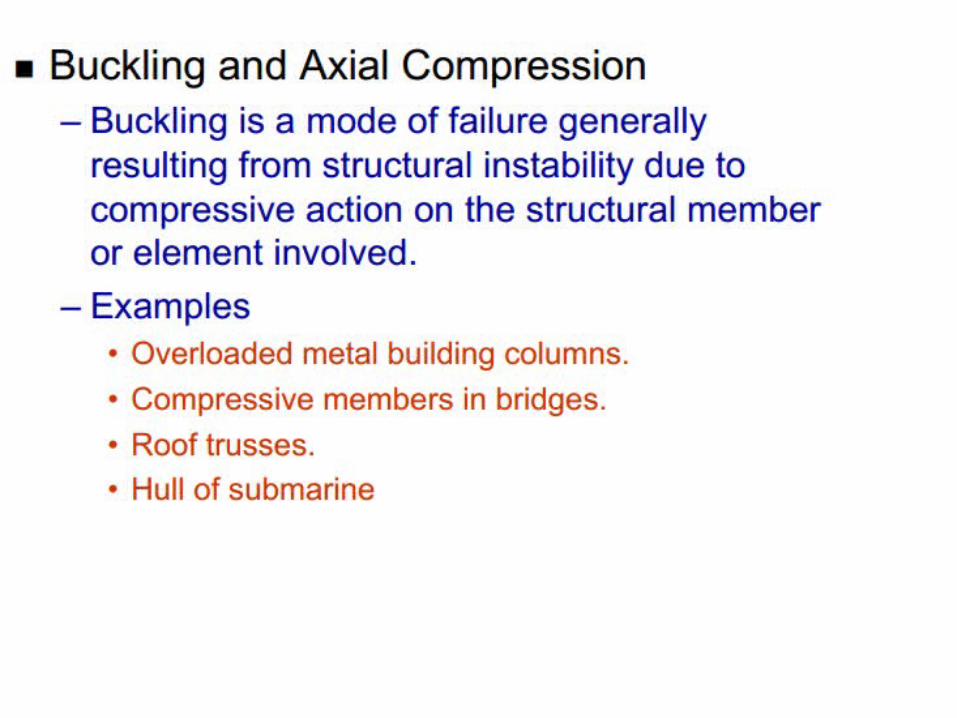
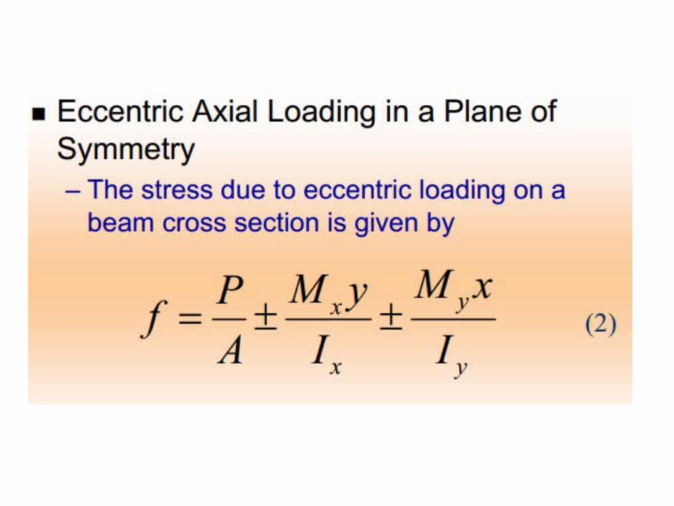
Strength of short or Slender Columns
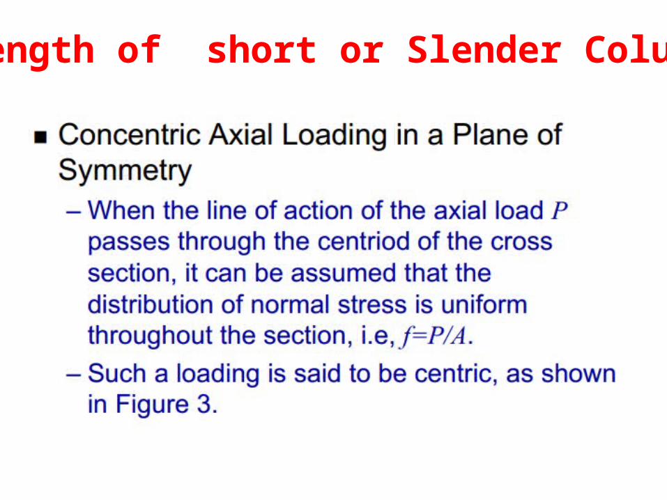
Strength of short or Slender Columns
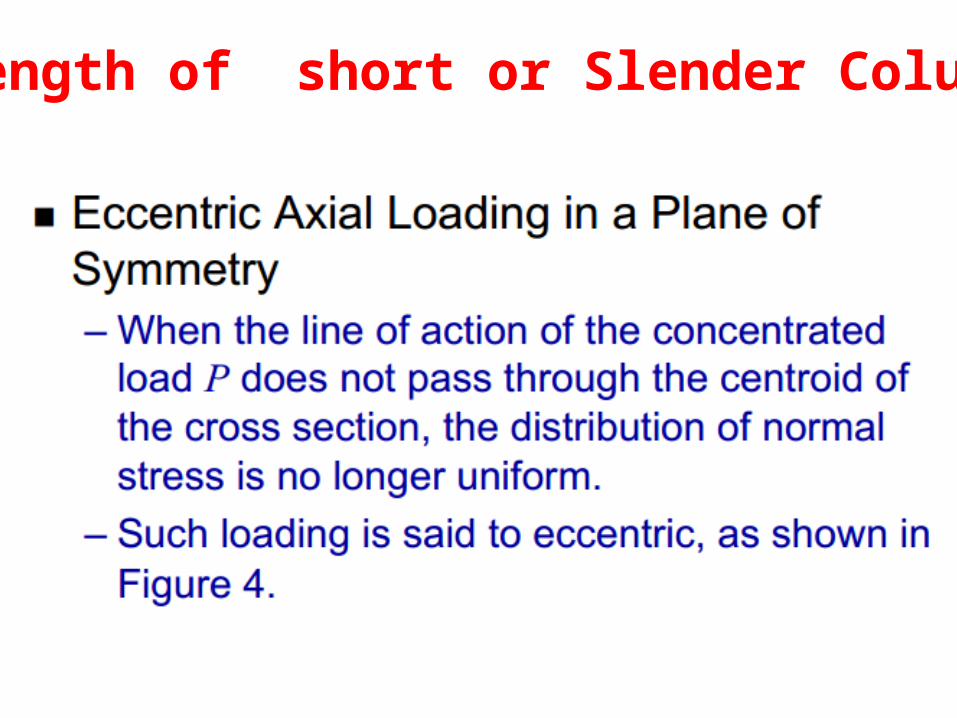
Strength of short or Slender Columns
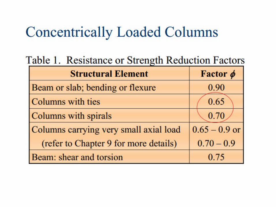
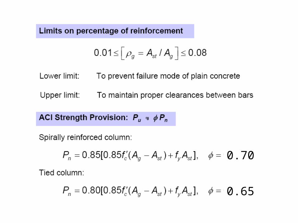
0.70
0.65
Analysis and Design of “Short” Analysis and Design of “Short” ColumnsColumns
General Information
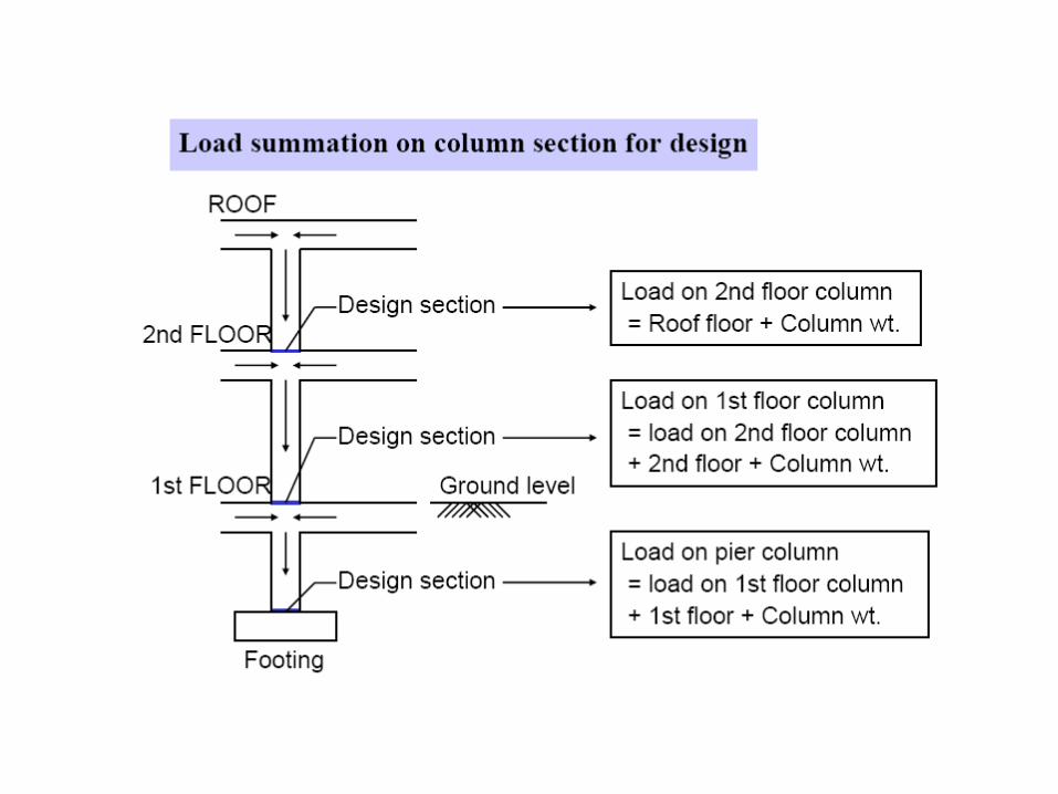
Vertical Structural membersTransmits axial compressive loads with or without momenttransmit loads from the floor & roof to the foundation
Column:
Analysis and Design of “Short” Analysis and Design of “Short” ColumnsColumns
General Information
Column:
Analysis and Design of “Short” Analysis and Design of “Short” ColumnsColumns
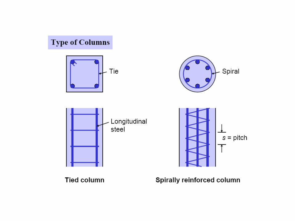
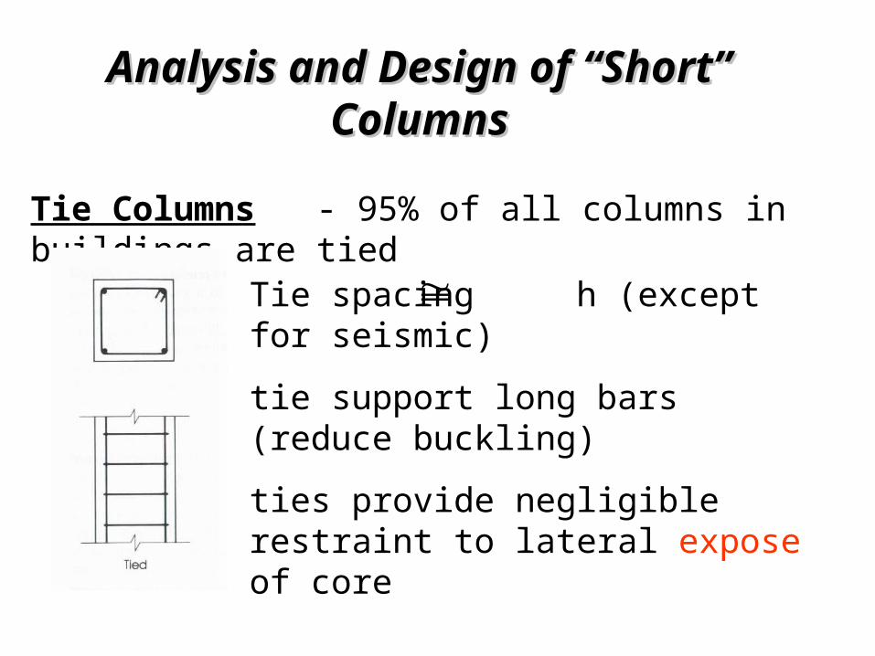
Tie spacing h (except for seismic)tie support long bars (reduce buckling)ties provide negligible restraint to lateral expose of core
Tie Columns - 95% of all columns in buildings are tied
Analysis and Design of “Short” Analysis and Design of “Short” ColumnsColumns
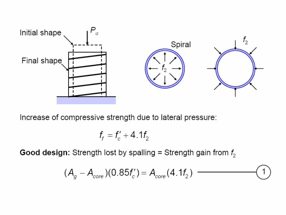
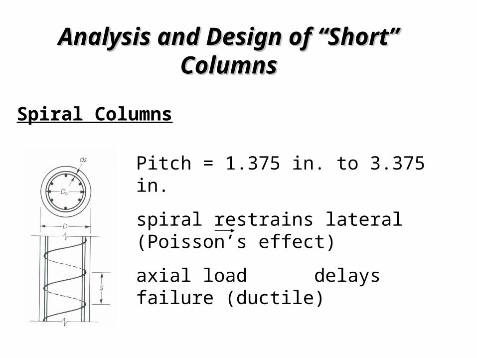
Pitch = 1.375 in. to 3.375 in.spiral restrains lateral (Poisson’s effect)axial load delays failure (ductile)
Spiral Columns
Analysis and Design of “Short” Analysis and Design of “Short” ColumnsColumns
Elastic Behavior Concrete creeps and shrinks, therefore we can not calculate the stresses in the steel and concrete due to “acting” loads using an elastic analysis.
Analysis and Design of “Short” Analysis and Design of “Short” ColumnsColumns
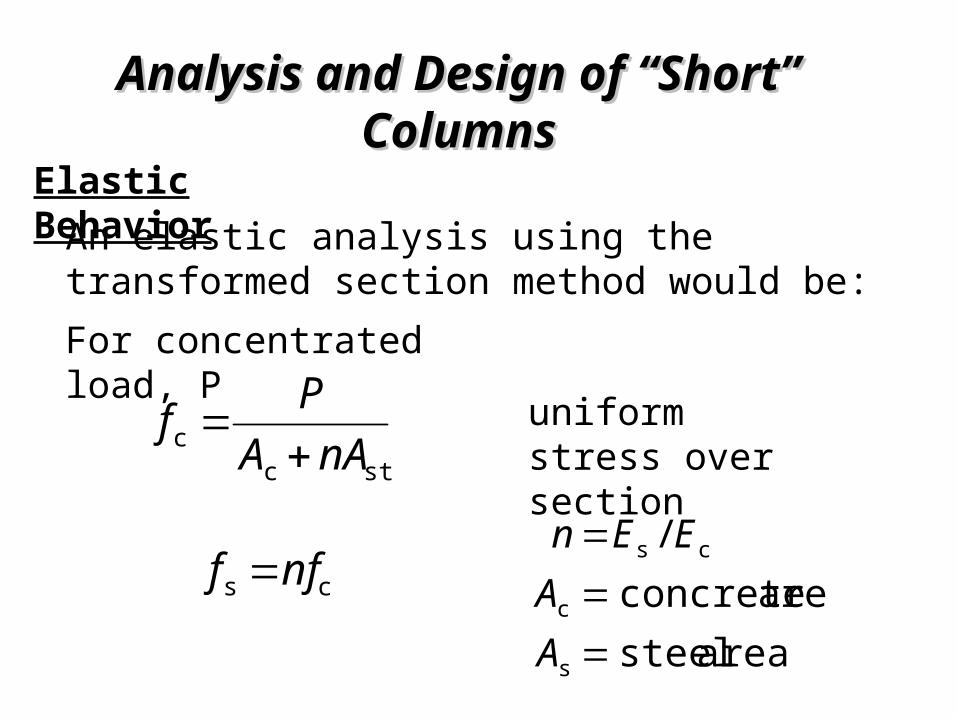
Elastic Behavior An elastic analysis using the transformed section method would be:
stcc nAA
Pf
For concentrated load, P uniform
stress over section
cs nff
area steel area concrete
/
s
c
cs
AA
EEn
Analysis and Design of “Short” Analysis and Design of “Short” ColumnsColumns
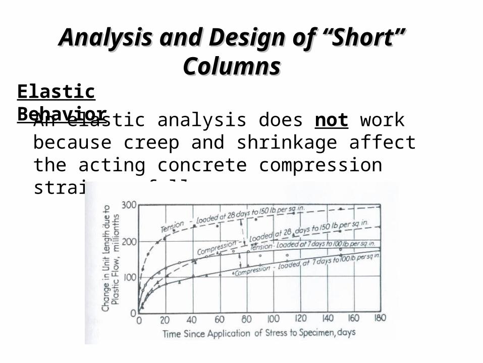
Elastic Behavior An elastic analysis does not work because creep and shrinkage affect the acting concrete compression strain as follows:
Analysis and Design of “Short” Analysis and Design of “Short” ColumnsColumns
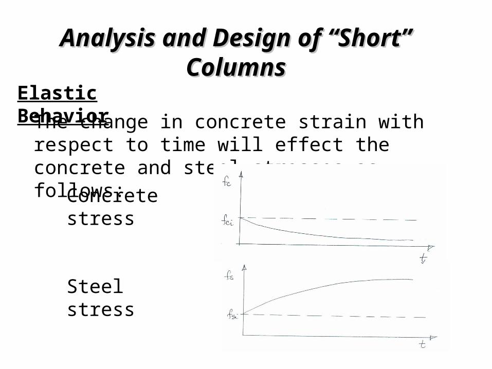
Elastic Behavior The change in concrete strain with respect to time will effect the concrete and steel stresses as follows:Concrete
stress
Steel stress
Analysis and Design of “Short” Analysis and Design of “Short” ColumnsColumns
Elastic Behavior Therefore, we are not able to calculate the real stresses in the reinforced concrete column under acting loads over time. As a result, an “allowable stress” design procedure using an elastic analysis was found to be unacceptable. Reinforced concrete columns have been designed by a “strength” method since the 1940’s.
Creep and shrinkage do not affect the strength of the member.
Note:
Behavior, Nominal Capacity and Behavior, Nominal Capacity and Design under concentric Axial loadsDesign under concentric Axial loads
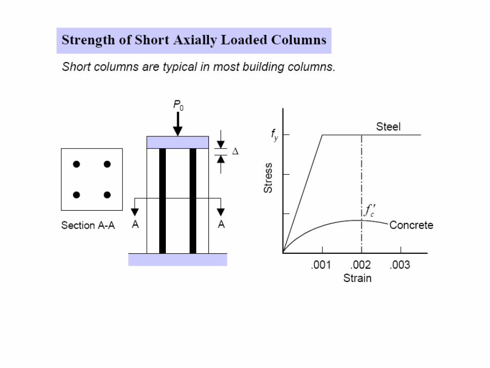
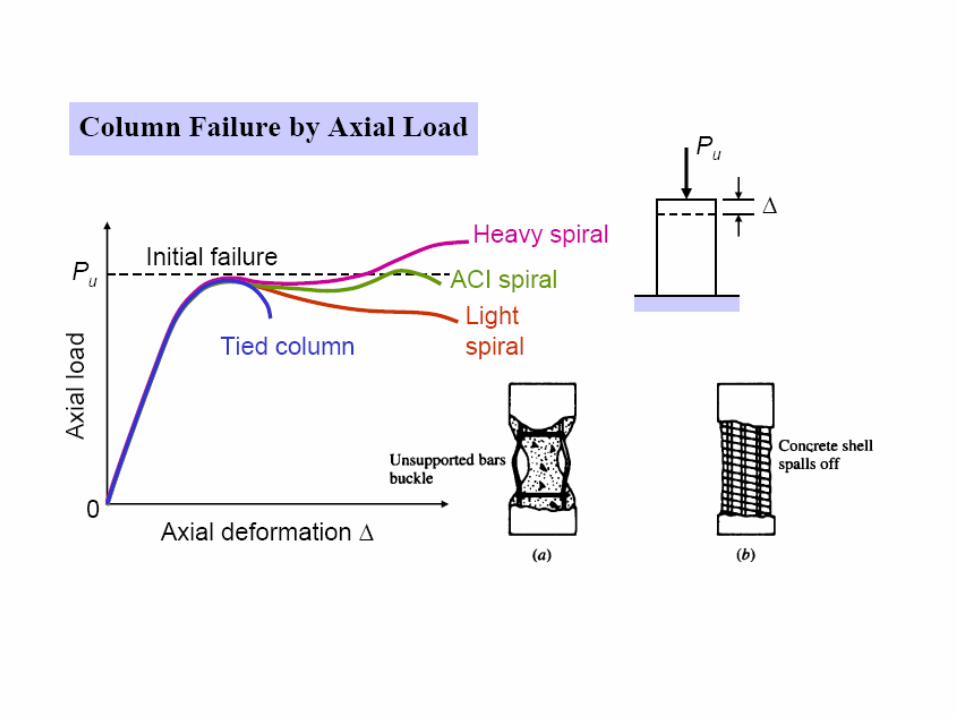
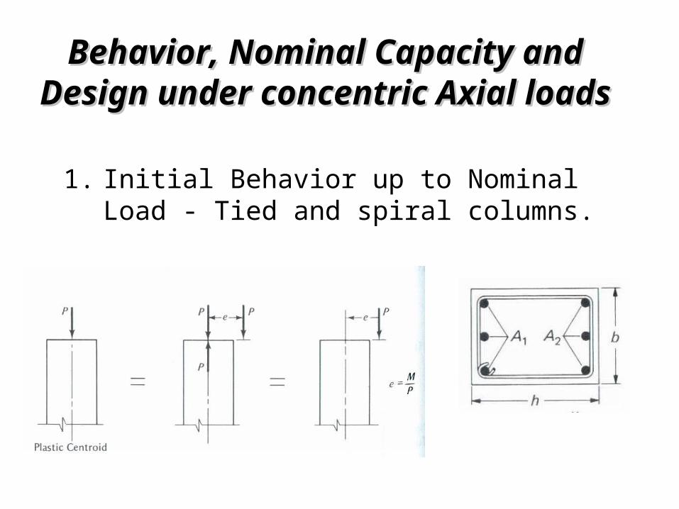
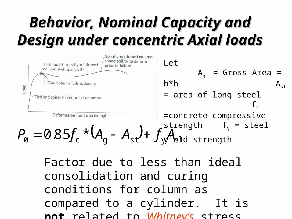
Initial Behavior up to Nominal Load - Tied and spiral columns.
1.
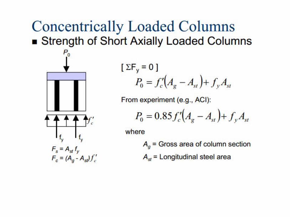
Behavior, Nominal Capacity and Behavior, Nominal Capacity and Design under concentric Axial loadsDesign under concentric Axial loads
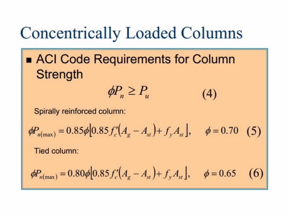
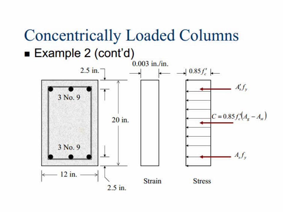
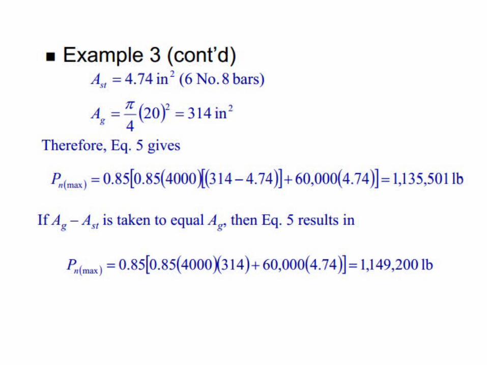
stystgc0 *85.0 AfAAfP
Factor due to less than ideal consolidation and curing conditions for column as compared to a cylinder. It is not related to Whitney’s stress block.
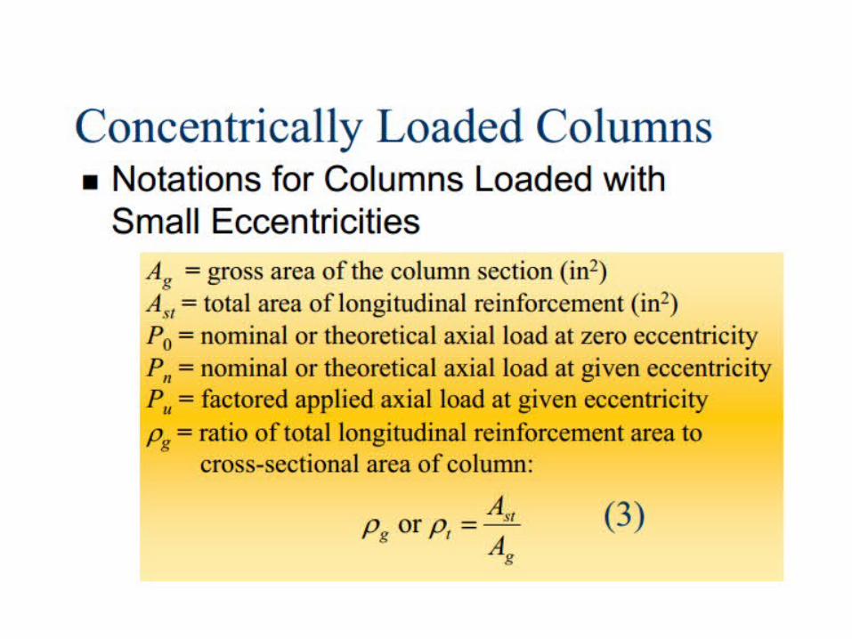
Let Ag = Gross Area = b*h Ast = area of long steel fc =concrete compressive strength fy = steel yield strength
Behavior, Nominal Capacity and Behavior, Nominal Capacity and Design under concentric Axial loadsDesign under concentric Axial loads
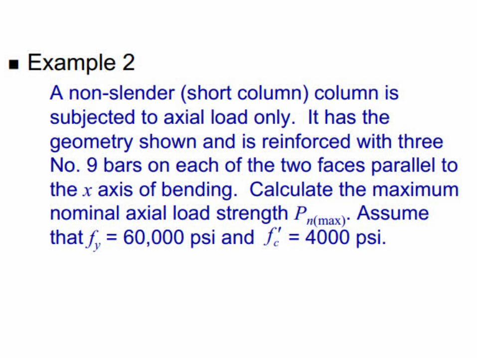
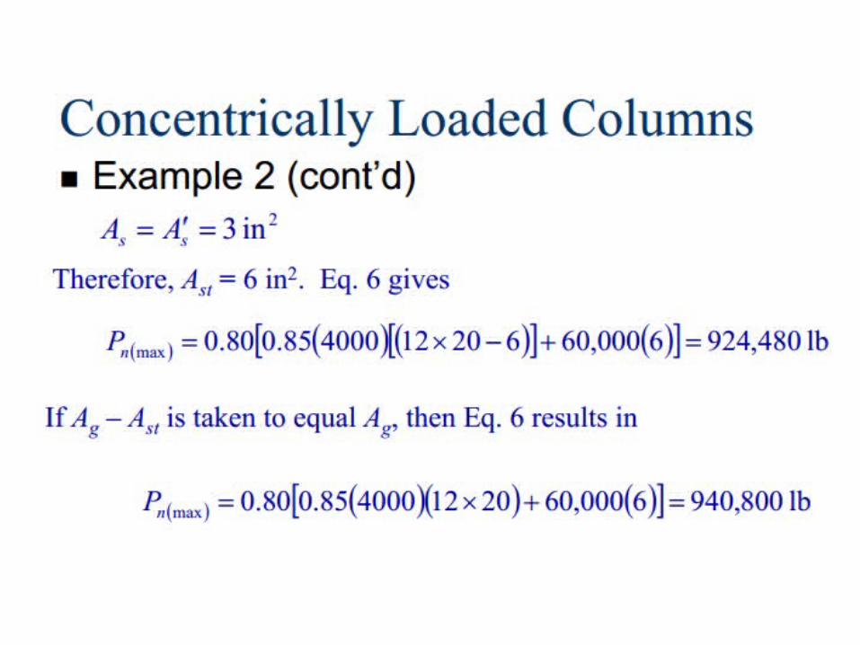
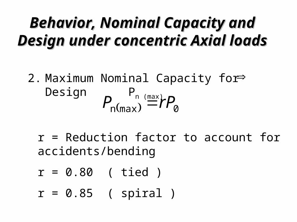
Maximum Nominal Capacity for Design Pn (max)
2.
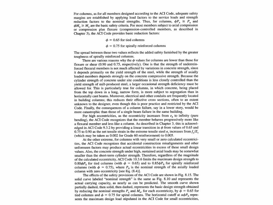
0maxn rPP
r = Reduction factor to account for accidents/bendingr = 0.80 ( tied )r = 0.85 ( spiral )
Behavior, Nominal Capacity and Behavior, Nominal Capacity and Design under concentric Axial loadsDesign under concentric Axial loads
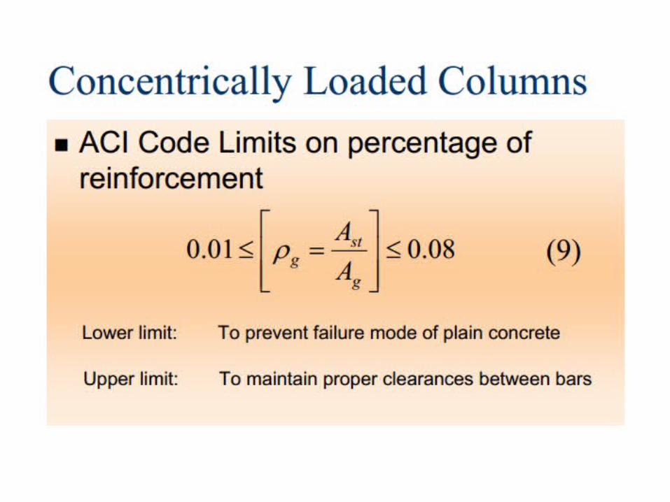
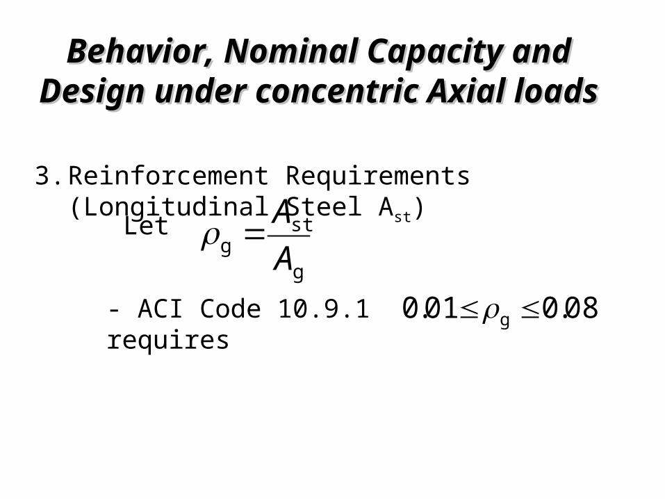
Reinforcement Requirements (Longitudinal Steel Ast)
3.
g
stg A
A
- ACI Code 10.9.1 requires
Let
08.001.0 g
Behavior, Nominal Capacity and Behavior, Nominal Capacity and Design under concentric Axial loadsDesign under concentric Axial loads
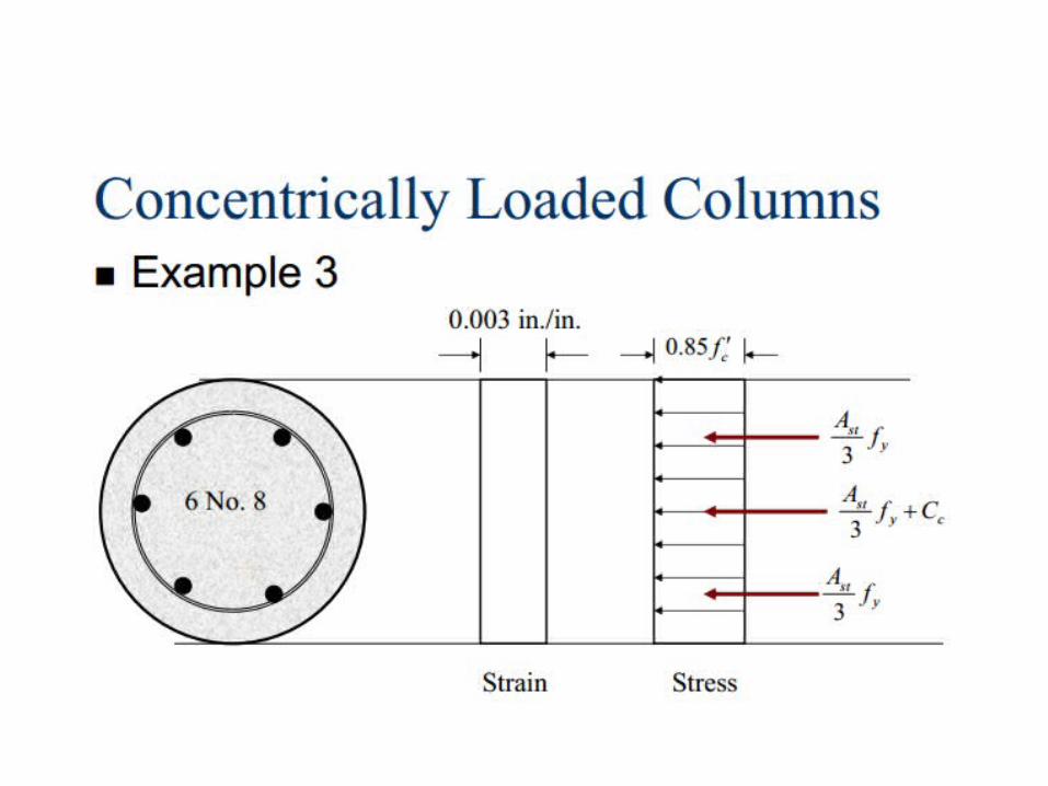
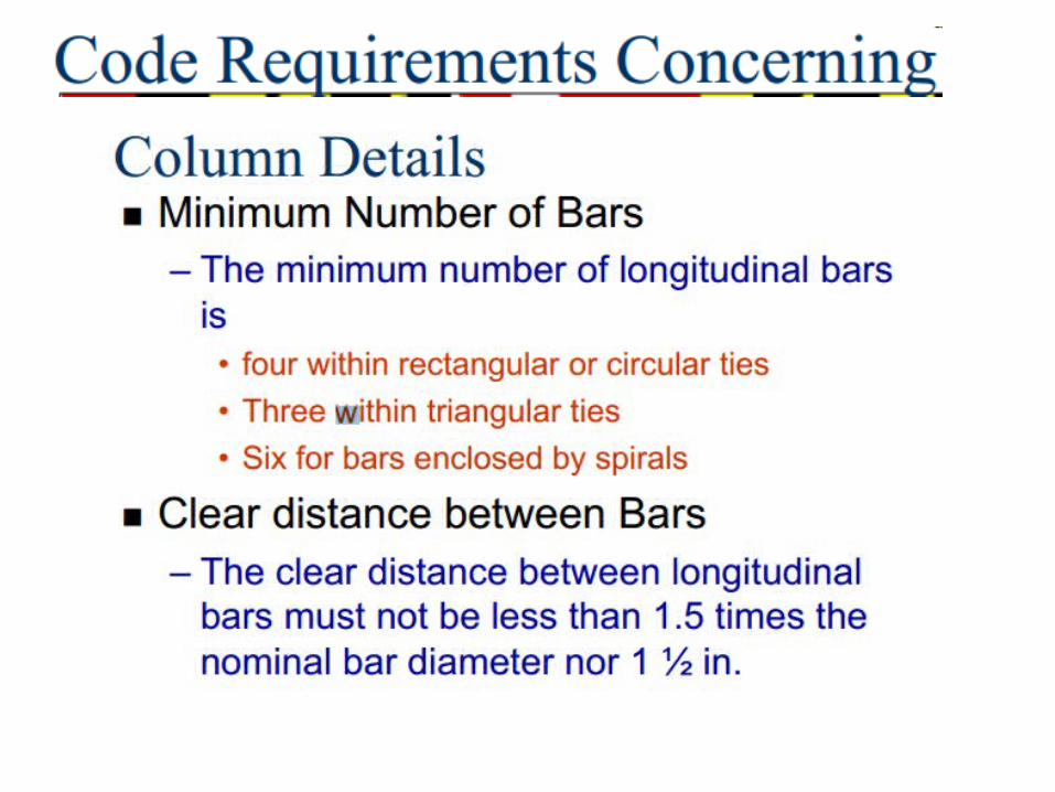
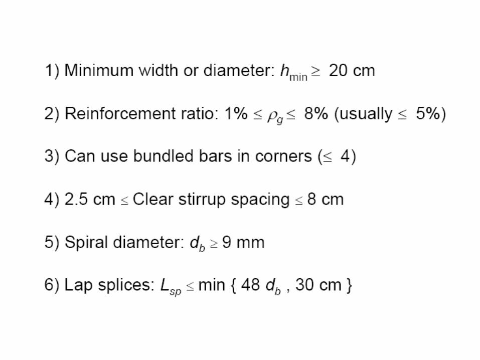
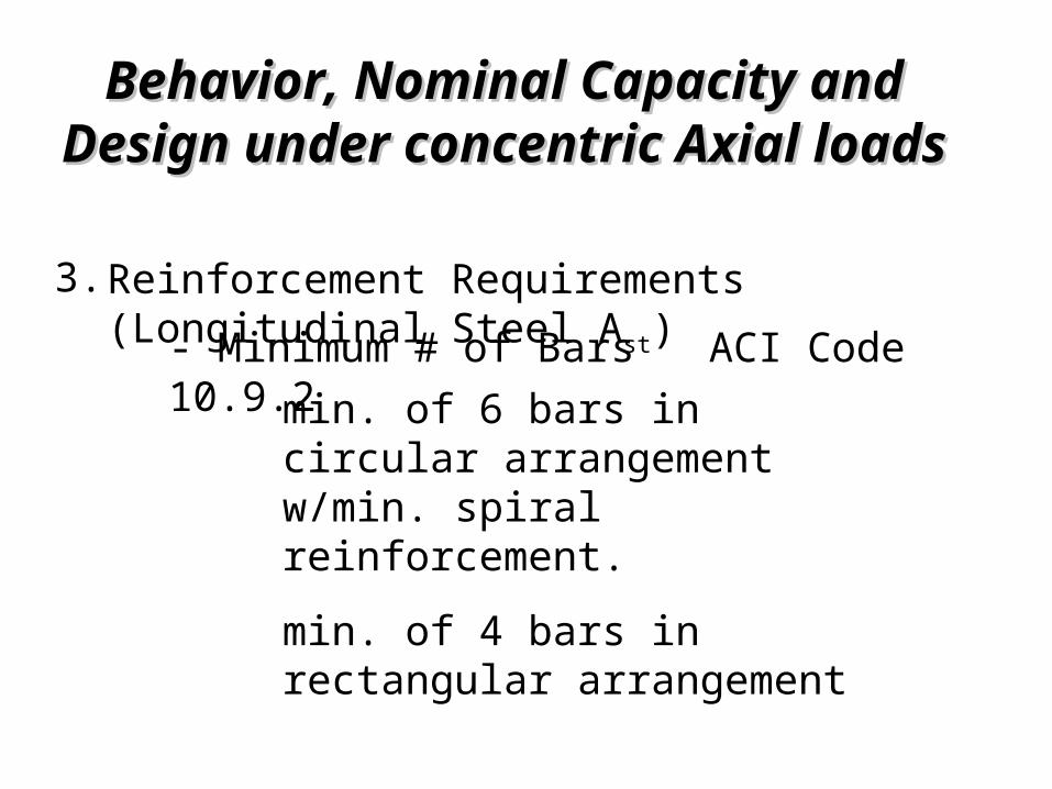
3.- Minimum # of Bars ACI Code 10.9.2 min. of 6 bars in
circular arrangement w/min. spiral reinforcement.min. of 4 bars in rectangular arrangement
Reinforcement Requirements (Longitudinal Steel Ast)
Behavior, Nominal Capacity and Behavior, Nominal Capacity and Design under concentric Axial loadsDesign under concentric Axial loads
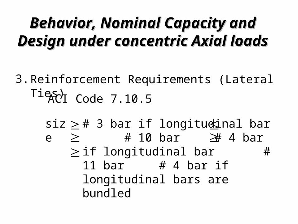
3.ACI Code 7.10.5
Reinforcement Requirements (Lateral Ties)
# 3 bar if longitudinal bar # 10 bar # 4 bar if longitudinal bar # 11 bar # 4 bar if longitudinal bars are bundled
siz
e
Behavior, Nominal Capacity and Behavior, Nominal Capacity and Design under concentric Axial loadsDesign under concentric Axial loads
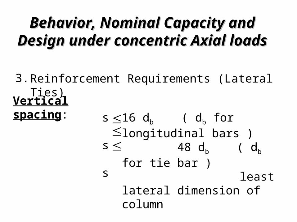
3.Reinforcement Requirements (Lateral Ties)
16 db ( db for longitudinal bars ) 48 db ( db for tie bar ) least lateral dimension of column
Vertical spacing:
s s s

Behavior, Nominal Capacity and Behavior, Nominal Capacity and Design under concentric Axial loadsDesign under concentric Axial loads
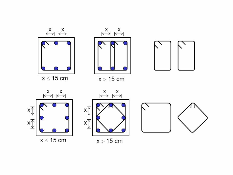
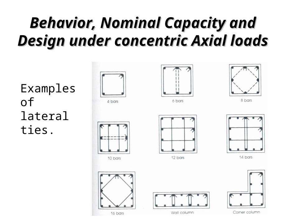
3.Reinforcement Requirements (Lateral Ties) Vertical spacing: Arrangement,
At least every other longitudinal bar shall have lateral support from the corner of a tie with an included angle 135o.No longitudinal bar shall be more than 6 in. clear on either side from “support” bar.
1.)
2.)
Behavior, Nominal Capacity and Behavior, Nominal Capacity and Design under concentric Axial loadsDesign under concentric Axial loads
Examples of lateral ties.
Behavior, Nominal Capacity and Behavior, Nominal Capacity and Design under concentric Axial loadsDesign under concentric Axial loads
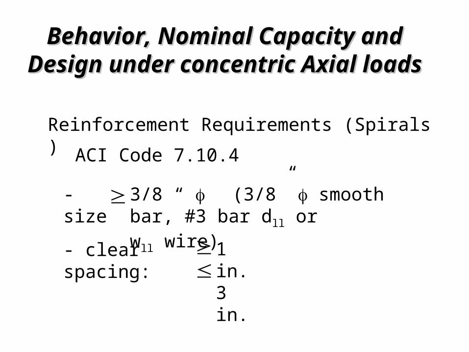
ACI Code 7.10.4
Reinforcement Requirements (Spirals )
3/8 “ (3/8” smooth bar, #3 bar dll or wll wire)
- size- clear spacing:
1 in. 3 in.
Behavior, Nominal Capacity and Behavior, Nominal Capacity and Design under concentric Axial loadsDesign under concentric Axial loads
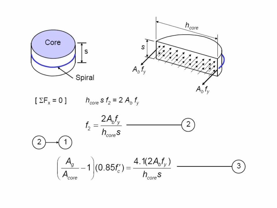
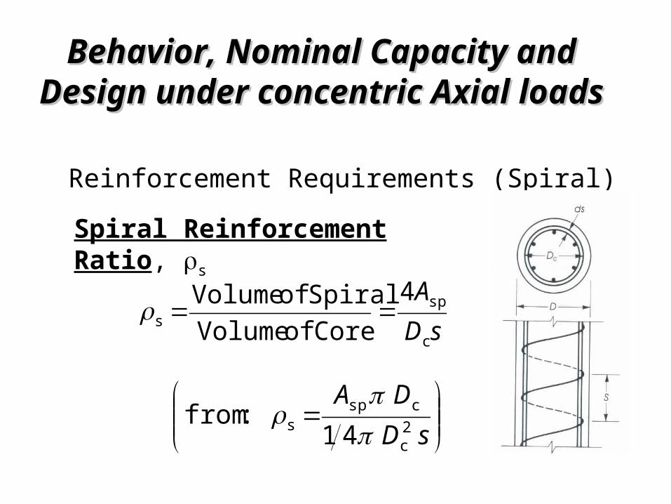
Reinforcement Requirements (Spiral)
sDAc
sps
4Core of VolumeSpiral of Volume
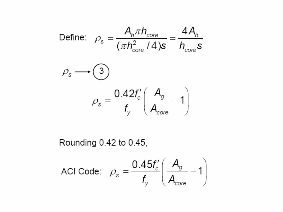
Spiral Reinforcement Ratio, s
sDDA 41
:from 2c
csps
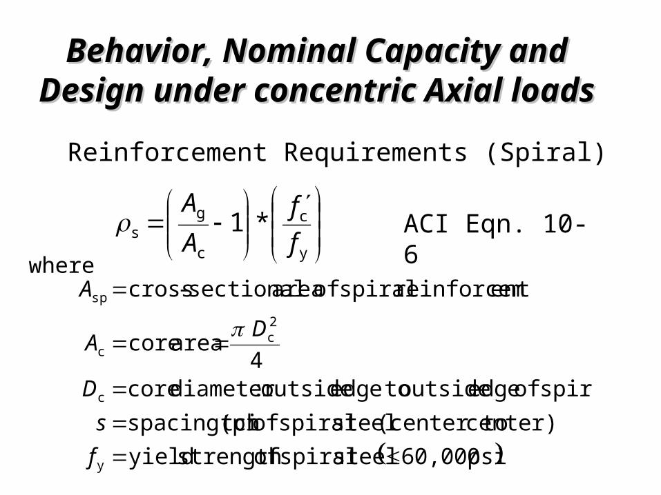
Behavior, Nominal Capacity and Behavior, Nominal Capacity and Design under concentric Axial loadsDesign under concentric Axial loadsReinforcement Requirements (Spiral)
y
c
c
gs *1
ff
AA
ACI Eqn. 10-6
psi 60,000 steel spiral ofstrength yield center) (center to steel spiral oftch spacing(pi
spiral of edge outside toedge outside :diameter core 4 area core
entreinforcem spiral of area sectional-cross
y
c
2c
c
sp
fs
D
DA
A
where
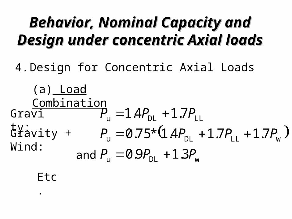
Behavior, Nominal Capacity and Behavior, Nominal Capacity and Design under concentric Axial loadsDesign under concentric Axial loads4.Design for Concentric Axial Loads
(a) Load Combination
wDLu
wLLDLu
LLDLu
3.19.07.17.14.1*75.0
7.14.1
PPPPPPP
PPP
Gravity:Gravity + Wind: and
Etc.
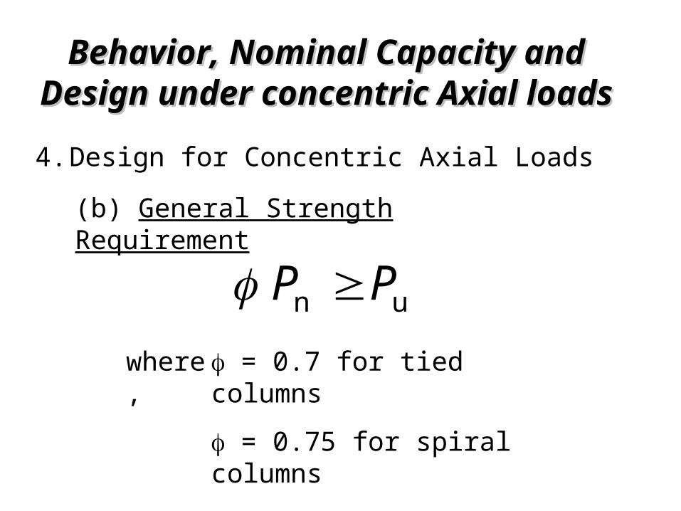
Behavior, Nominal Capacity and Behavior, Nominal Capacity and Design under concentric Axial loadsDesign under concentric Axial loads4.Design for Concentric Axial Loads
(b) General Strength Requirement
un PP = 0.7 for tied columns = 0.75 for spiral columns
where,
Behavior, Nominal Capacity and Behavior, Nominal Capacity and Design under concentric Axial loadsDesign under concentric Axial loads4.Design for Concentric Axial Loads
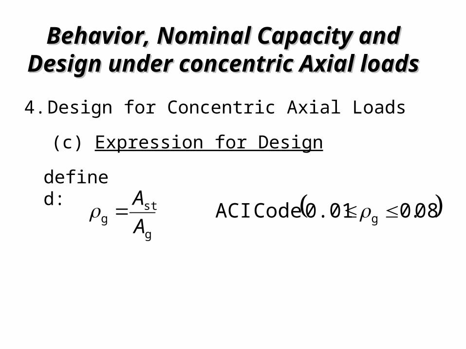
(c) Expression for Design
08.00.01 Code ACI gg
stg
AA
defined:
Behavior, Nominal Capacity and Behavior, Nominal Capacity and Design under concentric Axial loadsDesign under concentric Axial loads
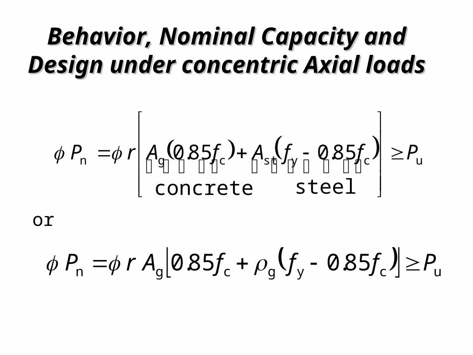
ucystcgn
steel85.0
concrete85.0 PffAfArP
or
ucygcgn 85.085.0 PfffArP
Behavior, Nominal Capacity and Behavior, Nominal Capacity and Design under concentric Axial loadsDesign under concentric Axial loads
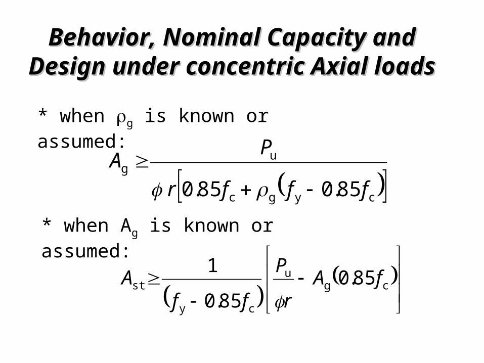
85.085.0 cygc
ug
fffr
PA
* when g is known or assumed:
cg
u
cyst 85.0
85.01 fA
rP
ffA
* when Ag is known or assumed:
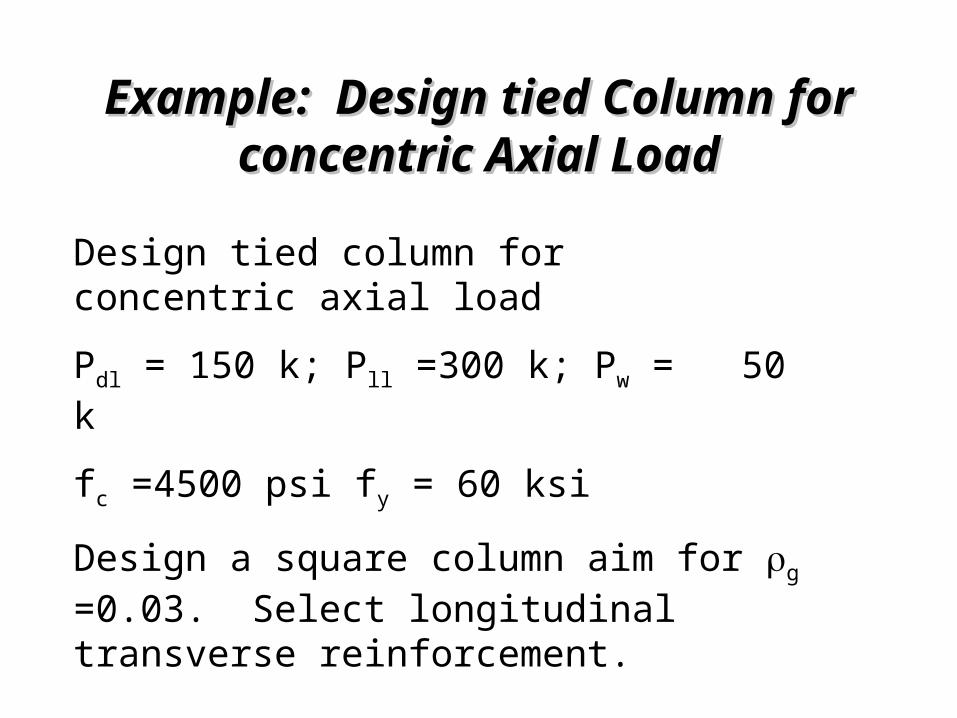
Example: Design tied Column for Example: Design tied Column for concentric Axial Loadconcentric Axial Load
Design tied column for concentric axial loadPdl = 150 k; Pll =300 k; Pw = 50 kfc =4500 psi fy = 60 ksiDesign a square column aim for g =0.03. Select longitudinal transverse reinforcement.
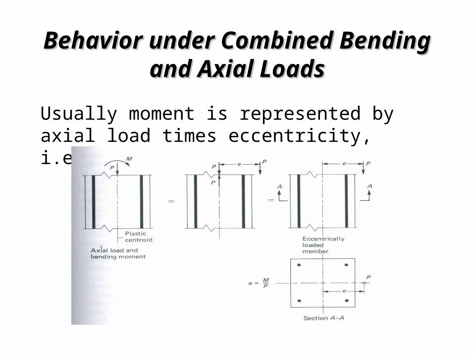
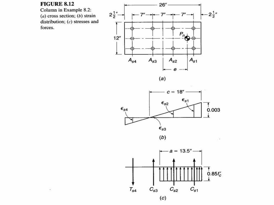
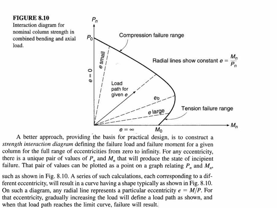
Behavior under Combined Bending Behavior under Combined Bending and Axial Loadsand Axial Loads
Usually moment is represented by axial load times eccentricity, i.e.
Behavior under Combined Bending Behavior under Combined Bending and Axial Loadsand Axial Loads
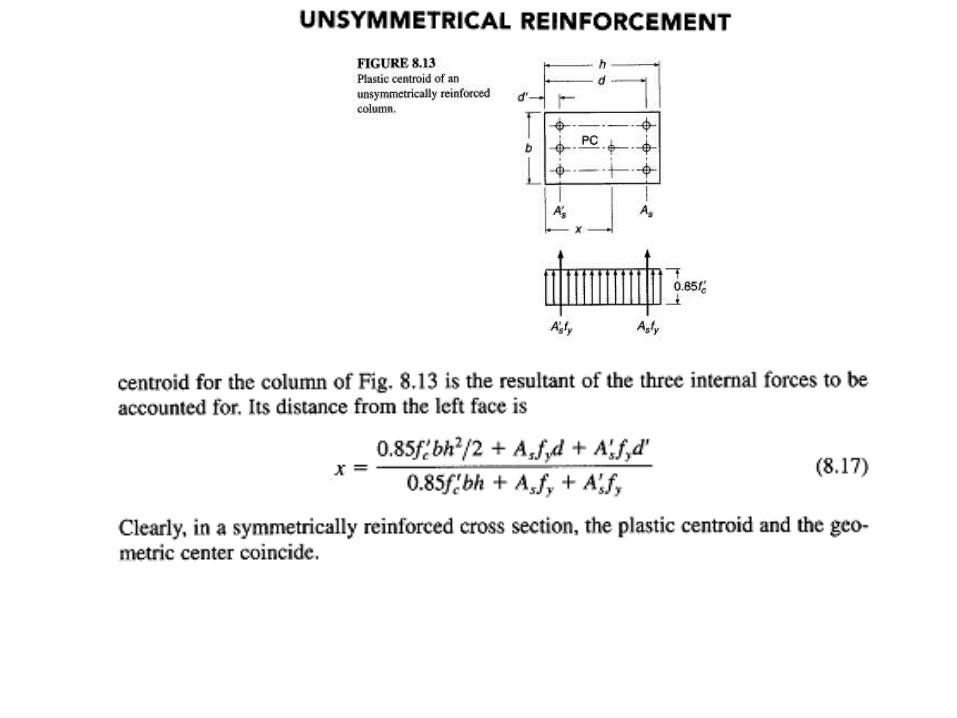
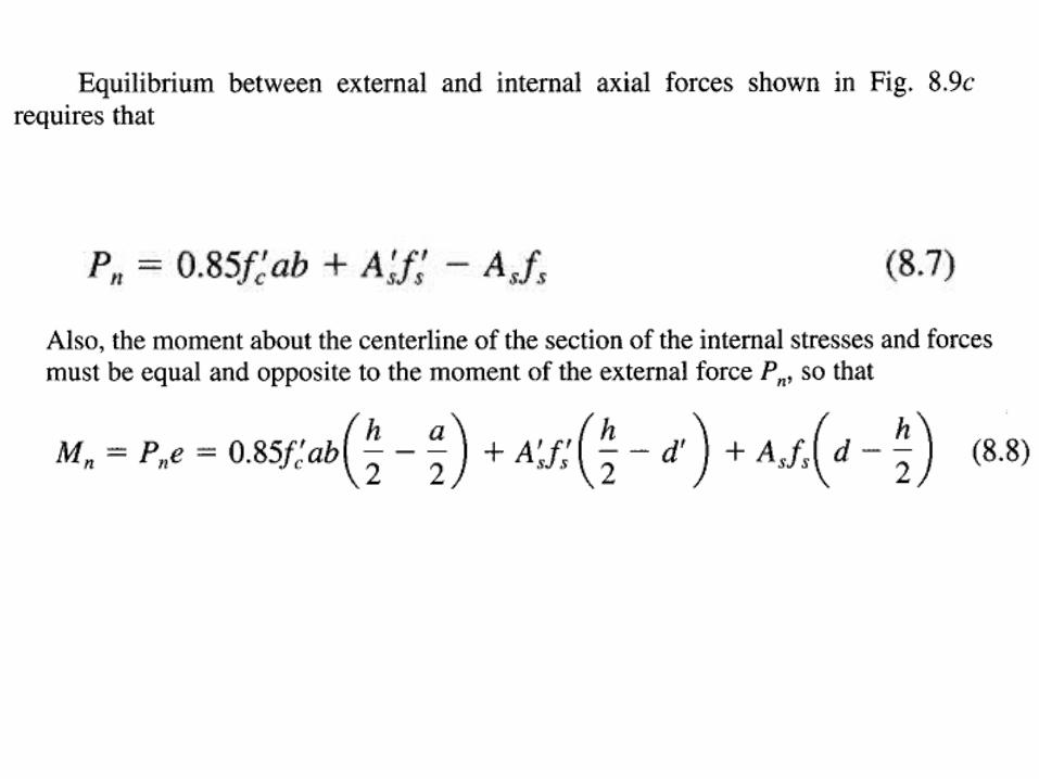
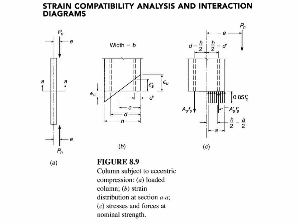
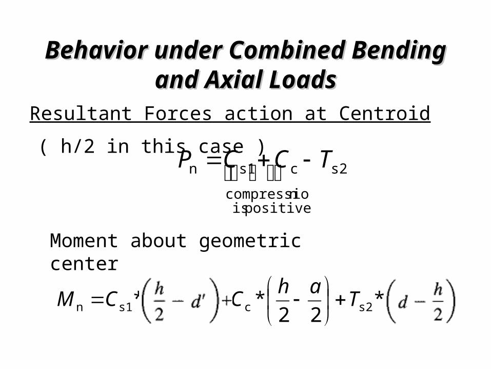
Resultant Forces action at Centroid( h/2 in this case )
s2
positive is ncompressiocs1n TCCP
Moment about geometric center
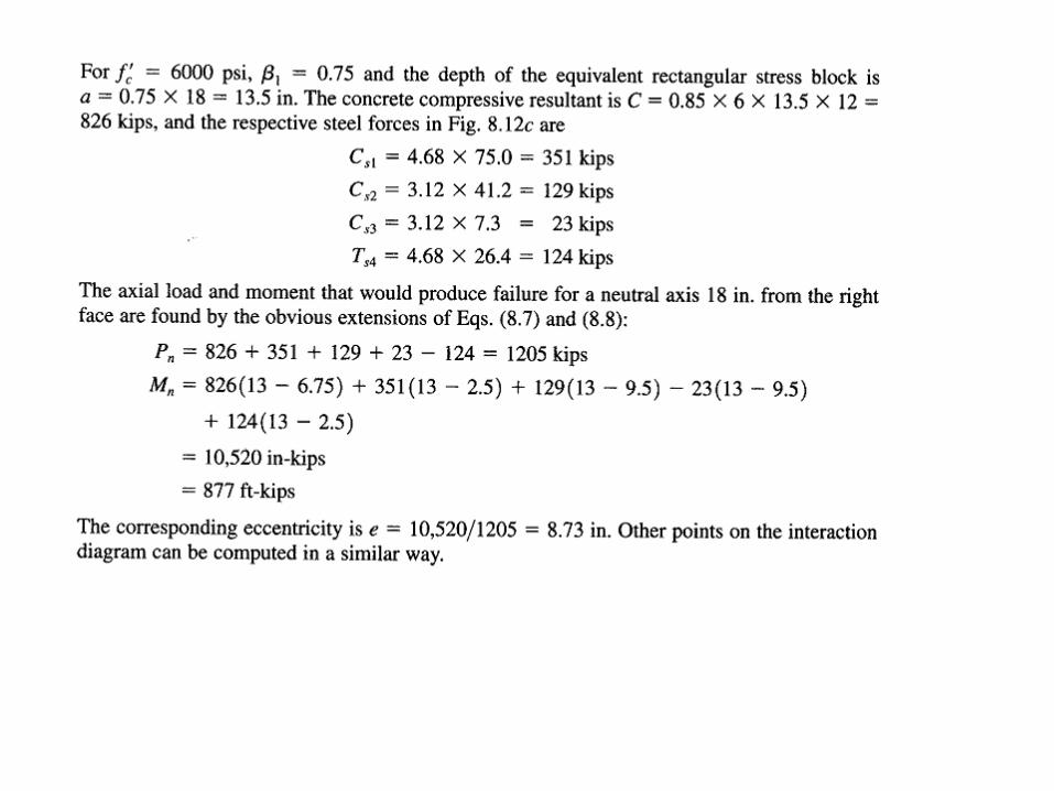
2*22*2* 2s2c1s1n
hdTahCdhCM
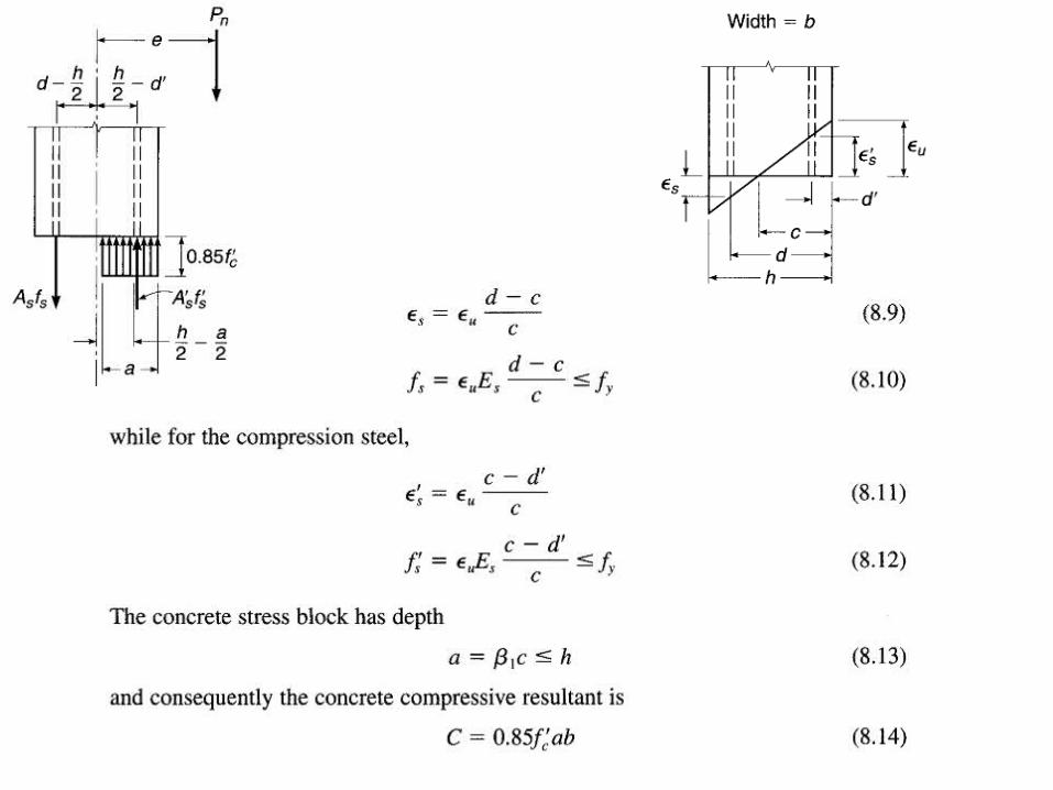
Behavior under Combined Bending Behavior under Combined Bending and Axial Loadsand Axial Loads
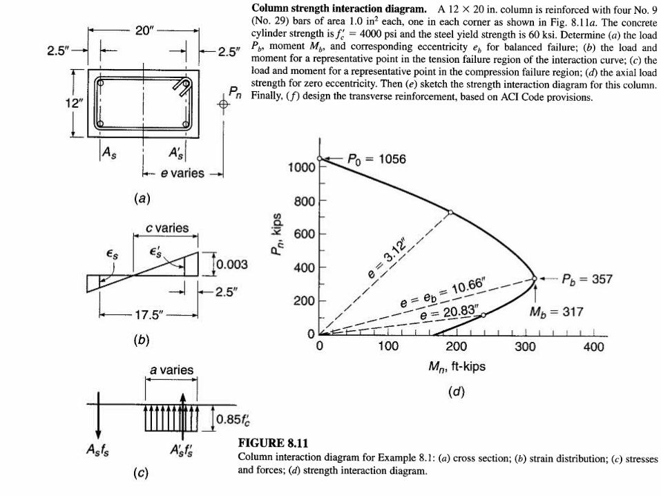
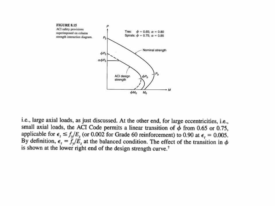
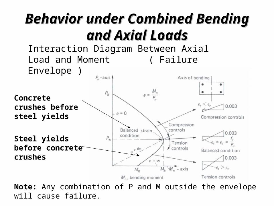
Interaction Diagram Between Axial Load and Moment ( Failure Envelope )
Concrete crushes before steel yields
Steel yields before concrete crushes
Note: Any combination of P and M outside the envelope will cause failure.
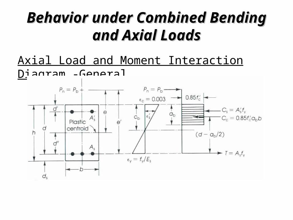
Behavior under Combined Bending Behavior under Combined Bending and Axial Loadsand Axial Loads
Axial Load and Moment Interaction Diagram -General
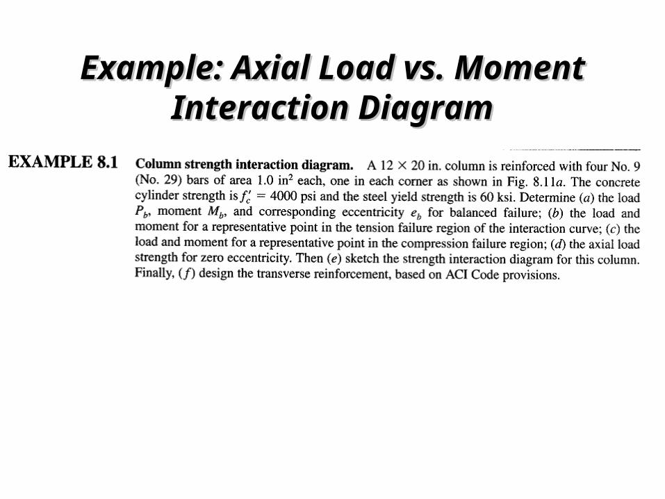
Example: Axial Load vs. Moment Example: Axial Load vs. Moment Interaction DiagramInteraction Diagram