STRONG COLUMN WEAK BEAM CONCEPT BY ANALYSING ...
9
http://iaeme.com/Home/journal/IJCIET 2238 [email protected] International Journal of Civil Engineering and Technology (IJCIET) Volume 10, Issue 03, March 2019, pp. 2238-2246. Article ID: IJCIET_10_03_224 Available online at http://iaeme.com/Home/issue/IJCIET?Volume=10&Issue=3 ISSN Print: 0976-6308 and ISSN Online: 0976-6316 © IAEME Publication Indexed Scopus STRONG COLUMN WEAK BEAM CONCEPT BY ANALYSING RCC MRF FRAME BY NON LINEAR STATIC PROCEDURE Ajay Singh Thakur M.E Student, Department of Civil Engineering, Chandigarh University Garhuan Jagdish Chand Assistant Professor, Chandigarh University Garhuan ABSTRACT During past earthquakes column plastic hinges are more prominent than beam hinges which gives rise to global structural damage and high life threatening risk. All the structural components transfers their forces through column and column than shares it with foundation to soil, so u can imagine if column fails whole structure can collapse this is strong beam weak column concept. By making column more moment resistant than beams the plastic hinges shifts to beam and avoids the global damage in this case only beam will show flexure as a sign of beam damage and the people will have adequate time to evacuate the place and beam failure will only limit to a particular storey. This concept is strong column weak beam. In this paper three RC frame of 5, 8 and 12 storey height are investigated for strong column weak beam concept for zone 5 and medium soil and moment capacities are checked as per IS1893:2016. For checking the performance of plastic hinges of column and beam non linear static analysis (pushover analysis) is done in ETABS 2016 these hinges are checked and verified according to acceptance criteria given in FEMA 356. Base shear and performance point with displacement is checked for all frames. Keywords: Etabs, pushover analysis, moment capacity ratio, performance point, FEMA356. Cite this Article: Ajay Singh Thakur and Jagdish Chand, Strong Column Weak Beam Concept by Analysing R M Frame b Non-Linear Static Procedure, CC RF y International Journal of Civil Engineering and Technology, 10(3), 2019, pp. 2238- 2246. http://iaeme.com/Home/issue/IJCIET?Volume=10&Issue=3 1. INTRODUCTION The formation of plastic hinges in beams helps to build the most desired and suitable energy dissipating mechanism for structure in seismic conditions. If the plastic hinges are formed on
-
Upload
khangminh22 -
Category
Documents
-
view
6 -
download
0
Transcript of STRONG COLUMN WEAK BEAM CONCEPT BY ANALYSING ...

http://iaeme.com/Home/journal/IJCIET 2238 [email protected]
International Journal of Civil Engineering and Technology (IJCIET) Volume 10, Issue 03, March 2019, pp. 2238-2246. Article ID: IJCIET_10_03_224 Available online at http://iaeme.com/Home/issue/IJCIET?Volume=10&Issue=3 ISSN Print: 0976-6308 and ISSN Online: 0976-6316
© IAEME Publication Indexed Scopus
STRONG COLUMN WEAK BEAM CONCEPT BY ANALYSING RCC MRF FRAME BY NON
LINEAR STATIC PROCEDURE Ajay Singh Thakur
M.E Student, Department of Civil Engineering, Chandigarh University Garhuan
Jagdish Chand
Assistant Professor, Chandigarh University Garhuan
ABSTRACT During past earthquakes column plastic hinges are more prominent than beam
hinges which gives rise to global structural damage and high life threatening risk. All the structural components transfers their forces through column and column than
shares it with foundation to soil, so u can imagine if column fails whole structure can collapse this is strong beam weak column concept. By making column more moment resistant than beams the plastic hinges shifts to beam and avoids the global damage in this case only beam will show flexure as a sign of beam damage and the people will have adequate time to evacuate the place and beam failure will only limit to a particular storey. This concept is strong column weak beam. In this paper three RC
frame of 5, 8 and 12 storey height are investigated for strong column weak beam concept for zone 5 and medium soil and moment capacities are checked as per
IS1893:2016. For checking the performance of plastic hinges of column and beam non linear static analysis (pushover analysis) is done in ETABS 2016 these hinges are
checked and verified according to acceptance criteria given in FEMA 356. Base shear and performance point with displacement is checked for all frames.
Keywords: Etabs, pushover analysis, moment capacity ratio, performance point, FEMA356.
Cite this Article: Ajay Singh Thakur and Jagdish Chand, Strong Column Weak Beam Concept by Analysing R M Frame b Non-Linear Static Procedure,CC RF y
International Journal of Civil Engineering and Technology, 10(3), 2019, pp. 2238-2246.
http://iaeme.com/Home/issue/IJCIET?Volume=10&Issue=3
1. INTRODUCTION The formation of plastic hinges in beams helps to build the most desired and suitable energy dissipating mechanism for structure in seismic conditions. If the plastic hinges are formed on

Ajay Singh Thakur and Jagdish Chand
http://iaeme.com/Home/journal/IJCIET 2239 [email protected]
both ends of column then column is not able to spread the plasticity and collapses which can lead to global failure. In previous earthquakes same things had happened column fails early in compression than beams in flexure lead to life threatening condition of people in buildings. The case study of previous earthquakes in India like 1897 Assam earthquake of magnitude 8.0Mw, 1905 Kangra earthquake of magnitude 7.8Mw, 1934 Nepal Bihar earthquake of magnitude 8.0Mw, 2001 Bhuj earthquake of 7.7Mw magnitude, 2005 Kashmir earthquake of
magnitude 7.6Mw , 2015 Nepal earthquake of 7.8Mw shows that the Reinforced Concrete structure have shown poor performance during strong earthquake in showing ductility of the structure. The main and common failure was the beam column failure, storey failure, column collapsing ahead of beam, short column effect. The irregular building invites large base shear
and they are in greater risk but the failure of regular frames without major structure irregularity is the major concern in this paper. The failure modes in all the past earthquakes are almost similar and strong beam weak column comes out to be a major problem which
leads columns to sway or sway mechanism and these structures also have lack of ductile detailing in beam and column joints. All international codes follows strong column weak
beam concept and have different value of β (beta) for different country codes. The code
provision says that the moment in column should be β times stronger than beams.
∑Mc ≥ β x ∑M b (1)
TABLE 1 Values of Moment Capacity Factor for Various International Codes
International codes Value of β American standard (ACI 318M-02) 1.2
New Zealand standard (NZS3101:1995 1.4 European standard (NZS3101:1995 1.4
Indian standard (IS13920:2016) 1.4
Pushover analysis is static non linear analysis and is know by pushover method which can be performed with the help of guidelines given in FEMA356, 440 and ATC40 and this analysis comes under static analysis and is absent from our IS1893:2016 so we have to follow FEMA and ATC guidelines for approaching the performance of structure. Hinges were assigned to column and beam after analysis for gravity load to check the plastic performance of components and record and checks the hinge rotations for performance. This analysis can be operated on various packages like Etabs, SAP2000 and STAAD Pro. This analysis is the main keys for performance based design which helps in designing the key column and beams
for new structure and retrofits the old structure by checking the plastic hinge acceptance criteria given by FEMA356. This picture shows the performance criteria of building in
which IO means Immediate Occupancy LS means life safety CP means collapse prevention which comes in B to C which is plastic zone in which the structure ductility yields for plastic behaviour.
Figure 1 Shear Force vs. Deformation Strong column weak beam behaviour Figure 2 a)b) Weak column strong beam

Strong Column Weak Beam Concept by Analysing RCC MRF Frame by Non-Linear Static Procedure
http://iaeme.com/Home/journal/IJCIET 2240 [email protected]
A comparison of moment capacity ratio of beam and column was done by Yangbing Liu, Yuanxin Liao & Nina Zhen 2012 by varing the capacity ratio from 0.8 to 2.2 to improve the bearing capacity at node end of column and beam has suggested that with the decrease in
ductility column loses its strength and β = 1.2 gives first hinge on column base and β =1.6 gives beam sway moment. Another research by Dooley & Bracci, 2001; Haselton et al., 2011; Ibarra & Krawinkler, 2005 shows that for tall buildings the present over strength factor of 1.2 is not sufficient to prevent the mechanism of plastic hinges and for 4 storey and more the over strength factor of 2 shows complete beam sway mechanism suggested by (Haselton et al., 2011; Ibarra & Krawinkler, 2005). B Shiva kumara Swamy, S K Prasad, Sunil N 2015
concludes in their research that the structure with least stiffness ratio by varying the dimension of beam and column are vulnerable to seismic excitation with the help of pushover
analysis and the results are compared for different zones and soil type. A total of 15 structures of 12, 18 and 24 storey with varying capacity ratio from 1.2 to 2.0 was analysed by Cagurangan (2015) and numerical modelling was done on opensess and response of beams and column for incremental dynamic analysis was plotted on research paper.
2. STRUCTURE GENERAL INFORMATION The structural frame consists of 2 mid rise and 1 high rise RC building frame was selected
which comes in category of SMRF (special moment resistant frame) due to its zone type which is zone 5 means the frame will be designed under IS456:2000 and IS1893:2002 and 2016 part1 and IS13920:2002 and 2016 . These frames is first designed for gravity loading and then the results of rebar percentage, column beam capacity ratio and seismic results are checked and if the result are passed then further pushover analysis is done for plastic capacity of structure by assigning hinges in beam column and performance is checked for all frames but in some cases beam and column dimensions are not sufficient for some combination for seismic and gravity loading so the dimensions are modified to reduce the rebar percentage for economic purpose and maintaining the column beam capacity ratio and then pushover is done
to check the damage and performance of 3 frames. These frames are without dual frame structure like shear wall, dampers, struts which helps in dissipating energy or distributing
seismic energy to check the actual performance of frame.
3. METHODOLOGY WITH BUILDING DESCRIPTION The buildings consist of 5x5 grid of plan area 22.5m2 (4.5x4.5) m with bottom storey height which includes the distance of foundation from plinth beam and storey height is kept same as 3.3m with varying floors (g+5, g+8, g+12) in north India with average imposed load 3KN/m2
for residential building per IS875:1987 Part 2 table 1 which includes one or multy family
Ajay Singh Thakur and Jagdish Chand
http://iaeme.com/Home/journal/IJCIET 2241 [email protected]
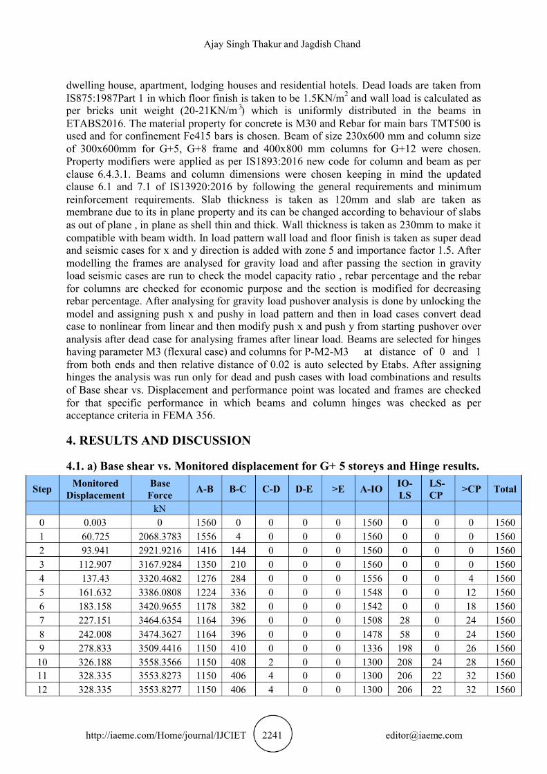
dwelling house, apartment, lodging houses and residential hotels. Dead loads are taken from IS875:1987Part 1 in which floor finish is taken to be 1.5KN/m2 and wall load is calculated as
per bricks unit weight (20-21KN/m 3 ) which is uniformly distributed in the beams in ETABS2016. The material property for concrete is M30 and Rebar for main bars TMT500 is used and for confinement Fe415 bars is chosen. Beam of size 230x600 mm and column size
of 300x600mm for G+5, G+8 frame and 400x800 mm columns for G+12 were chosen. Property modifiers were applied as per IS1893:2016 new code for column and beam as per clause 6.4.3.1. Beams and column dimensions were chosen keeping in mind the updated
clause 6.1 and 7.1 of IS13920:2016 by following the general requirements and minimum reinforcement requirements. Slab thickness is taken as 120mm and slab are taken as
membrane due to its in plane property and its can be changed according to behaviour of slabs as out of plane , in plane as shell thin and thick. Wall thickness is taken as 230mm to make it compatible with beam width. In load pattern wall load and floor finish is taken as super dead and seismic cases for x and y direction is added with zone 5 and importance factor 1.5. After modelling the frames are analysed for gravity load and after passing the section in gravity load seismic cases are run to check the model capacity ratio , rebar percentage and the rebar for columns are checked for economic purpose and the section is modified for decreasing rebar percentage. After analysing for gravity load pushover analysis is done by unlocking the model and assigning push x and pushy in load pattern and then in load cases convert dead case to nonlinear from linear and then modify push x and push y from starting pushover over analysis after dead case for analysing frames after linear load. Beams are selected for hinges
having parameter M3 (flexural case) and columns for P- - at distance of 0 and 1 M2 M3from both ends and then relative distance of 0.02 is auto selected by Etabs. After assigning hinges the analysis was run only for dead and push cases with load combinations and results of Base shear vs. Displacement and performance point was located and frames are checked
for that specific performance in which beams and column hinges was checked as per acceptance criteria in FEMA 356.
4. RESULTS AND DISCUSSION
4.1. a) Base shear vs. Monitored displacement for G+ 5 storeys and Hinge results.
Step Monitored Displacement
Base Force A-B B-C C-D D-E >E A- IO IO-
LS LS-CP >CP Total
kN 0 0.003 0 1560 0 0 0 0 1560 0 0 0 1560 1 60.725 2068.3783 1556 4 0 0 0 1560 0 0 0 1560 2 93.941 2921.9216 1416 144 0 0 0 1560 0 0 0 1560 3 112.907 3167.9284 1350 210 0 0 0 1560 0 0 0 1560 4 137.43 3320.4682 1276 284 0 0 0 1556 0 0 4 1560 5 161.632 3386.0808 1224 336 0 0 0 1548 0 0 12 1560 6 183.158 3420.9655 1178 382 0 0 0 1542 0 0 18 1560 7 227.151 3464.6354 1164 396 0 0 0 1508 28 0 24 1560 8 242.008 3474.3627 1164 396 0 0 0 1478 58 0 24 1560 9 278.833 3509.4416 1150 410 0 0 0 1336 198 0 26 1560 10 326.188 3558.3566 1150 408 2 0 0 1300 208 24 28 1560 11 328.335 3553.8273 1150 406 4 0 0 1300 206 22 32 1560 12 328.335 3553.8277 1150 406 4 0 0 1300 206 22 32 1560

Strong Column Weak Beam Concept by Analysing RCC MRF Frame by Non-Linear Static Procedure
http://iaeme.com/Home/journal/IJCIET 2242 [email protected]
Performance point of G+5 frames and Sa vs. Sg curve
Step Monitored
Displacement
Base Force A-B B-C C-D D-E >E A- IO IO-
LS LS-CP >CP Total
mm KN 0 0.005 0 2340 0 0 0 0 2340 0 0 0 2340 1 118.805 4027.6632 2340 0 0 0 0 2340 0 0 0 2340 2 124.082 4206.5844 2332 8 0 0 0 2340 0 0 0 2340 3 163.516 5228.8925 2112 228 0 0 0 2340 0 0 0 2340 4 185.056 5524.2412 1968 372 0 0 0 2340 0 0 0 2340 5 207.728 5677.2806 1892 448 0 0 0 2338 0 0 2 2340 6 230.876 5751.1532 1852 488 0 0 0 2338 0 0 2 2340
4.2. b) Base shear vs. Monitored displacement for G+8 storeys and Hinge results. The maximum base shear for the building under push x is 5757.1532KN and the performance point for this frame is 5685KN which is acceptable and in Sa VS Sg graph the reading are
with respect to time and shown in below picture the values of t(secent and effective) are given. The dispcement and time with respect to this graph is matched with pushover curve
(base shear vs displacement ) and hinges are checked only for those points (performance point) and hinges moments and results is checked and the results of 8 storey frame shows that
the displacement of performance point is 210.298mm which is between 207.728 mm and 230.876mm and plastic hinges are formed upto immidiate occupancy as shown in above table 1b) in step 5-6 only 2 hinges are greater than collapse prevention which can be modified with the help of increasing size of columns or by changing the oriantation of column.

Ajay Singh Thakur and Jagdish Chand
http://iaeme.com/Home/journal/IJCIET 2243 [email protected]
Performance point of G+8 frames and Sa vs. Sg curve
4.3. c) Base shear vs. Monitored displacement og G+12 storeys and Hinge results.
Step Monitored
Displacement
Base Force A-B B-C C-D D-E >E A- IO IO-
LS LS-CP >CP Total
mm kN 0 0.014 0 3380 0 0 0 0 3380 0 0 0 3380 1 97.332 2207.3565 3370 10 0 0 0 3380 0 0 0 3380 2 126.602 2697.8315 3122 258 0 0 0 3380 0 0 0 3380 3 174.51 3009.1402 2942 438 0 0 0 3380 0 0 0 3380 4 348.148 3489.2293 2722 658 0 0 0 3380 0 0 0 3380 5 530.388 3752.7342 2606 774 0 0 0 3136 242 0 2 3380 6 557.514 3783.1108 2582 798 0 0 0 3078 298 0 4 3380 7 706.09 3888.9235 2544 836 0 0 0 2870 500 2 8 3380 8 706.115 3888.9316 2544 836 0 0 0 2870 500 2 8 3380 9 706.173 3888.9802 2544 836 0 0 0 2870 500 2 8 3380 10 706.176 3888.9474 2544 836 0 0 0 2870 500 2 8 3380 11 707.003 3889.474 2544 836 0 0 0 2870 500 2 8 3380
The performace point for 12 storey frame is 3778 KN which comes near to maximum base shear it shows that with the increasing of storey height the buildings need shear wall to resist the sway and reduce the shear force for dissipating energy as we know the shear wall is more stronger than columns and the displacement is 553.293 mm which comes between step
5-6 in table 1c) the plastic hinges is this step is also safe because the size of column is increased for this building to satisfy the capacity moment ratio and rebar percentange.

Strong Column Weak Beam Concept by Analysing RCC MRF Frame by Non-Linear Static Procedure
http://iaeme.com/Home/journal/IJCIET 2244 [email protected]
Performance point of G+12 frames and Sa vs. Sg curve
The hinges formed in G+12 storeys frame first appeared in beam and follows same patterns indicate the beam failure in flexure than column in axial compression in push x.
Figure A) Hinge state coloured as per B, C, D, and E point. Hinge state coloured for IO, LS, and B)CP.
The above Figures depicts the maximum hinge moments for maximum deflection in push x case for 12 storey frame and some columns in figure b are in collapse condition which can be fixed but this is for maximum push case in which only 8 hinges are in collapse prevention so for this case the bottom storey column size can be increased for some storeys or shear wall can reduce the hinges moment and reduce the base shear and displacements

Ajay Singh Thakur and Jagdish Chand
http://iaeme.com/Home/journal/IJCIET 2245 [email protected]
Figure c) Step 1 of push x case in 2d in elevation step 11 of push x case in elevation d)
The c and d figure are hinges as per B, C, D and E criteria and the green colour shows the hinges in b to c zoneich shows the first hinge in beam and supports the strong column weak beam concept and shows beam sway.
5. CONCLUSION The results concluded that the cross section of beam and column matters a lot in designing capacity-based design based on strong column weak beam concept which is systematically represented by the hinges formed during pushover analysis.
The moment capacity ratio plays a major role in increasing the ductility of column and moment resistivity of column is increased as per the code guidelines.
The frame follows mixed pattern in which only the bottom node of column in ground floor shows hinge formation and rest follows beam mechanism.
With the increasing of storey height the performance point and displacement also increased which implies the need of shear walls for lowering the displacement and increasing the strength of building.
REFERENCES
[1] Kissi.B, Riyad. Y, Mrani.I, Parron, M.A, Labjar,N, Haouzi.A, ElEl Fqih. M, Ait Guemimi, C 2018, Influence of zone type on performance of retrofitted Reinforced
Concrete buildings by using Pushover Analysis, journal of Materials Today: Proceedings, Vol. 5, Issue 1, pp 22-29.
[2] -jassim, Samir A B Jabbar, & Husssain, Mohanned Abdul, Pushover Analysis of G + 5 Al Reinforced Concrete Building in Basrah, International Journal of Innovations in
Engineering and Technology (IJIET), ISSN: 2319-1058, Vol. 11, Issue , August 2018, pp. 53-59.
[3] Naik Pramodini, & Annigeri Satish, 2017, Performance evaluation of 9 storey RC building located in North Goa, 11th International Symposium on Plasticity and Impact
Mechanics, Implast 2016, Procedia Engineering 173 (2017), pp. 1841-1846. [4] Priyanka, Bhave, & Mayur, Banarase, Analysis and Capacity Based Earthquake
Resistance Design of Multy Bay Multy Storeyed Residential Building, Int. Journal of
Strong Column Weak Beam Concept by Analysing RCC MRF Frame by Non-Linear Static Procedure
http://iaeme.com/Home/journal/IJCIET 2246 [email protected]
Engineering Research and Applications www.ijera.com ISSN: 2248-9622, Vol. 6, Issue 4, (Part - 5) April 2016, pp.78-84
[5] Ravi, Avula, & Reddy, Teja, 2015, Design of RC framed building considering MCR s recommended in various international codes, (online), Assessed 20-10-18
http://ethesis.nitrkl.ac.in/7476/1/2015_BT_design_Reddy.pd [6] Cagurangan, Colleen Kirsten, 2015, Effects of Strong-Column Weak-Beam Ratios on
Collapse Capacities of Tall Reinforced Concrete Moment Frame Structures, Ph D. Thesis, University of California, Berkeley.
[7] Swamy, B Shivakumara &Prasad, S K, Influence of strong column and weak beam concept, soil type and zone on performance of RC frames, Volume: 04 Special Issue: 04 | ASHCE-2015 | May-2015, pp. 61-76, Available @ http://www.ijret.org
[8] Hadigheh, S A, Maheri, Mahmoud R, Mahini, S S, 2013, Performance of strong column and weak beam RC frames strengthened at the joint by FRP, IJST, Transactions of Civil Engineering, Vol. 37, No. C1, pp 33-51, Printed in The Islamic Republic of Iran, 2013© Shiraz University
[9] Leslie, Rahul, Design, Buildings, The Pushover Analysis, explained in its Simplicity, proceedings of 2nd national conference-RACE13 at Saintgits College of engineering,
Kottayam. [10] Liu, Yangbing, Liao, Yuanxin , Zheng, Nina, 2012, Analysis of Strong Column and Weak
Beam Behavior of Steel-concrete Mixed Frames, 15 world conference on earthquake engineering, lisboa 2012, pp.2-7
[11] Bento, Rita, 2000, Evolution of the need of strong column and weak beam design in dual frame wall structures,12 world conference on earthquake engineering, Auckland,2000,
pp1-7. [12] Yang, Pu, Wang, Yayong, 1940, A study on improvement of pushover analysis, 12 world
conference on earthquake engineering, Auckland, 2000, pp.19-40. [13] Magenes, Guido,1866, A method for pushover analysis in seismic assessment of masonry
buildings, 12 world conference on earthquake engineering, Auckland,2000, paper no 1866
[14] “BIS IS 456: Plain and reinforced concrete-code of practice. New Delhi (India): Bureau of Indian Standards; 2000”.
[15] “BIS IS 1893: Criteria for earthquake resistant design of structures, Part 1. New Delhi (India): Bureau of Indian Standards; 2002”.
[16] “BIS IS 13920: Ductile detailing of reinforced concrete structures subjected to seismic forces-code of practice. New Delhi (India): Bureau of Indian Standards; 1993”.
[17] “BIS IS 875: Code Of Practice For Design Loads For Buildings And Structures, Part 2. New Delhi (India): Bureau of Indian Standards; 1987".
[18] Paulay, T., Park, R., and Priestley, M. J. N., “Reinforced Concrete Beam-Column Joints Under Seismic Actions ACI Journal.” , 1978, pp 585-59.
[19] FEMA 356, (2000), Pre standard and commentary for the seismic rehabilitation of buildings, American society of civil engineers, Reston VA.