Deck Slab Design
11
92 Prof. Dr. Ali H. Aziz- Deck Slab Design 1-Deck Slab Thickness According to AASHTO, the minimum depths for constant depth members can be calculated from the following Table - 3 Super structure type Minimum Depth (ft) Simple Span Continuous Span Bridge Slab with Main Reinforcement Parallel to Traffic (1) 1.2(S+10)/30 ) S+10)/30≥0.542 T-Girders (Monolithic) .0.0S 0.065S Box-Girders 0.06S 0.055S Pedestrian Structure Girders 0.033S 0.033S (1) May be used for Reinforcement Perpendicular to Traffic S=Effective Span (ft). The Effective Span (S) is the Least of:- 1-Clear Span (l n ) + Effective Depth (d) 2- c/c of Bearing0 2-Deck Slab Reinforcement 2-1-Main Reinforcement ┴ Traffic 2-1-1- Main Reinforcement (As) main Live load moment can be calculated by using the following formula:- Where M L.L =Live Load Moment (kN. m/m) S=Span (m( (.00m≤ S≤7.3m) P=Wheel Load (kN) = 72 kN For (HS-20) AASHTO = 90.74 kN For (Military) Iraqi Specification Note: In slabs continuous over three or more supports, a continuity factor of (0.8) shall be applied to the above formula for both (M + ) and (M - ). M LL = 3.28 +2 32 ∗P Note: Traffic=Direction of Vehicle Movement Figure (1) Main Reinforcement // Traffic Figure (2) Main Reinforcement ┴ Traffic
-
Upload
khangminh22 -
Category
Documents
-
view
1 -
download
0
Transcript of Deck Slab Design

92 Prof. Dr. Ali H. Aziz-
Deck Slab Design
1-Deck Slab Thickness
According to AASHTO, the minimum depths for constant depth members can be calculated from
the following Table -3
Super structure type Minimum Depth (ft)
Simple Span Continuous Span
Bridge Slab with Main Reinforcement
Parallel to Traffic(1)
1.2(S+10)/30 ) S+10)/30≥0.542
T-Girders (Monolithic) .0.0S 0.065S
Box-Girders 0.06S 0.055S
Pedestrian Structure Girders 0.033S 0.033S (1) May be used for Reinforcement Perpendicular to Traffic
S=Effective Span (ft).
The Effective Span (S) is the Least of:-
1-Clear Span (ln) + Effective Depth (d)
2- c/c of Bearing0
2-Deck Slab Reinforcement
2-1-Main Reinforcement ┴ Traffic
2-1-1- Main Reinforcement (As) main
Live load moment can be calculated by using the
following formula:-
Where
ML.L=Live Load Moment (kN. m/m)
S=Span (m ( (.00m≤ S≤7.3m)
P=Wheel Load (kN)
= 72 kN For (HS-20) AASHTO
= 90.74 kN For (Military) Iraqi Specification
Note:
In slabs continuous over three or more supports, a continuity factor of (0.8) shall be applied to the
above formula for both (M+) and (M
-).
MLL = 3.28 𝑺+ 2
32∗ P
Note: Traffic=Direction of Vehicle Movement
Figure (1) Main Reinforcement // Traffic
Figure (2) Main Reinforcement ┴ Traffic

0. Prof. Dr. Ali H. Aziz-
Dead load moment can be calculated by using the following formula:-
Where
MD.L= Dead Load Moment (kN. m/m)
Wd= Service (un-factored) Dead Load
Total applied moment is:-
Check the slab thickness for strength requirements by using the following formula:-
= √2
. . .
Where
dmin= Minimum effective depth (slab thickness) for strength requirements
fc= Allowable Compressive Strength of Concrete= 0.4 (MPa)
k= Neutral axis depth coefficient ≈ 3/8
j= Internal resisting moment arm coefficient ≈ 7/8
b= Strip width=1000mm
Note: f'c =0.85fcu (Relationship between cylinder and cube compressive strength)
The main reinforcement (As)main can be calculated by using the following formula:-
Asmain= Mtotal/(fs*J*d)
Where
fs= Allowable Tensile Strength of Steel Reinforcement
fs= 04.MPa if fy <350 MPa
fs= 00.MPa if fy ≥350 MPa
2-1-2-Distribution Reinforcement (Secondary Reinforcement) (AS)Dist. According AASHTO specifications, the distribution reinforcement, (AS)Dist., can be calculated (for
M+) by using the formula3-
. = 2.2 ( )M
√3.28 .67 ( )M
2-2-Min Reinforcement // Traffic
2-2-1-Min Reinforcement
Strip Method for Decks Analysis: An approximate analysis method in which the deck is subdivided
into strips perpendicular to the supporting components. This method shall be considered acceptable
M L =1
1 ∗ wd ∗ 2
MTotal =MDL+MLL+MI)
00 Prof. Dr. Ali H. Aziz-
for slab bridges and concrete slabs having more than (4.6m) spans which primarily in the direction
parallel to traffic. The equivalent width of longitudinal strips per lane for both shear and moment
with one lane (E) of wheels or two lanes (2E) for lane loaded may be determined as:-
= 1.22 + . 6 2.14
Where
E=Effective Width (m)
S=Span (m)
= min. (c/c Span, Clear span+t(
t= Effective Depth
Use elastic analysis to calculate (MLL and MDL) and the Impact effect must be included
Check the slab thickness for strength requirements by using the following formula:-
= √2
. . .
The main reinforcement (As)main can be calculated by using the following formula:-
Asmain= Mtotal/(fs*J*d)
9-9-9-Distribution reinforcement (Secondary reinforcement(
The distribution reinforcement (As) Dist. can be calculated by using the following formula:-
. = ( )M
√3.28 .5 ( )M
Note:
1-For cantilever parts (such as sidewalk), use elastic analysis.
2-Lane load (UDL+KEL) are distributed over a width of (2E).
3-Single wheel load are distributed over a width of (E).
3-Slab Bridge
The slab bridges can be divided in to two types:-
Simply Supported Slab Bridge: The simplest form of bridge is the single-span slab bridge which
is simply supported at its ends. This form is widely used when the bridge crosses a minor road or
small river. In such cases, the span is relatively small and multiple spans are infeasible and/or
unnecessary. The simply supported bridge is relatively simple to analyze and to construct but is
disadvantaged by having bearings and joints at both ends. The cross-section is often solid
rectangular but can be made with voided slab section.
Continuous Slab Bridge: continuous slab construction has significant advantages over simply
supported spans in that there are fewer joints and bearings and the applied bending moments are
less. For bridges of moderate total length, the concrete can be poured in-situ in one pour. This
09 Prof. Dr. Ali H. Aziz-
completely removes the need for any joints. However, as the total bridge length becomes large, the
amount of concrete that needs to be cast in one pour can become excessive. This tends to increase
cost as the construction becomes more of a batch process than a continuous one.
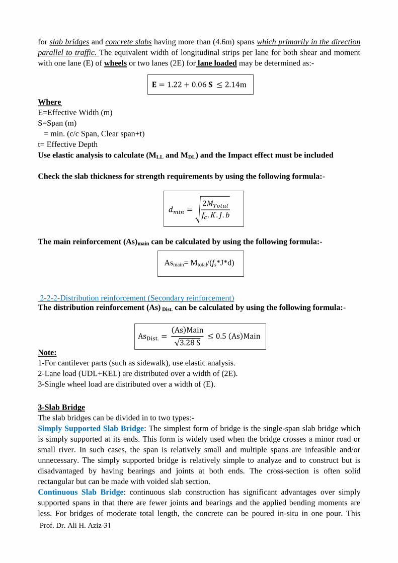
Figure (6) Bending moment diagrams due to uniform loading of intensity (w)
(a) Three simply supported spans of length (l); (b) Three-span continuous beam with span
lengths (l).
4-Design of Slab Bridge (AASHTO)
The slab bridge is short-span Bridge consisting of a reinforced-concrete Slab resting on piers or
abutments (supports). It is a simple type of bridges in which the main reinforcement parallel to
traffic (because the bridge is rest on two opposite supports).
1- Distribution of wheel load HS20 (truck) over on effective width (E).
= 1.22 + . 6 2.14
Figure (3) Simply supported Slab Bridge
Figure (4) Series of simply supported Slab Bridge
Figure (5) Continuous Slab Bridge

00 Prof. Dr. Ali H. Aziz-
2-Lane load (UDL+KEL) are distributed over a width of (2E).
3- When the span of bridge is smaller than the truck length, use single wheel load distributed over a
width of (E).
Example-1
For the cross-section of Slab Bridge shown in Figure (8), compute the required reinforcement.
Effective span = S = 10m;
Surfacing = 5cm
f'c = 25.5MPa, fy = 350 MPa
γc=24kN/m3, γAsphalt=22kN/m
3
Use HS-20 loading
Solution
tmin =1.2(S+10)/30=1.2 (10x3.28+10)/30=1.71ft= 29cm → use = 55
E=1.22+0.06xS =1.22+0.06x10=1.82m ≤ 2.14m…..ok
Live load
1-Lane Loading (UDL+KEL)
According to AASHTO specifications, the lane loading (UDL+KEL) is distributed over a width of
(2E).
2E=2x1.82=3.64m
UDL=9.3 kN/m-lane → UDL/m=9.3/3.64=2.55 kN/m
M(UDL) =1/8x2.55x(10)2=31.88 kN.m/m
KEL=80 kN/lane → KEL /m=80/3.64=21.98 kN
M(KEL) =1/4x21.98x(10)=54.95 kN.m/m
M(UDL+KEL) =86.83 kN.m/m
Impact Factor=I=15.24/(S+38.1)= .2
. = .317 .3→use I=0.3
M(UDL+KEL+I) =86.83X1.3=112.88 kN.m/m
2-Wheel Loading
According to AASHTO specifications, the distribution of wheel load HS20 (truck) should be over
on an effective width (E). Arrangement of wheel load for maximum moment is shown in Figure (9).
Figure (7) Simply Supported Slab Bridge
Figure (8) Slab Bridge Cross-section

04 Prof. Dr. Ali H. Aziz-
Arrangement of wheel load on Slab Bridge is shown in Figure (10). The next step is drawing of
SFD and BMD, and then the maximum bending moment is located at point (C) (under the middle
wheel).
= 162 (2.85 + 1.44)
1 = 69.5
Since the maximum bending moment is located at point (C); then:-
Mc =69.5x (0.02+4.27)-18x4.27= 99000 kN.m
E=1.82m (as before)
Moment/m= Mc/E=221.3/1.82=121.6 kN.m
Impact Factor=I=0.3(as before)
M (LL+I)= 121.6x1.3= 02100 kN.m/m ˃ M (UDL+KEL+I)= 112.88 kN.m/m
Use M (LL+I) =02100 kN.m/m for design…………ok
Dead load
w = .55 24 = 13.2 2
= . 5 22 = 1.1 2
M( L) = 1
8(14.3) (1 )2 = 178.75 .
M = M(L.L .L ) = 178.75 + 158.1 = 336.85 .
Figure (9) Arrangement of Wheel Load for Maximum Moment
Figure (10) Arrangement of Wheel Load on Slab Bridge

02 Prof. Dr. Ali H. Aziz-
= √2M
∗ ∗ ∗ = √
2 336.85 1
1 .2 38
78 1
= 449
Assume bar diameter (ϕ) =16mm and concrete cover=50mm
d d =
2= 55 5
16
2= 692
dprovided =692mm ˃ dmin=449mm…..ok
= M
=
336.85 1
17 78 492
= 463 2
32 15 ( = 536 2 )
Distribution Reinforcement
Since the main reinforcement // traffic, the distribution reinforcement can be calculated by:-
. =
√3.28 .5
=
√ .2 = 8 8 2 .5 463 = 2315 2
Use . = 8 8 2
. = . 2 ∗ ∗ = . 2 1 55 = 11 2
16 175 ( = 1149 2 )
Shear and Bond
According to AASHTO specification, slabs designed for bending moment may be considered
satisfactory for shear, but let’s try it:-
Live load shear (VLL)
1-Lane Loading (UDL+KEL)
VLL=KEL+UDLxL/2=21.98+2.55x (10/2) =34.73 kN
2-Wheel Loading
VLL=72/1.82+72/1.82x (10-4.27)/10+18/1.82x (10-2x4.27)/10=63.7kN
Use VLL=63.7kN
Dead load shear (VDL)
VDL= (14.3)x10/2=71.5 kN
Impact Factor=I=0.3(as before)
VTotal=71.5+1.3x63.7=154.31 kN
Shear stress (v) = V/ (bxd) =154.31x1000/ (1000x692) =0.22MPa
According to AASHTO specification the allowable shear stress is 𝑣𝑎𝑙𝑙 = 0.03f'c
𝑣𝑎𝑙𝑙 =0.03*25.5=0.765MPa˃ Shear stress (v) =0.22MPa→The section safe against shear

00 Prof. Dr. Ali H. Aziz-
Design of Edge Beam
Edge beam shall be provided for all slab bridge having main reinforcement parallel to traffic. The
beam may consist of a slab section additionally reinforced, a beam integral with and deeper than
slab, or an integral reinforced section of slab and curb.
It shall be designed to resist a live load moment of:-
M (LL)=0.1xPxS
Where
P=Wheel load (kN) → For HS-20, P=72kN
S=Span Length (m)
ML.L = .1 72 1 = 72 .
. = .6 .75 25 = 11.25 .
M .L = 1
8 11.25 1 2 = 14 .63 .
Total moment = M(L.L .L )
= 72 1.3 + 14 .63
= 234.23 .
= √2 234.23 1
1 .2 38
78 6
= 483 684 .
= 234.23 1
17 78 684
= 2316 2
3 32 (As)provided=2413mm
2……..ok
Note
= .4 and
= 17 𝑎 35 𝑎
= 14 𝑎 35 𝑎
Figure (11) Reinforcement Details

00 Prof. Dr. Ali H. Aziz-
Example-2-
Design a one way slab bridge which having a clear span of (5m), a width of (18m), asphalt paving
weight of (1.4kN/m2), seat width of (400mm), fʹc=30MPa, fy=300MPa, γc=24kN/m
3, weight of hand
rail=0.4kN/m, curb width=600mm, use (HS-20) truck and assume (tmin=ln/20), (where ln=clear
span).
Solution
=
2 = 25
= 3
3 5 2
2 238
= ( + )
= (5.4 5.238) = 5.4
= 1.22 + . 6 2.14 = 1.22 + . 6 5.24 = 1.534 2.14
ML.L =
P
4=
721.534
5.24
4= 61.47 .
=15.24
+ 38.1=
15.24
5.24 + 38.1= .352 .3 = .3
M(L.L ) = 61.47 1.3 = 8 .
. = ∗ + w = .3 24 + 1.4 = 8.6 2
M .L =1
8(8.6)(5.24)2 = 3 .
= 8 + 3 = 11 .
= √2
= √
2 11 1
12 38
78 1
= .4 3 = 12 𝑎
= 14 𝑎
= 236 = 238
= M
=
11 1
14 78 238
= 3773 2
( 25 ) = 49 2
= 1
=
49 1
3773= 13
25 125 (M )
Distribution Reinforcement
=
√3.28 .5
. = 3773
√3.28 5.24= 91 2 .5 3773 = 1887 2
P
S / 2 S / 2
E
Figure (12) Slab Bridge Effective Width

01 Prof. Dr. Ali H. Aziz-
. = . 2 = . 2 3 1 = 6 2
( 16 ) = 2 1 2 = 2 1 1
91 = 221
( 16 ) 2
Design of Edge beam
. = ( .3 + .2) .6 24 + .4 = 7.6 .
M .L =1
8(7.6)(5.24)2 = 27.5 .
ML.L = .1 72 5.24 = 35.84 .
= .3 ( )
M = 35.84 1.3 + 27.5 = 74 .
= √2 74 1
12 38
78 6
= 25 .3 = 5 5 25
2 438
=
=
74 1
14 78 438
= 1379 2
(3 25 )
( ) = 1473 2
Example-3-
For the composite prestressed-concrete bridge shown in Figure (14), if the span length= 20m c/c of
bearing, f'c = 20 MPa , fy = 410 MPa, total slab thickness =t=200mm, effective depth=d=140mm
,top flange width =400mm; Determine the main and distribution reinforcement. Use AASHTO (HS-
20) loading.
Solution
= ( + )
= (2.1 2.1 .4 + .14) = (2.1 1.84 )
= 1.84 6
=1.2( + 1 )
3 =
1.2(6 + 1 )
3 = .64 19.5 2
Handrail
Edge Beam
300mm
200mm
600mm Figure (13) Edge Beam Details
[email protected]=8.4m
5cm Surfacing
Ln
Precast
Prestressed
Girder
8m 0.6m 0.6m
0.4m
Figure (14) Composite Prestressed-Concrete Bridge

02 Prof. Dr. Ali H. Aziz-
Dead Load Moment (MDL)
= .2 24 = 4.8 2
= . 5 22 = 1.1 2 = 5.9 2
M L = 1
1 w 2 =
1
1 5.9 (1.84)2 = 2 .
Live Load Moment (MLL)
= .8 3.28 + 2
32 P = .8
3.28 1.84 + 2
32 72 = 14.46 .
=15.24
+ 38.1=
15.24
1.84 + 38.1= .38 .3 = .3
M = .3 14.46 = 4.34 .
= 2 + 14.46 + 4.34 = 2 .8 .
= √2M
= √
2 2 .8 1
8 38
78 1
= 126
d d = 14 = 126 ……ok
=M
=
2 .8 1
17 78 14
= 999 2 16 18
(As=1117mm2/m), Top and Bottom in Transverse Direction.
Distribution Reinforcement (Longitudinal Reinforcement)
An AASHTO specification requires an amount as the percentage of the main reinforcement for
(M+): For main Reinforcement ┴ traffic;
. =2.2
√3.28 =
2.2 999
√3.28 1.84= 895 2 .67 = 669 2
= 669 2 16 25 ( = 8 4 2 ) →Bottom Longitudinal
. = . 2 = . 2 1 2 = 4 2
12 25 ( = 452 2 )
Shear and Bond
The AASHTO specification says that designed for moment will be says that slabs designed for
moment will be considered safe in shear and bond (i.e. No need to check shear and bond).
2.1m
ϕ16mm@180mm
ϕ16mm@180mm
ϕ12mm@250mm
ϕ12mm@250mm
200mm
Figure (15) Deck Slab Reinforcement Details