VULCRAFT® DECK SOLUTIONS
125
-
Upload
khangminh22 -
Category
Documents
-
view
0 -
download
0
Transcript of VULCRAFT® DECK SOLUTIONS


VULCRAFT® DECK SOLUTIONS& Catalog Solutions : Web Based Solutions
General
&
Product Offer Information
Bekaert Steel Fiber Information
Pour Stop Selection Table
Non-Composite Slab Design
Cellular Deck Design Guidance
Acoustical Solutions
&Acoustical Roof Deck – NRC Ratings
2.0D FormLok® Deck-Slab - STC & IIC Ratings
3.5D FormLok® Deck-Slab - STC & IIC Ratings
UL Fire Ratings
& UL Fire Ratings - Roof Deck
UL Fire Ratings - Floor Deck
Hanging Solutions
& Sammy X-Press Swivel Head® for Roof Deck
Wedge-Nut for FormLok® Dovetail Deck-Slab
: Steel Deck Roving Load - Web Based Design Tool
Approvals - Download PDF
:
IAPMO UES Report ER-652 for Vulcraft Deck and Deck-Slabs
IAPMO UES Report ER-423 for Dovetail Deck and Deck-Slabs
FM Approval Reports
Vulcraft Deck CSI Guide Spec
Dovetail Deck CSI Guide Spec
Roof Deck
:Steel Deck Uniform Loads - Web Based Design Tool
Steel Deck Web-Crippling - Web Based Design Tool
Steel Deck Diaphragm Strength - Web Based Design Tool
ASD Roof Deck (Properties and Vertical Load Tables)
&
2.0D Dovetail Roof Deck
3.5D Dovetail Roof Deck
1.5B-36/1.5BI-36/1.5PLB-36 GR50 Roof Deck
1.5B-36/1.5BI-36/1.5PLB-36 GR80 Roof Deck
3NL-32/3NI-32/3PLN-32 GR50 Roof Deck
3NL-32/3NI-32/3PLN-32 GR80 Roof Deck
3N-24/3NI-24 Roof Deck
&
2.0DA Dovetail Acoustical Roof Deck
3.5DA Dovetail Acoustical Roof Deck
1.5BA-36/1.5BIA-36/1.5PLBA-36 GR50 Acoustical Roof Deck
1.5BA-36/1.5BIA-36/1.5PLBA-36 GR80 Acoustical Roof Deck
3NLA-32/3NIA-32/3PLNA-32 GR50 Acoustical Roof Deck
3NLA-32/3NIA-32/3PLNA-32 GR80 Acoustical Roof Deck
3NA-24/3NIA-24 Acoustical Roof Deck
: LRFD Roof Deck (Properties and Vertical Load Tables) - Download PDF

VULCRAFT® DECK SOLUTIONS& Catalog Solutions : Web Based Solutions
Composite Deck
:Unshored Span - Web Based Design Tool
Composite Deck-Slab Strength (Superimposed Load) - Web Based Design Tool
Composite Deck Diaphragm Strength - Web Based Design Tool
&
ASD Composite Deck (Properties and Superimposed Load Tables)2.0D FormLok® Dovetail Deck-Slab
3.5D FormLok® Dovetail Deck-Slab
1.5VL-36/1.5VLI-36/1.5PLVLI-36 Composite Deck-Slab
1.5VLR-36 Composite Deck-Slab
2VLI-36/2VLJ-36/2PLVLI-36 Composite Deck-Slab
3VLI-36/3VLJ-36/3PLVLI-36 Composite Deck-Slab
: LRFD Composite Deck (Properties and Superimposed Load Tables) - Download PDF
Non-Composite Deck
&
ASD Non-Composite Deck (Properties and Vertical Load Tables)0.6C-30/0.6C-35 Non-Composite Deck
0.6C-36 Non-Composite Deck
1.0C-32 Non-Composite Deck
1.0C-33 Non-Composite Deck
1.0C-36 Non-Composite Deck
1.3C-32 Non-Composite Deck
1.5C-36 Non-Composite Deck
2C-36 Non-Composite Deck
3C-36 Non-Composite Deck
: LRFD Non-Composite Deck (Properties and Vertical Load Tables)
Cellular Deck
&
ASD Cellular Deck (Properties Tables)1.5BP-36/1.5PLBP-36/1.5VLP-36/1.5PLVLP-36 Cellular Deck
1.5BPA-36/1.5PLBPA-36/1.5VLPA-36/1.5PLVLPA-36 Acoustical Cellular Deck
3NP-32/3PLNP-32 Cellular Deck
3NPA-32/3PLNPA-32 Acoustical Cellular Deck
3NP-24 Cellular Deck
3NPA-24 Acoustical Cellular Deck
2VLP-36/2PLVLP-36 Cellular Deck
2VLPA-36/2PLVLPA-36 Acoustical Cellular Deck
3VLP-36/3PLVLP-36 Cellular Deck
3VLPA-36/3PLVLPA-36 Acoustical Cellular Deck
: LRFD Cellular Deck (Properties Tables) - Download PDF


VULCRAFT® DECK PRODUCT OFFER1.5B ROOF DECKS
32” WIDE 3N ROOF DECKS
24” WIDE 3N ROOF DECKS
1.5VL COMPOSITE DECKS
1.5VLR COMPOSITE DECKS
2VLI COMPOSITE DECKS
3VLI COMPOSITE DECKS
ROOF DECKS
COMPOSITE DECKS
COVER WIDTHS: 30”, 36”GAGES: 24, 22, 20, 19, 18, 16
COVER WIDTH: 32”GAGES: 22, 20, 19, 18, 16
COVER WIDTH: 24”GAGES: 22, 20, 19, 18, 16
COVER WIDTH: 36”GAGES: 22, 20, 19, 18, 16
COVER WIDTH: 36”GAGES: 22, 20, 19, 18, 16
COVER WIDTH: 36”GAGES: 22, 20, 19, 18, 16
COVER WIDTH: 36”GAGES: 22, 20, 19, 18, 16
NON-COMPOSITE DECKS0.6C NON-COMPOSITE DECKS
1.0C NON-COMPOSITE DECKS
1.3C NON-COMPOSITE DECKS
COVER WIDTHS: 30”, 35”, 36”GAGES: 28, 26, 24, 22
COVER WIDTHS: 32”, 33”, 36”GAGES: 26, 24, 22, 20
COVER WIDTH: 32”GAGES: 26, 24, 22, 20
1.5C NON-COMPOSITE DECKS
2C NON-COMPOSITE DECKS
3C NON-COMPOSITE DECKS
COVER WIDTHS: 30”, 36”GAGES: 24, 22, 20, 18
COVER WIDTH: 36”GAGES: 22, 20, 18, 16
COVER WIDTH: 36”GAGES: 22, 20, 18, 16
2.0D DOVETAIL DECKSCOVER WIDTH: 24.5”GAGES: 22, 20, 19, 18, 16
3.5D DOVETAIL DECKSCOVER WIDTH: 24”GAGES: 20, 19, 18, 16
DOVETAIL DECKS

VULCRAFT® DECK PRODUCT OFFER1.5BP CELLULAR DECKS
1.5VLP CELLULAR DECKS
2VLP CELLULAR DECKS
3VLP CELLULAR DECKS
CELLULAR DECK PRODUCT OFFER
COVER WIDTH: 24”, 36”GAGES: 20/20, 20/18, 18/20, 18/18, 18/16, 16/18, 16/16
COVER WIDTH: 24”, 36”GAGES: 20/20, 20/18, 18/20, 18/18, 18/16, 16/18, 16/16
COVER WIDTH: 24”GAGES: 20/20, 20/18, 18/20, 18/18, 18/16, 16/18, 16/16
COVER WIDTH: 24”, 36”GAGES: 20/20, 20/18, 18/20, 18/18, 18/16, 16/18, 16/16
COVER WIDTH: 24”, 36”GAGES: 20/20, 20/18, 18/20, 18/18, 18/16, 16/18, 16/16
32” WIDE 3NP CELLULAR DECKSCOVER WIDTH: 32”GAGES: 20/20, 20/18, 18/20, 18/18, 18/16, 16/18, 16/16
24” WIDE 3NP CELLULAR DECKS

BEKAERT | APRIL 2020
VULCRAFT® COMPOSITE DECKS with
Minimum Reinforcing Options for Temperature and Shrinkage
Cover Depth
(in.)
Min. As for T&S
(in.2)
Recommended Reinforcing for Temperature and Shrinkage
WWR (OR)Bekaert Dramix® Steel Fiber
Alternate to WWR (lb/yd3)
3D 65/60BG
Normal Weight Concrete (145 pcf)
2 0.028 6x6-W1.4xW1.4 27
2¼ 0.028 6x6-W1.4xW1.4 25
2½ 0.028 6x6-W1.4xW1.4 22
2¾ 0.028 6x6-W1.4xW1.4 20
3 0.028 6x6-W1.4xW1.4 19
3¼ 0.029 6x6-W2.1xW2.1 18
3½ 0.032 6x6-W2.1xW2.1 18
3¾ 0.034 6x6-W2.1xW2.1 18
4 0.036 6x6-W2.1xW2.1 18
4¼ 0.038 6x6-W2.1xW2.1 18
4½ 0.041 6x6-W2.1xW2.1 18
4¾ 0.043 6x6-W2.9xW2.9 18
5 0.045 6x6-W2.9xW2.9 18
Light Weight Concrete (110 pcf)
2 0.028 6x6-W1.4xW1.4 42
2¼ 0.028 6x6-W1.4xW1.4 34
2½ 0.028 6x6-W1.4xW1.4 30
2¾ 0.028 6x6-W1.4xW1.4 26
3 0.028 6x6-W1.4xW1.4 23
3¼ 0.029 6x6-W2.1xW2.1 22
3½ 0.032 6x6-W2.1xW2.1 22
3¾ 0.034 6x6-W2.1xW2.1 22
4 0.036 6x6-W2.1xW2.1 22
4¼ 0.038 6x6-W2.1xW2.1 22
4½ 0.041 6x6-W2.1xW2.1 22
4¾ 0.043 6x6-W2.9xW2.9 22
5 0.045 6x6-W2.9xW2.9 22
BEKAERT DRAMIX® STEEL FIBERS
Notes: 1. FRC reinforcement is based on IAPMO UES ER-497 and ER-465.2. Dramix® fibers may be used in UL or ULC fire rated assemblies in lieu of WWR. See UL file R19307 for additional information.
WWW.VULCRAFT.COM
For information on Bekaert Dramix® fibers contact 770-514-2295 or [email protected].
Total SlabDepthTotal Slab
Depth
Cover Depth
Deck Depth
Cover Depth
Deck Depth

BEKAERT | APRIL 2020
VULCRAFT® COMPOSITE DECKS withBEKAERT DRAMIX® STEEL FIBERS
NOTICE: Design defects that could cause injury or death may result from relying on the information in this document without independent verification by a qualified professional. The information in this document is provided “AS IS”. Nucor Corporation and its affiliates expressly disclaim: (i) any and all representations, warranties and conditions and (ii) all liability arising out of or related to this document and the information in it.
NUCOR, VULCRAFT, VERCO, and FORMLOK are registered trademarks of Nucor. DRAMIX is a registered trademark of Bekaert.
WWW.VULCRAFT.COM
31/2” Deep Decks
3” Deep Decks
2” Deep Decks
11/2” Deep Decks
1.5VL, 1.5VLI, 1.5PLVLI
1.5VLR
2.0D
2VLI, 2VLJ, 2PLVLI
3VLI, 3VLJ, 3PLVLI
3.5D
Composite Deck SlabCover Depth (in.)
Total Slab Depth
(in.)
3½” Deep Decks
3” Deep Decks
2” Deep Decks
1½” Deep Decks
Vulcraft Composite Decks
3.5D3VLI, 3VLJ,
3PLVLI2VLI, 2VLJ,
2PLVLI, 2.0D
1.5VL, 1.5VLI, 1.5PLVLI, 1.5VLR
3 1/2 - - - 2
3 3/4 - - - 2 1/4
4 - - 2 2 1/2
4 1/4 - - 2 1/4 2 3/4
4 1/2 - - 2 1/2 3
4 3/4 - - 2 3/4 3 1/4
5 - 2 3 3 1/2
5 1/4 - 2 1/4 3 1/4 3 3/4
5 1/2 2 2 1/2 3 1/2 4
5 3/4 2 1/4 2 3/4 3 3/4 4 1/4
6 2 1/2 3 4 4 1/2
6 1/4 2 3/4 3 1/4 4 1/4 4 3/4
6 1/2 3 3 1/2 4 1/2 5
6 3/4 3 1/4 3 3/4 4 3/4 5 1/4
7 3 1/2 4 5 5 1/2
7 1/4 3 3/4 4 1/4 5 1/4 5 3/4
7 1/2 4 4 1/2 5 1/2 6
7 3/4 4 1/4 4 3/4 5 3/4 6 1/4
8 4 1/2 5 6 6 1/2
Total SlabDepthTotal Slab
Depth
Cover Depth
Deck Depth
Cover Depth
Deck Depth

SDI POUR STOP SELECTION
WWW.VULCRAFT.COMPOUR STOP | SEPTEMBER 2020
Pour Stop GageSlab
Depth Overhang (in.)
(in.) 0 1 2 3 4 5 6 7 8 9 10 11 12
4.00 20 20 20 20 18 18 16 14 12 12 12 10 10
4.25 20 20 20 18 18 16 16 14 12 12 12 10 10
4.50 20 20 20 18 18 16 16 14 12 12 12 10 10
4.75 20 20 18 18 16 16 14 14 12 12 10 10 10
5.00 20 20 18 18 16 16 14 14 12 12 10 10
5.25 20 18 18 16 16 14 14 12 12 12 10 10
5.50 20 18 18 16 16 14 14 12 12 12 10 10
5.75 20 18 16 16 14 14 12 12 12 12 10 10
6.00 18 18 16 16 14 14 12 12 12 10 10 10
6.25 18 18 16 14 14 12 12 12 12 10 10
6.50 18 16 16 14 14 12 12 12 12 10 10
6.75 18 16 14 14 14 12 12 12 10 10 10
7.00 18 16 14 14 12 12 12 12 10 10 10
7.25 16 16 14 14 12 12 12 10 10 10
7.50 16 14 14 12 12 12 12 10 10 10
7.75 16 14 14 12 12 12 10 10 10 10
8.00 14 14 12 12 12 12 10 10 10
8.25 14 14 12 12 12 10 10 10 10
8.50 14 12 12 12 12 10 10 10
8.75 14 12 12 12 12 10 10 10
9.00 14 12 12 12 10 10 10
9.25 12 12 12 12 10 10 10
9.50 12 12 12 10 10 10
9.75 12 12 12 10 10 10
10.00 12 12 10 10 10 10
10.25 12 12 10 10 10
10.50 12 12 10 10 10
10.75 12 10 10 10
11.00 12 10 10 10
11.25 12 10 10
11.50 10 10 10
11.75 10 10
12.00 10 10
Gage
Design Thickness
(in.)
20 0.0358
18 0.0474
16 0.0598
14 0.0747
12 0.1046
10 0.1345
NOTES: 1. Normal weight concrete 150 PCF2. Horizontal and vertical deflection is limited to 1/4” maximum for dead load3. Desgin stress is limited to 20 KSI for concrete dead load temporarily increased by one-third for construction live load of 20 PSF 4. Pour Stop Selection Chart does not consider the effect of performance, deflection, or rotation of the pour stop support which may include both the supporting deck and/or the frame5. Vertical leg return lip is recommended for all gages6. This selection table is not meant to replace the judgment of experienced structural engineers and should be considered as a reference only
Composite Steel Floor Deck - SlabsC - 2011 Standard for
AmericAn nAtionAl stAndArds institute/ steel deck instituteSTEEL DECKINSTITUTE
s ®
uSer note attaChment 1
User Note Attachment 1Pour Stop Selection Table
2” MIN.
1” FILLET WELDS@ 12” O.C.
POUR STOP
SLAB DEPTH
OVERHANG
1/2” MIN.

NON-COMPOSITE SLAB DESIGN
WWW.VULCRAFT.COMNC SLAB DESIGN | SEPTEMBER 2020
NOTICE: Design defects that could cause injury or death may result from relying on the information in this document without independent verification by a qualified professional. The information in this document is provided “AS IS”. Nucor Corporation and its affiliates expressly disclaim: (i) any and all representations, warranties and conditions and (ii) all liability arising out of or related to this document and the information in it.
Design Notes for Reinforced Concrete Slabs
Concrete Design - Design of concrete slabs in accordance with ACI is the responsibility of the structural engineer of record. Values listed in these tables are provided as an aid in selecting the appropriate deck and Vulcraft does not assume responsibility for the design of the slab.
Temperature and Shrinkage Reinforcing - Temperature and shrinkage effects in the concrete shall be controlled by methods permitted by ACI 318. The designer shall be permitted to consider only the area of concrete above the deck.
Shoring - Slabs temporarily shored during construction must deduct the weight of the slab from the calculated capacity of the reinforced concrete slab.
Deck Finish - Galvanized form deck can be considered a permanent support in most applications. When uncoated or painted deck is used, the weight of the concrete slab shall be deducted from the calculated capacity of the reinforced concrete slab.
Allowable Slab Loads - These tables are based on an interior three span condition using moment coefficients from ACI 318- 14 Section 6.5.2. Moment coefficients must be adjusted for end spans, single spans, or double spans.
Serviceability - Tabulated values are not evaluated for deflection.
Span Ratio - The tabulated concrete cover thicknesses (t) for the table values shown meet the ratio of span/28 per ACI 318-14 Section 7.3.1.5.
Reinforcing Placement - Reinforcing shall be located at center of topping.
f’c = 3,000 psify = 60,000 psi
ɸ = 0.90T = As fy
b = 12 ina = T/0.85 f’ cb
+ M = 1/16W L2
- M = 1/12W L2 (L≤10 ft.)- M = 1/10W L2 (L>10 ft.)
+ Mc = T (d-a/2)/12- Mc = T (d-na)/12 ML = ɸ Mc/1.6
INDIVIDUAL DECK TABLES
“MAXIMUM CONSTRUCTION CLEAR SPANS”These tables list the maximum construction clear span
based on the S.D.I. criteria as is outlined on page 41.
“REINFORCED CONCRETE SLAB ALLOWABLE LOADS”This table shows the load carrying capacity the concrete
slab will develop when it is reinforced with welded wirefabric (mesh). For the loads shown in light print, the liveloads were calculated with the mesh halfway between thetop of the slab and the top of the deck. This is considered
“undraped”.The loads shown in bold print were calculatedusing the mesh near the top of the slab as negativereinforcement at the supports and near the bottom of theslab as positive reinforcement between supports. This iscalled “draped”. See illustration below.
“ALLOWABLE UNIFORM LOADS”These tables list the uniform allowable load the deck
alone will carry. Designers will want to use one of the threecategories of load carrying capacities depending on theapplication.
DESIGN NOTES FOR REINFORCED CONCRETE SLABS1. Slabs that are temporarily shored must have the slab weight deducted from the allowable live load regardless of the type of finish.2. Finish—Vulcraft painted floor decks can be considered as a permanent form for use in normal building environments. It's structural life would
be similar to that of painted roof deck. In high moisture atmospheres, a galvanized finish is recommended. Uncoated decks are not consideredpermanent and the weight of the slab should be deducted from the slab allowable load.
3. Allowable Slab Loads—These tables are based on a three span condition using a moment coefficient of 1/12 as allowed by A.C.I. 318-05(Sec. 8.3.3) for spans 10 feet or less. A moment coefficient of 1/10 per A.C.I. 318-05 (Sec. 8.3.3) was used for spans over 10 foot. For a twospan condition this coefficient should be increased to 1/9 per A.C.I. 318-05 (Sec. 8.3.3) and for one span to 1/8. Other conditions may requirefurther analysis.f'c = 3,000 psi E = 29,500,000 psi b = 12 in + M = 1/16W L2 + Mc = T (d-a/2)/12fy = 60,000 psi φ = 0.90 p = As/bd - M = 1/12W L2 (L<10 ft.) - Mc = T (d-na)/12
T = Asfy a = T/0.85 f' cb - M = 1/10W L2 (L>10 ft.) ML = φMc/1.7
4. Yield stress of material is 60,000 psi.
CONFORM (TYPE "C")
UNDRAPED
DRAPED
.6C, 1.0C & 1.3C do not include slot vents in the bottom flute.Check with plant for availability of sidelap vents.
0.6CSV, 1.0CSV & 1.3CSV are the types of deck thatshould be specified if slot vents in the bottom fluteare required. Check with plant for availability of deck types.
SLOT VENTS Length ≈ 5/8"(Type 0.6CSV, 1.0CSV, & 1.3CSV)
NON-C
OMPOSITE
23
SLOT VENTS
•0.6C, 1.0C and 1.3C – Do not include slot vents in bottom flange. Sidelap vents optional.•0.6CSV, 1.0CSV and 1.3CSV – Specify if bottom flange slot vents are required.
Venting Non-Composite Deck - Check with Vulcraft representative for availability.

REINFORCED CONCRETE SLABS ON NC DECK
WWW.VULCRAFT.COMNC SLAB DESIGN | SEPTEMBER 2020
ALLOWABLE SUPERIMPOSED UNIFORM LOADS (psf) FOR 1.0C DECK 3 Span Condition
Slab Depth Reinforcement Clear Span (ft-in.)
Total Topping WWR As 3'-0" 3'-3" 3'-6" 3'-9" 4'-0" 4'-6" 5'-0" 5'-6" 6'-0" 6'-6" 7'-0"
2½" 1½"
6x6-W2.1xW2.1 0.042 112 95 82 71
6x6-W2.9xW2.9 0.058 151 128 111 96
6x6-W4.0xW4.0 0.080 201 172 148 129
3" 2"
6x6-W2.9xW2.9 0.058 205 175 151 131 115 91
6x6-W4.0xW4.0 0.080 276 236 203 177 156 123
4x4-W4.0xW4.0 0.120 397 338 292 254 223 176
3½" 2½"
6x6-W2.9xW2.9 0.058 260 221 191 166 146 115 93 77
6x6-W4.0xW4.0 0.080 351 299 258 225 198 156 127 105
4x4-W4.0xW4.0 0.120 400 400 374 326 287 226 183 152
4" 3"
6x6-W4.0xW4.0 0.080 400 363 313 273 240 190 154 127 107 91 78
4x4-W2.9xW2.9 0.087 400 393 339 295 260 205 166 137 115 98 85
4x4-W4.0xW4.0 0.120 400 400 400 398 350 276 224 185 156 133 114
4½" 3½"
6x6-W4.0xW4.0 0.080 400 400 368 321 282 223 181 149 125 107 92
4x4-W2.9xW2.9 0.087 400 400 399 348 305 241 196 162 136 116 100
4x4-W4.0xW4.0 0.120 400 400 400 400 400 326 264 219 184 156 135
5" 4"
4x4-W2.9xW2.9 0.087 400 400 400 400 351 278 225 186 156 133 115
4x4-W4.0xW4.0 0.120 400 400 400 400 400 376 305 252 212 180 156
#3 @ 9" o.c. 0.147 400 400 400 400 400 400 368 304 256 218 188
ALLOWABLE SUPERIMPOSED UNIFORM LOADS (psf) FOR 0.6C DECK 3 Span Condition
Slab Depth Reinforcement Clear Span (ft-in.)
Total Topping WWR As 2’-0” 2’-3” 2’-6” 2’-9” 3’-0” 3’-3” 3’-6” 3’-9” 4’-0” 4’-6” 5’-0”
2” 1½”
6x6-W2.1xW2.1 0.042 251 198 161 133 112 95 82
6x6-W2.9xW2.9 0.058 339 268 217 179 151 128 111
6x6-W4.0xW4.0 0.080 400 358 290 240 201 172 148
2½” 2”
6x6-W2.9xW2.9 0.058 400 365 295 244 205 175 151 131 115 91
6x6-W4.0xW4.0 0.080 400 400 398 329 276 236 203 177 156 123
4x4-W2.9xW2.9 0.087 400 400 400 355 298 254 219 191 168 133
3” 2½”
6x6-W2.9xW2.9 0.058 400 400 374 309 260 221 191 166 146 115 93
6x6-W4.0xW4.0 0.080 400 400 400 400 351 299 258 225 198 156 127
4x4-W2.9xW2.9 0.087 400 400 400 400 380 324 279 243 214 169 137
3½” 3”
6x6-W4.0xW4.0 0.080 400 400 400 400 400 363 313 273 240 190 154
4x4-W2.9xW2.9 0.087 400 400 400 400 400 393 339 295 260 205 166
4x4-W4.0xW4.0 0.120 400 400 400 400 400 400 400 398 350 276 224
4” 3½”
6x6-W4.0xW4.0 0.080 400 400 400 400 400 400 368 321 282 223 181
4x4-W2.9xW2.9 0.087 400 400 400 400 400 400 399 348 305 241 196
4x4-W4.0xW4.0 0.120 400 400 400 400 400 400 400 400 400 326 264
4½” 4”
4x4-W2.9xW2.9 0.087 400 400 400 400 400 400 400 400 351 278 225
4x4-W4.0xW4.0 0.120 400 400 400 400 400 400 400 400 400 376 305
#3 @ 9" o.c. 0.147 400 400 400 400 400 400 400 400 400 400 368

REINFORCED CONCRETE SLABS ON NC DECK
WWW.VULCRAFT.COMNC SLAB DESIGN | SEPTEMBER 2020
ALLOWABLE SUPERIMPOSED UNIFORM LOADS (psf) FOR 1.5C DECK 3 Span Condition
Slab Depth Reinforcement Clear Span (ft-in.)
Total Topping WWR As 4'-0" 4'-6" 5'-0" 5'-6" 6'-0" 6'-6" 7'-0" 7'-6" 8'-0" 8'-6" 9'-0"
3½" 2"
6x6-W2.9xW2.9 0.058 115 91
6x6-W4.0xW4.0 0.080 156 123
4x4-W2.9xW2.9 0.087 168 133
4" 2½"
6x6-W2.9xW2.9 0.058 146 115 93 77
6x6-W4.0xW4.0 0.080 198 156 127 105
4x4-W2.9xW2.9 0.087 214 169 137 113
4½" 3"
6x6-W4.0xW4.0 0.080 240 190 154 127 107 91 78
4x4-W2.9xW2.9 0.087 260 205 166 137 115 98 85
4x4-W4.0xW4.0 0.120 350 276 224 185 156 133 114
5" 3½"
6x6-W4.0xW4.0 0.080 282 223 181 149 125 107 92 80 71
4x4-W2.9xW2.9 0.087 305 241 196 162 136 116 100 87 76
4x4-W4.0xW4.0 0.120 400 326 264 219 184 156 135 118 103
5½" 4"
4x4-W2.9xW2.9 0.087 351 278 225 186 156 133 115 100 88 78 69
4x4-W4.0xW4.0 0.120 400 376 305 252 212 180 156 136 119 106 94
#3 @ 9" o.c. 0.147 400 400 368 304 256 218 188 164 144 127 114
6" 4½"
4x4-W4.0xW4.0 0.120 400 400 345 285 240 204 176 154 135 120 107
#3 @ 9" o.c. 0.147 400 400 400 345 290 247 213 186 163 145 129
#4 @ 12" o.c. 0.196 400 400 400 400 378 322 278 242 213 188 168
ALLOWABLE SUPERIMPOSED UNIFORM LOADS (psf) FOR 1.3C DECK 3 Span Condition
Slab Depth Reinforcement Clear Span (ft-in.)
Total Topping WWR As 4'-0" 4'-6" 5'-0" 5'-6" 6'-0" 6'-6" 7'-0" 7'-6" 8'-0" 8'-6" 9'-0"
35/16" 2"
6x6-W2.9xW2.9 0.058 115 91
6x6-W4.0xW4.0 0.080 156 123
4x4-W2.9xW2.9 0.087 168 133
313/16" 2½"
6x6-W2.9xW2.9 0.058 146 115 93 77
6x6-W4.0xW4.0 0.080 198 156 127 105
4x4-W2.9xW2.9 0.087 214 169 137 113
45/16" 3"
6x6-W4.0xW4.0 0.080 240 190 154 127 107 91 78
4x4-W2.9xW2.9 0.087 260 205 166 137 115 98 85
4x4-W4.0xW4.0 0.120 350 276 224 185 156 133 114
413/16" 3½"
6x6-W4.0xW4.0 0.080 282 223 181 149 125 107 92 80 71
4x4-W2.9xW2.9 0.087 305 241 196 162 136 116 100 87 76
4x4-W4.0xW4.0 0.120 400 326 264 219 184 156 135 118 103
55/16" 4"
4x4-W2.9xW2.9 0.087 351 278 225 186 156 133 115 100 88 78 69
4x4-W4.0xW4.0 0.120 400 376 305 252 212 180 156 136 119 106 94
#3 @ 9" o.c. 0.147 400 400 368 304 256 218 188 164 144 127 114
513/16" 4½"
4x4-W4.0xW4.0 0.120 400 400 345 285 240 204 176 154 135 120 107
#3 @ 9" o.c. 0.147 400 400 400 345 290 247 213 186 163 145 129
#4 @ 12" o.c. 0.196 400 400 400 400 378 322 278 242 213 188 168

REINFORCED CONCRETE SLABS ON NC DECK
WWW.VULCRAFT.COMNC SLAB DESIGN | SEPTEMBER 2020
ALLOWABLE SUPERIMPOSED UNIFORM LOADS (psf) FOR 3C DECK 3 Span Condition
Slab Depth Reinforcement Clear Span (ft-in.)
Total Topping WWR As 6'-6" 7'-0" 7'-6" 8'-0" 8'-6" 9'-0" 9'-6" 10'-0" 10'-6" 11'-0" 11'-6"
5" 2"
6x6-W2.9xW2.9 0.058 44 38 33 29 26 23
6x6-W4.0xW4.0 0.080 59 51 44 39 34 31
4x4-W2.9xW2.9 0.087 64 55 48 42 37 33
5½" 2½"
6x6-W2.9xW2.9 0.058 55 48 42 36 32 29 26 23
6x6-W4.0xW4.0 0.080 75 65 56 49 44 39 35 32
4x4-W4.0xW4.0 0.120 109 94 82 72 63 57 51 46
6" 3"
6x6-W4.0xW4.0 0.080 91 78 68 60 53 47 43 38 29 26 24
4x4-W2.9xW2.9 0.087 98 85 74 65 57 51 46 42 31 29 26
4x4-W4.0xW4.0 0.120 133 114 100 87 77 69 62 56 42 39 35
6½" 3½"
6x6-W4.0xW4.0 0.080 107 92 80 71 62 56 50 45 34 31 28
4x4-W2.9xW2.9 0.087 116 100 87 76 68 60 54 49 37 34 31
4x4-W4.0xW4.0 0.120 156 135 118 103 92 82 73 66 50 46 42
7" 4"
4x4-W2.9xW2.9 0.087 133 115 100 88 78 69 62 56 42 39 35
4x4-W4.0xW4.0 0.120 180 156 136 119 106 94 84 76 58 53 48
#3 @ 9" o.c. 0.147 218 188 164 144 127 114 102 92 70 63 58
7½" 4½"
4x4-W4.0xW4.0 0.120 204 176 154 135 120 107 96 86 65 59 54
#3 @ 9" o.c. 0.147 247 213 186 163 145 129 116 104 79 72 66
#4 @ 12" o.c. 0.196 322 278 242 213 188 168 151 136 103 94 86
ALLOWABLE SUPERIMPOSED UNIFORM LOADS (psf) FOR 2C DECK 3 Span Condition
Slab Depth Reinforcement Clear Span (ft-in.)
Total Topping WWR As 5'-0" 5'-6" 6'-0" 6'-6" 7'-0" 7'-6" 8'-0" 8'-6" 9'-0" 9'-6" 10'-0"
4½" 2½"
6x6-W2.9xW2.9 0.058 93 77
6x6-W4.0xW4.0 0.080 127 105
4x4-W2.9xW2.9 0.087 137 113
5" 3"
6x6-W2.9xW2.9 0.058 113 93 78 67 58
6x6-W4.0xW4.0 0.080 154 127 107 91 78
4x4-W2.9xW2.9 0.087 166 137 115 98 85
5½" 3½"
6x6-W4.0xW4.0 0.080 181 149 125 107 92 80 71
4x4-W2.9xW2.9 0.087 196 162 136 116 100 87 76
4x4-W4.0xW4.0 0.120 264 219 184 156 135 118 103
6" 4"
4x4-W2.9xW2.9 0.087 225 186 156 133 115 100 88 78 69
4x4-W4.0xW4.0 0.120 305 252 212 180 156 136 119 106 94
#3 @ 9" o.c. 0.147 368 304 256 218 188 164 144 127 114
6½" 4½"
4x4-W4.0xW4.0 0.120 345 285 240 204 176 154 135 120 107 96 86
#3 @ 9" o.c. 0.147 400 345 290 247 213 186 163 145 129 116 104
#4 @ 12" o.c. 0.196 400 400 378 322 278 242 213 188 168 151 136
7" 5"
4x4-W4.0xW4.0 0.120 386 319 268 228 197 172 151 134 119 107 96
#3 @ 9" o.c. 0.147 400 386 325 277 239 208 183 162 144 130 117
#4 @ 12" o.c. 0.196 400 400 400 361 312 271 239 211 188 169 153

CELLULAR DECK DESIGN GUIDANCE
WWW.VULCRAFT.COMCELLULAR DECK | APRIL 2020
NOTICE: Design defects that could cause injury or death may result from relying on the information in this document without independent verification by a qualified professional. The information in this document is provided “AS IS”. Nucor Corporation and its affiliates expressly disclaim: (i) any and all representations, warranties and conditions and (ii) all liability arising out of or related to this document and the information in it.
CELLULAR DECK DESIGNCellular and cellular acoustical decks may be designed for out-of-plane loads, shoring and diaphragm loads based on the published properties. Superimposed loads are based on the profile and gage of the fluted top section.
Cellular and cellular acoustical decks may be designed based on their fluted top sections ignoring the contribution of the bottom pan, in accordance with the guidelines below. Please contact your Vulcraft representative if more detailed information is required.
Cellular Roof Decks• Out-of-Plane Loads: Cellular and cellular acoustical decks may be designed for out-of- plane loads based on fluted deck of the same gage and profile as the fluted top section of the cellular deck.• Diaphragm Design: Diaphragm shear strength and stiffness for cellular and cellular acoustical decks may be based on fluted deck of the same profile as the fluted top section but with the gage of the bottom pan.
Cellular Composite Decks• Unshored Clear Spans: Determination of maximum unshored clear spans of cellular and cellular acoustical decks may be based on fluted deck of the same gage and profile as the fluted top section of the cellular deck.
Fluted Top Section
Bottom Pan
Cellular Composite Deck-Slabs• Superimposed Loads: Superimposed loads for cellular composite and cellular acoustical composite decks with a given concrete type and thickness are based on composite deck of the same profile, gage and concrete as the fluted top section of the cellular deck.• Diaphragm Design: Diaphragm shear strength and stiffness for cellular composite and cellular acoustical composite decks with a given concrete type and thickness may be based on fluted composite deck of the same profile as the fluted top section but with the gage of the bottom pan.
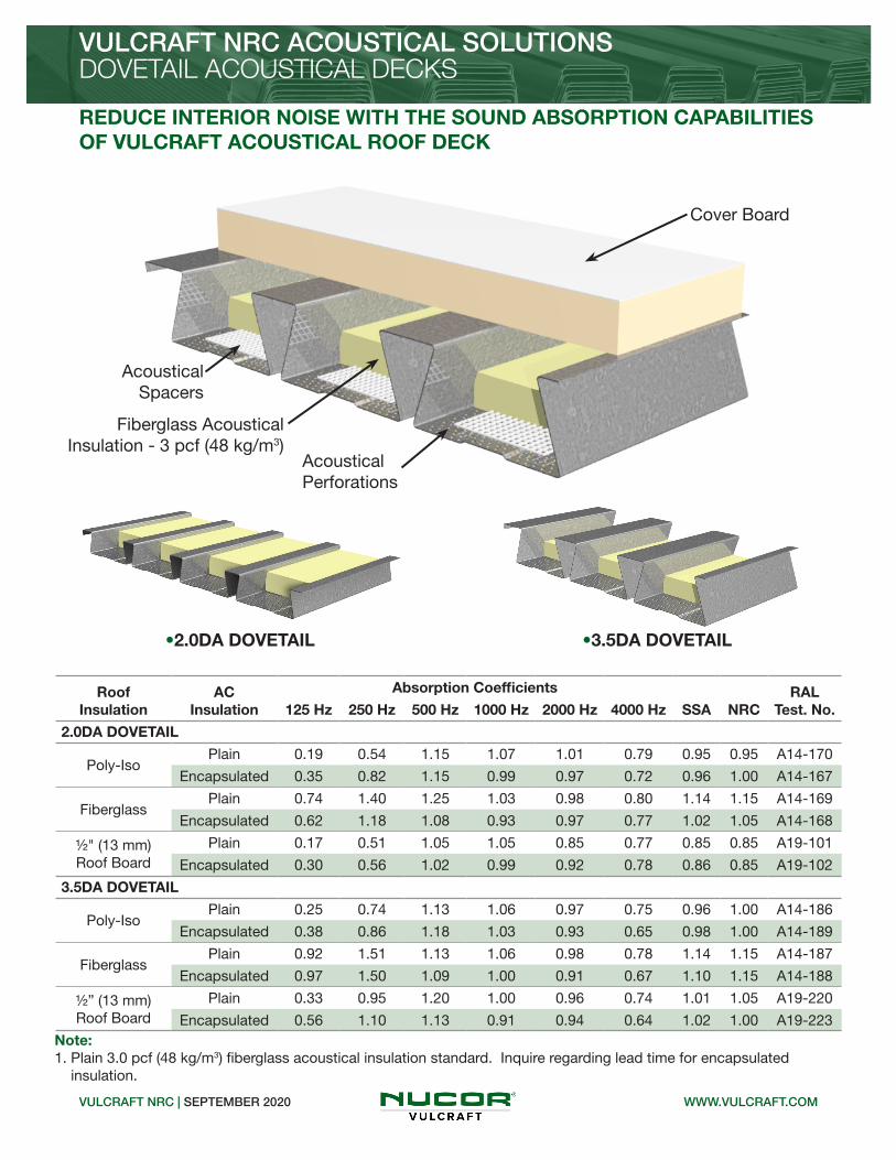
VULCRAFT NRC ACOUSTICAL SOLUTIONS
WWW.VULCRAFT.COMVULCRAFT NRC | SEPTEMBER 2020
DOVETAIL ACOUSTICAL DECKS
Cover Board
Fiberglass Acoustical Insulation - 3 pcf (48 kg/m3)
Acoustical Spacers
Acoustical Perforations
Roof Insulation
ACInsulation
Absorption Coefficients
SSA NRCRAL
Test. No.125 Hz 250 Hz 500 Hz 1000 Hz 2000 Hz 4000 Hz
2.0DA DOVETAIL
Poly-IsoPlain 0.19 0.54 1.15 1.07 1.01 0.79 0.95 0.95 A14-170
Encapsulated 0.35 0.82 1.15 0.99 0.97 0.72 0.96 1.00 A14-167
FiberglassPlain 0.74 1.40 1.25 1.03 0.98 0.80 1.14 1.15 A14-169
Encapsulated 0.62 1.18 1.08 0.93 0.97 0.77 1.02 1.05 A14-168
½" (13 mm) Roof Board
Plain 0.17 0.51 1.05 1.05 0.85 0.77 0.85 0.85 A19-101
Encapsulated 0.30 0.56 1.02 0.99 0.92 0.78 0.86 0.85 A19-102
3.5DA DOVETAIL
Poly-IsoPlain 0.25 0.74 1.13 1.06 0.97 0.75 0.96 1.00 A14-186
Encapsulated 0.38 0.86 1.18 1.03 0.93 0.65 0.98 1.00 A14-189
FiberglassPlain 0.92 1.51 1.13 1.06 0.98 0.78 1.14 1.15 A14-187
Encapsulated 0.97 1.50 1.09 1.00 0.91 0.67 1.10 1.15 A14-188
½” (13 mm) Roof Board
Plain 0.33 0.95 1.20 1.00 0.96 0.74 1.01 1.05 A19-220
Encapsulated 0.56 1.10 1.13 0.91 0.94 0.64 1.02 1.00 A19-223
•2.0DA DOVETAIL •3.5DA DOVETAIL
Note: 1. Plain 3.0 pcf (48 kg/m3) fiberglass acoustical insulation standard. Inquire regarding lead time for encapsulated insulation.
REDUCE INTERIOR NOISE WITH THE SOUND ABSORPTION CAPABILITIES OF VULCRAFT ACOUSTICAL ROOF DECK

VULCRAFT NRC ACOUSTICAL SOLUTIONS
WWW.VULCRAFT.COMVULCRAFT NRC | SEPTEMBER 2020
•1.5BA-36 / 1.5BIA-36 / 1.5PLBA-36
Roof Insulation
ACInsulation
Absorption Coefficients
SSA NRCRAL
Test. No.125 Hz 250 Hz 500 Hz 1000 Hz 2000 Hz 4000 Hz
1.5BA-36 / 1.5BIA-36 / 1.5PLBA-36
Poly-IsoPlain 0.09 0.20 0.47 0.86 0.55 0.32 0.55 0.55 A15-125
Encapsulated 0.14 0.35 0.74 0.76 0.44 0.27 0.57 0.55 A15-124
FiberglassPlain 0.68 1.16 1.17 0.96 0.52 0.31 0.95 0.95 A15-126
Encapsulated 0.75 0.83 0.78 0.68 0.42 0.28 0.67 0.70 A15-123
Cover Board
Fiberglass Acoustical Insulation (0.75 pcf)
Acoustical Perforations
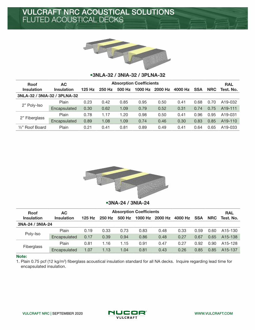
FLUTED ACOUSTICAL DECKS
Note: 1. Plain 0.75 pcf (12 kg/m3) fiberglass acoustical insulation standard for all BA decks. Inquire regarding lead time for encapsulated insulation.
VULCRAFT NRC ACOUSTICAL SOLUTIONS
WWW.VULCRAFT.COMVULCRAFT NRC | SEPTEMBER 2020
Roof Insulation
ACInsulation
Absorption Coefficients
SSA NRCRAL
Test. No.125 Hz 250 Hz 500 Hz 1000 Hz 2000 Hz 4000 Hz
3NLA-32 / 3NIA-32 / 3PLNA-32
2” Poly-IsoPlain 0.23 0.42 0.85 0.95 0.50 0.41 0.68 0.70 A19-032
Encapsulated 0.30 0.62 1.09 0.79 0.52 0.31 0.74 0.75 A19-111
2” FiberglassPlain 0.78 1.17 1.20 0.98 0.50 0.41 0.96 0.95 A19-031
Encapsulated 0.89 1.08 1.09 0.74 0.46 0.30 0.83 0.85 A19-110
½” Roof Board Plain 0.21 0.41 0.81 0.89 0.49 0.41 0.64 0.65 A19-033
•3NLA-32 / 3NIA-32 / 3PLNA-32
Roof Insulation
ACInsulation
Absorption Coefficients
SSA NRCRAL
Test. No.125 Hz 250 Hz 500 Hz 1000 Hz 2000 Hz 4000 Hz
3NA-24 / 3NIA-24
Poly-IsoPlain 0.19 0.33 0.73 0.83 0.48 0.33 0.59 0.60 A15-130
Encapsulated 0.17 0.39 0.94 0.86 0.48 0.27 0.67 0.65 A15-138
FiberglassPlain 0.81 1.16 1.15 0.91 0.47 0.27 0.92 0.90 A15-128
Encapsulated 1.07 1.13 1.04 0.81 0.43 0.26 0.85 0.85 A15-137
•3NA-24 / 3NIA-24
FLUTED ACOUSTICAL DECKS
Note: 1. Plain 0.75 pcf (12 kg/m3) fiberglass acoustical insulation standard for all NA decks. Inquire regarding lead time for encapsulated insulation.

VULCRAFT NRC ACOUSTICAL SOLUTIONS
WWW.VULCRAFT.COMVULCRAFT NRC | SEPTEMBER 2020
NOTICE: Design defects that could cause injury or death may result from relying on the information in this document without independent verification by a qualified professional. The information in this document is provided “AS IS”. Nucor Corporation and its affiliates expressly disclaim: (i) any and all representations, warranties and conditions and (ii) all liability arising out of or related to this document and the information in it.
•1.5BPA-36 / 1.5PLBPA-36 ROOF DECK •1.5VLPA-36 / 1.5PLVLPA-36 COMPOSITE DECK
•3NPA-32 / 3PLNPA-32 ROOF DECK
•3NPA-24 / 3PLNPA-24 ROOF DECK
•2VLPA-36 / 2PLVLPA-36 COMPOSITE DECK •3VLPA-36 / 3PLVLPA-36 COMPOSITE DECK
FloorAC
Insulation
Absorption Coefficients
SSA NRCRAL
Test. No.125 Hz 250 Hz 500 Hz 1000 Hz 2000 Hz 4000 Hz
2VLPA-36 / 2PLVLPA-36 COMPOSITE DECK
ConcretePlain 0.31 0.44 0.72 0.77 0.47 0.47 0.60 0.60 A15-120
Encapsulated 0.39 0.45 0.87 0.66 0.31 0.19 0.58 0.55 A15-119
3VLPA-36 / 3PLVLPA-36 COMPOSITE DECK
ConcretePlain 0.48 0.56 1.00 0.75 0.49 0.49 0.69 0.70 A15-121
Encapsulated 0.51 0.63 0.83 0.49 0.39 0.28 0.58 0.60 A15-122
CELLULAR ACOUSTICAL DECKS
Roof Insulation
ACInsulation
Absorption Coefficients
SSA NRCRAL
Test. No.125 Hz 250 Hz 500 Hz 1000 Hz 2000 Hz 4000 Hz
1.5BPA-36 / 1.5PLBPA-36 ROOF DECK OR 1.5VLPA-36 / 1.5PLVLPA-36 COMPOSITE DECK
Poly-IsoPlain 0.27 0.32 0.70 1.02 0.80 0.52 0.69 0.70 A15-114
Encapsulated 0.26 0.44 0.84 0.98 0.67 0.45 0.72 0.75 A15-115
3NPA-32 / 3PLNPA-32 ROOF DECK
Poly-IsoPlain TESTING CURRENTLY IN PROGRESS
Encapsulated TESTING CURRENTLY IN PROGRESS
3NPA-24 / 3PLNPA-24 ROOF DECK
Poly-IsoPlain 0.25 0.47 0.92 0.75 0.62 0.54 0.69 0.70 A15-141
Encapsulated 0.39 0.62 1.19 0.74 0.66 0.44 0.80 0.80 A15-231
Note: 1. Factory installed plain 3.0 pcf (48 kg/m3) fiberglass acoustical insulation standard for all cellular decks. Inquire regarding lead time for encapsulated insulation.

2.0D FORMLOK STC | SEPTEMBER 2020 WWW.DOVETAILDECK.COM
ACOUSTICAL SOLUTIONS2.0D DOVETAIL FORMLOK® DECK-SLAB
ACHIEVE QUIET SPACES WITH PREMIUM FINISHES BY USING THE SUPERIOR STC AND IIC RATINGS OF 2.0D FORMLOK DECK-SLABS
Underlayment (if Required)
Floor Covering
Exposed Deck (No Ceiling)
Floor Covering Underlayment STC IIC Intertek Test No.
Ceramic Tile 5 mm ECOsilence 51 41 H7786.06
Engineered Wood 5 mm ECOsilence 50 50 H7786.05
Fusion Hybrid Vinyl Plank 2 mm ECOsilence 46 51 H7786.02
Attain Luxury Vinyl Tile 5 mm ECOsilence 52 51 H7786.03
Forest Rx Rubber Backed Sheet Vinyl None 51 51 H7786.04
Exposed Concrete None 52 23 H7786.01
2.0D FORMLOK DECK-SLAB• 2” (51 mm) Deep Composite Deck• 51/2” (140 mm) Total Slab Depth• Normal Weight Concrete (145 pcf / 2325 kg/m3) • Exposed Deck Ceiling

Underlayment (if Required)
Floor Covering
Gypsum Board Ceilingon Furring Channels
2.0D FORMLOK STC | SEPTEMBER 2020 WWW.DOVETAILDECK.COM
ACOUSTICAL SOLUTIONS2.0D DOVETAIL FORMLOK® DECK-SLAB
Gypsum Board Ceiling on Furring Channels Directly Attached to Deck
Floor Covering Underlayment STC IIC Intertek Test No.
Ceramic Tile 5 mm ECOsilence 53 47 H7786.12
Engineered Wood 5 mm ECOsilence 50 50 H7786.11
Fusion Hybrid Vinyl Plank 2 mm ECOsilence 51 50 H7786.08
Attain Luxury Vinyl Tile 2 mm ECOsilence 52 50 H7786.09
Forest Rx Rubber Backed Sheet Vinyl None 50 50 H7786.10
Exposed Concrete None 52 32 H7786.07
2.0D FORMLOK DECK-SLAB
Note:1. Values shown are for gypsum board on furring channels directly connected to the underside of the slab. Gypsum board ceilings attached to the deck by methods providing acoustical separation will provide improved STC and IIC values.
• 2” (51 mm) Deep Composite Deck• 51/2” (140 mm) Total Slab Depth• Normal Weight Concrete (145 pcf / 2325 kg/m3)• Gypsum Board Ceiling

2.0D FORMLOK STC | SEPTEMBER 2020 WWW.DOVETAILDECK.COM
ACOUSTICAL SOLUTIONS2.0D DOVETAIL FORMLOK® DECK-SLAB
2.0D FORMLOK DECK-SLAB
Underlayment (if Required)
Floor Covering
Suspended Gypsum Board Ceiling
Suspended Gypsum Board Ceiling
Floor Covering Underlayment STC IIC Intertek Test No.
Ceramic Tile 5 mm ECOsilence 62 60 I5133.01
R13 Kraft Faced Fiberglass Insulation
Note:1. Laboratory tests determining STC and IIC for Dovetail FormLok deck with a suspended ceiling were conducted with ceramic tile and underlayment. Adding a suspended ceiling to the ceramic tile assembly improved the STC rating by 11 and the IIC rating by 19 compared to an assembly with no ceiling. Other flooring types can expect similar improvement in performance.
• 2” (51 mm) Deep Composite Deck• 51/2” (140 mm) Total Slab Depth• Normal Weight Concrete (145 pcf / 2325 kg/m3) • Suspended Gypsum Board Ceiling

Notes:
2.0D FORMLOK STC | SEPTEMBER 2020 WWW.DOVETAILDECK.COM
2.0D DOVETAIL FORMLOK® DECK-SLAB
1. The acoustical test reports with complete assembly details are available from www.dovetaildeck.com.
2. The testing was performed in accordance with the following standards: • ASTM E90-09 (2016), Standard Test Method for Laboratory Measurement of Airborne Sound Transmission Loss of Building Partitions • ASTM E492-09(2016)e1, Standard Test Method for Laboratory Measurement of Impact Sound Transmission Through Floor-Ceiling Assemblies Using the Tapping Machine
NOTICE: Design defects that could cause injury or death may result from relying on the information in this document without independent verification by a qualified professional. The information in this document is provided “AS IS”. Nucor Corporation and its affiliates expressly disclaim: (i) any and all representations, warranties and conditions and (ii) all liability arising out of or related to this document and the information in it.

3.5D FORMLOK STC | SEPTEMBER 2020 WWW.DOVETAILDECK.COM
ACOUSTICAL SOLUTIONS3.5D DOVETAIL FORMLOK® DECK-SLAB
ACHIEVE QUIET SPACES WITH PREMIUM FINISHES BY USING THE SUPERIOR STC AND IIC RATINGS OF 3.5D FORMLOK DECK-SLABS
Underlayment (if Required)
Floor Covering
Exposed Deck (No Ceiling)
Floor Covering Underlayment STC IIC Intertek Test No.
Ceramic Tile 5 mm ECOsilence 50 42 H7787.06
Engineered Wood 5 mm ECOsilence 45 46 H7787.05
Fusion Hybrid Vinyl Plank 2 mm ECOsilence 47 47 H7787.02
Attain Luxury Vinyl Tile 5 mm ECOsilence 50 50 H7787.03
Forest Rx Rubber Backed Sheet Vinyl None 49 49 H7787.04
Exposed Concrete None 50 24 H7787.01
3.5D FORMLOK DECK-SLAB• 31/2” (89 mm) Deep Composite Deck• 6” (152 mm) Total Slab Depth• Normal Weight Concrete (145 pcf / 2325 kg/m3) • Exposed Deck Ceiling

Underlayment (if Required)
Floor Covering
Gypsum Board Ceilingon Furring Channels
3.5D FORMLOK STC | SEPTEMBER 2020 WWW.DOVETAILDECK.COM
ACOUSTICAL SOLUTIONS3.5D DOVETAIL FORMLOK® DECK-SLAB
Gypsum Board Ceiling on Furring Channels Directly Attached to Deck
Floor Covering Underlayment STC IIC Intertek Test No.
Ceramic Tile 5 mm ECOsilence 56 49 H7787.12
Engineered Wood 5 mm ECOsilence 55 52 H7787.11
Fusion Hybrid Vinyl Plank 2 mm ECOsilence 55 53 H7787.08
Attain Luxury Vinyl Tile 5 mm ECOsilence 56 52 H7787.09
Forest Rx Rubber Backed Sheet Vinyl None 55 52 H7787.10
Exposed Concrete None 55 32 H7787.07
3.5D FORMLOK DECK-SLAB
Note:1. Values shown are for gypsum board on furring channels directly connected to the underside of the slab. Gypsum board ceilings attached to the deck by methods providing acoustical separation will provide improved STC and IIC values.
• 31/2” (89 mm) Deep Composite Deck• 6” (152 mm) Total Slab Depth• Normal Weight Concrete (145 pcf / 2325 kg/m3)• Gypsum Board Ceiling

3.5D FORMLOK STC | SEPTEMBER 2020 WWW.DOVETAILDECK.COM
ACOUSTICAL SOLUTIONS3.5D DOVETAIL FORMLOK® DECK-SLAB
3.5D FORMLOK DECK-SLAB
Underlayment (if Required)
Floor Covering
Suspended Gypsum Board Ceiling
Suspended Gypsum Board Ceiling
Floor Covering Underlayment STC IIC Intertek Test No.
Ceramic Tile 5 mm ECOsilence 62 62 I5133.02
R13 Kraft Faced Fiberglass Insulation
Note:1. Laboratory tests determining STC and IIC for Dovetail FormLok deck with a suspended ceiling were conducted with ceramic tile and underlayment. Adding a suspended ceiling to the ceramic tile assembly improved the STC rating by 12 and the IIC rating by 20 compared to an assembly with no ceiling. Other flooring types can expect similar improvement in performance.
• 31/2” (89 mm) Deep Composite Deck• 6” (152 mm) Total Slab Depth• Normal Weight Concrete (145 pcf / 2325 kg/m3)• Suspended Gypsum Board Ceiling

Notes:
3.5D FORMLOK STC | SEPTEMBER 2020 WWW.DOVETAILDECK.COM
3.5D DOVETAIL FORMLOK® DECK-SLAB
1. The acoustical test reports with complete assembly details are available from www.dovetaildeck.com.
2. The testing was performed in accordance with the following standards: • ASTM E90-09 (2016), Standard Test Method for Laboratory Measurement of Airborne Sound Transmission Loss of Building Partitions • ASTM E492-09(2016)e1, Standard Test Method for Laboratory Measurement of Impact Sound Transmission Through Floor-Ceiling Assemblies Using the Tapping Machine
NOTICE: Design defects that could cause injury or death may result from relying on the information in this document without independent verification by a qualified professional. The information in this document is provided “AS IS”. Nucor Corporation and its affiliates expressly disclaim: (i) any and all representations, warranties and conditions and (ii) all liability arising out of or related to this document and the information in it.

VULCRAFT UL ROOF | SEPTEMBER 2020
VULCRAFT® ROOF DECK
• Vulcraft steel decks may be used in assemblies which are required to meet hourly fire ratings. Approved hourly fire rated assemblies are a combination of specific proprietary materials as listed in UL fire resistance ratings.
USE UL RECOGNIZED VULCRAFT ROOF DECKS FOR YOUR FIRE RATED ASSEMBLIES
UL FIRE RATED ASSEMBLIES
Insulation
Fire Protection
Vulcraft Steel Deck
Deck Support
Insulation
Fire Protection
Vulcraft Steel Deck
Refer to the table on the following pages for a listing of UL fire-rated assemblies utilizing Vulcraft steel deck profiles. Refer to the particular UL assembly being considered for full details of construction, including specific information about fill or fireproofing thicknesses and span limitations.
WWW.VULCRAFT.COM
REPRESENTATIVE FIRE RATED ASSEMBLY

VULCRAFT UL ROOF | SEPTEMBER 2020
VULCRAFT® ROOF DECKUL FIRE RATED ASSEMBLIES
WWW.VULCRAFT.COM
UL Fire Resistance RatingsRestrained Assembly Ratings
(hr.)Type of
ProtectionType of
InsulationUL Design
No.
Deck TypeUnrestrained Beam Rating
(hr.)B32” 3N
24” 3N 2.0D 3.5D
1
Exposed GridRigid Insulation
P211+ ü
P214+ ü 1
P225+ ü ü ü 1,11/2
P227+ ü
P230+ ü 1,11/2
P235+ ü 1
Insulating Fill P214+ ü 1
Gypsum Board Rigid InsulationP510+ ü ü ü
P514 ü
Cementitious Rigid Insulation
P701* ü ü ü 1,11/2,2
P711* ü ü ü 1,11/2,2
P717* ü ü ü 1,11/2,2
Sprayed Fiber Rigid Insulation
P801* ü ü ü 1,11/2,2,3
P815* ü ü ü 1,11/2,2,3
P819* ü ü ü 1,11/2,2
Unprotected Deck
Insulating Fill
P902 ü ü ü 1,11/2,2
P907 ü ü ü 1,11/2,2
P908 ü ü ü ü ü 1,11/2,2
P919 ü ü ü 1,11/2
P920 ü ü ü 1,11/2,2
P921 ü ü ü ü ü 1,11/2,2
P922 ü ü ü 1,11/2,2
P923 ü ü ü 1,11/2,2
P937 ü ü
P938 ü ü 1,11/2,2
11/2
Exposed Grid Rigid Insulation
P225+ ü ü ü 1,11/2
P227+ ü 1,11/2
P230+ ü 1,11/2
Metal Lath Rigid Insulation P404+ ü
Gypsum Board Rigid Insulation P510+ ü ü ü
Cementitious Rigid Insulation
P701* ü ü ü 1,11/2,2
P711* ü ü ü 1,11/2,2
P717* ü ü ü 1,11/2,2

VULCRAFT UL ROOF | SEPTEMBER 2020
VULCRAFT® ROOF DECKUL FIRE RATED ASSEMBLIES
WWW.VULCRAFT.COM
UL Fire Resistance Ratings (continued)Restrained Assembly Ratings
(hr.)Type of
ProtectionType of
InsulationUL Design
No.
Deck TypeUnrestrained Beam Rating
(hr.)B32” 3N
24” 3N 2.0D 3.5D
11/2
Sprayed Fiber Rigid Insulation
P801* ü ü ü 1,11/2,2
P815* ü ü ü 1,11/2,2,3
P819* ü ü ü 1,11/2,2,3
Unprotected Deck
Insulating Fill
P902 ü ü ü 1,11/2,2
P907 ü ü ü 1,11/2,2
P908 ü ü ü ü ü 1,11/2,2
P919 ü ü ü 1,11/2
P920 ü ü ü 1,11/2,2
P921 ü ü ü ü ü 1,11/2,2
P922 ü ü ü 1,11/2,2
P923 ü ü ü 1,11/2,2
P937 ü ü
P938 ü ü 1,11/2,2
2
Exposed Grid Rigid Insulation P237+ ü 2
Metal Lath Rigid Insulation P404+ ü
Gypsum Board Rigid Insulation P514+ ü
Cementitious Rigid Insulation
P701* ü ü ü 1,11/2,2
P711* ü ü ü 1,11/2,2
P717* ü ü ü 1,11/2,2
Sprayed Fiber Rigid Insulation
P801* ü ü ü 1,11/2,2
P815* ü ü ü 1,11/2,2
P819* ü ü ü 1,11/2,2,3
Unprotected Deck
Insulating Fill
P902 ü ü ü 1,11/2,2
P907 ü ü ü 1,11/2,2
P908 ü ü ü ü ü 1,11/2,2
P920 ü ü ü 1,11/2,2
P921 ü ü ü ü ü 1,11/2,2
P922 ü ü ü 1,11/2,2
P923 ü ü ü 1,11/2,2
P937 ü ü
P938 ü ü 1,11/2,2

VULCRAFT® ROOF DECKUL FIRE RATED ASSEMBLIES
VULCRAFT UL ROOF | SEPTEMBER 2020 WWW.VULCRAFT.COM
NOTICE: Design defects that could cause injury or death may result from relying on the information in this document without independent verification by a qualified professional. The information in this document is provided “AS IS”. Nucor Corporation and its affiliates expressly disclaim: (i) any and all representations, warranties and conditions and (ii) all liability arising out of or related to this document and the information in it.
Notes: 1. Refer to the UL “Fire Resistance Directory” for the necessary construction details.2. Deck finish shall be galvanized unless noted otherwise. + Deck finish is not critical for fire resistance when used in P2--, P4--, & P5-- Series designs. Deck finish shall be galvanized or painted. * Denotes deck finish is critical for fire resistance. Deck finish shall be galvanized or painted. This gray paint is a special type of paint and is compatible with the spray-applied fire protection and is U.L. approved for use in the denoted P7-- & P8-- Series designs.3. B = 1.5B, 1.5BI, and 1.5PLB 32” 3N = 32” Wide 3NL, 3NI, and 3PLN 24” 3N = 24” Wide 3N and 3NI

VULCRAFT UL FLOOR - 1 | SEPTEMBER 2020
VULCRAFT® COMPOSITE & NON-COMPOSITE DECK
• Vulcraft composite and non-composite slabs may be used to meet hourly fire ratings. The type and thickness of concrete specified will generally determine whether fireproof-ing will be required on the underside of the composite or non-composite deck.
USE UL RECOGNIZED COMPOSITE AND NON-COMPOSITE DECKS FOR YOUR FIRE RATED ASSEMBLIES WITH STRUCTURAL CONCRETE FILL
UL FIRE RATED ASSEMBLIES
Concrete Reinforcement-If Required
Vulcraft Steel Deck
Deck Support
Deck Fire Protection Vulcraft Steel Deck
The table on the following pages lists the UL fire rated assemblies that include Vulcraft composite and non-composite decks profiles. This summary table is provided to assist in identification of assemblies to meet specific project requirements. Refer to the particular UL assembly for full details of construction including, specific information about concrete slab, framing, type of fire protection, deck types and span limitations.
Concrete Topping
Deck Support Fire Protection
Concrete ToppingThickness
Deck Connection to Support(In accordance with assembly)
REPRESENTATIVE FIRE RATED ASSEMBLY
WWW.VULCRAFT.COM

VULCRAFT UL FLOOR - 2 | SEPTEMBER 2020
VULCRAFT® COMPOSITE DECKUL FIRE RATED ASSEMBLIES
WWW.VULCRAFT.COM
UL Fire Resistance Ratings Restrained Assembly Ratings
(hr.)Type of
ProtectionConcrete
Thickness & TypeUL Design
No.
Deck TypeUnrestrained Beam Rating
(hr.)1.5VL 2VL 3VL 1.5VLP 2VLP 3VLP
3/4 Unprotected Deck
21/2” LWD914 # ü ü ü ü ü ü 1
D916 # ü ü ü ü ü ü 1,11/2,2,3
1
Exposed Grid 21/2” NW D216 + ü ü ü ü ü 2,3
Cementitious
2” NW & LW D743 * ü ü ü ü 1,11/2,2,3
21/2” NW & LW
D703 * ü ü ü ü ü ü 11/2
D712 * ü ü ü 2
D722 * ü ü ü ü 1,11/2,2
D739 * ü ü ü ü ü ü 1,11/2,2,3,4
D759 * ü ü ü ü ü ü 1,11/2,2,3
Sprayed Fiber
2” NW & LW D859 * ü ü ü ü 1,1.5,2,3
21/2” NW & LW
D832 * ü ü ü ü ü ü 1,11/2,2,3
D847 * ü ü ü ü 1,11/2,3
D858 * ü ü ü ü 1,11/2,2,3,4
D871 * ü ü ü ü 1,11/2,2,3
Unprotected Deck
21/2” LW
D902 # ü ü ü ü ü ü 1,11/2,2,3
D914 # ü ü ü ü ü ü 1
D916 # ü ü ü ü ü ü 1,11/2,2,3
D919 # ü ü ü ü ü ü 1,11/2
31/2” NW
D902 # ü ü ü ü ü ü 1,11/2,2,3
D916 # ü ü ü ü ü ü 1,11/2,2,3
D919 # ü ü ü ü ü ü 1,11/2
11/2
Gypsum Board 21/2” NW D502 * ü ü ü ü ü 11/2,2
Cementitious
2” NW & LW D743 * ü ü ü ü 1,11/2,2,3
21/2” NW & LW
D703 * ü ü ü ü ü ü 11/2
D712 * ü ü ü 2
D722 * ü ü ü ü 1,11/2,2
D739 * ü ü ü ü ü ü 1,11/2,2,3,4
D759* ü ü ü ü ü ü 1,11/2,2,3
ü+ 1.5VLI Only (continued on next page)

VULCRAFT UL FLOOR - 3 | SEPTEMBER 2020WWW.VULCRAFT.COM
UL Fire Resistance Ratings (continued)Restrained Assembly Ratings
(hr.)Type of
ProtectionConcrete
Thickness & TypeUL Design
No.
Deck TypeUnrestrained Beam Rating
(hr.)1.5VL 2VL 3VL 1.5VLP 2VLP 3VLP
11/2
Sprayed Fiber
2” NW & LW D859 * ü ü ü ü 1,11/2,2,3
21/2” NW & LW
D832 * ü ü ü ü ü ü 1,11/2,2,3
D847 * ü ü ü ü 1,11/2,3
D858 * ü ü ü ü 1,11/2,2,3,4
D871 * ü ü ü ü 1,11/2,2,3
Unprotected Deck
3” LW
D902 # ü ü ü ü ü ü 1,11/2,2,3
D916 # ü ü ü ü ü ü 1,11/2,2,3
D919 # ü ü ü ü ü ü 1,11/2
4” NW
D902 # ü ü ü ü ü ü 1,11/2,2,3
D916 # ü ü ü ü ü ü 1,11/2,2,3
D919 # ü ü ü ü ü ü 1,11/2
2
Exposed Grid 21/2” NW D216 + ü ü ü ü ü 2,3
Gypsum Board 21/2” NW D502 + ü ü ü ü ü 11/2,2
Cementitious
2” NW & LW D743 * ü ü ü ü 1,11/2,2,3
21/2” LWD746 * ü 1,11/2,2,3
D752 * ü ü ü ü ü ü 1,11/2,2,
21/2” NW & LW
D703 * ü ü ü ü ü ü 11/2
D712 * ü ü ü 2
D716 * ü ü ü ü ü 11/2,2
D722 * ü ü ü ü 1,11/2,2
D739 * ü ü ü ü ü 1,11/2,2,3,4
D745 * ü ü 1,11/2,2
D750 * ü ü ü 11/2,2
D755* ü ü ü ü ü ü 1,11/2,2,3
D759* ü ü ü ü ü ü 1,11/2,2,3
D760 * ü+ ü ü 1,11/2,2,3,4
21/2” NWD730 * ü ü ü ü
D742 * ü ü ü 1,11/2
VULCRAFT® COMPOSITE DECKUL FIRE RATED ASSEMBLIES
ü+ 1.5VLI Only (continued on next page)

VULCRAFT® COMPOSITE DECKUL FIRE RATED ASSEMBLIES
VULCRAFT UL FLOOR - 4 | SEPTEMBER 2020 WWW.VULCRAFT.COM
UL Fire Resistance Ratings (continued)Restrained Assembly Ratings
(hr.)Type of
ProtectionConcrete
Thickness & TypeUL Design
No.
Deck TypeUnrestrained Beam Rating
(hr.)1.5VL 2VL 3VL 1.5VLP 2VLP 3VLP
2
Sprayed Fiber
2” NW & LW D859 * ü ü ü ü 1,11/2,2,3
21/2” NW & LW
D822 * ü ü ü ü 1
D825 * ü ü ü ü ü 1,11/2,2
D831 * ü ü ü ü 1,11/2,2
D832 * ü ü ü ü ü ü 1,11/2,2,3
D833 * ü ü ü ü ü 11/2
D847 * ü ü ü ü 1,11/2,3
D858 * ü ü ü ü 1,11/2,2,3,4
D861 * ü ü 1,11/2
D871 * ü ü ü ü 1,11/2,2,3
21/2” LW D862 * ü ü 1
31/4” LW D860 * ü ü 1,11/2,2
UnprotectedDeck
31/4” LW
D826 # ü ü ü ü ü ü 1,11/2,2
D840 # ü ü ü ü ü ü 1,11/2
D902 # ü ü ü ü ü ü 1,11/2,2,3
D907 # ü ü ü ü ü ü 1,2
D913 # ü ü ü ü ü ü 1
D916 # ü ü ü ü ü ü 1,11/2,2,3
D919 # ü ü ü ü ü ü 1,11/2
D920 # ü ü ü ü 11/2
41/2” NW
D902 # ü ü ü ü ü ü 1,11/2,2,3
D916 # ü ü ü ü ü ü 1,11/2,2,3
D919 # ü ü ü ü ü ü 1,11/2
ü+ 1.5VLI Only (continued on next page)

VULCRAFT UL FLOOR - 5 | SEPTEMBER 2020WWW.VULCRAFT.COM
UL Fire Resistance Ratings (continued)Restrained Assembly Ratings
(hr.)Type of
ProtectionConcrete
Thickness & TypeUL Design
No.
Deck TypeUnrestrained Beam Rating
(hr.)1.5VL 2VL 3VL 1.5VLP 2VLP 3VLP
3
Exposed Grid 31/4” NW D216 + ü ü ü ü ü 2,3
Cementitious
2” NW & LW D743 * ü ü ü ü 1,11/2,2,3
21/2” LW D746 * ü 1,11/2,2,3
21/2” NW & LW
D703 * ü ü ü ü ü ü 11/2
D708 * ü+ ü ü ü ü ü 11/2,3
D739 * ü ü ü ü ü ü 1,11/2,2,3,4
D755 ü ü ü ü ü ü 1,11/2,2,3
D759 ü ü ü ü ü ü 1,11/2,2,3
D760 * ü+ ü ü 1,11/2,2,3,4
31/4” LW D754 * ü ü ü 11/2,2
31/4” NW D742 * ü ü ü 1,11/2
Sprayed Fiber
2” NW & LW D859 * ü ü ü ü 1,11/2,2,3
21/2” NW & LW
D816 * ü ü ü ü ü 11/2,2
D831 * ü ü ü ü 1,11/2,2
D832 * ü ü ü ü ü ü 1,11/2,2,3
D833 * ü ü ü ü ü 11/2
D858* ü ü ü ü 1,11/2,2,3,4
D871 * ü ü ü ü 1,11/2,2,3
31/4” LW D860 * ü ü 1,11/2,2
Unprotected Deck
4 3/16” LW
D902 # ü ü ü ü ü ü 1,11/2,2,3
D916 # ü ü ü ü ü ü 1,11/2,2,3
D919 # ü ü ü ü ü ü 1,11/2
51/4” NW
D902 # ü ü ü ü ü ü 1,11/2,2,3
D916 # ü ü ü ü ü ü 1,11/2,2,3
D919 # ü ü ü ü ü ü 1,11/2
4Cementitious
21/2” NW & LWD760 * ü+ ü ü 1,11/2,2,3,4
D739 * ü ü ü ü ü ü 1,11/2,2,3,4
31/4” LW D754 * ü ü ü 11/2,2
Sprayed Fiber21/2” NW & LW D858 * ü ü ü ü 1,11/2,2,3,4
31/4” LW D860 * ü ü 1,11/2,2
VULCRAFT® COMPOSITE DECKUL FIRE RATED ASSEMBLIES
ü+ 1.5VLI Only (continued on next page)
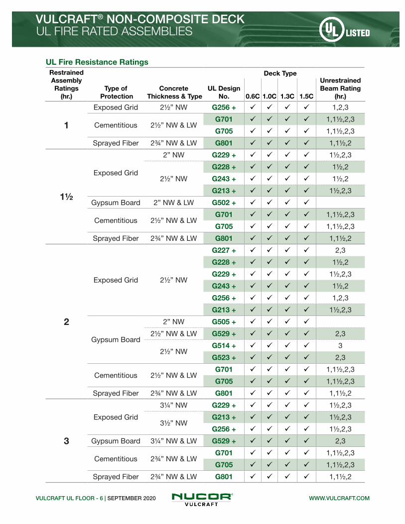
UL Fire Resistance RatingsRestrained Assembly Ratings
(hr.)Type of
ProtectionConcrete
Thickness & TypeUL Design
No.
Deck TypeUnrestrained Beam Rating
(hr.)0.6C 1.0C 1.3C 1.5C
1
Exposed Grid 21/2” NW G256 + ü ü ü ü 1,2,3
Cementitious 21/2” NW & LWG701 ü ü ü ü 1,11/2,2,3
G705 ü ü ü ü 1,11/2,2,3
Sprayed Fiber 23/4” NW & LW G801 ü ü ü ü 1,11/2,2
11/2
Exposed Grid
2” NW G229 + ü ü ü ü 11/2,2,3
21/2” NW
G228 + ü ü ü ü 11/2,2
G243 + ü ü ü ü 11/2,2
G213 + ü ü ü ü 11/2,2,3
Gypsum Board 2” NW & LW G502 + ü ü ü ü
Cementitious 21/2” NW & LWG701 ü ü ü ü 1,11/2,2,3
G705 ü ü ü ü 1,11/2,2,3
Sprayed Fiber 23/4” NW & LW G801 ü ü ü ü 1,11/2,2
2
Exposed Grid 21/2” NW
G227 + ü ü ü ü 2,3
G228 + ü ü ü ü 11/2,2
G229 + ü ü ü ü 11/2,2,3
G243 + ü ü ü ü 11/2,2
G256 + ü ü ü ü 1,2,3
G213 + ü ü ü ü 11/2,2,3
Gypsum Board
2” NW G505 + ü ü ü ü
21/2” NW & LW G529 + ü ü ü ü 2,3
21/2” NWG514 + ü ü ü ü 3
G523 + ü ü ü ü 2,3
Cementitious 21/2” NW & LWG701 ü ü ü ü 1,11/2,2,3
G705 ü ü ü ü 1,11/2,2,3
Sprayed Fiber 23/4” NW & LW G801 ü ü ü ü 1,11/2,2
3
Exposed Grid
31/4” NW G229 + ü ü ü ü 11/2,2,3
31/2” NWG213 + ü ü ü ü 11/2,2,3
G256 + ü ü ü ü 11/2,2,3
Gypsum Board 31/4” NW & LW G529 + ü ü ü ü 2,3
Cementitious 23/4” NW & LWG701 ü ü ü ü 1,11/2,2,3
G705 ü ü ü ü 1,11/2,2,3
Sprayed Fiber 23/4” NW & LW G801 ü ü ü ü 1,11/2,2
VULCRAFT UL FLOOR - 6 | SEPTEMBER 2020 WWW.VULCRAFT.COM
VULCRAFT® NON-COMPOSITE DECKUL FIRE RATED ASSEMBLIES

VULCRAFT UL FLOOR - 7 | SEPTEMBER 2020WWW.VULCRAFT.COM
VULCRAFT® DOVETAIL FORMLOK® DECKUL FIRE RATED ASSEMBLIES
UL Fire Resistance RatingsRestrained Assembly Ratings
(hr.)Type of
ProtectionConcrete
Thickness & TypeUL Design
No.
Deck TypeUnrestrained Beam Rating
(hr.)2D 3.5D
110 UnprotectedDeck
2" LW &23/4" NW
D904 ü 3/4
D961 ü 3/4
D917 ü
D928 ü 3/4
11/2 UnprotectedDeck
2" LW & 2" NW
D947 ü
D964 ü
D984 ü
2 UnprotectedDeck
21/2" LW, 3" SLW &31/4" NW
D904 ü 1
D961 ü 1
D917 ü 3/4
D928 ü 1
2" LW & 21/4" NW
D947 ü 3/4
D964 ü 3/4
D984 ü 3/4
3 UnprotectedDeck
31/4" LW, 4" SLW &43/4" NW
D904 ü 1
D961 ü 1
D917 ü 3/4
D928 ü 1
21/4" LW & 33/4" NW
D947 ü 11/2
D964 ü 11/2
D984 ü 11/2

VULCRAFT UL FLOOR - 8 | SEPTEMBER 2020 WWW.VULCRAFT.COM
VULCRAFT® COMPOSITE & NON-COMPOSITE DECKUL FIRE RATED ASSEMBLIES
NOTICE: Design defects that could cause injury or death may result from relying on the information in this document without independent verification by a qualified professional. The information in this document is provided “AS IS”. Nucor Corporation and its affiliates expressly disclaim: (i) any and all representations, warranties and conditions and (ii) all liability arising out of or related to this document and the information in it.
Notes: 1. Refer to the UL “Fire Resistance Directory” for the necessary construction details.2. 1.5VL = 1.5VL, 1.5VLI, and 1.5PLVLI 2VL = 2VLI, 2VLJ, and 2PLVLI 3VL = 3VLI, 3VLJ, and 3PLVLI 1.5VLP = 1.5VLP and 1.5PLVLP 2VLP = 2VLP, and 2PLVLP 3VLP = 3VLP, and 3PLVLP3. Concrete thickness is thickness of slab above deck, in.4. 1.5VLR may be used in designs D832, D902, and D916.5. All Dovetail FormLok composite deck assemblies are subject to an upper live load limit of 130 psf.6. Fluted deck finish shall be galvanized unless noted otherwise. + Denotes fluted deck finish is not critical when used in D2-- & D5-- Series designs. Deck finish shall be galvanized or phosphatized/painted. * Fluted deck finish is critical for fire resistance. Fluted deck finish shall be galvanized or phosphatized/ painted. This gray paint is a special type of paint and is compatible with the spray-applied fire protection and is U.L. approved for use in the denoted D7-- & D8-- Series designs. # Denotes fluted deck finish is not critical for fire resistance. Fluted deck finish shall be galvanized or phosphatized/painted.7. Vulcraft cellular deck used in the listed assemblies shall be galvanized.8. Vulcraft cellular deck units are approved by UL for use as electrical raceways under UL Standard 209.9. Dramix® fibers may be used in UL or ULC fire rated assemblies in lieu of WWR. See UL file R19307 for additional information.10. Restrained Assembly Rating is 11/2 hr with listed NW concrete thickness.
Concrete Thickness(in.) (mm)2 51
21/2 6423/4 7031/4 8331/2 894 102
4³⁄₁₆ 106
41/2 11443/4 12151/4 133

WWW.DOVETAILDECK.COMSAMMY X-PRESS | AUGUST 2019
DOVETAIL ROOF DECKSAMMY X-PRESS SWIVEL HEAD® HANGING SOLUTIONS
ITW BUILDEX SAMMY X-PRESS SWIVEL HEAD CONNECTION STRENGTH1-5
DeckGage
Part Number & Model
Connection Strength (lbs)
ASDPn / Ω
LRFDɸPn
22
8294922-SXP 208272957-SXP 2.0
200 320
20 240 390
19 280 460
18 320 520
16 8295922-SXP 358271957-SXP 3.5
400 660
14 500 820
HANG AND BRACE YOUR MECHANICAL SYSTEMS FROM DOVETAIL OR ACOUSTIC DOVETAIL ROOF DECK
0° ≤ ϴ ≤ 90°
0° ≤ α ≤ 360°
ϴ
α
Pn
Pn
⅜” or 1/2” Rod
Notes:1. Sammy X-Press Swivel Head fasteners may be installed in any flat portion of the bottom flange of 2.0D, 2.0DA, 3.5D or 3.5DA Dovetail Roof Decks. 2. Concentrated load shall not exceed the strength of the steel roof deck. 3. The allowable strength, Pn/Ω, shall be equal to or greater than the governing load combination for Allowable Stress Design (ASD) as stipulated in the IBC or ASCE/SEI 7.4. The factored strength, ɸPn, shall be equal to or greater than the governing load combination for Load and Resistance Factor Design as stipulated in the IBC or ASCE/SEI 7.5. Safety and resistance factors included in the table are Ω = 2.5 (ASD) and ɸ = 0.65 (LRFD) respectively.
NOTICE: Design defects that could cause injury or death may result from relying on the information in this document without independent verification by a qualified professional. The information in this document is provided “AS IS”. Nucor Corporation and its affiliates expressly disclaim: (i) any and all representations, warranties and conditions and (ii) all liability arising out of or related to this document and the information in it.

WWW.DOVETAILDECK.COMWEDGE-NUT | AUGUST 2019
HANG YOUR MECHANICAL SYSTEMS FROM DOVETAIL FORMLOK COMPOSITE DECK-SLABS
1. The concentrated hanging load shall not exceed the bending strength and vertical shear strength of the Dovetail FormLok Composite Deck-Slab.2. Hanging load shall not exceed the strength of the threaded rod or bolt provided by others.3. The hanging load shall be applied not more than 5 degrees from normal to the plane of the deck.4. The allowable strength, Pn /Ω, shall be equal to or greater than the governing load combination for Allowable Stress Design in the IBC or ASCE/SEI 7.5. The factored strength, øPn, shall be equal to or greater than the governing load combination for Load and Resistance Factor Design in the IBC or ASCE/SEI 7.6. Safety and resistance factors included in the table are Ω = 2.75 (ASD) and ø = 0.60 (LRFD) respectively.7. NPS = Nominal Pipe Size
WEDGE-NUT HANGING LOAD1-6
Profile Part Number
Connection Strength (lbs)
Nominal Pn
ASD Pn/ Ω
LRFD øPn
2.0D FormLok
2.0D-WN-3/8NC2.0D-WN-1/2NC
3828 1392 2297
3.5D FormLok
3.5D-WN-3/8NC3.5D-WN-1/2NC
5490 1996 3294
Notes:
DOVETAIL FORMLOK® DECK-SLABWEDGE-NUT HANGING SOLUTIONS
145 pcf NWC or ≥110 pcf LWC f’c = 2500 psi (min.)
DOVETAIL FORMLOK WEDGE-NUTS• IAPMO UES ER-423• UL Listed
MAXIMUM SPRINKLER PIPE DIAMETER
Profile Part NumberNPS7
Diameter (in.) UL No.
2.0D FormLok2.0D-WN-3/8NC2.0D-WN-1/2NC
4EX27777
6
3.5D FormLok3.5D-WN-3/8NC3.5D-WN-1/2NC
4EX27777
8

WWW.DOVETAILDECK.COMWEDGE-NUT | AUGUST 2019
DOVETAIL FORMLOK® DECK-SLABWEDGE-NUT HANGING SOLUTIONS
NOTICE: Design defects that could cause injury or death may result from relying on the information in this document without independent verification by a qualified professional. The information in this document is provided “AS IS”. Nucor Corporation and its affiliates expressly disclaim: (i) any and all representations, warranties and conditions and (ii) all liability arising out of or related to this document and the information in it.
Deck ribs shall be free of foreign material to ensure the wedge-nut bears directly on the steel deck.Insert wedge-nut and rotate to seat the surface against the webs of the steel deck as shown in Figure 1.Position wedge-nut in the center of the rib with the threaded rod or bolt perpendicular to the bottom surface of the steel deck as show in Figure 1.Tighten the ⅜” threaded rod or bolt 1 to 11/2 turns beyond snug tight.Tighten the 1/2” threaded rod or bolt 1/2 to 1 turn beyond snug tight.
DOVETAIL FORMLOK WEDGE-NUT INSTALLATION
Figure 1
1.
2.
3.
4.
5.


WWW.DOVETAILDECK.COM2.0D ROOF ASD | SEPTEMBER 2020
2.0D DOVETAIL ROOF DECK
2.0D DOVETAIL ROOF DECK• Enhanced 2-Coat Polyester Paint• White Factory Primer Paint• Galvanized Finish• FM Listed
Standard Features Optional Features• ASTM A653 SS GR 40 Min. with G90• Standard lengths – 6’-0” to 42’-0”• Tables conform to ANSI/SDI RD-2017• IAPMO UES ER-423, FM and UL Listed
• Inquire regarding cost and lead times for: -19 gage -Short cuts < 6’-0” -Alternative metallic and painted finishes• Acoustical Version
GRADE 40 STEEL AS
D
Allowable Reactions at Supports Based on Web Crippling, Rn/Ω (lb/ft)Bearing Length of Webs
One-Flange Loading Two-Flange Loading
DeckGage
End Bearing Interior Bearing End Bearing Interior Bearing
1½" 2" 3" 4" 3" 5" 1½" 2" 3" 4" 3" 5"
22 653 717 826 917 1281 1516 702 757 848 925 1567 1877
20 931 1020 1170 1296 1823 2146 1058 1136 1266 1376 2258 2690
18 1556 1697 1933 2132 3036 3544 1893 2023 2239 2422 3813 4507
16 2378 2582 2926 3215 4629 5360 3043 3237 3563 3837 5866 6880
Section Properties
Deck Gage
Deck Weight
Base Metal Thickness
Yield Strength
Effective Moment of Inertia
at Service LoadId = (2Ie+Ig)/3
Effective Section Modulus
at Fy = 40 ksiAllowable Moment
Vertical Web
Shear
wdd t Fy Id+ Id- Se+ Se- Mn+/Ω Mn-/Ω Vn/Ω
(psf) (in.) (ksi) (in4/ft) (in4/ft) (in3/ft) (in3/ft) (lb-ft/ft) (lb-ft/ft) (lb/ft)
22 2.1 0.0295 40 0.387 0.359 0.272 0.272 543 543 2896
20 2.6 0.0358 40 0.472 0.447 0.343 0.334 684 666 3498
18 3.4 0.0474 40 0.626 0.612 0.463 0.450 924 898 4584
16 4.3 0.0598 40 0.792 0.791 0.587 0.576 1172 1150 5723
Nominal Dimensions

WWW.DOVETAILDECK.COM
2.0D DOVETAIL ROOF DECK
2.0D ROOF ASD | SEPTEMBER 2020
NOTICE: Design defects that could cause injury or death may result from relying on the information in this document without independent verification by a qualified professional. The information in this document is provided “AS IS”. Nucor Corporation and its affiliates expressly disclaim: (i) any and all representations, warranties and conditions and (ii) all liability arising out of or related to this document and the information in it.
AS
D
GRADE 40 STEEL
Inward Uniform Allowable Loads, ASD (psf)
Deck Gage Spans Criteria
Span (ft-in.)
4'-0" 5'-0" 6'-0" 7'-0" 8'-0" 9'-0" 10'-0" 11'-0" 12'-0" 13'-0" 14'-0"
22
SingleWn / Ω 272 174 121 89 68 54 43 36 30 26 22
L/240 --- --- 117 74 50 35 25 19 15 12 9
DoubleWn / Ω 264 171 119 88 67 53 43 36 30 26 22
L/240 --- --- --- --- --- --- --- --- --- --- 21
TripleWn / Ω 327 212 148 109 84 67 54 45 38 32 28
L/240 --- --- --- --- --- 61 44 33 26 20 16
20
SingleWn / Ω 342 219 152 112 86 68 55 45 38 32 28
L/240 --- --- 143 90 60 42 31 23 18 14 11
DoubleWn / Ω 324 209 146 108 83 65 53 44 37 31 27
L/240 --- --- --- --- --- --- --- --- --- --- 26
TripleWn / Ω 401 260 182 134 103 82 66 55 46 39 34
L/240 --- --- --- --- --- 76 55 42 32 25 20
18
SingleWn / Ω 462 296 205 151 115 91 74 61 51 44 38
L/240 --- --- 190 120 80 56 41 31 24 19 15
DoubleWn / Ω 436 282 197 145 111 88 72 59 50 42 37
L/240 --- --- --- --- --- --- --- --- --- --- 35
TripleWn / Ω 539 350 245 181 139 110 89 74 62 53 46
L/240 --- --- --- --- --- 104 76 57 44 34 28
16
SingleWn / Ω 586 375 260 191 146 116 94 77 65 55 48
L/240 --- --- 240 151 101 71 52 39 30 24 19
DoubleWn / Ω 558 361 252 186 143 113 92 76 64 54 47
L/240 --- --- --- --- --- --- --- --- --- --- 46
TripleWn / Ω 688 447 313 231 178 141 114 94 79 68 58
L/240 --- --- --- --- --- 134 98 74 57 45 36
Notes: 1.Table does not account for web crippling. Required bearing should be determined based on specific span conditions.2. The symbol “---” indicates that the uniform allowable load based on deflection exceeds the allowable load based on stress.

WWW.DOVETAILDECK.COM3.5D ROOF ASD | SEPTEMBER 2020
3.5D DOVETAIL ROOF DECK
3.5D DOVETAIL ROOF DECK
Standard Features Optional Features• Inquire regarding cost and lead times for: -19 gage -Short cuts < 6’-0” -Alternative metallic and painted finishes• Acoustical Version
GRADE 40 STEEL
• Enhanced 2-Coat Polyester Paint• White Factory Primer Paint• Galvanized Finish• FM Listed
AS
D
• ASTM A653 SS GR 40 Min. with G90• Standard lengths – 6’-0” to 42’-0”• Tables conform to ANSI/SDI RD-2017• IAPMO UES ER-423, FM and UL Listed
Allowable Reactions at Supports Based on Web Crippling, Rn/Ω (lb/ft)Bearing Length of Webs
One-Flange Loading Two-Flange Loading
DeckGage
End Bearing Interior Bearing End Bearing Interior Bearing
2" 3" 4" 5" 4" 6" 2" 3" 4" 5" 4" 6"
20 693 794 880 955 1459 1670 714 796 865 926 1724 1991
18 1168 1330 1467 1588 2422 2753 1310 1450 1568 1672 2927 3360
16 1793 2032 2233 2410 3681 4162 2137 2352 2533 2693 4515 5157
Section Properties
Deck Gage
Deck Weight
Base Metal Thickness
Yield Strength
Effective Moment of Inertia
at Service LoadId = (2Ie+Ig)/3
Effective Section Modulus
at Fy = 40 ksiAllowable Moment
Vertical Web
Shear
wdd t Fy Id+ Id- Se+ Se- Mn+/Ω Mn-/Ω Vn/Ω
(psf) (in.) (ksi) (in4/ft) (in4/ft) (in3/ft) (in3/ft) (lb-ft/ft) (lb-ft/ft) (lb/ft)
20 3.3 0.0358 40 1.762 1.646 0.676 0.781 1349 1559 3435
18 4.3 0.0474 40 2.415 2.272 0.980 1.070 1956 2136 6012
16 5.4 0.0598 40 3.133 2.968 1.317 1.377 2629 2749 8313
Nominal Dimensions

WWW.DOVETAILDECK.COM
3.5D DOVETAIL ROOF DECK
3.5D ROOF ASD | SEPTEMBER 2020
NOTICE: Design defects that could cause injury or death may result from relying on the information in this document without independent verification by a qualified professional. The information in this document is provided “AS IS”. Nucor Corporation and its affiliates expressly disclaim: (i) any and all representations, warranties and conditions and (ii) all liability arising out of or related to this document and the information in it.
GRADE 40 STEEL AS
D
Inward Uniform Allowable Loads, ASD (psf)
Deck Gage Spans Criteria
Span (ft-in.)
11'-0" 12'-0" 13'-0" 14'-0" 15'-0" 16'-0" 17'-0" 18'-0" 19'-0" 20'-0" 21'-0"
20
SingleWn / Ω 89 75 64 55 48 42 37 33 30 27 24
L/240 87 67 53 42 34 28 24 20 17 14 12
DoubleWn / Ω 101 85 73 63 55 48 43 38 34 31 28
L/240 --- --- --- --- --- --- --- --- --- --- 28
TripleWn / Ω 125 106 90 78
L/240 --- --- --- 74
18
SingleWn / Ω 129 109 93 80 70 61 54 48 43 39 35
L/240 119 92 72 58 47 39 32 27 23 20 17
DoubleWn / Ω 139 117 100 86 75 66 59 52 47 43 39
L/240 --- --- --- --- --- --- --- --- --- --- ---
TripleWn / Ω 173 146 125 108
L/240 --- --- --- 102
16
SingleWn / Ω 174 146 124 107 93 82 73 65 58 53 48
L/240 154 119 93 75 61 50 42 35 30 26 22
DoubleWn / Ω 180 151 129 111 97 85 76 68 61 55 50
L/240 --- --- --- --- --- --- --- --- --- --- ---
TripleWn / Ω 224 188 161 139
L/240 --- --- --- 134
Notes: 1.Table does not account for web crippling. Required bearing should be determined based on specific span conditions.2. The symbol “---” indicates that the uniform allowable load based on deflection exceeds the allowable load based on stress.

Nominal Dimensions
Standard Features Optional Features• ASTM A653 SS GR50 Min., with G60 or G90, white or gray primer optional• ASTM A1008 SS GR50 Min. with gray primer• Standard lengths – 6’-0” to 42’-0”• IAPMO UES ER-0652, UL, and FM Listed• Tables conform to ANSI/SDI RD-2017
Allowable Reactions at Supports Based on Web Crippling, Rn/Ω (lb/ft)Bearing Length of Webs
One-Flange Loading Two-Flange Loading
DeckGage
End Bearing Interior Bearing End Bearing Interior Bearing
1½" 2" 3" 4" 3" 4" 1½" 2" 3" 4" 3" 4"
22 807 887 1021 1115 1482 1602 842 908 1017 1093 1834 1994
20 1153 1263 1448 1574 2127 2289 1274 1368 1525 1632 2662 2881
19 1532 1674 1913 2071 2839 3043 1766 1891 2100 2239 3579 3859
18 1931 2105 2398 2588 3586 3831 2297 2454 2716 2887 4546 4884
16 2958 3212 3639 3900 5517 5855 3713 3950 4347 4590 7050 7523
• Inquire regarding cost and lead times for: -Short cuts < 6’-0” -Sheet Lengths > 42’-0” -Alternative metallic and painted finishes• Web Perforated Acoustical Versions
1.5B/1.5BI GR50 ASD | SEPTEMBER 2020
1.5B-36/1.5BI-36/1.5PLB-36 ROOF DECKSGRADE 50 STEEL A
SD
1.5B ROOF DECKS
WWW.VULCRAFT.COM
• 1.5B-36 Deck used with Side-lap Screws• 1.5BI-36 Deck used with TSWs or BPs• 1.5PLB-36 Deck used with PunchLok® II System
Section Properties
Deck Gage
Deck Weight
Base Metal Thickness
Yield Strength
Effective Moment of Inertia
at Service LoadId = (2Ie+Ig)/3
Effective Section Modulus
at Fy = 50 ksiAllowable Moment
Vertical Web
Shear
wdd t Fy Id+ Id- Se+ Se- Mn+/Ω Mn-/Ω Vn/Ω
(psf) (in.) (ksi) (in4/ft) (in4/ft) (in3/ft) (in3/ft) (lb-ft/ft) (lb-ft/ft) (lb/ft)
22 1.6 0.0295 50 0.155 0.178 0.169 0.179 422 447 2654
20 2.0 0.0358 50 0.197 0.217 0.224 0.229 559 571 3207
19 2.3 0.0418 50 0.239 0.257 0.266 0.278 663 693 3728
18 2.6 0.0474 50 0.277 0.290 0.306 0.318 763 793 4209
16 3.3 0.0598 50 0.364 0.367 0.393 0.402 981 1003 5261

1.5B-36/1.5BI-36/1.5PLB-36 ROOF DECKSGRADE 50 STEEL
1.5B/1.5BI GR50 ASD | SEPTEMBER 2020
Inward Uniform Allowable Loads, ASD (psf)
Deck Gage Spans Criteria
Span (ft-in.)
2'-0" 3'-0" 4'-0" 5'-0" 6'-0" 7'-0" 8'-0" 9'-0" 10'-0" 11'-0" 12'-0"
22
SingleWn / Ω 843 375 211 135 94 69 53 42 34 28 23
L/240 --- --- 159 81 47 30 20 14 10 8 6
DoubleWn / Ω 823 382 219 141 98 72 56 44 36 29 25
L/240 --- --- --- --- --- --- 55 39 28 21 16
TripleWn / Ω 997 470 271 175 122 90 69 55 44 37 31
L/240 --- --- --- --- 102 64 43 30 22 17 13
20
SingleWn / Ω 1117 497 279 179 124 91 70 55 45 37 31
L/240 --- 478 202 103 60 38 25 18 13 10 7
DoubleWn / Ω 1044 487 279 180 126 93 71 56 46 38 32
L/240 --- --- --- --- --- --- 67 47 34 26 20
TripleWn / Ω 1260 598 345 223 156 115 88 70 57 47 40
L/240 --- --- --- 215 124 78 52 37 27 20 16
19
SingleWn / Ω 1327 590 332 212 147 108 83 66 53 44 37
L/240 --- 580 245 125 73 46 31 21 16 12 9
DoubleWn / Ω 1257 589 338 218 152 112 86 68 55 46 38
L/240 --- --- --- --- --- --- 79 56 41 30 23
TripleWn / Ω 1514 722 417 271 189 140 107 85 69 57 48
L/240 --- --- --- 254 147 93 62 44 32 24 18
18
SingleWn / Ω 1527 679 382 244 170 125 95 75 61 50 42
L/240 --- 673 284 145 84 53 35 25 18 14 11
DoubleWn / Ω 1435 673 386 249 174 128 98 78 63 52 44
L/240 --- --- --- --- --- --- 89 63 46 34 27
TripleWn / Ω 1727 825 477 310 217 160 123 97 79 65 55
L/240 --- --- --- 287 166 105 70 49 36 27 21
16
SingleWn / Ω 1962 872 490 314 218 160 123 97 78 65 54
L/240 --- --- 373 191 110 70 47 33 24 18 14
DoubleWn / Ω 1811 850 488 315 220 162 124 99 80 66 56
L/240 --- --- --- --- --- --- 113 79 58 44 34
TripleWn / Ω 2177 1041 603 391 274 202 155 123 100 82 69
L/240 --- --- --- 363 210 132 89 62 45 34 26
Notes: 1.Table does not account for web crippling. Required bearing should be determined based on specific span conditions.2. The symbol “---” indicates that the uniform allowable load based on deflection exceeds the allowable load based on stress.
AS
D
NOTICE: Design defects that could cause injury or death may result from relying on the information in this document without independent verification by a qualified professional. The information in this document is provided “AS IS”. Nucor Corporation and its affiliates expressly disclaim: (i) any and all representations, warranties and conditions and (ii) all liability arising out of or related to this document and the information in it.
WWW.VULCRAFT.COM

• 1.5B-36 Deck used with Side-lap Screws• 1.5BI-36 Deck used with TSWs or BPs• 1.5PLB-36 Deck used with PunchLok® II System
Nominal Dimensions
Standard Features Optional Features
1.5B/1.5BI GR80 ASD | SEPTEMBER 2020
1.5B-36/1.5BI-36/1.5PLB-36 ROOF DECKSGRADE 80 STEEL A
SD
1.5B ROOF DECKS
WWW.VULCRAFT.COM
• ASTM A653 SS GR80, with G60 or G90, white or gray primer optional• ASTM A1008 SS GR80 with gray primer• Standard lengths – 6’-0” to 42’-0”• IAPMO UES ER-0652, UL, and FM Listed• Tables conform to ANSI/SDI RD-2017
• Inquire regarding cost and lead times for: -Short cuts < 6’-0” -Sheet Lengths > 42’-0” -Alternative metallic and painted finishes• Web Perforated Acoustical Versions
Allowable Reactions at Supports Based on Web Crippling, Rn/Ω (lb/ft)Bearing Length of Webs
One-Flange Loading Two-Flange Loading
DeckGage
End Bearing Interior Bearing End Bearing Interior Bearing
1½" 2" 3" 4" 3" 4" 1½" 2" 3" 4" 3" 4"
24 657 724 837 918 1197 1300 639 691 778 840 1460 1594
22 969 1065 1226 1338 1778 1922 1011 1089 1220 1312 2201 2392
20 1383 1515 1737 1888 2553 2747 1529 1641 1830 1959 3195 3458
19 1839 2009 2295 2486 3406 3652 2120 2269 2520 2687 4295 4631
18 2317 2526 2878 3105 4303 4597 2757 2944 3260 3464 5455 5861
Section Properties
Deck Gage
Deck Weight
Base Metal Thickness
Yield Strength
Effective Moment of Inertia
at Service LoadId = (2Ie+Ig)/3
Effective Section Modulus
at Fy = 60 ksiAllowable Moment
Vertical Web
Shear
wdd t Fy Id+ Id- Se+ Se- Mn+/Ω Mn-/Ω Vn/Ω
(psf) (in.) (ksi) (in4/ft) (in4/ft) (in3/ft) (in3/ft) (lb-ft/ft) (lb-ft/ft) (lb/ft)
24 1.3 0.0239 60 0.118 0.138 0.120 0.131 359 392 1551
22 1.6 0.0295 60 0.151 0.175 0.162 0.173 485 518 3186
20 2.0 0.0358 60 0.192 0.217 0.215 0.223 644 668 3848
19 2.3 0.0418 60 0.232 0.254 0.263 0.271 787 811 4473
18 2.6 0.0474 60 0.272 0.290 0.302 0.315 904 943 5051

1.5B-36/1.5BI-36/1.5PLB-36 ROOF DECKSGRADE 80 STEEL
1.5B/1.5BI GR80 ASD | SEPTEMBER 2020
AS
D
NOTICE: Design defects that could cause injury or death may result from relying on the information in this document without independent verification by a qualified professional. The information in this document is provided “AS IS”. Nucor Corporation and its affiliates expressly disclaim: (i) any and all representations, warranties and conditions and (ii) all liability arising out of or related to this document and the information in it.
WWW.VULCRAFT.COM
Inward Uniform Allowable Loads, ASD (psf)
Deck Gage Spans Criteria
Span (ft-in.)
2'-0" 3'-0" 4'-0" 5'-0" 6'-0" 7'-0" 8'-0" 9'-0" 10'-0" 11'-0" 12'-0"
24
SingleWn / Ω 719 319 180 115 80 59 45 35 29 24 20
L/240 --- 287 121 62 36 23 15 11 8 6 4
DoubleWn / Ω 663 321 187 122 85 63 48 38 31 26 22
L/240 --- --- --- --- --- --- 43 30 22 16 13
TripleWn / Ω 781 389 229 150 106 78 60 48 39 32 27
L/240 --- --- --- 137 79 50 33 23 17 13 10
22
SingleWn / Ω 970 431 243 155 108 79 61 48 39 32 27
L/240 --- 367 155 79 46 29 19 14 10 7 6
DoubleWn / Ω 960 444 254 164 114 84 64 51 41 34 29
L/240 --- --- --- --- --- 81 54 38 28 21 16
TripleWn / Ω 1164 547 315 203 142 105 80 64 52 43 36
L/240 --- --- --- 173 100 63 42 30 22 16 13
20
SingleWn / Ω 1287 572 322 206 143 105 80 64 51 43 36
L/240 --- 466 197 101 58 37 25 17 13 9 7
DoubleWn / Ω 1225 570 326 211 147 108 83 66 53 44 37
L/240 --- --- --- --- --- 100 67 47 34 26 20
TripleWn / Ω 1481 701 404 261 183 135 103 82 66 55 46
L/240 --- --- --- 215 124 78 52 37 27 20 16
19
SingleWn / Ω 1575 700 394 252 175 129 98 78 63 52 44
L/240 --- 563 238 122 70 44 30 21 15 11 9
DoubleWn / Ω 1478 690 396 255 178 131 101 80 65 53 45
L/240 --- --- --- --- --- 117 78 55 40 30 23
TripleWn / Ω 1782 847 489 317 222 164 126 99 81 67 56
L/240 --- --- --- 252 146 92 61 43 31 24 18
18
SingleWn / Ω 1808 804 452 289 201 148 113 89 72 60 50
L/240 --- 660 279 143 83 52 35 24 18 13 10
DoubleWn / Ω 1709 800 459 297 207 153 117 93 75 62 52
L/240 --- --- --- --- --- 134 89 63 46 34 27
TripleWn / Ω 2057 982 568 368 258 190 146 116 94 78 65
L/240 --- --- 561 287 166 105 70 49 36 27 21
Notes: 1.Table does not account for web crippling. Required bearing should be determined based on specific span conditions.2. The symbol “---” indicates that the uniform allowable load based on deflection exceeds the allowable load based on stress.

Nominal Dimensions
Standard Features Optional Features• Inquire regarding cost and lead times for: -Short cuts < 6’-0” -Sheet Lengths > 42’-0” -Alternative metallic and painted finishes• Web Perforated Acoustical Versions
3NL-32/3NI-32 GR50 ASD | SEPTEMBER 2020
3NL-32/3NI-32/3PLN-32 ROOF DECKSGRADE 50 STEEL A
SD
32” WIDE 3N ROOF DECKS
• ASTM A653 SS GR50 Min., with G60 or G90, white or gray primer optional• ASTM A1008 SS GR50 Min. with gray primer• Standard lengths – 6’-0” to 42’-0”• IAPMO UES ER-0652, UL, and FM Listed• Tables conform to ANSI/SDI RD-2017
WWW.VULCRAFT.COM
Allowable Reactions at Supports Based on Web Crippling, Rn/Ω (lb/ft)Bearing Length of Webs
One-Flange Loading Two-Flange Loading
DeckGage
End Bearing Interior Bearing End Bearing Interior Bearing
1½" 2" 3" 4" 4" 8" 1½" 2" 3" 4" 4" 8"
22 536 589 678 753 1185 1377 508 547 613 669 1380 1620
20 774 848 972 1077 1697 2101 788 846 944 1026 2014 2529
19 1036 1132 1294 1430 2258 2842 1112 1190 1322 1433 2715 3471
18 1313 1432 1631 1799 2847 3565 1464 1563 1731 1872 3454 4397
16 2031 2206 2499 2746 4365 5416 2414 2568 2826 3043 5374 6781
Section Properties
Deck Gage
Deck Weight
Base Metal Thickness
Yield Strength
Effective Moment of Inertia
at Service LoadId = (2Ie+Ig)/3
Effective Section Modulus
at Fy = 50 ksiAllowable Moment
Vertical Web
Shear
wdd t Fy Id+ Id- Se+ Se- Mn+/Ω Mn-/Ω Vn/Ω
(psf) (in.) (ksi) (in4/ft) (in4/ft) (in3/ft) (in3/ft) (lb-ft/ft) (lb-ft/ft) (lb/ft)
22 1.8 0.0295 50 0.643 0.715 0.345 0.372 861 928 2176
20 2.2 0.0358 50 0.806 0.886 0.448 0.476 1118 1187 3761
19 2.6 0.0418 50 0.965 1.052 0.554 0.579 1382 1445 5127
18 2.9 0.0474 50 1.123 1.200 0.660 0.675 1647 1684 6598
16 3.7 0.0598 50 1.479 1.524 0.869 0.885 2168 2208 9064
• 3NL-32 Deck used with Side-lap Screws• 3NI-32 Deck used with TSWs or BPs• 3PLN-32 Deck used with PunchLok® II System

3NL-32/3NI-32/3PLN-32 ROOF DECKSGRADE 50 STEEL
3NL-32/3NI-32 GR50 ASD | SEPTEMBER 2020
AS
D
NOTICE: Design defects that could cause injury or death may result from relying on the information in this document without independent verification by a qualified professional. The information in this document is provided “AS IS”. Nucor Corporation and its affiliates expressly disclaim: (i) any and all representations, warranties and conditions and (ii) all liability arising out of or related to this document and the information in it.
WWW.VULCRAFT.COM
Inward Uniform Allowable Loads, ASD (psf)
Deck Gage Spans Criteria
Span (ft-in.)
4'-0" 6'-0" 8'-0" 9'-0" 10'-0" 11'-0" 12'-0" 14'-0" 16'-0" 18'-0" 20'-0"
22
SingleWn / Ω 431 191 108 85 69 57 48 35 27 21 17
L/240 --- --- 82 58 42 32 24 15 10 7 5
DoubleWn / Ω 409 194 112 89 73 60 51 37 29 23 18
L/240 --- --- --- --- --- --- --- --- 28 19 14
TripleWn / Ω 489 237 138 110 90 75 63 47
L/240 --- --- --- --- 88 66 51 32
20
SingleWn / Ω 559 248 140 110 89 74 62 46 35 28 22
L/240 --- 245 103 72 53 40 31 19 13 9 7
DoubleWn / Ω 552 255 146 116 94 78 65 48 37 29 24
L/240 --- --- --- --- --- --- --- --- 34 24 17
TripleWn / Ω 671 315 181 143 117 97 81 60
L/240 --- --- --- --- 110 82 63 40
19
SingleWn / Ω 691 307 173 136 111 91 77 56 43 34 28
L/240 --- 293 124 87 63 48 37 23 15 11 8
DoubleWn / Ω 681 313 178 141 114 95 80 59 45 36 29
L/240 --- --- --- --- --- --- --- --- 41 28 21
TripleWn / Ω 832 386 221 175 142 118 99 73
L/240 --- --- --- --- 130 98 75 47
18
SingleWn / Ω 823 366 206 163 132 109 91 67 51 41 33
L/240 --- 341 144 101 74 55 43 27 18 13 9
DoubleWn / Ω 802 366 208 165 134 111 93 68 52 41 34
L/240 --- --- --- --- --- --- --- --- 46 32 24
TripleWn / Ω 983 453 258 205 167 138 116 85
L/240 --- --- --- 204 149 112 86 54
16
SingleWn / Ω 1084 482 271 214 173 143 120 89 68 54 43
L/240 --- 449 189 133 97 73 56 35 24 17 12
DoubleWn / Ω 1056 481 273 216 175 145 122 90 69 54 44
L/240 --- --- --- --- --- --- --- 88 59 41 30
TripleWn / Ω 1296 596 339 269 219 181 152 112
L/240 --- --- --- 259 189 142 109 69
Notes: 1.Table does not account for web crippling. Required bearing should be determined based on specific span conditions.2. The symbol “---” indicates that the uniform allowable load based on deflection exceeds the allowable load based on stress.

• 3NL-32 Deck used with Side-lap Screws• 3NI-32 Deck used with TSWs or BPs• 3PLN-32 Deck used with PunchLok® II System
Nominal Dimensions
Standard Features Optional Features• Inquire regarding cost and lead times for: -Short cuts < 6’-0” -Sheet Lengths > 42’-0” -Alternative metallic and painted finishes• Web Perforated Acoustical Versions
3NL-32/3NI-32 GR80 ASD | SEPTEMBER 2020
3NL-32/3NI-32/3PLN-32 ROOF DECKSGRADE 80 STEEL A
SD
32” WIDE 3N ROOF DECKS
• ASTM A653 SS GR80, with G60 or G90, white or gray primer optional• ASTM A1008 SS GR80 with gray primer• Standard lengths – 6’-0” to 42’-0”• IAPMO UES ER-0652, UL, and FM Listed• Tables conform to ANSI/SDI RD-2017
WWW.VULCRAFT.COM
Allowable Reactions at Supports Based on Web Crippling, Rn/Ω (lb/ft)Bearing Length of Webs
One-Flange Loading Two-Flange Loading
DeckGage
End Bearing Interior Bearing End Bearing Interior Bearing
1½" 2" 3" 4" 4" 8" 1½" 2" 3" 4" 4" 8"
22 643 707 814 904 1422 1653 610 657 736 802 1656 1944
20 929 1017 1166 1292 2036 2522 946 1016 1132 1231 2417 3035
19 1244 1359 1552 1716 2709 3410 1334 1428 1586 1719 3257 4165
18 1576 1718 1957 2159 3416 4279 1756 1876 2077 2246 4145 5276
Section Properties
Deck Gage
Deck Weight
Base Metal Thickness
Yield Strength
Effective Moment of Inertia
at Service LoadId = (2Ie+Ig)/3
Effective Section Modulus
at Fy = 60 ksiAllowable Moment
Vertical Web
Shear
wdd t Fy Id+ Id- Se+ Se- Mn+/Ω Mn-/Ω Vn/Ω
(psf) (in.) (ksi) (in4/ft) (in4/ft) (in3/ft) (in3/ft) (lb-ft/ft) (lb-ft/ft) (lb/ft)
22 1.8 0.0295 60 0.635 0.707 0.335 0.346 1003 1036 2176
20 2.2 0.0358 60 0.794 0.876 0.434 0.463 1299 1386 3899
19 2.6 0.0418 60 0.950 1.040 0.536 0.563 1605 1686 5616
18 2.9 0.0474 60 1.103 1.195 0.637 0.659 1907 1973 7227
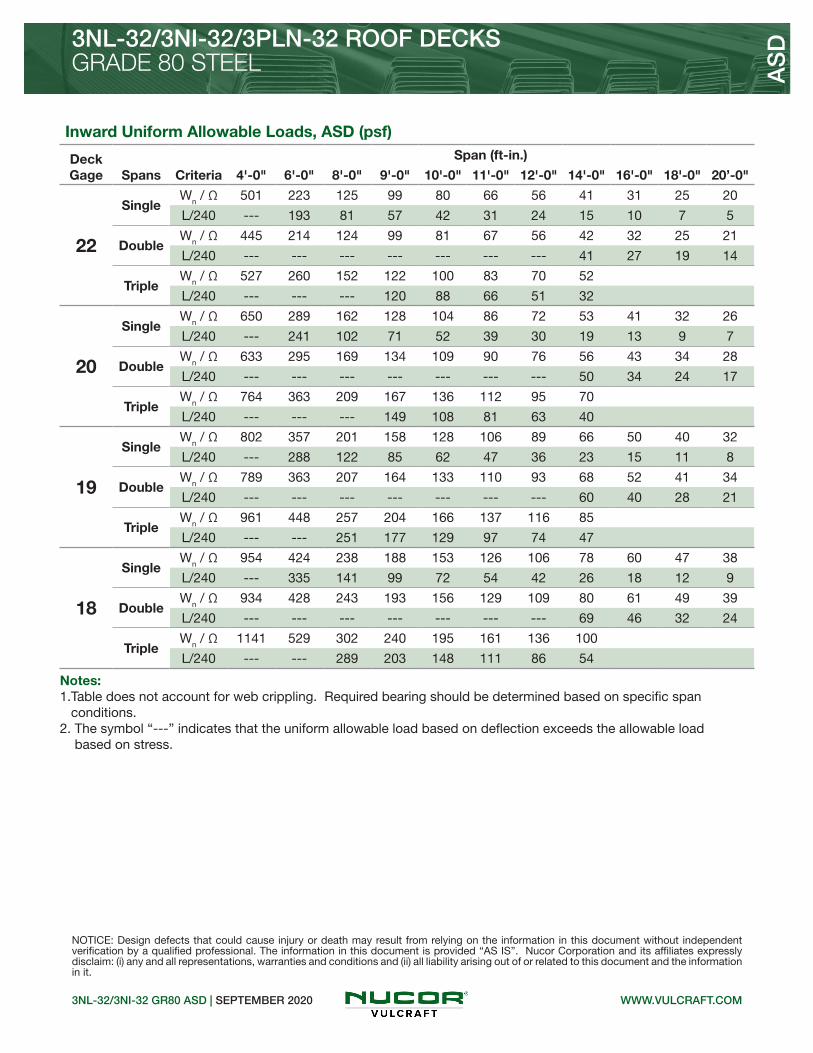
3NL-32/3NI-32/3PLN-32 ROOF DECKSGRADE 80 STEEL
3NL-32/3NI-32 GR80 ASD | SEPTEMBER 2020
Inward Uniform Allowable Loads, ASD (psf)
Deck Gage Spans Criteria
Span (ft-in.)
4'-0" 6'-0" 8'-0" 9'-0" 10'-0" 11'-0" 12'-0" 14'-0" 16'-0" 18'-0" 20’-0"
22
SingleWn / Ω 501 223 125 99 80 66 56 41 31 25 20
L/240 --- 193 81 57 42 31 24 15 10 7 5
DoubleWn / Ω 445 214 124 99 81 67 56 42 32 25 21
L/240 --- --- --- --- --- --- --- 41 27 19 14
TripleWn / Ω 527 260 152 122 100 83 70 52
L/240 --- --- --- 120 88 66 51 32
20
SingleWn / Ω 650 289 162 128 104 86 72 53 41 32 26
L/240 --- 241 102 71 52 39 30 19 13 9 7
DoubleWn / Ω 633 295 169 134 109 90 76 56 43 34 28
L/240 --- --- --- --- --- --- --- 50 34 24 17
TripleWn / Ω 764 363 209 167 136 112 95 70
L/240 --- --- --- 149 108 81 63 40
19
SingleWn / Ω 802 357 201 158 128 106 89 66 50 40 32
L/240 --- 288 122 85 62 47 36 23 15 11 8
DoubleWn / Ω 789 363 207 164 133 110 93 68 52 41 34
L/240 --- --- --- --- --- --- --- 60 40 28 21
TripleWn / Ω 961 448 257 204 166 137 116 85
L/240 --- --- 251 177 129 97 74 47
18
SingleWn / Ω 954 424 238 188 153 126 106 78 60 47 38
L/240 --- 335 141 99 72 54 42 26 18 12 9
DoubleWn / Ω 934 428 243 193 156 129 109 80 61 49 39
L/240 --- --- --- --- --- --- --- 69 46 32 24
TripleWn / Ω 1141 529 302 240 195 161 136 100
L/240 --- --- 289 203 148 111 86 54
AS
D
NOTICE: Design defects that could cause injury or death may result from relying on the information in this document without independent verification by a qualified professional. The information in this document is provided “AS IS”. Nucor Corporation and its affiliates expressly disclaim: (i) any and all representations, warranties and conditions and (ii) all liability arising out of or related to this document and the information in it.
Notes: 1.Table does not account for web crippling. Required bearing should be determined based on specific span conditions.2. The symbol “---” indicates that the uniform allowable load based on deflection exceeds the allowable load based on stress.
WWW.VULCRAFT.COM

• 3N-24 Deck used with Side-lap Screws• 3NI-24 Deck used with TSWs or BPs
Nominal Dimensions
Standard Features Optional Features• ASTM A653 SS GR40 Min., with G60 or G90, white or gray primer optional• ASTM A1008 SS GR40 Min. with gray primer• Standard lengths – 6’-0” to 42’-0”• IAPMO UES ER-0652, UL, and FM Listed• Tables conform to ANSI/SDI RD-2017
• Inquire regarding cost and lead times for: -Short cuts < 6’-0” -Sheet Lengths > 42’-0” -Alternative metallic and painted finishes• Web Perforated Acoustical Versions
3N-24/3NI-24 GR40 ASD | SEPTEMBER 2020
3N-24/3NI-24 ROOF DECKSGRADE 40 STEEL A
SD
24” WIDE 3N ROOF DECKS
WWW.VULCRAFT.COM
Allowable Reactions at Supports Based on Web Crippling, Rn/Ω (lb/ft)Bearing Length of Webs
One-Flange Loading Two-Flange Loading
DeckGage
End Bearing Interior Bearing End Bearing Interior Bearing
1½" 2" 3" 4" 4" 8" 1½" 2" 3" 4" 4" 8"
22 463 509 586 651 1014 1178 444 478 535 584 1189 1395
20 667 731 838 928 1451 1796 686 737 821 893 1733 2176
19 893 976 1115 1232 1930 2430 966 1034 1148 1244 2334 2984
18 1130 1233 1404 1548 2433 3047 1269 1355 1501 1623 2967 3777
16 1745 1895 2147 2359 3726 4624 2086 2219 2442 2630 4609 5816
Section Properties
Deck Gage
Deck Weight
Base Metal Thickness
Yield Strength
Effective Moment of Inertia
at Service LoadId = (2Ie+Ig)/3
Effective Section Modulus
at Fy = 40 ksiAllowable Moment
Vertical Web
Shear
wdd t Fy Id+ Id- Se+ Se- Mn+/Ω Mn-/Ω Vn/Ω
(psf) (in.) (ksi) (in4/ft) (in4/ft) (in3/ft) (in3/ft) (lb-ft/ft) (lb-ft/ft) (lb/ft)
22 2.0 0.0295 40 0.714 0.869 0.368 0.419 735 837 2436
20 2.5 0.0358 40 0.901 1.071 0.482 0.530 962 1058 3589
19 2.9 0.0418 40 1.088 1.252 0.584 0.637 1166 1271 4894
18 3.3 0.0474 40 1.268 1.421 0.674 0.731 1346 1459 5738
16 4.1 0.0598 40 1.682 1.795 0.876 0.934 1749 1864 7204

3N-24/3NI-24 ROOF DECKSGRADE 40 STEEL
3N-24/3NI-24 GR40 ASD | SEPTEMBER 2020
AS
D
NOTICE: Design defects that could cause injury or death may result from relying on the information in this document without independent verification by a qualified professional. The information in this document is provided “AS IS”. Nucor Corporation and its affiliates expressly disclaim: (i) any and all representations, warranties and conditions and (ii) all liability arising out of or related to this document and the information in it.
WWW.VULCRAFT.COM
Inward Uniform Allowable Loads, ASD (psf)
Deck Gage Spans Criteria
Span (ft-in.)
4'-0" 6'-0" 8'-0" 9'-0" 10'-0" 11'-0" 12'-0" 14'-0" 16'-0" 18'-0" 20'-0"
22
SingleWn / Ω 367 163 92 73 59 49 41 30 23 18 15
L/240 --- --- 91 64 47 35 27 17 11 8 6
DoubleWn / Ω 384 179 102 81 66 55 46 34 26 21 17
L/240 --- --- --- --- --- --- --- --- --- --- ---
TripleWn / Ω 465 220 127 101 82 68 57 42
L/240 --- --- --- --- --- --- --- 39
20
SingleWn / Ω 481 214 120 95 77 64 53 39 30 24 19
L/240 --- --- 115 81 59 44 34 22 14 10 7
DoubleWn / Ω 496 228 130 103 84 69 58 43 33 26 21
L/240 --- --- --- --- --- --- --- --- --- --- ---
TripleWn / Ω 605 282 161 128 104 86 73 54
L/240 --- --- --- --- --- --- --- 48
19
SingleWn / Ω 583 259 146 115 93 77 65 48 36 29 23
L/240 --- --- 139 98 71 54 41 26 17 12 9
DoubleWn / Ω 605 276 157 124 101 83 70 52 40 31 25
L/240 --- --- --- --- --- --- --- --- --- --- 25
TripleWn / Ω 740 342 195 155 126 104 88 64
L/240 --- --- --- --- --- --- --- 56
18
SingleWn / Ω 673 299 168 133 108 89 75 55 42 33 27
L/240 --- --- 162 114 83 62 48 30 20 14 10
DoubleWn / Ω 695 317 180 143 116 96 81 59 45 36 29
L/240 --- --- --- --- --- --- --- --- --- --- 28
TripleWn / Ω 852 393 224 178 144 119 101 74
L/240 --- --- --- --- --- --- --- 64
16
SingleWn / Ω 874 389 219 173 140 116 97 71 55 43 35
L/240 --- --- 215 151 110 83 64 40 27 19 14
DoubleWn / Ω 887 405 230 182 148 122 103 76 58 46 37
L/240 --- --- --- --- --- --- --- --- --- --- 35
TripleWn / Ω 1086 501 286 227 184 153 128 95
L/240 --- --- --- --- --- --- --- 81
Notes: 1.Table does not account for web crippling. Required bearing should be determined based on specific span conditions.2. The symbol “---” indicates that the uniform allowable load based on deflection exceeds the allowable load based on stress.

WWW.DOVETAILDECK.COM2.0DA ROOF ASD | SEPTEMBER 2020
2.0DA ACOUSTICAL DOVETAIL ROOF DECK
2.0DA ACOUSTICAL DOVETAIL ROOF DECK
Standard Features Optional Features• Inquire regarding cost and lead times for: -19 gage -Short cuts < 6’-0” -Alternative metallic and painted finishes
GRADE 40 STEEL
• Enhanced 2-Coat Polyester Paint• White Factory Primer Paint• Galvanized Finish• FM Listed
AS
D
• ASTM A653 SS GR 40 Min. with G90• Standard lengths – 6’-0” to 42’-0”• Tables conform to ANSI/SDI RD-2017• IAPMO UES ER-423 and FM Listed
Allowable Reactions at Supports Based on Web Crippling, Rn/Ω (lb/ft)Bearing Length of Webs
One-Flange Loading Two-Flange Loading
DeckGage
End Bearing Interior Bearing End Bearing Interior Bearing
1½" 2" 3" 4" 3" 5" 1½" 2" 3" 4" 3" 5"
22 653 717 826 917 1281 1516 702 757 848 925 1567 1877
20 931 1020 1170 1296 1823 2146 1058 1136 1266 1376 2258 2690
18 1556 1697 1933 2132 3036 3544 1893 2023 2239 2422 3813 4507
16 2378 2582 2926 3215 4629 5360 3043 3237 3563 3837 5866 6880
Section Properties
Deck Gage
Deck Weight
Base Metal Thickness
Yield Strength
Effective Moment of Inertia
at Service LoadId = (2Ie+Ig)/3
Effective Section Modulus
at Fy = 40 ksiAllowable Moment
Vertical Web
Shear
wdd t Fy Id+ Id- Se+ Se- Mn+/Ω Mn-/Ω Vn/Ω
(psf) (in.) (ksi) (in4/ft) (in4/ft) (in3/ft) (in3/ft) (lb-ft/ft) (lb-ft/ft) (lb/ft)
22 2.0 0.0295 40 0.340 0.310 0.261 0.258 521 515 2896
20 2.4 0.0358 40 0.415 0.385 0.330 0.317 659 633 3498
18 3.2 0.0474 40 0.551 0.528 0.445 0.427 888 852 4584
16 4.0 0.0598 40 0.697 0.684 0.564 0.546 1126 1090 5723
Nominal Dimensions

WWW.DOVETAILDECK.COM
2.0DA ACOUSTICAL DOVETAIL ROOF DECK
2.0DA ROOF ASD | SEPTEMBER 2020
NOTICE: Design defects that could cause injury or death may result from relying on the information in this document without independent verification by a qualified professional. The information in this document is provided “AS IS”. Nucor Corporation and its affiliates expressly disclaim: (i) any and all representations, warranties and conditions and (ii) all liability arising out of or related to this document and the information in it.
AS
D
GRADE 40 STEEL
Inward Uniform Allowable Loads, ASD (psf)
Deck Gage Spans Criteria
Span (ft-in.)
4'-0" 5'-0" 6'-0" 7'-0" 8'-0" 9'-0" 10'-0" 11'-0" 12'-0" 13'-0" 14'-0"
22
SingleWn / Ω 260 167 116 85 65 51 42 34 29 25 21
L/240 --- --- 103 65 44 31 22 17 13 10 8
DoubleWn / Ω 251 162 113 83 64 51 41 34 29 24 21
L/240 --- --- --- --- --- --- --- --- 28 22 18
TripleWn / Ω 311 201 141 104 80 63 51 42 36 30 26
L/240 --- --- --- --- 75 53 38 29 22 17 14
20
SingleWn / Ω 329 211 146 108 82 65 53 44 37 31 27
L/240 --- --- 126 79 53 37 27 20 16 12 10
DoubleWn / Ω 309 199 139 102 79 62 50 42 35 30 26
L/240 --- --- --- --- --- --- --- --- --- 28 22
TripleWn / Ω 382 247 173 128 98 78 63 52 44 37 32
L/240 --- --- --- --- 93 65 48 36 28 22 17
18
SingleWn / Ω 444 284 197 145 111 88 71 59 49 42 36
L/240 --- --- 167 105 71 50 36 27 21 16 13
DoubleWn / Ω 415 268 187 138 106 84 68 56 47 40 35
L/240 --- --- --- --- --- --- --- --- --- 38 30
TripleWn / Ω 513 333 233 172 132 104 85 70 59 50 43
L/240 --- --- --- --- 128 90 65 49 38 30 24
16
SingleWn / Ω 563 360 250 184 141 111 90 74 63 53 46
L/240 --- --- 212 133 89 63 46 34 26 21 17
DoubleWn / Ω 530 343 239 176 135 107 87 72 60 51 44
L/240 --- --- --- --- --- --- --- --- --- 49 39
TripleWn / Ω 655 425 297 220 169 133 108 90 75 64 55
L/240 --- --- --- --- 165 116 85 64 49 39 31
Notes: 1.Table does not account for web crippling. Required bearing should be determined based on specific span conditions.2. The symbol “---” indicates that the uniform allowable load based on deflection exceeds the allowable load based on stress.

WWW.DOVETAILDECK.COM3.5DA ROOF ASD | SEPTEMBER 2020
3.5DA ACOUSTICAL DOVETAIL ROOF DECK
3.5DA ACOUSTICAL DOVETAIL ROOF DECK
Standard Features Optional Features• Inquire regarding cost and lead times for: -19 gage -Short cuts < 6’-0” -Alternative metallic and painted finishes
GRADE 40 STEEL
• Enhanced 2-Coat Polyester Paint• White Factory Primer Paint• Galvanized Finish• FM Listed
AS
D
• ASTM A653 SS GR 40 Min. with G90• Standard lengths – 6’-0” to 42’-0”• Tables conform to ANSI/SDI RD-2017• IAPMO UES ER-423 and FM Listed
Allowable Reactions at Supports Based on Web Crippling, Rn/Ω (lb/ft)Bearing Length of Webs
One-Flange Loading Two-Flange Loading
DeckGage
End Bearing Interior Bearing End Bearing Interior Bearing
2" 3" 4" 5" 4" 6" 2" 3" 4" 5" 4" 6"
20 693 794 880 955 1459 1670 714 796 865 926 1724 1991
18 1168 1330 1467 1588 2422 2753 1310 1450 1568 1672 2927 3360
16 1793 2032 2233 2410 3681 4162 2137 2352 2533 2693 4515 5157
Section Properties
Deck Gage
Deck Weight
Base Metal Thickness
Yield Strength
Effective Moment of Inertia
at Service LoadId = (2Ie+Ig)/3
Effective Section Modulus
at Fy = 40 ksiAllowable Moment
Vertical Web
Shear
wdd t Fy Id+ Id- Se+ Se- Mn+/Ω Mn-/Ω Vn/Ω
(psf) (in.) (ksi) (in4/ft) (in4/ft) (in3/ft) (in3/ft) (lb-ft/ft) (lb-ft/ft) (lb/ft)
20 3.1 0.0358 40 1.531 1.430 0.655 0.657 1307 1311 3435
18 4.1 0.0474 40 2.098 1.950 0.934 0.928 1864 1852 6012
16 5.1 0.0598 40 2.719 2.533 1.255 1.241 2505 2477 8313
Nominal Dimensions

WWW.DOVETAILDECK.COM
3.5DA ACOUSTICAL DOVETAIL ROOF DECK
3.5DA ROOF ASD | SEPTEMBER 2020
NOTICE: Design defects that could cause injury or death may result from relying on the information in this document without independent verification by a qualified professional. The information in this document is provided “AS IS”. Nucor Corporation and its affiliates expressly disclaim: (i) any and all representations, warranties and conditions and (ii) all liability arising out of or related to this document and the information in it.
GRADE 40 STEEL AS
D
Inward Uniform Allowable Loads, ASD (psf)
Deck Gage Spans Criteria
Span (ft-in.)
11'-0" 12'-0" 13'-0" 14'-0" 15'-0" 16'-0" 17'-0" 18'-0" 19'-0" 20'-0" 21'-0"
20
SingleWn / Ω 86 73 62 53 46 41 36 32 29 26 24
L/240 75 58 46 37 30 25 20 17 15 13 11
DoubleWn / Ω 85 72 61 53 46 41 36 32 29 26 24
L/240 --- --- --- --- --- --- --- --- --- --- ---
TripleWn / Ω 106 89 76 66
L/240 --- --- --- 65
18
SingleWn / Ω 123 104 88 76 66 58 52 46 41 37 34
L/240 103 80 63 50 41 34 28 24 20 17 15
DoubleWn / Ω 121 102 87 75 66 58 51 46 41 37 34
L/240 --- --- --- --- --- --- --- --- --- --- 33
TripleWn / Ω 151 127 109 94
L/240 --- --- --- 88
16
SingleWn / Ω 166 139 119 102 89 78 69 62 56 50 45
L/240 134 103 81 65 53 44 36 31 26 22 19
DoubleWn / Ω 162 137 117 101 88 77 68 61 55 49 45
L/240 --- --- --- --- --- --- --- --- --- --- 43
TripleWn / Ω 202 170 145 125
L/240 --- --- 143 114
Notes: 1.Table does not account for web crippling. Required bearing should be determined based on specific span conditions.2. The symbol “---” indicates that the uniform allowable load based on deflection exceeds the allowable load based on stress.

• 1.5BA-36 Deck used with Side-lap Screws• 1.5BIA-36 Deck used with TSWs or BPs• 1.5PLBA-36 Deck used with PunchLok® II System
Nominal Dimensions
Standard Features Optional Features
1.5BA/1.5BIA GR50 ASD | SEPTEMBER 2020
1.5BA-36/1.5BIA-36/1.5PLBA-36 ACOUSTICAL ROOF DECKSGRADE 50 STEEL A
SD
1.5B ACOUSTICAL ROOF DECKS
WWW.VULCRAFT.COM
• Inquire regarding cost and lead times for: -Short cuts < 6’-0” -Sheet Lengths > 42’-0” -Alternative metallic and painted finishes
• ASTM A653 SS GR50 Min., with G60 or G90, white or gray primer optional• ASTM A1008 SS GR50 Min. with gray primer• Standard lengths – 6’-0” to 42’-0”• IAPMO UES ER-0652 and FM Listed• Tables conform to ANSI/SDI RD-2017
Allowable Reactions at Supports Based on Web Crippling, Rn/Ω (lb/ft)Bearing Length of Webs
One-Flange Loading Two-Flange Loading
DeckGage
End Bearing Interior Bearing End Bearing Interior Bearing
1½" 2" 3" 4" 3" 4" 1½" 2" 3" 4" 3" 4"
22 783 861 991 1082 1476 1595 798 859 963 1035 1792 1949
20 1122 1230 1410 1532 2120 2281 1214 1304 1453 1556 2608 2823
19 1495 1634 1867 2022 2829 3033 1691 1810 2011 2144 3512 3787
18 1887 2058 2344 2530 3575 3819 2207 2357 2609 2773 4466 4799
16 2899 3148 3567 3822 5501 5838 3585 3814 4198 4432 6941 7407
Section Properties
Deck Gage
Deck Weight
Base Metal Thickness
Yield Strength
Effective Moment of Inertia
at Service LoadId = (2Ie+Ig)/3
Effective Section Modulus
at Fy = 50 ksiAllowable Moment
Vertical Web
Shear
wdd t Fy Id+ Id- Se+ Se- Mn+/Ω Mn-/Ω Vn/Ω
(psf) (in.) (ksi) (in4/ft) (in4/ft) (in3/ft) (in3/ft) (lb-ft/ft) (lb-ft/ft) (lb/ft)
22 1.5 0.0295 50 0.148 0.169 0.161 0.170 402 424 2008
20 1.9 0.0358 50 0.187 0.206 0.213 0.218 532 544 2421
19 2.2 0.0418 50 0.227 0.244 0.253 0.264 631 659 2809
18 2.5 0.0474 50 0.263 0.276 0.290 0.302 723 753 3166
16 3.2 0.0598 50 0.346 0.348 0.374 0.382 933 953 3941

GRADE 50 STEEL
1.5BA/1.5BIA GR50 ASD | SEPTEMBER 2020
AS
D
NOTICE: Design defects that could cause injury or death may result from relying on the information in this document without independent verification by a qualified professional. The information in this document is provided “AS IS”. Nucor Corporation and its affiliates expressly disclaim: (i) any and all representations, warranties and conditions and (ii) all liability arising out of or related to this document and the information in it.
WWW.VULCRAFT.COM
1.5BA-36/1.5BIA-36/1.5PLBA-36 ACOUSTICAL ROOF DECKS
Inward Uniform Allowable Loads, ASD (psf)
Deck Gage Spans Criteria
Span (ft-in.)
2'-0" 3'-0" 4'-0" 5'-0" 6'-0" 7'-0" 8'-0" 9'-0" 10'-0" 11'-0" 12'-0"
22
SingleWn / Ω 804 357 201 129 89 66 50 40 32 27 22
L/240 --- --- 152 78 45 28 19 13 10 7 6
DoubleWn / Ω 750 355 205 133 93 68 53 42 34 28 23
L/240 --- --- --- --- --- --- 52 37 27 20 15
TripleWn / Ω 895 434 253 164 115 85 65 52 42 35 29
L/240 --- --- --- --- 97 61 41 29 21 16 12
20
SingleWn / Ω 1063 473 266 170 118 87 66 53 43 35 30
L/240 --- 454 192 98 57 36 24 17 12 9 7
DoubleWn / Ω 948 453 262 170 119 88 67 53 43 36 30
L/240 --- --- --- --- --- --- 64 45 33 24 19
TripleWn / Ω 1127 551 322 210 147 109 84 66 54 45 38
L/240 --- --- --- 204 118 74 50 35 25 19 15
19
SingleWn / Ω 1262 561 316 202 140 103 79 62 50 42 35
L/240 --- 551 233 119 69 43 29 20 15 11 9
DoubleWn / Ω 1136 545 316 205 144 106 81 65 52 43 36
L/240 --- --- --- --- --- --- 75 53 39 29 22
TripleWn / Ω 1347 663 388 254 178 132 101 80 65 54 45
L/240 --- --- --- 242 140 88 59 41 30 23 17
18
SingleWn / Ω 1447 643 362 231 161 118 90 71 58 48 40
L/240 --- 639 269 138 80 50 34 24 17 13 10
DoubleWn / Ω 1295 622 361 235 164 121 93 74 60 50 42
L/240 --- --- --- --- --- --- 85 60 44 33 25
TripleWn / Ω 1533 756 443 290 204 151 116 92 75 62 52
L/240 --- --- --- 273 158 100 67 47 34 26 20
16
SingleWn / Ω 1866 829 466 299 207 152 117 92 75 62 52
L/240 --- --- 354 181 105 66 44 31 23 17 13
DoubleWn / Ω 1631 786 456 297 208 153 118 93 76 63 53
L/240 --- --- --- --- --- --- 107 75 55 41 32
TripleWn / Ω 1929 954 560 366 257 190 147 116 94 78 66
L/240 --- --- --- 345 199 126 84 59 43 32 25
Notes: 1.Table does not account for web crippling. Required bearing should be determined based on specific span conditions.2. The symbol “---” indicates that the uniform allowable load based on deflection exceeds the allowable load based on stress.
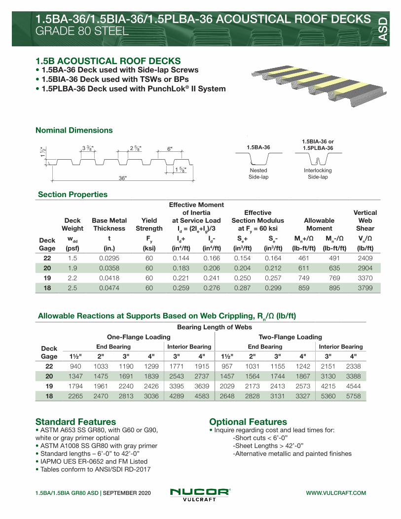
Nominal Dimensions
Standard Features Optional Features
1.5BA/1.5BIA GR80 ASD | SEPTEMBER 2020
GRADE 80 STEEL AS
D
1.5B ACOUSTICAL ROOF DECKS
WWW.VULCRAFT.COM
• 1.5BA-36 Deck used with Side-lap Screws• 1.5BIA-36 Deck used with TSWs or BPs• 1.5PLBA-36 Deck used with PunchLok® II System
1.5BA-36/1.5BIA-36/1.5PLBA-36 ACOUSTICAL ROOF DECKS
• Inquire regarding cost and lead times for: -Short cuts < 6’-0” -Sheet Lengths > 42’-0” -Alternative metallic and painted finishes
• ASTM A653 SS GR80, with G60 or G90, white or gray primer optional• ASTM A1008 SS GR80 with gray primer• Standard lengths – 6’-0” to 42’-0”• IAPMO UES ER-0652 and FM Listed• Tables conform to ANSI/SDI RD-2017
Allowable Reactions at Supports Based on Web Crippling, Rn/Ω (lb/ft)Bearing Length of Webs
One-Flange Loading Two-Flange Loading
DeckGage
End Bearing Interior Bearing End Bearing Interior Bearing
1½" 2" 3" 4" 3" 4" 1½" 2" 3" 4" 3" 4"
22 940 1033 1190 1299 1771 1915 957 1031 1155 1242 2151 2338
20 1347 1475 1691 1839 2543 2737 1457 1564 1744 1867 3130 3388
19 1794 1961 2240 2426 3395 3639 2029 2173 2413 2573 4215 4544
18 2265 2470 2813 3036 4289 4583 2648 2828 3131 3327 5360 5758
Section Properties
Deck Gage
Deck Weight
Base Metal Thickness
Yield Strength
Effective Moment of Inertia
at Service LoadId = (2Ie+Ig)/3
Effective Section Modulus
at Fy = 60 ksiAllowable Moment
Vertical Web
Shear
wdd t Fy Id+ Id- Se+ Se- Mn+/Ω Mn-/Ω Vn/Ω
(psf) (in.) (ksi) (in4/ft) (in4/ft) (in3/ft) (in3/ft) (lb-ft/ft) (lb-ft/ft) (lb/ft)
22 1.5 0.0295 60 0.144 0.166 0.154 0.164 461 491 2409
20 1.9 0.0358 60 0.183 0.206 0.204 0.212 611 635 2904
19 2.2 0.0418 60 0.221 0.241 0.250 0.257 749 769 3370
18 2.5 0.0474 60 0.259 0.276 0.287 0.299 859 895 3799

GRADE 80 STEEL
1.5BA/1.5BIA GR80 ASD | SEPTEMBER 2020
AS
D
NOTICE: Design defects that could cause injury or death may result from relying on the information in this document without independent verification by a qualified professional. The information in this document is provided “AS IS”. Nucor Corporation and its affiliates expressly disclaim: (i) any and all representations, warranties and conditions and (ii) all liability arising out of or related to this document and the information in it.
WWW.VULCRAFT.COM
1.5BA-36/1.5BIA-36/1.5PLBA-36 ACOUSTICAL ROOF DECKS
Inward Uniform Allowable Loads, ASD (psf)
Deck Gage Spans Criteria
Span (ft-in.)
2'-0" 3'-0" 4'-0" 5'-0" 6'-0" 7'-0" 8'-0" 9'-0" 10'-0" 11'-0" 12'-0"
22
SingleWn / Ω 922 410 231 148 102 75 58 46 37 30 26
L/240 - 350 148 76 44 28 18 13 9 7 5
DoubleWn / Ω 875 413 238 154 108 79 61 48 39 32 27
L/240 --- --- --- --- --- 76 51 36 26 20 15
TripleWn / Ω 1047 505 293 191 134 99 76 60 49 40 34
L/240 --- --- --- 164 95 60 40 28 21 15 12
20
SingleWn / Ω 1222 543 305 195 136 100 76 60 49 40 34
L/240 --- 444 187 96 56 35 23 16 12 9 7
DoubleWn / Ω 1114 530 306 198 139 102 79 62 50 42 35
L/240 --- --- --- --- --- 95 64 45 33 24 19
TripleWn / Ω 1327 646 377 246 172 127 98 78 63 52 44
L/240 --- --- --- 204 118 74 50 35 25 19 15
19
SingleWn / Ω 1497 665 374 240 166 122 94 74 60 49 42
L/240 --- 537 226 116 67 42 28 20 14 11 8
DoubleWn / Ω 1337 639 370 240 168 124 95 75 61 51 43
L/240 --- --- --- --- --- 111 74 52 38 29 22
TripleWn / Ω 1587 778 455 297 208 154 119 94 76 63 53
L/240 --- --- --- 239 138 87 58 41 30 22 17
18
SingleWn / Ω 1719 764 430 275 191 140 107 85 69 57 48
L/240 --- 629 265 136 79 50 33 23 17 13 10
DoubleWn / Ω 1543 741 429 279 195 144 111 88 71 59 49
L/240 --- --- --- --- --- 127 85 60 44 33 25
TripleWn / Ω 1827 900 528 345 242 179 138 109 89 73 62
L/240 --- --- --- 273 158 100 67 47 34 26 20
Notes: 1.Table does not account for web crippling. Required bearing should be determined based on specific span conditions.2. The symbol “---” indicates that the uniform allowable load based on deflection exceeds the allowable load based on stress.

• 3NLA-32 Deck used with Side-lap Screws• 3NIA-32 Deck used with TSWs or BPs• 3PLNA-32 Deck used with PunchLok® II System
Nominal Dimensions
Standard Features Optional Features• Inquire regarding cost and lead times for: -Short cuts < 6’-0” -Sheet Lengths > 42’-0” -Alternative metallic and painted finishes
3NLA-32/3NIA-32 GR50 ASD | SEPTEMBER 2020
3NLA-32/3NIA-32/3PLNA-32 ACOUSTICAL ROOF DECKSGRADE 50 STEEL A
SD
32” WIDE 3N ACOUSTICAL ROOF DECKS
• ASTM A653 SS GR50 Min., with G60 or G90, white or gray primer optional• ASTM A1008 SS GR50 Min. with gray primer• Standard lengths – 6’-0” to 42’-0”• IAPMO UES ER-0652 and FM Listed• Tables conform to ANSI/SDI RD-2017
WWW.VULCRAFT.COM
Allowable Reactions at Supports Based on Web Crippling, Rn/Ω (lb/ft)Bearing Length of Webs
One-Flange Loading Two-Flange Loading
DeckGage
End Bearing Interior Bearing End Bearing Interior Bearing
1½" 2" 3" 4" 4" 8" 1½" 2" 3" 4" 4" 8"
22 510 561 645 717 1178 1369 459 495 554 604 1331 1561
20 741 812 931 1031 1688 2090 724 777 866 942 1950 2448
19 997 1089 1244 1375 2246 2827 1031 1103 1225 1328 2635 3370
18 1267 1381 1573 1735 2833 3549 1366 1459 1616 1747 3361 4277
16 1968 2138 2422 2661 4346 5394 2277 2422 2666 2871 5247 6620
Section Properties
Deck Gage
Deck Weight
Base Metal Thickness
Yield Strength
Effective Moment of Inertia
at Service LoadId = (2Ie+Ig)/3
Effective Section Modulus
at Fy = 50 ksiAllowable Moment
Vertical Web
Shear
wdd t Fy Id+ Id- Se+ Se- Mn+/Ω Mn-/Ω Vn/Ω
(psf) (in.) (ksi) (in4/ft) (in4/ft) (in3/ft) (in3/ft) (lb-ft/ft) (lb-ft/ft) (lb/ft)
22 1.7 0.0295 50 0.611 0.680 0.328 0.353 819 881 1632
20 2.1 0.0358 50 0.766 0.842 0.426 0.452 1063 1128 2821
19 2.4 0.0418 50 0.917 1.000 0.526 0.550 1313 1372 3845
18 2.8 0.0474 50 1.067 1.140 0.627 0.641 1565 1599 4948
16 3.5 0.0598 50 1.405 1.448 0.826 0.841 2061 2098 6798
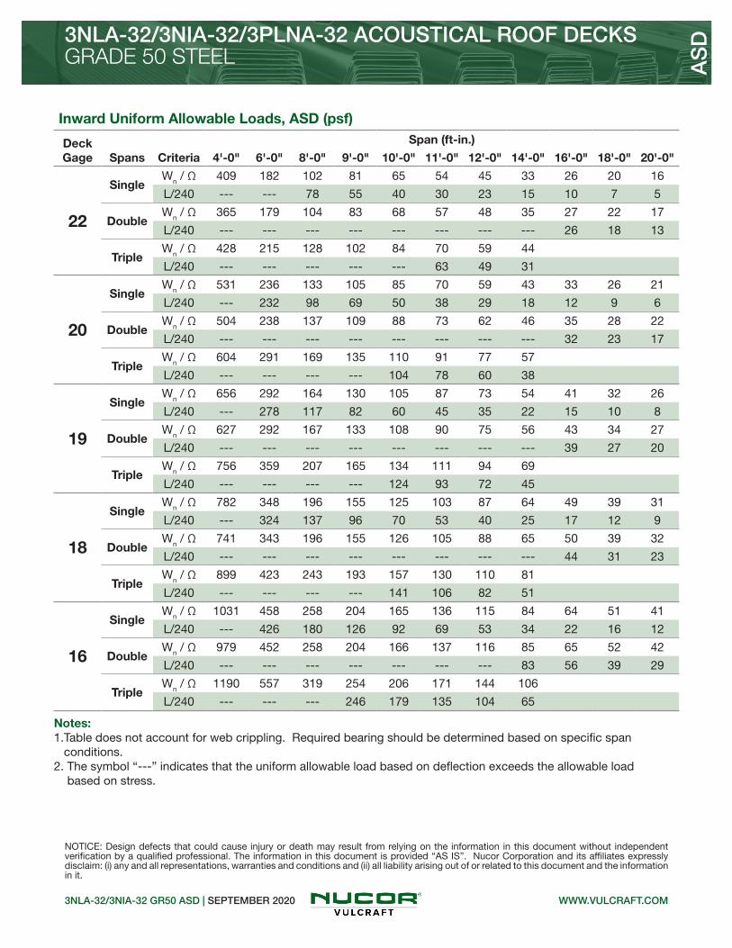
3NLA-32/3NIA-32/3PLNA-32 ACOUSTICAL ROOF DECKSGRADE 50 STEEL
3NLA-32/3NIA-32 GR50 ASD | SEPTEMBER 2020
AS
D
NOTICE: Design defects that could cause injury or death may result from relying on the information in this document without independent verification by a qualified professional. The information in this document is provided “AS IS”. Nucor Corporation and its affiliates expressly disclaim: (i) any and all representations, warranties and conditions and (ii) all liability arising out of or related to this document and the information in it.
WWW.VULCRAFT.COM
Inward Uniform Allowable Loads, ASD (psf)
Deck Gage Spans Criteria
Span (ft-in.)
4'-0" 6'-0" 8'-0" 9'-0" 10'-0" 11'-0" 12'-0" 14'-0" 16'-0" 18'-0" 20'-0"
22
SingleWn / Ω 409 182 102 81 65 54 45 33 26 20 16
L/240 --- --- 78 55 40 30 23 15 10 7 5
DoubleWn / Ω 365 179 104 83 68 57 48 35 27 22 17
L/240 --- --- --- --- --- --- --- --- 26 18 13
TripleWn / Ω 428 215 128 102 84 70 59 44
L/240 --- --- --- --- --- 63 49 31
20
SingleWn / Ω 531 236 133 105 85 70 59 43 33 26 21
L/240 --- 232 98 69 50 38 29 18 12 9 6
DoubleWn / Ω 504 238 137 109 88 73 62 46 35 28 22
L/240 --- --- --- --- --- --- --- --- 32 23 17
TripleWn / Ω 604 291 169 135 110 91 77 57
L/240 --- --- --- --- 104 78 60 38
19
SingleWn / Ω 656 292 164 130 105 87 73 54 41 32 26
L/240 --- 278 117 82 60 45 35 22 15 10 8
DoubleWn / Ω 627 292 167 133 108 90 75 56 43 34 27
L/240 --- --- --- --- --- --- --- --- 39 27 20
TripleWn / Ω 756 359 207 165 134 111 94 69
L/240 --- --- --- --- 124 93 72 45
18
SingleWn / Ω 782 348 196 155 125 103 87 64 49 39 31
L/240 --- 324 137 96 70 53 40 25 17 12 9
DoubleWn / Ω 741 343 196 155 126 105 88 65 50 39 32
L/240 --- --- --- --- --- --- --- --- 44 31 23
TripleWn / Ω 899 423 243 193 157 130 110 81
L/240 --- --- --- --- 141 106 82 51
16
SingleWn / Ω 1031 458 258 204 165 136 115 84 64 51 41
L/240 --- 426 180 126 92 69 53 34 22 16 12
DoubleWn / Ω 979 452 258 204 166 137 116 85 65 52 42
L/240 --- --- --- --- --- --- --- 83 56 39 29
TripleWn / Ω 1190 557 319 254 206 171 144 106
L/240 --- --- --- 246 179 135 104 65
Notes: 1.Table does not account for web crippling. Required bearing should be determined based on specific span conditions.2. The symbol “---” indicates that the uniform allowable load based on deflection exceeds the allowable load based on stress.

Nominal Dimensions
Standard Features Optional Features• Inquire regarding cost and lead times for: -Short cuts < 6’-0” -Sheet Lengths > 42’-0” -Alternative metallic and painted finishes
3NLA-32/3NIA-32 GR80 ASD | SEPTEMBER 2020
3NLA-32/3NIA-32/3PLNA-32 ACOUSTICAL ROOF DECKSGRADE 80 STEEL A
SD
32” WIDE 3N ACOUSTICAL ROOF DECKS
• ASTM A653 SS GR80, with G60 or G90, white or gray primer optional• ASTM A1008 SS GR80 with gray primer• Standard lengths – 6’-0” to 42’-0”• IAPMO UES ER-0652 and FM Listed• Tables conform to ANSI/SDI RD-2017
WWW.VULCRAFT.COM
Allowable Reactions at Supports Based on Web Crippling, Rn/Ω (lb/ft)Bearing Length of Webs
One-Flange Loading Two-Flange Loading
DeckGage
End Bearing Interior Bearing End Bearing Interior Bearing
1½" 2" 3" 4" 4" 8" 1½" 2" 3" 4" 4" 8"
22 612 673 775 860 1413 1643 551 594 665 725 1597 1874
20 889 974 1117 1237 2025 2508 868 932 1040 1130 2340 2938
19 1196 1307 1493 1650 2696 3393 1237 1324 1470 1594 3162 4043
18 1520 1657 1888 2082 3400 4258 1640 1751 1939 2097 4033 5133
Section Properties
Deck Gage
Deck Weight
Base Metal Thickness
Yield Strength
Effective Moment of Inertia
at Service LoadId = (2Ie+Ig)/3
Effective Section Modulus
at Fy = 60 ksiAllowable Moment
Vertical Web
Shear
wdd t Fy Id+ Id- Se+ Se- Mn+/Ω Mn-/Ω Vn/Ω
(psf) (in.) (ksi) (in4/ft) (in4/ft) (in3/ft) (in3/ft) (lb-ft/ft) (lb-ft/ft) (lb/ft)
22 1.7 0.0295 60 0.604 0.672 0.318 0.329 952 985 1632
20 2.1 0.0358 60 0.754 0.832 0.412 0.440 1234 1317 2924
19 2.4 0.0418 60 0.903 0.989 0.509 0.535 1524 1602 4213
18 2.8 0.0474 60 1.048 1.136 0.605 0.626 1811 1874 5420
• 3NLA-32 Deck used with Side-lap Screws• 3NIA-32 Deck used with TSWs or BPs• 3PLNA-32 Deck used with PunchLok® II System

3NLA-32/3NIA-32/3PLNA-32 ACOUSTICAL ROOF DECKSGRADE 80 STEEL
3NLA-31/3NIA-32 GR80 ASD | SEPTEMBER 2020
AS
D
NOTICE: Design defects that could cause injury or death may result from relying on the information in this document without independent verification by a qualified professional. The information in this document is provided “AS IS”. Nucor Corporation and its affiliates expressly disclaim: (i) any and all representations, warranties and conditions and (ii) all liability arising out of or related to this document and the information in it.
WWW.VULCRAFT.COM
Inward Uniform Allowable Loads, ASD (psf)
Deck Gage Spans Criteria
Span (ft-in.)
4'-0" 6'-0" 8'-0" 9'-0" 10'-0" 11'-0" 12'-0" 14'-0" 16'-0" 18'-0" 20'-0"
22
SingleWn / Ω 476 212 119 94 76 63 53 39 30 24 19
L/240 --- 183 77 54 40 30 23 14 10 7 5
DoubleWn / Ω 393 196 115 92 75 63 53 39 30 24 19
L/240 --- --- --- --- --- --- --- 39 26 18 13
TripleWn / Ω 456 234 140 113 93 77 65 49
L/240 --- --- --- --- 83 62 48 30
20
SingleWn / Ω 617 274 154 122 99 82 69 50 39 30 25
L/240 --- 229 97 68 49 37 29 18 12 8 6
DoubleWn / Ω 574 274 159 126 103 85 72 53 41 32 26
L/240 --- --- --- --- --- --- --- 48 32 23 16
TripleWn / Ω 682 334 195 156 127 106 89 66
L/240 --- --- --- 141 103 77 60 38
19
SingleWn / Ω 762 339 190 151 122 101 85 62 48 38 30
L/240 --- 274 116 81 59 44 34 22 14 10 7
DoubleWn / Ω 723 339 195 155 126 104 88 65 50 39 32
L/240 --- --- --- --- --- --- --- 57 38 27 20
TripleWn / Ω 870 416 241 192 156 130 109 81
L/240 --- --- 239 168 122 92 71 45
18
SingleWn / Ω 906 403 226 179 145 120 101 74 57 45 36
L/240 --- 318 134 94 69 52 40 25 17 12 9
DoubleWn / Ω 860 400 229 182 148 122 103 76 58 46 37
L/240 --- --- --- --- --- --- --- 65 44 31 22
TripleWn / Ω 1040 492 283 225 184 152 128 95
L/240 --- --- 275 193 141 106 81 51
Notes: 1.Table does not account for web crippling. Required bearing should be determined based on specific span conditions.2. The symbol “---” indicates that the uniform allowable load based on deflection exceeds the allowable load based on stress.

• 3NA-24 Deck used with Side-lap Screws• 3NIA-24 Deck used with TSWs or BPs
Nominal Dimensions
Standard Features Optional Features• Inquire regarding cost and lead times for: -Short cuts < 6’-0” -Sheet Lengths > 42’-0” -Alternative metallic and painted finishes
3NA-24/3NIA-24 GR40 ASD | SEPTEMBER 2020
3NA-24/3NIA-24 ACOUSTICAL ROOF DECKSGRADE 40 STEEL A
SD
24” WIDE 3N ACOUSTICAL ROOF DECKS
• ASTM A653 SS GR40 Min., with G60 or G90, white or gray primer optional• ASTM A1008 SS GR40 Min. with gray primer• Standard lengths – 6’-0” to 42’-0”• IAPMO UES ER-0652 and FM Listed• Tables conform to ANSI/SDI RD-2017
WWW.VULCRAFT.COM
Allowable Reactions at Supports Based on Web Crippling, Rn/Ω (lb/ft)Bearing Length of Webs
One-Flange Loading Two-Flange Loading
DeckGage
End Bearing Interior Bearing End Bearing Interior Bearing
1½" 2" 3" 4" 4" 8" 1½" 2" 3" 4" 4" 8"
22 440 483 556 618 1007 1171 400 431 483 526 1144 1343
20 638 699 801 887 1442 1786 628 674 752 817 1675 2103
19 857 937 1070 1183 1920 2417 893 956 1061 1150 2263 2893
18 1088 1187 1352 1491 2421 3032 1181 1262 1397 1511 2883 3670
16 1688 1834 2077 2283 3710 4603 1963 2088 2298 2475 4494 5671
Section Properties
Deck Gage
Deck Weight
Base Metal Thickness
Yield Strength
Effective Moment of Inertia
at Service LoadId = (2Ie+Ig)/3
Effective Section Modulus
at Fy = 40 ksiAllowable Moment
Vertical Web
Shear
wdd t Fy Id+ Id- Se+ Se- Mn+/Ω Mn-/Ω Vn/Ω
(psf) (in.) (ksi) (in4/ft) (in4/ft) (in3/ft) (in3/ft) (lb-ft/ft) (lb-ft/ft) (lb/ft)
22 1.9 0.0295 40 0.679 0.826 0.349 0.398 696 795 1816
20 2.4 0.0358 40 0.856 1.017 0.458 0.503 914 1004 2673
19 2.8 0.0418 40 1.033 1.189 0.555 0.605 1108 1208 3641
18 3.1 0.0474 40 1.204 1.350 0.640 0.695 1277 1387 4266
16 3.9 0.0598 40 1.598 1.705 0.832 0.887 1660 1771 5346

3NA-24/3NIA-24 ACOUSTICAL ROOF DECKSGRADE 40 STEEL
3NA-24/3NIA-24 GR40 ASD | SEPTEMBER 2020
AS
D
NOTICE: Design defects that could cause injury or death may result from relying on the information in this document without independent verification by a qualified professional. The information in this document is provided “AS IS”. Nucor Corporation and its affiliates expressly disclaim: (i) any and all representations, warranties and conditions and (ii) all liability arising out of or related to this document and the information in it.
WWW.VULCRAFT.COM
Inward Uniform Allowable Loads, ASD (psf)
Deck Gage Spans Criteria
Span (ft-in.)
4'-0" 6'-0" 8'-0" 9'-0" 10'-0" 11'-0" 12'-0" 14'-0" 16'-0" 18'-0" 20'-0"
22
SingleWn / Ω 348 155 87 69 56 46 39 28 22 17 14
L/240 --- --- 87 61 45 33 26 16 11 8 6
DoubleWn / Ω 349 166 96 76 62 52 43 32 25 19 16
L/240 --- --- --- --- --- --- --- --- --- --- ---
TripleWn / Ω 415 202 118 94 77 64 54 40
L/240 --- --- --- --- --- --- --- 37
20
SingleWn / Ω 457 203 114 90 73 60 51 37 29 23 18
L/240 --- --- 110 77 56 42 32 20 14 10 7
DoubleWn / Ω 454 213 122 97 79 65 55 41 31 25 20
L/240 --- --- --- --- --- --- --- --- --- --- ---
TripleWn / Ω 547 261 151 120 98 81 69 51
L/240 --- --- --- --- --- --- --- 46
19
SingleWn / Ω 554 246 138 109 89 73 62 45 35 27 22
L/240 --- --- 132 93 68 51 39 25 17 12 8
DoubleWn / Ω 558 259 148 117 95 79 66 49 38 30 24
L/240 --- --- --- --- --- --- --- --- --- --- 23
TripleWn / Ω 676 318 183 146 118 98 83 61
L/240 --- --- --- --- --- --- --- 54
18
SingleWn / Ω 639 284 160 126 102 84 71 52 40 32 26
L/240 --- --- 154 108 79 59 46 29 19 14 10
DoubleWn / Ω 643 298 170 135 110 91 76 56 43 34 28
L/240 --- --- --- --- --- --- --- --- --- --- 27
TripleWn / Ω 779 366 211 167 136 113 95 70
L/240 --- --- --- --- --- --- --- 61
16
SingleWn / Ω 830 369 208 164 133 110 92 68 52 41 33
L/240 --- --- 205 144 105 79 61 38 26 18 13
DoubleWn / Ω 818 379 217 172 140 116 97 72 55 44 35
L/240 --- --- --- --- --- --- --- --- --- --- 34
TripleWn / Ω 991 467 269 213 174 144 121 89
L/240 --- --- --- --- --- --- --- 77
Notes: 1.Table does not account for web crippling. Required bearing should be determined based on specific span conditions.2. The symbol “---” indicates that the uniform allowable load based on deflection exceeds the allowable load based on stress.

WWW.DOVETAILDECK.COM2.0D FORMLOK ASD | SEPTEMBER 2020
2.0D FORMLOK® DOVETAIL DECK
2.0D FORMLOK DOVETAIL DECK
Standard Features Optional Features• ASTM A653 SS GR 40 Min. with G90• Standard lengths – 6’-0” to 42’-0”• Tables conform to ANSI/SDI C-2017• IAPMO UES ER-423 and UL Listed
• Inquire regarding cost and lead times for: -19 gage -Short cuts < 6’-0” -Alternative metallic and painted finishes
AS
D
• Enhanced 2-Coat Polyester Paint• White Factory Primer Paint• Galvanized Finish• UL Listed
Allowable Reactions at Supports Based on Web Crippling, Rn/Ω (lb/ft)Bearing Length of Webs
One-Flange Loading Two-Flange Loading
DeckGage
End Bearing Interior Bearing End Bearing Interior Bearing
1½" 2" 3" 4" 3" 5" 1½" 2" 3" 4" 3" 5"
22 653 717 826 917 1281 1516 702 757 848 925 1567 1877
20 931 1020 1170 1296 1823 2146 1058 1136 1266 1376 2258 2690
18 1556 1697 1933 2132 3036 3544 1893 2023 2239 2422 3813 4507
16 2378 2582 2926 3215 4629 5360 3043 3237 3563 3837 5866 6880
Section Properties
Deck Gage
Deck Weight
Base Metal Thickness
Yield Strength
Effective Moment of Inertia
at Service LoadId = (2Ie+Ig)/3
Effective Section Modulus
at Fy = 40 ksiAllowable Moment
Vertical Web
Shear
wdd t Fy Id+ Id- Se+ Se- Mn+/Ω Mn-/Ω Vn/Ω
(psf) (in.) (ksi) (in4/ft) (in4/ft) (in3/ft) (in3/ft) (lb-ft/ft) (lb-ft/ft) (lb/ft)
22 2.1 0.0295 40 0.387 0.359 0.272 0.272 543 543 2896
20 2.6 0.0358 40 0.472 0.447 0.343 0.334 684 666 3498
18 3.4 0.0474 40 0.626 0.612 0.463 0.450 924 898 4584
16 4.3 0.0598 40 0.792 0.791 0.587 0.576 1172 1150 5723
Nominal Dimensions

WWW.DOVETAILDECK.COM
2.0D FORMLOK® DOVETAIL DECK-SLAB
2.0D FORMLOK ASD | SEPTEMBER 2020
NORMAL WEIGHT CONCRETE (145 pcf)
Maximum Unshored Spans Composite Deck-Slab Properties
Slab DepthDeck Gage
Maximum Unshored Construction Clear Span
Concrete + Deck
Deflection Moment Shear
Id = (Icr+Iu)/2 Mno/Ω Vno/Ω
Total Topping 1 2 3 (psf) (in4/ft) (kip-ft/ft) (kip/ft)
4” 2”
22 6'-10" 7'-11" 8'-1" 46.0 5.75 3.44 3.97
20 7'-11" 8'-9" 9'-0" 46.5 6.16 4.09 3.97
18 9'-6" 10'-1" 10'-5" 47.3 6.85 5.22 3.97
16 10'-11" 11'-4" 11'-9" 48.2 7.50 6.38 3.97
51/4” 31/4”
22 6'-3" 7'-2" 7'-4" 61.1 12.19 4.44 5.21
20 7'-2" 7'-11" 8'-2" 61.6 13.03 5.29 5.21
18 8'-7" 9'-2" 9'-5" 62.4 14.42 6.79 5.21
16 9'-10" 10'-4" 10'-8" 63.3 15.75 8.32 5.21
5½” 3½”
22 6'-1" 7'-0" 7'-2" 64.1 13.87 4.64 5.38
20 7'-1" 7'-9" 8'-0" 64.6 14.81 5.53 5.46
18 8'-5" 9'-0" 9'-3" 65.4 16.39 7.11 5.46
16 9'-8" 10'-1" 10'-6" 66.3 17.90 8.73 5.46
Superimposed Allowable Load, Wn/Ω, Limited by L/360 (psf) NWC (145 pcf), f’c = 3000 psi
Total Slab
DepthDeck Gage
Span (ft-in.)
10'-0" 11'-0" 12'-0" 13'-0" 14'-0" 15'-0" 16'-0" 18'-0" 20'-0"
4”
22 229 181 145 114 91 74 61 39 22
20 269 202 155 122 98 79 65 46 33
18 299 224 173 136 109 88 73 51 37
16 327 246 189 149 119 97 80 56 40
51/4”
22 293 232 185 148 119 96 77 48 27
20 361 288 232 188 154 126 103 68 44
18 480 386 314 258 214 178 149 105 73
16 602 487 398 313 250 203 168 118 86
5½”
22 307 242 193 155 125 100 80 50 28
20 378 301 242 197 161 132 108 71 46
18 503 404 329 271 224 187 156 110 76
16 631 510 418 346 285 231 190 134 97
AS
D
Notes: 1. For high loads long term concrete creep should be considered.2. See Composite Deck-Slab Strength Web Based Solutions for alternate slabs or LRFD design.
Note: 1. Maximum unshored spans do not consider web-crippling. Required bearing should be determined based on specific span conditions.

WWW.DOVETAILDECK.COM
LIGHT WEIGHT CONCRETE (110 pcf)
2.0D FORMLOK ASD | SEPTEMBER 2020
2.0D FORMLOK® DOVETAIL DECK-SLAB
Maximum Unshored Spans Composite Deck-Slab Properties
Slab DepthDeck Gage
Maximum Unshored Construction Clear Span
Concrete + Deck
Deflection Moment Shear
Id = (Icr+Iu)/2 Mno/Ω Vno/Ω
Total Topping 1 2 3 (psf) (in4/ft) (kip-ft/ft) (kip/ft)
4” 2”
22 7'-6" 8'-8" 8'-10" 35.4 4.43 3.30 3.97
20 8'-8" 9'-7" 9'-11" 35.9 4.79 3.90 3.97
18 10'-6" 11'-0" 11'-5" 36.7 5.36 4.96 3.97
16 11'-10" 12'-5" 12'-10" 37.6 5.89 6.02 3.97
4½” 2½”
22 7'-2" 8'-4" 8'-6" 40.0 6.11 3.68 4.32
20 8'-4" 9'-3" 9'-6" 40.5 6.59 4.36 4.47
18 10'-1" 10'-8" 11'-0" 41.3 7.36 5.55 4.47
16 11'-6" 11'-11" 12'-4" 42.2 8.09 6.76 4.47
51/4” 31/4”
22 6'-10" 7'-11" 8'-1" 46.9 9.33 4.27 4.60
20 7'-11" 8'-9" 9'-0" 47.4 10.04 5.08 5.15
18 9'-6" 10'-1" 10'-5" 48.2 11.21 6.48 5.21
16 10'-11" 11'-4" 11'-9" 49.1 12.30 7.91 5.21
Superimposed Allowable Load, Wn/Ω, Limited by L/360 (psf) LWC (110 pcf), f’c = 3000 psi
Total Slab
DepthDeck Gage
Span (ft-in.)
10'-0" 11'-0" 12'-0" 13'-0" 14'-0" 15'-0" 16'-0" 18'-0" 20'-0"
4”
22 193 145 112 88 70 57 47 33 24
20 209 157 121 95 76 61 51 35 26
18 234 175 135 106 85 69 57 40 29
16 257 193 149 117 93 76 62 44 32
4½”
22 254 200 154 121 97 79 65 45 33
20 287 216 166 131 104 85 70 49 35
18 321 241 186 146 117 95 78 55 40
16 353 265 204 160 128 104 86 60 44
51/4”
22 294 235 190 155 127 105 86 58 38
20 358 288 234 192 159 130 107 75 54
18 470 367 283 222 178 145 119 83 61
16 537 403 311 244 195 159 131 92 67
AS
D
Notes: 1. For high loads long term concrete creep should be considered.2. See Composite Deck-Slab Strength Web Based Solutions for alternate slabs or LRFD design.
Note: 1. Maximum unshored spans do not consider web-crippling. Required bearing should be determined based on specific span conditions.

WWW.DOVETAILDECK.COM2.0D FORMLOK ASD | SEPTEMBER 2020
2.0D FORMLOK® DOVETAIL DECK-SLAB
AS
D
NOTICE: Design defects that could cause injury or death may result from relying on the information in this document without independent verification by a qualified professional. The information in this document is provided “AS IS”. Nucor Corporation and its affiliates expressly disclaim: (i) any and all representations, warranties and conditions and (ii) all liability arising out of or related to this document and the information in it. DRAMIX is a registered trademark of Bekaert.
Notes: 1. FRC reinforcement is based on IAPMO UES ER-497 and ER-465.2. Dramix® fibers may be used in UL or ULC fire rated assemblies in lieu of WWR. See UL file R19307 for additional information.
For information on Bekaert Dramix® fibers contact 770-514-2295 or [email protected].
2.0D FormLok Deck-Slab Information
Total Slab
Depth(in.)
Cover Depth
(in.)
Theoretical Concrete Volume
(yd3/100 ft2)
Min. As for T&S
(in.2)
Recommended Reinforcing for Temperature and Shrinkage
WWR (OR) Bekaert Dramix® Steel Fiber
Alternate to WWR (lb/yd3)
3D 65/60BG
Normal Weight Concrete (145 pcf)
4 2 1.12 0.028 6x6-W1.4xW1.4 27
4½ 2½ 1.28 0.028 6x6-W1.4xW1.4 22
4¾ 2¾ 1.35 0.028 6x6-W1.4xW1.4 20
5 3 1.43 0.028 6x6-W1.4xW1.4 19
51/4 31/4 1.51 0.029 6x6-W2.1xW2.1 18
5½ 3½ 1.58 0.032 6x6-W2.1xW2.1 18
6 4 1.74 0.036 6x6-W2.1xW2.1 18
6¾ 4¾ 1.97 0.043 6x6-W2.9xW2.9 18
Light Weight Concrete (110 pcf)
4 2 1.12 0.028 6X6-W1.4xW1.4 42
4½ 2½ 1.28 0.028 6x6-W1.4xW1.4 30
5 3 1.43 0.028 6x6-W1.4xW1.4 23
51/4 31/4 1.51 0.029 6x6-W2.1xW2.1 22
5½ 3½ 1.58 0.032 6x6-W2.1xW2.1 22
6 4 1.74 0.036 6x6-W2.1xW2.1 22

WWW.DOVETAILDECK.COM3.5D FORMLOK ASD | SEPTEMBER 2020
3.5D FORMLOK® DOVETAIL DECK
Standard Features Optional Features• ASTM A653 SS GR 40 Min. with G90• Standard lengths – 6’-0” to 42’-0”• Tables conform to ANSI/SDI C-2017• IAPMO UES ER-423 and UL Listed
• Inquire regarding cost and lead times for: -19 gage -Short cuts < 6’-0” -Alternative metallic and painted finishes
3.5D FORMLOK DOVETAIL DECK
AS
D
• Enhanced 2-Coat Polyester Paint• White Factory Primer Paint• Galvanized Finish• UL Listed
Allowable Reactions at Supports Based on Web Crippling, Rn/Ω (lb/ft)Bearing Length of Webs
One-Flange Loading Two-Flange Loading
DeckGage
End Bearing Interior Bearing End Bearing Interior Bearing
2" 3" 4" 5" 4" 6" 2" 3" 4" 5" 4" 6"
20 693 794 880 955 1459 1670 714 796 865 926 1724 1991
18 1168 1330 1467 1588 2422 2753 1310 1450 1568 1672 2927 3360
16 1793 2032 2233 2410 3681 4162 2137 2352 2533 2693 4515 5157
Section Properties
Deck Gage
Deck Weight
Base Metal Thickness
Yield Strength
Effective Moment of Inertia
at Service LoadId = (2Ie+Ig)/3
Effective Section Modulus
at Fy = 40 ksiAllowable Moment
Vertical Web
Shear
wdd t Fy Id+ Id- Se+ Se- Mn+/Ω Mn-/Ω Vn/Ω
(psf) (in.) (ksi) (in4/ft) (in4/ft) (in3/ft) (in3/ft) (lb-ft/ft) (lb-ft/ft) (lb/ft)
20 3.3 0.0358 40 1.762 1.646 0.676 0.781 1349 1559 3435
18 4.3 0.0474 40 2.415 2.272 0.980 1.070 1956 2136 6012
16 5.4 0.0598 40 3.133 2.968 1.317 1.377 2629 2749 8313
Nominal Dimensions

WWW.DOVETAILDECK.COM
3.5D FORMLOK® DOVETAIL DECK-SLAB
3.5D FORMLOK ASD | SEPTEMBER 2020
NORMAL WEIGHT CONCRETE (145 pcf)
Maximum Unshored Spans Composite Deck-Slab Properties
Slab DepthDeck Gage
Maximum Unshored Construction Clear Span
Concrete + Deck
Deflection Moment Shear
Id = (Icr+Iu)/2 Mno/Ω Vno/Ω
Total Topping 1 2 3 (psf) (in4/ft) (kip-ft/ft) (kip/ft)
51/2” 2”
20 10'-11" 12'-2" 12'-7" 59.9 14.40 6.87 4.52
18 13'-6" 14'-3" 14'-8" 60.9 15.99 8.74 4.52
16 14'-9" 16'-1" 16'-7" 62.0 17.61 10.32 4.52
53/4” 21/4”
20 10'-9" 11'-11" 12'-4" 62.9 16.27 7.13 4.72
18 13'-3" 14'-0" 14'-5" 63.9 18.03 9.13 4.72
16 14'-7" 15'-9" 16'-4" 65.0 19.75 11.10 4.72
6” 21/2”
20 10'-6" 11'-9" 12'-1" 65.9 18.29 7.39 4.93
18 13'-0" 13'-9" 14'-2" 66.9 20.24 9.47 4.93
16 14'-5" 15'-6" 16'-0" 68.0 22.14 11.59 4.93
Superimposed Allowable Load, Wn/Ω, Limited by L/360 (psf) NWC (145 pcf), f’c = 3000 psi
Total Slab
DepthDeck Gage
Span (ft-in.)
15'-0" 16'-0" 17'-0" 18'-0" 19'-0" 20'-0" 21'-0" 23'-0" 25'-0"
51/2”
20 184 153 128 107 91 77 64 44 28
18 207 170 142 119 101 87 75 57 44
16 228 187 156 131 112 96 83 63 49
53/4”
20 190 159 134 113 95 79 66 44 28
18 233 192 160 135 114 98 85 64 50
16 255 210 175 147 125 107 93 70 55
6”
20 196 165 138 116 97 81 68 45 28
18 262 215 180 151 128 110 95 72 54
16 286 236 196 165 141 120 104 79 61
AS
D
Notes: 1. For high loads long term concrete creep should be considered.2. See Composite Deck-Slab Strength Web Based Solutions for alternate slabs or LRFD design.
Note: 1. Maximum unshored spans do not consider web-crippling. Required bearing should be determined based on specific span conditions.

WWW.DOVETAILDECK.COM
LIGHT WEIGHT CONCRETE (110 pcf)
3.5D FORMLOK ASD | SEPTEMBER 2020
3.5D FORMLOK® DOVETAIL DECK-SLAB
Maximum Unshored Spans Composite Deck-Slab Properties
Slab DepthDeck Gage
Maximum Unshored Construction Clear Span
Concrete + Deck
Deflection Moment Shear
Id = (Icr+Iu)/2 Mno/Ω Vno/Ω
Total Topping 1 2 3 (psf) (in4/ft) (kip-ft/ft) (kip/ft)
51/2” 2”
20 12'-2" 13'-5" 13'-10" 46.2 11.18 6.37 4.52
18 14'-10" 15'-8" 16'-2" 47.2 12.69 7.86 4.52
16 15'-9" 17'-8" 18'-2" 48.3 14.26 9.44 4.52
53/4” 21/4”
20 11'-11" 13'-2" 13'-8" 48.5 12.57 6.81 4.72
18 14'-8" 15'-5" 15'-11" 49.5 14.13 8.35 4.72
16 15'-7" 17'-4" 17'-11" 50.6 15.75 9.88 4.72
8” 41/2”
20 10'-5" 11'-7" 12'-0" 69.1 31.09 9.31 5.61
18 12'-10" 13'-7" 14'-0" 70.1 34.56 11.92 6.57
16 14'-4" 15'-4" 15'-10" 71.2 37.85 14.57 6.57
Superimposed Allowable Load, Wn/Ω, Limited by L/360 (psf) LWC (110 pcf), f’c = 3000 psi
Total Slab
DepthDeck Gage
Span (ft-in.)
15'-0" 16'-0" 17'-0" 18'-0" 19'-0" 20'-0" 21'-0" 23'-0" 25'-0"
51/2”
20 144 119 99 83 71 61 52 40 31
18 164 135 112 95 80 69 59 45 35
16 184 152 126 106 90 77 67 51 39
53/4”
20 162 134 111 94 80 68 59 45 35
18 182 150 125 105 90 77 66 50 39
16 203 168 140 118 100 86 74 56 44
8”
20 262 221 188 160 137 117 99 71 50
18 353 302 259 224 194 168 146 110 82
16 446 384 332 283 241 206 178 135 105
AS
D
Notes: 1. For high loads long term concrete creep should be considered.2. See Composite Deck-Slab Strength Web Based Solutions for alternate slabs or LRFD design.
Note: 1. Maximum unshored spans do not consider web-crippling. Required bearing should be determined based on specific span conditions.

WWW.DOVETAILDECK.COM3.5D FORMLOK ASD | SEPTEMBER 2020
3.5D FORMLOK® DOVETAIL DECK-SLAB
AS
D
NOTICE: Design defects that could cause injury or death may result from relying on the information in this document without independent verification by a qualified professional. The information in this document is provided “AS IS”. Nucor Corporation and its affiliates expressly disclaim: (i) any and all representations, warranties and conditions and (ii) all liability arising out of or related to this document and the information in it. DRAMIX is a registered trademark of Bekaert.
Notes: 1. FRC reinforcement is based on IAPMO UES ER-497 and ER-465.2. Dramix® fibers may be used in UL or ULC fire rated assemblies in lieu of WWR. See UL file R19307 for additional information.
For information on Bekaert Dramix® fibers contact 770-514-2295 or [email protected].
3.5D FormLok Deck-Slab Information
Total Slab
Depth(in.)
Cover Depth
(in.)
Theoretical Concrete Volume
(yd3/100 ft2)
Min. As for T&S
(in.2)
Recommended Reinforcing for Temperature and Shrinkage
WWR (OR) Bekaert Dramix® Steel Fiber
Alternate to WWR (lb/yd3)
3D 65/60BG
Normal Weight Concrete (145 pcf)
51/2 2 1.44 0.028 6x6-W1.4xW1.4 27
53/4 21/4 1.52 0.028 6x6-W1.4xW1.4 25
6 21/2 1.60 0.028 6x6-W1.4xW1.4 22
61/2 3 1.75 0.028 6x6-W1.4xW1.4 19
7 31/2 1.91 0.032 6x6-W2.1xW2.1 18
71/4 33/4 1.98 0.034 6x6-W2.1xW2.1 18
71/2 4 2.06 0.036 6x6-W2.1xW2.1 18
8 41/2 2.22 0.041 6x6-W2.1xW2.1 18
Light Weight Concrete (110 pcf)
51/2 2 1.44 0.028 6x6-W1.4xW1.4 N/A
53/4 21/4 1.52 0.028 6x6-W1.4xW1.4 34
6 21/2 1.60 0.028 6x6-W1.4xW1.4 30
61/2 3 1.75 0.028 6x6-W1.4xW1.4 23
7 31/2 1.91 0.032 6x6-W2.1xW2.1 22
71/2 4 2.06 0.036 6x6-W2.1xW2.1 22
8 41/2 2.22 0.041 6x6-W2.1xW2.1 22

• 1.5VL-36 Deck used with Side-lap Screws• 1.5VLI-36 Deck used with TSWs or BPs• 1.5PLVLI-36 Deck used with PunchLok® II System
Nominal Dimensions
Standard Features Optional Features
1.5VL/1.5VLI G50 ASD | APRIL 2020
1.5VL-36/1.5VLI-36/1.5PLVLI-36 COMPOSITE DECKSGRADE 50 STEEL A
SD
1.5VL COMPOSITE DECKS
WWW.VULCRAFT.COM
• ASTM A653 SS GR50 Min., with G60 or G90, white or gray primer bottom optional• ASTM A1008 SS GR50 Min. with gray primer bottom• Standard lengths – 6’-0” to 42’-0”• IAPMO UES ER-0652 and UL Listed• Tables conform to ANSI/SDI C-2017
• Inquire regarding cost and lead times for: -Short cuts < 6’-0” -Sheet Lengths > 42’-0” -Alternative metallic and painted finishes• Factory Hanger Tabs
Allowable Reactions at Supports Based on Web Crippling, Rn/Ω (lb/ft)Bearing Length of Webs
One-Flange Loading Two-Flange Loading
DeckGage
End Bearing Interior Bearing End Bearing Interior Bearing
1½" 2" 3" 4" 3" 4" 1½" 2" 3" 4" 3" 4"
22 807 887 1021 1115 1482 1602 842 908 1017 1093 1834 1994
20 1153 1263 1448 1574 2127 2289 1274 1368 1525 1632 2662 2881
19 1532 1674 1913 2071 2839 3043 1766 1891 2100 2239 3579 3859
18 1931 2105 2398 2588 3586 3831 2297 2454 2716 2887 4546 4884
16 2958 3212 3639 3900 5517 5855 3713 3950 4347 4590 7050 7523
Section Properties
Deck Gage
Deck Weight
Base Metal Thickness
Yield Strength
Effective Moment of Inertia
at Service LoadId = (2Ie+Ig)/3
Effective Section Modulus
at Fy = 50 ksiAllowable Moment
Vertical Web
Shear
wdd t Fy Id+ Id- Se+ Se- Mn+/Ω Mn-/Ω Vn/Ω
(psf) (in.) (ksi) (in4/ft) (in4/ft) (in3/ft) (in3/ft) (lb-ft/ft) (lb-ft/ft) (lb/ft)
22 1.6 0.0295 50 0.155 0.178 0.169 0.179 422 447 2654
20 2.0 0.0358 50 0.197 0.217 0.224 0.229 559 571 3207
19 2.3 0.0418 50 0.239 0.257 0.266 0.278 663 693 3728
18 2.6 0.0474 50 0.277 0.290 0.306 0.318 763 793 4209
16 3.3 0.0598 50 0.364 0.367 0.393 0.402 981 1003 5261

NORMAL WEIGHT CONCRETE (145 pcf)
1.5VL/1.5VLI G50 ASD | APRIL 2020
1.5VL-36/1.5VLI-36/1.5PLVLI-36 COMPOSITE DECK-SLABS
AS
D
WWW.VULCRAFT.COM
Maximum Unshored Spans Composite Deck-Slab Properties
Slab DepthDeck Gage
Maximum Unshored Construction Clear Span
Concrete + Deck
Deflection Moment Shear
Id = (Icr+Iu)/2 Mno/Ω Vno/Ω
Total Topping 1 2 3 (psf) (in4/ft) (kip-ft/ft) (kip/ft)
3½” 2”
22 6'-5" 7'-6" 7'-8" 32.2 2.64 1.84 2.01
20 7'-9" 9'-1" 9'-2" 32.6 2.85 2.16 2.01
19 8'-4" 9'-11" 10'-3" 32.9 3.03 2.47 2.01
18 8'-9" 10'-7" 11'-0" 33.2 3.19 2.74 2.01
16 9'-6" 11'-10" 11'-8" 33.9 3.52 3.30 2.01
5” 3½”
22 5'-7" 6'-7" 6'-8" 50.3 7.62 3.22 3.29
20 6'-9" 7'-10" 7'-11" 50.7 8.18 3.83 3.29
19 7'-3" 8'-8" 8'-10" 51.0 8.68 4.40 3.29
18 7'-8" 9'-3" 9'-6" 51.3 9.12 4.90 3.29
16 8'-4" 10'-4" 10'-4" 52.0 10.02 6.00 3.29
6” 4½”
22 5'-3" 6'-1" 6'-2" 62.4 13.11 4.24 4.27
20 6'-3" 7'-3" 7'-5" 62.8 14.02 5.05 4.27
19 6'-10" 8'-0" 8'-2" 63.1 14.85 5.81 4.27
18 7'-2" 8'-7" 8'-10" 63.4 15.57 6.50 4.27
16 7'-10" 9'-7" 9'-8" 64.1 17.06 7.98 4.27
Notes: 1. For high loads long term concrete creep should be considered.2. See Composite Deck-Slab Strength Web Based Solutions for alternate slabs or LRFD design.
Note: 1. Maximum unshored spans do not consider web-crippling. Required bearing should be determined based on specific span conditions.
Superimposed Allowable Load, Wn/Ω, Limited by L/360 (psf) NWC (145 pcf), f’c = 3000 psi
Total Slab
DepthDeck Gage
Span (ft-in.)
4'-0" 5'-0" 6'-0" 7'-0" 8'-0" 9'-0" 10'-0" 11'-0" 12'-0"
3½”
22 886 555 375 267 197 149 114 86 66
20 974 659 448 320 237 170 124 93 72
19 974 757 515 370 258 181 132 99 76
18 974 772 574 406 272 191 139 104 80
16 973 771 637 448 300 210 153 115 88
5”
22 1560 980 665 475 352 267 207 162 128
20 1593 1174 800 574 427 327 255 202 161
19 1592 1264 925 666 498 383 300 239 193
18 1592 1263 1038 749 561 433 341 272 221
16 1591 1263 1043 887 697 540 427 329 253
6”
22 2055 1292 878 629 467 355 276 217 172
20 2074 1552 1058 761 568 435 341 270 217
19 2073 1646 1228 885 663 510 401 321 259
18 2073 1646 1361 997 749 578 456 366 297
16 2072 1645 1360 1156 933 724 574 463 379

1.5VL/1.5VLI G50 ASD | APRIL 2020
1.5VL-36/1.5VLI-36/1.5PLVLI-36 COMPOSITE DECK-SLABSLIGHT WEIGHT CONCRETE (110 pcf) A
SD
WWW.VULCRAFT.COM
Maximum Unshored Spans Composite Deck-Slab Properties
Slab DepthDeck Gage
Maximum Unshored Construction Clear Span
Concrete + Deck
Deflection Moment Shear
Id = (Icr+Iu)/2 Mno/Ω Vno/Ω
Total Topping 1 2 3 (psf) (in4/ft) (kip-ft/ft) (kip/ft)
3½” 2”
22 6'-11" 8'-2" 8'-3" 24.8 2.07 1.74 2.01
20 8'-5" 9'-10" 10'-0" 25.2 2.24 2.04 2.01
19 9'-2" 10'-9" 11'-2" 25.5 2.39 2.31 2.01
18 9'-7" 11'-6" 11'-10" 25.8 2.52 2.56 2.01
16 10'-5" 12'-10" 12'-5" 26.5 2.79 3.07 2.01
4” 2½”
22 6'-8" 7'-10" 7'-11" 29.4 3.06 2.14 2.41
20 8'-0" 9'-4" 9'-7" 29.8 3.31 2.52 2.41
19 8'-8" 10'-4" 10'-8" 30.1 3.54 2.87 2.41
18 9'-1" 11'-0" 11'-4" 30.4 3.73 3.18 2.41
16 9'-10" 12'-3" 12'-0" 31.1 4.12 3.84 2.41
43/4” 31/4”
22 6'-3" 7'-4" 7'-5" 36.3 5.07 2.84 3.06
20 7'-7" 8'-10" 8'-11" 36.7 5.48 3.36 3.06
19 8'-2" 9'-8" 10'-0" 37.0 5.85 3.84 3.06
18 8'-6" 10'-4" 10'-8" 37.3 6.17 4.27 3.06
16 9'-3" 11'-7" 11'-5" 38.0 6.81 5.18 3.06Note: 1. Maximum unshored spans do not consider web-crippling. Required bearing should be determined based on specific span conditions.
Superimposed Allowable Load, Wn/Ω, Limited by L/360 (psf) LWC (110 pcf), f’c = 3000 psi
Total Slab
DepthDeck Gage
Span (ft-in.)
4'-0" 5'-0" 6'-0" 7'-0" 8'-0" 9'-0" 10'-0" 11'-0" 12'-0"
3½”
22 843 531 361 258 176 123 90 67 52
20 982 626 427 285 191 134 97 73 56
19 981 715 484 305 204 143 104 78 60
18 981 779 510 321 215 151 110 82 63
16 980 779 564 355 238 167 121 91 70
4”
22 1040 655 446 319 238 181 133 100 77
20 1176 776 530 381 282 198 144 108 83
19 1175 888 608 438 301 212 154 116 89
18 1175 934 676 475 318 223 162 122 94
16 1174 933 772 524 351 246 179 135 104
43/4”
22 1386 874 595 428 319 244 191 151 121
20 1492 1039 710 512 383 295 232 180 138
19 1492 1186 817 590 443 342 255 192 148
18 1492 1186 912 660 496 369 269 202 156
16 1491 1185 981 808 581 408 297 223 172Notes: 1. For high loads long term concrete creep should be considered.2. See Composite Deck-Slab Strength Web Based Solutions for alternate slabs or LRFD design.

1.5VL/1.5VLI G50 ASD | APRIL 2020
1.5VL-36/1.5VLI-36/1.5PLVLI-36 COMPOSITE DECK-SLABS
1.5VL-36/1.5VLI-36/1.5PLVLI-36 Composite Deck-Slab Information
Total Slab
Depth(in.)
Cover Depth
(in.)
Theoretical Concrete Volume
(yd3/100 ft2)
Min. As for T&S
(in.2)
Recommended Reinforcing for Temperature and Shrinkage
WWR (OR) Bekaert Dramix® Steel Fiber
Alternate to WWR (lb/yd3)
3D 65/60BG
Normal Weight Concrete (145 pcf)
3½ 2 0.78 0.028 6x6-W1.4xW1.4 27
4 2½ 0.94 0.028 6x6-W1.4xW1.4 22
4½ 3 1.09 0.028 6x6-W1.4xW1.4 19
5 3½ 1.24 0.032 6x6-W2.1xW2.1 18
5½ 4 1.40 0.036 6x6-W2.1xW2.1 18
6 4½ 1.55 0.041 6x6-W2.1xW2.1 18
Light Weight Concrete (110 pcf)
3½ 2 0.78 0.028 6x6-W1.4xW1.4 42
4 2½ 0.94 0.028 6x6-W1.4xW1.4 30
4½ 3 1.09 0.028 6x6-W1.4xW1.4 23
43/4 31/4 1.17 0.029 6x6-W2.1xW2.1 22
5 3½ 1.24 0.032 6x6-W2.1xW2.1 22
53/4 41/4 1.48 0.038 6x6-W2.1xW2.1 22
AS
D
NOTICE: Design defects that could cause injury or death may result from relying on the information in this document without independent verification by a qualified professional. The information in this document is provided “AS IS”. Nucor Corporation and its affiliates expressly disclaim: (i) any and all representations, warranties and conditions and (ii) all liability arising out of or related to this document and the information in it. DRAMIX is a registered trademark of Bekaert.
Notes: 1. FRC reinforcement is based on IAPMO UES ER-497 and ER-465.2. Dramix® fibers may be used in UL or ULC fire rated assemblies in lieu of WWR. See UL file R19307 for additional information.
For information on Bekaert Dramix® fibers contact 770-514-2295 or [email protected].
WWW.VULCRAFT.COM

• 1.5VLR-36 Deck used with Side-lap Screws
Nominal Dimensions
Standard Features Optional Features
1.5VLR GR50 ASD | APRIL 2020
1.5VLR-36 COMPOSITE DECKGRADE 50 STEEL A
SD
1.5VLR COMPOSITE DECK
WWW.VULCRAFT.COM
• Inquire regarding cost and lead times for: -Short cuts < 6’-0” -Sheet Lengths > 42’-0” -Alternative metallic and painted finishes
Allowable Reactions at Supports Based on Web Crippling, Rn/Ω (lb/ft)Bearing Length of Webs
One-Flange Loading Two-Flange Loading
DeckGage
End Bearing Interior Bearing End Bearing Interior Bearing
1½" 2" 3" 4" 3" 4" 1½" 2" 3" 4" 3" 4"
22 807 887 1021 1115 1482 1602 842 908 1017 1093 1834 1994
20 1153 1263 1448 1574 2127 2289 1274 1368 1525 1632 2662 2881
19 1532 1674 1913 2071 2839 3043 1766 1891 2100 2239 3579 3859
18 1931 2105 2398 2588 3586 3831 2297 2454 2716 2887 4546 4884
16 2958 3212 3639 3900 5517 5855 3713 3950 4347 4590 7050 7523
Section Properties
Deck Gage
Deck Weight
Base Metal Thickness
Yield Strength
Effective Moment of Inertia
at Service LoadId = (2Ie+Ig)/3
Effective Section Modulus
at Fy = 50 ksiAllowable Moment
Vertical Web
Shear
wdd t Fy Id+ Id- Se+ Se- Mn+/Ω Mn-/Ω Vn/Ω
(psf) (in.) (ksi) (in4/ft) (in4/ft) (in3/ft) (in3/ft) (lb-ft/ft) (lb-ft/ft) (lb/ft)
22 1.6 0.0295 50 0.178 0.155 0.179 0.169 447 422 2654
20 2.0 0.0358 50 0.217 0.197 0.229 0.224 571 559 3207
19 2.3 0.0418 50 0.257 0.239 0.278 0.266 693 663 3728
18 2.6 0.0474 50 0.290 0.277 0.318 0.306 793 763 4209
16 3.3 0.0598 50 0.367 0.364 0.402 0.393 1003 981 5261
• ASTM A653 SS GR50 Min., with G60 or G90, white or gray primer bottom optional• ASTM A1008 SS GR50 Min. with gray primer bottom• Standard lengths – 6’-0” to 42’-0”• IAPMO UES ER-0652 and UL Listed• Tables conform to ANSI/SDI C-2017

NORMAL WEIGHT CONCRETE (145 pcf)
1.5VLR GR50 ASD | APRIL 2020
1.5VLR-36 COMPOSITE DECK-SLABS
AS
D
WWW.VULCRAFT.COM
Maximum Unshored Spans Composite Deck-Slab Properties
Slab DepthDeck Gage
Maximum Unshored Construction Clear Span
Concrete + Deck
Deflection Moment Shear
Id = (Icr+Iu)/2 Mno/Ω Vno/Ω
Total Topping 1 2 3 (psf) (in4/ft) (kip-ft/ft) (kip/ft)
3½” 2”
22 6'-5" 7'-5" 7'-7" 37.5 3.43 2.60 3.36
20 7'-6" 8'-7" 8'-10" 37.9 3.68 3.08 3.36
19 8'-2" 9'-4" 9'-7" 38.2 3.91 3.53 3.36
18 8'-6" 9'-11" 10'-3" 38.5 4.11 3.93 3.36
16 9'-2" 11'-3" 11'-3" 39.2 4.50 4.79 3.36
5” 3½”
22 5'-8" 6'-6" 6'-8" 55.6 9.34 3.80 5.03
20 6'-7" 7'-6" 7'-9" 56.0 9.97 4.53 5.21
19 7'-3" 8'-2" 8'-5" 56.3 10.55 5.22 5.21
18 7'-6" 8'-9" 9'-0" 56.6 11.05 5.84 5.21
16 8'-1" 9'-10" 10'-0" 57.3 12.09 7.18 5.21
6” 4½”
22 5'-4" 6'-1" 6'-3" 67.7 15.62 4.84 5.59
20 6'-2" 7'-0" 7'-3" 68.1 16.63 5.78 6.10
19 6'-10" 7'-7" 7'-10" 68.4 17.55 6.67 6.33
18 7'-1" 8'-2" 8'-5" 68.7 18.36 7.48 6.33
16 7'-8" 9'-2" 9'-5" 69.4 20.03 9.23 6.33
Notes: 1. For high loads long term concrete creep should be considered.2. See Composite Deck-Slab Strength Web Based Solutions for alternate slabs or LRFD design.
Note: 1. Maximum unshored spans do not consider web-crippling. Required bearing should be determined based on specific span conditions.
Superimposed Allowable Load, Wn/Ω, Limited by L/360 (psf) NWC (145 pcf), f’c = 3000 psi
Total Slab
DepthDeck Gage
Span (ft-in.)
4'-0" 5'-0" 6'-0" 7'-0" 8'-0" 9'-0" 10'-0" 11'-0" 12'-0"
3½”
22 1261 793 539 386 287 205 150 112 86
20 1501 947 646 464 314 220 160 120 93
19 1640 1091 746 498 333 234 170 128 98
18 1639 1219 830 523 350 246 179 134 103
16 1639 1303 911 573 384 269 196 147 113
5”
22 1845 1160 789 565 419 319 248 195 155
20 2210 1394 951 684 510 391 306 243 195
19 2546 1614 1104 796 596 459 361 288 233
18 2545 1813 1241 897 673 520 410 329 267
16 2545 2024 1538 1115 840 652 517 396 305
6”
22 2351 1480 1007 722 537 410 319 252 201
20 2822 1782 1216 875 654 502 394 314 253
19 3095 2066 1414 1020 765 590 465 372 302
18 3095 2324 1593 1152 866 669 529 425 346
16 3094 2461 1980 1436 1083 841 668 540 443

1.5VLR GR50 ASD | APRIL 2020
1.5VLR-36 COMPOSITE DECK-SLABSLIGHT WEIGHT CONCRETE (110 pcf) A
SD
WWW.VULCRAFT.COM
Maximum Unshored Spans Composite Deck-Slab Properties
Slab DepthDeck Gage
Maximum Unshored Construction Clear Span
Concrete + Deck
Deflection Moment Shear
Id = (Icr+Iu)/2 Mno/Ω Vno/Ω
Total Topping 1 2 3 (psf) (in4/ft) (kip-ft/ft) (kip/ft)
3½” 2”
22 6'-11" 8'-2" 8'-3" 28.8 2.66 2.49 3.36
20 8'-3" 9'-4" 9'-8" 29.2 2.87 2.94 3.36
19 8'-11" 10'-2" 10'-6" 29.5 3.06 3.36 3.36
18 9'-3" 10'-10" 11'-2" 29.8 3.22 3.73 3.36
16 10'-0" 12'-2" 12'-0" 30.5 3.54 4.52 3.36
4” 2½”
22 6'-8" 7'-9" 7'-11" 33.4 3.85 2.86 3.91
20 7'-10" 8'-11" 9'-3" 33.8 4.15 3.38 3.95
19 8'-6" 9'-8" 10'-0" 34.1 4.42 3.87 3.95
18 8'-10" 10'-5" 10'-9" 34.4 4.65 4.31 3.95
16 9'-6" 11'-8" 11'-7" 35.1 5.11 5.24 3.95
43/4” 31/4”
22 6'-4" 7'-4" 7'-6" 40.3 6.20 3.43 4.26
20 7'-5" 8'-5" 8'-8" 40.7 6.68 4.07 4.76
19 8'-1" 9'-2" 9'-6" 41.0 7.11 4.67 4.88
18 8'-4" 9'-10" 10'-2" 41.3 7.47 5.21 4.88
16 9'-0" 11'-1" 11'-1" 42.0 8.22 6.36 4.88Note: 1. Maximum unshored spans do not consider web-crippling. Required bearing should be determined based on specific span conditions.
Superimposed Allowable Load, Wn/Ω, Limited by L/360 (psf) LWC (110 pcf), f’c = 3000 psi
Total Slab
DepthDeck Gage
Span (ft-in.)
4'-0" 5'-0" 6'-0" 7'-0" 8'-0" 9'-0" 10'-0" 11'-0" 12'-0"
3½”
22 1214 766 523 338 226 159 116 87 67
20 1439 910 580 365 244 172 125 94 72
19 1648 1044 619 389 261 183 133 100 77
18 1648 1125 651 410 274 193 140 105 81
16 1647 1239 717 451 302 212 154 116 89
4”
22 1396 881 601 433 323 230 168 126 97
20 1658 1049 718 518 354 248 181 136 104
19 1903 1205 826 563 377 264 193 145 111
18 1938 1344 923 592 396 278 203 152 117
16 1937 1542 1034 651 436 306 223 167 129
43/4”
22 1674 1057 722 519 388 298 234 186 150
20 1995 1262 864 624 468 361 285 219 168
19 2294 1453 997 721 542 420 310 233 179
18 2398 1625 1116 808 609 448 326 245 189
16 2397 1909 1371 996 701 492 359 269 207Notes: 1. For high loads long term concrete creep should be considered.2. See Composite Deck-Slab Strength Web Based Solutions for alternate slabs or LRFD design.

1.5VLR GR50 ASD | APRIL 2020
1.5VLR-36 COMPOSITE DECK-SLABS
AS
D
WWW.VULCRAFT.COM
NOTICE: Design defects that could cause injury or death may result from relying on the information in this document without independent verification by a qualified professional. The information in this document is provided “AS IS”. Nucor Corporation and its affiliates expressly disclaim: (i) any and all representations, warranties and conditions and (ii) all liability arising out of or related to this document and the information in it. DRAMIX is a registered trademark of Bekaert.
1.5VLR-36 Composite Deck-Slab Information
Total Slab
Depth(in.)
Cover Depth
(in.)
Theoretical Concrete Volume
(yd3/100 ft2)
Min. As for T&S
(in.2)
Recommended Reinforcing for Temperature and Shrinkage
WWR (OR) Bekaert Dramix® Steel Fiber
Alternate to WWR (lb/yd3)
3D 65/60BG
Normal Weight Concrete (145 pcf)
3½ 2 0.92 0.018 6x6-W1.4xW1.4 27
4 2½ 1.07 0.023 6x6-W1.4xW1.4 22
4½ 3 1.22 0.027 6x6-W1.4xW1.4 19
5 3½ 1.38 0.032 6x6-W2.1xW2.1 18
5½ 4 1.53 0.036 6x6-W2.1xW2.1 18
6 4½ 1.69 0.041 6x6-W2.1xW2.1 18
Light Weight Concrete (110 pcf)
3½ 2 0.92 0.018 6x6-W1.4xW1.4 42
4 2½ 1.07 0.023 6x6-W1.4xW1.4 30
4½ 3 1.22 0.027 6x6-W1.4xW1.4 23
43/4 31/4 1.30 0.029 6x6-W2.1xW2.1 22
5 3½ 1.38 0.032 6x6-W2.1xW2.1 22
53/4 41/4 1.61 0.038 6x6-W2.1xW2.1 22
Notes: 1. FRC reinforcement is based on IAPMO UES ER-497 and ER-465.2. Dramix® fibers may be used in UL or ULC fire rated assemblies in lieu of WWR. See UL file R19307 for additional information.
For information on Bekaert Dramix® fibers contact 770-514-2295 or [email protected].

• 2VLI Deck-36 used with TSWs or BPs• 2VLJ Deck-36 used with Side-lap Screws• 2PLVLI Deck-36 used with PunchLok® II System
Nominal Dimensions
Standard Features Optional Features
2VLI GR50 ASD | APRIL 2020
2VLI-36/2VLJ-36/2PLVLI-36 COMPOSITE DECKSGRADE 50 STEEL A
SD
2VLI COMPOSITE DECKS
WWW.VULCRAFT.COM
• Inquire regarding cost and lead times for: -Short cuts < 6’-0” -Sheet Lengths > 42’-0” -Alternative metallic and painted finishes• Factory Hanger Tabs
• ASTM A653 SS GR50 Min., with G60 or G90, white or gray primer bottom optional• ASTM A1008 SS GR50 Min. with gray primer bottom• Standard lengths – 6’-0” to 42’-0”• IAPMO UES ER-0652 and UL Listed• Tables conform to ANSI/SDI C-2017
Allowable Reactions at Supports Based on Web Crippling, Rn/Ω (lb/ft)Bearing Length of Webs
One-Flange Loading Two-Flange Loading
DeckGage
End Bearing Interior Bearing End Bearing Interior Bearing
1½" 2" 3" 4" 4" 6" 1½" 2" 3" 4" 4" 6"
22 363 399 460 511 767 882 362 390 437 476 924 1071
20 522 571 655 726 1098 1257 554 595 663 721 1342 1550
19 696 761 869 960 1462 1667 775 829 921 998 1805 2078
18 879 959 1092 1205 1843 2095 1013 1082 1198 1296 2292 2631
16 1354 1470 1666 1830 2825 3194 1654 1759 1936 2085 3554 4059
Section Properties
Deck Gage
Deck Weight
Base Metal Thickness
Yield Strength
Effective Moment of Inertia
at Service LoadId = (2Ie+Ig)/3
Effective Section Modulus
at Fy = 50 ksiAllowable Moment
Vertical Web
Shear
wdd t Fy Id+ Id- Se+ Se- Mn+/Ω Mn-/Ω Vn/Ω
(psf) (in.) (ksi) (in4/ft) (in4/ft) (in3/ft) (in3/ft) (lb-ft/ft) (lb-ft/ft) (lb/ft)
22 1.6 0.0295 50 0.324 0.324 0.244 0.255 609 637 1641
20 1.9 0.0358 50 0.409 0.407 0.326 0.337 813 841 2419
19 2.2 0.0418 50 0.490 0.488 0.409 0.421 1020 1050 2863
18 2.5 0.0474 50 0.557 0.557 0.485 0.500 1210 1247 3240
16 3.2 0.0598 50 0.703 0.703 0.643 0.652 1604 1627 4069

NORMAL WEIGHT CONCRETE (145 pcf)
2VLI GR50 ASD | APRIL 2020
2VLI-36/2VLJ-36/2PLVLI-36 COMPOSITE DECK-SLABS
AS
D
WWW.VULCRAFT.COM
Maximum Unshored Spans Composite Deck-Slab Properties
Slab DepthDeck Gage
Maximum Unshored Construction Clear Span
Concrete + Deck
Deflection Moment Shear
Id = (Icr+Iu)/2 Mno/Ω Vno/Ω
Total Topping 1 2 3 (psf) (in4/ft) (kip-ft/ft) (kip/ft)
4” 2”
22 7'-10" 9'-1" 9'-3" 37.9 4.14 2.41 3.03
20 9'-5" 10'-5" 10'-9" 38.2 4.43 2.86 3.07
19 10'-1" 11'-7" 12'-0" 38.5 4.68 3.27 3.07
18 10'-6" 12'-8" 12'-7" 38.8 4.92 3.64 3.07
16 11'-4" 14'-1" 13'-3" 39.5 5.39 4.43 3.07
5½” 3½”
22 6'-11" 7'-11" 8'-1" 56.0 10.32 3.46 3.84
20 8'-3" 9'-2" 9'-5" 56.3 11.00 4.12 4.55
19 9'-0" 10'-2" 10'-6" 56.6 11.60 4.73 4.67
18 9'-4" 11'-1" 11'-6" 56.9 12.14 5.28 4.67
16 10'-1" 12'-8" 12'-1" 57.6 13.25 6.47 4.67
6½” 4½”
22 6'-5" 7'-4" 7'-7" 68.1 16.78 4.40 4.44
20 7'-8" 8'-6" 8'-9" 68.4 17.83 5.26 5.15
19 8'-5" 9'-6" 9'-10" 68.7 18.77 6.05 5.55
18 8'-9" 10'-4" 10'-8" 69.0 19.61 6.77 5.87
16 9'-6" 11'-9" 11'-7" 69.7 21.36 7.91 5.87
Notes: 1. For high loads long term concrete creep should be considered.2. See Composite Deck-Slab Strength Web Based Solutions for alternate slabs or LRFD design.
Note: 1. Maximum unshored spans do not consider web-crippling. Required bearing should be determined based on specific span conditions.
Superimposed Allowable Load, Wn/Ω, Limited by L/360 (psf) NWC (145 pcf), f’c = 3000 psi
Total Slab
DepthDeck Gage
Span (ft-in.)
6'-0" 7'-0" 8'-0" 9'-0" 10'-0" 11'-0" 12'-0" 13'-0" 14'-0"
4”
22 498 356 263 200 155 121 96 76 60
20 597 428 319 244 190 145 111 88 70
19 688 495 370 280 204 153 118 93 74
18 770 555 416 294 214 161 124 97 78
16 945 684 459 323 235 176 136 107 85
5½”
22 713 509 376 286 221 173 136 107 85
20 859 616 458 350 273 216 172 138 111
19 994 715 534 410 321 256 206 167 136
18 1116 805 603 464 365 292 236 193 158
16 1379 998 750 581 459 369 301 248 206
6½”
22 910 650 482 366 284 223 176 140 111
20 1099 789 588 450 352 279 223 180 146
19 1274 918 687 528 415 331 267 217 178
18 1435 1036 777 599 472 378 307 251 207
16 1688 1222 919 711 563 453 369 304 253

2VLI GR50 ASD | APRIL 2020
2VLI-36/2VLJ-36/2PLVLI-36 COMPOSITE DECK-SLABSLIGHT WEIGHT CONCRETE (110 pcf) A
SD
WWW.VULCRAFT.COM
Maximum Unshored Spans Composite Deck-Slab Properties
Slab DepthDeck Gage
Maximum Unshored Construction Clear Span
Concrete + Deck
Deflection Moment Shear
Id = (Icr+Iu)/2 Mno/Ω Vno/Ω
Total Topping 1 2 3 (psf) (in4/ft) (kip-ft/ft) (kip/ft)
4” 2”
22 8'-7" 9'-11" 10'-2" 29.1 3.19 2.31 2.65
20 10'-5" 11'-4" 11'-9" 29.4 3.44 2.72 3.07
19 11'-1" 12'-8" 13'-0" 29.7 3.66 3.10 3.07
18 11'-5" 13'-9" 13'-5" 30.0 3.85 3.45 3.07
16 12'-1" 15'-0" 14'-2" 30.7 4.25 4.17 3.07
4½” 2½”
22 8'-3" 9'-6" 9'-9" 33.7 4.44 2.64 2.84
20 9'-11" 10'-11" 11'-3" 34.0 4.78 3.11 3.55
19 10'-7" 12'-2" 12'-7" 34.3 5.08 3.55 3.57
18 11'-0" 13'-3" 13'-0" 34.6 5.35 3.95 3.57
16 11'-8" 14'-6" 13'-8" 35.3 5.89 4.79 3.57
51/4” 31/4”
22 7'-9" 8'-11" 9'-2" 40.6 6.89 3.16 3.15
20 9'-4" 10'-3" 10'-7" 40.9 7.40 3.74 3.86
19 10'-0" 11'-6" 11'-10" 41.2 7.86 4.27 4.26
18 10'-5" 12'-6" 12'-5" 41.5 8.27 4.76 4.39
16 11'-2" 13'-11" 13'-1" 42.2 9.09 5.79 4.39Note: 1. Maximum unshored spans do not consider web-crippling. Required bearing should be determined based on specific span conditions.
Superimposed Allowable Load, Wn/Ω, Limited by L/360 (psf) LWC (110 pcf), f’c = 3000 psi
Total Slab
DepthDeck Gage
Span (ft-in.)
6'-0" 7'-0" 8'-0" 9'-0" 10'-0" 11'-0" 12'-0" 13'-0" 14'-0"
4”
22 483 347 259 190 139 104 80 63 50
20 575 414 293 205 150 112 86 68 54
19 659 466 312 219 159 120 92 72 58
18 735 491 329 231 168 126 97 76 61
16 860 542 363 255 185 139 107 84 67
4½”
22 552 396 295 226 177 140 112 88 70
20 658 474 355 273 208 156 120 95 76
19 755 545 409 304 222 166 128 101 80
18 843 610 456 320 233 175 135 106 85
16 1029 747 503 353 257 193 149 117 93
51/4”
22 660 474 353 271 211 168 134 108 88
20 789 569 426 328 258 206 166 136 111
19 908 656 492 380 300 241 196 156 125
18 1016 735 553 428 339 271 209 164 131
16 1244 903 681 529 397 298 229 180 144Notes: 1. For high loads long term concrete creep should be considered.2. See Composite Deck-Slab Strength Web Based Solutions for alternate slabs or LRFD design.

2VLI GR50 ASD | APRIL 2020
2VLI-36/2VLJ-36/2PLVLI-36 COMPOSITE DECK-SLABS
AS
D
WWW.VULCRAFT.COM
NOTICE: Design defects that could cause injury or death may result from relying on the information in this document without independent verification by a qualified professional. The information in this document is provided “AS IS”. Nucor Corporation and its affiliates expressly disclaim: (i) any and all representations, warranties and conditions and (ii) all liability arising out of or related to this document and the information in it. DRAMIX is a registered trademark of Bekaert.
2VLI-36/2VLJ-36/2PLVLI-36 Composite Deck-Slab Information
Total Slab
Depth(in.)
Cover Depth
(in.)
Theoretical Concrete Volume
(yd3/100 ft2)
Min. As for T&S
(in.2)
Recommended Reinforcing for Temperature and Shrinkage
WWR (OR) Bekaert Dramix® Steel Fiber
Alternate to WWR (lb/yd3)
3D 65/60BG
Normal Weight Concrete (145 pcf)
4 2 0.93 0.028 6x6-W1.4xW1.4 27
4½ 2½ 1.08 0.028 6x6-W1.4xW1.4 22
5 3 1.23 0.028 6x6-W1.4xW1.4 19
5½ 3½ 1.39 0.032 6x6-W2.1xW2.1 18
6 4 1.54 0.036 6x6-W2.1xW2.1 18
6½ 4½ 1.70 0.041 6x6-W2.1xW2.1 18
Light Weight Concrete (110 pcf)
4 2 0.93 0.028 6x6-W1.4xW1.4 42
4½ 2½ 1.08 0.028 6x6-W1.4xW1.4 30
5 3 1.23 0.028 6x6-W1.4xW1.4 23
51/4 31/4 1.31 0.029 6x6-W2.1xW2.1 22
5½ 3½ 1.39 0.032 6x6-W2.1xW2.1 22
61/4 41/4 1.62 0.038 6x6-W2.1xW2.1 22
Notes: 1. FRC reinforcement is based on IAPMO UES ER-497 and ER-465.2. Dramix® fibers may be used in UL or ULC fire rated assemblies in lieu of WWR. See UL file R19307 for additional information.
For information on Bekaert Dramix® fibers contact 770-514-2295 or [email protected].

• 3VLI-36 Deck used with TSWs or BPs• 3VLJ-36 Deck used with Side-lap Screws• 3PLVLI-36 Deck used with PunchLok® II System
Nominal Dimensions
Standard Features Optional Features
Allowable Reactions at Supports Based on Web Crippling, Rn/Ω (lb/ft)Bearing Length of Webs
One-Flange Loading Two-Flange Loading
DeckGage
End Bearing Interior Bearing End Bearing Interior Bearing
1½" 2" 3" 4" 4" 8" 1½" 2" 3" 4" 4" 8"
22 353 388 446 496 783 910 333 359 402 439 910 1068
20 510 559 640 709 1121 1388 518 556 620 674 1328 1668
19 683 747 853 943 1493 1879 731 783 869 942 1792 2291
18 866 944 1075 1186 1881 2356 963 1028 1138 1231 2279 2900
16 1339 1455 1648 1811 2884 3579 1589 1690 1860 2003 3546 4474
3VLI GR50 ASD | APRIL 2020
3VLI-36/3VLJ-36/3PLVLI-36 COMPOSITE DECKSGRADE 50 STEEL A
SD
3VLI COMPOSITE DECKS
WWW.VULCRAFT.COM
Section Properties
Deck Gage
Deck Weight
Base Metal Thickness
Yield Strength
Effective Moment of Inertia
at Service LoadId = (2Ie+Ig)/3
Effective Section Modulus
at Fy = 50 ksiAllowable Moment
Vertical Web
Shear
wdd t Fy Id+ Id- Se+ Se- Mn+/Ω Mn-/Ω Vn/Ω
(psf) (in.) (ksi) (in4/ft) (in4/ft) (in3/ft) (in3/ft) (lb-ft/ft) (lb-ft/ft) (lb/ft)
22 1.7 0.0295 50 0.732 0.737 0.387 0.410 966 1023 1407
20 2.1 0.0358 50 0.919 0.921 0.512 0.539 1277 1345 2485
19 2.4 0.0418 50 1.099 1.101 0.639 0.669 1595 1669 3389
18 2.7 0.0474 50 1.253 1.253 0.761 0.794 1899 1981 4361
16 3.5 0.0598 50 1.580 1.580 1.013 1.013 2528 2528 6126
• Inquire regarding cost and lead times for: -Short cuts < 6’-0” -Sheet Lengths > 42’-0” -Alternative metallic and painted finishes• Factory Hanger Tabs
• ASTM A653 SS GR50 Min., with G60 or G90, white or gray primer bottom optional• ASTM A1008 SS GR50 Min. with gray primer bottom• Standard lengths – 6’-0” to 42’-0”• IAPMO UES ER-0652 and UL Listed• Tables conform to ANSI/SDI C-2017

NORMAL WEIGHT CONCRETE (145 pcf)
3VLI GR50 ASD | APRIL 2020
3VLI-36/3VLJ-36/3PLVLI-36 COMPOSITE DECK-SLABS
Maximum Unshored Spans Composite Deck-Slab Properties
Slab DepthDeck Gage
Maximum Unshored Construction Clear Span
Concrete + Deck
Deflection Moment Shear
Id = (Icr+Iu)/2 Mno/Ω Vno/Ω
Total Topping 1 2 3 (psf) (in4/ft) (kip-ft/ft) (kip/ft)
5” 2”
22 10'-0" 10'-9" 11'-1" 44.0 7.54 3.47 3.16
20 11'-9" 12'-6" 12'-11" 44.4 8.04 4.13 3.74
19 12'-3" 13'-11" 14'-5" 44.7 8.49 4.73 3.74
18 12'-8" 15'-2" 14'-10" 45.0 8.89 5.28 3.74
16 13'-4" 16'-8" 15'-8" 45.8 9.72 6.45 3.74
6½” 3½”
22 8'-10" 8'-7" 9'-9" 62.1 15.94 4.57 3.94
20 10'-5" 11'-1" 11'-5" 62.5 16.93 5.45 4.93
19 11'-4" 12'-4" 12'-9" 62.8 17.82 6.26 5.31
18 11'-8" 13'-6" 13'-8" 63.1 18.62 7.00 5.31
16 12'-4" 15'-2" 14'-6" 63.9 20.27 8.57 5.31
7½” 4½”
22 8'-3" 7'-6" 8'-6" 74.2 24.12 5.36 4.52
20 9'-8" 10'-4" 10'-8" 74.6 25.57 6.40 5.51
19 10'-9" 11'-7" 11'-11" 74.9 26.87 7.36 6.33
18 11'-2" 12'-7" 13'-0" 75.2 28.04 8.24 6.47
16 11'-10" 14'-3" 13'-11" 76.0 30.47 10.12 6.47
Notes: 1. For high loads long term concrete creep should be considered.2. See Composite Deck-Slab Strength Web Based Solutions for alternate slabs or LRFD design.
Note: 1. Maximum unshored spans do not consider web-crippling. Required bearing should be determined based on specific span conditions.
Superimposed Allowable Load, Wn/Ω, Limited by L/360 (psf) NWC (145 pcf), f’c = 3000 psi
Total Slab
DepthDeck Gage
Span (ft-in.)
8'-0" 9'-0" 10'-0" 11'-0" 12'-0" 13’-0" 14'-0" 15'-0" 16'-0"
5"
22 389 298 233 185 148 120 97 79 64
20 471 363 285 228 184 150 124 102 84
19 546 422 333 267 214 168 135 109 90
18 615 476 377 291 224 176 141 115 94
16 760 582 424 319 245 193 154 125 103
6½"
22 509 389 303 240 191 154 124 100 80
20 618 475 373 297 240 195 159 131 107
19 719 555 437 350 284 233 192 159 132
18 811 627 496 399 325 268 222 185 155
16 1007 782 622 502 412 341 286 240 204
7½"
22 595 455 354 280 223 179 144 116 93
20 725 557 437 348 281 228 186 153 125
19 845 651 513 411 333 273 225 186 155
18 954 738 584 469 382 314 261 217 182
16 1189 923 733 593 486 403 337 283 240
AS
D
WWW.VULCRAFT.COM

3VLI GR50 ASD | APRIL 2020
3VLI-36/3VLJ-36/3PLVLI-36 COMPOSITE DECK-SLABSLIGHT WEIGHT CONCRETE (110 pcf) A
SD
WWW.VULCRAFT.COM
Maximum Unshored Spans Composite Deck-Slab Properties
Slab DepthDeck Gage
Maximum Unshored Construction Clear Span
Concrete + Deck
Deflection Moment Shear
Id = (Icr+Iu)/2 Mno/Ω Vno/Ω
Total Topping 1 2 3 (psf) (in4/ft) (kip-ft/ft) (kip/ft)
5” 2”
22 11'-1" 11'-10" 12'-3" 33.8 5.75 3.33 2.69
20 12'-7" 13'-8" 14'-2" 34.2 6.19 3.94 3.68
19 13'-1" 15'-3" 15'-5" 34.5 6.59 4.51 3.74
18 13'-6" 16'-8" 15'-10" 34.8 6.94 5.02 3.74
16 14'-3" 17'-9" 16'-9" 35.6 7.66 6.11 3.74
5½” 2½”
22 10'-7" 11'-4" 11'-9" 38.4 7.51 3.66 2.88
20 12'-2" 13'-2" 13'-7" 38.8 8.07 4.34 3.86
19 12'-9" 14'-8" 14'-11" 39.1 8.57 4.97 4.24
18 13'-2" 16'-0" 15'-5" 39.4 9.02 5.54 4.24
16 13'-10" 17'-3" 16'-3" 40.2 9.93 6.74 4.24
61/4” 31/4”
22 10'-0" 10'-9" 11'-1" 45.2 10.78 4.21 3.17
20 11'-9" 12'-6" 12'-11" 45.6 11.57 5.00 4.16
19 12'-3" 13'-11" 14'-4" 45.9 12.27 5.72 4.99
18 12'-8" 15'-2" 14'-10" 46.2 12.89 6.38 5.04
16 13'-4" 16'-7" 15'-8" 47.0 14.16 7.77 5.04Note: 1. Maximum unshored spans do not consider web-crippling. Required bearing should be determined based on specific span conditions.
Superimposed Allowable Load, Wn/Ω, Limited by L/360 (psf) LWC (110 pcf), f’c = 3000 psi
Total Slab
DepthDeck Gage
Span (ft-in.)
8'-0" 9'-0" 10'-0" 11'-0" 12'-0" 13’-0" 14'-0" 15'-0" 16'-0"
5”
22 381 294 232 186 145 114 91 74 61
20 458 355 270 203 156 123 98 80 66
19 528 395 287 216 166 131 104 85 70
18 592 416 303 227 175 138 110 89 74
16 654 459 334 251 193 152 122 99 81
5½”
22 419 323 254 203 165 135 111 91 76
20 504 390 308 248 202 160 128 104 86
19 581 451 358 281 216 170 136 111 91
18 652 507 394 296 228 179 143 116 96
16 801 595 433 325 251 197 158 128 105
61/4”
22 481 370 291 233 188 154 126 104 86
20 579 448 354 284 232 190 158 132 110
19 669 518 411 332 271 224 187 157 130
18 750 583 463 375 308 255 205 166 137
16 924 720 574 464 358 281 225 183 151Notes: 1. For high loads long term concrete creep should be considered.2. See Composite Deck-Slab Strength Web Based Solutions for alternate slabs or LRFD design.
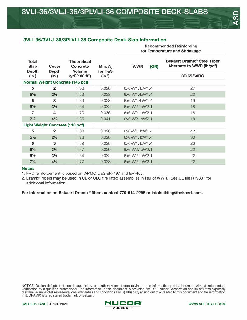
3VLI GR50 ASD | APRIL 2020
3VLI-36/3VLJ-36/3PLVLI-36 COMPOSITE DECK-SLABS
AS
D
WWW.VULCRAFT.COM
NOTICE: Design defects that could cause injury or death may result from relying on the information in this document without independent verification by a qualified professional. The information in this document is provided “AS IS”. Nucor Corporation and its affiliates expressly disclaim: (i) any and all representations, warranties and conditions and (ii) all liability arising out of or related to this document and the information in it. DRAMIX is a registered trademark of Bekaert.
3VLI-36/3VLJ-36/3PLVLI-36 Composite Deck-Slab Information
Total Slab
Depth(in.)
Cover Depth
(in.)
Theoretical Concrete Volume
(yd3/100 ft2)
Min. As for T&S
(in.2)
Recommended Reinforcing for Temperature and Shrinkage
WWR (OR) Bekaert Dramix® Steel Fiber
Alternate to WWR (lb/yd3)
3D 65/60BG
Normal Weight Concrete (145 pcf)
5 2 1.08 0.028 6x6-W1.4xW1.4 27
5½ 2½ 1.23 0.028 6x6-W1.4xW1.4 22
6 3 1.39 0.028 6x6-W1.4xW1.4 19
6½ 3½ 1.54 0.032 6x6-W2.1xW2.1 18
7 4 1.70 0.036 6x6-W2.1xW2.1 18
7½ 4½ 1.85 0.041 6x6-W2.1xW2.1 18
Light Weight Concrete (110 pcf)
5 2 1.08 0.028 6x6-W1.4xW1.4 42
5½ 2½ 1.23 0.028 6x6-W1.4xW1.4 30
6 3 1.39 0.028 6x6-W1.4xW1.4 23
61/4 31/4 1.47 0.029 6x6-W2.1xW2.1 22
6½ 3½ 1.54 0.032 6x6-W2.1xW2.1 22
71/4 41/4 1.77 0.038 6x6-W2.1xW2.1 22
Notes: 1. FRC reinforcement is based on IAPMO UES ER-497 and ER-465.2. Dramix® fibers may be used in UL or ULC fire rated assemblies in lieu of WWR. See UL file R19307 for additional information.
For information on Bekaert Dramix® fibers contact 770-514-2295 or [email protected].


AS
D
Nominal Dimensions
Standard Features Optional Features• Inquire regarding cost and lead times for: -Short cuts < 6’-0” -Sheet Lengths > 42’-0” -Alternative metallic and painted finishes• Side-lap or bottom flange slot venting
WWW.VULCRAFT.COM0.6C-30/0.6C-35 GR80 ASD | APRIL 2020
0.6C-30/0.6C-35 NON-COMPOSITE & ROOF DECKSGRADE 80 STEEL
Allowable Reactions at Supports Based on Web Crippling, Rn/Ω (lb/ft)Bearing Length of Webs
One-Flange Loading
DeckGage
End Bearing Interior Bearing
1½" 2" 1½" 2"
28 491 527 567 604
26 690 738 834 885
24 1176 1251 1507 1589
22 1729 1830 2295 2409
Section Properties
Deck Gage
Deck Weight
Base Metal Thickness
Yield Strength
Effective Moment of Inertia
at Service LoadId = (2Ie+Ig)/3
Effective Section Modulus
at Fy = 60 ksiAllowable Moment
Vertical Web
Shear
wdd t Fy Id+ Id- Se+ Se- Mn+/Ω Mn-/Ω Vn/Ω
(psf) (in.) (ksi) (in4/ft) (in4/ft) (in3/ft) (in3/ft) (lb-ft/ft) (lb-ft/ft) (lb/ft)
28 0.7 0.0149 60 0.011 0.011 0.033 0.034 99 102 1326
26 0.9 0.0179 60 0.013 0.013 0.042 0.042 126 126 1589
24 1.2 0.0239 60 0.017 0.017 0.056 0.056 168 168 2107
22 1.4 0.0295 60 0.021 0.021 0.069 0.068 207 204 2584
• ASTM A653 SS GR80 with G60• Standard lengths – 6’-0” to 42’-0”• IAPMO UES ER-0652 and UL Listed• Tables conform to ANSI/SDI NC-2017 and RD-2017

AS
D
WWW.VULCRAFT.COM0.6C-30/0.6C-35 GR80 ASD | APRIL 2020
0.6C-30/0.6C-35 NON-COMPOSITE & ROOF DECKSGRADE 80 STEEL
NOTICE: Design defects that could cause injury or death may result from relying on the information in this document without independent verification by a qualified professional. The information in this document is provided “AS IS”. Nucor Corporation and its affiliates expressly disclaim: (i) any and all representations, warranties and conditions and (ii) all liability arising out of or related to this document and the information in it.
Inward Uniform Allowable Loads, ASD (psf)
Deck Gage Spans Criteria
Span (ft-in.)
1'-0" 1'-6" 2'-0" 2'-6" 3'-0" 3'-6" 4'-0" 4'-6" 5'-0" 5'-6" 6'-0"
28
SingleWn / Ω 790 351 198 126 88 65 49 39 32 26 22
L/240 721 214 90 46 27 17 11 8 6 4 3
DoubleWn / Ω 760 351 200 129 90 66 51 40 32 27 23
L/240 --- --- --- 111 64 41 27 19 14 10 8
TripleWn / Ω 925 433 248 160 112 82 63 50 41 34 28
L/240 --- 403 170 87 50 32 21 15 11 8 6
26
SingleWn / Ω 1006 447 251 161 112 82 63 50 40 33 28
L/240 852 253 107 55 32 20 13 9 7 5 4
DoubleWn / Ω 935 432 247 159 111 82 63 49 40 33 28
L/240 --- --- --- 131 76 48 32 23 16 12 10
TripleWn / Ω 1136 533 306 198 138 102 78 62 50 41 35
L/240 --- 477 201 103 60 38 25 18 13 10 7
24
SingleWn / Ω 1341 596 335 215 149 109 84 66 54 44 37
L/240 1114 330 139 71 41 26 17 12 9 7 5
DoubleWn / Ω 1246 576 329 212 148 109 83 66 53 44 37
L/240 --- --- --- 172 99 63 42 29 21 16 12
TripleWn / Ω 1513 710 408 264 184 136 104 82 67 55 46
L/240 --- 623 263 135 78 49 33 23 17 13 10
22
SingleWn / Ω 1653 735 413 264 184 135 103 82 66 55 46
L/240 1377 408 172 88 51 32 22 15 11 8 6
DoubleWn / Ω 1515 700 400 257 179 132 101 80 65 54 45
L/240 --- --- --- 212 123 77 52 36 27 20 15
TripleWn / Ω 1841 863 495 320 223 165 126 100 81 67 56
L/240 --- 770 325 166 96 61 41 29 21 16 12
Notes: 1.Table does not account for web crippling. Required bearing should be determined based on specific span conditions.2. The symbol “---” indicates that the uniform allowable load based on deflection exceeds the allowable load based on stress.

AS
D
Nominal Dimensions
Standard Features Optional Features• Inquire regarding cost and lead times for: -Short cuts < 6’-0” -Sheet Lengths > 42’-0” -Alternative metallic and painted finishes• Side-lap or bottom flange slot venting
WWW.VULCRAFT.COM0.6C-36 GR80 ASD | APRIL 2020
0.6C-36 NON-COMPOSITE & ROOF DECKSGRADE 80 STEEL
Allowable Reactions at Supports Based on Web Crippling, Rn/Ω (lb/ft)Bearing Length of Webs
One-Flange Loading
DeckGage
End Bearing Interior Bearing
1½" 2" 1½" 2"
28 348 387 469 515
26 490 543 676 740
24 833 919 1186 1292
22 1227 1349 1782 1933
Section Properties
Deck Gage
Deck Weight
Base Metal Thickness
Yield Strength
Effective Moment of Inertia
at Service LoadId = (2Ie+Ig)/3
Effective Section Modulus
at Fy = 60 ksiAllowable Moment
Vertical Web
Shear
wdd t Fy Id+ Id- Se+ Se- Mn+/Ω Mn-/Ω Vn/Ω
(psf) (in.) (ksi) (in4/ft) (in4/ft) (in3/ft) (in3/ft) (lb-ft/ft) (lb-ft/ft) (lb/ft)
28 0.7 0.0149 60 0.012 0.012 0.034 0.035 102 105 1191
26 0.9 0.0179 60 0.015 0.015 0.043 0.043 129 129 1719
24 1.1 0.0239 60 0.020 0.020 0.058 0.058 174 174 2391
22 1.4 0.0295 60 0.023 0.023 0.071 0.071 213 213 2943
• ASTM A653 SS GR80 with G60• Standard lengths – 6’-0” to 42’-0”• IAPMO UES ER-0652 and UL Listed• Tables conform to ANSI/SDI NC-2017 and RD-2017

AS
D
WWW.VULCRAFT.COM0.6C-36 GR80 ASD | APRIL 2020
0.6C-36 NON-COMPOSITE & ROOF DECKSGRADE 80 STEEL
NOTICE: Design defects that could cause injury or death may result from relying on the information in this document without independent verification by a qualified professional. The information in this document is provided “AS IS”. Nucor Corporation and its affiliates expressly disclaim: (i) any and all representations, warranties and conditions and (ii) all liability arising out of or related to this document and the information in it.
Inward Uniform Allowable Loads, ASD (psf)
Deck Gage Spans Criteria
Span (ft-in.)
1'-0" 1'-6" 2'-0" 2'-6" 3'-0" 3'-6" 4'-0" 4'-6" 5'-0" 5'-6" 6'-0"
28
SingleWn / Ω 814 362 204 130 90 66 51 40 33 27 23
L/240 787 233 98 50 29 18 12 9 6 5 4
DoubleWn / Ω 767 358 205 132 92 68 52 41 33 28 23
L/240 --- --- --- 121 70 44 30 21 15 11 9
TripleWn / Ω 927 439 253 164 115 85 65 51 42 34 29
L/240 --- --- 186 95 55 35 23 16 12 9 7
26
SingleWn / Ω 1030 458 257 165 114 84 64 51 41 34 29
L/240 983 291 123 63 36 23 15 11 8 6 5
DoubleWn / Ω 965 444 253 163 114 84 64 51 41 34 29
L/240 --- --- --- 152 88 55 37 26 19 14 11
TripleWn / Ω 1174 548 314 203 141 104 80 63 51 42 36
L/240 --- --- 232 119 69 43 29 20 15 11 9
24
SingleWn / Ω 1389 617 347 222 154 113 87 69 56 46 39
L/240 1311 388 164 84 49 31 20 14 10 8 6
DoubleWn / Ω 1306 600 342 220 153 113 86 68 55 46 39
L/240 --- --- --- 202 117 74 49 35 25 19 15
TripleWn / Ω 1592 741 424 274 191 141 108 85 69 57 48
L/240 --- 733 309 158 92 58 39 27 20 15 11
22
SingleWn / Ω 1701 756 425 272 189 139 106 84 68 56 47
L/240 1508 447 188 96 56 35 24 17 12 9 7
DoubleWn / Ω 1599 735 418 269 188 138 106 84 68 56 47
L/240 --- --- --- 232 135 85 57 40 29 22 17
TripleWn / Ω 1950 908 519 335 234 172 132 104 85 70 59
L/240 --- 843 356 182 105 66 44 31 23 17 13
Notes: 1.Table does not account for web crippling. Required bearing should be determined based on specific span conditions.2. The symbol “---” indicates that the uniform allowable load based on deflection exceeds the allowable load based on stress.

Nominal Dimensions
Standard Features Optional Features
Allowable Reactions at Supports Based on Web Crippling, Rn/Ω (lb/ft)Bearing Length of Webs
One-Flange Loading
DeckGage
End Bearing Interior Bearing
1½" 2" 3" 1½" 2" 3"
26 479 530 617 724 792 906
24 815 899 1039 1250 1361 1547
22 1198 1317 1516 1856 2014 2278
20 1707 1870 2144 2668 2884 3247
• Inquire regarding cost and lead times for: -Short cuts < 6’-0” -Sheet Lengths > 42’-0” -Alternative metallic and painted finishes• Side-lap or bottom flange slot venting
1.0C-32 GR80 ASD | SEPTEMBER 2020
1.0C-32 NON-COMPOSITE & ROOF DECKGRADE 80 STEEL A
SD
WWW.VULCRAFT.COM
Section Properties
Deck Gage
Deck Weight
Base Metal Thickness
Yield Strength
Effective Moment of Inertia
at Service LoadId = (2Ie+Ig)/3
Effective Section Modulus
at Fy = 60 ksiAllowable Moment
Vertical Web
Shear
wdd t Fy Id+ Id- Se+ Se- Mn+/Ω Mn-/Ω Vn/Ω
(psf) (in.) (ksi) (in4/ft) (in4/ft) (in3/ft) (in3/ft) (lb-ft/ft) (lb-ft/ft) (lb/ft)
26 0.9 0.0179 60 0.041 0.043 0.067 0.071 201 213 1673
24 1.2 0.0239 60 0.057 0.058 0.098 0.103 293 308 2922
22 1.5 0.0295 60 0.071 0.071 0.130 0.134 389 401 3598
20 1.9 0.0358 60 0.090 0.090 0.168 0.166 503 497 4353
• ASTM A653 SS GR80 with G60• Standard lengths – 6’-0” to 42’-0”• IAPMO UES ER-0652 and UL Listed• Tables conform to ANSI/SDI NC-2017 and RD-2017

1.0C-32 NON-COMPOSITE & ROOF DECKGRADE 80 STEEL
1.0C-32 GR80 ASD | SEPTEMBER 2020
Inward Uniform Allowable Loads, ASD (psf)
Deck Gage Spans Criteria
Span (ft-in.)
2'-0" 2'-6" 3'-0" 3'-6" 4'-0" 4'-6" 5'-0" 5'-6" 6'-0" 6'-6" 7'-0"
26
SingleWn / Ω 401 257 178 131 100 79 64 53 45 38 33
L/240 336 172 100 63 42 29 22 16 12 10 8
DoubleWn / Ω 405 264 185 137 105 83 67 56 47 40 35
L/240 --- --- --- --- --- 75 54 41 31 25 20
TripleWn / Ω 497 325 229 170 131 103 84 70 59 50 43
L/240 --- --- 197 124 83 58 43 32 25 19 16
24
SingleWn / Ω 587 376 261 192 147 116 94 78 65 56 48
L/240 467 239 138 87 58 41 30 22 17 14 11
DoubleWn / Ω 596 386 270 199 153 121 98 81 68 58 50
L/240 --- --- --- --- 143 101 73 55 42 33 27
TripleWn / Ω 735 478 335 248 190 151 122 101 85 73 63
L/240 --- 459 266 167 112 79 57 43 33 26 21
22
SingleWn / Ω 778 498 346 254 195 154 125 103 86 74 64
L/240 582 298 172 109 73 51 37 28 22 17 14
DoubleWn / Ω 773 501 351 259 199 157 128 106 89 76 65
L/240 --- --- --- --- 175 123 90 67 52 41 33
TripleWn / Ω 951 620 435 322 247 196 159 132 111 94 82
L/240 --- 562 325 205 137 96 70 53 41 32 26
20
SingleWn / Ω 1006 644 447 328 251 199 161 133 112 95 82
L/240 738 378 219 138 92 65 47 35 27 21 17
DoubleWn / Ω 956 620 434 320 246 195 158 131 110 94 81
L/240 --- --- --- --- 222 156 114 85 66 52 41
TripleWn / Ω 1175 767 538 398 306 243 197 163 137 117 101
L/240 --- 713 413 260 174 122 89 67 52 41 32
Notes: 1.Table does not account for web crippling. Required bearing should be determined based on specific span conditions.2. The symbol “---” indicates that the uniform allowable load based on deflection exceeds the allowable load based on stress.
AS
D
NOTICE: Design defects that could cause injury or death may result from relying on the information in this document without independent verification by a qualified professional. The information in this document is provided “AS IS”. Nucor Corporation and its affiliates expressly disclaim: (i) any and all representations, warranties and conditions and (ii) all liability arising out of or related to this document and the information in it.
WWW.VULCRAFT.COM

Nominal Dimensions
Standard Features Optional Features• Inquire regarding cost and lead times for: -Short cuts < 6’-0” -Sheet Lengths > 42’-0” -Alternative metallic and painted finishes• Side-lap or bottom flange slot venting
1.0C-33 GR80 ASD | SEPTEMBER 2020
1.0C-33 NON-COMPOSITE DECK & ROOF DECKGRADE 80 STEEL A
SD
WWW.VULCRAFT.COM
Section Properties
Deck Gage
Deck Weight
Base Metal Thickness
Yield Strength
Effective Moment of Inertia
at Service LoadId = (2Ie+Ig)/3
Effective Section Modulus
at Fy = 60 ksiAllowable Moment
Vertical Web
Shear
wdd t Fy Id+ Id- Se+ Se- Mn+/Ω Mn-/Ω Vn/Ω
(psf) (in.) (ksi) (in4/ft) (in4/ft) (in3/ft) (in3/ft) (lb-ft/ft) (lb-ft/ft) (lb/ft)
26 0.9 0.0179 60 0.036 0.036 0.065 0.068 195 204 1606
24 1.2 0.0239 60 0.050 0.049 0.096 0.097 287 290 2131
22 1.5 0.0295 60 0.062 0.062 0.121 0.120 362 359 2613
20 1.8 0.0358 60 0.076 0.076 0.147 0.146 440 437 3148
• ASTM A653 SS GR80 with G60• Standard lengths – 6’-0” to 42’-0”• IAPMO UES ER-0652 and UL Listed• Tables conform to ANSI/SDI NC-2017 and RD-2017
Allowable Reactions at Supports Based on Web Crippling, Rn/Ω (lb/ft)Bearing Length of Webs
One-Flange Loading
DeckGage
End Bearing Interior Bearing
1½" 2" 3" 1½" 2" 3"
26 482 534 572 509 557 592
24 832 917 978 965 1050 1111
22 1232 1354 1437 1508 1636 1723
20 1769 1938 2046 2256 2439 2556

1.0C-33 NON-COMPOSITE & ROOF DECKGRADE 80 STEEL
1.0C-33 GR80 ASD | SEPTEMBER 2020
Inward Uniform Allowable Loads, ASD (psf)
Deck Gage Spans Criteria
Span (ft-in.)
2'-0" 2'-6" 3'-0" 3'-6" 4'-0" 4'-6" 5'-0" 5'-6" 6'-0" 6'-6" 7'-0"
26
SingleWn / Ω 389 249 173 127 97 77 62 51 43 37 32
L/240 295 151 87 55 37 26 19 14 11 9 7
DoubleWn / Ω 388 253 177 131 101 80 65 53 45 38 33
L/240 --- --- --- --- 89 62 45 34 26 21 17
TripleWn / Ω 476 312 219 162 125 99 81 67 56 48 41
L/240 --- 285 165 104 70 49 36 27 21 16 13
24
SingleWn / Ω 575 368 255 188 144 114 92 76 64 54 47
L/240 410 210 121 76 51 36 26 20 15 12 10
DoubleWn / Ω 550 359 252 186 143 113 92 76 64 55 47
L/240 --- --- --- 180 121 85 62 47 36 28 23
TripleWn / Ω 672 442 311 231 178 141 115 95 80 68 59
L/240 --- 388 225 141 95 67 49 36 28 22 18
22
SingleWn / Ω 725 464 322 237 181 143 116 96 81 69 59
L/240 508 260 151 95 64 45 33 24 19 15 12
DoubleWn / Ω 680 443 311 230 177 140 114 94 79 68 58
L/240 --- --- --- 228 153 107 78 59 45 36 29
TripleWn / Ω 830 546 385 285 220 175 142 117 99 84 73
L/240 --- 491 284 179 120 84 61 46 36 28 22
20
SingleWn / Ω 880 563 391 287 220 174 141 116 98 83 72
L/240 623 319 185 116 78 55 40 30 23 18 15
DoubleWn / Ω 826 539 379 280 215 171 139 115 96 82 71
L/240 --- --- --- 280 188 132 96 72 56 44 35
TripleWn / Ω 1009 664 468 347 267 212 172 143 120 103 89
L/240 --- 602 348 219 147 103 75 57 44 34 27
Notes: 1.Table does not account for web crippling. Required bearing should be determined based on specific span conditions.2. The symbol “---” indicates that the uniform allowable load based on deflection exceeds the allowable load based on stress.
AS
D
NOTICE: Design defects that could cause injury or death may result from relying on the information in this document without independent verification by a qualified professional. The information in this document is provided “AS IS”. Nucor Corporation and its affiliates expressly disclaim: (i) any and all representations, warranties and conditions and (ii) all liability arising out of or related to this document and the information in it.
WWW.VULCRAFT.COM

Nominal Dimensions
Standard Features Optional Features• ASTM A653 SS GR80 with G60• Standard lengths – 6’-0” to 42’-0”• IAPMO UES ER-0652 and UL Listed• Tables conform to ANSI/SDI NC-2017 and RD-2017
• Inquire regarding cost and lead times for: -Short cuts < 6’-0” -Sheet Lengths > 42’-0” -Alternative metallic and painted finishes• Side-lap or bottom flange slot venting
1.0C-36 GR80 ASD | APRIL 2020
1.0C-36 NON-COMPOSITE & ROOF DECKGRADE 80 STEEL A
SD
WWW.VULCRAFT.COM
Section Properties
Deck Gage
Deck Weight
Base Metal Thickness
Yield Strength
Effective Moment of Inertia
at Service LoadId = (2Ie+Ig)/3
Effective Section Modulus
at Fy = 60 ksiAllowable Moment
Vertical Web
Shear
wdd t Fy Id+ Id- Se+ Se- Mn+/Ω Mn-/Ω Vn/Ω
(psf) (in.) (ksi) (in4/ft) (in4/ft) (in3/ft) (in3/ft) (lb-ft/ft) (lb-ft/ft) (lb/ft)
26 0.9 0.0179 60 0.039 0.039 0.065 0.068 195 204 1656
24 1.2 0.0239 60 0.057 0.057 0.099 0.103 296 308 2754
22 1.5 0.0295 60 0.070 0.070 0.129 0.131 386 392 3389
20 1.8 0.0358 60 0.083 0.083 0.160 0.160 479 479 4100
Allowable Reactions at Supports Based on Web Crippling, Rn/Ω (lb/ft)Bearing Length of Webs
One-Flange Loading
DeckGage
End Bearing Interior Bearing
1½" 2" 3" 1½" 2" 3"
26 464 514 598 658 720 825
24 792 873 1010 1154 1257 1429
22 1167 1283 1477 1730 1877 2122
20 1665 1824 2091 2504 2707 3047

1.0C-36 NON-COMPOSITE & ROOF DECKGRADE 80 STEEL
1.0C-36 GR80 ASD | APRIL 2020
Inward Uniform Allowable Loads, ASD (psf)
Deck Gage Spans Criteria
Span (ft-in.)
2'-0" 2'-6" 3'-0" 3'-6" 4'-0" 4'-6" 5'-0" 5'-6" 6'-0" 6'-6" 7'-0"
26
SingleWn / Ω 389 249 173 127 97 77 62 51 43 37 32
L/240 320 164 95 60 40 28 20 15 12 9 7
DoubleWn / Ω 389 253 177 131 101 80 65 54 45 38 33
L/240 --- --- --- --- 96 68 49 37 29 22 18
TripleWn / Ω 478 312 220 163 125 99 81 67 56 48 41
L/240 --- 309 179 113 75 53 39 29 22 18 14
24
SingleWn / Ω 593 379 263 194 148 117 95 78 66 56 48
L/240 467 239 138 87 58 41 30 22 17 14 11
DoubleWn / Ω 594 385 269 199 153 121 98 81 68 58 50
L/240 --- --- --- --- 141 99 72 54 42 33 26
TripleWn / Ω 731 477 334 247 190 151 122 101 85 73 63
L/240 --- 452 261 165 110 77 56 42 33 26 21
22
SingleWn / Ω 772 494 343 252 193 153 124 102 86 73 63
L/240 574 294 170 107 72 50 37 28 21 17 13
DoubleWn / Ω 754 489 342 253 194 154 125 103 87 74 64
L/240 --- --- --- --- 173 121 88 66 51 40 32
TripleWn / Ω 926 605 425 314 242 191 155 129 108 92 80
L/240 --- 554 321 202 135 95 69 52 40 32 25
20
SingleWn / Ω 958 613 426 313 240 189 153 127 106 91 78
L/240 680 348 202 127 85 60 44 33 25 20 16
DoubleWn / Ω 920 597 418 309 237 188 152 126 106 90 78
L/240 --- --- --- 306 205 144 105 79 61 48 38
TripleWn / Ω 1130 738 518 383 295 234 190 157 132 113 97
L/240 --- 657 380 240 161 113 82 62 48 37 30
Notes: 1.Table does not account for web crippling. Required bearing should be determined based on specific span conditions.2. The symbol “---” indicates that the uniform allowable load based on deflection exceeds the allowable load based on stress.
AS
D
NOTICE: Design defects that could cause injury or death may result from relying on the information in this document without independent verification by a qualified professional. The information in this document is provided “AS IS”. Nucor Corporation and its affiliates expressly disclaim: (i) any and all representations, warranties and conditions and (ii) all liability arising out of or related to this document and the information in it.
WWW.VULCRAFT.COM

Nominal Dimensions
Standard Features Optional Features• ASTM A653 SS GR80 with G60• Standard lengths – 6’-0” to 42’-0”• IAPMO UES ER-652 and UL Listed• Tables conform to ANSI/SDI NC-2017 and RD-2017
Allowable Reactions at Supports Based on Web Crippling, Rn/Ω (lb/ft)Bearing Length of Webs
One-Flange Loading
DeckGage
End Bearing Interior Bearing
1½" 2" 3" 1½" 2" 3"
26 353 391 454 393 430 492
24 614 677 783 746 812 923
22 915 1006 1158 1166 1265 1431
20 1318 1444 1656 1744 1885 2122
• Inquire regarding cost and lead times for: -Short cuts < 6’-0” -Sheet Lengths > 42’-0” -Alternative metallic and painted finishes• Side-lap or bottom flange slot venting
1.3C GR80 ASD | SEPTEMBER 2020
1.3C-32 NON-COMPOSITE DECK & ROOF DECKGRADE 80 STEEL A
SD
WWW.VULCRAFT.COM
Section Properties
Deck Gage
Deck Weight
Base Metal Thickness
Yield Strength
Effective Moment of Inertia
at Service LoadId = (2Ie+Ig)/3
Effective Section Modulus
at Fy = 60 ksiAllowable Moment
Vertical Web
Shear
wdd t Fy Id+ Id- Se+ Se- Mn+/Ω Mn-/Ω Vn/Ω
(psf) (in.) (ksi) (in4/ft) (in4/ft) (in3/ft) (in3/ft) (lb-ft/ft) (lb-ft/ft) (lb/ft)
26 0.9 0.0179 60 0.067 0.067 0.080 0.089 240 266 1422
24 1.3 0.0239 60 0.093 0.092 0.126 0.130 377 389 2538
22 1.6 0.0295 60 0.116 0.116 0.163 0.163 488 488 3481
20 1.9 0.0358 60 0.139 0.139 0.197 0.197 590 590 4211

NOTICE: Design defects that could cause injury or death may result from relying on the information in this document without independent verification by a qualified professional. The information in this document is provided “AS IS”. Nucor Corporation and its affiliates expressly disclaim: (i) any and all representations, warranties and conditions and (ii) all liability arising out of or related to this document and the information in it.
1.3C GR80 ASD | SEPTEMBER 2020
1.3C-32 NON-COMPOSITE DECK & ROOF DECKGRADE 80 STEEL A
SD
WWW.VULCRAFT.COM
Inward Uniform Allowable Loads, ASD (psf)
Deck Gage Spans Criteria
Span (ft-in.)
4'-0" 4'-6" 5'-0" 5'-6" 6'-0" 6'-6" 7'-0" 7'-6" 8'-0" 9'-0" 10'-0"
26
SingleWn / Ω 120 95 77 63 53 45 39 34 30 24 19
L/240 69 48 35 26 20 16 13 10 9 6 4
DoubleWn / Ω 130 103 84 69 59 50 43 38 33 26 21
L/240 --- --- --- 64 49 39 31 25 21 15 11
TripleWn / Ω 160 128 104 86 73 62 54 47 41 33 26
L/240 130 91 66 50 38 30 24 20 16 11 8
24
SingleWn / Ω 189 149 121 100 84 71 62 54 47 37 30
L/240 95 67 49 37 28 22 18 14 12 8 6
DoubleWn / Ω 191 152 123 102 86 73 63 55 48 38 31
L/240 --- --- 116 87 67 53 42 34 28 20 15
TripleWn / Ω 237 188 153 127 107 91 79 69 60 48 39
L/240 178 125 91 68 53 41 33 27 22 16 11
22
SingleWn / Ω 244 193 156 129 108 92 80 69 61 48 39
L/240 119 83 61 46 35 28 22 18 15 10 8
DoubleWn / Ω 240 191 155 128 108 92 79 69 61 48 39
L/240 --- --- 147 110 85 67 53 43 36 25 18
TripleWn / Ω 298 237 193 159 134 115 99 86 76 60 49
L/240 224 158 115 86 66 52 42 34 28 20 14
20
SingleWn / Ω 295 233 189 156 131 112 96 84 74 58 47
L/240 142 100 73 55 42 33 27 22 18 12 9
DoubleWn / Ω 290 230 187 155 130 111 96 84 73 58 47
L/240 --- --- 176 132 102 80 64 52 43 30 22
TripleWn / Ω 361 286 233 193 162 138 120 104 92 73 59
L/240 269 189 138 103 80 63 50 41 34 24 17
Notes: 1.Table does not account for web crippling. Required bearing should be determined based on specific span conditions.2. The symbol “---” indicates that the uniform allowable load based on deflection exceeds the allowable load based on stress.

Standard Features Optional Features• ASTM A653 SS GR50 Min. with G60 -SS GR80 (Fy=60) for 24 gage• Standard lengths – 6’-0” to 42’-0”• IAPMO UES ER-0652 and UL Listed• Tables conform to ANSI/SDI NC-2017
Allowable Reactions at Supports Based on Web Crippling, Rn/Ω (lb/ft)Bearing Length of Webs
One-Flange Loading Two-Flange Loading
DeckGage
End Bearing Interior Bearing End Bearing Interior Bearing
1½" 2" 3" 4" 3" 4" 1½" 2" 3" 4" 3" 4"
24 657 724 837 918 1197 1300 639 691 778 840 1460 1594
22 807 887 1021 1115 1482 1602 842 908 1017 1093 1834 1994
20 1153 1263 1448 1574 2127 2289 1274 1368 1525 1632 2662 2881
18 1931 2105 2398 2588 3586 3831 2297 2454 2716 2887 4546 4884
• Inquire regarding cost and lead times for: -Short cuts < 6’-0” -Sheet Lengths > 42’-0” -Alternative metallic and painted finishes
1.5C GR50 ASD | SEPTEMBER 2020
1.5C-36 NON-COMPOSITE DECKGRADE 50 STEEL A
SD
WWW.VULCRAFT.COM
Section Properties
Deck Gage
Deck Weight
Base Metal Thickness
Yield Strength
Effective Moment of Inertia
at Service LoadId = (2Ie+Ig)/3
Effective Section Modulus
at Fy = 50 ksiAllowable Moment
Vertical Web
Shear
wdd t Fy Id+ Id- Se+ Se- Mn+/Ω Mn-/Ω Vn/Ω
(psf) (in.) (ksi) (in4/ft) (in4/ft) (in3/ft) (in3/ft) (lb-ft/ft) (lb-ft/ft) (lb/ft)
24 1.3 0.0239 60 0.138 0.118 0.131 0.120 392 359 1551
22 1.6 0.0295 50 0.178 0.155 0.179 0.169 447 422 2654
20 2.0 0.0358 50 0.217 0.197 0.229 0.224 571 559 3207
18 2.6 0.0474 50 0.290 0.277 0.318 0.306 793 763 4209
Nominal Dimensions

1.5C GR50 ASD | SEPTEMBER 2020
1.5C-36 NON-COMPOSITE DECKGRADE 50 STEEL A
SD
NOTICE: Design defects that could cause injury or death may result from relying on the information in this document without independent verification by a qualified professional. The information in this document is provided “AS IS”. Nucor Corporation and its affiliates expressly disclaim: (i) any and all representations, warranties and conditions and (ii) all liability arising out of or related to this document and the information in it.
WWW.VULCRAFT.COM
Inward Uniform Allowable Loads, ASD (psf)
Deck Gage Spans Criteria
Span (ft-in.)
4'-0" 4'-6" 5'-0" 5'-6" 6'-0" 6'-6" 7'-0" 7'-6" 8'-0" 9'-0" 10'-0"
24
SingleWn / Ω 196 155 126 104 87 74 64 56 49 39 31
L/240 141 99 72 54 42 33 26 21 18 12 9
DoubleWn / Ω 173 137 112 93 78 67 58 50 44 35 29
L/240 --- --- --- --- --- --- 54 44 36 26 19
TripleWn / Ω 212 170 138 115 97 83 72 63 55 44 36
L/240 --- 160 117 88 68 53 43 35 29 20 15
22
SingleWn / Ω 223 176 143 118 99 85 73 64 56 44 36
L/240 182 128 93 70 54 42 34 28 23 16 12
DoubleWn / Ω 207 164 133 110 93 79 68 60 52 41 34
L/240 --- --- --- --- --- --- --- 58 48 34 24
TripleWn / Ω 256 204 166 137 116 99 85 74 65 52 42
L/240 --- --- 153 115 89 70 56 45 37 26 19
20
SingleWn / Ω 286 226 183 151 127 108 93 81 71 56 46
L/240 222 156 114 86 66 52 41 34 28 20 14
DoubleWn / Ω 273 217 176 146 123 105 91 79 69 55 45
L/240 --- --- --- --- --- --- --- 74 61 43 31
TripleWn / Ω 338 269 219 181 153 131 113 98 87 69 56
L/240 --- 268 195 147 113 89 71 58 48 33 24
18
SingleWn / Ω 397 313 254 210 176 150 130 113 99 78 63
L/240 297 209 152 114 88 69 55 45 37 26 19
DoubleWn / Ω 372 296 240 199 168 143 124 108 95 75 61
L/240 --- --- --- --- --- --- --- 104 85 60 44
TripleWn / Ω 460 366 298 248 209 178 154 134 118 94 76
L/240 --- --- 274 206 159 125 100 81 67 47 34
Notes: 1.Table does not account for web crippling. Required bearing should be determined based on specific span conditions.2. The symbol “---” indicates that the uniform allowable load based on deflection exceeds the allowable load based on stress.

Standard Features Optional Features• ASTM A653 SS GR50 Min. with G60• Standard lengths – 6’-0” to 42’-0”• IAPMO UES ER-652 and UL Listed• Tables conform to ANSI/SDI NC-2017
Allowable Reactions at Supports Based on Web Crippling, Rn/Ω (lb/ft)Bearing Length of Webs
One-Flange Loading Two-Flange Loading
DeckGage
End Bearing Interior Bearing End Bearing Interior Bearing
1½" 2" 3" 4" 4" 6” 1½" 2" 3" 4" 4" 6"
22 363 399 460 511 767 882 362 390 437 476 924 1071
20 522 571 655 726 1098 1257 554 595 663 721 1342 1550
18 879 959 1092 1205 1843 2095 1013 1082 1198 1296 2292 2631
16 1354 1470 1666 1830 2825 3194 1654 1759 1936 2085 3554 4059
• Inquire regarding cost and lead times for: -Short cuts < 6’-0” -Sheet Lengths > 42’-0” -Alternative metallic and painted finishes• Factory Hanger Tabs
2C GR50 ASD | SEPTEMBER 2020
2C-36 NON-COMPOSITE DECKGRADE 50 STEEL A
SD
WWW.VULCRAFT.COM
Section Properties
Deck Gage
Deck Weight
Base Metal Thickness
Yield Strength
Effective Moment of Inertia
at Service LoadId = (2Ie+Ig)/3
Effective Section Modulus
at Fy = 50 ksiAllowable Moment
Vertical Web
Shear
wdd t Fy Id+ Id- Se+ Se- Mn+/Ω Mn-/Ω Vn/Ω
(psf) (in.) (ksi) (in4/ft) (in4/ft) (in3/ft) (in3/ft) (lb-ft/ft) (lb-ft/ft) (lb/ft)
22 1.6 0.0295 50 0.324 0.324 0.244 0.255 609 637 1641
20 1.9 0.0358 50 0.409 0.407 0.326 0.337 813 841 2419
18 2.5 0.0474 50 0.557 0.557 0.485 0.500 1210 1247 3240
16 3.2 0.0598 50 0.703 0.703 0.643 0.652 1604 1627 4069
Nominal Dimensions

2C GR50 ASD | SEPTEMBER 2020
2C-36 NON-COMPOSITE DECKGRADE 50 STEEL A
SD
NOTICE: Design defects that could cause injury or death may result from relying on the information in this document without independent verification by a qualified professional. The information in this document is provided “AS IS”. Nucor Corporation and its affiliates expressly disclaim: (i) any and all representations, warranties and conditions and (ii) all liability arising out of or related to this document and the information in it.
WWW.VULCRAFT.COM
Inward Uniform Allowable Loads, ASD (psf)
Deck Gage Spans Criteria
Span (ft-in.)
5'-0" 5'-6" 6'-0" 6'-6" 7'-0" 7'-6" 8'-0" 8'-6" 9'-0" 10'-0" 11'-0"
22
SingleWn / Ω 195 161 135 115 99 87 76 67 60 49 40
L/240 170 128 98 77 62 50 41 35 29 21 16
DoubleWn / Ω 190 159 135 115 100 88 77 69 61 50 41
L/240 --- --- --- --- --- --- --- --- --- --- 38
TripleWn / Ω 231 194 165 142 123 108 95 85 76 62 51
L/240 --- --- --- --- 117 95 78 65 55 40 30
20
SingleWn / Ω 260 215 181 154 133 116 102 90 80 65 54
L/240 214 161 124 98 78 64 52 44 37 27 20
DoubleWn / Ω 254 212 179 154 133 116 103 91 82 66 55
L/240 --- --- --- --- --- --- --- --- --- 64 48
TripleWn / Ω 310 260 221 189 164 144 127 113 101 82 68
L/240 --- --- --- 183 147 119 98 82 69 50 38
18
SingleWn / Ω 387 320 269 229 198 172 151 134 120 97 80
L/240 292 219 169 133 106 87 71 59 50 37 27
DoubleWn / Ω 372 311 264 226 196 172 152 135 120 98 81
L/240 --- --- --- --- --- --- --- --- --- 88 66
TripleWn / Ω 453 380 323 278 242 212 187 167 149 122 101
L/240 --- --- 319 251 201 163 135 112 95 69 52
16
SingleWn / Ω 513 424 356 304 262 228 201 178 158 128 106
L/240 369 277 213 168 134 109 90 75 63 46 35
DoubleWn / Ω 483 404 343 294 255 224 197 175 157 128 106
L/240 --- --- --- --- --- --- --- --- 152 111 83
TripleWn / Ω 587 493 420 361 314 275 243 217 194 158 131
L/240 --- --- 403 317 254 206 170 142 119 87 65
Notes: 1.Table does not account for web crippling. Required bearing should be determined based on specific span conditions.2. The symbol “---” indicates that the uniform allowable load based on deflection exceeds the allowable load based on stress.
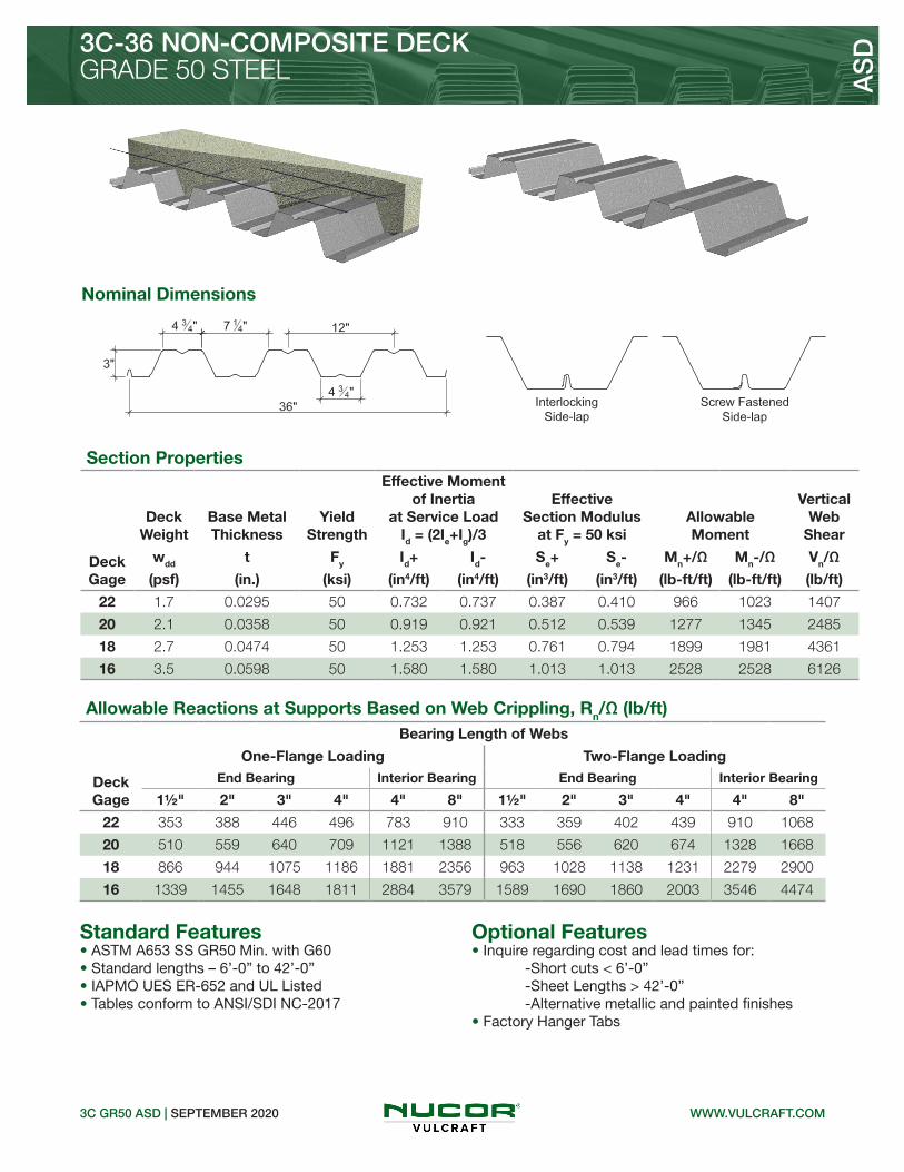
Standard Features Optional Features• ASTM A653 SS GR50 Min. with G60• Standard lengths – 6’-0” to 42’-0”• IAPMO UES ER-652 and UL Listed• Tables conform to ANSI/SDI NC-2017
Allowable Reactions at Supports Based on Web Crippling, Rn/Ω (lb/ft)Bearing Length of Webs
One-Flange Loading Two-Flange Loading
DeckGage
End Bearing Interior Bearing End Bearing Interior Bearing
1½" 2" 3" 4" 4" 8" 1½" 2" 3" 4" 4" 8"
22 353 388 446 496 783 910 333 359 402 439 910 1068
20 510 559 640 709 1121 1388 518 556 620 674 1328 1668
18 866 944 1075 1186 1881 2356 963 1028 1138 1231 2279 2900
16 1339 1455 1648 1811 2884 3579 1589 1690 1860 2003 3546 4474
• Inquire regarding cost and lead times for: -Short cuts < 6’-0” -Sheet Lengths > 42’-0” -Alternative metallic and painted finishes• Factory Hanger Tabs
3C GR50 ASD | SEPTEMBER 2020
3C-36 NON-COMPOSITE DECKGRADE 50 STEEL A
SD
WWW.VULCRAFT.COM
Section Properties
Deck Gage
Deck Weight
Base Metal Thickness
Yield Strength
Effective Moment of Inertia
at Service LoadId = (2Ie+Ig)/3
Effective Section Modulus
at Fy = 50 ksiAllowable Moment
Vertical Web
Shear
wdd t Fy Id+ Id- Se+ Se- Mn+/Ω Mn-/Ω Vn/Ω
(psf) (in.) (ksi) (in4/ft) (in4/ft) (in3/ft) (in3/ft) (lb-ft/ft) (lb-ft/ft) (lb/ft)
22 1.7 0.0295 50 0.732 0.737 0.387 0.410 966 1023 1407
20 2.1 0.0358 50 0.919 0.921 0.512 0.539 1277 1345 2485
18 2.7 0.0474 50 1.253 1.253 0.761 0.794 1899 1981 4361
16 3.5 0.0598 50 1.580 1.580 1.013 1.013 2528 2528 6126
Nominal Dimensions

3C GR50 ASD | SEPTEMBER 2020
3C-36 NON-COMPOSITE DECKGRADE 50 STEEL A
SD
NOTICE: Design defects that could cause injury or death may result from relying on the information in this document without independent verification by a qualified professional. The information in this document is provided “AS IS”. Nucor Corporation and its affiliates expressly disclaim: (i) any and all representations, warranties and conditions and (ii) all liability arising out of or related to this document and the information in it.
WWW.VULCRAFT.COM
Inward Uniform Allowable Loads, ASD (psf)
Deck Gage Spans Criteria
Span (ft-in.)
6'-0" 7'-0" 7'-6" 8'-0" 8'-6" 9'-0" 9'-6" 10'-0" 11'-0" 12'-0" 13'-0"
22
SingleWn / Ω 215 158 137 121 107 95 86 77 64 54 46
L/240 --- 140 114 94 78 66 56 48 36 28 22
DoubleWn / Ω 194 148 131 116 104 94 85 77 64 54 47
L/240 --- --- --- --- --- --- --- --- --- --- ---
TripleWn / Ω 230 177 157 140 126 114 103 94 79 67 57
L/240 --- --- --- --- --- --- --- 91 69 53 42
20
SingleWn / Ω 284 209 182 160 141 126 113 102 84 71 60
L/240 279 176 143 118 98 83 70 60 45 35 27
DoubleWn / Ω 272 205 180 159 142 127 115 104 86 73 62
L/240 --- --- --- --- --- --- --- --- --- --- ---
TripleWn / Ω 329 249 219 195 174 156 141 128 107 90 77
L/240 --- --- --- --- --- --- 133 114 86 66 52
18
SingleWn / Ω 422 310 270 237 210 188 168 152 126 105 90
L/240 380 239 195 160 134 113 96 82 62 48 37
DoubleWn / Ω 412 308 270 238 212 190 171 155 128 108 92
L/240 --- --- --- --- --- --- --- --- --- --- 90
TripleWn / Ω 501 377 331 293 261 234 211 191 159 134 115
L/240 --- --- --- --- 253 213 181 155 117 90 71
16
SingleWn / Ω 562 413 359 316 280 250 224 202 167 140 120
L/240 480 302 246 202 169 142 121 104 78 60 47
DoubleWn / Ω 531 396 347 306 272 243 219 198 164 138 118
L/240 --- --- --- --- --- --- --- --- --- --- 114
TripleWn / Ω 649 486 427 377 336 301 271 245 204 172 147
L/240 --- --- --- --- 318 268 228 196 147 113 89
Notes: 1.Table does not account for web crippling. Required bearing should be determined based on specific span conditions.2. The symbol “---” indicates that the uniform allowable load based on deflection exceeds the allowable load based on stress.


1.5BP/1.5VLP GR50 ASD | APRIL 2020
1.5BP/1.5VLP CELLULAR DECKSGRADE 50 STEEL A
SD
Nominal Dimensions
Standard Features Optional Features• ASTM A653 SS GR50 Min., with G60• Standard lengths – 6’-0” to 42’-0”• IAPMO UES ER-0652, UL, and FM Listed• Tables conform to ANSI/SDI RD-2017 and C-2017
Section Properties
Deck Gage
Deck Weight
Base Metal Thickness
Yield Strength
Effective Moment of Inertia
at Service LoadId = (2Ie+Ig)/3
Effective Section Modulus at Fy = 50 ksi
Allowable Moment
Vertical Web
Shear
wdd t Fy Id+ Id- Se+ Se- Mn+/Ω Mn-/Ω Vn/Ω
(psf) (in.) (ksi) (in4/ft) (in4/ft) (in3/ft) (in3/ft) (lb-ft/ft) (lb-ft/ft) (lb/ft)
20/20 3.6 0.0358/0.0358 50 0.393 0.293 0.272 0.240 679 599 3207
20/18 4.1 0.0358/0.0474 50 0.428 0.315 0.280 0.259 699 646 3207
18/20 4.1 0.0474/0.0358 50 0.504 0.369 0.405 0.312 1010 778 4209
18/18 4.6 0.0474/0.0474 50 0.551 0.396 0.415 0.330 1035 823 4209
18/16 5.1 0.0474/0.0598 50 0.594 0.423 0.425 0.350 1060 873 4209
16/18 5.3 0.0598/0.0474 50 0.667 0.479 0.579 0.400 1445 998 5261
16/16 5.8 0.0598/0.0598 50 0.721 0.510 0.591 0.421 1475 1050 5261
• Inquire regarding cost and lead times for: -Short Cuts < 6’-0” -Sheet Lengths > 42’-0” -Alternative metallic finishes• Cellular Acoustical Versions
BP CELLULAR ROOF DECK
VLP CELLULAR COMPOSITE DECK
Allowable Reactions at Supports Based on Web Crippling, Rn/Ω (lb/ft)Bearing Length of Webs
One-Flange Loading Two-Flange Loading
DeckGage
End Bearing Interior Bearing End Bearing Interior Bearing
1½" 2" 3" 4" 3" 4" 1½" 2" 3" 4" 3" 4"
20/XX 1153 1263 1448 1574 2127 2289 1274 1368 1525 1632 2662 2881
18/XX 1931 2105 2398 2588 3586 3831 2297 2454 2716 2887 4546 4884
16/XX 2958 3212 3639 3900 5517 5855 3713 3950 4347 4590 7050 7523
NOTICE: Design defects that could cause injury or death may result from relying on the information in this document without independent verification by a qualified professional. The information in this document is provided “AS IS”. Nucor Corporation and its affiliates expressly disclaim: (i) any and all representations, warranties and conditions and (ii) all liability arising out of or related to this document and the information in it.
WWW.VULCRAFT.COM
• 1.5BP Deck used with TSWs or BPs• 1.5PLBP Deck used with PunchLok® II System
• 1.5VLP Deck used with TSWs or BPs• 1.5PLVLP Deck used with PunchLok® II System
Plant Cover Width
VNY 24”
VNE 36”

Standard Features Optional Features
Section Properties
Deck Gage
Deck Weight
Base Metal Thickness
Yield Strength
Effective Moment of Inertia
at Service LoadId = (2Ie+Ig)/3
Effective Section Modulus at Fy = 50 ksi
Allowable Moment
Vertical Web
Shear
wdd t Fy Id+ Id- Se+ Se- Mn+/Ω Mn-/Ω Vn/Ω
(psf) (in.) (ksi) (in4/ft) (in4/ft) (in3/ft) (in3/ft) (lb-ft/ft) (lb-ft/ft) (lb/ft)
20/20 3.3 0.0358/0.0358 50 0.380 0.293 0.270 0.240 674 599 3207
20/18 3.8 0.0358/0.0474 50 0.414 0.315 0.277 0.259 691 646 3207
18/20 4.0 0.0474/0.0358 50 0.485 0.369 0.400 0.312 998 778 4209
18/18 4.4 0.0474/0.0474 50 0.530 0.395 0.411 0.330 1025 823 4209
18/16 4.9 0.0474/0.0598 50 0.572 0.407 0.420 0.311 1048 776 4209
16/18 5.1 0.0598/0.0474 50 0.641 0.478 0.571 0.400 1425 998 5261
16/16 5.6 0.0598/0.0598 50 0.692 0.492 0.583 0.380 1455 948 5261
1.5BPA/1.5VLPA GR50 ASD | APRIL 2020
1.5BPA/1.5VLPA CELLULAR ACOUSTICAL DECKSGRADE 50 STEEL A
SD
BP CELLULAR ACOUSTICAL ROOF DECK
VLP CELLULAR ACOUSTICAL COMPOSITE DECK
NOTICE: Design defects that could cause injury or death may result from relying on the information in this document without independent verification by a qualified professional. The information in this document is provided “AS IS”. Nucor Corporation and its affiliates expressly disclaim: (i) any and all representations, warranties and conditions and (ii) all liability arising out of or related to this document and the information in it.
Nominal Dimensions
Allowable Reactions at Supports Based on Web Crippling, Rn/Ω (lb/ft)Bearing Length of Webs
One-Flange Loading Two-Flange Loading
DeckGage
End Bearing Interior Bearing End Bearing Interior Bearing
1½" 2" 3" 4" 3" 4" 1½" 2" 3" 4" 3" 4"
20/XX 1153 1263 1448 1574 2127 2289 1274 1368 1525 1632 2662 2881
18/XX 1931 2105 2398 2588 3586 3831 2297 2454 2716 2887 4546 4884
16/XX 2958 3212 3639 3900 5517 5855 3713 3950 4347 4590 7050 7523
WWW.VULCRAFT.COM
• ASTM A653 SS GR50 Min., with G60• Standard lengths – 6’-0” to 42’-0”• IAPMO UES ER-0652, UL, and FM Listed• Tables conform to ANSI/SDI RD-2017 and C-2017
• Inquire regarding cost and lead times for: -Short Cuts < 6’-0” -Sheet Lengths > 42’-0” -Alternative metallic finishes
• 1.5BPA Deck used with TSWs or BPs• 1.5PLBPA Deck used with PunchLok® II System
• 1.5VPLA Deck used with TSWs or BPs• 1.5PLVPA Deck used with PunchLok® II System
Plant Cover Width
VNY 24”
VNE 36”

Section Properties
Deck Gage
Deck Weight
Base Metal Thickness
Yield Strength
Effective Moment of Inertia
at Service LoadId = (2Ie+Ig)/3
Effective Section Modulus at Fy = 50 ksi
Allowable Moment
Vertical Web
Shear
wdd t Fy Id+ Id- Se+ Se- Mn+/Ω Mn-/Ω Vn/Ω
(psf) (in.) (ksi) (in4/ft) (in4/ft) (in3/ft) (in3/ft) (lb-ft/ft) (lb-ft/ft) (lb/ft)
20/20 3.7 0.0358/0.0358 50 1.519 1.153 0.496 0.492 1238 1228 3761
20/18 4.2 0.0358/0.0474 50 1.645 1.248 0.523 0.552 1305 1377 3761
18/20 4.4 0.0474/0.0358 50 1.931 1.460 0.786 0.674 1961 1682 6598
18/18 4.9 0.0474/0.0474 50 2.094 1.568 0.806 0.733 2011 1829 6598
18/16 5.5 0.0474/0.0598 50 2.243 1.699 0.806 0.822 2011 2051 6598
16/18 5.7 0.0598/0.0474 50 2.549 1.901 1.093 0.901 2727 2248 9064
16/16 6.2 0.0598/0.0598 50 2.732 2.046 1.116 0.998 2784 2490 9064
3NP-32 GR50 ASD | APRIL 2020
3NP-32/3PLNP-32 CELLULAR DECKGRADE 50 STEEL A
SD
32” WIDE 3NP CELLULAR ROOF DECK
Nominal Dimensions
NOTICE: Design defects that could cause injury or death may result from relying on the information in this document without independent verification by a qualified professional. The information in this document is provided “AS IS”. Nucor Corporation and its affiliates expressly disclaim: (i) any and all representations, warranties and conditions and (ii) all liability arising out of or related to this document and the information in it.
Standard Features Optional Features• ASTM A653 SS GR50 Min., with G60• Standard lengths – 6’-0” to 42’-0”• IAPMO UES ER-0652 and FM Listed• Tables conform to ANSI/SDI RD-2017
Allowable Reactions at Supports Based on Web Crippling, Rn/Ω (lb/ft)Bearing Length of Webs
One-Flange Loading Two-Flange Loading
DeckGage
End Bearing Interior Bearing End Bearing Interior Bearing
1½" 2" 3" 4" 4" 8" 1½" 2" 3" 4" 4" 8"
20/XX 774 848 972 1077 1697 2101 788 846 944 1026 2014 2529
18/XX 1313 1432 1631 1799 2847 3565 1464 1563 1731 1872 3454 4397
16/XX 2031 2206 2499 2746 4365 5416 2414 2568 2826 3043 5374 6781
WWW.VULCRAFT.COM
• Inquire regarding cost and lead times for: -Short Cuts < 6’-0” -Sheet Lengths > 42’-0” -Alternative metallic finishes• Cellular Acoustical Versions
• 3NP-32 Deck used with TSWs or BPs• 3PLNP-32 Deck used with PunchLok® II System

Nominal Dimensions
Section Properties
Deck Gage
Deck Weight
Base Metal Thickness
Yield Strength
Effective Moment of Inertia
at Service LoadId = (2Ie+Ig)/3
Effective Section Modulus at Fy = 50 ksi
Allowable Moment
Vertical Web
Shear
wdd t Fy Id+ Id- Se+ Se- Mn+/Ω Mn-/Ω Vn/Ω
(psf) (in.) (ksi) (in4/ft) (in4/ft) (in3/ft) (in3/ft) (lb-ft/ft) (lb-ft/ft) (lb/ft)
20/20 3.6 0.0358/0.0358 50 1.458 1.152 0.491 0.492 1225 1228 3761
20/18 4.0 0.0358/0.0474 50 1.578 1.247 0.504 0.552 1257 1377 3761
18/20 4.3 0.0474/0.0358 50 1.851 1.459 0.775 0.674 1934 1682 6598
18/18 4.7 0.0474/0.0474 50 2.007 1.567 0.795 0.733 1984 1829 6598
18/16 5.2 0.0474/0.0598 50 2.151 1.636 0.797 0.745 1989 1859 6598
16/18 5.5 0.0598/0.0474 50 2.439 1.900 1.078 0.901 2690 2248 9064
16/16 6.0 0.0598/0.0598 50 2.613 1.980 1.101 0.908 2747 2265 9064
3NPA-32 GR50 ASD | APRIL 2020
3NPA-32/3PLNPA-32 CELLULAR ACOUSTICAL DECKGRADE 50 STEEL A
SD
32” WIDE 3NPA CELLULAR ACOUSTICAL ROOF DECK
NOTICE: Design defects that could cause injury or death may result from relying on the information in this document without independent verification by a qualified professional. The information in this document is provided “AS IS”. Nucor Corporation and its affiliates expressly disclaim: (i) any and all representations, warranties and conditions and (ii) all liability arising out of or related to this document and the information in it.
Standard Features Optional Features• ASTM A653 SS GR50 Min., with G60• Standard lengths – 6’-0” to 42’-0”• IAPMO UES ER-0652 and FM Listed• Tables conform to ANSI/SDI RD-2017
Allowable Reactions at Supports Based on Web Crippling, Rn/Ω (lb/ft)Bearing Length of Webs
One-Flange Loading Two-Flange Loading
DeckGage
End Bearing Interior Bearing End Bearing Interior Bearing
1½" 2" 3" 4" 4" 8" 1½" 2" 3" 4" 4" 8"
20/XX 774 848 972 1077 1697 2101 788 846 944 1026 2014 2529
18/XX 1313 1432 1631 1799 2847 3565 1464 1563 1731 1872 3454 4397
16/XX 2031 2206 2499 2746 4365 5416 2414 2568 2826 3043 5374 6781
WWW.VULCRAFT.COM
• Inquire regarding cost and lead times for: -Short Cuts < 6’-0” -Sheet Lengths > 42’-0” -Alternative metallic finishes
• 3NPA-32 Deck used with TSWs or BPs• 3PLNPA-32 Deck used with PunchLok® II System

Standard Features Optional Features
Section Properties
Deck Gage
Deck Weight
Base Metal Thickness
Yield Strength
Effective Moment of Inertia
at Service LoadId = (2Ie+Ig)/3
Effective Section Modulus at Fy = 40 ksi
Allowable Moment
Vertical Web
Shear
wdd t Fy Id+ Id- Se+ Se- Mn+/Ω Mn-/Ω Vn/Ω
(psf) (in.) (ksi) (in4/ft) (in4/ft) (in3/ft) (in3/ft) (lb-ft/ft) (lb-ft/ft) (lb/ft)
20/20 3.9 0.0358/0.0358 40 1.754 1.420 0.528 0.543 1054 1084 3589
20/18 4.5 0.0358/0.0474 40 1.897 1.564 0.528 0.628 1054 1253 3589
18/20 4.7 0.0474/0.0358 40 2.246 1.774 0.821 0.707 1639 1411 5738
18/18 5.2 0.0474/0.0474 40 2.455 1.938 0.841 0.791 1679 1579 5738
18/16 5.8 0.0474/0.0598 40 2.641 2.136 0.858 0.921 1713 1838 5738
16/18 6.0 0.0598/0.0474 40 3.019 2.323 1.156 0.952 2307 1900 7204
16/16 6.6 0.0598/0.0598 40 3.259 2.543 1.180 1.082 2355 2160 7204
3NP-24 GR40 ASD | APRIL 2020
3NP-24 CELLULAR DECKGRADE 40 STEEL A
SD
24” WIDE 3NP CELLULAR ROOF DECK
• ASTM A653 SS GR40 Min., with G60• Standard lengths – 6’-0” to 42’-0”• IAPMO UES ER-0652 and FM Listed• Tables conform to ANSI/SDI RD-2017
Nominal Dimensions
NOTICE: Design defects that could cause injury or death may result from relying on the information in this document without independent verification by a qualified professional. The information in this document is provided “AS IS”. Nucor Corporation and its affiliates expressly disclaim: (i) any and all representations, warranties and conditions and (ii) all liability arising out of or related to this document and the information in it.
Allowable Reactions at Supports Based on Web Crippling, Rn/Ω (lb/ft)Bearing Length of Webs
One-Flange Loading Two-Flange Loading
DeckGage
End Bearing Interior Bearing End Bearing Interior Bearing
1½" 2" 3" 4" 4" 8" 1½" 2" 3" 4" 4" 8"
20/XX 667 731 838 928 1451 1796 686 737 821 893 1733 2176
18/XX 1130 1233 1404 1548 2433 3047 1269 1355 1501 1623 2967 3777
16/XX 1745 1895 2147 2359 3726 4624 1745 1895 2147 2359 3726 5816
WWW.VULCRAFT.COM
• 3NP-24 Deck used with TSWs or BPs• 3NPLP-24 Deck used with PunchLok® II System
• Inquire regarding cost and lead times for: -Short Cuts < 6’-0” -Sheet Lengths > 42’-0” -Alternative metallic finishes• Cellular Acoustical Versions

• 3NPA-24 Deck used with TSWs or BPs• 3NPLPA-24 Deck used with PunchLok® II System
Standard Features Optional Features
Section Properties
Deck Gage
Deck Weight
Base Metal Thickness
Yield Strength
Effective Moment of Inertia
at Service LoadId = (2Ie+Ig)/3
Effective Section Modulus at Fy = 40 ksi
Allowable Moment
Vertical Web
Shear
wdd t Fy Id+ Id- Se+ Se- Mn+/Ω Mn-/Ω Vn/Ω
(psf) (in.) (ksi) (in4/ft) (in4/ft) (in3/ft) (in3/ft) (lb-ft/ft) (lb-ft/ft) (lb/ft)
20/20 3.8 0.0358/0.0358 40 1.684 1.419 0.522 0.543 1042 1084 3589
20/18 4.3 0.0358/0.0474 40 1.834 1.563 0.537 0.628 1072 1253 3589
18/20 4.6 0.0474/0.0358 40 2.151 1.773 0.809 0.707 1615 1411 5738
18/18 5.0 0.0474/0.0474 40 2.351 1.937 0.829 0.791 1655 1579 5738
18/16 5.6 0.0474/0.0598 40 2.532 2.035 0.847 0.797 1691 1591 5738
16/18 5.9 0.0598/0.0474 40 2.883 2.321 1.139 0.952 2273 1900 7204
16/16 6.4 0.0598/0.0598 40 3.111 2.434 1.163 0.955 2321 1906 7204
3NPA-24 GR40 ASD | APRIL 2020
3NPA-24 CELLULAR ACOUSTICAL DECKGRADE 40 STEEL A
SD
24” WIDE 3NP CELLULAR ACOUSTICAL ROOF DECK
• ASTM A653 SS GR40 Min., with G60• Standard lengths – 6’-0” to 42’-0”• IAPMO UES ER-0652 and FM Listed• Tables conform to ANSI/SDI RD-2017
Nominal Dimensions
NOTICE: Design defects that could cause injury or death may result from relying on the information in this document without independent verification by a qualified professional. The information in this document is provided “AS IS”. Nucor Corporation and its affiliates expressly disclaim: (i) any and all representations, warranties and conditions and (ii) all liability arising out of or related to this document and the information in it.
Allowable Reactions at Supports Based on Web Crippling, Rn/Ω (lb/ft)Bearing Length of Webs
One-Flange Loading Two-Flange Loading
DeckGage
End Bearing Interior Bearing End Bearing Interior Bearing
1½" 2" 3" 4" 4" 8" 1½" 2" 3" 4" 4" 8"
20/XX 667 731 838 928 1451 1796 686 737 821 893 1733 2176
18/XX 1130 1233 1404 1548 2433 3047 1269 1355 1501 1623 2967 3777
16/XX 1745 1895 2147 2359 3726 4624 1745 1895 2147 2359 3726 5816
WWW.VULCRAFT.COM
• Inquire regarding cost and lead times for: -Short Cuts < 6’-0” -Sheet Lengths > 42’-0” -Alternative metallic finishes

Section Properties
Deck Gage
Deck Weight
Base Metal Thickness
Yield Strength
Effective Moment of Inertia
at Service LoadId = (2Ie+Ig)/3
Effective Section Modulus at Fy = 50 ksi
Allowable Moment
Vertical Web
Shear
wdd t Fy Id+ Id- Se+ Se- Mn+/Ω Mn-/Ω Vn/Ω
(psf) (in.) (ksi) (in4/ft) (in4/ft) (in3/ft) (in3/ft) (lb-ft/ft) (lb-ft/ft) (lb/ft)
20/20 3.3 0.0358/0.0358 50 0.670 0.491 0.369 0.303 921 756 2419
20/18 3.8 0.0358/0.0474 50 0.714 0.526 0.378 0.341 943 851 2419
18/20 3.9 0.0474/0.0358 50 0.854 0.635 0.547 0.432 1365 1078 3240
18/18 4.4 0.0474/0.0474 50 0.914 0.675 0.556 0.469 1387 1170 3240
18/16 5.0 0.0474/0.0598 50 0.967 0.716 0.565 0.511 1410 1275 3240
16/18 5.0 0.0598/0.0474 50 1.099 0.830 0.731 0.602 1824 1502 4069
16/16 5.6 0.0598/0.0598 50 1.165 0.877 0.742 0.643 1851 1604 4069
Nominal Dimensions
Standard Features Optional Features
2VLP GR50 ASD | APRIL 2020
2VLP CELLULAR COMPOSITE DECKGRADE 50 STEEL A
SD
2VLP CELLULAR COMPOSITE DECK
• ASTM A653 SS GR50 Min., with G60• Standard lengths – 6’-0” to 42’-0”• IAPMO UES ER-0652 and UL Listed• Tables conform to ANSI/SDI C-2017
NOTICE: Design defects that could cause injury or death may result from relying on the information in this document without independent verification by a qualified professional. The information in this document is provided “AS IS”. Nucor Corporation and its affiliates expressly disclaim: (i) any and all representations, warranties and conditions and (ii) all liability arising out of or related to this document and the information in it.
Allowable Reactions at Supports Based on Web Crippling, Rn/Ω (lb/ft)Bearing Length of Webs
One-Flange Loading Two-Flange Loading
DeckGage
End Bearing Interior Bearing End Bearing Interior Bearing
1½" 2" 3" 4" 4" 6" 1½" 2" 3" 4" 4" 6"
20/XX 522 571 655 726 1098 1257 554 595 663 721 1342 1550
18/XX 879 959 1092 1205 1843 2095 1013 1082 1198 1296 2292 2631
16/XX 1354 1470 1666 1830 2825 3194 1654 1759 1936 2085 3554 4059
WWW.VULCRAFT.COM
• 2VLP Deck used with TSWs or BPs• 2PLVLP Deck used with PunchLok® II System
• Inquire regarding cost and lead times for: -Short Cuts < 6’-0” -Sheet Lengths > 42’-0” -Alternative metallic finishes• Cellular Acoustical Versions
Plant Cover Width
VNY 24”
VNE 36”

Standard Features Optional Features
Section Properties
Deck Gage
Deck Weight
Base Metal Thickness
Yield Strength
Effective Moment of Inertia
at Service LoadId = (2Ie+Ig)/3
Effective Section Modulus at Fy = 50 ksi
Allowable Moment
Vertical Web
Shear
wdd t Fy Id+ Id- Se+ Se- Mn+/Ω Mn-/Ω Vn/Ω
(psf) (in.) (ksi) (in4/ft) (in4/ft) (in3/ft) (in3/ft) (lb-ft/ft) (lb-ft/ft) (lb/ft)
20/20 3.2 0.0358/0.0358 50 0.655 0.491 0.367 0.303 916 756 2419
20/18 3.7 0.0358/0.0474 50 0.699 0.526 0.376 0.341 938 851 2419
18/20 3.8 0.0474/0.0358 50 0.834 0.634 0.543 0.432 1355 1078 3240
18/18 4.3 0.0474/0.0474 50 0.892 0.675 0.553 0.469 1380 1170 3240
18/16 4.8 0.0474/0.0598 50 0.945 0.716 0.562 0.511 1402 1275 3240
16/18 4.9 0.0598/0.0474 50 1.073 0.830 0.726 0.602 1811 1502 4069
16/16 5.4 0.0598/0.0598 50 1.137 0.877 0.737 0.643 1839 1604 4069
2VLPA GR50 ASD | APRIL 2020
2VLPA CELLULAR ACOUSTICAL COMPOSITE DECKGRADE 50 STEEL A
SD
2VLP CELLULAR ACOUSTICAL COMPOSITE DECK
• ASTM A653 SS GR50 Min., with G60• Standard lengths – 6’-0” to 42’-0”• IAPMO UES ER-0652 and UL Listed• Tables conform to ANSI/SDI C-2017
Nominal Dimensions
NOTICE: Design defects that could cause injury or death may result from relying on the information in this document without independent verification by a qualified professional. The information in this document is provided “AS IS”. Nucor Corporation and its affiliates expressly disclaim: (i) any and all representations, warranties and conditions and (ii) all liability arising out of or related to this document and the information in it.
Allowable Reactions at Supports Based on Web Crippling, Rn/Ω (lb/ft)Bearing Length of Webs
One-Flange Loading Two-Flange Loading
DeckGage
End Bearing Interior Bearing End Bearing Interior Bearing
1½" 2" 3" 4" 4" 6" 1½" 2" 3" 4" 4" 6"
20/XX 522 571 655 726 1098 1257 554 595 663 721 1342 1550
18/XX 879 959 1092 1205 1843 2095 1013 1082 1198 1296 2292 2631
16/XX 1354 1470 1666 1830 2825 3194 1654 1759 1936 2085 3554 4059
WWW.VULCRAFT.COM
• 2VLPA Deck used with TSWs or BPs• 2PLVLPA Deck used with PunchLok® II System
• Inquire regarding cost and lead times for: -Short Cuts < 6’-0” -Sheet Lengths > 42’-0” -Alternative metallic finishes
Plant Cover Width
VNY 24”
VNE 36”

Nominal Dimensions
Standard Features Optional Features
Section Properties
Deck Gage
Deck Weight
Base Metal Thickness
Yield Strength
Effective Moment of Inertia
at Service LoadId = (2Ie+Ig)/3
Effective Section Modulus at Fy = 50 ksi
Allowable Moment
Vertical Web
Shear
wdd t Fy Id+ Id- Se+ Se- Mn+/Ω Mn-/Ω Vn/Ω
(psf) (in.) (ksi) (in4/ft) (in4/ft) (in3/ft) (in3/ft) (lb-ft/ft) (lb-ft/ft) (lb/ft)
20/20 3.5 0.0358/0.0358 50 1.490 1.082 0.545 0.465 1360 1160 2485
20/18 4.0 0.0358/0.0474 50 1.575 1.152 0.573 0.512 1430 1277 2485
18/20 4.2 0.0474/0.0358 50 1.881 1.398 0.860 0.670 2146 1672 4361
18/18 4.7 0.0474/0.0474 50 2.011 1.477 0.871 0.715 2173 1784 4361
18/16 5.2 0.0474/0.0598 50 2.127 1.579 0.869 0.798 2168 1991 4361
16/18 5.3 0.0598/0.0474 50 2.415 1.820 1.152 0.917 2874 2288 6126
16/16 5.9 0.0598/0.0598 50 2.557 1.932 1.169 1.002 2917 2500 6126
3VLP GR50 ASD | APRIL 2020
3VLP CELLULAR COMPOSITE DECKGRADE 50 STEEL A
SD
3VLP CELLULAR COMPOSITE DECK• 3VLP Deck used with TSWs or BPs• 3PLVLP Deck used with PunchLok® II System
• ASTM A653 SS GR50 Min., with G60• Standard lengths – 6’-0” to 42’-0”• IAPMO UES ER-0652 and UL Listed• Tables conform to ANSI/SDI C-2017
NOTICE: Design defects that could cause injury or death may result from relying on the information in this document without independent verification by a qualified professional. The information in this document is provided “AS IS”. Nucor Corporation and its affiliates expressly disclaim: (i) any and all representations, warranties and conditions and (ii) all liability arising out of or related to this document and the information in it.
Allowable Reactions at Supports Based on Web Crippling, Rn/Ω (lb/ft)Bearing Length of Webs
One-Flange Loading Two-Flange Loading
DeckGage
End Bearing Interior Bearing End Bearing Interior Bearing
1½" 2" 3" 4" 4" 8" 1½" 2" 3" 4" 4" 8"
20/XX 510 559 640 709 1121 1388 518 556 620 674 1328 1668
18/XX 866 944 1075 1186 1881 2900 963 1028 1138 1231 2279 2900
16/XX 1339 1455 1648 1811 2884 3579 1589 1690 1860 2003 3546 4474
WWW.VULCRAFT.COM
• Inquire regarding cost and lead times for: -Short Cuts < 6’-0” -Sheet Lengths > 42’-0” -Alternative metallic finishes• Cellular Acoustical Versions
Plant Cover Width
VNY 24”
VNE 36”
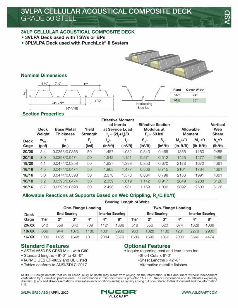
Standard Features Optional Features
Section Properties
Deck Gage
Deck Weight
Base Metal Thickness
Yield Strength
Effective Moment of Inertia
at Service LoadId = (2Ie+Ig)/3
Effective Section Modulus at Fy = 50 ksi
Allowable Moment
Vertical Web
Shear
wdd t Fy Id+ Id- Se+ Se- Mn+/Ω Mn-/Ω Vn/Ω
(psf) (in.) (ksi) (in4/ft) (in4/ft) (in3/ft) (in3/ft) (lb-ft/ft) (lb-ft/ft) (lb/ft)
20/20 3.4 0.0358/0.0358 50 1.457 1.082 0.543 0.465 1355 1160 2485
20/18 3.9 0.0358/0.0474 50 1.542 1.151 0.571 0.512 1425 1277 2485
18/20 4.1 0.0474/0.0358 50 1.837 1.398 0.853 0.670 2128 1672 4361
18/18 4.5 0.0474/0.0474 50 1.965 1.477 0.866 0.715 2161 1784 4361
18/16 5.0 0.0474/0.0598 50 2.078 1.578 0.864 0.798 2156 1991 4361
16/18 5.2 0.0598/0.0474 50 2.359 1.819 1.142 0.917 2849 2288 6126
16/16 5.7 0.0598/0.0598 50 2.496 1.931 1.159 1.002 2892 2500 6126
3VLPA GR50 ASD | APRIL 2020
3VLPA CELLULAR ACOUSTICAL COMPOSITE DECKGRADE 50 STEEL A
SD
3VLP CELLULAR ACOUSTICAL COMPOSITE DECK
• ASTM A653 SS GR50 Min., with G60• Standard lengths – 6’-0” to 42’-0”• IAPMO UES ER-0652 and UL Listed• Tables conform to ANSI/SDI C-2017
Nominal Dimensions
NOTICE: Design defects that could cause injury or death may result from relying on the information in this document without independent verification by a qualified professional. The information in this document is provided “AS IS”. Nucor Corporation and its affiliates expressly disclaim: (i) any and all representations, warranties and conditions and (ii) all liability arising out of or related to this document and the information in it.
Allowable Reactions at Supports Based on Web Crippling, Rn/Ω (lb/ft)Bearing Length of Webs
One-Flange Loading Two-Flange Loading
DeckGage
End Bearing Interior Bearing End Bearing Interior Bearing
1½" 2" 3" 4" 4" 8" 1½" 2" 3" 4" 4" 8"
20/XX 510 559 640 709 1121 1388 518 556 620 674 1328 1668
18/XX 866 944 1075 1186 1881 2900 963 1028 1138 1231 2279 2900
16/XX 1339 1455 1648 1811 2884 3579 1589 1690 1860 2003 3546 4474
WWW.VULCRAFT.COM
• 3VLPA Deck used with TSWs or BPs• 3PLVLPA Deck used with PunchLok® II System
• Inquire regarding cost and lead times for: -Short Cuts < 6’-0” -Sheet Lengths > 42’-0” -Alternative metallic finishes
Plant Cover Width
VNY 24”
VNE 36”