RESIDENTIAL WOOD DECK CONSTRUCTION GUIDE
32
1 RESIDENTIAL WOOD DECK CONSTRUCTION GUIDE Based on the 2015 Michigan Residential Code Revised May 17, 2016 The details in this document apply to residential decks only. Construction can not deviate from the details herein unless prior approval is obtained from the authority having jurisdiction. A copy of this document is required to be on the job site and available for each inspection. E2.2.9090 Effective 051716
-
Upload
khangminh22 -
Category
Documents
-
view
1 -
download
0
Transcript of RESIDENTIAL WOOD DECK CONSTRUCTION GUIDE

1
RESIDENTIALWOOD DECK
CONSTRUCTIONGUIDE
Based on the 2015 Michigan Residential CodeRevised May 17, 2016
The details in this document apply to residential decks only. Construction can not deviate from the details herein unless prior approval is
obtained from the authority having jurisdiction. A copy of this document is required to be on the job site and available for each inspection.
The Following Organizations Support the use of this Guide:
E2.2.9090 Effective 051716

Villages:
Village of Holly
Village of Leonard
Village of Webberville
City of Wyoming
City of Zeeland
City of Marine City
City of Battle Creek
City of Livonia
City of Madison Heights
City of Muskegon
City of New Baltimore
City of Northville
City of Norton Shores
City of Novi
City of Oak Park
City of Orchard Lake
City of Plymouth
City of Troy
City of Warren
Charter Township of White Lake
Charter Township of Washington
Charter Township of Plainfield
Charter Township of Shelby
Charter Township of Bloomfield
Charter Township of Canton
Charter Township of Clinton
Charter Township of Grand Haven
Charter Township of Groveland
Charter Township of Macomb
Charter Township of Milford
Charter Township of Oakland
Charter Township of Orion
Charter Township of Port Huron
Charter Township of Royal Oak
Townships:
City of Rochester Hills
City of Sterling Heights
City of Auburn Hills
City of Bloomfield Hills
City of Clawson
City of Fenton
City of Ferndale
City of Garden City
City of Grand Haven
City of Inkster
City of Lathrup Village
City of Lincoln Park
Cities:
Suppliers:
Dillman & Upton
Autumn Wood Construction
Horizon Builders Inc.
Lars/David Inc.
Contractors:
RESIDENTIAL
WOOD DECK CONSTRUCTION GUIDE
Wood Deck Construction in accordance with this guide is acceptable
in the following Michigan Communities:
The following Contractors & Suppliers support this Wood Deck Construction Guide:

CONTENTSCourtesy of American Wood Council - Leesburg, VA
Page
General Information.....................................................2
Decking.................................................................................3
Joists...................................................................................4-5
Beams.................................................................................6-8
Joist to Beam Connection.........................................9
Joist Hangers...............................................................9-10
Post Requirements.......................................................10
Post to Beam Connection.......................................11
Footings.......................................................................12-14
Ledger Board Attachment...............................15-16
Prohibited Ledger Attachments.........................16
***Solid vertical lines in the margins indicate a change from the previous Guide***
Page
Ledger Board Fasteners........................................17-18
Deck Stability..............................................................18-22
Guards.....................................................................................23
Guard Post Attachment.........................................23-24
Stair Requirements...................................................25-27
Stair Footing.......................................................................28
Stair Lighting.....................................................................28
Framing a Chimney/Bay Window.................28-29
Deck Framing Plan.........................................................29
Inspections Required.....................................................30
Page 1
GENERAL INFORMATION
1. This document applies to single level decks only.
2. The overall deck width at the house shall be equal to or greater than the distance the deck extends from the
house.
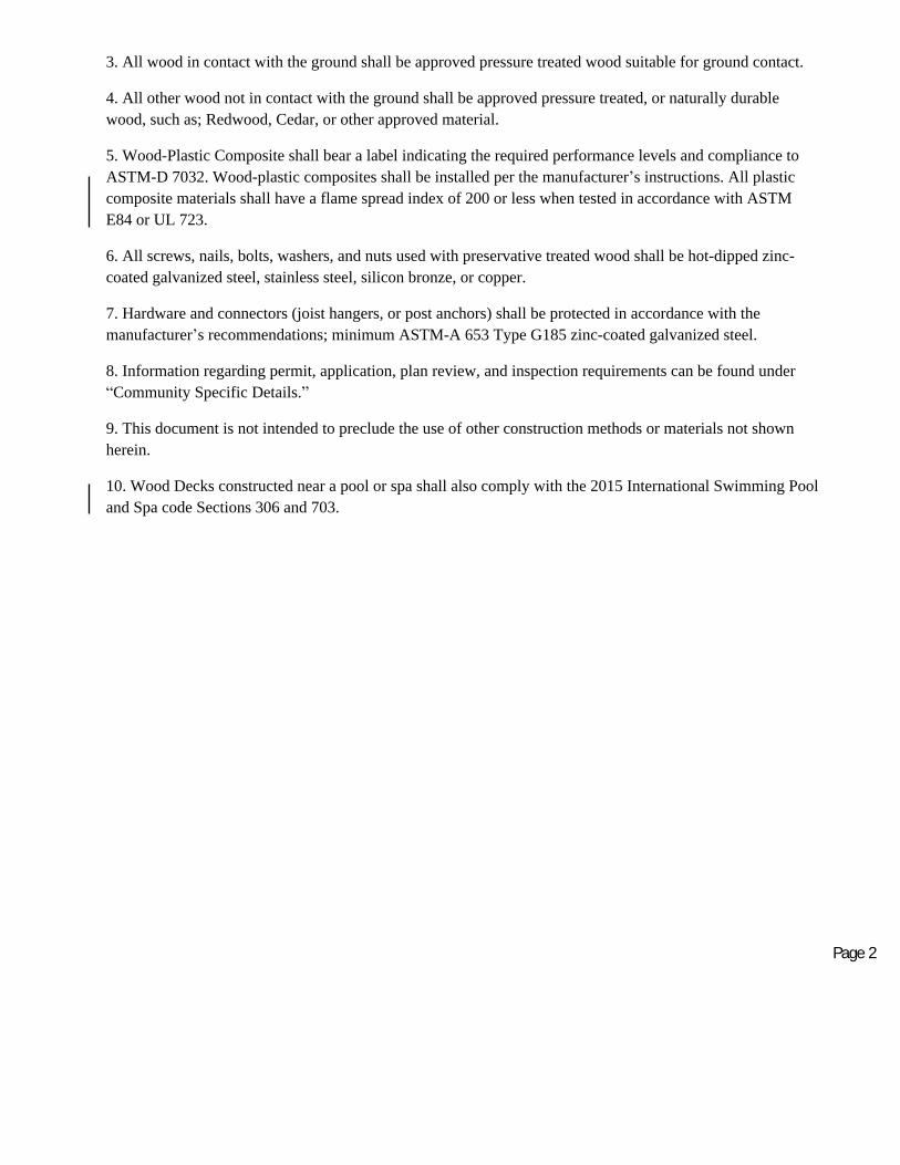
3. All wood in contact with the ground shall be approved pressure treated wood suitable for ground contact.
4. All other wood not in contact with the ground shall be approved pressure treated, or naturally durable
wood, such as; Redwood, Cedar, or other approved material.
5. Wood-Plastic Composite shall bear a label indicating the required performance levels and compliance to
ASTM-D 7032. Wood-plastic composites shall be installed per the manufacturer’s instructions. All plastic
composite materials shall have a flame spread index of 200 or less when tested in accordance with ASTM
E84 or UL 723.
6. All screws, nails, bolts, washers, and nuts used with preservative treated wood shall be hot-dipped zinc-
coated galvanized steel, stainless steel, silicon bronze, or copper.
7. Hardware and connectors (joist hangers, or post anchors) shall be protected in accordance with the
manufacturer’s recommendations; minimum ASTM-A 653 Type G185 zinc-coated galvanized steel.
8. Information regarding permit, application, plan review, and inspection requirements can be found under
“Community Specific Details.”
9. This document is not intended to preclude the use of other construction methods or materials not shown
herein.
10. Wood Decks constructed near a pool or spa shall also comply with the 2015 International Swimming Pool
and Spa code Sections 306 and 703.
Page 2

2x4, 2x6, or five
quarter board
(2)8d threaded
nails or (2) #8
screws at each joist
1/8” typical gap
after drying
DECKING
Spacing for joist supporting decking shall be in accordance with Table A1.
Decking shall be wood 2x4, 2x6, five quarter board, or Wood-Plastic Composite sizes per the
manufacturer’s specifications.
Wood decking shall be attached as shown in Figure 1.
Decking should also be attached to the rim board with
fasteners at 6” O.C.
Each wood decking member must rest on three joists
minimum.
Wood-Plastic Composite Decking shall be installed in
accordance with the manufacturer’s installation
instructions.
Wood-Plastic Composite Decking must be labeled and themanufacturer’s installation instructions shall be onsite for review by the inspector.
A valid ICC Evaluation Report must be provided and approved by the local building official for
any other decking products proposed.
a. Wood deck boards should not exceed an angle of 45 degrees from perpendicular
Material Type andNominal Size
Maximum On-Center Joist Spacing
Perpendicular to Joist Diagonal to Joista
1 1/4 inch thick plywood 16 inches 12 inches
2 inch thick plywood 24 inches 16 inches
Plastic CompositeIn accordance with ASTM D7032
LabelIn accordance with ASTM D7032
Label
Figure 1
Table A1 – Maximum Joist Spacing
Page 3

JOISTS
The joist span L is the distance between the two points supporting the joist and does not include
the length of the overhang (See Figures 2A, 2B, and 2C). Use Table 1 to determine allowable
joist span LJ. Allowable overhang length is LO as noted in Table 1 or L/4; whichever is less.
Courtesy of American Wood Council - Leesburg, VA
Fi gure 2 A. Joi st S pan – Joist Attached at House and Bearing over Beam
Fi gure 2 B . J o i s t S p a n – J o i s t s A t t a c h e d a t H o u s e a n d t o S i d e o f B e a m
J o i s t S p a n (L ≤ LJ): See Table 1
Courtesy of American Wood Council - Leesburg, VA
J o i s t S p a n (L ≤ LJ)
See Table 1
Page 1
Page 4

Joist Spacing (O.C.)
12" 16" 24" 12" 16" 24"
Species Size Allowable Span² (LJ) Allowable Overhang3 (LO)
Southern Pine
2x66 9'-11" 9'-0" 7'-7" 1'-0" 1'-1" 1'-3"
2x8 13'-1" 11'-10" 9'-8" 1'-10" 2'-0" 2'-4"
2x10 16'-2" 14'-0" 11'-5" 3'-1" 3'-5" 2'-10"
2x12 18'-0"7 16'-6" 13'-6" 4'-6" 4'-2" 3'-4"
Douglas Fir-Larch,Hem-Fir, Spruce-
Pine-fire4
2x66 9'-6" 8'-4" 6'-10" 0'-11" 1'-0" 1'-2"
2x8 12'-6" 11'-1" 9'-1" 1'-8" 1'-10" 2'-2"
2x10 15'-8" 13'-7" 11'-1" 2'-10" 3'-2" 2'-9"
2x12 18'-0"7 15'-9" 12'-10" 4'-4" 3'-11" 3'-3"
Redwood, WesternCedars, Ponderosa
Pine5, Red Pine5
2x66 8'-10" 8'-0" 6'-10" 0'-9" 0'-10" 0'-11"
2x8 11'-8" 10'-7" 8'-8" 1'-5" 1'-7" 1'-9"
2x10 14'-11" 13'-0" 10'-7" 2'-5" 2'-7" 2'-8"
2x12 17'-5" 15'-1" 12'-4" 3'-7" 3'-9" 3'-1"
BEAMS
Courtesy of American Wood Council - Leesburg, VA
Fi gure 2C. Joi st S pan – Non-Ledger Deck
1. Assumes 40 psf live load, 10 psf dead load, No. 2 stress grade, and wet service conditions.2. Assumes L/360 deflection.3. Maximum allowable overhang cannot exceed L/4 or ¼ of actual main span. Assumes cantilever length/180 deflection with 220 point load
(See Figure 2A and 2C).4. Incising assumed for Douglas fir-larch, hem-fir, and spruce-pine-fir.5. Design Values based on northern species with no incising assumed.6. Ledger shall be a minimum of 2x8 nominal. Where guards are required, outside joists and rim joists shall be a minimum length of 2x8 nominal.7. Joist length prescriptively limited to 18’-0” for footing design.
Table 1. Maximum Joist Spans and Overhangs1
Courtesy of American Wood Council - Leesburg, VA
J o i s t S p a n (L ≤ LJ)
See Table 1
Page 5

Beam span is measured between the supporting posts and does not include the overhang. See
Figure 3.
Beam size is determined by using Table 2A for joist framing from one side only. Joists may bear
on the beam and extend past the beam centerline up to the lesser of LO or L/4, as shown in
Figures 2A and 2C.
Use Table 2B for joist framing from both sides.
Beam may overhang past the supporting post up to one-fourth the beam span as indicated in
Figure 3.
Beams with multiple members shall be assembled in accordance with Figure 4.
Courtesy of American Wood Council - Leesburg, VA
Figure 3. Beam Span T ypes
Table 2A. Deck Beam Spans (LB)1 for Joists Framing from One Side Only
Courtesy of American Wood Council - Leesburg, VA
Figure 4. Beam Assembly Details
Beam span (L B): see Table 2A
or 2B
Beam span (L B): see Table 2A
or 2B
Page 6

Joist Spans (L) Less Than or Equal to:
Species Size4 6' 8' 10' 12' 14' 16' 18'
Southern Pine
2-2x6 6'-11' 5'-11" 5'-4" 4'-10" 4'-6" 4'-3" 4'-0"
2-2x8 8-9" 7'-7" 6'-9" 6'-2" 5'-9" 5'-4" 5'-0"
2-2x10 10'-4" 9'-0" 8'-0" 7'-4" 6'-9" 6'-4" 6'-0"
2-2x12 12'-2" 10'-7" 9'-5" 8'-7" 8'-0" 7'-6" 7'-0"
3-2x6 8'-2" 7'-5" 6'-8" 6'-1" 5'-8" 5'-3" 5'-0"
3-2x8 10'-10" 9'-6" 8'-6" 7'-9" 7'-2" 6'-8' 6'-4"
3-2x10 13'-0" 11'-3" 10'-0" 9'-2" 8'-6" 7'-11" 7'-6"
3-2x12 15'-3" 13'-3" 11”-10" 10'-9" 10”-0" 9'-4" 8'-10"
Douglas Fir-Larch2, Hem-Fir2,Spruce-Pine-Fir2,
Redwood,Western Cedars,
PonderosaPine3, Red Pine3
3x6 or 2-2x6 5'-5" 4'-8" 4'-2" 3'-10" 3'-6" 3'-1" 2'-9"
3x8 or 2-2x8 6'-10" 5'-11" 5'-4" 4'-10" 4'-6" 4'-1" 3'-8"
3x10 or 2-2x10 8'-4" 7'-3" 6'-6" 5'-11" 5'-6" 5'-1" 4'-8"
3x12 or 2-2x12 9'-8" 8'-5" 7'-6" 6'-10" 6'-4" 5'-11" 5'-7"
4x6 6'-5" 5'-6" 4'-11" 4'-6" 4'-2" 3'-11" 3'-8"
4x8 8'-5" 7'-3" 6'-6" 5'-11" 5'-6" 5'-2" 4'-10"
4x10 9'-11" 8'-7" 7'-8" 7'-0" 6'-6" 6'-1" 5'-8"
4x12 11'-5" 9'-11" 8'-10" 8'-1" 7'-6" 7'-0" 6'-7"
3-2x6 7'-4" 6'-8" 6'-0" 5'-6" 5'-1" 4'-9" 4'-6"
3-2x8 9'-8" 8'-6" 7'-7" 6'-11" 6'-5" 6'-0" 5'-8"
3-2x10 12'-0" 10'-5" 9'-4" 8'-6" 7'-10" 7'-4" 6'-11"
3-2x12 13'-11" 12'-1" 10'-9" 9'-10" 9'-1" 8'-6" 8'-1"
Page 6
Courtesy of American Wood Council - Leesburg, VA
1. Assumes 40 psf live load, 10 psf dead load, L/360 simple span beam deflection limit, cantilever length/180 deflection limit, No. 2 stress grade, and wet service conditions.
2. Incising assumed for Douglas fir-larch, hem-fir, and spruce-pine-fir.3. Design values based on northern species with no incising assumed.4. Beam depth must be equal to or greater than joist depth if joist hangers are used (see Figure 5, option 3).
Page 7

Joist Spans (L)6 Loading Beam from Both Sides in Feet:
Species Size4 6' 8' 10' 12' 14' 16'
Southern Pine
2-2x6 5'-8” 4'-11" 4'-5" 4'-0" 3'-9" 3'-6"
2-2x8 7'-2" 6'-3" 5'-7" 5'-1" 4'-8" 4'-5"
2-2x10 8'-7" 7'-5" 6'-8" 6'-1" 5'-7" 5'-3'
2-2x12 10'-2" 8'-10" 7'-11" 7'-2" 6'-8" 6'-3"
3-2x6 7'-6" 6'-6" 5'-9" 5'-3" 4'-11" 4'-7"
3-2x8 9'-5" 8'-2" 7'-4" 6'-8" 6'-2" 5'-9"
3-2x10 11'-4" 9'-9" 8'-9" 8'-0" 7'-5" 6'-11"
3-2x12 13'-5" 11'-7" 10'-4" 9'-6" 8'-9" 8'-2"
Douglas Fir-Larch2, Hem-Fir2,Spruce-Pine-Fir2,
Redwood,Western Cedars,Ponderosa Pine3,
Red Pine3
2-2x6 5’-5" 4'-8" 4'-2" 3'-10" 3'-6" 3'-4"
2-2x8 6'-11" 5'-11" 5'-4" 4'-10" 4'-6" 4'-2"
2-2x10 8'-5" 7'-3" 6'-6" 5’-11" 5'-6" 5'-1"
2-2x12 9'-9" 8'-5" 7'-6" 6'-10" 6'-4" 5'-11"
3-2x6 7'-2" 6'-2" 5'-6" 5'-0" 4'-8" 4'-4"
3-2x8 9'-1" 7'-10" 7'-0" 6'-4" 5'-11" 5'-6"
3-2x10 11'-1" 9'-7" 8'-6" 7'-9" 7'-3" 6'-9"
3-2x12 12'-10" 11'-1" 9'-11" 9'-1" 8'-4" 7'-10"
Table 2B. Deck Beam Spans (LB)1,5 for Joists Framing from Both Sides
1 . Assumes 40 psf live load, 10 psf dead load, L/360 s imple span beam deflection limit, L/180cantilever deflection limit, No. 2 grade, an d wet s ervice conditions.2 . Incising assumed for ref ractor y s pecies includi ng Douglas fir-larch, hem-fir, and sp r uce-pine-fir.3 . Design values based on northe rn species wi th no incising assumed.4 . Beam depth mus t be equal to or g reater t han joist depth if joist hangers are used.5. Loading based on joist span L on each side of beam x ½ x (10 psf dead load + 40 psf live load).6. Joist span in table based on joist span on each side of beam x ½. Example: Joist span L between Beams A and B= 10 ft and joist span L between Beams B and C = 6 ft. 10ft + 6ft = 16ft x ½ = 8. (Joist span used in Table 2B).
Page 8

JOIST TO BEAM CONNECTION
Attach joist to beam using one of the options shown in Figure 5. Blocking is required between
the joists at the beam when the joist overhangs past the beam.
Hurricane clips or mechanical fasteners used for option 2 must have a minimum capacity of
100lbs in both uplift and lateral load directions. Must be installed per manufacturer’s
requirements.
JOIST HANGERS
Joist hanger shall have a depth of at least 60% of the joist depth. See Figure 6.
Joist hangers shall be sized properly to accommodate the load and number of plies being
carried.
Hangers shall not be bent to accommodate field conditions.
Brackets or clip angles are not allowed for joist connections.
Fasten joist hangers per manufacturer’s recommendation.
Joist hangers with inside flanges shall be used as field conditions dictate.
Courtesy of American Wood Council - Leesburg, VA
Figure 5. Joist-to-Beam Detail
OPTION 1 OPTION 2* OPTION 3*
*See manufacturer’s recommendations for additional requirements
Page 9
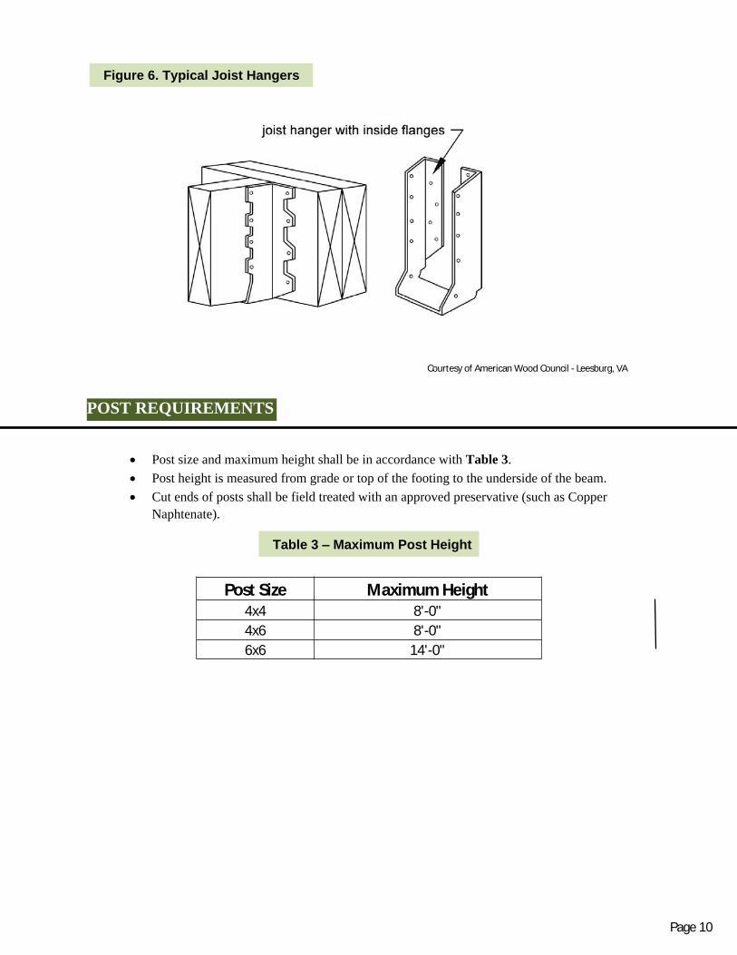
POST REQUIREMENTS
Post size and maximum height shall be in accordance with Table 3.
Post height is measured from grade or top of the footing to the underside of the beam.
Cut ends of posts shall be field treated with an approved preservative (such as Copper
Naphtenate).
Post Size Maximum Height4x4 8'-0"
4x6 8'-0"
6x6 14'-0"
Courtesy of American Wood Council - Leesburg, VA
Figure 6. Typical Joist Hangers
Table 3 – Maximum Post Height
Page 10

POST TO BEAM CONNECTIONS
Beams shall be attached to the post by one of the acceptable methods shown in Figure 7.
6x6 post minimum required where post supports a beam splice.
Attachment of the beam to the side of the post is prohibited.
Page 9
Courtesy of American Wood Council - Leesburg, VA
Figure 7. Post to Beam Connection
Two-ply
beam only
Beam must
bear on notch
6x6 or 4x6 post
(Posts supporting
beam splices
shall be 6x6 only)
(2) ½ “ diameter
through-bolts; at beam
splice, provide two
bolts at each beam end
Notch post for flush
beam bearing
Post
Two-or three-ply beam
Post Cap
6” Dimension
5 ½ Actual
Prohibited Connection
Notched Post
Page 10

FOOTINGS
Concrete shall have a minimum compressive strength of 2,500 lbs per square inch.
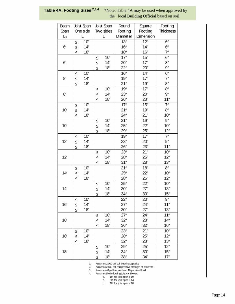
Footing size and thickness shall be in accordance with Table 4 for 1,500 psf soil bearing
capacity and Table 4A for 2,000 psf soil bearing capacity.
See Figure 8 for typical footing options.
Post shall be centered on the footing.
All footings shall bear on undisturbed soil at least 42” below grade. Footing inspection is
required prior to placement of concrete.
Footings closer than 5’-0” to an existing house foundation wall must bear on undisturbed soil
at the same elevation as the house foundation.
Page 12

BeamSpan
LB
Joist SpanOne side
L
Joist SpanTwo sides
L
RoundFooting
Diameter
SquareFooting
Dimension
FootingThickness
< 10’ 16” 14” 7”6’ < 14’ 19” 17” 7”
< 18’ 21” 19” 8”
< 10’ 19” 17” 8”6’ < 14’ 23” 20” 9”
< 18’ 26” 23” 11”
< 10’ 18” 16” 7”8’ < 14’ 22” 19” 9”
< 18’ 24” 22” 10”
< 10’ 22” 20” 9”8’ < 14’ 26” 23” 11”
< 18’ 30” 26” 12”
< 10’ 20” 18” 8”10’ < 14’ 24” 22” 10”
< 18’ 27” 24” 11”
< 10’ 25” 22” 10”10’ < 14’ 29” 26” 12”
< 18’ 33” 29” 14”
< 10’ 22” 20” 9”12’ < 14’ 27” 24” 11”
< 18’ 30” 27” 13”
< 10’ 27” 24” 11”12’ < 14’ 32” 28” 14”
< 18’ 36” 32” 16”
< 10’ 24” 21” 10”14’ < 14’ 29” 26” 12”
< 18’ 32” 29” 14”
< 10’ 29” 26” 12”14’ < 14’ 35” 31” 15”
< 18’ 39” 35” 17”
< 10’ 25” 23” 10”16’ < 14’ 31” 27” 13”
< 18’ 35” 31” 15”
< 10’ 31” 28” 13”16’ < 14’ 37” 33” 16”
< 18’ 42” 37” 18”
< 10’ 27” 24” 11”18’ < 14’ 33” 29” 14”
< 18’ 37” 33” 16”
< 10’ 33” 29” 14”18’ < 14’ 39” 35” 17”
< 18’ 44” 39” 19”
Table 4. Footing Sizes1,2,3,4
Page 13
1. Assumes 1,500 psf soil bearing capacity2. Assumes 2.500 psf compressive strength of concrete3. Assumes 40 psf live load and 10 psf dead load4. Assumes the following joist cantilever;
a. 18” for joist span ≤ 10’b. 30” for joist span ≤ 14’c. 36” for joist span ≤ 18’
BeamSpan
LB
Joist SpanOne side
L
Joist SpanTwo sides
L
RoundFooting
Diameter
SquareFooting
Dimension
FootingThickness
< 10’ 13” 12” 6”6’ < 14’ 16” 14” 6”
< 18’ 18” 16” 7”
< 10’ 17” 15” 6”6’ < 14’ 20” 17” 8”
< 18’ 22” 20” 9”
< 10’ 16” 14” 6”8’ < 14’ 19” 17” 7”
< 18’ 21” 19” 8”
< 10’ 19” 17” 8”8’ < 14’ 23” 20” 9”
< 18’ 26” 23” 11”
< 10’ 17” 15” 7”10’ < 14’ 21” 19” 8”
< 18’ 24” 21” 10”
< 10’ 21” 19” 9”10’ < 14’ 25” 22” 10”
< 18’ 29” 25” 12”
< 10’ 19” 17” 7”12’ < 14’ 23” 20” 9”
< 18’ 26” 23” 11”
< 10’ 23” 21” 10”12’ < 14’ 28” 25” 12”
< 18’ 31” 28” 13”
< 10’ 21” 18” 8”14’ < 14’ 25” 22” 10”
< 18’ 28” 25” 12”
< 10’ 25” 22” 10”14’ < 14’ 30” 27” 13”
< 18’ 34” 30” 15”
< 10’ 22” 20” 9”16’ < 14’ 27” 24” 11”
< 18’ 30” 27” 13”
< 10’ 27” 24” 11”16’ < 14’ 32” 28” 14”
< 18’ 36” 32” 16”
< 10’ 23” 21” 10”18’ < 14’ 28” 25” 12”
< 18’ 32” 28” 13”
< 10’ 29” 25” 12”18’ < 14’ 34” 30” 15”
< 18’ 38” 34” 17”
Table 4A. Footing Sizes,2,3,4 *Note: Table 4A may be used when approved by
the local Building Official based on soil
conditions.
Page
12
Page 14
1. Assumes 2,000 psf soil bearing capacity2. Assumes 2,500 psf compressive strength of concrete3. Assumes 40 psf live load and 10 psf dead load4. Assumes the following joist cantilever:
a. 18” for joist span ≤ 10’b. 30” for joist span ≤ 14’c. 36” for joist span ≤ 18’

LEDGER BOARD ATTACHMENTS
Gen e ral req u ire men ts
Led ger bo ard depth shall be great er than or equal t o the depth of the de ck joi sts , but not less than a 2x 8.
The led ger bo ard shall be att ached in a ccord anc e with one of the condit ions s hown in
F i g u r e s 1 0 a n d 1 1 .
The ex ist ing band board shall be capabl e of suppo rting the de ck. If this c a nnot be verified or
ex ist ing condit ions differ from th e details her ein , then a f r ee-standin g de ck or an en gine ered
d esign is r equir ed.
The top of the led ge r board and top of the de ck joi sts shall be at t he same el evati on.
Wood I -Joists as shown in F igure 9, located inside the house, must
have a 2x band board, or a mi nim um 1-inch thick en ginee r ed wood
product ( EW P ) band board cap able of suppo rting a d eck. If a
mi nim um 1 -inch EW P or 2x band board is not present, t hen a fr ee -
standing d eck is requir e d .
S i d i n g a n d F l a s h i n g
The ex terior fini sh, i.e., house sidi ng, must be rem oved prior to t he ins tallation of the ledger bo ard. Conti nuous flashing with a drip ed ge, as shown in F igure 10, is r equired at the led ger bo ard
wh en att ached to wood- fram ed constructi on .
Flashin g shall be copp er (att ached usin g copper n ail s onl y), stainless st eel, UV resis tant
plastic or galv aniz ed steel coated with 1.85 ounces of z inc per squar e foot (G -185 c oati ng).
Flashin g at a door thr esh old shall be inst all ed to prevent wat er intrusion fro m rain or melti ng snow.
Figure 9: Wood I-Joists
Courtesy of American Wood Council - Leesburg, VA
Figure 10. General Attachment of Ledger Board to Band Joist or Rim Board
Page 15

PROHIBITED LEDGER ATTACHMENTS
The ledger board attachments shown in Figure 12 are prohibited. These conditions require a free-standingdeck design.
Courtesy of American Wood Council - Leesburg, VA
Courtesy of American Wood Council - Leesburg, VA
Figure 11. Attachment of Ledger Board to Foundation Wall (Concrete or Solid Masonry)
Figure 12. Prohibited Ledger Attachments
Page 16
LEDGER BOARD FASTENERS
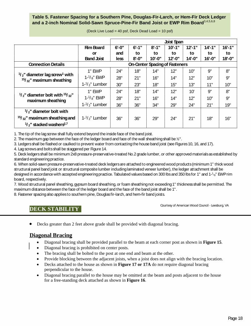
Spacing and placement of fasteners shall be in accordance with Figure 14 and Table 5. Lead anchors are prohibited. See General Information #6. Thru-Bolts shall have a diameter of ½”. Washers are required at the bolt head and nut. Expansion and Adhesive Anchors: Use approved expansion or adhesive anchors when attaching
a ledger board to a concrete or solid masonry wall, as shown in Figure 11. Expansion and adhesiveanchor bolts shall have a diameter of ½”, be equipped with washers, and installed permanufacturer’s instructions.
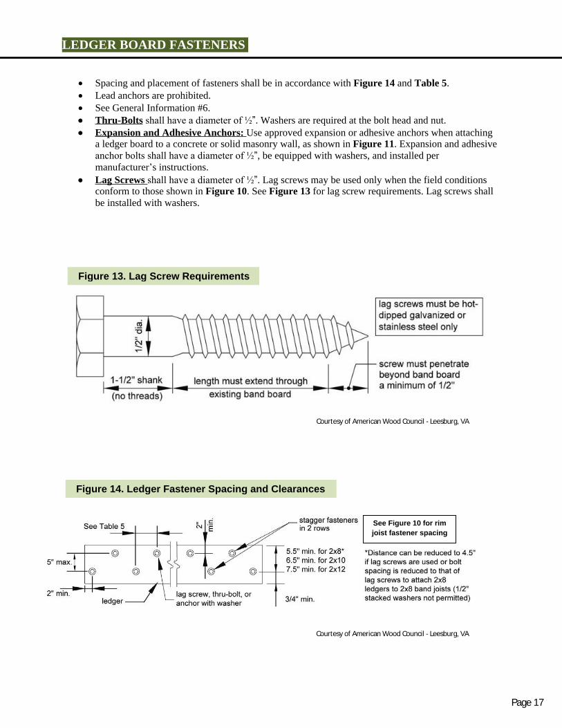
Lag Screws shall have a diameter of ½”. Lag screws may be used only when the field conditionsconform to those shown in Figure 10. See Figure 13 for lag screw requirements. Lag screws shallbe installed with washers.
Courtesy of American Wood Council - Leesburg, VA
Courtesy of American Wood Council - Leesburg, VA
Figure 13. Lag Screw Requirements
Figure 14. Ledger Fastener Spacing and Clearances
See Figure 10 for rim
joist fastener spacing
Page 17
Joist Span
Rim Board 6'-0" 6'-1" 8'-1" 10'-1" 12'-1" 14'-1" 16'-1"or and to to to to to to
Band Joist less 8'-0" 10'-0" 12'-0" 14'-0" 16'-0" 18'-0"
Connection Details On-Center Spacing of Fasteners
1/2" diameter lag screw1 with15/32" maximum sheathing
1" EWP 24" 18" 14" 12" 10" 9" 8"
1-1/8" EWP 28" 21" 16" 14" 12" 10" 9"
1-1/2" Lumber 30" 23" 18" 15" 13" 11" 10"
1/2" diameter bolt with 15/32"maximum sheathing
1" EWP 24" 18" 14" 12" 10' 9" 8"
1-1/8" EWP 28" 21" 16" 14" 12" 10" 9"
1-1/2" Lumber 36" 36" 34" 29" 24" 21" 19"1/2" diameter bolt with
15/32" maximum sheathing and 1-1/2" Lumber 36" 36" 29" 24" 21" 18" 16"1/2" stacked washers2,7
DECK STABILITY
Decks greater than 2 feet above grade shall be provided with diagonal bracing.
Diagonal Bracing Diagonal bracing shall be pr ovi ded par al lel to the beam at each corner post as shown i n Fi gur e 15. Diagonal bracing is prohibited on center posts. The br aci ng shal l be bol t ed t o t he post at one end and beam at the ot her . Provide blocking between the adjacent joists, when a joist does not align with the bracing location. Decks att ached to t he house as shown i n Fi gur e 17 or 17A do not requir e di agonal braci ng
per pendi cul ar t o the house.
Di agonal br aci ng par all el to the house may be o mi t t ed at t he beam and posts adj acent t o t he housef or a fr ee-st andi ng deck at tached as shown i n Fi gur e 16.
1. The t ip of th e l ag screw sha ll fully exte nd beyond the in sid e face of the b and jois t.2. The maxi mu m gap betw een t he fac e of the l edger board a nd face of the wall sheath in g shall be ½".3. Ledger s sha l l be flashed or ca ulked to prevent wa ter from conta ct ing th e hous e band joist ( se e F igur es 10, 16, and 17).4. Lag scre ws an d bolt s sha ll b e stagg ered per Fig ure 1 4 .5. De ck led gers s hal l be mi ni mu m 2 x8 press ure-preserva tiv e-trea ted No .2 grade lu mb er, or other appro ved ma teri al s as es tab li shed bystandard en gineering practice.6 . W hen so lid - sa wn pres sure -pr eserva tiv e- trea ted de ck l edge rs are at tac hed to eng ine ered wood product s (m in im um 1" thi ck woodstru ct ural pa ne l band joi st or stru ct ural com posi te l u mber i ncludi ng la m in ated ve ne er lu mber ), the led ger atta ch me n t sha ll b edesigned in accordance with accep ted eng ineering practi ce. Tabulated values based on 3 00 lbs and 350 lbs for 1" and 1-1
/8" EWP rim board , respectively.7. Wood structur al panel shea thing , gypsum board shea th in g, or foam sh eath ing no t exceed ing 1 " t hi ck nes s sh al l be p erm it ted . Themaxi mu m d is t ance b etw ee n the fa ce of th e ledger board a nd th e face of the ba nd joist shall be 1" .8. Fas ten er spa ci ng also app l ie s to sout her n pine, Doug las f ir -lar ch, a nd he m-f ir band jois ts .
Table 5. Fastener Spacing for a Southern Pine, Douglas-Fir-Larch, or Hem-Fir Deck Ledger
and a 2-inch Nominal Solid-Sawn Spruce-Pine-Fir Band Joist or EWP Rim Board3 , 4, 5, 6, 8
(Deck Live Load = 40 psf, Deck Dead Load = 10 psf)
Courtesy of American Wood Council - Leesburg, VA
Page 18

Diagonal Bracing Option
Diagonal bracing as shown in Figures 15A and 15B, is only allowed when the deck is supported by a
ledger attached to the house as indicated in Figures 10 and 11; and lateral load connections as shown
in Figure 17 or 17A, are provided near the outside edge of the deck on each side.
Bracing material must be 2x6 preservative treated wood.
Bracing must be attached with 3-16D nails at each joist.
Nails shall be hot dipped zinc coated galvanized steel or stainless steel.
Courtesy of American Wood Council - Leesburg, VA
Figure 15. Diagonal Bracing
Page 19

Figure 15A. Diagonal Bracing Attached to Underside of Joist on Single Span Deck
Figure 15B. Diagonal Bracing Attached to Underside of Joists on Double Span Deck
2x6 Lateral V bracing nailed to the underside of
the deck joist with 3-16D nails in each joist.
Lateral load device required as shown in Figure 17 or 17A.
2x6 Lateral V
bracing nailed
to the
underside of
the deck joist
with 3-16D
nails in each
joist. Optional layout
for braces
shown dashed
Lateral load device required as shown in Figure 17 or 17A.
Page 20

Free Standing Deck Attachment to House
At tach t h e deck ri m j o ist t o th e exist ing house ext er i or wal l as shown i n Fi gur e 16 f or a f ree-
st andi ng deck.
The wal l mus t be sheat hed w it h mi ni mu m 3/8" wood st r uct ur al panel sheat hi ng.
Use lag scr ews or t hr u-bol t s when f ast eni n g t o an existi ng band j oist o r wal l st ud.
Use expansi on anchor s or epoxy anchor s when fastening t o concrete or masonry.
DO NOT ATT ACH T O BRICK V ENEERS.
Fast eners shall be 16" on cent er and st agger ed in 2 r ows for free standing decks.
Fl ash in g i s r equi r ed o ver t he ri m j oi st. S e e “ L e d g e r B o a r d A t t a c h m e n t ” f o r f l a s h i n g d e t a i l s .
Deck Support ed by Le dger - Att achm ent to H ouse
Where support ed by at t achment t o an ext er ior wal l ( Fi gur es 10 or 11) , decks shal l be posit i vel y
anchor ed t o the pr i mar y st ruct ur e and desi gned for both ver t i cal and later al loads as appli cabl e.
The l ater al load connecti on requi r ed shal l be per mi t ted to be i n accordance wit h Fi gur e 17 or 17A.
Hol d down t ensi on devi ces shal l be pr ovi ded in not l ess t han t wo l ocati ons per deck, and each devi ce
shall have an all owabl e st ress desi gn capaci t y of not l ess than 1,500 l bs or hold down devices with an
allowable stress design capacity of not less than 750 lbs shall be installed per the manufacturers
installation instructions in not less than four locations per deck evenly distributed along deck and one
within 2” of each end of the ledger.
Courtesy of American Wood Council - Leesburg, VA
Figure 16. Attachment of Free-Standing Deck to House for Deck Stability
Page 21

Courtesy of American Wood Council - Leesburg, VA
Figure 17. Lateral Load Device with Joists Parallel to Deck Joists
Courtesy of American Wood Council - Leesburg, VA
Figure 17A. Lateral Load Device with Joists Perpendicular to Deck Joists
Courtesy of American Wood Council - Leesburg, VA
Page 22

GUARDS
A guard is required when a deck is greater than 30 inches above grade at any point within 36 inches
of the deck edge.
Wood-plastic composites used in guard systems shall be labeled, indicating the performance level and
demonstrating compliance with ASTM D 7032. Wood-plastic composites shall be installed in
accordance with the manufacturer’s instructions.
Alternative guard systems with a valid ICC Evaluation Service Report must be submitted to the
building official for evaluation and approval prior to installation.
Guards shall be no less than 36 inches above the adjacent walking surface.
Stair guards shall have a height no less than 34 inches measured vertically from a line connecting the
leading edges of the trends. See Figure 26.
Openings in guards shall not allow the passage of a 4-inch diameter sphere through any opening from
the walking surface to the required guard height.
Fi gure 18. Exampl e G uard Det ai l
GUARD POST ATTACHMENT
Guard posts shall be 4x4 minimum.
Notching of guard posts; as shown in Figure 19,
is prohibited.
Guard posts shall be attached as shown in
Figures 20 and 21.
Hold down anchors shall have a minimum
capacity of 1,800 lbs and must be installed in
accordance with the manufacturer’s instructions.
Do not
notch
Figure 19. Post Notches Prohibited
Courtesy of American Wood Council - Leesburg, VA
Figure 20. Guard Post to Outside Joist Example
Page 23

Courtesy of American Wood Council - Leesburg, VA
Courtesy of American Wood Council - Leesburg, VA
Figure 21. Guard Post to Rim Joist Example
See Figure 18 for guard
component attachment
requirements
See Figure 18 for guard
component attachment
requirements
21
Page 24

STAIR REQUIREMENTS
Stair Dimensions
Stairs shall have a minimum clear width of 36
inches.
Stair trends, risers, nosing, and opening
limitations shall meet the requirements shown in
Figure 22. All tread, riser, and nosing
dimensions shall not deviate from one another
by more than 3/8” in any flight of stairs.
Stair Dimensions with a width no less than the stair is required at
the top and bottom of each stairway.
8 ¼”
max.
riser
9” min.
tread tread
4” diameter
shall not pass
Figure 22. Treads and Risers
Each landing shall be 36” minimum in the
direction of travel.
Stairs with a vertical height exceeding 12’0” are
required to have an intermediate landing.
A landing, with a width no less than the stair, is
required at the top and bottom of each stairway.
Riser
¾”-1 ¼”
nosing
Stair Stringers
Stair stringers shall be 2x12 minimum.
Stair stringers shall not span more than the dimensions shown in Figure 23 for cut and solid stringers.
Stair stringers shall be 18” on center maximum.
Figure 23. Stair Stringer Requirements Fi gure 24. St air S tri nger At t achment Det ai l
Courtesy of American Wood Council - Leesburg, VACourtesy of American Wood Council - Leesburg, VA
Max Span = 6’0”
CUT STRINGER
Max Span = 13’3”
SOLID STRINGER
Rim joist or
outside joist
Sloped joist hanger, minimum
download capacity of 625 lbs;
see JOIST HANGERS for more
requirements
ATTACHMENT WITH HANGERS
Page 25
Treads
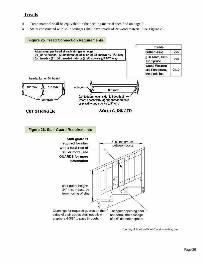
Tread material shall be equivalent to the decking material specified on page 2.
Stairs constructed with solid stringers shall have treads of 2x wood material. See Figure 25.
Treads
Southern Pine 2x6
Doug Fir Larch, HemFir, Spruce
2x8
Redwood, WesternCedars, Ponderosa,
Pine, Red Pine2x10
Courtesy of American Wood Council - Leesburg, VA
Courtesy of American Wood Council - Leesburg, VA
Fi gure 25 . Tread Connect i on Requi rement s
Fi gure 26. St air Guard Requi rement s
Stair guard is
required for stair
with a total rise of
30” or more; see
GUARDS for more
information
Page 26

Stair Handrails Stairs with four or more risers shall have
a handrail on at least one side at a height between 34
and 38 inches.
Handrail height shall be measured vertically from a
line connecting the leading edges of the treads. See
Figure 26.
Handrails shall be graspable and made of
decay-resistant and/or corrosion resistant
material. See Figures 27 and 28.
Handrails shall have a smooth surface with no sharp
corners.
Handrails shall run continuously from a point
directly over the lowest riser to a point directly over
the higher riser and shall return to the guard at each
end. See Figure 29.
Handrails may be interrupted by guard posts at a
turn in the stair.
Courtesy of American Wood Council - Leesburg, VA
Courtesy of American Wood Council - Leesburg, VA Courtesy of American Wood Council - Leesburg, VA
Fi gure 27. Handrai l Gri p Si ze
Fi gure 28. Handrai l Mount i ng Exampl es Fi gure 29. Mi scell aneous S t air Requi rement s
Page 27
STAIR FOOTING
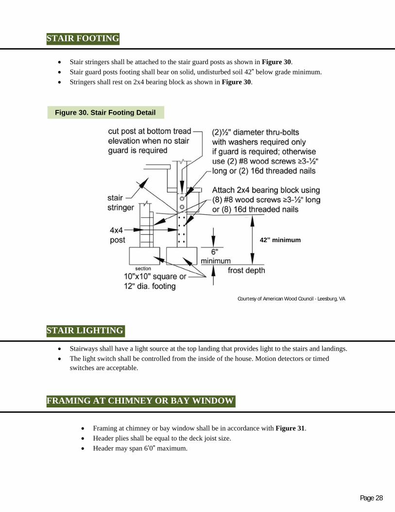
Stair stringers shall be attached to the stair guard posts as shown in Figure 30.
Stair guard posts footing shall bear on solid, undisturbed soil 42” below grade minimum.
Stringers shall rest on 2x4 bearing block as shown in Figure 30.
Courtesy of American Wood Council - Leesburg, VA
Figure 30. Stair Footing Detail
42” minimum
STAIR LIGHTING
Stairways shall have a light source at the top landing that provides light to the stairs and landings.
The light switch shall be controlled from the inside of the house. Motion detectors or timed
switches are acceptable.
FRAMING AT CHIMNEY OR BAY WINDOW
Framing at chimney or bay window shall be in accordance with Figure 31.
Header plies shall be equal to the deck joist size.
Header may span 6’0” maximum.
Page 28

Courtesy of American Wood Council - Leesburg, VA
Courtesy of American Wood Council - Leesburg, VA
Figure 31: Detail for Framing Aro und Chimne y or Ba y Window
Figure 32. Typical Deck Framing Plan
Triple joist
hanger, typical
*Trimmer joist may be double if joists are spaced
24” o.c. or if trimmer length is 8’-6” or less
*See Figure 14 for fastener spacing,
edge, and end distances
PLAN VIEW SECTIONMinimum 1” Clearance
required between wood
and chimney
DECK FRAMING PLAN
Page 29

INSPECTIONS REQUIRED
1. Post Hole and Ledger Board Inspection–After Post Holes are dug and Ledger Board is
Installed
Inspection of all post holes prior to placement of concrete.
Approved plans and a copy of this guide must be available to the inspector onsite.
All post holes shall be dug to solid, undisturbed soil at least 42” below grade.
All post holes within 5’ of the house wall must be dug to undisturbed soil at the same
elevation as the house foundation.
Inspection of ledger board attachment (if applicable) to the house bond or foundation
wall.
The inspector will need access to the inside of the house to verify proper attachment of
the ledger board. An adult needs to be present for the inspector to enter the house.
2. Open Joist Inspection–Before Decking is Installed
An open joist inspection is required on decks with less than 4’ clearance between the
deck floor joist and grade, or when special framing conditions are present.
3. Final Inspection–After Deck is Complete
Approved plans and a copy of this guide must be available to the inspector onsite.
The inspector will verify compliance with the building code and the requirements noted
in this document.
Note:
This Guide Book is only intended to be a guide for Wood Deck Construction and is not all inclusive of
the Building Code Requirements. For complete details of all requirements please see the Michigan
Residential Code 2015. The information in this guide is subject to change without notice.
Page 30