
Parvus® SWI-22-10 - Curtiss-Wright Defense Solutions
107
USER MANUAL Saved 10/7/2016 By Judy Parvus ® SWI-22-10 PCI/104-Express 8-/20-Port Gigabit Ethernet Switch MNL-0641-01 Rev A3 ECO-4823 Effective: 04 Oct 16
-
Upload
khangminh22 -
Category
Documents
-
view
4 -
download
0
Transcript of Parvus® SWI-22-10 - Curtiss-Wright Defense Solutions

USER MANUAL
Saved 10/7/2016 By Judy
Parvus® SWI-22-10
PCI/104-Express 8-/20-Port Gigabit Ethernet Switch
MNL-0641-01 Rev A3 ECO-4823 Effective: 04 Oct 16

Parvus SWI-22-10 Curtiss-Wright
Page 2 of 107 MNL-0641-01 Rev A3 ECO-4823 Effective: 04 Oct 16
Disclaimer
Although the information contained herein has been carefully verified, Curtiss-Wright assumes no responsibility for errors that might appear in this document or for damage to property or persons resulting from improper use of this manual or related software. Curtiss-Wright reserves the right to change the contents and form of this document, as well as the features and specifications of its products, at any time without notice. The information in this publication does not represent a commitment on the part of Curtiss-Wright. This document contains proprietary information that is protected by copyright. All rights are reserved. No part of this document may be photocopied, reproduced, or translated into another language without the prior written consent of Curtiss-Wright.
Contact Information
Curtiss-Wright Corporation
3222 S. Washington St.
Salt Lake City, Utah, USA 84115
Phone: +1 (801) 483-1533
Toll-Free: +1 (800) 483-3152
Fax: +1 (801) 483-1523
Email:
Sales: [email protected]
Support: [email protected]
Web-site: www.cwcdefense.com
Send us your comments and feedback: [email protected]
Trademarks
Parvus is a brand of Curtiss-Wright Corporation.
All trademarks, both marked and not marked, appearing in this document are the property of their respective owners.
Copyright
© 2015 Curtiss-Wright Corporation
MNL-0641-01 Rev A3 ECO-4823 Effective: 04 Oct 16 Page 3 of 107
Table of Contents
Chapter 1 Introduction ............................................................................................................. 9
About This Document .................................................................................................................................... 9 Definitions ............................................................................................................................................... 9 Description of Safety Symbols ................................................................................................................ 9
Functional Description ................................................................................................................................. 10 Configurations ....................................................................................................................................... 10 Special Order Options .......................................................................................................................... 10 Features ................................................................................................................................................ 11
High Port Density ........................................................................................................................... 11 Rugged Design .............................................................................................................................. 11 Carrier Grade ................................................................................................................................. 11 Layer 2 Switching ........................................................................................................................... 11 Layer 3 Routing: ............................................................................................................................. 11 Management .................................................................................................................................. 11 Declassification .............................................................................................................................. 11 Low Power ..................................................................................................................................... 11 Bus or External Powering............................................................................................................... 11 Integration Flexibility ...................................................................................................................... 11
Management Interface Overview .......................................................................................................... 12
Chapter 2 Hardware Description ........................................................................................... 14
Card Layout ................................................................................................................................................. 14 SWI-22-10-10 Card .............................................................................................................................. 14 SWI-22-10-01 Card .............................................................................................................................. 14
SWI-22-10 Thermal Plate ............................................................................................................................ 15
Chapter 3. Hardware Installation ........................................................................................... 19
Equipment Installation ................................................................................................................................. 19 Installation Precautions ........................................................................................................................ 19 Breakout Cable Set .............................................................................................................................. 20 Test Setup SWI-22-10-10 ..................................................................................................................... 22 Test Setup SWI-22-10-01 ..................................................................................................................... 23
Zeroization................................................................................................................................................... 24 Initiating Zeroization ............................................................................................................................. 24 Zeroization Recovery ............................................................................................................................ 24
Chapter 4 Management Interface Description ...................................................................... 26
Understanding the Switch Configuration Files ............................................................................................ 27
Using the CLI .............................................................................................................................................. 28 Serial CLI Setup.................................................................................................................................... 28 CLI Quick Start ..................................................................................................................................... 28
Log In ............................................................................................................................................. 28 Set VLAN 1 IP Address .................................................................................................................. 29 Check Connectivity ........................................................................................................................ 29 Save the Configuration................................................................................................................... 30 Create a Backup Copy of the Configuration .................................................................................. 30
CLI Command Groups .......................................................................................................................... 31 Working with Configuration Files .......................................................................................................... 32
Saving and Deleting Configuration Files ........................................................................................ 32 Reverting to the Default Configuration ........................................................................................... 33
Parvus SWI-22-10 Curtiss-Wright
Page 4 of 107 MNL-0641-01 Rev A3 ECO-4823 Effective: 04 Oct 16
Loading a New Firmware Image ........................................................................................................... 33
Using the Web GUI ..................................................................................................................................... 35 Ethernet GUI Features ......................................................................................................................... 35 Web GUI Introduction ........................................................................................................................... 37
Accessing the Web Interface ......................................................................................................... 37 Navigation Pane ............................................................................................................................. 39 System Buttons .............................................................................................................................. 39 Links to Detail Popups ................................................................................................................... 41
Changing and Saving Configuration Settings ....................................................................................... 42 Changing the Switch Hostname (Example) ................................................................................... 42 Changing the Admin Password (Example) .................................................................................... 44 Saving the Configuration via the Web GUI .................................................................................... 45
Managing Configuration Files ............................................................................................................... 46 Downloading a Configuration File .................................................................................................. 46 Uploading a Configuration File ....................................................................................................... 47 Activating a Configuration File ....................................................................................................... 49 Deleting a Configuration File .......................................................................................................... 49
Loading a New Firmware Image ........................................................................................................... 49
Chapter 5 Connector Descriptions ....................................................................................... 50
SWI-22-10-10 Card-Specific Connectors .................................................................................................... 50 Part Numbers ........................................................................................................................................ 50 Description and Pinouts ........................................................................................................................ 50
J2 Pinout ........................................................................................................................................ 51 J3 Pinout ........................................................................................................................................ 52
SWI-22-10-01 Card-Specific Connectors .................................................................................................... 53 Part Numbers ........................................................................................................................................ 53 Description and Pinouts ........................................................................................................................ 53
P4 Pinout ........................................................................................................................................ 54 P7 Pinout ........................................................................................................................................ 54 P5 Pinout ........................................................................................................................................ 54 P6 Pinout ........................................................................................................................................ 54
Connectors Common to All SWI-22-10 Models .......................................................................................... 55 Common Connector Locations ............................................................................................................. 55 Auxiliary Power Connector (P3) ........................................................................................................... 55 Mounting Holes (MTG1, MTG2) ........................................................................................................... 56 PCI Connectors (J1 & J6) ..................................................................................................................... 56 PCI-Express Connectors (J5 & J8)....................................................................................................... 57
PCIe Bus Pin Matrix (PCI/104 Express Standard) (J5 & J8) ......................................................... 57
Console Port ............................................................................................................................................... 58
Zeroize Port ................................................................................................................................................. 58
LED Port ...................................................................................................................................................... 58
Chapter 6 Specifications ....................................................................................................... 61
General Specifications ................................................................................................................................ 61 Applications .......................................................................................................................................... 61 Breakout Cable Set .............................................................................................................................. 61
Technical Specifications .............................................................................................................................. 61 Power .................................................................................................................................................... 61 Switching Architecture .......................................................................................................................... 61 Port Features ........................................................................................................................................ 62 Layer 2 Switching ................................................................................................................................. 62 Management ......................................................................................................................................... 62 Security ................................................................................................................................................. 62

MNL-0641-01 Rev A3 ECO-4823 Effective: 04 Oct 16 Page 5 of 107
Status Indication ................................................................................................................................... 62 Reliability .............................................................................................................................................. 62
Mechanical Specifications ........................................................................................................................... 63
Connector Specifications ............................................................................................................................ 63
Environmental Specifications ...................................................................................................................... 63
Protocol Standards ...................................................................................................................................... 64
Chapter 7 Troubleshooting ................................................................................................... 65
Product Identification ................................................................................................................................... 65
Technical Assistance .................................................................................................................................. 65
Returning for Service .................................................................................................................................. 65
Chapter 8 Contact Info ........................................................................................................... 66
Appendix A CLI Reference .................................................................................................... 67
Industry Standard CLI Format ..................................................................................................................... 67
CLI Basics ................................................................................................................................................... 67 How the CLI Works ............................................................................................................................... 68 Accessing the CLI Help Menu .............................................................................................................. 69 Using the Keyboard .............................................................................................................................. 71 Command History ................................................................................................................................. 72 Controlling the Display .......................................................................................................................... 73 Understanding Commands ................................................................................................................... 74
Command Structure ....................................................................................................................... 74 Command Syntax ........................................................................................................................... 74 Additional Syntax Elements ........................................................................................................... 75
Ethernet Interface Naming .................................................................................................................... 76 Filtering Output ..................................................................................................................................... 77 Using ‘no’ Forms to Reset or Remove Configuration Values ............................................................... 78
CLI Command Groups ................................................................................................................................ 78 Modes............................................................................................................................................. 81
Frequently Used CLI Commands ................................................................................................................ 83 Reset Configuration to Defaults ..................................................................................................... 83 Set the Device Hostname .............................................................................................................. 83 View the Current IP Configuration ................................................................................................. 83 Set the Switch IP Address.............................................................................................................. 84 Ping a Network Device ................................................................................................................... 84
Using ‘show’ Commands ...................................................................................................................... 85 Showing Available Commands ...................................................................................................... 85 Showing Command Help ............................................................................................................... 86 Show Running-Config .................................................................................................................... 87
Configuring the System ............................................................................................................................... 89
Advanced Concepts .................................................................................................................................... 91 Understanding Modes and Sub-modes ................................................................................................ 91
CLI Mode Transitions ..................................................................................................................... 93 Understanding Privilege Levels ............................................................................................................ 94 Managing Users.................................................................................................................................... 95 Understanding Terminal Parameters.................................................................................................... 96 Using Banners ...................................................................................................................................... 98
Appendix B Parvus CLI Enhancements ............................................................................... 99
Accessing the Parvus CLI Commands ....................................................................................................... 99 Entering Parvus Debug Mode .............................................................................................................. 99

Parvus SWI-22-10 Curtiss-Wright
Page 6 of 107 MNL-0641-01 Rev A3 ECO-4823 Effective: 04 Oct 16
Exiting Parvus Debug Mode ............................................................................................................... 100
Commands Overview ................................................................................................................................ 101 OptShow ...................................................................................................................................... 102 OptDefaults .................................................................................................................................. 102 EEdump ....................................................................................................................................... 103 Logshow ....................................................................................................................................... 103 optwrapfaultlog ............................................................................................................................. 104 LogErase ...................................................................................................................................... 104 Status ........................................................................................................................................... 104 Temp ............................................................................................................................................ 104 Uptime .......................................................................................................................................... 104 version .......................................................................................................................................... 105 xoshow ......................................................................................................................................... 105 xoup.............................................................................................................................................. 105
Zeroize ................................................................................................................................................ 106 optzdelay ...................................................................................................................................... 106 optzenable .................................................................................................................................... 106 optzpolarity (do not use)............................................................................................................... 106 optzstyle (do not use) ................................................................................................................... 106

MNL-0641-01 Rev A3 ECO-4823 Effective: 04 Oct 16 Page 7 of 107
List of Figures
Figure 1. Management Interface Block Diagram SWI-22-10-10 ................................................................ 12
Figure 2. Management Interface Block Diagram SWI-22-10-01 ................................................................ 13
Figure 3. SWI-22-10-10 Card ..................................................................................................................... 14
Figure 4. SWI-22-10-01 Card ..................................................................................................................... 15
Figure 5. SWI-22-10 Card with Thermal Plate ........................................................................................... 15
Figure 6. Thermal Plate Mounting Hole Locations ..................................................................................... 16
Figure 7. Thermal Plate Vertical Dimensions ............................................................................................. 16
Figure 8. Thermal Plate Horizontal Dimensions ........................................................................................ 17
Figure 9. Breakout Cableset (CBL-SWI-22-10-10) .................................................................................... 20
Figure 10. Breakout Cableset (CBL-SWI-22-10-01) .................................................................................. 21
Figure 11. Connector Locations (SWI-22-10-10) ....................................................................................... 22
Figure 12. Connector Locations (SWI-22-10-01) ....................................................................................... 23
Figure 13. CLI Functional Groups .............................................................................................................. 31
Figure 14. Web GUI Top Level Features (Alphabetized) ........................................................................... 36
Figure 15. SWI-22-10-10 Ethernet Connectors ......................................................................................... 50
Figure 16. SWI-22-10-10 Ethernet Connector Detail ................................................................................. 51
Figure 17. SWI-22-10-01 Ethernet Connectors ......................................................................................... 53
Figure 18. SWI-22-10-01 Ethernet Connector Detail ................................................................................. 54
Figure 19. SWI-22-10 Common Connectors .............................................................................................. 55
Figure 20. Auxiliary Power Connector Pin Orientation (P3) ....................................................................... 56
Figure 21. PCI Connectors (J1 & J6) ......................................................................................................... 56
Figure 22. Recommended SWI-22-10-10 LED Port Interface Circuit ......................................................... 59
Figure 23. Recommended SWI-22-10-01 LED Port Interface Circuit ......................................................... 59
Figure 24. CLI Mode Transition Commands .............................................................................................. 93

Parvus SWI-22-10 Curtiss-Wright
Page 8 of 107 MNL-0641-01 Rev A3 ECO-4823 Effective: 04 Oct 16

MNL-0641-01 Rev A3 ECO-4823 Effective: 04 Oct 16 Page 9 of 107
CHAPTER 1 INTRODUCTION The SWI-22-10 is a rugged PCI/104-Express Gigabit Ethernet Switch card equipped with up to twenty triple-speed 10/100/1000Mbps ports for connecting IPv4- and IPv6-compatible computing devices in demanding embedded systems LAN applications.
ABOUT THIS DOCUMENT
This manual provides functional and technical descriptions of the SWI-22-10 hardware, instructions on connecting the card to test equipment, operational information on using the SWI-22-10 management consoles and commands, connector descriptions and pinouts, and specifications.
DEFINITIONS Please refer to the Glossary at the end of this document for an explanation of networking terms used in this manual.
DESCRIPTION OF SAFETY SYMBOLS The following symbols are used in this manual to indicate important information and potentially dangerous situations.
Warning! Danger, electrical shock hazard!
Personal injury or death could occur. Also damage to the system, connected peripheral devices, or software could occur if the warnings are not followed carefully.
Caution! Hazard to individuals, environment, devices, or data!
If you do not adhere to the safety advice next to this symbol, there is obvious hazard to individuals, to environment, to materials, or to data.
Note: This symbol highlights important information or instructions that should be observed.

Chapter 1 Introduction
Parvus SWI-22-10 Curtiss-Wright
Page 10 of 107 MNL-0641-01 Rev A3 ECO-4823 Effective: 04 Oct 16
FUNCTIONAL DESCRIPTION
The SWI-22-10 is a rugged Commercial Off the Shelf (COTS) Gigabit Ethernet switch card optimized for Size, Weight and Power (SwaP)-sensitive embedded military and civilian computer network systems applications. Featuring advanced Layer 2 networking features with up to 20 ports with 10/100/1000Mbps connectivity, an integrated management processor, low power consumption, and robust carrier Ethernet software features, the SWI-22-10 enables reliable local area network (LAN) switching across extended
operating temperature ranges (-40 to +85C) and extreme shock/vibration for technology refresh and new system designs. With a compact PCI/104-Express form factor (approx. 3.6” x 3.8”) featuring either twenty or eight 1000BaseT Ethernet ports, the SWI-22-10 is one of the smallest rugged Gigabit Ethernet switches available, and is an ideal solution for connecting a large number of IP-enabled embedded devices, including computers, cameras, sensors, and command-and-control equipment deployed in manned and unmanned system platforms at the network edge.
This fully managed Layer 2 switch card supports IPv4- and IPv6-multicast traffic, Virtual Local Area Networks (VLANs), port control (speed/mode/statistics, flow control), Quality of Service (QoS) traffic prioritization, Link Aggregation (802.3AD), SNMP/v1/v2/v3 management, secure authentication (802.1X, ACLs, Web/CLI), redundancy (RSTP/MSTP), precision timing (IEEE-1588v2), port monitoring, IGMP Snooping, Low-power, Energy-Efficient, Ethernet compliance, and data zeroization. The unit also supports Layer 3 IPv4 / IPv6 unicast static routing for IP routing to attached WAN / radio ports. The SWI-22-10 is designed to integrate with open-architecture PCI-104, PCIe104, PC/104-Plus, PCI/104-Express, EPIC, or EBX systems, as well as non-PC/104 embedded systems, while flexibly supporting either CAT5e cabling or cableless (card-to-card) termination of the Ethernet signals. The SWI-22-10 is available with an optional integrated thermal plate, and can be ordered as a standalone card or pre-integrated into the Parvus DuraNET 20-10 switch subsystem. The card can also be integrated by Curtiss-Wright into other rugged enclosures and/or combined with PC/104-based DuraMAR mobile routers or DuraCOR mission computers subsystems.
CONFIGURATIONS The SWI-22-10 is available in four standard configurations: 20 GigE ports and 8 GigE ports, with or without an integrated thermal plate.
Product Number Description
SWI-22-10-10 PCI/104-Express GigE Switch, 20x 1000BaseT, Harwin Connectors
SWI-22-10-10T PCI/104-Express GigE Switch, 20x 1000BaseT, Harwin Connectors, Thermal Plate
SWI-22-10-01 PCI/104-Express GigE Switch, 8x 1000BaseT, Molex Connectors
SWI-22-10-01T PCI/104-Express GigE Switch, 8x 1000BaseT, Molex Connectors, Thermal Plate
SPECIAL ORDER OPTIONS
Conformal coating
No PCI/104 connectors (minimum order applies)

MNL-0641-01 Rev A3 ECO-4823 Effective: 04 Oct 16 Page 11 of 107
FEATURES
High Port Density
Up to 20 Gigabit Ethernet Switch ports in single-slot PCI/104-Express form factor (3.6”x3.8”) card; 8-port option also available.
Rugged Design
-40/+85C extended-temperature operation, vibration-tolerant connectors for cableless/cabled network connections, staked and underfilled components.
Carrier Grade
Carrier Ethernet (CE) Switch Engine with embedded 32-Bit Management Processor.
CE Services Software delivers Rich Layer-2 Switch Features, Layer 3-Aware Packet Processing, Service Classification and Traffic Policing; IEEE-1588 Precision Timing Protocol and Hardware Accurate Timestamping.
Layer 2 Switching
10/100/1000 Mbps Gigabit Ethernet connectivity, IPv4/IPv6 Multicast, VLAN, QoS/CoS Traffic Prioritization, Multiple/Rapid Spanning Tree, Link Aggregation, IEEE-1588 Sync.
Layer 3 Routing:
Layer 3 IPv4 / IPv6 Unicast Static Routing Support for IP Routing to Attached WAN / Radio Ports.
Management
SNMPv3, HTTP Server, Web GUI, RS-232 Console CLI, Port Monitoring, RMON, Syslog, Network Access Server (NAS), 802.1X Authentication, IGMP Snooping, Access Control Lists (ACLs), Zeroization, Built in Test (BIT) Diagnostics.
Declassification
Data Zeroization support for secure data (initiated by off-board signal trigger).
Low Power
Energy-efficient Ethernet (IEEE-802.3AZ) support with low-power PHYs and smart cable reach technology for extremely low power consumption.
Bus or External Powering
Can be powered via PCI-104 (PCI) bus, PCIe104 (PCI Express) bus, or auxiliary power connector for standalone operation.
Integration Flexibility
Two connector options (Harwin, Molex) to support either hand-crimping CAT5e cabling or card-to-card (cableless) interface for Ethernet ports.

Chapter 1 Introduction
Parvus SWI-22-10 Curtiss-Wright
Page 12 of 107 MNL-0641-01 Rev A3 ECO-4823 Effective: 04 Oct 16
MANAGEMENT INTERFACE OVERVIEW The SWI-22-10 provides two types of console interfaces for switch configuration and management: a serial command line interface (CLI) via RS-232 serial port, and a Web GUI via Ethernet. Each management interface on the card connects to a host PC which acts as the console.
Serial CLI: Connect to the host PC via a serial connector.
Web GUI: Connect to the host PC via any one of the Ethernet ports.
Figure 1 and Figure 2 illustrate the SWI-22-10-10 and -01 interfaces, respectively. Chapter 4 explains how to use each interface.
Figure 1. Management Interface Block Diagram SWI-22-10-10

MNL-0641-01 Rev A3 ECO-4823 Effective: 04 Oct 16 Page 13 of 107
Figure 2. Management Interface Block Diagram SWI-22-10-01

Chapter 2 Hardware Description
Parvus SWI-22-10 Curtiss-Wright
Page 14 of 107 MNL-0641-01 Rev A3 ECO-4823 Effective: 04 Oct 16
CHAPTER 2 HARDWARE DESCRIPTION This chapter describes the SWI-22-10-XX cards. The major differences in the cards are the number of ports (20 or 8) and whether the thermal plate is factory-installed.
SWI-22-10-10, 20 ports
SWI-22-10-10T, 20 ports, with thermal plate
SWI-22-10-01, 8 ports
SWI-22-10-01T, 8 ports, with thermal plate
CARD LAYOUT
SWI-22-10-10 CARD Figure 3 shows top and bottom views of the SWI-22-10-10 card.
Figure 3. SWI-22-10-10 Card
SWI-22-10-01 CARD Figure 4 shows top and bottom views of the SWI-22-10-01 card.
MNL-0641-01 Rev A3 ECO-4823 Effective: 04 Oct 16 Page 15 of 107
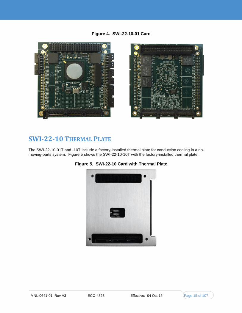
Figure 4. SWI-22-10-01 Card
SWI-22-10 THERMAL PLATE
The SWI-22-10-01T and -10T include a factory-installed thermal plate for conduction cooling in a no-moving-parts system. Figure 5 shows the SWI-22-10-10T with the factory-installed thermal plate.
Figure 5. SWI-22-10 Card with Thermal Plate

Chapter 2 Hardware Description
Parvus SWI-22-10 Curtiss-Wright
Page 16 of 107 MNL-0641-01 Rev A3 ECO-4823 Effective: 04 Oct 16
Figure 6 shows the mounting holes in the sides of the thermal plate that are used to mount the thermal plate in a chassis for heat dissipation.
Figure 6. Thermal Plate Mounting Hole Locations
Figure 7 and Figure 8 show where the thermal plate is located relative to the PCB.
Figure 7. Thermal Plate Vertical Dimensions

MNL-0641-01 Rev A3 ECO-4823 Effective: 04 Oct 16 Page 17 of 107
Figure 8. Thermal Plate Horizontal Dimensions
The 2D drawings and 3D model for the thermal plate are available to customers that wish to design their own thermal solution.
Note: If you do not use the thermal plate available from Curtiss-Wright, then your system design must provide adequate heat dissipation.

Chapter 2 Hardware Description
Parvus SWI-22-10 Curtiss-Wright
Page 18 of 107 MNL-0641-01 Rev A3 ECO-4823 Effective: 04 Oct 16

MNL-0641-01 Rev A3 ECO-4823 Effective: 04 Oct 16 Page 19 of 107
CHAPTER 3. HARDWARE INSTALLATION
EQUIPMENT INSTALLATION
To use the SWI-22-10-xx in a lab environment, you must have:
Appropriate cables, such as the CBL-SWI-22-10-10 Breakout Cable Set
A power source, either:
A PCI/104 stack or a PCI/104-Express stack
+5VDC@3A supplied to the SWI-22-10 board (connected at P3). A power cable is included with the Breakout Cable Set.
Thermal cooling, either:
SWI-22-10 Thermal Plate factory-installed on the SWI-22-10-10T or the SWI-22-10-01T
A custom cooling solution (a small fan blowing across the top of the board will do).
A host PC with a free RS-232 port and/or an Ethernet port. See “Serial CLI Setup” and “Using the Web GUI” in chapter four to setup the serial and Ethernet ports on the host PC.
INSTALLATION PRECAUTIONS
ESD Warning!
This product uses components that can be damaged by electrostatic discharge (ESD). Observe precautions for handling electrostatic-discharge sensitive devices.
Exercise extreme caution when installing or removing the board. The interface pins are very easily bent.
Ensure proper line-up with receptacles before applying force.
Apply force as evenly as possible to prevent the interface pins from inserting at an angle.
If the stack requires disassembly, apply even force while disassembling components.

Chapter 3. Hardware Installation
Parvus SWI-22-10 Curtiss-Wright
Page 20 of 107 MNL-0641-01 Rev A3 ECO-4823 Effective: 04 Oct 16
BREAKOUT CABLE SET You should test the SWI-22-10 interfaces and cabling prior to installation in the target system to ensure full operational capability. Full bench-top testing can be performed by using the appropriate cable set for the card. You can also use a custom set of cables made specifically for the intended target system, vehicle, or craft; refer to Chapter 5 for connector pinouts and descriptions.
The breakout cable set (CBL-SWI-22-10-10 or CBL-SWI-22-10-01) is available for purchase through Curtiss-Wright and is intended for lab or bench testing purposes only.
The SWI-22-10-10 cable set (CBL-SWI-22-10-10, shown in Figure 9) includes the following cables:
Cable Qty. Description Function
CBL-2444-01 1 SWI-22-10, ten Ethernet, console, zeroize
Breaks out to Ports 1-6 and Ports 17-20 RJ-45 cables, DB-9 console port cable, and zeroize port cable.
CBL-2444-02 1 SWI-22-10, ten Ethernet, LEDs Breaks out to Ports 7-16 RJ-45 cables and LED port cable
CBL-2551-01 1 SWI-22-10, external power Connects auxiliary power connector and chassis ground ring lugs to banana plugs for a bench-top power supply.
CBL-1536-01 1 6’ DB9 M/F serial extension Extends console port connection length if breakout cable is not long enough to reach host computer.
Figure 9. Breakout Cableset (CBL-SWI-22-10-10)
The SWI-22-10-01 cable set (CBL-SWI-22-10-01, shown in Figure 10) includes the following cables:
Cable Qty. Description Function
CBL-2562-01 1 SWI-22-10-0x, Ethernet ports 1-2, console, zeroize
Breaks out to Ethernet Ports 1 and 2 RJ-45 cables, DB-9 console port cable, and zeroize port cable.
CBL-2562-02 1 SWI-22-10-0x, Ethernet ports 3-4 Breaks out to Ports 3 and 4 RJ-45 cables.
CBL-2562-03 1 SWI-22-10-0x, Ethernet ports 5-6 Breaks out to Ports 5 and 6 RJ-45 cables.
CBL-2562-04 1 SWI-22-10-0x, Ethernet ports 7-8, LEDs Breaks out to Ports 7 and 8 RJ-45 cables and LED port cable.

MNL-0641-01 Rev A3 ECO-4823 Effective: 04 Oct 16 Page 21 of 107
Cable Qty. Description Function
CBL-2551-01 1 SWI-22-10, external power Connects auxiliary power connector and chassis ground ring lugs to banana plugs for a bench-top power supply.
CBL-1536-01 1 6’ DB9 M/F serial extension Extends console port connection length if breakout cable is not long enough to reach host computer.
Figure 10. Breakout Cableset (CBL-SWI-22-10-01)

Chapter 3. Hardware Installation
Parvus SWI-22-10 Curtiss-Wright
Page 22 of 107 MNL-0641-01 Rev A3 ECO-4823 Effective: 04 Oct 16
TEST SETUP SWI-22-10-10 Figure 11 shows the location of the connectors on the SWI-22-10-10.
Figure 11. Connector Locations (SWI-22-10-10)
1. Place the card on an anti-static surface, such as the bag that the card was packaged in, or install it into a PCI/104 or PCI/104-Express stack.
2. Connect the two Ethernet cables (CBL-2444-01 and -02) to the card, matching up the J2 and J3 labels on the cables with ports J2 and J3 on the card.
The Harwin connectors can’t be mated by just plugging them together. Match up the faces of the mating connectors and use a small bladed screwdriver to screw in one of the captive screws part way, then the other screw part way, then proceed to screw both screws in fully.
3. If the card is installed in a PCI/104 or PCI/104-Express stack, it will be powered by the stack. Skip to step 4. Otherwise, connect power:
Connect the power cable CBL-2551-01 to the auxiliary power connector P3.
Attach the two ring lugs on the power cable to the two mounting holes on the board: one to MTG1 (chassis ground 1) and the other one to MTG2 (chassis ground 2), using the supplied screws, star washers, and nuts.
Connect chassis ground 1 and chassis ground 2 either to the chassis ground of the bench-top power supply or to the chassis ground of the PCI/104 stack. Failure to do so could affect data transmission over long cables.
Connect the power cable banana plugs to a bench-top power supply that can supply 5V/3A.
4. Connect the DB-9 connector on CBL-2444-01 to an open serial port on your host computer for access to the console (CLI). Use the supplied extension cable (CBL-1536-01) if a longer reach is needed.
5. Connect one Ethernet port to your host computer or to a network shared by your host computer for access to the Web GUI management interface (GUI).
6. Connect other Ethernet ports to desired equipment for testing.

MNL-0641-01 Rev A3 ECO-4823 Effective: 04 Oct 16 Page 23 of 107
7. Turn on the power supply.
8. After about 18 seconds, a green LED should start flashing on the edge of the board next to the PCI-Express connector. The flashing LED indicates that the card is ready for operation. During this boot process the serial CLI port will output information about the progress of the booting process.
TEST SETUP SWI-22-10-01 Figure 12 shows the location of the connectors on the SWI-22-10-01.
Figure 12. Connector Locations (SWI-22-10-01)
1. Place the card on an anti-static surface, such as the bag that the card was packaged in, or install it into a PCI/104 or PCI/104-Express stack.
2. Connect the four Ethernet cables (CBL-2562-01, -02, -03, and -04) to the card, matching cables labeled P10, P13, P14, and P15 to the corresponding ports on the card.
3. If the card is installed in a PCI/104 or PCI/104-Express stack, it will be powered by the stack. Skip to step 4. Otherwise, connect power:
Connect the power cable CBL-2551-01 to the auxiliary power connector.
Attach the two ring lugs on the power cable to two mounting holes on the board: one to MTG1 (chassis ground 1) and the other one to MTG2 (chassis ground 2), using the supplied screws, star washers, and nuts.
Connect chassis ground 1 and chassis ground 2 either to the chassis ground of the bench-top power supply or to the chassis ground of the PCI/104 stack. Failure to do so could affect data transmission over long cables.
Connect the power cable banana plugs to a bench-top power supply that can supply 5V/3A.
4. Connect the DB-9 connector on CBL-2562-01 to an open serial port on your host computer for access to the console (CLI). Use the supplied extension cable (CBL-1536-01) if a longer reach is needed.
P7 Por
P6
P5
P4
Ports 7 & 8
LED Interface
Ports 5 & 6
Ports 3 & 4
Ports 1 & 2
RS232 & Zeroize Interfaces
MTG2 MTG1 J5/J8 (on bottom) PCI Express
J1/J6 (on bottom) PCI
P3

Chapter 3. Hardware Installation
Parvus SWI-22-10 Curtiss-Wright
Page 24 of 107 MNL-0641-01 Rev A3 ECO-4823 Effective: 04 Oct 16
5. Connect one Ethernet port to your host computer or to a network shared by your host computer for access to the Web GUI management interface (GUI).
6. Connect other Ethernet ports to desired equipment for testing.
7. Turn on the power supply.
8. After about 18 seconds, a green LED should start flashing on the edge of the board next to the PCI-Express connector. The flashing LED indicates that the card is ready for operation. During this boot process the CLI port will output information about the progress of the booting process.
ZEROIZATION
For data security, the SWI-22-10 provides a zeroization capability to erase the configuration data stored on the card. In normal operation, zeroization is used only if the user loses or forgets the SWI-22-10 password. The SWI-22-10 has no way to recover the password. The only way to resolve the issue and regain access to the SWI-22-10 management interface is to zeroize the configuration back to the default configuration. The user can then reload the user configuration.
INITIATING ZEROIZATION During lab testing, the breakout cable set provides zeroization capability. The breakout cables (CBL-2444-01 for the SWI-22-10-10 and CBL-2562-01 for the SWI-22-10-01) have a pair of wires protruding from the rear of the DB-9 shell, for use as the zeroization interface.
Before you can test zeroization, you must enable zeroization using the CLI command optzenable, described in Appendix B. The default time to zeroize is 2 seconds, but the time is adjustable through the CLI command optzdelay.
The hardware setup must generate the off-board Zeroize trigger, a nominal +12VDC signal pulse. For testing purposes, a fresh 9V battery can be used for the Zeroize trigger.
1. Attach the zeroize ground return (orange wire) to the negative terminal of the 9V battery.
2. Attach the zeroize input (green wire) to the positive terminal for more than the optzdelay delay time to initiate the zeroize operation.
Caution! Do not apply +9VDC or +12VDC to any other pin.
For information on user-made cabling, refer to the pinouts in Chapter 5: “J3 Pinout” for the SWI-22-10-10 or “P7 Pinout” for the SWI-22-10-01.
ZEROIZATION RECOVERY Zeroization erases the configuration data stored in startup-config. When the switch is restarted after power down, the switch will start up with the factory-default configuration. You can then reload the user configuration if you have a backup config file, otherwise, you have to reconfigure the switch.
On units that have firmware version 1.0.0, to ensure the system operates properly, logon with the user name admin and no password. Issue the following commands to the console:
1. configure terminal
2. Thermal-protect prio 0 temperature 255
3. Thermal-protect prio 1 temperature 255
4. Thermal-protect prio 2 temperature 255
5. Thermal-protect prio 3 temperature 255
6. hostname SWI-xxxx (xxxx is the unit serial number).

MNL-0641-01 Rev A3 ECO-4823 Effective: 04 Oct 16 Page 25 of 107
7. end
8. copy running-config startup-config

Chapter 4 Management Interface Description
Parvus SWI-22-10 Curtiss-Wright
Page 26 of 107 MNL-0641-01 Rev A3 ECO-4823 Effective: 04 Oct 16
CHAPTER 4 MANAGEMENT INTERFACE DESCRIPTION The SWI-22-10 management interfaces provide the network administrator with a set of comprehensive management functions. The network administrator has a choice of two easy-to-use management interfaces:
Serial CLI (command line interface)
Manages all switch features.
Must be used to change the switch IP address from the factory default.
Can be used even if there is no network connectivity.
Provides brief help on syntax for each command.
Web GUI (graphical user interface).
Manages all switch features except the switch IP address.
Requires network connectivity.
Provides extensive help on functions and parameters.
For centrally managed networks, the switch also supports SNMP Management (not described in this manual).
This chapter explains the switch configuration files that store switch parameters, and then provides step-by-step instructions on how to use each of these interfaces to configure and manage the switch. The CLI is described in detail in Appendix A.

MNL-0641-01 Rev A3 ECO-4823 Effective: 04 Oct 16 Page 27 of 107
UNDERSTANDING THE SWITCH CONFIGURATION FILES
The switch supports an Industry Standard configuration (ICFG) and stores the configuration in text files in CLI format. The files are either virtual (RAM-based) or stored in flash on the switch. All configuration files except ‘running-config’ are stored in the flash: file system.
There are four kinds of configuration files:
‘running-config’, a virtual file containing the currently running system configuration. running-config is created each time the system boots, by reading default-config and then startup-config. When you make configuration changes, they affect running-config.
‘startup-config’, containing the saved configuration that is read at boot time. If you make configuration changes, you must copy running-config to startup-config in order to save them and apply them at the next boot.
‘default-config’, a read-only file that contains the factory defaults for the switch. It is used to reset a feature to its default, or if ‘startup-config’ is missing, to set the entire configuration to factory defaults.
User-defined configuration files. These are typically used for backups or variants of startup-config. The maximum number of files in flash is limited to a compressed size which does not exceed roughly 1MB.
The CLI supports the maximum number of files.
The GUI file management capabilities are limited; refer to "Managing Configuration Files".
The configuration files can be edited and can be populated on multiple other switches using any standard text editor offline.
It is possible to reset the total system configuration to defaults in two ways:
Deleting ‘startup-config’ and rebooting.
Instructing the software to discard the current configuration and reset to defaults without rebooting.
Deleting ‘startup-config’ doesn’t change the current ‘running-config’; however, when the system is rebooted, only the defaults will be loaded. Conversely, discarding the current configuration affects ‘running-config’ but does not touch ‘startup-config’.
The sections on "Using the CLI" and "Using the Web GUI" provide instructions on working with the configuration files.
Note: You must use the CLI to change the VLAN 1 IP address from the factory default; refer to the "CLI Quick Start" section. For all other management activities, you can use either the CLI or the Web GUI.

Chapter 4 Management Interface Description
Parvus SWI-22-10 Curtiss-Wright
Page 28 of 107 MNL-0641-01 Rev A3 ECO-4823 Effective: 04 Oct 16
USING THE CLI
This document describes basic usage and configuration of the command line interface (CLI) for the Parvus SWI-22-10.
The CLI interface is an industry-standard CLI and consists of configuration commands which provide the ability to configure and view the configuration using the serial console, or Telnet or SSH access. Even if there is no network connectivity, you can still manage the switch using a serial connection.
SERIAL CLI SETUP 1. Connect the SWI-22-10 to a serial port on the host computer.
2. Power-on the SWI-22-10.
3. Set the serial port on the host to 115200 baud, no parity, 8 data bits, 1 stop bit, no parity, no flow control.
4. Start a terminal emulator on the host, such as TeraTerm or PuTTY on Windows, or Minicom on Linux.
CLI QUICK START The instructions in this section provide step-by-step instructions on how to use the most critical CLI commands. This section describes how to:
Log in.
Set the VLAN 1 IP address.
Verify connectivity using ‘ping.’
Set the admin user password (optional).
Display the current configuration and save it to flash storage.
Make a backup copy of the configuration.
Once the system is set to the correct VLAN 1 IP address, you can use either the CLI or the web GUI to perform system configuration.
Remember that bold identifies what you should type exactly as shown; bold italic marks a parameter you should provide, such as my-device.
Log In When the card powers on, the switch boots through RedBoot to the switch CLI and the following messages are displayed on the console:
RedBoot> go Parvus version 1.0.0 Press ENTER to get started
1. Press Enter one or more times until the ‘Username:’ prompt appears.
Username: 2. Type admin and press Enter.
Username: admin Password:
MNL-0641-01 Rev A3 ECO-4823 Effective: 04 Oct 16 Page 29 of 107
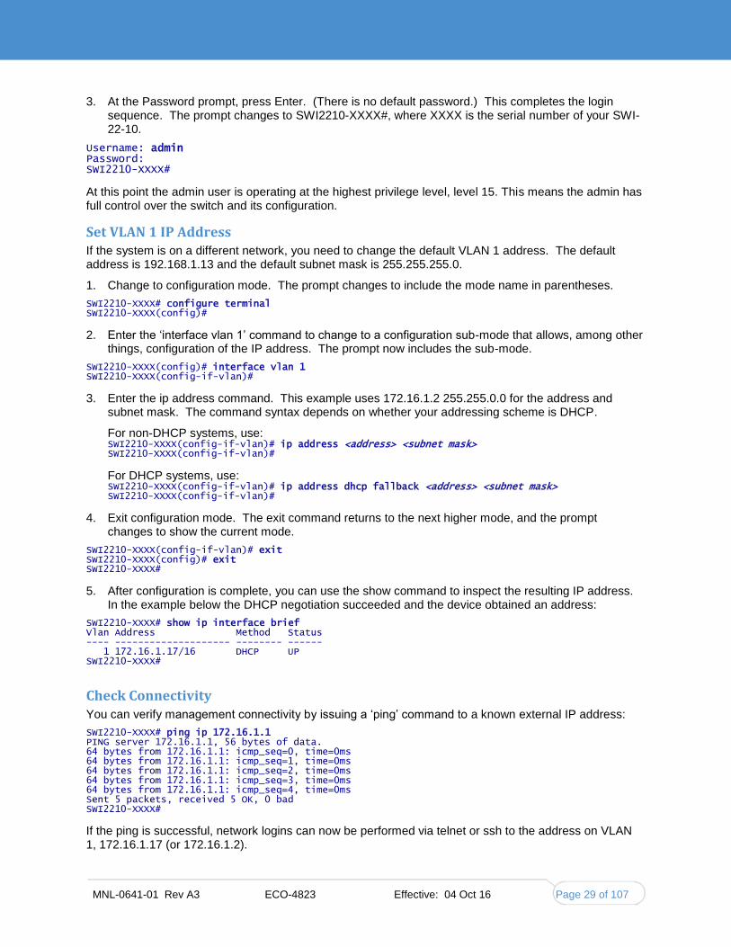
3. At the Password prompt, press Enter. (There is no default password.) This completes the login sequence. The prompt changes to SWI2210-XXXX#, where XXXX is the serial number of your SWI-22-10.
Username: admin Password: SWI2210-XXXX#
At this point the admin user is operating at the highest privilege level, level 15. This means the admin has full control over the switch and its configuration.
Set VLAN 1 IP Address If the system is on a different network, you need to change the default VLAN 1 address. The default address is 192.168.1.13 and the default subnet mask is 255.255.255.0.
1. Change to configuration mode. The prompt changes to include the mode name in parentheses.
SWI2210-XXXX# configure terminal SWI2210-XXXX(config)#
2. Enter the ‘interface vlan 1’ command to change to a configuration sub-mode that allows, among other things, configuration of the IP address. The prompt now includes the sub-mode.
SWI2210-XXXX(config)# interface vlan 1 SWI2210-XXXX(config-if-vlan)#
3. Enter the ip address command. This example uses 172.16.1.2 255.255.0.0 for the address and subnet mask. The command syntax depends on whether your addressing scheme is DHCP.
For non-DHCP systems, use: SWI2210-XXXX(config-if-vlan)# ip address <address> <subnet mask> SWI2210-XXXX(config-if-vlan)#
For DHCP systems, use: SWI2210-XXXX(config-if-vlan)# ip address dhcp fallback <address> <subnet mask> SWI2210-XXXX(config-if-vlan)#
4. Exit configuration mode. The exit command returns to the next higher mode, and the prompt changes to show the current mode.
SWI2210-XXXX(config-if-vlan)# exit SWI2210-XXXX(config)# exit SWI2210-XXXX#
5. After configuration is complete, you can use the show command to inspect the resulting IP address. In the example below the DHCP negotiation succeeded and the device obtained an address:
SWI2210-XXXX# show ip interface brief Vlan Address Method Status ---- -------------------- -------- ------ 1 172.16.1.17/16 DHCP UP SWI2210-XXXX#
Check Connectivity You can verify management connectivity by issuing a ‘ping’ command to a known external IP address:
SWI2210-XXXX# ping ip 172.16.1.1 PING server 172.16.1.1, 56 bytes of data. 64 bytes from 172.16.1.1: icmp_seq=0, time=0ms 64 bytes from 172.16.1.1: icmp_seq=1, time=0ms 64 bytes from 172.16.1.1: icmp_seq=2, time=0ms 64 bytes from 172.16.1.1: icmp_seq=3, time=0ms 64 bytes from 172.16.1.1: icmp_seq=4, time=0ms Sent 5 packets, received 5 OK, 0 bad SWI2210-XXXX#
If the ping is successful, network logins can now be performed via telnet or ssh to the address on VLAN 1, 172.16.1.17 (or 172.16.1.2).

Chapter 4 Management Interface Description
Parvus SWI-22-10 Curtiss-Wright
Page 30 of 107 MNL-0641-01 Rev A3 ECO-4823 Effective: 04 Oct 16
Save the Configuration These steps describe how to perform a basic save operation and view the new configuration file.
1. Copy running-config to startup-config:
SWI2210-XXXX# copy running-config startup-config Building configuration... % Saving 1326 bytes to flash:startup-config
2. Use the dir command to display the contents of the flash file system.
SWI2210-XXXX# dir Directory of flash:
r- 1970-01-01 00:00:00 648 default-config rw 1970-01-03 18:21:28 1326 startup-config
2 files, 1974 bytes total.
3. Enter the more command to output the contents of the startup-config file.
SWI2210-XXXX# more flash:startup-config hostname SWI2210-XXXX username admin privilege 15 password encrypted dmVyeS1zZWNyZXQ= ! vlan 1 name default [...]
Create a Backup Copy of the Configuration These steps describe how to make a backup copy of startup-config in the flash file system on the switch and then make another copy on the host computer.
1. Copy startup-config to a new file. In this example, backup is the name of the new file.
SWI2210-XXXX# copy startup-config flash:backup Building configuration... % Saving 1326 bytes to flash:backup
2. Use the dir command to display the contents of the flash file system.
SWI2210-XXXX# dir Directory of flash:
r- 1970-01-01 00:00:00 648 default-config rw 1970-01-03 18:21:28 1326 startup-config rw 1970-01-03 18:21:28 1326 backup
3 files, 3300 bytes total.
3. Enter the more command to output the contents of the backup file.
SWI2210-XXXX# more flash:backup hostname SWI2210-XXXX username admin privilege 15 password encrypted dmVyeS1zZWNyZXQ= ! vlan 1 name default [...]
4. To store the backup file on the host computer, use the copy command with this syntax:
SWI2210-XXXX# copy backup tftp://<server>[:<port>]/<path-to-file>

MNL-0641-01 Rev A3 ECO-4823 Effective: 04 Oct 16 Page 31 of 107
CLI COMMAND GROUPS CLI commands can be grouped into the following functional categories:
Manage and show switch settings.
Manage configuration and firmware files.
Manage system.
Manage Parvus extensions.
Figure 13 shows the list of Exec commands and the commands available in each group. Appendix A provides more information on the first three command groups, with multiple examples of their use. Appendix B describes the Parvus extensions, which are specialized commands for viewing board status and enabling optional board features like zeroization.
Figure 13. CLI Functional Groups

Chapter 4 Management Interface Description
Parvus SWI-22-10 Curtiss-Wright
Page 32 of 107 MNL-0641-01 Rev A3 ECO-4823 Effective: 04 Oct 16
WORKING WITH CONFIGURATION FILES Configuration file names are case-sensitive.
Saving and Deleting Configuration Files The available operations are copy, dir, more, and delete.
copy <source> <destination>
Copies source to destination. The source and destination can be one of:
running-config
startup-config (or flash:startup-config)
flash:<filename>
tftp://<server>[:<port>]/<path-to-file>
dir
Lists the contents of the flash: file system.
more flash: <filename>
Outputs the contents of the specified file <filename>to the terminal.
delete flash: <filename>
Deletes the specified file <filename>.
Example: Working With Configuration Files
The following example assumes a file system which contains a user-defined configuration file called ‘backup’, previously created with a ‘copy’ command.
! List files in flash: SWI2210-XXXX# dir Directory of flash:
r- 1970-01-01 00:00:00 648 default-config rw 1970-01-06 03:57:33 1313 startup-config rw 1970-01-01 19:54:01 1237 backup
3 files, 3198 bytes total. ! Display the contents of the file ‘backup’ (output is abbreviated): SWI2210-XXXX# more flash:backup hostname SWI2210-XXXX ... end ! Use file ‘backup’ for the next boot by overwriting startup-config: SWI2210-XXXX# copy flash:backup startup-config % Saving 1237 bytes to flash:startup-config ! Verify that the sizes are identical: SWI2210-XXXX# dir Directory of flash:
r- 1970-01-01 00:00:00 648 default-config rw 1970-01-06 05:30:41 1237 startup-config rw 1970-01-01 19:54:01 1237 backup
3 files, 3122 bytes total. ! Delete startup-config. Note how ‘flash:’ is required: SWI2210-XXXX# delete flash:startup-config SWI2210-XXXX# dir Directory of flash:
r- 1970-01-01 00:00:00 648 default-config

MNL-0641-01 Rev A3 ECO-4823 Effective: 04 Oct 16 Page 33 of 107
rw 1970-01-01 19:54:01 1237 backup 2 files, 1885 bytes total. ! Use the current running-config for next boot: SWI2210-XXXX# copy running-config startup-config Building configuration... % Saving 1271 bytes to flash:startup-config
Reverting to the Default Configuration An explicit ‘copy running-config startup-config’ is necessary to make the change persistent.
Rebooting and resetting configuration to defaults is accomplished with the ‘reload’ command:
reload cold [ sid <switch_id> ] reload defaults [ keep-ip ] The first form reboots the system. The second form loads configuration defaults. If the ‘keep-ip’ keyword is specified, the system attempts to keep the most relevant parts of the VLAN 1 IP setup--the IP address setup and the active default route--in order to maintain management connectivity.
Note: There is no guarantee that the above is sufficient. It depends on the actual network properties and the system’s total IP configuration. In some cases it may be preferable to explicitly un-configure the system using ‘no’ commands, or prepare a suitable configuration and download it to the system’s ‘startup-config’ and reboot.
Example: Using Reload Commands ! Reload defaults, but try to keep VLAN 1 configuration. First list current IP ! settings: SWI2210-XXXX# show ip interface brief Vlan Address Method Status ---- -------------------- -------- ------ 1 172.16.1.17/24 DHCP UP SWI2210-XXXX# reload defaults keep-ip % Reloading defaults, attempting to keep VLAN 1 IP address. Please stand by. # show ip interface brief Vlan Address Method Status ---- -------------------- -------- ------ 1 172.16.1.17/24 DHCP UP ! Contents of flash: are unchanged: SWI2210-XXXX# dir Directory of flash:
r- 1970-01-01 00:00:00 648 default-config rw 1970-01-06 05:33:18 1237 startup-config rw 1970-01-01 19:54:01 1237 backup
3 files, 3122 bytes total. ! Reload again, but don’t try to keep VLAN 1 settings: # reload defaults % Reloading defaults. Please stand by. ! Verify that the default IP settings have been restored: # show ip interface brief Vlan Address Method Status ---- -------------------- -------- ------ 1 192.0.2.1/24 Manual UP ! Reboot the system # reload cold % Cold reload in progress, please stand by. ! ... bootup output omitted ...
LOADING A NEW FIRMWARE IMAGE The system can store up to two software images in flash. The image selected for bootup is termed the active image, while the other is termed the alternate image.

Chapter 4 Management Interface Description
Parvus SWI-22-10 Curtiss-Wright
Page 34 of 107 MNL-0641-01 Rev A3 ECO-4823 Effective: 04 Oct 16
It is possible to swap the active and alternative images, and it is possible to upgrade to a new active image.
A swap simply switches the active/alternate designation on each image and reboots the system.
A firmware upgrade performs these steps:
Downloads new firmware using TFTP and verifies suitability for the system.
Overwrites the current alternate image with the newly downloaded image.
Swaps active/alternate and reboots.
The result is that the old active build becomes the alternate and the newly downloaded image is active.
The relevant commands are:
! Use show version to list details about the system, including the images in flash. SWI2210-XXXX# show version SWI2210-XXXX# firmware swap SWI2210-XXXX# firmware upgrade tftp://<server>[:<port>]/<path_to_file>
‘show version’ lists various details about the system, including the images in flash.

MNL-0641-01 Rev A3 ECO-4823 Effective: 04 Oct 16 Page 35 of 107
USING THE WEB GUI
The web-based software management method allows the network administrator to configure, manage, view, and control the switches remotely. The Web based Management method also provides help pages for assisting the switch administrator in understanding the usage. SNMP management is standards-based, with configuration parameters specified in the supported MIBs.
The supported web browsers are:
Internet Explorer 7.0 and above
Firefox 3.6 and above
Google Chrome 8.0 and above
Safari S5 and above
Opera 11 and above
Connect to the host PC via any Ethernet port. The factory-default IP address is: 192.168.1.13 and the default subnet mask is 255.255.255.0.
Note: You must use the CLI to change the VLAN 1 IP address from the factory default; refer to the "CLI Quick Start" section. For all other management activities, you can use either the CLI or the Web GUI.
ETHERNET GUI FEATURES The Web GUI is divided into four different trees:
Configuration of features
Monitoring of the configured features, with ‘Auto-Refresh’ option
Diagnostics
Maintenance-related features
Figure 14 is an alphabetized list of the top-level features in each group.

Chapter 4 Management Interface Description
Parvus SWI-22-10 Curtiss-Wright
Page 36 of 107 MNL-0641-01 Rev A3 ECO-4823 Effective: 04 Oct 16
Figure 14. Web GUI Top Level Features (Alphabetized)

MNL-0641-01 Rev A3 ECO-4823 Effective: 04 Oct 16 Page 37 of 107
WEB GUI INTRODUCTION This section explains how to access the web GUI, describes page navigation, and explains how to access help.
Accessing the Web Interface Once the IP address of the switch is set up, you can use the Web GUI to manage the switch.
where the IP address of the switch is .
1. Connect the switch to a host computer via an Ethernet port. The computer must exist on the same subnet as the switch IP address.
2. Type the switch URL (IP address) into the address bar of a web browser on the host computer; for example: http://10.33.15.2
3. The Password popup is displayed. Type admin in the User name box.
4. If you've already set an admin password, type it in the password box. Otherwise leave the box empty—there is no default password--and click OK.

Chapter 4 Management Interface Description
Parvus SWI-22-10 Curtiss-Wright
Page 38 of 107 MNL-0641-01 Rev A3 ECO-4823 Effective: 04 Oct 16
5. The GUI home page is displayed.
The standard parts of the GUI are the navigation pane on the left, the large work area, and system buttons in the upper right corner of the window. The default view for the GUI is the monitor for Port States.

MNL-0641-01 Rev A3 ECO-4823 Effective: 04 Oct 16 Page 39 of 107
Navigation Pane The navigation pane selects what is displayed in the work area. The pane is organized into categories (such as Configuration, Monitor, and Diagnostics) and subcategories (such as System, Green Ethernet, and Ports under Monitor). The categories and subcategories are just navigation tools—they aren't displayed in the work area. Only the work pages, represented by the square bullet, are displayed.
To expand or collapse a category, click the name, not the symbol. Expanding does not affect what's displayed in the work area.
indicates a collapsed topic.
indicates an expanded topic. Topics remain expanded until you collapse them.
indicates a work page.
The page displayed in the work area doesn’t change until you select a different command page. Only pages have help.
System Buttons The system buttons are circled in this example page.
Home: A shortcut to quickly display the home page without using the navigation pane. Any unsaved changes are lost.
Logout: Closes the GUI.
Help: Opens a separate help window for the current work page. It describes each field and button on the page, like this example for the Port State Overview page. If you leave the help window, navigate to a new page, and click Help, the help window updates with help for the new page.

Chapter 4 Management Interface Description
Parvus SWI-22-10 Curtiss-Wright
Page 40 of 107 MNL-0641-01 Rev A3 ECO-4823 Effective: 04 Oct 16
Note: If you minimize the help window and then try to display help for a new page, the help window may not automatically maximize.

MNL-0641-01 Rev A3 ECO-4823 Effective: 04 Oct 16 Page 41 of 107
Links to Detail Popups Many of the GUI pages display a table of results, like this example of the system log. Underlined entries in the table (ID 1 and 2) indicate that a detail page is available for the entry.
If you click on the underlined item, the display changes to show more information, like this example of detailed system log information for ID 2.

Chapter 4 Management Interface Description
Parvus SWI-22-10 Curtiss-Wright
Page 42 of 107 MNL-0641-01 Rev A3 ECO-4823 Effective: 04 Oct 16
CHANGING AND SAVING CONFIGURATION SETTINGS These instructions walk you through the processes for changing the switch hostname and the admin password, providing tips that are relevant to any configuration change. The instructions then explain how to save the configuration.
Changing the Switch Hostname (Example) The basic process for changing any configuration setting is illustrated here, using changing the switch host name from my-device to SW2210-XX as an example.
1. Use the navigation pane to find and display the appropriate page.
2. Display help if you're unsure what a field means.
3. Complete all required fields on the page.

MNL-0641-01 Rev A3 ECO-4823 Effective: 04 Oct 16 Page 43 of 107
4. Click the Save button.
If you left any optional fields blank, a reminder that the field is empty is displayed. Click OK or return to the page and supply a value.
Once all fields have been checked, the change goes into effect immediately.
5. Repeat steps 1-4 to make any other configuration changes you need.
6. When you're finished making changes, save the changes to startup-config, following the instructions in the next section. If you do not copy the changes to startup-config, they will be lost when power is turned off.

Chapter 4 Management Interface Description
Parvus SWI-22-10 Curtiss-Wright
Page 44 of 107 MNL-0641-01 Rev A3 ECO-4823 Effective: 04 Oct 16
Changing the Admin Password (Example) By default, there is no admin password. To set a password:
1. Use the navigation pane to find and display the appropriate page.
The Users Configuration page lists the configured users. You can also use this page to add users.
Each user name is underlined, indicating it is a link to a detail page.
2. Display help if you're unsure what a field means.
3. Click the admin user name. The Edit User popup is displayed
4. Type the new password twice.
5. Click the Save button. The change goes into effect immediately.
6. When you're finished making all changes, save the changes to startup-config, following the instructions in the next section. If you do not copy the changes to startup-config, they will be lost when power is turned off.

MNL-0641-01 Rev A3 ECO-4823 Effective: 04 Oct 16 Page 45 of 107
Saving the Configuration via the Web GUI This section explains how to copy running-config to startup-config, thereby ensuring that the currently active configuration will be available at the next reboot.
1. Use the navigation pane to find the appropriate page. Save startup-config is under Maintenance > Configuration.
2. Click Save start-up config.
3. Display help if you're unsure what this command does.
4. Click the Save Configuration button. A confirmation message is displayed, indicating that startup-config has been updated.
5. To make a backup copy of startup-config, refer to "Managing Configuration Files". You must download the file from the switch to the browser. If you want to store the backup file in the switch flash, you can then upload the file from the browser to the switch.

Chapter 4 Management Interface Description
Parvus SWI-22-10 Curtiss-Wright
Page 46 of 107 MNL-0641-01 Rev A3 ECO-4823 Effective: 04 Oct 16
MANAGING CONFIGURATION FILES Configuration parameters are represented as attribute values. When saving the configuration from the switch, the entire configuration including syntax descriptions is included in the file. The file may then be modified using an editor and loaded to a switch.
Downloading a Configuration File Downloading a configuration file creates a backup file by downloading the configuration file from the switch to the web browser. The default files include running-config, default-config and the startup-config. Other files on the flash are also listed.
1. Use the navigation pane to find the appropriate page. Download is under Maintenance > Configuration. Click Download.
2. Select the file to be downloaded, then click Download Configuration.
3. The actual save operation is browser-specific. The browser performs the save operation, and usually provides options to save-as new name and select the save location. Status and completion messages are controlled by the browser; the GUI work area doesn't change.

MNL-0641-01 Rev A3 ECO-4823 Effective: 04 Oct 16 Page 47 of 107
Uploading a Configuration File You can upload a file from the web browser to any of the files on the switch, except default-config, which is read-only. The upload can replace the current file or create a new file in flash.
If the destination is running-config, the file will be applied to the switch configuration. This can be done in two ways:
Replace mode: The current configuration is fully replaced with the configuration in the uploaded file.
Merge mode: The uploaded file is merged into running-config.
If the file system is full (i.e., contains three system files plus user-defined files), you can't create new files. In that case, you must either first delete an existing file or allow the upload to overwrite an existing file.
1. Use the navigation pane to find the appropriate page. Upload is under Maintenance > Configuration. Click Upload.
2. Click the Browse button and find the file to upload.

Chapter 4 Management Interface Description
Parvus SWI-22-10 Curtiss-Wright
Page 48 of 107 MNL-0641-01 Rev A3 ECO-4823 Effective: 04 Oct 16
3. Select the destination. The available destination files show the first four files in flash. If the GUI file system is full, the Create a new file option is not available and a message is displayed.
4. If you decide to delete an existing file, click Delete in the navigation pane. Then select the file to delete. A confirmation message is displayed. Return to step 1.

MNL-0641-01 Rev A3 ECO-4823 Effective: 04 Oct 16 Page 49 of 107
5. Click Upload Configuration. A completion message is displayed.
Activating a Configuration File Activating a file means initiating the process of completely replacing the existing configuration with that of the selected file. You can activate any of the configuration files present on the switch, except for running-config which represents the currently active configuration.
Deleting a Configuration File You can delete any of the writable files stored in flash, including startup-config. If this is done and the switch is rebooted without a prior Save operation, this effectively resets the switch to the default configuration.
LOADING A NEW FIRMWARE IMAGE TBD

Chapter 5 Connector Descriptions
Parvus SWI-22-10 Curtiss-Wright
Page 50 of 107 MNL-0641-01 Rev A3 ECO-4823 Effective: 04 Oct 16
CHAPTER 5 CONNECTOR DESCRIPTIONS This chapter identifies connector part numbers, locations, and pinouts to facilitate fabrication of cables that can connect to the SWI-22-10. The chapter describes the card-specific connectors for the SWI-22-10-10 and SWI-22-10-01 and then describes the connectors common to both cards. Finally, implementation information for the console, zeroize, and LED ports is provided.
SWI-22-10-10 CARD-SPECIFIC CONNECTORS
PART NUMBERS The following table shows the manufacturer part numbers for the SWI-22-10-10 connectors (identified in Figure 15), together with the suggested mating connectors.
Connector Part Number Mating Connector
J2 & J3 Harwin M83-LML3M1N96-0000-000 Harwin M83-LFC1F1N96-0000-000 for 24- gauge CAT-5E wiring
Harwin M83-LFT1F2N96-0000-000 for flex cable or PCB mounting
Figure 15. SWI-22-10-10 Ethernet Connectors
DESCRIPTION AND PINOUTS Connectors J2 and J3 form the Ethernet Switch Interface for the SWI-22-10-10.
20 Gigabit Ethernet Ports - The ports are numbered 1 through 20. Each port has four differential matched pairs: A, B, C, and D (e.g., GBE20_A_P and GBE20_A_N).
RS-232 Port - Serial console interface
Zeroize - an external configuration erase function which returns the board to a default configuration state.
Serial LED Interface

MNL-0641-01 Rev A3 ECO-4823 Effective: 04 Oct 16 Page 51 of 107
Figure 16 shows the physical orientation for J2 and J3.
Figure 16. SWI-22-10-10 Ethernet Connector Detail
J2 Pinout
J2 PIN SIGNAL J2 PIN SIGNAL J2 PIN SIGNAL
A1 GBE16_A_P B1 GBE12_A_P C1 GBE12_B_P
A2 GBE16_A_N B2 GBE12_A_N C2 GBE12_B_N
A3 GBE16_B_P B3 GBE12_C_P C3 GBE12_D_P
A4 GBE16_B_N B4 GBE12_C_N C4 GBE12_D_N
A5 CHASSIS B5 GBE11_A_P C5 GBE11_B_P
A6 GBE16_C_P B6 GBE11_A_N C6 GBE11_B_N
A7 GBE16_C_N B7 GBE11_C_P C7 GBE11_D_P
A8 GBE16_D_P B8 GBE11_C_N C8 GBE11_D_N
A9 GBE16_D_N B9 GBE15_A_P C9 GBE15_B_P
A10 GBE15_C_P B10 GBE15_A_N C10 GBE15_B_N
A11 GBE15_C_N B11 GBE10_A_P C11 GBE10_B_P
A12 CHASSIS B12 GBE10_A_N C12 GBE10_B_N
A13 GBE15_D_P B13 GBE10_C_P C13 GBE10_D_P
A14 GBE15_D_N B14 GBE10_C_N C14 GBE10_D_N
A15 GBE14_A_P B15 GBE9_A_P C15 GBE9_B_P
A16 GBE14_A_N B16 GBE9_A_N C16 GBE9_B_N
A17 GBE14_B_P B17 GBE9_C_P C17 GBE9_D_P
A18 GBE14_B_N B18 GBE9_C_N C18 GBE9_D_N
A19 NC B19 GBE14_C_P C19 GBE14_D_P
A20 CHASSIS B20 GBE14_C_N C20 GBE14_D_N
A21 GBE13_A_P B21 GBE8_A_P C21 GBE8_B_P
A22 GBE13_A_N B22 GBE8_A_N C22 GBE8_B_N
A23 GBE13_B_P B23 GBE8_C_P C23 GBE8_D_P
A24 GBE13_B_N B24 GBE8_C_N C24 GBE8_D_N
A25 GBE13_C_P B25 GBE7_A_P C25 GBE7_B_P
A26 GBE13_C_N B26 GBE7_A_N C26 GBE7_B_N
A27 GBE13_D_P B27 GBE7_C_P C27 GBE7_D_P
A28 GBE13_D_N B28 GBE7_C_N C28 GBE7_D_N
A29 NC B29 NC C29 NC
A30 NC B30 LED_LOAD C30 LED_nRESET
A31 NC B31 LED_CLOCK C31 LED_PWR
A32 NC B32 LED_DO C32 GND

Chapter 5 Connector Descriptions
Parvus SWI-22-10 Curtiss-Wright
Page 52 of 107 MNL-0641-01 Rev A3 ECO-4823 Effective: 04 Oct 16
J3 Pinout
J3 PIN SIGNAL J3 PIN SIGNAL J3 PIN SIGNAL
A1 GBE20_A_P B1 GBE6_A_P C1 GBE6_B_P
A2 GBE20_A_N B2 GBE6_A_N C2 GBE6_B_N
A3 GBE20_B_P B3 GBE6_C_P C3 GBE6_D_P
A4 GBE20_B_N B4 GBE6_C_N C4 GBE6_D_N
A5 CHASSIS B5 GBE5_A_P C5 GBE5_B_P
A6 GBE20_C_P B6 GBE5_A_N C6 GBE5_B_N
A7 GBE20_C_N B7 GBE5_C_P C7 GBE5_D_P
A8 GBE20_D_P B8 GBE5_C_N C8 GBE5_D_N
A9 GBE20_D_N B9 GBE19_A_P C9 GBE19_B_P
A10 GBE19_C_P B10 GBE19_A_N C10 GBE19_B_N
A11 GBE19_C_N B11 GBE4_A_P C11 GBE4_B_P
A12 CHASSIS B12 GBE4_A_N C12 GBE4_B_N
A13 GBE19_D_P B13 GBE4_C_P C13 GBE4_D_P
A14 GBE19_D_N B14 GBE4_C_N C14 GBE4_D_N
A15 GBE18_A_P B15 GBE3_A_P C15 GBE3_B_P
A16 GBE18_A_N B16 GBE3_A_N C16 GBE3_B_N
A17 GBE18_B_P B17 GBE3_C_P C17 GBE3_D_P
A18 GBE18_B_N B18 GBE3_C_N C18 GBE3_D_N
A19 NC B19 GBE18_C_P C19 GBE18_D_P
A20 CHASSIS B20 GBE18_C_N C20 GBE18_D_N
A21 GBE17_A_P B21 GBE2_A_P C21 GBE2_B_P
A22 GBE17_A_N B22 GBE2_A_N C22 GBE2_B_N
A23 GBE17_B_P B23 GBE2_C_P C23 GBE2_D_P
A24 GBE17_B_N B24 GBE2_C_N C24 GBE2_D_N
A25 GBE17_C_P B25 GBE1_A_P C25 GBE1_B_P
A26 GBE17_C_N B26 GBE1_A_N C26 GBE1_B_N
A27 GBE17_D_P B27 GBE1_C_P C27 GBE1_D_P
A28 GBE17_D_N B28 GBE1_C_N C28 GBE1_D_N
A29 NC B29 NC C29 NC
A30 NC B30 NC C30 ZEROIZE
A31 NC B31 RS232_RXD C31 ZEROIZE GND
A32 NC B32 RS232_TXD C32 GND

MNL-0641-01 Rev A3 ECO-4823 Effective: 04 Oct 16 Page 53 of 107
SWI-22-10-01 CARD-SPECIFIC CONNECTORS
PART NUMBERS The following table shows the manufacturer part numbers for the SWI-22-10-01 connectors (identified in Figure 17), together with the suggested mating connectors.
Connector Part Number Mating Connector
P4, P7 Molex 87833-2420 Molex 51110-2451, use with Molex crimp pins 50394-8052 or -8200
P5, P6 Molex 87833-1620 Molex 51110-1651, use with Molex crimp pins 50394-8052 or -8200
Figure 17. SWI-22-10-01 Ethernet Connectors
DESCRIPTION AND PINOUTS Connectors P4, P5, P6, and P7 form the Ethernet Switch Interface for the SWI-22-10-01.
8 Gigabit Ethernet Ports.
The ports are numbered 1 through 8.
Each port has four differential matched pairs: A, B, C, and D (e.g., GBE8_A_P and GBE8_A_N).
These connectors also provide the signals for the console port, the zeroize port, and the LED port.
Figure 18 shows the physical orientation for P4, P5, P6, and P7.
P7 Por
P6
P5
P4
Ports 7 & 8
LED Interface
Ports 5 & 6
Ports 3 & 4
Ports 1 & 2
RS232 & Zeroize Interfaces

Chapter 5 Connector Descriptions
Parvus SWI-22-10 Curtiss-Wright
Page 54 of 107 MNL-0641-01 Rev A3 ECO-4823 Effective: 04 Oct 16
Figure 18. SWI-22-10-01 Ethernet Connector Detail
Connectors P4 and P7 pin arrangement Connectors P5 and P6 pin arrangement
P4 Pinout P7 Pinout
P10 PIN SIGNAL P10 PIN SIGNAL P13 PIN SIGNAL P13 PIN SIGNAL
1 GBE8_A_P 2 GBE8_B_P 1 GBE2_A_P 2 GBE2_B_P
3 GBE8_A_N 4 GBE8_B_N 3 GBE2_A_N 4 GBE2_B_N
5 GBE8_C_P 6 GBE8_D_P 5 GBE2_C_P 6 GBE2_D_P
7 GBE8_C_N 8 GBE8_D_N 7 GBE2_C_N 8 GBE2_D_N
9 GBE7_A_P 10 GBE7_B_P 9 GBE1_A_P 10 GBE1_B_P
11 GBE7_A_N 12 GBE7_B_N 11 GBE1_A_N 12 GBE1_B_N
13 GBE7_C_P 14 GBE7_D_P 13 GBE1_C_P 14 GBE1_D_P
15 GBE7_C_N 16 GBE7_D_N 15 GBE1_C_N 16 GBE1_D_N
17 NC 18 NC 17 NC 18 NC
19 LED_LOAD 20 LED_nRESET 19 NC 20 ZEROIZE
21 LED_CLOCK 22 LED_PWR 21 RS232_RXD 22 ZEROIZE GND
23 LED_DO 24 GND 23 RS232_TXD 24 GND
P5 Pinout P6 Pinout
P14 PIN SIGNAL P14 PIN SIGNAL P15 PIN SIGNAL P15 PIN SIGNAL
1 GBE4_A_P 2 GBE4_B_P 1 GBE6_A_P 2 GBE6_B_P
3 GBE4_A_N 4 GBE4_B_N 3 GBE6_A_N 4 GBE6_B_N
5 GBE4_C_P 6 GBE4_D_P 5 GBE6_C_P 6 GBE6_D_P
7 GBE4_C_N 8 GBE4_D_N 7 GBE6_C_N 8 GBE6_D_N
9 GBE3_A_P 10 GBE3_B_P 9 GBE5_A_P 10 GBE5_B_P
11 GBE3_A_N 12 GBE3_B_N 11 GBE5_A_N 12 GBE5_B_N
13 GBE3_C_P 14 GBE3_D_P 13 GBE5_C_P 14 GBE5_D_P
15 GBE3_C_N 16 GBE3_D_N 15 GBE5_C_N 16 GBE5_D_N

MNL-0641-01 Rev A3 ECO-4823 Effective: 04 Oct 16 Page 55 of 107
CONNECTORS COMMON TO ALL SWI-22-10 MODELS
COMMON CONNECTOR LOCATIONS Figure 19 shows the location of the common connectors for all versions of the SWI-22-10. These connectors are:
Auxiliary power connector (P3)
Mounting holes (MTG1, MTG2)
PCI Connectors (J1 & J6)
PCI-Express Connectors (J5 & J8)
Figure 19. SWI-22-10 Common Connectors
AUXILIARY POWER CONNECTOR (P3) The following table shows the manufacturer part number for the SWI-22-10-XX auxiliary power connector (identified in Figure 20), together with the suggested mating connector.
Connector Part Number Mating Connector
P3 Hirose DF3-4P-2DSA(01) Hirose DF3-4S-2C, use with Hirose crimp pins DF3-2428SCC or DF3-22SCC.
P3 is an alternative way to provide power to the board during lab testing and configuration. Figure 20 shows the pin orientation for P3.
P3 MTG1 MTG2
J1/J6 (on bottom) PCI
J5/J8 (on bottom) PCI Express

Chapter 5 Connector Descriptions
Parvus SWI-22-10 Curtiss-Wright
Page 56 of 107 MNL-0641-01 Rev A3 ECO-4823 Effective: 04 Oct 16
Figure 20. Auxiliary Power Connector Pin Orientation (P3)
P3 Pin Signal Description
1 +V +3.0-5.5VDC Input (measured at P3)
2 +V +3.0-5.5VDC Input (measured at P3)
3 GND +V Return
4 GND +V Return
MOUNTING HOLES (MTG1, MTG2) Figure 19 shows the location of the card mounting holes. MTG1 and MTG2 must be connected to system chassis ground via a 4-40 screw and star washer. Refer to "Test Setup SWI-22-10-10" or "Test Setup SWI-22-10-01" for instructions.
PCI CONNECTORS (J1 & J6) See www.pc104.org for standardization details.
Figure 21 shows the pin orientation for the PCI connectors.
Figure 21. PCI Connectors (J1 & J6)
J1 & J6 Signal Pin List
GND A1, A5, A10, A14, A20, A24, A28, B3, B9, B13, B18, B23, C4, C7, C12, C16, C22, C26, D5, D11, D15, D20, D25, D27, D30
+5V A22, A26, B21, B27, C1, C24, C28, D2

MNL-0641-01 Rev A3 ECO-4823 Effective: 04 Oct 16 Page 57 of 107
PCI-EXPRESS CONNECTORS (J5 & J8) See www.pc104.org for standardization details.
PCIe Bus Pin Matrix (PCI/104 Express Standard) (J5 & J8)

Chapter 5 Connector Descriptions
Parvus SWI-22-10 Curtiss-Wright
Page 58 of 107 MNL-0641-01 Rev A3 ECO-4823 Effective: 04 Oct 16
CONSOLE PORT
On the SWI-22-10-10-10, the console port is located on a set of pins on J3.
J3 Signal Function
B31 CONSOLE_RXD Receive signal to the switch
B32 CONSOLE_TXD Transmit signal from the switch
C32 CONSOLE_GND Console signal ground
On the SWI-22-10-10-01, the console port is located on a set of pins on P4.
P4 Signal Function
21 CONSOLE_RXD Receive signal to the switch
23 CONSOLE_TXD Transmit signal from the switch
24 CONSOLE_GND Console signal ground
ZEROIZE PORT
On the SWI-22-10-10-10, the zeroize port is located on a set of pins on J3.
J3 Signal Function
C30 ZEROIZE Zeroize signal to the switch
C31 ZEROIZE_GND Zeroize signal ground
On the SWI-22-10-10-01, the console port is located on a set of pins on P4.
P4 Signal Function
20 ZEROIZE Zeroize signal to the switch
22 ZEROIZE_GND Zeroize signal ground
LED PORT
On the SWI-22-10-10-10, the LED port is located on a set of pins on J2.
J2 Signal
B30 LED_ LOAD
C30 LED_ nRESET
B31 LED_CLOCK
C31 LED_PWR
B32 LED_DO
C32 LED_GND
On the SWI-22-10-10-01, the LED port is located on a set of pins on P7.
P7 Signal
19 LED_ LOAD

MNL-0641-01 Rev A3 ECO-4823 Effective: 04 Oct 16 Page 59 of 107
20 LED_ nRESET
21 LED_CLOCK
22 LED_PWR
23 LED_DO
24 LED_GND
These pins implement a serial interface that outputs a string of LED on/off bits that indicate the status of the Ethernet ports and the overall status of the switch. The schematic in Figure 22 shows the recommended circuit that the standard firmware can drive to support two LEDs for each of the 20 copper Ethernet ports on the SWI-22-10-10.
Figure 22. Recommended SWI-22-10-10 LED Port Interface Circuit
The schematic in Figure 23 shows the recommended circuit that the standard firmware can drive to support two LEDs for each of the 8 copper Ethernet ports on the SWI-22-10-01.
Figure 23. Recommended SWI-22-10-01 LED Port Interface Circuit
If the LED Port Interface Circuit is to be located more than a few inches from the SWI-22-10, it is recommended that all four of the LED interface signals be driven by Schmitt-trigger input non-inverting buffers to reduce loading and improve signal quality on those signals.
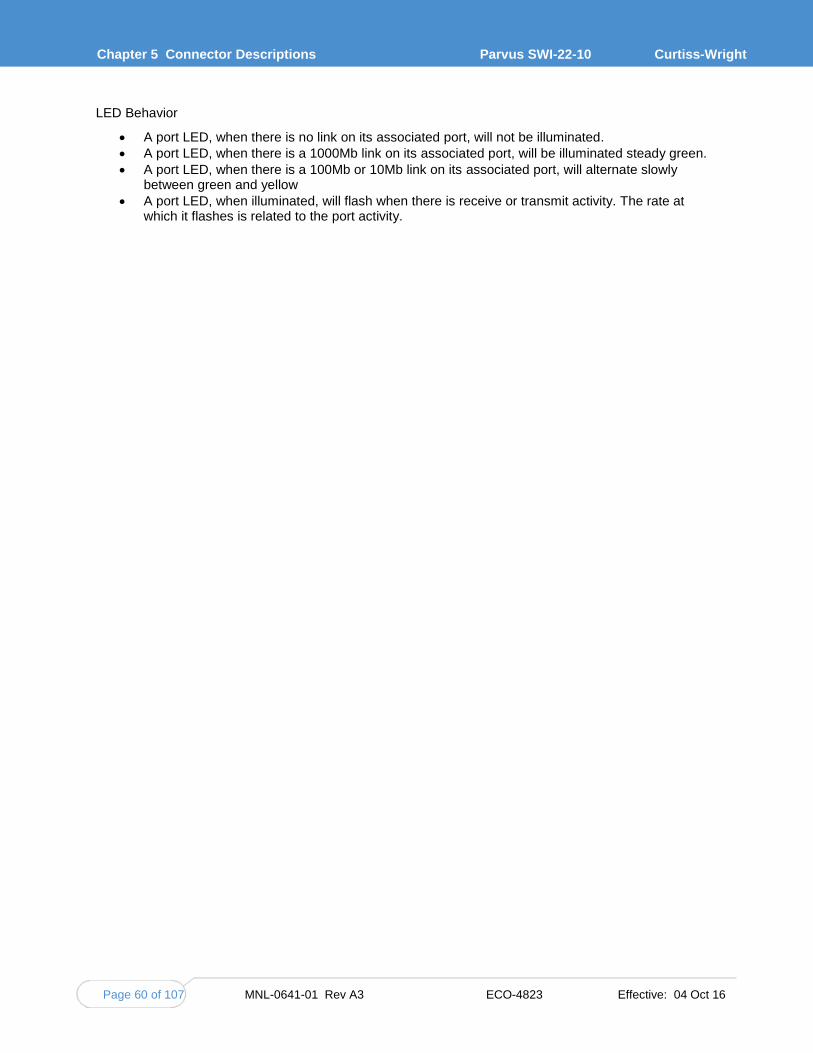
Chapter 5 Connector Descriptions
Parvus SWI-22-10 Curtiss-Wright
Page 60 of 107 MNL-0641-01 Rev A3 ECO-4823 Effective: 04 Oct 16
LED Behavior
A port LED, when there is no link on its associated port, will not be illuminated.
A port LED, when there is a 1000Mb link on its associated port, will be illuminated steady green.
A port LED, when there is a 100Mb or 10Mb link on its associated port, will alternate slowly between green and yellow
A port LED, when illuminated, will flash when there is receive or transmit activity. The rate at which it flashes is related to the port activity.

MNL-0641-01 Rev A3 ECO-4823 Effective: 04 Oct 16 Page 61 of 107
CHAPTER 6 SPECIFICATIONS
GENERAL SPECIFICATIONS
APPLICATIONS
Small form factor embedded systems, including standalone or stacking architectures (i.e., PC/104-Plus, PCI-104, PCIe/104, PCI/104-Express, EBX, EPIC)
High-speed Gigabit Ethernet Local Area Network (LAN) switching for IP-enabled equipment, such as onboard computers, cameras, sensors, monitoring devices, and command-and-control gear in harsh temperature and vibration environments
Size, Weight & Power (SWaP) sensitive mobile, tactical, airborne, and vehicle applications for situational awareness and network centric operations
BREAKOUT CABLE SET
Optional breakout cable set mates with onboard Ethernet and power connectors and transitions to RJ-45, RS-232, and power supply connectors (for lab/testing purposes)
TECHNICAL SPECIFICATIONS
This section describes the technical specifications of the SWI-22-10.
POWER
Power Input: 5VDC (via PCI bus / PCI Express Bus); 3.0-5.5VDC (via Auxiliary Power Connector, measured at the connector)
Power Consumption: < 14W maximum (all 20 ports actively driving 100-meter cables with full-bandwidth traffic)
Support for Energy Efficient Ethernet (IEEE 802.3az) in Switch Core and PHYs
SWITCHING ARCHITECTURE
Packet Processor: Highly Integrated Vitesse Carrier Grade Ethernet Switch Engine
Switching: Non-Blocking Layer 2, IPv4 / IPv6 Multicast, Low-Latency, Auto-MDI/MDIX, Auto-Negotiation, Auto-Detect; Speed Auto-Sensing, Auto-Crossover, Full/Half Duplex Modes
Management Processor: Embedded 32-Bit MIPS CPU @ 416MHz with DDR-2 Memory
Networking Software: Vitesse CEServices Carrier Ethernet application running on eCos operating system for optimal performance and Redboot bootloader for reliability

Chapter 6 Specifications
Parvus SWI-22-10 Curtiss-Wright
Page 62 of 107 MNL-0641-01 Rev A3 ECO-4823 Effective: 04 Oct 16
PORT FEATURES
20-Port: 20x Copper Gigabit Ethernet 1000BaseT, RS-232 Console, Harwin connectors
8-Port: 8x Copper Gigabit Ethernet 1000BaseT, RS-232 Console, Molex connectors
LAYER 2 SWITCHING
Port Control: port-speed, duplex mode, flow control, port frame size (jumbo frames), port state, port status (link monitoring), port statistics (MIB counters)
Quality of Service (QoS) Traffic Prioritization and Queuing: 8 priorities,8 CoS queues per port, strict or deficit-weighted RR Scheduling, shaping/policing per queue and per port, Storm Control
VLAN: 8K MAC addresses, 4K VLANs, 802.11Q Static VLAN, Protocol-Based VLAN, MRP, MVRP, MVR, IEEE-80210ad Provider Bridge, Link Aggregation (IEEE-802.3ad)
IEEE-802.1 D/w/s (Spanning Tree, Rapid Spanning Tree, Multiple Spanning Tree Protocol)
L2 IEEE-1588v2 Precision Timing Protocol (PTP)
MANAGEMENT
In-band Ethernet management using Web GUI or Simple Network Management Protocol (SNMP), or command line interface (CLI) over RS-232 console for Telnet / SSH / Terminal
HTTP/HTTPS Web Server, SNMP v1/v2/v3 Client, DHCP Client, IEEE 802.1X Authentication, System Syslog, SSHv2, IPv6 Management, IGMP/MLD/DHCP Snooping , Access Control Lists, Port Mirroring, BPDU Guard, RMON, Cisco Discovery Filtering, IEEE-802.10AB LLDP
SECURITY
Network Access Server (NAS) IEEE-802.1X, RADIUS Accounting, MAC address limit, TACACS, Web and CLI authentication, ACLs, IP Source Guard
Declassification: Data Zeroization support for secure data (initiated by offboard signal trigger)
STATUS INDICATION
Serial LED interface provides off-board support for two status LEDs per port
RELIABILITY
MTBF: 979,192 hours (ground benign, 25C)-Calculated per MIL-HDBK-217F. See qualification test report for further details.
Workmanship: Assembled to IPC-A-610 Class III Workmanship
No moving parts. No active cooling required. Staked components and underfilled BGAs.

MNL-0641-01 Rev A3 ECO-4823 Effective: 04 Oct 16 Page 63 of 107
MECHANICAL SPECIFICATIONS Form Factor: PCI/104-Express form factor compliant (PCIe, PCI buses)
Card only: 3.6” x 3.8” (90 x 96 mm) L x W (excluding Ethernet connector extensions)
Card with Thermal Plate: 3.86” x 4.11” x 0.63” (98 x 104.5 x 16mm) L x W x H (excluding Ethernet and bottom-side bus connector extensions)
Weight: card only =. 0.24 lbs (0.11 kg); card with thermal plate = 0.47 lbs (0.21 kg)
Passive thermal management: optional integrated thermal plate for conductive cooling to optimize/ease system integration
Conformal coating for additional humidity protection (optional)
No moving parts
Assembled to IPC-A-610 Class III Workmanship
Industrial temperature grade components
CONNECTOR SPECIFICATIONS
Refer to "Chapter 5 Connector Descriptions" for connector details.
Ethernet connectors:
Right-Angle Molex (8-port configuration)
Right-Angle Harwin Datamate (20-port configuration)
Recommended mating connectors support hand crimping of CAT5e wiring and include latching mechanisms for vibration mitigation.
Harwin connector can also support card-to-card cableless interface.
These card (de)population options are available:
No PCI/104-Express or PCI/104 buses
ENVIRONMENTAL SPECIFICATIONS
Designed to meet MIL-STD-810G:
Operating/Storage Temperature: -40° to +85°C / -40° to +185°F (MIL-STD-810G, Methods 501,502) with proper thermal management.
Operating Shock: 40g, 11ms, 3 pos/neg per axis (MIL-STD-810G, Method 516)
Random Vibration: Jet-Helo-Tracked Vehicle Profile, 3 Axes (MIL-STD-810G, Method 514)
Humidity: Up to 95% RH @ 40C, non-condensing (special order: conformal coating).

Chapter 6 Specifications
Parvus SWI-22-10 Curtiss-Wright
Page 64 of 107 MNL-0641-01 Rev A3 ECO-4823 Effective: 04 Oct 16
PROTOCOL STANDARDS IEEE 802.3 10Mbps 10BASE-T (Ethernet)
IEEE 802.3u 100BASE-TX 100Mbps (Fast Ethernet)
IEEE 802.3ab 1000BASE-T 1000Mbps (Gigabit Ethernet)
IEEE 802.3ad Link Aggregation
IEEE 802.3af PoE Support
IEEE 802.3az Energy Efficient Ethernet
IEEE 802.3x Full-Duplex Flow Control
IEEE 802.1ad Provider Bridges
IEEE 802.1ag Connectivity Fault Management
IEEE 802.1AS Timing and Synchronization for Time-Sensitive Applications in Bridged Local Area Networks
IEEE 802.1D Spanning Tree Protocol (Bridging)
IEEE 802.1P LAN Layer 2 QoS/CoS Protocol for Traffic Prioritization
IEEE 802.1Q Virtual LANs (VLAN) and Trunking
IEEE 802.1Qav Forwarding and Queuing Enhancements for Time-Sensitive Streams
IEEE 802.1S Multiple Spanning Trees
IEEE 802.1W Rapid Spanning Tree Reconfiguration
IEEE 802.1X Port-Based Network Access Control
RFC 2236 Internet Group Management Protocol, Version 2
RFC 2710 Multicast Listener Discovery for IPv6
RFC 2819 Remote Network Monitoring (RMON)
RFC 2863 The Interfaces Group MIB
RFC 3376 Internet Group Management Protocol, Version 3
RFC 3635 Definitions of Managed Objects for Ethernet-like Interface Types

MNL-0641-01 Rev A3 ECO-4823 Effective: 04 Oct 16 Page 65 of 107
CHAPTER 7 TROUBLESHOOTING
PRODUCT IDENTIFICATION
The product is labeled with the Curtiss-Wright P/N and serial number. Please refer to this information when communicating with Technical Support.
TECHNICAL ASSISTANCE
If you have a technical question or if you cannot isolate a problem with your product, please call or e-mail the Curtiss-Wright Technical Support team:
Email [email protected] Phone 1 (801) 433-6322 Fax 1 (801) 483-1523
RETURNING FOR SERVICE
Before returning any Curtiss-Wright product, please fill out a Return Material Authorization (RMA) request form, available for download from the following website under the support section:
www.cwcdefense.com/support/rma-salt-lake-city.html
Email this form to the Technical Support email address ([email protected]) to receive authorization for shipment. An RMA number will be emailed back to you as soon as possible.
Note: You must have the RMA number in order to return any product for any reason.
Warning!
Any product returned to Curtiss-Wright improperly packed will immediately void the warranty for that particular product.

Chapter 8 Contact Info
Parvus SWI-22-10 Curtiss-Wright
Page 66 of 107 MNL-0641-01 Rev A3 ECO-4823 Effective: 04 Oct 16
CHAPTER 8 CONTACT INFO
Company contact info:
Defense Solutions Division Curtiss-Wright 3222 S. Washington St. Salt Lake City, Utah, USA 84115 (801) 483-1533 FAX (801) 483-1523
Web-site: www.cwcdefense.com
Sales:
+1(800) 483-3152 or (801) 483-1533 [email protected]
Product Technical Support:
+1 (801) 433-6322 [email protected]
Customer Feedback:

MNL-0641-01 Rev A3 ECO-4823 Effective: 04 Oct 16 Page 67 of 107
APPENDIX A CLI REFERENCE This appendix describes basic usage and configuration of the command line interface (CLI) for the Parvus SWI-22-10.
The CLI interface is an industry-standard CLI and consists of configuration commands which provide the ability to configure and view the configuration using the serial console, or Telnet or SSH access. Even if there is no network connectivity, you can still manage the switch using a serial connection.
For CLI startup information, refer to "Serial CLI Setup" in Chapter 4.
INDUSTRY STANDARD CLI FORMAT
The switch software provides an industry-standard CLI which includes features such as the following also implemented on the other industry popular Switches/Routers:
Command history - Use of the Up arrow presents the history of commands
Command-line editing
Shortcut key options
Context-sensitive help - User has an option to press the '?' key for a list of valid possible parameters, with descriptions.
Auto completion - Press the Tab key after partially typing the keyword. The rest of the keyword will be entered automatically.
Modes - Each command can belong to one or more modes. The commands in a particular mode can be made invisible in any other mode.
Privilege - A set of privilege attributes may be assigned to each command based on the level configured. A command cannot be accessed or executed if the logged in user does not have sufficient privilege
Keyword abbreviations - Any keyword can be accepted just by typing an unambiguous prefix (e.g., "sh" for "show").
Error checking - Before executing a command, the CLI checks that the current mode is still valid, user has sufficient privilege, and valid range of parameter(s) among others. The user is alerted to the error by displaying a caret under the offending word along with an error message.
CLI BASICS
This section explains what you need to know in order to enter CLI commands successfully.
In the manual, terminal input/output is indicated by a special font and color. User input is shown in bold (commands and keywords) or bold italic (parameters you supply).
# show version MEMORY : Total=86382 KBytes, Free=70497 KBytes, Max=70496 KBytes FLASH : 0x40000000-0x40ffffff, 64 x 0x40000 blocks MAC Address : 00-01-c1-00-ad-80 Previous Restart : Cold ...

Appendix A CLI Reference
Parvus SWI-22-10 Curtiss-Wright
Page 68 of 107 MNL-0641-01 Rev A3 ECO-4823 Effective: 04 Oct 16
HOW THE CLI WORKS
The CLI has several different modes, and some commands are restricted to a specific mode. The top-level mode is called exec mode. It allows the user to perform operations related to configuration files, reloading defaults, displaying system information, etc., but it does not allow the user to change detailed configuration. Such operations are performed while in configuration mode. In turn, configuration mode has sub-modes for configuration of specific items, such as VLANs or Ethernet interfaces (ports).
The CLI is line-based, i.e., no screen-editing features, and executes commands instantly upon end-of-line (i.e., pressing Enter).
The CLI is designed to minimize the time required to type commands. Keywords and certain parameters can be abbreviated (truncated) as long as they are unambiguous. (See "Command Structure" for details.) For example, these commands are identical:
SWI2210# configure terminal SWI2210# config term SWI2210# conf t
The command line may be partially completed by the system, if the system can "guess" what you need to enter. For example, if you request help on a particular command, the prompt displayed after the list begins with that command, ready for you to enter the arguments. (GET NEW EXAMPLE)
SWI2210-XXXX# clear ? access Access management access-list Access list . . . spanning-tree STP Bridge statistics Clear statistics for one or more given interfaces SWI2210-XXXX# clear
The system will tell notify you if there's a problem with the command you entered.
SWI2210-XXXX# config % Incomplete command.
Frequently a caret is displayed under the incorrect entry along with the error message. If the caret is below the prompt, the problem may be that you aren't in the correct mode to use that command.
SWI2210-XXXX# show config ^ % Invalid word detected at '^' marker
Multiple sessions can co-exist at the same time, each providing separate environments with differences in logged-in user ID, privilege level, command history, mode, and session settings. It is therefore possible for the same user to control several concurrent sessions; for example, one serial console session and one ssh session.
The user database is either local or provided by a RADIUS or TACACS+ server. In case of a local user database, passwords and privilege levels are maintained on the device.

MNL-0641-01 Rev A3 ECO-4823 Effective: 04 Oct 16 Page 69 of 107
ACCESSING THE CLI HELP MENU To view the top-level help, type help or ? at the system prompt. If you use the ?, the help is displayed as soon as you type the ?—you don't need to press Enter.
SWI2210-XXXX# help Help may be requested at any point in a command by entering a question mark '?'. If nothing matches, the help list will be empty and you must backup until entering a '?' shows the available options. Two styles of help are provided: 1. Full help is available when you are ready to enter a command argument (e.g. 'show ?') and describes each possible argument. 2. Partial help is provided when an abbreviated argument is entered and you want to know what arguments match the input (e.g. 'show pr?'.)
To view a list of commands available in a particular mode, change to the mode and then type ?. A list of commands is displayed. (This example shows only the beginning of the list.)
SWI2210# conf t SWI2210(config)# ? aaa Authentication, Authorization and Accounting access Access management access-list Access list ...
If a help list or any other output to the screen is long (more than one screen), the display pauses and shows a "more" message at the bottom of the screen. Press Space to view the next page, g to continue the list, or Ctrl+C to quit.
... logging Syslog loop-protect Loop protection configuration mac Mac Address Table information -- more --, next page: Space, continue: g, quit: ^C
For help with an individual command, enter the command and press one of the keys in the table.
Key Operation
? Show next possible input and description
? ? / Ctrl+Q Show syntax of possible command(s)
TAB Show next possible input without description or expand current word fully if it is unambiguous

Appendix A CLI Reference
Parvus SWI-22-10 Curtiss-Wright
Page 70 of 107 MNL-0641-01 Rev A3 ECO-4823 Effective: 04 Oct 16
This example 1 shows the results for each help key. Comment lines have been added to the example to clarify what is shown; the comments are in italics and begin with an exclamation point (!).
Example: Using Context-sensitive Help ! Show possible next input for a command that begins with ‘show a’: SWI2210-XXXX# show a?
aaa Login methods access Access management access-list Access list aggregation Aggregation port configuration
! The same, but without descriptions: SWI2210-XXXX# show a<TAB> aaa access access-list aggregation ! If the user enters a ‘g’, the word ‘aggregation’ is the only possibility: SWI2210-XXXX# show ag?
aggregation Aggregation port configuration <cr>
! Pressing <TAB> now expands the word fully: SWI2210-XXXX# show aggregation ! Possible next input is displayed with a press of ‘?’: SWI2210-XXXX# show aggregation ?
| Output modifiers mode Traffic distribution mode <cr>
! The syntax is displayed with another press of ‘?’: SWI2210-XXXX# show aggregation ?
show aggregation [ mode ] ! This shows that there is an optional ‘mode’ word (square brackets indicate an option). ! Repeated presses of ‘?’ toggles display between next possible input and syntax: SWI2210-XXXX# show aggregation ?
| Output modifiers mode Traffic distribution mode <cr>
SWI2210-XXXX# show aggregation ? show aggregation [ mode ] ! Finally, the syntax display is also directly available with Ctrl+Q: SWI2210-XXXX# show aggregation ^Q show aggregation [ mode ]

MNL-0641-01 Rev A3 ECO-4823 Effective: 04 Oct 16 Page 71 of 107
USING THE KEYBOARD The CLI provides a rich set of keys to assist the user while working with the command line. The functionality is divided into:
Basic line editing
Command history
Context-sensitive help
Long lines and pagination
The table summarizes the keys supported by the CLI.
Key Operation
Line Editing Allows you to input characters to form a command, while also allowing cursor movement and insertion/deletion of characters and words.
Left or Right Move one character left/right
Home / Ctrl+A Move to start of line
End / Ctrl+E Move to end of line
Del / Ctrl+D Delete character at cursor
Backspace / Ctrl+H Delete character to the left of cursor
Ctrl+N Delete the entire current line
Ctrl+U / Ctrl+X Delete all characters to the left of the cursor
Ctrl+K Delete all characters under the cursor and right
Ctrl+W Delete from cursor to start of word on the left
TAB Complete word at end-of-line (see also "XXXX")
Command History Allows you to view previous or next commands (see Command History).
Up / Ctrl+P Previous line in command history
Down Next line in command history
Context-Sensitive Help Allows you to display context-sensitive help (see XXXXX).
? Show next possible input and description
? ? / Ctrl+Q Show syntax of possible command(s)
TAB Show next possible input without description or expand current word fully if it is unambiguous
Pagination Control Allows you to view output that is longer or wider than the terminal screen.
Enter Display next line of output
Space Display next page of output
G Display remainder of output without more pagination
Q / Ctrl+C Discard remainder of output
Any other key Display next page of output. Note that certain terminal keys (arrows, Home, End, etc.) may appear as multiple characters to the CLI, leading to multiple pages being output in quick succession.
Exec Mode Allows you to instantly return to Exec mode.
Ctrl+Z Return directly to Exec mode (see XXX for information on Exec mode).
Note: Your terminal emulator may not support all of these keys. For example, you may have to press Ctrl+H to backspace.

Appendix A CLI Reference
Parvus SWI-22-10 Curtiss-Wright
Page 72 of 107 MNL-0641-01 Rev A3 ECO-4823 Effective: 04 Oct 16
COMMAND HISTORY A session maintains a non-persistent command history of previously entered command lines. The history can be up to 32 lines long. Once full, a new line will push the oldest entry out.
Use 'show history' to list the history:
SWI2210-XXXX# show history show running-config copy running-config startup-config dir show history
SWI2210-XXXX#
The list begins with the oldest entry at top (‘show running-config’). To see additional lines, use the Up and Down keys.
The number of lines to keep in the history for the current session is configurable. The current value is displayed as part of the output from ‘show terminal’:
SWI2210-XXXX# show terminal Line is con 0.
* You are at this line now. Alive from Console. Default privileged level is 2. Command line editing is enabled Display EXEC banner is enabled. Display Day banner is enabled. Terminal width is 80.
length is 24. history size is 32. exec-timeout is 10 min 0 second.
Current session privilege is 15. Elapsed time is 0 day 0 hour 6 min 20 sec. Idle time is 0 day 0 hour 0 min 0 sec.
Use 'terminal history' to change the number of lines stored. The size is a value between 0 and 32. 0 disables the history entirely.
SWI2210-XXXX# terminal history size 32

MNL-0641-01 Rev A3 ECO-4823 Effective: 04 Oct 16 Page 73 of 107
CONTROLLING THE DISPLAY The session configuration controls the width of the terminal in characters and the height in lines. It uses these parameters to control handling of long input lines and to control pagination of multi-line output. For details about changing these parameters, please refer to section XX.
Long Lines
Long lines come into play when a line is longer than the terminal width minus the prompt. In that case the prompt is always displayed and part of the line will be hidden from display, as indicated by ‘$’ at the beginning and/or end of the visible part of the line. You can use the right and left arrows to see the rest of the line.
For example:
SWI2210-XXXX# $there is text to the left of what is visible here SWI2210-XXXX# there is text to the right of what is visible here$ SWI2210-XXXX# $there is text at both ends of what is visible here$
The first line has scrolled left; the second line has scrolled right; the third line has been scrolled to the middle of a quite long line.
Pagination
Pagination appears each time execution of a command causes output of more lines than what has been configured as terminal length. A typical example is the output from ‘show running-config’. After the first several lines have been output, the pagination prompt is presented:
! [lines of text] -- more --, next page: Space, continue: g, quit: ^C
The following keys control pagination:
Key Operation
Enter Display next line of output.
Space Display next page of output.
G Display remainder of output without more pagination.
Q / Ctrl+C Discard remainder of output.
Any other key Display next page of output. Note that certain terminal keys (arrows, Home, End, etc.) may appear as multiple characters to the CLI, leading to multiple pages being output in quick succession.
The terminal length (also sometimes called height) can be configured for the current session using the ‘terminal length lines’ command. If lines = 0 is input, pagination is disabled.
SWI2210-XXXX# terminal length 0 SWI2210-XXXX# terminal length 25

Appendix A CLI Reference
Parvus SWI-22-10 Curtiss-Wright
Page 74 of 107 MNL-0641-01 Rev A3 ECO-4823 Effective: 04 Oct 16
UNDERSTANDING COMMANDS
Command Structure A command is a single line of text consisting of keywords and parameters, for example:
SWI2210-XXXX# show vlan id 10 ... SWI2210-XXXX# show vlan id 20 ...
The keywords are show, vlan, and id. 10 and 20 are parameters that could contain a different value in another command invocation.
Keywords are case-insensitive, i.e., show, SHOW and Show are identical. Conversely, parameters may either be case-sensitive or case-insensitive depending on the command and parameter in question. For example, file names are usually case-sensitive.
Keywords and certain parameters can be truncated to save typing time, as long as they are unambiguous (unique within that mode or sub-mode) and known to the system (a standard parameter). For example, these commands are identical:
SWI2210-XXXX# show interface GigabitEthernet 1/5 capabilities ... SWI2210-XXXX# sh in g 1/5 c ...
This works because:
Many keywords begin with ‘s’ but only one begins with ‘sh’.
Several commands begin with ‘show i’ but only one begins with ‘show in’.
The ‘show interface’ command takes a port type as parameter. Depending on the hardware capabilities, the options are: FastEthernet, GigabitEthernet, 2.5GigabitEthernet, 5GigabitEthernet and 10GigabitEthernet. Thus, ‘g’ is a unique abbreviation for ‘GigabitEthernet’.
1/5 identifies the interface as belonging to switch 1, port 5. This parameter cannot be abbreviated.
The ‘show interface’ command can output different kinds of information--capabilities, statistics, status, and several others. The ‘c’ is a unique abbreviation for ‘capabilities’.
With a bit of practice this allows for highly efficient keyboard entry, in particular when coupled with the context-sensitive help features of the CLI (see XXXX).
Command Syntax A command is described by its syntax, for example:
show interface <list> { status | statistics | capabilities | switchport | veriphy }
The conventions are:
Keywords are shown in bold.
<Parameters> are enclosed by angle brackets and shown in bold italics. In the CLI online help, parameters are marked with angle brackets. Parameters often require a list of values. List items must be separated by commas with no spaces, and can include ranges such as 3-9.
[ ... ] indicates an optional construct. You can omit it.
{ ... } indicates a grouping; the constructs within belong together somehow.
‘|’ indicates a choice between two or more alternatives, e.g., a | b | c reads as “a or b or c”.
In the show interface example, the syntax is simple. You must enter a list of interfaces and then choose one of ‘status’, ‘statistics’, ‘capabilities’, ‘switchport’ or ‘veriphy’.
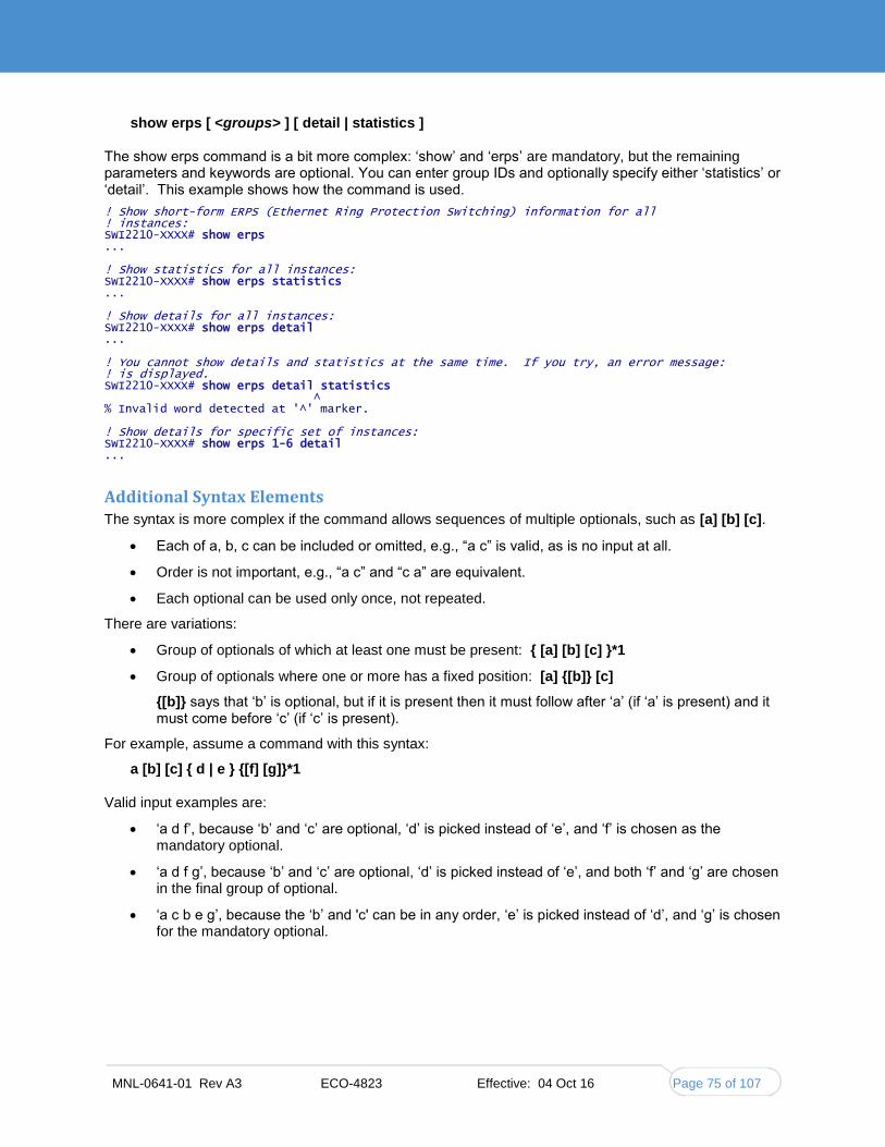
MNL-0641-01 Rev A3 ECO-4823 Effective: 04 Oct 16 Page 75 of 107
show erps [ <groups> ] [ detail | statistics ]
The show erps command is a bit more complex: ‘show’ and ‘erps’ are mandatory, but the remaining parameters and keywords are optional. You can enter group IDs and optionally specify either ‘statistics’ or ‘detail’. This example shows how the command is used.
! Show short-form ERPS (Ethernet Ring Protection Switching) information for all ! instances: SWI2210-XXXX# show erps ... ! Show statistics for all instances: SWI2210-XXXX# show erps statistics ... ! Show details for all instances: SWI2210-XXXX# show erps detail ... ! You cannot show details and statistics at the same time. If you try, an error message: ! is displayed. SWI2210-XXXX# show erps detail statistics ^ % Invalid word detected at '^' marker. ! Show details for specific set of instances: SWI2210-XXXX# show erps 1-6 detail ...
Additional Syntax Elements The syntax is more complex if the command allows sequences of multiple optionals, such as [a] [b] [c].
Each of a, b, c can be included or omitted, e.g., “a c” is valid, as is no input at all.
Order is not important, e.g., “a c” and “c a” are equivalent.
Each optional can be used only once, not repeated.
There are variations:
Group of optionals of which at least one must be present: { [a] [b] [c] }*1
Group of optionals where one or more has a fixed position: [a] {[b]} [c]
{[b]} says that ‘b’ is optional, but if it is present then it must follow after ‘a’ (if ‘a’ is present) and it must come before ‘c’ (if ‘c’ is present).
For example, assume a command with this syntax:
a [b] [c] { d | e } {[f] [g]}*1
Valid input examples are:
‘a d f’, because ‘b’ and ‘c’ are optional, ‘d’ is picked instead of ‘e’, and ‘f’ is chosen as the mandatory optional.
‘a d f g’, because ‘b’ and ‘c’ are optional, ‘d’ is picked instead of ‘e’, and both ‘f’ and ‘g’ are chosen in the final group of optional.
‘a c b e g’, because the ‘b’ and 'c' can be in any order, ‘e’ is picked instead of ‘d’, and ‘g’ is chosen for the mandatory optional.

Appendix A CLI Reference
Parvus SWI-22-10 Curtiss-Wright
Page 76 of 107 MNL-0641-01 Rev A3 ECO-4823 Effective: 04 Oct 16
ETHERNET INTERFACE NAMING An Ethernet interface (“port”) is identified by three pieces of information:
Its type: FastEthernet, GigabitEthernet, 2.5GigabitEthernet, 5GigabitEthernet, 10GigabitEthernet.
The switch it belongs to. For non-stacking systems this value is always 1.
The port number within the type and switch. The switch and port numbers are separated by a slash, such as 1/1. The numbering starts with 1 for each type, so a switch may have both GigabitEthernet 1/1 and 2.5GigabitEthernet 1/1, for example.
Many CLI commands accept a list of interfaces. In a list, the switch ID and port numbers can be listed as single numbers, as a range like 1-3, or as a comma-separated list (no spaces) like 2,4,6.
Examples:
GigabitEthernet 1/5 for the single gigabit port number 5 on switch 1 GigabitEthernet 1/2,4,10-12 for gigabit ports 2, 4, 10, 11, 12 on switch 1 GigabitEthernet 1-3/2 for gigabit port 2 on switches 1, 2 and 3 You can use a wildcard (*) for the type and/or switch ID and/or ports to mean “all types”, “all switch IDs” and “all ports”, respectively.
‘*’ means “all ports of all types on all switches”
type ‘*’ means “all ports of the specified type on all switches”
Examples:
This example assumes a stack with two switches, switch ID 1 and 3. Each switch has 9 gigabit ports and two 2.5 gigabit ports.
interface * (or: interface * * *)
All ports of all types on all switches: GigabitEthernet 1,3/1-9 2.5GigabitEthernet 1,3/1-2
interface * 1/2
Switch 1, port number 2 of all types: GigabitEthernet 1/2 2.5GigabitEthernet 1/2
interface * */2
All switches, all types, port number 2: GigabitEthernet 1,3/2 2.5GigabitEthernet 1,3/2
interface * */4
All switches, all types, port number 4: GigabitEthernet 1,3/4. Note that there are no 2.5 gigabit ports in the result.
interface GigabitEthernet 3/*
Switch 3, all gigabit ports: GigabitEthernet 3/1-9
interface 2.5GigabitEthernet * (or: interface 2.5GigabitEthernet */*)
All 2.5 gigabit ports on all switches: 2.5GigabitEthernet 1,3/1-2
Wildcards will include the largest possible set of ports, but may output an error message if a specific switch ID or port number doesn’t exist. For example, these sets are invalid:
interface * 2/*
All ports of all types on switch 2 – which isn’t a member of the stack
interface * */100
There is no port 100 of any type on any switch.
interface GigabitEthernet */* 2.5GigabitEthernet 2/*
Again, switch 2 doesn’t exist so the entire set is considered invalid.
Validity is determined per set of (type, switch ID/port) containing wildcards. The result for that set is valid if there is at least one port that matches the set. A list of sets is valid if all sets match at least one port each.

MNL-0641-01 Rev A3 ECO-4823 Effective: 04 Oct 16 Page 77 of 107
FILTERING OUTPUT The output from commands can in most cases be filtered to limit the output to only those lines that match/trigger a specific string. The available filtering is:
Begin – display the first line that begins with the matching string and all subsequent lines
Include – display only those lines that match
Exclude – display only those lines that do not match
The filter is added at the end of the command and its parameters; the | character marks the beginning of the filter. The <string> parameter is case-sensitive and can specify any item in the output line. The syntax is:
<command> | { begin | include | exclude } <string>
! Execute a command that generates some output; no filtering initially: SWI2210-XXXX# show users Line is con 0.
* You are at this line now. Connection is from Console. User name is admin. Privilege is 15. Elapsed time is 0 day 21 hour 52 min 50 sec. Idle time is 0 day 0 hour 0 min 0 sec.
! Filter to include specific word: SWI2210-XXXX# show users | include User
User name is admin. ! Exclude all lines that contain ‘0’ (zero) SWI2210-XXXX# show users | exclude 0
* You are at this line now. Connection is from Console. User name is admin. Privilege is 15.
! Begin output when specific word is matched: SWI2210-XXXX# show users | begin Elapsed
Elapsed time is 0 day 21 hour 53 min 29 sec. Idle time is 0 day 0 hour 0 min 0 sec.

Appendix A CLI Reference
Parvus SWI-22-10 Curtiss-Wright
Page 78 of 107 MNL-0641-01 Rev A3 ECO-4823 Effective: 04 Oct 16
USING ‘NO’ FORMS TO RESET OR REMOVE CONFIGURATION VALUES Almost all configuration commands have a “no” form to negate or set its default. In general, the no form is used to reverse the action of a command or reset a value back to the default. For example, the ‘no ip routing’ configuration command reverses the ‘ip routing’ of an interface.
The ‘no’ form is syntactically similar (but not necessarily identical) to the configuration command, but either resets the parameters to defaults for the configurable item being addressed, or removes the item altogether.
In many cases ‘no’ can be read as “no(t) different from default settings”.
Example: Using ‘no’ Forms
The following example:
Configures the VLAN 1 interface IP address to use DHCP.
Configures the DNS name server to be taken from DHCP.
Inspects the configuration.
Removes the DNS name server.
Removes the IP address on the VLAN 1 interface.
Inspects the configuration again.
Both ‘no’ operations can be viewed as reset-to-default, with the defaults being: No DNS name server and IP address.
SWI2210-XXXX# configure terminal SWI2210-XXXX(config)# interface vlan 1 SWI2210-XXXX(config-if-vlan)# ip address dhcp SWI2210-XXXX(config-if-vlan)# exit SWI2210-XXXX(config)# ip name-server dhcp SWI2210-XXXX(config)# end SWI2210-XXXX# show ip interface brief Vlan Address Method Status ---- -------------------- -------- ------ 1 172.16.1.15/24 DHCP UP SWI2210-XXXX# show ip name-server Current DNS server is 172.16.1.1 set by DHCP. SWI2210-XXXX# configure terminal SWI2210-XXXX(config)# no ip name-server SWI2210-XXXX(config)# interface vlan 1 SWI2210-XXXX(config-if-vlan)# no ip address SWI2210-XXXX(config-if-vlan)# end SWI2210-XXXX# show ip name-server Current DNS server is not set. SWI2210-XXXX# show ip interface brief Vlan Address Method Status ---- -------------------- -------- ------ SWI2210-XXXX#
Note how the syntax of the configuration commands and their ‘no’ forms are different. The ‘no’ forms usually do not take as many parameters.
CLI COMMAND GROUPS
The CLI implements a number of modes that control the available command set (refer to XXX for more information on modes). The commands are divided into command groups as shown below. Help texts are available on groups and specific commands.

MNL-0641-01 Rev A3 ECO-4823 Effective: 04 Oct 16 Page 79 of 107
EXEC Commands
The EXEC commands include the following:
SWI2210-XXXX# ? clear Reset functions configure Enter configuration mode copy Copy from source to destination debug Debugging functions delete Delete one file in flash: file system dir Directory of all files in flash: file system disable Turn off privileged commands do To run exec commands in config mode dot1x IEEE Standard for port-based Network Access Control enable Turn on privileged commands erps Ethernet Ring Protection Switching exit Exit from EXEC mode firmware Firmware upgrade/swap help Description of the interactive help system ip IPv4 commands link-oam Link OAM configuration logout Exit from EXEC mode more Display file no Negate a command or set its defaults ping Send ICMP echo messages ptp Enable wireless mode for an interface. reload Reload system. send Send a message to other tty lines show Show running system information terminal Set terminal line parameters SWI2210-XXXX#
Show Commands
Show commands display switch configuration, statistics, and other information.
SWI2210-XXXX# show ? aaa Login methods access Access management access-list Access list aggregation Aggregation port configuration clock Configure time-of-day clock dot1x IEEE Standard for port-based Network Access Control eps Ethernet Protection Switching erps Ethernet Ring Protection Switching evc Ethernet Virtual Connections green-ethernet Green ethernet (Power reduction) history Display the session command history interface Interface status and configuration ip Internet Protocol ipmc IPv4/IPv6 multicast configuration ipv6 IPv6 configuration commands lacp LACP configuration/status line TTY line information link-oam Link OAM configuration lldp Display LLDP neighbors information. logging Syslog loop-protect Loop protection configuration mac Mac Address Table information mep Maintenance Entity Point mvr Multicast VLAN Registration configuration network-clock Show selector state. ntp Configure NTP platform Platform specific information poe Power Over Ethernet. port-security privilege Display command privilege ptp Precision time Protocol (1588) pvlan PVLAN configuration qos Quality of Service radius-server RADIUS configuration rmon RMON statistics running-config Show running system information sflow Statistics flow. snmp Display SNMP configurations spanning-tree STP Bridge switchport Display switching mode characteristics tacacs-server TACACS+ configuration terminal Display terminal configuration parameters

Appendix A CLI Reference
Parvus SWI-22-10 Curtiss-Wright
Page 80 of 107 MNL-0641-01 Rev A3 ECO-4823 Effective: 04 Oct 16
thermal-protect Display thermal protection status. upnp Display UPnP configurations users Display information about terminal lines version System hardware and software status vlan VLAN status voice Voice appliance attributes web Web SWI2210-XXXX#
Configuration Commands
Configuration commands allow you to configure features and available options of the device. This is the list for Global Configuration Mode.
SWI2210-XXXX(config)# ? aaa Authentication, Authorization and Accounting access Access management access-list Access list aggregation Aggregation mode banner Define a login banner clock Configure time-of-day clock default Set a command to its defaults do To run exec commands in config mode dot1x IEEE Standard for port-based Network Access Control enable Modify enable password parameters end Go back to EXEC mode eps Ethernet Protection Switching. erps Ethernet Ring Protection Switching evc Ethernet Virtual Connections exit Exit from current mode green-ethernet Green ethernet (Power reduction). gvrp Enable GVRP feature help Description of the interactive help system hostname Set system's network name interface Select an interface to configure ip Internet Protocol ipmc IPv4/IPv6 multicast configuration ipv6 IPv6 configuration commands lacp LACP settings line Configure a terminal line lldp LLDP configurations. logging Syslog loop-protect Loop protection configuration mac MAC table entries/configuration mep Maintenance Entity Point monitor Set monitor configuration. mvr Multicast VLAN Registration configuration network-clock network-clock no Negate a command or set its defaults ntp Configure NTP poe Power Over Ethernet. port-security Enable/disable port security globally. privilege Command privilege parameters ptp qos Quality of Service radius-server Configure RADIUS rmon Remote Monitoring sflow Statistics flow. snmp-server Set SNMP server's configurations spanning-tree Spanning Tree protocol switchport Set switching mode characteristics tacacs-server Configure TACACS+ thermal-protect Thermal protection configuirations. upnp Set UPnP's configurations username Establish User Name Authentication vlan VLAN commands voice Voice appliance attributes web Web SWI2210-XXXX(config)#
Copy Commands
Copy commands allow transferring or saving the configuration files to and from the switch.
SWI2210-XXXX# copy ? flash:filename | tftp://server/path-and-filename File in FLASH or on TFTP server running-config Currently running configuration

MNL-0641-01 Rev A3 ECO-4823 Effective: 04 Oct 16 Page 81 of 107
startup-config Startup configuration SWI2210-XXXX# copy
Clear Commands
Clear commands clear (reset) specified settings to factory defaults.
SWI2210-XXXX# clear ? access Access management access-list Access list dot1x IEEE Standard for port-based Network Access Control eps Ethernet Protection Switching. erps Ethernet Ring Protection Switching evc Ethernet Virtual Connections ip Interface Internet Protocol config commands ipv6 IPv6 configuration commands lacp Clear LACP statistics link-oam Clear Link OAM statistics lldp Clears LLDP statistics. logging Syslog mac MAC Address Table mep Maintenance Entity Point mvr Multicast VLAN Registration configuration network-clock Clear active WTR timer. sflow Statistics flow. spanning-tree STP Bridge statistics Clear statistics for one or more given interfaces SWI2210-XXXX# clear
Modes
Example: VLAN Configuration Mode Commands SWI2210-XXXX(config)# vlan 100 SWI2210-XXXX(config-vlan)# ? do To run exec commands in config mode end Go back to EXEC mode exit Exit from current mode help Description of the interactive help system name ASCII name of the VLAN no SWI2210-XXXX(config-vlan)#
Example: Interface Configuration Mode Commands SWI2210-XXXX(config)# interface GigabitEthernet 1/10 SWI2210-XXXX(config-if)# ? access-list Access list aggregation Create an aggregation do To run exec commands in config mode dot1x IEEE Standard for port-based Network Access Control duplex Interface duplex end Go back to EXEC mode evc Ethernet Virtual Connections excessive-restart Restart backoff algorithm after 16 collisions (No excessive-restart means discard frame after 16 collisions) exit Exit from current mode flowcontrol Traffic flow control. green-ethernet Green ethernet (Power reduction) gvrp Enable GVRP on port(s) help Description of the interactive help system ip Internet Protocol ipv6 IPv6 configuration commands lacp Enable LACP on this interface link-oam Enable or Disable(when the no keyword is entered) Link OAM on the interface lldp LLDP configurations. loop-protect Loop protection configuration on port mac MAC keyword media-type Media type. mtu Maximum transmission unit mvr Multicast VLAN Registration configuration network-clock network-clock no Negate a command or set its defaults poe Power Over Ethernet. port-security Enable/disable port security per interface.

Appendix A CLI Reference
Parvus SWI-22-10 Curtiss-Wright
Page 82 of 107 MNL-0641-01 Rev A3 ECO-4823 Effective: 04 Oct 16
ptp pvlan Private VLAN qos Quality of Service rmon Configure Remote Monitoring on an interface sflow Statistics flow. shutdown Shutdown of the interface. snmp-server Set SNMP server's configurations spanning-tree Spanning Tree protocol speed Configures interface speed. If you use 10, 100, or 1000 keywords with the auto keyword the port will only advertise the specified speeds. switchport Switching mode characteristics thermal-protect Thermal priority for the interface. SWI2210-XXXX(config-if)#

MNL-0641-01 Rev A3 ECO-4823 Effective: 04 Oct 16 Page 83 of 107
FREQUENTLY USED CLI COMMANDS This section demonstrates how to use common CLI commands together to perform these tasks:
Reset the configuration to factory defaults.
Set the device hostname.
View the current IP configuration.
Set the switch IP address.
Ping a network device.
Use the Show command.
Reset Configuration to Defaults You can reset the configuration to factory defaults.
# reload defaults % Reloading defaults. Please stand by. #
When the prompt returns, the system has reverted to factory defaults.
Set the Device Hostname To set the device hostname, type the bold commands exactly as shown; bold italic marks a parameter you provide, such as my-device as the new hostname.
1. Change to configuration mode, using one of the commands shown here. As these examples show, you can abbreviate commands to short versions that are unique.
SWI2210# configure terminal SWI2210# config term SWI2210# conf t
2. The prompt changes to include the mode name in parentheses.
SWI2210(config)#
3. Enter the ‘hostname’ command and the new name. The command is executed immediately, and the prompt changes to show the new name of the switch.
SWI2210(config)# hostname my-device my-device(config)#
4. Exit configuration mode. The exit command returns to the next higher mode, and the prompt changes to show the new mode.
my-device(config)# exit my-device#
5. Save the configuration (see XXX).
View the Current IP Configuration To view the IP configuration, enter:
IP configuration

Appendix A CLI Reference
Parvus SWI-22-10 Curtiss-Wright
Page 84 of 107 MNL-0641-01 Rev A3 ECO-4823 Effective: 04 Oct 16
Set the Switch IP Address
To display the current IP address settings, enter the following commands:
# show ip interface brief Vlan Address Method Status ---- -------------------- -------- ------ 1 192.0.2.1/22 Manual UP #
To set up the switch with a static IP address, enter the following commands. This example sets the switch IP address to 192.0.2.1 with a subnet mask of 255.255.252.0:
# config term (config)# interface vlan 1 (config-vlan)# ip address 192.0.2.1 255.255.252.0 (config-vlan)# exit (config)# exit
To set up the switch to acquire an IP address using DHCP with a fallback address, enter the following commands. This example sets the switch to acquire an IP address using DHCP, and if unsuccessful, will set the IP address to 192.0.2.1 with a subnet mask of 255.255.252.0:
# config term (config)# interface vlan 1 (config-vlan)# ip address dhcp fallback 192.0.2.1 255.255.252.0 (config-vlan)# exit (config)# exit
To save these settings, enter the following command:
# copy running-config startup-config
Ping a Network Device IP Ping <ip_target>
where <ip_target> is the IP address or quoted host name (Like 'google.com')

MNL-0641-01 Rev A3 ECO-4823 Effective: 04 Oct 16 Page 85 of 107
USING ‘SHOW’ COMMANDS The family of ‘show’ commands is the cornerstone of CLI-based system monitoring. Most features implement one or more ‘show’ commands that will display a relevant mix of status and configuration.
Please note: The exact set of available commands, parameters and output format depends on the system configuration and software version, so some of the following commands and examples may not be applicable to all systems.
‘show’ commands exist only in the two Exec modes and are subject to session privilege level enforcement. Therefore, listing the largest possible set of ‘show’ commands requires the session to be at level 15.
Showing Available Commands
Example: Listing All ‘show’ Commands
The following example raises the session privilege level to 15. In this example an ‘enable secret’ has been specified, so password entry is required to proceed.
Then the user inputs ‘show’ and uses the context-sensitive help feature to list the possible show commands, in this case for a Carrier Ethernet system.
SWI2210-XXXX> enable Password: *** SWI2210-XXXX# show ?
aaa Login methods access Access management access-list Access list aggregation Aggregation port configuration clock Configure time-of-day clock dot1x IEEE Standard for port-based Network Access Control eps Ethernet Protection Switching erps Ethernet Ring Protection Switching evc Ethernet Virtual Connections green-ethernet Green ethernet (Power reduction) history Display the session command history interface Interface status and configuration ip Internet Protocol ipmc IPv4/IPv6 multicast configuration ipv6 IPv6 configuration commands lacp LACP configuration/status line TTY line information link-oam Link OAM configuration lldp Display LLDP neighbors information. logging Syslog loop-protect Loop protection configuration mac Mac Address Table information mep Maintenance Entity Point mvr Multicast VLAN Registration configuration network-clock Show selector state. ntp Configure NTP perf-mon Performance Monitor platform Platform specific information port-security Port security privilege Display command privilege ptp Precision time Protocol (1588) pvlan PVLAN configuration qos Quality of Service radius-server RADIUS configuration rfc2544 RFC2544 perfomance tests rmon RMON statistics running-config Show running system information sflow Statistics flow. snmp Display SNMP configurations spanning-tree STP Bridge switchport Display switching mode characteristics tacacs-server TACACS+ configuration terminal Display terminal configuration parameters thermal-protect Display thermal protection status. upnp Display UPnP configurations users Display information about terminal lines version System hardware and software status vlan VLAN status

Appendix A CLI Reference
Parvus SWI-22-10 Curtiss-Wright
Page 86 of 107 MNL-0641-01 Rev A3 ECO-4823 Effective: 04 Oct 16
voice Voice appliance attributes web Web
Showing Command Help
Example: Using Context-sensitive Help for Discovery
The context-sensitive help feature for syntax display is useful as well while drilling down on the exact command to execute. In the following example the user discovers the proper command ‘show ip statistics system’ through exploration:
SWI2210-XXXX# show ip ? arp Address Resolution Protocol dhcp Dynamic Host Configuration Protocol http Hypertext Transfer Protocol igmp Internet Group Management Protocol interface IP interface status and configuration name-server Domain Name System route Display the current ip routing table source source command ssh Secure Shell statistics Traffic statistics verify verify command
SWI2210-XXXX# show ip statistics ?
| Output modifiers icmp IPv4 ICMP traffic icmp-msg IPv4 ICMP traffic for designated message type interface Select an interface to configure system IPv4 system traffic <cr>
! A repeated press of ‘?’ displays the syntax: SWI2210-XXXX# show ip statistics ? show ip statistics [ system ] [ interface vlan <v_vlan_list> ] [ icmp ] [ icmp-msg <type> ] SWI2210-XXXX# show ip statistics system IPv4 statistics: Rcvd: 2768 total in 181458 bytes 1727 local destination, 0 forwarding 0 header error, 0 address error, 0 unknown protocol 0 no route, 0 truncated, 0 discarded Sent: 2553 total in 180047 bytes 1512 generated, 0 forwarded 0 no route, 0 discarded Frags: 0 reassemble (0 reassembled, 0 couldn't reassemble) 0 fragment (0 fragmented, 0 couldn't fragment) 0 fragment created Mcast: 0 received in 0 byte 0 sent in 0 byte Bcast: 0 received, 0 sent

MNL-0641-01 Rev A3 ECO-4823 Effective: 04 Oct 16 Page 87 of 107
Show Running-Config ‘running-config’ consists of a list of commands that, taken together, result in the currently running system configuration. This list of commands is usually not 100% identical to the list of commands a user has input to configure the device. That is because ‘running-config’ is a textual representation of the system configuration which is stored in binary form in the RAM memory of the device.
Since the effective device configuration is huge, ‘running-config’ in the majority of cases only lists the delta between default settings and current settings. This significantly reduces the amount of output and greatly improves readability of the configuration, but it does require that you know what the default settings are. You can specify that defaults be included by appending the keyword ‘all-defaults’ to the ‘show running-config’ command.
Example: Default vs. Non-default vs. All Defaults
In this example if the speed and duplex settings of an Ethernet interface are at default values (auto-negotiation). then nothing will be output. If the user then changes the speed to be fixed at 1Gbps then that value is now non-default and will be output. Duplex is also output, since it is forced to ‘full’ when the speed is fixed at 1Gbps.
! Display current configuration for an interface. All settings are at default: SWI2210-XXXX# show running-config interface GigabitEthernet 1/4 Building configuration... interface GigabitEthernet 1/4 ! end ! Now set the speed to 1Gbps and display the configuration again: SWI2210-XXXX# configure terminal SWI2210-XXXX(config)# interface GigabitEthernet 1/4 SWI2210-XXXX(config-if)# speed 1000 SWI2210-XXXX(config-if)# end SWI2210-XXXX# show running-config interface GigabitEthernet 1/4 Building configuration... interface GigabitEthernet 1/4 speed 1000 duplex full ! end ! Include all default settings for that interface: SWI2210-XXXX# show running-config interface GigabitEthernet 1/4 all-defaults Building configuration... interface GigabitEthernet 1/4 switchport voice vlan mode disable no switchport voice vlan security switchport voice vlan discovery-protocol oui loop-protect no loop-protect action loop-protect tx-mode switchport access vlan 1 switchport trunk native vlan 1 switchport hybrid native vlan 1 ! ... much output omitted for brevity ...
Note how the output of ‘show running-config’ can be restricted to a specific interface. There are several other such filters, described below.
show running-config [ all-defaults ]
This displays the entire currently running system configuration.

Appendix A CLI Reference
Parvus SWI-22-10 Curtiss-Wright
Page 88 of 107 MNL-0641-01 Rev A3 ECO-4823 Effective: 04 Oct 16
show running-config feature <feature_name> [ all-defaults ]
Only output the commands relevant to a particular feature. The feature list depends on system configuration and software version. For example:
SWI2210-XXXX# show running-config feature ? CWORD Valid words are 'GVRP' 'access' 'access-list' 'aggregation' 'arp-inspection' 'auth' 'clock' 'dhcp' 'dhcp-snooping' 'dhcp_server' 'dns' 'dot1x' 'eps' 'erps' 'evc' 'green-ethernet' 'http' 'icli' 'ip-igmp-snooping' 'ip-igmp-snooping-port' 'ip-igmp-snooping-vlan' 'ipmc-profile' 'ipmc-profile-range' 'ipv4' 'ipv6' 'ipv6-mld-snooping' 'ipv6-mld-snooping-port' 'ipv6-mld-snooping-vlan' 'lacp' 'link-oam' 'lldp' 'logging' 'loop-protect' 'mac' 'mep' 'monitor' 'mstp' 'mvr' 'mvr-port' 'network-clock' 'ntp' 'perf-mon' 'phy' 'port' 'port-security' 'ptp' 'pvlan' 'qos' 'rfc2544' 'rmon' 'snmp' 'source-guard' 'ssh' 'thermal-protect' 'upnp' 'user' 'vlan' 'voice-vlan' 'web-privilege-group-level'
SWI2210-XXXX# show running-config feature dns Building configuration... ! vlan 1 ! ! ! ip dns proxy ! interface GigabitEthernet 1/1 ...
The structure of running-config is maintained in the output, i.e., sub-modes such as VLANs and Ethernet interfaces are listed but may be empty if the requested feature is irrelevant for the particular sub-mode.
show running-config interface <list> [ all-defaults ]
Show running-config for the specific list of Ethernet interfaces. This may contain wildcards, for example:
SWI2210-XXXX# show running-config interface 2.5GigabitEthernet * Building configuration... interface 2.5GigabitEthernet 1/1 speed 1000 duplex full ! interface 2.5GigabitEthernet 1/2 ! end
show running-config vlan <list> [ all-defaults ]
Show running-config for the specific list of VLANs, for example:
SWI2210-XXXX# show running-config vlan 1-10 Building configuration... vlan 1 name default ! end
In this example there is only one VLAN on the system.

MNL-0641-01 Rev A3 ECO-4823 Effective: 04 Oct 16 Page 89 of 107
show running-config interface vlan <list> [ all-defaults ]
Show running-config for the specific list of VLAN interfaces, for example:
SWI2210-XXXX# show running-config interface vlan 1-10 Building configuration... interface vlan 1 ip address dhcp fallback 172.16.1.2 255.255.0.0 ! end
In this example there is only one VLAN interface on the system.
show running-config line { console | vty } <list> [ all-defaults ]
Show running-config for the console or list of virtual terminal devices (vty). On current designs there is a single console device, 0. Example:
SWI2210-XXXX# show running-config line console 0 Building configuration... line console 0 exec-timeout 0 0 ! end
CONFIGURING THE SYSTEM
Changes to system configuration can only be done from the Global Configuration mode and its sub-modes (the exception is that working with configuration files or reloading defaults must be done in Privileged Exec mode). The process is:
1. Raise privilege level to 15.
2. Enter Global Configuration mode.
3. Input appropriate configuration commands.
4. Optionally enter sub-modes and input appropriate commands there.
5. Exit Global Configuration mode.
6. Verify configuration.
7. Save configuration to flash.
Example: Configuration
In this example the hostname and VLAN 1 IP address are configured, verified and saved.
! This example assumes the session is initially unprivileged. ! Step 1: Raise privilege level: > enable Password: *** ! Step 2: Enter Global Configuration mode: # configure terminal ! Step 3: Input configuration commands. The IP address is set from within the ! VLAN interface submode: (config)# hostname SWI2210-XXXX SWI2210-XXXX(config)# interface vlan 1 SWI2210-XXXX(config-if-vlan)# ip address dhcp fallback 172.16.1.2 255.255.0.0 SWI2210-XXXX(config-if-vlan)# exit ! Step 4: Leave Global Configuration mode and go back to Privileged Exec: SWI2210-XXXX(config)# end

Appendix A CLI Reference
Parvus SWI-22-10 Curtiss-Wright
Page 90 of 107 MNL-0641-01 Rev A3 ECO-4823 Effective: 04 Oct 16
! Step 5: Inspect and verify the configuration (some output omitted for brevity): SWI2210-XXXX# show running-config Building configuration... hostname SWI2210-XXXX username admin privilege 15 password encrypted Zm9v ! vlan 1 name default ! interface GigabitEthernet 1/1 ! interface GigabitEthernet 1/2 ! ... interface vlan 1 ip address dhcp fallback 172.16.1.2 255.255.0.0 ! ... end ! More verification: Display IP interfaces and assigned IP address and status: SWI2210-XXXX# show ip interface brief Vlan Address Method Status ---- -------------------- -------- ------ 1 172.16.1.15/24 DHCP UP ! An address was obtained from DHCP, so the fallback wasn’t used ! Try to inspect hostname: SWI2210-XXXX# show hostname ^ % Invalid word detected at '^' marker. ! No such command exists, but it is possible to extract a single line from ! running-config by using a filter: SWI2210-XXXX# show running-config | include hostname hostname SWI2210-XXXX ! Step 6: Save configuration to flash: SWI2210-XXXX# copy running-config startup-config Building configuration... % Saving 1272 bytes to flash:startup-config

MNL-0641-01 Rev A3 ECO-4823 Effective: 04 Oct 16 Page 91 of 107
ADVANCED CONCEPTS
UNDERSTANDING MODES AND SUB-MODES The CLI implements a number of modes that control the available command set. The modes are further influenced by the privilege level of the user; some modes or commands are only accessible to administrators while others require no privileges beyond log in.
There are three major modes, Exec, Privileged Exec and Config. Under Config are a number of sub-modes. The sub-modes allow configuration of specific VLANs, Ethernet interfaces, etc.
Mode Parent Mode Description
Exec - Lowest-privileged mode; used for basic system monitoring. Generally does not allow modifications to the system.
Command: disable Prompt: hostname>
Privileged Exec Exec Privileged mode; allows configuration and other modifications to the system.
Command: enable Prompt: hostname#
Config Privileged Exec Global configuration mode
Command: configure terminal Prompt: hostname(config)#
VLAN config Config Sub-mode for configuring active VLANs
Command: vlan vlan_id_list Prompt: hostname(config-vlan)#
VLAN interface config Config Sub-mode for configuring VLAN interfaces
Command: interface vlan vlan_id_list Prompt: hostname(config-if-vlan)#
Interface config Config Sub-mode for configuring Ethernet interfaces
Command: interface type switch_num/port_num Prompt: hostname(config-if)#
Line Config Sub-mode for configuring terminal lines
Command: line { con | vty } line_num Prompt: hostname(config-line)#
IPMC Profile Config Config Sub-mode for configuring IP Multicast profiles
Command: ipmc profile profile_name Prompt: hostname(config-ipmc-profile)#
SNMP Server Host Config Config Sub-mode for configuring SNMP server host entries
Command: snmp-server host host_name Prompt: hostname(config-snmps-host)#
STP Aggregation Config Config Sub-mode for configuring Spanning Tree Protocol aggregation
Command: spanning-tree aggregation Prompt: hostname(config-stp-aggr)#
DHCP Pool Config Config Sub-mode for configuring DHCP client pools
Command: ip dhcp pool pool_name Prompt: hostname(config-dhcp-pool)#
RFC2544 Profile Config Config Sub-mode for configuring RFC2544 profiles
Command: rfc2544 profile profile_name Prompt: hostname(config-rfc2544-profile)#

Appendix A CLI Reference
Parvus SWI-22-10 Curtiss-Wright
Page 92 of 107 MNL-0641-01 Rev A3 ECO-4823 Effective: 04 Oct 16
It is possible for a user to transition between these modes using certain commands, subject to the user’s privilege level and the current session privilege level (see section XXX).
The initial mode is determined by the privilege level of the user logging in. If the privilege level is 0 or 1, the user is unprivileged and begins in the (Unprivileged) Exec mode. If the privilege level is higher, the session begins in Privileged Exec mode. The User EXEC mode contains a limited set of commands. The command prompt shown at this level is:
SWI2210-XXXX>
The user can raise the Exec mode privilege level to a higher value if an enable password has been configured for that level. This elevation is done with the ‘enable level’ command, where level is a value between 1 and 15. Level 15 is required to have access to the full suite of commands. The reverse operation, lowering the privilege level, is achieved with the ‘disable’ command. The command prompt shown at this level is:
SWI2210-XXXX#
Once in Privileged Exec mode it is possible to enter into the Global Configuration mode by entering the command ‘configure terminal’. Exit from Global Configuration is achieved with one of ‘end’, ‘exit’ or Ctrl+Z.
Access to a configuration sub-mode (e.g., for Ethernet interfaces) goes through Global Configuration or another sub-mode, i.e., it is possible to change directly from, say, VLAN sub-mode to Ethernet interface sub-mode.
Each mode and sub-mode thus implements a scope for commands: Inside each mode a particular subset of commands is available; to get to other commands one must generally change mode/sub-mode. This is necessary because there are commands with identical prefixes in different modes; for example there are commands that begin with ‘ip’ in Privileged Exec, Global Configuration and VLAN Interface Configuration modes.
There are two exceptions to this:
While in a configuration sub-mode, access to Global Configuration mode commands is possible as long as there is no ambiguity. Execution of a Global Configuration command exits the sub-mode.
Exec mode commands, be that privileged or unprivileged, are accessible from within Global Configuration or one of the sub-modes by using the ‘do’ command.
The ‘do’ command takes the specified command line from Exec and executes it. In the following example, the user wants to change the IP address on the VLAN 1 interface, but wants to verify the current address while in the sub-mode.
Example: Using ‘do’ While In a Sub-mode SWI2210-XXXX# configure terminal SWI2210-XXXX(config)# interface vlan 1 SWI2210-XXXX(config-if-vlan)# do show ip interface brief Vlan Address Method Status ---- -------------------- -------- ------ 1 172.16.1.15/24 DHCP UP SWI2210-XXXX(config-if-vlan)# end ! When in Exec, no ‘do’ prefix is needed: SWI2210-XXXX# show ip interface brief Vlan Address Method Status ---- -------------------- -------- ------ 1 172.16.1.15/24 DHCP UP

MNL-0641-01 Rev A3 ECO-4823 Effective: 04 Oct 16 Page 93 of 107
CLI Mode Transitions Figure 24 illustrates the possible transitions between major modes and sub-modes, and some of the relevant commands.
Figure 24. CLI Mode Transition Commands
Example: Changing Between CLI Modes ! Initial mode for this example is Unprivileged Exec. Raise level ! (and change mode): SWI2210-XXXX> enable Password: *** SWI2210-XXXX# ! Note how the prompt changed from ‘>’ to ‘#’ to indicate the privileged exec mode ! Enter Global Configuration mode: SWI2210-XXXX# configure terminal ! Now create VLAN 100 and give it a name. This enters the VLAN sub-mode, as ! indicated by a new prompt: SWI2210-XXXX(config)# vlan 100 SWI2210-XXXX(config-vlan)# name MyVlan ! Change directly from VLAN sub-mode into Ethernet interface sub-mode for ! interface instance 4 on switch 1, and set link speed to ‘auto’ SWI2210-XXXX(config-vlan)# interface GigabitEthernet 1/4 SWI2210-XXXX(config-if)# speed auto ! Then enter a command from the global configuration mode; this leaves Ethernet ! interface sub-mode SWI2210-XXXX(config-if)# hostname SWI2210-XXXX ! Exit Global Configuration mode and go back to Privileged Exec SWI2210-XXXX(config)# end ! And use ‘disable’ to go back to Unprivileged Exec: SWI2210-XXXX# disable SWI2210-XXXX>

Appendix A CLI Reference
Parvus SWI-22-10 Curtiss-Wright
Page 94 of 107 MNL-0641-01 Rev A3 ECO-4823 Effective: 04 Oct 16
UNDERSTANDING PRIVILEGE LEVELS A privilege level is a number in the range 0 to 15, inclusive, with 0 being the lowest. It is assigned to a user session and used to determine access to CLI commands: Only commands at the same or lower privilege level can be accessed.
Each user on the device has a default privilege level which is copied to the session’s privilege level at log in. It is, however, possible for the user to change the session privilege level by executing the ‘enable’ or ‘disable’ commands. This can be used, for example, as follows:
The user account is configured with privilege level 0.
Whenever the user needs to perform higher-privileged commands, the user changes session priority level, executes the necessary commands, and then reverts back to the default priority level.
Access to higher priority levels must be password-protected by using the ‘enable password’ or ‘enable secret’ global configuration commands. The main difference between the two is whether passwords are displayed in clear text or encrypted form in running-config (and, consequently, startup-config).
Password input can also be in encrypted or clear text form. The latter is used when an operator inputs a new password, as the operator will usually not know the encrypted form of the password.
The admin user is by default at level 15, i.e., at the highest possible privilege level.
Example: Configuring Privilege Level Passwords
The following example configures a level 15 password using ‘enable secret’, inspects the resulting configuration, then removes it again.
SWI2210-XXXX# configure terminal ! A secret can either be input in clear text or encrypted form; a digit indicates ! which kind follows on the command line: SWI2210-XXXX(config)# enable secret ?
0 Specifies an UNENCRYPTED password will follow 5 Specifies an ENCRYPTED secret will follow
! In this case: Unencrypted. Then follows either the level for which a password ! is being configured, or, if no level is given, the password for level 15: SWI2210-XXXX(config)# enable secret 0 ?
<word32> Password level Set exec level password
! The following two commands are equivalent: SWI2210-XXXX(config)# enable secret 0 my-secret SWI2210-XXXX(config)# enable secret 0 level 15 my-secret ! The running configuration can be inspected to see the encrypted form: SWI2210-XXXX(config)# do show running-config | include enable enable secret 5 level 15 D29441BF847EA2DD5442EA9B1E40D4ED ! To remove the password, use the ‘no’ form (the two first two commands are ! equivalent for level 15): SWI2210-XXXX(config)# no enable secret SWI2210-XXXX(config)# no enable secret level 15 SWI2210-XXXX(config)# do show running-config | include enable SWI2210-XXXX(config)#

MNL-0641-01 Rev A3 ECO-4823 Effective: 04 Oct 16 Page 95 of 107
MANAGING USERS This section describes local user management on the device. RADIUS and TACACS+ user management is beyond the scope of this document.
It is possible to create several user accounts on a system. Each user account has a set of configurable attributes:
User name
Password
Privilege level
All attributes are configured with the same command, ‘username’.
username <username> privilege <level> password { unencrypted | encrypted } <password> username <username> privilege <level> password none no username <username>
‘password none’ is used when no password is desired; the security implications of using this should be considered carefully.
‘no username’ deletes the given user account.
Example: Adding, Modifying and Deleting Users
The following example adds two user accounts at different privilege levels, inspects the configuration, and deletes one account using ‘no username’.
! Display current set of local user accounts: SWI2210-XXXX# show running-config | include username username admin privilege 15 password encrypted dmVyeS1zZWNyZXQ= ! Add two accounts, ‘operator’ and ‘monitor’. The passwords are supplied in ! unencrypted form: SWI2210-XXXX# configure terminal SWI2210-XXXX(config)# username operator privilege 10 password unencrypted a-secret SWI2210-XXXX(config)# username monitor privilege 1 password unencrypted new-secret ! Verify that the configuration is correct (shows 3 usernames) . Note that passwords ! are displayed in encrypted form: SWI2210-XXXX(config)# do show running-config | include username username admin privilege 15 password encrypted dmVyeS1zZWNyZXQ= username operator privilege 10 password encrypted YS1zZWNyZXQ= username monitor privilege 1 password encrypted YW5vdGhlci1zZWNyZXQ= ! Delete the ‘operator’ user and verify it is removed from the configuration: SWI2210-XXXX(config)# no username operator SWI2210-XXXX(config)# do show running-config | include username username admin privilege 15 password encrypted dmVyeS1zZWNyZXQ= username monitor privilege 1 password encrypted YW5vdGhlci1zZWNyZXQ=

Appendix A CLI Reference
Parvus SWI-22-10 Curtiss-Wright
Page 96 of 107 MNL-0641-01 Rev A3 ECO-4823 Effective: 04 Oct 16
UNDERSTANDING TERMINAL PARAMETERS Each login to the system--whether via the serial console or telnet or ssh-- creates a session. The session is initialized with settings that are configurable from the ‘line’ configuration sub-mode, but most of them can also be changed from exec mode while the session is active. Such changes are not persistent, however, and are lost when the session is terminated.
The table lists the available settings and the modes where each can be configured.
Setting Modes Description
editing Exec, Line Enable/disable command line scrolling.
exec-banner Line Enable/disable display of the Exec banner (configured with ‘banner exec ...’).
exec-timeout Exec, Line Inactivity timer; automatically log out after a period of inactivity. A value of zero disables automatic logout.
history Exec, Line Length of command history buffer.
length Exec, Line Terminal length in lines, used for pagination. Zero disables pagination.
location Line A line of text that describes the terminal location, e.g., “Server room”.
motd-banner Line Enable/disable display of Message-Of-The-Day banner (configured with ‘banner motd ...’).
privilege Line Assign default privilege level.
width Exec, Line Terminal width in characters, used for pagination.
The system allows one serial console session and up to 16 network sessions. The console session is called “console 0” whereas each network session is called “vty X”, where X is a value between 0 and 15 (vty is an abbreviation for virtual TTY).
The configuration appears near the bottom of the ‘running-config’ output and looks like this:
line console 0 exec-timeout 0 ! line vty 0 ! line vty 1 ! line vty 2 ! [...]
It is possible to specify different settings for each vty, but this is generally not recommended since there is no way to associate an incoming ssh or telnet connection with a specific vty.

MNL-0641-01 Rev A3 ECO-4823 Effective: 04 Oct 16 Page 97 of 107
Example: Changing Terminal Parameters
This example shows how to change some values for the current session and for all future console sessions.
! First inspect current settings for this session: SWI2210-XXXX# show terminal Line is con 0. * You are at this line now. Alive from Console. Default privileged level is 2. Command line editing is enabled Display EXEC banner is enabled. Display Day banner is enabled. Terminal width is 80. length is 24. history size is 32. exec-timeout is 10 min 0 second. Current session privilege is 15. Elapsed time is 0 day 0 hour 15 min 42 sec. Idle time is 0 day 0 hour 0 min 0 sec. ! Then set terminal length to zero to disable pagination, and exec-timeout to ! zero to disable automatic logout: SWI2210-XXXX# terminal length 0 SWI2210-XXXX# terminal exec-timeout 0 SWI2210-XXXX# show terminal Line is con 0. . .
Terminal width is 80. length is 0. history size is 32. exec-timeout is 0 min 0 second.
! Then we do the same, but for all future console sessions. Note how the commands ! have no ‘terminal’ prefix ('length' vs. ‘terminal length’): SWI2210-XXXX# configure terminal SWI2210-XXXX(config)# line console 0 SWI2210-XXXX(config-line)# exec-timeout 0 SWI2210-XXXX(config-line)# length 0 SWI2210-XXXX(config-line)# end ! Finally save the configuration to startup-config to make it persistent: SWI2210-XXXX# copy running-config startup-config Building configuration... % Saving 1287 bytes to flash:startup-config SWI2210-XXXX#

Appendix A CLI Reference
Parvus SWI-22-10 Curtiss-Wright
Page 98 of 107 MNL-0641-01 Rev A3 ECO-4823 Effective: 04 Oct 16
USING BANNERS The system provides three different banners--text that is output as messages to the user:
The Message Of The Day banner (MOTD), displayed upon connection to the system, or when a console login attempt has timed out
The Login banner, displayed before the first “Username:” login prompt
The Exec banner, displayed upon successful login
All banners are configured in a similar manner, using the ‘banner’ command:
banner [ motd ] <banner> banner exec <banner> banner login <banner>
The <banner> text can be either a single line or multiple lines. The first character of the text defines a delimiter character; the actual text of the banner then follows and ends at the first appearance of the delimiter character. Neither of the delimiters are included in the actual text. The delimiter can be any printable character that is not used in the message.
Example: Configuring Banners ! First configure the MOTD banner, which in this case is multi-line. ‘*’ is ! used as delimiter character, but any printable character that isn’t used in ! the message is usable: SWI2210-XXXX# configure terminal SWI2210-XXXX(config)# banner motd *This is the Message Of The Day Banner. Enter TEXT message. End with the character '*'. It spans multiple lines. And one more. But now it ends.* ! Then the Login and Exec banners. Both are single-line. Note how different ! delimiters are used in each banner: SWI2210-XXXX(config)# banner login XThis is SWI2210-XXXX.X SWI2210-XXXX(config)# banner exec “WARNING: Production system. Be careful.” SWI2210-XXXX(config)# end ! Inspect configuration: SWI2210-XXXX# show running-config Building configuration... banner motd "This is the Message Of The Day Banner. It spans multiple lines. And one more. But now it ends." banner exec "WARNING: Production system. Be careful." banner login "This is SWI2210-XXXX." hostname SWI2210-XXXX ! [...] end ! Test it: Log out, then log in again: SWI2210-XXXX# exit This is the Message Of The Day Banner. It spans multiple lines. And one more. But now it ends. Press ENTER to get started<ENTER> This is SWI2210-XXXX. Username: admin Password: WARNING: Production system. Be careful. SWI2210-XXXX# ! Finally save the configuration to startup-config to make it persistent: SWI2210-XXXX# copy running-config startup-config Building configuration... % Saving 1461 bytes to flash:startup-config SWI2210-XXXX#

MNL-0641-01 Rev A3 ECO-4823 Effective: 04 Oct 16 Page 99 of 107
APPENDIX B PARVUS CLI ENHANCEMENTS This appendix describes the Parvus enhancements to the SWI-22-10 CLI software. The enhancements provide additional commands for viewing system data, running manufacturing tests, and setting options for advanced functions such as data zeroization. These functions are available only through the CLI; they do not have GUI equivalents.
Caution! Incorrect use of some commands can cause loss of configuration files.
Follow the instructions in this appendix and do not use commands identified as "For manufacturing use only."
ACCESSING THE PARVUS CLI COMMANDS
The Parvus commands are available only from a special debug mode. You must type the full strings shown here—no abbreviations allowed.
ENTERING PARVUS DEBUG MODE 1. At the system prompt, enter the following string, including the underscores. The prompt does not
change.
SWI2210-XXXX# _debug_privilege_ SWI2210-XXXX#
2. Type the following string. The system prompt changes to :/>
SWI2210-XXXX# debug vcli debug cli toggle SWI2210-XXXX:/>
3. Enter the debug command. A message is displayed and the prompt changes to :/Debug>
SWI2210-XXXX:/> debug Type 'up' to move up one level or '?' to go to root level SWI2210-XXXX:/Debug>
4. Enter the following string. A message is displayed and the prompt changes to :/Debug/Parvus>
SWI2210-XXXX:/Debug> parvus Type 'up' to move up one level or '?' to go to root level SWI2210-XXXX:/Debug/Parvus>
5. You can now enter Parvus debug commands.

Appendix B Parvus CLI Enhancements
Parvus SWI-22-10 Curtiss-Wright
Page 100 of 107 MNL-0641-01 Rev A3 ECO-4823 Effective: 04 Oct 16
EXITING PARVUS DEBUG MODE To exit debug mode, you need to return to the root level and then reboot the switch. You can use either the up command or a /.
1. Type 'up' to move up one level or '/' to go to root level.
SWI2210-XXXX:/Debug/Parvus>up SWI2210-XXXX:/Debug>/ SWI2210-XXXX:/>
2. Type 'system' to access the system level.
SWI2210-XXXX:/>system
3. Type 'reboot'. The system reboots.
SWI2210-XXXX:/>reboot

MNL-0641-01 Rev A3 ECO-4823 Effective: 04 Oct 16 Page 101 of 107
COMMANDS OVERVIEW Commands are persistent, meaning values are changed immediately and written to permanent
storage.
Commands are not case-sensitive. They are displayed with capitals for readability.
Commands cannot be abbreviated.
As shown in the summary table, some commands are for manufacturing use only (e.g., Built-in Test); others should not be changed. Using these commands may wipe out all configuration data, requiring a complete reload of firmware and configuration.
Type Command Description
Built-In Test BitClear TEST--Manufacturing Use Only
BitInterval <integer> TEST--Manufacturing Use Only
BitStatus TEST--Manufacturing Use Only
EEPROM EeDump <addr> <item_cnt> Displays fault logging
EeFill <addr> <item_cnt> <fill_val> TEST--Manufacturing Use Only
LED LED TEST--Manufacturing Use Only
Log LogAddEntry TEST--Manufacturing Use Only
LogErase Erases the fault log
LogShow Displays the fault log
OptDefaults
OptShow
OptWrapFaultLog <integer>
Temperature OptTCritical <integer> <integer>
OptTDisplay <integer>
OptTWarning <integer> <integer>
Zeroization OptZDelay <integer> Zeroization delay parameter
OptZEnable <integer> Zeroization enable parameter
OptZPolarity <integer> DO NOT CHANGE
OptZStyle <integer> DO NOT CHANGE
Switch Data Status Debug status
Temp TEST--Manufacturing Use Only
Uptime Lifetime counter
Version Displays the Parvus version number
WatchdogEnable <integer> DO NOT CHANGE
XoShow TEST--Manufacturing Use Only
XoUp TEST--Manufacturing Use Only

Appendix B Parvus CLI Enhancements
Parvus SWI-22-10 Curtiss-Wright
Page 102 of 107 MNL-0641-01 Rev A3 ECO-4823 Effective: 04 Oct 16
OptShow
Displays the current values of all Parvus persistent options.
Syntax
Debug Parvus OptShow
Example SWI2210-XXXX:/Debug/Parvus>optshow Parvus options: Fault log wrapping: enabled Watchdog enabled: enabled Zeroize enabled: disabled Zeroize polarity: +12 VDC Zeroize style: 0 - Clear configuration. Zeroize debounce time: 20 (2.0 S) CBIT test interval: 600 (60.0 S) Temp monitor display: disabled Temperature thresholds: Sensor warn critical ------ ---- -------- local 100 115 switch 100 115 phy1 100 115 phy2 100 115 SWI2210-XXXX:/Debug/Parvus>
OptDefaults Resets all Parvus persistent options to default values.
Syntax
Debug Parvus OptDefaults
Example SWI2210-XXXX:/Debug/Parvus>optdefaults

MNL-0641-01 Rev A3 ECO-4823 Effective: 04 Oct 16 Page 103 of 107
EEdump
Display contents of eeprom.
Syntax
Debug Parvus EeDump <addr> <item_cnt>
<addr> is the starting address <item_cnt> is the number of locations to display. Default: 1
Example SWI2210-XXXX:/Debug/Parvus>eedump 0 348 Dumping EEPROM. 348 bytes @ 0x0000... 00000 00 04 39 4E 00 04 3A 4D-00 04 37 40 00 04 38 4F ..9N..:[email protected] 00010 01 10 00 14 58 02 64 64-64 64 73 73 73 73 CA 00 ....X.ddddssss.. 00020 FF FF FF FF FF FF FF FF-FF FF FF FF FF FF FF FF ................ 00030 07 04 00 00 00 00 01 00-19 06 00 00 00 00 00 00 ................ 00040 CC 07 04 F0 2C 01 00 01-00 C2 06 00 F0 2C 01 00 ....,........,.. 00050 00 88 07 04 F0 2C 01 00-01 00 C2 06 00 F0 2C 01 .....,........,. 00060 00 00 88 07 04 C0 2F 01-00 01 00 C1 06 00 C0 2F ....../......../ 00070 01 00 00 E4 07 04 30 38-01 00 01 00 E5 06 00 30 ......08.......0 00080 38 01 00 00 E8 07 04 98-39 01 00 01 00 1F 06 00 8.......9....... 00090 98 39 01 00 00 14 07 04-70 43 01 00 01 00 B2 06 .9......pC...... 000A0 00 70 43 01 00 00 98 07-04 D8 44 01 00 01 00 03 .pC.......D..... 000B0 06 00 D8 44 01 00 00 10-07 04 A8 47 01 00 01 00 ...D.......G.... 000C0 76 06 00 A8 47 01 00 00-B4 07 04 08 6F 01 00 01 v...G.......o... 000D0 00 DC 06 00 08 6F 01 00-00 39 07 04 08 6F 01 00 .....o...9...o.. 000E0 01 00 DC 06 00 08 6F 01-00 00 39 07 04 D8 71 01 ......o...9...q. 000F0 00 01 00 B8 06 00 D8 71-01 00 00 F7 07 04 B0 7B .......q.......{ 00100 01 00 01 00 67 06 00 B0-7B 01 00 00 DE 07 04 80 ....g...{....... 00110 7E 01 00 01 00 2F 06 00-80 7E 01 00 00 C6 07 04 ~..../...~...... 00120 80 7E 01 00 01 00 2F 06-00 80 7E 01 00 00 C6 07 .~..../...~..... 00130 04 68 96 01 00 01 00 E3-06 00 68 96 01 00 00 30 .h........h....0 00140 07 04 38 C6 01 00 01 00-F1 06 00 38 C6 01 00 00 ..8........8.... 00150 36 07 04 18 D7 01 00 01-00 9A 06 00 6........... SWI2210-XXXX:/Debug/Parvus>
Logshow Displays the contents of the fault log.
Syntax
logshow
Example SWI2210-XXXX:/Debug/Parvus>logshow Dumping fault log... ix len time-hex days:hh:mm:ss op info/description ---- --- -------- ------------- -- ----------------------------------------- 0000 7 0005F730 4:12:36:00 4 BIT error detected. Flag(s):WATCHDOG_RESET_DETECTED 0009 6 0005F730 4:12:36:00 0 Power on reset detected. Cause:1. 2 fault log entries found! SWI2210-XXXX:/Debug/Parvus>

Appendix B Parvus CLI Enhancements
Parvus SWI-22-10 Curtiss-Wright
Page 104 of 107 MNL-0641-01 Rev A3 ECO-4823 Effective: 04 Oct 16
optwrapfaultlog
Enables or disables fault log wrapping. If wrapping is enabled and the fault log is full, the fault log wraps and overwrites older entries. Otherwise it stops accepting new entries.
Syntax
Debug Parvus OptWrapFaultLog <integer>
<integer> is 1 (enable) or 0 (disable) fault log wrapping
Example SWI2210-XXXX:/Debug/Parvus>optwrapfaultlog
LogErase Erases the entire fault log. Depending on the number of entries, this may require several minutes to complete.
Syntax
logerase
Example SWI2210-XXXX:/Debug/Parvus>logerase Erasing fault log. Remaining locations...XXXXXXX
A counter decrements as the locations are erased. When the erasure is complete, the system reboots.
Status Shows the status of Parvus extensions.
Syntax
status
Example SWI2210-XXXX:/Debug/Parvus>status Parvus thread has run 54442 times. Zeroize input is not asserted.
Temp Displays temperature readings.
Syntax
temp
Example SWI2210-XXXX:/Debug/Parvus>temp Temp readings... LOCAL = 51.0 deg C. SWITCH = 68.0 deg C. PHY1 = 54.4 deg C. PHY2 = 55.0 deg C. SWI2210-XXXX:/Debug/Parvus>
Uptime Displays up-time and service life (operational hours).

MNL-0641-01 Rev A3 ECO-4823 Effective: 04 Oct 16 Page 105 of 107
Syntax
uptime
Example SWI2210-XXXX:/Debug/Parvus>uptime Up time 0:01:38:42 (days:hh:mm:ss) Lifetime 4:12:32:42 SWI2210-XXXX:/Debug/Parvus>
version Show Parvus version number.
Syntax
version
Example SWI2210-XXXX:/Debug/Parvus>version Parvus version 1.0.0. SWI2210-XXXX:/Debug/Parvus>
xoshow Show registers from Silicon Labs Si570 Programmable XO.
Syntax
Debug Parvus XoShow
Example SWI2210-XXXX:/Debug/Parvus>xoshow Si570 HS_DIV = 1, N1 = 7, RFREQ = 0x2BC0CA731 (11744880433). SWI2210-XXXX:/Debug/Parvus>
xoup Increases frequency of Silicon Labs Si570 Programmable XO.
Syntax
Debug Parvus XoUp
Example
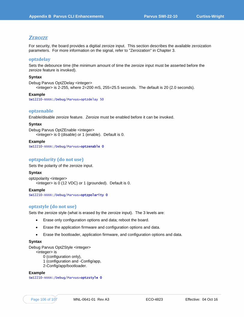
Appendix B Parvus CLI Enhancements
Parvus SWI-22-10 Curtiss-Wright
Page 106 of 107 MNL-0641-01 Rev A3 ECO-4823 Effective: 04 Oct 16
ZEROIZE For security, the board provides a digitial zeroize input. This section describes the available zeroization parameters. For more information on the signal, refer to "Zeroization" in Chapter 3.
optzdelay Sets the debounce time (the minimum amount of time the zeroize input must be asserted before the zeroize feature is invoked).
Syntax
Debug Parvus OptZDelay <integer> <integer> is 2-255, where 2=200 mS, 255=25.5 seconds. The default is 20 (2.0 seconds).
Example SWI2210-XXXX:/Debug/Parvus>optzdelay 50
optzenable Enable/disable zeroize feature. Zeroize must be enabled before it can be invoked.
Syntax
Debug Parvus OptZEnable <integer> <integer> is 0 (disable) or 1 (enable). Default is 0.
Example SWI2210-XXXX:/Debug/Parvus>optzenable 0
optzpolarity (do not use) Sets the polarity of the zeroize input.
Syntax
optzpolarity <integer> <integer> is 0 (12 VDC) or 1 (grounded). Default is 0.
Example SWI2210-XXXX:/Debug/Parvus>optzpolarity 0
optzstyle (do not use) Sets the zeroize style (what is erased by the zeroize input). The 3 levels are:
Erase only configuration options and data; reboot the board.
Erase the application firmware and configuration options and data.
Erase the bootloader, application firmware, and configuration options and data.
Syntax
Debug Parvus OptZStyle <integer> <integer> is
0 (configuration only), 1 (configuration and -Config/app, 2-Config/app/bootloader.
Example SWI2210-XXXX:/Debug/Parvus>optzstyle 0

MNL-0641-01 Rev A3 ECO-4823 Effective: 04 Oct 16 Page 107 of 107