DESIGN OF A LARGE SKEW SLAB PRESTRESSED ...
14
DESIGN OF A LARGE SKEW SLAB PRESTRESSED CONCRETE BRIDGE AT PARK TERRACE, ADELAIDE V. NECHVOGLOD, BTech(Civil), MIEAust, CPE Supervising Designing Engineer Department of Road Transport, Walkerville SA G. EDWARDS, BE, MIEAust, CPE Designing Engineer Department of Road Transport, Walkerville SA SUMMARY Construction of what is believed to be the largest skew slab prestressed concrete bridge in Australia has been completed and the bridge opened to traffic in September 1990. The new bridge is a three span structure, having 30 metre outer spans and a 49.5 metre central span, and carries six lanes of traffic over four railway lines at a 60 degree skew angle. The cast in place concrete deck slab is 1.2 metres thick, 24 metres wide and post tensioned longitudinally and transversely. The unusual geometry of the bridge posed problems in design and interpretation of code rules. This paper summarises the design approached adopted in dealing with aspects not adequately covered by design codes, and in particular the methodology used in dealing with live load, temperature effects, and longitudinal and transverse prestress. In- service monitoring of the structure is being undertaken to provide a comparison between the design and 'as built' performance, in particular all bearings are equipped with pressure cells to measure bearing loads. KEYWORDS Bridge, Skew, Slab, Prestressed concrete, Temperature effects, Instrumented bearings, Load monitoring. ACKNOWLEDGEMENT The authors would like to thank Mr R.J. Payze, Executive Director of the Department of Road Transport for his permission to publish this paper. The views expressed are those of the authors and do not necessarily reflect those of the Department of Road Transport. RJ Heywood (Editor) Bridges - Part of the Transport System Pages 729-742
-
Upload
khangminh22 -
Category
Documents
-
view
2 -
download
0
Transcript of DESIGN OF A LARGE SKEW SLAB PRESTRESSED ...
DESIGN OF A LARGE SKEW SLAB PRESTRESSED CONCRETE BRIDGE AT PARK TERRACE, ADELAIDE
V. NECHVOGLOD, BTech(Civil), MIEAust, CPE Supervising Designing Engineer Department of Road Transport, Walkerville SA
G. EDWARDS, BE, MIEAust, CPE Designing Engineer Department of Road Transport, Walkerville SA
SUMMARY
Construction of what is believed to be the largest skew slab prestressed concrete bridge in Australia has been completed and the bridge opened to traffic in September 1990. The new bridge is a three span structure, having 30 metre outer spans and a 49.5 metre central span, and carries six lanes of traffic over four railway lines at a 60 degree skew angle. The cast in place concrete deck slab is 1.2 metres thick, 24 metres wide and post tensioned longitudinally and transversely. The unusual geometry of the bridge posed problems in design and interpretation of code rules. This paper summarises the design approached adopted in dealing with aspects not adequately covered by design codes, and in particular the methodology used in dealing with live load, temperature effects, and longitudinal and transverse prestress. In-service monitoring of the structure is being undertaken to provide a comparison between the design and 'as built' performance, in particular all bearings are equipped with pressure cells to measure bearing loads.
KEYWORDS
Bridge, Skew, Slab, Prestressed concrete, Temperature effects, Instrumented bearings, Load monitoring.
ACKNOWLEDGEMENT
The authors would like to thank Mr R.J. Payze, Executive Director of the Department of Road Transport for his permission to publish this paper. The views expressed are those of the authors and do not necessarily reflect those of the Department of Road Transport.
RJ Heywood (Editor) Bridges - Part of the Transport System Pages 729-742

Vic Nechvoglod graduated with B.Tech.(Civil) from the University of Adelaide in 1968 and has been employed by the Department of Road Transport since that time. He has worked in bridge foundation investigation, road and bridge construction supervision, bridge inspection and bridge design. In 1978 he developed and implemented a computer based bridge inspection and asset management system. He is currently Supervising Designing Engineer for Structural Standards, Quality and Consultant Liaison. He is also Chairman of the Standards Australia Committee CE/26 - Precast Reinforced Concrete Box Culverts.
Glyn Edwards graduated with B.E.(Civil) in 1974 from the University of Adelaide and has been employed by the Department of Road Transport since that time. He has worked in the Structural Services Section (formerly Bridge Section) for the past fifteen years and has been involved in the inspection and design of bridges and other structures. He currently holds the position of Designing Engineer for Structural Standards, Quality and Consultant Liaison.
730 AUSTROADS Conference Brisbane 1991

508mm Ma voids (central span only)
000 00000000 L noo
109 500
49 500 30 000 30 000
24 000
0 0 0 0 000
1200
Fig. 1
road
Precast fascia panels —_
Circular drop panel above each pier column
1800
INTRODUCTION
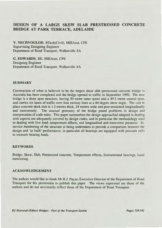
Construction of what is believed to be the largest skew slab bridge in Australia has been completed and the bridge and associated roadworks opened to road traffic in September 1990. The form of the new bridge was chosen on the basis of cost and aesthetics following preliminary design and costing of a number of alternatives.
The new bridge (refer to fig.l.) is a three span -structure, having 30 metre outer spans and a 49.5 metre central span, and carries six lanes of traffic and one footpath over four railway lines at a 60 degree skew angle (ie. 30 degree angle between road and railway lines). The cast in place concrete deck slab is 1.2 metres thick, 24 metres wide and post tensioned longitudinally and transversely. The central span has longitudinal circular voids to reduce dead load, and has a skew span to depth ratio of just over 41. The deck slab is supported on 16 bearings, four at each abutment and four at each line of piers. The piers consist of 1.8 metre diameter circular columns on 1.7 metre thick footings. The pier and abutment footings are supported on 450mm octagonal precast prestressed concrete piles having lengths of 14 metres at the piers and 16 metres at the abutments, driven into firm clays.
RI Heywood (Editor) Bridges - Part of the Transport System 731

The bridge is located at the junction of two geological fault lines and was designed to cater for earthquake loading. Each pier was designed for train impact loadings as given by the AUSTROADS Draft Code (Aug.1984 version). The design goes beyond the draft code requirement in that the bridge is designed to remain stable in the event that any one pier is completely removed.
Construction of the bridge approach embankments was carried out in early 1986, prior to completion of final des,ign of the bridge-in December 1986 and an independent design proof check in February 1987. Construction of the bridge commenced in January 1989 and was completed in August 1990 at a construction cost of $4.945 million, The deck slab required 2900 cubic metres of concrete, 340 tonnes of reinforcing bars and 220 tonnes of prestressing steel. The bearings used ranged from 3000kN capacity at abutments to 11,000 kN at the piers. All bearings are instrumented to monitor vertical load, this being the first known use of instrumented bearings on a bridge in Australia.
UNUSUAL DESIGN ASPECTS
The design of the 1.2 metre thick deck skew slab presented a number of problems which are not adequately dealt with in bridge design codes. The unusual geometry of the bridge and the type of superstructure selected posed problems of interpretation of code rules, which are framed to cater for the more usual linear beam and slab form of structure. For example, the definition of "span" - in terms of distance between_ points of contraflexure for a skew slab is not applicable. The concept of maximising live load moment and shear effects by utilizing a lane loading together with concentrated point loads is not suitable for multiple span highly skewed slabs. It is proposed to summarize some of the design approaches adopted in dealing with aspects not adequately covered by design codes or engineering literature.
OPTIMUM DESIGN OF SLABS
It was decided at an early stage in the design phase to use orthogonally placed reinforcement and prestress for the deck slab. The design approach described here is specifically for this case, however it can be adapted for reinforcement placed on skew.
Procedures for design of slabs under a static load are reasonably well documented. The loading induces principal moments within the slab which can be resolved at any point into orthogonal flexural moment components Mx, My, and a torsional moment Mxy (these components are generally referred to as the moment triad). Reinforcement placed orthogonally, can be provided to resist this moment triad. The procedure for calculating orthogonal reinforcement has been presented by a number of authors including Kemp (1971) who states that, for
732 AUSTROADS Conference Brisbane 1991

Negative yield
Optimum mxt myt
SAFE
( 3rd QUADRANT ) ( 4 th QUADRANT )
( 2nd QUADRANT )
( 1st QUADRANT )
SAFE
Optimum m xb, m Yb
any slab element subject to a moment triad Mx, My and Mxy, the yield function for an orthogonally reinforced slab is
(mx - Mx)(my - My) M2xy (1)
where mx and my are the yield moments per unit length in the x and y directions. Equation (1) represents a rectangular hyperpola with assymptotes mx = Mx and my = My and is shown diagramatically in Fig.2 indicating the safe combinations of yield moments mx and my for positive yield (-defined as inducing tension in the bottom reinforcement in the slab) and
negative yield (defined as inducing tension in the top reinforcement of the slab). Kemp states that admissible solutions to equation (1) must lie in the first quadrant for positive yield and the third quadrant for negative yield. For both bottom and top reinforcement the optimum solution is provided when the sum (mx + my) is minimised. This occurs at the tangent point of the yield curve and straight lines defined by (mx + my) = constant, as shown in Fig.2.
Fig 2 Yield curve ( rectangular hyperbola ) for one moment triad Mx, My, Mxy
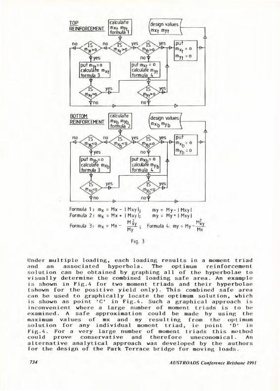
For any element there are four 'optimum' design moment values required namely mxt, myt, mxb, myb. For orthogonal reinforcement and for a single moment triad the optimum solutions for positive and negative yield are given by the equations tabulated in Fig.3 which displays the analytical process by which the design moments were derived.
lkywood (Editor) Bridges - Part of the Transport System 733
(design values mxt myt
es
no viN, no myt>o
Yes Ye Myt>
put My. o calculate mxt formula 3
put mxt = o calculate myt formula 4
put M -
myt = °
TOP calculate REINFORCEMENT mxt mYt
formula 1
yes
put Myh= 0
calculate mxb formula 3
Ye
no
put mx= o calculate My b formula 4
put mxb r 0
mYb °
no IS yes
BOTTOM REINFORCEMENT
calculate mxb m formula
yb 2
/design values I
‘mxb myb
es es
Formula 1: mx = Mx - I Mxy I; Formula 2: mx = Mx + I Mxy I;
2 Formula 3: mx = Mx -
My '
my = My- I Mxyl my= My + I Mxy I
My2 v Formula 4: my = My-
Mx
Fig. 3
Under multiple loading, each loading results in a moment triad and an associated hyperbola. The optimum reinforcement solution can be obtained by graphing all of the hyperbolae to visually determine the combined loading safe area. An example is shown in Fig.4 for two moment triads and their hyperbolae (shown for the positive yield only). This combined safe area can be used to graphically locate the optimum solution, which is shown as point 'C' in Fig.4. Such a graphical approach is inconvenient where a large number of moment triads is to be examined. A safe approximation could be made by using the maximum values of mx and my resulting from the optimum solution for any individual moment triad, ie point 'D' in Fig.4. For a very large number of moment triads this method could prove conservative and therefore uneconomical. An alternative analytical approach was developed by the authors for the design of the Park Terrace bridge for moving loads.
734 AUSTROADS Conference Brisbane 1991

Fig. 4 Optimum values for multiple triads ( showing two triads A and B)
DESIGN FOR MOVING LOADS
The bridge was designed for six lanes of traffic. To ensure adequate identification of the maximum load effects of the NAASRA T44 design vehicle the following procedure was adopted. The analysis was carried out using computer programmed finite element theory. The finite element model was prepared using conventional rectangular and triangular finite elements to best approximate the superstructure and the trafficked lanes of the bridge. The T44 vehicle (including impact effects) was modelled as a uniformly distributed patch load and shifted along each lane to "simulate" a moving vehicle. By using the output moment triad for each element and for each load position the design moment values mxt, myt, mxb, myb. were produced. Refer to Fig.3. For each element, the maximum for each design moment value was isolated, along with the originating moment triad values and load position. This process was performed for each of the six lanes. For each element, and for each design moment value the six individual moment triad values are then summed. Thus, for each element and corresponding to each design moment value a T44 vehicle maximum moment triad for simultaneous loading of all six lanes was produced. That is the location of the vehicles to produce the maximum moment effect in both the longitudinal and transverse direction for the top and bottom of the slab was determined.
DECK SLAB DESIGN
The deck slab was designed as a partially prestressed concrete slab in accordance with the 1981 Addendum to Section 6 of NAASRA BDS (1976). Serviceability and ultimate strength combinations were checked in accordance with Section 6 for Partially Prestressed Concrete. Additionally,the superstructure was checked with any one pier removed and found to be adequate to support the dead load of the deck slab plus a small proportion of the design live load capacity.
RJ Heywood (Editor) Bridges - Part of the Transport System 735

The analysis of a skew slab to resist combined bending and in plane forces is very complex. A design solution can be obtained by adopting a 'sandwich' approach such as suggested by Morley and Gulvanssian (1977). Clark and West (1974) give guidance as to the solution in the case of solid skew slabs subjected to longitudinal prestress. Their procedure makes use of the 'load balancing method' of modelling prestress. The design procedure used by the authors generally follows their approach, in which prestressing effects can be considered as equivalent vertical loads (line and point loads) combined with horizontal in-plane forces. The flexural effects of the equivalent loads on the structure were analysed separately to produce a moment triad for each element. Similarly all other loadings including dead load, live load, and temperature effects were applied to the structure to generate their respective moment triads. The design moment values were determined for the various prescribed load combinations by the process outlined earlier. The in plane effects of prestress were considered separately for each of the orthogonal directions and for each of the design moment values. This is best explained as follows: Consider that the in-plane force is applied first, producing a uniform compressive stress. The flexural moment is then applied, gradually reaching a triangular stress distribution. ie. a state of decompression on one face is reached. Further increase in flexural moment results in the need for additional capacity which in the case of Park Terrace was provided by the use of non prestressed reinforcement which was calculated, as an acceptable approximation, using a reinforced concrete section approach.
Computer programs were written to plot the element design moments as contours over the whole slab. This ability to plot design moments as contours greatly facilitated the design process and provided a visual representation of moments (and deflections) for all loads and load combinations. Due to the presence of the footpath on one side the traffic lanes are not symmetrically located across the bridge, consequently symmetry in the contour plots is not displayed. Refer to Fig.5:
TEMPERATURE EFFECTS
The analysis of differential temperature effects for beam type structures is well documented. For highly skewed and assymetrical voided slabs this is not so. It is considered that the approach adopted by the authors in dealing with temperature effects is one that can readily be understood and applied to skew rectangular slabs, or indeed any other shaped slab.
The approach is based on the fact that a uniformly stiff plate of any shape subjected to differential temperature strains will deform so as to undertake a curvature corresponding to that of a sphere. The same spherical deflection surface can be obtained if an appropriate bending moment is uniformly applied along the plate edges. The curvature will depart from spherical for plates having different stiffness in the
736 AUSTROAI)S Conference Brisbane 1991

100
X
100
a°
DESIGN MOMENT VALUE m x+ kNm per metre For T44 VEHICLE LIVE LOAD.
RJ
Heyw
ood (E
dito
r) Brid
ges - P
art o
f the T
ransp
ort S
ystem
sot,
DESIGN MOMEN — VALUE m xt : kNm per metre
FCR SERVICEABI_ITY ANALYSIS LOAD CASE
PERMANENT LO DS + T44 LIVE LOAD
FIGURE 5 DESIGN MOMENT CONTOURS

longitudinal and transverse directions. For the bridge this occurs in the voided central span but the difference is small and was neglected in design. The secondary moments and reactions were found as follows: The number of plate support points was first reduced to three, thereby changing the system to a statically determinate one with the plate forming a spherical surface. The strains and stresses can be readily determined for this case. The deflections of the spherical surface from the other thirteen supports were calculated and were then used as imposed deformations to return the plate to its designed support position, and the secondary moments and reactions derived accordingly. Refer to Clark and West (1974) and to Blythe and Lunniss (1978).
HEAT OF HYDRATION TEMPERATURE RISE
The thickness of concrete sections were 1.7m for pier footings, 1.2m for abutment footings (both 30 MPa concrete) and 1.2m for the deck slab (45MPa concrete). It was anticipated, particularly for the deck slab, that there would be a considerable temperature rise within the slab as well as a temperature differential through the thickness.
To investigate this temperature rise and differential it was decided to cast instrumented full depth concrete test blocks. Temperatures were measured in the block at casting and for a period of about eight days thereafter. The elongations of the 12mm diameter bars holding the thermocouples were also measured. Concrete mixes using types A and D cement were tested. Refer to Fig.6.
As expected, it was found that the temperature rise above average ambient for Type 'A' cement was higher (a peak rise of 52°C at 24 hours, being 10.8°C per 100 kg of cement) than Type 'D' cement (a peak rise of 47°C at 29 hours, being 9.8°C per 100 kg of cement). It was also found that the maximum difference in temperature at the centre of the slab to the temperature at the top surface was about 17°C for Type A and about 13°C for Type D, and that these differences occured at the peak and were only about 20% less three days after casting. Also as expected, the daily temperature variations greatly influenced the top surface temperature of the concrete where this was not covered by insulation.
As a result of these tests it was decided to use Type D cement and to insulate the top of the deck slab during construction. The actual peak temperature rise recorded during the deck slab pour was about 45°C. It should be noted however that the actual concrete used was a different mix. The mix used in construction had 420 kg per cubic metre of type D cement and 80 kg per cubic metre of fly-ash. Interestingly the measured elongations of the 12mm diameter bars could not be correlated to their temperature gradients using the accepted coefficient of thermal expansion for steel. The implication being that the coefficient of thermal expansion for concrete may not be similar to that of steel during the hydration process.
738 AUSTROADS Conference Brisbane 1991

Ambient (shade air temperature)
TYPE 'A' CEMENT ( 45 MPa
( 480 kg /m3 Top not insulated)
Thermocouples
7fMAX. 4
50
\-..-i '—'—'1,-2'—'-- 250
-43- \ ,.., ) 12 di bars. -'""
\ \ 4 4. 2) \ 19mm mood form4
....., - 300 •̀.2
t.* ¶5 S. 250
:\.t . 4 _./ I 7 SO
• i000:(square) 150 thick polystyrene
AT -52C 2 11
10.8.C/100 kg)
C
0 ...
..- 1.' ...... .
:4-- .--- .....","....'...... s . -C ...1
CL C C.\ ........,...
M = c\-1.,. ••••••• •
. -- ...,... ...., ..... .........,...3,i --",-......
/AVERAGE 20.
20 25 40 60 80 100 120 140 160 180 TIME ( Hours)
TYPE 'El' CEMENT (45 MPa)
(480 kg /m3 Top insulated) 80 63° MAX st POUR MAX.1--- 73C
pour on 11/12/89 maximum temperature rise 28°c to 73°c
AT 45°c
'AT =47.C. (-9.81/100kg)
AVERAGE le Ambient (shade air temperature) 29 317
Li oo 60 LsJ Ii.
ix 40 a_
I- 28
20
80
Li 60
CC
a. CC w 40 LU I-
20
20 40 60 80 100 120 140 160 180 TIME ( Hours)
Fig. 6
BEARING VERTICAL LOADS
Due to some uncertainty as to pile settlement predictions and the complexity of design inherent in such a highly skewed bridge, it was decided to instrument the bearings to allow monitoring of vertical loads.
RJ Heywood (Editor) Bridges - Part of the Transport System 739

Hercules Engineering (a Sydney based bridge bearing manufacturer) was approached regarding the availability of load monitoring bearings. Following investigation and development, Hercules Engineering indicated that they could economically supply instrumented bearings designed to measure vertical loads to the required level of accuracy for a monitoring life of at least two years. The specification requirement in the bridge contract was that the bearings should be supplied with a calibration curve (or data) for the full range of load from zero to 1.5 times the working load (which- ranged from 3000kN at the abutment to 11000kN at the piers), to an accuracy of half of one percent of maximum reading.
Readings of vertical loads commenced in July 1990, prior to completion of all dead load and have continued to date with great success. Refer to Table 1, which shows design values and measured readings. The comparison between design and actual is very good. It is to be noted that the design model did not allow for a slight wedge shaped widening of the bridge deck at one end due to the final prescribed road alignment. Also at this stage there is additional fill material in the widened central median as the present disposition is for four lanes of traffic only whereas the design was for six lanes and much smaller median. These factors account for the higher measured loads on the bearings at the abutments compared to the design values. Calculated temperature loads are tabulated, however these can not be separated from the readings.
CONSTRUCTION
No serious or unusual problem occurred during the twenty month construction period. Precautions were taken at the design stage and incorporated into the drawings and specification to avoid anticipated problem areas. Two areas in particular needed attention. The likelyhood of plastic settlement cracking in deep concrete pours with reinforcement- and void formers within the section was high. Thermal movements due to heating and cooling of the slab can cause considerable loads to be imposed on the supporting falsework and the bearings. The deck slab was poured in five separate stages and the bearings were not installed until just prior to longitudinal stressing which was carried out in two stages over a period of eight days.
CONCLUSION
A description is provided of what is believed to be the largest partially prestressed skew slab bridge in Australia. An outline has been given of the approach adopted in designing this highly skewed bridge for live loads, temperature effects and for orthogonal longitudinal and transverse prestress effects. It is considered that the design approach adopted is also suitable for other slab structures having an unusual plan shape and/or irregular bearing support configurations.
740 AUSTROAM Conference Brisbane 1991

2 8
7
BEARING NUMBERS
10 2 6 NORTH
9
5
13
Bearing Numb... (see diagram above) Total
Load
(10 - 3) KN 1 8 2 7 3 6 4 5 9 16 10 15 11 14 1 13
Deal., Loads
(10'3) 1,8
1 Permanent I Load
7.04 7.04 7.67 7.67 6.69 6.69 8.04 8.04 2.62 2.42 1.65 1.65 1.71 1.71 1. 2 1.12 72.68
1 Temperature
Load
0.55 0.55 -1.2 -1.2 -1.17 -1.57 1.25 1.25 0.91 0.91 -0.58 -0.58 -0.49 -0.49 1..3 1.13 0.00
18/7/90 DL Load
(No median,No AC) (10 - 31 KN
6.82 7.02 6.60 7.26 6.2, 6.86 7.23 7.34 3.72 3.04 1.55 1.51 1.87 1.57 2.06 2.27 73.55
27 /8 /90 , DL
(No nedianodlth AC)
Load
(10'3) KN
7.26 7.17 6.76 7.35 6.43 7.04 7.62 7.78 3.39 4.01 1.64 1.60 1.90 1.54 2 1 2.4 76.35
7/1/91 1 DL I Load
(Full DL) (10'3) MN
7.40 7.27 6.79 7.25 6.41 7.03 7.96 8.20 3.48 4.25 1.67 1.53 2.00 1.61 2.19 2.62 77.96
1
26/4/91 : DL Load
(Full DL) (10'3) KW
7131 7.11 7.00 7.41 6.59 7.14 7.86 8.12 3.58 4.26 1.58 1.47 2.07 1.73 2.06 2.52 78.03
18/7/91 : DL Load
(Full DL) (10 - 3) MN
7.28 7.03 7.14 7.52 6.53 7.29 7.72 7.99 3.51 4.18 1.63 1.51 2.21 1.79 2..7 2.43 78.03
8/9/91 : DL
I (Full DL)
Load
(10 - 11 ON
7.27 7.02 7.16 7.59 6.77 7.35 7.70 7.98 3.46 4.14 1.69 1.57 7.11 1.79 2..3 7.41 70.16
TABLE 1 : VERTICAL LOADS ON BEARINGS

REFERENCES
CLARK, L.A. and WEST, R. (1974). The behaviour of solid skew slab bridges under longitudinal prestress. Cement and Concrete Association, London. ppl-40.
KEMP, K.O. (1971). Optimum reinforcement in a concrete slab subjected to multiple loadings. International Association for Bridge and Structural Engineering, Publication 31-1, pp93-105.
MORLEY, C.T. and GULVANESSIAN, H. (1977). Optimum reinforcement of concrete slab elements. Proc. Instn. Civ. Engrs. Part 2, June, 1977, pp441-454.
CLARK, L.A. (1983). Concrete bridge design to BS5400, Construction Press, London and New York.
BLYTHE, D,W,R. and LUNNISS. R.S. (1978). Temperature difference effects in concrete bridges. TRRL Supplementary Report 442, pp68-80.
742
AUSTROADS Conference Brisbane 1991