non-linear analysis of rc bridge slab on prestressed beams
22
NON-LINEAR ANALYSIS OF RC BRIDGE SLAB ON PRESTRESSED BEAMS IN TRANSVERSE DIRECTION GAN ZHI HAN A project report submitted in fulfilment of the requirements for the award of the degree of Master of Engineering (Structure) School of Civil Engineeing Faculty of Engineering Universiti Teknologi Malaysia JANUARY 2019
-
Upload
khangminh22 -
Category
Documents
-
view
1 -
download
0
Transcript of non-linear analysis of rc bridge slab on prestressed beams

NON-LINEAR ANALYSIS OF RC BRIDGE SLAB ON PRESTRESSED BEAMS
IN TRANSVERSE DIRECTION
GAN ZHI HAN
A project report submitted in fulfilment of the
requirements for the award of the degree of
Master of Engineering (Structure)
School of Civil Engineeing
Faculty of Engineering
Universiti Teknologi Malaysia
JANUARY 2019

ii
ACKNOWLEDGEMENT
First and foremost, I would like to express my sincere appreciation and
gratitude towards my project supervisor, Associate Professor Dr. Redzuan Abdullah
for his encouragement and guidance throughout the whole project, especially on using
the LUSAS softwar
along the way. I am also thankful to my chief panel, Associate Professor Dr Izni
Syahrizal Ibrahim for his suggestions and constructive criticisms on my project.
Lastly, I would like to express my gratitude towards my family, friends and
postgraduate course mates for your words of encouragement and spiritual support
throughout my period of study here in Universiti Teknologi Malaysia. This project
report will not be made possible without each and every one of you.

iii
ABSTRACT
Construction of bridge decks in Malaysia for typical spans of 10m-40m is
mostly made of reinforced concrete slab on wide prestressed T-beam. The function of
slab is mainly distribute wheel load to the beams. It is well known that the slab
designed by consultants is assumed as continuous beams and they are always
conservative. The purpose of this study is to determine the ultimate load capacity of
the minimum reinforced concrete bridge slab supported by a wide flange T-section
girder by conducting a nonlinear finite element analysis. The analysis results are
compared with experiment using traffic loading at notional lane 1 of Load Model 1
(LM1) stipulated in EN 1991-2: 2004. Besides, this study is also meant to confirm the
minimum transverse reinforcement as proposed by a previous researcher in accordance
to clause 6.2.4. of EN 1992-1-1: 2004. Two beam models were analysed which are T-
Beam without slab (flange only) and T-Beam with 200mm thick slab on top of the
beam flange. The analysis results were validated against experiment results conducted
by previous researcher. The findings of the study confirms that the slab supported by
wide flange T-beam with minimum reinforcement is sufficient to support Eurocode
traffic load. This study warrants further research for construction of concrete slab on
T-Beam girders with minimum reinforcement.

iv
ABSTRAK
Dek jambatan yang dibina di Malaysia yang panjang sekitar 10-40m
kebanyakannya dibina menggunakan papak konkrit yang disokong oleh girder-T
dengan flang panjang. Fungsi papak konkrit adalah untuk mengagihkan beban
kenderaan ke girder. Umumnya, papak direka bentuk oleh jurutera perunding dengan
mengangap sebagai rasuk selanjar. Rekabentuk ini selalunya amat konservatif. Tujuan
kajian ini dijalankan adalah untuk menentukan kapasiti beban muktamad papak
konkrit yang disokong oleh girder T-flange lebar pada sebuah komponen jambatan
komposit dengan kaedah analisis tidak lelurus unsur terhingga. Hasil analysis
dibandingkan dengan dapatan kajian eksperimen oleh penyelidik terdahulu yang
menggunakan beban kenderaan pada lorong nosional 1, Modal Beban 1 (LM1) seperti
yang ditentukan oleh EN 1991-2: 2004. Dua model dek yang telah dianalisis iaitu
girder-T tanpa papak konkrit dan girder-T yang diletakkan pada papak konkrit 200m
tebal di atas flange. Hasil analisis telah menunjukkan bahawa kapasiti yang
mempunyai tetulang minimum meyemai data ujikaji. Hasil kajian ini menunjukkan
bahawa papak jambatan yang dicadangkan oleh penyelidik terdahulu iaitu dengan
meletakkan tetulang minimum sahaja sudah memadai untuk menahan beban trafik
LM1. Hal ini telah memberi petunjuk bahawa satu kajian yang lebih mendalam
berbaloi untuk dilaksanakan agar papak pada dek jambatan boleh dibina dengan
tetulang minimum sahaja.

v
TABLE OF CONTENTS
TITLE PAGE
DECLARATION i
ACKNOWLEDGEMENT ii
ABSTRACT iii
ABSTRAK iv
TABLE OF CONTENTS v
LIST OF TABLES vii
LIST OF FIGURES viii
LIST OF ABBREVIATIONS xi
LIST OF SYMBOLS xii
LIST OF APPENDICES xiii
INTRODUCTION 1
1.1 Background of Study 1
1.2 Problem Statement 2
1.3 Objectives of Study 3
1.4 Scope of Study 3
1.5 Outline of Thesis 4
LITERATURE REVIEW 7
2.1 Introduction 7
2.2 Compressive Membrane Actions 7
2.3 Finite Element Analysis 8
2.4 Plastic and Elastic Material Properties 10
2.5 Concrete-to-Concrete Composite Actions 11
2.6 Initial Study by Najiyu (2018) 12
2.7 Similar Methods with Other Studies 21

vi
METHODOLOGY 27
3.1 Introduction 27
3.2 Experimental Study by Najiyu (2018) 28
3.3 Nonlinear Finite Element Analysis with LUSAS 30
3.4 LUSAS Analysis Procedures 30
3.5 Discretisation of Model 31
3.5.1 Geometric and Material Definitions 33
3.5.2 Nonlinear Analysis Settings 37
3.6 Transverse Steel Reinforcement at Flange 39
3.7 Comparison between Experimental and NLFEA Results 41
RESULTS AND DISCUSSION 43
4.1 Introduction 43
4.2 Load Model 1 (LM1) according to EN 1991-2: 2002 43
4.3 Results obtained from LUSAS 44
4.4 Discussion of Results 58
4.5 Transverse Steel Reinforcement Validation 60
CONCLUSION AND RECOMMENDATIONS 63
5.1 Conclusion of Findings 63
5.2 Recommendations 63
REFERENCES 65

vii
LIST OF TABLES
TABLE NO. TITLE PAGE
Table 2.1 The comparison of stresses and moments from the supports and mid spans of Decks A and B (Source: Najiyu, 2018)
16
Table 2.2 Comparison between support moments and area of steel reinforcement required between the conventional and modified approach (Source: Najiyu, 2018)
17
Table 2.3 Specimen details of experiment from Najiyu (2018) 18
Table 2.4 Overall experiment results by Najiyu (2018) 20
Table 3.1 Model attributes used in LUSAS for TB1 32
Table 3.2 Model attributes used in LUSAS for D1 32
Table 4.1 Load and displacement results of TB1 49
Table 4.2 Load and displacement results of D1 54
Table 4.3 Comparison between experimental and NLFEA results of TB1 57
Table 4.4 Comparison between experimental and NLFEA results of D1 57
Table 4.5 Summary of transverse reinforcement details 61

viii
LIST OF FIGURES
FIGURE NO. TITLE PAGE
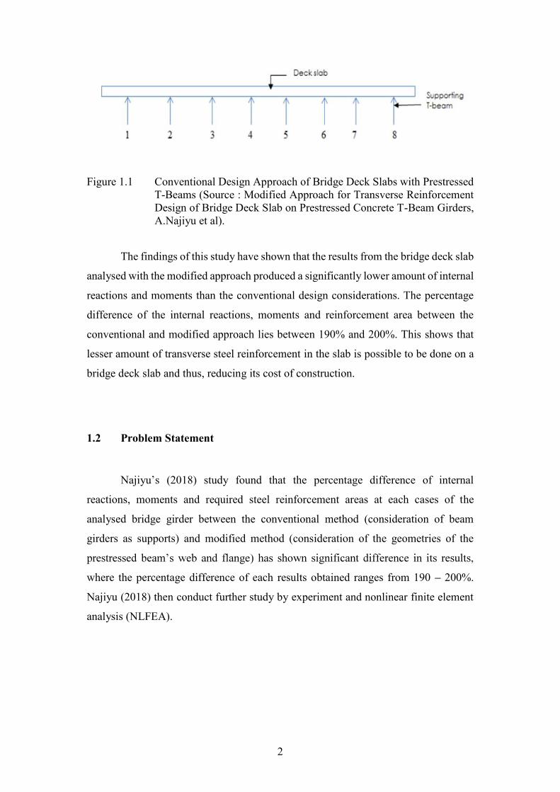
Figure 1.1
Conventional design dpproach of bridge deck slabs with prestressed T-Beams (Source : Modified Approach for Transverse Reinforcement Design of Bridge Deck Slab on Prestressed Concrete T-Beam Girders, Abubakar.N et al)
2
Figure 2.1
Compressive membrane actions (Source: Belletti et al)
8
Figure 2.2 Examples of geometric nonlinear behaviour of the structure
9
Figure 2.3 Example of boundary condition nonlinearity
10
Figure 2.4 Conventional stress-strain curve (Source: Mechanics of Materials by R.C. Hibbler)
11
Figure 2.5 Explanation of interfacial shear stresses/bond stresses by M.A. Mahmoud et al. (2013). (a) Girder in full composite action. (b) The interfacial stress transfer in composite section. (c) horizontal slip of the composite girder (d) non-composite section.
12
Figure 2.6 The conventional design approach of bridge deck analysis using LUSAS. The arrows underneath indicated the fixed support of the deck slab, which is also where the prestressed T-Beams are located
13
Figure 2.7 The slab and T-Beam configuration of study.
14
Figure 2.8 Support conditions and loadings of the system configuration (Source: Najiyu, 2018)
14
Figure 2.9 The stress contours of the analysed deck A and the stresses calculated at (a) Span, (b) Support (Source: Najiyu, 2018)
15
Figure 2.10
Stress contours at Deck B (Source: Najiyu, 2018) 16
Figure 2.11 The set up and instrumentation of TB1 (Najiyu, 2018)
18
Figure 2.12
The set up and instrumentation of D1 (Najiyu, 2018) 19
Figure 2.13 The set up and instrumentation of D2, D3 and D4 (Najiyu, 2018)
19

ix
Figure 2.14 The set up and instrumentation of D2 and D3 on the cantilever part of the specimen (Najiyu, 2018)
20
Figure 2.15 Proposed cross section by Yu Zheng and authors (2017)
21
Figure 2.16 The restrain FRP rods system from Yu Zheng and authors' study (2017)
22
Figure 2.17 The principal strain behaviour from the finite element model (Zheng, Y., 2013)
23
Figure 2.18 The failure mode after from the analysed finite element model (Zheng, Y., 2013)
23
Figure 2.19 The transverse stress distributions from the finite element model according to its stages of imposed loading (Zheng, Y., 2013)
24
Figure 2.20 The finite element model of the pretensioned bridge girder by Pinar Okumus and authors (2012)
25
Figure 2.21 The difference of strain analysis onto the pretension girder end with both linear and nonlinear FEA (Okumus et al., 2012)
25
Figure 2.22 Principal tensile strain contours from the study by Okumus et al. (2012)
26
Figure 2.23 Principal strain directions from the model
26
Figure 3.1 Dimensions and steel reinforcement details of TB1 (Najiyu, 2018)
28
Figure 3.2 Dimensions and steel reinforcement details of D1 (Najiyu, 2018)
29
Figure 3.3 Finite Element Model of TB1 in LUSAS
31
Figure 3.4
Finite Element Model of D1 in LUSAS 31
Figure 3.5
Geometric Surface Dialog Box 34
Figure 3.6
Line Meshing Dialog Box 34
Figure 3.7
Surface Meshing Dialog Box 35
Figure 3.8
Plastic Material Properties Dialog Box 36
Figure 3.9
Elastic Material Properties Dialog Box 36
Figure 3.10 Nonlinear and Transient Dialog Box 37

x
Figure 3.11 Advanced Nonlinear Incrementation Parameters Dialog Box
38
Figure 3.12
Notations of flange and web connections and the shear stresses taking place (Source : Figure 6.7, EN 1992-1: 2004)
39
Figure 4.1 Application of Load Model 1 (LM1) according to EN 1991-2: 2003
44
Figure 4.2 Load versus Displacement Graph for TB1 obtained from LUSAS NLFEA Analysis
45
Figure 4.3 Load versus Displacement Graph of D1 obtained from LUSAS NLFEA Analysis
45
Figure 4.4 Load versus Displacement graph obtained from LUSAS Analysis of TB1 at 164.3kN (Ultimate Load of Experiment)
46
Figure 4.5
Load versus Displacement graph obtained from LUSAS Analysis of D1 at 489.3kN (Ultimate Load of Experiment)
46
Figure 4.6
Load versus deflection results of TB1 from experiment on both left and right flanges of the T-Beam. (Source: Najiyu, 2018)
47
Figure 4.7 Load versus deflection curves of D1 from the experimental results, which is results of D1 are indicated as D1a and D1b that represents the left and right flanges respectively. (Source: Najiyu, 2018)
47
Figure 4.8 Load versus Displacement Curves of TB1 from both LUSAS and Experimental results
48
Figure 4.9 Load versus Displacement Curves of D1 from both LUSAS and Experimental Results
48

xi
LIST OF ABBREVIATIONS
2D - Two dimensional
3D - Three dimensional
D1 - T-Beam with slab
EN 1991-2: 2003 - Eurocode 1
EN 1992-1: 2004 - Eurocode 2
FEA - Finite Element Analysis
FRP - Fibre-Reinforced Polymer
kN - kilo Newton
LFEA - Linear Finite Element Analysis
LM1 - Load Model 1
LM2 - Load Model 2
LM3 - Load Model 3
LVDT - Linear Variable Displacement Transducers
mm - millimetres
N - Newton
N/ - Newton per area in millimetres
NLFEA - Nonlinear Finite Element Analysis
TB1 - T-Beam without slab
TS - Tandem system

xii
LIST OF SYMBOLS
E -
- Longitudinal Shear Stress at web-flange interface
- Change in longitudinal force
- Height of flange
- Distance measured at zero moment
- Change in moment
b - Flange width
- Web width
d - Effective depth of beam
w - Load capacity
L - Length of beam at z-direction (1m)
- Minimum amount of transverse steel
- Mean tensile stress of transverse steel
- Yield stress of transverse steel

xiii
LIST OF APPENDICES
APPENDIX TITLE PAGE
Appendix A
Stress-Strain Curve of Rebar at T-Beam Flange 68
Appendix B
Stress-Strain Curve of Concrete Slab 69


1
INTRODUCTION
1.1 Background of Study
One of the most common types of bridge decks being constructed in Malaysia
is using prestressed beams with reinforced concrete slab commonly known as a beam
girder deck. The slab is supporting the wheel load and transfer the load transversely to
the prestressed beam or known as girder.
The conventional design practices of bridge slab is by assuming the slab as
continuous beam supported by the girder as minimum support (Figure 1.1). This type
of assumption is very conservative. Hence, bridge decks are often designed with higher
amounts of reinforcement areas due to this negligence, making the cost of bridge
construction expensive.
This statement is supported by Najiyu (2018) on a modified approach of
designing a bridge deck slab on prestressed concrete T-Beam girders. His findings
showed that the conventional design method was too conservative due to the
neglecting of the strength and geometry of the flange and web thicknesses of the
prestressed beams in the analysis of bridge deck structures.
Najiyu (2018) have modified the design approach for the transverse
reinforcement of a bridge deck slab, where the geometries and material properties of
the flanges and webs of the prestressed T-Beams are considered and tested with both
finite element analysis and experiments.
2
Figure 1.1 Conventional Design Approach of Bridge Deck Slabs with Prestressed T-Beams (Source : Modified Approach for Transverse Reinforcement Design of Bridge Deck Slab on Prestressed Concrete T-Beam Girders, A.Najiyu et al).
The findings of this study have shown that the results from the bridge deck slab
analysed with the modified approach produced a significantly lower amount of internal
reactions and moments than the conventional design considerations. The percentage
difference of the internal reactions, moments and reinforcement area between the
conventional and modified approach lies between 190% and 200%. This shows that
lesser amount of transverse steel reinforcement in the slab is possible to be done on a
bridge deck slab and thus, reducing its cost of construction.
1.2 Problem Statement
Najiyu (2018) study found that the percentage difference of internal
reactions, moments and required steel reinforcement areas at each cases of the
analysed bridge girder between the conventional method (consideration of beam
girders as supports) and modified method (consideration of the geometries of the
where the percentage difference of each results obtained ranges from 190 200%.
Najiyu (2018) then conduct further study by experiment and nonlinear finite element
analysis (NLFEA).

3
The experimental study conducted by Najiyu was following the actual bridge
structure but with minimum reinforcement in the slab. It was found that the reduced
reinforcement of the bridge deck girders are able to withstand ultimate loadings as high
as 489kN (with slab) and is far exceeding the Eurocode vehicle loads. Consequently,
this study is conducted to validate the results obtained by the experiment conducting
by Najiyu (2018) by conducting NLFEA using LUSAS 14.0.
1.3 Objectives of Study
The objectives of this study includes the following:
1. To determine the ultimate moment capacity of the reinforced concrete
bridge deck slab supported by a wide flange T-section girder by conducting
a nonlinear finite element analysis (NLFEA).
2. To compare the results obtained from the NLFEA with the experimental
results and the Eurocode traffic loading standards.
3. To compare the transverse reinforcement proposed to the bridge deck with
the requirements stipulated in EN 1992-1: 2004.
1.4 Scope of Study
The scopes of this study are:
To conduct a 2D plane stress NLFEA of a bridge deck with and without
slab while neglecting the prestressing forces inside the girder.

4
The dimensions and material properties of the bridge deck model are
based on the experiment conducted by Najiyu (2018).
The load-displacement curves and the T-
from NLFEA will be compared with the experimental results by Najiyu
Abubakar and the tandem system of Load Model 1 (LM1) bridge
loadings in accordance to Eurocode 1 (EN 1991-2:2003).
The minimum transverse reinforcement proposed by Najiyu Abubakar
are validated based on clause 6.2.4 of EN 1992-1: 2004.
1.5 Outline of Thesis
This thesis consists of five chapters. Chapter 1 of this thesis will be the
introduction of this study along with the background of the study, problem statements,
objectives and scopes of this study.
Chapter 2 will be the literature review of the prior study from Najiyu Abubakar,
past researches or findings from similar studies and relevant information to this study
such as compressive membrane actions, stress and strain of materials, bond strengths
of materials and finite element analysis.
Chapter 3 will discuss the method of conducting this study. The details of the
dimensions and materials used on the proposed bridge girder from the experiment will
be shown here along with the method to conduct NLFEA with LUSAS. The procedures
to determine and validate the minimum transverse reinforcement required according
to clause 6.2.4 of EN 1992-1: 2004 are discussed in this chapter also.
Chapter 4 will discuss the findings obtained from NLFEA and the comparison
of results with the experiment. This chapter will also discuss the transverse
reinforcement provided in the proposed bridge girder from the numerical calculations
obtained according to clause 6.2.4 of EN 1992-1: 2004.

5
Chapter 5 will conclude from the results obtained in this study and provide
recommendations for further improvements to this study. This is followed by
references and appendices.

65
REFERENCES
Abubakar, N. (n.d.). Effect of Transverse Shear in Reinforced Concrete Slab on Wide
Flange T-Beam. 2018
Abubakar, N., Redzuan bin, A., Ahmad Beng Hong, K., & Mohamad Salleh, Y.
(2017). Capacity of Lightly Reinforced Bridge Deck Cantilever Overhang
Subjected to Static Loading.
Abubakar, N., Abdullah, R., Hong, A. K. B., & Yassin, M. S. (2017). Modified
approach for transverse reinforcement design of bridge deck slab on prestressed
concrete T-beam girders. International Journal of Civil Engineering and
Technology, 8(8), 1239 1246.
Abubakar, N., Abdullah, R. Bin, Kueh, A. B. H., & Yassin, M. S. (2017). Transverse
slab reinforcement design of concrete bridge deck: A review. ARPN Journal of
Engineering and Applied Sciences, 12(21), 5929 5937.
Alexander, S. D. B., Simmonds, S. H, Tests of column-flat plate connections. ACI
Struct J 1992;89:495 502.
Applications and Examples Manual (Bridge, Civil, Structural), LUSAS Version
15.2 :Issue 1 (2014)
single-spanned historic masonry arch bridges (Ordu, Sarpdere Bridge).
Engineering Failure Analysis, 84(November 2017), 131 138.
https://doi.org/10.1016/j.engfailanal.2017.11.002
Belletti, B., Walraven, J. C., & Trapani, F. (2015). Evaluation of compressive
membrane action effects on punching shear resistance of reinforced concrete
slabs. Engineering Structures, 95, 25 39.
https://doi.org/10.1016/j.engstruct.2015.03.043
British Standards Institution. (2008). Eurocode 1 : Actions on Structures - Part 2:
Traffic Loads on Bridges: British standard. London: BSi.

66
British Standards Institution. (2008). Eurocode 2 : Design of Concrete Structures:
British standard. London: BSi.
Cook, R. D., Malkus, D. S., Plesha, M. E., & Witt, R. J. (2002). Concepts and
Applications of Finite Element Analysis (4th ed.). Hoboken, New Jersey: John
Wiley & Sons.
redistribution and compressive membrane action on punching strength of flat
slabs. Engineering Structures, 86, 43 57.
https://doi.org/10.1016/j.engstruct.2014.12.032
Examples Manual, LUSAS Version 15.2 :Issue 1 (2011)
Genikomsou, A. S., & Polak, M. A. (2017). 3D finite element investigation of the
compressive membrane action effect in reinforced concrete flat slabs.
Engineering Structures, 136, 233 244.
https://doi.org/10.1016/j.engstruct.2017.01.024
Hibbler, R. C. (2003). Mechanics of Materials (5th ed.). Pearson Education.
Lynn, K.M., Isobe, D. Finite element code for impact collapse problems of framed
strucutures, International Journal for Numerical Methods in Engineering 69 (12)
(2007) 2538-2563
Mahmoud, M. A., Elafandy, T. H., Okail, H. O., & Abdelrahman, A. A. (2013).
Interfacial shear behavior of composite flanged concrete beams. HRBC
Journal, 10, 206-214. Retrieved January 1, 2019.
MD Aripin, M. (2014). Plastic Analysis of Concrete Beam Structure using LUSAS.
Universiti Teknologi Malaysia.
Mohamed, M. E., Ibrahim, I. S., Abdullah, R., Abdul Rahman, A., Kueh, A. B., &
Usman, J. (2014). Friction and cohesion coefficients of composite concrete-to-
concrete bond. Cement and Concrete Composites. Retrieved January 1, 2019.
Mohamed, M. E., Ibrahim, I. S., Saim, A. A., & Abdul Rahman, A. (2012). Influence
of Roughness, Cohesion and Friction on the Interface Shear Strength of
Composite Concrete-to- Concrete Bond. Retrieved January 1, 2019, from
http://people.utm.my/iznisyahrizal/files/2013/01/Composite-5.pdf

67
Mosley, B. Bungey,J.and Hulse, R. Reinforced Concrete Design to Eurocode 2, 7th
Edition. Palgrave Macmillan, 2012.
Newhook, J. P., Mufti, A. A, (1997). The behaviour of Steel-Free Concrete Bridge
Deck Slabs Under Static Loading Conditions. Faculty of Graduate Studies Online
Theses, Dalhousie University.
Okumus, P., Oliva, M. G., & Becker, S. (2012). Nonlinear finite element modeling of
cracking at ends of pretensioned bridge girders. Engineering Structures, 40, 267
275. https://doi.org/10.1016/j.engstruct.2012.02.033
Tairu, O., Aiyedun, P. O., & Tairu, O. T. (2014). Relationship between yield stress
and yield strength on various grade of steel being hot rolled. Retrieved December
24, 2018, from http://www.iosrjournals.org/iosr-jmce/papers/vol11-
issue1/Version-1/E011114046.pdf
Tan, E.H. (2006). Behaviour and Strength Study on Steel Semi Rigid Connection
Using LUSAS. Universiti Teknologi Malaysia
Vessali, N., Valipour, H., Samali, B., & Foster, S. J. (2014). Development of the
compressive membrane action in partially-restrained reinforced concrete sub-
assemblages, I, 357 362.
Zheng, Y., Fu, X., Lu, Z., & Pan, Y. (2013). Investigation of structural behaviour of
GFRP reinforced concrete deck slabs through NLFEA. Construction and
Building Materials, 45, 60 77.
https://doi.org/10.1016/j.conbuildmat.2013.03.047
Zheng, Y., Yu, T., Yang, J., Li, Y., & Sun, C. (2017). Investigation of the behaviour
of reinforcement-free concrete deck slabs restrained by FRP rods. Engineering
Structures, 135, 191 208. https://doi.org/10.1016/j.engstruct.2017.01.005
Yassin, M.S., & Abdullah, R. (2016). Reinforced Concrete Design to Eurocode 2.
Penerbit UTM Press.