
Chaotic transport in reversed shear tokamaks
8
IOP PUBLISHING NUCLEAR FUSION Nucl. Fusion 48 (2008) 024018 (8pp) doi:10.1088/0029-5515/48/2/024018 Chaotic transport in reversed shear tokamaks F.A. Marcus 1 , T. Kroetz 2 , M. Roberto 2 , I.L. Caldas 1 , E.C. da Silva 1 , R.L. Viana 3,a and Z.O. Guimar ˜ aes-Filho 1 1 Instituto de F´ ısica, Universidade de S˜ ao Paulo, 05315-970, S˜ ao Paulo, S˜ ao Paulo, Brazil 2 Instituto Tecnol´ ogico de Aeron´ autica, Centro T´ ecnico Aeroespacial, Departamento de F´ ısica, 12228-900, S˜ ao Jos´ e dos Campos, S˜ ao Paulo, Brazil 3 Departamento de F´ ısica, Universidade Federal do Paran´ a, 81531-990, Curitiba, Paran´ a, Brazil E-mail: viana@fisica.ufpr.br Received 11 May 2007, accepted for publication 6 September 2007 Published 30 January 2008 Online at stacks.iop.org/NF/48/024018 Abstract For tokamak models using simplified geometries and reversed shear plasma profiles, we have numerically investigated how the onset of Lagrangian chaos at the plasma edge may affect the plasma confinement in two distinct but closely related problems. Firstly, we have considered the motion of particles in drift waves in the presence of an equilibrium radial electric field with shear. We have shown that the radial particle transport caused by this motion is selective in phase space, being determined by the resonant drift waves and depending on the parameters of both the resonant waves and the electric field profile. Moreover, we have shown that an additional transport barrier may be created at the plasma edge by increasing the electric field. In the second place, we have studied escape patterns and magnetic footprints of chaotic magnetic field lines in the region near a tokamak wall, when there are resonant modes due to the action of an ergodic magnetic limiter. A non-monotonic safety factor profile has been used in the analysis of field line topology in a region of negative magnetic shear. We have observed that, if internal modes are perturbed, the distributions of field line connection lengths and magnetic footprints exhibit spatially localized escape channels. For typical physical parameters of a fusion plasma, the two Lagrangian chaotic processes considered in this work can be effective in usual conditions so as to influence plasma confinement. The reversed shear effects discussed in this work may also contribute to evaluate the transport barrier relevance in advanced confinement scenarios in future tokamak experiments. PACS numbers: 52.55.Fa, 52.55.Lf, 52.35.Mw, 52.55.Dy, 52.25.Gj 1. Introduction Many experiments carried out in the last decade have confirmed long-standing claims that plasma confinement in toroidal devices strongly depends on the electric and magnetic fields at the plasma edge [1–5]. The former fields are related to the observed anomalous particle transport at the plasma edge, which has been shown to be largely controlled by low- frequency electrostatic drift waves [2]. The steep density and temperature gradients existing in the plasma edge give rise to diamagnetic currents across the confining toroidal magnetic field so generating drift waves propagating in the poloidal direction. Drift instabilities occur along this process, such that particle thermal energy is converted in wave energy, the corresponding fields causing the chaotic motion of plasma particles typically related to anomalous diffusion. a Author to whom any correspondence should be addressed. As for the magnetic fields, chaotic field lines at the plasma edge have been found to play a key role in plasma– wall interactions in tokamaks [6–8]. One of the possible effects of chaotic field lines is the concentration of heat and particle loadings on the tokamak wall, which deteriorates the overall plasma confinement quality [9–11]. Chaotic field line transport, however, is to be taken in the Lagrangian sense, meaning spatial separation of nearby field lines at fixed time, when the magnetic field line configuration is non-integrable [12–14]. Since charged plasma particles follow magnetic field lines to leading order, it appears natural to think of anomalous diffusion arising from some combination of the above mentioned electric and magnetic fields. On the other hand, things are not so simple for even uniform magnetic fields may cause chaotic particle gyration when suitable electrostatic waves are applied [15]. Hence a comprehensive description of anomalous particle diffusion would have to take into account 0029-5515/08/024018+08$30.00 1 © 2008 IAEA, Vienna Printed in the UK
-
Upload
independent -
Category
Documents
-
view
6 -
download
0
Transcript of Chaotic transport in reversed shear tokamaks

IOP PUBLISHING NUCLEAR FUSION
Nucl. Fusion 48 (2008) 024018 (8pp) doi:10.1088/0029-5515/48/2/024018
Chaotic transport in reversed sheartokamaksF.A. Marcus1, T. Kroetz2, M. Roberto2, I.L. Caldas1,E.C. da Silva1, R.L. Viana3,a and Z.O. Guimaraes-Filho1
1 Instituto de Fısica, Universidade de Sao Paulo, 05315-970, Sao Paulo, Sao Paulo, Brazil2 Instituto Tecnologico de Aeronautica, Centro Tecnico Aeroespacial, Departamento deFısica, 12228-900, Sao Jose dos Campos, Sao Paulo, Brazil3 Departamento de Fısica, Universidade Federal do Parana, 81531-990, Curitiba, Parana,Brazil
E-mail: [email protected]
Received 11 May 2007, accepted for publication 6 September 2007Published 30 January 2008Online at stacks.iop.org/NF/48/024018
AbstractFor tokamak models using simplified geometries and reversed shear plasma profiles, we have numerically investigatedhow the onset of Lagrangian chaos at the plasma edge may affect the plasma confinement in two distinct but closelyrelated problems. Firstly, we have considered the motion of particles in drift waves in the presence of an equilibriumradial electric field with shear. We have shown that the radial particle transport caused by this motion is selectivein phase space, being determined by the resonant drift waves and depending on the parameters of both the resonantwaves and the electric field profile. Moreover, we have shown that an additional transport barrier may be created atthe plasma edge by increasing the electric field. In the second place, we have studied escape patterns and magneticfootprints of chaotic magnetic field lines in the region near a tokamak wall, when there are resonant modes due tothe action of an ergodic magnetic limiter. A non-monotonic safety factor profile has been used in the analysis offield line topology in a region of negative magnetic shear. We have observed that, if internal modes are perturbed,the distributions of field line connection lengths and magnetic footprints exhibit spatially localized escape channels.For typical physical parameters of a fusion plasma, the two Lagrangian chaotic processes considered in this workcan be effective in usual conditions so as to influence plasma confinement. The reversed shear effects discussed inthis work may also contribute to evaluate the transport barrier relevance in advanced confinement scenarios in futuretokamak experiments.
PACS numbers: 52.55.Fa, 52.55.Lf, 52.35.Mw, 52.55.Dy, 52.25.Gj
1. Introduction
Many experiments carried out in the last decade have confirmedlong-standing claims that plasma confinement in toroidaldevices strongly depends on the electric and magnetic fieldsat the plasma edge [1–5]. The former fields are relatedto the observed anomalous particle transport at the plasmaedge, which has been shown to be largely controlled by low-frequency electrostatic drift waves [2]. The steep density andtemperature gradients existing in the plasma edge give rise todiamagnetic currents across the confining toroidal magneticfield so generating drift waves propagating in the poloidaldirection. Drift instabilities occur along this process, suchthat particle thermal energy is converted in wave energy, thecorresponding fields causing the chaotic motion of plasmaparticles typically related to anomalous diffusion.
a Author to whom any correspondence should be addressed.
As for the magnetic fields, chaotic field lines at theplasma edge have been found to play a key role in plasma–wall interactions in tokamaks [6–8]. One of the possibleeffects of chaotic field lines is the concentration of heat andparticle loadings on the tokamak wall, which deteriorates theoverall plasma confinement quality [9–11]. Chaotic field linetransport, however, is to be taken in the Lagrangian sense,meaning spatial separation of nearby field lines at fixed time,when the magnetic field line configuration is non-integrable[12–14].
Since charged plasma particles follow magnetic field linesto leading order, it appears natural to think of anomalousdiffusion arising from some combination of the abovementioned electric and magnetic fields. On the other hand,things are not so simple for even uniform magnetic fieldsmay cause chaotic particle gyration when suitable electrostaticwaves are applied [15]. Hence a comprehensive description ofanomalous particle diffusion would have to take into account
0029-5515/08/024018+08$30.00 1 © 2008 IAEA, Vienna Printed in the UK

Nucl. Fusion 48 (2008) 024018 F.A. Marcus et al
the possible existence of both electric and magnetic fields atplasma edge. The complexity of the energy transfer amongwaves and particles makes it difficult to directly attack thisproblem by, e.g. computer codes based on a kinetic descriptionof particles interacting with electric and magnetic fields chaoticin space and time. In spite of such difficulties, some commonissues exist such that we can grasp some physically interestingissues from the isolated analysis of chaotic magnetic andelectric fields.
One of the common features of complex electric andmagnetic field structures in the tokamak plasma edge is theexistence of reversed shear, which has been given a greatdeal of attention in recent years, since they arise in advancedtokamak scenarios [16]. Electric and magnetic reversed shearfields are considered separately in this work with respect totheir influences on the transport of particles and field lines,respectively, in the plasma edge region.
Reversed magnetic shear in tokamaks is possible when theplasma current radial profiles are non-monotonic such that thefield line rotational transform possesses a simple maximum orminimum for some radius, which we call shearless radius fromnow on. As a consequence, the field line map is non-twist,i.e. it does not satisfy the so-called twist condition. Sincethe field line map is two-dimensional and area-preserving(for a divergenceless magnetic field), the twist condition canbe expressed in the following form: points more radiallydisplaced from the wall make larger jumps in the poloidaldirection [17]. The field line map we obtained for reversed-field configurations fail to satisfy this condition due to theexistence of a shearless radius.
Reversed shear also occurs for the radial electric fieldrelated to drift waves, in the plasma edge region, and causesa E × B force which drives particles into a reversed sheardrift flow with a wide variety of experimentally observedeffects. We performed numerical simulations of particlemotion by solving the canonical equations from a drift-kineticHamiltonian considering the action of two waves with a phase-difference, leading to a non-integrable system, for which thereare periodic, quasi-periodic and chaotic trajectories.
Our main goal in this paper is to investigate possible effectsfrom electric and magnetic reversed shear fields on plasmaconfinement through a combination of numerical simulationresults and concepts from Hamiltonian theory. Whereas theelectric reversed shear is tractable from direct integration ofparticle equations of motion, the magnetic reversed shearrequires the obtention of a field line map. We kept the modelsfor both electric and magnetic reversed shear fields as simpleas possible so as to isolate their effects on the particle andfield line transport. Accordingly, for the electric reversedshear field the magnetic field is monotonic and vice versa.However, many interesting phenomena stem from consideringsimultaneously both forms of shear, like the possible obtentionof a high-confinement mode for tokamak discharges [18–20].For the magnetic reversed shear equilibrium field we haveadded the field of an ergodic magnetic limiter so as to generatenon-integrable field line configurations and Lagrangian chaos.Our numerical simulations used parameters taken from theBrazilian tokamak TCABR, for which an ergodic limiter hasbeen designed to control plasma oscillations [21]. As far asother tokamaks are concerned, ergodic limiters have been used
to improve plasma confinement in TORE SUPRA [22–24],TEXTOR [25] and DIII-D [26].
The rest of this paper is organized as follows: in section 2we consider the electric reversed shear configuration throughthe interaction of particles with one and two electrostatic wavesin a monotonic magnetic field. Section 3 deals with themagnetic reversed shear case by presenting the model fields forthe tokamak non-monotonic equilibrium field and the ergodiclimiter perturbation. We show the obtention of a field linemap, and our numerical results concerning escape patternsand magnetic footprints. Our conclusions are left to the lastsection.
2. Drift wave transport in reversed shear flows
Experiments indicate that the plasma edge behaviour dependson the anomalous particle transport caused by the observedelectrostatic turbulence [2]. Thus, it is important to estimatethe contribution to this transport due to chaotic particle orbitsdriven by the turbulent fluctuation. To do that, in this workwe study the transport of particles in a magnetically confinedplasma due to electrostatic drift waves. The adopted modeldescribes the trajectory of the guiding centre of a particle in auniform magnetic field perpendicular to a radial electric fieldperturbed by drift waves [27].
We have used the Hamiltonian description for the guidingcentre trajectory. The E × B drift produced by the equilibriumradial electric field and a dominant wave is represented bythe integrable part of the Hamiltonian, while the other partcontains the perturbation representing the fluctuating electricfield associated to other drift waves. We study the resonancesand island chains created at the plasma edge and associate theanomalous plasma edge transport to the Lagrangian chaotictransport of the guiding centres of ions [27]. In this way weobtain chaotic orbits that determine the particle radial transport[28, 29]. We have used the experimental data of electrostaticturbulence measured in TCABR tokamak to obtain realisticpredictions.
Single particle motion in one drift wave is described by anintegrable Hamiltonian system and can be solved analytically.For a resonant wave, a two-dimensional lattice of counterrotating rolls separated by a separatrix is created in the resonantregion. The particles cannot cross the separatrix so that theyare confined to motion within a single roll [27]. The secondwave, with an amplitude smaller than that of the first wave, istreated as a perturbation. The Hamiltonian is no longer time-independent such that a particle is no longer confined to asingle roll [27]. Thus, qualitative features of this transport canbe approximated by a low-dimensional dynamical system withisland chains in phase space due to the superposition of twodominant drift waves. For experimental parameters usuallyobserved in tokamaks, we analyse the onset of chaos in thissystem.
We describe the superposition of poloidal drift waves as aHamiltonian system without dissipation. The drift velocity ofthe guiding centres are given by [27]
�v =�E × �BB2
, �E = −∇φ, (1)
2

Nucl. Fusion 48 (2008) 024018 F.A. Marcus et al
which is equivalent, in the slab approximation and using polarcylindrical coordinates, to the following set of differentialequations:
vr = dr
dt= − 1
rB0
∂
∂θφ(r, θ), (2)
vθ = dθ
dt= 1
B0
∂
∂rφ(r, θ), (3)
representing canonical equations obtained from theHamiltonian as
H(r, θ, t) = φ(r, θ, t)
r0B0, (4)
for a uniform magnetic field.We describe the electrical potential φ(r, θ, t) at the plasma
edge as the superposition of an equilibrium term φ0(r) and N
electrostatic drift waves
φ(r, θ, t) = φ0(r) +N∑
i=1
Ci sin(krir) cos(kθi
θ − ωit). (5)
Substituting (5) into equation (4) and dividing by E0/B0 yieldsa dimensionless Hamiltonian given by
H(r, θ, t) = H0(r) +N∑
i=1
Ai sin(krir) cos(kθi
θ − ωit). (6)
Moreover, in order to investigate the effects of reversed electricfield we choose a potential with a non-monotonic radial profile
φ0(r) = ar3 + br2 + cr, (7)
where a, b, and c are dimensionless parameters whosevalues can be fit to the background potential measured at thetokamak edge.
In this work we consider the cases of both one (N = 1)
and two drift waves (N = 2), which represents an integrableand a non-integrable Hamiltonian system, respectively, thelatter typically presenting chaotic behaviour depending on theperturbation strength and the initial conditions chosen. We canremove the time dependence in the first wave by performing acanonical transformation
r = r ′ and θ ′ = θ − ω1
kθ1t, (8)
such that the transformed Hamiltonian reads (omitting theprimes in the variables for notational simplicity),
H(r, θ, t) = ar3 + br2 + (c − u1)r + A1 sin(kr1r) cos(kθ1θ)
+A2 sin(kr2r) cos[kθ2(θ − ut)], (9)
where u = u2 − u1 ≡ (ω2/kθ2) − (ω1/kθ1) is thephase difference between the waves. This transformationcorresponds to a change to a frame moving with the phasevelocity u1 of the first wave.
Let us begin by the integrable case of only one wave(A2 = 0), for which the Hamiltonian is given by
H(r, θ) = ar3 + br2 + (c − u1)r + A1 sin(kr1r) cos(kθ1θ).
(10)
0.5 1r
-1
-0.5
0
0.5
1
U(r
)
Figure 1. Radial profiles A (full curve) and B (dashed curve) of thetrapping parameter U(r) for the case of a non-monotonic electricfield.
The corresponding canonical equations have a single relevantdimensionless parameter, the trapping parameter given by
U(r) = 3ar2 + 2br + (c − u1)
A1kr1
= −Er − u1
A1kr1
, (11)
which describes the influence of the wave parameters and thenormalized electric field on the radial transport of the guidingcentres. The resonant condition, u1 = −Er , occurs at thoseradii r given by U(r) = 0. Figure 1 presents the two radialprofiles of the trapping parameter, which we call A and Bhereafter, which correspond to radial electric field profilesand phase velocities of two kinds of discharges observed inthe Brazilian tokamak TCABR. This is a ohmically-heatedtokamak with hydrogen circular plasma, with major radiusR = 61 cm and minor radius a = 18 cm. The plasma currentreaches a maximum value of 100 kA, with duration 100 ms, thehydrogen filling pressure is 3 × 10⁻⁴ Pa and toroidal magneticfield BT = 1.1 T [30].
Figure 2(a) depicts a phase space plot for the integrableHamiltonian system consisting of the profile A and one wave(A2/A1 = 0). Without the second wave there is no chaosand the phase space exhibits some periodic structures whereU ≈ 0, consisting of islands chains centred at fixed points.The particular island chain, occurring at the radial locationwherein U(r) = 0, turns to be the place where the secondwave will act more intensively generating a chaotic layer. Sucha resonant island chain occurs at r ≈ 0.87, which is also thelocation of the elliptic (o-) points at the centres of those islands.The poloidal positions of these points are θj = πj/12, forj = 0, 1, 2, . . . , 24. The widths of the islands belonging tothis chain can be estimated from the positions of the hyperbolic(x-) points adjacent to this specific chain, and which are locatedat r1 ≈ 0.94 and r2 ≈ 0.80, their poloidal positions beingθj = (π/12)(j + 1/2), with j = 0, 1, 2, . . . , 24.
On the other hand, for |U | ≈ 1, we see barriers acting tolimit the particle radial transport so effectively helping in theconfinement of the particle guiding centres. This occurs in twodifferent regions, one is the scrape-off layer next to the tokamakinner wall, and the second is the internal part of the plasmaedge. In fact, tokamak experiments have pointed out that thequality of plasma confinement may increase with the rise ofthe radial electric field when the tokamak wall is polarized bya bias voltage [30]. In addition, we have observed that thismay be also produced by the electric field of drift waves of
3

Nucl. Fusion 48 (2008) 024018 F.A. Marcus et al
Figure 2. Phase space plots for the drift Hamiltonian (9) with thenon-monotonic profile A and (a) A2/A1 = 0; (b) A2/A1 = 0.1 and(c) A2/A1 = 0.4. Note the island chains created at the shearlessradius r ≈ 0.87.
suitable phase velocity and wave amplitude, according to thebehaviour of the trapping parameter U .
The superposition of two drift waves turns the Hamiltoniansystem into a non-integrable one, with the consequentbreakdown of a number of invariant curves (in the phaseplane) and the consequent formation of homoclinic chaos.Figure 2(b) shows the perturbed phase plot (for a shorterpoloidal angle interval for the sake of a better visualization)obtained by adding a second wave with amplitude A2 = 0.1A1
to the integrable system of one wave. The separatrix orbitsconnecting the hyperbolic points are the first ones to becomechaotic when the second wave is added. The orbits near theelliptic points remain closed, while orbits near the hyperbolicpoints are chaotic, filling some nonzero area in the phase planewith a bounded radial excursion, thus contributing to particlediffusion along this direction. Increasing the amplitude of thesecond wave to A2 = 0.4A1 (figure 2(c)), we observe chieflythe enlargement of the chaotic layer. Small islands of stability
Figure 3. Phase space plot for the drift Hamiltonian (9) with thenon-monotonic profile B and (a) A2/A1 = 0; (b) A2/A1 = 0.4. Anadditional barrier appears with an average radial coordinate〈r〉 ≈ 0.85.
still exist near the elliptic points, but large scale diffusion takesplace due to the more pronounced radial excursion of orbitsthroughout the chaotic layer.
In figures 3(a) and (b) we consider the non-monotonicequilibrium profile B for one and two waves, respectively. Theoverall characteristics are kept unchanged here, but we seethat an additional barrier appear in the region for which U ≈ 1separating the island chains seen in the previous figures. Thisbarrier appears due to the electric field increase according tothe profile B. As a consequence of this variation, the orbitstochastization is reduced to the internal part of the plasmaedge. This result shows that the transport can be reduced byincreasing the radial electric field.
3. Connections lengths and magnetic footprints withreversed magnetic shear
A second problem related to reversed field and transport is theinfluence of a reversed magnetic shear on the field line structurein a tokamak already perturbed such that there is a regionof Lagrangian chaos for magnetic field lines. The field linemap so derived has been used in previous works to investigatethe homoclinic tangles underlying chaotic field line regions inthe outer tokamak region, when monotonic safety profiles areused [31,32]. The formation of a transport barrier, in the caseof non-monotonic profiles, has been also put into evidencewith help of this map [33]. In this paper we consider sucha non-monotonic profile from the point of view of magneticfootprints and connection lengths.
4
Nucl. Fusion 48 (2008) 024018 F.A. Marcus et al
The field line geometry can be described by using the non-orthogonal polar-toroidal coordinates (rt , θt , ϕt ), given by [34]
rt = R′0
cosh ξ − cos ω, θt = π − ω, ϕt = �, (12)
where R′0 is the magnetic axis radius and (ξ, ω, �) are the
toroidal coordinates. The coordinate surfaces rt = constantare displaced with respect to the tokamak minor axis so as toemulate the Shafranov shift effect [34]. Magnetic surfaces arecharacterized by nested surfaces of rt = constant, for whichthe safety factor is [33]
qc(rt )=qc(a)r2t
a2
[1−
(1+β ′ r
2t
a2
)(1− r2
t
a2
)γ +1
�(
1− rt
a
)]−1
,
(13)
with
qc(a) ≡ Ipa2
IeR′20
, (14)
where Ip is the total plasma current, a is the plasma radius, Ie
is the external current that generates the equilibrium toroidalfield, and the parameters γ and β, with
β ′ ≡ β(γ + 1)
(β + γ + 2)(15)
describing the plasma current profile [33,35]. In the following,we will choose q ≈ 5 at the plasma edge (rt = a). Fora non-monotonic safety factor profile, there is a region ofnegative magnetic shear as well as a shearless radius. We adoptγ = 0.80 and β = 3.00 so as to have q ≈ 4.80 at the magneticaxis. We will also choose parameters so that a/R′
0 = 0.26,which is a typical value for tokamaks [36].
Since the equilibrium magnetic field is axisymmetric, wemay set the ignorable coordinate ϕt as a time-like variable, t
(to be used as a field line parametrization), and put the field lineequations in a Hamiltonian form [17]. This enables us to defineangle-action variables (J , ϑ) for an equilibrium Hamiltoniangiven by
H0(J ) = 2π
∫dJ
q(rt (J )). (16)
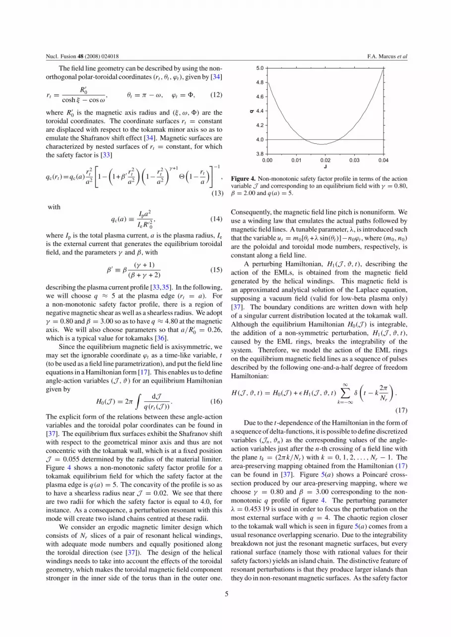
The explicit form of the relations between these angle-actionvariables and the toroidal polar coordinates can be found in[37]. The equilibrium flux surfaces exhibit the Shafranov shiftwith respect to the geometrical minor axis and thus are notconcentric with the tokamak wall, which is at a fixed positionJ = 0.055 determined by the radius of the material limiter.Figure 4 shows a non-monotonic safety factor profile for atokamak equilibrium field for which the safety factor at theplasma edge is q(a) = 5. The concavity of the profile is so asto have a shearless radius near J = 0.02. We see that thereare two radii for which the safety factor is equal to 4.0, forinstance. As a consequence, a perturbation resonant with thismode will create two island chains centred at these radii.
We consider an ergodic magnetic limiter design whichconsists of Nr slices of a pair of resonant helical windings,with adequate mode numbers and equally positioned alongthe toroidal direction (see [37]). The design of the helicalwindings needs to take into account the effects of the toroidalgeometry, which makes the toroidal magnetic field componentstronger in the inner side of the torus than in the outer one.
Figure 4. Non-monotonic safety factor profile in terms of the actionvariable J and corresponding to an equilibrium field with γ = 0.80,β = 2.00 and q(a) = 5.
Consequently, the magnetic field line pitch is nonuniform. Weuse a winding law that emulates the actual paths followed bymagnetic field lines. A tunable parameter, λ, is introduced suchthat the variable ut = m0[θt +λ sin(θt )]−n0ϕt , where (m0, n0)
are the poloidal and toroidal mode numbers, respectively, isconstant along a field line.
A perturbing Hamiltonian, H1(J , ϑ, t), describing theaction of the EMLs, is obtained from the magnetic fieldgenerated by the helical windings. This magnetic field isan approximated analytical solution of the Laplace equation,supposing a vacuum field (valid for low-beta plasma only)[37]. The boundary conditions are written down with helpof a singular current distribution located at the tokamak wall.Although the equilibrium Hamiltonian H0(J ) is integrable,the addition of a non-symmetric perturbation, H1(J , ϑ, t),caused by the EML rings, breaks the integrability of thesystem. Therefore, we model the action of the EML ringson the equilibrium magnetic field lines as a sequence of pulsesdescribed by the following one-and-a-half degree of freedomHamiltonian:
H(J , ϑ, t) = H0(J ) + εH1(J , ϑ, t)
∞∑k=−∞
δ
(t − k
2π
Nr
).
(17)
Due to the t-dependence of the Hamiltonian in the form ofa sequence of delta-functions, it is possible to define discretizedvariables (Jn, ϑn) as the corresponding values of the angle-action variables just after the n-th crossing of a field line withthe plane tk = (2πk/Nr) with k = 0, 1, 2, . . . , Nr − 1. Thearea-preserving mapping obtained from the Hamiltonian (17)can be found in [37]. Figure 5(a) shows a Poincare cross-section produced by our area-preserving mapping, where wechoose γ = 0.80 and β = 3.00 corresponding to the non-monotonic q profile of figure 4. The perturbing parameterλ = 0.453 19 is used in order to focus the perturbation on themost external surface with q = 4. The chaotic region closerto the tokamak wall which is seen in figure 5(a) comes from ausual resonance overlapping scenario. Due to the integrabilitybreakdown not just the resonant magnetic surfaces, but everyrational surface (namely those with rational values for theirsafety factors) yields an island chain. The distinctive feature ofresonant perturbations is that they produce larger islands thanthey do in non-resonant magnetic surfaces. As the safety factor
5

Nucl. Fusion 48 (2008) 024018 F.A. Marcus et al
Figure 5. Example of the Poincare cross-section produced by theEML mapping, in terms of the action-angle variables (J, ϑ), for anon-monotonic q profile with γ = 0.80 and β = 3.000, Nr = 4,λ = 0.453 19, Ih = 8.5% of Ip and (a) (m0, n0) = (4, 1),(b) (m0, n0) = (5, 1).
near the tokamak wall is monotonic (without shear reversals),KAM theory holds again permitting the creation of chaoticregions at the tokamak edge.
Next, we analyse the connection lengths and the magneticfootprints of the chaotic region obtained for a non-monotonicsafety profile, in order to investigate the effect of using non-twist mappings on the escape patterns on the tokamak wall.The cases of resonances closer and farther from the wall areconsidered. In order to obtain the connection lengths we usea grid of 500 × 500 points chosen inside the small rectangleshown in figure 5(a), and which comprises a representative partof the chaotic region near the wall. We iterate each point of thegrid until the line reach the wall (J = 0.055). The connectionlengths NCL indicate how many turns are necessary for thetoroidal field line to strike the tokamak wall, and can take onvalues in a wide interval, from NCL = 1 to NCL ≈ 104.
In order to examine field lines with small connectionlengths we consider those values of NCL covering an intervalfrom 1 to 10, to which different shades of gray are assigned.Accordingly, black pixels correspond to field lines which donot escape until 4000 iterations have been elapsed, and canbe considered as trapped. Figure 6(a) shows the connectionlengths for this case. One can observe that the initial conditions
Figure 6. (a) Connection lengths for the EML map shown infigure 5(a). The lengths of the field lines belong to the interval[1, 10] and are represented in gray-scale. (b) The lengths of thefield lines are in the range [1, 200].
with NCL > 10 saturate in a fixed shade of gray. Figure 6(b)shows the connection length for NCL = 1–200. They have afractal pattern. These results were obtained for a limiter withmode numbers (4, 1), which intercepts the tokamak wall atpreferential regions. We can alter the limiter parameters so asto generate a chaotic region which touches the wall in more andwider intervals. Figure 5(b) shows this possibility and presentsa Poincare mapping with the grid of initial conditions for modenumbers (5, 1) and the same perturbation current as in theformer case. Figures 7(a) and (b) show the connection lengthsfor both small and large values of NCL. We observed thatinitial conditions generating orbits with low NCL correspond toregions with smooth boundaries in the phase portraits, whereasinitial conditions related to large values of NCL form regionswith a fractal boundary structure.
Neglecting the thickness of the vessel wall, we can setthe tokamak wall at the same radius as the ergodic limiterrings themselves rt = rW. Suppose that a chaotic region doesintercept this constraint at one or more intervals. It is thusnecessary to impose that a field line is considered lost once itreaches this radial position. The magnetic footprints are thedeposition patterns of field lines from the chaotic region andwhich are lost due to collisions with this constraint [38]. Theescape time NET is the number of iterations it takes for a givenfield line to hit this point. We observed that the escape timeis related with the density of points in the Poincare plots, inthe sense that those field lines belonging to densely populatedregions take more time to escape (hitting the tokamak wall)than those field lines in sparsely populated regions.
6

Nucl. Fusion 48 (2008) 024018 F.A. Marcus et al
Figure 7. (a) Connection lengths for the EML map shown infigure 5(b). The lengths of the field lines belong to the interval[1, 10] and are represented in grey-scale. (b) The lengths of thefield lines are in the range [1, 200].
Field lines tend to escape following the unstable manifoldsof periodic orbits embedded in the chaotic region, i.e. suchmanifolds, which have an involved fractal structure, formchannels of preferential escape [31, 39, 40]. For this reason,the magnetic footprints resulting from collisions of field lineswith the tokamak wall present likewise a fractal structure. Forthe non-monotonic profile used in this work, the magneticfootprints are shown in figures 8(a) and (b), where we cansee the dependence of the escape time NET with the poloidalangle ϑf , for initial conditions chosen uniformly along thepoloidal cross section. For many intervals there is no fieldline incidence. On the other hand, there are abrupt variationsin some intervals, revealing very involved, and actually fractalstructures.
Figure 8(a) was obtained for a limiter with mode numbers(m0, n0) = (4, 1), for which the chaotic region intercepts thetokamak wall in two narrow intervals. Altering the limiterparameters generates a chaotic region which touches the wallin other intervals. Figure 8(b) demonstrates this possibilityfor mode numbers (m0, n0) = (5, 1). Instead of two centredescape channels, we now have at least five channels. Thesefractal regions with high NET values not always correspondto regions with many field lines. The resonance excited bymode numbers (4, 1) turned out to be deeper (i.e. farther fromthe wall) than the resonance induced by (5, 1). Hence, whencomparing the chaotic regions for both cases, with a nearlyequal limiter current, we expect the chaotic region of the latterintercepting more points of the wall than the former. This is
Figure 8. (a) The magnetic footprints for the parameters offigure 5(a). (b) The parameters are those of figure 5(b).
not really unexpected, since the radial location of the (4, 1)
resonance is slightly less than of the (5, 1) one. Even thoughwe are dealing here with a non-monotonic safety profile,the interval to which both resonances belong has a positivemagnetic shear, i.e. it is an effectively monotonic increasingprofile for that region.
4. Conclusions
In this work we applied the Lagrangian chaos theory,considering fusion plasma parameters for simplified tokamakgeometries. We discussed two effects observed at the plasmaedge, namely, the chaotic anomalous particle transport fromthe E × B drift motion, as well as the distribution of chaoticmagnetic field lines at the wall.
Initially, we explored a dynamical mechanism by whichthe particle transport is achieved and showed how alterationson the electric field radial profile at the plasma edge canmodify this transport within this region. Thus, guiding centretrajectories can be stochastized by this process within theregion where the trapping parameter vanishes. On the otherhand, by increasing the trapping parameter a particle transportbarrier can appear at this region.
After that, we showed that the number and the distributionof the escape channels are determined by two factors: the mean
7

Nucl. Fusion 48 (2008) 024018 F.A. Marcus et al
width of the chaotic region and the resonance from which itstarts. The former depends in a complicated fashion on thelimiter current, whereas the second is dictated by the shape ofthe safety current profile in the region of interest. Our resultssuggest that the deeper is the resonance from which the chaoticregion starts, the more concentrated are the deposition patternsdue to the existence of less escape channels.
In the design of experiments of the sort described in thispaper, we propose that, if the limiter current cannot be raisedabove some levels, it would be better to use resonances nearthe wall, provided there are non-monotonic profiles. However,we must remark that our conclusions were drawn from arather simplified model and thus more comparisons should beperformed with experiments conducted in machines like DIII-D [7, 26] and TEXTOR [1, 6] tokamaks on controlled plasmaedge transport.
Acknowledgments
This work was made possible through partial financialsupport from the following Brazilian government agencies:FAPESP (Sao Paulo), CNPq, CAPES, and Fundacao Araucaria(Parana).
References
[1] Abdullaev S.S., Finken K.H., Jakubowski M.W., Kasilov S.V.,Kobayashi M., Reiser D., Reiter D., Runov A.V. and WolfR. 2003 Nucl. Fusion 43 299
[2] Horton W. 1999 Rev. Mod. Phys 71 735[3] Balescu R. 2005 Aspects of Anomalous Transport in Plasmas
(London: Taylor and Francis)[4] Alejaldre C. et al 1999 Plasma Phys. Control. Fusion 41 B109[5] Hidalgo C. et al 2005 Nucl. Fusion 45 S266[6] Jakubowski M.W. et al 2006 Phys. Rev. Lett. 96 35004[7] Evans T.E. et al 2005 J. Nucl. Mater. 337 691[8] McCool S.C. et al 1989 Nucl. Fusion 29 547[9] Post D.E. and Behrisch R. 1986 Physics of Plasma–Wall
Interactions in Controlled Fusion (New York: Plenum)[10] Parker R., Janeschitz G., Pacher H.D., Post D.E., Chiocchio S.,
Federici G. and Ladd P. 1997 J. Nucl. Mater. 241–243 1[11] Stangeby P.C. 2000 The Plasma Boundary of Magnetic Fusion
Devices (Bristol: Institure of Physics Publishing)[12] Meiss J.D. 1992 Rev. Mod. Phys. 64 795[13] Morrison P.J. 1998 Rev. Mod. Phys. 70 467[14] Boozer A.H. 2004 Rev. Mod. Phys. 76 1071[15] Smith G.R. and Pereira N.R. 1978 Phys. Fluids 21 2253
[16] Mazzucato E. et al 1996 Phys. Rev. Lett. 77 3145[17] Morrison P.J. 2000 Phys. Plasmas. 7 2279[18] Kwon J.-M., Horton W., Zhu P., Morrison P.J., Park H.-B. and
Choi D.I. 2000 Phys. Plasmas 7 1169[19] Weyssow B., Misguich J.H. and Balescu R. 1991 Plasma.
Phys. Control. Fusion 33 763[20] El Monden M., Saifaoui D., Dezaini A., Zine B. and
Eddahby M. 2007 J. Plasma. Phys. 73 439[21] Heller M.V.A.P., Caldas I.L., Ferreira A.A., Saettone E.A.O.,
Vannucci A. and Nascimento I.C. 2005 Czech. J. Phys.55 265
[22] Evans T.E., Goniche M., Grosman A., Guilhem D., Hess W.and Vallet J.C. 1992 J. Nucl. Mater. 196–198 421
[23] Boedo J.A. et al 2005 Phys. Plasmas 12 72516[24] Moyer R.A. et al 2005 Phys. Plasmas 12 56119[25] Jakubowski M.W., Abdullaev S.S., Finken K.H. and
the TEXTOR Team 2004 Nucl. Fusion. 44 S1[26] Evans T.E., Roeder R.K.W., Carter J.A. and Rapoport B.I.
2004 Contrib. Plasma Phys. 44 235[27] Horton W. 1985 Plasma Phys. Control. Fusion 27 937[28] Osipenkov I. 2000 Diffusion in chaotic systems
MSc Dissertation, Report IFSR #885 Institute for FusionStudies, The University of Texas at Austin
[29] Marcus F.A. Dynamic instability of tokamak electrostaticfluctuations MSc Dissertation IFUSP, Sao Paulo,unpublished (in portuguese)
[30] Nascimento I.C. et al 2005 Nucl. Fusion 45 796[31] da Silva E.C., Caldas I.L., Viana R.L. and Sanjuan M.A.F.
2002 Phys. Plasmas 9 4917[32] Portela J.S.E., Caldas I.L., Viana R.L. and Morison P.J. 2007
Int. J. Bifurcat. Chaos 17 1589[33] Roberto M., da Silva E.C., Caldas I.L. and Viana R.L. 2004
Phys. Plasmas 11 214[34] Kucinski M.Y., Caldas I.L., Monteiro L.H.A. and Okano V.
1990 J. Plasma. Phys. 44 303[35] Oda G.A. and Caldas I.L. 1995 Chaos Solitons Fractals 5 15
Corso G., Oda G.A. and Caldas I.L. 1997 Chaos SolitonsFractals 8 1891
[36] Caldas I.L., Viana R.L., Vannucci A., da Silva E.C.,Araujo M.S.T., Ullmann K., Heller M.V.A.P. andKucinski M.Y. 2002 Braz. J. Phys. 32 980
[37] da Silva E.C., Caldas I.L. and Viana R.L. 2001 IEEE Trans.Plasma Sci. 29 617
[38] Abdullaev S.S., Finken K.H., Kaleck A. and Spatschek K.H.1998 Phys. Plasmas 5 196
Abdullaev S.S., Finken K.H. and Spatschek K.H. 1999 Phys.Plasmas 6 153
Abdullaev S.S., Th. Eich and Finken K.H. 2001 Phys. Plasmas8 2739
[39] Grebogi C., Ott E. and Yorke J.A. 1983 Physica D 7 181[40] Silva E.C., Roberto M., Caldas I.L. and Viana R.L. 2006 Phys.
Plasmas 13 52511
8