Pedagogy and "Reflex": Frank Lloyd Wright's Hanna House Revisited
Upload
khangminh22Category
view
0download
0
INSTRUCTION MANUAL
HI83314Wastewater Treatment Photometer

Thank you for choosing a Hanna Instruments product.Please read this instruction manual carefully before using the instrument.This manual will provide you with the necessary information for correct use of the instrument, as well as a precise idea of its versatility.If you need additional technical information, do not hesitate to e‑mail us at [email protected] or view our worldwide contact list at www.hannainst.com.
All rights are reserved. Reproduction in whole or in part is prohibited without the written consent of the copyright owner, Hanna Instruments Inc., Woonsocket, Rhode Island, 02895, USA.
DearCustomer,

3
TABLE OF CONTENTS
55
7
7
9
11
11
14
15
6
7
8
10
11
14
15
1617
17
1. PRELIMINARY EXAMINATION ............................................................................................2. SAFETY MEASURES...................... ....................................................................................3. SPECIFICATIONS ..............................................................................................................4. DESCRIPTION..... ............................................................................................................. 4.1. GENERAL DESCRIPTION............................................................................................. 4.2. PRECISION AND ACCURACY........................................................................................ 4.3. FUNCTIONAL DESCRIPTION........................................................................................ 4.4. PRINCIPLE OF OPERATION......................................................................................... 4.5. OPTICAL SYSTEM......................................................................................................5. GENERAL OPERATIONS......... ............................................................................................
5.1. POWER CONNECTION AND BATTERY MANAGEMENT......................................................5.2. GENERAL SETUP........................................................................................................5.3. USING HANNA DIGITAL ELECTRODES...........................................................................5.4. MODE SELECTION.....................................................................................................5.5. LOGGING DATA.........................................................................................................5.6. ADDING SAMPLE / USER NAMES TO LOG DATA............................................................5.7. DATA MANAGEMENT..................................................................................................5.8. CONTEXTUAL HELP....................................................................................................
6. PHOTOMETER MODE......... ...............................................................................................6.1. METHOD SELECTION.................................................................................................6.2. COLLECTING AND MEASURING SAMPLES AND REAGENTS..............................................
6.2.1. PROPER USE OF SYRINGE...................................................................................6.2.2. PROPER USE OF DROPPER...................................................................................6.2.3. PROPER USE OF POWDER PACKET.........................................................................
6.3. CUVETTE PREPARATION.............................................................................................6.4. USING THE 16 mm VIAL ADAPTER..............................................................................6.5. TIMERS AND MEASUREMENT FUNCTIONS...................................................................6.6. CHEMICAL FORMULA / UNIT CONVERSIONS................................................................6.7. METER VALIDATION / CAL CHECK................................................................................6.8. ABSORBANCE MEASUREMENTS..................................................................................
7. PROBE MODE................... ............................................................................................... 7.1. pH CALIBRATION......................................................................................................
7.2. pH CALIBRATION MESSAGES......................................................................................7.3. pH MEASUREMENT...................................................................................................7.4. pH MEASUREMENT MESSAGES / WARNINGS...............................................................7.5. pH GLP.....................................................................................................................
171818
1818192022222323
2424262628
29

4
TABL
E OF
CON
TENT
S 3032
35
41
47
54
60
70
75
32
38
44
50
57
6763
73
8186
89
7.6. pH ELECTRODE CONDITIONING AND MAINTENANCE.....................................................8. METHOD PROCEDURES........ ............................................................................................ 8.1. AMMONIA LOW RANGE.............................................................................................. 8.2. AMMONIA LOW RANGE (16 mm VIAL)........................................................................
8.3. AMMONIA MEDIUM RANGE........................................................................................8.4. AMMONIA HIGH RANGE.............................................................................................8.5. AMMONIA HIGH RANGE (16 mm VIAL).......................................................................8.6. CHLORINE, FREE.......................................................................................................8.7. CHLORINE, TOTAL.....................................................................................................8.8. CHEMICAL OXYGEN DEMAND LOW RANGE (16 mm VIAL).............................................8.9. CHEMICAL OXYGEN DEMAND MEDIUM RANGE (16 mm VIAL).......................................8.10. CHEMICAL OXYGEN DEMAND HIGH RANGE (16 mm VIAL)..........................................8.11. IRON, TOTAL (16 mm VIAL).....................................................................................
8.12. NITRATE (16 mm VIAL)........................................................................................... 8.13. NITRITE LOW RANGE............................................................................................... 8.14. NITRITE HIGH RANGE.............................................................................................. 8.15. NITROGEN, TOTAL LOW RANGE (16 mm VIAL)........................................................... 8.16. NITROGEN, TOTAL HIGH RANGE (16 mm VIAL).......................................................... 8.17. PHOSPHORUS, REACTIVE LOW RANGE (16 mm VIAL)................................................ 8.18. PHOSPHORUS, REACTIVE HIGH RANGE (16 mm VIAL)............................................... 8.19. PHOSPHORUS, ACID HYDROLYZABLE (16 mm VIAL).................................................. 8.20. PHOSPHORUS, TOTAL LOW RANGE (16 mm VIAL)..................................................... 8.21. PHOSPHORUS, TOTAL HIGH RANGE (16 mm VIAL)....................................................9. ERROR DESCRIPTIONS......... ............................................................................................10. STANDARD METHODS......... ...........................................................................................11. ACCESSORIES................................................................................................................ 11.1. REAGENT SETS....................................................................................................... 11.2. pH ELECTRODES..................................................................................................... 11.3. pH SOLUTIONS....................................................................................................... 11.4. OTHER ACCESSORIES..............................................................................................12. ABBREVIATIONS............................................................................................................RECOMMENDATIONS FOR USERS..........................................................................................WARRANTY.........................................................................................................................
9296100
104
105106106
107
108109110111
111

5
1. PRELIMINARY EXAMINATIONRemove the instrument and accessories from the packaging and examine it carefully to make sure that no damage has occurred during shipping. Notify your nearest Hanna Customer Service Center if damage is observed.Each HI83314 is supplied with:
• Sample Cuvette and Cap (4 pcs.)• Cloth for Wiping Cuvettes • Scissors• USB Cable• 5 Vdc Power Adapter• 16 mm Vial Adapter• 16 mm diameter Vial Cuvette with cap (6 pcs.)• Instruction Manual• Quality Certificate
Note: Save all packing material until you are sure that the instrument works correctly.Any damaged or defective item must be returned in its original packing material with the supplied accessories.
2. SAFETY MEASURES•The chemicals contained in the reagent kits may be hazardous if improperly
handled.•Read the Safety Data Sheets (SDS) before performing tests.
• Safety equipment: Wear suitable eye protection and clothing when required, and follow instructions carefully.
• Reagent spills: If a reagent spill occurs, wipe up immediately and rinse with plenty of water. If reagent contacts skin, rinse the affected area thoroughly with water. Avoid breathing released vapors.
• Waste disposal: for proper disposal of reagent kits and reacted samples, contact a licensed waste disposal provider.
PRELIMINARY EXAM
INATIONSAFETY M
EASURES

6
SPEC
IFIC
ATIO
NS
Measurement Channels 5 x optical channels1 x digital electrode channel (pH measurement)
Absorbance
Range 0.000 to 4.000 AbsResolution 0.001 AbsAccuracy ±0.003 Abs (at 1.000 Abs)Light Source light emitting diodeBandpass Filter Bandwidth 8 nm
Bandpass Filter Wavelength Accuracy ±1.0 nm
Light Detector silicon photocellCuvette Types round, 24.6 mm diameter and 16 mm diameterNumber of Methods 26
pH
Range ‑2.00 to 16.00 pH (± 1000.0 mV)*Resolution 0.01 pH (0.1 mV)Accuracy ±0.01 pH (±0.2 mV) (@ 25 °C / 77 °F)Temperature Compensation ATC (‑5.0 to 100.0 °C; 23.0 to 212.0 °F)*
Calibration 2 points, eligible from 5 available buffers (4.01, 6.86, 7.01, 9.18, 10.01 pH)
Electrode Intelligent pH / temperature electrode
TemperatureRange ‑20.0 to 120.0°C (‑4.0 to 248.0 °F)Resolution 0.1 °C (0.1 °F)Accuracy ±0.5 °C (@ 25 °C / 77 °F)
Additional Specifications
Logging 1000 readings (mixed photometer and electrode)Display 128 x 64 pixel B/W LCD with backlightUSB‑A (Host) Functions mass‑storage hostUSB‑B (Device) Functions power input, mass‑storage device
Battery Life > 500 photometer measurements, or 50 hours of continuous pH measurement
Power Supply 5 Vdc USB 2.0 power adapter/type micro‑B connector3.7 Vdc Li‑polymer rechargeable battery, non‑serviceable
Environment 0 to 50 °C (32 to 122 °F); 0 to 95% RH, non‑serviceable
Dimensions 206 x 177 x 97 mm (8.1 x 7.0 x 3.8")Weight 1.0 kg (2.2 lbs.)
3. SPECIFICATIONS
*Limits will be reduced to actual probe/sensor limits.

7
4. DESCRIPTION4.1.GENERAL DESCRIPTION HI83314 multiparameter photometer is compact and versatile meter with two measurement modes: Absorbance and pH/ mV. Absorbance mode include CAL Check feature and 26 different methods that cover a wide variety of applications, making it ideal for both benchtop and portable operation.
• Digital electrode input for pH measurements• Certified CAL Check cuvettes to confirm meter functionality• Dual purpose micro‑USB flash drive• Li‑polymer rechargeable battery• Auto‑off• Absorbance mode• User and sample name entry• GLP features
4.2.PRECISION AND ACCURACYPrecision is how closely repeated measurements are to one another. Precision is usually expressed as standard deviation (SD). Accuracy is defined as the closeness of a test result to the true value. Although good precision suggests good accuracy, precise results can be inaccurate. The figure explains these definitions. For each method, the accuracy is expressed in the related measurement section.
DESCRIPTION

8
DESC
RIPT
ION
1) Splash‑proof keypad2) Liquid Crystal Display (LCD)3) Indexing mark4) Protective port covers5) Light‑blocking cover panel6) Cuvette holder7) ON/OFF power button8) 3.5‑mm TRRS (jack) input for digital electrodes9) Standard USB host connector for data transfer to a USB flash drive10) Micro‑USB device connector for power or PC interface
4.3. FUNCTIONAL DESCRIPTION

9
Keypad DescriptionThe keypad contains 12 direct keys and 3 functional keys with the following functions:
Press the functional keys to perform the function displayed above them on the LCD.
Press to access the list of photometer methods.
Press to move up in a menu or a help screen, to increment a set value, or to access second level functions.
Press to toggle between photometer and pH (electrode) mode.
Press to move left in a menu or to decrement a set value.
Press to move down in a menu or a help screen, to decrement a set value, or to access second level functions.
Press to move right in a menu or to increment a set value.
Press to access the setup screen.
Press to log the current reading.
Press to review saved logs.
Press to exit the current screen.
Press to display the help screen.
ON/OFF power button.
4.4. PRINCIPLE OF OPERATIONAbsorption of light is a typical phenomenon of interaction between electromagnetic radiation and matter. When a light beam crosses a substance, some of the radiation may be absorbed by atoms, molecules or crystal lattices.If pure absorption occurs, the fraction of light absorbed depends both on the optical path length through the matter and on the physical‑chemical characteristics of the substance according to the Lambert‑Beer Law:
‑log I/Io = e
l c d
or A = e
l c d
DESCRIPTION

10
Instrument Block Diagram
The internal reference system (reference detector) of the HI83314 photometer compensates for any drifts due to power fluctuations or ambient temperature changes, providing a stable source of light for your blank (zero) measurement and sample measurement.LED light sources offer superior performance compared to tungsten lamps. LEDs have a much higher luminous efficiency, providing more light while using less power. They also produce little heat, which could otherwise affect electronic stability. LEDs are available in a wide array of wavelengths, whereas tungsten lamps have poor blue/violet light output.Improved optical filters ensure greater wavelength accuracy and allow a brighter, stronger signal to be received. The end result is higher measurement stability and less wavelength error.A focusing lens collects all of the light that exits the cuvette, eliminating errors from cuvette imperfections and scratches, eliminating the need to index the cuvette.
4.5. OPTICAL SYSTEM
Io = intensity of incident light beam
I = intensity of light beam after absorptionel
= molar extinction coefficient at wavelength lc = molar concentration of the substanced = optical path through the substance
Therefore, the concentration "c" can be calculated from the absorbance of the substance as the other factors are constant.Photometric chemical analysis is based on specific chemical reactions between a sample and reagent to produce a light‑absorbing compound.
DESC
RIPT
ION

11
5. GENERAL OPERATIONS5.1. POWER CONNECTION AND BATTERY MANAGEMENTThe meter can be powered from an AC/DC adapter (included) or from the built‑in rechargeable battery.The meter will perform an auto‑diagnostic test when it is first powered on. During this test, the HANNA® logo will appear on the LCD. After 5 seconds, if the test was successful, the last method used will appear on the display. The battery icon on the LCD will indicate the battery status:
‑ battery is charging from external adapter ‑ battery fully charged (meter connected to AC/DC adapter)
‑ battery capacity (no external adapter) ‑ battery near 0% (no external adapter)
‑ battery at 0% (no external adapter)
To conserve battery, the meter will turn off automatically after 15 minutes of inactivity (30 minutes before a READ measurement). If a photometer measurement is on the screen, an auto‑log is created before shutdown.
5.2. GENERAL SETUPPress SETUP key to enter in Setup menu, highlight desired option using and press Select.
CAL Check (Photometer Only)Press Select to enter the CAL Check screen. The date, time and values for the last CAL Check are displayed on the screen.To start a new CAL Check press Check key and follow the prompts on the screen.
GENERAL OPERATIONS

12
GENE
RAL O
PERA
TION
S
BacklightValues: 0 to 8Press the Modify key to access the backlight intensity.Use the functional keys or the keys to increase or decrease the value.Press the Accept key to confirm or ESC to return to the Setup menu without saving the new value.
ContrastValues: 0 to 20Press the Modify key to change the display’s contrast.Use the functional keys or the keys to increase or decrease the value.Press the Accept key to confirm the value or ESC to return to the Setup menu without saving the new value.
Date / TimePress the Modify key to change the date/time.Press the functional keys or the keys to highlight the value to be modified (year, month, day, hour, minute or second).Use the keys to change the value.Press the Accept key to confirm or ESC to return to the Setup without saving the new date or time.
Time FormatOption: AM/PM or 24-hour Press the functional key to select the desired time format.
Temperature Unit (pH Only)Option: °C or °FPress the functional key to select the desired temperature unit.

13
Date FormatPress the Modify key to change the Date Format.Use the keys to select the desired format.Press the Select key to confirm or ESC to return to the Setup menu without saving the new format.
Decimal Separator Option: Comma ( , ) or Period ( . ) Press the functional key to select the desired decimal separator. The decimal separator is used on the measurement screen and CSV files.
Language Press the Modify key to change the Language. Use the keys to select the desired language. Press Select to change the language. Press the functional key to select one of the 7 languages installed.
BeeperOption: Enable or DisableWhen enabled, a short beep is heard every time a key is pressed. A long beep alert sounds when the pressed key is not active or an error is detected. Press the functional key to enable/disable the beeper.
Instrument IDOption: 0 to 999999This option is used to set the instrument’s ID (identification number). Press the Modify key to access the instrument ID screen. Use the functional keys or the keys to highlight the digit to be modified. Press the keys in order to set the desired value. Press the Accept key to confirm the value or ESC to return to the Setup menu without saving the new value.
GENERAL OPERATIONS

14
Meter InformationPress the Select key to view the model, serial number, firmware version and selected language. Press ESC to return to the Setup menu.
Probe Information (pH mode only)Press the Select key to view model number, serial number and firmware version for the connected probe.Press ESC to return to the Setup menu.
5.3. USING HANNA DIGITAL ELECTRODESThe HI83314 can be used to perform direct pH measurements by connecting a HANNA® digital pH electrode with a 3.5 mm TRRS connector. To begin taking probe measurements, connect the electrode to the 3.5 mm port marked with “EXT PROBE” located at the rear of the meter. If the meter is in “Photometer Mode”, set the meter to “Probe Mode” by pressing the MODE key.
5.4. MODE SELECTIONThe HI83314 has two operational modes: Photometer Mode and Probe Mode. Photometer Mode enables on‑demand measurement of a cuvette using the integrated optical system. Photometric‑related functions, such as Method selection, Zero, Read, and Timers are available in this mode.
Probe Mode enables continuous measurement using a Hanna Digital Electrode connected to the 3.5 mm port. Probe‑related functions, such as calibration and GLP, are available in this mode.To switch between Photometer Mode and Probe Mode, use the button.
Note: The active mode cannot be switched while in menus, such as Setup, Recall, Method, etc.
GENE
RAL O
PERA
TION
S

15
5.5. LOGGING DATAThe instrument features a data log function to help you keep track of all your analysis. The data log can hold 1000 individual measurements. Storing, viewing and deleting the data is possible using the LOG and RECALL keys.Storing data: You can store only a valid measurement. Press LOG and the last valid measurement will be stored with date and time stamp.
5.6. ADDING SAMPLE / USER NAMES TO LOG DATAA sample ID and user ID can be added to the saved log. Use the keys to highlight the Sample ID or User ID then press Modify.
Text EntrySample ID and User ID care entered using the alphanumeric multi‑tapping keypad.
Enter one character at a time by pressing the key with the assigned character repeatedly until the desired character is highlighted. For reference, a list of the characters available for the current key will be shown under the text box.The character will be entered after a two‑second delay or after another key is pressed.
Once all characters have been entered, press Accept to use the displayed text.
GENERAL OPERATIONS

16
The following functions are available during Text Entry:
• Accept: Press to accept the current displayed text.
• Arrow: Press to delete the last character.
• Clear: Press to delete all characters.
Press to discard all changes and return to the previous screen.
Viewing and deleting: You can view, export and delete the data by pressing the RECALL key. Use the keys to scroll through the saved logs. Press Info to view additional information about the selected log.
Data Export:Log data can be exported to a USB flash drive or to a PC. To access Data Export functions, press Recall then Export.
Use the keys to select the desired export location. For export to USB Flash Drive, insert the USB Flash Drive into the dedicated port at the back of the meter labeled HOST USB, then follow the on‑screen prompts. For export to PC, connect the meter to a PC using the supplied micro‑USB cable. Insert the cable into the port at the back of the meter labeled PC PWR. Follow the on‑screen prompts. When the meter says PC connected, use a file manager (such as Windows Explorer or Mac Finder) to move the file from the meter to the PC. The meter will appear as a removable disk.
5.7. DATA MANAGEMENTGENE
RAL O
PERA
TION
S

17
5.8. CONTEXTUAL HELPHI83314 offers an interactive contextual help mode that assists the user at any time.To access the help screen press HELP.The instrument will display additional information related to the current screen. To read all the available information, scroll the text using the keys.To exit help mode press ESC key and the meter will return to the previous screen.
Log data is exported as a single file containing all logged photometer and probe data. The file name is: “HI83314.csv”. The CSV file (Comma‑Separated Values) may be opened with a text editor or spreadsheet application.
6. PHOTOMETER MODE6.1. METHOD SELECTIONIn order to select the desired method press the METHOD key and a screen with the available methods will appear.Press the keys to highlight the desired method. Press Select.
After the desired method is selected, follow the procedure described in the related section.Before performing a method read all the instructions carefully.
GENERAL OPERATIONSPHOTOM
ETER MODE

18
6.2. COLLECTING AND MEASURING SAMPLES AND REAGENTS6.2.1. PROPER USE OF SYRINGE(a) Push the plunger completely into the syringe and insert the tip
into the solution. (b) Pull the plunger up until the lower edge of the seal is exactly on
the mark for the desired volume. (c) Take out the syringe and clean the outside of the syringe tip, be
sure that no drops are hanging on the tip of the syringe. Then, keeping the syringe in vertical position above the cuvette, push the plunger down into the syringe, the desired volume has been delivered into the cuvette.
6.2.2. PROPER USE OF DROPPER(a) For reproducible results, tap the dropper on the table several times and wipe the outside of the
tip with a cloth.(b) Always keep the dropper bottle in a vertical position while dosing the reagent.
6.2.3. PROPER USE OF POWDER PACKET(a) Use scissors to open the powder packet(b) Push the edges of the packet to form a spout(c) Pour out the content of the packet.
PHOT
OMET
ER M
ODE

19
6.3. CUVETTE PREPARATIONProper mixing is very important for reproducibility of the measurements. The proper mixing technique for each method is listed in the method procedure.(a) Invert the cuvette a couple of times or for a specified time: hold the cuvette in the vertical
position. Turn the cuvette upside‑down and wait for all of the solution to flow to the cap end, then return the cuvette to the upright vertical position and wait for all of the solution to flow to the cuvette bottom. This is one inversion. The correct speed for this mixing technique is 10‑15 complete inversions in 30 seconds.
This mixing technique is indicated with “invert to mix” and the following icon:
(b) Shaking the cuvette, moving the cuvette up and down. The movement may be gentle or vigorous. This mixing method is indicated with “shake gently” or “shake vigorously”, and one of the following icons:
In order to avoid reagent leaking and to obtain more accurate measurements, close the cuvette first with the supplied HDPE plastic stopper and then the black cap.Whenever the cuvette is placed into the measurement holder, it must be dry outside and free of fingerprints, oil or dirt. Wipe it thoroughly with HI731318 or a lint‑free cloth prior to insertion.Shaking the cuvette can generate bubbles in the sample, causing higher readings. To obtain accurate measurements, remove such bubbles by swirling or by gently tapping the cuvette.
shake gently shake vigorously
PHOTOMETER M
ODE

20
Do not let the reacted sample stand too long after reagent is added. For best accuracy, respect the timings described in each specific method.It is possible to take multiple readings in a row, but it is recommended to take a new zero reading for each sample and to use the same cuvette for zeroing and measurement when possible.Discard the sample immediately after the reading is taken, or the glass might become permanently stained.All the reaction times reported in this manual are at 25 °C (77 °F). In general, the reaction time should be increased for temperatures lower than 20 °C (68 °F), and decreased for temperatures higher than 25 °C (77 °F).
InterferenceIn the method measurement section the most common interferences that may be present in a typical water sample have been reported. It is possible that a particular application could introduce other compounds that will also interfere.
6.4. USING THE 16mm VIAL ADAPTERSome parameters require special single‑use 16 mm vials. These parameters can be identified by the "(16)" in the method name and the appearance of "16 mm" on the measurement screen.
To prepare the meter for use with 16 mm vials:
1. Lift open the meter’s sample cover.
2. Orient the vial adapter with the six small holes toward the bottom.
3. Orient the vial adapter with the indexing mark toward the left. This indexing mark should align with the indexing mark located on the meter.
4. Insert the vial slowly into the cuvette holder of the meter keeping the index marks on the adapter and meter aligned with each other. If the adapter appears blocked, the adapter may need to be rotated slightly in order to correctly engage the guides in the meter’s cuvette holder.
PHOT
OMET
ER M
ODE

21
5. Using light pressure, push the adapter down until it reaches the bottom of the meter’s cuvette holder. When the vial adapter reaches the bottom, you should no longer be able to see the notched area of the adapter.
6. The meter is ready for use with 16 mm vial parameters. Always use the vial adapter for both “Zero” and “Read” measurements as specified in the parameter instructions.
Note :The meter’s sample cover will not close completely while using the vial adapter. This is normal – the vial adapter itself will block out external light.
WARNING: Improper use of the 16 mm vial adapter could cause irreversible damage to the meter. Always use the following precautions while using the 16 mm vial adapter:
• Never use excessive force to insert the adapter. You should be able to insert the vial with light pressure using one finger. If the vial is not reaching the bottom, if there is large resistance, or if you are receiving a “light low” error during the “Zero” operation, re‑check that the indexing marks are aligned on the adapter and meter.
• Never insert hot vials/samples into the vial adapter. Samples should be near room temperature before inserting into the meter/adapter.
• Do not attempt to close the sample cover while using the 16 mm vials or adapter. It is normal for the vials/adapter to prevent the cover from closing completely.
PHOTOMETER M
ODE

22
6.5. TIMERS AND MEASUREMENT FUNCTIONSEach method requires a different preparation procedure, reaction times, sample preparations, etc. If a timer or timers are necessary for proper sample preparation, the Timer key will be available.
To use a reaction timer, press the Timer key.
The default timer will start immediately. To stop and reset the timer, press Stop.
If the selected method requires more than one timer, the meter will automatically select each timer in the appropriate order. To bypass the default order, you may press the desired key to activate a different timer (only while the current timer is stopped). Press Continue to start the active timer.
For some methods, the timer is only necessary after a Zero measurement has been performed. In this case, the timer key will only be available after the Zero measurement has been performed.
If the method requires a Zero or Read measurement after a timer has expired, the meter will automatically perform the appropriate action. Follow the instructions in the Method Procedure.
To perform a Zero or Read measurement, insert the appropriate prepared cuvette, then press the Zero or Read key. A Zero measurement must be conducted before Read measurements.
6.6. CHEMICAL FORMULA / UNIT CONVERSIONChemical formula/unit conversion factors are pre‑programmed into the instrument and are method specific. In order to view the displayed result in the desired chemical formula press keys to access the second level function and then press the Chem Frm key to toggle between the available chemical formulas for the selected method.
PHOT
OMET
ER M
ODE

23
6.7. METER VALIDATION / CAL CHECK
WARNING: Do not validate the meter with standard solutions other than the HANNA® CAL Check Standards. For accurate validation results, please perform tests at room temperature (18 to 25 °C; 64.5 to 77.0 °F).
Validation of the HI83314 involves absorbance measurements of certified HANNA® CAL Check Standards (see “Accessories”). The “CAL Check” screen guides the user through the measurement of each CAL Check Standard and applies the factory calibration corrections to each measurement. The HI83314 stores the results of the most recent CAL Check measurements which may be viewed on the “CAL Check” screen. Compare these results with the values printed on the Certificate provided with each HANNA® CAL Check Standards kit.To perform a validation:
1. Press Setup button.
2. Highlight CAL Check, then press Select.
3. Follow the prompts on the screen. The meter will prompt to measure each cuvette provided in the HANNA® CAL Check Standards kit. To abort the process at any time, press ESC button.
4. Press ESC to return in Setup menu.
6.8. ABSORBANCE MEASUREMENTSRaw absorbance measurements may be performed on the HI83314 for personal or diagnostic purposes. For example, you may monitor the stability of a reagent blank by occasionally measuring its absorbance versus deionized water.
To measure the raw absorbance of a prepared sample:
1. Enable “Photometer Mode” if necessary by pressing the MODE key.
2. Press the METHOD key.
PHOTOMETER M
ODE

24
3. Highlight the appropriate Absorbance method (according to the wavelength to be used), then press Select. Absorbance methods are located at the bottom of the method list.
4. Prepare the sample cuvette according to the method.
5. Insert a cuvette filled with deionized water, then press Zero.
6. Insert the prepared sample cuvette, then press Read.
WARNING: Never use Absorbance methods for validation using HANNA® CAL Check cuvettes. The factory calibration corrections for CAL Check cuvettes are applied while in CAL Check mode only!
7. PROBE MODE7.1. pH CALIBRATIONPress MODE to enter in pH/ mV measurement mode.
Press Calibrate to access electrode calibration functions.
Calibration ModeWhile in pH Calibration Mode, the display will show the current pH reading, the current temperature reading, the current selected buffer, and the buffer number (“Buffer: 1” for the1st buffer, “Buffer: 2” for the 2nd buffer).
The following functions are available in pH Calibration Mode:
• Clear: Press to clear the current calibration from the probe.
• Confirm: Press to accept the current calibration point. Only available if the measurement is stable and within the limits for the selected buffer.
PROB
E M
ODE

25
PROBE MODE
Press to cycle through the list of available buffers: 4.01, 6.86, 7.01, 9.18, 10.01 pH.
Press to exit calibration and return to pH Measurement Mode.
PreparationPour small quantities of the buffer solutions into clean beakers. If possible, use plastic beakers to minimize any EMC interferences. For accurate calibration and to minimize cross‑contamination, use two beakers for each buffer solution: one for rinsing the electrode and one for calibration. If you are measuring in the acidic range, use pH 7.01 or 6.86 as the first buffer and pH 4.01 as the second buffer. If you are measuring in the alkaline range, use pH 7.01 or 6.86 as the first buffer and pH 10.01 or 9.18 as the second buffer.
ProcedureCalibration can be performed using one or two calibration buffers. For more accurate measurements, a two‑point calibration is recommended.Submerse the pH electrode approximately 3 cm (1¼”) into a buffer solution and stir gently. From the Probe Measurement screen, press the Calibrate key to begin the calibration process.
When the reading is stable and close to the selected buffer, the Confirm key will become available. Press Confirm to accept and store the calibration point.
The meter will now prompt for the second buffer (“Buffer: 2”). To use only a one‑point calibration, press to exit calibration mode at this time. The meter will store the calibration information to the probe and return to Measurement mode. To continue calibrating with a second buffer, rinse and submerse the pH electrode approximately 3 cm (1¼”) into the second buffer solution and stir gently. If necessary, press keys to select a different buffer value.
When the reading is stable and close to the selected buffer, the Confirm key will become available. Press Confirm to accept and store the second calibration point.
The meter will store the two‑point calibration information to the probe and return to Measurement mode. The list of calibrated buffers will appear at the bottom of the screen.

26
7.2. pH CALIBRATION MESSAGES
Clean Probe:The "Clean Probe" message indicates poor electrode performance (offset out of accepted window, or slope under the accepted lower limit). Often, cleaning the probe will improve the pH electrode's response. See pH Electrode Conditioning and Maintenance for details. Repeat calibration after cleaning.
Check Probe & Buffer:The “Check Probe & Buffer” message appears when there is a large difference between the pH measurement and the selected buffer value, or the electrode slope is outside of the accepted slope limit. You should check your probe and confirm the correct buffer selection. Cleaning may also improve this response.
Wrong Temperature:The buffer temperature is too extreme for the selected buffer value.
7.3. pH MEASUREMENTThe HI83314 can be used to perform direct pH measurements by connecting a HANNA® digital pH electrode with a 3.5 mm TRRS connector. To begin taking probe measurements, connect the electrode to the 3.5 mm port marked with EXT PROBE located at the rear of the meter. If the meter is in “Photometer Mode”, set the meter to “Probe Mode” by pressing the MODE key.
While taking pH probe measurements, the following functions are available:
• Calibrate: Press to access electrode calibration functions.
• GLP: Press to review the last calibration information, including date/time, buffers used, slope, and offset.
• Range: Press to switch between “pH” units and “mV” units.
PROB
E M
ODE

27
Press to switch to Photometer mode.
Press to access the meter’s Setup menu.
Press to log the current measurement.
Press to review the meter’s log history.
Press to view contextual help information.
For high accuracy it is recommended to calibrate your electrode often. pH electrodes should be recalibrated at least once per week, but daily calibration is recommended. Always recalibrate after cleaning an electrode. See page 24 for more information on pH calibration.
To take pH measurements:• Remove the protective cap and rinse the electrode with water.• Collect some sample in a clean, dry beaker.• Preferably, rinse the electrode with a small amount of sample. Discard the rinse.• Submerse the electrode tip approximately 3 cm (1¼”) into the sample to be tested and stir the
sample gently. Make sure the electrode junction is completely submersed.• Allow time for the electrode to stabilize in the sample. When the symbol disappears, your
reading is stable.
If measurements are taken successively in different samples, it is recommended to rinse the electrodes thoroughly with deionized or distilled water and then with some of the next sample to prevent cross‑contamination.
pH measurements are affected by temperature. HANNA® Digital pH electrodes include a built‑in temperature sensor and automatically calculate corrected pH values. The measured temperature is displayed on the screen with the pH measurements.
PROBE MODE

28
PROB
E M
ODE 7.4. pH MEASUREMENT MESSAGES / WARNINGS
No Probe:No probe is connected or the probe is broken.
Connecting:The meter has detected a probe and is reading the probe configuration and calibration information.
Incompatible Probe:The connected probe is not compatible with this device.
Incompatible Calibration:The probe’s current calibration is not compatible with this meter. The calibration must be cleared to use this probe.
Exceeded Probe Range:The pH and/or temperature measurement exceed the specifications of the probe. The affected measurement value(s) will be flashing.
Broken Temperature Sensor:The temperature sensor inside the probe is broken. Temperature compensation will revert to a fixed value of 25 °C (77 °C).
Cal Due:The probe has no calibration. See section Probe Calibration.

29
PROBE MODE
7.5. pH GLPGood Laboratory Practice (GLP) refers to a quality control function used to ensure uniformity and consistency of sensor calibrations and measurements. To view the GLP information, press the GLP key from the Probe Measurement screen.
The pH GLP screen displays the following information about the last pH calibration:
• Date and time of the last calibration• List of buffers used in the last calibration• Calculated slope and offset
• Press ESC to return in measurement mode.

30
7.6. pH ELECTRODE CONDITIONING AND MAINTENANCE
Remove the protective cap of the pH electrode.DO NOT BE ALARMED IF SALT DEPOSITS ARE PRESENT. This is normal with electrodes. They will disappear when rinsed with water.During transport, tiny bubbles of air may form inside the glass bulb affecting proper functioning of the electrode. These bubbles can be removed by “shaking down” the electrode as you would do with a glass thermometer. If the bulb and/or junction is dry, soak the electrode in HI70300 or HI80300 storage solution for at least one hour.
For refillable electrodes:If the filling solution (electrolyte) is more than 2½ cm (1”) below the fill hole, add HI7082 or HI8082 3.5M KCl Electrolyte Solution for double junction electrodes.Unscrew the fill hole cover during measurements so the liquid reference junction maintains an outward flow of electrolyte.
MeasurementRinse the electrode tip with distilled water. Submerse the tip 3 cm (1¼”) in the sample and stir gently for a few seconds. For a faster response and to avoid cross‑contamination of the samples, rinse the electrode tip with a few drops of the solution to be tested, before taking measurements.
PROB
E M
ODE

31
Storage ProcedureTo minimize clogging and ensure a quick response time, the glass bulb and the junction should be kept moist and not allowed to dry out.Replace the solution in the protective cap with a few drops of HI70300 or HI80300 Storage Solution or, in its absence, Filling Solution (HI7082 or HI8082 for double junction electrodes).Follow the preparation procedure before taking measurements.
Note: NEVER STORE THE ELECTRODE IN DISTILLED OR DEIONIZED WATER.
Periodic MaintenanceInspect the electrode and the cable. The cable used for connection to the instrument must be intact and there must be no points of broken insulation on the cable or cracks on the electrode stem or bulb. Connectors must be perfectly clean and dry. If any scratches or cracks are present, replace the electrode. Rinse off any salt deposits with water.For refillable electrodes: Refill the reference chamber with fresh electrolyte (HI7082 or HI8082 for double junction electrodes). Allow the electrode to stand upright for 1 hour.Follow the Storage Procedure above.
Cleaning ProcedureUse diagnostic messages to aid pH electrode troubleshooting. Several cleaning solutions are available:
• General – Soak in Hanna HI7061 or HI8061 General Cleaning Solution for approximately ½ hour.
• Protein –Soak in Hanna HI7073 or HI8073 Protein Cleaning Solution for 15 minutes.• Inorganic – Soak in Hanna HI7074 Inorganic Cleaning Solution for 15 minutes.• Oil/grease – Rinse with Hanna HI7077 or HI8077 Oil and Fat Cleaning Solution.
Note: After performing any of the cleaning procedures, rinse the electrode thoroughly with distilled water, refill the reference chamber with fresh electrolyte (not necessary for gel- filled electrodes) and soak the electrode in HI70300 or HI80300 Storage Solution for at least 1 hour before taking measurements.
Temperature Correlation For pH Sensitive GlassVerify the temperature range by reading the limits on electrodes cap. The pH electrode’s life also depends on the temperature that is used. If constantly cycled between two temperatures, the life of the electrode is drastically reduced.
PROBE MODE

32
10 mL
8. METHOD PROCEDURES8.1. AMMONIA LOW RANGE
SPECIFICATIONSRange 0.00 to 3.00 mg/L (as NH3‑N)Resolution 0.01 mg/LAccuracy ±0.04 mg/L ±4% of reading at 25 °CLight Source LED with narrow band interference filter @ 420 nm Method Adaptation of the ASTM Manual of Water and Environmental Technology, D1426 Nessler method.
REQUIRED REAGENTSCode Description QuantityHI93700A‑0 Ammonia Low Range Reagent A 4 dropsHI93700B‑0 Ammonia Low Range Reagent B 4 drops
REAGENT SETSHI93700‑01 Reagents for 100 testsHI93700‑03 Reagents for 300 testsFor other accessories see page 109.
MEASUREMENT PROCEDURE• Select the Ammonia LR method using the procedure described in the
Method Selection section (see page 17).
• Fill the cuvette with 10 mL of unreacted sample (up to the mark) and replace the cap.
• Place the cuvette into the holder and close the lid.
• Press the Zero key. The display will show “‑0.0‑” when the meter is zeroed and ready for measurement.
• Remove the cuvette.
AMM
ONIA
LOW
RAN
GE

33
AMM
ONIA LOW RANGE
• Add 4 drops of HI93700A‑0 Ammonia Low Range Reagent A. Replace the cap and mix the solution.
• Add 4 drops of HI93700B‑0 Ammonia Low Range Reagent B. Replace the cap and mix the solution.
• Reinsert the cuvette into the instrument and close the lid.
• Press Timer and the display will show the countdown prior to the measurement or, alternatively, wait for 3 minutes and 30 seconds and press Read. When the timer ends the meter will perform the reading. The instrument displays the results in mg/L of ammonia nitrogen (NH3-N).

34
AMM
ONIA
LOW
RAN
GE • Press or to access the second level functions. • Press the Chem Frm key to convert the result to mg/L of ammonia (NH3) and ammonium
(NH4+).
• Press or to return to the measurement screen.
INTERFERENCEInterference may be caused by:AcetoneAlcoholsAldehydesGlycineHardness above 1 g/LIronOrganic chloraminesSulfideVarious aliphatic and aromatic amines

35
AMM
ONIA LOW RANGE (16 m
m VIAL)
8.2. AMMONIA LOW RANGE (16 mm VIAL)
SPECIFICATIONSRange 0.00 to 3.00 mg/L (as NH3‑N)Resolution 0.01 mg/LAccuracy ± 0.10 mg/L or ± 5% of reading at 25 °C, whichever is greaterLight Source LED with narrow band interference filter @ 420 nm Method Adaptation of the ASTM Manual of Water and Environmental Technology, D1426 Nessler method.
REQUIRED REAGENTSCode Description QuantityHI93764A‑0* Ammonia Low Range Reagent Vial 1 vialHI93764‑0 Nessler Reagent 4 drops*Reagent Vial identification: A LR, white label
Note: Store the unused vials in a cool and dark place.
REAGENT SETSHI93764A‑25 Reagents for 25 testsFor other accessories see page 109.
MEASUREMENT PROCEDURE• Select the Ammonia LR (16) method following one of the procedures
described in the Method Selection section (see page 17).
• Insert the 16mm vial adapter using the procedure described in the Using the 16mm Vial Adapter section (see page 20).
• Remove the cap from HI93764A‑0 Ammonia Low Range Reagent Vial.
• Add 5.0 mL of sample to the vial, while keeping the vial at a 45‑degree angle.
• Replace the cap and invert several times to mix.

36
AMM
ONIA
LOW
RAN
GE (1
6 m
m V
IAL)
• Place the vial into the holder.
• Press the Zero key. The display will show “‑0.0‑” when the meter is zeroed and ready for measurement.
• Remove the vial.
• Remove the cap and add 4 drops of HI93764‑0 Nessler Reagent.
• Replace the cap and invert the vial several times to mix.
• Place the vial into the holder.
• Press Timer and the display will show the countdown prior to the measurement, or, alternatively, wait for 3 minutes and 30 seconds and press Read. When the timer ends the meter will perform the reading. The instrument displays the results in mg/L ammonia nitrogen (NH3-N).

37
AMM
ONIA LOW RANGE (16 m
m VIAL)
• Press or to access the second level functions.• Press the Chem Frm key to convert the result to mg/L of ammonia (NH3) and ammonium (NH4
+).
• Press or to return to the measurement screen.
INTERFERENCESInterference may be caused by:Organic compounds like: chloramines, various aliphatic and aromatic amines, glycine or urea above 10 ppm (to eliminate these interferences distillation is required).Organic compounds like: aldehydes, alcohols (e.g. ethanol), or acetone above 0.1%. (to eliminate these interferences distillation is required).Sulfide: may cause turbidity.

38
10 mL
8.3. AMMONIA MEDIUM RANGE
SPECIFICATIONSRange 0.00 to 10.00 mg/L (as NH3‑N)Resolution 0.01 mg/LAccuracy ±0.05 mg/L ±5% of reading at 25 °CLight Source LED with narrow band interference filter @ 420 nm Method Adaptation of the ASTM Manual of Water and Environmental Technology, D1426, Nessler method.
REQUIRED REAGENTSCode Description QuantityHI93715A‑0 Ammonia Medium Range Reagent A 4 dropsHI93715B‑0 Ammonia Medium Range Reagent B 4 drops
REAGENT SETSHI93715‑01 Reagents for 100 testsHI93715‑03 Reagents for 300 testsFor other accessories see page 109.
MEASUREMENT PROCEDURE• Select the Ammonia MR method using the procedure described in the
Method Selection section (see page 17).
• Fill the cuvette with 10 mL of unreacted sample (up to the mark) and replace the cap.
• Place the cuvette into the holder and close the lid.
• Press the Zero key. The display will show “‑0.0‑” when the meter is zeroed and ready for measurement.
AMM
ONIA
MED
IUM
RAN
GE

39
AMM
ONIA MEDIUM
RANGE
• Remove the cuvette.
• Add 4 drops of HI93715A‑0 Ammonia Medium Range Reagent A. Replace the cap and mix the solution.
• Add 4 drops of HI93715B‑0 Ammonia Medium Range Reagent B. Replace the cap and mix the solution.
• Reinsert the cuvette into the instrument and close the lid.
• Press Timer and the display will show the countdown prior to the measurement or, alternatively, wait for 3 minutes and 30 seconds and press Read. When the timer ends the meter will perform the reading. The instrument displays the results to mg/L of ammonia nitrogen (NH3-N).
• Press or to access the second level functions.

40
AMM
ONIA
MED
IUM
RAN
GE • Press the Chem Frm key to convert the result in mg/L of ammonia (NH3) and ammonium (NH4
+).
• Press or to return to the measurement screen.
INTERFERENCESInterference may be caused by:AcetoneAlcoholsAldehydesGlycineHardness above 1 g/LIronOrganic chloraminesSulfideVarious aliphatic and aromatic amines

41
AMM
ONIA HIGH RANGE
8.4. AMMONIA HIGH RANGE
SPECIFICATIONSRange 0.0 to 100.0 mg/L (as NH3‑N)Resolution 0.1 mg/LAccuracy ±0.5 mg/L ±5% of reading at 25 °CLight Source LED with narrow band interference filter @ 420 nm Method Adaptation of the ASTM Manual of Water and Environmental Technology, D1426, Nessler method.
REQUIRED REAGENTSCode Description QuantityHI93733A‑0 Ammonia High Range Reagent A 4 dropsHI93733B‑0 Ammonia High Range Reagent B 9 mL
REAGENT SETSHI93733‑01 Reagents for 100 testsHI93733‑03 Reagents for 300 testsFor other accessories see page 109.
MEASUREMENT PROCEDURE• Select the Ammonia HR method using the procedure described in the
Method Selection section (see page 17).
• Add 1mL of unreacted sample to the cuvette using 1mL syringe.
• Use the pipette to fill the cuvette up to the 10 mL mark with HI93733B‑0 Ammonia High Range Reagent B. Replace the cap and mix the solution.
• Place the cuvette into the holder and close the lid.
1 mL

42
• Press the Zero key. The display will show “‑0.0‑” when the meter is zeroed and ready for measurement.
• Remove the cuvette.
• Add 4 drops of HI93733A‑0 Ammonia High Range Reagent A. Replace the cap and swirl the solution.
• Reinsert the cuvette into the instrument and close the lid.
• Press Timer and the display will show the countdown prior to the measurement or, alternatively, wait for 3 minutes and 30 seconds and press Read. When the timer ends the meter will perform the reading. The instrument displays the results in mg/L of ammonia nitrogen (NH3-N).
• Press or to access the second level functions.
AMM
ONIA
HIG
H RA
NGE

43
AMM
ONIA HIGH RANGE
•Press the Chem Frm key to convert the result to mg/L of ammonia (NH3) and ammonium (NH4
+).
•Press or to return to the measurement screen.
INTERFERENCESInterference may be caused by:AcetoneAlcoholsAldehydesGlycineHardness above 1 g/LIronOrganic chloraminesSulfideVarious aliphatic and aromatic amines

44
8.5. AMMONIA HIGH RANGE (16 mm VIAL)
SPECIFICATIONSRange 0.0 to 100.0 mg/L (as NH3‑N)Resolution 0.1 mg/LAccuracy ± 1.0 mg/L or ± 5% of reading at 25 °C, whichever is greaterLight Source LED with narrow band interference filter @ 420 nm Method Adaptation of the ASTM Manual of Water and Environmental Technology, D1426 Nessler method.
REQUIRED REAGENTSCode Description QuantityHI93764B‑0* Ammonia High Range Reagent Vial 1 vialHI93764‑0 Nessler Reagent 4 drops*Reagent Vial identification: A HR, green label.
Note: Store the unused vials in a cool and dark place.
REAGENT SETSHI93764B‑25 Reagents for 25 testsFor other accessories see page 109.
MEASUREMENT PROCEDURE• Select the Ammonia HR (16) method using the procedure described
in the Method Selection section (see page 17).
• Insert the 16 mm vial adapter using the procedure described in the Using the 16 mm Vial Adapter section (see page 20).
• Remove the cap from HI93764B‑0 Ammonia High Range Reagent Vial.
• Add 1.0 mL of sample to the vial, while keeping the vial at a 45‑degree angle.
• Replace the cap and invert several times to mix.
AMM
ONIA
HIG
H RA
NGE
(16
mm
VIA
L)

45
AMM
ONIA HIGH RANGE (16 mm
VIAL)
• Place the vial into the holder.
• Press the Zero key. The display will show “‑0.0‑” when the meter is zeroed and ready for measurement.
• Remove the vial.
• Add 4 drops of HI93764‑0 Nessler Reagent.
• Replace the cap and invert several times to mix.
• Place the vial into the holder.
• Press Timer and the display will show the countdown prior to the measurement, or, alternatively wait 3 minutes and 30 seconds. When the timer ends the meter will perform the reading. The instrument displays the results in mg/L ammonia nitrogen (NH3-N).
• Press or to access the second level functions.

46
AMM
ONIA
HIG
H RA
NGE
(16
mm
VIA
L) • Press the Chem Frm key to convert the result to mg/L of ammonia (NH3) and ammonium (NH4
+).
•Press or to return to the measurement screen.
INTERFERENCESInterference may be caused by:Organic compounds like: chloramines, various aliphatic and aromatic amines, glycine or urea above 100 ppm; to eliminate these interferences distillation is required.Organic compounds like: aldehydes, alcohols (e.g. ethanol) or acetone above 1 %; to eliminate these interferences distillation is required.Sulfide: may cause turbidity.

47
CHLORINE, FREE
8.6. CHLORINE, FREE
SPECIFICATIONSRange 0.00 to 5.00 mg/L (as Cl2)Resolution 0.01 mg/LAccuracy ±0.03 mg/L ±3% of reading at 25 °CLight Source LED with narrow band interference filter @ 525 nmMethod Adaptation of the EPA DPD method 330.5.
REQUIRED REAGENTSPOWDER:Code Description QuantityHI93701‑0 Free Chlorine Reagent 1 packet
LIQUID:Code Description QuantityHI93701A‑F Free Chlorine Reagent A 3 dropsHI93701B‑F Free Chlorine Reagent B 3 drops
REAGENT SETSHI93701‑F Reagents for 300 tests (liquid)HI93701‑01 Reagents for 100 tests (powder)HI93701‑03 Reagents for 300 tests (powder)For other accessories see page 109.
MEASUREMENT PROCEDURE• Select the Chlorine (Free) method using the procedure described in
the Method Selection section (see page 17).
• Fill the cuvette with 10 mL of unreacted sample (up to the mark) and replace the cap.
• Place the cuvette into the holder and close the lid.
10 mL

48
• Press the Zero key. The display will show “‑0.0‑” when the meter is zeroed and ready for measurement.
• Remove the cuvette.
POWDER REAGENT PROCEDURE• Add the content of one packet of HI93701‑0 Free Chlorine
Reagent. Replace the cap and shake gently for 20 seconds.
• Reinsert the cuvette into the instrument and close the lid.
• Press Timer and the display will show the countdown prior to the measurement or alternatively, wait for 1 minute and press Read. When the timer ends the meter will perform the reading. The instrument displays the results in mg/L of chlorine (Cl2).
LIQUID REAGENT PROCEDURE• To an empty cuvette add 3 drops of HI93701A‑F Free
Chlorine Reagent A and 3 drops of HI93701B‑F Free Chlorine Reagent B.
CHLO
RINE
, FRE
E

49
CHLORINE, FREE
• Insert the cuvette into the instrument and close the lid.
• Press Read to start the reading. The instrument displays the results in mg/L of chlorine (Cl2).
Note: Free and Total Chlorine have to be measured separately with fresh sample following the related procedure if both values are desired.
INTERFERENCESInterference may be caused by: Bromine, Iodine, Ozone, Oxidized forms of Chromium and Manganese. In case of water with hardness greater than 500 mg/L CaCO3, shake the sample for approximately 2 minutes after adding the powder reagent.If the water used for this procedure has an alkalinity value greater than 250 mg/L CaCO3 or acidity value greater than 150 mg/L CaCO3, the color of the sample may develop only partially, or may rapidly fade. To resolve this, neutralize the sample with diluted HCl or NaOH.
10 mL
• Swirl gently to mix.
• Add 10 mL of unreacted sample (up to the mark). Replace the cap and shake gently.

50
8.7. CHLORINE, TOTAL
SPECIFICATIONSRange 0.00 to 5.00 mg/L (as Cl2)Resolution 0.01 mg/LAccuracy ±0.03 mg/L ±3% of reading at 25 °CLight Source LED with narrow band interference filter @ 525 nmMethod Adaptation of the EPA DPD method 330.5.
REQUIRED REAGENTSPOWDER:Code Description QuantityHI93711‑0 Total Chlorine Reagent 1 packet
LIQUID:Code Description QuantityHI93701A‑T Total Chlorine Reagent A 3 dropsHI93701B‑T Total Chlorine Reagent B 3 dropsHI93701C‑T Total Chlorine Reagent C 1 drop
REAGENT SETSHI93701‑T Reagents for 300 tests (liquid)HI93711‑01 Reagents for 100 total tests (powder)HI93711‑03 Reagents for 300 total tests (powder)For other accessories see page 109.
MEASUREMENT PROCEDURE• Select the Chlorine (Total) method using the procedure described in
the Method Selection section (see page 17).
• Fill the cuvette with 10 mL of unreacted sample (up to the mark) and replace the cap.
• Place the cuvette into the holder and close the lid.
10 mL
CHLO
RINE
, TOT
AL

51
CHLORINE, TOTAL
• Press the Zero key. The display will show “‑0.0‑” when the meter is zeroed and ready for measurement.
• Remove the cuvette.
POWDER REAGENT PROCEDURE
• Add 1 packet of HI93711‑0 Total Chlorine Reagent. Replace the cap and shake gently for 20 seconds.
• Reinsert the cuvette into the instrument and close the lid.
• Press Timer and the display will show the countdown prior to the measurement or, alternatively, wait for 2 minutes and 30 seconds and press Read. When the timer ends the meter will perform the reading. The instrument displays the results in mg/L of chlorine (Cl2).

52
CHLO
RINE
, TOT
AL
10 mL• Add 10 mL of unreacted sample (up to the mark).
Replace the cap and shake gently.
• Insert the cuvette into the instrument and close the lid.
• Press Timer and the display will show the countdown prior to the measurement or, alternatively, wait for 2 minutes and 30 seconds and press Read. When the timer ends the meter will perform the reading. The instrument displays the results in mg/L of chlorine (Cl2).
LIQUID REAGENT PROCEDURE• To an empty cuvette add 3 drops of HI93701A‑T
Total Chlorine Reagent A, 3 drops of HI93701B‑T Total Chlorine Reagent B, and 1 drop of HI93701C‑T Total Chlorine Reagent C. Swirl gently to mix.

53
CHLORINE, TOTAL
Note: Free and Total Chlorine have to be measured separately with fresh unreacted samples following the related procedure if both values are desired.
INTERFERENCESInterference may be caused by: Bromine, Iodine, Ozone, Oxidized forms of Chromium and Manganese. In case of water with hardness greater than 500 mg/L CaCO3 shake the sample for approximately 2 minutes after adding the powder reagent.If the water used for this procedure has an alkalinity value greater than 250 mg/L CaCO3 or acidity value greater than 150 mg/L CaCO3, the color of the sample may develop only partially, or may rapidly fade. To resolve this, neutralize the sample with diluted HCl or NaOH.

54
8.8. CHEMICAL OXYGEN DEMAND LOW RANGE (16 mm VIAL)
SPECIFICATIONSRange 0 to 150 mg/L (as O2)Resolution 1 mg/LAccuracy ±5 mg/L or ±4% of reading @ 25 °C, whichever is greaterLight Source LED with narrow band interference filter @ 420 nmMethod Adaptation of the USEPA 410.4 approved method for the COD determination on surface waters and wastewaters.
REQUIRED REAGENTSCode Description QuantityHI93754A‑0* COD Low Range Reagent Vial 2 vialsDEIONIZED120 Deionized Water 2 mL*Reagent Vial identification: COD A, red label.
REAGENT SETSHI93754A‑25 Reagents for 24 testsFor other accessories see page 109.
Note: Store the unused vials in a cool and dark place.
MEASUREMENT PROCEDURE Before using the reagent kit carefully read all the instructions and the Safety Data Sheets (SDS). Pay particular attention to all warnings, cautions, and notes. Failure to do so may result in serious injury to the operator.
Reagent Blank Correction: This method requires a reagent blank correction. A single blank vial may be used more than once. The blank vial is stable for several months at room temperature. For improved accuracy, run a blank for each set of measurements and always use the same lot of reagents for blank and samples.
• Choose a homogeneous sample. Samples containing solids capable of settling need to be homogenized with a blender.
• Preheat the HANNA® Reactor HI839800 to 150 °C (302 °F).The optional HI740217 safety shield is strongly recommended.
DO NOT USE AN OVEN OR MICROWAVE samples may leak and generate a corrosive and possibly explosive atmosphere.
CHEM
ICAL
OXY
GEN
DEM
AND
LOW
RAN
GE (1
6 m
m V
IAL)

55
CHEMICAL OXYGEN DEM
AND LOW RANGE (16 m
m VIAL)
• Remove the cap from two HI93754A‑0 COD Low Range Reagent Vials.
• Add 2.0 mL of deionized water to the first vial (#1) and 2.0 mL of sample to the second vial (#2), while keeping the vials at a 45‑degree angle. Replace the cap and invert several times to mix.
WARNING: The vials will become hot during mixing, use caution when handling.
• Insert the vials into the reactor and heat them for 2 hours at 150 °C.
• At the end of the digestion period switch off the reactor. Wait for twenty minutes to allow the vials to cool to about 120 °C.
• Invert each vial several times while still warm, then place them in the test tube rack.
WARNING: The vials are still hot, use caution when handling.
• Leave the vials in the tube rack to cool to room temperature. Do not shake or invert them, the samples may become turbid.

56
• Select COD LR (16) method using the procedure described in the Method Selection section (see page 17).
• Insert the 16 mm vial adapter using the procedure described in the Using the 16 mm Vial Adapter section (see page 20).
• Place the blank vial (#1) into the holder.
• Press the Zero key. The display will show ‑0.0‑ when the meter is zeroed and ready for measurement.
• Remove the vial.
• Place the sample vial (#2) into the holder.
• Press Read to start the reading. The instrument displays the results in mg/L of oxygen (O2).
INTERFERENCESInterference may be caused by:Chloride (Cl¯) above 2000 mg/L.Samples with higher chloride concentration should be diluted.
#1
#2
CHEM
ICAL
OXY
GEN
DEM
AND
LOW
RAN
GE (1
6 m
m V
IAL)

57
8.9. CHEMICAL OXYGEN DEMAND MEDIUM RANGE (16 mm VIAL)
SPECIFICATIONSRange 0 to 1500 mg/L (as O2)Resolution 1 mg/LAccuracy ±15 mg/L or ±4% of reading @ 25 °C, whichever is greaterLight Source LED with narrow band interference filter @ 610 nmMethod Adaptation of the USEPA 410.4 approved method for the COD determination on surface waters and wastewaters.
REQUIRED REAGENTSCode Description QuantityHI93754B‑0* COD Medium Range Reagent Vial 2 vialsDEIONIZED120 Deionized Water 2 mL*Reagent Vial identification: COD B, white label.
REAGENT SETSHI93754B‑25 Reagents for 24 testsFor other accessories see page 109.
Note: Store the unused vials in a cool and dark place.
MEASUREMENT PROCEDUREBefore using the reagent kit carefully read all the instructions and the Safety Data Sheets (SDS). Pay particular attention to all warnings, cautions, and notes. Failure to do so may result in serious injury to the operator.
Reagent Blank Correction: This method requires a reagent blank correction. A single blank vial may be used more than once. The blank vial is stable for several months at room temperature. For improved accuracy measurement, run a blank for each set of measurements and always use the same lot of reagents for blank and samples.
• Choose a homogeneous sample. Samples containing solids capable of settling need to be homogenized with a blender.
• Preheat the HANNA® Reactor HI839800 to 150 °C (302 °F). Use of the optional HI740217 safety shield is strongly recommended.
DO NOT USE AN OVEN OR MICROWAVE samples may leak and generate a corrosive and possibly explosive atmosphere.
CHEMICAL OXYGEN DEM
AND MEDIUM
RANGE (16 mm
VIAL)

58
• Remove the cap from two HI93754B‑0 COD Medium Range Reagent Vials.
• Add 2.0 mL of deionized water to the first vial (#1) and 2.0 mL of sample to the second vial (#2), while keeping the vials at a 45‑degree angle. Replace the cap and invert several times to mix.
WARNING: The vials will become hot during mixing, use caution when handling
• Insert the vials into the reactor and heat them for 2 hours at 150 °C.
• At the end of the digestion period switch off the reactor. Wait for twenty minutes to allow the vials to cool to about 120 °C.
• Invert each vial several times while still warm, then place them in the test tube rack.
WARNING: The vials are still hot, use caution when handling.
• Leave the vials in the tube rack to cool to room temperature. Do not shake or invert them, the samples may become turbid.
CHEM
ICAL
OXY
GEN
DEM
AND
MED
IUM
RAN
GE (1
6 m
m V
IAL)

59
CHEMICAL OXYGEN DEM
AND MEDIUM
RANGE (16 mm
VIAL)
• Select COD MR (16) method using the procedure described in the Method Selection section (see page 17).
• Insert the 16 mm vial adapter using the procedure described in the Using the 16 mm Vial Adapter section (see page 20).
• Place the blank vial into the holder.
• Press Zero key the display will show ‑0.0‑ when the meter is zeroed and ready for measurement.
• Remove the vial.
• Place the sample vial (#2) into the holder.
• Press Read to start the reading. The instrument displays the results in mg/L of oxygen (O2).
INTERFERENCESInterference may be caused by:Chloride (Cl¯) above 2000 mg/L.Samples with higher chloride concentration should be diluted.
#1
#2

60
8.10. CHEMICAL OXYGEN DEMAND HIGH RANGE (16 mm VIAL)
SPECIFICATIONSRange 0 to 15000 mg/L (as O2)Resolution 1 mg/LAccuracy ±150 mg/L or ±2% of reading @ 25 °C, whichever is greaterLight Source LED with narrow band interference filter @ 610 nmMethod Adaptation of the USEPA 410.4 approved method for the COD determination on surface waters and wastewaters.
REQUIRED REAGENTSCode Description QuantityHI93754C‑0* COD High Range Reagent Vial 2 vialsDEIONIZED120 Deionized Water 0.2 mL* Reagent Vial identification: COD C, green label
REAGENT SETSHI93754C‑25 Reagents for 24 testsFor other accessories see page 109.
Note: Store the unused vials in their container in a cool and dark place.
MEASUREMENT PROCEDUREBefore using the reagent kit carefully read all the instructions and the Safety Data Sheets (SDS). Pay particular attention to all warnings, cautions and notes. Failure to do so may result in serious injury to the operator.
Reagent Blank Correction: This method requires a reagent blank correction. A single blank vial may be used more than once. The blank vial is stable for several months at room temperature. For improved accuracy measurement, run a blank for each set of measurements and always use the same lot of reagents for blank and samples.
• Choose a homogeneous sample. Samples containing solids capable of settling need to be homogenized with a blender.
• Preheat the HANNA® Reactor HI839800 to 150 °C (302 °F). Use of the optional HI740217 safety shield is strongly recommended.
DO NOT USE AN OVEN OR MICROWAVE samples may leak and generate a corrosive and possibly explosive atmosphere.
CHEM
ICAL
OXY
GEN
DEM
AND
HIGH
RAN
GE (1
6 m
m V
IAL)

61
CHEMICAL OXYGEN DEM
AND HIGH RANGE (16 mm
VIAL)
• Remove the cap from two HI93754C‑0 COD High Range Reagent Vials.
• Add 0.2 mL of deionized water to the first vial (#1) and 0.2 mL of sample to the second vial (#2), while keeping the vials at a 45‑degree angle. Replace the cap and invert several times to mix.
WARNING: The vials will become hot during mixing, use caution when handling.
• Insert the vials into the reactor and heat them for 2 hours at 150 °C.
• At the end of the digestion period switch off the reactor. Wait for twenty minutes to allow the vials to cool to about 120 °C.
• Invert each vial several times while still warm, then place them in the test tube rack.
WARNING: The vials are still hot, use caution when handling.
• Leave the vials in the tube rack to cool to room temperature. Do not shake or invert them, the samples may become turbid.

62
CHEM
ICAL
OXY
GEN
DEM
AND
HIGH
RAN
GE (1
6 m
m V
IAL) • Select COD HR (16) method using the procedure described in the Method Selection section
(see page 17).
• Insert the 16 mm vial adapter using the procedure described in the Using the 16 mm Vial Adapter section (see page 20).
• Place the blank vial (#1) into the holder.
• Press Zero key. The display will show ‑0.0‑ when the meter is zeroed and ready for measurement.
• Remove the vial.
• Place the sample vial (#2) into the holder.
• Press Read key to start the reading. The instrument displays the results in mg/L of oxygen (O2).
INTERFERENCESInterference may be caused by:Chloride (Cl¯) above 20000 mg/L.Samples with higher chloride concentration should be diluted.
#2
#1

63
8.11. IRON, TOTAL (16 mm VIAL)
SPECIFICATIONSRange 0.00 to 7.00 mg/L (as Fe)Resolution 0.01 mg/LAccuracy ±0.20 mg/L or± 3% of reading, whichever is greaterLight Source LED with narrow band interference filter @ 525 nmMethod Adaptation of Standard Methods for the Examination of Water and
Wastewater, 3500‑Fe B., Phenanthroline Method
REQUIRED REAGENTS Code Description QuantityHI96778V‑0 Total Iron Digestion Vial 1 vialHI96778A‑0 Total Iron Reagent A 1 mLHI96778B‑0 Total Iron Reagent B 1 packetPERSULFATE/I Potassium Persulfate Reagent 1 packet
*Reagent vial Identification: IRON, red label Note: Store the unused vials in their container in a cool and dark place.REAGENTS SETSHI96778‑25 Reagent Set, 25 Tests.For other accessories, see page 109.
PRINCIPLEDigestion of the sample with sulfuric acid and persulfate liberates iron from organic and inorganic complexes. After digestion, the iron reacts with 1,10‑phenanthroline to form an orange‑red complex.
APPLICATION: Surface water, drinking water, ground water, process control, waste water.
SIGNIFICANCE AND USE Iron is an abundant, naturally‑occurring element found in soils, streams, surface waters, and groundwater. High levels of iron in drinking water can cause objectionable taste and can stain plumbing and laundry. Iron in drinking water and wastewater is regulated by the EPA and other regulatory bodies. For samples that contain complexed/chelated iron or suspended iron, such as typical wastewater samples, digestion of the sample is required to allow all of the iron to react with the reagent.The Total Iron method measures all forms of iron, including ferrous, ferric, dissolved, suspended, and complexed iron.
IRON, TOTAL (16 mm
VIAL)

64
IRON
, TOT
AL (1
6 m
m V
IAL) SAFETY
The acidification of samples containing reactive materials may result in the release of toxic gases, such as cyanides or sulfides; the preparation of sample and the digestion should be done in a fume hood. Safety data sheets for all chemical reagents should be read and understood by all personnel using this method. Specifically, concentrated sulfuric acid is moderately toxic and corrosive to skin and mucous membranes. Use these reagents in a fume hood whenever possible. If eye or skin contact occurs, flush with large volumes of water. Always wear skin and eye protection when working with these reagents.• Preheat the HANNA® Reactor HI839800 to 150˚C (302˚F). The optional HI740217 safety
shield is strongly recommended.
DO NOT USE AN OVEN OR MICROWAVE samples may leak and generate a corrosive and possibly explosive atmosphere.
MEASUREMENT PROCEDURE• Remove the cap from a HI96778V‑0 Digestion Vial
• Add 8.0 mL of sample to the vial, while keeping the vial at a 45‑degree angle. Replace the cap and invert several times to mix.
WARNING: The vials will become hot during mixing, use caution when handling.
• Add one packet of PERSULFATE/I Potassium Persulfate Reagent. Replace the cap and shake the vial vigurously for 60 seconds.

65
IRON, TOTAL (16 mm
VIAL)
• Insert the vial into the reactor and heat it for 30 minutes at 150˚C.
• At the end of the digestion switch off the reactor. Allow the vials to cool to room temperature. Invert each vial several times and place them in the test tube rack.
• Select the Iron (Total) (16) method using the procedure described in the Method Selection section (see page 17).
• Insert the 16 mm vial adapter using the procedure described in the Using the 16 mm Vial Adapter section (see page 20).
• Remove the cap from the vial and add exactly 1.0 mL of HI96778A‑0 Total Iron Reagent A, while keeping the vial at a 45‑degree angle.
• Replace the cap and invert the vial several times to mix.
WARNING: The vials will become hot during mixing, use caution when handling.
• Wipe the vial thoroughly with HI731318 or a lint‑free cloth prior to insertion.
• Place the vial into the holder.
• Press the Zero key. The display will show "‑0.0‑"; the meter is zeroed and ready for measurement.

66
IRON
, TOT
AL (1
6 m
m V
IAL) • Remove the vial from the meter.
• Ensure the temperature of the vial is 18 °C ‑ 22 °C before continuing to the next step.
• Remove the cap and add one packet of HI96778B‑0 Total Iron Reagent B.
• Replace the cap and shake gently for 30 seconds.• Wipe the vial thoroughly with HI731318 or a lint‑free cloth prior to
insertion.
• Place the vial into the holder.
• Press Timer and the display will show the countdown prior to the measurement or, alternatively, wait for 3 minutes and press Read. The instrument displays the result in mg/L of Iron, Total (Fe).
INTERFERENCESExtreme pH or highly buffered samples. After adding the sample to digestion vial, the pH must be less than 1 for complete distinction of complexes. After addition of HI96778A‑0 Total Iron Reagent A, the pH must be 3.8‑5.5.Interference may be caused by:Molybdate Molybdenum above 50 ppmCalcium above 10000 ppm (as CaCO3)Magnesium above 100000 ppm (as CaCO3) Chloride above 185000 ppm.If the sample exhibits turbidity after the digestion, this must be eliminated by filtration.Matrix factors (e.g. interference ions, color, turbidities, etc.) may have a negative impact on themeasurement and cause false results. Sample with suspended solids cannot be correctly determinedwithout good homogenization before digestion.

67
8.12. NITRATE (16 mm VIAL)
SPECIFICATIONSRange 0.0 to 30.0 mg/L Nitrate (as N03
‑‑N)Resolution 0.1 mg/LAccuracy ±1.0 mg/L or ±3% of reading at 25 °C, whichever is greaterLight Source LED with narrow band interference filter @ 420 nm Method Chromotropic acid method.
REQUIRED REAGENTSCode Description QuantityHI93766V‑0* Nitrate Reagent Vial 1 vialHI93766‑0 Nitrate Reagent 1 packet* Reagent Vial Identification: N, white label.
Note: Store the unused vials in a cool and dark place.
REAGENT SETSHI93766‑50 Reagents for 50 testsFor other accessories see page 109.
MEASUREMENT PROCEDUREBefore using the reagent kit carefully read all the instructions and the Safety Data Sheets (SDS). Pay particular attention to all warnings, cautions, and notes. Failure to do so may result in serious injury to the operator.
• Select the Nitrate (16) method using the procedure described in the Method Selection section (see page 17).
• Insert the 16 mm vial adapter using the procedure described in the Using the 16 mm Vial Adapter section (see page 20).
• Remove the cap from a HI93766V‑0 Nitrate Reagent Vial.
• Add 1.0 mL of sample to the vial, while keeping the vial at a 45‑degree angle.
• Replace the cap and invert the vial 10 times. This is blank.
WARNING: The vial will become hot during mixing. Use caution when handling.
NITRATE (16 mm
VIAL)

68
NITR
ATE
(16
mm
VIA
L) Note: The method is technique sensitive. See procedure on page 19 Cuvette Preparation for proper mixing technique.
• Place the vial into the holder.
• Press Zero, the display will show “‑0.0‑” when the meter is zeroed and ready for measurement.
• Remove the vial.• Add one packet of HI93766‑0 Nitrate Reagent.• Replace the cap and invert the vial 10 times. This is the reacted
sample.
Note: The method is technique sensitive. See procedure on page 19 Cuvette Preparation for proper mixing technique.
• Place the vial into the holder.
• Press Timer and the display will show the countdown prior to the measurement or alternatively, wait for 5 minutes and press Read. The instrument displays the concentration in mg/L of nitrate-nitrogen (NO3
--N).

69
• Press or to access the second level functions the Chem Frm key to convert the result in mg/L of nitrate (NO3
-).
• Press or to return to the measurement screen.
INTERFERENCESInterference may be caused by:Barium (Ba2+) above 1 mg/LChloride (Cl‑) above 1000 mg/LNitrite (NO2
‑) above 50 mg/LSamples containing up to 100 mg/L nitrite may be measured after the following treatment: add 400 mg of urea to 10 mL of sample, mix until completely dissolved, then proceed with the usual measurement procedure.
NITRATE (16 mm
VIAL)

70
8.13. NITRITE LOW RANGE
SPECIFICATIONSRange 0 to 600 µg/L (as NO2
‑‑N)Resolution 1 µg/LAccuracy ±20 µg/L ±4% of reading at 25 °CLight Source LED with narrow band interference filter @ 466 nm Method Adaptation of the EPA Diazotization method 354.1.
REQUIRED REAGENTSCode Description QuantityHI93707‑0 Nitrite Low Range Reagent 1 packet
REAGENT SETSHI93707‑01 Reagents for 100 testsHI93707‑03 Reagents for 300 testsFor other accessories see page 109.
MEASUREMENT PROCEDURE• Select the Nitrite LR method using the procedure described
in the Method Selection section (see page 17).
• Fill the cuvette up to the mark with 10 mL of unreacted sample (up to the mark) and replace the cap.
• Place the cuvette into the holder and close the lid.
• Press the Zero key. The display will show “‑0.0‑” when the meter is zeroed and ready for measurement.
• Remove the cuvette.
10 mL
NITR
ITE
LOW
RAN
GE

71
NITRITE LOW RANGE
• Add one packet of HI93707‑0 Nitrite Low Range Reagent. Replace the cap and shake gently for about 15 seconds.
• Reinsert the cuvette into the instrument and close the lid.
• Press Timer and the display will show the countdown prior to the measurement or, alternatively, wait for 15 minutes and press Read. When the timer ends the meter will perform the reading. The instrument displays concentration in µg/L of nitrite-nitrogen (NO2
--N).
• Press or to access the second level functions.• Press the Chem Frm key to convert the result to µg/L of nitrite (NO2
-) and sodium nitrite (NaNO2).
• Press or to return to the measurement screen.

72
INTERFERENCESInterference may be caused by the following ions: ferrous, ferric, cupric, mercurous, silver, antimonious, bismuth, auric, lead, metavanadate and chloroplatinate. Strongly reducing and oxidizing reagents.High levels of nitrate (above 100 mg/L) could yield falsely high readings due to a minute amount of reduction to nitrite that could occur at these levels.
NITR
ITE
LOW
RAN
GE

73
NITRITE HIGH RANGE
8.14. NITRITE HIGH RANGE
SPECIFICATIONSRange 0 to 150 mg/L (as NO2
‑)Resolution 1 mg/LAccuracy ±4 mg/L ±4% of reading at 25 °CLight Source LED with narrow band interference filter @ 575 nm Method Adaptation of the Ferrous Sulfate method.
REQUIRED REAGENTSCode Description QuantityHI93708‑0 Nitrite High Range Reagent 1 packet
REAGENT SETSHI93708‑01 Reagents for 100 testsHI93708‑03 Reagents for 300 testsFor other accessories see page 109.
MEASUREMENT PROCEDURE• Select the Nitrite HR method using the procedure described
in the Method Selection section (see page 17).
• Fill the cuvette up to the mark with 10 mL of unreacted sample (up to the mark) and replace the cap.
• Place the cuvette into the holder and close the lid.
• Press the Zero key. The display will show “‑0.0‑” when the meter is zeroed and ready for measurement.
• Remove the cuvette.
10 mL
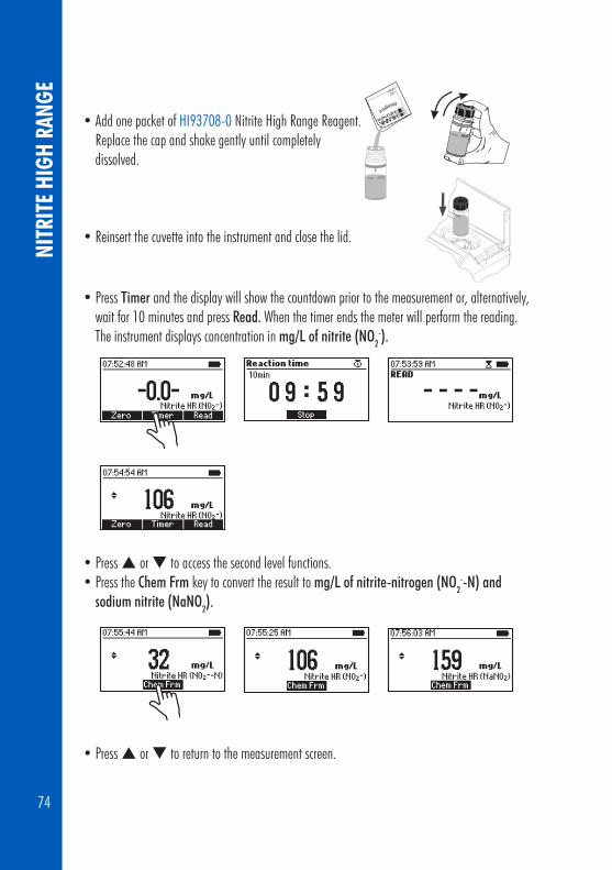
74
NITR
ITE
HIGH
RAN
GE
• Add one packet of HI93708‑0 Nitrite High Range Reagent. Replace the cap and shake gently until completely dissolved.
• Reinsert the cuvette into the instrument and close the lid.
• Press Timer and the display will show the countdown prior to the measurement or, alternatively, wait for 10 minutes and press Read. When the timer ends the meter will perform the reading. The instrument displays concentration in mg/L of nitrite (NO2
-).
• Press or to access the second level functions. • Press the Chem Frm key to convert the result to mg/L of nitrite-nitrogen (NO2
--N) and sodium nitrite (NaNO2).
• Press or to return to the measurement screen.

75
NITROGEN, TOTAL LOW RANGE (16 m
m VIAL)
8.15. NITROGEN, TOTAL LOW RANGE (16 mm VIAL)
SPECIFICATIONSRange 0.0 to 25.0 mg/L (as N)Resolution 0.1 mg/LAccuracy ±1.0 mg/L or ±5% of reading at 25 °C, whichever is greaterLight Source LED with narrow band interference filter @ 420 nm Method Chromotropic acid method.
REQUIRED REAGENTSCode Description QuantityHI93767A‑B* Total Nitrogen Low Range Digestion Vial 2 vialsDEIONIZED120 Deionized Water 2 mLPERSULFATE/N Potassium Persulfate Reagent 2 packetsBISULFITE/N Sodium Metabisulfite Reagent 2 packetsHI93767‑0 Total Nitrogen Reagent 2 packetsHI93766V‑0LR** Total Nitrogen Low Range Reagent Vial 2 vials * Reagent Vial identification: N LR, green label** Reagent Vial identification: N LR, red label
Notes: Store the unused vials in their container in a cool and dark place.
REAGENT SETSHI93767A‑50 Reagents for up to 49 tests. Box 1: HI93767A‑50 Reagent Set Box 2: HI93767A&B‑50 Reagent Set, for Nitrogen Total Low Range.For other accessories see page 109.
MEASUREMENT PROCEDUREBefore using the reagent kit carefully read all the instructions and the Safety Data Sheets (SDS). Pay particular attention to all warnings, cautions and notes. Failure to do so may result in serious injury to the operator.
Reagent Blank Correction: This method requires a reagent blank correction. A single blank vial may be used more than once, the blank vial is stable for one week if stored in a dark place at room temperature. For improved accuracy use the same lot of reagents for the blank and sample, and run a blank for each set of measurements.• Preheat the HANNA® Reactor HI839800 to 105 °C (221 °F). The optional HI740217 safety
shield is strongly recommended.

76
NITR
OGEN
, TOT
AL LO
W R
ANGE
(16
mm
VIA
L) DO NOT USE AN OVEN OR MICROWAVE samples may leak and generate a corrosive and possibly explosive atmosphere.
• Remove the cap from two HI93767A‑B Total Nitrogen Low Range Digestion Vials.
• Add one packet of Persulfate/N, Potassium Persulfate to each vial.
• Add 2 mL of deionized water to the first vial (#1, blank) and 2 mL of sample to the second vial (#2, sample), while keeping the vials at a 45‑degree angle.
• Replace the cap and shake vigorously for 30 seconds or until powder is completely dissolved.

77
NITROGEN, TOTAL LOW RANGE (16 m
m VIAL)
• Insert the vials into the reactor and heat them for 30 minutes at 105 °C.Note: To obtain most accurate results, it is strongly recommended to remove the vials from the reactor after 30 minutes.
• At the end of the digestion period switch off the reactor, place the vials in the test tube rack and allow to cool to room temperature.
WARNING: The vials are still hot, use caution when handling.
• Select Nitrogen Total LR (16) method using the procedure described in Method Selection section (see page 17).
• Insert 16 mm vial adapter using the procedure described in the Using the 16 mm Vial Adapter section (see Page 20).
• For this method the instrument provides 3 reaction timers which can be used troughout the procedure.
• Remove the cap from the vials and add one packet of BISULFITE/N Sodium Metabisulfite analysis to each vial. Replace the cap and shake gently for 15 seconds.
• Press Timer and the display will show the countdown prior to adding HI93767‑0 Total Nitrogen Reagent, or alternatively wait 3 minutes.

78
• Remove the cap from the vials and add one packet of HI93767‑0 Total Nitrogen Reagent to each vial. Replace the cap and shake gently for 15 seconds.
• Press Continue and the display will show the countdown, or alternatively wait 2 minutes (without shaking the vials) to allow the reaction to complete.
• Remove the cap from two HI93766V‑0LR Total Nitrogen Low Range Reagent Vial.
• Add 2 mL of digested blank (#1) to one of the reagent vials and 2 mL of digested sample (#2) to the second reagent vial, while keeping the vials at a 45‑degree angle.
• Replace the cap and invert 10 times.
WARNING: The vials will become hot during mixing, use caution when handling.
Note: The method is technique sensitive. See procedure on page 19 Cuvette preparation for proper mixing technique.
NITR
OGEN
, TOT
AL LO
W R
ANGE
(16
mm
VIA
L)

79
• Place the blank vial (#1) into the holder
• Press Continue and the display will show the countdown, or alternatively wait for 5 minutes.
• Press the Zero key. The display will show "‑0.0‑" when the meter is zeroed and ready for measurement.
• Remove the blank vial.
• Place the sample vial (#2) into the holder.
• Press Read key to start the reading. The instrument displays the results in mg/L of nitrogen (N).
• Press or to access the second level functions.
#1
#2
NITROGEN, TOTAL LOW RANGE (16 m
m VIAL)

80
• Press the Chem Frm key to convert the result to mg/L of ammonia (NH3) and nitrate (NO3-).
• Press or to return to the measurement screen.
INTERFERENCESInterference may be caused by:Bromide (Br ‑) above 60 mg/LChloride (Cl‑) above 1000 mg/LChromium (Cr3+) above 0.5 mg/L
NITR
OGEN
, TOT
AL LO
W R
ANGE
(16
mm
VIA
L)

81
NITROGEN, TOTAL HIGH RANGE (16 mm
VIAL)
8.16. NITROGEN, TOTAL HIGH RANGE (16 mm VIAL)
SPECIFICATIONSRange 0 to 150 mg/L (as N)Resolution 1 mg/LAccuracy ±3 mg/L or ±4% of reading at 25 °C, whichever is greaterLight Source LED with narrow band interference filter @ 420 nm Method Chromotropic acid method.
REQUIRED REAGENTSCode Description QuantityHI93767B‑B* Total Nitrogen High Range Digestion Vial 2 vials DEIONIZED120 Deionized Water 0.5 mLPERSULFATE/N Potassium Persulfate Reagent 2 packetsBISULFITE/N Sodium Metabisulfite Reagent 2 packetsHI93767‑0 Total Nitrogen Reagent 2 packetsHI93766V‑0HR** Total Nitrogen High Range Reagent Vial 2 vials* Reagent Vial identification: N HR, red label** Reagent Vial identification: N HR, green label
Notes: Store the unused vials in their container in a cool and dark place.
REAGENT SETSHI93767B‑50 Reagents for up to 49 tests. Box 1: HI93767B‑50 Reagent Set Box 2: HI93767A&B‑50 Reagent Set, for Nitrogen Total High Range.For other accessories see page 109.
MEASUREMENT PROCEDUREBefore using the reagent kit carefully read all the instructions and the Safety Data Sheets (SDS). Pay particular attention to all warnings, cautions and notes. Failure to do so may result in serious injury to the operator.
Reagent Blank Correction: This method requires a reagent blank correction. A single blank vial may be used more than once, the blank vial is stable for one week if stored in a dark place at room temperature. For improved accuracy always use the same lot of reagents for the blank and sample, and run a blank for each set of measurements.• Preheat the HANNA® Reactor HI839800 to 105 °C (221 °F). The optional HI740217 safety
shield is strongly recommended.

82
NITR
OGEN
, TOT
AL H
IGH
RANG
E (1
6 m
m V
IAL) DO NOT USE AN OVEN OR MICROWAVE samples may leak and generate a corrosive and
possibly explosive atmosphere.• Remove the cap from two HI93767B‑B Total Nitrogen High Range Digestion Vials.
• Add one packet of PERSULFATE/N, Potassium Persulfate to each vial.
• Add 0.5 mL of deionized water to the first vial (#1, blank) and 0.5 mL of sample to the second vial (#2, sample), while keeping the vials at a 45‑degree angle.
• Replace the cap and shake vigorously for about 30 seconds or until powder is completely dissolved.
• Insert the vials into the reactor and heat them for 30 minutes at 105°C.
Note: To obtain most accurate results, it is strongly recommended to remove the vials from the reactor after 30 minutes.

83
• At the end of the digestion place the vials in the test tube rack and allow to cool to room temperature.
WARNING: The vials are still hot, use caution when handling.
• Select Nitrogen Total HR (16) method using the procedure described in Method selection section (page 17).
• Insert the 16 mm vial adapter using the procedure described in the Using the 16 mm Vial Adapter section (see page 20).
• For this method the instrument provides 3 reaction timers which can be used throughout the procedure.
• Remove the cap from the vials and add one packet of BISULFITE/N, Sodium Metabisulfite to each vial. Replace the cap and shake gently for 15 seconds.
• Press Timer and the display will show the countdown prior to adding HI93767‑0 Total Nitrogen Reagent, or alternatively wait 3 minutes.
• Remove the cap from the vials and add one packet of HI93767‑0 Total Nitrogen Reagent to each vial. Replace the cap and shake gently for 15 seconds.
NITROGEN, TOTAL HIGH RANGE (16 mm
VIAL)

84
NITR
OGEN
, TOT
AL H
IGH
RANG
E (1
6 m
m V
IAL) • Press Continue and the display will show the countdown, or alternatively wait 2 minutes.
• Remove the cap from two HI93766V‑0HR Total Nitrogen High Range Regent Vials.
• Add 2 mL of digested blank (#1) to one of the reagent vials and 2 mL of digested sample (#2) to the second reagent vial, while keeping the vials at a 45‑degree angle.
• Replace the cap tightly and invert the vials 10 times.
WARNING: The vials will become hot during mixing, use caution when handling.
Note: The method is technique sensitive, see procedure on page 19 Cuvette preparation for proper mixing technique.
• Place the sample vial (#1) into the holder.
• Press Continue and the display will show the countdown, or alternatively wait for 5 minutes.
#1

85
• Press the Zero key. The the display will show “‑0.0‑”.
• Remove the blank vial.
• Place the sample vial (#2) into the holder.
• Press Read to start the reading. The instrument displays the results in mg/L nitrogen (N).
• Press or to access the second level functions.• Press the Chem Frm key to convert the result to mg/L of ammonia (NH3) and nitrate
(NO3¯).
• Press or to return to the measurement screen.The method detects all organic and inorganic forms of nitrogen present in the sample.
INTERFERENCESInterference may be caused by:Bromide (Br¯) above 240 mg/LChloride (Cl¯) above 3000 mg/LChromium (Cr3+) above 0.5 mg/L
#2
NITROGEN, TOTAL HIGH RANGE (16 mm
VIAL)

86
8.17. PHOSPHORUS, REACTIVE LOW RANGE (16 mm VIAL)
SPECIFICATIONSRange 0.00 to 1.60 mg/L (as P)Resolution 0.01 mg/LAccuracy ±0.05 mg/L or ±4% of reading at 25 °C, whichever is greaterLight Source LED with narrow band interference filter @ 610 nm Method Adaptation of the EPA method 365.2 and Standard Methods for the Examination of Water and Wastewater, 20th edition, 4500‑P E, ascorbic acid method.
REQUIRED REAGENTSCode Description QuantityHI93758A‑0* Phosphorus Reactive Reagent Vial 1 vialHI93758‑0 Phosphorus Reagent 1 packet * Reagent Vial identification: P R, red label
REAGENT SETSHI93758A‑50 Reagents for 50 testsFor other accessories see page 109.
MEASUREMENT PROCEDURE• Select the Phosphorus React. LR (16) method using the procedure described
in the Method Selection section (see page 17).
• Insert the 16 mm vial adapter using the procedure described in the Using 16 mm Vial Adapter section (see page 20).
• Remove the cap from HI93758A‑0 Reactive Phosphorus Reagent Vial.
• Add 5.0 mL of sample to the vial, while keeping the vial at a 45‑degree angle.
• Replace the cap and invert several times to mix.
• Place the vial into the holder.
PHOS
PHOR
US, R
EACT
IVE
LOW
RAN
GE (1
6 m
m V
IAL)

87
PHOSPHORUS, REACTIVE LOW RANGE (16 m
m VIAL)
• Press the Zero key. The display will show "‑0.0‑" when the meter is zeroed and ready for measurement.
• Remove the vial.• Remove the cap and add one packet of HI93758‑0
Phosphorus Reagent.
• Replace the cap shake gently for 2 minutes until most of the powder is dissolved.
• Place the vial into the holder.
• Press Timer and the display will show the countdown prior to the measurement, or alternatively wait for 3 minutes and press Read. When the timer ends the meter will perform the reading.The instrument displays the results in mg/L of Phosphorous (P).
• Press or to access the second level functions.

88
PHOS
PHOR
US, R
EACT
IVE
LOW
RAN
GE (1
6 m
m V
IAL) • And press the Chem Frm key to convert the result to mg/L of phosphate (PO4
3¯) and phosphorus pentoxide (P2O5).
• Press or to return to the measurement screen.
INTERFERENCESInterference may be caused by:Arsenate at any levelSilica above 50 mg/LSulfide above 6 mg/LTo eliminate sulfide: add Bromine Water drop‑wise until a pale yellow color develops; remove Bromine Water excess by adding Phenol solution drop‑wise.Turbidity and suspended matter in large amounts may cause interference because the reaction conditions may dissolve suspended matter or cause desorption of phosphates from particles. Turbidity or suspended matter should be removed before measurement by treatment with active carbon and by prior filtration.

89
PHOSPHORUS, REACTIVE HIGH RANGE (16 mm
VIAL)
8.18. PHOSPHORUS, REACTIVE HIGH RANGE (16 mm VIAL)
SPECIFICATIONSRange 0.0 to 32.6 mg/L (as P)Resolution 0.1 mg/LAccuracy ±0.5 mg/L or ±4% of reading at 25 °C, whichever is greaterLight Source LED with narrow band interference filter @ 420 nm Method Adaptation of the Standard Methods for the Examination of Water and Wastewater, 20th edition, 4500‑P C, vanadomolybdophosphoric acid method.
REQUIRED REAGENTSCode Description QuantityHI93763A‑0* Reactive Phosphorus High Range Reagent Vial 2 vialsDEIONIZED120 Deionized Water 5 mL*Reagent vial Identification: P RHR, green label
Note: Store the unused vials in their container in a cool and dark place.
REAGENT SETSHI93763A‑50 Reagents for up to 49 testsFor other accessories see page 109.
MEASUREMENT PROCEDUREReagent Blank Correction: This method requires a reagent blank correction. A single blank vial may be used more than once; the blank vial is stable up to two weeks (room temperature). For improved accuracy always use the same lot of reagents for the blank and sample, and run a blank for each set of measurements.• Select the Phosphorus React. HR (16) method using the procedure described in the Method
Selection section (see page 17).• Insert the 16 mm vial adapter using the procedure described in the Using the 16 mm Vial
Adapter section (see page 20).• Remove the cap from two HI93763A‑0 Phosphorus Reactive High Range Reagent Vials.
• Add 5 mL of deionized water to the first vial (#1) and 5 mL of sample to the second vial (#2), while keeping the vials at a 45‑degree angle.

90
PHOS
PHOR
US, R
EACT
IVE
HIGH
RAN
GE (1
6 m
m V
IAL) • Replace the cap and invert several times to mix.
• Place the blank vial (#1) into the holder and push it completely down.
• Press Timer and the display will show the countdown prior to the zero reading, or alternatively wait 7 minutes and press Zero. The display will show "‑0.0‑" when the meter is zeroed and ready for measurement.
• Remove the blank vial.
• Place the sample vial (#2) into the holder.
• Press Read to start the measurement. The instrument displays the results in mg/L of phosphorus (P).
#1
#2

91
• Press or to access the second level functions.• Press the Chem Frm key to convert the result to mg/L of phosphate (PO4
3¯) and phosphorus pentoxide (P2O5).
• Press or to return to the measurement screen.
INTERFERENCESInterference may be caused by:BismuthFluoridepH: the sample should have a neutral pHSulfide: to eliminate sulfide add Bromine Water drop‑wise until a pale yellow color develops; remove BromineWater excess by adding Phenol solution drop‑wise.Temperature: the method is temperature sensitive.It is recommended to run measurements at T = 20 to 25 °C:T < 20 °C causes a negative errorT > 25 °C causes a positive errorTurbidity and suspended matter in large amounts may cause interference because the strongly acidic reaction conditions may dissolve suspended matter or cause desorption of phosphates from particles. Before measurement, turbidity or suspended matter should be removed by treatment with active carbon and by prior filtration.
PHOSPHORUS, REACTIVE HIGH RANGE (16 mm
VIAL)

92
8.19. PHOSPHORUS, ACID HYDROLYZABLE (16 mm VIAL)
SPECIFICATIONSRange 0.00 to 1.60 mg/L (as P)Resolution 0.01 mg/LAccuracy ±0.05 mg/L or ±5% of reading at 25 °C, whichever is greaterLight Source LED with narrow band interference filter @ 610 nm Method Adaptation of the EPA method 365.2 and Standard Methods for the Examination of Water and Wastewater, 20th edition, 4500‑P E, ascorbic acid method.
REQUIRED REAGENTSCode Description QuantityHI93758V‑0AH* Phosphorus Reagent Vial 1 vialHI93758B‑0 NaOH Solution 1.20N 2 mLHI93758‑0 Phosphorous Reagent 1 packet* Reagent vial Identification: P AH, white label
Note: Store the unused vials in their container in a cool and dark place.
REAGENT SETSHI93758B‑50 Reagents for 50 testsFor other accessories see page 109.
MEASUREMENT PROCEDUREBefore using the reagent kit carefully read all the instructions and the Safety Data Sheets (SDS). Pay particular attention to all warnings, cautions and notes. Failure to do so may result in serious injury to the operator.
• Preheat the HANNA® Reactor HI839800 to 150 °C (302°F). The optional HI740217 safety shield is strongly recommended.
DO NOT USE AN OVEN OR MICROWAVE samples may leak and generate a corrosive and possibly explosive atmosphere.
PHOS
PHOR
US, A
CID
HYDR
OLYZ
ABLE
(16
mm
VIA
L)

93
PHOSPHORUS, ACID HYDROLYZABLE (16 mm
VIAL)
• Remove the cap from a HI93758V‑0AH Phosphorus Reagent Vial.
• Add 5.0 mL of sample to the vial, while keeping the vial at a 45‑degree angle.
• Replace the cap and invert to mix.
• Insert the vial into the reactor and heat it for 30 minutes at 150°C.
• At the end of the digestion place the vials carefully in the test tube rack and allow to cool to room temperature.
WARNING: The vials are still hot, use caution when handling.
• Select the Phosphorus Acid Hydr. (16) method using the procedure described in the Method Selection section (see page 17).
• Insert the 16 mm vial adapter using the procedure described in the Using the 16 mm vial Adapter section (see page 20).
• Remove the cap from the vial and add 2.0 mL of HI93758B‑0 NaOH Solution 1.20N while keeping the vial at a 45‑degree angle.
• Replace the cap and invert to mix.

94
• Place the vial into the holder.
• Press Zero key. The display will show “‑0.0‑”. Now the meter is zeroed and ready for measurement.
• Remove the vial.
• Remove the cap and add one packet of HI93758‑0 Phosphorus Reagent.
• Replace the cap and shake gently for 2 minutes until most of the powder is dissolved.
• Place the vial into the holder.
• Press Timer and the display will show the countdown prior to the measurement, or alternatively wait for 3 minutes and press Read. The instrument displays the results in mg/L of phosphorus (P).
PHOS
PHOR
US, A
CID
HYDR
OLYZ
ABLE
(16
mm
VIA
L)

95
Note: The method detects free (orthophosphate) and condensed inorganic forms (meta-, pyro- and other polyphosphates) of phosphates present in the sample.
• Press or to access the second level functions.• Press the Chem Frm key to convert the result in mg/L of phosphate (PO4
3¯) and mg/L phosphorus pentoxide (P2O5).
• Press or to return to the measurement screen.
INTERFERENCESInterference may be caused by:Arsenate at any levelSilica above 50 mg/LSulfide above 9 mg/LTo eliminate sulfide: add Bromine Water drop‑wise until a pale yellow color develops; remove Bromine Water excess by adding Phenol solution drop‑wise.Turbidity and suspended matter in large amounts may cause interference because the strongly acidic reaction conditions may dissolve suspended matter or cause desorption of phosphates from particles. Before measurement, turbidity or suspended matter should be removed by treatment with active carbon and by prior filtration.
PHOSPHORUS, ACID HYDROLYZABLE (16 mm
VIAL)

96
8.20. PHOSPHORUS, TOTAL LOW RANGE (16 mm VIAL)
SPECIFICATIONSRange 0.00 to 1.15 mg/L (as P)Resolution 0.01 mg/LAccuracy ±0.05 mg/L or ±6% of reading at 25 °C, whichever is greaterLight Source LED with narrow band interference filter @ 610 nm Method Adaptation of the EPA method 365.2 and Standard Methods for the Examination of Water and Wastewater, 20th edition, 4500‑P E, ascorbic acid method.
REQUIRED REAGENTSCode Description QuantityHI93758V‑0* Phosphorus Reagent Vial 1 vialHI93758C‑0 NaOH solution 1.54N 2 mLHI93758‑0 Phosphorous Reagent 1 packetPERFULFATE/P Potassium Persulfate 1 packet* Reagent vial Identification: P TLR, red label
Note: Store the unused vials in their container in a cool and dark place.
REAGENT SETSHI93758C‑50 Reagents for 50 testsFor other accessories see page 109.
MEASUREMENT PROCEDUREBefore using the reagent kit carefully read all the instructions and the Safety Data Sheets (SDS). Pay particular attention to all warnings, cautions and notes. Failure to do so may result in serious injury to the operator.
• Preheat the HANNA® Reactor HI839800 to 150 °C (302°F). The optional HI740217 safety shield is strongly recommended.
DO NOT USE AN OVEN OR MICROWAVE samples may leak and generate a corrosive and possibly explosive atmosphere.
PHOS
PHOR
US, T
OTAL
LOW
RAN
GE (1
6mm
VIA
L)

97
PHOSPHORUS, TOTAL LOW RANGE (16 m
m VIAL)
• Remove the cap from a HI93758V‑0 Reagent Vial.
• Add 5.0 mL of sample to the vial, while keeping the vial at a 45‑degree angle.
• Add one packet of PERSULFATE/P Potassium Persulfate. Replace the cap and shake gently the vial until all the powder is completely dissolved.
• Insert the vial into the reactor and heat it for 30 minutes at 150°C.
• At the end of the digestion place the vials carefully in the test tube rack and allow to cool to room temperature.
WARNING: the vials are still hot, use caution when handling.
• Select the Phosphorus Total LR (16) method using the procedure described in the Method Selection section (see page 17).
• Insert the 16 mm vial adapter using the procedure described in the Using the 16 mm Vial Adapter section (see page 20).
• Remove the cap from the vial and add exactly 2.0 mL of HI93758C‑0 NaOH Solution 1.54 N, while keeping the vial at a 45‑degree angle.
• Replace the cap and invert the vial several times to mix.

98
• Place the vial into the holder.
• Press Zero key. The display will show"‑0.0‑" when the meter is zeroed and ready for measurement.
• Remove the vial.• Remove the cap and add one packet of HI93758‑0 Phosphorus
Reagent.• Replace the cap and shake for 2 minutes until the powder is
completely dissolved.
• Place the vial into the holder.
• Press Timer and the display will show the countdown prior to the measurement, or alternatively, wait for 3 minutes and press Read. The instrument displays the results in mg/L of phosphorus (P).
PHOS
PHOR
US, T
OTAL
LOW
RAN
GE (1
6mm
VIA
L)

99
Note: The method detects free (orthophosphate) and condensed inorganic forms (meta-, pyro- and other polyphosphates) of phosphates present in the sample.
• Press or to access the second level functions.• Press the Chem Frm key to convert the result to mg/L of phosphate (PO4
3¯) and phosphorus pentoxide (P2O5).
• Press or to return to the measurement screen.
INTERFERENCESInterference may be caused by:Arsenate at any levelSilica above 50 mg/LSulfide above 90 mg/L.Turbidity and suspended matter in large amounts may cause interference because the strongly acidic reaction conditions may dissolve suspended matter or cause desorption of phosphates from particles. Before measurement, turbidity or suspended matter should be removed by treatment with active carbon and by prior filtration.
PHOSPHORUS, TOTAL LOW RANGE (16 m
m VIAL)

100
8.21. PHOSPHORUS, TOTAL HIGH RANGE (16 mm VIAL)
SPECIFICATIONSRange 0.0 to 32.6 mg/L (as P)Resolution 0.1 mg/LAccuracy ±0.5 mg/L or ±5% of reading at 25 °C, whichever is greaterLight Source LED with narrow band interference filter @ 420 nm Method Adaptation of the Standard Methods for the Examination of Water and Wastewater, 20th edition, 4500‑P C, vanadomolybdophosphoric acid method.
REQUIRED REAGENTSCode Description QuantityHI93758V‑0HR* Phosphorus Reagent Vial 2 vialsHI93758C‑0 NaOH solution 1.54N 4 mLHI93763B‑0 Total Phosphorous High Range Reagent B 1 mLDEIONIZED120 Deionized Water 5 mLPERSULFATE/P Potassium Persulfate 2 packets*Reagent vial Identification: P THR, green label
Note: Store the unused vials in their container in a cool and dark place.
REAGENT SETSHI93763B‑50 Reagents for up to 49 testsFor other accessories see page 109.
MEASUREMENT PROCEDUREBefore using the reagent kit carefully read all the instructions and the Safety Data Sheets (SDS). Pay particular attention to all warnings, cautions and notes. Failure to do so may result in serious injury to the operator.
Reagent Blank Correction: This method requires a reagent blank correction. A single blank vial may be used more than once. The blank vial is stable for one day at room temperature.
• Preheat the HANNA® Reactor HI839800 to 150 °C (302°F). The optional HI740217 safety shield is strongly recommended.
DO NOT USE AN OVEN OR MICROWAVE samples may leak and generate a corrosive and possibly explosive atmosphere.
PHOS
PHOR
US, T
OTAL
HIG
H RA
NGE
(16
mm
VIA
L)

101
PHOSPHORUS, TOTAL HIGH RANGE (16 mm
VIAL)
• Remove the cap from two HI93758V‑OHR Phosphorus Reagent Vials.
• Add 5 mL of deionized water to the first vial (#1) and 5 mL of sample to the second vial (#2), while keeping the vials at a 45‑degree angle.
• Add one packet of PERFSULFATE/P Potassium Persulfate to each vial. Replace the cap and shake gently until all the powder is completely dissolved.
• Insert the vials into the reactor and heat them for 30 minutes at 150°C.
• At the end of the digestion place the vials carefully in the test tube rack and allow to cool to room temperature.
WARNING: The vials are still hot, use caution when handling.

102
• Select the Phosphorus Total HR (16) method using the procedure described in the Method Selection section (see page 17).
• Insert the 16 mm vial adapter using the procedure described in the Using the 16 mm Vial Adapter section (see page 20).
• Remove the cap from the vials and add 2.0 mL of HI93758C‑0 NaOH Solution 1.54N to each vial, while keeping the vials at a 45‑degree angle. Replace the cap tightly and invert the vials several times to mix.
• Remove the cap from the vials and add 0.5 mL of HI93763B‑0 Total Phosphorous High Range Reagent B to each vial, while keeping the vial at a 45‑degree angle. Replace the cap and invert several times to mix.
• Place the blank vial (#1) into the holder.
• Press Timer and the display will show the countdown prior to the measurement, or alternatively wait for 7 minutes and press Zero. The display will show "‑0.0‑" when the meter is zeroed and ready for measurement.
#1
PHOS
PHOR
US, T
OTAL
HIG
H RA
NGE
(16
mm
VIA
L)

103
• Remove the blank vial.
• Place the sample vial (#2) into the holder.
• Press Read key. The instrument displays the results in mg/L phosphorus (P).
Note: The method detects free (orthophosphate), condensed inorganic forms (meta-, pyro- and other polyphosphates) and organic forms of phosphates present in the sample.
• Press or to access the second level functions and then press the Chem Frm key to convert the result to mg/L of phosphate (PO4
3¯) and phosphorus pentoxide (P2O5).
• Press or to return to the measurement screen.
INTERFERENCESInterference may be caused by:ArsenatepH: the sample should have a neutral pHTemperature: the method is temperature sensitive.It is recommended to add the Molybdovanadate Reagent and to run measurements at T = 20 to 25 °C:T < 20 °C causes a negative errorT > 25 °C causes a positive errorTurbidity and suspended matter in large amounts may cause interference because the strongly acidic reaction conditions may dissolve suspended matter or cause desorption of phosphates from particles. Before measurement, turbidity or suspended matter should be removed by treatment with active carbon and by prior filtration.
#2
PHOSPHORUS, TOTAL HIGH RANGE (16 mm
VIAL)

104
ERRO
R DE
SCRI
PTIO
NS
The instrument shows clear warning messages when erroneous conditions appear and when measured values are outside the expected range. These messages are described below.
No Light: The light source is not functioning properly.
Light Leak: There is an excess amount of ambient light reaching the detector.
Inverted Cuvette: The sample and the zero cuvettes are inverted.
Light Low: The instrument cannot adjust the light level. Please check that the sample does not contain any debris.
Light High: There is too much light to perform a measurement. Please check the preparation of the zero cuvette.
9. ERROR DESCRIPTIONS
Ambient temperature out of limit: The meter is too hot or too cold for an accurate measurement. Allow the meter to reach 10 °C to 40 °C (50 °F to 104 °F) before performing a measurement.
Ambient temperature changed: The temperature of the meter has changed significantly since the zero measurement has been performed. A zero measurement must be performed again.
Out of range: The measured value is outside the limits of the method.
Invalid reading: The measured value cannot be calculated. Please check sample preparation.

105
STANDARD METHODS
10. STANDARD METHODSDescription Range Method
Ammonia LR 0.00 to 3.00 mg/L NesslerAmmonia LR (16 mm Vial) 0.00 to 3.00 mg/L NesslerAmmonia MR 0.00 to 10.00 mg/L NesslerAmmonia HR 0.0 to 100.0 mg/L NesslerAmmonia HR (16 mm Vial) 0.0 to 100.0 mg/L NesslerChlorine Free 0.00 to 5.00 mg/L DPDChlorine Total 0.00 to 5.00 mg/L DPDChemical Oxygen Demand LR (16 mm Vial) 0 to 150 mg/L EPA 410.4Chemical Oxygen Demand MR (16 mm Vial) 0 to 1500 mg/L EPA 410.4Chemical Oxygen Demand HR (16 mm Vial) 0 to 15000 mg/L EPA 410.4Iron, Total (16 mm Vial) 0.00 to 7.00 mg/L EPA 315B
Nitrate (16 mm Vial) 0.0 to 30.0 mg/L Chromotropic AcidNitrite LR 0 to 600 µg/L DiazotizationNitrite HR 0 to 150 mg/L Ferrous SulfateNitrogen, Total LR (16 mm Vial) 0.0 to 25.0 mg/L Chromotropic AcidNitrogen, Total HR (16 mm Vial) 10 to 150 mg/L Chromotropic AcidPhosphorus, Reactive LR (16 mm Vial) 0.00 to 1.60 mg/L Ascorbic AcidPhosphorus, Reactive HR (16 mm Vial) 0.0 to 32.6 mg/L Vanadomolybdophosphoric AcidPhosphorus, Acid Hydrolyzable (16mm Vial) 0.00 to 1.60 mg/L Ascorbic AcidPhosphorus, Total LR (16 mm Vial) 0.00 to 1.15 mg/L Ascorbic AcidPhosphorus, Total HR (16 mm Vial) 0.0 to 32.6 mg/L Vanadomolybdophosphoric Acid

106
11. ACCESSORIES11.1. REAGENT SETSCode DescriptionHI93700‑01 100 ammonia LR testsHI93700‑03 300 ammonia LR testsHI93701‑01 100 chlorine free tests (powder)HI93701‑03 300 chlorine free tests (powder)HI93701‑F 300 chlorine free tests (liquid)HI93701‑T 300 chlorine total tests (liquid)HI93707‑01 100 nitrite LR testsHI93707‑03 300 nitrite LR testsHI93708‑01 100 nitrite HR testsHI93708‑03 300 nitrite HR testsHI93711‑01 100 chlorine total tests (powder)HI93711‑03 300 chlorine total tests (powder)HI93715‑01 100 ammonia MR testsHI93715‑03 300 ammonia MR testsHI93733‑01 100 ammonia HR testsHI93733‑03 300 ammonia HR testsHI93754A‑25 24 chemical oxygen demand LR tests (Vial)HI93754B‑25 24 chemical oxygen demand MR tests (Vial)HI93754C‑25 24 chemical oxygen demand HR tests (Vial)HI93758A‑50 50 phosphorus reactive LR tests (Vial)HI93758B‑50 50 phosphorus acid hydrolyzed tests (Vial)HI93758C‑50 50 phosphorus total LR tests (Vial) HI93763A‑50 49 phosphorus reactive HR tests (Vial)HI93763B‑50 49 phosphorus total HR tests (Vial)HI93764A‑25 25 ammonia LR tests (Vial)HI93764B‑25 25 ammonia HR tests (Vial)HI93766‑50 50 nitrate tests (Vial)HI93767A‑50 49 nitrogen total LR tests (Vial)HI93767B‑50 49 nitrogen total HR tests (Vial)HI96778‑25 25 total iron tests (Vial)
ACCE
SSOR
IES

107
ACCESSORIES
11.2 pH ELECTRODES Code DescriptionHI10530 Triple ceramic, double junction, low temperature glass, refillable pH electrode with conical tip and temperature sensorHI10430 Triple ceramic, double junction, high temperature glass, refillable pH electrode with temperature sensorHI11310 Glass body, double junction, refillable pH/temperature electrodeHI11311 Glass body, double junction, refillable pH/temperature electrode with enhanced diagnosticsHI12300 Plastic body, double junction, gel filled, non refillable pH/temperature electrodeHI12301 Plastic body, double junction, gel filled, non refillable pH/temperature electrode with enhanced diagnosticsHI10480 Glass body, double junction with temperature sensor for wine analysisFC2320 Double junction, open reference, non refillable, electrolyte viscolene, PVDF body with conical tip, pH/temperature electrodeFC2100 Double junction, open reference, non refillable, electrolyte viscolene, glass body with conical tip, pH/temperature electrodeFC2020 Double junction, open reference, non refillable, electrolyte viscolene, PVDF body with conical tip, pH/temperature electrode
Note: The enhanced diagnostics information are not displayed by meter.

108
ACCE
SSOR
IES 11.3 pH SOLUTIONS
BUFFER SOLUTIONSCode DescriptionHI70004P pH 4.01 Buffer Sachets, 20 mL (25 pcs.)HI70007P pH 7.01 Buffer Sachets, 20 mL (25 pcs.)HI70010P pH 10.01 Buffer Sachets, 20 mL (25 pcs.)HI7001L pH 1.68 Buffer Solution, 500 mLHI7004L pH 4.01 Buffer Solution, 500 mLHI7006L pH 6.86 Buffer Solution, 500 mLHI7007L pH 7.01 Buffer Solution, 500 mLHI7009L pH 9.18 Buffer Solution, 500 mLHI7010L pH 10.01 Buffer Solution, 500 mLHI8004L pH 4.01 Buffer Solution in FDA approved bottle, 500 mLHI8006L pH 6.86 Buffer Solution in FDA approved bottle, 500 mLHI8007L pH 7.01 Buffer Solution in FDA approved bottle, 500 mLHI8009L pH 9.18 Buffer Solution in FDA approved bottle, 500 mLHI8010L pH 10.01 Buffer Solution in FDA approved bottle, 500 mL
ELECTRODE STORAGE SOLUTIONSHI70300L Storage Solution, 500 mLHI80300L Storage Solution in FDA approved bottle, 500 mL
ELECTRODE CLEANING SOLUTIONSHI70000P Electrode Rinse Sachets, 20 mL (25 pcs.)HI7061L General Cleaning Solution, 500 mLHI7073L Protein Cleaning Solution, 500 mLHI7074L Inorganic Cleaning Solution, 500 mL HI7077L Oil & Fat Cleaning Solution, 500 mLHI8061L General Cleaning Solution in FDA approved bottle, 500 mLHI8073L Protein Cleaning Solution in FDA approved bottle, 500 mLHI8077L Oil & Fat Cleaning Solution in FDA approved bottle, 500 mL

109
ELECTRODE REFILL ELECTROLYTE SOLUTIONSHI 7082 3.5M KCl Electrolyte, 4x30 mL, for double junction electrodesHI 8082 3.5M KCl Electrolyte in FDA approved bottle, 4x30 mL, for double junction electrodes.
ACCESSORIES
11.4. OTHER ACCESSORIESCode DescriptionHI72083300 carrying caseHI731311 vial cuvette 16 mm diam (5 pcs.)HI731318 cloth for wiping cuvettes (4 pcs.)HI731331 glass cuvettes (4 pcs.)HI731335N cap for cuvette (4 pcs.)HI731340 200 µL automatic pipetteHI731341 1000 µL automatic pipetteHI731342 2000 µL automatic pipetteHI740034P cap for 100 mL beaker (10 pcs.)HI740036P 100 mL plastic beaker (10 pcs.)HI740038 60 mL glass bottle and stopperHI740142P 1 mL graduated syringe (10 pcs)HI740143 1 mL graduated syringe (6 pcs.)HI740144 pipette tip (6 pcs.)HI740157P plastic refilling pipette (20 pcs.)HI740216 Cooling RackHI740217 safety shield for reactorHI740220 25 mL graduated glass vial (2 pcs.)HI740223 170 mL plastic beakerHI740224 170 mL plastic beaker (12 pcs.)HI740225 60 mL graduated syringeHI740226 5 mL graduated syringeHI740227 filter assemblyHI740228 filter discs (25 pcs.)HI740229 100 mL graduated cylinder

110
Code DescriptionHI74083300 COD Adapter DEMI‑02 demineralizerHI75110/220E USB power adapter, European plugHI75110/220U USB power adapter, USA plugHI76404A electrode holderHI83314‑11 CAL Check cuvette kit for HI83314HI83300‑100 Sample preparation kit consisting of activated carbon for 50 tests, demineralizer bottle for 10 L of water, 100 mL graduated beaker with cap, 170 mL graduated beaker with cap, 3 mL pipette, 60 mL syringe, 5 mL syringe, graduated cylinder, spoon, funnel, filter paper (25 pcs.). HI839800‑01 reactor, European plugHI839800‑02 reactor, USA plugHI920015 USB to micro USB cable connectorHI93703‑50 cuvette cleaning solution (230 mL)HI93703‑55 activated carbon (50 pcs.)
ACCE
SSOR
IES
12. ABBREVIATIONS EPA: US Environmental Protection Agency°C: degree Celsius °F: degree Fahrenheit µg/L: micrograms per liter (ppb)mg/L: milligrams per liter (ppm)g/L: grams per liter (ppt)mL: milliliterGLP good laboratory practiceUHR ultra high range ULR ultra low rangeHR: high range MR: medium rangeLR: low range PAN: 1‑(2‑pyridylazo)‑2‑naphtolTPTZ: 2,4,6‑tri‑(2‑pyridyl)‑1,3,5‑triazine
ABBR
EVIA
TION
S
MAN83314 09/18

Before using this product make sure that they are entirely suitable for your specific application and for the environment in which they are used.Operation of these instruments may cause unacceptable interferences to other electronic equipment. Take all necessary steps to correct such interferences. Any variation introduced by the user to the supplied equipment may degrade the instruments EMC performance.To avoid damages or burns, do not put the instrument in a microwave oven. For yours and the instrument safety do not use or store the instrument in hazardous environments.
Recommendations for Users
The HI83314 is warranted for two years against defects in workmanship and materials when used for their intended purpose and maintained according to instructions. Damage due to accidents, misuse, tampering or lack of prescribed maintenance is not covered.If service is required, contact your local Hanna Instruments Office. If under warranty, report the model number, date of purchase, serial number and the nature of the problem. If the repair is not covered by the warranty, you will be notified of the charges incurred. If the instrument is to be returned to Hanna Instruments, first obtain a Returned Goods Authorization (RGA) number from the Technical Service department and then send it with shipping costs prepaid. When shipping any instrument, make sure it is properly packed for complete protection.
Warranty
Hanna Instruments reserves the right to modify the design, construction or appearance of its products without advance notice.

Printed in ROMANIAMAN83314
WorldHeadquartersHanna Instruments Inc.Highland Industrial Park584 Park East DriveWoonsocket, RI 02895 USAwww.hannainst.com
Local OfficeHanna Instruments USA270 George Washington HighwaySmithfield, RI 02917Phone: 800.426.6287Fax: 401.765.7575e‑mail: [email protected]
Copyright © 2022 FDOKUMEN