User's Manual - CASA Modular Systems
274
TECRA M3 TOSHIBA TECRA M3 Portable Personal Computer User’s Manual
-
Upload
khangminh22 -
Category
Documents
-
view
0 -
download
0
Transcript of User's Manual - CASA Modular Systems

TECRA M3
TOSHIBA
TECRA M3
Portable Personal Computer
User’s Manual

ii User’s Manual
User’s Manual
Copyright© 2005 by TOSHIBA Corporation. All rights reserved. Under the copyright laws, this manual cannot be reproduced in any form without the prior written permission of TOSHIBA. No patent liability is assumed, with respect to the use of the information contained herein.TOSHIBA TECRA M3 Portable Personal Computer User’s ManualFirst edition January 2005Copyright authority for music, movies, computer programs, data bases and other intellectual property covered by copyright laws belongs to the author or to the copyright owner. Copyrighted material can be reproduced only for personal use or use within the home. Any other use beyond that stipulated above (including conversion to digital format, alteration, transfer of copied material and distribution on a network) without the permission of the copyright owner is a violation of copyright or author’s rights and is subject to civil damages or criminal action. Please comply with copyright laws in making any reproduction from this manual.
DisclaimerThis manual has been validated and reviewed for accuracy. The instructions and descriptions it contains are accurate for the TOSHIBA TECRA M3 Portable Personal Computer at the time of this manual’s production. However, succeeding computers and manuals are subject to change without notice. TOSHIBA assumes no liability for damages incurred directly or indirectly from errors, omissions or discrepancies between the computer and the manual. Graphics processor performance may vary considerably from specifications due to design configuration.
TrademarksIBM is a registered trademark and IBM PC is a trademark of International Business Machines Corporation.Intel, Intel SpeedStep, Pentium and Centrino are trademarks or registered trademarks of Intel Corporation or its subsidiaries in the United States and other countries/regions.Windows and Microsoft are registered trademarks of Microsoft Corporation.Photo CD is a trademark of Eastman Kodak.Sonic RecordNow! is registered trademarks of Sonic Solutions.Bluetooth is a trademark owned by its proprietor and used by TOSHIBA under license.i.LINK is trademark and registered trademark of Sony Corporation.InterVideo and WinDVD are registered trademarks of the InterVideo Inc. WinDVD Creator is trademark of the InterVideo Inc.Other trademarks and registered trademarks not listed above may be used in this manual.

User’s Manual iii
User’s Manual
FCC information
Product Name : TECRA M3
Model number : PTM30
FCC notice "Declaration of Conformity Information"This equipment has been tested and found to comply with the limits for a Class B digital device, pursuant to part 15 of the FCC rules. These limits are designed to provide reasonable protection against harmful interference in a residential installation. This equipment generates, uses and can radiate radio frequency energy and, if not installed and used in accordance with the instructions, may cause harmful interference to radio communications. However, there is no guarantee that interference will not occur in a particular installation. If this equipment does cause harmful interference to radio or television reception, which can be determined by turning the equipment off and on, the user is encouraged to try to correct the interference by one or more of the following measures:■ Reorient or relocate the receiving antenna.■ Increase the separation between the equipment and receiver.■ Connect the equipment into an outlet on a circuit different from that to
which the receiver is connected.■ Consult the dealer or an experienced radio/TV technician for help.
FCC conditionsThis device complies with part 15 of the FCC Rules. Operation is subject to the following two conditions:1. This device may not cause harmful interference.2. This device must accept any interference received, including
interference that may cause undesired operation.
ContactAddress: TOSHIBA America Information Systems, Inc.
9740 Irvine BoulevardIrvine, California 92618-1697
Telephone: (949) 583-3000
Only peripherals complying with the FCC class B limits may be attached to this equipment. Operation with non-compliant peripherals or peripherals not recommended by TOSHIBA is likely to result in interference to radio and TV reception. Shielded cables must be used between the external devices and the computer’s external monitor port, USB port, parallel port, IEEE1394 port and microphone jack. Changes or modifications made to this equipment, not expressly approved by TOSHIBA or parties authorized by TOSHIBA could void the user’s authority to operate the equipment.

iv User’s Manual
User’s Manual
EU Declaration of Conformity
TOSHIBA declares, that the product: PTM30* conforms to the following Standards:
This product is carrying the CE-Mark in accordance with the related European Directives. Responsible for CE-Marking is TOSHIBA Europe, Hammfelddamm 8, 41460 Neuss, Germany.
VCCI Class B Information
Modem warning noticeConformity Statement
The equipment has been approved to [Commission Decision “CTR21”] for pan-European single terminal connection to the Public Switched Telephone Network (PSTN).However, due to differences between the individual PSTNs provided in different countries/regions the approval does not, of itself, give an unconditional assurance of successful operation on every PSTN network termination point.In the event of problems, you should contact your equipment supplier in the first instance.
Supplementary Information:
“The product complies with the requirements of the Low Voltage Directive 73/23/EEC, the EMC Directive 89/336/EEC and/or the R&TTE Directive 1999/05/EEC.”

User’s Manual v
User’s Manual
Network Compatibility StatementThis product is designed to work with, and is compatible with the following networks. It has been tested to and found to conform with the additional requirements conditional in EG 201 121.Germany ATAAB AN005,AN006,AN007,AN009,AN010
and DE03,04,05,08,09,12,14,17Greece ATAAB AN005,AN006 and GR01,02,03,04Portugal ATAAB AN001,005,006,007,011 and
P03,04,08,10Spain ATAAB AN005,007,012, and ES01Switzerland ATAAB AN002All other countries/regions ATAAB AN003,004Specific switch settings or software setup are required for each network, please refer to the relevant sections of the user guide for more details.The hookflash (timed break register recall) function is subject to separate national type approvals. It has not been tested for conformity to national type regulations, and no guarantee of successful operation of that specific function on specific national networks can be given.
Japan regulationsRegion selection
If you are using the computer in Japan, technical regulations described in the Telecommunications Business Law require that you select the Japan region mode. It is illegal to use the modem in Japan with any other selection.
RedialUp to two redial attempts can be made. If more than two redial attempts are made, the modem will return Black Listed. If you are experiencing problems with the Black Listed code, set the interval between redials at one minute or longer. Japan’s Telecommunications Business Law permits up to two redials on analogue telephones, but the redials must be made within a total of three minutes.The internal modem is approved by Japan Approvals Institute for Telecommunications Equipment.
A02-0604JP

vi User’s Manual
User’s Manual
Pursuant to FCC CFR 47, Part 68:When you are ready to install or use the modem, call your local telephone company and give them the following information:■ The telephone number of the line to which you will connect the modem■ The registration number that is located on the deviceThe FCC registration number of the modem will be found on either the device which is to be installed, or, if already installed, on the bottom of the computer outside of the main system label.■ The Ringer Equivalence Number (REN) of the modem, which can vary.
For the REN of your modem, refer to your modem’s label.The modem connects to the telephone line by means of a standard jack called the USOC RJ11C.
Type of serviceYour modem is designed to be used on standard-device telephone lines. Connection to telephone company-provided coin service (central office implemented systems) is prohibited. Connection to party lines service is subject to state tariffs. If you have any questions about your telephone line, such as how many pieces of equipment you can connect to it, the telephone company will provide this information upon request.
Telephone company proceduresThe goal of the telephone company is to provide you with the best service it can. In order to do this, it may occasionally be necessary for them to make changes in their equipment, operations, or procedures. If these changes might affect your service or the operation of your equipment, the telephone company will give you notice in writing to allow you to make any changes necessary to maintain uninterrupted service.
If problems ariseIf any of your telephone equipment is not operating properly, you should immediately remove it from your telephone line, as it may cause harm to the telephone network. If the telephone company notes a problem, they may temporarily discontinue service. When practical, they will notify you in advance of this disconnection. If advance notice is not feasible, you will be notified as soon as possible. When you are notified, you will be given the opportunity to correct the problem and informed of your right to file a complaint with the FCC. In the event repairs are ever needed on your modem, they should be performed by TOSHIBA Corporation or an authorized representative of TOSHIBA Corporation.
DisconnectionIf you should ever decide to permanently disconnect your modem from its present line, please call the telephone company and let them know of this change.

User’s Manual vii
User’s Manual
Fax brandingThe Telephone Consumer Protection Act of 1991 makes it unlawful for any person to use a computer or other electronic device to send any message via a telephone fax machine unless such message clearly contains in a margin at the top or bottom of each transmitted page or on the first page of the transmission, the date and time it is sent and an identification of the business, other entity or individual sending the message and the telephone number of the sending machine or such business, other entity or individual. In order to program this information into your fax modem, you should complete the setup of your fax software before sending messages.
Instructions for IC CS-03 certified equipment1. The Industry Canada label identifies certified equipment. This
certification means that the equipment meets certain telecommunications network protective, operational and safety requirements as prescribed in the appropriate Terminal Equipment Technical Requirements document(s). The Department does not guarantee the equipment will operate to the user’s satisfaction.Before installing this equipment, users should ensure that it is permissible to be connected to the facilities of the local telecommunications company. The equipment must also be installed using an acceptable method of connection.The customer should be aware that compliance with the above conditions may not prevent degradation of service in some situations. Repairs to certified equipment should be coordinated by a representative designated by the supplier. Any repairs or alterations made by the user to this equipment, or equipment malfunctions, may give the telecommunications company cause to request the user to disconnect the equipment.Users should ensure for their own protection that the electrical ground connections of the power utility, telephone lines and internal metallic water pipe systems, if present, are connected together. This precaution may be particularly important in rural areas.
2. The user manual of analog equipment must contain the equipment’s Ringer Equivalence Number (REN) and an explanation notice similar to the following:The Ringer Equivalence Number (REN) of the modem, which can vary. For the REN of your modem, refer to your modem’s label.
Users should not attempt to make such connections themselves, but should contact the appropriate electric inspection authority, or electrician, as appropriate.

viii User’s Manual
User’s Manual
3. The standard connecting arrangement (telephone jack type) for this equipment is jack type(s): USOC RJ11C.The IC registration number of the modem is shown below.
Canada: 1353A-L4AINT
Notes for Users in Australia and New ZealandModem warning notice for Australia
Modems connected to the Australian telecoms network must have a valid Austel permit. This modem has been designed to specifically configure to ensure compliance with Austel standards when the country/region selection is set to Australia. The use of other country/region setting while the modem is attached to the Australian PSTN would result in you modem being operated in a non-compliant manner. To verify that the country/region is correctly set, enter the command ATI which displays the currently active setting. To set the country/region permanently to Australia, enter the following command sequence:
AT%TE=1ATS133=1AT&FAT&WAT%TE=0ATZ
Failure to set the modem to the Australia country/region setting as shown above will result in the modem being operated in a non-compliant manner. Consequently, there would be no permit in force for this equipment and the Telecoms Act 1991 prescribes a penalty of $12,000 for the connection of non-permitted equipment.
The Ringer Equivalence Number (REN) assigned to each terminal device provides an indication of the maximum number of terminals allowed to be connected to a telephone interface. The termination on an interface may consist of any combination of devices subject only to the requirement that the sum of the Ringer Equivalence Numbers of all the devices does not exceed 5.

User’s Manual ix
User’s Manual
Notes for use of this device in New Zealand■ The grant of a Telepermit for a device in no way indicates Telecom
acceptance of responsibility for the correct operation of that device under all operating conditions. In particular the higher speeds at which this modem is capable of operating depend on a specific network implementation which is only one of many ways of delivering high quality voice telephony to customers. Failure to operate should not be reported as a fault to Telecom.
■ In addition to satisfactory line conditions a modem can only work properly if:a/ it is compatible with the modem at the other end of the call and.b/ the application using the modem is compatible with the application
at the other end of the call - e.g., accessing the Internet requires suitable software in addition to a modem.
■ This equipment shall not be used in any manner which could constitute a nuisance to other Telecom customers.
■ Some parameters required for compliance with Telecom’s PTC Specifications are dependent on the equipment (PC) associated with this modem. The associated equipment shall be set to operate within the following limits for compliance with Telecom Specifications:a/ There shall be no more than 10 call attempts to the same number
within any 30 minute period for any single manual call initiation, andb/ The equipment shall go on-hook for a period of not less than 30
seconds between the end of one attempt and the beginning of the next.
c/ Automatic calls to different numbers shall be not less than 5 seconds apart.
■ Immediately disconnect this equipment should it become physically damaged, and arrange for its disposal or repair.
■ The correct settings for use with this modem in New Zealand are as follows:
ATB0 (CCITT operation)AT&G2 (1800 Hz guard tone)AT&P1 (Decadic dialing make-break ratio =33%/67%)ATS0=0 (not auto answer)ATS6=4 (Blind dial delay)ATS7=less than 90 (Time to wait to carrier after dialing)ATS10=less than 150 (loss of carrier to hangup delay, factorydefault of 15 recommended)ATS11=90 (DTMF dialing on/off duration=90 ms)ATX2 (Dial tone detect, but not (U.S.A.) call progress detect)

x User’s Manual
User’s Manual
■ When used in the Auto Answer mode, the S0 register must be set with a value of 3 or 4. This ensures:■ a person calling your modem will hear a short burst of ringing before
the modem answers. This confirms that the call has been successfully switched through the network.
■ caller identification information (which occurs between the first and second ring cadences) is not destroyed.
■ The preferred method of dialing is to use DTMF tones (ATDT...) as this is faster and more reliable than pulse (decadic) dialing. If for some reason you must use decadic dialing, your communications program must be set up to record numbers using the following translation table as this modem does not implement the New Zealand “Reverse Dialing” standard.
Number to be dialed: 0 1 2 3 4 5 6 7 8 9Number to program into computer: 0 9 8 7 6 5 4 3 2 1Note that where DTMF dialing is used, the numbers should be entered normally.
■ The transmit level from this device is set at a fixed level and because of this there may be circumstances where the performance is less than optimal. Before reporting such occurrences as faults, please check the line with a standard Telepermitted telephone, and only report a fault if the phone performance is impaired.
■ It is recommended that this equipment be disconnected from the Telecom line during electrical storms.
■ When relocating the equipment, always disconnect the Telecom line connection before the power connection, and reconnect the power first.
■ This equipment may not be compatible with Telecom Distinctive Alert cadences and services such as FaxAbility.NOTE THAT FAULT CALLOUTS CAUSED BY ANY OF THE ABOVE CAUSES MAY INCUR A CHARGE FROM TELECOM

User’s Manual xi
User’s Manual
General conditionsAs required by PTC 100, please ensure that this office is advised of any changes to the specifications of these products which might affect compliance with the relevant PTC Specifications.The grant of this Telepermit is specific to the above products with the marketing description as stated on the Telepermit label artwork. The Telepermit may not be assigned to other parties or other products without Telecom approval.A Telepermit artwork for each device is included from which you may prepare any number of Telepermit labels subject to the general instructions on format, size and color on the attached sheet.The Telepermit label must be displayed on the product at all times as proof to purchasers and service personnel that the product is able to be legitimately connected to the Telecom network.The Telepermit label may also be shown on the packaging of the product and in the sales literature, as required in PTC 100.The charge for a Telepermit assessment is $337.50. An additional charge of $337.50 is payable where an assessment is based on reports against non-Telecom New Zealand Specifications. $112.50 is charged for each variation when submitted at the same time as the original.An invoice for $NZ1237.50 will be sent under separate cover.

xii User’s Manual
User’s Manual
Description on Laser specificationThe optical drive such as CD-ROM drive, DVD-ROM drive, DVD-ROM&CD-R/RW drive, DVD Super Multi drive and DVD±R/±RW drive that is used in this computer is equipped with laser. The classification label with the following sentence is affixed to the surface of the drive.
CLASS 1 LASER PRODUCTLASER KLASSE 1LUOKAN 1 LASERLAITEAPPAREIL A LASER DE CLASSE 1KLASS 1 LASER APPARAT
The drive with the above label is certified by the manufacturer that the drive complies with the requirement for laser product on the date of manufacturing pursuant to article 21 of Code of Federal Regulations by the United States of America, Department of Health & Human Services, Food and Drug Administration.In other countries, the drive is certified to comply with the requirement pursuant to IEC 825 and EN60825 on class 1 laser product.This computer is equipped with the optical drive in the following list according to the model.
Manufacturer Type
TEAC CD-224EC
HITACHI LG GDR-8082N
TSST SD-C2612
MATSUSHITA UJDA760
TEAC DW-224EB
Pioneer DVR-K14
MATSUSHITA UJ-830

TECRA M3
User’s Manual xiii
Table of Contents
PrefaceManual contents . . . . . . . . . . . . . . . . . . . . . . . . . . . . . . . . . . . . . . . . . . xxiConventions. . . . . . . . . . . . . . . . . . . . . . . . . . . . . . . . . . . . . . . . . . . . . .xxii
Abbreviations. . . . . . . . . . . . . . . . . . . . . . . . . . . . . . . . . . . . . . . . . . . xxiiIcons . . . . . . . . . . . . . . . . . . . . . . . . . . . . . . . . . . . . . . . . . . . . . . . . . xxiiKeys. . . . . . . . . . . . . . . . . . . . . . . . . . . . . . . . . . . . . . . . . . . . . . . . . . xxiiKey operation . . . . . . . . . . . . . . . . . . . . . . . . . . . . . . . . . . . . . . . . . .xxiiiDisplay. . . . . . . . . . . . . . . . . . . . . . . . . . . . . . . . . . . . . . . . . . . . . . . .xxiiiMessages . . . . . . . . . . . . . . . . . . . . . . . . . . . . . . . . . . . . . . . . . . . . .xxiii
General PrecautionsStress injury . . . . . . . . . . . . . . . . . . . . . . . . . . . . . . . . . . . . . . . . . . . . xxvHeat injury . . . . . . . . . . . . . . . . . . . . . . . . . . . . . . . . . . . . . . . . . . . . . xxvPressure or impact damage. . . . . . . . . . . . . . . . . . . . . . . . . . . . . . . . xxvPC card overheating . . . . . . . . . . . . . . . . . . . . . . . . . . . . . . . . . . . . .xxviMobile phone . . . . . . . . . . . . . . . . . . . . . . . . . . . . . . . . . . . . . . . . . . .xxviDisclaimers . . . . . . . . . . . . . . . . . . . . . . . . . . . . . . . . . . . . . . . . . . . .xxvi
IntroductionEquipment checklist . . . . . . . . . . . . . . . . . . . . . . . . . . . . . . . . . . . . . . . 1-1
Hardware . . . . . . . . . . . . . . . . . . . . . . . . . . . . . . . . . . . . . . . . . . . . . . 1-1Software. . . . . . . . . . . . . . . . . . . . . . . . . . . . . . . . . . . . . . . . . . . . . . . 1-2Documentation. . . . . . . . . . . . . . . . . . . . . . . . . . . . . . . . . . . . . . . . . . 1-2
Features . . . . . . . . . . . . . . . . . . . . . . . . . . . . . . . . . . . . . . . . . . . . . . . . . 1-2Special features. . . . . . . . . . . . . . . . . . . . . . . . . . . . . . . . . . . . . . . . . . 1-12Utilities . . . . . . . . . . . . . . . . . . . . . . . . . . . . . . . . . . . . . . . . . . . . . . . . . 1-15Options. . . . . . . . . . . . . . . . . . . . . . . . . . . . . . . . . . . . . . . . . . . . . . . . . 1-18
The Grand TourFront with the display closed. . . . . . . . . . . . . . . . . . . . . . . . . . . . . . . . 2-1Left side . . . . . . . . . . . . . . . . . . . . . . . . . . . . . . . . . . . . . . . . . . . . . . . . . 2-2Right side . . . . . . . . . . . . . . . . . . . . . . . . . . . . . . . . . . . . . . . . . . . . . . . . 2-4Back side . . . . . . . . . . . . . . . . . . . . . . . . . . . . . . . . . . . . . . . . . . . . . . . . 2-5Underside. . . . . . . . . . . . . . . . . . . . . . . . . . . . . . . . . . . . . . . . . . . . . . . . 2-6Front with the display open . . . . . . . . . . . . . . . . . . . . . . . . . . . . . . . . . 2-8System indicators . . . . . . . . . . . . . . . . . . . . . . . . . . . . . . . . . . . . . . . . 2-11

xiv User’s Manual
Table of Contents
Keyboard indicators . . . . . . . . . . . . . . . . . . . . . . . . . . . . . . . . . . . . . . 2-12USB floppy disk drive. . . . . . . . . . . . . . . . . . . . . . . . . . . . . . . . . . . . . 2-13Optical media drives. . . . . . . . . . . . . . . . . . . . . . . . . . . . . . . . . . . . . . 2-14
Region codes for DVD drives and media . . . . . . . . . . . . . . . . . . . . 2-14Writable discs . . . . . . . . . . . . . . . . . . . . . . . . . . . . . . . . . . . . . . . . . 2-14CDs . . . . . . . . . . . . . . . . . . . . . . . . . . . . . . . . . . . . . . . . . . . . . . . . . 2-15DVDs. . . . . . . . . . . . . . . . . . . . . . . . . . . . . . . . . . . . . . . . . . . . . . . . 2-15Formats . . . . . . . . . . . . . . . . . . . . . . . . . . . . . . . . . . . . . . . . . . . . . . 2-15CD-ROM drive. . . . . . . . . . . . . . . . . . . . . . . . . . . . . . . . . . . . . . . . . 2-15DVD-ROM drive . . . . . . . . . . . . . . . . . . . . . . . . . . . . . . . . . . . . . . . 2-15DVD-ROM&CD-R/RW drive . . . . . . . . . . . . . . . . . . . . . . . . . . . . . . 2-16DVD Super Multi drive. . . . . . . . . . . . . . . . . . . . . . . . . . . . . . . . . . . 2-16DVD±R/±RW drive (DVD Dual drive) . . . . . . . . . . . . . . . . . . . . . . . 2-16
AC adaptor. . . . . . . . . . . . . . . . . . . . . . . . . . . . . . . . . . . . . . . . . . . . . . 2-17
Getting StartedSetting up your work space . . . . . . . . . . . . . . . . . . . . . . . . . . . . . . . . . 3-1
General conditions . . . . . . . . . . . . . . . . . . . . . . . . . . . . . . . . . . . . . . 3-2Placement of the computer . . . . . . . . . . . . . . . . . . . . . . . . . . . . . . . . 3-2Seating and posture . . . . . . . . . . . . . . . . . . . . . . . . . . . . . . . . . . . . . 3-3Lighting . . . . . . . . . . . . . . . . . . . . . . . . . . . . . . . . . . . . . . . . . . . . . . . 3-3Work habits . . . . . . . . . . . . . . . . . . . . . . . . . . . . . . . . . . . . . . . . . . . . 3-4
Connecting the AC adaptor . . . . . . . . . . . . . . . . . . . . . . . . . . . . . . . . . 3-4Opening the display . . . . . . . . . . . . . . . . . . . . . . . . . . . . . . . . . . . . . . . 3-6Turning on the power . . . . . . . . . . . . . . . . . . . . . . . . . . . . . . . . . . . . . . 3-7Starting up for the first time. . . . . . . . . . . . . . . . . . . . . . . . . . . . . . . . . 3-7Turning off the power . . . . . . . . . . . . . . . . . . . . . . . . . . . . . . . . . . . . . . 3-8
Shut Down mode (Boot mode) . . . . . . . . . . . . . . . . . . . . . . . . . . . . . 3-8Hibernation mode . . . . . . . . . . . . . . . . . . . . . . . . . . . . . . . . . . . . . . . 3-8Standby mode . . . . . . . . . . . . . . . . . . . . . . . . . . . . . . . . . . . . . . . . . 3-10
Restarting the computer. . . . . . . . . . . . . . . . . . . . . . . . . . . . . . . . . . . 3-11Create Optical Recovery Discs . . . . . . . . . . . . . . . . . . . . . . . . . . . . . 3-12Restoring the preinstalled software from the Recovery HDD. . . . . 3-12Restoring the preinstalled software from your creating Recovery Media. . . . . . . . . . . . . . . . . . . . . . . . . . . . . . 3-13
Operating BasicsTOSHIBA Dual Pointing Device . . . . . . . . . . . . . . . . . . . . . . . . . . . . . . 4-1
Using the Touch Pad . . . . . . . . . . . . . . . . . . . . . . . . . . . . . . . . . . . . . 4-1Using the AccuPoint . . . . . . . . . . . . . . . . . . . . . . . . . . . . . . . . . . . . . 4-2AccuPoint precautions. . . . . . . . . . . . . . . . . . . . . . . . . . . . . . . . . . . . 4-2Replacing the cap . . . . . . . . . . . . . . . . . . . . . . . . . . . . . . . . . . . . . . . 4-3

User’s Manual xv
Table of Contents
Using the USB floppy disk drive . . . . . . . . . . . . . . . . . . . . . . . . . . . . . 4-4Connecting USB floppy disk drive . . . . . . . . . . . . . . . . . . . . . . . . . . . 4-4Disconnecting USB floppy disk drive. . . . . . . . . . . . . . . . . . . . . . . . . 4-4
Changing Slim Select Bay modules . . . . . . . . . . . . . . . . . . . . . . . . . . 4-5Removing a module. . . . . . . . . . . . . . . . . . . . . . . . . . . . . . . . . . . . . . 4-5Inserting a module . . . . . . . . . . . . . . . . . . . . . . . . . . . . . . . . . . . . . . . 4-6
Using optical media drives. . . . . . . . . . . . . . . . . . . . . . . . . . . . . . . . . . 4-7Loading discs. . . . . . . . . . . . . . . . . . . . . . . . . . . . . . . . . . . . . . . . . . . 4-7Removing discs . . . . . . . . . . . . . . . . . . . . . . . . . . . . . . . . . . . . . . . . . 4-9How to remove CD/DVD when the disk tray will not open. . . . . . . . 4-10
Writing CDs on DVD-ROM&CD-R/RW drive . . . . . . . . . . . . . . . . . . . 4-10Before writing or rewriting . . . . . . . . . . . . . . . . . . . . . . . . . . . . . . . . 4-11When writing or rewriting . . . . . . . . . . . . . . . . . . . . . . . . . . . . . . . . . 4-12
Writing CD/DVDs on DVD±R/±RW drive (DVD Dual drive). . . . . . . . 4-12Writing CD/DVDs on DVD Super Multi drive . . . . . . . . . . . . . . . . . . . 4-12
Important message (DVD±R/±RW drive). . . . . . . . . . . . . . . . . . . . . 4-12Important message (DVD Super Multi drive) . . . . . . . . . . . . . . . . . . 4-13Disclaimer (DVD±R/±RW drive). . . . . . . . . . . . . . . . . . . . . . . . . . . . 4-13Disclaimer (DVD Super Multi drive) . . . . . . . . . . . . . . . . . . . . . . . . . 4-13Before writing or rewriting . . . . . . . . . . . . . . . . . . . . . . . . . . . . . . . . 4-14When writing or rewriting . . . . . . . . . . . . . . . . . . . . . . . . . . . . . . . . . 4-16RecordNow! Basic for TOSHIBA . . . . . . . . . . . . . . . . . . . . . . . . . . . 4-17Data Verification. . . . . . . . . . . . . . . . . . . . . . . . . . . . . . . . . . . . . . . . 4-18DLA for TOSHIBA . . . . . . . . . . . . . . . . . . . . . . . . . . . . . . . . . . . . . . 4-18Video . . . . . . . . . . . . . . . . . . . . . . . . . . . . . . . . . . . . . . . . . . . . . . . . 4-18When using WinDVD Creator Platinum. . . . . . . . . . . . . . . . . . . . . . 4-18How to make a DVD-Video . . . . . . . . . . . . . . . . . . . . . . . . . . . . . . . 4-19How to learn more about InterVideo WinDVD Creator . . . . . . . . . . 4-19Important information for use. . . . . . . . . . . . . . . . . . . . . . . . . . . . . . 4-19
Media care . . . . . . . . . . . . . . . . . . . . . . . . . . . . . . . . . . . . . . . . . . . . . . 4-21CD/DVDs . . . . . . . . . . . . . . . . . . . . . . . . . . . . . . . . . . . . . . . . . . . . . 4-21Floppy disks. . . . . . . . . . . . . . . . . . . . . . . . . . . . . . . . . . . . . . . . . . . 4-21
Sound System . . . . . . . . . . . . . . . . . . . . . . . . . . . . . . . . . . . . . . . . . . . 4-22Using the microphone . . . . . . . . . . . . . . . . . . . . . . . . . . . . . . . . . . . 4-22SoundMAX control panel . . . . . . . . . . . . . . . . . . . . . . . . . . . . . . . . . 4-22Mic Effect . . . . . . . . . . . . . . . . . . . . . . . . . . . . . . . . . . . . . . . . . . . . . 4-23

xvi User’s Manual
Table of Contents
Modem . . . . . . . . . . . . . . . . . . . . . . . . . . . . . . . . . . . . . . . . . . . . . . . . . 4-23Region selection . . . . . . . . . . . . . . . . . . . . . . . . . . . . . . . . . . . . . . . 4-24Properties menu . . . . . . . . . . . . . . . . . . . . . . . . . . . . . . . . . . . . . . . 4-24Setting . . . . . . . . . . . . . . . . . . . . . . . . . . . . . . . . . . . . . . . . . . . . . . . 4-24Modem Selection. . . . . . . . . . . . . . . . . . . . . . . . . . . . . . . . . . . . . . . 4-25Dialing Properties . . . . . . . . . . . . . . . . . . . . . . . . . . . . . . . . . . . . . . 4-25Connecting . . . . . . . . . . . . . . . . . . . . . . . . . . . . . . . . . . . . . . . . . . . 4-25Disconnecting . . . . . . . . . . . . . . . . . . . . . . . . . . . . . . . . . . . . . . . . . 4-26
Wireless communications . . . . . . . . . . . . . . . . . . . . . . . . . . . . . . . . . 4-26Wireless LAN. . . . . . . . . . . . . . . . . . . . . . . . . . . . . . . . . . . . . . . . . . 4-26Bluetooth wireless technology. . . . . . . . . . . . . . . . . . . . . . . . . . . . . 4-27BluetoothTM Stack for Windows® by TOSHIBA . . . . . . . . . . . . . . . . 4-28Wireless communication switch . . . . . . . . . . . . . . . . . . . . . . . . . . . 4-28Wireless communication Indicator. . . . . . . . . . . . . . . . . . . . . . . . . . 4-29
LAN. . . . . . . . . . . . . . . . . . . . . . . . . . . . . . . . . . . . . . . . . . . . . . . . . . . . 4-29LAN cable types . . . . . . . . . . . . . . . . . . . . . . . . . . . . . . . . . . . . . . . 4-29Connecting LAN cable. . . . . . . . . . . . . . . . . . . . . . . . . . . . . . . . . . . 4-30Disconnecting LAN cable . . . . . . . . . . . . . . . . . . . . . . . . . . . . . . . . 4-30
Cleaning the computer . . . . . . . . . . . . . . . . . . . . . . . . . . . . . . . . . . . . 4-31Moving the computer . . . . . . . . . . . . . . . . . . . . . . . . . . . . . . . . . . . . . 4-31Heat dispersal . . . . . . . . . . . . . . . . . . . . . . . . . . . . . . . . . . . . . . . . . . . 4-32
The KeyboardTypewriter keys . . . . . . . . . . . . . . . . . . . . . . . . . . . . . . . . . . . . . . . . . . . 5-1Function keys: F1 … F12 . . . . . . . . . . . . . . . . . . . . . . . . . . . . . . . . . . . 5-2Soft keys: Fn key combinations . . . . . . . . . . . . . . . . . . . . . . . . . . . . . 5-2
Emulating keys on enhanced keyboard . . . . . . . . . . . . . . . . . . . . . . 5-2Hot keys . . . . . . . . . . . . . . . . . . . . . . . . . . . . . . . . . . . . . . . . . . . . . . . . . 5-3
Fn Sticky key . . . . . . . . . . . . . . . . . . . . . . . . . . . . . . . . . . . . . . . . . . . 5-6Windows special keys . . . . . . . . . . . . . . . . . . . . . . . . . . . . . . . . . . . . . 5-7Keypad overlay . . . . . . . . . . . . . . . . . . . . . . . . . . . . . . . . . . . . . . . . . . . 5-7
Turning on the overlays. . . . . . . . . . . . . . . . . . . . . . . . . . . . . . . . . . . 5-7Temporarily using normal keyboard (overlay on) . . . . . . . . . . . . . . . 5-8Temporarily using overlay (overlay off) . . . . . . . . . . . . . . . . . . . . . . . 5-8Temporarily changing modes . . . . . . . . . . . . . . . . . . . . . . . . . . . . . . 5-8
Generating ASCII characters . . . . . . . . . . . . . . . . . . . . . . . . . . . . . . . . 5-9
Power and Power-Up ModesPower conditions . . . . . . . . . . . . . . . . . . . . . . . . . . . . . . . . . . . . . . . . . 6-1Power indicators . . . . . . . . . . . . . . . . . . . . . . . . . . . . . . . . . . . . . . . . . . 6-4
Battery indicators. . . . . . . . . . . . . . . . . . . . . . . . . . . . . . . . . . . . . . . . 6-4DC IN indicator . . . . . . . . . . . . . . . . . . . . . . . . . . . . . . . . . . . . . . . . . 6-4Power indicator . . . . . . . . . . . . . . . . . . . . . . . . . . . . . . . . . . . . . . . . . 6-5

User’s Manual xvii
Table of Contents
Battery types . . . . . . . . . . . . . . . . . . . . . . . . . . . . . . . . . . . . . . . . . . . . . 6-5Battery pack. . . . . . . . . . . . . . . . . . . . . . . . . . . . . . . . . . . . . . . . . . . . 6-52nd battery pack (option) . . . . . . . . . . . . . . . . . . . . . . . . . . . . . . . . . . 6-6High capacity battery pack. . . . . . . . . . . . . . . . . . . . . . . . . . . . . . . . . 6-6Real Time Clock (RTC) battery . . . . . . . . . . . . . . . . . . . . . . . . . . . . . 6-6
Care and use of the battery pack. . . . . . . . . . . . . . . . . . . . . . . . . . . . . 6-7Safety precautions. . . . . . . . . . . . . . . . . . . . . . . . . . . . . . . . . . . . . . . 6-7Charging the batteries . . . . . . . . . . . . . . . . . . . . . . . . . . . . . . . . . . . . 6-9Monitoring battery capacity . . . . . . . . . . . . . . . . . . . . . . . . . . . . . . . 6-11Maximizing battery operating time. . . . . . . . . . . . . . . . . . . . . . . . . . 6-11Retaining data with power off . . . . . . . . . . . . . . . . . . . . . . . . . . . . . 6-12Extending battery life . . . . . . . . . . . . . . . . . . . . . . . . . . . . . . . . . . . . 6-12
Replacing the battery pack. . . . . . . . . . . . . . . . . . . . . . . . . . . . . . . . . 6-13Removing the battery pack . . . . . . . . . . . . . . . . . . . . . . . . . . . . . . . 6-13Installing the battery pack . . . . . . . . . . . . . . . . . . . . . . . . . . . . . . . . 6-14
TOSHIBA Password Utility . . . . . . . . . . . . . . . . . . . . . . . . . . . . . . . . . 6-15User password. . . . . . . . . . . . . . . . . . . . . . . . . . . . . . . . . . . . . . . . . 6-15Supervisor password . . . . . . . . . . . . . . . . . . . . . . . . . . . . . . . . . . . . 6-17Starting the computer by password . . . . . . . . . . . . . . . . . . . . . . . . . 6-17
Power-up modes . . . . . . . . . . . . . . . . . . . . . . . . . . . . . . . . . . . . . . . . . 6-18Windows utilities . . . . . . . . . . . . . . . . . . . . . . . . . . . . . . . . . . . . . . . 6-18Hot keys. . . . . . . . . . . . . . . . . . . . . . . . . . . . . . . . . . . . . . . . . . . . . . 6-18
Panel power on/off . . . . . . . . . . . . . . . . . . . . . . . . . . . . . . . . . . . . . . . 6-18System Auto Off . . . . . . . . . . . . . . . . . . . . . . . . . . . . . . . . . . . . . . . . . 6-18
HW SetupAccessing HW Setup . . . . . . . . . . . . . . . . . . . . . . . . . . . . . . . . . . . . . . 7-1HW Setup window . . . . . . . . . . . . . . . . . . . . . . . . . . . . . . . . . . . . . . . . . 7-1Configuring the Execute-Disable Bit Capability and TPM. . . . . . . . . 7-8
Starting and Ending the BIOS Setup Program. . . . . . . . . . . . . . . . . . 7-9Execute-Disable Bit Capability. . . . . . . . . . . . . . . . . . . . . . . . . . . . . . 7-9Security controller . . . . . . . . . . . . . . . . . . . . . . . . . . . . . . . . . . . . . . 7-10
Optional DevicesPC card. . . . . . . . . . . . . . . . . . . . . . . . . . . . . . . . . . . . . . . . . . . . . . . . . . 8-2
Inserting a PC card . . . . . . . . . . . . . . . . . . . . . . . . . . . . . . . . . . . . . . 8-2Removing a PC card . . . . . . . . . . . . . . . . . . . . . . . . . . . . . . . . . . . . . 8-3
ExpressCard . . . . . . . . . . . . . . . . . . . . . . . . . . . . . . . . . . . . . . . . . . . . . 8-3Inserting a ExpressCard . . . . . . . . . . . . . . . . . . . . . . . . . . . . . . . . . . 8-3Removing a ExpressCard . . . . . . . . . . . . . . . . . . . . . . . . . . . . . . . . . 8-4

xviii User’s Manual
Table of Contents
SD card . . . . . . . . . . . . . . . . . . . . . . . . . . . . . . . . . . . . . . . . . . . . . . . . . 8-5Formatting an SD memory card . . . . . . . . . . . . . . . . . . . . . . . . . . . . 8-5Inserting an SD card . . . . . . . . . . . . . . . . . . . . . . . . . . . . . . . . . . . . . 8-5Removing an SD card . . . . . . . . . . . . . . . . . . . . . . . . . . . . . . . . . . . . 8-6SD card care . . . . . . . . . . . . . . . . . . . . . . . . . . . . . . . . . . . . . . . . . . . 8-7Creation of a boot disk . . . . . . . . . . . . . . . . . . . . . . . . . . . . . . . . . . . 8-7
Memory expansion . . . . . . . . . . . . . . . . . . . . . . . . . . . . . . . . . . . . . . . . 8-7Installing memory module . . . . . . . . . . . . . . . . . . . . . . . . . . . . . . . . . 8-8Removing memory module . . . . . . . . . . . . . . . . . . . . . . . . . . . . . . . 8-11
Battery pack. . . . . . . . . . . . . . . . . . . . . . . . . . . . . . . . . . . . . . . . . . . . . 8-12Slim Select Bay 2nd battery pack . . . . . . . . . . . . . . . . . . . . . . . . . . . 8-12
Inserting. . . . . . . . . . . . . . . . . . . . . . . . . . . . . . . . . . . . . . . . . . . . . . 8-13Removing . . . . . . . . . . . . . . . . . . . . . . . . . . . . . . . . . . . . . . . . . . . . 8-13
AC adaptor. . . . . . . . . . . . . . . . . . . . . . . . . . . . . . . . . . . . . . . . . . . . . . 8-13Battery charger . . . . . . . . . . . . . . . . . . . . . . . . . . . . . . . . . . . . . . . . . . 8-14Hard disk drive pack. . . . . . . . . . . . . . . . . . . . . . . . . . . . . . . . . . . . . . 8-14
Removing the HDD pack. . . . . . . . . . . . . . . . . . . . . . . . . . . . . . . . . 8-14Installing the HDD pack. . . . . . . . . . . . . . . . . . . . . . . . . . . . . . . . . . 8-15
Slim Select Bay HDD adaptor (Black) . . . . . . . . . . . . . . . . . . . . . . . . 8-16USB floppy disk drive. . . . . . . . . . . . . . . . . . . . . . . . . . . . . . . . . . . . . 8-17External monitor . . . . . . . . . . . . . . . . . . . . . . . . . . . . . . . . . . . . . . . . . 8-17TV . . . . . . . . . . . . . . . . . . . . . . . . . . . . . . . . . . . . . . . . . . . . . . . . . . . . . 8-18
Using the TOSHIBA Assist button. . . . . . . . . . . . . . . . . . . . . . . . . . 8-18Changing the resolution . . . . . . . . . . . . . . . . . . . . . . . . . . . . . . . . . 8-19
Displaying movies on a TV or CRT . . . . . . . . . . . . . . . . . . . . . . . . . . 8-19i.LINK (IEEE1394) . . . . . . . . . . . . . . . . . . . . . . . . . . . . . . . . . . . . . . . . 8-20
Precautions . . . . . . . . . . . . . . . . . . . . . . . . . . . . . . . . . . . . . . . . . . . 8-20Connecting . . . . . . . . . . . . . . . . . . . . . . . . . . . . . . . . . . . . . . . . . . . 8-21Disconnecting . . . . . . . . . . . . . . . . . . . . . . . . . . . . . . . . . . . . . . . . . 8-21
Advanced Port Replicator IIl . . . . . . . . . . . . . . . . . . . . . . . . . . . . . . . 8-22Parallel printer. . . . . . . . . . . . . . . . . . . . . . . . . . . . . . . . . . . . . . . . . . . 8-23Security lock . . . . . . . . . . . . . . . . . . . . . . . . . . . . . . . . . . . . . . . . . . . . 8-24
TroubleshootingProblem solving process . . . . . . . . . . . . . . . . . . . . . . . . . . . . . . . . . . . 9-1
Preliminary checklist . . . . . . . . . . . . . . . . . . . . . . . . . . . . . . . . . . . . . 9-2Analyzing the problem. . . . . . . . . . . . . . . . . . . . . . . . . . . . . . . . . . . . 9-2

User’s Manual xix
Table of Contents
Hardware and system checklist. . . . . . . . . . . . . . . . . . . . . . . . . . . . . . 9-3System start-up . . . . . . . . . . . . . . . . . . . . . . . . . . . . . . . . . . . . . . . . . 9-3Self test . . . . . . . . . . . . . . . . . . . . . . . . . . . . . . . . . . . . . . . . . . . . . . . 9-3Power . . . . . . . . . . . . . . . . . . . . . . . . . . . . . . . . . . . . . . . . . . . . . . . . 9-4Password. . . . . . . . . . . . . . . . . . . . . . . . . . . . . . . . . . . . . . . . . . . . . . 9-7Keyboard . . . . . . . . . . . . . . . . . . . . . . . . . . . . . . . . . . . . . . . . . . . . . 9-7Internal LCD display panel. . . . . . . . . . . . . . . . . . . . . . . . . . . . . . . . . 9-8Hard disk drive. . . . . . . . . . . . . . . . . . . . . . . . . . . . . . . . . . . . . . . . . . 9-8CD-ROM drive . . . . . . . . . . . . . . . . . . . . . . . . . . . . . . . . . . . . . . . . . . 9-9DVD-ROM drive. . . . . . . . . . . . . . . . . . . . . . . . . . . . . . . . . . . . . . . . 9-10DVD-ROM&CD-R/RW drive . . . . . . . . . . . . . . . . . . . . . . . . . . . . . . 9-11DVD±R/±RW drive (DVD Dual drive). . . . . . . . . . . . . . . . . . . . . . . . 9-12DVD Super Multi drive . . . . . . . . . . . . . . . . . . . . . . . . . . . . . . . . . . . 9-13USB floppy disk drive . . . . . . . . . . . . . . . . . . . . . . . . . . . . . . . . . . . 9-14SD card . . . . . . . . . . . . . . . . . . . . . . . . . . . . . . . . . . . . . . . . . . . . . . 9-15PC card . . . . . . . . . . . . . . . . . . . . . . . . . . . . . . . . . . . . . . . . . . . . . . 9-15ExpressCard . . . . . . . . . . . . . . . . . . . . . . . . . . . . . . . . . . . . . . . . . . 9-15Infrared port . . . . . . . . . . . . . . . . . . . . . . . . . . . . . . . . . . . . . . . . . . . 9-16TOSHIBA Dual Pointing Device. . . . . . . . . . . . . . . . . . . . . . . . . . . . 9-16USB . . . . . . . . . . . . . . . . . . . . . . . . . . . . . . . . . . . . . . . . . . . . . . . . . 9-18Memory expansion . . . . . . . . . . . . . . . . . . . . . . . . . . . . . . . . . . . . . 9-18Sound system . . . . . . . . . . . . . . . . . . . . . . . . . . . . . . . . . . . . . . . . . 9-19External monitor . . . . . . . . . . . . . . . . . . . . . . . . . . . . . . . . . . . . . . . 9-19i.LINK (IEEE1394) . . . . . . . . . . . . . . . . . . . . . . . . . . . . . . . . . . . . . . 9-20Modem. . . . . . . . . . . . . . . . . . . . . . . . . . . . . . . . . . . . . . . . . . . . . . . 9-20LAN . . . . . . . . . . . . . . . . . . . . . . . . . . . . . . . . . . . . . . . . . . . . . . . . . 9-21Wireless LAN. . . . . . . . . . . . . . . . . . . . . . . . . . . . . . . . . . . . . . . . . . 9-21Bluetooth . . . . . . . . . . . . . . . . . . . . . . . . . . . . . . . . . . . . . . . . . . . . . 9-22Printer . . . . . . . . . . . . . . . . . . . . . . . . . . . . . . . . . . . . . . . . . . . . . . . 9-22TV output signal. . . . . . . . . . . . . . . . . . . . . . . . . . . . . . . . . . . . . . . . 9-23
TOSHIBA support . . . . . . . . . . . . . . . . . . . . . . . . . . . . . . . . . . . . . . . . 9-23Before you call . . . . . . . . . . . . . . . . . . . . . . . . . . . . . . . . . . . . . . . . . 9-23Where to write . . . . . . . . . . . . . . . . . . . . . . . . . . . . . . . . . . . . . . . . . 9-24

xx User’s Manual
Table of Contents
Appendix A Specifications
Appendix B Display Controller and Modes
Appendix C AT Commands
Appendix D S-registers
Appendix E V.90
Appendix F Wireless LAN
Appendix G Bluetooth wireless technology Interoperability
Appendix H AC Power Cord and Connectors
Appendix I Parts Numbers
Glossary
Index

User’s Manual xxi
TECRA M3
Preface
Congratulations on your purchase of the TECRA M3 computer. This powerful notebook computer provides excellent expansion capability, including multimedia devices, and it is designed to provide years of reliable, high-performance computing.This manual tells how to set up and begin using your TECRA M3 computer. It also provides detailed information on configuring your computer, basic operations and care, using optional devices and troubleshooting. If you are a new user of computers or if you’re new to portable computing, first read over the Introduction and The Grand Tour chapters to familiarize yourself with the computer’s features, components and accessory devices. Then read Getting Started for step-by-step instructions on setting up your computer.If you are an experienced computer user, please continue reading the preface to learn how this manual is organized, then become acquainted with this manual by browsing through its pages. Be sure to look over the Special features section of the Introduction, to learn about features that are uncommon or unique to the computers and carefully read HW Setup. If you are going to install PC cards or connect external devices such as a monitor, be sure to read Chapter 8, Optional Devices.
Manual contentsThis manual is composed of the following nine chapters, nine appendixes, a glossary and an index.Chapter 1, Introduction, is an overview of the computer’s features, capabilities, and options. Chapter 2, The Grand Tour, identifies the components of the computer and briefly explains how they function.Chapter 3, Getting Started, provides a quick overview of how to begin operating your computer and gives tips on safety and designing your work area.

xxii User’s Manual
Preface
Chapter 4, Operating Basics, includes instructions on using the following devices: TOSHIBA Dual Pointing Device, USB floppy disk drive, Slim Select Bay modules, optical media drives, sound system, modem, Wireless communication features, LAN. It also provides tips on care of the computer, floppy disks and CD/DVDs.Chapter 5, The Keyboard, describes special keyboard functions including the keypad overlay and hot keys.Chapter 6, Power and Power-Up Modes, gives details on the computer’s power resources and battery save modes and how to set a password.Chapter 7, HW Setup, explains how to configure the computer using the HW Setup program.Chapter 8, Optional Devices, describes the optional hardware available.Chapter 9, Troubleshooting, provides helpful information on how to perform some diagnostic tests, and suggests courses of action if the computer doesn’t seem to be working properly.The Appendixes provide technical information about your computer.The Glossary defines general computer terminology and includes a list of acronyms used in the text.The Index quickly directs you to the information contained in this manual.
ConventionsThis manual uses the following formats to describe, identify, and highlight terms and operating procedures.
AbbreviationsOn first appearance, and whenever necessary for clarity, abbreviations are enclosed in parentheses following their definition. For example: Read Only Memory (ROM). Acronyms are also defined in the Glossary.
IconsIcons identify ports, dials, and other parts of your computer. The indicator panel also uses icons to identify the components it is providing information on.
KeysThe keyboard keys are used in the text to describe many computer operations. A distinctive typeface identifies the key top symbols as they appear on the keyboard. For example, Enter identifies the Enter key.

User’s Manual xxiii
Preface
Key operationSome operations require you to simultaneously use two or more keys. We identify such operations by the key top symbols separated by a plus sign (+). For example, Ctrl + C means you must hold down Ctrl and at the same time press C. If three keys are used, hold down the first two and at the same time press the third.
Display
MessagesMessages are used in this manual to bring important information to your attention. Each type of message is identified as shown below.
ABC When procedures require an action such as clicking an icon or entering text, the icon’s name or the text you are to type in is represented in the type face you see to the left.
S ABCNames of windows or icons or text generated by the computer that appears on its display screen is presented in the type face you see to the left.
Pay attention! A caution informs you that improper use of equipment or failure to follow instructions may cause data loss or damage your equipment.
Please read. A note is a hint or advice that helps you make best use of your equipment.
Indicates a potentially hazardous situation, which could result in death or serious injury, if you do not follow instructions.

xxiv User’s Manual
Preface

TECRA M3
User’s Manual xxv
General Precautions
TOSHIBA computers are designed to optimize safety, minimize strain and withstand the rigors of portability. However, certain precautions should be observed to further reduce the risk of personal injury or damage to the computer.Be certain to read the general precautions below and to note the cautions included in the text of the manual.
Stress injuryCarefully read the Instruction Manual for Safety & Comfort. It contains information on prevention of stress injuries to your hands and wrists than can be caused by extensive keyboard use. Chapter 3, Getting Started, also includes information on work space design, posture and lighting that can help reduce physical stress.
Heat injury■ Avoid prolonged physical contact with the computer. If the computer is
used for long periods, its surface can become very warm. While the temperature will not feel hot to the touch, if you maintain physical contact with the computer for a long time (if you rest the computer on your lap, or if you keep your hands on the palm rest, for example) your skin might suffer low-heat injury.
■ If the computer has been used for a long time, avoid direct contact with the metal plate supporting the I/O ports. It can become hot.
■ The surface of the AC adaptor can become hot when in use. This condition does not indicate a malfunction. If you need to transport the AC adaptor, disconnect it and let it cool before moving it.
■ Do not lay the AC adaptor on a material that is sensitive to heat. The material could be damaged.
Pressure or impact damageDo not apply heavy pressure to the computer or subject it to strong impact. Excessive pressure or impact can cause damage to computer components or otherwise cause malfunctions.

xxvi User’s Manual
General Precautions
PC card overheatingSome PC cards can become hot with prolonged use. Overheating of a PC card can result in errors or instability in the PC card operation. Also be careful when you remove a PC card that has been used for a long time.
Mobile phoneUse of mobile phones can interfere with the audio system. Computer operation is not impaired but it is recommended that a distance of 30 cm be maintained between the computer and a mobile phone in use.
Disclaimers
LCDOver a period of time, and depending on the usage of the computer, the brightness of the LCD screen will deteriorate. This is an intrinsic characteristic of LCD technology.Maximum brightness is only available when operating in AC power mode. Screen will dim when the computer is operated on battery power and you may not be able to increase the brightness of the screen.
CPUCentral Processing Unit (“CPU”) Performance Disclaimer.CPU performance in your computer product may vary from specifications under the following conditions:■ use of certain external peripheral products■ use of battery power instead of AC power ■ use of certain multimedia, computer generated graphics or video
applications■ use of standard telephone lines or low speed network connections■ use of complex modeling software, such as high end computer aided
design applications■ use of several applications or functionalities simultaneously■ use of computer in areas with low air pressure (high altitude >1,000
meters or >3,280 feet above sea level) ■ use of computer at temperatures outside the range of 5°C to 30°C
(41°F to 86°F) or >25°C (77°F) at high altitude (all temperature references are approximate and may vary depending on the specific computer model - please refer to your PC documentation or visit the Toshiba website at www.pcsupport.toshiba.com for details).
CPU performance may also vary from specifications due to design configuration.

User’s Manual xxvii
General Precautions
Under some conditions, your computer product may automatically shut-down. This is a normal protective feature designed to reduce the risk of lost data or damage to the product when used outside recommended conditions. To avoid risk of lost data, always make back-up copies of data by periodically storing it on an external storage medium. For optimum performance, use your computer product only under recommended conditions. Read additional restrictions under “Environmental Conditions” in your PC documentation. Contact Toshiba technical service and support, refer to TOSHIBA support section in Chapter 9 Trouble shooting for more information.
Copy ProtectionCopy protection technology included in certain media may prevent or limit recording or viewing of the media.
HDD Drive Capacity1 Gigabyte (GB) means 1000 × 1000 × 1000 = 1,000,000,000 bytes using powers of 10. The computer operating system, however, reports storage capacity using powers of 2 for the definition of 1 GB = 1024 × 1024 × 1024 = 1,073,741,824 bytes, and therefore may show less storage capacity. Available storage capacity will also be less if the product includes one or more pre-installed operating systems, such as Microsoft Operating System and/or pre-installed software applications, or media content. Actual formatted capacity may vary.
Non-applicable IconsCertain notebook chassis are designed to accommodate all possible configurations for an entire product series. Your selected model may not have all the features and specifications corresponding to all of the icons or switches shown on the notebook chassis, unless you have selected all those features.

xxviii User’s Manual
General Precautions

User’s Manual 1-1
TECRA M3
Chapter 1
Introduction
This chapter provides an equipment checklist, and it identifies the computer’s features, options and accessories.
Equipment checklistCarefully unpack your computer. Save the box and packing materials for future use.
HardwareCheck to make sure you have all the following items:■ TECRA M3 Portable Personal Computer■ AC adaptor and power cord (2-pin plug or 3-pin plug)■ USB floppy disk drive (Option or provided with some models)■ Spare AccuPoint (pointing device) caps■ Slim Select Bay weight saver module■ Battery pack
Some of the features described in this manual may not function properly if you use an operating system that was not preinstalled by TOSHIBA.

1-2 User’s Manual
Introduction
Software
Microsoft® Windows XP Professional■ The following software is preinstalled:
■ Microsoft® Windows XP Professional■ Microsoft Internet Explorer■ TOSHIBA Utilities■ TOSHIBA SD Memory Boot Utility ■ DVD Video Player■ TOSHIBA Dual Pointing Device utility■ TOSHIBA Power Saver■ TOSHIBA Mobile Extension■ TOSHIBA Assist■ TOSHIBA ConfigFree■ TOSHIBA Zooming Utility■ TOSHIBA PC Diagnostic Tool■ TOSHIBA Controls■ TOSHIBA Mic Effect■ TOSHIBA Password Utility■ Online manual
Documentation■ TECRA M3 Portable Personal Computer User's Manual ■ Microsoft Windows XP manual package■ Instruction Manual for Safety & Comfort■ End User License Agreement
If any of the items are missing or damaged, contact your dealer immediately.
FeaturesThe computer uses TOSHIBA’s advanced Large Scale Integration (LSI), Complementary Metal-Oxide Semiconductor (CMOS) technology extensively to provide compact size, minimum weight, low power usage, and high reliability. This computer incorporates the following features and benefits:

User’s Manual 1-3
Introduction
Processor
Memory
Power
Built-in The computer is equipped with an Intel® processor.Intel® Pentium® M processor, which incorporates a 32KB level 1 cache memory and a 1MB level 2 cache memory. It also supports Enhanced Intel® SpeedStepTM technology.
Some models of the computers carry Intel® Centrino™ technology, which is based on three separate technologies of Intel® Pentium® M, Intel® PRO/Wireless Network Connection, and Intel® 915 Chipset Family. Intel® 915 Chipset Family is a model by whom Intel® Pentium® M processor is installed.
Slots The slot accepts a 256, 512 or 1,024 MB memory module. 256, 512 or 1,024 MB memory modules can be installed in the two memory slots for a maximum of 2,048 MB system memory.
Video RAM Part of system memory is used for Video RAM. 64 or 128 MB of RAM is provided for video display.
Battery pack The computer is powered by one rechargeable lithium-ion battery pack.
RTC battery The internal RTC battery backs up the Real Time Clock (RTC) and calendar.
AC adaptor The AC adaptor provides power to the system and recharges the batteries when they are low. It comes with a detachable power cord. It encloses 2-pin or 3-pin plug type.Because it is universal, it can receive a range of AC voltage from 100 to 240 volts; however, the output current varies among different models. Using the wrong model can damage your computer. Refer to the AC adaptor section in Chapter 2, The Grand Tour.

1-4 User’s Manual
Introduction
Disks
Hard disk drive Available in four sizes.■ 40.0 billion bytes (37.26 GB)■ 60.0 billion bytes (55.89 GB)■ 80.0 billion bytes (74.53 GB)■ 100.0 billion bytes (93.16 GB)
USB floppy disk drive
Accommodates either 3 1/2" 1.44-megabyte or 720-kilobyte floppy disks. It connects to a USB port. Option or provided with some models.
Computers in this series can be configured with an optical media drive installed in the Slim Select Bay. The available optical media drives are described below.

User’s Manual 1-5
Introduction
CD-ROM drive Some models are equipped with a full-size, CD-ROM drive module that lets you run CD without using an adaptor. It reads CD-ROMs at maximum 24 speed. This drive supports the following formats:■ CD-DA■ CD-Text■ Photo CD™ (single/multi-session)■ CD-ROM Mode 1, Mode 2■ CD-ROM XA Mode 2 (Form1, Form2)■ Enhanced CD (CD-EXTRA)■ Addressing Method 2
DVD-ROM drive Some models are equipped with a full-size, DVD-ROM drive module that lets you run either 12 cm (4.72") or 8 cm (3.15") CDs or 12cm (4.72") DVDs without using an adaptor. It runs DVD-ROMs at maximum 8 speed and CD-ROMs at maximum 24 speed. The drive supports the following formats:■ DVD-ROM■ DVD-Video■ CD-DA■ CD-Text■ Photo CD™ (single/multi-session)■ CD-ROM Mode 1, Mode 2■ CD-ROM XA Mode 2 (Form1, Form2)■ Enhanced CD (CD-EXTRA)■ Addressing Method 2
DVD-ROM&CD-R/RW drive
Some models are equipped with a full-size, DVD-ROM&CD-R/RW drive module that lets you run CD/DVDs without using an adaptor. It reads DVD-ROMs at maximum 8 speed and CD-ROMs at maximum 24 speed. It writes CD-R and CD-RW at maximum 24 speed. For reading, this drive supports the same formats as the DVD-ROM drive.■ CD-R■ CD-RW

1-6 User’s Manual
Introduction
DVD Super Multi drive
Some models are equipped with a full-size DVD Super Multi drive module that lets you record data to rewritable CD/DVDs as well as run either 12cm (4.72") or 8cm (3.15") CD/DVDs without using an adaptor. It reads DVD-ROMs at maximum 8 speed and CD-ROMs at maximum 24 speed. It writes CD-R at maximum 24 speed, CD-RW at maximum 10 speed, DVD-R and DVD+R at maximum 8 speed, DVD-RW and DVD+RW at maximum 4 speed, DVD-RAM at maximum 3 speed. This drive supports the following formats in addition to DVD-ROM&CD-R/RW drive.■ DVD-R■ DVD-RW■ DVD+R■ DVD+RW■ DVD-RAM
DVD±R/±RW drive (DVD Dual drive)
Some models are equipped with a full- size DVD±R/±RW drive module that lets you record data to rewritable CD/DVDs as well as run either 12cm (4.72") or 8cm (3.15") CD/DVDs without using an adaptor. It reads DVD-ROMs at maximum 8 speed and CD-ROMs at maximum 24 speed. It writes CD-R and CD-RW at up to 24 speed, DVD-R and DVD+R at up to 8 speed, DVD-RW and DVD+RW at maximum 4 speed. This drive supports the following formats in addition to DVD-ROM&CD-R/RW drive.■ DVD+R■ DVD+RW

User’s Manual 1-7
Introduction
DisplayThe computer’s LCD display panel supports high-resolution video graphics. The LCD screen can be set at a wide range of viewing angles for maximum comfort and readability.
Keyboard
TOSHIBA Dual Pointing Device
Ports
Built-in 14.1" TFT LCD screen, 16 M colors, with one of the following resolutions:■ XGA, 1024 horizontal × 768 vertical pixels■ SXGA+, 1400 horizontal × 1050 vertical
pixels
Graphics controller Graphics controller maximizes display performance. Refer to Display Controller and Modes section in Appendix B for more information.
Built-in 85 keys or 86 keys, compatible with IBM® enhanced keyboard, embedded numeric overlay,
dedicated cursor control, and keys. Refer to Chapter 5, The Keyboard, for details.
Built-in Touch Pad A Touch Pad and control buttons in the palm rest enable control of the on-screen pointer and scrolling of windows.
Built-in AccuPoint This pointer control stick, located in the center of the keyboard, provides convenient control of the cursor.
Parallel Parallel printer or other parallel device (ECP compatible).
External monitor Analog VGA port supports VESA DDC2B compatible functions.
Universal Serial Bus (USB 2.0)
The computer has Universal Serial Bus ports that comply with the USB 2.0 standard, which enables data transfer speeds 40 times faster than the USB 1.1 standard (The ports also support USB 1.1).
Docking interface This port enables connection of an optional Advanced Port Replicator III described in the Options section.

1-8 User’s Manual
Introduction
Slots
Multimedia
i.LINK™ (IEEE1394) This port enables high-speed data transfer directly from external devices such as digital video cameras.
Infrared The serial infrared port is compatible with Infrared Data Association (IrDA 1.1) standards. It enables cableless 4 Mbps, 1.152 Mbps, 115.2 kbps, 57.6 kbps, 38.4 kbps, 19.2 kbps or 9.6 kbps data transfer with IrDA 1.1 compatible external devices.
PC card The PC card slot accommodate a Type II card.
ExpressCard The ExpressCard slot accommodate an ExpressCard.
SD card This slot lets you easily transfer data from devices, such as digital cameras and Personal Digital Assistants, that use SD card flash-memory.You can use memory module in this slot.Refer to Chapter 8, Optional Devices.
Sound system Windows sound system compatible sound system provides internal speakers and microphone as well as jacks for an external microphone and headphone.
Video-out jack(S-Video)
The video out jack lets you transfer video data to external devices. Data output depends on the type of device connected to the S-Video cable.
Headphone jack A 3.5 mm mini headphone jack enables connection of stereo headphones.
Microphone jack A 3.5 mm mini microphone jack enables connection of a three-conductor mini jack for monaural microphone input.

User’s Manual 1-9
Introduction
Communications
Modem An internal modem provides capability for data and fax communication. It supports V.90 (V.92). Refer to V.90 section in Appendix E. The speed of data transfer and fax depends on analog telephone line conditions. It has a modem jack for connecting to a telephone line. It is preinstalled as a standard device in some markets. Both of V.90 and V.92 are supported only in USA, Canada and Australia. Only V.90 is available in other regions.
LAN The computer has built-in support for Ethernet LAN (10 megabits per second, 10BASE-T), Fast Ethernet LAN (100 megabits per second, 100BASE-TX) and Gigabit Ethernet LAN (1000 megabits per second, 1000BASE-T). It is preinstalled as a standard device in some markets.
Bluetooth Some computers in this series are equipped with Bluetooth functions. Bluetooth wireless technology eliminates the need for cables between electronic devices such as computers and printers. Bluetooth provides fast, reliable, and secure wireless communication in a small space. Refer to Bluetooth wireless technology Interoperability section in Appendix G.

1-10 User’s Manual
Introduction
Wireless LAN Some computers in this series are equipped with a Wireless LAN mini-PCI card that is compatible with other LAN systems based on Direct Sequence Spread Spectrum/Orthogonal Frequency Division Multiplexing radio technology that complies with the IEEE 802.11 Standard (Revision A, B or G), and Turbo Mode. Refer to Wireless LAN section in Appendix F.■ Theoretical maximum speed: 54Mbps
(IEEE802.11a, 802.11g)■ Theoretical maximum speed: 11Mbps
(IEEE802.11b)■ Theoretical maximum speed: 108Mbps
(Turbo Mode; Atheros 11a/b/g combo type)■ Frequency Channel Selection (5 GHz:
Revision A / 2.4 GHz: Revision B/G)■ Roaming over multiple channels■ Card Power Management■ Atheros Super AGTM technology (Atheros
module type).■ Wired Equivalent Privacy (WEP) data
encryption, based on 152 bit encryption algorithm (Atheros module type).
■ Wired Equivalent Privacy (WEP) data encryption, based on 128 bit encryption algorithm (Intel module type).
■ Advanced Encryption Standard (AES) data encryption, based on 256 bit encryption algorithm (Atheros module type).
■ The numerical values for display are the theoretical maximums for Wireless LAN standards. The actual values may differ.
■ The transmission speed over the wireless LAN and the distance over which wireless LAN can reach may vary depending on surrounding electromagnetic environment, obstacles, access point design and configuration, and client design and software/hardware configurations. The Transmit Rate (at X Mbit/s) is the theoretical maximum speed under the IEEE802.11 (a/b/g) standard. The actual transmission speed will be lower than the theoretical maximum speed. To use the Atheros SuperAG™ function, your client and access point must support the corresponding feature. Performance of these functions may vary depending on the format of data transmitted.

User’s Manual 1-11
Introduction
Security
Wireless communication switch
This switch turns the Wireless LAN and Bluetooth functions on and off.
Slim Select Bay Modules
Slim Select Bay is a single-drive bay that accommodates a CD-ROM drive, DVD-ROM drive, DVD-ROM&CD-R/RW drive, DVD Super Multi drive, DVD±R/±RW drive, secondary hard disk drive or secondary battery pack. The TOSHIBA Mobile Extension enables hot insertion of modules when you are using a plug and play operating system.
Slim Select Bay Weight Saver
To reduce weight, the Slim Select Bay module can be removed and a weight saver installed.
Security lock slot Connects an optional security lock to anchor the computer to a desk or other large object.
Slim Select Bay lock Slim Select Bay module can be secured by Slim Select Bay lock fixed with a lock screw in the lock position. The lock screw is inserted in the unlock position when purchased.

1-12 User’s Manual
Introduction
Special featuresThe following features are either unique to TOSHIBA computers or are advanced features, which make the computer more convenient to use.
TOSHIBA Assist button
Press this button to launch an application automatically. The default is TOSHIBA Assist.
TOSHIBA Presentation button
Press this button to change internal display, external display, simultaneous display, or multi-monitor display.
Hot keys Key combinations let you quickly change the system configuration directly from the keyboard without running a system configuration program.
Display automatic power off
This feature automatically cuts off power to the computer’s LCD display panel when there is no keyboard input for a time specified. Power is restored when any key is pressed. You can specify the time in the Monitor power off item of the Basic Setup tab in TOSHIBA Power Saver.
HDD automatic power off
This feature automatically cuts off power to the hard disk drive when it is not accessed for a time specified. Power is restored when the hard disk is accessed. You can specify the time in the HDD power off item of the Basic Setup tab in TOSHIBA Power Saver.
System automatic Standby/Hibernation
This feature automatically shuts down the system in standby mode or Hibernation mode when there is no input or hardware access for a time specified. You can specify the time and select either System Standby or System hibernation in the System standby and System item of the Basic Setup tab in TOSHIBA Power Saver.
Keypad overlay A ten-key pad is integrated into the keyboard. Refer to the Keypad overlay section in Chapter 5, The Keyboard, for instructions on using the keypad overlay.
Power on password Two levels of password security, supervisor and user, are available to prevent unauthorized access to your computer.
Instant security A hot key function blanks the LCD screen and disables the computer providing data security.

User’s Manual 1-13
Introduction
Intelligent power supply
A microprocessor in the computer’s intelligent power supply detects the battery’s charge and calculates the remaining battery capacity. It also protects electronic components from abnormal conditions, such as voltage overload from an AC adaptor. You can monitor remaining battery capacity. Use the Battery remaining item in TOSHIBA Power Saver.
Battery save mode This feature lets you save battery power. You can specify the Power Save Mode in the Profile item in TOSHIBA Power Saver.
Panel power on/off This feature turns power to the computer off when the computer’s LCD display panel is closed and turns it back on when the computer’s LCD display panel is opened. You can specify the setting in the When I close the lid item of the Setup Action tab in TOSHIBA Power Saver.
Low battery automatic hibernation
When battery power is exhausted to the point that computer operation cannot be continued, the system automatically enters Hibernation and shuts down. You can specify the setting in the Setup Action tab in TOSHIBA Power Saver.
Heat dispersal To protect from overheating, the CPU has an internal temperature sensor. If the computer’s internal temperature rises to a certain level, the cooling fan is turned on or the processing speed is lowered. Use the Cooling Method item of the Basic Setup tab in TOSHIBA Power Saver.
■ Maximum Performance
Turns on fan first, then if necessary lowers CPU processing speed.
■ Performance Uses a combination of fan and lowering the CPU processing speed.
■ Battery optimized Lowers the CPU processing speed first, then if necessary turns on the Cooling Method.

1-14 User’s Manual
Introduction
Optical media drive power icon
Use this to turn the power of the optical media drive on or off. Clicking on the optical media drive icon on the taskbar will turn the power of the optical media drive on or off. If the optical media drive power is off, the disc tray will not open even if the eject button is pushed. The power of the optical media drive can be turned on using the optical media drive icon.
Hibernation This feature lets you turn off the power without exiting from your software. The contents of main memory are saved to the hard disk, when you turn on the power again, you can continue working right where you left off. Refer to the Turning off the power section in Chapter 3, Getting Started, for details.
Standby If you have to interrupt your work, you can turn off the power without exiting from your software. Data is maintained in the computer’s main memory. When you turn on the power again, you can continue working right where you left off.

User’s Manual 1-15
Introduction
UtilitiesThis section describes preinstalled utilities and tells how to start them. For details on operations, refer to each utility’s online manual, help files or readme.txt files.
TOSHIBA Power Saver
To access this power savings management program, click start, click Control Panel, click Performance and Maintenance and select the TOSHIBA Power Saver icon.
HW Setup This program lets you customize your hardware settings according to the way you work with your computer and the peripherals you use. To start the utility, To access this utility, click start, click Control Panel, click Printers and Other Hardware and select the TOSHIBA HWSetup icon.
TOSHIBA Controls This utility have a section to let you do the following:■ Buttons: Assign applications or functions to
the TOSHIBA Presentation button (default setting is the simultaneous display on LCD and CRT with resolution of 1024 × 768.) and to the TOSHIBA Assist button (default setting is the TOSHIBA Assist).
Fn-esse This Windows program lets you define your own “shortcut” keys to quickly launch applications and speed your work in Windows. To start the utility, click start, point to All Programs, point to TOSHIBA, point to Utilities and click Fn-esse.
DVD Video Player The DVD Video Player is used to play DVD-Video. It has an on-screen interface and functions. Click start, point to All Programs, point to InterVideo WinDVD, then click InterVideo WinDVD.
Bluetooth TOSHIBA Stack
This software enables communication between remote Bluetooth devices.
Bluetooth cannot be used in models that do not have a Bluetooth module installed.

1-16 User’s Manual
Introduction
TOSHIBA SD Memory Boot Utility
The TOSHIBA SD memory boot utility is a utility which can create SD memory card to a boot disk. You can boot TOSHIBA SD Memory Boot Utility from the menu bar as follows. Click start, point to All Programs, point to TOSHIBA, point to Utilities and click SD Memory Boot Utility.
TOSHIBA Zooming Utility
This utility allows you to enlarge or reduce the icon size on the desktop or the application window.
RecordNow! Basic for TOSHIBA
You can create CD/DVDs in several formats including audio CDs that can be played on a standard stereo CD player and data CD/DVDs to store the files and folders on your hard disk drive. This software can be used on a model with DVD-ROM&CD-R/RW drive, DVD Super Multi drive and DVD±R/±RW drive.
TOSHIBA Assist TOSHIBA Assist is a graphical user interface that provides easy access to help and services. It is the default function launched by the TOSHIBA Assist button.
TOSHIBA PC Diagnostic Tool
TOSHIBA PC Diagnostic Tool displays the basic information on PC, and the test of built-in devices can also be performed. To start TOSHIBA PC Diagnostic Tool, click start, point to All Programs, point to TOSHIBA, point to Utilities and click PC Diagnostic Tool.
TOSHIBA Mobile Extension
This utility enables hot insertion of Slim Select Bay modules, that is, you can remove/insert Slim Select Bay modules while the computer is on. To activate this utility, select TOSHIBA Mobile Extension from TOSHIBA Assist.
TOSHIBA ConfigFree TOSHIBA ConfigFree is a suite of utilities to allow easy control of communication devices and network connections. TOSHIBA ConfigFree also allows you to find communication problems and create profiles for easy switching between locations and communication networks. To start ConfigFree, click start, point to All Programs, point to TOSHIBA, point to Networking and click ConfigFree.
TOSHIBA Dual Pointing Device utility
This utility has the following functions:To disable/enable TOSHIBA Dual Pointing Device with Fn + F9 keys. To customize the functions of TOSHIBA Dual Pointing Device easily.

User’s Manual 1-17
Introduction
TOSHIBA Mic Effect This utility provides you with a hands-free environment for holding mutual communication via the Internet Protocol or Local Area Network. Refer to the Sound System section in Chapter 4, Operating Basics, for details.
NVIDIA Rotation Settings
This utility let you rotate the desktop by 0 and 180 easily. It can rotate by clicking the icon in a taskbar or pressing Ctrl + Shft + R. In a multi-monitor setup, the display that contains the cursor is effective.
TOSHIBA Password Utility
This utility lets you set a password that restricts access to the computer.
Sound drivers A broad range of audio controls are available through the ADI sound driver, including Software Synthesize, Mic Volume, Noise Reduction and Audio Power Management.Click start, click Control Panel and click SoundMAX icon to change the Mic Noise Reduction settings and the Power Management settings. If you are viewing the Control Panel in Category View, click on Switch to Classic View.For other sound settings, use the Windows Device Manager, Multimedia Panel or Volume Dial.
TOSHIBA Accessibility
This utility lets you make the Fn key sticky, that is, you can press it once, release it, and they press an “F number” key. The Fn key remains active until another key is pressed.
DLA for TOSHIBA DLA (Drive Letter Access) is the packet writing software which provides the function which writes files and/or folders to DVD-RW, CD-RW and DVD+RW discs via a drive letter like a floppy disk or other removable disks.
TOSHIBA Hotkey Utility for Display Devices
This utility has the change of a display device, and the function to change display resolution. Press Fn + F5 to change the active display device. Press Fn + Space keys to change the display resolution.

1-18 User’s Manual
Introduction
OptionsYou can add a number of options to make your computer even more powerful and convenient to use. The following options are available:
TOSHIBA SD Memory Card Format
This utility has the function which formats SD memory card by SD standard format.
CD/DVD Drive Acoustic Silencer
This utility has the function to set up the read speed of CD.It is ineffective in DVD.You can set up one of the modes: [Normal Mode] can read data early, and [Quiet Mode] can lessen noise.
Memory expansion A 256, 512 or 1,024 MB memory module (PC2-4200) can easily be installed in the computer.
Battery pack An additional battery pack can be purchased from your TOSHIBA dealer. Use it as a spare or replacement.
High capacity battery pack
An additional battery pack can be purchased from your TOSHIBA dealer. Use it as a spare or replacement.
AC adaptor If you use your computer at more than one site frequently, it may be convenient to purchase an additional AC adaptor for each site so you will not have to carry the adaptor with you.
Battery charger The battery charger lets you charge extra batteries outside the computer.
Security lock A slot is available to attach a security cable to the computer to deter theft.
USB floppy disk Kit USB floppy disk drive accommodates 1.44-megabyte or 720-kilobyte floppy disk. It connects to a USB port. (You cannot format 720-kilobyte floppy disks on Windows XP, but you can use previously formatted disks.)
Advanced Port Replicator III
The Advanced Port Replicator III provides the ports available on the computer in addition to separate PS/2 mouse and PS/2 keyboard ports, a digital visual interface (DVI) port, i.LINK™ (IEEE1394) port, line-in jack and line-out jack, External monitor port, Universal Serial Bus port (USB2.0) × 4, LAN jack, Modem jack, Serial port, Parallel port.

User’s Manual 1-19
Introduction
Slim Select Bay optionsThe following modules can be installed in the Slim Select Bay. All other modules are options.
Hard disk drive You can increase your computer's data storage capacity with additional hard disk drives. They are available in the following sizes:■ 40 billion bytes (37.26 GB)■ 60 billion bytes (55.89 GB)■ 80 billion bytes (74.53 GB)■ 100 billion bytes (93.16 GB)
Wireless LAN Kit This option enables wireless LAN functions in computers that do not have wireless preinstalled. It is installed by dealers only.
Bluetooth Kit This option enables Bluetooth wireless communications in computers that do not have Bluetooth preinstalled. It is installed by dealers only.
CD-ROM Refer to the Features section for details.
DVD-ROM Refer to the Features section for details.
DVD-ROM&CD-R/RW Refer to the Features section for details.
DVD Super Multi Refer to the Features section for details.
DVD±R/±RW(DVD Dual drive)
Refer to the Features section for details.
Slim Select Bay HDD adaptor (Black)
An adaptor lets you install an optional HDD described in Chapter 8, Optional Devices.
Hard disk drive You can increase your computer’s data storage capacity with an additional 40 billion bytes (37.26 GB), 60 billion bytes (55.89 GB), 80 billion bytes (74.53 GB) and 100 billion bytes (93.16 GB) hard disk drive in the Slim Select Bay HDD adaptor.
Slim Select Bay 2nd battery pack
The secondary battery increases your computer’s battery power and operating time when a main battery is also installed.

1-20 User’s Manual
Introduction

User’s Manual 2-1
TECRA M3
Chapter 2
The Grand Tour
This chapter identifies the various components of your computer. Become familiar with each component before you operate the computer.
Front with the display closedFigure 2-1 shows the computer’s front with its LCD display panel in the closed position.
Figure 2-1 Front of the computer with LCD display panel closed
Certain notebook chassis are designed to accommodate all possible configurations for an entire product series. Your select model may not have all the features and specifications corresponding to all of the icons or switches shown on the notebook chassis, unless you have selected all those features.
Display latchSystem indicators
Wireless communication switch
Infrared port
Volume control
Systemindicators
LEDs let you monitor the status of various computer functions. Details are given in the System indicators section.
Display latch This latch secures the LCD panel in its closed position. Slide the latch to open the display.
Volume control Use this dial to adjust the volume of the stereo speakers and the stereo headphones.

2-2 User’s Manual
The Grand Tour
Left sideFigure 2-2 shows the computer’s left side.
Figure 2-2 The left side of the computer
Infrared port This infrared port is compatible with Infrared Data Association (IrDA 1.1) standards. It enables cableless 4 Mbps, 1.15 Mbps, 115.2 kbps, 57.6 kbps, 38.4 kbps, 19.2 kbps or 9.6 kbps data transfer with IrDA 1.1 compatible external devices.
Wirelesscommunicationswitch
Slide this switch to the left to turn off Wireless LAN and Bluetooth functions. Slide it to the right to turn on the functions.Some models are equipped with a Wireless communication.
Off On
Set the switch to off in airplanes and hospitals. Check the wireless communication indicator. It will stop glowing when the wireless communication function is off.
Cooling vents
i.LINK (IEEE1394) port
Parallel portSecurity lock slot
PC card slot
SD card slot
ExpressCard slot
ExpressCard eject button
PC card eject button
Parallel port This Centronics-compatible, 25-pin parallel port is used to connect a parallel printer or other parallel device. This port supports Extended Capabilities Port (ECP) standard.
Cooling vents Cooling vents help CPU keep from overheating.
Do not block the cooling vents. Do not insert or allow foreign objects to enter the cooling vents. If pins or similar objects are inserted into the computer, the computer’s circuitry may be damaged.

User’s Manual 2-3
The Grand Tour
Security lock slot A security cable attaches to this slot. The optional security cable anchors your computer to a desk or other large object to deter theft.
i.LINK (IEEE1394) port
Connect an external device, such as a digital video camera to this port for high-speed data transfer.
ExpressCard slot The ExpressCard slot can accommodate an ExpressCard.
ExpressCard eject button
This is a button for taking out ExpressCard from ExpressCard slot.
PC card slot The PC card slot can accommodate a Type II card. The slot supports 16-bit PC cards and CardBus PC cards.
PC card eject button This is a button for taking out PC card from a PC card slot.
Keep foreign objects out of the ExpressCard slot and PC card slot. A pin or similar object can damage the computer’s circuitry.
SD card slot SD cards are used in a wide variety of external devices. This slot lets you transfer data from the device to your computer.
Keep foreign objects out of the SD card slot. A pin or similar object can damage the computer’s circuitry.

2-4 User’s Manual
The Grand Tour
Right sideFigure 2-3 shows the computer’s right side.
Figure 2-3 The right side of the computer
Microphone jackHeadphone jack Slim Select Bay
External monitor portUSB ports
Headphone jack A 3.5 mm mini headphone jack enables connection of stereo headphones.
Microphone jack A 3.5 mm mini microphone jack enables connection of a three-conductor mini jack for monaural microphone input.
Universal Serial Bus (USB 2.0) ports
Two Universal Serial Bus ports are on the right side. The ports comply with the USB 2.0 standard, which enables data transfer speeds 40 times faster than the USB 1.1 standard (The ports also support USB 1.1).
Keep foreign objects out of the USB connectors. A pin or similar object can damage the computer’s circuitry.
Operation of all functions of all USB devices has not been confirmed. Some functions might not execute properly.
Slim Select Bay A CD-ROM drive, DVD-ROM drive, DVD-ROM&CD-R/RW drive, DVD±R/±RW drive, DVD Super Multi drive, Slim Select Bay HDD adaptor or Slim Select Bay 2nd battery pack can be installed in the Slim Select Bay. A weight saver can be installed when there is no module.
External monitor port
This external monitor port lets you connect an external video display.

User’s Manual 2-5
The Grand Tour
Back sideFigure 2-4 shows the computer’s back side.
Figure 2-4 The back side of the computer
Video-out jack Modem jack DC IN 15V jack
Link indicator (green)
LAN active indicator (orange)
LAN jack
Video-out jack Plug an S-Video cable into this jack for video-out. The S-Video cable carries video signal.
Modem jack In areas where an internal modem is installed as standard equipment, there is a modem jack that lets you use a modular cable to connect the modem directly to a telephone line.
■ In case of a lightning storm, unplug the modular cable from the telephone jack.
■ Do not connect the modem to a digital telephone line. A digital line will damage the modem.
LAN jack This jack lets you connect to a LAN. The adaptor has built-in support for Ethernet LAN (10 megabits per second, 10BASE-T), Fast Ethernet LAN (100 megabits per second, 100BASE-TX) and Gigabit Ethernet LAN (1000 megabits per second, 1000BASE-T). The LAN has two indicators. Refer to Chapter 4, Operating Basics, for details.
Ether
■ Do not connect any cable other than a LAN cable to the LAN jack. It could cause damage or malfunction.
■ Do not connect the LAN cable to a power supply. It could cause damage or malfunction.
Link indicator (green)
This indicator glows green when the computer is connected to a LAN and the LAN is functioning properly.

2-6 User’s Manual
The Grand Tour
UndersideFigure 2-5 shows the underside of the computer. Make sure the display is closed before turning over your computer.
Figure 2-5 The underside of the computer
LAN active indicator (orange)
This indicator glows orange when data is being exchanged between the computer and the LAN.
DC IN 15V jack The AC adaptor connects to this jack. Use only the model of AC adaptor that comes with the computer. Using the wrong adaptor can damage your computer.
DC IN 15V
NotchesBattery lock
Slim Select Bay lock screw
HDD pack cover screw
Slim Select Bay lock
Docking Interface
Battery release latch
Slim Select Bay
Battery pack
Battery lock Slide this lock to release the battery pack for removal.
Battery pack The battery pack powers the computer when the AC adaptor is not connected. For detailed information on the battery pack, refer to Chapter 6, Power and Power-Up Modes.
Notches Notches on the computer engage hooks on the Advanced Port Replicator III to hold the connection securely.

User’s Manual 2-7
The Grand Tour
Battery release latch Slide and hold this latch to release the battery pack for removal.For detailed information on removing the battery packs, refer to Chapter 6, Power and Power-Up Modes.
Docking interface This port enables connection of an optional Advanced Port Replicator III described in Chapter 8, Optional Devices.
Keep foreign objects out of the docking interface port. A pin or similar object can damage the computer's circuitry. A plastic shutter protects the connector.
Slim Select Bay lock Slide the lock to release or secure the Slim Select Bay ejector.
Be sure to lock the Slim Select Bay lock before you transport or carry the computer.
HDD pack cover screw
One screw secures the HDD cover.
Slim Select Bay See the Right side section in this chapter for details.
Slim Select Bay lock screw
One screw secures the Slim Select Bay lock.

2-8 User’s Manual
The Grand Tour
Front with the display openThis section shows the computer with the LCD display panel open. Refer to the appropriate illustration for details. To open the display, slide the display latch on the front of the LCD display panel and lift up. Position the LCD display panel at a comfortable viewing angle.
Figure 2-6 The front of the computer with the LCD panel open
LCD screen
Stereo speaker(Right)
Touch Padcontrol buttons
Touch Pad
AccuPointcontrol Buttons
AccuPoint
TOSHIBA PresentationButton
TOSHIBA Assist Button
Power button
Display hinge
Stereo speaker(Left)
Microphone
LCD Sensor switch(Not shown)
Display hinge The display hinge holds the LCD display panel at easy-to-view angles.
Microphone A built-in microphone lets you record sound into your applications. Refer to the Using the microphone section in Chapter 4, Operating Basics.

User’s Manual 2-9
The Grand Tour
LCD screen The LCD screen displays high-contrast text and graphics. The available resolution depends on the model. With XGA, you can change the resolution between 800 × 600 and 1024 × 768 pixels. With SXGA, between 800 × 600 and 1400 × 1050 pixels. Refer to Display Controller and Modes section in Appendix B.When the computer operates on the AC adaptor the LCD screen’s image will be somewhat brighter than when it operates on battery power. The lower brightness level is intended to save battery power.
Stereo speakers The speakers emit sound generated by your software as well as audio alarms, such as low battery condition, generated by the system.
Touch Pad control buttons
Control buttons below the Touch Pad let you select menu items or manipulate text and graphics designated by the on-screen pointer.
Touch Pad A Touch Pad located in the center of the palm rest is used to control the on-screen pointer. Refer to the Using the Touch Pad section in Chapter 4, Operating Basics.
AccuPoint control buttons
Control buttons below the keyboard let you select menu items or manipulate text and graphics designated by the on-screen pointer. Refer to the Using the AccuPoint section in Chapter 4, Operating Basics.
AccuPoint A pointer control device located in the center of the keyboard is used to control the on-screen pointer. Refer to the Using the AccuPoint section in Chapter 4, Operating Basics.

2-10 User’s Manual
The Grand Tour
TOSHIBA Presentation button
Press this button to change internal display, simultaneous display, or multi-monitor display.The default setting is the simultaneous display on LCD and CRT with resolution of 1024 × 768. When you press this button twice, the display mode returns to single display on LCD only. Setting of multi-monitor display in Windows XP, computer changes its display mode to the multi-monitor display on LCD and CRT. You can also return to single display by pressing this button twice.The setting of TOSHIBA Presentation button can be changed through the properties of TOSHIBA Controls. Display mode is changed to the multi-monitor display by selecting "Different Image" (Windows XP only) or to the simultaneous display on internal and external display by selecting "Same Image".
TOSHIBA Assist button
Press this button to launch the program automatically. When power-off, stand-by and hibernation, press this button to start the computer and launch the program.You can select the function on TOSHIBA Controls properties.The default is TOSHIBA Assist.
Power button Press the power button to turn the computer’s power on and off.
LCD Sensor switch This switch senses when the computer's LCD display panel is closed or opened and activates the Panel Power Off/On feature. When you close the LCD display panel the computer enters Hibernation mode and shuts down. When you open the computer's LCD display panel the computer starts in Hibernation mode. Use the TOSHIBA Power Saver Utility to enable or disable this feature. The default is "enabled". Refer to the TOSHIBA Power Saver Utility and Panel Power Off/On items in Chapter 1, Special features, for details on settings.
Do not put a magnetic object close to the switch. The computer will automatically enter Hibernation mode and shut down even if the Panel Power Off features is disabled.

User’s Manual 2-11
The Grand Tour
System indicatorsLEDs beneath icons, light when various computer operations are in progress.
Figure 2-7 System indicators
SD card The SD card indicator glows green when the computer is accessing the SD card slot.
DC IN The DC IN indicator glows in green when DC power is supplied from the AC power adaptor. If the adaptor’s output voltage is abnormal or if the power supply malfunctions, this indicator flashes orange.
Power The Power indicator glows in green when the computer is on. If you select Standby from Shut Down Windows, this indicator blinking orange (one second on, two seconds off) while the computer shuts down.
Battery The Battery indicator shows the condition of the battery’s charge: Green indicates full charge, orange indicates battery charging and flashing orange indicates a low battery charge. Refer to Chapter 6, Power and Power-Up Modes.
HDD The HDD indicator glows green when the computer is accessing the built-in hard disk.
Slim Select Bay The Slim Select Bay indicator glows in green when the computer is accessing a CD-ROM drive, DVD-ROM drive, DVD-ROM&CD-R/RW drive, DVD Super Multi drive and DVD±R/±RW drive or Slim Select Bay HDD adaptor in the Slim Select Bay. When the secondary battery is in the Slim Select Bay, the Slim Select Bay indicator glows as follows:green : fully chargedorange : charging the battery

2-12 User’s Manual
The Grand Tour
Keyboard indicatorsThe figures below show the positions of the keypad overlay indicators and the Caps Lock indicator.When the Arrow mode indicator glows the keypad overlay lets you control the cursor.When the Numeric mode indicator glows the keypad overlay lets you enter numbers.When the Caps Lock indicator glows the keyboard is in all-caps mode.
Figure 2-8 Caps Lock indicator
Figure 2-9 Keypad overlay indicators
Wireless communication
The Wireless communication indicator glows when the Bluetooth and wireless LAN functions are turned on.Some models are equipped with a Wireless communication.
Caps Lock indicator
Caps Lock This indicator glows green when the alphabet keys are locked in uppercase.
Numeric mode indicator
Arrow mode indicator

User’s Manual 2-13
The Grand Tour
USB floppy disk driveUSB floppy disk drive accommodates 1.44-megabyte or 720-kilobyte floppy disks. It connects to the USB port. Option or provided with some models.
Figure 2-10 USB floppy disk drive
Arrow mode When the Arrow mode indicator lights green, you can use the keypad overlay (gray labeled keys) as cursor keys. Refer to the Keypad overlay section in Chapter 5, The Keyboard.
Numeric mode You can use the keypad overlay (gray labeled keys) for numeric input when the Numeric mode indicator lights green. Refer to the Keypad overlay section in Chapter 5, The Keyboard.
USB connector Insert this connector to the USB port of your computer.
Disk-In-Use Indicator This indicator lights when the floppy disk is being accessed.
Floppy disk slot Insert a floppy disk in this slot.
Eject button When a floppy disk is fully seated in the drive, the eject button pops out. To remove a floppy disk, push in the eject button and the floppy disk pops out partially for removal.
Eject buttonFloppy disk slot
Disk-In-Use Indicator
USB connector
Check the Disk-In-Use indicator when you use the USB floppy disk drive. Do not press the eject button or turn off the computer while the light is glowing. Doing so could destroy data and damage the floppy disk or the drive.
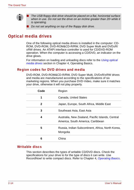
2-14 User’s Manual
The Grand Tour
Optical media drivesOne of the following optical media drives is installed in the computer: CD-ROM, DVD-ROM, DVD-ROM&CD-R/RW, DVD Super Multi and DVD±R/±RW drives. An ATAPI interface controller is used for CD/DVD-ROM operation. When the computer is accessing a CD/DVD, an indicator on the drive glows.For information on loading and unloading discs refer to the Using optical media drives section in Chapter 4, Operating Basics.
Region codes for DVD drives and mediaDVD-ROM, DVD-ROM&CD-R/RW, DVD Super Multi, DVD±R/±RW drives and media are manufactured according to the specifications of six marketing regions. When you purchase DVD-Video, make sure it matches your drive, otherwise it will not play properly.
Writable discsThis section describes the types of writable CD/DVD discs. Check the specifications for your drive to for the type of discs it can write. Use RecordNow! to write compact discs. Refer to Chapter 4, Operating Basics.
■ The USB floppy disk drive should be placed on a flat, horizontal surface when in use. Do not set the drive on an incline greater than 20o while it is operating.
■ Do not set anything on top of the floppy disk drive.
Code Region
1 Canada, United States
2 Japan, Europe, South Africa, Middle East
3 Southeast Asia, East Asia
4 Australia, New Zealand, Pacific Islands, Central America, South America, Caribbean
5 Russia, Indian Subcontinent, Africa, North Korea,Mongolia
6 China

User’s Manual 2-15
The Grand Tour
CDs■ CD-R discs can be written only once. The recorded data cannot be
erased or changed.■ CD-RW discs can be recorded more than once. Use either 1, 2, or 4
multi speed CD-RW discs or high-speed 4- to 10-speed discs. The write speed of the ultra-speed CD-RW discs is maximum 24-speed.
DVDs■ DVD-R and DVD+R discs can be written only once. The recorded data
cannot be erased or changed.■ DVD-RW, DVD+RW and DVD-RAM discs can be recorded more than
once.
FormatsThe drives support the following formats:
CD-ROM driveThe full-size CD-ROM drive module lets you run either 12 cm (4.72") or 8 cm (3.15") CD without using an adaptor.
DVD-ROM driveThe full-size DVD-ROM drive module lets you run either 12 cm (4.72") or 8 cm (3.15") CD/DVDs without using an adaptor.
■ CD-ROM■ DVD-ROM■ CD-DA■ Photo CDTM (single/multi-session)■ CD-ROM XA Mode 2 (Form1,
Form2)
■ DVD -Video■ CD-Text■ CD-ROM Mode 1, Mode 2 ■ Enhanced CD (CD-EXTRA)■ Addressing Method 2
The read speed is slower at the center of a disc and faster at the outer edge.
CD read 24 speed (maximum)
The read speed is slower at the center of a disc and faster at the outer edge.
DVD read 8 speed (maximum)CD read 24 speed (maximum)

2-16 User’s Manual
The Grand Tour
DVD-ROM&CD-R/RW driveThe full-size DVD-ROM&CD-R/RW drive module lets you record data to rewritable CDs as well as run either 12 cm (4.72") or 8 cm (3.15") CD/DVDs without using an adaptor.
DVD Super Multi drive
DVD±R/±RW drive (DVD Dual drive)The full- size DVD±R/±RW drive module lets you record data to rewritable CD/DVDs as well as run either 12 cm (4.72") or 8 cm (3.15") CD/DVDs without using an adaptor.
The read speed is slower at the center of a disc and faster at the outer edge.
DVD read 8 speed (maximum)CD read 24 speed (maximum)CD-R write 24 speed (maximum)CD-RW write 24 speed (maximum, high-speed media)
The read speed is slower at the center of a disc and faster at the outer edge.
DVD read 8 speed (maximum)DVD-R write 8 speed (maximum)DVD-RW write 4 speed (maximum)DVD+R write 8 speed (maximum)DVD+RW write 4 speed (maximum)DVD-RAM write 3 speed (maximum)CD read 24 speed (maximum)CD-R write 24 speed (maximum)CD-RW write 10 speed (maximum, Ultra-speed media)
The read speed is slower at the center of a disc and faster at the outer edge.
DVD read 8 speed (maximum)DVD-R write 8 speed (maximum)DVD-RW write 4 speed (maximum)DVD+R write 8 speed (maximum)DVD+RW write 4 speed (maximum)CD read 24 speed (maximum)CD-R write 24 speed (maximum)CD-RW write 24 speed (maximum, high-speed media)

User’s Manual 2-17
The Grand Tour
AC adaptorThe AC adaptor can automatically adjust to any voltage ranging from 100 to 240 volts and to a frequency of either 50 or 60 hertz, enabling you to use this computer in almost any country/region. And the adaptor converts AC power to DC power and reduces the voltage supplied to this computer.To recharge the battery, simply connect the AC adaptor to a power source and the computer. Refer to Chapter 6 Power and Power-Up Modes for details.
Figure 2-11 The AC adaptor (2-pin plug)
Figure 2-12 The AC adaptor (3-pin plug)
■ The Universal AC Adaptor and power cord bundled with this product may differ depending on the product model. Depending on the model, a 2-pin plug or 3-pin plug set of the above may be bundled.
■ Do not use a 3-pin to 2-pin conversion plug.■ The supplied power cord conforms to safety rules and regulations in
the region the product is bought and should not be used outside this region. For use in other regions, please buy power cords that conform to safety rules and regulations in the particular region.
Use only the AC adaptor that came with the computer or an equivalent optional adaptor. Use of any other adaptors could damage your computer. TOSHIBA assumes no liability for any damage in such case.

2-18 User’s Manual
The Grand Tour
Use only the AC adaptor supplied as an accessory. Other AC adaptors have different voltage and terminal polarities and use of them may produce heat and smoke or even result in fire or rupture.

User’s Manual 3-1
TECRA M3
Chapter 3
Getting Started
This chapter provides basic information to get you started using your computer. It covers the following topics:■ Setting up your work space — for your health and safety
■ Connecting the AC adaptor■ Opening the display■ Turning on the power■ Starting up for the first time■ Turning off the power■ Restarting the computer■ Creating recovery media■ Restoring the preinstalled software from the HDD■ Restoring the preinstalled software from the Recovery Media
Setting up your work spaceEstablishing a comfortable work site is important for you and your computer. A poor work environment or stressful work habits can result in discomfort or serious injury from repetitive strain to your hands, wrists or other joints. Proper ambient conditions should also be maintained for the computer’s operation. This section discusses the following topics:■ General conditions■ Placement of the computer■ Seating and posture■ Lighting■ Work habits
Be sure also to read Instruction Manual for Safety & Comfort. This guide, which is included with the computer, explains product liability.
All users should be sure to read the section Starting up for the first time.

3-2 User’s Manual
Getting Started
General conditionsIn general, if you are comfortable, so is your computer, but read the following to make sure your work site provides a proper environment.■ Make sure there is adequate space around the computer for proper
ventilation.■ Make sure the AC power cord connects to an outlet that is close to the
computer and easily accessible.■ The temperature should be 5 to 35 degrees Centigrade (41 to 95
degrees Fahrenheit) and the relative humidity should be 20 to 80 percent.
■ Avoid areas where rapid or extreme changes in temperature or humidity may occur.
■ Keep the computer free of dust, moisture, and exposure to direct sunlight.
■ Keep the computer away from heat sources, such as electric heaters.■ Do not use the computer near liquids or corrosive chemicals.■ Do not place the computer near objects that create strong magnetic
fields (e.g., stereo speakers).■ Some computers in the computer, including data storage media, can be
damaged by magnets. Do not place the computer near magnetic objects or bring magnetic objects close to the computer. Be careful of objects, such as stereo speakers, that produce strong magnetic fields during operation. Also, be careful with metal objects, such as bracelets, which can be inadvertently magnetized.
■ Do not operate the computer in close proximity to a mobile phone.■ Leave ample ventilation room for the fan. Do not block the vents.
Placement of the computerPosition the computer and peripheral devices to provide comfort and safety.■ Set the computer on a flat surface at a comfortable height and distance.
The LCD display panel should be no higher than eye level to avoid eyestrain.
■ Place the computer so that it is directly in front of you when you work and make sure you have adequate space to easily operate other devices.
■ Allow adequate space behind the computer to let you freely adjust the LCD display panel. The LCD display panel should be angled to reduce glare and maximize visibility.
■ If you use a paper holder, set it at about the same height and distance as the computer.

User’s Manual 3-3
Getting Started
Seating and postureThe height of your chair in relation to the computer and keyboard as well as the support it gives your body are primary factors in reducing work strain. Refer to the following tips and to figure 3-1.
Figure 3-1 Posture and positioning of the computer
■ Place your chair so that the keyboard is at or slightly below the level of your elbow. You should be able to type comfortably with your shoulders relaxed.
■ Your knees should be slightly higher than your hips. If necessary, use a foot rest to raise the level of your knees to ease pressure on the back of your thighs.
■ Adjust the back of your chair so it supports the lower curve of your spine.
■ Sit straight so that your knees, hips and elbows form approximately 90 degree angles when you work. Do not slump forward or lean back too far.
LightingProper lighting can improve legibility of the LCD screen and reduce eyestrain.■ Position the computer so that sunlight or bright indoor lighting does not
reflect off the LCD screen. Use tinted windows, shades or other screen to eliminate sun glare.
■ Avoid placing the computer in front of bright light that could shine directly in your eyes.
■ If possible, use soft, indirect lighting in your computer work area. Use a lamp to illuminate your documents or desk, but be sure to position the lamp so that it does not reflect off the LCD screen or shine in your eyes.
Foot rest
Below eye level
90°angles

3-4 User’s Manual
Getting Started
Work habitsA key to avoiding discomfort or injury from repetitive strain is to vary your activities. If possible, schedule a variety of tasks into your workday. If you must spend long periods at the computer, finding ways to break up the routine can reduce stress and improve your efficiency.■ Sit in a relaxed posture. Good positioning of your chair and equipment
as described earlier can reduce tension in your shoulders or neck and ease back strain.
■ Vary your posture frequently.■ Occasionally stand up and stretch or exercise briefly.■ Exercise and stretch your wrists and hands a number of times during
the day.■ Frequently, look away from the computer and focus your eyes on a
distant object for several seconds, for example 30 seconds every 15 minutes.
■ Take frequent short breaks instead of one or two long breaks, for example, two or three minutes every half hour.
■ Have your eyes examined regularly and visit a doctor promptly, if you suspect you might be suffering from a repetitive strain injury.
A number of books are available on ergonomics and repetitive strain injury or repetitive stress syndrome. For more information on these topics or for pointers on exercises for such stress points as hands and wrists, please check with your library or book vendor. Also refer to the computer’s Instruction Manual for Safety & Comfort.
Connecting the AC adaptorAttach the AC adaptor when you need to charge the battery or you want to operate from AC power. It is also the fastest way to get started, because the battery pack will need to be charged before you can operate from battery power.The AC adaptor can be connected to any power source supplying from 100 to 240 volts and 50 or 60 hertz. For details on using the AC adaptor to charge the battery pack, refer to Chapter 6, Power and Power-Up Modes.
Use only the AC adaptor supplied as an accessory. Other AC adaptors have different voltage and terminal polarities and use of them may produce heat and smoke or even result in fire or rupture.

User’s Manual 3-5
Getting Started
1. Connect the power cord to the AC adaptor.
Figure 3-2 Connecting the power cord to the AC adaptor (2-pin plug)
Figure 3-3 Connecting the power cord to the AC adaptor (3-pin plug)
■ Use only the AC adaptor supplied with your computer or an equivalent adaptor that is compatible. Use of any incompatible adaptor could damage your computer. TOSHIBA assumes no liability for any damage caused by use of an incompatible adaptor.
■ The supplied power cord conforms to safety rules and regulations in the region the product is bought and should not be used outside this region. For use in other regions, please buy power cords that conform to safety rules and regulations in the particular region.
■ Do not use a 3-pin to 2-pin conversion plug.■ When you connect the AC adaptor to the computer, always follow the
steps in the exact order as described in the User’s Manual. Connecting the power cable to a live electrical outlet should be the last step otherwise the adaptor DC output plug could hold an electrical change and cause an electrical shock or minor bodily injury when touched. As a general safety precaution, avoid touching any metal parts.
The Universal AC Adaptor and power cord bundled with this product may differ depending on the product model. Depending on the model, a 2-pin plug or 3-pin plug set of the above may be bundled.

3-6 User’s Manual
Getting Started
2. Connect the AC adaptor’s DC output plug to the DC IN 15V jack on the back of the computer.
Figure 3-4 Connecting the adaptor to the computer
3. Plug the power cord into a live wall outlet. The Battery and DC IN indicators on the front of the computer should glow.
Opening the displayThe computer’s LCD display panel can be rotated in a wide range of angles for optimal viewing.1. Slide the display latch on the front of the computer to the right.2. While holding down the palm rest with one hand so that the main body
is not raised, lift the panel slowly. Adjust the angle of the panel to provide optimal clarity.
Figure 3-5 Opening the LCD display panel
DC IN 15V jack
Use reasonable care when opening and closing the LCD display panel. Opening it vigorously or slamming it shut could damage the computer.
Display latch
LCD display panel

User’s Manual 3-7
Getting Started
Turning on the powerThis section describes how to turn on the power.The Power button LED indicates the status. Refer to the Power indicators section in Chapter 6, Power and Power-Up Modes.
1. Open the computer’s LCD display panel.2. Press and hold the computer’s power button for two or three seconds.
Figure 3-6 Turning on the power
Starting up for the first timeWhen you first turn on the power, the computer’s initial screen is the Microsoft Windows XP Startup Screen Logo. Follow the on-screen directions for each screen. During setup, you can click the Back button to return to the previous screen. Be sure to read the Windows End User License Agreement display carefully.
■ After you turn on the power for the first time, do not turn it off until you have set up the operating system. Refer to the section Starting up for the first time.
■ If the USB floppy disk drive is connected, make sure it is empty. If a floppy disk is in the drive, press the eject button and remove the floppy disk.
Power button
Be sure to read the License Agreement carefully.
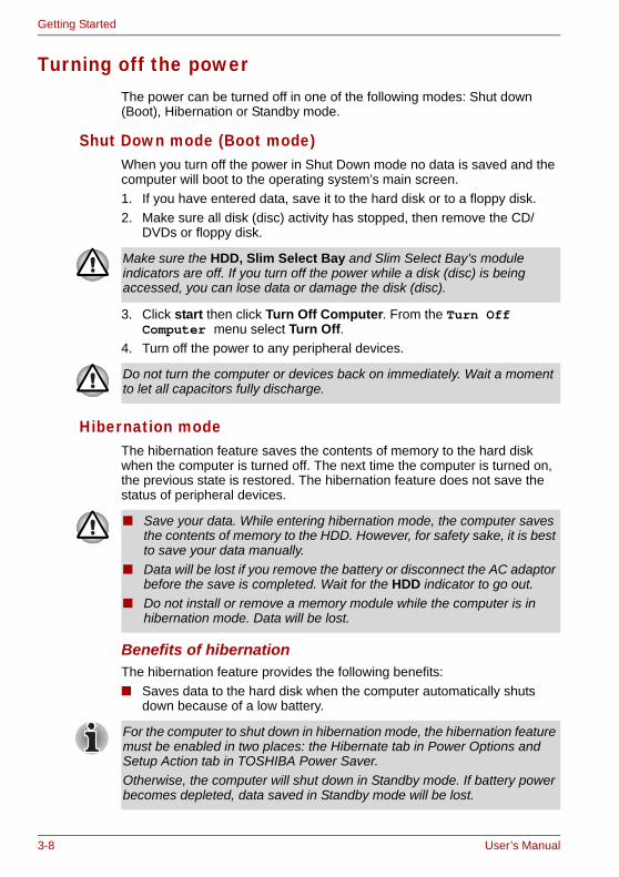
3-8 User’s Manual
Getting Started
Turning off the powerThe power can be turned off in one of the following modes: Shut down (Boot), Hibernation or Standby mode.
Shut Down mode (Boot mode)When you turn off the power in Shut Down mode no data is saved and the computer will boot to the operating system’s main screen.1. If you have entered data, save it to the hard disk or to a floppy disk.2. Make sure all disk (disc) activity has stopped, then remove the CD/
DVDs or floppy disk.
3. Click start then click Turn Off Computer. From the Turn Off Computer menu select Turn Off.
4. Turn off the power to any peripheral devices.
Hibernation modeThe hibernation feature saves the contents of memory to the hard disk when the computer is turned off. The next time the computer is turned on, the previous state is restored. The hibernation feature does not save the status of peripheral devices.
Benefits of hibernationThe hibernation feature provides the following benefits:■ Saves data to the hard disk when the computer automatically shuts
down because of a low battery.
Make sure the HDD, Slim Select Bay and Slim Select Bay’s module indicators are off. If you turn off the power while a disk (disc) is being accessed, you can lose data or damage the disk (disc).
Do not turn the computer or devices back on immediately. Wait a moment to let all capacitors fully discharge.
■ Save your data. While entering hibernation mode, the computer saves the contents of memory to the HDD. However, for safety sake, it is best to save your data manually.
■ Data will be lost if you remove the battery or disconnect the AC adaptor before the save is completed. Wait for the HDD indicator to go out.
■ Do not install or remove a memory module while the computer is in hibernation mode. Data will be lost.
For the computer to shut down in hibernation mode, the hibernation feature must be enabled in two places: the Hibernate tab in Power Options and Setup Action tab in TOSHIBA Power Saver.Otherwise, the computer will shut down in Standby mode. If battery power becomes depleted, data saved in Standby mode will be lost.

User’s Manual 3-9
Getting Started
■ You can return to your previous working environment immediately when you turn on the computer.
■ Saves power by shutting down the system when the computer receives no input or hardware access for the duration set by the System hibernate feature.
■ You can use the panel power off feature.
Starting Hibernation
To enter Hibernation mode, follow the steps below.1. Click start.2. Select Turn Off Computer.3. Open the Turn Off Computer dialog box. Hibernate is not displayed.4. Press the Shift key. The Standby item will change to Hibernate.5. Select the Hibernate.
Automatic HibernationThe computer will enter Hibernate mode automatically when you press the power button or close the lid. First, however, make the appropriate settings according to the steps below.1. Click start and open the Control Panel.2. Open Performance and Maintenance and open Power Options.3. Select the Hibernate window in the Power Options Properties,
select the Enable hibernation check box and click the Apply button.4. Open TOSHIBA Power Saver.5. Select the Setup Action window.6. Enable the desired Hibernation settings for When I press the power
button and When I close the lid.7. Click the OK button.
Data save in hibernation modeWhen you turn off the power in hibernation mode, the computer takes a moment to save current memory data to the hard disk. During this time, the Disk indicator will light.After you turn off the computer and memory is saved to the hard disk, turn off the power to any peripheral devices.
You can also enable Hibernation by pressing Fn + F4. Refer to Chapter 5, The Keyboard, for details.
Do not turn the computer or devices back on immediately. Wait a moment to let all capacitors fully discharge.

3-10 User’s Manual
Getting Started
Standby modeIf you have to interrupt your work, you can turn off the power without exiting from your software. Data is maintained in the computer’s main memory. When you turn on the power again, you can continue working right where you left off.
Benefits of standbyThe standby feature provides the following benefits:■ Restores the previous working environment more rapidly than does
hibernation.■ Saves power by shutting down the system when the computer receives
no input or hardware access for the duration set by the System Standby feature.
■ You can use the panel power off feature.
■ When the AC adaptor is connected, the computer will go into Standby mode according to the settings in the TOSHIBA Power Saver utility.
■ To restore operation from Standby mode, press the power button or press any key. The latter action works only if Wake-up on Keyboard is enabled in HW Setup.
■ If the computer automatically enters Standby mode while a network application is active, the application might not be restored when the computer wakes up from Standby.
■ To prevent the computer from automatically entering Standby mode, disable Standby in TOSHIBA Power Saver. That action, however, will nullify the computer’s Energy Star compliance.
■ Before entering Standby mode, be sure to save your data.■ Do not install or remove a memory module while the computer is in
standby mode. The computer or the module could be damaged.■ Do not remove the battery pack while the computer is in standby mode
(unless the computer is connected to an AC power source). Data in memory will be lost.
■ If you carry the computer on board an aircraft or into a hospital, be sure to shut down the computer in hibernation mode or in shutdown mode to avoid radio signal interference.

User’s Manual 3-11
Getting Started
Executing standby
You can enter standby mode in one of three ways:1. Click start, click Turn Off Computer and click Stand By.2. Close the computer’s LCD display panel. This feature must be enabled.
Refer to the Setup Action tab in TOSHIBA Power Saver Utility described in the Control Panel. Open Performance and Maintenance and open TOSHIBA Power Saver.
3. Press the power button. This feature must be enabled. Refer to the Setup Action tab in TOSHIBA Power Saver Utility described in the Control Panel.Open Performance and Maintenance and open TOSHIBA Power Saver.
When you turn the power back on, you can continue where you left when you shut down the computer.
Standby limitationsStandby will not function under the following conditions:■ Power is turned back on immediately after shutting down.■ Memory circuits are exposed to static electricity or electrical noise.
Restarting the computerCertain conditions require that you reset the system. For example, if:■ You change certain computer settings.■ An error occurs and the computer does not respond to your keyboard
commands.■ There are three ways to reset the computer system:1. Click start then click Turn off computer. From the Turn off
computer menu select Restart.2. Press Ctrl + Alt + Del to display the Windows Task Manager, then
select Shut Down and Restart.3. Press the power button and hold it down for five seconds. Wait 10 to 15
seconds, then turn the power on again by pressing the power button.
You can also enable Standby by pressing Fn + F3. See Chapter 5, The Keyboard, for details.
■ When the computer is shut down in standby mode, the power indicator blinking orange.
■ If you are operating the computer on battery power, you can lengthen the operating time by shutting down in hibernation mode. Standby mode consumes more power.

3-12 User’s Manual
Getting Started
Create Optical Recovery DiscsA recovery image of your computer is stored on the hard disk. You may use this image to create CD or DVD recovery discs using the following steps:1. Select either blank CDs or DVD media.2. The application will allow you to choose a type of media to create
recovery CDs/DVD including: CD-R, CD-RW, DVD-R, DVD-RW, DVD+R and DVD+RW.
3. Turn on your computer to open Windows XP.4. Insert the (first) blank media into the tray of the optical media drive.5. Double click the Recovery Disc Creator Launcher icon on the Windows
XP desktop, or Select the application from start Menu.6. After Recovery Disc Creator starts, select the type of media and the title
you wish to copy to the media then click the Burn button.
Restoring the preinstalled software from the Recovery HDD
About 2GB of hard disk space is reserved for recovery partition.When re-setting up your hard disk, do not change, delete or add partitions in a manner other than specified in the manual. Otherwise, space for software may be destroyed.In addition, if you use a third-party partitioning program to reconfigure partitions on your hard disk, it may become impossible to re-setup your computer.
1. Turn off your computer.2. While holding down 0 (zero) key on the keyboard, turn on your
computer.3. A menu appears. Press the "1" key on the keyboard to restore the
original configuration as purchased. Press the "2" key to keep your current partitions intact and restore. Press the "3" key to specify partitions and restore.
4. Follow the on-screen instructions.
Some media may not be compatible with the optical media drive of your computer. Please verify your optical media drive supports the blank media you choose.
If your optical media drive can only write to CDs, select "CD" as the "Type" on Recovery Disc Creator. If your optical media drive of your computer can write to either CD or DVDs, select the one you are using as the "Type" on Recovery Disc Creator.
When sound mute is turned ON by the Fn + Esc key, turn OFF before starting restore. Refer to Chapter 5, The Keyboard, for details.

User’s Manual 3-13
Getting Started
Restoring the preinstalled software from your creating Recovery Media
If preinstalled files are damaged, use the your creating Recovery Media or using HDD Recovery to restore them. To restore the operating system and all preinstalled software, follow the steps below.
1. Load the Recovery Media in the optional optical media drive and turn off the computer’s power.
2. Hold down the F12 key and turn on the power. When In Touch with Tomorrow TOSHIBA appears, release the F12 key.
3. Use the left or right cursor key to select the CD-ROM icon in the display menu. For details, refer to the Boot Priority section in Chapter 7, HW Setup.
4. A menu appears. Press the "1" key on the keyboard to restore all hard disk. Press the "2" key to Restore drive C:. Press the "3" key to Restore Recovery tool.
5. Follow the on-screen instructions.
■ If the optical media drive device is a CD-ROM drive or DVD-ROM drive, Optical Recovery Discs cannot be created. When there is a need to start the recovery process, use the Recovery HDD instead.
■ When creating Optical Recovery Discs, use a separate and external optical media drive that can write the data to CD-R or DVD-R discs.
When sound mute is turned ON by the Fn + Esc key, turn OFF before starting restore. Refer to Chapter 5, The Keyboard, for details.
When you reinstall the Windows operating system, the hard disk will be reformatted and all data will be lost.

3-14 User’s Manual
Getting Started

User’s Manual 4-1
TECRA M3
Chapter 4
Operating Basics
This chapter gives information on basic operations including using the TOSHIBA Dual Pointing Devices, USB floppy disk drive, changing Slim Select Bay modules, optical media drives, Sound System, Modem, Wireless communication features and LAN. It also provides tips on caring for your computer, floppy disks and CD/DVDs.
TOSHIBA Dual Pointing DeviceThe computer is equipped with a dual point system: a Touch Pad and an AccuPoint pointing stick.
Using the Touch PadTo use the Touch Pad, simply touch and move your fingertip across it in the direction you want the on-screen pointer to go.
Figure 4-1 Touch Pad and Touch Pad control buttons
Touch Pad
Touch Pad control buttons
AccuPoint AccuPoint Control Buttons

4-2 User’s Manual
Operating Basics
Two buttons below the Touch Pad are used like the buttons on a mouse pointer. Press the left button to select a menu item or to manipulate text or graphics designated by the pointer. Press the right button to display a menu or other function depending on the software you are using.
Using the AccuPointTo use the AccuPoint, simply push it with your finger tip in the direction you want to move the on-screen pointer.Two buttons above the Touch Pad work in the same way with the AccuPoint as they do with the Touch Pad. Refer to the Using the Touch Pad section for details.
AccuPoint precautionsCertain conditions can affect the on-screen pointer when using AccuPoint. For example, the pointer may travel contrary to AccuPoint operation or an error message may appear, if■ You touch the AccuPoint during power-up.■ You apply constant, soft pressure during power-up.■ There is a sudden temperature change.■ Strong stress is applied to the AccuPoint.If an error message appears, reboot the computer. If an error message does not appear, wait a moment for the pointer to stop, then continue operation.
You can also tap the Touch Pad to perform functions similar to those of the left button.
Click: Tap onceDouble-click: Tap twiceDrag and drop: Tap to select the material you want to move. Leave your finger on the Touch Pad after the second tap and move the material.

User’s Manual 4-3
Operating Basics
Replacing the capThe AccuPoint cap is an expendable item that should be replaced after prolonged use. One spare AccuPoint cap is supplied with the computer.1. To remove the AccuPoint cap, firmly pinch the cap and pull it straight
up.
Figure 4-2 Removing the AccuPoint cap
2. Position a new cap on the peg and press it into place.
The peg is square, so be careful to align the cap’s square hole with the peg.

4-4 User’s Manual
Operating Basics
Using the USB floppy disk driveUSB floppy disk drive connects to the computer’s USB port. It accommodates 1.44-megabyte or 720-kilobyte floppy disks. Refer to Chapter 2, The Grand Tour, for more information.Option or provided with some models.
Connecting USB floppy disk driveTo connect the drive, plug the floppy disk drive’s USB connector into a computer’s USB port. Refer to Figure 4-3.
Figure 4-3 Connecting the USB floppy disk drive
Disconnecting USB floppy disk driveWhen you have finished using the USB floppy disk drive, follow the procedures below to disconnect it:1. Wait for the indicator light to go out to make sure all floppy disk activity
has stopped.
2. Click the Safely Remove Hardware icon on the Task Bar.3. Click floppy disk drive that you want remove.4. Pull the USB floppy disk drive’s USB connector out of the computer’s
USB port.
Make sure the connector is right side up and properly aligned with the socket. Do not try to force the connection, doing so can damage the connecting pins.
USB connector
USB port
If you connect the USB floppy disk drive after turning on the computer, it will take about 10 seconds for the computer to recognize the drive. Do not disconnect and reconnect before 10 seconds has elapsed.
If you disconnect the USB floppy disk drive or turn off the power while the computer is accessing the drive you may lose data or damage the floppy disk or the drive.

User’s Manual 4-5
Operating Basics
Changing Slim Select Bay modulesThis section explains how to change modules in the Slim Select Bay. The illustrations show replacement of the optical media drive with the Slim Select Bay HDD adaptor. Therefore, the text refers to those modules. However, the procedures are the same for any of the modules: CD-ROM drive, DVD-ROM drive, DVD-ROM&CD-R/RW drive, DVD±R/±RW drive, DVD Super Multi drive, HDD adaptor, Slim Select Bay 2nd battery pack with separate tray or weight saver.
Removing a moduleRemove the optical media drive as described below.1. You can confirm that the disks are not operating with indicators. If all
indicators are off, it means that no disks are operating currently.2. Turn the computer upside down.
3. Remove the lock screw near the icon securing the Slim Select Bay.4. Make sure the screw in the Slim Select Bay lock is set in the hole for the
unlock position. 5. Slide the Slim Select Bay latch to the unlock position.
■ To avoid injury, do not put your hand into the Slim Select Bay slot.■ Before removing or inserting a second battery pack, turn off the
computer’s power.
The TOSHIBA Mobile Extension is preinstalled to support hot swapping under Windows. Refer to Chapter 1, Introduction for information on using this utility to change modules while the computer’s power is on.
Wait for all disk indicators to go out before you turn over the computer and do not lay the computer down gently. Shock can damage the HDD or other components.

4-6 User’s Manual
Operating Basics
6. Grasp the optical media drive and slide it out.
Figure 4-4 Removing the optical media drive
Inserting a moduleInsert the Slim Select Bay HDD adaptor as described below.1. Insert the Slim Select Bay HDD adaptor in the computer as shown
below and press until the ejector clicks.2. If you want to lock the Slim Select Bay HDD adaptor, set the Slim Select
Bay lock screw in the hole for the lock position (➁). The lock screw is inserted in the unlock position (➀) at the time of purchasing.
Figure 4-5 Inserting the Slim Select Bay HDD adaptor
The optical media drive and other Slim Select Bay modules can become hot with use. Be careful when removing the module.
Slim Select Bay lock screw
Optical media drive
Slim SelectBay latch
Slim Select Bay HDD adaptor
Slim Select Bay lock screw

User’s Manual 4-7
Operating Basics
Using optical media drivesThe text and illustrations in this section refer primarily to the optional media drive. However, operation is the same for other optical drive in the Slim Select Bay. The full-size drive provides high-performance execution of CD/DVD-ROM-based programs. You can run either 12 cm (4.72") or 8 cm (3.15") CD/DVDs without an adaptor. An ATAPI interface controller is used for CD/DVD-ROM operation. When the computer is accessing a CD/DVD-ROM, an indicator on the drive glows and the Slim Select Bay indicator glows.
If you have a DVD-ROM&CD-R/RW drive, refer also to the Writing CDs on DVD-ROM&CD-R/RW drive section for precautions on writing to CDs.If you have a DVD±R/±RW drive, refer also to the Writing CD/DVDs on DVD±R/±RW drive (DVD Dual drive) section for precautions on writing to CDs.If you have a DVD Super Multi drive, refer also to the Writing CD/DVDs on DVD Super Multi drive section for precautions on writing to CDs.
Loading discsTo load CD/DVDs, follow the steps below and refer to figures 4-6 to 4-9.1. When the computer’s power is on, press the eject button to open
the disc tray slightly.
Figure 4-6 Pressing the eject button
Use the WinDVD application to view DVD-Video discs.
When the power of the optical media drive is off, pressing the Fn + Tab keys will turn the power of the optical media drive on. Furthermore, it is possible to set it to turn the power of the optical media drive on and eject the tray at the same time.
Eject Button

4-8 User’s Manual
Operating Basics
2. Grasp the disc tray gently and pull until it is fully opened.
Figure 4-7 Pulling the disc tray open
3. Lay the CD/DVD, label side up, in the disc tray.
Figure 4-8 Inserting a CD/DVD
4. Press gently at the center of the CD/DVD until you feel it click into place. The CD/DVD should lie below the top of the spindle, flush with the spindle base.
Disc tray
Laser lens
When the disc tray is fully opened, the edge of the computer will extend slightly over the CD/DVD tray. Therefore, you will need to turn the CD/DVD at an angle when you place it in the disc tray. After seating the CD/DVD, however, make sure it lies flat, as shown in figure 4-8.
■ Do not touch a laser lens and its circumference portion. Doing so could cause misalignment.
■ Prevent foreign objects from entering the drive. Check the surface of the disc tray, especially the area behind the front edge of the disc tray, to make sure there are no such objects before closing the drive.

User’s Manual 4-9
Operating Basics
5. Push the center of the disc tray to close it. Press gently until it locks into place.
Figure 4-9 Closing the DVD-ROM disc tray
Removing discsTo remove the CD/DVD, follow the steps below and refer to figure 4-10.
1. To pop the disc tray partially open, press the eject button. Gently pull the disc tray out until it is fully opened.
2. The CD/DVD extends slightly over the sides of the disc tray so you can hold it. Hold the CD/DVD gently and lift it out.
Figure 4-10 Removing a CD/DVD
3. Push the center of the disc tray to close it. Press gently until it locks into place.
If the CD/DVD is not seated properly when the disc tray is closed, the CD/DVD might be damaged. Also, the disc tray might not open fully when you press the eject button.
Do not press the eject button while the computer is accessing the media drive. Wait for the Slim Select Bay indicator to go out before you open the disc tray. Also, if the CD/DVD is spinning when you open the disc tray, wait for it to stop before you remove it.
When the disc tray pops open slightly, wait a moment to make sure the CD/DVD has stopped spinning before pulling the disc tray fully open.

4-10 User’s Manual
Operating Basics
How to remove CD/DVD when the disk tray will not openPressing the eject button will not open the disc tray when the computer power is off. If the power is off, you can open the disc tray by inserting a slender object (about 15 mm) such as a straightened paper clip into the eject hole just to the right of the eject button.
Figure 4-11 Manual release with the eject hole
Writing CDs on DVD-ROM&CD-R/RW driveDepending on the type of drive installed, you may be able to write CDs. The DVD-ROM&CD-R/RW drive lets you write as well as read CD-ROMs. Observe the precautions in this section to ensure the best performance for writing CDs. For information on loading and unloading CDs refer to the Using optical media drives section.
Eject hole
Turn off the power before you use the eject hole. If the CD/DVD is spinning when you open the disc tray, the CD/DVD could fly off the spindle and cause injury.
■ CD-R discs can be written to only once. CD-RW discs can be rewritten many times.
■ When the power of the optical media drive is off, the disc tray will not open even if the eject button is pushed. Use the optical media drive power icon to turn the power of the optical media drive on. Refer to Chapter 1, Special features.
■ Do not turn off the power of the optical media drive while the computer is accessing the drive. If you turn off the power, you may lose data.

User’s Manual 4-11
Operating Basics
Before writing or rewritingPlease observe the following points when you write or rewrite the data.■ We recommend the following manufacturers of CD-R and CD-RW
media. Media quality can affect write or rewrite success rates.
TOSHIBA has confirmed the operation of CD-R and CD-RW media of the manufacturers above. Operation of other media cannot be guaranteed.■ The actual number of rewrites to CD-RW is affected by the quality of the
disc and the way it is used. ■ Be sure to connect the AC adaptor when you write or rewrite.■ Be sure to close all other software programs except the writing
software.■ Do not run software such as a screen saver which can put a heavy load
on the CPU.■ Operate the computer at full power. Do not use power-saving features.■ Do not write while virus check software is running. Wait for it to finish,
then disable virus detection programs including any software that checks files automatically in the background.
■ Do not use hard disk utilities, including those intended to enhance HDD access speed. They may cause unstable operation and damage data.
■ Write from the computer's HDD to the CD. Do not try to write from shared devices such as a LAN server or any other network device.
■ Writing with software other than Sonic RecordNow! has not been confirmed. Therefore, operation with other software cannot be guaranteed.
CD-R:TAIYO YUDEN CO., LTD.MITSUBISHI CHEMICAL CORPORATIONRICOH Co., Ltd.Hitachi Maxell Ltd.
CD-RW:MITSUBISHI CHEMICAL CORPORATIONRICOH Co., Ltd.
The following special media recommend the next manufacturers.
Multi-Speed and High-Speed CD-RW:MITSUBISHI CHEMICAL CORPORATIONRICOH Co., Ltd.
Ultra-Speed CD-RW:MITSUBISHI CHEMICAL CORPORATION

4-12 User’s Manual
Operating Basics
When writing or rewritingNote the following when you write or rewrite a CD-R or CD-RW.■ Always copy data from the HDD to the CD. Do not use cut-and-paste.
The original data will be lost if there is a write error.■ Do not perform any of the following actions:
■ Change users in the Windows XP operating system.■ Operate the computer for any other function, including use of a
mouse or Touch Pad, closing/opening the LCD panel.■ Start a communication application such as a modem.■ Apply impact or vibration to the computer.■ Install, remove or connect external devices, including the following:
PC card, ExpressCard, SD card, USB devices, external monitor, i.LINK devices, optical digital devices.
■ Open the optical media drive.■ Remove the optical media drive from the Slim Select Bay.
■ If the media is poor in quality, dirty or damaged, writing or rewriting errors may occur.
■ Set the computer on a level surface and avoid places subject to vibration such as airplanes, trains or cars. Do not use an unstable surface such as a stand.
■ Keep mobile phones and other wireless communication devices away from the computer.
Writing CD/DVDs on DVD±R/±RW drive (DVD Dual drive)
You can use the DVD±R/±RW drive to write data to either CD-R/RW or DVD-R/-RW/+R/+RW discs. The following applications for writing are preinstalled: RecordNow!, and DLA licensed by Sonic Solutions.
Writing CD/DVDs on DVD Super Multi driveYou can use the DVD Super Multi drive to write data to either CD-R/RW or DVD-R/-RW/+R/+RW/-RAM discs. The following applications for writing are preinstalled: RecordNow!, and DLA licensed by Sonic Solutions.
Important message (DVD±R/±RW drive)Before you write or rewrite to CD-R/RW or DVD-R/-RW/+R/+RW disc, read and follow all setup and operating instructions in this section. If you fail to do so, the DVD±R/±RW drive may not function properly, and you may fail to write or rewrite, lose data or incur other damage.

User’s Manual 4-13
Operating Basics
Important message (DVD Super Multi drive)Before you write or rewrite to CD-R/RW or DVD-R/-RW/+R/+RW/-RAM disc, read and follow all setup and operating instructions in this section. If you fail to do so, the DVD Super Multi drive may not function properly, and you may fail to write or rewrite, lose data or incur other damage.
Disclaimer (DVD±R/±RW drive)TOSHIBA does not bear responsibility for the following:■ Damage to any CD-R/RW or DVD-R/-RW/+R/+RW disc that may be
caused by writing or rewriting with this product.■ Any change or loss of the recorded contents of CD-R/RW or DVD-R/-
RW/+R/+RW disc that may be caused by writing or rewriting with this product, or for any business profit loss or business interruption that may be caused by the change or loss of the recorded contents.
■ Damage that may be caused by using third party equipment or software.
Given the technological limitations of current optical disc writing drives, you may experience unexpected writing or rewriting errors due to disc quality or problems with hardware devices. Also, it is a good idea to make two or more copies of important data, in case of undesired change or loss of the recorded contents.
Disclaimer (DVD Super Multi drive)TOSHIBA does not bear responsibility for the following:■ Damage to any CD-R/RW or DVD-R/-RW/+R/+RW/-RAM disc that may
be caused by writing or rewriting with this product.■ Any change or loss of the recorded contents of CD-R/RW or DVD-R/-
RW/+R/+RW/-RAM disc that may be caused by writing or rewriting with this product, or for any business profit loss or business interruption that may be caused by the change or loss of the recorded contents.
■ Damage that may be caused by using third party equipment or software.
Given the technological limitations of current optical disc writing drives, you may experience unexpected writing or rewriting errors due to disc quality or problems with hardware devices. Also, it is a good idea to make two or more copies of important data, in case of undesired change or loss of the recorded contents.

4-14 User’s Manual
Operating Basics
Before writing or rewriting■ Based on TOSHIBA's limited compatibility testing, we suggest the
following manufacturers of CD-R/RW and DVD-R/+R/-RW/+RW/-RAM disc. However, in no event does TOSHIBA guarantee the operation, quality or performance of any disc. Disc quality can affect write or rewrite success rates.
CD-R:TAIYO YUDEN CO., LTD.MITSUBISHI CHEMICAL CORPORATIONRICOH Co., Ltd.Hitachi Maxell Ltd.
CD-RW: (Multi-Speed and High-Speed)MITSUBISHI CHEMICAL CORPORATIONRICOH Co., Ltd.
CD-RW: (Ultra-Speed)MITSUBISHI CHEMICAL CORPORATION
DVD-R:DVD Specifications for Recordable Disc for General Version 2.0TAIYO YUDEN CO., LTD.Matsushita Electric Industrial Co., Ltd.
DVD+R:MITSUBISHI CHEMICAL CORPORATIONRICOH Co., Ltd.
DVD-RW:DVD Specifications for Recordable Disc for Version 1.1 or version 1.2VICTOR COMPANY OF JAPAN.LIMITEDMITSUBISHI CHEMICAL CORPORATION
DVD+RW:MITSUBISHI CHEMICAL CORPORATIONRICOH Co., Ltd.
DVD-RAM:DVD Specifications for DVD-RAM Disc for Version 2.0 or Version 2.1Matsushita Electric Industrial Co., Ltd.Hitachi Maxell Ltd.

User’s Manual 4-15
Operating Basics
■ If the disc is poor in quality, dirty or damaged, writing or rewriting errors may occur. Be careful to check the disc for dirt or damage before you use it.
■ The actual number of rewrites to CD-RW, DVD-RW, DVD+RW or DVD-RAM is affected by the quality of the disc and the way it is used.
■ There are two types of DVD-R discs: authoring and general use discs. Do not use authoring discs. Only general use discs can be written to by a computer drive.
■ You can use DVD-RAM discs that can be removed from a cartridge and DVD-RAM discs designed without a cartridge. You cannot use a disc with a 4.7 GB single-sided capacity or 9.4 GB double-sided capacity.
■ Other DVD-ROM drives for computers or other DVD players may not be able to read DVD-R/-RW or DVD+R/+RW discs.
■ Data written to a CD-R/DVD-R/DVD+R disc cannot be deleted either in whole or in part.
■ Data deleted (erased) from a CD-RW, DVD-RW, DVD+RW and DVD-RAM disc cannot be recovered. Check the content of the disc carefully before you delete it. If multiple drives that can write data to discs are connected, be careful not to delete data from the wrong drive.
■ In writing to a DVD-R/-RW, DVD+R/+RW or DVD-RAM disc, some disc space is required for file management, so you may not be able to write the full capacity of the disc.
■ Since the disc is based on the DVD standard, it might be filled with dummy data if the written data is less than about 1 GB. Even if you write only a small amount of data, it might take time to fill in the dummy data.
■ DVD-RAM formatted by FAT32 cannot be read in Windows 2000 without DVD-RAM Driver Software.
■ When multiple drives that can write data to discs are connected, be careful not to write to the wrong drive.
■ Be sure to connect the AC adaptor before you write or rewrite.■ Before you enter standby/hibernation mode, be sure to finish DVD-RAM
writing. Writing is finished if you can eject DVD-RAM media.■ Be sure to close all other software programs except the writing
software.■ Do not run software such as a screen saver, which can put a heavy load
on the CPU.■ Operate the computer in the full-power mode. Do not use power-saving
features.■ Do not write while virus check software is running. Wait for it to finish
and then disable virus detection programs including any software that checks files automatically in the background.
■ Do not use hard disk utilities, including those intended to enhance HDD access speed. They may cause unstable operation and data damage.
This drive cannot use discs that allow writing faster than 8 speed (DVD-R, DVD+R), 4 speed (DVD-RW, DVD+RW), 3 speed (DVD-RAM)

4-16 User’s Manual
Operating Basics
■ CD-RW (Ultra Speed +) media is not available. If used, data may be lost or damaged.
■ Write from the computer's HDD to the CD/DVD. Do not try to write from shared devices such as a LAN server or any other network device.
■ Writing with software other than RecordNow! and InterVideo WinDVD Creator Platinum are not recommended.
When writing or rewritingPlease observe/consider the following when you write or rewrite to a CD-R/RW, DVD-R/-RW/-RAM or DVD+R/+RW disc.■ Do not perform any of the following actions when writing or rewriting:
■ Change users in the Windows XP operating system.■ Operate the computer for any other function, including using a
mouse or Touch Pad or closing/opening the LCD panel.■ Start a communication application such as a modem.■ Apply impact or vibration to the computer.■ Install, remove or connect external devices, including the following:
PC card, ExpressCard, SD card, USB devices, external monitor, i.LINK devices, optical digital devices.
■ Use the Audio/Video control button to reproduce music or voice.■ Open the optical media drive.■ Remove the optical media drive from the Slim Select Bay.
■ Do not use shut down/log off and standby/hibernation while writing or rewriting.
■ Make sure writing or rewriting is completed before going into standby/hibernation. Writing is completed if you can open the DVD-ROM&CD-R/RW or DVD Super Multi drive tray.
■ Set the computer on a level surface and avoid places subject to vibration such as airplanes, trains, or cars. Do not use an unstable surface such as a stand.
■ Keep mobile phones and other wireless communication devices away from the computer.
■ Always copy data from the HDD to the DVD-RAM. Do not use cut-and-paste. The original data will be lost if there is a write error.

User’s Manual 4-17
Operating Basics
RecordNow! Basic for TOSHIBANote the following limitations when you use RecordNow!:■ DVD-Video cannot be created using RecordNow!.■ DVD-Audio cannot be created using RecordNow!.■ You cannot use RecordNow!'s “Audio CD for Car or Home CD Player”
function to record music to the DVD-R/-RW or DVD+R/+RW disc.■ Do not use the “Exact Copy” function of RecordNow! to copy DVD-
Video and DVD-ROM with copyright protection.■ DVD-RAM disc cannot be backed up with the “Exact Copy” function of
RecordNow!.■ You cannot back up a CD-ROM or CD-R/RW to DVD-R/-RW or
DVD+R/+RW using the “Exact Copy” function of RecordNow!.■ You cannot back up DVD-ROM, DVD-Video or DVD-R/-RW or DVD+R/
+RW to CD-R/RW using the “Exact Copy” function of RecordNow!.■ RecordNow! cannot record in packet format.■ You might not be able to use the “Exact Copy” function of RecordNow!
to back up a DVD-R/-RW or DVD+R/+RW disc that was made with other software on a different DVD-R/-RW or DVD+R/+RW recorder.
■ If you add data to a DVD-R and DVD+R disc that you have already recorded to, you might not be able to read the added data under some circumstances. It cannot be read in 16-bit operating systems, such as Windows 98SE and Windows Me. In Windows NT4, you will need Service Pack 6 or later to read added data. In Windows 2000, you will need Service Pack 2 or later to read it. Some DVD-ROM and DVD-ROM&CD-R/RW drives cannot read added data regardless of the operating system.
■ RecordNow! does not support recording to DVD-RAM discs. To record to a DVD-RAM, use Explorer or other utility.
■ When you back up a DVD disc, be sure the source drive supports recording to DVD-R/-RW or DVD+R/+RW discs. If the source drive does not support recording to DVD-R/-RW or DVD+R/+RW discs, it might not be backed up correctly.
■ When you back up a DVD-R, DVD-RW, DVD+R or DVD+RW, be sure to use the same type of disc.
■ You cannot partially delete any data written to a CD-RW, DVD-RW or DVD+RW disc.

4-18 User’s Manual
Operating Basics
Data VerificationTo verify that data is written or rewritten correctly, follow the steps below before you write or rewrite a Data CD/DVD.
1. Click the Options button ( ) on the RecordNow! Console to open the Options panels.
2. Select the Data in the left-side menu.3. Mark the Verify data written to the disc after burning check box in the
Data Options.Click the OK button.
DLA for TOSHIBANote the following limitations when you use DLA:■ This software supports only rewritable discs (DVD+RW, DVD-RW, and
CD-RW). It does not support DVD+R, DVD-R, and CD-R discs that are not rewritable.
■ DLA does not support formatting a DVD-RAM disc and writing to it. They are performed by DVD-RAM Driver Software. If DLA Format menu may appear when inserting a DVD-RAM disc into the drive and right-clicking the drive icon in Windows Explorer, please use "DVDForm" to format this disc. You can run "DVDForm" by clicking the start button on the taskbar to display the start menu and then selecting "All Programs", "DVD-RAM", "DVD-RAM Driver" and "DVDForm" sequentially.
■ Do not use any discs that have been formatted with packet writing software other than DLA. Similarly, do not use any discs that have been formatted with DLA with any packet writing software other than DLA. When using a disc you are not familiar with, format it by selecting “Full Format” before using it.
■ Do not use the Cut & Paste function for files and folders. A file or folder that has been cut may be lost if writing fails due to an error on the disc.
■ When writing the Setup files for the program to a disc formatted by DLA and starting Setup from this disc, an error may occur. In this case, please copy them to your hard disk and then run Setup.
VideoAs for InterVideo WinDVD Creator Platinum. Only the model that can be written in to DVD is attached.
When using WinDVD Creator PlatinumYou can record video back to your digital camcorder via i.LINK (IEEE1394) using WinDVD Creator Platinum. However, there is a case where its playback sound is choppy.1. Click start and select the Control Panel.2. Click the Performance and Maintenance icon in the Control Panel.3. Click the System icon in the Performance and Maintenance window.

User’s Manual 4-19
Operating Basics
4. Click the Advanced tab in the System Properties window.5. Click the Settings icon in the "Performance" section.6. Click the Advanced tab in the Performance Options window.7. Click the Change icon in the "virtual memory" section.8. Select the Custom size button in the Virtual Memory window.9. Specify much higher values for "Initial size" and "Maximum size." 10. Click the Set button in the Virtual Memory window.11. Click the OK button in the Virtual Memory window.
How to make a DVD-VideoSimplified steps for making a DVD-Video from video data captured from a DV-Camcorder:1. Click [start]-[All Programs] - [InterVideo WinDVD Creator2] - [InterVideo
WinDVD Creator] to launch WinDVD Creator.2. Click [Capture] button then capture the video data from the DV-
Camcorder via IEEE1394.3. Click [Edit] button then drag the video clips from [Video Library] tab to
the edit track.4. Click [Make Movie] button in the top bar.5. Double Click the Right arrow button icon in the center of right side.6. Put a blank DVD-R/+R disc or an erased DVD-RW/+RW disc in the
drive.7. Click [start] to record to the disc.8. When recording is finished, the tray opens.
How to learn more about InterVideo WinDVD CreatorPlease refer to the on-line Help for additional InterVideo WinDVD Creator information.
Important information for useNote the following limitations when you write video DVD:1. Editing digital video
■ Log in with Administrator rights to use WinDVD Creator.■ Make sure that your computer is running on AC power when using
WinDVD Creator.■ Operate the computer at Full Power. Do not use power-saving
features.■ While you are editing DVD, you can display previews. However, if
another application is running, the preview might not display properly.
■ WinDVD Creator cannot show video on the external monitor when in simultaneous mode.
■ WinDVD Creator cannot edit or play copy protected content.

4-20 User’s Manual
Operating Basics
■ Do not change display settings while using WinDVD Creator.■ Do not enter standby/hibernation mode while using WinDVD
Creator.■ Do not operate WinDVD Creator immediately after turning on the
computer. Please wait until all Disc Drive activity has stopped.■ When recording to a DV-Camcorder, to ensure you capture all of
your data, let the camcorder record for a few seconds before you begin recording your actual data.
■ CD recorder, JPEG functions, DVD-Audio, mini DVD and Video CD functions are not supported in this version.
■ While recording video to DVD or tape, please close all other programs.
■ Do not run software like a screen saver because it can put a heavy load on the CPU.
■ Do not run communication applications like a modem or a LAN.2. Before recording the video to DVD
■ When you record to DVD disc, please use only discs recommended by the Drive manufacturer.
■ Do not set the working drive to a slow device like a USB 1.1 hard disk drive or it will fail to write DVD.
■ Do not perform any of the following actions: • Operate the computer for any other function, including using a
mouse or Touch Pad or closing/opening the LCD panel. • Bump or cause vibration to the computer. • Use the Mode control button and Audio/Video control button to
reproduce music or voice. • Open the optical media drive. • Install, remove or connect external devices, including the
following:PC card, ExpressCard, SD card, USB devices, external monitor, i.LINK devices, optical digital devices.
■ Please verify your disc after recording important data.■ DVD-R/+R/-RW disc cannot be written in VR format.■ WinDVD Creator cannot export to DVD-Audio, VideoCD, miniDVD
format.■ WinDVD Creator can write DVD-RAM/+RW in VR format, but the
disc may only play on your computer.■ When writing to DVD disc, WinDVD Creator requires 2GB or more
over disk space every one hour of video.■ When you make a fully recorded DVD, the chapter sequence may
not play correctly.

User’s Manual 4-21
Operating Basics
3. About Disc Manager■ WinDVD Creator can edit one play list on a disc.■ WinDVD Creator might show a different a thumbnail than you
previously set in CE (Consumer Electronics) DVD-RAM recorder.■ Using the Disc Manager, you can edit DVD-VR format on DVD-
RAM, DVD+VR format on DVD+RW, and DVD-Video format on DVD-RW.
4. About recorded DVDs■ Some DVD-ROM drives for personal computers or other DVD
players may not be able to read DVD-R/+R/-RW/+RW/-RAM discs.■ When playing your recorded disc on your computer, please use the
WinDVD software application.■ If you use an over-used rewritable disc, the full formatting might be
locked. Please use a brand new disc.
Media careThis section provides tips on protecting data stored on your CD/DVDs and floppy disks.Handle your media with care. The following simple precautions will increase the lifetime of your media and protect the data stored on them:
CD/DVDs1. Store your CD/DVDs in the container they came in to protect them and
keep them clean.2. Do not bend the CD/DVD.3. Do not write on, apply a sticker to, or otherwise mar the surface of the
CD/DVD that contains data.4. Hold the CD/DVD by its outside edge or the edge on the center hole.
Fingerprints on the surface can prevent the drive from properly reading data.
5. Do not expose to direct sunlight, extreme heat or cold. Do not place heavy objects on your CD/DVDs.
6. If your CD/DVDs become dusty or dirty, wipe them with a clean dry cloth. Wipe from the center out, do not wipe in a circular direction around the CD/DVD. If necessary, use a cloth dampened in water or a neutral cleaner. Do not use benzine, thinner or similar cleaner.
Floppy disks1. Store your floppy disks in the container they came in to protect them
and keep them clean. If a floppy disk is dirty, do not use cleaning fluid. Clean it with a soft damp cloth.
2. Do not slide back the floppy disk’s protective metal covering or touch the floppy disk’s magnetic surface. Fingerprints may prevent the floppy disk drive from reading data from the floppy disk.

4-22 User’s Manual
Operating Basics
3. Data may be lost if the floppy disk is twisted; bent; or exposed to direct sunlight, extreme heat or cold.
4. Do not place heavy objects on your floppy disks.5. Do not eat, smoke, or use erasers near your floppy disks. Foreign
particles inside the floppy disk’s jacket can damage the magnetic surface.
6. Magnetic energy can destroy the data on your floppy disks. Keep your floppy disks away from speakers, radios, television sets and other sources of magnetic fields.
Sound SystemUsing the microphone
Your computer has a built-in microphone that can be used to record monaural sounds into your applications. It can also be used to issue voice commands to applications that support such functions.Since your computer has a built-in microphone and speaker, “howling” may be heard under certain conditions. Howling occurs when sound from the speaker is picked up in the microphone and amplified back to the speaker, which amplifies it again to the microphone.This howling occurs repeatedly and causes a very loud, high-pitched noise. It is a common phenomenon that occurs in any sound system when the microphone input is output to the speaker (throughput) and the speaker volume is too loud or too close to the microphone. You can control throughput by adjusting the volume of your speaker or through the Mute function.To adjust the volume or activate Mute, click start, point to All Programs, point to Accessories, point to Entertainment and click Volume Control. In the Volume Control panel, you can use the slide bars to adjust the volume level or click Mute at the bottom of the panel.
SoundMAX control panelThe SoundMAX control panel lets you control additional functions for the Microphone Enhancement and Audio Power Management. To launch the SoundMAX Control Panel, follow the steps below.1. Click start and click Control Panel.2. If you are viewing the Control Panel in Category View, click on Switch
to Classic View.3. Double-click the SoundMAX icon.The Microphone Setup allows you to optimize the microphone input settings for your particular configuration. Choose Standard Microphone if you have an ordinary desktop microphone. Choose Headset if you have a wearable microphone that is positioned directly in front of your mouth.

User’s Manual 4-23
Operating Basics
You can launch the Setup Wizard from the Control Panel to help you to automatically set proper microphone input volumes and ensure that your voice input(s) are working correctly. As you speak into the microphone, the Sound Meter indicates the audio signal that your PC is receiving.The Noise Reduction enhancement helps to eliminate ambient noise from the voice input signal to provide a clean and clear signal to applications. This feature can be used with any microphone.The audio controller can be powered down when the audio function is idle. To enable the Audio Power Management, follow the steps below.1. Click the Power Management tab.2. Select the Normal Power Savings in the Power Mode pull-down list.
If you want to a more effect for the power management, you can select another mode, the High Power Savings which can save the power than the Normal Power Savings. To select it, follow the steps below.1. Click the Power Management tab.2. Select the High Power Savings in the Power Mode pull-down list.3. Input a time in Power Save Delay (Seconds).
Mic EffectTOSHIBA Mic Effect provides you with a hands-free environment for holding mutual communication via the Internet Protocol or Local Area Network. If you wish to communicate with someone on your computer, you can use a messenger application. However, with such an application, you would hear your own voice returning to you as echo during the communication if you did not use a headset system or headphone. TOSHIBA Mic Effect will reduce these echoes generated on your computer. Form more information on using the TOSHIBA Mic Effect, refer to its help.
ModemThis section describes how to connect and disconnect the internal modem to and from a telephone jack.
If the No Power Savings is selected, the audio controller always runs.
If the High Power Saving is selected, you need to play an audio file once before you use a microphone or play an audio CD by the analog CD audio.
The internal modem does not support voice functions. All data and fax functions are supported.
■ In case of a lightning storm, unplug the modular cable from the telephone jack.
■ Do not connect the modem to a digital telephone line. A digital line will damage the modem.

4-24 User’s Manual
Operating Basics
Region selectionTelecommunication regulations vary from one region to another, so you will need to make sure the internal modem’s settings are correct for the region in which it will be used.To select a region, follow the steps below.1. Click start, point to All Programs, point to TOSHIBA, point to
Networking and click Modem Region Select.
2. The Region Selection icon will appear in the Windows Task Bar.3. Click the icon with the primary mouse button to display a list of regions
that the modem supports. A sub menu for telephony location information will also be displayed. A check will appear next to the currently selected region and telephony location.
4. Select a region from the region menu or a telephony location from the sub-menu. ■ When you click a region it becomes the modem’s region selection,
and the New Location for telephony will be set automatically.■ When you select a telephony location, the corresponding region is
automatically selected and it becomes the modem’s current region setting.
Properties menuClick the icon with the secondary mouse button to display properties menu on the screen.
SettingYou can enable or disable the following settings:
AutoRun ModeThe Region Select utility starts automatically when you start up the operating system.
Open the Dialing Properties dialog box after selecting region.The dialing properties dialog box will be displayed automatically after you select the region.
Location list for region selection.A submenu appears displaying location information for telephony.
Do not use the Country/Region Select function in the Modem setup utility in the Control Panel if the function is available. If you change the Country/Region in the Control Panel, the change may not take effect.

User’s Manual 4-25
Operating Basics
Open dialog box, if the modem and Telephony Current Location region code do not match.A warning dialog box is displayed if current settings for region code and telephony location are incorrect.
Modem SelectionIf the computer cannot recognize the internal modem, a dialog box is displayed. Select the COM port for your modem to use.
Dialing PropertiesSelect this item to display the dialing properties.
ConnectingTo connect the modular cable, follow the steps below.
1. Plug one end of the modular cable into the computer’s modem jack.2. Plug the other end of the modular cable into a telephone jack.
Figure 4-12 Connecting the internal modem
If you are using the computer in Japan, the Telecommunications Business Law requires that you select Japan region mode. It is illegal to use the modem in Japan with any other selection.
The modular cable that comes with the computer must be used to connect a modem. Connect the end of the modular cable with the core to the computer.
■ In case of a lightning storm, unplug the modular cable from the telephone jack.
■ Do not connect the modem to a digital telephone line. A digital line will damage the modem.
Telephone jackModem jack Modular cable
Do not pull on the cable or move the computer while the cable is connected.

4-26 User’s Manual
Operating Basics
DisconnectingTo disconnect the internal modular cable, follow the steps below.1. Pinch the lever on the connector in the telephone jack and pull out the
connector.2. Disconnect the cable from the computer’s modem jack in the same
manner.
Wireless communicationsThe computer’s wireless communication function supports both Wireless LAN and Bluetooth devices. Bluetooth provided with some models.
Wireless LANThe Wireless LAN is compatible with other LAN systems based on Direct Sequence Spread Spectrum /Orthogonal Frequency Division Multiplexing radio technology that complies with IEEE802.11 Wireless LAN standard (Revision A, B or G) and Turbo Mode.■ Theoretical maximum speed: 54Mbps (IEEE802.11a, 802.11g)■ Theoretical maximum speed: 11Mbps (IEEE802.11b)■ Theoretical maximum speed: 108Mbps (Turbo Mode; Atheros 11a/b/g
combo type)■ Frequency Channel Selection (Revision A/Turbo Mode:5 GHz, Revision
B/G: 2.4 GHz)■ Roaming over multiple channels■ Card Power Management■ Atheros Super AGTM technology (Atheros module type).■ Wired Equivalent Privacy (WEP) data encryption, based on the 152 bit
encryption algorithm (Atheros module type). ■ Wired Equivalent Privacy (WEP) data encryption, based on the 128 bit
encryption algorithm (Intel module type).■ Advanced Encryption Standard (AES) data encryption, based on 256
bit encryption algorithm (Atheros module type).
If you use a storage device such as an optical drive or HDD connected to a 16-bit PC card, you might experience the following modem problems:■ Modem speed is slow or communication is interrupted.■ Skips may occur in sound.

User’s Manual 4-27
Operating Basics
Security■ Be sure to enable WEP (encryption) function. Otherwise your computer
will allow the illegal access by outsider through Wireless LAN to cause illegal intrusion, eavesdropping, and loss or destruction of stored data. TOSHIBA strongly recommend the customer to enable the WEP function.
■ TOSHIBA is not liable for the eavesdropping of data due to the use of Wireless LAN and the damage thereof.
Bluetooth wireless technologyBluetooth™ wireless technology eliminates the need for cables between electronic devices such as desktop computers, printers and mobile phones. You cannot use the built-in Bluetooth functions and an optional Bluetooth SD card 2 simultaneously.Bluetooth wireless technology has the following features:
Worldwide operationThe Bluetooth radio transmitter and receiver operate in the 2.4 GHz band, which is license-free and compatible with radio systems in most countries in the world.
Radio linksYou can easily establish links between two or more devices. The link is maintained even if the devices are not within line of sight.
SecurityTwo advanced security mechanisms ensure a high level of security:■ Authentication prevents access to critical data and makes it impossible
to falsify the origin of a message.■ Encryption prevents eavesdropping and maintains link privacy.
■ The numerical values for display are the theoretical maximums for Wireless LAN standards. The actual values may differ.
■ The transmission speed over the wireless LAN and the distance over which wireless LAN can reach may vary depending on surrounding electromagnetic environment, obstacles, access point design and configuration, and client design and software/hardware configurations. The Transmit Rate (at X Mbit/s) is the theoretical maximum speed under the IEEE802.11 (a/b/g) standard. The actual transmission speed will be lower than the theoretical maximum speed. To use the Atheros SuperAGTM function, your client and access point must support the corresponding feature. Performance of these functions may vary depending on the format of data transmitted.

4-28 User’s Manual
Operating Basics
BluetoothTM Stack for Windows® by TOSHIBAPlease note that this software is specifically designed for the following operating systems:
■ Microsoft® Windows® 2000 Professional
■ Microsoft® Windows® XPDetailed information regarding the use with these operating systems is listed below. Please refer also to the electronic information which is included with each software.
Release Notes related to the BluetoothTM Stack for Windows® by TOSHIBA1. Install:
On Windows2000 or Windows XP, BluetoothTM Stack for Windows® by TOSHIBA does not need signature.
2. Fax application software:Regarding FAX application software, there are some software that you cannot use on this BluetoothTM Stack.
3. Multi User:On Windows XP, Multi user does not supported.When you use Bluetooth, you might not use Bluetooth another logon user.
Product Support:The latest information regarding Operating System support, Language Support or available upgrades can be found on our web site http://www.toshiba-europe.com/computers/tnt/bluetooth.htm in Europe or www.pcsupport.toshiba.com in the United States.
Wireless communication switchYou can enable or disable Wireless LAN and Bluetooth functions, with the on/off switch. No transmissions are sent or received when the switch is off. Slide the switch to the right to turn it on and to the left to turn it off.
This BluetoothTM Stack is based on BluetoothTM Version 1.1/1.2 specification. TOSHIBA cannot confirm all compatibility among any PC products and/or other electronic devices using BluetoothTM other than TOSHIBA mobile PCs.
■ Set the switch to off in airplanes and hospitals. Check the indicator. It will stop glowing when the wireless communication function is off.
■ Turn the computer off when you enter an airplane and check the carrier's regulations before you use a computer on board.

User’s Manual 4-29
Operating Basics
Wireless communication IndicatorThe wireless communication indicator indicates the status of the wireless communication functions.
If you used the Task Bar to disable W-LAN, restart the computer or follow the procedures below to enable the system to recognize W-LAN. Open or click the following: start, Control Panel, System, Hardware Device Manager, Network adapters, Intel® PRO/Wireless LAN 2100 3B Mini PCI Adapter or Intel® PRO/Wireless 2200BG/2915ABG Network Connection or Atheros AR5004G/AR5004X Wireless Network Adapter and enable.
LANThe computer has built-in support for Ethernet LAN (10 megabits per second, 10BASE-T), Fast Ethernet LAN (100 megabits per second, 100BASE-TX) and Gigabit Ethernet LAN (1000 megabits per second, 1000BASE-T). Some models are equipped with a Gigabit Ethernet LAN.This section describes how to connect/disconnect to a LAN.
LAN cable types
If you are using Gigabit Ethernet LAN (1000 megabits per second, 1000BASE-T), be sure to connect with a CAT5E cable or higher. You cannot use a CAT3 or CAT5 cable.If you are using Fast Ethernet LAN (100 megabits per second, 100BASE-TX), be sure to connect with a CAT5 cable or higher. You cannot use a CAT3 cable.
Indicator status Indication
Indicator off Wireless communication switch is set to off. Automatic power down because of overheating. Power malfunction
Indicator glows Wireless communication switch is on. Wireless LAN or Bluetooth is turned on by an application.
Do not install or remove an optional memory module while Wake-up on LAN is enabled.
The Wake-up on LAN function consumes power even when the system is off. Leave the AC adaptor connected while using this feature.
The computer must be configured properly before connecting to a LAN. Logging onto a LAN using the computer’s default settings could cause a malfunction in LAN operation. Check with your LAN administrator regarding set-up procedures.

4-30 User’s Manual
Operating Basics
If you are using Ethernet LAN (10 megabits per second, 10BASE-T), you can connect with a CAT3 or higher.
Connecting LAN cableTo connect the LAN cable, follow the steps below.
1. Turn off the power to the computer and to all external devices connected to the computer.
2. Plug one end of the cable into the LAN jack. Press gently until you hear the latch click into place.
Figure 4-13 Connecting the LAN cable
3. Plug the other end of the cable into a LAN hub connector. Check with your LAN administrator before connecting to a hub.
Disconnecting LAN cableTo disconnect the LAN cable, follow the steps below.
1. Pinch the lever on the connector in the computer’s LAN jack and pull out the connector.
2. Disconnect the cable from the LAN hub in the same manner. Check with your LAN administrator before disconnecting from the hub.
■ Connect the AC adaptor before connecting the LAN cable. The AC adaptor must remain connected during LAN use. If you disconnect the AC Adaptor while the computer is accessing a LAN, the system may hang up.
■ Do not connect any other cable to the LAN jack except the LAN cable. Otherwise, malfunctions or damage may occur.
■ Do not connect any power supplying device to the LAN cable that is connected to the LAN jack. Otherwise, malfunctions or damage may occur.
LAN connector
LAN jack
When the computer is exchanging data with the LAN, the LAN Active indicator glows orange. When the computer is connected to a LAN hub but is not exchanging data, the Link indicator glows green.
Make sure the LAN Active indicator (orange LED) is out before you disconnect the computer from the LAN.

User’s Manual 4-31
Operating Basics
Cleaning the computerTo help ensure long, trouble-free operation, keep the computer free of dust and use care with liquids around the computer.■ Be careful not to spill liquids into the computer. If the computer does get
wet, turn the power off immediately and let the computer dry completely before you turn it on again.
■ Clean the computer using a slightly damp (with water) cloth. You can use glass cleaner on the LCD display screen. Spray a small amount of cleaner on a soft, clean cloth and wipe the screen gently with the cloth.
Moving the computerThe computer is designed for rugged durability. However, a few simple precautions taken when moving the computer will help ensure trouble-free operation.■ Make sure all disk activity has ended before moving the computer.
Check the HDD and Slim Select Bay indicators on the computer.■ If a CD/DVD is in the drives, remove it. Also make sure the disc tray is
securely closed.■ Turn off the power to the computer.■ Disconnect the AC adaptor and all peripherals before moving the
computer.■ Close the LCD display panel. Do not pick up the computer by its panel.■ Close all port covers.■ Use the carrying case when transporting the computer.■ When carrying your computer, be sure to hold it securely so that it does
not fall or hit anything.■ Do not carry your computer by holding protruded portions.
Never spray cleaner directly onto the computer or let liquid run into any part of it. Never use harsh or caustic chemical products to clean the computer.

4-32 User’s Manual
Operating Basics
Heat dispersalTo protect from overheating, the CPU has an internal temperature sensor. If the computer’s internal temperature rises to a certain level, the cooling fan is turned on or the processing speed is lowered. You can select whether to control the CPU temperature by turning on the fan first, then if necessary, lowering the CPU speed. Or, by lowering the CPU speed first, then if necessary, turning on the fan. Use the Cooling Method item of the Basic Setup tab in TOSHIBA Power Saver.
When the CPU temperature falls to a normal range, the fan is turned off and the CPU operation returns to standard speed.
MaximumPerformance
Turns on the fan first, then if necessary, lowers the CPU processing speed.
Performance Uses a combination of the fan and lowering the CPU processing speed.
Batteryoptimized
Lowers the CPU processing speed first, then if necessary turns on the fan.
If the CPU temperature reaches an unacceptably high level with either setting, the system automatically shuts down to prevent damage. Data in memory will be lost.

User’s Manual 5-1
TECRA M3
Chapter 5
The Keyboard
The computer’s keyboard layouts are compatible with a 101/102-key enhanced keyboard. By pressing some keys in combination, all the 101/102-key keyboard functions can be executed on the computer.The number of keys on your keyboard depends on which country/region’s keyboard layout your computer is configured with. Keyboards for numerous languages are available.There are six types of keys: typewriter keys, function keys, soft keys, Hot keys, Windows special keys and keypad overlay.
Typewriter keysThe typewriter keys produce the upper- and lower-case letters, numbers, punctuation marks, and special symbols that appear on the screen.There are some differences, however, between using a typewriter and using a computer keyboard:■ Letters and numbers produced in computer text vary in width. Spaces,
which are created by a “space character,” may also vary depending on line justification and other factors.
■ The lowercase l (el) and the number 1 (one) are not interchangeable on computers as they are on a typewriter.
■ The uppercase O (oh) and the 0 (zero) are not interchangeable.■ The Caps Lock function key locks only the alphabetic characters in
uppercase while the shift lock on a typewriter places all keys in the shifted position.
■ The Shift keys, the Tab key, and the BkSp (backspace) key perform the same function as their typewriter counterparts but also have special computer functions.

5-2 User’s Manual
The Keyboard
Function keys: F1 … F12The function keys (not to be confused with Fn) are the 12 keys at the top of your keyboard. These keys function differently from other keys.
F1 through F12 are called function keys because they execute programmed functions when pressed. Used in combination with the Fn key, keys marked with icons execute specific functions on the computer. Refer to the section, Soft keys: Fn key combinations, in this chapter. The function executed by individual keys depends on the software you are using.
Soft keys: Fn key combinationsThe Fn (function) is unique to TOSHIBA computers and is used in combination with other keys to form soft keys. Soft keys are key combinations that enable, disable or configure specific features.
Emulating keys on enhanced keyboard
Figure 5-1 A 101-key enhanced keyboard layout
The keyboard is designed to provide all the features of the 101-key enhanced keyboard, shown in figure 5-1. The 101/102-key enhanced keyboard has a numeric keypad and scroll lock key. It also has additional Enter and Ctrl keys to the right of the main keyboard. Since the keyboard is smaller and has fewer keys, some of the enhanced keyboard functions must be simulated using two keys instead of one on the larger keyboard.Your software may require you to use keys that the keyboard does not have. Pressing the Fn key and one of the following keys simulates the enhanced keyboard’s functions.
Some software may disable or interfere with soft-key operations. Soft-key settings are not restored by the Standby feature.
Esc
#
3Home PgUpBk Sp
F1 F2 F3 F4 F5 F6 F7 F8 F9 F10 F11 F12
!
1 2$
4
%
5 6 8 (
9
)
0
&
7
_ +=
PgDnEnd
Shift
Del
Ins
CapsLock
Shift
Enter
Q W R T Y U I O P{[
}]
E
~
`
A S D F G H J K L:;
@
?/
> .
< ,MNVCXZ B
\
^ * -
Tab
AltAlt
7
Home
8 9
PgUp
654
1
End
2 3
PgDn
0
Ins
Num
Lock
.
Del
PrtSc Scroll
lock
Pause
Break
CtrlCtrl
SysReq
/ *.
,,,

User’s Manual 5-3
The Keyboard
Press Fn + F10 or Fn + F11 to access the integrated keypad. When activated, the keys with gray markings on the bottom edge become numeric keypad keys (Fn + F11) or cursor control keys (Fn + F10). Refer to the Keypad overlay section in this chapter for more information on how to operate these keys. The power on default for both settings is off.
Press Fn + F12 (ScrLock) to lock the cursor on a specific line. The power on default is off.
Press Fn + Enter to simulate Enter on the enhanced keyboard’s numeric keypad.
Press Fn + Ctrl to simulate the enhanced keyboard’s right Ctrl key.
Hot keysHot keys (Fn + a function or Esc key) let you enable or disable certain features of the computers.
Sound mute: Pressing Fn + Esc in a Windows environment turns sound on or off. When you press these hot keys, the current setting will change and be displayed as an icon.

5-4 User’s Manual
The Keyboard
Instant security: Press Fn + F1 to blank the screen to prevent others from accessing your data. To restore the screen and original settings, press any key or press the Dual Pointing Device. If a screensaver password is registered, a dialog box will appear. Enter the screensaver password and click OK. If no password is set, the screen will be restored when you press any key or press the Dual Pointing Device.
Power save mode: Pressing Fn + F2 changes the power save mode.If you press Fn + F2 in a Windows environment, the settings dialog box for the Power Save Mode, similar to the one below, is displayed. Continue holding down Fn, and release and press F2 again to toggle between the settings. Release both Fn and F2 to put the new setting into effect. You can also change this setting through the Profile options in TOSHIBA Power Saver.
Standby: When you press Fn + F3, the computer enters the Standby mode. Before entering Standby, a dialog box appears asking for your confirmation. This dialog box will not be displayed in the future when you click the check box in it.
Hibernation: When you press Fn + F4, the computer enters the Hibernation mode. Before entering Hibernation, a dialog box appears asking for your confirmation. This dialog box will not be displayed in the future when you click the check box in it.

User’s Manual 5-5
The Keyboard
Display selection: Press Fn + F5 to change the active display device. When you press these hot keys, a dialog box appears. Only selectable devices will be displayed. Hold down Fn and press F5 again to change the device. When you release Fn and F5, the selected device will change. If you hold down these hot keys for five seconds the selection will return to the internal LCD.
Internal LCD screen Brightness: Pressing Fn + F6 decreases the LCD screen brightness in decrements. When you press these hot keys, the current setting will be displayed for two seconds by an icon. You can also change this setting through the Screen brightness item of the Basic Setup tab in TOSHIBA Power Saver.
Internal LCD screen Brightness: Pressing Fn + F7 increases the LCD screen brightness in increments. When you press these hot keys, the current setting will be displayed for two seconds by a pop-up icon. You can also change this setting through the Screen brightness item of the Basic Setup tab in TOSHIBA Power Saver..
Wireless setting: If your computer has both Bluetooth and wireless LAN functions, you can press Fn + F8 to select which type of wireless communication you want to use. When you press these hot keys, a dialog box will appear. Continue holding down Fn and press F8 to change the setting. If wireless communication is turned off, Disabled Wireless Communication Switch will be displayed.
■ The brightness level is always set at the maximum value for about 18 seconds, when the internal LCD screen turns on. After 18 seconds, the brightness level will appear at the Power Save Mode setting or you can change it manually.
■ LCD screen clarity increases with the brightness level.

5-6 User’s Manual
The Keyboard
Dual Pointing Device: Pressing Fn + F9 in a windows environment enables or disables the Dual Pointing Device function. When you press these hot keys, the current setting will change and be displayed as an icon.
LCD screen resolution selection: Press Fn + Space keys to change the display resolution. Each time when you press these hot keys, the LCD screen resolution changes as follows: The available resolution depends on the model. With XGA, you can change the resolution between 800 × 600 and 1024 × 768 pixels. With SXGA, between 800 × 600 and 1400 × 1050 pixels.
Optical media drive power icon: Press the Fn + Tab keys to turn the power of the optical media drive on or eject the disc tray. A dialog box is displayed when this hotkey is pressed. To choose between the functions, press the Tab key while holding down the Fn key. The chosen function is executed when the Fn + Tab keys are released.
TOSHIBA Zooming Utility (reduce): To reduce the icon size on the desktop or the application window, press the 1 key while holding down the Fn key.
TOSHIBA Zooming Utility (enlarge): To enlarge the icon size on the desktop or the application window, press the 2 key while holding down the Fn key.
Fn Sticky keyYou can use the TOSHIBA Accessibility Utility to make the Fn key sticky, that is, you can press it once, release it, and then press an “F number” key. To start the TOSHIBA Accessibility Utility, click start, point to All Programs, point to TOSHIBA, point to Utilities and click Accessibility.
If no wireless communication device is installed, no dialog box will appear.

User’s Manual 5-7
The Keyboard
Windows special keysThe keyboard provides two keys that have special functions in Windows: Windows logo key activates the start menu and the other, the application key, has the same function as the secondary mouse button.
This key activates the Windows start menu.
This key has the same function as the secondary mouse button.
Keypad overlayYour computer’s keyboard does not have an independent numeric keypad, but its numeric keypad overlay functions like one.The keys in the center of the keyboard with gray letters make up the numeric keypad overlay. The overlay provides the same functions as the numeric keypad on the 101/102-key enhanced keyboard in figure 5-2.
Turning on the overlaysThe numeric keypad overlay can be used for numeric data input or cursor and page control.
Arrow modeTo turn on the Arrow mode, press Fn + F10. The Arrow mode indicator lights. Now try cursor and page control using the keys shown in figure 5-2. Press Fn + F10 again to turn off the overlay.
Numeric modeTo turn on the Numeric mode, press Fn + F11. The Numeric mode indicator lights. Now try numeric data entry using the keys in figure 5-2. Press Fn + F11 again to turn off the overlay.

5-8 User’s Manual
The Keyboard
Figure 5-2 The numeric keypad overlay
Temporarily using normal keyboard (overlay on)While using the overlay, you can temporarily access the normal keyboard without turning off the overlay:1. Hold Fn and press any other key. All keys will operate as if the overlay
were off.2. Type upper-case characters by holding Fn + Shift and pressing a
character key.3. Release Fn to continue using the overlay.
Temporarily using overlay (overlay off)While using the normal keyboard, you can temporarily use the keypad overlay without turning it on:1. Press and hold down Fn. 2. Check the keyboard indicators. Pressing Fn turns on the most recently
used overlay. If the Numeric mode indicator lights, you can use the overlay for numeric entry. If the Arrow mode indicator lights, you can use the overlay for cursor and page control.
3. Release Fn to return to normal keyboard operation.
Temporarily changing modesIf the computer is in Numeric mode, you can switch temporarily to Arrow mode by pressing a shift key. If the computer is in Arrow mode, you can switch temporarily to Numeric mode by pressing a shift key.

User’s Manual 5-9
The Keyboard
Generating ASCII charactersNot all ASCII characters can be generated using normal keyboard operation. But, you can generate these characters using their ASCII codes.With the overlay on:1. Hold down Alt.2. Using the overlay keys, type the ASCII code.3. Release Alt, and the ASCII character appears on the display screen.With the overlay off:1. Hold down Alt + Fn.2. Using the overlay keys, type the ASCII code.3. Release Alt + Fn, and the ASCII character appears on the display
screen.

5-10 User’s Manual
The Keyboard

User’s Manual 6-1
TECRA M3
Chapter 6
Power and Power-Up Modes
The computer’s power resources include the AC adaptor, battery pack and internal batteries. This chapter gives details on making the most effective use of these resources including charging and changing batteries, tips for saving battery power, and power up modes.
Power conditionsThe computer’s operating capability and battery charge status are affected by the power conditions: whether an AC adaptor is connected, whether a battery pack is installed and what the charge level is for the battery.
Table 6-1 Power conditions
Power on Power off (no operation)
AC adaptor connected
Main Battery fully charged
• Operates • No charge • LED: Battery green
DC IN green
• No charge • LED: Battery green
DC IN green
Main Battery partially charged or no charge
• Operates • Charge*1 • LED: Battery orange
DC IN green
• Quick charge*1
• LED: Battery orange DC IN green
No Main battery installed
• Operates • No charge • LED: Battery off
DC IN green
• No charge • LED: Battery off
DC IN green

6-2 User’s Manual
Power and Power-Up Modes
Table 6-1 Power conditions continued
Power on Power off (no operation)
AC adaptor connected
2nd battery fully charged
• Operates • No charge • LED: 2nd Battery green
DC IN green
• No charge • LED: 2nd battery green
DC IN green
2nd Battery partially charged or no charge
• Operates • Charge*2 • LED: 2nd battery
orangeDC IN green
• Quick charge*2
• LED: 2nd battery orangeDC IN green
No 2nd battery installed
• Operates • No charge • LED: 2nd battery off
DC IN green
• No charge • LED: 2nd Battery off
DC IN green
AC adaptor not connected
Main battery charge is above low battery trigger point
• Operates • LED: Battery off
DC IN off
Main battery charge is below low battery trigger point
• Operates • LED: Battery
flashes orangeDC IN off
Main battery charge is exhausted
Computer shuts down *3
No main battery installed
• No operation *4
• LED: Battery offDC IN off

User’s Manual 6-3
Power and Power-Up Modes
Table 6-1 Power conditions continued
*1 When the 2nd battery is not charging.*2 When the main battery is not charging.*3 For the computer to shut down in hibernation mode, the hibernation
feature must be enabled in two places in TOSHIBA Power Saver: the Hibernate window and the Battery Alarm item of the Alarm window. If a main battery and a 2nd battery are installed, the computer does not shut down until the charge in both batteries is exhausted.
*4 When no 2nd battery is installed.*5 When no main battery is installed.
Power on Power off (no operation)
AC adaptor not connected
2nd battery charge is above low battery trigger point
• Operates • LED: 2nd battery off
DC IN off
2nd battery charge is below low battery trigger point
• Operates • LED: 2nd battery
flashes orangeDC IN off
2nd battery charge is exhausted
Computer shuts down *3
No 2nd battery is installed
• No operation *5
• LED: 2nd battery offDC IN off
2nd battery indicator refers to the Slim Select Bay indicator when a secondary battery is installed.
When batteries are charged, the main battery is charged first. When it is fully charged, the 2nd battery is charged.

6-4 User’s Manual
Power and Power-Up Modes
Power indicatorsAs shown in the above table, the Battery, Slim Select Bay, DC IN and Power indicators on the system indicator alert you to the computer’s operating capability and battery charge status.
Battery indicatorsCheck the Battery indicator to determine the status of the main battery and the Slim Select Bay indicator to determine the status of the 2nd battery. The following indicator lights indicate the battery status:
DC IN indicatorCheck the DC IN indicator to determine the power status with the AC adaptor connected:
Flashing orange The battery charge is low. The AC adaptor must be connected to recharge the battery.
Orange Indicates the AC adaptor is connected and charging the battery.
Green Indicates the AC adaptor is connected and the battery is fully charged.
No light Under any other conditions, the indicator does not light.
If the battery pack becomes too hot while it is being charged, the charge will stop and the Battery indicator will go out. When the battery pack’s temperature falls to a normal range, charge will resume. This occurs whether the computer’s power is on or off.
Green Indicates the AC adaptor is connected and supplying proper power to the computer.
Flashing orange Indicates a problem with the power supply. Plug the AC adaptor into another power outlet. If it still does not operate properly, contact your dealer.
No light Under any other conditions, the indicator does not light.

User’s Manual 6-5
Power and Power-Up Modes
Power indicatorCheck the Power indicator to determine the power status:
Battery typesThe computer has four types of batteries:■ Battery pack■ 2nd battery pack (option)■ High capacity battery pack■ Real Time Clock (RTC) battery
Battery packWhen the AC adaptor is not connected, the computer’s main power source is a removable lithium ion battery pack, also referred to in this manual as the main battery. You can purchase additional battery packs for extended use of the computer away from an AC power source.Before you remove the battery pack, set the computer to Hibernation mode or save your data and shut down the computer. Do not change the battery pack while the AC adaptor is connected.
Green Indicates power is being supplied to the computer and the computer is turned on.
Blinking orange Indicates power is being supplied to the computer while the computer is in Standby mode. The indicator turns on for one second and off for two seconds.
No light Under any other conditions, the indicator does not light.
■ The battery pack is a lithium ion battery, which can explode if not properly replaced, used, handled or disposed of. Dispose of the battery as required by local ordinances or regulations. Use only batteries recommended by TOSHIBA as replacements.
■ Do not remove the battery pack while the computer is in Standby mode. Data is stored in RAM, so if the computer loses power it will be lost. When the computer is powered off in Standby mode, and the AC adaptor is not connected, the main battery pack and optional 2nd battery pack supply power to maintain data and program in memory. If the battery pack(s) is completely discharged, Standby mode does not function and the computer loses all data in memory.

6-6 User’s Manual
Power and Power-Up Modes
To ensure that the battery pack maintains its maximum capacity, operate the computer on battery power at least once a month until the battery pack is fully discharged. Refer to Extending battery life in this chapter for procedures. If the computer is continuously operated on AC power through an AC adaptor for an extended period, more than a month, the battery may fail to retain a charge. It may not function efficiently over the expected life of the battery and the Battery indicator may not indicate a low-battery condition.
2nd battery pack (option)An optional 2nd battery pack can be installed in the Slim Select Bay to increase your battery operating time. Note the caution on Standby mode in the previous section Battery pack.
High capacity battery packA High capacity battery pack is installable instead of a main battery pack. The connection method of High capacity battery pack is the same as that of main battery pack.
Real Time Clock (RTC) batteryThe Real Time Clock (RTC) battery provides power for the internal real time clock and calendar. It also maintains the system configuration.If the RTC battery becomes completely discharged, the system loses this data and the real time clock and calendar stop working. The following message appears when you turn on the power:
S **** RTC battery is low or CMOS checksum is inconsistent **** Press [F1] key to set Date/Time.
The 2nd battery pack is a lithium ion battery, which can explode if not properly replaced, used, handled or disposed of. Dispose of the battery as required by local ordinances or regulations. Use only batteries recommended by TOSHIBA as replacements.
■ The battery pack is a lithium ion battery, which can explode if not properly replaced, used, handled or disposed of. Dispose of the battery as required by local ordinances or regulations. Use only batteries recommended by TOSHIBA as replacements.
■ Do not remove the battery pack while the computer is in Standby mode. Data is stored in RAM, so if the computer loses power it will be lost. When the computer is powered off in Standby mode, and the AC adaptor is not connected, the main battery pack and optional 2nd battery pack supply power to maintain data and program in memory. If the battery pack(s) is completely discharged, Standby mode does not function and the computer loses all data in memory.
■ Do not have only High capacity battery pack, when having connected High capacity battery pack with the computer.

User’s Manual 6-7
Power and Power-Up Modes
You can change the setting of RTC by pressing F1 key. Refer to Chapter 9 Troubleshooting for the detail.
Care and use of the battery packThe battery pack is a vital component of portable computing. Taking proper care of it will help ensure longer operating time on battery power as well as a longer life for your battery pack. Follow the instructions in this section carefully to ensure safe operation and maximum performance.
Safety precautionsMishandling of battery packs can cause death, serious injury or property damage. Carefully observe the following advisories:Danger: Indicates an imminently hazardous situation, which could result in death or serious injury, if you do not follow instructions.Warning: Indicates a potentially hazardous situation, which could result in death or serious injury, if you do not follow instructions.Caution: Indicates a potentially hazardous situation, which if not avoided, may result in moderate or minor injury or property damage.Note: Provides important information.
Danger1. Never try to dispose of the battery pack by burning or expose it to a
heating device such as a microwave oven. The battery pack could explode and cause bodily injury.
2. Never try to disassemble, repair or otherwise tamper with a battery pack. The battery pack will overheat and ignite. Leakage of caustic alkaline solution or other electrolytic substances will cause fire or injury, possibly resulting in death or serious injury.
3. Never short-circuit the battery pack by contacting the terminals with a metal object. A short-circuit can cause fire or otherwise damage the battery pack and possibly cause injury. To avoid accidental short-circuit, always wrap the battery pack in plastic and cover the terminals with electrical tape when storing or disposing of the battery pack.
4. Never puncture the battery pack with a nail or other sharp object. Never strike it with a hammer or other object. Never step on it.
5. Never try to charge the battery pack in any manner other than that described in the user’s manual. Never connect the battery pack to a plug socket or to an automobile’s cigarette lighter socket. It may rupture or ignite.
The computer’s RTC battery is a Ni-MH battery and should be replaced only by your dealer or by a TOSHIBA service representative. The battery can explode if not properly replaced, used, handled or disposed of. Dispose of the battery as required by local ordinances or regulations.

6-8 User’s Manual
Power and Power-Up Modes
6. Use only the battery pack supplied with the computer or other device or a battery pack approved by the computer or device’s manufacturer. Battery packs have different voltages and terminal polarities. Use of an improper battery could cause smoke, fire or rupture of the battery pack.
7. Never subject a battery pack to heat, such as storage near a heat source. Exposure to heat can cause the battery pack to ignite, explode or leak caustic liquid and cause death or serious injury. It could also fail or malfunction causing data loss.
8. Never expose the battery pack to abnormal shock, vibration or pressure. The battery pack’s internal protective device will fail, causing it to overheat, explode, ignite or leak caustic liquids possibly resulting in death or serious injury.
9. Never let a battery pack become wet. A wet battery pack will overheat, ignite or rupture possibly resulting in death or serious injury.
Warning1. Never allow caustic electrolyte fluid leaked from a battery pack to
contact your eyes, skin or clothing. If caustic electrolyte fluid should contact your eyes, immediately wash your eyes with large amounts of running water and seek medical attention, to help prevent eye damage. If electrolyte fluid should contact your skin immediately wash it under running water to prevent rash. If it contacts your clothes, promptly remove them to prevent the fluid from contacting your skin or eyes.
2. Immediately turn off the power, disconnect the AC adaptor and remove the battery if any of the following events are observed in the battery pack: offensive or unusual odor, excessive heat, discoloration or deformation. Never use the computer again until it has been checked by a TOSHIBA service provider. It might generate smoke or fire, or the battery pack might rupture.
3. Make sure the battery is securely installed in the computer before attempting to charge the battery pack. Improper installation could generate smoke or fire, or cause the battery pack to rupture.
4. Keep the battery pack out of reach of infants and children. It can cause injury.
Caution1. Never continue to use a battery pack after its recharging capacity has
become impaired, or after the display of a warning message indicating that the battery pack’s power is exhausted. Continued use of an exhausted or impaired battery pack could cause the loss of data.
2. Never dispose of battery packs with normal trash. Bring them to your TOSHIBA dealer or to another recycling center to save resources and prevent environmental damage. Cover the terminals with electrical tape to prevent short-circuits, which could cause the battery pack to ignite or rupture.
3. Use only battery packs recommended by TOSHIBA as replacements.4. Always make sure the battery pack is installed correctly and securely.
Otherwise, a battery pack could fall out and possibly cause injury.

User’s Manual 6-9
Power and Power-Up Modes
5. Charge the battery pack only in an ambient temperature between 5 and 35 degrees Celsius. Otherwise, the electrolyte solution might leak, battery pack performance might deteriorate and the battery life might be shortened.
6. Be sure to monitor the remaining battery power. If the battery pack and real time clock battery discharge completely, Standby and Suspend will not function and data in memory will be lost. Also, the computer might register an incorrect time and date. In this case, connect the AC adaptor to recharge the batteries.
7. Never install or remove the battery pack without first turning off the power and disconnecting the AC adaptor. Never remove the battery pack while the computer is in Suspend or Standby mode. Data will be lost.
Note1. Never remove the battery pack while the Wake-up on LAN function is
enabled. Data will be lost. Before you remove a battery pack, disable the Wake-up on LAN function.
2. To ensure the battery pack maintains maximum capacity, operate the computer on battery power once a week until the battery pack is fully discharged. Refer to the section Extending battery life in this chapter for procedures. If the computer is continuously operated on AC power for an extended period, more than a week, the battery might fail to retain a charge. It might not function efficiently over the expected life of the battery pack and the Battery indicator might not indicate a low-battery condition.
3. After the battery pack is charged, avoid leaving the AC adaptor connected and the computer turned off for more than a few hours at a time. Continuing to charge a fully-charged battery pack can damage the battery.
Charging the batteriesWhen the power in the battery pack becomes low, the Battery indicator flashes orange indicating that only a few minutes of battery power remain. If you continue to use the computer while the Battery indicator flashes, the computer enables Hibernation mode (so you don’t lose data) and automatically turns off.
You must recharge a battery pack when it becomes discharged.
ProceduresTo recharge a battery pack while it is installed in the computer, connect the AC adaptor to the DC IN 15V jack and plug the other end into a working outlet.The Battery indicator glows orange when the battery is being charged.
The computer enters Hibernate mode only if Hibernation is enabled in two places: the Hibernate tab in Power Options and Setup Action tab in TOSHIBA Power Saver.

6-10 User’s Manual
Power and Power-Up Modes
TimeThe following table shows the approximate time required to fully charge a discharged battery.
Charging time (hours)
Battery charging noticeThe battery may not charge right away under the following conditions:■ The battery is extremely hot or cold. If the battery is extremely hot, it
might not charge at all. To ensure the battery charges to its full capacity, charge the battery at room temperature of 10° to 30°C (50° to 88°F).
■ The battery is nearly completely discharged. Leave the AC adaptor connected for a few minutes and the battery should begin charging.
The Battery indicator may show a rapid decrease in battery operating time when you try to charge a battery under the following conditions:■ The battery has not been used for a long time.■ The battery has completely discharged and been left in the computer
for a long time.■ A cool battery is installed in a warm computer.In such case, follow the steps below.1. Fully discharge the battery by leaving it in the computer with the power
on until the power automatically shuts off.2. Connect the AC adaptor to the DC IN 15V jack of the computer, and the
AC adaptor into power outlet.3. Charge the battery until the Battery indicator glows green.Repeat these steps two or three times until the battery recovers normal capacity.
Use only the computer connected to an AC power source or the optional TOSHIBA Battery charger to charge the battery pack. Never attempt to charge the battery pack with any other charger.
Battery type Power on Power off
High capacity battery pack (8800mAh) about 9.0 to 21.5 about 4.5
Battery pack (4700mAh) about 5.5 to 13.0 about 3.0
2nd battery pack (3600mAh) about 4.0 to 9.5 about 3.0
RTC battery 8.0 Doesn't charge
The charging time when the computer is on is affected by ambient temperature, the temperature of the computer and how you use the computer. If you make heavy use of external devices, for example, the battery might scarcely charge at all during operation. Refer also to the section Maximizing battery operating time.

User’s Manual 6-11
Power and Power-Up Modes
Monitoring battery capacityRemaining battery power can be monitored in TOSHIBA Power Saver.
Maximizing battery operating timeA battery’s usefulness depends on how long it can supply power on a single charge.How long the charge lasts in a battery depends on:■ How you configure the computer (for example, whether you enable
battery-power saving options). The computer provides a battery save mode, which can be set in TOSHIBA Power Saver, to conserve battery power. This mode has the following options:■ CPU Processing speed■ Screen brightness■ Cooling Method■ System standby■ System Hibernation■ Monitor Power off■ HDD Power off
■ How often and how long you use the hard disk, optical disc and the floppy disk drive.
■ How much charge the battery contained to begin with.■ How you use optional devices, such as a PC card, to which the battery
supplies power.■ Enabling Standby mode conserves battery power if you are frequently
turning the computer off and on.■ Where you store your programs and data.
Leaving the AC adaptor connected will shorten battery life. At least once a month, run the computer on battery power until the battery is fully discharged, then recharge the battery.
■ Wait at least 16 seconds after turning on the computer before trying to monitor the remaining operating time. The computer needs this time to check the battery’s remaining capacity and to calculate the remaining operating time, based on the current power consumption rate and remaining battery capacity. The actual remaining operating time may differ slightly from the calculated time.
■ With repeated discharges and recharges, the battery’s capacity will gradually decrease. Therefore, an often used, older battery will not operate for as long as a new battery even when both are fully charged. In this case, TOSHIBA Power Saver will indicate a 100% charge for both the old and new battery, but the displayed estimated time remaining will be shorter for the older battery.

6-12 User’s Manual
Power and Power-Up Modes
■ Closing the LCD display panel when you are not using the keyboard saves power.
■ Operating time decreases at low temperatures.■ The condition of the battery terminals. Make sure the battery terminals
stay clean by wiping them with a clean dry cloth before installing the battery pack.
Retaining data with power offWhen you turn off your computer with fully charged batteries, the batteries retain data for the following approximate time periods:
Retention time
Extending battery lifeTo maximize the life of your battery pack:■ At least once a month, disconnect the computer from a power source
and operate it on battery power until the battery pack fully discharges. Before doing so, follow the steps below.
■ If you have extra battery packs, rotate their use.■ If you will not be using the system for an extended period, more than
one month, remove the battery pack.
Battery type State and Retention Time
High capacity battery pack (8800mAh) about 11 days (Standby mode)about 80 days (Boot mode)
Battery pack (4700mAh) about 6 days (Standby mode)about 40 days (Boot mode)
2nd battery pack (3600mAh) about 4 days about 30 days
RTC battery 30 days
1. Turn off the computer’s power.2. Disconnect the AC adaptor and turn on the computer’s power. If it
does not turn on go to step 4.3. Operate the computer on battery power for five minutes. If the
battery pack has at least five minutes of operating time, continue operating until the battery pack is fully discharged. If the Battery indicator flashes or there is some other warning to indicate a low battery, go to step 4.
4. Connect the AC adaptor to the computer and the power cord to a power outlet. The DC IN indicator should glow green, and the Battery indicator should glow orange to indicate that the battery pack is being charged. If the DC IN indicator does not glow, power is not being supplied. Check the connections for the AC adaptor and power cord.
5. Charge the battery pack until the Battery indicator glows green.

User’s Manual 6-13
Power and Power-Up Modes
■ Disconnect the AC adaptor when the battery is fully charged. Overcharging makes the battery hot and shortens life.
■ If you are not going to use the computer for more than eight hours, disconnect the AC adaptor.
■ Store spare battery packs in a cool dry place out of direct sunlight.
Replacing the battery packWhen the battery pack reaches the end of its operating life you will need to install a new one. If the Battery indicator or Slim Select Bay indicator (if a Slim Select Bay 2nd battery pack is installed) flashes orange shortly after fully recharging the battery, the battery pack needs to be replaced.You might also replace a discharged battery pack with a charged spare when you are operating your computer away from an AC power source. This section explains how to remove and install the battery pack. For the details about removing/installing the Slim Select Bay 2nd battery pack, refer to Chapter 8, Optional Devices.
Removing the battery packTo replace a discharged battery pack, follow the steps below.
1. Save your work.2. Turn the computer’s power off. Make sure the Power indicator is off.3. Remove all cables connected to the computer.4. Close the LCD display panel and turn the computer upside down.5. Slide the battery lock (➀) to unlock position ( ) (Move it completely to
the left).
■ When handling battery packs, do not short-circuit the terminals. Also do not drop, hit or otherwise apply impact; do not scratch or break the casing and do not twist or bend the battery pack.
■ Do not remove the battery pack while the computer is in Standby mode. Data is stored in RAM, so if the computer loses power it will be lost.
■ In Hibernation mode, data will be lost if you remove the battery pack or disconnect the AC adaptor before the save is completed. Wait for the HDD indicator to go out.
■ Do not touch the battery release latch while holding the computer. Or you may get injured by the dropped battery pack by unintentional release of the battery release latch.

6-14 User’s Manual
Power and Power-Up Modes
6. Slide and hold the battery release latch (➁) to disengage the battery pack, then remove the battery pack (➂).
Figure 6-1 Releasing the battery pack
7. Return your computer to the upright position.
Installing the battery packTo install a battery pack, follow the steps below.
1. Turn the computer’s power off.2. Disconnect all cables connected to the computer.3. Close the LCD display panel and turn the computer upside down.4. Insert the battery pack (➀).
Battery pack Battery release latchBattery lock
For environmental reasons, do not throw away a spent battery pack. Please return spent battery packs to your TOSHIBA dealer.
■ The battery pack is a lithium ion battery, which can explode if not properly replaced, used, handled or disposed of. Dispose of the battery as required by local ordinances or regulations. Use only batteries recommended by TOSHIBA as replacements.
■ Do not touch the battery release latch while holding the computer. Or you may get injured by the dropped battery pack by unintentional release of the battery release latch.

User’s Manual 6-15
Power and Power-Up Modes
5. Secure the battery pack lock. Check the battery lock (➁) was changed to the lock position ( ).
Figure 6-2 Securing the battery cover
6. Return your computer to the upright position.
TOSHIBA Password UtilityThe TOSHIBA Password Utility provides two levels of password security: User and Supervisor.
User passwordTo start the utility, point to or click the following items:
start -> All Programs -> TOSHIBA -> Utilities ->Password UtilityThe user password dialog box contains two main fields: User Password and User Token.User authentication may be required to validate user rights when using "TOSHIBA Password Utility" to delete or change passwords, or create tokens, etc.
Battery packBattery lock
Passwords set in TOSHIBA Password Utility are different from the Windows password.

6-16 User’s Manual
Power and Power-Up Modes
User Password field■ Set (button)
Click this button to register a password of up to 50 characters. After a password is set, you will be prompted to enter it when you start the computer.
■ Delete (button)Click this button to delete a registered password. Before you can delete a password, you must first enter the current password correctly or insert a proper token.
■ Change (button)Click this button to change a registered password. Before you can change a password, you must first enter the current password correctly or insert a proper token.
■ Owner String (text box)You can use this box to associate text with the password. After you enter text, click Apply or OK. At the time of a startup of a computer, this text is displayed, when you can ask for the input of a password.
User Token field■ Create (button)
You can use an SD card token, instead of entering the password. After you have registered a password, insert an SD card in SD card slot and click Create. You can use an SD card of any capacity, but it must be formatted correctly.If an unformatted card or one with an incompatible format is inserted, you will be prompted to format it with a tool named TOSHIBA SD Memory Card Format. To start the format tool, point to or click the following items:
start -> All Programs -> TOSHIBA -> Utilities -> SD Memory Card Format
■ After you set the password, a dialog box will be displayed asking whether you want to save it to a floppy disk or other media. If you forget the password, you can open the password file on another computer. Be sure to keep the media in a safe place.
■ When entering the character string to register the password, enter from the keyboard character by character and do not enter as ASCII code or copy-and-paste the character string. In addition, ensure that the registered password is correct by outputting the character string to the password file.
When you format an SD Memory card, all data will be deleted. Be sure to save data on the card to other media before you format the card.

User’s Manual 6-17
Power and Power-Up Modes
■ Disable (button)Click this button to invalidate the token. You cannot revalidate old tokens, but you can use the same SD cards to create new tokens.
Supervisor passwordIf you set a supervisor password, some functions might be restricted when a user logs on with the user password. To set a supervisor password, execute the file TOSPU.EXE. The file is located at:C:\Program Files\Toshiba\Windows Utilities\SVPWTool\TOSPU.EXEThis utility lets you do the following:■ Register, delete or change the supervisor password.■ Create or invalidate a supervisor password token.
■ Specify restrictions for general users.
Starting the computer by passwordIf you registered a password, there are two ways to start the computer:■ Insert an SD card token before you turn on the computer. The computer
will start normally, without displaying a password prompt.■ Enter the password manually.
To enter a password manually, follow these steps:1. Turn on the power as described in Chapter 3, Getting Started. The
following message will appear in the LCD:
S Password=
2. Enter the Password.3. Press Enter.
After using the token created for authentication, do not leave it inserted in the SD card slot, ensure that the token is removed from the slot and stored in a safe location. If the token is left in the slot, there is a danger of theft or a third party using it for authentication and operating the user's computer (resulting in extraction, modification or deletion of data) when the user is not at their desk.
This function in the TOSHIBA Password Utility lets you invalidate only supervisor tokens or all tokens, including user and supervisor tokens.
The password is necessary only if the computer was shut down in boot mode. It is not needed in Standby mode.
If you enter the password incorrectly three times in a row, the computer shuts off. In this case, you must turn the computer back on to retry password entry.

6-18 User’s Manual
Power and Power-Up Modes
Power-up modesThe computer has the following power-up modes:■ Boot: Computer shuts down without saving data. Always save your
work before you turn the computer off in boot mode.■ Hibernation: Data in memory is saved to the hard disk. ■ Standby: Data is maintained in the computer’s memory.
Windows utilitiesYou can specify the setting in TOSHIBA Power Saver.
Hot keysYou can use hot keys Fn + F3 to enter Standby mode and Fn + F4 to enter Hibernation. Refer to Chapter 5, The Keyboard for details.
Panel power on/offYou can set up your computer so that power turns off automatically when you close the computer’s LCD display panel. When you open the computer’s LCD display panel, power turns on in Standby or Hibernation mode but not in boot mode.
System Auto OffThis feature turns the system off automatically if it is not used for a set duration. The system shuts down in Standby mode or Hibernation mode in Windows.
Refer also to the sections Turning on the power and Turning off the power in Chapter 3, Getting Started.
If the panel power off function is enabled and you use Shut down Windows, do not close the computer’s LCD display panel until the shut down function is completed.

User’s Manual 7-1
TECRA M3
Chapter 7
HW Setup
This chapter explains how to use TOSHIBA HW Setup program to configure your computer. And the method of a setup of Execute-Disable Bit Capability and TPM is explained. TOSHIBA HW Setup lets you configure settings for General, Display, Boot Priority, Keyboard, CPU, LAN, Device Config, Parallel/Printer and USB.
Accessing HW SetupTo run HW Setup, click start, click Control Panel, click Printers and Other Hardware and select TOSHIBA HWSetup.
HW Setup windowThe HW Setup window contains the following tabs: General, Display, Boot Priority, Keyboard, CPU, LAN, Device Config, Parallel/Printer and USB.There are also three buttons: OK, Cancel and Apply.
OK Accepts your changes and closes the HW Setup window.
Cancel Closes the window without accepting your changes.
Apply Accepts all your changes without closing the HW Setup window.

7-2 User’s Manual
HW Setup
GeneralThis window displays the BIOS version and contains two buttons: Default and About.
SetupThis field displays BIOS Version and date.
DisplayThis tab lets you customize your computer’s display settings for either the internal LCD screen or for an external monitor.
Power On DisplayLets you use the display to be used when the computer is booted (This setting is only available on Standard VGA mode and not available on Windows Desktop).
Default Return all HW Setup values to the factory settings.
About Display the HW Setup version.
Auto-Selected Selects an external monitor if one is connected. Otherwise, it selects the internal LCD (Default).
LCD + Analog RGB Selects both the internal LCD and external monitor for simultaneous display.
If the connected external monitor does not support the SVGA mode, selecting the LCD + Analog RGB mode will not display the screen on that monitor.At Windows start-up, the screen is displayed on the external monitor if it was connected at the time of the previous power-off, and is found at the start-up. Otherwise, the screen is displayed on the internal LCD.

User’s Manual 7-3
HW Setup
Boot Priority
Boot Priority OptionsThis option sets the priority for booting the computer. Select from the following settings:
You can override the settings and manually select a boot device by pressing one of the following keys while the computer is booting:
*1 FDD is looked for when the boot disk is contained in external FDD. When SD memory card is set as the boot disk, external FDD is looked for first. Next, SD memory card is looked for.*2 In this computer, CD-ROM refers to the Slim Select Bay optical media drive.
HDD −> FDD −> CD-ROM −> LAN
The computer looks for bootable files in the following order: HDD, floppy disk drive*1, CD-ROM*2 and LAN (Default).
FDD −> HDD −> CD-ROM −> LAN
The computer looks for bootable files in the following order: floppy disk drive*1, HDD, CD-ROM*2 and LAN.
HDD −> CD-ROM −> LAN −> FDD
The computer looks for bootable files in the following order: HDD, CD-ROM*2, LAN and floppy disk drive*1.
FDD −> CD-ROM −> LAN −> HDD
The computer looks for bootable files in the following order: floppy disk drive*1, CD-ROM*2, LAN and HDD.
CD-ROM −> LAN −> HDD −> FDD
The computer looks for bootable files in the following order: CD-ROM*2, LAN, HDD, floppy disk drive*1.
CD-ROM −> LAN −> FDD −> HDD
The computer looks for bootable files in the following order: CD-ROM*2, LAN, floppy disk drive*1 and HDD.
U Selects the USB floppy disk drive.
N Selects the Network.
1 Selects the primary HDD.
2 Selects the secondary HDD.
C Selects the CD-ROM*2.

7-4 User’s Manual
HW Setup
To change the boot drive, follow the steps below.1. Hold down F12 and boot the computer.2. The following menu will be displayed with the following icons: Built-in
HDD, Slim Select Bay HDD, CD-ROM, FDD (or SD memory card), Network (LAN) boot.
3. Use the left/right cursor keys to highlight the boot device you want and press Enter.
A bar will appear only under the selected device.
■ If a supervisor password is set only, it is the following.■ The menu above appear when you use the user password to start
the computer (able to run HW Setup).■ The menu above does not appear when you use the user password
to start the computer (unable to run HW Setup).■ If the supervisor and user password are set, it is the following.
■ The menu above appear when you use the supervisor and user password to start the computer (able to run HW Setup).
■ The menu above does not appear when you use the user password to start the computer (unable to run HW Setup).
■ The menu above appear when you use the supervisor password to start the computer (unable to run HW Setup).
■ The selection method above does not change the boot priority settings in HW Setup.
■ If you press a key other than one of those above or if the selected device is not installed, the system will boot according to the current setting in HW Setup.

User’s Manual 7-5
HW Setup
HDD Priority OptionsIf more than one HDD is installed in the computer, this option lets you set the priority for HDD detection. If the first detected HDD has a boot command, the system will boot from the HDD.
Network Boot ProtocolThis feature sets the protocol to remotely boot from the network.
[PXE]Sets PXE as the protocol (Default).[RPL]Sets RPL as the protocol.
Keyboard
External Keyboard Fn keyUse this option to set a key combination on an external keyboard to emulate the Fn key on the computer’s internal keyboard. Setting an Fn key equivalent will let you use Hot keys by pressing the set combination instead of the Fn key (PS/2 keyboard only).
Built-in HDD −> 2nd HDD (Default)
The computer will look for the Built-in HDD first, next the 2nd HDD and then the HDD (Default).
2nd HDD −> Built-in HDD
The computer will look for the 2nd HDD first, next the Built-in HDD and then the HDD.
■ If a boot command is not found on the first detected HDD, the system will not boot from the other HDD. It will search the next device in the boot priority for a boot command.
■ Some modules may not be displayed.
Disabled No Fn key equivalent (Default).
Fn Equivalent Left CtrlRight CtrlLeft AltRight AltLeft Alt
+++++
Left AltRight AltLeft ShiftRight ShiftCaps Lock
If you select Left Ctrl + Left Alt or Right Ctrl + Right Alt for this option, you cannot use the selected keys to reboot the computer in combination with the Del key. For example, if you select Left Ctrl + Left Alt, you must use Right Ctrl, Right Alt and Del to reboot the computer. Left Ctrl, Left Alt and Del cannot be used.

7-6 User’s Manual
HW Setup
Wake-up on KeyboardWhen this feature is enabled and the computer is in Standby mode, you can turn on the computer by pressing any key. It is effective only for the internal keyboard and only when the computer is in standby mode.
CPUThis function lets you set the CPU operating mode.
Dynamic CPU Frequency ModeThis option lets you choose from the following settings:
LAN
Wake-up on LANThis feature lets the computer’s power be turned on when it receives a wake-up signal from the LAN.
Enabled Enables the Wake-up on Keyboard.
Disabled Disables the Wake-up on Keyboard (Default).
It is displayed in Pentium-M® model only.
Dynamically Switchable
CPU power consumption and clock speed automatic switching function is enabled. When the computer is in use, CPU operation is automatically switched when necessary (Default).
Always High CPU power consumption and clock speed automatic switching function is disabled. The CPU always runs at its fastest speed.
Always Low CPU power consumption and clock speed automatic switching function is disabled. The CPU always runs at low power consumption and low speed.
Enabled Enables Wake-up on LAN.
Disabled Disables Wake-up on LAN (Default).
Do not install or remove an optional memory module while Wake-up on LAN is enabled.
The Wake-up on LAN function consumes power even when the system is off. Leave the AC adaptor connected while using this feature.

User’s Manual 7-7
HW Setup
Built-in LANThis feature enables or disables the Built-in LAN.
Device Config
Device ConfigurationThis option lets you set the device configuration.
PCI Express Link ASPMThis feature lets you set the PCI Express power-saving configuration.
Parallel/PrinterSome models are equipped with Parallel/Printer tab. This tab lets you set the Parallel Port Mode. Use the Windows Device Manager to make settings for the Parallel port.
Parallel Port ModeThe options in this tab are ECP and Standard Bi-directional.
Enabled Enables Built-in LAN functions (Default).
Disabled Disables Built-in LAN functions.
All Devices BIOS sets all devices.
Setup by OS Operating system sets devices that it can control (Default).
Enabled Enables power-saving when the PCI Express device is not being used.
Disabled Disables power-saving for performance.
Auto Power-saving is enabled when the battery power supply is used and the PCI Express device is not being used (Default).
ECP Sets the port type to Extended Capabilities Port (ECP). For most printers, the port should be set to ECP (Default).
Standard Bi-directional
This setting should be used with some other parallel devices.

7-8 User’s Manual
HW Setup
USB
USB KB/Mouse Legacy EmulationUse this option to enable or disable USB KB/Mouse Legacy Emulation. If your operating system does not support USB, you can still use a USB mouse and keyboard by setting the USB KB/Mouse Legacy Emulation item to Enabled.
USB-FDD Legacy EmulationUse this option to enable or disable USB-FDD Legacy Emulation.
Configuring the Execute-Disable Bit Capability and TPM
The configurations for the Execute-Disable Bit Capability and TPM are carried out in the BIOS setup program.
Enabled Enables the USB KB/Mouse Legacy Emulation (Default).
Disabled Disables the USB KB/Mouse Legacy Emulation.
Enabled Enables the USB-FDD Legacy Emulation (Default).
Disabled Disables the USB-FDD Legacy Emulation.
Notes before using the BIOS Setup■ In normal cases, changes in system configuration should be made in
Windows using TOSHIBA HW Setup, TOSHIBA Password Utility, TOSHIBA Power Saver, Device Manager, etc. If the configuration in the BIOS setup program is different from the configuration in the Windows utility, the configuration in the Windows utility takes priority.
■ Depending on the system, changes made to the system configuration might not be reflected.
■ The settings in the BIOS setup program are not erased even if the power supply is switched off. However, if the built-in battery (RTC battery) runs out of power, the settings will revert back to their default values.The following item does not revert back to their default values.• Password • HDD Password • Security controller

User’s Manual 7-9
HW Setup
Starting and Ending the BIOS Setup Program
Starting the BIOS Setup Program1. Switch on your computer while pressing the Esc key.
If “Password =” is displayed, enter the user password and press the Enter key.Please refer to Chapter 6, the TOSHIBA Password Utility, for details about the user password. The “Check system. Then press [F1] key.” message is displayed.
2. Press the F1 key.The BIOS setup program will start up.
Ending the BIOS Setup ProgramSave the changes and end the program.1. Press the End Key.
The “Are you sure? (Y/N) The changes you made will cause the system to reboot.” message is displayed.
2. Press the Y key.The configured settings are saved and the BIOS setup program ends.The computer may reboot depending on the settings that were modified.
Ending the BIOS Setup Program HalfwayThe configuration settings can be terminated halfway without saving any of the changes made.1. Press the Esc key.
The “Exit without saving? (Y/N)” message is displayed.2. Press the Y key.
The BIOS setup program will end.
Execute-Disable Bit CapabilityThis setting enables or disables the Execute-Disable Bit function.The Execute-Disable Bit Capability setting is available in SYSTEM SETUP (1/2).
Select either the Execute-Disable Bit Capability or settings in the security controller to make changes. Please refer to the operating instructions displayed in the settings screen.
Available Make the Execute-Disable Bit Capability usable (Available).
Not Available Disable the Execute-Disable Bit Capability (Not Available) (Default).

7-10 User’s Manual
HW Setup
Security controllerThe security controller settings are available in SYSTEM SETUP (2/2).
TPMThis setting enables or disables the security controller known as TPM (Trusted Platform Module).
Clear TPM OwnerThis setting is used to erase the data in TPM when disposing of the computer or when the owner of the computer changes, etc. Once this operation is carried out, the TPM configuration settings are erased, such that the encrypted data can no longer be decrypted and the files can no longer be read. Please backup or delete the data as necessary before carrying out this operation.The operating procedure is as follows:1. Move the cursor to the Clear TPM Owner setting and press the Space
key.2. A message is displayed. Press the Y, E, S, and Enter keys and the
TPM information is erased.3. The TPM setting changes from being displayed as Enable to Disabled,
and the setting is no longer displayed.
System configuration changes other than changes to this setting should be made in Windows using TOSHIBA HW Setup, TOSHIBA Password Utility, TOSHIBA Power Saver, Device Manager, etc.
Enabled Enables the TPM.
Disabled Disables the TPM (Default).
■ System configuration changes other than changes to this setting should be made in Windows using TOSHIBA HW Setup, TOSHIBA Password Utility, TOSHIBA Power Saver, Device Manager, etc.
■ When using TPM, please install the Infineon TPM Installation Guide from the TOSHIBA Application Installer.Please ensure that the user reads the Infineon TPM Installation Guide as it contains usage information and notes on using TPM.

User’s Manual 8-1
TECRA M3
Chapter 8
Optional Devices
Optional devices can expand the computer’s capabilities and its versatility. This chapter describes connection or installation of the following devices, which are available from your TOSHIBA dealer:
Cards/memory■ PC card■ ExpressCard■ SD card■ Memory expansion
Power devices■ Battery pack■ Slim Select Bay 2nd battery pack■ AC adaptor■ Battery charger
Peripheral devices■ Hard disk drive pack■ Slim Select Bay HDD adaptor (Black)■ USB floppy disk drive■ External monitor■ TV■ Displaying movies on a TV or CRT■ i.LINK (IEEE1394)■ Advanced Port Replicator lll■ Parallel printer
Other■ Security lock

8-2 User’s Manual
Optional Devices
PC cardThe computer is equipped with a PC card slot that can accommodate a Type II card. Any PC card that meets industry standards (manufactured by TOSHIBA or other vendor) can be installed. The slot supports 16-bit PC cards, including PC card 16’s multifunction card and CardBus PC cards. CardBus supports the new standard of 32-bit PC cards. The bus provides superior performance for the greater demands of multimedia data transmission.
Inserting a PC cardThe PC card slot is located on the left side of the computer. Windows hot-install feature lets you insert PC cards while the computer’s power is on.
To insert a PC card, follow the steps below:1. Press the PC card eject button to extend it.2. Press the extended eject button to pop the Dummy card out slightly. 3. Grasp the Dummy card and draw it out.4. Insert a PC card in the PC card slot. 5. Press gently to ensure a firm connection.
Figure 8-1 Inserting the PC card
6. After inserting the PC card, refer to the PC card’s documentation and check the configuration in Windows to make sure it is appropriate for your PC card.
Do not insert a PC card while the computer is in standby or hibernation mode. Some cards might not work properly.
PC card
PC card slot

User’s Manual 8-3
Optional Devices
Removing a PC cardTo remove the PC card, follow the steps below.1. Open the Safely Remove Hardware icon on the Task Bar.2. Point to PC card and click.3. Press the PC card eject button to extend it.
4. Press the extended eject button to pop the card out slightly. 5. Grasp the PC card and draw it out.
Figure 8-2 Removing the PC card
ExpressCardThe computer is equipped with a ExpressCard slot that can accommodate a Type II card. Any ExpressCard that meets industry standards (manufactured by TOSHIBA or other vendor) can be installed. The slot supports hot plug connection. This slot utilizes the PCI-Express interface that supports the reading and writing of data at data rates (bus specification for PC) of 2.5 Gbps (theoretical value) each.
Inserting a ExpressCardThe ExpressCard slot is located on the left side of the computer. Windows’ hot-install feature lets you insert ExpressCard while the computer’s power is on.
To insert a ExpressCard, follow the steps below:1. Insert a ExpressCard in the ExpressCard card slot.
If the PC card is not inserted all the way, the eject button may not pop out. Be sure to push the PC card firmly and press the eject button again.
PC cardPC card eject button
When you do not use a PC card, please be sure to insert a Dummy card.
Do not insert a ExpressCard while the computer is in standby or hibernation mode. Some cards might not work properly.

8-4 User’s Manual
Optional Devices
2. Press gently to ensure a firm connection.
Figure 8-3 Inserting the ExpressCard
3. After inserting the ExpressCard, refer to the ExpressCard’s documentation and check the configuration in Windows to make sure it is appropriate for your ExpressCard.
Removing a ExpressCardTo remove the ExpressCard, follow the steps below.1. Open the Safely Remove Hardware icon on the Task Bar.2. Point to ExpressCard and click.3. Press the ExpressCard eject button to extend it.
4. Press the extended eject button to pop the card out slightly. 5. Grasp the ExpressCard and draw it out.
Figure 8-4 Removing the ExpressCard
ExpressCard
ExpressCardslot
If the ExpressCard is not inserted all the way, the eject button may not pop out. Be sure to push the ExpressCard firmly and press the eject button again.
ExpressCardExpressCard eject button

User’s Manual 8-5
Optional Devices
SD cardThe computer is equipped with an SD card slot that can accommodate Secure Digital flash memory cards with various memory capacities. SD cards let you easily transfer data from devices, such as digital cameras and Personal Digital Assistants, that use SD card flash-memory. The cards have a high level of security and copy protection features. The slot cannot accommodate Multi Media cards.
Formatting an SD memory cardSD memory cards are sold with format in conformity to the Standards of SD memory card. If you format the SD card again, be sure to format it with the utility of TOSHIBA SD memory card format, not in the format defined as the Windows standard format.In order to run TOSHIBA SD memory card format, click start, point to All Programs, point to TOSHIBA, point to Utilities and click SD memory card Format.TOSHIBA SD memory card format does not format the protected area of SD memory card. When you format all area of the SD memory card including the protected area, use the application that responds to the copy protection system.
Inserting an SD cardTo insert an SD card, follow the steps below.1. Insert an SD card in the SD card slot.
Keep foreign objects out of the SD card slot. A pin or similar object can damage the computer’s circuitry.
SD memory cards comply with SDMI (Secure Digital Music Initiative), which is a technology adopted to prevent unlawful copy or playback of digital music. For this reason, you cannot copy or playback protected material on another computer or other device. You may not use the reproduction of any copyrighted material except for your personal enjoyment.

8-6 User’s Manual
Optional Devices
2. Press gently to ensure a firm connection.
Figure 8-5 Inserting an SD card
Removing an SD cardTo remove an SD card, follow the steps below.1. Open the Safely Remove Hardware icon on the Task Bar.2. Point to SD card and click.3. Push in the SD card and release it to pop the card out slightly. 4. Grasp the SD card and remove it.
Figure 8-6 Removing an SD card
SD card
SD card slot
Make sure the SD card is oriented properly before you insert it.
SD card
SD card slot
■ Make sure the SD card indicator is out before you remove the SD card or turn off the computer’s power. If you remove the card or turn off the power while the computer is accessing the card you may lose data or damage the card.
■ Do not remove an SD card while the computer is in Standby or Hibernation mode. The computer could become unstable or data in the SD card could be lost.

User’s Manual 8-7
Optional Devices
SD card care
1. Do not write to an SD card if the battery power is low. Low power could affect writing accuracy.
2. Do not remove an SD card while read/write is in progress.3. The SD card is designed so that it can be inserted only one way. Do not
try to force the SD card into the SD card slot.4. Do not leave an SD card partially inserted in the slot. Press the SD card
until you hear it click into place.5. Do not twist or bend SD cards.6. Do not expose SD cards to liquids or store in humid areas or lay media
close to containers of liquid.7. After using an SD card, return it to its case.8. Do not touch the metal part or expose it to liquids or let it get dirty.
Creation of a boot diskIn TOSHIBA SD Memory Boot Utility, a boot disk can be created with SD memory card. Refer to the Utilities of Chapter 1, Introduction for details.
Memory expansionThis computer is equipped with two memory module sockets beneath the keyboard. You can increase the amount of RAM by installing an additional memory or replacing default memories with additional memories. This section describes how to install and remove a memory module.
Set the write-protect switch to the lock position, if you do not want to record data.
■ Place a mat beneath the computer to prevent making a scratch on the lid when replacing the memory module. Avoid the mat that generates static electricity.
■ When you remove a memory, please do not touch other portions of a computer.

8-8 User’s Manual
Optional Devices
If you install a memory module that is not compatible with the computer, beep will sound when you turn on the power. If the memory module is installed in slot A, there will be a long beep (1 second) followed by two short beeps (0.5 second each). If the memory module is in slot B, there will be a long beep followed by four short beeps. If the both memory modules in slot A and slot B are incompatible, there will be a long beep followed by two short beeps and after a pause (1 second) a long beep followed by four short beeps. In this case, shut down the power and remove the incompatible module(s).
Installing memory moduleThere are slots for two memory modules, one over the other. The procedures are the same for installing either module.1. Set the computer to boot mode and turn the computer’s power off.
Make sure the Power indicator is off. Refer to the Turning off the power section in Chapter 3, Getting Started.
2. Remove AC adaptor and all cables connected to the computer.3. Turn the computer upside down and remove the battery pack. Refer to
Replacing the battery pack section in Chapter 6, Power and Power-Up Modes, for details.
■ Use only memory modules approved by TOSHIBA.■ Do not try to install or remove a memory module under the following
conditions. You can damage the computer and the module. Also, data will be lost.a.The computer is turned on.b.The computer was shut down using the Standby mode or Hibernation
mode.c.Wake-up on LAN is enabled.
■ Be careful not to let screws or other foreign matter fall into the computer. It could cause malfunction or electric shock.
■ Expansion memory is a precision electronic component that may be fatally damaged by static electricity. Since human body has slight static electricity, be sure to discharge static electricity from your body before installing an expansion memory module. To discharge your body’s static electricity, simply touch any metal close to you with bare hands.
Be sure to install memory module to slot A. The computer does not boot when slot A is vacant.
Use a point size 0 Phillips screwdriver to remove and fasten screws. Use of an incorrect screwdriver can damage the screw heads.

User’s Manual 8-9
Optional Devices
4. One screw in the position which removed the battery pack is removed.
Figure 8-7 Removing a one screw
5. Return to your computer to the upright position.6. Slide the display latch on the front of the computer to the right and open
the LCD display panel. 7. Slip your finger under a notch at the end of the keyboard brace and lift
up to release latches and remove the keyboard brace.
8. Remove two screws securing the keyboard.
Figure 8-8 Removing the keyboard brace and removing two screws
Screw
Remove a keyboard brace after surely performing step 4. If step 4 is not performed, there is a possibility of damaging a keyboard brace.
Keyboard braceScrews
Use a point size 0 Phillips screwdriver.

8-10 User’s Manual
Optional Devices
9. Lift up the back of the keyboard, rotate it toward you and lay in face down on the palm rest.
Figure 8-9 Rotate the keyboard
10. One screw of Metal brace which is pressing down the keyboard cable is removed. Metal brace is removed.
Figure 8-10 Removing the metal brace
■ When you move the keyboard forward, do not touch the keys. Doing so could cause misalignment. Hold the keyboard by the sides and lay it gently on the palm rest.
■ The keyboard is connected to the computer by a ribbon cable. Be careful not to apply tension to this cable when you lift up the keyboard. Do not try to disconnect this cable.
Screw
Do not touch the connectors on the memory module or on the computer. Debris on the connectors may cause memory access problems.
The slot A is reserved for main memory. Use the slot B for expanded memory. If only one card is installed, use the slot A.

User’s Manual 8-11
Optional Devices
11. Fit the memory module's connectors into the socket at about a 45 degree angle and push the module down until latches on either side snap into place.Align the notch of the memory module with that of the memory slot and gently insert the module into the slot.
Figure 8-11 Installing the memory module
12. The keyboard cable is pressed down with Metal brace and one screw secures the metal brace.
13. Insert tabs on the front of the keyboard into corresponding notches on the computer and seat the keyboard.
14. Two screws secure the keyboard.
15. Set the keyboard brace into its groove and press down to secure the latches.
16. Install the battery pack. Refer to Replacing the battery pack section in Chapter 6, Power and Power-up Modes, for details.
17. Turn the power on and make sure the added memory is recognized. Click start, click Control Panel, click Performance and Maintenance and select the System icon. Open System Properties window and click General tab.
Removing memory moduleTo remove the memory module, make sure the computer is in boot mode then:1. Turn the computer off and remove all cables connected to the
computer. 2. Turn the computer upside down and remove the battery pack. Refer to
Replacing the battery pack section in Chapter 6, Power, for details.3. Follow steps 4 through 8 in Installing memory module to access the
memory module.
Slot A
Slot B
When seating the keyboard, be sure to fit the flexible printed circuit board under the palm rest if the flat cable was pulled out while you were removing the keyboard.
Be sure to use all two screws removed in step 8. Make sure no screw was dropped into the computer. Make sure all foreign matter, such as the tape applied in step 11 is removed.

8-12 User’s Manual
Optional Devices
4. Push the latches to the outside to release the memory module. A spring will force one end of the memory module up.
5. Grasp the sides of the module and pull it out, then replace the insulator.
Figure 8-12 Removing the memory module
6. Rotate the keyboard back into place and secure the keyboard brace as described in the previous section.
7. Turn the computer upside down and install the battery pack.8. Return your computer to the upside position.
Battery packYou can increase the portability of the computer with additional battery packs. If you’re away from an AC power source and your battery runs low, you can replace it with a freshly charged battery. Refer to Chapter 6, Power and Power-Up Modes.
Slim Select Bay 2nd battery packYou can insert a 2nd battery pack in the computer’s Slim Select Bay. The battery comes with an adaptor. For details on using the adaptor, follow the steps below. For details on inserting modules in the Slim Select Bay, refer to Chapter 4, Operating Basics.
■ If you use the computer for a long time, the memory modules and the circuits locating close to the memory modules will become hot. In this case, let them cool to room temperature before you replace them. Or you will get burnt if you touch any of them.
■ Do not touch the connectors on the memory module or on the computer. Debris on the connectors may cause memory access problems.
Latches

User’s Manual 8-13
Optional Devices
InsertingTo install the 2nd battery pack in the adaptor, follow the steps below.1. Fit the side of the 2nd battery pack opposite the connector into the
adaptor.2. Lay the battery into the adaptor. The latch should close automatically to
secure the 2nd battery pack.
Figure 8-13 Inserting the 2nd battery pack in the adaptor
RemovingTo remove the 2nd battery from the adaptor, follow the steps below.1. Slide the latch in the direction of the arrow shown below.2. Push the 2nd battery pack up from the bottom and lift it out.
Figure 8-14 Removing the 2nd battery pack from the adaptor
AC adaptorIf you frequently transport the computer between different sites such as your home and office, purchasing an AC adaptor for each location will reduce the weight and bulk of your carrying load.
Latch
2nd battery pack

8-14 User’s Manual
Optional Devices
Battery chargerThe battery charger provides a convenient way to charge battery packs without requiring the use of your computer. The battery charger holds up to two battery packs (lithium ion).
Hard disk drive packAn extra HDD expands the flexibility of your system and lets you carry your data without carrying the computer.
Removing the HDD packTo remove the HDD pack, follow the steps below.1. Set the computer to boot mode and turn off the power.2. Disconnect the AC adaptor and all external cables connected to the
computer.3. Remove the main battery and optional secondary battery when it is
used.4. Turn the computer upside down and remove one screw securing the
HDD cover. 5. A small row of ridges mark latches securing the cover. Press on these
ridges until you hear a click. 6. Press on the arrows and lift the cover up and out to remove it.
Figure 8-15 Removing the HDD pack cover
7. Raise the HDD’s plastic tab, pinch it and slide the HDD pack to disconnect from the connector.
Use a point size 0 Phillips screwdriver.
Screw
Be sure to slide the HDD pack first and confirm that the HDD pack has disconnected.

User’s Manual 8-15
Optional Devices
8. Lift the HDD pack and remove it.
Figure 8-16 Removing the HDD pack
Installing the HDD packTo install the HDD pack, follow the steps below.1. Place the HDD into the space for HDD. Slide the HDD to connect to the
connector. 2. Fold over the plastic tab so that it goes into the HDD space. Press the
HDD to ensure a firm connection.
Figure 8-17 Installing the HDD pack
3. Seat the cover and press down until the latches click into place.4. Secure the cover with a screw.5. Return your computer to the upright position.
Plastic tab

8-16 User’s Manual
Optional Devices
Slim Select Bay HDD adaptor (Black)You can increase your computer’s data storage capacity by installing an additional 40.0 billion bytes (37.26 GB), 60.0 billion bytes (55.89 GB), 80.0 billion bytes (74.53 GB) and 100.0 billion bytes (93.16 GB) hard disk drive in the Slim Select Bay.To install an HDD in the Slim Select Bay HDD adaptor follow the steps below.1. Slide the lock to the unlock position and open the lid.
Figure 8-18 Opening the lid
2. Insert the HDD in the Slim Select Bay HDD adaptor and push forward to ensure a firm connection.
Figure 8-19 Inserting the HDD
Lock
Lid

User’s Manual 8-17
Optional Devices
3. Close the lid and slide the lock to the lock position.
Figure 8-20 Closing the lid
For details on inserting the Slim Select Bay HDD adaptor in the computer’s Slim Select Bay slot, refer to Chapter 4, Operating Basics.
USB floppy disk driveThe USB floppy disk drive module can be connected to the USB port. For details on connecting the USB floppy disk drive module, refer to Chapter 4, Operating Basics.
External monitorAn external analog monitor can be connected to the external monitor port on the computer. The computer supports VGA and Super VGA video modes. To connect a monitor, follow the steps below.1. Turn the computer’s power off.2. Connect the monitor cable to the external monitor port.
Figure 8-21 Connecting the monitor cable to the external monitor port
3. Turn the monitor’s power on.4. Turn the computer’s power on. When you turn on the power, the computer automatically recognizes the monitor and determines whether it is color or monochrome.
Monitor cable
External monitor port

8-18 User’s Manual
Optional Devices
However, the Windows Desktop appears on a display device that you used last time to shut down your computer, if the display device exists when you turn on the power.To change the display settings, press Fn + F5. If you disconnect the external monitor before you turn the computer’s power off, be sure to press Fn + F5 to switch to the internal display. Refer to Chapter 5, The Keyboard, for details on using hot keys to change the display setting.
TVYou can connect a television set to the Video out jack on the computer. Follow the steps below.
Using the TOSHIBA Assist button1. Connect the TV adaptor cable’s S-Video plug to the Video-out jack on
the computer.
Figure 8-22 Connecting the S-Video cable to the Video-out jack
2. Connect the TV adaptor cable’s S-Video plug to the Video-out jack on the TV.
3. Press the TOSHIBA Assist button.You can use the hot keys Fn + F5 to change the display device. Refer to Chapter 5, The Keyboard.To use "TV OUT" function by "TOSHIBA Assist button", it is necessary to change the settings of "TOSHIBA Assist button" in advance.To open "TOSHIBA Controls" properties, click Start, click Control Panel, click Printers and Other Hardware, select "TOSHIBA Controls", and set "TV OUT" to "TOSHIBA Assist button" on "Button" tab.
Video-out jack
TV adaptor cableTV adaptor cable

User’s Manual 8-19
Optional Devices
Changing the resolutionIf you want to change the resolution, follow the steps below.1. Open Display properties and select the Settings tab.2. Select Advanced.3. Select the Adapter tab, then select List all modes.4. Select a resolution from the menu.
Displaying movies on a TV or CRTThis section describes how to set up your system to display movies simultaneously on your computer’s internal LCD and on an external TV or CRT monitor.Follow the steps below.1. Open the Control Panel and click Appearance and Themes.2. Click Display.3. Select the Settings tab and click Advanced button.4. Select the GeForce Go 6600 TE 64M/6200 TE 128M tab.
a. Click the GeForce Go 6600 TE 64M/6200 TE 128M button.b. Click Full Screen Video in the small menu.c. From the Full screen device drop down menu, select Primary
display or Secondary display to enable movie display on an external TV or CRT monitor. Primary Device: Movies will be displayed full screen on the computer's internal LCD and in a window on the TV or CRT monitor. Secondary Device: Movies will be displayed full screen on the TV or CRT monitor and in a window on the computer's internal LCD.Disable: Movies will not be displayed on a TV or CRT monitor.
If a television is connected to the computer, set the TV type in Display Properties. Follow the steps below.
a. Click start and click Control Panel.b. Double-click the Display icon to open the Display Properties
window.c. Click the Settings tab and click the Advanced button.d. Click the GeForce Go 6600 TE 64M/6200 TE 128M tab, click
Device Settings and click Select TV format.e. Select Advanced and select TV Settings in the TV Settings
window.f. Select the Signal format box and select the format that your TV
supports.

8-20 User’s Manual
Optional Devices
d. Click OK.e. Click OK in the Display Properties screen.
i.LINK (IEEE1394)i.LINK (IEEE1394) is used for high-speed data transfer for a range of compatible devices such as ■ Digital video cameras■ Hard disk drives■ MO drives■ CD-RW drives
Precautions■ Make a back-up of your data before transferring it to the computer.
There is a possibility that the original data will be damaged. There is a particular risk that some frames will be deleted in the case of digital video transfer. TOSHIBA assumes no liability for such loss of data.
■ Do not transfer data in areas where static electricity is easily generated or in areas subjected to electronic noise. Data can be destroyed.
■ If you are transferring data through an IEEE1394 hub, do not connect or disconnect other devices from the hub during data transfer. There is a likelihood that data will be damaged. Connect all devices to the hub before you turn on the computer’s power.
■ You may not use any copyrighted video or music data copied from a video camera except for your personal enjoyment.
■ If you connect/disconnect an i.LINK device to/from another i.LINK device that is currently exchanging data with the computer, data frames might be dropped.
■ Make sure data transfer has ended or turn off the computer, before you:■ Connect/disconnect an i.LINK device to/from the computer.■ Connect/disconnect an i.LINK device to/from another i.LINK device
that is connected to the computer.
Even if the above does not set up, there are some as which the movies is simultaneously displayed depending on the type of the movies.
i.LINK uses a four-pin connector, which does not carry electric current. External devices will need their own power supply.

User’s Manual 8-21
Optional Devices
Connecting1. Make sure the connectors are properly aligned and plug the i.LINK
(IEEE1394) cable into the computer.
Figure 8-23 Connecting the i.LINK(IEEE1394) cable into the computer
2. Plug the other end of the cable into the device.Note the following when you use i.LINK:■ You may need to install drivers for your i.LINK devices.■ Not all i.LINK devices have been tested. Therefore, compatibility with all
i.LINK devices cannot be guaranteed.■ Some devices might not support standby or automatic off functions.■ Do not connect or disconnect an i.LINK device while it is using an
application or when the computer is automatically shutting it down to save power. Data might be destroyed.
Disconnecting1. Open the Safely Remove Hardware icon on the Task Bar.2. Point to i.LINK (IEEE1394) device and click.3. Disconnect the cable from the computer then from the i.LINK device.
i.LINK (IEEE1394)connector
i.LINK (IEEE1394)port
Refer also to the documentation that came with your i.LINK device.

8-22 User’s Manual
Optional Devices
Advanced Port Replicator IIlIn addition to the ports available on the computer, the Advanced Port Replicator lll provides serial port and separate ports for PS/2 mouse and PS/2 keyboard. The Advanced Port Replicator connects directly to the docking interface on the underside of the computer. The AC adaptor connects the Advanced Port Replicator to a power source.
The following ports and accessories are available on the Advanced Port Replicator III.■ RJ45 LAN jack■ RJ11 Modem jack■ External monitor port■ Parallel port■ Serial port■ PS/2 mouse port■ PS/2 keyboard port■ DC IN 15V jack■ Security lock slot■ Audio line-in, line-out jacks■ Universal Serial Bus 2.0 port (four)■ i.LINK (IEEE 1394) port■ DVI port (This port is not supported by the computer.)
The computer must be configured properly before connecting to a LAN. Logging onto a LAN using the computer’s default settings could cause a malfunction in LAN operation. Check with your LAN administrator regarding set-up procedures.
■ You must connect the AC adaptor before you connect to an Advanced Port Replicator III.
■ When an Advanced Port Replicator III is connected to the computer, you can not use the following computer’s ports: Modem jack, LAN jack, DC IN 15V jack, Parallel port, External monitor port, i.LINK (IEEE 1394) port, Video-out jack.

User’s Manual 8-23
Optional Devices
Parallel printerYou can connect any standard Centronics-compatible parallel printer to your computer. All you need is an IBM PC™ parallel printer cable. Your dealer can supply one or you can purchase one at most computer stores.The cable’s connectors are designed so that it is impossible for you to connect them incorrectly. To connect a printer, follow these steps:1. Turn off the computer’s power.2. Connect the cable into the Advanced Port Replicator III’s parallel port.3. Tighten the screws that fasten the connector to the Advanced Port
Replicator III’s parallel port.4. Connect the other connecter of the cable into the printer’s parallel
connector.5. Fasten the connector to the printer with the clips on the parallel port.6. Turn on the printer’s power.7. Turn on the computer’s power.8. Start the HW Setup program. Refer to Chapter 7, HW Setup.9. Select the Parallel/Printer tab from the TOSHIBA HW Setup
window. 10. Set the Parallel Port Mode and press OK.11. Choose Reboot for the change to take effect.12. Select the printer in Windows Add Print Wizard. To access the Add
Print Wizard utility, click start, click Control Panel, click Printers and Other Hardware and select the Add Printer.

8-24 User’s Manual
Optional Devices
Security lockSecurity locks enable you to anchor your computer and optional Advanced Port Replicator III to a desk or other heavy object to help prevent unauthorized removal of the computer or Advanced Port Replicator III. The computer has a security lock slot on the left side. Attach one end of a cable to a desk and the other end to the security lock slot.1. Turn the computer so the left side faces you.2. Align the holes for the security lock and attach the lock.
Figure 8-24 Security lock
Security lock slot

User’s Manual 9-1
TECRA M3
Chapter 9
Troubleshooting
TOSHIBA designed the computer for durability. However, should problems occur, following the procedures in this chapter can help to determine the cause.All readers should become familiar with this chapter. Knowing what might go wrong can help prevent problems from occurring.
Problem solving processResolving problems will be much easier if you observe the following guidelines:■ Stop immediately when you recognize a problem exists. Further action
may result in data loss or damage. You may destroy valuable problem-related information that can help solve the problem.
■ Observe what is happening. Write down what the system is doing and what actions you performed immediately before the problem occurred. If you have a printer attached, print a copy of the screen using PrtSc.
The questions and procedures offered in this chapter are meant as a guide, they are not definitive problem solving techniques. Many problems can be solved simply, but a few may require help from your dealer. If you find you need to consult your dealer or others, be prepared to describe the problem in as much detail as possible.

9-2 User’s Manual
Troubleshooting
Preliminary checklistConsider the simplest solution first. The items in this checklist are easy to fix and yet can cause what appears to be a serious problem.■ Make sure you turn on all peripheral devices before you turn on the
computer. This includes your printer and any other external device you are using.
■ Before you attach an external device, turn the computer off. When you turn the computer back on it recognizes the new device.
■ Make sure all options are set properly in the setup program.■ Check all cables. Are they correctly and firmly attached? Loose cables
can cause signal errors.■ Inspect all connecting cables for loose wires and all connectors for
loose pins.■ Check that your floppy disk or CD/DVD-ROM is correctly inserted and
that the floppy disk’s write protect tab is correctly set.Make notes of your observations and keep them in a permanent error log. This will help you describe your problems to your dealer. If a problem recurs, the log will help you identify the problem faster.
Analyzing the problemSometimes the system gives clues that can help you identify why it is malfunctioning. Keep the following questions in mind:■ Which part of the system is not operating properly: keyboard, floppy
disk drives, hard disk drive, optical media drive, display. Each device produces different symptoms.
■ Is the operating system configuration set properly? Check the configuration options.
■ What appears on the display screen? Does it display any messages or random characters? If you have a printer attached, print a copy of the screen using PrtSc. Look up the messages in the software and operating system documentation. Check that all connecting cables are correctly and firmly attached. Loose cables can cause erroneous or intermittent signals.
■ Do any indicators light? Which ones? What color are they? Do they stay on or blink? Write down what you see.
■ Do you hear any beeps? How many? Are they long or short? Are they high pitched or low? Is the computer making any unusual noises? Write down what you hear.
Record your observations so you can describe them to your dealer.

User’s Manual 9-3
Troubleshooting
Hardware and system checklistThis section discusses problems caused by your computer’s hardware or attached peripherals. Basic problems may occur in the following areas:
System start-up When the computer does not start properly, check the following items:■ Self Test■ Power Sources■ Power-on Password
Self test When the computer starts up, the self test will be run automatically, and the following will be displayed:
Software The problems may be caused by your software or disk. If you cannot load a software package, the media may be damaged or the program might be corrupted. Try loading another copy of the software.If an error message appears while you are using a software package, check the software documentation. These documents usually include a problem solving section or a summary of error messages.Next, check any error messages in the OS documentation.
Hardware If you cannot find a software problem, check your hardware. First run through the items in the preliminary checklist above. If you still cannot correct the problem, try to identify the source. The next section provides checklists for individual components and peripherals.
■ System start-up■ Self test■ Power ■ Password■ Keyboard■ Internal LCD display panel■ Hard disk drive■ CD-ROM drive■ DVD-ROM drive■ DVD-ROM&CD-R/RW drive■ DVD±R/±RW drive
(DVD Dual drive)■ DVD Super Multi drive■ USB floppy disk drive■ SD card
■ PC card■ ExpressCard■ Infrared port■ Dual Pointing device■ USB■ Memory expansion■ Sound system■ External monitor■ i.LINK (IEEE1394)■ Modem■ LAN■ Wireless LAN■ Bluetooth■ Printer■ TV output signal

9-4 User’s Manual
Troubleshooting
This message remains on the screen for a few seconds.If the self test is successful, the computer tries to load the operating system, depending on how the Boot Priority is set in the TOSHIBA HW Setup program.If any of the following conditions are present, the self test failed:■ The computer stops and does not proceed to display information or
messages except the TOSHIBA logo.■ Random characters appear on the screen, and the system does not
function normally.■ The screen displays an error message.Turn off the computer and check all cable connections. If the test fails again, contact your dealer.
Power When the computer is not plugged into an AC outlet, the battery pack is the primary power source. However, your computer has a number of other power resources, including intelligent power supply, Real Time Clock battery. These resources are interrelated and any one could affect apparent power problems. This section provides checklists for AC power and the battery. If you cannot resolve a problem after following them, the cause could lie with another power resource. In such case, contact your dealer.
Overheating power downIf the computer’s internal temperature becomes too high, the computer will automatically enter Hibernation or Resume mode and shut down.
S In Touch with TomorrowTOSHIBA
Problem Procedure
Computer shuts down and DC IN indicator blinks orange
Leave the computer off until the DC IN indicator stops blinking.
It is recommended to leave the computer off until the its interior reaches room temperature even though the DC IN indicator stops blinking.
If the computer has reached room temperature and still does not start, or if it starts but shuts down quickly contact your dealer.
Computer shuts down and its DC IN indicator is flashing in green
Indicates a problem with the heat dispersal system. Please contact your dealer.

User’s Manual 9-5
Troubleshooting
AC powerIf you have trouble turning on the computer with the AC adaptor connected, check the DC IN indicator. Refer to Chapter 6, Power and Power-Up Modes for more information.
BatteryIf you suspect a problem with the battery, check the DC IN indicator as well as the Battery indicator. For information on indicators and battery operation see Chapter 6, Power and Power-Up Modes.
Problem Procedure
AC adaptor doesn’t power the computer (DC IN indicator does not glow green)
Check the connections. Make sure the cord is firmly connected to the computer and a power outlet.
Check the condition of the cord and terminals. If the cord is frayed or damaged, replace it. If the terminals are soiled, wipe them with cotton or a clean cloth.
If the AC adaptor still does not power the computer, contact your dealer.
Problem Procedure
Battery doesn’t power the computer
The battery may be discharged. Connect the AC adaptor to charge the battery.

9-6 User’s Manual
Troubleshooting
Battery doesn’t charge when the AC adaptor is attached (Battery or Slim Select bay indicator does not glow in orange.)
If the battery is completely discharged, it will not begin charging immediately. Wait a few minutes.If the battery still does not charge, make sure the outlet of the AC adaptor is supplying power. Test it by plugging in an appliance.
Check whether the battery is hot or cold to the touch. If the battery is too hot or too cold, it will not charge properly. Let it reach room temperature.
Unplug the AC adaptor and remove the battery to make sure the terminals are clean. If necessary wipe them with a soft dry cloth dipped in alcohol.Connect the AC adaptor and replace the battery. Make sure it is securely seated.Check the Battery indicator. If it does not glow, let the computer charge the battery for at least 20 minutes. If the Battery indicator glows after 20 minutes, let the battery continue to charge at least another 20 minutes before turning on the computer.If the indicator still does not glow, the battery may be at the end of its operating life. Replace it.If you do not think the battery is at the end of its operating life, see your dealer.
Battery doesn’t power the computer as long as expected
If you frequently recharge a partially charged battery, the battery might not charge to its full potential. Fully discharge the battery, then try to charge it again.
Check the power consumption settings in TOSHIBA Power Saver utility. Consider using a power saving mode.
Problem Procedure

User’s Manual 9-7
Troubleshooting
Real Time Clock
Password
Keyboard Keyboard problems can be caused by your setup configuration. For more information refer to Chapter 5, The Keyboard.
Problem Procedure
The following message is Displayed on the LCD screen:RTC battery is low or CMOS checksum is inconsistent. Press [F1] key to set Date/Time.
The battery for RTC is wearing. Set the date and time in BIOS setup with the following steps:1. Press F1 key. BIOS setup will boot up.2. Set the date in System Date.3. Set the time in System Time.4. Press End key. Confirmation message will
appear.5. Press Y key. BIOS setup will terminate and
the computer will be rebooted.
Problem Procedure
Cannot enter password
Refer to the TOSHIBA Password Utility section in Chapter 6, Power and Power-Up Modes.
Problem Procedure
Some letter keys produce numbers
Check that the numeric keypad overlay is not selected. Press Fn + F10 and try typing again.
Output to screen is garbled
Make sure the software you are using is not remapping the keyboard. Remapping involves reassigning the meaning of each key. See your software’s documentation.If you are still unable to use the keyboard, consult your dealer.

9-8 User’s Manual
Troubleshooting
Internal LCD display panelApparent LCD problems may be related to the computer’s setup. Refer to Chapter 7, HW Setup, for more information.
Hard disk drive
Problem Procedure
No display Press hotkeys Fn + F5 to change the display priority, to make sure it is not set for an external monitor.
Markings appear on the LCD screen.
They might have come from contact with the keyboard, Touch Pad. Try wiping the LCD screen gently with a clean dry cloth. If markings remain, use LCD screen cleaner. Be sure to let the LCD screen dry before closing it.
Problems above remain unresolved or other problems occur
Refer to your software’s documentation to determine if the software is causing the difficulty.Run the diagnostic test.Contact your dealer if the problems continue.
Problem Procedure
Computer does not boot from hard disk drive
Check if a floppy disk is in the floppy disk drive or a CD-ROM is in the optical media drive. Remove any floppy disk and/or CD-ROM and check Boot priority. Refer to the Boot Priority section in Chapter 7, HW Setup.
There may be a problem with your operating system files. Refer to your OS documentation.
Slow performance Your files may be fragmented. Run Disk Defragmenter to check the condition of your files and disk. Refer to your OS documentation or online HELP for information on running the Disk Defragmenter.
As a last resort, reformat the hard disk. Then, reload the operating system and other files.If problems persist, contact your dealer.

User’s Manual 9-9
Troubleshooting
CD-ROM driveFor more information, refer to Chapter 4, Operating Basics
Problem Procedure
You cannot access a CD in the drive
Make sure the drive’s disc tray is securely closed. Press gently until it clicks into place.
Check whether the drive power is on. If the power is off, click on the optical media drive icon in the task tray and turn on the power.
Open the disc tray and make sure the CD is properly seated. It should lie flat with the label facing up.
A foreign object in the disc tray could block laser light from reading the CD. Make sure there is no obstruction. Remove any foreign object.
Check whether the CD/DVD is dirty. If it is, wipe it with a clean cloth dipped in water or a neutral cleaner. Refer to the Media care section in Chapter 4 for details on cleaning.
Some CDs run correctly, but others do not
The software or hardware configuration may be causing a problem. Make sure the hardware configuration matches your software’s needs. Check the CD’s documentation.
Check the type of CD you are using. The drive supports:CD-ROM: CD-DA, CD-Text, Photo CDTM
(single/multi-session), CD-ROM Mode 1, Mode 2, CD-ROM XA Mode 2 (Form1, Form2), Enhanced CD (CD-EXTRA), Addressing Method 2
If problems persist, contact your dealer.

9-10 User’s Manual
Troubleshooting
DVD-ROM driveFor more information, refer to Chapter 4, Operating Basics
Problem Procedure
You cannot access a CD/DVD in the drive
Make sure the drive’s disc tray is securely closed. Press gently until it clicks into place.
Check whether the drive power is on. If the power is off, click on the optical media drive icon in the task tray and turn on the power.
Open the disc tray and make sure the CD/DVD is properly seated. It should lie flat with the label facing up.
A foreign object in the disc tray could block laser light from reading the CD/DVD. Make sure there is no obstruction. Remove any foreign object.
Check whether the CD/DVD is dirty. If it is, wipe it with a clean cloth dipped in water or a neutral cleaner. Refer to the Media care section in Chapter 4 for details on cleaning.
Some CD/DVDs run correctly, but others do not
The software or hardware configuration may be causing a problem. Make sure the hardware configuration matches your software’s needs. Check the CD/DVD’s documentation.
Check the type of CD/DVD you are using. The drive supports:DVD-ROM: DVD-ROM, DVD-VideoCD-ROM: CD-DA, CD-Text, Photo CDTM
(single/multi-session), CD-ROM Mode 1, Mode 2, CD-ROM XA Mode 2 (Form1, Form2), Enhanced CD (CD-EXTRA), Addressing Method 2
Check the region code on the DVD. It must match that on the DVD-ROM drive. Region codes are listed in the Optical media drives section in Chapter 2, The Grand Tour.If problems persist, contact your dealer.

User’s Manual 9-11
Troubleshooting
DVD-ROM&CD-R/RW driveFor more information, refer to Chapter 4, Operating Basics.
Problem Procedure
You cannot access a CD/DVD in the drive
Make sure the drive’s disc tray is securely closed. Press gently until it clicks into place.
Check whether the drive power is on. If the power is off, click on the optical media drive icon in the task tray and turn on the power.
Open the disc tray and make sure the CD/DVD is properly seated. It should lie flat with the label facing up.
A foreign object in the disc tray could block laser light from reading the CD/DVD. Make sure there is no obstruction. Remove any foreign object.
Check whether the CD/DVD is dirty. If it is, wipe it with a clean cloth dipped in water or a neutral cleaner. Refer to the Media care section in Chapter 4 for details on cleaning.
Some CD/DVDs run correctly, but others do not
The software or hardware configuration may be causing a problem. Make sure the hardware configuration matches your software’s needs. Check the CD/DVD’s documentation.
Check the type of CD/DVD you are using. The drive supports:DVD-ROM: DVD-ROM, DVD-VideoCD-ROM: CD-DA, CD-Text, Photo CDTM
(single/multi-session), CD-ROM Mode 1, Mode 2, CD-ROM XA Mode 2 (Form1, Form2), Enhanced CD (CD-EXTRA), Addressing Method 2
Recordable CD: CD-R, CD-RW
Check the region code on the DVD. It must match that on the DVD-ROM&CD-R/RW drive. Region codes are listed in the Optical media drives section in Chapter 2, The Grand Tour.

9-12 User’s Manual
Troubleshooting
DVD±R/±RW drive (DVD Dual drive)For more information, refer to Chapter 4, Operating Basics.
Cannot write correctly If you have trouble writing, make sure you are observing the following precautions:■ Use only media recommended by TOSHIBA.■ Do not use the mouse or keyboard during
writing.■ Use only the software supplied with the
computer for recording.■ Do not run or start other software during
writing.■ Do not jar the computer during writing.■ Do not connect/disconnect external devices
or install/remove internal cards during writing.If problems persist, contact your dealer.
Problem Procedure
Problem Procedure
You cannot access a CD/DVD in the drive
Make sure the drive's disc tray is securely closed.Press gently until it clicks into place.
Check whether the drive power is on. If the power is off, click on the optical media drive icon in the task tray and turn on the power.
Open the disc tray and make sure the CD/DVD is properly seated. It should lie flat with the label facing up.
A foreign object in the disc tray could block laser light from reading the CD/DVD. Make sure there is no obstruction. Remove any foreign object.
Check whether the CD/DVD is dirty. If it is, wipe it with a clean cloth dipped in water or a neutral cleaner. Refer to the Media care section in Chapter 4 for details on cleaning.
Some CD/DVDs run correctly, but others do not
The software or hardware configuration may be causing a problem. Make sure the hardware configuration matches your software's needs. Check the CD/DVD's documentation.

User’s Manual 9-13
Troubleshooting
DVD Super Multi driveFor more information, refer to Chapter 4, Operating Basics.
Check the type of CD/DVD you are using. The drive supports:DVD-ROM: DVD-ROM, DVD-Video, DVD-R,
DVD-RW, DVD+R, DVD+RWCD-ROM: CD-DA, CD-Text, Photo CDTM
(single/multi-session), CD-ROM Mode 1, Mode 2, CD-ROM XA Mode 2 (Form1, Form2), Enhanced CD (CD-EXTRA), Addressing Method 2
Check the region code on the DVD. It must match that on the DVD±R/±RW drive. Region codes are listed in the Optical media drives section in Chapter 2, The Grand Tour.
Cannot write correctly If you have trouble writing, make sure you are observing the following precautions:■ Use only media recommended by TOSHIBA.■ Do not use the mouse or keyboard during
writing. ■ Use only the software supplied with the
computer for recording.■ Do not run or start other software during
writing.■ Do not jar the computer during writing.■ Do not connect/disconnect external devices
or install/remove internal cards during writing.If problems persist, contact your dealer.
Problem Procedure
You cannot access a CD/DVD in the drive
Make sure the drive’s disc tray is securely closed.Press gently until it clicks into place.
Check whether the drive power is on. If the power is off, click on the optical media drive icon in the task tray and turn on the power.
Open the disc tray and make sure the CD/DVD is properly seated. It should lie flat with the label facing up.

9-14 User’s Manual
Troubleshooting
USB floppy disk driveFor more information, refer to Chapter 4, Operating Basics.
A foreign object in the disc tray could block laser light from reading the CD/DVD. Make sure there is no obstruction. Remove any foreign object.
Check whether the CD/DVD is dirty. If it is, wipe it with a clean cloth dipped in water or a neutral cleaner. Refer to the Media care section in Chapter 4 for details on cleaning.
Some CD/DVDs run correctly, but others do not
The software or hardware configuration may be causing a problem. Make sure the hardware configuration matches your software’s needs. Check the CD/DVD's documentation.
Check the type of CD/DVD you are using. The drive supports:DVD-ROM: DVD-ROM, DVD-VideoCD-ROM: CD-DA, CD-Text, Photo CDTM
(single/multi-session), CD-ROM Mode 1, Mode 2, CD-ROM XA Mode 2 (Form1, Form2), Enhanced CD (CD-EXTRA), Addressing Method 2
Check the region code on the DVD. It must match that on the DVD Super Multi drive. Region codes are listed in the Optical media drives section in Chapter 2, The Grand Tour.
Problem Procedure
Drive does not operate There may be a faulty cable connection. Check the connection to the computer and to the drive.
Some programs run correctly but others do not
The software or hardware configuration may be causing a problem. Make sure the hardware configuration matches your software needs.
You cannot access the external 3 1/2" floppy disk drive
Try another floppy disk. If you can access the floppy disk, the original floppy disk (not the drive) is probably causing the problem.
If problems persist, contact your dealer.

User’s Manual 9-15
Troubleshooting
SD cardRefer also to Chapter 8, Optional Devices.
PC cardRefer also to Chapter 8, Optional Devices.
ExpressCardRefer also to Chapter 8, Optional Devices.
Problem Procedure
SD card error occurs Reseat the SD card to make sure it is firmly connected.Check the card’s documentation.
You cannot write to an SD memory card
Make sure the card is not write protected.
You cannot read a file Make sure the target file is on the SD memory card inserted in the slot.If problems persist, contact your dealer.
Problem Procedure
PC card error occurs Reseat the PC card to make sure it is firmly connected.
Make sure the connection between the external device and the card is firm.
Check the card’s documentation.If problems persist, contact your dealer.
Problem Procedure
ExpressCard error occurs
Reseat the ExpressCard to make sure it is firmly connected.
Make sure the connection between the external device and the card is firm.
Check the card’s documentation.If problems persist, contact your dealer.

9-16 User’s Manual
Troubleshooting
Infrared portRefer also to the documentation for your IrDA compatible device and related software.
TOSHIBA Dual Pointing DeviceIf you are using a USB mouse, also refer to the USB section in this chapter and to your mouse documentation.
Touch Pad/AccuPoint
Problem Procedure
Infrared devices do not work as expected
Make sure there is no obstruction blocking communication between the computer and the target device. If problems persist, contact your dealer.
Problem Procedure
Either the Touch Pad or the AccuPoint does not work.
Check the Device Select settings. Click start, click Control Panel, click Printers and Other Hardware and select Mouse icon. Open the Mouse Properties and click Dual Pointing Device tab. Then click the Detail Setting button and click the Device Select tab.Check that the Touch Pad is not selected. Pressing Fn + F9 to enables TOSHIBA Dual Pointing Device.
On-screen pointer does not respond to Pad operation
The system might be busy. If the pointer is shaped as an hourglass, wait for it to resume its normal shape and try again to move it.
The mouse pointer moves too fast or too slow
Try changing the speed setting in the mouse control utility.1. Click start, click Control Panel, click
Printers and Other Hardware and select Mouse icon.
2. Click the Pointer Options tab.3. Set the speed as instructed and click OK.

User’s Manual 9-17
Troubleshooting
USB mouse
Double-tapping (Touch Pad) or double-clicking (AccuPoint) does not work
Try changing the double-click speed setting in the mouse control utility.1. Click start, click Control Panel, click
Printers and Other Hardware and select Mouse icon.
2. Click the Buttons tab.3. Set the double-click speed as instructed and
click OK.If problems persist, contact your dealer.
Problem Procedure
On-screen pointer does not respond to mouse operation
The system might be busy. If the pointer is shaped as an hourglass, wait for it to resume its normal shape and try again to move it.
Make sure the mouse is properly connected to the USB port.
Double-clicking does not work
Try changing the double-click speed setting in the mouse control utility.1. Click start, click Control Panel, click
Printers and Other Hardware and select Mouse icon.
2. Click the Buttons tab.3. Set the double-click speed as instructed and
click OK.
The mouse pointer moves too fast or too slow
Try changing the speed setting in the mouse control utility.1. Click start, click Control Panel, click
Printers and Other Hardware and select Mouse icon.
2. Click the Pointer Options tab.3. Set the speed as instructed and click OK.
The mouse pointer moves erratically
The mouse might be dirty. Refer to your mouse documentations for instructions on cleaning.If problems persist, contact your dealer.
Problem Procedure

9-18 User’s Manual
Troubleshooting
USBRefer also to your USB device’s documentation.
Memory expansionRefer also to Chapter 8, Optional Devices, for information on installing memory modules.
Problem Procedure
USB device does not work
Check for a firm cable connection between the USB ports on the computer and the USB device.
Make sure the USB device drivers are properly installed. Refer to your Windows XP documentation for information on checking the drivers.
If you are using an operating system that does not support USB, you can still use a USB mouse and/or USB keyboard. If these devices do not work, make sure the USB KB/Mouse Legacy Emulation item in HW Setup is set to Enabled.If problems persist, contact your dealer.
Problem Procedure
Beep sounds.(Two beeps, a dash and a dot, for a defective memory module in slot A. Three beeps, a dash and two dots for slot B.When both beeps sound, both memories in slot A and B are defective.)
Make sure the memory module installed in the memory slot is compatible with the computer.If an incompatible module has been installed, follow the steps below.1. Turn off the computer.2. Disconnect the AC adaptor and all peripheral
devices.3. Remove the battery pack.4. Remove the memory module.5. Install the battery and/or connect the AC
adaptor.6. Turn on the power.If problems persist, contact your dealer.

User’s Manual 9-19
Troubleshooting
Sound systemRefer also to documentation for your audio devices.
External monitorRefer also to Chapter 8, Optional Devices, and to your monitor’s documentation.
Problem Procedure
No sound is heard Adjust the volume control dial.
Check the software volume settings.
Make sure the headphone connection is secure. If problems persist, contact your dealer.
Check Windows Device Manager. Make sure the sound function is enabled and that settings for I/O address, Interrupt level and DMA are correct for your software and do not conflict with other hardware devices that you may have connected to the computer.
Annoying soundis heard
You may be experiencing feedback. Refer to Using the microphone in Chapter 4, Operating Basics.If problems persist, contact your dealer.
Problem Procedure
Monitor does not turn on
Make sure that the external monitor’s power switch is on. Confirm that the external monitor’s power cable is plugged into a working power outlet.
No display Try adjusting the contrast and brightness controls on the external monitor.
Press hot keys Fn + F5 to change the display priority and make sure it is not set for the internal LCD.
Display error occurs Check that the cable connecting the external monitor to the computer is attached firmly.If problems persist, contact your dealer.

9-20 User’s Manual
Troubleshooting
i.LINK (IEEE1394)
ModemRefer to Appendix C, AT Commands and Appendix D, S-registers.
Problem Procedure
i.LINK device does not function
Make sure the cable is securely connected to the computer and to the device.
Make sure the device’s power is turned on.
Reinstall the drivers. Open the Windows Control Panel and double-click the Add Hardware icon. Follow the on-screen directions.
Restart Windows.If problems persist, contact your dealer.
Problem Procedure
Communication software can’t initialize modem
Make sure the computer’s internal modem settings are correct. Refer to Phone and Modem Properties in the Control Panel.
You can hear a dial tone but can’t make a call
If the call is going through a PBX machine, make sure the communication application’s tone dial detection feature is disabled.You can also use the ATX command. Refer to Appendix C, AT Commands.
You place a call, but a connection can’t be made
Make sure the settings are correct in your communications application.
After making a call you can’t hear a ring
Make sure the tone or pulse selection in your communications application is set correctly.You can also use the ATD command. Refer to Appendix C, AT Commands.
Communication is cut off unexpectedly
The computer will automatically cut off communication when connection with the carrier is not successful for a set time interval. Try lengthening this time interval.
A CONNECT display is quickly replaced by NO CARRIER
Check the error control setting in your communications application.You can also use the AT\N command. Refer to Appendix C, AT Commands.

User’s Manual 9-21
Troubleshooting
LAN
Wireless LANIf the following procedures do not restore LAN access, consult your LAN administrator. For more information on wireless communication, refer to Chapter 4, Operating Basics.
Character display becomes garbled during a communication
In data transmission, make sure the parity bit and stop bit settings correspond with those of the remote computer.Check the flow control and communication protocol.
You cannot receive an incoming call
Check the rings before auto answer setting in your communications application. You can also use the ATS0 command. Refer to Appendix D, S-registers.If problems persist, contact your dealer.
Problem Procedure
Problem Procedure
Cannot access LAN Check for a firm cable connection between the LAN jack and the LAN HUB.
Wake-up on LAN does not work
Make sure the AC adaptor is connected. The Wake-up on LAN function consumes power even when the system is off.If problems persist, consult your LAN administrator.
Problem Procedure
Cannot access Wireless LAN
Make sure the computer’s wireless communication switch is set to on.If problems persist, contact your LAN administrator.

9-22 User’s Manual
Troubleshooting
BluetoothFor more information on wireless communication, refer to Chapter 4, Operating Basics.
PrinterRefer also to the Parallel printer sections in Chapter 8, Optional Devices, and to the troubleshooting and other relevant sections in your printer and software documentation.
Problem Procedure
Cannot access Bluetooth device
Make sure the computer’s wireless communication switch is set to on.
Make sure the Bluetooth Manager is running and the power to the Bluetooth device is turned on.
Make sure no optional Bluetooth PC card and Bluetooth SD card are installed in the computer. The built-in Bluetooth function and an optional Bluetooth PC card cannot operate simultaneously. If problems persist, contact your dealer.
Problem Procedure
Printer does not turn on. Check that the printer is connected to an electric outlet. Make sure the outlet is supplying power by plugging in an appliance.
Computer/printer do not communicate
Make sure the printer is turned on and is online (ready to use). Inspect the cable connecting the printer to the computer for damage. Make sure it is securely connected.A parallel printer connects to the parallel port. Make sure the port is configured correctly. Refer to Chapter 7, HW Setup.Make sure your software is configured to recognize the printer. Check your printer and software documentation.
Printer error Check your printer documentation.If problems persist, contact your dealer.

User’s Manual 9-23
Troubleshooting
TV output signalRefer also to your Personal Conferencing Kit’s documentation.
TOSHIBA supportIf you require any additional help using your computer or if you are having problems operating the computer, you may need to contact TOSHIBA for additional technical assistance.
Before you callSome problems you experience may be related to software or the operating system, it is important to investigate other sources of assistance first. Before contacting TOSHIBA, try the following:■ Review troubleshooting sections in the documentation for software and
peripheral devices.■ If a problem occurs when you are running software applications, consult
the software documentation for troubleshooting suggestions. Call the software company’s technical support for assistance.
■ Consult the dealer you purchased your computer and/or software from. They are your best sources for current information and support.
Problem Procedure
Display on TV is poor Make sure the TV type is correct for your area: NTSC (US, JAPAN), PAL (Europe).
No display Try adjusting the contrast and brightness controls on the external monitor.
Press hotkeys Fn + F5 to change the display. Refer to Chapter 5, The Keyboard.If problems persist, contact your dealer.
If you turn the computer off in Standby mode while the display is on TV, the computer will select either the internal LCD or an external computer CRT as the display device.

9-24 User’s Manual
Troubleshooting
Where to writeIf you are still unable to solve the problem and suspect that it is hardware related, write to TOSHIBA at the nearest location listed below:
Outside of Europe In Europe
AustraliaTOSHIBA Australia Pty. Ltd.Information Systems Division 84-92 Talavera RoadNorth Ryde N.S.W. 2113 Sydney
Germany & AustriaTOSHIBA Europe (I.E.) GmbHGeschäftsbereich,Deutschland-ÖsterreichHammfelddamm 8, D-41460 Neuss, Germany
CanadaTOSHIBA of Canada Ltd.191 McNabb Street,Markham, OntarioL3R 8H2
FranceTOSHIBA Systèms France S.A.7, Rue Ampère B.P. 131,92804 Puteaux Cedex
ChinaTOSHIBA Personal Computer & Network (Shanghai) Co., Ltd.43F, Hong Kong New World Tower,No. 300 Huaihai Zhong Road,Shanghai, P. R . China 200021
NetherlandsTOSHIBA Information Systems, Benelux B.V.Rivium Boulevard 41 2909 LK Capelle a/d IJssel
SingaporeTOSHIBA Singapore Pte. Ltd.438B Alexandra Road #06-01Alexandra TechnoparkSingapore 119968
SpainTOSHIBA Information Systems, ESPAÑAParque Empresarial San FernandoEdificio Europa, la Planta,Escalera A 28830 Madrid

User’s Manual 9-25
Troubleshooting
United States of AmericaTOSHIBA America Information Systems, Inc.9740 Irvine BoulevardIrvine, California 92618USA
United KingdomTOSHIBA Information Systems (U.K.) Ltd.TOSHIBA CourtWeybridge Business ParkAddlestone RoadWeybridge, Surrey KT15 2UL
The Rest of EuropeTOSHIBA Europe (I.E.) GmbHGeschäftsbereich,Deutschland-ÖsterreichHammfelddamm 8, D-41460 Neuss, Germany
Outside of Europe In Europe

9-26 User’s Manual
Troubleshooting

User’s Manual A-1
TECRA M3
Appendix A
Specifications
This appendix summarizes the computer’s technical specifications.
Physical Dimensions
Environmental Requirements
Weight (typical) 2.26 kilograms, configured with: 14.1”XGA, 256MB RAM, 40GB HDD, CD-ROM drive, modem, LAN (100M Bit), Wireless LAN, no BT antenna, 6cell battery pack.Weight will vary with other configurations. Above weights are measured at a specific criteria. They are not guaranteed as the maximum weight of the actual product.
Size 314 (w) × 260 (d) × 31.5/34.9(h) millimeters (not including parts that extend beyond the main body)
Conditions Ambient temperature Relative humidity
Operating 5°C (41°F) to 35°C (95°F) 20% to 80%
Non-operating -20°C (-4°F) to 65°C (149°F) 10% to 95%
Thermal Gradient 20°C per hour maximum
Wet-bulb temperature
26°C maximum
Conditions Altitude (from sea level)
Operating -60 to 3,000 meters
Non-operating -60 to 10,000 meters maximum

A-2 User’s Manual
Specifications
Power Requirements
Built-in Modem
AC adaptor 100-240 volts AC
50 or 60 hertz (cycles per second)
Computer 15 VDC
5.0 amperes
Network control unit (NCU)
Type of NCU AA
Type of line Telephone line (analog only)
Type of dialing PulseTone
Control command AT commandsEIA-578 commands
Monitor function Computer’s speaker
Communication specifications
Communication system
Data: Full duplexFax: Half duplex
Communication protocol
DataITU-T-Rec V.21/V.22/V.22bis/V.32(Former CCITT) /V.32bis/V.34/V.90Bell 103/212AFaxITU-T-Rec V.17/V.29/V.27ter(Former CCITT) /V.21 ch2
Communication speed
Data transmission and reception 300/1200/2400/4800/7200/9600/12000/14400/16800/19200/21600/24000/26400/28800/31200/33600 bpsData reception only with V.9028000/29333/30666/32000/33333/34666/36000/37333/38666/40000/41333/42666/44000/45333/46666/48000/49333/50666/52000/53333/54666/56000 bpsFax2400/4800/7200/9600/12000/14400 bps

User’s Manual A-3
Specifications
Transmitting level -10 dBm
Receiving level -10 to -40 dBm
Input/output impedance
600 ohms ±30%
Error correcting MNP class 4 and ITU-T V.42
Data compression MNP class 5 and ITU-T V.42bis
Power supply +3.3V (supplied by computer)

A-4 User’s Manual
Specifications

User’s Manual B-1
TECRA M3
Appendix B
Display Controller and Modes
Display controllerThe display controller interprets software commands into hardware commands that turn particular pels on or off.The display controller supports VGA, SVGA and XGA mods at internal LCD display panel. SXGA+ model supports SXGA and SXGA+ in addition to VGA, SVGA and XGA modes.■ 14.1" XGA, 1024 horizontal × 768 vertical pixels ■ 14.1" SXGA+, 1400 horizontal × 1050 vertical pixels
A high-resolution external monitor connected to the computer can display up to 2048 horizontal and 1536 vertical pixels at up to 16M colors.The display controller also controls the video mode, which uses industry standard rules to govern the screen resolution and the maximum number of colors that can be displayed on screen.Software written for a given video mode will run on any computer that supports the mode.The computer’s display controller supports all VGA and Super VGA modes, the most widely used industry standards.
Video modesThe computer supports video modes defined in the tables below. If your application offers a selection of mode numbers that do not match the numbers on the table, select a mode based on mode type, resolution, character matrix, number of colors and refresh rates. Also, if your software supports both graphics and text modes, the screen display may appear to operate faster using a text mode.
Because of the LCD’s increased resolution, lines may appear broken in DOS mode.

B-2 User’s Manual
Display Controller and Modes
Table1 Video modes (VGA)
Video mode
Type Resolution Charactermatrix(pels)
Colors Scanningfrequency
Vertical (Hz)
0, 1 VGA Text
40 × 25Characters
8 × 8 16 of 256K 70
2, 3 VGA Text
80 × 25Characters
8 × 8 16 of 256K 70
0*, 1* VGA Text
40 × 25Characters
8 × 14 16 of 256K 70
2*, 3* VGAText
80 × 25Characters
8 × 14 16 of 256K 70
0+, 1+ VGAText
40 × 25Characters
9 × 16 16 of 256K 70
2+, 3+ VGAText
80 × 25Characters
9 × 16 16 of 256K 70
4, 5 VGA Grph
320 × 200Pels
8 × 8 4 of 256K 70
6 VGAGrph
640 × 200Pels
8 × 8 2 of 256K 70
7 VGAText
80 × 25Characters
9 × 14 Mono 70
7+ VGAText
80 × 25Characters
9 × 16 Mono 70

User’s Manual B-3
Display Controller and Modes
Table1 Video modes (VGA) continued
Videomode
Type Resolution Charactermatrix(pels)
Colors Scanningfrequency
Vertical (Hz)
D VGAGrph
320 × 200Pels
8 × 8 16 of 256K 70
E VGA Grph
640 × 200Pels
8 × 8 16 of 256K 70
F VGAGrph
640 × 350Pels
8 × 14 Mono 70
10 VGAGrph
640 × 350Pels
8 × 14 16 of 256K 70
11 VGAGrph
640 × 480Pels
8 × 16 2 of 256K 60
12 VGAGrph
640 × 480Pels
8 × 16 16 of 256K 60
13 VGAGrph
320 × 200Pels
8 × 8 256 of 256K 70

B-4 User’s Manual
Display Controller and Modes
Table 2 Video modes (XGA model)
* Only External Monitor can perform change of Vertical frequency (Hz).
Resolution LCDcolors
CRTcolors
Verticalfrequency (Hz)*
640 × 480 256/256K 256/256K 607585
100
800 × 600 256/256K 256/256K 607585
100
1024 × 768 256/256K 256/256K 607585100
1280 × 1024(Virtual with LCD
only)
256/256K 256/256K 607585
100
1600 × 1200(Virtual with LCD
only)
256/256K 256/256K 607585
100
1920 × 1440(Virtual with LCD
only)
256/256K 256/256K 607585
2048 × 1536(Virtual with LCD
only)
256/256K 256/256K 6075
The screen may not be displayed properly in high resolution mode while running 3D applications, during DVD playback, etc. Reduce the resolution until the screen is displayed properly in such cases.

User’s Manual B-5
Display Controller and Modes
Table 2 Video modes (XGA model) continued
* Only External Monitor can perform change of Vertical frequency (Hz).
Resolution LCDcolors
CRTcolors
Verticalfrequency (Hz)*
640 × 480 64K/64K 64K/64K 607585
100
800 × 600 64K/64K 64K/64K 607585
100
1024 × 768 64K/64K 64K/64K 607585
100
1280 × 1024(Virtual with LCD
only)
64K/64K 64K/64K 607585100
1600 × 1200(Virtual with LCD
only)
64K/64K 64K/64K 607585
100
1920 × 1440(Virtual with LCD
only)
64K/64K 64K/64K 607585
2048 × 1536(Virtual with LCD
only)
64K/64K 64K/64K 6075
The screen may not be displayed properly in high resolution mode while running 3D applications, during DVD playback, etc. Reduce the resolution until the screen is displayed properly in such cases.

B-6 User’s Manual
Display Controller and Modes
Table 2 Video modes (XGA model) continued
* Only External Monitor can perform change of Vertical frequency (Hz).
Resolution LCDcolors
CRTcolors
Verticalfrequency (Hz)*
640 × 480 16M/16M 16M/16M 607585
100
800 × 600 16M/16M 16M/16M 607585
100
1024 × 768 16M/16M 16M/16M 607585
100
1280 × 1024(Virtual with LCD
only)
16M/16M 16M/16M 607585
100
1600 × 1200(Virtual with LCD
only)
16M/16M 16M/16M 607585
100
1920 × 1440(Virtual with LCD
only)
16M/16M 16M/16M 607585
2048 × 1536(Virtual with LCD
only)
16M/16M 16M/16M 6075
The screen may not be displayed properly in high resolution mode while running 3D applications, during DVD playback, etc. Reduce the resolution until the screen is displayed properly in such cases.

User’s Manual B-7
Display Controller and Modes
Table 3 Video modes (SXGA+ model)
* Only External Monitor can perform change of Vertical frequency (Hz).
Resolution LCDcolors
CRTcolors
Verticalfrequency (Hz)*
640 × 480 256/256K 256/256K 607585100
800 × 600 256/256K 256/256K 607585100
1024 × 768 256/256K 256/256K 607585100
1280 × 1024 256/256K 256/256K 607585100
1400 × 1050 256/256K 256/256K 607585100
1600 × 1200(Virtual with LCD
only)
256/256K 256/256K 607585100
1920 × 1440(Virtual with LCD
only)
256/256K 256/256K 607585
2048 × 1536(Virtual with LCD
only)
256/256K 256/256K 6075
The screen may not be displayed properly in high resolution mode while running 3D applications, during DVD playback, etc. Reduce the resolution until the screen is displayed properly in such cases.

B-8 User’s Manual
Display Controller and Modes
Table 3 Video modes (SXGA+ model) continued
* Only External Monitor can perform change of Vertical frequency (Hz).
Resolution LCDcolors
CRTcolors
Verticalfrequency (Hz)*
640 × 480 64K/64K 64K/64K 607585
100
800 × 600 64K/64K 64K/64K 607585
100
1024 × 768 64K/64K 64K/64K 607585
100
1280 × 1024 64K/64K 64K/64K 607585100
1400 × 1050 64K/64K 64K/64K 607585
100
1600 × 1200(Virtual with LCD
only)
64K/64K 64K/64K 607585
100
1920 × 1440(Virtual with LCD
only)
64K/64K 64K/64K 607585
2048 × 1536(Virtual with LCD
only)
64K/64K 64K/64K 6075
The screen may not be displayed properly in high resolution mode while running 3D applications, during DVD playback, etc. Reduce the resolution until the screen is displayed properly in such cases.

User’s Manual B-9
Display Controller and Modes
Table 3 Video modes (SXGA+ model) continued
* Only External Monitor can perform change of Vertical frequency (Hz).
Resolution LCDcolors
CRTcolors
Verticalfrequency (Hz)*
640 × 480 16M/16M 16M/16M 607585
100
800 × 600 16M/16M 16M/16M 607585
100
1024 × 768 16M/16M 16M/16M 607585
100
1280 × 1024 16M/16M 16M/16M 607585100
1400 × 1050 16M/16M 16M/16M 607585
100
1600 × 1200(Virtual with LCD
only)
16M/16M 16M/16M 607585
100
1920 × 1440(Virtual with LCD
only)
16M/16M 16M/16M 607585
2048 × 1536(Virtual with LCD
only)
16M/16M 16M/16M 6075
The screen may not be displayed properly in high resolution mode while running 3D applications, during DVD playback, etc. Reduce the resolution until the screen is displayed properly in such cases.

B-10 User’s Manual
Display Controller and Modes

User’s Manual C-1
TECRA M3
Appendix C
AT Commands
In most cases, you will not need to type AT commands manually. However, there might be some occasions when you will need to do so.This chapter describes AT commands for data mode. Fax and voice commands are taken care of by application software.The format for entering AT commands is:
ATXnwhere X is the AT command, and n is the specific value for that command. After you type in the command press Enter.Any command issued is acknowledged with a response in either text or numeric values known as result codes.All commands and command-values accepted by the modem are described in this section; any entry other than those listed results in an error.
+++ Escape sequenceThe escape sequence allows the modem to exit data mode and enter on-line command mode. While in on-line command mode, you can communicate directly to your modem using AT commands. Once you finish, you can return to data mode using the ATO command.A pause, the length of which is set by Escape Guard Time (S12), must be completed after an escape sequence is entered. This pause prevents the modem from interpreting the escape sequence as data.The value of the escape sequence character may be changed using register S2.
A/ Repeat last commandThis command repeats the last command string entered. Do not precede this command with an AT prefix or conclude it by pressing Enter.
A Answer commandThis command instructs the modem to go off-hook and answer an incoming call.

C-2 User’s Manual
AT Commands
Bn Communication standard settingThis command determines the communication standard CCITT or Bell.
B0 Selects CCITT V.22 mode when the modem is at 1200 bps. B1 Selects Bell 212A when the modem is at 1200 bps (default).B15 Selects V.21 when the modem is at 300 bps.B16 Selects Bell 103J when the modem is at 300 bps (default).Result Codes:OK n=0,1,15,16ERROROtherwise
Dn DialThis command instructs the modem to dial a telephone number. Enter n (the telephone number and any modifiers) after the ATD command.Any digit or symbol (0-9, *, #, A, B, C, D) may be dialed as touch-tone digits. Characters such as spaces, hyphens, and parentheses do not count. They are ignored by the modem, but you may want to include them to make the number and modifiers easier to read.The following may be used as phone number modifiers:
P Pulse dialing.T Touch-tone dialing (default)., Pause during dialing. Pause for time specified in Register S8
before processing the next character in the dial string.W Wait for dial tone. Modem waits for a second dial tone before
processing the dial string.@ Wait for quiet answer. Wait for five seconds of silence after
dialing the number. If silence is not detected, the modemsends a NO ANSWER result code back to the caller.
! Hook flash. Causes the modem to go on-hook for 0.5 seconds and then return to off-hook.
; Return to command mode. Causes the modem to return to command mode after dialing a number, without disconnecting the call.
S=n Dial a telephone number previously stored using the &Zn=X command (See &Zn=X command for more information). The range is 0-3.
En Echo commandThis command controls whether or not the characters entered from your computer keyboard are displayed on your monitor (echoed) while the modem is in command mode.
E0 Disables echo to the computer.E1 Enables echo to the computer (default).

User’s Manual C-3
AT Commands
Result Codes:OK n=0,1ERROROtherwise
Hn Hook controlThis command instructs the modem to go on-hook to disconnect a call, or off-hook to make the phone line busy.
H0 Modem goes on-hook (default).H1 Modem goes off-hook.Result Codes:OK n=0,1ERROROtherwise
In Request ID informationThis command displays product information about the modem.
I0 Returns modem identity string and driver version number.I3 Same as I0.I9 Returns region ID in English.Result Codes:OK n=0,3,9ERROROtherwise
Ln Monitor speaker volumeThis command sets speaker volume to low, medium, or high.
L0 Low volume.L1 Low volume. (Same as L0)L2 Medium volume (default).L3 High volume.Result Codes:OK n=0,1,2,3ERROROtherwise
Mn Monitor speaker modeThis command turns the speaker on or off.
M0 The speaker is off.M1 The speaker is on until the modem detects the carrier signal
(default).M2 The speaker is always on when modem is off-hook.M3 Speaker is on until the carrier is detected, except when
dialing.Result Codes:OK n=0,1,2,3ERROROtherwise

C-4 User’s Manual
AT Commands
Nn Modulation handshakeThis command controls whether or not the local modem performs a negotiated handshake at connection time with the remote modem when the communication speed of the two modems is different.
N0 When originating or answering, this is for handshake only at the communication standard specified by S37 and the ATB command.
N1 When originating or answering, begin the handshake at the communication standard specified by S37 and the ATB command (default).During handshake, a lower transmission speed may be selected.
Result Codes:OK n=0,1ERROROtherwise
On Return on-line to data modeO0 Instructs the modem to exit on-line command mode and
return to data mode (see AT escape sequence, +++).O1 This command issues a retrain before returning to on-line
data mode.O3 This command issues a rate renegotiation before returning to
on-line data mode.Result Codes:OK n=0,1,3ERROROtherwise
P Select pulse dialingThis command configures the modem for pulse (non touch-tone) dialing. Dialed digits are pulsed until a T command or dial modifier is received. Tone dial is the default setting.
Qn Result code controlResult codes are informational messages sent from the modem and displayed on your monitor. Basic result codes are OK, CONNECT, RING, NO CARRIER, and ERROR. The ATQ command allows the user to turn result codes on or off.
Q0 Enables modem to send result codes to the computer (default).
Q1 Disables modem from sending result codes to the computer.Result Codes:OK n=0,1ERROROtherwise

User’s Manual C-5
AT Commands
T Select tone dialingThis command instructs the modem to send DTMF tones while dialing. Dialed digits are tone dialed until a P command or dial modifier is received. This is the default setting.
Vn DCE response formatThis command controls whether result codes (including call progress and negotiation progress messages) are displayed as words or their numeric equivalents.
V0 Displays result codes as digits.V1 Displays result codes as text (default).Result Codes:OK n=0,1ERROROtherwise
Xn Result code selection, call progress monitoringThis command selects which result codes will be used by the modem.
Command Dial tonedetect
Busy signaldetect
Supported Result Code
X0 Disable Disable OK, CONNECT, RING, NO CARRIER, ERROR
X1 Disable Disable OK, RING, NO CARRIER, ERROR, CONNECT <RATE>
X2 Enable Disable OK, RING, NO CARRIER, ERROR, NODIALTONE, CONNECT <RATE>
X3 Disable Enable OK, RING, NO CARRIER, ERROR, BUSY, CONNECT <RATE>, BLACKLISTED
X4 (default) Enable Enable OK, RING, NO CARRIER, ERROR, NODIALTONE, BUSY, CONNECT <RATE>, DELAYED, BLACKLISTED, REORDER, WARBLE, CALL WAITING DETECTED
X5 Enable Enable OK, RING, NO CARRIER, ERROR, NODIALTONE, BUSY, CONNECT <RATE>, RRING, NO BONGTONE, DELAYED, BLACKLISTED, REORDER, WARBLE, CALL WAITING DETECTED

C-6 User’s Manual
AT Commands
Dial tone detectDisabled: The modem dials a call regardless of whether it detects a dial
tone.Enabled: The modem dials only upon detection of a dial tone, and
disconnects the call if the dial tone is not detected within 10 seconds.
Busy tone detectDisabled: The modem ignores any busy tones it receives.Enabled: The modem monitors for busy tones.
Result Codes:OK n=0,1,2,3,4,5ERROROtherwise
Zn Recall stored profileThe modem performs a soft reset and restores (recalls) the configuration profile according to the parameter supplied. If no parameter is specified, zero is assumed. Either Z0 or Z1 restores the profile.
Result Codes:OK n=0,1ERROROtherwise
&Cn Data Carrier Detect (DCD) controlData Carrier Detect is a signal from the modem to the computer indicating that a carrier signal is being received from a remote modem. DCD normally turns off when the modem no longer detects the carrier signal.
&C0 The state of the carrier from the remote modem is ignored. DCD circuit is always on.
&C1 DCD turns on when the remote modem’s carrier signal is detected, and off when the carrier signal is not detected (default).
Result Codes:OK n=0,1ERROROtherwise
&Dn DTR controlThis command interprets how the modem responds to the state of the DTR signal and changes to the DTR signal.
&D0 Ignore. The modem ignores the true status of DTR and treats it as always on. This should only be used if your communication software does not provide DTR to the modem
&D1 If the DTR signal is not detected while in on-line data mode, the modem enters command mode, issues an OK result code, and remains connected.

User’s Manual C-7
AT Commands
&D2 If the DTR signal is not detected while in on-line data mode, the modem disconnects (default).
&D3 Reset on the on-to-off DTR transition.Result Codes:OK n=0,1,2,3ERROROtherwise
&F Load factory settingsThis command loads the configuration stored and programmed at the factory. This operation replaces all of the command options and the S-register settings in the active configuration with factory values.
&F Recall factory setting as active configuration.
&Gn V.22bis guard tone controlThis command determines which guard tone, if any, to transmit while transmitting in the high band (answer mode). This command is only used in V.22 and V.22bis mode. This option is not used in North America and is for international use only.
&G0 Guard tone disabled (default).&G1 Sets guard tone to 550 Hz.&G2 Sets guard tone to 1800 Hz.Result Codes:OK n=0,1,2ERROROtherwise
&Kn Local flow control selection&K0 Disable flow control.&K3 Enable CTS/RTS flow control (default).&K4 Enable XON/XOFF flow control.Result Codes:OK n=0,3,4ERROROtherwise
&Pn Select Pulse Dial Make/Break Ratio (WW)&P0 Selects 39% - 61% make/break ratio at 10 pulses per
second. &P1 Selects 33% - 67% make/break ratio at 10 pulses per
second. &P2 Selects 33% - 67% make/break ratio at 20 pulses per
second.
Result Codes:OK n=0,1,2ERROR Otherwise

C-8 User’s Manual
AT Commands
&Tn Self-test commandsThese tests can help to isolate problems if you experience periodic data loss or random errors.
&T0 Abort. Stops any test in progress.&T1 Local analog loop. This test verifies modem operation, as
well as the connection between the modem and computer. Any data entered at the local DTE is modulated, then demodulated, and returned to the local DTE. To work properly, the modem must be off-line.
Result Codes:OK n=0CONNECT n=1ERROR Otherwise
&V Display Current ConfigurationThis command displays the current configuration of the modem. If nonvolatile memory is supported the stored profiles are displayed as well.
&V View profiles.
&W Store current configurationSaves the current (active) configuration (profile), including S-Registers.The current configuration comprises a list of storable parameters illustrated in the &V command. These settings are restored to the active configuration upon receiving a Zn command or at power up. Refer to the &V command.
&W Stores the current configuration.
&Zn=x Store telephone numberThis command is used to store up to four dialing strings in the modem’s nonvolatile memory for later dialing. The format for the command is &Zn=“stored number” where n is the location 0-3 to which the number should be written. The dial string may contain up to 34 characters. The ATDS=n command dials using the string stored in location n.
Result Codes:OK n=0, 1, 2, 3ERROR Otherwise
\Nn Error control mode selectionThis command determines the type of error control used by the modem when sending or receiving data.
\N0 Buffer mode. No error control.\N1 Direct mode.\N2 MNP or disconnect mode. The modem attempts to connect
using MNP2-4 error control procedures. If this fails, the modem disconnects. This is also known as MNP reliable mode.

User’s Manual C-9
AT Commands
\N3 V.42, MNP, or buffered (default).The modem attempts to connect in V.42 error control mode. If this fails, it attempts to connect in MNP mode. If this fails, it connects in buffer mode and continues operation. This is also known as V.42/MNP auto reliable mode (same as &Q5).
\N4 V.42 or disconnect. The modem attempts to connect in V.42 error control mode. If this fails, the modem disconnects.
\N5 V.42. MNP or buffered (same as \N3).\N7 V.42. MNP or buffered (same as \N3).Result Codes:OK n=0,1,2,3,4,5,7ERROROtherwise
\Qn Local flow control selection\Q0 Disable flow control.\Q1 XON/XOFF software flow control.\Q3 CTS/RTS to DTE (default).Result Codes:OK n=0,1,3ERROROtherwise
\Vn Protocol result code\V0 Disable protocol result code appended to DCE speed.\V1 Enable protocol result code appended to DCE speed
(default).Result Codes:OK n=0,1ERROROtherwise
%B View numbers in blacklistIf blacklisting is in effect, this command displays the numbers for which the last call attempted in the past two hours failed. The ERROR result code appears in regions that do not require blacklisting.
%Cn Data compression controlThis command determines the operation of V.42bis and MNP class 5 data compression. On-line changes do not take effect until a disconnect occurs first.
%C0 V.42bis/MNP 5 disabled. No data compression.%C3 V.42bis/MNP 5 enabled. Data compression enabled
(default).

C-10 User’s Manual
AT Commands
Result Codes:OK n=0,3ERROR Otherwise

User’s Manual D-1
TECRA M3
Appendix D
S-registers
S-registers contain the settings that determine how a number of functions of the internal modem operate. For example, how many times to let the telephone ring before the modem answers and how long to wait before it hangs up if a connection fails. You can also customize certain AT commands such as the escape sequence and command line termination. The contents of the registers are changed automatically when you modify corresponding settings in your communication software. If you choose, however, you can display and edit the contents of the registers manually when the modem is in command mode. If the value is out of the acceptable range, then an error is generated.This chapter describes the settings for each S-register.
S-register valuesThe format for displaying the value of an S-register is:
ATSn?where n is the register number. After you type in the register press Enter.The format for modifying the value of an S-register is:
ATSn=rwhere n is the register number, and r is the new register value. After you type in the register and its new value press Enter.
S0 Auto answer ring numberThis register determines the number of rings the modem will count before automatically answering a call. Enter 0 (zero) if you do not want the modem to automatically answer at all. When disabled, the modem can only answer with an ATA command.Range: 0-255Default: 0Units: rings
Some registers vary from one country/region to another.

D-2 User’s Manual
S-registers
S1 Ring counterThis register is read only. The value of S1 is incremented with each ring. If no ring occurs over a six-second interval, this register is cleared.Range: 0-225Default: 0Units: rings
S2 AT escape character (user defined)This register determines the ASCII values used for an escape sequence. The default is the + character. The escape sequence allows the modem to exit data mode and enter command mode when on-line. Values greater than 127 disable the escape sequence.Range: 0-255, ASCII decimalDefault: 43Units: ASCII
S3 Command line termination character (user defined)This register determines the ASCII values as the carriage return character. This character is used to end command lines and result codes.Range: 0-127, ASCII decimalDefault: 13 (carriage return)Units: ASCII
S4 Response formatting character (user defined)This register determines the ASCII value used as the line feed character. The modem uses a line feed character in command mode when it responds to the computer.Range: 0-127, ASCII decimalDefault: 10 (line feed)Units: ASCII

User’s Manual D-3
S-registers
S5 Command line editing character (user defined)This register sets the character recognized as a backspace and pertains to asynchronous only. The modem will not recognize the backspace character if it is set to a value that is greater than 32 ASCII. This character can be used to edit a command line. When the echo command is enabled, the modem echoes back to the local DTE the backspace character, an ASCII space character, and a second backspace character. This means a total of three characters are transmitted each time the modem processes the backspace character.Range: 0-127, ASCII decimalDefault: 8 (backspace)Units: ASCII
S6 Wait before dialingThis register sets the length of time, in seconds, that the modem must wait (pause) after going off-hook before dialing the first digit of the telephone number. The modem always pauses for a minimum of two seconds, even if the value of S6 is less that two seconds. The wait for dial tone call progress feature (W dial modifier in the dial string) will override the value in register S6. This operation, however, may be affected by some ATX options according to country/region restrictions. In some countries/regions, S6 will set dial tone detect time.Range: 3-255Default: 3Units: seconds
S7 Connection completion time-outThis register sets the time, in seconds, that the modem must wait before hanging up because carrier is not detected. The timer is started when the modem finishes dialing (originate), or goes off-hook (answer). In originate mode, the timer is reset upon detection of an answer tone if allowed by county restriction. The timer also specifies the wait for silence time for the @ dial modifier in seconds. S7 is not associated with the W dial modifier.Range: 1-255Default: 50Units: seconds

D-4 User’s Manual
S-registers
S8 Comma pause timeThis register sets the time, in seconds, that the modem must pause when it encounters a comma (,) in the dial command string. In some countries/regions, S8 will set both wait before dialing and comma pause time.Range: 0-255Default: 2Units: seconds
S11 DTMF dialing speedThis register determines the dialing speed which is prefixed for each country/region. Range: 50-255Default: 95Units: .001 seconds
S12 Escape guard timeThis register sets the value (in 20 millisecond increments) for the required pause after the escape sequence.Range: 0-255Default: 50Units: .02 seconds

User’s Manual D-5
S-registers
S37 Dial line rate
S37 = 0 (default) maximum modem speed
S37 = 1 reserved
S37 = 2 1200/75 bps
S37 = 3 300 bps
S37 = 4 reserved
S37 = 5 1200 bps
S37 = 6 2400 bps
S37 = 7 4800 bps
S37 = 8 7200 bps
S37 = 9 9600 bps
S37 = 10 12000 bps
S37 = 11 14400 bps
S37 = 12 16800 bps
S37 = 13 19200 bps
S37 = 14 21600 bps
S37 = 15 24000 bps
S37 = 16 26400 bps
S37 = 17 28800 bps
S37 = 18 31200 bps
S37 = 19 33600 bps

D-6 User’s Manual
S-registers
AT command set result codesThe following table shows the result codes.
The result code summary
Result Code Numeric Description
OK 0 Command executed
CONNECT 1 Modem connected to line
RING 2 A ring signal has been detected
NO CARRIER 3 Modem lost carrier signal, or does not detect carrier signal, or does not detect answer tone
ERROR 4 Invalid command
CONNECT 1200 EC*1 5 Connection at 1200 bps
NO DIAL TONE 6 No dial tone detected
BUSY 7 Busy signal detected
NO ANSWER 8 No quiet answer
CONNECT 2400 EC*1 10 Connection at 2400 bps
CONNECT 4800 EC*1 11 Connection at 4800 bps
CONNECT 9600 EC*1 12 Connection at 9600 bps
CONNECT 14400 EC*1 13 Connection at 14400 bps
CONNECT 19200 EC*1 14 Connection at 19200 bps
CONNECT 7200 EC*1 24 Connection at 7200 bps
CONNECT 12000 EC*1 25 Connection at 12000 bps
CONNECT 16800 EC*1 86 Connection at 16800 bps
CONNECT 300 EC*1 40 Connection at 300 bps
CONNECT 21600 EC*1 55 Connection at 21600 bps
CONNECT 24000 EC*1 56 Connection at 24000 bps
CONNECT 26400 EC*1 57 Connection at 26400 bps
CONNECT 28800 EC*1 58 Connection at 28800 bps
CONNECT 31200 EC*1 59 Connection at 31200 bps

User’s Manual D-7
S-registers
*1: EC only appears when the Extended Result Codes configuration option is enabled. EC is replaced by one of the following symbols, depending upon the error control method used:
V.42bis - V.42 error control and V.42bis data compression.V.42 - V.42 error control only.MNP 5 - MNP class 4 error control and MNP class 5 data compression.MNP 4 - MNP class 4 error control only.NoEC - No error control protocol.
*2: In some countries/regions, these result codes may not appear.
CONNECT 33600 EC*1 60 Connection at 33600 bps
DELAYED*2 88 Delay is in effect for the dialed number
BLACKLISTED*2 89 Dialed number is blacklisted
BLACKLIST FULL*2 90 Blacklist is full

D-8 User’s Manual
S-registers

User’s Manual E-1
TECRA M3
Appendix E
V.90
The TOSHIBA internal modem uses V.90 technology. The modem is capable of downstream speeds of 56kbps (kilobits per second) when connected to an Internet service provider that supports V.90. As with any modem, the actual throughput (speed of data transfer) depends on analog telephone line conditions, which can vary considerably. Therefore, many users will experience throughput in the range of 28-50kbps under normal telephone line conditions. Upstream data flows at the V.34 rate.
V.90 mode
V.90 rates can be achieved only when one V.90-capable host modem is connected to another. The TOSHIBA Internal modem will select automatically V.34 if the remote modem lacks V.90 capability or if a combination of network and/or phone line conditions prevent V.90 connection.
Function Transmission speed
Data V.90 From 56kbps (maximum) to 28kbps (minimum)Reception only

E-2 User’s Manual
V.90
Table E-1 Result codes for a V.90 connection
No. Result code Description
70 CONNECT 32000 EC* Connection at 32000 bps
72 CONNECT 36000 EC* Connection at 36000 bps
74 CONNECT 40000 EC* Connection at 40000 bps
76 CONNECT 44000 EC* Connection at 44000 bps
78 CONNECT 48000 EC* Connection at 48000 bps
80 CONNECT 52000 EC* Connection at 52000 bps
82 CONNECT 56000 EC* Connection at 56000 bps
100 CONNECT 28000 EC* Connection at 28000 bps
101 CONNECT 29333 EC* Connection at 29333 bps
102 CONNECT 30666 EC* Connection at 30666 bps
103 CONNECT 33333 EC* Connection at 33333 bps
104 CONNECT 34666 EC* Connection at 34666 bps
105 CONNECT 37333 EC* Connection at 37333 bps
106 CONNECT 38666 EC* Connection at 38666 bps
107 CONNECT 41333 EC* Connection at 41333 bps
108 CONNECT 42666 EC* Connection at 42666 bps
109 CONNECT 45333 EC* Connection at 45333 bps
110 CONNECT 46666 EC* Connection at 46666 bps
111 CONNECT 49333 EC* Connection at 49333 bps
112 CONNECT 50666 EC* Connection at 50666 bps
113 CONNECT 53333 EC* Connection at 53333 bps
114 CONNECT 54666 EC* Connection at 54666 bps

User’s Manual E-3
V.90
*EC stands for the Error Control method, which appears only when the extended result codes configuration option is enabled. EC is replaced by one of the following symbols, depending on the error control method used.
AT Command
V42bis V.42 error control and V.42bis data compression
V42 V.42 error control only
NoEC No error control protocol
-V90=* V.90 Dial Line Rate-V90 sets the maximum V.90 downstream that the modem attempts to connect.
-V90=0 V.90 disabled
-V90=1 V.90 enabled: automatic speed selection - maximum modem speed (default)

E-4 User’s Manual
V.90

TECRA M3
User’s Manual F-1
Appendix F
Wireless LAN
Card Specifications
Radio CharacteristicsRadio Characteristics of Wireless LAN Cards may vary according to:■ Country/region where the product was purchased■ Type of productWireless communication is often subject to local radio regulations. Although Wireless LAN wireless networking products have been designed for operation in the license-free 2.4GHz and 5GHz band, local radio regulations may impose a number of limitations to the use of wireless communication equipment.
Form Factor Mini PCI Type III
Compatibility ■ IEEE 802.11 Standard for Wireless LANS■ Wi-Fi (Wireless Fidelity) certified by the Wi-Fi
Alliance. The ‘Wi-Fi CERTIFIED’ logo is a certification mark of the Wi-Fi Alliance.
Network Operating System
■ Microsoft Windows® Networking
Media AccessProtocol
■ CSMA/CA (Collision Avoidance) with Acknowledgment (ACK)
Data Rate ■ Theoretical maximum speed: 54Mbps(IEEE802.11a/IEEE802.11g: 11b/g, 11a/b/g combo type)
■ Theoretical maximum speed: 11Mbps(IEEE802.11b)■ Theoretical maximum speed: 108Mbps (Turbo Mode:
Atheros11a/b/g combo type)
Refer to the sheet “Information to the User” for regulatory information that may apply in your country/region.

F-2 User’s Manual
Wireless LAN
The range of the wireless signal is related to the transmit rate of the wireless communication. Communications at lower transmit range may travel larger distances.■ The range of your wireless devices can be affected when the antennas
are placed near metal surfaces and solid high-density materials.■ Range is also impacted due to "obstacles" in the signal path of the radio
that may either absorb or reflect the radio signal.
Supported Frequency Sub-bandsSubject to the radio regulations that apply in the countries/regions, your Wireless LAN card may support a different set of 5 GHz/2.4 GHz channels. Consult your Authorized Wireless LAN or TOSHIBA Sales office for information about the radio regulations that apply in the countries/regions.
Wireless IEEE 802.11 Channels Sets (Revision B and G)
R-F Frequency ■ Band 5GHz (5150-5850 MHz) (Revision A, Turbo Mode)
■ Band 2.4GHz (2400-2483.5 MHz) (Revision B, G, Turbo Mode)
ModulationTechnique
■ DSSS-CCK, DSSS-DQPSK, DSSS-DBPSK (Revision B)
■ OFDM-BPSK, OFDM-QPSK, OFDM-16QAM, OFDM-64QAM (Revision A, G, Turbo Mode)
Frequency Range Channel ID*2
2400-2483.5 MHz
1 2412
2 2417
3 2422
4 2427
5 2432
6 2437
7 2442
8 2447
9 2452

User’s Manual F-3
Wireless LAN
*1 Factory-set default channels*2 Refer to the sheet Approved Countries/Regions for use for the countries/
regions that in which these channels can be used.When installing Wireless LAN cards, the channel configuration is managed as follows:■ For wireless clients that operate in a Wireless LAN Infrastructure, the
Wireless LAN card will automatically start operation at the channel identified by the Wireless LAN Access Point. When roaming between different access points the station can dynamically switch to another channel if required.
■ For Wireless LAN cards installed in wireless clients that operating in a peer-to-peer mode, the card will use the default channel 10.
■ In a Wireless LAN Access Point, the Wireless LAN card will use the factory-set default channel (printed in bold), unless the LAN Administrator selected a different channel when configuring the Wireless LAN Access Point device.
Wireless IEEE 802.11 Channels Sets (Revision A)
10 2457*1
11 2462
12 2467
13 2472
Frequency Range Channel ID*2
5150-5850 MHz
36 5180
40 5200
44 5220
48 5240
52 5260
56 5280
60 5300
64 5320
100 5500

F-4 User’s Manual
Wireless LAN
*2 Refer to the sheet Approved Countries/Regions for use for the countries/regions that in which these channels can be used.
Wireless Channels Sets (Turbo Mode)
104 5520
108 5540
112 5560
116 5580
120 5600
124 5620
128 5640
132 5660
136 5680
140 5700
149 5745
153 5765
157 5785
161 5805
165 5825
Frequency Range Channel ID
2400-2483.5 MHz Note
6 2437 US only *3

User’s Manual F-5
Wireless LAN
Wireless Channels Sets (Turbo Mode)
*3 These channels are available to Atheros A/B/G combo type only. Available Area: US (USA, CANADA) only.
Frequency Range Channel ID
5150-5850 MHz Note
42 5210 US only *3
50 5250 US only *3
58 5290 US only *3
152 5760 US only *3
160 5800 US only *3

F-6 User’s Manual
Wireless LAN

User’s Manual G-1
TECRA M3
Appendix G
Bluetooth wireless technology Interoperability
BluetoothTM Cards from TOSHIBA are designed to be interoperable with any product with Bluetooth wireless technology that is based on Frequency Hopping Spread Spectrum (FHSS) radio technology, and is compliant to:■ Bluetooth Specification Ver.1.2, as defined and approved by The
Bluetooth Special Interest Group.■ Logo certification with Bluetooth wireless technology as defined by The
Bluetooth Special interest Group.

G-2 User’s Manual
Bluetooth wireless technology Interoperability
■ Bluetooth wireless technology is a new innovative technology, and TOSHIBA has not confirmed compatibility of its BluetoothTM products with all computers and/or equipment using Bluetooth wireless technology other than TOSHIBA portable computers.Always use BluetoothTM Cards from TOSHIBA in order to enable wireless networks over two or more (up to a total of seven) TOSHIBA portable computers using these cards. Please contact TOSHIBA PC product support on Web sitehttp://www.toshiba-europe.com/computers/tnt/bluetooth.htm in Europe orhttp://www.pc.support.global.toshiba.com in the United States for more information.
■ When you use BluetoothTM Cards from TOSHIBA close to 2.4 GHz Wireless LAN devices, Bluetooth transmissions might slow down or cause errors. If you detect certain interference while you use BluetoothTM Cards from TOSHIBA, always change the frequency, move your computer to the area outside of the interference range of 2.4 GHz Wireless LAN devices (40 meters/43.74 yards or more) or stop transmitting from your computer. Please contact TOSHIBA PC product support on Web site http://www.toshiba-europe.com/computers/tnt/bluetooth.htm in Europe or http://www.pc.support.global.toshiba.com in the United States for more information.
■ BluetoothTM and Wireless LAN devices operate within the same radio frequency range and may interfere with one another. If you use BluetoothTM and Wireless LAN devices simultaneously, you may occasionally experience a less than optimal network performance or even lose your network connection.If you should experience any such problem, immediately turn off either one of your BluetoothTM or Wireless LAN. Please contact TOSHIBA PC product support on web site http://www.toshiba-europe.com/computers/tnt/bluetooth.htm in Europe or http://www.pc.support.global.toshiba.com in the United States for more information.

User’s Manual G-3
Bluetooth wireless technology Interoperability
Bluetooth wireless technology and your HealthThe products with Bluetooth wireless technology, like other radio devices, emit radio frequency electromagnetic energy. The level of energy emitted by devices with Bluetooth wireless technology however is far much less than the electromagnetic energy emitted by wireless devices like for example mobile phones.Because products with Bluetooth wireless technology operate within the guidelines found in radio frequency safety standards and recommendations, TOSHIBA believes Bluetooth wireless technology is safe for use by consumers. These standards and recommendations reflect the consensus of the scientific community and result from deliberations of panels and committees of scientists who continually review and interpret the extensive research literature.In some situations or environments, the use of Bluetooth wireless technology may be restricted by the proprietor of the building or responsible representatives of the organization. These situations may for example include:■ Using the equipment with Bluetooth wireless technology on board of
airplanes, or■ In any other environment where the risk of interference to other devices
or services is perceived or identified as harmful.If you are uncertain of the policy that applies on the use of wireless devices in a specific organization or environment (e.g. airports), you are encouraged to ask for authorization to use the device with Bluetooth wireless technology prior to turning on the equipment.
Regulatory statementsGeneral
This product complies with any mandatory product specification in any country/region where the product is sold. In addition, the product complies with the following.
European Union (EU) and EFTAThis equipment complies with the R&TTE directive 1999/5/EC and has been provided with the CE mark accordingly.
Canada - Industry Canada (IC)This device complies with RSS 210 of Industry Canada.Operation is subject to the following two conditions: (1) this device may not cause interference, and (2) this device must accept any interference, including interference that may cause undesired operation of this device.

G-4 User’s Manual
Bluetooth wireless technology Interoperability
L ‘ utilisation de ce dispositif est autorisée seulement aux conditions suivantes: (1) il ne doit pas produire de brouillage et (2) l’ utilisateur du dispositif doit étre prét à accepter tout brouillage radioélectrique reçu, même si ce brouillage est susceptible de compromettre le fonctionnement du dispositif.
The term “IC” before the equipment certification number only signifies that the Industry Canada technical specifications were met.IC: 248H-DPA3232B
Caution: FCC Interference StatementThis device complies with part15 of the FCC rules. Operation is subject to the following two conditions:■ This device may not cause harmful interference, and ■ This device must accept any interference received, including
interference that may cause undesired operation.Note that any changes or modifications to this equipment not expressly approved by the manufacturer may void the authorization to operate this equipment.
Caution: Exposure to Radio Frequency RadiationThe radiated output power of the BluetoothTM Card from TOSHIBA is far below the FCC radio frequency exposure limits. Nevertheless, the BluetoothTM Card from TOSHIBA shall be used in such a manner that the potential for human contact during normal operation is minimized. In order to comply with FCC radio frequency radiation exposure guidelines for an uncontrolled environment, the BluetoothTM Card from TOSHIBA has to be operated while maintaining a minimum body to antenna which are located on top of LCD distance of 20 cm. Refer to the Regulatory Statements as identified in the documentation that comes with those products for additional information. The BluetoothTM Card from TOSHIBA is far below the FCC radio frequency exposure limits. Nevertheless, it is advised to use the BluetoothTM Card from TOSHIBA in such a manner that human contact during normal operation is minimized.(The model with embedded Wireless LAN module: PA3171U-1MPC)
Relevant transmitters include FCC IDs: CJ6PA3171WL, CJ6UPA3232BT
(The model with embedded Wireless LAN module: PA3272U-1MPC)Relevant transmitters include FCC IDs: CJ6UPA3272WLP, CJ6UPA3232BT
(The model with embedded Wireless LAN module: PA3231U-1MPC)Relevant transmitters include FCC IDs: CJ6UPA3231WL, CJ6UPA3232BT
(The model with embedded Wireless LAN module e: PA3233U-1MPC)Relevant transmitters include FCC IDs: CJ6UPA3233WL, CJ6UPA3232BT

User’s Manual G-5
Bluetooth wireless technology Interoperability
(The model with embedded Wireless LAN module: PA3234U-1MPC)Relevant transmitters include FCC IDs: CJ6UPA3234WL, CJ6UPA3232BT
(The model with embedded Wireless LAN module: PA3297U-1MPC)Relevant transmitters include FCC IDs: CJ6UPA3297WL, CJ6UPA3232BT
(The model with embedded Wireless LAN module: PA3299U-1MPC)Relevant transmitters include FCC IDs: CJ6UPA3299WLP, CJ6UPA3232BT
(The model with embedded Wireless LAN module: PA3362U-1MPC)Relevant transmitters include FCC IDs: CJ6UPA3362WL, CJ6UPA3232BT
(The model with embedded Wireless LAN module: PA3373U-1MPC)Relevant transmitters include FCC IDs: CJ6UPA3373WL, CJ6UPA3232BT
(The model with embedded Wireless LAN module: PA3374U-1MPC)Relevant transmitters include FCC IDs: CJ6UPA3374WL, CJ6UPA3232BT
(The model with embedded Wireless LAN module: PA3375-1MPC)Relevant transmitters include FCC IDs: CJ6UPA3375WL, CJ6UPA3232BT
TaiwanArticle 14 Unless approved, for any model accredited low power radio
frequency electric machinery, any company, trader or user shall not change the frequency, increase the power or change the features and functions of the original design.
Article 17 Any use of low power radio frequency electric machinery shall not affect the aviation safety and interfere with legal communications. In event that any interference is found, the use of such electric machinery shall be stopped immediately, and reusing of such products can be resumed until no interference occurs after improvement.The legal communications mentioned in the above item refer to radio communications operated in accordance with telecommunication laws and regulations. Low power radio frequency electric machinery shall resist against interference from legal communications or from industrial, scientific and medical radio emission electric machinery.
Changes or modifications made to this equipment not expressly approved by TOSHIBA or parties authorized by TOSHIBA could void the user’s authority to operate the equipment.

G-6 User’s Manual
Bluetooth wireless technology Interoperability
Using BluetoothTM Card from TOSHIBA equipment in Japan
In Japan, the frequency bandwidth of 2,400~2,483.5 MHz for second generation low-power data communication systems such as this equipment overlaps that of mobile object identification systems (premises radio station and specified low-power radio station).1. StickerPlease put the following sticker on computer incorporating this product.
2. IndicationThe indication shown below appears on this equipment.
(1) 2.4 : This equipment uses a frequency of 2.4 GHz.(2) FH : This equipment uses FH-SS modulation.(3) 1: The interference range of this equipment is less than 10 m.(4) This equipment uses a frequency bandwidth from
2,400 MHz to 2,483.5 MHz. It is impossible to avoid the band of mobile object identification systems.
The frequency bandwidth of this equipment may operate within the same range as industrial devices, scientific devices, medical devices, microwave ovens, licensed radio stations and non-licensed specified low-power radio stations for mobile object identification systems (RFID) used in factory production lines (Other Radio Stations).
1. Before using this equipment, ensure that it does not interfere with any of the equipment listed above.
2. If this equipment causes RF interference to other radio stations, promptly change the frequency being used, change the location of use, or turn off the source of emissions.
3. Contact TOSHIBA Direct PC if you have problems with interference caused by this product to Other Radio Stations.

User’s Manual G-7
Bluetooth wireless technology Interoperability
3. TOSHIBA Direct PCMonday - Friday: 10:00-17:00Toll Free Tel : 0120-13-1100Direct Dial : 03-3457-5916FAX : 03-5444-9450
Device AuthorizationThis device obtains the Technical Regulation Conformity Certification and the Technical Conditions Compliance Approval, and it belongs to the device class of radio equipment of low-power data communication system radio station stipulated in the Radio Law and the Telecommunications Business of Japan.The Name of the radio equipment: EYXF2CSTELECOM ENGINEERING CENTER
Approval Number: 001NYDA1507JAPAN APPROVALS INSTITUTE FOR TELECOMMUNICATIONS EQUIPMENT
Approval Number: D04-0411001The following restrictions apply:Do not disassemble or modify the device.Do not install the embedded wireless module into other device.

G-8 User’s Manual
Bluetooth wireless technology Interoperability
Approved Countries/Regions for use (BluetoothTM wireless technology)
BluetoothTM Card from TOSHIBA equipment is approved to the radio standard by the countries/regions in the following table.
Countries/regions that have approved BluetoothTM Card from TOSHIBA
Do not use this equipment except in the countries/regions in the following table.
Australia Austria Belgium
Canada Denmark Finland
Germany Iceland Ireland
Japan Luxembourg Netherlands
New Zealand Norway Sweden
Switzerland UK USA
Greece Italy France
Portugal Spain Liechtenstein

TECRA M3
User’s Manual H-1
Appendix H
AC Power Cord and Connectors
The power cord’s AC input plug must be compatible with the various international AC power outlets and the cord must meet the standards for the country/region in which it is used. All cords must meet the following specifications:
Certification agencies
Length: Minimum 2 meters
Wire size: Minimum 0.75 mm2
Current rating: Minimum 2.5 amperes
Voltage rating: 125 or 250 VAC (depending on country/region’s power standards)
U.S. and Canada: UL listed and CSA certifiedNo. 18 AWG, Type SVT or SPT-2
Australia: AS
Japan: DENANHO
Europe:
Austria: OVE Italy: IMQ
Belgium: CEBEC The Netherlands: KEMA
Denmark: DEMKO Norway: NEMKO
Finland: FIMKO Sweden: SEMKO

H-2 User’s Manual
AC Power Cord and Connectors
In Europe, two conductors power cord must be VDE type, H05VVH2-F or H03VVH2-F and for three conductors power cord must be VDE type, H05VV-F.For the United States and Canada, two pin plug configuration must be a 2-15P (250V) or 1-15P (125V) and three pin plug configuration must be 6-15P (250V) or 5-15P (125V) as designated in the U.S. National Electrical code handbook and the Canadian Electrical Code Part II.The following illustrations show the plug shapes for the U.S.A. and Canada, the United Kingdom, Australia and Europe.
France: LCIE Switzerland: SEV
Germany: VDE United Kingdom: BSI
USA
Australia Europe
United Kingdom
AS approved Approved by the
BS approvedUL approved
CSA approved
appropriate agency
Canada

User’s Manual I-1
TECRA M3
Appendix I
Parts Numbers
The computer configuration and parts numbers, printed on a label on the bottom of the computer, indicate the CPU, LCD, memory, HDD and communication devices.
ConfigurationsThe following table shows the computer configuration indicated on a label. Shaded areas indicate abbreviations used on the label. The explanations are to the left of the shading. Abbreviations are not limited to those in this chart. They may change without notice.
CPU LCD Memory HDD Communication
Pentium M
1.6G PM1.6 14.1”TFT-XGA 14X 256+0MB 256M 40GB 40 802.11g without BT antenna
WLg
1.73G PM1.7 14.1”TFT-SXGA+
14+ 256+256MB 512M 60GB 60 802.11g with BT antenna WLg/BTA
1.86G PM1.86 256+512MB 768M 80GB 80 802.11a/g combo without BT antenna
WLag
2.0AG PM2.0A 256+1024MB
1280M 100GB 100 802.11a/g combo with BT antenna
WLag/BTA
2.13G PM2.13 512+0MB 512M 802.11g/BT integrated WLg/BT
512+512MB 1024M 802.11a/g combo/BT integrated
WLag/BT
512+1024MB
1536M Wireless LAN Antenna and BT Antenna only
WLA/BTA
1024+0MB 1024M
1024+1024MB
2048M

I-2 User’s Manual
Parts Numbers

User’s Manual Glossary-1
TECRA M3
Glossary
The terms in this glossary cover topics related to this manual. Alternate naming is included for reference.
AbbreviationsAC: alternating currentAGP: accelerated graphics portANSI: American National Standards InstituteAPM: advanced power managerASCII: American Standard Code for Information InterchangeBIOS: basic input output systemCD-ROM: Compact Disc-Read Only Memory CD-RW: Compact Disc-ReWritableCMOS: complementary metal-oxide semiconductorCPU: central processing unitCRT: cathode ray tubeDC: direct currentDDC: display data channelDMA: direct memory accessDOS: disk operating systemDVD: digital versatile discDVD-R: Digital Versatile Disc-RecordableDVD-RAM: Digital Versatile Disc-Random Access MemoryDVD-ROM: Digital Versatile Disc-Read Only MemoryDVD-RW: Digital Versatile Disc-ReWritableECP: extended capabilities portFDD: floppy disk driveFIR: fast infraredHDD: hard disk driveIDE: integrated drive electronicsI/O: input/output

Glossary-2 User’s Manual
Glossary
IrDA: Infrared Data AssociationIRQ: interrupt requestKB: kilobyteLCD: liquid crystal displayLED: light emitting diodeLSI: large scale integrationMB: megabyteMS-DOS: Microsoft Disk Operating SystemOCR: optical character recognition (reader)PCB: printed circuit boardPCI: peripheral component interconnectRAM: random access memoryRGB: red, green, and blueROM: read only memoryRTC: real time clockSCSI: small computer system interfaceSIO: serial input/outputSXGA+: super extended graphics array plusTFT: thin-film transistorUART: universal asynchronous receiver/transmitterUSB: Universal Serial BusUXGA: ultra extended graphics arrayVESA: Video Electronic Standards AssociationVGA: video graphics array VRT: voltage reduction technologyWXGA: wide extended graphics arrayXGA: extended graphics array
AAccuPoint: A pointing device integrated into the TOSHIBA computer
keyboard.adaptor: A device that provides an interface between two dissimilar
electronic devices. For example, the AC adaptor modifies the power from a wall outlet for use by the computer. This term also refers to the add-in circuit cards that control external devices, such as video monitors and magnetic tape devices.
allocate: To assign a space or function for a specific task.alphanumeric: Keyboard characters including letters, numbers and other
symbols, such as punctuation marks or mathematical symbols.alternating current (AC): Electric current that reverses its direction of flow
at regular intervals.

User’s Manual Glossary-3
Glossary
analog signal: A signal whose characteristics such as amplitude and frequency vary in proportion to (are an analog of) the value to be transmitted. Voice communications are analog signals.
ANSI: American National Standards Institute. An organization established to adopt and define standards for a variety of technical disciplines. For example, ANSI defined the ASCII standard and other information processing requirements.
antistatic: A material used to prevent the buildup of static electricity.application: A group of programs that together are used for a specific task
such as accounting, financial planning, spreadsheets, word processing and games.
ASCII: American Standard Code for Information Interchange. ASCII code is a set of 256 binary codes that represent the most commonly used letters, numbers, and symbols.
async: Short for asynchronous.asynchronous: Lacking regular time relationship. As applied to computer
communications, asynchronous refers to the method of transmitting data that does not require a steady stream of bits to be transmitted at regular time intervals.
Bbackup: A duplicate copy of files kept as a spare in case the original is
destroyed.batch file: A file that can be executed from the system prompt containing
a sequence of operating system commands or executable files. binary: The base two number system composed of zeros and ones (off or
on), used by most digital computers. The right-most digit of a binary number has a value of 1, the next a value of 2, then 4, 8, 16, and so on. For example, the binary number 101 has a value of 5. See also ASCII.
BIOS: Basic Input Output System. The firmware that controls data flow within the computer. See also firmware.
bit: Derived from "binary digit," the basic unit of information used by the computer. It is either zero or one. Eight bits is one byte. See also byte.
board: A circuit board. An internal card containing electronic components, called chips, which perform a specific function or increase the capabilities of the system.
boot: Short for bootstrap. A program that starts or restarts the computer. The program reads instructions from a storage device into the computer’s memory.
bps: Bits per second. Typically used to describe the data transmission speed of a modem.
buffer: The portion of the computer’s memory where data is temporarily stored. Buffers often compensate for differences in the rate of flow from one device to another.

Glossary-4 User’s Manual
Glossary
bus: An interface for transmission of signals, data or electric power.byte: The representation of a single character. A sequence of eight bits
treated as a single unit; also the smallest addressable unit within the system.
Ccache memory: High speed memory which stores data that increases
processor speed and data transfer rate. When the CPU reads data from main memory, it stores a copy of this data in cache memory. The next time the CPU needs that same data, it looks for it in the cache memory rather than the main memory, which saves time. The computer has two cache levels. Level one is incorporated into the processor and level two resides in external memory.
capacity: The amount of data that can be stored on a magnetic storage device such as a floppy disk or hard disk. It is usually described in terms of kilobytes (KB), where one KB = 1024 bytes and megabytes (MB), where one MB = 1024 KB.
card: Synonym for board. See board.CardBus: An industry standard bus for 32-bit PC cards.CD-ROM: A Compact Disc-Read Only Memory is a high capacity disc that
can be read from but not written to. The CD-ROM drive uses a laser, rather than magnetic heads, to read data from the disc.
CD-R: A Compact Disc-Recordable disc can be written once and read many times. See also CD-ROM.
CD-RW: A Compact Disc-ReWritable disc can be rewritten many times. See also CD-ROM.
character: Any letter, number, punctuation mark, or symbol used by the computer. Also synonymous with byte.
chassis: The frame containing the computer.chip: A small semiconductor containing computer logic and circuitry for
processing, memory, input/output functions and controlling other chips.
CMOS: Complementary Metal-Oxide Semiconductor. An electronic circuit fabricated on a silicon wafer that requires very little power. Integrated circuits implemented in CMOS technology can be tightly packaged and are highly reliable.
cold start: Starting a computer that is currently off (turning on the power).COM1, COM2, COM3 and COM4: The names assigned to the serial and
communication ports.commands: Instructions you enter at the terminal keyboard that direct the
actions of the computer or its peripheral devices.communications: The means by which a computer transmits and
receives data to and from another computer or device. See parallel interface; serial interface.

User’s Manual Glossary-5
Glossary
compatibility: 1) The ability of one computer to accept and process data in the same manner as another computer without modifying the data or the media upon which it is being transferred.2) the ability of one device to connect to or communicate with another system or component.
components: Elements or parts (of a system) which make up the whole (system).
computer program: A set of instructions written for a computer that enable it to achieve a desired result.
computer system: A combination of hardware, software, firmware, and peripheral components assembled to process data into useful information.
configuration: The specific components in your system (such as the terminal, printer, and disk drives) and the settings that define how your system works. You use the HW Setup program to control your system configuration.
control keys: A key or sequence of keys you enter from the keyboard to initiate a particular function within a program.
controller: Built-in hardware and software that controls the functions of a specific internal or peripheral device (e.g. keyboard controller).
co-processor: A circuit built into the processor that is dedicated to intensive math calculations.
CPS: Characters Per Second. Typically used to indicate the transmission speed of a printer.
CPU: Central Processing Unit. The portion of the computer that interprets and executes instructions.
CRT: Cathode Ray Tube. A vacuum tube in which beams projected on a fluorescent screen-producing luminous spots. An example is the television set.
cursor: A small, blinking rectangle or line that indicates the current position on the display screen.
Ddata: Information that is factual, measurable or statistical that a computer
can process, store, or retrieve.data bits: A data communications parameter controlling the number of bits
(binary digits) used to make up a byte. If data bits = 7 the computer can generate 128 unique characters. If data bits = 8 the computer can generate 256 unique characters.
DC: Direct Current. Electric current that flows in one direction. This type of power is usually supplied by batteries.
default: The parameter value automatically selected by the system when you or the program do not provide instructions. Also called a preset value.

Glossary-6 User’s Manual
Glossary
delete: To remove data from a disk or other data storage device. Synonymous with erase.
device driver: A program that controls communication between a specific peripheral device and the computer. The CONFIG.SYS file contains device drivers that MS-DOS loads when you turn the computer on.
dialog box: A window that accepts user input to make system settings or record other information.
disk drive: The device that randomly accesses information on a disk and copies it to the computer’s memory. It also writes data from memory to the disk. To accomplish these tasks, the unit physically rotates the disk at high speed past a read-write head.
disk storage: Storing data on magnetic disk. Data is arranged on concentric tracks much like a phonograph record.
display: A CRT, LCD, or other image producing device used to view computer output.
documentation: The set of manuals and/or other instructions written for the users of a computer system or application. Computer system documentation typically includes procedural and tutorial information as well as system functions.
DOS: Disk Operating System. See operating system.driver: A software program, generally part of the operating system, that
controls a specific piece of hardware (frequently a peripheral device such as a printer or mouse).
Dual Pointing Device: Pointing device consisting of AccuPoint and Touch Pad. Both of these device can function together or separately. See AccuPoint and Touch Pad.
DVD-R (+R, -R): A Digital Versatile Disc-Recordable disk can be written once and read many times. The DVD-R drive uses a laser to read data from the disc.
DVD-RAM: A Digital Versatile Disc-Random Access Memory is a high-capacity, high performance disc that lets you store large volumes of data. The DVD-ROM drive uses a laser to read data from the disc.
DVD-ROM: A Digital Versatile Disc-Read Only Memory is a high capacity, high performance disc suitable for play back of video and other high-density files. The DVD-ROM drive uses a laser to read data from the disc.
DVD-RW (+RW, -RW): A Digital Versatile Disc-ReWritable disc can be rewritten many times.
Eecho: To send back a reflection of the transmitted data to the sending
device. You can display the information on the screen, or output it to the printer, or both. When a computer receives back data it transmitted to a CRT (or other peripheral device) and then retransmits the data to printer, the printer is said to echo the CRT.
erase: See delete.

User’s Manual Glossary-7
Glossary
escape: 1) A code (ASCII code 27), signaling the computer that what follows are commands; used with peripheral devices such as printers and modems. 2) A means of aborting the task currently in progress.
escape guard time: A time before and after an escape code is sent to the modem which distinguishes between escapes that are part of the transmitted data, and escapes that are intended as a command to the modem.
execute: To interpret and execute an instruction.Extended Capability Port: An industry standard that provides a data
buffer, switchable forward and reverse data transmission, and run length encoding (RLE) support.
Ffast infrared: An industry standard that enables cableless infrared serial
data transfer at speeds of up to 4 Mbps. file: A collection of related information; a file can contain data, programs,
or both.firmware: A set of instructions built into the hardware which controls and
directs a microprocessor’s activities.floppy disk: A removable disk that stores magnetically encoded data. floppy disk drive (FDD): An electromechanical device that reads and
writes to floppy disks.Fn-esse: A TOSHIBA utility that lets you assign functions to hot keys.folder: An icon in Windows used to store documents or other folders.format: The process of readying a blank disk for its first use. Formatting
establishes the structure of the disk that the operating system expects before it writes files or programs onto the disk.
function keys: The keys labeled F1 through F12 that tell the computer to perform certain functions.
Ggigabyte (GB): A unit of data storage equal to 1024 megabytes. See also
megabyte.graphics: Drawings, pictures, or other images, such as charts or graphs,
to present information.
Hhard disk: A non-removable disk usually referred to as drive C. The
factory installs this disk and only a trained engineer can remove it for servicing. Also called fixed disk.
hard disk drive (HDD): An electromechanical device that reads and writes a hard disk. See also hard disk.

Glossary-8 User’s Manual
Glossary
hardware: The physical electronic and mechanical components of a computer system: typically, the computer itself, external disk drives, etc. See also software and firmware.
hertz: A unit of wave frequency that equals one cycle per second.hexadecimal: The base 16 numbering system composed of the digits 0
through 9 and the letters A, B, C, D, E, and F.host computer: The computer that controls, regulates, and transmits
information to a device or another computer.hot key: The computer’s feature in which certain keys in combination with
the extended function key, Fn, can be used to set system parameters, such as speaker volume.
HW Setup: A TOSHIBA utility that lets you set the parameters for various hardware components.
Iicon: A small graphic image displayed on the screen or in the indicator
panel. In Windows, an icon represents an object that the user can manipulate.
i.LINK (IEEE1394): This port enables high-speed data transfer directly from external devices such as digital video cameras.
infrared port: A cableless communications port capable of using infrared signals to send serial data.
input: The data or instructions you provide to a computer, communication device or other peripheral device from the keyboard or external or internal storage devices. The data sent (or output) by the sending computer is input for the receiving computer.
instruction: Statements or commands that specify how to perform a particular task.
interface: 1) Hardware and/or software components of a system used specifically to connect one system or device to another. 2) To physically connect one system or device to another to exchange information. 3) The point of contact between user, the computer, and the program, for example, the keyboard or a menu.
interrupt request: A signal that gives a component access to the processor.
I/O: Input/output. Refers to acceptance and transfer of data to and from a computer.
I/O devices: Equipment used to communicate with the computer and transfer data to and from it.
IrDA 1.1: An industry standard that enables cableless infrared serial data transfer at speeds of up to 4 Mbps.

User’s Manual Glossary-9
Glossary
Jjumper: A small clip or wire that allows you to change the hardware
characteristics by electrically connecting two points of a circuit.
KK: Taken from the Greek word kilo, meaning 1000; often used as
equivalent to 1024, or 2 raised to the 10th power. See also byte and kilobyte.
KB: See kilobyte.keyboard: An input device containing switches that are activated by
manually pressing marked keys. Each keystroke activates a switch that transmits a specific code to the computer. For each key, the transmitted code is, in turn, representative of the (ASCII) character marked on the key.
kilobyte (KB): A unit of data storage equal to 1024 bytes. See also byte and megabyte.
Llevel 2 cache: See cache.Light Emitting Diode (LED): A semiconductor device that emits light
when a current is applied.Liquid Crystal Display (LCD): Liquid crystal sealed between two sheets
of glass coated with transparent conducting material. The viewing-side coating is etched into character forming segments with leads that extend to the edge of the glass. Applying a voltage between the glass sheets alters the brightness of the liquid crystal.
LSI: Large Scale Integration. 1) A technology that allows the inclusion of up to 100,000 simple logic gates on a single chip. 2) An integrated circuit that uses large scale integration.
Mmain board: See motherboard.megabyte (MB): A unit of data storage equal to 1024 kilobytes. See also
kilobyte.megahertz: A unit of wave frequency that equals 1 million cycles per
second. See also hertz.menu: A software interface that displays a list of options on the screen.
Also called a screen.microprocessor: A hardware component contained in a single integrated
circuit that carries out instructions. Also called the central processing unit (CPU), one of the main parts of the computer.

Glossary-10 User’s Manual
Glossary
mode: A method of operation, for example, the boot mode, standby mode or the hibernation mode.
modem: Derived from modulator/demodulator, a device that converts (modulates) digital data for transmission over telephone lines and then converts modulated data (demodulates) to digital format where received.
monitor: A device that uses rows and columns of pixels to display alphanumeric characters or graphic images. See also CRT.
motherboard: A name sometimes used to refer to the main printed circuit board in processing equipment. It usually contains integrated circuits that perform the processor’s basic functions and provides connectors for adding other boards that perform special functions. Sometimes called a main board.
MP3: An audio compression standard that enables high-quality transmission and real-time playback of sound files.
Nnon-system disk: A formatted floppy disk you can use to store programs
and data but you cannot use to start the computer. See system disk.nonvolatile memory: Memory, usually read-only (ROM), that is capable
of permanently storing information. Turning the computer’s power off does not alter data stored in nonvolatile memory.
numeric keypad overlay: A feature that allows you to use certain keys on the keyboard to perform numeric entry, or to control cursor and page movement.
OOCR: Optical Character Recognition (reader). A technique or device that
uses laser or visible light to identify characters and input them into a storage device.
online state: A functional state of a peripheral device when it is ready to receive or transmit data.
operating system: A group of programs that controls the basic operation of a computer. Operating system functions include interpreting programs, creating data files, and controlling the transmission and receipt (input/output) of data to and from memory and peripheral devices.
output: The results of a computer operation. Output commonly indicates data. 1) printed on paper, 2) displayed at a terminal, 3) sent through the serial port of internal modem, or 4) stored on some magnetic media.

User’s Manual Glossary-11
Glossary
Pparallel interface: Refers to a type of information exchange that transmits
information one byte (8 bits) at a time. See also serial interface.parity: 1) The symmetrical relationship between two parameter values
(integers) both of which are either on or off; odd or even; 0 or 1. 2) In serial communications, an error detection bit that is added to a group of data bits making the sum of the bits even or odd. Parity can be set to none, odd, or even.
password: A unique string of characters used to identify a specific user. The computer provides various levels of password protection such as user, supervisor and eject.
pel: The smallest area of the display that can be addressed by software. Equal in size to a pixel or group of pixels. See pixel.
peripheral component interconnect: An industry standard 32-bit bus.peripheral device: An I/O device that is external to the central processor
and/or main memory such as a printer or a mouse.pixel: A picture element. The smallest dot that can be made on a display
or printer. Also called a pel.plug and play: A capability with Windows that enables the system to
automatically recognize connections of external devices and make the necessary configurations in the computer.
port: The electrical connection through which the computer sends and receives data to and from devices or other computers.
Power Saver Utility: A TOSHIBA utility that lets you set the parameters for various power-saving functions.
printed circuit board (PCB): A hardware component of a processor to which integrated circuits and other components are attached. The board itself is typically flat and rectangular, and constructed of fiberglass, to form the attachment surface.
program: A set of instructions a computer can execute that enables it to achieve a desired result. See also application.
prompt: A message the computer provides indicating it is ready for or requires information or an action from you.
RRadio frequency interference (RFI) shield: A metal shield enclosing the
printed circuit boards of the printer or computer to prevent radio and TV interference. All computer equipment generates radio frequency signals. The FCC regulates the amount of signals a computing device can allow past its shielding. A Class A device is sufficient for office use. Class B provides a more stringent classification for home equipment use. TOSHIBA portable computers comply with Class B computing device regulations.
Random Access Memory (RAM): High speed memory within the computer circuitry that can be read or written to.

Glossary-12 User’s Manual
Glossary
restart: Resetting a computer without turning it off (also called “warm boot” or “soft reset”). See also boot.
RGB: Red, green, and blue. A device that uses three input signals, each activating an electron gun for a primary additive color (red, green, and blue) or port for using such a device. See also CRT.
RJ11: A modular telephone jack.RJ45: A modular LAN jack.ROM: Read Only Memory: A nonvolatile memory chip manufactured to
contain information that controls the computer’s basic operation. You cannot access or change information stored in ROM.
SSCSI: Small Computer System Interface is an industry standard interface
for connection of a variety of peripheral devices.SD card: Secure Digital cards are flash memory widely used in a variety of
digital devices such as digital cameras and Personal Digital Assistants.
serial communications: A communications technique that uses as few as two interconnecting wires to send bits one after another.
serial interface: Refers to a type of information exchange that transmits information sequentially, one bit at a time. Contrast: Parallel interface.
SIO: Serial Input/Output. The electronic methodology used in serial data transmission.
soft key: Key combinations that emulate keys on the IBM keyboard, change some configuration options, stop program execution, and access the numeric keypad overlay.
software: The set of programs, procedures and related documentation associated with a computer system. Specifically refers to computer programs that direct and control the computer system’s activities. See also hardware.
stop bit: One or more bits of a byte that follow the transmitted character or group codes in asynchronous serial communications.
subpixel: Three elements, one red, one green and blue (RGB), that make up a pixel on the color LCD. The computer sets subpixels independently, each may emit a different degree of brightness. See also pixel.
synchronous: Having a constant time interval between successive bits, characters or events.
system disk: A disk that has been formatted with an operating system. For MS-DOS the operating system is contained in two hidden files and the COMMAND.COM file. You can boot a computer using a system disk. Also called an operating system disk.

User’s Manual Glossary-13
Glossary
Tterminal: A typewriter-like keyboard and CRT display screen connected to
the computer for data input/output.TFT display: A liquid crystal display (LCD) made from an array of liquid
crystal cells using active-matrix technology with thin film transistor (TFT) to drive each cell.
Touch Pad: A pointing device integrated into the TOSHIBA computer palm rest.
TTL: Transistor-transistor logic. A logic circuit design that uses switching transistors for gates and storage.
UUniversal Serial Bus: This serial interface lets you communicate with
several devices connected in a chain to a single port on the computer.
VVGA: Video Graphics Array is an industry standard video adaptor that lets
you run any popular software.volatile memory: Random access memory (RAM) that stores information
as long as power is supplied to the computer.
Wwarm start: Restarting or resetting a computer without turning it off.window: A portion of the screen that can display its own application,
document or dialog box. Often used to mean a Microsoft Windows window.
Wireless LAN: Local Area Network (LAN) through wireless communication.
write protection: A method for protecting a floppy disk from accidental erasure.

Glossary-14 User’s Manual
Glossary

User’s Manual Index-1
TECRA M3
Index
AAC adaptor 1-3, 2-17
additional 1-18, 8-13connecting 3-4DC IN 15V jack 2-6
Advanced Port Replicator III 1-18, 8-22ASCII characters 5-9BBattery
2nd 6-6charging 6-9extending life 6-12indicator 2-11, 6-4location 2-6monitoring capacity 6-11real time clock 1-3, 6-6safety precautions 6-7save mode 1-13types 6-5
Battery charger 1-18, 8-14Battery pack 1-3, 2-6
additional 8-12replacing 6-13
Bluetooth 1-9, 4-27problems 9-22TOSHIBA Stack 1-15
Boot Priority 7-3CCD-ROM drive 1-5
location 2-4problems 9-9using 4-7
Cleaning the computer 4-31Cooling vents 2-2DDC IN indicator 2-11, 6-4Display 1-7
automatic power off 1-12brightness decrease 5-5brightness increase 5-5controller B-1hinge 2-8opening 3-6
DLA for TOSHIBA 1-17, 4-18Docking interface 1-7, 2-7Documentation list 1-2Dual Pointing Device 1-7
AccuPoint 1-7, 2-9AccuPoint control buttons 2-
9problems 9-16Touch Pad 1-7, 2-9Touch Pad control buttons
2-9Touch Pad location 2-8using 4-1
DVD Super Multi drive 1-6location 2-4problems 9-13using 4-7

Index-2 User’s Manual
Index
writing 4-12DVD±R/±RW drive (DVD Dualdrive) 1-6
location 2-4problems 9-12using 4-7writing 4-12
DVD-ROM drive 1-5location 2-4problems 9-10using 4-7
DVD-ROM&CD-R/RW drive 1-5location 2-4problems 9-11using 4-7writing 4-10
EEnvironment 3-1Equipment checklist 1-1Equipment setup
general conditions 3-2placement 3-2
Ergonomicslighting 3-3seating and posture 3-3work habits 3-4
ExpressCard 1-8, 8-3inserting 8-3location of slot 2-2problems 9-15removing 8-4
FFloppy disk care 4-21Fn + Ctrl (enhanced keyboardsimulation) 5-3Fn + Enter 5-3Fn + Esc (sound mute) 5-3Fn + F1 (instant security) 5-4Fn + F10 (Arrow mode) 5-3Fn + F11 (Numeric mode) 5-3Fn + F12 (ScrLock) 5-3Fn + F2 (power save mode) 5-4
Fn + F5 (display selection) 5-5Fn + F6 (internal LCD screenbrightness) 5-5Fn + F7 (internal LCD screenbrightness) 5-5Fn + F8 (wireless setting) 5-5Fn + F9 (Dual Pointing Device)5-6Fn + space (LCD screen resolu-tin selection) 5-6Fn + Tab (Optical media drivepower icon) 5-6Fn-esse 1-15Function keys 5-2GGraphics controller 1-7HHard disk drive 1-4, 1-19
automatic power off 1-12installing 8-15removing 8-14
HDD indicator 2-11Heat dispersal 1-13, 4-32Hibernation 1-14, 5-4High capacity battery 1-18, 6-6Hot keys 1-12
display selection 5-5instant security 5-4LCD screen brightness de-
crease 5-5LCD screen brightness in-
crease 5-5power save mode 5-4sound mute 5-3standby 5-4wireless setting 5-5
HW Setup 1-15accessing 7-1boot priority 7-3CPU 7-6device config 7-7display 7-2

User’s Manual Index-3
Index
general 7-2keyboard 7-5LAN 7-6parallel/printer 7-7USB 7-8window 7-1
Ii.LINK 1-8, 2-3, 8-20
connecting 8-21disconnecting 8-21precautions 8-20problems 9-20
Indicators 2-11, 6-4Infrared port 1-8
location 2-1problems 9-16
KKeyboard 1-7, 5-1
emulating enhanced key-board 5-2
Fn Sticky key 5-6Function keys F1...F12 5-2hot keys 5-3problems 9-7typewriter keys 5-1Windows special keys 5-7
Keypad overlay 1-12, 5-7Arrow mode 5-7Numeric mode 5-7temporarily using normal
keyboard (overlayon) 5-8
temporarily using overlay(overlay off) 5-8
turning on the overlays 5-7LLAN 1-9, 4-29
cable types 4-29connecting 4-30disconnecting 4-30jack 2-5LAN active indicator 2-6
Link indicator 2-5problems 9-21
LCD screen 2-9MMedia care 4-21
CD/DVDs 4-21floppy disks 4-21SD card 8-7
Memory 1-3expansion 1-18, 8-7installing 8-8problems 9-18removing 8-11
Modem 1-9, 4-23connecting 4-25disconnecting 4-26jack 2-5problems 9-20properties menu 4-24region selection 4-24
Monitorexternal 1-7, 2-4, 8-17problems 9-19
Moving the computer 4-31NNVIDIA Rotation Settings 1-17PPassword
power on 1-12problems 9-7starting the computer by 6-
17supervisor 6-17user 6-15
PC card 1-8, 8-2inserting 8-2location of slot 2-2problems 9-15removing 8-3
PortsDocking interface 1-7external monitor 1-7

Index-4 User’s Manual
Index
i.LINK 1-8infrared 1-8Parallel 1-7USB 1-7
Powerbutton location 2-8conditions 6-1hibernation mode 3-8indicators 6-4panel on/off 1-13, 6-18problems 9-4shut down mode (boot
mode) 3-8standby mode 3-10system auto off 6-18turning off 3-8turning on 3-7
Power-up modes 6-18Printer
parallel 7-7, 8-23Problems
AC power 9-5Analyzing symptoms 9-2Battery 9-5Bluetooth 9-22CD-ROM drive 9-9Dual Pointing Device 9-16DVD Super Multi drive 9-13DVD±R/±RW drive (DVD
Dual drive) 9-12DVD-ROM drive 9-10DVD-ROM&CD-R/RW drive
9-11ExpressCard 9-15External monitor 9-19Hard disk drive 9-8Hardware and system
checklist 9-3i.LINK 9-20Infrared port 9-16Internal LCD display panel
9-8Keyboard 9-7
LAN 9-21Memory expansion 9-18Modem 9-20mouse, USB 9-17Overheating power down 9-
4Password 9-7PC card 9-15Power 9-4SD card 9-15Self test 9-3Sound system 9-19support from TOSHIBA 9-
23System start-up 9-3Touch Pad/AccuPoint 9-16USB 9-18USB floppy disk drive 9-14Wireless LAN 9-21
Processor 1-3RRecordNow! 1-16, 4-17Recovery HDD 3-12Recovery Media 3-13Restarting the computer 3-11SSD card 1-8, 8-5
care 8-7indicator 2-11inserting 8-5location of slot 2-2problems 9-15removing 8-6
Security lock 1-18attaching 8-24location 2-2
Slim Select Bay 2-42nd battery pack 1-19, 8-12changing modules 4-5HDD adaptor (Black) 8-16indicator 2-11location of slot 2-4

User’s Manual Index-5
Index
modules 1-11options 1-19weight saver 1-11
Soft keysenhanced keyboard 5-2Enter 5-3right Ctrl key 5-3ScrLock 5-3
Sound System 4-22headphone jack 1-8, 2-4microphone 4-22microphone jack 1-8, 2-4mute hot keys 5-3problems 9-19speakers 2-9volume control 2-1
Standby 1-14setting 3-10System automatic 1-12
TTOSHIBA Assist 1-16TOSHIBA Assist button 1-12, 2-10TOSHIBA Controls 1-15TOSHIBA Dual Pointing Deviceutility 1-16TOSHIBA Mic Effect 1-17TOSHIBA Mobile Extension 1-16TOSHIBA PC Diagnostic Tool 1-16TOSHIBA Power Saver 1-15TOSHIBA Presentation button1-12TOSHIBA SD Memory Boot Util-ity 1-16TOSHIBA Zooming Utility 1-16TV 8-18UUSB 1-7
location 2-4problems 9-18
USB floppy disk drive 1-4problems 9-14using 4-4
VVideo modes B-1Video RAM 1-3Volume control 2-1WWireless communication 4-26
indicator 2-12, 4-29switch 1-11, 2-2, 4-28
Wireless LAN 1-10, 4-26problems 9-21

Index-6 User’s Manual
Index