C 727 - Control valves Altitude valve electrically operated and ...
8
socla.com C 727 Control valves Altitude valve electrically operated and upstream pressure sustaining function Technical Data Sheet
-
Upload
khangminh22 -
Category
Documents
-
view
0 -
download
0
Transcript of C 727 - Control valves Altitude valve electrically operated and ...

socla.com
C 727Control valves Altitude valve electrically operated and upstream pressure sustaining function
Technical Data Sheet

2
Description
Technical featuresOperating temperature -10 °C to 90 °CUpstream pressure Mini. : 1 bar / Maxi. : 25 bar (see table above)
ConnectionDN 40 to 300 mm : with flange PN (see table above)DN 1”1/2 : threaded F/F
Mediums Clear water 2 mmVertical mounting In optional
The control valves C 727 operated by a solenoid valve connected to level sensor or float. The solenoid valve, N.C., will open at a low water level, and close at a preset high water level. The valve works like an ON/OFF duty and guarantees a minimum upstream pressure. It guarantees a preset sustaining upstream pressure and allows the filling when the pressure in the network is high enough : relief function. Equipped with check valves, it closes automatically in case of backflow (C727C).
Altitude valve electrically operated and upstream pressure sustaining function
C 727
Important notice :
The indicated pressure for the different categories of fluids (L1/L2/G1/G2) is under no condition a guarantee of use.Therefore, it is essential to validate the use of products under given operating conditions.
DNPN
PFAin bar
PSCat Ref.
Weight*Kg” mm L1 L2 G1 G2
1 1/2 10/16/25 25 25 25 x x 4.3 149B018010 840 10/16/25 25 25 25 x x 4.3 149B018783 1250 10/16/25 25 25 25 x x 4.3 194B010560 1365 10/16/25 25 25 25 x x 4.3 149B72706N 2180 10/16/25 25 20 25 x x 4.3 149B72708N 26
100 10/16 16 16 16 x x 4.3 149B72710N 39125 10/16 16 16 16 x x 4.3 149B72711N 59150 10/16 16 16 16 x x 4.3 149B72712N 73200 10 10 10 10 x x 4.3 149B72714N 122250 10 10 10 10 x x I - 208300 10 10 10 10 x x I - 328
* Weight of valve alone
3
As regulating a volume and not a level, the control valves C 727 this valve is suitable for filling during the night. The ON/OFF duty function is a supplementary energy saving when supplied by a pump.
Application
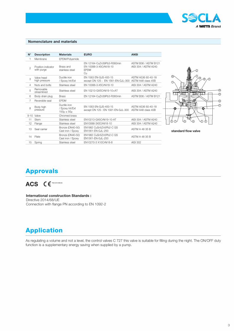
Nomenclature and materials
International construction Standards :Directive 2014/68/UEConnection with flange PN according to EN 1092-2
Approvals
ACS PED 2014/68/UE
N° Description Materials EURO ANSI
1 Membrane EPDM/Polyamide
2 Position indicatorwith purge
Brass andstainless steel
EN 12164-CuZn39Pb3-R360minEN 10088-3-X5CrNi18-10EPDMCu
ASTM B36 / ASTM B121AISI 304 / ASTM A240
3 Valve headhigh pressure
Ductile iron/ Epoxy Int/Ext
EN 1563 EN-GJS-400-15 except DN 125 : EN 1561-EN-GJL-300
ASTM A536 60-40-18ASTM A48 class 45B
4 Nuts and bolts Stainless steel EN 10088-3-X5CrNi18-10 AISI 304 / ASTM A240
5 Removablestreamlined Stainless steel EN 10213-GX5CrNi19-10+AT AISI 304 / ASTM A240
6 Body drain plug Brass EN 12164-CuZn39Pb3-R360min ASTM B36 / ASTM B121
7 Reversible seal EPDM
8 Body highpressure
Ductile iron/ Epoxy Int/Ext150μ ± 50μ
EN 1563 EN-GJS-400-15 except DN 125 : EN 1561-EN-GJL-300
ASTM A536 60-40-18ASTM A48 class 45B
9-10 Valve Chromed brass11 Stem Stainless steel EN10213-GX5CrNi19-10-AT AISI 304 / ASTM A24012 Flange Stainless steel EN10088-3X5CrNI18-10 AISI 304 / ASTM A240
13 Seal carrierBronze (DN40-50)Cast iron / Epoxy
EN1982 CuSn5Zn5Pb2-C GSEN1561-EN-GJL-250
ASTM A 48 35 B
14 PlateBronze (DN40-50)Cast iron / Epoxy
EN1982 CuSn5Zn5Pb2-C GSEN1561-EN-GJL-250
ASTM A 48 35 B
15 Spring Stainless steel EN10270-3 X10CrNi18-8 AISI 302
10
1
7 8 6 5
4103
2
11
12
9 9
13
14
15
standard fl ow valve
4
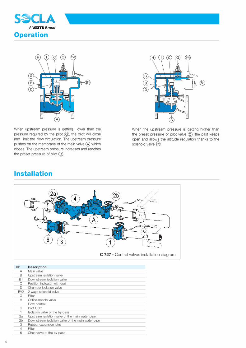
Operation
When upstream pressure is getting lower than the pressure required by the pilot Q , the pilot will close and limit the flow circulation. The upstream pressure pushes on the membrane of the main valve A which closes. The upstream pressure increases and reaches the preset pressure of pilot Q .
When the upstream pressure is getting higher than the preset pressure of pilot valve Q , the pilot keeps open and allows the altitude regulation thanks to the solenoid valve EV2 .
B1
A
B
C
D
H
G
I Q EV2
B1
A
B
C
D
H
G
I Q EV2
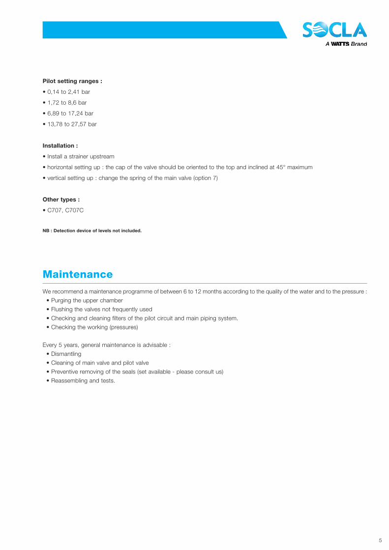
Installation
C 727 - Control valves installation diagram
N° DescriptionA Main valveB Upstream isolation valve
B1 Downstream isolation valveC Position indicator with drainD Chamber isolation valve
EV2 2 ways solenoid valveG FilterH Orifice-needle valveI Flow controlQ Pilot C3011 Isolation valve of the by-pass2a Upstream isolation valve of the main water pipe2b Downstream isolation valve of the main water pipe3 Rubber expansion joint4 Filter6 Chek valve of the by-pass
5
Pilot setting ranges :
• 0,14 to 2,41 bar
• 1,72 to 8,6 bar
• 6,89 to 17,24 bar
• 13,78 to 27,57 bar
Installation :
• Install a strainer upstream
• horizontal setting up : the cap of the valve should be oriented to the top and inclined at 45° maximum
• vertical setting up : change the spring of the main valve (option 7)
Other types :
• C707, C707C
NB : Detection device of levels not included.
We recommend a maintenance programme of between 6 to 12 months according to the quality of the water and to the pressure :
• Purging the upper chamber
• Flushing the valves not frequently used
• Checking and cleaning filters of the pilot circuit and main piping system.
• Checking the working (pressures)
Every 5 years, general maintenance is advisable :
• Dismantling
• Cleaning of main valve and pilot valve
• Preventive removing of the seals (set available - please consult us)
• Reassembling and tests.
Maintenance

6
Solid line : Base valve completely open
Headloss chart
FLOW GALLON/MIN
DEBIT M3/H
DN
P
PS
I
BA
R
Operating characteristics
Choice of base valve
DN Mini Maxi KVζ
PN PFA PN PFA PN PFA
mm m3/h m3/h m3/h L/s bar bar bar bar bar bar
1” 1/2 0,520 20,34 26,35 7,32 5,78 10/16 16 25 25 - -
40 0,675 32,00 45,66 12,68 1,93 10/16 16 25 25 - -
50 0,675 32,00 45,66 12,68 4,70 10/16 16 25 25 - -
65 0,855 54,00 57,75 16,08 8,39 10/16 16 25 25 - -
80 1,600 82,00 80,00 22,22 10,00 10/16 16 25 25 - -
100 2,720 127,00 136,00 37,78 8,47 10/16 16 25 25 - -
125 4,400 199,00 220,00 61,11 7,90 10/16 16 25 25 - -
150 5,280 286,00 264,00 73,33 11,38 10/16 16 25 25 - -
200 13,500 509,00 600,00 66,67 6,96 10 10 25 25 16 16
250 25,000 795,00 900,00 50,00 7,56 10 10 25 25 16 16
300 40,900 1145,00 1224,00 40,00 8,47 10 10 25 25 16 16

7
Sizing
ZØD
F
9
10
H
ØE
A
B
C
(1) 78/plats
DN A B C Ø D Ø E F H Z 9 10
” mm mm mm mm mm mm mm mm ” ”
1 1/2(F/F) 230 267 210 170 6 pans(1) - 400 254 1/4 3/8
40 230 285 210 170 152 23 400 254 1/4 3/8
50 230 285 210 170 161 23 400 254 1/4 3/8
65 290 352 257 200 185 24 470 254 3/8 1/4
80 310 372 272 217 200 26 500 254 3/8 3/8
100 350 423 302 241 235 28 510 254 3/8 3/8
125 400 506 371 296 270 30 570 254 3/8 3/8
150 480 551 401 363 300 20 650 254 3/8 3/8
200 600 709 529 467 360 22 750 254 3/8 3/8
250 730 844 631 587 425 24 900 254 1/2 1/2
300 850 975 730 680 486 27 1100 254 1/2 1/2
standard fl ow valve
ZØD
F
9
10
H
ØE
A
B
C
The descriptions and photographs contained in this product specification sheet are supplied by way of information only and are not binding.
Socla reserves the right to carry out any technical and design improvements to its products without prior notice. Warranty : All sales and contracts for sale are expressly conditioned on
the buyer’s assent to Socla terms and conditions found on its website at www.socla.com. Socla hereby objects to any term, different from or additional to Socla terms, contained in any
buyer communication in any form, unless agreed to in a writing signed by an officer of Socla.
© 2019 Socla
Socla sas365 rue du Lieutenant Putier • 71530 Virey-Le-Grand • France
Tel. +33 03 85 97 42 00 • Fax +33 03 85 97 42 [email protected] • www.socla.com
ISO 9001 version 2015 / ISO 18001
C727-TS-FR-S-UK-09-19-Rev.0
Other operating characteristics
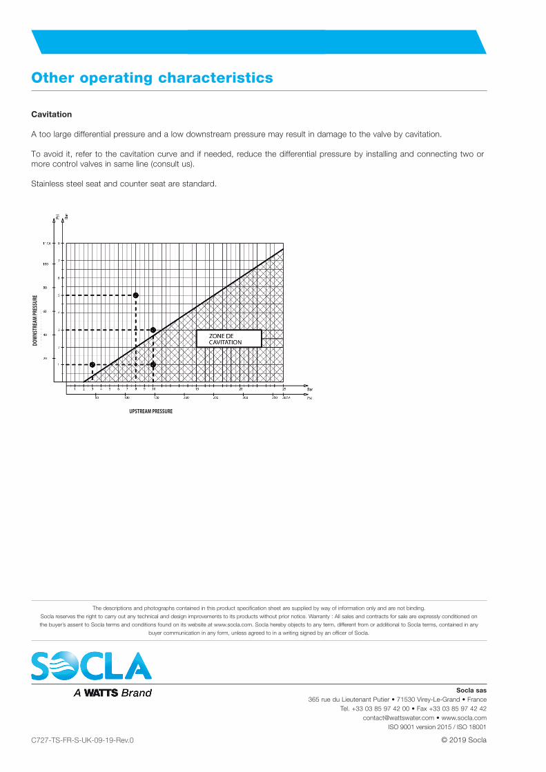
Cavitation
A too large differential pressure and a low downstream pressure may result in damage to the valve by cavitation.
To avoid it, refer to the cavitation curve and if needed, reduce the differential pressure by installing and connecting two or more control valves in same line (consult us).
Stainless steel seat and counter seat are standard.
UPSTREAM PRESSURE
DOW
NSTR
EAM
PRES
SURE