Design and Manufacturing of Remotely Operated Underwater Vehicle
71
i A DESIGN PROJECT OF A REMOTELY OPERATED UNDERWATER VEHICLE A Thesis Submitted to the Faculty of Engineering of İzmir Institute of Technology in Partial Fulfillment of the Requirements for Degree of BACHELOR OF SCIENCE in Mechanical Engineering by Group 7 Serdar ÖZDEMİR 160203013 Selim ŞAHİN 160203032 Mert Bartu IŞIK 160203040 Mustafa Harun YAKUT 160203007 Seyfi GİRGİN 160203041 Özgün ARI 150203006 June, 2013 İZMİR
-
Upload
istanbultek -
Category
Documents
-
view
1 -
download
0
Transcript of Design and Manufacturing of Remotely Operated Underwater Vehicle
i
A DESIGN PROJECT OF A REMOTELY
OPERATED UNDERWATER VEHICLE
A Thesis Submitted to the Faculty of Engineering of İzmir Institute of
Technology in Partial Fulfillment of the Requirements for Degree of
BACHELOR OF SCIENCE
in Mechanical Engineering
by
Group 7
Serdar ÖZDEMİR 160203013
Selim ŞAHİN 160203032
Mert Bartu IŞIK 160203040
Mustafa Harun YAKUT 160203007
Seyfi GİRGİN 160203041
Özgün ARI 150203006
June, 2013
İZMİR

ii
ACKNOWLEDGEMENTS
We would like to thank the advisors, Assistant Professor M. İ. Can DEDE and
Assistant Professor Ünver ÖZKOL for their help while studying on this project. Also,
we appreciate the help of the Civil Engineer Mehmet CENGİZ for funding, Efe Lazer
A.Ş. and Nehir EREN for Drybox manufacturing, Kastaş A.Ş. for sealing solutions,
İYTE workshop staff Murat MİRZA, Şerafettin ÇAVDAR, Arif TOSUN and Mert
Bartu IŞIK’s father for transportation.

iii
ABSTRACT
A DESIGN PROJECT OF A REMOTELY OPERATED UNDERWATER
VEHICLE
Underwater ROVs’ have very large field of operation and help many people
such as scientists, explorers or other different industrial users. Operators generally use
these vehicles to eliminate the risks of the underwater environment. Under 50 meters
divers need more oxygen and after the operation they may need to be treated in
pressurized rooms. The purpose of that study is to generate a simple solution for the
divers and underwater surveillance operations. This report includes design and
manufacture process of a small scale ROV which can be operational at maximum depth
of 50 m underwater and it provides the user a camera view and an object scaling system.

iv
TABLE OF CONTENTS
LIST OF FIGURES…………………………………………………………………….vi
LIST OF TABLES……………………………………………………………………...ix
CHAPTER 1. INTRODUCTION………………………………………………………..1
1.1. Purpose of Project……………………………………………………...1
CHAPTER 2. PROJECT MANAGEMENT STUDIES…………………………………2
2.1. Linear Responsibility Chart……………………………………………2
2.2. Gantt Chart…………………………………………………………….2
2.3. Work Breakdown Structure……………………………………………3
CHAPTER 3. DESIGN REQUIREMENTS AND CONSTRAINTS…………………...4
3.1. Problem Statement……………………………………………………...4
3.2. Design Requirements...............................................................................4
3.3. Design Constraints………………………………………………….......5
CHAPTER 4. DESIGN AND PROTOTYPING OF SUSBSYTEMS…………………6
4.1. Thruster Design………………………………………………………..6
4.1.1. Sealing of Thrusters………………………………………………..6
4.1.2. DC Motors…………………………………………………………9
4.1.3. Shaft………………………………………………………………10
4.1.3.1. Fatigue Calculations………………………………………….10
4.1.4. Coupling and Ball Bearings……………………………………13
4.1.5. Propellers………………………………………………………14
4.1.5.1. 13mm Propellers……………………………………………15
4.1.5.2. 8mm Propellers……………………………………………..15
4.1.6. Test of Thrusters…………………………………………………16
4.2. Drybox and Frame…………………………………………………..20
4.2.1. Geometry………………………………………………………...21
4.2.2. Sealing of Drybox………………………………………………..24

v
4.2.3. Cable Connections (Cable Glands)……………………………….24
4.2.4. Strength Analysis of Drybox……………………………………..25
4.2.5. Strength Analysis of Plexiglas…………………………………....28
4.3. Control………………………………………………………………..31
4.3.1. Electronic Components…………………………………………...31
4.3.1.1. Arduino and Ethernet Shield………………………………....31
4.3.1.2. Motor Driver Cards…………………………………………..33
4.3.1.3. Batteries……………………………………………………....33
4.3.1.4. Pressure Sensor……………………………………………….34
4.3.1.5. Camera………………………………………………………..34
4.3.1.6. Router………………………………………………………...35
4.3.1.7. Electronic Circuits…………………………………………....35
4.4. Buoyancy and Stabilization…………………………………………..36
4.4.1. Center of Buoyancy……………………………………………....36
4.4.2. Buoyancy Calculations…………………………………………...37
4.5. Object Scaling System ………………………………………………39
4.6. Communication and Tethering……………………………………….40
4.7. User Interface………………………………………………………...41
4.8. Manufacturing and Assembly………………………………………42
4.8.1. Manufacturing of Drybox……………………………………....42
4.8.2. Manufacturing of Thruster Casings…………………………….44
4.8.3. Production of Cable Glands……………………………………47
4.8.4. Production of Semispherical Plexiglas…………………………48
4.8.5. Production of Pulley System…………………………………...48
CHAPTER 5. RESULTS………………………………………………………………49
5.1. Vertical Motion………………………………………………………49
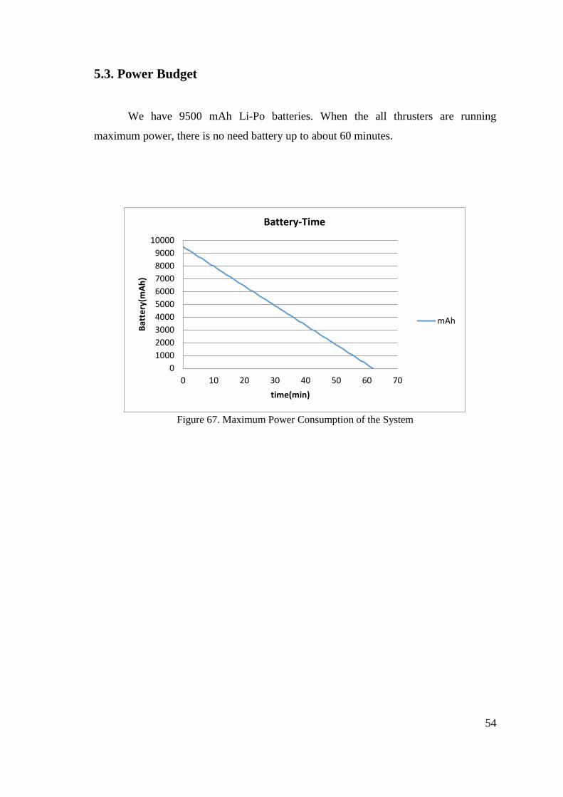
5.2. Horizontal Motion…………………………………………………....51
5.3. Power Budget………………………………………………………..54
5.4. Total Cost……………………………………………………………55
REFERENCES................................................................................................................56
APPENDICES.................................................................................................................57

vi
LIST OF FIGURES
Figure Page
Figure 1. Work Breakdown Structure 3
Figure 2. Section of Dynamic Sealing Part Manufactured by KASTAŞ A.Ş. 6
Figure 3. Section of Static Sealing Part Manufactured in İYTE Workshop 7
Figure 4. Dynamic Sealing Part with Sealing Elements 7
Figure 5. Static Sealing Parts with Sealing Elements 8
Figure 6. Cable Gland 8
Figure 7. The Behavior of the Hose Pipe under Pressure 9
Figure 8. DC Motor 10
Figure 9. Fatigue Calculation Diagrams 11
Figure 10. Coupling and Ball Bearing 14
Figure 11. 13mm Propeller 15
Figure 12. 8mm Propeller 16
Figure 13. Thruster Test Setup 16
Figure 14. Graph of Current versus Voltage (Without Oil) 17
Figure 15. Graph of Thrust versus Voltage (Without Oil) 17
Figure 16. Graph of Current versus Voltage (Without Oil) 18
Figure 17. Graph of Current versus Voltage (With Oil) 18
Figure 18. Graph of Thrust versus Voltage (With Oil) 19
Figure 19. Cross Section of Thruster Assembly 19
Figure 20. Assembly of Inner Components of Thruster 20
Figure 21. Illustration of the Drybox Main Body 21
Figure 22. Technical Drawings of Drybox Main Body 22
Figure 23. Technical Drawings of Frame 23
Figure 24. Technical Drawing of O-ring, Flange Assembly 24
Figure 25. Pressure Acting to the Surface 25
Figure 26. Result of Equivalent Stress 26
Figure 27. Maximum Principle Stress 26
Figure 28. The Maximum Shear Stress 27
Figure 29. The Equivalent Stress 27

vii
Figure 30. Total Displacement 29
Figure 31. Equivalent Stress 29
Figure 32. Equivalent Strain 30
Figure 33. Arduino Mega 2560 31
Figure 34. Arduino Ethernet Shield 32
Figure 35. Motor Driver Cards 33
Figure 36. Pressure Sensor 34
Figure 37. TP Link WR 720N Router Rear View 35
Figure 38. Fully Assembled Electronic Components 35
Figure 39. Center of Buoyancy and Mass 37
Figure 40. Diagram of the Forces Acting on the Body 37
Figure 41. User Interface of Scaling System 39
Figure 42. Tether Cable 40
Figure 43. User Interface 41
Figure 44. Unwelded Parts of Body 42
Figure 45. TIG Welding Process 43
Figure 46. Laser Cutting Process 43
Figure 47. Cylindrical Pipe (AISI316 Stainless Steel) 43
Figure 48. Flanges 44
Figure 49. Casing Front Cap 45
Figure 50. Inside of a Casing 45
Figure 51. Inner Components Assembly of a Thruster 46
Figure 52. Hose, Blind Plug and Motor, Coupling and Shaft Assembly 46
Figure 53. Fully Assembled Thruster 47
Figure 54. Cable Gland 47
Figure 55. Cable Gland (Disassembled) 47
Figure 56. Semispherical Plexiglas 48
Figure 57. Pulley System Left View 48
Figure 58. Pulley System Front View 48
Figure 59. Vertical Motion Velocity – Time Graph 49
Figure 60. Vertical Motion Facc – Fdrag versus Time Graph 50
Figure 61. Vertical Motion Acceleration – Time Graph 50
Figure 62. Vertical Motion Mechanical and Electrical Power 51
viii
Figure 63. Horizontal Motion Velocity – Time Graph 52
Figure 64. Horizontal Motion Facc – Fdrag – Time Graph 52
Figure 65. Horizontal Motion Acceleration – Time Graph 53
Figure 66. Horizontal Motion Mechanical and Electrical Power versus Time 53
Figure 67. Maximum Power Consumption of the System 54
ix
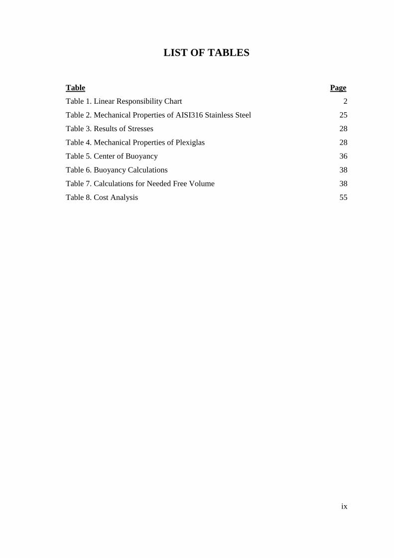
LIST OF TABLES
Table Page
Table 1. Linear Responsibility Chart 2
Table 2. Mechanical Properties of AISI316 Stainless Steel 25
Table 3. Results of Stresses 28
Table 4. Mechanical Properties of Plexiglas 28
Table 5. Center of Buoyancy 36
Table 6. Buoyancy Calculations 38
Table 7. Calculations for Needed Free Volume 38
Table 8. Cost Analysis 55

1
CHAPTER 1
INTRODUCTION
As a brief introduction, this project focuses on a design of an ROV, that’s why
short information about the ROV will be useful. First of all, ROV stands for remotely
operated vehicle. An ROV is a type of machine or robotic system which allows people
to explore the underwater environment or people can work at underwater structures via
ROV’s. These machines use propellers for thrust. And most of them are equipped with
at least one camera for surveillance. They can be controlled through a cable connection
or a wireless system. In this project the main subject is designing a small scale
unmanned ROV which can dive under 50 meters and accomplish specific tasks that are
predefined by the instructions. [1]
1.1. Purpose of the Project
When we consider this underwater ROV project, the main goal is to design and
manufacture a prototype which can be a solution for surveillance problems encountered
underwater operations. While designing the project secondary aim is to use our
knowledge on design process and project management areas. In addition to these
elements, to get some engineering experience that contains engineering design and
calculations. Then meeting the end user and the other engineers who are working active
in the field is another key element of conducting that project.
While developing this project, the point is that we have been trying to design a
system which satisfies the design requirements and criteria. These requirements are
given the section below.
Since the ROV can be operated 50 meters under the sea level, it can be a
practical solution for many end users. With the help of the additional task, the object
scaling with camera, this ROV especially focuses on the surveillance operations. So the
end users can use it while underwater pipe or cable inspection and determine the length
of cracks on the pipes or it can be used for ship hull inspections or to observe some
underwater living creatures.
2
CHAPTER 2
PROJECT MANAGEMENT STUDIES
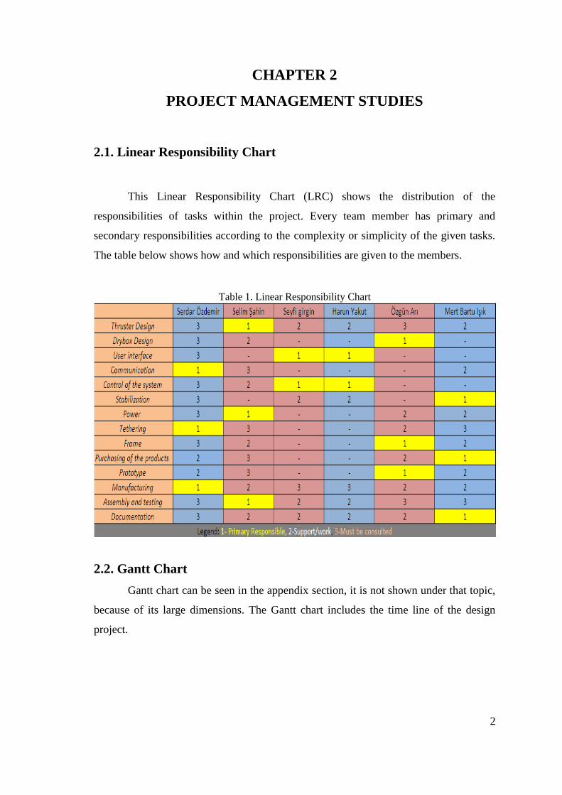
2.1. Linear Responsibility Chart
This Linear Responsibility Chart (LRC) shows the distribution of the
responsibilities of tasks within the project. Every team member has primary and
secondary responsibilities according to the complexity or simplicity of the given tasks.
The table below shows how and which responsibilities are given to the members.
Table 1. Linear Responsibility Chart
2.2. Gantt Chart
Gantt chart can be seen in the appendix section, it is not shown under that topic,
because of its large dimensions. The Gantt chart includes the time line of the design
project.

3
2.3. Work Breakdown Structure
Figure 1. Work Breakdown Structure
4
CHAPTER 3
DESIGN REQUIREMENTS AND CONSTRAINTS
3.1. Problem Statement
The starting point of that project is that how can we keep humans away from
risky environment while making underwater surveillance work. These risks can be
indicated as; higher hydrostatic pressure, lack of oxygen, risk of decompression
sickness that’s why as a group, we tried to find a solution to eliminate these risks and
any possible injuries.
3.2. Design Requirements
Before starting that project in order to specify a design target, design
requirements are needed and this section contains these requirements and the desired
features of the ROV.
Will be operated at the depth of 50 meters
At least one hour battery life for operation
With an onboard camera that can be rotated ± 80º in two axis
Can be controlled remotely by an operator on a boat
Will dive and move on the plane of desired depth;
Able to turn right or left while moving in desired direction
Able to rotate around the vertical axis that passes through the center of mass.
Will be controlled with at least one joystick
Have a user interface which provides;
Depth information
Orientation and direction information
Interface to capture and save photographs from camera view
Object scaling interface
Able to approach sea-floor without muddying.
5
3.3. Design Constraints
These are the design constraints which we encountered if the design
requirements are considered.
Economic
Our budget is approximately 2000 TL. We have managed to receive some fund
for the project and that amount should not exceed. The cost is the most important value
in evaluating design alternatives.
Environmental
Environment is another concern while designing the project. To protect the
nature, the paint on the body and other components should be friendly for environment.
The thruster casings will be filled with oil and the oil discharge to the sea is an
undesired result.
Health and Safety
Due to the ROV runs on electrical power that’s why any short circuits or
electrical leaks could be dangerous for operator or other sea inhabitants. In addition to
that, all of the sharp objects and edges on the system are unwanted.
Manufacturability
Our budget is limited so the design alternatives that can be easy produced should
be preferred. Besides the limited budget, the production facilities are limited and the
design can be changed as a result of the tests, so ease of the manufacture is desired.

6
CHAPTER 4
DESIGN AND PROTOTYPING OF SUBSYSTEMS
4.1. Thruster Design
Thrust is the reaction force that is created by propulsion system by accelerating a
mass of fluid and it is a vector quantity having both a magnitude and a direction.
Thruster is a device that creates force to move any object. In this project, we have
determined to use propeller-shaft-motor system as thruster. The main purpose of ROV
is to dive and running 50m underwater. This is the hardest design constrains that we
have to solve. The ROV must work at 6 bar pressure.
4.1.1. Sealing of Thrusters
The most conservative solution of sealing is to use sealing elements as O Ring
or rod sealing elements. We could not manufacture the parts where the sealing elements
are used. So we arranged a meeting with Kastaş A.Ş to design and produce the dynamic
sealing parts. They design the thruster part and produce the new rod sealing elements
for our project. We manufactured the static sealing part in our workshop at lathe.
Figure 2. Section of Dynamic Sealing Part Manufactured by KASTAŞ A.Ş.

7
Figure 3. Section of Static Sealing Part Manufactured in İYTE Workshop
Figure 4. Dynamic Sealing Part with Sealing Elements
Rod Sealing
Elements
O Rings

8
Figure 5. Static Sealing Parts with Sealing Elements
In addition to this we used cable glands and Teflon tape for thruster connection.
Figure 6. Cable Gland
[2] (Source: http://www.cable-glands-brass.com/brass-metric-strain-
relief/brass-cable-glands.gif)
O Rings Cable Gland
Housing
9
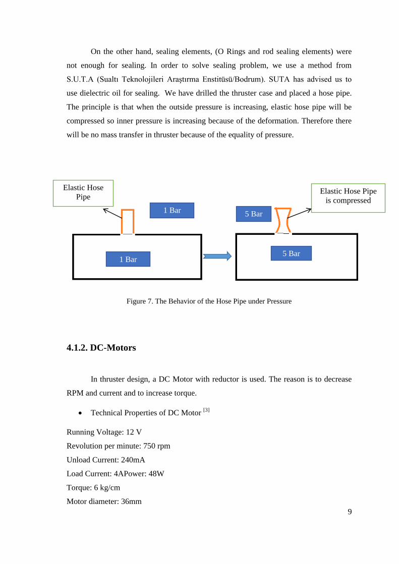
On the other hand, sealing elements, (O Rings and rod sealing elements) were
not enough for sealing. In order to solve sealing problem, we use a method from
S.U.T.A (Sualtı Teknolojileri Araştırma Enstitüsü/Bodrum). SUTA has advised us to
use dielectric oil for sealing. We have drilled the thruster case and placed a hose pipe.
The principle is that when the outside pressure is increasing, elastic hose pipe will be
compressed so inner pressure is increasing because of the deformation. Therefore there
will be no mass transfer in thruster because of the equality of pressure.
Figure 7. The Behavior of the Hose Pipe under Pressure
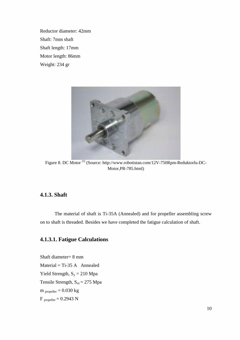
4.1.2. DC-Motors
In thruster design, a DC Motor with reductor is used. The reason is to decrease
RPM and current and to increase torque.
Technical Properties of DC Motor [3]
Running Voltage: 12 V
Revolution per minute: 750 rpm
Unload Current: 240mA
Load Current: 4APower: 48W
Torque: 6 kg/cm
Motor diameter: 36mm
Elastic Hose
Pipe Elastic Hose Pipe
is compressed
1 Bar
1 Bar
5 Bar
5 Bar
10
Reductor diameter: 42mm
Shaft: 7mm shaft
Shaft length: 17mm
Motor length: 86mm
Weight: 234 gr
Figure 8. DC Motor
[3] (Source: http://www.robotistan.com/12V-750Rpm-Reduktorlu-DC-
Motor,PR-785.html)
4.1.3. Shaft
The material of shaft is Ti-35A (Annealed) and for propeller assembling screw
on to shaft is threaded. Besides we have completed the fatigue calculation of shaft.
4.1.3.1. Fatigue Calculations
Shaft diameter= 8 mm
Material = Ti-35 A Annealed
Yield Strength, Sy = 210 Mpa
Tensile Strength, Sut = 275 Mpa
m propeller = 0.030 kg
F propeller = 0.2943 N

11
Figure 9. Fatigue Calculation Diagrams
Se = ka.kb.kc.kd.ke.kf..Se’
Se’ = 0.5 Sut = 137.5 MPa
Surface Factor, ka
ka = a*Sutb
Surface finish, hot rolled
a = 57.7
b = -0.718
ka = 1.022668
Size Factor, kb
kb = 1.24.d-0.107
kb = 0.9926

12
Loading Factor, kc
kc = 1 For combined loading
Temperature Factor, kd
At 50 C kd = 1.010
Reliability Factor, ke
ke = 1
Miscellaneous-Effects Factor,kf
kf = 1
Characterizing Fluctuating Stresses
Fm = (Fmax + Fmin ) /2 Fa = (Fmax – Fmin )/2
σm = ( σmax + σmin )/ 2 σa = ( σmax + σmin) / 2
σbending = M.c / I σnormal = P/A τTorsion = T.r /J
Where ;
σbending = Bending Stress
M = Moment
c = distance to neutral axis
I = Moment of Inertia
T = Torque
r = Radius
J = Polar Moment of Inertia
A = Area
P = 2 N and -2 N
M= 0.02943 Nm
r= 0.004
I= (π* r4)/4 = 2.010619298e-10 m
4
J=(π* r4)/2= 4.021238597e-10 m
4

13
σbending = M.c / I = 0.585 MPa
σnormal = P/A = 0.039 Mpa and -0.039 Mpa
τTorsion = T.r /J =6.963 Mpa
The Distortion Energy theory
σ= [(σbending + σnormal) 2 + 3*τTorsion
2 ] ½
σmax = 12.076 Mpa
σmin = 12.072 Mpa
σm = 12.074 Mpa
σa = 0.002 Mpa
Soderberg
(σa / Se ) + ( σm/ Sy ) = 1 / n
Se = ka.kb.kc.kd.ke.kf.Se’
Se = 140.972 MPa
n = Safety Factor
(0.002/140.972) + (12.074/210) = 1/n
n= 17.338
4.1.4. Coupling and Ball Bearing
We have 22 mm outer diameter, 8 mm inner diameter and 7 mm thickness ball
bearing. We have used Chloraethyl to assembly for shaft and bearing. To extend shaft
we use coupling that has 7 mm and 8 mm inner dia. The maximum allowable torque of
shaft is 7 Nm.

14
Figure 10. Coupling (Right) and Ball Bearing (Left)
4.1.5. Propellers
Propeller selection is the hardest process for thruster system. Because if we
designed propeller that gives us desired thrust, we could not manufacture it. So we had
to try different type’s propeller.
The Criteria of Selection
Weightless
It has to be light because of the torque of motor and shaft.
Material
Material is important for corrosion.
Dimensions
The maximum diameter has to be 150 mm.
Cost
We had to test each propeller to reach desired thrust. For this process our budged
was limited.
Pair
15
The propeller that we selected must be two-way. According to these criteria we have
selected two propellers for vertical and horizontal directions.
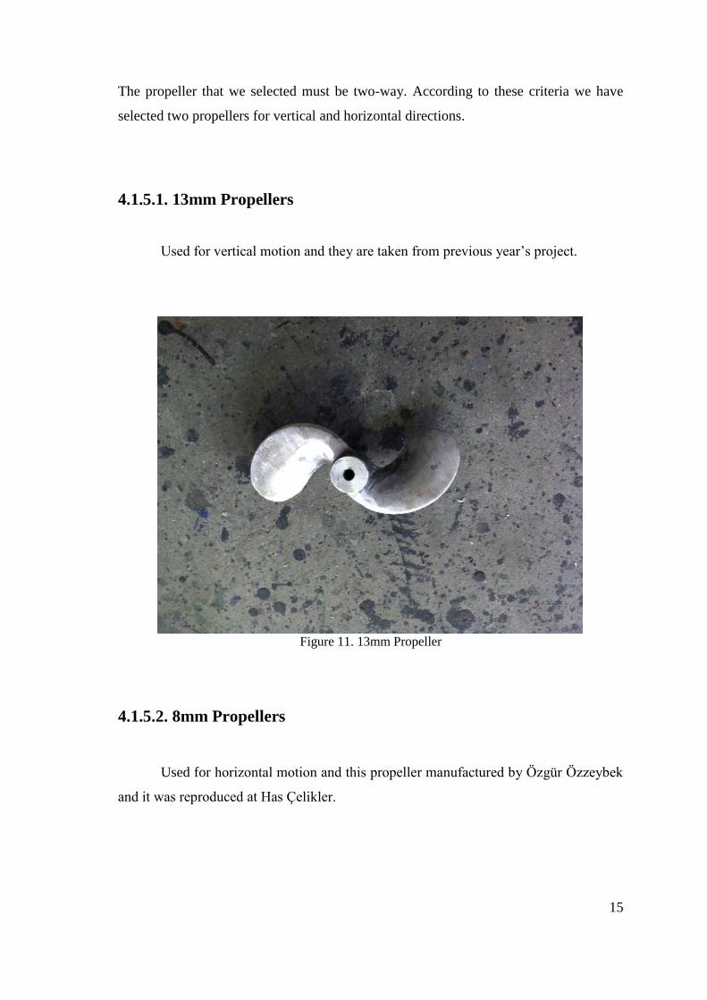
4.1.5.1. 13mm Propellers
Used for vertical motion and they are taken from previous year’s project.
Figure 11. 13mm Propeller
4.1.5.2. 8mm Propellers
Used for horizontal motion and this propeller manufactured by Özgür Özzeybek
and it was reproduced at Has Çelikler.

16
Figure 12. 8mm Propeller
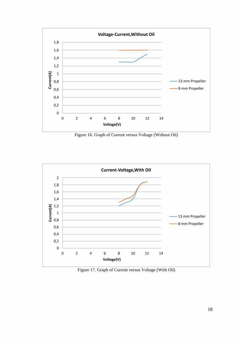
4.1.6. Test Results of Thrusters
We have manufactured a test device to measure net thrust force with respect to
voltage and current. In test we used seed oil as dielectric oil.
Figure 13. Thruster Test Setup

17
Figure 14. Graph of Current versus Voltage (Without Oil)
Figure 15. Graph of Thrust versus Voltage (Without Oil)
0
0,2
0,4
0,6
0,8
1
1,2
1,4
0 2 4 6 8 10 12 14
Cu
rre
nt(
A)
Voltage(V)
Current-Voltage ,In Air,Without Oil
13 mm propeller
8 mm propeller
0
0,5
1
1,5
2
2,5
3
3,5
4
4,5
0 2 4 6 8 10 12 14
Thru
st (
N)
Voltage(V)
Thrust-Voltage, Without oil
13 mm propeller
8 mm Propeller
18
Figure 16. Graph of Current versus Voltage (Without Oil)
Figure 17. Graph of Current versus Voltage (With Oil)
0
0,2
0,4
0,6
0,8
1
1,2
1,4
1,6
1,8
0 2 4 6 8 10 12 14
Cu
rre
nt(
A)
Voltage(V)
Voltage-Current,Without Oil
13 mm Propeller
8 mm Propeller
0
0,2
0,4
0,6
0,8
1
1,2
1,4
1,6
1,8
2
0 2 4 6 8 10 12 14
Cu
rre
nt(
A)
Voltage(V)
Current-Voltage,With Oil
13 mm Propeller
8 mm Propeller

19
Figure 18. Graph of Thrust versus Voltage (With Oil)
Figure 19. Cross Section of Thruster Assembly
0
0,5
1
1,5
2
2,5
3
3,5
4
4,5
0 2 4 6 8 10 12 14
Thru
st(N
)
Voltage(V)
Thrust-Voltage,With Oil
13 mm Propeller
8 mm Propeller

20
Figure 20. Assembly of Inner Components of Thruster
4.2. Drybox and Frame
For that work package, we separate it into five different sections to get better
results and understanding. These subsections are geometry, sealing, cable connectors
and mechanical analysis of the drybox and the semispherical Plexiglas dome.

21
4.2.1. Geometry
In order to have an advantageous and strong structure design for under
hydrostatic pressure, a cylindrical geometry was selected. Besides that criterion we tried
to keep the design simple and tried to have a symmetrical shape for increased stability.
We started with a cylindrical pipe which has a diameter of 140 mm and 380 mm in
length. The thickness of the pipe is 3 mm. Then two 5 mm thick flanges are welded to
the front and rear ends. These will help us to fasten the rear plate and front semi
spherical Plexiglas dome. Flanges and the end caps are fixed to the main body by 6
bolts and nuts (M8) through the M8 holes. The material of the body and the frame is
AISI316 stainless steel to create a sufficiently strong structure which can withstand the
forces due to the hydrostatic pressure of 0,6 MPa, and it is selected from a stainless
material to prevent the corrosion effects of seawater.
On the other hand the drybox bod and the frame are designed together to get a
monocoque structure. While designing the frame component, the general ideas are again
the symmetry and the positions of the thrusters for better stability. In order to deal with
any possible problems the orientation of the thrusters are kept on the same plane by the
center of mass. The geometry of the body can be seen the figure below.
Figure 21. Illustration of the Drybox Main Body

22
Figure 22. Technical Drawings of Drybox Main Body

23
Figure 23. Technical Drawings of Frame (in mm)
24
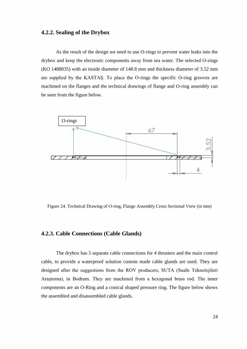
4.2.2. Sealing of the Drybox
As the result of the design we need to use O-rings to prevent water leaks into the
drybox and keep the electronic components away from sea water. The selected O-rings
(KO 1488035) with an inside diameter of 148.8 mm and thickness diameter of 3.52 mm
are supplied by the KASTAŞ. To place the O-rings the specific O-ring grooves are
machined on the flanges and the technical drawings of flange and O-ring assembly can
be seen from the figure below.
Figure 24. Technical Drawing of O-ring, Flange Assembly Cross Sectional View (in mm)
4.2.3. Cable Connections (Cable Glands)
The drybox has 5 separate cable connections for 4 thrusters and the main control
cable, to provide a waterproof solution custom made cable glands are used. They are
designed after the suggestions from the ROV producers, SUTA (Sualtı Teknolojileri
Araştırma), in Bodrum. They are machined from a hexagonal brass rod. The inner
components are an O-Ring and a conical shaped pressure ring. The figure below shows
the assembled and disassembled cable glands.
O-rings
25
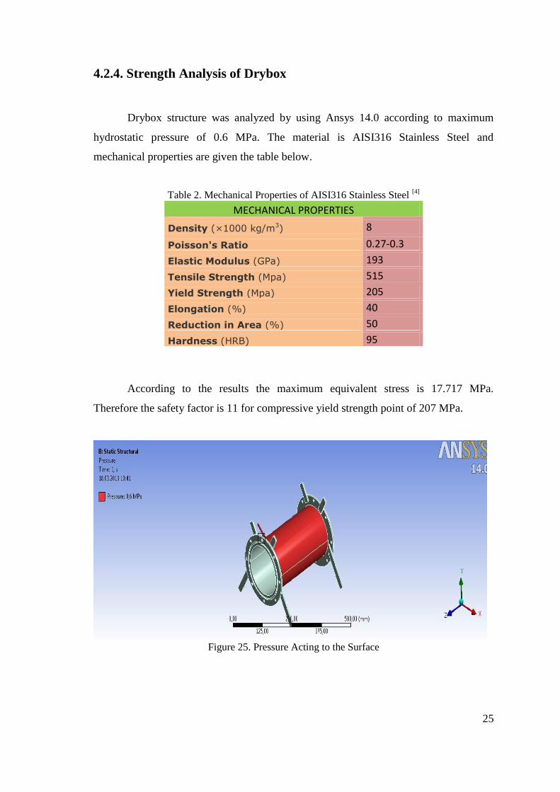
4.2.4. Strength Analysis of Drybox
Drybox structure was analyzed by using Ansys 14.0 according to maximum
hydrostatic pressure of 0.6 MPa. The material is AISI316 Stainless Steel and
mechanical properties are given the table below.
Table 2. Mechanical Properties of AISI316 Stainless Steel [4]
MECHANICAL PROPERTIES
Density (×1000 kg/m3) 8
Poisson's Ratio 0.27-0.3
Elastic Modulus (GPa) 193
Tensile Strength (Mpa) 515
Yield Strength (Mpa) 205
Elongation (%) 40
Reduction in Area (%) 50
Hardness (HRB) 95
According to the results the maximum equivalent stress is 17.717 MPa.
Therefore the safety factor is 11 for compressive yield strength point of 207 MPa.
Figure 25. Pressure Acting to the Surface

26
Figure 26. Result of Equivalent Stress
Figure 27. Maximum Principle Stress

27
Figure 28. The Maximum Shear Stress
Figure 29. The Equivalent Stress
Because of the lack of sufficient space, we the full page figures of analysis are
not placed in this section. However you can find more them detailed figures in the
appendix section.
28
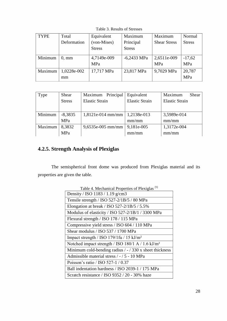
Table 3. Results of Stresses
4.2.5. Strength Analysis of Plexiglas
The semispherical front dome was produced from Plexiglas material and its
properties are given the table.
Table 4. Mechanical Properties of Plexiglas
[5]
Density / ISO 1183 / 1.19 g/cm3
Tensile strength / ISO 527-2/1B/5 / 80 MPa
Elongation at break / ISO 527-2/1B/5 / 5.5%
Modulus of elasticity / ISO 527-2/1B/1 / 3300 MPa
Flexural strength / ISO 178 / 115 MPa
Compressive yield stress / ISO 604 / 110 MPa
Shear modulus / ISO 537 / 1700 MPa
Impact strength / ISO 179/1fu / 15 kJ/m²
Notched impact strength / ISO 180/1 A / 1.6 kJ/m²
Minimum cold-bending radius / - / 330 x sheet thickness
Admissible material stress / - / 5 - 10 MPa
Poisson’s ratio / ISO 527-1 / 0.37
Ball indentation hardness / ISO 2039-1 / 175 MPa
Scratch resistance / ISO 9352 / 20 - 30% haze
TYPE Total
Deformation
Equivalent
(von-Mises)
Stress
Maximum
Principal
Stress
Maximum
Shear Stress
Normal
Stress
Minimum 0, mm 4,7149e-009
MPa
-6,2433 MPa 2,6511e-009
MPa
-17,62
MPa
Maximum 1,0228e-002
mm
17,717 MPa 23,817 MPa 9,7029 MPa 20,787
MPa
Type Shear
Stress
Maximum Principal
Elastic Strain
Equivalent
Elastic Strain
Maximum Shear
Elastic Strain
Minimum -8,3835
MPa
1,8121e-014 mm/mm 1,2138e-013
mm/mm
3,5989e-014
mm/mm
Maximum 8,3832
MPa
9,6535e-005 mm/mm 9,181e-005
mm/mm
1,3172e-004
mm/mm

29
Figure 30. Total Displacement in mm
Figure 31. Equivalent Stress in Pa

30
Figure 32. Equivalent Strain
According to the results and the compressive yield stress point, the safety factor
of Plexiglas is 8.870. After the strength calculation we have verified that our ROV can
dive to the 60 m depth without any trouble and it can even go deeper within safety
limits.

31
4.3. Control
4.3.1. Electronic Components
We have used a lot of different electronic devices to achieve the control of the
ROV. These are can be listed mainly as microprocessors, motors, motor driver units,
batteries, and communication shields and so on.
4.3.1.1. Arduino and Arduino Ethernet Shield
We are using Arduino Mega 2560 as our microcontroller. It is chosen since its
open source coded microcontroller and great utility in the robotics applications. Also it
has quite enough inputs and outputs on its board, which is needed for our ROV due to
having a lot of sub component to be attached.
Figure 33. Arduino Mega 2560
[6] (Source: http://arduino.cc/en/Main/arduinoBoardMega)

32
Arduino Mega has USB connection port but we couldn’t make use of it since
our robot will function at 50 meters depth, meaning we have to use at least 70-75 meters
long cable for tethering. Since we know that after 7-8 meters, USB communication will
be impossible and huge amount of data loss will be encountered, we had to find another
communication way between the Arduino mega placed in ROV with the User placed in
surface. So we figure the communication problem out by using Ethernet cable and an
Ethernet shield placed on the Arduino Mega. In our research we have learned that data
loss up to 100 meters is not a problem via Ethernet cable. Cat-6 type Ethernet cable will
be used for the communication between the Ethernet shield and PC.
We also made some tests to see the reliability of the Ethernet communication
before we use it for the ROV. In our tests, we have confirmed the same results.
Figure 34. Arduino Ethernet Shield
[7] (Source:
http://arduino.cc/en/Main/ArduinoEthernetShield)

33
4.3.1.2. Motor Driver Cards
We have searched through the internet but we couldn’t find any proper dc motor
control unit for our purpose. So we ourselves produced our dc motor control units. We
have manufactured it via printed circuit board method. It enables us to drive every
motor forward and backwards. It has great current drawn capability, it supports up to
50A normal current and 60A peak current for 10seconds.
Figure 35. Motor Driver Cards (Front View)
4.3.1.3. Batteries
We are asked to operate our ROV for 1 hour, at least. So we have made our
calculations to reach the desired operation time. We decided to use Li-Po batteries since
they are powerful, and lighter than the other battery options. Additionally, they are re-
chargeable and we can use them again and again. We are using 9.500mAh Li-Po
batteries in total.
34
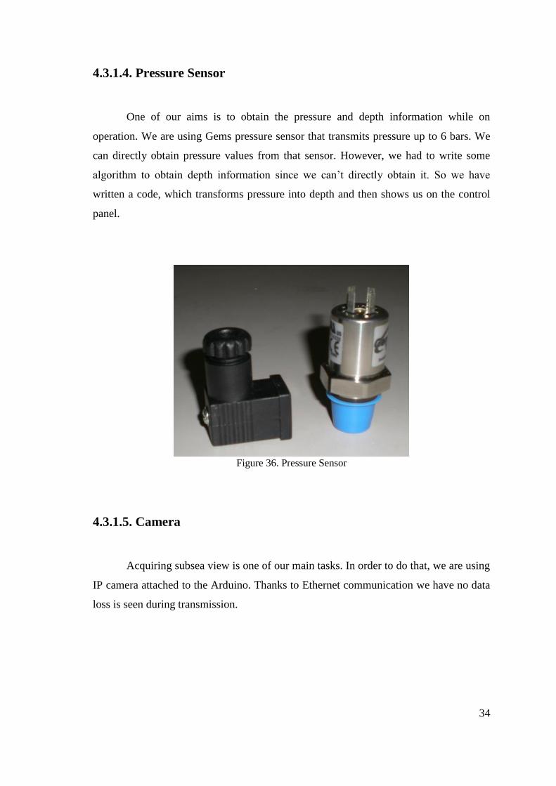
4.3.1.4. Pressure Sensor
One of our aims is to obtain the pressure and depth information while on
operation. We are using Gems pressure sensor that transmits pressure up to 6 bars. We
can directly obtain pressure values from that sensor. However, we had to write some
algorithm to obtain depth information since we can’t directly obtain it. So we have
written a code, which transforms pressure into depth and then shows us on the control
panel.
Figure 36. Pressure Sensor
4.3.1.5. Camera
Acquiring subsea view is one of our main tasks. In order to do that, we are using
IP camera attached to the Arduino. Thanks to Ethernet communication we have no data
loss is seen during transmission.

35
4.3.1.6. Router
We are attached a router into our system, in order to link the ethernet shield and
IP camera to the main computer located in the surface.
Figure 37. TP Link WR 720N Router Rear View (Source: http://www.tp-
link.com/en/products/details/?model=TL-WR720N) [8]
Router wirelessly connects the IP camera. Ethernet shield is wired to the router
and the tether comes from the surface. We have selected TP-LINK WR 720N type,
since it’s small and sufficient for our requirements.
4.3.1.7. Electronic Circuits
After the coding part, hardware part comes in. We connected the electronic
equipment, which are electronic motor controllers, Arduino Mega & Arduino ethernet
shield, router, ip camera, and power control circuit needs to be linked all over. The hard
part of this process is fitting all the electronic devices into the ROV. After connecting
all the electronic parts, all the system looked like this:
Figure 38. Fully Assembled Electronic Components

36
4.4. Buoyancy and Stabilization
The ability of an object to float or sink relates to relation of buoyant force (B)
and weight (W). If B is greater than W, the object floats. Put other way, if B is smaller
than W, the object sinks. If they are equal to each other, the object remains where it is.
Based on the basic information, we have designed that, the density of our ROV is less
than the density of seawater. Thus, if any failure in mechanical or electronic systems of
our ROV occurs under water, it will provide a big benefit which is to rise automatically
to water surface by itself.
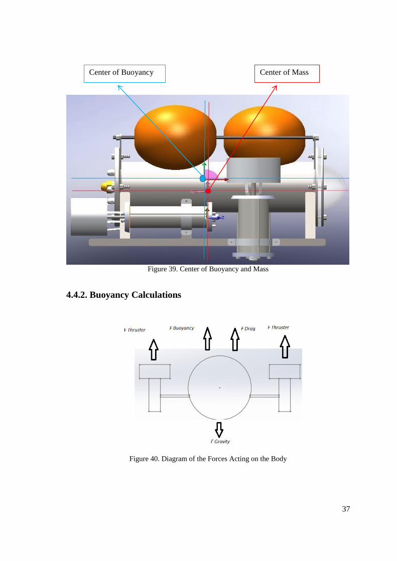
For stability design of ROV, it is the most important rule to put center of
buoyancy to the top and center of gravity to the bottom on same vertical axis. Therefore,
these two centers should be as far as possible from each other for more stable. In order
to increase distance between center of gravity and center of buoyancy, stand on the
bottom side of ROV and apparatus on the upper side of ROV for buoyant materials have
been designed. This technique provides easily stability on the pitch and roll axis.
4.4.1. Center of Buoyancy
Table 5. Center of Buoyancy
Center of Buoyancy
Ʃ (volume*distance) / Ʃ
(Volume)
Part Name Volume m^3 Unit x y
Vertical Thrusters 0,0004241 2 172 50
Horizontal Thrusters 0,0004241 2 364 80
Front Buoy 0,004 1 160 349
Rear Buoy 0,004 2 349 134
Drybox 0,0062 1 257 174
Center of Buoyancy (mm)
x axis 275,42848
y axis 183,805412
37
Figure 39. Center of Buoyancy and Mass
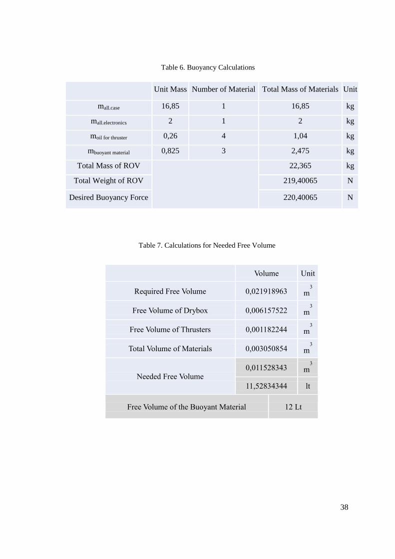
4.4.2. Buoyancy Calculations
Figure 40. Diagram of the Forces Acting on the Body
Center of Buoyancy Center of Mass
38
Table 6. Buoyancy Calculations
Table 7. Calculations for Needed Free Volume
Unit Mass Number of Material Total Mass of Materials Unit
mall.case 16,85 1 16,85 kg
mall.electronics 2 1 2 kg
moil for thruster 0,26 4 1,04 kg
mbuoyant material 0,825 3 2,475 kg
Total Mass of ROV
22,365 kg
Total Weight of ROV 219,40065 N
Desired Buoyancy Force 220,40065 N
Volume Unit
Required Free Volume 0,021918963 m3
Free Volume of Drybox 0,006157522 m3
Free Volume of Thrusters 0,001182244 m3
Total Volume of Materials 0,003050854 m3
Needed Free Volume 0,011528343 m
3
11,52834344 lt
Free Volume of the Buoyant Material 12 Lt
39
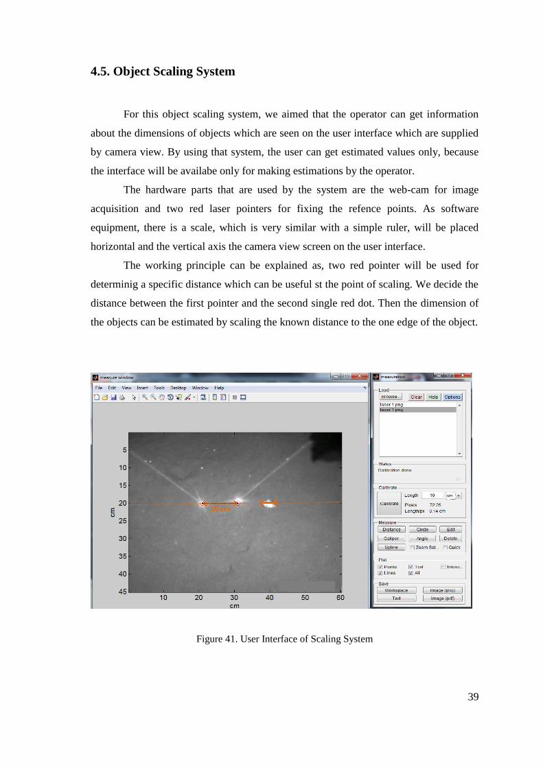
4.5. Object Scaling System
For this object scaling system, we aimed that the operator can get information
about the dimensions of objects which are seen on the user interface which are supplied
by camera view. By using that system, the user can get estimated values only, because
the interface will be availabe only for making estimations by the operator.
The hardware parts that are used by the system are the web-cam for image
acquisition and two red laser pointers for fixing the refence points. As software
equipment, there is a scale, which is very similar with a simple ruler, will be placed
horizontal and the vertical axis the camera view screen on the user interface.
The working principle can be explained as, two red pointer will be used for
determinig a specific distance which can be useful st the point of scaling. We decide the
distance between the first pointer and the second single red dot. Then the dimension of
the objects can be estimated by scaling the known distance to the one edge of the object.
Figure 41. User Interface of Scaling System
40
4.6. Communication and Tethering
The easiest way to communicate with the ROVs is to have no communication at
all. Direct cable connection can be used in the vehicles which are on board a support
ship and mission may be pre-programmed in the vehicle. Although this way is
inexpensive and simple, it limits flexibility in operation. It depends on the mission may
not be changed in response to what happens.
For the communication with the operator; ROVs use a tether, high-bandwidth
communication. With the electrical or fiber optic tethers we can transfer high-definition
video, but a tether between the operator and vehicle can be a problem. The vehicle must
be operated close to shore, or support vessel must be moved with the ROV. Only
relatively shallow depths may be reached, because the drag force on the tether becomes
prohibitive at some point. The perfect ROV should have the following features;
Minimum tether diameter.
Powered from the surface to increase working-endurance limit.
Very small in size.
Have an enough data pipeline for sensors. [9]
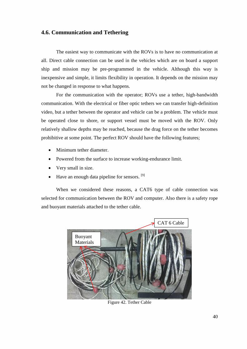
When we considered these reasons, a CAT6 type of cable connection was
selected for communication between the ROV and computer. Also there is a safety rope
and buoyant materials attached to the tether cable.
Figure 42. Tether Cable
Buoyant
Materials
CAT 6 Cable
41
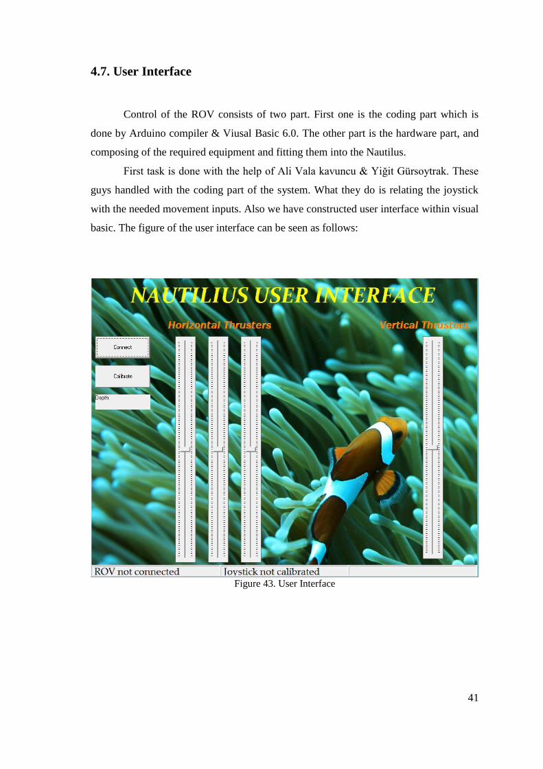
4.7. User Interface
Control of the ROV consists of two part. First one is the coding part which is
done by Arduino compiler & Viusal Basic 6.0. The other part is the hardware part, and
composing of the required equipment and fitting them into the Nautilus.
First task is done with the help of Ali Vala kavuncu & Yiğit Gürsoytrak. These
guys handled with the coding part of the system. What they do is relating the joystick
with the needed movement inputs. Also we have constructed user interface within visual
basic. The figure of the user interface can be seen as follows:
Figure 43. User Interface

42
4.8. Manufacturing and Assembly
4.8.1. Manufacturing of Drybox
Production of drybox is made in Bursa by Efe Lazer. Thanks to this company we
got all our materials and laser cut is completed. All of our materials are stainless steel.
We used a cylindrical pipe as a body with 140 mm in diameter and 380 mm in length
and thickness is 3mm. Flanges with 5 mm thickness are cut in laser with 6 holes (M8) in
one side. After that, flanges went to the turning machine to open O-ring channels and
welded by TIG welding. Two legs with 5mm thickness were welded under the body to
tie thruster on the drybox. We bought a flat plate Plexiglas and put it on de body to see
how Plexiglas behaves between two flanges.
Figure 44. Unwelded Parts of Body

43
Figure 45. TIG Welding Process
Figure 46. Laser Cutting Process
Figure 47. Cylindrical Pipe (AISI316 Stainless Steel)
44
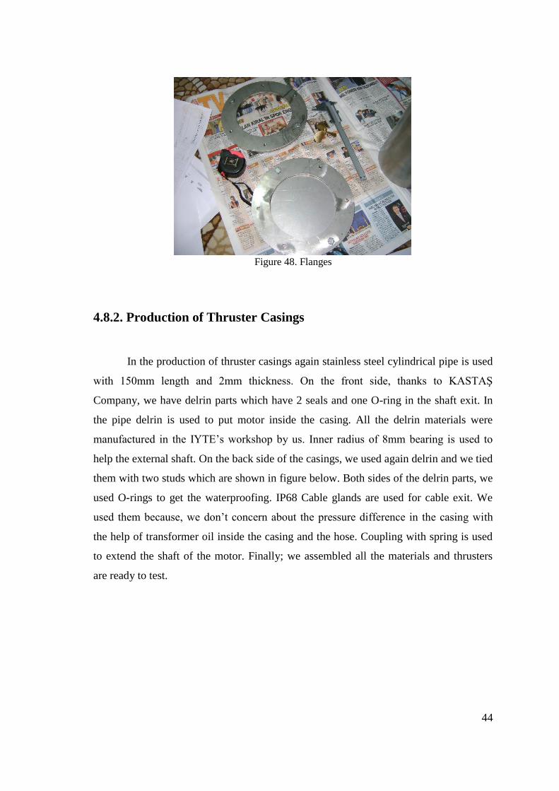
Figure 48. Flanges
4.8.2. Production of Thruster Casings
In the production of thruster casings again stainless steel cylindrical pipe is used
with 150mm length and 2mm thickness. On the front side, thanks to KASTAŞ
Company, we have delrin parts which have 2 seals and one O-ring in the shaft exit. In
the pipe delrin is used to put motor inside the casing. All the delrin materials were
manufactured in the IYTE’s workshop by us. Inner radius of 8mm bearing is used to
help the external shaft. On the back side of the casings, we used again delrin and we tied
them with two studs which are shown in figure below. Both sides of the delrin parts, we
used O-rings to get the waterproofing. IP68 Cable glands are used for cable exit. We
used them because, we don’t concern about the pressure difference in the casing with
the help of transformer oil inside the casing and the hose. Coupling with spring is used
to extend the shaft of the motor. Finally; we assembled all the materials and thrusters
are ready to test.

45
Figure 49. Casing Front Cap
Figure 50. Inside of a Casing

46
Figure 51. Inner Components Assembly of a Thruster
Figure 52. Hose, Blind Plug and Motor, Coupling and Shaft Assembly
47
Figure 53. Fully Assembled Thruster
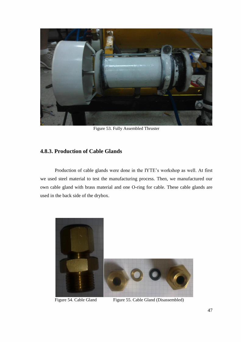
4.8.3. Production of Cable Glands
Production of cable glands were done in the IYTE’s workshop as well. At first
we used steel material to test the manufacturing process. Then, we manufactured our
own cable gland with brass material and one O-ring for cable. These cable glands are
used in the back side of the drybox.
Figure 54. Cable Gland Figure 55. Cable Gland (Disassembled)
48
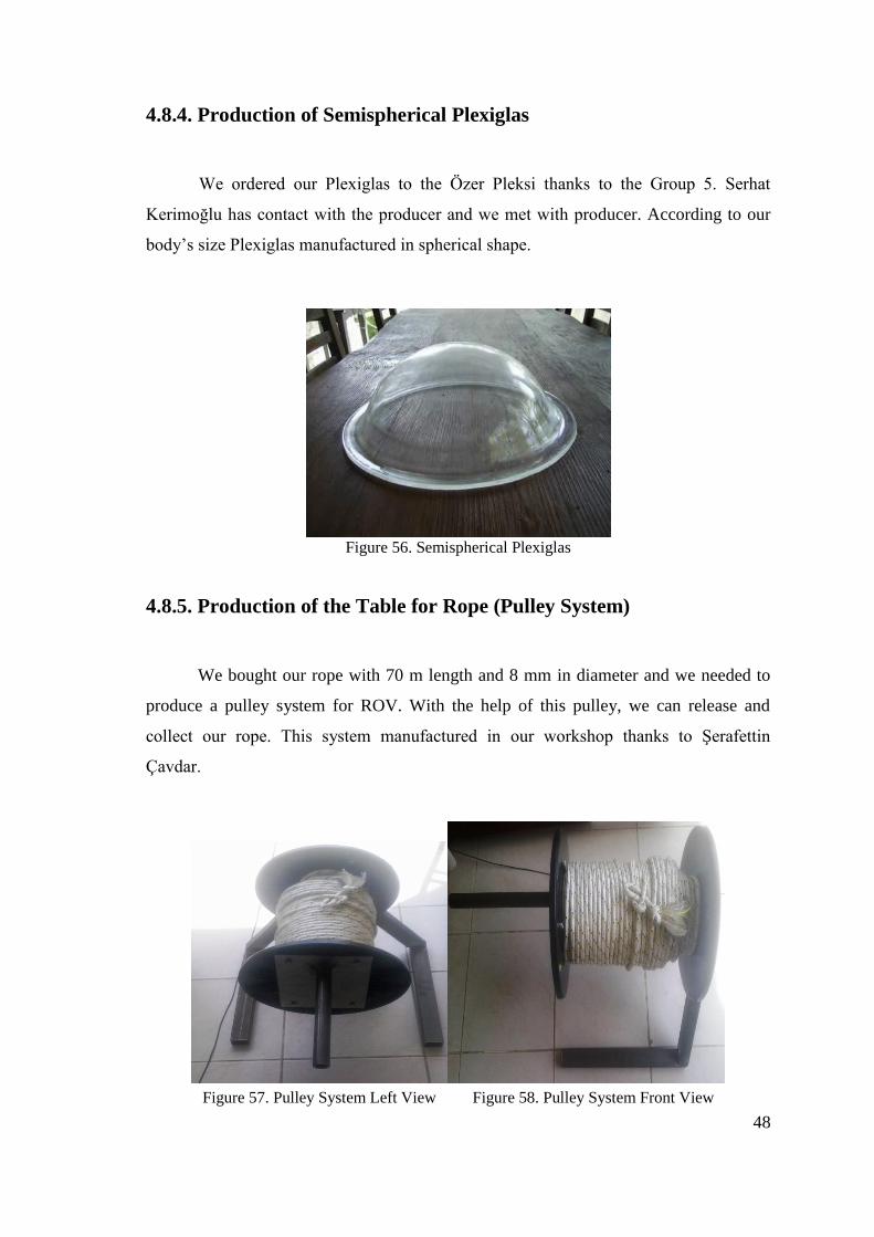
4.8.4. Production of Semispherical Plexiglas
We ordered our Plexiglas to the Özer Pleksi thanks to the Group 5. Serhat
Kerimoğlu has contact with the producer and we met with producer. According to our
body’s size Plexiglas manufactured in spherical shape.
Figure 56. Semispherical Plexiglas
4.8.5. Production of the Table for Rope (Pulley System)
We bought our rope with 70 m length and 8 mm in diameter and we needed to
produce a pulley system for ROV. With the help of this pulley, we can release and
collect our rope. This system manufactured in our workshop thanks to Şerafettin
Çavdar.
Figure 57. Pulley System Left View Figure 58. Pulley System Front View

49
CHAPTER 5
RESULTS
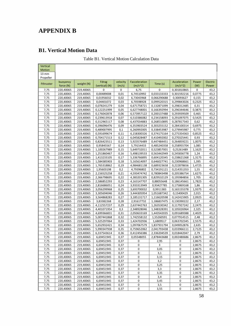
5.1. Vertical Motion
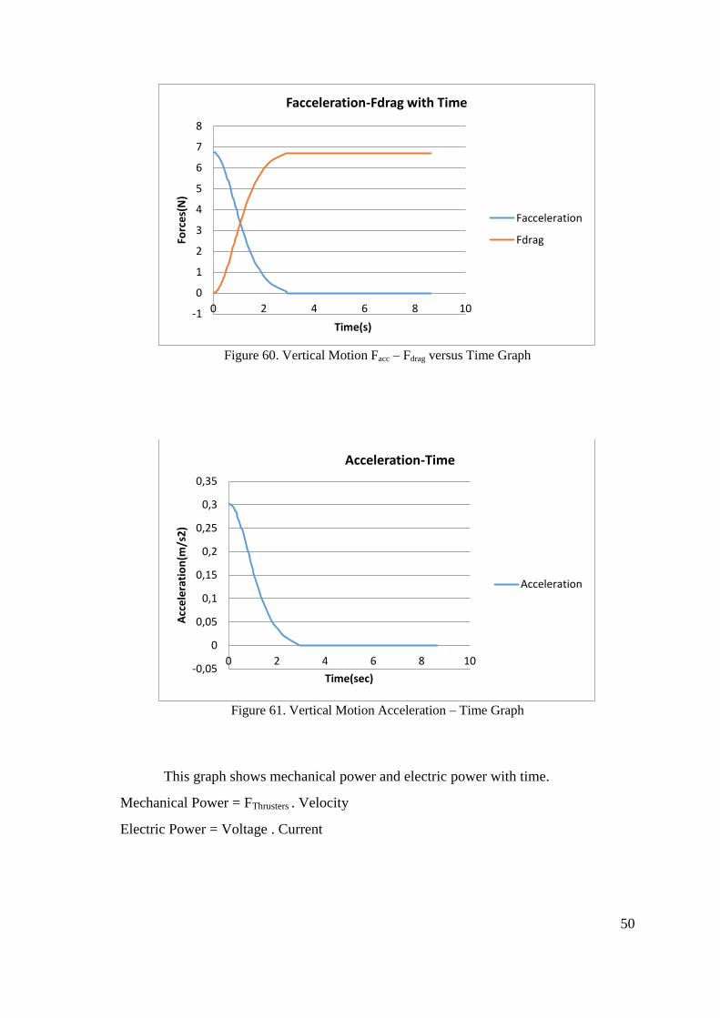
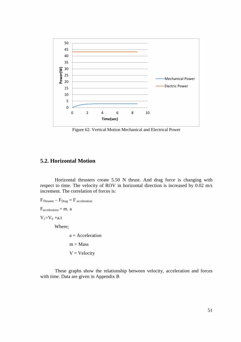
When the vertical thrusters start to run at 12 V, they create 7.75 N thrust. This
value, buoyancy force and weight are constant. And Drag force is changing with respect
to velocity. The correlation of these forces is:
FThrust + Weight – FBuoyancy – FDrag = Facceleration
Facceleration = m . a
V1 = V0 + a.t
Where;
a = Acceleration
m = Mass
V = Velocity
Velocity of ROV is increased by 0.01 m/s increment. When the Facceleration is zero, the
velocity reaches maximum value. Data are given in Appendix B.
Figure 59. Vertical Motion Velocity – Time Graph
0
0,05
0,1
0,15
0,2
0,25
0,3
0,35
0,4
0 2 4 6 8 10
Ve
loci
ty(m
/s)
Time(sec)
Velocity-Time
Velocity
50
Figure 60. Vertical Motion Facc – Fdrag versus Time Graph
Figure 61. Vertical Motion Acceleration – Time Graph
This graph shows mechanical power and electric power with time.
Mechanical Power = FThrusters . Velocity
Electric Power = Voltage . Current
-1
0
1
2
3
4
5
6
7
8
0 2 4 6 8 10
Forc
es(
N)
Time(s)
Facceleration-Fdrag with Time
Facceleration
Fdrag
-0,05
0
0,05
0,1
0,15
0,2
0,25
0,3
0,35
0 2 4 6 8 10
Acc
ele
rati
on
(m/s
2)
Time(sec)
Acceleration-Time
Acceleration
51
Figure 62. Vertical Motion Mechanical and Electrical Power
5.2. Horizontal Motion
Horizontal thrusters create 5.50 N thrust. And drag force is changing with
respect to time. The velocity of ROV in horizontal direction is increased by 0.02 m/s
increment. The correlation of forces is:
FThruster – FDrag = F acceleration
Facceleration = m. a
V1=V0 +a.t
Where;
a = Acceleration
m = Mass
V = Velocity
These graphs show the relationship between velocity, acceleration and forces
with time. Data are given in Appendix B
0
5
10
15
20
25
30
35
40
45
50
0 2 4 6 8 10
Po
we
r(W
)
Time(sec)
Mechanical Power
Electric Power

52
Figure 63. Horizontal Motion Velocity – Time Graph
Figure 64. Horizontal Motion Facc – Fdrag – Time Graph
0
0,05
0,1
0,15
0,2
0,25
0,3
0,35
0,4
0,45
0,5
0 1 2 3 4 5 6
Ve
loci
ty(m
/s)
Time(sec)
Velocity-Time
Velocity
-1
0
1
2
3
4
5
6
0 1 2 3 4 5 6
Forc
es(
N)
Time(s)
Facceleration,Fdrag with Time
Facceleration
Fdrag

53
Figure 65. Horizontal Motion Acceleration – Time Graph
This graph shows mechanical power and electric power with time.
Mechanical Power = FThrusters . Velocity
Electric Power = Voltage . Current
Figure 66. Horizontal Motion Mechanical and Electrical Power versus Time
-0,05
0
0,05
0,1
0,15
0,2
0,25
0,3
0 1 2 3 4 5 6
Acc
ele
rati
on
(m/s
2)
Time(sec)
Acceleration-Time
Acceleration
0
5
10
15
20
25
30
35
40
45
50
0 2 4 6
Po
we
r(W
)
Time(sec)
Mechanical and Electric Power-Time
Mechanical Power
Electric Power
54
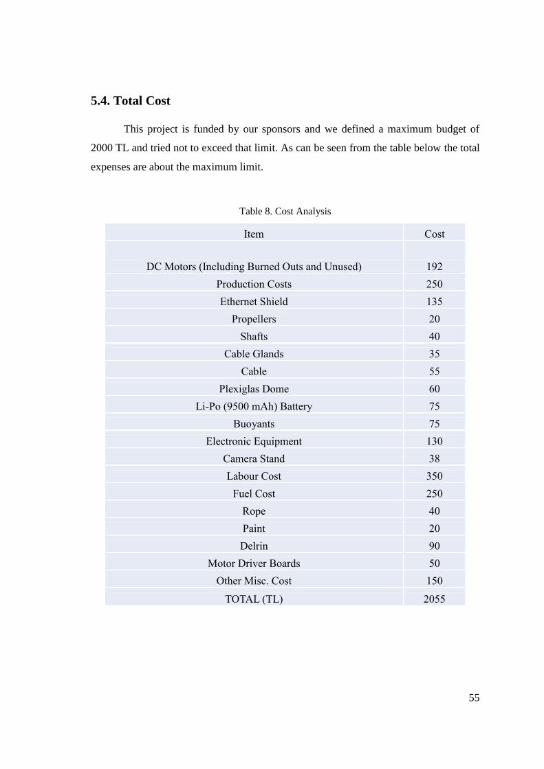
5.3. Power Budget
We have 9500 mAh Li-Po batteries. When the all thrusters are running
maximum power, there is no need battery up to about 60 minutes.
Figure 67. Maximum Power Consumption of the System
0
1000
2000
3000
4000
5000
6000
7000
8000
9000
10000
0 10 20 30 40 50 60 70
Bat
tery
(mA
h)
time(min)
Battery-Time
mAh
55
5.4. Total Cost
This project is funded by our sponsors and we defined a maximum budget of
2000 TL and tried not to exceed that limit. As can be seen from the table below the total
expenses are about the maximum limit.
Table 8. Cost Analysis
Item Cost
DC Motors (Including Burned Outs and Unused) 192
Production Costs 250
Ethernet Shield 135
Propellers 20
Shafts 40
Cable Glands 35
Cable 55
Plexiglas Dome 60
Li-Po (9500 mAh) Battery 75
Buoyants 75
Electronic Equipment 130
Camera Stand 38
Labour Cost 350
Fuel Cost 250
Rope 40
Paint 20
Delrin 90
Motor Driver Boards 50
Other Misc. Cost 150
TOTAL (TL) 2055

56
References
[1] Sea View, “What is a ROV?”
http://www.seaviewsystems.com/questions/what-is-an-rov/
[2] Cable Gland,
http://www.cable-glands-brass.com/brass-metric-strain-relief/brass-cable-glands.gif
[3] Robotistan, “12V 750 rpm Redüktörlü DC Motor”,
http://www.robotistan.com/12V-750Rpm-Reduktorlu-DC-Motor,PR-785.html
[4] Efunda.com, “Stainless Steel”,
http://www.efunda.com/Materials/alloys/stainless_steels/show_stainless.cfm?ID=AISI_
Type_316&prop=all&Page_Title=AISI%20Type%20316, in 2013.
[5] Plexiglas.net, “Plexiglas Properties”,
http://www.plexiglas.net/product/plexiglas/en/about/faq/Pages/properties.aspx, in 2013.
[6] Arduino.cc, Arduino “Mega 2650”,
http://arduino.cc/en/Main/arduinoBoardMega
[7] Arduino.cc, Arduino Ethernet Shield,
http://arduino.cc/en/Main/ArduinoEthernetShield
[8] TP Link, “150 Mbps Wireless N Router”,
http://www.tp-link.com/en/products/details/?model=TL-WR720N
[9] OWENS, Dylan. DSpace@MIT. June 2009.
http://dspace.mit.edu/handle/1721.1/50267.

57
APPENDIX A
A1. Gantt Chart
The Gantt chart can be seen on the next page
58
APPENDIX B
B1. Vertical Motion Data
Table B1. Vertical Motion Calculation Data
Vertical Motion
13 mm Propeller
Fthruster buoyancy force (N)
weight (N) Fdrag
(vertical) (N) velocity
(m/s) Facceleration
(m/s^2) Time (s)
Acceleration (m/s^2)
Power (W)
Electric Power
7,75 220,40065 219,40065 0 0 6,75 0 0,301810865 0 43,2
7,75 220,40065 219,40065 0,00489008 0,01 6,74510992 0,033133333 0,301592216 0,0775 43,2
7,75 220,40065 219,40065 0,01956032 0,02 6,73043968 0,066290688 0,30093627 0,155 43,2
7,75 220,40065 219,40065 0,04401072 0,03 6,70598928 0,099520315 0,299843026 0,2325 43,2
7,75 220,40065 219,40065 0,078241279 0,04 6,671758721 0,132871099 0,298312485 0,31 43,2
7,75 220,40065 219,40065 0,122251999 0,05 6,627748001 0,166392994 0,296344646 0,3875 43,2
7,75 220,40065 219,40065 0,176042878 0,06 6,573957122 0,200137488 0,293939509 0,465 43,2
7,75 220,40065 219,40065 0,239613918 0,07 6,510386082 0,234158093 0,291097075 0,5425 43,2
7,75 220,40065 219,40065 0,312965117 0,08 6,437034883 0,268510895 0,287817343 0,62 43,2
7,75 220,40065 219,40065 0,396096476 0,09 6,353903524 0,303255152 0,284100314 0,6975 43,2
7,75 220,40065 219,40065 0,489007995 0,1 6,260992005 0,338453987 0,279945987 0,775 43,2
7,75 220,40065 219,40065 0,591699674 0,11 6,158300326 0,374175164 0,275354363 0,8525 43,2
7,75 220,40065 219,40065 0,704171513 0,12 6,045828487 0,410492002 0,270325441 0,93 43,2
7,75 220,40065 219,40065 0,826423511 0,13 5,923576489 0,447484451 0,264859221 1,0075 43,2
7,75 220,40065 219,40065 0,95845567 0,14 5,79154433 0,485240358 0,258955704 1,085 43,2
7,75 220,40065 219,40065 1,100267989 0,15 5,649732011 0,523857001 0,25261489 1,1625 43,2
7,75 220,40065 219,40065 1,251860467 0,16 5,498139533 0,563442949 0,245836778 1,24 43,2
7,75 220,40065 219,40065 1,413233105 0,17 5,336766895 0,604120345 0,238621368 1,3175 43,2
7,75 220,40065 219,40065 1,584385903 0,18 5,165614097 0,646027741 0,230968661 1,395 43,2
7,75 220,40065 219,40065 1,765318862 0,19 4,984681138 0,689323658 0,222878656 1,4725 43,2
7,75 220,40065 219,40065 1,95603198 0,2 4,79396802 0,734191121 0,214351353 1,55 43,2
7,75 220,40065 219,40065 2,156525258 0,21 4,593474742 0,780843498 0,205386754 1,6275 43,2
7,75 220,40065 219,40065 2,366798695 0,22 4,383201305 0,829532129 0,195984856 1,705 43,2
7,75 220,40065 219,40065 2,586852293 0,23 4,163147707 0,88055648 0,186145661 1,7825 43,2
7,75 220,40065 219,40065 2,816686051 0,24 3,933313949 0,93427785 0,175869168 1,86 43,2
7,75 220,40065 219,40065 3,056299968 0,25 3,693700032 0,9911383 0,165155378 1,9375 43,2
7,75 220,40065 219,40065 3,305694046 0,26 3,444305954 1,051687342 0,15400429 2,015 43,2
7,75 220,40065 219,40065 3,564868283 0,27 3,185131717 1,116620598 0,142415905 2,0925 43,2
7,75 220,40065 219,40065 3,83382268 0,28 2,91617732 1,186837475 0,130390222 2,17 43,2
7,75 220,40065 219,40065 4,112557237 0,29 2,637442763 1,263530342 0,117927242 2,2475 43,2
7,75 220,40065 219,40065 4,401071954 0,3 2,348928046 1,348328391 0,105026964 2,325 43,2
7,75 220,40065 219,40065 4,699366831 0,31 2,050633169 1,443542035 0,091689388 2,4025 43,2
7,75 220,40065 219,40065 5,007441868 0,32 1,742558132 1,55260591 0,077914515 2,48 43,2
7,75 220,40065 219,40065 5,325297064 0,33 1,424702936 1,6809517 0,063702345 2,5575 43,2
7,75 220,40065 219,40065 5,652932421 0,34 1,097067579 1,837931794 0,049052876 2,635 43,2
7,75 220,40065 219,40065 5,990347938 0,35 0,759652062 2,041793438 0,033966111 2,7125 43,2
7,75 220,40065 219,40065 6,337543614 0,36 0,412456386 2,336204539 0,018442047 2,79 43,2
7,75 220,40065 219,40065 6,69451945 0,37 0,05548055 2,878443688 0,002480686 2,8675 43,2
7,75 220,40065 219,40065 6,69451945 0,37 0 2,95 0 2,8675 43,2
7,75 220,40065 219,40065 6,69451945 0,37 0 3 0 2,8675 43,2
7,75 220,40065 219,40065 6,69451945 0,37 0 3,05 0 2,8675 43,2
7,75 220,40065 219,40065 6,69451945 0,37 0 3,1 0 2,8675 43,2
7,75 220,40065 219,40065 6,69451945 0,37 0 3,15 0 2,8675 43,2
7,75 220,40065 219,40065 6,69451945 0,37 0 3,2 0 2,8675 43,2
7,75 220,40065 219,40065 6,69451945 0,37 0 3,25 0 2,8675 43,2
7,75 220,40065 219,40065 6,69451945 0,37 0 3,3 0 2,8675 43,2
7,75 220,40065 219,40065 6,69451945 0,37 0 3,35 0 2,8675 43,2
7,75 220,40065 219,40065 6,69451945 0,37 0 3,4 0 2,8675 43,2
7,75 220,40065 219,40065 6,69451945 0,37 0 3,45 0 2,8675 43,2
7,75 220,40065 219,40065 6,69451945 0,37 0 3,5 0 2,8675 43,2
7,75 220,40065 219,40065 6,69451945 0,37 0 3,55 0 2,8675 43,2

59
7,75 220,40065 219,40065 6,69451945 0,37 0 3,6 0 2,8675 43,2
7,75 220,40065 219,40065 6,69451945 0,37 0 3,65 0 2,8675 43,2
7,75 220,40065 219,40065 6,69451945 0,37 0 3,7 0 2,8675 43,2
7,75 220,40065 219,40065 6,69451945 0,37 0 3,75 0 2,8675 43,2
7,75 220,40065 219,40065 6,69451945 0,37 0 3,8 0 2,8675 43,2
7,75 220,40065 219,40065 6,69451945 0,37 0 3,85 0 2,8675 43,2
7,75 220,40065 219,40065 6,69451945 0,37 0 3,9 0 2,8675 43,2
7,75 220,40065 219,40065 6,69451945 0,37 0 3,95 0 2,8675 43,2
7,75 220,40065 219,40065 6,69451945 0,37 0 4 0 2,8675 43,2
7,75 220,40065 219,40065 6,69451945 0,37 0 4,05 0 2,8675 43,2
7,75 220,40065 219,40065 6,69451945 0,37 0 4,1 0 2,8675 43,2
7,75 220,40065 219,40065 6,69451945 0,37 0 4,15 0 2,8675 43,2
7,75 220,40065 219,40065 6,69451945 0,37 0 4,2 0 2,8675 43,2
7,75 220,40065 219,40065 6,69451945 0,37 0 4,25 0 2,8675 43,2
7,75 220,40065 219,40065 6,69451945 0,37 0 4,3 0 2,8675 43,2
7,75 220,40065 219,40065 6,69451945 0,37 0 4,35 0 2,8675 43,2
7,75 220,40065 219,40065 6,69451945 0,37 0 4,4 0 2,8675 43,2
7,75 220,40065 219,40065 6,69451945 0,37 0 4,45 0 2,8675 43,2
7,75 220,40065 219,40065 6,69451945 0,37 0 4,5 0 2,8675 43,2
7,75 220,40065 219,40065 6,69451945 0,37 0 4,55 0 2,8675 43,2
7,75 220,40065 219,40065 6,69451945 0,37 0 4,6 0 2,8675 43,2
7,75 220,40065 219,40065 6,69451945 0,37 0 4,65 0 2,8675 43,2
7,75 220,40065 219,40065 6,69451945 0,37 0 4,7 0 2,8675 43,2
7,75 220,40065 219,40065 6,69451945 0,37 0 4,75 0 2,8675 43,2
7,75 220,40065 219,40065 6,69451945 0,37 0 4,8 0 2,8675 43,2
7,75 220,40065 219,40065 6,69451945 0,37 0 4,85 0 2,8675 43,2
7,75 220,40065 219,40065 6,69451945 0,37 0 4,9 0 2,8675 43,2
7,75 220,40065 219,40065 6,69451945 0,37 0 4,95 0 2,8675 43,2
7,75 220,40065 219,40065 6,69451945 0,37 0 5 0 2,8675 43,2
7,75 220,40065 219,40065 6,69451945 0,37 0 5,05 0 2,8675 43,2
7,75 220,40065 219,40065 6,69451945 0,37 0 5,1 0 2,8675 43,2
7,75 220,40065 219,40065 6,69451945 0,37 0 5,15 0 2,8675 43,2
7,75 220,40065 219,40065 6,69451945 0,37 0 5,2 0 2,8675 43,2
7,75 220,40065 219,40065 6,69451945 0,37 0 5,25 0 2,8675 43,2
7,75 220,40065 219,40065 6,69451945 0,37 0 5,3 0 2,8675 43,2
7,75 220,40065 219,40065 6,69451945 0,37 0 5,35 0 2,8675 43,2
7,75 220,40065 219,40065 6,69451945 0,37 0 5,4 0 2,8675 43,2
7,75 220,40065 219,40065 6,69451945 0,37 0 5,45 0 2,8675 43,2
7,75 220,40065 219,40065 6,69451945 0,37 0 5,5 0 2,8675 43,2
7,75 220,40065 219,40065 6,69451945 0,37 0 5,55 0 2,8675 43,2
7,75 220,40065 219,40065 6,69451945 0,37 0 5,6 0 2,8675 43,2
7,75 220,40065 219,40065 6,69451945 0,37 0 5,65 0 2,8675 43,2
7,75 220,40065 219,40065 6,69451945 0,37 0 5,7 0 2,8675 43,2
7,75 220,40065 219,40065 6,69451945 0,37 0 5,75 0 2,8675 43,2
7,75 220,40065 219,40065 6,69451945 0,37 0 5,8 0 2,8675 43,2
7,75 220,40065 219,40065 6,69451945 0,37 0 5,85 0 2,8675 43,2
7,75 220,40065 219,40065 6,69451945 0,37 0 5,9 0 2,8675 43,2
7,75 220,40065 219,40065 6,69451945 0,37 0 5,95 0 2,8675 43,2
7,75 220,40065 219,40065 6,69451945 0,37 0 6 0 2,8675 43,2
7,75 220,40065 219,40065 6,69451945 0,37 0 6,05 0 2,8675 43,2
7,75 220,40065 219,40065 6,69451945 0,37 0 6,1 0 2,8675 43,2
7,75 220,40065 219,40065 6,69451945 0,37 0 6,15 0 2,8675 43,2
7,75 220,40065 219,40065 6,69451945 0,37 0 6,2 0 2,8675 43,2
7,75 220,40065 219,40065 6,69451945 0,37 0 6,25 0 2,8675 43,2
7,75 220,40065 219,40065 6,69451945 0,37 0 6,3 0 2,8675 43,2
7,75 220,40065 219,40065 6,69451945 0,37 0 6,35 0 2,8675 43,2
7,75 220,40065 219,40065 6,69451945 0,37 0 6,4 0 2,8675 43,2
7,75 220,40065 219,40065 6,69451945 0,37 0 6,45 0 2,8675 43,2
7,75 220,40065 219,40065 6,69451945 0,37 0 6,5 0 2,8675 43,2
7,75 220,40065 219,40065 6,69451945 0,37 0 6,55 0 2,8675 43,2
7,75 220,40065 219,40065 6,69451945 0,37 0 6,6 0 2,8675 43,2
7,75 220,40065 219,40065 6,69451945 0,37 0 6,65 0 2,8675 43,2
7,75 220,40065 219,40065 6,69451945 0,37 0 6,7 0 2,8675 43,2
7,75 220,40065 219,40065 6,69451945 0,37 0 6,75 0 2,8675 43,2
7,75 220,40065 219,40065 6,69451945 0,37 0 6,8 0 2,8675 43,2
7,75 220,40065 219,40065 6,69451945 0,37 0 6,85 0 2,8675 43,2

60
7,75 220,40065 219,40065 6,69451945 0,37 0 6,9 0 2,8675 43,2
7,75 220,40065 219,40065 6,69451945 0,37 0 6,95 0 2,8675 43,2
7,75 220,40065 219,40065 6,69451945 0,37 0 7 0 2,8675 43,2
7,75 220,40065 219,40065 6,69451945 0,37 0 7,05 0 2,8675 43,2
7,75 220,40065 219,40065 6,69451945 0,37 0 7,1 0 2,8675 43,2
7,75 220,40065 219,40065 6,69451945 0,37 0 7,15 0 2,8675 43,2
7,75 220,40065 219,40065 6,69451945 0,37 0 7,2 0 2,8675 43,2
7,75 220,40065 219,40065 6,69451945 0,37 0 7,25 0 2,8675 43,2
7,75 220,40065 219,40065 6,69451945 0,37 0 7,3 0 2,8675 43,2
7,75 220,40065 219,40065 6,69451945 0,37 0 7,35 0 2,8675 43,2
7,75 220,40065 219,40065 6,69451945 0,37 0 7,4 0 2,8675 43,2
7,75 220,40065 219,40065 6,69451945 0,37 0 7,45 0 2,8675 43,2
7,75 220,40065 219,40065 6,69451945 0,37 0 7,5 0 2,8675 43,2
7,75 220,40065 219,40065 6,69451945 0,37 0 7,55 0 2,8675 43,2
7,75 220,40065 219,40065 6,69451945 0,37 0 7,6 0 2,8675 43,2
7,75 220,40065 219,40065 6,69451945 0,37 0 7,65 0 2,8675 43,2
7,75 220,40065 219,40065 6,69451945 0,37 0 7,7 0 2,8675 43,2
7,75 220,40065 219,40065 6,69451945 0,37 0 7,75 0 2,8675 43,2
7,75 220,40065 219,40065 6,69451945 0,37 0 7,8 0 2,8675 43,2
7,75 220,40065 219,40065 6,69451945 0,37 0 7,85 0 2,8675 43,2
7,75 220,40065 219,40065 6,69451945 0,37 0 7,9 0 2,8675 43,2
7,75 220,40065 219,40065 6,69451945 0,37 0 7,95 0 2,8675 43,2
7,75 220,40065 219,40065 6,69451945 0,37 0 8 0 2,8675 43,2
7,75 220,40065 219,40065 6,69451945 0,37 0 8,05 0 2,8675 43,2
7,75 220,40065 219,40065 6,69451945 0,37 0 8,1 0 2,8675 43,2
7,75 220,40065 219,40065 6,69451945 0,37 0 8,15 0 2,8675 43,2
7,75 220,40065 219,40065 6,69451945 0,37 0 8,2 0 2,8675 43,2
7,75 220,40065 219,40065 6,69451945 0,37 0 8,25 0 2,8675 43,2
7,75 220,40065 219,40065 6,69451945 0,37 0 8,3 0 2,8675 43,2
7,75 220,40065 219,40065 6,69451945 0,37 0 8,35 0 2,8675 43,2
7,75 220,40065 219,40065 6,69451945 0,37 0 8,4 0 2,8675 43,2
7,75 220,40065 219,40065 6,69451945 0,37 0 8,45 0 2,8675 43,2
7,75 220,40065 219,40065 6,69451945 0,37 0 8,5 0 2,8675 43,2
7,75 220,40065 219,40065 6,69451945 0,37 0 8,55 0 2,8675 43,2
7,75 220,40065 219,40065 6,69451945 0,37 0 8,6 0 2,8675 43,2
7,75 220,40065 219,40065 6,69451945 0,37 0 8,65 0 2,8675 43,2

61
B2. Horizontal Motion Data
Table B2. Horizontal Motion Results Data
Facceleration (N)
Fthrusters (N)
Fdrag (N) Velocity
(m/s) Acceleration
(m/s2) mass (kg) time (sec) Power(W)
Electrical Power
5,4936 5,4936 0 0 0,24104918 22,79037 0 0 43,2
5,4820106 5,4936 0,0115894 0,02 0,240540658 0,082971 0,109872 43,2
5,4472424 5,4936 0,0463576 0,04 0,239015093 0,166117 0,219744 43,2
5,3892954 5,4936 0,1043046 0,06 0,236472484 0,249793 0,329616 43,2
5,3081696 5,4936 0,1854304 0,08 0,232912831 0,33437 0,439488 43,2
5,203865 5,4936 0,289735 0,1 0,228336135 0,420239 0,54936 43,2
5,0763816 5,4936 0,4172184 0,12 0,222742395 0,507829 0,659232 43,2
4,9257194 5,4936 0,5678806 0,14 0,216131612 0,597619 0,769104 43,2
4,7518784 5,4936 0,7417216 0,16 0,208503785 0,690155 0,878976 43,2
4,5548586 5,4936 0,9387414 0,18 0,199858914 0,786077 0,988848 43,2
4,33466 5,4936 1,15894 0,2 0,190197 0,886147 1,09872 43,2
4,0912826 5,4936 1,4023174 0,22 0,179518042 0,991301 1,208592 43,2
3,8247264 5,4936 1,6688736 0,24 0,167822041 1,102711 1,318464 43,2
3,5349914 5,4936 1,9586086 0,26 0,155108996 1,221885 1,428336 43,2
3,2220776 5,4936 2,2715224 0,28 0,141378907 1,350826 1,538208 43,2
2,885985 5,4936 2,607615 0,3 0,126631775 1,49229 1,64808 43,2
2,5267136 5,4936 2,9668864 0,32 0,110867599 1,650228 1,757952 43,2
2,1442634 5,4936 3,3493366 0,34 0,094086379 1,830624 1,867824 43,2
1,7386344 5,4936 3,7549656 0,36 0,076288116 2,043194 1,977696 43,2
1,3098266 5,4936 4,1837734 0,38 0,05747281 2,305358 2,087568 43,2
0,85784 5,4936 4,63576 0,4 0,03764046 2,653349 2,19744 43,2
0,3826746 5,4936 5,1109254 0,42 0,016791066 3,184692 2,307312 43,2
0,3826746 5,4936 5,1109254 0,42 0,016791066 3,184692 2,307312 43,2
0,13639985 5,4936 5,3572002 0,43 0,005984977 3,780247 2,362248 43,2
0,01108946 5,4936 5,4825105 0,435 0,000486585 4,615672 2,389716 43,2
0,01108946 5,4936 5,4825105 0,435 0,000486585 4,615672 2,389716 43,2
0 5,4936 5,4825105 0,435 0 5 2,389716 43,2
0 5,4936 5,4825105 0,435 0 5,1 2,389716 43,2
0 5,4936 5,4825105 0,435 0 5,2 2,389716 43,2
0 5,4936 5,4825105 0,435 0 5,3 2,389716 43,2
0 5,4936 5,4825105 0,435 0 5,4 2,389716 43,2
0 5,4936 5,4825105 0,435 0 5,5 2,389716 43,2
0 5,4936 5,4825105 0,435 0 5,6 2,389716 43,2
0 5,4936 5,4825105 0,435 0 5,7 2,389716 43,2

62
ÖNERİLER
Sualtı gözlem aracı tasarlayacak olan takımlara teknik ve işleyiş hakkında,
yaşadığımız tecrübelerden birkaç öneride bulunabiliriz. Bunun yanında dersin işlenişi
ile ilgili de önerilerim olacak. Öncelikle proje işleyişi ile ilgili şunu kesinlikle
söyleyebilirim ki, 6 kişilik bir grubu yönetmek kolay bir iş değil. Yapılmasının faydalı
olacağını düşündüğüm şeyleri maddeler halinde yazacağım.
1. İlk olarak yapılması gereken herkesin boş günlerini göze alarak ortak bir
toplantı zamanı belirlemek. Toplantılar bir projede koordinasyonu sağlama açısından
çok önemlidir.
2. Proje tamamen öğrencilerin maddi kaynakları ile yapıldığından, birinci dönem
sonunda bir sponsorluk dosyası hazırlayıp firmalara başvurmanız sizin için faydalı
olacaktır.
3. Hazırlanan gantt çizelgesine göre hareket etmek, projenin zamanında
bitmesini sağlayacaktır fakat çizelgeyi hazırlarken test sürelerini mümkün olduğunca
uzun tutun çünkü beklenmedik aksilikler olabiliyor.
4. Dönem başında yapılan görev dağılımına bağlı kalın, yavaş giden işlerde
sorumluyu en başından uyarın çünkü aksayan işler ileriki zamanlarda başınıza büyük
dertler açabilir.
Dersin işlenişi hakkında;
1. Üç haftada bir yapılan sunumlar faydalı oluyor fakat verilen raporların geri
dönüşü yapılırsa projeyi sürdüren grup eksik veya yanlış yaptığı yerleri görüp
düzeltebilir.
2. Bizim projemizde en çok zorlandığımız kısım elektronik oldu. Bunun sebebi
makine mühendisliği öğrencisi olmamızdır ve şahsi görüşüm şudur ki, bu tarz kontrolün
dahil olduğu projelerde her gruba en az 2 elektronik veya bilgisayar mühendisliği
öğrencisi dahil edilmelidir.
Projeyi yapacak arkadaşlara başarılar dilerim.
Serdar ÖZDEMİR