battery operated hydraulic crimping tool - Cembre
16
ENGLISH BATTERY OPERATED HYDRAULIC CRIMPING TOOL 14 M 174 E OPERATION AND MAINTENANCE MANUAL B54MD-D6 B54MD-D6E ENGLISH 14 M 174 E
-
Upload
khangminh22 -
Category
Documents
-
view
2 -
download
0
Transcript of battery operated hydraulic crimping tool - Cembre

1
ENGLISH
BATTERY OPERATED
HYDRAULIC CRIMPING TOOL
14 M 174 E
OPERATION AND MAINTENANCE
MANUAL
B54MD-D6
B54MD-D6E
ENGLISH
14 M 174 E

2
Before using the tool, carefully read the instructions in this manual.
When operating the tool, keep hands away from the danger zone.
See page 8.
WARNING LABELS
Never throw batteries into fi re or water.
Always recycle the batteries.
Do not discard batteries into domestic refuse or waste disposal.
Tool
Battery

3
BATTERY OPERATED HYDRAULIC CRIMPING TOOL
1. GENERAL CHARACTERISTICS
suitable for installing electrical compression connectors
for conductors up to 150 mm2 (300 MCM)
54 (6)
340 (4,900)
458 x 133 x 81 (18 x 5.2 x 3.2)
2,95 (6.5)
18
18 / 2.0 Li-Ion
220-240 / 50-60
AGIP ARNICA 22 or ESSO INVAROL EP22 or equivalent.
the tool is equipped with a maximum pressure valve.
Application range:
Crimping force kN (sh ton):
Rated operating pressure bar (psi):
Dimensions LxWxH mm (inches):
Weight with battery kg (lbs):
Motor Volt DC:
Battery type CB1820L Volt / Ah:
Battery charger supply Volt / Hz:
Recommended oil:
Safety:
Types of jaw supplied:
Acoustic Noise (Directive 2006/42/EC, annexe 1, point 1.7.4.2 letter u)– The weighted continuous acoustic pressure level equivalent A at the work place L
pA is equal to .............................................................................................................. 64,9 dB (A)
– The maximum value of the weighted acoustic displacement pressure C at the work place L
pCPeak is equal to ........................................................................................ 99,7 dB (C)
– The acoustic power level emitted by the machine L
WA is equal to ...................................................................................................................................................... 69,3 dB (A)
Risks due to vibration (Directive 2006/42/EC, annexe 1, point 2.2.1.1)Tests carried out in compliance with the indications contained in EN ISO 5349-1/2 and UNI EN 28662-1 Standards, and under operating conditions much more severe than those normally found, certify that the weighted root mean square in frequency of the acceleration the upper limbs are exposed to for each biodynamic reference axis is 0,527 m/sec2 max.
CDD 6 with D3 groove to accept all "W" style crimping dies +
"BG" fi xed groove
INTERCHANGEABLE CRIMPING JAWS
JAW TYPE GROOVES CRIMPING DIE COMPATIBILITY
CDD6“D3” TO ACCEPT ALL “W” STYLE CRIMPING DIES + “BG” FIXED
GROOVE
FCI Burndy W, X SeriesGreenlee KD6 SeriesIlsco ND SeriesHuskie HT-58 SeriesPanduit CD-2001 series
TOOL TYPE: B54MD-D6 B54MD-D6E

4
2. INSTRUCTIONS FOR USE
The tool can be held in one hand while positioning the connector with the other.
Residual battery capacity level is automatically displayed after every cycle.
The part reference includes the following:
– Basic tool complete with crimping jaws with thermoplastic protection.
– Spare battery.
– Battery charger.
– Plastic carrying case type VAL P45.
2.1) Preparation With the tool in the rest position (the ram fully retracted) proceed as follows:
– Select the appropriate groove or die set for the connector to be crimped.
– Insert the dies into the jaws of the tool (see § 2.8).
– Insert the conductor into the connector.
2.2) Die advancement (Ref. to Fig. 1)
Grip the tool fi rmly and comfortably.
– Position the connector in the die groove
and ensure the correct location of the
crimp.
– Press operating button (4) to activate
the motor-pump group for the advance-
ment of the ram. To halt the advance-
ment, release the operating button and
the motor will cut out.
Make sure the dies are exactly positioned
on the desired crimp point otherwise
re-open dies following instructions as per
§ 2.5 and reposition the connector.
2.3) CompressionInsert the conductor in the connector and press the operating button (4): the ram will gradually
move forward until the two dies touch. It is recommended to keep operating until the maximum
pressure valve is activated and a "click" is heard.
2.4) Head rotationFor ease of operation the tool head can rotate through 180°, allowing the operator to work in the
most comfortable position.
Warning: do not attempt to rotate the head when the hydraulic circuit is pressurised.
2.5) Release of diesPress the pressure release button (9), the ram will retract and open the jaws.
9
4
FIG. 11

5
2
FIG. 2
P
2.6) Battery status (Ref. to Fig. 2)
The battery is equipped with LED indicators
that indicate the remaining battery life at
any time by pressing the adjacent button (P).
4 LEDs illuminated: Fully charged
2 LEDs illuminated: 50 % capacity
1 LED fl ashing: Minimum charge, replace the battery
WHEN THE BATTERY VOLTAGE HAS DROPPED BELOW A MINIMUM SAFETY THRESHOLD, THE TOOL WILL NOT START, AND IT IS NECESSARY TO RECHARGE OR REPLACE THE BATTERY.
The approximate time to fully recharge a battery is about 40 minutes.
2.7) Insertion/replacement of battery
To replace the battery, remove it by pressing the release button (15) (Ref. to Fig. 3), then insert the
new battery, sliding it into the guides until it locks.
FIG. 3
2
15
WHEN THE BATTERY VOLTAGE HAS DROPPED BELOW A MINIMUM SAFETY THRESHOLD, THE TOOL WILL NOT START, AND IT IS NECESSARY TO RECHARGE OR REPLACE THE BATTERY.

6
2.9) Jaw replacementThe tool is supplied with the interchangeable CDD 6 jaw.
Other types of jaw can also be supplied separately, for
replacement proceed as follows:
– Push and turn clockwise the locking pin (9) so that
the jaws are released.
– Slide the jaws out of the top of the tool and insert the
new ones (see Fig. 5).
– Fully insert the locking pin (9) into the tool and lock it
by turning clockwise until the red lines are aligned.
red lines
9FIG. 5
FIG. 4
2.8) ”W” style crimping dies assembles
– Press pins (2) and insert “W” dies into their
seats (see Fig. 4).
– To disassemble them simply press the pins and
slip them from the jaws.
IT IS RECOMMENDED TO USE THE TOOL ONLY
WITH PRODUCT TO BE CRIMPED INSERTED.
22
7
3.1) Using the battery chargerCarefully follow the instructions in the battery charger manual.
4. MAINTENANCE
The tool is robust, completely sealed and requires very little daily maintenance. Compliance with the following points should help to maintain the optimum performance of the tool:
4.1) Thorough cleaningDust, sand and dirt are a danger for any hydraulic device.Every day, after use, the tool must be wiped with a clean cloth taking care to remove any residue, especially close to moveable parts.
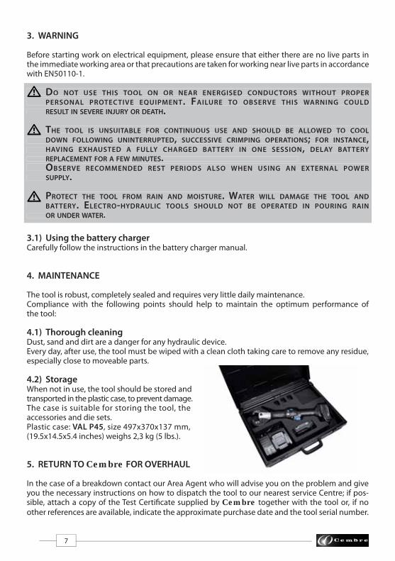
4.2) Storage When not in use, the tool should be stored and transported in the plastic case, to prevent damage. The case is suitable for storing the tool, the accessories and die sets. Plastic case: VAL P45, size 497x370x137 mm, (19.5x14.5x5.4 inches) weighs 2,3 kg (5 lbs.).
5. RETURN TO Cembre FOR OVERHAUL In the case of a breakdown contact our Area Agent who will advise you on the problem and give you the necessary instructions on how to dispatch the tool to our nearest service Centre; if pos-sible, attach a copy of the Test Certifi cate supplied by Cembre together with the tool or, if no other references are available, indicate the approximate purchase date and the tool serial number.
3. WARNING
Before starting work on electrical equipment, please ensure that either there are no live parts in the immediate working area or that precautions are taken for working near live parts in accordance with EN50110-1.
DO NOT USE THIS TOOL ON OR NEAR ENERGISED CONDUCTORS WITHOUT PROPER PERSONAL PROTECTIVE EQUIPMENT. FAILURE TO OBSERVE THIS WARNING COULD RESULT IN SEVERE INJURY OR DEATH.
THE TOOL IS UNSUITABLE FOR CONTINUOUS USE AND SHOULD BE ALLOWED TO COOL DOWN FOLLOWING UNINTERRUPTED, SUCCESSIVE CRIMPING OPERATIONS; FOR INSTANCE, HAVING EXHAUSTED A FULLY CHARGED BATTERY IN ONE SESSION, DELAY BATTERY REPLACEMENT FOR A FEW MINUTES. OBSERVE RECOMMENDED REST PERIODS ALSO WHEN USING AN EXTERNAL POWER SUPPLY.
PROTECT THE TOOL FROM RAIN AND MOISTURE. WATER WILL DAMAGE THE TOOL AND BATTERY. ELECTRO-HYDRAULIC TOOLS SHOULD NOT BE OPERATED IN POURING RAIN OR UNDER WATER.

8
The guarantee is void if parts used are not Cembre original spares.
When ordering spare parts always specify the following:
- code number of item
- name of item
- type of tool
- serial number of tool
SPARE PARTS LIST
TABLE 1 (JAW)
Code N° DESCRIPTION
6000630 1 RUBBER COVER 26600022 2 DIE RETAINER PIN 2 6520404 3 SPRING 26520630 4 SPRING 16180171 5 M3 AUTOLOCK NUT 26760085 6 Ø 3x12 ELASTIC PIN 2
QtyItem
USER INFORMATION in accordance with “Directives 2002/95/EC and 2002/96/EC regarding the reduction of hazardous substances in electrical and electronic equipment, including the disposal of waste”.
The 'Not in the bin' symbol above when shown on equipment or packaging means that the equipment must, at the end of its life, be disposed of separately from other waste. The separate waste collection of such equipment is organised and managed by the manufacturer. Users wishing to dispose of such equipment must contact the manufacturer and follow the prescribed guidelines for its separate collection. Appropriate waste separation, collection, environmentally compatible treatment and disposal is intended to reduce harmful environmental eff ects and promote the reuse and recycling of materials contained in the equipment. Unlawful disposal of such equipment will be subject to the application of admin-istrative sanctions provided by current legislation.
- Following information applies in member states of the European Union:

9
TABLE 2
Code N° DESCRIPTION
6000577 1 BODY RIGHT+LEFT SHELL 16000128 2 BATTERY ADAPTER SHELL R+L 12598495 3 BATTERY CB1820L Li-Ion 18V 2Ah 16000217 4 OPERATING BUTTON 16000127 5 SHUTTER 16000591 6 ROD 16000593 7 SPRING 16000150 8 CONTACT SUPPORT 16000218 9 PRESSURE RELEASE BUTTON 16000582 10 BUTTON STRIKER 16000200 11 MECHANICAL GROUP 16004168 12 ELECTRONIC CARD 16000126 13 SHUTTER 16000589 14 WRIST STRAP 16006280 15 BATTERY RELEASE 16900650 16 3,5X16 SCREW 86520531 17 SPRING 16232755 18 TG.0999 LABEL 16232500 19 TG.0704 LABEL 16232676 20 TG.0919 LABEL 2
QtyItem
5
1
2
3 6
54
32
6
1
CDD6 jaw

10
11
4
12
7
2
119
16
20
See TABLE 3

11
20
10
9
18
15
17
8
14
6
1
2
3
13
5
TABLE 2

12
TABLE 3 (ITEM 11 IN TABLE 2)
Code N° DESCRIPTION
6000625 90 RUBBER GRIP 16000199 100 ACTUATING MECHANICAL GROUP 16000357 100 1 HOUSING 16000358 100 4 GEAR 16760004 100 8 Ø 2X8 CYLINDRICAL PIN 36900008 100 9 M3x6 SCREW 26000849 100 10 Ø 3 SCHNORR WASHER 26740020 100 11 1/4" BALL 26000363 100 15 GEAR 36402009 100 16 BEARING 16402006 100 17 WASHER 16000328 100 18 WASHER 16760012 100 19 CYLINDRICAL PIN 26000315 100 20 SPACER 36000231 100 210 COMPLETE DISC 1 6000229 100 6 DISC 16000227 100 7 BALLS SUPPORT 16700080 100 8 Ø 6 CIRCLIP 16650136 100 9 WASHER 16000232 100 220 COMPLETE CAM 1 6000198 100 250 COMPLETE MOTOR 1 6000152 300 COMPLETE HYDRAULIC GROUP 16620122 300 1 RAM 16362098 300 11 SEAL 16000560 300 15 MEMBRANE RING 16720072 300 16 OIL RESERVOIR 16300027 300 17 VALVE PISTON 16000561 300 18 GRUB SCREW 16520232 300 19 VALVE SPRING 16620378 300 21 PUMPING RAM 16000563 300 24 VALVE ROD 16000575 300 26 SPRING SUPPORT 16000565 300 27 TEST PRESSURE CAP 16641027 300 30 WASHER 16000567 300 31 SETTING VALVE LOCKNUT 16000603 300 45 PRESSURE RELEASE LEVER 16000570 300 57 PUMPING RAM RETURN SPRING 16740100 300 62 5/32" BALL 16520160 300 63 SPRING 16340590 300 64 GRUB SCREW 1
QtyItem

13
Code N° DESCRIPTION QtyItem
6520200 300 65 SPRING 16740120 300 66 7/32" BALL 13041735 300 67 TIE 26640205 300 68 D. 4 SCHNORR WASHER 16900052 300 69 M4x6 SCREW 16000602 300 70 LEVER SPRING 16900054 300 71 M4x6 SCREW 16360022 300 72 O-RING 16360125 300 75 O-RING 16641020 300 77 Ø 6 CU WASHER 16000318 300 78 SPRING GUIDE 16160081 300 310 BODY 1 6000153 300 350 RESERVOIR CAP 1 6000588 300 360 COMPLETE LEVER SUPPORT 1 6000601 300 400 COMPLETE MEMBRANE 1 6900602 300 500 COMPLETE SUCTION SCREW 1 6000620 600 COMPLETE JAW SUPPORT 16000621 600 2 SUPPORT 16000632 600 3 ROLL 26560200 600 4 PIN ROLL 26000622 600 5 JAWS SUPPORT 16000623 600 6 SPRING 16040564 600 7 RAM GUIDE RING 16000624 600 8 PIN GRIP 16000633 600 9 JAW LOCKING PIN 16700051 600 12 Ø 10 CIRCLIP 16900013 600 13 M3x4 SCREW 16520030 600 14 RAM RETURN SPRING 16520601 600 15 SPRING 16760420 600 16 CYLINDRICAL PIN 16900180 600 17 M4x10 SCREW 1
TABLE 3 (ITEM 11 IN TABLE 2)

14
24
26
31
19
18
1775
30
67
16
350
67
64
65
66
310
70
45
63
77360
7162
5
4
3
3
12
13
15
16
68
17
90
11
600
9
2
1
2772
69
78
68
*

15
419
18
1
250
10
9
20
16
17
15
21
57
400
300
15
100
147
500
*
TIGHTENING TORQUE COUPLE DE SERRAGEDREHMOMENTPAR DE TORSIONCOPPIA DI SERRAGGIO
8 Nm (5.9 lbf ft)
8
210
11
86
11
220
7
9
TABLE 3 (ITEM 11)

16
This
ma
nu
al i
s th
e p
rop
erty
of C
embr
e: a
ny
rep
rod
uct
ion
is fo
rbid
de
n w
ith
ou
t w
ritt
en
pe
rmis
sio
n.
cod
. 62
61
39
7
Cembre Ltd.Dunton ParkKingsbury Road, Curdworth - Sutton ColdfieldWest Midlands B76 9EB (UK) Tel.: 01675 470440 - Fax: 01675 470220E-mail: [email protected]
Cembre S.p.A. Via Serenissima, 9 25135 Brescia (Italia) Telefono: 030 36921Telefax: 030 3365766E-mail: [email protected]
Cembre S.a.r.l.22 Avenue Ferdinand de Lesseps91420 Morangis (France)Tél.: 01 60 49 11 90 - Fax: 01 60 49 29 10CS 92014 – 91423 Morangis CédexE-mail: [email protected]
Cembre España S.L.U.Calle Verano, 6 y 8 - P.I. Las Monjas28850 Torrejón de Ardoz - Madrid (España)Teléfono: 91 4852580Telefax: 91 4852581E-mail: [email protected]
Cembre GmbHHeidemannstraße 16680939 München (Deutschland)Telefon: 089 3580676Telefax: 089 35806777E-mail: [email protected]
Cembre Inc.Raritan Center Business Park181 Fieldcrest AvenueEdison, New Jersey 08837 (USA)Tel.: 732 225-7415 - Fax: 732 225-7414E-mail: [email protected]
www.cembre.com