
IMPLEMENTATION OF FUZZY LOGIC CONTROLLER FOR BUCK-BOOST CONVERTER COMBINING KY AND SYNCHRONOUS BUCK...
8
Journal of Theoretical and Applied Information Technology 10 th September 2014. Vol. 67 No.1 © 2005 - 2014 JATIT & LLS. All rights reserved . ISSN: 1992-8645 www.jatit.org E-ISSN: 1817-3195 151 IMPLEMENTATION OF FUZZY LOGIC CONTROLLER FOR BUCK-BOOST CONVERTER COMBINING KY AND SYNCHRONOUS BUCK CONVERTER FOR BATTERY OPERATED PORTABLE DEVICES R.ANAND 1 , I.GNANAMBAL 2 , N.POORNEMA 3 1 Mahendra college of Engineering, Anna University, Salem, India. 2 Government college of Engineering, Salem, India. 3 Paavai Engineering College, Anna University, Namakkal, India. Email :[email protected] ABSTRACT KY converter and buck converter, combined into a positive buck–boost converter is a recently proposed system by K. I. Hwuet. Al. This converter produces low output voltage ripple than the conventional DC- DC negative voltage boosting converters. In this manuscript a PI controller and Fuzzy controller is modelled to control the output voltage ripple to reduce the peak overshoot and settling time of the converter. The results of proposed PI and Fuzzy controlled negative output KY boost converter with the digital simulation by Matlab/Simulink shows reduction in voltage ripple for about 5milli Volts for PI controlled system to 2milli Volts by the proposed Fuzzy controlled combined buck and KY converter. Also the peak overshoot of the system and its settling time are reduced to a greater extent with the proposed system. The performance of the converter with traditional Proportional-Integral-Controller (PIC) and Fuzzy controller is compared at different working conditions in the MATLAB/Simulink. Experimental model using field programmable gate array (FPGA)were also done and the simulation results were verified. Keywords: Fuzzy Logic Controller (FCL), Proportional Integral Controller(PIC), Modified KY Buck Boost Converter, Output voltage ripple, DC-DC Converter 1. INTRODUCTION In fast progress of communication and computing gadgets DC-DC converters are employed for various devices like amplifiers, personal digital assistant (PDA), MP3 players, blue tooth devices etc., needs a stepped-up voltage from a specific input voltage. The specifications such as output voltage ripple, settling time and load transient response of the converters has to be taken into contemplation. The conventional non-isolated dc-dc boosting converters are supposed to produce more output voltage ripples. For the purpose of ripple reduction traditional controllers are employed. The KY buck-boost converter (KY- BBC) recently introduced by K.I. Hwu and Y.T. Yau works in CCM, keeping the output current non-pulsating hence suppressed voltage stress across the output capacitor [1-3]. The control methodologies for KY converter topologies are studied for future applications. Reasonably better candidate in the family of DC-DC converters, the KY-BBC is considered for this study. It converts the positive DC source voltage into positive DC load voltage with reduced output ripple voltage. The switching signal flow graph (SFG), small signal analysis, and state space averaging mathematical models for DC-DC converters have been presented [4-5]. Among these methods, the state space averaging technique has better modelling approach for the converters operated in dynamic condition in comparison with other methods. The traditional controller for the output voltage control of the DC-DC converters is presented in [6]. However, these controllers are very sensitive to circuit parameter variations, change in operating region, line and load voltage disturbances. A fuzzy logic controller (FLC) and sliding mode controller (SMC) for the conventional DC-DC converters has been reported in [7-8]. However, the FLC for all the converters has produced small output voltage start-up overshoots, high overshoots during the dynamic conditions and high output ripple voltage compared to PI controller [9]. The FLC based PID controller for the buck DC-DC converter has been reported [10]. The SMC for various types of the DC-DC converters namely Cuk, buck and Luo-Converters have been dealt with [11-12].PI controller for KY converter combined with buck boost converter has been presented [13]. This paper proposes a design of
-
Upload
independent -
Category
Documents
-
view
4 -
download
0
Transcript of IMPLEMENTATION OF FUZZY LOGIC CONTROLLER FOR BUCK-BOOST CONVERTER COMBINING KY AND SYNCHRONOUS BUCK...

Journal of Theoretical and Applied Information Technology 10
th September 2014. Vol. 67 No.1
© 2005 - 2014 JATIT & LLS. All rights reserved.
ISSN: 1992-8645 www.jatit.org E-ISSN: 1817-3195
151
IMPLEMENTATION OF FUZZY LOGIC CONTROLLER FOR
BUCK-BOOST CONVERTER COMBINING KY AND
SYNCHRONOUS BUCK CONVERTER FOR BATTERY
OPERATED PORTABLE DEVICES
R.ANAND1, I.GNANAMBAL
2, N.POORNEMA
3
1Mahendra college of Engineering, Anna University, Salem, India. 2Government college of Engineering, Salem, India.
3Paavai Engineering College, Anna University, Namakkal, India. Email :[email protected]
ABSTRACT
KY converter and buck converter, combined into a positive buck–boost converter is a recently proposed system by K. I. Hwuet. Al. This converter produces low output voltage ripple than the conventional DC-DC negative voltage boosting converters. In this manuscript a PI controller and Fuzzy controller is modelled to control the output voltage ripple to reduce the peak overshoot and settling time of the converter. The results of proposed PI and Fuzzy controlled negative output KY boost converter with the digital simulation by Matlab/Simulink shows reduction in voltage ripple for about 5milli Volts for PI controlled system to 2milli Volts by the proposed Fuzzy controlled combined buck and KY converter. Also the peak overshoot of the system and its settling time are reduced to a greater extent with the proposed system. The performance of the converter with traditional Proportional-Integral-Controller (PIC) and Fuzzy controller is compared at different working conditions in the MATLAB/Simulink. Experimental model using field programmable gate array (FPGA)were also done and the simulation results were verified. Keywords: Fuzzy Logic Controller (FCL), Proportional Integral Controller(PIC), Modified KY Buck
Boost Converter, Output voltage ripple, DC-DC Converter
1. INTRODUCTION
In fast progress of communication and
computing gadgets DC-DC converters are employed for various devices like amplifiers, personal digital assistant (PDA), MP3 players, blue tooth devices etc., needs a stepped-up voltage from a specific input voltage. The specifications such as output voltage ripple, settling time and load transient response of the converters has to be taken into contemplation. The conventional non-isolated dc-dc boosting converters are supposed to produce more output voltage ripples. For the purpose of ripple reduction traditional controllers are employed. The KY buck-boost converter (KY-BBC) recently introduced by K.I. Hwu and Y.T. Yau works in CCM, keeping the output current non-pulsating hence suppressed voltage stress across the output capacitor [1-3]. The control methodologies for KY converter topologies are studied for future applications. Reasonably better candidate in the family of DC-DC converters, the KY-BBC is considered for this study. It converts the positive DC source voltage into positive DC load voltage with reduced output ripple voltage.
The switching signal flow graph (SFG), small signal analysis, and state space averaging mathematical models for DC-DC converters have been presented [4-5]. Among these methods, the state space averaging technique has better modelling approach for the converters operated in dynamic condition in comparison with other methods. The traditional controller for the output voltage control of the DC-DC converters is presented in [6]. However, these controllers are very sensitive to circuit parameter variations, change in operating region, line and load voltage disturbances. A fuzzy logic controller (FLC) and sliding mode controller (SMC) for the conventional DC-DC converters has been reported in [7-8]. However, the FLC for all the converters has produced small output voltage start-up overshoots, high overshoots during the dynamic conditions and high output ripple voltage compared to PI controller [9]. The FLC based PID controller for the buck DC-DC converter has been reported [10]. The SMC for various types of the DC-DC converters namely Cuk, buck and Luo-Converters have been dealt with [11-12].PI controller for KY converter combined with buck boost converter has been presented [13]. This paper proposes a design of

Journal of Theoretical and Applied Information Technology 10
th September 2014. Vol. 67 No.1
© 2005 - 2014 JATIT & LLS. All rights reserved.
ISSN: 1992-8645 www.jatit.org E-ISSN: 1817-3195
152
FLC to regulate the output voltage of modified KY-BBC operated in CCM. The main merits of the designed FLC are its stability under the large line and load disturbances. Generally designing such a stable system via traditional controllers requires a precise mathematical model of the system and complex computations. The paper is organized as follows. Initially the circuit modes of operation of the converter are discussed. Then the design procedure of PIC and FLC for the converter is discussed. The simulation results of the KY-BBC using FLC and PIC at the various operating regions are simulated and verified via hardware setup.
2. MODES OF OPERATION
Figure: 1 Topology Of A Two Switch Modified KY Converter
Figure: 2 Mode-1 Operation Of The Converter
In mode-1 switch S1 is turned ON but the switch S2 is turned off and the diode D1 is reverse biased hence operating as open circuit. Inductor L1 and C1 charges via the input voltage Vin. The inductor is gets magnetized and the voltage across the inductor is Vin minus Vc1. At the same time inductor L2 gets charged and the voltage across the inductor is the sum of the input voltage together with voltage across the capacitor C2 minus the output voltage. The capacitor C2 discharges at this time.
Figure: 3 Mode-2 Operation Of The Converter.
In mode-2 switch S1 is turned OFF but S2 is turned ON. During this state the energy stored in L1 and C1 is released to C2. Inductor L1 is demagnetized, the capacitor C1 gets discharged whereas capacitor C2 and C0 gets charged. At the same time the voltage across L2 is Vc2 minus V0 thereby causing L2 to be demagnetized. The working mode equations are described as
3. PI CONTROLLER
An improved closed loop controller
namely PI controller is proposed in this paper. In general PI controller has the ability to reject disturbances and can stabilize the process. A PIC provides proficient output voltage regulation and reduced steady state error for the modified KY-BBC. The dc output voltage is sensed and compared with reference output voltage, which gives the error signal. This error signal is processed by the PIC to keep the output voltage constant and reduce the steady state error. Here, the PIC output sets the control signal for the modifiedKY-BBC. The PIC parameters of modifiedKY-BBC model, proportional gain (Kp) and double integral times (Ti) are found by using Zeigler – Nichols tuning method (Kp= 9.36 and Ti=0.016s).

Journal of Theoretical and Applied Information Technology 10
th September 2014. Vol. 67 No.1
© 2005 - 2014 JATIT & LLS. All rights reserved.
ISSN: 1992-8645 www.jatit.org E-ISSN: 1817-3195
153
Figure: 4 Proposed PI Controllers For Modified KY
Converter.
4. FUZZY CONTROLLER
Fuzzy logic controller modeled for
modified KY buck boost converter is shown in Figure 5. The output voltage of the modified KY buck boost converter is compared with reference voltage by the comparator and the output of converter is error signal which is fed to the Fuzzy controller along with the change in error signal. The output of controller is duty cycle which is fed to PWM block and the PWM output is fed as switching signal to the converter as shown in Figure 5.
Figure: 5 Model Of Fuzzy Logic Controller
The fuzzifier inputs consists of two inputs
error (e) and change in error (ce) and these inputs are classified into 5 membership functions namely Negative Big (NB), Negative Small (NS), Zero (ZE), Positive Big (PB) and Positive Small (PS). The input membership function shapes are chosen as “trapmf” membership functions.
Figure 6: Surface View Of The Rules
Figure 6 represents the surface view of the rules for the proposed fuzzy logic control. The rules are represented as the combinations of the two inputs error and change in error for a function of output.
Figure 7: Graphical Diagram Of Trapezoidal Membership Functions For Error (e)
Figure 8: Graphical Diagram Of Trapezoidal
Membership Functions For Change In Error (ce)

Journal of Theoretical and Applied Information Technology 10
th September 2014. Vol. 67 No.1
© 2005 - 2014 JATIT & LLS. All rights reserved.
ISSN: 1992-8645 www.jatit.org E-ISSN: 1817-3195
154
Figure: 9 Graphical Diagram Of Trapezoidal
Membership Functions For Output (O)
Table: 1 Rules of the Fuzzy Logic Controller
E
CE
NB NM NS Z PS PM PB
NB NB NB NB NB NM NS Z
NM NB NM NM NM NS Z PS
NS NB NM NS NS Z PS PM
Z NB NM NS Z PS PM PB
PS NM NS Z PS PS PM PB
PM NS Z PS PM PM PM PB
PB Z PS PM PB PB PB PB
There are two input variables for the fuzzy logic controller namely the error and change in error. The value of error is calculated by comparing the output voltage and reference voltage.
5. SIMULATION RESULTS
5.1 Line Variation
Figure: 10 Simulated Output Voltage Response For Line Variation Of Modified KY Converter With Pic/Fuzzy
Controller.
Figure 10 represents the line variation response comparing the output of PI and fuzzy for and input variation from 12v to 10v. The simulation response shows that the response time. The converter acts in boost mode as the input is changed from 12v to 10v.
Figure 11: Simulated output voltage response of modified
KY converter with PIC/Fuzzy controller.
Figure 11 shows the line variation response comparing the output of PI and fuzzy for the input variation from 12v to 16v. Thus the converter acts in the buck mode. Settling time in buck mode for line variations is.005 seconds i.e 5 milli-seconds for PI controller and 2 milli-seconds for fuzzy controller. Thus the developed fuzzy controller is
more efficient than PI controller.
5.2 Load Variation
Figure 12: Simulated Output Voltage And Current
Response For Load Variation Of Modified KY Converter
With Pic/Fuzzy Controller.
The load variation response for the PI controller shows the output voltage of the converter to be constant at about 11.9 volts and the change of the load resistance has produced least or no variations approximately. Thus the developed PI controller is
very effective to handle the load variation.

Journal of Theoretical and Applied Information Technology 10
th September 2014. Vol. 67 No.1
© 2005 - 2014 JATIT & LLS. All rights reserved.
ISSN: 1992-8645 www.jatit.org E-ISSN: 1817-3195
155
Figure: 13 Simulated Output Voltage And Current Response Of Modified Ky Converter With Pic/Fuzzy
Controller.
The load variation response for the fuzzy controller shows the output voltage of the converter to be constant at about 12 volts and the change of the load resistance has produced least or no variations approximately. Thus the developed fuzzy controller is very effective to handle the load variation and is a lot better than the PI controller.
5.3 Components Variation
Figure: 14. Simulated Output Voltage And Current
Response Of Modified Ky Converter For Capacitor Variation With Pi Controller.
Figure: 15 Simulated Output Voltage And Current
Response Of Modified KY Converter For Capacitor
Variation With Fuzzy Controller.
Figure 14& 15 shows the response of the PI & fuzzy controller fed modified KY-BBC for the variation of values of capacitor. For instance the capacitor value of the capacitance is varied from 470µF to about 550µF.The converter is stable for variation of the capacitor value and produces a
constant output without any deviation.
Figure: 16 Simulated Output Voltage And Current
Response Of Modified KY Converter For Inductor Variation With PI Controller.
Journal of Theoretical and Applied Information Technology 10
th September 2014. Vol. 67 No.1
© 2005 - 2014 JATIT & LLS. All rights reserved.
ISSN: 1992-8645 www.jatit.org E-ISSN: 1817-3195
156
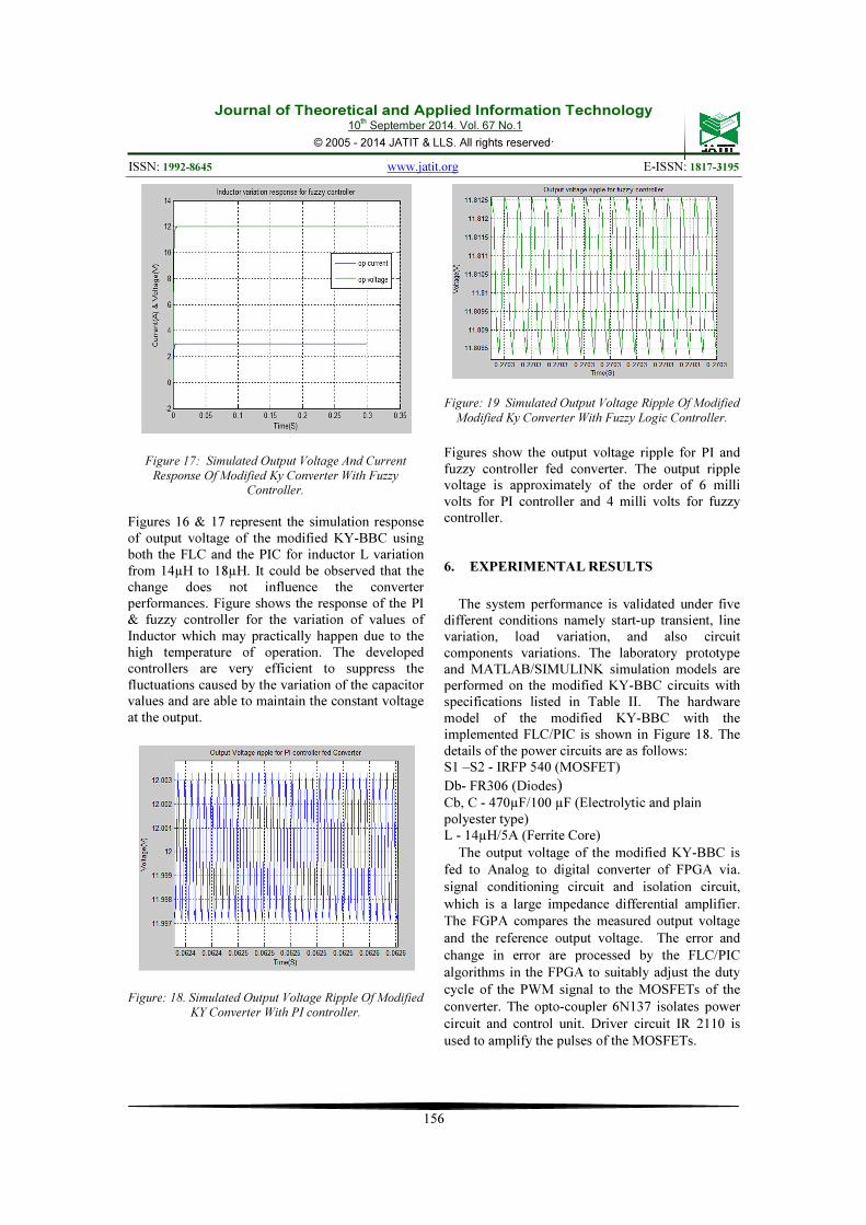
Figure 17: Simulated Output Voltage And Current
Response Of Modified Ky Converter With Fuzzy Controller.
Figures 16 & 17 represent the simulation response of output voltage of the modified KY-BBC using both the FLC and the PIC for inductor L variation from 14µH to 18µH. It could be observed that the change does not influence the converter performances. Figure shows the response of the PI & fuzzy controller for the variation of values of Inductor which may practically happen due to the high temperature of operation. The developed controllers are very efficient to suppress the fluctuations caused by the variation of the capacitor values and are able to maintain the constant voltage at the output.
Figure: 18. Simulated Output Voltage Ripple Of Modified
KY Converter With PI controller.
Figure: 19 Simulated Output Voltage Ripple Of Modified
Modified Ky Converter With Fuzzy Logic Controller.
Figures show the output voltage ripple for PI and fuzzy controller fed converter. The output ripple voltage is approximately of the order of 6 milli volts for PI controller and 4 milli volts for fuzzy controller.
6. EXPERIMENTAL RESULTS
The system performance is validated under five different conditions namely start-up transient, line variation, load variation, and also circuit components variations. The laboratory prototype and MATLAB/SIMULINK simulation models are performed on the modified KY-BBC circuits with specifications listed in Table II. The hardware model of the modified KY-BBC with the implemented FLC/PIC is shown in Figure 18. The details of the power circuits are as follows: S1 –S2 - IRFP 540 (MOSFET)
Db- FR306 (Diodes) Cb, C - 470µF/100 µF (Electrolytic and plain polyester type) L - 14µH/5A (Ferrite Core)
The output voltage of the modified KY-BBC is
fed to Analog to digital converter of FPGA via.
signal conditioning circuit and isolation circuit,
which is a large impedance differential amplifier.
The FGPA compares the measured output voltage
and the reference output voltage. The error and
change in error are processed by the FLC/PIC
algorithms in the FPGA to suitably adjust the duty
cycle of the PWM signal to the MOSFETs of the
converter. The opto-coupler 6N137 isolates power
circuit and control unit. Driver circuit IR 2110 is
used to amplify the pulses of the MOSFETs.
Journal of Theoretical and Applied Information Technology 10
th September 2014. Vol. 67 No.1
© 2005 - 2014 JATIT & LLS. All rights reserved.
ISSN: 1992-8645 www.jatit.org E-ISSN: 1817-3195
157
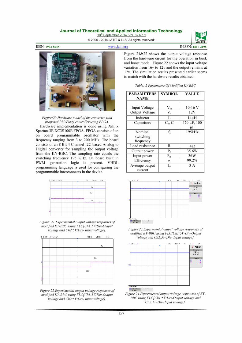
Figure:20 Hardware model of the converter with
proposed PIC/Fuzzy controller using FPGA.
Hardware implementation is done using Xilinx Spartan-3E XC3S100E FPGA. FPGA consists of an on board programmable oscillator with the frequency ranging from 3 to 200 MHz. The board consists of an 8 Bit 4 Channel I2C based Analog to Digital converter for sampling the output voltage from the KY-BBC. The sampling rate equals the switching frequency 195 KHz. On board built in PWM generation logic is present. VHDL programming language is used for configuring the programmable interconnects in the device.
Figure: 21 Experimental output voltage responses of
modified KY-BBC using FLC[Ch1:5V/Div-Output voltage and Ch2:5V/Div- Input voltage].
Figure 22.Experimental output voltage responses of modified KY-BBC using FLC[Ch1:5V/Div-Output
voltage and Ch2:5V/Div- Input voltage].
Figure 21&22 shows the output voltage response from the hardware circuit for the operation in buck and boost mode. Figure 22 shows the input voltage variation from 16v to 12v and the output remains at 12v. The simulation results presented earlier seems to match with the hardware results obtained.
Table: 2 Parameters Of Modified KY BBC
PARAMETERS
NAME
SYMBOL VALUE
Input Voltage
Vin
10-16 V
Output Voltage Vo 12V
Inductor L 14µH
Capacitors Cb, C 470 µF, 100 µF
Nominal switching frequency
fs 195kHz
Load resistance R 4Ω
Output power Po 35.6W
Input power Pin 36W
Efficiency η 99.2%
Average output current
Io 3 A
Figure 23.Experimental output voltage responses of
modified KY-BBC using FLC[Ch1:5V/Div-Output
voltage and Ch2:5V/Div- Input voltage].
Figure 24.Experimental output voltage responses of KY-
BBC using FLC[Ch1:5V/Div-Output voltage and
Ch2:5V/Div- Input voltage].

Journal of Theoretical and Applied Information Technology 10
th September 2014. Vol. 67 No.1
© 2005 - 2014 JATIT & LLS. All rights reserved.
ISSN: 1992-8645 www.jatit.org E-ISSN: 1817-3195
158
Table: 3 Comparision Of Performance Of The Existing
And Proposed Controller Output
PARAMETER
PIC BASED
MODIFIED KY-
BBC
FLC BASED
MODIFIED KY-
BBC
Output Voltage
ripple 6 millivolts 2 millivolts
Efficiency 93% 99.2%
Settling time 5 milli seconds 2 milli seconds
Table 3 compares the performance parameters of PIC and fuzzy controller for modified KY-BBC. From the table it can be concluded that the performance of the converter is enhanced via the fuzzy logic controller implemented.
7. CONCLUSION
The proposed Fuzzy controller for Synchronous buck boost converter modeled in this article demonstrate reduction in output voltage ripple upto 5 milli-seconds for the PI controller and 2 milli-seconds for the fuzzy controller with the reduction in settling time and reduction in peak overshoot of the output when compared with the existing PI controlled system. The performance exhibited by the proposed system is well suited for communication system and photo-voltaic applications. The performance of this converter can be improved by implementing various optimization techniques.
REFERENCE
[1] K. I. Hwu and Y.T Yau, A KY Boost
Converter, IEEE Transactions on Power Electronics, Vol. 25(Issue 11):2699 – 2703,
November 2010.
[2] K.I. Hwu, and Y.T Yau, Two Types of KY Buck–Boost Converters, IEEE Transactions on Industrial Electronics, Vol. 56 (Issue 8):2970 –
2980, August 2009.
[3] K. I. Hwu, K. W. Huang and W.C. Tu, Step-up converter combining KY and buck-boost converters, IET Electronics Letters, vol.47,
(Issue 12): 722-724, 2011.
[4] M. Veerachary, General rules for signal flow graph modeling and analysis of dc–dc converters, IEEE Transanctions on Aerospace.
Electronic. Systems, Vol. 40(Issue 1):259–271,
January 2004. [5] P. Mattavelli, L. Rossetto and G. Spiazzi,
Small signal analysis of DC-DC converter with sliding mode control, IEEE Transaction on Power Electronics, Vol. 12(Issue 1): 96-102,
1997. [6] P. Comines and N. Munro, PID controllers:
recent tuning methods and design to specification, IEEE Proceedings. Control Theory Application, Vol. 149(Issue 1), pp. 46-
53, 2002 [7] K.H Cheng, C.F Hsu, C.M Lin, T.T Lee and C.
Li, Fuzzy–neural sliding-mode control for DC–DC converters using asymmetric Gaussian membership functions, IEEE Transaction on Industrial Electronics, Vol. 54(Issue 3): 1528–
1536, 2007 [8] M. Rabbani, H.M.M. Maruf, T. Ahmed, M.A.
Kabir and U. Mahbub, Fuzzy Logic Driven Adaptive PID Controller for PWM Based Buck Converter, International Conference on
Informatics, Electronics & Vision (ICIEV), pp.
958-962, Dhaka, May 2012. [9] N.F. Nik Ismail, N. Hasim and R. Baharom, A
Comparitive study of Propotional Integral Derivative controller and Fuzzy Logic controller on DC/DC Buck Boost converter, IEEE symposium on Industrial Electronics and
Applications (ISIEA), pp 149-154, Langkawi,
Sep. 2011.
[10] S. M. Ayob, N.A. Azli and Z. Salam, PWM DC–AC converter regulation using a multi-loop single input fuzzy PI controller, Journal
of Power Electronics, Vol. 9(Issue 1):124 -
131, 2009. [11] M.G. Umamaheswari, G.Uma and
K.M.Vijayalakshmi, Design and implementation of reduced-order sliding mode controller for higher-order power factor correction converters, IET Power Electronics,
Vol. 4(Issue 9):984–992, 2011. [12] K. Ramashkumar and S.
JeevananthanModelling and implementation of fixed switching frequency sliding mode controller for negative output elementary super lift Luo-converter, IET Power Electronics, Vol.
5(Issue 8):1593–1604, 2012 [13] K. Sreedevi and E. David, The Feedback PI
controller for Buck-Boost converter combining KY and Buck converter, Journal of Academia and Industrial Research (JAIR), Volume 2, Issue 2 July 2013