OPERATOR'S MANUAL - Globe Marine And Electrical Supplies
155
MARINE RADAR MODEL 1815 OPERATOR'S MANUAL www.furuno.com
-
Upload
khangminh22 -
Category
Documents
-
view
0 -
download
0
Transcript of OPERATOR'S MANUAL - Globe Marine And Electrical Supplies

MARINE RADAR
MODEL 1815
OPERATOR'S MANUAL
www.furuno.com

The paper used in this manual
is elemental chlorine free.
・FURUNO Authorized Distributor/Dealer
9-52 Ashihara-cho,
Nishinomiya, 662-8580, JAPAN
A : FEB 2017.Printed in JapanAll rights reserved.
A2 : APR . 24, 2017
Pub. No. OME-36660-A2
(MISU ) MODEL1815
0 0 0 1 9 2 8 5 4 1 0

i
IMPORTANT NOTICES
General• This manual has been authored with simplified grammar, to meet the needs of international users.• The operator of this equipment must read and follow the descriptions in this manual.
Wrong operation or maintenance can cancel the warranty or cause injury.• Do not copy any part of this manual without written permission from FURUNO.• If this manual is lost or worn, contact your dealer about replacement.• The contents of this manual and equipment specifications can change without notice.• The example screens (or illustrations) shown in this manual can be different from the screens you
see on your display. The screens you see depend on your system configuration and equipment settings.
• Save this manual for future reference.• Any modification of the equipment (including software) by persons not authorized by FURUNO will
cancel the warranty.• The following concern acts as our importer in Europe, as defined in DECISION No 768/2008/EC.
- Name: FURUNO EUROPE B.V.- Address: Ridderhaven 19B, 2984 BT Ridderkerk, The Netherlands
• All brand and product names are trademarks, registered trademarks or service marks of theirrespective holders.
How to discard this productDiscard this product according to local regulations for the disposal of industrial waste. For disposal in the USA, see the homepage of the Electronics Industries Alliance (http://www.eiae.org/) for thecorrect method of disposal.
How to discard a used batterySome FURUNO products have a battery(ies). To see if your product has a battery, see the chap-ter on Maintenance. Follow the instructions below if a battery is used. Tape the + and - terminals of battery before disposal to prevent fire, heat generation caused by short circuit.
In the European UnionThe crossed-out trash can symbol indicates that all types of batteries must not be discarded in standard trash, or at a trash site. Take the used batter-ies to a battery collection site according to your national legislation and the Batteries Directive 2006/66/EU.
In the USAThe Mobius loop symbol (three chasing arrows) indicates thatNi-Cd and lead-acid rechargeable batteries must be recycled.Take the used batteries to a battery collection site according tolocal laws.
In the other countriesThere are no international standards for the battery recycle symbol. The number of symbols can increase when the other countries make their own recycle symbols in the future.
Cd
Ni-Cd Pb

SAFETY INSTRUCTIONS
WARNING Indicates a condition that can cause death or serious injury if not avoided.
CAUTION Indicates a condition that can cause minor or moderate injury if not avoided.
Warning, Caution Mandatory ActionProhibitive Action
Read these safety instructions before you operate or install the equipment.
WARNINGRadio Frequency Radiation HazardThe radar antenna sends the electromagnetic radio frequency (RF) energy. This energy can be dangerous to you, especially your eyes. Do not look at the radiator or near the antenna when the antenna is rotating.
The distances at which RF radiation levels of 100 W/m2, 50 W/m2 and 10 W/m2 exist are shown in the table.
Note: If the antenna unit is installed at a close distance in front of the wheel house, prevent the transmission in that area to protect passengers and crew from microwave radiation. Set the [Sector Blanks] in the [System] menu.
Distance to100 W/m2 point
Distance to50 W/m2 point
Distance to10 W/m2 point
Worst case 85 cm
Standard SteeringDisplay unit 0.45 m 0.30 m
CAUTIONCAUTION
Antenna unit 1.70 m 1.05 m
Unit
Observe the following compass safe distances to prevent deviation of a magnetic compass.
WARNINGDo not open the equipment.
The equipment uses high voltage that can cause electrical shock. Refer any repair work to a qualified technician.
Before turning on the radar, be sure no one is near the antenna.
Prevent the potential risk of being struck by the rotating antenna, which can result in serious injury or death.
If water leaks into the equipment or something is dropped into the equipment, immediately turn off the power at the switchboard.
Fire or electrical shock can result.
If the equipment is giving off smoke or fire, immediately turn off the power at the switchboard.
Fire or electrical shock can result.
Do not disassemble or modify the equipment.
Fire, electrical shock or serious injury can result.
Do not place operate the equipment with wet hands.
Electrical shock can result.
ii

SAFETY INSTRUCTIONS
WARNINGUsethe correct fuse.
Use of a wrong fuse can result in fire or damage to the equipment.
Do not place liquid-filled containerson the equipment.
Fire or electrical shock can result if a liquid spills into the equipment.
CAUTIONCAUTIONThe guard zone alarm is an effective aid to anti-collison.
Its use does not relieve the operator of the responsibility to keep a vigilant watch on his or her surroundings.
The data presented by this equipment is intended as a source of navigation information.
The prudent navigator never relies exclusively on any one source of navigation information, for safety of vessel and crew.
WARNINGThe TT function is a valuable aid to navigation. However, the navigator must check all aids available to avoid collision.
- The TT automatically tracks an automatically or manually acquired radar target and calculates its course and speed, indicating them with a vector. Since the data generated by the TT depends on the selected radar targets, the radar must be optimally tuned for use with the TT, to ensure required targets will not be lost or unnecessary targets, like sea returns and noise, will not be acquired and tracked.
- A target is not always a landmass, reef, ship, but can also be returns from the sea surface and from clutter. As the level of clutter changes with the environment, the operator must correctly adjust the sea and rain clutter controls and the gain control so that the target echoes do not dis- appear from the radar screen.
Target Tracking (TT) safety information
CAUTIOCAUTIONThe plotting accuracy and response of this TT meets IMO standards. Tracking accuracy is affected by the following:
• Tracking accuracy is affected by course change. One to two minutes is required to restore vectors to full accuracy after an abrupt course change. (The actual amount depends on gyrocompass specifications.)
• The amount of tracking delay is inversely proportional to the relative speed of the target. Delay is approx. 15-30 seconds for the higher relative speed; approx. 30-60 seconds for the lower relative speed. The following factors can affect accuracy: - Echo intensity - Radar transmission pulse length - Radar bearing error - Heading sensor error - Course change (own ship and targets)
iii

SAFETY INSTRUCTIONS
WARNINGRadiation hazard. Only qualified personnel should work inside scanner.Confirm that TX has stopped beforeopening scanner.
Name: Warning StickerType: 03-129-1001-3Code No.: 100-236-743-10
Warning Label(s) Warning label(s) is(are) attached to the equipment. Do not remove the label(s). If a label is missing or damaged, contact a FURUNO agent or dealer about replacement.
TFT display The high quality TFT (Thin Film Transistor) LCD displays 99.99% of its picture elements. The remaining 0.01% may drop out or light. However, this is an inherent property of the TFT; it is not a sign of malfunction.
iv
TABLE OF CONTENTS
FOREWORD................................................................................................................... ixSYSTEM CONFIGURATION .......................................................................................... xi
1. INSTALLATION .....................................................................................................1-11.1 Equipment List............................................................................................................1-11.2 How to Install the Equipment......................................................................................1-1
1.2.1 Display unit .....................................................................................................1-11.2.2 Antenna unit ...................................................................................................1-4
1.3 Wiring .........................................................................................................................1-91.4 Input Signal...............................................................................................................1-11
1.4.1 Talker ...........................................................................................................1-111.4.2 NMEA I/O sentences....................................................................................1-11
1.5 Initial Settings ...........................................................................................................1-131.5.1 How to select language ................................................................................1-131.5.2 How to select radar application ....................................................................1-151.5.3 Initial settings................................................................................................1-15
1.6 Optional Equipment ..................................................................................................1-181.6.1 External buzzer ............................................................................................1-18
2. OPERATION ..........................................................................................................2-12.1 Controls ......................................................................................................................2-12.2 How to Turn the Radar On/Off....................................................................................2-22.3 TX/Standby.................................................................................................................2-22.4 Display Indications......................................................................................................2-32.5 How to Adjust Display Brilliance, Panel Dimmer ........................................................2-42.6 Menu Description........................................................................................................2-42.7 Tuning.........................................................................................................................2-62.8 Display Modes............................................................................................................2-7
2.8.1 How to select the display mode......................................................................2-72.8.2 Description of display modes .........................................................................2-8
2.9 How to Select the Range Scale................................................................................2-102.10 How to Adjust the Gain (sensitivity)..........................................................................2-102.11 How to Reduce the Sea Clutter ................................................................................2-112.12 How to Reduce the Rain Clutter ...............................................................................2-122.13 Cursor.......................................................................................................................2-132.14 How to Temporarily Erase the Heading Line............................................................2-142.15 Interference Rejector ................................................................................................2-142.16 Noise Rejector ..........................................................................................................2-152.17 How to Measure the Range to a Target ...................................................................2-15
2.17.1 How to adjust range ring brilliance ...............................................................2-152.17.2 How to measure the range with a VRM........................................................2-162.17.3 How to select VRM unit ................................................................................2-17
2.18 How to Measure the Bearing to a Target..................................................................2-172.18.1 How to measure the bearing with an EBL ....................................................2-172.18.2 EBL reference ..............................................................................................2-18
2.19 How to Measure the Range and Bearing Between Two Targets .............................2-192.20 Target Alarm.............................................................................................................2-20
2.20.1 How to set a target alarm zone ....................................................................2-202.20.2 How to stop the audio alarm.........................................................................2-212.20.3 How to select the alarm type ........................................................................2-212.20.4 How to sleep a target alarm temporarily.......................................................2-222.20.5 How to deactivate a target alarm..................................................................2-22
v

TABLE OF CONTENTS
2.20.6 How to select the target strength which triggers a target alarm................... 2-222.20.7 How to turn the buzzer on/off ....................................................................... 2-22
2.21 How to Off-center the Display .................................................................................. 2-232.21.1 How to select the off-center mode ............................................................... 2-232.21.2 How to off-center the display........................................................................ 2-23
2.22 Zoom........................................................................................................................ 2-242.22.1 Zoom reference............................................................................................ 2-242.22.2 How to zoom ................................................................................................ 2-25
2.23 Echo Stretch............................................................................................................. 2-272.24 Target Trails ............................................................................................................. 2-27
2.24.1 Trail time ...................................................................................................... 2-272.24.2 Trail mode .................................................................................................... 2-282.24.3 Trail gradation .............................................................................................. 2-292.24.4 Trail color ..................................................................................................... 2-292.24.5 Trail level...................................................................................................... 2-292.24.6 How to restart, stop the trails ....................................................................... 2-292.24.7 Narrow trails ................................................................................................. 2-302.24.8 Own ship trail ............................................................................................... 2-302.24.9 How to erase all trails................................................................................... 2-31
2.25 How to Program the FUNC Key ............................................................................... 2-312.26 Echo Average........................................................................................................... 2-322.27 Wiper........................................................................................................................ 2-322.28 Display-Curve........................................................................................................... 2-332.29 Own Ship and Barge Mark ....................................................................................... 2-33
2.29.1 How to show the own ship mark .................................................................. 2-332.29.2 How to show the barge mark ....................................................................... 2-34
2.30 Watchman ................................................................................................................ 2-352.31 Alert Status...............................................................................................................2-362.32 Color Selections ....................................................................................................... 2-38
2.32.1 Preset colors ................................................................................................ 2-382.32.2 Custom colors .............................................................................................. 2-38
2.33 Echo Area ................................................................................................................ 2-392.34 Initial Sub Menu ....................................................................................................... 2-39
2.34.1 How to open the Initial sub menu................................................................. 2-392.34.2 Description of Initial sub menu..................................................................... 2-40
2.35 Sector Blank............................................................................................................. 2-412.36 Other Menu Items .................................................................................................... 2-41
2.36.1 Brill/Color menu............................................................................................ 2-412.36.2 Display menu ............................................................................................... 2-432.36.3 Echo menu................................................................................................... 2-432.36.4 Units menu................................................................................................... 2-44
2.37 Navigation Data........................................................................................................ 2-452.37.1 Navigation data during standby.................................................................... 2-452.37.2 Navigation data at the bottom of the screen ................................................ 2-45
2.38 Waypoint Mark ......................................................................................................... 2-462.39 How to Send the Target Position and Enter the Origin Mark ................................... 2-47
3. HOW TO INTERPRET THE RADAR DISPLAY.....................................................3-13.1 General ...................................................................................................................... 3-1
3.1.1 Minimum and maximum ranges ..................................................................... 3-13.1.2 Radar resolution............................................................................................. 3-23.1.3 Bearing accuracy ........................................................................................... 3-33.1.4 Range measurement...................................................................................... 3-3
3.2 False Echoes ............................................................................................................. 3-33.2.1 Multiple echoes .............................................................................................. 3-33.2.2 Sidelobe echoes............................................................................................. 3-4
vi

TABLE OF CONTENTS
3.2.3 Virtual image ..................................................................................................3-43.2.4 Shadow sector................................................................................................3-5
3.3 SART (Search and Rescue Transponder)..................................................................3-63.3.1 SART description ...........................................................................................3-63.3.2 General remarks on receiving SART..............................................................3-7
3.4 RACON.......................................................................................................................3-8
4. TT OPERATION.....................................................................................................4-14.1 Precautions.................................................................................................................4-14.2 Controls for Use with TT.............................................................................................4-14.3 TT Display On/Off.......................................................................................................4-24.4 TT Symbol Color.........................................................................................................4-24.5 How to Acquire and Track the Targets .......................................................................4-2
4.5.1 Manual acquisition..........................................................................................4-24.5.2 Automatic acquisition .....................................................................................4-3
4.6 How to Stop Tracking a TT.........................................................................................4-34.6.1 How to stop tracking a single target ...............................................................4-34.6.2 How to stop tracking all targets ......................................................................4-3
4.7 Lost Target .................................................................................................................4-44.8 Vector Attributes .........................................................................................................4-4
4.8.1 What is a vector?............................................................................................4-44.8.2 Vector time and vector reference ...................................................................4-54.8.3 Own ship vector..............................................................................................4-6
4.9 Past Position Display (target past position) ................................................................4-64.10 TT Data.......................................................................................................................4-74.11 CPA/TCPA Alarm .......................................................................................................4-84.12 Proximity Alarm ..........................................................................................................4-9
5. AIS OPERATION ...................................................................................................5-15.1 AIS Display On/Off .....................................................................................................5-15.2 AIS Symbols ...............................................................................................................5-25.3 Activating, Sleeping Targets.......................................................................................5-35.4 AIS Target Data..........................................................................................................5-45.5 How to Sort Targets....................................................................................................5-45.6 Display Range ............................................................................................................5-55.7 How to Display the Targets within a Specific Sector ..................................................5-55.8 Number of Targets to Display.....................................................................................5-65.9 Vector Attributes .........................................................................................................5-6
5.9.1 What is a vector?............................................................................................5-65.9.2 Vector time and vector reference ...................................................................5-6
5.10 Past Position Display (target past position) ................................................................5-75.11 CPA/TCPA Alarm .......................................................................................................5-85.12 Proximity Alarm ..........................................................................................................5-95.13 Lost Target .................................................................................................................5-95.14 Symbol Color ............................................................................................................5-105.15 How to Ignore Slow Targets .....................................................................................5-10
6. GPS OPERATION .................................................................................................6-16.1 Navigator Mode ..........................................................................................................6-16.2 Datum.........................................................................................................................6-16.3 WAAS Setup...............................................................................................................6-26.4 Satellite Monitor..........................................................................................................6-36.5 Self Test .....................................................................................................................6-46.6 Cold Start....................................................................................................................6-4
vii
TABLE OF CONTENTS
viii
7. MAINTENANCE, TROUBLESHOOTING...............................................................7-17.1 Preventive Maintenance............................................................................................. 7-27.2 Fuse Replacement ..................................................................................................... 7-27.3 Magnetron Life ........................................................................................................... 7-37.4 Simple Troubleshooting ............................................................................................. 7-37.5 Advanced-level Troubleshooting................................................................................ 7-47.6 Self Test ..................................................................................................................... 7-57.7 LCD Test ....................................................................................................................7-77.8 Radar Sensor Test ..................................................................................................... 7-8
APPENDIX 1 MENU TREE .......................................................................................AP-1APPENDIX 2 GEODETIC CHART LIST ...................................................................AP-5APPENDIX 3 DIGITAL INTERFACE.........................................................................AP-7APPENDIX 4 JIS CABLE GUIDE ...........................................................................AP-14APPENDIX 5 RADIO REGULATORY INFORMATION ..........................................AP-15APPENDIX 6 ALERT LIST......................................................................................AP-17SPECIFICATIONS .....................................................................................................SP-1PACKING LISTS..........................................................................................................A-1OUTLINE DRAWINGS.................................................................................................D-1INTERCONNECTION DIAGRAM ................................................................................ S-1INDEX.......................................................................................................................... IN-1

ix
FOREWORD
A Word to the Owner of the MODEL1815 Marine RadarCongratulations on your choice of the FURUNO MODEL1815 Marine Radar. We are confident you will see why the FURUNO name has become synonymous with quality and reliability.
Since 1948, FURUNO Electric Company has enjoyed an enviable reputation for innovative and dependable marine electronics equipment. This dedication to excellence is furthered by our ex-tensive global network of agents and dealers.
Your equipment is designed and constructed to meet the rigorous demands of the marine envi-ronment. However, no machine can perform its intended function unless properly installed and maintained. Please carefully read and follow the operation and maintenance procedures set forth in this manual.
We would appreciate feedback from you, the end-user, about whether we are achieving our pur-poses.
Thank you for considering and purchasing FURUNO equipment.
FeaturesThe main features are as shown below.
• The radar is operated with keys, knobs and a Cursorpad.
• Easy-to-view 8.4 inch LCD.
• Echo area display with full screen provides observation of a wider range around the vessel.
• User-programmable function key
• AIS data available with connection of FURUNO AIS Transponder/Receiver.
Program No.
Display unit: 0359375-01.**Antenna unit: 0359364-01.****=Minor modification
CE declaration
With regards to CE declarations, please refer to our website (www.furuno.com) for further infor-mation about RoHS conformity declarations.

FOREWORD
x
Radar function availabilityThe Model 1815 is available in two types, [River] (river use) and [Sea] (sea use). Some functions may not available depending on the type selected See the table below for item and availability.
Type and function availability
Note on Chinese font: The Chinese font (GB 18030) used in this equipment is DynaComware Corporation’s bitmap font.
Conventions used in this manual• Keys and controls are shown in boldface type. For example, the MODE key.
• Menu names and menu items are put in brackets. For example, the [Echo] menu.
• To select a menu, menu item or option, you press the or symbol on the Cursorpad. For the sake of brevity, we substitute “select” when it is necessary to use those symbols on the Cur-sorpad. For example, “Push or on the Cursorpad to select [Echo Stretch]”...is written in the manual as “Select [Echo Stretch]”...
CE declaration
With regards to CE declarations, please refer to our website (www.furuno.com) for further infor-mation about RoHS conformity declarations.
Item Type Paragraph, section referenceRiver Sea
Automatic menu clo-sure
Menu closes automatically when no operation is detected after 10 seconds.)
Effective radius dot count
240 dots
Echo color Select the echo display color, among yellow, green, orange, and multi-color
paragraph 2.36.1
Echo color customiz-ing
Can customize the echo display color. paragraph 2.36.1
Echo area Select the display area from [Normal] or [Full Screen].
paragraph 2.36.3
Text display Can show or hide the base text indications. paragraph 2.36.2Range preset Select the radar ranges to use. paragraph 2.34.2Unit defaults1) range 2) speed
1) KM2) km/h, m/s
1) NM2) kn
paragraph 2.36.4
Bearing scale Graduation every 1°, 5°, 10°, 30°, no numeric in-dication, displayed in the effective radius
VRM unit Can set the VRM unit independently from the range unit.
paragraph 2.17.3
Range unit Can change the unit of range measurement. paragraph 2.36.4AIS symbol color Select the AIS symbol color from [Green], [Red],
[Blue], [White] or [Black].section 5.14
Vector reference Select the display mode for the vector from [Rel-ative] or [True].
section 4.8
TT number Empty numbers numbered in ascending orderHeading line erasure Heading line, EBL, VRM, guard zone, etc. tem-
porarily erased.section 2.14

SYSTEM CONFIGURATION
Basic configuration is shown below with solid line.
Equipment category
Antenna Unit: Exposed to the weatherOther Equipment: Protected from the weather
Power cable 1.4 m
Antenna cable (FRU-CF-FF-XXM) (10/15/20 m)* Option: CP03-37630 (30 m):Standard supply
Display UnitRDP-157
MODEL 1815 Antenna UnitRSB-127-120
RTR-120
GPS navigatorSatellite compassHeading sensor
PlotterAIS
DSB transceiver
External Buzzer (OP03-21)
Junction Box (FI-5002)
NMEA Data Converter (IF-NMEA2K2)
Junction Box(local supply)
Cable Assembly(FRU-CF-F01)
Power supply12 - 24 VDC
:Option or local supply
xi

SYSTEM CONFIGURATION
This page is intentionally left blank.
xii

1. INSTALLATION
1.1 Equipment List
Standard supply
Optional supply
1.2 How to Install the Equipment
1.2.1 Display unit
The display unit can be installed on a desktop or flush mounted in a console. Do not install the unit on the overhead or a bulkhead. Select a suitable location for the unit considering the following points:
Name Type Code No. Qty RemarksDisplay Unit RDP-157 — 1Antenna Unit RSB-127-120 — 1InstallationMaterials
CP03-35701 001-351-480 For antenna unitCO03-37501 001-464-940 For display unitCP03-37600 000-033-122
Selectone
10 m cableCP03-37610 000-033-123 15 m cableCP03-37620 000-033-124 20 m cable
Spare Parts SP03-17901 001-351-470 1 Fuse for display unit(FRU-2P5S-FU-5A-B, Code No. 000-168-869-10)
Accessories FP03-12501 001-464-950 1 For display unitTemplate E32-01304-B 000-178-948-11 1 For antenna unit
Name Type Code No. Qty RemarksAntenna Unit RSB-127-120 — 1Radome Mounting Bracket OP03-209 001-078-350 1 For fixing antenna
to mastExternal Buzzer OP03-21 000-030-097 1NMEA Data Converter IF-NMEA2K2 000-020-510 1Junction Box FI-5002 000-010-765 1Cable Assy. FRU-CF-FF-30M 001-464-270 1 30 m cableFlush Mount Kit OP03-242 001-464-280 1
CAUTIONDo not use paint, anti-corrosion products, contact spray or
other items containing organic solvents on the equipment.
Organic solvents can harm paint and plastic, particularly the con-nectors.
1-1

1. INSTALLATION
Desktop mount
Fasten the unit to the mounting location as shown below. For mounting dimensions, see the outline drawing at the back of this manual.
1. Fix the hanger assembly to a desktop with four self-tapping screws (525, sup-plied). Be sure to follow the recommended maintenance space show in the outline drawing. Insufficient space may damage the connectors when disconnecting and reconnecting them.
2. Loosely screw the knob into the hanger assembly.
3. Set the channel in the display unit to the hanger assembly.
4. Adjust the angle of the display unit for comfortable viewing angle.Note: Do not tilt the unit 90-degree backward or forward. The cable connector may be damaged if it contacts the bracket.
5. Tighten the knob.
6. Attach the hard cover to the display unit to protect the unit when it is not in use.
• Select a location where the controls can be easily operated.• Locate the unit away from the direct wind from air conditioners.• The temperature range in the mounting location should be -15°C(5°F to 55°C(131°F).• Locate the unit away from devices that emit active gas.• The mounting location must be well ventilated.• Select a location where vibration and shock are minimal.• A magnetic compass will be affected if the display unit is placed too close to the com-
pass. Observe the compass safe distances in the safety instructions to prevent inter-ference to the compass.
• Locate the unit away from direct sunlight to prevent heat build up inside the cabinet and condensation in the display.
• Keep the unit away from water and water splash. (The unit complies with waterproofing specification IP5.)
Hanger assy.
Knob
Loosely fasten knob to hanger assy.
Cable connector
1-2

1. INSTALLATION
Flush mount (in a console)
The flush mount kit (option) is required to mount the unit in a console. Select a flat mounting location, and install the unit as shown below.
Note: It is recommended to set up a dedicated breaker when flush mounting the unit, since it will be difficult to disconnect cables after the unit is installed.
1. Using the paper template (supplied), make a cutout in the mounting location.
2. Unfasten four washer head screws on the rear of the display unit to remove the bracket cover and the cover sponge.
3. Set the flush mounting sponge (supplied) to the display unit.
4. Screw four threaded rods (supplied) to the display unit.
5. Set the display unit to the cutout.
6. Fasten the display unit from behind with four sets of flat washers, spring washers
and wing nuts (supplied).
Screw
Hanger cover
Cover sponge
1-3

1. INSTALLATION
1.2.2 Antenna unit
Select a mounting location for the antenna unit considering the following points.
• Install the unit on a common mast, radar mast, etc.
• Install the antenna unit on a solid location, for example radar arch or on a mast on a platform. (For sailboats, a mounting bracket is optionally available.) You must put the antenna unit where there is a good complete view. Make sure that no part of the superstructure is within the scanning beam. Any obstruction causes shadow sec-tors. For example, a mast with a diameter smaller than the horizontal beam width causes only a small blind sector. A horizontal spreader or crosstrees in the same horizontal plane creates a large obstruction. Install the antenna unit above a hori-zontal spreader or crosstrees.
• To avoid electrical interference, do not run the antenna cable near other electrical equipment. Also do not run the cable in parallel to power cables.
• Do not install the unit where its motor noise may affect crew or passengers.
• As much as possible install the unit on the ship’s centerline, to prevent misplace-ment of echoes (wrong bearing) on the display.
• Make sure the mounting location does not allow water to accumulate at the mount-ing platform.
• A magnetic compass will be affected if the display unit is placed too close to the compass. Observe the compass safe distances in the safety instructions to prevent interference to the compass.
• Do not paint the radome.
• Be sure to follow the recommended maintenance space shown in the outline draw-ing at the back of this manual.
• If the unit is installed on a large vessel observe the following points.
• The antenna cable comes in lengths of 10, 15 and 20 m (30 m optionally avail-able). Consider the length of the cable when selecting a mounting location.
• Keep the unit away from smoke and exhaust stacks. Hot air affects antenna per-formance. Hot air can also damage the unit. The temperature at the mounting lo-cation should not exceed 55°C(131°F).
Mounting on a sailboat Mounting on a power boat
AntennaAntennaAntennaAntennaAntennaAntenna
Rear view
Rear view
Horizontal beam width
12.5°12.5°
Rear view
1-4

1. INSTALLATION
Tools and materials for mounting
How to mount the antenna unit
Note: The outer diameter of the small flat washer is the same size as the bolt hole. If the radome is put upside down with only the small flat washer and hex bolt in place, the hex bolt and flat washer may protrude into the radome and damage the RT unit. For this reason, DO NOT put the radome upside down when carrying the radome.
Name UsageElectric drill Drill holes for mounting. Drill bit: 11 mmHexagonal wrench Fastening bolts: Diagonal: 6 mmSilicon sealant For coating exposed parts of bolts
SternBowAlign bow mark (▲) on antenna with boat’s centerline.
Power cable (1.4 m)
Drill holes referring to outline drawing.
Mounting platform
Hex head bolt (M10×**)Spring washerFlat washer
Flat washer (large), top in order
Flat washer (small) middle in order
Spring washer (large) last in order.
Default orientation of bolt and flat washer
Bolt hole
** Bolt length. See table on next page for details.
1-5

1. INSTALLATION
1. From the bottom of the radome, remove spring washers (M10), flat washers (M10) and hex head bolts (M10**).**: The length of the hex head bolt depends on the thickness of the platform. See the table below for platform thickness and bolt to use.
2. Use the mounting template (supplied) to mark the location of fixing holes in the mounting platform. Be sure to drill the holes parallel with the bow.
3. Lay the antenna unit on the mounting platform with the bow mark() on the an-tenna unit facing the bow.
4. Use hex bolts*, flat washers and spring washers (removed at step 1) to fasten the radar sensor to the platform. The torque for the bolts must be 19.6 to 24.5 Nm. Apply marine sealant (local supply) to hex bolt, flat washer and spring washer as shown below.*See the figure below to determine the bolt length to use.
5. Connect the power cable to the antenna unit. The pin arrangement is as shown below.
Platform thickness Bolt size to use5 mm or less M10206 to 10 mm M1025More than 10 mm Local supply
Hex head bolt (M10×**)Spring washerFlat washer
×4
Mounting platform
Antenna unit base
Flat washer
Hex boltSpring washer
Determine the length of bolts according to platform thickness.
Marine sealant (local supply)
Pin arrangement
10 mm
1-6
1. INSTALLATION
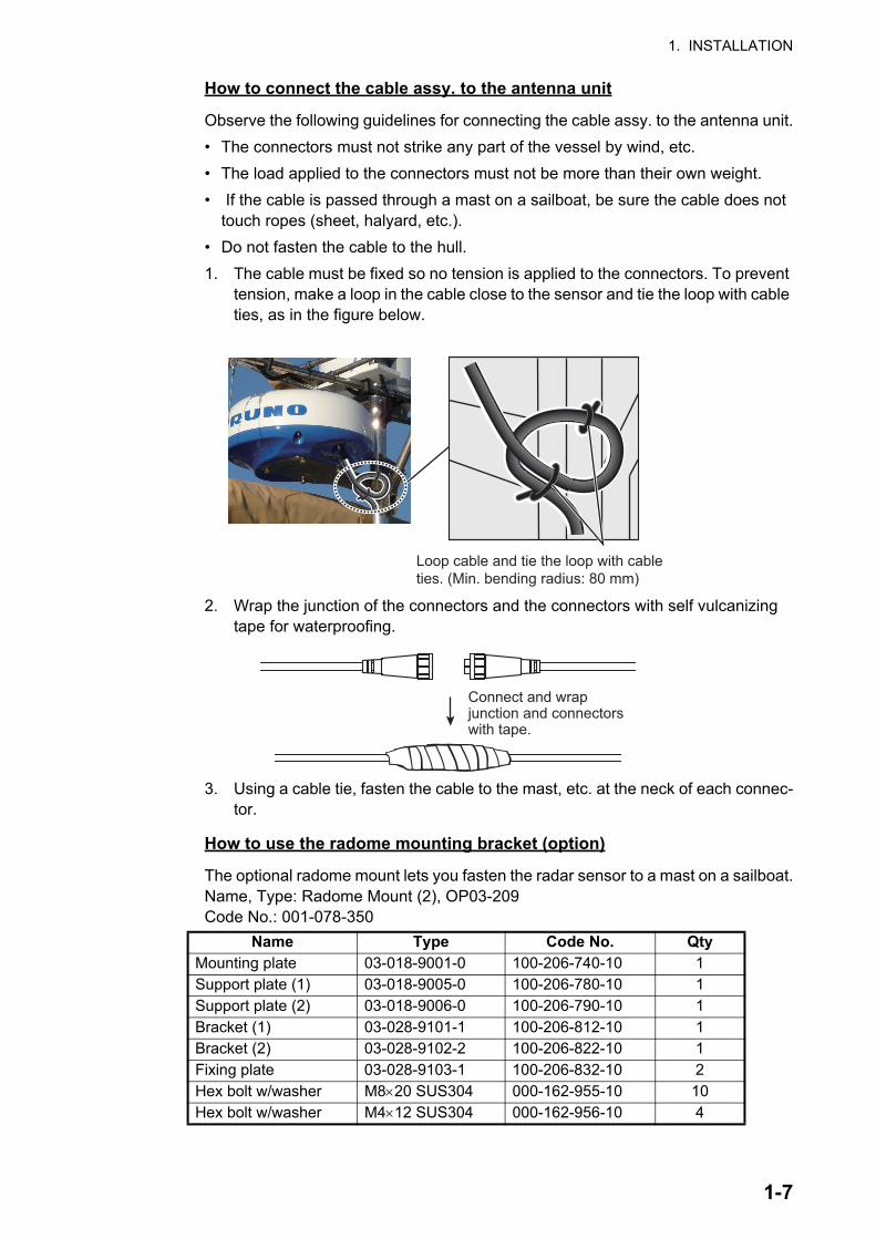
How to connect the cable assy. to the antenna unit
Observe the following guidelines for connecting the cable assy. to the antenna unit.
• The connectors must not strike any part of the vessel by wind, etc.
• The load applied to the connectors must not be more than their own weight.
• If the cable is passed through a mast on a sailboat, be sure the cable does not touch ropes (sheet, halyard, etc.).
• Do not fasten the cable to the hull.
1. The cable must be fixed so no tension is applied to the connectors. To prevent tension, make a loop in the cable close to the sensor and tie the loop with cable ties, as in the figure below.
2. Wrap the junction of the connectors and the connectors with self vulcanizing tape for waterproofing.
3. Using a cable tie, fasten the cable to the mast, etc. at the neck of each connec-tor.
How to use the radome mounting bracket (option)
The optional radome mount lets you fasten the radar sensor to a mast on a sailboat.Name, Type: Radome Mount (2), OP03-209Code No.: 001-078-350
Name Type Code No. QtyMounting plate 03-018-9001-0 100-206-740-10 1Support plate (1) 03-018-9005-0 100-206-780-10 1Support plate (2) 03-018-9006-0 100-206-790-10 1Bracket (1) 03-028-9101-1 100-206-812-10 1Bracket (2) 03-028-9102-2 100-206-822-10 1Fixing plate 03-028-9103-1 100-206-832-10 2Hex bolt w/washer M820 SUS304 000-162-955-10 10Hex bolt w/washer M412 SUS304 000-162-956-10 4
Loop cable and tie the loop with cable ties. (Min. bending radius: 80 mm)
Connect and wrapjunction and connectorswith tape.
1-7

1. INSTALLATION
How to assemble the bracket:
1. Fasten the fixing plates to the brackets (1) and (2) with four M412 hex bolts.
2. Fit brackets (1) and (2) loosely with support plates (1) and (2) using four M412 hex bolts, so that the gap between the brackets can be adjusted.
3. Place the mounting plate on the brackets and fix the plate loosely with four M820 hex bolts.
How to fasten the bracket to the mast:
1. Drill eight holes of 6.5 mm into the mast. Fasten the bracket to the mast with eight stainless steel rivets (local supply) whose diameter is 6.4 mm.
2. Tighten the bolts on the bracket.
3. Fasten the antenna unit to the bracket with bolts (M1025).
Fixing plate
Bracket (2) Bracket (1)Bracket (2)
Bracket (1) M8×20
M4×12 M4×12
Mounting plate
Dwg (1) Dwg (2) Dwg (3)
M8×20
M8×20
M10×25
Rivet
1-8

1. INSTALLATION
1.3 WiringUse the supplied cable FRU-CF-F01 to connect a satellite compass, heading sensor, GPS navigator, external buzzer, and power supply to the 12-24 VDC/NMEA connec-tor.
Connect the antenna cable (FU-CF-FF-xxM (10m/15m/20m, 30 m optionally avail-able) to the antenna port. See the interconnection diagram at the back of this manual for details. Leave slack in the cable to ease maintenance.
Note 1: The display unit comes with connector caps. Use the caps to cover the con-nectors whenever the display unit is removed from the boat.
Note 2: Cut unused wires and wrap them with vinyl tape to keep them from touching one another.
Note 3: Use care when disconnecting cables to prevent damage to their connectors.
Note 4: When an NMEA equipment uses ±12 V supplied from this equipment, do not connect the cable earth of the signal line of that equipment (for example, satellite com-pass) to 12 V-P(+)/12 V_M(-).
Note 5: Do not shorten the supplied cable.
Ground
Power/signal connector(FRU-CF-F01)
Antenna cableFRU-CF-FF-**M, 10/15/20 m,
30m optionally available
Ship’s switchboard, external equipment, ground terminal, etc.
1-9

1. INSTALLATION
Ground
Grounding guidelines:
• The ground wire (local supply) should be 2sq or higher.
• The length of the ground wire should be as short as possible.
• For an FRP vessel, fasten a 20 cm30 cm earthing plate to the outside of the boat’s hull and attach the ground wire to a bolt on the plate.
• Attach a closed-end lug ( ) to the ground wire. Do not use an open-end lug
( ).
• External equipment whose signal line is connected to ground cannot be directly connected to this equipment if the positive polarity of the vessel’s DC power is con-nected to ground.
Connector Color Remarks1 DC-P-IN(+) RED Power input, 12-24 VDC2 DC-M-IN(-) BLK3 TD1-A GRN/BLK(1) IEC61162-2/NMEA14 TD1-B GRN/RED(1)5 RD1-H GRY/BLK(1)6 RD1-C GRY/RED(1)7 TD2-A GRN/BLK(2) IEC61162-2/NMEA28 TD2-B GRN/RED(2)9 RD2-H GRY/BLK(2)
10 RD2-C GRY/RED(2)11 RD3-H GRY/BLK(3) IEC61162-2/NMEA312 RD3-C GRY/RED(3)13 12V-P(+) BRN Power output, 12-24 VDC14 12V-M(-) ORG15 EXT-BUZZ-EN WHT External buzzer16 SHIELD BLK Drain wire, (Connect to ground ter-
minal of ship’s switchboard.)
CAUTIONDo not fail to ground the display unit.
If the ground is poor or there is no ground, the radar and other equipment may pick up interfer-ence.
1-10

1. INSTALLATION
How to connect the display unit to the power supply
Connect the cable assy. to the power supply (24 VDC).
• Red cable: Connect to the positive (+) terminal. The fuse holder is attached to this wire.
• Black cable: Connect to the negative (-) terminal.
• Black cable: Shield wire. Connect to ground.
Note 1: To use a12 VDC power supply, connect a DC-DC converter whose output cur-rent is at least 5A.
Note 2: This equipment cannot be used with a power supply greater than 24 VDC.
1.4 Input SignalThis radar accepts signals in NMEA format. Three NMEA ports are provided, and sen-tence handling is common to all ports.
1.4.1 Talker
Every device that sends data has an identification code at the head of the data. The device that receives the data is for identifying the device that sent the data, and this code is called the “talker”. This equipment has the talkers GN, GP, GL, GA, and RA.
1.4.2 NMEA I/O sentences
NMEA1/NMEA2
• Talker: Any
• Baud rate: 4800/38400
• NMEA 0183 (IEC 61162-2
Sentence DescriptionALR Set alarm stateBWC Bearing and distance to waypoint-Great CircleBWR Bearing and distance to waypoint - Rhumb LineDBT Depth Below TransducerDPT DepthDTM Data ReferenceGGA Global Positioning System Fix DataGLL Geographic Position
Signal line (External buzzer, etc.)
Display Unit
Cable Assy.
Shield
Distribution Board
Power Supply(12-24 VDC)
Fuse holder
BLK RED
BLK
1-11

1. INSTALLATION
NMEA3 (HDG)
GNS GNSS Fix DataGSA GNSS DOP and Active SatellitesGSV GNSS Satellites in ViewHDG Heading, Deviation & VariationHDM Heading, MagneticHDT Heading TrueMTW Water TemperatureMWV Wind Speed and AngleRMB Recommended Minimum Specific Navigation InformationRMC Recommended Minimum Specific GNSS DataTHS True Heading and StatusTTM Tracked Target MessageVDM AIS VHF Data-link MessageVHW Water Speed and HeadingVTG Course Over Ground & Ground SpeedVWR Wind relative Bearing and VelocityVWT True Wind Speed and AngleXTE Cross-Track Error, Measured?ZDA Time & DateALR Set alarm stateBWC Bearing and distance to waypoint - Great CircleBWR Bearing and distance to waypoint - Rhumb LineDBT Depth Below TransducerDPT Depth
Sentence DescriptionHDG Heading, Deviation & VariationHDM Heading, MagneticHDT Heading TrueTHS True Heading and StatusVHW Water Speed and Heading
Sentence Description
1-12

1. INSTALLATION
1.5 Initial Settings
1.5.1 How to select language
Language selection at initial start up
At the first power on after installation or whenever the memory is cleared, the lan-guage selection screen appears. Select your language as shown below. The default language is English.
1. Press the ( ) key on the display unit to turn on the power. The splash screen appears followed by the language selection screen.
2. Operate the Cursorpad ( or ) to select the language of your choice then press the ENTER key.
3. Push on the Cursorpad to select [Yes] then press the ENTER key.
4. Press the MENU/ESC key to close the menu.
1-13

1. INSTALLATION
Language selection from the menu
1. Press the ( ) key on the display unit to turn on the power.
2. Press the MENU/ESC key to show the menu.
3. Do the following to access the [Factory] menu.
1) Select [Factory], then press the ENTER key.
2) While holding and pressing the MENU/ESC key, press the ALARM key five times, press the ENTER key.
4. Select [Language], then press the ENTER key.
5. Select your language, then press the ENTER key.
6. Press the MENU/ESC key to close the menu.
1-14

1. INSTALLATION
1.5.2 How to select radar application
The radar application setting automatically changes the unit of range measurement and other settings.
1. Press the MENU/ESC key to show the menu.
2. Do the following to access the [Factory] menu.
1) Select [Factory], then press the ENTER key.
2) While holding and pressing the MENU/ESC key, press the ALARM key five times then press the ENTER key.
3. Select [Usage], then press the ENTER key.
4. Select [River] or [Sea] as appropriate, then press the ENTER key.
5. Press the MENU/ESC key to close the menu.
1.5.3 Initial settings
1. Press the MENU/ESC key to show the menu.
2. Select [Installation], then press the ENTER key.
3. While holding and pressing the ENTER key, press the ALARM key five times to unlock the [Installation] menu.
4. Select the item to set, then press the ENTER key.
5. Select the option required, then press the ENTER key.
6. After setting all items, press the MENU/ESC key to close the menu.
1-15

1. INSTALLATION
Item description
• [Simulation]: Normally, set to [Off.] To view the demonstration picture, select [On].
• [Antenna Rotation]: Select [Rotate] to rotate the antenna and transmit radar puls-es. The [Stop] setting, which transmits radar pulses without rotating the antenna, is for use by the service technician.
• [Heading Alignment]: You have installed the antenna unit so that the unit faces to-ward the bow. A target at the front of the boat and aligned with the bow must appear on the heading line (zero degrees). If the target does not appear on the heading line, do the procedure shown below to adjust the heading.
1. Set ship heading toward an acceptable target (for example, ship at anchor or buoy) at a range between 0.125 and 0.25 nautical mile.
2. Transmit the radar at the range of 0.25 nautical mile and measure the bearing of that target relative to ship heading with an EBL.
3. Open the [Installation] menu and select [Heading Adjust].
4. Press the ENTER key to show the heading adjustment window.
5. Press or to set the value measured at the above step 2. Check that the target appears on the heading line.
6. Press the ENTER key to finish.
• [Sweep Timing]: This adjustment gives correct radar performance on short ranges. The radar measures the time required for a transmitted echo to go to the target and return to the source. The received echo appears on the display according to the measured time. The sweep must start from the center of the display.A trigger pulse created in the display unit goes to the antenna unit through the signal cable to acti-vate the transmitter (magnetron). The time taken by the signal to move to the anten-na unit changes, according to the length of the signal cable. During this period, the display unit must wait before the radar starts the sweep. When the display unit is not adjusted correctly, the echoes from a straight object will not appear as a straight line. The target appears "pushed" or "pulled" near the picture center. The range to objects are shown at wrong distances.
1. Transmit on the shortest range, then adjust the gain and the A/C SEA.
2. Visibly select a target that creates a straight line (harbor wall, straight piers).
3. Open the [Installation] menu and select [Timing Adjust].
4. Press the ENTER key to show the timing adjustment window.
5. Press or to make straight the target selected at step 2, then press the EN-TER key to finish.
(1) Target pulled (2) Correct (3) Target pushed outward
1-16
1. INSTALLATION
• [Main Bang Suppression]: Reduce the main bang (black hole at center of screen), which appears at the display center on short ranges, as follows.
1. Open the [Installation] menu and select [MBS Adjust].
2. Press the ENTER key to show the MBS adjustment window.
3. Press or on the Cursorpad so that the main bang is reduced.
4. Press the ENTER key to finish.
• How to automatically set the equipment: The tuning, timing, and video can be au-tomatically adjusted as follows.Note: Before doing this procedure, transmit the radar more than 10 minutes on a long range and check that [Sector Blank] is [Off].
1. Transmit on the maximum range.
2. Open the [Installation] menu and select [Auto Initial Setup], then press the EN-TER key.
3. Press on the Cursorpad to select [Yes], then press the ENTER key.
The tuning adjustment begins automatically, and the message "Tuning adjusting" appears during tuning adjustment. After the tuning adjustment is completed, the tim-ing and video are adjusted in that order, showing appropriate status messages. Af-ter all adjustments are completed, the window disappears. If the result for any item is not best for your conditions, manually adjust the item according to the procedure in this section.
• [Total On Time]: You can set the total on time as shown below.
1. Open the [Installation] menu and select [Total On Time].
2. Press the ENTER key.
3. Press or on the Cursorpad to set value. The range is 000000.H to 999999.9 H.
4. Press the ENTER key to finish.
• [Total TX Time]: You can set the total TX time as shown below.
1. Open the [Installation] menu and select [Total TX Time].
2. Press the ENTER key.
3. Press or on the Cursorpad to set value. The range is 000000.H to 999999.9 H.
4. Press the ENTER key to finish.
• [Memory Clear]: The memory clear feature restores all settings to default, including the default settings for the antenna connected to LAN.
1. Open the [Installation] menu and select [Memory Clear].
2. Press the ENTER key.
3. Press or on the Cursorpad to select [Yes], then press the ENTER key.
4. Press the ENTER key to finish.
1-17
1. INSTALLATION
1.6 Optional Equipment
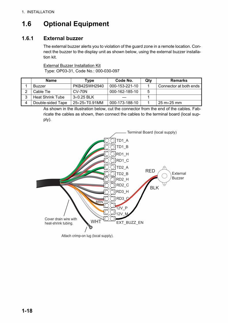
1.6.1 External buzzer
The external buzzer alerts you to violation of the guard zone in a remote location. Con-nect the buzzer to the display unit as shown below, using the external buzzer installa-tion kit.
External Buzzer Installation Kit Type: OP03-31, Code No.: 000-030-097
As shown in the illustration below, cut the connector from the end of the cables. Fab-ricate the cables as shown, then connect the cables to the terminal board (local sup-ply).
Name Type Code No. Qty Remarks1 Buzzer PKB42SWH2940 000-153-221-10 1 Connector at both ends2 Cable Tie CV-70N 000-162-185-10 53 Heat Shrink Tube 30.25 BLK — 14 Double-sided Tape 2525T0.91MM 000-173-188-10 1 25 m25 mm
Terminal Board (local supply)
RED
BLK
WHT
BRN
ExternalBuzzer
TD1_A TD1_B
RD1_H RD1_C
TD2_A TD2_B RD2_H RD2_C
RD3_H
RD3_C
12V_P 12V_M
EXT_BUZZ_ENCover drain wire with heat-shrink tubing.
Attach crimp-on lug (local supply).
1-18
2. OPERATION
2.1 Controls
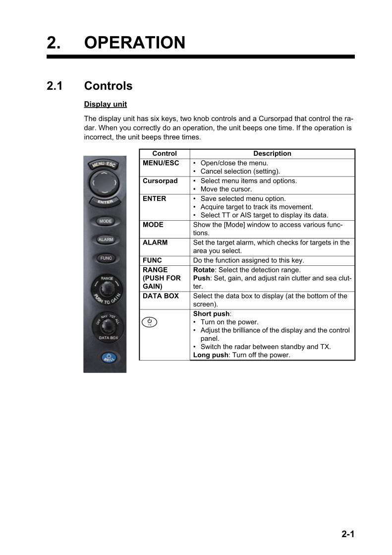
Display unit
The display unit has six keys, two knob controls and a Cursorpad that control the ra-dar. When you correctly do an operation, the unit beeps one time. If the operation is incorrect, the unit beeps three times.
Control DescriptionMENU/ESC • Open/close the menu.
• Cancel selection (setting).Cursorpad • Select menu items and options.
• Move the cursor.ENTER • Save selected menu option.
• Acquire target to track its movement.• Select TT or AIS target to display its data.
MODE Show the [Mode] window to access various func-tions.
ALARM Set the target alarm, which checks for targets in the area you select.
FUNC Do the function assigned to this key.RANGE(PUSH FOR GAIN)
Rotate: Select the detection range.Push: Set, gain, and adjust rain clutter and sea clut-ter.
DATA BOX Select the data box to display (at the bottom of the screen).Short push:• Turn on the power.• Adjust the brilliance of the display and the control
panel.• Switch the radar between standby and TX.Long push: Turn off the power.
2-1

2. OPERATION
2.2 How to Turn the Radar On/Off
Press the key to turn on the radar. To turn off the radar, press and hold down the key until the screen turns off.
When you turn on the power, the initialization screen appears followed by the splash screen. The ROM and RAM are tested and if those are normal, the standby screen appears approx. 5 sec. later, and the time remaining for magnetron warm-up (approx. 90 seconds) is counted down on the screen. If NG appears as the result of the ROM and RAM test, contact your dealer for instruction.
2.3 TX/StandbyAfter the magnetron has warmed, the indication [ST-BY] appears at the screen center. The radar is now ready to transmit radar pulses. The standby screen is available in two types, normal and nav (navigation data). See section 2.37.
To switch between TX and standby, push the key to show the [Brill/Panel] win-dow.
The cursor is selecting [TX/STBY]. Press the ENTER key to transmit the radar pulses and put the radar in standby alternately. The antenna rotates in transmit and is stopped in standby. Because the magnetron ages with use, set the radar in stand-by when you are not using the radar, to extend the life of the magnetron.
Note: Power is supplied to the antenna unit even when the power is shut off at the display unit. If the radar is not to be used for an extended period, shut off the radar from the breaker.
2-2

2. OPERATION
2.4 Display Indications
Heading
Display modeRange ring interval
Range
Trail reference
No. 1 EBL bearingNo. 2 EBL bearing
Offcenter(M: Manual, A: Auto, C: Custom)
North marker
Tuning indicator
Target Alarm 1 (2)indications
WATCHMANTarget alarm zone 1
Target alarm zone 2
3 5 0 . 0 ° TRAIL(T)15 S
+
1.51.5NMNM
WTC
Heading lineRange ring
VRM 2
EBL 2
Zoom window
Zoom cursor
EBL 1VRM 1
Cursor
Bearing scale
HDG
0.5H UP
TUNEAUTO
ALM1_INALM2_IN
IR 1 Interference rejector
22.0°R270.0°R
ES 1EAV 1
EBL
Echo stretchEcho averaging
ZOOM(R) Zoom indication
Trail time
OFFCENT(A)
Vector time/Cursor databox
No. 1 VRM rangeNo. 2 VRM range
VRM
0.889NM0.422NM
LAT 34°56.123NLON 135°34.567ESPEED 12.3KN
LAT 34°56.123NLON 135°34.567ETTG 00:00
BRG 14.8°RNG 0.876NMTTG 00:00
OWN SHIP + CURSOR WAYPOINT
VECT TRUE 06:00 0.0°R 0.000NM+
NAV data boxVarious navigation data can be shown below the Vector time/Cursor data box. Use the DATA BOX knob to select a data display. The example below shows nav data (NAV position on DATA BOX knob).
2-3
2. OPERATION
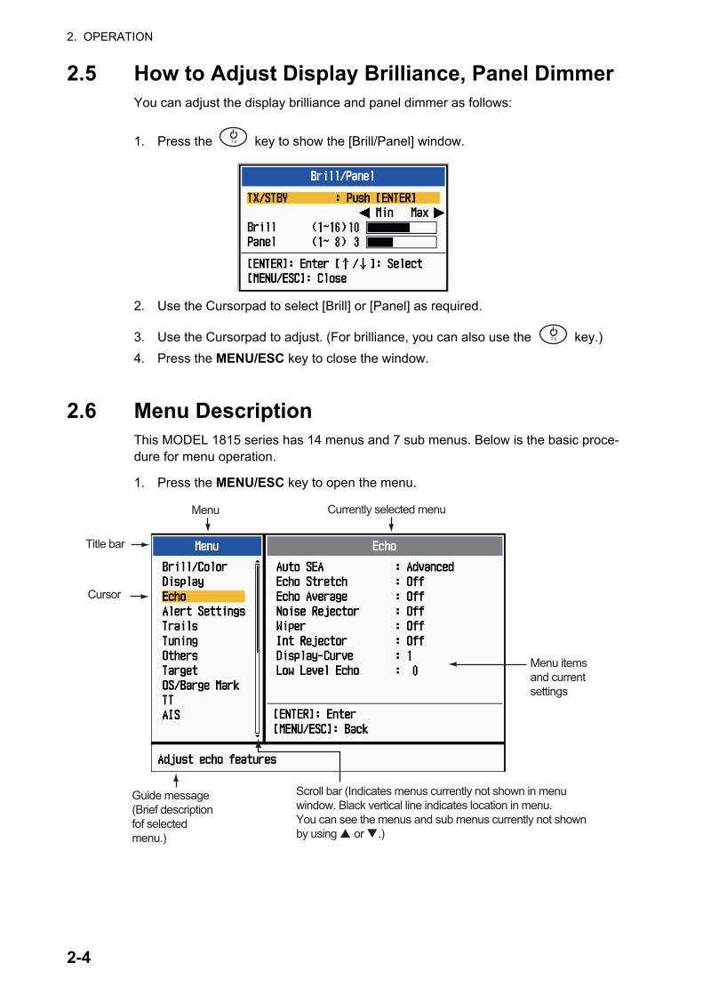
2.5 How to Adjust Display Brilliance, Panel DimmerYou can adjust the display brilliance and panel dimmer as follows:
1. Press the key to show the [Brill/Panel] window.
2. Use the Cursorpad to select [Brill] or [Panel] as required.
3. Use the Cursorpad to adjust. (For brilliance, you can also use the key.)
4. Press the MENU/ESC key to close the window.
2.6 Menu DescriptionThis MODEL 1815 series has 14 menus and 7 sub menus. Below is the basic proce-dure for menu operation.
1. Press the MENU/ESC key to open the menu.
Cursor
Menu itemsand currentsettings
Currently selected menu
Scroll bar (Indicates menus currently not shown in menuwindow. Black vertical line indicates location in menu.You can see the menus and sub menus currently not shownby using � or �.)
Menu
Title bar
Guide message(Brief description fof selected menu.)
2-4

2. OPERATION
2. Select a menu or a sub menu. The cursor (yellow) in the Menu column highlights the menu currently selected. The menu items in the right window change accord-ing to the menu selected.
Menu description[Brill/Color]: Adjust the brilliance and color.[Display]: Set up the display-related features.[Echo]: Adjust the echo features.[Alert Settings]: Customize the user settings.[Trails]: Process trails of the radar targets.[Tuning]: Adjust the radar tuning.[Others]: Set up other items.[Target]: Set up the targets configuration.[OS/Barge Mark]: Set up the own ship mark and barge mark.[TT]: Set up the TT (Target Tracking).[AIS]: Set up the AIS.[GPS]: Set up GP-320B (Black-Box GPS).[System]: - [Initial]: Initial settings.- [Tests]: System diagnostic and LCD test.- [Sector Blanks]: Prevent the transmission in a certain area.- [Units]: Set up units of measurement.- [TT]: Set up TT system. For the installer. Do not change the settings.- [Installation] and [Factory]: For installation.
3. Press the ENTER key to switch the control to the menu items column. The cursor in the menu column now turns gray and the cursor in the menu items column is yellow.To switch control from the menu items column to the menu column, use the MENU/ESC key. The color of the title bar of the active column is blue and the in-active column is gray.
4. Select a menu item, then press the ENTER key. A window with options for the re-lated menu item appears.
5. Use or on the Cursorpad to select an option or set a numeric value.
6. Press the ENTER key to save your selection. To close the window without saving, press the MENU/ESC key.
7. Press the MENU/ESC key to close the menu.
Display Color options Echo Brill setting window
2-5

2. OPERATION
2.7 TuningIn default, the radar receiver can be tuned automatically after turning the radar to TX. If you require fine tuning in manual, do the following:
1. Set the radar in transmit state, then select the maximum range with the RANGE knob.
2. Press the MENU/ESC key to open the menu.
3. Select [Tuning], then press the ENTER key.
4. Select [Tuning Mode], then press the ENTER key.
5. Select [Manual], then press the ENTER key.
6. Select [Manual Tuning], then press the ENTER key to show the manual tuning setting window.
7. Use the Cursorpad to adjust the tuning while you look at the tuning bar at the upper-right corner of the display. The best tuning point is where the tuning bar moves to maximum value. The vertical bar on the tuning bar shows the tuning voltage.
8. Press the ENTER key.
9. Press the MENU/ESC key to close the menu.
Note: If the automatic tuning does not give the correct tuning, run the [Tuning Initial-ization] again.
TUNE MAN Tuning method (Manual)Tuning bar
Vertical bar
2-6

2. OPERATION
2.8 Display ModesThis radar has the display modes shown below. All modes except head up require a heading signal. The true motion mode additionally requires position data.
Relative Motion (RM) displays
• [Head Up] ([H UP]): Heading is at the top of the screen.
• [Course Up] ([C UP]): The heading line positions to the course bearing at the mo-ment the course up mode is selected. The bearing scale rotates accordingly.
• [North Up] ([N UP]): North is the reference direction; bearing scale is fixed.
• [True View]: Ship’s bow is at the top of the screen. The picture is redrawn in real time.
True Motion (TM) displays
• [True Motion] (TM)
2.8.1 How to select the display mode
1. Press the MENU/ESC key to open the menu.
2. Select [Display], then press the ENTER key.
3. Select [Display Mode], then press the ENTER key.
4. Select a display mode, then press the ENTER key.
5. Press the MENU/ESC key to close the menu.
Note 1: The display mode is automatically switched to head up if the heading signal becomes lost.
Note 2: All modes except head up require a heading signal in AD-10 format or NMEA format. If the heading signal is lost, the mode is changed to head up and the north
2-7

2. OPERATION
mark disappears. The display for heading is XXX.X and the alarm sounds. The mes-sage "GYRO" (AD-10 format data) or "NMEA_HDG" (NMEA format data) appears in the alarm message display. To stop the audio alarm, press any key. When the heading signal is restored, check the heading. The numeric value is displayed at the heading indication when the heading signal is restored.
2.8.2 Description of display modes
Head up mode
A display without azimuth stabilization in which the line that connects the center with the top of the display indicates your heading. Targets are shown at their measured dis-tances and their directions relative to your heading. The short dotted line on the bearing scale is the north mark.
Course up mode
The radar picture is stabilized and displayed with the currently selected course at the top of the screen. When you change the head-ing, the heading line moves with the course selected. If you select a new course, select the course up mode again to display the new course at the top of the display.
Targets are shown at their measured dis-tances and their directions relative to the set course, which is at the 0-degree position. The heading line moves according to the yawing and any course change.
North up mode
Targets are shown at their measured dis-tances and their true (compass) directions from your ship. North is at the top of the screen. The heading line changes its direc-tion according to your heading.
Heading lineNorth mark
Heading lineNorth mark
Heading line
North mark
2-8
2. OPERATION
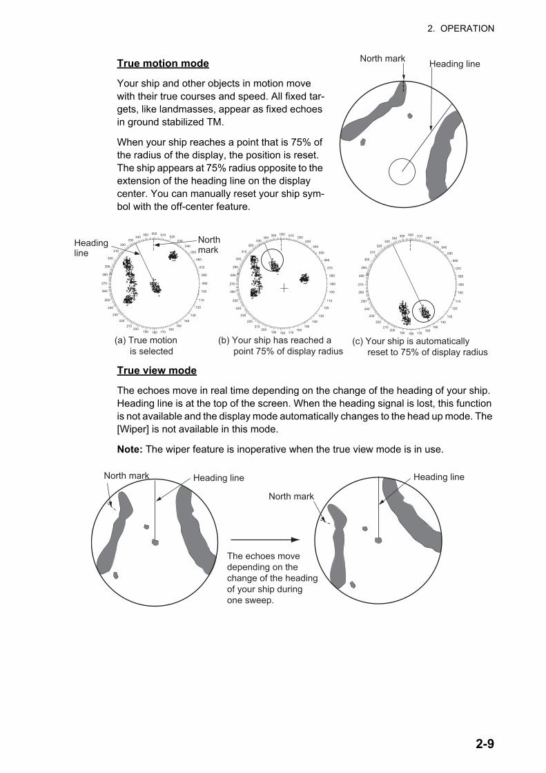
True motion mode
Your ship and other objects in motion move with their true courses and speed. All fixed tar-gets, like landmasses, appear as fixed echoes in ground stabilized TM.
When your ship reaches a point that is 75% of the radius of the display, the position is reset. The ship appears at 75% radius opposite to the extension of the heading line on the display center. You can manually reset your ship sym-bol with the off-center feature.
True view mode
The echoes move in real time depending on the change of the heading of your ship. Heading line is at the top of the screen. When the heading signal is lost, this function is not available and the display mode automatically changes to the head up mode. The [Wiper] is not available in this mode.
Note: The wiper feature is inoperative when the true view mode is in use.
Heading lineNorth mark
000 010 020030
040
050
060
070
080
090
100
110
120
130
140150
160170180190
200210
220
230
240
250
260
270
280
290
300
310
320330
340350
Headingline
Northmark
(a) True motion is selected
(b) Your ship has reached a point 75% of display radius
(c) Your ship is automatically reset to 75% of display radius
000 010 020030
040
050
060
070
080
090
100
110
120
130
140150
160170180190
200210
220
230
240
250
260
270
280
290
300
310
320330
340350 000 010 020
030040
050
060
070
080
090
100
110
120
130
140150
160170180190
200210
220
230
240
250
260
270
280
290
300
310
320330
340350
The echoes movedepending on thechange of the headingof your ship duringone sweep.
Heading lineNorth mark Heading line
North mark
2-9

2. OPERATION
2.9 How to Select the Range ScaleThe selected range scale, range ring interval and pulse length are shown at the top left corner on the screen. When an objective target comes closer, reduce the range scale so that a target appears in 50-90% of the display radius.
Rotate the RANGE knob to select range, clockwise to increase the range, or counter-clockwise to decrease the range.
2.10 How to Adjust the Gain (sensitivity)The gain control adjusts the sensitivity of the receiver for the best reception. The gain can be adjusted automatically or manually.
1. Push the RANGE knob to show the [GAIN/SEA/RAIN] window. (This window clos-es if there is no operation within 10 seconds.)
2. The cursor is selecting [GAIN]. Press the ENTER key to show [GAIN AUTO] or [GAIN MAN] as required. For manual adjustment, see the section below.
3. Press the MENU/ESC key to close the window.
Manual adjustment of gain
1. Rotate the RANGE knob (or use or on the Cursorpad) to adjust the gain so that weak noise appears on all of the screen. If the gain is too low, weak echoes are erased. If the gain is too high, the background noise hides weak targets.
2. Press the MENU/ESC key to close the window.
3NM 12NM
Short range Long range
Object size changes with range
AUTO: Automatic, MAN: Manual
Gain setting bar
GAIN/SEA/RAIN
2-10

2. OPERATION
2.11 How to Reduce the Sea ClutterThe reflected echoes from the waves appear around your ship and have the name "sea clutter". The sea clutter extends according to the height of waves and antenna above the water. When the sea clutter hides the targets, use the sea clutter function to reduce the clutter, either manually or automatically.
How to select the sea clutter adjustment method
1. Press the RANGE knob to show the [GAIN/SEA/RAIN] window. (This window closes if there is no operation within 10 seconds.)
2. Select [SEA]. Press the ENTER key to show [SEA AUTO] or [SEA MAN] as re-quired. For manual adjustment, see the section below.
3. Press the MENU/ESC key to close the window.
Manual adjustment of sea clutter
1. Rotate the RANGE knob (or use or on the Cursorpad) to adjust the sea clut-ter.Note: When the sea clutter is properly adjusted, the clutter is broken into small dots, and small targets become identified. If the setting is not enough, targets are hidden in the clutter. If the setting is higher than necessary, both sea clutter and targets disappear from the display. Normally adjust the knob until the clutter has disappeared to leeward, but a small amount of the clutter is visible windward.
2. Press the MENU/ESC key to close the window.
How to select the automatic sea clutter adjustment method
The automatic sea clutter adjustment is available in two types for optimal automatic adjustment according to the situation. Select the required method as shown below.
1. Press the MENU/ESC key to open the menu.
2. Select [Echo], then press the ENTER key.
SEA setting bar
AUTO: Automatic, MAN: Manual
SEA control adjusted;sea clutter reduced
Sea clutter atscreen center
2-11

2. OPERATION
3. Select [Auto SEA], then press the ENTER key.
4. Select [Coastal] or [Advanced] then press the ENTER key. The window for GAIN/SEA/RAIN indicator appears for confirmation.[Advanced]: Discriminate land echoes from sea reflections to suppress only sea reflections. The degree of sea clutter reduction is smaller than [Coastal]. Use this mode for general use.[Coastal]: Suppress both land and sea clutter. Useful when cruising along a coastline.
5. Press the MENU/ESC key to close the window.
6. Press the MENU/ESC key to close the menu.
2.12 How to Reduce the Rain ClutterThe reflections from the rain or snow appear on the screen. These reflections have the name "rain clutter". When the rain clutter is strong, targets in the rain clutter are hidden in the clutter. Reflections from the rain clutter are easily identified from true targets by their wool-like appearance.
The rain clutter function works like the sea clutter function, adjusting the receiver sen-sitivity, but in longer range. If the setting is high, the rain clutter is more reduced. The rain control breaks the continuous display of rain or snow reflections into a random pattern. When the rain clutter hides the targets, adjust the rain clutter (automatic or manual) to reduce the clutter.
How to select the rain clutter adjustment method
1. Push the RANGE knob to show the [GAIN/SEA/RAIN] window. (This window clos-es if there is no operation within 10 seconds.)
2. Select [RAIN]. Press the ENTER key to show [RAIN AUTO] or [RAIN MAN] as re-quired. For manual adjustment, see the section below.
3. Press the MENU/ESC key to close the window.
Manual adjustment of rain clutter
1. Rotate the RANGE knob (or use or on the Cursorpad) to adjust the rain clutter.
2. Press the MENU/ESC key to close the window.
RAIN setting bar
AUTO: Automatic, MAN: Manual
Rain clutter near center of screen
RAIN control adjusted; rain clutter reduced
2-12

2. OPERATION
2.13 CursorThe cursor functions to find the range and bearing (default function) to a target or the latitude and longitude position of a target. Use the Cursorpad to position the cursor and read the cursor data at the screen bottom.
How to select cursor data type
You can show the cursor data as range and bearing (from your ship to the cursor) or latitude and longitude. Position and heading signal are required.
1. Press the MENU/ESC key to open the menu.
2. Select [Others], then press the ENTER key.
3. Select [Cursor Data], then press the ENTER key.
4. Select [RNG/BRG] or [LAT/LON] then press the ENTER key. (When the navigation data is displayed, cursor latitude and longi-tude position cannot be displayed.)
5. Press the MENU/ESC key to close the menu.
Cursor data(bearing and range,
or latitutde and longitude)
NM0.5
Cursor+
VECT TRUE 06:00 0.0°R 0.000NM+
2-13

2. OPERATION
2.14 How to Temporarily Erase the Heading LineThe heading line is a line from your ship position to the outer edge of the radar display area, and indicates the heading of your ship in all display modes. The heading line ap-pears at zero degrees on the bearing scale in head up and true view modes. The heading line changes the orientation depending on the ship orientation in north up and true motion modes and when the course is changed in the course up mode.
In some cases, the heading line may hide a object. To erase the heading line to view an object hidden by the line, press the MENU/ESC key. The heading line and the range rings are temporarily erased. Release the key to redisplay the line and rings.
2.15 Interference RejectorRadar interference can occur when your ship is near the radar of another ship that op-erates on the same frequency band with your radar. The interference shows on the screen as many bright dots. The dots can be random or in the shape of dotted lines that run from the center to the edge of the display. You can identify the interference from the normal echoes, because the interference does not appear in the same loca-tion at the next antenna rotation. When this feature is turned on, "IR 1", "IR 2" or "IR 3" appears at the lower-right corner.
1. Press the MENU/ESC key to open the menu.
2. Select [Echo], then press the ENTER key.
3. Select [Int Rejector], then press the ENTER key.
4. Select [Off] or [On] then press the ENTER key.
5. Press the MENU/ESC key to close the menu.
Note: When there is no interference, turn off the interference rejector so you do not miss the small targets.
2-14

2. OPERATION
2.16 Noise RejectorWhite noise can appear on the screen as random "marks". You can reduce this noise as follows:
1. Press the MENU/ESC key to open the menu.
2. Select [Echo], then press the ENTER key.
3. Select [Noise Rejector], then press the ENTER key.
4. Select [Off] or [On] then press the ENTER key.
5. Press the MENU/ESC key to close the menu.
2.17 How to Measure the Range to a TargetYou can measure the range to a target in three methods. the fixed range rings, the cursor (if set to measure range and bearing), and the VRM (Variable Range Marker).
Use the fixed range rings to get a rough estimate of the range to a target. The fixed range rings are the concentric solid circles about your ship. The number of rings changes with the selected range scale. The interval of the range ring is displayed at the upper-left corner of the screen. Count the number of rings between the center of the display and the target. Check the range ring interval and measure the distance of the echo from the nearest ring.
2.17.1 How to adjust range ring brilliance
1. Press the MENU/ESC key to open the menu.
2. Select [Brill/Color], then press the ENTER key.
3. Select [Rings Brill], then press the ENTER key.
4. Select an option, then press the ENTER key. [4] is the brightest. [Off] turns off the range rings.
5. Press the MENU/ESC key to close the menu.
cation at the
2-15

2. OPERATION
2.17.2 How to measure the range with a VRM
There are two VRMs, No. 1 and No. 2. The VRMs are dashed rings so that you can identify the rings from the fixed range rings. You can identify VRM 1 from VRM 2 by different lengths of dashes. The dashes of the No. 1 VRM are shorter than those of the No. 2 VRM.
1. Press the MODE key to show the [Mode] window.
2. Select [VRM] then press the ENTER key.
3. Select [VRM 1] or [VRM 2] as required, then press the ENTER key. The corre-sponding VRM indication appears at the bottom right corner, inside a rectangle.
4. Use the Cursorpad to align the VRM with the inner edge of the target. Read the distance at the lower-right corner of the screen. The size of the VRM ring changes in proportion to the selected range scale.
5. To anchor the VRM, press the ENTER key. To reactivate the VRM, select it from the [Mode] window.
6. To erase a VRM, press the MODE key to open the [Mode] window, select [VRM], then select the VRM to erase. Press the MENU/ESC key to erase the VRM and its indication. (If a VRM’s indication is already in a rectangle, simply press the MENU/ESC key to erase the VRM and its indication.)
VRM 1 VRM 2
Target+
VRM5 . 0 4 4 NM2 . 0 8 2 NM
Cursor (+)
VRM 1 rangeVRM 2 range
The currently active VRMis in a rectangle.
3 7 . 4 ° R 5 . 0 4 4 NM
Cursor range and bearing
VECT TRUE 06:00 0.0°R 0.000NM+
2-16

2. OPERATION
2.17.3 How to select VRM unit
You can select the unit of measurement used by the VRM. The selections are nautical miles (NM), kilometers (KM), statute miles (SM) or kiloyard (KYD). The cursor range unit is also changed when the VRM unit is changed.
1. Press the MENU/ESC key to open the menu.
2. Select [Others], then press the ENTER key.
3. Select [VRM Unit], then press the ENTER key.
4. Select the unit, then press the ENTER key.
5. Press the MENU/ESC key to close the menu.
2.18 How to Measure the Bearing to a TargetUse the Electronic Bearing Line (EBL) to take a bearing of a target. There are two EBLs, No. 1 and No. 2. Each EBL is a straight dashed line from the center of the screen to the edge. The dashes of the No. 1 EBL are shorter than those of the No. 2 EBL.
2.18.1 How to measure the bearing with an EBL
1. Press the MODE key to show the [Mode] window.
2. Select [EBL] then press the ENTER key.
3. Select [EBL 1] or [EBL 2] as required, then press the ENTER key. The EBL indication appears at the bottom left corner, inside a rectangle.
4. Use the Cursorpad to place the EBL through the center of the target. Read the distance at the bottom left corner of the screen. The cursor on the EBL pro-vides an estimate of the range to a target.
5. To anchor the EBL, press the ENTER key. To reac-tivate the EBL, select it from the [Mode] window.
6. To erase a EBL, press the MODE key to open the [Mode] window, select [EBL], then select the EBL to erase. Press the MENU/ESC key to erase the EBL and its indication. (If a EBL’s indication is already in a rectangle, simply press the MENU/ESC key to erase the EBL and its indication.)
NM: 0.1 NM or aboveYD: Less than 0.1 NM
2-17

2. OPERATION
2.18.2 EBL reference
"R" (relative) follows the EBL indication if the bearing is relative to the heading of your ship. "T" (true) follows the EBL indication if the bearing is in reference to the north. You can select relative or true in the head up and true view modes. The bearing indication is true in all other modes. True bearing requires a heading sensor.
1. Press the MENU/ESC key to open the menu.
2. Select [Others], then press the ENTER key.
3. Select [EBL Reference], then press the ENTER key.
4. Select [Relative] or [True] then press the ENTER key.
5. Press the MENU/ESC key to close the menu.
+
EBL2 7 0 . 0 ° R 4 5 . 0 ° R
EBL 1EBL 2
Target
Cursor (+)
The currently active EBLis in a rectangle.
EBL 1 bearingEBL 2 bearing
Cursor range and bearing
VECT TRUE 06:00 0.0°R 0.000NM+
2-18

2. OPERATION
2.19 How to Measure the Range and Bearing Between Two TargetsYou can move the origin of the EBL to measure the range and bearing between two targets.
1. Press the MODE key.
2. Select [EBL], followed by [EBL 1], then press the ENTER key.
3. Use the Cursorpad to put the cursor on the center of the target A.
4. Press the MODE key, and the origin of the EBL moves to the cursor position.
5. Use the Cursorpad to put the cursor on the center of the target B, then press the ENTER key.
6. Press the MODE key, select [VRM] followed by [VRM 1], then press the ENTER key
7. Use the Cursorpad to set the VRM on the inner edge of the target B.
8. Read the bearing and range indications at the bottom of the screen.
The range and bearing to another target (C and D in the figure above) can be mea-sured using [EBL 2] and [VRM 2].
To cancel the this function, turn off the EBL and VRM.
EBL origin
++
Target B
Range/bearing betweentargets A and B
Range/bearing betweentargets C and D
EBL 2
VRM 2
EBL 1
VRM 1
EBL 4 5 . 0 ° R3 2 7 . 0 ° R
VRM0 . 5 5 0 NM0 . 5 5 0 NM
Target A Target D
Target C
255.5°R 1.094NMV E C T T R U E 0 5 : 0 0
+
2-19

2. OPERATION
2.20 Target AlarmThe target alarm looks for targets (ship, landmass, etc.) in the area you set. Audiovi-sual alarms are released when a target enters (or exits) the alarm area.
2.20.1 How to set a target alarm zone
The following procedure shows you how to set a target alarm zone.
1. Press the ALARM key to activate ALARM 1 or ALARM 2. Press the ALARM key to change the active ALARM between No. 1 and No. 2. The indication of the cur-rently active ALARM is in a rectangle at the upper-right corner of the screen.
2. Use the Cursorpad to move the cursor to the position A, then press the ENTER key.
3. Move the cursor to the position B, then press the ENTER key. The rectangle that shows alarm status indication at the upper-right corner of the screen disappears.
Note 1: To set a 360-degree guard zone, set the position B in the same bearing as the position A.
Note 2: When the target alarm zone is not within the range in use, the indication "ALM1(or 2)_RNG" replaces "ALM1(or 2)_IN(or OUT)" in the alarm status area. (When the target alarm zone is within the range of full off-centering, the indication does not change.) Select a range which displays the target alarm zone.
CAUTIONCAUTION· Do not depend on the alarm as the only means to detect possible collision situations.
· Adjust the A/C SEA, A/C RAIN and GAIN controls correctly so that the alarm system does not miss the target echoes.
Cursor
+
Target alarm zone 1(Length of dashand interval foralarm zone 2 arelonger than alarmzone 1.)
AB
Alarm statusA L M 1 _ I NA L M 2 _ O U T
255.5°R 1.094NMV E C T T R U E 0 5 : 0 0
+
2-20

2. OPERATION
2.20.2 How to stop the audio alarm
When a target enters (or exits) the target alarm zone, the target flashes and the alarm sounds. The alarm message appears at the bottom of the screen. To stop the audio alarm, press any key. When the target enters (or exits) the target alarm zone again, the audio alarm sounds.
2.20.3 How to select the alarm type
You can set the target alarm to activate against targets entering or exiting the alarm zone.
1. Press the MENU/ESC key to open the menu.
2. Select [Alert Settings], then press the ENTER key.
3. Select [Target Alarm 1] or [Target Alarm 2] then press the ENTER key.
4. Select [In] or [Out].[In]: The alarm sounds against targets entering a target alarm zone.[Out]: The alarm sounds against targets exiting a target alarm zone.
5. Press the ENTER key followed by the MENU/ESC key.
“In” target alarm “Out” target alarm
2-21

2. OPERATION
2.20.4 How to sleep a target alarm temporarily
When you do not require a target alarm temporarily, you can sleep the target alarm. The alarm zone remains on the screen, but any targets that enter (or exit) the alarm zone do not trigger the audio and visual alarms.
1. Press the ALARM key to select the ALARM 1 or ALARM 2 indication at the upper-right corner on the screen. The selected indication is in a rectangle.
2. Press the MENU/ESC key. The alarm indication now shows "ALM1(or 2)_ACK".
To activate a sleeping target alarm zone, press the ALARM key to select the ALARM 1 or ALARM 2, then press the ENTER key. The alarm indication then changes to "ALM1(or 2)_IN(or OUT)".
2.20.5 How to deactivate a target alarm
1. Press the ALARM key to select the ALARM 1 or ALARM 2 indication at the upper-right corner on the screen. The selected indication is in a rectangle.
2. Press the MENU/ESC key. The alarm indication now shows "ALM1(or 2)_ACK".
3. Press the ALARM key. The alarm indication "ALM1(or 2)_ACK" is shown in a dashed-line rectangle.
4. Press the MENU/ESC key. The target alarm zone and the alarm indication are erased from the screen.
2.20.6 How to select the target strength which triggers a target alarm
You can select the target strength which triggers the target alarm as follows:
1. Press the MENU/ESC key to open the menu.
2. Select [Alarm], then press the ENTER key.
3. Select [Alarm Level], then press the ENTER key.
4. Select the echo strength level, among [Low], [Med] and [High].
5. Press the ENTER key followed by the MENU/ESC key.
2.20.7 How to turn the buzzer on/off
You can turn on/off the panel buzzer or external buzzer for target alarms. The panel buzzer is for this equipment. The external buzzer is for the optional buzzer, which is connected to this equipment to give the target alarm at a remote location.
1. Press the MENU/ESC key to open the menu.
2. Select [Alarm], then press the ENTER key.
3. Select [Panel Buzzer] (or [External Buzzer] for optional buzzer), then press the ENTER key.
4. Select [On] or [Off] then press the ENTER key.
5. Press the MENU/ESC key to close the menu.
2-22

2. OPERATION
2.21 How to Off-center the DisplayYou can off-center your ship position to expand the view field without selecting a larger range scale. The display can be off-centered manually, or automatically according to speed of the ship.
Note: Off-centering is not available in the true motion mode.
2.21.1 How to select the off-center mode
1. Press the MENU/ESC key to open the menu.
2. Select [Display], then press the ENTER key.
3. Select [Off-center mode], then press the ENTER key.
4. Select [Manual], [Custom] or [Auto] then press the ENTER key. Press the ENTER key again to change between on and off.
5. After setting all options, Select [EXIT? YES], then press the ENTER key.
6. Press the MENU/ESC key to close the menu.
2.21.2 How to off-center the display
The off-center features shifts own position according to the off-center mode selected.
The mode selected from the menu appears at top left corner of the display, when the off-center feature is acti-vated - "OFFCENT(M)" (Manual), "OFFCENT(C)" (Cus-tom) or "OFFCENT(A)" (Auto).
Manual off-center
You can move your ship position to the current cursor position on all modes except true motion, within 75% of the available display area.
1. Put the cursor on the position where to off-center the display.
2. Press the MODE key, select [Off-center], then press the ENTER key.
The indication "OFFCENT(M)" appears at the top left corner
Custom off-center
You can move your ship position to the position which you preset. Follow the proce-dure shown below to register the cursor position. Then, the display is off-centered by the amount set here, when you activate the off-center function.
1. Turn off the off-center display.
2. Put the cursor on the position where to off-center the display.
3. Press the MODE key, select [Off-center], then press the ENTER key.
Press the ENTER keyto change betweenon and off.
2-23

2. OPERATION
4. Press the MENU/ESC key to open the menu.
5. Select [Display], then press the ENTER key.
6. Select [Save Offcenter], then press the ENTER key. The message "Complete" ap-pears.
7. Press any key to close the message window.
8. Press the MENU/ESC key to close the menu.
The indication "OFFCENT(M)" appears at the top left corner
Automatic off-center
The amount of automatic move is calculated according to speed of the ship. The max-imum amount is 75% of the range in use. The formula to calculate automatic shift is shown below.
If the offcenter speed setting is 15 knots and the speed of the ship is 10 knots, for ex-ample, the amount of move at the stern of your ship will be 50% of the available display area.
How to select offcenter speed
1. Press the MENU/ESC key to open the menu.
2. Select [Initial] sub menu in [System] menu, then press the EN-TER key.
3. Select [Offcenter Speed], then press the ENTER key.
4. Select the speed to use, then press the ENTER key.
5. Press the MENU/ESC key to close the menu.
2.22 ZoomThe zoom function expands the length and width of a selected target as much as twice its normal size, in the zoom window. You select the target to zoom with the zoom cur-sor. The selected target is zoomed in the zoom window.
TT and AIS symbols can be displayed in the zoom window, but are not zoomed. You can process TT and AIS targets that are in the zoom window, in the same method as on the normal radar display.
2.22.1 Zoom reference
There are three types of zoom.
[Relative]: The zoom cursor is fixed to the range and bearing from your ship.[True]: The zoom cursor is fixed to set geographical position.[Target]: The zoom cursor is fixed to the zoomed AIS or TT target.
1. Press the MENU/ESC key to open the menu.
2. Select [Display], then press the ENTER key.
Offcenter speed setting x 0.75 = Amount of move (%)
Speed of ship
2-24

2. OPERATION
3. Select [Zoom Reference], then press the ENTER key.
4. Select [Relative], [True] or [Target] then press the ENTER key.Note: True zoom mode requires a heading signal and position da-ta.
5. Press the MENU/ESC key to close the menu.
2.22.2 How to zoom
Relative or True zoom mode
1. Use the Cursorpad to put the cursor on the position desired.
2. Press the MENU/ESC key to open the menu.
3. Select [Display], then press the ENTER key.
4. Select [Zoom], then press the ENTER key.
5. Select [On], then press the ENTER key.The ZOOM indication appears at the upper-left corner on the screen. The zoom window and the zoom cursor also appear (see the illustration on the next page). To quit the zoom, select [Off] instead of [On], then press the ENTER key.
6. Press the MENU/ESC key to close the menu.
1.51.5NMNM
Zoom window
ZOOM(T)
+Zoom cursor
Zoom indication
255.5°R 1.094NMV E C T T R U E 0 5 : 0 0
+
2-25

2. OPERATION
Target (AIS, TT) zoom mode
The TT or AIS target as below can be displayed in the zoom window:
TT: The symbol is enlarged twice its normal size. AIS: The symbol is enclosed in a broken square. (The symbol is not enlarged.)
The zoom cursor moves with the TT or AIS target.
Note: If neither TT nor AIS targets are selected, the message "NO TARGET." ap-pears. Press any key to erase the message.
1. Press the MENU/ESC key to open the menu.
2. Select [Display], then press the ENTER key.
3. Select [Zoom], then press the ENTER key.
4. Select [On], then press the ENTER key.The ZOOM indication appears at the upper-left corner on the screen. The zoom window and the zoom cursor also appear (see the following illustration). To quit the zoom, select [Off] instead of [On], then press the ENTER key.
5. Press the MENU/ESC key to close the menu.
Zoom window
Zoom cursor
Zoom indication
1.51.5NMNM
255.5°R 1.094NM
ZOOM(T)
+
V E C T T R U E 0 5 : 0 0+
Target zoom mode(example: AIS)
999999000
999999000
2-26

2. OPERATION
2.23 Echo StretchThe echo stretch feature enlarges the targets in the range and bearing directions to make the targets easier to see. This feature is available on any range. There are three levels of echo stretch, [1], [2] and [3]. [3] enlarges the targets the most.
Note: The echo stretch magnifies the targets, sea and rain clutters, and radar interfer-ence. Correctly adjust the sea clutter, rain clutter and radar interference before you ac-tivate the echo stretch.
1. Press the MENU/ESC key to open the menu.
2. Select [Echo], then press the ENTER key.
3. Select [Echo Stretch], then press the ENTER key.
4. Select an echo stretch option, then press the ENTER key.
5. Press the MENU/ESC key to close the menu. When the echo stretch is active, "ES 1 (2, or 3)" appears at the lower-left corner on the display.
2.24 Target TrailsThe trails of the radar targets can be shown simulated in afterglow to check target movement. The target trails are selected for either relative or true. True motion trails require a heading signal and position data.
2.24.1 Trail time
1. Press the MODE key to open the [Mode] window.
2. Select [Trail Time], then press the ENTER key.
3. Select a time, then press the ENTER key.
4. Press the MENU/ESC key to close the menu.
The selected time appears at the top right corner.
Press the ENTER keyto change betweenon and off.
2-27

2. OPERATION
2.24.2 Trail mode
You can display the echo trails in true or relative motion.
The selected trail mode and trail time appear at the top right corner.
True mode
The true trails show true target movements according to their over-the-ground speeds and courses. The stationary targets do not show the trails. The true trails require a heading signal and position data.
Relative mode
The relative trails show other ships’ movements relative to your ship. The stationary targets also show the trails.
To select the trail mode, do the following:
1. Press the MENU/ESC key to open the menu.
2. Select [Target Trails], then press the ENTER key.
3. Select [Mode], then press the ENTER key.
4. Select [Relative] or [True] then press the ENTER key.
5. Press the MENU/ESC key to close the menu.
TRAIL(T)15 S
Trail Mode (T: True, R: Relative)Trail Time
True target trails Relative target trails
2-28

2. OPERATION
2.24.3 Trail gradation
Trails can be shown in single or multiple gradation. Multiple gradation fades the gra-dation over time.
1. Press the MENU key to open the menu.
2. Select [Target Trails], then press the ENTER key.
3. Select [Gradation], then press the ENTER key.
4. Select [Single] or [Multi] then press the ENTER key.
5. Press the MENU key to close the menu.
2.24.4 Trail color
You can select the color for trails as follows:
1. Press the MENU key to open the menu.
2. Select [Target Trails], then press the ENTER key.
3. Select [Color], then press the ENTER key.
4. Select a color, then press the ENTER key.
5. Press the MENU key to close the menu.
2.24.5 Trail level
You can select which target strength to display.
1. Press the MENU/ESC key to open the menu.
2. Select [Target Trails], then press the ENTER key.
3. Select [Level], then press the ENTER key.
4. Select [1], [2] or [3] then press the ENTER key.[1]: Display the trails for all targets (including weak targets).[2]: Display the trails for medium-to-strong level targets.[3]: Display the trails for only strong targets.
5. Press the MENU/ESC key to close the menu.
2.24.6 How to restart, stop the trails
When the range is changed while the trail feature is active, trails within the previous range scale can be stopped and restarted.
1. Press the MENU key to open the menu.
2. Select [Target Trails], then press the ENTER key.
3. Select [Restart], then press the ENTER key.
Multiple(Gradual shading)
Single(Monotone shading)
2-29

2. OPERATION
4. Select [Off] or [On] then press the ENTER key.[Off]: The previous trails data are saved when the range is changed. The trails are not restarted and the saved trails are not updated. When you return the range scale to the previous range scale, the saved trails are displayed and updated.[On]: The previous trails are zoomed in or out depending on the changed scale and updated.
Note: If the newly selected range is less than or equal to 1/4 of the previous range, trails are erased. If the newly selected range is longer than the previous range, the previous trails are left to be displayed.
5. Press the MENU key to close the menu.
2.24.7 Narrow trails
You can display the target trails in thin trails. When there are many targets on the screen, you can separate trails close to one another with this function.
1. Press the MENU/ESC key to open the menu.
2. Select [Target Trails], then press the ENTER key.
3. Select [Narrow], then press the ENTER key.
4. Select [Off] or [On] then press the ENTER key.
5. Press the MENU/ESC key to close the menu.
2.24.8 Own ship trail
You can show the trail of your ship as follows:
1. Press the MENU/ESC key to open the menu.
2. Select [Target Trails], then press the ENTER key.
3. Select [Own Ship], then press the ENTER key.
4. Select [Off], [1] or [2] then press the ENTER key.[Off]: Hide the trail of your ship.[1]: Show the trail of your ship.[2]: Show the trail of your ship, but hide the trail of sea clutter near your ship.
5. Press the MENU/ESC key to close the menu.
Before changing range After changing range
Copied trail picture
2-30

2. OPERATION
2.24.9 How to erase all trails
All trails can be erased by the methods shown below. A beep sounds upon completion of the erasure.
Erase all trails from the menu
1. Press the MENU/ESC key to open the menu.
2. Select [Trails], then press the ENTER key.
3. Select [Trail Erase], then press the ENTER key.
4. You are asked if you are sure to erase all trails. Press on the Cursorpad to se-lect [Yes] then press the ENTER key.
Erase all trails with the MODE key
Press the MODE key to show the mode options. Select [Trail Erase], then press the ENTER key.
2.25 How to Program the FUNC KeyThe FUNC key can be programmed to do the function you assign.
Function key operation
Press the FUNC key to do the function assigned to the key. Press the key successive-ly to change the setting.
How to change a function key program
1. Press the MENU/ESC key to open the menu.
2. Select [Others], then press the ENTER key.
3. Select [FUNC Setup], then press the ENTER key.
4. Scroll through the list to select a function, then press the ENTER key. Below are the available functions. The default function is [Trail Time].
5. Press the MENU/ESC key to close the menu.
2-31

2. OPERATION
2.26 Echo AverageTo identify true target echoes from the sea clutter, echoes are averaged over succes-sive picture frames. If an echo is solid and stable, the echo is shown in its normal in-tensity. The brilliance of sea clutter is reduced to easily identify true targets from the sea clutter.
Note 1: Do not use the echo average function under heavy pitching and rolling. You can lose a target.
Note 2: This feature requires a heading signal and position data. When either signal becomes lost, echo average is deactivated.
To correctly use the echo average function, first reduce the sea clutter:
1. Press the MENU/ESC key to open the menu.
2. Select [Echo], then press the ENTER key.
3. Select [Echo Average], then press the ENTER key.
4. Select an echo averaging option, then press the ENTER key.[Off]: Deactivate the echo average.[1]: Identify true targets from the sea clutter and reduce the brilliance of unstable echoes.[2]: Identify true targets from the sea clutter that you cannot reduce the brilliance with setting 1.[Auto]: Identify true targets from the sea clutter. Detect far and unstable targets.
5. Press the MENU/ESC key to close the menu. The selected echo average ("EAV 1", "EAV 2" or "EAV(A)") appears at the lower-left corner of the display.
2.27 WiperThe wiper feature automatically reduces the brilliance of unwanted weak signals (noise, sea clutter, rain clutter, etc.) and unnecessary signals, like radar interference, to clear the picture of unnecessary echoes. The result of wiper depends on the wiper setting used and whether echo averaging is turned on or off, as described below.
Echo averaging and wiper states and wiper effect
Processing content A: The brilliance of unnecessary weak echoes, like noise and radar interference, is reduced to clear the picture. The difference between wiper 1 and 2 is that brilliance is lowered more slowly in 1.Processing content B: Echo averaging is automatically turned on from off when the wiper feature is turned on. You can see how the picture changes with the echo aver-aging turned off and turned on.
To activate the wiper feature, do the following:
1. Press the MENU/ESC key to open the menu.
Echo average settingWiper Setting
Wiper 1 Wiper 2Off Processing content AOn (1, 2, Auto) Processing content A Processing content B
2-32

2. OPERATION
2. Select [Echo], then press the ENTER key.
3. Select [Wiper], then press the ENTER key.
4. Select [1] or [2] then press the ENTER key.
5. Press the MENU/ESC key to close the menu.
Note: This function is not available when the [Display Mode] is [True View].
2.28 Display-CurveYou can change the characteristics curve to reduce unwanted weak echoes (sea re-flections, etc.). Select [1], [2] or [3] depending on conditions when unwanted weak echoes hide wanted targets.
1. Press the MENU/ESC key to open the menu.
2. Select [Echo], then press the ENTER key.
3. Select [Display-Curve], then press the ENTER key.
4. Select [1], [2] or [3] then press the ENTER key.[1]: Reduce weak echoes.[2]: Normal use[3]: Display weaker echoes in stronger color compared to [1].
Display curve
5. Press the MENU/ESC key to close the menu.
2.29 Own Ship and Barge MarkThis section shows you how display and set up the own ship and barge marks.
2.29.1 How to show the own ship mark
1. Press the MENU/ESC key to open the menu.
2. Select [OS/Barge Mark], then press the ENTER key.
3. Select [OS Mark], then press the ENTER key.
4. Select [On], then press the ENTER key.
3 2 1
Input level
Echo colorstrength
Strong
Strong
2-33

2. OPERATION
5. Select [OS Length] then press the ENTER key.
6. Set the length of own ship then press the ENTER key.
7. Select [OS Width] then press the ENTER key.
8. Set the width of own ship then press the ENTER key.
9. Press the MENU/ESC key to close the menu.
The own ship mark appears on the display, scaled according to the length and width entered here.
2.29.2 How to show the barge mark
The length and breadth of the total barge size can be displayed as a simple rectangle on the radar display. Up to five rows of barges and nine barges per row can be shown.
Note: Turn on [OS Mark] in the [OS/Barge Mark] menu to enable display of barge marks.
1. Press the MENU/ESC key to open the menu.
2. Select [OS/Barge Mark], then press the ENTER key.
3. Select [Barge Mark], then press the ENTER key.
4. Select [On], then press the ENTER key.
5. Select [Barge Position] then press the ENTER key.
6. Select [Bow] or [Stern], then press the ENTER key.
7. Select [Barge Length] then press the ENTER key.
Barge mark
OS mark
OS mark
STERNBOW
2-34

2. OPERATION
8. Set the length of the barge, then press the ENTER key.
9. Select [Barge Beam] then press the ENTER key.
10. Select [Barge Arrangement], then press the ENTER key.
11. The cursor is selecting [Column1(PORT)]. Press the ENTER key.
12. Set the number of barges in the port column.
13. Set other columns similar to how you did in steps 11 and 12.
14. After setting all required columns, select [Close This Window], then press the ENTER key.
15. Press the MENU/ESC key to close the menu.
2.30 WatchmanThe Watchman sounds the buzzer to tell the operator to check the radar display. The radar transmits for one minute and then goes into standby for the selected time inter-val. If the target alarm is active and a target is found in the alarm zone, Watchman is cancelled, and the radar transmits continuously.
In standby, the timer near the <WATCH> label at the center of the screen counts down the remaining time until the transmission. When the set time interval has passed, the audio alarm sounds, the timer disappears and the radar transmits for one minute. After one minute, the audio alarm sounds and the watch alarm timer again begins the count-down sequence.
If you press the STBY/TX key before the set time interval comes, the radar goes into transmission.
Do the following to activate the Watchman:
1. Press the MENU/ESC key to open the menu.
2. Select [Alarm], then press the ENTER key.
BOW
ST-BY
5,10 or 20 min.
Tx
1 min.
Watchmanstarts
*
* Beep sounds just before radar transmits or goes into standby.
Tx *
5,10 or 20 min.1 min.
* *ST-BY
2-35

2. OPERATION
3. Select [Watchman], then press the ENTER key.
4. Select [Off] or a time ([5min], [10min] or [20min]) then press the ENTER key.
5. Press the MENU/ESC key to close the menu.
To turn off watchman, select [Off] at step 4.
2.31 Alert StatusThe alert status window shows all currently violated alarms and system messages.
Note: The alert status window is not automatically displayed when an alarm occurs.
1. Press the MENU/ESC key to open the menu.
2. Select [Alert Settings], then press the ENTER key.
3. Select [Alert Status], then press the ENTER key.
Alert Status display
4. Press the MENU/ESC key to close the [Alert Status] display.
5. Press the MENU/ESC key to close the menu.
See the next page for a list of alert status messages and their meanings.
TRIGGER HEADING BEARING GYROVIDEO POSITION NMEA_HDG
IN OUTIN OUT
COLLISION LOST PROXIMITYCOLLISION PROXIMITY
TX ANT CH1 CH2 CH70 FAIL MKDEPFS L/L SOG COG HDG ROT
OVER_TEMP
[MENU/ESC]: Close
Alert Status
2-36

2. OPERATION
*: Have a qualified technician check the equipment.
Alert category MeaningSIGNAL MISSING*TRIGGER Trigger signal lost (only for remote display)HEADING Heading signal lostBEARING Bearing signal lostGYRO AD-10 format gyro signal lostVIDEO Video signal lostPOSITION NMEA format position data lostNMEA_HDG NMEA format heading signal lostANT ERR No data from antenna unit for one minuteTARGET ALARM1(2)IN An echo has entered a target alarm zone.OUT An echo has exited a target alarm zone.TT ALARMCOLLISION CPA and TCPA of an TT target is less than CPA and
TCPA alarm settings.LOST Acquired TT target becomes lost.PROXIMITY The range to an TT target is less than the user-set prox-
imity alarm range.AIS ALARMCOLLISION CPA and TCPA of an AIS target is less than CPA and
TCPA alarm settings.LOST AIS target becomes lost.PROXIMITY The range to an AIS target is less than the user-set prox-
imity alarm range.AIS SYSTEM*TX TX stopped or TX errorANT Antenna VSWR problemCH1 TDM2 RX1 board problemCH2 TDM2 RX2 board problemCH70 RX channel 70 problemFAIL System failureUTC UTC sync invalidMKD Minimum input device lostGNSS Internal/external GNSS position mismatchNAV_STATUS NAV status incorrectHDG_OFFSET Heading sensor offsetSART Active AIS-SARTEPFS Navigator (GPS, etc.) problemL/L Position data lostSOG Speed data lostCOG Course data lostHDG Heading data lostROT Rate of turn data lostOTHER*OVER_TEMP The temperature of the equipment is more than the spec-
ified value.
2-37
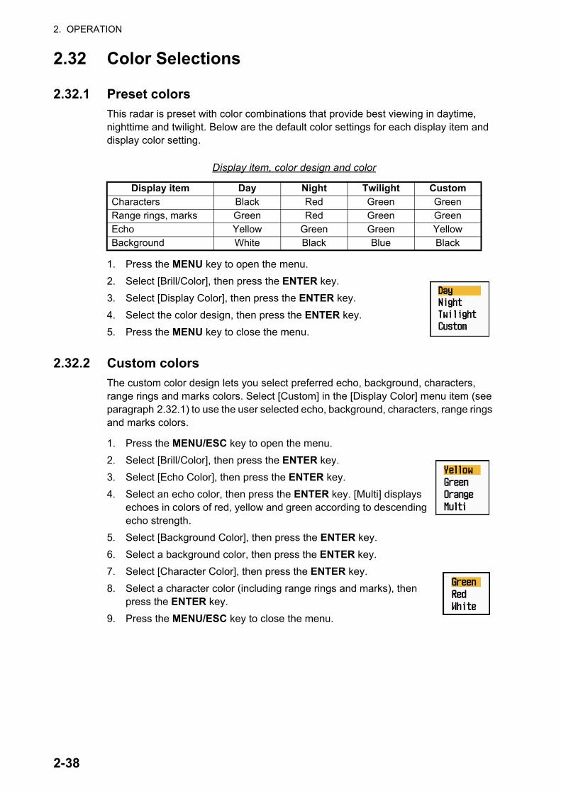
2. OPERATION
2.32 Color Selections
2.32.1 Preset colors
This radar is preset with color combinations that provide best viewing in daytime, nighttime and twilight. Below are the default color settings for each display item and display color setting.
Display item, color design and color
1. Press the MENU key to open the menu.
2. Select [Brill/Color], then press the ENTER key.
3. Select [Display Color], then press the ENTER key.
4. Select the color design, then press the ENTER key.
5. Press the MENU key to close the menu.
2.32.2 Custom colors
The custom color design lets you select preferred echo, background, characters, range rings and marks colors. Select [Custom] in the [Display Color] menu item (see paragraph 2.32.1) to use the user selected echo, background, characters, range rings and marks colors.
1. Press the MENU/ESC key to open the menu.
2. Select [Brill/Color], then press the ENTER key.
3. Select [Echo Color], then press the ENTER key.
4. Select an echo color, then press the ENTER key. [Multi] displays echoes in colors of red, yellow and green according to descending echo strength.
5. Select [Background Color], then press the ENTER key.
6. Select a background color, then press the ENTER key.
7. Select [Character Color], then press the ENTER key.
8. Select a character color (including range rings and marks), then press the ENTER key.
9. Press the MENU/ESC key to close the menu.
Display item Day Night Twilight CustomCharacters Black Red Green GreenRange rings, marks Green Red Green GreenEcho Yellow Green Green YellowBackground White Black Blue Black
2-38

2. OPERATION
2.33 Echo AreaYou can select the display area from [Normal] or [Full Screen].
1. Press the MENU/ESC key to open the menu.
2. Select [Display], then press the ENTER key.
3. Select [Echo Area], then press the ENTER key.
4. Select [Normal] or [Full Screen] then press the ENTER key.
5. Press the MENU/ESC key to close the menu.
2.34 Initial Sub MenuThe [Initial] sub menu in the [System] menu contains items that allow you to customize your radar to meet your needs.
2.34.1 How to open the Initial sub menu
1. Press the MENU key to open the menu.
2. Select [Initial], then press the ENTER key.
Normal Full Screen
Area in which echoes are displayed
2-39

2. OPERATION
2.34.2 Description of Initial sub menu
[Key Beep]: When a key is pressed, a beep sounds. You can turn on or off this beep.
[Off-center Speed]: Set the speed of your ship to calculate amount of your ship’s off-center. The setting range is 1-99 (kn).
[Compass Type]: Select the type of bearing sensor connected to the radar; [True] (gy-rocompass, satellite compass) or [Magnetic] (magnetic compass).
[Range Preset]: You can select the radar ranges. Select a range, then press the EN-TER key to switch on and off. At least two ranges must be turned on. The maximum range available depends on the radar model. 0.0625 is not available in KM (kilome-ters).
[Wind Direction]: Wind direction is shown as [Apparent] or [True].
[NMEA Port 1]: Set the baud rate of the equipment connected to Port 1 ([Auto], [4800], or [38400] (bps)). [Auto] provides automatic detection of baud rate from 4800, 9600, 19200 or 38400 (bps).
[NMEA Port 2]: Same function as Port 1 but for Port 2.
[NMEA Mixing Out]: Data input to Port 1 may be output from Port 2 mixed with data output to Port 2. Select [On] to use this feature.
NM (nautical miles) KM (kilometers) SM (statute miles)
2-40

2. OPERATION
2.35 Sector BlankYou must prevent the transmission in some areas to protect passengers and crew from microwave radiation. Also, if the reflections of echoes from the mast appear on the screen, you must prevent the transmission in that area. You can set two sectors.
1. Press the MENU/ESC key to open the menu.
2. Select [Sector Blanks], then press the ENTER key.
3. Select [Sect-Blank 1 (or 2) Status], then press the ENTER key.
4. Select [On], then press the ENTER key.
5. Select [Sect-Blank 1 (or 2) Start], then press the ENTER key.
6. Set the start point of the sector, then press the ENTER key.
7. Select [Sect-Blank 1 (or 2) End], then press the ENTER key.
8. Set the end point of the sector, then press the ENTER key.Note 1: You can not set the sector more than 180 degrees.
Note 2: You can not set the total width of sector 1 and sector 2 more than 270 degrees.
9. Press the MENU/ESC key to close the menu.
As shown in the following illustration, dashed lines mark the start and end points of the sector.
2.36 Other Menu ItemsThis section describes the menu items not previously described.
2.36.1 Brill/Color menu
[Echo Brill]: Adjust the brilliance of echoes.
[Ring Brill]: Adjust the brilliance of the range rings.
[Mark Brill]: Adjust the brilliance of all marks.
[HL Brill]: Adjust the brilliance of the heading line.
+
Area of notransmission Start bearing
of sectorEnd bearingof sector
2-41

2. OPERATION
[Character Brill]: Adjust the brilliance of all characters.
[Viewing Position]: You can select the angle from where you see the screen.
[Menu Transparency]: You can select the degree of transparency of the menu window so the menu window does not hide the echo display. [4] is the greatest degree of transparency. [Off] functions to hide the echo display be-hind the menu window completely.
Note: Alpha blending technology is used for transparency effects.
[Echo Color Mode]: You can select the color palette from [System] or [Custom]. [System] is the preset color palette and [Custom] is the color palette you can set yourself. This function is not available in the [IEC] or [Russian-River] mode.
[Custom Echo Color]: You can customize the echo color with the following two meth-ods. This function is not available in the [IEC] or [Russian-River] mode.
Custom Echo Color setting window
Method 1: 1) Select the echo rank to change on the [Rank] (setting range: 1 - 31).
2) Set the RGB values for selected echo rank on the [Red], [Green] and [Blue] (setting range: 0 - 63).
Method 2: 1) Select 31 on the [Rank].
2) Set the RGB values for 31 echo rank on the [Red], [Green] and [Blue] (setting range: 0 - 63).
3) Interpolate the RGB values between the maximum rank and minimum rank on the [Fitting To Curve] with the following curves (setting range: -20 to 20).
2-42

2. OPERATION
Setting range > 0: Logarithmic curve, useful to emphasize the weak echoes.
Setting range = 0: Straight line
Setting range < 0: Exponential curve, useful to emphasize the strong echoes.
[Copy To Custom]: Copy the color palette from [System] to [Custom].
2.36.2 Display menu
[Text Display]: You can select on/off for the text indications of the following items on the display. The settings on this function are used when you set [Echo Area] to [Full Screen] on the [Display] menu. This function is not available in the [IEC] or [Russian-River] mode.
The text indications set to off appear when you operate any key. The indications dis-appear when there is no key operation for 10 seconds.
[STBY Display]: Set what to show on the standby display.- [Normal]: Display "ST-BY" at the screen center.- [Nav]: Display navigation data.
2.36.3 Echo menu
[Color Erase]: Erase the lower echo color whose level is set here. Set a large value to display only the stronger echoes.
Press the ENTER keyto change betweenon and off.
2-43
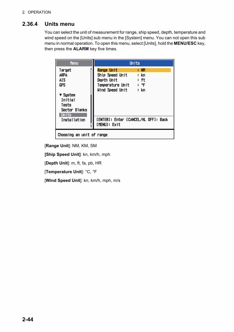
2. OPERATION
2.36.4 Units menu
You can select the unit of measurement for range, ship speed, depth, temperature and wind speed on the [Units] sub menu in the [System] menu. You can not open this sub menu in normal operation. To open this menu, select [Units], hold the MENU/ESC key, then press the ALARM key five times.
[Range Unit]: NM, KM, SM
[Ship Speed Unit]: kn, km/h, mph
[Depth Unit]: m, ft, fa, pb, HR
[Temperature Unit]: °C, °F
[Wind Speed Unit]: kn, km/h, mph, m/s
2-44

2. OPERATION
2.37 Navigation Data
2.37.1 Navigation data during standby
The navigation data is shown in standby when [STBY Display] on the [Display] menu is set to [Nav]. Appropriate sensors are required to display the data.
2.37.2 Navigation data at the bottom of the screen
Navigation data can be displayed at the bottom of the screen. The figure below shows the navigation data display
To show or hide the navigation data at the bottom of the screen, operate the DATA BOX knob to select [OFF], [NAV], [TGT] or [ALL].[OFF]: Turn off the data box display.[NAV]: Navigation data[TGT]: TT and AIS data (see section 4.10, section 5.4.)[ALL]: Navigation data plus TT and AIS target data
SpeedStandby indication
Depth Water temperature
Trip distance
Wind speed Wind direction
Time until TXin watchman
Heading indicatorHeading
CourseTime to go todestination waypointBearing to
destination Range to go todestination waypoint
Waypoint mark
Your position
Cross track error(numeric value)
Cross track error(graphic): For example,when the indicator is offto the right side, steeryour ship to the left to goto the destination waypoint.
- Cursor latitude position- Cursor longitude position- Time to go to cursor position
Your ship position and speed- Bearing from your ship to waypoint- Range from your ship to waypoint- Time to go from your ship position to waypoint
LAT 34°56.123NLON 135°34.567ESPEED 12.3KN
LAT 34°56.123NLON 135°34.567ETTG 01:00
BRG 14.8°RNG 0.876NMTTG 00:20
OWN SHIP + CURSOR WAYPOINT
2-45

2. OPERATION
2.38 Waypoint MarkThe waypoint mark shows the location of the destination waypoint set on a navigation plotter. The heading signal or course data are required. You can turn on/off the way-point mark as follows:
1. Press the MENU/ESC key to open the menu.
2. Select [Others], then press the ENTER key.
3. Select [WPT Mark], then press the ENTER key.
4. Select [Off] or [On] then press the ENTER key.
5. Press the MENU/ESC key to close the menu.
+
Waypointmark
2-46

2. OPERATION
2.39 How to Send the Target Position and Enter the Origin MarkThe TLL function sends the cursor position to a chart plotter and put an origin mark
( ) at the cursor position on the radar. Use the Cursorpad to put the cursor on a tar-get. Press the MODE key to open the [Mode] window, select [TLL] then press the EN-TER key. You can enter up to 20 origin marks on the radar display. When the capacity for origin marks is reached, the oldest mark is erased to make room for the latest mark, to keep a maximum of 20 marks. To erase a mark, put the cursor on the mark, then press the MENU/ESC key.
TLL mode
You can select how to handle TLL position.
1. Press the MENU/ESC key to open the menu.
2. Select [Others], then press the ENTER key.
3. Select [TLL Mode], then press the ENTER key.
4. Select [TLL Output], [Origin Mark] or [Both] then press the ENTER key.[TLL Output]: Send the latitude and longitude of the cursor position to a chart plot-ter. (Position and heading signal are required.)[Origin Mark]: Enter an origin mark at the cursor position on the radar display. (Position and heading signal are required.)[Both]:Send the target position to a chart plotter and enter an origin mark on the radar display.
5. Press the MENU/ESC key to close the menu.
Note: All origin marks are deleted and not saved when the power is turned off.
2-47

2. OPERATION
This page is intentionally left blank.
2-48
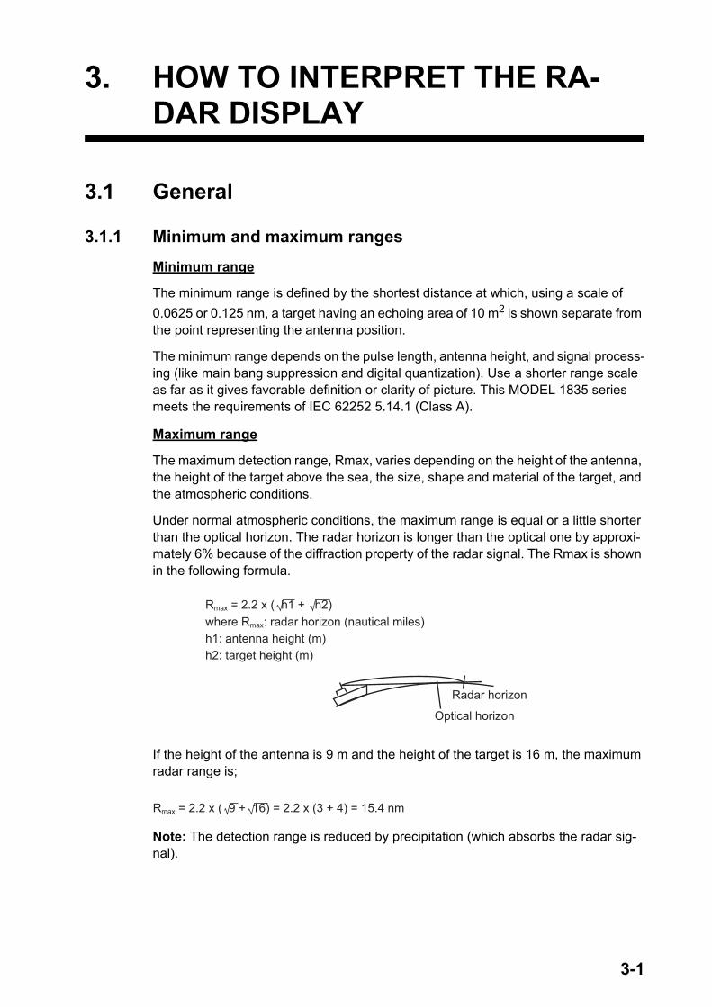
3. HOW TO INTERPRET THE RA-DAR DISPLAY
3.1 General
3.1.1 Minimum and maximum ranges
Minimum range
The minimum range is defined by the shortest distance at which, using a scale of
0.0625 or 0.125 nm, a target having an echoing area of 10 m2 is shown separate from the point representing the antenna position.
The minimum range depends on the pulse length, antenna height, and signal process-ing (like main bang suppression and digital quantization). Use a shorter range scale as far as it gives favorable definition or clarity of picture. This MODEL 1835 series meets the requirements of IEC 62252 5.14.1 (Class A).
Maximum range
The maximum detection range, Rmax, varies depending on the height of the antenna, the height of the target above the sea, the size, shape and material of the target, and the atmospheric conditions.
Under normal atmospheric conditions, the maximum range is equal or a little shorter than the optical horizon. The radar horizon is longer than the optical one by approxi-mately 6% because of the diffraction property of the radar signal. The Rmax is shown in the following formula.
If the height of the antenna is 9 m and the height of the target is 16 m, the maximum radar range is;
Note: The detection range is reduced by precipitation (which absorbs the radar sig-nal).
Rmax = 2.2 x ( h1 + h2)where Rmax: radar horizon (nautical miles)h1: antenna height (m)h2: target height (m)
Radar horizon
Optical horizon
Rmax = 2.2 x ( 9 + 16) = 2.2 x (3 + 4) = 15.4 nm
3-1

3. HOW TO INTERPRET THE RADAR DISPLAY
3.1.2 Radar resolution
The bearing resolution and range resolution are important in radar resolution.
Bearing resolution
The bearing resolution is the ability of the radar to display the echoes received from two targets at the same range as the separate echoes. The bearing resolution is pro-portional to the antenna length and the wavelength.
Range resolution
The range resolution is the ability to display the echoes received from two targets on the same bearing as separate echoes. The range resolution is determined by only pulse length.
The test targets used to determine the range and bearing resolution are radar reflec-
tors that have an echoing area of 10 m2.
Targets
Targets
Horizontal beam width
Horizontal beam width
Separatetarget echoes
Overlappedtarget echoes
Separatetarget echoes
Overlappingtarget echoes
Targets
Targets
Overlapping
Transmissionpulse
Transmissionpulse
3-2

3. HOW TO INTERPRET THE RADAR DISPLAY
3.1.3 Bearing accuracy
One of the most important features of the radar is how accurately the bearing of a tar-get can be measured. The accuracy of bearing measurement depends on the narrow-ness of the radar beam. The bearing is taken relative to the heading of the ship. Correct adjustment of the heading line at installation is important to get accurate bear-ings. To minimize the error when you measure the bearing of a target, put the target echo at the extreme position on the screen by selecting a suitable range.
3.1.4 Range measurement
Measurement of the range to a target is important function of the radar. There are three methods of measuring range: the fixed range rings, the Variable Range Marker (VRM), and the cursor (if set to measure range and bearing). The fixed range rings appear on the screen with a given interval and provide a rough estimate of the range to a target. The diameter of VRM is increased or decreased so that the marker touches the inner edge of the target. The VRM is a more accurate range measurement than the fixed range rings.
3.2 False EchoesThe echo signals can appear on the screen at positions where there is no target or disappear when there are targets. These false echoes are shown below.
3.2.1 Multiple echoes
Multiple echoes occur when a transmitted pulse returns from a solid object like a large ship, bridge, or breakwater. A second, a third or more echoes can be seen on the dis-play at double, triple or other multiples of the actual range of the target as shown be-low. You can reduce and remove the multiple reflection echoes with the sea clutter function.
Your ship
Target
Trueecho
Multipleechoes
3-3

3. HOW TO INTERPRET THE RADAR DISPLAY
3.2.2 Sidelobe echoes
When the radar pulse is transmitted, some radiation escapes on each side of the beam, called "sidelobes". If a target is where a target can be detected by the sidelobes as well as the mainlobe, the side echoes can be shown on both sides of the true echo at the same range. Sidelobes show normally only on short ranges and from strong tar-gets. You can reduce the sidelobes with the sea clutter function.
3.2.3 Virtual image
A large target close your ship can appear at two positions on the screen. One of them is the true echo reflected by the target. The other is a false echo which is caused by the mirror effect of a large object on or close your ship as shown in the following figure. If your ship comes close to a large metal bridge, for example, a false echo can tempo-rarily appear on the screen.
True target
Mainlobe (beam)
Antenna
Sidelobe
False echoes by sidelobes
Sidelobe
Trueecho
Falseecho
Your ship
Target ship
Mirror imageof target ship
Bridge
Route for direct reflection
Route forindirect reflection
3-4

3. HOW TO INTERPRET THE RADAR DISPLAY
3.2.4 Shadow sector
Funnels, stacks, masts, or derricks near the antenna interrupt the radar beam, and a non-detecting sector can occur. Targets can not be detected within this sector.
Wharf and its echo
Large ship
Shadow sectoroccurs becausewharf is hiddenbehind ship.
Size of blind sector dependson size of obstruction and range.
Radar positionRadar position
Wharf and its echo
Shadow sector occursbecause obstruction(like mast) is in pathof radar beam.
3-5
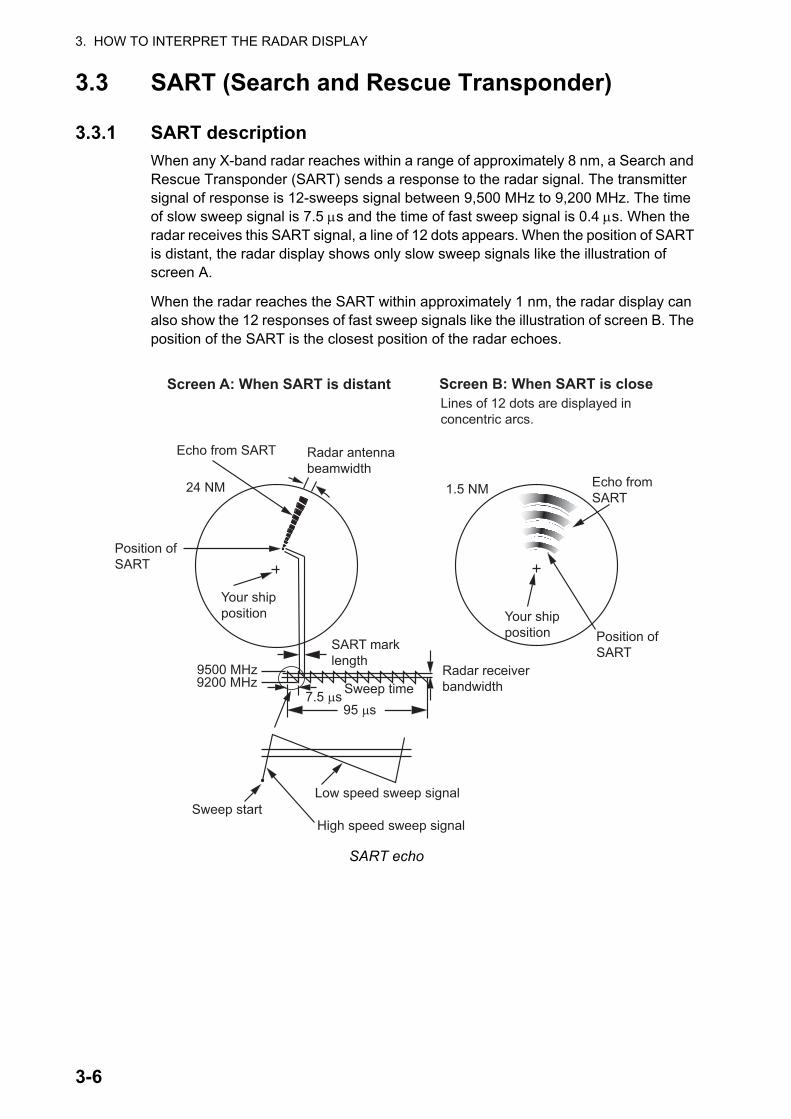
3. HOW TO INTERPRET THE RADAR DISPLAY
3.3 SART (Search and Rescue Transponder)
3.3.1 SART description
When any X-band radar reaches within a range of approximately 8 nm, a Search and Rescue Transponder (SART) sends a response to the radar signal. The transmitter signal of response is 12-sweeps signal between 9,500 MHz to 9,200 MHz. The time of slow sweep signal is 7.5 s and the time of fast sweep signal is 0.4 s. When the radar receives this SART signal, a line of 12 dots appears. When the position of SART is distant, the radar display shows only slow sweep signals like the illustration of screen A.
When the radar reaches the SART within approximately 1 nm, the radar display can also show the 12 responses of fast sweep signals like the illustration of screen B. The position of the SART is the closest position of the radar echoes.
SART echo
9500 MHz9200 MHz
Radar antennabeamwidth
Screen A: When SART is distant Screen B: When SART is close
Echo from SART
Position ofSART
Your shipposition Your ship
positionSART marklength
Radar receiverbandwidthSweep time7.5 µs
95 µs
Sweep startHigh speed sweep signal
Low speed sweep signal
24 NM 1.5 NM
Position ofSART
Echo fromSART
Lines of 12 dots are displayed inconcentric arcs.
3-6

3. HOW TO INTERPRET THE RADAR DISPLAY
3.3.2 General remarks on receiving SART
SART range errors
When the SART is at a range greater than approximately 1 nm, the first dot is dis-played at 0.64 nm beyond the true position of the SART. When the range closes so that the fast sweep responses are seen also, the first range echoes are displayed at 150 m beyond the true position.
Range scale
When you find the SART position, do as follows:
1. Use the RANGE key to set the range scale to 6 nm or 12 nm.
2. Turn off [Int Rejector].
SART display
To display only the SART echo clearly on the radar screen, reduce the tuning on man-ual mode. The normal radar echoes get weak, however, the SART echoes remain. Your ship comes close to the SART, the arc for the SART display becomes larger. Most of the radar screen becomes fuzzy. Adjust the sea clutter and gain to display the necessary screen.
3-7

3. HOW TO INTERPRET THE RADAR DISPLAY
3.4 RACONA RACON is a radar beacon which emits radar-receivable signals in the radar frequen-cy spectrum (X- or S-band). There are several signal formats; in general, the RACON signal appears on the radar screen as a rectangular echo originating at a point just beyond the position of the radar beacon. It has a Morse coded pattern. Note that the position on the radar display is not accurate.
Echoes on the radar screen
Echo description
Your ship position
RACON signal
RACON station
3-8

4. TT OPERATION
The TT (Tracked Target) feature manually or automatically acquires and tracks ten targets. Once a target is acquired, a target is automatically tracked within 0.1 to 16 nm.
4.1 Precautions
4.2 Controls for Use with TTENTER key: Acquire cursor-selected target. Display data for tracked target (in the data box at the bottom of the screen).
MENU/ESC key: (1) Remove data of cursor-selected tracked target from the data box. (2) Stop tracking the cursor-selected target (when its data is not displayed in the data box). (3) Access the [Target] and [TT] menus for TT operations.
Cursorpad: Select a target to acquire (or cancel the tracking). Select a target to show (or remove) target data.
Do not depend on one navigation devicefor the navigation of the ship. Thenavigator must check all aids availableto confirm position. Electronic aids arenot a replacement for basic navigationprinciples and common sense.
· The TT automatically tracks an automatically or manually acquired radar target and calculates its course and speed, indicating them by a vector. Since the data from the auto plotter depend on the selected radar targets, the radar must be optimally tuned for use with the auto plotter, to ensure required targets will not be lost or unnecessary targets like sea returns and noise will not be acquired and tracked.
· A target is not always a landmass, reef, ship, but can be returns from the sea surface and clutter. As the level of clutter changes with the environment, the operator must correctly adjust the rain clutter, sean clutter and gain controls so that the target echoes do not disappear from the radar screen.
The plotting accuracy and response ofthis TT meets IMO standards.The tracking accuracy is affected by thefollowing:
· The tracking accuracy is affected by course change. One to two minutes is required to restore vectors to full accuracy after a sudden course change. (The actual amount depends on gyrocompass specifications.)· The amount of tracking delay is inversely proportional to the relative speed of the target. Delay is on the order of 15-30 seconds for high relative speed; 30-60 seconds for low relative speed.
The display accuracy is affected by thefollowing:
· Echo intensity· Pulse width of radar transmission· Radar bearing error· Gyrocompass error· Course change (your ship or target)
CAUTIONCAUTION CAUTIONCAUTION
4-1

4. TT OPERATION
4.3 TT Display On/OffYou can turn the TT display on or off. The system continuously tracks TT regardless of this setting.
1. Press the MENU/ESC key to open the menu.
2. Select [TT], then press the ENTER key.
3. Select [Display], then press the ENTER key.
4. Select [Off] or [On], then press the ENTER key.
5. Press the MENU/ESC key to close the menu.
4.4 TT Symbol ColorYou can select the TT symbol color from Green, Red, Blue, White or Black.
1. Press the MENU/ESC key to open the menu.
2. Select [TT], then press the ENTER key.
3. Select [Color], then press the ENTER key.
4. Select the color, then press the ENTER key.
5. Press the MENU/ESC key to close the menu.
Note: Symbols can not be shown in the same color as the background color.
4.5 How to Acquire and Track the TargetsTen targets are acquired and tracked manually or automatically.
4.5.1 Manual acquisition
You can acquire up to ten TT. When the automatic acquisition ([Auto Acquisition] on the [TT] menu) is set to on, you can manually acquire up to five targets.
1. Use the Cursorpad to put the cursor on the target to acquire.
2. Press the ENTER key.
The TT symbol changes over time as below. A vector, which indicates the motion di-rection of the target, appears shortly after acquisition.
Target number
A maximum of ten targets can be acquired and tracked. When a target is lost and a new target is acquired and tracked, it is assigned the youngest empty target number.
At acquisition Tracking01 Target number01
4-2

4. TT OPERATION
4.5.2 Automatic acquisition
When you set an automatic acquisition area, the TT can acquire up to five targets au-tomatically.
The automatic acquisition area is 2.0 to 2.5 nm in range and ±45° on either side of the heading line in bearing. When you change the automatic acquisition to manual acqui-sition, targets being tracked in automatic acquisition are continuously tracked.
1. Press the MENU/ESC key to open the menu.
2. Select [TT], then press the ENTER key.
3. Select [Auto Acquisition], then press the ENTER key.
4. Select [On], then press the ENTER key.
5. Press the MENU/ESC key to close the menu.
4.6 How to Stop Tracking a TTWhen ten targets have been acquired, no more acquisition occurs unless targets are cancelled. If you acquire additional targets, you must cancel one or more individual targets, or all targets. Use one of the following procedures.
4.6.1 How to stop tracking a single target
1. Use the Cursorpad to put the cursor on the target to cancel the tracking.
2. Press the MENU/ESC key to cancel the tracking and erase the TT symbol. The unit beeps twice and the symbol is erased from the screen.
4.6.2 How to stop tracking all targets
1. Press the MENU/ESC key to open the menu.
2. Select [TT], then press the ENTER key.
3. Select [All Cancel], then press the ENTER key.
4. Use the Cursorpad () to select [Yes], then press the ENTER key. All symbols are erased from the screen and the long beep sounds.
5. Press the MENU/ESC key to close the menu.
Automatic acquisition area
45° port 45° starboard2.0 - 2.5 nm Heading line
4-3

4. TT OPERATION
4.7 Lost TargetWhen the system detects a lost TT, the audio alarm sounds and the alarm message "LOST" appears. The target symbol becomes a flashing square like the following illustration. When the system detects the target again, the target symbol becomes a normal symbol.
To erase a lost TT symbol, put the cursor on the symbol, then press the MENU/ESC key. If you leave a lost target symbol flashing, the symbol disappears after one minute.
You can remove all lost TT from the screen as follows:
1. Press the MENU/ESC key to open the menu.
2. Select [TT], then press the ENTER key.
3. Select [Erase Lost Targets], then press the ENTER key.
4. Use the Cursorpad () to select [Yes], then press the ENTER key. All lost targets symbols are erased from the screen and the long beep sounds.
5. Press the MENU/ESC key to close the menu.
4.8 Vector Attributes
4.8.1 What is a vector?
A vector is a line extending from a tracked target. A vector shows speed and course of the target. The top of a vector shows estimated position of the target after the se-lected vector time elapses. If you extend the vector length (time), you can evaluate the risk of collision with any target.
Vector
Current position of the target
Vector timePredicted position of the target in 15 minutes later
4-4
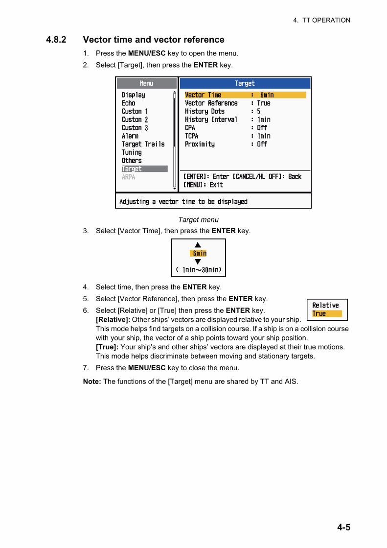
4. TT OPERATION
4.8.2 Vector time and vector reference
1. Press the MENU/ESC key to open the menu.
2. Select [Target], then press the ENTER key.
Target menu
3. Select [Vector Time], then press the ENTER key.
4. Select time, then press the ENTER key.
5. Select [Vector Reference], then press the ENTER key.
6. Select [Relative] or [True] then press the ENTER key. [Relative]: Other ships’ vectors are displayed relative to your ship. This mode helps find targets on a collision course. If a ship is on a collision course with your ship, the vector of a ship points toward your ship position.[True]: Your ship’s and other ships’ vectors are displayed at their true motions. This mode helps discriminate between moving and stationary targets.
7. Press the MENU/ESC key to close the menu.
Note: The functions of the [Target] menu are shared by TT and AIS.
4-5

4. TT OPERATION
4.8.3 Own ship vector
The vector of own ship is shown as an arrow from your ship position. The vector of own ship is shown on the following conditions:
• Select [True] on the menu item [Vector Reference] on the [Target] menu.
Note: The vector of own ship is shown in the same color as the TT symbol color.
4.9 Past Position Display (target past position)This radar can display time-spaced dots (maximum ten dots) that mark the past posi-tions of any TT. You can evaluate actions of a target by the spacing between dots. Be-low are examples of dot spacing and target movement.
You can select the number of past position dotes to display and the time interval to display the dots.
1. Press the MENU/ESC key to open the menu.
2. Select [Target], then press the ENTER key.
3. Select [Past Positions], then press the ENTER key.
+
Own shipvector
01
Data box
02
Cursor
0304
(a) Ship turning (b) Ship running straight
(c) Ship reduced speed
(d) Ship increased speed
4-6

4. TT OPERATION
4. Select number of past position dots to display (5 or 10) or select [Off] to turn off the history display.
5. Press the ENTER key.
6. Select [Past Posn Interval], then press the ENTER key.
7. Select the time interval, then press the ENTER key.
8. Press the MENU/ESC key to close the menu.
4.10 TT DataYou can show TT data at the bottom of the screen. Set the DATA BOX knob to the [Target] (TT data) or [All] (TT data + nav data) position.
1. Use the Cursorpad to put the cursor on an TT.
2. Press the ENTER key to show the data of the target.
TT data
The symbol for the selected TT is enlarged double to distinguish from other symbols.
To remove the data of a target from a data box, put the cursor on the corresponding target symbol, then press the MENU/ESC key.
TRUE 05:00 <TT> No. 01BRG 53.7°T RNG 2.987NM CRS 350.4° SOG 23.45KNCPA 1.65NM TCPA 06:14
Vector referenceVector time Target no.
Bearing, range, course, speed CPA, TCPA
+
TT selected fordata display
01
TT
Data box
02
Cursor
4-7

4. TT OPERATION
4.11 CPA/TCPA AlarmSet CPA (Closest Point of Approach) alarm range and TCPA (predicted Time to CPA) alarm time to alert you to targets that can be on a collision course. When CPA and TCPA of any TT become less than the preset CPA and TCPA alarm settings, the audio alarm sounds. The alarm message "COLLISION" appears. The target symbol chang-es to a dangerous target symbol (triangle) and flashes with its vector. You can stop the audio alarm with any key. The flashing of the triangle stops when the tracked TT is not in the CPA and TCPA alarm setting. The TT continuously monitors CPA and TCPA of all TT.
This feature helps identify targets that can be on a collision course. Correctly adjust the gain, sea clutter and rain clutter.
1. Press the MENU/ESC key to open the menu.
2. Select [Target], then press the ENTER key.
3. Select [CPA], then press the ENTER key.
CPA options
4. Select CPA distance, then press the ENTER key.
CAUTIONDo not depend on the CPA/TCPA alarm as
the only method to detect the risk of colli-
sion. The navigator is not released of the re-
sponsibility to keep visual caution for
collision situations, whether or not the ra-
dar or other plotting aid is in use.
Target beforealert generation
Target afteralert generation
(flashing)
4-8

4. TT OPERATION
5. Select [TCPA], then press the ENTER key.
TCPA options
6. Select TCPA, then press the ENTER key.
7. Press the MENU/ESC key to close the menu.
4.12 Proximity AlarmThe proximity alarm alerts you when a TT is within the range you set. (The setting is commonly shared between TT and AIS. See section 5.12.)The audio alarm sounds and the alarm message "PROXIMITY" appears. The target symbol changes to a dan-gerous target symbol and flashes with its vector. Press any key to stop the audio alarm. The flashing continues until the target is not within the range set, the alarm range is changed to exclude the target, or the proximity alarm is deactivated.
1. Press the MENU/ESC key to open the menu.
2. Select [Target], then press the ENTER key.
3. Select [Proximity], then press the ENTER key.
Proximity options
4. Select the range, then press the ENTER key.
5. Press the MENU/ESC key to close the menu.
Target beforealert generation
Target afteralert generation
(flashing)
4-9

4. TT OPERATION
This page is intentionally left blank.
4-10
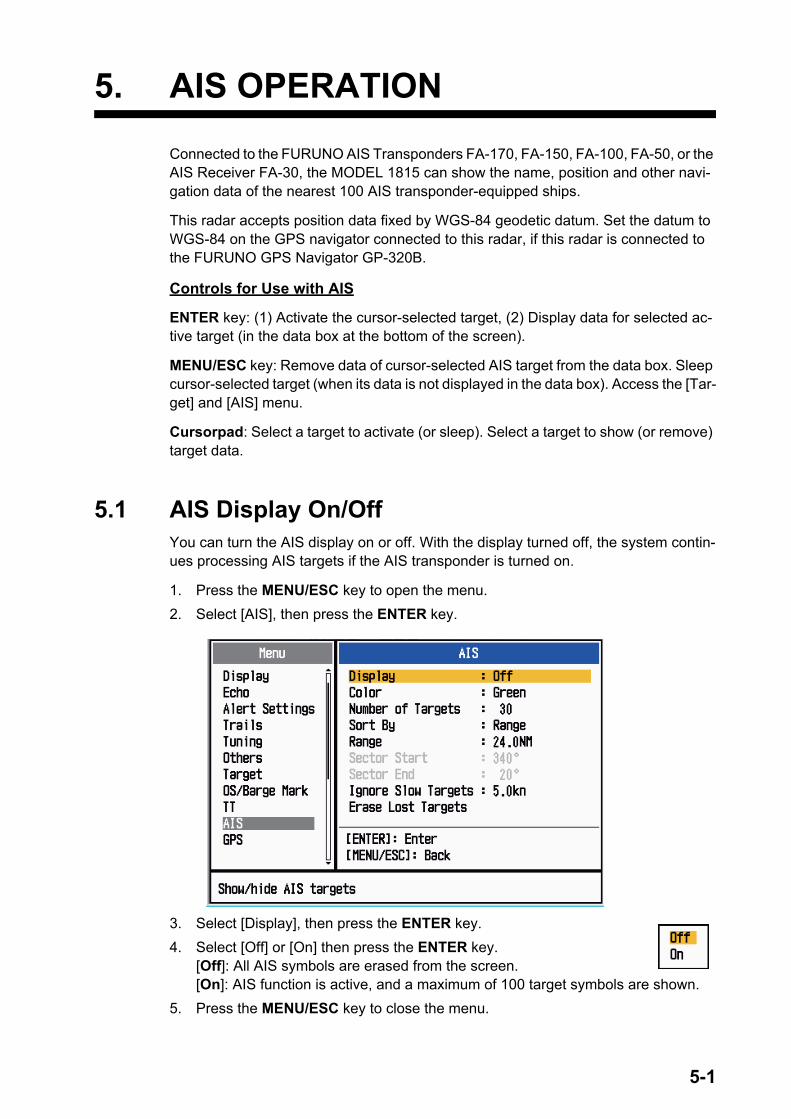
5. AIS OPERATION
Connected to the FURUNO AIS Transponders FA-170, FA-150, FA-100, FA-50, or the AIS Receiver FA-30, the MODEL 1815 can show the name, position and other navi-gation data of the nearest 100 AIS transponder-equipped ships.
This radar accepts position data fixed by WGS-84 geodetic datum. Set the datum to WGS-84 on the GPS navigator connected to this radar, if this radar is connected to the FURUNO GPS Navigator GP-320B.
Controls for Use with AIS
ENTER key: (1) Activate the cursor-selected target, (2) Display data for selected ac-tive target (in the data box at the bottom of the screen).
MENU/ESC key: Remove data of cursor-selected AIS target from the data box. Sleep cursor-selected target (when its data is not displayed in the data box). Access the [Tar-get] and [AIS] menu.
Cursorpad: Select a target to activate (or sleep). Select a target to show (or remove) target data.
5.1 AIS Display On/OffYou can turn the AIS display on or off. With the display turned off, the system contin-ues processing AIS targets if the AIS transponder is turned on.
1. Press the MENU/ESC key to open the menu.
2. Select [AIS], then press the ENTER key.
3. Select [Display], then press the ENTER key.
4. Select [Off] or [On] then press the ENTER key.[Off]: All AIS symbols are erased from the screen.[On]: AIS function is active, and a maximum of 100 target symbols are shown.
5. Press the MENU/ESC key to close the menu.
5-1

5. AIS OPERATION
5.2 AIS SymbolsWhen the AIS is turned on, AIS targets are displayed with AIS symbol as below.
Note: The AIS symbols are momentarily erased after the screen is redrawn when the heading is changed in the head up mode.
Target type Symbol DescriptionSleeping target Sleeping target
Activated target Activated target. Heading line and ROT are shown. Ground tracking speed and course are shown with vector.
Dangerous target A target whose distance, CPA and TCPA are less than corresponding alarm settings.
Lost target A target for which no data has been received within a certain period.The symbol flashes.
Selected target A target selected to show its target data.
Aid to navigation (AtoN)
AIS base station Always shown on the screen.
SART aircraft Always shown on the screen.
AIS-SART Always shown on the screen.
5-2
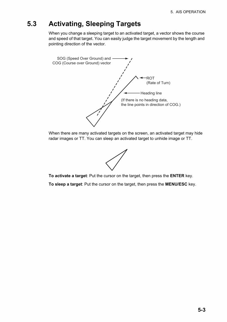
5. AIS OPERATION
5.3 Activating, Sleeping TargetsWhen you change a sleeping target to an activated target, a vector shows the course and speed of that target. You can easily judge the target movement by the length and pointing direction of the vector.
When there are many activated targets on the screen, an activated target may hide radar images or TT. You can sleep an activated target to unhide image or TT.
To activate a target: Put the cursor on the target, then press the ENTER key.
To sleep a target: Put the cursor on the target, then press the MENU/ESC key.
Heading line
SOG (Speed Over Ground) andCOG (Course over Ground) vector
(If there is no heading data,the line points in direction of COG.)
ROT(Rate of Turn)
5-3

5. AIS OPERATION
5.4 AIS Target DataYou can show AIS target data at the bottom of the screen. Set the DATA BOX knob to the [Target] (AIS data) or [All] (AIS data + nav data) position.
1. Use the Cursorpad to put the cursor on an activated target.
2. Press the ENTER key to show the data of the target.
AIS target data
To remove the target data from a data box, put the cursor on the corresponding target symbol, then press the MENU/ESC key.
5.5 How to Sort TargetsYou can sort the AIS targets received from the AIS transponder by range from your ship, by sector, by CPA or TCPA.
1. Press the MENU/ESC key to open the menu.
2. Select [AIS], then press the ENTER key.
3. Select [Sort By], then press the ENTER key.
4. Select sorting method, then press the ENTER key.[Range]: Sort targets within the display range set (see section 5.6), from nearest to furthest.[Sector]: Sort targets within the display sector set (see section 5.7) and within 24 nm, from nearest to furthest.[CPA]: Sort targets within 24 nm by CPA, from closest to furthest.[TCPA]: Sort targets within 24 nm by TCPA, from earliest time to latest time.
5. Press the MENU/ESC key to close the menu.
AIS targetselected fordata display
MMSI of vessel Name ofvessel
PEGASUSCursor
Data box
TRUE 05:00 <AIS> MMSI: 123456789 NAME: PEGASUSBRG 53.7°T RNG 2.987NM COG 350.4° SOG 23.45KNCPA 1.65NM TCPA 06:14 LEN 100M BEAM 45M
Vector referenceVector time
Bearing, range, course, speed CPA, TCPA, Length, Beam of vessel
+
Name of vessel(or MMSI)
5-4

5. AIS OPERATION
5.6 Display RangeYou can set the AIS system to show only those AIS targets within the range you set. The setting range is 0.1-36 nm for MODEL 1835, 0.1-48 nm for MODEL 1935, 0.1-64 nm for MODEL 1945. Actual range depends on the AIS Transponder. If the target sort-ing method is selected to [Range], the target data within the range set here is trans-mitted to this radar.
1. Press the MENU/ESC key to open the menu.
2. Select [AIS], then press the ENTER key.
3. Select [Range], then press the ENTER key.
4. Set the display range, then press the ENTER key.
5. Press the MENU/ESC key to close the menu.
Note: The unit of measurement for range is NM.
5.7 How to Display the Targets within a Specific Sec-torYou can display AIS targets only within a specific sector. If the target sorting method is selected to [Sector], the target data within the sector set here is transmitted to this radar.
1. Press the MENU/ESC key to open the menu.
2. Select [AIS], then press the ENTER key.
3. Select [Sector Start], then press the ENTER key.
4. Set the start point for the sector, then press the ENTER key.
5. Select [Sector End], then press the ENTER key.
6. Set the end point for the sector, then press the ENTER key.
7. Press the MENU/ESC key to close the menu.
5-5

5. AIS OPERATION
5.8 Number of Targets to DisplayYou can select the maximum number of AIS targets to display. The setting value is 10 to 100. When the screen becomes cluttered with AIS targets, you can limit the number of AIS targets to show. Targets are selected and displayed according to sort method. (see section 5.5).
1. Press the MENU/ESC key to open the menu.
2. Select [AIS], then press the ENTER key.
3. Select [Number of Targets], then press the ENTER key.
4. Select the number of targets to display, then press the ENTER key.
5. Press the MENU/ESC key to close the menu.
5.9 Vector Attributes
5.9.1 What is a vector?
A vector is a line extending from a tracked target. A vector shows speed and course of the target. The top of a vector shows estimated position of the target after the se-lected vector time elapses. If you extend the vector length (time), you can evaluate the risk of collision with any target.
5.9.2 Vector time and vector reference
1. Press the MENU/ESC key to open the menu.
2. Select [Target], then press the ENTER key.
3. Select [Vector Time], then press the ENTER key.
4. Select time, then press the ENTER key.
5. Select [Vector Reference], then press the ENTER key.
6. Select [Relative] or [True] then press the ENTER key.[Relative]: Other ships’ vectors are displayed relative to your ship. This mode helps find targets on a collision course. If a ship is on a collision course with your ship, the vector of a ship points toward your ship posi-tion.[True]: Your ship’s and other ships’ vectors are displayed at their true motions. This mode helps discriminate between moving and stationary targets.
7. Press the MENU/ESC key to close the menu.
5-6

5. AIS OPERATION
5.10 Past Position Display (target past position)This radar can display time-spaced dots (maximum ten dots) that marks the past po-sitions of any tracked AIS target. You can evaluate actions of a target by the spacing between dots. Below are examples of dot spacing and target movement.
You can select the number of history dots to display and the time interval to display the history dots.
1. Press the MENU/ESC key to open the menu.
2. Select [Target], then press the ENTER key.
3. Select [Past Positions], then press the ENTER key.
4. Select number of past position dots to display (5 or 10) or select [Off] to turn off the past position display.
5. Press the ENTER key.
6. Select [Past Posn Interval], then press the ENTER key.
7. Select time interval, then press the ENTER key.
8. Press the MENU/ESC key to close the menu.
(a) Ship turning (b) Ship running straight
(c) Ship reduced speed
(d) Ship increased speed
5-7

5. AIS OPERATION
5.11 CPA/TCPA AlarmSet CPA (Closest Point of Approach) alarm range and TCPA (predicted Time to CPA) alarm time to alert you to targets that can be on a collision course. When CPA and TCPA of any AIS target (including a sleeping target) become less than the preset CPA and TCPA alarm settings, the audio alarm sounds. The alarm message "COLLISION" appears. The target symbol changes to a dangerous target symbol (red) and flashes with its vector. You can stop the audio alarm and flashing with any key. The dangerous target symbol is displayed until the AIS target is not in the CPA and TCPA alarm set-ting. The AIS continuously monitors CPA and TCPA of all AIS targets.
This feature helps identify targets that can be on a collision course.
1. Press the MENU/ESC key to open the menu.
2. Select [Target], then press the ENTER key.
3. Select [CPA], then press the ENTER key.
4. Select CPA distance, then press the ENTER key.
5. Select [TCPA], then press the ENTER key.
6. Select TCPA time, then press the ENTER key.
7. Press the MENU/ESC key to close the menu.
Thicker than normal activated target(red and flashing)
5-8

5. AIS OPERATION
5.12 Proximity AlarmThe proximity alarm alerts you when an AIS target is within the range you set. The au-dio alarm sounds and the alarm message "PROXIMITY" appears. The target symbol changes to a dangerous target symbol (red) and flashes with its vector. Press any key to stop the audio alarm and flashing. The dangerous target symbol is displayed until the target is not within the range set, the alarm range is changed to exclude the target, or the proximity alarm is deactivated.
1. Press the MENU/ESC key to open the menu.
2. Select [Target], then press the ENTER key.
3. Select [Proximity], then press the ENTER key.
4. Select the range, then press the ENTER key.
5. Press the MENU/ESC key to close the menu.
5.13 Lost TargetWhen AIS data is not received from a target at fixed interval (3-5* report intervals), the target symbol changes to the lost target symbol (flashing). No audio or visual alarm is given for a lost target.
* The interval at which AIS data is sent depends on speed of the AIS transponder. For detailed information, refer to the Operator's Manual for the AIS transponder.
You can remove all lost AIS targets from the display as follows:
1. Press the MENU/ESC key to open the menu.
2. Select [AIS], then press the ENTER key.
3. Select [Erase Lost Targets], then press the ENTER key.
4. Use the Cursorpad () to select [Yes], then press the ENTER key. All lost targets symbols are erased from the screen and the long beep sounds.
5. Press the MENU/ESC key to close the menu.
5-9

5. AIS OPERATION
5.14 Symbol ColorYou can select the AIS symbol color among Green, Red (unavailable in the [IEC] or [Russian-River] purpose), Blue, White or Black.
1. Press the MENU/ESC key to open the menu.
2. Select [AIS], then press the ENTER key.
3. Select [Color], then press the ENTER key.
4. Select the color, then press the ENTER key.
5. Press the MENU/ESC key to close the menu.
Note: Symbols can not be shown in the same color as the background color.
5.15 How to Ignore Slow TargetsYou can prevent activation of the CPA/TCPA alarm against AIS targets that are trav-eling at a speed lower than set here. The AIS symbols are not affected by this setting.
1. Press the MENU/ESC key to open the menu.
2. Select [AIS], then press the ENTER key.
3. Select [Ignore Slow Targets], then press the ENTER key.
4. Set speed (0.0 - 9.9 kn), then press the ENTER key.
5. Press the MENU/ESC key to close the menu.
5-10

6. GPS OPERATION
If the FURUNO GPS Navigator GP-320B is connected to this radar, you can set GP-320B from this radar.
6.1 Navigator Mode1. Press the MENU/ESC key to open the menu.
2. Select [GPS], then press the ENTER key.
3. Select [Mode], then press the ENTER key.
4. Select [GPS] or [WAAS] then press the ENTER key.
5. Press the MENU/ESC key to close the menu.
6.2 DatumSelect the type of datum which matches the paper charts you use for navigation. Se-lect [WGS-84] if the radar is connected to an AIS Transponder.
1. Press the MENU/ESC key to open the menu.
2. Select [GPS], then press the ENTER key.
3. Select [Datum], then press the ENTER key.
4. Select the type of datum, then press the ENTER key. If you selected [WGS-84] or [Tokyo], go to step 7.For [Other], go to the next step.
5. Select [Datum Number], then press the ENTER key.
6. Select the datum number, then press the ENTER key. (See Appendix 2.)
7. Press the MENU/ESC key to close the menu.
6-1

6. GPS OPERATION
6.3 WAAS SetupGeostationary satellites, the type used with WAAS, provide more accurate position data when compared to GPS. These satellites can be tracked automatically or manu-ally. Auto tracking automatically searches for the best geostationary satellite from your current position.
1. Press the MENU/ESC key to open the menu.
2. Select [GPS], then press the ENTER key.
3. Select [WAAS], then press the ENTER key.
4. Select [Auto] or [Manual] then press the ENTER key. If you selected [Auto], go to step 7. For [Manual], go to the next step.
5. Select [WAAS No], then press the ENTER key.
6. Select WAAS number, then press the ENTER key. (The setting range is 120 - 158. Refer to the following table.)
7. Press the MENU/ESC key to close the menu.
Provider Satellite type Longitude Satellite No.WAAS Inmarsat-3-F4 (AOR-W) 142°W 122
Inmarsat-3-F3 (POR) 178°E 134Intelsat Galaxy XV 133°W 135TeleSat Anik F1R 107.3°W 138
EGNOS Inmarsat-3-F2 (AOR-E) 15.5°W 120Artemis 21.5°E 124Inmarsat-3-F5 (IOR-W) 25°E 126
MSAS MTSAT-1R 140°E 129MTSAT-2 145°E 137
6-2

6. GPS OPERATION
6.4 Satellite MonitorThe Satellite Monitor provides the information about GPS and WAAS satellites. See your GPS navigator's owner's manual for detailed information.
1. Press the MENU/ESC key to open the menu.
2. Select [GPS], then press the ENTER key.
3. Select [Satellite Monitor], then press the ENTER key.
4. Press the ENTER key to close only the satellite monitor display.
06
3DDOP
1.5
15m
13
Altitude
01GPS
WAAS
12
24
16
SNRSatellite No.30 40 50
122
01
31
18
19
06
07
09
08
13
North mark
DOP (Dilution of Precision, 0.0 - 99.0)
SNR of tracked GPS satellitesSatellites whose SNR is above40 are used to fix position.
GPS mode2D, 3D,W2D, W3D
GPS satellite no.*
WAAS satellite
Satellites in ring have elevationangle of 5°
Satellites in ring have elevationangle of 45°
Altitude ofGPS antennafrom seasurface
SNR of trackedWAAS satellite
W
N
[MENU/ESC] / [ENTER]: Close this window
* Satellites used to fix position are shown in red.
Satel l i te Monitor
01
09
2412
19
18
07
13
16
08
31
6-3
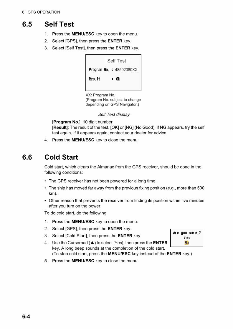
6. GPS OPERATION
6.5 Self Test1. Press the MENU/ESC key to open the menu.
2. Select [GPS], then press the ENTER key.
3. Select [Self Test], then press the ENTER key.
Self Test display
[Program No.]: 10 digit number[Result]: The result of the test, [OK] or [NG] (No Good). If NG appears, try the self test again. If it appears again, contact your dealer for advice.
4. Press the MENU/ESC key to close the menu.
6.6 Cold StartCold start, which clears the Almanac from the GPS receiver, should be done in the following conditions:
• The GPS receiver has not been powered for a long time.
• The ship has moved far away from the previous fixing position (e.g., more than 500 km).
• Other reason that prevents the receiver from finding its position within five minutes after you turn on the power.
To do cold start, do the following:
1. Press the MENU/ESC key to open the menu.
2. Select [GPS], then press the ENTER key.
3. Select [Cold Start], then press the ENTER key.
4. Use the Cursorpad () to select [Yes], then press the ENTER key. A long beep sounds at the completion of the cold start. (To stop cold start, press the MENU/ESC key instead of the ENTER key.)
5. Press the MENU/ESC key to close the menu.
XX: Program No.(Program No. subject to changedepending on GPS Navigator.)
48502380XX
Self Test
6-4

7. MAINTENANCE, TROUBLE-SHOOTING
This chapter has information about maintenance and troubleshooting that the user can follow to care for the equipment.
WARNINGELECTRICAL SHOCK HAZARDDo not open the equipment.
Only qualified personnel can work inside the equipment.
Turn off the power before you service the antenna unit. Post a warning sign near the power switch indicating that the powershould be left off while you are servicing the antenna unit.
Prevent the potential risk of being struck by the rotating antenna and exposure to RF radiation hazard.
When you work on the antenna unit, wear a safety belt and hard hat.
Serious injury or death can result if a person falls from the radar antenna mast.
NOTICEDo not apply paint, anti-corrosive sealant or contact spray to plastic parts or equipment coating.
Those items contain products that can damage plastic parts and equipment coating.
7-1

7. MAINTENANCE, TROUBLESHOOTING
7.1 Preventive MaintenanceRegular maintenance helps keep your equipment in good condition and prevents fu-ture problems. Check the items shown in the table below to help keep your equipment in good condition for years to come.
Maintenance
7.2 Fuse ReplacementThe fuse on the power cable protects the equipment from overcurrent and equipment fault. If the fuse blows, find the cause before you replace the fuse. Use the correct fuse. A wrong fuse can damage the equipment. If the fuse blows again, contact your dealer for advice.
Interval Item Check point Remedy
When nec-essary
LCD Dust on the LCD Remove the dust from the LCD with the tissue paper and an LCD cleaner. To remove dirt or salt, use the LCD cleaner. Change the tis-sue paper often so as not to scratch the LCD.
3 to 6 months
Ground terminal on display unit
Check for tight connec-tion and rust.
Tighten or replace as necessary.
Display unit con-nectors
Check for tight connec-tion.
Tighten if the connectors are loos-ened.
Exposed nuts and bolts on the anten-na unit
Check for corroded or loosened bolts.
Clean and repaint as necessary. Use sealing compound instead of paint.
Antenna radiator Check for dirt and cracks on the radiator surface.
Clean radiator surface with fresh-water-moistened cloth. Do not use plastic solvents to clean.
WARNINGUse the correct fuse.
A wrong fuse can damage the equipment and cause fire.
Type Code No. RemarksFRU-2P5S-FU-5A-B 000-168-869-10 12-24 VDC
7-2

7. MAINTENANCE, TROUBLESHOOTING
7.3 Magnetron LifeWhen the life of the magnetron is reached, no targets appear on the display. If long-range performance appears to have decreased, contact a FURUNO agent or dealer about replacement of the magnetron.
7.4 Simple TroubleshootingThis section provides simple troubleshooting procedures which the user can follow to restore normal operation. If you cannot restore normal operation, do not check inside the unit. Have a qualified technician check the equipment.
Simple troubleshooting
Part Magnetron type Code No. Estimated life
Magnetron E3571 000-146-867-11 Approx. 2,000 hours
Problem Remedy
You cannot turn on the power. • Check for blown fuse.• Check that the power connector is fastened.• Check for corrosion on the power cable con-
nector.• Check for damaged power cable.• Check battery for correct voltage output.
There is no response when a key is pressed.
Turn off and on the power. If you do not get a response, the key is damaged. Contact your dealer for instructions.
The power is on and you operated the power key to transmit. The marks and characters appear, but no echoes ap-pear.
Check that the antenna cable is fastened.
Tuning is correctly adjusted, but sen-sitivity is poor.
The magnetron may be faulty. Contact your dealer about replacement of the magnetron.
You can change the range, but the ra-dar picture does not change.
Reset the power.
Poor discrimination in range because of many echoes from waves.
Adjust the sea clutter.
The true motion presentation is not working correctly.
• Check that the setting of [Display Mode] in the [Display] menu is set to [True Motion].
• Check if the heading and position data are in-put and correct.
The range rings are not displayed. Check that the setting of [Rings Brill] in the [Brill/Color] menu is set to other than [Off].
Target is not tracked correctly be-cause of sea clutter.
Adjust the sea clutter and rain clutter.
7-3

7. MAINTENANCE, TROUBLESHOOTING
7.5 Advanced-level TroubleshootingThis section provides hardware and software troubleshooting procedures for the qual-ified serviceman.
Advanced-level troubleshooting
ProblemProbable cause or check
pointsRemedy
Power cannot be turned on.
1) Mains voltage/polarity
2) Power supply board
1) Correct the wiring and input voltage.
2) Replace power supply board.
Brilliance adjusted but no picture.
1) MAIN Board 1) Replace the MAIN board.
Antenna not rotat-ing.
1) Antenna drive mechanism 1) Replace the antenna drive mechanism.
Gain is maximum and sea clutter is minimum. Marks and indications ap-pear but no noise or echo.
1) Signal cable between an-tenna and display unit
2) IF-SPU Board
1) Check continuity and isola-tion of coaxial cable.
2) Replace IF-SPU Board.Check coax line MIC and IF-SPU board for tight connec-tion. If connection is good, replace IF-SPU board.
Marks, indications and noise appear but echoes do not. (Own ship is not shown.)
1) Magnetron2) MD-PWR Board3) IF-SPU Board
1) Select max. range, then check magnetron current. If current is below rated value, replace magnetron.
2) Replace MD-PWR Board.3) Replace IF-SPU board.
The picture has “frozen”.
1) Heading sensor inside an-tenna unit
2) MAIN board
1) Check connection between IF-SPU board and heading sensor.
2) Replace MAIN board.3) Turn radar off and on.
Radar is correctly tuned but sensitivi-ty is poor.
1) Dirt on radiator face2) Deteriorated magnetron3) Detuned MIC
1) Clean the radiator.2) Check the magnetron cur-
rent with radar on max. range. If the current is below normal, magnetron may be defective. Replace the mag-netron.
3) Restore default tuning. Re-place MIC.
Range picture does not change when range is changed.
1) MAIN Board2) SPU board
1) Replace MAIN Board.2) Turn radar off and on.
Range rings are not displayed.
1) Adjust their brilliance on the [Brill/Color] menu.
2) MAIN Board
1) Replace associated circuit board if unsuccessful.
2) Replace MAIN Board.
7-4

7. MAINTENANCE, TROUBLESHOOTING
7.6 Self TestThe self test checks the system for correct operation. This test is for use by service technicians, but the user can do this test to provide the service technician with infor-mation.
1. Press the MENU/ESC key to open the menu.
2. Select [Tests], then press the ENTER key.
3. Select [Self Test], then press the ENTER key.
Test results
• [ROM], [RAM]: The results of the ROM and RAM test are displayed as [OK] or [NG] (No Good).
• [LAN]: The results of the LAN test are displayed as [OK] or [--]. This test re-quires a special checker. [--] indicates the checker is not connected.
• [NMEA1], [NMEA2]: The results of the ports NMEA1 and NMEA2 are displayed as OK or [--]. Ports NMEA1 and NMEA2 require a special connector to test
XX.XX: Program version no.
Key, buzzer, knob controland Cursorpad check
XX. XXXX. XX
[INPUT NMEA]window
Program no.FPGA version
MAC addressIP address
Power supply voltageTemperature
--
23.9 V36°C
[MENU]/ESC] x 3: Exit [FUNC]: Alarm Test
7-5

7. MAINTENANCE, TROUBLESHOOTING
them. [--] appears when the connector is not connected. If [--] appears when the connector is connected, contact your dealer for advice.
• [APPLICATION VERSION], [FPGA VERSION]: The program numbers and pro-gram version numbers (XX.XX) are displayed.
• [TEMPERATURE]: Temperature of the equipment is shown.
• [INPUT NMEA] window: The condition of all the NMEA sentences being input to this radar are displayed as OK or "- -". "- -" means no data input. Sentences are updated every second.
Key check
Press each key one by one. A key’s on-screen location becomes green if the key is normal.
Cursorpad check
Press each arrow on the Cursorpad one by one. The on-screen location is colored green if the pressed arrow is normal.
Buzzer check
Press the FUNC key to test the panel buzzer or external buzzer. To stop the buzz-er, press the FUNC key again.
Knob control check
Rotate each control knob. The digit (0 to 100) to the right of the control icon incre-ments or decrements with control operation. Push each knob. The knob corre-sponding on-screen circle changes in green if the knob is normal.
Data display check
Rotate the DATA BOX knob. The display shows [OFF], [NAV], [TGT] or [ALL] which each increment.
4. Press the MENU/ESC key three times to close the test results.
5. Press the MENU/ESC key to close the menu.
7-6

7. MAINTENANCE, TROUBLESHOOTING
7.7 LCD Test1. Press the MENU/ESC key to open the menu.
2. Select [Tests], then press the ENTER key.
3. Select [LCD Test], then press the ENTER key.
4. Press the MENU/ESC key several times to close the menu.
Note: You can adjust the screen brilliance with the key during the test.
Black
MENU/ESCkey
MENU/ESCkey
MENU/ESCkey
MENU/ESCkey
MENU/ESCkey
MENU/ESCkey
White Red
Green Blue Checkered pattern 7 tones of gray
7-7

7. MAINTENANCE, TROUBLESHOOTING
7.8 Radar Sensor TestThis test checks the antenna unit (RSB-127-120) for proper operation.
1. Press the MENU/ESC key to open the menu.
2. Select [Tests], then press the ENTER key.
3. Select [Radar Sensor Test], then press the ENTER key.
4. Press the MENU/ESC key three times to close the test screen.
OKOK349.7 V5.0 V12.4 VOKOKOKOK23.8 rpm5.0 V73.7 H1.3 H0.3 V
0359366-0359367-
172. 31. 3. 2700-d0-1d-0f-ac-79
0359368-
00
XX. XX
XX: Program no.
XX. XXXX. XX
[MENU/ESC]: Exit
7-8

APPENDIX 1 MENU TREE
MENU/ESC key
Brill/Color
Display
Echo
AlertSettings
Echo Brill (1~8, 8)Rings Brill (Off, 1, 2, 3, 4)Mark Brill (1, 2, 3, 4)HL Brill (1, 2, 3, 4)Character Brill (1, 2, 3, 4)Viewing Position (Left, Left-Center, Center, Right-Center, Right)Display Color (Day, Night, Twilight, Custom)Echo Color (Yellow, Green, Orange, Multi)Background Color (Black, DK Blue, Blue, White)Character Color (Green, Red, White)Menu Transparency (Off, 1, 2, 3, 4)Echo Color Mode (System, Custom)Custom Echo Color
Display Mode (Head Up, Course Up, North Up, True Motion, True View)Zoom (Off, On)Zoom Reference (Relative, True, Target)Off-center mode (Manual, Custom, Auto) Save Off-centerEcho Area (Normal, Full Screen)Text Display (Range, Mode, Alarm, Echo, EBL/VRM, +Cursor; All On in default.)STBY Display (Normal, Nav)
Auto SEA (Coastal, Advanced)Echo Stretch (Off, 1, 2, 3)Echo Average (Off 1, 2, Auto)Noise Rejector (Off, On)Wiper (Off, 1, 2)Int Rejector (Off, 1, 2, 3)Display-Curve (1, 2, 3)Low Level Echo (0~11, 0)
Target Alarm 1 (In, Out)Target Alarm 2 (In, Out)Target Alarm Level (Low, Med, High)Watchman (Off, 5min, 10min, 20min)Panel Buzzer (Off, On)External Buzzer (Off, On)Alert Status (Display names of active alerts.)
(Continued on next page)
Default settings in boldface italic.
AP-1
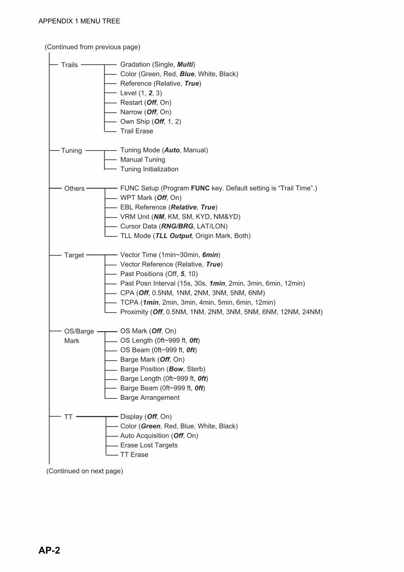
APPENDIX 1 MENU TREE
(Continued from previous page)
Trails
Tuning
Gradation (Single, Multi)Color (Green, Red, Blue, White, Black)Reference (Relative, True)Level (1, 2, 3)Restart (Off, On)Narrow (Off, On)Own Ship (Off, 1, 2)Trail Erase
Tuning Mode (Auto, Manual)Manual TuningTuning Initialization
FUNC Setup (Program FUNC key. Default setting is “Trail Time”.)WPT Mark (Off, On)EBL Reference (Relative, True)VRM Unit (NM, KM, SM, KYD, NM&YD)Cursor Data (RNG/BRG, LAT/LON)TLL Mode (TLL Output, Origin Mark, Both)
Vector Time (1min~30min, 6min) Vector Reference (Relative, True)Past Positions (Off, 5, 10)Past Posn Interval (15s, 30s, 1min, 2min, 3min, 6min, 12min)CPA (Off, 0.5NM, 1NM, 2NM, 3NM, 5NM, 6NM)TCPA (1min, 2min, 3min, 4min, 5min, 6min, 12min)Proximity (Off, 0.5NM, 1NM, 2NM, 3NM, 5NM, 6NM, 12NM, 24NM)
OS Mark (Off, On)OS Length (0ft~999 ft, 0ft)OS Beam (0ft~999 ft, 0ft)Barge Mark (Off, On)Barge Position (Bow, Sterb)Barge Length (0ft~999 ft, 0ft)Barge Beam (0ft~999 ft, 0ft)Barge Arrangement
Display (Off, On)Color (Green, Red, Blue, White, Black)Auto Acquisition (Off, On)Erase Lost TargetsTT Erase
Others
Target
OS/BargeMark
TT
(Continued on next page)
AP-2

APPENDIX 1 MENU TREE
(Continued from previous page)
AIS
GPS
Display (Off, On)Color (Green, Red, Blue, White, Black)Number of Targets (10~100, 50)Sort By (Range, Sector, CPA, TCPA)Range (0.1NM~36.0NM, 24.0NM)Sector Start (0°~359°, 340°)Sector End (0°~359°, 20°)Ignore Slow Targets (0.0~9.9kn, 5.0kn)Erase Lost Targets
Navigational Aid (GPS, WAAS)Datum (WGS-84, Tokyo, Other)Datum Number (001~192, 201~254, 001)WAAS (Auto, Manual)WAAS Number (120 - 158, 158)Satellite MonitorSelf TestCold Start
(Continued on next page)
System Initial
Tests
SectorBlanks
Units
Key Beep (Off, On)Off-center Speed (1kn~99kn, 15kn)Compass Type (Magnetic, True)Range PresetWind Direction (Apparent, True)NMEA Port 1 (Auto, 4800bps, 38400bps)NMEA Port 2 (Auto, 4800bps, 38400bps)NMEA Mixing Out (Off, On)
Self TestLCD TestARPA Test
Sect-Blank 1 Status (Off, On)Sect-Blank 1 Start (0°~359°, 0°)Sect-Blank 1 End (0°~359°, 0°)Sect-Blank 2 Status (Off, On)Sect-Blank 2 Start (0°~359°, 0°)Sect-Blank 2 End (0°~359°, 0°)
Range Unit (NM, KM, SM)Ship Speed Unit (kn, km/h, mph)Depth Unit (m, ft, fa, pb, HR)Temperature Unit (°C, °F)Wind Speed Unit (kn, km/h, mph, m/s)
AP-3

APPENDIX 1 MENU TREE
(Continued from previous page)
TT
Installation
Factory
(For use by the installer. Do not change the settings.)
Simulation (Off, On)Antenna Rotation (Rotate, Stop)Heading Alignment (0.0°~359°, 0.0°)Sweep Timing (0, -50~50MBS Adjustment (0~25, 0)Auto Install Setup (Set up system automatically.)Total On Time (000000.0~999999.9, 000000.0)Total Tx Time (000000.0~999999.9, 000000.0)Memory Reset (Restore default settings.)
Language (English, Other languages)Usage (River, Sea)
AP-4

APPENDIX 2 GEODETIC CHART LIST
001: WGS84 002: WGS72 003: TOKYO : 004: NORTH AMERICAN 1927 : Mean Value (CONUS) 005: EUROPEAN 1950 : Mean Value 006: AUSTRALIAN GEODETIC 1984 : Australia & Tasmania 007: ADINDAN-MN : Mean Value (Ethiopia & Sudan) 008: ADINDAN-E : Ethiopia 009: ADINDAN-MA : Mali 010: ADINDAN-SE : Senegal 011: ADINDAN-SU : Sudan 012: AFG : Somalia 013: AIN EL ABD 1970 : Bahrain Is. 014: ANNA 1 ASTRO 1965 : Cocos Is. 015: ARC 1950-MN : Mean Value 016: ARC 1950-B : Botswana 017: ARC 1950-L : Lesotho 018: ARC 1950-M : Malawi 019: ARC 1950-S : Swaziland 020: ARC 1950-ZR : Zaire 021: ARC 1950-ZM : Zambia 022: ARC 1950-ZB : Zimbabwe 023: ARC 1960-MN : Mean Value (Kenya & Tanzania) 024: ARC 1960-K : Kenya 025: ARC 1960-T : Tanzania 026: ASCENSION IS. 1958 : Ascension Is. 027: ASTRO BEACON “E” : Iwo Jima Is. 028: ASTRO B4 SOR. ATOLL : Tern Is. 029: ASTRO POS 71/4 : St. Helena Is. 030: ASTRONOMIC STATION 1952 : Marcus Is. 031: AUSTRALIAN GEODETIC 1966 : Australia & Tasmania 032: BELLEVUE (IGN) : Efate & Erromango Is.033: BERMUDA 1957 : Bermuda Is.034: BOGOTA OBSERVATORY : Columbia 035: CAMPO INCHAUSPE : Argentina 036: CANTON IS. 1966 : Phoenix Is.037: CAPE : South Africa 038: CAPE CANAVERAL : 039: CARTHAGE : Tunisia 040: CHATHAM 1971 : Chatham Is. (New Zealand) 041: CHUA ASTRO : Paraguay 042: CORREGO ALEGRE : Brazil 043: DJAKARTA (BATAVIA) : Sumatra Is. (Indonesia) 044: DOS 1968 : Gizo Is. (New Georgia Is.) 045: EASTER IS. 1967 : Easter Is. 046: EUROPEAN 1950-WE : Western Europe 047: EUROPEAN 1950-CY : Cyprus 048: EUROPEAN 1950-EG : Egypt 049: EUROPEAN 1950-ESC : 050: EUROPEAN 1950-EIS : 051: EUROPEAN 1950-GR : Greece 052 EUROPEAN 1950-IR : Iran 053: EUROPEAN 1950-SA : Italy, Sardinia 054: EUROPEAN 1950-SI : Italy, Sicily 055: EUROPEAN 1950-NF : Norway & Finland 056: EUROPEAN 1950-PS : Portugal & Spain 057: EUROPEAN 1979 : Mean Value 058: GANDAJIKA BASE : Republic of Maldives 059: GEODETIC DATUM 1949 : New Zealand 060: GUAM 1963 : Guam Is. 061: GUX 1 ASTRO : Guadalcanal Is. 062: HJORSEY 1955 : Iceland 063: HONG KONG 1963 : Hong Kong 064: INDIAN-TV : Thailand & Vietnam 065: INDIAN-BIN : Bangladesh, India & Nepal 066: IRELAND 1965 : Ireland 067: ISTS 073 ASTRO 1969 : Diego Garcia 068: JOHNSTON IS. 1961 : Johnston Is. 069: KANDAWALA : Sri Lanka 070: KERGUELEN IS. : Kerguelen Is. 071: KERTAU 1948 : West Malaysia & Singapore 072: LA REUNION : Mascarene Is. 073: L. C. 5 ASTRO : Cayman Brac Is. 074: LIBERIA 1964 : Liberia 075: LUZON : Philippines (excl. Mindanao Is.) 076: LUZON-M : Mindanao Is. 077: MAHE 1971 : Mahe Is. 078: MARCO ASTRO : Salvage Islands 079: MASSAWA : Eritrea (Ethiopia) 080: MERCHICH : Morocco 081: MIDWAY ASTRO 1961 : Midway Is. 082: MINNA : Nigeria 083: NAHRWAN-O : Masirah Is. (Oman) 084: NAHRWAN-UAE : United Arab Emirates 085: NAHRWAN-SA : Saudi Arabia 086: NAMIBIA : Namibia 087: MAPARIMA, BWI : Trinidad & Tobago 088: NORTH AMERICAN 1927WU : Western United States 089: NORTH AMERICAN 1927EU : Eastern United States 090: NORTH AMERICAN 1927AK : Alaska
091: NORTH AMERICAN 1927BH : Bahamas (excl. San Salvador Is.)
Mean Value (Japan, Korea & Okinawa)
Mean Value (Florida & Bahama Is.)
England, Scotland, Channel & Shetland Is.England, Ireland, Scotland & Shetland Is.
092: NORTH AMERICAN 1927SS : Bahamas, San Salvador Is. 093: NORTH AMERICAN 1927CN : Canada (incl. Newfoundland Is.) 094: NORTH AMERICAN 1927AB : Alberta & British Columbia 095: NORTH AMERICAN 1927EC : East Canada 096: NORTH AMERICAN 1927MO : Manitoba & Ontario 097: NORTH AMERICAN 1927NE : 098: NORTH AMERICAN 1927YK : Yukon 099: NORTH AMERICAN 1927CZ : Canal Zone 100: NORTH AMERICAN 1927CR : Caribbean 101: NORTH AMERICAN 1927CA : Central America 102: NORTH AMERICAN 1927CU : Cuba 103: NORTH AMERICAN 1927GR : Greenland 104: NORTH AMERICAN 1927MX : Mexico 105: NORTH AMERICAN 1983AK : Alaska 106: NORTH AMERICAN 1983CN : Canada 107: NORTH AMERICAN 1983CS : CONUS 108: NORTH AMERICAN 1983MX : Mexico, Central America 109: OBSERVATORIO 1966 : Corvo & Flores Is. (Azores)110: OLD EGYPTIAN 1930 : Egypt 111: OLD HAWAIIAN-MN : Mean Value 112: OLD HAWAIIAN-HW : Hawaii 113: OLD HAWAIIAN-KA : Kauai 114: OLD HAWAIIAN-MA : Maui 115: OLD HAWAIIAN-OA : Oahu 116: OMAN : Oman 117: ORDNANCE SURVEY OF GREAT BRITAIN 1936-NM : Mean Value118: ORDNANCE SURVEY OF GREAT BRITAIN 1936-E : England119: ORDNANCE SURVEY OF GREAT BRITAIN 1936-IM : England, Isle
of Man & Wales 120: ORDNANCE SURVEY OF GREAT BRITAIN 1936-SSI : Scotland &
Shetland Is. 121: ORDNANCE SURVEY OF GREAT BRITAIN 1936-WL : Wales122: PICO DE LAS NIVIES : Canary Is.123: PITCAIRN ASTRO 1967 : Pitcairn Is. 124: PROVISIONS SOUTH CHILEAN 1963: South Chile (near 53°S) 125: PROVISIONAL SOUTH AMERICAN 1956MN: Mean Value 126: PROVISIONAL SOUTH AMERICAN 1956BO: Bolivia 127: PROVISIONAL SOUTH AMERICAN 1956NC: Chile-Northern Chile
(near 19°S) 128: PROVISIONAL SOUTH AMERICAN 1956SC: Chile-Southern Chile
(near 43°S)
129: PROVISIONAL SOUTH AMERICAN 1956CO: Columbia130: PROVISIONAL SOUTH AMERICAN 1956EC: Ecuador 131: PROVISIONAL SOUTH AMERICAN 1956GY: Guyana 132: PROVISIONAL SOUTH AMERICAN 1956PR: Peru 133: PROVISIONAL SOUTH AMERICAN 1956VN: Venezuela
134: PUERTO RICO : Puerto Rico & Virgin Is.135: QATAR NATIONAL : Qatar 136: QORNOQ : South Greenland 137: ROME 1940 : Sardinia Is.138: SANTA BRAZ : 139: SANTO (DOS) : Espirito Santo Is. 140: SAPPER HILL 1943 : East Falkland Is. 141: SOUTH AMERICAN 1969MN : Mean Value 142: SOUTH AMERICAN 1969AG : Argentina 143: SOUTH AMERICAN 1969BO : Bolivia 144: SOUTH AMERICAN 1969BR : Brazil 145: SOUTH AMERICAN 1969CH : Chile 146: SOUTH AMERICAN 1969CO : Columbia 147: SOUTH AMERICAN 1969EC : Ecuador 148: SOUTH AMERICAN 1969GY : Guyana 149: SOUTH AMERICAN 1969PA : Paraguay 150: SOUTH AMERICAN 1969PR : Peru 151: SOUTH AMERICAN 1969TT : Trinidad & Tobago 152: SOUTH AMERICAN 1969VZ : Venezuela 153: SOUTH ASIA : Singapore 154: SOUTHEAST BASE : Porto Santo & Madeira Is.155: SOUTHWEST BASE : 156: TIMBALAI 1948 : 157: TOKYO JP : Japan 158: TOKYO KP : Korea 159: TOKYO OK : Okinawa 160: TRISTAN ASTRO 1968 : Tristan da Cunha 161: VITI LEVU 1916 : Viti Levu Is. (Fiji Is.)162: WAKE-ENIWETOK 1960 : Marshall Is.163: ZANDERIJ : Surinam 164: BUKIT RIMPAH : 165: CAMP AREA ASTRO : Camp Mcmurdo Area, Antarctica 166: G. SEGARA : Kalimantan Is. (Indonesia) 167: HERAT NORTH : Afghanistan 168: HU-TZU-SHAN : Taiwan
169: TANANARIVE OBSERVATORY 1925 : Madagascar170: YACARE : Uruguay171: RT-90 : Sweden
172: TOKYO : Mean Value (Japan, Korea & Okinawa) 173: AIN EL ABD 1970 : Bahrain Is.
Northwest Territories & Saskatchewan
Sao Miguel, Santa Maria Is. (Azores)
Faial, Graciosa, Pico, Sao Jorge & Terceria Is.Brunei & East Malaysia (Sarawak & Sabah)
Bangka & Belitung Is. (Indonesia)
174:175:
ARC 1960ARS-A
: Mean Value (Kenya, Tanzania): Kenya
AP-5

APPENDIX 2 GEODETIC CHART LIST
178: CAPE CANAVERAL 179: EASTER IS. 1967 180: EUROPEAN 1950 : 181: JHONSTON IS. 1961 : Jhonston Is.182: NAHRWAN : Saudi Arabia 183: NAPARIMA, BWI : Trinidad & Tobago184: NORTH AMERICAN 1927 : Caribbeen185: OLD HAWAIIAN : Oahu186: SAPPER HILL 1943 : East Falkland Is. 187: TIMBALAI 1948 : Brunei & East Malaysia (Sarawak & Sabah) 188: TOKYO : Japan 189: TOKYO : South Korea 190: TOKYO : Okinawa191: WAKE-ENIWETOK 1960 : Marshall Is. 192: HU-TZU-SHAN : Taiwan201: ADINDAN : Burkina Faso 202: ADINDAN : Cameroon 203: ARC 1950 : Burundi 204: AYABELLE LIGHTHOUSE : Djibouti205: BISSAU : Guinea-Bissau 206: DABOLA : Guinea 207: EUROPEAN 1950 : Tunisia208: LEIGON : Ghana209: MINNA : Cameroon 210: M’ PORALOKO : Gebon211: NORTH SAHARA 1959 : Algeria212 POINT58 : Mean Solution (Burkina Faso & Niger) 213: POINTE NOIRE 1948 : Congo214: SIERRA LEONE 1960 : Sierra Leone215: VOIROL 1960 : Algeria216: AIN EL ABD 1970 : Saudi Arabia217: INDIAN : Bangladesh218: INDIAN : India & Nepal219: INDIAN 1954 : Thailand220: INDIAN 1960 : Vietnam (near 16N)
221: INDIAN 1960 : Con Son Is. (Vietnam)222: INDIAN 1975 : Thailand223: INDONESIAN 1974 : 224: CO-ORDINATE SYSTEM 1937 OF ESTONIA : Estonia 225: EUROPEAN 1950 : MaltaPortugal & Spain
Indonesia
226: EUROPEAN 1950 : Tunisia227: S-42 (PULKOVO 1942) : Hungary228: S-42 (PULKOVO 1942) : Poland229: S-42 (PULKOVO 1942) : Czechoslovakia 230: S-42 (PULKOVO 1942) : Latvia231: S-42 (PULKOVO 1942) : 232: S-42 (PULKOVO 1942) : Albania 233: S-42 (PULKOVO 1942) : Romenia234: S-JTSK : Czechoslovakia 235: NORTH AMERICAN 1927 : East of 180W236: NORTH AMERICAN 1927 : West of 180W 237: NORTH AMERICAN 1983 : Aleutian Is. 238: NORTH AMERICAN 1983 : Hawaii 239: SOUTH AMERICAN 1969 : Baltra, Galapagos Is. 240: ANTIGUA IS. ASTRO 1943 : Antigua, Leeward Is. 241: DECEPTION IS. : Deception Is., Antarctica 242: FORT THOMAS 1955 : Nevis, St. Kitts, Leeward Is. 243: ISTS 061 ASTRO 1968 : South Georgia Is.244: MONTSERRAT IS. ASTRO 1958 : Montserrat, Leeward Is. 245: FEUNION : Mascarene Is. 246: AMERICAN SAMOA 1962 : American Samoa Is. 247: INDONESIAN 1974 : Indonesia 248: KUSAIE ASTRO 1951 : Caroline Is., Fed. States of Micronesia 249: WAKE Is. ASTRO 1952 : Wake Atoll 250: EUROPEAN 1950 : Iraq, Israel, Jordan, Kuwait, Lebanon,
251: HERMANNSKOGEL : Yugoslavia (Prior to 1990) Slovenia,
252: INDIAN : Pakistan253: PULKOVO 1942 : Russia254: VOIROL 1874 : Tunisia/Algeria
Kazakhstan
: Easter Is.: Mean Value (Florida & Bahama Is.)
Saudi Arabia, and Syria
Croatia Bonsia and Herzegovina Serbia
176:177:
ARS-BASCENSION IS. 1958
: Tanzania: Ascension Is.
AP-6

APPENDIX 3 DIGITAL INTERFACE
Input Sentences
All ports common
ALR, BMC, BMR, DBT, DPT, GGA, GLL, GNS, GSA, GSV, HDG, HDM, HDT, MTW, MWV, RMB, RMC, THS, TTM, VDM, VHW, VTG, VWR, VWT, XTE, ZDA
Output Sentences
The NMEA(HDG) port does not handle all output sentences.
ACK, RSD, TLL, TTM
FURUNO Proprietary Sentences
Input: PFEC (GPast, GPstd, GPtst, GPwav, DRtnm, DRtsm, idfnc, pireq)Output: PFEC (GPclr, GPint, GPpsp, GPset, GPtrq, GPwas, idatr, idfnc, pidat,)
Data Sentences
Input: PFEC (GPast, GPstd, GPtst, GPwav, DRtnm, DRtsm, idfnc, pireq)Output: PFEC (GPclr, GPint, GPpsp, GPset, GPtrq, GPwas, idatr, idfnc, pidat,)
Sentence Description
ALR-Set Alarm State
BMC- Bearing and Distance to Waypoint-Great Circle
$**ALR,Hhmmss.ss,xxx,A,A,c—c,*hh<CR><LF> 1 2 3 4 51. Time of alarm condition change, UTC (000000.00 to 240001.00)2. Unique alarm number (identifier) at alarm source (000 to 999)3. Alarm condition (A=threshold exceeded, V=not exceeded)4. Alarm acknowledge state (A=acknowledged, V=not acknowledged)5. Alarm description text (alphanumeric)
$ GPBWC,hhmmss.ss,llll.ll, a,IIIII.II,a,yyy.y,T, yyy.y,M,yyy.y,N,c--c,A,*hh<CR><LF> 1 2 3 4 5 6 7 8 9 10 11 12 131. UTC of observation (000000.00 to 240001.00)2. Waypoint latitude (0.00000 to 9000.00000)3. N/S4. Waypoint longitude (0.00000 to 18000.00000)5. E/W6. Bearing, degrees true (0.00 to 360.00)7. Unit, True8. Bearing, degrees (0.00 to 360.00)9. Unit, Magnetic10. Distance, nautical miles (0.000 to 10000)11. Unit, N12. Waypoint ID (Max. 13 characters)13. Mode Indicator (A=Autonomous D=Differential S=Simulator)
AP-7

APPENDIX 3 DIGITAL INTERFACE
BWR-Bearing Waypoint to Waypoint
DBT-Depth Below Transducer
DPT-Depth
GGA-Global Positioning System (GPS) Fix Data
$ GPBWR,hhmmss.ss,llll.ll,a,IIIII.II,a,yyy.y,T,yyy.y,M,yyy.y,N,c--c,A,*hh<CR><LF> 1 2 3 4 5 6 7 8 9 10 11 12 131. UTC of observation (000000.00 to 240001.00)2. Waypoint latitude (0.00000 to 9000.00000)3. N/S4. Waypoint longitude (0.00000 to 18000.00000)5. E/W6. Bearing, degrees true (0.00 to 360.00)7. Unit, True8. Bearing, degrees (0.00 to 360.00)9. Unit, Magnetic10. Distance, nautical miles (0.000 to 10000)11. Unit, N12. Waypoint ID (Max. 13 characters)13. Mode Indicator (A=Autonomous D=Differential S=Simulator)
$**DBT,xxxx.x,f,xxxx.x,M,xxxx.x,F,*hh<CR><LF> 1 2 3 4 5 61. Water depth (0.00 to 99999.99)2. feet3. Water depth (0.00 to 99999.99)4. Meters5. Water depth (0.00 to 99999.99)6. Fathoms
$**DPT,x.x,x.x,x.x,*hh<CR><LF> 1 2 3 1. Water depth relative to the transducer, meters (0.00 to 99999.99)2. Offset from transducer, meters (-99.99 to 99.99)3. Minimum range scale in use (no use)
$**GGA,hhmmss.ss,llll.lll,a,yyyyy.yyy,a,x,xx,x.x,x.x,M,x.x,M,x.x,xxxx,*hh<CR><LF> 1 2 3 4 5 6 7 8 9 10 11 12 13 141. UTC of position (no use)2. Latitude (0.00000 to 9000.00000)3. N/S4. Longitude (0.00000 to 18000.00000)5. E/W6. GPS quality indicator (1 to 5, 8)7. Number of satllite in use (00 to 99)8. Horizontal dilution of precision (0.00 to 999.99)9. Antenna altitude above/below mean sea level (-999.99 to 9999.99)10. Unit, m11. Geoidal separation (-999.99 to 9999.99)12. Unit, m13. Age of differential GPS data (0 to 99) 14. Differential reference station ID (0000 to 1023)
AP-8

APPENDIX 3 DIGITAL INTERFACE
GLL-Geographic Position - Latitude/Longitude
GNS-GNSS Fix Data
GSA-GNSS DOP and Active Satellites
GSV-GNSS Satellites in View
$**GLL,llll.lll,a,yyyyy.yyy,a,hhmmss.ss,a,x,*hh<CR><LF> 1 2 3 4 5 6 7 1. Latitude (0.00000 to 9000.00000)2. N/S3. Longitude (0.00000 to 18000.00000)4. E/W5. UTC of position (no use)6. Status (A=data valid V=data invalid)7. Mode indicator (A=Autonomous D=Differential S=Simulator)
$**GNS,hhmmss.ss,llll.lll,a,IIIII.III,a,c--c,xx,x.x,x.x,x.x,x.x,x.x,a*hh<CR><LF> 1 2 3 4 5 6 7 8 9 10 11 12 131. UTC of position (no use)2. Latitude (0.00000 to 9000.00000)3. N/S4. Longitude (0.00000 to 18000.00000)5. E/W6. Mode indicator N=No fix A=Autonomous D=Differential P=Precise R=Real Time Kinematic F=Float RTK E=Estimated Mode M=Manual Input Mode S=Simulator Mode7. Total number of satellites in use (00 to 99)8. HDOP (0.0 to 999.99)9. Antenna altitude, meters (-999.99 to 9999.99) 10. Geoidal separation (-999.99 to 9999.99)11. Age of differential data (0 to 999)12. Differential reference station ID (0000 to 1023)13. Naivgational status indicator
$--GSA,a,x,xx,xx,xx,xx,xx,xx,xx,xx,xx,xx,xx,xx,x.x,x.x,x.x,*hh<CR><LF> 1 2 3 4 5 6 1. Mode (M=manual, forced to operate in 2=2D 3=3D mode A=automatic, allowed to automatically switch 2D/3D)2. Mode (1=fix not available 2=2D 3=3D)3. ID number of satellites used in solution (01 to 96, null)4. PDOP (0.00 to 999.99)5. HDOP (0.00 to 999.99)6. VDOP (0.00 to 999.99)
$**GSV,x,x,xx,xx,xx,xxx,xx.........,xx,xx,xxx,xx,*hh<CR><LF> 1 2 3 4 5 6 7 8 91. Total number of messages (1 to 9)2. Message number (1 to 9)3. Total number of satellites in view (01 to 99)4. Satellite ID number (01 to 96)5. Elevation, degrees (00 to 90)6. Azimuth, degrees true (000 to 359)7. SNR(C/No) (00 to 99(dB-Hz), null when not tracking)8. Second and third SVs9. Fourth SV
AP-9

APPENDIX 3 DIGITAL INTERFACE
HDG-Heading, Deviation and Variation
HDM-Heading, Magnetic
HDT-HeadingTrue
MWV-Wind Speed and Angle
MTW-Water Temperature
RMB-Recommended Minimum Specific Navigation Information
$**HDG,x.x,x.x,a,x.x,a*hh<CR><LF> 1 2 3 4 51. Magnetic sensor heading, degrees (0.00 to 360.00)2. Magnetic deviation, degrees (0.0 to 180.00)3. E/W4. Magnetic variation, degrees (0.0 to 180.00)5. E/W
$ ** HDM, x.x, M *hh <CR><LF> 1 2 1. Heading, degrees (0.00 to 360.00)2. Magnetic (M)
$**HDT, xxx.x,T*hh<CR><LF> 1 2 1. Heading, degrees (0.00 to 360.00)2. True (T)
$**MWV,x.x,a,x.x,a,A*hh<CR><LF> 1 2 3 4 5 1. Wind angle, degrees (0 to 350)2. Reference (R/T)
$**MTW,x.x,C<CR><LF> 1 1. Water temperature, degrees C (-9.999 to 99.999)
$GPRMB,A,x.x,L,CCCC,CCCC,xxxx.xx,a,xxxxxx.xx,a,xxx.x,xxx,xx.x,A,a*hh <CR><LF> 1 2 3 4 5 6 7 8 9 10 11 12 13141. Data status (A=Data valid, V=Navigation receiver warning)2. Cross track error (NM) (0.00 to 9.99)3. Direction to steer (L/R)4. Origin waypoint ID5. Destination waypoint ID6. Destination waypoint latitude (0.0000 to 9000.000)7. N/S8. Destination waypoint longitude (0.0000 to 18000.000)9. E/W10. Range to destination, nautical miles (0.000 to 10000) 11. Bearing to destination, degrees true (0.0 to 359.9)12. Destination closing velocity, knots (-99.9 to 99.9)13. Arrival status (A=Arrival circle entered or perpendicular passed, V=Not entered/passed)14. Mode indicator (A= Autonomous D= Differential mode E=Estimated (dead reckoning mode) M=Manual input mode S= Simulator N=Data not valid)
AP-10

APPENDIX 3 DIGITAL INTERFACE
RMC-Recommended Minimum Specific GNSS Data
THS-True Heading and Status
TTM-Tracked Target Message
VDM-AIS VHF Data-Link Message
$**RMC,hhmmss.ss,A,llll.ll,a,yyyyy.yy,a,x.x,x.x,ddmmyy,x.x,a,a,a*hh<CR><LF> 1 2 3 4 5 6 7 8 9 10 11 1213 1. UTC of position fix (000000 - 235959)2. Status (A=data valid, V=navigation receiver warning)3. Latitude (0000.00000 - 9000.0000)4. N/S5. Longitude (0000.00000 - 18000.0000)6. E/W7. Speed over ground, knots (0.00 - 99.94)8. Course over ground, degrees true (0.0 - 360.0)9. Date (010100 - 311299)10. Magnetic variation, degrees E/W (0.00 - 180.0/NULL)11. E/W12. Mode indicator (A= Autonomous mode D= Differential mode S= Simulator F=Float RTK P=Precise R=Real time kinematic E=Estimated (DR) M=Manual13. Navigational status indication (S=Safe C=Caution U=Unsafe V=Navigational status not valid)
$**THS,xxx.x,a*hh<CR><LF> 1 2 1. Heading, degrees True (0.00 to 360.00)2. Mode indicator (A=Autonomous E=Estimated M=Manual input S=Simulator V=Data not valid)
$**TTM,05,12.34,23.4,R,45.67,123.4,T,1.23,8.23,N,c--c,T,R,hhmmss.ss,M*hh<CR><LF> 1 2 3 4 5 6 7 8 9 10 11 12 13 14 15 1. Target number (00 to 999)2. Target distance from own ship (0.000 - 99.999)3. Bearing from own ship,degrees (0.0 - 359.9) 4. True or Relative (T) 5. Target speed (0.00 - 999.99, null)6. Target course, degrees (0.0 - 359.9, null)7. True or Relative8. Distance of closet point of approach (0.00 - 99.99, null)9. Time to CPA, min., "-" increasing (-99.99 - 99.99, null)10. Speed/distance units (N=nm)11. Target name (null)12. Target status (L=Lost Q=Acquiring T=Tracking)13. Reference target (R, NULL otherwise)14. UTC of data (null)15. Type of acquisition (A=Automatic M=Manual )
!**VDM,x,x,x,x,s--s,x,*hh<CR><LF> 1 2 3 4 5 61. Total number of sentences needed to transfer the message (1 to 9)2. Message sentence number (1 to 9)3. Sequential message identifier (0 to 9, NULL)4. AIS channel Number (A or B)5. Encapsulated ITU-R M.1371 radio message (1 - 63 bytes)6. Number of fill-bits (0 to 5)
AP-11

APPENDIX 3 DIGITAL INTERFACE
VHW- Water Speed and Heading
VTG- Course Over Ground and Ground Speed
VWR-Wind Relative Bearing and Velocity
VWT- True Wind Speed and Angle
$GPVHW,x.x,T,x.x,M,x.x,N,x.x,K,*hh <CR><LF> 1 2 3 4 5 6 7 81. Heading, degrees (0.0 to 359.9, null) 2. T=True (fixed)3. Heading, degrees (0.0 to 359.9, null)4. M=Magnetic (fixed)5. Speed, knots (0.0 to 9999.9)6. N=Knots (fixed)7. Speed, knots (0.0 to 9999.9)8. K=km/hr (fixed)
$GPVTG,x.x,T,x.x,M,x.x,N,x.x,K,a,*hh <CR><LF> 1 2 3 4 5 6 7 8 91. Course over ground, degrees (0.0 to 359.9)2. T=True (fixed)3. Course over ground, degrees (0.0 to 359.9)4. M=Magnetic (fixed)5. Speed over ground, knots (0.00 to 9999.9)6. N=Knots (fixed)7. Speed over ground (0.00 to 9999.9)8. K=km/h (fixed)9. Mode indicator (A=Autonomous, D=Differential E=Estimated (dead reckoning) M=Manual input S=Simulator N=Data not valid)
$**VWR,x.x,x,x.x,N,x.x,M,x.x,K<CR><LF> 1 2 3 4 5 6 7 81. Measured wind angle relative to the vessel, degrees (0.0 to 180.0)2. L=Left semicircle, R=Right semicircle3. Velocity, knots (0.0 to 9999.9)4. Unit (N, fixed)5. Velocity (0.0 to 999.9)6. Unit (M, fixed)7. Velocity, km/h8. Unit (K, fixed)
$**VWT,x.x,x,x.x,N,x.x,M,x.x,K<CR><LF> 1 2 3 4 5 6 7 81. Measured wind angle relative to the vessel, degrees (0.0 to 180.0)2. L=Left semicircle, R=Right semicircle3. Velocity, knots (0.0 to 9999.9)4. Unit (N, fixed)5. Velocity (0.0 to 999.9)6. Unit (M, fixed)7. Velocity, km/h8. Unit (K, fixed)
AP-12

APPENDIX 3 DIGITAL INTERFACE
XTE- Cross-Track Error, Measured
ZDA- Time and Date
$**XTE,A,A,x.x,a,N,a,*hh<CR><LF> 1 2 3 4 5 61. Status: A=data valid V=LORAN C blink or SNR warning 2. Status: V=LORAN C blink or SNR warning3. Magnitude of cross-track error (0.0000 - 9.9999)4. Direction to steer, L/R5. Units, nautical miles (fixed)6. Mode indicator (A=Autonomous mode D=Differential mode S=Simulator mode)
$GPZDA,hhmmss.ss,xx,xx,xxxx,xx,xx<CR><LF> 1 2 3 4 5 61. UTC (000000 to 235959)2. Day (01 to 31)3. Month (01 to 12)4. Year (UTC, 0000 to 9999)5. Local zone, hours (-13 to ±13)6. Local zone, minutes (00 to ±59)
AP-13

AP-14
APPENDIX 4 JIS CABLE GUIDE
CoreType Area Diameter
The following reference table lists gives the measurements of JIS cables commonly used with Furuno products:
TTYCSLA-4
MPYC-4
TPYCY
DPYCY
Cable Diameter
DPYC-1.5 1.5mm2 1.56mm 11.7mmDPYC-2.5 2.5mm2 2.01mm 12.8mmDPYC-4 4.0mm2 2.55mm 13.9mmDPYC-6 6.0mm2 3.12mm 15.2mmDPYC-10 10.0mm2 4.05mm 17.1mmDPYCY-1.5 1.5mm2 1.56mm 13.7mmDPYCY-2.5 2.5mm2 2.01mm 14.8mmDPYCY-4 4.0mm2 2.55mm 15.9mmMPYC-2 1.0mm2 1.29mm 10.0mmMPYC-4 1.0mm2 1.29mm 11.2mmMPYCSLA-4 1.0mm2 1.29mm 11.4mmMPYC-7 1.0mm2 1.29mm 13.2mmMPYC-12 1.0mm2 1.29mm 16.8mmTPYC-1.5 1.5mm2 1.56mm 12.5mmTPYC-2.5 2.5mm2 2.01mm 13.5mmTPYC-4 4.0mm2 2.55mm 14.7mmTPYCY-1.5 1.5mm2 1.56mm 14.5mmTPYCY-2.5 2.5mm2 2.01mm 15.5mmTPYCY-4 4.0mm2 2.55mm 16.9mm
TTYCS-1 0.75mm2 1.11mm 10.1mmTTYCS-1T 0.75mm2 1.11mm 10.6mmTTYCS-1Q 0.75mm2 1.11mm 11.3mmTTYCS-4 0.75mm2 1.11mm 16.3mmTTYCSLA-1 0.75mm2 1.11mm 9.4mmTTYCSLA-1T 0.75mm2 1.11mm 10.1mmTTYCSLA-1Q 0.75mm2 1.11mm 10.8mmTTYCSLA-4 0.75mm2 1.11mm 15.7mmTTYCY-1 0.75mm2 1.11mm 11.0mmTTYCY-1T 0.75mm2 1.11mm 11.7mmTTYCY-1Q 0.75mm2 1.11mm 12.6mmTTYCY-4 0.75mm2 1.11mm 17.7mmTTYCY-4S 0.75mm2 1.11mm 21.1mmTTYCY-4SLA 0.75mm2 1.11mm 19.5mmTTYCYS-1 0.75mm2 1.11mm 12.1mmTTYCYS-4 0.75mm2 1.11mm 18.5mmTTYCYSLA-1 0.75mm2 1.11mm 11.2mmTTYCYSLA-4 0.75mm2 1.11mm 17.9mm
EX: TTYCYSLA - 4 MPYC - 4Designation type # of twisted pairs Designation type # of cores
1 2 3 4 5 6 1 2 3 4
Cables listed in the manual are usually shown as Japanese Industrial Standard (JIS). Use the following guide to locate an equivalent cable locally.
JIS cable names may have up to 6 alphabetical characters, followed by a dash and a numerical value (example: DPYC-2.5).For core types D and T, the numerical designation indicates the cross-sectional Area (mm2) of the core wire(s) in the cable.For core types M and TT, the numerical designation indicates the number of core wires in the cable.
1. Core TypeD: Double core power lineT: Triple core power lineM: Multi coreTT: Twisted pair communications
(1Q=quad cable)
2. Insulation TypeP: Ethylene Propylene
Rubber
3. Sheath TypeY: PVC (Vinyl)
4. Armor TypeC: Steel
5. Sheath TypeY: Anticorrosive vinyl
sheath
6. Shielding TypeS: All cores in one sheath-S: Individually sheathed coresSLA: All cores in one shield, plastic
tape w/aluminum tape-SLA: Individually shielded cores,
plastic tape w/aluminum tape
CoreType Area Diameter
Cable Diameter

APPENDIX 5 RADIO REGULATORY INFORMATION
USA-Federal Communications Commission (FCC)
This device complies with part 15 of the FCC Rules. Operation is subject to the following two con-ditions: (1) This device may not cause harmful interference, and (2) this device must accept any interference received, including interference that may cause undesired operation.
Any changes or modifications not expressly approved by the party responsible for compliance could void the user's authority to operate the equipment.
Caution: Exposure to Radio Frequency Radiation.
This equipment complies with FCC radiation exposure limits set forth for an uncontrolled environ-ment and meets the FCC radio frequency (RF) Exposure Guidelines in Supplement C to OET65.
This equipment should be installed and operated keeping the radiator at least 85cm or more away from person's body.
This device must not be co-located or operating in conjunction with any other antenna or transmit-ter.
AP-15

APPENDIX 5 RADIO REGULATORY INFORMATION
Canada-Industry Canada (IC)
Caution: Exposure to Radio Frequency RadiationThis equipment complies with IC radiation exposure limits set forth for an uncontrolled environment and meets RSS-102 of the IC radio frequency (RF) Exposure rules. This equipment should be installed and operated keeping the radiator at least 85 cm or more away from person's body.
Cet équipement est conforme aux limites d'exposition aux rayonnements énoncées pour un environnement non contr êolé et respecte les règles d'exposition aux fréquences radioélectriques (RF) CNR-102 de l'IC. Cet équipement doit etre installé et utilise en gardant une distance de 85 cm ou plus entre le dispositif rayonnant et le corps.
To reduce potential radio interference to other users, the antenna type and its gain should be so chosen that the equivalent isotropically radiated power (EIRP) is not more than that required for successful communication.
AP-16

APPENDIX 6 ALERT LIST
This radar outputs alert information in ALR format. When the alert status changes from OFF (no alert) to ON (error), an alert pop-up appears and the audio alarm sounds.
• The alert pop-up can be erased and the audio alarm silenced by pressing any key.
• The alert pop-up and the audio alarm are generated whenever an alarm condition occurs or re-occurs. This condition continues until all the causes for an alert are removed or the alert(s) are acknowledged.
• When multiple alerts are generated simultaneously, and there is no alert acknowledgement, the audio alarm continues to sound no matter even if an alert condition has gone. Also, the pop-up remains displayed and the latest alert appears in the pop-up
• When there is no alert acknowledgment, the audio alarm continues until the condition causing the alert(s) is removed. The pop-up remains displayed.
• When multiple alerts are generated simultaneously, press any key to acknowledge all alerts.
• To indicate that multiple alerts have been generated simultaneously, the pop-up shows “(!)”after the alert name, as in the example below.
SIGNAL MISSING ALERTS
This radar releases an audiovisual alarm against missing signals.
• [SIGNAL MISSING] TRIGGERThe trigger signal from the antenna unit is missing.
• [SIGNAL MISSING] HEADINGThe heading signal from the antenna unit is missing.
• [SIGNAL MISSING] BEARINGThe bearing signal from the antenna unit is missing.
• [SIGNAL MISSING] VIDEOThe video signal from the antenna unit is missing.
• [SIGNAL MISSING] POSITIONNMEA position data is missing.
[SIGNAL MISSING] POSITION (!)
[SIGNAL MISSING] TRIGGER
[SIGNAL MISSING] HEADING
[SIGNAL MISSING] BEARING
[SIGNAL MISSING] VIDEO
[SIGNAL MISSING] POSITION
AP-17

APPENDIX 6 ALERT LIST
• [SIGNAL MISSING] NMEA HDGNMEA heading signal is missing.
• [SIGNAL MISSING] ANT ERRNo communication with antenna unit for one minute.
TARGET ALARM 1 / TARGET ALARM 2 ALERTS
This radar releases an audiovisual alarm against a target that enters (or exits) the target alarm zone.
• INA target is entering the target alarm zone.
• OUTA target is exiting the target alarm zone.
TT ALERTS
The audiovisual alarm is given against TT in the following cases.
• COLLISIONA tracked target whose CPA and TCPA are lower than those set for the CPA and TCPA alarm.
• LOSTA tracked target has become lost.
• PROXIMITYA target is within the range set for the proximity alarm.
[SIGNAL MISSING] NMEA HDG
[SIGNAL MISSING] ANT ERR
[TARGET ALARM 1] IN
[TARGET ALARM 1] OUT
[TT ALARM] COLLISION
[TT ALARM] LOST
[TT ALARM] PROXIMITY
AP-18

APPENDIX 6 ALERT LIST
AIS ALERTS
This radar releases an audiovisual alarm against AIS targets in the following cases.
• COLLISIONA AIS target whose CPA and TCPA are lower than the those set for the CPA/TCPA alarm.
• PROXIMITYA target is within the range set for the proximity alarm.
• TARGET FULLThe capacity for AIS targets has been reached.
AIS SYSTEM ALERTS
This radar releases an audiovisual alarm when it receives an alert (ALR sentence) from the con-nected AIS transponder. These alerts are as shown in the table below.
ALR No. Error Error messageALR No. 1 Alert TX error [AIS SYSTEM] TXALR No. 2 Alert Antenna standing wave abnormality [AIS SYSTEM] ANTALR No. 3 Alert RX channel 1 (RX1) error [AIS SYSTEM] CH1ALR No. 4 Alert RX channel 2 (RX2) error [AIS SYSTEM] CH2ALR No. 5 Alert RX channel 70 (DSC) error [AIS SYSTEM] CH70ALR No. 6 Alert System failure [AIS SYSTEM] FAILALR No. 7 Alert Operating without synchronizing with UTC [AIS SYSTEM] UTCALR No. 8 Alert Loss of minimum input device (MKD) [AIS SYSTEM] MKDALR No. 9 Alert Position mismatch between internal
GNSS and external GNSS[AIS SYSTEM] GNSS
ALR No. 10 Alert Nav status is incorrect [AIS SYSTEM] NAV_STATUSALR No. 11 Alert Inconsistent with COG and HDG data [AIS SYSTEM] HDG_OFFSETALR No. 14 Alert Received AIS-SART (emergency info) [AIS SYSTEM] SARTALR No. 25 Alert Loss of EPFS position-fixing device [AIS SYSTEM] EPFSALR No. 26 Alert Loss of position data [AIS SYSTEM] L/LALR No. 29 Alert Loss of speed data [AIS SYSTEM] SOGALR No. 30 Alert Loss of course data [AIS SYSTEM] COGALR No. 32 Alert Loss of heading data [AIS SYSTEM] HDGALR No. 35 Alert Loss of ROT data [AIS SYSTEM] ROT
[AIS ALARM] COLLISION
[AIS ALARM] PROXIMITY
[AIS ALARM] TARGET FULL
AP-19

APPENDIX 6 ALERT LIST
OTHER
• High TemperatureThe audiovisual alarm is given when the temperature in the display unit rises above the tem-perature limit.
[OTHER] OVER_HEAT
AP-20

FURUNO MODEL1815
SP - 1 E3666S01B 170120
SPECIFICATIONS OF MARINE RADAR MODEL1815
1 ANTENNA UNIT
1.1 Antenna type Patch array
1.2 Radiator length 18-inch
1.3 Horizontal beam width 5.2°
1.4 Vertical beam width 25°
1.5 Sidelobe -20 dB or less (within ±20° of main-lobe)
-25 dB or less (outside ±20° of main-lobe)
1.6 Rotation 24 rpm
2 TRANSCEIVER MODULE (CONTAINED IN ANTENNA UNIT)
2.1 Tx frequency 9410±30 MHz
2.2 Radiation type P0N
2.3 Output power 4 kW
2.4 Duplexer Ferrite circulator
2.5 Intermediate frequency 60 MHz
2.6 Range scale, Pulse length (PL) and Pulse repetition rate (PRR)
Range (NM) PL (s) PRR (Hz approx.)
0.0625 to 1.5 0.08 360
1.5 to 2 0.3 360
3 to 36 0.8 360
2.7 Minimum range 25 m
2.8 Range resolution 25 m
2.9 Range accuracy 1 % of range in use or 0.01 NM, whichever is greater
2.10 Bearing resolution 5.2°
2.11 Bearing accuracy ±1°
3 DISPLAY UNIT
3.1 Screen type 8.4-inch color LCD, 640 (V) x 480 (H) dots, VGA
3.2 Effective radar diameter 128 mm
3.3 Brightness 0.27 to 600 cd/m2 typical (16 steps)
3.4 Range scales and Ring interval
Range scale (NM) 0.0625 0.125 0.25 0.5 0.75 1 1.5 2 3 4 6 8 12 16 24 36
Ring interval (NM) 0.03125 0.0625 0.125 0.125 0.25 0.25 0.5 0.5 1 1 2 2 3 4 6 12
Number of rings 2 2 2 4 3 4 3 4 3 4 3 4 4 4 4 3
3.5 Marks Heading line, Bearing scale, Range ring, Tuning indicator, Cursor,
North mark, Variable range marker (VRM), Electric bearing line
(EBL), Target alarm zone, Zoom window, Waypoint mark*,
Origin mark*
3.6 Alphanumeric indication Range, Range ring interval, Display mode (H UP/ C UP/ N UP/ TM/
TRUE VIEW), Off-center (OFFCENT (M/A/C)), Heading data*,
Target trails, Tuning indicator, Target alarms, Echo stretch (ES),

FURUNO MODEL1815
SP - 2 E3666S01B 170120
Echo average (EAV), Electric bearing line (EBL), Vector time*,
Range and bearing to cursor or cursor position*, Interference
rejecter (IR), Auto anti-clutter (A/C Auto), Variable range marker
(VRM), Navigation data*(position, speed, course),
TT/AIS/ships target data*
*: external data required
4 INTERFACE
4.1 Number of ports
NMEA 3 ports (IEC61162-2, I/O: 2, I: 1)
Contact closure 1 port (output for external buzzer, 0.3 A max.)
4.2 Data sentences
Input ALR, BWC, BWR, DBT, DPT, DTM, GGA, GLL, GNS, GSA, GSV,
HDG, HDT, HDM, MTW, MWV, RMB, RMC, THS, TTM, VDM,
VHW, VTG, VWR, VWT, XTE, ZDA
Output ACK, RSD, TLL, TTM
5 POWER SUPPLY
12-24 VDC: 3.2-1.6 A
6 ENVIRONMENTAL CONDITIONS
6.1 Ambient temperature
Antenna unit -25°C to +55°C (storage: -30°C to +70°C)
Display unit -15°C to +55°C (storage: -30°C to +70°C)
6.2 Relative humidity 95% or less at +40°C
6.3 Degree of protection
Antenna unit IP26
Display unit IP56
6.4 Vibration IEC 60945 Ed.4
7 UNIT COLOR
7.1 Antenna unit N9.5 (cover), PANTONE2945C (bottom)
7.2 Display unit N2.5

A-1
C3666-Z06-A
A-2

C3666-Z07-A
A-3
A-4

A-5
A-6
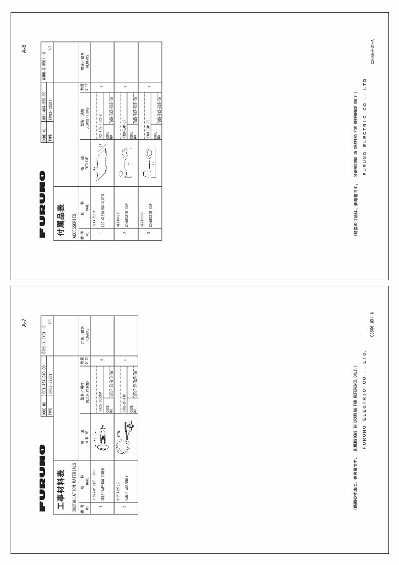
A-7
A-8

A-9

hmaki
タイプライターテキスト
8/Sep/2016 H.MAKI
dmills
Text Box
D-1

hmaki
タイプライターテキスト
8/Sep/2016 H.MAKI
dmills
Text Box
D-2
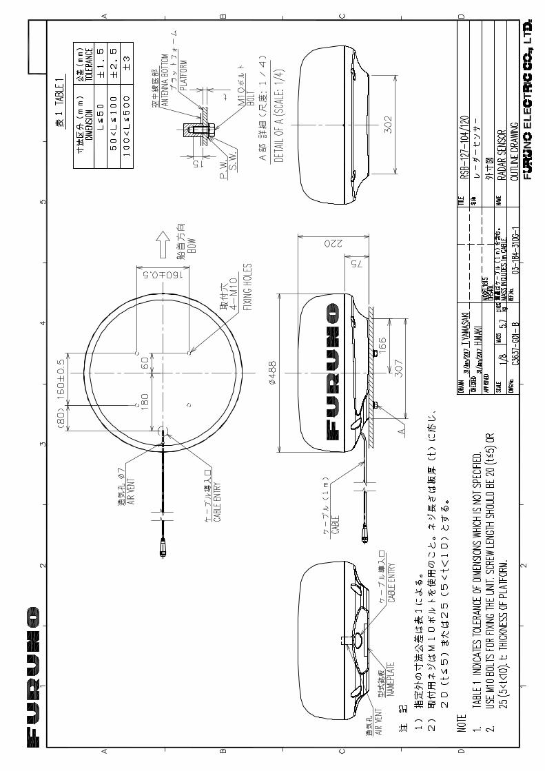
hmaki
タイプライターテキスト
1/Feb/2017 H.MAKI
dmills
Text Box
D-3

24
3
A
1
B C
DRAWN
CHECKED
APPROVED
DWG.No.
TITLE
NAME
名称
REF.No.
SCALE
MASS
kg
T.YAMASAKI
INTERCONNECTIONDIAGRAM
MARINE
RADAR
相互結
線図
船舶用
レーダー
MODEL1815
03-192-6001-0
H.MAKI
NOTE
*1:
SHIPYARD
SUPPLY.
*2:
OPTION.
注記
*1)
造船所手
配。
*2)
オプショ
ン。
7.5A
TB
*1
3 4 5 6 7 8 9 10
11
12
13
14
15
16
TD1-A
TD1-B
TD2-A
TD2-B
RD1-H
RD1-C
RD2-H
RD2-C
RD3-H
RD3-C
12V_P
12V_M
EXT_BUZZ_EN
SHIELD
1 2DC_P_IN
DC_M_IN
RED
BLK
SHIELD
シロ
WHT
ダイ
ORG
チャ
BRN
ハイ/クロ3
ハイ/アカ3
GRY/BLK3
GRY/RED3
ミドリ/クロ1
ミドリ/アカ1
GRN/BLK1
GRN/RED1
ハイ/クロ1
ハイ/アカ1
GRY/BLK1
GRY/RED1
ミドリ/クロ2
ミドリ/アカ2
GRN/BLK2
GRN/RED2
指示部
DISPLAY
UNIT
RDP-157
J201
P P P P
P P P P
77
1.4m
空中線
部ANTENNA
UNIT
RSB-127-120
IV-2sq.
*1
J202
NMEA1
NMEA2
NMEA3
TTYCSLA-1
TTYCSLA-1Q
TTYCSLA-1Q*1
*1
*1
ハイ/クロ2
ハイ/アカ2
GRY/BLK2
GRY/RED2
FRU-CF-FF-**M,10/15/20/30m,φ
9.7
アカ
クロ
FRU-CF-F01,3.3m
EXT.
BUZZER
外部
ブザー
OP03-21
*2
選択
SELECT
NAV.
EQUIPMENT
航法装
置
サテ
ライト
コンパ
スプ
ロッタ,AISな
どSATELLITE
COMPASS
PLOTTER/AIS,ETC.
ヘデ
ィング
センサ
ーHEADING
SENSOR
12VOUTPUT
(+)
(-)
12-24VDC
IF-NMEA2K2
NMEAデータ
変換器
NMEA
DATACONVERTER
CAN
bus
NETWORK
*2
2m
0.3m
C3666-C01-B
2/Feb/2017
2/Feb/2017
S-1
hmaki
タイプライターテキスト
2/Feb/2017 H.MAKI

INDEX
AAISactivating targets ..................................... 5-3controls for .............................................. 5-1CPA/TCPA alarm .................................... 5-8display on/off ........................................... 5-1display range........................................... 5-5display sector .......................................... 5-5lost target ................................................ 5-9number of targets .................................... 5-6past position display................................ 5-7proximity alarm........................................ 5-9sleeping targets....................................... 5-3sorting targets ......................................... 5-4symbol color .......................................... 5-10symbols ................................................... 5-2target data ............................................... 5-4vector ...................................................... 5-6vector reference ...................................... 5-6vector time............................................... 5-6
ALARM key ............................................. 2-20Alert list .................................................AP-17Alert status .............................................. 2-36
BBackground color .................................... 2-38Barge mark.............................................. 2-34Brill/Color menu....................................... 2-41
CCharacter color........................................ 2-38Cold start ................................................... 6-4Colorbackground ........................................... 2-38characters ............................................. 2-38preset .................................................... 2-38
Controls..................................................... 2-1Course up mode........................................ 2-8CPA/TCPA alarmAIS .......................................................... 5-8TT............................................................ 4-8
Cursor ..................................................... 2-13
DDATA BOX knob ..................................... 2-45Depth unit ................................................ 2-44Digital interface .......................................AP-7Display brillance ........................................ 2-4Display menu .......................................... 2-43Display-curve .......................................... 2-33
EEBLmeasuring bearing by............................ 2-17reference ............................................... 2-18
Echo area................................................ 2-39
Echo average .......................................... 2-32Echo color ............................................... 2-38Echo menu .............................................. 2-43Echo stretch ............................................ 2-27
FFalse echoes............................................. 3-3FUNC key................................................ 2-31Fuse replacement ..................................... 7-2
GGain adjustment ...................................... 2-10Geodetic chart list ...................................AP-5GPScold start.................................................. 6-4datum ...................................................... 6-1navigator mode ....................................... 6-1satellite monitor ....................................... 6-3test .......................................................... 6-4WAAS...................................................... 6-2
HHead up mode........................................... 2-8Heading line erasure ............................... 2-14
IIndications ................................................. 2-3Initial sub menu ....................................... 2-39Interference rejector ................................ 2-14
JJIS cable guide......................... AP-14, AP-17
LLCD test .................................................... 7-7Lost targetAIS .......................................................... 5-9TT............................................................ 4-4
MMagnetron ................................................. 7-3Maintenancefuse replacement..................................... 7-2magnetron ............................................... 7-3preventive................................................ 7-2
Menu overview .......................................... 2-4Menu tree ................................................AP-1Multiple echoes ......................................... 3-3
NNavigation data ....................................... 2-45Noise rejector .......................................... 2-15North up mode .......................................... 2-8
OOff-centerautomatic............................................... 2-24custom................................................... 2-23manual .................................................. 2-23
IN-1

INDEX
mode ......................................................2-23speed in automatic mode.......................2-24
Origin mark ..............................................2-47Own ship mark .........................................2-33
PPanel brillance ...........................................2-4Past position displayAIS ...........................................................5-7TT.............................................................4-6
POWER/BRILL key............................ 2-2, 2-4Proximity alarmAIS ...........................................................5-9TT.............................................................4-9
RRACON ......................................................3-8Radar sensor test.......................................7-8Radio regulator information...................AP-15Rain clutter adjustment ............................2-12Range and bearing between two targets .2-19RANGE knob ...........................................2-10Range measurementfixed range rings.....................................2-15VRM .......................................................2-16
Range ring brilliance ................................2-15Range unit................................................2-44
SSART .........................................................3-6Satellite monitor .........................................6-3Sea clutter adjustment .............................2-11Sector blank .............................................2-41Shadow sector ...........................................3-5Ship speed unit ........................................2-44Sidelobe echoes ........................................3-4Specifications..........................................SP-1System configuration ................................... xiSystem test ................................................7-5
TTarget alarmalarm type ..............................................2-21audio alarm silencing .............................2-21deactivating ............................................2-22setting.....................................................2-20sleeping..................................................2-22strength level..........................................2-22
Target trailscolor .......................................................2-29erase all trails .........................................2-31gradation ................................................2-29level........................................................2-29mode ......................................................2-28narrow trails............................................2-30own ship trail ..........................................2-30restarting ................................................2-29time ........................................................2-27
Temperature unit......................................2-44
TestsGPS..........................................................6-4LCD..........................................................7-7radar sensor .............................................7-8system......................................................7-5
TLL...........................................................2-47Troubleshootingadvanced-level .........................................7-4simple.......................................................7-3
True motion mode......................................2-9True view mode..........................................2-9TTacquiring targets automatically.................4-3acquiring targets manually .......................4-2controls for ...............................................4-1CPA/TCPA alarm .....................................4-8display on/off ............................................4-2lost target .................................................4-4own ship vector ........................................4-6past position display.................................4-6precautions...............................................4-1proximity alarm.........................................4-9stopping tracking ......................................4-3symbol color .............................................4-2target data ................................................4-7vector description .....................................4-4vector reference .......................................4-5
Tuning ........................................................2-6
UUnits menu...............................................2-44
VVectordescription, AIS ........................................5-6description, TT .........................................4-4own ship ...................................................4-6reference, AIS ..........................................5-6reference, TT............................................4-5
Virtual image ..............................................3-4VRMmeasuring range by ...............................2-16unit for ....................................................2-17
WWatchman................................................2-35Waypoint marker ......................................2-46Wind speed unit .......................................2-44Wiper........................................................2-32
ZZoomnon-tracked target ..................................2-25reference ................................................2-24TT or AIS target......................................2-26
IN-2

Declaration of Conformity
Bulgarian(BG)
Spanish(ES)
Czech(CS)
Danish(DA)
German(DE)
Estonian(ET)
Greek(EL)
English(EN)
French(FR)
Croatian(HR)
Italian(IT)
Latvian(LV)
Pilns ES atbilstības deklarācijas teksts ir pieejams šādā interneta vietnē:
Με την παρούσα η Furuno Electric Co., Ltd., δηλώνει ότι ο προαναφερθένταςραδιοεξοπλισμός πληροί την οδηγία 2014/53/ΕΕ.Το πλήρες κείμενο της δήλωσης συμμόρφωσης ΕΕ διατίθεται στην ακόλουθηιστοσελίδα στο διαδίκτυο:
Hereby, Furuno Electric Co., Ltd. declares that the above-mentioned radioequipment type is in compliance with Directive 2014/53/EU.The full text of the EU declaration of conformity is available at the followinginternet address:
Le soussigné, Furuno Electric Co., Ltd., déclare que l'équipement radioélectriquedu type mentionné ci-dessusest conforme à la directive 2014/53/UE.Le texte complet de la déclaration UE de conformité est disponible à l'adresseinternet suivante:
Furuno Electric Co., Ltd. ovime izjavljuje da je gore rečeno radijska oprema tipau skladu s Direktivom 2014/53/EU.Cjeloviti tekst EU izjave o sukladnosti dostupan je na sljedećoj internetskojadresi:
Il fabbricante, Furuno Electric Co., Ltd., dichiara che il tipo di apparecchiaturaradio menzionato sopra è conforme alla direttiva 2014/53/UE.Il testo completo della dichiarazione di conformità UE è disponibile al seguenteindirizzo Internet:
Ar šo Furuno Electric Co., Ltd. deklarē, ka augstāk minēts radioiekārta atbilstDirektīvai 2014/53/ES.
[MODEL1815]
ELi vastavusdeklaratsiooni täielik tekst on kättesaadav järgmiselinternetiaadressil:
С настоящото Furuno Electric Co., Ltd. декларира, че гореспоменат типрадиосъоръжение е в съответствие с Директива 2014/53/ЕС.Цялостният текст на ЕС декларацията за съответствие може да се намерина следния интернет адрес:
Por la presente, Furuno Electric Co., Ltd. declara que el tipo de equiporadioeléctrico arriba mencionado es conforme con la Directiva 2014/53/UE.El texto completo de la declaración UE de conformidad está disponible en ladirección Internet siguiente:
Tímto Furuno Electric Co., Ltd. prohlašuje, že výše zmíněné typ rádiovéhozařízení je v souladu se směrnicí 2014/53/EU.Úplné znění EU prohlášení o shodě je k dispozici na této internetové adrese:
Hermed erklærer Furuno Electric Co., Ltd., at ovennævnte radioudstyr er ioverensstemmelse med direktiv 2014/53/EU.EU-overensstemmelseserklæringens fulde tekst kan findes på følgendeinternetadresse:
Hiermit erklärt die Furuno Electric Co., Ltd., dass der oben genannteFunkanlagentyp der Richtlinie 2014/53/EU entspricht.Der vollständige Text der EU-Konformitätserklärung ist unter der folgendenInternetadresse verfügbar:
Käesolevaga deklareerib Furuno Electric Co., Ltd., et ülalmainitud raadioseadmetüüp vastab direktiivi 2014/53/EL nõuetele.

Lithuanian(LT)
Hungarian(HU)
Maltese(MT)
Dutch(NL)
Polish(PL)
Portuguese(PT)
Romanian(RO)
Slovak(SK)
Slovenian(SL)
Finnish(FI)
Swedish(SV)
Online Resourcehttp://www.furuno.com/en/support/red_doc
Furuno Electric Co., Ltd. vakuuttaa, että yllä mainittu radiolaitetyyppi ondirektiivin 2014/53/EU mukainen.EU-vaatimustenmukaisuusvakuutuksen täysimittainen teksti on saatavillaseuraavassa internetosoitteessa:
Härmed försäkrar Furuno Electric Co., Ltd. att ovan nämnda typ avradioutrustning överensstämmer med direktiv 2014/53/EU.Den fullständiga texten till EU-försäkran om överensstämmelse finns påföljande webbadress:
Prin prezenta, Furuno Electric Co., Ltd. declară că menționat mai sus tipul deechipamente radio este în conformitate cu Directiva 2014/53/UE.Textul integral al declarației UE de conformitate este disponibil la următoareaadresă internet:
Furuno Electric Co., Ltd. týmto vyhlasuje, že vyššie spomínané rádiovézariadenie typu je v súlade so smernicou 2014/53/EÚ.Úplné EÚ vyhlásenie o zhode je k dispozícii na tejto internetovej adrese:
Furuno Electric Co., Ltd. potrjuje, da je zgoraj omenjeno tip radijske opremeskladen z Direktivo 2014/53/EU.Celotno besedilo izjave EU o skladnosti je na voljo na naslednjem spletnemnaslovu:
O texto integral da declaração de conformidade está disponível no seguinteendereço de Internet:
Aš, Furuno Electric Co., Ltd., patvirtinu, kad pirmiau minėta radijo įrenginių tipasatitinka Direktyvą 2014/53/ES.Visas ES atitikties deklaracijos tekstas prieinamas šiuo interneto adresu:
Furuno Electric Co., Ltd. igazolja, hogy fent említett típusú rádióberendezésmegfelel a 2014/53/EU irányelvnek.Az EU-megfelelőségi nyilatkozat teljes szövege elérhető a következő internetescímen:
B'dan, Furuno Electric Co., Ltd., niddikjara li msemmija hawn fuq-tip ta' tagħmirtar-radju huwa konformi mad-Direttiva 2014/53/UE.It-test kollu tad-dikjarazzjoni ta' konformità tal-UE huwa disponibbli f'dan l-indirizztal-Internet li ġej:
Hierbij verklaar ik, Furuno Electric Co., Ltd., dat het hierboven genoemde typeradioapparatuur conform is met Richtlijn 2014/53/EU.De volledige tekst van de EU-conformiteitsverklaring kan worden geraadpleegdop het volgende internetadres:
Furuno Electric Co., Ltd. niniejszym oświadcza, że wyżej wymieniony typurządzenia radiowego jest zgodny z dyrektywą 2014/53/UE.Pełny tekst deklaracji zgodności UE jest dostępny pod następującym adreseminternetowym:
O(a) abaixo assinado(a) Furuno Electric Co., Ltd. declara que o mencionadoacima tipo de equipamento de rádio está em conformidade com a Diretiva2014/53/UE.