Operator's Manual - OSE100
62
© BT Industries AB Valid only for serial number: BT Products AB S-595 81 MJÖLBY SWEDEN Operator’s Manual en WARNING! Do not use the truck before first reading through the OPERATOR’S MANUAL. NOTE! Keep for future reference. OSE100 Valid from serial number: 744051- Order number: 222714-040 Issued: 2005-03-08 ITS
-
Upload
khangminh22 -
Category
Documents
-
view
1 -
download
0
Transcript of Operator's Manual - OSE100

Operator’s Manual en
WARNING!Do not use the truck before first reading through the OPERATOR’S MANUAL.
NOTE!Keep for future reference.
OSE100Valid from serial number: 744051-
Valid only for serial number:
Order number: 222714-040Issued: 2005-03-08 ITS
© BT Industries AB
BT Products ABS-595 81 MJÖLBY SWEDEN

© BT Industries AB 222714-0402
It is important that you read this Operator’s Manual for your own safety!
Before you start to use this truck it is of extreme importance that you have read the contents of the entire Operator’s Manual to be able to use the truck in a safe and efficient manner.
This Operator’s Manual contains information on how you should use the truck, safety regulations and how to keep the truck in a safe condition by following daily service routines.
Only personnel who have been trained on the operation of this type of truck, are permitted to use this truck.
It is your employer’s responsibility to ensure that you have suffi-cient knowledge of how to use your truck safely. Do not hesitate to contact your supervisor if you feel the slightest uncertainty of how to use this truck.
Always follow the warnings given in this Operator’s Manual and on the truck to avoid accidents and incidents from occurring.
BT Products AB

Table of Contents
Safety regulations ............................................................................... 5Warning symbols .............................................................................. 5General safety regulations ................................................................ 7
Warning and information plates and symbols ............................... 12
Presentation of the truck ................................................................. 14Intended application of the truck ..................................................... 14Prohibited application of the truck .................................................. 14Truck data ...................................................................................... 15Truck dimensions ........................................................................... 16Identification plate .......................................................................... 18Modification plate ............................................................................ 18Capacity plate ................................................................................. 19
Main components ............................................................................. 20
Controls and instruments ................................................................ 22Display and programming ............................................................... 29Warning codes ................................................................................ 31Error codes ..................................................................................... 32
Accessories ....................................................................................... 34
Driving ............................................................................................... 35Starting the truck ............................................................................ 35Braking ........................................................................................... 36Deceleration ................................................................................... 36Steering .......................................................................................... 36Parking the truck ............................................................................. 36
Transporting loads ........................................................................... 37Order picking .................................................................................. 37Collecting a load ............................................................................. 38Depositing a load ............................................................................ 38
Battery ............................................................................................... 39Fitting the battery and battery lock ................................................. 39Replacing the battery ...................................................................... 39Charging the battery ....................................................................... 41Battery maintenance ....................................................................... 42
Daily service and function checks .................................................. 44
© BT Industries AB 222714-0403

Table of Contents
Maintenance ...................................................................................... 47Cleaning and washing .................................................................... 49Maintenance chart .......................................................................... 51Lubrication chart ............................................................................. 55Oil and grease specification ........................................................... 55
Transporting and storing the truck ................................................. 57The truck’s dimensions and weight as standard ............................. 57Lifting the truck ............................................................................... 58Towing and transporting a defective truck ...................................... 59Storing the truck ............................................................................. 59Starting after a period of disuse ...................................................... 59
Recycling/discarding ........................................................................ 60Discarding the battery ..................................................................... 60Scrapping the truck ......................................................................... 60
© BT Industries AB 222714-0404

Safety regulations
Safety regulationsWarning symbols
Always follow the warnings given in this Operator’s Manual and on the truck to avoid accidents and incidents from occur-ring.
Warning levelsWarning texts regarding safety are given in four levels and pro-vide information on the risks, describe the consequences and instruct how to avoid accidents.
DANGER!Warns that an accident will occur if you do not follow the instructions.The consequences are serious personal injury or possibly death and/or extremely large material damage.
WARNING!Warns that accidents can occur if the instructions are not fol-lowed.The consequences are serious personal injury or possibly death and/or large material damage.
CAUTION!Warns that accidents can occur if the instructions are not fol-lowed.The consequences are personal injury and/or material dam-age.
NOTE!Marks the risk of a crash/breakdown if the instructions are not followed.
© BT Industries AB 222714-0405

Safety regulations
Prohibitory symbols
NO SMOKINGIf smoking occurs in situations where a restriction against smoking is stated, a serious accident can occur.
NAKED FLAMES PROHIBITEDIf naked flames are used in situations where naked flames are prohibited, a serious accident can occur.
GENERAL PROHIBITIONIf the prohibition is ignored, a serious accident can occur.
Ordinance symbols
SAFETY SHOESWhen the directive for safety shoes is given, safety shoes must always be worn to avoid personal injury.
PROTECTIVE GLASSESWhen the directive for protective glasses is given, protective glasses must always be worn to avoid personal injury.
© BT Industries AB 222714-0406

Safety regulations
General safety regulationsAlways carry out daily service before the truck is used, see chapter Daily service and function checks. The working order of all safety equipment, guards and safety switches should be checked before you use the truck. Such safety equipment must not be disengaged or removed.
• Check to make sure that all warning and machine designation plates are clean and undamaged.
The battery must be secured in its intended compartment. The battery shall have a weight that corresponds with the information stated on the truck’s identification plate.
The truck must not be used if it is damaged or has faults that affect safety or its safe use. The truck may not be used if it has been repaired, modified or adjusted unless it has been checked and approved by personnel authorised by BT.
Operating the truckThe truck is designed and produced to be your tool for internal order picking in a warehouse when picking from floor level and from the first and second level of warehouse shelving (applies to standard design trucks).
If the truck is to be used in cold storage rooms the truck must be especially built for this type of use.
It is not permitted to use the truck for purposes that it has not been designed and produced for, e.g. the following applications:
- In areas where the atmosphere contains dust or gases that can cause fires or explosions.
- As a towing truck for trailers.- To tow other trucks.- To transport/lift passengers.
Operator’s responsibility• The truck shall only be driven by personnel that have been
specially trained and have the management’s permission to drive the truck.
• Each country (state) has its own safety regulations. It is the operator’s obligation to know and follow these.This also applies to local regulations and for different types of handling. If the recommendations in this manual deviate from your national regulations, the local safety regulations should be followed.
• The truck should be insured in accordance with local direc-tives and laws where the truck is used.
© BT Industries AB 222714-0407

Safety regulations
• Any accidents that have caused personal injury or damage to buildings or equipment must be reported to the supervisor. Incidents and faults on the truck shall also be reported.
• The truck shall only be driven with care, good judgement and in a responsible manner.
• Local regulations regarding personal safety equipment shall be followed.
• The truck should not be driven with oily hands or oily shoes due to the risk of slipping.
Working area• If there are marked truck routes these shall be used.
• The truck should only be driven on hard and even surfaces, e.g. concrete or asphalt.
• Ensure that the floor where the truck is to be used has suffi-cient load bearing capacity for the total weight of the truck including the maximum load and the weight of the operator.
• Take special care if there are protruding parts from racks, shelves or walls that can cause personal injury or damage to the truck.
• It is prohibited for persons to be present in the area around the truck when there is a risk of personal injury, e.g. areas that can be reached by falling goods, lowering load handling devices or in the truck’s manoeuvring area.
Driving and conduct while driving• It is not permitted to stand on the pallet and/or forks.
• Always drive the truck from a specified operator position.
• Always drive the truck in a responsible manner and with full control. Sudden starts and braking as well as cornering at high speed should be avoided.
• Reduce the speed if the surface is slippery to prevent the truck from sliding or overturning.
• Adapt your speed to suit the driving conditions, and where there are pedestrians or other trucks in the working area. Reduce speed when the line of vision is limited and when pedestrians or other vehicles can be encountered.
• Pay particular attention to other personnel as well as fixed and moving objects within the working area and thereby avoid accidents.
• Always be prepared to stop if other personnel are in the work-ing area.
• Keep a safe distance from all vehicles ahead.
© BT Industries AB 222714-0408

Safety regulations
• Always keep a safe distance from the edges of loading bays and loading ramps. Be attentive to marked risk areas.
• Sound the horn when overtaking and when the attention of other personnel is required.
• Always give way to a loaded truck at junctions and in confined aisles.
• Never allow passengers to ride on the truck.
• Never drive with any part of your body outside the operator compartment.
Handling loads• Drive with care when collecting or depositing a load.
• Only handle loads that are within the truck’s permitted lifting capacity. The length/width of the forks should be adapted to the load’s shape and dimensions.
• Only handle loads that are stable and arranged in a safe manner.
• Particular care should be exercised when handling long and high loads.
Parking the truck• Always park the truck with the load carrier and the operator
cabin fully lowered. The brake is automatically applied if you do not activate the deadman’s handle.
• Always park in designated areas if available.
• Never leave the truck parked with the current on.
• Never park the truck on an incline.
• Never park the truck so that it obstructs emergency exits.
• Never park the truck so that it obstructs traffic or work.
Handling the battery• Always handle the battery and its connections with care.
Read and follow the instructions carefully before replacing or charging the battery. See chapter Battery.
• Always wear protective glasses when working with the bat-tery.
• Make sure the battery in the truck is of a weight that corre-sponds with the information on the truck’s identification plate.
• Make sure the battery is secured in its compartment.
© BT Industries AB 222714-0409

Safety regulations
Maintenance and repairMaintenance instructions should be followed to prevent faults and accidents, see the Maintenance chart in chapter Mainte-nance. Only qualified and BT trained personnel are permitted to maintain, adjust or repair the truck.
All replacement parts shall be BT approved spare parts.
Modifications or conversions to the truck that affect the safe use or function are not permitted.
© BT Industries AB 222714-04010

Safety regulations
© BT Industries AB 222714-04011

Warning and information plates and symbols
Warning and information plates and symbolsThe figure shows the position and significance of the plates and symbols located on the truck.
1. Modification plate2. Travel direction3. Hydraulic control: Lift4. Hydraulic control: Lower5. Signal/Horn6. Identification plate7. Serial number8. Hydraulic oil filling9. Lifting points10. Passengers prohibited11. Capacity plate12. Do not walk under elevated load13. Do not stand on the forks14. Hydraulic lever: Lifting the forks15. Hydraulic lever: Lowering the forks
© BT Industries AB 222714-04012

Warning and information plates and symbols
5
10
11
12
13
1
4
6
7
8
9
2
3
14
15
© BT Industries AB 222714-04013

Presentation of the truck
Presentation of the truck
The truck is an order picking truck designed to pick orders from ground level and the 1st and 2nd level in warehouse racks. The truck is designed for order picking with correct ergonomic pos-ture. The operator's environment has been specially designed to provide a work position and an overview of truck handling for safe and comfortable operation.
The truck has a maximum lifting capacity of 1000 kg.
The truck has a 24V electrical system and the speed is regulated by means of a transistor controller to provide gentle control of acceleration and speed while driving. For reasons of safety and stability the speed in the direction of the forks is lower than the forward speed. Additionally, the speed is reduced in both direc-tions if the platform is lifted higher than 500 mm.
The forks are lifted by using a powerful and compact hydraulic unit that is automatically shut-off when the forks reach their high-est lifting position. The automatic shut-off is used to increase the service life of the hydraulic components and reduce the power consumption from the battery.
Note that some of the truck models described in the Operator’s Manual may not be marketed in your country.
Intended application of the truckThe truck is solely designed and manufactured to handle goods. The trucks should be fitted with the appropriate accessories rele-vant to the application.
Prohibited application of the truckThe truck is designed for indoor order picking. It is not permitted to use the trucks for other purposes including the following:
- In areas that contain dust or gases which can cause fires or explosions
- As a tow-truck for trailers- To tow other trucks- To transport/lift passengers- To drive on gravel or grass
© BT Industries AB 222714-04014

Presentation of the truck
Truck typRated capa
Lift height, m
Instep heigh
Travel spee
Travel spee
Travel spee
Travel spee
Weight with
Turning rad
ContinuousEN 12053,
Vibration lev
Permitted d
Truck dataThe table provides information regarding some technical data, which is of value with daily use of the truck.
* Deviations may occur on trucks adapted to specific application; the correct value can be found on the truck’s identification plate. In such cases the truck is also fitted with a modification plate.
e OSE100city, kg * 1000
m (platform height + 680 mm) 1100
t, mm 180
d forward without load, km/h 12
d forward with rated load, km/h 8
d in fork direction without load, km/h 10.5
d in fork direction with rated load, km/h 6
out battery, 1150 mm forks, kg 1162
ius (Wa), mm 1490
equivalent noise level according to dBA
71
el according to EN 13059, m/s2 0,9
rive wheel, material VulkollanPowerthanesiped Tractothan
© BT Industries AB 222714-04015

Presentation of the truck
Dimb1 C
b5 W
Wa
l Fo
h12
h20
h23
h3
h 9
Truck dimensionsThe illustration shows external dimensions for the truck in its standard design.
ensions OSE100hassis, mm 790
idth across fork, mm justerbar 300 > 750
Turning radius, mm 1540
rk length, mm 800 / 1000 / 1150
h7
l20
h13
m2
l1 l2
y
h1h4
e
b1 b5
Wa
x
L24
© BT Industries AB 222714-04016

Presentation of the truck
e F
l2 T
l20
l24
x B
y W
h1 H
h3 L
h4 H
h7 I
h9 I
h12
h13
h20
h23
m2
Dim
ork width, mm 115ruck length incl. back of fork, mm 1690
Platform length, mm 548
Instep width, mm 471
ack of fork to wheel centre, mm 158
heel base, mm 1351
eight of truck, min., mm 1550
ift movement, mm 1020
eight of truck, max., mm 2570
nstep height, mm 180
nitial lift 780
Platform height, mm 1200
Height of lowered fork, mm 80
Picking height, mm 2800
Total lift height, mm 1880
Floor clearance mid wheelbase, mm 70
ensions OSE100
© BT Industries AB 222714-04017

Presentation of the truck
ABCDEEF
G
A
B
C D
E F G
Identification plateThe illustration shows the identification plate used on the truck.
Modification plateThe illustration shows the modification plate which is found on the truck if it is supplied as non-standard or if it has been modi-fied after leaving the manufacturer. The plate includes informa-tion according to the table below.
Item Text UnitA MODEL
B NO.
C RATED CAPACITY kg
D WEIGHT WITHOUT BATTERY kg
E BATTERY WEIGHT MAX MIN
kg kg
F BATTERY VOLTAGE V
G BATTERY TYPE — CLASS ACC TO UL583
Item TextA Modification plate
B Type
C Serial number
D Place of manufacture
E Place of manufacture
F Modification number
G Date
© BT Industries AB 222714-04018

Presentation of the truck
Capacity plateThe illustration shows the capacity plate used on the truck.
Item Text UnitH NO
I LIFT HEIGHT mm
J ACTUAL CAPACITY kg
K LOAD CENTRE mm
© BT Industries AB 222714-04019

Main components
Main components1. Steering unit:
The truck can be manoeuvred by the operator either stand-ing in the driver’s compartment or walking by the side of the truck. The speed is reduced to 6.0 km/h when operating from the side. The brake is activated in the steering unit’s raised position.
2. Identification plate: With type designation, serial number, year of manufacture, weight without battery, battery weight, rated capacity, battery voltage, manufacturer and battery type (only ASME).
3. Cover: Removable which provides good accessibility when servic-ing.
4. Driv wheel/motor: Central placement of the drive wheel and drive motor.
5. Lifting points: For the truck weight, see the identification plate.
6. Battery/Recharging connector: The battery is charged via the permanently fitted charging connector.
7. Battery: 24 V.
8. Electrical steering motor: Servo-steering for the drive wheel.
9. Emergency switch off: Press the emergency switch to shut off the power.
10. Initial lift mast: The forks can be lifted/lowered separately.
11. Hydraulic unit: Pump motor, pump and oil tank are integrated in a compact unit.
© BT Industries AB 222714-04020

Main components
2
6
7
9
8
5
10
5
3
11
4
© BT Industries AB 222714-04021

Controls and instruments
Controls and instruments1. Travel direction selector and speed control2. Control for lifting and lowering the operator platform3. Horn4. Display5. Keypad6. Emergency switch off7. Battery disconnector and battery connector8. Steering unit and brake9. Control for lifting and lowering the forks
12 3
4
5 1 23
7
8
9
© BT Industries AB 222714-04022

Controls and instruments
R
B
A
Travel direction selector and speed con-trol (1)
• Select the travel direction by moving the lever, R, in the required direction. The speed is controlled variably based on the position of the lever. The brake is released at the same instant the lever is activated. The speed when reversing depends on the position of the lever. When the operator releases the lever and it returns to the neutral position the speed is automatically reduced.
Control for lifting and lowering the oper-ator platform (2)
The control buttons activate a microswitch to start the pump motor with lifting and to control the solenoid valve when lower-ing. The lowering speed of the platform is controlled by a flow valve.
The diagram illustrates the controls, seen from the operator’s position. Lift the platform by pressing A and lower by pressing B.
Note: The forks cannot be lowered when the truck has been switched off.
Pallet to ground protection (Option)Lifting/lowering of the forks can only be operated when the oper-ator is present on the platform. Lowering stops when the fork height is less than +/- 150 mm from the floor. From this position, the forks can only be lowered further by releasing the lowering button and then pressing it again.
Horn (3)
The horn sounds as long as the button is pressed.
© BT Industries AB 222714-04023
Controls and instruments
A
BCDE
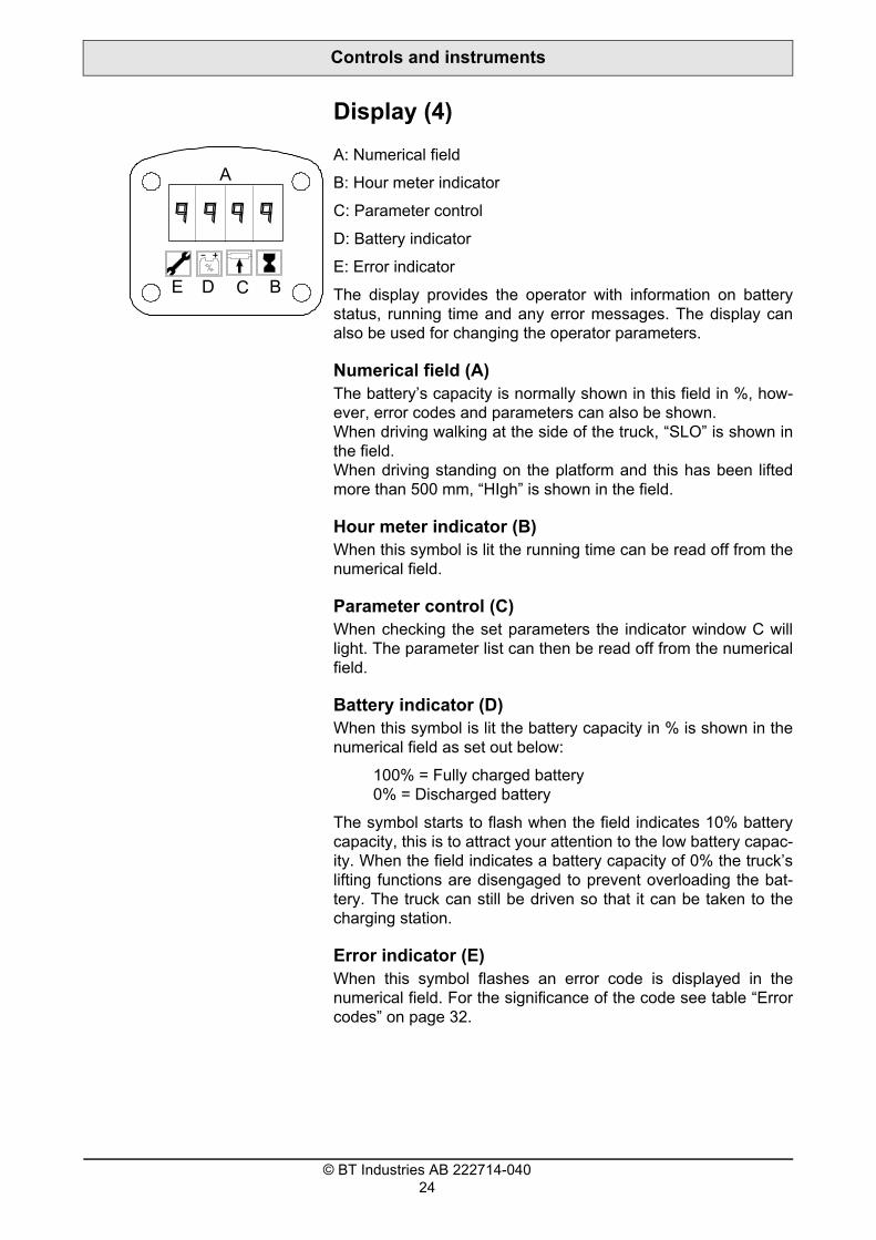
Display (4)
A: Numerical field
B: Hour meter indicator
C: Parameter control
D: Battery indicator
E: Error indicator
The display provides the operator with information on battery status, running time and any error messages. The display can also be used for changing the operator parameters.
Numerical field (A)The battery’s capacity is normally shown in this field in %, how-ever, error codes and parameters can also be shown. When driving walking at the side of the truck, “SLO” is shown in the field. When driving standing on the platform and this has been lifted more than 500 mm, “HIgh” is shown in the field.
Hour meter indicator (B)When this symbol is lit the running time can be read off from the numerical field.
Parameter control (C)When checking the set parameters the indicator window C will light. The parameter list can then be read off from the numerical field.
Battery indicator (D)When this symbol is lit the battery capacity in % is shown in the numerical field as set out below:
100% = Fully charged battery 0% = Discharged battery
The symbol starts to flash when the field indicates 10% battery capacity, this is to attract your attention to the low battery capac-ity. When the field indicates a battery capacity of 0% the truck’s lifting functions are disengaged to prevent overloading the bat-tery. The truck can still be driven so that it can be taken to the charging station.
Error indicator (E)When this symbol flashes an error code is displayed in the numerical field. For the significance of the code see table “Error codes” on page 32.
© BT Industries AB 222714-04024

Controls and instruments
FunctionWhen the control current is switched on the driver version is shown first, followed by, for a few seconds, the hour meter with the hour meter indicator and then the continuous battery capac-ity and the battery indicator.
If an error should occur the error code indicator flashes on the display at the same time as the error code is shown in the numerical field.
Keypad (5)
The truck is equipped with a keyboard for logging in using a PIN-code.
• Start the truck by entering your PIN-code and then press I. If you state the PIN-code incorrectly a red LED comes on.
• Switch off the truck by pressing (0).It is the four figures entered last that apply as the PIN-code. This means that with incorrect entry, you only need to start from the first number in the PIN-code.
Emergency switch off (6)
The truck is equipped with emergency switch off (see illustr.). Press in the emergency switch off to cut the power supply in the event of:
- An accident.- Emergency situation, risk of an accident.- With welding work.
• Release the emergency switch off by turning the knob in the direction of the arrow.
© BT Industries AB 222714-04025

Controls and instruments
Battery disconnector and battery con-nector (7)• Remove the battery disconnector to cut the power supply in
the event of:- An accident.- Emergency situation, risk of an accident.- Welding work.
NOTE!The battery can be damaged.When welding using an electric power source the welding cur-rent can enter the battery.It is necessary to disconnect the battery.
To charge the battery, pull out the battery disconnector and con-nect the charger connector to the truck’s permanent battery con-nector. After charging, replace the battery disconnector.
© BT Industries AB 222714-04026

Controls and instruments
F
Steering unit and brake (8)• Drive the truck with the steering unit in the lowered position,
F.
• Raise the steering unit (B2) for emergency braking, or press the emergency switch.
The brakes are applied electrically by the steering/brake unit. The brakes are applied with the unit in raised position (B2).
The travel brake has double functions - neutral brake and motor brake/reversing brake.
Neutral brake: The neutral brake is activated when the operator releases the speed control to its centre position. The braking power can be adjusted using parameter 4 “Automatic speed reduction”.
Motor brake/reversing brake: Will be activated when the operator moves the speed control in the opposite driving direction. When reversing the speed in this way the truck’s driving system is being used most efficiently.
The mechanical brake is activated when the steering unit is raised (B2), which is the position it should be when the truck is not in use. For common order picking operations the steering unit does not need to be raised since the mechanical brake is activated as soon as the operator leaves the truck. The brake will be released as soon as the speed control is activated.
If the operator leaves the truck while driving, the truck will be stopped by means of the motor brake and after that the mechan-ical brake will be applied. The braking power for leaving the truck while driving can be adjusted using parameter 7 “Brake”.
B2
© BT Industries AB 222714-04027

Controls and instruments
CD
Control for lifting and lowering the forks (9)
The control buttons activate a microswitch to start the pump motor with lifting and to control the solenoid valve when lower-ing. The lowering speed of the forks is controlled by a flow valve.
The diagram illustrates the controls, seen from the operator’s position.
• Lift the forks by pressing A and lower by pressing B.
Note: The forks cannot be lowered when the truck has been switched off.
© BT Industries AB 222714-04028

Controls and instruments
Display and programmingIt is possible to look in the machine-specific register, but not to re-programme. However, you can re-programme the operator-specific parameters. The parameters can be found in the table “Parameters” on page 30. For further information regarding parameters and warning and error codes, see the Service Man-ual (SM).
DisplayFollow the instructions below to look into the operator and machine-specific register:
• Press the horn button while at the same time pressing “I”.
The display will now show the functions: - Running time and time remaining until next service (H)- Error codes (E)- Parameters (P)- Hardware and software numbers (Pn)
• Release the horn button at the required display.
• Step between the different functions above by turning the speed control.
ProgrammingTo re-programme the operator-specific parameters (if the change is permitted), carry out the following:
NOTE.Truck handling.The handling characteristics of the truck will change if you change any of the truck specific parameters. Do not change any parameters without possessing the necessary know-how.
Truck with keyboard• Enter the number of the driver whose parameters are to be
changed using the keyboard.
• Press “I” on the keyboard while at the same time pressing the horn button, or just press the horn button.
• Release the horn button when the display shows “P”. The parameter symbol on the display lights.
• To locate the required parameter turn the speed control until the display shows the correct parameter number.
• Press the horn button once to change the value. The parameter symbol on the display starts flashing.
• Change the value by turning the speed control.
© BT Industries AB 222714-04029

Controls and instruments
No. Parameter type U
1 Max speed, in fork direction
%
2 Max speed in drive wheel direction
%
3 Acceleration %
4 Automatic speed reduction
%
5 Speed with the plat-form raised more than 0.5 m
%
6 Speed when driving the truck walking by the side
%
7 Brake %
• Confirm by pressing the horn button once more. The parameter symbol on the display stops flashing and remains lit.
• End programming by pressing “O” on the keyboard.
Parameters
nit Min./Max.
Std. value
Notes
30/100 80 30: low speed 100: full speedTo the nearest 5th value
30/100 100 30: low speed 100: full speedTo the nearest 5th value
10/100 80 10: low acceleration 100: full acceleration To the nearest 5th value
40/100 80 Braking power when the speed control is returned to the neutral position. 40: low speed reduction 100: high speed reduction To the nearest 5th value
0/100 100 Max speed with the platform raised more than 0.5 m.100: 6 km/h0 : disabled
40/100 70 40: low speed 100: full speedMax. speed 6 km/hTo the nearest 5th value
60/100 90 Brake power when the opera-tor leaves the platform while driving
© BT Industries AB 222714-04030

Controls and instruments
Code No Error type
C19 The truck’s pnot OK, stan
C20 Speed contro
C26 No communiservo when s
C28 Emergency sactivated.
C29 Time for serv
C31 Problem withor the cables
C35 Steer servo,
C41 Battery volta
C42 Battery volta
C43 High temperapanel
A
BCDE
Warning codesWhen an error occurs a code is displayed, during a 10 second period, on the right-hand side of the character window (A). If the error remains after 1 minute the warning will be reactivated for a further 2 second period. This process continues until the fault is rectified, however the truck can still be driven with all functions according to the table. The error is also indicated in the indicator window (E).
WARNING!Ignoring error indications.Truck safety in jeopardy.Always contact a service technician before the truck is used again after an error code has been displayed.
Effect on the truck
arameter values are dard values entered.
Truck driving characteristics changed.
l not in neutral at start Truck cannot be driven
cation with the steer tarting the truck
Truck cannot be driven
witch off has been The truck is stopped.
ice Cause of error is shown on the display
the hydraulic sensor The speed is maximized as if the truck was fully loaded.
temperature warning Cause of error is shown on the display
ge too low Cause of error is shown on the display
ge too high Cause of error is shown on the display
ture in transistor Driving performance reduced
© BT Industries AB 222714-04031

Controls and instruments
Code No Error type
E50 Platform switchminutes when t
E80 Steer servo erro
E81 Steer servo erro
E101 Hardware error
E104 Hardware error
E106 Too high currenfield current too
E107 Main contactor
E108 Contactor welde
E110 System error
E113 Steer servo, un
E114-E134
Steer servo erro
E135 Potentiometer mparameter 36
E136 Potentiometer e
E137 Steer servo, che
E138 Steer servo, no
E139 Communication
E140 Check sum erro
E141 Faulty software
E150 Communication
E151 Communication
A
BCDE
Error codesWhen an error occurs a code is displayed in character window (A) and the indicator window (E) lights. The effect of each error code on the truck is shown in the table below.
Effect on the truck
active more than 5 ruck is inactive
The truck drives in crawling speed; 2,5 km/h
r The truck drives in crawling speed; 2,5 km/h
r, too low voltage The truck drives in crawling speed; 2,5 km/h
The truck cannot be started
The truck is stopped
t on digital output or high
The truck is stopped
not turned on The truck is stopped
d The truck is stopped
The truck is stopped
specified error The truck is stopped
r The truck is stopped
ust be calibrated, use The truck is stopped
rror The truck is stopped
ck sum error The truck is stopped
communication The truck is stopped
error The truck is stopped
r The truck is stopped
The truck is stopped
fault The truck is stopped
fault The truck is stopped
© BT Industries AB 222714-04032

Controls and instruments
E157 CAN-bus fault
E159 CAN-bus fault
E160 Faulty safety re
E200 Shunt winding o
E201 Faulty M-minus
E202 Faulty current s
E214 CAN time-out, t
Code No Error type
The truck is stopped
The truck is stopped
versing function The truck is stopped
pen The truck is stopped
, transistor unit The truck is stopped
hunt in transistor unit The truck is stopped
ransistor unit The truck is stopped
Effect on the truck
© BT Industries AB 222714-04033

Accessories
© BT Industries AB 222714-04034
AccessoriesThe truck can be fitted with different accessories to increase your safety when using the truck. Accessories can be combined.
Battery rollersBattery rollers enable easy replacement of the battery since it can be pulled out sideways. In the standard configuration, the battery rests on a level surface, in which case it needs to be lifted out by crane for replacement.
Battery replacement tableThis table has rollers and can accommodate two batteries for swift battery replacement from the side
Writing boardThe board features a paper clip to keep A4-size sheets in place.

Driving
DrivingStarting the truck• Make sure the emergency switch off is not pressed in.
• Enter the code on the keyboard and exit with I.• Make sure the battery controller indicates a sufficient charge
level (1/2 - 1).
NOTE!Low charge level.A low charge level can result in damage to the battery with pro-longed operating.Do not drive without first charging the battery.
• Lower the steering unit to the drive position (F).
• Move the travel direction selector/speed control in the desired direction.
• The parking brake is released automatically when the speed control is activated.
The maximum travel speed of 12 km/h can only be achieved when the operator stands on the ride-on platform.
• Always drive with great care when cornering. Always reduce speed when approaching a corner.
WARNING!Loss of function.Safety risk.Always check the safety functions listed below before begin-ning the day’s work.- That the speed control functions in both directions.- That the horn functions correctly.- That the steering functions correctly.- That the brakes function correctly.- That deceleration functions correctly.- That the hydraulic functions are operational.
• Start gently by accelerating slowly until you reach the desired speed.
WARNING!Dangerous driving.Accidents can occur.Always drive with care, good judgement and responsibility as set out in the general safety regulations.
© BT Industries AB 222714-04035

Driving
BrakingReducing the speed ought to/should take place by using the drive motor, through turning the travel direction selector in the opposite travel direction. Speed reduction is regulated by means of an accelerator.
• Emergency brake by moving the steering unit to the raised position.
DecelerationThe speed of the truck can also be reduced by means of the electric drive motor by turning the travel direction selector to the opposite travel direction. Control the braking force by the posi-tion of the speed control.
The truck is equipped with so called automatic speed reduction, which means that the speed is automatically reduced as soon as the speed control is released and returns to the neutral position.
Steering• Steer by using the steering unit.
• If the truck gets caught against an obstacle, do not use more force to steer than used when steering the truck under normal conditions. Try to free yourself by carefully driving forwards and backwards at the same time as you turn the steering unit.
WARNING!Risk of slipping.You can lose control of the truck if your hands or shoes are oily.Always dry your hands and shoes before driving.
Parking the truck• Stop the truck and disengage the travel direction selector.
• Raise the steering unit; the parking brake is activated and the brakes are applied.
• Lower the forks fully to the floor.
• Turn off the truck.
WARNING!Unauthorised use.Accidents can happen.Always remove the ignition key when the truck is left unat-tended.
© BT Industries AB 222714-04036

Transporting loads
Transporting loadsThe weight of the load should be within the truck’s permitted lift-ing capacity. See the truck’s identification plate.
WARNING!Risk of overturning.The lifting capacity is reduced if additional equipment is attached to the truck.Always check the truck’s overall lifting capacity.
• Only handle loads that are stable and arranged safely. Take particular care when handling high and long loads.
WARNING!Lost stability.High loads can fall when cornering at high speed. Drive slowly and carefully when cornering.
WARNING!Protruding loads.The load can collide with personnel, fixed or moving objects.A truck with a protruding load requires more room when cor-nering.
• Drive the truck with the load trailing, when the load impairs the line of vision.
• If necessary, when the operator’s vision is impaired, ask someone to direct operations so that transportation can take place without the risk of causing personal injury or material damage.
Order picking• Always wear safety shoes when picking orders.
• Never stand with your feet under the forks or platform.
WARNING!Risk of crushing under the forks/platform. There is a risk of injury due to crushing with unintentional low-ering of the forks or a fault with the hydraulic system.Never stand with your feet under the forks/platform.
• Ensure the load is secured on a pallet.
© BT Industries AB 222714-04037

Transporting loads
Collecting a load• Lower the forks and carefully position the forks under the
load.
• Lift the forks. Do not drive at the same time as you lift the forks.
CAUTION!Lost stability.Lifting a loaded pallet when the truck is still moving can result in the load falling off of the pallet.Never lift a load if the truck is moving.
• Start slowly and then increase the speed.
Depositing a load• Stop the truck and lower the forks. Do not lower the forks until
the truck has come to a standstill.
• Leave the load so that it does not block, e.g. truck aisles or emergency exits.
CAUTION!Lost stability.Lowering a loaded pallet when the truck is still moving can result in the load falling off the pallet.Never lower a load if the truck is moving.
• Start slowly and then increase the speed.
© BT Industries AB 222714-04038

Battery
BatteryThe truck is designed so that it receives its energy supply from a so-called lead traction battery. If any other type of battery or energy source is used, measures shall be taken to ensure that the battery voltage during operation always exceeds 70% of nominal voltage: 17 volts for a 24 volt system. This is necessary in order for the truck to function as intended.
• Check that the battery in the truck is a 24 V traction battery having a weight within the minimum/maximum values stated on the identification plate.
Battery sizes from 465 Ah to 620 Ah are available for the truck if the battery is manufactured according to BT Products original drawings.
Fitting the battery and battery lock • Make sure that the battery cables are correctly connected to
the battery.
WARNING!Risk of short-circuiting. An incorrectly connected battery can cause short-circuiting. Check that the polarity is correct. Compare the markings on the cables with those on the battery’s poles.
The battery can be changed from either side as well as from above.
Replacing the battery• Only replace the battery with a battery of the same weight as
the original. The battery weight affects the truck’s stability and its braking capacity. Information on the lowest permitted bat-tery weight can be found on the truck’s identification plate.
WARNING!Risk of moving the centre of gravity.A battery weight that is too low gives impaired stability and braking capacity.The battery weight must be in accordance with the information on the truck’s identification plate.
• Press in the emergency switch off.
• Open the battery compartment cover.
• Disconnect the battery connector from the battery.
© BT Industries AB 222714-04039
Battery
• Release the battery from the battery lock, if fitted.
• Lift out the discharged battery and put in the charged one. If the truck has a battery change table: Slide out the discharged battery.
• Connect the intermediate cables from the truck to the charged battery and drive the truck into position near the charged battery.
• Turn off the truck, disconnect the intermediate cables and slide in the charged battery.
• Lower the battery lock into position and make sure it is prop-erly fastened.
• Connect the battery connector to the battery
• Close the battery compartment cover.
• Reset the emergency switch off.
WARNING!Falling battery.If the truck should overturn the battery can fall if the battery catches are not fastened.Ensure the battery catches are fastened.
WARNING!Falling battery.When changing the battery, it can be dropped.Always lift the battery using an approved lifting device and use a battery yoke intended for the battery.
© BT Industries AB 222714-04040

Battery
Charging the batteryGENERAL PROHIBITION
When charging the battery it is absolutely prohibited to smoke or use a naked flame.
Use an automatic battery charger intended for charging traction batteries.
The charger shall have an automatic maintenance charging fea-ture for a certain period after the main charging period has been completed. This eliminates the risk of overcharging the battery and the need to monitor the charging procedure is reduced to a minimum.
The charger shall have a minimum charging current of:
WARNING!Corrosive acid.The battery fluid contains sulphuric acid. Fluid spilt on the skin should be rinsed off immediately. Wash thoroughly with soap and water.If the fluid has come into contact with the eyes, wash the eyes immediately using an eye shower, contact a doctor.
ALWAYS WEAR PROTECTIVE GLASSES AND PROTECTIVE GLOVES WHEN CHECKING THE BATTERY!
Before charging• Park the truck in the assigned charging area.
• Ensure nothing prevents ventilation above the battery.
• Remove the emergency disconnector.
• Make sure the battery charger is switched off.
• Connect the battery charger to the permanently fitted battery connector.
• Start the charging unit.
WARNING!Risk of EXPLOSION.During the charging process oxygen and hydrogen gases are always formed in the battery.Short-circuits, naked flames and sparks in the vicinity of the battery can cause an EXPLOSION. Always switch off the charging current BEFORE removing the battery connector.Provide good ventilation, especially if the battery is charged in a confined area.
Battery (Ah) Charger (A)465 - 620 80 - 110
© BT Industries AB 222714-04041

Battery
During charging• After approximately ten minutes make sure that the ammeter
indicates a normal reading and that the control lamp is on.
After charging• Make sure that the ammeter indicates an insignificant or no
reading and that maintenance charge lamp is on, if fitted.
• Switch off the battery charger.
• Disconnect the battery charger from the permanently fitted battery connector.
• Replace the emergency disconnector.
CAUTIONRisk of short-circuiting.The terminals can otherwise be damaged inside and result in a subsequent short-circuit.Do not pull the cables to disconnect from the charger.
Battery maintenanceCarry out battery maintenance after recharging:
WARNING!Corrosive acid.The battery fluid contains sulphuric acid. Fluid spilt on the skin should be rinsed off immediately. Wash thoroughly with soap and water.If the fluid has come into contact with the eyes, wash the eyes immediately using an eye shower, contact a doctor.
ALWAYS WEAR PROTECTIVE GLASSES AND PROTECTIVE GLOVES WHEN CHECKING THE BATTERY!
Each week:• Remove all cell caps. Note: This does not apply to batteries
with level caps or central filling.
• Check the fluid level in the cells and note any cells that con-sume more than a normal amount of fluid.
• Fill using distilled water. The fluid level should be 10 - 15 mm above the cell plates.
• Refit all of the cell caps.
• Rinse off and dry the battery.
© BT Industries AB 222714-04042

Battery
Each month:• Measure the temperature in one of the centre cells immedi-
ately after charging. The temperature should not exceed 50 °C.
• Measure the density of the battery fluid using an acid tester. Hold the acid tester absolutely vertical and extract sufficient fluid so that the hydrometer float moves freely.
Correct density values at different fluid temperatures for a fully charged battery:
Temperature °C Density g/cm3
-15 1.31
0 1.30
+15 1.29
+30 1.28
+45 1.27
© BT Industries AB 222714-04043

Daily service and function checks
Pos no Check points1 Operating control
2 Hydraulic functions
3 Horn
4 Steering
5 Running time
6 Platform/ Brake switc
7 Hydraulic system
8 Drive unit
9 Brake
10 Chassis
11 Wheels
12 Lifting device
13 Battery
Daily service and function checks• The operator is responsible for the daily service and care of
the truck.
• Carry out the daily service at the start of the working day or shift, before the truck is used. The daily service is a function control as set out in the checklist below.
• You need no tools to carry out the service checks.
• If you fail to carry out the daily service, the safety and reliabil-ity of the truck can be affected.
WARNING!Never neglect the daily service and function checks. Serious accidents can occur.Always report any faults or damage to the management with-out delay. Never use a truck that has faults.
ActionCheck its function, forwards/backwards
Check its function
Check its function
Check its function
Carry out maintenance as set out in the table in chapter Maintenance
h Check its function
Check the oil level and for oil leakage
Inspect abnormal noises and leakage
Check its function
Check for damage, remove dirt and the like
Check for damage, remove oil, metal chips and the like
Check for damage, remove dirt and the like
Check the acid level and the charge condition
© BT Industries AB 222714-04044

Daily service and function checks
12
12 3
4
1 23
5
6
7
8
9
10
11
13
12
11
© BT Industries AB 222714-04045

Daily service and function checks
© BT Industries AB 222714-04046

Maintenance
MaintenanceEnsure the truck is given a regular maintenance service after 500 operating hours. The truck´s safety, efficiency and service life is dependent on the service and maintenance it is given.
Only use BT approved spare parts when service and repair work are carried out.
BT recommends that you contact your closest BT representative to sign a service and maintenance agreement to ensure the truck’s operating economy and safety.
Safety regulations with maintenance workOnly personnel that have been trained in the service and repair of this type of truck are authorised to carry out service and repair work.
• Do not carry out any maintenance work on the truck unless you have the correct training and knowledge to do so.
• Keep the area where you carry out the service clean. Oil or water makes the floor slippery.
• Never wear loose objects or jewellery when working on the truck.
The truck is equipped with a fan for cooling the electrical system. The fan keeps running as long as the main contactor (K 10) is activated. Note the danger for finger or hand injuries.
WARNING!Short-circuiting/Burns.When working with the truck’s electrical system, short-circuiting/burns can occur if a metal object comes into contact with live electrical connections.Remove watches, rings or other types of metal jewellery.
• Always disconnect the battery by pulling out the emergency disconnector when carrying out maintenance work on the truck unless otherwise stated in this publication or the Service Manual.
• Always switch off the truck’s power supply before opening the covers on the drive unit or electrical system.
• Relieve the system pressure slowly before starting work on the truck’s hydraulic system.
• Use paper or a rigid sheet of cardboard when checking for oil leakage. Never use your hand.
© BT Industries AB 222714-04047

Maintenance
• Bear in mind that the oil in the transmission or the hydraulic system can be hot.
WARNING!Risk of burns.Hot transmission and hydraulic oil.Let the truck cool before replacing the oil.
• Only fill the hydraulic system with new and clean oil.
WARNING!The hydraulic system can be damaged.If the oil is contaminated hydraulic components can be dam-aged.Always use new and clean oil in the hydraulic system.
• Store and dispose of changed oil in accordance with local directives.
• Do not release solvents and the like, which are used for cleaning/washing, into drains that are not intended for this purpose. Follow the local directives that apply for disposal.
• Disconnect the battery when welding on the truck.
NOTE!The battery can be damaged.When welding using an electric power source the welding cur-rent can enter the battery.The battery should therefore be disconnected.
• Remove at least 100 mm (4”) of paint around the welding/grinding area through sand-blasting or the use of a paint strip-per when welding or grinding on painted surfaces.
CAUTION!Harmful gases.Paint that is heated gives off harmful gases.Remove 100 mm (4”) of paint from the work area.
• When working underneath the truck, support the truck on trestle-blocks.
WARNING!Risk of crushing.A badly supported truck can fall.Never work under a truck that is not supported on trestle-blocks and secured by a lifting device.
© BT Industries AB 222714-04048

Maintenance
Maintenance work that is to be carried out by the operatorDaily service and function checks as set out in the checklist in chapter Daily service and function checks.
Maintenance points with intervals 1 day, 1 week and 1 month as set out in the maintenance chart may be carried out by the oper-ator.
Other maintenance points as set out in the maintenance chart may only be carried out by personnel who have completed main-tenance training for this type of truck.
Maintenance work that may be carried out by trained maintenance personnelAll maintenance points as set out in the maintenance chart.
With uncertainty regarding working procedures, consult the Service Manual for the truck.
In addition to the maintenance points in the maintenance chart, all service and repair work should be carried out by personnel with special training for this type of truck.
Cleaning and washingCleaning and washing of the truck is important to ensure the truck’s reliability.
• Carry out general cleaning and washing weekly.
NOTE!Risk of short-circuiting.The electrical system can be damagedDisconnect the battery before washing by pulling out the emer-gency disconnector.
External cleaning• Remove rubbish, etc. from the wheels daily.
• Use a well-known degreasing agent, diluted to a suitable con-centration.
• Rinse off loose grime using tepid water.
NOTE!Jamming, corrosion.Mechanical components can be damaged.After washing, the truck should be lubricated as set out in the lubrication chart in chapter Maintenance.
© BT Industries AB 222714-04049

Maintenance
Cleaning the motor compartment• Cover the electric motors, connections and valves before
washing.
NOTE!Risk of short-circuiting.The electrical system can be damaged.Electrical components must not be cleaned with a high pres-sure washing unit.
• Clean the motor compartment using a well-known degreasing agent, diluted to a suitable concentration.
• Rinse off loose grime using tepid water.
Electrical components• Blow electric motors down using compressed air.
• Clean the electrical panels, electronic boards, contactors, connections, solenoid valves, etc. using a damp cloth and a cleaning agent.
NOTE!Risk of short-circuiting.Electrical components can be damaged.Do not break the guarantee seal on the electronic board.
© BT Industries AB 222714-04050

Maintenance
Maintenance chart
I: Inspect, rectify and change if necessary T: Tighten C: Clean L: Lubricate. M: Control measurement, rectify if necessaryPos. no.
Work to carry outInterval in hours - may vary due to application 5 20 500 1000 3000Interval in days/weeks/months - may vary due to application
1 d 1 w 6 m 12 m 36 m
0000. Chassis0000.1 Inspect all links and tension bolts I0000.2 Inspect possible damage on the chassis, open
the battery cover and use it as an aidI
0000.3 Inspect all cover locks I0000.4 Inspect the finger protectors, load protectors I0000.5 Inspect all plates and stickers I0380 Fork carriage0380.1 Inspect for cracking and other damage I0380.2 Inspect any play in bushings and links I0380.3 Force grease into the lubricant nipples (note 6) I0380.4 Inspect the lift limiter switch I0380.5 Inspect guide pin wear and apply grease (note 6) I0450 Frame-mounted components0450.0 Inspect the mounting bolts of the motor plate I1700. Motors1700.1 Inspect any play in the connectors I/T1 I/T1700.2 Inspect the carbon brushes in the drive motor M1700.3 Clean the drive motor C1700.4 Tighten all mounting bolts T2
1700.5 Inspect any noise in the bearings I2550. Drive unit2550.1 Check for leakage I3 I2550.2 Inspect the oil level I2550.3 Inspect any noise I2550.4 Inspect the mounting and any play in the guide
bearingI
2550.5 Replace the drive gear oil L4 L2550.6 Lubricate the gear rim L3100 Brake3100.1 Clean and verify correct functioning of the service
brake and parking brakeC/I
3100.2 Inspect brake disc wear and verify correct tighten-ing torque (48 Nm)
M
3100.3 Inspect play in the neutral position M
© BT Industries AB 222714-04051

Maintenance
3500. Wheels3500.1 Remove strings, dirt3500.2 Inspect drive wheel 3500.3 Verify that the swive
freely. Lubricate the swivel wheel wear a
4110. Steering unit4110.1 Inspect any steering
jogging4110.2 Inspect any play in s
return spring4110.3 Inspect mechanical
and its centre positio4110.4 Inspect the gear of t4110.5 Inspect correct moun
on both sides5000. Electric functions5000.1 Inspect correct oper
switch5000.2 Inspect correct oper
switch5000.3 Inspect lift/lower fun5000.4 Inspect correct oper5000.5 Inspect correct oper5000.6 Inspect cable wear5000.7 Inspect correct oper5000.8 Inspect the error cod
segments in the disp5110. Battery5110.1 Inspect the electroly
cell plates5110.2 Inspect all battery, tr5110.3 Verify that the cell an
damaged5110.4 Inspect the fluid den5110.5 Suck up excess fluid5110.6 Verify the battery loc
I: Inspect, rectify and change if M: Control measurement, rectifyPos. no.
Work to carry ouInterval in hours - mInterval in days/weto application
, etc. Iwear and its mounting Il wheel rotates and turns horizontal bearing. Inspect nd its mounting
I
response restrictions and I
teering couplings and the I
locking of the steering arm n
I
he steering servo-unit Iting of the steering linkage I
ation of the micro brake I I
ation of the emergency stop I I
ction of the forks Iation of the platform switch I Iation of the horn I I
Iation of operator controls I Ie log, operating hours and all lay panel
I I
te level: 10-15 mm above the M
uck and charger connections Id pole protectors are not I
sity and temperature M from the battery pan Cking device I
necessary T: Tighten C: Clean L: Lubricate. if necessarytay vary due to application 5 20 500 1000 3000
eks/months - may vary due 1 d 1 w 6 m 12 m 36 m
© BT Industries AB 222714-04052

Maintenance
5400 Power system 5400.1 Clean and inspect th5400.2 Tighten all cable con5400.3 Inspect the K10 and5400.4 Inspect contactor mo6100. Hydraulic system6100.1 Inspect hoses and c6100.2 Inspect hoses for we6100.3 Inspect the tank6100.4 Replace the oil and 7100. Mast7100.1 Inspect the mounting7100.2 Lubricate lifting chai7100.3 Inspect the mounting7100.4 Lubricate the mast ra
the side steering roll7100.5 Lubricate the contac7100.6 Check adjustment o
bolts and chain mouinspect safety cotter
7160. Initial lift mast7160.1 Lubricate lifting chai7160.2 Lubricate the contac7160.3 Adjust the forks
I: Inspect, rectify and change if M: Control measurement, rectifyPos. no.
Work to carry ouInterval in hours - mInterval in days/weto application
1 = Retighten all connections the first time after 500 hours, and then every 1,000 hours.
2 = Retighten the mounting bolts after 500 hours to a torque of 45 Nm.
3 = Inspect for leakage during first oil replacement.
4 = Replace the oil the first time after 500 hours/6 months and then every 3,000 hours/36 months.
5 = Replace the oil and clean the filter the first time after 500 hours/6 months and then every 1,000 hours/12 months.
6 = If the machine is used in cold stores or other severe environ-ments, perform this item every 250 hours.
When points are carried out according to higher hour intervals, even the points at lower time intervals are to be carried out, unless otherwise stated above.
e mounting devices C/Tnectors T K30 contactor tips Ibility I
ouplings for leakage Iar I
Iclean the filter L5 L
of the lift cylinder Ins L bolts Iils at the steering rollers and
ersL
t surfaces of the chain roller Lf lifting chains. Check chain nting. Tighten lock nuts and on all chains.
I
ns Lt surfaces of the chain roller L
M
necessary T: Tighten C: Clean L: Lubricate. if necessarytay vary due to application 5 20 500 1000 3000
eks/months - may vary due 1 d 1 w 6 m 12 m 36 m
© BT Industries AB 222714-04053

Maintenance
3500
7100
7160
2550
5000
5700
50005000
51100000 0450
4110
5400
3100
5000
6100
1700
1700
1700
© BT Industries AB 222714-04054

Maintenance
Lubrication chart
L= Lubrication C = Check O = Oil change
4 = Replace the oil the first time prior to 500 hours and then every 3000 hours/36 months.
5 = Replace the oil and clean the filter the first time prior to 500 hours and then every 1,000 hours/12 months.
Oil and grease specification
Pos no Service point Interval/Running hours Lubricant500 h 1000 h 3000 h
2550 Drive transmission O4 C O C2550 Gear ring L E6100 Hydraulic system O5 O B7100 Mast rollers/profiles L D7160 Initial lift mast/chains L A
Lubricant Specification Application area> - 15°C < - 15°C
A Grease BT 055 73100 (tin) BT 055 73040 (spray)
BT 055 73100 (tin)BT 055 73040 (spray)
Initial lift mast/chains
B Hydraulic oil ISO-L-HM32 ISO-VG32 Hydraulic systemC Transmission
oilHypoid oil SAE 80W/90
Hypoid oil SAE 75W
Drive transmission
D Grease See table below See table below Mast rollers/profilesE Grease Grafloscon
A-G1 (Klüber)GraflosconA-G1 (Klüber)
Gear ring
Ambient temperature Viscosity class Recommended products (Similar products from other manufactur-ers may be used)
> - 40°C< - 30°C
VG 15 Klüberoil 4UH 1-15, Klüber Lubrication
> - 30°C< + 5°C
VG 68 Klüberoil 4UH 1-68N, Klüber LubricationAnticorit LBO 160 TT, Fuchs DEA
> + 5°C< +45°C
VG 150 Klüberoil 4UH 1-150N, Klüber LubricationAnticorit LBO 160, Fuchs DEARexoil, Rexnord Kette
>+ 45°C<+ 80°C
VG 220 Klüberoil 4UH 1-220N, Klüber Lubrication
© BT Industries AB 222714-04055

Maintenance
710
716
2550
6100
0
0
© BT Industries AB 222714-04056

Transporting and storing the truck
Transporting and storing the truckThe truck’s dimensions and weight as standardNOTE! the truck’s dimensions and weight can vary with different accessories.
The truck’s dimensions and weight OSE100Length mm
Fork length 1150 mm 2840
Width mm
790
Height mm
1550
Weight without battery kg
1294
Battery weight kg
465/620 Ah 350/530
© BT Industries AB 222714-04057

Transporting and storing the truck
Lifting the truck
• Lift the truck from the marked lifting points when using a lifting device.
WARNING!Risk of overturning.The truck can overturn if it is lifted from the wrong lifting points.Always lift the truck from the marked lifting points.
• Lift from the truck’s centre of gravity when using another fork lift truck.
• Secure the truck to the lifting truck’s forks.
• Lift with the greatest of care.
WARNING!Risk of overturning.The truck can overturn if it is lifted incorrectly.Always lift the truck secured to, and with the centre of gravity between, the lifting truck’s forks.
© BT Industries AB 222714-04058

Transporting and storing the truck
Towing and transporting a defec-tive truckTow or transport a defective truck to a repair station as follows:
• Tow the truck using a tow-truck and trailer if the truck’s drive wheel is jammed. The truck’s drive wheel must be lifted off the ground.
The towed truck shall always have an operator who can steer and apply the brake when towing using a tow-truck and tow-rope.
Storing the truckTake the following action if the truck is not used for a long period of time:
Battery• Recharge the batteries fully and carry out usual battery main-
tenance.
• Remove the battery connector if you do not intend to use the truck for periods longer than one week.
• Maintenance charge the battery every third month and check the fluid level.
Hydraulic system• Change the oil in the hydraulic system when stored for peri-
ods longer than one year, see the oil specification in the Lubrication chart in chapter Maintenance.
Drive unit• Block up the truck’s drive section to take the load off the drive
wheel, when stored for periods longer than one week.
Starting after a period of disuseBefore the truck is put into operation after a period of disuse it should undergo a function and safety check as set out in the chapter Daily service and function checks.
• When stored for a period greater than three months carry out preventive maintenance as set out in the instructions, 500 hours interval.
© BT Industries AB 222714-04059

Recycling/discarding
Recycling/discarding
Batteries are hazardous to the environment and should be returned to the manufacturer for recycling.
Discarding the batteryWhen the working life of the battery in the truck is at an end (change to a new battery) or if the entire truck is to be scrapped special regard to environmental risks shall be taken when dis-posing/recycling batteries.
Spent batteries shall be returned /sent to the manufacturer of the battery or its representatives (see the sign on the battery) for dis-posal/recycling. You can also return batteries to your local BT-representative who will then take care of returning the battery to the manufacturer.
Scrapping the truckThe truck consists of parts that contain recyclable metals and plastics. Below is a list of those materials used in the truck’s sub-systems.
ChassisChassis Steel
Drive unit Steel and cast material
Bushings Polyamide
Finish Epoxy-polyester
Wheels Polyurethane
© BT Industries AB 222714-04060

Recycling/discarding
Hydraulic systemOil tank Polythene
Pump unit Steel and aluminium
Hoses Rubber and steel
Cylinders Cast iron and steel
Electrical systemCables Copper cores with PVC
sheaths
Electronic board Reinforced glass fibre circuit board laminate
Motors Steel and copper
© BT Industries AB 222714-04061

© BT Industries AB 222714-04062
EC Declaration of Conformity
We,
Declare that the machine:
Make:
Type:
Notified body* - Cert.no.:
Serial no:As described in attached documentation is in conformity with:- The Machinery Directive 98/37 by complying to following standards: EN 1726-1, EN 1726-2 and
EN 1175-1.- The Directive Electromagnetic Compatibility 89/336 as amended by Directive 92/31 by comply-
ing to following standards; EN 12895.
Other information
__________________________Eriksson, Lars, V.P. Projects and Product Safety
For deliveries to countries outside the European Union, differences may occur with regard to requirements for documentation in the local language.
*THE SWEDISH MACHINERY TESTING INSTITUTE, Fyrisborgsgatan 3, S-754 50 Uppsala Telefon/Telephone: +46 18-56 15 00, Telefax: +46 18-12 72 44.
Modification no _______________________________________________
__________________________________________________________________
Place & date of issue) Signature
__________________________________________________________________
(Company) (Clarification of signature)