Operator's Manual - Hire Express
102
Operator’s Manual Track dumper Machine model DT08-P/DT08-D Edition 1.0 Language en Article number 1000268368
-
Upload
khangminh22 -
Category
Documents
-
view
0 -
download
0
Transcript of Operator's Manual - Hire Express

Operator’s Manual
Track dumper
Machine model DT08-P/DT08-D
Edition 1.0
Language en
Article number 1000268368

Documentation
Description Language Order no.
Operator’s Manual en 1000268368
Spare parts list de/en/fr 1000271904
de/it/es 1000271905
Edition Issued
1.0 03/2012
Copyright – 2012 Wacker Neuson Linz GmbH, Linz-LeondingPrinted in AustriaAll rights reserved
No part of this publication may be reproduced, translated or used in any form or by any means – graphic, electronic or mechanical including photocopying, recording, taping or information storage or retrieval systems – without prior permission in writing from the manufacturer.
The cover features the machine with possible optional equipment.
Wacker Neuson Linz GmbHHaidfeldstr. 37A-4060 Linz-LeondingPhone +43 (0) 732 90 5 90-0E-mail: [email protected]: BA DT08 SL ENOrder no.: 1000268368Edition: 1.0

Table of contentsTable of contents
Table of contentsI
IntroductionImportant information on this Operator’s Manual ..................................................... 1-1Overall view of machine ........................................................................................... 1-2Brief description ....................................................................................................... 1-3
Definition of operator’s control stand ................................................................. 1-3Regulations .............................................................................................................. 1-3EC declaration of conformity model DT08-P, for machines with CE mark on type label 1-4Declaration of conformity model DT08-P, for machines without CE mark on type label 1-5EC declaration of conformity model DT08-D, for machines with CE mark on type label 1-6Declaration of conformity model DT08-D, for machines without CE mark on type label 1-7Type labels and component numbers ...................................................................... 1-8Signs and symbols ................................................................................................... 1-9
Safety instructionsIdentification of warnings and dangers .................................................................... 2-1Warranty .................................................................................................................. 2-1Disposal ................................................................................................................... 2-1Designated use and exemption from liability ........................................................... 2-2General conduct and safety instructions .................................................................. 2-2
Organisational measures ................................................................................... 2-2Selection and qualification of staff, basic responsibilities .................................. 2-3
Safety instructions regarding operation ................................................................... 2-4Normal operation ............................................................................................... 2-4Applications with lifting gear .............................................................................. 2-6Trailers ............................................................................................................... 2-6Transport ........................................................................................................... 2-6Temperature ranges .......................................................................................... 2-6
Safety instructions for maintenance ......................................................................... 2-7Warning of special hazards ..................................................................................... 2-9
Electrical energy ................................................................................................ 2-9Gas, dust, steam, smoke ................................................................................... 2-9Hydraulics .......................................................................................................... 2-9Noise ............................................................................................................... 2-10Oil, grease and other chemical substances ..................................................... 2-10Battery ............................................................................................................. 2-10Tracks .............................................................................................................. 2-10
OperationControl stand overview (model DT08-P skip and high-tip skip) .............................. 3-1Control stand overview (model DT08-D skip and high-tip skip) ............................... 3-2Putting into operation ............................................................................................... 3-4
Safety instructions ............................................................................................. 3-4Putting the machine into operation for the first time .......................................... 3-4Running-in period .............................................................................................. 3-4Check lists ......................................................................................................... 3-5Start-up checklist ............................................................................................... 3-5Operation checklist ............................................................................................ 3-5Parking checklist ................................................................................................ 3-5Before starting the engine ................................................................................. 3-6General information on starting the petrol engine ............................................. 3-6Procedure .......................................................................................................... 3-6
BA DT08 SL EN - Edition 1.0 * BaDT08en1_0IVZ.fm 1-1

Table of contents
Manual starter .................................................................................................... 3-7Electric starter .................................................................................................... 3-7Starting at low temperatures .............................................................................. 3-7When the engine has started ............................................................................. 3-7Stopping the petrol engine ................................................................................. 3-8General Informationen on starting the diesel engine ......................................... 3-9Procedure .......................................................................................................... 3-9Manual starter .................................................................................................. 3-10Electric starter .................................................................................................. 3-10Starting at low temperatures ............................................................................ 3-11When the engine has started ........................................................................... 3-11Stopping the diesel engine .............................................................................. 3-11Jump-starting the engine (supply battery) ....................................................... 3-12Special instructions for driving on public roads ................................................ 3-12Moving off ........................................................................................................ 3-13Drive levers ...................................................................................................... 3-13Driving on slopes ............................................................................................. 3-14Specific safety instructions .............................................................................. 3-14Driving across slopes ....................................................................................... 3-15Driving on slopes ............................................................................................. 3-15Driving on slopes with a high-tip skip ............................................................... 3-16Skip operation .................................................................................................. 3-17High-tip skip (option) ........................................................................................ 3-17Loader unit operation (option) .......................................................................... 3-18Parking the machine ........................................................................................ 3-19Foothold ........................................................................................................... 3-19Crane handling the machine ............................................................................ 3-20Loading and transporting the machine ............................................................ 3-21Tying down the machine .................................................................................. 3-22Towing the machine ......................................................................................... 3-22
Working with the machine ...................................................................................... 3-23General safety instructions .............................................................................. 3-23Working with the loader unit ............................................................................ 3-23Transporting with a full bucket ......................................................................... 3-23Loading loose material ..................................................................................... 3-24Ending loading ................................................................................................. 3-24Transporting with a full skip ............................................................................. 3-25Dumping out the skip ....................................................................................... 3-26Dumping out the skip upwards (option) ........................................................... 3-27Emergency lowering of the skip ....................................................................... 3-27Auxiliary hydraulics (option) ............................................................................. 3-28
TroubleshootingEngine trouble .......................................................................................................... 4-1
MaintenanceIntroduction .............................................................................................................. 5-1
Maintenance strut .............................................................................................. 5-1Maintenance strut for high-tip skip ..................................................................... 5-2
Fuel system .............................................................................................................. 5-3Specific safety instructions ................................................................................ 5-3Checking the fuel level ....................................................................................... 5-3Refuelling ........................................................................................................... 5-4Stationary fuel pumps ........................................................................................ 5-4Petrol specification ............................................................................................. 5-5Diesel fuel specification ..................................................................................... 5-5Cleaning the fuel filter (petrol engine) ................................................................ 5-5Cleaning the fuel filter of the diesel engine ........................................................ 5-6
1-2 BA DT08 SL EN - Edition 1.0 * BaDT08en1_0IVZ.fm

Table of contents
Spark plug (petrol engine) ................................................................................. 5-7Engine lubrication system ........................................................................................ 5-8
Checking the oil level ......................................................................................... 5-8Filling up engine oil ............................................................................................ 5-9
Air filter ................................................................................................................... 5-10Replacing the filter (petrol engine) ................................................................... 5-11Replacing the filter (diesel engine) .................................................................. 5-12
Hydraulic system ................................................................................................... 5-13Specific safety instructions .............................................................................. 5-13Checking the hydraulic oil level ....................................................................... 5-14Filling up hydraulic oil ...................................................................................... 5-14Important information for the use of biodegradable oil .................................... 5-15Checking hydraulic pressure lines ................................................................... 5-16
Tracks .................................................................................................................... 5-17Checking track tension .................................................................................... 5-17Increasing track tension ................................................................................... 5-17Decreasing track tension ................................................................................. 5-18
Electrical system .................................................................................................... 5-19Specific safety instructions .............................................................................. 5-19Service and maintenance work at regular intervals ......................................... 5-19Instructions concerning specific components .................................................. 5-20Alternator ......................................................................................................... 5-20Battery ............................................................................................................. 5-21
General maintenance work .................................................................................... 5-22Cleaning .......................................................................................................... 5-22General instructions for all areas of the machine ............................................ 5-22Exterior of the machine .................................................................................... 5-23Engine compartment ....................................................................................... 5-23Screw connections and attachments ............................................................... 5-23Pivots and hinges ............................................................................................ 5-23
Fluids and lubricants .............................................................................................. 5-24Maintenance plan DT08-P (petrol engine) ............................................................. 5-25Maintenance plan DT08-D (diesel engine) ............................................................ 5-27Lubrication plan DT08 with skip ............................................................................. 5-29Lubrication plan DT08 with high-tip skip (option) ................................................... 5-30
Maintenance opening ...................................................................................... 5-31
SpecificationsEngine .................................................................................................................... 6-33Hydraulic system ................................................................................................... 6-33Undercarriage ........................................................................................................ 6-33Work hydraulics ..................................................................................................... 6-34Skip ........................................................................................................................ 6-34High-tip skip (option) .............................................................................................. 6-34Loader unit (option) ................................................................................................ 6-34Noise levels ........................................................................................................... 6-35Vibration ................................................................................................................. 6-35Dimensions model DT08-D with skip ..................................................................... 6-36Dimensions model DT08-D with high-tip skip (option) ........................................... 6-37Dimensions model DT08-P with skip ..................................................................... 6-38Dimensions model DT08-P with high-tip skip (option) ........................................... 6-39Electrical system .................................................................................................... 6-40Fuses ..................................................................................................................... 6-40
BA DT08 SL EN - Edition 1.0 * BaDT08en1_0IVZ.fm 1-3

Index
IndexI
AAbbreviations .........................................................................................1-1Acoustic warning system for control panel ............................................3-2Air filter .................................................................................................5-10Applications with lifting gear ..................................................................2-6
BBiodegradable oil .................................................................................5-15
CCharge function .....................................................................................3-3Check lists .............................................................................................3-5Clean the filter cup .................................................................................5-5Clean the fuel filter .................................................................................5-6Control stand overview ..........................................................................3-2Crane-handling bracket .......................................................................3-20
DDesignated use and exemption from liability .........................................2-2Driving on public roads ........................................................................3-12Dumping out the skip ...........................................................................3-27
EEC declaration of conformity for model DT08 ........................................1-8Emergency lowering of the skip ...........................................................3-27Engine number ......................................................................................1-8
FFluids and lubricants ............................................................................5-24
IImportant information
On this Operator’s Manual ..............................................................1-1Instrument panel overview ............................................................. 3-1, 3-2
LLegal regulations ...................................................................................1-3
MMachine
Brief description .............................................................................. 1-3Loading and transporting .............................................................. 3-21Machine .......................................................................................... 1-2
MaintenanceAir filter ................................................................................5-11, 5-12Biodegradable oil .......................................................................... 5-15Check the engine oil level .............................................................. 5-8Checking the hydraulic oil level .................................................... 5-14Clean ............................................................................................ 5-22Diesel engine maintenance plan .................................................. 5-27Electrical system .......................................................................... 5-19Engine lubrication system .............................................................. 5-8Filling in engine oil .......................................................................... 5-9Filling up hydraulic oil ................................................................... 5-14Fluids and lubricants .................................................................... 5-24Fuel filter ......................................................................................... 5-8Fuel system .................................................................................... 5-3General maintenance work .......................................................... 5-22Hydraulic pressure lines ............................................................... 5-16Hydraulic system .......................................................................... 5-13Instructions concerning specific components ............................... 5-20Lubricating the lift ram .................................................................. 5-31Lubrication plan ............................................................................ 5-29Maintenance opening ................................................................... 5-31Petrol engine maintenance plan ................................................... 5-25Pivots and hinges ......................................................................... 5-23Screw connections ....................................................................... 5-23Service and maintenance work at regular intervals ...................... 5-19Track maintenance ....................................................................... 5-17Water separator .............................................................................. 5-8
Maintenance strut .................................................................................. 5-1
NNoise levels ......................................................................................... 1-10
OOperation .............................................................................................. 3-1
Before starting the engine .............................................................. 3-6Control stand overview ............................................................ 3-1, 3-2Moving off ..................................................................................... 3-13Parking the machine ..................................................................... 3-19Starting the engine ......................................................................... 3-6
PPutting into operation ............................................................................ 3-1
Check lists ...................................................................................... 3-5Putting the machine into operation for the first time ....................... 3-4Safety instructions .......................................................................... 3-4
RRefuelling .............................................................................................. 5-4Running-in period .................................................................................. 3-4
1-1 BA DT08 SL EN - Edition 1.0 * BaDT08en1_0SIX.fm
Index
SSafety instructions .................................................................................2-1
Applications with lifting gear ............................................................2-6General conduct ..............................................................................2-2Identification ....................................................................................2-1Maintenance ...................................................................................2-7Operation ........................................................................................2-4Special hazards ..............................................................................2-9Trailers and attachments ................................................................2-6Transport .........................................................................................2-6
Signs and symbols .................................................................................1-9Spark plug ..............................................................................................5-7Specifications
Coolant compound table ...............................................................6-40Electrical system ...........................................................................6-40Engine ...........................................................................................6-40Noise levels ...................................................................................6-40Work hydraulics ............................................................................6-40
Starting aid ...........................................................................................3-12
TTrack maintenance ..............................................................................5-17
WWarranty ................................................................................................2-1
BA DT08 SL EN - Edition 1.0 * BaDT08en1_0SIX.fm 1-2

Index
1-3 BA DT08 SL EN - Edition 1.0 * BaDT08en1_0SIX.fm

Introduction
1 Introduction
1.1 Important information on this Operator’s Manual
Please store the Operator’s Manual in the storage tube under the engine cover.
This Operator’s Manual contains important information on how to work safely, correctly and economically with the machine. Therefore, it aims not only at new operators, but it also serves as a reference for experienced ones. It helps to avoid dangerous situations and reduce repair costs and downtimes. Furthermore, the reliability and the service life of the machine will be increased by following the instructions in the Operator’s Manual. This is why the Operator’s Manual must always be kept at hand in the machine.
The safety of the driver and other persons heavily depends on how safely the machine is used. Therefore, carefully read and understand this Operator’s Manual prior to the first drive. This Operator’s Manual will help to familiarise yourself more easily with the machine, thereby enabling you to use it more safely and efficiently.
Prior to the first drive, carefully read chapter “Safety Instructions” as well, in order to be prepared for possible dangerous situations, as it will be too late for it during operation. As a rule, keep the following in mind:
Careful and prudent working is the best way to avoid accidents!
Operational safety and readiness of the machine do not only depend on your skill, but also on maintenance and servicing of the machine. This is why regular maintenance and ser-vice work is absolutely necessary. Extensive maintenance and repair work must always be carried out by an expert with appropriate training. Insist on using original spare parts when carrying out maintenance and repair work. This ensures operational safety and readiness of your machine, and maintains its value.
Your Wacker Neuson dealer will be pleased to answer any further questions regarding the machine or the Operator’s Manual.
Abbreviations/symbols
• This symbol stands for a list
• Subdivision within lists or an activity. Follow the steps in the recommended order
☞This symbol requires you to carry out the activity described
➥Description of the effects or results of an activity
n. s. = not shown
“Opt” = option
Stated whenever controls or other components of the machine are installed as an option.
This symbol shows the driving direction – for better orientation in figures and graphics.
BA DT08 SL EN – Edition 1.0 * dt08b110.fm 1-1

Introduction
1.2 Overall view of machine
Fig. 1: Machine outside views
1 Control stand/handle
2 Skip
3 Loader unit (option)
4 Engine
5 Travelling drive
6Eye hook for loading/tying down the machine
7 Undercarriage
8 Track
9 Foothold
10 Engine cover
11 Auxiliary hydraulics (option)
1 2 36
4
10
6
9
5 7 8
2 16 11
7 5
8
1-2 BA DT08 SL EN – Edition 1.0 * * dt08b110.fm

Introduction
1.3 Brief descriptionThe model DT08 dumper is a self-propelled work machine.Get informed on and follow the legal regulations of your country.
The main components of the machine are:• Tracked travel gear• Control stand with integrated oil and fuel tanks• Internal combustion engine
• Model DT08-P: single-cylinder petrol engine• Model DT08-D: single-cylinder diesel engine
• Skip• High-tip skip (option)• Loader unit (option)
Definition of operator’s control stand
The dumper’s control stand is the:• Foothold• Control standOperate the machine only by means of the foothold and the control stand.
Danger!
The driver must not lean or reach outside the dimensions of the machine. This applies in particular to his feet –
Danger of accidents☞Stand on the foothold ensuring that neither your feet nor other limbs pro-
trude beyond the dimensions of the machine!
Danger!
The driver must always firmly hold onto the handle of the control stand with both hands –
Danger of accidents☞The driver is subjected to high acceleration forces in particular when mov-
ing off with the machine!
1.4 RegulationsRequirements to be met by the driverEarth moving machines may be driven and serviced only by persons who meet the follow-ing requirements:• 18 years or older• Physically and mentally suited for this work• Persons have been instructed in driving and servicing the earth moving machine and
have proven their qualifications to the contractor• Persons are expected to carry out work reliably.They have been appointed by the contractor for driving and servicing the earth moving machine.Get informed on and follow the legal regulations of your country.
Fig. 2: Control stand
BA DT08 SL EN – Edition 1.0 * dt08b110.fm 1-3

Introduction
1.5 EC declaration of conformity model DT08-P, for machines with CE mark on type label
EC Declaration of ConformityAccording to Machine Directive 2006/42/EC, appendix II A
ManufacturerWacker Neuson Linz GmbHHaidfeldstr. 37A-4060 Linz-Leonding
ProductMachine designation: Compact DumperMachine model: DT08-PSerial no.: ______________Output (kW): 6.6 kWMeasured sound power level: 100 dB (A)Guaranteed sound power level: 101 dB (A)
Conformity assessment procedureNotified body according to Directive 2006/42/EC, appendix XI:Fachausschüsse Bau und Tiefbau Prüf- und Zertifizierungsstelle im BG-PRÜFZERTLandsberger Str. 309D-80687 MunichDistinguishing EU number 0515
Notified body according to Directive 2000/14/EC, appendix VI:TÜV SÜD Industrie Service GmbHWestendstr. 199D-80686 Munich
Directives and standards We hereby declare that this product corresponds to the relevant regulations and requirements of the following Directives and standards:2004/108/EC, 2000/14/EC, 97/68/EC, EN ISO 12100;EN 474-1 (except 5.5.8.1, 5.9, 5.19.1), EN 474-6 (except 5.7.3.3)
Managing directorResponsible for documentation Leonding, Place, date
1-4 BA DT08 SL EN – Edition 1.0 * * dt08b110.fm

Introduction
1.6 Declaration of conformity model DT08-P, for machines without CE mark on type label
Declaration of conformity
ManufacturerWacker Neuson Linz GmbHHaidfeldstr. 37A-4060 Linz-Leonding
ProductMachine designation: Compact DumperMachine model: DT08-PSerial no.: ______________Output (kW): 6.6 kWMeasured sound power level: 100 dB (A)Guaranteed sound power level: 101 dB (A)
Directives and standards We hereby declare that this product corresponds to the relevant regulations and requirements of the following Directives and standards:2004/108/EC, 2000/14/EC, 97/68/EC, EN ISO 12100;EN 474-1 (except 5.5.8.1, 5.9, 5.19.1), EN 474-6 (except 5.7.3.3)
Managing directorResponsible for documentation Leonding, Place, date
BA DT08 SL EN – Edition 1.0 * dt08b110.fm 1-5
Introduction
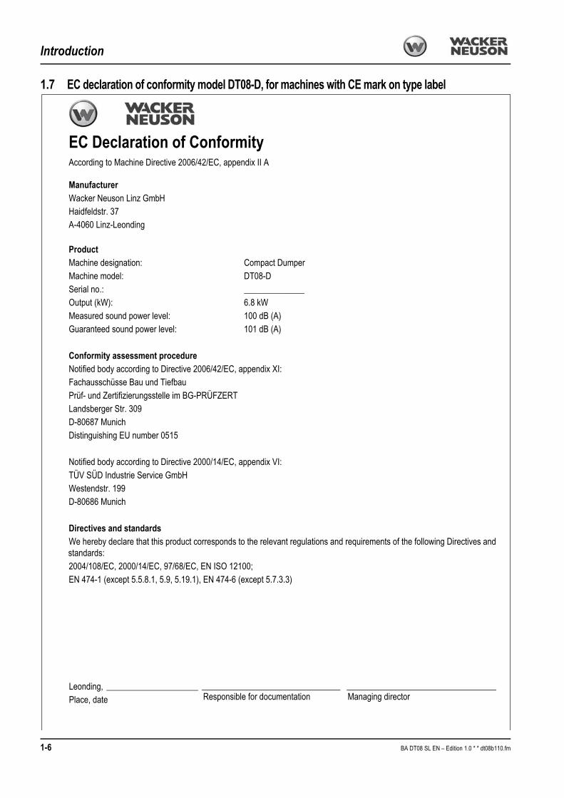
1.7 EC declaration of conformity model DT08-D, for machines with CE mark on type label
EC Declaration of ConformityAccording to Machine Directive 2006/42/EC, appendix II A
ManufacturerWacker Neuson Linz GmbHHaidfeldstr. 37A-4060 Linz-Leonding
ProductMachine designation: Compact DumperMachine model: DT08-DSerial no.: ______________Output (kW): 6.8 kWMeasured sound power level: 100 dB (A)Guaranteed sound power level: 101 dB (A)
Conformity assessment procedureNotified body according to Directive 2006/42/EC, appendix XI:Fachausschüsse Bau und Tiefbau Prüf- und Zertifizierungsstelle im BG-PRÜFZERTLandsberger Str. 309D-80687 MunichDistinguishing EU number 0515
Notified body according to Directive 2000/14/EC, appendix VI:TÜV SÜD Industrie Service GmbHWestendstr. 199D-80686 Munich
Directives and standards We hereby declare that this product corresponds to the relevant regulations and requirements of the following Directives and standards:2004/108/EC, 2000/14/EC, 97/68/EC, EN ISO 12100;EN 474-1 (except 5.5.8.1, 5.9, 5.19.1), EN 474-6 (except 5.7.3.3)
Managing directorResponsible for documentation Leonding, Place, date
1-6 BA DT08 SL EN – Edition 1.0 * * dt08b110.fm
Introduction
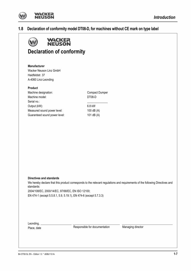
1.8 Declaration of conformity model DT08-D, for machines without CE mark on type label
Declaration of conformity
ManufacturerWacker Neuson Linz GmbHHaidfeldstr. 37A-4060 Linz-Leonding
ProductMachine designation: Compact DumperMachine model: DT08-DSerial no.: ______________Output (kW): 6.8 kWMeasured sound power level: 100 dB (A)Guaranteed sound power level: 101 dB (A)
Directives and standards We hereby declare that this product corresponds to the relevant regulations and requirements of the following Directives and standards:2004/108/EC, 2000/14/EC, 97/68/EC, EN ISO 12100;EN 474-1 (except 5.5.8.1, 5.9, 5.19.1), EN 474-6 (except 5.7.3.3)
Managing directorResponsible for documentation Leonding, Place, date
BA DT08 SL EN – Edition 1.0 * dt08b110.fm 1-7

Introduction
1.9 Type labels and component numbers
Serial number
The serial number is located on the type label.
The type label is located at the rear right of the control stand.
Type label information
Machine designation: COMPACT DUMPERModel: ---------------Model year: ---------------CEE no.: ---------------Output: ---------------Serial no.: ---------------Max. payload: ---------------GWR: ---------------Operating weight: ---------------Front GAWR: ---------------Transport weight: ---------------Rear GAWR: ---------------Version: ---------------Other information – see chapter 6 Specifications on page 6-33
Engine number
The type label (arrow) is located next to the oil check plug.
The type label (arrow) is located below the tank (engine).
Fig. 3: Position of the type label
COMPACT DUMPER
Fig. 4: Engine number (petrol engine)
Fig. 5: Diesel engine number
1-8 BA DT08 SL EN – Edition 1.0 * * dt08b110.fm

Introduction
1.10 Signs and symbols
XXXX
BA DT08 SL EN – Edition 1.0 * dt08b110.fm 1-9

Introduction
The following states signs and symbols which are not unequivocally comprehensible. They do not contain explanatory text and are not explained in the following chapters.
Meaning
Machine is raised by the eye hooks
– see chapter Crane handling the machine on page 3-20
Location
On the chassis near the front and rear eye hooks
Meaning
Points for tying down the machine.
The eye hooks are used for tying down the machine during loading and transport.
– see chapter Tying down the machine on page 3-22
Location
On the chassis near the front and rear eye hooks.
Meaning
Noise levels produced by the machine.
LWA = sound power level
Other information – see chapter on page 6-35
Location
Protective plate on control stand
Meaning
Indication of driver-perceived sound pressure level.
LPa = sound pressure level
Other information – see chapter on page 6-35
Location
Protective plate on control stand
Meaning
General indication of danger
This symbol alerts persons standing or working near the machine of an existing danger.
Location
On left and right of skip
Meaning
The CE mark means that the machine meets the requirements of the Machine Directive and that the conformity procedure has been carried out. The machine meets all the health and safety requirements of the Machine Directive.
Location
On the type label
Fig. 6: Eye hook label
Fig. 7: Label for points used for tying down the machine
Fig. 8: Noise level label
XX
Fig. 9: Label with indication of sound pressure
XX
Fig. 10: Danger label
Fig. 11: CE mark
1-10 BA DT08 SL EN – Edition 1.0 * * dt08b110.fm

Introduction
Meaning
Fill in petrol only! 91 octane regular
Location
On the control stand (model DT08-P)
Meaning
Fill in diesel fuel only!
Location
On the control stand (model DT08-D)
Meaning
The tank contains hydraulic oil.
– see chapter Filling up hydraulic oil on page 5-14
Location
Next to the filler inlet of the hydraulic oil tank
Meaning
Read the Operator’s Manual before using the machine.
Location
On left and right of skip
Meaning
Use a safety strut before carrying out work under the skip.
Location
On left and right of skip
Meaning
General indication of danger
This symbol alerts persons standing or working near the machine of an existing danger of shearing around the machine.
Location
On left and right of skip
Meaning
Do not touch hot surfaces, wait for parts to cool down.
Location
Near the exhaust system
Meaning
Danger due to spring-loaded components! Always read the Operator’s Manual before working on the tracks.
Location
Right and left-hand side of chassis
Fig. 12: Petrol
Fig. 13: Diesel
Fig. 14: Hydraulic oil
Fig. 15: Read the Operator’s Manual
Fig. 16: Safety strut
Fig. 17: Danger of shearing
Fig. 18: Hot surfaces
Fig. 19: Track tension adjustment
BA DT08 SL EN – Edition 1.0 * dt08b110.fm 1-11

Introduction
Meaning
This label explains the machine’s control elements
– see chapter 3.1 Control stand overview (model DT08-P skip and high-tip skip) on page 3-1 and – see chapter 3.2 Control stand overview (model DT08-D skip and high-tip skip) on page 3-2
Location
On the control stand
Meaning
Indication of throttle.
Location
On the control stand
Meaning
The machine’s control stand is not enclosed, therefore always carry an ear protection.
Location
On the control stand
Fig. 20: Main label
Fig. 21: Throttle
Fig. 22: Ear protection
1-12 BA DT08 SL EN – Edition 1.0 * * dt08b110.fm
Safety instructions
2 Safety instructions
2.1 Identification of warnings and dangers
Important indications regarding the safety of the staff and the machine are identified in this Operator’s Manual with the following terms and symbols:
Danger!
Failure to observe the instructions identified by this symbol can result in personal injury or death for the operator or other persons.
☞Measures for avoiding danger
Caution!
Failure to observe the instructions identified by this symbol can result in damage to the machine.
☞Measures for avoiding danger for the machine
Notice!
This symbol identifies instructions for a more efficient and economical use of the machine.
Environment!
Failure to observe the instructions identified by this symbol can result in damage to the environment. The environment is in danger if environmentally hazardous material (e.g. waste oil) is not subject to proper use or disposal.
2.2 Warranty
Warranty claims can be brought forward to your Wacker Neuson dealer only.Furthermore, the instructions in this Operator’s Manual must be observed.
2.3 Disposal
All fluids, lubricants, material, etc., used on the machine are subject to specific regulations regarding collection and disposal. Dispose of different materials and consumables sepa-rately and in an environmentally friendly manner!
Disposal may be carried out by a Wacker Neuson dealer only. Also observe the national regulations regarding disposal!
Environment!
Avoid damage to the environment! Do not allow the oil and oily wastes to get into the ground or stretches of water!
BA DT08 SL EN – Edition 1.0 * dt08b210.fm 2-1

Safety instructions
2.4 Designated use and exemption from liability
• The machine is intended for:• Moving earth, gravel, coarse gravel or ballast and rubble
• Every other application is regarded as not designated for the use of the machine. Wacker Neuson shall not be liable for damage resulting from this and the risk shall be fully borne by the user.Designated use also includes observing the instructions set forth in the Operator’s Manual and observing the maintenance and service conditions.
• The safety of the machine can be negatively affected by carrying out machine modifica-tions without proper authority and by using spare parts, equipment and options which have not been checked and released by Wacker Neuson. Wacker Neuson GmbH will not be liable for damage resulting from this
• Wacker Neuson Linz shall not be liable for personal injury and/or damage to property caused by failure to observe the safety instructions and the Operator’s Manual, and by the negligence of the duty to exercise due care when:• handling
• operating
• servicing and carrying out maintenance work and
• repairing the machine. This is also applicable in those cases in which special attention has not been drawn to the duty to exercise due care, in the safety instruc-tions, the Operator’s Manuals and maintenance manuals (machine/engine).
• Read and understand the Operator’s Manual before starting up, servicing or repairing the machine. Observe the safety instructions!
• The machine may not be used for transport jobs on public roads.
2.5 General conduct and safety instructions
Organisational measures
• The machine has been designed and built in accordance with state-of-the-art standards and the recognised safety regulations. Nevertheless, its use can constitute a risk to life and limb of the user or of third parties, or cause damage to the machine and to other material property
• The machine must only be used in technically perfect condition in accordance with its designated use and the instructions set forth in the Operator’s Manual, and only by safety-conscious persons who are fully aware of the risks involved in operating the machine! Any malfunctions, especially those affecting safety, must therefore be rectified immediately!Basic rule:Before putting the machine into operation, inspect the machine for safety in work and road operation!
• Careful and prudent working is the best way to avoid accidents!• The Operator’s Manual must always be at hand at the place of use of the machine, and
must therefore be kept in its storage bin.Immediately complete or replace an incomplete or illegible Operator’s Manual.
• In addition to the Operator’s Manual, observe and instruct the operator in all other generally applicable legal and other mandatory regulations relevant to accident prevention and environmental protection.These compulsory regulations may also deal with handling hazardous substances, issuing and/or wearing personal protective equipment, or traffic regulations
• With regard to specific operational features, e.g. those relevant to job organisation, work sequences or the persons entrusted with the work, supplement the Operator’s Manual by corresponding instructions, including those relevant to supervising and reporting duties
2-2 BA DT08 SL EN – Edition 1.0 * * dt08b210.fm

Safety instructions
• Persons entrusted with work on the machine must have read and understood the Operator’s Manual and in particular, chapter “Safety Instructions” before beginning work. This applies especially to persons working only occasionally on the machine, e.g. set-up or maintenance
• The user/owner must check – at least from time to time – whether the persons entrusted with operation or maintenance are working in compliance with the Operator’s Manual and are aware of risks and safety factors.
• The user/owner commits himself to operate and keep the machine in perfect condition, and, if necessary or required by law, to require the operating or servicing persons to wear protective clothing (e. g. safety shoes, hard hat).
• In the event of safety-relevant modifications or changes on the machine or of its behaviour, stop the machine immediately and report the malfunction to the competent authority/person.Safety-relevant damage or malfunctions of the machine must be rectified immediately
• Never make any modifications, additions or conversions to the machine and its super-structures (e.g. control stand, skip etc.), as well as to the attachments, which might affect safety without the approval of Wacker Neuson! This also applies to the instal-lation and the adjustment of safety devices and valves, as well as to welding work on load-bearing elements
• Spare parts must comply with the technical requirements specified by Wacker Neuson. Original spare parts can be relied to do so
• Replace hydraulic hoses within stipulated and appropriate intervals even if no safety-relevant defects have been detected
• Before working on or with the machine, remove jewellery, such as rings, wristwatches, bracelets etc., and tie back long hair and do not wear loose-fitting garments, such as unbuttoned or unzipped jackets, ties or scarves.Injury can result from being caught up in the machinery or from rings catching on moving parts!
• Keep the machine clean. This reduces
• Fire hazard, e.g. due to oil-soaked rags lying around
• Danger of injury, e.g. due to dirt or debris on the foothold, and
• Danger of accidents e.g. due to dirt pile-up on the control elements
• Observe all safety, warning and information signs and labels on the machine
• Adhere to prescribed intervals or those specified in the Operator’s Manual for routine checks/inspections and maintenance work!
• For service, inspection, maintenance or repair work, tools and workshop equipment adapted to the task on hand are absolutely indispensable.
Selection and qualification of staff, basic responsibilities
• Any work on or with the machine must be carried out by reliable staff only. Do not let unauthorised persons drive or work with the machine! Observe statutory minimum age limits!
• The machine may be used by correctly trained or competent staff only. The staff’s authorities for operating, equipping and carrying out maintenance and repair of the machine must be defined clearly and distinctly!
• Define the machine operator’s responsibilities – also with regard to observing traffic regulations. Give the operator the authority to refuse instructions by third parties that are contrary to safety.
• Do not allow persons to be trained or instructed or persons taking part in a general training course to work on or with the machine without being permanently supervised by an experienced person!
BA DT08 SL EN – Edition 1.0 * dt08b210.fm 2-3

Safety instructions
• Work on the electrical system and equipment, on the undercarriage and the steering and brake systems may be carried out only by skilled staff which has been specially trained for such work. Work on the hydraulic system of the machine must be carried out only by staff with special knowledge and experience in hydraulic equipment!
• Seal off the danger zone should it not be possible to keep a safe distance.Stop work if persons do not leave the danger zone in spite of warning! Keep out of the danger zone!
Danger zone:
The danger zone is the area in which persons are in danger due to the movements of the
• machine• work equipment• additional equipment or• material• This also includes the area affected by falling material, equipment or by parts which
are thrown out.The danger zone must be extended by 0.5 m in the immediate vicinity of
• buildings• scaffolds or• other elements of construction
2.6 Safety instructions regarding operationNormal operation
• Avoid any operational mode that might be prejudicial to safety! • Before beginning work, familiarise yourself with the surroundings and circumstances of
the work site. These are e.g. obstacles in the working and travelling area, the soil bearing capacity and any necessary barriers separating the work site from public roads
• Take the necessary precautions to ensure that the machine is used only when in a safe and reliable state!Operate the machine only if all protective and safety-oriented devices, e.g. removable safety-devices, soundproofing elements and exhausters etc., are in place and fully functional!
• Check the machine at least once a day/per work shift for visible damage and defects! Report any changes (incl. changes in working behaviour) to the competent organi-sation/person immediately! If necessary, stop the machine immediately and lock it!
• In the event of malfunctions, stop the machine immediately and lock it! Have any defects rectified immediately!
• Start and operate the machine from the seat only! • Carry out start-up and shut-down procedures in accordance with the Operator’s
Manual, and observe the indicator lights! • Before putting the machine/attachment into operation (start-up/moving), ensure that no-
one is at risk by putting the machine/attachment into operation! • Before driving with the machine, and also after interrupting work, check whether all
control levers are functional!• Before moving the machine always check whether the supplementary equipment has
safely stowed away or attached! • When driving on public roads, ways and places for purposes of construction work,
observe the traffic regulations in force and, if necessary, ensure beforehand that the machine is in a condition perfectly compatible with these regulations!
• Ensure good illumination of the machine’s work area in conditions of poor visibility or after dark!• Stop work if this is not possible to a reasonable degree!
• Since the machine has no acoustic warning system, stop the machine or interrupt work immediately if a person is likely to approach the working range of the machine!
2-4 BA DT08 SL EN – Edition 1.0 * * dt08b210.fm

Safety instructions
• No lifting, lowering or carrying persons!• Installing a man basket or a working platform is prohibited!• When crossing underpasses, bridges and tunnels, or when passing under overhead
lines always ensure that there is enough clearance! • Always keep a safe distance from the edges of building pits and slopes! • When working in buildings or in enclosed areas, look out for:
• Height of the ceiling/clearances • Width of entrances• Maximum load of ceilings and floors• Sufficient room ventilation – danger of poisoning!
• Avoid any operation that might be a risk to machine stability! • During operation on slopes, drive or work uphill or downhill. If driving across a slope
cannot be avoided, bear in mind the tilting limit of the machine! Always keep the work equipment close to the ground! This also applies to driving downhill! When driving or working across a slope, the load must be on the uphill side of the machine.
• If the skip is less than half full, drive backwards uphill or forwards downhill.• If the skip is more than half full, drive forwards uphill or backwards downhill.• On sloping terrain always adapt your drive speed to the prevailing ground conditions!
Never change to lower gear on a slope but always before reaching it! • Before leaving the seat always secure the machine against unintentional movement
and unauthorised use!Lower the work equipment to the ground
• The machine has no FOPS protection. Therefore, do not use the machine in areas with danger of falling objects!
• Before starting work check whether • all safety devices are properly installed and functional
• Before moving the machine or before taking up work:• Ensure that visibility is sufficient• Inspect the immediate area (children!)• In the work area the operator is responsible for third parties!
• Caution when handling fuel – increased danger of fire!• Ensure that fuel does not come into contact with hot parts!
Do not smoke during refuelling, and avoid fire and sparks. Stop the engine during refuelling and do not smoke!
• Operation in potentially explosive areas is forbidden.• Never get on or off a moving machine! Never jump off the machine! • The drive levers take time getting used to them. Drive speed must be adapted to your
skills and to the prevailing conditions.
BA DT08 SL EN – Edition 1.0 * dt08b210.fm 2-5

Safety instructions
Applications with lifting gearDefinition:Applications with lifting gear are understood as procedures involving raising, transporting and lowering loads with the help of slings and load-securing devices (e.g. ropes, chains). In doing so, the help of persons is necessary for securing and detaching the load. This applies for example to lifting and lowering pipes, shaft rings or containers.
• No applications with lifting gear!Trailers
• Hitching and towing other vehicles is not allowed!
Transport• The machine must be loaded and transported only in accordance with the Operator’s
Manual! • For towing the machine observe the prescribed transport position, admissible speed
and itinerary.• Use only suitable means of transport of adequate capacity/payload! • Safely secure the machine on means of transport! Use suitable mounting points and
load-securing devices• The recommissioning procedure must be strictly in accordance with the Operator’s
Manual!
Temperature rangesThe machine can be used at a maximum temperature of +45 °C and a minimum tempera-ture of −15 °C. Get in touch with your Wacker Neuson dealer if you intend to use the machine in other temperature ranges (e. g. tropical temperatures, etc.). Carry out all maintenance and inspection work before storing the machine for the winter. Then store the machine in a dry place at ambient temperature (about +15 °C). Observe these temperature ranges so as not to affect the machine’s service life.
2-6 BA DT08 SL EN – Edition 1.0 * * dt08b210.fm

Safety instructions
2.7 Safety instructions for maintenance
• Avoid any operational mode that might be prejudicial to safety! • Observe the adjustment, maintenance and inspection activities and intervals set forth in
the Operator’s Manual, including information on the replacement of parts/partial equipment! These activities must be carried out by technical staff only.
• The machine may not be serviced, repaired or test-driven by unauthorised staff• Brief the staff/the driver before beginning special operations and maintenance work!
Appoint a person to supervise the activities! • In any work concerning the operation, conversion or adjustment of the machine and its
safety-oriented devices, or any work related to maintenance, inspection and repair, observe the start-up and shut-down procedures set forth in the Operator’s Manual, and the information on maintenance work.
• If required, secure the maintenance area appropriately! • Prior to carrying out service, maintenance and repair work, attach a warning label, such
as “Repair work – do not start machine!”, to the ignition lock/steering wheel or to the control elements. Remove the ignition key!
• Carry out service, maintenance and repair work only if the• machine is positioned on firm and level ground• the forwards-reverse lever is in neutral• all hydraulically movable attachments and working equipment have been lowered to
the ground• engine is stopped• ignition key is removed and• machine has been secured against unintentional movement• the maintenance strut is installed – see chapter Maintenance strut on page 5-1
• Should maintenance or repair be inevitable with the engine running:• Only work in groups of two• Both persons must be authorised for the operation of the machine• Observe the specific safety instructions in the work manual• Keep a safe distance from all rotating and moving parts, e.g. fan blades, V-belt
drives, fans etc.• Prior to carrying out assembly work on the machine, ensure that no movable parts will
roll away or start moving.• To avoid the risk of accidents, parts and large assemblies being moved for replacement
purposes must be carefully attached and secured to lifting gear. Use only suitable lifting gear and suspension systems in a technically perfect state with adequate load-bearing capacity! Stay clear of suspended loads!
BA DT08 SL EN – Edition 1.0 * dt08b210.fm 2-7

Safety instructions
• Have loads fastened and crane operators guided by experienced persons only!The person guiding the operator must be within sight or sound of him
• Always use specially designed or otherwise safety-oriented ladders and working platforms to carry out overhead assembly work.Never use machine parts or attachments/superstructures as a climbing aid!Wear a safety harness when carrying out maintenance work at greater heights!Keep all handles, steps, handrails, platforms, landings and ladders free from dirt, snow and ice!
• Clean the machine, especially connections and threaded unions, of any traces of oil, fuel or preservatives before carrying out maintenance/repair work!Do not use aggressive detergents!Use lint-free cleaning rags!
• Before cleaning the machine with water, steam jet (high-pressure cleaner) or deter-gents, cover or tape up all openings which – for safety and functional reasons – must be protected against water, steam or detergent penetration. Special care must be taken with the electrical system.
• After cleaning, remove all covers and tapes applied for that purpose! • After cleaning, examine all fuel, lubricant and hydraulic oil lines for leaks, chafe marks
and damage!Rectify all defects without delay!
• Always tighten any screw connections that have been loosened during maintenance and repair!
• Any safety devices removed for set-up, maintenance or repair purposes must be refitted and checked immediately upon completion of the maintenance and repair work.
• Ensure that all consumables and replaced parts are disposed of safely and with minimum environmental impact!
• Do not use the work equipment as lifting platforms for persons! • Before taking up work on machine parts dangerous for life and limb (bruising, cutting),
always ensure safe blocking/support of these areas• Carry out maintenance and repair work beneath a raised machine, attachments or
additional equipment only if a safe and secure support has been provided for (the sole use of hydraulic rams, jacks etc. does not sufficiently secure raised machines or equipment/attachments)
• Avoid contact with hot parts, such as the engine block or the exhaust system during the operation of the machine and for some time afterwards – danger of burns!
• Retainer pins can fly out or splinter when struck with force – danger of personal injury! • Do not use starting fuel! This especially applies to those cases in which a heater plug
(intake-air preheating) is used at the same time – danger of explosions! • Apply special care when working on the fuel system – increased danger of fire!
2-8 BA DT08 SL EN – Edition 1.0 * * dt08b210.fm

Safety instructions
2.8 Warning of special hazardsElectrical energy
• Use only original fuses with the specified current rating!Switch off the machine immediately and rectify the malfunction if trouble occurs in the electrical system!
• When working with the machine, maintain a safe distance from overhead electric lines! If work must be carried out close to overhead lines, the equipment/attachments must be kept well away from them. Caution, danger! Get informed on the prescribed safety distances!
• If your machine comes into contact with a live wire
• Warn others against approaching and touching the machine
• Have the live wire de-energised
• Do not leave the machine until the line that has been touched or damaged has been safely de-energised!
• Work on the electrical system may only be carried out by a technician with appropriate training, in accordance with the applicable electrical engineering rules
• Inspect and check the electric equipment of the machine at regular intervals. Defects such as loose connections or scorched cables must be rectified immediately
• Observe the machine’s operating voltage!
• Always remove the earthing strap from the battery when working on the electrical system or when carrying out welding work!
• Starting with a battery jumper cable can be dangerous if carried out improperly. Observe the safety instructions regarding the battery!
Gas, dust, steam, smoke
• Operate the machine only on adequately ventilated premises! Before starting the internal combustion engine on enclosed premises, ensure that there is sufficient venti-lation!Observe the regulations in force at the respective site!
• Welding, burning and grinding work on the machine may only be carried out by a Wacker Neuson dealer. Risk of fire and explosion!
• Before carrying out welding, flame-cutting and grinding work, clean the machine and its surroundings from dust and other inflammable substances, and ensure that the premises are adequately ventilated – danger of explosions!
• In areas with special hazards (e.g. toxic gases, caustic vapours, toxic environments), wear appropriate protective equipment (breathing filters, protective clothing)!
Hydraulics
• Work on the hydraulic equipment of the machine must be carried out only by persons having specific technical knowledge and experience in hydraulic systems!
• Check all lines, hoses and screw connections regularly for leaks and obvious damage! Repair any damage and leaks immediately! Splashed oil can cause injury and fire
• In accordance with the Operator’s Manual/instructions for the respective assembly, release the pressure in all system sections and pressure lines (hydraulic system) to be opened before carrying out any implementing/repair work!
• Hydraulic and compressed-air lines must be laid and fitted properly! Ensure that no connections are interchanged! The fittings, lengths and quality of the hoses must comply with the technical requirements
BA DT08 SL EN – Edition 1.0 * dt08b210.fm 2-9

Safety instructions
Noise
• During operation all sound baffles must be closed.• Wear ear protectors if necessary!
Oil, grease and other chemical substances
• When handling oil, grease and other chemical substances (e.g. battery electrolyte – sulphuric acid), observe the product-related safety regulations (safety data sheet)!
• Be careful when handling hot consumables – risk of being burned or scalded by fluids!
Battery
• When handling the battery observe the specific safety instructions and regulations relevant to accident prevention. Batteries contain sulphuric acid – caustic!
• When charging batteries in particular, as well as during normal operation of batteries, an oxyhydrogen mixture is formed in the battery cells. Danger of explosion!
• In case of a frozen battery or of an insufficient electrolyte level, do not try start-up with a battery jumper cable. The battery can burst or explode
☞Dispose of the battery immediately
Tracks
• Repair work on the tracks must be carried out by technical staff or by an authorised workshop only!
• Defective tracks reduce the machine’s operational safety. Therefore carry out regular checks of the tracks for• Cracks, cuts or other damage
• Check track tension at regular intervals.
2-10 BA DT08 SL EN – Edition 1.0 * * dt08b210.fm

Operation
3 Operation
This chapter describes the controls, and contains information on the function and handling of the indicator lights and controls.
The pages stated in the table refer to the description of the controls.
Numeric or alphanumeric combinations (for example 40/18 or 40/A) used for identifying control elements, mean: figure no. 40/control element no. 18, or position A in figure no. 40
Figures carry no numbers if they are placed to the left of the text.
3.1 Control stand overview (model DT08-P skip and high-tip skip)
Pos. Description For more information see page1 Loader unit operation (option)/raise skip (option) ......................................................................................................................3-182 Skip operation ......................................................................................................................................................................3-173 Normal or high speed lever ....................................................................................................................................................3-134 Drive lever (left) ....................................................................................................................................................................3-135 Drive lever (right) ..................................................................................................................................................................3-136 Throttle
7 Auxiliary hydraulics (option).................................................................................................................................................................... 3-288 Hour meter
9 Lock
1 2 3 46
5
8
7
9
BA DT08 SL EN – Edition 1.0 * dt08b320.fm 3-1

Operation
3.2 Control stand overview (model DT08-D skip and high-tip skip)
1 2 3 546
12
8 9
10
13
7
11
Pos. Description For more information see page1 Loader unit operation (option)/raise skip (option) ......................................................................................................................3-182 Skip operation ......................................................................................................................................................................3-173 Normal or high speed lever ....................................................................................................................................................3-134 Drive lever (left) ....................................................................................................................................................................3-135 Drive lever (right) ..................................................................................................................................................................3-136 Throttle
7 Auxiliary hydraulics (option).................................................................................................................................................................... 3-288 Hour meter
9 Ignition lock
10 Alternator charge function indicator light ....................................................................................................................................3-311 Engine oil pressure indicator light 3-312 Lock
13 Buzzer ...................................................................................................................................................................................................... 3-3
3-2 BA DT08 SL EN – Edition 1.0 * * dt08b320.fm

Operation
10 Alternator charge function indicator light
Caution!
If the indicator light comes on with the engine running:
☞Stop the engine immediately and
☞Have the cause repaired by an authorised workshop
The alternator or the charging circuit of the alternator is faulty if the indicator light comes on with the engine running. The battery is no longer charged.
11 Engine oil pressure indicator light
Caution!
If the indicator light comes on with the engine running:
☞Stop the engine immediately and
☞Check the oil level. If it is too low, fill up the engine oil. If it is correct, contact an authorised workshop.
The oil pressure is too low if this indicator light comes on with the engine running. Operat-ing the machine with insufficient oil pressure can cause engine damage!
13 Buzzer
The buzzer sounds as soon as ignition is switched on.
This avoids emptying the battery by leaving ignition switched on unintentionally.
☞Turn the ignition key and switch off the control panel.
BA DT08 SL EN – Edition 1.0 * dt08b320.fm 3-3

Operation
3.3 Putting into operation
Safety instructions
• Always face the machine as you get on and off the machine
• Never use the controls or movable lines and cables as handles
• Never get on or off a moving machine! Never jump off the machine
Putting the machine into operation for the first time
Important information
• The machine may be put into operation by authorised staff only – see chapter Selection and qualification of staff, basic responsibilities on page 2-3 and – see chapter 2 Safety instructions on page 2-1 of this Operator’s Manual.
• The staff must have read and understood this Operator’s Manual before putting the machine into operation
• The machine may only be used in technically perfect condition in accordance with its designated use and the instructions set forth in the Operator’s Manual, and only by safety-conscious persons who are fully aware of the risks involved in operating the machine
• Go through the “Start-up” checklist in the following chapter
Running-in period
Handle the machine carefully during its first 50 operating hours.
The future performance and service life of the machine are heavily dependent on the observance of the following recommendations during the running-in period.
• Do not overload the machine, but at the same time do not drive too cautiously either, as the machine will never reach its proper operating temperature
• Do not run the engine at high speed for extended periods
• Increase the load gradually whilst varying the engine speed
• Strictly observe the maintenance schedules in the appendix– see chapter 5.10 Maintenance plan DT08-P (petrol engine) on page 5-25 – see chapter 5.11 Maintenance plan DT08-D (diesel engine) on page 5-27
3-4 BA DT08 SL EN – Edition 1.0 * * dt08b320.fm
Operation
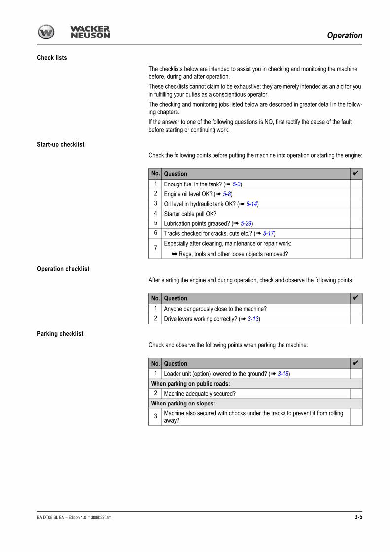
Check lists
The checklists below are intended to assist you in checking and monitoring the machine before, during and after operation.
These checklists cannot claim to be exhaustive; they are merely intended as an aid for you in fulfilling your duties as a conscientious operator.
The checking and monitoring jobs listed below are described in greater detail in the follow-ing chapters.
If the answer to one of the following questions is NO, first rectify the cause of the fault before starting or continuing work.
Start-up checklist
Check the following points before putting the machine into operation or starting the engine:
Operation checklist
After starting the engine and during operation, check and observe the following points:
Parking checklist
Check and observe the following points when parking the machine:
No. Question ✔
1 Enough fuel in the tank? (➠ 5-3)2 Engine oil level OK? (➠ 5-8)3 Oil level in hydraulic tank OK? (➠ 5-14)4 Starter cable pull OK?5 Lubrication points greased? (➠ 5-29)6 Tracks checked for cracks, cuts etc.? (➠ 5-17)
7Especially after cleaning, maintenance or repair work:
➥Rags, tools and other loose objects removed?
No. Question ✔
1 Anyone dangerously close to the machine?2 Drive levers working correctly? (➠ 3-13)
No. Question ✔
1 Loader unit (option) lowered to the ground? (➠ 3-18)
When parking on public roads:2 Machine adequately secured?
When parking on slopes:
3 Machine also secured with chocks under the tracks to prevent it from rolling away?
BA DT08 SL EN – Edition 1.0 * dt08b320.fm 3-5

Operation
Operation
Before starting the engine
☞Run through the “Start-up” checklist
General information on starting the petrol engine
Caution!
Never start the petrol engine without petrol!
☞Always check the fuel tank contents before!
• The engine will not start unless the fuel cock is open• Do not run the starter for more than 5 seconds if the engine does not start• Wait about 10 seconds before trying again
Procedure
After you have completed the starting preparations:☞Open the engine cover
☞Turn fuel cock A to the right
☞Turn choke lever B to the left
Notice!
Do not use choke lever B if the engine is warm or at high air temperatures.
☞Slightly move throttle 6 forwards
☞Turn the engine switch to position E
Fig. 23: Fuel cock
A
B
Fig. 24: Throttle
6
Fig. 25: Engine switch
D
E
3-6 BA DT08 SL EN – Edition 1.0 * * dt08b330.fm

Operation
Manual starter
Caution!
Do not allow starter handle F to whiplash against the engine.
☞Carefully move back handle F to avoid damage to the starter.
☞Slightly pull starter handle F until you can feel a resistance, then firmly pull the handle.
Electric starter
☞Turn starter G to position H and keep it in this position until the engine starts.
➥Move the switch back to position I after the engine has started.
Notice!
Do not actuate the electric starter for more than 5 seconds. If the engine does not start, release the ignition switch and wait 10 seconds before actuating the starter again.
Circuit-breaker (for electric starter):The circuit-breaker protects the battery’s load circuit. The circuit-breaker is triggered in case of a short circuit or if the battery’s terminals are inverted.The green indicator in the circuit-breaker is ejected to indicate that the circuit-breaker has been triggered. In this case find out the cause for the error or contact your Wacker Neuson workshop before resetting the circuit-breaker.☞Press circuit-breaker button J back in to reset.
Starting at low temperatures
When the engine runs smoothly (increased engine speed):
Notice!
In general, a battery delivers less energy in cold conditions. Therefore ensure that the battery is always well charged.
When the engine has started
☞Gradually push choke lever A to position B
☞Let the engine warm up
➥After the engine has reached its operating temperature, move choke lever A fully to the right
At cold temperatures:☞ Increase the engine speed slowly
☞Do not run the engine at full load until it has reached its operating temperature
Fig. 26: Starter handle
F
Fig. 27: Electric starter
G
H
I
J
K
Fig. 28: Choke lever
A
B
BA DT08 SL EN – Edition 1.0 * dt08b330.fm 3-7
Operation
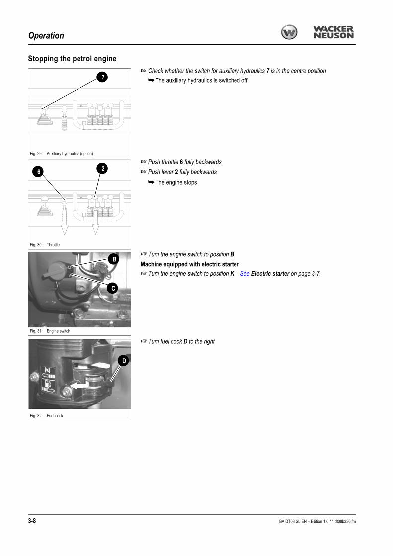
Stopping the petrol engine
☞Check whether the switch for auxiliary hydraulics 7 is in the centre position
➥The auxiliary hydraulics is switched off
☞Push throttle 6 fully backwards
☞Push lever 2 fully backwards
➥The engine stops
☞Turn the engine switch to position B
Machine equipped with electric starter☞Turn the engine switch to position K – See Electric starter on page 3-7.
☞Turn fuel cock D to the right
Fig. 29: Auxiliary hydraulics (option)
7
Fig. 30: Throttle
6 2
Fig. 31: Engine switch
B
C
Fig. 32: Fuel cock
D
3-8 BA DT08 SL EN – Edition 1.0 * * dt08b330.fm
Operation
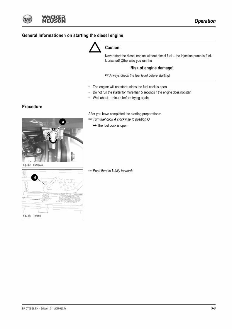
General Informationen on starting the diesel engine
Caution!
Never start the diesel engine without diesel fuel – the injection pump is fuel-lubricated! Otherwise you run the
Risk of engine damage!
☞Always check the fuel level before starting!
• The engine will not start unless the fuel cock is open• Do not run the starter for more than 5 seconds if the engine does not start• Wait about 1 minute before trying again
Procedure
After you have completed the starting preparations:☞Turn fuel cock A clockwise to position O
➥The fuel cock is open
☞Push throttle 6 fully forwards
Fig. 33: Fuel cock
A
OS
6
Fig. 34: Throttle
BA DT08 SL EN – Edition 1.0 * dt08b330.fm 3-9

Operation
Manual starter
Caution!
Do not allow starter handle C to whiplash against the engine.
☞Carefully move back handle C to avoid damage to the starter.
☞Slightly pull starter handle C until you can feel a resistance, then slowly release starter handle C.
☞Press decompression lever D all the way down.
☞Firmly and quickly pull starter handle C with both hands
➥ If the engine does not start:
☞Repeat the procedure.
Notice!
The engine will not start unless the cable is pull fully and firmly!
Electric starter
☞Turn the ignition key to position 1
Turn and hold the ignition key in position 3 until the engine starts
➥ If the engine does not start after 5 seconds
☞Stop starting the engine and try again after 10 seconds
➥ If the engine still does not start after the second try
☞Contact a Wacker Neuson workshop for troubleshooting
➥As soon as the engine runs:
☞Release the ignition key
Notice!
Do not actuate the electric starter for more than 5 seconds.
Fig. 35: Starter handle
C
Fig. 36: Decompression lever
D
Fig. 37: Starting
1
3
3-10 BA DT08 SL EN – Edition 1.0 * * dt08b330.fm

Operation
Starting at low temperatures
When the engine runs smoothly (increased engine speed):
Notice!
In general, a battery delivers less energy in cold conditions. Therefore ensure that the battery is always well charged.
When the engine has started
☞Let the engine warm up
At cold temperatures:☞ Increase the engine speed slowly
☞Do not run the engine at full load until it has reached its operating temperature
Stopping the diesel engine
☞Check whether the switch for auxiliary hydraulics 7 is in the centre position
➥The auxiliary hydraulics is switched off
☞Push throttle 6 fully backwards until the engine stops
➥The acoustic warning system 13 sounds to indicate that the control panel is still switched on.
☞Turn ignition key B to position E
☞Turn fuel cock F counterclockwise to position S
Fig. 38: Auxiliary hydraulics (option)
7
Fig. 39: Throttle
6
13
Fig. 40: Electric starter
B
E
Fig. 41: Fuel cock
F
OS
BA DT08 SL EN – Edition 1.0 * dt08b330.fm 3-11

Operation
Jump-starting the engine (supply battery)
Safety instructions
• Never jump-start the engine if the battery of the machine is frozen – danger of explosion!
☞Dispose of a frozen battery!
• The dumper must not touch the jump-starting vehicle when connected with jump leads – risk of sparking!
• The external power source must deliver 12 V; higher supply voltages will damage the electrical system of the vehicles!
• Use only authorised jump leads which conform to the safety requirements and which are in perfect condition!
• The jump lead connected to the positive + terminal of the starting battery must never be brought into connection with electrically conductive vehicle parts – danger of short circuit!
• Route the jump leads so they cannot catch on rotating components in the engine compartment!
Procedure☞Drive the jump-starting vehicle close enough to the machine so that the jump leads can
reach to connect the two batteries
☞Let the engine of the jump-starting vehicle run
☞First connect one end of the red jump lead (+) to the + terminal of the flat battery, then connect the other end to the + terminal of the starting battery
☞Connect one end of the black jump lead (–) to the – terminal of the starting battery
☞Connect the other end of the black jump lead (–) onto a solid metal component fimly mounted on the engine block or onto the engine block itself. Do not connect it to the negative terminal of the flat battery, as otherwise explosive gas emerging from the bat-tery can ignite if sparks are formed!
☞Start the engine of the machine with the flat battery
Once the engine has started:☞With the engine running, disconnect both jump leads in exactly the reverse order (first
remove the – terminal, then the + terminal) – this prevents sparking in the vicinity of the battery!
Special instructions for driving on public roads
The machine is subject to the:• Applicable legal regulations of your country (e.g. road traffic regulations)
Notice!
Operation of electric consumers (e.g. lighting equipment) is not allowed. This is why the machine has no socket.
Also observe the applicable regulations for accident prevention of your country.
12 V
12 V
34001b710_05.epsFig. 42: Starting aid with jump leads
Flat battery
Startingbattery
3-12 BA DT08 SL EN – Edition 1.0 * * dt08b330.fm

Operation
Moving off
After starting the engine:☞Slowly actuate the drive lever
➥Machine moves off
Danger!
The machine has no rearview mirrors –
Danger of accidents when reversing!
☞The driver must be guided by another person if he does not have sufficient visibility to the rear.
Drive levers
Caution!
Never drive the machine with the skip dumped out and with the loader unit lowered.
☞Dump in the skip.
☞Raise the loader unit.
The drive movements of the machine are controlled with drive levers 4 and 5.
The machine has two drive speeds which can be selected as follows:☞Push lever 3 forwards – see Control stand overview (model DT08-P skip and high-
tip skip) on page 3-1 or – see Control stand overview (model DT08-D skip and high-tip skip) on page 3-2
➥The machine moves at high speed
☞Pull lever 3 backwards
➥The machine moves at slow speed.
Notice!
Ensure that both tracks move as you change direction, otherwise the rubber tracks are subject to increased abrasion.
Fig. 43: Drive lever
C
A B
D
4
3
5Position Function
• A
• B4Push forwards5 Push forwards
Track dumper moves forwards
• C
• D4 Pull backwards5 Pull backwards
Track dumper moves backwards
• C
• B4Pull backwards5 Push forwards
Track dumper turns to the left
• A
• D4Push forwards5 Pull backwards
Track dumper turns to the right
BA DT08 SL EN – Edition 1.0 * dt08b330.fm 3-13
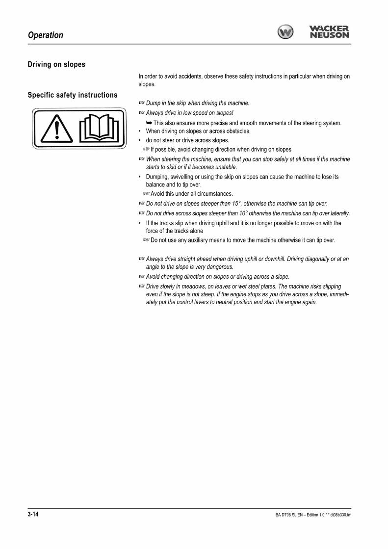
Operation
Driving on slopes
In order to avoid accidents, observe these safety instructions in particular when driving on slopes.
Specific safety instructions☞Dump in the skip when driving the machine.
☞Always drive in low speed on slopes!
➥This also ensures more precise and smooth movements of the steering system.• When driving on slopes or across obstacles, • do not steer or drive across slopes.
☞ If possible, avoid changing direction when driving on slopes
☞When steering the machine, ensure that you can stop safely at all times if the machine starts to skid or if it becomes unstable.
• Dumping, swivelling or using the skip on slopes can cause the machine to lose its balance and to tip over.
☞Avoid this under all circumstances.
☞Do not drive on slopes steeper than 15°, otherwise the machine can tip over.
☞Do not drive across slopes steeper than 10° otherwise the machine can tip over laterally.
• If the tracks slip when driving uphill and it is no longer possible to move on with the force of the tracks alone
☞Do not use any auxiliary means to move the machine otherwise it can tip over.
☞Always drive straight ahead when driving uphill or downhill. Driving diagonally or at an angle to the slope is very dangerous.
☞Avoid changing direction on slopes or driving across a slope.
☞Drive slowly in meadows, on leaves or wet steel plates. The machine risks slipping even if the slope is not steep. If the engine stops as you drive across a slope, immedi-ately put the control levers to neutral position and start the engine again.
3-14 BA DT08 SL EN – Edition 1.0 * * dt08b330.fm

Operation
Driving across slopesThe dumper may be driven on firm ground across a slope of up to 10°.
Danger!
Do not exceed the maximum slope.
Danger of accidents!☞The angle must be smaller in the case of soft and uneven ground!
☞Do not actuate the skip as you drive on slopes
☞Always dump in the skip before driving on slopes
☞Always keep the loader unit 30 – 40 cm above the ground when driving the machine.
☞Always reduce your speed as you drive on slopes – see Drive levers on page 3-13
☞Always drive straight ahead when driving uphill or downhill. Avoid driving diagonally or at an angle.
☞The machine is very narrow. Therefore, drive very carefully on slopes or on soft or uneven ground.
☞Drive with extreme care on slopes in rain or if the ground is wet or slippery.
Driving on slopesThe dumper may be driven on firm ground on a slope of up to 15°.
Danger!
Do not exceed the maximum slope.
Danger of accidents!
☞The driver is not allowed to stand on the foothold when driving on slopes with a loaded machine!
☞ If the skip is less than half full, drive backwards uphill or forwards downhill.
☞ If the skip is more than half full, drive forwards uphill or backwards downhill.
☞The angle must be smaller in the case of soft and uneven ground!
☞Before driving on a slope, lower the skip and do not operate it on the slope!
☞Always keep the loader unit 30 – 40 cm above the ground.
☞Always reduce your speed as you drive on slopes – see Drive levers on page 3-13
☞Always drive straight ahead when driving uphill or downhill. Avoid driving diagonally or at an angle.
☞The machine is very narrow. Therefore, drive very carefully on slopes or on soft or uneven ground.
☞Drive with extreme care on slopes in rain or if the ground is wet or slippery.
Fig. 44: Driving across slopes
max. 10°
Fig. 45: Driving with a load on slopes
Fig. 45: Driving an empty machine on slopes
max. 15°
max. 15°
BA DT08 SL EN – Edition 1.0 * dt08b330.fm 3-15

Operation
Driving on slopes with a high-tip skip
☞Do not raise or dump out the skip on slopes, otherwise the machine can tip forwards.
☞Unloading on slopes is not allowed.
☞Driving with a raised and tilted skip is forbidden regardless of the ground the machine is driving on.
☞Raise and dump out the skip only if the machine is at a standstill.
Fig. 46: Do not raise or dump out the skip on slopes, other-wise the machine can tip forwards.
< 15°
< 10°
Fig. 47: Driving with a high-tip skip
3-16 BA DT08 SL EN – Edition 1.0 * * dt08b330.fm

Operation
Skip operation
Danger!
Do not operate the skip when driving on slopes, otherwise –
Danger of accidents!
☞Do not actuate the skip when driving across slopes
☞Do not actuate the skip when driving up or down slopes
Notice!
The loader unit also moves as the skip is dumped in and out.
High-tip skip (option)
Danger!
Do not operate the skip when driving on slopes, otherwise –
Danger of accidents!
☞Do not actuate the skip when driving across slopes
☞Do not actuate the skip when driving up or down slopes
Notice!
The loader unit also moves as the skip is dumped in and out.
Fig. 48: Skip operation
A
B
2Position Function
• A 2 Push forwards Skip is dumped out
• B 2 Pull backwards Skip is dumped in
Fig. 49: Operating the high-tip skip
A
B
E
F
1 2
Position Function
• A 1 Push forwards Skip is lowered
• B 1 Pull backwards Skip is raised
• E 2 Push forwards Skip is dumped out
• F 2 Pull backwards Skip is dumped in
BA DT08 SL EN – Edition 1.0 * dt08b330.fm 3-17

Operation
Loader unit operation (option)
Notice!
Always keep the loader unit 30 – 40 cm above the ground when driving the machine.
Fig. 50: Loader unit
A
B
1 Position Function
• A 1 Push forwards Loader unit is lowered
• B 1 Pull backwards Loader unit is raised
3-18 BA DT08 SL EN – Edition 1.0 * * dt08b330.fm
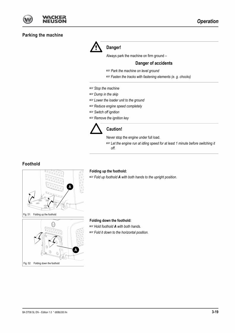
Operation
Parking the machine
Danger!
Always park the machine on firm ground –
Danger of accidents
☞Park the machine on level ground
☞Fasten the tracks with fastening elements (e. g. chocks)
☞Stop the machine
☞Dump in the skip
☞Lower the loader unit to the ground
☞Reduce engine speed completely
☞Switch off ignition
☞Remove the ignition key
Caution!
Never stop the engine under full load.
☞Let the engine run at idling speed for at least 1 minute before switching it off.
Foothold
Folding up the foothold:
☞Fold up foothold A with both hands to the upright position.
Folding down the foothold:
☞Hold foothold A with both hands.
☞Fold it down to the horizontal position.
Fig. 51: Folding up the foothold
A
A
Fig. 52: Folding down the foothold
BA DT08 SL EN – Edition 1.0 * dt08b330.fm 3-19

Operation
Crane handling the machine
Safety instructions• The crane and the lifting gear must have suitable dimensions• Crane handling the machine requires suitable lifting gear• Secure the machine against unintentional movement!
Danger!
Incorrect crane handling of the machine –
Danger of accidents!
☞Ensure that no-one is near the machine!
☞Have loads fastened and crane operators guided by experienced persons only! The person guiding the crane operator must be within sight or sound of him
☞Ensure that the crane and the lifting gear (cables, chains) have sufficient load-bearing capacity!
☞Only raise the machine with an empty loader unit and skip
☞Stay clear of suspended loads!
☞ It is essential that you read the safety instructions at the beginning of this chapter and follow any other safety instructions relevant in your country!
☞Load the machine as follows:
• Empty the skip and the loader unit
• Lower the skip
• Stop the engine
• Remove the ignition key.
• Use suitable lifting gear, chains etc.
☞Length L1 of the lifting gear on the skip must be at least 2.0 m long
☞Length L2 of the lifting gear (two cables or chains) on the control stand must be at least 2.0 m long
• Slowly raise the machine
Fig. 53: Craning operation
L1L2
L2
L1 L2
3-20 BA DT08 SL EN – Edition 1.0 * * dt08b330.fm

Operation
Loading and transporting the machine
Safety instructions• The transport vehicle must be of sufficient size. See Chapter 6 “Specifications” for
the dimensions and the weight of the machine!• Remove any mud, snow or ice from the tracks so that the machine can be safely driven
onto the ramps• Secure the machine against unintentional movement – see Parking the machine on
page 3-19!
Danger!
The machine must be loaded and transported properly –
Danger of accidents!
☞ It is essential that you read the safety instructions at the beginning of this chapter and follow any other safety instructions relevant in your country!
Load as follows:☞Secure the transport vehicle with chocks to prevent it from rolling
☞Place the access ramps at the smallest possible angle. Ensure that the grade does not exceed 15° (27 %). Use access ramps with an antiskid surface only.
☞Ensure that the loading area is clear and access to it is not obstructed – e.g. by super-structures
☞Ensure that the ramps and the tracks of the dumper are free of oil, grease and ice
☞Start the engine of the dumper
☞Lower the skip
☞Raise the loader unit enough so that it will not touch the access ramps
☞Carefully drive the dumper onto the middle of the transport vehicle
☞Lower the loader unit to the loading area
☞Stop the engine
☞Remove the ignition key (option)
Notice!
The manufacturer’s warranty shall not apply to accidents or damage caused by loading or transporting the machine.
<17°
Fig. 54: Access ramps
< 17°<
BA DT08 SL EN – Edition 1.0 * dt08b330.fm 3-21

Operation
Tying down the machine
Danger!
The machine must be loaded and transported properly –
Danger of accidents!
☞ It is essential that you read the safety instructions at the beginning of this chapter and follow any other safety instructions relevant in your country!
☞Ensure that the authorised maximum height is not exceeded
☞Secure the tracks of the dumper on the sides.
☞Lower the skip and the loader unit
☞Firmly fasten the dumper onto the platform. To this end, use chains or straps to pass the cables between the tracks and the skip
☞Before transporting the machine through heavy rain:Cover the exhaust pipe with a suitable cover
☞Before transporting, ensure that the driver of the transport vehicle knows the overall height, width and weight of the machine (incl. the dumper) and the applicable legal reg-ulations in the country where this type of transport is to take place!
Towing the machine
Danger!
Keep out of the danger zone of the machine –
Danger of accidents!
☞Ensure that no-one is dangerously close to the dumper.
Notice!
The manufacturer’s warranty shall not apply to accidents or damage caused by towing the machine. No towing away other machines with the eye hook. The machine can also be salvaged with a crane.
Fig. 55: Tying down the dumper
L1L2
L2
L1 L2
Fig. 56: Tying down the dumper
3-22 BA DT08 SL EN – Edition 1.0 * * dt08b330.fm

OperationOperation
1.01.033.4 Working with the machineGeneral safety instructions
• Never drive up to the edge of a pit from outside – danger of cave-in!• Do not drive under projecting earth. Stones or earth can fall onto the machine.
• When working on roofs or similar structures, check the resistance and the structure itself before starting work. The building can collapse, causing severe injury and damage to property.
• Do not place the machine directly under the workplace during demolition, otherwise demolished parts can fall onto the machine or the building can collapse, causing severe injury or damage.
• Operation of the machine by unauthorised staff is prohibited!• The hydraulic system of the machine is still pressurised even when the engine is not
running! Release the pressure in the sections of the system and hydraulic lines which are to be opened before starting setup or repair work, e.g. fitting/removing an attachment with hydraulic functions.
• Before dumping out the skip next to an excavation, secure the machine with suitable wheel chocks or other auxiliary means.
• Always watch the material as you dump out the skip: ensure that the material is dumped out evenly and does not remain stuck in the skip, otherwise the machine could tip over.
• Do not dump the load when working on sloping ground.
• No transporting of persons, animals etc. in the skip.• When transporting material, actuating the skip and/or the loader unit (option) is not
allowed!• Always carry out precise and smooth control movements, do not carry out abrupt
movements.
• Do not get off the machine when it is moving.
• Avoid dangerous work conditions on the work site, do not work in severe weather and ensure that no-one is at risk.
• Transporting persons is prohibited.Working with the loader unit
The following section describes work operations with the machine equipped with the loader unit. The loader unit is mainly used for earth-moving applications, and for loosening, picking up and loading loose material.
Transporting with a full bucket
Caution!
No transport of material: the loader unit is designed for loading loose material only.
☞Loading loose material is described below
☞Only load material with the skip dumped in
BA DT08 SL EN – Edition 1.0 * dt08b340.fm 3-23

Operation
Loading loose material
Caution!
Do not carry out any steering movements once the bucket has penetrated the material.Lower the loader unit only when the machine is at a standstill and if there is enough room to the front.The loader unit is not designed for loading compacted material (hard to penetrate), severe loader unit damage can occur.☞Only load loose material
☞Lower the loader unit to the ground A☞Push control lever 1 forwards B
Caution!
Do not carry out any steering movements once the bucket has penetrated the material.
Caution!
Load the machine only on firm and level ground!
☞Drive forwards into the material AIf the engine speed decreases due to too much material:
☞Raise the loader unit a little☞Pull control lever 1 backwards D
Notice!
If the loader unit cannot be raised in the material
• Reduce the load on the loader unit by reversing
Ending loading
☞Set the loader unit to position C☞Pull control lever 1 backwards D
Fig. 57: Horizontal lowering of the loader unit
A
1B
Fig. 58: Driving into the material
A
1D
Fig. 59: Tilt in the loader unit
C
1D
3-24 BA DT08 SL EN – Edition 1.0 * * dt08b340.fm
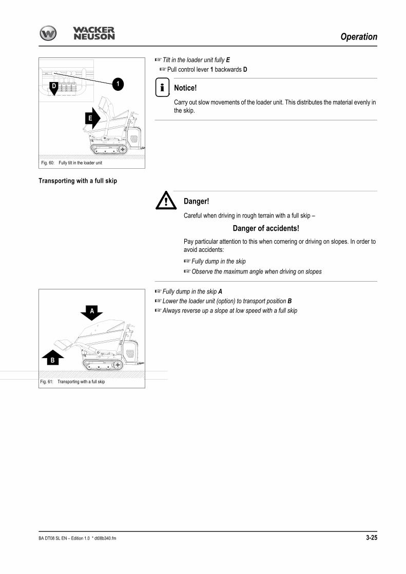
Operation
☞Tilt in the loader unit fully E☞Pull control lever 1 backwards D
Notice!
Carry out slow movements of the loader unit. This distributes the material evenly in the skip.
Transporting with a full skip
Danger!
Careful when driving in rough terrain with a full skip –
Danger of accidents!
Pay particular attention to this when cornering or driving on slopes. In order to avoid accidents:
☞Fully dump in the skip
☞Observe the maximum angle when driving on slopes
☞Fully dump in the skip A☞Lower the loader unit (option) to transport position B☞Always reverse up a slope at low speed with a full skip
Fig. 60: Fully tilt in the loader unit
1D
E
Fig. 61: Transporting with a full skip
B
A
BA DT08 SL EN – Edition 1.0 * dt08b340.fm 3-25

Operation
Dumping out the skip
Danger!
Dumping out the skip alongside a pit is dangerous –
Danger of accidents!
☞Ensure sufficient stability
☞Do not drive too closely to the pit
• Secure the machine with chocks if necessary
☞Slowly dump out the skip
☞Always watch the material as you dump out the skip: ensure that the mate-rial is dumped out evenly and does not remain stuck in the skip, otherwise the machine could tip over
☞Dump out the skip A☞Push control lever 2 forwards C ➥The loader unit is raised
Caution!
As you dump out the skip, ensure that the loader unit does not touch the ground or the material transported in the skip, otherwise the loader unit can be damaged.
☞Always select the optimal position for the loader unit
Fig. 62: Dumping out the skip
2C
A
3-26 BA DT08 SL EN – Edition 1.0 * * dt08b340.fm

Operation
Dumping out the skip upwards (option)
Danger!
Careful when handling the high-tip skip –
Danger of accidents!☞Do not raise or dump out the skip when driving☞Do not raise or dump out the skip on slopes or in an inclined position
☞Place the machine on level and horizontal ground
☞Dump out skipA upwards
☞Pull control lever 1 backwards C
➥Skip is raised☞Dump out skip D
☞Push control lever 2 forwards F
➥Skip dumps out
Emergency lowering of the skip
Danger!
Emergency lowering of the skip –
Danger of crushing and injury!☞Stay clear of the skip
Emergency lowering of the skip is only possible with the help of two persons.
☞Pull lever 2 backwards A during emergency lowering and keep it in this position• Once the skip is fully dumped out
☞Push the skip downwards by hand beyond pivot point B and at the same time, pull lever 2 backwards A
☞The skip is lowered by its own weight once it is beyond the pivot point.
Fig. 63: Dumping out the skip upwards (option)
D
A
F
C
2
1
Fig. 64: Emergency lowering of the skip
2
B
A
BA DT08 SL EN – Edition 1.0 * dt08b340.fm 3-27

Operation
Auxiliary hydraulics (option)
The auxiliary hydraulics has a throughput of 20 l/min at 150 bar.
☞Stop the engine
☞Check whether the switch for auxiliary hydraulics 7 is in the centre position
➥The auxiliary hydraulics is switched off☞Connect the quick couplers of the equipment to the corresponding ports P and P1 of
the auxiliary hydraulics of the machine.
☞Switch on the auxiliary hydraulics and move lever 7 to position A or B depending on the line used as pressure line.
☞Regulate the dumper’s throttle so as to adapt the output to the equipment connected
Caution!
Switch on the auxiliary hydraulics only if an equipment is connected by means of the quickcouplers. Switching on the auxiliary hydraulics with no work equipment connected can be the cause of starting failure (no start) or output loss of the dumper, or of oil overheating in the hydraulic system
.
Fig. 65: Auxiliary hydraulics (option)
AB
P1
7
P
7
Position Function
• A 7 Push to the right Uppoer auxiliary hydraulics port P
• B 7 Push to the left Lower auxiliary hydraulics port P1
3-28 BA DT08 SL EN – Edition 1.0 * * dt08b340.fm

Troubleshooting
4 Troubleshooting
The information given in this chapter is provided for maintenance staff, for fast and reliable detection of malfunctions and their appropriate repair.
Repairs must be carried out by authorised staff.
4.1 Engine trouble
Problem Possible causes See
Engine does not start or is not easy to start
Wrong SAE grade of engine lubrication oil 5-24
Fuel grade does not comply with specifications 5-24
Defective or flat battery 5-21
Loose or oxidised cable connections in starter circuit
Defective starter, or pinion does not engage
Wrong valve clearance
Defective fuel injector
Defective fuse
Check the spark plug 5-7
Engine starts, but does not run smoothly or faultless
Fuel grade does not comply with specifications 5-24
Wrong valve clearance
Injection line leaks
Defective fuel injector
Engine overheats
Oil level too low 5-8
Oil level too high 5-8
Dirty air filter 5-10
Defective fuel injector
Insufficient engine output
Oil level too high 5-8
Fuel grade does not comply with specifications 5-24
Dirty air filter 5-10
Wrong valve clearance
Injection line leaks
Defective fuel injector
Dirty carburettor (DT08-P only)
Defective ignition (DT08-P only)
Defective spark plugs (DT08-P only)
Insufficient or no engine oil pressure
Oil level too low 5-8
Too much machine inclination (max. 15°)
Wrong SAE grade of engine lubrication oil 5-24
Engine oil consumption too highOil level too high 5-8
Too much machine inclination (max. 15°)
BA DT08 SL EN – Edition 1.0 * dt08b410.fm 4-1

Troubleshooting
Engine smoke
BlueOil level too high 5-8
Too much machine inclination (max. 15°)
White
Engine starting temperature too low
Fuel grade does not comply with specifications 5-24
Wrong valve clearance
Defective fuel injector
Black
Dirty air filter 5-10
Wrong valve clearance
Defective fuel injector
Problem Possible causes See
4-2 BA DT08 SL EN – Edition 1.0 * * dt08b410.fm

Maintenance
5 Maintenance
5.1 IntroductionOperational readiness and the service life of machines are heavily dependent on mainte-nance.It is therefore in the interest of the machine owner to carry out the prescribed maintenance work.Before carrying out service and maintenance work, always read, understand and follow the instructions given in:• Chapter 2 “Safety instructions” of this Operator’s Manual and• The Operator’s Manuals of the attachments.Daily service and maintenance work, and maintenance according to maintenance plan “A” must be carried out by a specifically trained driver. All other maintenance work must be carried out by trained and qualified staff only.The maintenance plans indicate when the maintenance work mentioned below must be carried out.
Maintenance strut
Danger!
Careful when carrying out maintenance work on or under the skip, and in general when carrying out maintenance work with the dumper body dumped out –
Danger of accidents!
☞Use the maintenance strut
Mount the maintenance strut as follows:☞Take maintenance strut A out of its bracket
☞The maintenance strut is fastened with lock pin C and pin D
☞Fit maintenance strut A onto tilt ram B
☞Secure maintenance strut A with lock pin C and pin D
During transport fit maintenance strut A as shown in Fig. 66 – transport bracket.
Fig. 66: Maintenance strut
Fig. 66: Transport bracket
A
B
D
C
A
BA DT08 SL EN – Edition 1.0 * dt08b510.fm 5-1

Maintenance
Maintenance strut for high-tip skip
Danger!
Careful when carrying out maintenance work on or under the skip, and in general when carrying out maintenance work with the dumper body dumped out –
Danger of accidents!
☞Use the maintenance strut
Mount the maintenance strut as follows:☞Raise the skip
☞Dump out the skip
☞Raise safety rod A
➥The skip is blocked in the raised position
☞Remove the safety pin and the stud from opening B and insert them in opening C
➥The skip is blocked in the raised position
Fig. 67: Maintenance strut
B C
A
5-2 BA DT08 SL EN – Edition 1.0 * * dt08b510.fm

Maintenance
5.2 Fuel system
Specific safety instructions
• Caution when handling fuel – increased danger of fire!• Never carry out work on the fuel system in the vicinity of naked flames or sparks!• Do not smoke when working on the fuel system or when refuelling!• Before refuelling, stop the engine and remove the ignition key!• Do not refuel in closed rooms!• Wipe away fuel spills immediately!• Keep the machine clean to reduce the risk of fire!
Checking the fuel level
Model DT08-P (petrol engine)Check the fuel level as follows:☞The fuel level must be between the min. und max. levels
☞ If the fuel level is below min.
☞Refuel
Notice!
The machine has no filling level indicator, therefore always check the fuel level before putting the machine into operation.
Model DT08-D (diesel engine):Check the fuel level as follows:☞Check the fuel level on sight glass A
☞The fuel level must be between the min. und max. levels
☞ If the fuel level is below min.
☞Refuel
Notice!
The machine has no filling level indicator, therefore always check the fuel level before putting the machine into operation.
Fig. 68: Model DT08-P (petrol engine)
Min.Max.
Fig. 69: Model DT08-D (diesel engine)
A
Min.
Max.
BA DT08 SL EN – Edition 1.0 * dt08b510.fm 5-3

Maintenance
Refuelling
Filler inlet B of the fuel tank is located on the top side of the engine.
Danger!
All work involving fuel carries an increased
Danger of fire and poisoning!
☞Do not refuel in closed rooms
☞Never carry out work on the fuel system in the vicinity of naked flames or sparks
Notice!
Ensure that you refuel with the correct fuel. It is indicated on the label beside the filler inlet.
Environment!
Use a suitable container to collect the fuel as it drains and dispose of it in an environmentally friendly manner!
Stationary fuel pumps
General
Only refuel from stationary fuel pumps. Fuel from barrels or cans is usually dirty.Even the smallest particles of dirt can cause• Increased engine wear• Malfunctions in the fuel system and• Reduced effectiveness of the fuel filters
Refuelling from barrels
If refuelling from barrels cannot be avoided, note the following points (see fig. 71):• Barrels must neither be rolled nor tilted before refuelling• Protect the suction pipe opening of the barrel pump with a fine-mesh screen• Immerse it down to a max. 15 cm above the floor of the barrel• Only fill the tank using refuelling aids (funnels or filler pipes) with integral microfilter• Keep all refuelling containers clean at all times
B
Fig. 70: Model DT08-D (diesel engine)
Fig. 70: Model DT08-P (petrol engine)B
Wrong
Right
Fig. 71: Refuelling from a barrel
5-4 BA DT08 SL EN – Edition 1.0 * * dt08b510.fm

Maintenance
Petrol specification
Use only high-grade fuels
For model DT08-P (petrol engine)
Diesel fuel specification
Use only high-grade fuels
For model DT08-D (diesel engine)
Cleaning the fuel filter (petrol engine)
Danger!
Petrol is extremely flammable, and explosive under certain circumstances.
Danger of accidents!
☞No smoking in the work area, no naked flames or sparks.
☞Once the filter cup is back in position, check for leaks and ensure that all petrol spills have been wiped away before starting the engine.
☞Set the fuel cock to OFF
☞Unscrew filter cup A with a suitable tool
☞Remove filter cup A and O-ring B, and wash with a nonflammable solvent.
☞Allow filter cup A to dry thoroughly
☞Screw filter cup A back on again with a suitable tool
☞Set the fuel cock to ON and check for leaks
GradeOctane number
Use
• Regular DIN 51607 91 −15 °C to 45 °C
GradeCetane number
Use
• No. 2-D according to DIN 51 601
Min. 45
4 °C to 45 °C
• No. 1-D according to DIN 51601
For outside temperatures below 4 °C or for operation above 1500 m altitude
Fig. 72: Filter cup DT08-P (petrol engine)
A
B
BA DT08 SL EN – Edition 1.0 * dt08b510.fm 5-5

Maintenance
Cleaning the fuel filter of the diesel engine
☞Open drain plug A with a suitable tool
➥The fuel drains
☞Close drain plug A again after the fuel has drained completely
☞Open screw B on the fuel cock
☞Pull filter C out of the filler inlet of the fuel tank
☞Wash filter C with a nonflammable solvent.
☞Allow filter C to dry thoroughly
☞ Insert filter C back into the filler inlet of the fuel tank
☞Close screw B on the fuel cock
Environment!
Dispose of the drained fuel in an environmentally friendly manner.
Fig. 73: Clean the fuel filter
BA
C
5-6 BA DT08 SL EN – Edition 1.0 * * dt08b510.fm

Maintenance
Spark plug (petrol engine)
Danger!
The engine is very hot after it has been in service.
Danger of burns!
☞Allow the engine to cool down
Caution!
If the spark plug is not tightened correctly, it can become very hot and cause engine damage.
☞Always tighten the spark plug firmly
☞Never use a spark plug with the wrong heat range
The spark plug must be set correctly and be free of deposits to ensure that the engine runs correctly.Remove spark plug B as follows:☞Stop the engine
☞Remove spark plug connector A
☞Remove spark plug B with a suitable spark plug key
☞Check spark plug B as follows:
☞Check the outside of spark plug B
➥Dispose of spark plug B if it is worn, or if the insulator is torn or cracked.
☞Measure the electrode gap with a suitable tool
➥The gap must be between 0.70 and 0.80 mm
☞Check the sealing ring for wear
☞Clean spark plug B with a suitable tool (e.g. wire brush etc.) if it can be used again
Mount spark plug B as follows:☞Screw in spark plug B by hand to avoid damage to the thread
☞Tighten spark plug B with a suitable spark plug key.
☞Tighten a new spark plug B by ½ a revolution after it makes contact, in order to com-press the sealing ring
☞Tighten a spark plug B that is already used by 1/8 – 1/4 of a revolution after it makes contact, in order to compress the sealing ring
☞Fit spark plug connector A back on again
The following spark plugs have been released:
Fig. 74: Spark plug
A0.70 mm – 0.80 mm
B
Manufacturer’s description Manufacturer
• BPR6ES NGK
• W20EPR-U DENSO
BA DT08 SL EN – Edition 1.0 * dt08b510.fm 5-7

Maintenance
5.3 Engine lubrication system
Caution!
If the engine oil level is too low or if an oil change is overdue, this can cause
Loss of output and engine damage!
☞Have the oil changed by an authorised workshop– see chapter 5.11 Maintenance plan DT08-D (diesel engine) on page 5-27– see chapter 5.10 Maintenance plan DT08-P (petrol engine) on page 5-25
Checking the oil levelThe oil level can be checked from either side.
Notice!
Check the oil level once a day.We recommend checking it before starting the engine. After stopping a warm engine, wait at least 5 minutes before checking.
Checking the oil level
☞Proceed as follows:
• Park the machine on level ground
➥Max. inclination about 5°
• Stop the engine!
• Oil dipstick A:
☞Pull it out
☞Wipe it with a lint-free cloth
☞Push it back in as far as possible
☞Withdraw it and read off the oil level
☞However if necessary, fill up oil at the latest when the oil reaches the MIN mark on the oil dipstick A
Fig. 75: Oil level check (petrol engine)
maxmin
A
Fig. 75: Oil level check (diesel engine)
maxmin
A
5-8 BA DT08 SL EN – Edition 1.0 * * dt08b510.fm

Maintenance
Filling up engine oil
Caution!
Too much or incorrect engine oil can result in engine damage! Therefore:
☞Do not add engine oil above the MAX mark of the oil dipstick 76/A
☞Use only the specified engine oil
Environment!
Use a suitable container to collect the engine oil as it drains and dispose of it in an environmentally friendly manner!
Proceed as follows:☞Clean the area around filler cap A with a clean lint-free cloth☞Open filler cap A☞Fill in engine oil☞Wait a moment until all the oil has run into the oil sump☞Check the oil level☞Fill up if necessary and check the oil level again☞Close filler cap A☞Completely remove all oil spills
OIL
Fig. 76: Filling up engine oil (petrol engine)
Fig. 76: Filling up engine oil (diesel engine)
OIL
A
A
BA DT08 SL EN – Edition 1.0 * dt08b510.fm 5-9

Maintenance
Maintenance
5.4 Air filterCaution!
The filter element will be damaged if it is washed or brushed out!Bear in mind the following to avoid premature engine wear!
☞Never let the engine run without the air filter installed
☞Replace the filter cartridge according to the maintenance plan
☞Never reuse a damaged filter cartridge
☞Ensure cleanliness when replacing the filter cartridge!
☞Replace filter cartridge A according to the maintenance plan.
Caution!
Filter cartridges degrade prematurely when in service in acidic air for longer periods of time. This risk is present for example in acid production facilities, steel and aluminium mills, chemical plants and other nonferrous-metal plants
☞Replace filter cartridge A after 50 service hours at the latest!Fig. 77: Air filter (petrol engine)
Fig. 77: Air filter (diesel engine)
A
A
5-10 BA DT08 SL EN – Edition 1.0 * * dt08b520.fm

Maintenance
Replacing the filter (petrol engine)
Replace filter cartridge A as follows:
☞Stop the engine
☞Unscrew wing nut B off cover C
☞Remove cover C
☞Unscrew wing nut D off filter cartridge A
☞ Insert the new filter cartridge A
☞Tighten wing nut D on filter cartridge A
☞Ensure that all dirt (dust) inside the cover C has been removed
☞Position cover C (ensure that it is properly seated)
☞Tighten wing nut B again on cover C
Environment!
Dispose of filter cartridge A in an environmentally friendly manner.
Fig. 79: Cleaning/replacing the DT08-P filter (petrol engine)
A
B
C
D
BA DT08 SL EN – Edition 1.0 * dt08b520.fm 5-11

Maintenance
Replacing the filter (diesel engine)
Replace filter cartridge A as follows:
☞Stop the engine
☞Unscrew wing nut B off cover C
☞Remove cover C
☞Remove filter cartridge A
☞ Insert the new filter cartridge A
☞Ensure that all dirt (dust) inside the cover C has been removed
☞Position cover C (ensure that it is properly seated)
☞Tighten wing nut B again on cover C
Environment!
Dispose of filter cartridge A in an environmentally friendly manner.
Notice!
The filter cartridge of the diesel engine cannot be cleaned. Replace it if it is defec-tive or according to the maintenance interval.
Fig. 80: Replacing the air filter (diesel engine)
B
C
A
5-12 BA DT08 SL EN – Edition 1.0 * * dt08b520.fm

Maintenance
5.5 Hydraulic system
Specific safety instructions
• Release the pressure in all lines carrying hydraulic oil prior to any maintenance and repair work. To do this:
• Lower all hydraulically controlled attachments to the ground
• Move all control levers of the hydraulic control valves several times
• Hydraulic oil escaping under high pressure can penetrate the skin and cause serious injuries. Always consult a doctor immediately even if the wound seems insignificant – otherwise serious infections could set in!
• If the hydraulic oil in the sight glass is cloudy, this indicates that water or air has penetrated the hydraulic system. This can cause damage to the hydraulic system!
☞Contact your Wacker Neuson dealer immediately
• Oil or fuel flowing out of high pressure lines can cause fire or malfunctions, and severe injuries or damage to property. Interrupt work immediately if slack nuts or damaged hoses and lines are detected.
☞Contact your Wacker Neuson dealer immediately
• Replace a line if one of the following problems is detected:
☞Damaged or leaky hydraulic seals.
☞Worn or torn shell, or bare reinforcement
☞Expanded shells in several positions.
☞Entangled or crushed movable parts.
☞Foreign bodies jammed or stuck in protective layers.
Caution!
Dirty hydraulic oil, lack of oil or wrong hydraulic oil –
Danger of severe damage to the hydraulic system!
☞Take care to avoid dirt when working!
☞Always fill in hydraulic oil using the filling screen!
☞Only use authorised oils of the same type – see chapter 5.9 Fluids and lubricants on page 5-24
☞Always fill up hydraulic oil before the level gets too low – see Filling up hydraulic oil on page 5-14
☞ If the hydraulic system is filled with biodegradable oil, then use only biode-gradable oil of the same type for filling up – observe the sticker on the hydraulic oil tank!
☞Contact customer service if the hydraulic system filter is contaminated with metal chippings. Otherwise, follow-on damage can result!
Environment!
Collect drained hydraulic oil and biodegradable oil in a suitable container! Dispose of drained oil and used filters by an ecologically safe method. Always contact the relevant authorities or commercial establishments in charge of oil dis-posal before disposing of biodegradable oil.
BA DT08 SL EN – Edition 1.0 * dt08b520.fm 5-13

Maintenance
Checking the hydraulic oil level
Proceed as follows:
☞Park the machine on level ground
☞Raise the skip and lock it in the safety position See Maintenance strut on page 5-1.
☞Stop the engine
☞The dipstick is integrated in filler cap B of hydraulic oil tank A
☞Check whether the oil level is between MIN and MAX
☞Fill up hydraulic oil if the oil level is too low
Filling up hydraulic oil
Refill hydraulic oil only with the engine stopped otherwise hydraulic oil will overflow at the filler opening on the hydraulic oil tank.
Fill up as follows:
☞Park the machine on level ground
☞Raise the skip and lock it in the safety position See Maintenance strut on page 5-1.
☞Stop the engine
☞Unscrew filler cap B
☞Use an oil funnel with microfilter to fill in oil
With the filter insert in place:
☞Fill up hydraulic oil
☞Check the hydraulic oil level with the dipstick integrated in filler cap B
☞Fill up if necessary and check again
☞Firmly tighten filler cap B by hand.
Fig. 81: Hydraulic oil level
A
B
Fig. 82: Hydraulic oil level
FULL
LOW
5-14 BA DT08 SL EN – Edition 1.0 * * dt08b520.fm
Maintenance
Important information for the use of biodegradable oil
• Use only the biodegradable hydraulic fluids which have been tested and approved by Wacker Neuson GmbH. Always contact Wacker Neuson GmbH for the use of other products which have not been recommended. In addition, ask the oil supplier for a written declaration of guarantee. This guarantee is applicable to damage occurring on the hydraulic components, which can be proved to be due to the hydraulic fluid
• Use only biodegradable oil of the same type for filling up. In order to avoid misunder-standings, a label providing clear information is located on the hydraulic oil tank (next to the filler inlet) regarding the type of oil currently used!The joint use of two different biodegradable oils can affect the quality of one of the oil types. Therefore, ensure that the remaining amount of initial hydraulic fluid in the hydraulic system does not exceed 8 % when changing biodegradable oil (manufacturer indications)
• Do not fill up with mineral oil – the content of mineral oil should not exceed 2 % in order to avoid foaming problems and to ensure biological degradability
• When running the machine with biodegradable oil, the same oil and filter replacement intervals are valid as for mineral oil – see Maintenance plan DT08-P (petrol engine) on page 5-25– see Maintenance plan DT08-D (diesel engine) on page 5-27
• Always have the condensation water in the hydraulic oil tank drained by an authorised workshop before the cold season. The water content may not exceed 0.1 % by weight
• The instructions in this Operator’s Manual concerning environmental protection are also valid for the use of biodegradable oil
• If additional hydraulic attachments are mounted or operated, use the same type of biodegradable oil for these attachments to avoid mixtures in the hydraulic system
Subsequent change from mineral oil to biodegradable oil must be carried out by an author-ised workshop or by your Wacker Neuson partner
BA DT08 SL EN – Edition 1.0 * dt08b520.fm 5-15
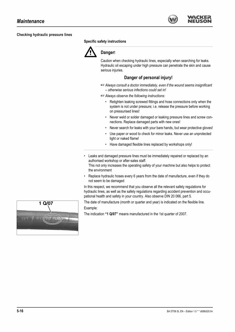
Maintenance
Checking hydraulic pressure lines
Specific safety instructions
Danger!
Caution when checking hydraulic lines, especially when searching for leaks. Hydraulic oil escaping under high pressure can penetrate the skin and cause serious injuries.
Danger of personal injury!
☞Always consult a doctor immediately, even if the wound seems insignificant – otherwise serious infections could set in!
☞Always observe the following instructions:
• Retighten leaking screwed fittings and hose connections only when the system is not under pressure; i.e. release the pressure before working on pressurised lines!
• Never weld or solder damaged or leaking pressure lines and screw con-nections. Replace damaged parts with new ones!
• Never search for leaks with your bare hands, but wear protective gloves!
• Use paper or wood to check for minor leaks. Never use an unprotected light or naked flame!
• Have damaged flexible lines replaced by workshops only!
• Leaks and damaged pressure lines must be immediately repaired or replaced by an authorised workshop or after-sales staff.This not only increases the operating safety of your machine but also helps to protect the environment
• Replace hydraulic hoses every 6 years from the date of manufacture, even if they do not seem to be damaged
In this respect, we recommend that you observe all the relevant safety regulations for hydraulic lines, as well as the safety regulations regarding accident prevention and occu-pational health and safety in your country. Also observe DIN 20 066, part 5.
The date of manufacture (month or quarter and year) is indicated on the flexible line.
Example:
The indication “1 Q/07” means manufactured in the 1st quarter of 2007.
1 Q/07
5-16 BA DT08 SL EN – Edition 1.0 * * dt08b520.fm
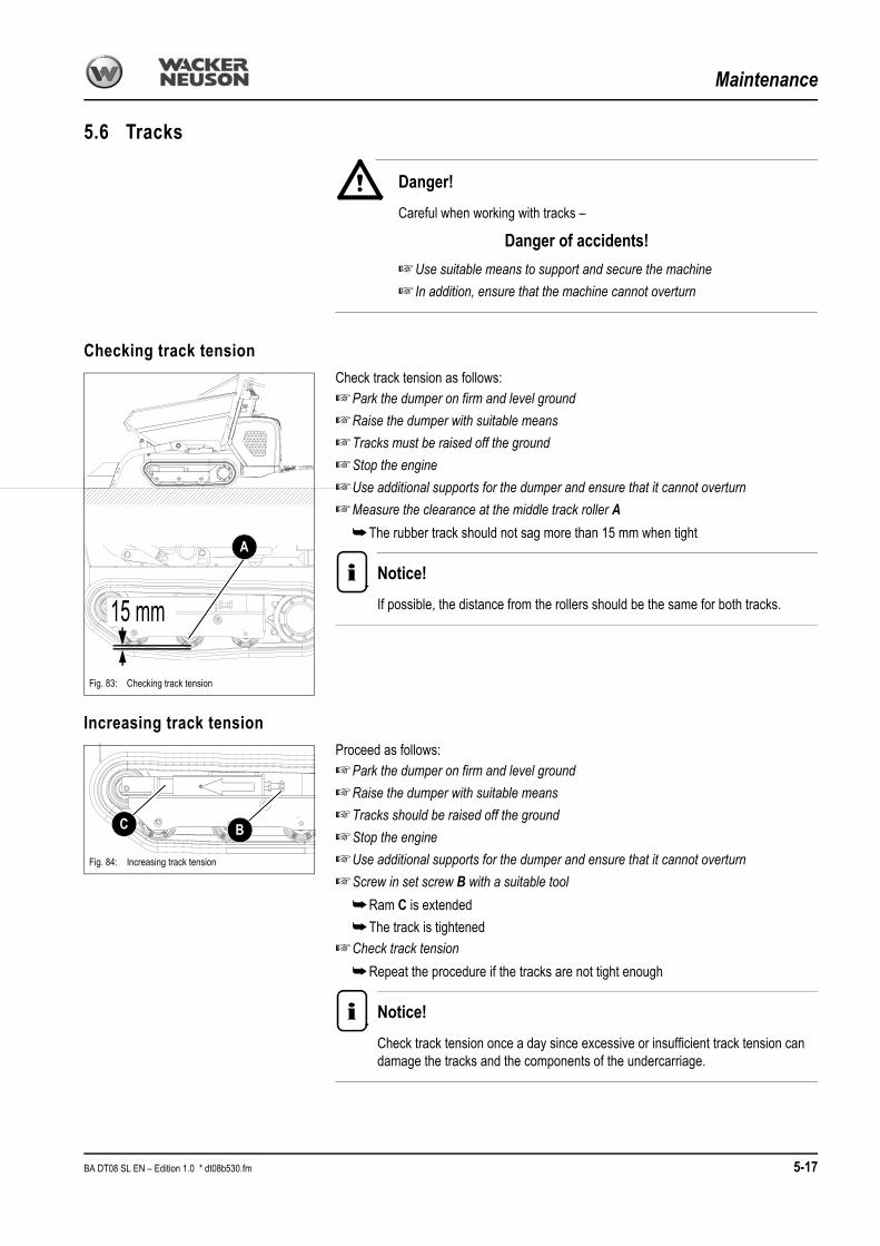
MaintenanceMaintenance
5.6 Tracks
Danger!
Careful when working with tracks –
Danger of accidents!
☞Use suitable means to support and secure the machine
☞ In addition, ensure that the machine cannot overturn
Checking track tension
Check track tension as follows:☞Park the dumper on firm and level ground
☞Raise the dumper with suitable means
☞Tracks must be raised off the ground
☞Stop the engine
☞Use additional supports for the dumper and ensure that it cannot overturn
☞Measure the clearance at the middle track roller A
➥The rubber track should not sag more than 15 mm when tight
Notice!
If possible, the distance from the rollers should be the same for both tracks.
Increasing track tension
Proceed as follows:☞Park the dumper on firm and level ground
☞Raise the dumper with suitable means
☞Tracks should be raised off the ground
☞Stop the engine
☞Use additional supports for the dumper and ensure that it cannot overturn
☞Screw in set screw B with a suitable tool
➥Ram C is extended
➥The track is tightened
☞Check track tension
➥Repeat the procedure if the tracks are not tight enough
Notice!
Check track tension once a day since excessive or insufficient track tension can damage the tracks and the components of the undercarriage.
Fig. 83: Checking track tension
15 mm
A
Fig. 84: Increasing track tension
BC
BA DT08 SL EN – Edition 1.0 * dt08b530.fm 5-17

Maintenance
Decreasing track tension
☞Park the dumper on firm and level ground
☞Raise the dumper with suitable means
☞Tracks should be raised off the ground
☞Stop the engine
☞Use additional supports for the dumper and ensure that it cannot overturn
☞Unscrew set screw D with a suitable tool
➥The fork E is retracted
➥The track is slackened
☞Check track tension
➥Repeat the procedure if track tension is too low or too high
Fig. 85: Decreasing track tension
DE
5-18 BA DT08 SL EN – Edition 1.0 * * dt08b530.fm

Maintenance
5.7 Electrical system
Specific safety instructions
• The battery contains sulphuric acid! This acid must not be allowed to come into contact with the skin, the eyes, clothing or the machineTherefore when recharging or working near the battery:
☞Always wear goggles and protective clothing with long sleeves
If acid is spilt:☞Thoroughly rinse all affected surfaces immediately with plenty of water
☞Thoroughly wash any part of the body touched by the acid immediately with plenty of water and seek medical attention at once!
• Especially when charging batteries, as well as during normal operation of batteries, an oxyhydrogen mixture is formed in the battery cells – danger of explosion!
• In case of a frozen battery or of an insufficient electrolyte level, do not try start-up with a starting aid. The battery can burst or explode!
☞Replace the battery immediately
• There must be no naked flame near open battery cells. Avoid sparks. No smoking. The gas that forms during normal battery operation can ignite!
• Use only 12 V power sources. Higher voltages will damage the electric components• When connecting the battery leads, ensure that the poles +/– are not inverted,
otherwise sensitive electric components will be damaged• Do not interrupt voltage-carrying circuits at the battery terminals because of the danger
of sparking!• Never place tools or other conductive articles on the battery – danger of short circuit!• Disconnect the negative (-) battery terminal from the battery before starting repair work
on the electrical system• First remove the (–) terminal and then the (+) terminal as you disconnect the electrical
system• Dispose of used batteries properly
Service and maintenance work at regular intervals
Every week☞Check once a week:
• Electric fuses
• Cable and earth connections
• Battery charge condition – see Battery on page 5-21
• Condition of battery terminals
BA DT08 SL EN – Edition 1.0 * dt08b530.fm 5-19

Maintenance
Instructions concerning specific components
Electric lines and fusesAlways observe the following instructions:• Defective components of the electrical system must always be replaced by an
authorised expert. Fuses may be changed by unqualified persons• When carrying out maintenance work on the electrical system, pay particular attention
to ensuring good contact in leads
Alternator
Always observe the following instructions:• Only test run the engine with the battery connected• When connecting the battery, ensure that the poles (+/–) are not inverted• Always disconnect the battery before carrying out welding work or connecting a quick
battery charger
Notice!
Operation of electric consumers (e.g. lighting equipment) is not allowed. This is why the machine has no socket.
5-20 BA DT08 SL EN – Edition 1.0 * * dt08b530.fm

Maintenance
Battery
Danger!
Battery acid is highly caustic!
Danger of burns!
Therefore when recharging and/or working near the battery:☞Always wear goggles and protective clothing with long sleevesIf acid is spilt:☞Thoroughly rinse all affected surfaces immediately with plenty of water☞Thoroughly wash any part of the body touched by the acid immediately with
plenty of water and seek medical attention at once!Especially when charging batteries, as well as during normal operation of batteries, an oxyhydrogen mixture is formed in the battery cells –
Danger of explosion!☞Avoid naked lights and sparks in the vicinity of the battery and do not
smoke!☞Do not attempt to jump-start the machine if the battery is frozen or if the
acid level is low. The battery can rupture or explode!• Replace the battery immediately
☞Always disconnect the negative terminal (–) from the battery before starting repair work on the electrical system!
Battery A is located under the cover. The battery is “maintenance-free”. However have the battery checked at regular intervals to ensure that the electrolyte level is between the MIN and MAX marks.Checking the battery requires it to be removed and must be carried out by an authorised workshop.Always follow the specific battery safety instructions!
Notice!
Do not disconnect the battery while the engine is running!
Disconnecting the battery in an emergency• Firmly pull cable C to disconnect the battery in an emergency.
Notice!
Firmly pull cable C in an emergency only since this damages the electric line and possibly the starter.
Fig. 86: Battery
-
+
A
Fig. 87: Battery
C
BA DT08 SL EN – Edition 1.0 * dt08b530.fm 5-21
Maintenance
5.8 General maintenance work
Cleaning
Cleaning the machine is divided into 3 separate areas:• Exterior of the machine• Engine compartmentThe wrong choice of cleaning equipment and agents can impair the operating safety of the machine on the one hand, and on the other undermine the health of the persons in charge of cleaning the machine. It is therefore essential to observe the following instructions.
General instructions for all areas of the machine
Cleaning with washing solvents
• Ensure adequate room ventilation• Wear suitable protective clothing• Do not use flammable liquids, such as petrol or diesel
Cleaning with compressed air
• Work carefully• Wear goggles and protective clothing• Do not aim the compressed air at the skin or at other people• Do not use compressed air for cleaning your clothing
Cleaning with a high-pressure cleaner or steam jet
• Electric components and damping material must be covered and not directly exposed to the jet
• Cover the vent filter on the hydraulic oil tank and the filler caps for fuel, hydraulic oil etc.• Protect the following components from moisture:
• Engine
• Electrical components such as the alternator etc.
• Control devices and seals
• Air intake filters etc.
Cleaning with volatile and easily flammable anticorrosion agents and sprays:
• Ensure adequate room ventilation• Do not use unprotected lights or naked flames• Do not smoke!
5-22 BA DT08 SL EN – Edition 1.0 * * dt08b530.fm

Maintenance
Exterior of the machine
Caution!
Cleaning the machine can cause engine damage.
☞Protect the engine against humidity
The following articles are generally suitable:• High-pressure cleaner• Steam jet
Engine compartment
Danger!
Clean the engine at engine standstill only –
Danger of personal injury!
☞Stop the engine before cleaning
Caution!
When cleaning the engine with a water or steam jet
☞The engine must be cold
☞and do not point the jet directly at electric sensors such as the oil pressure switch.
The humidity penetrating any such sensors causes them to fail and leads to engine damage!
Screw connections and attachments
All screw connections must be checked regularly for tightness, even if they are not listed in the maintenance schedules.☞Engine fastening screws
☞Fastening screws on the hydraulic system
☞Line and pin fastenings on the attachment
Tighten loose connections immediately. Contact an authorised workshop if necessary.
Pivots and hinges
Lubricate all mechanical pivots on the machine (such as joints) and fittings at regular inter-vals even if they are not listed in the lubrication plan.
BA DT08 SL EN – Edition 1.0 * dt08b530.fm 5-23

Maintenance
5.9 Fluids and lubricants
Component/applicationEngine/machine
fluidSpecification
Season/tempera-ture
Capacities1
1. The capacities indicated are approximate values; the oil level check alone is relevant for the correct oil level1. Capacities indicated are no system fills
Petrol engine(model DT08-P) Honda petrol engine
Engine oil AGIP MOTOROIL HD SAE 15W-40 Year-round 1.1 l
Diesel engine (model DT08-D) Yanmar diesel engine
Engine oilAGIP DIESEL SIGMA S 30SAE2 15W-40
2. According to DIN 51511
Year-round 0.6 l
Hydraulic oil tank(model DT08-P)
Hydraulic oil AGIP ARNICA 463
3. According to DIN 51524 section 3
Year-round 22.3 lBiodegradable oil4
4. Biodegradable hydraulic oil based on saturated synthetic esters with an iodine value of < 10, according to DIN 51524, section 3, HVLP, HEES
PANOLIN HLP Synth 46
FINA BIOHYDRAN SE 46
Hydraulic oil tank(model DT08-D)
Hydraulic oil AGIP ARNICA 465
5. According to DIN 51524 section 3
Year-round 30.1 lBiodegradable oil 6
6. Biodegradable hydraulic oil based on saturated synthetic esters with an iodine value of < 10, according to DIN 51524, section 3, HVLP, HEES
PANOLIN HLP Synth 46
FINA BIOHYDRAN SE 46
GreaseRoller and friction bearings7
7. KF2K-25 according to DIN 51502 multipurpose lithium grease with MoS² additive
AGIP GR SM Year-round As required
Lubrication point Multipurpose grease AGIP GR SM Year-round As required
Fuel tank (model DT08-P) Honda petrol engine
Petrol Regular8 91 octane, DIN 51 607
8. Unleaded regular
Year-round 6.0 l
Fuel tank(model DT08-D) Yanmar diesel engine
Diesel fuelNo. 2-D, DIN 51601 grade Over 4 °C
5.4 lNo. 1-D, DIN 51601 grade Below 4 °C
5-24 BA DT08 SL EN – Edition 1.0 * * dt08b530.fm

Maintenance
Mai
nten
ance
5.10
Mai
nten
ance
pla
n D
T08-
P (p
etro
l eng
ine)
Wor
k de
scrip
tion
For s
ervi
ce a
nd m
aint
enan
ce w
ork
on th
e at
tach
men
t, pl
ease
refe
r to
the
oper
atio
n an
d m
aint
enan
ce m
anua
l of
the
atta
chm
ent m
anuf
actu
rer a
s w
ell.
Mai
nten
ance
pla
n/se
rvic
e ho
urs
(s/h
)
Service work(daily)
Every 20 s/h
Every 50 s/h
Every 100 s/h
300 s/h
Every 1000 s/honce a year
Customer
Authorised
workshop
Flui
d an
d fil
ter c
hang
es (
):
Car
ry o
ut th
e fo
llow
ing
oil a
nd fi
lter c
hang
es (c
heck
oil
leve
ls a
fter t
est r
un):
•En
gine
oil1
●●
●
•Fu
el fi
lter2
●●
●
•H
ydra
ulic
oil
filte
r ins
ert
●●
●
•H
ydra
ulic
oil
●●
•R
epla
ce th
e ai
r filt
er e
lem
ent
●●
•H
ydra
ulic
oil
tank
bre
athe
r ●
●
•R
epla
ce th
e sp
ark
plug
●●
Insp
ectio
n w
ork
():
Che
ck th
e fo
llow
ing
mat
eria
l. R
efill
if ne
cess
ary:
Che
ck th
e fu
el le
vel,
fill u
p fu
el●
●
•En
gine
oil
●●
•H
ydra
ulic
oil
●●
Cle
an th
e fil
ter c
up●
●
Che
ck h
ydra
ulic
oil
radi
ator
for d
irt, c
lean
if n
eces
sary
●
●
Che
ck o
il co
olin
g sy
stem
s an
d ho
ses
for l
eaks
and
pre
ssur
e (v
isua
l che
ck)
●●
Air f
ilter
(dam
age)
●●
Che
ck e
xhau
st s
yste
m fo
r dam
age
and
cond
ition
●●
Che
ck v
alve
cle
aran
ce, a
djus
t if n
eces
sary
●●
Che
ck a
nd c
lean
the
spar
k pl
ug●
●
Che
ck/s
et id
ling
spee
d●
●
Empt
y th
e pe
trol t
ank
●●
Che
ck b
atte
ry e
lect
roly
te. F
ill up
with
dis
tille
d w
ater
if n
eces
sary
●●
●
Che
ck a
ltern
ator
, sta
rter a
nd e
lect
ric c
onne
ctio
ns, b
earin
g pl
ay a
nd fu
nctio
n●
●
Pres
sure
che
ck o
f prim
ary
pres
sure
lim
iting
val
ves
●●
●
BA DT08 SL EN – Edition 1.0 * * dt08b540.fm 5-25

Maintenance
Che
ck tr
acks
for c
rack
s an
d cu
ts●
●
Che
ck tr
ack
tens
ion.
Ret
ight
en if
nec
essa
ry●
●
Bear
ing
play
of t
read
rolle
rs, t
rack
car
rier r
olle
rs, f
ront
idle
rs
●●
Che
ck p
isto
n ro
ds fo
r dam
age
●●
Che
ck s
crew
s fo
r tig
htne
ss●
●●
Pin
lock
●●
Line
fixt
ures
●●
Adhe
sive
labe
ls a
nd O
pera
tor’s
Man
ual
●●
●
Lubr
icat
ion
serv
ice
():
Lubr
icat
e th
e fo
llow
ing
asse
mbl
ies/
com
pone
nts
– se
e Lu
bric
atio
n pl
an D
T08
with
ski
p on
pag
e 5-
29:
•Sk
ip●
●
•Ti
lt ra
m●
●
•Lo
ader
uni
t (op
tion)
●●
•Lo
ader
uni
t ram
s (o
ptio
n)●
●
•Tr
ack
tens
ion
●●
•Tr
ack
rolle
r bea
rings
●●
Leak
age
chec
k (
):
Che
ck fo
r tig
htne
ss, l
eaks
and
cha
fing:
pip
es, f
lexi
ble
lines
and
scr
ew c
onne
ctio
ns o
f the
follo
win
g as
sem
blie
s an
d co
mpo
nent
s. R
ectif
y if
nece
ssar
y:•
Visu
al c
heck
●●
☞En
gine
and
hyd
raul
ic s
yste
m●
●
☞O
il co
olin
g ci
rcui
t●
●
☞Tr
avel
ling
driv
e●
●
1.R
epla
ce th
e en
gine
oil
the
first
tim
e af
ter 2
0 s/
h or
the
first
mon
th, t
hen
ever
y 10
0 s/
h or
afte
r 6 m
onth
s at
the
late
st2.
Rep
lace
the
fuel
filte
r the
firs
t tim
e af
ter 5
0 s/
h, th
en e
very
400
s/h
5.10
Mai
nten
ance
pla
n D
T08-
P (p
etro
l eng
ine)
Wor
k de
scrip
tion
For s
ervi
ce a
nd m
aint
enan
ce w
ork
on th
e at
tach
men
t, pl
ease
refe
r to
the
oper
atio
n an
d m
aint
enan
ce m
anua
l of
the
atta
chm
ent m
anuf
actu
rer a
s w
ell.
Mai
nten
ance
pla
n/se
rvic
e ho
urs
(s/h
)
Service work(daily)
Every 20 s/h
Every 50 s/h
Every 100 s/h
300 s/h
Every 1000 s/honce a year
Customer
Authorised
workshop
5-26 BA DT08 SL EN – Edition 1.0 * * dt08b540.fm

Maintenance
Mai
nten
ance
5.11
Mai
nten
ance
pla
n D
T08-
D (d
iese
l eng
ine)
W
ork
desc
riptio
n
For s
ervi
ce a
nd m
aint
enan
ce w
ork
on th
e at
tach
men
t, pl
ease
refe
r to
the
oper
atio
n an
d m
aint
enan
ce m
anua
l of t
he
atta
chm
ent m
anuf
actu
rer a
s w
ell.
Mai
nten
ance
pla
n/se
rvic
e ho
urs
(s/h
)
Service work(daily)
Once a month orafter 50 s/h
Every 3 months orafter 200 s/h
Every 6 monthsor after 400 s/h
Every 1000 s/honce a year
Customer
Authorisedworkshop
Flui
d an
d fil
ter c
hang
es (
):
Car
ry o
ut th
e fo
llow
ing
oil a
nd fi
lter c
hang
es (c
heck
oil
leve
ls a
fter t
est r
un):
•En
gine
oil1
●●
●
•En
gine
oil
filte
r2●
●●
•R
epla
ce th
e fu
el fi
lter e
lem
ent3
●●
●
•R
epla
ce th
e ai
r filt
er e
lem
ent
●●
•H
ydra
ulic
oil
filte
r ins
ert
●●
●
•H
ydra
ulic
oil
●●
•H
ydra
ulic
oil
tank
bre
athe
r●
●
Insp
ectio
n w
ork
():
Che
ck th
e fo
llow
ing
mat
eria
l. R
efill
if ne
cess
ary:
Che
ck in
ject
ion
setti
ng●
●
Che
ck a
nd a
djus
t inj
ectio
n tim
e 4
●●
Cle
an a
nd a
djus
t the
fuel
inje
ctio
n pu
mp
5●
●
Che
ck a
nd a
djus
t the
inje
ctio
n pr
essu
re o
f the
inje
ctio
n no
zzle
s, c
lean
the
inje
ctio
n ne
edle
s/no
zzle
s●
●
Cle
an th
e fu
el fi
lter
●●
Che
ck c
ondi
tion
and
inje
ctio
n of
fuel
inje
ctio
n no
zzle
●●
Che
ck th
e fu
el le
vel,
fill u
p fu
el●
●
•En
gine
oil
●●
•H
ydra
ulic
oil
●●
Che
ck h
ydra
ulic
oil
radi
ator
for d
irt, c
lean
if n
eces
sary
●
●
Che
ck o
il co
olin
g sy
stem
s an
d ho
ses
for l
eaks
and
pre
ssur
e (v
isua
l che
ck)
●●
Air f
ilter
(dam
age)
●●
Che
ck e
xhau
st s
yste
m fo
r dam
age
and
cond
ition
●●
Inta
ke a
nd e
xhau
st v
alve
cle
aran
ce●
●
Empt
y di
esel
fuel
tank
●●
Che
ck b
atte
ry e
lect
roly
te. F
ill up
with
dis
tille
d w
ater
if n
eces
sary
●●
●
Che
ck a
ltern
ator
, sta
rter a
nd e
lect
ric c
onne
ctio
ns, b
earin
g pl
ay a
nd fu
nctio
n●
●
Pres
sure
che
ck o
f prim
ary
pres
sure
lim
iting
val
ves
●●
●
Che
ck tr
acks
for c
rack
s an
d cu
ts●
●
BA DT08 SL EN – Edition 1.0 * * dt08b550.fm 5-27

Maintenance
Che
ck v
alve
cle
aran
ce. A
djus
t if n
eces
sary
●●
Che
ck tr
ack
tens
ion.
Ret
ight
en if
nec
essa
ry●
●
Bear
ing
play
of t
read
rolle
rs, t
rack
car
rier r
olle
rs, f
ront
idle
rs
●●
Che
ck p
isto
n ro
ds fo
r dam
age
●●
Che
ck s
crew
s fo
r tig
htne
ss●
●●
Pin
lock
●●
Line
fixt
ures
●●
Adhe
sive
labe
ls a
nd O
pera
tor’s
Man
ual
●●
●
Lubr
icat
ion
serv
ice
():
Lubr
icat
e th
e fo
llow
ing
asse
mbl
ies/
com
pone
nts
– se
e Lu
bric
atio
n pl
an D
T08
with
ski
p on
pag
e 5-
29:
•Sk
ip●
●
•Ti
lt ra
m●
●
•Lo
ader
uni
t (op
tion)
●●
•Lo
ader
uni
t ram
s (o
ptio
n)●
●
•Tr
ack
tens
ion
●●
•Tr
ack
rolle
r bea
rings
●●
Leak
age
chec
k (
):
Che
ck fo
r tig
htne
ss, l
eaks
and
cha
fing:
pip
es, f
lexi
ble
lines
and
scr
ew c
onne
ctio
ns o
f the
follo
win
g as
sem
blie
s an
d co
mpo
nent
s. R
ectif
y if
nece
ssar
y:•
Visu
al c
heck
●●
☞En
gine
and
hyd
raul
ic s
yste
m●
●
☞O
il co
olin
g ci
rcui
t●
●
☞Tr
avel
ling
driv
e●
●
1.D
rain
eng
ine
oil t
he fi
rst t
ime
afte
r 50
s/h,
then
eve
ry 2
00 s
/h2.
Rep
lace
the
engi
ne o
il fil
ter t
he fi
rst t
ime
afte
r 50
s/h,
then
eve
ry 4
00 s
/h3.
Rep
lace
the
fuel
filte
r the
firs
t tim
e af
ter 5
0 s/
h, th
en e
very
400
s/h
4.C
heck
and
adj
ust i
njec
tion
time
ever
y ot
her 1
000
s/h
serv
icin
g5.
Cle
an a
nd a
djus
t the
fuel
inje
ctio
n pu
mp
ever
y ot
her 1
000
s/h
serv
icin
g
5.11
Mai
nten
ance
pla
n D
T08-
D (d
iese
l eng
ine)
W
ork
desc
riptio
n
For s
ervi
ce a
nd m
aint
enan
ce w
ork
on th
e at
tach
men
t, pl
ease
refe
r to
the
oper
atio
n an
d m
aint
enan
ce m
anua
l of t
he
atta
chm
ent m
anuf
actu
rer a
s w
ell.
Mai
nten
ance
pla
n/se
rvic
e ho
urs
(s/h
)
Service work(daily)
Once a month orafter 50 s/h
Every 3 months orafter 200 s/h
Every 6 monthsor after 400 s/h
Every 1000 s/honce a year
Customer
Authorisedworkshop
5-28 BA DT08 SL EN – Edition 1.0 * * dt08b550.fm
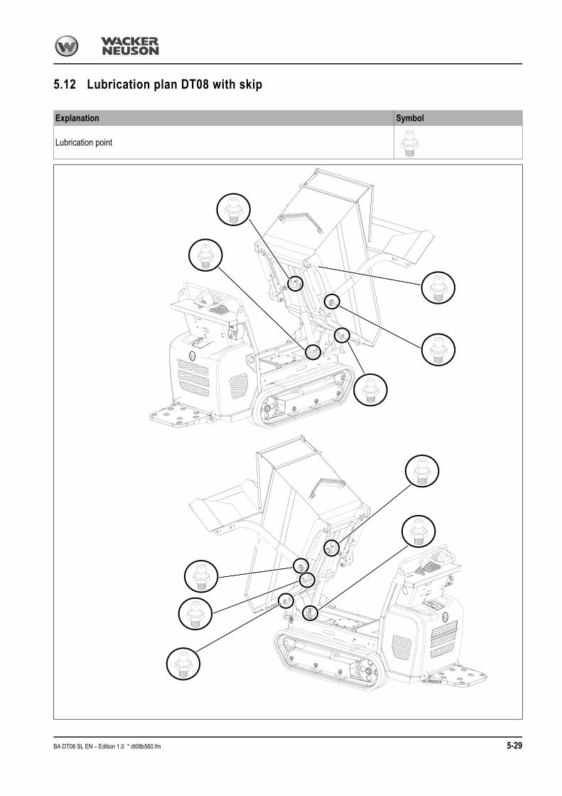
5.12 Lubrication plan DT08 with skip
Explanation Symbol
Lubrication point
BA DT08 SL EN – Edition 1.0 * dt08b560.fm 5-29

5.13 Lubrication plan DT08 with high-tip skip (option)
Explanation Symbol
Lubrication point
5-30 BA DT08 SL EN – Edition 1.0 * * dt08b560.fm

Maintenance opening
Maintenance opening for cleaning the chassis.
☞Unscrew 4 screws to remove housing A.
Fig. 88: Maintenance opening
A
BA DT08 SL EN – Edition 1.0 * dt08b560.fm 5-31

5-32 BA DT08 SL EN – Edition 1.0 * * dt08b560.fm

Specifications
6 Specifications
6.1 EngineSturdy steel sheet chassis, rubber-mounted engine
6.2 Hydraulic system
6.3 Undercarriage
Engine Model DT08-D Model DT08-P
Product Yanmar diesel engine Honda petrol engine
Type L100N6 CA1T1AAS1 GX 270 U QE OH
Design Air-cooled 4-stroke engine
No. of cylinders 1
Displacement 435 cm³ 270 cm³
Nominal bore and stroke 86 x 75 mm 77 x 58
Output 6.8 kW at 3100 rpm 6.6 kW at 3600 rpm
Max. torque 22.5 Nm at 2000 rpm 17.7 Nm at 2500 rpm
Max. engine speed without load 3100 +/− 30 rpm 3850 +/− 100 rpm
Idling speed 1200 +/− 30 rpm 1400 +/− 150 rpm
Fuel injection system Mechanical governor Electronic ignition
Starting aid Reverse starter
Battery 12 V/44 Ah 12 V/30 Ah
Max. inclined position (engine no longer supplied with oil):
20° continuously 20° continuously
Exhaust values according to 97/68 EC, EPA 97/68 EC, EPA
Hydraulics Model DT08-D Model DT08-P
Pump3 gear pumps
6 + 3.2 + 3.2 cm³/rev
Flow rate 41 l/min at 3600 rpm
Operating pressure for work hydraulics
150 bar
Operating pressure for drive hydraulics
175 bar
Hydraulic tank capacity 22.3 l 22.3 l
Undercarriage Model DT08-D Model DT08-P
2 drive speeds 2.1 and 4.0 kph
Theoretical climbing ability 20°
Track width 180 mm
No. of track rollers on either side 3
Ground clearance 110 mm
Ground pressure 0.19 – 0.36 kg/cm² 0.16 – 0.34 kg/cm²
BA DT08 SL EN – Edition 1.0 * dt08b610.fm 6-33

Specifications
6.4 Work hydraulics
6.5 Skip
6.6 High-tip skip (option)
6.7 Loader unit (option)
Work hydraulics Model DT08-D Model DT08-P
Hydraulic pump displacement: 20 l/min at 3600 rpm
Control valve 1 section/2 sections
Max. operating pressure 150±5 bar
Filter Return filter
Hydraulic oil tank 22.3 l 22.3 l
Skip Model DT08-D Model DT08-P
Struck 334 l
Heaped 387 l
Liquid capacity 166 l
Skip length 1135 mm
Skip width 700 mm
Skip height 374 mm
Skip (option) Model DT08
Struck 240 l
Heaped 280 l
Liquid capacity 195 l
Skip length 1134 mm
Skip width 764 mm
Skip height 442 mm
Loader unit (option) Model DT08-D Model DT08-P
Width 830 mm
Scraping depth 130 mm
6-34 BA DT08 SL EN – Edition 1.0 * * dt08b610.fm

Specifications
6.8 Noise levels
Notice!
Sound power level measurement based on Directive 2000/14/EC. Driver-per-ceived noise level measured in compliance with EU Directives 84/532/EEC, 89/514/EEC and 95/27/EEC. Measurements carried out on asphalted surface.
6.9 Vibration
Sound power level Model DT08-D Model DT08-P
Sound power level (LWA)1
1. According to ISO 6395
100 dB (A) 100 dB (A)
Driver-perceived sound pressure level (LPA) 2
2. According to ISO 6396
93 dB (A) 87 dB (A)
Uncertainty (KPA) 3
3. According to EN ISO 4871
1.3 dB (A) 1.4 dB (A)
Vibration DT08
Effective acceleration value for the upper extremities of the body1
1. Measurements as per 2002/44/EC, ISO EN 20643 and ISO/TR 25398 (measurement under the following conditions: exca-vating, driving). Machine and attachment operation and maintenance as per Operator’s Manual. Uncertainty of measurement: measurements as per EN 12096:1997Value of vibrations transmitted to human body specified under special operational and ground conditions. Therefore it does not apply to a large number of applications. Therefore, the value of the vibrations transmitted to the human body (indicated by the machine manufacturer in accordance with European standards) must not be used as a reference for specifying machine operator exposure to vibrations.
< 2.5
Effective acceleration value for the body 1 < 0.5
ms2------
ms2------
BA DT08 SL EN – Edition 1.0 * dt08b610.fm 6-35
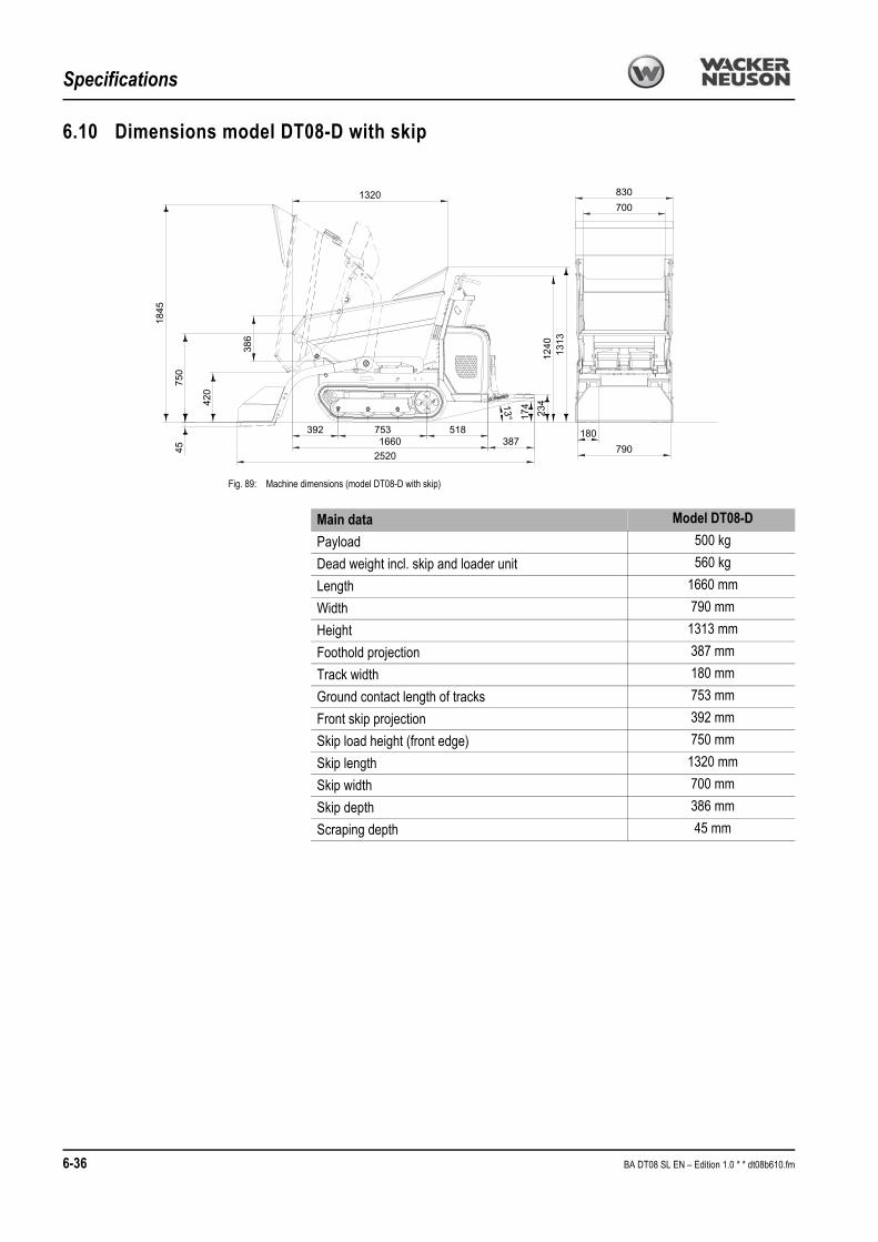
Specifications
6.10 Dimensions model DT08-D with skip
830700
180790
174
23413°
38716602520
518753392
1320
4575
0
386
1845
420
1240
1313
Fig. 89: Machine dimensions (model DT08-D with skip)
Main data Model DT08-D
Payload 500 kg
Dead weight incl. skip and loader unit 560 kg
Length 1660 mm
Width 790 mm
Height 1313 mm
Foothold projection 387 mm
Track width 180 mm
Ground contact length of tracks 753 mm
Front skip projection 392 mm
Skip load height (front edge) 750 mm
Skip length 1320 mm
Skip width 700 mm
Skip depth 386 mm
Scraping depth 45 mm
6-36 BA DT08 SL EN – Edition 1.0 * * dt08b610.fm

Specifications
6.11 Dimensions model DT08-D with high-tip skip (option)25
70
1426
75796
4
1134
274 753 518
3871545
82°
13° 234
180
790
764
1646
1240
1898
112
442
Fig. 90: Machine dimensions (model DT08-D with high-tip skip)
Main data Model DT08-D
Payload 500 kg
Dead weight incl. skip and loader unit 625 kg
Length 1545 mm
Width 790 mm
Height 1240 mm
Foothold projection 387 mm
Track width 180 mm
Ground contact length of tracks 753 mm
Front skip projection 274 mm
Skip load height (front edge) 964 mm
Skip length 1134 mm
Skip width 764 mm
Skip depth 442 mm
BA DT08 SL EN – Edition 1.0 * dt08b610.fm 6-37

Specifications
6.12 Dimensions model DT08-P with skip
700830
18079045
750
1845
386
1320
72°
14° 180 257
388
2520
515753392
1660
420
1180 13
13
Fig. 91: Machine dimensions (model DT08-P with skip)
Main data Model DT08-P
Payload 500 kg
Dead weight incl. skip and loader unit 515 kg
Length 1660 mm
Width 790 mm
Height 1313 mm
Foothold projection 388 mm
Track width 180 mm
Ground contact length of tracks 753 mm
Front skip projection 392 mm
Skip load height (front edge) 750 mm
Skip length 1320 mm
Skip width 700 mm
Skip depth 386 mm
Scraping depth 45 mm
6-38 BA DT08 SL EN – Edition 1.0 * * dt08b610.fm

Specifications
6.13 Dimensions model DT08-P with high-tip skip (option)
1426
2570
75796
5
1134
82°
274 753 515
3881540
764
180
790
25714°
1646
1180
1898
112
442
Fig. 92: Machine dimensions (model DT08-P with high-tip skip)
Main data Model DT08-P
Payload 500 kg
Dead weight incl. skip and loader unit 580 kg
Length 1540 mm
Width 790 mm
Height 1180 mm
Foothold projection 388 mm
Track width 180 mm
Ground contact length of tracks 753 mm
Front skip projection 274 mm
Skip load height (front edge) 965 mm
Skip length 1134 mm
Skip width 764 mm
Skip depth 442 mm
Scraping depth 500 kg
BA DT08 SL EN – Edition 1.0 * dt08b610.fm 6-39

Specifications
6.14 Electrical system
6.15 Fuses
Loader unit (option)
Electrical system Model DT08-D Model DT08-P
Dynamo 12 V 15 A 12 V 1 A
Starter 12 V 12 V
Battery 12 V 44 Ah 12 V 30 Ah
Fig. 93: Diesel engine fuse
Fig. 93: Petrol engine fuse
Fuse Rated current (A)
Model DT08-D – diesel engine 20 A
Model DT08-P – petrol engine 5 A
6-40 BA DT08 SL EN – Edition 1.0 * * dt08b610.fm

Wacker Neuson Linz GmbH keep abreast of the latest technical developments and con-stantly improve their products. For this reason, we may from time to time need to make changes to diagrams and descriptions in this documentation which do not reflect products which have already been delivered and which will not be implemented on these machines. Technical data, dimensions and weights are given as an indication only. Responsibility for errors or omissions not accepted.No reproduction or translation of this publication, in whole or part, without the written con-sent of Wacker Neuson Linz GmbH.All rights under the provision of the Copyright Act are reserved. Wacker Neuson Linz GmbHHaidfeldstr. 37A-4060 Linz-LeondingAustria

Wacker Neuson Linz GmbHHaidfeldstr. 37A-4060 Linz-LeondingAustriaTel.: +43 (0) 732 90 5 90-0Fax: +43 (0) 732 90 5 90-200E-mail [email protected]
Order no. 1000268368Language en