OPERATOR'S MANUAL - Helpjuice
318
FAR-2218 FAR-2218-BB FAR-2228 FAR-2228-BB FAR-2228-NXT FAR-2228-NXT-BB FAR-2238S FAR-2238S-BB FAR-2238S-NXT FAR-2238S-NXT-BB FAR-2318 FAR-2328 FAR-2328-NXT FAR-2328W FAR-2338SW FAR-2338S FAR-2338S-NXT OPERATOR'S MANUAL www.furuno.com Model MARINE RADAR
-
Upload
khangminh22 -
Category
Documents
-
view
3 -
download
0
Transcript of OPERATOR'S MANUAL - Helpjuice
FAR-2218FAR-2218-BBFAR-2228FAR-2228-BBFAR-2228-NXTFAR-2228-NXT-BBFAR-2238SFAR-2238S-BBFAR-2238S-NXTFAR-2238S-NXT-BBFAR-2318FAR-2328FAR-2328-NXTFAR-2328WFAR-2338SWFAR-2338SFAR-2338S-NXT
OPERATOR'S MANUAL
www.furuno.com
Model
MARINE RADAR

The paper used in this manual
is elemental chlorine free.
・FURUNO Authorized Distributor/Dealer
9-52 Ashihara-cho,
Nishinomiya, 662-8580, JAPAN
A : NOV 2017.Printed in JapanAll rights reserved.
K : NOV . 10, 2021
Pub. No. OME-36520-K
(REFU ) FAR-2xx8 series
0 0 0 1 9 3 8 7 8 1 9

i
IMPORTANT NOTICES
General• This manual has been authored with simplified grammar, to meet the needs of international users.• The operator of this equipment must read and follow the instructions in this manual.
Wrong operation or maintenance can void the warranty or cause injury.• Do not copy any part of this manual without written permission from FURUNO.• If this manual is lost or worn, contact your dealer about replacement.• The contents of this manual and the equipment specifications can change without notice.• The example screens (or illustrations) shown in this manual can be different from the screens you
see on your display. The screens you see depend on your system configuration and equipment settings.
• Save this manual for future reference.• Any modification of the equipment (including software) by persons not authorized by FURUNO will
void the warranty.• The following concern acts as our importer in Europe, as defined in DECISION No 768/2008/EC.
- Name: FURUNO EUROPE B.V.- Address: Ridderhaven 19B, 2984 BT Ridderkerk, The Netherlands
• The following concern acts as our importer in UK, as defined in SI 2016/1025 as amended SI 2019/470.- Name: FURUNO (UK) LTD.- Address: West Building Penner Road Havant Hampshire PO9 1QY, U.K.
• InstantAccess bar™ is a registered trademark of FURUNO Electric co., Ltd.• SDHC is a registered trademark of SD-3C, LLC.• All brand, product names, trademarks, registered trademarks, and service marks belong to their
respective holders.
How to discard this productDiscard this product according to local regulations for the disposal of industrial waste. For disposal in the USA, see the homepage of the Electronics Industries Alliance (http://www.eiae.org/) for thecorrect method of disposal.
How to discard a used batterySome FURUNO products have a battery(ies). To see if your product has a battery, see the chapter on Maintenance. If a battery is used, tape the + and - terminals of the battery before disposal to pre-vent fire, heat generation caused by short circuit.
In the European UnionThe crossed-out trash can symbol indicates that all types of batteries must not be discarded in standard trash, or at a trash site. Take the used batteries to a battery collection site according to your national legislation and the Batteries Directive 2006/66/EU.
In the USAThe Mobius loop symbol (three chasing arrows) indicates thatNi-Cd and lead-acid rechargeable batteries must be recycled.Take the used batteries to a battery collection site according tolocal laws.
In the other countriesThere are no international standards for the battery recycle symbol. The number of symbols can in-crease when the other countries make their own recycle symbols in the future.
Cd
Ni-Cd Pb
SAFETY INSTRUCTIONS
DANGER
WARNINGCAUTION
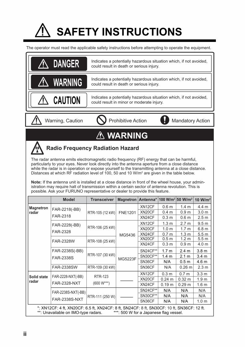
The operator must read the applicable safety instructions before attempting to operate the equipment.
Indicates a potentially hazardous situation which, if not avoided, could result in death or serious injury.
Indicates a potentially hazardous situation which, if not avoided, could result in death or serious injury.
Indicates a potentially hazardous situation which, if not avoided, could result in minor or moderate injury.
Warning, Caution Prohibitive Action Mandatory Action
The radar antenna emits electromagnetic radio frequency (RF) energy that can be harmful, particularly to your eyes. Never look directly into the antenna aperture from a close distance while the radar is in operation or expose yourself to the transmitting antenna at a close distance. Distances at which RF radiation level of 100, 50 and 10 W/m2 are given in the table below.
Note: If the antenna unit is installed at a close distance in front of the wheel house, your admin-istration may require halt of transmission within a certain sector of antenna revolution. This is possible. Ask your FURUNO representative or dealer to provide this feature.
Radio Frequency Radiation Hazard
WARNING
*: XN12CF: 4 ft, XN20CF: 6.5 ft, XN24CF: 8 ft, SN24CF: 8 ft, SN30CF: 10 ft, SN36CF: 12 ft.**: Unavailable on IMO-type radars. ***: 500 W for a Japanese flag vessel.
FAR-2218(-BB)FAR-2318
RTR-105 (12 kW)
RTR-123(600 W***)
RTR-106 (25 kW)
RTR-108 (25 kW)
RTR-107 (30 kW)
RTR-109 (30 kW)
XN12CFXN20CFXN24CF
FAR-2228(-BB)FAR-2328
FAR-2338S
XN12CFXN20CFXN24CF
0.6 m0.4 m0.3 m1.3 m1.0 m0.7 m
1.4 m0.9 m0.6 m2.7 m1.7 m1.3 m
4.4 m3.0 m2.5 m9.5 m6.8 m5.5 m
FAR-2328W
FAR-2238S(-BB)
FAR-2328-NXTFAR-2228-NXT(-BB)
FAR-2338SW
XN20CFXN24CFSN24CF**SN30CF**SN36CF
XN12CFXN20CFXN24CF
SN36CF
0.5 m0.3 m
N/A 0.26 m 2.3 m
1.2 m0.9 m
5.5 m4.0 m
Model Transceiver Magnetron
FNE1201
MG5436
MG5223F
Antenna* 100 W/m2 50 W/m2 10 W/m2
Magnetron radar
Solid state radar
1.7 m1.4 mN/A
0.3 m0.24 m0.19 m
0.7 m0.32 m0.29 m
2.4 m2.1 m0.5 m
3.8 m3.4 m4.6 m
3.3 m1.9 m1.6 m
RTR-111 (250 W)FAR-2338S-NXT
FAR-2238S-NXT(-BB) SN24CF**SN30CF**SN36CF
N/AN/AN/A
N/AN/AN/A
N/AN/A
1.0 m
ii
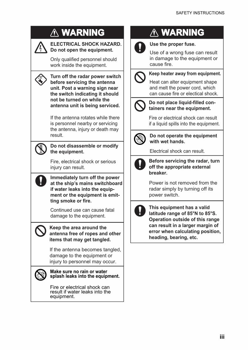
SAFETY INSTRUCTIONS
Make sure no rain or water splash leaks into the equipment.
Fire or electrical shock can result if water leaks into the equipment.
WARNINGWARNING WARNINGWARNING
Before servicing the radar, turn off the appropriate external breaker.
ELECTRICAL SHOCK HAZARD.Do not open the equipment.
Turn off the radar power switch before servicing the antenna unit. Post a warning sign near the switch indicating it should not be turned on while the antenna unit is being serviced.
Only qualified personnel should work inside the equipment.
Use the proper fuse.Use of a wrong fuse can result in damage to the equipment or cause fire.
If the antenna rotates while there is personnel nearby or servicing the antenna, injury or death may result.
Do not place liquid-filled con-tainers near the equipment.
Fire or electrical shock can result if a liquid spills into the equipment.
Do not operate the equipment with wet hands.
Electrical shock can result.
Keep heater away from equipment.Heat can alter equipment shape and melt the power cord, which can cause fire or electical shock.
Do not disassemble or modify the equipment.
Fire, electrical shock or serious injury can result.
Immediately turn off the power at the ship’s mains switchboard if water leaks into the equip-ment or the equipment is emit-ting smoke or fire.
Continued use can cause fatal damage to the equipment.
This equipment has a valid latitude range of 85°N to 85°S. Operation outside of this range can result in a larger margin of error when calculating position, heading, bearing, etc.
Power is not removed from the radar simply by turning off its power switch.
Keep the area around the antenna free of ropes and other items that may get tangled.
If the antenna becomes tangled, damage to the equipment or injury to personnel may occur.
iii

SAFETY INSTRUCTIONS
Name: Warning Label 1Type: 86-003-1011-3Code No.: 100-236-233-10
Name: Warning LabelType: 03-160-1042-0Code No.: 100-302-750-10
WARNINGTo avoid electrical shock, do not remove cover. No user-serviceable parts inside.
WARNING LABELWarning labels are attached to the equipment. Do not remove any label. If a label is missing or damaged, contact a FURUNO agent or dealer about replacement.
WARNINWARNING CAUTIONCAUTIONNo one navigational aid should be relied upon for the safety of vessel and crew.The navigator has the responsibility to check all aids available to confirm position. Electronic aids are not a substitute for basic navigational principles and common sense.
This TT automatically tracks automatically or manually acquired radar targets and calculates their courses and speeds, indicating them by vectors. Since the data generated by the auto plotter are based on what radar targets are selected, the radar must always be optimally tuned for use with the auto plotter, to ensure required targets will not be lost or unwanted targets such as sea returns and noise will not be acquired and tracked.
A target does not always mean a land-mass, reef, ships or other surface vessels but can imply returns from sea surface and clutter. As the level of clutter changes with environment, the operator should properly adjust the A/C SEA, A/C RAIN and GAIN controls to be sure target echoes are not eliminated from the radar screen.
The plotting accuracy and response of this TT meets IMO standards. Tracking accuracy is affected by the following:
The data generated by TT, AIS and video plotter are intended for reference only.
Tracking accuracy is affected by course change. One to two minutes is required to restore vectors to full accuracy after an abrupt course change. (The actual amount depends on gyrocompass specifications.)
The amount of tracking delay is inversely proportional to the relative speed of the target. Delay is on the order of 15 - 30 seconds for high relative speed; 30 - 60 seconds for low relative speed.
The target tracking and pertinent vector calculation accuracy is influenced by the following: - Echo intensity- The range measurement accuracy;
characterized by both random and biased measurement errors.
- The angular measurement accuracy;characterized by beam shape, target glint and bias errors.
- Radar transmission pulsewidth- Gyrocompass heading error- Speed log error - Curent and wind (set & drift)- Course change (own ship and target)
Refer to official nautical charts for detailed and up-to-date information.
DANGERElectrical shock hazard.Turn off power beforeservicing.
iv

TABLE OF CONTENTS
FOREWORD.................................................................................................................. xiiSYSTEM CONFIGURATION ....................................................................................... xvii
1. OPERATIONAL OVERVIEW.................................................................................1-11.1 Controls Overview ......................................................................................................1-1
1.1.1 Control Unit RCU-014 ....................................................................................1-11.1.2 Control Unit RCU-015/RCU-016 ....................................................................1-3
1.2 How to Turn the Radar On/Off....................................................................................1-41.3 How to Adjust the Brilliance........................................................................................1-41.4 Display Indications......................................................................................................1-5
1.4.1 InstantAccess bar™ buttons ...........................................................................1-61.4.2 Radar display and shortcuts...........................................................................1-71.4.3 Information and settings .................................................................................1-9
1.5 Menu Operations ......................................................................................................1-101.5.1 How to open and close the main menu ........................................................1-101.5.2 How to operate the menus ...........................................................................1-10
1.6 How to Use the On-screen Box Menus ....................................................................1-121.7 How to Use the CURSOR Menu ..............................................................................1-131.8 Cursor Data ..............................................................................................................1-14
1.8.1 How to change the cursor data attributes (B/W-type only) ...........................1-151.9 How to Set Up Function Keys...................................................................................1-151.10 How to Customize Operation....................................................................................1-171.11 How to Select the Interface for Heading Input..........................................................1-191.12 How to Set Own Ship’s Speed .................................................................................1-19
1.12.1 Automatic speed input (log or EPFS navigator) ...........................................1-191.12.2 Manual speed input ......................................................................................1-21
1.13 How to Set the Own Ship Position............................................................................1-211.14 How to Adjust the Date and Time.............................................................................1-221.15 User Settings............................................................................................................1-23
1.15.1 How to reset the user settings......................................................................1-251.15.2 How to save/load user settings ....................................................................1-25
1.16 How to Start/Stop Transmission ...............................................................................1-261.17 How to Tune the Receiver (Magnetron Radars Only) ..............................................1-27
1.17.1 How to select the tuning method ..................................................................1-271.17.2 How to initialize tuning..................................................................................1-271.17.3 How to tune the receiver manually ...............................................................1-27
1.18 How to Select a Pulselength.....................................................................................1-281.18.1 How to select a pulselength .........................................................................1-281.18.2 How to change the preset pulselength .........................................................1-28
1.19 How to Adjust Sensitivity ..........................................................................................1-291.20 How to Reduce Sea Clutter ......................................................................................1-29
1.20.1 How to select the method of clutter adjustment ...........................................1-291.20.2 How to fine-tune sea clutter reduction..........................................................1-301.20.3 How to manually reduce sea clutter .............................................................1-301.20.4 How to use the BERTHING STC function ....................................................1-31
1.21 How to Reduce Rain Clutter .....................................................................................1-311.21.1 How to select the method of rain clutter reduction .......................................1-321.21.2 How to manually reduce the rain clutter .......................................................1-32
1.22 Interference Rejector ................................................................................................1-341.23 Echo Stretch.............................................................................................................1-351.24 Echo Averaging ........................................................................................................1-361.25 Automatic Clutter Elimination (ACE) Function..........................................................1-38
v

TABLE OF CONTENTS
1.25.1 How to turn the Automatic Clutter Elimination (ACE) function on/off ........... 1-381.25.2 How to adjust the gain in Automatic Clutter Elimination (ACE) mode.......... 1-381.25.3 How to get high sensitivity............................................................................ 1-391.25.4 How to suppress false echoes ..................................................................... 1-39
1.26 Noise Rejector.......................................................................................................... 1-401.27 Wiper........................................................................................................................ 1-401.28 How to Preset Controls for a Specific Navigation Purpose ...................................... 1-41
1.28.1 How to select a customized echo................................................................. 1-441.28.2 How to edit a customized echo .................................................................... 1-441.28.3 How to restore a user customized echo to the saved settings..................... 1-451.28.4 How to restore a user customized echo to the factory default settings........ 1-461.28.5 How to edit the available customized echoes .............................................. 1-46
1.29 How to Reject Second-trace Echoes ....................................................................... 1-471.30 Orientation Modes.................................................................................................... 1-48
1.30.1 How to select an presentation mode............................................................ 1-481.30.2 Description of presentation modes............................................................... 1-48
1.31 How to Select a Range Scale .................................................................................. 1-501.32 How to Measure Range ........................................................................................... 1-51
1.32.1 How to show/hide the range rings................................................................ 1-511.32.2 How to measure range with the variable range marker (VRM) .................... 1-511.32.3 How to set the VRM unit of measurement (B-type only) .............................. 1-521.32.4 How to show TTG to VRM ........................................................................... 1-53
1.33 How to Measure Bearing.......................................................................................... 1-531.33.1 Methods to measure bearing ....................................................................... 1-541.33.2 True or relative bearing................................................................................ 1-54
1.34 Collision Assessment by Offset EBL........................................................................ 1-551.34.1 How to assess risk of collision using the offset EBL .................................... 1-551.34.2 How to set the origin point reference for EBL OFFSET ............................... 1-56
1.35 How to Measure Range and Bearing Between Two Targets ................................... 1-571.36 How to Off-Center the Display ................................................................................. 1-591.37 Target Trails ............................................................................................................. 1-60
1.37.1 True or relative trails .................................................................................... 1-601.37.2 Trail time ...................................................................................................... 1-611.37.3 Trail gradation .............................................................................................. 1-621.37.4 Trail level...................................................................................................... 1-621.37.5 Narrow trails (B/W-type only) ....................................................................... 1-631.37.6 How to hide the trails temporarily................................................................. 1-631.37.7 Trail stabilization in true motion.................................................................... 1-631.37.8 How to erase/restart trails ............................................................................ 1-631.37.9 How to prevent sea clutter in true trails........................................................ 1-641.37.10How to show/hide OS trails .......................................................................... 1-651.37.11How to show/hide land trails (B/W-type only)............................................... 1-651.37.12How to set the trail length (B/W-type only)................................................... 1-661.37.13How to set the trail color (B/W-type only)..................................................... 1-661.37.14How to remove the colors from a section of a multicolor trail (B/W-type only) ... 1-671.37.15How to offset the colors for multicolored trail (B/W-type only) ..................... 1-68
1.38 Target Analyzer (B/W-type only) .............................................................................. 1-691.38.1 How to activate/deactivate the target analyzer ............................................ 1-70
1.39 Target Alarm ............................................................................................................ 1-711.39.1 How to set a target alarm............................................................................. 1-711.39.2 How to mute the target alarm....................................................................... 1-721.39.3 How to deactivate a target alarm ................................................................. 1-721.39.4 How to change target alarm attributes ......................................................... 1-72
1.40 PI (Parallel Index) Lines ........................................................................................... 1-731.40.1 How to show/hide the PI lines ...................................................................... 1-731.40.2 How to set the maximum number of lines to display.................................... 1-73
vi

TABLE OF CONTENTS
1.40.3 How to change PI line bearing and interval ..................................................1-741.40.4 How to change the PI line bearing reference (B/W-type only) .....................1-741.40.5 How to change the PI line orientation...........................................................1-751.40.6 How to reset the PI lines to default (ship’s heading) ....................................1-751.40.7 How to change PI line length (IMO/A/B/R-types only)..................................1-75
1.41 How to Use the Net (Diamond) Cursor (B/W-type only) ...........................................1-761.41.1 How to activate the net cursor......................................................................1-761.41.2 How to set the net cursor dimensions and orientation .................................1-77
1.42 Zoom ........................................................................................................................1-781.43 How to Use Marks ....................................................................................................1-79
1.43.1 Heading line mark ........................................................................................1-791.43.2 How to hide/show the stern mark .................................................................1-791.43.3 North mark....................................................................................................1-801.43.4 How to set up the own ship symbol..............................................................1-801.43.5 How to set the barge marker ........................................................................1-801.43.6 Antenna mark ...............................................................................................1-811.43.7 Latitude/longitude grid ..................................................................................1-81
1.44 Drop Mark.................................................................................................................1-821.44.1 How to activate the drop mark......................................................................1-821.44.2 How to inscribe a drop mark.........................................................................1-821.44.3 How to erase drop marks .............................................................................1-82
1.45 Brilliance and Color Schemes ..................................................................................1-831.45.1 How to select a brilliance and color scheme ................................................1-831.45.2 How to change the color and brilliance assigned to a palette ......................1-831.45.3 How to change the color palette...................................................................1-85
1.46 How to Display and Set Up Navigational Data .........................................................1-861.46.1 How to set up the navigational data .............................................................1-861.46.2 How to display navigational data..................................................................1-87
1.47 How to Use the Information Box...............................................................................1-881.48 Interswitch ................................................................................................................1-90
1.48.1 How to display antenna information .............................................................1-901.48.2 How to preset antenna and display combinations........................................1-911.48.3 How to clear the interswitch .........................................................................1-93
1.49 Performance Monitor ................................................................................................1-931.49.1 How to activate/deactivate the performance monitor ...................................1-931.49.2 How to check the radar’s performance.........................................................1-95
1.50 How to Change the Reference Position ...................................................................1-961.51 Anchor Watch...........................................................................................................1-971.52 Alerts ........................................................................................................................1-98
1.52.1 What is an alert? ..........................................................................................1-981.52.2 How to interpret the [ALERT] box.................................................................1-991.52.3 How to acknowledge an alert .......................................................................1-991.52.4 How to silence the alert buzzer ....................................................................1-991.52.5 Alert list.......................................................................................................1-1001.52.6 Alert icons and their meanings ...................................................................1-1021.52.7 Responsibility transfer alert ........................................................................1-103
1.53 Icing Prevention......................................................................................................1-1041.54 How to Select a Display Mode (B/W-type Only) .....................................................1-1051.55 How to Manage SD Card Data ...............................................................................1-106
1.55.1 Formatting the SD card ..............................................................................1-1061.55.2 Cautionary notes on handling SD cards.....................................................1-1061.55.3 Compatible SD cards .................................................................................1-1061.55.4 How to insert SD cards...............................................................................1-1071.55.5 How to remove SD cards ...........................................................................1-1071.55.6 How to save data to an SD card.................................................................1-1081.55.7 How to read (load) data from an SD card...................................................1-108
vii

TABLE OF CONTENTS
1.55.8 How to delete data from an SD card .......................................................... 1-1081.56 How to Take a Screenshot..................................................................................... 1-1091.57 How to Use the Watch Alert (A/B/W-types only) .................................................... 1-1091.58 Dual Radar (A/B-types only) .................................................................................. 1-110
1.58.1 How to toggle control of each dual radar display ....................................... 1-1111.58.2 Operating considerations for the dual radar display................................... 1-112
1.59 Wave Mode ............................................................................................................ 1-1141.60 Doppler Feature (X-band Solid State Radars only)................................................ 1-115
2. RADAR OBSERVATION .......................................................................................2-12.1 General ...................................................................................................................... 2-1
2.1.1 Minimum range .............................................................................................. 2-12.1.2 Maximum range ............................................................................................. 2-12.1.3 X-band and S-band........................................................................................ 2-22.1.4 Radar resolution............................................................................................. 2-22.1.5 Bearing accuracy ........................................................................................... 2-32.1.6 Range measurement...................................................................................... 2-3
2.2 False Echoes ............................................................................................................. 2-32.3 SART (Search and Rescue Transponder) ................................................................. 2-5
2.3.1 SART description ........................................................................................... 2-52.3.2 How to show SART marks on the radar display............................................. 2-62.3.3 General remarks on receiving SARTs............................................................ 2-6
2.4 RACON ...................................................................................................................... 2-72.5 Radar Target Enhancer (RTE) ................................................................................... 2-72.6 Solid state radar ......................................................................................................... 2-8
3. TARGET TRACKING (TT) .....................................................................................3-13.1 Precautions when Using Target Tracking .................................................................. 3-13.2 TT Controls ................................................................................................................ 3-23.3 TT Box Overview........................................................................................................ 3-23.4 How to Select the TT mode........................................................................................ 3-33.5 How to Acquire and Track Targets............................................................................. 3-4
3.5.1 How to manually acquire a target................................................................... 3-43.5.2 How to automatically acquire targets ............................................................. 3-5
3.6 How to Enter Own Ship Speed .................................................................................. 3-53.6.1 Echo-referenced speed input ......................................................................... 3-5
3.7 How to Cancel Target Tracking.................................................................................. 3-73.7.1 How to cancel tracking for individual TT targets ............................................ 3-73.7.2 How to cancel tracking for all TT targets........................................................ 3-7
3.8 Lost Target .................................................................................................................3-83.8.1 How to set the lost target filter........................................................................ 3-83.8.2 How to enable/disable the lost target alert ..................................................... 3-8
3.9 TT Symbols and Attributes......................................................................................... 3-93.9.1 How to adjust symbol brilliance...................................................................... 3-93.9.2 How to set the symbol color ........................................................................... 3-93.9.3 How to select a TT symbol (B/W-types only) ............................................... 3-10
3.10 How to Display/Remove Target Data....................................................................... 3-103.10.1 TT pop up information.................................................................................. 3-103.10.2 How to show/remove target data in the data display area ........................... 3-113.10.3 How to display, hide and sort the target list ................................................. 3-12
3.11 How to Assign a Preset Name to TT Targets (B/W-type only)................................. 3-143.11.1 How to activate the preset name function .................................................... 3-143.11.2 How to setup preset names ......................................................................... 3-143.11.3 How to assign a name to a TT ..................................................................... 3-15
3.12 Vector Modes ........................................................................................................... 3-163.12.1 Description of vectors................................................................................... 3-16
viii
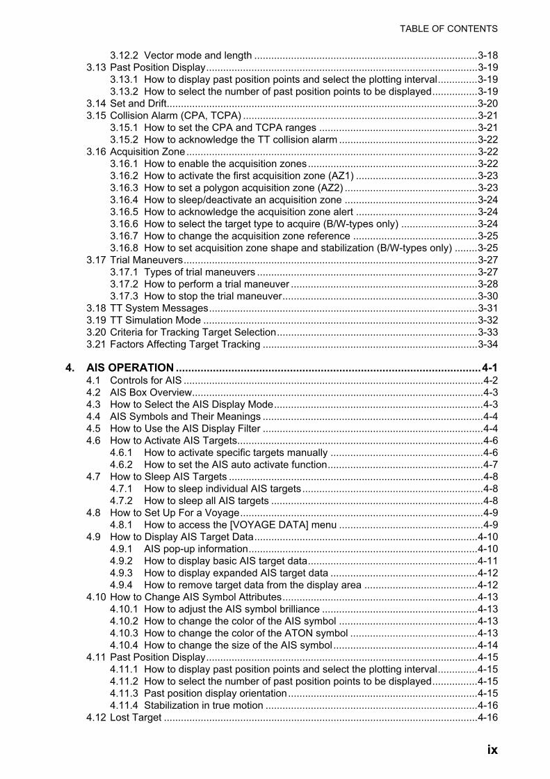
TABLE OF CONTENTS
3.12.2 Vector mode and length ...............................................................................3-183.13 Past Position Display................................................................................................3-19
3.13.1 How to display past position points and select the plotting interval..............3-193.13.2 How to select the number of past position points to be displayed................3-19
3.14 Set and Drift..............................................................................................................3-203.15 Collision Alarm (CPA, TCPA) ...................................................................................3-21
3.15.1 How to set the CPA and TCPA ranges ........................................................3-213.15.2 How to acknowledge the TT collision alarm .................................................3-22
3.16 Acquisition Zone.......................................................................................................3-223.16.1 How to enable the acquisition zones............................................................3-223.16.2 How to activate the first acquisition zone (AZ1) ...........................................3-233.16.3 How to set a polygon acquisition zone (AZ2) ...............................................3-233.16.4 How to sleep/deactivate an acquisition zone ...............................................3-243.16.5 How to acknowledge the acquisition zone alert ...........................................3-243.16.6 How to select the target type to acquire (B/W-types only) ...........................3-243.16.7 How to change the acquisition zone reference ............................................3-253.16.8 How to set acquisition zone shape and stabilization (B/W-types only) ........3-25
3.17 Trial Maneuvers........................................................................................................3-273.17.1 Types of trial maneuvers ..............................................................................3-273.17.2 How to perform a trial maneuver ..................................................................3-283.17.3 How to stop the trial maneuver.....................................................................3-30
3.18 TT System Messages...............................................................................................3-313.19 TT Simulation Mode .................................................................................................3-323.20 Criteria for Tracking Target Selection.......................................................................3-333.21 Factors Affecting Target Tracking ............................................................................3-34
4. AIS OPERATION ...................................................................................................4-14.1 Controls for AIS ..........................................................................................................4-24.2 AIS Box Overview.......................................................................................................4-34.3 How to Select the AIS Display Mode..........................................................................4-34.4 AIS Symbols and Their Meanings ..............................................................................4-44.5 How to Use the AIS Display Filter ..............................................................................4-44.6 How to Activate AIS Targets.......................................................................................4-6
4.6.1 How to activate specific targets manually ......................................................4-64.6.2 How to set the AIS auto activate function.......................................................4-7
4.7 How to Sleep AIS Targets ..........................................................................................4-84.7.1 How to sleep individual AIS targets................................................................4-84.7.2 How to sleep all AIS targets ...........................................................................4-8
4.8 How to Set Up For a Voyage......................................................................................4-94.8.1 How to access the [VOYAGE DATA] menu ...................................................4-9
4.9 How to Display AIS Target Data...............................................................................4-104.9.1 AIS pop-up information.................................................................................4-104.9.2 How to display basic AIS target data............................................................4-114.9.3 How to display expanded AIS target data ....................................................4-124.9.4 How to remove target data from the display area ........................................4-12
4.10 How to Change AIS Symbol Attributes.....................................................................4-134.10.1 How to adjust the AIS symbol brilliance .......................................................4-134.10.2 How to change the color of the AIS symbol .................................................4-134.10.3 How to change the color of the ATON symbol .............................................4-134.10.4 How to change the size of the AIS symbol...................................................4-14
4.11 Past Position Display................................................................................................4-154.11.1 How to display past position points and select the plotting interval..............4-154.11.2 How to select the number of past position points to be displayed................4-154.11.3 Past position display orientation...................................................................4-154.11.4 Stabilization in true motion ...........................................................................4-16
4.12 Lost Target ...............................................................................................................4-16
ix
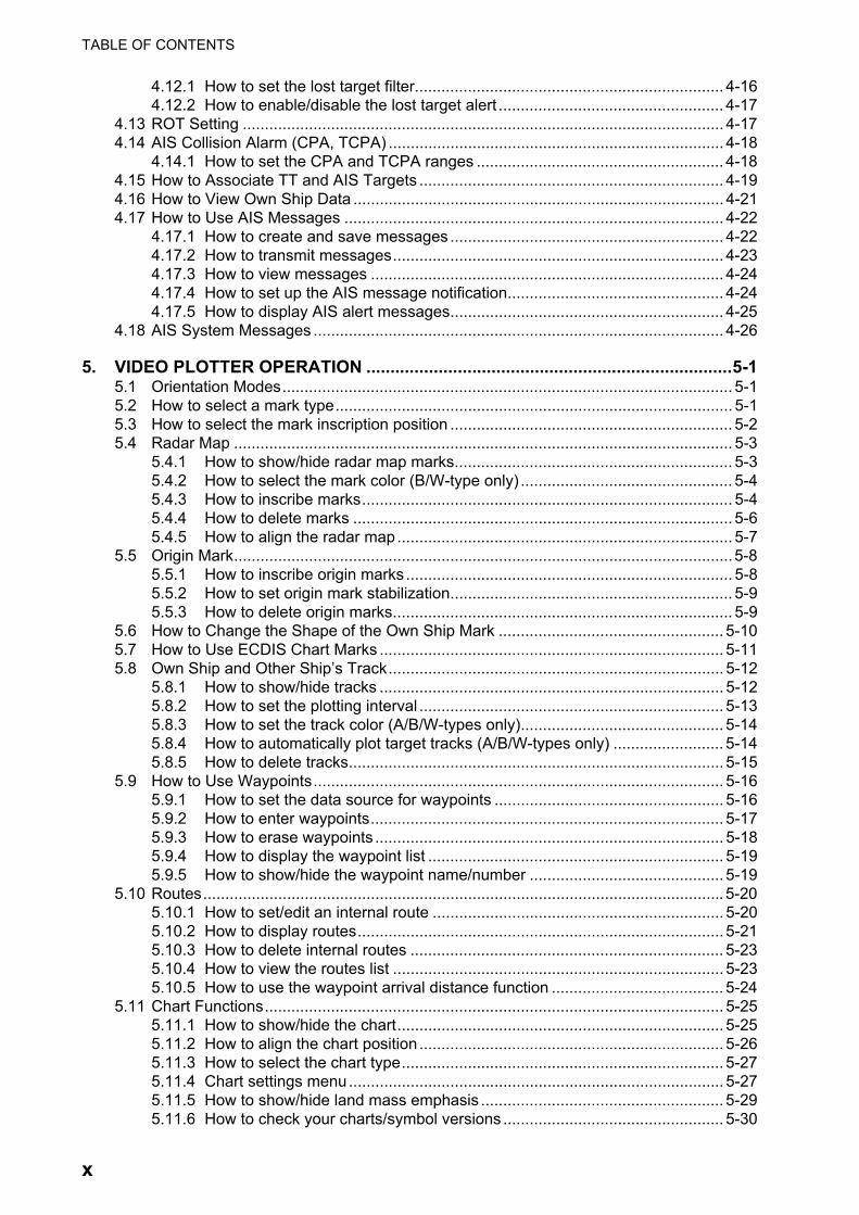
TABLE OF CONTENTS
4.12.1 How to set the lost target filter...................................................................... 4-164.12.2 How to enable/disable the lost target alert ................................................... 4-17
4.13 ROT Setting ............................................................................................................. 4-174.14 AIS Collision Alarm (CPA, TCPA) ............................................................................ 4-18
4.14.1 How to set the CPA and TCPA ranges ........................................................ 4-184.15 How to Associate TT and AIS Targets ..................................................................... 4-194.16 How to View Own Ship Data .................................................................................... 4-214.17 How to Use AIS Messages ...................................................................................... 4-22
4.17.1 How to create and save messages .............................................................. 4-224.17.2 How to transmit messages........................................................................... 4-234.17.3 How to view messages ................................................................................ 4-244.17.4 How to set up the AIS message notification................................................. 4-244.17.5 How to display AIS alert messages.............................................................. 4-25
4.18 AIS System Messages ............................................................................................. 4-26
5. VIDEO PLOTTER OPERATION ............................................................................5-15.1 Orientation Modes...................................................................................................... 5-15.2 How to select a mark type.......................................................................................... 5-15.3 How to select the mark inscription position ................................................................ 5-25.4 Radar Map ................................................................................................................. 5-3
5.4.1 How to show/hide radar map marks............................................................... 5-35.4.2 How to select the mark color (B/W-type only) ................................................ 5-45.4.3 How to inscribe marks.................................................................................... 5-45.4.4 How to delete marks ...................................................................................... 5-65.4.5 How to align the radar map............................................................................ 5-7
5.5 Origin Mark.................................................................................................................5-85.5.1 How to inscribe origin marks .......................................................................... 5-85.5.2 How to set origin mark stabilization................................................................ 5-95.5.3 How to delete origin marks............................................................................. 5-9
5.6 How to Change the Shape of the Own Ship Mark ................................................... 5-105.7 How to Use ECDIS Chart Marks .............................................................................. 5-115.8 Own Ship and Other Ship’s Track............................................................................ 5-12
5.8.1 How to show/hide tracks .............................................................................. 5-125.8.2 How to set the plotting interval ..................................................................... 5-135.8.3 How to set the track color (A/B/W-types only).............................................. 5-145.8.4 How to automatically plot target tracks (A/B/W-types only) ......................... 5-145.8.5 How to delete tracks..................................................................................... 5-15
5.9 How to Use Waypoints............................................................................................. 5-165.9.1 How to set the data source for waypoints .................................................... 5-165.9.2 How to enter waypoints................................................................................ 5-175.9.3 How to erase waypoints ............................................................................... 5-185.9.4 How to display the waypoint list ................................................................... 5-195.9.5 How to show/hide the waypoint name/number ............................................ 5-19
5.10 Routes...................................................................................................................... 5-205.10.1 How to set/edit an internal route .................................................................. 5-205.10.2 How to display routes................................................................................... 5-215.10.3 How to delete internal routes ....................................................................... 5-235.10.4 How to view the routes list ........................................................................... 5-235.10.5 How to use the waypoint arrival distance function ....................................... 5-24
5.11 Chart Functions........................................................................................................ 5-255.11.1 How to show/hide the chart.......................................................................... 5-255.11.2 How to align the chart position ..................................................................... 5-265.11.3 How to select the chart type......................................................................... 5-275.11.4 Chart settings menu..................................................................................... 5-275.11.5 How to show/hide land mass emphasis ....................................................... 5-295.11.6 How to check your charts/symbol versions .................................................. 5-30
x
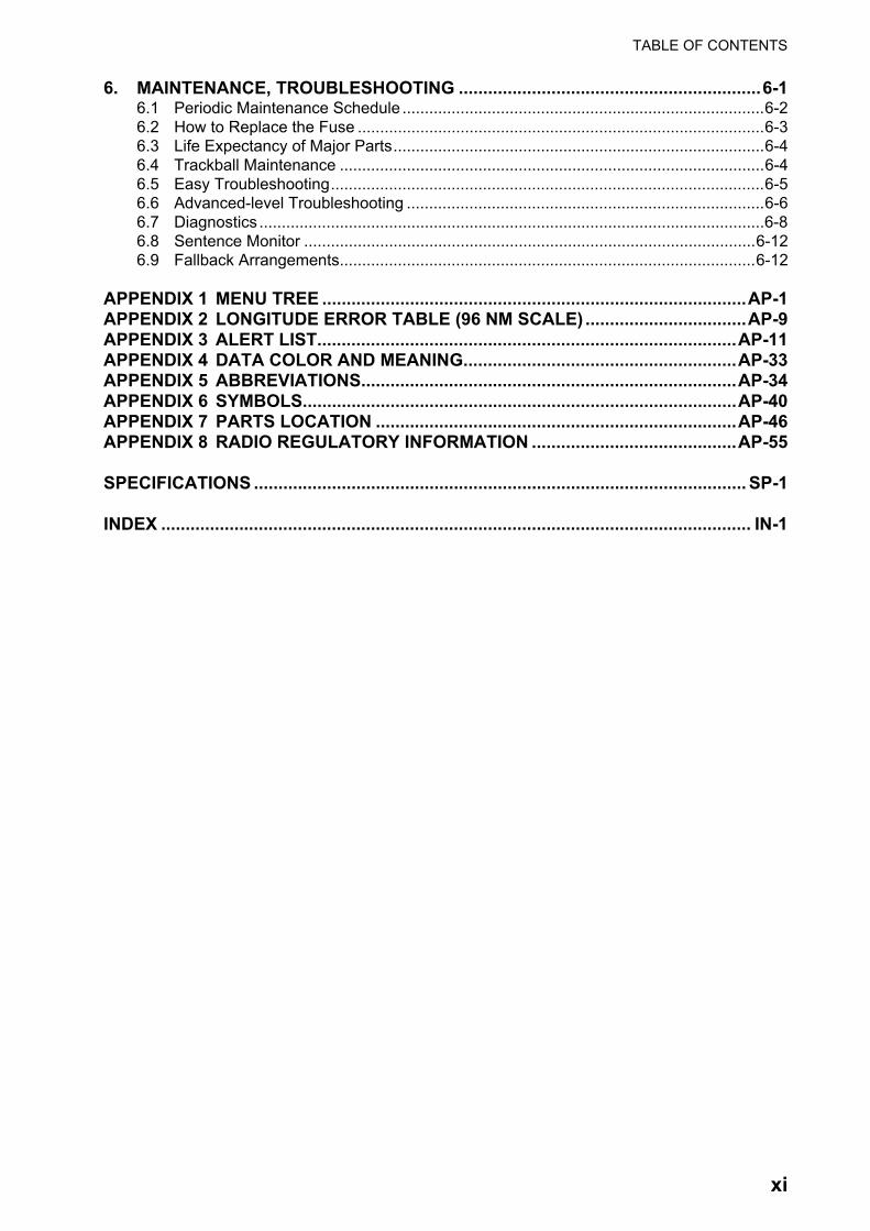
TABLE OF CONTENTS
6. MAINTENANCE, TROUBLESHOOTING ..............................................................6-16.1 Periodic Maintenance Schedule .................................................................................6-26.2 How to Replace the Fuse ...........................................................................................6-36.3 Life Expectancy of Major Parts...................................................................................6-46.4 Trackball Maintenance ...............................................................................................6-46.5 Easy Troubleshooting.................................................................................................6-56.6 Advanced-level Troubleshooting ................................................................................6-66.7 Diagnostics .................................................................................................................6-86.8 Sentence Monitor .....................................................................................................6-126.9 Fallback Arrangements.............................................................................................6-12
APPENDIX 1 MENU TREE .......................................................................................AP-1APPENDIX 2 LONGITUDE ERROR TABLE (96 NM SCALE) .................................AP-9APPENDIX 3 ALERT LIST......................................................................................AP-11APPENDIX 4 DATA COLOR AND MEANING........................................................AP-33APPENDIX 5 ABBREVIATIONS.............................................................................AP-34APPENDIX 6 SYMBOLS.........................................................................................AP-40APPENDIX 7 PARTS LOCATION ..........................................................................AP-46APPENDIX 8 RADIO REGULATORY INFORMATION ..........................................AP-55
SPECIFICATIONS ..................................................................................................... SP-1
INDEX ......................................................................................................................... IN-1
xi
FOREWORD
A Word to the Owner of FAR-22x8/23x8 Series Marine Radar
Congratulations on your choice of the FURUNO FAR-22x8/FAR-23x8 series of radars. We are confident you will see why FURUNO has become synonymous with quality and reliability.
Since 1948, FURUNO Electric Company has enjoyed an enviable reputation for innovative and dependable marine electronics equipment. This dedication to excellence is furthered by our ex-tensive global network of agents and dealers.
Your radar is designed and constructed to meet the rigorous demands of the marine environment. However, no machine can perform its intended function unless installed, operated and maintained properly. Please carefully read and follow the recommended procedures for operation and main-tenance.We would appreciate hearing from you, the end-user, about whether we are achieving our goal.
Thank you for considering and purchasing FURUNO equipment.
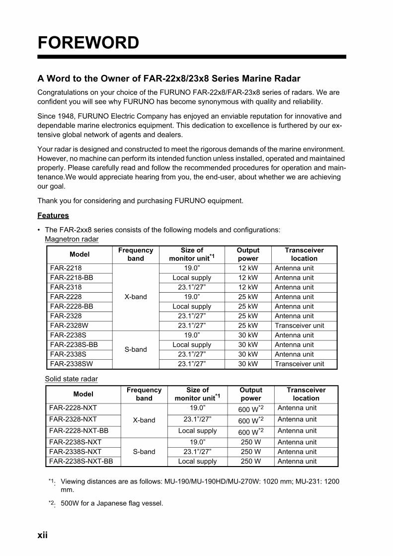
Features
• The FAR-2xx8 series consists of the following models and configurations:Magnetron radar
Solid state radar
ModelFrequency
bandSize of
monitor unit*1Output power
Transceiver location
FAR-2218
X-band
19.0” 12 kW Antenna unitFAR-2218-BB Local supply 12 kW Antenna unitFAR-2318 23.1”/27” 12 kW Antenna unitFAR-2228 19.0” 25 kW Antenna unitFAR-2228-BB Local supply 25 kW Antenna unitFAR-2328 23.1”/27” 25 kW Antenna unitFAR-2328W 23.1”/27” 25 kW Transceiver unitFAR-2238S
S-band
19.0” 30 kW Antenna unitFAR-2238S-BB Local supply 30 kW Antenna unitFAR-2338S 23.1”/27” 30 kW Antenna unitFAR-2338SW 23.1”/27” 30 kW Transceiver unit
ModelFrequency
bandSize of
monitor unit*1Output power
Transceiver location
FAR-2228-NXT
X-band
19.0” 600 W*2 Antenna unit
FAR-2328-NXT 23.1”/27” 600 W*2 Antenna unit
FAR-2228-NXT-BB Local supply 600 W*2 Antenna unit
FAR-2238S-NXTS-band
19.0” 250 W Antenna unitFAR-2338S-NXT 23.1”/27” 250 W Antenna unitFAR-2238S-NXT-BB Local supply 250 W Antenna unit
*1: Viewing distances are as follows: MU-190/MU-190HD/MU-270W: 1020 mm; MU-231: 1200 mm.
*2: 500W for a Japanese flag vessel.
xii

FOREWORD
• Two methods of operation are available: the standard supply control unit (RCU-014) and the optional trackball unit (RCU-015/RCU-016). The ergonomically designed palm rest on the track-ball unit makes it easy to use.
• Simple operation with “point-and-click” menu functionality.
• All functions can be accessed using only the trackball unit, however, RCU-016 trackball units do not have a power button.
• TT, AIS, Radar Map, Interswitch and FURUNO’s unique Target Analyzer are supplied as stan-dard.
• CPA/TCPA alarms.
• Targets activate the user-set alarm zone when entering or exiting the zone.
• The Target Analyzer function helps to find targets in high noise areas (rain/snow), or where there is interference from surface reflections. (Available for B/W-types only.)
• The FAR-2xx8 series complies with MED 2014/90/EU and also the following directives: IEC62388, IEC 62288, IMO MSC. 192(79).
Terminology standards used in this manual
This manual uses the following terminology standards:
For the sake of brevity, all procedures in this manual use the terms “Open the menu.” and “Close the menu”.
Program numbers
Please access the following URL if you need software information:http://www.furuno.com/en/merchant/radar/FAR-22x8_23x8/#SoftwareVersion
: Denotes minor changes to the software.
Terminology Meaning or usage exampleSelect • Use the trackball or scrollwheel on the control unit to move the cursor over
the item to be “selected”, then left-click.• With a menu open: Press the appropriate menu number.
Left-click Press the left mouse button.Right-click Press the right mouse button.Control Unit Refers to the RCU-014 Control Unit, unless otherwise specified.Open the menu. Press the MENU key to show the [MENU].Close the menu. Press the MENU key to close the [MENU].
System Program no. Version no. RemarksAntenna unit (common to all antennas)SPU 0359281 01. For magnetron radarSPU 0359286 01. For S-band solid state radarSPU 0359477 01. For X-band solid state radarMTR-DRV 0359293 01.PM 0359296 01.RF-Converter 0359302 01. For S-band solid state radarRF-Converter 0359414 01. For X-band solid state radarProcessor Unit: RPU-025MAIN 0359377 02.SUB 0359380 02.Control Unit: RCU-014/015/016KEY 0359385 01.
xiii

FOREWORD
About the programs used in A/B/W-types with Radar Plotter functionality
• Ubiquitous QuickBoot Copyright© 2015. Ubiquitous Corp. All right reserved.
• Portions of this software are copyright© 2016. The FreeType Project (www.freetype.org). All right reserved.
• This equipment includes GPL2.0, LGPL2.0, Apache, BSD, MIT or other licensed softwares. For further software information, please access the following URL:https://www.furuno.co.jp/en/contact/cnt_oss_e01.html
Radar Type and Function Availability
This radar is available in several specification types to meet the requirements of Authorities, and function availability depends on specification type. The table below shows the function that have limited availability. This manual provides descriptions for all functions of this radar series, and we have endeavored to denote in the text those functions that have limited availability. For detailed information on the function availability, see the menu tree at the back of this manual.
Type abbreviations and their meanings
• IMO: Meets the IMO requirements and is compliant with IMO regulations
• A: Near-IMO specifications
• B: Standard fishing specifications
• R: Russian River
• W: Washington Ferry
Function availability and specification type
FunctionType
IMO A B R WTT symbol selection No No Yes No YesAcquisition zone range limitation
Yes No No Yes No
Auto Track Target No Yes Yes No YesChart Display No Yes Yes No YesColor Echo No No Yes No YesCursor range unit selection
No No Yes No No
Cursor Size No No Yes No YesEcho area configuration
No No Yes No Yes
Mark color No No Yes No YesMark w/line No No Yes No YesRange [0.125],
[0.25], [0.5], [0.75], [1.5], [3], [6], [12], [24], [48],
[96]
Same as IMO
[0.125]***, [0.25], [0.5], [0.75], [1],
[1.5], [2], [3], [4], [6], [8], [12], [16], [24], [32], [48], [96],
[120]*
Same as IMO
Same as B
Range unit [NM] only Same as IMO
[NM], [SM], [km], [kyd]
Same as IMO
Same as B
xiv

FOREWORD
*: The range setting [120] is only available when the range unit is set to km,kyd.**: Available only for B/W-types.***: The range setting [0.125] is only available when the range unit is set to [NM] or [SM].
Advanced fishing specifications
The following radar plotter features will be available by updating to the software for advanced fish-ing specifications and installing the RP board to the processor unit. Consult your local dealer re-garding the software update and RP board installation.
• A variety of plotter-related functions.(Memory capacity increase for own and other ship’s track, ship’s track color customize function, mark/line function, memory capacity increase for origin mark, origin mark list, etc.)
• TT/AIS symbol customize function.
• Enhanced dynamic range for a more complete EAV (Echo Average) function.
• Compatible with the RCU-031 control unit that is specially designed for fisheries.
For details about advanced fishing specifications, see the operator’s manual (OME-36521).
VRM unit - selectable unit
No No Yes No No
Track - Other ship No Yes Yes No YesTrail Eraser No No Yes No YesTrails - Color No No Yes No YesTrails - Hide No No Yes No YesTrails - Long No No Yes No YesTrails - Narrow No No Yes No YesWPT marker No Yes Yes No YesTarget Analyzer No No Yes No YesNet Cursor No No Yes No YesTarget Type to Acquire
No No Yes No Yes
Check Area Setting No No Yes No YesDisplay Scroll** No No Yes No YesDual Radar display No Yes Yes No No
FunctionType
IMO A B R W
xv
FOREWORD
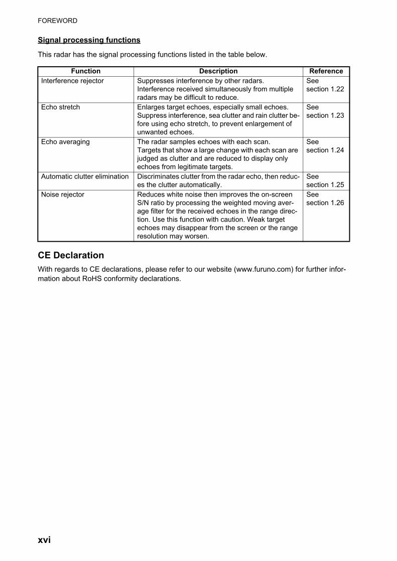
Signal processing functions
This radar has the signal processing functions listed in the table below.
CE Declaration
With regards to CE declarations, please refer to our website (www.furuno.com) for further infor-mation about RoHS conformity declarations.
Function Description ReferenceInterference rejector Suppresses interference by other radars.
Interference received simultaneously from multiple radars may be difficult to reduce.
See section 1.22
Echo stretch Enlarges target echoes, especially small echoes.Suppress interference, sea clutter and rain clutter be-fore using echo stretch, to prevent enlargement of unwanted echoes.
See section 1.23
Echo averaging The radar samples echoes with each scan.Targets that show a large change with each scan are judged as clutter and are reduced to display only echoes from legitimate targets.
See section 1.24
Automatic clutter elimination Discriminates clutter from the radar echo, then reduc-es the clutter automatically.
See section 1.25
Noise rejector Reduces white noise then improves the on-screen S/N ratio by processing the weighted moving aver-age filter for the received echoes in the range direc-tion. Use this function with caution. Weak target echoes may disappear from the screen or the range resolution may worsen.
See section 1.26
xvi

SYSTEM CONFIGURATION
Note: Basic configuration is shown with a solid line. For footnotes, see "Notes" on page xxi.
X-band (TR-UP)
IMO-type radar(s) must be interconnected to the following type approved sensors.For other radar types, it is recommended to connect the following type approved sensors. • EPFS meeting the requirements of the IMO resolution MSC.112(73). • Gyrocompass (or equivalent devices) meeting the requirements of the IMO resolution A.424(XI). • SDME meeting the requirements of IMO resolution MSC.96(72).
NOTICE
The radar may be interconnected via HUB-3000 to other FURUNO processing units having approved LAN ports.
100-230 VAC 1ø, 50-60 Hz
Transformer
USB Device*9
440 VAC 1ø, 50-60 Hz
24 VDCRectifierPR-850A
100/110/120 VAC 1ø, 50-60 Hz
USB Mouse
Switching HubHUB-100
Control UnitRCU-014 or RCU-015
Monitor Unit*3 MU-190/MU-231/MU-270W
Intelligent Hub HUB-3000*5
Gyrocompass*1 (AD-10 format)
Gyrocompass*1 (IEC61162 format)
AIS Transponder
EPFS*2 (GPS)
SDME (Speed log)
AMS (IEC61162 format)
Sub monitor 1 of ECDIS*8
Sub monitor 2 of ECDIS*8
AMS (Contact)*4
Processor Unit
RPU-025
100-230 VAC
100-230 VAC
Intelligent Hub HUB-3000*6
100-230 VAC
OR100-230 VAC
VDR(IEC61162-450 format)
Sensors(IEC61162-450 Ed.1 format)
VDR (Analog RGB)
: Standard supply: Optional or local supply
ECDIS
Control Unit RCU-016
For AC power
For DC power
or
Sub monitor Antenna Cable*10100-115/220-230 VAC
1ø, 50-60 Hz (for de-icer)
for FAR-2218(-BB)/2318, 12 kW(w/ Performance Monitor PM-32A*7)
XN12CF-RSB128-105XN20CF-RSB128-105XN24CF-RSB128-105
for FAR-2228(-BB)/2328, 25 kW(w/ Performance Monitor PM-32A*7)
XN12CF-RSB128-106XN20CF-RSB128-106XN24CF-RSB128-106
Antenna Unit
ORMonitor Unit*3 MU-190HD12-24 VDC
Sensors(IEC61162-450 Ed.2 format)
for FAR-2228-NXT(-BB)/2328-NXT, 600 W (500 W for a Japanese flag vessel)
(w/ Performance Monitor PM-32B*7)XN12CF-RSB128-123XN20CF-RSB128-123XN24CF-RSB128-123
xvii
SYSTEM CONFIGURATION
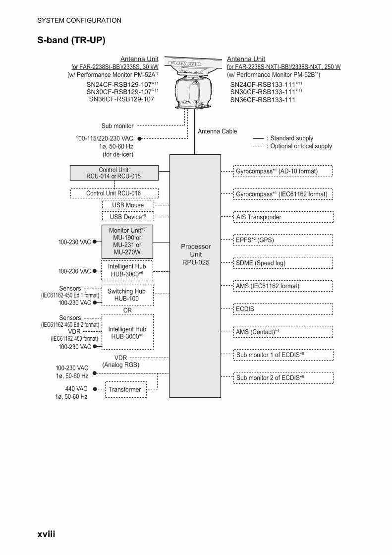
S-band (TR-UP)
Gyrocompass*1 (AD-10 format)
Gyrocompass*1 (IEC61162 format)
AIS Transponder
EPFS*2 (GPS)
SDME (Speed log)
AMS (IEC61162 format)
ECDIS
AMS (Contact)*4
Sub monitorAntenna Cable
100-115/220-230 VAC 1ø, 50-60 Hz
(for de-icer)
Processor Unit
RPU-025
Antenna Unitfor FAR-2238S(-BB)/2338S, 30 kW(w/ Performance Monitor PM-52A*7
SN24CF-RSB129-107*11
SN30CF-RSB129-107*11
SN36CF-RSB129-107
Antenna Unit for FAR-2238S-NXT(-BB)/2338S-NXT, 250 W(w/ Performance Monitor PM-52B*7)SN24CF-RSB133-111*11
SN30CF-RSB133-111*11
SN36CF-RSB133-111
Sub monitor 1 of ECDIS*8
Sub monitor 2 of ECDIS*8
Control UnitRCU-014 or RCU-015
Control Unit RCU-016
: Standard supply: Optional or local supply
USB Device*9
USB Mouse
100-230 VAC 1ø, 50-60 Hz
Transformer440 VAC 1ø, 50-60 Hz
Monitor Unit*3 MU-190 or MU-231 or MU-270W
Intelligent Hub HUB-3000*5
100-230 VAC
100-230 VAC
VDR(Analog RGB)
Switching HubHUB-100
Intelligent Hub HUB-3000*6
100-230 VAC
OR100-230 VAC
VDR(IEC61162-450 format)
Sensors(IEC61162-450 Ed.1 format)
Sensors(IEC61162-450 Ed.2 format)
xviii

SYSTEM CONFIGURATION
X-band (TR-DOWN)
Sub monitor
Antenna Cable
100-115/220-230 VAC 1ø, 50-60 Hz
(for de-icer)
Transceiver UnitRTR-108
Antenna Unitfor FAR-2328W, 25 kW(w/ Performance Monitor PM-32A)XN20CF-RSB130XN24CF-RSB130
Wave guideSignal cable
: Standard supply: Optional or local supply
Gyrocompass*1 (AD-10 format)
Gyrocompass*1 (IEC61162 format)
AIS Transponder
EPFS*2 (GPS)
SDME (Speed log)
AMS (IEC61162 format)
ECDIS
AMS (Contact)*4
Processor Unit
RPU-025
Sub monitor 1 of ECDIS*8
Sub monitor 2 of ECDIS*8
Control UnitRCU-014 or RCU-015
Control Unit RCU-016
USB Device*9
USB Mouse
100-230 VAC 1ø, 50-60 Hz
Transformer440 VAC 1ø, 50-60 Hz
Monitor Unit*3 MU-190 or MU-231 or MU-270W
Intelligent Hub HUB-3000*5
100-230 VAC
100-230 VAC
VDR(Analog RGB)
Switching HubHUB-100
Intelligent Hub HUB-3000*6
100-230 VAC
OR100-230 VAC
VDR(IEC61162-450 format)
Sensors(IEC61162-450 Ed.1 format)
Sensors(IEC61162-450 Ed.2 format)
xix

SYSTEM CONFIGURATION
S-band (TR-DOWN)
Sub monitor
Antenna Cable
100-115/220-230 VAC 1ø, 50-60 Hz
(for de-icer)
Transceiver UnitRTR-109
Antenna Unitfor FAR-2338SW, 30 kW
(w/ Performance Monitor PM-52A)SN36CF-RSB131
Coaxial cableSignal cable
: Standard supply: Optional or local supply
Gyrocompass*1 (AD-10 format)
Gyrocompass*1 (IEC61162 format)
AIS Transponder
EPFS*2 (GPS)
SDME (Speed log)
AMS (IEC61162 format)
ECDIS
AMS (Contact)*4
Processor Unit
RPU-025
Sub monitor 1 of ECDIS*8
Sub monitor 2 of ECDIS*8
Control UnitRCU-014 or RCU-015
Control Unit RCU-016
USB Device*9
USB Mouse
100-230 VAC 1ø, 50-60 Hz
Transformer440 VAC 1ø, 50-60 Hz
Monitor Unit*3 MU-190 or MU-231 or MU-270W
Intelligent Hub HUB-3000*5
100-230 VAC
100-230 VAC
VDR(Analog RGB)
Switching HubHUB-100
Intelligent Hub HUB-3000*6
100-230 VAC
OR100-230 VAC
VDR(IEC61162-450 format)
Sensors(IEC61162-450 Ed.1 format)
Sensors(IEC61162-450 Ed.2 format)
xx

SYSTEM CONFIGURATION
Category of units
• Antenna units: Exposed to the weather. • Other units: Protected from the weather.
Notes
1) The gyrocompass must be type approved for compliance with IMO resolution A.424(XI) (and/or resolution A.821(19) for installation on HSC). The gyrocompass must also have an update rate that is adequate for the ship’s rate of turn. The update rate must be better than 40 Hz (HSC) or 20 Hz (conventional vessel).
2) The EPFS must be type approved for compliance with IMO resolution MSC.112(73).
3) The monitors listed in the following table have been approved by the IMO.If a different monitor is to be used on IMO vessels, its effective diameter must meet the appli-cable Category requirements.
For installation and operation of other monitors, see the respective manuals.For BB type, a monitor unit is prepared by user.
4) Characteristics of contact output for Alarm:
• (Load current) 250 mA;
• (Polarity) Normally Open: 2 ports, Normally Close: 2 ports;
• Serial I/O for alarm is also possible, which complies with IEC 61162-1.
5) For configurations with 3 or more radars/ECDIS (FMD-3100/FMD-3200/FMD-3300) connect-ed, connect via the HUB-3000. For 2 radars, HUB-100 can be used.
6) For connection to a VDR or IEC61162-450 Ed.2 sensor, connection should be made via the HUB-3000.
• CAT 1 and CAT 1H: effective diameter of 320 mm or higher• CAT 2 and CAT 2H: effective diameter of 250 mm or higher• CAT 3: effective diameter of 180 mm or higher
Category Manufacturer Model Viewing distanceCAT 1 and CAT 1H
FURUNO MU-231 1.20 mMU-270W 1.02 m
Hatteland Display JH 23T14 FUD 1.20 mHD26T21 MMD 0.99 mHD26T22 FUD 0.99 mHD27T22 FUD 1.07 mHD32T22 FUD 0.64 mHD55T22 FUD 1.09 m
North Invent WA270-01-MON-01 1.07 mWA460-01-MON-01 0.60 m
CAT 2 and CAT 2H
FURUNO MU-190 1.02 mHatteland Display JH 19T14 FUD 1.02 m
JH 20T17 FUD 0.88 mHD19T22 FUD 1.02 mHD24T21 FUD 1.12 mHD24T22 FUD 1.12 m
CAT 3 FURUNO MU-152 1.02 mHatteland Display JH 15T17 FUD 1.02 m
HD15T22 FUD 1.02 m
xxi

SYSTEM CONFIGURATION
7) Some antenna configurations do not have an in-built Performance Monitor. This type of anten-na is not usable for IMO-type radars.
8) For connecting non-FURUNO ECDIS only. For connection of radars or plotters, the connection must be done at the radar antenna (or the transceiver unit) via the sub monitor connector.
9) Available only for A/B/W-types with Radar Plotter functionality.
10)Junction boxes are required for antenna cable length greater than 100 m (only for TX-band R-UP radar). Max. cable length is 400 m.
11)Unavailable on IMO-type radars.
xxii

1. OPERATIONAL OVERVIEW
1.1 Controls OverviewTwo types of control units are available for your FAR-2xx8: a full keyboard (RCU-014) or palm control (RCU-015/RCU-016).
Most operations can be done with either type of Control Unit. Throughout the manual, procedures are outlined using the RCU-014, unless otherwise specified.
1.1.1 Control Unit RCU-014
You can control almost all aspects of your radar from the RCU-014. The figure and table below show an overview of the control unit with a brief description of the controls.
No. Control Name Description1 Power button Turn the power on or off. See section 1.2.2 EBL controls • EBL keys: Turn the EBLs on or off.
• EBL knob: Move the selected EBL.See section 1.33.
3 BRILL knob Adjust echo brilliance and screen brilliance. See section 1.3.A/C RAIN knob Adjust auto/manual clutter reduction for rain. See section 1.21.A/C SEA knob Adjust auto/manual clutter reduction for rough seas. See
section 1.20.GAIN knob Adjust the gain (sensitivity). See section 1.19.
4 VRM controls • VRM keys: Turn the VRMs on or off.• VRM knob: Move the selected VRM.See section 1.32.
5 Functions keys (F1 to F4)
Perform a pre-registered function. See section 1.9.
ALARM ACK key Acknowledge active alerts. See section 1.52.STBY TX key Toggle the radar operation between transmit (TX) and standby
(STBY). See section 1.16.
ACQ
ON
MENU
OFF
VRM
A/C SEAA/C RAIN
MODE
3
LINEINDEX
6
OFF
21HL
CENTEROFF
4 5
RESETCU/TM
OFFSETEBL
GAIN
TARGETCANCEL
TARGETDATA
RANGE
-
+LIST
TARGET9
ENTERMARK
TIMEVECTOR
7 8
CANCELTRAILS
0
MODEVECTOR
BRILL
BRILL
EBL
F1
OFF
F2
ON
ACKALARM
F3 F4
STBYTX
1-1

1. OPERATIONAL OVERVIEW
6 1, HL OFF key • With the menu open: Select menu item "1".• Press and hold to hide the heading line, range rings and OS
symbol. Release to re-show the hidden items. See section 1.43.1.
2, EBL OFFSET key • With the menu open: Select menu item "2".• Sets the positive/negative value to “+”. See section 1.14 and
section 1.10.• Offset or reset the EBL. See section 1.34.
3, MODE key • With the menu open: Select menu item "3".• Change the orientation mode. See section 1.30.
4, OFF CENTER key • With the menu open: Select menu item "4".• Enable or disable off-center. See section 1.36.
5, CU/TM RESET key • With the menu open: Select menu item "5".• Course Up mode: Reset the heading line to 000°. See
section 1.30.• True Motion mode: Move Own Ship position 75% of the radius
in opposite direction of the current heading. See section 1.30.6, INDEX LINE key • With the menu open: Select menu item "6".
• Short press: Select a PI line. See section 1.40.• Long press: Show or hide the selected PI line. See section 1.40.
7, VECTOR TIME key • With the menu open: Select menu item "7".• Change the vector time. See section 3.12.2.
8, VECTOR MODE key • With the menu open: Select menu item "8".• Sets the positive/negative value to “-”. See section 1.14 and
section 1.10.• Toggle between true and relative vectors. See section 3.12.
9, TARGET LIST key • With the menu open: Select menu item "9".• Show or hide the TT/AIS target list. See section 3.10.3.
CANCEL TRAILS key Without the menu open (see section 1.37.2):• Short press: Change the trail display time.• Long press: Erase displayed trails.With the menu open (see section 1.5):• Go back one level in the menu. Closes the menu if the top level
is displayed.• Cancel changes made to a menu setting.
0, BRILL key • With the menu open: Select menu item "0".• Change the color scheme. See section 1.45.
ENTER MARK key Inside the Operational Display Area (ODA):Inscribe a mark. See section 1.43.With the menu open:Confirm changes, open the selected menu. See section 1.5
7 MENU key Open or close the menu the menu. See section 1.5.Note: The MENU key will not open/close the menu in the following situations:• VRM or EBL is being set.• DROP MARK or MARK is being inscribed.• Alarm Zone (AZ) or TARGET ALARM is being set.
RANGE controls Increase or decrease the range. See section 1.31.ACQ key • Manually acquire the cursor-highlighted target for Target Track-
ing (TT).TARGET DATA key • Show the information for the cursor-highlighted target.
• Change the selected TT target’s symbol (B/W-types only).• Activate a sleeping AIS target. See section 3.2.
No. Control Name Description
1-2

1. OPERATIONAL OVERVIEW
1.1.2 Control Unit RCU-015/RCU-016
The RCU-015 and RCU-016 offer an easy to use mouse-like control interface, without the bulkiness of the RCU-014. You can access all your radar functions from the RCU-015/RCU-016, however, only the function keys are available as short-cut keys.
*: The RCU-016 Control Unit has no power button. To turn the power on or off when using a RCU-016 Control Unit, use the power button on the RCU-014/RCU-015.
7 TARGET CANCEL key • Cancel tracking for the selected target.• Sleep the selected AIS target.• Long press: Cancel tracking for all TT targets. See section 3.2.
8 Trackball controls See section 1.1.2.
No. Control Name Description1 Power button* Turn the power on or off.
See section 1.2.2 Functions keys (F1 to F4) Perform a pre-registered function.
See section 1.9.3 Right mouse button Short press:
• Show the pop up menu for the highlighted item.• Cancel changes to the currently selected setting.• With pop up menus shown: Hide pop up menus.Long press:• Change the screen brilliance to [50].
4 Scrollwheel • Change settings.• Highlight a menu item.
5 Left mouse button Select a highlighted object or menu item.6 Trackball • Moves the cursor.
• Highlight an object or menu item.
No. Control Name Description
F1
F3
F4
F2
1-3
1. OPERATIONAL OVERVIEW
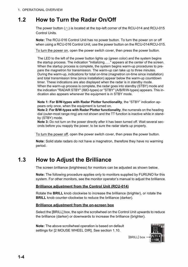
1.2 How to Turn the Radar On/OffThe power button ( ) is located at the top-left corner of the RCU-014 and RCU-015 Control Units.
Note: The RCU-016 Control Unit has no power button. To turn the power on or off when using a RCU-016 Control Unit, use the power button on the RCU-014/RCU-015.
To turn the power on, open the power switch cover, then press the power button.
To turn the power off, open the power switch cover, then press the power button.
Note: Solid state radars do not have a magnetron, therefore they have no warming period.
1.3 How to Adjust the BrillianceThe screen brilliance (brightness) for monitors can be adjusted as shown below.
Note: The following procedure applies only to monitors supplied by FURUNO for this system. For other monitors, see the monitor operator’s manual to adjust the brilliance.
Brilliance adjustment from the Control Unit (RCU-014)
Rotate the BRILL knob clockwise to increase the brilliance (brighter), or rotate the BRILL knob counter-clockwise to reduce the brilliance (darker).
Brilliance adjustment from the on-screen box
Select the [BRILL] box, the spin the scrollwheel on the Control Unit upwards to reduce the brilliance (darker) or downwards to increase the brilliance (brighter).
Note: The above scrollwheel operation is based on default settings for [2 MOUSE WHEEL DIR]. See section 1.10.
The LED to the left of the power button lights up (green color) and the system begins the startup process. The indication "Initializing......" appears at the center of the screen.When the startup process is complete, the system begins warm-up procedures to pre-pare the magnetron for transmission. The warm-up can take up to three minutes.During the warm-up, indications for total on-time (magnetron on-time since installation) and total transmission time (since installation) appear below the warm-up countdown timer. These indications are also displayed when the radar is in standby mode.When the warm-up process is complete, the radar goes into standby (STBY) mode and the indication "RADAR STBY" (IMO-types) or "STBY" (A/B/R/W-types) appears. This in-dication also appears whenever the equipment is in STBY mode.
Note 1: For B/W-types with Radar Plotter functionality, the “STBY” indication ap-pears only once, when the equipment is turned on.Note 2: For B/W-types with Radar Plotter functionality, the numerals on the heading dial (outer-most range ring) are not shown and the TT function is inactive while in stand-by (STBY) mode.Note 3: Do not turn on the power directly after it has been turned off. Wait several sec-onds before you reapply the power, to be sure the radar starts up properly.
[BRILL] box
1-4

1. OPERATIONAL OVERVIEW
1.4 Display IndicationsNote: The example screen below may differ slightly from your display, depending on the monitor purchased in your configuration. The overall information, however, is the same.
The on-screen display for your radar system is divided into three main areas, as shown in the figure below.
• 1: InstantAccess bar™. See section 1.4.1.
• 2: Radar display and function boxes. See section 1.4.2.
• 3: Information and settings. See section 1.4.3.
Display specifications
MU-190/MU-190HD MU-231 MU-270WNominal viewing distance 1.02 m 1.20 m 1.02 mText height (min. font) 3.53 mm 4.23 mm 3.64 mmText width (min. font) 2.36 mm 2.97 mm 2.43 mm
SCREENSHOT
1-5

1. OPERATIONAL OVERVIEW
1.4.1 InstantAccess bar™ buttons
Button DescriptionUpper Half
Standby/Transmit button.Toggle between standby (STBY) and transmit (TX).
Pulselength button.Selects the pulselength.
Tune button.Toggles between automatic and manual tuning. (See section 1.17.1.)Note: For SSD antennas, this button appears as "TX CH x" (“x” denotes the channel used for transmission). If your radar is receiving interference from another radar oper-ating at the same frequency, use the [TX CH] button to change the TX frequency.
Interference Rejector button.Activates/deactivates the interference rejector feature.
Echo Stretch button.Activates/deactivates the echo stretch function.
Echo Average button.Activates/deactivates the echo average function.Note: This item is grayed out under the following conditions:• ACE function is active.• No position data is input (excludes Dead Reckoning).
ACE button.Activates/deactivates the ACE (Auto Clutter Elimination) function.
Lower HalfChart button.• Shows/hides the chart.• Opens the [CHART] menu.Note: Appears on A/B/W-types with Radar Plotter functionality only.
Radar Map button.Shows/hides the radar map marks.
HEADING LINE button.Left-click and hold to hide the heading line, range rings and OS symbol.
CU/TM RESET button• Puts the ship’s heading at the top of the screen in course-up mode the moment this
button is pressed.• Resets the ship's position to a point of 75% radius opposite to the extension of the
heading line passing through the display center in true motion modes.Own Ship AIS button.Shows the AIS VOYAGE DATA for AIS data setup.
AIS Message button.Opens the AIS Message menu, allowing you to view received AIS messages.
Brilliance button.• Adjusts the screen brilliance• Opens the [BRILLIANCE] menu.• Selects the color palette. See section 1.45.1.
PULSE L
TUNE MAN
IROFF
ESOFF
EAVOFF
ACE OFF
CHART ON
MAP OFF
HLOFF
CU/TM RESET
OWN AIS
AIS
PLT1100
1-6

1. OPERATIONAL OVERVIEW
1.4.2 Radar display and shortcuts
No. Name Description- Operational Display Area Radar echoes are displayed here.1 [RANGE] box Shows/changes the current range in use.2 [REF POINT] box Shows/changes the point of reference.3 Indications Shows indications for SART, shuttle ferry mode, etc.4 [WATCH] box • Shows the watch alert countdown timer.
• Resets the watch alert countdown.Note: The watch alert is available only for A/B/W-types.
5 [ECHO ADJUST] box Place the cursor on a box to adjust the setting.• [GAIN] bar: Shows the level of gain in use.• [SEA] bar: Shows the level and mode of sea clutter re-
duction.• [RAIN] bar: Shows the level and mode of rain clutter re-
duction.6 Cursor position details • Shows the location (coordinates) of the cursor posi-
tion.• Shows the TTG to the cursor position.• Shows the bearing and range to the cursor position.
7 [MAP ALIGN] indication Shows/hides the map alignment status.8 [MENU] box Opens/closes the menu.9 User settings box • Loads pilot settings.
• Opens the [USER SET] menu.
Operational Display Area
CTRLM
1-7

1. OPERATIONAL OVERVIEW
10 [TGT LIST] box Shows the target details list for tracked TTs and active AIS targets.
11 [TRIAL MANEUVERS] box • Activates/deactivates trial maneuvers.• Sets up trial maneuver parameters.
12 [ACQUISITION ZONE] box • Adjust acquisition zone settings for target alarms.• Toggle between sentry zone and acquisition zone alert
modes.13 [VRM] box • Activate/deactivate the VRM (Variable Range Marker).
• Adjust the active (selected) VRM.• Shows VRM range and TTG.
14 [EBL] box • Activate/deactivate the EBL (Electronic Bearing Line).• Adjust the active (selected) EBL.• Shows EBL bearing.
15 [MAP MARK] box • Selects a map mark to use.• Inscribes the selected map mark.
16 [PI Lines] box • Selects PI line set to use.• Shows/hides the selected PI lines.• Shows the angle, reference and range interval for the
PI lines.17 [NOISE REJECTOR] indication Shows the noise rejector function’s ON/OFF status.18 [TUNING LEVEL] bar • Shows the level of tuning in use. See section 1.17.
• Adjusts the tuning (manual only). See section 1.17.3.Note: The [TUNING LEVEL] bar is not shown for solid state radars.
19 [PICTURE] box • Selects a preset custom display.• Right-click to open the [CUSTOMIZED ECHO] menu.
20 [ANTENNA SELECTION] box • Selects the antenna to use for radar images.• Right-click to open the [SELECT ANTENNA] menu.
21 [CONTROL] box Indicates which Dual Radar image is currently selected.• "M": Master. Operations and settings are applied to the
Main (Master) radar image.• "S": Slave. Operations and settings are applied to the
Sub (Slave) radar image.Note: Appears only for A/B-types when the dual radar function is enabled at installation and the connected ra-dar is turned on.
22 [PRESENTATION MODE] box Change the presentation (orientation) mode for the radar images.
23 [DROP MARK] box Shows the bearing and range to the drop mark(s).24 Screenshot button Saves a screenshot of the entire displayed area.
Note: Requires SD card to be inserted in the Processor Unit. Shown in gray and not selectable if no SD card is in-serted.
No. Name Description
1-8

1. OPERATIONAL OVERVIEW
1.4.3 Information and settings
No. Description1 Date/Time
Shows date and time (with offset indication).Working indicatorStops rotating if the system is not functioning normally (screen freeze, etc.).
2 Own Ship information
Shows heading, speed, water tracking speed*1, COG,
SOG*2, coordinates and sensor used for data input.3 Information box
• Shows information for selected TT or AIS targets.• Shows the currently selected menu.• Shows navigational data.• Shows the performance monitor graph.• Shows the zoomed area.Note: TT/AIS data are hidden when the menu is open.
4 TT/AIS settingsContains settings for vectors, CPA, TCPA, lost targets, trails, etc.
5 Alert boxShows active alerts and contains a shortcut to the alert list.
6 Guidance boxShows operational guidance for the Control Unit’s left button and right button.
*1: Direction is indicated with an arrow facing PORT or STBD.
*2: Where the data source for COG/SOG is a satellite log, the indica-tion shows "SLOG".
52601AISCOM ERROR
1-9
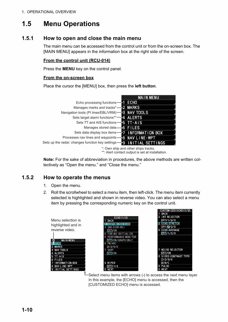
1. OPERATIONAL OVERVIEW
1.5 Menu Operations
1.5.1 How to open and close the main menu
The main menu can be accessed from the control unit or from the on-screen box. The [MAIN MENU] appears in the information box at the right side of the screen.
From the control unit (RCU-014)
Press the MENU key on the control panel.
From the on-screen box
Place the cursor the [MENU] box, then press the left button.
Note: For the sake of abbreviation in procedures, the above methods are written col-lectively as “Open the menu.” and “Close the menu.”
1.5.2 How to operate the menus
1. Open the menu.
2. Roll the scrollwheel to select a menu item, then left-click. The menu item currently selected is highlighted and shown in reverse video. You can also select a menu item by pressing the corresponding numeric key on the control unit.
Echo processing functionsManages marks and tracks*
Navigation tools (PI lines/EBL/VRM)Sets target alarm functions**
Sets TT and AIS functionsManages stored data
Sets data display box itemsProcesses nav lines and waypoints
Sets up the radar; changes function key settings
*: Own ship and other ships tracks.**: Alert contact output is set at installation.
Select menu items with arrows ( ) to access the next menu layer.In this example, the [ECHO] menu is accessed, then the [CUSTOMIZED ECHO] menu is accessed.
Menu selection is highlighted and in reverse video.
1-10

1. OPERATIONAL OVERVIEW
The next menu layer appears. Menu items with arrows, as shown in the above ex-ample figure, have their own menu layer. You can select these items to show the respective menu.
3. Roll the scrollwheel to select a menu item, then left-click. You can also select a menu item by pressing the corresponding numeric key.When required, repeat this step to access the next menu.In the example, [1 ECHO] is selected, which opens the [ECHO (1/2)] menu. Next, [2 CUSTOMIZED ECHO] is selected, which opens the [CUSTOMIZED ECHO (1/2)] menu. Finally, [3 ECHO STRETCH] is selected, in order to change settings.Menus such as the [ECHO] menu and [CUSTOMIZED ECHO] menu have more than one page. In this case, the currently displayed page is indicated in brackets to the right of the menu title.To view the next page of a menu, select [0 NEXT].To go back one layer (or page) in the menu, left-click [1 BACK], or right-click.
4. Roll the scrollwheel to select the desired setting, then left-click. The selected set-tings is highlighted and displayed in reverse video.In the above example, the selected setting at [3 ECHO STRETCH] is [1].Note 1: For some menu items, the software keyboard, shown in the figure below, is displayed at the bottom of the menu. Select the number/character desired with the cursor, then left-click. When you finish entering the desired numbers/charac-ters, left-click the [END] button on the software keyboard.
Note 2: Unless otherwise stated, operations in this manual use the scrollwheel for procedures which require menu selection, or settings changed.
5. Close the menu.
1-11

1. OPERATIONAL OVERVIEW
1.6 How to Use the On-screen Box MenusSome radar functions can be accessed using the on-screen box as a shortcut to the respective menus. A “” at the right side of an on-screen box indicates that there is a menu shortcut available.
Note: The cursor changes shape according to its location. When placed outside the
operational display area the cursor is an arrow ( ) shape. When placed inside the
operational display area, it is a cross ( ).
For the purpose of this example, place the cur-sor on the palette indication (displayed as "PLTx", where x is the currently selected pal-ette number), inside the brilliance settings box at the bottom-left of the screen.
The selected item appears highlighted with a light-blue colored box.
Right-click to show the [BRILL1] box menu.
Similar shortcuts are available from the follow-ing on-screen boxes/indications:
• [PICTURE] box.
• [AIS] box.
• [TT] box.
• [HDG] indication.
• [SPD] indication.
• [POSN] indication.
• [PLT] indication.
• [ANTENNA SELECTION] box.
• User settings box.
• [MARK] box.
• Time indication ("UTC" or "Local").
• [TRAIL] indication.
• [CHART ON/OFF] button (A/B/W-types with Radar Plotter functionality only).
Select the palette indication, then right-click.
1-12
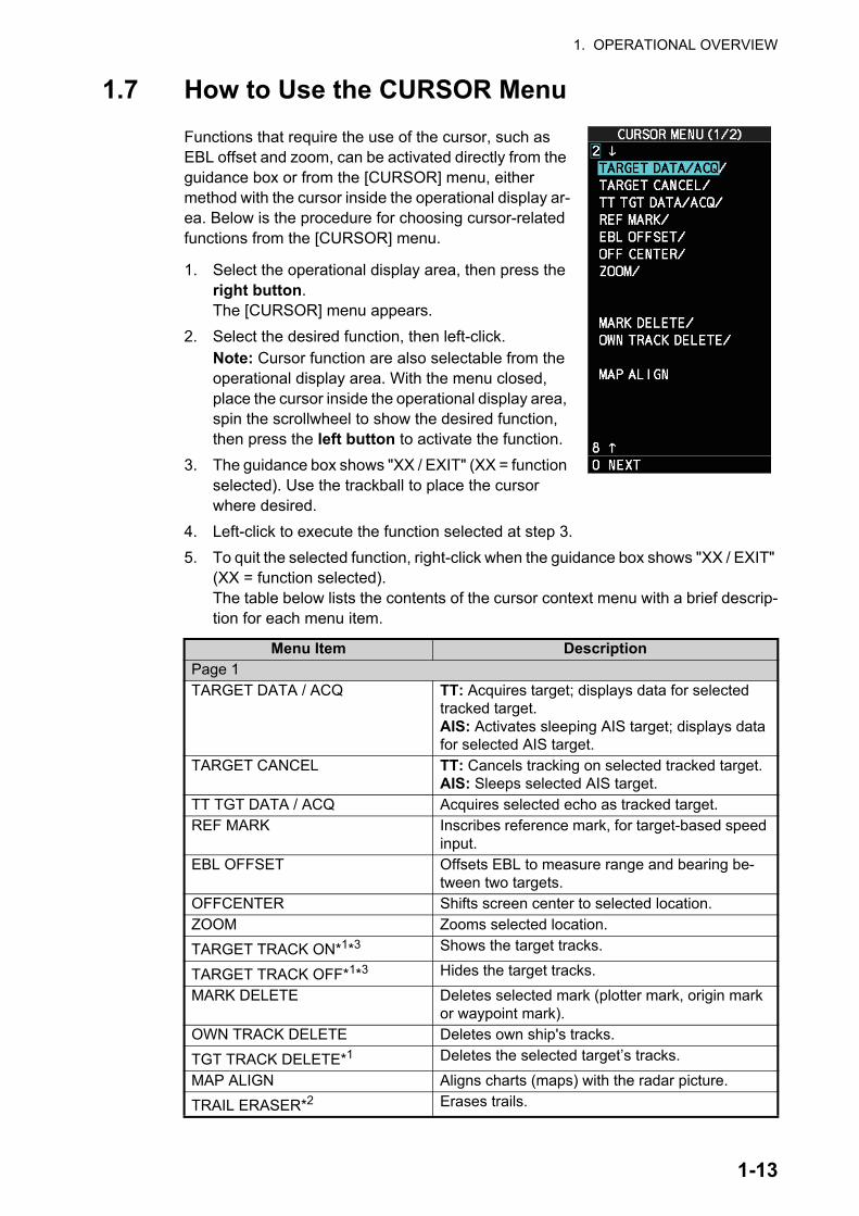
1. OPERATIONAL OVERVIEW
1.7 How to Use the CURSOR Menu
Functions that require the use of the cursor, such as EBL offset and zoom, can be activated directly from the guidance box or from the [CURSOR] menu, either method with the cursor inside the operational display ar-ea. Below is the procedure for choosing cursor-related functions from the [CURSOR] menu.
1. Select the operational display area, then press the right button.The [CURSOR] menu appears.
2. Select the desired function, then left-click.Note: Cursor function are also selectable from the operational display area. With the menu closed, place the cursor inside the operational display area, spin the scrollwheel to show the desired function, then press the left button to activate the function.
3. The guidance box shows "XX / EXIT" (XX = function selected). Use the trackball to place the cursor where desired.
4. Left-click to execute the function selected at step 3.
5. To quit the selected function, right-click when the guidance box shows "XX / EXIT" (XX = function selected).The table below lists the contents of the cursor context menu with a brief descrip-tion for each menu item.
Menu Item DescriptionPage 1TARGET DATA / ACQ TT: Acquires target; displays data for selected
tracked target.AIS: Activates sleeping AIS target; displays data for selected AIS target.
TARGET CANCEL TT: Cancels tracking on selected tracked target.AIS: Sleeps selected AIS target.
TT TGT DATA / ACQ Acquires selected echo as tracked target.REF MARK Inscribes reference mark, for target-based speed
input.EBL OFFSET Offsets EBL to measure range and bearing be-
tween two targets.OFFCENTER Shifts screen center to selected location.ZOOM Zooms selected location.
TARGET TRACK ON*1*3 Shows the target tracks.
TARGET TRACK OFF*1*3 Hides the target tracks.
MARK DELETE Deletes selected mark (plotter mark, origin mark or waypoint mark).
OWN TRACK DELETE Deletes own ship's tracks.
TGT TRACK DELETE*1 Deletes the selected target’s tracks.
MAP ALIGN Aligns charts (maps) with the radar picture.
TRAIL ERASER*2 Erases trails.
1-13

1. OPERATIONAL OVERVIEW
*1: Shown on A/B/W-types only
*2: Shown on B/W-types only
*3: Shown on A/B/W-types only when [5 AUTO TARGET TRACK], located in [2 MARKS] ([2 MARKS•CHARTS] for systems with Radar Plotter functionality) [7 TRACKS] [3 TARGET TRACK] menu, is set to [OFF].
1.8 Cursor DataThe cursor data display shows the cursor’s latitude and longitude position or the cur-sor’s X-Y co-ordinates.
Place the cursor on the [CURSOR DATA] box at the top-right side of the display then press the left button to switch between display formats.
The data box shows the cursor location, bearing/range to the cursor location and the time to go (TTG) to the cursor location.
Note 1: For the X-Y co-ordinates display, the Y-axis is the upper/lower half of the screen, the upper half of the screen is “plus” and the lower part of the screen is “mi-nus”. The X-axis is the left/right-side of the screen, right is “plus”, left is “minus”.
Note 2: Cursor data reads "- - -.-" when the cursor is placed outside the operational display area.
Page 2TARGET DATA / ACQ SETTING Change target tracking settings.TARGET CANCEL SETTING Change target cancel settings.
Menu Item Description
33°59.156’N135°06.328’E
X: +1.667NMY: +3.694NMTTG 00:05
33°59.156’N135°06.328’E
0.24.4ºR4.028NM
TTG 00:05
Bearing/range displayed
Cursor’s X-Y co-ordinates
displayed
Press the left button to switch between
display formats
Press the left button to switch between
display formats
TTG to cursor position
Bearing/range to cursor position.
X/Y axis coordinates to cursor position.
Cursor positon’s latitude/longitude
1-14
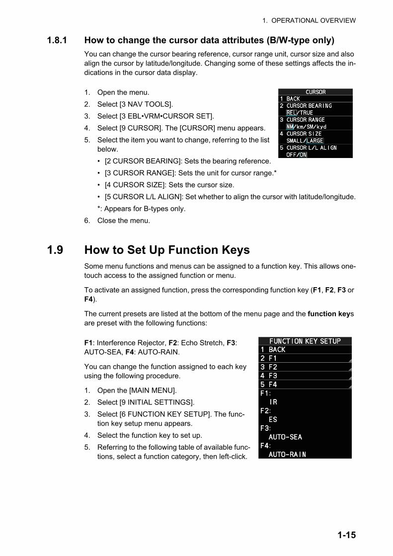
1. OPERATIONAL OVERVIEW
1.8.1 How to change the cursor data attributes (B/W-type only)
You can change the cursor bearing reference, cursor range unit, cursor size and also align the cursor by latitude/longitude. Changing some of these settings affects the in-dications in the cursor data display.
1. Open the menu.
2. Select [3 NAV TOOLS].
3. Select [3 EBL•VRM•CURSOR SET].
4. Select [9 CURSOR]. The [CURSOR] menu appears.
5. Select the item you want to change, referring to the list below.
• [2 CURSOR BEARING]: Sets the bearing reference.
• [3 CURSOR RANGE]: Sets the unit for cursor range.*
• [4 CURSOR SIZE]: Sets the cursor size.
• [5 CURSOR L/L ALIGN]: Set whether to align the cursor with latitude/longitude.
*: Appears for B-types only.
6. Close the menu.
1.9 How to Set Up Function KeysSome menu functions and menus can be assigned to a function key. This allows one-touch access to the assigned function or menu.
To activate an assigned function, press the corresponding function key (F1, F2, F3 or F4).
The current presets are listed at the bottom of the menu page and the function keys are preset with the following functions:
F1: Interference Rejector, F2: Echo Stretch, F3: AUTO-SEA, F4: AUTO-RAIN.
You can change the function assigned to each key using the following procedure.
1. Open the [MAIN MENU].
2. Select [9 INITIAL SETTINGS].
3. Select [6 FUNCTION KEY SETUP]. The func-tion key setup menu appears.
4. Select the function key to set up.
5. Referring to the following table of available func-tions, select a function category, then left-click.
1-15

1. OPERATIONAL OVERVIEW
*1: Appears for B/W-types only.
*2: Appears for A/B/W-types with radar plotter functionality only.
*3: Appears for A/B/W-types only.
6. Select the appropriate function to assign, then left-click.You can check the currently assigned functions in the bottom half of the menu.
7. Repeat the procedure as necessary to set up other function keys.
8. Close the menu.
Function category
Available functions
ECHO CUSTOM SELECT, IR, ES, EAV, NOISE REJ, ANT SELECT, PULSE LENGTH, AUTO-SEA, AUTO-RAIN, TUNE SELECT, 2ND ECHO REJ, STC CURVE, STC RANGE, PM, SART, ECHO TRAIL,
TRAIL T/R, WIPER*1, ACE, ACE HIGH SENSITIVITYSTD KEY ALERT ACK, STBY TX, HL OFF, EBL OFFSET, ORIENTATION-
MODE, OFF CENTER, CU-TM RESET, PI LINE, VECTOR TIME, VECTOR MODE, TARGET LIST, BRILL, MARK, MENU, RANGE UP, RANGE DOWN, ACQ, TARGET DATA, TARGET CANCEL
TT•AIS TT-DISP, AIS-DISP, TARGET DATA & ACQ, PAST POSN INTER-VAL, REF MARK, CPA LIMIT, CPA, TCPA, AZ1, AZ2, TARGET LIST SORT, TRIAL MANEUVER, TRIAL MODE CHANGE, AIS MESSAGE, AIS SCALED SYMBOL
DELETE DATA MARK DELETE, MARK ALL DELETE, OWN TRK DELETE, OWN
TRK ALL DELETE, TGT TRK DELETE*3, TGT TRK ALL DELETE*3
OPERATION BUZZER STOP, ECHO AREA*1, ECHO COLOR, PALETTE, RING(ON/OFF), ZOOM, MOB, ALARM1, ALARM2, WATCH ALERT
RESET*3, TLL*1, MAP ALIGN, ANCHOR WATCH, DROP MARK,
SCREEN SHOT, CHART DISPLAY*2, NAV AIDS*2
1-16

1. OPERATIONAL OVERVIEW
1.10 How to Customize OperationSeveral operation items can be customized to suit your needs.
1. Open the menu.
2. Select [9 INITIAL SETTING].
3. Select [5 OPERATION]. The [OPERATION] menu appears.
4. Referring to the table below, press the menu item number to select the appropri-ate menu item to customize.
Menu items DescriptionPage 1[2 MOUSE WHEEL DIR] Sets the direction of the wheel drive (scrollwheel).
• [NORMAL]: Scroll downwards to increase, or up-wards to decrease the value.
• [REVERSE]: Scroll directions are reverse of [NOR-MAL].
[3 KEY BEEP] Changes the key beep volume.Select [OFF] to silence the key beeps. Select [LOW], [MID], [HIGH] to adjust the volume for key beeps.
[4 OWN SHIP VECTOR] Select how the own ship vector is displayed.• [OFF]; Own ship vector is not displayed.• [HDG]: Vector is displayed in heading direction.• [COURSE]: Vector is displayed in course direction.
[5 STERN UP RM] Select [ON] to show [STERN UP RM] orientation in the selection cycle. (See section 1.30.)Note: This item is shown for A/B/W-types only.
[6 SHUTTLE FERRY] Sets the shuttle ferry mode to use.• [OFF]: Shuttle ferry mode is deactivated.• [MODE1]: Shuttle ferry mode is activated. See
"Shuttle ferry mode" on next page.• [MODE2]: Shuttle ferry mode is activated. See
"Shuttle ferry mode" on next page.Note: Shuttle ferry mode requires an external switch.
[7 ICING PREVENTION] Select [ON] to rotate the antenna without transmis-sion, to prevent ice buildup. See section 1.53.
[8 BRG FINE ADJUST] Adjusts the heading line location. 0.0°, the default set-ting, shows the heading line pointing towards the top of the screen.
These menu items appear for all radar types, however B/W-types may have additional menu items. See the following table for details.
1-17

1. OPERATIONAL OVERVIEW
5. Select the required setting by pressing the menu item number. For this example, set [3 KEY BEEP] to [HIGH]. Press the 3 MODE key to highlight [HIGH].For [8 BRG FINE ADJUST] and other menu items with a setting range, spin the scrollwheel, or use the number keys to adjust the required setting.Note: Regarding input for [8 BRG FINE ADJUST], when using the number keys, the indication is first selected as a whole. At this time, you can toggle between plus “+” or minus “-”. Press the 8 key for “-”, press the 2 key for “+”. If single digits are highlighted, toggle is not possible. In this case, press the CANCEL TRAILS key to re-highlight the whole indication.
6. Close the menu.
Shuttle ferry mode
The shuttle ferry mode changes the orientation of the display when the external switch is turned on. (The external switch should be connected to the RS-232C port on the processor unit at installation.)
There are two variations: Standard display ([SHUTTLE FERRY] is set to [OFF]) and reversed display ([SHUTTLE FERRY] is set to [MODE1] or [MODE2]).
When the display is reversed for shuttle ferry mode, the following changes also occur:
[9 USB MOUSE SPEED] Adjust the USB mouse sensitivity. A higher value in-crease the mouse cursor’s movement speed.
Page 2[2 AUTO COURSE UP RESET] Select [ON] to enable, or [OFF] to disable the auto-
matic reset of the screen when using COURSE UP orientation and your course is more than 22.5° to ei-ther side the center of the screen.
[3 DISPLAY SCROLL] Select [ON] to enable, [OFF] to disable display scroll-ing. When set to [ON], move the cursor to the edge of the screen in the direction you want to scroll.Note: This item is shown for B/W-types only.
• Echoes are displayed 180° opposite to normal display.• Bearing for speed data is re-calibrated to 180° opposite to normal.• Wind direction based on speed input is re-calibrated to 180° opposite to normal.• Where [Mode2] is selected, data input from the gyrocompass is re-calibrated to 180°
opposite to normal.Note: Gyrocompass data input is not re-calibrated for [Mode1].
Menu items Description
Standard display: Gyro input is displayed normally.
Reversed display: Gyro input is displayed in reverse.
1-18

1. OPERATIONAL OVERVIEW
1.11 How to Select the Interface for Heading InputWhen a gyrocompass is connected, the ship’s heading appears on the right side of the screen, in the data display area.
Heading input format can be selected as follows:
1. Open the menu.
2. Select [7 INFORMATION BOX].
3. Select [2 OWN SHIP INFO].
4. Select [2 HDG]. The [HDG] menu appears.Note: You can also access the [HDG] menu from the on-screen box. Place the cursor on the [HDG ] indication in the heading box at the top-right of the screen, then right-click.
5. Select [2 HDG SOURCE].
6. Select [GYRO1] or [GYRO2] as appropriate.
7. Close the menu.
Note 1: The heading sensor must be able to follow a minimum ROT of 20° per second. Heading sensors with a lesser capability may degrade the performance of echo aver-aging, trails and TT. The data refresh rate should also be as short as possible. If the refresh rate is too long, the ability to follow courses lessens, thereby affecting the per-formance of echo averaging, trails and TT.
Note 2: For IMO-types, Where the heading source is other than the heading sensor (for example, and EPFS device), the sensor indication is displayed in yellow color.
1.12 How to Set Own Ship’s SpeedThe TT and azimuth stabilized presentation modes require own ship speed input and compass signal. The speed can be entered from a log (STW, SOG) or EPFS (SOG) or manually on the menu.
1.12.1 Automatic speed input (log or EPFS navigator)
1. Open the menu.
2. Select [7 INFORMATION BOX].
3. Select [2 OWN SHIP INFO].
4. Select [3 SPEED].
5. Select [2 SHIP SPEED].Note: You can also access the [SPEED] menu from the on-screen box. Place the cursor on the [SPD ] indication in the speed box at the top-right of the screen, then right-click.
6. Select the appropriate source for automatic speed input, referring to following table.Note: Changes to the settings here are also applied to the speed calculations for TT targets, true trails, SOG and STW.
1-19

1. OPERATIONAL OVERVIEW
*1: Set and drift may be required to display [LOG (BT)] correctly in deep waters. To change set and drift, see section 3.14.
*2: Where [ECDIS] is selected as the speed source, [4 OWN SHIP POSN] in the [OWN SHIP INFO] menu is automatically set to [ECDIS] also. See section 1.13.
7. If you selected [MANUAL] as the speed data source, see section 1.12.2 to set the speed.
8. Close the menu.
Notes on speed input
It should be noted that in determining a target's aspect by radar, the calculation of its true track is dependent on the choice and accuracy of the own ship's course and speed input. A ground-stabilized target plot may accurately calculate the ground track of the target, but the target's heading may be significantly different from its track when experiencing set, drift or leeway. Similarly, a sea stabilized target plot may be inaccu-rate when own ship and the target, are experiencing different rates of set, drift or lee-way.
• IMO Resolution A.823(19) for TT recommends that a speed log to be interfaced with a TT should be capable of providing through-the-water speed (forward speed).
• Be sure not to select a [LOG] option when a speed log is not connected. If the log signal is not provided, the ship speed readout at the top of the screen will be blank. In the event of a log error, enter speed manually.
• If a speed log is selected as the data source and there is no signal present for 30 seconds, the [SPD] is shown as "*.* kn" and the label "LOST LOG(BT) SIG" or "LOST LOG(WT) SIG" in yellow-orange appears and the alert buzzer sounds.
• When the speed input in use is interrupted or lost, the system automatically chang-es to another speed input (stabilization reference) and shows the "SPD SOURCE CHG" indication.
• On IMO-type radars with AIS in use, [MANUAL] and [REF] are shown in gray to in-dicate they are not available for selection.
• A single-axis water log cannot measure speed when the wind is coming from the leeway direction.
• When [ECDIS] is selected as the speed data source and communication with the ECDIS is interrupted or lost for 30 seconds, the Alert "LOST ECDIS COM" is re-leased.
• When speed stabilization is changed at the ECDIS and [ECDIS] is selected as the speed data source, the "SPD SOURCE CHG" indication appears.
Selection Explanation Stabilization Mode
[LOG (BT)]*1 Log, speed over ground (SOG) Ground stabilization
[LOG (WT)] Log, Speed Thru Water (STW) Sea stabilization[EPFS] Speed input by GPS navigator Ground stabilization[MANUAL] Manually input speed Sea stabilization[REF] Echo-referenced speed input Ground stabilization
[ECDIS]*2 Speed input by ECDIS Ground stabilization or Sea Stabilization (Dependent on ECDIS settings).
1-20

1. OPERATIONAL OVERVIEW
1.12.2 Manual speed input
If the speed log is not working, enter speed manually as below. In this case the speed data type is shown as "MANUAL" and is speed thru water (STW). Manual speed input is not available on IMO-type radars when the AIS feature is active.
1. Open the menu.
2. Select [7 INFORMATION BOX].
3. Select [2 OWN SHIP INFO].
4. Select [3 SPEED].
5. Select [2 SHIP SPEED].Note: You can also access the [SPEED] menu from the on-screen box. Place the cursor on the [SPD ] indication in the speed box at the top-right of the screen, then right-click.
6. Select [MANUAL].
7. Select [3 MANUAL SPEED INPUT].
8. Spin the scrollwheel to set the speed.
9. Press the ENTER MARK key to confirm the new setting.
10. Close the menu.
1.13 How to Set the Own Ship PositionYou can select the data source for own ship’s position as follows:
1. Open the menu.
2. Select [7 INFORMATION BOX].
3. Select [2 OWN SHIP INFO].
4. Select [4 OWN SHIP POSN].Note: You can also access the [OWN SHIP POSN] menu from the on-screen box. Place the cursor on the [POSN ] indication in the position box at the top-right of the screen, then right-click.
5. Select [2 POSITION SOURCE] or [3 MANUAL L/L INPUT] as appropriate.
6. If [2 POSITION SOURCE] is selected at step 2, select the appropriate position source, referring to the list below.[2 POSITION SOURCE] uses navigational aids. Select the navigational aid to use. Available options are listed with a brief description in the table below:
Available options Description[EPFS1] Use the device assigned as EPFS1 for position data.[EPFS2] Use the device assigned as EPFS2 for position data.[LAN] Use the device connected to the LAN1 port for position data.[ECDIS] Use the connected ECDIS for position data.[DEAD RECKONING] Position data is derived from dead reckoning (manual input)
1-21

1. OPERATIONAL OVERVIEW
Note 1: Where [2 POSITION SOURCE] is set to [DEAD RECKONING], the indi-cation "DR" appears at the bottom of the [OS POSN] box.
Note 2: Where [2 POSITION SOURCE] is set to [DEAD RECKONING] or [MAN-UAL L/L INPUT], the AIS function cannot be used.
Note 3: Where [2 POSITION SOURCE] is set to [ECDIS], the source for own ship speed data is automatically set to [ECDIS] also.
Note 4: On IMO-type radars with AIS in use, [DEAD RECKONING] is shown in gray to indicate it is not available for selection.
Note 5: Speed and heading data is required in order to correctly display [DEAD RECKONING] position data.
7. To set [3 MANUAL L/L INPUT], do the following:
1) Select [3 MANUAL L/L INPUT]. The first digit of the latitude is highlighted.
2) Spin the scrollwheel to set the value, then left-click. The cursor moves to the next digit. Use the same method to select [N]/[S]/[E]/[W].You can also use the number keys on the Control Unit to input the value.
3) Repeat step 2 to set the latitude and longitude.
8. To share [OS POSN] data across the same network, do the following:
1) Select [4 SIO DATA LAN OUTPUT].
2) Select [ON] to share data. To disable [OS POSN] data sharing, select [OFF].
Note: A navigational aid must be selected at [2 POSITION SOURCE] to share [OS POSN] across the same network.
9. Close the menu.
1.14 How to Adjust the Date and TimeDate and time are displayed at the top-right of the screen in the [DATE/TIME box]. You can left-click the date/time format indication to toggle between [UTC] format and [LO-CAL] format.
You can also adjust the local time and switch between time formats from the menu.
To adjust the local time, follow the procedure below.
1. Open the menu.
2. Select [7 INFORMATION BOX].
3. Select [2 OWN SHIP INFO].
4. Select [5 DATE].Note: You can also access the [DATE] menu from the on-screen box. Place the cursor on the [UTC ] or [LOCAL ] indication in the date box at the top-right of the screen, then right-click.
19 / SEP / 2016 15 15Date
Date/time format indicationLeft-click: Toggle UTC and LOCAL time.Right-click: Open the [DATE] menu.
Time
1-22

1. OPERATIONAL OVERVIEW
5. Select [2 DATE-TIME], then select [UTC] or [LOCAL] as appropriate.
• [UTC]: Date and time are displayed in UTC format.
• [LOCAL]: Date and time are shown with the local time offset applied.
If you selected [UTC], close the menu. If you selected [LOCAL], go to step 6.
6. Select [3 ADJUST LOCAL TIME].
7. Spin the scrollwheel, or use the number keys to input the desired offset.The offset must be in 30 minute increments.Note: Regarding input for [3 ADJUST LOCAL TIME], when using the number keys, the indication is first selected as a whole. At this time, you can toggle be-tween plus “+” or minus “-”. Press the 8 key for “-”, press the 2 key for “+”. If single digits are highlighted, toggle is not possible. In this case, press the CANCEL TRAILS key to re-highlight the whole indication.
8. Close the menu.
1.15 User SettingsThe user functions shown in the table below can be reset to their default settings by enabling the [PILOT SETTING] option in the [USER SET] menu. Functions not shown in the table below maintain their previous setting.
The unit can store two separate user settings, for the functions listed below, in the in-ternal memory. These settings can also be recalled. Functions not shown in the table below cannot be stored or recalled.
Function Setting(s) Menu/On-screen boxGAIN Maintained as per
previous setting.[GAIN] box
SEA [AUTO] [SEA] boxRAIN [AUTO] [RAIN] boxTUNE [AUTO] [TUNE] box (Magnetron radars only)TX CH Maintained as per previous setting. (Solid State radars on-
ly)Range [6 NM] [RANGE] boxRange rings [OFF] [MAIN MENU] [3 NAV TOOLS]
[4 RANGE RINGS]VRM1 Display [ON] [VRM1] box
Distance [0.250 NM]VRM2 Display [OFF] [VRM2] box
Distance [0.000 NM]
Time indication highlighted as a whole.Toggle between “+” and “-” is possible.
Single digit is highlighted. Toggle between “+” and “-” is not possible.
1-23

1. OPERATIONAL OVERVIEW
*1: This menu is not available for IMO/A/R/W-types and the setting is fixed to [TRUE].
*2: Has the same effect as selecting the True Motion presentation mode.
EBL1 Display [ON] [EBL1] boxBearing Maintained as per
previous setting.Reference Maintained as per
previous setting.[MAIN MENU] [3 NAV TOOLS] [3 EBL•VRM•CURSOR SET] [5 EBL•CURSOR BEARING]
EBL2 Display [OFF] [EBL2] boxBearing Maintained as per
previous setting.Reference [MAIN MENU] [3 NAV TOOLS] [3 EBL•VRM•CURSOR SET] [5 EBL•CURSOR BEARING]
PI Lines Display [OFF] [PI Line] boxIntervalOrientationBearing (True or Relative)
[MAIN MENU] [3 NAV TOOLS] [2 PI LINES] [2 PI LINE BEAR-
ING] *1
Number of PI lines
[MAIN MENU] [3 NAV TOOLS] [2 PI LINES] [3 SET MAXIMUM PI LINE]
Mode (Parallel or Perpendicular)
[MAIN MENU] [3 NAV TOOLS] [2 PI LINES] [4 PI LINE MODE]
Presentation Mode [NORTH UP TM] [PRESENTATION MODE] boxStabilization mode (Sea/Ground)
[EPFS] (Ground) [SPEED] box [2 SHIP SPEED]
Off-centering On-centering OFF CENTER key.*2
Target trails
Display, time [ON], [6 MIN] [TRAIL MODE] boxMode [TRUE] [PAST POSN] box
Past position [OFF] [PAST POSN] boxVector mod [REL] [VECTOR] boxVector time [6 MIN]AZ1 [OFF] [AZ1] boxAZ2 [OFF] [AZ2] boxTT acquisition mode [MAN100] [TT TARGET] [TT SELECT]AIS display [DISP ALL] [AIS] boxAssociation [ON] (TT > AIS) [MAIN MENU] [5 TT•AIS] [7
TARGET ASSOCIATION] [2 AS-SOCIATION TGT TYPE]
Lost Target Alert [OFF] (Disabled) LOST TARGET ALERT boxCPA/TCPA alarm
ON/OFF [ON] [CPA LIMIT] boxCPA [2 NM]TCPA [12 MIN]
Function Setting(s) Menu/On-screen box
1-24

1. OPERATIONAL OVERVIEW
1.15.1 How to reset the user settings
1. Open the menu.
2. Select [9 INITIAL SETTINGS].
3. Select [4 USER SETTINGS].You can also access this menu from the [USER SET] box, as shown to the right.
4. Select [2 PILOT SETTING].
5. Select [YES].
6. Close the menu.
Note 1: Items not shown in the above table keep their previous settings when [PILOT SETTING] is activated.
Note 2: TT tracking is continued after [PI-LOT SETTING] is activated.
Note 3: The radar map displays the same map as before [PILOT SETTING] is activat-ed.
1.15.2 How to save/load user settings
1. Open the menu.
2. Select [9 INITIAL SETTINGS].
3. Select [4 USER SETTINGS].
4. Select [USER1(2) LOAD] or [USER1(2) SAVE] to recall or save user settings, re-spectively.
5. Select [YES].
6. Close the menu.
When loading settings, the following points apply:
• If the newly loaded settings cannot be applied to items not listed in the table above, then these items keep their previous settings.
• TT tracking is continued after the settings are loaded.
• The radar map displays the same map as before the settings were loaded.
Select the [USER SET] box, then right-click.
1-25

1. OPERATIONAL OVERVIEW
1.16 How to Start/Stop TransmissionThe radar is ready to transmit when the message "STBY" appears in the operational display area. Transmission can be started using one of the following procedures:
• Using the control unit: Press the STBY TX key.
• Using the on-screen box: Left-click the button on the InstantAccess bar™.
When the radar is switched to TX (transmit) status, most settings (such as brilliance, range, pulse width, etc) are restored with the same settings as before standby.
For magnetron radars, it is recommended to place the radar in standby when trans-mission is not required, to reduce wear on the magnetron. You can also set a “blank sector” where transmission is stopped (see the Installation Manual for details).
How to stop antenna rotation
Antenna rotation can be stopped using one of the following procedures:
• Turn the antenna switch off.
• Turn antenna rotation off from the menu (See installation manual).
Screen freeze
The screen is not refreshed if the screen has frozen. An audio alarm is released 30 seconds after a screen freeze. The ALARM ACK key flashes and a contact alert sig-nal is also released. To return the radar to normal operation, turn the radar off, then on again.
Quick start
Provided that the radar was in use and the magnetron (transmitter tube) is still warm, you can switch to transmit mode without the three minute warm-up time. If the radar was turned off by mistake or you wish to restart the radar promptly, wait several sec-onds before you press the POWER switch.
1-26

1. OPERATIONAL OVERVIEW
1.17 How to Tune the Receiver (Magnetron Radars Only)Your magnetron radar has a tuning function (automatic or manual). For solid-state ra-dars, tuning is not available.
1.17.1 How to select the tuning method
Tuning of the magnetron is typically done at installation and is not normally required unless you have replaced the magnetron.
1. Select the [TUNE] button, at the top of the InstantAccess bar™, to change the tun-ing method. The tuning box is displayed as "TUNE AUTO" or "TUNE MAN", de-pending on the currently selected tuning method.
2. Left-click to toggle between automatic and manual tuning.
1.17.2 How to initialize tuning
Automatic tuning is initialized at installation. Howev-er, if you feel that the automatic tuning is not func-tioning properly, re-initialize it by following the procedure below.
1. Open the menu.
2. Select [2 ECHO].
3. Select [4 TUNING INITIALIZE].The indication "TUNE INIT" appears in yellow characters at the top of the display during the ini-tialization.
4. Close the menu.
1.17.3 How to tune the receiver manually
1. Select the 48-mile range from the [RANGE] box. Left-click to lower the range; right-click to raise the range.
2. Select manual tuning following the procedure in section 1.17.1.
3. Place the arrow on the tuning level indication.
4. Spin the scrollwheel to adjust tuning. The best tuning point is where the bar graph swings maximum. The tuning control position is indicated with a triangle, dis-played inside the tuning bar.
Tuning level indication
Tuning methodShown as “TUNE MAN” or “TUNE AUTO”.
1-27

1. OPERATIONAL OVERVIEW
1.18 How to Select a Pulselength
The pulselength in use is indicated on the PULSE button of the InstantAccess bar™, at the top-left of the screen.The table below shows the indications and their meaning.
Appropriate pulselengths are preset to individual range scales and function keys. If you are not satisfied with the current pulselength settings, you can change them as shown in the procedure below.
1.18.1 How to select a pulselength
The pulselength can be changed using the procedure below.
1. Place the cursor in the [PULSE] box at the top left corner of the screen.
2. Left-click to decrease, right-click to increase the pulselength; or spin the scroll-wheel to cycle through pulselengths.The order in which the pulselengths are cycled is shown in the table below. "*" in-dicates the default preset for each range setting.
Note: Available pulselengths are restricted depending on the range.
1.18.2 How to change the preset pulselength
To change the preset pulselength for a range setting, follow the procedure below.
1. Open the menu.
2. Select [1 ECHO].
3. Select [2 CUSTOMIZED ECHO].Note: You can also access the [CUSTOMIZED ECHO] menu from the on-screen box. Place the cursor on the [PICTURE] indication in the date box at the top-left of the screen, then right-click.
4. Select [9 PULSE LENGTH].
5. Select the desired range, then select the re-quired pulselength.
6. Close the menu.
Range (PULSE) indication Range (PULSE) indication0.5 NM S1*, S2 6 NM M1, M2*, M3, L0.75 NM S1*, S2, M1 12 NM M1, M2, M3*, L1.5 NM S1*, S2, M1, M2 24 NM M2, M3, L*3 NM S2*, M1, M2, M3
PULSE L Current pulse length appears here.
(S1, S2, M1, M2, M3, L)
[PULSE] button
1-28
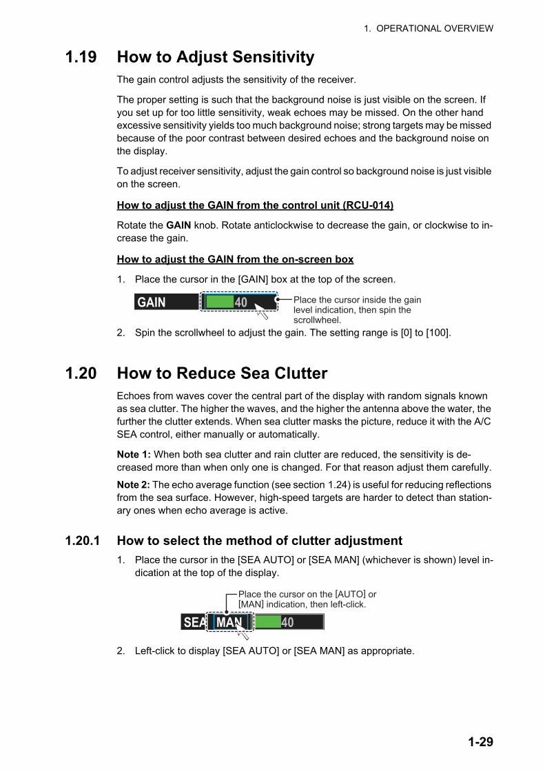
1. OPERATIONAL OVERVIEW
1.19 How to Adjust SensitivityThe gain control adjusts the sensitivity of the receiver.
The proper setting is such that the background noise is just visible on the screen. If you set up for too little sensitivity, weak echoes may be missed. On the other hand excessive sensitivity yields too much background noise; strong targets may be missed because of the poor contrast between desired echoes and the background noise on the display.
To adjust receiver sensitivity, adjust the gain control so background noise is just visible on the screen.
How to adjust the GAIN from the control unit (RCU-014)
Rotate the GAIN knob. Rotate anticlockwise to decrease the gain, or clockwise to in-crease the gain.
How to adjust the GAIN from the on-screen box
1. Place the cursor in the [GAIN] box at the top of the screen.
2. Spin the scrollwheel to adjust the gain. The setting range is [0] to [100].
1.20 How to Reduce Sea ClutterEchoes from waves cover the central part of the display with random signals known as sea clutter. The higher the waves, and the higher the antenna above the water, the further the clutter extends. When sea clutter masks the picture, reduce it with the A/C SEA control, either manually or automatically.
Note 1: When both sea clutter and rain clutter are reduced, the sensitivity is de-creased more than when only one is changed. For that reason adjust them carefully.
Note 2: The echo average function (see section 1.24) is useful for reducing reflections from the sea surface. However, high-speed targets are harder to detect than station-ary ones when echo average is active.
1.20.1 How to select the method of clutter adjustment
1. Place the cursor in the [SEA AUTO] or [SEA MAN] (whichever is shown) level in-dication at the top of the display.
2. Left-click to display [SEA AUTO] or [SEA MAN] as appropriate.
40GAIN Place the cursor inside the gain level indication, then spin the scrollwheel.
40SEA MAN
Place the cursor on the [AUTO] or [MAN] indication, then left-click.
1-29

1. OPERATIONAL OVERVIEW
1.20.2 How to fine-tune sea clutter reduction
Auto A/C SEA allows for fine tuning of the A/C SEA circuit, within ±20 dB. Accordingly, with the bar reading set to 50, gain is not lowered to minimum as with manual A/C SEA on close-in ranges. Further, the auto A/C SEA level is low because the average value of the original input echo is low in areas where there are no sea surface reflections. For example, when the ship is alongside a quay and the radar picture shows echoes from both land and sea, you can observe the size of the echoes because the STC curve changes with the size of the echoes.
Note: The auto A/C function can erase weak target echoes. Adjust the control care-fully, watching the display.
How to fine-tune sea clutter reduction from the control unit (RCU-014)
Rotate the AC/SEA knob. Rotate anticlockwise to decrease the AC/SEA, or clockwise to increase the A/C SEA.
How to fine-tune sea clutter reduction from the on-screen box
1. Select [SEA AUTO], following the procedure in section 1.20.1.
2. Place the arrow on level indicator inside the A/C SEA box at the top of the display.
3. While observing the A/C SEA level indicator, spin the scrollwheel to adjust the clutter reduction. The setting range is [-50] to [50].
1.20.3 How to manually reduce sea clutter
Note: The proper setting of the A/C SEA should be such that the clutter is broken up into small dots, and small targets become distinguishable. If the setting is set too low, targets will be hidden in the clutter, while if the setting is too high, both sea clutter and targets will disappear from the display. In most cases adjust the control until clutter has disappeared to leeward, but a little is still visible windward. Be careful not to remove all sea clutter, because you may erase weak echoes. Further, the possibility of losing weak echoes is greater when you use both A/C SEA and A/C RAIN to reduce clutter.
How to reduce sea clutter manually from the control unit (RCU-014)
Rotate the AC/SEA knob. Rotate anticlockwise to decrease the AC/SEA, or clockwise to increase the A/C SEA.
20SEA AUTO Place the cursor inside the level indication, then spin the scrollwheel.
Sea clutter at screen center
A/C SEA control adjusted; sea clutter reduced
1-30

1. OPERATIONAL OVERVIEW
How to reduce sea clutter manually from the on-screen box
1. Select [SEA MAN], following the procedure in section 1.20.1.
2. Place the cursor on the level indicator inside the A/C SEA box at the top of the display.
3. While observing the A/C SEA level indicator, spin the scrollwheel to adjust the clutter reduction. The setting range is [0] to [100].
1.20.4 How to use the BERTHING STC function
The [BERTHING STC] function allows you to show the main bang echo, even with the range set at 0.5 NM or less with AUTO SEA at maximum setting. This is particularly useful when attempting to berth, as it gives a clearer view of the berthing area and your ship’s location.
To use the [BERTHING STC] function, follow the procedure below.
1. Open the menu.
2. Select [1 ECHO].
3. Select [0 NEXT]. The second page of the [ECHO] menu appears.
4. Select [5 BERTHING STC].
5. Select [ON] to activate, or [OFF] to de-activate, this function.
6. Close the menu.
1.21 How to Reduce Rain ClutterUse the AUTO RAIN and A/C RAIN to reduced rain clutter. AUTO RAIN reduces rain clutter in the picture and A/C RAIN reduces clutter picked up by the antenna.
Note 1: When both sea clutter and rain clutter are reduced, the sensitivity is de-creased more than when only one is changed. For that reason adjust them carefully.
Note 2: The echo average function (see section 1.24) is useful for reducing reflections from the sea surface. However, high-speed targets are harder to detect than station-ary ones when echo average is active.
40SEA MAN Place the cursor inside the level indication, then spin the scrollwheel.
Shown only for FAR-2228-NXT, FAR-2228-NXT-BB and FAR-2328-NXT.
1-31

1. OPERATIONAL OVERVIEW
1.21.1 How to select the method of rain clutter reduction
1. Place the cursor in the [RAIN AUTO] or [RAIN MAN] (whichever is shown) level indication at the top of the display.
2. Left-click to display [RAIN AUTO] or [RAIN MAN] as appropriate.Note: Unlike sea clutter reduction, rain clutter cannot be finely adjusted when set to [AUTO].
1.21.2 How to manually reduce the rain clutter
The vertical beam width of the antenna is designed to see surface targets even when the ship is rolling. However, by this design the unit will also detect rain clutter (rain, snow, or hail) in the same manner as normal targets.
Note: The A/C RAIN control adjusts the receiver sensitivity as the A/C SEA control does but rather in a longer time period (longer range). The higher the setting the great-er the anti-clutter effect. When echoes from precipitation mask solid targets, adjust the A/C RAIN control to split up these unwanted echoes into a speckled pattern, making recognition of solid targets easier. Be careful remove all rain clutter, because you can erase weak echoes. Further, the possibility of losing weak echoes is greater when you use both A/C RAIN and A/C SEA to reduce clutter.
How to fine-tune rain clutter reduction from the control unit (RCU-014)
Rotate the A/C RAIN knob. Rotate anticlockwise to decrease the A/C RAIN, or clock-wise to increase the A/C RAIN.
How to fine-tune rain clutter reduction from the on-screen box
1. Select [RAIN MAN], following the procedure in section 1.21.1.
2. Place the cursor on the level indicator inside the A/C SEA box at the top of the display.
3. While observing the A/C RAIN level indicator, spin the scrollwheel to increase or decrease the level. 100 levels (0-100) are available.
Note: The detection range is reduced when the RAIN is used to show targets in rain. Generally, the amount of rain, TX pulse length and TX frequency are factors in deter-mining how the detection range is affected. The figure below illustrates this.
40RAIN MAN
Place the cursor inside the level indication, then left-click.
Rain clutter atscreen center
A/C RAIN control adjusted;rain clutter reduced
40RAIN MAN Place the cursor inside the level indication, then spin the scrollwheel.
1-32
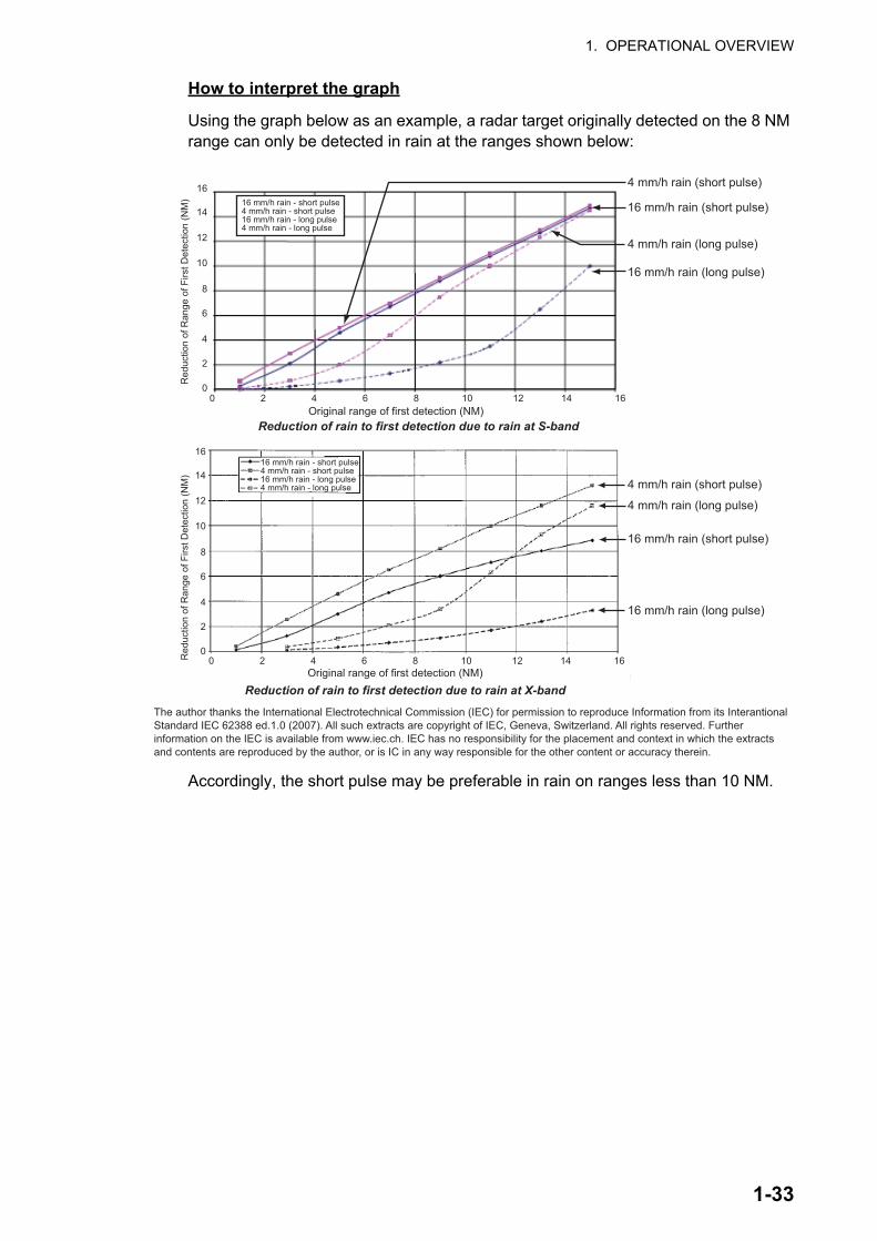
1. OPERATIONAL OVERVIEW
How to interpret the graph
Using the graph below as an example, a radar target originally detected on the 8 NM range can only be detected in rain at the ranges shown below:
Accordingly, the short pulse may be preferable in rain on ranges less than 10 NM.
Red
uctio
n of
rang
e of
firs
t det
ectio
n (N
M)
16 mm/h rain - short pulse 4 mm/h rain - short pulse16 mm/h rain - long pulse 4 mm/h rain - long pulse
14
16
12
10
8
6
4
2
00 2 4 6 8 10 12 14 16
16
12
10
8
6
4
2
0
14
0 2 4 6 8 10 12 14 16
4 mm/h rain (short pulse)
16 mm/h rain (short pulse)
4 mm/h rain (long pulse)
16 mm/h rain (long pulse)
4 mm/h rain (short pulse)
16 mm/h rain (short pulse)
4 mm/h rain (long pulse)
16 mm/h rain (long pulse)
Original range of first detection (NM)
Original range of first detection (NM)
16 mm/h rain - short pulse4 mm/h rain - short pulse16 mm/h rain - long pulse4 mm/h rain - long pulse
16 mm/h rain - short pulse4 mm/h rain - short pulse16 mm/h rain - long pulse4 mm/h rain - long pulse
Reduction of rain to first detection due to rain at S-band
Reduction of rain to first detection due to rain at X-band
The author thanks the International Electrotechnical Commission (IEC) for permission to reproduce Information from its Interantional Standard IEC 62388 ed.1.0 (2007). All such extracts are copyright of IEC, Geneva, Switzerland. All rights reserved. Further information on the IEC is available from www.iec.ch. IEC has no responsibility for the placement and context in which the extracts and contents are reproduced by the author, or is IC in any way responsible for the other content or accuracy therein.
Red
uctio
n of
Ran
ge o
f Firs
t Det
ectio
n (N
M)
Red
uctio
n of
Ran
ge o
f Firs
t Det
ectio
n (N
M)
1-33
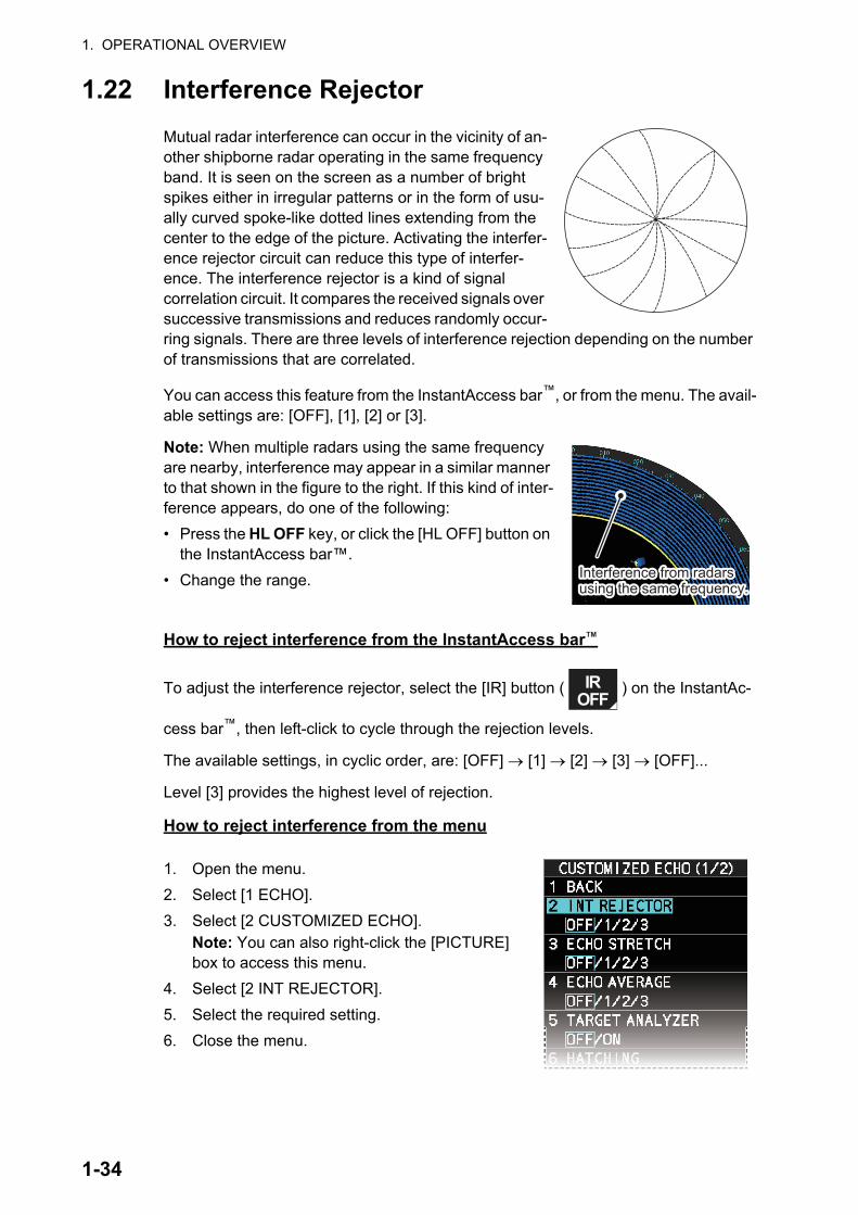
1. OPERATIONAL OVERVIEW
1.22 Interference Rejector
Mutual radar interference can occur in the vicinity of an-other shipborne radar operating in the same frequency band. It is seen on the screen as a number of bright spikes either in irregular patterns or in the form of usu-ally curved spoke-like dotted lines extending from the center to the edge of the picture. Activating the interfer-ence rejector circuit can reduce this type of interfer-ence. The interference rejector is a kind of signal correlation circuit. It compares the received signals over successive transmissions and reduces randomly occur-ring signals. There are three levels of interference rejection depending on the number of transmissions that are correlated.
You can access this feature from the InstantAccess bar™, or from the menu. The avail-able settings are: [OFF], [1], [2] or [3].
Note: When multiple radars using the same frequency are nearby, interference may appear in a similar manner to that shown in the figure to the right. If this kind of inter-ference appears, do one of the following:
• Press the HL OFF key, or click the [HL OFF] button on the InstantAccess bar™.
• Change the range.
How to reject interference from the InstantAccess bar
To adjust the interference rejector, select the [IR] button ( ) on the InstantAc-
cess bar™, then left-click to cycle through the rejection levels.
The available settings, in cyclic order, are: [OFF] [1] [2] [3] [OFF]...
Level [3] provides the highest level of rejection.
How to reject interference from the menu
1. Open the menu.
2. Select [1 ECHO].
3. Select [2 CUSTOMIZED ECHO].Note: You can also right-click the [PICTURE] box to access this menu.
4. Select [2 INT REJECTOR].
5. Select the required setting.
6. Close the menu.
Interference from radars using the same frequency.Interference from radars using the same frequency.
TM
IROFF
1-34
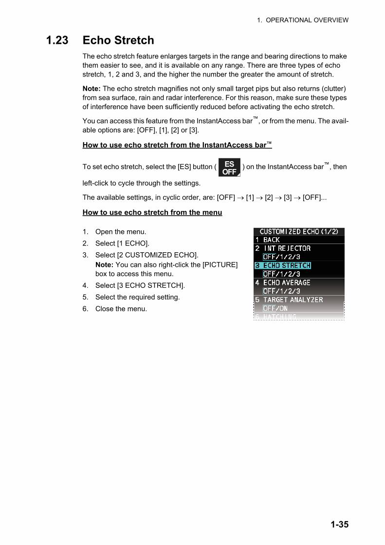
1. OPERATIONAL OVERVIEW
1.23 Echo StretchThe echo stretch feature enlarges targets in the range and bearing directions to make them easier to see, and it is available on any range. There are three types of echo stretch, 1, 2 and 3, and the higher the number the greater the amount of stretch.
Note: The echo stretch magnifies not only small target pips but also returns (clutter) from sea surface, rain and radar interference. For this reason, make sure these types of interference have been sufficiently reduced before activating the echo stretch.
You can access this feature from the InstantAccess bar™, or from the menu. The avail-able options are: [OFF], [1], [2] or [3].
How to use echo stretch from the InstantAccess bar
To set echo stretch, select the [ES] button ( ) on the InstantAccess bar™, then
left-click to cycle through the settings.
The available settings, in cyclic order, are: [OFF] [1] [2] [3] [OFF]...
How to use echo stretch from the menu
1. Open the menu.
2. Select [1 ECHO].
3. Select [2 CUSTOMIZED ECHO].Note: You can also right-click the [PICTURE] box to access this menu.
4. Select [3 ECHO STRETCH].
5. Select the required setting.
6. Close the menu.
TM
ESOFF
1-35

1. OPERATIONAL OVERVIEW
1.24 Echo AveragingThe echo averaging feature effectively reduces sea clutter. Echoes received from sta-ble targets such as ships appear on the screen at almost the same position every ro-tation of the antenna. On the other hand, unstable echoes such as sea clutter appear at random positions.
To distinguish real target echoes from sea clutter, echoes are averaged over succes-sive picture frames. If an echo is solid and stable over successive frames, it is present-ed in its normal intensity. Sea clutter is averaged over successive scans and its brilliance reduced, making it easier to discriminate real targets from sea clutter.
Echo averaging uses a scan-to-scan signal correlation technique based on the true motion over the ground of each target. Thus, small stationary targets such as buoys will be shown while reducing random echoes such as sea clutter. However, true echo averaging is not effective for picking up small targets running at high speeds over the ground.
Note 1: With echo average active it is harder to detect high-speed targets than sta-tionary ones.
Note 2: Do not use the echo averaging function under heavy pitching and rolling; loss of targets can result.
Note 3: Echo averaging requires heading, position and speed data.
Before using the echo averaging function, reduce sea clutter with the A/C SEA control. Leave a little sea clutter on the screen so as not to erase weak targets. The available settings options are shown in the table below.
You can access this feature from the InstantAccess bar™, or from the menu.
How to adjust the echo average function from the InstantAccess bar
Select the [EAV] button ( ) on the InstantAccess bar™, then left-click to select
the desired level of echo averaging.
Setting (level)
Description
[OFF] Echo averaging is not enabled[1], [2] Detects targets hidden in sea clutter. [2] is more effective than [1] in detecting
targets hidden in strong sea clutter. However, [1] is more effective than [2] in displaying high-speed targets. Select the setting best suited to current con-ditions. For effective monitoring of high-speed craft, you should use [2] to-gether with the Wiper function.
[3] Stably displays unstable targets; distinguishes high-speed craft.
TM
EAVOFF
1-36

1. OPERATIONAL OVERVIEW
How to use the echo average function from the menu
1. Open the menu.
2. Select [1 ECHO].
3. Select [2 CUSTOMIZED ECHO].Note: You can also right-click the [PICTURE] box to access this menu.
4. Select [4 ECHO AVERAGE].
5. Select the required setting.
6. Close the menu.
How to highlight fast-moving targets
Normally, when echo averaging is in use, fast-moving targets may be displayed weak-ly, or not at all. The fast target emphasis function highlights fast-moving targets, but can also highlight sea-surface reflections and other noise.
To use the fast target emphasis function, follow the procedure below.
1. Open the menu.
2. Select [1 ECHO].
3. Select [0 NEXT].
4. Select [6 EAV EMPH-FAST TGT].
5. Select [ON] or [OFF] as appropriate.
6. Close the menu.
1-37

1. OPERATIONAL OVERVIEW
1.25 Automatic Clutter Elimination (ACE) FunctionThis radar has the Automatic Clutter Elimination (ACE) function. This function detects sea and rain clutter from received echoes’ and automatically reduces sea and rain clutter according to the Automatic Clutter Elimination (ACE) threshold setting.
Note: Use this function with caution. Weak target echoes may disappear from the screen.
1.25.1 How to turn the Automatic Clutter Elimination (ACE) function on/off
You can activate/deactivate the ACE function with one of the two methods outlined be-low.
From the InstantAccess bar
Place the cursor on the [ACE] button, then left-click to toggle between [ON] and [OFF].
From the menu
1. Open the menu.
2. Select [1 ECHO].
3. Select [2 CUSTOMIZED ECHO].Note: You can also right-click the [PICTURE] box to access this menu.
4. Select [0 NEXT].
5. Select [4 ACE].
6. Select [ON] or [OFF] as appropriate.
7. Close the menu.
When [ACE] is activated, the [SEA] box and [RAIN] box are gray colored and cannot be adjusted, and the echo averaging function is disabled. The [GAIN] box changes to [GAIN ACE], as shown in the figure below.
Note: When [PERFORMANCE MON] (see section 1.49) or [SART] (see section 2.3) is [ON], [ACE] is disabled and cannot be activated.
1.25.2 How to adjust the gain in Automatic Clutter Elimination (ACE) mode
Rotate the GAIN knob to adjust the sensitivity.
ACE can also be adjusted by placing the cursor inside the [GAIN ACE] level indication, then spinning the scrollwheel.
TM
30GAIN30SEA30RAIN
MANMAN
30GAIN30SEA30RAIN
MANACE
MAN
ACE turned off. ACE turned on.
1-38

1. OPERATIONAL OVERVIEW
1.25.3 How to get high sensitivity
When the ACE function is [ON], the high sensitivity mode is also available. This re-quires a function key to be assigned with the [ACE HIGH SENSITIVITY] function (see section 1.9).
To use high sensitivity mode, activate the ACE feature, then press the assigned func-tion key.
You can select the level for the high sensitivity mode as follows:
1. Open the menu.
2. Select [1 ECHO].
3. Select [0 NEXT].
4. Select [2 ACE]. The [ACE] menu appears.
5. Select [2 SIGNAL ENHANCEMENT].
6. Select the level from [1], [2] or [3].
7. Close the menu.
1.25.4 How to suppress false echoes
When the ACE function is [ON], the echo signals can appear on the screen at posi-tions where there is no target or disappear when there are targets (see section 2.2). You can suppress these false echoes.
Note: This procedure is only available when the Automatic Clutter Elimination (ACE) function is [ON].
1. Open the menu.
2. Select [1 ECHO].
3. Select [0 NEXT].
4. Select [2 ACE].
5. Select [3 SUPPRESS SECTOR].
6. Spin the scrollwheel, or use the number keys, to set the start angle for sector sup-pression.If you use the number keys, the cursor moves from left to right. When all three dig-its are input, the cursor moves to the [ANGLE] item.If you use the scrollwheel, left-click when the start angle is set.To cancel any changes, press the CANCEL TRAILS key.
7. Left-click, or press the ENTER MARK key to confirm the start angle. The cursor moves to the [ANGLE] item.
8. Spin the scrollwheel, or use the number keys, set the angle range of the sector to be suppressed.If you use the number keys, the cursor moves from left to right. When all three dig-its are input, the setting process is complete.If you use the scrollwheel, left-click when the angle range is set.To cancel any changes, press the CANCEL TRAILS key.
9. Close the menu.
1-39
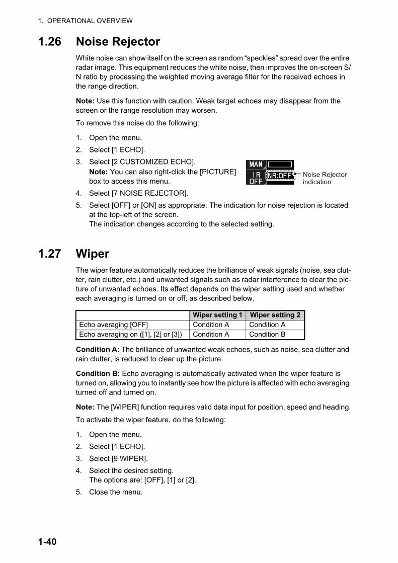
1. OPERATIONAL OVERVIEW
1.26 Noise RejectorWhite noise can show itself on the screen as random “speckles” spread over the entire radar image. This equipment reduces the white noise, then improves the on-screen S/N ratio by processing the weighted moving average filter for the received echoes in the range direction.
Note: Use this function with caution. Weak target echoes may disappear from the screen or the range resolution may worsen.
To remove this noise do the following:
1. Open the menu.
2. Select [1 ECHO].
3. Select [2 CUSTOMIZED ECHO].Note: You can also right-click the [PICTURE] box to access this menu.
4. Select [7 NOISE REJECTOR].
5. Select [OFF] or [ON] as appropriate. The indication for noise rejection is located at the top-left of the screen. The indication changes according to the selected setting.
1.27 WiperThe wiper feature automatically reduces the brilliance of weak signals (noise, sea clut-ter, rain clutter, etc.) and unwanted signals such as radar interference to clear the pic-ture of unwanted echoes. Its effect depends on the wiper setting used and whether each averaging is turned on or off, as described below.
Condition A: The brilliance of unwanted weak echoes, such as noise, sea clutter and rain clutter, is reduced to clear up the picture.
Condition B: Echo averaging is automatically activated when the wiper feature is turned on, allowing you to instantly see how the picture is affected with echo averaging turned off and turned on.
Note: The [WIPER] function requires valid data input for position, speed and heading.
To activate the wiper feature, do the following:
1. Open the menu.
2. Select [1 ECHO].
3. Select [9 WIPER].
4. Select the desired setting.The options are: [OFF], [1] or [2].
5. Close the menu.
Wiper setting 1 Wiper setting 2Echo averaging [OFF] Condition A Condition AEcho averaging on ([1], [2] or [3]) Condition A Condition B
Noise Rejector indication
1-40

1. OPERATIONAL OVERVIEW
1.28 How to Preset Controls for a Specific Navigation PurposeEvery time your navigating environment or task changes, you must adjust the radar, which can be a nuisance in a busy situation. Instead of changing radar settings case by case, it is possible to assign the function keys to provide optimum settings for often-encountered situations.
The radar's internal computer offers several picture preset options to be assigned to each function key for your specific navigating requirements. For instance, one of the presets is [ROUGH SEA], and is designed to be used in heavy rain.
Three user-programmable presets are also provided (labeled as [CUSTOM1], [CUS-TOM2] and [CUSTOM3]), so that you can have the radar automatically set to those conditions which are not covered by the provided setup options.
Below are the preset options provided with this radar.
*: [SMALL TARGET] replaces [NEAR BUOY] and [ICE] replaces [BIRD] when Ice Mode is enabled at installation.
Each picture option defines a combination of several radar settings for achieving op-timum setup for a particular navigating situation. These include gain, target analyzer, hatching, ACE, ACE gain, interference rejector, echo stretch, echo average, noise re-jector, automatic anti-sea and anti-rain clutter, video contrast, pulse length and sea and radar conditions.
Changing these features from the [CUSTOMIZED ECHO] menu changes the original function key settings. To restore the original settings for a particular customize option, it is necessary to select the default setting. For this reason, we recommended that you use the user-programmable presets ([CUSTOM1], [CUSTOM2] or [CUSTOM3]) when frequent adjustment of the radar image is necessary.
The default settings for the custom presets are listed on the following pages.
Preset Description[CUSTOM1], [CUSTOM2] and [CUSTOM3]
User-defined custom settings.
[NEAR] Optimum setting for short range detection using a range scale of 3 NM or less on calm seas.
[FAR] Optimum setting for long range detection, on a range scale of 6 NM or larger.
[NEAR BUOY]* Optimum setting for detecting buoys within 3 NM range.[FAR BUOY] Optimum setting for detecting buoys on a range scale of
6 NM or larger.[ROUGH SEA] Optimum setting for rough weather or heavy rain.[SHIP] Optimum setting for detecting other vessels.[HARBOR] Optimum setting for harbor berthing.[BIRD] Optimum setting for detecting birds.[ICE]* Optimum setting for navigating though sea ice.[COAST] Optimum setting for coastal travel.
1-41
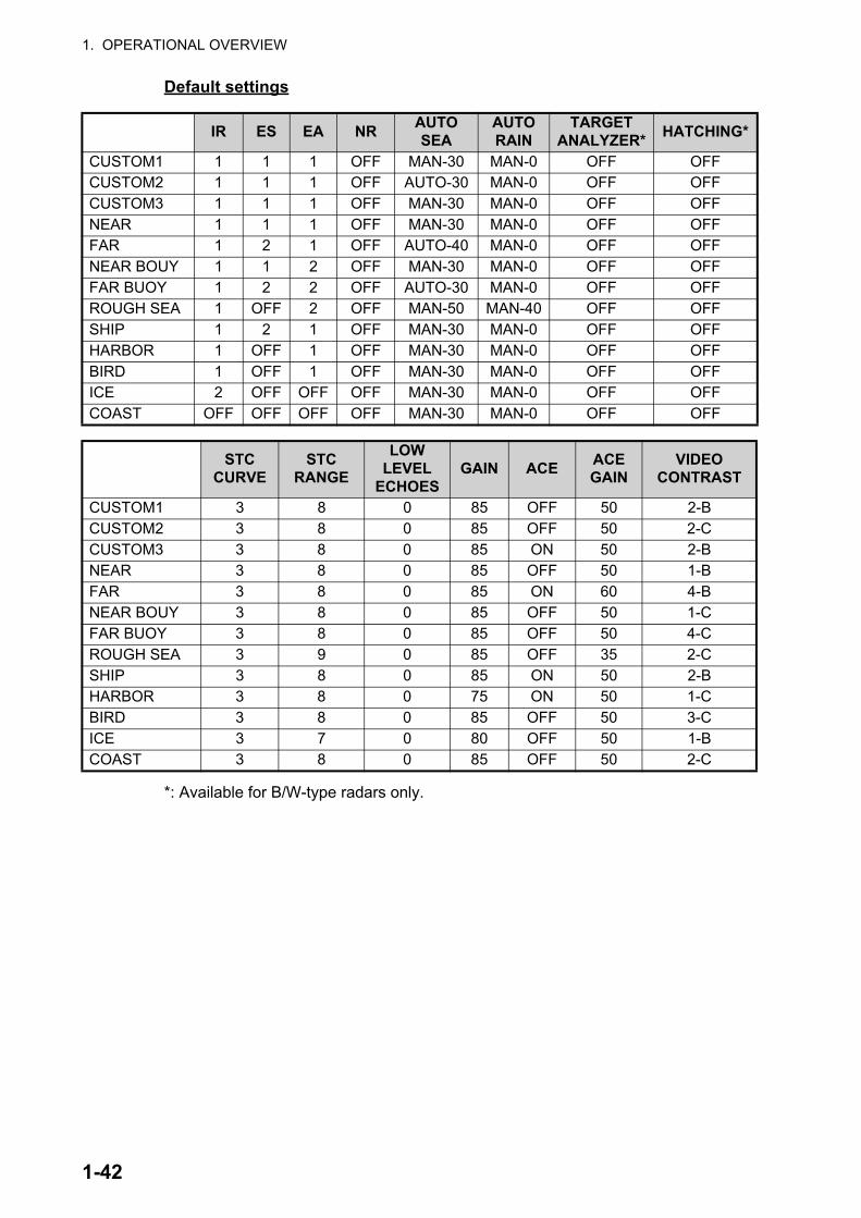
1. OPERATIONAL OVERVIEW
Default settings
*: Available for B/W-type radars only.
IR ES EA NRAUTO SEA
AUTO RAIN
TARGET ANALYZER*
HATCHING*
CUSTOM1 1 1 1 OFF MAN-30 MAN-0 OFF OFFCUSTOM2 1 1 1 OFF AUTO-30 MAN-0 OFF OFFCUSTOM3 1 1 1 OFF MAN-30 MAN-0 OFF OFFNEAR 1 1 1 OFF MAN-30 MAN-0 OFF OFFFAR 1 2 1 OFF AUTO-40 MAN-0 OFF OFFNEAR BOUY 1 1 2 OFF MAN-30 MAN-0 OFF OFFFAR BUOY 1 2 2 OFF AUTO-30 MAN-0 OFF OFFROUGH SEA 1 OFF 2 OFF MAN-50 MAN-40 OFF OFFSHIP 1 2 1 OFF MAN-30 MAN-0 OFF OFFHARBOR 1 OFF 1 OFF MAN-30 MAN-0 OFF OFFBIRD 1 OFF 1 OFF MAN-30 MAN-0 OFF OFFICE 2 OFF OFF OFF MAN-30 MAN-0 OFF OFFCOAST OFF OFF OFF OFF MAN-30 MAN-0 OFF OFF
STC CURVE
STC RANGE
LOW LEVEL
ECHOESGAIN ACE
ACE GAIN
VIDEO CONTRAST
CUSTOM1 3 8 0 85 OFF 50 2-BCUSTOM2 3 8 0 85 OFF 50 2-CCUSTOM3 3 8 0 85 ON 50 2-BNEAR 3 8 0 85 OFF 50 1-BFAR 3 8 0 85 ON 60 4-BNEAR BOUY 3 8 0 85 OFF 50 1-CFAR BUOY 3 8 0 85 OFF 50 4-CROUGH SEA 3 9 0 85 OFF 35 2-CSHIP 3 8 0 85 ON 50 2-BHARBOR 3 8 0 75 ON 50 1-CBIRD 3 8 0 85 OFF 50 3-CICE 3 7 0 80 OFF 50 1-BCOAST 3 8 0 85 OFF 50 2-C
1-42

1. OPERATIONAL OVERVIEW
Default settings for [PULSELENGTH]
*: These ranges are available for B/W-type radars only.
About the ICE custom setting (optional specification)
0.125 NM to 0.5 NM
0.75 NM 1 NM* 1.5 NM 2 NM* 3 NM
CUSTOM1 S1 S1 S1 S2 S2 M1CUSTOM2 S1 S1 S1 S2 S2 M1CUSTOM3 S1 S1 S1 S2 S2 M1NEAR S1 S1 S1 S2 S2 M1FAR S1 S1 S1 S2 S2 M1NEAR BOUY S1 S1 S1 S2 S2 M1FAR BUOY S1 S1 S1 S2 S2 M1ROUGH SEA S1 S1 S1 S2 S2 M1SHIP S1 S1 S1 S2 S2 M1HARBOR S1 S1 S1 S2 S2 M1BIRD S1 S1 S1 S2 S2 M1ICE S1 S1 S1 S1 S1 S2COAST S1 S1 S1 S2 S2 M1
4 NM* 6 NM 8 NM* 12 NM 16 NM* 24 NMCUSTOM1 M1 M2 M2 L L LCUSTOM2 M1 M2 M2 L L LCUSTOM3 M1 M2 M2 L L LNEAR M1 M3 M3 M3 M3 LFAR M1 M3 M3 L L LNEAR BOUY M1 M2 M2 M3 M3 LFAR BUOY M1 M3 M3 L L LROUGH SEA M1 M2 M2 M3 M3 LSHIP M1 M2 M2 L M3 LHARBOR M1 M2 M2 M3 M3 LBIRD M1 M2 M2 M3 M3 LICE S2 M1 M1 M1 M1 M2COAST M1 M2 M2 M3 M3 L
The ICE custom setting sets up the radar to detect areas of ice on the sea surface. With ICE active, the following restrictions or requirements apply:• For interswitch configurations with a FAR-2xx8 series as the main radar and a FAR-
2xx7 series as the sub radar, ice echoes may not appear correctly on the FAR-2xx7 series screen. Avoid using a FAR-2xx7 series radar as the interswitch sub-radar with Ice Mode enabled.
• Ice Mode must be enabled from the [RADAR INSTALLATION] menu. See the Instal-lation Manual for details.
• Dual radar mode must be disabled from the [RADAR INSTALLATION] menu. See the Installation Manual for details.
• Ice Mode replaces Bird Mode. While Ice Mode is in use, Bird Mode-related settings and operations are not available.
• Video Contrast settings are fixed to ICE settings when the performance monitor is ac-tivated while Ice Mode is enabled.
• While Ice Mode is enabled, the following functions are not available:• Target Analyzer • Rain Echo Hatching • Video Contrast• Automatic Clutter Elimination (ACE) • Fast Target Emphasis • Trail Hide
1-43

1. OPERATIONAL OVERVIEW
1.28.1 How to select a customized echo
Left-click the [CUSTOMIZE ECHO] box at the top left of the screen to cycle through the options and select a customized echo option.
The available options depend on the settings selected for [3 SELECT CUSTOM] in the [ECHO] menu. See section 1.28.5.
1.28.2 How to edit a customized echo
1. Select a customize echo option to edit (see section 1.28.1).
2. Open the menu.
3. Select [1 ECHO].
4. Select [2 CUSTOMIZED ECHO].Note: You can also right-click the [PICTURE] box to access this menu.
5. Set the items below referring to the sections shown.
*: Available for B/W-type radars only.Note: To set [2 CONDITION] and [4 ACE], select [0 NEXT] to show the second page of the [CUSTOMIZED ECHO] menu.
6. Select [8 VIDEO CONTRAST TYPE].
7. Select [1], [2], [3] or [4] (Dynamic Range) or [A], [B], [C] (Curve) as appropriate. Video contrast and curve change depending on setting for [VIDEO CONTRAST] (set at installation), as shown in the figure below.
• [2 INT REJECTOR] : section 1.22• [3 ECHO STRETCH] : section 1.23• [4 ECHO AVERAGE] : section 1.24• [5 TARGET ANALYZER]* : section 1.38• [6 HATCHING]* : section 1.38• [7 NOISE REJECTOR] : section 1.26• [8 VIDEO CONTRAST TYPE] : described in this section.• [9 PULSE] : section 1.18• [2 CONDITION] : described in this section.• [4 ACE] : section 1.25
CO
NTR
AS
T
LEVEL CO
NTR
AS
T
LEVEL CO
NTR
AS
T
LEVEL CO
NTR
AS
T
LEVEL
A B C
[VIDEO CONTRAST] set to [ADVANCE] at installation:
[VIDEO CONTRAST] set to [LEGACY] at installation:CONTRAST
CBA
CONTRAST
33 2244
11
33 22 1144
1-44
1. OPERATIONAL OVERVIEW
1 to 4: Control dynamic range. 1 provides the widest dynamic range; 4 is the nar-rowest dynamic range.A: Low level echo brilliance is reduced and noise and clutter are also reduced.B: Low and high level echoes are displayed evenly.C: High level echoes' outer edge has gradation to indicate the echo level, with the higher level echo at the core.
8. Select [0 NEXT] to show the next menu page.
9. Select [2 CONDITION].
10. Select [2 STC CURVE].
11. Select the appropriate setting for the current sea conditions. The available set-tings are: [2], [2.5], [3], [3.5], [4.2]. A higher setting is recommended for rough weather.
12. Select [3 STC RANGE].
13. Set the distance for STC effectiveness. A higher setting eliminates farther surface reflections.
14. If necessary, select [4 LOW LEVEL ECHO] to reject low level echoes. The setting range is [0] to [8]. The higher the figure, the stronger the low level echo that is erased.
15. Select [1 BACK] to show the second page of the [CUSTOMIZED ECHO] menu.
16. To save custom settings, select [SAVE] from [3 DEFAULT].
17. Close the menu.
1.28.3 How to restore a user customized echo to the saved settings
If you get lost in operation while changing the settings for a user customized echo, you can easily restore the settings for that user customized echo saved at section 1.28.2.
1. Open the menu.
2. Select [1 ECHO].
3. Select [2 CUSTOMIZED ECHO].Note: You can also right-click the [PICTURE] box to access this menu.
4. Select [0 NEXT] to show the next menu page.
5. Select [3 DEFAULT].
6. Select [USER].
7. Close the menu.
1-45

1. OPERATIONAL OVERVIEW
1.28.4 How to restore a user customized echo to the factory default settings
You can restore customized echo options to their factory default settings (see the ta-bles on page 1-42 for a list of the default settings).
1. Open the menu.
2. Select [1 ECHO].
3. Select [2 CUSTOMIZED ECHO].Note: You can also right-click the [PICTURE] box to access this menu.
4. Select [0 NEXT] to show the next menu page.
5. Select [3 DEFAULT].
6. Select [FACTORY].
1.28.5 How to edit the available customized echoes
To edit which customizations are available from the [CUS-TOMIZE ECHO] box, follow the procedure below.
1. Open the menu.
2. Select [1 ECHO].
3. Select [0 NEXT].
4. Select [3 SELECT CUSTOM]. The [SELECT CUS-TOM] menu appears.
5. Select the customization you want to edit.The customizations are listed over two menu pages. Select [0 NEXT] to see the next page, or select [1 BACK] to return to the previous menu page.
6. Select [ON] to make the customization available from the [CUSTOMIZE ECHO] box, or select [OFF] to hide the customization from the [CUSTOMIZE ECHO] box.
7. Close the menu.
Page 1
Page 2
1-46

1. OPERATIONAL OVERVIEW
1.29 How to Reject Second-trace EchoesIn certain situations, echoes from very distance targets can appear as false echoes (second-trace echoes) on the screen. This occurs when the return echo is received one transmission cycle later, or after a next radar pulse has been transmitted.
This equipment lengthens the pulse repetition period to reject false echoes.
Note: his function decreases the number of echo hits. Use this function carefully so that the possibility of detecting small targets and high-speed craft does not lessen.
To enable or disable second-trace echo rejection, do the following:
1. Open the menu.
2. Select [1 ECHO].
3. Select [3 2ND ECHO REJ].
4. Select [ON] to enable second-trace echo rejection.Select [OFF] to disable rejection.
5. Close the menu.
Pulse interval
Actual ranges
Second-trace echo
Measured ranges
1-47
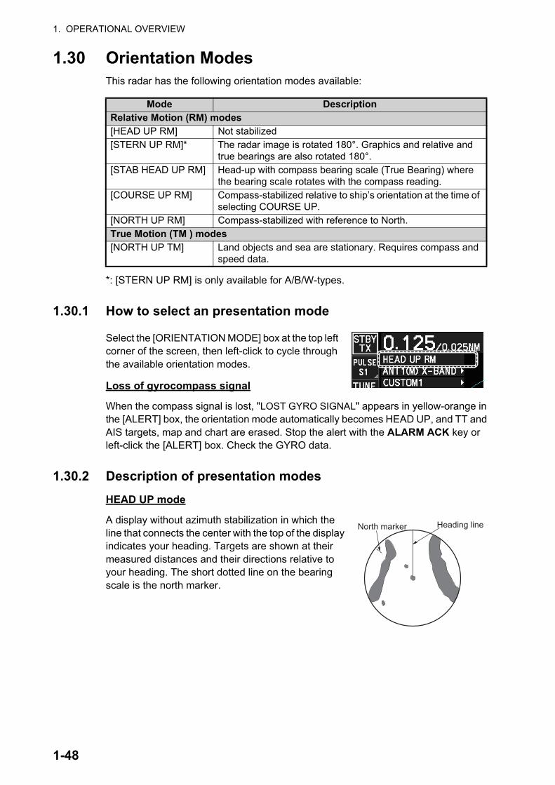
1. OPERATIONAL OVERVIEW
1.30 Orientation ModesThis radar has the following orientation modes available:
*: [STERN UP RM] is only available for A/B/W-types.
1.30.1 How to select an presentation mode
Select the [ORIENTATION MODE] box at the top left corner of the screen, then left-click to cycle through the available orientation modes.
Loss of gyrocompass signal
When the compass signal is lost, "LOST GYRO SIGNAL" appears in yellow-orange in the [ALERT] box, the orientation mode automatically becomes HEAD UP, and TT and AIS targets, map and chart are erased. Stop the alert with the ALARM ACK key or left-click the [ALERT] box. Check the GYRO data.
1.30.2 Description of presentation modes
HEAD UP mode
A display without azimuth stabilization in which the line that connects the center with the top of the display indicates your heading. Targets are shown at their measured distances and their directions relative to your heading. The short dotted line on the bearing scale is the north marker.
Mode DescriptionRelative Motion (RM) modes[HEAD UP RM] Not stabilized[STERN UP RM]* The radar image is rotated 180°. Graphics and relative and
true bearings are also rotated 180°.[STAB HEAD UP RM] Head-up with compass bearing scale (True Bearing) where
the bearing scale rotates with the compass reading.[COURSE UP RM] Compass-stabilized relative to ship’s orientation at the time of
selecting COURSE UP.[NORTH UP RM] Compass-stabilized with reference to North.True Motion (TM ) modes[NORTH UP TM] Land objects and sea are stationary. Requires compass and
speed data.
Heading lineNorth marker
1-48

1. OPERATIONAL OVERVIEW
COURSE UP mode
The radar picture is stabilized and displayed with the currently selected course at the top of the screen. When you change the heading, the heading line moves with the course selected. If you select a new course, select the course up mode again to display the new course at the top of the display. Targets are shown at their measured distances and their direc-tions relative to the set course, which is at the 0-de-gree position. The heading line moves according to the yawing and any course change.
NORTH UP mode
Targets are shown at their measured distances and their true (compass) directions from your ship. North is at the top of the screen. The heading line changes its di-rection according to your heading.
STAB HEAD UP mode
Radar echoes are shown in the same way as in the HEAD UP mode. The difference from normal HEAD UP presentation lies in the orien-tation of the bearing scale. The bearing scale is heading sensor stabilized. That is, it rotates in accordance with the heading sensor signal, enabling you to know own ship's heading at a glance.
This mode is available when the radar is interfaced with a gyrocompass. If the gyro-compass fails, the bearing scale returns to the state of HEAD UP mode.
True motion mode
Your ship and other objects in motion move with their true courses and speed. All fixed targets, like landmasses, ap-pear as fixed echoes in ground stabilized TM. When your ship reaches a point that is 50% of the radius of the display, the position is reset. The ship appears at 75% radius oppo-site to the extension of the current course. You can manu-ally reset your ship symbol if you highlight the [CU/TM RESET] indication at the top of the screen, then left-click.
Heading lineNorth marker
Heading lineNorth marker
Heading lineNorth
Headingline
Northmarker
(a) True motion is selected
(b) Your ship has reached a point 50% of display radius
(c) Your ship is automatically reset to 75% of display radius
1-49
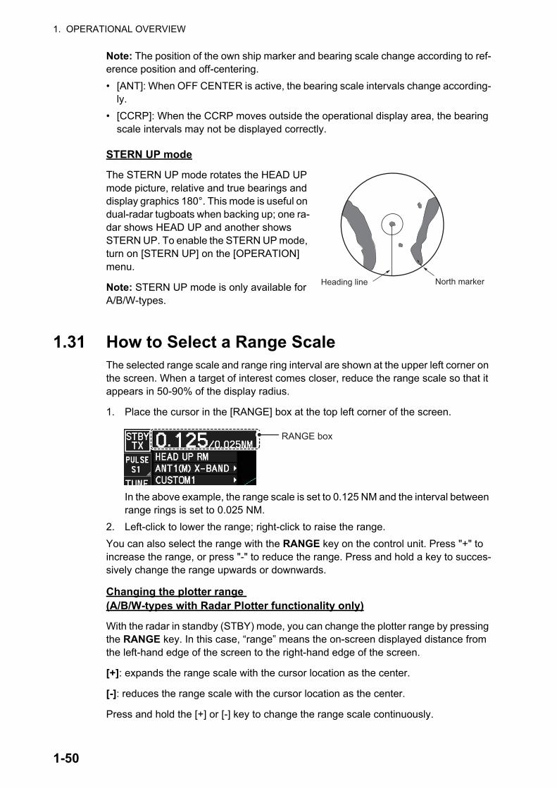
1. OPERATIONAL OVERVIEW
Note: The position of the own ship marker and bearing scale change according to ref-erence position and off-centering.
• [ANT]: When OFF CENTER is active, the bearing scale intervals change according-ly.
• [CCRP]: When the CCRP moves outside the operational display area, the bearing scale intervals may not be displayed correctly.
STERN UP mode
The STERN UP mode rotates the HEAD UP mode picture, relative and true bearings and display graphics 180°. This mode is useful on dual-radar tugboats when backing up; one ra-dar shows HEAD UP and another shows STERN UP. To enable the STERN UP mode, turn on [STERN UP] on the [OPERATION] menu.
Note: STERN UP mode is only available for A/B/W-types.
1.31 How to Select a Range ScaleThe selected range scale and range ring interval are shown at the upper left corner on the screen. When a target of interest comes closer, reduce the range scale so that it appears in 50-90% of the display radius.
1. Place the cursor in the [RANGE] box at the top left corner of the screen.
In the above example, the range scale is set to 0.125 NM and the interval between range rings is set to 0.025 NM.
2. Left-click to lower the range; right-click to raise the range.
You can also select the range with the RANGE key on the control unit. Press "+" to increase the range, or press "-" to reduce the range. Press and hold a key to succes-sively change the range upwards or downwards.
Changing the plotter range (A/B/W-types with Radar Plotter functionality only)
With the radar in standby (STBY) mode, you can change the plotter range by pressing the RANGE key. In this case, “range” means the on-screen displayed distance from the left-hand edge of the screen to the right-hand edge of the screen.
[+]: expands the range scale with the cursor location as the center.
[-]: reduces the range scale with the cursor location as the center.
Press and hold the [+] or [-] key to change the range scale continuously.
Heading line North marker
RANGE box
1-50

1. OPERATIONAL OVERVIEW
1.32 How to Measure RangeThe range to a target can be measured three ways: with the fixed range rings, with the cursor, or with the VRM.
Use the fixed range rings to get an estimate of the range to a target. The rings are the concentric solid circles on the display. The number of rings is automatically set by the current range scale. The distance between the rings is the range ring interval, and the current interval appears at the upper-left position on the screen. To measure the range to a target with the range rings, count the number of rings between the center of the display and the target. Check the range ring interval and estimate the distance of the echo from the inner edge of the nearest ring.
1.32.1 How to show/hide the range rings
1. Open the menu.
2. Select [3 NAV TOOLS] to show the [NAV TOOLS] menu.
3. Select [4 RANGE RINGS].
4. Select [ON] or [OFF] as appropriate.
5. Close the menu.
1.32.2 How to measure range with the variable range marker (VRM)
There are two VRMs, No. 1 and No. 2, which appear as dashed rings so that you can distinguish them from the fixed range rings. The two VRMs can be distinguished from each other by the different lengths of their dashes; the dashes on the No. 2 VRM are longer.
There are two methods for measuring range with the VRMs, using the VRM key and on-screen menu box operation.
000 010 020030
040
050
060
070
080
090
100
110
120
130
140150
160170180190200210
220
230
240
250
260
270
280
290
300
310
320330
340 350
VRM1
VRM2
Target echo
Currently active VRM is highlighted.Range to VRM
TTG to VRM
28.11 36.44NMVRM1 VRM2
TTG 50:00 60:00TTGNM
1-51

1. OPERATIONAL OVERVIEW
Note: The maximum VRM distance is set by the current display range and can be set as high as twice the distance of the display range.
Using the VRM keys
1. Press the VRM ON key to activate the VRM1 box. Press the VRM ON key again to activate the VRM2 box. Press the VRM ON key again to switch between active VRMs. The currently active VRM marker is displayed as shown in the above fig-ure.
2. Rotate the VRM knob to align the active VRM with the inner edge of the target, then read the distance at the lower right of the screen. In the previous figure, the active VRM reads "36.44 NM".Each VRM remains at the same geographical distance when you operate the RANGE key or the [RANGE] box. This means that the apparent radius of the VRM ring changes in proportion to the selected range scale.
3. Press the VRM OFF key to hide the VRMs.
On-screen menu box operation
1. Select the appropriate [VRM] box.
2. The guidance box reads "VRM ON/". Left-click to turn on the VRM. The guidance box now reads "VRM SET L = DELETE /".Further, the box is highlighted and the corresponding VRM appears.
3. Left-click again and the cursor jumps to inside the operational display area. The guidance box now reads "VRM FIX L = DELETE / EXIT".
4. Move the trackball to adjust the VRM.
5. Left-click to anchor the VRM and fix its readout, or right-click to cancel and return the VRM to its previous location (range).
6. To hide the VRM, left-click the [VRM] box to show "VRM SET L = DELETE /" in the guidance box, then press and hold the left button on the trackball.
1.32.3 How to set the VRM unit of measurement (B-type only)
VRMs can be displayed in the following units of measurement:
To change the unit of measurement, do the following:
1. Open the menu.
2. Select [3 NAV TOOLS].
3. Select [3 EBL•VRM•CURSOR SET].
4. Select [VRM1] or [VRM2] as appropriate.
5. Select the unit of measurement.
6. Close the menu.
Note: Changes made to the measurement units also affect active VRMs.
• NM (Nautical Miles)• SM (Statute Miles)
• km (Kilometers)• kyd (Kiloyards)
1-52
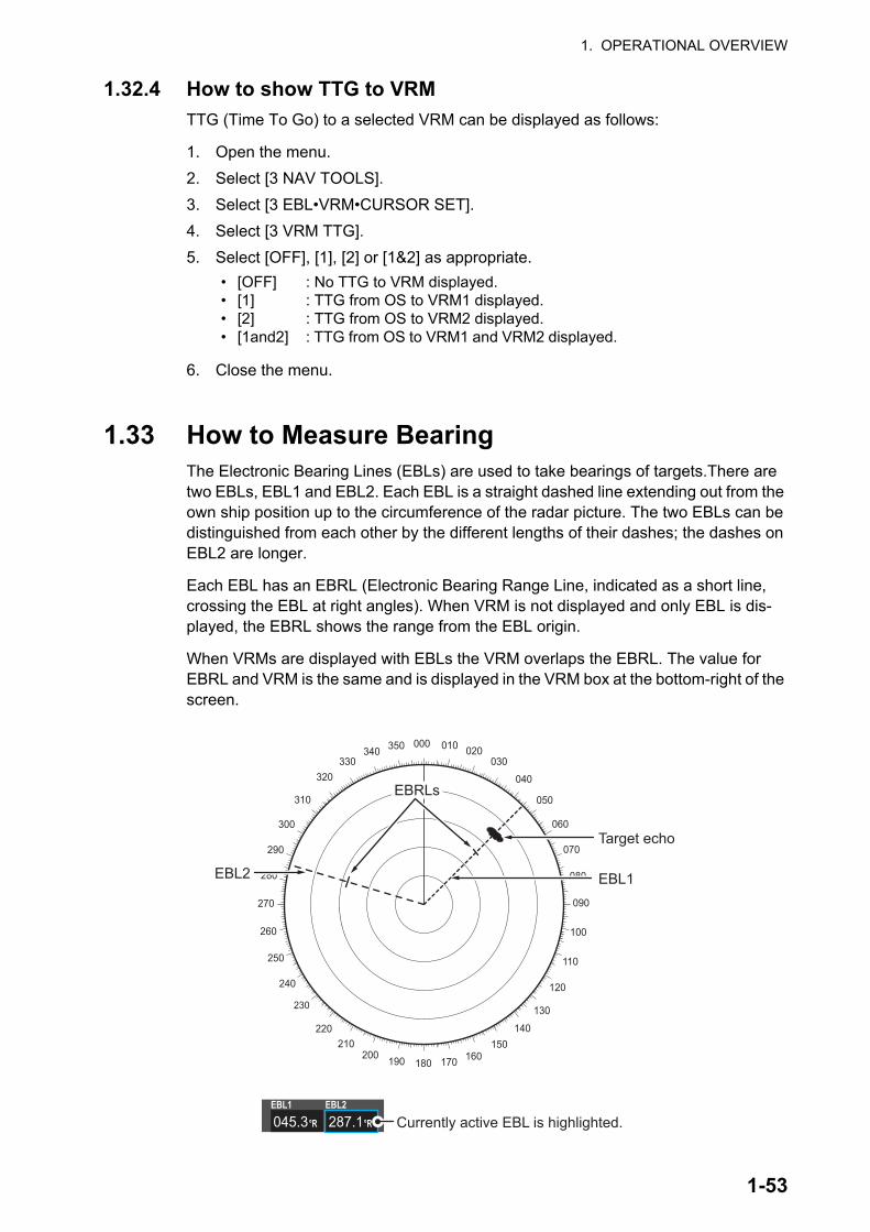
1. OPERATIONAL OVERVIEW
1.32.4 How to show TTG to VRM
TTG (Time To Go) to a selected VRM can be displayed as follows:
1. Open the menu.
2. Select [3 NAV TOOLS].
3. Select [3 EBL•VRM•CURSOR SET].
4. Select [3 VRM TTG].
5. Select [OFF], [1], [2] or [1&2] as appropriate.
6. Close the menu.
1.33 How to Measure BearingThe Electronic Bearing Lines (EBLs) are used to take bearings of targets.There are two EBLs, EBL1 and EBL2. Each EBL is a straight dashed line extending out from the own ship position up to the circumference of the radar picture. The two EBLs can be distinguished from each other by the different lengths of their dashes; the dashes on EBL2 are longer.
Each EBL has an EBRL (Electronic Bearing Range Line, indicated as a short line, crossing the EBL at right angles). When VRM is not displayed and only EBL is dis-played, the EBRL shows the range from the EBL origin.
When VRMs are displayed with EBLs the VRM overlaps the EBRL. The value for EBRL and VRM is the same and is displayed in the VRM box at the bottom-right of the screen.
• [OFF]• [1]• [2]• [1and2]
: No TTG to VRM displayed.: TTG from OS to VRM1 displayed.: TTG from OS to VRM2 displayed.: TTG from OS to VRM1 and VRM2 displayed.
000 010 020030
040
050
060
070
080
090
100
110
120
130
140150
160170180190200210
220
230
240
250
260
270
280
290
300
310
320330
340 350
EBL1
EBRLs EBRLs
EBL2
Target echo
045.3 287.1°R
EBL1 EBL2
°R Currently active EBL is highlighted.
1-53

1. OPERATIONAL OVERVIEW
1.33.1 Methods to measure bearing
There are two methods for measuring bearing, using the EBL key and on-screen menu box operation.
Using the EBL keys
1. Press the EBL ON key to activate the [EBL1] box. Press the EBL ON key again to activate the EBL2 box. Press the EBL ON key again to toggle active EBLs. The active EBL marker is displayed as shown on the previous page.
2. Rotate the EBL knob clockwise or counterclockwise until the active EBL bisects the target of interest, then read its bearing at the lower-left corner of the screen.
3. Press the EBL OFF key to erase the active EBL.
On-screen menu box operation
1. Select the appropriate EBL box.
2. The guidance box reads "EBL ON/". Press the left button to turn on the EBL.The guidance box now reads "EBL SET L=DELETE /".
3. Press the left button again and the cursor jumps to inside the operational display area. The guidance box now reads "EBL FIX L=DELETE/".
4. Spin the scrollwheel, or use the trackball, to move the EBL until the active EBL bisects the target of interest, then press the left button to anchor the EBL. Read the bearing at the lower-left corner of the screen.
5. Press the EBL OFF key to erase EBLs.
1.33.2 True or relative bearing
The EBL readout is affixed by "R" (relative) if it is relative to own ship's heading, "T" (true) if it is referenced to the north. True or relative indication is available regardless of presentation mode.
1. Open the menu.
2. Select [3 NAV TOOLS].
3. Select [3 EBL•VRM•CURSOR SET].
4. For IMO/A/R-type radars, select [5 EBL•CURSOR BEARING].For B-type radars, select [2 EBL1] or [3 EBL2] as appropriate.
5. Select the [REL] or [TRUE] as required, then press the ENTER MARK key.
6. Close the menu.
Note: The EBL and its indication change with gyrocompass changes as follows:
Gyro heading EBL changesHEAD UP / relative EBL indication and EBL marker are unchanged.HEAD UP / true EBL indication does not change, however the EBL marker
moves accordinglyCOURSE UP / relative EBL indication does not change, however the EBL marker
moves accordingly.COURSE UP / true EBL indication and EBL marker are unchanged.NORTH UP / relative EBL indication does not change, however the EBL marker
moves accordinglyNORTH UP / true EBL indication and EBL marker are unchanged.
1-54
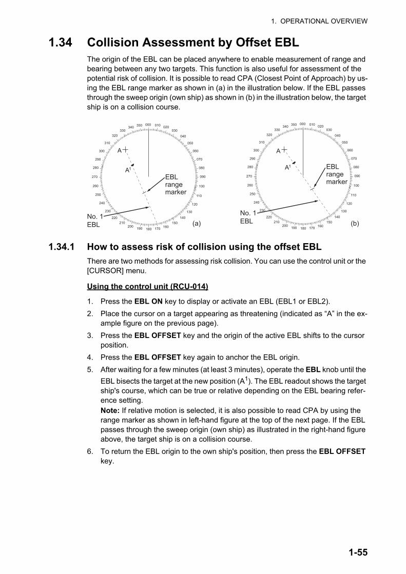
1. OPERATIONAL OVERVIEW
1.34 Collision Assessment by Offset EBLThe origin of the EBL can be placed anywhere to enable measurement of range and bearing between any two targets. This function is also useful for assessment of the potential risk of collision. It is possible to read CPA (Closest Point of Approach) by us-ing the EBL range marker as shown in (a) in the illustration below. If the EBL passes through the sweep origin (own ship) as shown in (b) in the illustration below, the target ship is on a collision course.
1.34.1 How to assess risk of collision using the offset EBL
There are two methods for assessing risk collision. You can use the control unit or the [CURSOR] menu.
Using the control unit (RCU-014)
1. Press the EBL ON key to display or activate an EBL (EBL1 or EBL2).
2. Place the cursor on a target appearing as threatening (indicated as “A” in the ex-ample figure on the previous page).
3. Press the EBL OFFSET key and the origin of the active EBL shifts to the cursor position.
4. Press the EBL OFFSET key again to anchor the EBL origin.
5. After waiting for a few minutes (at least 3 minutes), operate the EBL knob until the
EBL bisects the target at the new position (A1). The EBL readout shows the target ship's course, which can be true or relative depending on the EBL bearing refer-ence setting.Note: If relative motion is selected, it is also possible to read CPA by using the range marker as shown in left-hand figure at the top of the next page. If the EBL passes through the sweep origin (own ship) as illustrated in the right-hand figure above, the target ship is on a collision course.
6. To return the EBL origin to the own ship's position, then press the EBL OFFSET key.
000 010 020030
040
050
060
070
080
090
100
110
120
130
140150
160170180190200210
220
230
240
250
260
270
280
290
300
310
320330
340 350000 010 020030
040
050
060
070
080
090
100
110
120
130
140150
160170180190200210
220
230
240
250
260
270
280
290
300
310
320330
340 350
A
A1
A
A1
No. 1EBL
No. 1EBL(a) (b)
EBL range marker
EBL range marker
1-55

1. OPERATIONAL OVERVIEW
Using the [CURSOR] menu (on-screen box)
1. Select the operational display area, then right-click. The [CURSOR] context menu appears.
2. Select [EBL OFFSET].
3. Select the operational display area, then left-click. The EBL line is attached to the cursor.
4. Place the offset EBL on the target appearing as threatening, then left-click.
5. After waiting for a few minutes (at least 3 minutes), operate the EBL used in step
4 until it bisects the target at the new position (A1). The EBL readout shows the target ship's course, which can be true or relative depending on the EBL bearing reference setting.
6. To return the EBL origin to the own ship's position, repeat steps 1 to 3.
7. Close the menu.
1.34.2 How to set the origin point reference for EBL OFFSET
The origin point of the offset EBL can be ground stabilized (geographically fixed), north stabilized (true) or referenced to own ship’s heading (relative).
1. Open the menu.
2. Select [3 NAV TOOLS].
3. Select [3 EBL•VRM•CURSOR SET].
4. Select [2 EBL OFFSET BASE].
5. Select [STAB GND], [STAB HDG] or [STAB NORTH] as appropriate.
6. Close the menu.
• [STAB GND]:
• [STAB HDG]:
• [STAB NORTH]:
Reference to latitude and longitude. Origin position is always fixed regardless of your ship's movement.
Reference to heading. The relationship between origin posi-tion and own position is kept always.
Reference to North. The origin position changes with North position.
1-56

1. OPERATIONAL OVERVIEW
1.35 How to Measure Range and Bearing Between Two Targets
How to measure range and bearing from the [CURSOR] menu
This procedure uses EBL1 and VRM1 as an example and is written on the premise that neither of the EBLs or VRMs is active.
1. Place the cursor on the EBL1 box, then left-click. EBL1 is now active.
2. Place the cursor inside the operational display area, then right-click to show the [CURSOR] context menu.
3. Select [EBL OFFSET]. The cursor is displayed with a red surround, indicating that the [EBL OFFSET] mode is now active.
4. With the cursor in the operational display area, left-click. EBL1 moves to the cur-sor location.
5. Place the offset EBL on the target of interest (Target 1), then left-click.
6. Right-click to deactivate the [EBL OFFSET] mode. The red surround on the cursor disappears.
7. Place the cursor on the [EBL1] box, then spin the scrollwheel until EBL1 intersects the secondary target (Target 2 in the example figure).
8. Place the cursor on the [VRM1] box, then spin the scrollwheel until the range marker on EBL1 aligns with Target 2. The readouts for EBL1 and VRM1, at the bottom of the screen, indicate the bearing and range between the Target 1 and Target 2.
9. You can repeat the same procedure on third and fourth targets (shown as “Target 3” and “Target 4” in the above example) by using EBL2 and VRM2.
Bearing is shown relative to own ship with suffix "R" or as a true bearing with suffix "T" depending on EBL relative/true settings in the [EBL•VRM•CURSOR SET] menu.
000 010 020030
040
050
060
070
080
090
100
110
120
130
140150
160170180190200210
220
230
240
250
260
270
280
290
300
310
320330
340 350
R2
Range/bearing between targets 1 and 2
Range/bearing between targets 3 and 4
28.11 36.44NMVRM1 VRM2
TTG 50:00 60:00TTGNM045.3 287.1°R
EBL1 EBL2
°R
EBL1
EBL origin
Range Marker
Range Marker
Target 1Target 1
Target 2Target 2
Target 3Target 3
Target 4Target 4
EBL2
1-57

1. OPERATIONAL OVERVIEW
How to measure range and bearing from the control unit (RCU-014)
Range and bearing can be measure using the EBL OFFSET key.
1. Press the EBL ON key to activate EBL1.
2. Place the cursor inside the operational display area, then press the EBL OFFSET key. EBL1 moves to the cursor.
3. Place the cursor (EBL1 moves with the cursor) on a target of interest. (Shown as “Target 1” in the above example), then press the EBL OFFSET key.
4. Rotate the EBL knob to move the EBL until it passes through another target of in-terest. (Shown as “Target 2” in the above example).
5. Place the cursor on the [VRM1] box.
6. Rotate the VRM knob until the range marker on the EBL is on the inside edge of Target 2. The readouts for EBL1 and VRM1, at the bottom of the screen, indicate the bearing and range between the Target 1 and Target 2.
7. You can repeat the same procedure on third and fourth targets (shown as “Target 3” and “Target 4” in the above example) by using the No. 2 EBL and the No. 2 VRM.
Bearing is shown relative to own ship with suffix "R" or as a true bearing with suffix "T" depending on EBL relative/true settings in the [EBL•VRM] menu.
How to reset the EBL origin to the center of the screen
1. Place the cursor on the box for the EBL to reset, then left-click. The selected EBL is now active and highlighted.
2. Place the cursor inside the operational display area, then right-click. The [CUR-SOR] context menu appears.
3. Select [EBL OFFSET]. The cursor is now displayed with a red surround.
4. Left-click to return the EBL to the center of the display.
5. Right-click to deactivate the [EBL OFFSET] mode. The red surround on the cursor disappears.
How to link EBL and VRM OFFSET
You can link the EBL and VRM offset to show the VRM range ring with one target as the center-point. This may helpful if the range marker on the EBL is difficult to see.
1. Open the menu.
2. Select [3 NAV TOOLS].
3. Select [3 EBL•VRM•CURSOR].
4. Select [8 VRM OFFSET].
5. Select [LINK EBL] to link the offset EBL is now displayed with the VRM range ring, as indicated in the figure below.Select [OFF] to deactivate the link be-tween the offset EBL and the VRM.
6. Close the menu.
000 010 020030
040
050
060
070
080
090
100
110
120
130
140150
160170180190200210
220
230
240
250
260
270
280
290
300
310
320330
340 350
Target 2Target 2EBL1EBL1
EBL originEBL origin
Linked VRM1Linked VRM1
Target 1Target 1
1-58

1. OPERATIONAL OVERVIEW
1.36 How to Off-Center the DisplayOwn ship position, or sweep origin, can be displaced to expand the view field without switching to a larger range scale. The sweep origin can be off-centered to the cursor position, but not more than 75% of the range in use; if the cursor is set beyond 75% of the range scale, the sweep origin will be off-centered to the point of 75% of the limit.
This feature is not available on the 96 nm range or in the true motion mode.
If the conning position is outside the effective radar display, some parts of the bearing scale are not shown. For details, see section 1.50.
How to off-center the display from the control unit (RCU-014)
1. Place the cursor at the position where you wish to move the sweep origin.
2. Press the OFF CENTER key. The sweep origin is now off-centered at the cursor position.
3. To cancel off-centering, press the OFF CENTER key again.
How to off-center the display from the on-screen menu
1. Place the cursor inside the operational display area, then right-click to show the [CURSOR] menu.
2. Select [OFF CENTER]. The cursor is now displayed with a red surround, indicat-ing that [OFF CENTER] mode is active.
3. Move the cursor to the position where you wish to move the sweep origin, then left click. The display is now centered at the cursor position.Note: If you need to move off-center position, you can reset the off-center while the cursor is displayed with the red surround by left-clicking the operational dis-play area.
4. Right-click to cancel [OFF CENTER] mode.
5. To reset the sweep origin to the center of the operational display area, repeat steps 1 to 2, then left-click the operational display area.
Note: When the conditions shown below are met, off-center cannot be canceled. This is because the radar antenna position is located at a position greater than 75% of the effective radar display.
• Own ship marker is large.• The distance between antenna position and conning position is large.• Short-distance display range.To cancel the off-center in these cases, select a larger range, then cancel the off-center.
Off-centered displayPut cursor where desired and do appropriate off-center procedure.
CursorCursor
1-59
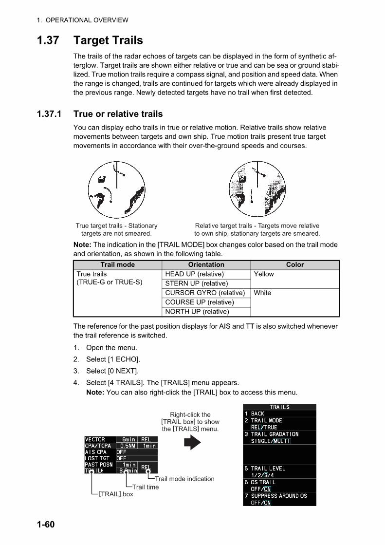
1. OPERATIONAL OVERVIEW
1.37 Target TrailsThe trails of the radar echoes of targets can be displayed in the form of synthetic af-terglow. Target trails are shown either relative or true and can be sea or ground stabi-lized. True motion trails require a compass signal, and position and speed data. When the range is changed, trails are continued for targets which were already displayed in the previous range. Newly detected targets have no trail when first detected.
1.37.1 True or relative trails
You can display echo trails in true or relative motion. Relative trails show relative movements between targets and own ship. True motion trails present true target movements in accordance with their over-the-ground speeds and courses.
Note: The indication in the [TRAIL MODE] box changes color based on the trail mode and orientation, as shown in the following table.
The reference for the past position displays for AIS and TT is also switched whenever the trail reference is switched.
1. Open the menu.
2. Select [1 ECHO].
3. Select [0 NEXT].
4. Select [4 TRAILS]. The [TRAILS] menu appears.Note: You can also right-click the [TRAIL] box to access this menu.
Trail mode Orientation ColorTrue trails (TRUE-G or TRUE-S)
HEAD UP (relative) YellowSTERN UP (relative)CURSOR GYRO (relative) WhiteCOURSE UP (relative)NORTH UP (relative)
True target trails - Stationary targets are not smeared.
Relative target trails - Targets move relative to own ship, stationary targets are smeared.
[TRAIL] boxTrail time
Trail mode indication
Right-click the [TRAIL box] to show the [TRAILS] menu.
1-60

1. OPERATIONAL OVERVIEW
5. Select [2 TRAIL MODE].
6. Select the appropriate trail mode.
• [REL]: Relative target trails. Targets move relative to own ship and stationary targets appear smeared.
• [TRUE]: True target trails. Targets true movements are shown, stationary tar-gets are not smeared.
7. Close the menu.
You can also click the trail mode indication to toggle between relative and true trails.
1.37.2 Trail time
Trail time is the interval at which the trail is plotted on-screen. You can change the trail time as follows:
Using the control unit (RCU-014)
Press the CANCEL TRAILS key to cycle through and select the desired setting.
The options, in cyclic order, are:[OFF] [15 sec] [30 sec] [1 min] [3 min] [6min] [15 min] [30 min] [CONT] [OFF]...
For B/W-types, the available options depend on the setting for [TRAIL LENGTH] in the [TRAILS] section of the [ECHO] menu.
Using the on-screen box
1. Place the cursor on the trail time setting inside the [TRAIL] box, at the bottom-right of the screen.
2. Left-click the [TRAIL] box to change the trail time. The options, in cyclic order, are: [OFF] [15 sec] [30 sec] [1 min] [3 min] [6min] [15 min] [30 min] [CONT] [OFF]...
For B/W-types, the available options depend on the setting for [TRAIL LENGTH] in the [TRAILS] section of the [ECHO] menu.
Spin the scrollwheel to change the trail time. The options for each [TRAIL LENGTH] setting are listed the following table.
[TRAIL LENGTH] setting
Available options
[NORMAL] [OFF], [15 sec], [30 sec], [1 min], [3 min], [6 min], [15 min], [30 min], [CONT].
[12H] [OFF], [30 min], [1 hr], [3 hr], [6 hr], [12 hr], [CONT].[24H] [OFF], [1 hr], [2 hr], [3 hr], [6 hr], [12 hr], [18 hr], [24 h], [CONT].[48H] [OFF], [2 hr], [4 hr], [8 hr], [16 hr], [24 hr], [36 hr], [48 h], [CONT].
00:00Trail time
Trail mode and stabilization.Displayed as: “TRUE-S”, “TRUE-G” or “REL”.S: Sea stablized, G: Ground stabilized, REL: Relative
Trail time setting
1-61

1. OPERATIONAL OVERVIEW
Note 1: The timer displays the elapsed time of the selected trail. Use caution when using this feature, as the displayed time is not the overall trail time. Also, when the trail timer is displayed, the trail accuracy of other ship’s echoes may be lowered. When the trail time reaches the preset interval, the timer disappears.
Note 2: The [CONT] option sets the trail time plotting as continuous. When the plotting time reaches 29:59, the timer is hidden. The timer reappears when [TRAIL ALL CLEAR] is selected, or when the range is changed.
1.37.3 Trail gradation
The trail afterglow can be displayed in a single tone or with gradual shading.
1. Open the menu.
2. Select [1 ECHO].
3. Select [0 NEXT].
4. Select [4 TRAILS]. The [TRAILS] menu appears.Note: You can also right-click the [TRAIL] box to access this menu.
5. Select [3 TRAIL GRADATION].
6. Select [SINGLE] or [MULTI] (Multiple) as appropriate.
7. Close the menu.
1.37.4 Trail level
The level, or intensity, of the afterglow that extends from radar targets can be selected as below.
1. Open the menu.
2. Select [1 ECHO].
3. Select [0 NEXT].
4. Select [4 TRAILS]. The [TRAILS] menu appears.Note: You can also right-click the [TRAIL] box to access this menu.
5. Select [5 TRAIL LEVEL].
6. Select the appropriate setting. The higher the number, the greater the intensity of the afterglow.
7. Close the menu.
[TRAIL LENGTH] setting
Available options
[NORMAL] [OFF], [15 sec], [30 sec], [1 min] to [30 min] at 30-seconds inter-vals, [CONT].
[12H] [OFF], [00:30] to [12:00] at 30 minute intervals, [CONT].[24H] [OFF], [00:30] to [24:00] at one hour intervals, [CONT].[48H] [OFF], [00:30] to [48:00] at two hour intervals, [CONT].
Multiple(Gradual shading)
Single(Monotone shading)
1-62

1. OPERATIONAL OVERVIEW
1.37.5 Narrow trails (B/W-type only)
Target trails can be painted with thinner lines if desired. This csection 1.37.2an be useful when there are a lot of targets on the screen and it is hard to distinguish one from another.
1. Open the menu.
2. Select [1 ECHO].
3. Select [0 NEXT].
4. Select [4 TRAILS]. The [TRAILS] menu appears.Note: You can also right-click the [TRAIL] box to access this menu.
5. Select [8 NARROW TRAIL].
6. Select the appropriate setting from [OFF], [1] or [2], then press the ENTER MARK key. A trail with a setting of [2] is thinner than a trail with a setting of [1].
7. Close the menu.
1.37.6 How to hide the trails temporarily
Following the procedure outlined in section 1.37.2, set the trail time to [OFF]. The trails are hidden from view, but are continued. To show the trails again, repeat the proce-dure, setting the trail time to any interval other than [OFF].
1.37.7 Trail stabilization in true motion
True motion trails can be ground stabilized or sea stabilized. The [TRAIL] box shows current stabilization as "TRUE-G" or "TRUE-S". You can change the stabilization mode with the following procedure.
1. Open the menu.
2. Select [7 INFORMATION BOX].
3. Select [2 OWN SHIP INFO].
4. Select [3 SPEED]. The [SPEED] menu appears.Note: You can also right-click the [SPD ] indication to access this menu.
5. Select [2 SHIP SPEED].
6. Select [LOG(BT)] (ground stabilization) or [LOG(WT)] (sea stabilization) as re-quired.
7. Close the menu.
Note: The stabilization mode is applied to own ship speed and TT trails.
1.37.8 How to erase/restart trails
All trails can be erased (including those in the memory) and restarted to start fresh trails. There are three methods you can use to erase trails.
To erase all trails displayed in the operational display area:
• Select the [TRAIL] box, then press and hold the left button on the trackball; or
• Press and hold CANCEL TRAILS key.
1-63

1. OPERATIONAL OVERVIEW
To erase a section of a trail (B/W-types only):
1. Place the cursor inside the operational display area, then right-click to show the [CURSOR] menu.
2. Select [TRAIL ERASER]. The cursor is now displayed with a red surround and a dashed circle, indicating that [TRAIL ERASER] mode is active.
3. Press the left button to change the diameter of the dashed circle, as shown in the figure below.
4. Place the cursor on the trail whose section you want to erase, then press and hold the left button.
5. With the left button pressed, drag the cursor over the section of the trail you want to erase. The section of trail “covered” by the dashed circle is erased.
6. Release the left button.
7. Right-click to deactivate the [TRAIL ERASER] function. The cursor is no longer highlighted and the dashed circle disappears.
1.37.9 How to prevent sea clutter in true trails
You can prevent the display of sea clutter in true trails about your ship to clear the ra-dar picture. Your ship's trails can also be shown or hidden.
1. Open the menu.
2. Select [1 ECHO].
3. Select [0 NEXT].
4. Select [4 TRAILS]. The [TRAILS] menu appears.Note: You can also right-click the [TRAIL] box to access this menu.
5. Select [7 SUPPRESS AROUND OS].
6. Select [OFF] or [ON] as appropriate.Note: When [6 OS TRAIL] is set to [ON], [7 SUPPRESS TRAILS] is automatically fixed at [ON]. To disable the sea clutter suppression feature, change [6 OS TRAIL] to [OFF], then change the setting for [7 SUPPRESS TRAILS].
7. Close the menu.
1-64
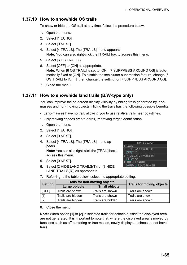
1. OPERATIONAL OVERVIEW
1.37.10 How to show/hide OS trails
To show or hide the OS trail at any time, follow the procedure below.
1. Open the menu.
2. Select [1 ECHO].
3. Select [0 NEXT].
4. Select [4 TRAILS]. The [TRAILS] menu appears.Note: You can also right-click the [TRAIL] box to access this menu.
5. Select [6 OS TRAIL].S
6. Select [OFF] or [ON] as appropriate.Note: When [6 OS TRAIL] is set to [ON], [7 SUPPRESS AROUND OS] is auto-matically fixed at [ON]. To disable the sea clutter suppression feature, change [6 OS TRAIL] to [OFF], then change the setting for [7 SUPPRESS AROUND OS].
7. Close the menu.
1.37.11 How to show/hide land trails (B/W-type only)
You can improve the on-screen display visibility by hiding trails generated by land-masses and non-moving objects. Hiding the trails has the following possible benefits:
• Land-masses have no trail, allowing you to use relative trails near coastlines.
• Only moving echoes create a trail, improving target identification.
1. Open the menu.
2. Select [1 ECHO].
3. Select [0 NEXT].
4. Select [4 TRAILS]. The [TRAILS] menu ap-pears.Note: You can also right-click the [TRAIL] box to access this menu.
5. Select [0 NEXT].
6. Select [2 HIDE LAND TRAILS(T)] or [3 HIDE LAND TRAILS(R)] as appropriate.
7. Referring to the table below, select the appropriate setting.
8. Close the menu.
Note: When option [1] or [2] is selected trails for echoes outside the displayed area are not generated. It is important to note that, where the displayed area is moved by functions such as off-centering or true motion, newly displayed echoes do not have trails.
SettingTrails for non-moving objects
Trails for moving objectsLarge objects Small objects
[OFF] Trails are shown Trails are shown Trails are shown[1] Trails are hidden Trails are shown Trails are shown[2] Trails are hidden Trails are hidden Trails are shown
1-65

1. OPERATIONAL OVERVIEW
1.37.12 How to set the trail length (B/W-type only)
You can save up to 48 hours of trails. the [TRAIL LENGTH] can be set to one of the following lengths: [NORMAL], [12H], [24H] or [48H]. To set the trail length, follow the procedure below.
1. Open the menu.
2. Select [1 ECHO].
3. Select [0 NEXT].
4. Select [4 TRAILS]. The [TRAILS] menu appears.Note: You can also right-click the [TRAIL] box to access this menu.
5. Select [0 NEXT] to show the second page of the menu.
6. Select [4 TRAIL LENGTH].
7. Select the desired length.[NORMAL]: Trails are displayed in a single, continuous line with a single color.[12H], [24H] or [48H]: Trails appear in segments. The interval for each segment change depends on your selection, as shown below.
Note: When a length other than [NORMAL] is selected, set [3 TRAIL GRADA-TION] to [SINGLE]. If you select [MULTI], the interval between each colored seg-ment may be difficult to see clearly.
8. Close the menu.
1.37.13 How to set the trail color (B/W-type only)
The setting for trail coloration depends on the setting for [3 TRAIL GRADATION] and [4 TRAIL LENGTH], as shown in the following table.
When [TRAIL LENGTH] is set to [NORMAL]
You can assign one of six colors when [4 TRAIL LENGTH] is set to [NORMAL].
1. Open the menu.
2. Select [1 ECHO].
3. Select [0 NEXT].
4. Select [4 TRAILS]. The [TRAILS] menu appears.Note: You can also right-click the [TRAIL] box to access this menu.
5. Select [4 TRAIL COLOR].
6. Select the required color. The available colors are: [GRN] (green), [BLU] (blue), [CYA] (cyan), [MAG] (magenta), [WHT] (white) and [YEL] (yellow).
7. Close the menu.
• 12H: One hour intervals.• 24H: Two hour intervals.• 48H: Four hour intervals.
Length Gradation Setting locationNORMAL SINGLE [MAIN] [2 ECHO] [0 NEXT] [4 TRAILS]
[4 TRAIL COLOR]MULTI[12H], [24H], [48H] MULTI
SINGLE [MAIN] [2 ECHO] [0 NEXT] [4 TRAILS] [0 NEXT] [6 LONG TRAIL COLOR]
1-66

1. OPERATIONAL OVERVIEW
When [TRAIL LENGTH] is set to other than [NORMAL]
When [4 TRAIL LENGTH] is set to [12H], [24H] or [48H], you can select the color for each trail segment.
1. Open the menu.
2. Select [1 ECHO].
3. Select [0 NEXT].
4. Select [4 TRAILS]. The [TRAILS] menu appears.Note: You can also right-click the [TRAIL] box to ac-cess this menu.
5. Select [0 NEXT] to show the second page of the menu.
6. Select [6 LONG TRAIL COLOR]. The [LONG TRAIL COLOR MENU] appears (see figure to the right).
7. Select [3 LONG TRAIL COLORS].
8. Set the colors as desired.Left-click to move the cursor through the colors, spin the scrollwheel to change the highlighted color. The menu shows 12 colors, num-bered accordingly from [1] to [12]. The first segment of the trails is assigned the color for number [1].
9. Close the menu.
1.37.14 How to remove the colors from a section of a multicolor trail (B/W-type only)
You can remove the color(s) from a section of a multicolor trail, leaving the selected section as a gray trail. To remove the color(s), follow the procedure below.
Note: This function is only available when [4 TRAIL LENGTH] is set to other than [NORMAL].
1. Open the menu.
2. Select [1 ECHO].
3. Select [0 NEXT].
4. Select [4 TRAILS]. The [TRAILS] menu appears.Note: You can also right-click the [TRAIL] box to access this menu.
5. Select [0 NEXT] to show the second page of the menu.
6. Select [5 TRAIL GRAY-OUT TIME].
7. Select the start and end times for the period you want to gray-out.
8. Close the menu.
To disable the color removal, set the start and end to [00:00] at step 7 of the above procedure.
1-67
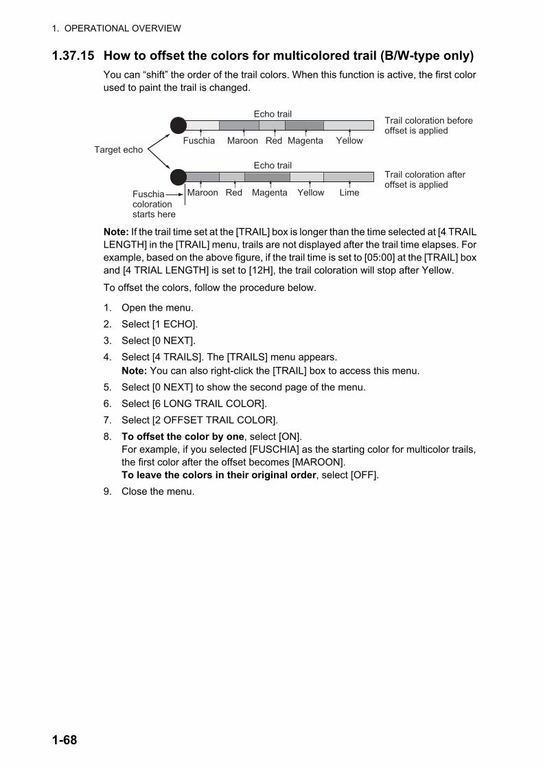
1. OPERATIONAL OVERVIEW
1.37.15 How to offset the colors for multicolored trail (B/W-type only)
You can “shift” the order of the trail colors. When this function is active, the first color used to paint the trail is changed.
Note: If the trail time set at the [TRAIL] box is longer than the time selected at [4 TRAIL LENGTH] in the [TRAIL] menu, trails are not displayed after the trail time elapses. For example, based on the above figure, if the trail time is set to [05:00] at the [TRAIL] box and [4 TRIAL LENGTH] is set to [12H], the trail coloration will stop after Yellow.
To offset the colors, follow the procedure below.
1. Open the menu.
2. Select [1 ECHO].
3. Select [0 NEXT].
4. Select [4 TRAILS]. The [TRAILS] menu appears.Note: You can also right-click the [TRAIL] box to access this menu.
5. Select [0 NEXT] to show the second page of the menu.
6. Select [6 LONG TRAIL COLOR].
7. Select [2 OFFSET TRAIL COLOR].
8. To offset the color by one, select [ON].For example, if you selected [FUSCHIA] as the starting color for multicolor trails, the first color after the offset becomes [MAROON].To leave the colors in their original order, select [OFF].
9. Close the menu.
Target echo
Fuschia coloration starts here
Fuschia Maroon Red Magenta Yellow
Maroon Red Magenta Yellow Lime
Echo trail
Echo trail
Trail coloration before offset is applied
Trail coloration after offset is applied
1-68

1. OPERATIONAL OVERVIEW
1.38 Target Analyzer (B/W-type only)The target analyzer function analyzes echoes and assists the operator to determine dangerous targets. This function is particularly useful under heavy rain/snow or where there is surface reflection, which can cause interference and noise.
The target analyzer function can also place hatching over heavy rain areas, reducing the visible interference and allowing a clearer view of potential targets.
Echoes are displayed in five different colors to assist the operator in identifying tar-gets. The colors and their respective echoes change depending on the echo color se-lected from the [BRILL] menu (see section 1.45) are shown in the table below.
The following example figures show the manner in which this function affects dis-played echoes.
EchoSelected echo color
YEL GRN WHT AMB M-GRN M-CYASurface reflection Green Green Green Green Green GreenRain Gray Gray Gray Gray Gray GrayMoving target Red Red Red Red Pink PinkApproaching target Pink Pink Pink Pink White WhiteOther echoes Yellow Green White Amber Red to green Red to blue
No echo adjustment (Target analyzer off, EAV off, hatching off)Rain, moving targets and surface reflections are all displayed with no filtering.
Minimal echo adjustment (Target analyzer on, EAV off, hatching off)Echoes are colored, surface reflections are filtered, rain is displayed.
Maximum echo adjustment (Target analyzer on, EAV on, hatching on)Echoes are colored, surface reflections are filtered, rain is displayed in gray colored hatching.
Moderate echo adjustment (Target analyzer on, EAV on, hatching off)Echoes are colored, surface reflections and rain are filtered.
1-69

1. OPERATIONAL OVERVIEW
Note 1: This function works best when the settings for [GAIN], [STC], [RAIN], [NOISE REJECT] and [VIDEO CONTRAST] are properly adjusted (surface reflections are dis-played in green and rain is displayed in gray).
Note 2: This function recognizes moving targets as approaching targets. Buoys and other stationary objects are not recognized as approaching targets by this function.
Note 3: The target analyzer function requires a short period of time to analyze echoes and display them on-screen. If your antenna revolves at more than 40 rpm, moving targets may not be displayed correctly. For this reason, caution is advised when using the target analyzer function.
Note 4: The target analyzer function’s performance may be affected by factors such as target size, weather and sea conditions, physical equipment configuration, offset settings and other factors.
What is “hatching”?
Where echo averaging may hide light rain on the display, the hatching feature, when activated, places a gray “veil” over the areas where rain is detected. This allows the operator to see where the rain is without affecting the quality of the displayed echoes.
1.38.1 How to activate/deactivate the target analyzer
1. Open the menu.
2. Select [1 ECHO].
3. Select [2 CUSTOMIZED ECHO].Note: You can also right-click the [PICTURE] box to access this menu.
4. Select [5 TARGET ANALYZER].
5. Select [OFF] to deactivate the function, or [ON] to activate the function.
6. Select [6 RAIN ECHO HATCHING].
7. Select [OFF] to deactivate the function, or [ON] to activate the function.
8. Close the menu.
1-70

1. OPERATIONAL OVERVIEW
1.39 Target AlarmThe target alarm serves to alert the navigator to targets (ships, landmasses, etc.) en-tering a specific area, with audiovisual alerts.
The operator can set the alarm zones at any location, with any size, however, the zones must be inside the operational display area.
Note: The target alarm boxes are not displayed when the setting for [AZ/ALR SELECT] in the [TT•AIS] menu is set to the default setting [AQUISITION ZONE]. To enable this function, set [AZ/ALR SELECT] in the [TT•AIS] menu to [TARGET ALARM ZONE].
1.39.1 How to set a target alarm
The procedure below shows how to set a target alarm using the figure below as an example. The alarm boxes are labeled [1:] and [2:], and are located at the bottom-right of the screen, near the VRM boxes.
1. Select the appropriate alarm box, then left-click. The cursor jumps into the opera-tional display area and the indication "SET" appears inside the target alarm box selected.
2. Using the trackball, move the cursor to Point A, then left-click.
3. Using the trackball, move the cursor to Point B, then left-click.The indication “SET” is replaced with “WORK” in the box. The target alarm zone’s lines are shown as dashed lines.
Note 1: To create a 360° alarm zone, set Point B at the same location as Point A.
Note 2: Two alarm zones can be set simultaneously. The second alarm zone is only available when the first alarm zone is active, however.
Note 3: When the target alarm zone is not within the range in use the indication "UP RNG" appears to the right of the target alarm box. In this case select a range that will display the target alarm zone.
CAUTIONCAUTIONThe alarm should not be relied upon as the sole means for detecting possible collision situations.
A/C SEA, A/C RAIN and GAIN controls should be properly adjusted to be sure the alarm system does not overlook target echoes.
Click the Alarm Zone you want to set.
The indication changes to “SET”.
TGT ALRTT / AIS1:2:
TGT ALRTT / AIS1:SET2:
XX
X
X
000 010 020030
040
050
060
070
080
090
100
110
120
130
140150
160170180190200210
220
230
240
250
260
270
280290
300
310
320330
340 350
A BTarget alarm zone
Other alarm zone examples
Point A
Point A
Point B
Point B
1-71

1. OPERATIONAL OVERVIEW
1.39.2 How to mute the target alarm
A target in the target alarm zone produces both visual (flashing) and audible (beep) alarms. To silence the audio alarm select the appropriate target alarm box then left-click. The target alarm box indication shows "MUTE". This will deactivate the audio alarm but will not stop the flashing of the offending target. You can also stop the alarm by deactivating the target alarm zone (see section 1.39.3).
To reactivate the audio alarm, select the target alarm box then left-click to show "WORK" in the box.
1.39.3 How to deactivate a target alarm
Select the target box to be deactivated, then press and hold the left button on the Control Unit.
Note: When both alarm zones are active, the second ([2:]) alarm zone must be deac-tivated before the first ([1:]) can be deactivated.If both zones are active when you try to deactivate zone [1:], the system releases two audible beeps and shows the message "DELETE ALR2 FIRST".
1.39.4 How to change target alarm attributes
You can select the echo strength level that triggers the alarm, the condition that gen-erates the alarm and the volume of the audio alarm as follows:
1. Open the menu.
2. Select [4 ALERTS].
3. Select [6 TARGET ALARM].
4. Select [2 ALR1 MODE] or [3 ALR2 MODE] as appropriate.
5. Select [IN] or [OUT] as appropriate.[IN]: Targets entering the alarm zone trigger the alarm.[OUT]: Targets leaving the alarm zone trigger the alarm.
6. Select [4 LEVEL].
7. Select the appropriate level of echo strength to trigger the alarm. [1]: weak echoes can trigger the alarm, [4]: only strong echoes trigger the alarm.
8. Select [1 BACK] to return to the [ALERT] menu.
9. Select [3 ALERT VOLUME].
10. Select [OFF], [LOW], [MID] or [HIGH] as appropriate.Note 1: This setting is applied to all alarms output from this radar system.
Note 2: The [OFF] options is not shown for IMO/R-type radars.
11. Close the menu.
1-72

1. OPERATIONAL OVERVIEW
1.40 PI (Parallel Index) LinesPI lines are useful for keeping a constant distance be-tween own ship and a coastline or a partner ship when navigating.
You can control the presentation and interval of the PI lines from the [PI Line] box, which is at the lower-left corner of the screen.
[PI Line] box
1.40.1 How to show/hide the PI lines
You can show or hide the PI lines as required with the following procedure.
1. Place the cursor on the PI line number or PI line status in the PI line box.
2. Spin the scrollwheel to select the PI line (PI1 to PI6) you want to show or hide.Note 1: For IMO/A/B/R-types, PI5 and PI6 are only available when [SET MAXI-MUM PI LINES] is set to [1].
Note 2: For W-types, PI5 and PI6 are not available.
3. Left-click to toggle between [ON] (PI line is shown) or [OFF] (PI line is hidden).
1.40.2 How to set the maximum number of lines to display
The maximum number of PI lines available to display depends on your radar type. Fur-ther, the actual number of lines visible can be less depending on line interval.
IMO/A/B/R-types
1. Open the menu.
2. Select [3 NAV TOOLS].
3. Select [2 PI LINES]. The [PI LINES] menu ap-pears.
4. Select [3 SET MAXIMUM PI LINES].Up to six sets of PI lines are available depending on the maximum number of PI lines selected on the menu.
• [1]: Six sets of PI lines (PI1 to PI6) are avail-able.
• [2], [3] or [6]: Four sets of PI lines (PI1 to PI4).
5. Select the appropriate option.
6. Close the menu.
PI lines
PI line number
PI line interval
PI line status
PI line bearing and reference
1-73

1. OPERATIONAL OVERVIEW
W-types
1. Open the menu.
2. Select [3 NAV TOOLS].
3. Select [2 PI LINES]. The [PI LINES] menu ap-pears.
4. Select [2 SET MAXIMUM PI 1•3 LINES] or [3 SET MAXIMUM PI 2•4 LINES] as required.Up to four sets of PI lines are available depend-ing on the maximum number of PI lines selected on the menu.
• [1]: Not available for W-types.
• [2], [3] or [6]: Four sets of PI lines (PI1 to PI4).
5. Select the appropriate option.
6. Close the menu.
1.40.3 How to change PI line bearing and interval
1. If not already displayed, show a PI line, referring to section 1.40.1.
2. Place the arrow on the PI line bearing and reference indication in the [PI Line] box.
3. Spin the scrollwheel to adjust the PI line bearing, between 000.0° to 359.9°.
4. Place the cursor on the PI line interval.
5. Spin the scrollwheel to adjust the PI line interval.A negative interval value moves to the PI line to one side of the line which inter-sects the own ship position. A positive interval value moves the line to the other side of the own ship position.
1.40.4 How to change the PI line bearing reference (B/W-type only)
IMO/A/R-type radars’ PI line bearing reference is fixed to North (True). For B/W-type radars however, PI line bearing reference can be relative to own ship’s heading (Rel-ative) or referenced to North (True) as below.
B-types
1. Open the menu.
2. Select [3 NAV TOOLS].
3. Select [2 PI LINES].
4. Select [2 PI LINE BEARING].
5. Select [REL] or [TRUE] as appropriate.
6. Close the menu.
W-types
Place the cursor on the PI line bearing and reference indication at the bottom-left of the screen, then right-click to toggle between [T] (True) and [R] (Relative).
1-74
1. OPERATIONAL OVERVIEW
1.40.5 How to change the PI line orientation
PI lines orientation can be selected from parallel or perpendicular.
Note: This function is only available when [SET MAXIMUM PI LINES] is set for other than [1].
1. Open the menu.
2. Select [3 NAV TOOLS].
3. Select [2 PI LINES].
4. Select [4 PI LINE MODE].
5. Select [PARALLEL] or [PERPENDIC] as appropriate.
6. Close the menu.
1.40.6 How to reset the PI lines to default (ship’s heading)
You can automatically return PI lines to default orientation (ship’s heading), 0-degrees for parallel orientation, 90-degrees for perpendicular orientation. This is faster than do-ing it manually.
From the PI line box
Place the cursor on the PI line number box indication, then press and hold the left but-ton.
From the menu
1. Open the menu.
2. Select [3 NAV TOOLS].
3. Select [2 PI LINES].
4. Select [5 RESET PI LINES]. The PI lines are reset.
5. Close the menu.
1.40.7 How to change PI line length (IMO/A/B/R-types only)
You can change the length of the PI lines. This function is only available when [SET MAXIMUM PI LINES] is set to [1]. If not already displayed, you can show PI lines for which you wish to change the length by referring to section 1.40.2.
1. Open the menu.
2. Select [3 NAV TOOLS].
3. Select [2 PI LINES].
4. Select [6 TRUNC RANGE 1].
5. Select [ON].
6. Spin the scrollwheel to adjust the front PI line length. The available range is 0.000 NM to 24.000 NM. All PI lines beyond this mark will be hidden.
7. Left-click to confirm the setting.
8. Select [7 TRUNC RANGE 2].
9. Select [ON].
1-75

1. OPERATIONAL OVERVIEW
10. Spin the scrollwheel to adjust the front PI line length. The available range is 0.000 NM to 24.000 NM. All PI lines beyond this mark will be hidden.
11. To change the length of other PI lines, activate the line you wish to adjust, then repeat steps 1 through 10.
12. Close the menu.
1.41 How to Use the Net (Diamond) Cursor (B/W-type only)The net cursor is used to depict your fishing net on the ra-dar display.
It is especially useful for bottom trawlers for knowing where the net is located. Enter the dimensions of your net in the menu to show the net in scale on the display.
1.41.1 How to activate the net cursor
To activate the net cursor, do the following procedure.
1) Open the menu.2) Select [3 NAV TOOLS].3) Select [3 EBL•VRM•CURSOR SET].4) Select [0 NEXT] to show the second page of the
menu.5) Select [NET CURSOR].6) Select [NET CURSOR DISPLAY].7) Select [ON] to activate, or [OFF] to deactivate the
net cursor.8) Close the menu.
Heading line PI line
TRUNC RANGE 1 length settingTRUNC RANGE 1 length setting
TRUNC RANGE 2 length settingTRUNC RANGE 2 length setting
OS location
EBL2
Net cursor(Dimond cursor)Net cursor(Dimond cursor)
1-76
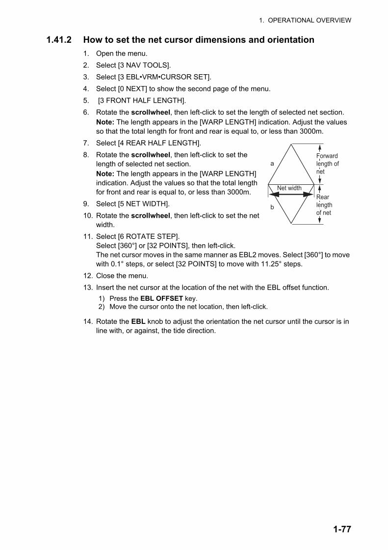
1. OPERATIONAL OVERVIEW
1.41.2 How to set the net cursor dimensions and orientation
1. Open the menu.
2. Select [3 NAV TOOLS].
3. Select [3 EBL•VRM•CURSOR SET].
4. Select [0 NEXT] to show the second page of the menu.
5. [3 FRONT HALF LENGTH].
6. Rotate the scrollwheel, then left-click to set the length of selected net section.Note: The length appears in the [WARP LENGTH] indication. Adjust the values so that the total length for front and rear is equal to, or less than 3000m.
7. Select [4 REAR HALF LENGTH].
8. Rotate the scrollwheel, then left-click to set the length of selected net section.Note: The length appears in the [WARP LENGTH] indication. Adjust the values so that the total length for front and rear is equal to, or less than 3000m.
9. Select [5 NET WIDTH].
10. Rotate the scrollwheel, then left-click to set the net width.
11. Select [6 ROTATE STEP].Select [360°] or [32 POINTS], then left-click.The net cursor moves in the same manner as EBL2 moves. Select [360°] to move with 0.1° steps, or select [32 POINTS] to move with 11.25° steps.
12. Close the menu.
13. Insert the net cursor at the location of the net with the EBL offset function.
14. Rotate the EBL knob to adjust the orientation the net cursor until the cursor is in line with, or against, the tide direction.
1) Press the EBL OFFSET key.2) Move the cursor onto the net location, then left-click.
Net width
a
b
Forward length of net
Forward length of net
Rear length of net
Rear length of net
1-77

1. OPERATIONAL OVERVIEW
1.42 ZoomThe zoom function enlarges an area of interest as large as twice the normal viewing size, in the [INFORMATION BOX]. Zoom can be selected using the control unit or from a preset function key (see section 1.9 for how to assign functions to the function keys).
Zoom is not available when the [INFORMATION BOX] setting for [TARGET DATA] is [LARGE].
To enable/disable the zoom magnification, select the appropriate zoom setting ([2TIMES]: Enables magnification at 2, or [3TIMES]: Enables magnification at 3) from the [ZOOM] option in the [INFORMATION BOX] menu. (See section 1.47.)
1. Select the operational display area, then right-click to show the [CURSOR] con-text menu.
2. Select [ZOOM].
3. Place the cursor inside the operational display area, then left-click. The cursor is now displayed with a zoom box.
4. Place the cursor and zoom box at the location you wish to zoom, then left-click to anchor the box.If the zoom box is not placed where you intended to place it, left-click twice, then move the box to the correct place. Left-click to anchor the box.
5. Right-click to complete the procedure. The selected area is displayed on the right-side of the screen and the cursor returns to normal shape.
To disable the zoom function, repeat steps 1 to 3. At step 3, the zoom box is removed from the display.
Note: Where the zoom function is assigned to a function key, press the function key to cycle through the zoom settings in the following order: [OFF] [2TIMES] (2 mag-nification) [3TIMES] (3 magnification) [OFF]...This operation works in direct relation with the settings selected from the [ZOOM] op-tion in the [INFORMATION BOX] menu. To use the zoom function on a different area, do the procedure (step 1 to step 5) listed above.
Cursor with zoom box
Zoom box is placed at the location to be zoomed and the cursor returns to its normal shape.
1-78

1. OPERATIONAL OVERVIEW
1.43 How to Use Marks
1.43.1 Heading line mark
The heading line is a line from the own ship position to the outer edge of the radar dis-play area and appears at zero degrees on the bearing scale in HEAD UP mode. The orientation of the line changes depending on the ship orientation in NORTH UP and True Motion modes.
How to hide the heading line temporarily
To temporarily extinguish the heading line to look at targets existing dead ahead of own ship, press and hold the HL OFF key, or place the cursor on the [HL OFF] box in
the InstantAccess bar™ then left-click and hold.
In addition to the heading line, the stern marker and all graphics within the operational display area are also erased. To redisplay the heading line, etc., release the key or the left button.
1.43.2 How to hide/show the stern mark
The stern marker, which is a dotted line, appears opposite to the heading line.
To display or erase this marker do the following:
1. Open the menu.
2. Select [2 MARKS].For A/B/W-types with Radar Plotter functionality, select [2 MARKS•CHART].
3. Select [3 STERN MARK].
4. Select [ON] or [OFF] as appropriate.
5. Close the menu.
Heading line
Stern line
1-79

1. OPERATIONAL OVERVIEW
1.43.3 North mark
The north mark is displayed as a short dotted line on the in-side edge of the operational display area. In HEAD UP mode, the north mark moves according to the own ship bearing.
The north mark is hidden when the radar is in standby mode.
1.43.4 How to set up the own ship symbol
The own ship symbol marks own position on the display. It can be turned on or off and its configuration selected from the [MARK] menu. Two configurations are available: minimized symbol and scaled symbol. If the largest dimension of the symbol gets smaller than 6 mm, the scaled symbol will disappear and the own ship mark will be shown as a minimized symbol. The scaled symbol is scaled to indicate the length and beam of the vessel. Ship’s dimensions should be entered at installation to use the scaled ship symbol.
1. Open the menu.
2. Select [2 MARKS].For A/B/W-types with Radar Plotter functionality, select [2 MARKS•CHART].
3. Select [2 OWN SHIP MARK].
4. Select [MINIMIZED] or [SCALED] as appropriate.
5. Close the menu.
1.43.5 How to set the barge marker
You can mark the locations of barges on the display with icons.
Note: This function is not available if [ECDIS] is set to [SERIAL] or [LAN] at installa-tion. Consult your dealer for details.
Set up barge information as follows:
1. Open the menu.
2. Select [2 MARKS].For A/B/W-types with Radar Plotter functionality, select [2 MARKS•CHART].
3. Select [6 BARGE MARK].
4. Select [2 BARGE MARK DISPLAY].
5. Select [ON] to display barge marks, [OFF] to hide barge marks, as appropriate.
6. Select [3 BARGE SIZE]. Spin the scrollwheel, then left-click to enter the [LENGTH] and [WIDTH] of the barge.
North mark
Scaled symbol Minimized symbol
Heading line
Beam line
XAntennaposition
Heading line
Beam line
1-80
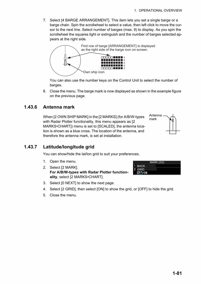
1. OPERATIONAL OVERVIEW
7. Select [4 BARGE ARRANGEMENT]. This item lets you set a single barge or a barge chain. Spin the scrollwheel to select a value, then left click to move the cur-sor to the next line. Select number of barges (max. 9) to display. As you spin the scrollwheel the squares light or extinguish and the number of barges selected ap-pears at the right side.
You can also use the number keys on the Control Unit to select the number of barges.
8. Close the menu. The barge mark is now displayed as shown in the example figure on the previous page.
1.43.6 Antenna mark
When [2 OWN SHIP MARK] in the [2 MARKS] (for A/B/W-types with Radar Plotter functionality, this menu appears as [2 MARKS•CHART]) menu is set to [SCALED], the antenna loca-tion is shown as a blue cross. The location of the antenna, and therefore the antenna mark, is set at installation.
1.43.7 Latitude/longitude grid
You can show/hide the lat/lon grid to suit your preferences.
1. Open the menu.
2. Select [2 MARK].For A/B/W-types with Radar Plotter function-ality, select [2 MARKS•CHART].
3. Select [0 NEXT] to show the next page.
4. Select [2 GRID], then select [ON] to show the grid, or [OFF] to hide the grid.
5. Close the menu.
49994
X
First row of barge [ARRANGEMENT] is displayed as the right side of the barge icon on-screen.
Own ship icon
XAntennamark
MARK (2/2)BACKGRID
1-81

1. OPERATIONAL OVERVIEW
1.44 Drop Mark
The operator can inscribe a drop mark at a selected lo-cation to find the range and bearing from own ship to the mark. This can be useful for marking a point to avoid while navigating to a destination.
1.44.1 How to activate the drop mark
To active the drop mark feature, do the following:
1. Open the menu.
2. Select [2 MARKS].For A/B/W-types with Radar Plotter functionality, this menu appears as [2 MARKS•CHART].
3. Select [4 DROP MARK].
4. Select [ON] to enable [DROP MARK]. Two indications appear at the bottom of the screen.
5. Close the menu.
1.44.2 How to inscribe a drop mark
1. Select a drop mark box, then left-click.
2. Place the cursor at the location to inscribe the drop mark, then left-click.The drop mark box shows the range and bearing to the marked location.
1.44.3 How to erase drop marks
Select the drop mark to be erased, then press and hold the left button. The mark is erased and the range/bearing indications are no longer shown.
Drop mark
Drop mark boxes show the mark number, bearing and range to the mark.
1-82

1. OPERATIONAL OVERVIEW
1.45 Brilliance and Color SchemesBrilliance and color schemes are preset “palettes” that let you change the brilliance and color of on-screen data together.
1.45.1 How to select a brilliance and color scheme
The system has four presets of brilliance and color settings to choose from. Each pre-set is customizable (see section 1.45.3).
The following list shows each preset along with their default settings.
• [PLT1] (default [DAY-GRY]): preset for use in daylight with a gray background.
• [PLT2] (default [DAY-BLU]): preset for use in daylight with a blue background.
• [PLT3] (default [DUSK-BLU]): preset for use at dusk with a blue background.
• [PLT4] (default [NIGHT-GRY]): preset for use at night with a gray background.
To change the current scheme, do the following:
1. Place the cursor on the [PLT] indication, inside the brilliance settings box at the bottom-left of the screen.
2. Spin the scrollwheel to show the scheme you want to use, then left-click.You can also left-click the indication to cycle through the schemes.
1.45.2 How to change the color and brilliance assigned to a palette
1. Referring to section 1.45.1, select the scheme whose settings you want to change.
2. Open the menu.
3. Select [9 INITIAL SETTINGS].
4. Select [2 BRILL]. The [BRILL] menu appears.
Note: You can also access this menu by right-clicking the [PLT] indication, inside the brilliance settings box at the bottom-left of the screen.
PLT1100
Place cursor here, then left-click to change brilliance preset, right-click to open the [BRILL] menu.
1-83
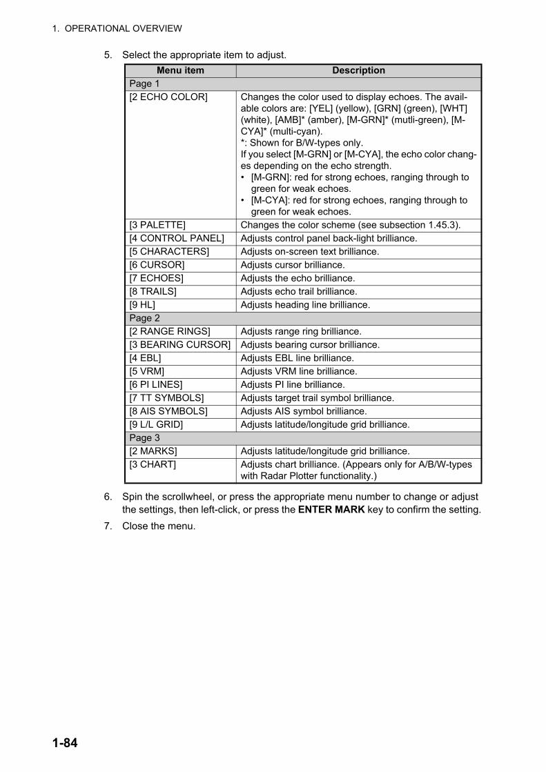
1. OPERATIONAL OVERVIEW
5. Select the appropriate item to adjust.
6. Spin the scrollwheel, or press the appropriate menu number to change or adjust the settings, then left-click, or press the ENTER MARK key to confirm the setting.
7. Close the menu.
Menu item DescriptionPage 1[2 ECHO COLOR] Changes the color used to display echoes. The avail-
able colors are: [YEL] (yellow), [GRN] (green), [WHT] (white), [AMB]* (amber), [M-GRN]* (mutli-green), [M-CYA]* (multi-cyan).*: Shown for B/W-types only.If you select [M-GRN] or [M-CYA], the echo color chang-es depending on the echo strength.• [M-GRN]: red for strong echoes, ranging through to
green for weak echoes.• [M-CYA]: red for strong echoes, ranging through to
green for weak echoes.[3 PALETTE] Changes the color scheme (see subsection 1.45.3).[4 CONTROL PANEL] Adjusts control panel back-light brilliance.[5 CHARACTERS] Adjusts on-screen text brilliance.[6 CURSOR] Adjusts cursor brilliance.[7 ECHOES] Adjusts the echo brilliance.[8 TRAILS] Adjusts echo trail brilliance.[9 HL] Adjusts heading line brilliance.Page 2[2 RANGE RINGS] Adjusts range ring brilliance.[3 BEARING CURSOR] Adjusts bearing cursor brilliance.[4 EBL] Adjusts EBL line brilliance.[5 VRM] Adjusts VRM line brilliance.[6 PI LINES] Adjusts PI line brilliance.[7 TT SYMBOLS] Adjusts target trail symbol brilliance.[8 AIS SYMBOLS] Adjusts AIS symbol brilliance.[9 L/L GRID] Adjusts latitude/longitude grid brilliance.Page 3[2 MARKS] Adjusts latitude/longitude grid brilliance.[3 CHART] Adjusts chart brilliance. (Appears only for A/B/W-types
with Radar Plotter functionality.)
1-84

1. OPERATIONAL OVERVIEW
1.45.3 How to change the color palette
This radar provides eight sets of color and brilliance schemes to match any ambient lighting condition and can be assigned to a [BRILL] box preset.
1. Open the menu.
2. Select [9 INITIAL SETTINGS].
3. Select [2 BRILL]. The [BRILL] menu appears.
4. Select [3 PALETTE].
5. Select the appropriate palette. The default settings for each palette are shown in the following table.
*1: Available for A/B/W-types only
*2: This setting is fixed and cannot be changed.
6. Close the menu.
Display itemPalette
DAY-GRY
DAY-BLU
DAY-GRN
DUSK-GRY
DUSK-BLU
DUSK-GRN
NIGHT-GRY
NIGHT-BLU
Screen brilliance 100 100 100 40 40 40 4 4Panel brilliance 15 15 15 7 7 7 3 3Character brilliance 15 15 15 15 15 15 15 15Cursor brilliance 15 15 15 12 12 12 12 12Echo brilliance 15 15 15 12 12 12 12 12Trail brilliance 15 15 15 8 8 8 8 8Heading Line brilliance
15 15 15 12 12 12 12 12
Range ring brilliance
15 15 15 7 7 7 15 15
Bearing ring brilliance
15 15 15 6 6 6 15 15
EBL brilliance 15 15 15 12 12 12 12 12VRM brilliance 15 15 15 12 12 12 12 12PI Line brilliance 15 15 15 12 12 12 12 12TT symbol brilliance 15 15 15 12 12 12 12 12AIS symbol brilliance
15 15 15 12 12 12 12 12
LL Grid brilliance 15 15 15 12 12 12 12 12Mark brilliance 15 15 15 12 12 12 12 12
Chart brilliance*1 7 7 7 6 6 6 6 6
Character color*2 White White Green White White Green Orange White
Background color*2 Gray/black
Blue/dark blue
Gray/black
Dark gray/dark blue
Dark blue/blue
Dark gray/black
Dark gray/black
Dark blue/blue
ODA color*2 Black Dark blue
Black Dark blue
Blue Black Black Blue
1-85
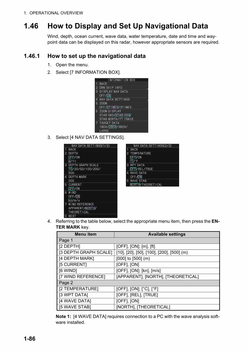
1. OPERATIONAL OVERVIEW
1.46 How to Display and Set Up Navigational DataWind, depth, ocean current, wave data, water temperature, date and time and way-point data can be displayed on this radar, however appropriate sensors are required.
1.46.1 How to set up the navigational data
1. Open the menu.
2. Select [7 INFORMATION BOX].
3. Select [4 NAV DATA SETTINGS].
4. Referring to the table below, select the appropriate menu item, then press the EN-TER MARK key.
Note 1: [4 WAVE DATA] requires connection to a PC with the wave analysis soft-ware installed.
Menu item Available settingsPage 1[2 DEPTH] [OFF], [ON]; [m], [ft][3 DEPTH GRAPH SCALE] [10], [20], [50], [100], [200], [500] (m)[4 DEPTH MARK] [000] to [500] (m)[5 CURRENT] [OFF], [ON][6 WIND] [OFF], [ON]; [kn], [m/s][7 WIND REFERENCE] [APPARENT], [NORTH], [THEORETICAL]Page 2[2 TEMPERATURE] [OFF], [ON]; [°C], [°F][3 WPT DATA] [OFF], [REL], [TRUE][4 WAVE DATA] [OFF], [ON][5 WAVE STAB] [NORTH], [THEORETICAL]
1-86

1. OPERATIONAL OVERVIEW
Note 2: [4 WAVE DATA] can only be active at one radar at any time. If [4 WAVE DATA] is turned [ON] at another radar in the same network, it is automatically turned [OFF] at this radar.
5. Referring to the table above, select the appropriate setting, then press the ENTER MARK key.
6. Close the menu.
Wave data display
You can view wave data when a PC with the wave analysis software installed is con-nected to the same network as this radar. When [4 WAVE DATA] is set to [ON], the wave data appears in the information box in a manner similar to that shown below.
For further details regarding the wave analysis data, see the operator’s manual (OMC-36181) supplied with the wave analysis software.
1.46.2 How to display navigational data
1. Open the menu.
2. Select [7 INFORMATION BOX].
3. Select [3 DISPLAY NAV DATA].
4. Select [ON] to display navigational data, [OFF] to hide navigational data.
5. Close the menu.
Wind/wave directions appear as colored triangle icons around the compass circle. The center of the compass circle show the own ship and current bearing as an icon.Purple color: wind directionCyan color: 1st wave’s directionGreen color: 2nd wave’s direction
Wave information appears here.[HEIGHT]: Wave height[DIR]: Direction from which the wave is approaching.[PERIOD]: Time until the wave meets own ship.
Wind angle and speed appear here
Note: Analysis data which has low integrity or reliability is displayed in yellow text.
Significant wave height appears here.
[5 WAVE STAB] setting appears here.
1-87

1. OPERATIONAL OVERVIEW
1.47 How to Use the Information BoxThe information box shows target data, navigational data and zoomed areas of the ra-dar display. To set up the information box, do the following:
1. Open the menu.
2. Select [7 INFORMATION BOX].
3. Select and set the appropriate menu item, referring to the table below.
4. Close the menu.
Menu item Settings Description[2 OWN SHIP INFO] See section 1.11,
section 1.12 and section 1.13 for details.
Set up various own ship information, such as sensors used for position fix, date and time format/offsets, heading and speed sensors used.
[3 DISPLAY NAV DATA] • [OFF]• [ON]
• Disable navigational data display.• Enable navigational data display.
[4 NAV DATA SETTINGS] See section 1.46 for details.
Set up the format in which various navigational data is displayed in the [INFORMATION BOX].
[5 ZOOM] • [OFF]• [2TIMES]• [3TIMES]
• Disable zoom magnification.• Set zoom magnification at 2.• Set zoom magnification at 3.
[6 ZOOM DISPLAY] • [STAB GND]
• [STAB HDG]• [STAB NORTH]• [TT TRACK]
• Ground stabilized zoom (Geo-graphically fixed).
• Heading stabilized zoom (Rela-tive).
• North stabilized zoom (True).• Tracked targets are zoomed.
[7 TARGET DATA] • [1BOX]• [2BOX]• [3BOX]• [LARGE]
See the figure on the following page.
1-88

1. OPERATIONAL OVERVIEW
1BOX 2BOX 3BOX LARGE
Only TT/AIS Data is displayed in the large box.
Up to three AIS targets or up six
TT targets.For MU-270W configurations, up to two TT
targets can be shown.
Zoom and
navigational data
are displayed here.
Zoom and navigational data
are displayed here.
Zoom can be displayed here, but can be hidden by
TT/AIS data.
• TT/AIS data displayed in the information box is shown in order of acquisition in the bottom half of the box.
• When using the 2BOX or 3BOX setting and the bottom half of the information box is full, the upper half is overlayed with the newly aquired TT/AIS target data.• When the target data is no
longer displayed (TT is cancelled, etc.) in the upper box, the previous display is restored.
• Each box may display up two TT targets or one AIS target. (For MU-270W configurations, up to three TT targets can be shown)
Zoom and navigational data
are displayed here, but can be hidden by TT/AIS data.
Zoom and navigational data
are displayed here, but can be hidden by TT/AIS data.
Zoom and navigational data
are displayed here, but can be hidden by TT/AIS data.
Zoom can be displayed here, but can be hidden by
TT/AIS data.
Zoom can be displayed here, but can be hidden by
TT/AIS data.
Zoom and
navigational data
are displayed here.
Zoom and
navigational data
are displayed here.
1-89

1. OPERATIONAL OVERVIEW
1.48 InterswitchThe interswitch of this radar uses an Ethernet to transfer video and control signals. A digital signal transfers the video and control signals. You can connect up to four an-tennas and four display units. Set radar display and antenna groups from the [ANTEN-NA SELECT] display.
When you switch to a different antenna, the heading skew and timing adjustment (set at installation) for that antenna are automatically applied.
The [ANTENNA] box at the upper left position shows current antenna selection.
1.48.1 How to display antenna information
1. Open the menu.
2. Select [9 INITIAL SETTINGS].
3. Select [3 SELECT ANTENNA]. The [SELECT ANTENNA] menu appears.Note: You can also right-click the [ANTENNA] box to access this menu.
Note: For configurations with processors assigned as [DISP5]/[DISP6]/[DISP7]/[DISP8] at installation, the processor unit automatically connects to the system as [SLAVE] when first turned on. You can change this setting after the first connection. See section 1.48.2.
Antenna boxANTx: “x” indicates antenna selected.(M) or (S): indicates antenna is (M)aster or (S)lave.X-Band or S-Band: indicates antenna bandwidth.
The following information is displayed in the [SELECT ANTENNA] menu:• Radar band, output power and antenna position of each antenna
currently powered. (If an antenna is not powered, its data area is blank.)• Own ship radar number (radar in use).• Current antenna and display combinations.
SELECT ANTENNA1 BACKANT 1 : X-BAND 25UP Main TopANT 2 : S-BAND 30UP Main 2ndANT 3 : X-BAND 12 ForeANT 4 : X-BAND 12 AftOWN RADAR NO.12 DISP1 ANT1 MASTER DISP2 ANT2 MASTER DISP3 ANT3 MASTER DISP4 ANT4 MASTER9 SAVE INTER-SWITCH NO / YES0 CLEAR INTER-SWITCH NO / YES
←
←
Using the information displayed in this example the antenna system configuration would look something like this.
ANT1 ANT2 ANT3 ANT4
Antenna Unit
Processor Unit
HUB-3000
DISP1 DISP2 DISP3 DISP4
1-90
1. OPERATIONAL OVERVIEW
1.48.2 How to preset antenna and display combinations
You can preset the antenna and display combinations for each antenna and display in the radar system. As an example, the procedure below shows how to select the no. 1 antenna unit for the no. 2 display unit.
1. Open the menu.
2. Select [9 INITIAL SETTINGS].
3. Select [3 SELECT ANTENNA]. The [SELECT ANTENNA] menu appears.Note: You can also right-click the [ANTENNA] box to access this menu.
4. Select the display unit for which to select an antenna (at the next step). For the purpose of this example, select [DISP2] to select the no. 2 display unit.The indication for the antenna is highlighted.
5. Spin the scrollwheel to toggle between [MASTER] and [SLAVE]. The MASTER system passes on settings such as [CPA], [TCPA] and alarm settings to SLAVE radars connected to the same network.
6. Repeat steps 2 and 3 to set other display and antenna combinations.
7. Select [SAVE INTER-SWITCH], then select [YES] to save your selections.
8. Close the menu.
Antenna selection considerations
• An antenna unit cannot be controlled from multiple display units. Select one Master display unit for one antenna unit. If two antenna units are set as masters, the display last-set as master becomes the master and all other displays are automatically changed to slave.
• An antenna unit without a Master display cannot be selected on the sub display units. If there is no antenna unit set as master, the lowest number display is auto-matically set as master.
• If the Alert "LOST ISW FUNC" appears, do one of the following, as applicable:- If only your antenna is not displayed on the [ANT SELECT] display, the LAN line in the Processor Unit may be faulty. In this case, use the standalone mode.- If the antenna that was in use does not appear on the [ANT SELECT] display, the LAN line in other Processor Unit may be faulty. In this case, see the preceding page for how to select a different antenna unit
• When the Network fails, the Interswitch does not work, but standalone operation is possible.
• Disable the Dual Radar function from the [RADAR INSTALLATION] menu (see the Installation manual IME-36520) before setting up the Interswitch feature.
• When using a FAR-2xx7 series radar for Interswitch connection, the following set-tings must be done from the FAR-2xx7 [RADAR INSTALLATION] menu.
• When using a FAR-3xx0 series radar for Interswitch connection, the following set-tings must be done from the FAR-3xx0 [RADAR INSTALLATION] menu.
• Set [SCANNER] [DUAL RADAR SETTINGS] [DUAL RADAR] to [OFF].• Set [NETWORK] [LAN1•3 IP ADDRESS] CLASS to [C].
• Set [SCANNER] [OTHERS] [COMBINE FUNC] to [OFF].• Set [NETWORK] [LAN1•3 IP ADDRESS] CLASS to [C].• Set the radar number as [1], [2], [3] or [4].• Disable the [Icing Prevention] feature.
1-91

1. OPERATIONAL OVERVIEW
• Radar functions are controlled independently, dependently or commonly depending on selection as [MASTER] or [SLAVE] (see the following table).
*1: When the connected radar is a FAR-2xx8/FAR-3xx0 series radar, these items can be adjusted from the “Slave” radar.
*2: When the connected radar antenna is a FAR-3xx0/FAR-2xx8 series magnetron-type, and the radar is assigned as “Slave”, the desired value can be set for these func-tions. For FAR-3xx0/FAR-2xx8 series SSD-types, these functions cannot be con-trolled.
*3: The desired value can be set when the radar is assigned as “Slave”, however the maximum displayable range is dependent on the setting at the “Master” radar.
Radar Functions Control Master Display Option Slave Display OptionAIS function Independent Desired value can be set Desired value can be
setBrillianceEcho trailsEBLLat/long dataPresentation modeSpeed dataTarget alarmTT, AIS on/offTT, AIS track intervalVector modeVector timeVRMWiperZoomTT COLLISION alarm
Range*3
A/C SEA*1 Dependent Control
Cannot control
A/C RAIN*1
Automatic Clutter
Elimination (ACE)*1
Gain*1
IR*2
Echo stretch*1
Echo averaging*1
Picture setting*1
(Customize echo)STBY/TXTuningReference Point Independent Desired value can be
setTT LOST warning Common
ControlItem Commonly Con-trolled
Item Commonly Con-trolledTT alerts ACK
TT acquireTT/AIS AZ
1-92

1. OPERATIONAL OVERVIEW
Compatibility of display and operation
When connecting with FAR-2xx7 series radar
When switching the antenna from FAR-2xx8 to FAR-2xx7, the image for FAR-2xx7 is displayed on the screen and each function is operative. However, when switching the antenna from FAR-2xx7 to FAR-2xx8, the following functions are not operative.
• Automatic Clutter Elimination (ACE) function.
• Selection of the transmit frequency by the [TX CH] button for solid state radar.
• Target Analyzer function.
• Hatching.
• Berthing STC.
1.48.3 How to clear the interswitch
You can clear the interswitch settings by following the procedure below.
1. Open the menu.
2. Select [9 INITIAL SETTINGS].
3. Select [3 SELECT ANTENNA]. The [SELECT ANTENNA] menu appears.Note: You can also right-click the [ANTENNA] box to access this menu.
4. Select [0 CLEAR INTER-SWITCH].
5. Select [YES] to clear the interswitch settings. The antenna settings are restored to default.
1.49 Performance MonitorThe performance monitor, installed in the antenna unit, produces a visual indication on the radar display screen when the radar transmitter power and radar receiver sen-sitivity are within the prescribed limits.
1.49.1 How to activate/deactivate the performance monitor
1. Set the radar to TX (transmit) mode.
2. Open the menu.
3. Select [1 ECHO].
4. Select [5 PERFORMANCE MONITOR].
5. Select the appropriate setting, then press the ENTER MARK key.
• [OFF]: Deactivate the performance monitor.Note: You can also deactivate the performance monitor by adjusting the range manually.
• [ON]: Activate the performance monitor and show the graph.
• [GRAPH ONLY]: Show the performance monitor graph, however the perfor-mance monitor is not activated.
6. Close the menu.
When the performance monitor is active, the indication "PM" appears in yellow char-acters at the top of the display.
1-93
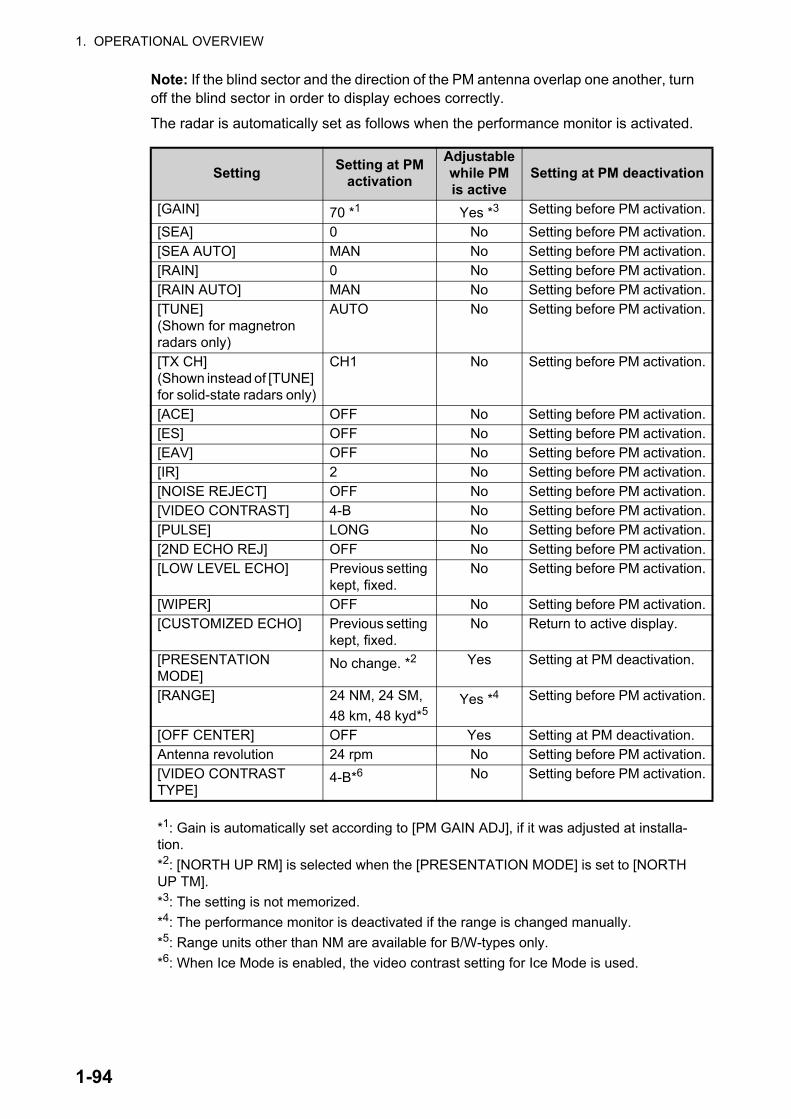
1. OPERATIONAL OVERVIEW
Note: If the blind sector and the direction of the PM antenna overlap one another, turn off the blind sector in order to display echoes correctly.
The radar is automatically set as follows when the performance monitor is activated.
SettingSetting at PM
activation
Adjustable while PM is active
Setting at PM deactivation
[GAIN] 70 *1 Yes *3 Setting before PM activation.
[SEA] 0 No Setting before PM activation.[SEA AUTO] MAN No Setting before PM activation.[RAIN] 0 No Setting before PM activation.[RAIN AUTO] MAN No Setting before PM activation.[TUNE](Shown for magnetron radars only)
AUTO No Setting before PM activation.
[TX CH](Shown instead of [TUNE] for solid-state radars only)
CH1 No Setting before PM activation.
[ACE] OFF No Setting before PM activation.[ES] OFF No Setting before PM activation.[EAV] OFF No Setting before PM activation.[IR] 2 No Setting before PM activation.[NOISE REJECT] OFF No Setting before PM activation.[VIDEO CONTRAST] 4-B No Setting before PM activation.[PULSE] LONG No Setting before PM activation.[2ND ECHO REJ] OFF No Setting before PM activation.[LOW LEVEL ECHO] Previous setting
kept, fixed.No Setting before PM activation.
[WIPER] OFF No Setting before PM activation.[CUSTOMIZED ECHO] Previous setting
kept, fixed.No Return to active display.
[PRESENTATION MODE]
No change. *2 Yes Setting at PM deactivation.
[RANGE] 24 NM, 24 SM,
48 km, 48 kyd*5Yes *4 Setting before PM activation.
[OFF CENTER] OFF Yes Setting at PM deactivation.Antenna revolution 24 rpm No Setting before PM activation.[VIDEO CONTRAST TYPE]
4-B*6 No Setting before PM activation.
*1: Gain is automatically set according to [PM GAIN ADJ], if it was adjusted at installa-tion.
*2: [NORTH UP RM] is selected when the [PRESENTATION MODE] is set to [NORTH UP TM].
*3: The setting is not memorized.
*4: The performance monitor is deactivated if the range is changed manually.
*5: Range units other than NM are available for B/W-types only.
*6: When Ice Mode is enabled, the video contrast setting for Ice Mode is used.
1-94

1. OPERATIONAL OVERVIEW
1.49.2 How to check the radar’s performance
The range scale is automatically set to 24 NM. The radar screen will show arcs. If the radar transmitter and receiver are in good working conditions in as much as the origi-nal state when the monitor was turned on, the innermost arcs should appear between 8.0 NM to 19.8 NM. The performance monitor can observe a total of 10 dB loss in transmitter and receiver.
How to set the number of arcs
1. Open the menu.
2. Select [1 ECHO].
3. Select [6 PM ARC].
4. Select [2], [3], [5] or [6] as appropriate, then press the ENTER MARK key.
5. Close the menu.
The figure belows shows an example where [PM ARC] is set to [5].
Note 1: The lengths of the arcs can vary according to installation environment. Judge the strength of the echo that appears within 60° from the arc location to confirm if the radar is working properly or not.
Note 2: The location of the arcs changes according to the [PM ARC] setting.
Turn the performance monitor off when finished.
8.0 NM to 19.8 NM
8.0 NM to 19.8 NM
Display Radar State Display
Transmitter: normalReceiver: normal
Transmitter and receiver: No arc indicates 10 dB loss. Contact your dealer for advice. (For magnetron radars, have a technician check the magnetron.
Radar State
1-95

1. OPERATIONAL OVERVIEW
1.50 How to Change the Reference PositionThe reference position for measurements (range, bearing, etc.) and markers (heading line, stern mark, etc.) can be the radar antenna position ([ANT]) or the consistent com-mon reference point ([CCRP]).
The reference position is a location on own ship to which all horizontal measurements, for example range, bearing, relative course, relative speed, closest point of approach (CPA) or time to closest point of approach (TCPA), are normally referenced.
[CCRP] for this series of radars is fixed at the conning position and [ANT] is fixed at the radar antenna position.
To change the reference position, use the trackball to place the cursor over the "REF POINT" indication at the top of the screen, then left-click to select [ANT] or [CCRP] as required. You can also change the reference by spinning the scrollwheel when the cur-sor is placed over the indication.
The position of the own ship marker changes according to reference position as shown below. If the CCRP is positioned outside of the effective display area, the bear-ing scale is indicated with the appropriate reduced detail.
Range and bearing are measured and graphics are drawn according to reference po-sition as in the table below.
Category ItemReference point
ANT CCRPRange and bearing measurements
EBL Range and bearing measured from an-tenna position.
Range and bearing measured from CCRP.
VRMCursorPI lineRange ringDrop mark
Graphics Heading line Drawn from anten-na position.
Drawn from CCRP.Stern markBeam lineOwn ship vectorOwn ship track
Bearing cursor Drawn with antenna position at center.
Drawn with CCRP at center.
Course, speed Calculated with an-tenna position at center.
Calculated with CCRP at center.
Table continued on following page
X
CCRP position
X
ANT position
Radar antennaposition is at
center of display
Conning position is atcenter of display
1-96

1. OPERATIONAL OVERVIEW
Note: When the antenna is located some distance from the CCRP, the CCRP can be outside the bearing cursor in true-motion or off-center. Also, when the CCRP is set as a reference point, some parts of the bearing cursor are not displayed.
1.51 Anchor WatchThe anchor watch feature alerts you when your ship has traveled a distance greater than a threshold value, when it should be at rest. When the anchor watch is active, an orange dashed circle marks the anchor watch range.
If your ship drifts more than the anchor watch setting, the alert "ANCHOR WATCH" appears in the [ALERT] box. Also, if your vessel returns to within the tolerable radius, the alert status is automatically changed to rectified.
1. Open the menu.
2. Select [4 ALERTS].
3. Select [4 ANCHOR WATCH].
4. Select [ON] to enable [ANCHOR WATCH], then press the ENTER MARK key.
5. Spin the scrollwheel to set the distance for the alert. Press the ENTER MARK key to apply the setting.
6. Close the menu.
Table continued from previous pageCPA, TCPA Calculated with an-
tenna position at center.
Calculated with CCRP at center.
BCR, BCT Calculated from bow position.Own ship data Heading Data is taken from respective sensors, re-
gardless of reference point selected.SpeedCourse over groundSpeed over groundOwn L/L Location of the CCRP.
Category ItemReference point
ANT CCRP
Anchor watch alarm setting
Own ship location when anchor watch is set
Own ship moves outside watch zoneAlarm is
triggered
1-97

1. OPERATIONAL OVERVIEW
1.52 Alerts
1.52.1 What is an alert?
“Alert” is a generic name for a notice to any unusual or potentially dangerous situation generated within the system.
For detailed information regarding specific alerts and alert codes, including possible remedies, see "ALERT LIST" on page AP-11.
Alerts are classified according to priority and category.
Note 1: This equipment does not provide the functional alert group function.
Note 2: The reserved cluster identifier for this equipment, which is defined in IEC62923-2 is “Nav”.
Alert priority
The level of priority, from highest to lowest, is ALARM WARNING CAUTION.
Alarm: Situations or conditions which require immediate attention, decision and (if necessary) action by the bridge team to avoid any kind of hazardous situation and to maintain the safe navigation of the ship.
Warning: Conditions or situations which require immediate attention for precautionary reasons, to make the bridge team aware of conditions which are not immediately haz-ardous, but may become so.
Caution: Awareness of a condition which continues to require attention out of the or-dinary consideration of the situation or of given information.
Note: All active-unacknowledged warnings are repeated as warnings after 60 sec-onds (manufacturer’s fixed time period).
Alert category
An alert is further classified by category, A, B or C, according to its degree of severity or source.
Category DescriptionA Category A alerts include the following, and must be confirmed from the
equipment that generated the alert.• Danger of collision
B Category B alerts are alerts where no additional information for decision support is necessary. Category B alerts are all alerts not falling under category A.
C Category C alerts are not shown on this equipment.
1-98

1. OPERATIONAL OVERVIEW
1.52.2 How to interpret the [ALERT] box
When an alert condition is found, the applicable alert message appears in the [ALERT] box. A buzzer sounds for alarm and warning alerts. When no active alert and indica-tion occurs, "NO ACTIVE ALERTS" appears in the [ALERT] box.
The [ALERT] box is composed of three lines of text information, and several icons, as shown below.
The alert icon shows the level of the alert (alarm, caution, warning or indication) and the active alert counter shows how many alerts are unacknowledged.
When an Alarm or Warning level alert is released, the alert message flashes in the [ALERT] box. The message is accompanied by the appropriate alert icon and the buzzer sounds. The buzzer and alert continue to flash and sound until the buzzer is silenced or the alert condition is rectified.
The alert also appears in the [ALERT LIST] (see section 1.52.5) until acknowledged and rectified.
1.52.3 How to acknowledge an alert
Alerts can be acknowledged in one of the following manners:
• Press the ALARM ACK key.
• Click the alert name in the [ALERT] box.
• Click the alert name in the [ALERT LIST].
The icon for an acknowledged alert changes as shown in section 1.52.6.
1.52.4 How to silence the alert buzzer
You can temporarily silence the buzzer by menu operation or the function key. The icon for a silenced alert also changes, as show in section 1.52.6.
To silence the buzzer by the function key, assign the buzzer stop function to the func-tion key, referring to section 1.9. For the menu operation, do as follows.
1. Open the menu.
2. Select [4 ALERTS].
3. Select [6 BUZZER STOP].
4. Close the menu.
Alert number and instance ID
Alert name/description
Alert icon Alert list/log button
Background alert icon:(shown only when one or more alerts are active)
Number of unacknowledged alert
1-99

1. OPERATIONAL OVERVIEW
1.52.5 Alert list
The alert list displays the names of violated alerts, including the time and date violated. Up to 100 alerts are stored in the internal memory. Unacknowledged alarms are dis-played first in the list (in red text), in the order in which they appear in the [ALERT] box. Unacknowledged warnings are displayed in the list (in yellow-orange text), in the order in which they appear in the [ALERT] box.
Cautions are displayed in the list (in yellow text), in the order in which they appear in the [ALERT] box.
Indications are displayed with a yellow “i” surrounded with a yellow box.
To display the alarm list, place the cursor on the alert list/log button in the [ALERT] box then left-click.
*: The date and time of alert is synchronized with UTC, using the ZDA sentence. If the ZDA sentence is lost, the date and time cannot be synchronized with UTC.
An unacknowledged alert can be acknowledged from the list by selecting it, then left-clicking. To erase the data for the number selected, left-click again. To refresh the alert list, select [9 REFRESH DATA], then press and hold the left button.
23:1503/FEB
23:1503/FEB
23:1503/FEB
23:1503/FEB
23:1503/FEB
- Select to go to the next page- Long-press the left button to
go to the last page.
- Select to refresh the list.- Long-press the left button
to remove acknowledged and rectified alerts from the list.
Displayed page/Pages available
- When selected at page 1, closes the list.
- When selected at page 2 or later, goes back to the previous page.
- Long-press the left button to go to page 1.
Radar which output this alert
Date and time of alert*
Alert icon
Alert code and alert message
1-100

1. OPERATIONAL OVERVIEW
Detailed alert information
To view detailed information for an alert, open the alert list, place the cursor on the alert you want to view detailed information for, then press and hold the left button.
Go back to the alert list.Alert code
Alert message
Alert status
Alert priorityAlert categoryDate and time of alert
Radar which output this alert
Select to refresh the information.
Alert details
12:34 05/JUN
1-101

1. OPERATIONAL OVERVIEW
1.52.6 Alert icons and their meanings
Icon Status Visual indication Audible alert
Active - unacknowledged alarm
Active - acknowledged alarm
Active - responsibility transferred alarm
Rectified - unacknowledged alarm
Active - unacknowledged warning
Active - silenced alarm
Red, flashing
Yellow-orange, flashing
Active - silenced warning Yellow-orange, flashing
Red, flashing Silent
Red Silent
Red Silent
Red, flashing Silent
Silent
Active - acknowledged warning Yellow-orange Silent
Active - responsibility transferred warning
Yellow-orange Silent
Rectified - unacknowledged warning
Yellow-orange, flashing Silent
Caution Yellow Silent
3 short, audible alerts repeated every 7 seconds.
2 short, audible alerts repeated every 60 seconds.
Indication SilentYellow
1-102

1. OPERATIONAL OVERVIEW
1.52.7 Responsibility transfer alert
MSC302(87) requires the use of the “responsibility transfer alert” which functions in the multiple sensor, multiple equipment installation. When one sensor or one equip-ment fails but does not disturb the system operation (other sensor or equipment is nor-mal), the AMS automatically sends the “responsibility transfer alert” (ACN sentence) to the sensor or equipment that generated the alert.
If the sensor or equipment refuses the responsibility transfer, normal operation is re-stored.
If the HBT sentence is not received from the AMS within the prescribed time interval, the alert processed as responsibility transfer alert is made active.
CAM HMIALF
ExternalEquipment
SensorA
Check if there is problem for system
Some alerts occur ACN
SensorB
AMSHBT
SensorA
Some alerts occur
Responsibility transferedHBT timeout computed
Alerts re-generated
SensorB
1-103

1. OPERATIONAL OVERVIEW
1.53 Icing PreventionYou can rotate the antenna (24 rpm) without transmission to keep the antenna from freezing.
1. Open the menu.
2. Select [9 INITIAL SETTINGS].
3. Select [5 OPERATION].
4. Select [7 ICING PREVENTION].
5. Select [ON] or [OFF] as appropriate. If you select [ON], the message "Rotate An-tenna to Prevent Icing." appears at the bottom of the screen.
6. Click [Start Antenna Rotation] to rotate the antenna without transmission. The message changes to read "Antenna Rotating,No TX.".
To stop the antenna rotation, left-click [Stop Antenna Rotation].
With this feature active and the antenna stopped, pushing the STBY TX key on the Control Unit or click the [STBY TX] button on the Status bar rotates the antenna and transmits pulses. Operating one of the above-mentioned controls again stops trans-mission but the antenna rotates.
When the antenna stops When the antenna rotates
Rotate Antenna to Prevent Icing.
Start Antenna RotationAntenna Rotating,No TX.Stop Antenna Rotation
1-104

1. OPERATIONAL OVERVIEW
1.54 How to Select a Display Mode (B/W-type Only)B/W-type radars of this series have three echo display modes available:
• [CIRCLE] mode: The echoes are displayed inside a circle on the screen. This is the default (IMO compliant) mode.
• [WIDE] mode: The echoes are displayed in a square area, but are not displayed in the data display area.
• [ALL] mode: The echoes are displayed across the entire screen.
Follow the procedure below to change display modes.
1. Open the menu.
2. Select [1 ECHO]. The [ECHO] menu appears.
3. Select [8 ECHO AREA].
4. Select the appropriate setting, then press the ENTER MARK key.
5. Close the menu.
CIRCLE WIDE ALL
1-105

1. OPERATIONAL OVERVIEW
1.55 How to Manage SD Card Data
The following data can be stored on a SD Card: marks, lines, user set-tings, installation settings, own track, target track (for A/B/W-types on-ly), alert history and some logs (for example, the alert log).
Note: The menu operations outlined in this section are only available when a SD-Card is inserted. When there is no SD-Card inserted, the [FILES] menu is not selectable. SD Cards must be formatted as FAT32. Other formats are not usable.
1.55.1 Formatting the SD card
You do not normally need to format a SD card. If the card becomes unreadable, format the card with a formatting program that is compatible with the specifications of the card.
1.55.2 Cautionary notes on handling SD cards
• Handle the cards carefully. Improper use can damage the card and destroy its con-tents.
• Make sure the card slot cover is closed, unless removing/inserting a card.
• Remove or insert a card using only your fingers. Do not use metal instruments (such as tweezers) to remove the card.
• Do not remove the card when data is loading from, or saving to, the card.
1.55.3 Compatible SD cards
The table below lists the SD cards that have been verified as compatible for use with this equipment.
Note 1: The cards were verified using basic functions. All functions were not verified. FURUNO does not guarantee card operations.
Note 2: SD cards other than those listed below have not been verified.
Maker SD card type CapacityPanasonic RP-SDUC16GJK 16GB
RP-SDUC32GJK 32GBRP-SDWA16GJK 16GBRP-SDWA-32GJK 32GB
SanDisk SDSDB-016G-J35U 16GBSDSDC-032G-J35U 32GBSDSDXPA-016G-JU3 16GBSDSDXPA-032G-JU3 32GBSDSDXVE-032GB-JNJIP 32GB
TOSHIBA SDAR40N16G 16GBSDAR40N32G 32GBSD-L016G4 16GBSD-L032G4 32GBSDXU-B016G 16GBSDXU-B032G 32GB
1-106

1. OPERATIONAL OVERVIEW
1.55.4 How to insert SD cards
The SD card slot is located on the front face of the processor unit, between the LAN1 port and the DVI-I port.
Note: Do not use any instruments to insert the card.
1. Remove the rubber cover on the SD card slot.
2. To insert a card, gently push the card into the slot, making sure that the card con-nectors are facing downwards.
3. Close the rubber cover.
1.55.5 How to remove SD cards
Follow the procedure below to safely remove an SD card.
Note 1: When the system power is turned off, skip steps 1 to 3.
Note 2: Do not use any instruments/tools top insert or remove the SD card.
1. Open the menu.
2. Select [6 FILES]. The [FILES] menu appears.
3. Select [REMOVE EXT MEDIA], then select [YES].You can now remove the SD card safely.
4. Remove the rubber cover on the SD card slot.
5. Gently push the SD cards to release the card from the card slot.
6. Remove the SD card. Do not use any instruments to remove the card.
7. Close the menu.
SD card slot (covered)
1-107

1. OPERATIONAL OVERVIEW
1.55.6 How to save data to an SD card
1. Open the menu.
2. Select [6 FILES]. The [FILES] menu appears.
3. Select [2 SAVE DATA].
4. Select the data to save.The software keyboard appears.
5. Using the software keyboard, name the file, then select [END] to start saving data. The file name-can be up to seven characters in length.Note: Depending on the data saved, the first let-ter of the filename is preset and cannot be changed. The presets are listed below.
*: Shown only for A/B/W-types.
The indication "WR CARD DATA" appears during the save process and the menu closes automatically.When the process is complete, the indication "COMPLETED" appears in the guid-ance box and the menu automatically closes.
1.55.7 How to read (load) data from an SD card
1. Open the menu.
2. Select [6 FILES]. The [FILES] menu appears.
3. Select [3 LOAD DATA].
4. Select the data to load.The indication "RD CARD DATA" appears during the read process and the menu closes automatically.When the process is complete, the menu closes automatically.
1.55.8 How to delete data from an SD card
1. Open the menu.
2. Select [6 FILES]. The [FILES] menu appears.
3. Select [4 DELETE DATA].
4. Select the data to delete.The indication "DELETE CARD DATA" appears during the delete process.When the process is complete, the menu auto-matically closes.
• Marks/Lines: M• Nav lines/Waypoints: W• Setting data: S• Install data: I
• Own track: T• Target track: A*• Alert history: H• Log file: L
1-108

1. OPERATIONAL OVERVIEW
1.56 How to Take a ScreenshotThe system has an in-built screenshot feature. To use the feature, a SD Card must be inserted in the Processor Unit. If there is no card inserted, the screenshot button on the screen is not active.
To take a screenshot of the currently displayed screen, click the screenshot but-ton.
Note: The screenshot function can also be assigned to a function key. For how to set up the function keys, see section 1.9
1.57 How to Use the Watch Alert (A/B/W-types only)The watch alert provides a visual alert at regular intervals to remind you to monitor the radar picture for safety or other purposes. When the watch alert is enabled, the WATCH box appears at the top of the screen. The watch alert function is available only for A/B/W-types.
When the timer reaches 00:00, an audible alert is released. To silence the buzzer, click the watch box. The timer is reset and begins to countdown again. You can reset the timer at any time by clicking the watch box.
To enable or disable the watch alert, follow the procedure below.
1. Open the menu.
2. Select [4 ALERTS]. The [ALERTS] menu appears.
3. Select [2 WATCH ALERT].
4. Select the [OFF] to disable the alert, or select the required interval at which the alert is released.The available intervals are: [6min], [10min], [12min], [15min] and [20min].
5. Close the menu.
Screenshot button
Watch box
1-109
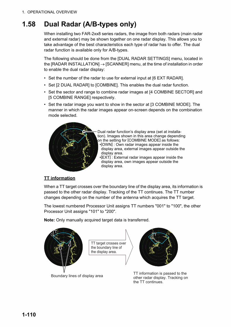
1. OPERATIONAL OVERVIEW
1.58 Dual Radar (A/B-types only)When installing two FAR-2xx8 series radars, the image from both radars (main radar and external radar) may be shown together on one radar display. This allows you to take advantage of the best characteristics each type of radar has to offer. The dual radar function is available only for A/B-types.
The following should be done from the [DUAL RADAR SETTINGS] menu, located in the [RADAR INSTALLATION] [SCANNER] menu, at the time of installation in order to enable the dual radar display:
• Set the number of the radar to use for external input at [6 EXT RADAR].
• Set [2 DUAL RADAR] to [COMBINE]. This enables the dual radar function.
• Set the sector and range to combine radar images at [4 COMBINE SECTOR] and [5 COMBINE RANGE] respectively.
• Set the radar image you want to show in the sector at [3 COMBINE MODE]. The manner in which the radar images appear on-screen depends on the combination mode selected.
TT information
When a TT target crosses over the boundary line of the display area, its information is passed to the other radar display. Tracking of the TT continues. The TT number changes depending on the number of the antenna which acquires the TT target.
The lowest numbered Processor Unit assigns TT numbers "001" to "100", the other Processor Unit assigns "101" to "200".
Note: Only manually acquired target data is transferred.
Dual radar function’s display area (set at installa-tion). Images shown in this area change depending on the setting for [COMBINE MODE] as follows: •[OWN] : Own radar images appear inside the
display area, external images appear outside the display area.
•[EXT] : External radar images appear inside the display area, own images appear outside the display area.
Boundary lines of display area TT information is passed to the other radar display. Tracking on the TT continues.
TT target crosses over the boundary line of the display area.
TTTTTTTT
1-110

1. OPERATIONAL OVERVIEW
1.58.1 How to toggle control of each dual radar display
Note: Dual radar mode must be enabled and both radars must be turned on.
You can switch between radars to control either your own, or the external radar from the antenna box. Left-click to toggle control.
Place the cursor on the [CONTROL] box, then left-click. The indication toggles be-tween "M" (Master) and "S" (Slave) to show the level of control you have for the radar you are currently controlling.
There can be only one Master radar at any time. If the radar in operation is set to Slave and the operator switches to Master, the other radar is automatically changed to Slave.
Depending on your level of control, available operations are as follows:
Radar Functions Control Master SlaveAIS function Independent Desired value can
be setDesired value can be set
BrillianceEcho trailsEBLLat/long dataPresentation modeSpeed dataTarget alarmTT, AIS on/offTT, AIS track intervalVector modeVector timeVRMWiperZoomTT COLLISION alarmRange**A/C SEAA/C RAINAutomatic Clutter Elimination (ACE)Gain adjustmentEcho stretchEcho averagingPicture setting(Customize echo)STBY/TXTT/AIS AZ
Click the box to toggle the level of control of the radars.“M”: Main (Master); “S”: Sub (Slave)
The radar numbers for “Own” and “External” radars appear here. The currently controlled radar’s number appears to the left.
1-111

1. OPERATIONAL OVERVIEW
*: When the connected radar antenna is a magnetron-type, and the radar is assigned as “Slave”, the desired value can be set for these functions. For SSD-types, this func-tion cannot be controlled.
**: The desired value can be set when the radar is assigned as “Slave”, however the maximum displayable range is dependent on the pulse setting at the “Master” radar.
1.58.2 Operating considerations for the dual radar display
You can toggle each radar between standby and TX in the dual radar display. When switching to standby on either radar, the "ISW: STBY" indication appears and the radar echoes from the radar in standby are not displayed. Further, when switching to stand-by, all TT targets are removed and tracking stops on the radar which is in standby. However if a TT target is acquired on the radar which is not in standby, the TT infor-mation is passed to the radar which is in standby.
Changes made to the following functions are applied to both the own radar echoes and the external echoes, on the display of the radar which made the changes. These settings are not applied to the display of the external radar.
IR* Dependent Control
Desired value can be set
Cannot controlTuningTT LOST warning Common
ControlItem Commonly Controlled
Item Commonly ControlledTT alerts ACKTT acquire
• Off-center display• CU/TM reset• Presentation mode• Range scale• Electronic chart on/off• Wiper
• Trail settings• Echo stretch• Echo Average• Color Erase• TT lost target filter
Radar Functions Control Master Slave
Either radar enters STBY mode
Boundary line is removed and display shows only the Own radar echoes.
1-112

1. OPERATIONAL OVERVIEW
Notes regarding dual radar operations
• The dual radar function is available between two FAR-2xx8 series radars using the LAN. FAR-2xx7 and FAR-3xx0 series radars are not compatible.
• When a transmission error occurs between two radars in the dual radar mode, the Alert "LOST ISW FUNC" appears and the dual radar function is turned off.
• The dual radar display is not available on external equipment (such as ECDIS, etc) which overlays the main radar image, even though the dual radar is turned on.
• If a TT target passes between the two radars (see page 1-110) while the dual radar function is active, TT data (TTD/TTM) is shared and tracking is continued.
• If the Alert "TT TGT 95%(AUTO)" is released while the dual radar function is active, disable tracking for unnecessary targets until the Alert condition is rectified. Con-tinuing automatic acquisition after this Alert is released and is still active may cause discrepancies between TT targets on the connected radars.
Restrictions during dual radar operations
The following restrictions are applicable when using the dual radar function.
• A REF (reference) mark can be entered on the display of the main radar but not the external radar.
• Targets acquired and/or tracked prior to activating dual radar mode are all released when dual radar mode is activated.
• Targets acquired and/or tracked prior to deactivating dual radar mode are all re-leased when dual radar mode is deactivated.
• If either radar enters standby mode, all TT targets acquired while the Dual Radar function was active are released (removed).
• TT targets can be acquired manually or automatically. TT target data sharing be-tween the radar in dual radar mode is restricted to manually acquired targets. See "TT information" on page 1-110.
• The reference position is fixed at [CCRP] (see section 1.50) when dual radar mode is enabled. Set the same CCRP position between two radars at the time of installa-tion.
• The following functions are not available in the dual radar mode.
• If the distance between the Own radar antenna and the External radar antenna is larger than 125 meters, the dual radar display area and the sweep area are re-duced. In this case, if the range is decreased, only the own radar echoes are dis-played on the screen. Further, the following occurs when only the own radar is shown under these circumstances:
• Performance monitor• SART• ICE mode• Target Analyzer (B-type only)
• TT simulation mode• Icing prevention• Interswitch• Hatching (B-type only)
• Dual radar boundary line is not shown.• Antenna selection is unavailable (on-screen box and menu item are gray and inac-
tive).• Trails are all cleared (removed).No alerts is released under these circumstances, however normal dual radar display is restored when the range is increased again.
1-113

1. OPERATIONAL OVERVIEW
1.59 Wave ModeYou can output echo data from this radar to a PC with the wave analysis software in-stalled. The wave analysis software calculates incoming waves and gives you an on-screen indication as to wave size, direction and time between waves.
This section covers how to use the wave mode and related functions on your FAR-2xx8 series radar. For details regarding the analysis software and PC indications, see the manual supplied with the software.
Preparations and cautions for wave mode
• Wave mode requires the connection of a PC to the same network as the FAR-2xx8 series radar to be used for data input.
• The connected PC must have the wave analysis software installed. See the soft-ware manual for how to install the software.
• Wave mode may only be active on one radar at any time. If a second radar has wave mode activated, wave mode is disabled on the first radar.
• One ore radars must set [8 OUTPUT TO WAVE PC] to [ON]. If all radars set [8 OUT-PUT TO WAVE PC] to [OFF], the “LOST WAVE UNIT” indication may appear.
• Wave analysis and the output data are intended for reference purposes only, as an aid to safe navigation. Always confirm conditions, visually and with other methods.
1. Establish a LAN connection with the analysis PC.
2. Open the menu.
3. Select [1 ECHO]
4. Select [0 NEXT] to show the second page of the menu.
5. Select [7 WAVE MODE].
6. Select [ON] or [OFF] as appropriate.Select [ON] to output echo data to analysis PC.
7. Select [7 WAVE MODE].
8. Select [ON] or [OFF] as appropriate.Select [ON] to output navigational data to analysis PC.
9. Close the menu.
1-114

1. OPERATIONAL OVERVIEW
1.60 Doppler Feature (X-band Solid State Radars only)When activated, the doppler feature can help with clutter reduction, making targets easier to find. This feature is only available with FAR-2228-NXT, FAR-2228-NXT-BB or FAR-2328-NXT.
To activate and use the feature, follow the procedure below.
1. Open the menu.
2. Select [1 ECHO].
3. Select [0 NEXT] to show the second page of the menu.
4. Select [9 DOPPLER].
5. Select the required setting, referring to the table below.
• [0]: Disables the doppler feature.
• [1]: Reduces noise, making weak targets easier to find.
• [2]: Reduces clutter from rain, etc., making it easier to find targets previously hidden by clutter.
6. Close the menu.
1-115

1. OPERATIONAL OVERVIEW
This page is intentionally left blank.
1-116

2. RADAR OBSERVATION
2.1 General
2.1.1 Minimum range
The minimum range is defined by the shortest distance at which, using a scale of 1.5
or 0.75 nm, a target having an echoing area of 10 m2 is still shown separate from the point representing the antenna position.
It is mainly dependent on the pulselength, antenna height, and signal processing such as main bang reduction and digital quantization. It is a good practice to use a shorter range scale as far as it gives favorable definition or clarity of picture.
The IMO Resolution MSC.192(79) requires the minimum range to be less than 40 m, respectively. This series of radars satisfy this requirement.
2.1.2 Maximum range
The maximum detecting range of the radar, Rmax, varies considerably depending on several factors such as the height of the antenna above the waterline, the height of the target above the sea, the size, shape and material of the target, and the atmospheric conditions.
Under normal atmospheric conditions, the maximum range is equal to the radar hori-zon or a little shorter. The radar horizon is longer than the optical one by about 6% because of the diffraction property of the radar signal. The Rmax is given in the follow-ing equation.
For example, if the height of the antenna above the waterline is 9 meters and the height of the target is 16 meters, the maximum radar range is;
It should be noted that the detection range is reduced by precipitation (which absorbs the radar signal).
h1
h2Optical horizon
D: Radar horizon
Globe
D = 2.2 x ( h1 + h2)where D: radar horizon (nautical miles)h1: antenna height (m)h2: target height (m)
Rmax = 2.2 x ( 9 + 16) = 2.2 x (3 + 4) = 15.4 nm
2-1

2. RADAR OBSERVATION
2.1.3 X-band and S-band
In fair weather, the equation on the previous page does not give a significant differ-ence between X- and S-band radars. However, in heavy precipitation condition, an S-band radar would have better detection than an X-band radar.
2.1.4 Radar resolution
There are two important factors in radar resolution (discrimination): bearing resolution and range resolution.
• Bearing resolution is the ability of the radar to display as separate pips the echoes received from two targets that are at the same range and close together. It is pro-portional to the antenna length and reciprocally proportional to the wavelength. The length of the antenna radiator should be selected for a bearing resolution better than 2.5° (IMO Resolution). This condition is normally satisfied with a radiator of 1.2 m (4 ft) or longer in the X-band. The S-band radar requires a radiator of about 12 feet (3.6 m) or longer.
• Range resolution is the ability to display as separate pips the echoes received from two targets that are on the same bearing and close to each other. This is determined by pulselength only. Practically, a 0.08 microsecond pulse offers the discrimination better than 40 m as do so with all FURUNO radars.Test targets for determining the range and bearing resolution are radar reflectors
having an echoing area of 10 m2.
Targets
Horizontal beam width
Separate target echoes
Ovelapped target echoes
Horizontal beam width
Targets
Transmission pulse Targets
TargetsTransmission pulse
Separate target echoes
Ovelapped target echoes
Ovelapping
2-2
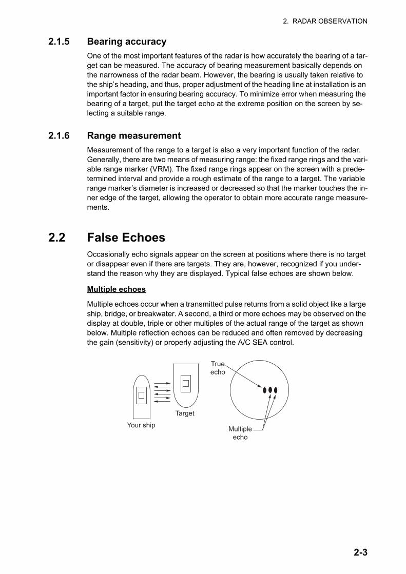
2. RADAR OBSERVATION
2.1.5 Bearing accuracy
One of the most important features of the radar is how accurately the bearing of a tar-get can be measured. The accuracy of bearing measurement basically depends on the narrowness of the radar beam. However, the bearing is usually taken relative to the ship’s heading, and thus, proper adjustment of the heading line at installation is an important factor in ensuring bearing accuracy. To minimize error when measuring the bearing of a target, put the target echo at the extreme position on the screen by se-lecting a suitable range.
2.1.6 Range measurement
Measurement of the range to a target is also a very important function of the radar. Generally, there are two means of measuring range: the fixed range rings and the vari-able range marker (VRM). The fixed range rings appear on the screen with a prede-termined interval and provide a rough estimate of the range to a target. The variable range marker’s diameter is increased or decreased so that the marker touches the in-ner edge of the target, allowing the operator to obtain more accurate range measure-ments.
2.2 False EchoesOccasionally echo signals appear on the screen at positions where there is no target or disappear even if there are targets. They are, however, recognized if you under-stand the reason why they are displayed. Typical false echoes are shown below.
Multiple echoes
Multiple echoes occur when a transmitted pulse returns from a solid object like a large ship, bridge, or breakwater. A second, a third or more echoes may be observed on the display at double, triple or other multiples of the actual range of the target as shown below. Multiple reflection echoes can be reduced and often removed by decreasing the gain (sensitivity) or properly adjusting the A/C SEA control.
Your ship
Target
Trueecho
Multipleecho
2-3

2. RADAR OBSERVATION
Sidelobe echoes
Every time the radar pulse is transmitted, some radiation escapes on each side of the beam, called “sidelobes”. If a target exists where it can be detected by the side lobes as well as the main lobe, the side echoes may be represented on both sides of the true echo at the same range. Side lobes show usually only on short ranges and from strong targets. They can be reduced through careful reduction of the gain or proper adjust-ment of the A/C SEA control.
Virtual image
A relatively large target close to your ship may be represented at two positions on the screen. One of them is the true echo directly reflected by the target and the other is a false echo which is caused by the mirror effect of a large object on or close to your ship as shown in the figure below. If your ship comes close to a large metal bridge, for example, such a false echo may temporarily be seen on the screen.
True target
Mainlobe (beam)
Antenna
Sidelobe
False echoes by sidelobes
Sidelobe
Trueecho
Falseecho
Your ship
Target ship
Mirror imageof target ship
Bridge
Route for direct reflection
Route forindirect reflection
2-4

2. RADAR OBSERVATION
Shadow sectors
Funnels, stacks, masts, or derricks in the path of the antenna block the radar beam. If the angle subtended at the antenna is more than a few degrees, a non-detecting sec-tor may be produced. Within this sector targets can not be detected.
2.3 SART (Search and Rescue Transponder)
2.3.1 SART description
A Search and Rescue Transponder (SART) can be triggered by any X-Band (3 cm) radar within a range of approximately 8 nm. Each radar pulse received causes it to transmit a response which is swept repetitively across the complete radar frequency band. When interrogated, it first sweeps rapidly (0.4 s) through the band before be-ginning a relatively slow sweep (7.5 s) through the band back to the starting frequen-cy. This process is repeated for a total of twelve complete cycles. At some point in each sweep, the SART frequency will match that of the interrogating radar and be within the pass band of the radar receiver. If the SART is within range, the frequency match during each of the 12 slow sweeps will produce a response on the radar dis-play, thus a line of 12 dots equally spaced by about 0.64 nautical miles will be shown.
When the radar to the SART is reduced to about 1 nm, the radar display my show also the 12 responses generated during the fast sweeps. These additional dot responses, which also are equally spaced by 0.64 nautical miles, will be interspersed with the orig-inal line of 12 dots. They will appear slightly weaker and smaller than the original dots.
Wharf and its echo
Large ship Size of blind sector dependson size of obstruction and range.
Radar position Radar positionWharf and its echo
Shadow sector occursbecause obstruction(like mast) is in pathof radar beam.
Shadow sectoroccurs becausewharf is hiddenbehind ship.
Radar antennabeamwidth
Screen A: When SART is distant Screen B: When SART is close
Echo from SART
Position ofSART
Your shipposition Your ship
positionSART marklength
24 NM 1.5 NM
Position ofSART
Echo fromSART
Lines of 12 dots are displayed inconcentric arcs.
2-5

2. RADAR OBSERVATION
2.3.2 How to show SART marks on the radar display
This radar is equipped with a feature that optimally sets up the radar for SART detec-tion. This feature automatically detunes the radar receiver out of its best tuning condi-tion. This erases or weakens all normal radar echoes, but the SART marks are not erased because the SART response signal scans over all frequencies in the 9 GHz band. When the radar approaches the SART in operation, the SART marks will en-large to large arcs, blurring a large part of the screen.
1. Open the menu.
2. Select [1 ECHO].
3. Select [7 SART].
4. Select [ON] to show SART marks on the radar display, or select [OFF] to hide SART marks.When the SART function is active, the settings listed in the following table are au-tomatically made to radar functions:
For X-band solid state radars, the pulselength is fixed as follows while SART is active.
5. Close the menu.
The indication "SART" appears at the top of the screen, in yellow text, when this fea-ture is active. Be sure to turn this feature off when SART detection is no longer your objective.
Note 1: For magnetron radars, any changes made to the range while SART is active will deactivate SART.
Note 2: X-band solid state radars allow the range to be changed while keeping SART active. SART must be turned off manually for X-band solid state radars. SART detec-tion is not available for S-band solid state radars.
2.3.3 General remarks on receiving SARTs
SART range errors
When responses from only the 12 low frequency sweeps are visible (when the SART is at a range greater than about 1 nm), the position at which the first dot is displayed can be as much as 0.64 nm beyond the true position of the SART. When the range closes so that the fast sweep responses are seen also, the first of these will be no more than 150 meters beyond the true position.
SettingChanged to...
Magnetron radars Solid state radarsRange 12 NM 24 NM or lowerPulselength Long Dependent on range. See table below.Echo Stretch OffNoise Rejector OffEcho Averaging OffInterference Rejector OffPerformance Monitor OffA/C RAIN Off
Range (NM) 0.125 0.25 0.5 0.75 1 1.5 2 3 4 6 8 12 16 24Pulselength S1 S2 M1 M2 L
2-6

2. RADAR OBSERVATION
Radar bandwidth
This is normally matched to the radar pulselength and is usually switched with the range scale and the associated pulselength. Narrow bandwidths of 3-5 MHz are used with long pulses on long range scales and wide bandwidths of 10-25 MHz with short pulses on short ranges.
A radar bandwidth of less than 5 MHz will attenuate the SART signal slightly, so it is preferable to use a medium bandwidth to ensure optimum detection of the SART.
Radar sidelobes
As the SART is approached, sidelobes from the radar antenna can show the SART responses as a series of arcs or concentric rings. These can be removed by the use of the anti-clutter sea control although it can be operationally useful to observe the side lobes as they may be easier to detect in clutter conditions and also they will con-firm that the SART is near to own ship.
Note: SART information excerpted from IMO SN/Circ 197 OPERATION OF MARINE RADAR FOR SART DETECTION.
2.4 RACONA RACON is a radar beacon that emits radar receivable signals in the radar frequency spectrum (X- or S-band). There are several signal formats; in general, the RACON sig-nal appears on the radar screen as a rectangular echo originating at a point just be-yond the position of the radar beacon. It has a Morse coded pattern. Note that the position on the radar display is not accurate.
2.5 Radar Target Enhancer (RTE)An RTE is a radar transponder mounted on navigation buoys and masts of small crafts to significantly improve their detection by radar. Unlike a SART or RACON, which are passive, the RTE receives a radar signal, amplifies it and re-transmits it, with the in-tention of making the target's signal look larger on a radar display. The RTE is avail-able in X-band and S-band types.
Echo description
RACON signalRACON signalRACON stationRACON station
Echoes on the radar screen
Your ship positionYour ship position
2-7
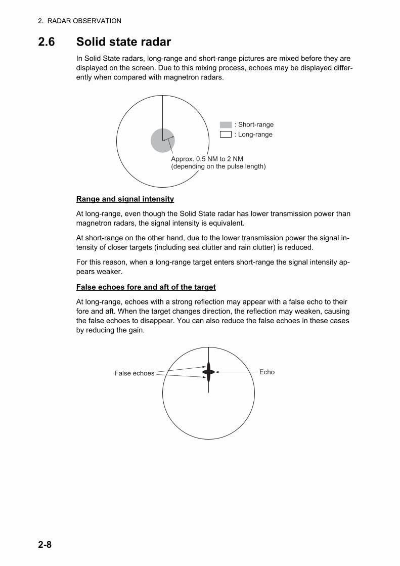
2. RADAR OBSERVATION
2.6 Solid state radarIn Solid State radars, long-range and short-range pictures are mixed before they are displayed on the screen. Due to this mixing process, echoes may be displayed differ-ently when compared with magnetron radars.
Range and signal intensity
At long-range, even though the Solid State radar has lower transmission power than magnetron radars, the signal intensity is equivalent.
At short-range on the other hand, due to the lower transmission power the signal in-tensity of closer targets (including sea clutter and rain clutter) is reduced.
For this reason, when a long-range target enters short-range the signal intensity ap-pears weaker.
False echoes fore and aft of the target
At long-range, echoes with a strong reflection may appear with a false echo to their fore and aft. When the target changes direction, the reflection may weaken, causing the false echoes to disappear. You can also reduce the false echoes in these cases by reducing the gain.
: Short-range: Long-range
Approx. 0.5 NM to 2 NM (depending on the pulse length)Approx. 0.5 NM to 2 NM (depending on the pulse length)
EchoFalse echoes
2-8

3. TARGET TRACKING (TT)
3.1 Precautions when Using Target Tracking
WARNINWARNINGNo one navigational aid should be relied upon for the safety of vessel and crew.The navigator has the responsibility to check all aids available to confirm position. Electronic aids are not a substitute for basic navigational principles and common sense.
This TT automatically tracks automatically or manually acquired radar targets and calculates their courses and speeds, indicating them by vectors. Since the data generated by the auto plotter are based on what radar targets are selected, the radar must always be optimally tuned for use with the auto plotter, to ensure required targets will not be lost or unwanted targets such as sea returns and noise will not be acquired and tracked.
A target does not always mean a land-mass, reef, ships or other surface vessels but can imply returns from sea surface and clutter. As the level of clutter changes with environment, the operator should properly adjust the [A/C SEA], [A/C RAIN] and [GAIN] controls to be sure target echoes are not eliminated from the radar screen.
CAUTIONCAUTIONThe plotting accuracy and response of this TT meets IMO standards. Tracking accuracy is affected by the following:
The data generated by TT, AIS and video plotter are intended for reference only.
Tracking accuracy is affected by course change. One to two minutes is required to restore vectors to full accuracy after an abrupt course change. (The actual amount depends on gyrocompass specifications.)
The amount of tracking delay is inversely proportional to the relative speed of the target. Delay is on the order of 15 - 30 seconds for high relative speed; 30 - 60 seconds for low relative speed.
The target tracking and pertinent vector calculation accuracy is influenced by the following: - Echo intensity- The range measurement accuracy;
characterized by both random and biased measurement errors.
- The angular measurement accuracy;characterized by beam shape, target glint and bias errors.
- Radar transmission pulsewidth- Gyrocompass heading error- Speed log error - Curent and wind (set & drift)- Course change (own ship and target)
Refer to official nautical charts for detailed and up-to-date information.
3-1
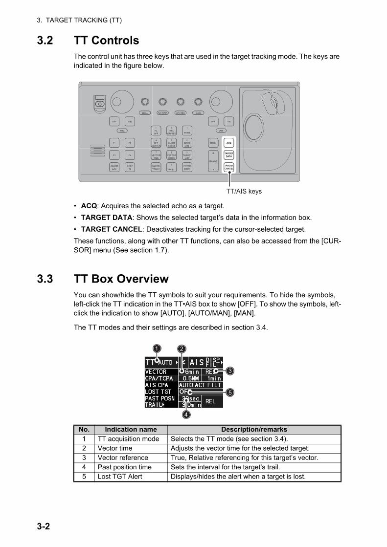
3. TARGET TRACKING (TT)
3.2 TT ControlsThe control unit has three keys that are used in the target tracking mode. The keys are indicated in the figure below.
• ACQ: Acquires the selected echo as a target.
• TARGET DATA: Shows the selected target’s data in the information box.
• TARGET CANCEL: Deactivates tracking for the cursor-selected target.
These functions, along with other TT functions, can also be accessed from the [CUR-SOR] menu (See section 1.7).
3.3 TT Box OverviewYou can show/hide the TT symbols to suit your requirements. To hide the symbols, left-click the TT indication in the TT•AIS box to show [OFF]. To show the symbols, left-click the indication to show [AUTO], [AUTO/MAN], [MAN].
The TT modes and their settings are described in section 3.4.
No. Indication name Description/remarks1 TT acquisition mode Selects the TT mode (see section 3.4).2 Vector time Adjusts the vector time for the selected target.3 Vector reference True, Relative referencing for this target’s vector.4 Past position time Sets the interval for the target’s trail.5 Lost TGT Alert Displays/hides the alert when a target is lost.
ACQ
ON
MENU
OFF
VRM
A/C SEAA/C RAIN
MODE
3
LINEINDEX
6
OFF
21HL
CENTEROFF
4 5
RESETCU/TM
OFFSETEBL
GAIN
TARGETCANCEL
TARGETDATA
RANGE
-
+LIST
TARGET9
ENTERMARK
TIMEVECTOR
7 8
CANCELTRAILS
0
MODEVECTOR
BRILL
BRILL
EBL
F1
OFF
F2
ON
ACKALARM
F3 F4
STBYTX
ON
MENU
OFF
VRM
A/C SEAA/C RAIN
MODE
3
LINEINDEX
6
OFF
21HL
CENTEROFF
4 5
RESETCU/TM
OFFSETEBL
GAIN
RANGE
-
+LIST
TARGET9
ENTERMARK
TIMEVECTOR
7 8
CANCELTRAILS
0
MODEVECTOR
BRILL
BRILL
EBL
F1
OFF
F2
ON
ACKALARM
F3 F4
STBYTX
TT/AIS keys
4
2
3
1
OFF 5
3-2
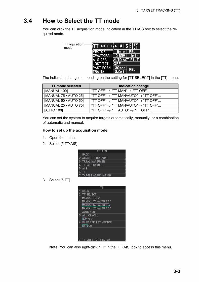
3. TARGET TRACKING (TT)
3.4 How to Select the TT modeYou can click the TT acquisition mode indication in the TT•AIS box to select the re-quired mode.
The indication changes depending on the setting for [TT SELECT] in the [TT] menu.
You can set the system to acquire targets automatically, manually, or a combination of automatic and manual.
How to set up the acquisition mode
1. Open the menu.
2. Select [5 TT•AIS].
3. Select [6 TT].
Note: You can also right-click "TT" in the [TT•AIS] box to access this menu.
TT mode selected Indication change[MANUAL 100] "TT OFF" "TT MAN" "TT OFF"...[MANUAL 75 • AUTO 25] "TT OFF" "TT MAN/AUTO" "TT OFF"...[MANUAL 50 • AUTO 50] "TT OFF" "TT MAN/AUTO" "TT OFF"...[MANUAL 25 • AUTO 75] "TT OFF" "TT MAN/AUTO" "TT OFF"...[AUTO 100] "TT OFF" "TT AUTO" "TT OFF"...
OFF
TT aquisition mode
3-3

3. TARGET TRACKING (TT)
4. Select [2 TT SELECT], then select the acquisition condition.Your selection here changes how many targets can be acquired, both automati-cally and manually.
5. Close the menu.
Note: When the menu-set number of automatically acquired targets have been ac-quired, the Alert "TT TGT FULL(AUTO)" appears in the [Alert] box.
3.5 How to Acquire and Track TargetsThis radar can automatically acquire and track a maximum of 100 targets.
A target just acquired automatically is marked with a dashed circle and a vector ap-pears within one minute to indicate the target's motion trend. Within three minutes, the initial tracking stage is finished and the target becomes ready for stable tracking. At this time, the dashed circle changes to a solid circle.
3.5.1 How to manually acquire a target
Acquire a target from the Control Unit (RCU-014)
Use the trackball to place the cursor on the target you want to acquire, then press the ACQ key.
Acquire a target by the trackball module
1. When the target to acquire and the AIS symbol overlap one another, right-click the operational display area to show the [CURSOR MENU] then select [TT TARGET DATA/ACQ] to acquire the target.
2. Place the cursor on the target to acquire then left-click.
The plotting symbol is drawn by a dashed circle during the initial acquisition stage. A vector appears approximately one minute after acquisition. The vector indicates the motion trend of the target. If the target is consistently detected for three minutes, the plotting symbol changes to a solid circle. If acquisition fails, the target symbol blinks.
Menu setting Acquisition condition[MANUAL 100] 100 targets manually, auto acquisition not available[MANUAL 75 • AUTO 25] 25 targets automatically, 75 targets manually[MANUAL 50 • AUTO 50] 50 targets automatically, 50 targets manually[MANUAL 25 • AUTO 75] 75 targets automatically, 25 targets manually[AUTO 100] 100 targets automatically, manual acquisition not avail-
able
At acquisition Within 1 min. after acquisition Stable tracking
Vector
3-4

3. TARGET TRACKING (TT)
3.5.2 How to automatically acquire targets
Targets are automatically acquired when the TT mode is set to other than [MANUAL 100] and a target enters the acquisition zone (see section 3.16). The maximum track-ing distance (24 NM or 32 NM) is set at installation.
3.6 How to Enter Own Ship SpeedThe TT requires own ship's speed and heading data. The speed can be STW, SOG or echo-referenced speed (based on 3 max. stationary objects). Manual input is also possible. For automatic or manual input, see section 1.12. For echo-referenced speed input follow the procedure below.
3.6.1 Echo-referenced speed input
The use of echo-referenced speed is recommended when:
• The speed log is not operating properly or not connected to the radar.
• The vessel has no device (doppler sonar, speed log, etc.) that can measure ship's bow-stern, port-starboard movement.
If you select echo-referenced speed, the TT calculates own ship's speed relative to a fixed reference target. The number of targets may be R1, R2 or R3. When a plural of objects are selected, the mean value is used, for stabilization and speed.
1. Right-click the operational display area to show the [CURSOR MENU].
2. Select [REF MARK]. The cursor is highlighted to indicate that the reference mark function is active.
3. Place the cursor on a fixed echo (such as an island, etc.) at a range of 0.1 to 24 NM from own ship, to be used as a reference, then left-click. The cursor changes from the highlighted cross to a circle with dashed lines, indicating that the refer-ence location is now set. See section 3.9 for more information on TT symbols and their attributes.
The dashed lines of the reference point change to a solid line over time, as shown in the figure above.
Note 1: For successful acquisition, the target should be within 24 NM (or 32 NM, de-pending on initial setting) from own ship and not obscured by sea or rain clutter.Note 2: You are alerted when the capacity of manual acquisition is 95% and 100%. These alerts are "TT TGT 95%(MAN)" and "TT TGT FULL(MAN)". If the capacity is 100% you cannot acquire more targets. Cancel tracking of non-threatening targets if you wish to acquire additional targets manually.Note 3: When a target being tracked nears another target being tracked, the targets may be “swapped”. When two targets acquired either automatically or manually come close to each other, one of the two may become a lost target. If this occurs, manual re-acquisition of the lost target may be necessary after the two have separated.Note 4: You can reuse a target number. This is useful when you acquire the “wrong” target. Drag and drop the symbol onto the correct target.
At acquisition Stable tracking
3-5

3. TARGET TRACKING (TT)
4. Repeat step 3 until to place up to three reference points.
5. Right-click to deactivate the reference mark function.
6. Right-click the [SPD] indication at the top-right of the screen to show the [SPEED] menu.
7. Select [2 SHIP SPEED].
8. Select [REF].
9. Close the menu.It takes approximately one minute for the speed to appear in the own ship information box. When the speed appears, the indication "REF BT" also appears to the right of the speed value.
Notes on speed input by reference target
• Reference targets are only used for the calculation of true speed.
• Do not use reference target generated true speed to calculate relative speed. Relative speed data is not accurate because response to speed change is slow, hampering the TT's ability to accurately judge the possibility of collision.
• Select a stationary target as a reference target to calculate own ship speed as ground tracking speed. Do not choose a moving target as a reference target. A mov-ing target produces error in the vector for TT and AIS, which results in wrong colli-sion avoidance information. Further, an unstable stationary target produces inaccurate speed data and the target itself may become lost.
• On IMO-type radars with AIS in use, echo-referenced speed is shown in gray to in-dicate they are not available for selection.
• When a reference target is lost or goes out of the acquisition range, that reference target mark blinks and the alert box shows "REF TARGET LOST". If all reference targets are lost, the speed indication reads "*.*" Select a different reference target if currently selected one is lost.
• When all targets are deleted, the reference target mark is also deleted and the tar-get-based speed becomes invalid. The speed is indicated as "BTREF" where BT means Bottom Track (speed over ground).
• Reference targets can be marked with a vector.This can be done with [4 DISP REF TGT VECTOR] on the [TT] menu.
• Loss of reference target will affect the calculation of true speed and true course of targets. Further, own ship speed will be inaccurate.
How to cancel echo-referenced speed input
1. Open the menu.
2. Select [7 INFORMATION BOX].
3. Select [2 OWN SHIP INFO].
4. Select [3 SPEED]. The [SPEED] menu appears.
5. Select any option, other than [REF], then press the ENTER MARK key.
6. Close the menu.
3-6

3. TARGET TRACKING (TT)
3.7 How to Cancel Target TrackingWhen the number of tracked targets reaches maximum capacity, the alert box shows "TT TGT FULL(MAN)" or "TT TGT FULL(AUTO)", based on the selected TT mode. No new targets can be acquired until a tracked target is lost or tracking is canceled. When this occurs, cancel tracking for non-dangerous targets as required.
3.7.1 How to cancel tracking for individual TT targets
Using the control unit (RCU-014)
1. Place the cursor on the tracked target, or tracked target’s data, to cancel.
2. Press the TARGET CANCEL key.
Using the CURSOR menu
Note: This methods requires [TGT CANCEL SETTING] in the second page of the [CURSOR MENU] to be set as [ANY] or [TT ONLY].
1. Right-click the operational display area to show the [CURSOR MENU].
2. Select [TARGET CANCEL], then left-click.
3. Select the tracked target to cancel, then left-click.
4. Right-click to complete the procedure.
3.7.2 How to cancel tracking for all TT targets
Using the control unit (RCU-014)
Press and hold the TARGET CANCEL key.
Using the menu
1. Open the menu.
2. Select [5 TT•AIS].
3. Select [6 TT].
4. Select [3 ALL CANCEL].
5. Select [YES] to cancel tracking for all TT targets.
6. Close the menu.
3-7

3. TARGET TRACKING (TT)
3.8 Lost TargetTargets not detected in nine consecutive scans become “lost targets”. A lost target is shown in the display with a flashing red "". Flashing stops after the lost target alert is acknowledged. Further, the alert box shows the "TT TARGET LOST" alert in orange characters and the audible alert sounds. The symbol disappears when the alert is ac-knowledged.
If you are in an area where tracked targets are lost frequently, you may want to disable the lost target alert against tracked targets by maximum range.
3.8.1 How to set the lost target filter
You can set the lost target alert to sound against lost targets that are within a specific range. To set the criteria, use the procedure below.
1. Open the menu.
2. Select [5 TT•AIS].
3. Select [6 TT].
4. Select [7 TT LOST TGT FILTER].
5. Select [MAX RANGE].
6. Select [ON]. The settings can now be adjusted.
7. Spin the scrollwheel to adjust the setting as re-quired, then left-click to apply the setting.
8. Close the menu.
Note: Reference targets are not affected by this filter.
3.8.2 How to enable/disable the lost target alert
The [LOST TARGET] box, located at the bottom-right corner of the screen, enables and disables the lost target alert.
Select the box with the cursor, then left-click to cycle through the settings in the follow-ing order: [OFF] [FILT] [ALL] [OFF]...
• [OFF]: Disable the alert.
• [FILT]: Enable the alert for all lost targets, excluding filtered targets.
• [ALL]: Enable the alert for all lost targets, including filtered targets.
Note: The filter setting is applied to both TT and AIS lost targets.
OFF Lost target filter setting
3-8

3. TARGET TRACKING (TT)
3.9 TT Symbols and AttributesThe TT symbols used in this equipment are compliant with IEC62288. For details re-garding the symbols and their meanings, see "TT symbols" on page AP-43.
3.9.1 How to adjust symbol brilliance
Note: Each color scheme (palettes PLT1 to PL4) can be adjusted individually. For how to select a color scheme, see section 1.45.2 and section 1.45.3.
1. Open the menu.
2. Select [9 INITIAL SETTINGS].
3. Select [2 BRILL]. The [BRILL] menu appears.
Note: You can also right-click the [PLT] indication to access this menu.
4. Select [0 NEXT] to show the next menu page.
5. Select [7 TT SYMBOLS]. The set-tings are highlighted and can now be adjusted.
6. Spin the scrollwheel to select the de-sired brilliance, then left-click to ap-ply the setting.
7. Close the menu.
3.9.2 How to set the symbol color
1. Open the menu.
2. Select [5 TT•AIS].
3. Select [4 TT•AIS SYMBOL].
4. Select [2 TT•AIS SYMBOL COLOR]. The settings can now be adjusted.
5. Select the appropriate color.
6. Close the menu.
Spin the scrollwheel to adjust the brilliance.
3-9

3. TARGET TRACKING (TT)
3.9.3 How to select a TT symbol (B/W-types only)
In addition to the "standard" circle TT symbol, you may select from the symbols shown below, using the full keyboard. This cannot be done with trackball-type control unit (RCU-015, RCU-016). However, you can program a function key to do so: assign the function key the [TARGET DATA] function from the [STD KEY] category. For function key setup, see section 1.9.
To change the TT symbol, do the following procedure.
1. Place the cursor on the target whose symbol you want to change, then left-click.
2. Press the TARGET DATA key to cycle through the symbols and select the de-sired symbol.
3.10 How to Display/Remove Target DataThe TT mode provides the full functionality of TT as required by the IMO Resolution A.823(19) and IEC 62288, including display of range, bearing, course, speed, CPA and TCPA of all tracked targets.
The target bearing is shown in relative bearing in the HEAD UP mode and true bearing in the COURSE UP, NORTH UP and True Motion modes, with the suffix "R" (Relative) or "T" (True).
The target speed and course are shown as speed over the ground or speed through the water depending on speed source.
3.10.1 TT pop up information
The TT pop-up shows abbreviated TT data (target no., COG, SOG, CPA and TCPA) for the selected TT. Simply put the cursor on the TT symbol to show the pop-up.
The popup can be enabled or disabled with the following procedure.
1. Open the menu.
2. Select [5 TT•AIS].
3. Select [4 TT•AIS SYMBOL].
4. Select [7 TT POP-UP INFO].
5. Select [ON] or [OFF] as required.
6. Close the menu
TT No.
Abbreviated TT data
3-10

3. TARGET TRACKING (TT)
3.10.2 How to show/remove target data in the data display area
Place the cursor on a desired tracked target and left-click, or press the ACQ key. The target’s symbol is surround with a broken square and the selected TT target’s data is shown in the data display area.
Note: This feature requires [2 TGT DATA/ACQ SETTING] on the second page of the [CURSOR] menu to be set as [ANY] or [TT ONLY].
The number of TT data that can be displayed at one time in the information box de-pends on your settings for [7 INFORMATION BOX] (see section 1.47).
To remove the target data, place the cursor on a desired tracked target, or the dis-played data in the data area, then press the TARGET CANCEL key, left-click. The se-lect target’s data is removed from the data display area.
Indication DescriptionTarget No. Number assigned by the system to this target. Target numbers which
have become vacant are not re-used until the system is restarted, or the system tracks more than 100 targets.
Name Name assigned to this target (B/W-types only).Note: If the assigned name (see section 3.11) is more than six characters in length, only the fist six characters of the name appear here.
BRG Bearing from own ship to target in relative (R) or True (T) reference.RNG Range from own ship to target.T COG Relative (R) or True (T) Course Over Ground of target.
Displayed as "T CTW" where speed input is set to [LOG(WT)].Displayed as "R CRS" where speed data is not available.
T SOG Relative (R) or True (T) Speed Over Ground of target.Displayed as T STW where speed input is set to [LOG(WT)]. Displayed as R SPD where speed data is not available.
CPA Closest Point of Approach of target to own ship.TCPA Time to CPA of target to own ship.BCR Bow crossing range of target.BCT Bow crossing time of target.
Target No.Name
3-11

3. TARGET TRACKING (TT)
3.10.3 How to display, hide and sort the target list
The target list provides a comprehensive data display of all TT (and AIS) targets being tracked. A total of 1303 targets can be displayed in the list.
How to display the target list
Select the [TGT LIST] menu item at the bottom-right of the screen, then left-click. The target list appears inside the information box.
The following operations are available when the list is open:
How to hide the target list
To hide the list, do one of the following:
• Place the cursor inside the list, then right-click.
• Press the MENU key.
• Left-click the [MENU] box.
• Go to next page : Click [0 NEXT].• Go back one page : Click [1 BACK].• Go to the first (top) page of the list : Select [1 BACK], then press and hold
the left-button.• Go to the last (bottom) page of the list : Select [0 NEXT], then press and hold
the left-button.• Refresh the list : Click [9 REFRESH DATA].
Target details
3-12

3. TARGET TRACKING (TT)
How to sort the target list
1. With the target list displayed, place the cursor on the sorting method indication to the right of [SORT] ("CPA" in the example below). The indication is highlighted.
2. Spin the scrollwheel to select the sort method, referring to the table below, then left-click.
Note: Targets with no data are sorted to the back of the list, regardless of the se-lected sorting method.
3. Set the filter method in the same manner.
4. Close the menu.
Sorting method Description[CPA] Targets are sorted in order from closest to farthest CPA.[TCPA] Targets are sorted in order from shortest to longest TCPA.[BCR] Targets are sorted in order from closest to farthest BCR.[BCT] Targets are sorted in order from shortest to longest BCT.[RANGE] Targets are sorted in order from closest to farthest range.[SPEED] Targets are sorted in order from fastest to slowest.[NAME] Targets are sorted in Alphabetical order.
Filter method Description[TT ONLY] Show only TT targets.[AIS ONLY] Show only AIS targets.[DISP FILTER] Show only filtered targets.[ALL TGT] Show all targets (ignore filter settings).
Sorting methodFilter method
3-13

3. TARGET TRACKING (TT)
3.11 How to Assign a Preset Name to TT Targets (B/W-type only)You can assign a preset name to TT targets, which is displayed alongside the TT num-ber in the target list.
3.11.1 How to activate the preset name function
1. Open the menu.
2. Select [5 TT•AIS].
3. Select [6 TT].
4. Select [5 TARGET NAME FUNCTION].
5. Select [ON], then press the ENTER MARK key.
3.11.2 How to setup preset names
1. Open the menu.
2. Select [5 TT•AIS].
3. Select [6 TT].
4. Select [6 TARGET NAME PRESETS].
5. Select the appropriate preset.The software keyboard appears.
6. Referring to section 1.5.2, set the preset name. A maximum of eight characters may be used for the preset name.Note: If the assigned name is more than six characters in length, only the fist six characters of the name appear in the target list (see section 3.10).
7. Close the menu.
Select [0 NEXT] to show page 2.
3-14
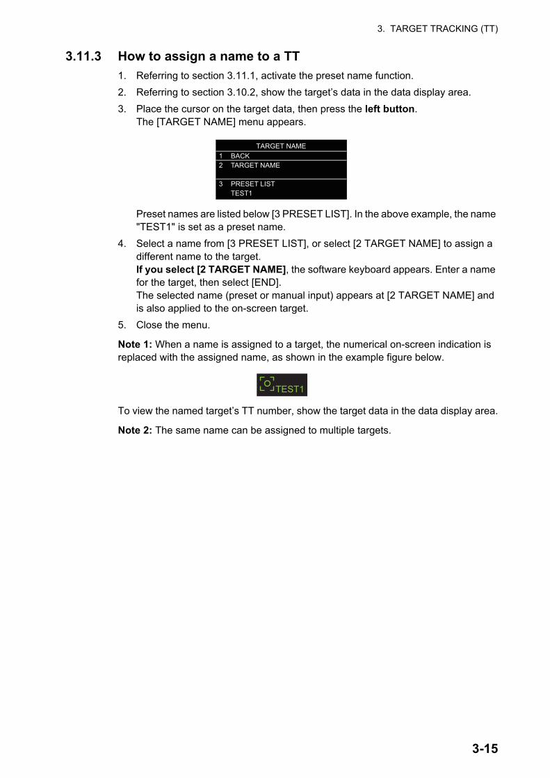
3. TARGET TRACKING (TT)
3.11.3 How to assign a name to a TT
1. Referring to section 3.11.1, activate the preset name function.
2. Referring to section 3.10.2, show the target’s data in the data display area.
3. Place the cursor on the target data, then press the left button.The [TARGET NAME] menu appears.
Preset names are listed below [3 PRESET LIST]. In the above example, the name "TEST1" is set as a preset name.
4. Select a name from [3 PRESET LIST], or select [2 TARGET NAME] to assign a different name to the target.If you select [2 TARGET NAME], the software keyboard appears. Enter a name for the target, then select [END].The selected name (preset or manual input) appears at [2 TARGET NAME] and is also applied to the on-screen target.
5. Close the menu.
Note 1: When a name is assigned to a target, the numerical on-screen indication is replaced with the assigned name, as shown in the example figure below.
To view the named target’s TT number, show the target data in the data display area.
Note 2: The same name can be assigned to multiple targets.
TARGET NAME1 BACK2 TARGET NAME 3 PRESET LIST TEST1
TEST1
3-15

3. TARGET TRACKING (TT)
3.12 Vector ModesTarget vectors can be displayed relative to own ship’s heading (Relative) or North (True).
Note: IMO recommends the use of true vector mode in sea stabilization or relative vector mode for collision avoidance.
3.12.1 Description of vectors
Stabilization modes
It is important to select the optimum stabilization mode for the radar display. To assess risk of collision the relative motion of a target gives the clearest indication of CPA and may be monitored by observing either the direction of the target's relative trail, or the CPA predicted by the relative vector. By default, relative motion displays relative target trails and true motion displays true target trails. Where true target trails is selected, a sea stabilized display will indicate all targets' motion through the water. A ground sta-bilized display will indicate all targets' motion over the ground.
In coastal, estuarine and river waters where a significant set and drift may be experi-enced, a sea stabilized display will produce significant target trails from all fixed (sta-tionary) objects possibly producing an unacceptably high level of clutter and masking. In such circumstances a ground stabilized display may reduce its effect and enable the observer to detect clearly the trails of moving targets, thus enhancing the observ-er's situational awareness.
However, the display should be considered only as an approximation of the course and speed made good over the ground. Among other factors, the accuracy of the ground-stabilization is affected by inaccuracies in speed and heading inputs as well as radar measurement imprecision and will require the display to be readjusted peri-odically. The information displayed should be interpreted with due regard to these fac-tors.
Note: It should be noted that in determining a target's aspect by radar; the calculation of its true track is dependent on the choice and accuracy of the own ship's course and speed input. A ground-stabilized target plot may accurately calculate the ground track of the target, but the target's heading may be significantly different from its track when experiencing set, drift or leeway. Similarly, a sea stabilized target plot may be inaccu-rate when own ship and the target, are experiencing different rates of set, drift or lee-way.
3-16

3. TARGET TRACKING (TT)
Ground stabilization and sea stabilization
Target vectors can be ground stabilized or sea stabilized in the True Motion mode. To select speed over the ground or speed through the water data, open the page from the menu. Select for ground stabilization or for sea stabilization. The vector mode indica-tion shows the stabilization mode in the true motion as [TRUE-G] or [TRUE-S].
Sea stabilization is a mode where own ship and all targets are referenced to the sea using a compass heading and single-axis log water speed inputs in the true motion mode. Ground stabilization is a mode where own ship and all targets are referenced to the ground using the ground track or set and drift inputs. If the accuracy seems un-satisfactory, enter set and drift corrections. Note that set and drift should not be used when the radar is displaying AIS targets.
True vector
In the true motion mode, all fixed targets such as land, navigational marks and ships at anchor remain stationary on the radar screen with vector length zero. But in the presence of wind and/or current, the vectors appear on fixed targets representing the reciprocal of set and drift affecting own ship unless set and drift values are properly entered.
In the true vector mode, there are two types of stabilization: ground stabilization (TRUE-G) and sea stabilization (TRUE-S). The stabilization mode is automatically se-lected according to speed selection, as shown in the table below. Manual selection is available from the [SPD] menu at the top-right of the screen.
Relative vector
Relative vectors on targets that are not moving over the ground such as land, naviga-tional marks and ships at anchor will represent the reciprocal of own ship's ground track. A target whose vector passes through own ship is on a collision course. (Dotted lines in the figure are for explanation only.)
Speed selection True vector modeLOG(WT) TRUE-SLOG(WTC) TRUE-GLOG(BT) TRUE-GEPFS(BT) TRUE-GREF(BT) TRUE-GMAN(WT) TRUE-SMAN(WTC) TRUE-G
Buoy
Own Ship
True vectors in ground stabilization
AIS
Buoy
Own Ship
True vectors in sea stabilization
TT
AIS
TTBuoy
Own Ship
Relative vectors
AIS
TTCurrent(Set and drift)
3-17
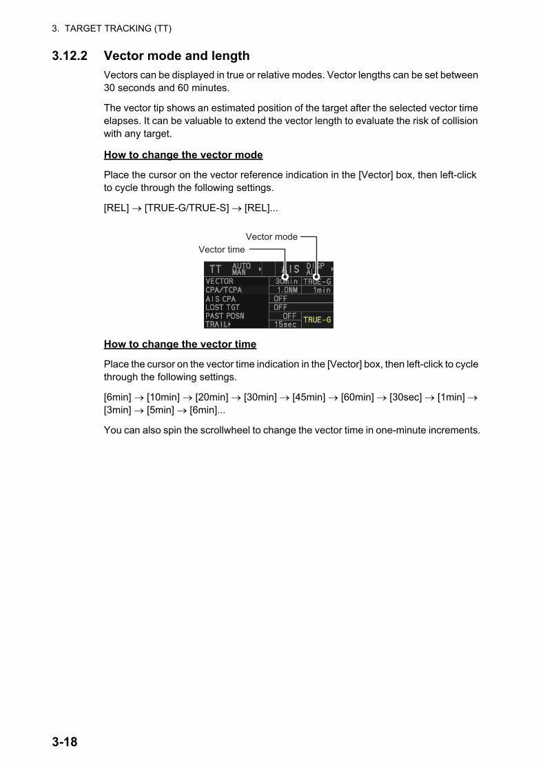
3. TARGET TRACKING (TT)
3.12.2 Vector mode and length
Vectors can be displayed in true or relative modes. Vector lengths can be set between 30 seconds and 60 minutes.
The vector tip shows an estimated position of the target after the selected vector time elapses. It can be valuable to extend the vector length to evaluate the risk of collision with any target.
How to change the vector mode
Place the cursor on the vector reference indication in the [Vector] box, then left-click to cycle through the following settings.
[REL] [TRUE-G/TRUE-S] [REL]...
How to change the vector time
Place the cursor on the vector time indication in the [Vector] box, then left-click to cycle through the following settings.
[6min] [10min] [20min] [30min] [45min] [60min] [30sec] [1min] [3min] [5min] [6min]...
You can also spin the scrollwheel to change the vector time in one-minute increments.
Vector timeVector mode
3-18
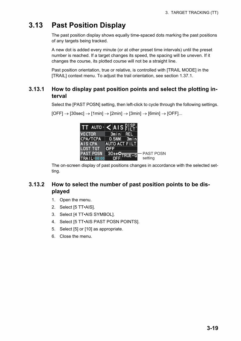
3. TARGET TRACKING (TT)
3.13 Past Position DisplayThe past position display shows equally time-spaced dots marking the past positions of any targets being tracked.
A new dot is added every minute (or at other preset time intervals) until the preset number is reached. If a target changes its speed, the spacing will be uneven. If it changes the course, its plotted course will not be a straight line.
Past position orientation, true or relative, is controlled with [TRAIL MODE] in the [TRAIL] context menu. To adjust the trail orientation, see section 1.37.1.
3.13.1 How to display past position points and select the plotting in-terval
Select the [PAST POSN] setting, then left-click to cycle through the following settings.
[OFF] [30sec] [1min] [2min] [3min] [6min] [OFF]...
The on-screen display of past positions changes in accordance with the selected set-ting.
3.13.2 How to select the number of past position points to be dis-played
1. Open the menu.
2. Select [5 TT•AIS].
3. Select [4 TT•AIS SYMBOL].
4. Select [5 TT•AIS PAST POSN POINTS].
5. Select [5] or [10] as appropriate.
6. Close the menu.
OFFPAST POSN setting
3-19

3. TARGET TRACKING (TT)
3.14 Set and DriftSet, the direction in which a water current flows, can be manually entered in 0.1-de-gree steps. Drift, also known as “Rate”, or the speed of the current, can also be en-tered manually in 0.1-knot steps.
When course through water and speed through water are available, activate set and drift to get course over ground and speed over ground.
Set and drift corrections are beneficial for increasing the accuracy of vectors and tar-get data. Refer to the tide table on board the ship for setting information. These values are applied to all targets. If stationary targets have vectors, set and drift values should be adjusted until they lose vectors.
To enter set and drift do the following:
1. Open the menu.
2. Select [7 INFORMATION BOX].
3. Select [2 OWN SHIP INFO].
4. Select [3 SPEED].Note: You can also right-click the [SPD] box to access this menu.
5. Select [4 SET DRIFT].
6. Select [ON]. The setting can now be adjusted and [SET] is selected.
7. Spin the scrollwheel to select the appropriate setting (Setting range: 000.0° to 359.9°), then left-click. The [DRIFT] setting is now selected.
8. Spin the scrollwheel to select the appropriate setting (Setting range: 00.0kn to 19.9kn), then left-click.
9. Close the menu.
Note 1: Set and drift are available when using manually input speed, speed through the water. The speed source is shown as "WTC" (Water Tracking Count).
Note 2: Set and drift should be checked periodically for correctness.
Note 3: When speed data input from the position sensor is valid, set and drift are not adjustable.
3-20

3. TARGET TRACKING (TT)
3.15 Collision Alarm (CPA, TCPA)This radar calculates CPA and TCPA by using own ship and relative target positions.
The TT continuously monitors the pre-dicted range at the Closest Point of Ap-proach (CPA) and predicted time to CPA (TCPA) of each TT. When the predicted CPA of any TT becomes smaller than a preset CPA range and its predicted TCPA less than a preset TCPA limit, the audio alarm sounds and "CPA/TCPA" appears (in red, flashing) in the Alert Box. In addition, the symbol of the offending TT is red and flashes together with its vector.
This feature, when used correctly, helps prevent the risk of collision by alerting you to threatening targets. It is important that GAIN, A/C SEA, A/C RAIN and other radar con-trols are properly adjusted.
CPA and TCPA ranges must be set up properly taking into consideration the size, ton-nage, speed, turning performance and other characteristics of own ship.
The reference point for CPA and TCPA calculation can be selected from antenna po-sition or conning position. For further details, see section 1.50.
3.15.1 How to set the CPA and TCPA ranges
CPA and TCPA ranges can be adjusted from the ap-propriate indication in the [TT] box.
1. Left-click the [CPA/TCPA] indication to activate the feature.
2. Place the cursor on the indication you wish to adjust.
3. Left-click, or spin the scrollwheel, to adjust the settings as required. The settings options are outlined in the table below.
Indication Method Settings optionsCPA Left-click 0.5, 1.0, 1.5, 2.0, 3.0, 4.0, 5.0, 6.0 (NM)
Scrollwheel 0.1 to 20; 0 to 10 in 0.1 NM increments, 1 NM incre-ments thereafter
TCPA Left-click 1, 2, 3, 4, 5, 6, 12, 15 (minutes)Scrollwheel 1 to 60 minutes in 1-minute increments
CAUTIONCPA/TCPA AlarmThe CPA and TCPA alarm feature shouldnever be relied upon as the sole means fordetecting the risk of collision.The navigatoris not relieved of the responsibility to keepvisual lookout for avoiding collisions,whether or not the radar or other plottingaid is in use.
CPA setting
TCPA setting
Left-click here to activate CPA/TCPA settings.
3-21

3. TARGET TRACKING (TT)
3.15.2 How to acknowledge the TT collision alarm
Press the ALARM ACK key on the control unit, or select the [ALERT] box with the trackball then left-click to acknowledge the alarm and silence the buzzer. The alert "CPA/TCPA" remains in the Alert Box until the dangerous situation is gone or you in-tentionally terminate target tracking. The symbol and vector stop flashing and are dis-played in a solid red color.
Note: When the "CPA/TCPA" alert is generated the AIS display is automatically turned on.
3.16 Acquisition ZoneThe acquisition zone functions both to alert you targets in a specific area and acts as an automatic acquisition area when automatic target acquisition is active. Any targets entering the zone will be automatically acquired.
When a target enters an acquisition zone, the buzzer sounds and "TT NEW TARGET" or "AIS NEW TARGET" appears (in yellow-orange) in the Alert Box. The symbol of the offending target is red and flashing. Further, the AIS display is automatically turned on if it is off.
There are two types of acquisition zones available, arc and polygon, however, AZ1 can only be set as an arc.
Note: The acquisition zones are disabled when the setting for [2 AZ/ALR SELECT] in the [ACQUISITION ZONE] menu is set to [TARGET ALARM ZONE].
3.16.1 How to enable the acquisition zones
1. Open the menu.
2. Select [5 TT•AIS].
3. Select [2 ACQUISITION ZONE].
4. Select [2 AZ/ALR SELECT].
5. Select [ACQUISITION ZONE].
6. Close the menu.
3-22

3. TARGET TRACKING (TT)
3.16.2 How to activate the first acquisition zone (AZ1)
The No. 1 acquisition zone is available between 3 NM and 6 NM and can have a width between 0.5 NM and 1 NM. The TT/AIS acquisition zone’s lines are white and dashed so as to distinguish them from the radar target alarm.
The procedure below shows how to set AZ1, using the example at the bottom of the page.
1. Place the cursor on the [1:] indication at the bottom-right of the screen, then left-click. The AZ zone setting reads "1: SET" and the cursor moves inside the opera-tional display area.
2. Place the cursor on the acquisition zone starting point (“A” in the figure to the right), then left-click.
3. Place the cursor on the acquisition zone end point (“B” in the figure to the right), then left-click.The AZ zone setting now reads "1: WORK".
3.16.3 How to set a polygon acquisition zone (AZ2)
Note: This procedure is not available if [5 AZ POLYGON] in the [ACQUISITION ZONE] menu is set to [OFF].
The No. 2 acquisition zone can be set anywhere when the No. 1 zone is already in use.
Polygon zones must have at least three points.
To set a polygon shaped acquisition zone:
1. Place the cursor on the [2:] acquisition zone indication at the bottom-right of the screen, then left-click. The cursor moves inside the operational display area.
2. Place the cursor on the acquisition zone starting point, then left-click.
3. Place the cursor on the second point, then left-click.
4. Repeat step 3 as required to set the remaining points of the polygon zone.
5. Right-click to complete the acquisition zone set up.Note: If 10 points are used for the polygon, the zone setup is automatically com-pleted and there is no need to right-click.
Notes on acquisition zones
• If you wish to create an acquisition zone having a 360-degree coverage around own ship, set point B in almost the same direction (approx. ±3°) as point A.
• The default acquisition zone is fan shaped. It can also be a polygon having 3-10 points.
• If both AZ1 and AZ2 are displayed, a maximum of four polygon points are shown.• TT and AIS are automatically set to TT=AUTO MAN and AIS=DISP, respectively,
when an AZ is activated in the following conditions:TT: TT=OFF or TT=MANUAL 100AIS: AIS FUNC=OFF or AIS DISP=OFF
Target in acquisition zone is red and flashing
B
0.5 to 1 NM0.5 to 1 NMA
3-23
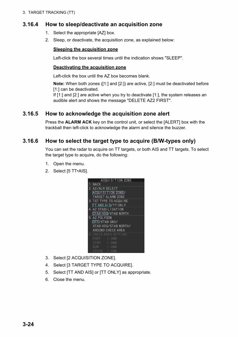
3. TARGET TRACKING (TT)
3.16.4 How to sleep/deactivate an acquisition zone
1. Select the appropriate [AZ] box.
2. Sleep, or deactivate, the acquisition zone, as explained below:
Sleeping the acquisition zone
Left-click the box several times until the indication shows "SLEEP".
Deactivating the acquisition zone
Left-click the box until the AZ box becomes blank.
Note: When both zones ([1:] and [2:]) are active, [2:] must be deactivated before [1:] can be deactivated.If [1:] and [2:] are active when you try to deactivate [1:], the system releases an audible alert and shows the message "DELETE AZ2 FIRST".
3.16.5 How to acknowledge the acquisition zone alert
Press the ALARM ACK key on the control unit, or select the [ALERT] box with the trackball then left-click to acknowledge the alarm and silence the buzzer.
3.16.6 How to select the target type to acquire (B/W-types only)
You can set the radar to acquire on TT targets, or both AIS and TT targets. To select the target type to acquire, do the following:
1. Open the menu.
2. Select [5 TT•AIS].
3. Select [2 ACQUISITION ZONE].
4. Select [3 TARGET TYPE TO ACQUIRE].
5. Select [TT AND AIS] or [TT ONLY] as appropriate.
6. Close the menu.
3-24

3. TARGET TRACKING (TT)
3.16.7 How to change the acquisition zone reference
The acquisition zone can be referenced to heading or North using the following pro-cedure:
1. Open the menu.
2. Select [5 TT•AIS].
3. Select [2 ACQUISITION ZONE].
4. Select [4 AZ STABILIZATION].
5. Select [STAB HDG] to reference heading, or [STAB NORTH] to reference North.
6. Close the menu.
3.16.8 How to set acquisition zone shape and stabilization (B/W-types only)
The shape of the No. 2 acquisition zone can be a sector or a polygon having up to 10 points. (The shape of the No.1 acquisition zone is always a sector.)
1. Open the menu.
2. Select [5 TT•AIS].
3. Select [2 ACQUISITION ZONE].
4. Select [5 AZ POLYGON].
5. Select the appropriate setting.
*: Shown only for B/W-type.
6. Close the menu.
Setting Description[OFF] Acquisition zone is a sector; number of points is limited to four.
Stabilized against land.[STAB GND] Polygon having 3-10 points. Stabilized against ground.[STAB HDG] Polygon having 3-10 points. Stabilized against heading.[STAB NORTH] Polygon having 3-10 points. Stabilized against North.[AROUND CHECK AREA]*
Sets a check area around own ship. See the topic on the follow-ing page for details and settings.
3-25

3. TARGET TRACKING (TT)
How to set the check area around own ship (B/W-type only)
When [5 AZ POLYGON] is set to [AROUND CHECK AREA], the area details must be set. To setup the check area, do the following procedure. This procedure is abbrevi-ated, and takes into consideration that [AROUND CHECK AREA] is selected.
1. Select [6 CHECK AREA SETTING].
2. Referring to the figure below, use the number keys to enter a distance for [PORT], [STBD], [BOW] and [STERN]. You can also spin the scrollwheel, then left-click to enter these values.
The area shown in gray is the “check area”.The available setting range for all four values is [0.0NM] to [16.0NM]. The default setting for all four values is [1.0NM].
Own
ship
[PORT] setting[PORT] setting
[BOW] setting[BOW] setting
[STERN] setting
[STERN] setting
[STBD] setting[STBD] setting
3-26

3. TARGET TRACKING (TT)
3.17 Trial ManeuversThe trial maneuver feature simulates the effect of own ship's movement against all tracked targets, without interrupting the updating of target information. It is available for use with the TT and AIS functions. For more accurate results, use sea stabilization (water tracking).
3.17.1 Types of trial maneuvers
There are two types of trial maneuvers: dynamic and static.
Dynamic trial maneuver
A dynamic trial maneuver displays predicted positions of the tracked targets and own ship. You enter own ship's intended speed and course with a certain "delay time." Assuming that all tracked targets maintain their present speeds and courses, the targets' and own ship's future movements are simulated in 0.5-second increments indicating their predicted positions in 30-second intervals as illustrated in the right figure.
The delay time represents the time lag from the present time to the time when own ship will actually start to change her speed and/or course. You should therefore take into consid-eration own ship's maneuvering characteris-tics such as rudder delay, turning delay and acceleration delay. This is particularly important on large vessels. How much the delay is set the situation starts immediately and ends in a minute.
In the example shown below, own ship will advance straight ahead (even after a ma-neuver) for a delay time of 2:30 and alters speed and course until operator-specified intended speed and course are achieved (position OS7 in this example).
Delay time = 2 m 30 s.
Current position
3-27
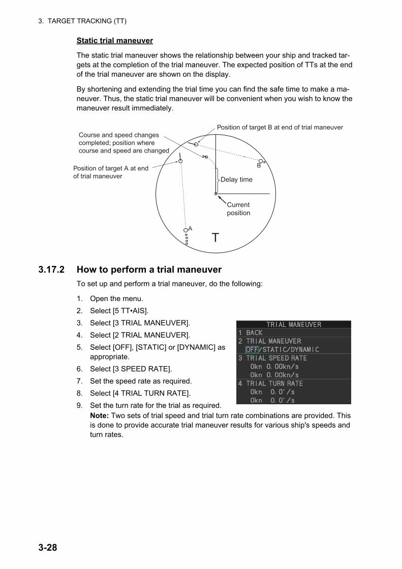
3. TARGET TRACKING (TT)
Static trial maneuver
The static trial maneuver shows the relationship between your ship and tracked tar-gets at the completion of the trial maneuver. The expected position of TTs at the end of the trial maneuver are shown on the display.
By shortening and extending the trial time you can find the safe time to make a ma-neuver. Thus, the static trial maneuver will be convenient when you wish to know the maneuver result immediately.
3.17.2 How to perform a trial maneuver
To set up and perform a trial maneuver, do the following:
1. Open the menu.
2. Select [5 TT•AIS].
3. Select [3 TRIAL MANEUVER].
4. Select [2 TRIAL MANEUVER].
5. Select [OFF], [STATIC] or [DYNAMIC] as appropriate.
6. Select [3 SPEED RATE].
7. Set the speed rate as required.
8. Select [4 TRIAL TURN RATE].
9. Set the turn rate for the trial as required.Note: Two sets of trial speed and trial turn rate combinations are provided. This is done to provide accurate trial maneuver results for various ship's speeds and turn rates.
A
B
Current position
Delay time
T
Course and speed changes completed; position where course and speed are changed
Position of target B at end of trial maneuver
Position of target A at end of trial maneuver
3-28

3. TARGET TRACKING (TT)
10. For A/B/W-type radars, select [5 TRIAL TARGET DATA].Note: For IMO/R-types, [5 TRIAL TARGET DATA] is not shown; skip to step 12 if your radar is an IMO/R-type.
11. Select the target data to use for the trial. The available options are: [ACTUAL] and [TRIAL].
12. Highlight the [TRIAL] status indication in the [TRIAL] box, then left-click. The indi-cation changes from "OFF" to "SET" and the trial maneuver settings appear.
Note: The initial indications for course and speed are derived from own ship’s cur-rent course and speed at the time when the trial maneuver set up starts.
13. Select the trial maneuver course and reference indication, then left-click.
Setting example for [3 TRIAL SPEED RATE]
5 kn, 0.15 kn/s10 kn, 0.45 kn/s
Tria
l spe
ed ra
te
Trial maneuver speed
5 kn(First setting)
0.15 kn/s(First setting)
0.45 kn/s(Second setting)
10 kn(Second setting)
Setting example for [4 TRIAL TURN RATE]
5 kn, 1.5 °/s10 kn, 4.5 °/s
Tria
l tur
n ra
te
Trial maneuver speed
5 kn(First setting)
1.5 °/s(First setting)
4.5 °/s(Second setting)
10 kn(Second setting)
Trial maneuver course and referenceTrial maneuver
speed
Delay time
Trial maneuver mode.“S”: Static; “D”: DynamicTrial maneuver
status
[STATIC] mode
[DYNAMIC] modeClick here
3-29
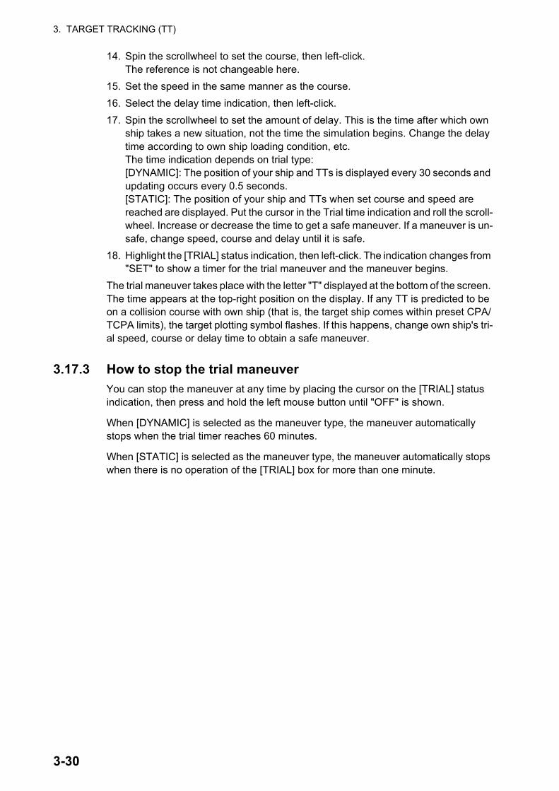
3. TARGET TRACKING (TT)
14. Spin the scrollwheel to set the course, then left-click.The reference is not changeable here.
15. Set the speed in the same manner as the course.
16. Select the delay time indication, then left-click.
17. Spin the scrollwheel to set the amount of delay. This is the time after which own ship takes a new situation, not the time the simulation begins. Change the delay time according to own ship loading condition, etc.The time indication depends on trial type:[DYNAMIC]: The position of your ship and TTs is displayed every 30 seconds and updating occurs every 0.5 seconds.[STATIC]: The position of your ship and TTs when set course and speed are reached are displayed. Put the cursor in the Trial time indication and roll the scroll-wheel. Increase or decrease the time to get a safe maneuver. If a maneuver is un-safe, change speed, course and delay until it is safe.
18. Highlight the [TRIAL] status indication, then left-click. The indication changes from "SET" to show a timer for the trial maneuver and the maneuver begins.
The trial maneuver takes place with the letter "T" displayed at the bottom of the screen. The time appears at the top-right position on the display. If any TT is predicted to be on a collision course with own ship (that is, the target ship comes within preset CPA/TCPA limits), the target plotting symbol flashes. If this happens, change own ship's tri-al speed, course or delay time to obtain a safe maneuver.
3.17.3 How to stop the trial maneuver
You can stop the maneuver at any time by placing the cursor on the [TRIAL] status indication, then press and hold the left mouse button until "OFF" is shown.
When [DYNAMIC] is selected as the maneuver type, the maneuver automatically stops when the trial timer reaches 60 minutes.
When [STATIC] is selected as the maneuver type, the maneuver automatically stops when there is no operation of the [TRIAL] box for more than one minute.
3-30

3. TARGET TRACKING (TT)
3.18 TT System MessagesThere are four main reasons the TT may trigger the audio and visual alerts:
You can acknowledge visual alerts and silence the audio alerts with one of the follow-ing methods:
• Press the ALARM ACK key on the control unit
• Click the [ALERT] box, at the bottom-right of the screen.
• Click the alert in the [ALERT LIST].
• Collision alarm• Acquisition zone alert
• Lost target alert• Target capacity
Alert title Priority Meaning Action requiredCPA/TCPA Alarm A tracked target is on col-
lision course with your vessel.
Take evasive action or ter-minate tracking of TT.
TT NEW TARGET
Warning Tracked target has en-tered an acquisition zone. The tracked tar-get's symbol is red and flashing.
Confirm the tracked target, then press the ALARM ACK key.
TT TARGET LOST
Warning When the system detects a loss of a tracked target, the lost tracked target symbol appears in red and flashes. At the same time, an audio alert is produced for one sec-ond. The lost target mark disappears from the screen after the lost tar-get alert is acknowl-edged.
Confirm the lost target, re-acquire if necessary.
REF TARGET LOST
Warning When the system detects a loss of a reference tar-get, the target symbol turns red and flashes. At the same time, an audio alert is produced for one second. The reference target mark disappears from the screen after the reference target alarm is acknowledged.
To continue using a refer-enced target for speed in-put, select another tracked target.
TT TGT FULL (AUTO) or (MAN)
Warning Appears when capacity for automatically (manu-ally) acquired targets is full.
To continue acquiring tar-gets, cancel tracking for un-necessary targets.
TT TGT 95% (AUTO) or (MAN)
Caution Appears when capacity for automatically (manu-ally) tracked targets is 95% full.
3-31

3. TARGET TRACKING (TT)
3.19 TT Simulation ModeYou can simulate the risk of a collision by using the TT simulation mode. This function can be used for familiarization training for your crew. The simulation can be terminated at any time by pressing the STBY TX key.
1. Open the menu.
2. Select [9 INITIAL SETTINGS].
3. Select [7 TESTS].
4. Select [4 TT SIMULATION MODE].
The normal operation is suspended then three simulated targets appear on the dis-play.
The indication "S" appears at the bottom of the effective display area during the sim-ulation mode. The simulation may be terminated any time by going to the STBY mode.
Three simulated targets move as the following table. The simulated target is automat-ically generated with the relative movement in the following table based on own ship's movement at the start of simulation mode.
Note: If own ship moves after the start of simulation mode, the movement of the sim-ulated target is not matched with the values in the following table.
Place the cursor on a target, then press the ACQ key to display the target data.
Acquire the simulated targets after the TT simulation mode is performed. The tracking state changes from unstable to stable and the vector appears. You can simulate the movement of each function with changing true/relative vector, stabilization through the water/over the ground, range or length of vector.
Repeat the check for all targets.
Range (R) Bearing (R) Speed (R) Course (R) CPA TCPATarget 01 9.5 NM 270.0° 20.0 kn 90.0° 0.0 NM 28.5 minTarget 02 1.1 NM 333.0° 10.2 kn 90.2° 1.0 NM 2.9 minTarget 03 9.3 NM 45.0° 19.9 kn 225.1° 0.0 NM 28.0 min
S
01
03
02
3-32

3. TARGET TRACKING (TT)
3.20 Criteria for Tracking Target SelectionThe FURUNO TT video processor detects targets in midst of noise and discriminates radar echoes on the basis of their size. Target whose echo measurements are greater than those of the largest ship in range or tangential extent are usually land and are displayed only as normal radar video. All smaller ship-sized echoes that are less than this dimension, are further analyzed and regarded as ships and displayed as small cir-cles superimposed over the video echo.
When a target is first displayed, it is shown as having zero true speed but develops a course vector as more information is collected. In accordance with the International Marine Organization Automatic Radar Plotting Aid (IMO TT) requirements, an indica-tion of the motion trend should be available within 20 scans of antenna and full vector accuracy within 60 scans. The FURUNO TTs comply with these requirements.
Acquisition and tracking criteria
A target which is hit by five consecutive radar pulses, is detected as a radar echo. Manual acquisition is done by designating a detected echo with the trackball.Automat-ic acquisition is done in the acquisition areas when a target is detected 5-7 times con-tinuously depending upon the congestion. Tracking is achieved the target is clearly distinguishable on the display for 5 out of 10 consecutive scans, whether acquired au-tomatically or manually. Required tracking facilities are available within 0.1-32 nm on range scales including 3, 6, 12 nm, full plotting information is available within one scan when the range scale has been changed.
Targets not detected in five consecutive scans become “lost targets”.
Quantization
The entire picture is converted to a digital from called “Quantized Video”. A sweep range is divided into small segments and each range element is”1” if there is radar echo return above a threshold level, or “0” if there is no return.
The digital radar signal is then analyzed by a ship-sized echo discriminator. As the an-tenna scans, if there are five consecutive radar pulses with 1’s indicating an echo presence at the exact same range, a target “start” is initiated. Since receiver noise is random, it is not three-bang correlated, and it is filtered out and not classified as an echo.
The same is true of radar interference. Electronic circuits track both the closet and most distant edges of the echo. At the end of the scanning of the echo, the discrimi-nator indicates the measured maximum range extent and total angular extent sub-tended by the echo. If the echo is larger than a ship-sized echo in range extent and/or angular width, adjusted as a function of range, it is declared to be a coastline and the closet edge is put into memory as a map of the area.
This land outline is used to inhibit further acquisition and tracking of ship-sized echoes beyond the closest coast outline. Five consecutive scans of coastal outline are re-tained in memory to allow for signal variation. All smaller echoes are declared to be ship sized and the middle of the leading edge is used to provide precise range and bearing co-ordinates of each echo on every scan. This range/bearing data is matched to previous data and analyzed from scan-to-scan for consistency. When it is deter-mined to be as consistent as a real target, automatic acquisition occurs and tracking is initiated. Continued tracking and subsequent calculation develop the relative course and speed of the target.
3-33

3. TARGET TRACKING (TT)
The true course and speed of own ship are computed from own ship's gyro and speed inputs, and the resulting course and speed of each tracked target is easily computed by vector summing of the relative motion with own ship’s course and speed. The re-sulting true or relative vector is displayed for each of the tracked targets. This process is updated continually for each target on every scan of the radar.
Qualitative description of tracking error
The FURUNO TT's accuracy complies with or exceed IMO standards.
Own ship maneuvers
For slow turns there is no effect. For very high turning rates (greater than 150°/minute, depending on gyro), there is some influence on all tracked targets that lasts for a min-ute or two then all tracked targets revert to full accuracy.
Other ship maneuvers
Target ship courses, lag 15 to 30 seconds at high relative speed, or 3 to 6 seconds at low (near 0) relative speed. It is less accurate during a turn due to lag, but accuracy recovers quickly.
3.21 Factors Affecting Target Tracking
Sea returns
If the radar anti-clutter control is adjusted properly, there is no serious effect because distant wave clutter, not eliminated by this control, is filtered out by more than one bang correlation and scan-to-scan matching of data.
Rain and snow
Rain clutter can be acquired and tracked as targets. Adjust the rain clutter control to suppress the clutter. If it is heavy rain, switch to S-band if provided, or switch on the interference rejector on the radar. If heavy clutter still exists, switch to manual acqui-sition. Accuracy can be affected.
Low clouds
Usually no affect. If necessary, adjust the rain clutter control.
Non-synchronous emissions
No effect.
Low gain
Insufficient or low radar receiver gain will result in some targets not being acquired at long distance. The TT display will be missing on one or more targets that could only be visible if the radar sensitivity control (GAIN control) were increased.
The setting of the correct radar receiver gain is not critical but the target should be on the radar PPI and be clearly visible and well defined.
Manual acquisition is done if a target is positively displayed more than once. Automat-ic acquisition is done when the target is detected 5-7 times continuously.
3-34

3. TARGET TRACKING (TT)
Tracking continues if a return echo is received at least once in nine antenna rotations. However, the fewer the return echoes the lower the accuracy. If no return echo is re-ceived within nine antenna rotations the target is declared a lost target.
Second trace echoes
When the radar beam is super refracted, strong echoes may be received at such long ranges that they appear on a different timebase sweep than the transmitted pulse. This gives an incorrect range indication. Second- and third-trace echoes can be tracked if they are consistent enough to meet acquisition and tracking criteria but tar-get course and speed data will be in error.
Blind and shadow sectors
Radar shadow or blind areas caused by obstructions aboard the ship, for example, funnels and masts, in the path of the radar beam can result in reduction of radar beam intensity in that particular direction. This may eliminate the detection of some targets. The TT system will lose track of targets shortly after they are lost on the radar picture and if they remain in a blind zone. These targets will however be acquired and tracked when they pass out of the blind zone and again present normal radar echo. The an-gular width and bearing of any shadow sector should be determined for their influence on the radar. In certain cases false echoes in the shadow sector cause the TT system to acquire, track, and vector them. Shadow sectors should be avoided.
Indirect echoes
A target at close range is usually picked up directly, but it can also be received as re-flection from a large, flat surface. This will result in the radar presenting two or more echoes on the display, each at a different range. The TT system can acquire and track a false echo if it is detected in five consecutive scans. Reduction in radar gain can eliminate the multiple echoing but care should be taken as range detection also will be reduced.
Radar interference
If interference is extreme due to another radar operating at close range, spiral "dotting" and/or false targets may appear momentarily. The interference rejector can clear the display.
Delay of sensor input
If the refresh rate of the gyrocompass signal is too slow, error in target bearing occurs when own ship turns. To prevent this error, the refresh rate of the gyrocompass signal must be as indicated in the System Configuration drawings.
3-35

3. TARGET TRACKING (TT)
This page is intentionally left blank.
3-36

4. AIS OPERATION
An AIS transponder can be connected to this radar to overlay AIS targets on the radar display. The radar can store up to 1,200 AIS targets in its storage buffer. When this buffer becomes full of AIS targets, the Alert "AIS CPTY FULL" is generated to alert you to full storage buffer. The storage buffer contains automatic dead reckoning for all AIS targets, which is based on reported Speed Over the Ground (SOG) and Course Over the Ground (COG). The storage buffer also contains calculation of range, bearing, CPA, TCPA, etc. The CPA and TCPA limits set for dangerous targets are common for TT and AIS targets.
This radar can activate 50 AIS targets. The Alert "ACTIVE AIS FULL" is generated when 50 AIS targets are activated.
This radar can display a maximum of 350 AIS targets. The Alert "AIS DISPLAY FULL" is generated when 350 AIS targets, which includes both activated and sleeping tar-gets, are displayed.
The frequency for update of AIS transponder-sent data depends on speed and course of tracked AIS target. The table below shows the IMO standardized reporting rates for the AIS transponder. Based on the table below, the radar defines which AIS targets are in tracking or lost. When you acknowledge a lost target alert, the corresponding AIS symbol will be removed from the display.
An AIS transponder "sees" all ships fitted with an AIS transponder belonging to either a Class A or Class B AIS. Additionally, the AIS transponder receives messages from ships and non-ships (AIS SAR aircraft, AIS aid to navigation, AIS base station, and AIS search and rescue transmitter).
Type of Ship
IMOnominalreportinginterval
Lost target indication (reportinginterval >)
Class A: Navigation status is “anchor” or “not under command” or “moored” or “aground”, and SOG 3kn
3 min 10 min
Class A: Navigation status is “anchor” or “not under command” or “moored” or “aground”, and SOG > 3kn
10 s 50 s
Class A: 0kn SOG < 14kn 10 s 50 sClass A: 14kn SOG 23kn 6 s 30 sClass A: SOG > 23kn 2 s 10 sClass B: “CS” SOG 2kn 3 min 10 minClass B: “CS” SOG > 2kn 30 s 150 sClass B: “SO” 0 kn SOG 2kn 3 min 10 minClass B: “SO” 2 kn < SOG < 14kn 30 s 150 sClass B: “SO” 14 kn SOG 23kn 15 s 75 sClass B: “SO” SOG > 23kn 5 s 25 sClass A and Class B: no SOG available N/A 10 minAIS SAR aircraft 10 s 50 sAIS aid to navigation 3 min 10 minAIS base station 10 s 50 sAIS search and rescue transponder N/A 10 min
4-1
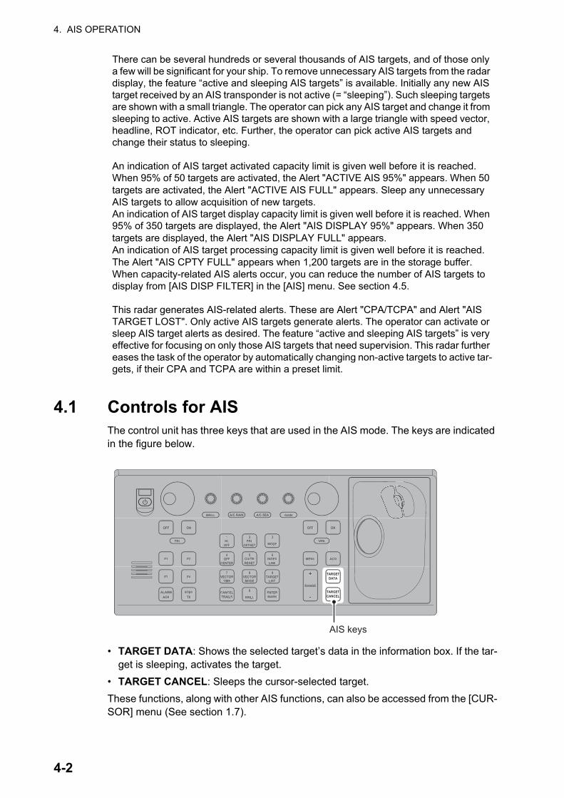
4. AIS OPERATION
4.1 Controls for AISThe control unit has three keys that are used in the AIS mode. The keys are indicated in the figure below.
• TARGET DATA: Shows the selected target’s data in the information box. If the tar-get is sleeping, activates the target.
• TARGET CANCEL: Sleeps the cursor-selected target.
These functions, along with other AIS functions, can also be accessed from the [CUR-SOR] menu (See section 1.7).
There can be several hundreds or several thousands of AIS targets, and of those only a few will be significant for your ship. To remove unnecessary AIS targets from the radar display, the feature “active and sleeping AIS targets” is available. Initially any new AIS target received by an AIS transponder is not active (= “sleeping”). Such sleeping targets are shown with a small triangle. The operator can pick any AIS target and change it from sleeping to active. Active AIS targets are shown with a large triangle with speed vector, headline, ROT indicator, etc. Further, the operator can pick active AIS targets and change their status to sleeping.
An indication of AIS target activated capacity limit is given well before it is reached. When 95% of 50 targets are activated, the Alert "ACTIVE AIS 95%" appears. When 50 targets are activated, the Alert "ACTIVE AIS FULL" appears. Sleep any unnecessary AIS targets to allow acquisition of new targets.An indication of AIS target display capacity limit is given well before it is reached. When 95% of 350 targets are displayed, the Alert "AIS DISPLAY 95%" appears. When 350 targets are displayed, the Alert "AIS DISPLAY FULL" appears.An indication of AIS target processing capacity limit is given well before it is reached. The Alert "AIS CPTY FULL" appears when 1,200 targets are in the storage buffer.When capacity-related AIS alerts occur, you can reduce the number of AIS targets to display from [AIS DISP FILTER] in the [AIS] menu. See section 4.5.
This radar generates AIS-related alerts. These are Alert "CPA/TCPA" and Alert "AIS TARGET LOST". Only active AIS targets generate alerts. The operator can activate or sleep AIS target alerts as desired. The feature “active and sleeping AIS targets” is very effective for focusing on only those AIS targets that need supervision. This radar further eases the task of the operator by automatically changing non-active targets to active tar-gets, if their CPA and TCPA are within a preset limit.
ACQ
ON
MENU
OFF
VRM
A/C SEAA/C RAIN
MODE
3
LINEINDEX
6
OFF
21HL
CENTEROFF
4 5
RESETCU/TM
OFFSETEBL
GAIN
TARGETCANCEL
TARGETDATA
RANGE
-
+LIST
TARGET9
ENTERMARK
TIMEVECTOR
7 8
CANCELTRAILS
0
MODEVECTOR
BRILL
BRILL
EBL
F1
OFF
F2
ON
ACKALARM
F3 F4
STBYTX
ACQ
ON
MENU
OFF
VRM
A/C SEAA/C RAIN
MODE
3
LINEINDEX
6
OFF
21HL
CENTEROFF
4 5
RESETCU/TM
OFFSETEBL
GAIN
RANGE
-
+LIST
TARGET9
ENTERMARK
TIMEVECTOR
7 8
CANCELTRAILS
0
MODEVECTOR
BRILL
BRILL
EBL
F1
OFF
F2
ON
ACKALARM
F3 F4
STBYTX
AIS keys
4-2

4. AIS OPERATION
4.2 AIS Box Overview
4.3 How to Select the AIS Display Mode
• [DISP OFF]: AIS symbols are hidden.
• [DISP FILT]: Only filtered AIS targets are displayed.
• [DISP ALL]: All AIS symbols are displayed.
To disable the AIS function, put the cursor on the AIS display mode indication, then long right-click. The AIS display mode indication shows [FUNC OFF] when the AIS function is disabled.
No. Indication name Description/remarks1 Association indication Shows the association setting. See section 4.15 for
details.2 AIS mode setting Shows the current filter setting for AIS target display.
• [FUNC OFF]: AIS display is disabled.• [DISP OFF]: AIS symbols are hidden.• [DISP FILT]: Only filtered AIS targets are displayed.• [DISP ALL]: All AIS symbols are displayed.
3 [VECTOR] • Adjusts the vector time for the selected target.• True, Relative referencing for this target’s vector.See section 3.12 for details.
4 [CPA/TCPA] Adjusts the CPA/TCPA settings.5 [AIS CPA] Adjusts the AIS auto activate settings.6 [LOST TGT] Adjusts the settings for lost targets and related alerts.7 [PAST POSN] Adjusts the setting for past position tracks. See
section 3.13 fro details.8 Trail mode Changes the trail mode in use. See section 1.37 for
details.9 Trail time Shows the interval setting for trails. See section 1.37.2
for details.
21
OFF
3
54
67 8
9
AIS display mode
4-3

4. AIS OPERATION
4.4 AIS Symbols and Their MeaningsWhen the AIS display is active, each AIS target is marked with a symbol that indicates the target’s status. For the meaning of each AIS symbol, see "AIS symbols" on page AP-44.
Note 1: The equipment continues to process AIS targets when the AIS feature is de-activated. When the AIS is activated again, symbols are immediately displayed.
Note 2: AIS symbols are momentarily erased and the screen is redrawn after the heading is changed in the HEAD UP mode.
Note 3: When no AIS data is received, the message "LOST AIS COM" appears in the Alert Box. Check connection with the AIS transponder.When the AIS function is disabled: Above message is prioritized as a Caution level alert for IMO/R-types. A/B/W-types do not show this alert.When the AIS function is active: Above message is prioritized as a Warning level alert for all radar types.
4.5 How to Use the AIS Display FilterIf there are too many AIS targets on the screen you may wish to remove unnecessary ones. You can remove sleeping targets class A/B by distance from own ship, speed and class. For example, you might want to remove slow moving targets, as they nor-mally do not require close monitoring.
1. Open the menu.
2. Select [5 TT•AIS].
3. Select [5 AIS].
Note: You can also right-click the AIS indication in the [TT•AIS] box to open the [TT] menu.
4. Select [0 NEXT] to show the next menu page.
Current display filter settings appear here
4-4
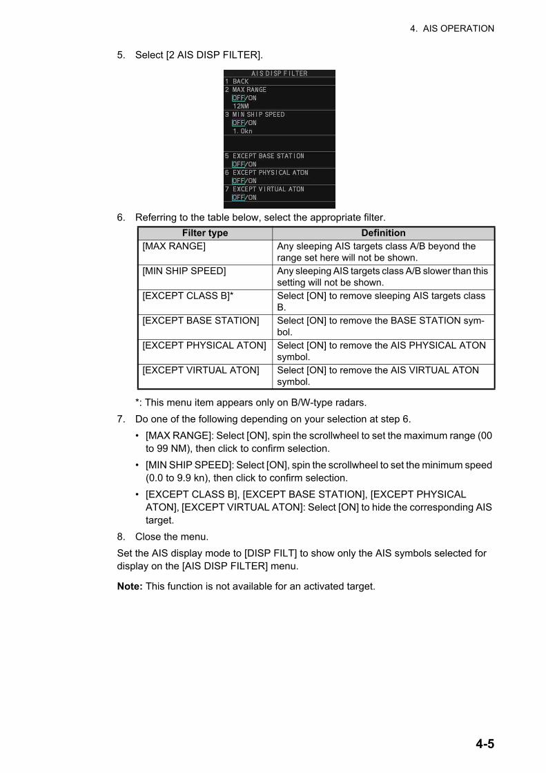
4. AIS OPERATION
5. Select [2 AIS DISP FILTER].
6. Referring to the table below, select the appropriate filter.
*: This menu item appears only on B/W-type radars.
7. Do one of the following depending on your selection at step 6.
• [MAX RANGE]: Select [ON], spin the scrollwheel to set the maximum range (00 to 99 NM), then click to confirm selection.
• [MIN SHIP SPEED]: Select [ON], spin the scrollwheel to set the minimum speed (0.0 to 9.9 kn), then click to confirm selection.
• [EXCEPT CLASS B], [EXCEPT BASE STATION], [EXCEPT PHYSICAL ATON], [EXCEPT VIRTUAL ATON]: Select [ON] to hide the corresponding AIS target.
8. Close the menu.
Set the AIS display mode to [DISP FILT] to show only the AIS symbols selected for display on the [AIS DISP FILTER] menu.
Note: This function is not available for an activated target.
Filter type Definition[MAX RANGE] Any sleeping AIS targets class A/B beyond the
range set here will not be shown.[MIN SHIP SPEED] Any sleeping AIS targets class A/B slower than this
setting will not be shown.[EXCEPT CLASS B]* Select [ON] to remove sleeping AIS targets class
B.[EXCEPT BASE STATION] Select [ON] to remove the BASE STATION sym-
bol.[EXCEPT PHYSICAL ATON] Select [ON] to remove the AIS PHYSICAL ATON
symbol.[EXCEPT VIRTUAL ATON] Select [ON] to remove the AIS VIRTUAL ATON
symbol.
4-5
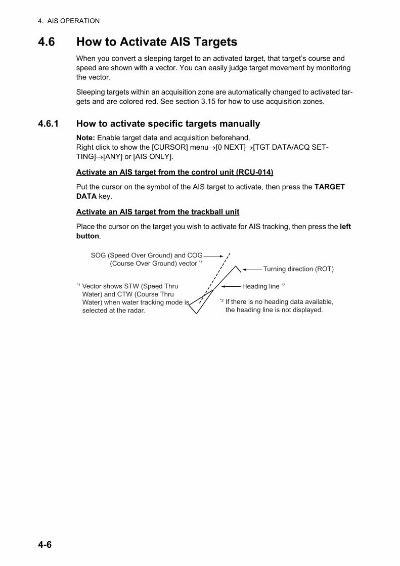
4. AIS OPERATION
4.6 How to Activate AIS TargetsWhen you convert a sleeping target to an activated target, that target’s course and speed are shown with a vector. You can easily judge target movement by monitoring the vector.
Sleeping targets within an acquisition zone are automatically changed to activated tar-gets and are colored red. See section 3.15 for how to use acquisition zones.
4.6.1 How to activate specific targets manually
Note: Enable target data and acquisition beforehand.Right click to show the [CURSOR] menu[0 NEXT][TGT DATA/ACQ SET-TING][ANY] or [AIS ONLY].
Activate an AIS target from the control unit (RCU-014)
Put the cursor on the symbol of the AIS target to activate, then press the TARGET DATA key.
Activate an AIS target from the trackball unit
Place the cursor on the target you wish to activate for AIS tracking, then press the left button.
SOG (Speed Over Ground) and COG (Course Over Ground) vector *1
*1 Vector shows STW (Speed Thru Water) and CTW (Course Thru Water) when water tracking mode is selected at the radar.
Turning direction (ROT)
Heading line *2
*2 If there is no heading data available, the heading line is not displayed.
4-6

4. AIS OPERATION
4.6.2 How to set the AIS auto activate function
You can limit the function of the AIS auto activate function by distance from own ship, ship's speed, ship class, and ship's length.
How to set the AIS auto activate function
1. Open the menu.
2. Select [5 TT•AIS].
3. Select [5 AIS].
4. Select [9 CPA AUTO ACTIVATE] to show the [CPA AUTO ACTIVATE] menu.
5. Referring to the table below, select the appropriate filter.
6. Do one of the following depending on your selection at step 5.
• [MAX RANGE]: Select [ON], spin the scrollwheel to set the maximum range (00 to 99 N), then click to confirm selection.
• [MIN SHIP SPEED]: Select [ON], spin the scrollwheel to set the minimum speed (0.0 to 9.9 kn), then click to confirm selection.
• [EXCEPT CLASS B], [EXCEPT BASE STATION], [EXCEPT PHYSICAL ATON], [EXCEPT VIRTUAL ATON]: Select [ON] to hide the corresponding AIS target.
7. Close the menu.
How to enable/disable the AIS auto activate function
Use the [CPA AUTO ACTIVATE] box at the bottom right corner to enable or disable the AIS auto activate function.
Filter type Definition[MAX RANGE] Any AIS targets beyond the range set here will not be au-
tomatically activated.[MIN SHIP SPEED] Any AIS targets slower than this setting will not be auto-
matically activated.[EXCEPT CLASS B] Select [ON] to prevent activation of AIS targets class B.
Filter type Definition[OFF] Disable the AIS auto activate function.[AUTO ACT FILT] Activation against AIS targets which meet the following criteria:
• AIS target that meets the criteria set with [CPA AUTO ACTI-VATE] on the [TT•AIS] menu.
• CPA or TCPA of an AIS target is smaller than that set in section section 3.15.
OFFOFF Place the cursor on the [CPA AUTO
ACTIVATE] box, then left-click to cycle through the auto activate settings.
4-7
4. AIS OPERATION
4.7 How to Sleep AIS TargetsYou can “sleep” an AIS target as below when the screen becomes filled with radar echoes and TTs, which might prevent important radar and AIS displays from being identified.
Note: Dangerous targets and targets that have been activated automatically cannot be “slept”.
4.7.1 How to sleep individual AIS targets
Note: Enable target data and acquisition beforehand.Right click to show the [CURSOR] menu[0 NEXT][TGT DATA/ACQ SET-TING][ANY] or [AIS ONLY].
Sleep a AIS target from the control unit keyboard (RCU-014)
Place the cursor on the symbol of the AIS target to sleep, then press the TARGET CANCEL key.
Sleep a AIS target with the trackball
1. Place the cursor inside the operational display area, then right-click. The [CUR-SOR] menu appears.
2. Select [TARGET CANCEL].
3. Place the cursor on the symbol of the AIS target to sleep, then click.
4.7.2 How to sleep all AIS targets
1. Open the menu.
2. Select [5 TT•AIS].
3. Select [5 AIS].
4. Select [2 SLEEP ALL TARGETS].
5. Select [YES] or [NO] as appropriate.
6. Close the menu.
[AUTO ACT ALL] Activation against AIS targets whose CPA or TCPA is less than set in section 3.15
Filter type Definition
4-8

4. AIS OPERATION
4.8 How to Set Up For a VoyageAt the start of a voyage, following five items must be input from the [VOYAGE DATA] menu: navigational status, ETA, destination, draught and crew.
4.8.1 How to access the [VOYAGE DATA] menu
There are two methods by which you can access the [VOYAGE DATA] menu: from
the InstantAccess bar™, or from the menu. The following procedure shows the menu
method. If you click the [OWN AIS] button on the lower half of the InstantAccess bar™, skip to step 5 in the below procedure.
1. Open the menu.
2. Select [5 TT•AIS].
3. Select [5 AIS].
4. Select [6 VOYAGE DATA].
5. Select [2 NAV STATUS].
6. Spin the scrollwheel to select the navigation status number, then left-click.
Nav Status No. Meaning00 UNDERWAY USING ENGINE01 AT ANCHOR02 NOT UNDER COMMAND03 RESTRICTED MANEUVERABILITY04 CONSTRAINED BY HER DRAUGHT05 MOORED (DEFAULT)06 AGROUND07 ENGAGED IN FISHING08 UNDER WAY SAILING09 RESERVED FOR HIGH SPEED CRAFT (HSC)10 RESERVED FOR WING IN GROUND
(WIG, FOR EXAMPLE, HYDROFOIL)11 POWER-DRIVEN VESSEL (AHEAD/ASTERN)12 POWER-DRIVEN VESSEL (AHEAD/ALONGSIDE)13 RESERVED FOR FUTURE USE14 SART ACTIVE15 UNDEFINED
4-9
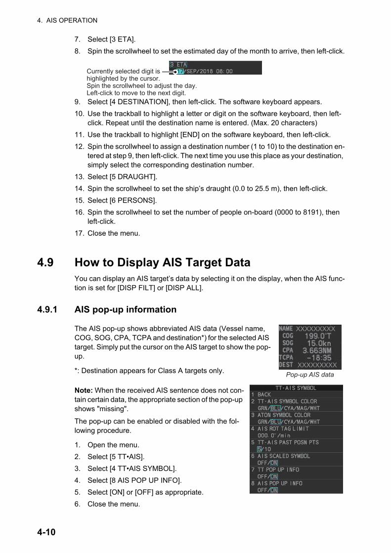
4. AIS OPERATION
7. Select [3 ETA].
8. Spin the scrollwheel to set the estimated day of the month to arrive, then left-click.
9. Select [4 DESTINATION], then left-click. The software keyboard appears.
10. Use the trackball to highlight a letter or digit on the software keyboard, then left-click. Repeat until the destination name is entered. (Max. 20 characters)
11. Use the trackball to highlight [END] on the software keyboard, then left-click.
12. Spin the scrollwheel to assign a destination number (1 to 10) to the destination en-tered at step 9, then left-click. The next time you use this place as your destination, simply select the corresponding destination number.
13. Select [5 DRAUGHT].
14. Spin the scrollwheel to set the ship’s draught (0.0 to 25.5 m), then left-click.
15. Select [6 PERSONS].
16. Spin the scrollwheel to set the number of people on-board (0000 to 8191), then left-click.
17. Close the menu.
4.9 How to Display AIS Target DataYou can display an AIS target’s data by selecting it on the display, when the AIS func-tion is set for [DISP FILT] or [DISP ALL].
4.9.1 AIS pop-up information
The AIS pop-up shows abbreviated AIS data (Vessel name, COG, SOG, CPA, TCPA and destination*) for the selected AIS target. Simply put the cursor on the AIS target to show the pop-up.
*: Destination appears for Class A targets only.
Note: When the received AIS sentence does not con-tain certain data, the appropriate section of the pop-up shows "missing".
The pop-up can be enabled or disabled with the fol-lowing procedure.
1. Open the menu.
2. Select [5 TT•AIS].
3. Select [4 TT•AIS SYMBOL].
4. Select [8 AIS POP UP INFO].
5. Select [ON] or [OFF] as appropriate.
6. Close the menu.
Currently selected digit is highlighted by the cursor.Spin the scrollwheel to adjust the day.Left-click to move to the next digit.
XXXXXXXXX
XXXXXXXXXPop-up AIS data
4-10
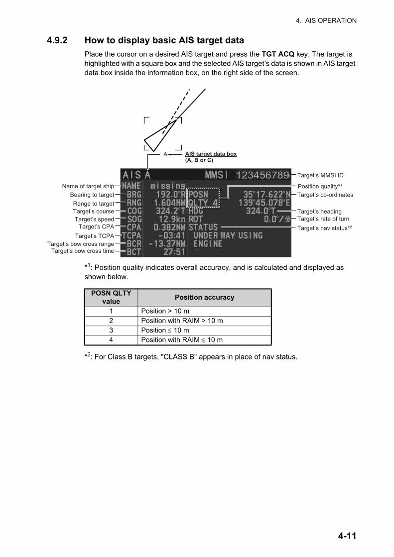
4. AIS OPERATION
4.9.2 How to display basic AIS target data
Place the cursor on a desired AIS target and press the TGT ACQ key. The target is highlighted with a square box and the selected AIS target’s data is shown in AIS target data box inside the information box, on the right side of the screen.
*1: Position quality indicates overall accuracy, and is calculated and displayed as shown below.
*2: For Class B targets, "CLASS B" appears in place of nav status.
POSN QLTY value
Position accuracy
1 Position > 10 m2 Position with RAIM > 10 m3 Position 10 m4 Position with RAIM 10 m
Target’s MMSI ID
Name of target shipBearing to targetRange to targetTarget’s courseTarget’s speed
Target’s CPATarget’s TCPA
Target’s bow cross rangeTarget’s bow cross time
Target’s co-ordinates
Target’s headingTarget’s rate of turnTarget’s nav status*2
A AIS target data box(A, B or C)
123456789Position quality*1
4-11

4. AIS OPERATION
4.9.3 How to display expanded AIS target data
The expanded AIS data display provides additional information about an AIS target, including call sign, IMO No., etc. To display expanded AIS data, show the basic data for a target, then left-click the target data display. The expanded data appears.
If data for an item is unknown, "missing" appears.
4.9.4 How to remove target data from the display area
Place the cursor on a desired tracked target and press the TARGET CANCEL key. The select target’s data is no longer displayed in the data display area.
Note: Navigation status is not available for Class B targets. Where the selected AIS target is an aircraft, the [STATUS] box shows the aircraft’s altitude.
123456789012345678901234567
GPS GLONASS
POWE-DRIVEN VESSEL(AHEAD/ALONGSIDE)
123456789123456789
25.4m
1234567890123456789023:59 31/DEC
1
1
EXPANDED DATAVessel name
Call sign
Position
Type of position sensor
Position accuracy
Navigation status
MMSI number
IMO number
Vessel dimensions
Destination
ETA at destination
AIS transponder versionAssociation (ON or OFF)
Ship and cargo type
Repeat indicator
4-12

4. AIS OPERATION
4.10 How to Change AIS Symbol AttributesTo change the brilliance, size and color of AIS symbols follow the appropriate proce-dure in this section.
4.10.1 How to adjust the AIS symbol brilliance
Note: The brilliance of the AIS symbols can be adjusted from the [PLT] button on the
Instant Access bar™. See section 1.45.1.
1. Open the menu.
2. Select [9 INITIAL SETTINGS].
3. Select [2 BRILL]. The [BRILL] menu appears.
4. Select [0 NEXT] to show the next menu page.
5. Select [8 AIS SYMBOLS]. The settings are highlighted and can now be adjusted.
6. Spin the scrollwheel to select the desired brilliance, then left-click to apply the set-ting.
7. Close the menu.
4.10.2 How to change the color of the AIS symbol
1. Open the menu.
2. Select [5 TT•AIS].
3. Select [4 TT•AIS SYMBOL].
4. Select [2 TT•AIS SYMBOL COLOR].
5. Select the appropriate color.
6. Close the menu.
4.10.3 How to change the color of the ATON symbol
1. Open the menu.
2. Select [5 TT•AIS].
3. Select [4 TT•AIS SYMBOL].
4. Select [3 ATON SYMBOL COLOR].
5. Select the appropriate color.
6. Close the menu.
Spin the scrollwheel to adjust the brilliance.
4-13
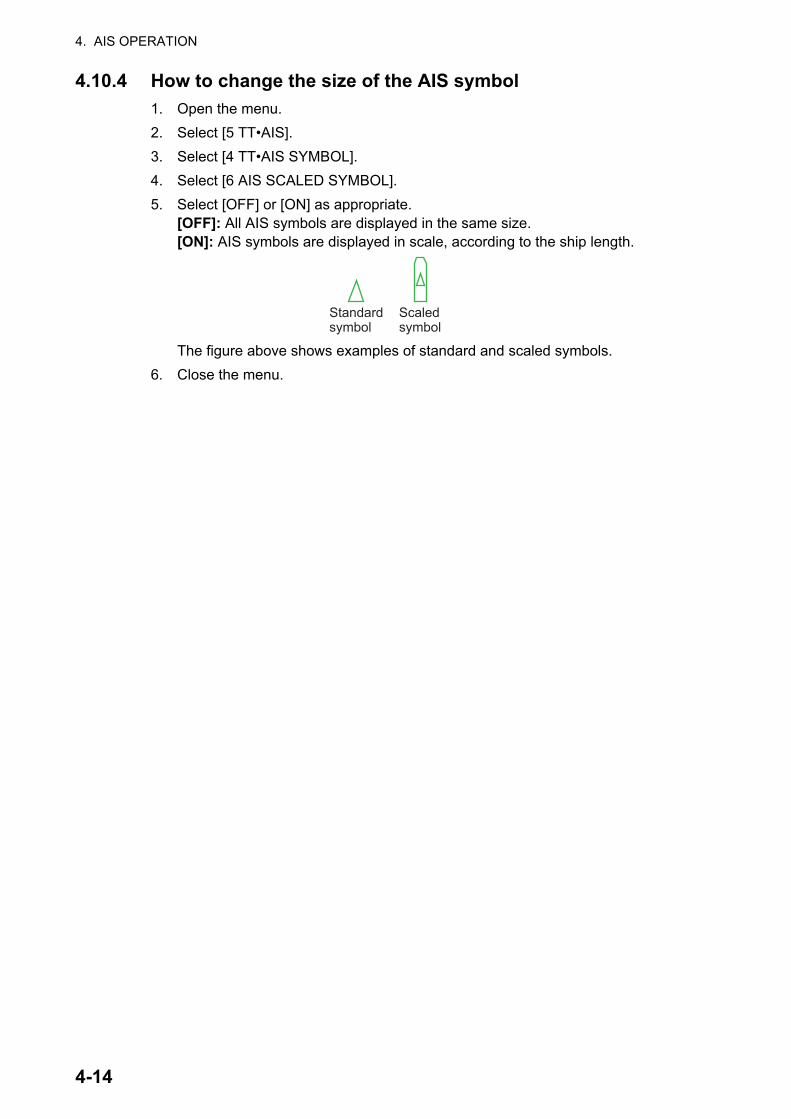
4. AIS OPERATION
4.10.4 How to change the size of the AIS symbol
1. Open the menu.
2. Select [5 TT•AIS].
3. Select [4 TT•AIS SYMBOL].
4. Select [6 AIS SCALED SYMBOL].
5. Select [OFF] or [ON] as appropriate.[OFF]: All AIS symbols are displayed in the same size.[ON]: AIS symbols are displayed in scale, according to the ship length.
The figure above shows examples of standard and scaled symbols.
6. Close the menu.
Standard symbol
Scaled symbol
4-14

4. AIS OPERATION
4.11 Past Position DisplayThe past position display shows equally time-spaced dots marking past positions of activated AIS targets. A new dot is added at preset time intervals until the preset num-ber is reached. If a target changes its speed, the spacing will be uneven. If it changes course, its plotted course will not be a straight line.
Below are examples of past position displays.
4.11.1 How to display past position points and select the plotting in-terval
Select the [PAST POSN] setting, then left-click to cycle through the following settings.
[OFF] [30sec] [1min] [2min] [3min] [6min] [OFF]...
The past positions are displayed in accordance with the selected setting.
4.11.2 How to select the number of past position points to be dis-played
1. Open the menu.
2. Select [5 TT•AIS].
3. Select [4 TT•AIS SYMBOL].
4. Select [5 TT•AIS PAST POSN POINTS].
5. Select [5] or [10] as appropriate.
6. Close the menu.
4.11.3 Past position display orientation
Past position orientation, true or relative, is controlled with [TRAIL MODE] in the [TRAIL] context menu. To adjust the trail orientation, see section 1.37.1.
(a) Ship turning (b) Ship running straight (c) Ship reduced speed (d) Ship increased speed
OFFPAST POSN setting
4-15

4. AIS OPERATION
4.11.4 Stabilization in true motion
True motion past position display can be ground stabilized or sea stabilized. The [TRAIL] box shows current stabilization as "TRUE-G" or "TRUE-S". To change stabi-lization mode, open the [SHIP SPEED MENU] menu and set [SHIP SPEED] to [LOG(BT)] (ground stabilization) or [LOG(WT)] (sea stabilization).
4.12 Lost TargetA target is declared a lost target when it fails to produce data for six minutes or five reporting intervals, whichever is the shorter. When this occurs, the target is marked with the (flashing) lost target symbol and the message "AIS TARGET LOST" appears in the Alert Box. To acknowledge a lost target, press the ALARM ACK key, or use the trackball to select the [ALERT] box then press the left button.
4.12.1 How to set the lost target filter
If there are a lot of AIS targets in your area, the lost target alert can sound frequently. In this case you may wish to have the alert ignore lost targets whose range, speed, class or length are below the threshold value you specify.
1. Open the menu.
2. Select [5 TT•AIS].
3. Select [5 AIS].
4. Select [0 NEXT].
5. Select [3 AIS LOST TGT FILTER].
6. Referring to the following table, select the appropri-ate filter.
7. Select [ON] to activate the filter, or select [OFF] to deactivate the filter.The setting range for [MAX RANGE] and [MIN SHIP SPEED] are listed below.
• [MAX RANGE]: [00NM] to [99NM]
• [MIN SHIP SPEED]: [0.0kn] to [9.9kn]
8. Spin the scrollwheel to adjust the setting as required, then left-click to apply the setting.
9. Close the menu.
Filter type Definition[MAX RANGE] Any AIS targets beyond the range set here will not trigger
the lost target alert.[MIN SHIP SPEED] Any AIS targets slower than this setting will not trigger the
lost target alert.[EXCEPT CLASS B] Select [ON] to prevent class B AIS targets from triggering
the lost target alert.
4-16

4. AIS OPERATION
4.12.2 How to enable/disable the lost target alert
The [LOST TARGET] box, located at the bottom-right corner of the screen, enables and disables the lost target alert.
Select the box with the cursor, then left-click to cycle through the settings in the follow-ing order: [OFF] [FILT] [ALL] [OFF]...
• [OFF]: Disable the alert.
• [FILT]: Enable the alert for all lost targets, excluding filtered targets.
• [ALL]: Enable the alert for all lost targets, including filtered targets.
Note: The filter setting is applied to both TT and AIS lost targets.
4.13 ROT SettingYou can set the lower limit of the ROT (Rate Of Turn) at which the heading line on target symbols will point in direction which the vessel is turning.
ROT display
1. Open the menu.
2. Select [5 TT•AIS].
3. Select [4 TT•AIS SYMBOL].
4. Select [4 AIS ROT TAG LIMIT], then left-click. The settings can now be adjusted.
5. Spin the scrollwheel to adjust the ROT as appropriate, then left-click. The setting range is 000.0°/min to 720.0°/min.
6. Close the menu.
OFF Lost target filter setting
Ship turning to starboard
4-17

4. AIS OPERATION
4.14 AIS Collision Alarm (CPA, TCPA)This radar calculates CPA and TCPA by using own ship and relative target positions. An AIS dangerous target is one whose CPA and TCPA are within the range of the CPA and TCPA limits set in the TT/AIS box. The AIS symbol of an AIS dangerous target is red and flashing, and is announced with the Alert "CPA/TCPA". After the alert is ac-knowledged the target symbol is displayed in red color.
4.14.1 How to set the CPA and TCPA ranges
CPA and TCPA ranges can be adjusted from the ap-propriate indication in the [TT] box.
1. Left-click the [CPA/TCPA] indication to activate the feature.
2. Place the cursor on the indication you wish to adjust.
3. Left-click, or spin the scrollwheel, to adjust the settings as required. The settings options are outlined in the table below.
Indication Method Settings optionsCPA Left-click 0.5, 1.0, 1.5, 2.0, 3.0, 4.0, 5.0, 6.0 (NM)
Scrollwheel 0.1 to 20; 0 to 10 in 0.1 NM increments, 1 NM incre-ments thereafter
TCPA Left-click 1, 2, 3, 4, 5, 6, 12, 15 (minutes)Scrollwheel 1 to 60 minutes in 1-minute increments
Thicker thanactivated target
When a sleeping or an activated target violates the CPA/TCPA alarm setting its symbol changes to the dangerous target symbol (red and flashing) and the message "CPA/TCPA" appears. Press the ALARM ACK key (or click the [ALERT] box with the left button) to acknowledge the CPA/TCPA alarm. The audible alarm is silenced and the symbol stops flashing.Take appropriate action to avoid collision.
Dangerous target
CPA setting
TCPA setting
Left-click here to activate CPA/TCPA settings.
4-18

4. AIS OPERATION
4.15 How to Associate TT and AIS TargetsAn AIS-equipped ship is usually displayed by two symbols on the radar display. This is because the AIS ship position is measured by a GPS navigator (L/L) whereas the radar detects the same ship by PPI principle (range and bearing relative to own ship radar antenna).
To avoid the presentation of two target symbols for the same physical target, use the “association” function. If target data from both AIS and TT are available and if the as-sociation criteria are fulfilled, either the AIS or TT symbol is presented according to the association method selected.
Association will not happen between AIS and TT if the AIS target is sleeping or the AIS target is lost.
1. Confirm that the [TT ACQ MODE] indication shows "AUTO", "AUTO MAN" or "MAN".
2. Open the menu.
3. Select [5 TT•AIS].
4. Select [7 TARGET ASSOCIATION].
5. Select [2 ASSOCIATION TGT TYPE].
6. Select [OFF], [AIS] or [TT], as appropriate, to select which symbols and data to display when the associ-ation criteria are met.
Note: Association can also be switched on and off from the screen by left-clicking the Association Us-age icon, shown below.
7. Referring to the list below, set the association criteria. Spin the scrollwheel to ad-just the value, then left-click to confirm the setting.
8. Close the menu.
[OFF] : Disable association.[AIS] : Use AIS symbols and AIS data.[TT] : Use TT symbols and TT data.
[3 GAP] : Range between AIS target and tracked target.(setting range: 0.000-0.050 (NM))
[4 RANGE] : Range direction difference from own ship to AIS target and tracked target. (setting range: 0.000-0.100 (NM))
[5 BEARING] : Bearing difference from own ship to AIS target and tracked target. (setting range: 0.0-9.9 (°))
[6 SPEED] : Speed difference between AIS target and tracked target.(setting range: 0.0-6.0 (kn))
[7 COURSE] : Course difference between AIS target and tracked target.(setting range: 0.0-25.0 (°))
TT ACQ MODE indication
Left-click the association icon to change the association setting.>: Use TT Symbols and data.<: Use AIS symbols and data.No indication: Association is disabled.
4-19

4. AIS OPERATION
When the association criteria (gap, range, bearing, speed, and course) is met, and the ASSOCIATION TARGET setting is [AIS], the TT symbol is erased and only the AIS symbol is displayed.
All default association settings are restored whenever the power is turned on.
To show the association information, place the cursor on the target data box at the right side of the screen, then press the ACQ key. The selected target’s AIS and TT data are displayed together as shown in the examples below.
Combined TT/AIS data for a CLASS A vessel
Combined TT/AIS data for a CLASS B vessel
4-20

4. AIS OPERATION
4.16 How to View Own Ship DataOwn ship’s static data (type of ship, call sign, etc.) can be viewed as follows:
1. Open the menu.
2. Select [5 TT•AIS].
3. Select [5 AIS].
4. Select [7 OWN SHIP DATA]. The [OWN SHIP DATA] menu appears.
Note: The indications "A", "B", "C" and "D" at [EXT EPFS ANT POSN] show the location of the external EPFS antenna, calculated in the following manner:
5. Close the menu.
FURUNOMARUName of your shipShip’s callsign
Current location
Ship’s MMSI numberShip’s IMO number
Ship’s dimensions
AIS transponder version
Ship and cargo type
External EPFS device’s installation location
Course/Speed
Positioning source and quality of positioning data
Heading/Rate of Turn
AZ1234567
External EPFS antenna position
4-21

4. AIS OPERATION
4.17 How to Use AIS MessagesYou can transmit and receive messages via the AIS, to a specified destination (MMSI) or all ships in the area. Messages can be sent to warn of safety of navigation, for ex-ample, an iceberg sighted. Routine messages are also permitted.
Short safety related messages are only an additional means to broadcast safety infor-mation. They do not remove the requirements of the GMDSS.
4.17.1 How to create and save messages
Up to ten messages can be saved at any time. To create and save a message, do the following:
Note: The MMSI of the receiving ship can be automatically set by selecting [TRANS-MIT MESSAGE] from the pop up menu. To show the pop up menu, select the receiv-ing ship’s data in the AIS data display area, then press the right button.
1. Open the menu.
2. Select [5 TT•AIS].
3. Select [5 AIS].
4. Select [5 TRANSMIT MESSAGE].
5. Select [2 ADDRESS TYPE].
6. Select [3 MESSAGE TYPE].
7. Select [SAFETY] (for safety messages) or [BINARY] (for routine messages).
8. For [ADDRESSED] message, do this step. For [BROADCAST] message, or if [TRANSMIT MESSAGE] was selected from the AIS data display pop up menu, go to step 8.
1) Select [4 MMSI No.].
2) Use the number keys to set the receiving ship’s MMSI.
9. Select [5 CHANNEL].
10. Select the AIS channel to transmit your message over: [A], [B], [A or B], or [A and B].
11. Select [0 NEXT] to show the next menu page.
12. Select [4 EDIT]. A software keyboard appears at the bottom of the menu.
13. Select the character desired, then left-click.The maximum of 80 characters can be entered for the message.
4-22

4. AIS OPERATION
14. Select [END] to complete message input, then left-click.
15. Select [3 SAVE FILE].
16. Spin the scrollwheel to select the appropriate number, then left-click.
17. Close the menu.
4.17.2 How to transmit messages
1. Open the menu.
2. Select [5 TT•AIS].
3. Select [5 AIS].
4. Do one of the following:
a) Create a message, as described in subsection 4.17.1.
b) Use a file saved in the memory by selecting [5 TRANSMIT MESSAGE] fol-lowed by [2 OPEN FILE] from the second page of the [TRANSMIT MESSAGE] menu.
5. Select [5 TRANSMIT MESSAGE] from the second page of the [TRANSMIT MES-SAGE] menu to transmit the message.During transmission, the message "AIS TRANSMITTING" appears in the guid-ance box. The message disappears when the message is sent successfully."AIS MSG SEND ERR" appears in the alert box if an error occurred while transmit-ting the message.
6. Close the menu.
Message contents appear here
4-23
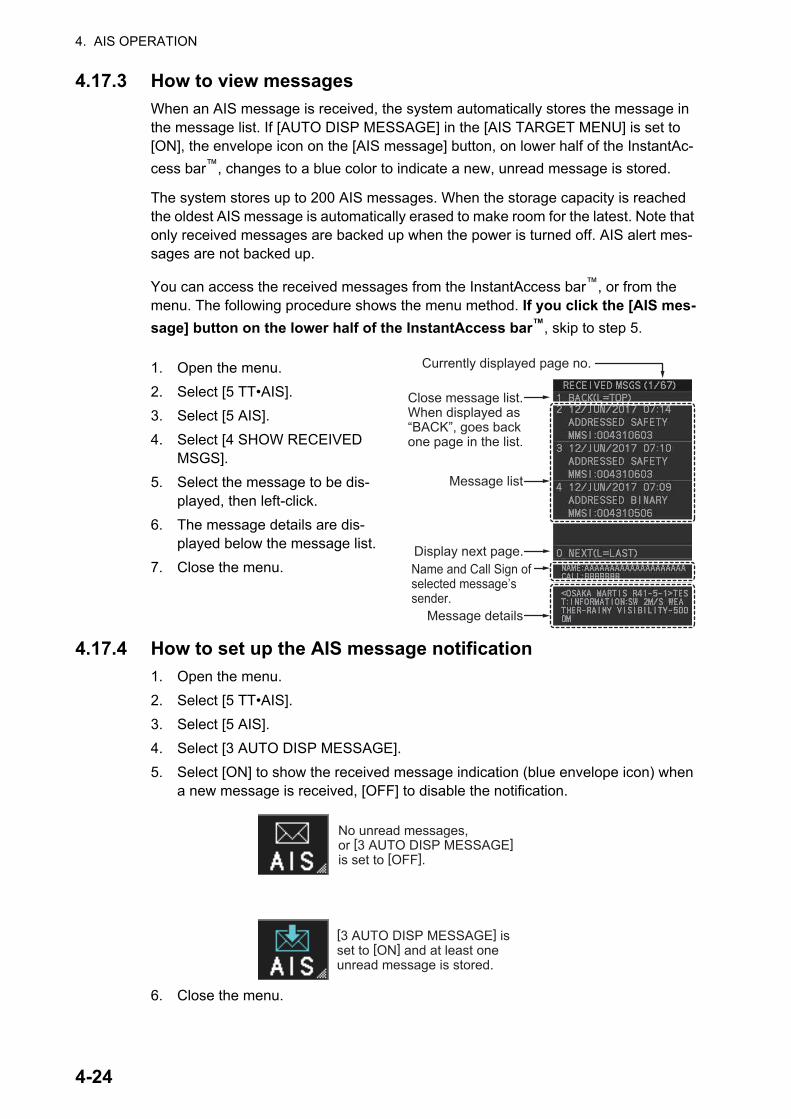
4. AIS OPERATION
4.17.3 How to view messages
When an AIS message is received, the system automatically stores the message in the message list. If [AUTO DISP MESSAGE] in the [AIS TARGET MENU] is set to [ON], the envelope icon on the [AIS message] button, on lower half of the InstantAc-
cess bar™, changes to a blue color to indicate a new, unread message is stored.
The system stores up to 200 AIS messages. When the storage capacity is reached the oldest AIS message is automatically erased to make room for the latest. Note that only received messages are backed up when the power is turned off. AIS alert mes-sages are not backed up.
You can access the received messages from the InstantAccess bar™, or from the menu. The following procedure shows the menu method. If you click the [AIS mes-
sage] button on the lower half of the InstantAccess bar™, skip to step 5.
1. Open the menu.
2. Select [5 TT•AIS].
3. Select [5 AIS].
4. Select [4 SHOW RECEIVED MSGS].
5. Select the message to be dis-played, then left-click.
6. The message details are dis-played below the message list.
7. Close the menu.
4.17.4 How to set up the AIS message notification
1. Open the menu.
2. Select [5 TT•AIS].
3. Select [5 AIS].
4. Select [3 AUTO DISP MESSAGE].
5. Select [ON] to show the received message indication (blue envelope icon) when a new message is received, [OFF] to disable the notification.
6. Close the menu.
Currently displayed page no.
Message list
Display next page.Name and Call Sign of selected message’s sender.
Message details
Close message list.When displayed as “BACK”, goes back one page in the list.
No unread messages, or [3 AUTO DISP MESSAGE] is set to [OFF].
[3 AUTO DISP MESSAGE] is set to [ON] and at least one unread message is stored.
4-24

4. AIS OPERATION
4.17.5 How to display AIS alert messages
The AIS transponder outputs various alert messages. To view the alert list:
1. Open the menu.
2. Select [5 TT•AIS].
3. Select [5 AIS].
4. Select [8 AIS ALERT MES-SAGES].
5. Select the message to dis-play.
6. Close the menu. Message contents appear here
4-25

4. AIS OPERATION
4.18 AIS System MessagesAIS system messages are displayed at the bottom right corner of the screen. The table below shows the AIS system messages, their alert priority and their meanings.
Message Priority MeaningCPA/TCPA Alarm CPA and TCPA of an activated AIS target are be-
low value set on the menu.AIS NEW TARGET
Warning AIS target has entered an acquisition zone.
AIS TARGET LOST Warning Lost target. An activated target is declared a lost target when it fails to produce data for six minutes or five reporting intervals, whichever is the shorter.
AIS DISPLAY FULL Warning The radar only displays the closest 350 AIS targets from own ship.
ACTIVE AIS FULL Warning Number of active AIS targets has reached 50.LOST AIS COM Warning Not receiving AIS data from own AIS (VDO mes-
sage).Note: When no AIS data is received, the message "AIS COM ERROR" appears in the Alert Box. Check connection with the AIS transponder.When the AIS function is disabled: Above mes-sage is prioritized as a Caution level alert for IMO/A/R-types. B/W-types do not show this alert.When the AIS function is active: Above message is prioritized as a Warning level alert for all radar types.
AIS CAPACITY 95% Caution Number of AIS targets has reached 1140. (Ap-pears for R-types only.)
AIS CPTY FULL Caution Number of AIS targets has reached 1200. (Priority is set to Warning for R-types.)
AIS DISPLAY 95% Caution Number of displayed AIS targets has reached 333.ACTIVE AIS 95% Caution Number of active AIS targets has reached 48.AIS MSG SEND ERR Caution Could not send AIS message.
4-26

5. VIDEO PLOTTER OPERATION
The video plotter has the following functions:
• Enter waypoints (up to 198) and marks.
• Creates and displays radar maps.
• Own ship track plotting.
• Display charts and chart-related information (requires a valid chart card).
5.1 Orientation ModesSix orientation modes are available: [HEAD UP RM], [STAB HEAD UP RM],[STERN UP RM], [COURSE UP RM], [NORTH UP RM], [NORTH UP TM] (True Motion).
Note 1: The [STERN UP RM] orientation mode is only available it has been set to [ON] in [STERN UP RM] in the [INITIAL SETTING] [OPERATION] menu.
Note 2: The screen may flash when the heading is changed more than one degree in the [HEAD UP RM] or [STAB HEAD UP RM] mode.
Automatic resetting of own ship mark in true motion mode
In the true motion mode, the own ship mark is automatically returned stern-ward 75% from the screen center when it reaches a location 50% of the display radius.
To select an orientation mode, see section 1.30.
Marks can be entered at any location inside the operational display area, however, no mark can be entered at the location of an on-screen box. A total of 20,000 marks can be inscribed at any one time.
5.2 How to select a mark type1. Open the menu.
2. Select [2 MARKS].For A/B/W-types with Radar Plotter function-ality, this menu appears as [2 MARKS•CHART].
3. Select [5 RADAR MAP].The [RADAR MAP] menu appears.Note: You can also right-click the [MARK] box to open the [RADAR MAP] menu.
4. Select [3 MARK TYPE].
5. Select the appropriate type of marker, referring to the list below.
• [ORIGIN MARK(No.)]: Inscribes the standard
origin mark symbol ( ), with mark number (1 to 10). For detailed information regarding ori-gin marks, see section 5.5.
5-1
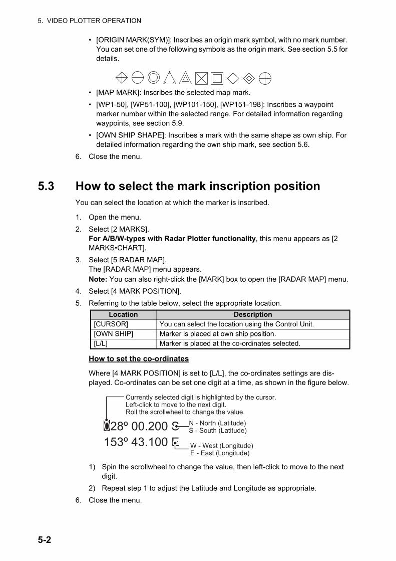
5. VIDEO PLOTTER OPERATION
• [ORIGIN MARK(SYM)]: Inscribes an origin mark symbol, with no mark number. You can set one of the following symbols as the origin mark. See section 5.5 for details.
• [MAP MARK]: Inscribes the selected map mark.
• [WP1-50], [WP51-100], [WP101-150], [WP151-198]: Inscribes a waypoint marker number within the selected range. For detailed information regarding waypoints, see section 5.9.
• [OWN SHIP SHAPE]: Inscribes a mark with the same shape as own ship. For detailed information regarding the own ship mark, see section 5.6.
6. Close the menu.
5.3 How to select the mark inscription positionYou can select the location at which the marker is inscribed.
1. Open the menu.
2. Select [2 MARKS].For A/B/W-types with Radar Plotter functionality, this menu appears as [2 MARKS•CHART].
3. Select [5 RADAR MAP].The [RADAR MAP] menu appears.Note: You can also right-click the [MARK] box to open the [RADAR MAP] menu.
4. Select [4 MARK POSITION].
5. Referring to the table below, select the appropriate location.
How to set the co-ordinates
Where [4 MARK POSITION] is set to [L/L], the co-ordinates settings are dis-played. Co-ordinates can be set one digit at a time, as shown in the figure below.
1) Spin the scrollwheel to change the value, then left-click to move to the next digit.
2) Repeat step 1 to adjust the Latitude and Longitude as appropriate.
6. Close the menu.
Location Description[CURSOR] You can select the location using the Control Unit.[OWN SHIP] Marker is placed at own ship position.[L/L] Marker is placed at the co-ordinates selected.
028º 00.200 S153º 43.100 E
Currently selected digit is highlighted by the cursor.Left-click to move to the next digit.Roll the scrollwheel to change the value.
N - North (Latitude)S - South (Latitude)
W - West (Longitude)E - East (Longitude)
5-2

5. VIDEO PLOTTER OPERATION
5.4 Radar Map
Note: The location and orientation of mark symbols and mark lines can change, de-pending on the display presentation mode, as shown in the table below.
5.4.1 How to show/hide radar map marks
You can show or hide marks on the radar map.
1. Open the menu.
2. Select [2 MARKS].For A/B/W-types with Radar Plotter functionality, this menu appears as [2 MARKS•CHART].
3. Select [5 RADAR MAP].The [RADAR MAP] menu appears.Note: You can also right-click the [MARK] box to open the [RADAR MAP] menu.
4. Select [0 NEXT] to show the next menu page.
5. Select [2 MAP DISPLAY].
6. Select [ON] or [OFF] as appropriate.Note: You can also show/hide the radar map marks from the Radar Map button
on the InstantAccess bar™.
7. Close the menu.
A radar map is a combination of map lines and symbols whereby the user can define and input the navigation data, route planning and monitoring data. The radar map can contain 20,000 points of data. Inscribed marks are retained when the power is turned off.The radar map is referenced to the WGS-84 datum and appears only when there is valid position data input. The radar map does not affect any radar functions.
Presentation mode Mark symbol Mark lineHEAD UP RMSTERN UP RMSTAB HEAD UP RM
Location is changed accord-ing to heading and own ship position. Orientation is unchanged.
Location and orientation are changed according to heading and own ship position.
COURSE UP RMNORTH UP RMNORTH UP TM
Location is changed accord-ing to own ship position.Orientation is unchanged.
Location and orientation are changed according to own ship position.
MAP OFF
MAP ON
Click to toggleHide the radar map
Show the radar map
5-3

5. VIDEO PLOTTER OPERATION
5.4.2 How to select the mark color (B/W-type only)
type radars of this series allow the change of mark colors. For all other types, the color is fixed and cannot be changed.
1. Open the menu.
2. Select [2 MARKS].For B/W-types with Radar Plotter functionality, this menu appears as [2 MARKS•CHART].
3. Select [5 RADAR MAP].The [RADAR MAP] menu appears.Note: You can also right-click the [MARK] box to open the [RADAR MAP] menu.
4. Select [0 NEXT] to show the next menu page.
5. Select [3 MARK COLOR].
6. Select the appropriate color. Available options are shown in the table below.
7. Close the menu.
5.4.3 How to inscribe marks
You can inscribe marks anywhere inside the operational display area, however, marks cannot be inscribed in the same location as a menu box.
Depending on the setting for [4 MARK POSITION] the method to inscribe a mark is slightly different.
Where [4 MARK POSITION] is set to [CURSOR]
1. Referring to section 5.2, select the mark type you want to use.
2. Place the cursor on the [MARK] box, at the bottom-left of the screen.
3. Spin the scrollwheel to select the appropriate mark, then left-click. The cursor moves inside the operational display area.
4. Place the cursor on the location (inside the operational display area) you wish to inscribe the mark, then left-click to anchor the mark.
5. Repeat steps 3 to 4 for multiple mark inscription.
6. Right-click to complete the procedure.
Where [4 MARK POSITION] is set to [OWN SHIP]
1. Referring to section 5.2, select the mark type you want to use.
2. Place the cursor on the [MARK] box, at the bottom-left of the screen.
3. Spin the scrollwheel to select the appropriate mark, then left-click. The selected mark is inscribed at the OS position.
4. Repeat steps 1 to 2 for multiple mark inscription, or right-click to complete the pro-cedure.
Menu indication
ColorMenu
indicationColor
Menu indication
Color
RED Red CYA Cyan BLU BlueGRN Green MAG Magenta YEL YellowWHT White
5-4

5. VIDEO PLOTTER OPERATION
Where [4 MARK POSITION] is set to [L/L]
1. Referring to section 5.2, select the mark type you want to use.
2. Place the cursor on the [MARK] box, at the bottom-left of the screen.
3. Spin the scrollwheel to select the appropriate mark, then left-click. [RADAR MAP] menu appears and the first digit of the latitude is selected.
4. Referring to section 5.3, set the latitude and longitude.
5. Repeat steps 1 to 3 for multiple mark inscription, or right-click to complete the pro-cedure.
Note: You can see the number of radar map marks, lines used, on the [RADAR MAP] menu: [MENU][2 MARKS*][5 RADAR MAP].
*: Appears as [2 MARKS•CHART] for A/B/W-types with Radar Plotter functionality.
Radar map marks, lines entered/total number of marks, lines available
5-5
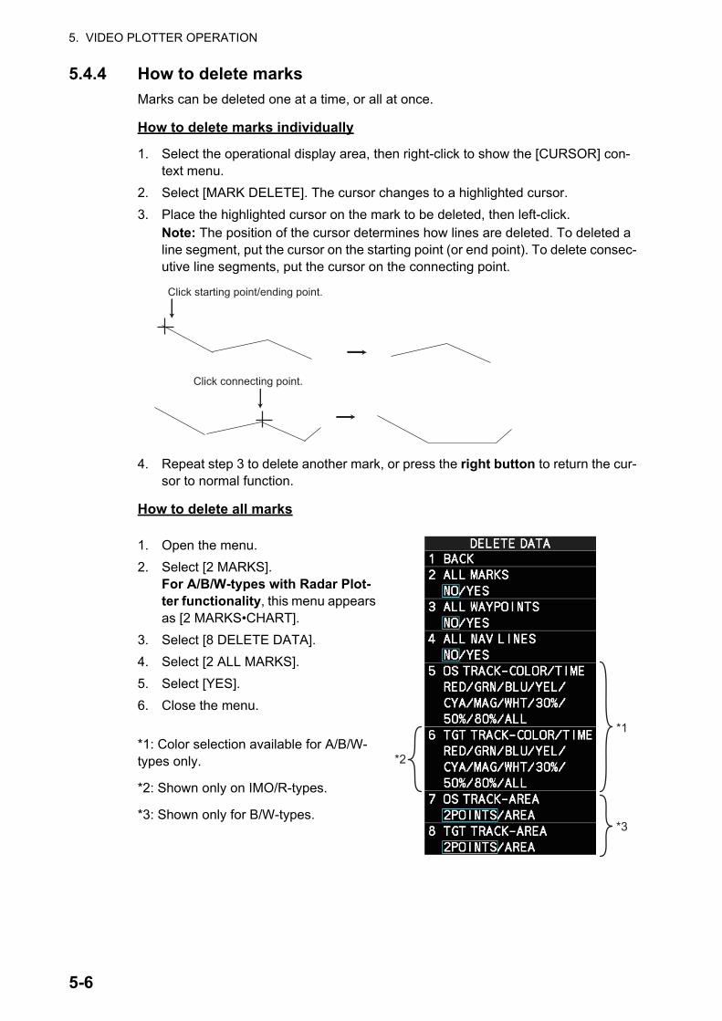
5. VIDEO PLOTTER OPERATION
5.4.4 How to delete marks
Marks can be deleted one at a time, or all at once.
How to delete marks individually
1. Select the operational display area, then right-click to show the [CURSOR] con-text menu.
2. Select [MARK DELETE]. The cursor changes to a highlighted cursor.
3. Place the highlighted cursor on the mark to be deleted, then left-click.Note: The position of the cursor determines how lines are deleted. To deleted a line segment, put the cursor on the starting point (or end point). To delete consec-utive line segments, put the cursor on the connecting point.
4. Repeat step 3 to delete another mark, or press the right button to return the cur-sor to normal function.
How to delete all marks
1. Open the menu.
2. Select [2 MARKS].For A/B/W-types with Radar Plot-ter functionality, this menu appears as [2 MARKS•CHART].
3. Select [8 DELETE DATA].
4. Select [2 ALL MARKS].
5. Select [YES].
6. Close the menu.
*1: Color selection available for A/B/W-types only.
*2: Shown only on IMO/R-types.
*3: Shown only for B/W-types.
Click starting point/ending point.
Click connecting point.
*2
*1
*3
5-6
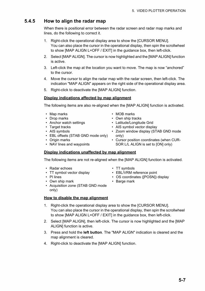
5. VIDEO PLOTTER OPERATION
5.4.5 How to align the radar map
When there is positional error between the radar screen and radar map marks and lines, do the following to correct it.
1. Right-click the operational display area to show the [CURSOR MENU].You can also place the cursor in the operational display, then spin the scrollwheel to show [MAP ALIGN L=OFF / EXIT] in the guidance box, then left-click.
2. Select [MAP ALIGN]. The cursor is now highlighted and the [MAP ALIGN] function is active.
3. Left-click the map at the location you want to move. The map is now “anchored” to the cursor.
4. Move the cursor to align the radar map with the radar screen, then left-click. The indication "MAP ALIGN" appears on the right side of the operational display area.
5. Right-click to deactivate the [MAP ALIGN] function.
Display indications affected by map alignment
The following items are also re-aligned when the [MAP ALIGN] function is activated.
Display indications unaffected by map alignment
The following items are not re-aligned when the [MAP ALIGN] function is activated.
How to disable the map alignment
1. Right-click the operational display area to show the [CURSOR MENU].You can also place the cursor in the operational display, then spin the scrollwheel to show [MAP ALIGN L=OFF / EXIT] in the guidance box, then left-click.
2. Select [MAP ALIGN], then left-click. The cursor is now highlighted and the [MAP ALIGN] function is active.
3. Press and hold the left button. The "MAP ALIGN" indication is cleared and the map alignment is cleared.
4. Right-click to deactivate the [MAP ALIGN] function.
• Map marks• Drop marks• Anchor watch settings• Target tracks• AIS symbols• EBL offsets (STAB GND mode only)• Origin marks• NAV lines and waypoints
• MOB marks• Own ship tracks• Latitude/Longitude Grid• AIS symbol vector display• Zoom window display (STAB GND mode
only)• Cursor position coordinates (when CUR-
SOR L/L ALIGN is set to [ON] only)
• Radar echoes• TT symbol vector display• PI lines• Own ship mark• Acquisition zone (STAB GND mode
only)
• TT symbols• EBL/VRM reference point• OS coordinates ([POSN]) display• Barge mark
5-7

5. VIDEO PLOTTER OPERATION
5.5 Origin MarkYou can mark any prominent target or a point of particular interest using the origin mark feature. When an origin mark in entered, the distance and bearing from the cur-sor position to the mark are shown at the bottom of the screen, as in the figure below. Twenty origin marks may be entered.
5.5.1 How to inscribe origin marks
The method in which an origin mark is inscribed depends on the setting of [MARK PO-SITION] (section 5.3). Below are the procedures for each method.
Heading and position inputs are necessary to inscribe an origin mark.
Where [4 MARK POSITION] is set to [CURSOR]
1. Referring to section 5.2, set [3 MARK TYPE] to [ORIGIN MARK No.] or [ORIGIN MARK SYM].
2. Put the cursor on the [MARK] box at the bottom of the screen.
3. Spin the scrollwheel to select the origin mark to inscribe.
4. Click the [MARK] box.
5. Click the location where to put the origin mark.The origin mark is inscribed at the location selected. To re-inscribe the origin mark at a different location, click the desired location for the mark.
6. To enter an origin mark at another location, spin the scrollwheel to change the or-igin mark, then click the desired location for the origin mark.
7. Right click to finish.
Where [4 MARK POSITION] is set to [OWN SHIP]
1. Referring to section 5.2, set [3 MARK TYPE] to [ORIGIN MARK No.] or [ORIGIN MARK SYM].
2. Put the cursor on the [MARK] box at the bottom of the screen.
3. Spin the scrollwheel to select the appropriate origin mark, then left-click. The se-lected mark is inscribed at the OS position.
4. Repeat steps 1 to 2 for multiple origin mark inscription, or right-click to complete the procedure.
MARK
Distance from cursor position to origin mark
Bearing from cursor position to origin mark
5-8

5. VIDEO PLOTTER OPERATION
Where [4 MARK POSITION] is set to [L/L]
1. Referring to section 5.2, set [3 MARK TYPE] to [ORIGIN MARK No.] or [ORIGIN MARK SYM].
2. Put the cursor on the [MARK] box at the bottom of the screen.
3. Spin the scrollwheel to select the appropriate origin mark, then left-click. RADAR MAP menu appears and the first digit of the latitude is selected.
4. Referring to section 5.3, set the latitude and longitude.
5. Repeat steps 1 to 3 for multiple origin mark inscription, or right-click to complete the procedure.
5.5.2 How to set origin mark stabilization
Origin marks can be geographically fixed (ground stabilized) or moving (sea stabi-lized).
1. Open the menu.
2. Select [2 MARKS].For A/B/W-types with Radar Plotter functionality, this menu appears as [2 MARKS•CHART].
3. Select [5 RADAR MAP].The [RADAR MAP] menu appears.Note: You can also right-click the [MARK] box to open the [RADAR MAP] menu.
4. Select [2 ORIGIN MARK STAB].
5. Select [GND] or [SEA] as appropriate.
6. Close the menu.
5.5.3 How to delete origin marks
Unlike other marks, you can only delete origin marks individually. To delete origin marks, follow the procedure below.
1. Select the operational display area, then right-click to show the [CURSOR] con-text menu.
2. Select [MARK DELETE]. The cursor changes to a highlighted cursor.
3. Place the highlighted cursor on the origin mark to be deleted, then left-click.
4. Repeat step 3 to delete another origin mark, or press the right button to return the cursor to normal function.
5-9

5. VIDEO PLOTTER OPERATION
5.6 How to Change the Shape of the Own Ship MarkTen locations on the own ship mark (section 1.43.4) can be adjusted to depict the shape of own ship more realistically. The ten points are as shown below.
1. Referring to section 5.2, set [3 MARK TYPE] to [OWN SHIP SHAPE].
2. Put the cursor in the [MARK] box at the bottom of the screen.
3. Spin the scrollwheel to select the point no. to change.The cursor movies to the selected point position.
4. Use the trackball to move the point to the position desired, then click.Point position information appears in the [MARK] box, as shown in the figure be-low.
5. Repeat steps 3 to 4 to adjust other points.
01
03
04
0506
07
08
1009
02
Distance from own ship to point
Distance from port side of own ship to point
MARK
5-10

5. VIDEO PLOTTER OPERATION
5.7 How to Use ECDIS Chart MarksNote: This function is only available if [ECDIS] is set to [SERIAL] or [LAN] at installa-tion. Consult your dealer for details.
You can display marks received from an ECDIS on the radar screen. If the received mark also contains predicted position data, the predicted position is also displayed on-screen.
1. Open the menu.
2. Select [2 MARKS].For A/B/W-types with Radar Plotter function-ality, this menu appears as [2 MARKS•CHART].
3. Select [6 ECDIS MARKS DISPLAY].
4. Select the appropriate item.
• [2 USER CHART]: Shows/hides received user charts.
• [3 CURVED EBL]: Shows/hides the received Curved EBL.
• [4 CHART SYMBOL]: Shows/hides the re-ceived chart symbols.
• [5 NOTE BOOK]: Shows/hides the received notes. [ON] shows notes only when they are received. [DISPLAY] shows notes continuously. The notes are shown in the information box at the right-side of the screen.
• [6 ROUTE]: Shows/hides the received route. [CENT] shows only the route line; [ALL] shows both the route line and the route width.
• [7 PREDICTOR]: Shows/hides the received predicted position with a symbol (dotted line) of the same size as the own ship.
5. Select [ON] or [OFF] as appropriate.[ON] shows the selected item’s ECDIS mark when received, [OFF] hides the EC-DIS mark.
6. Close the menu.
5-11
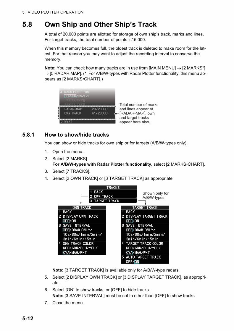
5. VIDEO PLOTTER OPERATION
5.8 Own Ship and Other Ship’s TrackA total of 20,000 points are allotted for storage of own ship’s track, marks and lines. For target tracks, the total number of points is15,000.
When this memory becomes full, the oldest track is deleted to make room for the lat-est. For that reason you may want to adjust the recording interval to conserve the memory.
Note: You can check how many tracks are in use from [MAIN MENU] [2 MARKS*] [5 RADAR MAP]. (*: For A/B/W-types with Radar Plotter functionality, this menu ap-pears as [2 MARKS•CHART].)
5.8.1 How to show/hide tracks
You can show or hide tracks for own ship or for targets (A/B/W-types only).
1. Open the menu.
2. Select [2 MARKS].For A/B/W-types with Radar Plotter functionality, select [2 MARKS•CHART].
3. Select [7 TRACKS].
4. Select [2 OWN TRACK] or [3 TARGET TRACK] as appropriate.
Note: [3 TARGET TRACK] is available only for A/B/W-type radars.
5. Select [2 DISPLAY OWN TRACK] or [3 DISPLAY TARGET TRACK], as appropri-ate.
6. Select [ON] to show tracks, or [OFF] to hide tracks.Note: [3 SAVE INTERVAL] must be set to other than [OFF] to show tracks.
7. Close the menu.
Total number of marks and lines appear at [RADAR-MAP], own and target tracks appear here also.
Shown only for A/B/W-types
5-12

5. VIDEO PLOTTER OPERATION
5.8.2 How to set the plotting interval
1. Open the menu.
2. Select [2 MARKS].For A/B/W-types with Radar Plotter functionality, select [2 MARKS•CHART].
3. Select [7 TRACKS].
4. Select [2 OWN TRACK] or [3 TARGET TRACK] as appropriate.Note: For IMO/R-types, [3 TARGET TRACK] is not shown.
5. Select [3 SAVE INTERVAL].
6. Select the appropriate setting, then left-click.The following tables show the relation between plotting interval settings and max-imum track recording time. Note that the maximum recording time is different for own tracks and target tracks.
Own track recording times
Target track recording times
Note: To hide own ship or target past tracks, set the interval to [OFF]. To hide both tracks, set the interval for both own ship and targets tracks to [OFF]. Tracks plot-ted after the setting is set to [OFF] are hidden. Previously plotted tracks remain on-screen.
7. Close the menu.
Interval Max. Recording Time Interval Max. Recording Time10 s 56 hours 3 min 1000 hours30 s 167 hours 6 min 2000 hours1 min 333 hours 15 min 5000 hours2 min 667 hours DRAW ONLY No track data recorded.
IntervalMax. Recording Time
(One target only)Max. Recording Time
(15 targets)10 s 42 hours 3 hours30 s 125 hours 8.5 hours1 min 250 hours 16.5 hours2 min 500 hours 33.5 hours3 min 750 hours 50 hours6 min 1500 hours 100 hours15 min 3750 hours 250 hoursDRAW ONLY No track data recorded. No track data recorded.
5-13

5. VIDEO PLOTTER OPERATION
5.8.3 How to set the track color (A/B/W-types only)
1. Open the menu.
2. Select [2 MARKS].For A/B/W-types with Radar Plotter functionality, select [2 MARKS•CHART].
3. Select [7 TRACKS].
4. Select [2 OWN TRACK] or [3 TARGET TRACK] as appropriate.
5. Select [4 OWN TRACK COLOR]. The following colors are available.
6. Select the appropriate setting.
7. Close the menu.
5.8.4 How to automatically plot target tracks (A/B/W-types only)
You can automatically plot target tracks for TT target numbers 001 to 015.
Note 1: [3 SAVE INTERVAL] must be set to other than [OFF] to show tracks.
Note 2: When this feature is active, only the tracks TT targets 001 through 015 are plotted.
1. Open the menu.
2. Select [2 MARKS].For A/B/W-types with Radar Plotter functionality, select [2 MARKS•CHART].
3. Select [7 TRACKS].
4. Select [3 TARGET TRACK].
5. Select [5 AUTO TARGET TRACK].
6. Select [OFF] or [ON] as appropriate.Note: When [5 AUTO TARGET TRACK] is set to [ON], [TARGET TRACK ON] and [TARGET TRACK OFF] are disabled and are not displayed in the [CURSOR] menu.
7. Close the menu.
• [RED] (Red)• [YEL] (Yellow)• [WHT] (White)
• [GRN] (Green)• [CYA] (Cyan)
• [BLU] (Blue)• [MAG] (Magenta)
5-14
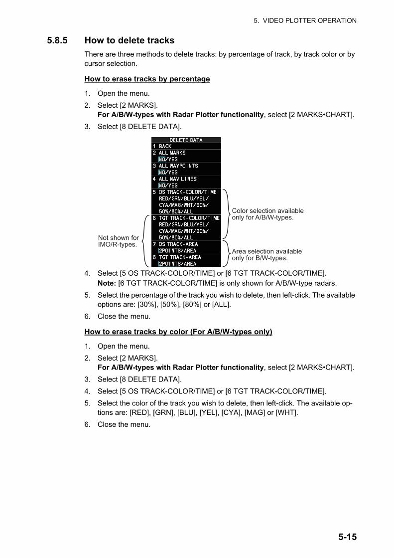
5. VIDEO PLOTTER OPERATION
5.8.5 How to delete tracks
There are three methods to delete tracks: by percentage of track, by track color or by cursor selection.
How to erase tracks by percentage
1. Open the menu.
2. Select [2 MARKS].For A/B/W-types with Radar Plotter functionality, select [2 MARKS•CHART].
3. Select [8 DELETE DATA].
4. Select [5 OS TRACK-COLOR/TIME] or [6 TGT TRACK-COLOR/TIME].Note: [6 TGT TRACK-COLOR/TIME] is only shown for A/B/W-type radars.
5. Select the percentage of the track you wish to delete, then left-click. The available options are: [30%], [50%], [80%] or [ALL].
6. Close the menu.
How to erase tracks by color (For A/B/W-types only)
1. Open the menu.
2. Select [2 MARKS].For A/B/W-types with Radar Plotter functionality, select [2 MARKS•CHART].
3. Select [8 DELETE DATA].
4. Select [5 OS TRACK-COLOR/TIME] or [6 TGT TRACK-COLOR/TIME].
5. Select the color of the track you wish to delete, then left-click. The available op-tions are: [RED], [GRN], [BLU], [YEL], [CYA], [MAG] or [WHT].
6. Close the menu.
Color selection available only for A/B/W-types.
Not shown for IMO/R-types.
Area selection available only for B/W-types.
5-15

5. VIDEO PLOTTER OPERATION
How to erase tracks with the cursor (For B/W-types only)
1. Open the menu.
2. Select [2 MARKS].For B/W-types with Radar Plotter functionality, select [2 MARKS•CHART].
3. Select [8 DELETE DATA].
4. Select [7 OS TRACK-AREA] or [8 TGT TRACK-AREA].
5. Select [2POINTS] or [AREA] as appropriate, then left-click. The cursor jumps into the operational display area.[2POINTS]: Delete track between two points. All points between start point to end point change from circle-shaped to square-shaped icons.[AREA]: Delete all track within an area. Points within the selected area change from circle-shaped to square-shaped icons.
6. Place the cursor on the first point (A), then left-click.
7. Place the cursor on the second point (B), then left-click. If [AREA] was selected at step 5, the two points form a square.
8. Close the menu.
5.9 How to Use WaypointsA particular location is known as a “waypoint”, whether it be a starting point, a desti-nation point or an intermediate point on a voyage. This radar system can store 200 waypoints. Waypoints 1 to 198 are user set waypoints, waypoint 199 is reserved for external input, waypoint 200 is reserved for MOB (Man Over Board). Waypoints can be entered with the cursor, or from the menu (manual input of latitude and longitude). Waypoints 1 to 198 can be edited from the menu.
5.9.1 How to set the data source for waypoints
1. Open the menu.
2. Select [8 NAVLINE•WPT].
3. Select [2 NAV LINE DATA SOURCE].
4. Select the appropriate data source, referring to the list below.
• [OFF]: Waypoints and nav lines (such as tracks) are not shown.
• [EXT DATA]: Use navigational data from an ex-ternal EPFS device for waypoints and nav lines.
• [INTERNAL DATA]: Use waypoints and nav lines saved internally.
• [WPT MARK] (shown only for A/B/W-type ra-dars): Shows the waypoint marks, however re-ceived routes are not shown.
[2POINTS] method [AREA] method
A
A
BB
5-16

5. VIDEO PLOTTER OPERATION
5. Close the menu.
5.9.2 How to enter waypoints
How to enter waypoints with the cursor
1. Referring to section 5.2, select the appropriate waypoint number group.The available groups are: [WP1 to WP50], [WP51 to WP100], [WP101 to WP150] or [WP151 to WP198].
2. Place the cursor on the [MARK] box. Spin the scrollwheel to select the waypoint number for new waypoint, then left-click. The cursor jumps inside the operational display area.
3. Place the cursor on the location to inscribe the waypoint, then left-click.
4. Repeat steps 2 to 3 to inscribe other waypoints.
5. Right-click the operational display area to complete waypoint inscription.
How to enter/edit waypoints from the menu
Note: Waypoints which are part of a route that is currently in use cannot be edited.
1. Open the menu.
2. Select [8 NAVLINE•WPT].
3. Select [2 WPT SET].
4. Select [2 WPT NO. SELECT].
5. Spin the scrollwheel, or use the control unit num-bered keys, to select a waypoint number.
6. To edit or input a waypoint name, select [3 WPT NAME], then left-click. The software keyboard ap-pears. Referring to section 1.5.2, name the way-point.To skip naming the waypoint, go to step 7.
7. Select [4 WPT L/L]. The latitude and longitude settings can now be adjusted.
8. Input the latitude and longitude with the number keys, or spin the scrollwheel to select a digit, then left-click to move to the next digit.
9. Close the menu.
Spin scrollwheel to select number.
MARK
WPT L/L
WPT L/L
Use the scrollwheel to select a numeral, then left-click. The cursor jumps to to next right place. Repeat to enter the latitude and longitude.
5-17
5. VIDEO PLOTTER OPERATION
5.9.3 How to erase waypoints
There are two methods to erase individual waypoints: cursor selection or from the menu.
How to erase a waypoint by cursor selection
1. Place the cursor inside the operational display area, then right-click.
2. Select [MARK DELETE]. The mark delete function is activated and the cursor is highlighted when inside the operational display area.
3. Select the waypoint you wish to delete, then left-click.
4. Right-click inside the operational display area to deactivate the mark delete func-tion.
How to erase a waypoint from the menu
1. Open the menu.
2. Select [8 NAVLINE•WPT].
3. Select [6 WPT SET].
4. Select [2 WPT NO. SELECT]. Then select the waypoint to erase.
5. Select [5 CLEAR DATA].
6. Select [YES] or [NO] as appropriate, then left-click.
7. Close the menu.
How to erase all waypoints
You can erase all waypoints from the menu. If there is an active route, this procedure cannot be completed.
1. Open the menu.
2. Select [2 MARKS].For A/B/W-types with Radar Plotter functionality, select [2 MARKS•CHART].
3. Select [8 DELETE DATA].
4. Select [3 ALL WAYPOINTS].
5. Select [YES] to erase all waypoints. Select [NO] to cancel the procedure.Note: All routes are also deleted with this procedure.
6. Close the menu.
5-18

5. VIDEO PLOTTER OPERATION
5.9.4 How to display the waypoint list
1. Open the menu.
2. Select [8 NAVLINE•WPT].
3. Select [7 WPT LIST] to show the [WPT LIST].
4. Close the menu.
5.9.5 How to show/hide the waypoint name/number
1. Open the menu.
2. Select [8 NAVLINE•WPT], then select [0 NEXT] to show the next page.
3. Select [4 DISP WPT NO.] or [5 DISP WPT NAME] as appropriate.
4. Select [ON] to show the waypoint name/number, or [OFF] to hide the waypoint name/number, then left-click. he waypoint number and/or waypoint name appear to the right of the waypoint mark.
5. Close the menu.
Displayed page/Total no. of pages- Click while on page No.1 to close the list.
- Click while on page No.2 or after to go back on page.
- Long-push the left button to go to page No.1.
WPT No., WPT name
Latitude and longitude position of waypoint
- Go to next page.- Long-push the left button to go to last page.
Waypoint name
Waypoint number
5-19

5. VIDEO PLOTTER OPERATION
5.10 RoutesYou can display one route (NAV LINE), which is either received from a connected EPFS device (GPS, etc), or stored internally.
Note: While a route is active, tracks and waypoints cannot be deleted and data cannot be loaded from an SD card.
5.10.1 How to set/edit an internal route
You can store up to 30 routes, each with up to 20 waypoints, in the internal memory.
The procedure for new routes and route editing is the same. To edit a route, you can skip setting other items and only edit the items you wish to change.
1. Open the menu.
2. Select [8 NAVLINE•WPT].
3. Select [8 NAV LINE SET]. The [NAV LINE SET] menu appears.
4. Select [2 SELECT NAV LINE].
5. Spin the scrollwheel, or input the number from the keyboard, to assign a number to the route. The in-put areas for [3 NAV LINE], [4 NAV LINE ENTRY] and [5 CLEAR DATA] become active.
6. Select [3 NAV LINE NAME].
7. Referring to section 1.5.2, assign a name to the route. You can use up to 15 characters in the name.
8. Select [4 NAV LINE ENTRY].
9. Spin the scrollwheel to select a waypoint, then left-click.
10. Repeat step 9 until all waypoints for the route are entered.When the last waypoint is entered, move the cursor to the next blank input area, then left-click, or assign the last waypoint as "000" using the numeric keys. If 30 waypoints are entered, the setting process for waypoints is automatically complet-ed.
11. Close the menu.
5-20

5. VIDEO PLOTTER OPERATION
5.10.2 How to display routes
To display internal routes or received routes, follow the procedure below.
1. Open the menu.
2. Select [8 NAV LINE•WPT]. The [8 NAV LINE•WPT] menu appears.
3. Select [2 NAV LINE DATA SOURCE].
4. Select the desired source, referring to the list be-low.
• [OFF]: No routes are displayed.
• [EXT DATA]: Routes received from external sources are displayed.
• [INTERNAL DATA]: Routes saved in the inter-nal memory are displayed.
For [INTERNAL DATA], see step 5; for [EXT DA-TA], see step 8.
5. Select [NAV LINE SELECT].
6. Spin the scrollwheel to select the desired route number, then left-click.
7. Select the direction you want to navigate the route in.[FORWARD]: Navigate the route in the direction in which it was created.[REVERSE]: Navigate the route in reverse of the direction in which it was created.
8. Close the menu.
How to skip a waypoint
On a voyage similar to the below example, you may want to skip a waypoint to save time. You can skip the next waypoint on the current leg of your route by using the pro-cedure below.
1. Open the menu.
2. Select [8 NAV LINE•WPT]. The [8 NAV LINE•WPT] menu appears.
3. Select [4 SKIP NEXT WPT].
4. Close the menu.
Departure port
Destination port
New route leg
WPT1 WPT2
WPT3WPT4
WPT5WPT6
5-21
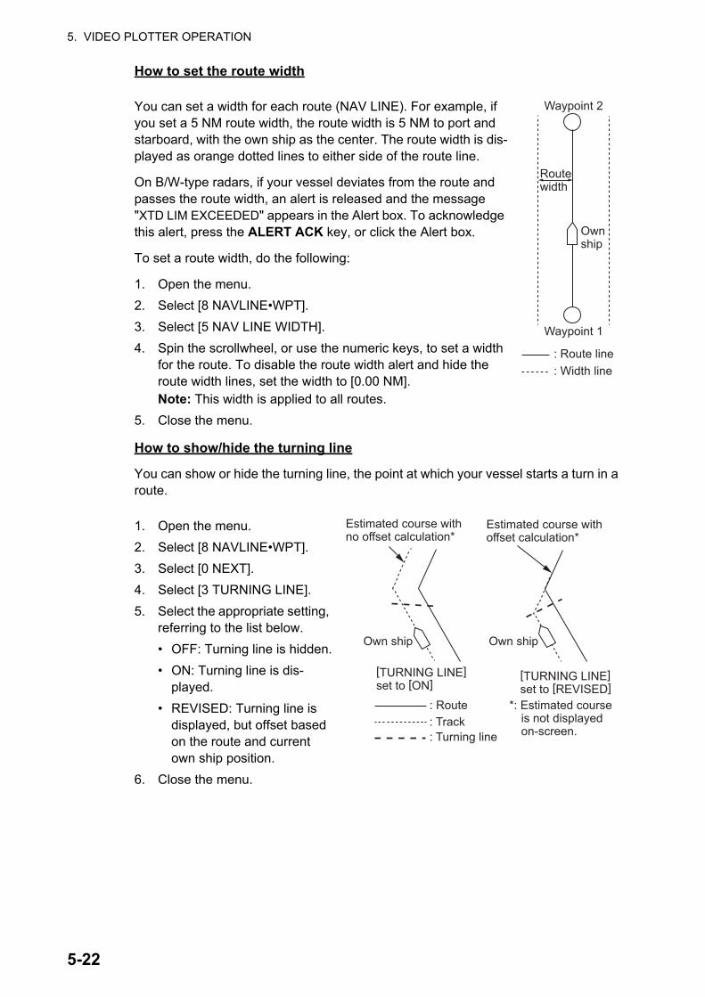
5. VIDEO PLOTTER OPERATION
How to set the route width
You can set a width for each route (NAV LINE). For example, if you set a 5 NM route width, the route width is 5 NM to port and starboard, with the own ship as the center. The route width is dis-played as orange dotted lines to either side of the route line.
On B/W-type radars, if your vessel deviates from the route and passes the route width, an alert is released and the message "XTD LIM EXCEEDED" appears in the Alert box. To acknowledge this alert, press the ALERT ACK key, or click the Alert box.
To set a route width, do the following:
1. Open the menu.
2. Select [8 NAVLINE•WPT].
3. Select [5 NAV LINE WIDTH].
4. Spin the scrollwheel, or use the numeric keys, to set a width for the route. To disable the route width alert and hide the route width lines, set the width to [0.00 NM].Note: This width is applied to all routes.
5. Close the menu.
How to show/hide the turning line
You can show or hide the turning line, the point at which your vessel starts a turn in a route.
1. Open the menu.
2. Select [8 NAVLINE•WPT].
3. Select [0 NEXT].
4. Select [3 TURNING LINE].
5. Select the appropriate setting, referring to the list below.
• OFF: Turning line is hidden.
• ON: Turning line is dis-played.
• REVISED: Turning line is displayed, but offset based on the route and current own ship position.
6. Close the menu.
Waypoint 2
: Route line: Width line
Waypoint 1
Route width
Own ship
Estimated course with no offset calculation*
Estimated course with offset calculation*
*: Estimated course is not displayed on-screen.
: Route: Track: Turning line
Own shipOwn ship
[TURNING LINE] set to [ON]
[TURNING LINE] set to [REVISED]
5-22
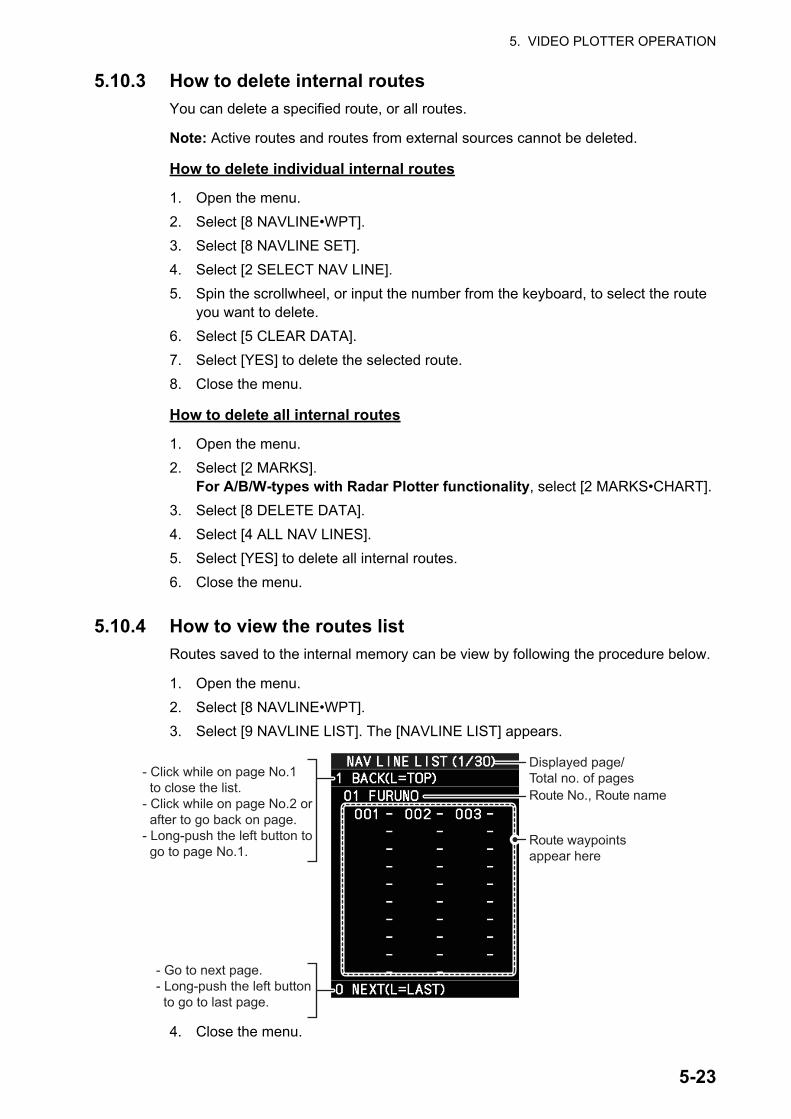
5. VIDEO PLOTTER OPERATION
5.10.3 How to delete internal routes
You can delete a specified route, or all routes.
Note: Active routes and routes from external sources cannot be deleted.
How to delete individual internal routes
1. Open the menu.
2. Select [8 NAVLINE•WPT].
3. Select [8 NAVLINE SET].
4. Select [2 SELECT NAV LINE].
5. Spin the scrollwheel, or input the number from the keyboard, to select the route you want to delete.
6. Select [5 CLEAR DATA].
7. Select [YES] to delete the selected route.
8. Close the menu.
How to delete all internal routes
1. Open the menu.
2. Select [2 MARKS].For A/B/W-types with Radar Plotter functionality, select [2 MARKS•CHART].
3. Select [8 DELETE DATA].
4. Select [4 ALL NAV LINES].
5. Select [YES] to delete all internal routes.
6. Close the menu.
5.10.4 How to view the routes list
Routes saved to the internal memory can be view by following the procedure below.
1. Open the menu.
2. Select [8 NAVLINE•WPT].
3. Select [9 NAVLINE LIST]. The [NAVLINE LIST] appears.
4. Close the menu.
Displayed page/Total no. of pages- Click while on page No.1
to close the list.- Click while on page No.2 or after to go back on page.- Long-push the left button to go to page No.1.
Route No., Route name
Route waypointsappear here
- Go to next page.- Long-push the left button to go to last page.
5-23

5. VIDEO PLOTTER OPERATION
5.10.5 How to use the waypoint arrival distance function
The waypoint arrival distance function lets you know when you are within a preset dis-tance from the next waypoint. When the waypoint arrival area is set, the next waypoint is shown circumscribed with an dashed orange-colored circle, whose radius is equiv-alent to waypoint arrival distance setting. When your vessel comes within the destina-tion arrival radius, the system places the arrival radius marker on the next destination.
For type radars only, you can also set a waypoint arrival alert.
Note: To use this alert, set [2 NAV LINE DATA SOURCE] in the [NAV LINE•WPT] menu to [EXT DATA] or [INTERNAL DATA] before-hand. See section 5.9.1 for details.
To set and use the waypoint arrival area function, follow the procedure below.
1. Open the menu.
2. Select [8 NAVLINE•WPT].
3. Select [0 NEXT]. The second page of the [NAVLINE•WPT] menu appears.
4. Select [2 WPT ARRIVAL DIST].
5. For B/W-type radars only, select [ON] to enable the arrival alert, or [OFF] to dis-able the arrival alert.
6. For all radar types, set the width (radius) of the arrival area.
7. Close the menu.
Waypoint arrival radius
Own ship
Waypoint arrival distance
Waypoint
Alert area
5-24

5. VIDEO PLOTTER OPERATION
5.11 Chart FunctionsNote: All chart functions are available only for A/B/W-types with Radar Plotter func-tionality.
5.11.1 How to show/hide the chart
The [CHART DISPLAY] menu item is [ON] as a factory default. There are two methods to show/hide the chart.
Show/hide the chart using the InstantAccess bar
Click the Chart button to toggle between [CHART ON] (shows the chart) and [CHART OFF] (hide the chart).
Show/hide the chart from the menu
1. Open the menu.
2. Select [2 MARKS•CHART].
3. Select [0 NEXT] to show the next page of the menu.
4. Select [6 CHART DISPLAY].
5. Select [ON] to display the chart, or select [OFF] to hide the chart, then left-click.
6. Close the menu.
Chart buttonChart button
Chart iconChart icon
TM
5-25

5. VIDEO PLOTTER OPERATION
Chart Icons
The chart icon appears at the top-left section of the screen. The icon changes depend-ing on the chart status, as shown below.
5.11.2 How to align the chart position
When the radar target and the chart are not overlaid correctly, align the chart position.
1. Right-click the operational display area to show the [CURSOR MENU].
2. Select [MAP ALIGN]. The cursor is now highlighted and the [MAP ALIGN] function is active.
3. Left-click the map at the location you want to move. The map is now “anchored” to the cursor.
4. Move the cursor to align the radar map with the radar screen, then left-click. The indication "MAP ALIGN" appears on the right side of the operational display area.
5. Right-click to deactivate the [MAP ALIGN] function.
Display indications affected by map alignment
The following items are also re-aligned when the [MAP ALIGN] function is activated.
Display indications unaffected by map alignment
The following items are not re-aligned when the [MAP ALIGN] function is activated.
Chart Icons MeaningSuitable chart scale.
Unsuitable chart scale. Press the ZOOM IN or ZOOM OUT key to adjust the chart scale.
No chart file.
Note 1: When you activate or deactivate the [MAP ALIGN] function, trails for both own ship and other ships are not reset.Note 2: Chart alignments are not retained when the radar power is turned off.
• Map marks• Drop marks• Anchor watch settings• Target tracks• AIS symbols• EBL offsets (STAB GND mode only)• Origin marks• NAV lines and waypoints
• MOB marks• Own ship tracks• Latitude/Longitude Grid• AIS symbol vector display• Zoom window display (STAB GND mode
only)• Cursor position coordinates (when CUR-
SOR L/L ALIGN is set to [ON] only)
• Radar echoes• TT symbol vector display• PI lines• Own ship mark
• TT symbols• EBL/VRM reference point• OS coordinates ([POSN]) display• Barge mark
5-26

5. VIDEO PLOTTER OPERATION
How to disable the map alignment
1. Right-click the operational display area to show the [CURSOR MENU].
2. Select [MAP ALIGN], then left-click. The cursor is now highlighted and the [MAP ALIGN] function is active.
3. Press and hold the left button. The "MAP ALIGN" indication is cleared and the map alignment is cleared.
4. Right-click to deactivate the [MAP ALIGN] function.
5.11.3 How to select the chart type
You can select one of four types of charts, depending on your requirements.
1. Open the menu.
2. Select [2 MARKS•CHART].
3. Select [0 NEXT] to show the next page of the menu.
4. Select [5 CHANGE CHARTS].
5. Select either of the following charts, then left-click.[VECTOR]: Navigational chart (data by FURUNO).[FISHING]: Fishing chart that shows detailed depth contours.[C-MAP]: Select this when installing C-MAP chart data.[NAVIONICS]: Select this when installing Navionics chart data.
6. Close the menu.
Note: Depth contours for [FISHING] are drawn differently from navigational chart data (bathymetric chart data). The [FISHING] chart does not have the latest shallow infor-mation, so select [VECTOR] when sailing into/out of port or sailing along coastlines.
5.11.4 Chart settings menu
Below is the explanation about the each item of [CHART SETTINGS].
1. Open the menu.
2. Select [2 MARKS•CHART].
3. Select [3 CHART SETTINGS].The [CHART SETTINGS] menu has four pages.
4. Select a menu item to change the settings, then left-click.
Page 1 Page 2 Page 3
Page 4
5-27
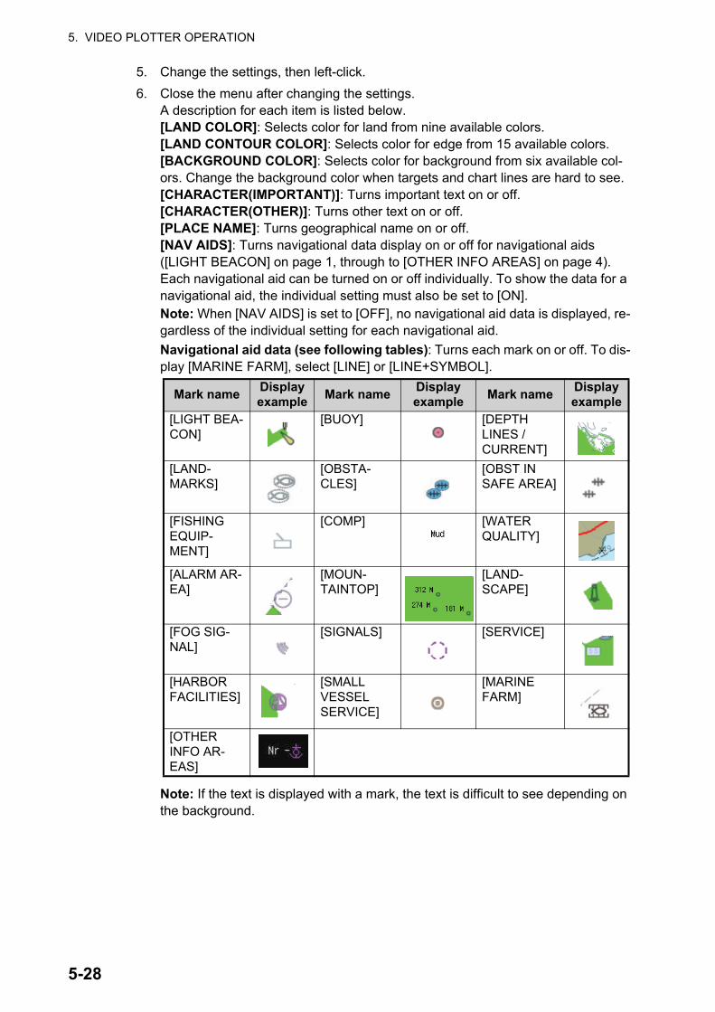
5. VIDEO PLOTTER OPERATION
5. Change the settings, then left-click.
6. Close the menu after changing the settings.A description for each item is listed below.[LAND COLOR]: Selects color for land from nine available colors.[LAND CONTOUR COLOR]: Selects color for edge from 15 available colors.[BACKGROUND COLOR]: Selects color for background from six available col-ors. Change the background color when targets and chart lines are hard to see.[CHARACTER(IMPORTANT)]: Turns important text on or off.[CHARACTER(OTHER)]: Turns other text on or off.[PLACE NAME]: Turns geographical name on or off.[NAV AIDS]: Turns navigational data display on or off for navigational aids ([LIGHT BEACON] on page 1, through to [OTHER INFO AREAS] on page 4). Each navigational aid can be turned on or off individually. To show the data for a navigational aid, the individual setting must also be set to [ON].Note: When [NAV AIDS] is set to [OFF], no navigational aid data is displayed, re-gardless of the individual setting for each navigational aid.
Navigational aid data (see following tables): Turns each mark on or off. To dis-play [MARINE FARM], select [LINE] or [LINE+SYMBOL].
Note: If the text is displayed with a mark, the text is difficult to see depending on the background.
Mark nameDisplay example
Mark nameDisplay example
Mark nameDisplay example
[LIGHT BEA-CON]
[BUOY] [DEPTH LINES / CURRENT]
[LAND-MARKS]
[OBSTA-CLES]
[OBST IN SAFE AREA]
[FISHING EQUIP-MENT]
[COMP] [WATER QUALITY]
[ALARM AR-EA]
[MOUN-TAINTOP]
[LAND-SCAPE]
[FOG SIG-NAL]
[SIGNALS] [SERVICE]
[HARBOR FACILITIES]
[SMALL VESSEL SERVICE]
[MARINE FARM]
[OTHER INFO AR-EAS]
5-28

5. VIDEO PLOTTER OPERATION
The mark display for light sector differs according to the setting of light beacon. For details, see the table below.
5.11.5 How to show/hide land mass emphasis
[LAND MASS EPHASIS] sets whether to highlight the outer edge of land masses on the display.
1. Open the menu.
2. Select [2 MARKS•CHART].
3. Select [0 NEXT].
4. Select [4 EMPHASIZE LAND MASS].
5. Select [OFF] to disable the emphasis. There are three levels of emphasis avail-able; a higher setting gives a thicker emphasis line around the land mass.
6. Close the menu.
[LIGHT SECTOR] set to [ON]. [LIGHT SECTOR] set to [OFF].[LIGHT BEACON] set to [ON].
Light sector and range lines are displayed (lines for range are long).
Only light sector is displayed (lines for range are short).
[LIGHT BEACON] set to [OFF].
Light sector and range lines are displayed (range lines are long).
Light sector is not displayed.
Light sectorRange line
Light buoy
5-29

5. VIDEO PLOTTER OPERATION
5.11.6 How to check your charts/symbol versions
You can check the version of your charts and symbols from the [CHART ADMINIS-TRATION] menu.
1. Open the menu.
2. Select [9 INITIAL SETTINGS].
3. Select [8 UPDATE CHART]. The confirmation message "OTHER FUNCTIONS WILL STOP DURING THE CHART UPDATE. ARE YOU SURE?" appears.
4. Select [RUN] to access the [CHART ADMINISTRATION] menu.
5. Select [6 BASECHARTS • SYMBOLS VERSION]. The version information for your charts and symbols appears.
6. Right-click to go back to the [CHART ADMINISTRATION] menu.
7. Select [7 CLOSE]. The confirmation message [CLOSE CHART ADMINISTRA-TION AND RESTART THE SYSTEM?] appears.
8. Select [RUN]. The system restarts.
Instructions for these menu items are contained in the Installation Manual IME-36520
5-30
6. MAINTENANCE, TROUBLE-SHOOTING
Periodic checks and maintenance are important for proper operation of any electronic system. This chapter contains maintenance and troubleshooting instructions to be fol-lowed to obtain optimum performance and the longest possible life of the equipment. Before attempting any maintenance or troubleshooting procedure please review the safety information below.
WARNINGWARNINGDo not open the equipment.
Hazardous voltage which can cause electrical shock exists inside the equipment. Only qualified personnel should work inside the equipment.
Turn off the radar power switch before servicing the antenna unit. Post a warning sign near the switch indicating it should not be turned on while the antenna unit is being serviced.
Prevent the potential risk of being struck by the rotating antenna.
Wear a safety belt and hard hat when working on the antenna unit.
Serious injury or death can result if someone falls from the radar antenna mast.
A transmitting radar antenna emits electromagnetic waves, which can be harmful, particularly to the eyes.
Never look directly into the antenna aperture from a close distance while the radar is in operation, or expose yourself to the transmitting radar at a close distance.
NOTICEDo not apply paint, anti-corrosive sealant or contact spray to coating or plastic parts of the equipment.
Those items contain organic solvents that can damage coating and plastic parts, especially plastic connectors.
6-1

6. MAINTENANCE, TROUBLESHOOTING
6.1 Periodic Maintenance ScheduleRegular maintenance is essential to good performance. A regular maintenance pro-gram should be established and should at least include the items in the table below.
Interval Check Point Checks and measures RemarksAs required
The LCD will in time accumulate a layer of dust which tends to dim the picture
Check that dust or dirt is not on the display. Wipe it care-fully to prevent scratching. For difficult to remove dirt or salt deposits, use a cloth made wet with water and neutral detergent (less than 1% detergent). Squeeze the cloth dry then clean the dis-play. When the display is clean, gently wipe the dis-play with a clean, soft, dry cloth, to prevent scratching.
Processor unit cleanli-ness
Dust and dirt may be re-moved with a soft cloth.
Do not use chemical-based cleaners to clean the processor unit. They can remove paint and markings.
3 to 6 months
Exposed nuts and bolts on antenna unit
Check for corroded or loos-ened nuts and bolts. If nec-essary, clean and repaint them thickly. Replace if heavily corroded.
Sealing compound can be used instead of paint. Apply a small amount of grease between nuts and bolts for easy removal in fu-ture.
Antenna radiator Check for dirt and cracks on radiator surface. Thick dirt should be wiped off with soft cloth dampened with fresh water. If a crack is found, apply a slight amount of sealing compound or adhe-sive as a temporary remedy, then call for repair.
Do not use chemical-based cleaners for cleaning. They can remove paint and markings. If you need to remove ice from the antenna unit, use a wooden or plastic head hammer. Cracks on the unit may cause water in-gress, causing serious damages to internal circuits.
Terminal strips and plugs in antenna unit (TECHNICIANS only)
Open antenna cover to check terminal strip and plug connections inside. Also check the rubber gas-ket of antenna covers for deterioration.
When closing antenna covers in position, be careful not to catch loose wires between covers and unit.
Adhesive (marine sealant) on nuts and bolts
Check for deteriorations such as splits and peeling. Re-apply as required. For areas with extensive deteri-oration, remove the existing adhesive before re-applying a fresh coat.
Adhesive deterioration can result in water leakage, which can cause corrosion.
6 months to one year
Terminal strips, sock-ets, earth terminal on processor unit (TECHNICIANS only)
Check for loose connec-tions. Check contacts and plugs for proper seating, etc.
6-2

6. MAINTENANCE, TROUBLESHOOTING
6.2 How to Replace the Fuse
Fuses are located as shown in the tables below. Each fuse protects the equipment from reverse polarity of the ship’s mains and equipment fault. If a fuse blows, find the cause before replacing it. Use the correct fuse. Using the wrong fuse will damage the equipment and void the warranty.
Note: For monitor units MU-190/MU-190HD/MU-231/MU-270W, see the monitor’s op-erator manual for fuse details.
For all AC-powered configurations
Note: This fuse is located on the front of the processor unit.
For DC-powered configurations
For configurations with the High Speed Kit installed
Note: This fuse is located on the front of the processor unit.
Every year
Antenna Unit Check the antenna unit for corrosion and paint pealing.
If corrosion or paint pealing is found, paint the affected area. Do not paint the antenna (see below), only paint the scanner.
Note: Painting the antenna may result in reduced performance and/or damage to the antenna.
5 years Antenna Unit If the grease dries out, the V-ring may break, allowing water to leak inside the an-tenna unit.
Have a qualified technician apply the grease oil to the antenna ro-tary.
Radar Model(s) Type Code No.FAR-2218(-BB)/FAR-2228(-BB)/FAR-2228-NXT(-BB)/FAR-2238S(-BB)/FAR-2238S-NXT(-BB)/FAR-2318/FAR-2328/FAR-2328-NXT/FAR-2328W/FAR-2338SW/FAR-2338S/FAR-2338S-NXT
FGBO-A 250V 7A PBF 000-178-084-10
Radar Model(s) Type Code No.FAR-2218(-BB)/FAR-2228(-BB)/FAR-2228-NXT(-BB)/FAR-2318/FAR-2328/FAR-2328-NXT
FGBO 125V 20A 000-155-780-10
Radar Model(s) Type Code No.FAR-2238S(-BB)/FAR-2238S-NXT(-BB)/FAR-2338SW/FAR-2338S/FAR-2338S-NXT
FGBO-A 250V 3A PBF 000-155-841-10
Interval Check Point Checks and measures Remarks
Do NOT paint
WARNINWARNINGUse the proper fuse.Use of the wrong fuse can cause fire or electrical shock.
6-3
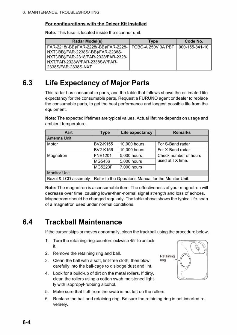
6. MAINTENANCE, TROUBLESHOOTING
For configurations with the Deicer Kit installed
Note: This fuse is located inside the scanner unit.
6.3 Life Expectancy of Major PartsThis radar has consumable parts, and the table that follows shows the estimated life expectancy for the consumable parts. Request a FURUNO agent or dealer to replace the consumable parts, to get the best performance and longest possible life from the equipment.
Note: The expected lifetimes are typical values. Actual lifetime depends on usage and ambient temperature.
Note: The magnetron is a consumable item. The effectiveness of your magnetron will decrease over time, causing lower-than-normal signal strength and loss of echoes. Magnetrons should be changed regularly. The table above shows the typical life-span of a magnetron used under normal conditions.
6.4 Trackball MaintenanceIf the cursor skips or moves abnormally, clean the trackball using the procedure below.
1. Turn the retaining ring counterclockwise 45° to unlock it.
2. Remove the retaining ring and ball.
3. Clean the ball with a soft, lint-free cloth, then blow carefully into the ball-cage to dislodge dust and lint.
4. Look for a build-up of dirt on the metal rollers. If dirty, clean the rollers using a cotton swab moistened light-ly with isopropyl-rubbing alcohol.
5. Make sure that fluff from the swab is not left on the rollers.
6. Replace the ball and retaining ring. Be sure the retaining ring is not inserted re-versely.
Radar Model(s) Type Code No.FAR-2218(-BB)/FAR-2228(-BB)/FAR-2228-NXT(-BB)/FAR-2238S(-BB)/FAR-2238S-NXT(-BB)/FAR-2318/FAR-2328/FAR-2328-NXT/FAR-2328W/FAR-2338SW/FAR-2338S/FAR-2338S-NXT
FGBO-A 250V 3A PBF 000-155-841-10
Part Type Life expectancy RemarksAntenna UnitMotor BV2-K155 10,000 hours For S-Band radar
BV2-K156 10,000 hours For X-Band radarMagnetron FNE1201 5,000 hours Check number of hours
used at TX time.MG5436 5,000 hoursMG5223F 7,000 hours
Monitor UnitBezel & LCD assembly Refer to the Operator’s Manual for the Monitor Unit.
Retaining ring
6-4
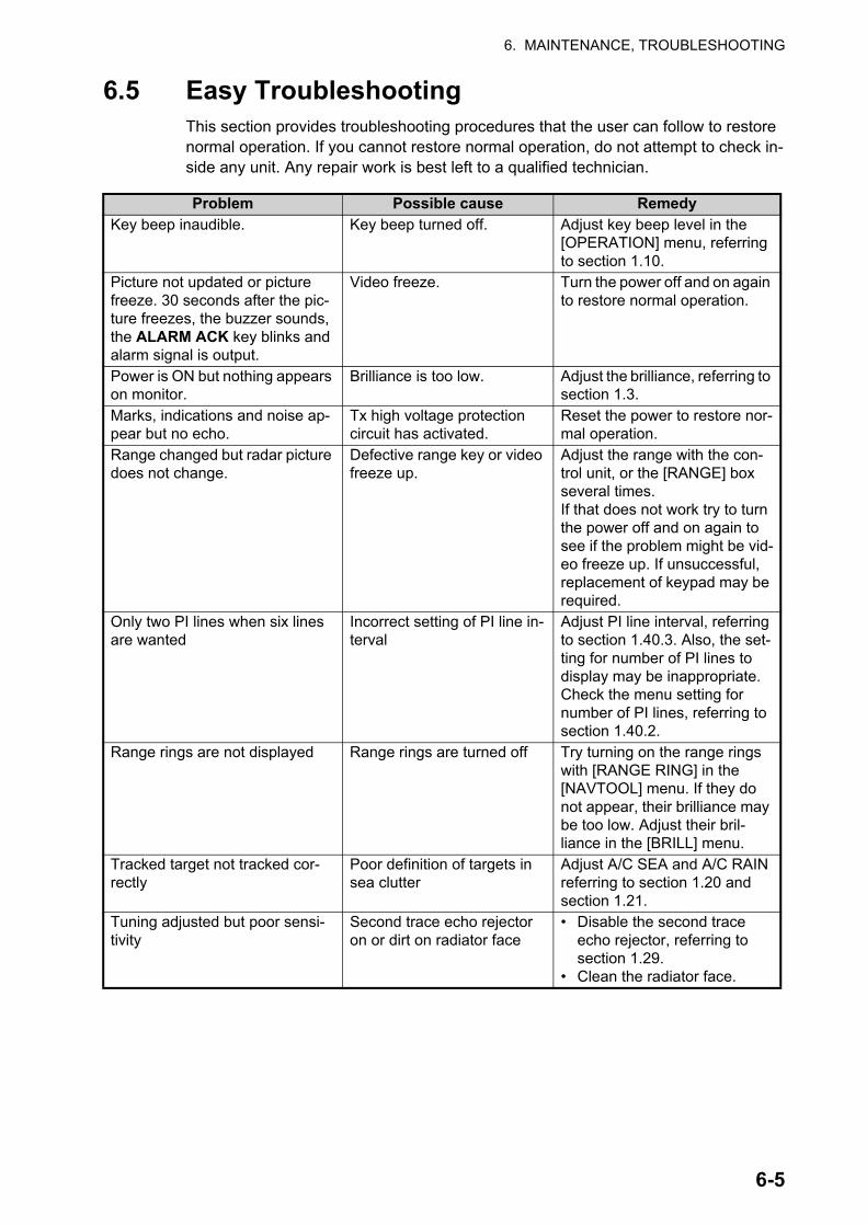
6. MAINTENANCE, TROUBLESHOOTING
6.5 Easy TroubleshootingThis section provides troubleshooting procedures that the user can follow to restore normal operation. If you cannot restore normal operation, do not attempt to check in-side any unit. Any repair work is best left to a qualified technician.
Problem Possible cause RemedyKey beep inaudible. Key beep turned off. Adjust key beep level in the
[OPERATION] menu, referring to section 1.10.
Picture not updated or picture freeze. 30 seconds after the pic-ture freezes, the buzzer sounds, the ALARM ACK key blinks and alarm signal is output.
Video freeze. Turn the power off and on again to restore normal operation.
Power is ON but nothing appears on monitor.
Brilliance is too low. Adjust the brilliance, referring to section 1.3.
Marks, indications and noise ap-pear but no echo.
Tx high voltage protection circuit has activated.
Reset the power to restore nor-mal operation.
Range changed but radar picture does not change.
Defective range key or video freeze up.
Adjust the range with the con-trol unit, or the [RANGE] box several times. If that does not work try to turn the power off and on again to see if the problem might be vid-eo freeze up. If unsuccessful, replacement of keypad may be required.
Only two PI lines when six lines are wanted
Incorrect setting of PI line in-terval
Adjust PI line interval, referring to section 1.40.3. Also, the set-ting for number of PI lines to display may be inappropriate. Check the menu setting for number of PI lines, referring to section 1.40.2.
Range rings are not displayed Range rings are turned off Try turning on the range rings with [RANGE RING] in the [NAVTOOL] menu. If they do not appear, their brilliance may be too low. Adjust their bril-liance in the [BRILL] menu.
Tracked target not tracked cor-rectly
Poor definition of targets in sea clutter
Adjust A/C SEA and A/C RAIN referring to section 1.20 and section 1.21.
Tuning adjusted but poor sensi-tivity
Second trace echo rejector on or dirt on radiator face
• Disable the second trace echo rejector, referring to section 1.29.
• Clean the radiator face.
6-5

6. MAINTENANCE, TROUBLESHOOTING
6.6 Advanced-level TroubleshootingThis section describes how to cure hardware and software troubles that should be car-ried out by qualified service personnel.
Note 1: This radar equipment contains complex modules in which fault diagnosis and repair down to component level are not practicable by users.
Note 2: When replacement of the MAIN board is necessary, the previous settings can be transferred to new MAIN board as follows:
• Save your settings to a SD-card, referring to section section 1.55.
• After replacing the MAIN board, load the entire contents of the SD-card to the radar, referring to section section 1.55 for the procedure.
Problem Possible cause RemedyCannot turn power on. 1) Blown fuse.
2) Mains voltage/polarity.3) Power supply board
(PWR1 and/or PWR2) in-side the Processor unit.
1) Replace blown fuse.2) Correct wiring and input voltage.3) Replace the faulty power supply
board.
Brilliance adjusted but no picture.
MAIN board - inside the Pro-cessor unit.
Replace MAIN board.
Antenna not rotating. 1) Antenna drive mecha-nism
2) MTR-DRV board
1) Replace antenna drive mechanism.
2) Replace the MTR-DRV board.Data and marks not displayed in Transmit status
MAIN board - inside the Pro-cessor unit.
Replace MAIN board.
Adjust GAIN with A/C SEA set at minimum. Marks and indications appear but no noise or echo.
1) IF amplifier2) Signal cable between an-
tenna and processor unit
1) Replace IF amplifier.2) Check continuity and isolation of coax-
ial cable.Note: Disconnect the plug and lugs at both ends of coaxial cable before checking it by ohmmeter.
Marks, indications and noise appear but no echo (transmission leak representing own ship position is absent)
1) TX high voltage protec-tion circuit has activated.
2) Magnetron
3) MD board inside the an-tenna.
4) SPU board inside the an-tenna.
1) Reset power to restore normal opera-tion.
2) Check magnetron current.Replace magnetron.
3) Replace MD board.
4) Replace SPU board.
Picture not updated or picture freeze-up
1) Rotary Encoder inside the antenna unit.
2) SPU board inside the an-tenna.
3) Video freeze-up
1) Check the connection of signal cables.2) Replace SPU board.
3) Turn the radar off, then on.Incorrect orientation of picture
1) Rotary Encoder inside the antenna unit
2) SPU board inside the an-tenna unit.
3) MTR-DRV board inside the antenna unit.
If the message “LOST HEADLINE” ap-pears in orange letters inside the alert box, the heading signal is lost or interrupted. Check the heading line signal cable and board connections. If there is no problem with cables or connections, replace the faulty board.
6-6
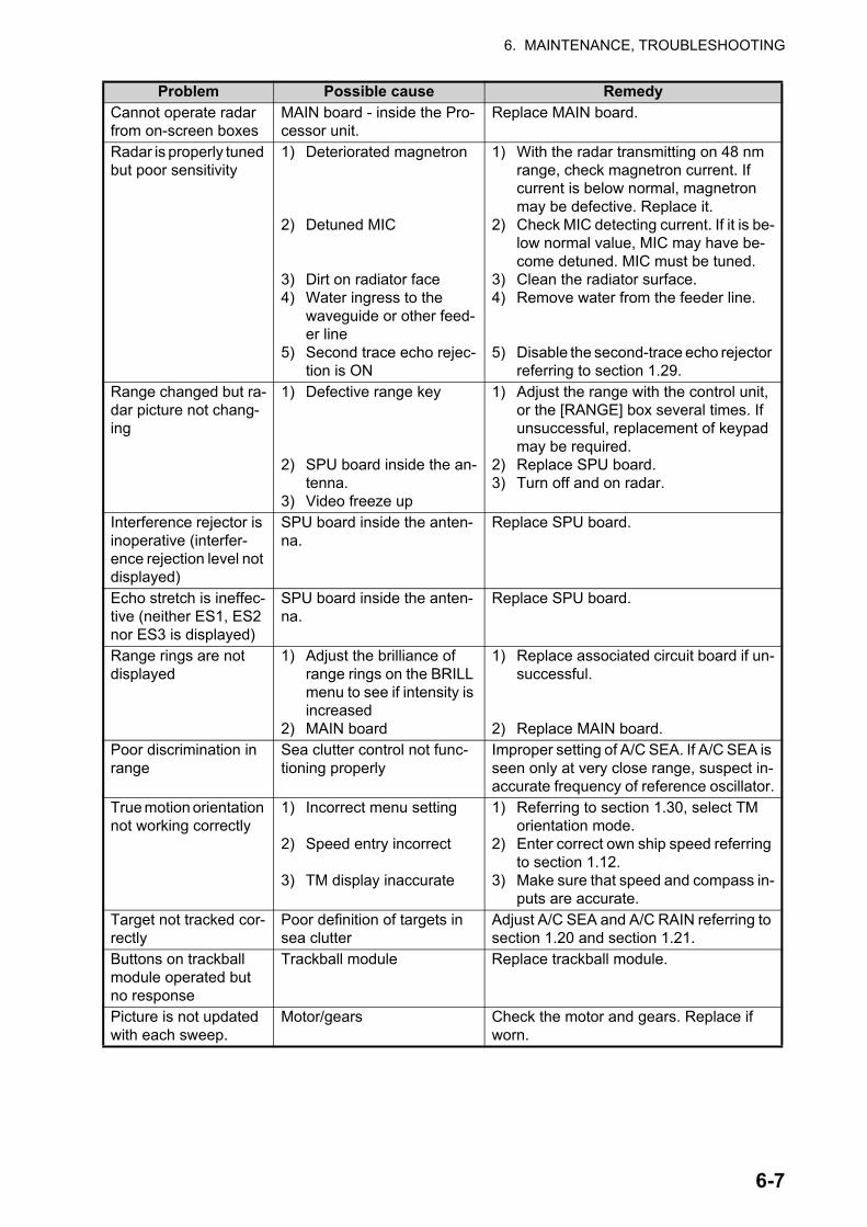
6. MAINTENANCE, TROUBLESHOOTING
Cannot operate radar from on-screen boxes
MAIN board - inside the Pro-cessor unit.
Replace MAIN board.
Radar is properly tuned but poor sensitivity
1) Deteriorated magnetron
2) Detuned MIC
3) Dirt on radiator face4) Water ingress to the
waveguide or other feed-er line
5) Second trace echo rejec-tion is ON
1) With the radar transmitting on 48 nm range, check magnetron current. If current is below normal, magnetron may be defective. Replace it.
2) Check MIC detecting current. If it is be-low normal value, MIC may have be-come detuned. MIC must be tuned.
3) Clean the radiator surface.4) Remove water from the feeder line.
5) Disable the second-trace echo rejector referring to section 1.29.
Range changed but ra-dar picture not chang-ing
1) Defective range key
2) SPU board inside the an-tenna.
3) Video freeze up
1) Adjust the range with the control unit, or the [RANGE] box several times. If unsuccessful, replacement of keypad may be required.
2) Replace SPU board.3) Turn off and on radar.
Interference rejector is inoperative (interfer-ence rejection level not displayed)
SPU board inside the anten-na.
Replace SPU board.
Echo stretch is ineffec-tive (neither ES1, ES2 nor ES3 is displayed)
SPU board inside the anten-na.
Replace SPU board.
Range rings are not displayed
1) Adjust the brilliance of range rings on the BRILL menu to see if intensity is increased
2) MAIN board
1) Replace associated circuit board if un-successful.
2) Replace MAIN board.Poor discrimination in range
Sea clutter control not func-tioning properly
Improper setting of A/C SEA. If A/C SEA is seen only at very close range, suspect in-accurate frequency of reference oscillator.
True motion orientation not working correctly
1) Incorrect menu setting
2) Speed entry incorrect
3) TM display inaccurate
1) Referring to section 1.30, select TM orientation mode.
2) Enter correct own ship speed referring to section 1.12.
3) Make sure that speed and compass in-puts are accurate.
Target not tracked cor-rectly
Poor definition of targets in sea clutter
Adjust A/C SEA and A/C RAIN referring to section 1.20 and section 1.21.
Buttons on trackball module operated but no response
Trackball module Replace trackball module.
Picture is not updated with each sweep.
Motor/gears Check the motor and gears. Replace if worn.
Problem Possible cause Remedy
6-7
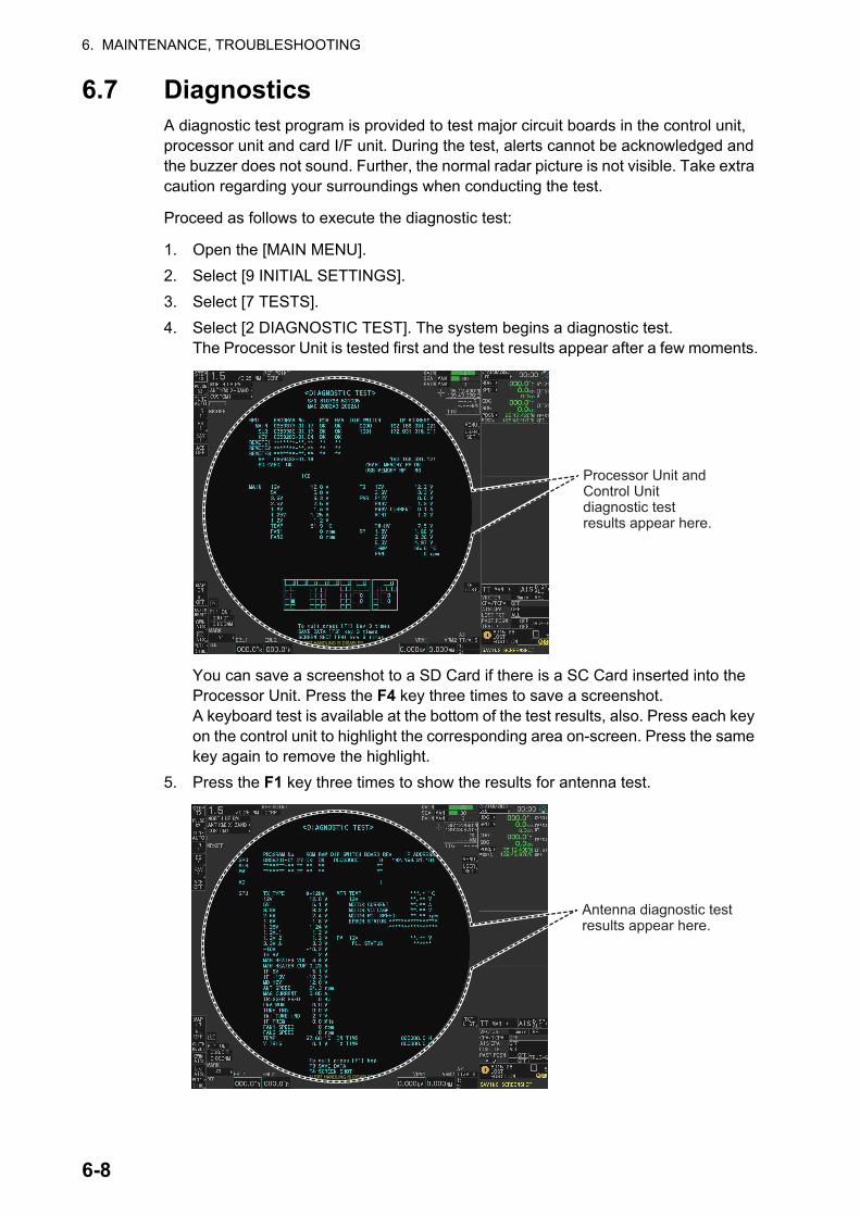
6. MAINTENANCE, TROUBLESHOOTING
6.7 DiagnosticsA diagnostic test program is provided to test major circuit boards in the control unit, processor unit and card I/F unit. During the test, alerts cannot be acknowledged and the buzzer does not sound. Further, the normal radar picture is not visible. Take extra caution regarding your surroundings when conducting the test.
Proceed as follows to execute the diagnostic test:
1. Open the [MAIN MENU].
2. Select [9 INITIAL SETTINGS].
3. Select [7 TESTS].
4. Select [2 DIAGNOSTIC TEST]. The system begins a diagnostic test.The Processor Unit is tested first and the test results appear after a few moments.
You can save a screenshot to a SD Card if there is a SC Card inserted into the Processor Unit. Press the F4 key three times to save a screenshot.A keyboard test is available at the bottom of the test results, also. Press each key on the control unit to highlight the corresponding area on-screen. Press the same key again to remove the highlight.
5. Press the F1 key three times to show the results for antenna test.
Processor Unit and Control Unit diagnostic test results appear here.
ALERT HANDLING IS DISABLED
Antenna diagnostic test results appear here.
ALERT HANDLING IS DISABLED
6-8

6. MAINTENANCE, TROUBLESHOOTING
You can save a screenshot to a SD Card if there is a SD Card inserted into the Processor Unit. Press the F4 key three times to save a screenshot.
6. Press the F1 key to close the test results and complete the test.
Diagnostic test results
The following table lists each test result along with the normal value range for each item. "OK" appears for normal operation. If "NG" (No Good) appears, corresponding components may be defective.
Also, if a connected fan or PCB shows the check results as asterisks, it is an indication that the fan or PCB has failed, or is disconnected.
If there are any components which are suspected to be defective, or any test does not complete satisfactorily, consult your dealer for advice.
Tested itemNormal value or Description
Magnetron Radar Solid State RadarMAIN (Processor Unit) test[PROGRAM No.] Shows the program version number.[ROM] OK[RAM] OK[DIP SWITCH] Shows the DIP SWITCH settings.[IP ADDRESS] Shows the IP address for the Processor Unit.[SD CARD] OK[SD CARD RP] (Not currently used)[HSC] Shown only for systems with the optional High Speed Conver-
sion kit.[RMS] Shown only when Remote Maintenance Service is enabled.[ICE] Shown only when Ice Mode is enabled.[MAIN] [12V] 10.8 to 13.2 V
[5V] 4.7 to 5.3 V[3.3V] 3.0 to 3.6 V
[MAIN] [2.5V] 2.3 to 2.7 V[1.8V] 1.6 to 2.0 V[1.25V] 1.13 to 1.38 V[1.2V] 1.0 to 1.3 V[TEMP] -15 to +70°C[FAN1] 3700 to 5700 rpm[FAN2] 3700 to 5700 rpm[FAN3] • X/S-Band radars with 24 rpm config: Not shown
• S-Band radars with 42 rpm (HSC) config: 3700 to 5700 rpm[TB] [12V] 10.8 to 13.2 V
[3.3V] 3.0 to 3.6 V[PWR] [P12V] 10.8 to 13.2 V
[P48V] 46 to 50 V[P48 V CURRENT] 0 to 3 A[MTR1] 45.1 to 51.3 V[MTR2] • X/S-Band radars with 24 rpm config: Not shown
• S-Band radars with 42 rpm (HSC) config: 45.1 to 51.3 V[TX HV] 500 to 570 V
(Continued on following page)
6-9
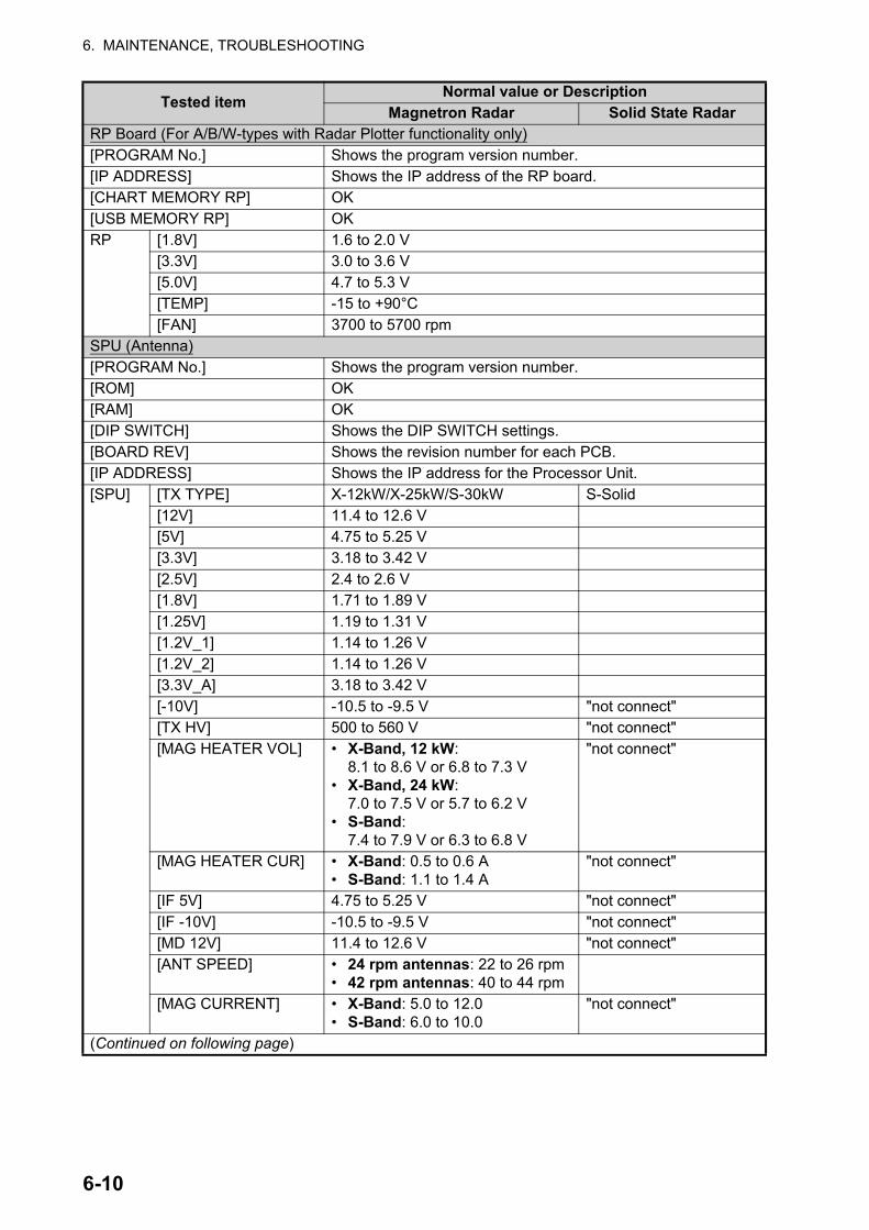
6. MAINTENANCE, TROUBLESHOOTING
RP Board (For A/B/W-types with Radar Plotter functionality only)[PROGRAM No.] Shows the program version number.[IP ADDRESS] Shows the IP address of the RP board.[CHART MEMORY RP] OK[USB MEMORY RP] OKRP [1.8V] 1.6 to 2.0 V
[3.3V] 3.0 to 3.6 V[5.0V] 4.7 to 5.3 V[TEMP] -15 to +90°C[FAN] 3700 to 5700 rpm
SPU (Antenna)[PROGRAM No.] Shows the program version number.[ROM] OK[RAM] OK[DIP SWITCH] Shows the DIP SWITCH settings.[BOARD REV] Shows the revision number for each PCB.[IP ADDRESS] Shows the IP address for the Processor Unit.[SPU] [TX TYPE] X-12kW/X-25kW/S-30kW S-Solid
[12V] 11.4 to 12.6 V[5V] 4.75 to 5.25 V[3.3V] 3.18 to 3.42 V[2.5V] 2.4 to 2.6 V[1.8V] 1.71 to 1.89 V[1.25V] 1.19 to 1.31 V[1.2V_1] 1.14 to 1.26 V[1.2V_2] 1.14 to 1.26 V[3.3V_A] 3.18 to 3.42 V[-10V] -10.5 to -9.5 V "not connect"[TX HV] 500 to 560 V "not connect"[MAG HEATER VOL] • X-Band, 12 kW:
8.1 to 8.6 V or 6.8 to 7.3 V• X-Band, 24 kW:
7.0 to 7.5 V or 5.7 to 6.2 V• S-Band:
7.4 to 7.9 V or 6.3 to 6.8 V
"not connect"
[MAG HEATER CUR] • X-Band: 0.5 to 0.6 A• S-Band: 1.1 to 1.4 A
"not connect"
[IF 5V] 4.75 to 5.25 V "not connect"[IF -10V] -10.5 to -9.5 V "not connect"[MD 12V] 11.4 to 12.6 V "not connect"[ANT SPEED] • 24 rpm antennas: 22 to 26 rpm
• 42 rpm antennas: 40 to 44 rpm[MAG CURRENT] • X-Band: 5.0 to 12.0
• S-Band: 6.0 to 10.0"not connect"
(Continued on following page)
Tested itemNormal value or Description
Magnetron Radar Solid State Radar
6-10
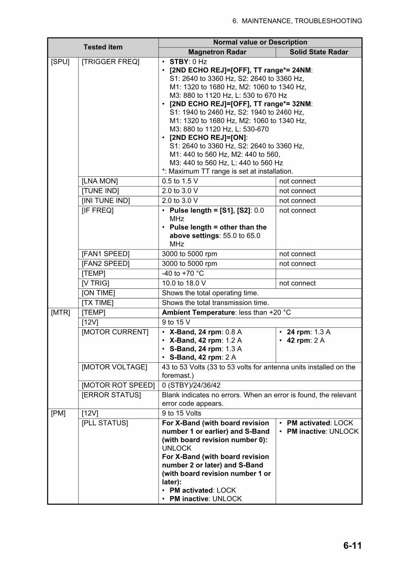
6. MAINTENANCE, TROUBLESHOOTING
[SPU] [TRIGGER FREQ] • STBY: 0 Hz• [2ND ECHO REJ]=[OFF], TT range*= 24NM:
S1: 2640 to 3360 Hz, S2: 2640 to 3360 Hz, M1: 1320 to 1680 Hz, M2: 1060 to 1340 Hz, M3: 880 to 1120 Hz, L: 530 to 670 Hz
• [2ND ECHO REJ]=[OFF], TT range*= 32NM: S1: 1940 to 2460 Hz, S2: 1940 to 2460 Hz, M1: 1320 to 1680 Hz, M2: 1060 to 1340 Hz, M3: 880 to 1120 Hz, L: 530-670
• [2ND ECHO REJ]=[ON]:S1: 2640 to 3360 Hz, S2: 2640 to 3360 Hz, M1: 440 to 560 Hz, M2: 440 to 560, M3: 440 to 560 Hz, L: 440 to 560 Hz
*: Maximum TT range is set at installation.[LNA MON] 0.5 to 1.5 V not connect[TUNE IND] 2.0 to 3.0 V not connect[INI TUNE IND] 2.0 to 3.0 V not connect[IF FREQ] • Pulse length = [S1], [S2]: 0.0
MHz• Pulse length = other than the
above settings: 55.0 to 65.0 MHz
not connect
[FAN1 SPEED] 3000 to 5000 rpm not connect[FAN2 SPEED] 3000 to 5000 rpm not connect[TEMP] -40 to +70 °C[V TRIG] 10.0 to 18.0 V not connect[ON TIME] Shows the total operating time.[TX TIME] Shows the total transmission time.
[MTR] [TEMP] Ambient Temperature: less than +20 °C [12V] 9 to 15 V[MOTOR CURRENT] • X-Band, 24 rpm: 0.8 A
• X-Band, 42 rpm: 1.2 A• S-Band, 24 rpm: 1.3 A• S-Band, 42 rpm: 2 A
• 24 rpm: 1.3 A• 42 rpm: 2 A
[MOTOR VOLTAGE] 43 to 53 Volts (33 to 53 volts for antenna units installed on the foremast.)
[MOTOR ROT SPEED] 0 (STBY)/24/36/42[ERROR STATUS] Blank indicates no errors. When an error is found, the relevant
error code appears.[PM] [12V] 9 to 15 Volts
[PLL STATUS] For X-Band (with board revision number 1 or earlier) and S-Band (with board revision number 0): UNLOCKFor X-Band (with board revision number 2 or later) and S-Band (with board revision number 1 or later):• PM activated: LOCK• PM inactive: UNLOCK
• PM activated: LOCK• PM inactive: UNLOCK
Tested itemNormal value or Description
Magnetron Radar Solid State Radar
6-11
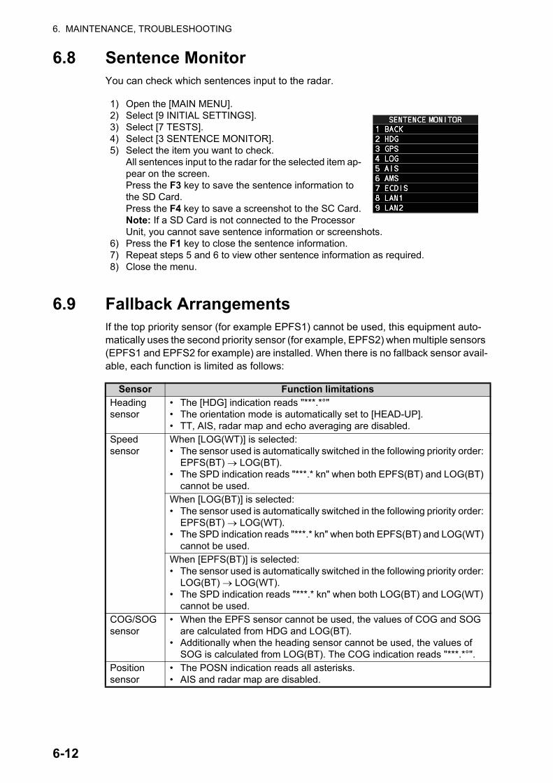
6. MAINTENANCE, TROUBLESHOOTING
6.8 Sentence MonitorYou can check which sentences input to the radar.
6.9 Fallback ArrangementsIf the top priority sensor (for example EPFS1) cannot be used, this equipment auto-matically uses the second priority sensor (for example, EPFS2) when multiple sensors (EPFS1 and EPFS2 for example) are installed. When there is no fallback sensor avail-able, each function is limited as follows:
1) Open the [MAIN MENU].2) Select [9 INITIAL SETTINGS].3) Select [7 TESTS].4) Select [3 SENTENCE MONITOR].5) Select the item you want to check.
All sentences input to the radar for the selected item ap-pear on the screen.Press the F3 key to save the sentence information to the SD Card.Press the F4 key to save a screenshot to the SC Card.Note: If a SD Card is not connected to the Processor Unit, you cannot save sentence information or screenshots.
6) Press the F1 key to close the sentence information.7) Repeat steps 5 and 6 to view other sentence information as required.8) Close the menu.
Sensor Function limitationsHeading sensor
• The [HDG] indication reads "***.*°"• The orientation mode is automatically set to [HEAD-UP].• TT, AIS, radar map and echo averaging are disabled.
Speed sensor
When [LOG(WT)] is selected:• The sensor used is automatically switched in the following priority order:
EPFS(BT) LOG(BT).• The SPD indication reads "***.* kn" when both EPFS(BT) and LOG(BT)
cannot be used.When [LOG(BT)] is selected:• The sensor used is automatically switched in the following priority order:
EPFS(BT) LOG(WT).• The SPD indication reads "***.* kn" when both EPFS(BT) and LOG(WT)
cannot be used.When [EPFS(BT)] is selected:• The sensor used is automatically switched in the following priority order:
LOG(BT) LOG(WT).• The SPD indication reads "***.* kn" when both LOG(BT) and LOG(WT)
cannot be used.COG/SOG sensor
• When the EPFS sensor cannot be used, the values of COG and SOG are calculated from HDG and LOG(BT).
• Additionally when the heading sensor cannot be used, the values of SOG is calculated from LOG(BT). The COG indication reads "***.*°".
Position sensor
• The POSN indication reads all asterisks.• AIS and radar map are disabled.
6-12

APPENDIX 1 MENU TREE
1 2
MENU box(click)
MENU key(press)
or
1 ECHO 2 CUSTOMIZED ECHO
2 INT REJECTOR (OFF, 1, 2, 3)3 ECHO STRETCH (OFF, 1, 2, 3)4 ECHO AVERAGE (OFF, 1, 2, 3)5 TARGET ANALYZER (OFF, ON)*2
6 RAIN ECHO HATCHING (OFF, ON)*2
7 NOISE REJECTOR (OFF, ON)8 VIDEO CONTRAST TYPE (1, 2, 3, 4, A, B, C)
2 0.5NM (S1, S2)3 0.75NM (S1, S2, M1)4 1.5NM (S1, S2, M1, M2)5 3NM (S2, M1, M2, M3)6 6NM (M1, M2, M3, L)7 12NM (M1, M2, M3, L)8 24NM (M2, M3, L)
9 PULSE LENGTH
2 CONDITION
3 2ND ECHO REJ (OFF, ON)4 TUNING INTIALIZE (Requires antenna rotation)5 PERFORMANCE MONITOR (OFF, ON, GRAPH ONLY)*1
6 PM ARC (2, 3, 5, 6)*1
7 SART (OFF, ON)8 ECHO AREA (CIRCLE, WIDE, ALL)*2
9 WIPER (OFF, 1, 2)
2 SIGNAL ENHANCEMENT (1, 2, 3)3 SUPPRESS SECTOR (START: 000° to 359°; ANGLE: 000° to 180°)
2 ACE
3 SELECT CUSTOM 2 CUSTOM1 (OFF, ON)3 CUSTOM2 (OFF, ON)4 CUSTOM3 (OFF, ON)5 NEAR (OFF, ON)
2 SHIP (OFF, ON)3 HARBOR (OFF, ON)4 BIRD (OFF, ON)*4
5 COAST (OFF, ON)
6 FAR (OFF, ON)7 NEAR BUOY (OFF, ON)*3
8 FAR BUOY (OFF, ON)9 ROUGH SEA (OFF, ON)
3 DEFAULT (NO, SAVE, USER, FACTORY)4 ACE (OFF, ON)
Next page
Next page
Next page
2 STC CURVE (2, 2.5, 3, 3.5, 4.2)3 STC RANGE (0, 1, 2, 3, 4, 5, 6, 7, 8, 9, 10)4 LOW LEVEL ECHO (0 to 8)
Default settings are listed in Bold Italic font.
*1: Options only available when PM function is installed.
*2: Shown for B/W-types only.*3: Appears as “7 SMALL
TARGET” when Ice Mode is enabled at installation.
*4: Appears as “4 ICE” when Ice Mode is enabled at installation.
AP-1

APPENDIX 1 MENU TREE
1 24 TRAILS
5 BERTHING STC (OFF, ON)6 EAV EMPH-FAST TGT (OFF, ON)7 WAVE MODE (OFF, ON)8 OUTPUT TO WAVE PC (OFF, ON)
START (00:00 to 12:00/24:00/48:00*5)END (00:00 to 12:00/24:00/48:00*5)
2 OFFSET TRAIL COLOR (NO, YES)3 LONG TRAIL COLORS (FUSCHIA, MAROON,
RED, MAGENTA, YELLOW, LIME, GREEN, OLIVE, TEAL, CYAN, BLUE, NAVY)
2 TRAIL MODE (REL, TRUE)3 TRAIL GRADATION (SINGLE, MULTI)4 TRAIL COLOR (GRN, BLU, CYA, MAG, WHT, YEL)*1
5 TRAIL LEVEL (1, 2, 3, 4)6 OS TRAIL (OFF, ON)7 SUPPRESS AROUND OS (OFF, ON)8 NARROW TRAIL (OFF, 1, 2)*1
3 HIDE LAND TRAILS (R) (OFF, 1, 2)*1
4 TRAIL LENGTH (NORMAL, 12H, 24H, 48H)*1
6 LONG TRAIL COLOR*6
5 TRAIL GRAY-OUT TIME*6
2 HIDE LAND TRAILS (T) (OFF, 1, 2)*1Next page
(Continued from previous page)
1 2
2 MARKS*7 2 OWN SHIP MARK (MINIMIZED, SCALED)3 STERN MARK (OFF, ON)4 DROP MARK (OFF, ON)
2 ORIGIN MARK STAB (GND, SEA)
2 BARGE MARK DISPLAY (OFF, ON)
2 USER CHART (OFF, ON)3 CURVED EBL (OFF, ON)4 CHART SYMBOL (OFF, ON)5 NOTE BOOK (OFF, ON, DISPLAY)6 ROUTE (OFF, CENT, ALL)7 PREDICTOR (OFF, ON)
4 BARGE ARRANGEMENT3 BARGE SIZE (LENGTH: 000ft to 999ft; WIDTH: 000ft to 999ft)
2 MAP DISPLAY (OFF, ON)
4 MARK POSITION (CURSOR, OS, L/L)Display only (used marks/max. marks) RADAR MAP, OWN TRACK,
TGT TRACK*4
3 MARK TYPE (ORIGIN MARK(No.), ORIGIN MARK(SYM), MAP MARK, WP 1~50, WP 51~100, WP 101~150, WP 151~198, OWN SHIP SHAPE)
5 RADAR MAP
6 BARGE MARK*2
6 ECDIS MARKS DISPLAY*3
7 TRACKS 2 OWN TRACK 2 DISPLAY OWN TRACK (OFF, ON)
4 OWN TRACK COLOR (RED, GRN, BLU, YEL, CYA, MAG, WHT)*4
3 SAVE INTERVAL (OFF, DRAW ONLY, 10s, 30s, 1min, 2min, 3min, 6min, 15min)
3 TARGET TRACK*4
3 MARK COLOR (RED, GRN, BLU, YEL, CYA, MAG, WHT)*1
Next page
5 AUTO TARGET TRACK (OFF, ON)
2 DISPLAY TARGET TRACK (OFF, ON)
4 TARGET TRACK COLOR (RED, GRN, BLU, YEL, CYA, MAG, WHT)
3 SAVE INTERVAL (OFF, DRAW ONLY, 10s, 30s, 1min, 2min, 3min, 6min, 15min)
(Continued on next page)
*1: Shown for B/W-types only.*2: Shown only when ECDIS is
set to OFF at installation.*3: Shown only when ECDIS is
set to SERIAL or LAN at installation.
*4: Shown for A/B/W-types only.*5: Based on setting for [TRAIL
LENGTH].*6: Shown when [TRAIL
LENGTH] is set to other than [NORMAL].
*7: Shown as “MARKS•CHARTS” for A/B/W-types with Radar Plotter functionality.
*8: Shown for FAR-2228-NXT(-BB) and FAR-2328-NXT only.
9 DOPPLER*8 (0, 1, 2)
AP-2

APPENDIX 1 MENU TREE
1
1 2
9 RADAR MAP DISPLAY
2 GRID (OFF, ON)3 CHART SETTINGS*3
4 EMPHASIZE LAND MASS*3 (OFF, 1, 2, 3)5 CHANGE CHARTS*3 (VECTOR, FISHING, C-MAP, NAVIONICS)6 CHART DISPLAY*3 (OFF, ON)
2 MARK (OFF, ON)3 BUOY (OFF, ON)4 DANGER (OFF, ON)5 COAST LINE (OFF, ON)6 CONTOUR LINE (OFF, ON)7 NAV LINE (OFF, ON)8 PROHIBITED AREA (OFF, ON)
2 LAND COLOR (1 to 9, 3)3 LAND CONTOUR COLOR (1 to 15, 9)4 BACKGROUND COLOR (1 to 6) 5 CHARACTER (IMPORTANT) (OFF, ON)6 CHARACTER (OTHER) (OFF, ON)7 PLACE NAME (OFF, ON)8 NAV AIDS (OFF, ON)9 LIGHT BEACON (OFF, ON)
Next page
Next page (Page 2/4)
Next page (Page 3/4)
Next page (Page 4/4)
(Continued from previous page)
(Continued on next page)
8 DELETE DATA 2 ALL MARKS (NO, YES)3 ALL WAYPOINTS (NO, YES)4 ALL NAVLINES (NO, YES)
7 OS TRACK-AREA (2POINTS, AREA)*1
8 TGT TRACK-AREA (2POINTS, AREA)*2
5 OS TRACK-COLOR/TIME (RED*1, GRN*1, BLU*1, YEL*1, CYA*1, MAG*1, WHT*1, 30%, 50%, 80%, ALL)
6 TGT TRACK-COLOR/TIME (RED, GRN, BLU, YEL, CYA, MAG, WHT, 30%, 50%, 80%, ALL)*1
2 BUOY (OFF, ON)3 DEPTH LINES/CURRENT (OFF, ON)4 LANDMARKS (OFF, ON)5 OBSTACLES (OFF, ON)6 OBST IN SAFE AREA (OFF, ON)7 FISHING EQUIPMENT (OFF, ON)8 COMP (OFF, ON)9 WATER QUALITY (OFF, ON)
2 ALARM AREA (OFF, ON)3 LIGHT SECTOR (OFF, ON)4 MOUNTAINTOP (OFF, ON)5 LANDSCAPE (OFF, ON)6 FOG SIGNAL (OFF, ON)7 SIGNALS (OFF, ON)8 SERVICE (OFF, ON)9 HARBOR FACILITIES (OFF, ON)
2 SMALL VESSEL SERVICE (OFF, ON)3 MARINE FARM (OFF, LINE, LINE+SYMBOL)
*1: Shown for A/B/W-types only.*2: Shown for B/W-types only.*3: Shown for A/B/W-types with Radar Plotter functionality only.
4 OTHER INFO AREAS (OFF, ON)
AP-3
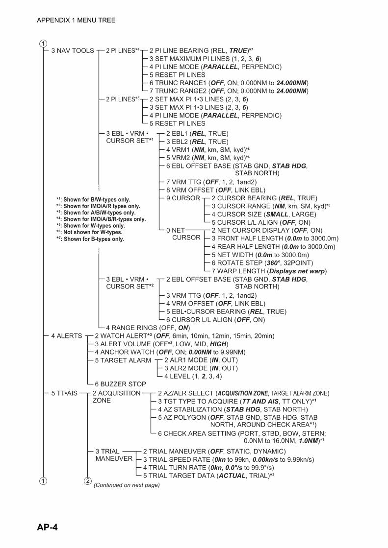
APPENDIX 1 MENU TREE
1
13 NAV TOOLS 2 PI LINE BEARING (REL, TRUE)*7
3 SET MAXIMUM PI LINES (1, 2, 3, 6)4 PI LINE MODE (PARALLEL, PERPENDIC)5 RESET PI LINES6 TRUNC RANGE1 (OFF, ON; 0.000NM to 24.000NM)7 TRUNC RANGE2 (OFF, ON; 0.000NM to 24.000NM)
2 EBL1 (REL, TRUE)3 EBL2 (REL, TRUE)4 VRM1 (NM, km, SM, kyd)*6
5 VRM2 (NM, km, SM, kyd)*6
6 EBL OFFSET BASE (STAB GND, STAB HDG, STAB NORTH)
7 VRM TTG (OFF, 1, 2, 1and2)8 VRM OFFSET (OFF, LINK EBL)9 CURSOR
0 NET CURSOR
2 CURSOR BEARING (REL, TRUE)
4 CURSOR SIZE (SMALL, LARGE)5 CURSOR L/L ALIGN (OFF, ON)
3 CURSOR RANGE (NM, km, SM, kyd)*6
2 NET CURSOR DISPLAY (OFF, ON)3 FRONT HALF LENGTH (0.0m to 3000.0m)4 REAR HALF LENGTH (0.0m to 3000.0m)5 NET WIDTH (0.0m to 3000.0m)6 ROTATE STEP (360°, 32POINT)7 WARP LENGTH (Displays net warp)
2 SET MAX PI 1•3 LINES (2, 3, 6)3 SET MAX PI 1•3 LINES (2, 3, 6)4 PI LINE MODE (PARALLEL, PERPENDIC)5 RESET PI LINES
2 PI LINES*5
2 PI LINES*4
3 EBL • VRM • CURSOR SET*1
4 RANGE RINGS (OFF, ON)
2 EBL OFFSET BASE (STAB GND, STAB HDG, STAB NORTH)
3 VRM TTG (OFF, 1, 2, 1and2)4 VRM OFFSET (OFF, LINK EBL)5 EBL•CURSOR BEARING (REL, TRUE)6 CURSOR L/L ALIGN (OFF, ON)
3 EBL • VRM • CURSOR SET*2
4 ALERTS 2 WATCH ALERT*3 (OFF, 6min, 10min, 12min, 15min, 20min)3 ALERT VOLUME (OFF*3, LOW, MID, HIGH)4 ANCHOR WATCH (OFF, ON; 0.00NM to 9.99NM)5 TARGET ALARM 2 ALR1 MODE (IN, OUT)
3 ALR2 MODE (IN, OUT)4 LEVEL (1, 2, 3, 4)
5 TT•AIS 2 ACQUISITION ZONE
2 AZ/ALR SELECT (ACQUISITION ZONE, TARGET ALARM ZONE)3 TGT TYPE TO ACQUIRE (TT AND AIS, TT ONLY)*1
4 AZ STABILIZATION (STAB HDG, STAB NORTH)
6 CHECK AREA SETTING (PORT, STBD, BOW, STERN; 0.0NM to 16.0NM, 1.0NM)*1
5 AZ POLYGON (OFF, STAB GND, STAB HDG, STAB NORTH, AROUND CHECK AREA*1)
3 TRIAL MANEUVER
2 TRIAL MANEUVER (OFF, STATIC, DYNAMIC)3 TRIAL SPEED RATE (0kn to 99kn, 0.00kn/s to 9.99kn/s)4 TRIAL TURN RATE (0kn, 0.0°/s to 99.9°/s)5 TRIAL TARGET DATA (ACTUAL, TRIAL)*3
(Continued on next page)2
*1: Shown for B/W-types only.*2: Shown for IMO/A/R types only.*3: Shown for A/B/W-types only.*4: Shown for IMO/A/B/R-types only.*5: Shown for W-types only.*6: Not shown for W-types.*7: Shown for B-types only.
6 BUZZER STOP
AP-4
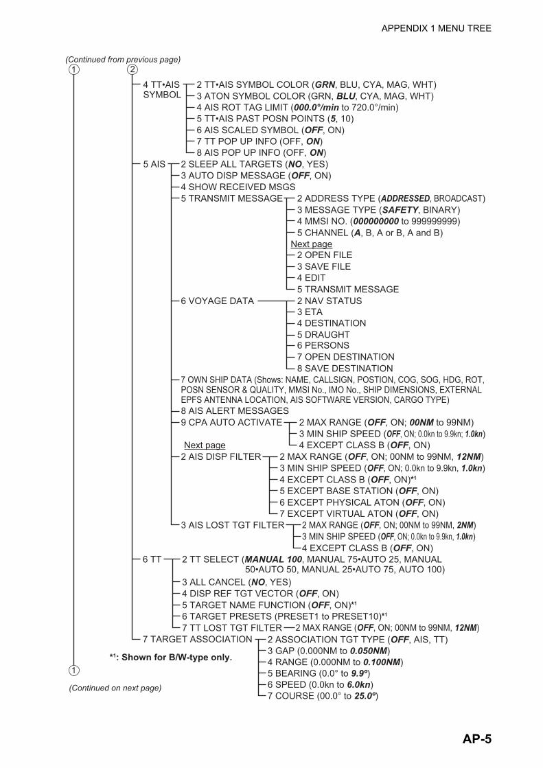
APPENDIX 1 MENU TREE
1
1
4 TT•AIS SYMBOL
5 AIS
2 TT•AIS SYMBOL COLOR (GRN, BLU, CYA, MAG, WHT)3 ATON SYMBOL COLOR (GRN, BLU, CYA, MAG, WHT)4 AIS ROT TAG LIMIT (000.0°/min to 720.0°/min)5 TT•AIS PAST POSN POINTS (5, 10)6 AIS SCALED SYMBOL (OFF, ON)7 TT POP UP INFO (OFF, ON)8 AIS POP UP INFO (OFF, ON)
2 SLEEP ALL TARGETS (NO, YES)3 AUTO DISP MESSAGE (OFF, ON)4 SHOW RECEIVED MSGS5 TRANSMIT MESSAGE
6 VOYAGE DATA 2 NAV STATUS3 ETA4 DESTINATION5 DRAUGHT6 PERSONS7 OPEN DESTINATION8 SAVE DESTINATION
8 AIS ALERT MESSAGES9 CPA AUTO ACTIVATE
7 OWN SHIP DATA (Shows: NAME, CALLSIGN, POSTION, COG, SOG, HDG, ROT, POSN SENSOR & QUALITY, MMSI No., IMO No., SHIP DIMENSIONS, EXTERNAL EPFS ANTENNA LOCATION, AIS SOFTWARE VERSION, CARGO TYPE)
2 ADDRESS TYPE (ADDRESSED, BROADCAST)3 MESSAGE TYPE (SAFETY, BINARY)
5 CHANNEL (A, B, A or B, A and B)4 MMSI NO. (000000000 to 999999999)
Next page2 OPEN FILE3 SAVE FILE
5 TRANSMIT MESSAGE4 EDIT
2 MAX RANGE (OFF, ON; 00NM to 99NM)3 MIN SHIP SPEED (OFF, ON; 0.0kn to 9.9kn; 1.0kn)4 EXCEPT CLASS B (OFF, ON)
2(Continued from previous page)
(Continued on next page)
2 AIS DISP FILTER
3 AIS LOST TGT FILTER
2 MAX RANGE (OFF, ON; 00NM to 99NM, 12NM)3 MIN SHIP SPEED (OFF, ON; 0.0kn to 9.9kn, 1.0kn)4 EXCEPT CLASS B (OFF, ON)*1
2 MAX RANGE (OFF, ON; 00NM to 99NM, 2NM)3 MIN SHIP SPEED (OFF, ON; 0.0kn to 9.9kn, 1.0kn)4 EXCEPT CLASS B (OFF, ON)
5 EXCEPT BASE STATION (OFF, ON)6 EXCEPT PHYSICAL ATON (OFF, ON)7 EXCEPT VIRTUAL ATON (OFF, ON)
Next page
6 TT
2 MAX RANGE (OFF, ON; 00NM to 99NM, 12NM)
2 TT SELECT (MANUAL 100, MANUAL 75•AUTO 25, MANUAL 50•AUTO 50, MANUAL 25•AUTO 75, AUTO 100)
4 DISP REF TGT VECTOR (OFF, ON)5 TARGET NAME FUNCTION (OFF, ON)*1
6 TARGET PRESETS (PRESET1 to PRESET10)*1
7 TT LOST TGT FILTER
3 ALL CANCEL (NO, YES)
7 TARGET ASSOCIATION 2 ASSOCIATION TGT TYPE (OFF, AIS, TT)3 GAP (0.000NM to 0.050NM)4 RANGE (0.000NM to 0.100NM)5 BEARING (0.0° to 9.9º)6 SPEED (0.0kn to 6.0kn)7 COURSE (00.0° to 25.0º)
*1: Shown for B/W-type only.
AP-5
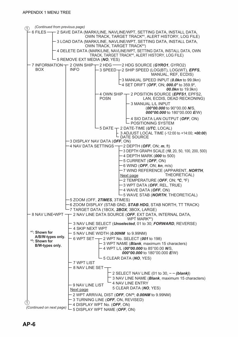
APPENDIX 1 MENU TREE
16 FILES
2 OWN SHIP INFO
2 HDG5 REMOVE EXT MEDIA (NO, YES)
3 SPEED2 HDG SOURCE (GYRO1, GYRO2)
4 SET DRIFT (OFF, ON; 000.0° to 359.9º, 00.0kn to 19.9kn)
3 MANUAL SPEED INPUT (0.0kn to 99.9kn)
2 SHIP SPEED (LOG(BT), LOG(WT), EPFS, MANUAL, REF, ECDIS)
7 INFORMATION BOX
2 SAVE DATA (MARK/LINE, NAVLINE/WPT, SETTING DATA, INSTALL DATA, OWN TRACK, TARGET TRACK*1, ALERT HISTORY, LOG FILE)
4 DELETE DATA (MARK/LINE, NAVLINE/WPT, SETTING DATA, INSTALL DATA, OWN TRACK, TARGET TRACK*1, ALERT HISTORY, LOG FILE)
3 LOAD DATA (MARK/LINE, NAVLINE/WPT, SETTING DATA, INSTALL DATA, OWN TRACK, TARGET TRACK*1)
(Continued from previous page)
1
4 OWN SHIP POSN
5 DATE 2 DATE-TIME (UTC, LOCAL)3 ADJUST LOCAL TIME (-12:00 to +14:00; +00:00)DATE SOURCE
2 POSITION SOURCE (EPFS1, EPFS2, LAN, ECDIS, DEAD RECKONING)
4 SIO DATA LAN OUTPUT (OFF, ON)POSITIONING SYSTEM
3 MANUAL L/L INPUT(00°00.000 to 90°00.00 N/S, 000°00.000 to 180°00.000 E/W)
(Continued on next page)
3 DISPLAY NAV DATA (OFF, ON)4 NAV DATA SETTINGS
5 ZOOM (OFF, 2TIMES, 3TIMES)
7 TARGET DATA (1BOX, 2BOX, 3BOX, LARGE)6 ZOOM DISPLAY (STAB GND, STAB HDG, STAB NORTH, TT TRACK)
2 DEPTH (OFF, ON; m, ft)
2 TEMPERATURE (OFF, ON; ºC, ºF)3 WPT DATA (OFF, REL, TRUE)4 WAVE DATA (OFF, ON)5 WAVE STAB (NORTH, THEORETICAL)
4 DEPTH MARK (000 to 500)5 CURRENT (OFF, ON)6 WIND (OFF, ON; kn, m/s)7 WIND REFERENCE (APPARENT, NORTH,
THEORETICAL)
3 DEPTH GRAPH SCALE (10, 20, 50, 100, 200, 500)
Next page
8 NAV LINE•WPT 2 NAV LINE DATA SOURCE (OFF, EXT DATA, INTERNAL DATA, WPT MARK*1)
3 NAV LINE SELECT (Unselected, 01 to 30; FORWARD, REVERSE)4 SKIP NEXT WPT5 NAV LINE WIDTH (0.00NM to 9.99NM)6 WPT SET
7 WPT LIST8 NAV LINE SET
2 WPT No. SELECT (001 to 198)
5 CLEAR DATA (NO, YES)
5 CLEAR DATA (NO, YES)
4 WPT L/L (00°00.000 to 85°00.00 N/S, 000°00.000 to 180°00.000 E/W)
3 WPT NAME (Blank, maximum 15 characters)
3 NAV LINE NAME (Blank, maximum 15 characters)4 NAV LINE ENTRY9 NAV LINE LIST
3 TURNING LINE (OFF, ON, REVISED)4 DISPLAY WPT No. (OFF, ON)5 DISPLAY WPT NAME (OFF, ON)
Next page
*1: Shown for A/B/W-types only.
*2: Shown for B/W-types only.
2 SELECT NAV LINE (01 to 30, (blank))
2 WPT ARRIVAL DIST (OFF, ON*2; 0.00NM to 9.99NM)
AP-6

APPENDIX 1 MENU TREE
1
(Continued on next page)
(Continued from previous page)9 INITIAL SETTINGS 2 BRILL 2 ECHO COLOR (YEL, GRN, WHT, AMB*1, M-GRN*1, M-CYA*1)
4 CONTROL PANEL (Slide-bar)5 CHARACTERS (Slide-bar)6 CURSOR (Slide-bar)7 ECHOES (Slide-bar)8 TRAILS (Slide-bar)9 HL (Slide-bar)
4 EBL (Slide-bar)
2 RANGE RINGS (Slide-bar)3 BEARING CURSOR (Slide-bar)
5 VRM (Slide-bar)6 PI LINES (Slide-bar)7 TT SYMBOLS (Slide-bar)8 AIS SYMBOLS (Slide-bar)9 L/L GRID (Slide-bar)Next page
Next page
2 MARKS (Slide-bar)3 CHART (Slide-bar)*4
3 PALETTE (DAY-GRY, DAY-BLU, DAY-GRN, DUSK-GRY, DUSK-BLU, DUSK-GRN, NIGHT-GRY, NIGHT-BLU)
Next page
2 3 4
9 SAVE INTER-SWITCH (NO, YES)0 CLEAR INTER-SWITCH (NO, YES)
2 DISP1 ANTx*2 (MASTER, SLAVE)3 DISP2 ANTx*2 (MASTER, SLAVE)4 DISP3 ANTx*2 (MASTER, SLAVE)5 DISP4 ANTx*2 (MASTER, SLAVE)
2 PILOT SETTING (NO, YES)3 USER 1 SAVE (NO, YES)4 USER 1 LOAD (NO, YES)5 USER 2 SAVE (NO, YES)6 USER 2 LOAD (NO, YES)
3 SELECT ANTENNA*5
4 USER SETTINGS
5 OPERATION 2 MOUSE WHEEL DIR (NORMAL, REVERSE)3 KEY BEEP (OFF, LOW, MID, HIGH)4 OWN SHIP VECTOR (OFF, HDG, COURSE)5 STERN UP RM (OFF, ON)*3
6 SHUTTLE FERRY (OFF, MODE1, MODE2)7 ICING PREVENTION (OFF, ON)8 BRG FINE ADJUST (-9.9º to +9.9º; +0.0º)9 USB MOUSE SPEED (1, 2, 3, 4, 5)
2 AUTO COURSE UP RESET (OFF, ON)3 DISPLAY SCROLL (OFF, ON)*1
(Details for the antennas currently in use are displayed here)
2 F1 2 ECHO 2 (CUSTOM SELECT, IR, ES, EAV, NOISE REJ, ANT SELECT, PULSE LENGTH, AUTO-SEA, AUTO-RAIN, TUNE SELECT, 2ND ECHO REJ, STC CURVE, STC RANGE, PM, SART, ECHO TRAIL, TRAIL T/R, WIPER*1, ACE, ACE HIGH SENSITIVITY)
6 FUNCTION KEY SETUP
*1: Shown for B/W-type only.*2: “x” indicates antenna number
(assigned at installation).*3: Shown for A/B/W-types only.*4: Shown for A/B/W-types with
Radar Plotter functionality only.*5: For radars with Dual Radar mode
enabled, the indications show which displays are combined.
AP-7
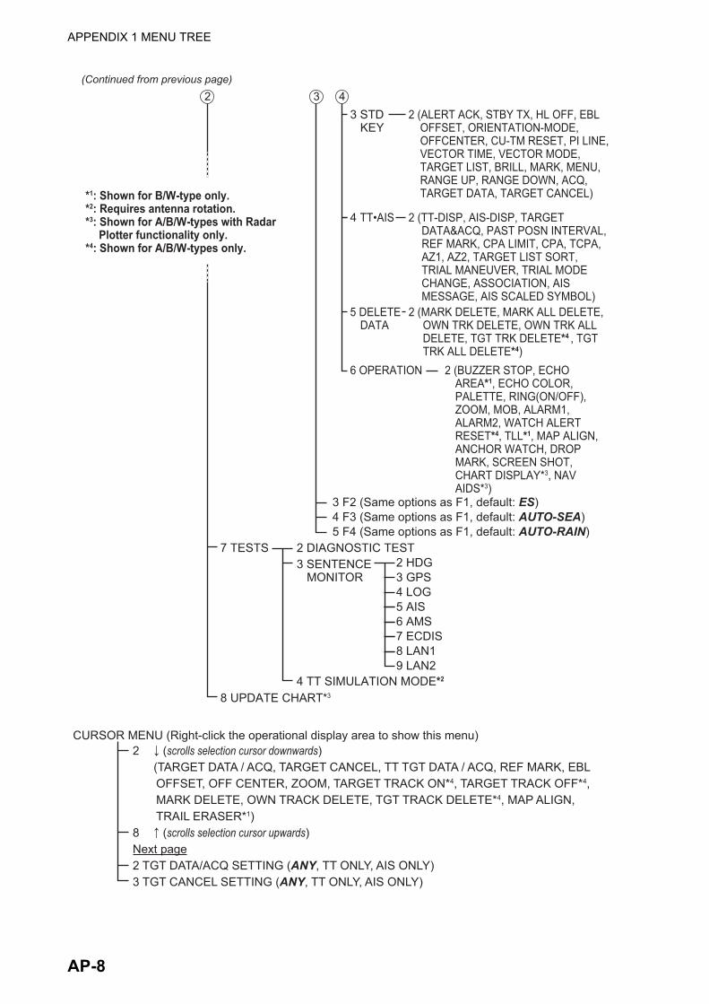
APPENDIX 1 MENU TREE
(Continued from previous page)2 3 4
3 F2 (Same options as F1, default: ES)
7 TESTS
8 UPDATE CHART*3
4 F3 (Same options as F1, default: AUTO-SEA)5 F4 (Same options as F1, default: AUTO-RAIN)
4 TT•AIS 2 (TT-DISP, AIS-DISP, TARGET DATA&ACQ, PAST POSN INTERVAL, REF MARK, CPA LIMIT, CPA, TCPA, AZ1, AZ2, TARGET LIST SORT, TRIAL MANEUVER, TRIAL MODE CHANGE, ASSOCIATION, AIS MESSAGE, AIS SCALED SYMBOL)
2 (BUZZER STOP, ECHO AREA*1, ECHO COLOR, PALETTE, RING(ON/OFF), ZOOM, MOB, ALARM1, ALARM2, WATCH ALERT RESET*4, TLL*1, MAP ALIGN, ANCHOR WATCH, DROP MARK, SCREEN SHOT, CHART DISPLAY*3, NAV AIDS*3)
6 OPERATION
5 DELETE DATA
2 (MARK DELETE, MARK ALL DELETE, OWN TRK DELETE, OWN TRK ALL DELETE, TGT TRK DELETE*4 , TGT TRK ALL DELETE*4)
2 DIAGNOSTIC TEST2 HDG3 GPS4 LOG5 AIS6 AMS7 ECDIS8 LAN19 LAN2
3 SENTENCE MONITOR
4 TT SIMULATION MODE*2
2 ↓ (scrolls selection cursor downwards) (TARGET DATA / ACQ, TARGET CANCEL, TT TGT DATA / ACQ, REF MARK, EBL
OFFSET, OFF CENTER, ZOOM, TARGET TRACK ON*4, TARGET TRACK OFF*4, MARK DELETE, OWN TRACK DELETE, TGT TRACK DELETE*4, MAP ALIGN, TRAIL ERASER*1)
8 ↑ (scrolls selection cursor upwards)Next page2 TGT DATA/ACQ SETTING (ANY, TT ONLY, AIS ONLY)3 TGT CANCEL SETTING (ANY, TT ONLY, AIS ONLY)
CURSOR MENU (Right-click the operational display area to show this menu)
3 STD KEY
2 (ALERT ACK, STBY TX, HL OFF, EBL OFFSET, ORIENTATION-MODE, OFFCENTER, CU-TM RESET, PI LINE, VECTOR TIME, VECTOR MODE, TARGET LIST, BRILL, MARK, MENU, RANGE UP, RANGE DOWN, ACQ, TARGET DATA, TARGET CANCEL)*1: Shown for B/W-type only.
*2: Requires antenna rotation.*3: Shown for A/B/W-types with Radar
Plotter functionality only.*4: Shown for A/B/W-types only.
AP-8

APPENDIX 2 LONGITUDE ERROR TA-BLE (96 NM SCALE)
The longitude lines concentrate on the north pole and south pole, namely, 1 nm is equivalent to 1 minute at 0 degree latitude, 2 minutes at 60 degrees latitude, 3 minutes at 70 degrees latitude and so on. For this reason, a longitude error occurs on the radar display.
For example, when own ship is at 60°N and 135°E, even if the cursor indication is 62°N and 139°E, the real cursor position is deviated to the left (west) side. The table below shows the longitude er-ror, represented from 0° to 90° at 96 nm from the radar center (own ship).
62°N °N
60°N
135°E
°E
96 nmq
Real cursor position
Cursor positionindicated
139°E
LAT
Real cursor positionR: Error
Cursor positionindicated
OS position
0.2256 0.4444 0.6496 0.8350 0.9950 1.1248 1.2202 1.2786 1.2980
0.21980213 0.43290201 0.632803 0.8134132 0.96923215 1.09551918 1.1884382 1.24517456 1.26402037
0.21229339 0.41810678 0.61115946 0.78556318 0.93600295 1.05790007 1.14755221 1.20224625 1.22034042
0.20316898 0.40012949 0.58486463 0.75173456 0.89565021 1.0122297 1.09793265 1.15016811 1.16737294
0.19249832 0.37910698 0.55411863 0.71218478 0.84848102 0.95885565 1.03998717 1.08933651 1.10552105
0.18036264 0.35519924 0.51915545 0.66721485 0.79485438 0.89818413 0.97406698 1.02021439 1.03525547
0.16685429 0.32858822 0.48024119 0.61716701 0.73517843 0.83067689 0.90076355 0.94332783 0.95711098
0.15207608 0.29947644 0.437672 0.56242216 0.66990732 0.7568477 0.82060477 0.85926197 0.87168229
0.13614047 0.26808546 0.39177186 0.53339693 0.59953781 0.67725844 0.73420069 0.76865661 0.77961957
0.11916876 0.2346542 0.3428901 0.44054055 0.52460545 0.59251483 0.6422089 0.67220131 0.68162348
0.10129001 0.19943707 0.29139874 0.37433139 0.44568053 0.50326182 0.54532952 0.57063015 0.57843983
0.08264056 0.16270211 0.23768966 0.30527334 0.36336372 0.41017869 0.44429984 0.46471615 0.47085389
0.06336208 0.12472888 0.18217162 0.23389198 0.27828148 0.31397386 0.33988878 0.35526538 0.35968447
0.04360137 0.0858064 0.12526714 0.16073056 0.19108136 0.21537949 0.23289096 0.24311083 0.24577764
0.02350833 0.04623087 0.0674093 0.08634588 0.10242699 0.11514595 0.1241207 0.12910605 0.13000029
0.00323737 0.0063035 0.00903844 0.01130406 0.01299309 0.01403609 0.0144058 0.0141187 0.01323356
75°70°65°60°55°50°45°40°35°30°25°20°15°10° 5° 0°
5° 10° 15° 20° 25° 30° 35° 40° 45°LATq
(nm)
AP-9
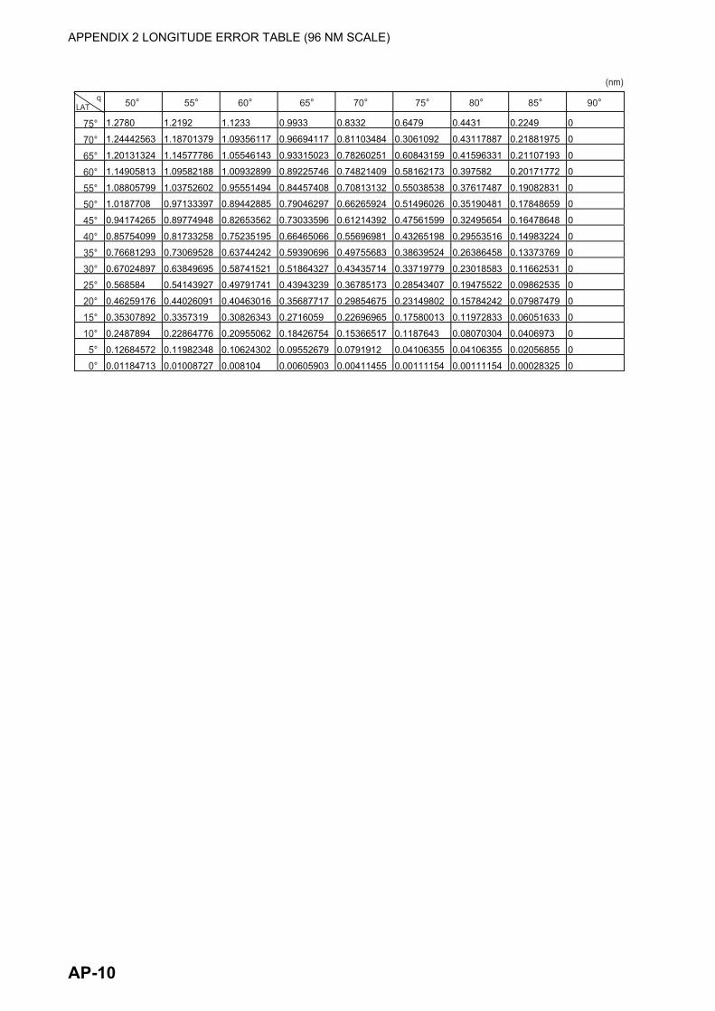
APPENDIX 2 LONGITUDE ERROR TABLE (96 NM SCALE)
1.2780 1.2192 1.1233 0.9933 0.8332 0.6479 0.4431 0.2249 0
1.24442563 1.18701379 1.09356117 0.96694117 0.81103484 0.3061092 0.43117887 0.21881975 0
1.20131324 1.14577786 1.05546143 0.93315023 0.78260251 0.60843159 0.41596331 0.21107193 0
1.14905813 1.09582188 1.00932899 0.89225746 0.74821409 0.58162173 0.397582 0.20171772 0
1.08805799 1.03752602 0.95551494 0.84457408 0.70813132 0.55038538 0.37617487 0.19082831 0
1.0187708 0.97133397 0.89442885 0.79046297 0.66265924 0.51496026 0.35190481 0.17848659 0
0.94174265 0.89774948 0.82653562 0.73033596 0.61214392 0.47561599 0.32495654 0.16478648 0
0.85754099 0.81733258 0.75235195 0.66465066 0.55696981 0.43265198 0.29553516 0.14983224 0
0.76681293 0.73069528 0.63744242 0.59390696 0.49755683 0.38639524 0.26386458 0.13373769 0
0.67024897 0.63849695 0.58741521 0.51864327 0.43435714 0.33719779 0.23018583 0.11662531 0
0.568584 0.54143927 0.49791741 0.43943239 0.36785173 0.28543407 0.19475522 0.09862535 0
0.46259176 0.44026091 0.40463016 0.35687717 0.29854675 0.23149802 0.15784242 0.07987479 0
0.35307892 0.3357319 0.30826343 0.2716059 0.22696965 0.17580013 0.11972833 0.06051633 0
0.2487894 0.22864776 0.20955062 0.18426754 0.15366517 0.1187643 0.08070304 0.0406973 0
0.12684572 0.11982348 0.10624302 0.09552679 0.0791912 0.04106355 0.04106355 0.02056855 0
0.01184713 0.01008727 0.008104 0.00605903 0.00411455 0.00111154 0.00111154 0.00028325 0
75°70°65°60°55°50°45°40°35°30°25°20°15°10° 5° 0°
50° 55° 60° 65° 70° 75° 80° 85° 90°LATq
(nm)
AP-10
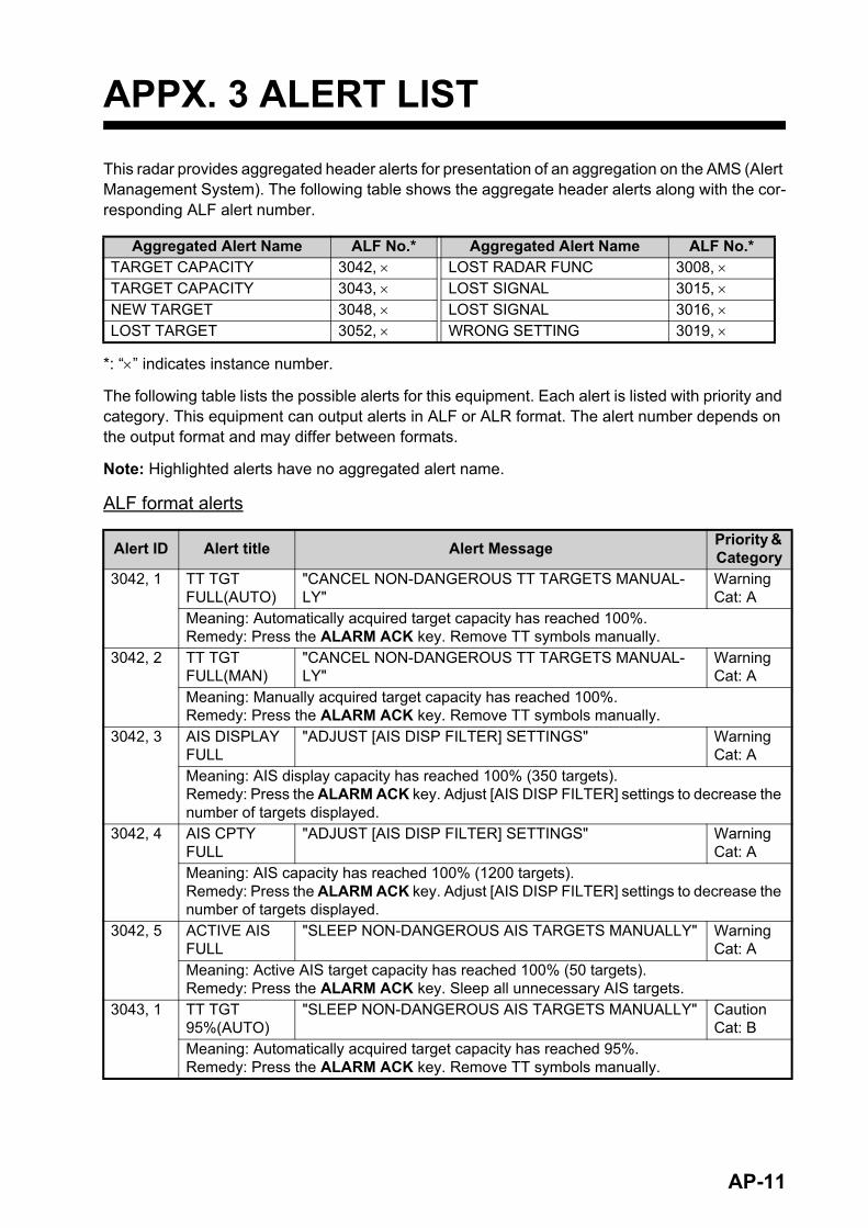
APPX. 3 ALERT LIST
This radar provides aggregated header alerts for presentation of an aggregation on the AMS (Alert Management System). The following table shows the aggregate header alerts along with the cor-responding ALF alert number.
*: “” indicates instance number.
The following table lists the possible alerts for this equipment. Each alert is listed with priority and category. This equipment can output alerts in ALF or ALR format. The alert number depends on the output format and may differ between formats.
Note: Highlighted alerts have no aggregated alert name.
ALF format alerts
Aggregated Alert Name ALF No.* Aggregated Alert Name ALF No.*TARGET CAPACITY 3042, LOST RADAR FUNC 3008, TARGET CAPACITY 3043, LOST SIGNAL 3015, NEW TARGET 3048, LOST SIGNAL 3016, LOST TARGET 3052, WRONG SETTING 3019,
Alert ID Alert title Alert MessagePriority & Category
3042, 1 TT TGT FULL(AUTO)
"CANCEL NON-DANGEROUS TT TARGETS MANUAL-LY"
WarningCat: A
Meaning: Automatically acquired target capacity has reached 100%.Remedy: Press the ALARM ACK key. Remove TT symbols manually.
3042, 2 TT TGT FULL(MAN)
"CANCEL NON-DANGEROUS TT TARGETS MANUAL-LY"
WarningCat: A
Meaning: Manually acquired target capacity has reached 100%.Remedy: Press the ALARM ACK key. Remove TT symbols manually.
3042, 3 AIS DISPLAY FULL
"ADJUST [AIS DISP FILTER] SETTINGS" WarningCat: A
Meaning: AIS display capacity has reached 100% (350 targets).Remedy: Press the ALARM ACK key. Adjust [AIS DISP FILTER] settings to decrease the number of targets displayed.
3042, 4 AIS CPTY FULL
"ADJUST [AIS DISP FILTER] SETTINGS" WarningCat: A
Meaning: AIS capacity has reached 100% (1200 targets).Remedy: Press the ALARM ACK key. Adjust [AIS DISP FILTER] settings to decrease the number of targets displayed.
3042, 5 ACTIVE AIS FULL
"SLEEP NON-DANGEROUS AIS TARGETS MANUALLY" WarningCat: A
Meaning: Active AIS target capacity has reached 100% (50 targets).Remedy: Press the ALARM ACK key. Sleep all unnecessary AIS targets.
3043, 1 TT TGT 95%(AUTO)
"SLEEP NON-DANGEROUS AIS TARGETS MANUALLY" CautionCat: B
Meaning: Automatically acquired target capacity has reached 95%.Remedy: Press the ALARM ACK key. Remove TT symbols manually.
AP-11

APPX. 3 ALERT LIST
3043, 2 TT TGT 95%(MAN)
"CANCEL NON-DANGEROUS TT TARGETS MANUAL-LY"
CautionCat: B
Meaning: Manually acquired target capacity has reached 95%.Remedy: Press the ALARM ACK key. Remove TT symbols manually.
3043, 3 AIS DISPLAY 95%
"ADJUST [AIS DISP FILTER] SETTINGS" CautionCat: B
Meaning: AIS display capacity has reached 95% (333 targets).Remedy: Press the ALARM ACK key. Adjust [AIS DISP FILTER] settings to decrease the number of targets displayed.
3043, 4 AIS CAPACI-TY 95%
"ADJUST [AIS DISP FILTER] SETTINGS" CautionCat: B
Meaning: AIS capacity has reached 95% (1140 targets).Remedy: Press the ALARM ACK key. Adjust [AIS DISP FILTER] settings to decrease the number of targets displayed.
3043, 5 AIS CPTY FULL
"ADJUST [AIS DISP FILTER] SETTINGS" CautionCat: B
Meaning: AIS capacity has reached 100% (1200 targets).Remedy: Press the ALARM ACK key. Adjust [AIS DISP FILTER] settings to decrease the number of targets displayed.
3043, 6 ACTIVE AIS 95%
"SLEEP NON-DANGEROUS AIS TARGETS MANUALLY" CautionCat: B
Meaning: Active AIS target capacity has reached 95% (48 targets).Remedy: Press the ALARM ACK key. Sleep all unnecessary AIS targets.
3044 CPA/TCPA "TAKE EVASIVE ACTION IF NECESSARY" AlarmCat: A
Meaning: Target is within CPA/TCPA threshold, danger of collision.Remedy: Press the ALARM ACK key. Take evasive action if necessary. Adjust CPA/TCPA settings.
3048, 1 TT NEW TAR-GET
"CONFIRM TT NEW TARGETS" WarningCat: A
Meaning: A new TT target has entered the Acquisition Zone.Remedy: Press the ALARM ACK key. Confirm location of new target.
3048, 2 AIS NEW TARGET
"CONFIRM AIS NEW TARGETS" WarningCat: A
Meaning: A new AIS target has entered the Acquisition Zone.Remedy: Press the ALARM ACK key. Confirm location of new target.
3052, 1 TT TARGET LOST
"CHECK LOST TGT. ACQ TARGET IF NECESSARY" WarningCat: A
Meaning: TT target is lost.Remedy: Press the ALARM ACK key. Lost target indication (blinking in red) is removed.
3052, 2 REF TARGET LOST
"CHECK LOST TGT. ACQ TARGET IF NECESSARY" WarningCat: A
Meaning: REF targets is lost.Remedy: Press the ALARM ACK key. Lost target indication (blinking in red) is removed.
3052, 3 AIS TARGET LOST
"CONFIRM AIS LOST TARGETS" WarningCat: A
Meaning: AIS target is lost.Remedy: Press the ALARM ACK key. Lost target indication (blinking in red) is removed.
3003 AIS MSG SEND ERR
"UNABLE TO TRANSMIT AIS MESSAGE. CHECK AIS" CautionCat: B
Meaning: Unable to transmit AIS binary message.Remedy: Press the ALARM ACK key. Check power and connection to AIS unit.
Alert ID Alert title Alert MessagePriority & Category
AP-12

APPX. 3 ALERT LIST
3008, 1 LOST ISW FUNC
"USE RADAR AS STANDALONE" WarningCat: B
Meaning: Interswitch function had to be stopped. (Only displayed when Interswitch is ac-tive.)Remedy: Press the ALARM ACK key. Use the radar as a standalone.
3008, 2 LOST WAVE FUNC
"CHECK CONNECTION WITH WAVE ANALYSIS PC" WarningCat: B
Meaning: Wave analysis function has a problem.Remedy: Press the ALARM ACK key. Check connection with wave analysis PC, or dis-able WAVE mode.
3015, 1 LOST HEAD-LINE
"EXECUTE THE DIAGNOSTIC TEST" WarningCat: B
Meaning: Heading marker signal interrupted/lost.Remedy: Press the ALARM ACK key. Restore signal or rectify reason for signal loss.
3015, 2 LOST AZI-MUTH SIG
"EXECUTE THE DIAGNOSTIC TEST" WarningCat: B
Meaning: Antenna azimuth signal is interrupted/lost.Remedy: Press the ALARM ACK key. Restore signal or rectify reason for signal loss.
3015, 3 LOST TRIG-GER SIG
"EXECUTE THE DIAGNOSTIC TEST" WarningCat: B
Meaning: Antenna trigger interrupted/lostRemedy: Press the ALARM ACK key. Restore signal or rectify reason for signal loss.
3015, 4 LOST VIDEO SIG
"EXECUTE THE DIAGNOSTIC TEST" WarningCat: B
Meaning: Video signal interrupted/lost.Remedy: Press the ALARM ACK key. Restore signal or rectify reason for signal loss.
3015, 5 LOST CTRL UNIT
"CHECK CONNECTION WITH CONTROL UNIT" WarningCat: B
Meaning: Control Unit (RCU-014/015/016) signal interrupted/lost.Remedy: Press the ALARM ACK key. Restore signal or rectify reason for signal loss.
3015, 6 LOST TUNE IND
"INITIALIZE TUNING AGAIN" WarningCat: B
Meaning: TUNE error due to faulty settings or malfunction.Remedy: Press the ALARM ACK key. Restore signal or rectify reason for signal loss.
3015, 7 LOST RADAR ANT
"CHECK CONNECTION WITH RADAR ANTENNA" WarningCat: B
Meaning: Signal between processor and antenna interrupted/lost.Remedy: Press the ALARM ACK key. Restore signal or rectify reason for signal loss.
3015, 8 LOST MTR-DRV
"EXECUTE THE DIAGNOSTIC TEST" WarningCat: B
Meaning: Signal between antenna’s SPU and MTR-DRV interrupted/lost.Remedy: Press the ALARM ACK key. Restore signal or rectify reason for signal loss.
3015, 9 LOST RF-
CONV*1"EXECUTE THE DIAGNOSTIC TEST" Warning
Cat: B
Meaning: Signal between antenna’s SPU and RF-CONVERTER interrupted/lost.Remedy: Press the ALARM ACK key. Restore signal or rectify reason for signal loss.
3015, 10 LOST RP
BOARD*5"EXECUTE THE DIAGNOSTIC TEST" Warning
Cat: B
Meaning: Signal between MAIN board and RP board in the processor is interrupted or lost.Remedy: Press the ALARM ACK key. Restore signal or rectify reason for signal loss.
Alert ID Alert title Alert MessagePriority & Category
AP-13

APPX. 3 ALERT LIST
3015, 11 LOST TUNE
GATE*2"EXECUTE THE DIAGNOSTIC TEST" Warning
Cat: B
Meaning: No tune gate signal from the FAR-2x58 antenna.Remedy: Press the ALARM ACK key. Consult your local dealer for service.
3015, 12 LOST TX-HV
VOLT*2"EXECUTE THE DIAGNOSTIC TEST" Warning
Cat: B
Meaning: The antenna voltage is below 300 V (For FAR-2x58/2x68DS).Remedy: Press the ALARM ACK key. Turn the PSU-019 power on. If the problem per-sists, consult your local dealer for service.
3015, 20 LOST GYRO SIGNAL
"CHECK HEADING SENSOR OR SENTENCE MONITOR" WarningCat: B
Meaning: No heading information received from gyrocompass for five seconds.Remedy: Press the ALARM ACK key. Restore the signal to remove this indication.
3015, 21 LOST LOG(WT) SIG
"CHECK SPEED SENSOR OR SENTENCE MONITOR" WarningCat: B
Meaning: No speed through water data received for thirty seconds when [LOG(WT)] is set as speed reference.Remedy: Press the ALARM ACK key. Use a different sensor if necessary.
3015, 22 LOST LOG(BT) SIG
"CHECK SPEED SENSOR OR SENTENCE MONITOR" WarningCat: B
Meaning: No speed over ground data received for thirty seconds when [LOG(BT)] is set as speed reference.Remedy: Press the ALARM ACK key. Use a different sensor if necessary.
3015, 23 LOST POSI-TION
"CHECK POSITION SENSOR OR SENTENCE MONI-TOR"
WarningCat: B
Meaning: EPFS Error. No position data received from EPFS device for thirty seconds.Remedy: Press the ALARM ACK key. Restore the signal. This indication cannot be erased if the position signal is missing. The indication is automatically removed when the signal is restored.
3015, 24 LOST DATUM "CHECK POSITION SENSOR OR SENTENCE MONI-TOR"
WarningCat: B
Meaning: DTM sentence not received for thirty seconds, or erroneous data received.Remedy: Press the ALARM ACK key. Use the WGS-84 datum.
3015, 25 LOST UTC SIGNAL
"CHECK POSITION SENSOR OR SENTENCE MONI-TOR"
WarningCat: B
Meaning: UTC error. No date or time data received for thirty seconds. No ZDA sentence input.Remedy: Press the ALARM ACK key. Restore the signal to remove this indication.
3015, 26 LOST AIS COM
"CHECK AIS OR SENTENCE MONITOR" WarningCat: B
Meaning: No AIS data received for thirty seconds.Remedy: Press the ALARM ACK key. Check power and connection to AIS unit.
3015, 27 LOST COG/SOG SIG
"CHECK POSITION SENSOR OR SENTENCE MONI-TOR"
WarningCat: B
Meaning: No COG/SOG data received from EPFS device for thirty seconds when [EPFS] is set as speed reference.Remedy: Press the ALARM ACK key. Restore the signal. This indication cannot be erased if the COG/SOG signal is missing. The indication is automatically removed when the signal is restored.
Alert ID Alert title Alert MessagePriority & Category
AP-14

APPX. 3 ALERT LIST
3015, 28 LOST ECDIS COM
"CHECK ECDIS OR SENTENCE MONITOR" WarningCat: B
Meaning: No ECDIS data received for thirty seconds when [ECDIS] is set as speed refer-ence.Remedy: Press the ALARM ACK key. Check power and connection to ECDIS unit.
3016, 13 LOST PM BOARD
"EXECUTE THE DIAGNOSTIC TEST" CautionCat: B
Meaning: Signal between antenna’s SPU and PM interrupted/lost.Remedy: Press the ALARM ACK key. Restore signal or rectify reason for signal loss.
3016, 21 LOST LOG(WT) SIG
"CHECK SPEED SENSOR OR SENTENCE MONITOR" CautionCat: B
Meaning: No speed through water data received for thirty seconds when [LOG(WT)] is NOT set as speed reference.Remedy: Press the ALARM ACK key. Use a different sensor if necessary.
3016, 22 LOST LOG(BT) SIG
"CHECK SPEED SENSOR OR SENTENCE MONITOR" CautionCat: B
Meaning: No speed over ground data received for thirty seconds when [LOG(BT)] is set as speed reference.Remedy: Press the ALARM ACK key. Use a different sensor if necessary.
3016, 26 LOST AIS COM
"CHECK AIS OR SENTENCE MONITOR" CautionCat: B
Meaning: No AIS data received for thirty seconds when AIS function is OFF.Remedy: Press the ALARM ACK key. Check power and connection to AIS unit.
3016, 27 LOST COG/SOG SIG
"CHECK POSITION SENSOR OR SENTENCE MONI-TOR"
CautionCat: B
Meaning: No COG/SOG data received from EPFS device for thirty seconds when [EPFS] NOT is set as speed reference.Remedy: Press the ALARM ACK key. Restore the signal. This indication cannot be erased if the COG/SOG signal is missing. The indication is automatically removed when the signal is restored.
3019, 1 WRONG IP ADDR
"CHECK IP SETTINGS AND ASSIGN A UNIQUE IP" CautionCat: B
Meaning: LAN1 IP address is in use by other equipment.Remedy: Press the ALARM ACK key. Check the IP settings and assign a unique IP ad-dress.
3019, 2 WRONG IP (LAN2)
"CHECK IP SETTINGS AND ASSIGN A UNIQUE IP" CautionCat: B
Meaning: LAN2 IP address is in use by other equipment.Remedy: Press the ALARM ACK key. Check the IP settings and assign a unique IP ad-dress.
3019, 3 RP VER MIS-
MATCH*5"CONSULT YOUR LOCAL DEALER FOR SW UPDATE" Caution
Cat: B
Meaning: MAIN board and RP board software versions do not match.Remedy: Press the ALARM ACK key. Consult you local dealer for a software update.
3019, 4 WRONG POSN INT
"CHECK THE OUTPUT SETTINGS FOR EPFS DEVICE" CautionCat: B
Meaning: Position signal interval cycle has exceeded 10 seconds for a period.Remedy: Press the ALARM ACK key. Check the output settings for the connected EPFS device. Adjust output interval (cycle) as required.
Alert ID Alert title Alert MessagePriority & Category
AP-15

APPX. 3 ALERT LIST
3032 ANCHOR WATCH
"CONFIRM OWN SHIP LOCATION" WarningCat: B
Meaning: Ship position outside set anchor watch zone.Remedy: Press the ALARM ACK key. Confirm Own Ship location and adjust as neces-sary.
52795 SELECT
SART MODE*3"SART SIGNAL DETECTED. SELECT SART MODE" Warning
Cat: A
Meaning: A SART signal was detected.Remedy: Press the ALARM ACK key. Show the SART marks on the radar display ([7 SART] set to [ON]).
52782 ARRIVED AT
WPT*4"SET NEXT WPT, IF NECESSARY" Warning
Cat: B
Meaning: Ship has entered the destination arrival alert zone.Remedy: Press the ALARM ACK key. Set next waypoint, if necessary.
52785 XTD LIM EX-
CEEDED*4"CHECK COURSE AND ADJUST AS NECESSARY" Warning
Cat: B
Meaning: Cross-track error, ship is off-course.Remedy: Press the ALARM ACK key. Check course and adjust as necessary.
52792 CHART MEM-
ORY ERR*5"CHECK PROCESSOR UNIT" Warning
Cat: B
Meaning: An error has occurred while loading chart data.Remedy: Press the ALARM ACK key. Have a qualified technician check the processor unit.
*1: This alert appears only for FAR-2228-NXT(-BB) and FAR-2328-NXT.
*2: This alert appears only for For FAR-2x58/2x68DS.
*3: This alert appears only for FAR-2228-NXT(-BB) and FAR-2328-NXT. Keep in mind the following points:• This alert can occur when this equipment receives interference simultaneously from multiple
radars.• This alert may not occur under the bad weather conditions such as at rain.
*4: This alert is output only on B/W-type radars.
*5: This alert is output only on A/B/W-types with radar plotter functionality.
Alert ID Alert title Alert MessagePriority & Category
AP-16

APPX. 3 ALERT LIST
ALF format indications
The following indications are shown by this equipment when ALF format is in use. The indications have no category, are not subject to responsibility transfer and are not output as ALF sentences.
Note: Indications also appear in the ALERT BOX on the screen and on the ALERT LIST.
ID Title Message52001, 4 RPU:HIGH TEMP "CONDUCT A DIAGNOSTIC TEST WHILE THE ERROR
IS PRESENT. SUPPLY THE TEST RESULTS TO YOUR LOCAL DEALER."
Meaning: Temperature in the RPU is above the recommended limit.Remedy: Press the ALARM ACK key. Lower the temperature.
52001, 11 MD TYPE MISMATCH "CONDUCT A DIAGNOSTIC TEST WHILE THE ERROR IS PRESENT. SUPPLY THE TEST RESULTS TO YOUR LOCAL DEALER."
Meaning: Unable to detect the MD board bandwidth.Remedy: Press the ALARM ACK key. Check connections to the antenna.
52001, 12 PM TYPE MISMATCH "CONDUCT A DIAGNOSTIC TEST WHILE THE ERROR IS PRESENT. SUPPLY THE TEST RESULTS TO YOUR LOCAL DEALER."
Meaning: Unable to detect the MD board bandwidth.Remedy: Press the ALARM ACK key. Check connections to the antenna.
52001, 21 MTR-DRV:HIGH TEMP "CONDUCT A DIAGNOSTIC TEST WHILE THE ERROR IS PRESENT. SUPPLY THE TEST RESULTS TO YOUR LOCAL DEALER."
Meaning: MTR-DRV board temperature is above the recommended limit.Remedy: Press the ALARM ACK key. Lower the temperature.
52001, 22 MTR-DRV:OVER CUR-RENT
"CONDUCT A DIAGNOSTIC TEST WHILE THE ERROR IS PRESENT. SUPPLY THE TEST RESULTS TO YOUR LOCAL DEALER."
Meaning: MTR-DRV board power input from the motor is outside recommended rating.Remedy: Press the ALARM ACK key. Have a qualified technician check the motor.
52001, 23 MTR-DRV:MTR PWR ERR "CONDUCT A DIAGNOSTIC TEST WHILE THE ERROR IS PRESENT. SUPPLY THE TEST RESULTS TO YOUR LOCAL DEALER."
Meaning: MTR-DRV board motor’s voltage is outside recommended rating.Remedy: Press the ALARM ACK key. Have a qualified technician check the motor.
52001, 24 MTR-DRV:P12V ERR "CONDUCT A DIAGNOSTIC TEST WHILE THE ERROR IS PRESENT. SUPPLY THE TEST RESULTS TO YOUR LOCAL DEALER."
Meaning: Voltage in the +12V line of the MTR-DRV motor is outside recommended rat-ing.Remedy: Press the ALARM ACK key. Have a qualified technician check the power sup-ply.
52001, 25 MTR-DRV:HALL SEN-SOR ERR
"CONDUCT A DIAGNOSTIC TEST WHILE THE ERROR IS PRESENT. SUPPLY THE TEST RESULTS TO YOUR LOCAL DEALER."
Meaning: Error in the hall sensor signal detected by the MTR-DRV board.Remedy: Press the ALARM ACK key. Have a qualified technician check the hall sensor.
52001, 26 MTR-DRV:ANT LOCK "CHECK THE SCANNER FOR OBSTRUCTIONS. IF THERE ARE NONE, SUPPLY THE TEST RESULTS TO YOUR LOCAL DEALER."
Meaning: Antenna lock detected by the MTR-DRV board.Remedy: Press the ALARM ACK key. Unlock the antenna.
AP-17
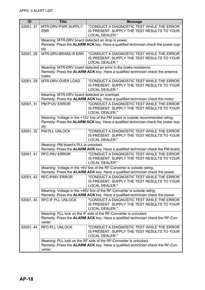
APPX. 3 ALERT LIST
52001, 27 MTR-DRV:PWR SUPPLY ERR
"CONDUCT A DIAGNOSTIC TEST WHILE THE ERROR IS PRESENT. SUPPLY THE TEST RESULTS TO YOUR LOCAL DEALER."
Meaning: MTR-DRV board detected an drop in power.Remedy: Press the ALARM ACK key. Have a qualified technician check the power sup-ply.
52001, 28 MTR-DRV:BRAKE-R ERR "CONDUCT A DIAGNOSTIC TEST WHILE THE ERROR IS PRESENT. SUPPLY THE TEST RESULTS TO YOUR LOCAL DEALER."
Meaning: MTR-DRV board detected an error in the brake resistance.Remedy: Press the ALARM ACK key. Have a qualified technician check the antenna brake.
52001, 29 MTR-DRV:OVER LOAD "CONDUCT A DIAGNOSTIC TEST WHILE THE ERROR IS PRESENT. SUPPLY THE TEST RESULTS TO YOUR LOCAL DEALER."
Meaning: MTR-DRV board detected an overload.Remedy: Press the ALARM ACK key. Have a qualified technician check the motor.
52001, 31 PM:P12V ERROR "CONDUCT A DIAGNOSTIC TEST WHILE THE ERROR IS PRESENT. SUPPLY THE TEST RESULTS TO YOUR LOCAL DEALER."
Meaning: Voltage in the +12V line of the PM board is outside recommended rating.Remedy: Press the ALARM ACK key. Have a qualified technician check the power sup-ply.
52001, 32 PM:PLL UNLOCK "CONDUCT A DIAGNOSTIC TEST WHILE THE ERROR IS PRESENT. SUPPLY THE TEST RESULTS TO YOUR LOCAL DEALER."
Meaning: PM board’s PLL is unlocked.Remedy: Press the ALARM ACK key. Have a qualified technician check the PM board.
52001, 41 RFC:P6V ERROR "CONDUCT A DIAGNOSTIC TEST WHILE THE ERROR IS PRESENT. SUPPLY THE TEST RESULTS TO YOUR LOCAL DEALER."
Meaning: Voltage in the +6V line of the RF-Converter is outside rating.Remedy: Press the ALARM ACK key. Have a qualified technician check the power.
52001, 42 RFC:P48V ERROR "CONDUCT A DIAGNOSTIC TEST WHILE THE ERROR IS PRESENT. SUPPLY THE TEST RESULTS TO YOUR LOCAL DEALER."
Meaning: Voltage in the +48V line of the RF-Converter is outside rating.Remedy: Press the ALARM ACK key. Have a qualified technician check the power.
52001, 43 RFC:IF PLL UNLOCK "CONDUCT A DIAGNOSTIC TEST WHILE THE ERROR IS PRESENT. SUPPLY THE TEST RESULTS TO YOUR LOCAL DEALER."
Meaning: PLL lock on the IF side of the RF-Converter is unlocked.Remedy: Press the ALARM ACK key. Have a qualified technician check the RF-Con-verter.
52001, 44 RFC:PLL UNLOCK "CONDUCT A DIAGNOSTIC TEST WHILE THE ERROR IS PRESENT. SUPPLY THE TEST RESULTS TO YOUR LOCAL DEALER."
Meaning: PLL lock on the RF side of the RF-Converter is unlocked.Remedy: Press the ALARM ACK key. Have a qualified technician check the RF-Con-verter.
ID Title Message
AP-18

APPX. 3 ALERT LIST
52001, 45 RFC:OUTPUT SIG LVL ERR
"CONDUCT A DIAGNOSTIC TEST WHILE THE ERROR IS PRESENT. SUPPLY THE TEST RESULTS TO YOUR LOCAL DEALER."
Meaning: Signal output from the RF-Converter is outside the recommended rating.Remedy: Press the ALARM ACK key. Have a qualified technician check the RF-Con-verter.
52001, 46 RFC:INPUT SIG LVL ERR "CONDUCT A DIAGNOSTIC TEST WHILE THE ERROR IS PRESENT. SUPPLY THE TEST RESULTS TO YOUR LOCAL DEALER."
Meaning: Signal input from the RF-Converter is outside the recommended rating.Remedy: Press the ALARM ACK key. Have a qualified technician check the RF-Con-verter.
52001, 47 HPA:OUTPUT SIG LVL ERR
"CONDUCT A DIAGNOSTIC TEST WHILE THE ERROR IS PRESENT. SUPPLY THE TEST RESULTS TO YOUR LOCAL DEALER."
Meaning: Signal output from the HPA board is outside the recommended rating.Remedy: Press the ALARM ACK key. Have a qualified technician check the HPA board.
52001, 48 HPA:OUTPUT PK CRR ERR
"CONDUCT A DIAGNOSTIC TEST WHILE THE ERROR IS PRESENT. SUPPLY THE TEST RESULTS TO YOUR LOCAL DEALER."
Meaning: Peak current detected in the signal output from the HPA board.Remedy: Press the ALARM ACK key. Have a qualified technician check the HPA board.
52001, 51 HPA:HIGH TEMP "CONDUCT A DIAGNOSTIC TEST WHILE THE ERROR IS PRESENT. SUPPLY THE TEST RESULTS TO YOUR LOCAL DEALER."
Meaning: Excessively high temperature detected on the HPA board.Remedy: Press the ALARM ACK key. Have a qualified technician check the HPA board.
52001, 52 VSWR ERROR "CONDUCT A DIAGNOSTIC TEST WHILE THE ERROR IS PRESENT. SUPPLY THE TEST RESULTS TO YOUR LOCAL DEALER."
Meaning: Abnormal VSWR detected by the RF Converter.Remedy: Press the ALARM ACK key. Have a qualified technician check the antenna.
52002, 1 RPU:FAN1 NO ROTATE "CONDUCT A DIAGNOSTIC TEST WHILE THE ERROR IS PRESENT. SUPPLY THE TEST RESULTS TO YOUR LOCAL DEALER."
Meaning: The FAN1 in the processor unit is stopped or disconnected.Remedy: Press the ALARM ACK key. Have a qualified technician check the processor unit.
52002, 2 RPU:FAN2 NO ROTATE "CONDUCT A DIAGNOSTIC TEST WHILE THE ERROR IS PRESENT. SUPPLY THE TEST RESULTS TO YOUR LOCAL DEALER."
Meaning: The FAN2 in the processor unit is stopped or disconnected.Remedy: Press the ALARM ACK key. Have a qualified technician check the processor unit.
52002, 3 RPU:FAN3 NO ROTATE "CONDUCT A DIAGNOSTIC TEST WHILE THE ERROR IS PRESENT. SUPPLY THE TEST RESULTS TO YOUR LOCAL DEALER."
Meaning: The FAN3 in the processor unit is stopped or disconnected.Remedy: Press the ALARM ACK key. Have a qualified technician check the processor unit.
ID Title Message
AP-19
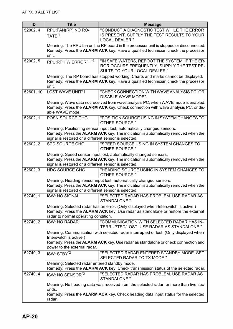
APPX. 3 ALERT LIST
52002, 4 RPU:FAN(RP) NO RO-
TATE*1"CONDUCT A DIAGNOSTIC TEST WHILE THE ERROR IS PRESENT. SUPPLY THE TEST RESULTS TO YOUR LOCAL DEALER."
Meaning: The RPU fan on the RP board in the processor unit is stopped or disconnected.Remedy: Press the ALARM ACK key. Have a qualified technician check the processor unit.
52002, 5 RPU:RP HW ERROR*1, *3 "IN SAFE WATERS, REBOOT THE SYSTEM. IF THE ER-ROR OCCURS FREQUENTLY, SUPPLY THE TEST RE-SULTS TO YOUR LOCAL DEALER."
Meaning: The RP board has stopped working. Charts and marks cannot be displayed.Remedy: Press the ALARM ACK key. Have a qualified technician check the processor unit.
52601, 10 LOST WAVE UNIT*1 "CHECK CONNECTION WITH WAVE ANALYSIS PC, OR DISABLE WAVE MODE".
Meaning: Wave data not received from wave analysis PC, when WAVE mode is enabled.Remedy: Press the ALARM ACK key. Check connection with wave analysis PC, or dis-able WAVE mode.
52602, 1 POSN SOURCE CHG "POSITION SOURCE USING IN SYSTEM CHANGES TO OTHER SOURCE."
Meaning: Positioning sensor input lost, automatically changed sensors.Remedy: Press the ALARM ACK key. The indication is automatically removed when the signal is restored or a different sensor is selected.
52602, 2 SPD SOURCE CHG "SPEED SOURCE USING IN SYSTEM CHANGES TO OTHER SOURCE."
Meaning: Speed sensor input lost, automatically changed sensors.Remedy: Press the ALARM ACK key. The indication is automatically removed when the signal is restored or a different sensor is selected.
52602, 3 HDG SOURCE CHG "HEADING SOURCE USING IN SYSTEM CHANGES TO OTHER SOURCE."
Meaning: Heading sensor input lost, automatically changed sensors.Remedy: Press the ALARM ACK key. The indication is automatically removed when the signal is restored or a different sensor is selected.
52740, 1 ISW: NO SIGNAL "SELECTED RADAR HAS PROBLEM. USE RADAR AS STANDALONE."
Meaning: Selected radar has an error. (Only displayed when Interswitch is active.)Remedy: Press the ALARM ACK key. Use radar as standalone or restore the external radar to normal operating condition.
52740, 2 ISW: NO RADAR "COMMUNICATION WITH SELECTED RADAR HAS IN-TERRUPTED/LOST. USE RADAR AS STANDALONE."
Meaning: Communication with selected radar interrupted or lost. (Only displayed when Interswitch is active.)Remedy: Press the ALARM ACK key. Use radar as standalone or check connection and power to the external radar.
52740, 3 ISW: STBY*2 "SELECTED RADAR ENTERED STANDBY MODE. SET SELECTED RADAR TO TX MODE."
Meaning: Selected radar entered standby mode.Remedy: Press the ALARM ACK key. Check transmission status of the selected radar.
52740, 4 ISW: NO SENSOR*2 "SELECTED RADAR HAS PROBLEM. USE RADAR AS STANDALONE."
Meaning: No heading data was received from the selected radar for more than five sec-onds.Remedy: Press the ALARM ACK key. Check heading data input status for the selected radar.
ID Title Message
AP-20

APPX. 3 ALERT LIST
*1: This indication is output only on A/B/W-types with radar plotter functionality.*2: This indication appears only on A/B-type radars when Dual Radar mode is active and enabled.*3: When this indication is rectified, the [Chart] button appears in yellow color. Click the [Chart] but-ton to restore the system to normal operation.
52793, 1 LOST WV UTC SIG "CHECK THAT DATA INPUT TO WAVE ANALYZER IS CORRECT, OR DISABLE WAVE MODE."
Meaning: With the wave radar active ([4 WAVE DATA] set to [ON]), the wave analysis PC has an error in time/date input.Remedy: Press the ALARM ACK key. Check that data input to Wave Analyzer is correct, or disable WAVE mode.
52793, 2 LOST WV COG/SOG "CHECK THAT DATA INPUT TO WAVE ANALYZER IS CORRECT, OR DISABLE WAVE MODE."
Meaning: With the wave radar active ([4 WAVE DATA] set to [ON]), the wave analysis PC has an error in speed data input.Remedy: Press the ALARM ACK key. Check that data input to Wave Analyzer is correct, or disable WAVE mode.
52793, 3 LOST WV WIND SIG "CHECK THAT DATA INPUT TO WAVE ANALYZER IS CORRECT, OR DISABLE WAVE MODE."
Meaning: With the wave radar active ([4 WAVE DATA] set to [ON]), the wave analysis PC has an error in speed data input.Remedy: Press the ALARM ACK key. Check that data input to Wave Analyzer is correct, or disable WAVE mode.
52793, 4 LOST WV RADAR ANT "CHECK THE CONNECTION WITH SELECTED RADAR IS CORRECT, OR DISABLE WAVE MODE."
Meaning: With the wave radar active ([4 WAVE DATA] set to [ON]), the wave analysis PC has an error in speed data input.Remedy: Press the ALARM ACK key. Check that data input to Wave Analyzer is correct, or disable WAVE mode.
52793, 5 LOST WV GYRO SIG "CHECK THAT DATA INPUT TO WAVE ANALYZER IS CORRECT, OR DISABLE WAVE MODE."
Meaning: With the wave radar active ([4 WAVE DATA] set to [ON]), the wave analysis PC has an error in speed data input.Remedy: Press the ALARM ACK key. Check that data input to Wave Analyzer is correct, or disable WAVE mode.
ID Title Message
AP-21

APPX. 3 ALERT LIST
ALR format alerts
The Alert "CPA/TCPA" cannot be acknowledged from external equipment and must be acknowl-edged from the radar itself.
ALR Alert ID
Alert title Alert descriptionPriority & Category
523 TT TGT FULL(AUTO) "CANCEL NON-DANGEROUS TT TARGETS MANUALLY"
WarningCat: A
Meaning: Automatically acquired target capacity has reached 100%.Remedy: Press the ALARM ACK key. Remove TT symbols manually.
525 TT TGT FULL(MAN) "CANCEL NON-DANGEROUS TT TARGETS MANUALLY"
WarningCat: A
Meaning: Manually acquired target capacity has reached 100%.Remedy: Press the ALARM ACK key. Remove TT symbols manually.
531 AIS DISPLAY FULL "ADJUST [AIS DISP FILTER] SETTINGS" WarningCat: A
Meaning: AIS display capacity has reached 100% (350 targets).Remedy: Press the ALARM ACK key. Adjust [AIS DISP FILTER] settings to decrease the number of targets displayed.
533 AIS CPTY FULL "ADJUST [AIS DISP FILTER] SETTINGS" WarningCat: A
Meaning: AIS capacity has reached 100% (1200 targets).Remedy: Press the ALARM ACK key. Adjust [AIS DISP FILTER] settings to decrease the number of targets displayed.
535 ACTIVE AIS FULL "SLEEP NON-DANGEROUS AIS TARGETS MANUALLY"
WarningCat: A
Meaning: Active AIS target capacity has reached 100% (50 targets).Remedy: Press the ALARM ACK key. Sleep all unnecessary AIS targets.
522 TT TGT 95%(AUTO) "CANCEL NON-DANGEROUS TT TARGETS MANUALLY"
CautionCat: B
Meaning: Automatically acquired target capacity has reached 95%.Remedy: Press the ALARM ACK key. Remove TT symbols manually.
524 TT TGT 95% (MAN) "CANCEL NON-DANGEROUS TT TARGETS MANUALLY"
CautionCat: B
Meaning: Manually acquired target capacity has reached 95%.Remedy: Press the ALARM ACK key. Remove TT symbols manually.
530 AIS DISPLAY 95% "ADJUST [AIS DISP FILTER] SETTINGS" CautionCat: B
Meaning: AIS display capacity has reached 95% (333 targets).Remedy: Press the ALARM ACK key. Adjust [AIS DISP FILTER] settings to decrease the number of targets displayed.
532 AIS CAPACITY 95% "ADJUST [AIS DISP FILTER] SETTINGS" CautionCat: B
Meaning: AIS capacity has reached 95% (1140 targets).Remedy: Press the ALARM ACK key. Adjust [AIS DISP FILTER] settings to decrease the number of targets displayed.
533 AIS CPTY FULL "ADJUST [AIS DISP FILTER] SETTINGS" CautionCat: B
Meaning: AIS capacity has reached 100% (1200 targets).Remedy: Press the ALARM ACK key. Adjust [AIS DISP FILTER] settings to decrease the number of targets displayed.
AP-22
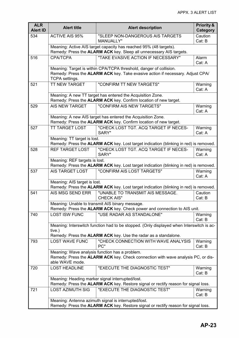
APPX. 3 ALERT LIST
534 ACTIVE AIS 95% "SLEEP NON-DANGEROUS AIS TARGETS MANUALLY"
CautionCat: B
Meaning: Active AIS target capacity has reached 95% (48 targets).Remedy: Press the ALARM ACK key. Sleep all unnecessary AIS targets.
516 CPA/TCPA "TAKE EVASIVE ACTION IF NECESSARY" AlarmCat: A
Meaning: Target is within CPA/TCPA threshold, danger of collision.Remedy: Press the ALARM ACK key. Take evasive action if necessary. Adjust CPA/TCPA settings.
521 TT NEW TARGET "CONFIRM TT NEW TARGETS" WarningCat: A
Meaning: A new TT target has entered the Acquisition Zone.Remedy: Press the ALARM ACK key. Confirm location of new target.
529 AIS NEW TARGET "CONFIRM AIS NEW TARGETS" WarningCat: A
Meaning: A new AIS target has entered the Acquisition Zone.Remedy: Press the ALARM ACK key. Confirm location of new target.
527 TT TARGET LOST "CHECK LOST TGT. ACQ TARGET IF NECES-SARY"
WarningCat: A
Meaning: TT target is lost.Remedy: Press the ALARM ACK key. Lost target indication (blinking in red) is removed.
528 REF TARGET LOST "CHECK LOST TGT. ACQ TARGET IF NECES-SARY"
WarningCat: A
Meaning: REF targets is lost.Remedy: Press the ALARM ACK key. Lost target indication (blinking in red) is removed.
537 AIS TARGET LOST "CONFIRM AIS LOST TARGETS" WarningCat: A
Meaning: AIS target is lost.Remedy: Press the ALARM ACK key. Lost target indication (blinking in red) is removed.
541 AIS MSG SEND ERR "UNABLE TO TRANSMIT AIS MESSAGE. CHECK AIS"
CautionCat: B
Meaning: Unable to transmit AIS binary message.Remedy: Press the ALARM ACK key. Check power and connection to AIS unit.
740 LOST ISW FUNC "USE RADAR AS STANDALONE" WarningCat: B
Meaning: Interswitch function had to be stopped. (Only displayed when Interswitch is ac-tive.)Remedy: Press the ALARM ACK key. Use the radar as a standalone.
793 LOST WAVE FUNC "CHECK CONNECTION WITH WAVE ANALYSIS PC"
WarningCat: B
Meaning: Wave analysis function has a problem.Remedy: Press the ALARM ACK key. Check connection with wave analysis PC, or dis-able WAVE mode.
720 LOST HEADLINE "EXECUTE THE DIAGNOSTIC TEST" WarningCat: B
Meaning: Heading marker signal interrupted/lost.Remedy: Press the ALARM ACK key. Restore signal or rectify reason for signal loss.
721 LOST AZIMUTH SIG "EXECUTE THE DIAGNOSTIC TEST" WarningCat: B
Meaning: Antenna azimuth signal is interrupted/lost.Remedy: Press the ALARM ACK key. Restore signal or rectify reason for signal loss.
ALR Alert ID
Alert title Alert descriptionPriority & Category
AP-23

APPX. 3 ALERT LIST
722 LOST TRIGGER SIG "EXECUTE THE DIAGNOSTIC TEST" WarningCat: B
Meaning: Antenna trigger interrupted/lostRemedy: Press the ALARM ACK key. Restore signal or rectify reason for signal loss.
723 LOST VIDEO SIG "EXECUTE THE DIAGNOSTIC TEST" WarningCat: B
Meaning: Video signal interrupted/lost.Remedy: Press the ALARM ACK key. Restore signal or rectify reason for signal loss.
70 LOST CTRL UNIT "CHECK CONNECTION WITH CONTROL UNIT" WarningCat: B
Meaning: Control Unit (RCU-014/015/016) signal interrupted/lost.Remedy: Press the ALARM ACK key. Restore signal or rectify reason for signal loss.
48 LOST TUNE IND "INITIALIZE TUNING AGAIN" WarningCat: B
Meaning: TUNE error due to faulty settings or malfunction.Remedy: Press the ALARM ACK key. Restore signal or rectify reason for signal loss.
727 LOST RADAR ANT "CHECK CONNECTION WITH RADAR ANTEN-NA"
WarningCat: B
Meaning: Signal between processor and antenna interrupted/lost.Remedy: Press the ALARM ACK key. Restore signal or rectify reason for signal loss.
781 LOST MTR-DRV "EXECUTE THE DIAGNOSTIC TEST" WarningCat: B
Meaning: Signal between antenna’s SPU and MTR-DRV interrupted/lost.Remedy: Press the ALARM ACK key. Restore signal or rectify reason for signal loss.
783 LOST RF-CONV*1 "EXECUTE THE DIAGNOSTIC TEST" WarningCat: B
Meaning: Signal between antenna’s SPU and RF-CONVERTER interrupted/lost.Remedy: Press the ALARM ACK key. Restore signal or rectify reason for signal loss.
786 LOST RP BOARD*5 "EXECUTE THE DIAGNOSTIC TEST" WarningCat: B
Meaning: Signal between MAIN board and RP board in the processor is interrupted or lost.Remedy: Press the ALARM ACK key. Restore signal or rectify reason for signal loss.
787 LOST TUNE GATE*2 "EXECUTE THE DIAGNOSTIC TEST" WarningCat: B
Meaning: No tune gate signal from the FAR-2x58 antenna.Remedy: Press the ALARM ACK key. Consult your local dealer for service.
789 LOST TX-HV VOLT*2 "EXECUTE THE DIAGNOSTIC TEST" WarningCat: B
Meaning: The antenna voltage is below 300 V (For FAR-2x58/2x68DS).Remedy: Press the ALARM ACK key. Turn the PSU-019 power on. If the problem per-sists, consult your local dealer for service.
450 LOST GYRO SIGNAL "CHECK HEADING SENSOR OR SENTENCE MONITOR"
WarningCat: B
Meaning: No heading information received from gyrocompass for five seconds.Remedy: Press the ALARM ACK key. Restore the signal to remove this indication.
278 LOST LOG(WT) SIG*4 "CHECK SPEED SENSOR OR SENTENCE MON-ITOR"
WarningCat: B
Meaning: No speed through water data received for thirty seconds when [LOG(WT)] is set as speed reference.Remedy: Press the ALARM ACK key. Use a different sensor if necessary.
ALR Alert ID
Alert title Alert descriptionPriority & Category
AP-24

APPX. 3 ALERT LIST
284 LOST LOG(BT) SIG*5 "CHECK SPEED SENSOR OR SENTENCE MON-ITOR"
WarningCat: B
Meaning: No speed over ground data received for thirty seconds when [LOG(BT)] is set as speed reference.Remedy: Press the ALARM ACK key. Use a different sensor if necessary.
170 LOST POSITION "CHECK POSITION SENSOR OR SENTENCE MONITOR"
WarningCat: B
Meaning: EPFS Error. No position data received from EPFS device for thirty seconds.Remedy: Press the ALARM ACK key. Restore the signal. This indication cannot be erased if the position signal is missing. The indication is automatically removed when the signal is restored.
469 LOST DATUM "CHECK POSITION SENSOR OR SENTENCE MONITOR"
WarningCat: B
Meaning: DTM sentence not received for thirty seconds, or erroneous data received.Remedy: Press the ALARM ACK key. Use the WGS-84 datum.
272 LOST UTC SIGNAL "CHECK POSITION SENSOR OR SENTENCE MONITOR"
WarningCat: B
Meaning: UTC error. No date or time data received for thirty seconds. No ZDA sentence input.Remedy: Press the ALARM ACK key. Restore the signal to remove this indication.
380 LOST AIS COM "CHECK AIS OR SENTENCE MONITOR" WarningCat: B
Meaning: No AIS data received for thirty seconds.Remedy: Press the ALARM ACK key. Check power and connection to AIS unit.
279 LOST COG/SOG SIG "CHECK POSITION SENSOR OR SENTENCE MONITOR"
WarningCat: B
Meaning: No COG/SOG data received from EPFS device for thirty seconds when [EPFS] is set as speed reference.Remedy: Press the ALARM ACK key. Restore the signal. This indication cannot be erased if the COG/SOG signal is missing. The indication is automatically removed when the signal is restored.
50 LOST ECDIS COM "CHECK ECDIS OR SENTENCE MONITOR" WarningCat: B
Meaning: No ECDIS data received for thirty seconds when [ECDIS] is set as speed refer-ence.Remedy: Press the ALARM ACK key. Check power and connection to ECDIS unit.
782 LOST PM BOARD "EXECUTE THE DIAGNOSTIC TEST" CautionCat: B
Meaning: Signal between antenna’s SPU and PM interrupted/lost.Remedy: Press the ALARM ACK key. Restore signal or rectify reason for signal loss.
278 LOST LOG(WT) SIG*4 "CHECK SPEED SENSOR OR SENTENCE MON-ITOR"
CautionCat: B
Meaning: No speed through water data received for thirty seconds when [LOG(WT)] is NOT set as speed reference.Remedy: Press the ALARM ACK key. Use a different sensor if necessary.
284 LOST LOG(BT) SIG*5 "CHECK SPEED SENSOR OR SENTENCE MON-ITOR"
CautionCat: B
Meaning: No speed over ground data received for thirty seconds when [LOG(BT)] is set as speed reference.Remedy: Press the ALARM ACK key. Use a different sensor if necessary.
ALR Alert ID
Alert title Alert descriptionPriority & Category
AP-25

APPX. 3 ALERT LIST
380 LOST AIS COM "CHECK AIS OR SENTENCE MONITOR" CautionCat: B
Meaning: No AIS data received for thirty seconds when AIS function is OFF.Remedy: Press the ALARM ACK key. Check power and connection to AIS unit.
279 LOST COG/SOG SIG "CHECK POSITION SENSOR OR SENTENCE MONITOR"
CautionCat: B
Meaning: No COG/SOG data received from EPFS device for thirty seconds when [EPFS] NOT is set as speed reference.Remedy: Press the ALARM ACK key. Restore the signal. This indication cannot be erased if the COG/SOG signal is missing. The indication is automatically removed when the signal is restored.
784 WRONG IP ADDR "CHECK IP SETTINGS AND ASSIGN A UNIQUE IP"
CautionCat: B
Meaning: LAN1 IP address is in use by other equipment.Remedy: Press the ALARM ACK key. Check the IP settings and assign a unique IP ad-dress.
785 WRONG IP (LAN2) "CHECK IP SETTINGS AND ASSIGN A UNIQUE IP"
CautionCat: B
Meaning: LAN2 IP address is in use by other equipment.Remedy: Press the ALARM ACK key. Check the IP settings and assign a unique IP ad-dress.
788 RP VER MISMATCH*5 "CONSULT YOUR LOCAL DEALER FOR SW UP-DATE"
CautionCat: B
Meaning: MAIN board and RP board software versions do not match.Remedy: Press the ALARM ACK key. Consult you local dealer for a software update.
729 WRONG POSN INT "CHECK THE OUTPUT SETTINGS FOR EPFS DEVICE"
CautionCat: B
Meaning: Position signal interval cycle has exceeded 10 seconds for a period.Remedy: Press the ALARM ACK key. Check the output settings for the connected EPFS device. Adjust output interval (cycle) as required.
495 ANCHOR WATCH "CONFIRM OWN SHIP LOCATION" WarningCat: B
Meaning: Ship position outside set anchor watch zone.Remedy: Press the ALARM ACK key. Confirm Own Ship location and adjust as neces-sary.
755 SELECT SART
MODE*3"SART SIGNAL DETECTED. SELECT SART MODE"
WarningCat: A
Meaning: A SART signal was detected.Remedy: Press the ALARM ACK key. Show the SART marks on the radar display ([7 SART] set to [ON]).
790 ARRIVED AT WPT*4 "SET NEXT WPT, IF NECESSARY" WarningCat: B
Meaning: Ship has entered the destination arrival alert zone.Remedy: Press the ALARM ACK key. Set next waypoint, if necessary.
791 XTD LIM EXCEED-
ED*4"CHECK COURSE AND ADJUST AS NECES-SARY"
WarningCat: B
Meaning: Cross-track error, ship is off-course.Remedy: Press the ALARM ACK key. Check course and adjust as necessary.
ALR Alert ID
Alert title Alert descriptionPriority & Category
AP-26

APPX. 3 ALERT LIST
ALR format indications
The following indications are shown by this equipment when ALR format is in use. The indications have no category, and are not output as ALR sentences.
Note: Indications also appear in the ALERT BOX on the screen and on the ALERT LIST.
792 CHART MEMORY
ERR*5"CHECK PROCESSOR UNIT" Warning
Cat: B
Meaning: An error has occurred while loading chart data.Remedy: Press the ALARM ACK key. Have a qualified technician check the processor unit.
*1: This alert appears only for FAR-2228-NXT(-BB) and FAR-2328-NXT.
*2: This alert appears only for For FAR-2x58/2x68DS.
*3: This alert appears only for FAR-2228-NXT(-BB) and FAR-2328-NXT. Keep in mind the following points:• This alert can occur when this equipment receives interference simultaneously from multiple
radars.• This alert may not occur under the bad weather conditions such as at rain.
*4: This alert is output only on B/W-type radars.
*5: This alert is output only on A/B/W-types with radar plotter functionality.
ID Title Message075 RPU:HIGH TEMP "CONDUCT A DIAGNOSTIC TEST WHILE THE ERROR IS
PRESENT. SUPPLY THE TEST RESULTS TO YOUR LOCAL DEALER."
Meaning: Temperature in the RPU is above the recommended limit.Remedy: Press the ALARM ACK key. Lower the temperature.
770-1 MD TYPE MISMATCH "CONDUCT A DIAGNOSTIC TEST WHILE THE ERROR IS PRESENT. SUPPLY THE TEST RESULTS TO YOUR LOCAL DEALER."
Meaning: Unable to detect the MD board bandwidth.Remedy: Press the ALARM ACK key. Check connections to the antenna.
772-1 PM TYPE MISMATCH "CONDUCT A DIAGNOSTIC TEST WHILE THE ERROR IS PRESENT. SUPPLY THE TEST RESULTS TO YOUR LOCAL DEALER."
Meaning: Unable to detect the MD board bandwidth.Remedy: Press the ALARM ACK key. Check connections to the antenna.
771-1 MTR-DRV:HIGH TEMP "CONDUCT A DIAGNOSTIC TEST WHILE THE ERROR IS PRESENT. SUPPLY THE TEST RESULTS TO YOUR LOCAL DEALER."
Meaning: MTR-DRV board temperature is above the recommended limit.Remedy: Press the ALARM ACK key. Lower the temperature.
ALR Alert ID
Alert title Alert descriptionPriority & Category
AP-27

APPX. 3 ALERT LIST
771-2 MTR-DRV:OVER CURRENT
"CONDUCT A DIAGNOSTIC TEST WHILE THE ERROR IS PRESENT. SUPPLY THE TEST RESULTS TO YOUR LOCAL DEALER."
Meaning: MTR-DRV board power input from the motor is outside recommended rating.Remedy: Press the ALARM ACK key. Have a qualified technician check the motor.
771-3 MTR-DRV:MTR PWR ERR
"CONDUCT A DIAGNOSTIC TEST WHILE THE ERROR IS PRESENT. SUPPLY THE TEST RESULTS TO YOUR LOCAL DEALER."
Meaning: MTR-DRV board motor’s voltage is outside recommended rating.Remedy: Press the ALARM ACK key. Have a qualified technician check the motor.
771-4 MTR-DRV:P12V ERR "CONDUCT A DIAGNOSTIC TEST WHILE THE ERROR IS PRESENT. SUPPLY THE TEST RESULTS TO YOUR LOCAL DEALER."
Meaning: Voltage in the +12V line of the MTR-DRV motor is outside recommended rating.Remedy: Press the ALARM ACK key. Have a qualified technician check the power sup-ply.
771-5 MTR-DRV:HALL SEN-SOR ERR
"CONDUCT A DIAGNOSTIC TEST WHILE THE ERROR IS PRESENT. SUPPLY THE TEST RESULTS TO YOUR LOCAL DEALER."
Meaning: Error in the hall sensor signal detected by the MTR-DRV board.Remedy: Press the ALARM ACK key. Have a qualified technician check the hall sensor.
771-6 MTR-DRV:ANT LOCK "CHECK THE SCANNER FOR OBSTRUCTIONS. IF THERE ARE NONE, SUPPLY THE TEST RESULTS TO YOUR LO-CAL DEALER."
Meaning: Antenna lock detected by the MTR-DRV board.Remedy: Press the ALARM ACK key. Unlock the antenna.
771-7 MTR-DRV:PWR SUP-PLY ERR
"CONDUCT A DIAGNOSTIC TEST WHILE THE ERROR IS PRESENT. SUPPLY THE TEST RESULTS TO YOUR LOCAL DEALER."
Meaning: MTR-DRV board detected an drop in power.Remedy: Press the ALARM ACK key. Have a qualified technician check the power sup-ply.
771-8 MTR-DRV:BRAKE-R ERR
"CONDUCT A DIAGNOSTIC TEST WHILE THE ERROR IS PRESENT. SUPPLY THE TEST RESULTS TO YOUR LOCAL DEALER."
Meaning: MTR-DRV board detected an error in the brake resistance.Remedy: Press the ALARM ACK key. Have a qualified technician check the antenna brake.
771-9 MTR-DRV:OVER LOAD
"CONDUCT A DIAGNOSTIC TEST WHILE THE ERROR IS PRESENT. SUPPLY THE TEST RESULTS TO YOUR LOCAL DEALER."
Meaning: MTR-DRV board detected an overload.Remedy: Press the ALARM ACK key. Have a qualified technician check the motor.
772-2 PM:P12V ERROR "CONDUCT A DIAGNOSTIC TEST WHILE THE ERROR IS PRESENT. SUPPLY THE TEST RESULTS TO YOUR LOCAL DEALER."
Meaning: Voltage in the +12V line of the PM board is outside recommended rating.Remedy: Press the ALARM ACK key. Have a qualified technician check the power sup-ply.
ID Title Message
AP-28

APPX. 3 ALERT LIST
772-3 PM:PLL UNLOCK "CONDUCT A DIAGNOSTIC TEST WHILE THE ERROR IS PRESENT. SUPPLY THE TEST RESULTS TO YOUR LOCAL DEALER."
Meaning: PM board’s PLL is unlocked.Remedy: Press the ALARM ACK key. Have a qualified technician check the PM board.
773-1 RFC:P6V ERROR "CONDUCT A DIAGNOSTIC TEST WHILE THE ERROR IS PRESENT. SUPPLY THE TEST RESULTS TO YOUR LOCAL DEALER."
Meaning: Voltage in the +6V line of the RF-Converter is outside rating.Remedy: Press the ALARM ACK key. Have a qualified technician check the power.
773-2 RFC:P48V ERROR "CONDUCT A DIAGNOSTIC TEST WHILE THE ERROR IS PRESENT. SUPPLY THE TEST RESULTS TO YOUR LOCAL DEALER."
Meaning: Voltage in the +48V line of the RF-Converter is outside rating.Remedy: Press the ALARM ACK key. Have a qualified technician check the power.
773-3 RFC:IF PLL UNLOCK "CONDUCT A DIAGNOSTIC TEST WHILE THE ERROR IS PRESENT. SUPPLY THE TEST RESULTS TO YOUR LOCAL DEALER."
Meaning: PLL lock on the IF side of the RF-Converter is unlocked.Remedy: Press the ALARM ACK key. Have a qualified technician check the RF-Convert-er.
773-4 RFC:PLL UNLOCK "CONDUCT A DIAGNOSTIC TEST WHILE THE ERROR IS PRESENT. SUPPLY THE TEST RESULTS TO YOUR LOCAL DEALER."
Meaning: PLL lock on the RF side of the RF-Converter is unlocked.Remedy: Press the ALARM ACK key. Have a qualified technician check the RF-Convert-er.
773-5 RFC:OUTPUT SIG LVL ERR
"CONDUCT A DIAGNOSTIC TEST WHILE THE ERROR IS PRESENT. SUPPLY THE TEST RESULTS TO YOUR LOCAL DEALER."
Meaning: Signal output from the RF-Converter is outside the recommended rating.Remedy: Press the ALARM ACK key. Have a qualified technician check the RF-Convert-er.
773-6 RFC:INPUT SIG LVL ERR
"CONDUCT A DIAGNOSTIC TEST WHILE THE ERROR IS PRESENT. SUPPLY THE TEST RESULTS TO YOUR LOCAL DEALER."
Meaning: Signal input from the RF-Converter is outside the recommended rating.Remedy: Press the ALARM ACK key. Have a qualified technician check the RF-Convert-er.
775-1 HPA:OUTPUT SIG LVL ERR
"CONDUCT A DIAGNOSTIC TEST WHILE THE ERROR IS PRESENT. SUPPLY THE TEST RESULTS TO YOUR LOCAL DEALER."
Meaning: Signal output from the HPA board is outside the recommended rating.Remedy: Press the ALARM ACK key. Have a qualified technician check the HPA board.
775-2 HPA:OUTPUT PK CRR ERR
"CONDUCT A DIAGNOSTIC TEST WHILE THE ERROR IS PRESENT. SUPPLY THE TEST RESULTS TO YOUR LOCAL DEALER."
Meaning: Peak current detected in the signal output from the HPA board.Remedy: Press the ALARM ACK key. Have a qualified technician check the HPA board.
ID Title Message
AP-29

APPX. 3 ALERT LIST
775-3 HPA:HIGH TEMP "CONDUCT A DIAGNOSTIC TEST WHILE THE ERROR IS PRESENT. SUPPLY THE TEST RESULTS TO YOUR LOCAL DEALER."
Meaning: Excessively high temperature detected on the HPA board.Remedy: Press the ALARM ACK key. Have a qualified technician check the HPA board.
775-4 VSWR ERROR "CONDUCT A DIAGNOSTIC TEST WHILE THE ERROR IS PRESENT. SUPPLY THE TEST RESULTS TO YOUR LOCAL DEALER."
Meaning: Abnormal VSWR detected by the RF Converter.Remedy: Press the ALARM ACK key. Have a qualified technician check the antenna.
083 RPU:FAN1 NO RO-TATE
"CONDUCT A DIAGNOSTIC TEST WHILE THE ERROR IS PRESENT. SUPPLY THE TEST RESULTS TO YOUR LOCAL DEALER."
Meaning: The FAN1 in the processor unit is stopped or disconnected.Remedy: Press the ALARM ACK key. Have a qualified technician check the processor unit.
084 RPU:FAN2 NO RO-TATE
"CONDUCT A DIAGNOSTIC TEST WHILE THE ERROR IS PRESENT. SUPPLY THE TEST RESULTS TO YOUR LOCAL DEALER."
Meaning: The FAN2 in the processor unit is stopped or disconnected.Remedy: Press the ALARM ACK key. Have a qualified technician check the processor unit.
085 RPU:FAN3 NO RO-TATE
"CONDUCT A DIAGNOSTIC TEST WHILE THE ERROR IS PRESENT. SUPPLY THE TEST RESULTS TO YOUR LOCAL DEALER."
Meaning: The FAN3 in the processor unit is stopped or disconnected.Remedy: Press the ALARM ACK key. Have a qualified technician check the processor unit.
082 RPU:FAN(RP) NO RO-
TATE*1"CONDUCT A DIAGNOSTIC TEST WHILE THE ERROR IS PRESENT. SUPPLY THE TEST RESULTS TO YOUR LOCAL DEALER."
Meaning: The RPU fan on the RP board in the processor unit is stopped or disconnected.Remedy: Press the ALARM ACK key. Have a qualified technician check the processor unit.
087 RPU:RP HW
ERROR*1, *3"IN SAFE WATERS, REBOOT THE SYSTEM. IF THE ERROR OCCURS FREQUENTLY, SUPPLY THE TEST RESULTS TO YOUR LOCAL DEALER."
Meaning: The RP board has stopped working. Charts and marks cannot be displayed.Remedy: Press the ALARM ACK key. Have a qualified technician check the processor unit.
798 LOST WAVE UNIT*1 "CHECK CONNECTION WITH WAVE ANALYSIS PC, OR DISABLE WAVE MODE."
Meaning: Wave data not received from wave analysis PC, when WAVE mode is enabled.Remedy: Press the ALARM ACK key. Check connection with wave analysis PC, or dis-able WAVE mode.
472 POSN SOURCE CHG "POSITION SOURCE USING IN SYSTEM CHANGES TO OTHER SOURCE."
Meaning: Positioning sensor input lost, automatically changed sensors.Remedy: Press the ALARM ACK key. The indication is automatically removed when the signal is restored or a different sensor is selected.
ID Title Message
AP-30

APPX. 3 ALERT LIST
474 SPD SOURCE CHG "SPEED SOURCE USING IN SYSTEM CHANGES TO OTH-ER SOURCE."
Meaning: Speed sensor input lost, automatically changed sensors.Remedy: Press the ALARM ACK key. The indication is automatically removed when the signal is restored or a different sensor is selected.
473 HDG SOURCE CHG "HEADING SOURCE USING IN SYSTEM CHANGES TO OTHER SOURCE."
Meaning: Heading sensor input lost, automatically changed sensors.Remedy: Press the ALARM ACK key. The indication is automatically removed when the signal is restored or a different sensor is selected.
741 ISW: NO SIGNAL "SELECTED RADAR HAS PROBLEM. USE RADAR AS STANDALONE."
Meaning: Selected radar has an error. (Only displayed when Interswitch is active.)Remedy: Press the ALARM ACK key. Use radar as standalone or restore the external radar to normal operating condition.
742 ISW: NO RADAR "COMMUNICATION WITH SELECTED RADAR HAS INTER-RUPTED/LOST. USE RADAR AS STANDALONE."
Meaning: Communication with selected radar interrupted or lost. (Only displayed when Interswitch is active.)Remedy: Press the ALARM ACK key. Use radar as standalone or check connection and power to the external radar.
743 ISW: STBY*2 "SELECTED RADAR ENTERED STANDBY MODE. SET SE-LECTED RADAR TO TX MODE."
Meaning: Selected radar entered standby mode.Remedy: Press the ALARM ACK key. Check transmission status of the selected radar.
744 ISW: NO SENSOR*2 "SELECTED RADAR HAS PROBLEM. USE RADAR AS STANDALONE."
Meaning: No heading data was received from the selected radar for more than five sec-onds.Remedy: Press the ALARM ACK key. Check heading data input status for the selected radar.
793-1 LOST WV UTC SIG "CHECK THAT DATA INPUT TO WAVE ANALYZER IS COR-RECT, OR DISABLE WAVE MODE."
Meaning: With the wave radar active ([4 WAVE DATA] set to [ON]), the wave analysis PC has an error in time/date input.Remedy: Press the ALARM ACK key. Check that data input to Wave Analyzer is correct, or disable WAVE mode.
793-2 LOST WV COG/SOG "CHECK THAT DATA INPUT TO WAVE ANALYZER IS COR-RECT, OR DISABLE WAVE MODE."
Meaning: With the wave radar active ([4 WAVE DATA] set to [ON]), the wave analysis PC has an error in speed data input.Remedy: Press the ALARM ACK key. Check that data input to Wave Analyzer is correct, or disable WAVE mode.
793-3 LOST WV WIND SIG "CHECK THAT DATA INPUT TO WAVE ANALYZER IS COR-RECT, OR DISABLE WAVE MODE."
Meaning: With the wave radar active ([4 WAVE DATA] set to [ON]), the wave analysis PC has an error in speed data input.Remedy: Press the ALARM ACK key. Check that data input to Wave Analyzer is correct, or disable WAVE mode.
ID Title Message
AP-31

APPX. 3 ALERT LIST
*1: This indication is output only on A/B/W-types with radar plotter functionality.*2: This indication appears only on A/B-type radars when Dual Radar mode is active and enabled.*3: When this indication is rectified, the [Chart] button appears in yellow color. Click the [Chart] but-ton to restore the system to normal operation.
793-4 LOST WV RADAR ANT "CHECK THE CONNECTION WITH SELECTED RADAR IS CORRECT, OR DISABLE WAVE MODE."
Meaning: With the wave radar active ([4 WAVE DATA] set to [ON]), the wave analysis PC has an error in speed data input.Remedy: Press the ALARM ACK key. Check that data input to Wave Analyzer is correct, or disable WAVE mode.
793-5 LOST WV GYRO SIG "CHECK THAT DATA INPUT TO WAVE ANALYZER IS COR-RECT, OR DISABLE WAVE MODE."
Meaning: With the wave radar active ([4 WAVE DATA] set to [ON]), the wave analysis PC has an error in speed data input.Remedy: Press the ALARM ACK key. Check that data input to Wave Analyzer is correct, or disable WAVE mode.
ID Title Message
AP-32
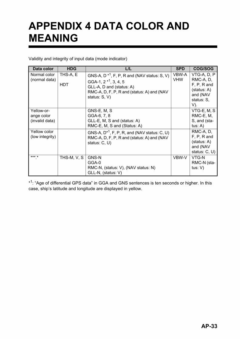
AP-33
APPENDIX 4 DATA COLOR AND MEANING
Validity and integrity of input data (mode indicator)
*1: “Age of differential GPS data” in GGA and GNS sentences is ten seconds or higher. In this case, ship’s latitude and longitude are displayed in yellow.
Data color HDG L/L SPD COG/SOGNormal color(normal data)
THS-A, E
HDT
GNS-A, D *1, F, P, R and (NAV status: S, V)
GGA-1, 2 *1, 3, 4, 5GLL-A, D and (status: A)RMC-A, D, F, P, R and (status: A) and (NAV status: S, V)
VBW-AVHW
VTG-A, D, PRMC-A, D, F, P, R and (status: A) and (NAV status: S, V).
Yellow-or-ange color(invalid data)
GNS-E, M, SGGA-6, 7, 8GLL-E, M, S and (status: A)RMC-E, M, S and (Status: A)
VTG-E, M, SRMC-E, M, S, and (sta-tus: A)
Yellow color(low integrity)
GNS-A, D*1, F, P, R, and (NAV status: C, U)RMC-A, D, F, P, R and (status: A) and (NAV status: C, U)
RMC-A, D, F, P, R and (status: A) and (NAV status: C, U)
***.* THS-M, V, S GNS-NGGA-0RMC-N, (status: V), (NAV status: N)GLL-N, (status: V)
VBW-V VTG-NRMC-N (sta-tus: V)
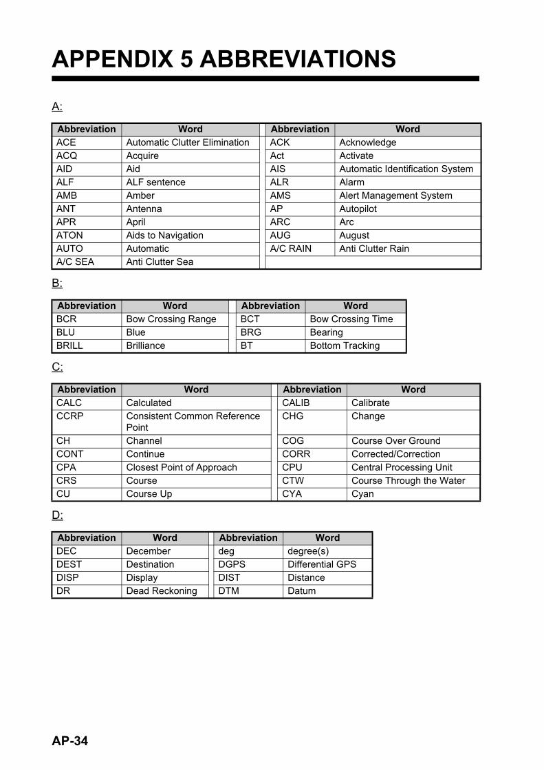
APPENDIX 5 ABBREVIATIONS
A:
B:
C:
D:
Abbreviation Word Abbreviation WordACE Automatic Clutter Elimination ACK AcknowledgeACQ Acquire Act ActivateAID Aid AIS Automatic Identification SystemALF ALF sentence ALR AlarmAMB Amber AMS Alert Management SystemANT Antenna AP AutopilotAPR April ARC ArcATON Aids to Navigation AUG AugustAUTO Automatic A/C RAIN Anti Clutter RainA/C SEA Anti Clutter Sea
Abbreviation Word Abbreviation WordBCR Bow Crossing Range BCT Bow Crossing TimeBLU Blue BRG BearingBRILL Brilliance BT Bottom Tracking
Abbreviation Word Abbreviation WordCALC Calculated CALIB CalibrateCCRP Consistent Common Reference
PointCHG Change
CH Channel COG Course Over GroundCONT Continue CORR Corrected/CorrectionCPA Closest Point of Approach CPU Central Processing UnitCRS Course CTW Course Through the WaterCU Course Up CYA Cyan
Abbreviation Word Abbreviation WordDEC December deg degree(s)DEST Destination DGPS Differential GPSDISP Display DIST DistanceDR Dead Reckoning DTM Datum
AP-34
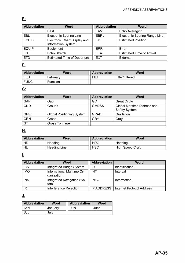
APPENDIX 5 ABBREVIATIONS
E:
F:
G:
H:
I:
J:
Abbreviation Word Abbreviation WordE East EAV Echo AveragingEBL Electronic Bearing Line EBRL Electronic Bearing Range LineECDIS Electronic Chart Display and
Information SystemEP Estimated Position
EQUIP Equipment ERR ErrorES Echo Stretch ETA Estimated Time of ArrivalETD Estimated Time of Departure EXT External
Abbreviation Word Abbreviation WordFEB February FILT Filter/FilteredFUNC Function
Abbreviation Word Abbreviation WordGAP Gap GC Great CircleGND Ground GMDSS Global Maritime Distress and
Safety SystemGPS Global Positioning System GRAD GradationGRN Green GRY GrayGT Gross Tonnage
Abbreviation Word Abbreviation WordHD Heading HDG HeadingHL Heading Line HSC High Speed Craft
Abbreviation Word Abbreviation WordIBS Integrated Bridge System ID IdentificationIMO International Maritime Or-
ganizationINT Interval
INS Integrated Navigation Sys-tem
INFO Information
IR Interference Rejection IP ADDRESS Internet Protocol Address
Abbreviation Word Abbreviation WordJAN January JUN JuneJUL July
AP-35

APPENDIX 5 ABBREVIATIONS
L:
Abbreviation Word Abbreviation WordL Long pulse LAT LatitudeLAN Local Area Network LCD Liquid Crystal DisplayLIM Limit L/L Latitude/LongitudeLOG Log LON LongitudeLOP Line Of Position
AP-36
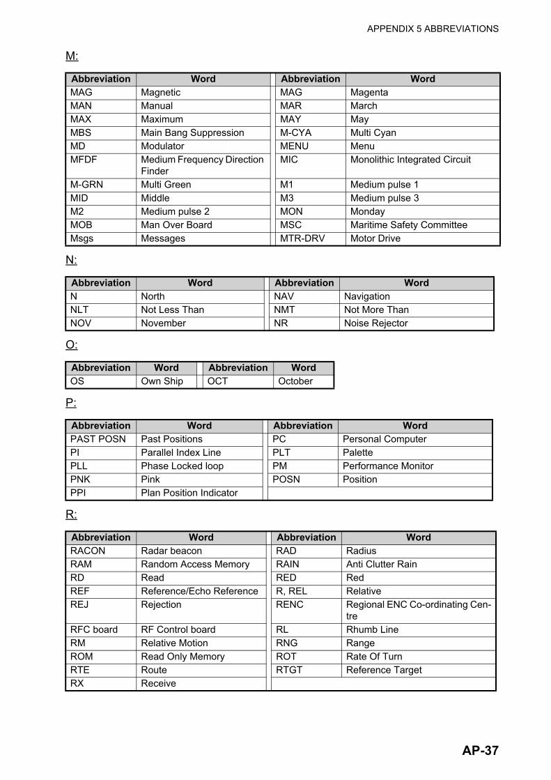
APPENDIX 5 ABBREVIATIONS
M:
N:
O:
P:
R:
Abbreviation Word Abbreviation WordMAG Magnetic MAG MagentaMAN Manual MAR MarchMAX Maximum MAY MayMBS Main Bang Suppression M-CYA Multi CyanMD Modulator MENU MenuMFDF Medium Frequency Direction
FinderMIC Monolithic Integrated Circuit
M-GRN Multi Green M1 Medium pulse 1MID Middle M3 Medium pulse 3M2 Medium pulse 2 MON MondayMOB Man Over Board MSC Maritime Safety CommitteeMsgs Messages MTR-DRV Motor Drive
Abbreviation Word Abbreviation WordN North NAV NavigationNLT Not Less Than NMT Not More ThanNOV November NR Noise Rejector
Abbreviation Word Abbreviation WordOS Own Ship OCT October
Abbreviation Word Abbreviation WordPAST POSN Past Positions PC Personal ComputerPI Parallel Index Line PLT PalettePLL Phase Locked loop PM Performance MonitorPNK Pink POSN PositionPPI Plan Position Indicator
Abbreviation Word Abbreviation WordRACON Radar beacon RAD RadiusRAM Random Access Memory RAIN Anti Clutter RainRD Read RED RedREF Reference/Echo Reference R, REL RelativeREJ Rejection RENC Regional ENC Co-ordinating Cen-
treRFC board RF Control board RL Rhumb LineRM Relative Motion RNG RangeROM Read Only Memory ROT Rate Of TurnRTE Route RTGT Reference TargetRX Receive
AP-37
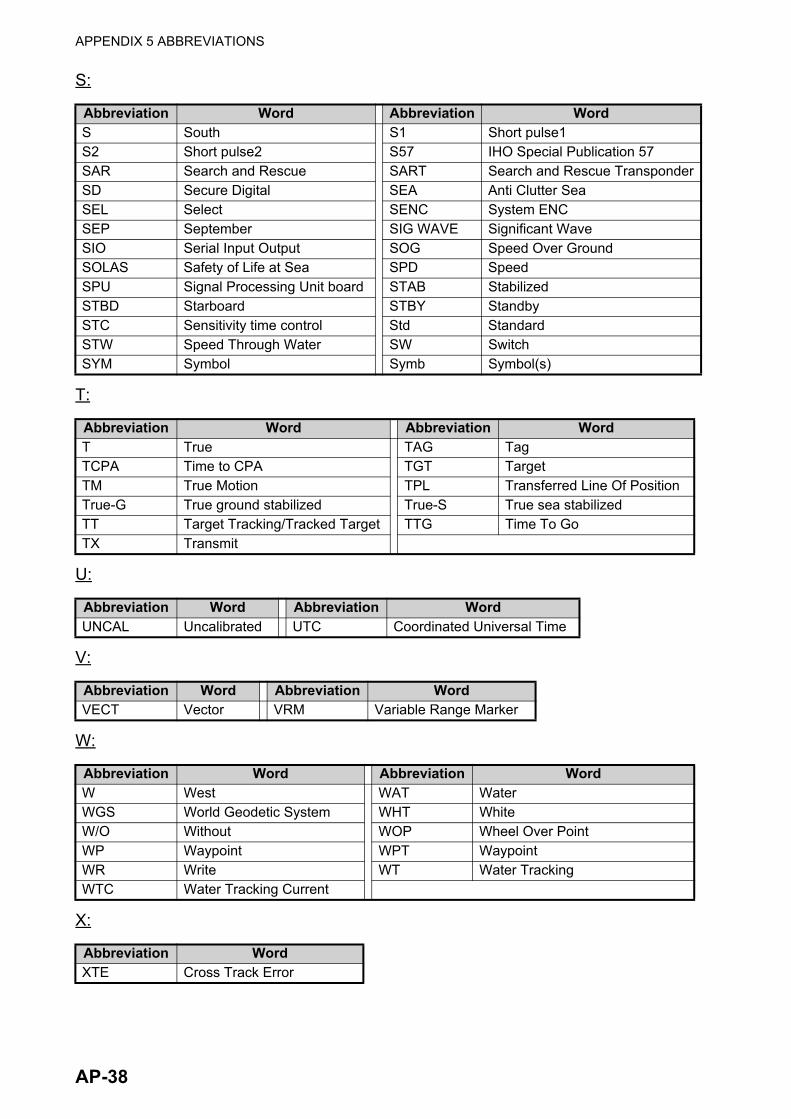
APPENDIX 5 ABBREVIATIONS
S:
T:
U:
V:
W:
X:
Abbreviation Word Abbreviation WordS South S1 Short pulse1S2 Short pulse2 S57 IHO Special Publication 57SAR Search and Rescue SART Search and Rescue TransponderSD Secure Digital SEA Anti Clutter SeaSEL Select SENC System ENCSEP September SIG WAVE Significant WaveSIO Serial Input Output SOG Speed Over GroundSOLAS Safety of Life at Sea SPD SpeedSPU Signal Processing Unit board STAB StabilizedSTBD Starboard STBY StandbySTC Sensitivity time control Std StandardSTW Speed Through Water SW SwitchSYM Symbol Symb Symbol(s)
Abbreviation Word Abbreviation WordT True TAG TagTCPA Time to CPA TGT TargetTM True Motion TPL Transferred Line Of PositionTrue-G True ground stabilized True-S True sea stabilizedTT Target Tracking/Tracked Target TTG Time To GoTX Transmit
Abbreviation Word Abbreviation WordUNCAL Uncalibrated UTC Coordinated Universal Time
Abbreviation Word Abbreviation WordVECT Vector VRM Variable Range Marker
Abbreviation Word Abbreviation WordW West WAT WaterWGS World Geodetic System WHT WhiteW/O Without WOP Wheel Over PointWP Waypoint WPT WaypointWR Write WT Water TrackingWTC Water Tracking Current
Abbreviation WordXTE Cross Track Error
AP-38

APPENDIX 5 ABBREVIATIONS
Y:
Units of measurement
Abbreviation WordYEL Yellow
Unit abbreviation Meaning Unit abbreviation Meaningdeg Degree(s) ft Foot/feetH Hour(s) km Kilometer(s)KM Kilometer(s) kn Knot(s)KYD Kiloyard(s) min Minute(s)m Meter(s) MHz MegahertzNM Nautical miles sec Second(s)SM Statute mile(s) ° Degree(s)
AP-39
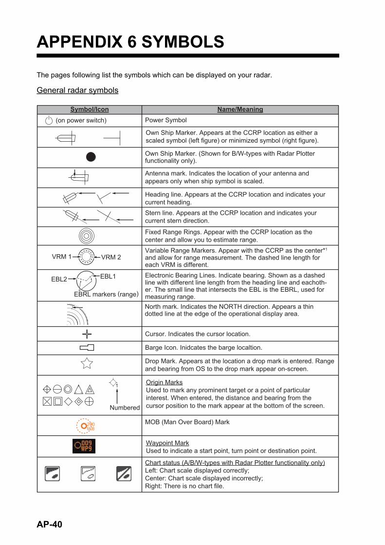
APPENDIX 6 SYMBOLS
The pages following list the symbols which can be displayed on your radar.
General radar symbols
(on power switch) Power Symbol
Own Ship Marker. Appears at the CCRP location as either a scaled symbol (left figure) or minimized symbol (right figure).
Own Ship Marker. (Shown for B/W-types with Radar Plotter functionality only).
Antenna mark. Indicates the location of your antenna and appears only when ship symbol is scaled.
MOB (Man Over Board) Mark
Origin MarksUsed to mark any prominent target or a point of particular interest. When entered, the distance and bearing from the cursor position to the mark appear at the bottom of the screen.
Waypoint MarkUsed to indicate a start point, turn point or destination point.
Fixed Range Rings. Appear with the CCRP location as the center and allow you to estimate range. Variable Range Markers. Appear with the CCRP as the center*1 and allow for range measurement. The dashed line length for each VRM is different.
VRM 2VRM 1
Cursor. Indicates the cursor location.
Barge Icon. Inidcates the barge localtion.
Drop Mark. Appears at the location a drop mark is entered. Range and bearing from OS to the drop mark appear on-screen.
Symbol/Icon Name/Meaning
Electronic Bearing Lines. Indicate bearing. Shown as a dashed line with different line length from the heading line and eachoth-er. The small line that intersects the EBL is the EBRL, used for measuring range.
Chart status (A/B/W-types with Radar Plotter functionality only)Left: Chart scale displayed correctly;Center: Chart scale displayed incorrectly;Right: There is no chart file.
Heading line. Appears at the CCRP location and indicates your current heading.Stern line. Appears at the CCRP location and indicates your current stern direction.
EBL1
EBRL markers (range)
EBL2
North mark. Indicates the NORTH direction. Appears a thin dotted line at the edge of the operational display area.
1
200MOB
Numbered
AP-40

APPENDIX 6 SYMBOLS
Radar map symbols (B/W radar types)
For B/W-types, the color of some symbols can be changed (see section 5.4.2).
Symbol Name
Mark
Danger Highlight
Danger Highlight
Buoy
Buoy
Buoy
Buoy
Buoy
Danger Highlight
Mark
Mark
Mark
Mark
Mark
Mark
Mark
Nav Line (map)
Coastline
Contour
Prohibited Area
)elbac(
(w/line) Buoy
(w/line) Mark
(w/line) Mark
(w/line) Mark
AP-41

APPENDIX 6 SYMBOLS
Radar map symbols (IMO/A/R radar types)
Buoy
Buoy
Buoy
Buoy
Buoy
Buoy
Buoy
Buoy
thgilhgiHregnaDDanger Highlight
Mark
Mark
Mark
)pam(enilvaN
eniltsaoC
eniLruotnoC
thgilhgiHregnaD
thgilhgiHregnaD
kraM
kraM
Symbol Name NameSymbol
Red
Red
Red
Red
Green
Green
Green
GreenMagentaMagenta
Orange
Orange
White
Magenta
Orange
Magenta
Gray
Magenta (cable)OrangeOrange
AP-42

APPENDIX 6 SYMBOLS
TT symbols
Note: For B/W-types, In addition to the "standard" circle TT symbol, you may select from the sym-bols shown below. You can also change the symbol’s attributes (name, color, etc). See section 3.9.3.
TT symbols Symbol Name
Manually acquired target. Appears as a dashed circle at intial acquisition, changes to solid circle when tracking is stable.
Automatically acquired target. Appears as a dashed red circle at intial acquisition, changes to solid circle when tracking is stable.
Vector on acquired target (approx. 1 minute after acquisition)
Stable tracking on acquired target (approx. 3 minute after acquisition)
Dangerous target. Symbol flashes in red color to indicate that this target may be on a collision course with your vessel.
Associated TT target. Appears when the target is associated and TT is given priority.
Associated dangerous TT target. Appears in red color when the target is associated, TT is given priority and the target may be on a collision course with your vessel.
Lost TT target. Indicates that this target is lost and is no longer being tracked. Appears as a flashing symbol with a red colored “X”.
Acquisition zone target. Appears when a target is acquired by the acquisition zone. Target symbol flashes in red color.
Selected target. Indicates that the target is selected for data display (range, bearing, speed, etc.).
Reference target. Indicates that this target is selected as a reference point for speed calculations.
Trial maneuver indication (IMO-types only)
TT simulation mode indication
R
TS
R
Three minutes later
AP-43

APPENDIX 6 SYMBOLS
AIS symbols
Symbol NameActivated AIS target. Appears a thick-lined symbol. Color is selectable from the menu.
Activated AIS target with vector. Indicates the target’s ROT (Rate Of Turn). Vector appears when the target’s ROT is higher than the menu setting.
Dangerous AIS target. Flashing red symbol indicates that the target matches then CPA/TCPA criteria. Symbol stops flashing after the alert is acknowledged.
Lost AIS target. Indicates that this target is lost and is no longer being tracked. Appears as a flashing symbol with a red colored “X” until the alert is acknowledged.
Sleeping AIS target. Color is selectable from the menu.
AIS target selected for data display. Location of data display in the information box is indicated below the target as “A”, “B” or “C”.
Associated AIS target. Appears when the target is associated and AIS is given priority.
Dangerous associated AIS target. Appears in red color when the target is associated, AIS is given priority and the target may be on a collision course with your vessel.
Active AIS target with scaled ship symbol. Indicates the target vessel’s dimensions (length, width, antenna location) and changes on-screen size according to display range.
AIS SART (ACTIVE)
AIS Base station
AIS Aircraft.Note: AIS aircraft are not regarded as a collision hazard. CPA and TCPA for AIS aircraft appears as “***”.
AIS Search and Rescue (SAR) Vessel
AIS SART (TEST)
AIS symbols
A
AIS target with no heading/COG data. Symbol faces the top of the screen. Furthermore, if CPA/TCPA cannot be calculated, symbol appears as a dashed line.
AP-44

APPENDIX 6 SYMBOLS
Basic shape
RACON
Emergency wreck mark
North cardinal mark
East cardinal mark
South cardinal mark
West cardinal mark
Port hand mark
Starboard hand mark
Isolated danger
Safe water
Special mark
Off position (Displayed with yellow line and yellow text)
Light fail or at reduced range (Displayed with yellow text)
RACON error(Displayed with yellow text)
Missing(Displayed with yellow dashedline and yellow text)
AIS Physical AtoN Symbol
AIS Virtual AtoN Symbol Meaning
No virtual symbol
No virtual symbol
No virtual symbol
No virtual symbol
No physical symbol
AP-45
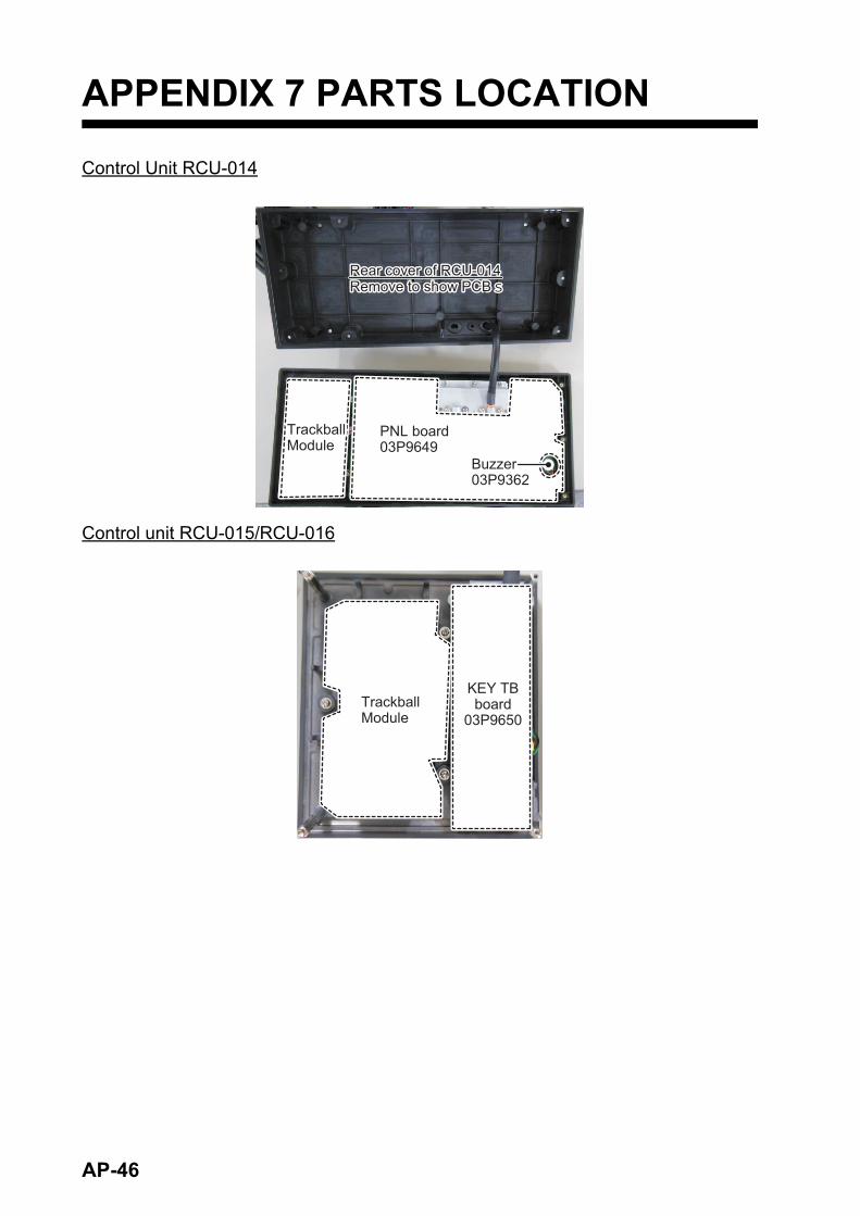
APPENDIX 7 PARTS LOCATION
Control Unit RCU-014
Control unit RCU-015/RCU-016
Rear cover of RCU-014Remove to show PCBsRear cover of RCU-014Remove to show PCBs
PNL board 03P9649PNL board 03P9649
Buzzer 03P9362Buzzer 03P9362
Trackball ModuleTrackball Module
Trackball ModuleTrackball Module
KEY TB board
03P9650
KEY TB board
03P9650
AP-46

APPENDIX 7 PARTS LOCATION
Processor Unit RPU-025
MAIN board03P9652
FAN(attached to plate)
FAN(attached to plate)
LAN Signal Converter*
RPU-025 front viewRemove caps to replace fuses
FIL boardAC-powered: 03P9545DC-powered: 03P9676
(Under LAN Signal Converter)
FIL boardAC-powered: 03P9545DC-powered: 03P9676
(Under LAN Signal Converter)
PWR2 board* 03P9527
PWR1 board AC-powered: 03P9543DC-powered: 03P9677
TB board03P9648
Remove top layer (inner chassis) to show PWR1 and PWR2 boards.
*: The presence of this component depends on configuration purchased.
FANFAN*
Fuse 1Fuse 1 Fuse 2*Fuse 2*
AP-47

APPENDIX 7 PARTS LOCATION
Scanner Unit RSB-128 (FAR-2218(-BB), FAR-2318, FAR-2228(-BB), FAR-2328)
Performance MonitorPerformance Monitor
Rear coverRear cover De-icer boardDe-icer board
RF Unit*
Inside rear cover
*: RTR-105 or RTR-106. Depends on configuration purchased.
Front CoverFront Cover
De-icer boardDe-icer board
Inside front cover
Rear of RSB-128Rear of RSB-128
RF Unit*
*: RTR-105 or RTR-106. Depends on configuration purchased.
AP-48

APPENDIX 7 PARTS LOCATION
RF Unit RTR-105/106 (FAR-2218(-BB), FAR-2318, FAR-2228(-BB), FAR-2328)
MTR-DRV boardMTR-DRV board
MotorMotor
FanFan
Front view of RSB-128(front cover removed)
RF TB board03P9570RF TB board03P9570
Remove base to show MD board and IF Board (underside of unit).
BaseBase
MD boardRTR-105: 03P9565ARTR-106: 03P9565B
MD boardRTR-105: 03P9565ARTR-106: 03P9565B
IF board 03P9568AIF board 03P9568A
MMIC board 03P9567(located below IF board)
MMIC board 03P9567(located below IF board)
Remove cover to show RF PWR board.RTR-105: 03P9537ARTR-106: 03P9537B
Remove cover to show RF PWR board.RTR-105: 03P9537ARTR-106: 03P9537B
AP-49

APPENDIX 7 PARTS LOCATION
Scanner Unit RSB-129 (FAR-2238S(-BB), FAR-2338S)
RF Unit RTR-107 (FAR-2238S(-BB), FAR-2338S)
RF UnitRTR-107
Remove rear cover to show the RF UNIT (RTR-107)
RSB-129 rear
cover
RSB-129 rear
cover
Performance monitorPerformance monitor
MotorMotor
MTR-DRV board03P9560
(inside case)
MTR-DRV board03P9560
(inside case)
Remove RF UNIT (RTR-107) to access motor and MTR-DRV board.
Remove RF UNIT (RTR-107) to access motor and MTR-DRV board.
RTR-107 - right-side
RTR-107 - left-side
Remove covers to show:MD board 03P2568BPulse Transformer 03TF00080
Remove covers to show:MD board 03P2568BPulse Transformer 03TF00080
RF TB board03P9570RF TB board03P9570
Remove cover to show RF PWR board 03P9537C
Remove cover to show RF PWR board 03P9537C
Remove cover to show IF board 03P9568B
Remove cover to show IF board 03P9568B
Remove base to show SPU board 03P9561Remove base to show SPU board 03P9561
MagnetronMG5223FMagnetronMG5223F
Curculator &
Limiter
Curculator &
Limiter
MIC board03P9569
RTR-107 rear-view
LAN signal coverter
LAN signal coverter
FanFan
AP-50

APPENDIX 7 PARTS LOCATION
Scanner Unit RSB-130 (FAR-2328W)
De-icer boardDe-icer board
Inside front and rear cover
Performance MonitorPerformance Monitor
RSB-130 rear coverRSB-130 rear cover
RSB-130 front coverRSB-130 front cover
RF TB board03P9570RF TB board03P9570
MTR-DRV board03P9560MTR-DRV board03P9560
RSB-130 - rear view
MotorMotor
RSB-130 - front view
AP-51

APPENDIX 7 PARTS LOCATION
RF Unit RTR-108 (FAR-2328W)
RF coverRF cover
MagentronMG5436MagentronMG5436
RTR-108 - Case cover removed
RTR-108 - RF Unit removed from case (top view)
Remove the RF cover to show
the magnetron. RF TB board03P9570(inside case)
RF TB board03P9570(inside case)
Remove the fan and cover to show RF PWR board 03P9537B.
FanFan
CoverCover
Remove covers to show SPU board 03P9561
Remove covers to show SPU board 03P9561 SPU board
03P9561SPU board 03P9561
Magnetron fan
Magnetron fan
RTR-108 - RF Unit removed from case (bottom view)
Remove the SPU board to show:MD board 03P9565BIF board 03P9568AMMIC board 03P9567Pulse Transformer 03TF00073
AP-52
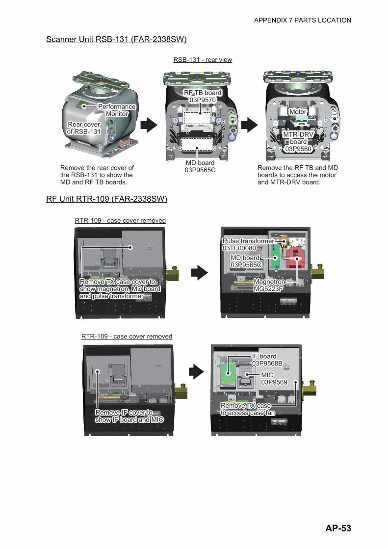
APPENDIX 7 PARTS LOCATION
Scanner Unit RSB-131 (FAR-2338SW)
RF Unit RTR-109 (FAR-2338SW)
RF TB board 03P9570
RF TB board 03P9570
Performance Monitor
Performance Monitor
Rear cover of RSB-131Rear cover of RSB-131
Remove the rear cover of the RSB-131 to show the MD and RF TB boards.
Remove the rear cover of the RSB-131 to show the MD and RF TB boards.
Remove the RF TB and MD boards to access the motor and MTR-DRV board.
Remove the RF TB and MD boards to access the motor and MTR-DRV board.
RSB-131 - rear viewRSB-131 - rear view
MD board 03P9565CMD board 03P9565C
MotorMotor
MTR-DRV board
03P9560
MTR-DRV board
03P9560
Remove TX case cover to show magnetron, MD board and pulse transformer
Remove TX case cover to show magnetron, MD board and pulse transformer
MagnetronMG5223FMagnetronMG5223F
Pulse transformer03TF00080Pulse transformer03TF00080
RTR-109 - case cover removedRTR-109 - case cover removed
MD board03P9565CMD board03P9565C
RTR-109 - case cover removedRTR-109 - case cover removed
Remove IF cover to show IF board and MICRemove IF cover to show IF board and MIC
IF board03P9568BIF board03P9568B
MIC03P9569MIC03P9569
Remove TX case to access case fanRemove TX case to access case fan
AP-53

APPENDIX 7 PARTS LOCATION
Scanner Unit RSB-133 (FAR-2238S-NXT(-BB)/2338S-NXT)
RF Unit RTR-111 (FAR-2238S-NXT(-BB)/2338S-NXT)
Remove to show RF PWR board
03P9537C
Remove to show RF PWR board
03P9537C
RTR-109 - Top view, case cover removed
RF TB board 03P9570
RF TB board 03P9570
Remove RF TB board and SPU chassis cover to show
SPU board 03P9561
Remove RF TB board and SPU chassis cover to show
SPU board 03P9561
Remove SPU chassis to access RF TB board and
SPU board.
Remove SPU chassis to access RF TB board and
SPU board.
Performance monitorPerformance monitor
RSB-133 rear
cover
RSB-133 rear
cover
Remove rear cover to access the RF Unit.Remove rear cover to access the RF Unit.
RF UnitRTR-111
HPA board03P9552
HPA board03P9552
SPU board03P9546
SPU board03P9546
RTR-111 - rear view RTR-111 - front view
RF PWR board03P9538
RF PWR board03P9538
RF TB board03P9570
RF TB board03P9570
TR Module03P955503P955603P9588
TR Module03P955503P955603P9588
RF-CONV board03P9577
RF-CONV board03P9577
AP-54

AP-55
APPENDIX 8 RADIO REGULATORY INFORMATION
XX cm
FAR-2218(-BB)FAR-2318 RTR-105 RTR-109
RTR-106
RTR-108
RTR-107
RTR-123FAR-2228(-BB)FAR-2328
FAR-2328WFAR-2238S(-BB)FAR-2338S
FAR-2228-NXT(-BB)FAR-2328-NXT
FAR-2338SW
460 cm
330 cm
RTR-111FAR-2238S-NXT(-BB)FAR-2338S-NXT 100 cm
440 cm
950 cm
550 cm
230 cm

FURUNO FAR-2xx8 SERIES
SPECIFICATIONS OF MARINE RADAR FAR-2xx8 SERIES
1 ANTENNA RADIATOR 1.1 Type Slotted waveguide array
1.2 Beam width and sidelobe attenuation
Radiator type X-band S-band
XN12CF XN20CF XN24CF** SN24CF* SN30CF* SN36CF Length 4 ft 6.5 ft 8 ft 8 ft 10 ft 12 ft Horizontal beam width 1.9° 1.23° 0.95° 2.6° 2.3° 1.8° Vertical beam width 20° 25° Sidelobe within ±10° -24 dB -28 dB -28 dB
- -24 dB
Sidelobe outside ±10° -30 dB -32 dB -32 dB -30 dB Sidelobe within ±20°
- -23 dB -24 dB
- Sidelobe outside ±20° -27 dB -30 dB
*: A/B-type radar only. **: 24 rpm only.
1.3 Polarization Horizontal
1.4 Rotation 24 rpm or 42 rpm (for high speed craft)
1.5 Wind load 100 kn relative
1.6 De-icer (option) On: when temperature goes down to 0°C
Off: when temperature goes up to +5°C
2 TRANSCEIVER 2.1 TX Frequency and modulation
X-band (Magnetron) 9410 MHz ±30 MHz, P0N
X-band (Solid state) CH1 P0N: 9403.75 MHz/ Q0N: 9423.75 MHz ±5 MHz or
CH2 P0N: 9413.75 MHz/ Q0N: 9433.75 MHz ±5 MHz
S-band (Magnetron) 3050 MHz ±30 MHz, P0N
S-band (Solid state) CH1 P0N: 3043.75 MHz/ Q0N: 3063.75 MHz ±5 MHz or
CH2 P0N: 3053.75 MHz/ Q0N: 3073.75 MHz ±5 MHz
2.2 Output power
FAR-2218(BB)/2318 12 kW
FAR-2228(BB)/2328/2328W 25 kW
FAR-2228-NXT(BB)/2328-NXT 600 W (500 W for Japanese vessel)
FAR-2238S(BB)/2338S/2338SW 30 kW
FAR-2238S-NXT(BB)/2338S-NXT 250 W
2.3 Range scale, Pulse Repetition Rate and Pulselength
X/S-band Magnetron radar
PRR (Hz approx.)
Range scale (NM) 0.125 0.25 0.5 0.75 1 1.5 2 3 4 6 8 12 16 24 32 48 96
3000* S1
3000* S2
1500 M1
1200 M2
1000 M3
600** L
1/2/4/8/16/32 NM ranges: B/W-type radar only
*: 2200 Hz with TT range on 32 NM. **: 500 Hz on 96 NM range.
SP - 1 E3652S01R-M 211102

FURUNO FAR-2xx8 SERIES
X-band Solid state radar
PRR (Hz approx.)
Range scale (NM) 0.125 0.25 0.5 0.75 1 1.5 2 3 4 6 8 12 16 24 32 48 96
1500 S1
1500 S2
1200 M1
1000 M2
1000 M3
600 L
1/2/4/8/16/32 NM ranges: B/W-type radar only
S-band Solid state radar
PRR (Hz approx.)
Range scale (NM) 0.125 0.25 0.5 0.75 1 1.5 2 3 4 6 8 12 16 24 32 48 96
2400* S1
2000* S2
1500 M1
1060 M2
1000 M3
600 L
1/2/4/8/16/32 NM ranges: B/W-type radar only
*: 1800 Hz (S1) and 1500 Hz (S2) with TT range on 32 NM.
3 PROCESSOR UNIT 3.1 Minimum range 22 m
3.2 Range discrimination 26 m
3.3 Range accuracy 1% of the maximum range of the scale in use or 10 m,
whichever is the greater
3.4 Bearing discrimination
X-band: 2.1° (XN12CF),1.5° (XN20CF), 1.2° (XN24CF),
S-band: 2.8° (SN24CF), 2.5° (SN30CF), 2.0° (SN36CF)
3.5 Bearing accuracy ±1°
3.6 Range scale and Range ring interval (RI) Range (NM) 0.125 0.25 0.5 0.75 1 1.5 2 3 4 6 8 12 16 24 32 48 96 RI (NM) 0.025 0.05 0.1 0.25 0.25 0.25 0.5 0.5 1 1 2 2 4 4 8 8 16 Number of rings 5 5 5 3 4 6 4 6 4 6 4 6 4 6 4 6 6
3.7 Warm-up time
Magnetron radar 3 min. approx.
Solid state radar Nil
3.8 Presentation mode Head-up, STAB head-up, Course-up, North-up (RM/TM), Stern-up
3.9 Marks Cursor, Range ring, Heading mark, North mark, Bearing mark,
VRM, EBL, Acquisition zone
3.10 Target tracking (TT) Auto or manual acquisition: 100 targets in 24/32 NM
(range selected from menu for maintenance)
Auto tracking on all acquired targets,
Tracking: 5/10 pts on all activated targets
Vector time: Off, 30 s, 1-60 min
3.11 AIS Display capacity: 350 targets,
Tracking: 5/10 pts on all activated targets
SP - 2 E3652S01R-M 211102
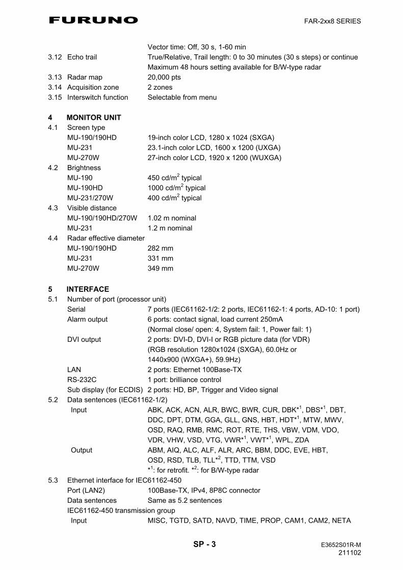
FURUNO FAR-2xx8 SERIES
Vector time: Off, 30 s, 1-60 min
3.12 Echo trail True/Relative, Trail length: 0 to 30 minutes (30 s steps) or continue
Maximum 48 hours setting available for B/W-type radar
3.13 Radar map 20,000 pts
3.14 Acquisition zone 2 zones
3.15 Interswitch function Selectable from menu
4 MONITOR UNIT 4.1 Screen type
MU-190/190HD 19-inch color LCD, 1280 x 1024 (SXGA)
MU-231 23.1-inch color LCD, 1600 x 1200 (UXGA)
MU-270W 27-inch color LCD, 1920 x 1200 (WUXGA)
4.2 Brightness
MU-190 450 cd/m2 typical
MU-190HD 1000 cd/m2 typical
MU-231/270W 400 cd/m2 typical
4.3 Visible distance
MU-190/190HD/270W 1.02 m nominal
MU-231 1.2 m nominal
4.4 Radar effective diameter
MU-190/190HD 282 mm
MU-231 331 mm
MU-270W 349 mm
5 INTERFACE 5.1 Number of port (processor unit)
Serial 7 ports (IEC61162-1/2: 2 ports, IEC61162-1: 4 ports, AD-10: 1 port)
Alarm output 6 ports: contact signal, load current 250mA
(Normal close/ open: 4, System fail: 1, Power fail: 1)
DVI output 2 ports: DVI-D, DVI-I or RGB picture data (for VDR)
(RGB resolution 1280x1024 (SXGA), 60.0Hz or
1440x900 (WXGA+), 59.9Hz)
LAN 2 ports: Ethernet 100Base-TX
RS-232C 1 port: brilliance control
Sub display (for ECDIS) 2 ports: HD, BP, Trigger and Video signal
5.2 Data sentences (IEC61162-1/2)
Input ABK, ACK, ACN, ALR, BWC, BWR, CUR, DBK*1, DBS*1, DBT,
DDC, DPT, DTM, GGA, GLL, GNS, HBT, HDT*1, MTW, MWV,
OSD, RAQ, RMB, RMC, ROT, RTE, THS, VBW, VDM, VDO,
VDR, VHW, VSD, VTG, VWR*1, VWT*1, WPL, ZDA
Output ABM, AIQ, ALC, ALF, ALR, ARC, BBM, DDC, EVE, HBT,
OSD, RSD, TLB, TLL*2, TTD, TTM, VSD
*1: for retrofit. *2: for B/W-type radar
5.3 Ethernet interface for IEC61162-450
Port (LAN2) 100Base-TX, IPv4, 8P8C connector
Data sentences Same as 5.2 sentences
IEC61162-450 transmission group
Input MISC, TGTD, SATD, NAVD, TIME, PROP, CAM1, CAM2, NETA
SP - 3 E3652S01R-M 211102
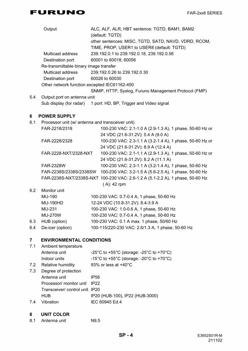
FURUNO FAR-2xx8 SERIES
Output ALC, ALF, ALR, HBT sentence: TGTD, BAM1, BAM2
(default: TGTD)
other sentences: MISC, TGTD, SATD, NAVD, VDRD, RCOM,
TIME, PROP, USER1 to USER8 (default: TGTD)
Multicast address 239.192.0.1 to 239.192.0.18, 239.192.0.56
Destination port 60001 to 60018, 60056
Re-transmittable binary image transfer
Multicast address 239.192.0.26 to 239.192.0.30
Destination port 60026 to 60030
Other network function excepted IEC61162-450
SNMP, HTTP, Syslog, Furuno Management Protocol (FMP)
5.4 Output port on antenna unit
Sub display (for radar) 1 port: HD, BP, Trigger and Video signal
6 POWER SUPPLY 6.1 Processor unit (w/ antenna and transceiver unit)
FAR-2218/2318 100-230 VAC: 2.1-1.0 A (2.9-1.3 A), 1 phase, 50-60 Hz or
24 VDC (21.6-31.2V): 5.4 A (9.0 A)
FAR-2228/2328 100-230 VAC: 2.3-1.1 A (3.2-1.4 A), 1 phase, 50-60 Hz or
24 VDC (21.6-31.2V): 8.9 A (12.4 A)
FAR-2228-NXT/2328-NXT 100-230 VAC: 2.1-1.1 A (2.9-1.3 A), 1 phase, 50-60 Hz or
24 VDC (21.6-31.2V): 8.2 A (11.1 A)
FAR-2328W 100-230 VAC: 2.3-1.1 A (3.2-1.4 A), 1 phase, 50-60 Hz
FAR-2238S/2338S/2338SW 100-230 VAC: 3.2-1.5 A (5.6-2.5 A), 1 phase, 50-60 Hz
FAR-2238S-NXT/2338S-NXT 100-230 VAC: 2.6-1.2 A (5.1-2.2 A), 1 phase, 50-60 Hz
( A): 42 rpm
6.2 Monitor unit
MU-190 100-230 VAC: 0.7-0.4 A, 1 phase, 50-60 Hz
MU-190HD 12-24 VDC (10.8-31.2V): 8.4-3.9 A
MU-231 100-230 VAC: 1.0-0.6 A, 1 phase, 50-60 Hz
MU-270W 100-230 VAC: 0.7-0.4 A, 1 phase, 50-60 Hz
6.3 HUB (option) 100-230 VAC: 0.1 A max. 1 phase, 50/60 Hz
6.4 De-icer (option) 100-115/220-230 VAC: 2.6/1.3 A, 1 phase, 50-60 Hz
7 ENVIRONMENTAL CONDITIONS 7.1 Ambient temperature
Antenna unit -25°C to +55°C (storage: -25°C to +70°C)
Indoor units -15°C to +55°C (storage: -20°C to +70°C)
7.2 Relative humidity 93% or less at +40°C
7.3 Degree of protection
Antenna unit IP56
Processor/ monitor unit IP22
Transceiver/ control unit IP20
HUB IP20 (HUB-100), IP22 (HUB-3000)
7.4 Vibration IEC 60945 Ed.4
8 UNIT COLOR 8.1 Antenna unit N9.5
SP - 4 E3652S01R-M 211102

FURUNO FAR-2xx8 SERIES
8.2 Processor/ transceiver unit N2.5
8.3 Control/ monitor unit N2.5
8.4 HUB N3.0 (HUB-100), N2.5 (HUB-3000)
8.5 Radar console 2.5GY5/1.5 (standard), 7.5BG7/2, 2.5G7/2, N7.5
9 PERFORMANCE MONITOR 9.1 PM-32A (X-band, MAG)
Frequency range 9380 to 9440 MHz
Input power +18 dBm to +30 dBm
Output power -21 dBm (1st pulse max. output), -41 dBm (1st pulse min. output)
Step level 8 to 12 dB (1st pulse to last pulse)
9.2 PM-32B (X-band, SSD)
Frequency range 9423.75 ±1.6 MHz
Input power +6 dBm to +26 dBm
Output power -35 dBm (1st pulse max. output), -66 dBm (1st pulse min. output)
Step level 8 to 12 dB (1st pulse to last pulse)
9.3 PM-52A (S-band, MAG)
Frequency range 3040 to 3080 MHz
Input power +25 dBm to +40 dBm
Output power -38 dBm (1st pulse max. output), -58 dBm (1st pulse min. output)
Step level 8 to 12 dB (1st pulse to last pulse)
9.4 PM-52B (S-band, SSD)
Frequency range 3063.75 ±2 MHz
Input power +5 dBm to +25 dBm
Output power -52 dBm (1st pulse max. output), -72 dBm (1st pulse min. output)
Step level 8 to 12 dB (1st pulse to last pulse)
SP - 5 E3652S01R-M 211102
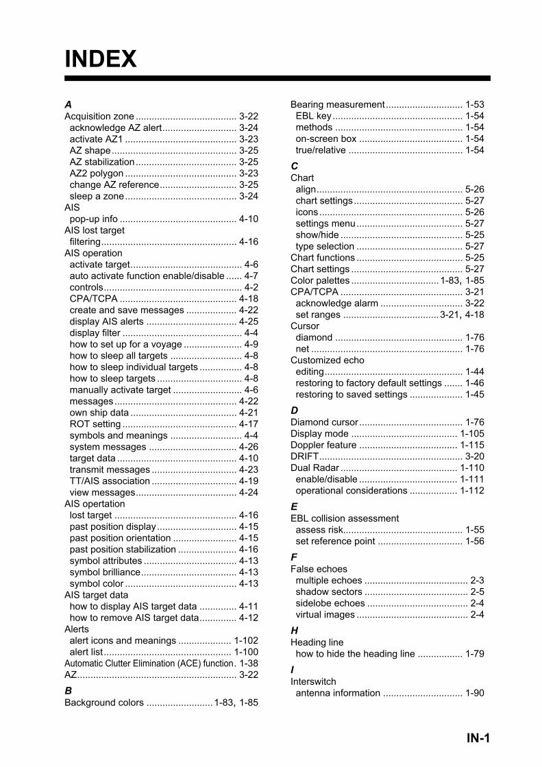
INDEX
AAcquisition zone ...................................... 3-22acknowledge AZ alert............................ 3-24activate AZ1 .......................................... 3-23AZ shape............................................... 3-25AZ stabilization...................................... 3-25AZ2 polygon .......................................... 3-23change AZ reference............................. 3-25sleep a zone.......................................... 3-24
AISpop-up info ............................................ 4-10
AIS lost targetfiltering................................................... 4-16
AIS operationactivate target.......................................... 4-6auto activate function enable/disable ...... 4-7controls.................................................... 4-2CPA/TCPA ............................................ 4-18create and save messages ................... 4-22display AIS alerts .................................. 4-25display filter ............................................. 4-4how to set up for a voyage ...................... 4-9how to sleep all targets ........................... 4-8how to sleep individual targets ................ 4-8how to sleep targets ................................ 4-8manually activate target .......................... 4-6messages.............................................. 4-22own ship data ........................................ 4-21ROT setting ........................................... 4-17symbols and meanings ........................... 4-4system messages ................................. 4-26target data ............................................. 4-10transmit messages ................................ 4-23TT/AIS association ................................ 4-19view messages...................................... 4-24
AIS opertationlost target .............................................. 4-16past position display.............................. 4-15past position orientation ........................ 4-15past position stabilization ...................... 4-16symbol attributes ................................... 4-13symbol brilliance.................................... 4-13symbol color .......................................... 4-13
AIS target datahow to display AIS target data .............. 4-11how to remove AIS target data.............. 4-12
Alertsalert icons and meanings .................... 1-102alert list ................................................ 1-100
Automatic Clutter Elimination (ACE) function. 1-38AZ............................................................ 3-22
BBackground colors .........................1-83, 1-85
Bearing measurement............................. 1-53EBL key................................................. 1-54methods ................................................ 1-54on-screen box ....................................... 1-54true/relative ........................................... 1-54
CChartalign....................................................... 5-26chart settings......................................... 5-27icons...................................................... 5-26settings menu........................................ 5-27show/hide .............................................. 5-25type selection ........................................ 5-27
Chart functions ........................................ 5-25Chart settings .......................................... 5-27Color palettes .................................1-83, 1-85CPA/TCPA .............................................. 3-21acknowledge alarm ............................... 3-22set ranges ....................................3-21, 4-18
Cursordiamond ................................................ 1-76net ......................................................... 1-76
Customized echoediting.................................................... 1-44restoring to factory default settings ....... 1-46restoring to saved settings .................... 1-45
DDiamond cursor....................................... 1-76Display mode ........................................ 1-105Doppler feature ..................................... 1-115DRIFT...................................................... 3-20Dual Radar ............................................ 1-110enable/disable ..................................... 1-111operational considerations .................. 1-112
EEBL collision assessmentassess risk............................................. 1-55set reference point ................................ 1-56
FFalse echoesmultiple echoes ....................................... 2-3shadow sectors ....................................... 2-5sidelobe echoes ...................................... 2-4virtual images .......................................... 2-4
HHeading linehow to hide the heading line ................. 1-79
IInterswitchantenna information .............................. 1-90
IN-1

INDEX
LLost target alertenable/disable alert ........................ 3-8, 4-17
MMaintenancemajor parts life expectancy ......................6-4periodic schedule .....................................6-2
Marksbarge mark .............................................1-80delete marks.............................................5-6hide heading line ....................................1-79how to inscribe a mark ..................... 5-4, 5-8INS mark ................................................5-11mark inscription position...........................5-2mark type .................................................5-1origin mark stabilization............................5-9own ship symbol settings .......................1-80radar map marks ......................................5-3show/hide radar map marks.....................5-3show/hide stern mark .............................1-79
Menu operations ......................................1-10main menu .............................................1-10menu layers............................................1-10
NNav datadisplay settings.......................................1-86enable/disable display............................1-87
Net cursor ................................................1-76Noise rejector ...........................................1-40NR............................................................1-40
OObservationbearing accuracy......................................2-3false echoes.............................................2-3range measurement .................................2-3resolution..................................................2-2
Off-center .................................................1-59Orientation modesdescription..............................................1-48selection .................................................1-48
PParallel index lines ...................................1-73bearing and interval................................1-74bearing reference...................................1-74displayed lines........................................1-73length adjustment...................................1-75orientation ..............................................1-75reset .......................................................1-75
Past positionPOSN plotting intervals ................ 3-19, 4-15set points to display...................... 3-19, 4-15show/hide past POSN.................. 3-19, 4-15
Past position display ................................3-19PAST POSN ............................................3-19Performance monitoractivate/deactivate .................................1-93
check radar performance .......................1-95PI..............................................................1-73PI lines .....................................................1-73
RRACON ......................................................2-7Radar map .................................................5-3disable map alignment ................... 5-7, 5-27enable map alignment..............................5-7
Radar Target Enhancer..............................2-7Range and bearing measurement............1-57how to measure......................................1-58
Range measurement................................1-51on-screen box ........................................1-52TTG to VRM...........................................1-53VRM key.................................................1-52VRM units...............................................1-52
Range ringshide/show rings ......................................1-51
Responsibility transfer alert....................1-103RTE............................................................2-7
SSART .........................................................2-5bandwidth.................................................2-7description................................................2-5radar sidelobes.........................................2-7range errors..............................................2-6show/hide SART marks............................2-6
SC carddelete data ...........................................1-108load data ..............................................1-108read data ..............................................1-108save data..............................................1-108
Search and rescure transponder................2-5SET ..........................................................3-20SET DRIFT...............................................3-20Shuttle ferry mode....................................1-18Static trial maneuver ................................3-28Symbolsgeneral radar symbols.........................AP-40IMO map radar symbols......................AP-42radar map............................................AP-41radar(AIS symbols) .............................AP-43radar(TT symbols)...............................AP-43
TTarget alarm.............................................1-71alarm settings.........................................1-72deactivate...............................................1-72mute .......................................................1-72on/off ......................................................1-71setting.....................................................1-71
Target trackingcontrols.....................................................3-2display/remove target data.....................3-11echo referenced speed ............................3-5hide target list.........................................3-12lost target .................................................3-8lost target filter..........................................3-8
IN-2

INDEX
mode selection ........................................ 3-3on-screen box overview .......................... 3-2own ship speed ....................................... 3-5selection criteria .................................... 3-33show target list ...................................... 3-12simulation mode .................................... 3-32sort target list......................................... 3-12symbol brilliance...................................... 3-9symbol color ............................................ 3-9symbols and attributes ............................ 3-9system messages ................................. 3-31
Target trails ............................................. 1-60clutter prevention................................... 1-64hide trails............................................... 1-63narrow trails........................................... 1-63trail erase/restart ................................... 1-63trail gradation ........................................ 1-62trail level ................................................ 1-62trail stabilization..................................... 1-63trail time................................................. 1-61true/relative ........................................... 1-60
Trial maneuverstatic trial ............................................... 3-28
Troubleshootingadvanced troubleshooting ....................... 6-6basic troubleshooting .............................. 6-5diagnostics .............................................. 6-8
TT............................................................ 1-60dual radar behavior ............................. 1-110static trial maneuver .............................. 3-28
VVector modes .......................................... 3-16description............................................. 3-16vector length.......................................... 3-18vector time............................................. 3-18
Video plottercreate waypoints ................................... 5-17delete own ship’s track.......................... 5-15delete waypoints ................................... 5-18display waypoint list .............................. 5-19display waypoint name/number............. 5-19enter waypoints ..................................... 5-17orientation modes.................................... 5-1own ship’s track..................................... 5-12own ship’s track color ............................ 5-14own ship’s track plot interval ................. 5-13radar map................................................ 5-3waypoints .............................................. 5-16
WWave data ............................................... 1-87Wave mode ........................................... 1-114Wave stabilization ................................... 1-86Wiper....................................................... 1-40
IN-3

Declaration of Conformity
Bulgarian(BG)
Spanish(ES)
Czech(CS)
Danish(DA)
German(DE)
Estonian(ET)
Greek(EL)
English(EN)
French(FR)
Croatian(HR)
Italian(IT)
Latvian(LV)
Με την παρούσα η Furuno Electric Co., Ltd., δηλώνει ότι ο προαναφερθένταςραδιοεξοπλισμός πληροί την οδηγία 2014/53/ΕΕ, SI 2017/1206.Το πλήρες κείμενο της δήλωσης συμμόρφωσης EE/UK διατίθεται στην ακόλουθηιστοσελίδα στο διαδίκτυο:
Hereby, Furuno Electric Co., Ltd. declares that the above-mentioned radioequipment type is in compliance with Directive 2014/53/EU, SI 2017/1206.The full text of the EU/UK declaration of conformity is available at the followinginternet address:
Le soussigné, Furuno Electric Co., Ltd., déclare que l'équipement radioélectriquedu type mentionné ci-dessus est conforme à la directive 2014/53/UE, SI 2017/1206.Le texte complet de la déclaration UE/RU de conformité est disponible à l'adresseinternet suivante:
Furuno Electric Co., Ltd. ovime izjavljuje da je gore rečeno radijska oprema tipau skladu s Direktivom 2014/53/EU, SI 2017/1206.Cjeloviti tekst EU/UK izjave o sukladnosti dostupan je na sljedećoj internetskojadresi:
Il fabbricante, Furuno Electric Co., Ltd., dichiara che il tipo di apparecchiaturaradio menzionato sopra è conforme alla direttiva 2014/53/UE, SI 2017/1206.Il testo completo della dichiarazione di conformità UE/RU è disponibile al seguenteindirizzo Internet:
Ar šo Furuno Electric Co., Ltd. deklarē, ka augstāk minēts radioiekārta atbilstDirektīvai 2014/53/ES, SI 2017/1206.
[FAR-2218/FAR-2218-BB/FAR-2228/FAR-2228-BB/FAR-2228-NXT/FAR-2228-NXT-BB/FAR-2238S/FAR-2238S-BB/FAR-2238S-NXT/FAR-2238S-NXT-BB/FAR-2318/FAR-2328/FAR-2328-NXT/FAR-2328W/FAR-2338SW/FAR-2338S/FAR-2338S-NXT Marine Radar]
EL/GB vastavusdeklaratsiooni täielik tekst on kättesaadav järgmiselinternetiaadressil:
С настоящото Furuno Electric Co., Ltd. декларира, че гореспоменат типрадиосъоръжение е в съответствие с Директива 2014/53/ЕС, SI 2017/1206.Цялостният текст на EC/UK декларацията за съответствие може да се намерина следния интернет адрес:
Por la presente, Furuno Electric Co., Ltd. declara que el tipo de equipo radioeléctricoarriba mencionado es conforme con la Directiva 2014/53/UE, SI 2017/1206.
El texto completo de la declaración de conformidad de la EU/UK está disponible enla siguiente dirección Internet:
Tímto Furuno Electric Co., Ltd. prohlašuje, že výše zmíněné typ rádiovéhozařízení je v souladu se směrnicí 2014/53/EU, SI 2017/1206.Úplné znění EU/SK prohlášení o shodě je k dispozici na této internetové adrese:
Hermed erklærer Furuno Electric Co., Ltd., at ovennævnte radioudstyr er ioverensstemmelse med direktiv 2014/53/EU, SI 2017/1206.EU/UK-overensstemmelseserklæringens fulde tekst kan findes på følgendeinternetadresse:
Hiermit erklärt die Furuno Electric Co., Ltd., dass der oben genannteFunkanlagentyp der Richtlinie 2014/53/EU, SI 2017/1206 entspricht.Der vollständige Text der EU/UK-Konformitätserklärung ist unter der folgendenInternetadresse verfügbar:
Käesolevaga deklareerib Furuno Electric Co., Ltd., et ülalmainitud raadioseadmetüüp vastab direktiivi 2014/53/EL, SI 2017/1206 nõuetele.
Lithuanian(LT)
Hungarian(HU)
Maltese(MT)
Dutch(NL)
Polish(PL)
Portuguese(PT)
Romanian(RO)
Slovak(SK)
Slovenian(SL)
Finnish(FI)
Swedish(SV)
Online Resourcehttp://www.furuno.com/en/support/red_doc
Notice for radiated immunity
O(a) abaixo assinado(a) Furuno Electric Co., Ltd. declara que o mencionadoacima tipo de equipamento de rádio está em conformidade com a Diretiva2014/53/UE, SI 2017/1206.
Den fullständiga texten till EU/Storbritannien-försäkran om överensstämmelse finnspå följande webbadress:
The test for the radiated immunity is performed up to 2.7 GHz only without the special conditionof spot frequency being applied. There is a chance that this equipment may interfere withallocated services in the frequency range of 2.7 GHz to 6 GHz, particularly in harbors, rivers,lake banks, etc.
Úplné EÚ/SK vyhlásenie o zhode je k dispozícii na tejto internetovej adrese:
Furuno Electric Co., Ltd. potrjuje, da je zgoraj omenjeno tip radijske opremeskladen z Direktivo 2014/53/EU, SI 2017/1206.
Furuno Electric Co., Ltd. vakuuttaa, että yllä mainittu radiolaitetyyppi ondirektiivin 2014/53/EU, SI 2017/1206 mukainen.EU/UK-vaatimustenmukaisuusvakuutuksen täysimittainen teksti on saatavillaseuraavassa internetosoitteessa:
Härmed försäkrar Furuno Electric Co., Ltd. att ovan nämnda typ avradioutrustning överensstämmer med direktiv 2014/53/EU, SI 2017/1206.
Celotno besedilo izjave EU/ZK o skladnosti je na voljo na naslednjem spletnemnaslovu:
Prin prezenta, Furuno Electric Co., Ltd. declară că echipamentul radio menționatmai sus este în conformitate cu Directiva 2014/53/UE, SI 2017/1206.Textul integral al declarației de conformitate UE/RU este disponibil la următoareaadresă internet:
Furuno Electric Co., Ltd. týmto vyhlasuje, že vyššie spomínané rádiovézariadenie typu je v súlade so smernicou 2014/53/EÚ, SI 2017/1206.
O texto integral da declaração de conformidade da EU/UK está disponível noseguinte endereço de Internet:
It-test kollu tad-dikjarazzjoni ta' konformità tal-UE/RU huwa disponibblif'dan l-indirizz tal-Internet li ġej:
Hierbij verklaar ik, Furuno Electric Co., Ltd., dat het hierboven genoemde typeradioapparatuur conform is met Richtlijn 2014/53/EU, SI 2017/1206.De volledige tekst van de EU/VK-conformiteitsverklaring kan worden geraadpleegdop het volgende internetadres:
Furuno Electric Co., Ltd. niniejszym oświadcza, że wyżej wymieniony typurządzenia radiowego jest zgodny z dyrektywą 2014/53/UE, SI 2017/1206.Pełny tekst deklaracji zgodności UE/UK jest dostępny pod następującym adreseminternetowym:
Aš, Furuno Electric Co., Ltd., patvirtinu, kad pirmiau minėta radijo įrenginių tipasatitinka Direktyvą 2014/53/ES, SI 2017/1206.Visas ES/JK atitikties deklaracijos tekstas prieinamas šiuo interneto adresu:
Furuno Electric Co., Ltd. igazolja, hogy fent említett típusú rádióberendezésmegfelel a 2014/53/EU, SI 2017/1206 irányelvnek.Az EU/EK-megfelelőségi nyilatkozat teljes szövege elérhető a következő internetescímen:
B'dan, Furuno Electric Co., Ltd., niddikjara li msemmija hawn fuq-tip ta' tagħmirtar-radju huwa konformi mad-Direttiva 2014/53/UE, SI 2017/1206.
Pilns ES/AK atbilstības deklarācijas teksts ir pieejams šādā interneta vietnē: