OPERATOR'S MANUAL - Furuno USA
157
SATELLITE SPEED LOG GS-100 OPERATOR'S MANUAL www.furuno.com Model
-
Upload
khangminh22 -
Category
Documents
-
view
1 -
download
0
Transcript of OPERATOR'S MANUAL - Furuno USA

SATELLITE SPEED LOG
GS-100
OPERATOR'S MANUAL
www.furuno.com
Model

The paper used in this manual
is elemental chlorine free.
・FURUNO Authorized Distributor/Dealer
9-52 Ashihara-cho,
Nishinomiya, 662-8580, JAPAN
A : MAY 2014Printed in JapanAll rights reserved.
K : MAY 28, 2019
Pub. No. OME-72790-K
(YOTA ) GS-100
0 0 0 1 7 8 6 2 4 1 9

i
IMPORTANT NOTICE
General• This manual has been authored with simplified grammar, to meet the needs of international users.• The operator of this equipment must read and follow the descriptions in this manual. Wrong oper-
ation or maintenance can cancel the warranty or cause injury.• Do not copy any part of this manual without written permission from FURUNO.• If this manual is lost or worn, contact your dealer about replacement.• The contents of this manual and equipment specifications can change without notice.• The example screens (or illustrations) shown in this manual can be different from the screens you
see on your display. The screens you see depend on your system configuration and equipment settings.
• Save this manual for future reference.• Any modification of the equipment (including software) by persons not authorized by FURUNO will
cancel the warranty.• The following concern acts as our importer in Europe, as defined in DECISION No 768/2008/EC.
- Name: FURUNO EUROPE B.V.- Address: Ridderhaven 19B, 2984 BT Ridderkerk, The Netherlands
• All brand and product names are trademarks, registered trademarks or service marks of their re-spective holders.
How to discard this productDiscard this product according to local regulations for the disposal of industrial waste. For disposal in the USA, see the homepage of the Electronics Industries Alliance (http://www.eiae.org/) for the correct method of disposal.
How to discard a used batterySome FURUNO products have a battery(ies). To see if your product has a battery, see the chapter on Maintenance. If a battery is used, tape the + and - terminals of the battery before disposal to pre-vent fire, heat generation caused by short circuit.In the European UnionThe crossed-out trash can symbol indicates that all types of batter-ies must not be discarded in standard trash, or at a trash site. Take the used batteries to a battery collection site according to your na-tional legislation and the Batteries Directive 2006/66/EU.
In the USAThe Mobius loop symbol (three chasing arrows) indicates that Ni-Cd and lead-acid rechargeable batteries must be recycled. Take the used batteries to a battery collection site according to local laws.
In the other countriesThere are no international standards for the battery recycle symbol. The number of symbols can in-crease when the other countries make their own recycle symbols in the future.
Cd
Ni-Cd Pb

SAFETY INSTRUCTIONS
Indicates a condition that can cause death or serious injury if not avoided.
Indicates a condition that can cause minor or moderate injury if not avoided.
WARNING
CAUTION
WARNING CAUTIONDo not disassemble or modifythe equipment.
Fire, electrical shock or seriousinjury can occur.
Turn off the power immediately ifwater leaks into the equipment orsmoke or fire is coming from theequipment.
Failure to turn off the equipment cancause fire or electrical shock.Contact a FURUNO agent for service.
Handle the display carefully.
Injury can result if the display breaks.
Use the correct fuse.
A wrong fuse can cause fire or serious damage to the equipment.
Do not connect/disconnect the signal cable while turning the power on.
The unit may be damaged.
About the TFT LCDThe TFT LCD is constructed using the latest LCD techniques, and displays 99.99% of its pixels. The remaining 0.01% of the pixels may drop out or blink, however this is not an indication of malfunction.
Warning, Caution Prohibitive Action Mandatory Action
Safety Instructions for the Operator
No single navigation aid (includingthis unit) should ever be relied upon as the exclusive means for navigating your vessel.
The navigator is responsible for checking all aids available to confirm his position. Electronic aids are intended to assist, not replace, the navigator.
ii

SAFETY INSTRUCTIONS
WARNING CAUTION
Turn off the power at the switchboard before beginning the installation.
Fire or electrical shock can result if the power is left on.
Safety Instructions for the Installer
Be sure that the power supply is compatible with the voltage rating of the equipment.
Connection of an incorrect power supply can cause fire or damage the equipment.
Ground the equipment to prevent electrical shock and mutual interference.
Observe the following compass safe distances to prevent interference to a magnetic compass:
Standard compass
Steering compass
Antenna UnitDisplay UnitJunction Box
Type
GS-1001B
GS-1002
GS-1003
0.70 m 0.45 m
0.60 m 0.40 m
0.75 m 0.50 m
Display Unit (option)
DS-600 0.60 m 0.40 m
Have a qualified serviceman do the installation.
Only qualified personnel should work inside the equipment.
Use the specified power cable.
Fire can result if an incorrect cable is used.
The mounting location for the units must satisfy the following conditions:
- Away from rain and water splash- Out of direct sunlight- Away from air conditioner vents- Moderate and stable in temperature
and humidity
iii

TABLE OF CONTENTS
FOREWORD ..................................................................................................................viiSYSTEM CONFIGURATIONS........................................................................................ixEQUIPMENT LISTS.........................................................................................................x
1. OPERATIONAL OVERVIEW .................................................................................1-11.1 Controls...................................................................................................................... 1-11.2 How to Turn the Power On/Off................................................................................... 1-31.3 How to Adjust the Brilliance of the Display and Panel ............................................... 1-41.4 Main Menu Overview ................................................................................................. 1-51.5 List Overview.............................................................................................................. 1-6
2. DISPLAYS..............................................................................................................2-12.1 Display Modes............................................................................................................ 2-12.2 How to Select the Background Color ......................................................................... 2-22.3 Navigation Display ..................................................................................................... 2-22.4 Integrity Display.......................................................................................................... 2-5
3. SETTINGS..............................................................................................................3-13.1 Display Menu ............................................................................................................. 3-1
3.1.1 How to set the time for smoothing.................................................................. 3-13.1.2 How to set the current direction and wind angle ............................................ 3-13.1.3 How to use the "cm/sec" display .................................................................... 3-2
3.2 Trip Menu ...................................................................................................................3-33.2.1 How to calculate the trip distance .................................................................. 3-33.2.2 How to set the total distance.......................................................................... 3-3
3.3 System Menu ............................................................................................................. 3-43.3.1 How to change the user password................................................................. 3-43.3.2 SNTP setting .................................................................................................. 3-5
3.4 How to Set the Demo Mode ....................................................................................... 3-53.5 GNSS Menu ............................................................................................................... 3-7
3.5.1 How to set the positioning condition............................................................... 3-73.6 Other Setting Menus for Antenna Unit ....................................................................... 3-8
3.6.1 How to reset the sensor ................................................................................. 3-83.6.2 How to clear the sensor settings .................................................................... 3-83.6.3 How to set the time for dead reckoning.......................................................... 3-83.6.4 How to restart heading data output after restoration of heading data ............ 3-9
3.7 Device List.................................................................................................................. 3-93.7.1 How to open the device list from the menu.................................................... 3-93.7.2 Device menu ................................................................................................ 3-10
3.8 I/O Menu .................................................................................................................. 3-113.8.1 How to set the output data 1, 2, 3 or 4 ......................................................... 3-113.8.2 How to set the sentences to output to the Ethernet ..................................... 3-123.8.3 How to select the input data......................................................................... 3-133.8.4 Line monitor log............................................................................................ 3-143.8.5 How to set the digit number for sentences................................................... 3-16
3.9 How to Clear the Memory ........................................................................................ 3-16
4. NOTICES................................................................................................................4-14.1 Audio Notice Type...................................................................................................... 4-14.2 Ship Speed Notice ..................................................................................................... 4-14.3 Trip Notice.................................................................................................................. 4-2
iv

TABLE OF CONTENTS
5. ALERTS .................................................................................................................5-15.1 Overview.....................................................................................................................5-15.2 Alert List......................................................................................................................5-55.3 Alert Log .....................................................................................................................5-65.4 How to Acknowledge Alerts........................................................................................5-65.5 Responsibility Transfer Alert.......................................................................................5-7
6. BERTHING DISPLAY ............................................................................................6-16.1 Berthing Display for the GS-100.................................................................................6-16.2 Controls for the Display Unit DS-600..........................................................................6-36.3 Various Settings .........................................................................................................6-46.4 Display Range ............................................................................................................6-7
6.4.1 How to select a range.....................................................................................6-76.4.2 How to pre-set ranges ....................................................................................6-8
6.5 Track...........................................................................................................................6-86.5.1 Types of tracks ...............................................................................................6-86.5.2 How to select the type of track to display .......................................................6-96.5.3 How to select the past track format ..............................................................6-106.5.4 How to select the predicted track plot interval ..............................................6-10
6.6 How to Show, Hide Navigation Data and 3-axis Speed Data...................................6-106.7 Berthing Line ............................................................................................................6-11
6.7.1 How to register a berthing line......................................................................6-116.7.2 How to edit a berthing line............................................................................6-136.7.3 How to delete a point or a line......................................................................6-136.7.4 How to send the berthing lines data to DS-600............................................6-14
7. MAINTENANCE, TROUBLESHOOTING ..............................................................7-17.1 Maintenance...............................................................................................................7-17.2 Fuse Replacement .....................................................................................................7-17.3 Consumable Parts ......................................................................................................7-27.4 Troubleshooting..........................................................................................................7-37.5 Equipment Information ...............................................................................................7-47.6 Self Test .....................................................................................................................7-57.7 Backup........................................................................................................................7-77.8 Replacement Parts Settings .......................................................................................7-8
7.8.1 How to reset the operating time for replacement parts ..................................7-87.8.2 Correction for the replaced sensor board.......................................................7-9
8. INSTALLATION .....................................................................................................8-18.1 Mounting.....................................................................................................................8-1
8.1.1 Display unit GS-1002 .....................................................................................8-18.1.2 Antenna unit GS-1001....................................................................................8-38.1.3 Junction box GS-1003....................................................................................8-7
8.2 Wiring .........................................................................................................................8-88.2.1 Junction box ...................................................................................................8-98.2.2 Display unit ...................................................................................................8-118.2.3 Antenna unit .................................................................................................8-128.2.4 How to connect the Cable Replacement Kit (OP20-50) ...............................8-138.2.5 How to secure and waterproof the cable connections..................................8-16
8.3 Adjustments..............................................................................................................8-178.3.1 Language .....................................................................................................8-178.3.2 Device mode ................................................................................................8-178.3.3 Unit ...............................................................................................................8-178.3.4 Datum...........................................................................................................8-188.3.5 Time format ..................................................................................................8-188.3.6 Equipment ID................................................................................................8-19
v
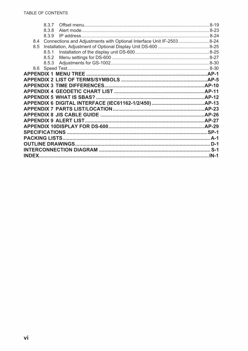
TABLE OF CONTENTS
8.3.7 Offset menu.................................................................................................. 8-198.3.8 Alert mode.................................................................................................... 8-238.3.9 IP address.................................................................................................... 8-24
8.4 Connections and Adjustments with Optional Interface Unit IF-2503........................ 8-248.5 Installation, Adjustment of Optional Display Unit DS-600 ........................................ 8-25
8.5.1 Installation of the display unit DS-600.......................................................... 8-258.5.2 Menu settings for DS-600 ............................................................................ 8-278.5.3 Adjustments for GS-1002............................................................................. 8-30
8.6 Speed Test............................................................................................................... 8-30APPENDIX 1 MENU TREE .......................................................................................AP-1APPENDIX 2 LIST OF TERMS/SYMBOLS ..............................................................AP-5APPENDIX 3 TIME DIFFERENCES........................................................................AP-10APPENDIX 4 GEODETIC CHART LIST .................................................................AP-11APPENDIX 5 WHAT IS SBAS? ..............................................................................AP-12APPENDIX 6 DIGITAL INTERFACE (IEC61162-1/2/450) ......................................AP-13APPENDIX 7 PARTS LIST/LOCATION..................................................................AP-23APPENDIX 8 JIS CABLE GUIDE ...........................................................................AP-26APPENDIX 9 ALERT LIST......................................................................................AP-27APPENDIX 10DISPLAY FOR DS-600.....................................................................AP-29SPECIFICATIONS .....................................................................................................SP-1PACKING LISTS..........................................................................................................A-1OUTLINE DRAWINGS.................................................................................................D-1INTERCONNECTION DIAGRAM ................................................................................ S-1INDEX..........................................................................................................................IN-1
vi

FOREWORD
A Word to the Owner of the GS-100
Congratulations on your choice of the FURUNO GS-100 Satellite Speed Log. We are confident you will see why the FURUNO name has become synonymous with quality and reliability.
Since 1948, FURUNO Electric Company has enjoyed an enviable reputation for innovative and dependable marine electronics equipment. This dedication to excellence is furthered by our ex-tensive global network of agents and dealers.
Your equipment is designed and constructed to meet the rigorous demands of the marine envi-ronment. However, no machine can perform its intended function unless properly installed and maintained. Please carefully read and follow the operation and maintenance procedures set forth in this manual.
We would appreciate feedback from you, the end-user, about where we are achieving our purpos-es.
Thank you for considering and purchasing FURUNO equipment.
Features
The main features of the GS-100 are as shown below.
• High-resolution color LCD
• Comprehensive navigation data displays
• Highly accurate speed data
• External USB memory capability (for maintenance)
• Vessel speed for port and starboard at any position of the hull by built-in satellite compass
• Optional DS-600 (display unit) can be connected to the GS-100 to add berthing support capa-bility
• Notices: Ship speed, Trip
• Alerts: Warning, Caution
• Ethernet port for connection to a LAN
Software used in this product
This equipment uses the following open source software.
This product includes software to be licensed under the GNU General Public License (GPL) ver-sion 2.0, GNU Lesser General Public Software License (LGPL) version 2.0, Apache, BSD and oth-ers. The program(s) is/are free software(s), and you can copy it and/or redistribute it and/or modify it under the terms of the GPL version 2.0 or LGPL version 2.0 as published by the Free Software Foundation. Please access to the following URL if you need source codes: https://www.furuno.co.jp/en/contact/cnt_oss_e01.html
vii

FOREWORD
Program No.
**: Minor change
CE declaration
With regards to CE declarations, please refer to our website (www.furuno.com) for further infor-mation about RoHS conformity declarations.
Unit Name No.GS-1001B GNSS 48505230**
OS 2051590-01.**APL 2051591-01.**
GS-1002 Boot 2051551-02.**APL 2051552-03.**
DS-600 Starter 6652000-01.**Booter 6652001-02.**Main 6652002-02.**
viii

ix
SYSTEM CONFIGURATIONS
Basic configuration is shown with solid line.
Antenna Unit GS-1001B
Display Unit GS-1002
Network Equipment, HUB, etc.
Nav Equipment, IF-2503, etc.
Rectifier PR-62
Environmental categoryAntenna unit: Exposed to the weatherAll other units: Protected from the weather
Junction Box GS-1003
24 VDC
Rectifier PR-240
110/220 VAC1ø, 50/60 Hz
100-115/220-230 VAC1ø, 50/60 Hz
USB Flash Memory
MENU ESC ENT
LIST DISPLAY
1 2 3
4 5 6
7 8 9
ACK 0 BRILL
DS-600 (Sub Display)

EQUIPMENT LISTS
Standard supply
Optional supply
Name Type Code No. Qty RemarksAntenna Unit GS-1001B-A - Select
oneFor GNSS (GPS, GLONASS, Gal-ileo, QZSS) For cable 30/40/50m with armor
GS-1001B-N - For GNSS (GPS, GLONASS, Gal-ileo, QZSS)For cable 15/30m without armor
Display Unit GS-1002 - 1Junction Box GS-1003 - 1InstallationMaterials
CP20-03503 001-531-980 Select one
For Antenna Unit CP20-03502 001-265-740CP20-03600 000-024-964 1 For Display UnitCP20-03701 001-265-650 1 For Junction BoxCP20-03820 000-024-980 Select
one30 m cable, w/armor
CP20-03830 000-024-981 40 m cable, w/armorCP20-03840 000-024-982 50 m cable, w/armorCP20-03870 000-035-909 15 m cable, w/o armorCP20-03880 000-035-910 30 m cable, w/o armor
Spare Parts SP20-01501 001-265-820 1 For Junction Box (See the packing list at the back of this manual.)
Accessories FP20-01100 000-042-239 1 LCD Cleaning Cloth for display unit(Type: 19-028-3125-6,Code No.: 100-360-676-10)
Name Type Code No. Qty RemarksFlush Mount Kit OP20-40 001-243-890 1 For S-typeFlush Mount Kit OP20-41 001-243-900 1 For F-typeRectifier PR-62 - 1 For 110/220 VACAC/DC Power Supply Unit
PR-240 - 1 For 100-115/200-230 VAC
Interface Unit IF-2503 - 1Bird-Repellent Fixture
OP20-36 004-380-830 1 Four piecesOP20-37 004-380-840 1 Single.
Display Unit DS-600-S - 1Bracket Assem-bly with Knobs
OP26-8 000-016-313 1 For DS-600-S
x

EQUIPMENT LISTS
Cable Conversion kit
OP20-50 001-506-810 1 Replacement kit for GS-1001 (MJ-A10SPF0015-xxxC)
Contents- Waterproof relay box (JPBS 06)- 120 Ω Lead resistance (03S9939)- FRU-NMEA-PFF-060- Vinyl tape (0.2X19X10000MM Black, 000-172-691-10)- Self-bonding tape (No.15, 000-174-646-10)
Cable Assy. MJ-A6SPF0003-050C 000-154-054-10 1 5 m, For DATA1, 2 or 3MJ-A6SPF0011-050C 000-159-690-10 1 5 m, For DATA1, 2 or 3MJ-A6SPF0011-100C 000-159-691-10 1 10 m, For DATA1, 2 or 3MJ-A6SPF0011-200C 001-244-120 1 20 m, For DATA1, 2 or 3MJ-A6SPF0012-050C 000-154-053-10 1 5 m, For DATA1, 2 or 3MJ-A6SPF0012-100C 000-154-037-10 1 10 m, For DATA1, 2 or 3MJ-A6SPF0012-200C 001-244-130 1 20 m, For DATA1, 2 or 3MJ-A7SPF0003-050C 000-159-688-10 1 5 m, For DATA 4MOD-WPAS0001-030+ 000-164-609-10 1 3 m, Between Display Unit
and Switching HubM12-05BFFM-060 001-105-800-10 1 6 m, Between Display Unit
and Junction BoxMJ-A3SPF0015-060C 001-265-430 1 6 m, For powerMJ-A10SPF0016-010C 001-266-040 1 1 m, For Antenna Unit80-580-0008 000-193-291-10 1 0.3m, In-line terminator
For cable w/armorANT-DN18WAPVC-300 001-277-330 1 30 m, w/armor, Between An-
tenna Unit and Junction BoxANT-DN18WAPVC-400 001-277-340 1 40 m,w/armor, Between An-
tenna Unit and Junction BoxANT-DN18WAPVC-500 001-277-350 1 50 m,w/armor, Between An-
tenna Unit and Junction BoxMJ-A10SPF0015-150C 000-166-891-11 1 15 m, w/o armor, Between
Antenna Unit and Junction BoxFor GS-1001-N
MJ-A10SPF0015-300C 000-166-892-11 1 30 m, w/o armor, Between Antenna Unit and Junction BoxFor GS-1001-N
FRU-NMEA-NFF-R15 000-194-637-11 1 15 m, w/o armor, Between Antenna Unit and Junction BoxFor GS-1001B
FRU-NMEA-NFF-R30 000-194-638-11 1 30 m, w/o armor, Between Antenna Unit and Junction BoxFor GS-1001B
Name Type Code No. Qty Remarks
xi

EQUIPMENT LISTS
This page is intentionally left blank.
xii

1. OPERATIONAL OVERVIEW
1.1 Controls
The keys are arranged according to the function.
No. KeyFunction
Menu screen Display mode1 MENU ESC • Closes the menu.
• Quits current operation.Opens the menu.
2 ENT Confirms a selection. Switches the screen between main (digital navigation data) and sub (graphic screen).
3 Cursorpad • or : Select the menu item.• : Returns one layer in multi-layer
menu.• : Go to one layer in multi-layer menu.
or : Switches display on the in-tegrity display.
4 LIST • Opens the list.• Switches the list (any display → active alert → alert log → device list → any
display). Long-press to switch the list in reverse order.5 DISPLAY Opens the display mode. Switches the screen between THD
and SDME modes.6 0 to 9 • Selects and confirms the menu item.
• Enters a numeric character.• Long-press 0 key to reset the trip
distance.• Long-press 1 key to switch the
unit of the own ship’s speed be-tween [cm/sec] and [Preset Unit] set in paragraph 8.3.3.
7 ACK Acknowledges an unacknowledged alert when the pop-up appears.8 BRILL Opens the brilliance adjustment window.
Adjusts the display brilliance when the adjustment window is open.9 (Power) Turn the power on and off.
MENU ESC ENT
LIST DISPLAY
1 2 3
4 5 6
7 8 9
ACK 0 BRILL
Operation keys
Function keys
11
33
44 22
55
66
77
88
99
MENU ESC ENT
LIST DISPLAY
1 2 3
4 5 6
7 8 9
ACK 0 BRILL
1010
1-1

1. OPERATIONAL OVERVIEW
Key sound
When you operate a key, a single beep sounds. If you do not need the key beep, de-activate the beep sound as follows (see section 1.4):
1. Press the MENU ESC key to open the main menu.
2. Select [2 Speed/Trip Setting] then [4 Sound].
3. Select [2 Key Sound].
4. Select [2 Off].
5. Press the MENU ESC key to close the main menu.
10 USB port For connection of USB flash memory.
No. KeyFunction
Menu screen Display mode
1-2

1. OPERATIONAL OVERVIEW
1.2 How to Turn the Power On/Off
Press the key to turn the display unit on. The start-up screen appears for 30 sec-onds then the screen set at the [6 Device Mode] menu (see paragraph 8.3.2) appears.
Note: The screen refreshes slower in low ambient temperature.
To turn the display unit off, press the key.
Antenna unit power is turned on/off at the ship's mains.
Self test results
Start-up screen
SDME mode THD mode
2051552-03.xx48505230xx2051591-01.xx
GNSS
GN 3D- GN 3D-
1-3

1. OPERATIONAL OVERVIEW
1.3 How to Adjust the Brilliance of the Display and Panel1. Press the BRILL key to show the following setting window.
2. To adjust the display brilliance, press the cursorpad ( or ) or the BRILL key (setting range: 0 to 15, default: 14 for day mode/6 for night mode).
3. To adjust the panel brilliance, press the cursorpad ( or ) (setting range: 0 to 9, default: 7 for day and night modes).
4. Press the MENU ESC key to close the setting window.
Note 1: The default settings for night mode is 6 for [Display] and 7 for [Panel]. If the display is difficult to see when switching to the night mode, press the cursorpad ( ) to increase the display brilliance.
Note 2: When you switch the brilliance mode, the last-used brilliance for the selected mode is set.
Note 3: When the brilliance is preset, the background color is also preset (see section 2.2). So both the brilliance and the background color are restored to the de-fault when long-pressing the ENT key.
Switch the color mode between day mode and night mode.Long-press to restore the settings to default of day mode.
1-4

1. OPERATIONAL OVERVIEW
1.4 Main Menu Overview1. Press the MENU ESC key to open the main menu.
2. Press the cursorpad ( or ) to select a menu item then press the ENT key. You can also select a menu item by pressing the numeric keys. This manual states this operating procedure as “Select [No. menu name].” The menu items that have a indicate additional menus.
3. Select an option.
4. Press the MENU ESC key to close the main menu.
Triangles indicate additional menus.
GN 3D-
Second layer Third layer
GN 3D- GN 3D-
1-5
1. OPERATIONAL OVERVIEW
1.5 List OverviewThe LIST key displays the active alert list, alert log list and device list, in the sequence shown below.
Any display Active Alert
Alert LogDevice List
: Short-press the LIST key: Long-press the LIST key
000001
211011 2051591- xx.xx
1002GS- 2051552- xx.xx
GN 3D- GN 3D-
GN 3D-GN 3D-
1-6

2. DISPLAYS
2.1 Display ModesThe GS-100 has two main display modes. The SDME (Speed and Distance Measur-ing Equipment) mode measures speed and distance. The THD (Transmitting Heading Device) outputs heading data to external equipment. You can switch between the two display modes with the DISPLAY key. The mode is indicated at the top left corner as follows:
*: See paragraph 8.3.2.
Each mode has a main (digital navigation data) and sub (graphic) display, and you can switch between them with the ENT key. For a description of the sub displays, see sec-tions 2.3 and 2.4.
The example below shows sample screens when the SDME mode is the “Device Mode”. The screens for the THD mode are similar.
The trip distance can be reset from the main screen of the SDME mode. Long-press (more than one second) the 0 key to reset the trip distance.
Indication DescriptionMode selected on the [Device Mode]* menu.
Top: Currently selected mode.Bottom: Mode selected on the [Device Mode]* menu.
Press the ENT key.
Main (digital navigation data) Sub (graphic screen: Navigation)
Press the ENT key.
Sub (graphic screen: Integrity)
Press the DISPLAY key.
Main (digital navigation data)
GN 3D- GN 3D-
GN 3D-
2-1

2. DISPLAYS
2.2 How to Select the Background ColorYou can select the background color to suit lighting conditions or environment (see section 1.3).
1. Press the MENU ESC key to open the main menu.
2. Select [1 Display] then [1 Background Color].
3. Select [1 White] or [2 Black].
4. Press the MENU ESC key to close the main menu.
2.3 Navigation DisplayThe navigation display in the SDME mode shows various navigation data.
How to select the data to display
You can select the data to display on the windows 1 to 5.
1. Press the MENU ESC key to open the main menu.
2. Select [1 Display] then [2 Navigation Display].
Window1
Window2
Window3
Window4
Window5
GN 3D-
2-2

2. DISPLAYS
3. Select [1 Window1].
4. Select [1 Roll/Pitch], [2 SDME] or 3 [Blank].
5. Select the options for windows 2 to 5 as well.
Note: The options [SDME], [Current], [Wind] and [Depth] require appropriate ex-ternal sensors.
6. Press the MENU ESC key to close the main menu.
[Roll/Pitch], [Position], [Time&Date], [Heave] or [Trip Time] selected
Displays external input data for doppler SOG/COG.
Window1 Window2
Window3 Window4 Window5
Atm: Atmospheric pressureTemp: Air temperature
Heading
Status indication
Roll
Ship’s position
Time and date
Heave
Rate of turn
GNSS speed over ground and course over ground
Trip time
Trip distance
Total distance
Calculation state(Start up, Normal, DR (Dead-Reckoning), Stopped (HDG stopped),SYS FAULT (System fault))HDOP: 2D
PDOP: 3D
Satellite number common to ANT1 and ANT2
Spinner rotates when the equipment is functioning normally.
: Starboard: Port( (
Pitch
: Starboard: Port( (
: Up: Down( (
See page AP-8.
GN 3D-
2-3

2. DISPLAYS
[SDME], [Current], [Wind], [Depth] or [Drift] selected
Note: When there is no external input or the input value is invalid, the applicable win-dow is blank. When the input value is valid, ":EXT" is displayed.
Status indications
No.Indication
System2D positioning 3D positioning
1 GP-2D GP-3D GPS2 GP-S2D GP-S3D GPS + SBAS3 GN-2D GN-3D Multi4 GN-S2D GN-S3D Multi + SBAS5 No Fix No fixed
Heading
Status indication
External doppler speed over ground and course over ground
External current speed and direction
External wind speed and direction*
External depth
GNSS speed over ground and course over ground
Drift
Trip distanceTotal distance
Spinner rotates when the equipment is functioning normally.
HDOP: 2DPDOP: 3D
* [WIND T]: True, [WIND TH]: Theoretical, [WIND R]: Relative (See paragraph 3.1.2.)
: Starboard: Port( (
Rate of turn: Starboard: Port( (
Calculation state(Start up, Normal, DR (Dead-Reckoning), Stopped (HDG stopped),SYS FAULT (System fault)) See page
AP-8.
Satellite number common to ANT1 and ANT2
GN 3D-
2-4

2. DISPLAYS
3-axis speed display
The circle at the center of the display shows the own ship’s speed.
2.4 Integrity DisplayThe integrity display, available in the THD mode, provides information about GNSS satellite position and signal quality. There are three integrity displays: GNSS, graph for satellite angle and graph for signal noise ratio.
Use the cursorpad ( or ) to change the displays, in the following sequence.
*: These triangles are displayed in the following conditions:• Current direction: Selected [Current] in the [Window2] menu.• Wind velocity: Selected [Wind] in the [Window3] menu.• Drift angle: Selected [Drift] in the [Window5] menu.
**: When the current indication method is [Flow from] (set on the [Current] menu, see paragraph 3.1.2), the blue icon for current direction turns 180° and is displayed outside of the circle.***: The speed value at the position where the antenna is installed is more accurate.
N, E, S, W: Bearing scale Stern
BowPicture of ship
Bow velocity
Wind velocity* (Magenta)
N
Broadside speed at stern position***
Speed for heading
Drift angle* (Brown)
Current direction*/** (Blue)
Broadside speed at bow position***
Heading velocity
Stern velocity
GNSS
Graph: signal noise ratio
Graph: satellite angle
: Press the ▲ key. : Press the ▼ key.
2-5
2. DISPLAYS
GNSS
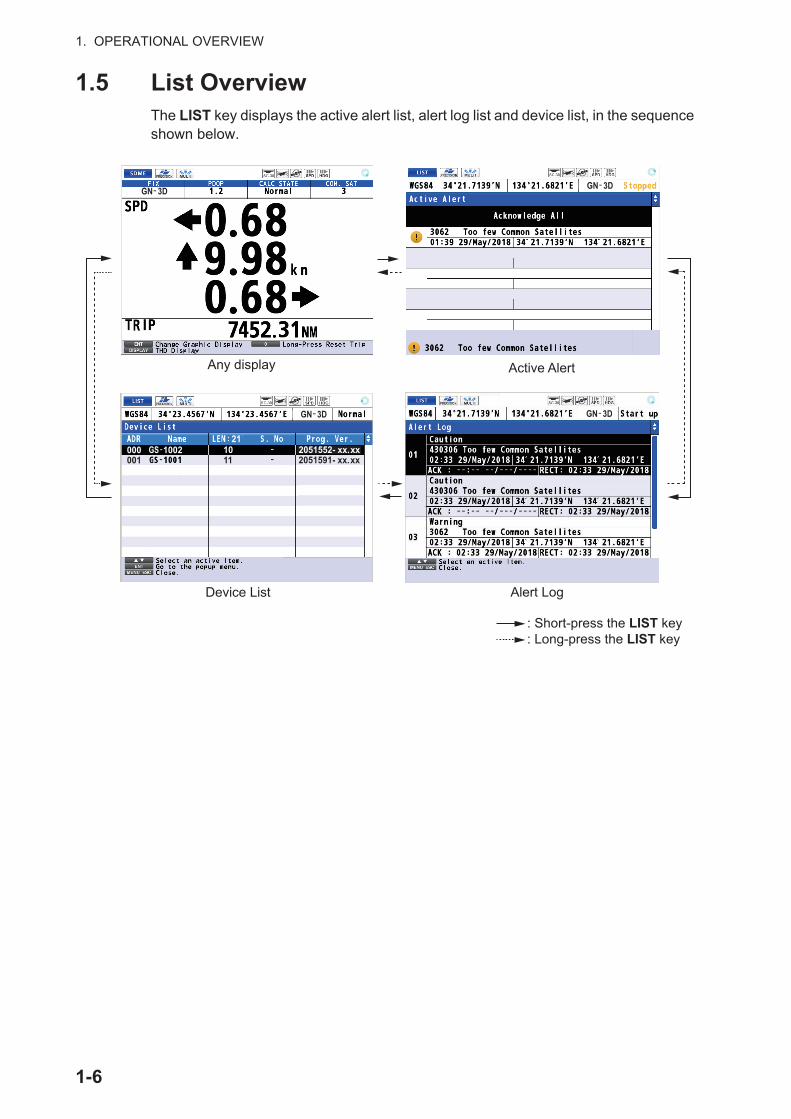
The GNSS display shows the condition of satellite positioning system. Number, azi-muth and elevation angle of all satellites (if applicable) in view of your receiver appear.
*: Satellites are displayed in order of acquisition, not numerical order.
Elevation 60° Elevation 30° Elevation 0°
Receiver signal levelBars show signal level.
Satellite numbers*
Green: Satellites acquired by ANT1Purple: Satellites acquired by ANT2Blue: Satellites common to ANT1 and ANT2Gray: Blocked satellites
Satellites used for positioning (Satellite numbers used for positioning are displayed in white, or black if not used for positioning.)
2-6

2. DISPLAYS
Graphs
The graph displays show satellite angle and signal noise ratio used for positioning for the last six hours.
Satellite angle
Signal noise ratio
2-7
2. DISPLAYS
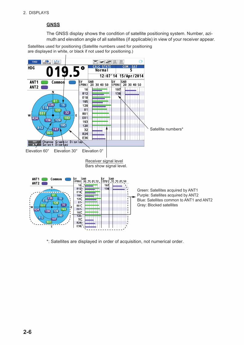
An alert (see chapter 5), which informs you to various types of errors, may appear on a graph display, with a red bar and triangle. Below is an an example of an alert on the signal noise ratio graph.
Information about the latest alert, which is saved in the alert log and occurs within the past six hours, appears here. The reason for the alert, the time of the alert and the position at the time of the alert are displayed.Information of the first line changes according to the alert mode.• [Alert I/F 1], [Alert I/F 2]: Display alert number and instance number.• [Legacy]: Display alert name.
Filled red triangle marks the latest alert.
A hollow triangle marks an alert that occurred within the past six hours.
2-8

3. SETTINGS
3.1 Display Menu
3.1.1 How to set the time for smoothing
When the receiving condition is unfavorable, the GNSS fix may change randomly, even if the boat is dead in water. This change can be reduced by smoothing the raw GNSS fixes. The higher the setting the more smoothed the raw data, however too high a setting slows response time to change in latitude and longitude.
1. Press the MENU ESC key to open the main menu.
2. Select [1 Display] then [3 Smoothing].
3. Select [1 VTG].
4. Enter the time (unit: second) for smoothing of the antenna transmission speed with the numeric keys.
5. Move the cursor to [Enter] then press the ENT key.
6. Set [2 L/L], [3 VBW], [4 Wind] and [5 ROT] as well.[L/L]: Position[VBW]: Ship’s 3-axis speed[Wind]: Wind[ROT]: Rate of turn
7. Press the MENU ESC key to close the main menu.
3.1.2 How to set the current direction and wind angle
Note: These functions require the external input.
1. Press the MENU ESC key to open the main menu.
2. Select [1 Display] then [4 Current/Wind].
3. Select [1 Current].
4. Select [1 Flow to] or [2 Flow from].[Flow to]: The direction of the currents is shown as flowing to.[Flow from]: The direction of the currents is shown as flowing from.
3-1
3. SETTINGS
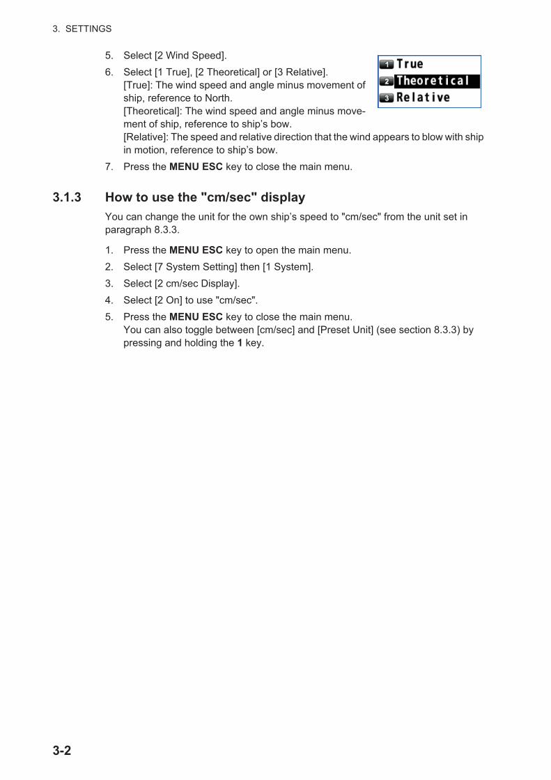
5. Select [2 Wind Speed].
6. Select [1 True], [2 Theoretical] or [3 Relative].[True]: The wind speed and angle minus movement of ship, reference to North.[Theoretical]: The wind speed and angle minus move-ment of ship, reference to ship’s bow.[Relative]: The speed and relative direction that the wind appears to blow with ship in motion, reference to ship’s bow.
7. Press the MENU ESC key to close the main menu.
3.1.3 How to use the "cm/sec" display
You can change the unit for the own ship’s speed to "cm/sec" from the unit set in paragraph 8.3.3.
1. Press the MENU ESC key to open the main menu.
2. Select [7 System Setting] then [1 System].
3. Select [2 cm/sec Display].
4. Select [2 On] to use "cm/sec".
5. Press the MENU ESC key to close the main menu.You can also toggle between [cm/sec] and [Preset Unit] (see section 8.3.3) by pressing and holding the 1 key.
3-2

3. SETTINGS
3.2 Trip Menu
3.2.1 How to calculate the trip distance
1. Press the MENU ESC key to open the main menu.
2. Select [2 Speed/Trip Setting] then [2 Trip].
3. Select [1 Calculation].
4. Select [1 Stop], [2 Start/Restart] or [3 Clear].[Stop]: Stops the trip distance calculation.[Start/Restart]: Starts or restarts the trip distance calculation.[Clear]: Resets the trip distance and trip time.
5. Press the MENU ESC key to close the main menu.
3.2.2 How to set the total distance
1. Press the MENU ESC key to open the main menu.
2. Select [2 Speed/Trip Setting] then [3 Total Distance].
3. Select [2 Preset].
4. Enter the default total distance with the numeric keys.
5. Move the cursor to [Enter] then press the ENT key.
6. Press the MENU ESC key to close the main menu.
To reset the total distance, select [1 Clear] at step 3. In this case, trip distance and trip time are reset.
3-3

3. SETTINGS
3.3 System Menu
3.3.1 How to change the user password
You can set a four-character password to prevent unauthorized entry into certain menus. The default setting is no password.
1. Press the MENU ESC key to open the main menu.
2. Select [7 System Setting] then [1 System].
3. Select [9 Password].Note: The default setting is "0000", which means no password is set. When the password is "0000", the [Input Pass-word] screen does not appear.
4. Enter the password (four characters) with the numeric keys (default: 0000).
5. Enter the new password (four characters) with the numeric keys.
6. Enter the password (four characters) with the numeric keys again.
7. Press the ENT key.
8. Press the MENU ESC key to close the main menu.
When the password is set, access to the following menus and settings requires pass-word input.
• [4 Maintenance] - [3 Backup] - [2 Load User Setting] (See section 7.7.)• [6 Sensor Setting] - [9 Device List] - [4 Set Device Instance] (See paragraph 3.7.2.)• [6 Sensor Setting] - [9 Device List] - [5 Set System Instance] (See paragraph 3.7.2.)
3-4

3. SETTINGS
3.3.2 SNTP setting
SNTP (Simple Network Time Protocol) is a communication protocol that synchronizes the time data in this equipment with UTC.
1. Press the MENU ESC key to open the main menu.
2. Select [7 System Setting] then [2 Network].
3. Select [4 SNTP Server].
4. Select [1 On], or [2 Off].
5. Press the MENU ESC key to close the main menu.
3.4 How to Set the Demo ModeA demo mode, which shows internally generated navigation data, is provided to ac-quaint you with the features of the GS-100. You can set the demo mode as follows:
1. Press the MENU ESC key to open the main menu.
2. Select [7 System Setting] then [4 Demo].
3. Select [1 Moving Setting].
4. Enter each setting with the numeric keys referring to the figure above.[Date]: Set the starting date and time in UTC.[Position]: Set the starting position. To change the coordinate, select "N" or "E"
3-5

3. SETTINGS
then press one of keys from 0 to 9.[1. Direction]: Set the direction for translatory movement.[2. SOG]: Set the speed for translatory movement in kn.[3. Direction]: Select the direction for rotary motion from [CW] (clockwise) and [CCW] (counterclockwise).[4. Radius]: Set the radius for rotary motion in NM.[5. Angular Speed]: Set the angular speed for rotary motion.
5. Move the cursor to [Enter] then press the ENT key.
6. Select [2 Attitude Setting].
7. Enter each setting with the numeric keys.[6. Heading Amplitude]: Set the amplitude for the heading.[7. Heading Angular rate]: Set the angular rate for the heading.[8. Pitch Amplitude]: Set the amplitude for bow and stern sway of own ship.[9. Pitch Angular rate]: Set the angular rate for bow and stern sway of own ship.[10. Roll Amplitude]: Set the amplitude for port and starboard sway of own ship.[11. Roll Angular rate]: Set the angular rate for port and starboard sway of own ship.[12. Amplitude]: Set the amplitude for heave.[13. Frequency]: Set the frequency for heave.
8. Move the cursor to [Enter] then press the ENT key.
9. Select [3 Output Status].Note: This function is for a serviceman.
10. Select a mode for NMEA output in demo mode.
11. Select [4 Demo Start]. The confirma-tion message appears.
12. Select [1 Yes]. The equipment restarts.
3-6

3. SETTINGS
3.5 GNSS Menu
3.5.1 How to set the positioning condition
Satellite elevation
Note: This function is for a serviceman.
You can set the minimum elevation of satellites to use to calculate the heading and position.
Disable satellite
Every GNSS satellite is broadcasting abnormal satellite number(s) in its Almanac, which contains general orbital data about all GNSS satellites. Using this information, the GNSS receiver automatically eliminates any malfunctioning satellite from the GNSS satellite schedule. However, the Almanac sometimes may not contain this in-formation. You can disable an inoperative satellite manually. Enter satellite numbers (up to three satellites) in three digits.
1. Press the MENU ESC key to open the main menu.
2. Select [6 Sensor Setting] then [2 GNSS].
3. Select [2 Condition].
4. Select [2 Not used GPS], [3 Not used GLONASS], [4 Not used GALILEO] or [5 Not used QZSS].
5. Enter the satellite numbers with the nu-meric keys according to the following set-ting ranges.GPS: 001 to 032GLONASS: 001 to 024Galileo: 001 to 036QZSS: 193 to 197
6. Move the cursor to [Enter] then press the ENT key.
7. Press the MENU ESC key to close the main menu.
3-7

3. SETTINGS
3.6 Other Setting Menus for Antenna Unit
3.6.1 How to reset the sensor
You can reset the sensor (antenna unit) when experiencing antenna trouble.
1. Press the MENU ESC key to open the main menu.
2. Select [6 Sensor Setting] then [4 Other].
3. Select [1 App Reset].The confirmation message appears.
4. Select [1 Yes]. The sensor restarts.
3.6.2 How to clear the sensor settings
Note: This function is for a serviceman.
You can clear the sensor (antenna sensor) settings when experiencing antenna trou-ble.
1. Press the MENU ESC key to open the main menu.
2. Select [6 Sensor Setting] then [4 Other].
3. Select [2 Clear Setting]. The confirmation message appears.
4. Select [1 Yes]. The message "Processing..." appears on the screen then the sen-sor settings are cleared.
5. Turn the power off then on.
3.6.3 How to set the time for dead reckoning
You can set the dead reckoning interval to use with the internal rate gyro sensor to calculate bearing when the GNSS signal is lost.
1. Press the MENU ESC key to open the main menu.
2. Select [6 Sensor Setting] then [4 Other].
3. Select [3 Dead Reckoning Time].
4. Select [1 1 min], [2 2 min], [3 3 min], [4 4 min] or [5 5 min].
5. Press the MENU ESC key to close the main menu.
3-8

3. SETTINGS
3.6.4 How to restart heading data output after restoration of heading data
Heading data can be output automatically or manually after heading data is restored.
Note: If there is no heading data, the 3-axis speed data can not be output.
1. Press the MENU ESC key to open the main menu.
2. Select [6 Sensor Setting] then [4 Other].
3. Select [4 HDG Output Restart Mode].
4. Select [1 Manual] or [2 Auto].[Manual]: Manually resumes the heading data output after heading data is lost. Press the ACK key to acknowledge the in-dicator alert message and resume the heading data output.[Auto]: Automatically resumes the heading data output after heading data is lost.Note: For [Manual], the color for the heading icon changes as follows (see page AP-9):
• The icon is blue when the heading is calculable.
• The icon is gray when the heading is not calculable.
5. Press the MENU ESC key to close the main menu.
3.7 Device ListThe Device List, which shows the particulars about the devices in the system, can be shown from the menu or by operating the LIST key (see section 1.5).
3.7.1 How to open the device list from the menu
1. Press the MENU ESC key to open the main menu.
2. Select [6 Sensor Setting] then [9 Device List].
3. Press the MENU ESC key to close the main menu.
Address
Load Equivalency Number
2051591- xx. xx000001
211011
GN 3D-
3-9

3. SETTINGS
3.7.2 Device menu
The Device List has the [Device] menu, which provides various information about the device selected and sets device instance and system instance. To display the [Device] menu, use the cursorpad to select the device then press the ENT key.
*: These menu items require the password (see paragraph 3.3.1).
Menu item Function[1 Product Information] Displays the product information for the selected device.
[2 Device Information] Displays the device information for the selected device.
[3 Select Master Sensor] These menus are reserved for future use.[4 Set Device Instance]*[5 Set System Instance]*
000001
211011
GN 3D-
3-10

3. SETTINGS
3.8 I/O MenuBesides its fundamental function of displaying position, the GS-100 can also output various data to external equipment. Before outputting data to external equipment, first determine what data the external equipment requires. Output only necessary data to ensure data will be output correctly.
All data transmitted by marine electronics equipment are prefixed with a two character code called a talker. The same talker must be shared by the transmitting and receiving equipment to transmit and receive data successfully.
3.8.1 How to set the output data 1, 2, 3 or 4
1. Press the MENU ESC key to open the main menu.
2. Select [5 I/O].
3. Select [1 Output Data1].
4. Select [1 Format].Note: This function is for a serviceman.
5. Select [1 IEC61162-1 Ed.4], [2 IEC61162-1 Ed.3], [3 NMEA V2.0], [4 NMEA V1.5] or [5 IEC61162-1 Ed.5].
6. Select [2 BPS].Note: This function is for a serviceman.
7. Select [1 4800 bps] or [2 38400 bps].
3-11

3. SETTINGS
8. Select [3 Sentence].Note: Ask a serviceman, if [GGA], [GLL], [GNS], [RMC] or [XDR] is grayed out as shown in the below example.
9. Press the cursorpad to select the sentence then press the ENT key.
10. Press the cursorpad ( or ) to select the TX interval.
11. Press the ENT key.
12. Set [2 Output Data2], [3 Output Data3] and [4 Output Data4] similarly.
13. Press the MENU ESC key to close the sentence window.
3.8.2 How to set the sentences to output to the Ethernet
1. Press the MENU ESC key to open the main menu.
2. Select [5 I/O] then [5 Ethernet].
3. Select [1 Sentence].
4. Press the cursorpad to select the sen-tence then press the ENT key.
5. Press the cursorpad ( or ) to select the TX interval.
6. Press the ENT key.
7. Press the MENU ESC key to close the sentence window.
Sentence Available TX intervalGGA, GLL, GNS, RMC, VBW, VLW, VTG, XDR, ZDA
[- - -] (off), [1s], [2s], [3s], [4s], [5s], [10s]
HDT, HRM, ROT, THS, GPatt, GPhve, GPimu
[- - -] (off), [0.020s]*, [0.025s]*, [0.1s]*, [0.2s], [1s], [2s], [4s]*: Available when selecting [38400 bps] at step 7.
Sentence Available TX intervalGGA, GLL, GNS, RMC, VBW, VLW, VTG, XDR, ZDA
[- - -] (off), [1s], [2s], [3s], [4s], [5s], [10s]
HDT, HRM, ROT, THS, GPatt, GPhve, GPimu
[- - -] (off), [0.020s], [0.025s], [0.1s], [0.2s], [1s], [2s], [4s]
GN 3D-
3-12

3. SETTINGS
3.8.3 How to select the input data
1. Press the MENU ESC key to open the main menu.
2. Select [5 I/O] then [6 Data Source Select].
3. Select [1 HDG].
4. Select the port for heading data.[1 Data1], [2 Data2], [4 Data4]: Use the heading data received from the equipment connected to the port 1 (or 2, 4). The heading data calculated from the GS-1001 is not used. Go to step 7.[5 Ethernet]: Use the heading data received from the equipment connected via the LAN port. Go to step 5.[6 CAN]: Use the heading data calculated from the GS-1001. The heading data received from the external equipment is not used. Go to step 11.
5. Enter the Ethernet SFI with two alphabets and four figures. SFI (System Function ID) is an identification code used by the system.
To enter "AB1234", for example, do as follows:
1) Use the cursorpad to select "A" then press the ENT key.
2) Use the cursorpad to select "B" then press the ENT key. The cursor moves to "0".
3) Use the cursorpad ( ) to select "1" then press the ENT key. Or press the 1 key.
4) Refer to step 3, enter "2", "3" and "4".
6. Move the cursor to [Enter] then press the ENT key. Go to step 11.
7. Select [1 HDG].
Backspace
3-13

3. SETTINGS
8. Select [7 User Priority].
Note 1: The default priority order is Data1 > Data2 > Data4. Data 3 port is not available for serial input.
Note 2: When the heading data is input from CAN, CAN has the top priority.
9. Enter the priority for heading data by port number. For example, to set the priority order as Data1, Data4, Data2, enter 1, 4, 2.Note: The heading data calculated from the GS-1001 (CAN) has the top priority. Then the heading data set above is used in order.
10. Move the cursor to [Enter] then press the ENT key.
11. Set the input data for [2 Ext. STW/COG/SOG] (external speed through water/course over ground/speed over ground), [3 Ext. CUR] (external current), [4 Ext. DEPTH] (external water depth) and [5 Ext. Wind] (external true wind speed and angle) as well. Set these menus when the external input is available.Note: [CAN] is available only for [HDG].
12. Press the MENU ESC key to close the main menu.
3.8.4 Line monitor log
Line monitor
1. Press the MENU ESC key to open the main menu.
2. Select [5 I/O] then [7 Line Monitor].
3-14

3. SETTINGS
3. Select [1 Data1] (or 2, 3, 4), [5 Ethernet] or [6 CAN]. The following is an example of the display for [Data1].
4. Press the MENU ESC key to close the line monitor log.
LAN error counter
1. Press the MENU ESC key to open the main menu.
2. Select [5 I/O] then [7 Line Monitor].
3. Select [0 LAN Error Counter].
Press the ACK key to reset all counts to 0.
4. Press the MENU ESC key to close the LAN error counter.
$YCMTW,027.32,C$GPZDA,012614.00,01,11,2012,-09,00 42$YCMTW,027.32,C$GPZDA,012614.00,01,11,2012,-09,00 42$YCMTW,027.32,C$GPZDA,012614.00,01,11,2012,-09,00 42$YCMTW,027.32,C$GPZDA,012614.00,01,11,2012,-09,00 42$YCMTW,027.32,C$GPZDA,012614.00,01,11,2012,-09,00 42$YCMTW,027.32,C$GPZDA,012614.00,01,11,2012,-09,00 42$YCMTW,027.32,C$GPZDA,012614.00,01,11,2012,-09,00 42$YCMTW,027.32,C$GPZDA,012614.00,01,11,2012,-09,00 42$YCMTW,027.32,C$GPZDA,012614.00,01,11,2012,-09,00 42$YCMTW,027.32,C$GPZDA,012614.00,01,11,2012,-09,00 42
$GPZDA,012613.00,01,11,2012,-09,00 45$GPDTM,W84,,00.0000,N,00.0000,E,,W84 41$GPGGA,012614.00,0844.7963,S,11512.6084,E,2,6,0.7,15,M,,M,, 78$GPVTG,258.0,T,256.5,M,0.1,N,0.2,K,D 2E$GPZDA,012613.00,01,11,2012,-09,00 45$GPDTM,W84,,00.0000,N,00.0000,E,,W84 41$GPGGA,012614.00,0844.7963,S,11512.6084,E,2,6,0.7,15,M,,M,, 78$GPVTG,258.0,T,256.5,M,0.1,N,0.2,K,D 2E$GPZDA,012613.00,01,11,2012,-09,00 45$GPDTM,W84,,00.0000,N,00.0000,E,,W84 41$GPGGA,012614.00,0844.7963,S,11512.6084,E,2,6,0.7,15,M,,M,, 78$GPVTG,258.0,T,256.5,M,0.1,N,0.2,K,D 2E$GPZDA,012613.00,01,11,2012,-09,00 45$GPDTM,W84,,00.0000,N,00.0000,E,,W84 41$GPGGA,012614.00,0844.7963,S,11512.6084,E,2,6,0.7,15,M,,M,, 78$GPVTG,258.0,T,256.5,M,0.1,N,0.2,K,D 2E
GN 3D-
GN 3D-
3-15

3. SETTINGS
3.8.5 How to set the digit number for sentences
Set the number of figures to show after the decimal point for heading, speed (VTG, VBW), and roll, pitch.
1. Press the MENU ESC key to open the main menu.
2. Select [5 I/O] then [8 Number of digits after decimal point].
3. Select [1 VTG], [2 VBW], [3 HDG] or [4 Roll, Pitch].
4. Select [1 1] or [2 2].[1]: Displays the sentence data to the first decimal place.[2]: Displays the sentence data to the second decimal place.Note 1: When changing the setting for [3 HDG], the setting is re-flected to the ROT indication.
Note 2: When changing the setting for [4 Roll, Pitch], the setting is reflected to the HEAVE indication.
5. Press the MENU ESC key to close the main menu.
3.9 How to Clear the MemoryYou can clear display setting or GNSS memory to start afresh, or restore the default settings.
1. Press the MENU ESC key to open the main menu.
2. Select [7 System Setting] then [9 Clear Memory].
3. Select [1 Clear Display Setting], [2 Clear GNSS] or [3 Clear All].[Clear Display Setting]: Clears the dis-play setting.[Clear GNSS]: Clears the GNSS memo-ry.[Clear All]: Clears both display setting and GNSS memory.For [Clear All], the window for password appears. Enter the password (four char-acters) with the numeric keys. The con-firmation message appears.
4. Select [1 Yes]. The message "Processing... " appears. After the memory clear, the application automatically restarts.
For serviceman
3-16

4. NOTICES
There are two notice conditions which generate both audio and visual notices: Ship Speed and Trip. When the conditions of a notice are met, the buzzer sounds according to the notice sound setting and the icon related to the notice turns from gray to blue at the top right-hand corner of the display.
You can silence the buzzer by pressing the ACK key.
4.1 Audio Notice TypeYou can select the audio notice type as follows. When the conditions of a notice are met, the icon color related to the notice changes regardless of the audio notice type.
1. Press the MENU ESC key to open the main menu.
2. Select [2 Speed/Trip Setting] then [4 Sound].
3. Select [1 Notice Sound].
4. Select [1 Off], [2 On] or [3 Continuous].[Off]: No sound, only visible notice (an icon turns blue)[On]: Three long buzzer and visible notice (an icon turns blue)[Continuous]: This buzzer sounds until the ACK key is pressed (to acknowledge the notice). Visible notice (an icon turns blue).
5. Press the MENU ESC key to close the main menu.
4.2 Ship Speed NoticeThe ship speed notice alerts you when own ship’s speed is lower or higher than the speed setting or within the range set.
1. Press the MENU ESC key to open the main menu.
: Trip
: Speed
Notice icons
GN 3D-
4-1

4. NOTICES
2. Select [2 Speed/Trip Setting] then [1 Ship Speed].
3. Select [2 In] or [3 Out]. The ship speed notice icon ( ) appears in gray at the top right-hand corner of the display.[In]: The notice alerts you when own ship’s speed is within the range set.[Out]: The notice alerts you when own ship’s speed is lower or higher than the range set.
4. Select [1 Ship Speed].
5. Select [4 Speed].
6. Enter the minimum and maximum speeds with the numeric keys.Note: When the settings for minimum and maximum are equal, the notice alerts you when own ship’s speed matches the set-ting, or is higher than the setting for [2 In] or lower for [3 Out].
7. Move the cursor to [Enter] then press the ENT key.
8. Press the MENU ESC key to close the main menu.
To turn off the ship speed notice, select [1 Off] at step 3.
4.3 Trip NoticeThe trip notice alerts you when own ship has traveled the preset trip distance.
1. Press the MENU ESC key to open the main menu.
2. Select [2 Speed/Trip Setting] then [2 Trip].
3. Select [2 Range].
4. Enter the trip distance with the numeric keys.
5. Move the cursor to [Enter] then press the ENT key.
6. Select [3 Notice].
7. Select [2 On] to turn on the trip notice. The trip notice icon ( ) appears in gray at the top right-hand corner of the display.
8. Select [1 Calculation].
9. Select [2 Start/Restart]. The system starts the trip calculation.
10. Press the MENU ESC key to close the main menu.
To turn off the trip notice, select [1 Off] at step 7.
4-2

5. ALERTS
“Alert” is a generic name for a notice to any unusual or potentially dangerous situation generated within the system. There are two types of alerts, warning and caution.Warning: Conditions or situations which require immediate attention for precautionary reasons.Caution: Awareness of a condition which continues to require attention out of the or-dinary consideration of the situation.
5.1 OverviewThe GS-100 release alerts according to the alert mode selected at installation (Alert I/F1, Alert I/F2, Legacy; see section 8.3.8). For full lists of the alerts for each alert mode, see "ALERT LIST" on page AP-27.
When an alert situation occurs, the buzzer sounds (except for a caution) and the name of the alert appears at the bottom of the display. Also, the values and indication for the following items are displayed in yellowish orange for a warning, yellow for a caution.
• 3-axis speed
• Heading
• Calculation state (DR, Stopped, SYS FAULT)
• Position (only when the status indication is "No Fix")
• Time and date (only when the status indication is "No Fix")
In addition to the alert appeared at the bottom of the display, there is any alert, the ap-propriate icon appears in the bottom-right corner of the display in the following situa-tions:
• There is an additional active alert.
• There is an additional rectified unacknowledged alert.
The icons which may appear are for warning level alerts and for caution level
alerts.
5-1

5. ALERTS
Example 1: Warning
Example 2: Caution
Alert category
For details, see page AP-9.
Note: When a warning is not acknowledged within five minutes, the warning is repeat-ed.
Alert I/F 1
Priority Icon Visual indicationWarning Circle • Acknowledged: Yellowish orange
• Not acknowledged: Yellowish orange, flashingCaution Square Yellow
No. Text PriorityTHD/SDME306 DR Mode Caution/BTHD
GN 3D-
The additional icon(s) apprear(s) here.
GN 3D-
The additional icon(s) apprear(s) here.
5-2

5. ALERTS
Alert I/F 2
Legacy
Note: After alert ID 312 is released, the deviation for all speeds other than in the bow direction increases over time. For details on these increases, see the tables below.
240 System Fault Warning/BSDME309 SDME Fault Caution/B
No. Text PriorityTHD/SDME
430306 GNSS Core(2) Fault Caution/BGNSS Core(3) Fault Caution/BToo few Common Satellites Caution/B
THD3062 GNSS Core(2) Fault Warning/B
GNSS Core(3) Fault Warning/BToo few Common Satellites Warning/BAntenna Unit Connection Lost Warning/BRate gyro broken down Warning/BAccelerometer broken down Warning/BSettling failure Warning/B
SDME430309 GNSS Core(2) Fault Caution/B
GNSS Core(3) Fault Caution/BToo few Common Satellites Caution/BAntenna Unit Connection Lost Caution/BRate gyro broken down Caution/BAccelerometer broken down Caution/BSettling failure Caution/B
No. Text Priority210 HDOP exceeded Caution211 No calculation of position
Abbreviated messages:No calculation of POSN
Caution
212 Loss of position Caution240 System fault Caution301 Dead-Reckoning Warning302 Output Stopped (HDG) Caution303 EXT HDG/ROT Caution311 Output Stopped (Speed) Caution312 EXT HDG applied Warning321 Rate gyro broken down Caution322 Accelerometer broken down Caution
No. Text Priority
5-3
5. ALERTS
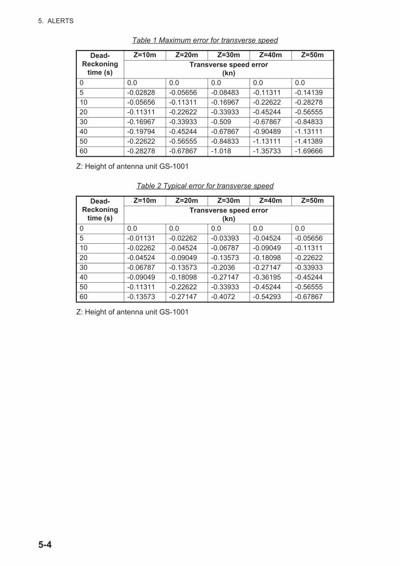
Table 1 Maximum error for transverse speed
Z: Height of antenna unit GS-1001
Table 2 Typical error for transverse speed
Z: Height of antenna unit GS-1001
Dead-Reckoning
time (s)
Z=10m Z=20m Z=30m Z=40m Z=50mTransverse speed error
(kn)0 0.0 0.0 0.0 0.0 0.05 -0.02828 -0.05656 -0.08483 -0.11311 -0.1413910 -0.05656 -0.11311 -0.16967 -0.22622 -0.2827820 -0.11311 -0.22622 -0.33933 -0.45244 -0.5655530 -0.16967 -0.33933 -0.509 -0.67867 -0.8483340 -0.19794 -0.45244 -0.67867 -0.90489 -1.1311150 -0.22622 -0.56555 -0.84833 -1.13111 -1.4138960 -0.28278 -0.67867 -1.018 -1.35733 -1.69666
Dead-Reckoning
time (s)
Z=10m Z=20m Z=30m Z=40m Z=50mTransverse speed error
(kn)0 0.0 0.0 0.0 0.0 0.05 -0.01131 -0.02262 -0.03393 -0.04524 -0.0565610 -0.02262 -0.04524 -0.06787 -0.09049 -0.1131120 -0.04524 -0.09049 -0.13573 -0.18098 -0.2262230 -0.06787 -0.13573 -0.2036 -0.27147 -0.3393340 -0.09049 -0.18098 -0.27147 -0.36195 -0.4524450 -0.11311 -0.22622 -0.33933 -0.45244 -0.5655560 -0.13573 -0.27147 -0.4072 -0.54293 -0.67867
5-4

5. ALERTS
5.2 Alert ListThe alert list shows all currently violated alerts and state of acknowledgment. All un-acknowledged alerts are shown, even those whose reason for the alert has passed.
1. Press the MENU ESC key to open the main menu.
2. Select [3 Alert] then [1 Active Alert] to show the alert list. Unacknowledged alerts flash.
The Alert list can also be shown by operating the LIST key (see section 1.5).
3. Press the MENU ESC key to close the alert list.
Not acknowledged Acknowledged
Alert icon
Alert number Alert name
Date and time of occurrence Position of occurrence
GN 3D- GN 3D-
5-5

5. ALERTS
5.3 Alert LogThe alert log shows the latest 50 alerts. When the log becomes full, the oldest entry is erased to make room for current alerts.
1. Press the MENU ESC key to open the main menu.
2. Select [3 Alert] then [4 Alert Log] to show the alert log.
3. Press the MENU ESC key to close the alert log.
5.4 How to Acknowledge Alerts
With the ACK key
When an alert condition occurs, the buzzer sounds (warning alert only) and the alert type indication appears at the bottom of the display. Press the ACK key to acknowl-edge the alert. The buzzer stops and the alert type indication disappears. If multiple alert conditions occur simultaneously, the alerts are acknowledged in order of impor-tance.
How to acknowledge an alert from the alert list
1. Open the alert list (see section 5.2).
2. Press the cursorpad ( or ) to select the alert to acknowledge then press the ENT key.
How to acknowledge all alerts from the alert list
1. Open the alert list (see section 5.2).
2. Press the cursorpad ( ) to select [Acknowledge All] then press the ENT key.
List no.
PriorityAlert number Alert name
Date and time of occurrence Position of occurrence
Date and time of acknowledgement
Date and time when alert was rectified
GN 3D-
5-6

5. ALERTS
5.5 Responsibility Transfer AlertMSC302(87) requires the use of the “responsibility transfer alert,” which functions in the multiple sensor, multiple equipment installation. When one sensor or one equip-ment fails but does not disturb the system operation (other sensor or equipment is nor-mal), the CAM automatically sends the “responsibility transfer alert” (ACN sentence) to the sensor or equipment that generated the alert.
If the sensor or equipment refuses the responsibility transfer, normal operation is re-stored.
If the HBT sentence is not received from equipment within the prescribed time interval, the alert processed as responsibility transfer alert is made active and the “System communication fail” alert is generated.
CAM HMIALF
ExternalEquipment
SensorA
Check if there is problem for system
Some alerts occur ACN
SensorB
CAM HMIALF
ExternalEquipment
SensorA
HBT timeout computed.Some
alerts occur ACN
SensorB
Alertre-generated.
CAM HMIHBT
ExternalEquipment
SensorA
HBT timeout computedSome
alerts occur
SensorB
Alertre-generated
5-7

5. ALERTS
This page is intentionally left blank.
5-8

6. BERTHING DISPLAY
The berthing display shows ship's track (past and/or predicted) and provides help with berthing operations. With position and heading inputs, customizable berthing lines can be shown to help in berthing.
All berthing lines within the current display range are automatically shown.
The display orientation is available in Head-up and North-up. Head-up has your head-ing at the screen top and North-up has North at the top.
The navigation data, which appears at the left side of the display, can be shown or hid-den as necessary.
The 3-axis speed display shows ship's speed in three axes: transverse speed at the reference point, longitudinal speed, and transverse speed at the reference point.
6.1 Berthing Display for the GS-100On the berthing display from the GS-100, the following four data are displayed as"– – –" because they are not input.
• Doppler sonar SOG (STW) and COG
• Current (tide) speed and direction
• Wind reference, speed and angle
• Depth
Long-push the ENT key of the DS-600 to show the display for 3-axis speed data as below (see section 6.6).
3-axis speed data, NAV data OFF
You can prepare and edit berthing lines on the display unit GS-1002 and send them to the optional display unit DS-600 for display on the unit. For installation details, see section 8.5.
6-1
6. BERTHING DISPLAY
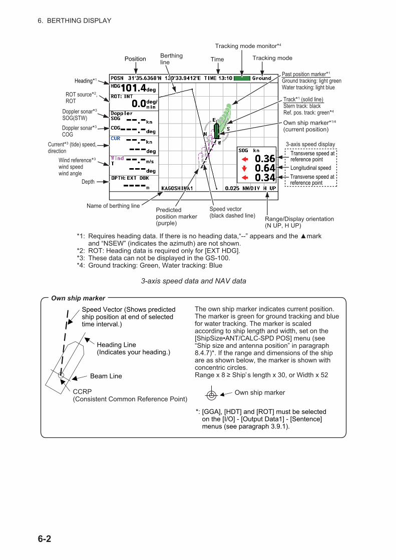
3-axis speed data and NAV data
*1: Requires heading data. If there is no heading data,“--” appears and the ▲mark and “NSEW” (indicates the azimuth) are not shown.
*2: ROT: Heading data is required only for [EXT HDG].*3: These data can not be displayed in the GS-100.*4: Ground tracking: Green, Water tracking: Blue
Position Berthing line Time
Tracking mode monitor*4
Tracking mode
Heading*1
ROT source*2, ROT
Doppler sonar*3
SOG(STW)Doppler sonar*3
COGCurrent*3 (tide) speed, direction
Wind reference*3
wind speedwind angle
Depth
Name of berthing linePredicted position marker (purple)
Speed vector (black dashed line) Range/Display orientation
(N UP, H UP)
3-axis speed displayTransverse speed at reference pointLongitudinal speedTransverse speed at reference point
Past position marker*1
Ground tracking: light greenWater tracking: light blue
Track*1 (solid line)Stern track: blackRef. pos. track: green*4
Own ship marker*1/4 (current position)
The own ship marker indicates current position. The marker is green for ground tracking and blue for water tracking. The marker is scaled according to ship length and width, set on the [ShipSize•ANT/CALC-SPD POS] menu (see “Ship size and antenna position” in paragraph 8.4.7)*. If the range and dimensions of the ship are as shown below, the marker is shown with concentric circles.Range x 8 ≥ Ship’s length x 30, or Width x 52
Own ship markerSpeed Vector (Shows predicted ship position at end of selected time interval.)
Heading Line(Indicates your heading.)
Beam Line
CCRP (Consistent Common Reference Point)
Own ship marker
*: [GGA], [HDT] and [ROT] must be selected on the [I/O] - [Output Data1] - [Sentence] menus (see paragraph 3.9.1).
6-2

6. BERTHING DISPLAY
6.2 Controls for the Display Unit DS-600
No. Control Function1 PWR Turn the power on and off.2 DISP • Select a display.
• Close the menu and return to the last-used display.• In multiple data displays, select a data indication to change
its unit of measurement (with the UNIT key).3 TRKG/MODE Select the ship speed mode between SOG and STW.4 UNIT Select the unit of measurement for speed, depth, distance, cur-
rent (tide) speed, wind speed, etc.5 RNG Select the range in the berthing and echo monitor displays.6 DAY/NT Select the daytime and nighttime displays alternately.7 MENU ESC • Open the menu.
• Return control to the menu window without making any changes at the menu options window.
• Select the item to change its unit of measurement in multiple data displays.
• Close the menu when the menu window is active.8 ENT • Confirm an operation in menu operation.
• Long-push to hide or show nav data and 3-axis speed data in the berthing display.
9 BRILL • Adjust the screen brilliance in 10 levels including off. to decrease the brilliance, to increase the brilliance. To quickly increase or decrease the brilliance, press and hold the related cursorpad point.
• Move the cursor in menu operation.
PWR
DISP
TRKGMODE
UNIT
RNG DAYNT
MENUESC
ENT
BRILL
UNITUNIT
RNG
BRILL
ENT
MENU ESC
DAY NT
DISP
TRKGMODE
PWR
1 2 4
3 5
7 9
6 8
No use
6-3

6. BERTHING DISPLAY
6.3 Various Settings
Key beep
A key beeps when it is pressed. You can turn this beep on or off.
1. Press the MENU ESC key to open the menu.
2. Select [Key Beep] then press the ENT key.
3. Select [ON] or [OFF] then press the ENT key.
4. Press the DISP key to close the menu.
Key dimmer
You can adjust the dimmer for the keys as follows:
1. Press the MENU ESC key to open the menu.
2. Select [Key BRILL] then press the ENT key.
3. Select a dimmer level (setting range: 1 to 8) then press the ENT key. The higher the figure, the higher the dimmer level.
4. Press the DISP key to close the menu.
How to change units of measurement
The UNIT key selects the unit of measurement for current (tide) speed, depth, dis-tance, Doppler SOG and STW, GNSS SOG, and wind speed.
1. Press the UNIT key. A unit is highlighted in yellow.
2. Press the DISP key to select the data for which to change its unit. (Use the MENU ESC key to reverse the selection order.)
3. Press the UNIT key to change the unit. See the table below for item and available units.
To quit the unit selection, press the DISP key until the yellow highlight disappears.
Item Available unitsBerthing display range meters/DIV (m/DIV), nautical miles/DIV (NM/DIV)Ground tracking (SOG) Water tracking (STW)
kilometers/hour (km/h), knots (kn), meters/second (m/s)
6-4

6. BERTHING DISPLAY
How to set time
Time
You can select the source for time, set local time, and turn summer time indication (daylight savings time) on or off.
1. Press the MENU ESC key to open the menu.
2. Select [Ship's Time] then press the ENT key.
3. Select [Source] then press the ENT key.
4. Select [Internal] or [NAV EQUIP] then press the ENT key. Select [Internal] to use local time, or [NAV EQUIP] to use UTC time. For [Internal], the [Local Time ADJ] screen appears; go to step 5. For [NAV EQUIP], go to step 6.
5. Use or to set the time difference between lo-cal time and UTC time then press the ENT key.
6. Select [Summer Time] (to turn the daylight savings time indication on or off) then press the ENT key.
7. Select [ON] or [OFF] then press the ENT key.
8. Press the DISP key to close the menu.
6-5

6. BERTHING DISPLAY
Time format
You can display time in UTC or ship's time (local time).
1. Press the MENU ESC key to open the menu.
2. Select [Scale Set Up] then press the ENT key.
3. Select [Mode] then press the ENT key.
4. Select [Time] then press the ENT key.
5. Select [UTC] or [Ship's Time] then press the ENT key.
6. Press the DISP key to close the menu.
Direction symbol format
The direction symbols for speed and ROT can be shown with arrows or text.
1. Press the MENU ESC key to open the menu.
2. Select [Scale Set Up] then press the ENT key.
3. Select [Direction SYM] then press the ENT key.
4. Select [Arrows] or [Text] then press the ENT key.
5. Press the DISP key to close the menu.
* Navigation data display, berthing display
Arrows Text
STBD, S*
PORT, P*
FWD
AFT
6-6

6. BERTHING DISPLAY
Vector Time
The tip of the vector line on the own ship marker shows the estimated position of your ship after the selected vector time elapses, using the current course and speed. You can adjust the length of the vector line to see estimated position at the end of the se-lected time interval.
1. Press the MENU ESC key to open the menu.
2. Select [Vector Time] then press the ENT key.
3. Select a vector time then press the ENT key. The longer the time, the longer the vector line.
4. Press the DISP key to close the menu.
6.4 Display Range
6.4.1 How to select a range
The display range is the distance between grid sides on the berthing display. Use the RNG key to select a range. The range appears below the 3-axis speed display as shown below. The system is pre-set with five ranges (nm): 0.025, 0.04, 0.05, 0.075 and 0.1. A total of 11 ranges are available and you can select the ranges to use from the menu, as shown in the next paragraph.
Display range
Grid
Set with RNG key.
Range
6-7

6. BERTHING DISPLAY
6.4.2 How to pre-set ranges
The berthing display has a total of 11 ranges. Select the ranges to use, following the procedure shown below. A minimum of one range must be turned on.
1. Press the MENU ESC key to open the menu.
2. Select [Scale Set Up] then press the ENT key.
3. Select [Range] then press the ENT key.
4. Select a range then press the ENT key. Show "X" in a check box to select the range, or remove the "X" to deselect the range.
5. Press to show and select [Save] then press the ENT key.Note: If all ranges are turned off, the message "No item be selected." appears. Select at least one range.
6. Press the DISP key to close the menu.
6.5 TrackYou can show past track or predicted track, or both past and predicted tracks on the display using the speed data.
6.5.1 Types of tracks
Two types of track are available: past and predicted.
Past track
The past track can be shown with a solid line or both solid line and past ship markers.
Solid line: There are two types of past track: reference position track and stern track. The reference position track is green (ground tracking) or blue (water tracking), and the stern track is black. The tracks of the past five minutes are shown.
Past ship markers: A past track marker is added every 30 seconds. The markers are colored light blue for water tracking, and light green for ground tracking. The last five minutes of past track markers are shown.
You can select the type of past track to show from the menu. See paragraph 6.5.3 for the procedure.
6-8

6. BERTHING DISPLAY
Predicted track
The predicted track feature shows estimated position of your ship at the end of the selected time interval. (See paragraph 6.5.4 for the proce-dure.) The estimated position is cal-culated from the reference point and stern speeds taken from the ground and water tracking speed data. The marker is purple, hollow and dashed to distinguish it from the own ship marker and the past track markers.
6.5.2 How to select the type of track to display
1. Press the MENU ESC key to open the menu.
2. Select [Ship's Track] then press the ENT key.
3. Select the type of track to display then press the ENT key. Select [OFF] to hide all tracks.
4. Press the DISP key to close the menu.
Own ship marker
Own ship marker
Reference position trackWater tracking: BlueGround tracking: Green
Stern track (black)
Past track (solid line) Past track (marker and solid line)
Past track (solid line)
Past track (marker)
Marker characteristics- One marker is added every
30 seconds.- Water tracking: Light blue- Ground tracking: Light green
Predicted track marker (purple)
Own ship marker
Predicted track
6-9
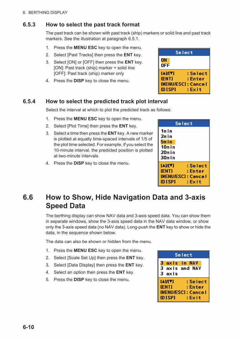
6. BERTHING DISPLAY
6.5.3 How to select the past track format
The past track can be shown with past track (ship) markers or solid line and past track markers. See the illustration at paragraph 6.5.1.
1. Press the MENU ESC key to open the menu.
2. Select [Past Tracks] then press the ENT key.
3. Select [ON] or [OFF] then press the ENT key.[ON]: Past track (ship) marker + solid line[OFF]: Past track (ship) marker only
4. Press the DISP key to close the menu.
6.5.4 How to select the predicted track plot interval
Select the interval at which to plot the predicted track as follows:
1. Press the MENU ESC key to open the menu.
2. Select [Plot Time] then press the ENT key.
3. Select a time then press the ENT key. A new marker is plotted at equally time-spaced intervals of 1/5 of the plot time selected. For example, if you select the 10-minute interval, the predicted position is plotted at two-minute intervals.
4. Press the DISP key to close the menu.
6.6 How to Show, Hide Navigation Data and 3-axis Speed DataThe berthing display can show NAV data and 3-axis speed data. You can show them in separate windows, show the 3-axis speed data in the NAV data window, or show only the 3-axis speed data (no NAV data). Long-push the ENT key to show or hide the data, in the sequence shown below.
The data can also be shown or hidden from the menu.
1. Press the MENU ESC key to open the menu.
2. Select [Scale Set Up] then press the ENT key.
3. Select [Data Display] then press the ENT key.
4. Select an option then press the ENT key.
5. Press the DISP key to close the menu.
6-10

6. BERTHING DISPLAY
6.7 Berthing LineBerthing lines, which can be used to assist in berthing operations, can be created and edited at the GS100. The saved lines can be sent to the DS-600 for display. A maxi-mum of 100 lines can be saved in the GS-100 and each line can have up to three points.
6.7.1 How to register a berthing line
1. Press the MENU ESC key to open the main menu.
2. Select [7 System Setting] then [5 Berthing Line].
*: Press the TRKG MODE key to switch between SOG and STW.
3-axis speed data* from the GS-100 in NAV data window
The data in dashed rectangle can not be displayed.
3-axis speed data in NAV data (3 axis in NAV)Long-push ENT.
Long-push ENT.
3-axis speed data*
3-axis speed data*
NAV data
The data in dashed rectangle can not be displayed.
3-axis speed data and NAV data (3 axis and NAV)Long-push ENT.
3-axis speed data, NAV data OFF (3 axis)
6-11

6. BERTHING DISPLAY
3. Select [1 List].
4. With the cursor at the [New] position, press the ENT key.
5. Enter the 1st position with the numeric keys. To change the coordinate, select "N" or "E" then press one of keys from 0 to 9.
6. Move the cursor to [Enter] then press the ENT key.
7. Select [3 2nd Pos] or [4 3rd Pos] then press the ENT key. Enter the 2nd or 3rd position as well as the 1st position.Note: Enter each value so that the difference between two positions is less than 1°.
8. Select [1 Name] then press the ENT key.
9. Enter the name for a berthing line referring to step 5 at paragraph 3.8.3.
10. Move the cursor to [Enter] then press the ENT key.
GN 3D-
GN 3D-
6-12

6. BERTHING DISPLAY
11. Select [9 Enter].Note: It is necessary to enter a name and at least two positions in order to register a berthing line.
12. Press the MENU ESC key to close the setting window.
6.7.2 How to edit a berthing line
1. Press the MENU ESC key to open the main menu.
2. Select [7 System Setting] then [5 Berthing Line].
3. Select [1 List].
4. Select the berthing line to edit then press the ENT key.
5. Select an option to edit then press the ENT key.
6. Change the name or position as appropriate.
7. Select [9 Enter].
8. Press the MENU ESC key to close the setting window.
6.7.3 How to delete a point or a line
1. Press the MENU ESC key to open the main menu.
2. Select [7 System Setting] then [5 Berthing Line].
3. Select [1 List].
4. Select the berthing line to delete then press the ENT key.
5. To delete a point, select [5 Delete 1st Point], [6 Delete 2nd Point] or [7 Delete 3rd Point]. Go to step 6.To delete a berthing line, select [8 Delete Line]. Go to step 7.
6. Select [9 Enter].
7. Press the MENU ESC key to close the setting window.
GN 3D-
6-13

6. BERTHING DISPLAY
6.7.4 How to send the berthing lines data to DS-600
To display the berthing lines on the display of the DS-600, do the following.
Note: Turn on the DS-600 before doing the following procedures.
1. Press the MENU ESC key to open the main menu.
2. Select [7 System Setting] then [5 Berthing Line].
3. Select [2 Share].
4. Press the MENU ESC key to close the main menu.
6-14

7. MAINTENANCE, TROUBLE-SHOOTING
7.1 MaintenanceRegular maintenance is important to maintain performance. Check the following points to help maintain performance.
• Check that connectors on the rear panel are firmly tightened and free of rust.
• Check that the ground system is free of rust and the ground wire is tightly fastened.
• Check that battery terminals are clean and free of rust.
• Dust or dirt may be removed from the cabinet with soft cloth. Water-diluted mild de-tergent may be used if desired. DO NOT use chemical cleaners to clean the display unit; they may remove paint and markings.
• Wipe the display carefully to prevent scratching, using tissue paper and a display cleaner. To remove dirt or salt deposits, use a display cleaner, wiping slowly with tissue paper so as to dissolve the dirt or salt. Change paper frequently so the salt or dirt will not scratch the display. Do not use solvents such as thinner, acetone or benzene for cleaning. Also, do not use degreaser or antifog solution, as they can strip the coating from the display.
7.2 Fuse Replacement
Junction box GS-1003
The junction box GS-1003 has a fuse that protects the GS-1003 from overcurrent and equipment fault. If you cannot turn on the power, check the fuse to see if it has blown. Find the reason for the blown fuse before you replace the fuse. If the fuse blows again
NOTICEDo not apply paint, anti-corrosive sealant or contact spray to plastic parts or equipment coating.
Those items contain products that can damage plastic parts and equipment coating.
WARNINGUse the proper fuse.
A wrong fuse can damage the equipment and cause fire.
7-1

7. MAINTENANCE, TROUBLESHOOTING
after the replacement, contact your dealer for information. A wrong fuse can damage the equipment.
Display unit DS-600
The fuse in the display unit DS-600 protects the unit from overcurrent. If you cannot turn on the power, have a technician check if the fuse inside the display unit has blown. If the fuse has blown, find the cause before replacing the fuse. If the fuse blows again, contact your dealer.
7.3 Consumable Parts
Life of LCD for the GS-1002
The life of the LCD is approximately 60,000 hours. The actual number of hours de-pends on ambient temperature and humidity. When the brilliance cannot be raised suf-ficiently, ask your dealer about replacement.
Backlight for the DS-600
The life of the backlight is approximately 30,000 hours at the temperature of 55°C. When the brilliance cannot be raised sufficiently, ask your dealer about replacement for the panel/LCD assembly (Type: DS-600 PNL/LCD, Code No.: 001-098-070).
Name Type Code No.Glass tube fuse FGMB-A 125V 3A PBF 000-157-481-10
Name Type Code No.Glass tube fuse FGMB-A 125V 2A PBF 000-157-479-10
Fuse
GS-1003
7-2

7. MAINTENANCE, TROUBLESHOOTING
7.4 TroubleshootingThis section provides simple troubleshooting procedures which the user can follow to restore normal operation. If you cannot restore normal operation, do not attempt to check inside the unit. Any trouble should be referred to a qualified technician.
Symptom Remedy
You cannot turn on the pow-er.
• Check for damaged power cable and connector.• Check if the power cable is firmly fastened.• Check the battery for proper voltage output.
No picture appears. Press the BRILL key followed by the cursorpad ( ) to in-crease the display brilliance.
There is no response when a key is pressed.
Turn off and on the power. If no change, ask your dealer.
Position is not fixed • Check if the antenna connector is firmly fastened.• Check the number of satellites on the integrity display.
If there are two or less, check for obstructions between antenna unit and satellites.
Position is wrong. Check if the correct geodetic chart system is correctly se-lected on the [7 System Setting] - [1 System] -[4 Datum] menu.
Data are not transmitted to external equipment.
• Check if the data format is correct on the [5 I/O] menu.• The TX interval may be set to off. Select the proper in-
terval.• Check the appropriate settings on the external equip-
ment. • Check the connections:
• Connect the TD-A of the GS-100 to the RD-A of the external equipment.
• Connect the TD-B of the GS-100 to the RD-B of the external equipment.
Heading output stops be-cause of the antenna loca-tion.
Check the antenna location.• Check for interfering objects near the antenna.• Check the installation site and mounting base for vi-
bration.• Check for antenna of radar, radio equipment, etc. near
the installation site.
The icon shown in the right appears on the display. • : The SC-30 is installed. Mount the GS-
1001.
• : The SC-33 is installed. Mount the GS-1001B.
• : The antenna acceleration is over 5G. When these icons appear frequently, change the an-tenna location or implement the anti-vibration mea-sures.
• : The common satellite for antenna 1 and 2 is blocked. Try to change the antenna location.
7-3

7. MAINTENANCE, TROUBLESHOOTING
7.5 Equipment InformationYou can display the information of this equipment from the menu.
1. Press the MENU ESC key to open the main menu.
2. Select [4 Maintenance] then [1 Information].
3. Select [1 Display Unit] or [2 Antenna Unit].
4. Select the information to display.
5. Press the ENT key to close each information window.
6. Press the MENU ESC key to close the main menu.
[1 Display Unit] [2 Antenna Unit]
Main board for display unit
Panel board for display unit
CAN board for display unit
Main board for antenna unit
GNSS for antenna unit
Sensor for antenna unit
7-4

7. MAINTENANCE, TROUBLESHOOTING
7.6 Self TestThe self test checks the ROM, RAM, input/output data, GNSS core, keyboard, LCD performance and sound. The user can do the tests to help the service technician in troubleshooting.
Memory
1. Press the MENU ESC key to open the main menu.
2. Select [4 Maintenance] then [2 Self Test].
3. Select [1 Memory].
4. Press the MENU ESC key to close the memory test win-dow.
Keyboard test
The keyboard test checks the controls on the operation panel for proper operation.
1. Press the MENU ESC key to open the main menu.
2. Select [4 Maintenance] then [2 Self Test].
3. Select [2 Keyboard Test].
4. Press each key one by one. A key's corresponding location on the display turns blue if the key is normal. To do the key-board test again, long-press the ENT key.
5. Press the MENU ESC key three times to close the key-board test window.
7-5

7. MAINTENANCE, TROUBLESHOOTING
LCD test
The LCD test checks for proper display of colors.
1. Press the MENU ESC key to open the main menu.
2. Select [4 Maintenance] then [2 Self Test].
3. Select [3 Test Pattern]. The operation instructions display opens.
4. Press the ENT key. Each press of this key changes the LCD pattern in the se-quence shown below.
Note: You can cancel the test at any time by pressing the MENU ESC key.
5. Press the MENU ESC key to close the test pattern window.
Automatic test
The memory, keyboard and LCD tests are automatically tested.
1. Press the MENU ESC key to open the main menu.
2. Select [4 Maintenance] then [2 Self Test].
Black White Red Green
Blue Checker board Operation instructions display
RGB gradation
7-6

7. MAINTENANCE, TROUBLESHOOTING
3. Select [4 Automatic Test]. The GS-100 automatically repeats the following se-quence. A beep sounds when a test screen is switched.Information screen (see the following figure) → Memory → Keyboard → LCD
Note 1: You can cancel the test at any time when you press the MENU ESC key.
Note 2: If NG (No Good) appears for an item in the memory test results, the au-tomatic test stops.
4. Press the MENU ESC key to close the test window.
Sound test
Note: This function is for a serviceman.
1. Press the MENU ESC key to open the main menu.
2. Select [4 Maintenance] then [2 Self Test].
3. Select [5 Sound Test].
4. Press the cursorpad ( or ) to select [Frequency] or [Voltage].
5. Press the cursorpad ( or ) to set the value then press the ENT key. The buzz-er sounds.
6. Press the MENU ESC key to close the setting window.
7.7 BackupThe GS-100 can save user settings (current settings for display, unit, I/O, etc.) to a USB flash memory. You can load the saved settings after clearing the memory, for ex-ample.
1. Set a USB flash memory in the USB port.Note 1: Do not use an encrypted USB flash memory.
Note 2: Keep water away from the unit when the USB flash memory is inserted.
2. Press the MENU ESC key to open the main menu.
7-7

7. MAINTENANCE, TROUBLESHOOTING
3. Select [4 Maintenance] then [3 Backup].
4. Select [1 Backup User Setting] or [2 Load User Setting].[Backup User Setting]: Saves the cur-rent settings to USB.[Load User Setting]: Loads the saved settings from USB. This menu item re-quires the password.The confirmation message appears.
5. Select [1 Yes]. The message "Now Processing.... "appears.
7.8 Replacement Parts SettingsNote: This function is for a serviceman.
7.8.1 How to reset the operating time for replacement parts
Before replacing an LCD or main panels for display or sensor unit, reset the usage hours indication for the replaced part.
1. Press the MENU ESC key to open the main menu.
2. Select [4 Maintenance] then [5 Exchange].
3. Select [1 Display Unit] or [2 Antenna Unit].
4. For [Display Unit], select [1 LCD] or [2 Main]. For [Antenna Unit], select [1 Main]. The confirmation mes-sage appears.
7-8

7. MAINTENANCE, TROUBLESHOOTING
5. Select [1 Yes]. The message shown in the right figure appears.
6. Press the key to turn the power off. When you turn the power on next time, the operating time for a replacement part is reset to 0.
7.8.2 Correction for the replaced sensor board
Set the rate gyro and acceleration through this menu only when installing the SUB IMU (sensor) board. It is not necessary to set the rate gyro when it is not available.
1. Press the MENU ESC key to open the main menu.
2. Select [4 Maintenance] then [5 Exchange].
3. Select [2 Antenna Unit].
4. Select [2 OMG] or [3 ACC].OMG: Rate gyroACC: Acceleration
5. Enter the correction value with the numeric keys as follows. The correction value is indicated on the seal attached to the rate gyro and acceleration.
6. Move the cursor to [Enter] then press the ENT key. The message "Processing..." appears. If normal, the last-used screen appears. If abnormal, the message "Re-sponse Error!!!" appears. If timeout occurred, the message "Time Out!!!" appears.
1) For example, to enter “+1.5”, press the cursorpad (►) to move the cursor here.
2) Press the 1 key. The cursor moves here and “+” appears.
3) Press the 5 key. The cursor moves here.
To switch between + and -, press the cursorpad (▲) to move the cursor here then press any numeric key.
4) Repeat 1) to 3) for other items.
7-9

7. MAINTENANCE, TROUBLESHOOTING
This page is intentionally left blank.
7-10

8. INSTALLATION
8.1 Mounting
8.1.1 Display unit GS-1002
The display unit can be installed one of three ways, tabletop or flush mount (two types). Refer to the outline drawings at the end of this manual.
• Locate the unit away from the exhaust pipes and vents.
• The mounting location should be well ventilated.
• Mount the unit where shock and vibration are minimal.
• Keep the display unit away from electromagnetic field generating equipment such as motor, generator.
• Allow sufficient maintenance space and slack in cables for maintenance and repair.
Tabletop mounting
Do not apply paint, anti-corrosive sealant or contact spray to coating or plastic parts of the equipment.
Those items contain organic solvents that can damage coating and plastic parts, especially plastic connectors.
NOTICE
8-1

8. INSTALLATION
Flush mounting type S
The optional flush mount kit type S is required. (Name: Flush Mount Kit (S-type), Type: OP20-40, Code No.: 001-243-890)
1. Prepare a cutout in the mounting location whose dimen-sions are 242 (W) × 152 (H) mm.
2. Insert the unit to the cutout.
3. Attach two flush mounting fixtures to the unit with two hexagonal head slot bolts (M6×12) and two spring washers.
4. Screw four wing bolts to four wing nuts.
5. Fasten the unit with four wing bolts assembled at step 4, and then tighten four wing nuts.
Flush mounting type F
The optional flush mount kit type F is required. (Name: Flush Mount Kit (F-type), Type: OP20-41, Code No.:001-243-900)
Name Type Code No. QtySpring Washer M6 SUS304 000-158-855-10 2Hexagonal Head Slot Bolt M6×12 SUS304 000-162-897-10 2Wing Nut M4 YBSC2 000-168-239-10 4Wing Bolt M4×30 YBSC2 000-168-243-10 4F(lush) Mounting Fixture 20-035-1062 100-381-290-10 2
Name Type Code No QtySpring Washer M6 SUS304 000-158-855-10 2Self-tapping Screw 5×20 SUS304 000-162-608-10 4Hexagonal Head Slot Bolt M6×12 SUS304 000-162-897-10 2Panel 20-035-1061 100-380-480-10 1
8-2

8. INSTALLATION
8.1.2 Antenna unit GS-1001
General considerations
When selecting a mounting location, keep in mind the following points:
• Observe the compass safe distances shown in the Safety Instructions (page iii) to prevent interference to a magnetic compass.
• The vibration should be less than 1 G.
• The antenna unit must be mounted above all sensors other than a Inmarsat C.
• The sensor should be separated more than three meters from communication an-tennas.
To prevent the shading and multipath problems which occur as shown in the figure be-low, follow the procedure in the next topic "Mounting location" to select a mounting lo-cation.
Mounting location
The mounting location must satisfy the following four conditions. After selecting the lo-cation, determine the mounting height, following the procedure in the next topic.
CONDITION 1: Locate the GS-100 sensor away from masts that might prevent reception of the GNSS signalMount the sensor where the field of view against zenith is at least ±85°. The mounting location should be as high as possible, above masts, etc. that might interfere with re-ception.
Reception blocked by radar mast.
Radar antenna
Bridge
GS-100 Sensor (improper site)
Location influenced by reflected wave.
GS-100
85° 85°
8-3

8. INSTALLATION
CONDITION 2: Locate the GS-100 higher than the top of radar and Inmarsat an-tennas*.
CONDITION 3: Locate the GS-100 sensor away from communication antennasSeparate the GS-100 as far as possible from communication antennas.
CONDITION 4: Select a stable location, one that does not resonate from engine noise or waves (The vibration should be less than 1 G)
GS-100
Radar antenna (open type)
Higher than a radar antenna
GS-100
Inmarsat antenna*
Higher than a Inmarsat antenna*
*: Other than a Inmarsat C
8-4

8. INSTALLATION
Mounting procedure
Note 1: The bird-repellent fixtures (optional supply) can be attached to the antenna cover to prevent birds from landing on the cover. If it is more convenient to attach the bird-repellent fixtures before securing the antenna unit to the mounting location, do step 6 below before fixing the antenna unit.
Note 2: Depending on the installation location, connecting the antenna pig tale con-nector to a cable from the junction box in advance can make the installation easier. To connect the cable and waterproof the connection, see step 5 of the following proce-dure.
1. As shown in the figure below, weld a platform (local supply) for which to mount the sensor.If corrosive material is used, take necessary anti-corrosion measures. The thick-ness of the platform should be 5 mm to 15 mm.Note: Holes drilled into the mounting platform must be parallel with the fore-aft line of the vessel.
2. Orient the antenna unit to face the bow, referring to the figure above. The antenna should be installed within ±2.5° of the bowline.Note 1: The antenna cable must be routed via the indent at the rear of the base (see the above figure).
Note 2: Take care not to cover the vent hole on the antenna.
3. Secure the unit to the platform with four sets of M10 hex. nuts, spring washers and flat washers (all included as installation materials) with 20 ±2 N•m torque.Note: Take care not to crush the cabling when mounting the antenna to the plat-form.
BOW200
300
160Flat washer (SUS316L)5 mm to 15 mm
Spring washer (SUS316L)Hexagonal nut (M10 SUS316L)
Fixing hole (ø11 mm)160
Positioning the antenna cable(Stern view)
IndentIndent
CableCable
Rear view
Vent hole
Nut 1Torque 25 N•m Nut 2
Torque 20 N•m Nut 1&2 (Simultaneous work)Nut1: Rotate slightly in opposite direction to 1 .Nut 2: Fixed in place.
Antenna unitPlatform
Flat washer
Spring washer
How to fasten double nuts
8-5

8. INSTALLATION
4. Coat the exposed parts of the nuts, bolts and washers with the Adhesive TB5211 (included) to prevent corrosion.
5. Connect the antenna pig tale connector to a cable from the junction box, then wa-terproof the connection. See section 8.2 for the wiring and section 8.2.3 for the waterproofing.
6. Remove the double-sided tape from the optional bird-repellent fixtures, then at-tach to the antenna cover. Coat around the bird-repellent fixtures with the Adhe-sive TB5211 (included).
7. Secure the satellite compass cable to the pipe at suitable intervals with the cable ties (included).Note: Create a loop in the cable close to the satellite compass and tie the loop with a cable tie for maintenance work, as shown in the below figure.
Nut2: Fix in place
Nut1: FastenNut1: Fasten
Note: Fasten the double nuts as shown in the figure to the right. Use spanners with a length of approx. 200 mm.
Note: Fasten the double nuts as shown in the figure to the right. Use spanners with a length of approx. 200 mm.
Mounting platform
Hex nuts
Bolt
Spring washer
Flat washerCoat with adhesive.
Antenna baseAntenna base
Create a loop of more than 15 cm in diameter (approx. twice the length of a pigtail connector) so that the loop does not put stress on the pigtail connector.
more than 15 cm
8-6
8. INSTALLATION
8.1.3 Junction box GS-1003
Mounting considerations
When selecting a mounting location, keep in mind the following points:
• Locate the junction box away from heat sources because of heat that can build up inside the cabinet.
• The vibration should be minimal.
• Locate the junction box away from places subject to water splash and rain.
• Make sure that the ground wire is connected between the earth terminal on chassis and the ship's earth.
• Leave sufficient space at the sides and rear of the unit to facilitate maintenance.
• A magnetic compass will be affected if the junction box is placed too close to the magnetic compass. Observe the compass safe distances at the front of this manual to prevent interference to a magnetic compass.
Mounting procedures
1. Unfasten four binding screws to remove the cover from the junction box.
2. Fasten four self-tapping screws (4×20, supplied) to fix the junction box to the mounting location.
3. Reattach the cover.
8-7

8. INSTALLATION
8.2 Wiring
Connection of WAGO connector
Remove the WAGO connector from each unit and connect each cable core to the WAGO connector. See the interconnection diagram at the back of this manual. The terminal opener is attached inside each unit.
Antenna Unit
HUB
External equipment
Rear of Display Unit
Junction boxJunction box
Ethernet
DATA1DATA2
DATA3
DATA4
Junction box
24 VDC
CAN cable Power
ANT-DN18WAPVC-300/400/50030/40/50 m (With armor)
Cable assembly80-580-0008 (0.3m)
FRU-NMEA-NFF-R15/3015/30 m (Without armor)
0.8 m
Ground terminalIV-1.25sq.
Ground terminalIV-1.25sq.
How to connect wires to WAGO connector
Press downward.
Terminal opener
WAGO connectorTwist
Wire
<Procedure>1. Twist the cores.2. Set and press the terminal opener downward.3. Insert the wire to hole.4. Remove the terminal opener.5. Pull the wire to confirm that it is secure.
8-8

8. INSTALLATION
8.2.1 Junction box
Connections
Unfasten four screws to remove the cover, pass the cables through the clamps and attach the cables to respective connectors. The shield part of the cable (or drain wire) must lie in the clamp. The terminal opener is attached to the back of the cover.
For fishing vessel specifications, fix the cable for the antenna unit to the clamp with the cable tie (CV-100N).
Fabrications
ANT-DN18WAPVC-300/400/500 cable
TB5TB5TB4TB4TB3TB3TB2TB2
TB1TB1TB1: 24 VDCTB2: Display unitTB3: CAN cable
TB4: Antenna unit
TB4: Antenna unitTB4TB4
Fix with cable tie (CV-100N).
Outer sheathOuter sheathVinyl tapeVinyl tape
100 mm or more100 mm or more 140 mm140 mm
Pass drain wire through shrink tubing (local supply).Pass drain wire through shrink tubing (local supply).
Remove sheath by 5 to 6 mm.Remove sheathby 5 to 6 mm.
Inner sheath 1Inner sheath 1(Remove outer sheath and inner sheath 2.)(Remove outer sheath and inner sheath 2.)
8-9

8. INSTALLATION
DPYC-1.5 cable
M12-05BFFM-060C
MJ-A3SPF0015-060C
ArmorArmor
50 mm50 mm
Vinyl tapeVinyl tape
Attach crimp-on lug (M4).Attach crimp-on lug (M4).
Vinyl tapeVinyl tape
100 mm100 mm
Remove sheath by 5 to 6 mm.Remove sheath by 5 to 6 mm.
Pass drain wire through shrink tubing (local supply).Pass drain wire through shrink tubing (local supply).
Vinyl tapeVinyl tape
40 mm40 mm
Remove sheath by 5 to 6 mm.Remove sheath by 5 to 6 mm.
Twist shield then pass cable through shrink tubing (local supply).Twist shield then pass cable through shrink tubing (local supply).
8-10

8. INSTALLATION
FRU-NMEA-NFF-R15/30 (For pleasure or fishing vessel use)
8.2.2 Display unit
The display unit DS-600 (option) can be connected to the display unit GS-1002. For details, see the Installation Manual for DS-60.
Connection
140 mm140 mm
Remove sheath by 5 to 6 mm.Remove sheath by 5 to 6 mm.
Unused signal wire(Cut unused wire and wrap it with vinyl tape).
Unused signal wire(Cut unused wire and wrap it with vinyl tape).
Pass drain wire through shrink tubing (local supply).Pass drain wire through shrink tubing (local supply).
HUB
External equipment
Rear of Display Unit
Junction boxJunction box
Ethernet
DATA1DATA2
DATA3
DATA4
CAN cable PowerMJ-A3SPF0015-060C, 6 mM12-05BFFM-060C, 6 m
MOD-WPAS0001-030+, 3 m (option)or
STP (CAT5) (shipyard supply)MJ-A6SPF0003-050C, 5 m, ø6
GroundFlat washer
Crimp-on lugSpring washer
Flat washer
Wing bolt
Display Unit DS-600
TB2
To DATA1 port of Display Unit GS-1002
6 5 4 3 2 1
8-11

8. INSTALLATION
Fabrication
TTYCS-1
8.2.3 Antenna unit
Connection of the cable assembly “80-580-0008”
1. Connect the main cable and antenna cable to the cable assembly as shown in the figure below.Note: Do not use pliers to tighten caps, otherwise the caps may be damaged. Use your fingers to tighten the connectors sufficiently. (0.39 to 0.49 N•m)
2. Wrap the cable assembly connectors with self-bonding tape and vinyl tape, for waterproofing, as outlined in the procedure below.
1) Wrap the connectors with a single layer of vinyl tape, then wrap the connec-tors with self-bonding tape.
2) Wrap two layers of vinyl tape over the self-bonding tape.
Arbitrary lengthArbitrary length
SheathSheath Vinyl tapeVinyl tape Vinyl tapeVinyl tapeWind the shield.Wind the shield.
35 mm35 mm 100 mm100 mm
7 mm7 mm
Cable from antenna unitCable from antenna unit
ANT-DN18WAPVC-300/400/500(Main cable)
ANT-DN18WAPVC-300/400/500(Main cable)
80-580-0008(Cable assembly)
80-580-0008(Cable assembly)
←GS-1001←GS-1001 GS-1003→GS-1003→
Cable from antenna unitCable from antenna unit
80-580-0008(Cable assembly)
80-580-0008(Cable assembly)
ANT-DN18WAPVC-300/400/500(Main cable)
ANT-DN18WAPVC-300/400/500(Main cable)
ANT-DN18WAPVC-300/400/500(Main cable)
ANT-DN18WAPVC-300/400/500(Main cable) Cable from antenna unitCable from antenna unit
80-580-0008(Cable assembly)
80-580-0008(Cable assembly)
8-12

8. INSTALLATION
8.2.4 How to connect the Cable Replacement Kit (OP20-50)
Use a waterproof relay box (JPBS06) to relay connection when connecting to the GS-1001B with the MJ-A10SPF0015-150C/300C cable used in GS-1001.
1) Unfasten four washer head screws on the top of the waterproof relay box to re-move the cover.
2) Fabricate the MJ-A10SPF0015-150C/300C as follows.
1) Cut the MJ-10 connector part. Expose inner vinyl sheath by approx. 40 mm. Be careful not to damage inner shield and cores.
2) Cut unused wires (green, yellow and purple) to approx. 10 mm, then isolate them with vinyl tape. Wrap the drain wire with a vinyl tube.
Note: Make sure the rubber bush and ring are oriented correctly (as shown in the figure above).
40 mm 40 mm 40 mm
Rubber Bush (Large)+ Ring
Rubber Bush (Large)+ Ring
10 mm10 mm10 mm
Wrap the drain wires with the vinyl tube. Wrap the drain wires with the vinyl tube.
Vinyl tapeVinyl tape
CapCap
8-13
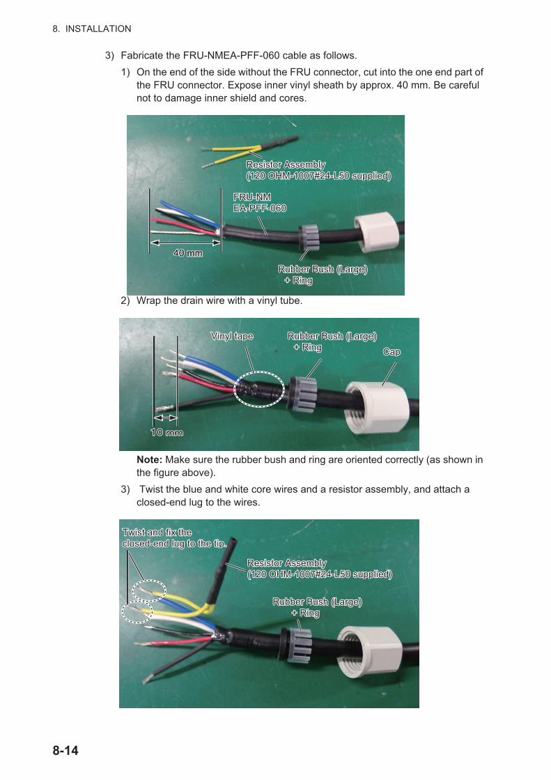
8. INSTALLATION
3) Fabricate the FRU-NMEA-PFF-060 cable as follows.
1) On the end of the side without the FRU connector, cut into the one end part of the FRU connector. Expose inner vinyl sheath by approx. 40 mm. Be careful not to damage inner shield and cores.
2) Wrap the drain wire with a vinyl tube.
Note: Make sure the rubber bush and ring are oriented correctly (as shown in the figure above).
3) Twist the blue and white core wires and a resistor assembly, and attach a closed-end lug to the wires.
40 mm 40 mm 40 mm
FRU-NM EA-PFF-060FRU-NM EA-PFF-060
Resistor Assembly(120 OHM-1007#24-L50 supplied) Resistor Assembly(120 OHM-1007#24-L50 supplied)
Rubber Bush (Large)+ Ring
Rubber Bush (Large)+ Ring
Rubber Bush (Large)+ Ring
Rubber Bush (Large)+ Ring
Vinyl tapeVinyl tape
CapCap
Twist and fix the closed-end lug to the tip.Twist and fix the closed-end lug to the tip.
Resistor Assembly (120 OHM-1007#24-L50 supplied) Resistor Assembly (120 OHM-1007#24-L50 supplied)
Rubber Bush (Large)+ Ring
Rubber Bush (Large)+ Ring
8-14

8. INSTALLATION
4) Connect the cables to the waterproof relay box.Connect the CAN cable (FRU-NMEA-PFF-060) included to the cable replace-ment kit and the cable for GS-1001 (MJ-A10SPF0015-150C/300C) to the inter-nal terminal box.
5) Fit the rubber bush, ring and cap, in that order. Make sure the order is as shown in the below figure, to keep the IP rating.
6) Fit the cover to the waterproof relay box, then secure the cover with the four washer screws removed at step 1.
FRU-NMEA-PFF-060FRU-NMEA-PFF-060
Waterproof Relay Box (JPBS06)Waterproof Relay Box (JPBS06)
MJ-A10SPF0015-150C/300CMJ-A10SPF0015-150C/300C
Cap
Ring
Rubber bush
Waterproof Relay Box
Cap
8-15

8. INSTALLATION
8.2.5 How to secure and waterproof the cable connections
Cable connection for the waterproof relay box, whether exposed to weather or other-wise, should be waterproofed and secured after making the connection.
1) Wrap the cap with several layers of self-bonding tape (supplied), to reduce the height difference between the cap and the box.
2) Starting at approximately 40 mm from the both caps, wrap the cap and waterproof relay box with three layers of self-bonding tape.
Note: Take care that the self-bonding tape is not cut on the waterproof relay box or cap edges.
3) Wrap two layers of vinyl tape, in opposite direction, to cover the self-bonding tape.
Cap
Self-Bonding Tape
Self-Bonding Tape
Approx. 40 mmApprox. 40 mm
Vinyl Tape
8-16

8. INSTALLATION
8.3 Adjustments
8.3.1 Language
The available languages are English and Japanese.
1. Press the MENU ESC key to open the main menu.
2. Select [7 System Setting] then [6 Language/ ].
3. Select [1 English].
4. Press the MENU ESC key to close the main menu.
8.3.2 Device mode
There are two display modes, [SDME] and [THD]. Only a serviceman can switch these modes, at the installation.
1. Press the MENU ESC key to open the main menu.
2. Select [7 System Setting] then [3 Tech Menu].
3. Select [6 Device Mode].
4. Select [SDME] or [THD].[SDME]: Enables the SDME mode.[THD]: Enables the THD mode.
5. Press the MENU ESC key to close the main menu.
8.3.3 Unit
You can set the units of measurement for distance, depth and ship’s speed.
1. Press the MENU ESC key to open the main menu.
2. Select [7 System Set-ting] then [1 System].
*1
*1*1
*2
*2
*1: No use.*2: For serviceman.
8-17

8. INSTALLATION
3. Select [1 Unit of Distance] or [3 Unit of Depth] and go to step 4, or select [2 cm/sec Display] and go to paragraph 3.1.3.
4. Select the unit.The unit of the own ship’s speed changes, depend-ing on the selection at [1 Unit of Distance] as fol-lows:
5. Press the MENU ESC key to close the main menu.
8.3.4 Datum
Your unit is programmed to recognize most of the major chart systems of the world. Although the WGS-84 system, the GPS standard, is now widely used other categories of charts still exist. Select the same datum which is used in your nautical charts.
1. Press the MENU ESC key to open the main menu.
2. Select [7 System Setting] then [1 System].
3. Select [4 Datum].
4. Select an option. For [6 Other], go to step 5. For others, go to step 7.
5. Enter the datum number with the numeric keys.
6. Move the cursor to [Enter] then press the ENT key.
7. Press the MENU ESC key to close the main menu.
8.3.5 Time format
UTC or Local
1. Press the MENU ESC key to open the main menu.
2. Select [7 System Setting] then [1 System].
3. Select [5 Local Time].
4. Select [1 UTC] or [2 Local]. For [2 Local], go to step 5. For [1 UTC], go to step 7.
5. Enter the difference time with the numeric keys. To switch between + and -, select it then press one of keys from 0 to 9.
6. Move the cursor to [Enter] then press the ENT key.
7. Press the MENU ESC key to close the main menu.
[1 NM]: kn [2 km]: km/h [3 SM]: SM/h
Distance Depth
8-18
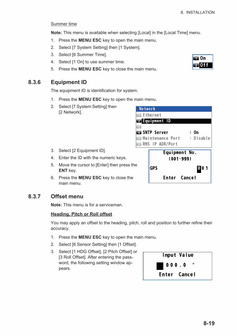
8. INSTALLATION
Summer time
Note: This menu is available when selecting [Local] in the [Local Time] menu.
1. Press the MENU ESC key to open the main menu.
2. Select [7 System Setting] then [1 System].
3. Select [6 Summer Time].
4. Select [1 On] to use summer time.
5. Press the MENU ESC key to close the main menu.
8.3.6 Equipment ID
The equipment ID is identification for system.
1. Press the MENU ESC key to open the main menu.
2. Select [7 System Setting] then [2 Network].
3. Select [2 Equipment ID].
4. Enter the ID with the numeric keys.
5. Move the cursor to [Enter] then press the ENT key.
6. Press the MENU ESC key to close the main menu.
8.3.7 Offset menu
Note: This menu is for a serviceman.
Heading, Pitch or Roll offset
You may apply an offset to the heading, pitch, roll and position to further refine their accuracy.
1. Press the MENU ESC key to open the main menu.
2. Select [6 Sensor Setting] then [1 Offset].
3. Select [1 HDG Offset], [2 Pitch Offset] or [3 Roll Offset]. After entering the pass-word, the following setting window ap-pears.
8-19

8. INSTALLATION
4. Enter the offset value with the numeric keys referring to as follows:
5. Move the cursor to [Enter] then press the ENT key. The message "Processing..." appears then the last-used screen appears.
Position offset
1. Press the MENU ESC key to open the main menu.
2. Select [6 Sensor Setting] then [1 Offset].
3. Select [4 Position Offset].
4. Enter the offset value with the numeric keys. To change the coordinate, select "N" or "E" then press one of keys from 0 to 9.
5. Move the cursor to [Enter] then press the ENT key.
6. Press the MENU ESC key to close the main menu.
1) For example, to enter “+10.0°”, press the cursorpad (►) to move the cursor here.
2) Press the 0, 1, 0, 0 keys. When inputting positive number, “+” appears.
To switch between + and -, press the cursorpad (◄) to move the cursor here then press any numeric key.
8-20

8. INSTALLATION
Ship size and antenna position
1. Press the MENU ESC key to open the main menu.
2. Select [6 Sensor Setting] then [1 Offset].
3. Select [5 ShipSize•ANT/CALC-SPD POS].
4. Enter the value for each item with the numeric keys. Refer to the figure at the right-hand of the display.Note: The value for [ANT Position] is more accurate than the value for [CALC-SPD POSN].
5. Move the cursor to [Enter] then press the ENT key.
6. Press the MENU ESC key to close the main menu.
1
2
3
1 : Set the width, length and height of your ship. Enter the values as correct as possible because these values influence the output sentence “POS”. Note that these values are the upper limits for the values of 2 and 3 .
: Set the mounting location for the antenna unit.X0: The horizontal distance from the reference position “0” to the antenna position.Y0: The forward distance from the reference position “0” to the antenna position.Z0: The height from the ship bottom to the antenna unit GS-1001.
2
: Set the correction of the mounting location for the antenna unit.Y1, Y2: Ship’s speed can be measured at two more positions in addition to the antenna position. Enter the forward distance from the reference position “0” to the position where you want to measure the ship’s speed.Note: Enter accurate positions for Y1 and Y2. If the positions are not set correctly, the speed indication may not be correct.If the settings are not changed from the default "0", speed and ROT indications will not be correct.The setting for Y1 is used to calculate port and starboard speeds, as well as ROT. Therefore, to show speed indications as accurately as possible, set the Y1 value to the same as ship length.Z: Enter “0” for the height from the transducer, the draft for the heght from the draft.
3
4
4 : Set the CCRP (Consistent Common Reference Point). Enter the forward distance from the reference position “0” to the CCRP. This information is used to draw the track based on the CCRP in the berthing display for the DS-600.
8-21

8. INSTALLATION
SOG offset
1. Press the MENU ESC key to open the main menu.
2. Select [6 Sensor Setting] then [1 Offset].
3. Select [6 SOG Offset].
4. Enter the offset value with the numeric keys as follows:
5. Move the cursor to [Enter] then press the ENT key.
6. Press the MENU ESC key to close the main menu.
Atmospheric pressure or air temperature offset
1. Press the MENU ESC key to open the main menu.
2. Select [6 Sensor Setting] then [1 Offset].
3. Select [7 ATM Offset] or [8 TEMP Offset].
4. Enter the offset value with the numeric keys as follows:
5. Move the cursor to [Enter] then press the ENT key.
6. Press the MENU ESC key to close the main menu.
1) For example, to enter “+10.0%”, press the cursorpad (►) to move the cursor here.
2) Press the 1, 0, 0 keys. When inputting positive number, “+” appears.
To switch between + and -, press the cursorpad (◄) to move the cursor here then press any numeric key.
Atmospheric pressure Air temperature
1) For example, to enter “+10.0”, press the cursorpad (►) to move the cursor here.
2) Press the 1, 0, 0 keys. When inputting positive number, “+” appears.
To switch between + and -, press the cursorpad (◄) to move the cursor here then press any numeric key.
8-22

8. INSTALLATION
8.3.8 Alert mode
1. Press the MENU ESC key to open the main menu.
2. Select [3 Alert] then [2 Mode].Note: This menu is for a serviceman.
3. Select [1 Alert I/F 1], [2 Alert I/F 2] or [3 Legacy]. For [1 Alert I/F 1] or [2 Alert I/F 2], go to step 6. For [3 Legacy], go to step 4.[Alert I/F 1]: This system is connected to a device that outputs the ALR sentence.[Alert I/F 2]: This system is connected to a bridge alarm system.[Legacy]: This system is connected to the IF-2503. Set the baud rate to 4800 bps. (See paragraph 3.8.1.)
4. Select [3 Remote Ack I/F].
5. Select [1 Ack] or [2 Buzzer Stop].[Ack]: Acknowledge an alert and stop the buzzer.[Buzzer Stop]: Stop the buzzer.
6. Press the MENU ESC key to close the main menu.
8-23
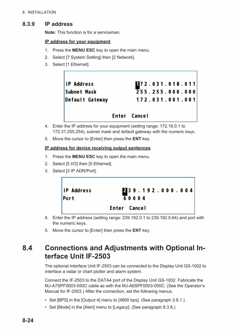
8. INSTALLATION
8.3.9 IP address
Note: This function is for a serviceman.
IP address for your equipment
1. Press the MENU ESC key to open the main menu.
2. Select [7 System Setting] then [2 Network].
3. Select [1 Ethernet].
4. Enter the IP address for your equipment (setting range: 172.16.0.1 to 172.31.255.254), subnet mask and default gateway with the numeric keys.
5. Move the cursor to [Enter] then press the ENT key.
IP address for device receiving output sentences
1. Press the MENU ESC key to open the main menu.
2. Select [5 I/O] then [5 Ethernet].
3. Select [3 IP ADR/Port].
4. Enter the IP address (setting range: 239.192.0.1 to 239.192.0.64) and port with the numeric keys.
5. Move the cursor to [Enter] then press the ENT key.
8.4 Connections and Adjustments with Optional In-terface Unit IF-2503The optional Interface Unit IF-2503 can be connected to the Display Unit GS-1002 to interface a radar or chart plotter and alarm system.
Connect the IF-2503 to the DATA4 port of the Display Unit GS-1002. Fabricate the MJ-A7SPF0003-050C cable as with the MJ-A6SPF0003-050C. (See the Operator’s Manual for IF-2503.) After the connection, set the following menus.
• Set [BPS] in the [Output 4] menu to [4800 bps]. (See paragraph 3.8.1.)
• Set [Mode] in the [Alert] menu to [Legacy]. (See paragraph 8.3.8.)
8-24

8. INSTALLATION
8.5 Installation, Adjustment of Optional Display Unit DS-600The Display Unit GS-1002 can be connected with the optional DS-600.
8.5.1 Installation of the display unit DS-600
Mounting considerations
The display unit DS-600 can be installed on a desktop, on the underside of a table, or flush mounted in a panel. When you select a mounting location, keep in mind the fol-lowing points:
• Locate the display unit away from exhaust pipes and vents.
• Select an installation location that is well ventilated.
• Locate the display unit where shock and vibration are minimal.
• Allow enough maintenance space at the sides and rear of the display unit and leave enough slack in cables to facilitate maintenance and servicing.
• Observe the compass safe distances (see page i) to prevent the interference to a magnetic compass.
• The nominal viewing distance for the display unit is 1 m. Select a suitable mounting location considering that distance.
Flush mount
See the outline drawing in the back of this manual. Before you fasten the display unit to the cutout, first connect the cable to the DATA1/DATA2 port of the display unit GS-1002. (See paragraph 8.2.2.)
1. Make a cutout in the mounting location as shown in the illustration below.
Note: Dimensions for the cutout are different depending on the mounting location, indoor or outdoor. For the outdoor mounting, ask dockyard to construct a water-proof case for the display unit.
2. Make four pilot holes for tapping screws (diameter: 5 mm) in the location indicated in the illustration at step 1.
3. Insert the sponge to the display unit from the rear side.
4. Set the display unit to the cutout and fasten the display unit with four tapping screws (5×20).
223±
0.5
(8.7
8”)
228±
1 (8
.98”
) (fo
r out
door
)23
2±1
(9.1
3”)
(for i
ndoo
r)
18 (0.71”)
228±1 (8.98”) (for outdoor)
232±1 (9.13”) (for indoor)
223±0.5 (8.78”)
Pilot hole(four places)
18 (0.71”)(for outdoor)
22 (0.87”)(for indoor)
or
240 (9.45”)
Fixing hole (4-ø6)
240
(9.4
5”)
12 (0.47”) 78 (3.07”)
8-25

8. INSTALLATION
5. Set a cosmetic cap to each fixing hole on the front panel. See "How to set the cos-metic caps and alarm lid assembly" on page 8-27.
Desktop or table underside mount
The display unit can be mounted on a desktop or on the underside of a table using the optional bracket. See the outline drawing for details.
Bracket Assembly with Knobs (Type: OP26-8, Code No.: 000-016-313))
1. Remove the hanger fixing plates from the hanger assembly.
2. Fasten the hanger fixing plates to the display unit from the left side and right side with four binding head screws (M5×12).
3. Make four pilot holes for tapping screws (5×20) in the mounting location.
4. Fix the hanger to the mounting location with four tapping screws (5×20).
5. Screw knobs into the display unit loose-ly.
6. Set the display unit to the hanger.
7. Tighten the knobs to fasten the hanger to the display unit.
8. Set a cosmetic cap to each fixing hole on the front panel.
Name Type Code No. QtyTapping screw 5×20 SUS304 000-171-997-10 4Binding head screw M5×12 SUS304 000-171-999-10 4Bracket assembly OP26-8-1 001-081-920 1
Screw (M5x12)
Hanger fixingplate (left side)
75±0
.5 (2
.95”
)
Fixing hole (4-ø7) 190±0.5 (7.48”)
40
288±5 (11.34”)240 (9.45”)
51±5 (2.01”)149 (5.87”)
91 (3.58”)
240
(9.4
5”)
260±
5 (1
0.24
”)
279±
5 (1
0.98
”)
8-26

8. INSTALLATION
How to set the cosmetic caps and alarm lid assembly
Set a cosmetic cap to each fixing hole on the front panel as shown in the illustration below.
For the display unit to be used as a sub display, attach the alarm lid (supplied as ac-cessories) to the ALARM ACK key to prevent accidental operation of the key.
8.5.2 Menu settings for DS-600
Set up for use with the DS-600 from the Service menu.
How to use the Service menu
1. Press the PWR key while pressing the DISP key to turn the power on.Note: Press and hold the keys until two beeps sound.
The start-up screen appears for 90 seconds then the service menu appears.
2. Use or to select a menu item then press the ENT key to show the setting window.
3. Use or to change the setting then press the ENT key. To return to the menu, press the MENU ESC key.
ALARM
Alarm lid assembly (For sub display only)
Attach the double-sided tape to the reverse side of the lid, and attach the lid here.
Set cosmetic cap to hole so cap is flush with panel.
8-27

8. INSTALLATION
4. Repeat steps 2 and 3 to complete the setting. For items to be set at the installa-tion, see the table at the top of the next page.
5. Press the PWR key to turn the power off.
How to set the displays
The DS-600 is preset with five displays as below:
• DISP1: Navigation data
• DISP2: Berthing (Head-up)
• DISP3: Heading and speed
• DISP4: Trip distance and total distance
• DISP5: Speed analog data (sub display only)
Only two berthing displays (for head-up and north-up) are available on the display unit DS-600 connected to the GS-1002. Set the displays as follows:
1. Press the MENU ESC key to open the menu.
2. Select [Display] then press the ENT key.
Menu item Meaning Option (bold: default)[Operation] Select [Main] or [Sub].
(For the display unit con-nected to the GS-1002, se-lect [Sub].)
[Main], [Sub], [Satellite]**: Sub display shared be-tween the GS-100 and the DS-60
[SIO Monitor] Monitor the serial signal input to the display units (main and sub).
[L/L digit] Set the number of digits to show for the minutes indi-cation in latitude and longi-tude position.
[3digit], [4digit]
Others For the serviceman. No use in installation.
8-28

8. INSTALLATION
3. Select [DISP1] or [DISP2] then press the ENT key.
4. Select the full screen then press the ENT key.
5. Select the orientation of the berthing display, [Berthing H Up] or [Berthing N Up], then press the ENT key.
6. Set [DISP3] to [DISP7] as blank (no display), following steps 3 to 5.
7. Press the DISP key to close the menu.
Full screen
Two-way horizontal split screen
Blank (no display)*
*: Not available with DISP1.
Berthing (Head-up) Berthing (North-up)56.0
8-29

8. INSTALLATION
8.5.3 Adjustments for GS-1002
Set the following menus in the [Output Data1]/[Output Data2] menu (see paragraph 3.8.1).
• [Format]: Select [IEC61162-1 Ed.4] or [IEC61162-1 Ed.3].
• [BPS]: Select [38400 bps].
• [Sentence]: Select the following sentences.
• GGA*, VBW, VTG, ZDA: 1s (*: Have a serviceman set GGA.)
• HDT, ROT: 0.1s
8.6 Speed TestNote: This function is for a serviceman.
1. Press the MENU ESC key to open the main menu.
2. Select [2 Speed/Trip Setting] then [2 Trip].
3. Select [4 Speed Test]. The confirma-tion message appears.
4. Select [1 Yes]. The sen-sor restarts then the fol-lowing screen appears.
5. Press the ENT key. The GS-100 starts calcula-tion of trip time, trip dis-tance and average speed.
GN 3D-
GN 3D-
8-30

APPENDIX 1 MENU TREEGS-100 Bold Italic : Default
1 DisplayBackground Color (White , Black)Navigation Display
Window1 (Roll/Pitch , SDME, Blank)Window2 (Position , Current, Blank)Window3 (Time&Date , Wind, Atm&Temp, Blank)Window4 (Heave , Depth, Blank)Window5 (Trip Time , Drift, Blank)
SmoothingVTG (Open the setting window.)L/L (Open the setting window.)VBW (Open the setting window.)Wind (Open the setting window.)ROT (Open the setting window.)
Current/WindCurrent (Flow to , Flow from)Wind Speed (True, Theoretical , Relative)
2 Speed/Trip SettingShip Speed (Off , In, Out, Speed)Trip
Calculation (Stop, Start/Restart , Clear)Range (Open the setting window.)Notice (Off , On)Speed Test* *: For serviceman.
Total Distance
Clear
Preset (Open the setting window.)Sound
Notice Sound (Off , On, Continuous)Key Sound (On , Off)
3 AlertActive Alert (Open the active alert list.)Mode* (Alert I/F 1 , Alert I/F 2, Legacy)Remote Ack I/F (Ack , Buzzer Stop)Alert Log (Open the alert log.)
4 MaintenanceInformation
Display UnitMain board (Open the information for main board.)Panel board (Open the information for panel board.)CAN board (Open the information for CAN board.)
Antenna UnitMain board (Open the information for main board.)GNSS (Open the information for GNSS.)Sensor (Open the information for sensor.)
Self TestMemoryKeyboard TestTest PatternAutomatic TestSound Test*1
AP-1

BackupBackup User Setting (Yes, No )Load User Setting (Yes, No )
SW/Database Update* *: For serviceman.Chk the Available Software
Display Unit: ApplicationDisplay Unit: BootAntenna Unit: ApplicationAntenna Unit: GNSSAntenna Unit: OS
Chk the New Data TableDatumWMM
Exchange*Display Unit
LCD (Yes, No )Main (Yes, No )
Antenna UnitMain (Yes, No )OMG (Open the setting window.)ACC (Open the setting window.)ATM (Open the setting window.)TEMP (Open the setting window.)
Serial No. (Open the entry window.)Destination Language (English , )
Sensor Status* (Open the sensor status window.)
5 I/OOutput Data1 to 4
Format* (IEC61162-1 Ed.4 , IEC61162-1 Ed.3, NMEA V2.0, NMEA V1.5, IEC61162-1 Ed.5)BPS* (4800 bps, 38400 bps)**
**: Default (Output Data1 to 3: 4800 bps, Output Data4: 38400 bps)Sentence (HDT: Off , HRM: Off , ROT: Off , THS: 0.2s ***, VBW: 1s , VLW: 1s ,VTG: 1s , ZDA: 1s , GPatt: Off , GPhve: Off, GPimu: Off ) ***: 0.020s for Output Data4.
EthernetSentence (HDT: 0.1s , HRM: 0.1s , ROT: 0.1s , THS: 0.020s , VBW: 1s , VLW: 1s ,VTG: 1s , ZDA: 1s , GPatt: 0.020s , GPhve: 0.020s, GPimu: Off )SFI* (Open the entry window.)IP ADR/Port* (Open the entry window.)
Data Source SelectHDG (Data1, Data2, Data4, Ethernet, CAN , User Priority)Ext. STW/COG/SOG (Data1 , Data2, Data4, Ethernet, User Priority)Ext. CUR (Data1 , Data2, Data4, Ethernet, User Priority)Ext. DEPTH (Data1 , Data2, Data4, Ethernet, User Priority)Ext. Wind (Data1 , Data2, Data4, Ethernet, User Priority)
Line MonitorData1 (Open the line monitor for serial data1.)Data2 (Open the line monitor for serial data2.)Data3 (Open the line monitor for serial datat3.)Data4 (Open the line monitor for serial datat4.)Ethernet (Open the line monitor for Ethernet.)CAN (Open the line monitor for CAN.)GS-1001* (No , USB, UDP)LAN Error Counter (Open the LAN error data list.)
1
1
AP-2
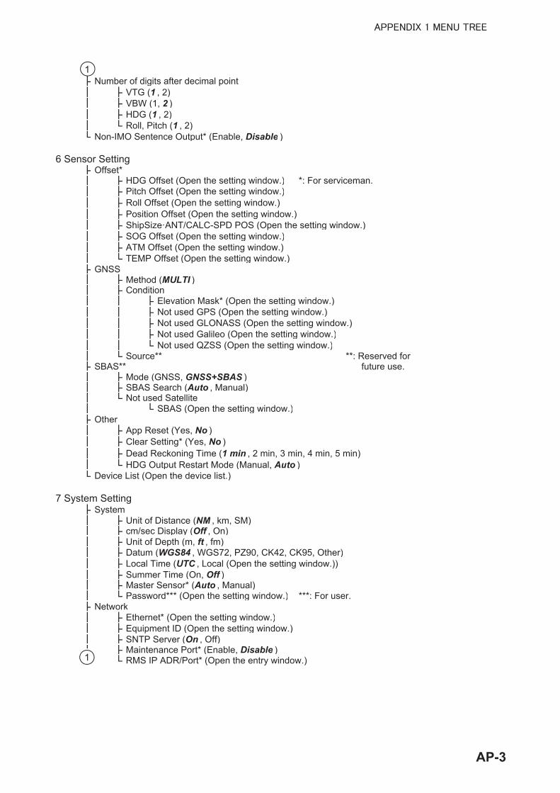
Number of digits after decimal pointVTG (1 , 2)VBW (1, 2 )HDG (1 , 2)Roll, Pitch (1 , 2)
Non-IMO Sentence Output* (Enable, Disable )
6 Sensor SettingOffset*
HDG Offset (Open the setting window.) *: For serviceman.Pitch Offset (Open the setting window.)Roll Offset (Open the setting window.)Position Offset (Open the setting window.)ShipSize·ANT/CALC-SPD POS (Open the setting window.)SOG Offset (Open the setting window.)ATM Offset (Open the setting window.)TEMP Offset (Open the setting window.)
GNSSMethod (MULTI )Condition
Elevation Mask* (Open the setting window.)Not used GPS (Open the setting window.)Not used GLONASS (Open the setting window.)Not used Galileo (Open the setting window.)Not used QZSS (Open the setting window.)
Source** **: Reserved forSBAS** future use.
Mode (GNSS, GNSS+SBAS )SBAS Search (Auto , Manual)Not used Satellite
SBAS (Open the setting window.)Other
App Reset (Yes, No )Clear Setting* (Yes, No )Dead Reckoning Time (1 min , 2 min, 3 min, 4 min, 5 min)HDG Output Restart Mode (Manual, Auto )
Device List (Open the device list.)
7 System SettingSystem
Unit of Distance (NM , km, SM)cm/sec Display (Off , On)Unit of Depth (m, ft , fm)Datum (WGS84 , WGS72, PZ90, CK42, CK95, Other)Local Time (UTC , Local (Open the setting window.))Summer Time (On, Off )Master Sensor* (Auto , Manual)Password*** (Open the setting window.) ***: For user.
NetworkEthernet* (Open the setting window.)Equipment ID (Open the setting window.)SNTP Server (On , Off)Maintenance Port* (Enable, Disable )RMS IP ADR/Port* (Open the entry window.)
1
1
AP-3

Tech Menu* *: For serviceman.Inner Status (No , Yes)Legacy Sentence Input (Disable , Enable)VTG Speed Source (Sensor Raw , Corrected)VBW Speed Source (Sensor Raw, Corrected )Trip calc (DS Mode , GS Mode)Device Mode (SDME , THD)
DemoMoving Setting (Open the setting window.)Attitude Setting (Open the setting window.)Output Status* (Simulation , Fix, Differential Fix, Estimation(DR), Manual Input, No Fix)Demo Start
Berthing LineList (Open the berthing line list.)Share (Send the berthing line data to DS-600.)
Language/ (English , )Clear Memory
Clear Display Setting (Yes, No )Clear GNSS* (Yes, No )Clear All* (Yes, No )Factory Default* (Yes, No )
DS-600 (The menus available on the sub display)
MENU ESC keyShip's Time
Source (Internal (-13:00 - + 13:00), NAV EQUIP )Summer Time (ON, OFF )
Ship's Track (Past+Predict , Past, Predict, OFF)Plot Time (1min, 2min, 5min , 10min, 20min, 30min)Past Tracks (ON , OFF)Vector Time (30s, 1min, 2min, 5min , 10min, 20min)Display (DISP1, DISP2)Scale Set Up
Speed Graphic (DISP1, DISP2)Astern SPD Scale (5kn(2.5m/s, 10km/h) , 10kn(5.0m/s, 20km/h),15kn(7.5m/s, 30km/h), 20kn(10.0m/s, 40km/h),25kn(12.5m/s, 50km/h), 30kn(15.0m/s, 60km/h), 35kn(17.5m/s, 70km/h), 40kn(20.0m/s, 80km/h),45kn(22.5m/s, 90km/h), 50kn(25.0m/s, 100km/h)) Ahead SPD Scale (Same choices as above,25kn(12.5m/s, 50km/h) )
Depth REF (EXT DBK , EXT DBT, INT DBT)Direction SYM (Arrows , Text)SYM Location (Left , Right)Berthing Range (50m(0.025NM) , 75m(0.040NM) , 100m(0.050NM) , 150m(0.075NM ),200m(0.100NM) , 250m(0.125NM), 300m(0.150NM), 400m(0.200NM), 600m(0.300NM),800m(0.400NM), 1000m(0.500NM), Save)Berthing Data Display (3 axis in NAV , 3 axis and NAV, 3 axis)CUR Direction (Flow to , Flow from)Mode
Wind (True , Theoretical, Relative, OFF)Time (UTC , Ship's Time)
InitializeWind Average (No Averaging, 1min , 2min, 3min, 5min, 10min)Key Beep (ON , OFF)Key BRILL (1, 2 , 3, 4, 5, 6, 7, 8)Speed Select (Forward-After , Vector)TESTS (System TEST, Display Unit TEST, LCD TEST)User RESET (Yes, No )
1
AP-4

APPENDIX 2 LIST OF TERMS/SYM-BOLS
The following table shows the terms and symbols used in the GS-100.
Terms
Terms MeaningACC AccelerometerACK AcknowledgeADJ Adjust, AdjustmentADR AddressALARM AlarmALT AltitudeANGLE AngleANT AntennaAPR AprilATM Atmosphere ATTITUDE AttitudeAUG AugustAUTO AutomaticAVERAGE AverageBARO BarometerBKGND BackgroundBPS Bit Per SecondBRILL BrillianceBS BackspaceCAL CalibrateCALC CalculationCAN Controller Area Network CCRP Consistent Common Reference PointCCRS Consistent Common Reference SystemCLR ClearCNCL CancelCOG Course Over the GroundCOM CommonCONT ContrastCORR CorrectionCPU Central Processing UnitCURRENT, CUR CurrentDATE DateDAY DayDEC DecemberDEL DeleteDELAY DelayDEPTH DepthDGLONASS Differential GLONASSDGNSS Differential GNSS
AP-5
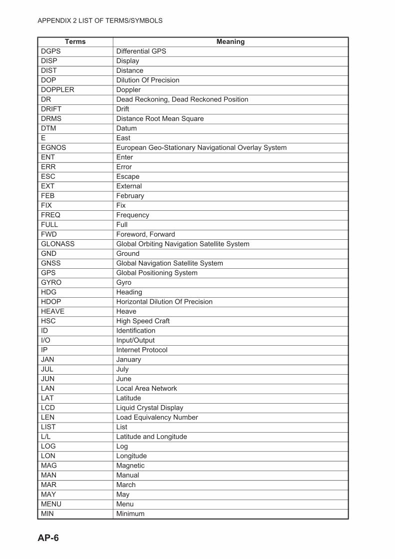
APPENDIX 2 LIST OF TERMS/SYMBOLS
DGPS Differential GPSDISP DisplayDIST DistanceDOP Dilution Of PrecisionDOPPLER DopplerDR Dead Reckoning, Dead Reckoned PositionDRIFT DriftDRMS Distance Root Mean SquareDTM DatumE EastEGNOS European Geo-Stationary Navigational Overlay SystemENT EnterERR ErrorESC EscapeEXT ExternalFEB FebruaryFIX FixFREQ FrequencyFULL FullFWD Foreword, ForwardGLONASS Global Orbiting Navigation Satellite SystemGND GroundGNSS Global Navigation Satellite SystemGPS Global Positioning SystemGYRO GyroHDG HeadingHDOP Horizontal Dilution Of PrecisionHEAVE HeaveHSC High Speed CraftID IdentificationI/O Input/OutputIP Internet ProtocolJAN JanuaryJUL JulyJUN JuneLAN Local Area NetworkLAT LatitudeLCD Liquid Crystal DisplayLEN Load Equivalency NumberLIST ListL/L Latitude and LongitudeLOG LogLON LongitudeMAG MagneticMAN ManualMAR MarchMAY MayMENU MenuMIN Minimum
Terms Meaning
AP-6

APPENDIX 2 LIST OF TERMS/SYMBOLS
MAX MaximumMSTR MasterN NorthNAV NavigationNM Nautical MileNORM NormalNOV NovemberNT NightOCT OctoberOFF OffOFFSET OffsetOMG OmegaON OnONF Other Network Function BlockOS Operating SystemPCB Printed Circuit BoardPDOP Positional Dilution Of PrecisionPITCH PitchPORT Port/PortsidePOSITION, POSN, POS
Position
PRN Pseudo-Random-NoisePWR PowerQZSS Quasi-Zenith Satellite SystemR Relative WindRAIM Receiver Autonomous Integrity MonitoringREF ReferenceREL RelativeRM Relative MotionRMS Root Mean SquareRMS Remote Maintenance System ROLL RollROT Rate Of TurnRx, RX ReceiveS SouthSATELLITE, SAT SatelliteSBAS Satellite Base Argument SystemSDME Speed and Distance Measuring EquipmentSEP SeptemberSFI System Function IDSIM SimulationSLAVE SlaveS/N Signal/NoiseSNTP Simple Network Time ProtocolSNR Signal to Noise RatioSOG Speed Over the GroundSPEED, SPD SpeedSTATE StateSTBD Starboard/Starboard Side
Terms Meaning
AP-7

APPENDIX 2 LIST OF TERMS/SYMBOLS
STW Speed Through the WaterSV Space VehicleSW SoftwareSYS SystemT TrueTAG TagTCVR TransceiverTEMP TemperatureTH Theoretical WindTHD Transmitting Heading DeviceTIME Ship’s Time, TimeTOTAL TotalTRIP TripTX TransmitTXRX Transmit and ReceiveUDP User Datagram ProtocolUTC Coordinated Universal Time, Universal Time CoordinatedW WestWARNING WarningWGS World Geodetic SystemWMM World Magnetic Model
Terms Meaning
AP-8

APPENDIX 2 LIST OF TERMS/SYMBOLS
Symbols
Symbols MeaningActive unacknowledged warning
Active acknowledged warning
Active responsibility transferred warning
Rectified unacknowledged warning
Silenced warning
Additional warning
Additional caution
Caution
Ship speed notice (See section 4.2.)
Trip notice (See section 4.3.)
There is no GS-1001 in CAN network but SC-30 is.
There is no GS-1001B in CAN network but SC-33 is.
The antenna acceleration is over 5 G.
Satellite blocked. The common satellite for antenna 1 and 2 is blocked.Ready to output speed signal (See paragraph 3.6.4.)
Ready to output heading signal (See paragraph 3.6.4.)
High precision speed computing
Apply to Multi-GNSS (GPS, GLONASS, Galileo and QZSS).Demo mode
AP-9

AP-10
APPENDIX 3 TIME DIFFERENCES

AP-11
APPENDIX 4 GEODETIC CHART LIST
001: WGS84 002: WGS72 003: TOKYO : 004: NORTH AMERICAN 1927 : Mean Value (CONUS) 005: EUROPEAN 1950 : Mean Value 006: AUSTRALIAN GEODETIC 1984 : Australia & Tasmania 007: ADINDAN : Mean Value (Ethiopia & Sudan) 008: ADINDAN : Ethiopia 009: ADINDAN : Mali 010: ADINDAN : Senegal 011: ADINDAN : Sudan 012: AFG : Somalia 013: AIN EL ABD 1970 : Bahrain Is. 014: ANNA 1 ASTRO 1965 : Cocos Is. 015: ARC 1950 : Mean Value 016: ARC 1950 : Botswana 017: ARC 1950 : Lesotho 018: ARC 1950 : Malawi 019: ARC 1950 : Swaziland 020: ARC 1950 : Zaire 021: ARC 1950 : Zambia 022: ARC 1950 : Zimbabwe 023: ARC 1960 : Mean Value (Kenya & Tanzania) 024: ARC 1960 : Kenya 025: ARC 1960 : Tanzania 026: ASCENSION IS. 1958 : Ascension Is. 027: ASTRO BEACON “E” : Iwo Jima Is. 028: ASTRO B4 SOR. ATOLL : Tern Is. 029: ASTRO POS 71/4 : St. Helena Is. 030: ASTRONOMIC STATION 1952 : Marcus Is. 031: AUSTRALIAN GEODETIC 1966 : Australia & Tasmania 032: BELLEVUE (IGN) : Efate & Erromango Is.033: BERMUDA 1957 : Bermuda Is.034: BOGOTA OBSERVATORY : Columbia 035: CAMPO INCHAUSPE : Argentina 036: CANTON IS. 1966 : Phoenix Is.037: CAPE : South Africa 038: CAPE CANAVERAL : 039: CARTHAGE : Tunisia 040: CHATHAM 1971 : Chatham Is. (New Zealand) 041: CHUA ASTRO : Paraguay 042: CORREGO ALEGRE : Brazil 043: DJAKARTA (BATAVIA) : Sumatra Is. (Indonesia) 044: DOS 1968 : Gizo Is. (New Georgia Is.) 045: EASTER IS. 1967 : Easter Is. 046: EUROPEAN 1950 (Cont’d) : Western Europe 047: EUROPEAN 1950 : Cyprus 048: EUROPEAN 1950 : Egypt 049: EUROPEAN 1950 : 050: EUROPEAN 1950 : 051: EUROPEAN 1950 : Greece 052 EUROPEAN 1950 : Iran 053: EUROPEAN 1950 : Italy, Sardinia 054: EUROPEAN 1950 : Italy, Sicily 055: EUROPEAN 1950 : Norway & Finland 056: EUROPEAN 1950 : Portugal & Spain 057: EUROPEAN 1979 : Mean Value 058: GANDAJIKA BASE : Republic of Maldives 059: GEODETIC DATUM 1949 : New Zealand 060: GUAM 1963 : Guam Is. 061: GUX 1 ASTRO : Guadalcanal Is. 062: HJORSEY 1955 : Iceland 063: HONG KONG 1963 : Hong Kong 064: INDIAN : Thailand & Vietnam 065: INDIAN : Bangladesh, India & Nepal 066: IRELAND 1965 : Ireland 067: ISTS 073 ASTRO 1969 : Diego Garcia 068: JOHNSTON IS. 1961 : Johnston Is. 069: KANDAWALA : Sri Lanka 070: KERGUELEN IS. : Kerguelen Is. 071: KERTAU 1948 : West Malaysia & Singapore 072: LA REUNION : Mascarene Is. 073: L. C. 5 ASTRO : Cayman Brac Is. 074: LIBERIA 1964 : Liberia 075: LUZON : Philippines (excl. Mindanao Is.) 076: LUZON : Mindanao Is. 077: MAHE 1971 : Mahe Is. 078: MARCO ASTRO : Salvage Islands 079: MASSAWA : Eritrea (Ethiopia) 080: MERCHICH : Morocco 081: MIDWAY ASTRO 1961 : Midway Is. 082: MINNA : Nigeria 083: NAHRWAN : Masirah Is. (Oman) 084: NAHRWAN : United Arab Emirates 085: NAHRWAN : Saudi Arabia 086: NAMIBIA : Namibia 087: MAPARIMA, BWI : Trinidad & Tobago 088: NORTH AMERICAN 1927 : Western United States 089: NORTH AMERICAN 1927 : Eastern United States
090: NORTH AMERICAN 1927 : Alaska 091: NORTH AMERICAN 1927 : Bahamas (excl. San Salvador Is.)
Mean Value (Japan, Korea & Okinawa)
Mean Value (Florida & Bahama Is.)
England, Scotland, Channel & Shetland Is.England, Ireland, Scotland & Shetland Is.
092: NORTH AMERICAN 1927 : Bahamas, San Salvador Is. 093: NORTH AMERICAN 1927 (Cont’d) : Canada (incl. Newfoundland Is.) 094: NORTH AMERICAN 1927 (Cont’d) : Alberta & British Columbia 095: NORTH AMERICAN 1927 (Cont’d) : East Canada 096: NORTH AMERICAN 1927 (Cont’d) : Manitoba & Ontario 097: NORTH AMERICAN 1927 (Cont’d) : 098: NORTH AMERICAN 1927 (Cont’d) : Yukon 099: NORTH AMERICAN 1927 (Cont’d) : Canal Zone 100: NORTH AMERICAN 1927 (Cont’d) : Caribbean 101: NORTH AMERICAN 1927 (Cont’d) : Central America 102: NORTH AMERICAN 1927 (Cont’d) : Cuba 103: NORTH AMERICAN 1927 (Cont’d) : Greenland 104: NORTH AMERICAN 1927 (Cont’d) : Mexico 105: NORTH AMERICAN 1983 : Alaska 106: NORTH AMERICAN 1983 : Canada 107: NORTH AMERICAN 1983 : CONUS 108: NORTH AMERICAN 1983 : Mexico, Central America 109: OBSERVATORIO 1966 : Corvo & Flores Is. (Azores)110: OLD EGYPTIAN 1930 : Egypt 111: OLD HAWAIIAN : Mean Value 112: OLD HAWAIIAN : Hawaii 113: OLD HAWAIIAN : Kauai 114: OLD HAWAIIAN : Maui 115: OLD HAWAIIAN : Oahu 116: OMAN : Oman 117: ORDNANCE SURVEY OF GREAT BRITAIN 1936: Mean Value118: ORDNANCE SURVEY OF GREAT BRITAIN 1936: England119: ORDNANCE SURVEY OF GREAT BRITAIN 1936: England, Isle
of Man & Wales 120: ORDNANCE SURVEY OF GREAT BRITAIN 1936: Scotland &
Shetland Is. 121: ORDNANCE SURVEY OF GREAT BRITAIN 1936 : Wales122: PICO DE LAS NIVIES : Canary Is.123: PITCAIRN ASTRO 1967 : Pitcairn Is. 124: PROVISIONAL SOUTH CHILEAN 1963: South Chi le (near 53°S) 125: PROVISIONAL SOUTH AMERICAN 1956: Mean Value 126: PROVISIONAL SOUTH AMERICAN 1956: Bolivia 127: PROVISIONAL SOUTH AMERICAN 1956: Chile-Northern Chile
(near 19°S) 128: PROVISIONAL SOUTH AMERICAN 1956: Chile-Southern Chile
(near 43°S)
129: PROVISIONAL SOUTH AMERICAN 1956: Columbia130: PROVISIONAL SOUTH AMERICAN 1956: Ecuador 131: PROVISIONAL SOUTH AMERICAN 1956: Guyana 132: PROVISIONAL SOUTH AMERICAN 1956: Peru 133: PROVISIONAL SOUTH AMERICAN 1956: Venezuela
134: PUERTO RICO : Puerto Rico & Virgin Is.135: QATAR NATIONAL : Qatar 136: QORNOQ : South Greenland 137: ROME 1940 : Sardinia Is.138: SANTA BRAZ : 139: SANTO (DOS) : Espirito Santo Is. 140: SAPPER HILL 1943 : East Falkland Is. 141: SOUTH AMERICAN 1969 : Mean Value 142: SOUTH AMERICAN 1969 : Argentina 143: SOUTH AMERICAN 1969 : Bolivia 144: SOUTH AMERICAN 1969 : Brazil 145: SOUTH AMERICAN 1969 : Chile 146: SOUTH AMERICAN 1969 : Columbia 147: SOUTH AMERICAN 1969 : Ecuador 148: SOUTH AMERICAN 1969 : Guyana 149: SOUTH AMERICAN 1969 : Paraguay 150: SOUTH AMERICAN 1969 : Peru 151: SOUTH AMERICAN 1969 : Trinidad & Tobago 152: SOUTH AMERICAN 1969 : Venezuela 153: SOUTH ASIA : Singapore 154: SOUTHEAST BASE : Porto Santo & Madeira Is.155: SOUTHWEST BASE : 156: TIMBALAI 1948 : 157: TOKYO : Japan 158: TOKYO : Korea 159: TOKYO : Okinawa 160: TRISTAN ASTRO 1968 : Tristan da Cunha 161: VITI LEVU 1916 : Viti Levu Is. (Fiji Is.)162: WAKE-ENIWETOK 1960 : Marshall Is.163: ZANDERIJ : Surinam 164: BUKIT RIMPAH : 165: CAMP AREA ASTRO : Camp Mcmurdo Area, Antarctica 166: G. SEGARA : Kalimantan Is. (Indonesia) 167: HERAT NORTH : Afghanistan 168: HU-TZU-SHAN : Taiwan
169: TANANARIVE OBSERVATORY 1925 : Madagascar170: YACARE : Uruguay171: RT-90 : Sweden
172: PULKOVO 1942 : Russia 173: FINNISH KKJ : Finland
Northwest Territories & Saskatchewan
Sao Miguel, Santa Maria Is. (Azores)
Faial, Graciosa, Pico, Sao Jorge & Terceria Is.Brunei & East Malaysia (Sarawak & Sabah)
Bangka & Belitung Is. (Indonesia)
(Cont’d)(Cont’d)(Cont’d)
(Cont’d)(Cont’d)(Cont’d)(Cont’d)(Cont’d)(Cont’d)(Cont’d)

AP-12
APPENDIX 5 WHAT IS SBAS?
A satellite based augmentation system, or SBAS (Satellite Based Augmentation System), is an augmentation system that uses additional messages from satellite broadcasts to support regional and wide area augmentation. SBAS provides GPS signal corrections to SBAS users, for even bet-ter position accuracy, through the GPS error corrections that are widely broadcasted from the geo-stationary satellite.
SBAS is used in America, Europe, Japan and India.
• America: WAAS (Wide Area Augmentation System)
• Europe: EGNOS (Euro Geostationary Navigation Overlay Service)
• Japan: MSAS (Multi-Functional Satellite Augmentation System)
• India: GAGAN (GPS And GEO Augmented Navigation)
These four systems have interoperability. The illustration below shows the coverage area for each provider. This manual uses "SBAS" for these four providers generically.
As of March 6th, 2014
Provider Satellite type Longitude Satellite No.WAAS Intelsat Galaxy XV 133°W 135
TeleSat Anik F1R 107.3°W 138Inmarsat-4-F3 98°W 133
EGNOS Inmarsat-3-F2/AOR-E 15.5°W 120Artemis 21.5°E 124Inmarsat-4-F2 25°E 126SES-5 5°E 136
MSAS MTSAT-1R 140°E 129MTSAT-2 145°E 137
GAGAN GSAT-8 55°E 127GSAT-10 83°E 128
WAAS
MSAS
EGNOS
GAGAN
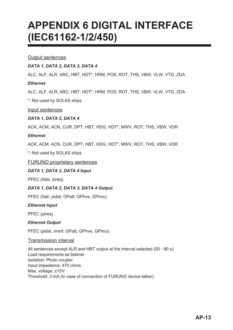
APPENDIX 6 DIGITAL INTERFACE (IEC61162-1/2/450)
Output sentences
DATA 1, DATA 2, DATA 3, DATA 4
ALC, ALF, ALR, ARC, HBT, HDT*, HRM, POS, ROT, THS, VBW, VLW, VTG, ZDA
Ethernet
ALC, ALF, ALR, ARC, HBT, HDT*, HRM, POS, ROT, THS, VBW, VLW, VTG, ZDA
*: Not used by SOLAS ships
Input sentences
DATA 1, DATA 2, DATA 4
ACK, ACM, ACN, CUR, DPT, HBT, HDG, HDT*, MWV, ROT, THS, VBW, VDR
Ethernet
ACK, ACM, ACN, CUR, DPT, HBT, HDG, HDT*, MWV, ROT, THS, VBW, VDR
*: Not used by SOLAS ships
FURUNO proprietary sentences
DATA 1, DATA 2, DATA 4 Input
PFEC (IIals, pireq)
DATA 1, DATA 2, DATA 3, DATA 4 Output
PFEC (IIalr, pidat, GPatt, GPhve, GPimu)
Ethernet Input
PFEC (pireq)
Ethernet Output
PFEC (pidat, rminf, GPatt, GPhve, GPimu)
Transmission interval
All sentences except ALR and HBT output at the interval selected (00 - 90 s).Load requirements as listenerIsolation: Photo couplerInput impedance: 470 ohmsMax. voltage: ±15VThreshold: 3 mA (in case of connection of FURUNO device talker)
AP-13

APPENDIX 6 DIGITAL INTERFACE (IEC61162-1/2/450)
Data transmission
Data is transmitted in serial asynchronous form in accordance with the standard referenced in IEC 61162-1 and IEC 61162-2. The first bit is a start bit and is followed by data bits.
The following parameters are used:Baud rate: 4800 for IEC61162-1, 38400 for IEC-61162-2Data bits: 8 (D7 = 0), parity noneStop bits: 1
IEC61162-1: Edition 5.0 2016, Edition 4.0 2010-11, Third edition 2007-04IEC61162-2: First Edition 1998-09 IEC61162-450: Edition 1.0 2011-06
Schematic diagrams
DATA 1, 2, or 3 port (output)
0
8GND
R17 154A
93A
72A
11A
12G4G
N
16VCC
4Z
4Y
3Z
2Z
1Z
4Y
2Y
1Y 2
3
6
5
10
11
14
13
CP58
CP59GPS-A
GPS-B
U9SN65LBC172A16DWR
5.1V_D
C20
0.1u
5.1V_D
5.1V_DCR7 CR8
CR6 CR5 CR4
CR31SS226_TE85L_F
TD1-A
TD1-B
TD2-A
TD2-B
TD3-A
TD3-B
(13A2)
(13A2)
(13B2)
(13C2)
(13A4)
(13A4)
AP-14
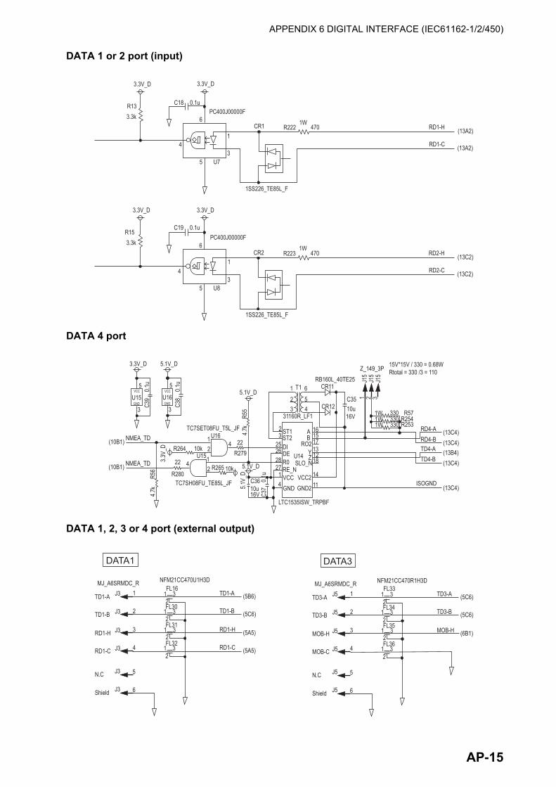
APPENDIX 6 DIGITAL INTERFACE (IEC61162-1/2/450)
DATA 1 or 2 port (input)
DATA 4 port
DATA 1, 2, 3 or 4 port (external output)
3.3V_D 3.3V_D
R133.3k
C18 0.1uPC400J00000F
6
1
35
4
U7
1W470R222CR1
1SS226_TE85L_F
RD1-H
RD1-C
(13A2)
(13A2)
3.3V_D 3.3V_D
R153.3k
C19 0.1uPC400J00000F
6
1
35
4
U8
1W470R223CR2
1SS226_TE85L_F
RD2-H
RD2-C
(13C2)
(13C2)
3.3V_D 5.1V_D
C39
0.1u5
3
U15VCC
GND C38
0.1u5
3
U16VCC
GND
(10B1)
(10B1)
NMEA_TD
NMEA_TD
4.7k
R56
3.3V
_D R264
R280
22
10k
4
1
12
2 R265
U15
U16TC7SET08FU_T5L_JF
4
10k
TC7SH08FU_TE85L_JF
22R279
5.1V
_D
5.1V_D
5.1V_D
4.7k
R55
C3610u16V C3
70.
1u 14
45
61
23
23
25262827
LTC1535ISW_TRPBF
RB160L_40TE25CR11
CR1231160R_LF1
T1
C3510u16V
ST1ST2DIDER0RE_NVCCGND
AB
YZ
16
RO2
U14SLO_N
VCC2GND2
1517131218
1411
1 2 3
1W1W1W
330330330
R57R254R253
Z_149_3PJ1
5J1
5J1
5
15V*15V / 330 = 0.68WRtotal = 330 /3 = 110
RD4-ARD4-BTD4-ATD4-B
ISOGND
(13C4)(13C4)
(13C4)
(13C4)
(13B4)
Shield
N.C
J3
J3
J3
J3
J3
J3
2
1
4
3
6
5
RD1-C
RD1-H
TD1-B
TD1-A
MJ_A6SRMDC_R NFM21CC470U1H3DFL16
1 32
1 32
1 32
1 32
FL30
FL31
FL32 RD1-C
RD1-H
TD1-B
TD1-A
(5A5)
(5A5)
(5C6)
(5B6)
DATA1
Shield
N.C
J5
J5
J5
J5
J5
J5
2
1
4
3
6
5
MOB-C
MOB-H
TD3-B
TD3-A
MJ_A6SRMDC_R NFM21CC470R1H3DFL33
1 32
1 32
1 32
1 32
FL34
FL35
FL36
MOB-H
TD3-B
TD3-A
(6B1)
(5C6)
(5C6)
DATA3
AP-15

APPENDIX 6 DIGITAL INTERFACE (IEC61162-1/2/450)
Ethernet
Note: For layout purposes and to prevent miswiring, the TX and RX lines on HX1188FNL are con-nected reversely of shown here. The TX and RX lines share the same transformer structure so there is no problem.
Shield
N.C
J4
J4
J4
J4
J4
J4
2
1
4
3
6
5
RD2-C
RD2-H
TD2-B
TD2-A
MJ_A6SRMDC_R NFM21CC470R1H3DFL37
1 32
1 32
1 32
1 32
FL38
FL39
FL40 RD2-C
RD2-H
TD2-B
TD2-A
(5B5)
(5A5)
(5C6)
(5C6)
DATA2
Shield
N.C
J6
J6
J6
J6
J6
J6
2
1
4
3
7
5
RD4-B
RD4-A
TD4-B
TD4-A
MJ_A7SRMDC_R NFM21CC470R1H3DFL41
1 32
1 32
1 32
1 32
FL42
FL43
FL44 RD4-B
RD4-A
TD4-B
TD4-A
(6A4)
(6A4)
(6A4)
(6A4)
DATA4
ISOGNDJ6 6
0.1u
C199
ISOGND (6B4)
3.3V_DFL19
BLM21PG221SN1D
3.3V_LAN
BD
3.3V_LAN3.3V_D
C29
0.01
u
C30
0.01
u
C31
0.01
u
U11 1 6 27 12
VDD2
AVD
DCR
VDD1
AVD
DIO
54
19
28293031
XTAL1_CLKINXTAL2
NRST
TXNTXPRXNRXP
22232425
21
TXD0TXD1TXD2TXD3
TXEN
207
111098
TXCLKRXCLK_PHYAD1
RXD0_MODE0RXD1_MODE1
RXD2_RMIISELRXD3_PHYAD2
131415
1826
RXER_RXD4_PHYAD0CRS
COL_CRS_DV_MODE2
NINT_TXER_TXD4RXDV
32
1716
RBIAS
MDCMDIO
33PG
ND
23LED2_NINTSEL
LED1_REGOFF
LAN8710AI_EZK
3.3V_LAN
3.3V_D
R30
R29
10k
10k
R31 4.7k
R27R28
33 FEC_RDATA(0)33 FEC_RDATA(1)
FEC_RDATA(1:0) (7B2)
R33 4.7
kR3
6 4.7kCP63
CP64
3.3V_D
R38
R34
10k 10k
R37R35
33
33
FEC_RX_ERR
FEC_RX_DV
LAN_INT_N
(3D3)
(7B2)
(10B2)
3.3V_LAN
R48
R47 270
330PY1112H_TR
PY1112H_TRACTIVE-LED:YELLOW
CR10
CR9
R43
R44
R45
R46
51 51 51 51
±0.5%
±0.5%
±0.5%
±0.5% U12
HX1188FNL16
RX_ P
TX1_P
7RCT
TD_PTCT
TD_N
1
2
3456
NC0NC1RD_P RD_N 8
RXCTRX1_NRX1_P
NC3NC2
TXCTTX1_N 14
15131211
109
C32
0.022
u
R32
10k
3.3V_D
MOD_WPJ88D_P1
2
3
4
5
6
7
8
G1
G2
H1
H2
J2
J2
J2
J2
J2
J2
J2
J2
J2
J2
J2
J2
±0.5%
±0.5%
±0.5%
±0.5%
±0.5%
±0.5%
R42
R41
51
51
51
5151
R40
R39
R289 51
R290
C_GND_LAN
C_GND_LAN
C_GND_LAN
C_GND_LAN
C33
C25
C27
R51
R50
75 75±0
.5%
±0.5%
1000
p 20
00V 10
00p
2000
V
1000
p20
00VRX_N
TX_NTX_P
C_GND_LAN C_GND_LAN
C_GND_LAN
R233 R235
R234
0 0
0
AP-16

APPENDIX 6 DIGITAL INTERFACE (IEC61162-1/2/450)
Sentence description
ACK-Acknowledge alarm
ACM-Alert Command
ACN-Alert command
ALC-Cyclic alert list
$**ACK,xxx,*hh<CR><LF> 1 1. Local alarm number (identifier)
$**ACM,hhmmss.ss,aaa,x.x,x.x,c,a*hh<CR><LF> 1 2 3 4 5 6 1. Time (hh=00 to 23, mm=00 to 59, ss.ss=00.00 to 59.99), null2. Manufacturer mnemonic code (3 digit alphanumeric code), null3. Alert identifier (000 to 999999)4. Alert instance (1 to 999999), null5. Alert command (A=ACK from ext. equipment, Q=Request from ext. equipment, O=Responsibility transfer, S=Silence from ext. equipment)6. Sentence status flag (C should not be null field. Sentence without C is not a command.)
$**ACN,hhmmss.ss,aaa,x.x,x.x,ca,a*hh<CR><LF> 1 2 3 4 5 6 1. Time (hh=00 to 23, mm=00 to 59, ss.ss=00.00 to 59.99), null2. Manufacturer mnemonic code (3 digit alphanumeric code), null3. Alert identifier (000 to 999999)4. Alert instance (1 to 999999), null5. Alert command (A=ACK from ext. equipment, Q=Request from ext. equipment, O=Responsibility transfer, S=Silence from ext. equipment)6. Sentence status flag (C should not be null field. Sentence without C is not a command.)
$**ALC,xx,xx,xx,x.x, aaa,x.x,x.x,x.x,’’’’’’,*hh<CR><LF> 1 2 3 4 5 6 7 8 9 1. Total number of sentences this message (01 to 99)2. Sentence number (01 to 99)3. Sequential message identifier (00 to 99)4. Number of alert entries (0 to 2)5. Manufacturer mnemonic code (FEC, null)6. Alert identifier (000 to 999999)7. Alert instance (1 to 999999)8. Revision counter (1 to 99)9. Additional alert entries (same as 5 and 8)
AP-17

APPENDIX 6 DIGITAL INTERFACE (IEC61162-1/2/450)
ALF-Alert sentence
ALR-Set alarm state
ARC-Alert command refused
$**ALF,x,x,x,hhmmss.ss,a,a,a,aaa,x.x,x.x,x.x,x,c--c,*hh<CR><LF> 1 2 3 4 5 6 7 8 9 10 11 12 13 1. Total number of ALF sentences this message (1, 2)2. Sentence number (1, 2)3. Sequential message identifier (0 to 9)4. Time of last change (hh=00 to 23, mm=00 to 59, ss.ss=00.00 to 60.99), null 5. Alert category (A=Alert category A, B=Alert category B, C=Alert category C), null when #2 is 2.6. Alert priority (E=Emergency Alarm, A=Alarm, W=Warning, C=Caution), null when #2 is 2.7. Alert state (V=Active – unacknowledged, S=Active – silenced, A=Active – acknowledged or active, O=Active – responsibility transferred, U=Rectified – unacknowledged, N=Normal), null when #2 is 2.8. Manufacturer mnemonic code (FEC, null)9. Alert identifier (000 to 999999)10. Alert instance (1 to 999999)11. Revision counter (1 to 99)12. Escalation counter (0 to 9)13. Alert text (max. 16 characters)
$**ALR,hhmmss.ss,xxx,A,A,c—c,*hh<CR><LF> 1 2 3 4 5
1. Time of alarm condition change, UTC2. Unique alarm number (identifier) at alarm source3. Alarm condition (A=threshold exceeded, V=not exceeded)4. Alarm acknowledge state (A=acknowledged, V=not acknowledged)5. Alarm description text (alphanumeric)
$**ARC,hhmmss.ss,aaa,x.x,x.x,c*hh<CR><LF> 1 2 3 4 5
1. Release time of the Alert Command Refused(UTC)2. Used for proprietary alerts, defined by the manufacturer (FEC, null)3. The alert identifier( 000 to 999999) 4. The alert instance(1 to 999999)5. Refused Alert Command(A, Q, O, S) A=acknowledge: A Q=request/repeat information O=responsibility transfer S=silence
AP-18

APPENDIX 6 DIGITAL INTERFACE (IEC61162-1/2/450)
CUR-Water current layer–Multi-layer water current data
DPT-Depth
HBT-Heartbeat supervision sentence
HDG-Heading, deviation and variation
HDT-Heading true (Not used by SOLAS ships)
$**CUR,A,x,x.x,x.x,x.x,a,x.x,x.x,x.x,a,a,*hh<CR><LF> 1 2 3 4 5 6 7 8 9 1011 1. Validity of data (A=Valid, V=Not valid)2. Data set number (0 to 9)3. Layer number (1 to 3)4. Current depth in meters (no use)5. Current direction in degrees (0.00 to 360.00)6. Direction reference in use (true or relative)7. Current speed in knots (0.00 to 99.99)8. Reference layer depth in meters (no use)9. Heading (0 to 360.00)10. Heading reference in use (true or magnetic) 11. Speed reference (B=Bottom track W=Water track P=Positioning system (no use)
$**DPT,x.x,x.x,x.x,*hh<CR><LF> 1 2 3 1. Water depth relative to the transducer, meters2. Offset from transducer, meters3. Minimum range scale in use (no use)
$**HBT,x.x,A,x*hh<CR><LF> 1 2 31. Configured repeat interval (1 to 99(s))2. Equipment status (A=Normal V=System fail)3. Sequential sequence identifier (0 to 9)
$**HDG,x.x,x.x,a,x.x,a*hh<CR><LF> 1 2 3 4 51. Magnetic sensor heading, degrees2. Magnetic deviation, degrees3. E/W4. Magnetic variation, degrees5. E/W
$**HDT, xxx.x,T*hh<CR><LF> 1 2
1. Heading, degrees2. True (T)
AP-19

APPENDIX 6 DIGITAL INTERFACE (IEC61162-1/2/450)
HRM-Heel angle, roll period and roll amplitude measurement device
MWV-Wind speed and angle
POS-Device position and ship dimensions report or configuration command
ROT-Rate of turn
THS-True heading and status
$**HRM,x.x,x.x,x.x,x.x,A x.x,x.x,hhmmss.ss,xx,xx*hh <CR><LF> 1 2 3 4 5 6 7 8 9 101. Actual heel angle, degrees2. Roll period, seconds3. Roll amplitude, port side, degrees4. Roll amplitude, starboard side, degrees5. Status6. Roll peak hold value, port side, degrees7. Roll peak hold value, starboard side, degrees8. Peak hold value reset time9. Peak hold value reset day, 01 to 3110. Peak hold value reset month, 01 to 12
$**MWV,x.x,a,x.x,a,A*hh<CR><LF> 1 2 3 4 5 1. Wind angle, degrees (0.00 to 360.00)2. Reference (R/T)3. Wind speed (0.00 to 9999.99)4. Wind speed units (K=km/h M=m/s N=nm)5. Status (A=Valid V=Not valid)
$**POS,cc,xx,a, x.x,x.x,x.x,a,x.x,x.x,a*hh <CR><LF> 1 2 3 4 5 6 7 8 9 10 1. Equipment ID (IEC 61162-1 Ed.5)2. Equipment number3. Position validity flag (A=valid V=invalid)4. Position X-coordinate5. Position Y-coordinate6. Position Z-coordinate7. Ship’s width and length (A=valid V=invalid)8. Ship’s width9. Ship’s length10. Sentence status flag (R=sentence is status report of current settings C=sentence is a configuration command to change settings
$**ROT,x.x,A*hh<CR><LF> 1 2 1. Rate of turn, deg/min, "-"=bow turns to port (-9999.9 to 9999.9)2. Status: A=Data valid, V=Data invalid
$**THS,xxx.x,a*hh<CR><LF> 1 2 1. Heading, degrees True2. Mode indicator (A=autonomous E=estimated M=manual input S=simulator V=data not valid)
AP-20

APPENDIX 6 DIGITAL INTERFACE (IEC61162-1/2/450)
VBW-Dual ground/water speed
VDR-Set and drift
VLW-Dual ground/water distance
VTG-Course over ground and ground speed
$**VBW,x.x,x.x,x,x.x,x.x,x,x.x,x,x.x,x,*hh<CR><LF> 1 2 3 4 5 6 7 8 9 101. Longitudinal water speed, knots2. Transverse water speed, knots3. Status: water speed, A=data valid V=data invalid4. Longitudinal ground speed, knots5. Transverse ground speed, knots6. Status: ground speed, A=data valid V=data invalid7. Stern transverse water speed, knots8. Status: stern water speed, A=data valid V=data invalid9. Stern transverse ground speed, knots10. Status: stern ground speed, A=data valid V=data invalid
$**VDR,x.x,T,x.x,M,x.x,N,*hh <CR><LF> 1 2 3 4 5 61. Direction, degrees2. T=True (fixed)3. Direction, degrees4. M=Magnetic (fixed)5. Current speed6. N=Knots (fixed)
$**VLW,x.x,N,x.x,N,x.x,N,x.x,N,*hh<CR><LF> 1 2 3 4 5 6 7 8 1. Total cumulative water distance (no use)2. N=Nautical miles3. Water distance since reset (no use)4. N=Nautical miles5. Total cumulative ground distance (0.000 to 999999.999)6. N=Nautical miles (no use)7. Ground distance since reset (0.000 to 999999.999)8. N=Nautical miles (no use)
$**VTG,x.x,T,x.x,M,x.x,N,x.x,K,a,*hh <CR><LF> 1 2 3 4 5 6 7 8 91. Course over ground, degrees2. T=True (fixed)3. Course over ground, degrees4. M=Magnetic (fixed)5. Speed over ground, knots6. N=Knots (fixed)7. Speed over ground8. K=km/h (fixed)9. Mode indicator (A=Autonomous, D=Differential E = Estimated (dead reckoning) M=Manual input S=Simulator N=Data not valid, P=Precise)
AP-21

APPENDIX 6 DIGITAL INTERFACE (IEC61162-1/2/450)
ZDA-Time and date
$**ZDA,hhmmss.ss,xx,xx,xxxx,xx,xx,*hh<CR><LF> 1 2 3 4 5 61. UTC2. Day3. Month4. Year (UTC)5. Local zone, hours6. Loca zone, minutes
AP-22

APPENDIX 7 PARTS LIST/LOCATION
Parts list
This equipment contains complex modules in which fault diagnosis and repair down to component level are not practical (IMO A.694(17)/8.3.1). Only some discrete components are used. FURUNO Electric Co., Ltd. Believes identifying these components is of no value for shipboard maintenance; therefore, they are not listed in this manual. Major modules can be located on the parts location photos on the next page.
Unit Antenna Unit GS-1001BELECTRICAL PARTS LISTCode No.
PRINTED CIRCUIT BOARD20P8234A, MAIN20P8222A, GNSS_LNA
Unit Display Unit GS-1002ELECTRICAL PARTS LISTCode No.
PRINTED CIRCUIT BOARD20P8209A, MAIN20P8210, PNL20P8213, CAN20P8218, CAN-FIL
NL6448BC18-01FLCD
Unit Junction Box GS-1003ELECTRICAL PARTS LISTCode No.
PRINTED CIRCUIT BOARD20P8221, TB
AP-23

APPENDIX 7 PARTS LIST/LOCATION
Parts location
Antenna Unit GS-1001B
Display Unit GS-1002
20P8234AMAIN
20P8222AGNSS_LNA
Antenna element Antenna element
20P8222AGNSS_LNA
20P8218CAN-FIL
20P8213CAN
20P8209AMAIN
20P8210PNL
NL6448BC18-01FLCD
Display unit, cover opened
AP-24

APPENDIX 7 PARTS LIST/LOCATION
Junction Box GS-1003
Display Unit DS-600
20P8221TB
26P0007PNL
NL6448BC26-22FLCD
02P6345MCN
26P0006MAIN
AP-25

AP-26
APPENDIX 8 JIS CABLE GUIDE
CoreType Area Diameter
The following reference table lists gives the measurements of JIS cables commonly used with Furuno products:
TTYCSLA-4
MPYC-4
TPYCY
DPYCY
Cable Diameter
DPYC-1.5 1.5mm2 1.56mm 11.7mmDPYC-2.5 2.5mm2 2.01mm 12.8mmDPYC-4 4.0mm2 2.55mm 13.9mmDPYC-6 6.0mm2 3.12mm 15.2mmDPYC-10 10.0mm2 4.05mm 17.1mmDPYCY-1.5 1.5mm2 1.56mm 13.7mmDPYCY-2.5 2.5mm2 2.01mm 14.8mmDPYCY-4 4.0mm2 2.55mm 15.9mmMPYC-2 1.0mm2 1.29mm 10.0mmMPYC-4 1.0mm2 1.29mm 11.2mmMPYC-7 1.0mm2 1.29mm 13.2mmMPYC-12 1.0mm2 1.29mm 16.8mmTPYC-1.5 1.5mm2 1.56mm 12.5mmTPYC-2.5 2.5mm2 2.01mm 13.5mmTPYC-4 4.0mm2 2.55mm 14.7mmTPYCY-1.5 1.5mm2 1.56mm 14.5mmTPYCY-2.5 2.5mm2 2.01mm 15.5mmTPYCY-4 4.0mm2 2.55mm 16.9mm
TTYCS-1 0.75mm2 1.11mm 10.1mmTTYCS-1T 0.75mm2 1.11mm 10.6mmTTYCS-1Q 0.75mm2 1.11mm 11.3mmTTYCS-4 0.75mm2 1.11mm 16.3mmTTYCSLA-1 0.75mm2 1.11mm 9.4mmTTYCSLA-1T 0.75mm2 1.11mm 10.1mmTTYCSLA-1Q 0.75mm2 1.11mm 10.8mmTTYCSLA-4 0.75mm2 1.11mm 15.7mmTTYCY-1 0.75mm2 1.11mm 11.0mmTTYCY-1T 0.75mm2 1.11mm 11.7mmTTYCY-1Q 0.75mm2 1.11mm 12.6mmTTYCY-4 0.75mm2 1.11mm 17.7mmTTYCY-4S 0.75mm2 1.11mm 21.1mmTTYCY-4SLA 0.75mm2 1.11mm 19.5mmTTYCYS-1 0.75mm2 1.11mm 12.1mmTTYCYS-4 0.75mm2 1.11mm 18.5mmTTYCYSLA-1 0.75mm2 1.11mm 11.2mmTTYCYSLA-4 0.75mm2 1.11mm 17.9mm
EX: TTYCYSLA - 4 MPYC - 4Designation type # of twisted pairs Designation type # of cores
1 2 3 4 5 6 1 2 3 4
Cables listed in the manual are usually shown as Japanese Industrial Standard (JIS). Use the following guide to locate an equivalent cable locally.
JIS cable names may have up to 6 alphabetical characters, followed by a dash and a numerical value (example: DPYC-2.5).For core types D and T, the numerical designation indicates the cross-sectional Area (mm2) of the core wire(s) in the cable.For core types M and TT, the numerical designation indicates the number of core wires in the cable.
1. Core TypeD: Double core power lineT: Triple core power lineM: Multi coreTT: Twisted pair communications
(1Q=quad cable)
2. Insulation TypeP: Ethylene Propylene Rubber
3. Sheath TypeY: PVC (Vinyl)
4. Armor TypeC: Steel
5. Sheath TypeY: Anticorrosive vinyl
sheath
6. Shielding TypeS: All cores in one sheath-S: Indivisually sheathed coresSLA: All cores in one shield, plastic
tape w/aluminum tape-SLA: Individually shielded cores,
plastic tape w/aluminum tape
CoreType Area Diameter
Cable Diameter

APPENDIX 9 ALERT LIST
The table below shows the alert no., alert name, text, priority, meaning and remedy for each alert. The alerts table is grouped by device mode. Alerts are not shared between device modes.
Note: "Inst." in the following tables denotes "Instance number" for the alert.
Alert I/F 1
Alert I/F 2
No. Alert name Text Priority RemedyTHD/SDME306 DR Mode DR Mode Caution/B If this alert occurs fre-
quently, contact your dealer.
THD240 System Fault System Fault Warning/B Restart the GS-100. If
the alert occurs again, contact your dealer.
SDME309 SDME Fault SDME Fault Caution/B Restart the GS-100. If
the alert occurs again, contact your dealer.
No. Inst. Alert name Text Priority RemedyTHD/SDME430306 2 DR Mode GNSS Core(2)
FaultCaution/B If this alert oc-
curs frequent-ly, contact your dealer.
3 GNSS Core(3) Fault
Caution/B
5 Too few Common Satellites
Caution/B
THD3062 2 System Fault GNSS Core(2)
FaultWarning/B Restart the
GS-100. If the alert occurs again, contact your dealer.
3 GNSS Core(3) Fault
Warning/B
5 Too few Common Satellites
Warning/B
6 Antenna Unit Con-nection Lost
Warning/B
7 Rate gyro broken down
Warning/B
8 Accelerometer bro-ken down
Warning/B
9 Settling failure Warning/B
AP-27

APPENDIX 9 ALERT LIST
Legacy
No. Inst. Alert name Text Priority RemedySDME430309 2 SDME Fault GNSS Core(2)
FaultCaution/B Restart the
GS-100. If the alert occurs again, contact your dealer.
3 GNSS Core(3) Fault
Caution/B
5 Too few Common Satellites
Caution/B
6 Antenna Unit Con-nection Lost
Caution/B
7 Rate gyro broken down
Caution/B
8 Accelerometer bro-ken down
Caution/B
9 Settling failure Caution/B
No. Text Priority Meaning Remedy210 HDOP exceeded Caution The value of HDOP
(Horizontal Dilution of Precision) is 4 or above. HDOP thresh-old being permanently set to 4.
If the same state contin-ues for five minutes, con-tact your dealer.
211 No calculation of positionAbbreviated messages:No calculation of POSN
Caution The signal from GPS core is not received for three seconds.
Restart the GS-100. If the alert occurs again, contact your dealer.
212 Loss of position Caution No positioning data. If the same state contin-ues for five minutes, con-tact your dealer.
240 System fault Caution Can not communicate with GS-1001.
Restart the GS-100. If the alert occurs again, contact your dealer.
301 Dead-Reckoning Warning The heading is calculat-ed using ROT, not GNSS position.
If this condition frequent-ly occurs, contact your dealer.
302 Output Stopped (HDG) Caution The heading output stopped.
If the same state contin-ues for five minutes, con-tact your dealer.
303 EXT HDG/ROT Caution Using external data to supplement calcula-tions.
If this condition frequent-ly occurs, contact your dealer.
311 Output Stopped (Speed) Caution The speed output stopped.
If the same state contin-ues for five minutes, con-tact your dealer.
312 EXT HDG applied Warning Using external data to supplement calcula-tions.
If this condition frequent-ly occurs, contact your dealer.
321 Rate gyro broken down Caution Rate gyro malfunction Contact your dealer.322 Accelerometer broken
downCaution Accelerometer mal-
functionContact your dealer.
AP-28

APPENDIX 10 DISPLAY FOR DS-600
The display of data received from a GS-100 and DS-60 can be switched on the sub displayDS-600.
Installation
The signals from GS-100 and DS-60 are directly output to the display unit DS-600. Connect the cables as shown in the figure below.
• Connect the cable between DATA1 port of the display unit GS-1002 and the TB3 port of the display unit DS-600.
• Connect the cable between TB1/TB2 port of the display unit DS-600 and the TB10 or TB11 port of the distributor unit DS-610.
For details, see the Installation manual for DS-60.
2 1 2 13456
2 134
TB1
TTYCS-4
TB4 TB2
TB3
IV-1.25 sq
TTYCS-1
Display Unit DS-600
To DATA1 port of Display Unit GS-1002
To TB10 or TB11 port of Distributor Unit DS-610
1007 35
1007
35
M4
x1
TTYCS-4 (TB1/2, for distributor)
Arbitrary length
SheathVinyl tape
Wind the shield.
Vinyl tape
TTYCS-1 (TB3, for GS-1002)Arbitrary length
SheathVinyl tapeVinyl tape
Wind the shield.
AP-29

APPENDIX 10 DISPLAY FOR DS-600
Presetting
The following settings must be set by a serviceman.
• When using the DS-600 as the sub display for the GS-100, set [Operation] to [Sub] in the [Ser-vice] menu for DS-60 (see paragraph 8.5.2).
• When using the DS-600 as the sub display for the GS-100 and DS-60, set [Operation] to [Sat-ellite] in the [Service] menu for DS-60 (see paragraph 8.5.2).
• Set the ship size and antenna position for GS-100 (see page 8-21) to the same settings as the DS-60.
For details, see the Installation manual for DS-60.
Switching the data
To switch the data between GS-100 and DS-60, long-press the DISP key of the display unit DS-600. "Ground" or "Water" is displayed at the right top of the display for DS-60, "SAT" for GS-100.
Example: Navigation data display
Data from GS-100 are displayed. Others are from DS-60.
Long-press the DISP key.
Data for DS-60 Data for GS-100
AP-30

FURUNO GS-100
SP - 1 E7279S01G 180626
SPECIFICATIONS OF SATELLITE SPEED LOG GS-100
1 GENERAL 1.1 Measurement range
Speed Fore-aft: -60.0 to +60.0 kn, Port-stbd: -60.0 to +60.0 kn Trip distance 0.0 to 999999.9 NM or 0.00 to 999999.99 NM Heading 0.0 to 359.9° or 0.00 to 359.99°
1.2 Accuracy Speed 2.0% or 0.2 kn whichever is the greater (tracking satellite: 3 or 4) 0.02 kn rms (tracking satellite: 5 or more, at antenna position) 0.08 kn rms (tracking satellite: 5 or more, at another position) Trip distance 0.01 NM Heading/Roll/Pitch 0.4° rms
1.3 Resolution Speed 0.1 kn or 0.01 kn (selected from menu) Heading/Roll/Pitch 0.1° or 0.01° (selected from menu) ROT 0.1°/min. or 0.01°/min.
1.4 Following speed 45°/s 1.5 Settling time 90 s approx. 1.6 Heading backup 1° or less (satellite obstructed time within 5 min.)
2 ANTENNA UNIT (GNSS BLOCK) 2.1 Receiving Frequency L1: 1575.42 MHz (GPS/Galileo/QZSS),
1602.5625 MHz (GLONASS) 2.2 Tracking code C/A code (GPS/QZSS), E1B (Galileo), 10F (GLONASS) 2.3 Number of channel GPS: 12 channels
GLONASS: 10 channels Galileo: 8 channels QZSS: 2 channels
2.4 Accuracy (dependent on ionospheric activity and multipath) GNSS: 5 m approx. (2drms, HDOP<4) SBAS: 4 m approx. (2drms, HDOP<4)
3 DISPLAY UNIT (GS-1002) 3.1 Screen 5.7-inch color LCD, 116.16 x 87.12 mm, 640 x 480 (VGA) 3.2 Picture color 262,144 colors 3.3 Brilliance 700 cd/m2 typical 3.4 Display mode Text, Graphic 3.5 Visible distance Speed: 4.5 m, Trip distance: 2.2 m, Heading: 5.5 m
Others: 0.625 m nominal
4 DISPLAY UNIT (DS-600, OPTION) 4.1 Screen 8.4-inch, Color LCD, 640 x 480 dot (VGA) 4.2 Brilliance 0.2 to 500 cd/m2
4.3 View angle Up/down/left/right: 75° or more (color is not considered)

FURUNO GS-100
SP - 2 E7279S01G 180626
4.4 Dimmer External dimmer control available 4.5 Backlight life 30,000 hrs approx. (+55°C)
5 INTERFACE 5.1 Number of ports
Serial I/O: 3 ports, O: 1 port Ethernet 1 port, 100base-TX USB 1 port for maintenance CAN (spare) 1 port
5.2 Data format IEC61162-1/2 (NMEA0183 V1.5/2.0/4.0), IEC61162-450 5.3 Data sentence
Input ACK, ACM, ACN, CUR, DPT, HBT, HDG, HDT*, MWV, ROT, THS, VBW, VDR Output ALC, ALF, ALR, ARC, HBT, HDT*, HRM, POS, ROT, THS, VBW, VLW, VTG, ZDA
5.4 Output proprietary sentence PFEC GPatt, GPhve, GPimu, IIalr, pidat, rminf, ds060
5.5 Ethernet 100Base-TX, RJ45 connector (waterproof) IEC61162-450 transmission group IN: MISC, SATD, NAVD OUT: Arbitrary (default: NAVD) Other Network Function (ONF) group of IEC61162-450 SNTP, HTTP, Furuno Management Protocol (FMP) Sentences IN: ACK, ACM, ACN, CUR, DPT, HBT, HDG, HDT*, MWV, ROT, THS, VBW, VDR OUT: ALC, ALF, ALR, ARC, HBT, HDT*, HRM, POS, ROT, THS, VBW, VLW, VTG, ZDA Sentence type CRP (Command-response pair) ACK, ACN, ALC, ALR, ALF, ARC, POS SBM (Sensor broadcast message) HBT, HDG, HDT, ROT, THS, VBW, VDR, VLW, VTG, ZDA
5.6 Contact closure (optional IF-2503 required) Dead reckoning, IF-2503 power fail *: Not used by SOLAS ships.
6 POWER SUPPLY 6.1 Junction box 24 VDC: 0.6 A (supplied to display unit and antenna unit) 6.2 Rectifier (option)
PR-240 100-115/200-230 VAC, 1 phase, 50/60Hz, 24VDC for back-up PR-62 100/110/115/220/230 VAC, 1 phase, 50/60Hz
7 ENVIRONMENTAL CONDITIONS 7.1 Ambient temperature
Antenna unit -25°C to +55°C Display unit/ Junction box -15°C to +55°C

FURUNO GS-100
SP - 3 E7279S01G 180626
Display unit (DS-600) -25°C to +55°C 7.2 Relative humidity 95% or less at +40°C 7.3 Degree of protection
Antenna unit IP56 Display unit IP25, IPX0 (USB port cover opened) Junction box IP22 Display unit (DS-600) IP56 (front panel)
7.4 Vibration IEC 60945 Ed.4
8 UNIT COLOR 8.1 Antenna unit N9.5 (fixed) 8.2 Display unit N2.5 (fixed) 8.3 Junction box N3.0

A-1
C7279-Z02-E
A-2

PPACKING LIST
20BG-X-9857-7
GS-1002-E ,GS-1002-J ,GS-1002-EHK ,GS-1002-JHK
N A M E
O U T L I N E
DESCRIPTION/CODE №
Q'TY1/1
ユニット
UNIT
表示部
DISPLAY UNIT
GS-1002-*
000-026-885-00
1
**付属品
ACCESSORIES
フィルタークリーナー
LCD CLEANING CLOTH
19-028-3125-7
100-360-677-10
1
工事材料
INSTALLATION MATERIALS
ケーブル(クミヒン)NMEA
CABLE ASSEMBLY
FRU-NMEA-PFF-060
000-194-606-10
1
ケーブル(組品)MJ
CABLE ASSEMBLY
MJ-A3SPF0015-060C
001-265-430-00
1
ケーブル組品MJ
CABLE ASSEMBLY
MJ-A6SPF0003-050C
000-154-054-10
1
工事材料
INSTALLATION MATERIALS
CP20-03401
001-321-400-00
1
図書
DOCUMENT
取扱説明書
OPERATOR'S MANUAL
OM*-72790-*
000-190-205-1*
1
**
コ-ト番゙号末尾の[**]は、選択品の代表コートを゙表します。
CODE NUMBER ENDING WITH "**" INDICATES THE CODE NUMBER OF REPRESENTATIVE MATERIAL.
(略図の寸法は、参考値です。 DIMENSIONS IN DRAWING FOR REFERENCE ONLY.)
CN
A-3
A-4

A-5
C7279-M02-G
A-6

A-7
A-8

A-9
A-1
0
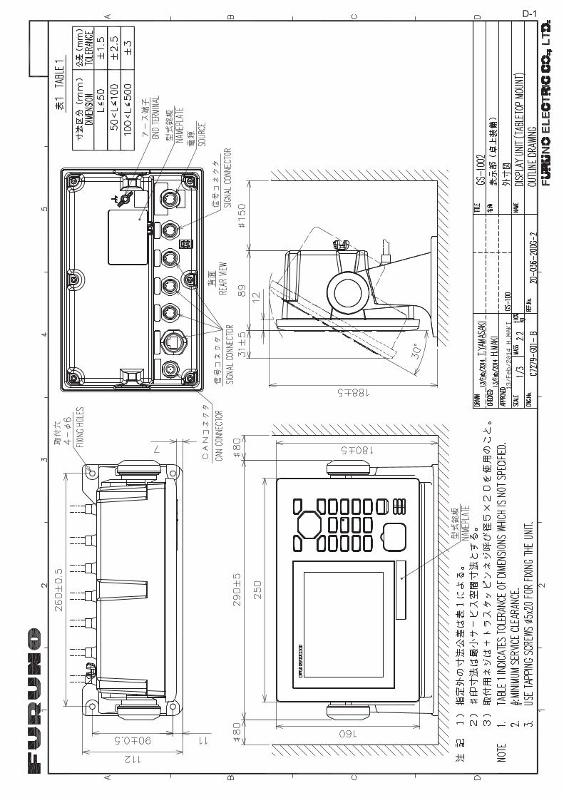
13/Feb/2014 H.MAKI
D-1

13/Feb/2014 H.MAKI
D-2

13/Feb/2014 H.MAKI
D-3

D-4
24/J
an/2
018
H.M
AK
I

13/Feb/2014 H.MAKI
D-5

D-6

18/Dec/2012 Y.NISHIYAMA
D-7

24
3
A
1
B C
DRAWN
CHECKED
APPROVED
DWG.No.
TITLE
NAME
名 称
REF.No.
SCALE
MASS
kg
T.YAMASAKI
H.MAKI
INTERCONNECTION DIAGRAM
相互
結線図
GS-100
サテライ
トスピード
ログ
SATELLITE SPEED LOG
1 2 3 4 5 6NC
J3
MJ-A6SPF
FG
TD1-A
TD1-B
RD1-H
RD1-C
PP
MJ-A6SPF0003
-050C,5m,φ6
1 2 3 4 5 6NC
FG
TD2-A
TD2-B
RD2-H
RD2-C
MJ-A6SPF
PP
6FG
1 2 3 4 5NC
MOB-H
MOB-C
MJ-A6SPF
TD3-B
TD3-A
Pシロ
クロ
WHT
BLK
1 2 3 4 5 6 7
J6
MJ-A7SPF
TD4-B
TD4-A
NC
ISOGNDFG
*2
RD4-H
RD4-C
PP P
シロ
クロ
キ ミドリ
WHT
BLK
YEL
GRN
アカ
アオ
RED
BLU
IV-1.25sq.
*1
J4
J5
IEC61162-1/2
Pキ ミドリYEL
GRN
DATA1
DATA2
DATA3
DATA4
MJ-A7SPF0003-050C,5m,φ
6.9
IEC61162-1
88
STP(CAT5) *1
MOD-WPAS0001-030+,3m
または OR
*2
NETWORK
HUB-100
スイッ
チング
HUB
SWITCHING HUB
3NR203PF-VVS1.25
3.5m
(x7 PORTS)
*1
STP(CAT5) CABLE
100-230VAC
1φ
,50/60Hz
ネット
ワー
ク機
器NETWORK EQUIPMENT
GS-1002
DISPLAY UNIT
表示部
シロ
クロ
キ ミドリ
WHT
BLK
YEL
GRN
*2
MJ-A6SPF0003
-050C,5m,φ6
*2
NOT USED
RD-A
RD-B航
法装
置NAV EQUIPMENT
*2
*1
IV-1.25sq.
1 2 3 4
TB2
TD1H
TD1B
RD1A
RD1B
1 2
TB1
+DC_H
-DC_C
*3
JB
12-24VDC
*1
DPYC(Y)-1.5
*1
*1
TTYC(Y)SLA-1
*1
IV-1.25sq.また
は 航法
装置
OR NAV EQUIPMENT
DISPLAY UNIT
DS-600
*2
指示器
*3
20-036-5701-4
5m,φ6
MJ-A6SPF0003-050C
IV-1.25sq.
TB1
3417
V_IN(+)
V_IN(-)
TB17 8 9 1011121819202122232425262728293031323313141516
*1
12-24VDC
1 2 3 4 5 6
TB1
DPYC-1.5*1
TTYCSLA-1
TTYCSLA-1
TTYCSLA-1
TTYCSLA-1
TTYCSLA-1
TTYCSLA-1Q
*1
*1
*1
*1
*1
*1
RADAR/PLOTTER ALARM SYSTEM
インターフェイスユニット
IF-2503
INTE
RFAC
E UN
IT*2
RD-H
RD-C
TD-A
TD-B
TD1-A
TD1-B
TD2-A
TD2-B
FG
FG
FG
ALM1-C
ALM1-NO
ALM1-NC
FG
ALM2-C
ALM2-NO
ALM2-NC
FG
ALM3-C
ALM3-NO
ALM3-NC
FG
REM-H
REM-CFGNC
FG
FG
LOC-C
LOC-NO
LOC-NC
また
は OR
航法
装置
NAV EQUIPMENT
AMS
アラートマネジメントシステム
DS-600
指示
器(
上記
参照)
DISPLAY UNIT (DITTO)
23 1E
U V7 6
220-230VAC
100-115/
1φ,50/60Hz
DPYC-1.5
AC/DC POWER
PR-240
SUPPLY UNIT
(+)
(-)
AC/D
C電源
ユニット
また
は OR
*1
*2
2E
1 365
1φ,50/60Hz
DPYC-1.5
*1
整流
器
PR-62
RECT
IFIE
R(+)
(-)
*2
220/230VAC
100/110/115/
IV-2sq.
*1
IV-2sq.
*1
5
POWER
CAN
1 2 3
(+)
(-)
SHIELD
1 2 3 4 5
BLK
クロ
WHT
BLU
シロ
アオ
RED
アカ
SHIELD
NET-S
NET-C
NET-H
NET-L
TB3
1 2 3
WHT
シロ
BLK
クロ
TB2
(+)
(-)
SHIELD
MJ-A3SPF0015-060C,6m
M12-05BFFM-060C,6m
IV-1.25sq.
*1
4USB
12345
SHIELDNET-SNET-CNET-HNET-L
TB5
DPYC-1.5
*1
1 2(+)
(-)
TB1
12345
TB4
NET-SNET-CNET-HNET-L
SHIELD
ANT-DN18WAPVC-300/400/500,
30/40/50m,φ
16
FRU-NMEA-NFF-R15/30,15/30m,φ
6.7
また
は
OR
REDBLKWHTBLU
アカクロシロアオ
80-580-0008,0.3m
IN-LINE TERMINATOR
イン
ラインターミネ
ーター
5
ANTENNA UNIT
空中線部
GS-1001/1001B
50.8m接
続箱
JUNCTION BOX
GS-1003
1 2 3 4 5
アカ
クロ
シロ
アオ
RED
BLK
WHT
BLU
FRU-NMEA-PFF-060,6m
120 ohm
RED
BLK
WHT
BLU
アカ
クロ
シロ
アオ
MJ-A10SPF0015-150C/300C,15/30m(FOR SC-30)
JPBS 06
RELAY BOX
WATERPROOF
防水中
継ボ
ック
スREPLACEMENT FOR SC-30
SC-30か
らの
換装
時
ケー
ブル
変換
キッ
トCABLE ADAPTER
OP20-50
24VDC
C7279-C01- K
注記
*1)
造船所手
配。
*2)
オプショ
ン。
*3)
不使用線
はまと
めて絶
縁す
る。
*4)
AMS接
続可
ポート
:DATA1/2/4。
NOTE
*1: SHIPYARD SUPPLY.
*2: OPTION.
*3: INSULATE UNUSED WIRES.
*4: AMS CONNECTION PORT: DATA1/2/4.
*2
*5
*5: GS-1001B: SUCCEEDING MODEL FOR GS-1001.
*5)
GS-1001BはGS-1001後継
機。
17/Oct/2018
17/Oct/2018
S-1
hmaki
タイプライターテキスト
23/Oct/2018 H.MAKI

INDEX
Numerics3-axis speed display.................................. 2-5
AAlert list .................................................AP-27Alert mode............................................... 8-23Alertsacknowledging ........................................ 5-6list ............................................................ 5-5log ........................................................... 5-6overview .................................................. 5-1
BBackground color ...................................... 2-2Backup ...................................................... 7-7Berthing displayberthing line........................................... 6-11overview .................................................. 6-1range ....................................................... 6-7track ........................................................ 6-8vector time............................................... 6-7
Brilliance.................................................... 1-4
CControl descriptionDS-600 .................................................... 6-3GS-1002.................................................. 1-1
Current direction........................................ 3-1
DDatum...................................................... 8-18Dead reckoning time ................................. 3-8Demo mode............................................... 3-5Device information .................................. 3-10Device instance....................................... 3-10Device list .................................................. 3-9Device mode ........................................... 8-17Digital interface .....................................AP-13Disable satelliteGNSS ...................................................... 3-7
Display modes........................................... 2-1DS-600display .................................................AP-29installation ............................................. 8-25menu settings........................................ 8-27
EEquipment ID .......................................... 8-19Equipment information .............................. 7-4Ethernet setting ....................................... 3-12
FFuse replacement ..................................... 7-1
GGeodetic chart list .................................AP-11GNSS ........................................................ 2-6
IIF-2503.................................................... 8-24Input data selection ................................. 3-13Integrity display ......................................... 2-5IP address ............................................... 8-24
JJis cable guide ......................................AP-26
KKey sound ................................................. 1-2
LLanguage selection ................................. 8-17Life of LCD ................................................ 7-2Line monitor log....................................... 3-14List of symbols ........................................AP-9List of terms.............................................AP-5List overview ............................................. 1-6
MMain menu overview ................................. 1-5Maintenance.............................................. 7-1Master sensor ......................................... 3-10Memory clear .......................................... 3-16Menu tree ................................................AP-1Mountingantenna unit ............................................ 8-3display unit .............................................. 8-1junction box ............................................. 8-7
NNavigation display ..................................... 2-2Noticeship speed............................................... 4-1sound ...................................................... 4-1trip ........................................................... 4-2
OOffset....................................................... 8-19Output data setting.................................. 3-11
PParts list ................................................AP-23Parts location ........................................AP-24Password .................................................. 3-4Power on/off .............................................. 1-3Product information ................................. 3-10
RReplacement parts settings....................... 7-8
SSatellite angle............................................ 2-7Satellite elevation ...................................... 3-7SBAS.....................................................AP-12SDME mode.............................................. 2-1Self test ..................................................... 7-5Sensor reset.............................................. 3-8
IN-1

INDEX
IN
SSSSSSS
TTTTTTT
UU
WWW
etting reset ...............................................3-8ignal noise ratio .......................................2-7moothing..................................................3-1NTP setting..............................................3-5peed test ................................................8-30ystem configurations.................................. ixystem instance.......................................3-10
HD mode..................................................2-1ime differences ...................................AP-10ime format ..............................................8-18otal distance.............................................3-3rip distance calculation ............................3-3roubleshooting .........................................7-3
nit selection ...........................................8-17
ind angle .................................................3-1iring
antenna unit ...........................................8-12display unit .............................................8-11interconnection.........................................8-8junction box ..............................................8-9
-2