OPERATOR'S MANUAL - Peterbilt
243
-
Upload
khangminh22 -
Category
Documents
-
view
0 -
download
0
Transcript of OPERATOR'S MANUAL - Peterbilt

OPERATOR’S MANUAL

© 2017 PACCAR Inc. - All Rights ReservedThis manual illustrates and describes the operation of features or equipment which may be either standard oroptional on this vehicle. This manual may also include a description of features and equipment which are nolonger available or were not ordered on this vehicle. Please disregard any illustrations or descriptions relating tofeatures or equipment which are not on this vehicle. PACCAR reserves the right to discontinue, changespecifications, or change the design of its vehicles at any time without notice and without incurring anyobligation. The information contained in this manual is proprietary to PACCAR. Reproduction, in whole or in part,by any means is strictly prohibited without prior written authorization from PACCAR Inc.

520520520520


Safety..................................... 1
Emergency..................................... 2
Controls..................................... 3
Driving..................................... 4
Maintenance..................................... 5
Information..................................... 6
Contents

Contents

Chapter 1 | SAFETYIn this Chapter:
Applies To...............................................................................................................................................7Using this Manual...................................................................................................................................7Safety Alerts...........................................................................................................................................8Illustrations............................................................................................................................................. 9General Safety Instructions....................................................................................................................9Data Recorder......................................................................................................................................12Environmental Protection Agency........................................................................................................ 12A Special Word About Repairs.............................................................................................................13Additional Sources of Information........................................................................................................ 14Cab Access.......................................................................................................................................... 14Cab Tilting............................................................................................................................................ 15Standard Seat...................................................................................................................................... 18What to do before starting the vehicle..................................................................................................23Vehicle Loading....................................................................................................................................24
1

Visual inspection while approaching the vehicle.................................................................................. 25Weekly Checks.....................................................................................................................................25Daily Checks........................................................................................................................................ 26
SAFETY -
6 Y53-6096-1A1 (01/17)
1

Applies To
Using this ManualPlease take the time to get acquainted withyour vehicle by reading this Operator’sManual. We recommend that you read andunderstand this manual from beginning to
end before you operate this equipment.This manual contains useful information forthe safe and efficient operation of thisequipment. It also provides service
SAFETY - Applies To
Y53-6096-1A1 (01/17) 7
1

information, with an outline for performingsafety checks and basic preventivemaintenance inspections. We have tried topresent the information you’ll need to learnabout functions, controls, and operation—and to present it as clearly as possible. Wehope you’ll find this manual easy to use.There will be times when you need to takethis manual out of the glovebox. When youdo, please be sure to return it when youare finished using it. That way it will bethere when you need it the next time orwhen you pass the vehicle on to the nextuser.
NOTE
After you’ve read this manual, it should bestored in the cab for convenient referenceand remain with this truck when sold.
Your vehicle may not have all the featuresor options mentioned in this manual.Therefore, you should pay careful attentionto the instructions that pertain to just yourvehicle. In addition, if your vehicle isequipped with special equipment or optionsnot discussed in this manual, consult yourdealer or the manufacturer of theequipment.
There are several tools built into thismanual to help you find what you needquickly and easily. First is the Quick Tableof Contents. Located at the front of themanual, this lists the main subjectscovered and gives section numbers whereyou can find these subjects. Use the QuickTable of Contents to find information on alarge subject like “Maintenance.” Cross-referenced citations also help you get theinformation you need. If some other part ofthe manual contains further information onthe subject you are reading about, we’llindicate that in a cross-reference like this:(See What to do before starting the vehicleon page 23). You won’t have to gosearching for more information. Finallyyou’ll find a helpful Subject Index. It’s in theback of the manual and alphabetically liststhe subjects covered. So if you wantinformation on brakes, for example, justlook under Brake in the Subject Index.You’ll find all the pages listed where brakesor braking are discussed.
All information contained in this manual isbased on the latest production informationavailable at the time of publication.Peterbilt Motors Company reserves theright to make changes at any time withoutnotice.
Safety Alerts
Please read and follow all of the safetyalerts contained in this manual. They arethere for your protection and information.These alerts can help you avoid injury toyourself, your passengers and help preventcostly damage to the vehicle. Safety alertsare highlighted by safety alert symbols andsignal words such as “WARNING”,“CAUTION”, or “NOTE”. Please DO NOTignore any of these alerts.
Warnings
The safety message following this symboland signal word provides a warning againstoperating procedures which could causedeath or injury. They could also causeequipment or property damage. The alertwill identify the hazard, how to avoid it andthe probable consequence of not avoidingthe hazard.
SAFETY - Safety Alerts
8 Y53-6096-1A1 (01/17)
1

WARNING!
Hot engine oil can be dangerous. You couldbe burned. Let the engine oil cool down be-fore changing it. Failure to comply may re-sult in death, personal injury, equipment orproperty damage.
Cautions
The safety message following this symboland signal word provides a caution againstoperating procedures which could causeequipment or property damage. The alertwill identify the hazard, how to avoid it, andthe probable consequence of not avoidingthe hazard.
CAUTION
Continuing to operate your vehicle with in-sufficient oil pressure will cause serious en-gine damage. Failure to comply may resultin equipment or property damage.
Notes
The message following this symbol andsignal word provides important informationthat is not safety related but should befollowed. The alert will highlight things thatmay not be obvious and is useful to yourefficient operation of the vehicle.
NOTE
Pumping the accelerator will not assist instarting the engine.
Illustrations
Some of the illustrations throughout thismanual are generic and will NOT lookexactly like the engine or parts used inyour application. The illustrations cancontain symbols to indicate an actionrequired and\or an acceptable or NOTacceptable condition.
The illustrations are intended to showrepair or replacement procedures. Theprocedure will be the same for allapplications, although the illustration maydiffer.
General SafetyInstructions
Important safety notices about operatingand servicing your engine.
WARNING!
Improper practices, carelessness, or ignor-ing any warnings may cause death, person-al injury, equipment or property damage.
Before performing any repair, read andunderstand all of the safety precautionsand warnings. The following is a list ofgeneral safety precautions that must befollowed to provide personal safety. Failureto follow these instructions may causedeath or injury. Special safety precautionsare included in the procedures when theyapply.
SAFETY - Illustrations
Y53-6096-1A1 (01/17) 9
1

Keep in mind that even a well maintainedvehicle must be operated within the rangeof its mechanical capabilities and the limitsof its load ratings. See the Weight Ratingslabel on the driver's door edge.
Every new vehicle is designed to conformto all Federal Motor Vehicle SafetyStandards applicable at the time ofmanufacture. Even with these safetyfeatures, continued safe and reliableoperation depends greatly upon regularvehicle maintenance. Follow themaintenance recommendations found inPreventive Maintenance section. This willhelp preserve your investment.
Make sure your vehicle is in top workingcondition before heading out on the road, itis the responsible driver's duty to do so.Inspect the vehicle according to theDriver's Check List.
• Use the proper tool for manuallyrotating the engine. DO NOTattempt to rotate the crankshaft bypulling or prying on the fan. Thispractice can cause death, personalinjury, equipment damage, ordamage to the fan blades, causingpremature fan failure.
• Work areas should be dry, well lit,well ventilated, free from clutter,loose tools, parts, ignition sourcesand hazardous substances.
• Wear protective glasses andprotective shoes when working.
• DO NOT wear loose-fitting or tornclothing. Tie back and/or tuck inlong hair. Remove all jewelry whenworking.
• Before beginning any repair,disconnect the battery (negative [-]cable) and discharge anycapacitors.
• Put a “DO NOT OPERATE” tag inthe operator's compartment or onthe controls.
• Allow the engine to cool beforeslowly loosening the coolant fillercap to relieve the pressure from thecooling system.
WARNING!
Removing the fill cap on a hot engine cancause scalding coolant to spray out andburn you badly. If the engine has been inoperation within the previous 30 minutes, bevery careful in removing the fill cap. Protectface, hands, and arms against escaping flu-
id and steam by covering the cap with alarge, thick rag. DO NOT try to remove it un-til the surge tank cools down or if you seeany steam or coolant escaping. In any situa-tion, remove the cap very slowly and care-fully. Be ready to back off if any steam orcoolant begins to escape.
• Always use wheel chocks or properjack stands to support the vehicle orvehicle components beforeperforming any service work. DONOT work on anything that issupported only by lifting jacks or ahoist. Before resting a vehicle onjack stands, be sure the stands arerated for the load you will be placingon them.
• Before removing or disconnectingany lines, fittings, or related items,relieve all pressure in the air, oil,fuel, and cooling systems. Remainalert for possible pressure whendisconnecting any device from asystem that contains pressure. Highpressure oil or fuel can cause deathor personal injury.
• Always wear protective clothingwhen working on any refrigerantlines and make sure that theworkplace is well ventilated.
SAFETY - General Safety Instructions
10 Y53-6096-1A1 (01/17)
1

Inhalation of fumes can cause deathor personal injury. To protect theenvironment, liquid refrigerantsystems must be properly emptiedand filled using equipment thatprevents the release of refrigerantgas. Federal law requires capturingand recycling refrigerant.
• When moving or lifting any heavyequipment or parts, make sure touse proper techniques andassistance. Ensure all lifting devicessuch as chains, hooks, or slings arein good condition and are of thecorrect load capacity. Make sure alllifting devices are positionedcorrectly.
• Corrosion inhibitors and lubricatingoils may contain alkali. DO NOT getthe substance in eyes and avoidprolonged or repeated contact withskin. DO NOT swallow. If ingested,seek immediate medical attention.DO NOT induce vomiting. In case ofcontact, immediately wash skin withsoap and water. In case of harmfulcontact, immediately contact aphysician. Always keep anychemicals OUT OF REACH OFCHILDREN.
• Naptha and Methyl Ethyl Ketone(MEK) are flammable materials andmust be used with caution. Followthe manufacturer's instructions toensure safety when using thesematerials. Always keep anychemicals OUT OF REACH OFCHILDREN.
• When working on the vehicle, bealert for hot parts on systems thathave just been turned off, exhaustgas flow, and hot fluids in lines,tubes, and compartments. Contactwith any hot surface may causeburns.
• Always use tools that are in goodcondition. Make sure you have theproper understanding of how to usethe tools before performing anyservice work. Use only genuinereplacement parts from PACCAR.
• Always use the same fastener partnumber (or equivalent) whenreplacing items. DO NOT use afastener of lesser quality ifreplacements are necessary. (e.g.,Do not replace a 10.9 grade with 8.8grade fastener.)
• Always torque fasteners and fuelconnections to the required
specifications. Overtightening orunder-tightening can allow leakage.
• Close the manual fuel valves priorto performing maintenance andrepairs, and when storing thevehicle inside.
• DO NOT perform any repair whenimpaired, tired, fatigued or afterconsuming alcohol or drugs that canimpair your functioning.
• Some state and federal agencies inthe United States of America havedetermined that used engine oil canbe carcinogenic and can causereproductive toxicity. Avoidinhalation of vapors, ingestion, andprolonged contact with used engineoil.
• DO NOT connect the jump startingor battery charging cables to anyignition or governor control wiring.This can cause electrical damage tothe ignition or governor.
• Coolant is toxic. If not reused,dispose of coolant in accordancewith local environmental regulations.
SAFETY - General Safety Instructions
Y53-6096-1A1 (01/17) 11
1

CAUTION
Corrosive chemicals can damage the en-gine. DO NOT use corrosive chemicals onthe engine. Failure to comply may result inequipment, or property damage.
California Proposition 65 Warning• Diesel engine exhaust and some of
its constituents are known to theState of California to cause cancer,birth defects, and other reproductiveharm.
• The catalyst substrate located in theDiesel Particulate Filter (DPF)contains vanadium pentoxide, whichhas been determined by the State ofCalifornia to cause cancer. Alwayswear protective clothing and eyeprotection when handling thecatalyst assembly. Dispose of thecatalyst in accordance with localregulations. If catalyst material getsinto the eyes, immediately floodeyes with water for a minimum of 15minutes. Avoid prolonged contactwith skin. In case of contact,immediately wash skin with soapand water. In case of harmful
contact, immediately contact aphysician.
• Other chemicals in this vehicle arealso known to the State of Californiato cause cancer, birth defects orother reproductive harm.
• Battery posts, terminals, and relatedaccessories contain lead and leadcompounds, chemicals known to theState of California to cause cancerand reproductive harm. Wash handsafter handling.
Data Recorder
California Vehicle Code - Section 9951-Disclosure of Recording Device
Your vehicle may be equipped with one ormore recording devices commonly referredto as "event data recorders" (EDR) or"sensing and diagnostic modules" (SDM).If you are involved in an accident, thedevice(s) may have the ability to recordvehicle data that occurred just prior toand/or during the accident. For additionalinformation on your rights associated withthe use of this data, contact:
• The California Department of MotorVehicles - Licensing OperationsDivision
• http://www.dmv.ca.gov/
Environmental ProtectionAgency
Information on use and disposal ofhazardous materials.
Some of the ingredients in engine oil,hydraulic oil, transmission and axle oil,engine coolant, diesel fuel, air conditioningrefrigerant (R12, R134a, and PAG oil),batteries, etc., may contaminate theenvironment if spilled or not disposed ofproperly.
SAFETY - Data Recorder
12 Y53-6096-1A1 (01/17)
1

WARNING!
Diesel engine exhaust and some of its con-stituents are known to the State of Californiato cause cancer, birth defects, and other re-productive harm. Other chemicals in this ve-hicle are also known to the State of Califor-nia to cause cancer, birth defects or otherreproductive harm. This warning require-ment is mandated by California law (Propo-sition 65) and does not result from anychange in the manner in which vehicles aremanufactured.
Contact your local government agency forinformation concerning proper disposal.
A Special Word AboutRepairs
WARNING!
Do not attempt repair work without sufficienttraining, service manuals, and the propertools. You could be killed or injured, or youcould make your vehicle unsafe. Do onlythose tasks you are fully qualified to do.
WARNING!
Modifying your vehicle can make it unsafe.Some modifications can affect your vehicle'selectrical system, stability, or other importantfunctions. Before modifying your vehicle,check with your dealer to make sure it canbe done safely. Improper modifications cancause death or personal injury.
CAUTION
The installation of electronic devices to theOn Board Diagnostics (OBD) connector, thevehicle Controller Area Network (CAN), ortheir associated wiring is not permitted. Do-ing so can adversely affect vehicle perform-ance and/or cause fault codes to be record-ed. The OBD connector is provided for tem-porary connection of service tools and for di-agnostic purposes only.
Your dealer’s service center is the bestplace to have your vehicle repaired. Youcan find dealers all over the country withthe equipment and trained personnel to getyou back on the road quickly—and keepyou there.
Your vehicle is a complex machine.Anyone attempting repairs on it needs
good mechanical training and the propertools. If you are sure you have theserequirements, then you can probablyperform some repairs yourself. However,all warranty repairs must be performed byan authorized service facility. If you aren’tan experienced mechanic, or don’t havethe right equipment, please leave allrepairs to an authorized service facility.They are the ones equipped to do the jobsafely and correctly.
Maintenance ManualsIf you do decide to do any complex repairwork, you’ll need the maintenancemanuals. Order them from your authorizeddealer. Please provide your Chassis SerialNumber when you order, to be sure youget the correct manuals for your vehicle.Allow about four weeks for delivery. Therewill be a charge for these manuals.
Final Chassis Bill of MaterialA complete, non-illustrated computerprintout listing of the parts used to custom-build your vehicle is available through thedealer from whom you purchased yourvehicle.
SAFETY - A Special Word About Repairs
Y53-6096-1A1 (01/17) 13
1

Additional Sources ofInformation
Major component suppliers also supplyoperation manuals specific to theirproducts. Additional manuals and otherpieces of literature are included in theglove box literature package. Look forinformation on products such as theengine, driver's seat, transmission, axles,wheels, tires, ABS/ESC, radio, 5th wheel,lane departure and adaptive cruise control.If you are missing these pieces ofliterature, ask your dealer for copies.
Another place to learn more about truckingis from local truck driving schools. Contactone near you to learn about courses theyoffer. Federal and state agencies such asthe department of licensing also haveinformation. The Interstate CommerceCommission can give you informationabout regulations governing transportationacross state lines.
Cab Access
Guidelines for getting into the cab
WARNING!
Always reinstall steps before entering thecab or accessing the deck plate. Withoutsteps you could slip and fall. Failure to com-ply may result in personal injury or death.
WARNING!
Keep steps clean. Clean any fuel, oil, orgrease off the steps before entering the cabor accessing the deck plate. Stepping on aslippery surface can cause a fall which mayresult in death or personal injury.
Be careful whenever you get into or out ofyour vehicle’s cab. Always maintain atleast three points of contact with yourhands on the grab handles and your feeton the steps.
SAFETY - Additional Sources of Information
14 Y53-6096-1A1 (01/17)
1

WARNING!
Jumping out of the cab or getting into thecab without proper care is dangerous. Youcould slip and fall, which could lead to deathor personal injury. Keep steps clean. Cleanany fuel, oil, or grease off of the steps be-fore entering the cab. Use the steps andgrab handles provided, and always keep atleast three points of contact between yourhands and feet and the truck. Look whereyou are going.
How to lock and unlock the cabdoorsInformation on locking your vehicle.
The vehicle has one key for cab doors,ignition, and the optional sleeper luggagecompartment. Frame-mounted tool boxlocks and locking fuel tank caps each haveseparate individual keys.
WARNING!
To help lessen the chance and/or severity ofdeath or personal injury in case of an acci-dent, always lock the doors while driving.Along with using the lap shoulder belts prop-erly, locking the doors helps prevent doorsfrom inadvertently opening and occupantsfrom being ejected from the vehicle.
To lock or unlock the doors from outsidethe cab:
1. Insert the key in the lock.2. Turn the key toward the rear to lock
of the vehicle (clockwise); forward(counter clockwise) to unlock.
Cab Tilting
Tilting the cab to gain access to the engineand equipment requires attention to safetyprecautions.
Some examples of safety precautions areuse of proper cab tilting equipment, secureloose objects in the cab, remove heavyobjects from the cab, proper positioning ofthe vehicle and ensuring that any people orproperty are at a safe distance from thevehicle.
WARNING!
Clear the area in front of the vehicle beforetilting the cab. A person in front of the cabcould be hit by the cab while it is being tilt-ed. Failure clear to the area may result indeath or personal injury.
SAFETY - Cab Tilting
Y53-6096-1A1 (01/17) 15
1

WARNING!
Tilt the cab by using the equipment providedon the vehicle or by a hoist with sufficientcapacity. Tilting the cab with an improvisedprop is an unsafe practice. Failure to usethe proper cab tilting equipment may lead todeath or personal injury.
WARNING!
Do not tamper with any component of thecab tilt system. The hydraulic hoses, tilt cyl-inders and velocity fuses should be servicedby an authorized service center. Failure tocomply may result in death or personal in-jury in the event the cab falls due to improp-er service of the tilt system.
NOTE
In case of oil loss in the system or a lockupin the tilt cylinders, refer to the maintenancemanual for repair instructions.
Raising the CabAn independent hydraulic system raisesand lowers the cab. A positive, dual-locking
device ensures safety and eliminatesdanger of mishaps while driving.
WARNING!
Always ensure the locking safety bar is fullyengaged before getting under a fully tiltedcab. Failure to engage the locking bar mayresult in the cab falling which may result indeath or personal injury.
CAUTION
Remove heavy items and secure any looseitems inside the cab before tilting the cab.Heavy items can damage the tilt mechanismand loose items can damage equipment in-side the cab.
The following cab tilting instructions arelabelled and installed on the base of thecompanion seat:
1. Park the vehicle on a level surfaceand turn the tires straight forward.
2. Secure or remove all loose items inthe cab. Close all doors.
3. Check the clearance above andahead of the cab. Ensure there willbe enough room to clear roofantennae when you tilt the cab.
Check for obstructions overhead(branches, power lines, lights, etc.)and in front (walls, work benches,other vehicles, etc.).
4. Place the control valve handle in the"Raise" position. Handle in "Raise"Position.
5. Attach pump handle to the pumpand pump to raise the cab (the latchhooks will release automaticallywhen pump is actuated).
6. Pump until the locking bar can bepositioned on the anchor mountedbelow the right-hand cab support.
SAFETY - Cab Tilting
16 Y53-6096-1A1 (01/17)
1

7. Place the control valve handle in the“Lower” position and allow the cabto settle down slightly on the lockingbar.
The raised cab with lockbar in place shouldappear like this when complete.
Lowering the Cab
1. Place the control valve handle in the"Raise" position and pump until thelocking bar can be removed fromthe anchor and fastened in itsstored position.
SAFETY - Cab Tilting
Y53-6096-1A1 (01/17) 17
1

CAUTION
Do not try to pump the cab down orhold it down with hydraulic force. Ifyou do, cab damage will occur.
2. Place the control valve handle in the"Lower" position. The cab shouldsettle down on the rear mounts.
3. Allow at least 20 seconds after thecab touches down for the full springforce to develop in the latch hooksin the rear mounts.
4. Remove the pump handle and storein the cab.
5. Visually inspect the cab latch hooksto ensure they are closed.
6. Ensure that the control valve handleis in the “Lower” position whenoperating the vehicle.
Standard Seat
WARNING!
Do not adjust the driver's seat while the ve-hicle is moving. The seat could move sud-denly and unexpectedly and can cause thedriver to lose control of the vehicle. Make alladjustments to the seat while the vehicle isstopped. After adjusting the seat and beforedriving off, always check to ensure that theseat is firmly latched in position. Failure tocomply may result in personal injury, death,equipment or property damage.
The standard driver's seat can be adjustedforward and rearward. These movementsare each controlled by levers located onthe FRONT of the seat.
Seat with Air Suspension (Optional)
The driver's seat with air suspension canbe adjusted on the side of the seat for seatheight and backrest incline. The front of theseat has controls to move the seat fore andaft.
WARNING!
Before driving or riding in vehicle, ensurethat there is adequate head clearance atmaximum upward travel of seat. Injury mayoccur if head clearance is not adequate.Failure to comply may result in personal in-jury or death.
Safety Restraint BeltsImportant safety information on how to useseat belts.
Safety belts have proven to be the singlemost effective means available forreducing the potential for either death orpersonal injury in motor vehicle accidents.The combination lap-shoulder belt isequipped with a locking mechanism. Thesystem adjusts automatically to a person'ssize and movements as long as the pull onthe belt is slow. Hard braking or a collisionlocks the belt. The belt will also lock when
SAFETY - Standard Seat
18 Y53-6096-1A1 (01/17)
1

driving up or down a steep hill or in a sharpcurve.
Unbelted riders could be thrown into thewindshield or other parts of the cab orcould be thrown out of the cab. They couldstrike another person. Injuries can be muchworse when riders are unbelted. Alwaysobserve user warnings pertaining to safetybelts. Your vehicle is equipped with a seatbelt indicator lamp, located on the face ofthe tachometer.
WARNING!
Do not drive vehicle without your seat beltand your passenger's belts fastened. Ridingwithout a safety belt properly fastened canlead to injury or death in an emergency.
WARNING!
Do not use the swivel function while a pas-senger is in the seat and the vehicle is inmotion. The seat belt will not provide properprotection if the passenger is not facing for-ward and the vehicle is in an accident. Fail-ure to comply mayresult in death or person-al injury.
Correct Use of RestraintCorrect Placement of Lap Belt
Correct Placement of Shoulder Belt
Incorrect Use of RestraintLap Belt Too High on the Hip
Should Belt Incorrectly Under the Arm
SAFETY - Standard Seat
Y53-6096-1A1 (01/17) 19
1

Safety Restraint Belt Twisted
During PregnancyPregnant women should always wearcombination lap/shoulder belts. The lapbelt portion must be worn snugly and aslow as possible across the pelvis. To avoidpressure on the abdomen, the belt mustnever pass over the waist. A properly wornseat belt may significantly reduce the risksto woman and baby in the event of a crash.
Safety Restraint Tips• Do not wear a belt over rigid or
breakable objects in or on yourclothing, such as eye glasses, pens,keys, etc., as these may causeinjury in an accident.
• Any authorized person sleeping inyour vehicle while it is movingshould use the bunk restraint.
• Any authorized person sitting in thesleeper area on the sofa bed (ifequipped) while it is moving shouldwear a seat belt.
• A responsible operator sees to itthat everyone in the vehicle rides orsleeps safely. The operator isresponsible to inform anypassengers or co-drivers how to
properly use the seat belts and bunkrestraint in the vehicle.
• Do not strap in more than oneperson with each belt.
• Keep seat belt and bunk restraintbuckles free of any obstruction thatmay prevent secure locking.
• Damaged or worn belts in the cab orsleeper, subjected to excessivestretch forces from normal wear,must be replaced. They may notprotect you if you have an accident.
• Any belts or restraints that havebeen subjected to an accidentshould be inspected for any loose(attaching) hardware or damagedbuckles.
• If belts show damage to any part ofassembly, such as webbing,bindings, buckles or retractors, theymust be replaced.
• Do not allow safety belts (seat orbunk) to become damaged bygetting caught in door, bunk or seathardware, or rubbing against sharpobjects.
• All belts must be kept clean ortheretractors may not work properly.
• Never bleach or dye seat or bunkrestraint belts: chemicals can
SAFETY - Standard Seat
20 Y53-6096-1A1 (01/17)
1

weaken them. Do, however, keepthem clean by following the carelabel on the belts. Let them drycompletely before allowing them toretract or be stowed away.
• Make sure the seat belts and bunkrestraint of the unoccupiedpassenger seat or bunk is fullywound up on its retractor or isstowed, so that the belt or restrainttongue is in its properly stowedposition. This reduces the possibilityof the tongue becoming a strikingobject in case of a sudden stop.
• Do not modify or disassemble theseat belts or bunk restraint in yourvehicle. They will not be available tokeep you and your passengers safe.
• If any seat belt or bunk restraint isnot working properly, seeanauthorized dealer for repair orreplacement.
How to Use Lap/Shoulder BeltImportant safety information on using theseat belts.
Follow these steps to fasten your seat beltand be sure anyone riding with you doesthe same.
WARNING!
Proper seat belt adjustment and use is im-portant to maximize occupant safety. Failureto wear or adjust the safety belt properlymay result in death or personal injury.
To fasten the belt:
1. Grasp the belt tongue.2. Pull belt in a continuous slow motion
across your chest and lap.3. Insert belt tongue into buckle on
inboard side of seat.4. Push down until the tongue is
securely locked with an audibleclick.
5. Pull belt to check for properfastening and adjustment
a. Pull shoulder section to makesure belt fits snugly across thechest and pelvis.
b. There should be less than oneinch (25 mm) gap between thebody and the belt.
c. The shoulder belt must bepositioned over the shoulder, itmust never rest against theneck or be worn under the arm.
d. Make sure any slack is woundup on the retractor and that thebelt is not twisted.
If the belt is locked, lean the body back toremove any tension in the belt. Afterreleasing the belt, allow the belt to retractcompletely by guiding the belt tongue untilthe belt comes to a stop.
To unfasten the belt, push the releasebutton on the buckle and the belt shouldspring out of the buckle.
SAFETY - Standard Seat
Y53-6096-1A1 (01/17) 21
1

Tether BeltsThis vehicle may have an external tetherbelt installed with a seat, instead of theinternal tethering device. Tether belts aredesigned to restrain the seat in the event ofa sudden stop or an accident. Internaltether belts do not require adjustment.
Make sure that the tether belt is attachedto the cab floor and seat frame. It shouldbe routed through the buckle on each side.Often the attachments are made using asplit-type hook. Make sure both halves ofthe hook are around the anchor bracket.
WARNING!
Do not remove, modify, or replace the tetherbelt system with a different tether system. Afailed or missing tether belt could allow theseat base to fully extend in the event of anaccident. Failure to comply may result indeath or personal injury.
WARNING!
Failure to adjust external tether belts proper-ly can cause excessive movement of theseat in an accident. Tether belts should beadjusted so that they are taut when the seat
is in its most upward and forward position.Failure to comply may result in death or per-sonal injury.
Adjust an external tether by eitherlengthening or shortening the strap. Tolengthen it:
1. Turn the buckle to a right angle tothe webbing.
2. Then pull the buckle.
To shorten the tether, pull on the strap.
Komfort-Latch® FeatureThis device is designed to eliminatecinching and provide improved safety andcomfort. Cinching is the condition where abelt becomes continually tighter aroundyou during a rough, bouncy ride. The needfor this feature increases with rough roadconditions, particularly over long distances.
WARNING!
Do not set the KomfortLatch® with too muchslack. Too much slack may reduce the effec-tiveness of the seat belt. Failure to complymay result in death or personal injury.
To eliminate cinching, simply activate theKomfort-Latch® device located on the seatbelt webbing at the appropriate time:
1. Adjust the seat to its proper drivingposition.
2. Latch the seat belt.3. If available, adjust the seat belt
height adjuster to a comfortabledriving position.
4. While seated appropriately, pushthe "on" button to engage theKomfort-Latch.
5. Learn forward in the seat until youhear a "click."
6. Return to normal driving position,and the Komfort-Latch maintains thepreset amount of tension relief.
More information and video tutorials can befound at: http://www.clicktugsnug.com/
To disengage the mechanism unbuckle theseat belt and then press the OFF button ofthe Komfort-Latch® or tug on the shoulderstrap.
SAFETY - Standard Seat
22 Y53-6096-1A1 (01/17)
1

What to do before startingthe vehicle
Checks before you operate your vehicle.
Safe Vehicle OperationBe sure to perform pre-trip inspectionsbefore starting and operating the vehicle.For your safety, as well as those aroundyou, be a responsible driver:
• If you drink alcohol, do not drive.• Do not drive if you are tired, ill, or
under emotional stress.
Safe driving is only possible with theproper concentration on the driving task.Keep distraction to a minimum to improveyour concentration. Examples ofdistractions may include radio controls,GPS navigation controls, cellular telephonecalls, cellular text messages, reading orreaching for something on the floor.Minimizing your distractions will improvesafe driving and will help avoid an accidentinvolving death or personal injury.
Be aware of local regulations that mayprohibit the use of cellular telephones while
driving. In addition to being an unsafepractice, it may be against local or federalordinances to use cellular devices whileoperating the vehicle.
Much has gone into the manufacturing ofyour vehicle including advancedengineering techniques, rigid qualitycontrol, and demanding inspections. Thesemanufacturing processes will be enhancedby you, the safe driver, who observes thefollowing:
• Knows and understands how tooperate the vehicle and all itscontrols
• Maintains the vehicle properly• Uses driving skills wisely
This manual is not a training manual. Itcannot tell you everything you need toknow about driving your vehicle. For thatyou need a good training program or truckdriving school. If you have not beentrained, get the proper training before youdrive. Only qualified drivers should drivethis vehicle.
For more information, refer to Departmentof Transportation Regulation 392.7, whichstates that interstate commercial motorvehicles are not to be driven unless the
driver is sure that certain parts andaccessories are in working order.
Do not drink alcohol and drive. Yourreflexes, perceptions, and judgment can beaffected by even a small amount ofalcohol. You could have a serious or evenfatal accident, if you drive after drinking.Please do not drink and drive or ride with adriver who has been drinking.
WARNING!
The use of alcohol, drugs, and certain medi-cations can impair perception, reactions,and driving ability. These circumstances cansubstantially increase the risk of an acci-dent. Failure to comply may result in death,personal injury, equipment or property dam-age.
WARNING!
Do not text and drive. Your reaction time,perceptions and judgment can be affectedwhile texting or using any other form of mo-bile messaging while driving. Failure to com-ply may result in death, personal injury,equipment or property damage.
SAFETY - What to do before starting the vehicle
Y53-6096-1A1 (01/17) 23
1

Emergency EquipmentIt is good practice to carry an emergencyequipment kit in your vehicle. One day, ifyou have a roadside emergency, you willbe glad the following items are with you:
• window scraper• snow brush• container or bag of sand or salt• emergency light• warning triangles• small shovel• first aid kit• fire extinguisher• vehicle recovery hitches
Drivers ChecklistTo keep your vehicle in top shape andmaintain a high level of safety for you, yourpassengers, and your load, make athorough inspection every day before youdrive. You will save maintenance time later,and the safety checks could help prevent aserious accident. Please remember, too,that Federal Motor Carrier SafetyRegulation 392.7 requires a pre-tripinspection and so do commercial truckingcompanies.
You are not expected to become aprofessional mechanic. The purpose ofyour inspections is to find anything thatmight interfere with the safe and efficienttransportation of yourself, any passengers,and your load. If you do find somethingwrong and cannot fix it yourself, have anauthorized dealer or qualified mechanicrepair your vehicle right away.
The following operations are to beperformed by the driver. Performing thesechecks and following the maintenanceprocedures in this manual will help keepyour vehicle running properly.
Vehicle Loading
Compare your vehicle's load capacity withthe total load you are carrying. Ifadjustments need to be made, make them,do not drive an overloaded vehicle. If youare overloaded or your load has shifted,your vehicle may be unsafe to drive.
WARNING!
Do not exceed the specified load rating.Overloading can result in loss of vehicle
control, either by causing component fail-ures or by affecting vehicle handling. Ex-ceeding load ratings can also shorten theservice life of the vehicle. Failure to complymay result in death or personal injury.
WARNING!
An unevenly distributed load or excessiveload over one axle can adversely affect thebraking and handling of your vehicle, whichcould result in an accident. Even if your loadis under the legal limits, be sure it is distrib-uted evenly. Failure to comply may result indeath, personal injury, equipment or proper-ty damage.
The Gross Vehicle Weight Rating (GVWR)or the maximum front and rear Gross AxleWeight Ratings are determined by thecomponents installed from the factory on tothe vehicle and their designedspecifications. (Axle weight ratings arelisted on the driver's door edge.)
GVWR is the Gross VehicleWeight Rating. This is theMAXIMUM WEIGHT yourvehicle is allowed to carry,including the weight of theempty vehicle, loading
SAFETY - Vehicle Loading
24 Y53-6096-1A1 (01/17)
1

platform, occupants, fuel,and any load. Neverexceed the GVWR of yourvehicle.
GCW is the actual combinedweight, or GrossCombination Weight(GCW), of your vehicleand its load: vehicle, plustrailer(s), plus cargo.
GAWR is the Gross Axle WeightRating. This is the totalweight that one axle isdesigned to transmit tothe ground. You will findthis number listed on thedriver's door edge.
LoadDistribution
be sure any load youcarry is distributed so thatno axle has to supportmore than its GAWR.
Be sure that the load on the vehicle isdistributed evenly across each axle so thatno axle has to support more than its ratedGAWR. In total, the vehicle and its loadshould not exceed the GAWR for each axleand must not exceed the GCW
Visual inspection whileapproaching the vehicle
Guidelines for visually inspecting yourvehicle.
While approaching the vehicle, inspect thegeneral appearance of the vehicle and itssurroundings for any signs of neededattention.
NOTE
If equipped with a three-piece roof fairing,DO NOT DRIVE WITH ROOF FAIRINGFOLDED DOWN, since the marker lampswill not be effective in that position.
Perform these basic inspection stepsbefore operating the vehicle.
1. Check the overall appearance andcondition. Are windows, mirrors, andlights clean and unobstructed?
2. Check beneath the vehicle. Arethere signs of fuel, oil, or waterleaks?
3. Check for damaged, loose, ormissing parts. Are there parts
showing signs of excessive wear orlack of lubrication? Have a qualifiedmechanic examine anyquestionable items and repair themwithout delay.
4. Check your load. Is it securedproperly?
See AlsoMaintenance Schedule on page 131Weekly Checks on page 25Daily Checks on page 26
Weekly Checks
A driver should perform these checks ofthe vehicle weekly.
NOTE
These checks are in addition to, not in placeof, Federal Motor Carrier Safety Regula-tions. These regulations may be purchasedby writing to: Superintendent of DocumentsU.S. Government Printing Office Bookstore710 North Capitol Street N.W. Washington,DC 20402 or [email protected].
SAFETY - Visual inspection while approaching the vehicle
Y53-6096-1A1 (01/17) 25
1

Engine• Belts• Hoses• Clamps• Radiator• Air Cleaner• Aftertreatments System
Components• Exhaust Pipes• Engine Air Pre-cleaner (Optional) -
For vocational vehicles with optionalengine air pre-cleaner, check thepurge valve at the bottom of thehood mounted engine air precleanerfor any obstructions. Make sure thepurge valve will open and close asneeded to purge dirt and water fromthe engine intake air.
• Automatic Transmission Fluid(where applicable) - Check level,after the engine has warmed up tooperating temperature.
Chassis and Cab Exterior• Battery - check battery and
terminals.• Wheel Cap Nuts - are they all in
place and torqued properly - tightenif necessary. Wheels on page 210
• Controls and Wiring - check forcondition and adjustment
• Steering Components - checkpitman arm, draglink, and powersteering hoses, etc., for loose,broken, or missing parts.
• Cab Air Conditioner Fresh Air Filter- check for condition andcleanliness.
See AlsoVisual inspection while approaching thevehicle on page 25
Daily Checks
A driver should perform these checks ofthe vehicle daily, as a minimum.
NOTE
These checks are in addition to, not in placeof, Federal Motor Carrier Safety Regula-tions. These regulations may be purchasedby writing to: Superintendent of DocumentsU.S. Government Printing Office Bookstore710 North Capitol Street N.W. Washington,DC 20402 or [email protected].
Engine• Engine Oil• Engine Coolant• Power Steering Fluid• Engine Belt• Fuel Filter (Water Separator) Fuel
System on page 192• Windshield Washer Fluid• Battery Cables - check the condition
of the battery and alternator cablesfor signs of chafing or rubbing.Make sure that all clamps (straps)holding the cables are present andin good working order.
• Hood Latch• Brake Lines and Hoses• Steering Components - (pitman
arm, draglink, power steering hoses,etc.).
• Hydraulic Clutch Fluid
Chassis and Cab Extrior• Lights - are any exterior lights
cracked or damaged?• Window and Mirrors - clean and
adjusted?• Tires, Wheels and hubs Tires on
page 207 Wheels on page 210
SAFETY - Daily Checks
26 Y53-6096-1A1 (01/17)
1

• Suspension Components - check forloose or missing fasteners. Checkdamage to springs or othersuspension parts such as cracks,gouges, distortions, bulges orchafing.
• Brake Lines and Hoses - checklines, linkages, chambers, parkingand service brake operation.
• Air System - What is the AirSystem? on page 155
• Steps and Grab Handles• Frame Mounted Tanks (Fuel, Diesel
Exhaust Fluid, etc) - checkunderneath the vehicle for signs offluid leaks. If any are found, correctbefore operating the vehicle. Is thetank fill cap secure? Are the tankstraps tight? Is the strap webbing inplace?
• Trailer Connections - are theysecure and the lines clear? If theyare not being used, are they storedproperly? Is the trailer spare wheelsecure and inflated? Is the landinggear up and the handle secured?
• Fifth Wheel - Is the kingpin or thesliding fifth wheel locked?
Cab Interior• Seat - adjust the seat for easy reach
of controls and visibility.• Seat Belts - fasten and adjust safety
restraint belts (which may includerestraints in the sleeper).
• Steering Column - adjust for easyreach and visibility.
• Mirrors - check and readjust mirrorsif necessary.
• Lights - turn ignition key to the ONposition and check for warning lightsand buzzer. Check operation of turnsignals and emergency lights.
• Instruments - check all instruments.• Windshield - check operation of
windshield wipers and washers.• Horn - check operation of horn.• Fuel - check fuel. Is there enough
fuel?• Diesel Exhaust Fluid - check level.
Is there enough fluid?• Air conditioning filters in the cab
and/or Sleeper - check the conditionof the sleeper air conditioning airfilter. Keep the sleeper floor areabehind the passenger front seatclear of debris and pet hair. Thesleeper air conditioner draws air
from this area and excessive dirt orpet hair may shorten the service lifeof the sleeper air conditioning airfilter.
See AlsoVisual inspection while approaching thevehicle on page 25
SAFETY - Daily Checks
Y53-6096-1A1 (01/17) 27
1

SAFETY - Daily Checks
28 Y53-6096-1A1 (01/17)
1

Chapter 2 | EMERGENCYIn this Chapter:
Roadside Assistance............................................................................................................................30How to Recover a Vehicle.................................................................................................................... 37
2

Roadside Assistance
Call toll-free to talk to someone at thePACCAR Customer Center.
1-800-4Peterbilt (800-473-8372)
The Customer Call Center is open24-7-365 days a year and staffed withtrained personnel (English and otherlanguages if necessary), free of charge, toprovide total roadside assistance. Theircustom mapping system can locate thenearest Authorized dealers andIndependent Service Providers (ISPs)based on the vehicle's location. In addition,the customer center can dispatch servicesfor jump and pull starts, tires, trailers, finesand permits, chains, towing, hazardousclean-up, out of fuel (roadside), mechanicalrepairs and preventive maintenanceservices. If they can’t answer a specific
question, they will direct you to arepresentative who can.
Low Air AlarmThese are actions that the operator shouldperform if the low air alarm on thedashboard instrument cluster turns on.
If this alarm turns on while parked ordriving, be sure to perform these tasks:
WARNING!
If the air pressure falls below 60 psi (414kPa) the spring brakes may stop the vehicleabruptly, which could cause an accident re-sulting in personal injury or death. Observethe red warning lamps on the gauges. If onecomes on, do not continue to drive the vehi-cle until it has been properly repaired orserviced.
1. Slow down carefully.2. Move a safe distance off the road
and stop.
3. Place the transmission in neutral(park with automatic transmissions,if equipped) and set the parkingbrake.
4. Turn OFF the engine.5. Turn ON the emergency flasher and
use other warning devices to alertother motorists.
If the light and alarm do not turn off atstartup, do not try to drive the vehicle untilthe problem is found and fixed.
See AlsoVehicle Air Pressure on page 68Air Brake System on page 106
Stop Engine Lamp
This warning lamp illuminates when theengine has a serious problem. This is anemergency and the vehicle should besafely stopped at the soonest opportunity.
EMERGENCY - Roadside Assistance
30 Y53-6096-1A1 (01/17)
2

WARNING!
This should be considered an emergency.You should stop the vehicle as safely aspossible and turn OFF the ignition. The ve-hicle must be serviced and the problem cor-rected before driving again. Failure to do somay cause severe engine or Diesel Particu-late Filter damage, orcause an accidentwhich may result in death or personal injury.
Low Oil Pressure LampThe low oil pressure warning lamp willilluminate when the engine oil pressuredrops which can cause damage to theengine.
CAUTION
Continuing to operate your vehicle with in-sufficient oil pressure will cause serious en-gine damage. Failure to comply may resultin equipment or property damage.
It is important to maintain oil pressurewithin acceptable limits. If oil pressure
drops below the minimum psi (kPa) a RedWarning Lamp on the oil pressure gaugewill illuminate and the Stop Engine Lampwill come ON.
1. Slow down carefully.2. Move a safe distance off the road
and stop.3. Place the transmission in neutral
(park with automatic transmissions,if equipped) and set the parkingbrake.
4. Turn OFF the engine.5. Turn ON the emergency flasher and
use other warning devices to alertother motorists.
6. Wait a few minutes to allow oil todrain into the engine oil pan, andthen check the oil level.
7. Add oil if necessary. If the problempersists, contact an authorizeddealer as soon as possible.
See AlsoEngine, Oil Temperature on page 62Engine, Oil Pressure on page 62
Engine is OverheatingThe cooling system may overheat if thecoolant level is below normal or if there is
sudden loss of coolant. Follow these stepsif the engine is overheating.
CAUTION
The cooling system may overheat if the en-gine coolant is at the minimum level. A sud-den loss of coolant, caused by a split hoseor broken hose clamp could also lead to anoverheat condition. Always inspect to en-sure hoses and clamps are not cracked,worn, or loose. Failure to comply may resultin equipment or property damage.
NOTE
The system may also temporarily overheatduring severe operating conditions such as:
• Climbing a hill on a hot day.• Stopping after high-speed/ high-
load driving.• Debris blocking air flow through
the cooling module (radiator).
EMERGENCY - Roadside Assistance
Y53-6096-1A1 (01/17) 31
2

If the engine coolant temperature warninglamp comes on and the audible alarmsounds showing an overheat condition, orif you have any other reason to suspect theengine may be overheating, DO NOTTURN OFF THE ENGINE unless a lowwater warning device indicates a loss ofcoolant. Follow these steps:
Follow these steps if the engine coolanttemperature is rising, or the temperature isalready above normal, and there are noother warning alarms displayed in theinstrument cluster.
1. Reduce engine speed, or stop.When stopped, place thetransmission in neutral (N) and setthe parking brake. Keep the enginerunning. See the vehicle operator'smanual for instructions ontransmission shifting and parkingbrake information.
WARNING!
To reduce the chance of personal in-jury, vehicle damage and/or deathfrom overheated engines, which canresult in a fire, never leave the en-gine idling without an alert driverpresent. If the engine should over-
heat, as indicated by the enginecoolant temperature light, immediateaction is required to correct the con-dition. Continued unattended opera-tion of the engine, even for a shorttime, may result in serious enginedamage or a fire. Failure to complymay result in death, personal injury,equipment or property damage.
WARNING!
Removing the fill cap on a hot en-gine can cause scalding coolant tospray out and burn you badly. If theengine has been in operation withinthe previous 30 minutes, be verycareful in removing the fill cap. Pro-tect face, hands, and arms againstescaping fluid and steam by cover-ing the cap with a large, thick rag.DO NOT try to remove it until thesurge tank cools down or if you seeany steam or coolant escaping. Inany situation, remove the cap veryslowly and carefully. Be ready toback off if any steam or coolant be-gins to escape.
NOTE
Keep the engine running at idlespeed unless a warning icon turnson and requires an engine to beshut off.
CAUTION
Prolonged periods of idling after theengine has reached operating tem-peratures can decrease engine tem-perature and could cause enginedamage from inadequate lubrication.The normal torsional vibrations gen-erated can also cause transmissionwear. An idle shutdown feature,available on PACCAR engines, canbe programmed to shut the enginedown after a period of low idle oper-ation with no driver activity. A flash-ing warning lamp will inform the driv-er of an impending shutdown. Fail-ure to comply may result in equip-ment or property damage.
EMERGENCY - Roadside Assistance
32 Y53-6096-1A1 (01/17)
2

CAUTION
If the truck is equipped with powertake off (PTO) equipment, the en-gine shutdown system can be deac-tivated when the PTO is operational;however, engine idle periods shouldnot exceed five minutes wheneverpossible. Failure to comply may re-sult in equipment or property dam-age.
2. Check to ensure the Oil PressureGauge reads normal.
3. Make sure the engine fan is turningby switching the Engine Fan Switchfrom AUTO to MAN (Manual).
4. Increase the engine speed to aboutone-half of full operating speed, or1,100 to 1,200 rpm, maximum for 2or 3 minutes.
5. Return the engine speed to normalidle. Monitor the enginetemperature. After the temperaturereturns to normal, allow the engineto idle 3 to 5 minutes before shuttingit off. This allows the engine to coolgradually and uniformly.
6. If overheating came from severeoperating conditions, thetemperature should have cooled by
this time. If it has not, stop theengine and let it cool beforechecking to see if the coolant is low.
7. Be sure the vehicle is parked onlevel ground or the readings may beincorrect. Check the coolant level atthe cooling module surge tank.
Check the coolant level after each tripwhen the engine has cooled. The coolantlevel should be visible within the surge tank—add coolant if necessary.
See AlsoEngine - Coolant Temperature on page66Engine, Low Coolant Level on page 62Engine, Coolant Temperature on page 62Inspect Coolant Level on page 172
How to inspect and replace a fuseAll the electrical circuits have fuses toprotect them from a short circuit oroverload. If something electrical on yourchassis stops working, the first thing youshould check for is a blown fuse.
Turn the ignition off and turn all lights off.Locate the fuses in either the cab, sleeperor main power fuse box.
WARNING!
Do not replace a fuse with a fuse of a higherrating. Doing so may damage the electricalsystem and cause a fire. Failure to complymay result in death, personal injury, equip-ment or property damage.
CAUTION
Never patch fuses with tin foil or wire. Thismay cause serious damage elsewhere inthe electrical circuit, and it may cause a fire.
CAUTION
If a circuit keeps blowing fuses, have theelectrical system inspected for a short circuitor overload by an authorized dealer as soonas possible. Failure to do so could causeserious damage to the electrical systemand/or vehicle.
EMERGENCY - Roadside Assistance
Y53-6096-1A1 (01/17) 33
2

CAUTION
Before replacing a fuse, turn OFF all lightsand accessories and remove the ignitionkey to avoid damaging the electrical system.
1. Turn OFF all lights and accessoriesand remove the ignition key to avoiddamaging the electrical system.
2. Determine from the chart on thefuse panel which fuse controls thatcomponent.
3. Remove that fuse and see if it isblown.Fuse Puller
If it is blown, replace it with a fuse of thesame rating. If a fuse of the same rating isnot available, a fuse of a lower rating maybe temporarily substituted. You can alsouse a fuse from a circuit you can dotemporarily without (for example anaccessory circuit or radio).
CAUTION
When replacing a failed circuit breaker, al-ways use an approved circuit breaker with acurrent rating equal to or less than the cir-cuit breaker being replaced. Only use theapproved Type II modified reset circuitbreakers. NEVER use a Type I (automaticreset) or Type III (manual reset) circuitbreaker. A fuse with a current rating equal toor less than the circuit breaker being re-placed can also be used.
Where are the Fuses Located?When determining if a fuse is blown, it isimportant to know where to find the relatedfuses.
Fuses for the cab are located in the fusepanel behind the drivers side kick panel.
Main power relays are located on thepower distribution center, in the engine
compartment, mounted to the front wall ofthe cab.
Fuses for the optional sleeper are locatedon a separate fuse box accessible throughthe luggage compartment door.
See AlsoHow to inspect and replace a fuse on page33Fuses, Circuit Breakers and Relays
How to Jump Start a BatteryJump starting a vehicle is not arecommended practice due to the variousbattery installations and electrical options.However, if the vehicle battery isdischarged (dead), the vehicle may start byusing energy from a good battery inanother vehicle. This is termed jumpstarting.
WARNING!
Batteries contain acid that can burn andgasses that can explode. Ignoring safetyprocedures may result in death, personal in-jury, equipment or property damage.
EMERGENCY - Roadside Assistance
34 Y53-6096-1A1 (01/17)
2

WARNING!
Never remove or tamper with battery caps.Ignoring this could allow battery acid to con-tact eyes, skin, fabrics, or painted surfaces.Failure to comply may result in death, per-sonal injury, equipment or property damage.
WARNING!
Never jump start a battery near fire, flames,or electrical sparks. Batteries generate ex-plosive gases that could explode. Keepsparks, flame, and lighted cigarettes awayfrom batteries. Failure to comply may resultin death, personal injury, equipment or prop-erty damage.
WARNING!
When jump starting using a battery booster,it is best to jump start with an equivalentlypowered vehicle. Verify that the booster bat-tery has the same volt and cold crankingamperage specifications as the dead batterybefore attempting to jump start. Failure tocomply may cause an explosion resulting indeath, personal injury, equipment or proper-ty damage.
CAUTION
Applying a higher voltage booster batterywill cause expensive damage to sensitiveelectronic components, such as relays, andthe radio. Failure to comply may result inequipment damage.
CAUTION
Improper hook-up of jumper cables or notfollowing these procedures can damage thealternator or cause seri ous damage to bothvehicles.
WARNING!
Heed all warnings and instructions of thejumper cable manufacturer. Failure to com-ply may result in death, personal injury,equipment or property damage.
Be careful that metal tools (or any metal incontact with the positive terminal) do notcontact the positive battery terminal andany other metal on the vehicle at the sametime. Remove metal jewelry and avoidleaning over the battery.
1. Remove any personal jewelry thatmay come in contact with thebattery terminals.
2. Select a jumper cable that is longenough to attach to both vehicles ina way that ensures neither vehicletouches each other.
3. Position the two vehicles together,but do not allow them to touch.
4. Turn OFF all lights, heater, radio,and any other accessory on bothvehicles.
5. Set the parking brakes: pull out theYellow button located on the dash.See Air Brake System on page106.
6. Shift the transmission into parkposition or neutral for manualtransmissions. See OperatingManual Transmissions on page 103and see Automatic and AutomatedTransmissions on page 105.
7. If either vehicle is equipped withbattery disconnects ensure they arein the OFF position prior toconnecting the two vehicles.
8. Attach one end of a jumper cable tothe positive (+) terminal of thedischarged (dead) battery. This will
EMERGENCY - Roadside Assistance
Y53-6096-1A1 (01/17) 35
2

have a large red + or P on thebattery case, post, or clamp.
NOTE
Always connect positive (+) to posi-tive (+) and negative (-) to negative(-).
9. Attach the other end of the samecable to the positive (+) terminal ofthe good (booster) battery.
10. Attach the remaining jumper cableFIRST to the negative (-) terminal(black or N) of the good battery.
NOTE
A small amount of oil in the systemmay be normal and should not, in it-self, be considered a reason to re-place the desiccant cartridge. Oilstained desiccant can function ade-quately.
11. Attach the other end of the negativecable (dead battery truck) to a baremetal part not bolted to the engineblock.
12. If either vehicle is equipped withbattery disconnects, ensure thatthey are in the ON position.
13. Start the vehicle that has the goodbattery first. Let it run for 5 minutes.
14. Start the vehicle that has thedischarged (dead) battery.
The engine should start. If the engine failsto start, do not continue to crank thestarter. Instead, contact the nearestauthorized dealer.
WARNING!
When disconnecting jumper cables, makesure they do not get caught in any movingparts in the engine compartment. Failure tocomply may result in death, personal injury,equipment or property damage.
Reverse the above procedure exactlywhen removing the jumper cables. Withengine running, disconnect jumper cablesfrom both vehicles in the exact reverseorder, making sure to first remove thenegative cable from the vehicle with thedischarged battery.
Where are the fuses located?When determining if a fuse is blown, it isimportant to know where to find the relatedfuses.
Cab fuses are located in the center panel.
Main power relays are located on thepower distribution center in the enginecompartment.
EMERGENCY - Roadside Assistance
36 Y53-6096-1A1 (01/17)
2

How to Recover a Vehicle
Follow these steps to properly recover avehicle from a situation where the vehicleis unable to move on its own.
CAUTION
Remove the drive axle shafts or lift the driv-ing wheels off the ground before towing thevehicle. Towing the vehicle with either thewheels on the ground or the axle shafts inthe axles will cause damage to the axlegears.
CAUTION
If your vehicle has a Meritor axle with a driv-er-controlled main differential lock, installthe caging bolt before removing the axlesfor towing, see Driver Controlled Main Differ-ential Lock. Installing the caging bolt pre-vents damage by locking internal axle com-ponents in position.
CAUTION
Connect recovery rigging only to hitches in-tended for that purpose. Do not attach tobumpers or brackets. Use only equipmentdesigned for this purpose. Failure to complymay result in equipment damage.
WARNING!
Before towing a vehicle, test your air brakesto ensure that you have properly connectedand inspected the recovery vehicle’s brakesystem. Failure to do so could lead to a lossof vehicle control which may result in an ac-cident involving death or personal injury.
Your vehicle is equipped with removableRecovery Hitches, designed for shortdistance recovery purposes only. Use onlythe provided hitches, according thefollowing instructions. When using thisconnection, do not transport your vehicleover long distances. (If your vehicle doesnot have the proper hitches, contact yourdealer.)
All lubricating and clutch application oilpressure is provided by an engine-drivenpump, which will not work when the engine
is stopped. You could seriously damageyour vehicle by towing it with the drivelineconnected and the drive wheels on theground. Worse, when vehicles are towed,either by wrecker or piggyback, thelubricant in the top front of the drive axlewill drain to the rear. This will leave the topcomponents dry. The resulting friction maydamage them. Always remove the maindrive axle shafts before towing yourvehicle.
1. Review and understand all thecautions and warnings of thissection.
2. Install the recovery hitch. See Whatis a Recovery Hitch? on page 40and How to use a Recovery Hitchon page 41.
3. Disconnect the drive axle shafts andcover the open hubs. This isnecessary because if thetransmission is driven by thedriveshaft (rear wheels on theground), no lubricant will reach thegears and bearings, causingdamage to the transmission. See How to Prepare the Axles forTowing on page 41.
4. Install the recovery rigging using asafety chain system, See What are
EMERGENCY - How to Recover a Vehicle
Y53-6096-1A1 (01/17) 37
2

the Best Practices for RecoveryRigging? on page 45.
5. Make sure the recovered vehicle'sparking brakes are released. See Manually Release the ParkingBrake on page 38.
6. If you desire to use the recoveredvehicle’s brakes, ensure that thevehicle’s air system is connected tothat of the recovery vehicle. Ensurethat any air line that has beenremoved from a driver-controlledmain differential lock is firmlycapped to prevent loss of airpressure from the recovery vehicle ifit is supplying air pressure. If youdon’t desire to use the recoveredvehicle’s brakes, ensure that youcage the spring brakes beforeattempting to move the vehicle, see How to Manually Lock a Differentialon page 42.
7. Follow state/provincial and locallaws that apply to vehicles in tow.
8. Do not tow vehicles at speeds inexcess of 55 mph (90 km/h).
For additional information concerningheavy duty truck recovery, refer to thefollowing Technology & MaintenanceCouncil (TMC) literature.
• Recommended Practice #602–A —“Front Towing Devices For Trucksand Tractors.”
• Recommended Practice #602–B —“Recovery Attachment Points ForTrucks, Tractors, and CombinationVehicles
• Recommended Practice #626 —“Heavy Duty Truck TowingProcedures.”
Copies of these can be obtained from thefollowing address: Technology &Maintenance Council 950 N. Glebe Road(703) 838-1763 Arlington, VA 22203 Email:[email protected] Website: http://tmc.truckline.com
Manually Release the ParkingBrakeRecovering a vehicle may require theparking brakes to be released. There maybe times when there is not enough airpressure, or the engine's air compressor isnot able to produce enough pressure, torelease the parking brakes. In such cases,the parking brakes (or Spring Brakes) canbe manually released.
WARNING!
Do not drive vehicle with malfunctioningbrakes. If one of the brake circuits shouldbecome inoperative, braking distances willincrease substantially and handling charac-teristics while braking will be affected. Youcould lose control of your vehicle or causean accident. Have it towed to the nearestdealer or qualified repair facility for repair.Failure to comply may result in death, per-sonal injury, equipment or property damage.
WARNING!
Do not operate a vehicle when the springbrakes have been manually released. Driv-ing a vehicle after its spring brakes are man-ually released is extremely dangerous. Thebrakes may not function. Failure to complymay result in death, personal injury, equip-ment or property damage.
EMERGENCY - How to Recover a Vehicle
38 Y53-6096-1A1 (01/17)
2

WARNING!
Do not disassemble a spring brake cham-ber. These chambers contain a powerfulspring that is compressed. Sudden releaseof this spring may result in death or personalinjury.
WARNING!
Releasing the spring brakes on an unse-cured vehicle could lead to an accident. Thevehicle could roll, which may result in death,personal injury, equipment or property dam-age. Always secure the vehicle with wheelchocks, chains, or other safe means to pre-vent rolling before manually releasing thespring brakes.
To move a vehicle immobilized by thespring brakes due to loss of air pressure inthe brake system, perform the followingprocedure:
1. Remove the cap from the springchamber
2. Remove the release stud assemblyfrom the side pocket, and removethe release nut and washer from therelease stud.
3. Slide out the release stud.
4. Insert the release stud through theopening in the spring chamberwhere the cap was removed. Insertit into the pressure plate. Turn therelease stud 1/4 turn clockwise inthe pressure plate. This secures thecross pin into the cross pin area ofthe pressure plate and locks it intothe manual release position.
5. Assemble the release stud washerand nut on the release stud.
EMERGENCY - How to Recover a Vehicle
Y53-6096-1A1 (01/17) 39
2

6. With a wrench, turn the release studassembly nut until the compressionspring is 90-95 percent caged.While doing this, check to makesure the push rod (adapter push rodor service push rod) is retracting. Donot over-torque the release studassembly. (S-Cam type maximum:50 lb-ft, Wedge type maximum: 30lb-ft). The spring brake is nowmechanically released.
What is a Recovery Hitch?A removable recovery hitch is a device thatattaches to the sockets in the front bumperin the event the vehicle needs to berecovered. These hitches are designed forshort distance and intermittant duty to helppull a vehicle. These hitches are notdesigned to be used as towing devices forlong distance.
Specially designed hitches are required torecover your vehicle. The recovery hitchesattach to the frame. Two hitch assemblies,
made up of the following parts, arerecommended for the proper recovery ofyour vehicle:
If your vehicle is not equipped with theproper recovery hitch assembly, contact anauthorized dealer to obtain the properequipment.
EMERGENCY - How to Recover a Vehicle
40 Y53-6096-1A1 (01/17)
2

WARNING!
Do not use parts from other trucks or materi-als from other sources to repair a hitch or toreplace a missing hitch. The parts providedfor recovery are made of high strength ma-terials and are specifically designed for vehi-cle recovery. Failure to use the correct facto-ry equipment may result in an accident in-volving death or personal injury.
CAUTION
Connect recovery rigging only to hitches in-tended for that purpose. Do not attach tobumpers or brackets. Use only equipmentdesigned for this purpose. Failure to complymay result in equipment damage.
How to use a Recovery Hitch
CAUTION
Recovery pull maximums assume the towrigging evenly distributes the load betweenboth recovery hitches. See examples in Re-covery Rigging for details. Serious damage
to the vehicle may occur if rigging is notconnected properly.
CAUTION
When recovering ditched or bogged vehi-cles, stay well below Maximum Capacities.Even at loads below maximum, the physicalstrain of recovering a vehicle could damageaxles, suspensions, fifth wheels, etc.
Use the following procedure to install theVehicle Recovery Hitches. See RecoveryHitch Assembly illustration for partidentification.
1. Check square sockets behind lowerbumper for obstructions, clear ifnecessary.
2. With lock pins removed, inserthitches through bumper and into thesquare hitch socket.
3. Align the hole in the tow hitch withthe square hitch socket hole.
4. Insert the lock pin into the squarehitch socket hole and through thehole in the tow hitch until the locktab is within the square hitch socket.
5. Rotate the lock pin 90 degrees tosecure the pin in place.
6. Ensure that the tow pin and lock clipare installed before using the hitch.
7. Remove the hitches and store allparts after recovering the vehicle.
How to Prepare the Axles forTowingIf the vehicle is going to be towed from thefront axle and using the rear axle forsupport, then the axle shafts should beprepared [removed] so that minimaldamage is made to the differential duringthe towing process.
Ensure that the recovered vehicle does nothave an open air line. An open air line onthe recovered vehicle will cause a leak inthe air system of the recovery vehicle ifboth vehicles’ brake systems areconnected. This could cause a loss ofsystem air, which can cause the servicebrakes not to function, resulting in thesudden application of the spring brakescausing wheel lock-up, loss of control, orovertake by following vehicles.
EMERGENCY - How to Recover a Vehicle
Y53-6096-1A1 (01/17) 41
2
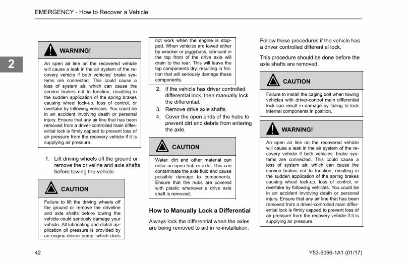
WARNING!
An open air line on the recovered vehiclewill cause a leak in the air system of the re-covery vehicle if both vehicles’ brake sys-tems are connected. This could cause aloss of system air, which can cause theservice brakes not to function, resulting inthe sudden application of the spring brakescausing wheel lock-up, loss of control, orovertake by following vehicles. You could bein an accident involving death or personalinjury. Ensure that any air line that has beenremoved from a driver-controlled main differ-ential lock is firmly capped to prevent loss ofair pressure from the recovery vehicle if it issupplying air pressure.
1. Lift driving wheels off the ground orremove the driveline and axle shaftsbefore towing the vehicle.
CAUTION
Failure to lift the driving wheels offthe ground or remove the drivelineand axle shafts before towing thevehicle could seriously damage yourvehicle. All lubricating and clutch ap-plication oil pressure is provided byan engine-driven pump, which does
not work when the engine is stop-ped. When vehicles are towed eitherby wrecker or piggyback, lubricant inthe top front of the drive axle willdrain to the rear. This will leave thetop components dry, resulting in fric-tion that will seriously damage thesecomponents.
2. If the vehicle has driver controlleddifferential lock, then manually lockthe differential.
3. Remove drive axle shafts.4. Cover the open ends of the hubs to
prevent dirt and debris from enteringthe axle.
CAUTION
Water, dirt and other material canenter an open hub or axle. This cancontaminate the axle fluid and causepossible damage to components.Ensure that the hubs are coveredwith plastic whenever a drive axleshaft is removed.
How to Manually Lock a DifferentialAlways lock the differential when the axlesare being removed to aid in re-installation.
Follow these procedures if the vehicle hasa driver controlled differential lock.
This procedure should be done before theaxle shafts are removed.
CAUTION
Failure to install the caging bolt when towingvehicles with driver-control main differentiallock can result in damage by failing to lockinternal components in position.
WARNING!
An open air line on the recovered vehiclewill cause a leak in the air system of the re-covery vehicle if both vehicles’ brake sys-tems are connected. This could cause aloss of system air, which can cause theservice brakes not to function, resulting inthe sudden application of the spring brakescausing wheel lock-up, loss of control, orovertake by following vehicles. You could bein an accident involving death or personalinjury. Ensure that any air line that has beenremoved from a driver-controlled main differ-ential lock is firmly capped to prevent loss ofair pressure from the recovery vehicle if it issupplying air pressure.
EMERGENCY - How to Recover a Vehicle
42 Y53-6096-1A1 (01/17)
2

CAUTION
A recovered vehicle will have no operationalbrake system. Additionally, the rear axlespring brakes will probably be applied.
1. Caging bolt storage location2. Location of air line to differential lock
actuator
• If you desire to use the recoveredvehicle’s brakes, ensure that thevehicles air system is connected tothat of the recovery vehicle. Alsoensure that any air line that hasbeen removed from a driver-controlled main differential lock isfirmly capped to prevent loss of airpressure from the recovery vehicle.
• If you don’t desire to use therecovered vehicle’s brakes, ensurethat you cage the spring brakesbefore attempting to move thevehicle.
1. Remove the air line and firmly capthe air line from the vehicle. (2)
2. Remove the caging bolt from itsstorage hole. (1)
3. Screw the caging bolt into the airline hole. (2)
When fully engaged, a 0.25 - 0.5 in.(6.35-12.7 mm) space will remain betweenthe air cylinder and the bolt head. Thisaction will lock the differential by pushing apiston into a “lock” position.
EMERGENCY - How to Recover a Vehicle
Y53-6096-1A1 (01/17) 43
2

Recovery Hitch CapacitiesThe maximum rated loads for vehiclerecovery varies depending on the directionor angle of pull. These capacities are listedin the table below and are for the twohitches working together, simultaneously.
Direction of Pull MaximumCapacity (lb)
Directly Forward 80,000 lb
Directly Vertical orHorizontally to the Side
14,600 lb
45 degrees in any Direction 20,000 lb
EMERGENCY - How to Recover a Vehicle
44 Y53-6096-1A1 (01/17)
2

What are the Best Practices forRecovery Rigging?Use these guidelines when recovering avehicle with rigging and hitches.
CAUTION
Recovery pull maximums assume the towrigging evenly distributes the load betweenboth recovery hitches. See examples in Re-covery Rigging for details. Serious damageto the vehicle may occur if rigging is notconnected properly.
CAUTION
When recovering ditched or bogged vehi-cles, stay well below Maximum Capacities.Even at loads below maximum, the physicalstrain of recovering a vehicle could damageaxles, suspensions, fifth wheels, etc.
Use a double chain or cable setup thatdistributes the load equally to both hitches.See 1 or 2 in Recovery Rigging illustration.
Never loop a single chain or cable throughboth hitches (3).
Use a spreader or equalizer bar todistribute the load on both hitches (1).
If no spreader bar is available, connect themain tow chain or cable no closer than 6 ft.from the vehicle (2).
Returning to Service AfterRecoveringOnce the vehicle is recovered, the axlesneed to have oil added to prevent geardamage during operation.
1. Into the pinion cage, add 1 pint (.47liter) of lubricant or into the interaxledifferential, add 2 pints (.94 liter) ofapproved lubricant.
2. After adding the specified type andamount of lubricant, drive thevehicle. It should be unloaded. Drive1 to 2 miles (1.5 to 3 km) at a speedlower than 25 mph (40 km/h). Thiswill thoroughly circulate the lubricantthrough the assembly.
3. If the parking brakes were manuallyreleased, they will need to bemodified back to their normaloperating condition.
4. If the differential lock was manuallylocked, then the caging bolt needsto be put back in its storage locationand the differential lock air lineneeds to be re-installed in its normalposition.
Add lubricant back to the axles afterrecovering the vehicle and before putting itback in to service.
EMERGENCY - How to Recover a Vehicle
Y53-6096-1A1 (01/17) 45
2

What to do if the Vehicle is Stuck inSand, Mud, Snow or Ice
WARNING!
Do not spin the wheels faster than 35 mph(55 km/h). Spinning a tire at speedometerreadings faster than 35 mph (55 km/h) canbe dangerous. Tires can explode from spin-ning too fast. Under some conditions, a tiremay be spinning at a speed twice thatshown on the speedometer. Any resultingtire explosion could cause injury or death toa bystander or passenger, as well as exten-sive vehicle damage: including tire, trans-mission and/or rear axle malfunction.
These suggestions are provided to improvethe ability to free a vehicle if the vehiclegets stuck in sand, mud, snow, or ice:
• Move the gearshift lever or selectorfrom First to Reverse.
• Apply light pressure on theaccelerator pedal while thetransmission is in gear.
• Remove your foot from theaccelerator while shifting.
• Do not race the engine.• For best traction and safety, avoid
spinning the wheels.
Follow these practices to avoidtransmission damage:
• Always start vehicle in motion withthe shift lever in first gear.
• Be sure that transmission is fullyengaged in gear before releasingthe clutch pedal (manual only).
• Do not shift into reverse while thevehicle is moving.
• If the vehicle needs to be recoveredfrom being stuck, do not permit thevehicle to be towed for longdistances without removing thedriveshaft.
If tire chains are needed, make sure theyare installed on both sides of the drivingaxle. Installing chains on only one side ofthe axle can cause equipment damage.
CAUTION
Chains on the tires of only one tandem axlecan damage the driveline U-joints and theinteraxle differential. Repairs could be costlyand time-consuming. Failure to comply mayresult in equipment damage.
Towing the VehicleTowing the vehicle should be done byeither an authorized dealer or acommercial vehicle towing service. Thedealer or commercial towing service willhave the necessary equipment to safelytow the vehicle and should be able to makearrangements to limit any damage to thevehicle. The towing service and the dealershould be aware of towing regulations andsafety precautions.
The towing service will ensure that thefollowing precautions are taken:
• Use of a safety chain system.• Abide by all local towing regulations.• Ensure that the towing device does
not contact any surfaces that couldbe damaged while in transit.
• If towing from the front, ensure thatthe rear axles are prepared fortowing.
• If towing from the rear, ensure thatall body components such as roof,side and chassis fairings aresecured properly to avoid damagewhile in transit.
EMERGENCY - How to Recover a Vehicle
46 Y53-6096-1A1 (01/17)
2

WARNING!
Secure the roof, side and chassis fairingswhile towing from the rear. An unsecuredfairing may come off of the vehicle duringtransit. Failure to secure the fairings whiletowing may cause an injury accident result-ing in death or personal injury.
EMERGENCY - How to Recover a Vehicle
Y53-6096-1A1 (01/17) 47
2

EMERGENCY - How to Recover a Vehicle
48 Y53-6096-1A1 (01/17)
2

Chapter 3 | CONTROLSIn this Chapter:
Getting to Know the Dash.................................................................................................................... 52Gauges in the Center Cluster...............................................................................................................54Left Hand Accessories Overhead........................................................................................................ 55Right Hand Accessories Overhead for Dual Sit Steer Applications..................................................... 55Guide to the Warning Symbols.............................................................................................................55Introduction.......................................................................................................................................... 65Speedometer........................................................................................................................................65Tachometer.......................................................................................................................................... 66Engine - Coolant Temperature............................................................................................................. 66Fuel Level.............................................................................................................................................66Engine, Oil Pressure............................................................................................................................ 67Diesel Exhaust Fluid (DEF)..................................................................................................................68Vehicle Air Pressure.............................................................................................................................68Driver Information Display....................................................................................................................68
3

Information Display.............................................................................................................................. 69Virtual Gauges......................................................................................................................................69Engine Speed RPM Detail................................................................................................................... 70Ignition Timer........................................................................................................................................70Trip Information.................................................................................................................................... 70Truck Information................................................................................................................................. 71Diagnostic Display................................................................................................................................71Transmission Display........................................................................................................................... 71Active Warnings................................................................................................................................... 72Clock.................................................................................................................................................... 72Settings................................................................................................................................................ 72Menu Control Switch............................................................................................................................ 73Switches in the Center Console........................................................................................................... 73Dual Station Switch.............................................................................................................................. 74Steering Column Controls.................................................................................................................... 74How to Use the Turn Signal................................................................................................................. 74How to Turn on High Beams................................................................................................................ 75How to Momentarily Flash High Beams............................................................................................... 75How to Flash Marker and Clearance Lights......................................................................................... 76
CONTROLS -
50 Y53-6096-1A1 (01/17)
3

Operate the Windshield Wipers........................................................................................................... 76How to Spray Windshield Washer Fluid...............................................................................................77Trailer Brake Hand Valve..................................................................................................................... 77Heating and Air Conditioning............................................................................................................... 77Air Conditioner Control Panel...............................................................................................................78How to Manually Control the Air Conditioner for the Cab.................................................................... 80Dash Switches..................................................................................................................................... 80
CONTROLS -
Y53-6096-1A1 (01/17) 51
3

Getting to Know the Dash
Cab interior dashboard overview for LowCab Forward applications with left hand
steer, dual sit and dual steer and right handstand up configuration.
1. Information Display2. Cup Holder3. Automatic Transmission Gear Selector4. Air Switches and Parking Brake5. Electronic Switches for Controls from Either Driving Position
CONTROLS - Getting to Know the Dash
52 Y53-6096-1A1 (01/17)
3

6. Left Hand Side Electronic Switches7. Arm Rest, Storage
(Optional) Right Hand Stand UpCab Station
7
3
12
1 2
9
45
11
6
10
8
1. Parking Brake2. Flipper Brake Valve3. Menu Control Switch4. City Horn5. Information Display6. Headlight Switch7. Tranmission Controls8. Engine Stop/Start9. Turn signal / Windshield Wipers
10. Gauges11. Brake Foot Pedal
12. Accelerator Pedal
Left Hand Drive Station
1. Gauges2. Information Display3. Ignition Switch4. Menu Control Switch
Right Hand Dual Drive Dual SitStationRight Hand (Curb) Side Instrument Clusterfor Dual Sit and Steer Applications
1. Gauges2. Information Display3. Engine Start/Stop Switch4. Menu Control Switch
CONTROLS - Getting to Know the Dash
Y53-6096-1A1 (01/17) 53
3

Right Hand Standup Drive StationRight Hand (Curb) Side Instrument Clusterfor Stand Up Applications
12
3
4
1. Information Display2. Speedometer3. Air Pressure4. DEF Gauge
Instrument System Self TestWhen the ignition switch is turned on theinstrumentation system will undergo a SelfTest. This test will verify the operation ofthe gauges and warnings. During theInstrumentation System Self Test, multiplewarning icons will be displayed in a
sequence. The total sequence should onlytake no more than 10 seconds to complete.Completing this sequence will indicate asuccessful Self Test. Have yourinstrumentation system checked by aqualified service technician if does notsuccessfully complete.
Audible AlarmThe audible alarm will sound during theInstrumentation System Self Test. Theaudible alarm will also sound in conjunctionwith most warning lights. These eventsinclude but are not limited to headlight on,fifth wheel, stop engine, primary/secondaryair, and driver door open warnings.
Optional IconsAdditional icons may be operationaldepending on individual vehiclespecifications. These will be included in theInstrument System Self Test.
NOTE
Some optional lights may illuminate eventhough your vehicle is not equipped withthat particular feature.
Gauges in the CenterCluster
Standard Gauges
1. Tachometer2. Information Display3. Secondary Air Pressure4. Fuel Level5. Diesel Exhaust Fluid6. Primary Air Pressure7. Speedometer
CONTROLS - Gauges in the Center Cluster
54 Y53-6096-1A1 (01/17)
3

Left Hand AccessoriesOverhead
These accessories are located in the lefthand side overhead compartment of thelow cab forward application.
Left Hand Overhead Acessories
1. Radio2. Air Conditioner3. Map Light
Right Hand AccessoriesOverhead for Dual SitSteer Applications
These accessories are located in the righthand side overhead compartment of thelow cab forward application and dual sitand steer configuration.
Right Hand Overhead Acessories
1. Map Light2. Radio extender controls3. Air Conditioner
Guide to the WarningSymbols
The warning lights and audible alarm mayindicate a system malfunction. Check thelights frequently, and respond properly assoon as you see one go on. These lightscould save you from a serious accident.
A single warning will result in the symboland text to alert the operator. Multiplewarnings will appear a smaller icons with amaxiumum of six icons appear in the view.If more than six are active, the MCS can beused to view the others active warnings.The total number of active warnings are
indicated on the right side of the view nextto an icon that represents the severity.
WARNING!
Do not ignore a warning light or audiblealarm. These signals tell you something iswrong with your vehicle. It could be a failurein an important system, such as the brakes,which could lead to an accident causingdeath or injury. Have the appropriate systemchecked immediately.
Some messages can be managed by theoperator while others may require anauthorized dealer repair. The following is alist of Warning Light/Indicator Symbols thatappear in the instrument cluster.
• The Symbol Name• the appearance of the Symbol• the Symbol Color when it is
illuminated• whether the symbol is standard
(Std) or optional (Opt)
CONTROLS - Left Hand Accessories Overhead
Y53-6096-1A1 (01/17) 55
3

Symbol Name Color Standard or Optional
Axle, Stability Control Yellow OPT
Axles, Traction Control Yellow OPT
Axle, Temperature Yellow OPT
Brakes, Anit-Lock Brake System Yellow STD
Brake, Park Brake Red STD
Brakes, Trailer Anti-Lock Brake System Yellow STD
Differential, Inter Axle Lock Yellow OPT
Emissions, Diesel Particulate Filter (DPF) Yellow STD
Emissions, Diesel Exhaust Fluid Quality Yellow STD
Emissions, Engine Derate Yellow STD
Emissions, High Exhaust System Temperature Yellow STD
Emissions, Malfunction Indicator Lamp Yellow STD
Engine, Air Filter Restriction Yellow STD
Engine, Check Engine Yellow STD
Engine, Low Coolant Level Yellow STD
Engine, Coolant Temperature Red STD
Engine, Oil Pressure Red STD
Engine, Oil Temperature Red OPT
Engine, Overspeed Air Shutdown Red OPT
CONTROLS - Guide to the Warning Symbols
56 Y53-6096-1A1 (01/17)
3

Symbol Name Color Standard or Optional
Engine, Retarder (Brake) Yellow OPT
Engine, Stop Engine Red STD
Engine, Wait To Start Yellow OPT
Fifth wheel, Slide Unlocked Red STD
Front Axle Engaged/Disengaged Yellow OPT
Fuel Water In Fuel (WIF) Yellow OPT
Lights, High Beam Blue STD
Seat Belt Fasten Red STD
Suspension Dump Yellow STD
Tire Inflation (TPMS) Yellow OPT
Transmission, Check Red OPT
Transmission, Oil Temperature High Yellow OPT
Transmission, Neutral Yellow OPT
Turn Signal, Left Green STD
Turn Signal, Right Green STD
Voltmeter Red STD
Axle, Traction Control
Monitors wheel speed for poor traction. If awheel begins to slip due to poor traction, itmay reduce engine power or apply brakesin an effort to regain traction.
CONTROLS - Guide to the Warning Symbols
Y53-6096-1A1 (01/17) 57
3

• Illuminates during the power-on self-test when the ignition is turned ON.It turns off after a few seconds if nosystem problems are detected. If anATC problem is detected, the ATCwarning lamp will turn on and stayon.
• Illuminates when the ATC isregulating wheel spin and turns offafter the traction control event hasended.
• Flashes continuously when theATC/ Deep Snow & Mud switch isturned on, indicating that thisfeature is active.
WARNING!
If this chassis is equipped with an electronicstability control (ESC) and is modified (e.g.adding or removing an axle, converting froma truck to a tractor, converting from a tractorto a truck, changing the body, lengthening ofthe wheelbase and/or frame, relocatingframe components, or modifying pneumaticor electrical ABS/ESC harnesses) the ESCmust be disabled by a qualified technician. Ifyou have any questions, contact your au-thorized dealer. Failure to comply may resultin death, personal injury, equipment or prop-erty damage.
NOTE
For more information about the stability con-trol system installed on your vehicle, pleaserefer to additional material supplied with thisoperator manual, included in your glove boxinformational packet.
Axle, Stability Control
Calculates the driver’s intended path oftravel from wheel speed and steering anglesensors, then compares calculations to theactual direction of travel. The system usesindividual wheel brakes to re-adjust thepath of the vehicle.
• The Stability Control Icon (ESC orElectronic Stability Control)illuminates during the power-on selftest when the ignition is turned ON.It turns off after a few seconds if nosystem problems are detected. If a
problem is detected, the ESCWarning lamp will turn on and stayon.
• Illuminates when the ESC system isregulating individual wheel brakes tocorrect the vehicle’s direction oftravel. (Refer to Advanced ABS withStability Control for moreinformation.)
WARNING!
If this chassis is equipped with an electronicstability control (ESC) and is modified (e.g.adding or removing an axle, converting froma truck to a tractor, converting from a tractorto a truck, changing the body, lengthening ofthe wheelbase and/or frame, relocatingframe components, or modifying pneumaticor electrical ABS/ESC harnesses) the ESCmust be disabled by a qualified technician. Ifyou have any questions, contact your au-thorized dealer. Failure to comply may resultin death, personal injury, equipment or prop-erty damage.
CONTROLS - Guide to the Warning Symbols
58 Y53-6096-1A1 (01/17)
3

NOTE
For more information about the stability con-trol system installed on your vehicle, pleaserefer to additional material supplied with thisoperator manual, included in your glove boxinformational packet.
Axle, Front DrivenThis icon will appear when the front drivenaxle is engaged.
Axle, Oil Temperature (Forward orRear)This warning icon is to alert the operator ofelevated axle lubricant temperature.
These temperatures will vary with the kindof load you are carrying and the drivingconditions you encounter. Maximum axletemperature may vary, depending upon the
axle and type of lubricant. Very hightemperatures signal a need to have youraxle(s) lubrication checked.
CAUTION
Driving with very hot temperatures in yourrear drive axles can cause serious damageto axle bearings and seals. Have your axlelubrication checked if you notice a sign ofoverheating.
Depending on the vehicle configuration,there may be a single gauge for more thanjust the forward and rear driver. The iconwill have a label FWD or REAR torepresent which axle the temperature iscausing the warning light.
Brakes, Anti-Lock Brake System
Illuminates during the InstrumentationSystem Self Test. Have the ABS systemchecked by an authorized dealer if the ABSWarning Lamp stays on for more than 3seconds.
• Illuminates during normal operatingconditions to indicate a problem withthe ABS System.
• Illuminates when a problem existswith Automatic Traction Control(ATC).
See AlsoAutomatic Traction Control on page 107
Brake, Park Brake
Illuminates in the status indicator whenparking brakes are applied.
Brakes, Trailer Anti-Lock BrakeSystem
Illuminates during the InstrumentationSystem Self Test and the tractor/truck isconnected with a ABS equipped trailer.
CONTROLS - Guide to the Warning Symbols
Y53-6096-1A1 (01/17) 59
3

Illuminates during normal operatingconditions to indicate a problem with theTrailer ABS System. This should bechecked by an authorized dealer as soonas possible.
NOTE
Tractors/Trucks and trailers built after03/01/2001 must be able to turn on an In-Cab Trailer ABS Warning Lamp (per U.S.FMVSS121). The industry chose PowerLine Communication (PLC) as the standardmethod to turn it on. On trailers built prior to03/01/2001 verify trailer ABS system statusvia the required external warning lampmounted on the trailer. The indicator lampon the trailer should be yellow and identifiedwith the letters ABS.
See AlsoAutomatic Traction Control on page 107
Emissions, High Exhaust SystemTemperature
WARNING!
If this light is on, do not park in an area ofcombustible vapors or materials. You mustkeep combustibles at least five (5) feet awayfrom the exhaust (outlet) stream (as it exitsthe tail pipe) while the HEST lamp isillumi-nated. Always park your vehicle outside.Failure to do so could ignite an explosion orharm bystanders which could result in seri-ous injury.
WARNING!
If this light is on, do not park in an areawhere people are close by. You must keepcombustibles at least five (5) feet awayfromthe exhaust outlet while the HEST lampis illuminated. Failure to do so could resultinserious injury.
WARNING!
If this light is on, temperature of the tailpipe,exhaust pipes, the diesel particular filter(DPF) / selective catalytic reduction (SCR)device and surrounding components includ-ing enclosures and steps becomes elevatedduring engine operation or any regenerationevent and can cause serious burns to the
skin. Allow adequate cooling time before ap-proaching, working on or near any part ofthe exhaust system or surrounding compo-nents.
Illuminates when the exhaust gastemperature and exhaust componentsbecome extremely hot.
Emissions, Malfunction IndicatorLamp
Illuminates when an engine emissionsfailure has occurred. The vehicle can besafely driven but should be serviced tocorrect the problem. The situation shouldnot be considered an emergency. In somecases, the Malfunction Indicator Lamp willactivate in conjunction with the HighExhaust Temperature, Diesel ParticulateFilter (DPF) and Diesel Exhaust Fluid(DEF) Warning Lights.
CONTROLS - Guide to the Warning Symbols
60 Y53-6096-1A1 (01/17)
3

Emissions, Engine DerateThe aftertreatment system requiresattention and as a result is derating theoutput of the engine.
The operator should perform a stationaryregeneration of the DPF and check theDEF fluid level. Seek service at the nextavailable opportunity if the warning iconstays on.
Diesel Particulate Filter (DPF)Warning LampThis warning symbol will appear when theDPF needs to be regenerated and thenalso during the regeneration cycle. Thisicon may also appear if the system isattempting to automatically regeneratewhile the vehicle is in Power Take Offoperation mode.
Engine aftertreatment system includes adiesel particulate filter and DPF warninglamp.
Diesel Exhaust Fluid (DEF) LampEngine aftertreatment system includes adiesel exhaust fluid (DEF) warning lamp onthe DEF gauge and additional warninglamps in the instrument cluster.
DEF Warning Lamp in Instrument Cluster
Diesel Exhaust Fluid (DEF) Gauge
211. DEF Symbol2. DEF Gauge Warning Lamp
The DEF lamp(s) will illuminate when thefluid in the DEF tank reaches a low level. Ifthe lamp illuminates but the level is full,seek service immediately for DEF fluidquality or DEF equipment repair.
Fifth Wheel Slide, Unlocked
CONTROLS - Guide to the Warning Symbols
Y53-6096-1A1 (01/17) 61
3

This icon will appear when the switch is inthe UNLOCKED position.
Engine, Check Engine
Illuminates when a non emissions relatedproblem exists, but the vehicle can still besafely driven. Vehicle should be serviced tocorrect the problem but the situation shouldnot be considered an emergency.
Engine, Low Coolant Level
lluminates with an audible alarm indicatingcritically low coolant level. The vehiclemust be serviced to correct the problembut the situation should not be consideredan emergency.
See AlsoEngine is Overheating on page 31
Engine, Coolant TemperatureThis warning will appear when the enginecoolant temperature has reached a valuethat needs attention.
See AlsoEngine is Overheating on page 31
Engine, Oil TemperatureThis warning icon will turn on if the oiltemperature exceeds the maximum limits,
(See the Engine Operation andMaintenance Manual for details.)
See AlsoLow Oil Pressure Lamp on page 31Check Engine Oil Level on page 187
Engine, Oil PressureIf oil pressure drops below the minimumpsi a red warning light in the gauge will turnon, the Stop Engine light will come on andan audible alarm tone will sound.
CAUTION
Continuing to operate your vehicle with in-sufficient oil pressure will cause serious en-gine damage. Failure to comply may resultin equipment or property damage.
It is important to maintain oil pressurewithin acceptable limits. For furtherinformation on engine oil and normaloperating pressures, see the EngineOperation and Maintenance Manual. If theoil pressure fails to rise within 10 secondsafter the engine starts, stop the engine anddetermine the cause. Check the enginemanufacturer's manual for the correct oilpressure ranges for your vehicle's engine.If the oil pressure suddenly drops, or theaudible alarm and engine oil pressurewarning light come on while driving. Forfurther information on engine gauges andoperating your engine properly, refer toEngine Maintenance material.
See Also
CONTROLS - Guide to the Warning Symbols
62 Y53-6096-1A1 (01/17)
3

Low Oil Pressure Lamp on page 31Check Engine Oil Level on page 187
VoltmeterThis icon will appear when the engine isON and the charging system voltage iseither below 10 volts or above 15 volts.
Engine, Overspeed Air Shutdown
Illuminates when the Engine overspeed airshutdown system is activated.
Engine, Retarder (Brake)
Illuminates when the engine retarder(compression brake or exhaust brake)
switch is turned on. (Engine retarders arean option.)
Engine, Stop Engine
Illuminates and an audible alarm tone willsound when a major engine systemproblem exists.
WARNING!
If the Stop Engine warning lamp illuminates,it means you have a serious engine systemproblem. This should be considered anemergency. You should stop the vehicle assafely as possible and turn OFF the ignition.The vehicle must be serviced and the prob-lem corrected before driving again. Failureto comply may result in death, personal in-jury, equipment or property damage.
See AlsoStop Engine Lamp on page 30
Engine, Wait To StartThis warning icon will appear when thesystem needs some time before attemptingto start the engine.
You may see this appear if the system hasdetected a situation where the starter is toohot and needs to cool down. Alternatively,you may see it when the engine grid heateris on and needs some time to warm up.(PACCAR PX and Cummins ISL engines)
Engine, Air Filter RestrictionThis icon indicates that the engine air filterneeds to be maintained.
CONTROLS - Guide to the Warning Symbols
Y53-6096-1A1 (01/17) 63
3

CAUTION
Continued operation with the Air Filter Re-striction Gauge reading 25 in. H2O maycause damage to the engine. Inspect the fil-ter and replace if necessary. Holes in thepaper element render an air cleaner uselessand may cause the Air Filter RestrictionGauge to give a false reading, even if the el-ement is clogged. Replace the element if itis damaged.
Fuel Filter RestrictionThis warning will appear when there is arestriction from the fuel filter to the fuelpump. Replace the filter with an approvedfilter only. Do not substitute the wrongmicron element.
NOTE
The maximum allowable restriction couldvary according to the type or make of the
engine. Consult the engine manufacturesmanual or engine dealer for fuel restrictionspecifications.
Fuel Water In Fuel (WIF)
Illuminates when water has been detectedin the fuel.
Lights, High Beam
Illuminates when the high beams are on.This icon will flash with audible alarm if theheadlamps are left ON when the door isopened and the key switch is OFF.
In addition, this icon will flash, but withoutan audible alarm, if there is a problem withthe low beam headlights or the low beamheadlight wiring. In such event, the highbeam headlights will turn on at 50% normalbrightness.
Suspension Dump
Illuminates when suspension air bags aredeflated.
Seat Belt Fasten
Illuminates when the ignition key is turnedon as a reminder to fasten your seat belt.
Tire Inflation (TPMS)
CONTROLS - Guide to the Warning Symbols
64 Y53-6096-1A1 (01/17)
3

Illuminates when tire pressures need to bechecked. (Tire Pressure Monitoring Systemis an optIion.)
Transmission, Check
Illuminates when transmission hasrecorded a fault code. This icon may alsoappear in the Transmission Display menuof the Driver Performance Center. If theuser is in this display menu, the icon doesnot indicate a fault code.
Transmission, NeutralThis symbol will appear when thetransmission is in Neutral.
Transmission, Oil TemperatureHigh
Illuminates when the oil in the maintransmission becomes too hot.
Turn Signal, Left
Blinks when the left turn signal or thehazard light function is operating.
Turn Signal, Right
Blinks when the right turn signal or thehazard light function is operating.
Introduction
On the pages that follow you will finddescriptions of some of the gauges on yourinstrument panel.
Some gauges will display a red LEDwarning light, with some accompanied byan audible alarm, whenever the limits ofthe function being displayed are exceeded.
WARNING!
Do not ignore a warning light or audiblealarm. These signals tell you something iswrong with your vehicle. It could be a failurein an important system, such as the brakes,which could lead to an accident causingdeath or injury. Have the appropriate systemchecked immediately.
Speedometer
The Speedometer indicates the vehiclespeed in miles per hour (mph) and inkilometers per hour (km/h).
CONTROLS - Introduction
Y53-6096-1A1 (01/17) 65
3

Tachometer
Engine speed information.
The Tachometer measures the enginespeed in revolutions per minute (rpm).
The rpm detail is also available as aviewable screen in the instrumentationcluster as a virtual gauge. The tachometeris a useful gauge when attempting to driveefficiently. It will let you match drivingspeed and gear selection to the operatingrange of your engine. If the engine speedgets too high, you can select a higher gearto lower the rpm's. If the engine speeddrops too low, you can select a lower gearto raise the rpm's. To avoid enginedamage, do not let the pointer exceedmaximum governed speed. (See yourEngine Operation and MaintenanceManual for rpm recommendations.)
Engine - CoolantTemperature
The water temperature gauge shows thetemperature of the engine coolant.
Under normal operating conditions thewater temperature gauge should registerbetween 165° and 205°F (74° and 90°C).Under certain conditions, somewhat highertemperatures may be acceptable. But themaximum allowable temperature is 210°F(99°C), except for certain special engines.Check your engine manual to be sure.
See AlsoEngine is Overheating on page 31Engine is Overheating on page 31
Fuel Level
The Fuel gauge indicates the total(approximate) amount of fuel in the fueltank.
In addition to indicating empty and full, thegauge(s) also indicate the fuel level ingraduated increments. When the fuel levelfor the tank is below 1/4 full, a red warninglight in the gauge will come on.
WARNING!
Do not carry additional fuel containers inyour vehicle. Fuel containers, either full orempty, may leak, explode, and cause orfeed a fire. Do not carry extra fuel contain-ers. Even empty ones are dangerous. Fail-ure to comply may result in death or person-al injury.
CONTROLS - Tachometer
66 Y53-6096-1A1 (01/17)
3

WARNING!
Diesel fuel in the presence of an ignitionsource could cause an explosion. A mixtureof gasoline or alcohol with diesel fuel in-creases this risk of explosion. Do not re-move a fuel tank cap near an open flame.Use only the fuel and/or additives recom-mended for your engine. Failure to complymay result in death, personal injury, equip-ment or property damage.
CAUTION
Use only Ultra Low Sulfur Diesel (ULSD)Fuel, as recommended by engine manufac-turers. If you need further information onfuel specifications, consult the Engine Oper-ation and Maintenance Manual.
NOTE
For Export vehicles, the fuel gauges will notstate: ULTRA LOW SULFUR DIESEL FUELONLY.
NOTE
This vehicle may be manufactured with dif-ferent fuel systems and different draw tubelocations. Because of this and the amount ofroad crown, it is recommended that you donot operate your vehicle with less than one-quarter of your truck’s fuel capacity. Allowingthe fuel level to go below one-quarter of ca-pacity could result in the lack of fuel to keepthe engine running. In addition, you will wantto keep the fuel tanks at least half-full to re-duce condensation of moisture in the tanks.This moisture can damage the engine.
See AlsoFinal Stopping Procedures on page 127
Engine, Oil Pressure
If oil pressure drops below the minimumpsi a red warning light in the gauge will turnon, the Stop Engine light will come on andan audible alarm tone will sound.
CAUTION
Continuing to operate your vehicle with in-sufficient oil pressure will cause serious en-gine damage. Failure to comply may resultin equipment or property damage.
It is important to maintain oil pressurewithin acceptable limits. For furtherinformation on engine oil and normaloperating pressures, see the EngineOperation and Maintenance Manual. If theoil pressure fails to rise within 10 secondsafter the engine starts, stop the engine anddetermine the cause. Check the enginemanufacturer's manual for the correct oilpressure ranges for your vehicle's engine.If the oil pressure suddenly drops, or theaudible alarm and engine oil pressurewarning light come on while driving. Forfurther information on engine gauges andoperating your engine properly, refer toEngine Maintenance material.
See AlsoLow Oil Pressure Lamp on page 31Check Engine Oil Level on page 187
CONTROLS - Engine, Oil Pressure
Y53-6096-1A1 (01/17) 67
3

Diesel Exhaust Fluid (DEF)
The diesel exhaust fluid gauge shows theapproximate amount of DEF fluid in theDEF tank.
CAUTION
Use Diesel Exhaust Fluid only. Failure to doso may damage components of the DieselParticulate Filter (DPF).
Besides empty and full, the gauge alsoindicates 1/4, 1/2, and 3/4 of total capacity.DEF fluid is required to meet certainemission requirements. Do not allow yourDEF tank to remain empty. Please refer toyour emission supplemental manual formore details about DEF fluid.
Vehicle Air Pressure
The Primary Air Pressure gauge indicatespressure in the rear braking system. TheSecondary gauge indicates pressure in thefront braking system.
Each gauge indicates the amount of airpressure in each system in pounds persquare inch (psi). On vehicles equippedwith metric air pressure gauges, the gaugeface plate includes a kPa (major) scale andpsi (minor) scale.
NOTE
Be sure the air pressure registers more than100 psi (690 kPa) in both service systemsbefore you move the vehicle.
NOTE
If the pressure in either or both circuits fallsbelow 65 psi (448 kPa), a red warning lightin the gauge will turn on and an audiblealarm tone will sound when the engine isrunning.
WARNING!
If the air pressure falls below 60 psi (414kPa) the spring brakes may stop the vehicleabruptly, which could cause an accident re-sulting in personal injury or death. Observethe red warning lamps on the gauges. If onecomes on, do not continue to drive the vehi-
cle until it has been properly repaired orserviced.
WARNING!
The air pressure warning light and the audi-ble alarm tone indicate a dangerous situa-tion: there is not enough air pressure in theair tanks for repeated braking and the brakesystem has failed. Without the use of yourservice brakes your spring brakes couldsuddenly apply causing a wheel lockup, lossof control, or overtake by following vehicles.This may cause an accident resulting indeath or personal injury. Bring the vehicle toa safe stop right away, while you still havecontrol of the vehicle.
See AlsoLow Air Alarm on page 30
Driver Information Display
The display can show multiple warninglights. Warning information will appearmomentarily and then will minimize in thescreen. Reviewing the warnings can be
CONTROLS - Diesel Exhaust Fluid (DEF)
68 Y53-6096-1A1 (01/17)
3
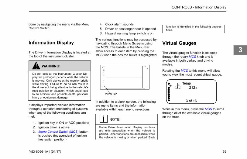
done by navigating the menu via the MenuControl Switch.
Information Display
The Driver Information Display is located atthe top of the instrument cluster.
WARNING!
Do not look at the Instrument Cluster Dis-play for prolonged periods while the vehicleis moving. Only glance at the monitor brieflywhile driving. Failure to do so can result inthe driver not being attentive to the vehicle’sroad position or situation, which could leadto an accident and possible death, personalinjury or equipment damage.
It displays important vehicle informationthrough a constant monitoring of systemswhen any of the following conditions aremet:
1. Ignition key in ON or ACC positions2. Ignition timer is active3. Menu Control Switch (MCS) button
is pushed (independent of ignitionkey switch position)
4. Clock alarm sounds5. Driver or passenger door is opened6. Hazard warning lamp switch is on
The various functions may be accessed bynavigating through Menu Screens usingthe MCS. The bullets in the Menu Barallow access to each item by pushing theMCS when the desired bullet is highlighted.
In addition to a blank screen, the followingare menu items and the informationavailable within each menu selections.
NOTE
Some Driver Information Display functionsare only accessible when the vehicle isparked. Other functions are accessible whilethe vehicle is moving or when parked. Each
function is identified in the following descrip-tions.
Virtual Gauges
The virtual gauges function is selectedthrough the rotary MCS knob and isavailable in both parked and drivingmodes.
Rotating the MCS to this menu will allowyou to view the most recent virtual gauge.
While in this menu, press the MCS to scrollthrough all of the available virtual gaugeson the truck.
CONTROLS - Information Display
Y53-6096-1A1 (01/17) 69
3

Engine Speed RPM Detail
RPM reading of actual engine RPM(Accessible while parked or driving).
Engine RPM between the chevron markersindicates efficient engine operatingconditions.
Ignition Timer
Ignition timer is set from this menu andaccessible while parked only.
This function allows the driver to set atimer to shut off the truck. After the timer isset, the ignition key may be turned to theoff position and removed. The engine willcontinue to run for the programmed time.The ignition timer may be set for up to 30minutes.
Trip Information
When accessing the trip information menu,push the MCS on this menu (bullet). Toexit, push the MCS again. To reset the tripvalues, press the Trip Odometer ResetButton on the main gauge instrumentcluster.
Trip Information functions area accessiblewhen when parked:
1. Instant Information
• Trip Economy• Average Speed
2. Trip Result
• Trip Distance• Trip Eng. Hours
3. Idle Information.
• Trip Idle Hours• Trip Idle %
4. PTO Information.
• PTO Hours• PTO Trip Hours• PTO Trip %
To reset the Trip Values, press the TripOdometer Reset Button on the main gaugeinstrument cluster.
CONTROLS - Engine Speed RPM Detail
70 Y53-6096-1A1 (01/17)
3

While moving, this menu will only displayinstantaneous fuel economy.
Truck Information
This menu provides information about thevehicle such as serial numbers.
Chassis Chassis NumberFleet IDCab ControllerSoftware Version
Engine MakeModelEngine ControllerSoftware VersionGoverned Speed LimitEngine Power
Transmission MakeModelTransmissionController SoftwareVersion
Antilock-BrakeSystem
MakeModelABS ControllerSoftware Version
Diagnostic Display
Diagnostic fault information can beexpanded in this menu. This information isavailable when the vehicle is parked.
The diagnostic display menu (bullet) willindicate a fault that is generated by thevehicle's Engine, ABS and/or Transmissionsystems. While on this menu item thedisplay will either indicate "No FaultsFound" or "Faults Found". If "Faults Found"is active, pushing the MCS will display newmenus for more information.
Transmission Display
This menu will show gear number thatcoincides with the current transmissiongear selected. The menu also displays thetransmission icon to let the user know what
CONTROLS - Truck Information
Y53-6096-1A1 (01/17) 71
3

screen they are in. (Does not indicate afault code.)
This information is available for AutomatedTransmissions and is accessible when thevehicle is parked or driving. Refer to theAutomated Transmission Operator’sManual for additional information.
Active Warnings
This information is accessible when thevehicle is parked or driving. This menuselection will display all active warningicons. The display will read “No Warnings”when there are no active warnings.
Clock
This information is accessible when thevehicle is parked or driving.
Settings
This information is accessible only whenthe vehicle is parked.
The Settings menu screen allows the driverto view and/or change the following menuitems:
• Alarm ON/OFF• Home/Local Time• Display Format 12 Hour (AM/PM) or
24 Hour (military)• Units of measure• Set Alarm Time• Set Clock (Home) Time• Set Local Time• Set Language (English, Spanish or
French)
How to Turn Alarm On/Off
To turn alarm ON/OFF:
1. When in the Settings Menu, scrollthrough the list of menu items to“Alarm”. Press the MCS.
2. Press the MCS to turn the alarm ONor OFF.
How to Set Time in the InformationDisplayThe information display has a clock for 2time zones and an alarm.
To set the time for local, home or alarm:
1. When in the Settings Menu, scrollthrough the list of menu items.
2. Press the MCS to select the item tochange.
3. Rotate the MCS knob to change thehour. AM/PM changes whenscrolling to “12”. Press the MCS.
CONTROLS - Active Warnings
72 Y53-6096-1A1 (01/17)
3

4. Rotate the MCS knob to change theminutes. Scrolling above “59” orbelow “ 00” will increment ordecrement the hour, respectively.
5. Press the button above the MCS toreturn to the settings menu.
How to Set Units of Measure
To set the units of measure, such as milesversus kilometers:
1. When in the Settings Menu, scrollthrough the list of menu items to"Units".
2. Press the MCS.3. Press the MCS to display either
Standard or Metric units.
How to Set Language
To change the language from English toeither French or Spanish:
1. When in the Settings Menu, scrollthrough the list of menu items to"Language".
2. Press the MCS.3. Rotate the MCS to display either
English, Spanish or French.4. Press the MCS knob to select the
desired language.
Menu Control Switch
The MCS is used to navigate the DriverInformation Display unit. The Menu ControlSwitch is located on the dash to the right ofthe steering wheel.
The MCS has the following functions:
1. Spin
• Setting values• Selecting menu screens
2. Push
• Confirm desired selection
Switches in the CenterConsole
These switches are available in the centerconsole for either left hand or right handdriving position.
1. Marker Ligtht2. Headlights
CONTROLS - Menu Control Switch
Y53-6096-1A1 (01/17) 73
3

3. Station Selector (for Dual SteerApplications)
4. Fog Lights5. Mirror Control6. Cab Lighting Dimmer Control7. Differential Lock8. Differential Lock9. Lift Axle
10. Lift Axle11. Lift Axle
Dual Station Switch
The dual station switch allows the controlsfor the vehicle from left hand to right handoperation.
Pushing this switch will engage electronicswitchs on the right hand side of thevehicle. Certain controls on the left hand
side of the cab cannot be used when righthand operation is in effect. Vehicleoperation will revert back to the left handdrive position when the ignition is turned tothe OFF position.
Steering Column Controls
The turn signal lever is mounted on the leftside of the steering column. The levercontrols several functions: turn signal, highbeam, and windshield wiper control.
1. Mulitfunction turn signal/wiper/washer
2. City Horn
How to Use the TurnSignal
The lever-action turn signal/high beamswitch is located on the left side of thesteering column. Each time a turn indicatoris activated the buzzer emits a short beep.The ignition key must be turned to ON forthe signal/switch to operate.
NOTE
If the vehicle turn signals and turn signal in-dicators in the dash gauge cluster ever be-gin flashing at an accelerated rate (115 cy-cles per minute) when the turn signal leveris in the OFF (center) position, or when aRight/Left turn has been selected, the prob-lem may be related to a failed turn signalswitch or turn signal module. In either case,the problem is not a failed bulb. Contactyour nearest authorized dealer to have theproblem corrected as soon as possible.
1. Push the lever up to engage theRIGHT turn signal and down toengage the LEFT turn signal.
CONTROLS - Dual Station Switch
74 Y53-6096-1A1 (01/17)
3

2. Release the signal stalk3. The turn signal will cancel when the
turn is complete.
Each time the turn indicator is activated theaudible warning emits a short beep.
WARNING!
After you complete a turn, shut the systemoff by returning the lever to the "OFF" (cen-ter) position. Failure to shut off a turn signalcould confuse other drivers and result in aninjury accident. An indicator light in the in-strument panel will flash until the turn signalis turned off.
How to Turn on HighBeams
The high beam function is operated by thesame steering column lever for the turnsignals. High beams will not turn on if theheadlights are turned off.
1. Gently pull the turn signal lever,toward the steering wheel, until youhear the switch click and the beamchanges.
2. To return to previous beam: pull thelever towards the steering wheelagain.
The blue indicator light in the instrumentpanel will turn ON and the high beams willturn on.
How to Momentarily FlashHigh Beams
The "flash to pass" high beam function isoperated by the same steering columnlever for the turn signals. The high beamflash to pass will work if the headlights arenot on.
1. Gently push the turn signal lever,away from the steering wheel.
2. The lever will automatically returnwhen the lever is released.
The blue indicator light in the instrumentpanel will momentarily turn ON and thehigh beams will flash. The high beams willnot remain on if the lever is still pressed.
CONTROLS - How to Turn on High Beams
Y53-6096-1A1 (01/17) 75
3

NOTE
The “flash to pass” functionality of the head-light switch is not available for vehicles man-ufactured with High Intensity Discharge(HID) headlamps. Please check with localregulations regarding restrictions on usinghigh beam flashing.
NOTE
Continued pressing of the high beam flashwill not keep the high beams on.
How to Flash Marker andClearance Lights
A button on the turn stalk will momentarilyflash the marker and clearance lights whenpushed.
1. Push the small button on the end ofthe turn stalk
Operate the WindshieldWipers
This vehicle is equipped with a two speed,intermittent windshield wiper system. Thewindshield wiper system is integrated withthe exterior lights so that the low beamheadlights will turn on when the windshieldwipers turn on.
WARNING!
Clean blades regularly with a damp cloth toremove road film and wax buildup. Do notdrive with worn or dirty wiper blades. Theycan reduce visibility, making driving hazard-ous which may lead to an injury accident re-sulting in death or personal injury.
CAUTION
Do not use antifreeze or engine coolant inthe windshield washer reservoir, damage toseals and other components will result.
To override this function, turn theheadlights on and then off again and thelow beams will turn off. Permanently
overriding this functionality is attainable viathe Settings Menu in the instrument clusterdisplay. Go to Settings - > Wiper Interlockand turn this value to OFF.
Avoid running the wiper blades over a drywindshield to prevent scratching the glass.Spray on washer fluid first. A scratchedwindshield will reduce visibility.
A seven-position rotary wiper switch(located on the turn signal lever) operatesthe windshield wipers and washer. If youneed to use the windshield wipers:
1. Rotate the end of the turn signallever to change the wiper modefrom off to on.
2. Continue to rotate the outer knob ofthe turn stalk lever to adjust thewiper speed.
• 4 levels of intermittent speeds• Low wiper speed• High wiper speed
CONTROLS - How to Flash Marker and Clearance Lights
76 Y53-6096-1A1 (01/17)
3

How to Spray WindshieldWasher Fluid
This vehicle is equipped with a functrion towash the windshield and simulatenouslyengage the wipers.
CAUTION
If the electric pump is operated for a longperiod (more than 15 seconds) with a dryreservoir, the pump motor may be damaged.
If you need to use the windshield wiperswasher:
1. Push the outer knob in.
• Press and hold will activate thewasher fluid and wipers.
• Instant press and release willactivate the washer fluid only.
Trailer Brake Hand Valve
This hand valve, mounted on the steeringwheel column, provides air pressure toapply the trailer brakes only. It operatesindependently of the foot treadle valve.
See AlsoAir Brake System on page 106
Heating and AirConditioning
This vehicle's heating and air conditioningsystem controls are located in the header.If this vehicle is a Dual Sit and Steerconfiguration, there will be a controlinstalled above both driver's positions.Vehicles with dual steer configuration willhave two air conditioner controls that canmodify the air temperature settings for thecab.
1. Fan Control2. Air Distribution3. Air Temperature Control4. Air Conditioner Button for Cold Air5. Recirculation Button
WARNING!
Do not drive with visibility reduced by fog,condensation, or frost on the windshield.Your view may be obscured, which may re-sult indeath, personal injury, equipment orproperty damage. For clear visibility andsafe driving it is extremely important for youto follow the instructions pertaining to thefunction and use of the ventilation/heatingand defogging/defrosting system. If in doubt,consult your dealer. Maximum heating out-put and fast defrosting can be obtained onlyafter the engine has reached operating tem-perature.
CONTROLS - How to Spray Windshield Washer Fluid
Y53-6096-1A1 (01/17) 77
3

WARNING!
Exhaust fumes from the engine contain car-bon monoxide, a colorless and odorlessgas. Do not breathe the engine exhaust gas.A poorly maintained, damaged or corrodedexhaust system can allow carbon monoxideto enter the cab. Entry of carbon monoxideinto the cab is also possible from other vehi-cles nearby. Failure to properly maintainyour vehicle could cause carbon monoxideto enter the cab, resulting in death or per-sonal injury.
WARNING!
Never idle your vehicle for prolonged peri-ods of time if you sense that exhaust fumesare entering the cab. Investigate the causeof the fumes and correct it as soon as possi-ble. If the vehicle must be driven underthese conditions, drive only with the win-dows open. Failure to repair the source of
the exhaust fumes may result in death, per-sonal injury, equipment or property damage.
CAUTION
Do not stay in the vehicle with the enginerunning or idling for more than 10 minuteswith the vehicle's Heater and A/C ventilationsystem in RECIRC or at LOW FAN SPEED.Even with the ventilation system on, runningthe engine while parked or stopped for pro-longed periods of time is not recommended.
NOTE
Keep the engine exhaust system and thevehicles cab ventilation system properlymaintained. It is recommended that the ve-hicles exhaust system and cab be inspected(1) By a competent technician every 15,000miles (24,140 km) (2) Whenever a change isnoticed in the sound of the exhaust system(3) Whenever the exhaust system, under-body, or cab is damaged.
NOTE
If you are required to idle your vehicle forlong periods of time, install an auxiliaryheater or automatic idle control. These aux-iliary devices can reduce fuel consumptionand save you money.
NOTE
If you are parked next to idling vehicles,move your vehicle or do not stay in your ve-hicle for prolonged periods of time.
Air Conditioner ControlPanel
These symbols for the air conditioneroperate various system functions.
CONTROLS - Air Conditioner Control Panel
78 Y53-6096-1A1 (01/17)
3

Symbols for the air conditioning control panel
Image Function
The source of air entering the cab can be set to either outside air or recirculation air using the button inside the fan speed control dial. Recirculated air isautomatically selected in defrost modes.
The fan speed is adjusted by rotating the dial clockwise to increase speed or counterclockwise to decrease speed. Setting the fan dial to "O" turns theHVAC system off.
The button inside the temperature control dial engages the A/C compressor. When activated the indicator on the button will illuminate. During AUTOmode, the A/C button indicator will remain illuminated at all times even though the compressor may be cycling.
Floor Vents
Defrost Vents (and Fresh air intake)
Panel and Floor Vents
Panel Vents
Floor and Defrost Vents (and Fresh air intake)
CONTROLS - Air Conditioner Control Panel
Y53-6096-1A1 (01/17) 79
3

How to Manually Controlthe Air Conditioner for theCab
Information on controls to set cab heatingand air conditioning.
TemperatureControl SetPoint
The cab temperature isset using thetemperature control dial.The operating range is60°F (16°C) and 84°F(28°C). Adjustments of2° increments.
AirConditionerButton
The button inside thetemperature control dialengages the A/Ccompressor. Whenactivated the indicatoron the button willilluminate. During AUTOmode, the A/C buttonindicator will remainilluminated at all timeseven though thecompressor may becycling.
NOTE
Fan Control Dial must also be in the ON po-sition for A/C to be on. A/C engages auto-matically in AUTO, defrost and floor/defrost.
The air conditioner defaults to Manualmode when turned on. The fan speed, airtemperature, and air outlets are selectedusing the dials on the controller.
1. To adjust the fan speed, turn the fancontrol dial clockwise to increasespeed or counterclockwise todecrease speed. Setting the fan dialto "O" turns the HVAC system off.
2. To adjust the temperature setting,turn the temperature control dial tothe desired temperature. Thesystem automatically adjusts theoutlet air temperature to achieve thedesired cab temperature.
3. Push the snowflake button if the airtemperature needs to be colder, thisbutton will manually turn on thecompressor.
4. To adjust the air distribution, turn theair distribution dial to the desiredposition as indicated by thegraphics.
5. Select the recirculation button forFRESH or RECIRC air.
The temperature of the air from the ventswill fluctuate as the vehicle works toachieve the chosen cab temperature.
When idling for short periods of time, keepthe fan ON and set the air mode to FRESHair. For vehicles with a sleeper, the cabcontrol can be used to activate/deactivatethe sleeper HVAC using the button insidethe mode dial.
Dash Switches
This custom vehicle will have a widevariety of switch controlled equipment.However, this particular vehicle may nothave every switch identified in this sectionof the operator manual. Some air deviceswitches on the dash may require that thevehicle either be at a specific speed, parkbrakes set or another device to be on or offfor the air device to operate. Theinstrument display will display informationregarding what needs to change in orderfor the air device to operate as expected.The following table provides a complete listof icons that may be found on the switch.
CONTROLS - How to Manually Control the Air Conditioner for the Cab
80 Y53-6096-1A1 (01/17)
3

Title Color Standard or Optional
Axle, Differential Lock - Tridrive Amber OPT
Axle, Diff-Lock - Dual Amber OPT
Axle, Diff-Lock - Forward Rear Amber OPT
Axle, Diff-Lock - Rear Rear Amber OPT
Axle, Diff-Lock - Single Rear Amber OPT
Axle, Diff-Lock - Steer Amber OPT
Axle, Inter-Axle Differential Locked (Tandem) Amber OPT
Axle, Two Speed Green OPT
Back Up Alarm Mute Amber OPT
Batteries, Low Voltage Disconnect (LVD) None STD
Brakes, ABS Off-Road Amber OPT
Brakes, Parking Brake Valve Red STD
Cab Dimmer Switch None STD
Dump Truck Gate Red OPT
Engine, Brake Level None OPT
Engine, Brake On/Off Green OPT
Engine, Cruise Control On/Off Green STD
Engine, Cruise Control Set/Resume None STD
Engine, Fan Override Green OPT
Engine, Heater Green OPT
CONTROLS - Dash Switches
Y53-6096-1A1 (01/17) 81
3

Title Color Standard or Optional
Engine, Overspeed Air Shutdown (Test) Amber OPT
Engine, Overspeed Air Shutdown (Manual) None OPT
Engine, Remote Throttle Amber OPT
Engine, Under Hood Air Intake Amber OPT
Exhaust, Diesel Particulate Filter (DPF) Regeneration None STD
Fifth Wheel Slide Red OPT
Fuel Heater Amber OPT
Generic Air, Accessory Green OPT
Generic, Spare SPARE Green OPT
Ignition Key Switch None STD
Lights, Auxiliary Green OPT
Lights, Beacon Green OPT
Lights, Daytime Running (Override) Green OPT
Lights, Dome None STD
Lights, Exterior Lights Self Test None STD
Lights, Flood Amber OPT
Lights, Flood ISO 3732 Spare Amber OPT
Lights, Fog Green OPT
Lights, Hazard Red STD
Lights, Headlight and Parking Lights None STD
Lights, Marker / Clearance / Cab None STD
CONTROLS - Dash Switches
82 Y53-6096-1A1 (01/17)
3

Title Color Standard or Optional
Lights, Marker / Clearance / Trailer None OPT
Lights, Park Light None STD
Lights, Spot Green OPT
Mud and Snow Traction Control None STD
Pintle Hook Green OPT
Power Take-off (PTO) Amber OPT
Power Take-off (PTO), Forward Amber OPT
Power Take-off (PTO), Rear Amber OPT
Roofdenser Green OPT
Suspension, Air Retention Amber OPT
Suspension, Axle, Pusher Green OPT
Suspension, Axle, Tag Amber OPT
Suspension, Dump Amber OPT
Suspension, Third Axle Lift Green OPT
Trailer Air Supply Red STD
Trailer, Axle (3rd Axle) Lift Green OPT
Trailer, Axle Lift Forward Green OPT
Trailer, Axle Lift Rear Green OPT
Trailer, Belly Dump Red OPT
Trailer, Belly Dump Gate Center Red OPT
Trailer, Belly Dump Gate Front Red OPT
CONTROLS - Dash Switches
Y53-6096-1A1 (01/17) 83
3

Title Color Standard or Optional
Trailer, Belly Dump Gate Rear Red OPT
Trailer, Dump Gate Red OPT
Trailer, Hotline Green OPT
Trailer, Suspension Air Dump Amber OPT
Transmission, Transfer Case Amber OPT
Transmission, Transfer Case 2 Speed Amber OPT
Winch Clutch Green OPT
Axle, Diff-Lock - Dual
Turn switch on to engage Front and RearAxle Diff Lock.
Axle, Diff-Lock - Forward Rear
Turn switch on to engage Forward RearAxle Diff Lock.
Axle, Diff-Lock - Steer
Turn switch on to engage Front Axle DiffLock.
Axle, Diff-Lock - Rear Rear
Turn switch on to engage Rear Rear AxleDiff Lock.
Axle, Diff-Lock - Single Rear
Turn switch on to engage Single Rear AxleDiff Lock.
CONTROLS - Dash Switches
84 Y53-6096-1A1 (01/17)
3

Axle, Inter-Axle Differential Locked(Tandem)
Turn switch on to engage Inter-AxleDifferential Lock.
Axle, Differential Lock - Tridrive
Tridrives will have these axle differentiallock controls and are 2 separate switches.FRONT will control the forward rear andREAR will control the center/rear-rear axle
differential. In addition, a vehicle withTridrive will have an interaxle differentiallock switch.
See AlsoAxle, Inter-Axle Differential Locked(Tandem) on page 85
Axle, Two Speed
If equipped, the two speed axle switchallows you to select axle high and lowranges. The low range (Off) providesmaximum torque for operating off-highway.The high range (On) is a faster ratio forhighway speeds.
Batteries, Low Voltage Disconnect(LVD)
If your vehicle is equipped with a LowVoltage Disconnect (LVD) feature, the LVDis integrated into the main load center.
Brakes, ABS Off-Road
Turn switch on to engage ABS Off-Roadmode.
See AlsoAnti-Lock Brake Systems (ABS) on page107
Brakes, Parking Brake Valve
Pull yellow knob to activate parking brakes.
See AlsoAir Brake System on page 106
CONTROLS - Dash Switches
Y53-6096-1A1 (01/17) 85
3

Cab Dimmer Switch
This switch is used to alter the brightnessof the instrument panel lights.
NOTE
The Headlamp Switch is an ON or OFFswitch. The panel lights are on full intensityduring the day and go to Dimmer modewhen headlamps are on.
Dump Truck Gate
Turn switch on to open Dump Truck Gate.
Engine, Brake On/Off
Turn switch on to activate Engine Brakesystem. For more information on when andhow to use the engine brake in yourvehicle, see the engine brake owner’smanual for additional engine brakeinformation.
Engine, Cruise Control On/Off
Turn switch on to activate CruiseControlSystem. If the vehicle has the optionalPredictive cruise control, this switch willhave a different icon and will be located onthe steering wheel.
See AlsoEngine, Cruise Control Set/Resume onpage 86
Engine, Cruise Control Set/Resume
The Cruise Control Set/Resume switchallows you to SET the desired speed orRESUME the desired speed after thecruise control function has beeninterrupted.
See AlsoEngine, Cruise Control On/Off on page 86
Engine, Fan Override
The optional engine fan switch allows youto control the engine fan manually orautomatically.
See AlsoEngine Fan Control on page 100
CONTROLS - Dash Switches
86 Y53-6096-1A1 (01/17)
3

Engine, Heater
Turn switch on to activate the EngineHeater.
Engine, Remote Throttle
Turn switch on to activate Remote ThrottleControl.
Engine, Overspeed Air Shutdown(Manual)
Turn switch on to engage the EngineOverspeed Air Shutdown system. Asystem reset will be required before re-starting engine. See EOAS systemmanufacturer's instruction manual fordetails.
Engine, Overspeed Air Shutdown(Test)
Hold down switch and increase engine rpmto test that Engine Overspeed AirShutdown system functions correctly. Asystem reset will be required beforerestarting engine. See EOAS systemmanufacturer's instruction manual fordetails.
Engine, Under Hood Air IntakeThis switch opens a door in the engine airfilter housing so that the air is taken fromunder the hood instead of outside air. Thisswitch can be useful when starting thevehicle in cold weather conditions.
CAUTION
Only operate the under hood intake airswitch when outside temperatures are be-low 32° F (0° C). Engaging the under hoodair intake while temperatures are abovefreezing may result in engine damage.
Exhaust, Diesel Particulate Filter(DPF) Regeneration
Manually controls the diesel particulatefilter regeneration process. Refer to EngineAftertreatment Controls Operator's Manualfor additional information.
Fifth Wheel Slide
CONTROLS - Dash Switches
Y53-6096-1A1 (01/17) 87
3

Turn switch on to “Unlock” Fifth WheelSlide mechanism. The switch is guarded toprotect you from accidentally activating orreleasing the lock.
WARNING!
Do not move the fifth wheel while the trac-tor-trailer is in motion. Your load could shiftsuddenly, causing you to lose control of thevehicle. Never operate the vehicle with theswitch in the UNLOCK position. Always in-spect the fifth wheel after you lock theswitch to be sure the fifth wheel slide lock isengaged. Failure to comply may result indeath, personal injury, equipment or proper-ty damage.
NOTE
Vehicles having an air slide fifth wheel havea fifth wheel slider lock controlled by aswitch on the instrument panel. By placingthe switch in the unlock position you canslide the fifth wheel to various positions toadjust weight distribution.
Fuel Heater
Turn switch on to activate Fuel Heater.
Generic Air, Accessory
Provides accessory air to the end of frameconnection when switch is turned on.
NOTE
The generic air accessory switch is de-signed by the original equipment manufac-turer to reset when the ignition power isturned off. When ignition is turned off, thiscircuit will exhaust air pressure.
Generic, Spare SPARE
Turn switch on to power customer installedaccessory.
Ignition Key Switch
The ignition key switch (located to the leftof the steering column) has four positions:ACC (Accessories), OFF, ON, and START.
Lights, Auxiliary
Turn switch on for Auxiliary Lights.
Lights, Beacon
Turn switch on for Beacon Light(s).
CONTROLS - Dash Switches
88 Y53-6096-1A1 (01/17)
3

Lights, Daytime Running (Override)
This switch overrides the normal operationof the Day Time Running Light (DRL)system. During normal operation the DRLwill turn on lights when the headlights areturned off, engine is on and the parkbrakes are dissengaged. The overrideswitch will turn the DRL off in theseinstances. The DRL is also turned off whenthe headlights are turned ON.
WARNING!
Do not use daytime running lights (DRL)during periods of darkness or reduced visi-bility. Do not use DRL as a substitute forheadlights or other lights during operationsthat require lighting of your vehicle. Failureto comply may result in death, personal in-jury, equipment or property damage.
If the headlight switch is turned OFF, theDRL system engages automatically afterthe engine starts and you release theparking brake. If the headlight switch isON, the DRL system is overridden, and
headlights operate normally. Also, duringengine cranking the DRL is temporarilyturned off.
Lights, Dome
Turn switch on for Cab Dome Lights.
Lights, Flood
Turn switch on for cab mounted FloodLights.
Lights, Flood (Spare)
Turn switch on for trailer mounted FloodLights.
Lights, Fog
Turn switch on for Fog Lights.
NOTE
Across the U.S.A. and Canada, State/Provincial requirements vary as to whenhigh beams and fog lights can and cannotbe used together. Some states allow onlyfour lights to be used together, while someallow more. How your lights are arrangedwill affect whether you can operate head-lights and fog lights concurrently alwayscomply with the state or provincial require-ments where you are driving.
CONTROLS - Dash Switches
Y53-6096-1A1 (01/17) 89
3

Lights, Hazard
This switch operates the emergencyflashers. With the switch in the ONposition, the emergency flasher makes allfour turn signals (front and rear) flashsimultaneously. The flasher worksindependently of the ignition switch. Youshould always use the flasher if the vehicleis disabled or parked under emergencyconditions.
WARNING!
Use your Hazard Warning Light System anytime you have to stop off the road or on theside of the road, day or night. A hard-to-seevehicle can result in an injury accident. An-other vehicle could run into you if you do notset your flashers and follow the placementof emergency signals per FMCSR 392.22.
Lights, Headlight
Turn switch for park/marker lights andheadlights. When the Headlights are ON,the dash lights, side, and tail lights are alsoon. Headlights will turn on if the windshieldwipers are turned on. Manually turning theheadlights on and then off will override thisfunction until the next time the vehicle isturned on.
CAUTION
If you have confirmed there is a problem inthe low beam wiring circuit, proceed withcaution to the next available exit/turnoff andsafely pull your vehicle completely off theroad and call for assistance. Driving yourvehicle with the headlamps on high beam(at reduced intensity) for a prolonged periodcould lead to an injury accident. Contactyour nearest dealer to have the problemcorrected as soon as possible.
Lights, Marker/Clearance
Turn switch on to control Cab and VehicleMarker/Clearance lights.
NOTE
An interrupt switch for the trailer markerlights is mounted on the end of the turn sig-nal lever.
Lights, Marker/Clearance/Trailer
Turn switch on to control Trailer Marker/Clearance lights separately from thevehicle marker/clearance lights.
CONTROLS - Dash Switches
90 Y53-6096-1A1 (01/17)
3

Lights, Park Light
Turn switch on for Park Lights. When thePark Lights are on the dash lights, side andtail lights are also on.
Lights, Spot
Turn switch on for Spot Light.
Mud and Snow Traction Control
Momentarily push switch in to engageTraction Control (TC).
Pintle Hook
Turn switch on to remove the slack fromthe Tow Hook.
Power Take-off (PTO)
This vehicle may be equipped with a dashmounted switch that controls PTOengagement/disengagement. When theoperator activates the switch for the PTO,the status indicator lamp (located on theswitch) will immediately illuminate eventhough PTO engagement may not haveoccurred. If the PTO is engaged and theoperator turns the switch OFF, the PTOstatus indicator lamp (located on the
switch) will go out immediately eventhough PTO disengagement may not haveoccurred.
NOTE
Actual PTO engagement/disengagementmay be delayed momentarily since it is con-trolled by the air system and mechanicalmovement.
CAUTION
Increasing engine rpm before the PTO is ac-tually engaged could prevent the PTO fromengaging and/or cause PTO damage.
Power Take-off (PTO), Forward
Your vehicle may be equipped with a dashmounted switch that controls forward PTOengagement/disengagement.
CONTROLS - Dash Switches
Y53-6096-1A1 (01/17) 91
3

Power Take-off (PTO), Rear
Your vehicle may be equipped with a dashmounted switch that controls the rear PTOengagement/disengagement.
Suspension, Axle, Pusher
Turn switch on to lower Single or ForwardPusher Axle.
Suspension, Axle, Tag
Turn switch on to lower tag axle.
Suspension, Dump
Turn switch on to deflate suspension airbags. The switch is guarded to protect youfrom accidentally deflating the suspension.
WARNING!
Do not operate the Air Suspension DeflateSwitch (Dump Valve) while driving. Suddendeflation while your vehicle is moving canaffect handling and control and could lead toan accident. Use this switch only when yourvehicle is not moving.
CAUTION
Operating a vehicle with air suspensionbags either overinflated or underinflatedmay cause damage to driveline compo-nents. If a vehicle must be operated undersuch conditions, do not exceed 5 mph (8km/h). Failure to comply may result in equip-ment damage.
Suspension, Air Retention
Suspension, Third Axle Lift
Turn switch on to raise Third Axle.
Trailer Air SupplyThe red octagon knob controls the airsupply to the trailer.
Trailer, Axle (3rd Axle) Lift
Turn switch on to lift 3rd Trailer Axle.
CONTROLS - Dash Switches
92 Y53-6096-1A1 (01/17)
3

Trailer, Axle Lift Forward
Turn switch on to lift Forward Trailer Axle.
Trailer, Axle Lift Rear
Turn switch on to lift Rear Trailer Axle.
Trailer, Belly Dump
Turn switch on to open Trailer Belly Dump.
Trailer, Dump Gate
Turn switch on to open Trailer Dump Gate.
Trailer, Belly Dump Gate Center
Turn switch on to open Trailer Center BellyDump Gate.
Trailer, Belly Dump Gate Front
Turn switch on to open Trailer Front BellyDump Gate.
Trailer, Belly Dump Gate Rear
Turn switch on to open Trailer Rear BellyDump Gate.
Trailer, Hotline
Turn switch on to supply electrical power totrailer accessories.
Trailer, Suspension Air Dump
Turn switch on to deflate Trailer AirSuspension.
CONTROLS - Dash Switches
Y53-6096-1A1 (01/17) 93
3

Transmission, Transfer Case
Turn switch on to shift the transfer case.
Transmission, Transfer Case 2Speed
Turn switch on to shift the 2 speed transfercase.
Winch Clutch
Turn switch on to engage Winch Clutch.
CONTROLS - Dash Switches
94 Y53-6096-1A1 (01/17)
3

Chapter 4 | DRIVINGIn this Chapter:
Starting and Operating......................................................................................................................... 96How to Use Engine Start Switch on Right Hand Drive.........................................................................96Starting and Warming Up.....................................................................................................................96Engine Operations............................................................................................................................. 100Transmission......................................................................................................................................103Brakes................................................................................................................................................ 106Axle and Suspension..........................................................................................................................114Aftertreatment System....................................................................................................................... 123Dual Steer Operation......................................................................................................................... 124Driving Tips and Techniques.............................................................................................................. 124Stopping the Vehicle.......................................................................................................................... 126
4

Starting and Operating
Since each vehicle is custom-equipped, allengine operation instructions in thismanual are general. You will want toconsult the manual for your engine to findout details about your specific engine’sneeds. You may need to use a slightlydifferent procedure from the one outlinedhere.
How to Use Engine StartSwitch on Right HandDrive
Right hand drive station has an EngineStart/Stop switch to enable engineoperation from the curb side position.
The Engine Start/Stop switch will only workwhen the ignition switch on the left handside cockpit is in the ON position and theRH Steer switch is in the engaged position.
1. Press and hold ENGINE STARTwhen using the right hand driveposition to start the engine.
2. Press ENGINE STOP when usingthe right hand drive position to stopthe engine.
Starting and Warming Up
How to Start Vehicle in NormalWeather
CAUTION
Never operate the starter motor while theengine is running. The starter and flywheelgears could clash or jam, severely damag-ing them.
NOTE
Some starters are equipped with overcrankprotection. Check the Engine Operation andMaintenance Manual for details.
When the outside temperature is above50°F (10°C), you can use the followingprocedure:
1. Set the parking brake.2. Put your main transmission in
Neutral.3. Disengage (depress) the clutch
(with manual transmission).4. Turn the key switch to ON.
a. If the center display promptsfor a Anti-Theft passcode, usethe Menu Control Switch toenter the four digit code.
5. Turn the ignition key to the STARTposition. If the engine does not startwithin 30 seconds, release theignition switch. To avoid overtaxingthe starter motor or the batteries,don’t use the starter for more than30 seconds. Let the starter motorcool and the batteries recover fortwo minutes before trying again. If
DRIVING - Starting and Operating
96 Y53-6096-1A1 (01/17)
4

the engine still won’t start after acouple of tries, check the fuel linesfor possible fuel starvation or airleaks. Starting failure may meanfuel isn’t reaching the injectors.
6. As soon as the engine starts, beginto watch the oil pressure gauge.Check your engine manufacturer’smanual for the right pressure foryour engine. If the oil pressuredoesn’t rise within a few seconds,stop the engine. Find out what iswrong before restarting the engine.
7. Slowly engage (release) the clutchafter the engine has started.
8. Wait for the oil pressure gauge toreach normal operating pressurebefore operating the vehicle or idlingfaster than 1,000 rpm.
Anti-Theft (Optional)Certain vehicles have functionality torequire an operator to enter a 4 digit codeto start the vehicle.
If the wrong code is entered, the displaywill show a lock icon. The unlock icon willappear once the correct code is enteredand the operator will have up to 6 minutesto turn the ignition on. If the engine is not
started within the 6 minute timeframe, theoperator will have to re-enter the passcodeto start the engine.
Tips to Remember When StartingVehicle in Cold WeatherIn cold weather, fast engine starting helpsrelieve the loads on the electrical systemand cranking motor. Using the special coldstarting equipment will help starting.
If you follow a few simple guidelines, youwill extend the service life of your engine:
• Keep the electrical system in topcondition.
• Use the best quality fuel of therecommended grade.
• Use recommended enginelubricating oil.
• For manual transmissions andauxiliary transmissions, leave thetransmission in neutral and allowthe transmission lubricating oil towarm up (approximately 3-5minutes) before operating vehicle.
Engine Block Heater (Optional)To preheat the engine before starting, plugthe optional engine block heater into a
properly grounded AC electrical source. Donot start the engine with the heaterplugged in.
WARNING!
Engine block heaters can cause fires whichmay result in death, injury and/or propertydamage if not properly maintained and oper-ated. Regularly inspect the engine blockheater wiring and connector for damaged orfrayed wires. Do not use the heater if thereare any signs of problems. Contact your au-thorized dealer or the manufacturer of theheater if you are in need of repairs or infor-mation.
CAUTION
Always unplug heater before starting the en-gine. Damage to the cooling system couldoccur if the heater is not turned OFF (un-plugged).
Depending on engine make, when thetemperature falls below -10°F (-24°C), theblock heater is required.
DRIVING - Starting and Warming Up
Y53-6096-1A1 (01/17) 97
4

Engine Warm Up
The purpose of engine warm-up is to allowoil film to be established between pistonsand liners, shafts and bearings while yourengine gradually reaches operatingtemperature.
1. After you’ve started your engine,idle it at approximately 600 rpmwhile you check:
a. oil pressureb. air pressurec. alternator output
2. After a few minutes of idling at 600rpm, increase your idle speed to900 or 1,000 rpm. Continue yourwarm-up. This procedure allows oilto warm and flow freely whilepistons, liners, shafts, and bearingsexpand slowly and evenly. Inextremely cold temperatures, youmay have to increase idle speed.
NOTE
In colder climates where the temper-ature is often below freezing, thewarm-up for turbocharged enginesis especially important. Chilled ex-
ternal oil lines leading to the turbo-charger will slow the oil flow until theoil warms, reducing oil available forthe bearings. Watch the engine oiltemperature or pressure gauge for awarming trend before increasing en-gine idle speed (rpm).
3. Continue the engine warm-up untilthe coolant temperature reaches atleast 130°F (54°C). At thistemperature, you can use partialthrottle. Wait until the coolanttemperature is at least 160°F (71°C)before operating at full throttle.
a. Under most circumstances,idling your engine for longperiods merely wastes fuel. Insevere arctic weatherconditions, however, you mayneed longer idling to be sure allparts of your engine are fullylubricated.
WARNING!
Exhaust fumes from the engine con-tain carbon monoxide, a colorlessand odorless gas. Do not breathethe engine exhaust gas. A poorlymaintained, damaged or corrodedexhaust system can allow carbon
monoxide to enter the cab. Entry ofcarbon monoxide into the cab is alsopossible from other vehicles nearby.Failure to properly maintain your ve-hicle could cause carbon monoxideto enter the cab, resulting in deathor personal injury.
WARNING!
Never idle your vehicle for pro-longed periods of time if you sensethat exhaust fumes are entering thecab. Investigate the cause of thefumes and correct it as soon as pos-sible. If the vehicle must be drivenunder these conditions, drive onlywith the windows open. Failure torepair the source of the exhaustfumes may result in death, personalinjury, equipment or property dam-age.
DRIVING - Starting and Warming Up
98 Y53-6096-1A1 (01/17)
4

WARNING!
To reduce the chance of personal in-jury, vehicle damage and/or deathfrom overheated engines, which canresult in a fire, never leave the en-gine idling without an alert driverpresent. If the engine should over-heat, as indicated by the enginecoolant temperature light, immediateaction is required to correct the con-dition. Continued unattended opera-tion of the engine, even for a shorttime, may result in serious enginedamage or a fire. Failure to complymay result in death, personal injury,equipment or property damage.
CAUTION
The use of a winterfront can result inexcessive engine coolant, oil, andcharge air (intake) temperatures,which can lead to overheating andpossible engine damage.
CAUTION
Do not allow your engine to idle, atlow rpm's (400–600 rpm), longer
than five minutes. Long periods ofidling after the engine has reachedoperating temperatures can de-crease engine temperature andcause gummed piston rings, clog-ged injectors, and possible enginedamage from lack of lubrication. Thenormal torsional vibrations generat-ed can also cause transmissionwear.
NOTE
Keep the engine exhaust systemand the vehicles cab ventilation sys-tem properly maintained. It is recom-mended that the vehicles exhaustsystem and cab be inspected (1) Bya competent technician every15,000 miles (24,140 km) (2) When-ever a change is noticed in thesound of the exhaust system (3)Whenever the exhaust system, un-derbody, or cab is damaged.
NOTE
If you are parked next to idling vehi-cles, move your vehicle or do notstay in your vehicle for prolongedperiods of time.
How to Warm Up the TransmissionIn cold weather (below 32°F (0°C), youmay find shifting sluggish when you firststart up. Transmission warm-up isespecially important at this time, but it isalways a good idea to warm-up yourtransmission before starting out on theroad.
To warm-up the transmission lubricating oilduring engine warm-up, with a singletransmission (manual and automatic):
1. Put the transmission in Neutral.2. Release the clutch pedal (manual
only) and operate the transmissionin neutral for 3 to 5 minutes prior tooperating the transmission in eitherforward or reverse range.
3. If you have a two-transmissioncombination:
a. Put the main transmission ingear.
b. Put the auxiliary transmissionin Neutral. This will allow thetransmission countershaft toturn, agitating the oil andwarming it.
DRIVING - Starting and Warming Up
Y53-6096-1A1 (01/17) 99
4

Engine Operations
Stationary Power Take OffOperationThe cruise control buttons for this vehiclemay be used to control the engine rpmwhen the vehicle is stationary and theoperator wants to use the Power Take Off(PTO) on the engine. Use the cruisecontrol options in the same manner as withthe vehicle in motion, but instead of settingvehicle speed, the engine speed (rpm) isset instead.
1. Ensure parking brakes are applied.2. Ensure transmission is in Neutral.3. Engage PTO per the manufacturer's
operating instructions.4. Move the ON/OFF switch to the ON
position.5. Toggle the SET/RESUME switch to
obtain the desired engine rpm.
Cancel the PTO operation by canceling theengine rpm set speed. This can be done bytapping the brake or clutch pedal or byusing the cruise control switches.
See Also
Cruise Control on page 101Cancelling and Resuming Cruise Controlon page 102How to Change Cruise Set Speed on page102
Engine Fan ControlImportant guidelines to using the enginefan control.
The engine fan switch on the dash has amanual and an automatic mode. In themanual mode, the engine fan will engageuntil the switch is back into automaticmode. In automatic mode, the engine fanoperation is controlled by the enginecomputer.
WARNING!
Do not work on or near the fan with the en-gine running. Anyone near the engine fanwhen it turns on could be injured. If it is setat MANUAL, the fan will turn on any time theignition key switch is turned to the ON posi-tion. In AUTO, it could engage suddenlywithout warning. Before turning on the igni-tion or switching from AUTO to MANUAL, besure no workers are near the fan. Failure to
comply may result in death or personal in-jury.
CAUTION
Do not operate the engine fan in the MAN-UAL position for extended periods of time.The fan hub was designed for intermittentoperation. Sustained operation will shortenthe fan hub’s service life as well as reducefuel economy.
CAUTION
The fan or equipment near it could be dam-aged if the fan turns on suddenly when youdo not expect it. Keep all tools and equip-ment away from the fan.
Using a WinterfrontA winterfront or other air flow restrictiondevice may be mounted in front of the
DRIVING - Engine Operations
100 Y53-6096-1A1 (01/17)
4

radiator to increase cab heatertemperature in cold climates.
CAUTION
The use of a winterfront can result in exces-sive engine coolant, oil, and charge air (in-take) temperatures, which can lead to over-heating and possible engine damage.
CAUTION
A winterfront should only be used at temper-atures below 40°F (4°C). Use of a winter-front above 40°F (4°C) can decrease life ofcooling module components. Remove win-terfront as soon as the ambient temp reach-es 41°F (5°C). The use of a winterfrontabove 40°F (4°C) can result in excessiveengine coolant, oil, and charge air (intake)temperatures, which can lead to overheatingand possible engine or coolant module dam-age and emissions non-compliance.
The winterfront is designed to minimize thetemperature differences across the radiatorand reduce the possibility of coolingmodule damage. Aftermarket winterfrontsmay not provide the proper airflowdistribution and could cause coolingmodule damage.
Engine Control DisplayYour vehicle may come with an optionalEngine and Driver Information Display.This instrument records information onengine diagnostics, scheduledmaintenance, driving conditions, andgeneral trip information. The specificfeatures of your display may varydepending on engine make.
What is Exhaust Aftertreatment
Vehicles manufactured with diesel engineshave an exhaust Aftertreatment System(ATS) to control vehicle exhaust emissions.The system consists of a Diesel ParticulateFilter (DPF), Selective Catalyst Reduction
(SCR), Regeneration Switch and warninglights. The DPF will trap soot from theengine exhaust gases. The SCR usesDiesel Exhaust Fluid to reduce the levels ofNOx in the engine exhaust. The ATS willperiodically clean (regenerate) the DPF.Please refer to the Exhaust AftertreatmentSystem Supplement provided with thevehicle for more detailed description offunctionality and warnings.
Cruise ControlThis vehicle has cruise control. Cruisecontrol functions and features may varydepending upon which engine you have.For specific explanation of your cruisecontrol, see the cruise control or enginemanual included with your vehicle.
This vehicles electronic system will performa ‘rationality check’ every time the vehicleis started. This check is to ensure that theservice brakes are working before allowingcruise control to function. This safetyfeature is designed to ensure that a driveris able to cancel the cruise set speed byusing the service brake pedal. The systemwill not allow cruise control operation if itdoes not pass the ‘rationality check.’ Theinstrument cluster will prompt you to pressthe service brake pedal if it has not been
DRIVING - Engine Operations
Y53-6096-1A1 (01/17) 101
4

pressed since the vehicle has beenstarted. In vehicles with Eatontransmissions, the cruise control switchesmay be located on the shift control knob.
How to Use Set Cruise ControlSpeed When DrivingInformation on using the cruise control.
This vehicle may have cruise controlswitches located on the steering wheelinstead of the switches on the dash board.The instructions are still the same. theseinstructions do not apply to AdaptiveCruise Control. While the buttons are alsoused to control PTO operations, theseinstructions are specifically for vehiclespeed. The vehicle speed must be greaterthan 19 mph (30 kph) for PACCARpowered vehicles or 30 mph (49 kph) forCummins powered vehicles and the enginespeed must be over 1,100 rpm for thecruise set speed to work.
To Set the Cruise Speed
1. Turn the cruise function on by usingthe ON/OFF buttonThe cruise icon will appear in theinstrument panel display.
2. Accelerate the vehicle viaaccelerator pedal to the desiredcruise speed.
3. Press the "SET" button to set thecruise speed.
NOTE
Cruise Control may not hold the setspeed going down hills. If the speedincreases going down a hill, use thebrakes to slow down. This will can-cel Cruise Control.
The cruise set speed will appear inthe instrument panel display.
How to Change Cruise Set SpeedOnce the cruise set speed is set, theoperator can push certain buttons toincrease or decrease speed.
The vehicle cruise control must be on andthe cruise speed engaged.
1. To increase speed:
• Press the + button on the RightSteering wheel pod if available.
• Press the SET portion of theSET/RESUME button on thedash
2. To decrease speed:
• Press the - button on the RightSteering wheel pod if available.
• Press the RESUME portion ofthe SET/RESUME button on thedash
Cancelling and Resuming CruiseControlAt times the operator will need to overridecruise control and take over.
There are three ways to cancel the setspeed in cruise control:
1. Tap the brake pedal2. Tap the clutch pedal3. Turn the cruise control system off
(ON/OFF button on steering wheelor the CANCEL button on the dash)
Using the brake or clutch pedal to cancelset speed allows the operator to use theRESUME feature. Pressing the RESUMEbutton will resume the vehicle speedpreviously set.
DRIVING - Engine Operations
102 Y53-6096-1A1 (01/17)
4

When turning the system off, the previousset speed is removed from memory. Theoperator will have to manually reset thecruise speed.
Transmission
How to Use the Hyrdaulic ClutchCertain vehicles have a hydraulic clutch toshift a manual transmission.
CAUTION
Be careful not to apply the clutch brakewhile the vehicle is moving. The purpose ofthe clutch brake is to stop the transmissionso that you can shift into a starting gearwithout grinding gears. Applying the clutchbrake when the vehicle is moving causes abraking effect on the drivetrain and shortensthe service life of the clutch brake.
CAUTION
Do not push the clutch pedal completely tothe floor when shifting while the vehicle is inmotion. using the clutch brake while shiftinga vehicle in motion will damage the clutch
brake. A non functioning clutch brake willmake shifting very difficult when the vehicleis stationary.
1. Depress the clutch pedal past thefirst 1/2 inch (13 mm) forapproximately 5 1/2 in (139.7 mm)of total pedal travel.
2. Depress the clutch pedal another1/2 in (13 mm) to engage the clutchbrake.The clutch brake is used forstopping transmission gears,allowing you to easily shift into firstgear or reverse without grindinggears. The clutch brake is notnecessary when shifting into othergears while in motion.
If the clutch pedal is pressed completely tothe floor and the transmission is notshifting, then it is time to have the clutchadjusted or serviced.
If the transmission has a butt-toothcondition and you cannot engage a gear,gradually release the clutch. Then the drivegear can roll enough to allow the teeth toline up properly and complete the shift.
The clutch is not a footrest. Do not drivewith your foot resting on the clutch pedal. It
will allow your clutch to slip, causingexcessive heat and wear, damage couldresult.
When you must idle your engine for anyperiod of time, shift your transmission toneutral and disengage the clutch (take yourfoot OFF of the pedal). This helps preventunnecessary wear to your clutch releasebearing, and it is less tiring for you, too.
• Always use the clutch when makingupshifts or downshifts.
• Never coast with the transmission inneutral and the clutch disengaged.
• To provide smooth gearengagements while shifting, useproper coordination between shiftlever and clutch.
Operating Manual TransmissionsFollow these instructions if the vehicle hasa manual transmission.
The transmission shift pattern for yourvehicle may be located on the shift controlknob. In addition to understanding the shiftpattern and its location, you should readthe transmission manufacturer’s manualprovided with your vehicle before operatingthe vehicle. After making sure the vehicle's
DRIVING - Transmission
Y53-6096-1A1 (01/17) 103
4

oil and air pressure are correct and allother parts and systems are in properworking condition:
1. For vehicles with a clutch pedal,locate the clutch pedal and engagethe clutch brake.
2. Shift into a low gear.
CAUTION
Always use first gear or a low speedrange to start the vehicle in motion.The use of a higher gear or speedrange forces undue strain on the en-gine, clutch, other transmissioncomponents, and may cause dam-age.
3. Evaluate the road surfaceconditions and terrain your vehicleis on. Select a gear low enough tolet your vehicle start forward withthe throttle at idle.
4. Push the parking brake valvehandle (Yellow) against the dashpanel to release the brakes.
5. Release the clutch pedal (manualonly), then gradually accelerate topermit smooth starting.
6. Do not allow your vehicle to roll(even a little) in the oppositedirection during clutch engagement.If you need to start up on an incline,apply your service brakes beforeyou release the parking brake. Thenrelease your service brakes as youengage the clutch and apply throttle.
For further instructions on operating yourtransmission, see the transmissionmanufacturer's Driver/Operator'sInstruction Manual.
If you want to shift directly into any gearother than first or reverse, depress theclutch pedal only far enough to release theclutch. Fully depressing the pedal appliesthe clutch brake and could cause gearhang-up.
If you have a misaligned gear condition inyour vehicle's transmission and cannotstart, gradually release the clutch, allowingthe drive gear teeth to line up properly.Then the drive gear can roll enough toallow the teeth to line up properly andcomplete the shift. The best engineperformance and maximum economy isobtained if gears are properly selected.This efficiency is achieved by alwaysselecting gears within optimum engine
rpm, which is where maximum torque andpower are obtained.
Shift carefully in a new vehicle. Thetransmission may be a little stiff at first.Avoid gear clashing, by closely followingthese procedures. When you are operatinga new vehicle or one that has beenexposed to cold weather, you want thetransmission lubricant (fluid) to circulateand coat the contacting surfaces of thegears. Metal contacting metal in movingparts may seriously damage yourtransmission, do not drive in one gear forlong periods of time until the transmissionlubricant has a chance to coat allcontacting surfaces.
• Always select a starting gear thatwill provide sufficient gear reductionfor the load and terrain.
• Never downshift when the vehicle ismoving too fast.
• Never slam or jerk the shift lever tocomplete gear engagement.
• Never coast with the transmission inneutral and the clutch disengaged.
DRIVING - Transmission
104 Y53-6096-1A1 (01/17)
4

How to Shift using Double ClutchMethodWhether you are upshifting or downshifting, it is best to double clutch. Doubleclutching is easier on the transmission andon the engine, helping your vehicle matchengine speed with driveline speed andachieving clash-free shifts.
To double clutch:
1. Push the clutch pedal down todisengage the clutch.
2. Move the gear shift lever to neutral.3. Release the pedal to engage the
clutch. This lets you control the rpmof the mainshaft gears, allowing youto match the rpm of the mainshaftgears to those of the output shaft.
a. a. Upshifts: let the engine andgears slow down to the rpmrequired for the next gear.
b. b. Downshifts: pressaccelerator, increase engineand gear speed to the rpmrequired in the lower gear.
4. Now quickly press the pedal todisengage the clutch and move thegear shift lever to the next gearspeed position.
5. Release the pedal to engage theclutch.
Automatic and AutomatedTransmissionsAn automatic or automated transmissionmakes shifting much easier. It remainsimportant to completely understand how tooperate the transmission to optimize itsefficiency. Please read the manual for yourautomatic or automated transmissionincluded with your vehicle.
For automated transmissions, there is no"park" position. So you will need to applythe parking brake before leaving the cab.
WARNING!
If your vehicle has an automated transmis-sion, be aware that it can roll backwardswhen stopped on a hill or grade, or whenstarting from a stop on a hill or grade. Fail-ure to comply may result in death, personalinjury, equipment or property damage. Ob-serve the following guidelines: (1) Whenstopped on a hill or grade, press the brakepedal. (2) When starting from a stop on a hillor grade, quickly remove your foot from the
brake pedal and firmly press on the acceler-ator pedal.
WARNING!
Do not leave the cab of your vehicle withoutapplying the parking brake. The truck couldroll and cause an accident resulting in deathor personal injury. Always apply the parkingbrake before you leave the cab.
Hill Hold
The hill hold feature is available as anoption with certain automatedtransmissions. This feature holds thevehicle while on a hill to allow the operatorto release the service brakes and press theaccelerator. This feature will hold thevehicle if the vehicle is attempting to go upa hill from a stop in either drive or reverse.
DRIVING - Transmission
Y53-6096-1A1 (01/17) 105
4

Auxiliary TransmissionInformation about using the auxiliarytransmission.
If you have an auxiliary transmission, seeyour transmission manufacturer’s manualfor its proper operation.
Brakes
Air Brake SystemThis vehicle’s brake system functions withthe use of compressed air generated fromthe engine’s air compressor. Thecompressed air is stored in various airtanks to ensure that air pressure isavailable whenever the driver needs it.
WARNING!
Do not drive through water deep enough towet brake components, as it may cause thebrakes to work less efficiently than normal.The vehicle's stopping distance may be lon-ger than expected, and the vehicle may pullto the left or right when brakes are applied,which could contribute to an accident involv-ing death or personal injury.
Compressed air is delivered to the brakesystem through the valve at the brakepedal and is controlled with various valvesand braking circuits. The brake system isdesigned with separate front, rear and(when applicable) trailer circuits so that ifone circuit is compromised and loses air,the other circuits will not be affected.Safety valves in each circuit will protect theother circuits in the event that a circuitloses air.
The air compressor on the engine willtypically provide 100-130 psi (690-896kPa) to the air tanks. The vehicle is alsodesigned with an air dryer, which removesmoisture from the compressed air in orderto protect all components in the air system.
The brake system may be furtherenhanced by additional devices such asbrake proportioning valves, Anti-lockbraking systems or sensors designed to letyou know if your brake pads need to beserviced. Certain conditions may result inthe brake surfaces getting wet. Brakesurfaces that are wet do not perform aswell as when they are dry. There may besituations where wet brake surfaces cannotbe avoided. In such situations, apply thebrakes while in motion, to dry the brakesurfaces.
Certain conditions may result in your brakesurfaces becoming overheated (above800°F or 427°C). Overheated brakes willdamage linings and drum surfaces,ultimately decreasing braking performance.Refer to Retarders and Descending agrade to avoid overheating the brakes.
Parking Brake
1
2
3
1. Normal Run Position2. Trailer Park with Vehicle Released3. System Park or Trailer Charge with
Vehicle Parked
DRIVING - Brakes
106 Y53-6096-1A1 (01/17)
4

Parking brakes work in reverse action ofthe regular brakes. When the parkingbrakes are engaged, air is exhausted fromthe spring chambers, which allows thespring to engage the brakes. This designalso provides a safety function if a brakecircuit has a leak and loses air. In such ascenario, the parking brakes will apply.
The vehicle’s parking brake controls arethe yellow diamond shaped knob on yourdash board. If the vehicle is equipped totow a trailer, then there will be an additionalred octagon shaped knob for the trailerparking brakes. Parking brakes will beengaged when either of these knobs arepulled OUT. (If one knob is pulled out, theother knob will automatically pop out.)
Pushing IN a knob will disengage therespective parking brakes. If you push inthe yellow knob only, you will disengagethe vehicle’s parking brakes but will notdisengage the trailer parking brakes (ifapplicable). Either knob will pop back out ifthe system pressure is not above 60 psi(414 kPa). The instrument panel displaywill provide a message any time theparking brakes (vehicle or the trailer) areset and the vehicle is put into motion.
See Also
Low Air Alarm on page 30
Automatic Traction ControlGeneral information on ABS and automatictraction control.
Your truck/tractor ABS is equipped with anautomatic traction control (ATC) feature.This feature is controlled by a switch on thedash. Do not allow the traction control lampto remain on continuously for an extendedlength of time. Extended continuous use ofthe ATC can cause overheating of the drivewheel brakes. Engine torque or vehiclespeed should be reduced to eliminatewheel spin and prevent excessiveapplication of the ATC system. Except forchecking for proper illumination of the ABSand traction control warning lamps whenfirst starting the vehicle, and for monitoringthese lamps while driving, no specialoperating procedures are required. Fordetailed system description, see literaturefor your specific ABS that was providedwith your vehicle.
Anti-Lock Brake Systems (ABS)Information on using the anti-lock brakesystem.
This vehicle may be equipped with an anti-lock braking system (ABS). This ABSreduces the possibility of wheel lock-up. Ifa wheel is about to lock during braking, theABS will automatically adjust air pressureto the brake chambers on the appropriatewheel(s) to prevent wheel lock-up. TheABS is automatically turned on when theignition switch is turned on.
WARNING!
The Anti-Lock Brake System is a critical ve-hicle safety system. For the safety of youand others around you, have the vehiclesubmitted for periodic preventive mainte-nance checks as well as having any sus-pected problems immediately checked byan authorized dealer. Failure to properlymaintain your brake system can lead to seri-ous accidents. Failure to comply may resultin death, personal injury, equipment or prop-erty damage.
DRIVING - Brakes
Y53-6096-1A1 (01/17) 107
4

WARNING!
Do not rely on an anti-lock brake systemthat is functioning improperly. You could losecontrol of the vehicle resulting in a severeaccident, causing death or personal injury. Ifyour ABS lamp goes on while you are driv-ing or stays on after the self-check, your an-ti-lock system might not be working. TheABS may not function in an emergency. Youwill still have conventional brakes, but notanti-lock brakes. If the lamp indicates aproblem, have the ABS checked.
Vehicles without anti-lock brake systems(ABS) are typically equipped with a bobtailbrake proportioning system. When a traileris not connected, the drive axle brakeapplication pressure will automatically belimited by the proportioning system. Whendriven in a bobtail mode, these tractors willrequire greater brake pedal application toprovide the equivalent braking to a bobtailtractor not equipped with a proportioningsystem.
Trailer ABS Pwer LineCommunication (PLC)North American on-highway vehicles areequipped with a separate electrical circuitto power the anti-lock brake system (ABS)
on towed vehicle(s). In most cases, theABS power will be supplied through theAuxiliary circuit on the primary 7-way trailerlight line connector. If the vehicle wasmanufactured with a switchable Auxiliarycircuit for trailer accessories, an additional7-way connector would have beenprovided for trailer ABS power. In eithercase, the ABS power line on the vehiclewill be PLC equipped.
CAUTION
Do not splice into the non-switchable Auxili-ary circuit on the primary 7-way trailer lightline. Doing so may cause the trailer ABS tomalfunction. This circuit is dedicated fortrailer ABS power. To add a switchable aux-iliary circuit, contact a dealership.
NOTE
Tractors/Trucks and trailers built after03/01/2001 must be able to turn on an In-Cab Trailer ABS Warning Lamp (per U.S.FMVSS121). The industry chose PowerLine Communication (PLC) as the standardmethod to turn it on. On trailers built prior to03/01/2001 verify trailer ABS system statusvia the required external warning lampmounted on the trailer. The indicator lamp
on the trailer should be yellow and identifiedwith the letters ABS.
For doubles or triples, the lamp does notdistinguish between trailers. An ABSproblem in any of the trailers will activatethe Trailer ABS Warning Lamp.
If you change the intended service in anyway (e.g., number of axles, multipletrailers, add switchable trailer accessories,etc.) from the date the vehicle wasmanufactured, you should contact yourtrailer manufacturer and/or trailer anti-lockbrake manufacturer to determine if thepower available at the 7-way trailer lightline is adequate. Failure to do so mightresult in insufficient power to the trailerABS system, which may affect itsoperation.
CAUTION
The center pin of the 7-way trailer light linemay be constantly powered for ABS. Makesure it will not accidently turn on trailerequipment.
DRIVING - Brakes
108 Y53-6096-1A1 (01/17)
4

Special Trailer ABS (Without PLC)OptionIf a trailer does not have PLC, but it doeshave ABS that is powered through anoptional second trailer connector (ISO3731) and that trailer ABS is designed tocontrol the Trailer ABS Warning Lamp inthe cab and the vehicle has been orderedwith the option to turn on this lamp forthese types of trailers, then this lamp willturn on when that trailer ABS has a systemproblem. This should be checked by adealer as soon as possible. The TrailerABS Warning Lamp will not turn on for thepower-on test when connected to thesetypes of trailers.
NOTE
Very few trailers built before 03/01/2001have this option. Trailers built after03/01/2001 are built with PLC technology.
Advanced ABS with StabilityControlWhat you need to know about yourvehicle's braking, traction, and stabilitycontrol features.
Electronic Stability Control is a feature thatreduces the risk of rollovers, jackknifing,and other loss of control situations. ESCfeatures include Roll Stability Program(RSP) and Yaw Control.
During operation, the ECU of the Bendix®Advanced ABS system constantlycompares performance models to thevehicle’s actual movement, using thewheel speed sensors of the ABS system,as well as lateral, yaw, and steering anglesensors. If the vehicle shows a tendency toleave an appropriate travel path, or ifcritical threshold values are approached,the system will intervene to assist thedriver.
ESC may reduce the vehicle speedautomatically. To minimize unexpecteddeceleration and reduce the risk of acollision the operator must:
• Avoid aggressive drivingmaneuvers, such as sharp turns orabrupt lane changes at high speeds,
which might trigger the stabilitysystem.
• Always operate the vehicle safely,drive defensively, anticipateobstacles and pay attention to road,weather, and traffic conditions. ABS,ATC, and ESC stability systems areno substitute for prudent, carefuldriving.
Roll Stability ProgramBendix® Roll Stability Program (RSP), anelement of the overall ESC system,addresses rollover conditions. In the caseof a potential roll event, the ECU willoverride the throttle and quickly applybrake pressure at all wheel ends to slowthe vehicle combination. The level ofbraking application during an RSP eventwill be proportional to roll risk.
A Real World Example of How theRSP System OperatesExcessive speed for road conditionscreates forces that exceed the threshold atwhich a vehicle is likely to rollover on ahigher-friction surface. The systemautomatically reduces engine torque andapplies the service brakes (based on theprojected rollover risk) to reduce the
DRIVING - Brakes
Y53-6096-1A1 (01/17) 109
4

vehicle speed, thereby reducing thetendency to roll over.
RSP Example
Yaw StabilityYaw stability counteracts the tendency of avehicle to spin about its vertical axis.During operation, if the friction between theroad surface and the tires is not sufficientto oppose lateral (side) forces, one or moreof the tires can slide, causing the truck/tractor to spin. These yaw events arereferred to as either "under-steer" (wherethere is a lack of vehicle response tosteering input due to tire slide on the steeraxle) or "over-steer" (where the tractor'srear end slides out due to tire slide on the
rear axle) situation. Generally, shorterwheelbase vehicles (tractors, for instance)have less natural yaw stability, while longerwheelbase vehicles (straight trucks, forinstance) have greater natural yaw stability.Factors that influence yaw stability are:wheelbase, suspension, steering geometry,weight distribution front to rear, and vehicletrack width.
Yaw ControlYaw Control responds to a wide range oflow- to high-friction surface scenariosincluding rollover, jackknife and loss ofcontrol. In the case of vehicle slide (over-steer or understeer situations), the systemwill reduce the throttle and then brake oneor more of the "four corners" of the vehicle(in addition to potentially applying thetrailer brakes), thus applying a counter-force to better align the vehicle with anappropriate path of travel. For example, inan over-steer situation, the system appliesthe "outside" front brake; while in an under-steer condition, the "inside" rear brake isapplied.
A Real World Example of How YawControl OperatesExcessive speed exceeds the threshold,creating a situation where a vehicle is likely
to spin and jackknife. The Bendix® YawControl system reduces engine throttle andselectively applies brakes to reduce thevehicle speed, thereby reducing thetendency to jackknife.
Yaw Control Example
Automatic Traction Control
Your truck/tractor ABS has an automatictraction control (ATC) feature. This featureis controlled by a switch. This feature ismonitored by a warning lamp located onthe switch. The Traction Control warninglamp will briefly illuminate and then go outwhen the ignition switch is first turned on.The traction control warning lamp will
DRIVING - Brakes
110 Y53-6096-1A1 (01/17)
4

illuminate whenever the ATC systemdetects drive wheel spin. The lamp willremain illuminated as long as wheel spin isdetected and the ATC system is applyingthe drive wheel brakes or reducing enginetorque. Engine torque or vehicle speedshould be reduced to eliminate wheel spinand prevent excessive application of theATC system.
Except for checking for proper illuminationof the ABS and traction control warninglamps when first starting the vehicle, andfor monitoring these lamps while driving,no special operating procedures arerequired. For detailed system description,see literature for your specific ABS thatwas provided with your vehicle.
This feature helps improve traction whenvehicles are on slippery surfaces orsurfaces with poor traction (i.e. mud orsnow) by reducing drive wheel overspin.Automatic traction control worksautomatically in two different ways:
• If a drive wheel starts to spin, ATCapplies air pressure to brake thewheel. This transfers engine torqueto the wheels with better traction.
• If all drive wheels spin, ATC reducesengine torque to provide improvedtraction.
ATC turns itself on and off, you do not haveto select this feature. If drive wheels spinduring acceleration, the ATC WarningLamp comes on, indicating wheel spincontrol is active. Do not allow the ATCWarning Lamp to remain on continuouslyfor an extended length of time. Extended,continuous use of the ATC can causeoverheating of the drive wheel brakes.
Deep Snow and Mud SwitchA deep snow and mud switch is includedwith Automatic Traction Control (ATC). TheDeep Snow and Mud feature is helpfulduring acceleration. This functionincreases available traction on extra softsurfaces like snow, mud or gravel, byslightly increasing the permissible wheelspin. When this function is in use, the ATCWarning Lamp blinks continuously.
Off-Road ABS Function Switch(option)Your vehicle may be equipped with aseparate switch to activate an Off-RoadABS function. This function is NOT to beused for On-Highway driving but is
intended to be used to improve stoppingperformance in Off-Highway conditions(e.g., loose gravel and mud). The Off-RoadABS function is accomplished by allowinga "wedge" of material to build-up in front ofmomentarily locked wheels.
• Changes the ABS control limits toallow for a more aggressive ABSfunction while off-road.
• Improves vehicle control and helpsreduce stopping distances in off-road conditions or on poor tractionsurfaces such as loose gravel,sand, and dirt.
• Allows retarders to functionindependently of the ABS function.
• If your vehicle does not have anengine retarder, the Off- Road ABSswitch will function the same.
DRIVING - Brakes
Y53-6096-1A1 (01/17) 111
4

WARNING!
While the off road mode can improve vehi-cle control and shorten stopping distances,some steering ability may be reduced oncertain surfaces resulting from the momen-tarily sliding tires. Always operate your vehi-cle at safe operating speeds. Failure to doso may cause you to lose control of the ve-hicle and could result in an accident or per-sonal injury.
CAUTION
Never drive your vehicle on improved roads/highways with the Off-Road ABS functionturned on. When you drive your vehicle ontoan improved road surface or highway, im-mediately turn off the Off-Road ABS switch.Failure to do so will cause the ABS systemto not function properly in an ABS event un-der 25 mph and could result in an accidentor personal injury.
The ABS lamp flashes slowly during off-road mode engagement. This is done toalert you of a modification to the ABScontrol software. At speeds above 25 mph,the ABS controller operates in the normalon-highway mode. At speeds between 10and 25 mph, the ABS control software is
modified to allow short periods (0.25seconds) of locked-wheel cycles. Atspeeds below 10 mph, the ABS controlsoftware is turned off to allow lockedwheels. When the Off-Road ABS functionis enabled, the Retarder Disable output isturned off. That is, the engine retarders areleft to function without ABS intervention.For additional information, see the Off-Road ABS pamphlet in your vehicle’s glovebox.
Effectiveness and LimitationsESC is designed and optimized for trucksand for tractors that tow single trailers. If atractor equipped with ESC is used to powermultiple trailer combinations (known as"doubles" or "triples") the effectiveness ofthe ESC system may be greatly reduced.
WARNING!
Exercise extreme care when towing doublesor triples with a vehicle equipped with Elec-tronic Stability Program. Excessive speedand aggressive maneuvers, such as sharpturns, sudden steering inputs or abrupt lanechanges should be avoided because thesemaneuvers could cause loss of vehicle con-
trol possibly resulting in an accident involv-ing death or personal injury.
Additionally, the ESC stability system’seffectiveness may be greatly reduced if:
• The load shifts due to improperretention, accident damage or theinherently mobile nature of someloads (for example, hanging meat,live animals or partially ladentankers).
• The vehicle has an unusually highor off-set center of gravity (CG).
• One side of the vehicle drops off thepavement at an angle that is toolarge to be counteracted by areduction in speed.
• The vehicle is used to haul doubleor triple trailer combinations.
• If very rapidly winding steeringinputs are inputted at high speeds.
• There are mechanical problems withsuspension leveling of the tractor ortrailer resulting in uneven loads.
• The vehicle is maneuvering on ahigh banked road creating eitheradditional side forces due to theweight (mass) of the vehicle or a
DRIVING - Brakes
112 Y53-6096-1A1 (01/17)
4

deviation between expected andactual yaw rates.
• Gusty winds are strong enough tocause significant side forces on thevehicle and any towed vehicles.
To maximize the effectiveness of ESC:
• Loads must be properly securedand evenly distributed at all times.
• Drivers need to exercise extremecaution at all times, and avoid sharpturns, sudden steering inputs orabrupt lane changes at high speeds,particularly if:
• The vehicle hauls loads thatcould shift,
• The vehicle or load has a high oroff-set center of gravity (CG)when loaded, or
• The vehicle tows doubles ortriples.
The ESC system was specificallycalibrated and validated only for yourvehicle’s original factory-built configuration.If your vehicle’s chassis components arealtered (for example; a wheelbaseextension or reduction, tag axle addition orremoval, tractor to truck conversion orsteering system component change) the
ESC system must be disabled immediatelyby a qualified mechanic.
WARNING!
Failure to disable ESC "Electronic StabilityControl" when modifying a vehicle could re-sult in a loss of vehicle control possibly re-sulting in an accident involving death or per-sonal injury.
WARNING!
For vehicles equipped with ESC" ElectronicStability Control" do not replace the vehi-cle’s steering wheel with an aftermarket ordifferent part number than originally sup-plied. Using a different steering wheel couldcause ESC to malfunction causing a loss ofvehicle control possibly resulting in an acci-dent involving death or personal injury.
Whenever maintenance or repair work isperformed to the steering mechanism,linkage, gear, adjustment of the wheeltrack, or if the steering angle sensor isreplaced or the steering wheel is changedor re-centered, the Steering Angle Sensormust be re-calibrated.
WARNING!
If the Steering Angle Sensor is not recali-brated, the Yaw Control system will notfunction properly. A uncalibrated sensorcould result in a loss of control of your vehi-cle which can lead to an accident involvingdeath or personal injury.
RetardersIdeally, you should always slow yourvehicle with your retarder (where permittedby law) and use your service brakes onlyfor stopping completely. Operating this waywill greatly prolong the life of your brakes.
Various retarders are available, whichfunction against the engine, driveline, ortransmission. These are devices that useyour engine’s power to slow down yourvehicle. They save wear and tear on yourservice brakes and can be a safety feature,too, because they can keep your brakesfrom overheating.
DRIVING - Brakes
Y53-6096-1A1 (01/17) 113
4

WARNING!
Do not use any of the vehicle’s retarders inany situation that requires an immediatestop and/or in situations of poor traction(such as wet, icy or snow covered roads).Trying to use the retarder instead of theservice brakes may cause a loss of vehiclecontrol, which may result in an accident in-volving death or personal injury.
WARNING!
The service brakes must be used in anemergency. The retarder alone might notstop you fast enough to prevent an accident.Failure to comply may result in death, per-sonal injury, equipment or property damage.
The retarder is NOT intended as theprimary brake for the vehicle, nor is it anemergency brake. The retarder only helpsthe service brakes by using pressure toslow the drivetrain. Use the service brakesfor quick stops. Do not use the retarderwhen operating on road surfaces with poortraction (such as wet, icy, or snow coveredroads or gravel). Retarders can cause thewheels to skid on a slippery surface.
We recommend that you do not use yourengine retarder to slow down when you arebobtailing or pulling an empty trailer.
This vehicle may have a transmissionretarder. Take your foot off the throttle andoperate the retarder switch. When you donot need full retarder effect, you can applyit intermittently (off and on) to causegradual or partial slowing. Continuousapplication of your retarder will cause yourhydraulic fluid to get hotter. Intermittentapplication will help prevent overheating.
WARNING!
Using an engine retarder can cause a wheellockup. The trailer is not loading the tiresenough to give the traction you may need.When you are bobtail or unloaded, you canhave a serious accident if your wheels locksuddenly during braking. You could be killedor injured. Don’t use your retarder when youare driving bobtail or with an unloaded trail-er.
WARNING!
Do not rely on your automatic transmissionhydraulic retarder to stop your vehicle. Ifyour engine shuts down, the vehicle’s re-tarder will cease to operate which may leadto an accident involving death or personalinjury. Always be ready to suddenly applythe service brakes.
See AlsoEngine Brake Operation for a Vehicle withAutomated TransmissionEngine Brake Operation
Axle and Suspension
Differential Lock
The vehicle may be equipped withswitches to lock the either of the rear axledifferentials. Depending on how the vehicleis specified, a combination of individual
DRIVING - Axle and Suspension
114 Y53-6096-1A1 (01/17)
4

switches may be available that can lock theinteraxle driveline and/or any combinationof the forward rear or rear-rear drivingaxles. The interaxle differential switchallows each axle to turn independently. Incertain situations, engaging the interaxledifferential lock relieves stress on the rearaxles and reduces tire wear. Engaging thisswitch will also provide better traction inslippery or loose gravel conditions.
In the LOCK position, continuous operationon paved, dry surfaces, put stress on theaxles, and can possibly damage theinternal gears. The switch has a guard toprevent accidental operation of the switch.
Locking the differentials is typically usedduring ice or snow conditions and withouttire chains, unpaved roads that have loosesand, mud or uneven surfaces. Lookahead and predict when the differentialneeds to be locked. Stop the vehicle andlock the differentials before approaching.
While using the differential in the lockedposition, do not exceed 25 mph (40 km/h).When disengaging the differential lock,reduce the throttle to prevent drivetraindamage.
WARNING!
Do not put the differential lock in the LOCKposition while the wheels are spinning freely(slipping), you could lose control of the vehi-cle or cause axle damage. Switch to LOCKonly when the wheels are not spinning. Fail-ure to comply may result in death, personalinjury, equipment or property damage.
Dual Range (Two-Speed) Rear AxleYour vehicle may be equipped with a two-speed or dual range axle (option). You canselect two rear axle ratios for operatingunder heavy loads or rough terrain as wellas for over the road hauling.
The Low Range provides maximum torquefor hauling heavy loads or traveling overrough terrain. The High Range is a fasterratio for highway speeds and general overthe road conditions. A switch on theaccessory switch panel controls the DualRange Rear Axle. You will notice that the
switch has a guard to protect you fromactivating it accidentally. Always park yourvehicle with the range selector in LOW.
Important tips on operating a Dual RangeAxle with Interaxle Differential:
• Shift the axle with the inter-axledifferential in the unlocked positiononly.
• When you are driving with poortraction, lock the differential. Whenyou have the differential locked,drive with the axle in LOW rangeonly.
• When you are driving on a surfacewith good traction, keep theinteraxle differential unlocked. Youcan drive with the axle in the LOWor HIGH range.
• Always UNLOCK the inter-axledifferential before shifting the axlespeed range.
DRIVING - Axle and Suspension
Y53-6096-1A1 (01/17) 115
4

WARNING!
Never shift the axle when moving downhill.Engine driveline disengagement may occur,eliminating engine retardation and allowingthe wheels to spin faster than the currentspeed of the engine. This may require se-vere braking to slow the vehicle down andcan result in an accident. Failure to complymay result in death, personal injury, equip-ment or property damage.
CAUTION
If you shift the axle range with the inter-axledifferential in LOCK, you could seriouslydamage the axles. Never shift the axlerange with the differential locked.
Proper shifting of the axle depends on thesynchronization of engine/driveline andwheel speed. When you shift the axle, theconnection between the engine and wheelsis momentarily disengaged while thegearing is synchronized. Normally whenthe axle is shifted the speed of the engine,axle, and wheels adjust, allowing for propergear engagement.
When going downhill the wheels will notslow down, but will tend to speed up, whichmakes gear synchronization almostimpossible. As a result, the axle is neitherin HIGH nor LOW range and all engine/driveline retardation is lost. Without engineretardation it is more difficult to slow thevehicle down and greater stress is put onthe brake system.
CAUTION
To avoid damaging your vehicle shift theaxle at slower travel speeds until you areused to driving with a dual range axle.
How to Operate Two Speed Axle -Low to HighThese steps should be used if operating a2 speed axle in LOW range on roughterrain and preparing to drive on animproved surface.
When you go from rough terrain to highwaydriving, shift the axle to the HIGH rangefollowing this procedure:
1. Be sure the differential isUNLOCKED.
2. Maintain your vehicle speed(accelerator depressed) and movethe Range Selector lever to HIGH.
3. Keep driving with the acceleratordepressed until you want the axle toshift.
4. To make the axle shift, release theaccelerator until the axle shifts. Youare now in the HIGH axle range forhighway speeds. Shift thetransmission normally to reach yourdesired cruising speed.
How to Operate Two Speed Axle -High to LowThese steps should be used if operating a2 speed axle in HIGH range on improvedroads and preparing to drive on roughterrain.
When you go from highway driving torough terrain, shift the axle to the LOWrange following this procedure:
1. Maintain your vehicle speed(accelerator depressed) and movethe Range Selector lever to LOW.
2. Keep driving with the acceleratordepressed until you want the axle todownshift.
DRIVING - Axle and Suspension
116 Y53-6096-1A1 (01/17)
4

3. To make the axle downshift, releaseand depress the accelerator quicklyto increase the engine rpm. Theaxle will shift to LOW range.
4. You are now in the LOW axle rangefor rough terrain and heavy loads.Shift the transmission normally tomaintain the desired speed.
What is an Auxiliary Axle
Adjustable auxiliary axles (commonlyknown as Pusher or Tag axles) can add tothe productivity of the vehicle by increasingthe load capabilities of the vehicle whenthey are in the deployed (down) position.
There are different configurations of axleswith different functionality (liftable versussteerable). Without the extra axle, theexcessive weight can reduce the servicelife of vehicle components such as, but notlimited to, the frame rail, axles, suspensionand brakes.
Operation of the auxiliary axles includesthe proper maintenance of the system andcalibration of its controls. Operating theauxiliary axles will also require a firmunderstanding of the Gross Axle WeightRating (GAWR) and the load that is beingcarried.
The vehicle will have switches on the dashto control the position of the auxiliary axles.In certain situations, however, the systemwill override the controls to protect the axlesystem. Replace with new text: For SelfSteering Lift Axles, the axle will raise whenthe park brakes are applied or if the vehicleis placed in reverse. For Non-Steer LiftAxles, the axle will only automatically raiseif the park brakes are applied and there areno park brakes on the lift axle. Non-SteerLift Axles do not automatically raise whenthe vehicle is placed in reverse.
Operating the auxiliary liftable axles mustbe performed in a manner that does notexceed the axle creep rating. Axle creepratings are weight and speed limits that areallowed while the vehicle is fully loaded (inexcess of the vehicle’s standard GAWR)and the axle is in its up position. Axle creepratings are assigned by the axlemanufacturer and are based on axle modeland intended service of the vehicle.
Contact an authorized dealership if you areunable to identify the axle creep rating ofthis vehicle.
• Liftable/steerable (axle liftcalibration required)
• Liftable/non-steerable (axle liftcalibration required)
• Non-liftable (some suspensionsrequire dump valve calibration)
WARNING!
Do not operate or park the vehicle with aux-iliary axles in the down/ loaded positionwhen vehicle is unladen, or is being unload-ed. Raise or dump air into driver controlledauxiliary axle(s) prior to unloading vehicle.Failure to do so can result in loss of vehiclecontrol or rollaway that may result in death,personal injury, equipment or property dam-age.
See AlsoVehicle Loading on page 24
DRIVING - Axle and Suspension
Y53-6096-1A1 (01/17) 117
4

Auxiliary Axle Pressure RegulatorInformation on using the auxiliary axlepressure regulator.
Vehicles with liftable auxiliary axles willhave knobs available to adjust thepressure in the auxiliary axle suspension.These knobs are in addition to the tag andpusher axle switches that control the axleposition.
Adding more pressure to the auxiliary axlewill increase the pressure the auxiliary axlepushes down. Increasing pressure willdecrease load on the drive axles and willdescrease traction. Decreasing pressurewill transfer more weight to the drive axlesand will result in more traction from thedrive axles.
Deflate the auxiliary axle suspensionbefore coupling or uncoupling a trailer.After the trailer is coupled or de-coupled,then increase pressure to balance tractionand axle load requirements. Inflate airsprings of the auxiliary axles to the desiredpressure after coupling to a loaded trailerwhile still maintaining proper traction of thedrive axles.
Adjust the pressure regulator control knobto a lower pressure until desired traction is
obtained. By reducing air pressure atpusher or tag axle, load will be transferredto drive axles. Do not overload drive axles.
Always deflate air springs of the auxiliaryaxles before attempting to unload vehicle.This allows maximum traction of the driveaxles to control the vehicle.
Depending on the suspension, variouscalibrations may be required. Contact yourauthorized dealer or axle/suspensionmanufacturer for specific calibrationprocedures.
Some suspensions require dump valvecalibration. For example, some dead axlesdo not lift, but the air can be dumped out ofthem to unload them when empty. Airpressure is controlled via an adjustableregulator. These axles need to becalibrated for load.
Contact your authorized dealer or axle/suspension manufacturer for dump valvecalibration procedures.
What is Axle Creep Rating
Vehicles outfitted with auxiliary axles, andfull truck configuration, will have an axlecreep rating which defines how much loadis allowed when the vehicle has a full load
and manuevering the vehicle, at very slowspeeds, with auxiliary axles in the upposition. In these situations, the loadexceeds the gross axle wieght rating of theaxles.
Operator's using vehicles equipped withliftable auxiliary axles must consider creepratings when any liftable axle is unloadedor in the raised position. Liftable auxiliaryaxles should only be raised (or unloaded)to improve maneuverability in an off-roaduse or when vehicle is unloaded.
WARNING!
Never operate the vehicle with more pres-sure in the lift axles than is necessary tocarry the load, as determined by the calibra-tion procedure described. Failure to do socan result in loss of traction and stability atthe steer and/or drive axles and can result inincreased braking distance, which couldcause loss of vehicle control resulting in anaccident. Failure to comply may result indeath, personal injury, equipment or proper-ty damage.
DRIVING - Axle and Suspension
118 Y53-6096-1A1 (01/17)
4

NOTE
Axle Creep ratings MUST NOT be exceed-ed.
CAUTION
Always lower the axles as soon as possibleafter receiving a load. Never exceed 5 milesper hour when driving with a load with theauxiliary axle(s) raised/unloaded. Failure tolower the axle(s) can overload the frameand remaining axles, and could causeequipment damage.
CAUTION
Do not modify the air system and/or controlfunctionality on a factory installed auxiliaryaxle(s). Modifying the factory operation ofthe pusher and/or tag axle(s) will void yourwarranty, and can cause equipment dam-age.
CAUTION
A change in tire size on either the auxiliaryaxles or the drive/steer axles can change
the calibration of the auxiliary axles. If tiresare installed with a different loaded radius,the calibration procedure must be repeated.Failure to do so can cause equipment dam-age.
Contact your dealer or axle manufacturerto determine what the creep rating is foryour particular axle(s) and configuration.Creep ratings are generally limited to thefollowing:
• Tandem rear axles only• Straight trucks only• Maximum spring mount centers per
axle manufacturers specifications• Maximum tire static loaded radius
(SLR) per axle manufacturersspecifications
See AlsoVehicle Loading on page 24
Pusher or Tag SuspensionCalibrationCalibrating the suspension is important toensure that the correct axle loads meetweight limits and obtain the proper loaddistribution.
Perform this procedure at or near a weightscale. Procedure can be performed whileparked on the weight scale if scale isavailable. To obtain the desired axle loaddistribution, you must correlate thesuspension air gauge pressure to theactual axle load by scaling the axleweight(s) and adjusting the pressure toobtain the desired load. Once the desiredload or load range is achieved, documentthe pressure-to-load ratio or setting forfuture use.
NOTE
This procedure must be performed prior toplacing the vehicle into service.
Add: Perform this procedure at or near aweight scale. Procedure can be performedwhile parked on the weight scale if scale isavailable.
Setting thePressure-to-LoadRatio
To obtain the desired axleload distribution, you mustcorrelate the suspensionair gauge pressure to theactual axle load by scalingthe axle weight(s) andadjusting the pressure to
DRIVING - Axle and Suspension
Y53-6096-1A1 (01/17) 119
4

obtain the desired load.Once the desired load orload range is achieved,document the pressure-to-load ratio or setting forfuture use.
These instructions are general in nature.For more specific instructions, review thepusher or tag suspension manufacturersmaintenance manual or contact thenearest authorized dealer.
1. Park loaded vehicle on level surfacewith wheels blocked.
2. Release vehicles spring brakes. (Donot release for Liftable/Non-Steerable pusher or tag axles).
3. Lower the pusher/tag axles with theaxle lift control flip valve. (For somenon-liftable axles, inflate airsuspension).
4. Adjust the amount of load on eachaxle by turning the pressureregulator clockwise to increase theload or counterclockwise todecrease the load. (The suspensionmanufacturer may publish pre-established Pressure-to-Load RatioPressure Settings to assist you in
achieving an estimated groundload).
5. After setting the pressure to obtainthe desired axle load, verify properground loading with the weightscale.
NOTE
Exceeding local, state or federal weight lim-its may result in citations. Contact your localcommercial weight enforcement office forlimits in your area.
NOTE
Steerable-pusher and/or tag axle(s) willraise when the transmission is shifted intoreverse or when the parking brakes are ap-plied.
Air Suspension Ride HeightInformation on air suspension andadjusting the ride height.
Vehicles equipped with rear or front airsuspensions have their ride height andaxle (pinion) angle(s) preset at the factory.These are precision settings and should
not be altered. Incorrectly adjusted rideheight may result in improper interaxle U-joint working angles. This can result in pre-mature driveline wear and drivelinevibration.
If it becomes necessary to reset the rideheight, you may temporarily set it byfollowing the next procedure. Proper rideheight measurement and values are shownin the illustration and table below.
CAUTION
Completing this procedure will enable you tosafely reach the nearest authorized dealeror repair facility to have ride height and pin-ion angle reset using the proper equipmentand technique. Do this as soon as possibleto avoid potential driveline damage.
NOTE
Suitable wheel chocks are at a minimum an18-inch (46 cm) long 4x4.
1. Park the vehicle, engage theparking brakes and clock thewheels.
DRIVING - Axle and Suspension
120 Y53-6096-1A1 (01/17)
4

2. Locate the air suspension rideheight valve
3. Ensure that the tractor is fully ladenduring this procedure. Do not usethese procedures on a vehicle thatis not laden (bobtail).
4. Ensure the air supply and deliveryplumbing of the height control valveis consistent with the followingillustrations.
5. Loosen the fasteners mounting aheight control valve to its bracket.
6. Rotate the valve either clockwise orcounterclockwise until air pressurein the air springs provides the rideheight specified for that suspension.Measure the ride height from thebottom of the frame rail to theapproximate centerline of therearmost drive axle hub:
• For tandem axles, make thevertical measurement at thecenterline of the suspension
• For a single axle, make themeasurement in front of the axle,in the area forward of the tiresbut not past the suspensionbracket.
7. When at the correct ride height,ensure that the height control valvelever is in the neutral position, theninstall either the built-in alignmentpin or a 1/8-inch (3 mm) dowel.
8. Torque the mounting fasteners to55-75 lb-in (6.2-8.5 Nm.).
9. Remove the alignment pin or dowel.10. Repeat Steps 2 through 6 above for
the RH valve on vehicles with adual-valve system.
DRIVING - Axle and Suspension
Y53-6096-1A1 (01/17) 121
4

Air Ride Height DataThese are factory settings for ride height ofthe rear air suspension.
1. Ride Height2. Centerline of suspension
Single Axle Laden Ride Height -inches (mm)
Air Trac 11.00 (279)
Low Air Leaf 6.50 (165)
Single Axle UnLaden RideHeight - inches(mm)
Air Trac 11.39 (289)
Low Air Leaf Built BeforeApril 2004
8.75 (222)
Low Air Leaf Built AfterApril 2004
6.75 (171)
Tandem Axle Laden Ride Height -inches (mm)
Air Leaf 11.70 (297)
Air Trac 11.00 (279)
Low Air Leaf 8.50 (216)
Low Low Air Leaf 6.50 (165)
FLEX Air 8.50 (216)
Tandem Axle Unladend Ride Height -inches (mm)
Air Leaf 12.0 (305)
Air Trac 11.38 (289)
Low Air Leaf 8.75 (222)
Low Low Air Leaf 6.75 (171)
FLEX Air 8.75 (222)
DRIVING - Axle and Suspension
122 Y53-6096-1A1 (01/17)
4

What to do if an Air SpringRuptures
If an air spring is ruptured, drive the vehicleto a safe stop off the highway to investigatethe problem.
WARNING!
Do not continue to drive with ruptured airsprings. The air loss can cause the springbrakes to apply allowing your brakes to dragand burn up the linings, which could lead toan accident causing death or personal in-jury. Do not continue to operate the vehiclein this condition.
WARNING!
Do not drive the vehicle if the air pressure isless than 100 psi (690 kPa). Driving the ve-hicle with less than 100 psi (690 kPa) couldmake the brakes unsafe to use which couldcause an accident involving death or per-sonal injury.
CAUTION
Operating a vehicle with air suspensionbags either overinflated or underinflatedmay cause damage to driveline compo-nents. If a vehicle must be operated undersuch conditions, do not exceed 5 mph (8km/h). Failure to comply may result in equip-ment damage.
You can get to a repair facility by removingthe height control link connected to theaxle and to the suspension air valve controlarm. This will cause the air valve controlarm to center in the closed position.Removing the link will allow the air systemof the truck to operate normally so that thevehicle can be driven to a service center.
Aftertreatment System
General information on the emissionsaftertreatment system in your vehicle.
This vehicle has an exhaust AftertreatmentSystem (ATS), to control vehicle exhaustemissions.The exhaust Aftertreatmentsystem consist of a Diesel Particulate Filter(DPF), Selective Catalyst Reduction
(SCR), Regeneration Switch and warninglights. The DPF will trap soot from theengine exhaust gases. The SCR usesDiesel Exhaust Fluid to reduce the levels ofNOx in the engine exhaust. The ATS willperiodically clean (regenerate) the DPF.Aftertreatment System Detail
1. Hydrocarbon Doser from Turbo2. Aftertreatment Unit (DPF, DEF Doser
and SCR)3. Filtered/Treated Exhaust4. Diesel Exhaust Fluid (DEF) Tank
Please refer to the Exhaust AftertreatmentSystem Supplement provided with thevehicle for more detailed description offunctionality and warnings.
DRIVING - Aftertreatment System
Y53-6096-1A1 (01/17) 123
4

Dual Steer Operation
Dual steer vehicles are equipped with dual-control electronic shift controls that mayhave an auto neutral control and a shiftshock eliminator feature. Follow theprocedures below to operate these types ofvehicles.
1. Bring the vehicle to a complete stopby using the foot brake pedal
2. Shift the transmission to neutral andpull out the parking valve knob.
3. Move to the drive station you wantto operate from.
4. Toggle the switch according to thelocation. If on the right hand side,then toggle the switch to the ONposition. Operating from the lefthand side, then toggle the switchOFF.
Driving Tips andTechniques
This section covers additional driving tipsand techniques on how to drive yourvehicle more efficiently.
Coasting
WARNING!
Do not coast with the transmission in neutralor with the clutch pedal depressed—it is adangerous practice. Coasting in neutral mayresult in damage to your drivetrain when youtry to re-engage the transmission. You couldlose control of the vehicle which can lead toan accident involving death or personal in-jury.
Do not coast with the transmission inneutral or with the clutch pedal depressed.Besides being illegal and dangerous,coasting is also expensive. It causespremature failure or damage to the clutchand transmission and overloads the brakesystem. Coasting with the transmission inneutral also prevents proper transmissioncomponent lubrication. During coasting the
transmission is driven by the rear wheels,and the countershaft gear (which lubricatesthe transmission components by oil splash)will only be turning at idle speed.
Descending a Grade
WARNING!
Do not hold the brake pedal down too longor too often while going down a steep orlong grade. This could cause the brakes tooverheat and reduce their effectiveness. Asa result, the vehicle will not slow down at theusual rate. To reduce the risk of an accidentwhich could cause death or personal injury,before going down a steep or long grade,reduce speed and shift the transmission intoa lower gear to help control your vehiclespeed. Failure to follow procedures for prop-er downhill operation could result in loss ofvehicle control.
Engine Overspeed
CAUTION
To avoid engine damage, do not let the en-gine rpm go beyond the maximum governedrpm—valve damage could result if over-speed conditions occur.
DRIVING - Dual Steer Operation
124 Y53-6096-1A1 (01/17)
4

NOTE
Often these recommendations are secon-dary to maintaining an adequate and safespeed relative to the surrounding traffic androad conditions.
Operate the engine within the optimumengine rpm range and do not allow therpm's to exceed the maximum governedspeed. See your Engine Operation andMaintenance manual for informationregarding engine rpm. When the engine isused as a brake to control vehicle speed(e.g., while driving down a grade), do notallow the engine rpm to exceed maximumgoverned speed. Under normal load androad conditions operate the engine in thelower end of the range.
The tachometer is an instrument that aidsin obtaining the best performance of theengine and manual transmission, servingas a guide for shifting gears. Refer to theEngine Operation and Maintenancemanual for optimum engine rpm.
• If the engine rpm moves beyond themaximum governed speed,indicating an overspeed condition,apply the service brake or shift to a
higher gear to bring engine rpmwithin the optimum speed range.
• When driving downhill: shift to alower gear, use the engine brake (ifso equipped), and use the servicebrake, keeping the engine speedbelow 2,100 rpm.
When the engine speed reaches itsmaximum governed speed, the injectionpump governor cuts off fuel to the engine.However, the governor has no control overthe engine rpm when it is being driven bythe vehicle's transmission, for example, onsteep downgrades. Apply service brakes orshift to a higher gear. Fuel economy andengine performance are also directlyrelated to driving habits:
• The best results in trip time and fueleconomy are obtained while drivingthe vehicle at a steady speed.
• Shift into higher or lower gears (orapply the service brake) to keepengine rpm near the lower end ofthe optimum operating range.
• Avoid rapid acceleration andbraking.
WARNING!
Do not look at the Instrument Cluster Dis-play for prolonged periods while the vehicleis moving. Only glance at the monitor brieflywhile driving. Failure to do so can result inthe driver not being attentive to the vehicle’sroad position or situation, which could leadto an accident and possible death, personalinjury or equipment damage.
Fuel ConsumptionThe vehicle's fuel consumption isconnected to five important factors:maintenance, driving habits, generalcondition of the road, traffic conditions, andvehicle load.
Proper maintenance will keep the vehiclerunning like new even after long periods ofuse. The driver must perform daily andweekly checks of the vehicle.
Maintenance factors affecting fuelconsumption:
• air and/or fuel filters partiallyclogged
• engine valves out of adjustment• injection pump improperly
synchronized
DRIVING - Driving Tips and Techniques
Y53-6096-1A1 (01/17) 125
4

• injection nozzles defective oruncalibrated
• improperly inflated tires• wheel bearings improperly adjusted• clutch improperly adjusted or worn
(slipping)• fuel leaks
Wrong driving habits must be correctedand the recommendations on economicdriving should be followed. Driving factorsaffecting fuel consumption:
• excessive speed and unnecessaryfast acceleration
• long periods of idling• driving with foot resting on the
(manual transmission) clutch pedal
General Condition Other factors affectingfuel consumption are related to loads andtype of roads on which the vehicleoperates. It is not always possible tochoose the most adequate road, but itmust be kept in mind that the ideal road isthe one that allows a steady speed in highgear, without requiring frequent brakingand acceleration. The following generalconditions can affect fuel consumption:
• overload• unbalanced load
• very high load• inadequate roads• traffic conditions
Stopping the Vehicle
A hot engine stores a great amount ofheat. It doesn’t cool down immediatelyafter you shut it off. Always cool yourengine down before shutting it off. You willgreatly increase its service life.
Idle the engine at 1000 rpm for fiveminutes. Then low idle for thirty secondsbefore shutdown. This will allow circulatingcoolant and lubricating oil to carry awayheat from the cylinder head, valves,pistons, cylinder liners, turbocharger, andbearings. This way you can preventserious engine damage that may resultfrom uneven cooling.
TurbochargerThis cooling-down practice is especiallyimportant on a turbocharged engine. Theturbocharger contains bearings and sealsthat are subjected to hot exhaust gases.While the engine is operating, heat iscarried away by circulating oil. If you stop
the engine suddenly, the temperature ofthe turbocharger could rise as much as100°F (55°C) above the temperaturereached during operation. A sudden rise intemperature like this could cause thebearings to seize or the oil seals to loosen.
RefuelingAir space in your fuel tanks allows water tocondense there. To prevent thiscondensation while you are stopped, fillyour tanks to 95 percent of capacity. Whenrefueling, add approximately the sameamount to each fuel tank on vehicles withmore than one tank.
WARNING!
Do not carry additional fuel containers inyour vehicle. Fuel containers, either full orempty, may leak, explode, and cause orfeed a fire. Do not carry extra fuel contain-ers. Even empty ones are dangerous. Fail-ure to comply may result in death or person-al injury.
DRIVING - Stopping the Vehicle
126 Y53-6096-1A1 (01/17)
4

WARNING!
Diesel fuel in the presence of an ignitionsource could cause an explosion. A mixtureof gasoline or alcohol with diesel fuel in-creases this risk of explosion. Do not re-move a fuel tank cap near an open flame.Use only the fuel and/or additives recom-mended for your engine. Failure to complymay result in death, personal injury, equip-ment or property damage.
CAUTION
Use only Ultra Low Sulfur Diesel (ULSD)Fuel, as recommended by engine manufac-turers. If you need further information onfuel specifications, consult the Engine Oper-ation and Maintenance Manual.
If your vehicle is equipped with fuel shut-offvalves for the take-off and return lines, theyare located on the fuel lines entering thetop of the fuel tank. Fuel shut-off valves forthe fuel crossover line are on the bottom ofthe fuel tank, at the crossover lineconnection.
Final Stopping ProceduresThese suggestions will help ensure thatyour vehicle is ready to go after a long stop(such as over night).
Your vehicle will be easier to get goingwhen you are ready, and it will be safer foranyone who might be around it. Pleaseremember, too, that in some states it isillegal to leave the engine running and thevehicle unattended.
WARNING!
Using the trailer hand brake or air brakes tohold a parked vehicle is dangerous. Be-cause they work with air pressure, thesebrakes could come loose. Your vehicle couldroll, causing an accident involving death orpersonal injury. Always set the parkingbrakes. Never rely on the trailer hand brakeor truck air brakes to hold a parked vehicle.
1. Set the parking brake before leavingthe driver’s seat. To hold yourvehicle while it is parked, don’t relyon:
• Air Brakes• Hand Control Valve for Trailer
Brakes
• Engine Compression2. If you are parked on a steep grade,
block the wheels.
3. Drain water from the air reservoirs.While the engine and air supplysystem are still warm, drainmoisture from the air reservoirs.Open the reservoir drains justenough to drain the moisture. Don’tdeplete the entire air supply. Besure to close the drains beforeleaving the vehicle.
DRIVING - Stopping the Vehicle
Y53-6096-1A1 (01/17) 127
4

4. Secure the vehicle. Close all thewindows and lock all the doors.
DRIVING - Stopping the Vehicle
128 Y53-6096-1A1 (01/17)
4

Chapter 5 | MAINTENANCEIn this Chapter:
Maintenance Schedule.......................................................................................................................131New Vehicle Maintenance Schedule..................................................................................................152Lubricants...........................................................................................................................................153Checking Oil Level............................................................................................................................. 154Inspect Power Steering Fluid............................................................................................................. 154What is the Air System?.....................................................................................................................155What is an Air Dryer?......................................................................................................................... 156Air Tanks............................................................................................................................................ 158How to Check for Air System Leaks...................................................................................................159What is an Air Compressor?.............................................................................................................. 159Brake System.....................................................................................................................................160Cab Maintenance............................................................................................................................... 165Cooling System Maintenance............................................................................................................ 168Safety Restraint System - Inspection................................................................................................. 173
5

Windshield Wiper/Washer..................................................................................................................175Electrical System................................................................................................................................176Engine Maintenance.......................................................................................................................... 186Fuel System....................................................................................................................................... 192Frame.................................................................................................................................................192Front Axle and Suspension................................................................................................................ 194Heater and Air Conditioner Maintenance........................................................................................... 196Noise and Emission Control...............................................................................................................199Rear Axle and Suspension.................................................................................................................201Steering System.................................................................................................................................204Driveline............................................................................................................................................. 207Tires................................................................................................................................................... 207Wheels............................................................................................................................................... 210Transmission Maintenance.................................................................................................................211Mechanical Clutch .............................................................................................................................212Specification Reference Charts..........................................................................................................212
MAINTENANCE -
130 Y53-6096-1A1 (01/17)
5

Maintenance Schedule
Preventive maintenance program beginswith the daily checks. Routine vehiclechecks can help avoid many large,expensive, and time consuming repairs.The vehicle will operate better, be safer,and last longer. Neglect of recommendedmaintenance can void your vehicle’swarranty. Some maintenance operationsdemand skills and equipment you may nothave. For such situations, please take yourvehicle to an authorized Service Center.
WARNING!
Before attempting any procedures in the en-gine compartment, stop the engine and let itcool down. Hot components can burn skinon contact. Failure to comply may result indeath, personal injury, equipment or proper-ty damage.
WARNING!
If the engine must be operating to inspect,be alert and cautious around the engine atall times. Failure to comply may result in
death, personal injury, equipment or proper-ty damage.
WARNING!
If work has to be done with the engine run-ning, always (1) set the parking brake, (2)block the wheels, and (3) ensure that theshift lever or selector is in Neutral. Failure tocomply may result in death, personal in-jury,equipment or property damage.
WARNING!
Excercise extreme caution to prevent neck-ties, jewerly, long hair or loose clothing fromgetting caught in the fan blades or anyothermoving engine parts. Failure to comply mayresult in death, personal injury, equipment orproperty damage.
WARNING!
Disconnect the battery ground strap when-ever you work on the fuel system or theelectrical system. When you work aroundfuel, do not smoke or work near heaters orother fire hazards. Keep an approved fireextinguisher near to you. Failure to comply
may result in death, personal injury, equip-ment or property damage.
WARNING!
Always support the vehicle with appropriatesafety stands if it is necessary to work un-derneath the vehicle. A jack is not adequatefor this purpose. Failure to comply may re-sult in death, personal injury, equipment orproperty damage.
WARNING!
When working underneath the vehicle with-out appropriate safety stands but with thewheels on the ground (not supported), makesure that (1) the vehicle is on hard levelground, (2) the parking brake is applied, (3)all wheels are blocked (front and rear) and(4) remove the ignition key so that the en-gine cannot be started. Failure to complymay result in death, personal injury, equip-ment or property damage.
MAINTENANCE - Maintenance Schedule
Y53-6096-1A1 (01/17) 131
5

WARNING!
Never start or let the engine run in an en-closed, unventilated area. Exhaust fumesfrom the engine contain carbon monoxide, acolorless and odorless gas. Carbon monox-ide can be fatal if inhaled. Failure to complymay result in death, personal injury, equip-ment or property damage.
The following pages contain a table ofmaintenance tasks with the relatedintervals for each task on the right side ofthe table. The top of the table displays aguide to a maintenance interval and itsschedule. Some tasks are dependent onthe vehicle application. These tasks will beshown as separate tasks and will have thewords “ON HIGHWAY”, “CITY DELIVERY”or “OFF-HIGHWAY” after the description.These tasks are differentiated becausethey are dependent on the vehicle’soperating environment. On highway is
defined for applications where the vehicleis NOT used off of a paved road duringnormal operation. City Delivery is definedfor applications where frequent start andstopping is required during normaloperation and the highway is usedinfrequently and for short periods of time.
Off highway is defined for applicationswhere the vehicle may be driven off thepavement on a regular basis, even if it isan infrequent basis and/or for a brief timeperiod. Please contact an authorizedservice dealership if there are questionsregarding which interval to follow. Consultthe supplier for specific recommendationswhere discrepancies develop betweenthese recommendations in this table andcomponent supplier recommendations.
• Engine lubricating oil changeintervals aren’t listed here. Refer toyour engine’s operating manual forrecommendations. For specific
information on maintenanceprocedures consult your vehiclemaintenance manual.
• The initial fill of drive axle lubricantmust be changed before the end ofthe first scheduled maintenanceinterval. See the axlemanufacturer's operator's manualfor recommended lubricationspecifications and service intervals.
• The initial fill of lubricant in manualtransmissions must be changedbefore the end of the firstmaintenance interval. See thetransmission manufacturer'soperator's manual for recommendedlubrication specifications andservice intervals.
• If your vehicle is equipped with anautomatic transmission, consult theowner’s manual for it that came withyour vehicle to obtain lubricantcheck and change intervals.
MAINTENANCE - Maintenance Schedule
132 Y53-6096-1A1 (01/17)
5

Preventative Maintenance Intervals
I A B C D E
At first 15,000 mi/24,000km or at first PM
15,000 mi/24,000 km/Monthly
30,000 mi/48,000 km 60,000 mi/96,000 km/ 6Months
120,000 mi/ 192,000 km/Annually
240,000 mi/ 384,000 km
Maintenance Schedule
System Component Task I A B C D E
Frame Fifth Wheel Check the kingpin lock and plate for wear and function:lubricate (NLGI #2 grease). •
Inspect fifth wheel operation; see Frame FastenerTorque Requirements on page 214 •
Frame Fasteners Check for tightness: tighten to the specified torquevalue as required; see Frame Fastener TorqueRequirements on page 214.
•
Crossmembers and Mounting Brackets Inspect for cracks and loose fasteners. Replace ortighten to the specified torque value as required; see Frame Fastener Torque Requirements on page 214.
•
Engine Mounting Inspect engine mounts every 60,000 miles (96,560km); see Engine Mounting on page 191. Contact anauthorized vehicle OEM dealership if engine mountsneed servicing.
•
MAINTENANCE - Maintenance Schedule
Y53-6096-1A1 (01/17) 133
5

System Component Task I A B C D E
Front Axle Total Vehicle Alignment Check and adjust as required. • •
Steering Knuckle Spindles, Thrust Bearings, Kingpins,Drawkeys, Tie Rod Ends, Steering Stops, andBushings.
Inspect for wear and damage and endplay. Shim orreplace as required; see Front Axle and Suspension onpage 194.
•
Kingpin Bushings, Thrust Bearings, and Tie Rod BallEnds
Lubricate with approved grease. •
Drawkeys Tighten nuts • •
Front Axle (Dana) Total Vehicle Alignment Check and adjust as required. • •
Kingpin Bushings, Thrust Bearings, and Tie Rod BallEnds (ON HIGHWAY)
Lubricate with approved grease. •
Kingpin Bushings, Thrust Bearings, and Tie Rod BallEnds (OFF-HIGHWAY)
Lubricate with approved grease. •
Steering Knuckle Spindles, Thrust Bearings, Kingpins,Drawkeys, Tie Rod Ends, Steering Stops, andBushings (ON HIGHWAY)
Inspect for wear and damage and for endplay. Shim orreplace as required. •
Steering Knuckle Spindles, Thrust Bearings, Kingpins,Drawkeys, Tie Rod Ends, Steering Stops, andBushings (OFF-HIGHWAY)
Inspect for wear and damage and for endplay. Shim orreplace as required. •
MAINTENANCE - Maintenance Schedule
134 Y53-6096-1A1 (01/17)
5

System Component Task I A B C D E
Front Suspension Front Spring Inspect for cracked leaves, worn bushings, andexcessive corrosion. •
Spring Pins and Shackles Inspect for worn parts and excessive joint clearance.Shim or replace as required. •
Shock Absorbers Inspect for leaking, body damage, and damaged orworn bushings. Replace as required. Check the shockmounting stud torque.
•
Spring Pins Lubricate with approved grease. •
Check for proper function. •
U-bolts (ON HIGHWAY) Check the general condition and the tightness of thenuts. Tighten the nuts to the specified torque value asrequired; see Suspension U-Bolts, Grade 8 on page213.
• •
U-bolts (VOCATIONAL) Check the general condition and the tightness of thenuts. Tighten the U-bolts after the first day or two ofoperation. Then tighten the nuts to the specified torquevalue as required; see Suspension U-Bolts, Grade 8 onpage 213.
• •
U-bolts (OFF HIGHWAY) Check the general condition and the tightness of thenuts. Tighten the U-bolts after the first day or two ofoperation. Then tighten the nuts to the specified torquevalue as required; see Suspension U-Bolts, Grade 8 onpage 213.
•
MAINTENANCE - Maintenance Schedule
Y53-6096-1A1 (01/17) 135
5

System Component Task I A B C D E
Drive Axle (Dana) Axle Housing Visually inspect for damage or leaks. •
Check oil level. Check "cold." Torque the drain plug. •
Drain the lubricant while warm. Flush each unit withclean flushing oil. Change the lubricant. See manufacturer's service requirements.
Air Shift Unit Check the lubricant level. •
Remove the housing cover and drain the lubricant.Wash the parts thoroughly and dry in air. •
Breather Clean or replace. •
Lube Pump (ON HIGHWAY) Remove the magnetic strainer and inspect for wearparticles. Wash in solvent and dry in air. •
Lube Pump (OFF HIGHWAY) Remove the magnetic strainer and inspect for wearparticles. Wash in solvent and dry in air. •
Lube Filter (ON HIGHWAY) Change. •
Lube Filter (OFF HIGHWAY) Change. •
Magnetic Drain Plug and Breather (ON HIGHWAY) Clean or replace. •
Magnetic Drain Plug and Breather (OFF HIGHWAY) Clean or replace. •
MAINTENANCE - Maintenance Schedule
136 Y53-6096-1A1 (01/17)
5

System Component Task I A B C D E
Drive Axle (MeritorLine Haul / ONHIGHWAY)
Axle Housing Check the "cold" fill level at the differential carrier plugfor a pinion angle of less than 7 degrees, or at the axlebowl plug for a pinion angle of greater than 7 degrees.Tighten the plug to 35-50 lb-ft (47-68 Nm)
•
Visually inspect for damage or leaks. •
Drain and replace the lubricant See Rear Axle Lubrication on page 203
Lubricant Filter Change the filter •
Breather Check the operation. If the cap doesn’t rotate freely,replace. •
Input Shaft and Pinion Shaft Check and adjust the endplay. •
Axle Shaft Tighten the rear axle flange nuts to the specified torquevalue. •
Interaxle Differential Check the operation. •
MAINTENANCE - Maintenance Schedule
Y53-6096-1A1 (01/17) 137
5

System Component Task I A B C D E
Drive Axle (MeritorCity Delivery /OFF HIGHWAY)
Axle Housing Check the "cold" fill level at the differential carrier plugfor a pinion angle of less than 7 degrees, or at the axlebowl plug for a pinion angle of greater than 7 degrees.Tighten the plug to 35-50 lb-ft (47-68 Nm)
•
Visually inspect for damage or leaks. •
Drain and replace the lubricant. See Rear Axle Lubrication on page 203
Lubricant Filter Change the filter •
Breather Check the operation. If the cap doesn’t rotate freely,replace. •
Input Shaft and Pinion Shaft Check and adjust the endplay. •
Axle Shaft Tighten the rear axle flange nuts to the specified torquevalue. •
Interaxle Differential Check the operation. •
Drive Axle (SISU) Axle Housing Change the oil in the differential carrier and the hubs,and clean the magnetic oil drain plugs. • •
Check the wheel bearing hubs and adjust if necessary. • •
Visually inspect for damage or leaks. • •
Check the oil level in the differential carrier and hubs. •
Breather Check the breather for proper operation. •
Lube Filter Clean the suction filter for the optional pressurelubrication system. •
S-cam Brakes Overhaul the brakes: degrease all moving parts, checkthe bushings and seals for wear. •
MAINTENANCE - Maintenance Schedule
138 Y53-6096-1A1 (01/17)
5

System Component Task I A B C D E
Rear Suspension U-bolts Check the torque. Tighten to specified torque value as • •
Frame and Crossmembers Bolts Check the torque. Tighten to specified torque value as •
Mounting Brackets and Fasteners Check the condition and the fastener torque. Tighten tothe specified torque value as required; see SuspensionU-Bolts, Grade 8 on page 213.
• •
Drum Brakes (All) Slack Adjusters Check the push rod travel and check the control armfor cracks. Adjust at reline; see Auto Slack Adjuster onpage 162.
•
Lubricate (NLGI #2 grease). •
Brake Camshaft Bearing Check for excessive camshaft play in the axial andradial directions. Max allowable play is 0.003 in.Lubricate (NLGI #2 grease).
•
Brake Treadle Valve Clean the area around the treadle, boot, and mountingplate. Check the pivot and mounting plate for integrity.Check the plunger boot for cracks. Lubricate roller pin,pivot pin, and plunger (NLGI #2 grease).
•
Brake Air System Check air lines and fittings for leaks; see How to Checkfor Air System Leaks on page 159. Adjust routing asrequired to prevent chafing. Check tank mounting andcondition.
•
Clean or replace the inline filters. •
Brake Lining Inspect: replace as required. •
MAINTENANCE - Maintenance Schedule
Y53-6096-1A1 (01/17) 139
5

System Component Task I A B C D E
Disc Brakes(Bendix®)
Brake Pads Inspect: replace as required. •
Brake Disc/rotor Inspect for visible cracks, heat checking, galling, orscoring of surface. Check for runout (max allowable is0.002 in.).
•
Caliper Sliding Function Ensure caliper slides freely with no obstructions orexcessive play. •
Caliper Slide Pins Inspect protective caps of the guide pins for damage orcracking. •
System Operation Check operation: inspect as per manufacturer’s serviceliterature. •
MAINTENANCE - Maintenance Schedule
140 Y53-6096-1A1 (01/17)
5

System Component Task I A B C D E
Hub, Drum, andHubcap
Hubs (non-LMS) Check the bearing endplay and adjust as required; see Wheels on page 210. •
Hubs (non-LMS) with Outrunner Seals Clean the components and check for excessive wearor damage. Change the oil and seal; see Wheels onpage 210.
•
Hubs (non-LMS) with Standard Seals Clean the components and check for excessive wearor damage. Change the oil and seal; see Wheels onpage 210.
•
Hub Seals (all) Check for leaks: replace as required. •
LMS Hubs (Dana) Inspect for leaks. Check the bearing endplay andadjust as required; see Wheels on page 210. •
LMS Hubs (Dana) with Synthetic Lubricant Service the bearings, seals and oil. This interval maybe different depending on the results of the regularinspection. See Wheels on page 210.
500,000 miles/ 800,000 km
LMS Hubs (Dana) with Mineral Lubricant Service the bearings, seals and oil. This interval maybe different depending on the results of the regularinspection. See Wheels on page 210.
350,000 miles/ 560,000 km
Brake Drums Inspect for visible cracks, heat checking, galling orscoring of the braking surface, and for severe corrosionon the outside surface. Check for out-of-round oroversize condition [0.080 in. (2 mm) more than theoriginal diameter]. Replace as required.
•
Hubcaps Clean the sight window. Check the center plug,mounting flange, and fill plug for leaks and for properinstallation. Replace broken or damaged parts. Checkthe lubricant level and add as required.
•
MAINTENANCE - Maintenance Schedule
Y53-6096-1A1 (01/17) 141
5

System Component Task I A B C D E
Main and AuxiliaryTransmission
Main and Auxiliary Transmission and Transfer Case Inspect for visible damage, signs of overheating, andleaks. • •
Check the drain plugs for tightness. •
Mounting Brackets and Fasteners Check the condition of the fasteners and their torque.Tighten to the specified torque value as required. •
Oil Cooler Clean the fins (air-to-oil type) and body. Check thehose condition and for leaks: replace as required. •
Main and Auxiliary Transmission Check the oil level: refill as required. •
Main and Auxiliary Transmission (ON HIGHWAY) Drain lubricant while warm. Flush each unit with cleanflushing oil. 500,000 miles/ 800,000 km
Main and Auxiliary Transmission (OFF HIGHWAY) Drain lubricant while warm. Flush each unit with cleanflushing oil. • •
AuxiliaryTransmission
Cotta Transfer Case TR2205 Fabco Transfer CaseTC142/TC143/TC170/ TC270 Marmon-HarringtonTransfer Case MVG2000/MVG2000SD
Inspect: Check oil level, inspect for leaks and anyvisible damage. •
Initial oil change: Drain oil while warm: flush case withgear oil-compatible fluid, clean magnetic drain plug,and refill. Do not flush the case with any solvent.
• •
Change oil. •
Air Intake Air Intake Piping, Mounting, and Charge Air Cooler Check the system for broken pipes, leaks, jointintegrity, cleanliness, and proper support; see AirIntake System on page 190.
•
Air Cleaner Replace the engine intake air cleaner element. When required by air restriction indicatoror required by the engine manufacturer'soperator manual.
MAINTENANCE - Maintenance Schedule
142 Y53-6096-1A1 (01/17)
5

System Component Task I A B C D E
Clutch Clutch Hydraulic Fluid Replace fluid and bleed system. 240,000 miles/384,000 km or 2 years,whichever occurs first.
Clutch Release Bearing Lubricate. •
Inspect and adjust when necessary (no adjustmentrequired for SOLO type clutches) •
Cooling Hoses Check the radiator and heater hoses for leaks. • •
Extended Life Coolant (ELC) Check the freeze point; see Cooling SystemMaintenance on page 168. •
Check for contamination using test strips; see CoolingSystem Maintenance on page 168. •
Replace blank water filter if applicable. •
Perform lab analysis. If lab analysis shows coolant isunsuitable for continued use: Flush, drain, and refill.Add ELC Extender; see Cooling System Maintenanceon page 168.
•
Flush, drain, and refill with new coolant; see CoolingSystem Maintenance on page 168. •
Fan Clutch Check for air leaks. See Engine Fan on page 189.Check the fan drive bearings (turn the sheave in bothdirections to check for worn hub bearings).
• •
Solenoid Valve Check the fan drive for proper engagement anddisengagement. • •
MAINTENANCE - Maintenance Schedule
Y53-6096-1A1 (01/17) 143
5

System Component Task I A B C D E
Tires and Wheels Tires Check inflation pressure; see Tires on page 207. Weekly "cold" using calibrated gauge.
Inspect for cuts, irregular wear, missing lugs, sidewalldamage, etc. •
Disc Wheels Inspect the wheel disc for any cracks or surfaceirregularities. Inspect the rim edge and bead seat areafor damage. Replace any damaged wheels - DO NOTATTEMPT TO REPAIR.
•
Demountable Rims Inspect the mounting ring, rim gutter, side ring, andlock ring for damage: replace as required. •
Wheel Nuts and Studs Check the tightness of the fasteners and tighten thefasteners to the specified torque as required; see Wheels on page 210.
•
Inspect for damaged hex corners, stripped or damagedthreads, and excessive corrosion: clean or replace asrequired.
•
MAINTENANCE - Maintenance Schedule
144 Y53-6096-1A1 (01/17)
5

System Component Task I A B C D E
Power Steering Reservoir Check the fluid level; see Power Steering Fluid onpage 205. •
Reservoir (ON HIGHWAY) Drain, replace the filter, and refill; see Power SteeringFluid Filter on page 205. • •
Reservoir (OFF HIGHWAY) Drain, replace the filter, and refill. See Power SteeringFluid on page 205. • •
Steering Gear Check the lash of the sector shaft: adjust as required. •
Grease the trunnion bearing (EP NLGI #2 lithium-based, moly-filled, HD grease). •
Grease the input shaft seal (EP NLGI #2 lithium-based,moly-filled, HD grease). •
Power Assist Cylinder Lubricate the ball joints. Inspect for leaking rod seals,damaged ball joint boots, and damage to cylinder rodor barrel.
•
Hoses and Tubes Check for leaks and chafing. •
MAINTENANCE - Maintenance Schedule
Y53-6096-1A1 (01/17) 145
5

System Component Task I A B C D E
SteeringComponents
Steering Linkage Check all joints for excessive lash: replace as required;see Steering System on page 204. •
Draglink Tube Clamp and Ball Socket Check the torque: tighten to specified torque value asrequired. • •
Pitman Arm Clamp Bolt and Nut Check the torque: tighten to specified torque value asrequired. • •
Steering Intermediate Shaft Check the torque on the pinch bolt and nut. • •
Steering Intermediate Shaft U-joints (ON HIGHWAY) Lubricate [EP NLGI #2 HD grease, +325°F to -10°F(+163°C to -23°C) range]. • •
Steering Intermediate Shaft U-joints (OFF HIGHWAYor CITY DELIVERY)
Lubricate [EP NLGI #2 HD grease, +325°F to -10°F(+163°C to -23°C) range]. • •
Draglink and Tie Rod Arm Ball Sockets (ONHIGHWAY)
Lubricate (EP NLGI #2 lithium-based, moly-filled, HDgrease). • •
Draglink and Tie Rod Arm Ball Sockets (OFFHIGHWAY or CITY DELIVERY)
Lubricate (EP NLGI #2 lithium-based, moly-filled, HDgrease). • •
Fuel and Tanks Fuel Tanks Inspect tanks, brackets, hoses, and fittings for correctlocation, tightness, abrasion damage, and leaks: repairor replace as required.
•
Fuel Tank Breathers Check for proper function: clean the drain hoses. •
Fuel Tank Straps Check the strap tightness: tighten to proper torquevalue as required; aluminum tank - 30 lb-ft (41 Nm)cylindrical steel tank - 8 lb-ft (11 Nm)
• •
Fuel Tank Steps Check for snug fit of side plates against tank and tankstraps. Check for damaged or broken steps, missingbolts, and missing grommet between tank and sideplate. Replace missing or damaged parts and adjust forfit as required.
•
MAINTENANCE - Maintenance Schedule
146 Y53-6096-1A1 (01/17)
5

System Component Task I A B C D E
Driveshafts Models SPL-90, 1710 and 1810 Slip Member and U-joints
Lubricate * • •
Inspect U-joint inspections should be performedevery time a vehicle comes in forscheduled maintenance. **
Model SPL-100 Slip Member and U-joints Lubricate * •
Inspect U-joint inspections should be performedevery time a vehicle comes in forscheduled maintenance. **
Models SPL- 140/140HD/170/ 170HD/250/250HD SlipMembers and U-joints (ON HIGHWAY and LINEHAUL)
Lubricate * •
Inspect U-joint inspections should be performedevery time a vehicle comes in forscheduled maintenance. **
Models SPL- 140/140HD/170/ 170HD/250/250HD SlipMembers and U-joints (OFF HIGHWAY)
Lubricate * •
Inspect U-joint inspections should be performedevery time a vehicle comes in forscheduled maintenance. **
Models SPL-140XL/ 170XL/250XL Slip Members andU-joints (ON HIGHWAY and LINE HAUL)
Lubricate * 350,000 mi (560,000 km) 1st interval andthen every 100,000 mi (160,00 km) after
that.
Inspect U-joint inspections should be performedevery time a vehicle comes in forscheduled maintenance. **
Models SPL-140XL/ 170XL/250XL Slip Members andU-joints (OFF HIGHWAY and CITY)
Lubricate * •
Inspect U-joint inspections should be performedevery time a vehicle comes in forscheduled maintenance. **
MAINTENANCE - Maintenance Schedule
Y53-6096-1A1 (01/17) 147
5

System Component Task I A B C D E
* Use only Spicer Driveshaft approved lubricants when greasing Spicer U-joints. ** Refer to Spicer Driveshaft service manual DSSM-0100 (3264-SPL) fordetailed instructions.
Battery Boxes,Tool Boxes, andSteps
Battery Cables Check the condition of the cables, cushion clamps,nylon tie straps, and routing. Replace a cushion clampif the rubber has deteriorated. Repair or tightenterminals, and secure cables to prevent chafing.Replace damaged cables (cuts, cracks, or excessivewear); see Batteries on page 181.
•
Batteries (ON HIGHWAY and LINE HAUL) Check for cracks and damage, electrolyte level,condition of terminals, and tightness of holddowns; see Batteries on page 181.
•
Batteries (OFF- HIGHWAY) Check for cracks and damage, electrolyte level,condition of terminals, and tightness of holddowns; see Batteries on page 181.
•
Battery Box and Tray (ON HIGHWAY and LINE HAUL) Check the box integrity. Clean the drain tube and checkfor acid leaks. Check condition of all equipmentmounted under the box.
•
Battery Box and Tray (OFF-HIGHWAY) Check the box integrity. Clean the drain tube and checkfor acid leaks. Check condition of all equipmentmounted under the box.
•
Battery Cable Fasteners Check battery cable fasteners and tighten asnecessary to 10-15 lb-ft (13.6-20.3 Nm) as specified onthe battery label.
•
MAINTENANCE - Maintenance Schedule
148 Y53-6096-1A1 (01/17)
5

System Component Task I A B C D E
Electrical andLights
Headlamps Check the aim and adjust as required. •
Warning Lights in Light Bar Check at the ignition start position to verify bulbs anddriver information display function. •
Turn, Stop, Reverse Lights and Signals Visual check. •
Alternator Check operation and output. •
Check tightness of the pulley nut. •
Check the tension of the drive belt; see Install EngineBelt on page 188. •
Check tightness of the terminal hex nuts. •
Starter Check torque on hex nuts. •
ECM Connector Check the tightness of the ECM connector. •
Wheel Sensors Check for damaged sensors and connectors, and wornor frayed wires. •
Fuel and Diesel Exhaust Fluid Tank Sending Unit Check the mounting screws and electrical connectionsfor worn or damaged wires and connectors. • •
Power Supply Harnesses (engine, Transmission, etc.) Check for worn or damaged insulation, corrodedterminals, frayed wires, and oil or fluid leaks on theconnectors or wiring.
•
Check for worn or damaged insulation, corrodedterminals, frayed. Wash to remove excess grease. •
MAINTENANCE - Maintenance Schedule
Y53-6096-1A1 (01/17) 149
5

System Component Task I A B C D E
Cab Structure,Doors and Hoods
Hood Lubricate the lower hood pivot (only if lube fittings arepresent). •
Hinges and Latch Lubricate with silicone spray. •
Body and Cab Holddown Bolts Check the condition and tightness. •
Heating and AirConditioning
Air Conditioner Operate the system. •
Heater and Air Conditioner Perform the checks per Heater and Air ConditionerMaintenance on page 196 •
Full operational and diagnostic check. •
Cabin Fresh Air Filter (ON HIGHWAY) Inspect and clean, replace if necessary. •
Cabin Fresh Air Filter (OFF-HIGHWAY) Inspect and clean, replace if necessary. •
Condenser Clear any debris from the front of the condenser. •
Sleeper Air Filter Inspect and clean, replace if necessary. •
Recirc Cab Air Filter (ON HIGHWAY) Please contact an authorized dealer when the serviceinterval is required to inspect the cabin recirculation airfilter.
•
Recirc Cab Air Filter (OFF-HIGHWAY) Please contact an authorized dealer when the serviceinterval is required to inspect the cabin recirculation airfilter.
•
MAINTENANCE - Maintenance Schedule
150 Y53-6096-1A1 (01/17)
5

System Component Task I A B C D E
AftertreatmentSystem
System Check for leaks and proper support; see Noise andEmission Control on page 199. •
Diesel Particulate Filter Clean filter. Refer to the Engine Maintenance Manual.
Diesel Exhaust Fluid Tank Inspect the tank, straps, brackets, hoses and fittings forabrasion damage, leaks, tightness and fully engagedconnectors.
•
Diesel Exhaust Fluid Supply Module Replace filter. Refer to the Engine Maintenance Manual.
Air Air Compressor Governor Replace air strainer. •
Air Lines Check condition and routing to prevent chafing. •
System Lubricate; see What is the Air System? on page 155. •
Inline Filters Replace elements or clean with solvent. •
Air Dryer Perform the checks listed; see What is an Air Dryer?on page 156. •
Air Dryer (ON HIGHWAY) Overhaul. 360,000 miles/576,000 km
Air Dryer (OFF HIGHWAY) Overhaul. •
Engine Basic Engine Maintenance and service interval recommendations are detailed in the engine manufacturer’sOperations and Maintenance Manual included with the vehicle. The engine manufacturer’srecommendations vary depending engine model. Information is also available from authorizeddealers, the engine manufacturer’s authorized service centers, and the engine manufacturer’s website.
Safety Three-point Safety Belt System Inspect. 20,000 miles/32,000km If the vehicle isexposed to severe environmental orworking conditions, more frequentinspections may be necessary.
See Also
MAINTENANCE - Maintenance Schedule
Y53-6096-1A1 (01/17) 151
5

Visual inspection while approaching thevehicle on page 25 New Vehicle Maintenance
Schedule
Maintenance tasks to perform in the first5,000 miles (4,800 km).
Operation/Frequency First Day First 50-100 mi/
80-160 kmFirst 500 mi/800
kmFirst 2,000 mi/
3,218 km
First 3,000-5,000mi/4,800 - 8,000
km
Steering Shaft U-Bolts.(OFF-HIGHWAY) •
Wheel Mounting •
Front Axle U-Bolt Torque •
Charge Air Cooler and AirIntake Pipe Clamps, re-torque fasteners.
•
Rear SuspensionFasteners •
Transmission Lubrication See the manufacturer's operator's manual
Axle Lubrication See the manufacturer's operator's manual
MAINTENANCE - New Vehicle Maintenance Schedule
152 Y53-6096-1A1 (01/17)
5

Lubricants
In this section you will find the basicinformation you need to do the routinelubrication your vehicle requires.
Of course you will want to schedule servicemore frequently if you are operating undersevere conditions such as extreme heat orcold, with very heavy loads, off-road, etc.For any special service requirements,consult your service manuals and yourlubricant supplier. Please remember: onekey to keeping your truck running at topeconomy and in prolonging its life is properlubrication servicing. Neglecting thisessential aspect of vehicle care can costtime and money in the long run.
WARNING!
Handle lubricants carefully. Vehicle lubri-cants (oil and grease) can be poisonous andcause death, personal injury or sickness.They can also damage the paint on the ve-hicle.
CAUTION
Do not mix different types of lubricants. Mix-ing lubricants (oil and grease) of differentbrands or types could damage vehicle com-ponents; therefore, drain (or remove) old lu-bricants from the unit before refilling it.
EngineProper engine lubrication depends on theoutside temperatures where you will bedriving. Use the oil recommended for theconditions you are most likely to beoperating in. You will find a completeengine lubrication service guide in theEngine Operation Manual that came withyour vehicle. The engine operator manualcontains specific maintenance tasks thatyou or a qualified service technician needto perform to maintain the engine.
WARNING!
Exhaust fumes from the engine contain car-bon monoxide, a colorless and odorlessgas. Do not breathe the engine exhaust gas.A poorly maintained, damaged or corrodedexhaust system can allow carbon monoxideto enter the cab. Entry of carbon monoxide
into the cab is also possible from other vehi-cles nearby. Failure to properly maintainyour vehicle could cause carbon monoxideto enter the cab, resulting in death or per-sonal injury.
WARNING!
Never idle your vehicle for prolonged peri-ods of time if you sense that exhaust fumesare entering the cab. Investigate the causeof the fumes and correct it as soon as possi-ble. If the vehicle must be driven underthese conditions, drive only with the win-dows open. Failure to repair the source ofthe exhaust fumes may result in death, per-sonal injury, equipment or property damage.
NOTE
Keep the engine exhaust system and thevehicles cab ventilation system properlymaintained. It is recommended that the ve-hicles exhaust system and cab be inspected(1) By a competent technician every 15,000miles (24,140 km) (2) Whenever a change isnoticed in the sound of the exhaust system(3) Whenever the exhaust system, under-body, or cab is damaged.
MAINTENANCE - Lubricants
Y53-6096-1A1 (01/17) 153
5

NOTE
Use only an exact replacement DPF in ex-haust systems. Using a noncompliant DPFas a replacement could violate these stand-ards and also void the emission system’swarranty.
Transmissions, Axles and HubsSee the manufacturer's operator's manualfor recommended lubrication specificationsand maintenance intervals.
Driveline Universal JointsRefer to the Spicer Universal Joints andDriveshafts service manual and lubricationspecifications.
See AlsoLubrication Specification Chart on page216
Checking Oil Level
For oil reservoir with side filler plugs(transmission, axles, steering gear boxes,transfer cases, etc.) the oil must be level
with the filler opening. Use care whenchecking the oil level with a finger. Justbecause you can reach the oil level with afinger, does not mean the oil level iscorrect.
Improper Oil Level
Correct Oil Level
See AlsoLubrication Specification Chart on page216
Inspect Power SteeringFluid
Regularly check the power steering fluid forproper level and fluid condition.
Access the power steering reservior in theengine compartment. Take all safetyprecautions when opening the hood.
CAUTION
When adding fluid, be sure to use fluid ofthe same type. While many fluids have thesame description and intended purpose,they should not be mixed due to incompati-ble additives. Mixing incompatible fluids maylead to equipment damage.
1. Turn engine off and open hood.2. Wipe outside of power steering
reservior cover so that no dirt canfall into the reservoir.
3. Verify that the fluid level is at thecorrect level. Add more fluid ifrequired.
4. Check fluid for air bubbles whichmay indicate contamination,discoloration, or burnt smell; correctsource of such problems beforereplacing fluid and filter.
If incompatible (insoluble) fluids are mixedin a power steering system, air bubblescan be produced at the interface of the twofluids. This can cause cavitation, whichreduces the lubrication between moving
MAINTENANCE - Checking Oil Level
154 Y53-6096-1A1 (01/17)
5

parts in the gear. This could result in worncomponents. The mixture of two differentfluids, although harmless to individualinternal components, may initiate achemical reaction that produces a newcompound that will attack seals and otherinternal components. Do not mix differentfluids.
What is the Air System?
Important safety information about yourvehicle's air system.
The operation of the vehicle’s brakingsystem and many vehicle accessoriesdepends upon the storage and applicationof a high-pressure air supply.
WARNING!
Do not attempt to modify, alter, repair or dis-connect any component of the air system.Repairs or modifications to the air system,other than what is described in this section,should only be performed by an authorizeddealer. Failure to comply may result in deathor personal injury.
WARNING!
Prior to the removal of any air system com-ponent, always block and hold the vehicleby a secure means other than the vehicle'sown brakes. Depleting air system pressuremay cause the vehicle to roll unexpectedlyresulting in an accident causing death orpersonal injuries. Keep hands away fromchamber push rods and slack adjusters,they may apply as system pressure drops.
WARNING!
After completing any repairs to the air sys-tem, always test for air leaks, and check thebrakes for safe operation before putting thevehicle in service. Failure to comply may re-sult in death, personal injury, equipment orproperty damage.
WARNING!
Never connect or disconnect a hose or linecontaining air pressure. It may whip as airescapes. Never remove a component orpipe plug unless you are certain all systempressure has been depleted. Failure to com-
ply may result in death, personal injury,equipment or property damage.
WARNING!
Never exceed recommended air pressureand always wear safety glasses when work-ing with air pressure. Never look into air jetsor direct them at anyone. Failure to complymay result in death, personal injury, equip-ment or property damage.
WARNING!
Never attempt to disassemble a componentuntil you have read and understood recom-mended procedures. Some componentscontain powerful springs and injury can re-sult if not properly disassembled. Use onlyproper tools and observe all precautionspertaining to use of those tools. Failure tocomply may result in death, personal injury,equipment or property damage.
MAINTENANCE - What is the Air System?
Y53-6096-1A1 (01/17) 155
5

WARNING!
Completely bypassing a Bendix® ADIS airdryer will bypass the system’s pressure pro-tection valves. This could lead to loss of airpressure or damage to the vehicle’s air sys-tem, which could cause an accident involv-ing death or personal injury. Always adhereto the manufacturer’s procedure if it is nec-essary in an emergency to temporarily by-pass an ADIS series air dryer. Failure tocomply may result in death, personal injury,equipment or property damage.
WARNING!
If a different air dryer brand or model is in-stalled on the vehicle other than what wasoriginally installed, it could cause the airsystem to not perform correctly unless thefull air system design is reviewed and modi-fications made to comply with Federal MotorVehicle Safety Standards (FMVSS) 121 Air-Brake Systems. Failure to abide by thiswarning and maintain compliance to FMVSS121 could cause loss of vehicle control andmay lead to death or serious personal injury.
WARNING!
If the supply and service air tanks are notdrained at the recommended frequency, wa-ter could enter the air lines and valves. Thiscould cause corrosion or blockage, whichcould compromise the brake system safetyand potentially cause an accident. Failure tocomply may result in death, personal injury,equipment or property damage.
Your vehicle’s compressor takes outside airand compresses it, usually to 100-120 psi(689-827 kPa). The compressed air thengoes to the reservoirs to be stored untilneeded. When you operate your airbrakes, the stored compressed air flowsinto the chambers where it is used to applyyour truck and trailer brakes. That is why,when you push down on your brake pedal,you don’t feel the same amount ofpressure on the pedal that you do whenyou apply the brakes on your car. All youare doing on your truck is opening an airvalve to allow air to flow into the brakechambers. Contamination of the air supplysystem is the major cause of problems inair-operated components such as brakevalves, and suspension height controlvalves. To keep contaminants to the lowest
possible level, follow these maintenanceprocedures.
Daily Checks• Drain moisture from the supply and
service air tanks.• Operate air devices to circulate
lubricants within the unit.
Periodically• Clean filter screens ahead of the
valves by removing the screens andsoaking them in solvent. Blow themdry with pressurized air beforereinstalling them.
Twice a Year• Maintain the air compressor to
prevent excessive oil by-pass. Seeyour maintenance manual fordetails.
• Replace worn seals in valves andair motors as they are needed.
What is an Air Dryer?
The function of the air dryer is to collectand remove air system contaminants insolid, liquid and vapor form before they
MAINTENANCE - What is an Air Dryer?
156 Y53-6096-1A1 (01/17)
5

enter the brake system. It provides clean,dry air to the components of the brakesystem, which increases the life of thesystem and reduces maintenance costs.
NOTE
Because no two vehicles operate underidentical conditions, maintenance and main-tenance intervals will vary. Experience is avaluable guide in determining the best main-tenance interval for any one particular oper-ation.
NOTE
A small amount of oil in the system may benormal and should not, in itself, be consid-ered a reason to replace the desiccant car-tridge. Oil stained desiccant can function ad-equately.
Every 900 operating hours or 25,000 miles(40,200 km) or every three (3) monthscheck for moisture in the air brake systemby opening air tanks, drain cocks, or valvesand checking for presence of water.
A tablespoon of water found in the air tankwould point to the need for a desiccantcartridge change. However, the following
conditions can also cause wateraccumulation and should be consideredbefore replacing the desiccant cartridge.
• Air usage is exceptionally high andnot normal for a highway vehicle.This may be due to accessory airdemands or some unusual airrequirement that does not allow thecompressor to load and unload(compressing and non-compressingcycle) in a normal fashion or it maybe due to excessive leaks in the airsystem.
• In areas where more than a 30°F(17°C) range of temperature occursin one day, small amounts of watercan accumulate in the air brakesystem due to condensation. Underthese conditions, the presence ofsmall amounts of moisture is normaland should not be considered as anindication that the dryer is notperforming properly.
• An outside air source has beenused to charge the air system. Thisair did not pass through the dryingbed.
OverhaulMaintenance intervals typical for on-highway operation would be 2 - 3 years,350,000 miles or 10,800 hours.Maintenance intervals typical for high dutycycle usage such as transit bus, refusehauler, dump truck, cement mixers and off-highway operation would be 1 year,100,000 miles or 3,600 hours.
NOTE
Review the warranty policy before perform-ing any maintenance procedures. An ex-tended warranty may be voided if unauthor-ized maintenance is performed during thisperiod.
Bendix® AD-IS Series Air DryerYour vehicle may be equipped with aBendix® AD-IS series air dryer. Any air
MAINTENANCE - What is an Air Dryer?
Y53-6096-1A1 (01/17) 157
5

dryer replacement should be made with anidentical component.
WARNING!
Use of an air dryer brand or model that dif-fers from what was originally installed couldcause the air system to not perform correct-ly unless the full air system design is re-viewed and modifications are made to com-ply with Federal Motor Vehicle Safety Stand-ard (FMVSS) 121 Air Brake Systems. Fail-ure to abide by this warning and maintaincompliance with FMVSS 121 could causeloss of vehicle control and may lead todeath or serious personal injury.
The AD-IS Series air dryer hasincorporated into its design variouscomponents that have typically beeninstalled separately on the vehicle (seebelow for components/areas affected):
• Pressure protection valves• Safety valve• Governor and plumbing• Plumbing of the front and rear
service air tanks• Plumbing to accessory systems
These components are required to meetthe Federal Motor Vehicle Safety
Standards (FMVSS 121 - Air BrakeSystems). As the Warning above states,any other type of air dryer installed in theplace of an AD-IS Series will requirechanges, modifications and/or additions toyour vehicle’s air system to maintaincompliance with FMVSS 121.
Air Tanks
Air tanks on the vehicle act as a reserviorfor the air system to use without runningthe air compressor all of the time. Theseair tanks require maintenance to keepthem operational.
WARNING!
If the supply and service air tanks are notdrained at the recommended frequency, wa-ter could enter the air lines and valves. Thiscould cause corrosion or blockage, whichcould compromise the brake system safetyand potentially cause an accident. Failure tocomply may result in death, personal injury,equipment or property damage.
CAUTION
Do not use penetrating oil, brake fluid, orwax-based oils in the air system. These flu-ids may cause severe damage to air systemcomponents.
To eject moisture from the air systemtanks, pull the line that is connected to themoisture ejection valve. Continue pullinguntil the air comes out free of water.
DailyThe supply and service air tanks, must bedrained on a daily basis. Operate airdevices daily to circulate lubricants withinthe unit.
MAINTENANCE - Air Tanks
158 Y53-6096-1A1 (01/17)
5

PeriodicallyClean filter screens ahead of the valves byremoving the screens and soaking them insolvent. Blow them dry with pressurized airbefore reinstalling them.
• Maintain the air compressor toprevent excessive oil bypass.
• Replace worn seals in valves andair motors as they are needed. Yourauthorized dealer carries rebuild kitsfor most units.
How to Check for AirSystem Leaks
Use these steps if the air gauges in thedash or any warning lights turn on thatindicate that a air leak exists in the system.Checking for air leaks should also be doneafter any service or repair has been doneto the air system.
WARNING!
Do not operate the vehicle if leakage in theair system is detected. Conduct the follow-ing procedure and contact an authorized
dealer (or any other properly equipped serv-ice center) if a leak is detected. Failure tocheck the brakes or follow these procedurescould cause a system failure, increasing therisk of an accident and may result in death,personal injury,equipment or property dam-age.
1. Build up air pressure in the systemto the governor cutout point or until120 psi (827 kPa) is reached.
2. Stop the engine and release theservice brakes.
3. Without applying the brake pedal,observe the rate of air pressuredrop. This rate should not exceed2.0 psi (14 kPa) per minute.
4. Start the engine and build up the airpressure again.
5. Stop the engine, and apply thebrakes fully. Apply the brake pedaland hold it down for five minutes.The pressure drop should notexceed 3.0 psi (21 kPa) per minute.
6. If you detect excessive leakage (airpressure loss greater than 3.0 psi(21 kPa) after five minutes of brakeapplication), a leakage test shouldbe made at the air line connectionsand at all air brake control units.
These tests should determine where air isescaping.
What is an AirCompressor?
Air systems have an air compressor thatprovides compressed air to the system.
All compressors, regardless of make ormodel, run continuously while the engine isrunning. System pressure is controlled bythe governor. The governor acts inconjunction with the unloading mechanismin the compressor cylinder block to startand stop compression of air. Thecompressor is unloaded when the systempressure reaches 120 psi (827 kPa) andcompression is reestablished when systempressure falls to 100 psi (690 kPa).
Preventive MaintenanceThe following service checks are providedfor your information only and should beperformed by a certified mechanic. Contactyour dealer or the engine manufacturer'sMaintenance Manual for further informationon servicing air compressors. Aftercompleting any repairs to the air system,
MAINTENANCE - How to Check for Air System Leaks
Y53-6096-1A1 (01/17) 159
5

always test for air leaks, and check thebrakes for safe operation before putting thevehicle in service. Below is a list of areasto maintain for the air compressor:
• Inspect compressor air filterelement, if so equipped, and replaceelement if clogged. Checkcompressor mounting and drive foralignment and belt tension. Adjust ifnecessary.
• Remove compressor dischargevalve cap nuts and check forpresence of excessive carbon. Ifexcessive carbon is found, clean orreplace the compressor cylinderhead. Also, check compressordischarge line for carbon, and cleanor replace the discharge line ifnecessary.
• Disassemble compressor andthoroughly clean and inspect allparts. Repair or replace all worn ordamaged parts, or replacecompressor with a factory exchangeunit.
CAUTION
When draining the engine cooling system isrequired, to prevent damage from freezing,the compressor must also be drained at thecylinder head and block. Engine damagecould occur if the cooling system is not peri-odically drained and maintained. See Cool-ing System for further information.
Brake System
General information about your vehicle'sbrake system and its components.
To operate your vehicle safely andprofitably, you need some understanding ofits brake systems. For more on brakes, seethe Index, under Brakes.
WARNING!
Do not work on the brake system withoutthe parking brake set and wheels chockedsecurely. If the vehicle is not secured to pre-vent uncontrolled vehicle movement, it couldroll and cause death, serious personal injuryor damage to the vehicle.
CAUTION
The air brake system of this vehicle wasconfigured for ONE of the following opera-tions: tractor or truck, and complies with therespective portions of FMVSS 121. A tractorshall not be operated or configured as atruck, nor shall a truck be operated or con-figured as a tractor, without significant modi-fications to the air brake system in order toretain compliance with FMVSS 121. Contactyour dealer for instructions.
WARNING!
Do not use brake linings with a thicknessbelow the specified minimum. Such liningswill have lining rivets exposed that can dam-age the brake drum and reduce brake effi-ciency, which could cause death, personalinjury or system failure.
MAINTENANCE - Brake System
160 Y53-6096-1A1 (01/17)
5

WARNING!
Do not use any replacement part in thebrake system unless it conforms exactly tooriginal specifications. A nonconforming partin your vehicle's brake system could causea malfunction resulting in an accident caus-ing death or personal injury. Sizes and typesare so related to one another that a seem-ingly unimportant change in one may resultin a change in how well the brakes work foryou on the road. If parts do not work togeth-er properly, you could lose control of yourvehicle, which could cause a serious acci-dent.
Brake adjustment and brake balance mustbe set carefully to (1) make the mostefficient use of the forces available forbraking and (2) allow equal stopping forcesat all wheels. Once a brake system is setto specifications, changing any one of itscomponents or any combination ofcomponents may cause the system to notwork as well. All parts have to worktogether to perform as they should. Anyreplacement components in your brakesystem should be exactly equal to theoriginal components. Any changes fromthe original specifications can affect thewhole system. All of the following areas are
interrelated and must conform to originalspecifications:
• Tire Size• Drum brakes• Cam Radius• Wedge Angle• Drum Radius• Brake Linings• Brake Chambers• Slack Adjusters• Disc Brakes• Disc Rotors
All vehicle operators should check theirbrakes regularly.
Air Disc BrakesThis vehicle may have disc brakes insteadof drum brakes.
1. Brake Caliper2. Caliper Mounting Flange3. Brake Rotor4. Inspection Notches
How to inspect brake pads on discbrakesHave brake pads inspected by a qualifiedmechanic for wear at regular intervalsaccording to the Preventive MaintenanceSchedule. In severe service or off-highwayapplications inspect the linings morefrequently.
To inspect the brake pads:
1. Park on level ground and chock thewheels.
2. Temporarily release the parkingbrakes.
MAINTENANCE - Brake System
Y53-6096-1A1 (01/17) 161
5

3. Looking from the ground up at thebottom of the caliper and rotor,compare the relative position of twonotches; one located on the caliperand the other on the carrier.
4. Take a measurement from betweenthese two notches and comparethem to the specifications todetermine if the pads need to bereplaced.
Have a qualified mechanic perform adetailed inspection if the notches are notfound. The pads and rotors should bemeasured and compared against themanufacturers specifications located in thebrake manufacturer’s service manual.
Inspect Disc Brake Caliper forRunning ClearanceRunning clearance describes the amountof movement between the caliper and themounting flange.
Regularly inspect caliper for RunningClearance:
1. Stop the vehicle on level groundand let the brakes cool down. Hotbrake calipers can burn skin oncontact.
2. Chock the wheels.
3. Temporarily release the parkingbrakes.
4. Grab the caliper and move it. Thismovement is Running Clearance.
5. Proper Running Clearance is 0.08inch (2 mm) of movement of thebrake caliper (approximately thethickness of a nickel) in the inboard/outboard direction.
Have a qualified mechanic provide furtherinspection if the caliper does not move orappears to move more than the specifiedclearance
Auto Slack AdjusterThe autoslack adjuster is a mechanism tomaintain the correct amount of spacebetween the braking surface and thefriction material.
1. Retracted Position, no brake pedalapplied
2. Applied Position, brake pedalengaged
Drum Brake InspectionImportant information about checking thebrakes.
Have brake drum linings inspected by aqualified mechanic for wear at regularintervals according to the maintenanceschedule. In severe service or off-highwayapplications inspect the linings morefrequently. In addition, periodically checkthe brake chamber stroke. Replace the
MAINTENANCE - Brake System
162 Y53-6096-1A1 (01/17)
5

slack adjuster if proper stroke cannot bemaintained.
Operational checks of automatic slackadjusters
1. Start the vehicle and get the airsystem up to normal operatingpressure. Do not apply the parkingbrake.
2. Apply pressure to the brake pedaland measure the distance the airchamber pushrod traveled.
3. Compare the results to thespecification to determine if theautomatic slack adjusters needreplacing.
WARNING!
Manual adjustment of automatic slack ad-justers is a dangerous practice that couldhave serious consequences. It gives the op-erator a false sense of security about the ef-fectiveness of the brakes. Contact the Serv-ice Department at your dealership if thestroke exceeds specifications. A stroke ex-ceeding specifications may indicate a prob-lem with the slack adjuster or the brakefoundation.
MAINTENANCE - Brake System
Y53-6096-1A1 (01/17) 163
5

Automatic Slack Adjuster StrokeSpecificationReplace the slack adjuster if proper strokecannot be maintained.
Chamber Type Stroke
36 (rear brakes) 1 1/2" - 2 1/2" (38-57mm)
30 (rear brakes) 1 1/2" - 2" (38-51 mm)
16,20 and 24 (frontbrakes)
1" - 1 3/4" (25.4-44.4 mm)
MAINTENANCE - Brake System
164 Y53-6096-1A1 (01/17)
5

Cab Maintenance
General recommendations for cleaning theexterior and interior of the cab.
Cab exterior and interior components needmaintenance to ensure longevity and safeoperations.
WARNING!
Always allow hot surfaces to cool down be-fore attempting to work near them. Failure tocomply may result in death or personal in-jury.
WARNING!
Handle cleaning agents carefully. Cleaningagents may be poisonous. Keep them out ofthe reach of children. Failure to comply mayresult in death, personal injury, equipment orproperty damage.
WARNING!
Do not use gasoline, kerosene, naphtha,nail polish remover or other volatile cleaning
fluids. They may be toxic, flammable or haz-ardous in other ways. Failure to comply mayresult in death, personal injury, equipment orproperty damage.
WARNING!
Do not clean the underside of chassis, fend-ers wheel covers, etc. without protectingyour hands and arms. You may cut yourselfon sharp edged metal parts. Failure to com-ply may result in death, personal injury,equipment or property damage.
WARNING!
Moisture, ice, and road salt on brakes mayaffect braking efficiency. Test the brakescarefully after each vehicle wash. Failure tocomply may result in death, personal injury,equipment or property damage.
Vehicle Cleaning• Observe all caution labels.• Always read directions on the
container before using any product.• Do not use any solution that can
damage the body paint.
• Most chemical cleaners areconcentrates that require dilution.
• Only use spot removing fluids inwell ventilated areas.
• Any vehicle is subjected todeterioration from industrial fumes,ice, snow, corrosive road salt, etc.,to name just a few causes.
ExteriorWash painted surfaces frequently toremove grime and caustic deposits whichmay stain the finish.
To prevent rust, keep chromed parts cleanand protected with wax at all times,especially in winter conditions where theroads are salted.
• If necessary, use a commercialchrome cleaner to remove light rust.
• Chrome surfaces are best cleanedwith fresh water. Wipe dry topreserve their luster. A commercialchrome cleaner will remove lightrust. After cleaning, wax flatsurfaces and apply a thin coat ofrust preventive lubricant aroundbolts or other fasteners.
• Clean aluminum wheels andbumpers with warm water. Tar
MAINTENANCE - Cab Maintenance
Y53-6096-1A1 (01/17) 165
5

remover will get rid of heavydeposits of road grime. To preventspotting, wipe aluminum surfacesdry after washing.
• Under corrosive conditions, such asdriving on salted roads, cleanaluminum parts with steam or highpressure water from a hose. A mildsoap solution will help. Rinsethoroughly.
To maintain the tailpipe quality finish, washthe tailpipe with a soft cloth, mild soap andwater or glass cleaner. A non-abrasivechrome polish can be used sparingly onhard to clean areas. Do Not clean yourhigh heat chrome using scouring pads,abrasive chrome polish, highly acidicchemical cleaners or any other abrasivecleaners.
Even high quality stainless steel parts canrust under prolonged exposure to saltwater, especially when the salt-ladenmoisture is held against the metal surfaceby road grime. It is, therefore, important tofrequently clean salty moisture and grimefrom stainless steel surfaces.
• If surface rust is encountered, washthe surface and use a commercial
polishing compound to clean off therust, followed by a coating of wax.
• Never use steel wool when cleaningstainless steel because minuteparticles of the steel wool canembed in the surface of thestainless steel and cause ruststaining.
Weather StrippingFrequent washings of the vehicle arerequired to remove grime andcontaminants that can stain and oxidizepaint and accelerate corrosion of platedand polished metal surfaces. Waxing offersadded protection against staining andoxidation. But to allow enough time for yourtruck's finish to cure, wait about 30 daysafter the date of manufacture beforewaxing. Do not apply wax in the hot sunand do not friction burn the paint with abuffing machine. Occasionally sprayweather-stripping on doors and windowswith silicone compound to help preserveresiliency. This is especially useful infreezing weather to prevent doors andwindows from sticking shut with ice.
Cleaning Interior Vinyl andUpholstery
NOTE
Strong cleaning agents such as hand sani-tizer, solvents, paint thinners, window clean-er and gasoline/ diesel fuel must never beused on your vehicle's interior.Repeated ex-posure to chemicals such as sunscreen, in-sect repellents containing DEET, or brakefluid may cause accelerated wear, tackinessor discoloration of interior surfaces.
Wipe vinyl upholstery and lining with agood commercial upholstery cleaner. Donot use acetone or lacquer thinner. Cleanfabric upholstery with upholstery shampoospecially formulated for this purpose.
• First remove loose dirt, dust ordebris with a vacuum cleaner.
• Use a soft brush to loosen caked ondirt before vacuuming it away.
• Wipe the fabric surface with aslightly damp cloth and dry the seatfabric thoroughly. If the fabric is stilldirty, wipe using a mixture of mildsoap and lukewarm water, then drythoroughly.
• If the stain does not come out usean upholstery shampoo specially
MAINTENANCE - Cab Maintenance
166 Y53-6096-1A1 (01/17)
5

formulated for this purpose. Test thecleaner on a hidden place to makesure it does not affect the fabricadversely. Follow the instructions onthe container.
Other interior surfaces may be cleanedusing a mixture of mild soap and lukewarmwater or an automotive interior cleaner,used on its intended surface (i.e. useleather conditioner on leather surfaces,etc.).
Avoid frequent or repeated use of thefollowing products on interior surfaces:
• Alcohol-based cleaners (includinghand sanitizer)
• Methanol-based cleaners• Bleach• Acetone• Any other strong solvent• Abrasive cleaners• Sunscreen
How to Wash the Exterior of theVehicleA well-cared-for vehicle can look like newmany years later. Regular and correct carewill contribute to maintaining the beauty
and the value of your vehicle. Your dealerhas a number of vehicle-care products andcan advise you on which ones to use forcleaning the exterior and interior of yourvehicle.
WARNING!
Handle cleaning agents carefully. Cleaningagents may be poisonous. Keep them out ofthe reach of children. Failure to comply mayresult in death, personal injury, equipment orproperty damage.
WARNING!
Do not use gasoline, kerosene, naphtha,nail polish remover or other volatile cleaningfluids. They may be toxic, flammable or haz-ardous in other ways. Failure to comply mayresult in death, personal injury, equipment orproperty damage.
WARNING!
Do not clean the underside of chassis, fend-ers wheel covers, etc. without protectingyour hands and arms. You may cut yourselfon sharp edged metal parts. Failure to com-
ply may result in death, personal injury,equipment or property damage.
WARNING!
Moisture, ice, and road salt on brakes mayaffect braking efficiency. Test the brakescarefully after each vehicle wash. Failure tocomply may result in death, personal injury,equipment or property damage.
CAUTION
Do not aim the water jet directly at doorlocks or latch. Tape the key holes to preventwater from seeping into the lock cylinders.Water in lock cylinders should be removedwith compressed air. To prevent locks fromfreezing in the winter, squirt glycerin or lockdeicer into the lock cylinders.
NOTE
To allow enough time for your truck's finishto cure, wait at least thirty days after thedate of manufacture before waxing.
1. Begin by spraying water over thedry surface to remove all loose dirt
MAINTENANCE - Cab Maintenance
Y53-6096-1A1 (01/17) 167
5

before applying the car wash andwax solution.
• Do not wash the vehicle in directsunshine.
• Do not spray water directly intothe cab vents.
2. Using soapy water, wash the vehiclewith a clean soft cloth or a softbrush made for automotivecleaning.
• Use cool or warm water and amild, household type soap.Strong industrial detergents andcleaning agents are notrecommended.
• Do not use stiff brushes, papertowels, steel wool, or abrasivecleaning compounds becausethey will scratch painted, plated,and polished metal surfaces.
3. Rinse surfaces frequently whilewashing to flush away dirt that mightscratch the finishes during thewashing operation.
4. Hose dirt and grime from the entirechassis.
If an oil leak develops, you will be able todetect it easier.
Corrosive materials used for ice and snowremoval and dust control can collect on theunderbody. If these materials are notremoved, accelerated corrosion (rust) canoccur on underbody parts such as fuellines, frames, floor pan, and exhaustsystem, even though they have beenprovided with corrosion protection.
At least every spring, flush these materialsfrom the under body with plain water. Besure to clean any area where mud andother debris can collect. Sediment packedin closed areas of the frame should beloosened before being flushed. If desired,your dealer can do this service for you.
5. Wipe everything dry with a chamoisto avoid water spots. To preventwater spotting, dry off the cosmeticsurfaces with a clean cloth orchamois.
6. Remove road tar with an automotivetype tar remover or mineral spirits.
7. After cleaning and drying, apply aquality automotive wax.
Care of Display Screens on theDashboardFrom time to time it may be necessary toclean the display screen.
To clean the screen, dampen a clean, soft,lint-free cloth with water only. A mild glasscleaner that does not contain alcohol orammonia may also be used. Cleaners thatcontain alcohol and/or ammonia willeventually dry-out, crack and "yellow" thescreen. Wipe the screen gently back andforth. You can also use a commercialcleaner especially designed for LCDscreens.
Cooling SystemMaintenance
Information about concentration andcondition of coolant, including filter.
Your engine’s cooling system is standardwith Nitrited forumulated Extended LifeCoolant (ELC) that meets or exceedsASTM D 6210 requirements. Nitrite-FreeExtended Life Antifreeze/Coolant can beused if it meets ASTM D6210 andCummins CES 14439. ELC consists of amixture of ethylene glycol, water, andnitrited organic acid technology (NOAT)corrosion inhibitors. ELC preventscorrosion and scale formation as well as
MAINTENANCE - Cooling System Maintenance
168 Y53-6096-1A1 (01/17)
5

provides freezing and boiling pointprotection.
WARNING!
Coolant is toxic. DO NOT get the fluid ineyes. If contact occurs, flood eyes with largeamounts of water for 15 minutes. Avoid pro-longed or repeated contact with skin. Incase of contact, immediately wash skin withsoap and water. DO NOT take internally. Ifswallowed, seek immediate medical atten-tion. DO NOT induce vomiting. Failure tocomply may result in death, personal injury,equipment or property damage.
CAUTION
The engine cooling system has very specificmaintenance and inspection requirements.Failure to follow requirements can damagethe engine. Engine damage can include butis not limited to freezing, boiling, corrosion,pitted cylinder liners. This information isfound in the engine manufacturers owner’smanual. It is the owner’s responsibility to fol-
low all requirements listed in the enginemanufacturers owner’s manual.
NOTE
Coolant is harmful to the environment. Un-used coolant must be stored as a toxic haz-ardous material in leakproof containers.Used coolant must be processed as indus-trial chemical waste. Please follow HAZMATguidelines with both used and unused cool-ants.
ConcentrationCheck the level of freeze/boiloverprotection, which is determined by the ELCconcentration. Use a glycol refractometerto determine glycol level. Add ELC toobtain the ELC/water ratio required toprovide the protection you need. A 50/50mix of ELC and water is adequate for mostapplications. For extremely cold operatingconditions, the ratio can be adjusted to ahigher concentration of ELC.
In an ELC-filled cooling system, the freezepoint should be maintained between -30° Fand -45° F (-34° C and -43° C).
NOTE
Maximum recommended ELC concentrationis 60% ELC and 40% water by volume (a60/40 coolant mixture). The minimum rec-ommended concentration is 40%.
ConditionPerform a visual inspection of the ELC. Itshould have no cloudiness or floatingdebris. Determine the chemical inhibitorconcentration level by using an ELC-specific test kit or test strips. Inhibitorconcentration level determines corrosionprotection. If you are concerned aboutpossible coolant quality, contamination, ormechanical problems, submit a coolantsample for analysis. Improper maintenancemay cause coolant degradation and couldresult in damage to the cooling system andengine components. Consult your dealer orthe ELC manufacturer’s representative forrecommended ELC test kits, test strips,and laboratory sample procedures.
MAINTENANCE - Cooling System Maintenance
Y53-6096-1A1 (01/17) 169
5

ELC Condition
Below Minimum Recommended Levels Above Maximum
DesiredELC/ WaterRatio
0% 10% 15% 20% 25% 30% 35% 40% 45% 50% 55% 60% 65% 70% 75% 80% 85% 90% 100%
FreezePoint °F(°C)
+32(0)
+25(-4)
+20(-7)
+15(-9)
+10(-12)
+5(-15)
-5(-21)
-12(-24)
-23(-31)
-34(-37)
-50(-46)
-65(-54)
-75(-59)
-84(-64)
-70(-57)
-55(-48)
-43(-42)
-30(-34)
-5(-21)
Coolant ExtenderAdd ELC extender if necessary accordingto the concentration level required. DONOT add coolant extender to nitrite-freecoolant.
Coolant Mix Ratio
-30 F -45 F-34 C -43 C
40% 50% 60%FactoryMin Max
Freeze Protection
Coolant FilterIf your vehicle came with a non-chemicalfilter ("blank filter"), replace it only with a
blank filter at the interval specified in thePreventive Maintenance Schedule. Neveruse filters that contain SCAs in an ELC-filled system.
CAUTION
Use of non-genuine coolant filters cancause severe engine damage.
MAINTENANCE - Cooling System Maintenance
170 Y53-6096-1A1 (01/17)
5

Cooling System Sealing Additives
1
OK
1. Do not use sealing additives.
CAUTION
The use of sealing additives in the coolingsystem can cause damage to the engine.Sealing additives can plug various areas ofthe radiator, EGR system and oil cooler. Theplugging of the cooling system can hamperheat transfer, causing internal engine dam-age. Do not use sealing additives in thecooling system. The use of sealing additivescan:
• Build up in coolant low-flowareas.
• Plug the radiator and oil cooler.• Damage the water pump seal.
Failure to comply may result in equipment orproperty damage.
Cooling System Soluble Oils
OK
1
1. Do not use soluble oils.
CAUTION
The use of soluble oils in the cooling systemcan cause damage to the engine. Solubleoils in the cooling system can:
• Damage heat transfer surfaces.• Damage seals and hoses.• Corrode brass and copper.
Failure to comply may result in equipment orproperty damage.
Where to add Coolant?The coolant surge tank is located on astructure behind the cab.
Coolant may be added via the fill cap onthe tank.
MAINTENANCE - Cooling System Maintenance
Y53-6096-1A1 (01/17) 171
5

WARNING!
Removing the fill cap on a hot engine cancause scalding coolant to spray out andburn you badly. If the engine has been inoperation within the previous 30 minutes, bevery careful in removing the fill cap. Protectface, hands, and arms against escaping flu-id and steam by covering the cap with alarge, thick rag. DO NOT try to remove it un-til the surge tank cools down or if you seeany steam or coolant escaping. In any situa-tion, remove the cap very slowly and care-fully. Be ready to back off if any steam orcoolant begins to escape.
1. Fill Cap2. Sight Glass
Inspect Coolant LevelTop off coolant when the level in the surgetank is below the sight glass on the side ofthe tank. Coolant is added through thepressure cap fill neck.
1. Fill Cap2. Sight Glass
See AlsoEngine is Overheating on page 31
How to Add Coolant to the CoolingSystemAdd coolant through the surge tank fill cap.Do not remove the pressure cap to fill thecooling system.
WARNING!
Do not remove the radiator fill cap while theengine is hot. Scalding steam and fluid un-der pressure may escape. You could bebadly burned. Failure to comply may resultin death or personal injury.
NOTE
If frequent topping off is necessary andthere are no visible signs of coolant leakswhen the engine is cold, check for leakswith the engine operating at normal temper-ature.
NOTE
Do not use the pressure cap to fill the surgetank with fluid.
MAINTENANCE - Cooling System Maintenance
172 Y53-6096-1A1 (01/17)
5

NOTE
Do not overfill a cooling system. Excesscoolant may result in overflow, loss of anti-freeze, and reduced corrosion protection.
1. If your cooling system is built withdrain valves in the upper enginecoolant pipe, open them beforefilling the surge tank.
2. Close any open coolant drains inthe system.
3. Remove the surge tank fill cap (donot remove the surge tank pressurecap).
4. Fill the system with premixedcoolant through the surge tank fillcap. Pour coolant at a steady flowrate until the surge tank is full (to thebase of the fill neck). It may benecessary to pause for 1 minuteand then re-fill if the fluid leveldropped.
5. Close any drain valves that wereopened in Step 1.
6. Start the engine and idle at low rpm.7. During low rpm idle, air will purge
from the cooling system which willlower the coolant level in the surge
tank. Continue to fill the surge tankuntil the coolant level remainsapproximately ½ in. above the"MIN" line. This may take up to 2minutes, depending on the outsidetemperature.
8. Operate the engine throttle until theoperating temperature stabilizes(when the thermostat opens).
9. Fill the surge tank as necessary toraise the coolant level to ½ in.above the "MIN" level.
10. Operate the engine at high idle foranother 10 minutes and then fill thesurge tank again to ½" above the"MIN" level.
11. Replace the surge tank fill cap.
Check the coolant level after each trip. Addcoolant as necessary. You may find yourcoolant level is not up to the correct levelsoon after you have filled the radiator. Thismay be because all the trapped air in thesystem has not yet been purged. It takes alittle time for all of the air to leave thesystem after you fill your radiator.
Use a solution of half ethylene glycolantifreeze and half water for best heaterperformance. Do not use more than 65
percent concentration of antifreeze, as ashortened heater life will result.
After servicing the cooling system, operatethe vehicle for a day or two before usingthe heater. Trapped air inside the engineneeds time to escape.
Safety Restraint System -Inspection
The seat belt system, including webbing,buckles, latches, and mounting hardware,endures heavy use in heavy-duty vehicles,much more than seat belt systems inpassenger cars. All users should be awareof the factors contributing to this heavy useand reduced belt life.
WARNING!
Failure to properly inspect and maintain re-straint systems can lead to injury or loss oflife. Without periodic inspection and mainte-nance to detect unsafe conditions, seat re-straint components can wear out or not pro-tect you in an accident.
MAINTENANCE - Safety Restraint System - Inspection
Y53-6096-1A1 (01/17) 173
5

WARNING!
It is important to remember that any time avehicle is involved in an accident, the entireseat belt system must be replaced. Unex-posed damage caused by the stress of anaccident could prevent the system fromfunctioning properly the next time it is need-ed. Failure to comply may result in death orpersonal injury.
Seat Belt Inspection Points
1. Web cut or frayed or extremely wornat latch area.
2. Web cut or frayed at D-loop webguide.
3. Comfort Clip cracked or damaged.4. Buckle casting broken.5. Retractor Web Storage for damage.
(located behind trim panel)6. Tethers for web wear and proper
tightness of mounting hardware.7. Mounting hardware for corrosion,
proper tightness of bolts and nuts.8. Web for deterioration, due to
exposure to the sun.
Factors contributing to reduced seat beltlife:
• Heavy trucks typically accumulatetwice as many miles as the averagepassenger car in a given timeperiod.
• Seat and cab movement in truckscauses almost constant movementof the belt due to ride characteristicsand seat design. The constantmovement of the belt inside therestraint hardware and the potentialfor the belt to come in contact withthe cab and other vehicle parts,contributes to the wear of the entiresystem.
• Environmental conditions, such asdirt and ultraviolet rays from thesun, will reduce the life of the seatbelt system.
Due to these factors, the three-point safetybelt system installed in your vehiclerequires thorough inspection every 20,000miles (32,000 km). If the vehicle is exposedto severe environmental or workingconditions, more frequent inspections maybe necessary. Any seat belt system thatshows cuts, fraying, extreme or unusualwear, significant discoloration due to UV(ultraviolet) exposure, abrasion to the seatbelt webbing, or damage to the buckle,latch plate, retractor hardware or any otherobvious problem should be replacedimmediately, regardless of mileage.
Inspection GuidelinesFollow these guidelines when inspectingfor cuts, fraying, extreme or unusual wearof the webbing, and damage to the buckle,retractor, hardware, or other factors.Damage to these areas indicates that beltsystem replacement is necessary.
MAINTENANCE - Safety Restraint System - Inspection
174 Y53-6096-1A1 (01/17)
5

WARNING!
Replace the entire belt system (retractorand buckle side) if replacement of any onepart is necessary. Unexposed damage toone or more components could prevent thesystem from functioning properly the nexttime it is needed. Failure to comply may re-sult in death or personal injury.
1. Check the web wear in the system.The webbing must be closelyexamined to determine if it iscoming into contact with any sharpor rough surfaces on the seat orother parts of the cab interior. Theseareas are typical places where theweb will experience cutting orabrasion. Cuts, fraying, or excessivewear would indicate the need forreplacement of the seat belt system.
2. The pillar web guide (D-loop) is thearea where almost constantmovement of the seat belt webbingoccurs because of relativemovement between the seat andcab.
3. Check the Komfort-Latch for cracksor possible damage and check forproper operation.
4. Check buckle and latch for properoperation and to determine if latchplate is worn, deformed, ordamaged.
5. Inspect the retractor web storagedevice, which is mounted on thefloor of the vehicle, for damage. Theretractor is the heart of the occupantrestraint system and can often bedamaged if abused, evenunintentionally. Check operation toensure that it is not locked up andthat it spools out and retractswebbing properly.
6. If tethers are used, be sure they areproperly attached to the seat and, ifadjustable, that they are adjusted inaccordance with installationinstructions. Tethers must also beinspected for web wear and propertightness of mounting hardware.
7. Mounting hardware should beevaluated for corrosion, and fortightness of bolts and nuts.
8. Check web in areas exposed toultraviolet rays from the sun. If thecolor of the web in these areas isgray to light brown, the physicalstrength of the web may havedeteriorated due to exposure to the
sun's ultraviolet rays. Replace thesystem.
Once the need for replacement of the seatbelt has been determined, be certain it isonly replaced with an authorized PACCARParts replacement seat belt. If theinspection indicates that any part of theseat belt system requires replacement, theentire system must be replaced. Aninstallation guide is attached to everyreplacement belt. Utilize the proper guidefor your type of seat, and follow theinstructions very closely. It is vitallyimportant that all components bereinstalled in the same position as theoriginal components that were removedand that the fasteners be torqued tospecification. This will maintain the designintegrity of the mounting points for the seatbelt assembly. Contact your dealer if youhave any questions concerning seat beltreplacement.
Windshield Wiper/Washer
The windshield wiper system ismaintenance free. Check wiper blades
MAINTENANCE - Windshield Wiper/Washer
Y53-6096-1A1 (01/17) 175
5

annually or every 60,000 miles (96,000km).
CAUTION
Do not use antifreeze or engine coolant inthe windshield washer reservoir, damage toseals and other components will result.
Washer ReservoirDaily: Check reservoir water level, locatedin the engine compartment. If necessary,refill to the proper level.
Electrical System
WARNING!
Battery posts, terminals and related acces-sories contain lead and lead compounds,chemicals known to the State of Californiato cause cancer and reproductive harm.Wash hands after handling.
WARNING!
Before attempting any work on the batteriesor electrical system, remove all jewelry. Ifmetal jewelry or other metal comes in con-tact with electrical circuits, a short circuitmay occur causing you to be injured, as wellas electrical system failure and damage.
CAUTION
Do not modify or improperly repair the vehi-cles electrical system or power distributionbox. All electrical repairs should be per-formed by an authorized dealer. Improperrepair or modifications will void your warran-ty and/or cause serious damage to your ve-hicle.
Aftertreatment System PowerRequirements
The aftertreatment system uses batterypower for up to 10 minutes after theignition is turned off. After the ignition turnsoff, the aftertreatment system circulatesDEF to help cool down the fluid andprevent overheating. For situations wherethe battery will be disconnected (ie for
service or maintenance of the vehicle),please wait 10 minutes beforedisconnecting battery power.
CAUTION
Wait at least 10 minutes after the key switchis turned OFF before disconnecting batterypower. The system uses battery power tocirculate DEF and prevent overheating ofthe DEF system. Failure to comply may re-sult in equipment or property damage.
What is Low Voltage Disconnect?General information on low voltagedisconnect.
The LVD may increase battery life andprevent unnecessary jump start conditionsby ensuring that an unattended load doesnot deplete the battery charge to a levelthat will prevent you from starting yourvehicle.
MAINTENANCE - Electrical System
176 Y53-6096-1A1 (01/17)
5

WARNING!
Do not use the Spare Battery A and B cir-cuits or other circuits that are controlled bythe LVD to power electronic engine controls,ABS circuits, or safety/work related lighting.Before adding any device to the vehicle'selectrical system, consult your nearest au-thorized dealer or read the contents of TMCRP136. Failure to do so may cause equip-ment damage or lead to personal injury.
NOTE
The determination of what circuits/loads thatwere connected to the LVD was based uponthe recommendation from Technology andMaintenance Council (TMC) of the Ameri-can Trucking Association. To review the rec-ommended practice, see TMC RP-136.
The LVD will disconnect non-vital batteryloads when battery voltage drops below12.2V for 2 minutes and the key switch isin the ACC or OFF position. During thenext 30 seconds, the LVD will flash theBattery Disconnect Telltale in the DriverInformation Display. As the telltale flashesan audio warning will also sound. Duringthe last 2 minutes the LVD will emit a slow
audible beep. After 2 minutes of flashingthe warning on the DPC, the LVD will shut-off any circuit connected through the LVDsystem. Even if the ignition switch is cycledOFF and ON again, the LVD will continueto fault until it sees battery voltage at, orabove, 12.2V.
Circuits Disconnected By LVD
• Cab Dome Lamps• Cab Accessories• Spare LVD wiring for customer
added accessories
NOTE
All LVD circuits are color-coded blue on thecentral electrical panel cover label.
MAINTENANCE - Electrical System
Y53-6096-1A1 (01/17) 177
5

Vehicle Light Bulb Specifications
BulbLocation
Type ofBulb
Notes
Headlight HalogenH5054-LL
(long lifeversion notrequired)
Headlight(Optional)
N/A LED Light
Rear tail light/ TurnSignal
N/A LED lighting
Interior map/dome/indirect light
N/A LED lighting
NOTE
Do not replace factory installed halogenheadlamps with LED headlamps.
MAINTENANCE - Electrical System
178 Y53-6096-1A1 (01/17)
5

Aiming HeadlightsPlease have an authorized dealership aimthe headlights.
The headlights were properly aimed at thefactory to meet safety specifications. If theheadlights need to be adjusted, pleasehave an authorized dealership aim theheadlights.
Fuses, Circuit Breakers and RelaysFuses, circuit breakers, and relays arelocated in the Power Distribution Box whichis located under the panel between theseats and closest to the rear window.
Location of Fuses
MAINTENANCE - Electrical System
Y53-6096-1A1 (01/17) 179
5

MAINTENANCE - Electrical System
180 Y53-6096-1A1 (01/17)
5

Altering the Electrical SystemRefer to a wiring diagram for your chassisbefore adding electrical options to ensureproper electrical system performance.
WARNING!
Do not replace a fuse with a fuse of a higherrating. Doing so may damage the electricalsystem and cause a fire. Failure to complymay result in death, personal injury, equip-ment or property damage.
WARNING!
Never install a circuit breaker in a circuit thatis designated as "fuse only" circuit(s). Fuseonly circuits are marked with an * on the re-verse side of the Power Distribution Boxcover. Using a circuit breaker in those fuseonly circuits may cause the circuit to over-heat when a short exists which could lead toequipment damage and/or personal injury.
CAUTION
Follow all manufacturers' circuit protectionrecommendations for the components and
wires being added. Failure to comply mayresult in equipment damage.
NOTE
If you are unfamiliar with proper electricalrepair practices and procedures, see yourauthorized dealer for assistance.
BatteriesInformation on maintaining your vehicle'sbatteries.
Regular attention to the charging systemwill help prolong the service life of thebatteries.
WARNING!
Batteries contain acid that can burn andgasses that can explode. Ignoring safetyprocedures may result in death, personal in-jury, equipment or property damage.
WARNING!
Never remove or tamper with battery caps.Ignoring this could allow battery acid to con-
tact eyes, skin, fabrics, or painted surfaces.Failure to comply may result in death, per-sonal injury, equipment or property damage.
WARNING!
Replace only with AGM (Group 31) batter-ies. Use of other batteries could result inacid leaks causing personal injury in theevent of a vehicle accident. Failure to com-ply may result in death, personal injury,equipment or property damage.
WARNING!
Battery cables and air/electrical harnessesare mounted to the bottom of the floor. Donot drill or screw into floor pan without firstchecking the location of the cables, har-nesses or any other component that mightbe damaged. Damaging any componentcould result in electrical shock which couldcause personal injury and/or loss of a criticaltruck system. Failure to comply may resultin death, personal injury, equipment or prop-erty damage.
MAINTENANCE - Electrical System
Y53-6096-1A1 (01/17) 181
5

WARNING!
Electrical damage or battery explosion canoccur when improperly charging batteries.Failure to comply may result in death, per-sonal injury, equipment or property damage.
WARNING!
Batteries release gases that are flammable.Batteries are equipped with vent tubes andflash arrestors which vent battery gases outof the cab. Ensure all vent tubes, flash ar-restors and grommets are properly installedand ensure they are clear and functioningproperly. Failure to reinstall or keep the venttubes and grommets clear or ensure theflash arrestor(s) are functioning properlycould result in death, personal injury, equip-ment or property damage.
CAUTION
Do not store other items in the battery box.Failure to comply could result in damage tothe truck and/or batteries.
CAUTION
Properly secure battery tie downs and bat-tery box cover when reinstalling batteries af-ter service. Do not over tighten. Over tight-ening can crack the battery case which canlead to equipment damage.
CAUTION
The Diesel Exhaust Fluid (DEF) systempurges to prevent damage from freezing. Ifyour vehicle is equipped with battery discon-nect switches, do NOT disconnect batterypower within two minutes of switching theignition key off. Failure to comply may resultin vehicle or property damage.
Here are some common causes of batteryfailure:
Overcharge: this condition results fromimproper voltage regulator adjustment. Itresults in overheating of the battery,warped plates, and evaporation ofelectrolyte.
Undercharge: the voltage regulator ismalfunctioning, the drive belt is slipping, oryour vehicle has undergone long periods of
standing idle or short distance driving.These conditions result in battery platesbecoming covered with a hard coating.
Vibration: loose battery hold-downs maycause battery plate failure.
Short Circuits: these discharge the batteryby draining electricity.
Dirty or Loose Connections: improperconnections may stop the flow of electricalpower to and from the battery.
Battery Charging
WARNING!
Batteries can injure you severely. They con-tain acid, produce poisonous and explosivegases, and supply levels of electric currenthigh enough to cause burns. A spark orflame near a battery on charge may cause itto explode with great force. Never removeor tamper with the battery caps. Failure tocomply may result in death, personal injury,equipment or property damage.
Except for using small trickle charges tomaintain battery condition, you shouldhave your vehicle's batteries charged by aqualified service facility. To help reduce therisk of personal injuries, follow these
MAINTENANCE - Electrical System
182 Y53-6096-1A1 (01/17)
5

guidelines carefully when recharging abattery:
• Before attempting any service in theelectrical installation, disconnect thebattery negative cable.
• Allow no sparks or open flameanywhere near the charging area.
• Charge a battery only in a well-ventilated area, such as outdoors orin a fully open garage whichcontains no pilot lights or otherflames. Gases generated during thecharging process must be allowedto escape.
• Always make sure the batterycharger is OFF before connecting ordisconnecting the cable clamps.
• To avoid short circuits, damage tothe vehicle, or personal injury, neverplace metal tools or jumper cableson the battery or nearby. Metal thataccidentally comes in contact withthe positive battery terminal or anyother metal on the vehicle (that is incontact with the positive terminal),could cause a short circuit or anexplosion.
Charging Reminders• Use protective eyewear.
• Keep all batteries away fromchildren.
• Never reverse battery poles.• Never attempt to place the vehicle
in motion, or run the engine withbatteries disconnected.
• Keep the battery clean and dry.• Look for any signs of damage.• Battery terminals should not be
coated with improper grease. Usepetroleum jelly or commerciallyavailable, noncorrosive,nonconductive terminal coatings.
• Never use a fast charger as abooster to start the engine. This canseriously damage sensitiveelectronic components such asrelays, radio, etc., as well as thebattery charger. Fast charging abattery is dangerous and shouldonly be attempted by a competentmechanic with the properequipment.
MAINTENANCE - Electrical System
Y53-6096-1A1 (01/17) 183
5

Cranking Battery SpecificationReplacement batteries must meet thefollowing specifications.
Category Specification
General Maintenance free
Group 31
Stud Type Thread
Cold Crank Amp 650
Voltage 12V
Reserve Capacity 160 minutes
MAINTENANCE - Electrical System
184 Y53-6096-1A1 (01/17)
5

Removing BatteriesInformation on removing batteries.
After accessing the battery, these stepscan be used to remove them from thevehicle.
1. Be sure all switches on the vehicleare turned OFF.
2. Wait 2 minutes after turning ignitionoff then disconnect negative groundcable first.
3. Disconnect positive cable.4. Unscrew the holding plate bolts with
open end wrench.
NOTE
Always dispose of automotive bat-teries in a safe and responsiblemanner. Contact your authorizeddealer for disposal standards. Callyour local authorized recycling cen-ter for information on recycling auto-motive batteries.
Follow the procedures below to reinstallbatteries on the vehicle and replace partsremoved for access.
Installing BatteriesFollow the procedure below to reinstallmain batteries on the vehicle:
NOTE
Always dispose of automotive batteries in asafe and responsible manner. Contact yourauthorized dealer for disposal standards.Call your local authorized recycling centerfor information on recycling automotive bat-teries.
NOTE
Make sure to reconnect the ground (nega-tive) cable last.
WARNING!
Battery replacement may alter or disturbbattery cable routing. Check to insure bat-tery cables are free from any point of chaff-ing. Failure to comply may result in death,personal injury, equipment or property dam-age.
1. Place batteries in vehicle andtighten bolt of holding plate.
2. Reconnect positive cable.3. Reconnect ground (negative)
ground cable.
Slow Battery ChargingA slow trickle charge is recommended foroptimum performance from the batteries.
WARNING!
Charger cables must be connected positiveto positive (+ to +) and negative to negative( - to - ). If connected improperly, batteriescould explode. Failure to comply may resultin death, personal injury, equipment or prop-erty damage.
WARNING!
Always make sure the battery charger isOFF before connecting or disconnecting thecable clamps. To reduce the danger of ex-plosions and resulting death or personal in-jury, do not connect or disconnect chargercables while the charger is operating.
MAINTENANCE - Electrical System
Y53-6096-1A1 (01/17) 185
5

NOTE
Some vehicles may have an ultra capacitormounted in the battery box. These deviceshave a similar shape to a battery but havetwo positive posts and one negative posts.Do not attach battery chargers to these de-vices to recharge the vehicles batteries.Connect directly to the conventional twopost charging batteries to charge them.
NOTE
Follow the instructions that come with yourbattery charger.
1. Access the battery terminals, thebatteries do not have to be removedfrom the vehicle.
2. Make sure the battery charger isturned off.
3. Disconnect the battery cables.4. Connect charger cables.5. Start charging the battery at a rate
not over 6 amperes. Normally, abattery should be charged at nomore than 10 percent of its ratedcapacity.
6. After charging, turn OFF chargerand disconnect charger cables.
Alternator
Take the following precautions to avoidburning out alternator diodes:
• Do not start the engine withalternator disconnected(connections removed) from thecircuit.
• Before welding, disconnect allelectronic connections to the vehiclebatteries.
• Remove battery power cable andinsulate it from the vehicle.
• Do not run the engine with thebatteries disconnected.
• Do not disconnect the batterycables or alternator connectioncables with the engine running.
• Never turn the ignition switch fromthe ON position to the STARTposition with the engine running.
• When charging the battery (installedin the vehicle) disconnect thebattery cables.
• Do not reverse the cables of thealternator, starter motor, or battery.
• Do not polarize the alternator. Thealternator should not be polarizedlike a generator. To ensure correctpolarity, use a test lamp or avoltmeter.
Engine Maintenance
Important precautions before perfomingengine maintenance on your vehicle.
These topics relate to the operatormaintenance tasks for the engine.Information provided here is in addition toinformation contained in the EngineOperator Manual supplied with the vehicle.
WARNING!
Exhaust fumes from the engine contain car-bon monoxide, a colorless and odorlessgas. Do not breathe the engine exhaust gas.A poorly maintained, damaged or corrodedexhaust system can allow carbon monoxideto enter the cab. Entry of carbon monoxideinto the cab is also possible from other vehi-cles nearby. Failure to properly maintainyour vehicle could cause carbon monoxideto enter the cab, resulting in death or per-sonal injury.
MAINTENANCE - Engine Maintenance
186 Y53-6096-1A1 (01/17)
5

WARNING!
Never start or let the engine run in an en-closed, unventilated area. Exhaust fumesfrom the engine contain carbon monoxide, acolorless and odorless gas. Carbon monox-ide can be fatal if inhaled. Failure to complymay result in death, personal injury, equip-ment or property damage.
WARNING!
Never idle your vehicle for prolonged peri-ods of time if you sense that exhaust fumesare entering the cab. Investigate the causeof the fumes and correct it as soon as possi-ble. If the vehicle must be driven underthese conditions, drive only with the win-dows open. Failure to repair the source ofthe exhaust fumes may result in death, per-sonal injury, equipment or property damage.
NOTE
Keep the engine exhaust system and thevehicles cab ventilation system properlymaintained. It is recommended that the ve-hicles exhaust system and cab be inspected(1) By a competent technician every 15,000miles (24,140 km) (2) Whenever a change is
noticed in the sound of the exhaust system(3) Whenever the exhaust system, under-body, or cab is damaged.
Check Engine Oil LevelRefer to the engine manufacturer's EngineOperation and Maintenance Manualsupplied with your vehicle for informationabout draining and refilling engine oil,engine crank case capacity, engine oiltype, and changing oil filters, etc.
WARNING!
Hot engine oil can be dangerous. You couldbe burned. Let the engine oil cool down be-fore changing it. Failure to comply may re-sult in death, personal injury, equipment orproperty damage.
NOTE
It takes approximately 15 minutes for all theoil to run into the sump when the engine is‘warm.’ If the level is checked immediatelyafter switching off the engine, the dipstickwill show a low oil level.
1. Make sure that the vehicle frame railis standing on a flat and levelsurface.
2. Make sure that the vehicle ishorizontal, both lengthwise andcrosswise. Check this carefully on avehicle with air suspension. Notethat the engine may be inclined upto 4° depending on the vehiclemodel and wheelbase.
3. Twist the dipstick handle to unlockit, then pull the dipstick out of theholder.
4. Wipe the dipstick clean with a lint-free cloth.
MAINTENANCE - Engine Maintenance
Y53-6096-1A1 (01/17) 187
5

5. Place the dipstick back into theholder.
6. Pull the dipstick out again andcheck the oil level. The oil levelshould always be between the 2marks on the dipstick.Engine Oil Dip Stick Markings
1
2
1. High oil level (1)2. Low oil level (2)
7. Reinstall the dipstick and twist tolock it in place.
See Also
Engine, Oil Temperature on page 62Engine, Oil Pressure on page 62
Topping Up the Engine Oil
1. Top up with oil, if necessary, via thefiller opening. Use the correct gradein the correct quantity. For oil
replacement, please see engineOperator’s Manual included with thischassis.
2. After topping up, wait 1 minute andcheck the oil level again.
3. Reinstall the oil fill cap and twist tolock it in place.
Install Engine BeltYou can extend the reliability and servicelife of your vehicle's drive belts with properattention to installation, and maintenance.Neglect could cause belt failure. The resultcould be the loss of the electrical or airsystem as well as possible engine damagefrom overheating. So it's a very good ideato check your belts frequently and replacethem as soon as you detect trouble.
NOTE
See the engine manufacturer's operator'smanual for further information on replacingengine drive belts.
Follow this procedure to install anaccessory drive belt:
1. Route the new belt around thepulleys, and then rotate the
MAINTENANCE - Engine Maintenance
188 Y53-6096-1A1 (01/17)
5

automatic tensioner so that the idlerpulley swings toward the beltrouting. The following figure showsan example of the rotation directionto release the tensioner.
2. Slip the belt around the idler pulleyattached to the automatic tensioner.
3. Release the automatic tensioner.4. Check the belt alignment on each
pulley. The belt must fall betweenthe flanges of each pulley.
Engine FanGeneral maintenance information andprecautions about the engine fan.
WARNING!
Do not work on or near the fan with the en-gine running. Anyone near the engine fanwhen it turns on could be injured. If it is setat MANUAL, the fan will turn on any time theignition key switch is turned to the ON posi-tion. In AUTO, it could engage suddenlywithout warning. Before turning on the igni-tion or switching from AUTO to MANUAL, besure no workers are near the fan. Failure tocomply may result in death or personal in-jury.
Your truck may be equipped with an On/Offor Viscous Fan Drive. Follow theseguidelines to check your engine fan:
• Check the fan bearings for fan hubbearing looseness, loss of lubricantand any abnormal conditions. (Forexample, fan belt misaligned orexcessive wear/damage.) Beforestarting the engine and with theengine off, look and feel forlooseness in the fan hub.
• With the engine idling and the hoodopen, stand at the front of thevehicle. Listen for any noisescoming from the fan hub. Bearingsthat have lost lubricant, and are dry,
MAINTENANCE - Engine Maintenance
Y53-6096-1A1 (01/17) 189
5

will typically emit a squeal or a growlwhen the engine is at operatingtemperature and the fan clutch isengaged. If noise is detected, havethe fan bearings inspected by anauthorized dealership.
Engine Fan BladeVerify that there is enough fan bladeclearance with the fan shroud. Around thefan shroud, the recommended distance is 1in. (25 mm) from front edge of any fanblade-to-radiator side member. Minimumclearance is 3/4 in. (19 mm).
• Rear edge of any blade must be nocloser than 3/8 in. (9 mm) to thenearest engine component. If thiscannot be obtained, the fan spaceror fan is not correct.
• The leading edge of any fan blademust be 1 in. (25 mm) from theinside edge of the shroud.
Air Intake SystemGeneral information and precautions onhow to maintain the air intake system.
Engine heat, vibration, and age combine toloosen air intake connections and causecracks in the tubing and elbows. Leaks in
the intake system allow abrasive dust toenter the engine and quickly causeexpensive damage. During your daily walk-around inspection, carefully check alltubing, elbows, clamps, supports andfasteners for condition and tightness.
Check the Charge-Air-Cooler for air leaksannually. The air leaks can be caused bycracked tubes or header. For service seeyour authorized dealer.
CAUTION
Do not use air intake pipes and connectionsas a step or to pull yourself up. This couldloosen the connections and open the sys-tem to unfiltered air which could damage theengine.
See AlsoPipe and Hose Clamp Torque Values onpage 221
TurbochargerGeneral information about maintaining theturbocharger.
WARNING!
Do not operate engine with turbocharger in-take piping disconnected. A suction is creat-ed when the engine is running. This suctioncould draw your hand or anything else nearit into the impeller fan. You could be injured.Always keep the intake piping connectedwhen you will be running the engine.
When servicing the air intake and exhaustsystems on a turbocharged engine, checkthe items listed below:
Lubricating SystemCheck the oil lines, housing, andconnections. Look for leaks, damage, ordeterioration. Leaks could mean you havedamaged oil lines or oil seals.
ManifoldWith the engine operating, check forleaking manifold or flange gaskets.
High Frequency VibrationVibration may indicate turbo rotorimbalance. Have your dealer investigatethis immediately. If you detect anydeficiencies, take the vehicle to anauthorized dealer for servicing. Delay could
MAINTENANCE - Engine Maintenance
190 Y53-6096-1A1 (01/17)
5

lead to severe and expensive damage toyour vehicle.
Air CleanersThe following service information is basicto all air cleaner makes and models.
WARNING!
Do not use air cleaner components as grabhandles. These components may break ifyou are using them to support your weight.Failure to comply may result in personal in-jury or damage to vehicle components.
CAUTION
Failure to replace air filter at proper intervalsmay result in passage of dirt/debris into theengine or the “dusting” of an engine result-ing in significant equipment damage.
Your vehicle is equipped with an air inletrestriction indicator. Service the filterelements when the air inlet restrictionindicator locks in the extreme Up position.Paper elements require care and properhandling because they are critical toengine service life. If your vehicle has anexternal air cleaner and cab-mounted
mirrors, the mirror must be pivoted toprovide access for servicing the filterelement.
Replace the filter by releasing the (6) tabsaround the perimeter of the lid.
Exhaust SystemGeneral information on maintaining theexhaust system.
The exhaust system is part of the noiseand emission control system. Periodicallycheck the exhaust system for wear,exhaust leaks, and loose or missing parts.
For details on how to maintain theemisssions components in the exhaustsystem, see "Noise and Emission Control"in your vehicle operator's manual. Pleaserefer to the Engine Operator's Manual formore details on how to maintain theemission's components in the exhaustsystem.
Engine MountingPeriodic Inspection: Inspect engine mountsevery 60,000 miles (96,560 km).
CAUTION
Do not re-torque or reuse existing flangehead bolts. These bolts are factory set tothe specified torque. If bolts are loose ordamaged, they must be replaced with thenew bolts. Failure to comply may result inequipment or property damage.
Check for the following:
• Inspect both mount and legfasteners. Check for loose or brokenbolts. Replace as necessary.
• Check mount and leg for fractures,breaks or deformation. Replace asnecessary.
MAINTENANCE - Engine Maintenance
Y53-6096-1A1 (01/17) 191
5

• Check for complete insertion ofmotor mount. Replace asnecessary.
• New leg to mount flange head boltsshould be torqued to 210-230 lb-ft(284-311 Nm).
Fuel System
Important information on your vehicle's fuelsystem.
Location of Fuel Shut-off ValvesFuel shut-off valves for the fuel crossoverline are on the bottom of the secondaryfuel tank, at the crossover line connection.They are optional on the primary fuel tank.
SpecificationUse only diesel fuel as recommended byengine manufacturers.
WARNING!
Diesel fuel in the presence of an ignitionsource could cause an explosion. A mixtureof gasoline or alcohol with diesel fuel in-creases this risk of explosion. Do not re-move a fuel tank cap near an open flame.
Use only the fuel and/or additives recom-mended for your engine. Failure to complymay result in death, personal injury, equip-ment or property damage.
CAUTION
If anyone ever pours gasoline into your fueltank, drain the entire system. Otherwise, thepump and engine will be damaged. Don’t tryto dilute the gasoline by adding diesel fuel(See Warning above).
Fuel FiltersSee Engine Manufacturer’s OperatorManual provided with this chassis.
Frame
WARNING!
Do not cut, splice or weld frame rails or drillthrough the top or bottom flanges of therails. These operations could affect framerail strength leading to a failure resulting inan accident. Rail failures resulting from suchmodifications are not warrantable. Failure to
comply may result in death, personal injury,equipment or property damage.
WARNING!
Frame welding is NOT recommended. Thehigh heat of welding nullifies the specialheat treatment of the rails, greatly reducingthe tensile strength of the frame rail. If aframe member becomes cracked from over-loading, fatigue, surface damage or a colli-sion, the only permanent repair is to replacethe damaged frame member with a newpart.
Emergency WeldingIn an emergency, a temporary repair maybe performed. Observe the followingprecautions to protect electronic systemsduring welding operations. Emergencywelding procedures are further explained inthe maintenance manuals. Please refer tothe ordering information on the back coverto obtain a maintenance manual.
In the event of emergency welding of aframe rail and when welding any other partof your truck or any component attached toyour truck, observe the followingprecautions before welding:
MAINTENANCE - Fuel System
192 Y53-6096-1A1 (01/17)
5

• Disconnect all electronic devices. Itis not possible to list all of theelectronics that could be affected,but a few examples include thefollowing: alternator, engineElectronic Control Unit (ECU),transmission ECU, ABS ECU,navigation devices, diagnosticdevices, and monitoring devices.
• Disconnect battery cables andinsulate them from the vehicle.
• Do not use the ECU or engineground stud for the ground of thewelding probe.
• Ensure that the ground connectionfor the welder is as close to the weldpoint as possible. This ensuresmaximum weld current andminimum risk to damage ofelectrical components on thevehicle.
PaintingDo not electrostatically paint your truck orany component on your truck without firstremoving all of the electronic componentsfrom the truck. It is not possible to list all ofthe electronics that could be affected, but afew examples include the alternator,engine Electronic Control Unit (ECU),
transmission ECU, ABS ECU, navigationdevices, diagnostic devices, andmonitoring devices.
Fifth Wheel Monthly MaintenanceProper preventive maintenance is essentialto trouble-free service and safe operationof the fifth wheel.
• Refer to specific manufacturer'sliterature for any specialinstructions.
• Steam clean the fifth wheel.• Check lock guard operation using a
commercial lock tester.• Clean and oil all moving parts.• Lubricate the lock mechanism with a
lithium-base grease.• All grease fittings (especially those
which grease the top surface of thefifth wheel).
Fifth Wheel Bi-Annual MaintenanceProper preventive maintenance is essentialto trouble-free service and safe operationof the fifth wheel.
NOTE
Whenever possible, torque all frame fasten-ers on the nut end, not the bolt head.
• Refer to specific manufacturer'sliterature for any specialinstructions.
• Remove fifth wheel from vehicle.Refer to the Shop Manual, "FifthWheel Removal."
• Steam clean the fifth wheel andmounting brackets.
• Check all moving parts forexcessive wear or damage. Replaceall worn or broken parts.
• Complete two-month serviceprocedure.
• Install fifth wheel. Refer to the ShopManual, "Fifth Wheel Installation."
Tighten all frame fasteners with a torquewrench. See Frame Fastener TorqueRequirements on page 214.
Sliding Fifth WheelsLubricate bearing surface of supportbracket through the grease fittings on the
MAINTENANCE - Frame
Y53-6096-1A1 (01/17) 193
5

side of the fifth wheel plate. Use a waterresistant lithium-base grease.
NOTE
The plate must be lifted up slightly to relievethe weight of the bracket while applyinggrease.
Front Axle andSuspension
Lubrication and inspection of front axleassemblies.
Axle LubricationRefer to the axle manufacturer's operator'smanual for lubrication specifications andservice intervals.
Kingpin Lubrication
Lubricate with approved lubricant.Lubricate knuckle thrust bearings, knucklepins, and tie rod ends. Lack of lubricationcauses premature wear and hard steering.Lubrication schedule may be shortened ifnecessary.
Suspension Lubrication
Each standard spring anchor pin has agrease fitting. Pressure lubricate springpins as specified. At regular intervals, thespring leaves may be lubricated with arust-inhibiting oil applied with a spray gunor brush. Depending on your suspension,lubricate all spring pins until grease flowsout of both ends of the bushing. Look forsigns of rust or water in the flushed grease.If a pin will not accept grease, it should beremoved, cleaned, and inspected.
CAUTION
Do not spray the suspension with chemicalproducts or mineral oil; it can cause damageto the bushings.
MAINTENANCE - Front Axle and Suspension
194 Y53-6096-1A1 (01/17)
5

InspectionFor all vehicles, mandatory maintenanceprocedures include retightening all U-boltsand inspecting the suspension for loosefasteners, abnormal wear, or damage.However, even with proper maintenance,the service life of leaf springs is affected bymany factors, such as: fatigue, vehiclegross weight, type of load, road conditions,and vehicle speed. Check for cracks, wearmarks, splits, or other defects on thesurface of the spring. Defective parts mustbe replaced. Because repaired springscannot be fully restored to their originalservice life, replace the complete assemblyif cracks or other defects are detected.Visually inspect shock absorbers andrubber bushings.
Wheel AlignmentFor driving safety and comfort, and toprolong the life of your vehicle, it isimportant to have wheels correctly aligned.Check tire wear frequently. Uneven tirewear is a sign that the wheels may bemisaligned. If you see uneven wear, takeyour vehicle to an authorized dealerfamiliar with aligning wheels on yourvehicle.
Suspension U-BoltsIt is important that U-bolts remain tight.Severe use of your vehicle will cause themto loosen faster. But all vehicles need tohave their U-bolts checked and tightenedregularly. Be sure someone with the propertraining and the right tools checks andtightens the U-bolts on your vehicle. Newsprings can settle in after service, relievingthe tension on the U-bolts. Loose U-boltscan cause leaf spring breakage, axlemisalignment, hard steering and abnormaltire wear. All vehicles should havesuspension U-bolts tightened after the first500 miles (800 km) of operation. Re-torquethe front spring pinch bolts and shacklepinch bolts.
WARNING!
Do not operate the vehicle if the suspensionU bolts are not properly tightened. Loose Ubolts will cause the axle to not be properlysecured to the suspension, which couldcause loss of vehicle control and an acci-dent. Loose U bolts can also cause uneventire wear and poor alignment. Failure tocomply may result in death, personal injury,equipment or property damage.
U-bolts are difficult to tighten unless youhave the right equipment. If you cannottighten them correctly yourself, be sure tohave them checked and tightened regularlyby an authorized mechanic. Tighten U-boltnuts to the specified torque value with thevehicle loaded to its normal gross weight.See Suspension U-Bolts, Grade 8 on page213 specifications for torque valuesapplying to U-bolts and nuts, with cleanthreads lubricated with Chevron zinclubricant (SAE 20 or 30 oils acceptable butnot preferred).
WARNING!
Do not replace U bolts and nuts with com-mon U bolts or standard nuts. These partsare critical to vehicle safety. If the wrong Ubolts or nuts are used, the axle could loosenor separate from the vehicle and cause aserious accident. Use only U bolts and nutsof SAE Grade 8 specification or better. Fail-ure to comply may result in death, personalinjury, equipment or property damage.
See AlsoSuspension U-Bolts, Grade 8 on page 213Wheel Cap Nut Torque Specifications onpage 215
MAINTENANCE - Front Axle and Suspension
Y53-6096-1A1 (01/17) 195
5

Frame Fastener Torque Requirements onpage 214Suspension U-Bolts, Grade 8 on page 213
Heater and Air ConditionerMaintenance
Important information to know aboutmaintaining the air conditioner for a LowCab Forward vehicle.
The combination heater-air conditionerprovides comfort for those in the cabthrough accurate control of the cabenvironment in all weather conditions.Regular attention to the items below willhelp you keep the heater-air conditionerunit running well. Keep the vehicle'sventilation system, engine exhaust systemand cab joints properly maintained. It isrecommended that the vehicle's exhaustsystem and cab be serviced as follows:
• Inspected by a competenttechnician every 15,000 miles
• Whenever a change is noticed inthe sound of the exhaust system
• Whenever the exhaust system,underbody or cab is damaged
To allow for proper operation of the vehicleventilation system, proceed as follows:
• Keep the inlet grille at the base ofthe windshield clear of snow, ice,leaves and other obstructions at alltimes.
• Keep the exhaust pipe area clear tohelp reduce the buildup of exhaustgas under the vehicle.
• Check the drain tube of the fresh airinlet for trapped water beforeassuming that there is a leak in theheating system.
Special Precautions
WARNING!
Excessive heat may cause the pressurizedcomponents of the air conditioning systemto explode. Never weld, solder, steam clean,or use a blow torch near any part of the airconditioning system. Failure to comply mayresult in death, personal injury, equipment orproperty damage.
WARNING!
Air conditioning refrigerant can be hazard-ous to your health. Do not expose yourself
to leaking refrigerant for prolonged periodsnear excessive heat, open flames, or with-out proper ventilation. Failure to do so mayresult in death or personal injury.
If a refrigerant leak develops in thepresence of excessive heat or an openflame, hazardous gases may begenerated. If you become aware of arefrigerant leak on your vehicle have yoursystem serviced immediately and observethe following precautions: Stay away fromthe hot engine until the exhaust manifoldhas cooled. Do not permit any open flamein the area. Even a match or a cigarettelighter may generate a hazardous quantityof poisonous gas. Do not smoke in thearea. Inhaling gaseous refrigerant througha cigarette may cause violent illness.
MAINTENANCE - Heater and Air Conditioner Maintenance
196 Y53-6096-1A1 (01/17)
5

Heater
CAUTION
During extreme cold weather, do not blowhot defroster air onto cold windshields. Thiscould crack the glass. Turn the Air FlowControl Dial to Defrost and adjust the fanspeed accordingly while the engine warms.If the engine is already warm, move theTemperature Control Dial to cool, then grad-ually increase the temperature when yousee that the windshield is starting to warmup. Failure to comply may result in equip-ment damage.
• Check all heater controls for full-range operation.
• Check hoses, connections, andheater core for condition and leaks.
Air Conditioner
WARNING!
The air conditioning system is under pres-sure. If not handled properly during servic-ing, it could explode. Any servicing that re-quires depressurizing and recharging the airconditioning system must be conducted by aqualified technician with the right facilities todo the job. Failure to comply may result in
death, personal injury, equipment or proper-ty damage.
WARNING!
Wear eye protection any time you blowcompressed air. Small particles blown bycompressed air could injure your eyes.
• Listen to the compressor and driveclutch for noise and vibration. If youfind problems, have the systemchecked thoroughly. Amalfunctioning clutch usuallyindicates trouble elsewhere in thesystem.
• Check the evaporator core, filter,and condenser core for debrisrestricting air flow. Clean ifnecessary. Small particles may beremoved with compressed air blownthrough the core in the oppositedirection of normal air flow.
• Check the engine belt for conditionand proper tension.
• Check all hoses for kinks,deterioration, chafing, and leaks.Adjust kinked or chafing hoses toeliminate restrictions and preventfurther wear.
• Check all components andconnections for refrigerant leaks. Ifyou discover a leak, do not try totighten a connection. Tightening aconnection may cause a leak toworsen. Have a qualified techniciancorrect the problem.
NOTE
A leaking evaporator or condenser corecannot be repaired; it must be replaced.
Have the air conditioning system fullyserviced annually by your authorizeddealer. Qualified service technicians willhave to evacuate and recharge the system.
How to Replace Air ConditionerFilterHow to replace air conditioner filter for lefthand steer, dual seat dual steer, and righthand steer cab configurations.
This procedure is for left hand steer, dualseat dual steer, and right hand steer cabconfigurations. The fresh air filter for thecab HVAC is located in front of thepassenger footwell. The filter is accessiblefrom inside the cabin via two Phillips head
MAINTENANCE - Heater and Air Conditioner Maintenance
Y53-6096-1A1 (01/17) 197
5

fasteners. Inspect and clean cab air filterelement every 3 - 6 months of service. Thefilter is reusable and should be gentlyrinsed with water. If the filter element isworn or broken, you should replace the cabair filter.
1. Remove the access door.
2. Pull out the air filter.
3. Repeat these steps for the otherside of the cab.
How to Replace Air ConditionerFilter for Right Hand Stand UpHow to replace air conditioner filter for righthand stand up configurations of the lowcab forward vehicle.
This procedure is for right hand stand upcab configurations. The fresh air filter forthe cab HVAC is located behind thepassenger seat and at the top of the airhandling unit.
Inspect and clean cab air filter elementevery 3 - 6 months of service. The filter isreusable and should be gently rinsed withwater. If the filter element is worn orbroken, you should replace the cab airfilter.
1. Remove the 4 screws that hold the(2) filter brackets to the box. Thefilter will come off once the bracketsare removed.
MAINTENANCE - Heater and Air Conditioner Maintenance
198 Y53-6096-1A1 (01/17)
5

1
Be sure to inspect and replace the filterlocated in the left side footwell. How toReplace Air Conditioner Filter on page 197
Noise and EmissionControl
Information about the federal lawprohibitaing tampering with the noise andemissions systems.
There are specific components on thevehicle that are designed to meet certain
Environmental Protection Agency (EPA)emissions and noise regulations. Tomaintain conformance with the regulations,these components need to be functionaland properly maintained.
Noise Emission WarrantyPeterbilt warrants to the first person whopurchases this vehicle for purposes otherthan resale and to each subsequentpurchaser that this vehicle asmanufactured by Peterbilt, was designed,built and equipped to conform at the time itleft Peterbilt's control with all applicableU.S. EPA Noise Control Regulations.
This warranty covers this vehicle asdesigned, built and equipped by Peterbilt,and is not limited to any particular part,component or system of the vehicle.Defects in design, assembly or in any part,component or system of the vehicle asmanufactured by Peterbilt, which, at thetime it left Peterbilt's control, caused noiseemissions to exceed Federal standards,are covered by this warranty for the life ofthe vehicle.
Tampering with Noise ControlSystemFederal law prohibits the following acts orthe causing thereof:
1. The removal or renderinginoperative by any person otherthan for purposes of maintenance,repair, or replacement, of anydevice or element of designincorporated into any new vehiclefor the purpose of noise control priorto its sale or delivery to the ultimatepurchaser or while it is in use, or
2. The use of the vehicle after suchdevice or element of design hasbeen removed or renderedinoperative by any person. Amongthose acts presumed to constitutetampering are the acts listed below:
• Air Intake System
• Removing or renderinginoperative the air cleaner/silencers or intake piping.
• Engine Cooling System
• Removing or rendering the fanclutch inoperative.
• Removing the fan shroud.• Engine
MAINTENANCE - Noise and Emission Control
Y53-6096-1A1 (01/17) 199
5

• Removing or rendering enginespeed governor inoperative soas to allow engine speed toexceed manufacturer'sspecifications.
• Modifying ECU parameters.• Exhaust System
• Removing or renderinginoperative exhaust systemcomponents.
• Fuel System
• Removing or rendering enginespeed governor inoperative,allowing engine speed toexceed manufacturer'sspecifications.
• Removing of air signalattenuator on enginesequipped with this device.
• Removing of diesel exhaustfluid tank and system.
• Inner Fender Shields and CabSkirts
• Removing shield or skirts.• Cutting away parts of shields,
skirts or damaged or looseportions of shields or skirts.
• Noise Insulating Blankets
• Removing noise insulatorsfrom engine block or fromaround the oil pan.
• Cutting holes in, or cuttingaway part of noise insulators.
• Removing hood-mounted noiseinsulation.
Inspecting Noise and EmissionComponentsIf, during periodic inspection andmaintenance of other systems andcomponents, it is found that parts of thenoise control system require attention, werecommend that those parts be inspectedat more frequent intervals to assureadequate maintenance and performance.
The following instructions are based oninspection of the noise control system atregular intervals as indicated in the NoiseControl System - Maintenance Log onpage 219.
Air Intake System
• Do all checks and maintenanceprocedures listed in this manualunder Engine Air Intake System andAir Cleaner.
• Check the induction tubing, elbowconnections, clamps, brackets, andfasteners for deterioration, cracks,and security.
• If you find an air leak anywherebetween the air cleaner and theengine, repair that leak immediately.
CAUTION
Air leaks cause excessive noise and mayresult in serious damage to the engine. Ifyou do not repair them the engine damagewill not be covered by your warranty. Repairall air leaks as soon as you find them.
Engine Mounted Noise Insulators
• Check condition. Is the insulatorsecure? How you do this willdepend on the method of attachingthe noise insulators on the engineand around the oil pan (bolts, snapfasteners, or straps). Tighten loosefasteners and repair or replace anyworn or damaged fasteners.
• Check insulators around fastenersand stress points, especially wherethey may be affected by enginevibration. Repair any cracked ordamaged mounting points. Use
MAINTENANCE - Noise and Emission Control
200 Y53-6096-1A1 (01/17)
5

suitable reinforcing plates to ensurethat the insulators will remain inposition.
Exhaust System
• Check for exhaust leaks, whichwould indicate a leaking manifoldgasket; replace gasket if necessary.
• Check cap screws for tightness,including those at the flanges. Referto the engine manufacturer's servicemanual for proper tighteningsequence and torque values.
Joints and Clamps
• Check for leaks, and tighten asnecessary. Check for deteriorationor dents in pipes and clamps whichcould allow exhaust to escape.
• Replace any serviceable joints,flexible pipes and gaskets at theservice intervals.
Selective Catalysts Reduction (SCR)
• Check SCR canister filter, clampsand mounting brackets. Tighten ifnecessary. Inspect SCR canister forsigns of rust or corrosion.
Exhaust Piping
• Check exhaust piping for rust,corrosion, or damage. Replacedeteriorated piping before holesappear. If piping is perforated at anypoint, temporary patching or laggingis acceptable until you can havepermanent repairs made. Onturbocharged engines, check jointsat flanges and mounting bracketsfor tightness.
Diesel Particulate Filter (DPF)
• Check diesel particulate filter (DPF),clamps, and mounting brackets.Tighten if necessary. Inspect dieselparticulate filter (DPF) for signs ofrust or corrosion.
• Check internal baffling. You can dothis by listening for rattling soundswhile tapping on the dieselparticulate filter (DPF) with a rubbermallet or revving the engine up anddown through its normal operatingrange.
Diesel Exhaust Fluid Tank (SeeAftertreatment System manual.)
Exhaust Tail Pipe
Engine Fan and Shroud
Hood Insulation Blanket
Inner Fenders Shields and Cab Skirts
Rear Axle and Suspension
Maintenance requirements for rear axlesuspension.
Your vehicle's suspension, by design,requires a minimal amount of maintenance.However, suspensions in over-the-roadoperations require periodic inspection toensure trouble-free performance.
WARNING!
Do not work on the vehicle without the park-ing brake set and wheels blocked securely.If the vehicle is not secured to prevent un-controlled vehicle movement, it could rolland may result in death, personal injury,equipment or property damage.
MAINTENANCE - Rear Axle and Suspension
Y53-6096-1A1 (01/17) 201
5

WARNING!
Do not operate the vehicle if the suspensionU bolts are not properly tightened. Loose Ubolts will cause the axle to not be properlysecured to the suspension, which couldcause loss of vehicle control and an acci-dent. Loose U bolts can also cause uneventire wear and poor alignment. Failure tocomply may result in death, personal injury,equipment or property damage.
WARNING!
Failure to maintain the specified torque val-ues or to replace worn parts can causecomponent system failure, possibly resultingin an accident. Improperly tightened (loose)suspension U bolts can lead to unsafe vehi-cle conditions, including: hard steering, axlemisalignment, spring breakage or abnormaltire wear. Failure to comply may result indeath, personal injury, equipment or proper-ty damage.
CAUTION
Do not spray the suspension with chemicalproducts or mineral oil; it can cause damageto the bushings.
NOTE
Failure to follow these recommendationscould void warranty.
Visual InspectionFor all vehicles, mandatory maintenanceprocedures include retightening of U-boltsand complete inspection. However, evenwith proper maintenance, many factorsaffect the service life of springs andsuspension components, such as: fatigue,vehicle gross weight, type of load, roadconditions, and vehicle speed. It isimportant that U-bolts remain tight. Severeuse of your vehicle can cause them toloosen faster. But all vehicles need to havetheir U-bolts checked and tightenedregularly. Be sure someone with the propertraining and the right tools checks andtightens the U-bolts on your vehicle. Afterthe first 500 miles (800 km) of operation,
inspect the suspension periodically, asnoted below:
• Visually check for loose or missingfasteners, cracks in hanger, or axleconnection brackets.
• Check that springs are centered inhangers and in good condition.
• Check for cracks, wear marks,splits, or other defects on thesurface of the spring.
• Replace defective parts. Becauserepaired springs cannot be fullyrestored to their original service life,replace the complete assembly ifcracks or other defects aredetected.
• After replacement of any part ordiscovery of loose components,check the torque of all fasteners.
• New springs settle-in after thevehicle's initial service, causing theU-bolts to become loose.
Rear Suspension FastenersTo maintain the performance of the airsuspension, check fastener torque valuesafter the first 2,000 miles (3,218 km) ofservice and every 60,000 miles (96,000km) thereafter. Torque recommendationsapply to fasteners supplied and installed by
MAINTENANCE - Rear Axle and Suspension
202 Y53-6096-1A1 (01/17)
5

vehicle manufacture. The values listed inthe at the back of this chapter(Specification Reference Charts), are forcadmium plated or phosphate and oilfasteners only. U-bolts are difficult totighten unless you have the rightequipment. If you cannot tighten themcorrectly yourself, be sure to have themchecked and tightened regularly by anauthorized mechanic.
Rear Suspension U-Bolts
NOTE
To ensure an accurate torque reading, useproperly maintained and calibrated torquewrenches. Clean the nut and bolt. No dirt,grit, or rust should be present.
WARNING!
Do not operate the vehicle if the suspensionU bolts are not properly tightened. Loose Ubolts will cause the axle to not be properlysecured to the suspension, which couldcause loss of vehicle control and an acci-dent. Loose U bolts can also cause uneventire wear and poor alignment. Failure tocomply may result in death, personal injury,equipment or property damage.
NOTE
Whenever possible, torque all frame fasten-ers on the nut end, not the bolt head.
Load the vehicle to its normal gross weightbefore tightening U-bolts. Loading thevehicle ensures proper adjustment of theU-bolt and spring assembly.
WARNING!
Do not replace U bolts and nuts with com-mon U bolts or standard nuts. These partsare critical to vehicle safety. If the wrong Ubolts or nuts are used, the axle could loosenor separate from the vehicle and cause aserious accident. Use only U bolts and nutsof SAE Grade 8 specification or better. Fail-ure to comply may result in death, personalinjury, equipment or property damage.
See AlsoSuspension U-Bolts, Grade 8 on page 213Wheel Cap Nut Torque Specifications onpage 215Frame Fastener Torque Requirements onpage 214Suspension U-Bolts, Grade 8 on page 213
Rear Axle LubricationLubrication requirements for rear axles.
See the axle manufacturer's operator'smanual for lubrication specifications andservice intervals.
Check oil level with the vehicle parked onlevel ground and the fluid warm. The levelshould be even with the bottom of the fillerhole.
Rear Axle AlignmentContinual road shock and load stressesmay force the rear axles out of alignment.If you detect rapid tire wear on the rearaxles, you may have misaligned axles. Ifyou suspect rapid tire wear, have your rearaxle alignment checked and adjusted by anauthorized dealer.
Suspension alignment should be checkedwhen any one of the following conditionsexist:
• Discovery of loose suspensionfasteners. (Loose, defined as anytorque below the recommendedtorque value.)
• Discovery of elongated holes in asuspension component.
MAINTENANCE - Rear Axle and Suspension
Y53-6096-1A1 (01/17) 203
5

• Bushing replacement.• Excessive or abnormal tire wear.
Steering System
The steering system consists of a powersteering pump, gearbox and reservior.
WARNING!
Do not operate the vehicle if the steeringsystem is not working properly. You couldlose control of your vehicle if the steeringsystem is not in good working condition,which could result in a serious accident. Fordriving safety, visually check the steeringgear and components. Frequent checks areimportant for driving safety, especially aftertraveling over rough roads. Failure to com-ply may result in death, personal injury,equipment or property damage.
WARNING!
If this chassis is equipped with an electronicstability system (ESC) and any part of thesteering system (e.g., linkage, steeringdriveline, column, front end alignment, etc)is repaired, removed, or disassembled in
any way, or if the steering angle sensor isreplaced, the steering angle sensor must berecalibrated. Any repairs or adjustments toany part of the steering system must be per-formed by an authorized dealer. Failure tocomply may result in death, personal injury,equipment or property damage.
Oil (under low pressure) provides thepower to operate the steering gear. It alsoserves to lubricate moving parts andremove heat. A loss of steering efficiencywill occur if too much heat builds up in thesystem.
If the steering feels unbalanced from side-to-side while turning, check for thefollowing possible causes:
• unequal tire pressures• vehicle overloaded or unevenly
distributed load• wheels out of alignment• wheel bearings improperly adjusted.
If you cannot correct the problem, checkwith an authorized dealer.
Your vehicle is equipped with integralpower steering. The system includes anengine-driven fluid pump, a fluid reservoir,the steering gear, and connecting hoses.
Because of the hydraulic power assist, littleeffort is required to turn the steering wheel.When no input is applied through thesteering wheel, the steering gear will returnto the neutral position. If, for any reason,the power assist system goes out, steeringthe vehicle is still possible, yet it will requiremuch greater effort.
Visually check the following parts:
• Crosstube: Is it straight?• Draglink tube clamp: Check for
looseness or interference.• Ball joints and steering U-joints:
Check for looseness.• Steering wheel for excessive free-
play. Check the simplest probablecauses first: a. unequal tirepressures b. loose cap nuts c. bentcrosstube d. lack of lubrication.
If these checks do not reveal the problem,or if you correct them and still have asteering problem, take your truck to anauthorized dealer for evaluation.
MAINTENANCE - Steering System
204 Y53-6096-1A1 (01/17)
5

Power Steering FluidHave the power steering fluid and filterschanged at an authorized dealer.
CAUTION
When adding fluid, be sure to use fluid ofthe same type. While many fluids have thesame description and intended purpose,they should not be mixed due to incompati-ble additives. Mixing incompatible fluids maylead to equipment damage.
NOTE
Before removing reservoir cover, wipe out-side of cover so that no dirt can fall into thereservoir.
Check and completely change the fluidlevel. Use the following procedure:
1. Park the vehicle on level groundand turn the engine off.
2. Open hood3. Open the fill cap to the power
steering reservior. In addition to thereservoir itself, the cap has adipstick that indicates fluid levelwhen the fluid is hot and when it is
cold. Each of the conditions have aMAX and a MIN mark.
• If you check the fluid with theengine and steering systemCOLD, the fluid level should beat/or above the Minimumindicator level and shouldgenerally not exceed the middlepoint between Maximum andMinimum level indicators.
• If you check the fluid with theengine and steering systemWARM, the fluid should NOTexceed the Maximum levelindicator and should generallynot drop below the middle pointbetween the Maximum andMinimum level indicators.
Power Steering Fluid FilterThe power steering system has a filter thatneeds to be maintained.
CAUTION
Servicing the power steering system withoutbleeding it of trapped air may cause dam-age to the power steering pump.
1. Park the vehicle and turn the engineoff
2. Open the hood and locate thepower steering filter housing
3. Open the housing by taking off thetop of the housing
4. Replace the filter5. Replace the fluid6. When adding new fluid, bleed the
power steering system by turning onthe engine and turning the steeringwheel full right and then full left. Addfluid when necessary as air bleedsout of the system.
MAINTENANCE - Steering System
Y53-6096-1A1 (01/17) 205
5

Steering Shaft Bolt TorqueSpecificationsFastener torque specifications for steeringshaft.
For off–highway vehicles, tighten the U–bolts after the first day or two of operation.Then check weekly. The following arecommon torque specifications for moststeering shafts.
Steering U-joint Pinch Bolt
Fastener Size TighteningSpecification ft-lb (N•m)
7/16 inch 55-60 (74-81)
Pitman Arm Clamp Bolt
Fastener Size TighteningSpecification ft-lb (N•m)
3/4 inch 300-320 (406-433)
WARNING!
If this chassis is equipped with an electronicstability control (ESC) and is modified (e.g.adding or removing an axle, converting froma truck to a tractor, converting from a tractorto a truck, changing the body, lengthening ofthe wheelbase and/or frame, relocatingframe components, or modifying pneumaticor electrical ABS/ESC harnesses) the ESCmust be disabled by a qualified technician. Ifyou have any questions, contact your au-thorized dealer. Failure to comply may resultin death, personal injury, equipment or prop-erty damage.
MAINTENANCE - Steering System
206 Y53-6096-1A1 (01/17)
5

Driveline
General lubrication information fordrivelines.
See the driveshaft manufacturer'soperator's manual for lubricationspecifications and service intervals.
WARNING!
Improper lubrication of U joints can causethem to fail prematurely. The driveshaftcould separate from the vehicle and result inan accident. Make sure lubricant is purgedat all four ends of each U joint and loosencaps if necessary. Also, regularly inspect Ujoints for excessive wear or movement, andrepair or replace as necessary. Failure tocomply may result in death, personal injury,equipment or property damage.
Tires
Information on maintaining your vehicle'stires.
Your tires are a very important part of yourvehicle’s whole braking system. How fast
you can stop depends in large measure onhow much friction you get between theroad and your tires. In addition, keepingyour tires in good condition is essential tothe safe, efficient operation of your vehicle.Regular, frequent inspection and the rightcare will give you the assurance of safeand reliable tire operation. Here are sometips on maintaining your tires.
Proper Over Under
TREAD CONTACT WITH ROAD
WARNING!
Do not repair damaged tires unless you arefully qualified and equipped to do so. Wheeland tire assemblies cannot be worked onwithout proper tools and equipment, suchas: safety cages or restraining devices.Have all tire repairs performed by an expert.Stand away from the tire assembly while theexpert is working. Failure to do this may re-sult in death or injury.
Checking Inflation PressureLow pressure is a tire’s worst enemy.Underinflation allows tires to fleximproperly, causing high temperatures tobuild up. Heat causes early tire damagesuch as flex break, radial cracks, and plyseparation. Low pressure may affectcontrol of your vehicle, especially at thefront wheels. Most tire wear problems arecaused by underinflation as the result ofslow leaks, so you’ll want to check tirepressure regularly. Lower tire pressuredoes not provide better traction on ice orsnow. Give your tires a visual test everyday, and check inflation with a gauge everyweek:
• When checking tire pressure,inspect each tire for damage tosidewalls, cuts, cracks, unevenwear, rocks between duals, etc. If atire appears underinflated, check fordamage to the wheel assembly.Don’t forget to check between dualwheels. If you find wheel damage,have an expert tire service repair it.
• Maximum tire pressure will beindicated on the sidewall of a tire.
• Check pressure only when the tiresare cool. Warm or hot tires causepressure buildup and will give you
MAINTENANCE - Driveline
Y53-6096-1A1 (01/17) 207
5

an inaccurate reading. So neverdeflate a warm tire to the specifiedpressure.
WARNING!
Do not operate a vehicle with underinflatedtires. The extra heat caused by underinfla-tion can cause sudden tire failure such as atire fire or blow out, which can cause an ac-cident resulting in death or personal injury.Low pressure may affect control at the frontwheels, which could result in an accident in-volving death or personal injury. Keep yourtires inflated to the manufacturer's recom-mended air pressure.
WARNING!
Do not attempt to raise the vehicle to re-move or install a damaged tire and wheelassembly if you are not fully qualified andnot equipped with the proper tools andequipment. Do not attempt to reinflate a tirethat has been run flat. Obtain expert help. Aperson can be seriously injured or killed ifusing the wrong service methods. Trucktires and wheels should be serviced only bytrained personnel using proper equipment.Follow OSHA regulations per section1910.177.
NOTE
Follow all warnings and cautions containedwithin the tire and wheel manufacturers liter-ature.
Overloaded TiresOverloading your truck is as damaging toyour tires as underinflation. The followingchart shows how neglect or deliberateabuse can affect the life of your tires.
Effects of Load and Pressure onTire Life
VehicleLoad
TirePressure
ExpectedTotal TireMileage
Normal Normal Normal
20% Over 20% Low 70%
40% Over 30% Low 50%
60% Over 35% Low 40%
80% Over 45% Low 30%
VehicleLoad
TirePressure
ExpectedTotal TireMileage
100% Over 55% Low 25%
Overinflated TiresToo much air pressure reduces the tiretread contact area and results in rapidwear in the center of the tread.Overinflating the tires reduces the treadcontact area with the road surface,concentrating all of the vehicle weight onthe center of the tread. This causespremature wear of the tire.
WARNING!
Overinflated tires can cause accidents. Theywear more quickly than properly inflatedtires and are more subject to punctures,cracks, and other damage. They could failand cause you to lose control of your vehi-cle resulting in an accident causing death orpersonal injury. Be sure all tires are inflatedcorrectly according to the manufacturer'srecommendations.
MAINTENANCE - Tires
208 Y53-6096-1A1 (01/17)
5
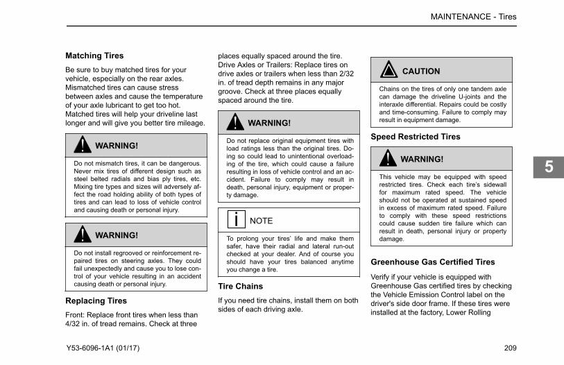
Matching TiresBe sure to buy matched tires for yourvehicle, especially on the rear axles.Mismatched tires can cause stressbetween axles and cause the temperatureof your axle lubricant to get too hot.Matched tires will help your driveline lastlonger and will give you better tire mileage.
WARNING!
Do not mismatch tires, it can be dangerous.Never mix tires of different design such assteel belted radials and bias ply tires, etc.Mixing tire types and sizes will adversely af-fect the road holding ability of both types oftires and can lead to loss of vehicle controland causing death or personal injury.
WARNING!
Do not install regrooved or reinforcement re-paired tires on steering axles. They couldfail unexpectedly and cause you to lose con-trol of your vehicle resulting in an accidentcausing death or personal injury.
Replacing TiresFront: Replace front tires when less than4/32 in. of tread remains. Check at three
places equally spaced around the tire.Drive Axles or Trailers: Replace tires ondrive axles or trailers when less than 2/32in. of tread depth remains in any majorgroove. Check at three places equallyspaced around the tire.
WARNING!
Do not replace original equipment tires withload ratings less than the original tires. Do-ing so could lead to unintentional overload-ing of the tire, which could cause a failureresulting in loss of vehicle control and an ac-cident. Failure to comply may result indeath, personal injury, equipment or proper-ty damage.
NOTE
To prolong your tires’ life and make themsafer, have their radial and lateral run-outchecked at your dealer. And of course youshould have your tires balanced anytimeyou change a tire.
Tire ChainsIf you need tire chains, install them on bothsides of each driving axle.
CAUTION
Chains on the tires of only one tandem axlecan damage the driveline U-joints and theinteraxle differential. Repairs could be costlyand time-consuming. Failure to comply mayresult in equipment damage.
Speed Restricted Tires
WARNING!
This vehicle may be equipped with speedrestricted tires. Check each tire’s sidewallfor maximum rated speed. The vehicleshould not be operated at sustained speedin excess of maximum rated speed. Failureto comply with these speed restrictionscould cause sudden tire failure which canresult in death, personal injury or propertydamage.
Greenhouse Gas Certified TiresVerify if your vehicle is equipped withGreenhouse Gas certified tires by checkingthe Vehicle Emission Control label on thedriver's side door frame. If these tires wereinstalled at the factory, Lower Rolling
MAINTENANCE - Tires
Y53-6096-1A1 (01/17) 209
5

Resistance codes (LRR) identify whichtires are certified.
NOTE
The tires installed on this vehicle at the fac-tory as original equipment may be certifiedfor Greenhouse Gas and Fuel Efficiencyregulations. Replacement tires must be ofequal or lower rolling resistance level (TRRLor Crr). Consult with your tire supplier(s) forappropriate replacement tires.
In order to limit the rolling resistance of thetires and optimize fuel economy, themaintenance procedures specified by thetire manufacture must be followed. Pleasesee Vehicle Emissions Limited ExpressWarranty for warranty on greenhouse gascertified tires.
See AlsoGreenhouse Gas Certification Label onpage 229
Wheels
Information on maintaining your vehicle'swheels.
After the vehicle travels about 50 to 100miles (80 to 160 km), wheel mountingsseat in and will lose some initial torque.Check hub/wheel mountings after thisinitial period and retighten. Threads shouldbe clean and dry. Do not lubricate wheelnuts or studs.
WARNING!
Never use oil or grease on studs or nuts; im-proper torque readings will result, whichcould cause improper wheel clamping andcould lead to a wheel failure resulting in anaccident. Failure to comply may result indeath, personal injury, equipment or proper-ty damage.
Wheel Replacement with DiscBrake Option
WARNING!
Use only the wheel brand, size and partnumber originally installed. Use of a differ-ent wheel brand or size could cause valvestem to interfere with a brake componentwhich could lead to loss of vehicle control.Failure to comply may result in death, per-sonal injury, equipment or property damage.
Vehicles equipped with front disc brakesare fitted with wheels designed specificallyfor disc brake applications. If it everbecomes necessary to replace an originalequipment wheel, the replacement wheelmust be the same brand and size as thetake-off wheel. On vehicles equipped with22.5 in. disc wheels, installing the wrongreplacement wheel could result in thewheel valve stem making contact with thedisc brake assembly. When installing anyreplacement wheel, always inspect thetires/wheels to ensure there is adequateclearance between other vehiclecomponents. With the hood open, checkfor clearance between the wheel and discbrake assembly. Use a hydraulic jack toraise the front of the vehicle off the groundto allow the wheel to spin freely. Whilerotating the wheel, check to ensure there isadequate clearance between the wheeland disc brake assembly.
MAINTENANCE - Wheels
210 Y53-6096-1A1 (01/17)
5

WARNING!
Improperly mounting and demounting tireand rim assemblies is dangerous. Failure toobserve proper precautions could cause thetire rim assembly to burst explosively, caus-ing death or personal injury. See the wheelmanufacturer's literature for the proper wayto mount and demount your tires and rims.Follow their precautions exactly.
WARNING!
Always ensure the hood hold open latch isengaged to keep the hood fully open anytime anyone gets under the hood for anyreason. Failure to do so may cause thehood to close uncontrollably which may re-sult in death or personal injury.
WARNING!
Always support the vehicle with appropriatesafety stands if it is necessary to work un-derneath the vehicle. A jack is not adequatefor this purpose. Failure to comply may re-sult in death, personal injury, equipment orproperty damage.
Disc Wheels
WARNING!
Use the correct components and tools whenworking on wheels. Grooves in the wheeldisc or other damage to the disc can weak-en the wheel and cause it to eventuallycome off. This could cause you to lose con-trol of your vehicle, and may result in an ac-cident. Failure to comply may result indeath, personal injury, equipment or proper-ty damage.
The end of the wheel wrench must besmooth. Burrs on the end of the wrenchcan tear grooves in the disc. Thesegrooves may lead to cracks in the disc, andcan cause it to fail.
Wheel BearingsFor safe, reliable operation and adequateservice life, your wheel bearings must beadjusted properly at the recommendedintervals. Contact your authorized dealer tomake sure the wheel bearings are properlyadjusted.
See AlsoSuspension U-Bolts, Grade 8 on page 213
Wheel Cap Nut Torque Specifications onpage 215Frame Fastener Torque Requirements onpage 214
Transmission Maintenance
General maintenance recommomendationsfor maintaining your vehicle's transmission.
See the transmission manufacturer'soperator's manual for lubricationspecifications and service intervals.
CAUTION
When adding oil, types and brands of oilshould not be intermixed because of possi-ble incompatibility, which could decrease theeffectiveness of the lubrication or causecomponent failure.
See AlsoLubrication Specification Chart on page216
MAINTENANCE - Transmission Maintenance
Y53-6096-1A1 (01/17) 211
5

Mechanical Clutch
The clutch in this vehicle is actuated via acombination of mechanical linkages fromthe cab to the transmission.
Free Pedal TravelFree pedal travel is the distance the clutchpedal moves by applying only slightpressure. During free pedal the releaseyoke in the transmission moves until itsbearing pads contact the release bearing.This movement of the release yoke iscalled free travel. Thus, free pedal and freetravel are directly related to each other. Asthe clutch pedal is depressed further, withharder pressure, the release yoke movesthe release bearing away from the engine.This causes the clutch plate to releasefrom the driven disks in the clutch. This iscalled release travel. And finally, as thepedal is pushed to the last 1/2 to 1 inch oftravel, the release bearing contacts andengages the clutch brake. This is calledclutch brake squeeze. When the clutchwears, the release bearing graduallymoves toward the engine, decreasing freepedal and free travel. When all free pedal
and free travel are gone, the clutchrequires adjustment. The clutch is adjustedby turning an adjustment ring that is builtinto the clutch. When the ring is turned, therelease bearing moves back toward thetransmission, restoring free pedal andclutch free travel. Under normal clutchwear this is the only adjustment needed.Do not attempt to change any othercomponent.
Clutch LinkageHave your authorized dealer service theclutch according to the clutchmanufacturer’s service guidelines. Thisvehicle is equipped with a rod and levermechanical clutch linkage. Lubricate eachpivot point on the clutch linkage. Replacewith the recommended fluid ComponentLubrication Index. Lubrication SpecificationChart on page 216
Clutch AdjustmentClutch pedal free travel is usually 1 3/4 in.to 2 in. (34 to 51 mm). This should be yourguide for determining whether your truckneeds clutch adjustment. Some vehicleshave automatic clutch adjustment. If yoursdoesn’t have this feature, adjustment willhave to be done by a trained certifiedmechanic. Have the adjustment done
before clutch pedal free travel is reduced tothe minimum allowable 1/2 in. (13 mm).
Clutch AdjustmentUnder normal wear conditions, the clutchwill require periodic adjustment. See theclutch manufacturer's Service Manual forthe proper adjustment procedures.
Specification ReferenceCharts
MAINTENANCE - Mechanical Clutch
212 Y53-6096-1A1 (01/17)
5

Suspension U-Bolts, Grade 8Torque specifications for suspension u-bolts.
Tighten all U-Bolts with a torque wrench.Torque specifications apply to the followingfasteners with lightly lubricated threads.Chevron Zinc Lubricant or SAE 20/30 oilshould be used on U-Bolt threads. Torquerequirements apply to manufacturerproprietary suspensions. All othersuspensions must refer and adhere tooriginal manufacturers shop manual.
Standard and Metric FastenerTorque for Grade 8 U-Bolts
U-BoltSizeDiameter(inches)
Torque(N•m)
Torque( lb-ft)
3/4 333-408 245-300
7/8 598-734 440-540
1 925-1,060 680-780
1 1/8 1,470-1,660 1,080-1,220
U-BoltSizeDiameter(inches)
Torque(N•m)
Torque( lb-ft)
1 1/4 1,890-2,120 1,390-1,560
1 1/2 3,130-3,860 2,300-2,840
M20 475 +/- 27 350 +/- 20
The values shown here are for suspensionu-bolts and should not be applied to boltsand fasteners for the frame.
See AlsoFront Axle and Suspension on page 194Rear Axle and Suspension on page 201Wheels on page 210
MAINTENANCE - Specification Reference Charts
Y53-6096-1A1 (01/17) 213
5

Frame Fastener TorqueRequirementsTorque specifications for standard andmetric frame fasteners, including the fifthwheel.
Use ESNA Style Lock Nut, with nyloninsert. Lubricate nylon insert nut lightly withSAE 20/30 oil. Tighten all frame fastenerswith a torque wrench. Torque specificationsapply to the following fasteners with lightlylubricated threads. These values areapplicable to fasteners on the frame anddo not apply to u-bolts for the suspension.
Fastener Size TighteningSpecification lb-ft(N•m)
5/16 16-22 (22-30)
3/8 30-40 (41-54)
7/16 55-65 (75-88)
1/2 80-90 (109-122)
9/16 115-140 (156-190)
5/8 165-195 (224-265)
3/4 290-340 (394-462)
7/8 380-460 (517-626)
Fastener Size TighteningSpecification lb-ft(N•m)
1 700-830 (952-1,129)
1-1/8 990-1,170 (1,346- 1,591)
1-1/4 1,380-1,630 (1,877- 2,217)
Metric FastenerSize (with nyloninsert nuts)
TighteningSpecification lb-ft(N•m)
M5 6-9 (8-12)
M6 7-11 (9-15)
M8 17-23 (23-31)
M10 24-32 (33-43)
M12 55-75 (75-101)
M16 120-160 (163-217)
M20 260-340 (352-460)
M20 (All Metal LockNuts)
315-350 (427-475)
See AlsoFront Axle and Suspension on page 194Rear Axle and Suspension on page 201Wheels on page 210
MAINTENANCE - Specification Reference Charts
214 Y53-6096-1A1 (01/17)
5

Wheel Cap Nut TorqueSpecificationsTorque specifications for wheel cap nuts,including standard and metric fasteners.
At the first scheduled lube interval, have allwheel cap nuts torqued to their specifiedvalue. After that, check wheel cap nuts atleast once a week.
Contact an authorized dealer forinformation on the proper installation
procedure for the wheels on your truck.This is a job you may not be able to doyourself. You need the right torquingequipment to do it.
Wheel and NutConfiguration Stud Size
Torque for Two Piece Flanged Cap Nuts
lb-ft N•m
Hub-Piloted Disc-Type Wheel w/Two PieceFlanged Cap Nuts: Steel or AluminumWheel PHP-10; Budd Uni-Mount-10;WDH-8
M22-1.5 450-500 610-680
Stud Backnuts (when used) 3/4-16 175-200 240-270
1-14 175-300 240-410
Cast Spoke Wheel Assembly Rim ClampNut Torque
1/2" Dia. 5/8" Dia. 3/4" Dia. 80-90 110-120
1/2" Dia. 5/8" Dia. 3/4" Dia. 160-185 220-250
1/2" Dia. 5/8" Dia. 3/4" Dia. 225-245 305-335
See AlsoFront Axle and Suspension on page 194Rear Axle and Suspension on page 201Wheels on page 210
MAINTENANCE - Specification Reference Charts
Y53-6096-1A1 (01/17) 215
5

Lubrication Specification Chart
NOTE
The responsibility for meeting these specifi-cations, the quality of the product, and itsperformance in service rests with the lubri-cant supplier.
*Consult manufacturer or lubricant supplierfor special details.
Lubricant Symbol Key
Type Application
ATF MD3 or MERCON®-approved automatic transmission fluid
BB High temperature ball bearing grease. Chevron SRI Mobile Grease HP, Texaco Multifax 2
CB Engine oil for mild to moderaterequirements
CC/CD Engine oil for severe requirements (MIL-L-2104B /MIL-L-45199B w/ 1.85% max. sulfated ash
CD Engine oil meeting API “Five engine test sequence”
CD50 SAE50W synthetic transmission fluid
CE Engine oil meeting severe duty service requirements for direct-injection turbocharged
CJ-4 Engine oil for PACCAR MX and Cummins EGR engines
CL Multipurpose chassis grease
EP Extreme Pressure Lubricant (Lithium 12-hydroxystearate base NGLI 2)
MAINTENANCE - Specification Reference Charts
216 Y53-6096-1A1 (01/17)
5

Type Application
GL Straight mineral gear lubricant
HD Hypoid Gear Oil, A.P.I. - GL-5, SAE 75W-90FE synthetic gear lubricant
HT High Temperature grease (Timken Spec. 0-616)
MP Multipurpose gear lubricant (MIL-L-2105B)
DOT3 orDOT4
Brake Fluid
Component Lubrication Index
Application Type
Steering Column CL
Alternator Bearing BB (1)
Fan Hub BB (1)
Power Steering Reservoir ATF
Steering Drag Link CL
Steering Knuckles CL
Spring Pins CL
Clutch Release Bearings BB
Brake Shoe Anchor Pins HT
MAINTENANCE - Specification Reference Charts
Y53-6096-1A1 (01/17) 217
5

Application Type
Brake Cam Bearings HT
Slack Adjusters CL
Starter Bearings CC
Turbocharger Aneroid CC
Water Pump BB (1)
Suspension Fittings (other than threaded pins and bushings) EP
Steering Shaft Grease Fittings EP
Brake Treadle Hinge and Roller Engine oil
Lock Cylinders Lock lubricant
Door Hinges Not required - Teflon bushings
Door Latches and Striker Plates Polyethylene grease stick
Door Weatherstrip Silicone lubricant
Hub-piloted Aluminum Wheels Coat the wheel pilot or hub pads with Freylube #3 lubricant (light colored) or ChevronZinc lube. Do not get lubricant on the face of the wheel or the hub.
Manual Transmission Hydraulic Clutch DOT3 or DOT4 (Brake Fluid)
(1) Consult manufacturer or lubricant supplier for special details.
See AlsoLubricants on page 153Checking Oil Level on page 154Transmission Maintenance on page 211
MAINTENANCE - Specification Reference Charts
218 Y53-6096-1A1 (01/17)
5

Steering Gear LubricationThe following recommendations are forgeneral purpose steering systems (bothTRW and Sheppard).
Application Type
For normal temperatures Automatic Transmission Fluid (ATF) Type E or F or Dexron® III
For cold temperatures of -22ºF (-30ºC) and above ATF Type A
For extremely cold temperatures between -22ºF (-30ºC) and -40ºF (-40ºC) ATF Type B
Noise Control System -Maintenance LogTo ensure your vehicles noise controlrequirements are maintained, record
maintenance checks. Use the following logsheet and retain copies of documentsregarding maintenance services performedand parts replaced on the vehicle.
Component Recom-mendedInterval(Miles)
Date &R.O. No.
RepairFacility &Location
WorkPerformed
Date &R.O. No.
RepairFacility &Location
WorkPerformed
Exhaust System RoutingIntegrity
25,000
Shutters Shrouds 25,000
Hood Insulation Blanket 10,000
Engine Mounted HoseInsulators Fasteners
10,000
MAINTENANCE - Specification Reference Charts
Y53-6096-1A1 (01/17) 219
5

Component Recom-mendedInterval(Miles)
Date &R.O. No.
RepairFacility &Location
WorkPerformed
Date &R.O. No.
RepairFacility &Location
WorkPerformed
Inner Fender Shields 50,000
Cab Skirts Fasteners 50,000
Air Intake System IntegrityElement
5,000
Clutch Type Fan Drive 10,000
MAINTENANCE - Specification Reference Charts
220 Y53-6096-1A1 (01/17)
5

Pipe and Hose Clamp TorqueValuesTorque specifications for engine parts.
These references are for pipes and hoses in the engine area.
Application Type of Clamp in-lb N•m
Radiator and Heat Exchanger Hoses Constant Torque CT-L 10.2-12.5 90-110
Heater Hoses Constant Tension not required not required
Air Intake Pipes Hi Torque HTM-L 11.3-14.2 100-125
Plastic Air Intake Pipes Constant Torque CT-L 4.5 40 (maximum)
Charge Air Intake Hoses Flex Seal 7.9-11.3 70-100
B9296 6-7 50-60
Fuel, Oil and Water Heat Exchangers (forhoses less than 9/16" diameter).
Miniature 3600L 1.1-1.7 10-15
See AlsoAir Intake System on page 190
MAINTENANCE - Specification Reference Charts
Y53-6096-1A1 (01/17) 221
5

MAINTENANCE - Specification Reference Charts
222 Y53-6096-1A1 (01/17)
5

Chapter 6 | INFORMATIONIn this Chapter:
Consumer Information........................................................................................................................224Vehicle Identification Labels...............................................................................................................224Clean Idle........................................................................................................................................... 227Greenhouse Gas Certification Label.................................................................................................. 229Vehicle Emissions Limited Express Warranty.................................................................................... 230
6

Consumer Information
How to Order Replacement PartsReplacement parts may be obtained froman authorized dealership. When you order,it is IMPORTANT that you have thefollowing information ready:
• Your name and address.• Serial number of the truck.• The name of the part you need.• The name and number of the
component for which the part isrequired.
• The quantity of parts you need.• How you want your order shipped.
National Highway Traffic and SafetyAdministration (NHTSA)If you believe that your vehicle has adefect, which could cause a crash or couldcause death or personal injury, you shouldimmediately inform the National HighwayTraffic Safety Administration (NHTSA) inaddition to notifying the vehiclemanufacturer. If NHTSA receives similarcomplaints, it may open an investigation,
and if it finds that a safety defect exists in agroup of vehicles, it may order a recall andremedy campaign. However, NHTSAcannot get involved in individual problemsbetween you, your dealer, and vehiclemanufacturer. Contacting NHTSA ispossible through telephone, written mailand email. NHTSA also has a websitewhere you can input your commentsdirectly to them on the web. Please useany of the four ways to contact NHTSA:
Toll Free 888-327-4236 (800-4249153 TTY) 8:00 am to10:00 pm ET Monday-Friday
Office of Defects Investigations/CRD NVS-216 1200New Jersey Ave SE. Washington, D.C. 20590
www.safercar.gov
email: [email protected]
Transport CanadaCanadian customers who wish to report asafety-related defect to Transport Canada,Defect Investigations and Recalls, maytelephone the toll free hotline1-800-333-0510, or contact TransportCanada by mail at:
Transport Canada, ASFAD Place de VilleTower C 330 Sparks Street Ottawa ONK1A 0N5
For additional road safety information,please visit the Road Safety website at:
http://www.tc.gc.ca
See Alsohttp://www.safercar.govhttp://www.tc.gc.ca
Vehicle IdentificationLabels
Information explaining the vehicleidentification number location, component,chassis weight, and tire labels.
Each vehicle completed by Peterbilt MotorsCompany uses a Vehicle IdentificationNumber (VIN) that contains the model yeardesignation of your vehicle. The practice isin compliance with 49 CFR 565, Code ofFederal Regulations.
The full, 17-digit VIN is located on theWeight Rating Data Label. The label is
INFORMATION - Consumer Information
224 Y53-6096-1A1 (01/17)
6

located on the driver's side door edge oron the driver's side door frame.
Chassis NumberThe Chassis Number refers to the last sixcharacters of the VIN. This number willallow your dealer to identify your vehicle.You will be asked for this number whenyou bring it in for service. Chassis NumberLocations
• Right frame rail, top flange, about 3ft. from the front end
• Cab back, left-hand rear panel,lower edge
• Tire, Rim, and Weight Rating Datalabel (truck)
• Components and Weights label• Noise Emission label• Paint Identification label
Certification LabelsYour vehicle information and specificationsare documented on labels. As noted below,each label contains specific informationpertaining to vehicle capacities andspecifications that you should be aware of.
Components and Chassis WeightLabelThe Components and Chassis WeightLabel is located on either the driver’s sidedoor edge or on the driver’s side doorframe. It includes chassis number, chassisweight and gross weight, plus modelinformation for the vehicle, engine,transmission, and axles.
Tire, Rim and Weight Rating DataLabelThe Tire, Rim and Weight Rating DataLabel is located on the driver’s side dooredge or on the driver’s side door frame. Itcontains the following information:
• GVWR - Gross Vehicle WeightRating
• GAWR FRONT, INTERMEDIATEand REAR - Gross Axle WeightRatings for Front, Intermediate andRear Axle
• TIRE/RIM SIZES AND INFLATIONPRESSURES - Tire/Rim Sizes andCold Pressure Minimums
• VIN including CHASSIS NUMBER.
The components of your vehicle aredesigned to provide satisfactory service, ifthe vehicle is not loaded in excess of eitherthe gross vehicle weight rating (GVWR), orthe maximum front and rear gross axleweight ratings (GAWRs).
INFORMATION - Vehicle Identification Labels
Y53-6096-1A1 (01/17) 225
6

WARNING!
Do not exceed the specified load rating.Overloading can result in loss of vehiclecontrol, either by causing component fail-ures or by affecting vehicle handling. Ex-ceeding load ratings can also shorten theservice life of the vehicle. Failure to complymay result in death or personal injury.
NOTE
GVW is the TOTAL SCALE WEIGHT the ve-hicle is designed to carry. This includes theweight of the empty vehicle, loading plat-form, occupants, fuel, and any load.
Noise Emission LabelThe Noise Emission Label is located in thedriver's side door frame. It containsinformation regarding U.S. noise emissionregulations, chassis number, and date ofmanufacture.
Paint Identification LabelThe Paint Identification Label contains thepaint colors used by the factory to paintyour vehicle. It lists frame, wheels, cabinterior and exterior colors. This label islocated inside the glove box.
Federal Safety StandardCertification LabelThe NHTSA regulations require a labelcertifying compliance with Federal Safety
Standards, for United States and U.S.Territories, be affixed to each motor vehicleand prescribe where such label may belocated. This certification label, whichindicates the date of manufacture andother pertinent information, is located onthe driver’s side door edge or on thedriver’s side door frame.
Component IdentificationEach of the major components on yourvehicle has an identification label or tag.For easy reference, record componentnumbers such as, model, serial, andassembly number.
INFORMATION - Vehicle Identification Labels
226 Y53-6096-1A1 (01/17)
6

Engine: For further information, please refer to the Engine Operation and Maintenance Manual.
Transmission: For both manual and automatic transmissions, the identification number is stamped on a tag affixed to the right rear side ofthe transmission case.
Clutch: Enclosed in clutch housing. Location depends on manufacturer.
Steer Axle: The front axle serial number is stamped on a plate located on the center of the axle beam.
Axle Specification Number: Usually stamped on the right rear side of the axle housing. This number identifies the complete axle.
Axle Housing Number: Usually located on the left forward side of the housing arm. This tag identifies the axle housing.
Axle Differential Carrier Identification: Usually located on the top side of the differential carrier. The following information is either stamped, or marked with a metaltag: Model No., Production Assembly No., Serial No., Gear Ratio, and Part Number.
Clean Idle
To comply with CARB emissionsrequirements your vehicle will either havethe Certified Clean Idle label or an EngineShutdown System (ESS). Some vehicles,however, are exempt from theserequirements because of theirconfigurations (for example: fire truckservice).
Your vehicle may have either of theselabels affixed to the vehicle to identify thatits engine meets the strict low exhaustemission regulations instituted by the stateof California (and other states that have
chosen to adopt CARB emissionsrequirements). Trucks with this type ofengine will not require an EngineShutdown System and will be allowed toidle continuously. It is important that you donot remove or deface this label. Do notblock it from view. Please contact yourauthorized dealership if you need toreplace this label. The dealership will beable to help you to determine whether ornot your vehicle's engine may be acandidate for a Certified Clean Idle label ifit did not already have the label.
If you have a PACCAR PX-6 or PX-8engine, your label will look like the image
below.
INFORMATION - Clean Idle
Y53-6096-1A1 (01/17) 227
6

If you have a Cummins engine, your labelwill look like the image below.
Engine Shutdown SystemIf the vehicle’s engine does not meet thelow exhaust emission standard it will havean Engine Shutdown System (ESS) tomeet limited idle regulations implementedby CARB and some additional states.These regulations require that the enginehave an automatic system to restrict theidle time on certain vehicles. An EngineShutdown System will shut down theengine after 5 minutes if the vehicle idleswith the park brake set and thetransmission in ‘neutral’ or ‘park’. The ESSwill also allow the vehicle 15 minutes ofidle time if the driver does not set the parkbrake and shifts the transmission to‘neutral’ or ‘park’. The ESS, however, willnot shut down the engine if the engine isoperating in Power Take Off (PTO) mode, ifthe engine coolant is below 60 degrees
Fahrenheit, or if the engine is performing aparked regeneration. The check enginelight will alert you when the ESS shutdowntimer reaches the last 30 seconds beforethe engine shuts down. The last 30seconds prior to engine shutdown is theonly time the driver may reset the idle timeby pressing on the accelerator. Moredetailed information may be available inthe Engine Operator’s Manual providedwith your vehicle.
INFORMATION - Clean Idle
228 Y53-6096-1A1 (01/17)
6

Greenhouse GasCertification Label
Definition of greenhouse gas labelidentifiers.
This vehicle may be equipped withcomponents that are identified asGreenhouse Gas Certified components(GHG). A label on the door is printed withcodes that identify the componentsmanufactured on the vehicle that are part
of the GHG certification. The codes aretranslated in the following table:
Emission Control Identifier Emissions Related Components
VSL, VSLS, VSLE, or VSLD Engine Software parameters that affect the Vehicle Speed Limiter
IRT5, IRTE Engine software parameters that affect the automatic engine shutdown timer
ATS Aerodynamic side skirts and/or fuel tank fairings
ARF Aerodynamic roof fairing
ARFR Adjustable height aerodynamic roof fairing
TGR Gap reducing fairing (tractor to trailer)
LRRA, LRRD, or LRRS Greenhouse Gas (GHG) Tires
See AlsoGreenhouse Gas Certified Tires on page209Vehicle Emissions Limited ExpressWarranty on page 230
INFORMATION - Greenhouse Gas Certification Label
Y53-6096-1A1 (01/17) 229
6

Vehicle Emissions LimitedExpress Warranty
Original Equipment TiresPACCAR Inc warrants the tires installed asoriginal equipment on this vehicle onlyagainst defects in materials andworkmanship which cause the vehicle tofail to comply with applicable U.S. andCanadian greenhouse gas emission limits("Warrantable Emissions Failures"). Thisvehicle emissions limited express warrantyrelating to original equipment tires is validfor two (2) years or 24,000 miles (38,624km), whichever occurs first. YOUR SOLEAND EXCLUSIVE REMEDY AGAINSTPACCAR Inc IS LIMITED TO THE REPAIROR REPLACEMENT OF ORIGINALEQUIPMENT TIRES, SUBJECT TOPACCAR’S TIME AND MILEAGELIMITATIONS LISTED ABOVE. ThisVehicle Emissions Limited ExpressWarranty relating to original equipmenttires begins on the date of delivery of thevehicle to the first purchaser or lessee andaccrued time and mileage is calculatedwhen the vehicle is brought in for
correction of the Warrantable EmissionsFailures relating to the original equipmenttires. PACCAR MAKES NO OTHERVEHICLE EMISSIONS WARRANTIESRELATING TO THE ORIGINALEQUIPMENT TIRES, EXPRESS ORIMPLIED. WHERE PERMITTED BY LAW,PACCAR EXPRESSLY DISCLAIMS ANYWARRANTY OF MERCHANTABILITY ORFITNESS FOR A PARTICULARPURPOSE RELATING TO VEHICLEEMISSIONS. PACCAR AND THESELLING DEALER SHALL NOT BELIABLE FOR INCIDENTAL ORCONSEQUENTIAL DAMAGESINCLUDING, BUT NOT LIMITED TO:LOSS OF INCOME OR LOST PROFITS;VEHICLE DOWNTIME;COMMUNICATION EXPENSES;LODGING AND/OR MEAL EXPENSES;FINES; APPLICABLE TAXES ORBUSINESS COSTS OR LOSSES;ATTORNEY’S FEES; AND ANY LIABILITYYOU MAY HAVE IN RESPECT TO ANYOTHER PERSON OR ENTITY RELATINGTO WARRANTABLE EMISSIONSFAILURES. This Vehicle Emissions LimitedExpress Warranty relating to originalequipment tires is limited to emissionscompliance only. The tires are separatelywarranted by their manufacturer for defects
in materials and workmanship other thanthose which cause non-compliance withU.S. and Canadian GHG regulations,subject to limitations and conditionscontained within the tire manufacturer’swarranty agreement. You are responsiblefor the safe operation and maintenance ofthe vehicle and its tires. PACCAR does notwarrant wear and tear of the tires.
Greenhouse Gas (GHG)Components Other Than TiresThis GHG vehicle Warranty applies to thevehicle (hereafter, vehicle) certified with theUS Environmental Protection Agency.
Your Warranty Rights andObligationsThis vehicle is warranted for componentsthat directly impact the manufacturersgreenhouse gas (GHG) certification withthe US Environmental Protection Agency.PACCAR must warrant these componentsfor the periods of time listed belowprovided there has been no abuse, neglector improper maintenance of the vehicle. Ifa GHG-related part on your vehicle isfound to have a defect in material orassembly, the part will be repaired orreplaced by PACCAR.
INFORMATION - Vehicle Emissions Limited Express Warranty
230 Y53-6096-1A1 (01/17)
6

Manufacturer's Warranty CoverageThis warranty coverage is provided for fiveyears or 100,000 miles (160,000) km,whichever first occurs, from the date ofdelivery of the vehicle to the first purchaseror first lessee. Where a WarrantableCondition exists, PACCAR will diagnoseand repair the vehicle, parts and laborincluded, at no cost to the first purchaser orfirst lessee and each subsequentpurchaser or lessee. This warranty doesnot override any extended warrantypurchased to cover specific vehiclecomponents.
Owner's Warranty ResponsibilitiesThe vehicle owner is responsible forperforming required maintenance that islisted in your engine and vehicleOperator’s Manuals. The owner isresponsible for presenting the vehicle to aservice location as soon as a problemexists. Any warranty repairs should becompleted in a reasonable amount of time.Retain all receipts covering maintenanceon this equipment. PACCAR cannot denywarranty solely for the lack of receipts orfor the failure to ensure the performance ofall scheduled maintenance. PACCAR maydeny warranty coverage if a vehicle
component has failed due to abuse,neglect, improper maintenance,unapproved modifications (both physicalcomponents and computer programming)or using non-Original Equipmentreplacement parts. If there are anyquestions regarding these warranty rightsand responsibilities, please contact thevehicle OEM manufacturer at the customercenter telephone number provided with thevehicle operating instructions. Prior to theexpiration of the applicable warranty,Owner must give notice of any warrantedfailure to an authorized PACCAR dealerand deliver the vehicle to such facility forrepair. Owner is responsible for incidentalcosts such as: communication expenses,meals, lodging incurred by Owner oremployees of Owner as a result of aWarrantable Condition. Owner isresponsible for downtime expenses, cargodamage, fines, all applicable taxes, allbusiness costs, and other losses resultingfrom a Warrantable Condition. Owner isresponsible for maintaining all emissionsrelated engine and vehicle computerprogram settings in accordance withmanufacturer specifications. Thisresponsibility includes GHG specificsettings that may not be altered before theGHG-related expiration mileage has been
reached for each system. Owner isresponsible for maintaining all physicalparts related to GHG-regulations in the as-built configuration and in proper workingorder for the full regulatory useful life of435,000 miles (700,000 km) for Class 8vehicles, 185,000 miles (300,000 km) forClass 6-7, and 110,000 miles (177,000 km)for Class 5.
Replacement PartsPACCAR recommends that any serviceparts used for maintenance, repair orreplacement of GHG components be newor genuine approved rebuilt parts andassemblies. The use of non-genuineengine or vehicle replacement parts thatare not equivalent to the PACCAR engineor OEM vehicle manufacturer’s originalpart specification as built from the factorymay impair the engine and vehicleemissions control system from working orfunctioning effectively, and may jeopardizeyour GHG warranty coverage. In addition,genuine vehicle or engine parts must bereplaced with the same material andfunction as the part assembled on thevehicle from the factory. The owner mayelect to have maintenance, replacement orrepair of the emission control partsperformed by a facility other than an
INFORMATION - Vehicle Emissions Limited Express Warranty
Y53-6096-1A1 (01/17) 231
6

authorized PACCAR dealer and may electto use parts other than new or genuineapproved rebuilt parts and assemblies forsuch maintenance, replacement or repair;however, the cost of such service or partsand subsequent failures resulting fromsuch service or parts may not be fullywarranted if the manufacturer determinesthat the replacement part is not of similarmaterial and function as the OEM partassembled to the vehicle at the factory.
PACCAR ResponsibilitiesThe warranty coverage begins when thevehicle is delivered to the first purchaser orfirst lessee. Repairs and service will beperformed by any authorized PACCARdealer using new or genuine approvedrebuilt parts and assemblies PACCAR willutilize replacement parts that are selectedand installed to support the GHGcompliance certification. PACCAR willrepair parts found by PACCAR to bedefective without charge for parts or labor(including diagnosis which results indetermination that there has been a failureof a warranted part).
Warranty LimitationsSole and exclusive remedy againstPACCAR and the Selling Dealer arising
from the purchase and use of this vehicleis limited to the repair or replacement of"warrantable failures", for replacementparts that are similar in material andfunction to OEM specifications and subjectto PACCAR’s time, mileage, and hourlimitations of the greenhouse gas warranty.The maximum time, mileage and hourlimitations of the warranty begin with theDate of Delivery to the first purchaser orfirst lessee. The accrued time, mileage, orhours is calculated when the vehicle isbrought in for correction of warrantablefailures. PACCAR is not responsible forfailures or damage resulting from whatPACCAR determines to be abuse, neglector uncontrollable acts of nature, including,but not limited to: damage due to accident;operation without adequate coolants orlubricants; overfueling; overspeeding; lackof maintenance of cooling, lubricating orintake systems; improper storage, starting,warm-up, run-in or shutdown practices;unauthorized modifications to the vehicleand its components. PACCAR is also notresponsible for failures caused by incorrectoil, fuel or diesel exhaust fluid or by water,dirt or other contaminants in the fuel, oil ordiesel exhaust fluid. Failure of replacementparts used in repairs due to the above non-warrantable conditions is not warrantable.
This warranty is void if the vehicle isaltered with parts that do not meet thematerial and functional specifications asmanufactured from the factory. Anyalterations to vehicle or engine computersettings will void GHG warranty andpotentially cause the vehicle to becomenon-compliant with the GHG regulation ofthe EPA Clean Air Act. Any alterations toGHG specific settings prior to the GHGrelated expiration mileage for each systemwill void GHG warranty and potentiallycause the vehicle to become non-compliant with the GHG regulation of theEPA Clean Air Act. This warranty is void ifcertain GHG components are not properlymaintained and thus cannot perform totheir designed capability. PACCAR is notresponsible for failures resulting fromimproper repair or the use of parts whichare not genuine approved parts. PACCARis not responsible for the material and laborcosts of emission control parts andassemblies replaced during ScheduledMaintenance of the engine as specified inPACCAR Operator’s Manuals. THISWARRANTY, TOGETHER WITH THEEXPRESS COMMERCIAL WARRANTIESARE THE SOLE WARRANTIES MADE BYPACCAR IN REGARD TO THIS VEHICLE.THIS LIMITED GHG WARRANTY IS THE
INFORMATION - Vehicle Emissions Limited Express Warranty
232 Y53-6096-1A1 (01/17)
6

SOLE WARRANTY MADE BY PACCARAND THE SELLING DEALER. EXCEPTFOR THE ABOVE LIMITED WARRANTY,PACCAR AND THE SELLING DEALERMAKE NO OTHER WARRANTIES,EXPRESS OR IMPLIED. PACCAR ANDTHE SELLING DEALER EXPRESSLYDISCLAIM ANY WARRANTY OFMERCHANTABILITY OR WARRANTY OFFITNESS FOR A PARTICULARPURPOSE. PACCAR AND THE SELLINGDEALER SHALL NOT BE LIABLE FORINCIDENTAL OR CONSEQUENTIALDAMAGES INCLUDING, BUT NOTLIMITED TO: LOSS OF INCOME ORLOST PROFITS; ENGINE OR VEHICLEDOWNTIME; THIRD PARTY DAMAGE,INCLUDING DAMAGE OR LOSS TOOTHER ENGINES, VEHICLES ORPROPERTY, ATTACHMENTS, TRAILERSAND CARGO; LOSS OR DAMAGE TOPERSONAL CONTENTS;COMMUNICATION EXPENSES;LODGING AND/OR MEAL EXPENSES;FINES; APPLICABLE TAXES ORBUSINESS COSTS OR LOSSES;ATTORNEYS’ FEES; AND ANY LIABILITYYOU MAY HAVE IN RESPECT TO ANYOTHER PERSON OR ENTITY.
See Also
Greenhouse Gas Certification Label onpage 229
INFORMATION - Vehicle Emissions Limited Express Warranty
Y53-6096-1A1 (01/17) 233
6

INFORMATION - Vehicle Emissions Limited Express Warranty
234 Y53-6096-1A1 (01/17)
6

Index
AAftertreatment System 123Aiming Headlights 179Air Cleaners 191Air Conditioner 77, 78Air Disc Brakes 161Air Filter 191Air Filter Restricton 63Air Intake System 190Air Tanks 158Altering the Electrical System 181Alternator 186Auto Slack Adjuster 162Automatic Slack Adjuster Stroke Specification 164Axle, Traction Control 57, 58, 107
See also ATCAxleAuxiliary 117AxleDiff Lock 114AxleDifferential Lock 114AxleDual Range 115AxlePusher Tag 117AxleTwo Speed 115
BBatteries 181BatteryJump start 34Bendix® AD-IS Series Air Dryer 157Brake System 160Brake, Park Brake 59Brake, ParkingManual release 38Brakes, Anit-Lock Brake System 59
Brakes, Trailer Anti-Lock Brake System 59
CCab 15–17Cab Access 14Cab Maintenance 165Care of Display Screens on the Dashboard 168Check Engine Oil Level 187Clutch 212Clutch Linkage 212Clutch Pedal 212Coolant 171Coolant Fill 171Coolant Surge Tank 171Cooling system maintenance 168Cooling System Overheating 31Cranking Battery Specification 184Cruise ControlCancel 102Cruise ControlChange Set Speed 102Cruise ControlResume Set Speed 102Cruise ControlSet Speed 102Cruise ControlStandard 101
DDaily Checks 26Dash Switch 74Diesel Exhaust Fluid (DEF) 68Diesel Exhaust Fluid (DEF) Lamp 61Diesel Particulate Filter (DPF) Warning Lamp 61Drive Axle Temperature 59Driver Information Display 68
Index

Drum Brake Inspection 162
EElectrical System 176Emissions 123Emissions, High Exhaust System Temperature 60Emissions, Malfunction Indicator Lamp 60Engine - Coolant Temperature 66Engine Fan 189Engine is overheating 31Engine Maintenance 186Engine Mounting 191Engine Oil Temperature 62Engine, Check Engine 62Engine, Low Coolant Level 62Engine, Oil Pressure 62, 67Engine, Overspeed Air Shutdown 63Engine, Retarder (Brake) 63Engine, Stop Engine 63Engine, Wait To Start 63Exhaust 123Exhaust System 191
FFifth Wheel Bi-Annual Maintenance 193Fifth Wheel Monthly Maintenance 193Fifth Wheel Slide Switch 87Fifth Wheel Slide Unlocked Warning 61Frame 192Frame Fastener Torque Requirements 214Free Travel 212Front axle and Suspension 194Front Spring Suspension U-Bolts, Grade 8 213Fuel Filter Restricton 64Fuel Level 66Fuel System 192Fuel Water In Fuel (WIF) 64
Fuse box label 179FuseInspect and replace 33FuseLocation 34, 36
GGeneral Safety Instructions 9Greenhouse Gas Certified Tires 209Guide to the Warning Symbols 55
HHeadlight 74Heater and Air Conditioner Maintenance 196High Beam 75High Beam Flash 75How to Add Coolant to the Cooling System 172How to Check for Air System Leaks 159How to inspect brake pads on disc brakes 161How to Replace Air Conditioner Filter 197, 198How to Wash the Exterior of the Vehicle 167
IIce 46Ignition timer 70Illustrations 9inside outside engine air intake 87Inspect Disc Brake Caliper for Running Clearance 162Inspect Power Steering Fluid 154Inspecting Noise and Emission Components 200Install Engine Belt 188Installing Batteries 185Instrument Cluster 52
Index

LLights Marker Clearance 76Lights, High Beam 64Low Air Alarm 30Low Oil Pressure Lamp 31Lower 17Lubricants 153Lubrication Specification Chart 216
MMud 46
NNoise and Emission Control 199Noise Control System - Maintenance Log 219
OOil Level 154
PPipe and Hose Clamp Torque Values 221power distribution box 179Power Steering Fluid 205Power Steering Fluid Filter 205Power Take Off 100PTO 100
RRaise 16Rear Axle Alignment 203Rear Axle and Suspension 201Rear Axle Lubrication 203Recovery Hitch 40Recovery hitch capacities 44Recovery hitch How to use tow pin 41Recovery hitchBest practices 45Recovery hitchManually lock a differential 42Recovery hitchPrepare axles 41Removing Batteries 185Returning to Service after Recovering 45Right Hand Steer 124Right Hand Steer Operation 74Roadside Assistance 30
SSafety 7Safety Alerts 8Safety Restraint System - Inspection 173Sand 46Seat Belt Fasten 64Sliding Fifth Wheels 193Slow Battery Charging 185Snow 46Speedometer 65Stability Control 57, 58Steering Gear Lubrication 219Steering Shaft Bolt Torque Specifications 206Steering System 204Stop Engine Lamp 30Suspension Dump 64
Index

TTachometer 66Tilt 15Tire Inflation 64Tires 207Topping Up the Engine Oil 188Tow Pin 40Towing the Vehicle 46Traction Control 91Trailer Hand Brake 77Transmission, Check 65Transmission, Oil Temperature High 65TransmissionMaintenance 211Turbocharger 190Turn Signal 74Turn Signal, Left 65Turn Signal, Right 65
UUnder hood air intake symbol 87
VVehicle Air Pressure 68Vehicle ID Labels 224Vehicle is stuck 46Vehicle Light Bulb specifications 178Vehicle Loading 24Vehicle recovery 37Vehicle stuck 37Visual inspection while approaching the vehicle 25
WWeekly Checks 25
What is an Air Compressor 159What is an Air Dryer 156What is Low Voltage Disconnect 176What is the Air System 155What to do before starting the vehicle 23Wheel Cap Nut Torque Specifications 215Wheels 210Windshield Washer 77Windshield Wiper 76Windshield Wiper/Washer 175Windshield Wipers 74
Index


Y53-6096-1A1 01/17 Printed in U.S.A. Peterbilt Motors Company, A PACCAR Company, P.O. Box 90208, Denton, Texas 76202