
Contents • Using Acrobat Reader • Printing PDF documents • Using Reader for UNIX
Upload
khangminh22Category
view
0download
0
OPERATOR’S MANUAL RAMP ® Reader
Response Biomedical Corp.

Operator’s Manual, RAMP® Reader i
Table of Contents
1.0 INTRODUCTION ......................................................................................................................... 1
1.1 Overview .................................................................................................................................. 1 1.2 Intended Use ............................................................................................................................ 1 1.3 How the RAMP
® System Works ............................................................................................... 1
1.4 How the RAMP® System Works ............................................................................................... 3
1.4.1 RAMP® Reader ................................................................................................................. 3
1.4.2 RAMP® Assay/Test Kit Components ................................................................................ 3
1.4.3 Accessories ....................................................................................................................... 3 1.5 Warnings and Precautions ....................................................................................................... 4
1.5.1 Symbols and Definitions ................................................................................................... 4 1.5.2 Summary of Warnings and Precautions ........................................................................... 5
1.6 Unpacking and Installation ....................................................................................................... 6 1.6.1 Unpacking ......................................................................................................................... 6 1.6.2 RAMP
® Reader Contents .................................................................................................. 6
1.6.3 Optional Accessories Contents ......................................................................................... 6 1.6.4 Installation ......................................................................................................................... 6 1.6.5 Initial Start-up .................................................................................................................... 7 1.6.6 Optional Accessories ........................................................................................................ 7
2.0 RAMP® SYSTEM OPERATION ................................................................................................ 10
2.1 Keypad Function and Use ...................................................................................................... 10 2.2 RUN/OPTIONS Menu ............................................................................................................ 12 2.3 Using Lot Cards ..................................................................................................................... 12 2.4 Running an Assay .................................................................................................................. 14
2.4.1 Entering User ID ............................................................................................................. 14 2.4.2 Entering User P.I.N. – “User Lock-out” Mode (P.I.N. Enabled) ...................................... 15 2.4.3 Entering Sample ID ......................................................................................................... 15 2.4.4 Inserting a Cartridge ....................................................................................................... 16
2.5 Using the OPTIONS Menu ..................................................................................................... 19 2.5.1 Output Results ................................................................................................................ 19 2.5.2 View Results ................................................................................................................... 22 2.5.3 Run Internal Quality Control (IQC) .................................................................................. 24 2.5.4 Run Liquid Quality Control (LQC) ................................................................................... 25 2.5.5 System Settings .............................................................................................................. 25 2.5.6 Exiting OPTIONS Menu .................................................................................................. 25
2.6 Using the SYSTEM SETTINGS Menu ................................................................................... 26 2.6.1 Accessing the SYSTEM SETTINGS Menu..................................................................... 26 2.6.2 Set Master P.I.N. ............................................................................................................. 27 2.6.3 Setting the System Clock ................................................................................................ 27 2.6.4 Enable User ID/P.I.N....................................................................................................... 28 2.6.5 Edit User ID/P.I.N. ........................................................................................................... 28 2.6.6 Print Settings ................................................................................................................... 29 2.6.7 Transfer Users ................................................................................................................ 31 2.6.8 Erase Memory ................................................................................................................. 32 2.6.9 Set IQC Timer ................................................................................................................. 33 2.6.10 Set LQC Timer ................................................................................................................ 33 2.6.11 Reset LQC Timer ............................................................................................................ 34 2.6.12 Test Counters ................................................................................................................. 35 2.6.13 Connectivity .................................................................................................................... 35 2.6.14 Exit Menu ........................................................................................................................ 35
3.0 MAINTENANCE ........................................................................................................................ 36
3.1 Overview ................................................................................................................................ 36
Operator’s Manual, RAMP® Reader ii
3.2 Cleaning and Decontamination .............................................................................................. 36 3.3 Battery Care ........................................................................................................................... 36
4.0 TROUBLESHOOTING GUIDE .................................................................................................. 37
4.1 Power-On Self-Test Messages / IQC Messages ................................................................... 37 4.2 Lot Card / Barcode Messages................................................................................................ 39 4.3 Transport Messages .............................................................................................................. 40 4.4 Test Run Messages ............................................................................................................... 41 4.5 General Messages ................................................................................................................. 43
5.0 READER SPECIFICATIONS .................................................................................................... 44
APPENDIX A ........................................................................................................................................ 45
Connecting the RAMP® Reader to Accessories ............................................................................... 45
Printer / Computer Connections ........................................................................................................ 45 Reader-to-Reader Connections ........................................................................................................ 45 Barcode Wand Connections ............................................................................................................. 45
APPENDIX B ........................................................................................................................................ 46
Sending Data from the RAMP® Reader to a Computer .................................................................... 46
APPENDIX C ........................................................................................................................................ 55
User Agreement and Warranty ......................................................................................................... 55 Return policy ..................................................................................................................................... 55 Receipt of delivery ............................................................................................................................ 55 Exchange policy ................................................................................................................................ 55 Warranty ............................................................................................................................................ 56 Exclusions ......................................................................................................................................... 56 Liability Limitations ............................................................................................................................ 56 Recall Policy ...................................................................................................................................... 56 End user license agreement ............................................................................................................. 57 Software Updates.............................................................................................................................. 57 Feedback .......................................................................................................................................... 57 Governing Law .................................................................................................................................. 57
APPENDIX D ........................................................................................................................................ 58
Contact Information ........................................................................................................................... 58 Response Biomedical Customer Service ......................................................................................... 58 European Authorized Representative ............................................................................................... 58

Operator’s Manual, RAMP® Reader iii
Revision History
Revision # Software (SW)
Version Effective Date Summary of Changes
1.0 3.20, 3.21 December 2010 Initial release of generic RAMP Operators Manual.
1.1 3.20, 3.21, 3.24 January 2013 Updated RAMP
® and symbols used on
Reader label, User agreement and warranty. Clarified Reader specifications
1.2 3.20, 3.21, 3.24,
3.31 March 2014 Update to Document Numbering

Operator’s Manual, RAMP® Reader 1
1.0 INTRODUCTION
1.1 Overview
The RAMP® System is a rapid, quantitative immunochromatographic system for performing in vitro
diagnostic analyses on a variety of analytes. The System can be used for various applications, from use in a clinical setting (point-of-care, central or STAT laboratory) to use for onsite screening of environmental samples.
The System is comprised of the RAMP® Reader (“Reader”) and various RAMP
® Assay/Test kits
(“Kits”). Optional accessories include a barcode wand, printer, and cabling required to connect the Reader to a computer, printer or another Reader. Calibration and expiration information for Kits are input to the Reader through Lot Cards enclosed with the Kits. The Reader only accepts Kits that are designed specifically for use with this instrument.
To perform a test, the operator prepares the appropriate sample according to the analyte-specific Package Insert, places an aliquot of the sample into the sample well of the Test Cartridge and inserts the Test Cartridge into the Reader.
Once the cartridge has been inserted, no further intervention is required. A barcode on the bottom of the cartridge is read to determine the Kit lot number. Information loaded with the Lot Card identifies lot-specific parameters and expiration date. This ensures that an expired cartridge is not used.
Analysis time is analyte-specific and typically less than 20 minutes per sample. Results may be viewed on the Reader LCD display and/or output to a printer or computer. Operator input is accepted from the Reader’s keypad or an optional barcode wand.
The RAMP® System should only be used by trained personnel.
1.2 Intended Use
The RAMP® Reader is a general use fluorometer that analyzes results produced by immunoassays
manufactured by Response Biomedical.
1.3 How the RAMP® System Works
Each disposable, single-use Test Cartridge houses an analyte-specific, immunochromatographic strip on which the Assay runs. The RAMP
® System uses an internal calibrator incorporated into each test
strip to compensate for test-to-test variations.
To perform an assay, the operator transfers a sample into the sample well of a cartridge and inserts the cartridge into the Reader. The sample is drawn by capillary action along the membrane. Analyte present in the sample interacts and binds with the fluorescently-labeled antibodies forming an antibody-antigen complex. The complexes and labeled antibodies are subsequently captured at the detection and internal standard zones. When the reaction in the cartridge is complete, the Reader scans the assay strip and detects fluorescence in the detection and the internal standard zones, then by comparing fluorescence captured at the detection and internal standard zones, converts this ratio (RAMP
® Ratio) into an analyte concentration using lot-specific calibration data. Refer to analyte-
specific package inserts for more details. The use of the RAMP® Ratio significantly reduces variation
due to sample, operator and membrane differences.
The assay result is displayed on the Reader’s LCD (liquid crystal display) following test development. The result is stored and can be printed, uploaded to a PC, or deleted.

Introduction
Operator’s Manual, RAMP® Reader 2
Lot specific information for each Kit lot is entered using a pre-programmed Lot Card, included with each Kit. Prior to running assays from a new Kit, the Lot Card is inserted into a slot on the front of the Reader just below the keypad. The Reader automatically uploads information, including the lot number, expiration (Use-by) date, and lot-specific parameters for that Kit.
The Reader scans the barcode graphic on the bottom of the Cartridge. This allows the Reader to use the barcode information to select the lot-specific data stored in the non-volatile memory of the instrument.
Built-in Internal Quality Control (IQC) performs an automated test of all Reader analytical systems at start-up and on a scheduled or operator-determined basis to provide a record of proper Reader functionality.

Introduction
Operator’s Manual, RAMP® Reader 3
1.4 How the RAMP® System Works
1.4.1 RAMP® Reader
The Reader is a scanning fluorometer and data analysis system used for the measurement of fluorescence in various RAMP
® immunoassay applications (Figure 1-1). The Reader can be
operated on battery power or powered via an AC adapter
1.4.2 RAMP® Assay/Test Kit Components
The Kits are used in conjunction with the Reader to detect the concentration of analyte in an aqueous sample. There are several components associated with the Kits, including a Lot Card and applicable sample handling supplies. For more information on the Kit, components, operation and sample handling for the assay, refer to the analyte-specific Package Insert.
NOTE: The Reader is only designed to be used with Kits manufactured by Response Biomedical Corporation.
1.4.3 Accessories
There are a number of optional accessories that can be purchased for use with the RAMP® System.
All items are available from Response Biomedical. Please contact your local distributor or Response Biomedical Customer Service (Appendix D) if you require any of the following accessories
1.4.3.1 Printer
A printer can be connected to the Reader via the RS-232 serial port on the back panel, and is used to create a hard copy of the assay results. The recommended printer is the Citizen iDP 3110
1.4.3.2 Barcode Wand
A barcode wand can be connected to the Reader via the back panel and used to enter sample identification or operator identification into the Reader instead of using the Reader keypad. The barcode wand is capable of reading UPC, Codabar, EAN, ISBN or similar barcode information.
1.4.3.3 Computer Connections
Appendix A and Appendix B provide the detailed instructions for enabling assay results to be output to a computer
1.4.3.4 Reader to Reader Cable
By linking Readers together with the appropriate cables, User ID (user identification) and P.I.N. (personal identification number) information can be transferred to another Reader. Appendix A provides more details.

Introduction
Operator’s Manual, RAMP® Reader 4
1.5 Warnings and Precautions
1.5.1 Symbols and Definitions
Read all contents of this manual prior to use.
The following symbols are used on the RAMP® Reader, related components and accessories, or in
the text of this user manual:
WARNING!
Indicates a hazardous situation, which if not avoided, could result in death or injury, e.g., fire, electrical shock or explosion.
WARNING!
Indicates an electrical shock hazard
CAUTION!
Indicates a situation, which if not avoided, could result in damage to the device.
Consult Accompanying Documents
Manufacturer
In Vitro diagnostic medical device
European authorized recipient
Consult operators manual
On (power supply)
Off (power supply)
Introduction
Operator’s Manual, RAMP® Reader 5
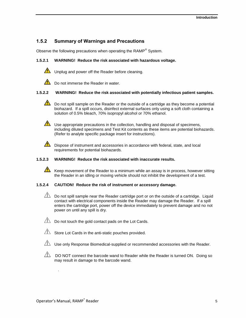
1.5.2 Summary of Warnings and Precautions
Observe the following precautions when operating the RAMP® System.
1.5.2.1 WARNING! Reduce the risk associated with hazardous voltage.
Unplug and power off the Reader before cleaning.
Do not immerse the Reader in water.
1.5.2.2 WARNING! Reduce the risk associated with potentially infectious patient samples.
Do not spill sample on the Reader or the outside of a cartridge as they become a potential biohazard. If a spill occurs, disinfect external surfaces only using a soft cloth containing a solution of 0.5% bleach, 70% isopropyl alcohol or 70% ethanol.
Use appropriate precautions in the collection, handling and disposal of specimens, including diluted specimens and Test Kit contents as these items are potential biohazards. (Refer to analyte specific package insert for instructions).
Dispose of instrument and accessories in accordance with federal, state, and local requirements for potential biohazards.
1.5.2.3 WARNING! Reduce the risk associated with inaccurate results.
Keep movement of the Reader to a minimum while an assay is in process, however sitting the Reader in an idling or moving vehicle should not inhibit the development of a test.
1.5.2.4 CAUTION! Reduce the risk of instrument or accessory damage.
Do not spill sample near the Reader cartridge port or on the outside of a cartridge. Liquid contact with electrical components inside the Reader may damage the Reader. If a spill enters the cartridge port, power off the device immediately to prevent damage and no not power on until any spill is dry.
Do not touch the gold contact pads on the Lot Cards.
Store Lot Cards in the anti-static pouches provided.
Use only Response Biomedical-supplied or recommended accessories with the Reader.
DO NOT connect the barcode wand to Reader while the Reader is turned ON. Doing so may result in damage to the barcode wand.
.
Introduction
Operator’s Manual, RAMP® Reader 6
1.6 Unpacking and Installation
1.6.1 Unpacking
The Reader and/or optional accessories are packed in a foam-cushioned container for maximum protection during shipment. If the shipping container is damaged, inspect the Reader as it is unpacked. If the Reader is damaged, notify the carrier and your distributor, or Response Biomedical Corporation to arrange for immediate repair or replacement. Retain the shipping container and all packaging material for repackaging.
To unpack the Reader, remove the top foam insert and carefully lift out the Reader. Place the Reader on a dry, clean, level surface. Remove the AC Adapter and Power Cord and check the label to confirm country-specific voltage requirements. Remove remaining contents and compare with the packing slip or list below. If any of the contents are missing, contact your distributor or Response Biomedical Corporation Customer Service (Appendix D).
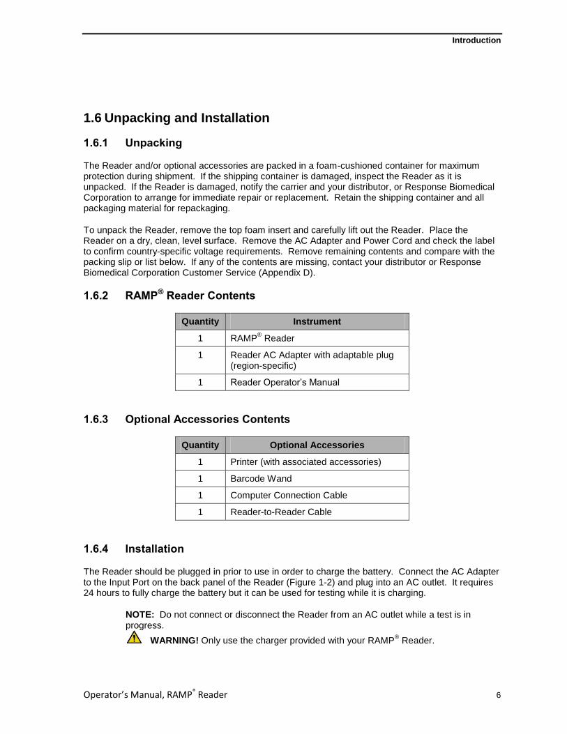
1.6.2 RAMP® Reader Contents
Quantity Instrument
1 RAMP® Reader
1 Reader AC Adapter with adaptable plug (region-specific)
1 Reader Operator’s Manual
1.6.3 Optional Accessories Contents
Quantity Optional Accessories
1 Printer (with associated accessories)
1 Barcode Wand
1 Computer Connection Cable
1 Reader-to-Reader Cable
1.6.4 Installation
The Reader should be plugged in prior to use in order to charge the battery. Connect the AC Adapter to the Input Port on the back panel of the Reader (Figure 1-2) and plug into an AC outlet. It requires 24 hours to fully charge the battery but it can be used for testing while it is charging.
NOTE: Do not connect or disconnect the Reader from an AC outlet while a test is in progress.
WARNING! Only use the charger provided with your RAMP® Reader.

Introduction
Operator’s Manual, RAMP® Reader 7
1.6.5 Initial Start-up The power button is located on the back panel of the Reader (Figure 1-2). When the power is turned on, the Reader performs a Power-On Self-Test (“POST”) to ensure the system is operating within certain pre-set parameters. The POST includes calibration verification, optical system verification, real-time clock test, transport movement test, and a battery test (if the Reader is operating on the battery at the time of the POST). If the measured battery voltage is low, a warning message appears on the LCD along with an audible alarm. If this occurs, the Reader should be plugged into an AC outlet using the supplied Adapter.
NOTE: A fully-charged battery will allow approximately 100 tests to be run before re-charging is required. In the event that a Reader is left on for 24 hours, the battery may run low. It takes approximately 24 hours to fully recharge the battery, however, the Reader may be operated with the AC Adapter during battery recharging. Refer to Section 3.3 for recommended battery care.
NOTE: Ensure that the battery is sufficiently charged or that the Reader is connected to an AC outlet prior to performing a test. Do not connect or disconnect the Reader from an AC outlet once the test has started.
The Reader can also function in an enhanced controlled manner by enabling the “User Lock-out” function. This requires the setting of a Master P.I.N., which provides controlled access to the SYSTEM SETTINGS Menu. Functions available through the SYSTEM SETTINGS Menu include changing the instrument clock, setting and enabling User IDs and associated P.I.N.s, transferring operator data, erasing data, selecting print settings, test counters, erasing memory, and setting QC timers. The User Lock-out mode ensures that only operators with a valid controlled P.I.N. are allowed to run tests on the Reader.
To operate the Reader with User Lock-out, ensure the SYSTEM SETTINGS Menu has limited access by setting a Master P.I.N. (Section 2.6.2) and that a User ID and P.I.N. are defined for each operator (Section 2.6.4).
NOTE: Ensure that operators have read and understood the Operator’s Manual and the analyte-specific Package Insert before attempting to perform a test.
1.6.6 Optional Accessories
If using a printer, connect it to the Reader via the RS-232 serial port on the back panel (Figure 1-2). See Appendix A for printer compatibility information.
If the Reader is connected to a computer or another Reader, ensure that the serial connection is properly secured. See Appendix A for serial port compatibility information.
CAUTION! If using the optional Barcode Wand accessory, ensure that it is properly connected to the Reader via the Barcode Wand connector port on the back panel PRIOR to turning the Reader on. Failure to do so may result in damage to the Barcode Wand.
Introduction
Operator’s Manual, RAMP® Reader 8
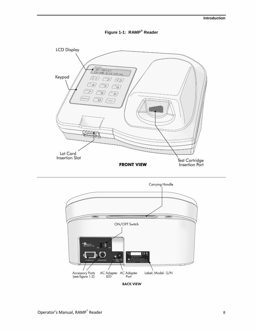
Figure 1-1: RAMP® Reader

Introduction
Operator’s Manual, RAMP® Reader 9
Figure 1-2: RAMP® Reader Rear Panel View

RAMP® System Operation
Operator’s Manual, RAMP® Reader 10
2.0 RAMP® SYSTEM OPERATION
2.1 Keypad Function and Use
To interface with the RAMP®
System, use the keypad (Figure 2-1) when prompted by the Reader display.
The keypad consists of ten alphanumeric character keys and two function keys, [Options] and [Enter]. To input a specific letter or number, press the key to scroll through the choices until the desired character is displayed. For example, to input the letter R, press the key marked [PQR 6] four times, until the letter R is displayed. When the character of choice has been selected, press a different key (other than the key initially pressed) to enter the character. The blank cursor will then move one character position to the right and display the new character. Press [Enter] to accept the displayed character string and proceed to the next step. Alternatively, a two-second pause after the desired character is selected will automatically enter the character and move the blank cursor one space to the right. This provides a means of entering multiple characters on the same key.
NOTE: When keying in a P.I.N., only the numerical character for each key (0-9) can be selected.
Press [Options] to erase and move the cursor one step to the left. This provides a backspace or correction function. Press [Options] again to erase the displayed character and move the cursor one more step to the left. Pressing a new character key will overwrite the displayed character above the cursor. If either [Options] or [Enter] key is pressed when no characters are shown on the display, this step is aborted and the operator is returned to the RUN/OPTIONS Menu.
The character keys [ABC 1] and [GHI 3] also function as the up [▲] and down [▼] keys respectively, allowing the operator to scroll through the OPTIONS menu or move the displayed “>” cursor to select specific options. Holding down the [▲] or [▼] key causes the display to scroll through the available choices. The “>” cursor points to the currently selected option. Whenever the OPTIONS Menu and associated functions are used, the keypad is limited to using the [▲], [▼], [Options], and [Enter] keys. All other character keys are inactive except when required for Editing User ID, User P.I.N., Master P.I.N. and adding printout information.

RAMP® System Operation
Operator’s Manual, RAMP® Reader 11
Figure 2-1: RAMP® Reader Keypad

RAMP® System Operation
Operator’s Manual, RAMP® Reader 12
2.2 RUN/OPTIONS Menu
When the Reader is turned on, it initially performs a Power-On Self-Test and displays the following animation on the display for one second while emitting two short beeps:
The following message scrolls across the screen from right to left and remains displayed for a few seconds (X.XX corresponds to the software version):
NOTE: If errors are found during the Power-On Self-Test, see Section 4.1 for detail.
When the Reader is ready for operation, the RUN/OPTIONS Menu is displayed:
At this point, the following actions may be performed:
Insert a Lot Card to upload lot information (Section 2.3).
Run an Assay (Section 2.4).
Access the OPTIONS menu (Section 2.5).
NOTE: If a critical system failure is found during the Power-On Self-Test or during IQC, the Reader will lock out the operator from running samples or Liquid Quality Control (LQC). Pressing [Enter] at either the RUN/OPTIONS or RUN LQC/EXIT prompts will display this message:
Press any key to return to the menu. The OPTIONS Menu is still accessible to output, print or view results.
2.3 Using Lot Cards
Each Kit includes a Lot Card that is individually packaged in an anti-static pouch. The Lot Card provides information, including lot-specific data and the expiration (Use-by) date of each Kit. Use the Lot Card to input the specific lot information into the Reader before using the Cartridges. This step is only required once prior to the use of a new lot.
SERVICE REQUIRED PRESS KEY TO PROCEED
RUN TEST: <Enter> OPTIONS: <Options>
*** RAMP READER *** *** Version X.XX ***
■■■■■■■■■■■■■■■■■■■■ ■■■■■■■■■■■■■■■■■■■■

RAMP® System Operation
Operator’s Manual, RAMP® Reader 13
To load the lot information, hold the Lot Card by the label with the arrow / text facing up, then insert the Lot Card with the arrow pointing toward the Reader, contact end first, into the slot located under the keypad on the front of the Reader (Figure 1-1).
CAUTION! Do not touch the gold contact pads on the Lot Card.
The Lot Card must be inserted before the accompanying new Kit lot can be used. If the Lot Card is not inserted prior to running the first cartridge for a new lot, the operator will be prompted to insert the appropriate Lot Card (Section 4.2).
Refer to the following steps for loading Lot Card information.
At the RUN/OPTIONS Menu prompt, insert the Lot Card. After the Lot Card is inserted, a beep is emitted and the screen displays the following message:
When the Lot Card is accepted, indicating that the Lot information has been successfully uploaded, the following message is displayed:
After the Lot Card data has been stored in memory, the Reader beeps twice and prompts the operator with the following instruction:
When the Lot Card is removed, the Reader will beep once.
CAUTION! The Lot Card should be kept in the anti-static pouch provided for safe storage and retained for the life of the Kit.
NOTE: Lot Card information will only upload successfully if it is inserted when either the RUN/OPTIONS or RUN LQC/EXIT Menus are displayed. The Reader will not acknowledge Lot Card insertion at any other time. It is only necessary to insert the Lot Card once per Kit lot as the lot information is retained even when the Reader power is switched off. The Reader can store data for up to 50 separate lot numbers. When the memory is full, the oldest data is overwritten when a new Lot Card is inserted. If a Lot Card is defective or cannot be read, the following message is displayed: LOT CARD READ-ERROR! (Section 4.2)
The Reader verifies the expiry (Use-by) date against its internal clock. If the current date exceeds the expiry date, the Reader emits an audible alarm and displays the error message: LOT CARD EXPIRED! (Section 4.2) Data from an expired lot is not copied into the Reader’s memory.
REMOVE LOT CARD
LOT DATA VERIFIED SAVING DATA...
READING LOT CARD PLEASE WAIT...
RAMP® System Operation
Operator’s Manual, RAMP® Reader 14
2.4 Running an Assay
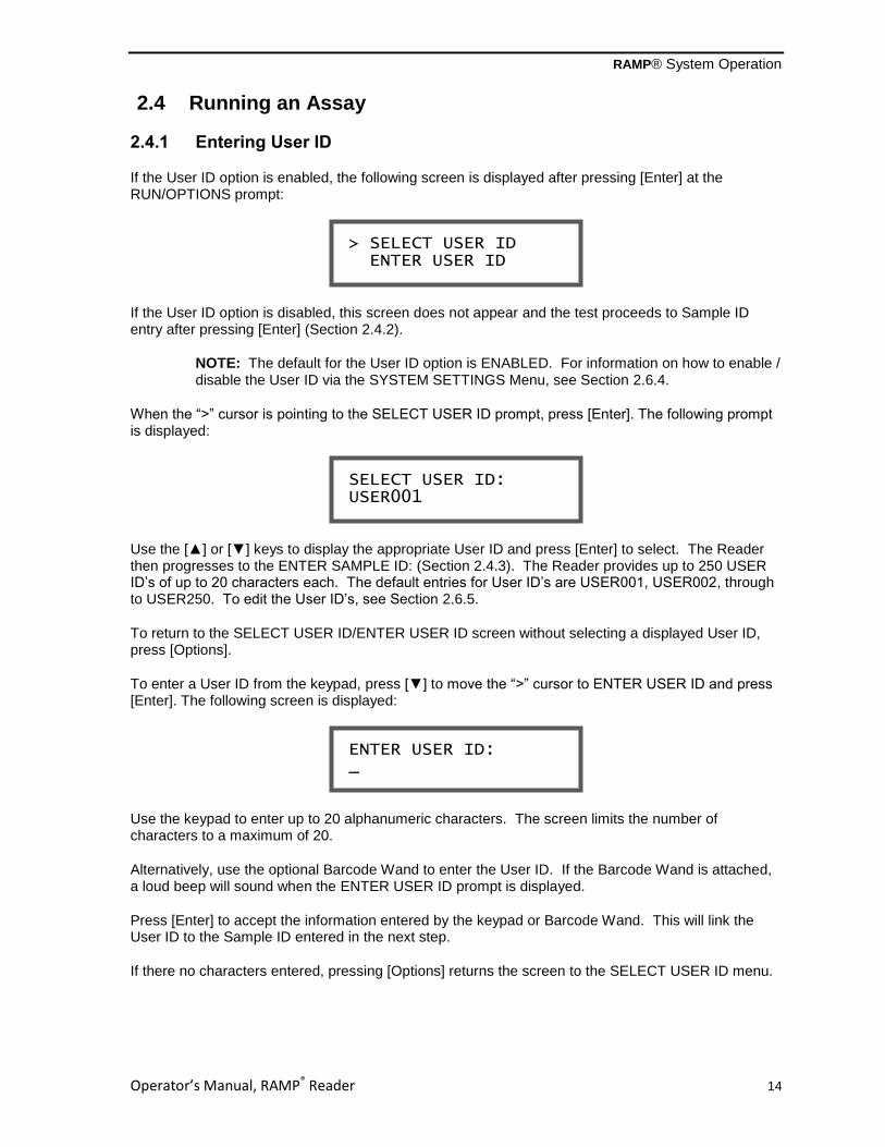
2.4.1 Entering User ID
If the User ID option is enabled, the following screen is displayed after pressing [Enter] at the RUN/OPTIONS prompt:
If the User ID option is disabled, this screen does not appear and the test proceeds to Sample ID entry after pressing [Enter] (Section 2.4.2).
NOTE: The default for the User ID option is ENABLED. For information on how to enable / disable the User ID via the SYSTEM SETTINGS Menu, see Section 2.6.4.
When the “>” cursor is pointing to the SELECT USER ID prompt, press [Enter]. The following prompt is displayed:
Use the [▲] or [▼] keys to display the appropriate User ID and press [Enter] to select. The Reader then progresses to the ENTER SAMPLE ID: (Section 2.4.3). The Reader provides up to 250 USER ID’s of up to 20 characters each. The default entries for User ID’s are USER001, USER002, through to USER250. To edit the User ID’s, see Section 2.6.5.
To return to the SELECT USER ID/ENTER USER ID screen without selecting a displayed User ID, press [Options].
To enter a User ID from the keypad, press [▼] to move the “>” cursor to ENTER USER ID and press [Enter]. The following screen is displayed:
Use the keypad to enter up to 20 alphanumeric characters. The screen limits the number of characters to a maximum of 20.
Alternatively, use the optional Barcode Wand to enter the User ID. If the Barcode Wand is attached, a loud beep will sound when the ENTER USER ID prompt is displayed.
Press [Enter] to accept the information entered by the keypad or Barcode Wand. This will link the User ID to the Sample ID entered in the next step.
If there no characters entered, pressing [Options] returns the screen to the SELECT USER ID menu.
ENTER USER ID: _
SELECT USER ID: USER001
> SELECT USER ID ENTER USER ID

RAMP® System Operation
Operator’s Manual, RAMP® Reader 15
2.4.2 Entering User P.I.N. – “User Lock-out” Mode (P.I.N. Enabled)
If the User ID and P.I.N. options are enabled, the following screen is displayed after pressing [Enter] to select the appropriate User ID:
If the User P.I.N. option is disabled, this screen does not appear and the Reader progresses to ENTER SAMPLE ID screen (Section 2.4.3).
NOTE: The default for the User P.I.N. option is DISABLED. For information on how to “enable / disable” the User P.I.N. via the SYSTEM SETTINGS Menu, see Section 2.6.4.
Use the keypad to enter the numeric User P.I.N. required and press [Enter]. The following screen is displayed briefly:
If the User P.I.N. is recognized, the Reader progresses to the ENTER SAMPLE ID screen (Section 2.4.3).
If the User P.I.N. is not recognized, the following screen is displayed:
Press any key to restore the screen to the RUN/OPTIONS prompt. Press [Enter] to retry, or consult supervisor.
2.4.3 Entering Sample ID
After the USER ID and/or P.I.N. is entered (if enabled), a beep is emitted and the following prompt is displayed:
NOTE: If the USER ID is disabled, the above prompt will be displayed after pressing [Enter] from the initial RUN/OPTIONS screen.
ENTER SAMPLE ID: _
P.I.N. IS INCORRECT! PRESS KEY TO PROCEED
VERIFYING P.I.N. PLEASE WAIT...
ENTER USER P.I.N.: _ ***************

RAMP® System Operation
Operator’s Manual, RAMP® Reader 16
A Sample ID of up to 20 alphanumeric characters can be input using the letter, number and space keys (Section 2.1).
When all characters have been entered, press [Enter] to store the displayed Sample ID into memory. If a letter or number has been inadvertently entered, press [Options] to clear the entry.
Alternatively, the optional Barcode Wand may be used to enter the Sample ID. If the Barcode Wand is attached, a loud beep will sound when the ENTER SAMPLE ID prompt is displayed.
Swipe the Barcode Wand across the barcoded information in either direction. A beep will sound if the swipe is successful. Accept the displayed information by pressing [Enter]. To erase the entry, press [Options].
NOTE: If the Reader is operating on the internal battery and a Sample ID is not entered within 30 seconds, the screen returns to the RUN/OPTIONS Menu. Pressing [Options] or [Enter] after clearing all letters or numbers also returns the screen to the RUN/OPTIONS Menu.
Once the Sample ID has been accepted and entered, the system proceeds to the ADD SAMPLE, THEN INSERT CARTRIDGE prompt (Section 2.4.4).
2.4.4 Inserting a Cartridge
After accepting a Sample ID, the Reader activates an internal barcode detector and prompts the operator to:
NOTE: The Reader will remain on this screen for 5 minutes or until a cartridge is inserted. If the sample is not available at this time or if the test is to be aborted, press [Options] to return to the RUN/OPTIONS Menu.
Prepare a cartridge with sample following the procedure described in the appropriate Assay Package Insert.
Insert the cartridge into the Cartridge Insertion Port (Figure 2-2A) by gently pushing the cartridge until firm resistance is felt (Figure 2-2B). Do not attempt to force the cartridge all the way into the slot. The Reader will automatically guide the cartridge while reading the barcode graphic on the bottom. The barcode contains the assay lot number and graphic markings to indicate to the Reader that the cartridge has been correctly inserted.
ADD SAMPLE, THEN INSERT CARTRIDGE
ENTER SAMPLE ID: R_

RAMP® System Operation
Operator’s Manual, RAMP® Reader 17
Figure 2-2: Inserting a Test Cartridge
2-2A 2-2B
CAUTION! To prevent damage to internal components of the Reader, it is important to prevent excess sample from getting onto the cartridge or spilling out of the sample well. Clean any spills before inserting the cartridge into the Reader.
NOTE: For most assays, it is important to IMMEDIATELY insert the cartridge into the Reader following sample addition. If the cartridge is not inserted into the Reader within 30 seconds of sample addition, the cartridge may be rejected and an error message displayed. This will abort the test and require another test to be performed (Section 4.4).
If the Reader is unable to detect the cartridge a beep is emitted and the error message REMOVE CARTRIDGE, THEN RE-INSERT is displayed (Section 4.4).
When the inserted cartridge is detected, the Reader automatically pulls the cartridge inside and displays the following:
Once the cartridge barcode is successfully read, the Reader searches its memory for the corresponding lot-specific data. If the matching data cannot be found, the operator is prompted to INSERT LOT CARD FOR LOT #Mxxxxx (Section 4.2).
If the Reader’s memory contains the corresponding lot information for the cartridge, a series of prompts indicating the progress of the analysis are displayed, as shown in the following example of a Myoglobin test:
Running time is displayed as a count-up timer until sample flow is detected.
TEST: Myo mm:ss RUNNING: 00:00
TEST: Myo BEGINNING TEST
TEST IN-PROGRESS, READING BARCODE...

RAMP® System Operation
Operator’s Manual, RAMP® Reader 18
NOTE: If sample flow is not detected within the time specified by the Lot Card, the following message is displayed, with the bottom line alternating display with “REMOVE CARTRIDGE…” (Section 4.4).
When the sample flow is detected within the proper time interval, a double-beep is emitted, SAMPLE FLOW DETECTED is displayed, followed by:
Development time is displayed as a countdown timer. The time interval is analyte-specific. Once the development time countdown reaches 0 seconds, the cartridge is scanned and the following message is displayed:
WARNING! To reduce the risk associated with inaccurate results, keep movement of the Reader to a minimum while an assay is in process, however sitting the Reader in an idling or moving vehicle should not inhibit the development of a test.
At the conclusion of the test, the cartridge is ejected and should be removed from the Reader. If auto print is selected, the result will automatically be printed (Section 2.6.6). The results and associated Sample ID are displayed, as in the following example:
The top line alternates from Sample ID (“ID: RB123”) to “PRESS ENTER to Cont.”, every 2 seconds until either the [Options] or [Enter] is pressed.
To view the Test Date/Time and Lot Identification, press [Options].
The top line alternates from the Test Date/Time (“23 Jun 2009 – 19:19”) to “PRESS ENTER to Cont.” until either the [Options] or [Enter] is pressed.
To re-display the Sample ID and test results, press [Options] again.
23 Jun 2009 – 19:19 Lot: Mxxxxx
ID: RB123 Myo: 61.7 ng/mL
TEST: Myo SCANNING **********
TEST: Myo mm:ss DEVELOPING: 00:00
SAMPLING ERROR #2 SEE INSTRUCTIONS
RAMP® System Operation
Operator’s Manual, RAMP® Reader 19
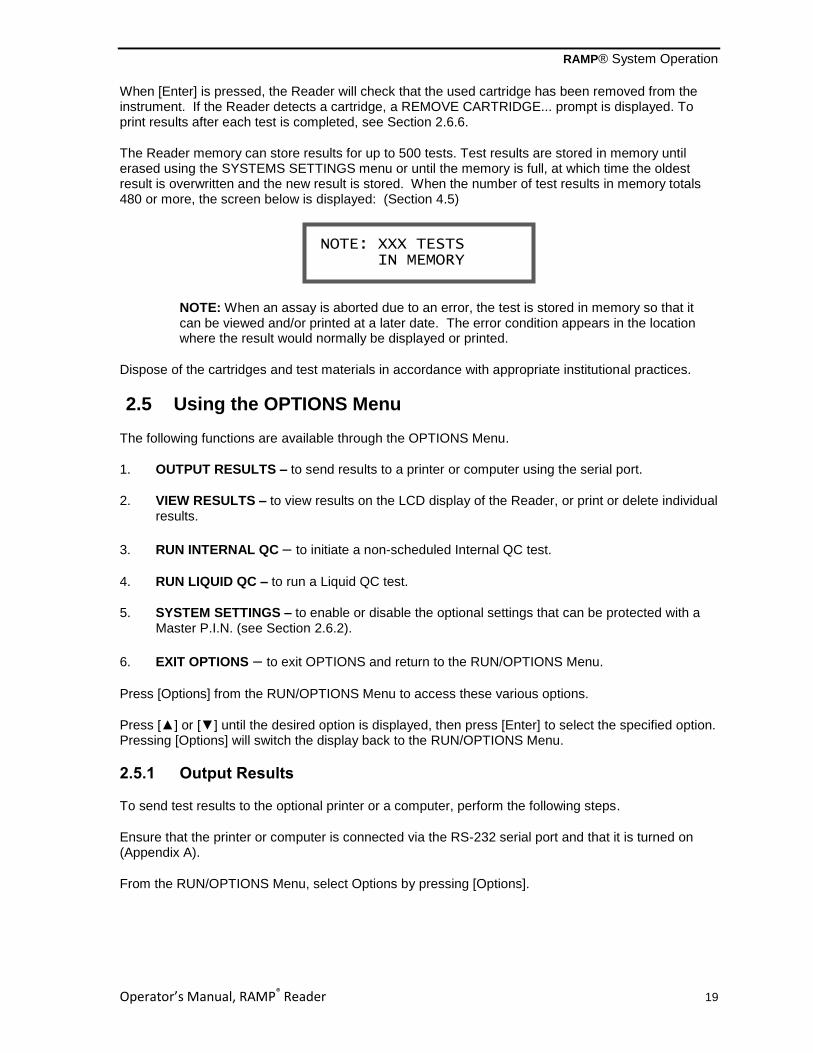
When [Enter] is pressed, the Reader will check that the used cartridge has been removed from the instrument. If the Reader detects a cartridge, a REMOVE CARTRIDGE... prompt is displayed. To print results after each test is completed, see Section 2.6.6.
The Reader memory can store results for up to 500 tests. Test results are stored in memory until erased using the SYSTEMS SETTINGS menu or until the memory is full, at which time the oldest result is overwritten and the new result is stored. When the number of test results in memory totals 480 or more, the screen below is displayed: (Section 4.5)
NOTE: When an assay is aborted due to an error, the test is stored in memory so that it can be viewed and/or printed at a later date. The error condition appears in the location where the result would normally be displayed or printed.
Dispose of the cartridges and test materials in accordance with appropriate institutional practices.
2.5 Using the OPTIONS Menu
The following functions are available through the OPTIONS Menu.
1. OUTPUT RESULTS – to send results to a printer or computer using the serial port.
2. VIEW RESULTS – to view results on the LCD display of the Reader, or print or delete individual results.
3. RUN INTERNAL QC – to initiate a non-scheduled Internal QC test.
4. RUN LIQUID QC – to run a Liquid QC test.
5. SYSTEM SETTINGS – to enable or disable the optional settings that can be protected with a Master P.I.N. (see Section 2.6.2).
6. EXIT OPTIONS – to exit OPTIONS and return to the RUN/OPTIONS Menu.
Press [Options] from the RUN/OPTIONS Menu to access these various options.
Press [▲] or [▼] until the desired option is displayed, then press [Enter] to select the specified option. Pressing [Options] will switch the display back to the RUN/OPTIONS Menu.
2.5.1 Output Results
To send test results to the optional printer or a computer, perform the following steps.
Ensure that the printer or computer is connected via the RS-232 serial port and that it is turned on (Appendix A).
From the RUN/OPTIONS Menu, select Options by pressing [Options].
NOTE: XXX TESTS IN MEMORY
RAMP® System Operation
Operator’s Manual, RAMP® Reader 20
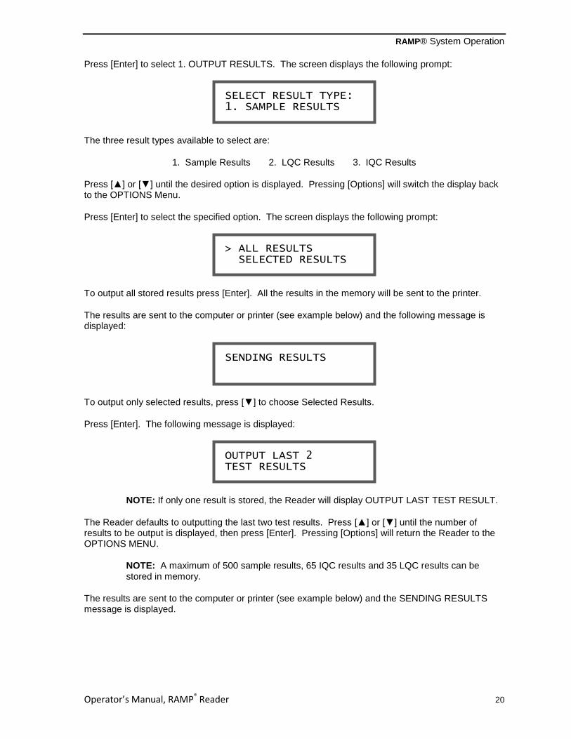
Press [Enter] to select 1. OUTPUT RESULTS. The screen displays the following prompt:
The three result types available to select are:
1. Sample Results 2. LQC Results 3. IQC Results
Press [▲] or [▼] until the desired option is displayed. Pressing [Options] will switch the display back to the OPTIONS Menu.
Press [Enter] to select the specified option. The screen displays the following prompt:
To output all stored results press [Enter]. All the results in the memory will be sent to the printer.
The results are sent to the computer or printer (see example below) and the following message is displayed:
To output only selected results, press [▼] to choose Selected Results.
Press [Enter]. The following message is displayed:
NOTE: If only one result is stored, the Reader will display OUTPUT LAST TEST RESULT.
The Reader defaults to outputting the last two test results. Press [▲] or [▼] until the number of results to be output is displayed, then press [Enter]. Pressing [Options] will return the Reader to the OPTIONS MENU.
NOTE: A maximum of 500 sample results, 65 IQC results and 35 LQC results can be stored in memory.
The results are sent to the computer or printer (see example below) and the SENDING RESULTS message is displayed.
OUTPUT LAST 2 TEST RESULTS
SENDING RESULTS
> ALL RESULTS SELECTED RESULTS
SELECT RESULT TYPE: 1. SAMPLE RESULTS

RAMP® System Operation
Operator’s Manual, RAMP® Reader 21
Figure 2-3: Sample Results Printout Example
When all results have completed printing, the report indicates completion by printing the message: END OF DATA at the bottom of the printout. The following message is then displayed:
NOTE: If the printer is not properly connected or if the printer is not turned on, an error message is displayed and the screen automatically returns to the OPTIONS Menu. Check to ensure the printer is turned on and properly connected. Repeat the above steps.
After output is completed, if User Lock-out is disabled (Section 2.4.2), the screen displays the following message:
To remove the type of results output from the memory, i.e. sample/ IQC /LQC, press [Enter] to select Yes.
NOTE: Pressing [Enter] erases all stored results from the specified memory. The operator is asked to confirm this request.
If the [Enter] is pressed for the YES prompt, all results stored in the specified memory are erased and a message specific to the database erased is displayed along with a double beep, as seen below for SAMPLE MEMORY:
After displaying this message for two seconds, the screen returns to the Options Menu.
If the results are not to be erased from memory, press [▼] to move the cursor to the NO option. Press either [Enter] or [Options] to return to the Options Menu. The results in memory will not be erased.
SAMPLE MEMORY HAS BEEN CLEARED
CLEAR MEMORY? >YES NO
OUTPUT COMPLETED
RAMP Reader S/N XXXXX Version X.XX ID: RB123 USER: USER1 RESULT: Myo 61.7 ng/mL DATE: 25 Jun 2009 TIME: 19:19 LOT: Mxxxxx EXP. 30 Jun 2010 END OF DATA

RAMP® System Operation
Operator’s Manual, RAMP® Reader 22
If there are no results stored in the Reader’s memory, the following is displayed with a long beep:
Press any key to return to the SELECT RESULT TYPE Menu.
2.5.2 View Results
To review results from previous samples on screen without outputting to a computer or printer, perform the following steps.
From the RUN/OPTIONS Menu select Options, then press [▲] or [▼] and select 2. VIEW RESULTS. Press [Enter], the screen displays the following Menu:
The three types of results available to select are:
1. Sample Results 2. LQC Results 3. IQC Results
Press [▲] or [▼] until the desired result type is displayed. Press [Enter] to select the specified option. Pressing [Options] will switch the display back to the OPTIONS Menu.
Pressing [Enter] at 1. SAMPLE RESULTS displays the most recent sample result, for example:
Pressing [Enter] at 2. LQC RESULTS displays the most recent LQC result. Pressing [Enter] at 3. IQC RESULTS displays the most recent IQC result.
If there are no sample results stored in the memory, the following message is displayed accompanied by a long beep:
The same sequence of steps applies to viewing SAMPLE, LQC and IQC results. The following illustrates the steps using a SAMPLE result.
To view a SAMPLE result, select it using [▲] or [▼] and press [Enter].
ID: RB123 Myo 61.7 ng/mL
NO TEST RESULTS IN MEMORY! PUSH A KEY.
SAMPLE RESULT #13 ID: RB123
SELECT RESULT TYPE: 1. SAMPLE RESULTS
NO TEST RESULTS IN MEMORY! PUSH A KEY

RAMP® System Operation
Operator’s Manual, RAMP® Reader 23
Press [Enter] again to display the sample result with date and time of the test.
Press [Enter] once more to display the Kit lot number with the expiry (Use by) date.
Press [Enter] to display the User ID that was recorded (if enabled) during the test.
NOTE: If a User ID was not used for the selected Sample ID, the screen is not displayed. (Pressing [Options] returns the screen to the Sample Result list.)
Press [Enter] to display the following prompt:
Use [▲] or [▼] and [Enter] to select desired option.
If User Lock-out mode is disabled (Section 2.4.2), the following prompt is displayed:
NOTE: Within the VIEW Menu, deleting results does not create more memory space. Deleting simply “hides” a result. To make more memory space, erase all results (Section 2.6.8).
Use [▲] or [▼] and [Enter] to select desired option.
If deleting result is selected, the operator is asked to confirm this request by the following prompt:
ARE YOU SURE? > NO YES
DELETE RESULT? > NO YES
PRINT RESULT? > NO YES
USER ID: USER001
LOT: Mxxxxx EXP. 15 Jun 2010
Myo 61.7 ng/mL 25 Jun 2009 – 19:19
RAMP® System Operation
Operator’s Manual, RAMP® Reader 24
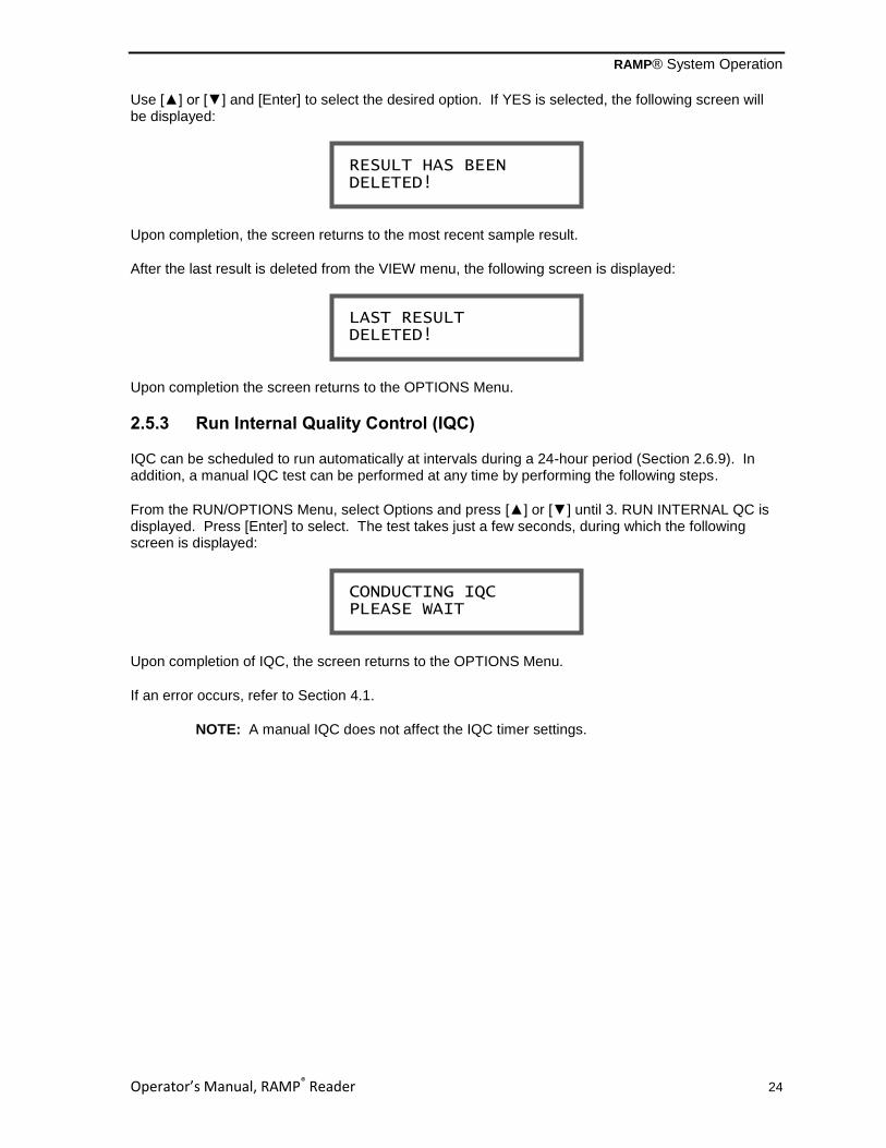
Use [▲] or [▼] and [Enter] to select the desired option. If YES is selected, the following screen will be displayed:
Upon completion, the screen returns to the most recent sample result.
After the last result is deleted from the VIEW menu, the following screen is displayed:
Upon completion the screen returns to the OPTIONS Menu.
2.5.3 Run Internal Quality Control (IQC)
IQC can be scheduled to run automatically at intervals during a 24-hour period (Section 2.6.9). In addition, a manual IQC test can be performed at any time by performing the following steps.
From the RUN/OPTIONS Menu, select Options and press [▲] or [▼] until 3. RUN INTERNAL QC is displayed. Press [Enter] to select. The test takes just a few seconds, during which the following screen is displayed:
Upon completion of IQC, the screen returns to the OPTIONS Menu.
If an error occurs, refer to Section 4.1.
NOTE: A manual IQC does not affect the IQC timer settings.
CONDUCTING IQC PLEASE WAIT
LAST RESULT DELETED!
RESULT HAS BEEN DELETED!

RAMP® System Operation
Operator’s Manual, RAMP® Reader 25
2.5.4 Run Liquid Quality Control (LQC)
External liquid quality control reagents are available for clinical RAMP® Assays. To conduct an LQC
test, perform the following steps.
From the RUN/OPTIONS Menu, select Options and press [▲] or [▼] until 4. RUN LIQUID QC is displayed. Press [Enter]. The following screen is displayed:
Press [Enter] to select Run LQC feature. If User ID or P.I.N. is enabled, the test will progress as described in Section 2.4.2. Then the display will prompt for a Sample ID.
Enter a sample ID and press [Enter], the following screen is shown:
Perform the LQC test following LQC and Assay package insert instructions. After completion of a successful LQC assay, relevant print messages are displayed (Section 2.6.6) and the screen returns to the RUN/OPTIONS prompt.
2.5.5 System Settings
The Reader provides built-in User Lock-out capability, such that Systems Settings require a Master P.I.N. The default setting is Master P.I.N. disabled.
To access the SYSTEM SETTINGS Menu from the RUN/OPTIONS Menu, select Options and press [▲] or [▼] until 5. SYSTEM SETTINGS is displayed.
See Section 2.6 for details on using the SYSTEMS SETTINGS Menu.
2.5.6 Exiting OPTIONS Menu
To exit from the OPTIONS Menu, press [Options], [▲], or [▼] until 6. EXIT OPTIONS is displayed.
Press [Enter] to select this option or press [Options] to return to the RUN/OPTIONS Menu.
ADD SAMPLE, THEN INSERT CARTRIDGE
RUN LQC: <ENTER> EXIT: <OPTIONS>

RAMP® System Operation
Operator’s Manual, RAMP® Reader 26
2.6 Using the SYSTEM SETTINGS Menu
The SYSTEM SETTINGS Menu allows controlled access to the following system settings:
1) SET MASTER P.I.N. – to edit the Master PIN.
2) SET CLOCK – to adjust the date and time.
3) DISABLE ID & P.I.N. – to enable or disable the User ID/PIN option.
4) EDIT USER ID/P.I.N. – to review and edit the User ID/PIN.
5) PRINT SETTINGS – allows for printing of the results after each test, and the ability to
include two additional lines of information on the printout. 6) TRANSFER USERS – to download User ID/PIN data to another RAMP
® Reader.
7) ERASE MEMORY – to delete test results stored in the Reader memories, i.e., Sample, LQC and IQC.
8) SET IQC TIMER – to set interval from 1-24 hours. 9) SET LQC TIMER – to set interval from 1-31 days. 10) RESET LQC TIMER – to set the LQC timer countdown.
11) TEST COUNTERS – maintains a record of the number of Sample, IQC and LQC tests
that the instrument has performed. 12) CONNECTIVITY – to allow the transfer of data to an external system. 13) EXIT MENU – to return to RUN/OPTIONS screen.
2.6.1 Accessing the SYSTEM SETTINGS Menu
Press [Options], and scroll to the 5. SYSTEM SETTINGS prompt from the OPTIONS Menu. Press [Enter] to select.
If the Master P.I.N. feature is enabled (Section 2.6.2), access to the SYSTEM Menu requires input of a P.I.N. at this prompt:
When the correct Master P.I.N. is entered, full access to the SYSTEM Menu is permitted. By default, the Master P.I.N. is disabled.
If no P.I.N. is entered, the screen reverts to the OPTIONS menu. If an incorrect P.I.N. is entered, a P.I.N. IS INCORRECT! message is displayed. Pressing any key will display the following:
Press [Enter] to re-enter correct P.I.N. or press [▼] and [Enter] to select the P.I.N. override feature. The following prompt is displayed:
CONTACT TECH SUPPORT WITH PERMIT #: XXXXX
> RE-ENTER P.I.N. OVERRIDE P.I.N.
ENTER MASTER P.I.N.: _ **************

RAMP® System Operation
Operator’s Manual, RAMP® Reader 27
NOTE: Please contact Technical Support (Appendix D). Be sure the Reader is accessible and the screen with the permit # (above) is visible. An override code will be provided by Technical Support.
Press [Enter] to enter the override code.
NOTE: Entering the override code does not reset the Master P.I.N. but allows immediate access to the SYSTEM SETTINGS menu where the Master P.I.N. can be reset.
If the Master P.I.N. is not enabled, all operators will have access to the SYSTEM SETTINGS menu.
2.6.2 Set Master P.I.N.
The Reader can be set such that system settings or stored results are protected from unauthorized change or deletion. From RUN/OPTIONS Menu, select Options and then press [▲] or [▼] until 5. SYSTEM SETTINGS is displayed. Press [Enter] to access the SYSTEM Menu. Press [Enter] at the screen to select 1. SET MASTER P.I.N.
The current P.I.N. is displayed in the first line. If the Master P.I.N. has not been set, “00000” is displayed. The second line prompts the operator to enter a new P.I.N.
Using the keypad, type in a new P.I.N. (the P.I.N. can be from 1 – 5 digits). Press [Enter] to accept and reset the P.I.N.
NOTE: To disable the Master P.I.N., set the Master P.I.N. to “00000”.
2.6.3 Setting the System Clock
The clock displays a 24-hour format. From the SYSTEM Menu, press [▲] or [▼] until 2. SET CLOCK is displayed. Press [Enter] to select this option. The following prompt is displayed:
The arrows surrounding a field indicate the active edit field. To edit the active field, press [▲] or [▼] until the proper value is displayed. When the value is correct, press [Options] to move the editor to the next field. When finished, press [Enter] to return to the SYSTEM Menu.
DATE:►2010◄ JUN 24 TIME: 11 : 55
EDIT P.I.N.: 12345 _ ***************
ENTER OVERRIDE CODE: _ *************
RAMP® System Operation
Operator’s Manual, RAMP® Reader 28
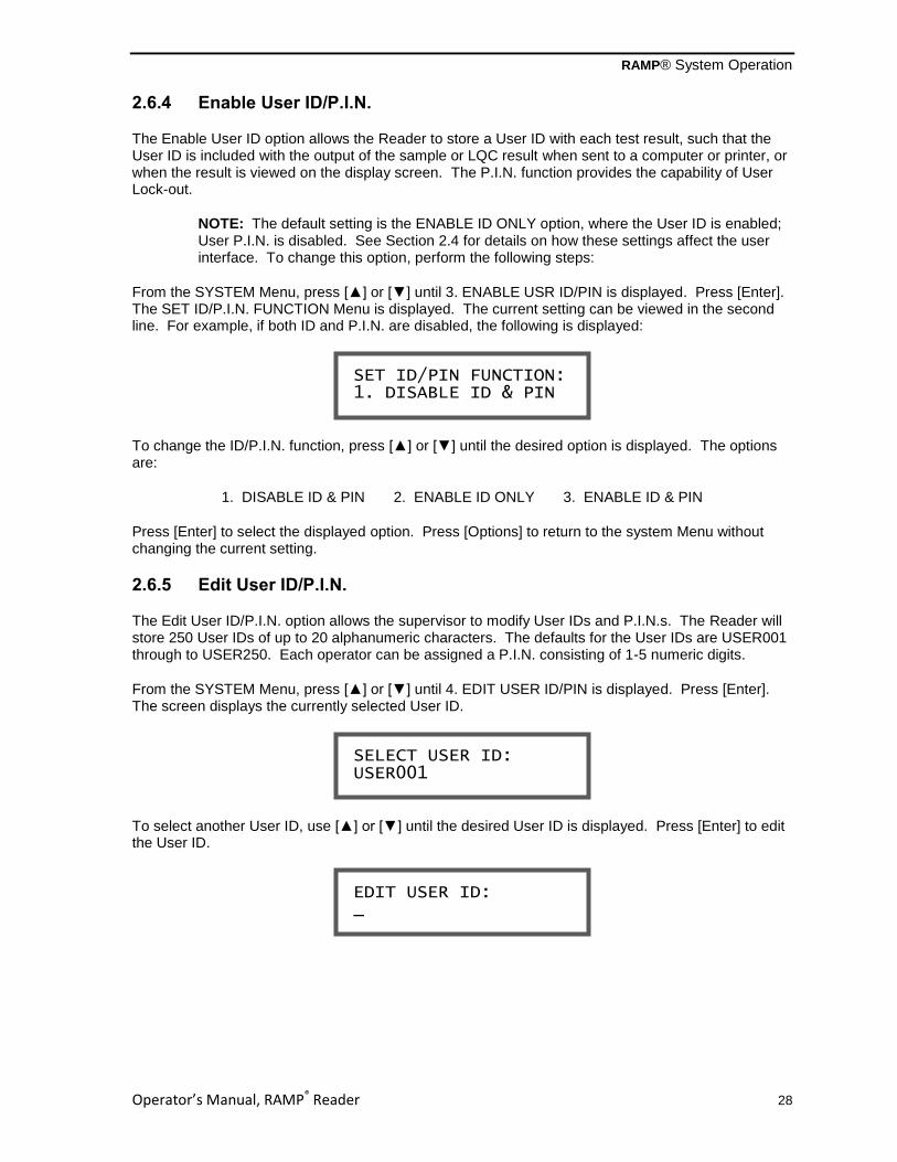
2.6.4 Enable User ID/P.I.N.
The Enable User ID option allows the Reader to store a User ID with each test result, such that the User ID is included with the output of the sample or LQC result when sent to a computer or printer, or when the result is viewed on the display screen. The P.I.N. function provides the capability of User Lock-out.
NOTE: The default setting is the ENABLE ID ONLY option, where the User ID is enabled; User P.I.N. is disabled. See Section 2.4 for details on how these settings affect the user interface. To change this option, perform the following steps:
From the SYSTEM Menu, press [▲] or [▼] until 3. ENABLE USR ID/PIN is displayed. Press [Enter]. The SET ID/P.I.N. FUNCTION Menu is displayed. The current setting can be viewed in the second line. For example, if both ID and P.I.N. are disabled, the following is displayed:
To change the ID/P.I.N. function, press [▲] or [▼] until the desired option is displayed. The options are:
1. DISABLE ID & PIN 2. ENABLE ID ONLY 3. ENABLE ID & PIN
Press [Enter] to select the displayed option. Press [Options] to return to the system Menu without changing the current setting.
2.6.5 Edit User ID/P.I.N.
The Edit User ID/P.I.N. option allows the supervisor to modify User IDs and P.I.N.s. The Reader will store 250 User IDs of up to 20 alphanumeric characters. The defaults for the User IDs are USER001 through to USER250. Each operator can be assigned a P.I.N. consisting of 1-5 numeric digits.
From the SYSTEM Menu, press [▲] or [▼] until 4. EDIT USER ID/PIN is displayed. Press [Enter]. The screen displays the currently selected User ID.
To select another User ID, use [▲] or [▼] until the desired User ID is displayed. Press [Enter] to edit the User ID.
EDIT USER ID: _
SELECT USER ID: USER001
SET ID/PIN FUNCTION: 1. DISABLE ID & PIN

RAMP® System Operation
Operator’s Manual, RAMP® Reader 29
Enter the User ID using the keypad or optional barcode wand. A maximum of 20 alphanumeric characters can be input for the User ID. When finished editing, press [Enter] to store the displayed User ID. To accept the ID without editing, press [Options] or [Enter] with nothing typed. The screen advances to the EDIT P.I.N. prompt.
Type in new P.I.N. and press [Enter] to accept. To accept the P.I.N. without editing, press [Options] or [Enter] with nothing typed. The screen returns to SYSTEM Menu. On entering a P.I.N., the Reader checks for a duplicate P.I.N. in memory while displaying the following screen:
If the entered P.I.N. does not match any in memory, P.I.N. IS OKAY is displayed and the Reader returns to the SYSTEM Menu.
If an identical P.I.N. is already in memory, the following screen is displayed:
The Reader then displays the EDIT P.I.N. screen as shown above.
NOTE: When operating on battery power, if a new/revised User ID is not entered within 30 seconds, the screen advances to the EDIT P.I.N. prompt as displayed above.
Press [Enter] to accept the information entered.
To cancel editing, press [Options] repeatedly to remove all characters previously entered and return to the SYSTEM menu.
2.6.6 Print Settings
The Print Settings allow automatic printing of results after each test, and the ability to include two additional lines of information with each printout, such as institution and/or department name.
From the SYSTEM Menu, press [▲] or [▼] until 5. PRINT SETTINGS is displayed. Press [Enter] to select this option, the PRINT SETTINGS menu is displayed.
2.6.6.1 Print options after assay completion
To change the print options, select 1. PRINT OPTION and press [Enter].
> 1. PRINT OPTION 2. ADD INFORMATION
ERROR:DUPLICATE PIN! INPUT DIFFERENT PIN
CHECKING P.I.N. PLEASE WAIT...
EDIT P.I.N.: 00000 _ ***************
RAMP® System Operation
Operator’s Manual, RAMP® Reader 30
Press [▲] or [▼] then [Enter] to select one of the three printing options:
1. DO NOT PRINT - (default) the user is not prompted to print after an assay is run. Results may be printed when viewing results at a later date.
2. PROMPT USER - the user is prompted to print each result after running an assay. When prompted, use [▲] or [▼] to select “YES” or “NO” and press [Enter]. If “YES” is selected the Reader will send the current result to a printer.
3. AUTO PRINT - each assay result will be printed automatically after running an assay followed by OUTPUT COMPLETE. The screen then displays the sample results.
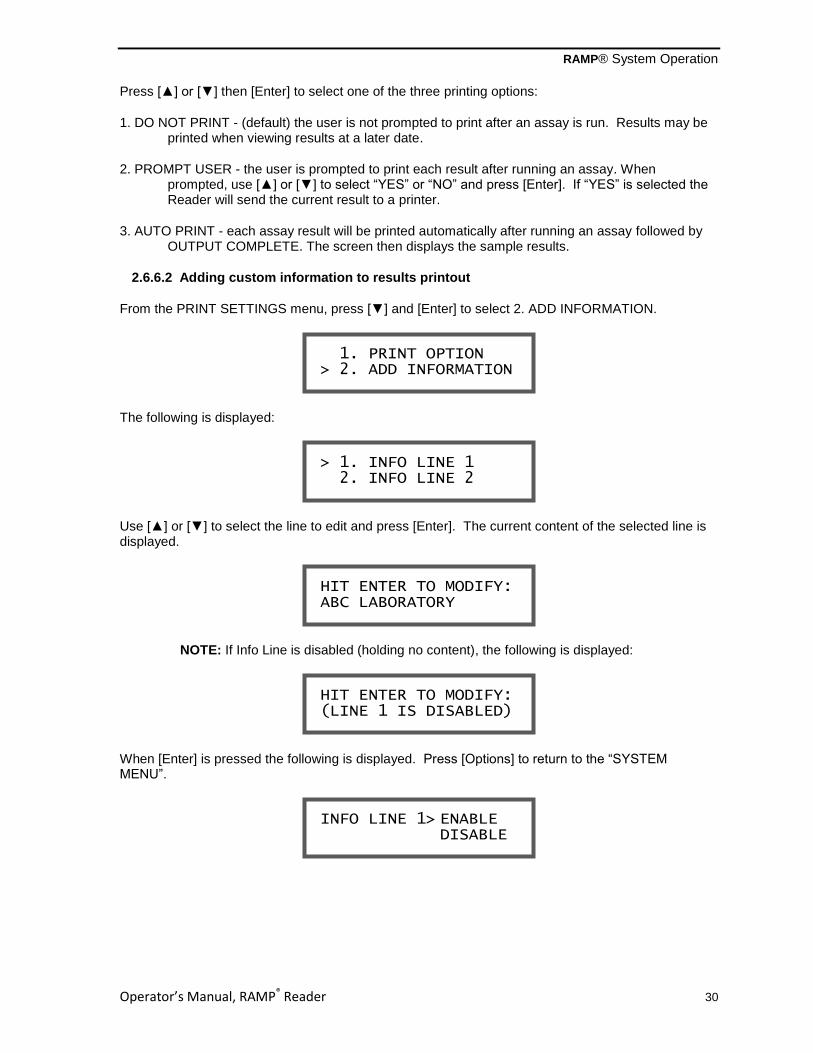
2.6.6.2 Adding custom information to results printout
From the PRINT SETTINGS menu, press [▼] and [Enter] to select 2. ADD INFORMATION.
The following is displayed:
Use [▲] or [▼] to select the line to edit and press [Enter]. The current content of the selected line is displayed.
NOTE: If Info Line is disabled (holding no content), the following is displayed:
When [Enter] is pressed the following is displayed. Press [Options] to return to the “SYSTEM MENU”.
INFO LINE 1> ENABLE DISABLE
HIT ENTER TO MODIFY: (LINE 1 IS DISABLED)
HIT ENTER TO MODIFY: ABC LABORATORY
> 1. INFO LINE 1 2. INFO LINE 2
1. PRINT OPTION > 2. ADD INFORMATION

RAMP® System Operation
Operator’s Manual, RAMP® Reader 31
Use [▲] or [▼] to select ENABLE or DISABLE. Pressing [Enter] when ENABLE is selected will display the INFO LINE input screen. Pressing [Enter] when DISABLE is selected will disable the INFO LINE (no content stored) and return to the SYSTEM SETTINGS Menu.
Each line can contain 20 alphanumeric characters. Use the keypad to enter the desired content for the selected information line and then press [Enter] to save the changes and return to SYSTEM MENU. Press [Options] to delete the last entered character. When no character is input, pressing [Options] or [Enter] will return the Reader to the SYSTEM MENU without any changes.
Example printouts are shown below, with 2 additional lines of information:
Figure 2-4: Sample Results Printout with custom information Example
2.6.7 Transfer Users
This option allows transfer of User ID and User P.I.N. data from one Reader (source Reader) to another (receiving Reader).
Connect source Reader to receiving Reader using a Reader-to-Reader cable (available from Response Biomedical, see Appendix D). Ensure the receiving Reader is powered on and the RUN/OPTIONS prompt is displayed.
From the source Reader SYSTEM SETTINGS Menu, press [▲] or [▼] until 6. TRANSFER USERS is displayed. Press [Enter] to begin download. During transfer, the source Reader displays the following screen:
SENDING USERS...
RAMP Reader S/N XXXXX Version X.XX CITY LABS NETWORK PATHOLOGY ID: RB123 USER: USER1 RESULT: Myo 61.7 ng/mL DATE: 25 Jun 2009 TIME: 19:19 LOT: Mxxxxx EXP. 30 Jun 2010 END OF DATA
ENTER INFO LINE 1: _

RAMP® System Operation
Operator’s Manual, RAMP® Reader 32
During transfer, the receiving Reader displays the following screen:
After completion, the following screen is displayed:
Upon completion of download, source Reader returns to TRANSFER USERS option screen.
If the receiving Reader is not properly connected, the source Reader briefly displays an error screen:
The source Reader then returns to the 6. TRANSFER USERS screen.
2.6.8 Erase Memory
Results can be erased from the Reader memory from the Output Results option. This selection removes all stored results of the selected result type.
From the SYSTEM SETTINGS Menu, press [▲] or [▼] until 7. ERASE MEMORY is displayed.
Press [Enter] and the RESULT TYPE Menu is displayed.
There are 3 available result types:
1. SAMPLE RESULTS 2. LQC RESULTS 3. IQC RESULTS
To remove the results from memory, press [▲] or [▼] until the appropriate result type is displayed. Press [Enter]. The display shows the following prompt:
To remove these results from the memory, press [Enter] to select YES. The operator is asked to confirm this request by the following prompt:
Press [Enter] to confirm results deletion. The MEMORY HAS BEEN CLEARED message with the result type is displayed for 2 seconds, and the screen returns to the SYSTEM SETTINGS Menu.
ARE YOU SURE? > YES NO
CLEAR MEMORY? > YES NO
RECEIVING READER IS NOT RESPONDING!
USER ID + PIN DATA RECEIVED & STORED
RECEIVING USERS...
RAMP® System Operation
Operator’s Manual, RAMP® Reader 33
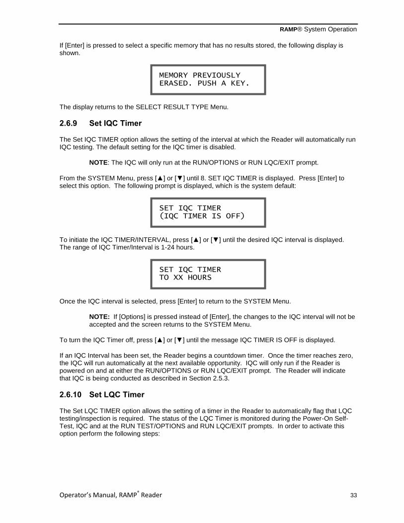
If [Enter] is pressed to select a specific memory that has no results stored, the following display is shown.
The display returns to the SELECT RESULT TYPE Menu.
2.6.9 Set IQC Timer
The Set IQC TIMER option allows the setting of the interval at which the Reader will automatically run IQC testing. The default setting for the IQC timer is disabled.
NOTE: The IQC will only run at the RUN/OPTIONS or RUN LQC/EXIT prompt.
From the SYSTEM Menu, press [▲] or [▼] until 8. SET IQC TIMER is displayed. Press [Enter] to select this option. The following prompt is displayed, which is the system default:
To initiate the IQC TIMER/INTERVAL, press [▲] or [▼] until the desired IQC interval is displayed. The range of IQC Timer/Interval is 1-24 hours.
Once the IQC interval is selected, press [Enter] to return to the SYSTEM Menu.
NOTE: If [Options] is pressed instead of [Enter], the changes to the IQC interval will not be accepted and the screen returns to the SYSTEM Menu.
To turn the IQC Timer off, press [▲] or [▼] until the message IQC TIMER IS OFF is displayed.
If an IQC Interval has been set, the Reader begins a countdown timer. Once the timer reaches zero, the IQC will run automatically at the next available opportunity. IQC will only run if the Reader is powered on and at either the RUN/OPTIONS or RUN LQC/EXIT prompt. The Reader will indicate that IQC is being conducted as described in Section 2.5.3.
2.6.10 Set LQC Timer
The Set LQC TIMER option allows the setting of a timer in the Reader to automatically flag that LQC testing/inspection is required. The status of the LQC Timer is monitored during the Power-On Self-Test, IQC and at the RUN TEST/OPTIONS and RUN LQC/EXIT prompts. In order to activate this option perform the following steps:
SET IQC TIMER TO XX HOURS
SET IQC TIMER (IQC TIMER IS OFF)
MEMORY PREVIOUSLY ERASED. PUSH A KEY.

RAMP® System Operation
Operator’s Manual, RAMP® Reader 34
From the SYSTEM Menu, press [▲] or [▼] until 9. SET LQC TIMER is displayed. Press [Enter]. The following prompt is displayed, which is the system default:
To initiate the LQC TIMER/INTERVAL, press [▲] or [▼] until the desired LQC interval is displayed. The range of the LQC Timer/Interval is 1-31 days.
Once the LQC interval is selected, press [Enter] to return to the SYSTEM Menu.
NOTE: If [Options] is pressed instead of [Enter], the changes to the LQC interval will not be accepted and the screen returns to the SYSTEM Menu.
To turn the LQC Timer off, press [▲] or [▼] until the message LQC TIMER IS OFF is displayed.
If an LQC Interval has been set, the Reader begins a countdown timer. When the timer reaches zero, any subsequent sample result will be flagged with the message “WARNING LQC OVERDUE!” on both viewing and printing sample results. If the LQC timer reaches zero and the Reader is displaying the RUN/OPTIONS screen, the display will change to:
2.6.11 Reset LQC Timer
Resetting the LQC Timer starts a new countdown to the specified time interval.
From SYSTEM Menu, press [▲] or [▼] until 10. RESET LQC TIMER is displayed. Press [Enter] to select this option. The Reader displays the following prompt along with a double beep:
Press [Enter] to select YES. The LQC Timer is reset to the specified interval and is confirmed by two short beeps. The following prompt is displayed for 2 seconds, and the screen returns to the SYSTEM Menu:
LQC TIMER HAS BEEN RESET
RESET TIMER? > YES NO
LQC NEEDED PRESS KEY TO PROCEED
SET LQC TIMER TO XX DAYS
SET LQC TIMER (LQC TIMER IS OFF)

RAMP® System Operation
Operator’s Manual, RAMP® Reader 35
NOTE: The RESET LQC TIMER option does not allow the operator to disable the LQC Timer. In order to turn the LQC Timer off, the steps outlined in Section 2.6.10 should be followed.
2.6.12 Test Counters
The TEST COUNTERS option maintains a record of the number of Sample, IQC and LQC tests that the instrument has performed. The counters can be viewed and reset.
From SYSTEM Menu, press [▲] or [▼] until 11. TEST COUNTERS is displayed. Press [Enter] to select this option. The Reader displays the following prompt (example sample test numbers):
Press [Enter] to display the LQC Counter.
Press [Enter] to display the IQC Counter.
Press [Enter] to display Reset Counters prompt:
Press [Enter] to select NO. If the Counters are to be reset, press [▼] to move the cursor to select the YES option.
NOTE: Resetting the Counters will reset all the counters (Sample, LQC and IQC) to 0.
2.6.13 Connectivity
Data can be transferred to a computer via the RS232 port on the Reader. See Appendix B for details on this data transfer.
2.6.14 Exit Menu
Selecting this option from the SYSTEM Menu returns the Reader to the RUN/OPTIONS prompt.
From SYSTEM SETTINGS Menu, press [▲] or [▼] and [Enter] to select 13. EXIT SYSTEM MENU and return to the RUN/OPTIONS screen. Once the SYSTEM Menu is exited, the Master P.I.N. is required for re-access unless the Master P.I.N. is disabled (set to “00000”).
RESET >NO COUNTERS? YES
IQC COUNTER COUNT NUMBER: 1279
LQC COUNTER COUNT NUMBER: 341
SAMPLE COUNTER COUNT NUMBER: 13212

Operator’s Manual, RAMP® Reader 36
3.0 MAINTENANCE
3.1 Overview
The Reader does not require routine maintenance other than occasional cleaning of external surfaces.
CAUTION! The instrument contains no operator-serviceable components. Replacement of the custom-built battery pack must only be performed by authorized service technicians.
3.2 Cleaning and Decontamination
WARNING! Unplug and power off the Reader before cleaning.
WARNING! Do not immerse the Reader in water.
To clean and decontaminate the Reader, wipe down the exterior surfaces of the Reader using a soft cloth containing a solution of 0.5% bleach, 70% isopropyl alcohol, 70% ethanol, or a non-organic disinfectant (containing not more than 0.5% bleach). Do not spray the Reader with disinfectant or attempt to clean any internal parts or surfaces. Any spills should be cleaned away before inserting a cartridge into the Reader.
If the Reader should require servicing or replacement, it must be decontaminated per above instructions prior to repackaging and shipping.
WEEE (Waste Electrical and Electronic Equipment)
Do not dispose of this product in municipal waste. Please contact Response Biomedical Technical Support to arrange disposal and recycling.
3.3 Battery Care
The service life of the internal custom battery pack depends on the amount of time the Reader is run on the battery. If battery operation is kept to a minimum and complete battery discharge is avoided, the battery pack should not require servicing over the lifetime of the instrument. If battery operation is frequent and continuous, however, the battery pack may need replacement within the Reader’s lifetime.
To maximize battery performance, the Reader should always be recharged (optimally for 24 hours) when the Low Battery indicator first appears. The Reader may be operated with the AC Adapter during battery recharging. The user may choose to recharge the battery before reaching full discharge. This is called topping up the charge. While this can be done, it will reduce the service life of the battery and will temporarily reduce battery capacity. A deep discharge is recommended after several top-up charges to restore full battery capacity.
CAUTION! Complete battery discharge should be avoided.

Operator’s Manual, RAMP® Reader 37
4.0 TROUBLESHOOTING GUIDE
When the Reader is unable to continue a specific task it will emit an audio alarm (long beep, unless otherwise stated) and display a message. Refer to the following list of messages when troubleshooting.
4.1 Power-On Self-Test Messages / IQC Messages
If any Error persists, call Technical Support (Appendix D).
LCD Message Cause Action
Blank Screen Battery is fully discharged. Turn off Reader. Charge battery fully for 24 hours.
CLOCK ERROR! NOTIFY SUPERVISOR The lower line of the message alternates between “NOTIFY SUPERVISOR” and “PRESS KEY TO PROCEED”.
An internal clock failure was detected during Power-On Self-Test or IQC.
Press any key. The clock is set to Jan 01, 2030. Reset the clock in the System Settings Menu.
*CTG TRANSPORT FAULT! CONSULT MANUAL The lower line of the message alternates between “CONSULT MANUAL” and “PRESS KEY TO PROCEED”. *Critical Failure – see note
During Power-On Self-Test or IQC, a failure was detected in transport, stepper motor, home sensor, or transport mechanism is jammed.
Remove Test Cartridge if present. Turn Reader off and then on again.
***DEAD BATTERY*** PLUG IN CHARGER! (Message accompanied by audio alarm.)
During the Power-On Self-Test, IQC or at the RUN/OPTIONS or RUN LQC/EXIT prompt, the Reader detects a battery that is fully discharged.
Turn off Reader. Plug in AC Adapter/Charger. When Reader is turned back on, RUN/OPTIONS Menu is displayed only after the battery voltage is sufficient for operation. NOTE: 24hours of continuous charging is required to completely charge battery. Tests may be run during charging.

Troubleshooting Guide
Operator’s Manual, RAMP® Reader 38
LCD Message Cause Action
RUN TEST: <Enter> *** LOW BATTERY! *** (Message accompanied by intermittent “chirp”.)
During Power-On Self-Test, IQC, RUN/OPTIONS or RUN LQC/EXIT prompt, Reader detects low battery voltage. From 1 to 4 tests remain before Reader will cease operation due to a fully discharged battery.
Plug in AC Adapter/Charger. NOTE: 24hours of continuous charging is required to completely charge battery. Tests may be run during charging.
*OPTICS FAULT! CONSULT MANUAL The lower line of the message alternates between “CONSULT MANUAL” and “PRESS KEY TO PROCEED”. *Critical Failure – see note
An optics failure was detected during Power-On Self-Test or IQC.
Press any key to return to the RUN/OPTIONS or RUN LQC/EXIT prompt. Contact Technical Support.
*READER CALIBR FAULT! CONSULT MANUAL *Critical Failure – see note
A “checksum” mismatch was detected in Reader calibration data during Power-On Self-Test or IQC.
Contact Technical Support for re-calibration servicing.
REMOVE CARTRIDGE! A Test Cartridge is detected in the Reader during the Power-On Self-Test or IQC.
Remove Test Cartridge. Reader displays the RUN/OPTIONS Menu. If no Cartridge is present, this error may be caused by a bright light shining on the Reader. Shade Reader to see if this corrects the error.
REMOVE LOT CARD! A Lot Card is detected during Power-On Self-Test or IQC.
Remove Lot Card. Reader displays RUN/OPTIONS Menu.
SERVICE REQUIRED PRESS KEY TO PROCEED
Critical Failure was detected during Power-On Self-Test or IQC. Access to running samples and LQC is blocked.
Press any key to return to the RUN/OPTIONS or RUN LQC/EXIT prompt. Contact Technical Support. Results in memory can still be viewed, printed or downloaded.
*Critical Failure – detected during Power-On Self-Test or IQC. Leads to “SERVICE REQUIRED” message, and access to running test samples and LQC is blocked. The results in memory can still be viewed, printed or downloaded.

Troubleshooting Guide
Operator’s Manual, RAMP® Reader 39
4.2 Lot Card / Barcode Messages
‡Repeat Test: Using the same whole blood sample, follow the testing procedure in the analyte-specific Package Insert, beginning at the SAMPLE PREPARATION section. A new Sample Buffer Vial, Assay Tip and Test Cartridge must be used.
LCD Message Cause Action
BARCODE DATA ERROR! RE-SCANNING BARCODE
Reader detects an error in reading Barcode.
Reader automatically re-scans Cartridge Barcode to recover data.
BARCODE UNREADABLE! PRESS KEY TO PROCEED
If re-scanning Barcode fails a second time (see above message), barcode lot information may be entered manually.
Follow on-screen instructions to enter lot number using keypad.
CARTRIDGE EXPIRED! EJECTING CARTRIDGE
Cartridge is from an expired lot. Remove cartridge. Do not use cartridges from this lot. The screen returns to the RUN/OPTIONS Menu.
DATA-SAVE ERROR! CONSULT MANUAL
Data from Lot Card was not correctly saved in the Reader’s memory.
Remove Lot Card, then re-insert.
ENTRY IS INCORRECT! CONSULT MANUAL The lower line of the message alternates between “CONSULT MANUAL” and “PRESS KEY TO PROCEED”.
Lot number information entered was not in correct format.
After pressing a key, operator will be prompted to enter lot number again. First character must be “M”; second character must be “0” (zero).
INCORRECT LOT CARD! CONSULT MANUAL
The wrong Lot Card was inserted at the above screen.
The test is aborted and cartridge ejected. Locate the correct Lot Card for kit. ‡Repeat Test with a fresh set
of components.
INSERT LOT CARD FOR LOT # Mxxxxx NOTE: If not correct Lot Card, press [Options] to abort Cartridge.
Reader cannot find matching Lot information stored in memory corresponding to Lot # specified on Cartridge Barcode.
Insert specified Lot Card. If Lot Card is not inserted within 5 minutes, the test is aborted and the cartridge is ejected.
LOT CARD EXPIRED!
REMOVE LOT CARD
The Lot Card contains data for an expired test lot.
Remove Lot Card to clear error message. Do not use Test Cartridges from this lot.

Troubleshooting Guide
Operator’s Manual, RAMP® Reader 40
LCD Message Cause Action
LOT CARD READ-ERROR!
REMOVE LOT CARD
Lot Card data is corrupted due to electrical fault or poor contact between Lot Card and Reader slot.
Remove Lot Card, then re-insert.
PROHIBITED TEST! REMOVE LOT CARD
Test is not compatible with this Reader.
Contact Technical Support.
REMOVE CARTRIDGE,
THEN RE-INSERT
Barcode sensor does not detect barcode correctly.
Ensure cartridge is properly inserted. The Reader waits until operator removes cartridge, then displays: RE-INSERT CARTRIDGE When cartridge is properly inserted, Reader displays: TEST IN PROGRESS, READING BARCODE…
TIMEOUT! DISCARD TEST. HIT A KEY
Either cartridge or Lot Card was not inserted within 5 minutes.
Insert correct Lot Card. ‡Repeat Test with a fresh set
of components.
4.3 Transport Messages
LCD Message Cause Action
SCANNING ERROR! ATTEMPTING RE-SCAN
A mechanical problem with the transport mechanism is detected during scanning phase of the test.
Reader automatically attempts a repeat of scan. Screen displays the message: TEST: Myo RE-SCAN * * * * * * * * * *
TRANSPORT ERROR! RE-CALIBRATING HOME Followed by: TEST IS REJECTED. PRESS KEY TO PROCEED
Mechanical fault in transport mechanism is detected after scan repeated. (See above message). After the “TRANSPORT ERROR! RECALIBRATING HOME” message, this message is displayed along with two short beeps.
Reader re-initializes transport mechanism. Next error message (see below) is displayed. Automatically performed by the Reader. Press any key on the keypad to continue. Contact Technical Support.
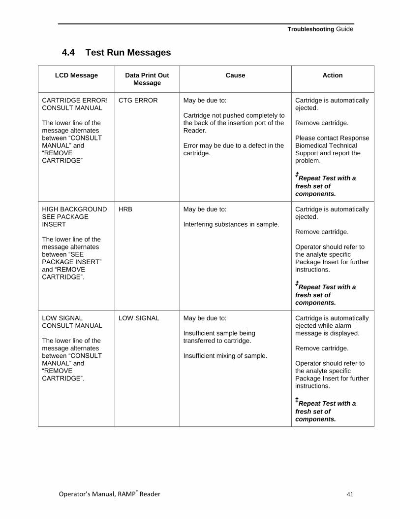
Troubleshooting Guide
Operator’s Manual, RAMP® Reader 41
4.4 Test Run Messages
LCD Message Data Print Out Message
Cause Action
CARTRIDGE ERROR! CONSULT MANUAL The lower line of the message alternates between “CONSULT MANUAL” and “REMOVE CARTRIDGE”
CTG ERROR May be due to: Cartridge not pushed completely to the back of the insertion port of the Reader. Error may be due to a defect in the cartridge.
Cartridge is automatically ejected. Remove cartridge. Please contact Response Biomedical Technical Support and report the problem. ‡Repeat Test with a
fresh set of components.
HIGH BACKGROUND SEE PACKAGE INSERT The lower line of the message alternates between “SEE PACKAGE INSERT” and “REMOVE CARTRIDGE”.
HRB May be due to: Interfering substances in sample.
Cartridge is automatically ejected. Remove cartridge. Operator should refer to the analyte specific Package Insert for further instructions. ‡Repeat Test with a
fresh set of components.
LOW SIGNAL CONSULT MANUAL The lower line of the message alternates between “CONSULT MANUAL” and “REMOVE CARTRIDGE”.
LOW SIGNAL May be due to: Insufficient sample being transferred to cartridge. Insufficient mixing of sample.
Cartridge is automatically ejected while alarm message is displayed. Remove cartridge. Operator should refer to the analyte specific Package Insert for further instructions. ‡Repeat Test with a
fresh set of components.

Troubleshooting Guide
Operator’s Manual, RAMP® Reader 42
LCD Message Data Print Out Message
Cause Action
SAMPLING ERROR #1 SEE INSTRUCTIONS The lower line of the message alternates between “SEE INSTRUCTIONS” and “REMOVE CARTRIDGE”.
SAMP ERROR 1 Sample flow occurred before the cartridge was inserted into the Reader. This may be due to: A delay of more than 30 seconds between sample addition to cartridge and insertion of the cartridge into the Reader (except WNV assay). Insertion of a used cartridge. Re-insertion of a cartridge that has been previously rejected by Reader.
Cartridge is automatically ejected. Remove Cartridge. Operator should refer to the analyte specific Package Insert for further instructions. ‡Repeat Test with fresh
set of components.
SAMPLING ERROR #2 SEE INSTRUCTIONS The lower line of the message alternates between “SEE INSTRUCTIONS” and “REMOVE CARTRIDGE”.
SAMP ERROR 2 Sample flow not detected. This may be due to: Insufficient sample being transferred to the cartridge. A clogged sample pad. Failure to use supplied Assay Tip. Insufficient mixing of sample. Analyte levels significantly higher than the upper reported range.
Cartridge is automatically ejected. Remove cartridge. Operator should refer to the analyte specific Package Insert for further instructions. ‡Repeat Test with a
fresh set of components.

Troubleshooting Guide
Operator’s Manual, RAMP® Reader 43
4.5 General Messages
LCD Message Cause Action
****** ERROR! ****** SERIAL PORT OFF-LINE
Reader attempted to Output Results to printer and either printer was not attached correctly, printer was not turned on, or printer is OFF-LINE.
Screen automatically returns to OPTIONS Menu. Ensure printer is properly connected, turned on and printer is ON-LINE. See printer’s Operator’s Manual for more information. If printer is not connected or turned on, do so and repeat the output request.
NO TEST RESULTS IN MEMORY! PUSH A KEY.
The VIEW RESULTS or OUTPUT RESULTS option is selected and there are no test results stored in the memory.
Press any key and return to Options Menu.
NOTE: XXX TESTS IN MEMORY
480 or more test results are stored in Reader’s memory.
Reader memory capacity is 500 tests. When number of tests exceeds this limit, oldest test is overwritten. If required, print out or download data to prevent loss of data, then erase memory.
REMOVE CARTRIDGE, THEN REPEAT TEST.
Message is displayed (along with a click) after the “TEST IS REJECTED PRESS KEY TO PROCEED” message and any key on the keypad is pressed.
The screen returns to the RUN/OPTIONS Menu. If error persists, contact Technical Support.
‡Repeat Test with a fresh set of
components.
TRANSFERRING DATA PLEASE WAIT
The Reader is transferring data to an external system.
If the Reader is not being used with an external system, disable the CONNECTIVITY option in SYSTEM SETTINGS (see Section 2.6.13).
WARNING LQC DUE! PRESS KEY TO PROCEED
Message is displayed at the VIEW RESULTS option as a sample result is viewed or printed out with sample result at OUTPUT RESULTS. The warning indicates that the sample was run after the LQC Timer had expired.
Run LQC (see Section 2.5.4). Reset LQC Timer (see Section 2.6.10)
If at any time further assistance is required, contact your distributor or Response Biomedical (see Appendix D).

Operator’s Manual, RAMP® Reader 44
5.0 READER SPECIFICATIONS
Dimensions 27 cm wide x 25 cm deep x 15 cm high (10 ½ in wide x 10 in deep x 6 in high)
Weight 2.1 kg (4.6 lbs)
Reader Power Requirements 15 – 18 Vdc, 1A Max
Power Supply Output Power Supply Input Pollution Degree
18 Vdc, 0.84A 100-240 Vac, 47-63 Hz 2
Installation Category II
RAMP® Battery Rechargeable
Internal; not operator serviceable
External Connections RS-232 DB-9 (male), for serial communication Proprietary Mini DIN for barcode wand
Operating Temperature Range 5 – 40°C (41 – 104°F) Note 1
Operating Humidity Range 20 – 80% relative humidity, non-condensing
Storage Humidity Range 20 – 90% relative humidity, non-condensing
Storage Temperature Range -10 - 50ºC (14 - 122ºF)
Operating/Storage Altitude <2000m
Keypad 10 character alphanumeric keys plus 2 special function keys
Display 2 line by 20 character Liquid Crystal Display (LCD)
Complies With IEC 61010-1: 2001 - Safety requirements for electrical equipment for
measurement, control, and laboratory use - Part 1: General requirements IEC61010-2-101-04 - Safety requirements for electrical equipment
for measurement, control and laboratory use Part 2 – 101 : Particular requirements for in vitro diagnostic (IVD) medical equipment – First Edition IEC 60601-1-2: 2001 - Electromagnetic Compatibility Requirements
for Medical Equipment (Emissions Only) CAN/CSA 601.1 FCC CFR47 Part 15/B
Noise Level Does not emit sound level greater than 85 dB when running an assay.
Note 1: Refers to Reader only. Please refer to specific assay temperature specification when running assays.

Operator’s Manual, RAMP® Reader 45
APPENDIX A
Connecting the RAMP® Reader to Accessories
Printer / Computer Connections
The Reader may be connected to an approved IEC 60950-1 printer or computer for transferring data via the RS-232 serial output port on the back panel of the Reader. Output configuration is as follows:
9600 baud
8 data bits
No Parity
1 Stop Bit.
This output is designed to be compatible with small 40 character serial printers such as those available from Citizen (Model: iDP 3110 - Dot Matrix Printer). The serial output is also compatible with some other serial input printers, and computer serial ports.
If connected to a printer, the Reader uses the DTR line (DB9 pin 4) as a handshaking signal. If the connected device is a personal computer, maintain the DTR or RTS line (DB9 pin 7) in the active (logic high) state to receive data from the Reader.
Reader-to-Reader Connections
A Reader-to-Reader cable is required to connect the Reader to another Reader when transferring User IDs and P.I.N.s. This cable can be purchased as an accessory from Response Biomedical.
Barcode Wand Connections
An optional Barcode Wand may be connected to the Reader by plugging the Barcode Wand into the appropriate slot on the back of the Reader (see Figure 1-2).
CAUTION! Ensure the Reader is turned OFF PRIOR to connecting the Barcode Wand. Failure to do so may cause irreversible damage to the Barcode Wand.
WARNING! Connect the RS-232 Port to only approved ITE equipment certified to IEC 60950-1

Operator’s Manual, RAMP® Reader 46
APPENDIX B
Sending Data from the RAMP® Reader to a Computer
For the following operating systems: Windows 98, Windows 2000 & XP.
NOTE: Response Biomedical is providing these directions for assistance only and is not responsible for this software, nor its suitability or function. If there are specific concerns, please consult with Technical Support at 1-866-525-RAMP.
Step 1:
Connect the ‘RS232 port DB-9 Extension Cable F/F’ (purchased from Response Biomedical) to the Reader and to the COM port on the rear panel of the CPU back of a personal computer. (Take note of the COM port # selected since it will be required in a later step.) If using a laptop, there may not be a serial port. In this situation, a USB to RS-232 adapter must be purchased and installed prior to use. This adapter will plug into a USB port on the laptop and allow the RS-232 cable to be plugged in.
NOTE: The COM port # will be COM 3.
NOTE: A new HyperTerminal connection must be created at each upload.
Step 2:
Switch on Reader.
Step 3:
Using the computer mouse, click “Start” at the bottom left hand corner of the screen. Select “Programs” from the menu, then select “Accessories, “Communications” and then the “HyperTerminal” folder (see picture below).

Appendix B
Operator’s Manual, RAMP® Reader 47
Step 4:
Once “HyperTerminal” is selected, a screen as illustrated below will appear. Select “No” with the mouse. If the following screen does not appear, proceed to Step 5.
Step 5:
If the screen illustrated below appears, fill in the boxes with the appropriate information and click “OK”. For example, “What country/region are you in now?”, select the appropriate country from the drop down box and proceed to the next box. If the screen below does not appear, proceed to Step 6.
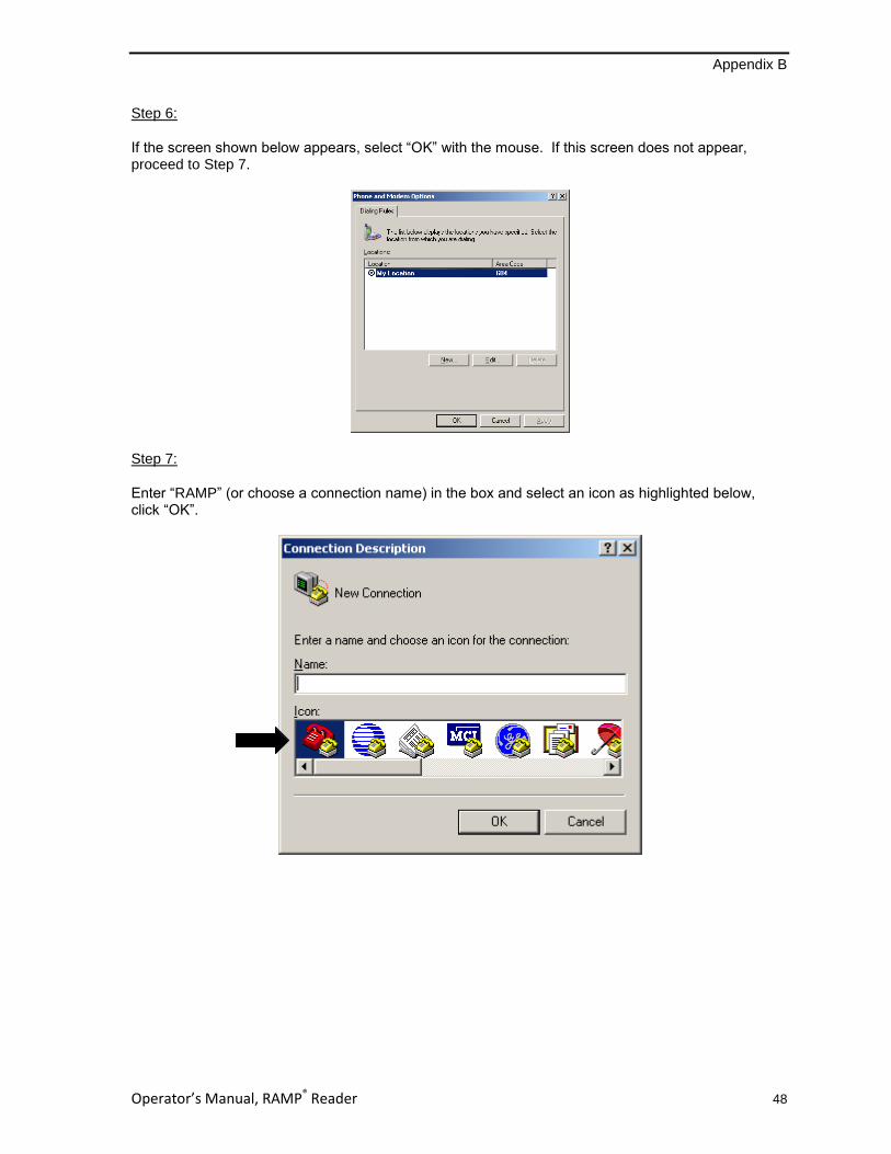
Appendix B
Operator’s Manual, RAMP® Reader 48
Step 6:
If the screen shown below appears, select “OK” with the mouse. If this screen does not appear, proceed to Step 7.
Step 7:
Enter “RAMP” (or choose a connection name) in the box and select an icon as highlighted below, click “OK”.

Appendix B
Operator’s Manual, RAMP® Reader 49
Step 8:
Choose the appropriate COM port below (COM port1 or COM port2, refer to Step 1 where this selection was made or COM port 3 if using a laptop that does not have a serial port). Click “OK”.
Step 9:
The following screen will appear. The five settings need to be changed to those shown below. Click “OK” once the settings are modified.
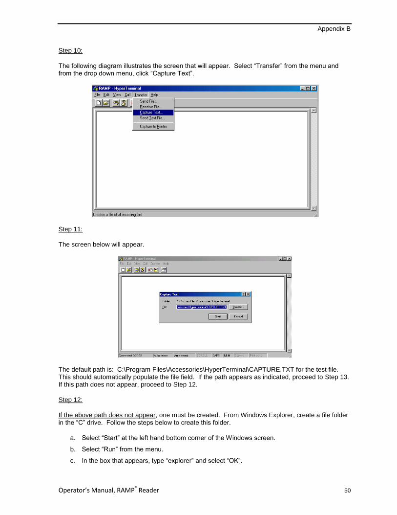
Appendix B
Operator’s Manual, RAMP® Reader 50
Step 10:
The following diagram illustrates the screen that will appear. Select “Transfer” from the menu and from the drop down menu, click “Capture Text”.
Step 11:
The screen below will appear.
The default path is: C:\Program Files\Accessories\HyperTerminal\CAPTURE.TXT for the test file. This should automatically populate the file field. If the path appears as indicated, proceed to Step 13. If this path does not appear, proceed to Step 12.
Step 12:
If the above path does not appear, one must be created. From Windows Explorer, create a file folder in the “C” drive. Follow the steps below to create this folder.
a. Select “Start” at the left hand bottom corner of the Windows screen.
b. Select “Run” from the menu.
c. In the box that appears, type “explorer” and select “OK”.

Appendix B
Operator’s Manual, RAMP® Reader 51
d. From the left-hand column, select “My Computer” by clicking on it once, the menu will expand.
e. Select the “C” drive by clicking on it once.
f. In the right-hand column, all files found in the “C” drive should have appeared. Right-click the mouse in a clear area of the column (not on top of any file names). A menu will appear.
g. From the menu, select “New” with the mouse and select “Folder” from the next menu that appears.
h. A new folder entitled “New Folder” should now appear in the right-hand column. Highlight the new folder by clicking on it once with the mouse. Once highlighted, right-click the mouse and a menu will appear.
i. Select “Rename” from the menu and “New Folder” will be highlighted. Type in the desired name for this folder i.e. RAMP.
Now, return to Step 11 and delete both the path and the text in the box and type in the drive and file name that was created above (i.e.“C:\RAMP\capture.txt”).
Step 13:
Select “Start” and a blank screen will appear as shown below.
Step 14:
From the RAMP Reader Output Options, follow the prompts on the LCD Display to send the data. (See Section 2.5.1 for detailed instructions.)
From the RUN/OPTIONS menu, press [Options] until 1. OUTPUT RESULTS appears.
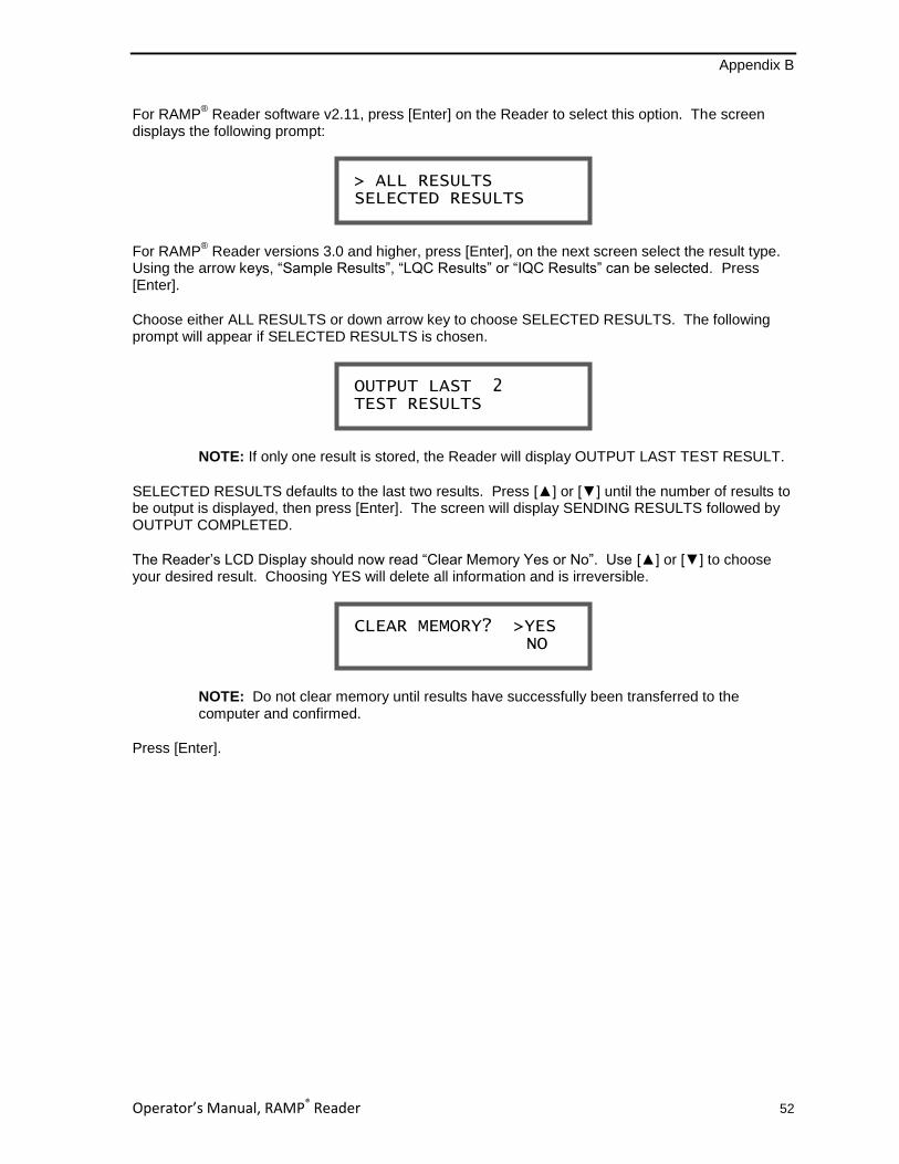
Appendix B
Operator’s Manual, RAMP® Reader 52
For RAMP® Reader software v2.11, press [Enter] on the Reader to select this option. The screen
displays the following prompt:
For RAMP® Reader versions 3.0 and higher, press [Enter], on the next screen select the result type.
Using the arrow keys, “Sample Results”, “LQC Results” or “IQC Results” can be selected. Press [Enter].
Choose either ALL RESULTS or down arrow key to choose SELECTED RESULTS. The following prompt will appear if SELECTED RESULTS is chosen.
NOTE: If only one result is stored, the Reader will display OUTPUT LAST TEST RESULT.
SELECTED RESULTS defaults to the last two results. Press [▲] or [▼] until the number of results to be output is displayed, then press [Enter]. The screen will display SENDING RESULTS followed by OUTPUT COMPLETED.
The Reader’s LCD Display should now read “Clear Memory Yes or No”. Use [▲] or [▼] to choose your desired result. Choosing YES will delete all information and is irreversible.
NOTE: Do not clear memory until results have successfully been transferred to the computer and confirmed.
Press [Enter].
CLEAR MEMORY? >YES NO
OUTPUT LAST 2 TEST RESULTS
> ALL RESULTS SELECTED RESULTS

Appendix B
Operator’s Manual, RAMP® Reader 53
Step 15:
Once the data has transferred as illustrated below, exit from this screen by selecting “File” and “Exit” from the drop down menu or double-clicking on the “X” at the top right of the screen.
After exiting the above screen, another screen may appear (see below). If this screen does appear, click “Yes”.
Step 16:
Import the file into Excel:

Appendix B
Operator’s Manual, RAMP® Reader 54
Open Excel and click “File Open”. Ensure that ‘Files of type’ field at the bottom of the screen has “ALL FILES” highlighted. Find the file named during Step 11, capture.txt. Highlight and click “Open”.
Step 17:
The following screen will appear. Ensure “Delimited’ is selected, click “Finish”.
Print or Save as necessary.

Operator’s Manual, RAMP® Reader 55
APPENDIX C
User Agreement and Warranty
This User Agreement and Warranty (this “Agreement”) is an agreement between you and Response Biomedical Corp.
(“Response”) and governs the purchase and use of your RAMP® Reader System. The RAMP
® Reader System comprises the
RAMP® Reader, the power supply; and optionally includes devices supported by the RAMP
® Reader System such as the
printer and barcode wand. Software Updates (defined below), which are released subsequent to the date of purchase of
RAMP® are not included as part of RAMP
® and are not subject to the terms of this Agreement except as expressly set forth
below. This Agreement sets out Response’s warranty of RAMP®, exclusions and limitations of Response’s liability to you,
provisions governing the recall, and exchange policies for RAMP®, and other important provisions. If you do not agree with any
term of this Agreement, you must not use RAMP®, and may return RAMP
® to the RAMP
® distributor from which you purchased
RAMP® (or to Response if purchased directly from Response) within 30 days of the date of receiving RAMP
® (“Date of
Receipt”). If you use RAMP®, you are deemed to have agreed to the terms of this Agreement.
Return policy
Returns must be marked as RETURN and must include proof of purchase and the bill of lading. Returns must be received by
Response within 30 days of the Date of Receipt. Upon acceptance of the terms of this Agreement, all sales are considered
final.
Receipt of delivery
The entire order is guaranteed to be correct. It is the purchaser’s responsibility to open the package and inspect the items upon
delivery. Packages that appear to be damaged should be immediately reported to the freight carrier. Damage due to shipping is
the sole responsibility of the freight carrier and all claims are to be made by the purchaser directly with the carrier immediately
upon recognizing a problem. Shipping carriers may not honour late claims. Response will not accept Returns or Exchanges
due to shipping damage.
In the case of wrong-shipped items (“Wrong-Shipped Items”), the purchaser should notify the distributor (or to Response if
purchased directly) of the error as soon as possible, but not later than 30 days from the Date of Receipt (the “Exchange
Period”). Exchanges for Wrong-Shipped Items are handled in accordance with the Exchange Policy noted below.
Exchange policy
The Exchange Policy applies only to newly purchased RAMP®, and is in effect for the Exchange Period only. Upon the expiry of
the Exchange Period, the Warranty provisions of this Agreement, if applicable, govern.
All exchanges, whether for defect or otherwise, are to be made through the distributor (or to Response if purchased directly)
where the item was purchased. Response will not accept any exchange claims directly from the purchaser (unless purchased
directly). For purposes of requesting an exchange, the purchaser should contact the local distributor’s Technical Support
Representative (or to Response’s Technical Support if purchased directly) as soon as possible, but not later than 30 days from
the Date of Receipt. All exchange requests should be handled in accordance with this Exchange Policy.
In the case of Wrong-Shipped Items, Response will work with the distributor or purchaser to replace these items with the
proper items, at no charge to the purchaser. In the case of defective items (“Defective Items”), where said defect was NOT
caused by shipping damage, misuse, neglect, unauthorized attempts to open, repair or modify RAMP®, or use of RAMP
® with
accessories or other products that are not authorized by Response, Response will work with the distributor or purchaser to
replace the Defective Item.
Prior to shipping any item for exchange, whether the item is defective or otherwise, the distributor (or purchaser if purchased
directly) must first contact Response to obtain written authorization for the exchange. Response will provide the instructions on
how to ship the return. Response will not accept shipments without a confirmed, written authorization. All the return items
authorized for exchange must be in the original (or equivalent) packaging and in compliance with the freight carrier’s
requirements. Response will pay the shipping charges for the product exchange.
Replaced items will be shipped to the purchaser (or distributor where appropriate) upon receipt and inspection of the Defective
or Wrong-Shipped Items by Response. Replacement of all items remains subject to in-stock availability.
Appendix C
Operator’s Manual, RAMP® Reader 56
Warranty
Response warrants to the original purchaser that RAMP® will be free from defects in material and workmanship on the date of
purchase and substantially conform to the material functional specifications contained in this Owner’s Manual (“Limited
Warranty”) for a period of one (1) year from the date of the original purchase from Response or an authorized distributor
(“Warranty Period”). This Limited Warranty is non-transferable and is conditioned upon observance of the published directions
included in this Owner’s Manual. This Limited Warranty is further conditioned upon observance of directions accompanying the
products specifically designed for use with RAMP® and authorized for use with RAMP
® by Response (including test cartridges,
control cartridges and kits containing same) (the “RAMP® Products”).
This Limited Warranty does not apply if the defect or malfunction in RAMP® was caused by misuse, neglect, unauthorized
attempts to open, repair or modify RAMP®, use of RAMP
® with accessories or other products that are not RAMP
® Products or
any cause other than the intended normal use of RAMP®.
If RAMP® becomes defective during the Warranty Period, and the Exchange Period has expired, the purchaser’s sole and
exclusive remedy, and Response’s sole obligation, will be to repair or replace RAMP®. Repaired or replaced products or parts
may be new or reconditioned, and are subject to this Limited Warranty through the end of the original Warranty Period. Non-
warranty work is charged at the standard repair rate.
To obtain warranty service, the purchaser must contact the distributor (or to Response if purchased directly) during the Warranty Period, provide the distributor (or to Response if purchased directly) with a dated proof of original purchase, and ship RAMP
® to Response in its original (or equivalent) packaging only after receiving an authorization notice in writing from either
Response or the distributor. The purchaser is responsible for shipping costs to Response.
For purchasers with an extended warranty plan (e.g. GOLD plan), the warranty is extended accordingly to the duration of the purchased warranty plan.
Exclusions
TO THE FULL EXTENT ALLOWED BY LAW, THIS LIMITED WARRANTY IS THE PURCHASER’S SOLE AND EXCLUSIVE
REMEDY, AND NO OTHER WARRANTIES, CONDITIONS OR GUARANTEES OF ANY KIND SHALL APPLY, WHETHER
STATUTORY, WRITTEN, ORAL, EXPRESS OR IMPLIED, INCLUDING WITHOUT LIMITATION WARRANTIES, CONDITIONS
OR GUARANTEES OF MERCHANTABILITY, NON-INFRINGEMENT, FITNESS FOR A PARTICULAR PURPOSE,
PERFORMANCE, QUALITY, OR DURABILITY, ALL OF WHICH ARE DISCLAIMED.
Liability Limitations
IN NO EVENT WILL RESPONSE BE LIABLE FOR ANY SPECIAL, EXTRAORDINARY, INDIRECT OR CONSEQUENTIAL
DAMAGES OF ANY KIND WHATSOEVER, INCLUDING WITHOUT LIMITATION DAMAGES FOR LOSS OF DATA, LOST
PROFITS, LOSS OF OPPORTUNITY, PATENT INFRINGEMENT, BUSINESS INTERRUPTION, PERSONAL INJURY OR
DEATH, OR ANY OTHER LOSS ARISING OUT OF, RELATING TO, OR IN CONNECTION WITH RAMP® EVEN IF
RESPONSE IS ADVISED OF THE POSSIBILITY OF SUCH DAMAGES. IF, AS A RESULT OF OR IN CONNECTION WITH,
ANY USE OF RAMP®, WHETHER IN CONJUNCTION WITH RAMP
® PRODUCTS OR OTHERWISE, RESPONSE BECOMES
LIABLE TO THE PURCHASER OR ANY OTHER PERSON FOR ANY DAMAGES, LOSSES, COSTS, EXPENSES, OR
OTHER LIABILITIES WHATSOEVER, AND REGARDLESS OF THE FORM OF ACTION (IN CONTRACT, TORT OR
PURSUANT TO STATUTE), THEN RESPONSE’S AGGREGATE LIABILITY TO ALL SUCH PERSONS WILL BE LIMITED TO
AN AMOUNT EQUAL TO THE PURCHASE PRICE PAID FOR RAMP® AND YOU HEREBY RELEASE RESPONSE FROM
ANY AND ALL OBLIGATIONS, LIABILITIES, CLAIMS OR DEMANDS IN EXCESS OF THIS LIMITATION.
The exclusion of certain conditions and warranties and the limitation of certain liabilities are prohibited in some jurisdictions, so
these limitations and exclusions may not apply to some purchasers.
Recall Policy
Recalls are actions taken by Response to remove certain serial or lot numbers of RAMP® or specific RAMP
® components
(“RAMP® Parts”), from the market. Recalls may be conducted on Response’s own initiative, or by the request of a regulatory
body. Response will inform the distributor or purchaser of the necessary recall information in writing via email or fax. Only lot or
serial numbers of RAMP® or RAMP
® Parts (the “Recalled Product”) that fall within the recall will be included.
The distributor (or purchaser if purchased directly) will take full responsibility for collecting all Recalled Products from their
customers or users and for taking proper actions to discard, destroy, or send the Recalled Products to Response-designated
destinations as instructed.

Appendix C
Operator’s Manual, RAMP® Reader 57
Upon return of the Recalled Product to the distributor (or Response if purchased directly), the purchaser’s sole and exclusive
remedy, and Response’s sole obligation will be to, at Response’s option repair the Recalled Product or replace the Recalled
Product with a an equivalent Response product (if available) of equal or lesser value. Failure to return the Recalled Product
may result in Response, at their sole discretion, deciding not to repair or replace the Recalled Product.
End user license agreement
Subject to the terms and conditions of this Agreement, Response grants to the purchaser a limited, non-exclusive license to
use RAMP® for its intended purpose, and to use the Reader Software solely as preinstalled on the Reader. The Reader
Software is referred to as “Software”. This license may be terminated by Response effective upon notice to the purchaser if the
purchaser fails to pay in full all fees for RAMP®. Response reserves all rights not expressly granted to the purchaser in this
Agreement, including all proprietary rights in and to all designs and other technology and information pertaining to RAMP®.
Response further retains all right, title, and interest, including all intellectual property rights, in and to the Software. The
Software is licensed, not sold, to the purchaser by Response and its suppliers. The purchaser will not have any rights in or to
the Software except as expressly granted in this Agreement. The limited end user license granted hereunder is not transferable
and is limited to the purchaser of RAMP® from Response or its duly authorized distributor, except that this end user license
may be transferred together with the permanent transfer of RAMP® and associated documentation so long as (a) the purchaser
does not retain any copies of the Software, (b) the transferee agrees to be bound by the terms and conditions of this
Agreement, and (c) the purchaser provides Response with written notice of the transfer within thirty (30) days of the transfer
date. Except as expressly provided in this Agreement, the purchaser will have no right to, and specifically agree not to, (i)
disassemble, reverse engineer, decompile, decrypt, or otherwise reduce RAMP® or the Software to a human perceivable form
to gain access to trade secrets or confidential information in RAMP® or the Software (except to the extent that such restrictions
are prohibited by applicable law); (ii) modify or adapt or otherwise make error corrections to RAMP® or the Software or create
derivative works based upon RAMP® or the Software, or permit third parties to do the same; (iii) make or distribute any copies
of RAMP® or the Software; and (iv) use the Reader Software except as embedded or preinstalled on the Reader.
Software Updates
Response may, in its sole discretion, provide replacements, updates, modifications, or bug fixes for the Software to the
purchaser or a transferee (“Software Updates”). Each Software Update is provided “as is” with no warranty of any kind.
Software Updates will be deemed part of the Software solely for purposes of the sections of this Agreement entitled LIABILITY
LIMITATIONS and END USER LICENSE AGREEMENT.
Feedback
Any materials, including but not limited to feedback, comments, suggestions, or identifying potential errors, improvements,
ideas or other information provided by you in the form of email or other submissions to Response (collectively “Feedback”), are
non-confidential and you hereby grant to Response and its subsidiaries and affiliates a nonexclusive, royalty-free, perpetual,
irrevocable, and sublicensable right to use your Feedback for any purpose without compensation or attribution to you.
Governing Law
This Agreement is governed solely by the laws of the Province of British Columbia, Canada and applicable federal laws of
Canada, and expressly excludes the United Nations Convention for the International Sale of Goods, and any rules of private
international law or conflict of laws which would lead to the application of any other laws. Any dispute arising from, connected
with or relating to this Agreement will be resolved by the courts of British Columbia, Canada and the parties hereby irrevocably
submit and attorn to the original and exclusive jurisdiction of those courts in respect to such matters. This Agreement is in the
English language. In the event this Agreement is translated into any other language and any inconsistency or contradiction in
meaning or interpretation results wherefrom, the English language version shall prevail and be controlling as between
Response and the purchaser. This Agreement constitutes the sole and exclusive agreement between the parties regarding
RAMP® and the Software. If any provision of this Agreement is held invalid or unenforceable, the remainder of this Agreement
will continue in full force and effect.

Operator’s Manual, RAMP® Reader 58
APPENDIX D
Contact Information
Response Biomedical Customer Service
1-888-591-5577 (North America only) Tel: +1-604-456-6010 Fax: +1-604-456-6066
Response 24-hour technical support
Toll free: 1 (866) 525-7267 (North America only) Tel: 1 (604) 219-6119 (International) E-mail: [email protected]
Response Biomedical Corporation 1781 75th Avenue West Vancouver, British Columbia Canada V6P 6P2
www.responsebio.com
RAMP® is a Registered Trademark of Response Biomedical Corporation
European Authorized Representative
Emergo Europe Molenstraat 15 2513 BH, The Hague The Netherlands Tel: +31 (0)70 345 8570 Fax: +31 (0)70 346 7299
C1100-1.2 March 2014
Copyright © 2022 FDOKUMEN