OPERATOR'S MANUAL - OAttachments
110
Part number 73391961 2 nd edition English December 2019 Replaces part number 73391590 Hydraulic Breaker OPERATOR’S MANUAL CB20 CB40 CB60 CB61 CB62 CB70 CB80 CB140 CB160 CB200 CB210 CB230 CB260 CB300 CB380 CB400 CB550 CB800
-
Upload
khangminh22 -
Category
Documents
-
view
2 -
download
0
Transcript of OPERATOR'S MANUAL - OAttachments

Part number 733919612nd edition English
December 2019Replaces part number 73391590
Hydraulic Breaker
OPERATOR’S MANUAL
CB20CB40CB60CB61CB62CB70CB80
CB140 CB160CB200CB210CB230CB260CB300CB380CB400CB550CB800

Contents
1 GENERAL INFORMATIONForeword . . . . . . . . . . . . . . . . . . . . . . . . . . . . . . . . . . . . . . . . . . . . . . . . . . . . . . . . . . . . . . . . . . . . . . . . . . . . . . . . . . . 1-1Note to the Owner . . . . . . . . . . . . . . . . . . . . . . . . . . . . . . . . . . . . . . . . . . . . . . . . . . . . . . . . . . . . . . . . . . . . . . . . . . 1-2Product identification . . . . . . . . . . . . . . . . . . . . . . . . . . . . . . . . . . . . . . . . . . . . . . . . . . . . . . . . . . . . . . . . . . . . . . . 1-3Product overview . . . . . . . . . . . . . . . . . . . . . . . . . . . . . . . . . . . . . . . . . . . . . . . . . . . . . . . . . . . . . . . . . . . . . . . . . . . 1-4
2 SAFETY INFORMATIONSAFETY INSTRUCTIONS . . . . . . . . . . . . . . . . . . . . . . . . . . . . . . . . . . . . . . . . . . . . . . . . . . . . . . . . . . . . . . . . . 2-1SAFETY PRECAUTIONS . . . . . . . . . . . . . . . . . . . . . . . . . . . . . . . . . . . . . . . . . . . . . . . . . . . . . . . . . . . . . . . . . . 2-4SAFETY DECALS . . . . . . . . . . . . . . . . . . . . . . . . . . . . . . . . . . . . . . . . . . . . . . . . . . . . . . . . . . . . . . . . . . . . . . . . . . 2-5
3 WORKING OPERATIONSGENERAL INFORMATION
OPERATING GUIDELINE AND SAFETY . . . . . . . . . . . . . . . . . . . . . . . . . . . . . . . . . . . . . . . . . . . . . . 3-1HANDLING THE ATTACHMENT . . . . . . . . . . . . . . . . . . . . . . . . . . . . . . . . . . . . . . . . . . . . . . . . . . . . . . . 3-4CHOICE OF TOOLS . . . . . . . . . . . . . . . . . . . . . . . . . . . . . . . . . . . . . . . . . . . . . . . . . . . . . . . . . . . . . . . . . . . 3-5INSTALLING THE ATTACHMENT . . . . . . . . . . . . . . . . . . . . . . . . . . . . . . . . . . . . . . . . . . . . . . . . . . . . . 3-8USING THE ATTACHMENT. . . . . . . . . . . . . . . . . . . . . . . . . . . . . . . . . . . . . . . . . . . . . . . . . . . . . . . . . . . . 3-9ANTI BLANK FIRING (AUTO-STOP). . . . . . . . . . . . . . . . . . . . . . . . . . . . . . . . . . . . . . . . . . . . . . . . . . 3-28WORKING TEMPERATURE OF BREAKER . . . . . . . . . . . . . . . . . . . . . . . . . . . . . . . . . . . . . . . . . . 3-29REMOVING THE ATTACHMENT . . . . . . . . . . . . . . . . . . . . . . . . . . . . . . . . . . . . . . . . . . . . . . . . . . . . . 3-30INCORRECT USE OF THE ATTACHMENT . . . . . . . . . . . . . . . . . . . . . . . . . . . . . . . . . . . . . . . . . . 3-31REPLACING A TOOL . . . . . . . . . . . . . . . . . . . . . . . . . . . . . . . . . . . . . . . . . . . . . . . . . . . . . . . . . . . . . . . . . 3-33MOVING THE ATTACHMENT. . . . . . . . . . . . . . . . . . . . . . . . . . . . . . . . . . . . . . . . . . . . . . . . . . . . . . . . . 3-36
4 MAINTENANCEGENERAL INFORMATION
GENERAL INSTRUCTION . . . . . . . . . . . . . . . . . . . . . . . . . . . . . . . . . . . . . . . . . . . . . . . . . . . . . . . . . . . . . 4-1
SERVICE INTERVALSEVERY 2 HOURS . . . . . . . . . . . . . . . . . . . . . . . . . . . . . . . . . . . . . . . . . . . . . . . . . . . . . . . . . . . . . . . . . . . . . . 4-2EVERY 10 HOURS OR ONCE A WEEK . . . . . . . . . . . . . . . . . . . . . . . . . . . . . . . . . . . . . . . . . . . . . . . 4-3EVERY 50 HOURS OR ONCE A MONTH . . . . . . . . . . . . . . . . . . . . . . . . . . . . . . . . . . . . . . . . . . . . . 4-4EVERY 500/600 HOURS. . . . . . . . . . . . . . . . . . . . . . . . . . . . . . . . . . . . . . . . . . . . . . . . . . . . . . . . . . . . . . . 4-5MAINTENANCE INTERVAL OF CONSUMABLES AND WEAR PARTS. . . . . . . . . . . . . . . 4-6MAINTENANCE INTERVAL OF SPECIAL APPLICATION BEAKER . . . . . . . . . . . . . . . . . . 4-8
WASHINGWASHING BREAKER . . . . . . . . . . . . . . . . . . . . . . . . . . . . . . . . . . . . . . . . . . . . . . . . . . . . . . . . . . . . . . . . . . 4-9
LUBRICATIONOIL & LUBRICATION. . . . . . . . . . . . . . . . . . . . . . . . . . . . . . . . . . . . . . . . . . . . . . . . . . . . . . . . . . . . . . . . . . . 4-9CORRECT MANUAL GREASING. . . . . . . . . . . . . . . . . . . . . . . . . . . . . . . . . . . . . . . . . . . . . . . . . . . . . 4-10AUTO LUBRICATION SYSTEM (ALS) . . . . . . . . . . . . . . . . . . . . . . . . . . . . . . . . . . . . . . . . . . . . . . . . 4-11

NITROGEN GAS CHARGE FOR BACK HEAD & ACCUMULATORBACK HEAD GAS CHARGING (CB20 ~ CB80) . . . . . . . . . . . . . . . . . . . . . . . . . . . . . . . . . . . . . . 4-14BACK HEAD GAS CHARGING (CB140 ~ CB800). . . . . . . . . . . . . . . . . . . . . . . . . . . . . . . . . . . . 4-17ACCUMULATOR GAS CHARGING (CB61, CB62) . . . . . . . . . . . . . . . . . . . . . . . . . . . . . . . . . . . 4-21ACCUMULATOR GAS CHARGING (CB140, CB800). . . . . . . . . . . . . . . . . . . . . . . . . . . . . . . . . 4-22CONVERSION TABLE FOR BACK HEAD AND ACCUMULATOR GAS PRESSURE 4-26
STORAGEPREPARATION FOR STORAGE. . . . . . . . . . . . . . . . . . . . . . . . . . . . . . . . . . . . . . . . . . . . . . . . . . 4-29REMOVAL FROM STORAGE. . . . . . . . . . . . . . . . . . . . . . . . . . . . . . . . . . . . . . . . . . . . . . . . . . . . . 4-29
5 SPECIFICATIONSWEAR LIMITS . . . . . . . . . . . . . . . . . . . . . . . . . . . . . . . . . . . . . . . . . . . . . . . . . . . . . . . . . . . . . . . . . . . . . . . . . . . . . . 5-1SPECIFICATIONS. . . . . . . . . . . . . . . . . . . . . . . . . . . . . . . . . . . . . . . . . . . . . . . . . . . . . . . . . . . . . . . . . . . . . . . . . 5-12TABLE OF APPLICATIONS . . . . . . . . . . . . . . . . . . . . . . . . . . . . . . . . . . . . . . . . . . . . . . . . . . . . . . . . . . . . . . . 5-16
6 ACCESSORIESUNDERWATER KIT . . . . . . . . . . . . . . . . . . . . . . . . . . . . . . . . . . . . . . . . . . . . . . . . . . . . . . . . . . . . . . . . . . . . . . . . 6-1


1 - GENERAL INFORMATION
1 - GENERAL INFORMATION###_1_###
ForewordThis Breaker Operator’s Manual is intended as a guide and/or instruction for correct use and maintenance of thebreaker, shall be read through very carefully before installation and/or operation of the breaker, or any maintenancework to the breaker. Keep this manual in the carrier cabin so that it is always at hand. Repurchase it if it is lost.
The breaker operator’s manual is written to apply for various markets. Therefore, we ask you to disregard the sectionswhich are not applicable to your breakers and/or carriers.
Many hours are spent on design and production to make breakers that are as efficient and safe as possible. Theaccidents which occur in spite of this, are mostly caused by the human factor. A safety conscious person and wellmaintained breaker and carrier make a safe, efficient and profitable combination. Therefore, read the safety instruc-tions and follow them.
We continually strive to improve our products and to make them more efficient through changes to their design. Weretain the right to make these changes without committing ourselves to introducing these improvements on productswhich have already been delivered. We also retain the right to change data and equipment, as well as instructionsfor service and maintenance measures without prior notice.
Be sure you are thoroughly familiar with the positions and functions of all instruments and controls of the carrier, alongwith the instructions in the Operator’s Manual before using the breaker or before service or maintenance is carriedout.
1-1

1 - GENERAL INFORMATION
Note to the OwnerSpare parts order
When you need parts or some information concerning maintenance of your breaker, contact your local authorizeddealer.
Required information:
• Name of customer and contact person
• Order number (when available)
• Delivery address
• Mode of delivery (air mail, etc.)
• Required delivery date
• Invoicing address
• Model and serial number of breaker
• Name, number and required amount of spare parts
1-2

1 - GENERAL INFORMATION
Product identificationName plateThe breaker information including serial number and keytechnical data is available on the name plate as shown inthe image, for your use to identify the product as well asits key specifications.
Make note of the serial number and quote it when orderingspare parts or consulting technical enquires to the autho-rized dealer.
PTIL19GEN0005AA 1
1-3

1 - GENERAL INFORMATION
Product overview
PTIL19GEN0001FA 1
• The breaker is a hydraulically powered breaker. It can be used on any carrier with correct carrier weight, hydraulicflow and necessary mechanical installation requirements.
• Breaker works by repeatedly raising a steel piston and driving it down onto the head of a removable breaking tool.
• No additional pressure accumulators are necessary for the carrier since the integrated pressure accumulator ab-sorbs hydraulic pressure peaks. The breaker impact energy is almost constant and independent of the carrier’shydraulic system.
Removal from packaging
• Remove all steel belts from the packaging. Open the packaging and remove all plastics covering the product. Scrapsteel belts and plastics.
• Wooden frames and boxes as well as steel bolts and plastics can be recycled.
• Check if the breaker is in good condition and there is no visible damage.
• Check if all ordered parts and accessories have been enclosed with the breaker. Some options may be providedby your local dealer such as installation kits, hoses, breaker bracket, etc.
1-4
1 - GENERAL INFORMATION
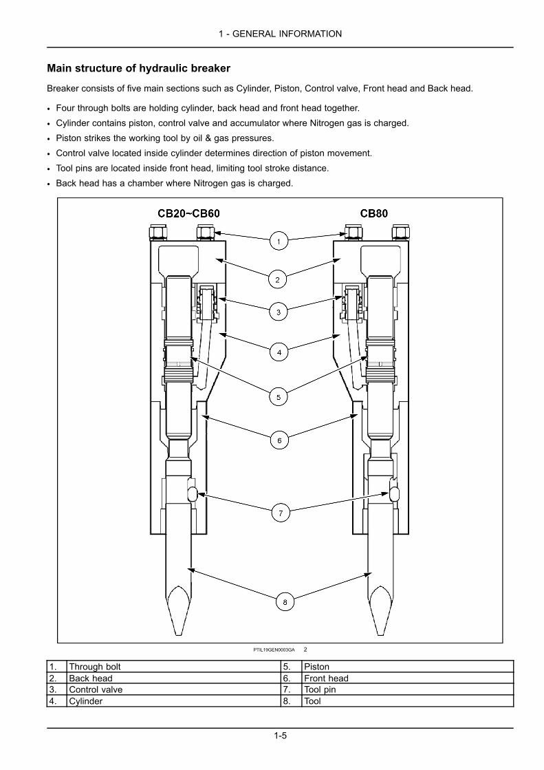
Main structure of hydraulic breaker
Breaker consists of five main sections such as Cylinder, Piston, Control valve, Front head and Back head.
• Four through bolts are holding cylinder, back head and front head together.
• Cylinder contains piston, control valve and accumulator where Nitrogen gas is charged.
• Piston strikes the working tool by oil & gas pressures.
• Control valve located inside cylinder determines direction of piston movement.
• Tool pins are located inside front head, limiting tool stroke distance.
• Back head has a chamber where Nitrogen gas is charged.
PTIL19GEN0003GA 2
1. Through bolt 5. Piston2. Back head 6. Front head3. Control valve 7. Tool pin4. Cylinder 8. Tool
1-5

1 - GENERAL INFORMATION
PTIL19GEN0004GA 3
1. Through bolt 6. Accumulator2. Back head 7. Front head3. Control valve 8. Tool pin4. Cylinder 9. Tool5. Piston
1-6

2 - SAFETY INFORMATION
2 - SAFETY INFORMATION###_2_###
SAFETY INSTRUCTIONSCAUTIONAvoid injury!Follow ALL of the precautions listed below.Failure to comply could result in minor or moderate injury.
C0125A
NOTICE: Read the following warning messages carefully which explain various hazards and how to avoid them.
Introduction
• All mechanical equipment can be hazardous if operated without due care or correct maintenance. Most accidentsinvolving breaker operation and maintenance are caused by failing in observing basic safety rules or precautions.
• The accident can often be avoided by recognizing potentially hazardous situations before it occurs. Since it isimpossible to anticipate every possible circumstance that might involve a potential hazard, the warnings in thisOperator’s Manual and on the breaker are not all inclusive.
• If any procedure, tool, working method or operating technique not specifically recommended by the manufactureris used, you must make sure that it is safe for yourself and others, also ensure that the breaker will not be damagedor handled unsafe by your selected method of operation or maintenance procedures.
• Safety is not just a matter of responding to the warnings. When working with the breaker, always pay attention towhat hazards there might be and how to avoid them. Do not work with the breaker until you are sure that you cancontrol it. Do not start any job until you are sure that you and those around you will be safe.
Operator’s manual
• Read and understand the Operator’s Manual.
• The operator must be thoroughly familiar with how to operate and maintain the breaker and should undergo requiredtraining on the breaker.
• The operator must follow the rules and recommendations given in this Operator’s Manual and the Carrier Operator’sManual, also pay attention to any statutory and national regulations or specific requirements or risks that apply tothe work site.
• If anything is unclear or not understandable on the Operator’s Manual or requires additional explanation, contactyour authorized dealer.
Care and alertness
• When working with the breaker, always be careful and stay alert for hazard. The risks of serious or even fatalaccident increase when you are intoxicated or under the influence of alcohol or drugs.
Clothing
• Suitable clothing for safe handling should be worn.
• Use a hard hat, safety glasses, protective shoes and gloves and an approved respirator (dust mask), also otherprotective items when required.
Training
• You and others can be injured or even killed if you perform unfamiliar operations without practicing them first. Prac-tice away from the work site, in a clear area.
• Keep other persons away. Do not perform any new operations until you are sure you can do them safely.
Communication
• Bad communication can cause accidents. Keep people around you informed of what you will be doing.
2-1

2 - SAFETY INFORMATION
• Work sites can be noisy. Do not rely only on spoken commands. If you intend to work with other persons, makesure they understand all hand signals you will be using.
Work site
• Work site can be hazardous. Inspect the site before working on it.
• Check for potholes, weak ground, hidden rocks, etc. Check for utilities (electric cables, gas, water pipes, etc.).Mark positions of the underground utilities prior to breaking the ground.
Banks and trenches
• Banked material and trenches can collapse. Do not work too close to banks and trenches where there is a dangerof collapse.
Safety barriers
• Unguarded breaker and carrier in public places can be dangerous. Place barriers around the breaker and carrierto keep people away.
Flying chips of rock
• Protect yourself and your neighborhood against flying chips of rock. Do not operate the breaker if someone is tooclose.
• Operating the breaker from canopy can be dangerous to the operator. Operate the breaker only with a carrier whereclosed type cabin is mounted, only when its windows and its doors are in fully closed condition.
• Fitting a screen structure on the carrier cabin window is highly recommended. No screen can be led to damage tothe cabin and its window and also injury or even fatal accident to the operator.
Equipment limits
• Operating the breaker beyond its design limits can cause damage. Always operate the breaker within its specifica-tion, shown at the Specification Section of this Operator’s Manual.
• Do not try to enhance the breaker performance with any modification not approved by the manufacturer or beyondthe breaker specifications.
Oil at high pressureCAUTIONEscaping fluid!Hydraulic fluid or diesel fuel leaking underpressure can penetrate the skin and causeinfection or other injury. To prevent personalinjury: Relieve all pressure before discon-necting fluid lines or performing work on thehydraulic system. Before applying pressure,make sure all connections are tight and allcomponents are in good condition. Never useyour hand to check for suspected leaks underpressure. Use a piece of cardboard or woodfor this purpose. If injured by leaking fluid,see your doctor immediately.Failure to comply could result in minor ormoderate injury.
C0104A
PTIL19GEN0006AA 1
• Hydraulic oil at system pressure can be dangerous. Before disconnecting or connecting hydraulic hoses, turn offthe engine, operate the controls to release pressure trapped in the hoses and wait 10 minutes. While operating,keep persons away from the hydraulic hoses.
2-2
2 - SAFETY INFORMATION
• Fine jets of hydraulic oil at high pressure can penetrate the skin. Do not use your fingers to check for hydraulic oilleaks. Do not put your face close to suspected leaks. Hold a piece of cardboard close to suspected leaks and theninspect the cardboard for signs of hydraulic oil. If hydraulic oil has penetrated your skin, seek medical treatmentimmediately.
• There might be pressurized oil trapped inside the breaker even if it is disconnected from the carrier. Be aware ofpossible blank firing while greasing or removing/installing working tool.
Pressure accumulator
• The breaker incorporates pressure accumulator. The accumulator is pressurized even after hydraulic pressure hasbeen released from the breaker. Attempting to remove or dismantle the accumulator without first releasing thepressure can cause severe injury or death. Do not try to dismantle pressure accumulator, contact your authorizeddealer.
Lifting equipment
• You can be injured if you use faulty lifting equipment. Make sure that lifting equipment is in good condition. Makesure that lifting tackle complies with all local regulations and is suitable for the job. Make sure that lifting equipmentis strong enough for the job and you know how to use it.
• Do not use the breaker or any of its parts for lifting other material. Contact your authorized dealer and find out howto do lifting work in proper way.
• Never leave the breaker in lifted condition, with any other lifted load and/or unattended.
• See 3-4
Spare parts
• Use only genuine spare parts including working tools of the breaker manufacturer.
• The use of non-genuine/counterfeit parts or tools may damage the breaker and will void warranty for the breaker.
Breaker and/or Carrier condition
• Defective breaker and/or carrier can cause severe injuries to you and others. Do not operate the breaker whichhas defective or missing parts.
• Make sure the maintenance procedures in this manual are completed before using the breaker.
Repair and maintenance
• Do not try to do any repair or maintenance work you do not understand.
Modification and welding
• Non approved modifications can cause injury and/or damage. Consult with your authorized dealer before modifyingthe breaker. Do not attempt to weld the breaker. If in doubt, contact your authorized dealer. Note that welding ofbreaker tools will render them useless and void the warranty.
Metal splinters
• You can be injured by flying splinters during maintenance and/or repair of the breaker.
• Always wear safety glasses.
2-3

2 - SAFETY INFORMATION
SAFETY PRECAUTIONS
WARNING!
The symbol above appears at various points in the manual together with a warning text. It means: Warning, be alert!Your safety is involved! It is the obligation of the operator to make sure that all warning decals are in place on thebreaker and that they are readable. Accidents may otherwise occur.
NOTICE: Do not operate the breaker and do not carry out any maintenance until you thoroughly study and understandthe contents of this Breaker Operator’s Manual.
Installation inspection
An installation inspection must be carried out after the breaker has been installed on the carrier. During the installationinspection certain specifications (port relief valve pressure, working pressure, oil flow, etc.) must be checked so thatthey are within given limits. Contact your authorized dealer.
2-4

2 - SAFETY INFORMATION
SAFETY DECALS• Warning decals are on various places of the breaker.
• The operator should pay attention to the warning decals and ensure use, maintenance and service of the breakerto be carried out accordingly, see reference information below.
• The warning decals should be cleaned and legible.
• Any missing, illegible or damaged decals should be replaced by the operator.
• When any part where the decal is positioned is replaced the decal must also be replaced by the operator.
Sign Image Content ReferenceHead wearing ear protection Must wear ear protection
Operator’s Manual Service Manual Consult manual for proper use,maintenance and service procedures.
Working breaker with diagonal slash Keep away from breaking area whilethe breaker is working.
Grease gun Inject grease into grease nipple withgrease gun periodically.
Accumulator Back head “HIGH PRESSURE” Discharge priorto disassembly
High temperature Keep away as the breaker is so“HOT”
2-5

2 - SAFETY INFORMATION
2-6

3 - WORKING OPERATIONS
3 - WORKING OPERATIONS###_6_###GENERAL INFORMATION
OPERATING GUIDELINE AND SAFETYSafety first
• When leaving the carrier, lower the breaker to the ground and turn engine off.
• Never attach any cable or sling to the breaker to hoist a load. Extremely dangerous!
• Remove working tool prior to transporting the breaker.
• Keep all the people and equipment away from the breaker when operating. Rock chips flying from the breaker cancause serious injury and accident.
• A safety screen is recommended to protect the operator from flying chips of rock. Keep windows and doors closedbefore operating.
• Only carriers with closed cabin equipped should be used for breaker operation. Carriers with open canopy shouldnot be used with breaker.
• Do not use the breaker to sweep rock borders and debris on the ground. It can cause damage to the breaker andexcessive wearing of the housing.
Inspection prior to operating the breaker
• Check if the breaker is filled with a sufficient amount of hydraulic oil.
• Check if hydraulic oil is kept away from contamination.
• Check if all hoses and fasteners are securely fitted and tightened.
• Apply a sufficient amount of grease on the shank area of working tool.
3-1

3 - WORKING OPERATIONS
Assemble and disassemble the breaker to / from the carrier
PTIL19GEN0013FA 1
• When installing or removing the breaker, the assistant is required. The assistant must be instructed by the operator.
• All directions, signals etc. must be agreed on beforehand between the operator and the assistant.
• The breaker should only be installed to the carrier of sufficient load capacity. Too light carrier can become unstableand fall over.
• Do not touch any part of the breaker as well as the carrier when the carrier is moving such as boom, arm, etc.
• Check the port relief valve setting pressure of the carrier.
• Check if breaker pipe lines are correctly connected from the carrier to the breaker.
• Do not install any breaker pipe lines and hoses that are not approved. Contact your authorized dealer, if required.
• Never touch the breaker when operating. The breaker hydraulic oil can become very hot.
• Never use your fingers to check bore alignment.
• If the breaker is connected to a quick coupler (or attachment bracket), the operator must take special care to ensurethat the quick coupler (or attachment bracket) does not sustain any damage and/or accident.
3-2

3 - WORKING OPERATIONS
Equipment limits
• Keep the people away from risk zone when operating the breaker. The operator is responsible to determine therisk zone. The operator must ensure the people to stay outside the risk zone.
• If the noise level exceeds 90 dB (A), all workers including the operator in the immediate area must wear ear pro-tection.
• Stop breaking immediately if any one moves into the risk zone, which is much larger for breaker operation thanexcavator operation due to the risk of flying rock splinters.
• Only approved hydraulic oil should be used.
• Do not operate the breaker with carrier’s hydraulic cylinders fully extended or fully retracted. Damage may occurto the carrier.
• When operating the breaker, make sure it does not interfere with the carrier or the hydraulic hoses.
• Do not push the breaker with too much or too little force.Too much: Carrier stabilizer leg feet or tracks are completely lifted from the ground.Too little: Tool does not stay firmly against the material to be broken and carrier starts to shake.
• Keep the tool perpendicular to the material at all times. If the material moves or its surface breaks, adjust the angleimmediately.
• Do not let the tool move outwards from the breaker without resistance when it penetrates the material. Keep thecarrier pushing force on the breaker steady and aligned with the tool while breaking.
• Do not continuously strike for more than 15 s.• Do not break a same spot of the material for more than 30 s. If the material is not broken or the tool does notpenetrate the material, stop breaking and change the position of breaking. Working too long in one spot will makedebris and dust piled under the tool, causing working tool to be heated and debris and dust to dampen strikingimpact energy.
• When the material is fully broken, stop breaking immediately. Do not allow the breaker to blank-fire. Frequent idlestrokes (blank fire) will damage the breaker.
• To use the breaker most efficiently, concentrate on small steps from the outer edge of the material andmove towardsthe center of the material.
• When breaking hard or frozen ground, use benching method. Start with clearing a small area from the edge, thencontinue to break the material towards the open area.
• When breaking the material never do leverage with tool. The tool may crack.
3-3

3 - WORKING OPERATIONS
HANDLING THE ATTACHMENTKey points when using toolsNOTICE: Pay attention for your body not to be hit by the tool. Pay attention for your body not to be squeezed betweenthe tool and other material.
Follow below instructions. Lack of respect to these instructions will be led to crack or other failures of tools andholding bushes.
• Do not lift, twist or hit.
• Do not leave in the rain or other wet conditions.
• Do not leave the tool heated.
• Do not leave the tool un-greased.
Lifting instructionsNOTICE: Ensure that no persons are near the breaker when it is lifted. If the breaker falls down there is a risk ofpersonal injuries.
• Use a hoist when lifting breaker or component parts, toavoid back injury.
• Make sure all chains, hooks, slings, etc., are in goodcondition and of correct capacity. Be sure that hooksare positioned correctly.
• Lifting devices must safely carry working weight of thebreaker, see 5-12. Place chains or slings, as shown inthe illustration, prior to lifting breaker.
• Always check balance of the breaker by lifting it grad-ually. If the breaker is well balanced, it may be liftedhigher.
PTIL19GEN0002AA 1
Lifting eyes and lifting eye boltsNOTICE: Ensure that lifting eye bolts are fully tightened to the housing before using them for lifting. If any lifting eyebolt is not properly tightened it may break. If the breaker falls down there is a risk of personal injuries.
• Lifting eyes on the breaker housing are only intended for handling the breaker.
• The breaker or its parts must not be used for lifting other products.
NOTE: Always remove lifting eye bolts and replace them with blanking screws before operating the breaker.
• Follow the safety instructions for lifting the breaker, see 2-1.
3-4

3 - WORKING OPERATIONS
CHOICE OF TOOLSRecommended application & breaker selection
• The breaker is designed to be used for breaking hard and soft rock, concrete, road surface or asphalt, hard orfrozen ground.
• It is suitable for applications such as primary rock breaking, secondary rock breaking, hard and soft rock removal,trenching, benching, ground compacting, etc.
Breaker selectionDescription CB20 CB40 CB60 CB61 CB62 CB70 CB80 CB140 CB160
Primary breakingSecondarybreakingHard rock removal X XSoft material androck removal X X X X X X X X X
Demolition X X X X X X X X X
Breaker selectionDescription CB200 CB210 CB230 CB260 CB300 CB380 CB400 CB550 CB800
Primary breaking X X X XSecondarybreaking X X X X X X X X
Hard rock removal X X X X X X X XSoft material androck removalDemolition X X X X
NOTE: Above breaker selection guideline was made upon global breaker use. It may not match with local specificrequirement of your market. Therefore consult with your authorized dealer before selecting breaker.
Principles of breaking
• To increase breaker working life, pay special attention to use correct working methods and to choose correct toolfor the job.
• There are essentially two ways of breaking with a hydraulic breaker.
Penetrative breaking (cutting)• In this form of breaking, a tool such as moil point orchisel is forced into the material. This method is veryeffective in soft, layered or plastic, low abrasive materi-als.
PTIL19GEN0007FA 1
3-5
3 - WORKING OPERATIONS
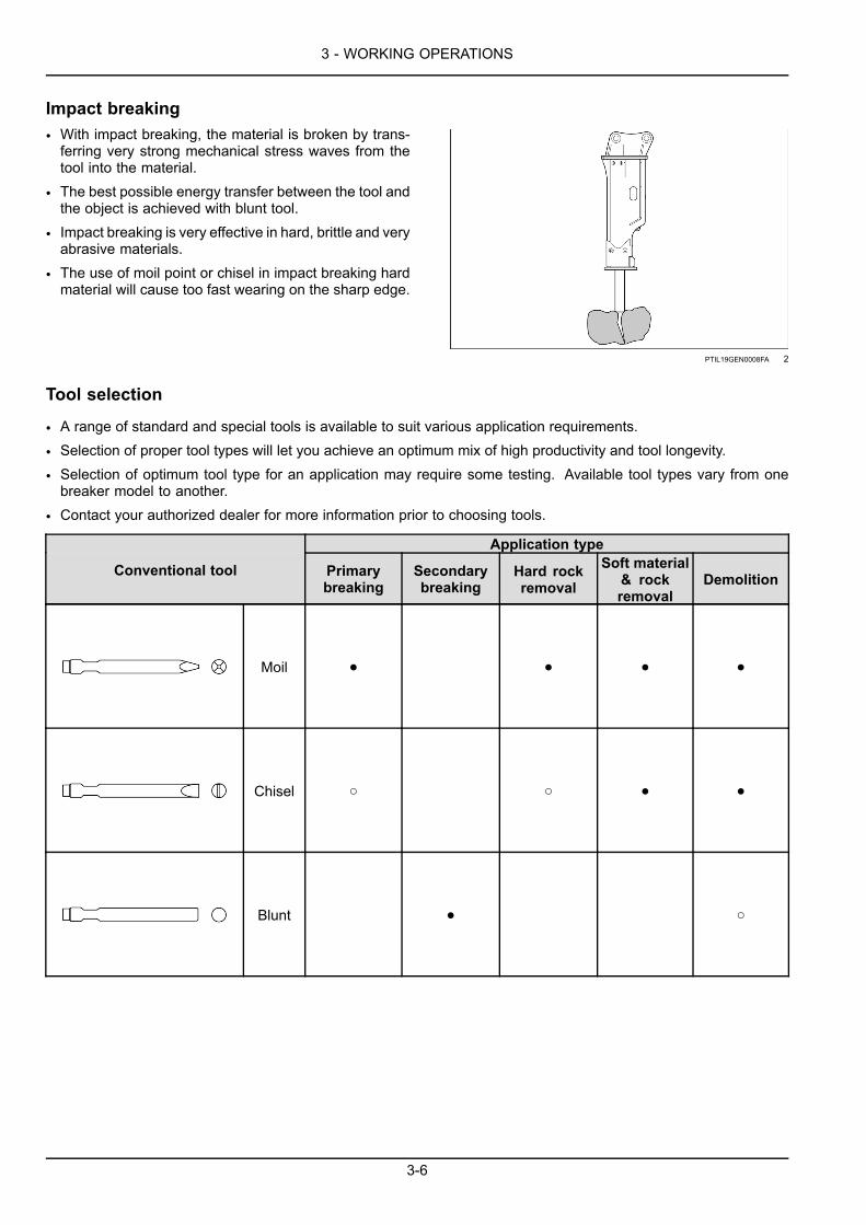
Impact breaking• With impact breaking, the material is broken by trans-ferring very strong mechanical stress waves from thetool into the material.
• The best possible energy transfer between the tool andthe object is achieved with blunt tool.
• Impact breaking is very effective in hard, brittle and veryabrasive materials.
• The use of moil point or chisel in impact breaking hardmaterial will cause too fast wearing on the sharp edge.
PTIL19GEN0008FA 2
Tool selection
• A range of standard and special tools is available to suit various application requirements.
• Selection of proper tool types will let you achieve an optimum mix of high productivity and tool longevity.
• Selection of optimum tool type for an application may require some testing. Available tool types vary from onebreaker model to another.
• Contact your authorized dealer for more information prior to choosing tools.
Application type
Conventional tool Primarybreaking
Secondarybreaking
Hard rockremoval
Soft material& rockremoval
Demolition
Moil ● ● ● ●
Chisel ○ ○ ● ●
Blunt ● ○
3-6
3 - WORKING OPERATIONS
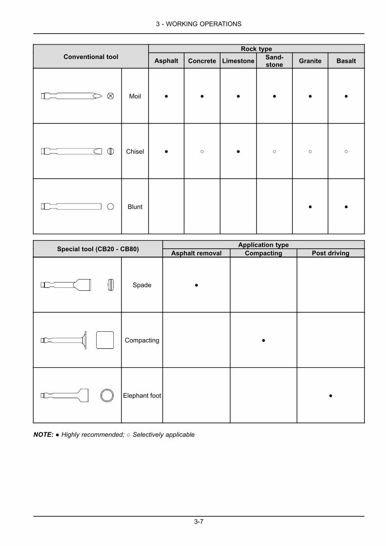
Rock typeConventional tool Asphalt Concrete Limestone Sand-
stone Granite Basalt
Moil ● ● ● ● ● ●
Chisel ● ○ ● ○ ○ ○
Blunt ● ●
Application typeSpecial tool (CB20 - CB80) Asphalt removal Compacting Post driving
Spade ●
Compacting ●
Elephant foot ●
NOTE: ● Highly recommended; ○ Selectively applicable
3-7

3 - WORKING OPERATIONS
INSTALLING THE ATTACHMENTPrinciple of installation
The breaker is installed on the carrier in a similar manner as installing a bucket or other attachments.
• The breaker is connected to the hydraulic system of the carrier through a breaker circuit.
• If the carrier is already equipped with such a circuit, only suitable hoses and fittings are required.
• If the carrier does not have a suitable circuit for running the breaker, the circuit must be ordered from a CNHiauthorized dealer.
• This may require more complex installation, including new piping and additional valves such as directional valveand pressure relief valve.
Breaker installation
PTIL19GEN0035EA 1
PTIL19GEN0036EA 2
Stop valve opening and closing
• Fit the breaker and breaker bracket in the carrier.
• Remove seal from hoses and plugs from stop valves.
• Install hydraulic hoses from the breaker with carrier piping stop valve.
• Open carrier piping stop valve.
3-8

3 - WORKING OPERATIONS
USING THE ATTACHMENTWork mode selection
Breaker work mode (Power mode or Speed mode) is selectable at the models of CB80 and above.
Mode recommendation
• Speed mode
○ Applications that require productivity from high speed breaking.
○ Soft material breaking such as light/medium duty limestone, soft duty granite, concrete structure, asphalt, etc.
• Power mode
○ Applications that require productivity from power breaking.
○ Hard material breaking such as heavy duty limestone/sand stone, granite, basalt, andesite, iron ore, etc.
Power mode or speed mode can be selected by followingprocedure.
• Remove MC Cover.
• Loosen adjuster valve nut until you can start to turn ad-juster valve.
• Turn adjuster valve with 5mm L-wrench (1) (availablein the tool box)
○ Power mode: turn to the right, clockwise to maximum(till fully tightened).
○ Speed mode: turn to the left, counter clockwise by 2turns.
NOTE: Power mode is pre-set when the breaker comesoff the factory.
• After setting, tighten adjuster valve nut (2) completely.
PTIL19GEN0012GB 1
Operating
When operating, the operator should pay attention to the following points. First of all, precautionary measures shouldbe taken to rule out the risks of accident.
• Operate the breaker only from the cabin inside the carrier.
• Close the cabin front screen or splinter guard to avoid injury from flying rock splinters.
• Wear ear protection to prevent hearing ability impairment. Anyone in the immediate vicinity of breaker operationsshould also wear ear protection.
• Switch breaker off immediately if any one moves into the risk zone.
3-9

3 - WORKING OPERATIONS
Proper way of operation
Proper thrust
PTIL19GEN0014GA 2
• To break effectively, a proper thrust force has to be applied to the breaker.
• If a thrust is insufficient, breaker impact energy may not be sufficient enough for breaking material.
• Then the breaking force may be transferred to breaker body, arm and boom of the carrier, etc. and cause damageto those parts.
3-10

3 - WORKING OPERATIONS
PTIL19GEN0015FA 3
• On the contrary, if a thrust is excessive or if breaking is performed with carrier’s tracks completely lifted, the carriermay suddenly tilt toward the movement.
• When the material is broken, the breaker body may violently hit against material and cause damage on the breaker.
3-11

3 - WORKING OPERATIONS
PTIL19GEN0016FA 4
• If breaker operation is carried out under such a condition, vibrations may also be transferred to the carrier.
• Therefore breaking in such a manner should be avoided for protection of the carrier as well.
• Therefore during breaking, always ensure to apply a proper level of thrust to the breaker. Do not break withoutproperly applied thrust.
3-12
3 - WORKING OPERATIONS
Direction of thrust
PTIL19GEN0017FA 5
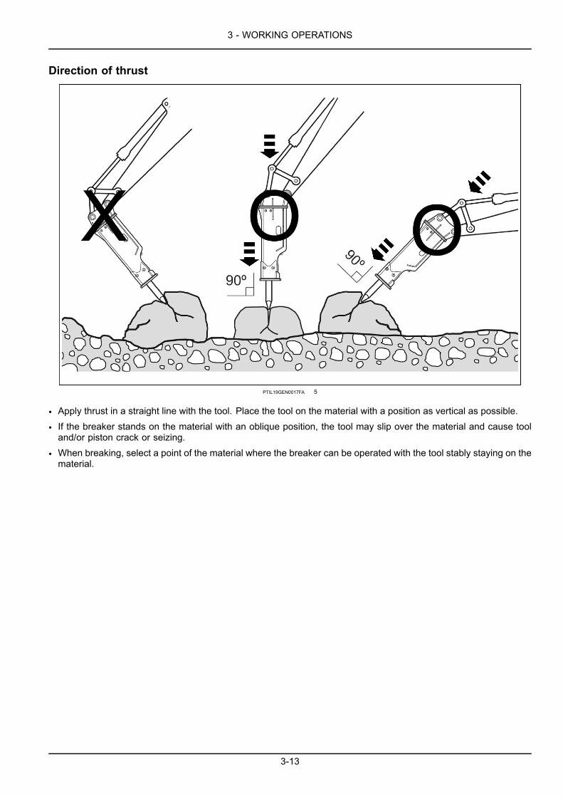
• Apply thrust in a straight line with the tool. Place the tool on the material with a position as vertical as possible.
• If the breaker stands on the material with an oblique position, the tool may slip over the material and cause tooland/or piston crack or seizing.
• When breaking, select a point of the material where the breaker can be operated with the tool stably staying on thematerial.
3-13

3 - WORKING OPERATIONS
Stop breaker operation as soon as the hoses vibrate excessively
PTIL19GEN0018FA 6
• Check if high and low pressure hoses vibrate excessively.
• If that, accumulator may not be working properly.
• Contact your authorized dealer and get it repaired. Check hose fitting points.
• If oil leaks, retighten or if necessary replace them. Check if tool is moving up and down during operation as illus-trated below.
• If not, tool may be seized. Disassemble front head and repair or if necessary replace defective parts.
Stop when the material is broken (avoid idle breaking to the utmost)
• As soon as material is broken, stop breaking and prevent idle breaking.
• If idle breaking continues, it can cause accumulator damage and bolt loosening or crack.
• It also can affect the carrier adversely.
• When a proper thrust is not applied or the tool is used like a lever during the operation, idle breaking will occur.
• In idle breaking, breaker striking generates abnormal sound like metal to metal hitting.
3-14
3 - WORKING OPERATIONS
Never use to move the material
PTIL19GEN0019FA 7
PTIL19GEN0020FA 8
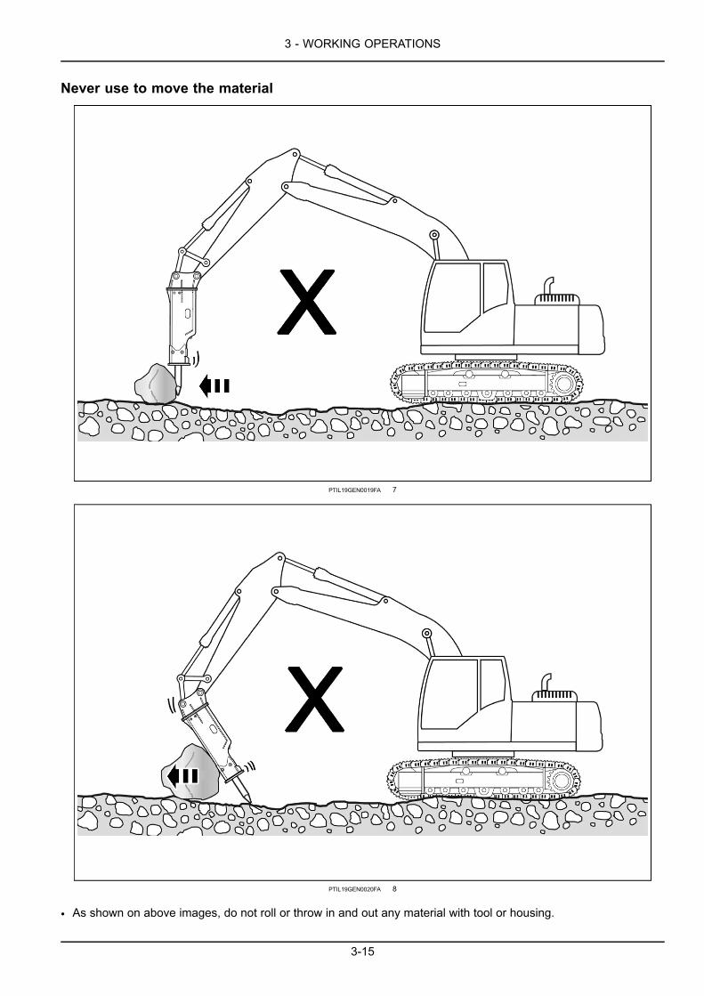
• As shown on above images, do not roll or throw in and out any material with tool or housing.
3-15

3 - WORKING OPERATIONS
• It can cause damage such as crack, deformation, abnormal wearing, etc. on bolt, housing and tool crack (orscuffed).
• It can also damage carrier boom & arm. Never move the material with breaker.
• Particularly never let the carrier travel with tool inside the material.
Never lever with the breaker
PTIL19GEN0021GA 9
Never attempt to use the breaker like a crowbar. It will cause tool crack.
3-16

3 - WORKING OPERATIONS
No breaking longer than 15 seconds continuously Never break a same spot for longer than30 seconds
PTIL19GEN0022FA 10
• When rocks are hardened, each breaking requires a longer time. However do not break a same spot for longerthan 30 seconds.
• Change the breaking spot. If not, oil temperature can increase, causing accumulator damage and excessive toolwearing.
Start at an edge in case of hard and large size rock
Start of breaking at a crack or edge area will enable hard and large size rock to be easily broken. Advancing by smallstep is more effective than large step.
3-17
3 - WORKING OPERATIONS
Use of proper engine speed
PTIL19GEN0023FA 11
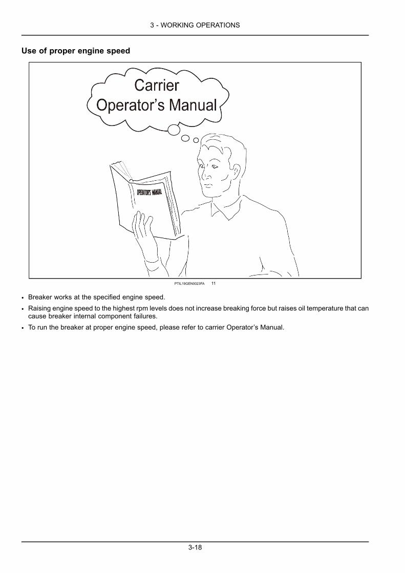
• Breaker works at the specified engine speed.
• Raising engine speed to the highest rpm levels does not increase breaking force but raises oil temperature that cancause breaker internal component failures.
• To run the breaker at proper engine speed, please refer to carrier Operator’s Manual.
3-18

3 - WORKING OPERATIONS
Never use at underwater or muddy applications without prior conversion
PTIL19GEN0024FA 12
• If water enter the percussion chamber, breaker blows may generate pressure waves that may cause irreparabledamage to cylinder, piston and front head of the breaker.
• In addition lower percussion piston zone may get rust. Water could also get into carrier hydraulic system.
• In order to avoid damage to the breaker, contact your authorized dealer and use a kit dedicated for underwaterapplication.
3-19

3 - WORKING OPERATIONS
Never use breaker like a sledge
PTIL19GEN0025FA 13
• Before starting up, rest the breaker on the ground.
• Never attempt to use the breaker and the carrier boom like a sledge when breaking the material.
• It will damage parts of the carrier.
3-20

3 - WORKING OPERATIONS
Never break with the cylinders at fully extended position
PTIL19GEN0026GA 14
• The carrier cylinders may be easily damaged when the breaker works with their fully stretched position to the end.
3-21

3 - WORKING OPERATIONS
Never use for transport or lifting purpose
PTIL19GEN0027FA 15
PTIL19GEN0028FA 16
• The breaker is not designed for lifting or transporting work.
3-22

3 - WORKING OPERATIONS
• It can be easily damaged if used for lifting or transporting material purpose.
• Furthermore it is very dangerous, incurring serious accidents.
How to operate breaker in secondary rock breaking applications
PTIL19GEN0029FA 17
• Tool pins can be easily cracked or damaged in secondary rock breaking quarry applications.
• Typical root cause is that tool hits tool pin repeatedly during the breaker operation.
• Follow below instruction for correct breaker operation.
Regulate operating pedal or switch to limit number of blows per breaking. This is important!
(A) - Rock size 30 cm, 1 blow(B) - Rock size 50 cm, 2 blows(C) - Rock size 100 cm, 3 - 5 blows
3-23

3 - WORKING OPERATIONS
PTIL19GEN0030FA 18
• In case the rock is unstable or slippery, blank firing can occur (tool hits tool pin with high impact power when thebreaker slips down off the rock).
• Ensure that you avoid blank firing by proper positioning of the breaker.
3-24

3 - WORKING OPERATIONS
PTIL19GEN0031FA 19
• Use blunt (flat end point) tool.
• A - Blunt
• B - Moil
• C - Chisel
3-25

3 - WORKING OPERATIONS
PTIL19GEN0032FA 20
• Do not lift up carrier tracks.
• Slow down breaker BPM (striking frequency) to 70% of conventional application BPM.
• In case you follow the aforesaid instruction, you willachieve a longer tool pin life as the risks of tool pin crackand excessive wearing can be reduced drastically.
• It will also increase housing service life by slowing downhousing bottom area wearing.
PTIL19GEN0033FA 21
3-26

3 - WORKING OPERATIONS
NOTICE: Lack of respect to the aforesaid instructions cancause failure to tool pin and also consequential failure tofront head at relatively early hours, which will not be sup-ported by manufacturer’s warranty.
However 5~10 blows per breaking may also be requiredwhen breaking large size rock boulders (larger than 1 m).
1. Tool pin damage 4. Tool2. Piston 5. Housing damage3. Tool pin
PTIL19GEN0034GA 22
Breaker use in special applicationsNOTICE: The breaker must not be used under water unless proper preparation kit is equipped with. If water enterthe percussion chamber, strong pressure waves are generated and damaging the breaker. Operating breaker at thespecial applications must be carried out with a proper preparation kit and/or special wear parts under full responsibilityof the operator, will not be supported by the warranty of breaker manufacturer.
If the breaker is to be used in the special applications such as,
1. tunnel application2. foundry cleaning application3. underwater application4. extremely low or high temperature application5. use of special hydraulic oils6. other special conditions
It may require modifications, special operating techniques, increased maintenance and/or special wear items. Youmust contact your authorized dealer for proper instructions.
3-27

3 - WORKING OPERATIONS
ANTI BLANK FIRING (AUTO-STOP)• Blank firing occurs when the operator keeps pressing breaker pedal switch even after breaking material is com-pletely broken. Then 3~5 times of surplus hitting by accumulated oil flow is conveyed directly to through bolts, toolpin and other parts where damage can occur.
• Anti blank firing system was designed to stop breaker operation after only one extra blow if the material is fullybroken, has proved its efficiency as well as durability and liability in actual operations at the job sites.
• However in case of secondary rock breaking application where the material sizes are small, the materials arebroken by 1~2 blows and then the breaker fires blanks. Therefore operator has to be extremely careful and followbelow instructions to prevent premature and unnecessary tool failure.
○ Use blunt tool
○ Operator must stop striking immediately after the material is broken.
3-28

3 - WORKING OPERATIONS
WORKING TEMPERATURE OF BREAKEROperating oil temperature
• Breaker operating oil temperature range is 40 – 80 °C (104 – 176 °F).• If oil temperature is below the range, ensure that the carrier oil is warmed up to minimum of operating oil temperaturerange prior to any operations.
• Ensure that the oil will have to remain warm during operation.
• If oil temperature is above the range, ensure that the carrier is equipped with additional oil cooling system so thatthe temperature can stay within the range.
NOTE: The temperature of the hydraulic oil must be monitored periodically. Ensure that the combination of oil gradeand oil temperature will guarantee correct oil viscosity.
Working in high temperature conditions
• Hydraulic oil temperature must not exceed 80 °C . Check the oil temperature in the oil tank constantly.
• If it is higher than 80 °C, carrier oil cooling function must be enhanced enough to lower it under 80 °C.• Use hydraulic oils of sufficient viscosity only. In summer and tropical climates, hydraulic oil type ISO VG-68 HV isthe minimum requirement. Refer 4-9.
Working in low temperature conditions
• Prior to breaker operation, increase oil temperature above 40 °C by carrier engine warming up, boom/arm moving,swing, traveling, etc.
NOTE: The breaker is not running to full capacity until the oil temperature has reached 60 °C at least.
NOTICE: Under the cold climate condition like winter if the breaker operates with low oil temperature, seals as wellas piston and diaphragm can be damaged.
3-29
3 - WORKING OPERATIONS
REMOVING THE ATTACHMENT
PTIL19GEN0035EA 1
PTIL19GEN0036EA 2
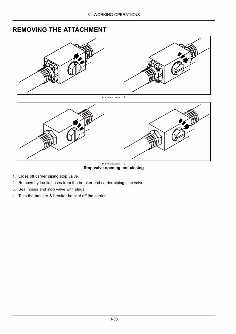
Stop valve opening and closing
1. Close off carrier piping stop valve.2. Remove hydraulic hoses from the breaker and carrier piping stop valve.3. Seal hoses and stop valve with plugs.4. Take the breaker & breaker bracket off the carrier.
3-30

3 - WORKING OPERATIONS
INCORRECT USE OF THE ATTACHMENTCause of tool failure
Bending by high pressure• Accumulated side force from repeated tool leverageworking, such as but not limited to incorrect breakerstriking angle, pulling the material with breaker, etc.
• Excessive force delivered to the tool from repeatedblank fires.
PTIL19GEN0120AA 1
• Extremely cold condition at the job site.
• Tool overheating from abnormal friction caused by lackof lubrication or excessive bending force.
• Oblique striking angle caused by excessive lower bushwear beyond the limit.
PTIL19GEN0121AB 2
Bending by high pressure1. Bending the tool2. High pressure and friction bending surface of tool
shank
PTIL19GEN0122AA 3
3-31
3 - WORKING OPERATIONS
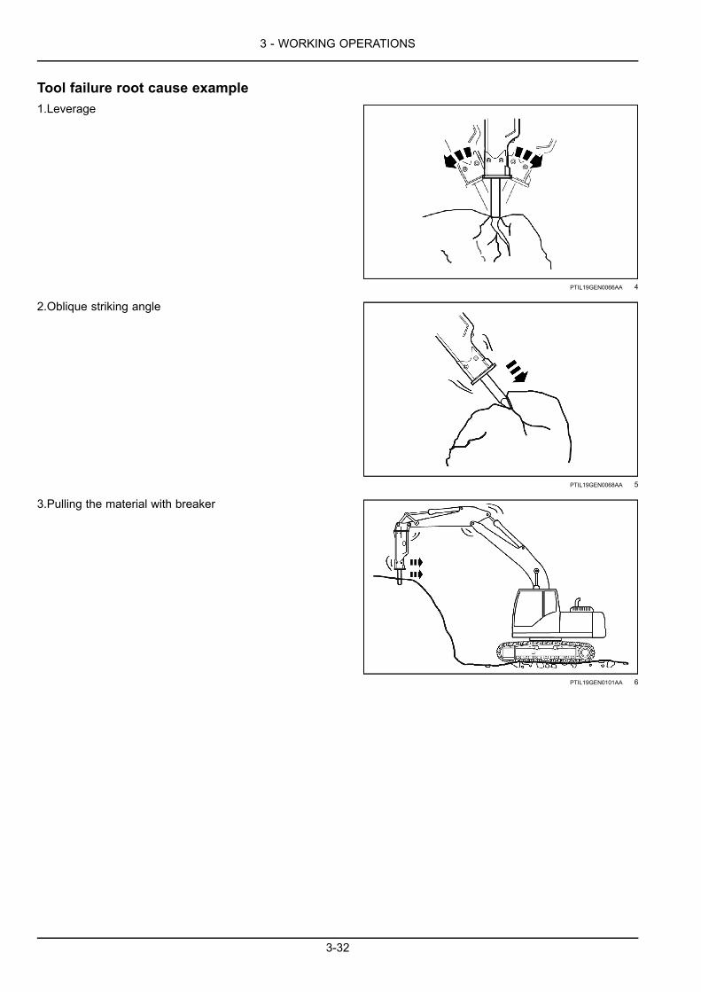
Tool failure root cause example1.Leverage
PTIL19GEN0066AA 4
2.Oblique striking angle
PTIL19GEN0068AA 5
3.Pulling the material with breaker
PTIL19GEN0101AA 6
3-32

3 - WORKING OPERATIONS
REPLACING A TOOLGeneral Information
• Always wear protective glasses and helmet when fitting or removing the working tool.
• The tool shank must be well lubricated during operation. Periodic visual inspections during operation are highlyrecommended.
• Greasing interval varies by breaker model and working condition.
• See 3-8,3-30 correct tool fitting/removal and greasing.
Tool replacementNOTICE: For safety reason, the carrier must be switched off before tool replacement work starts. Always wear pro-tective glasses and helmet when fitting or removing working tool as metal splinters may chip off while you are breakingtool pin into pieces for removal purpose. Never use your fingers to check alignment of tool grooves and tool pin holes.
NOTICE: Remove any residual pressure from the carrier before replacing the tool.
• Remove the tool from the breaker as illustrated below.
• Assembling the tool to the breaker can be done in reverse sequence order.
PTIL19GEN0087EA 1
CB20, CB40, CB60, CB61, CB70, CB80
3-33
3 - WORKING OPERATIONS
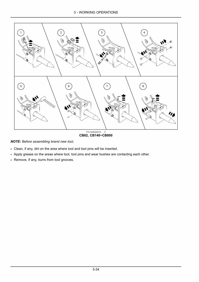
PTIL19GEN0091FA 2
CB62, CB140~CB800
NOTE: Before assembling brand new tool,
• Clean, if any, dirt on the area where tool and tool pins will be inserted.
• Apply grease on the areas where tool, tool pins and wear bushes are contacting each other.
• Remove, if any, burrs from tool grooves.
3-34
3 - WORKING OPERATIONS
Tool pin replacement or repair
PTIL19GEN0100FA 3
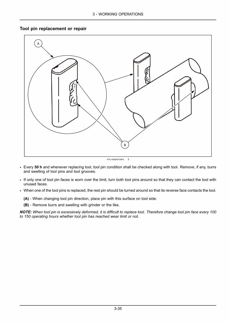
• Every 50 h and whenever replacing tool, tool pin condition shall be checked along with tool. Remove, if any, burrsand swelling of tool pins and tool grooves.
• If only one of tool pin faces is worn over the limit, turn both tool pins around so that they can contact the tool withunused faces.
• When one of the tool pins is replaced, the rest pin should be turned around so that its reverse face contacts the tool.
(A) - When changing tool pin direction, place pin with this surface on tool side.(B) - Remove burrs and swelling with grinder or the like.
NOTE:When tool pin is excessively deformed, it is difficult to replace tool. Therefore change tool pin face every 100to 150 operating hours whether tool pin has reached wear limit or not.
3-35

3 - WORKING OPERATIONS
MOVING THE ATTACHMENTTravelling position
Travelling positions are given below for various machine.
Breaker position in Backhoe LoaderEnsure that the breaker is not too close to carrier backhoeboom/arm, when travelling with tracked loader backhoe(or backhoe loader).
NOTE: Breaker positioning between boom and arm (illus-trated on the right side image) is achieved, depending oncarrier model & boom/arm specification.
PTIL19GEN0040AA 1
Breaker position in Skid steer loaderWhen travelling with skid steer loader, lower carrier boomand tilt the breaker fully backwards.
PTIL19GEN0041AA 2
Breaker position in excavatorWhen travelling with excavator, ensure the breaker not tobe too close to the cabin.
PTIL19GEN0042AA 3
3-36

4 - MAINTENANCE
4 - MAINTENANCE###_7_###GENERAL INFORMATION
GENERAL INSTRUCTION• The breaker is a hydraulic product precisely made. Therefore all hydraulic components of the breaker require yourhandling of great care and cleanliness.
• Dirt is the worst enemy to all hydraulic parts of the breaker.
• Ensure that all hydraulic parts are clean and covered by clean lint-free cloth.
• Do not use any materials other than designed for cleaning hydraulic part purpose. Never use water or carbontetrachloride.
NOTE: Hours are carrier hours while the breaker is mounted/used on/by the carrier, including installation, breakingoperation, repositioning on the rocks, etc. whether breaker piston is striking or not.
4-1

4 - MAINTENANCE
SERVICE INTERVALS
EVERY 2 HOURS1. Apply grease on tool, tool pins and bushes till grease
is visible on the tool underneath housing.
2. Check breaker paste or grease residual volume in thecartridge if ALS is mounted.
3. Tighten loose fittings and connections if necessary.
4. Check if breaker impact is efficient enough and ifbreaker is striking at constant speed.
4-2

4 - MAINTENANCE
EVERY 10 HOURS OR ONCE A WEEKNOTE: Every 10 h or once a week, whichever comes first.1. Remove tool and tool pins, then check their wearing
shape and amount.
2. Replace or repair tool and tool pins upon wear limit andrepair instruction, if necessary. See 3-33.
3. Check if tool and lower bush are sufficiently greased. Ifnot, apply grease more frequently.
4. Check through bolt & nut condition by hitting them withsteel bar via Service Window holes on each side on thehousing.
PTIL19GEN0043AA 1
4-3
4 - MAINTENANCE
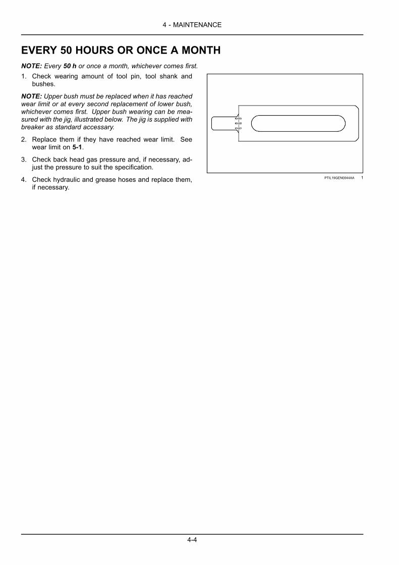
EVERY 50 HOURS OR ONCE A MONTHNOTE: Every 50 h or once a month, whichever comes first.1. Check wearing amount of tool pin, tool shank and
bushes.
NOTE: Upper bush must be replaced when it has reachedwear limit or at every second replacement of lower bush,whichever comes first. Upper bush wearing can be mea-sured with the jig, illustrated below. The jig is supplied withbreaker as standard accessary.
2. Replace them if they have reached wear limit. Seewear limit on 5-1.
3. Check back head gas pressure and, if necessary, ad-just the pressure to suit the specification.
4. Check hydraulic and grease hoses and replace them,if necessary.
PTIL19GEN0044AA 1
4-4

4 - MAINTENANCE
EVERY 500/600 HOURS1. Replace consumable and wear parts upon the mainte-
nance interval.
4-5

4 - MAINTENANCE
MAINTENANCE INTERVAL OF CONSUMABLES AND WEAR PARTS1. Consumable parts should be replaced upon below
maintenance interval.
CB20 ~ CB160Part 600 h or 6 months 1200 h or 12 months 1800 h or 18 months 2400 h or 24 monthsSeals X X X X
Hydraulic hose* X XDiaphragm X X X X
Accumulator bodybolt X
O-ring of gas valveset X
Through bolt set XTool pin
Bottom damperLower bushStopper pinShell pad
Upper damperUpper bush
Replace upon wear limit guide. See 5-1.
NOTE: Hours or months on above table should be applicable, whichever comes first.
NOTE: * Check hose condition and replace if necessary.
NOTE: Hours are carrier hours while the breaker is mounted/used on/by the carrier, including installation, breakingoperation, repositioning on the rocks, etc. whether breaker piston is striking or not.
4-6

4 - MAINTENANCE
CB210 ~ CB800Part 600 h or 6 months 1200 h or 12 months 1800 h or 18 months 2400 h or 24 monthsSeals X X X X
Hydraulic hose* X XDiaphragm X X X X
Accumulator bodybolt X
O-ring of gas valveset X
Through bolt set XTool pin
Bottom damperLower bushStopper pinShell pad
Upper damperUpper bush
Replace upon wear limit guide. See 5-1.
NOTE: Hours or months on above table should be applicable, whichever comes first.
NOTE: * Check hose condition and replace if necessary.
NOTE: Hours are carrier hours while the breaker is mounted/used on/by the carrier, including installation, breakingoperation, repositioning on the rocks, etc. whether breaker piston is striking or not.2. The end users are highly recommended to keep fast
moving spare parts in stock close to the breaker suchas tool, tool pin, stopper pin, rubber plug/cover, throughbolt and hoses.
3. The above maintenance interval should be respectedby the end users and/or the operators. Lack of respectcan void the warranty of breaker.
NOTE: Consumption of spare and wear parts varies upon the condition of breaker and/or carrier, operator’s skill, workmaterial, job site condition, etc.Therefore, if necessary, the parts should be replaced more frequently than the interval stated on above table.
4-7

4 - MAINTENANCE
MAINTENANCE INTERVAL OF SPECIAL APPLICATION BEAKER1. Breaker maintenance requirements to the special ap-
plication are much higher than the conventional appli-cations.
2. Therefore breaker maintenance interval at the specialapplications including but not limited to underground,tunneling, foundry cleaning, underwater, extremely lowor high temperature, etc. is much shorter than the con-ventional.
3. Consult with your authorized dealer.
4-8

4 - MAINTENANCE
WASHING
WASHING BREAKERNOTICE: Ensure pressure and return line ports and hoses are firmly plugged before washing the breaker to preventdirt coming into breaker component.1. The dirt on the breaker can make disassembly and as-
sembly difficult.
2. Highly recommended to remove the dirt before sendingit to the workshop.
LUBRICATION
OIL & LUBRICATION1. Breaker requires hydraulic oil and grease of proper vis-
cosity upon ambient temperature.
Service brake Grease Breaker paste
High ambienttemperature 0 – 50 °C
Low ambienttemperature –10 –
30 °CManual greasing Vibrating ALS Hydraulic ALS
ISO VG 68 HV ISO VG 46 HV NLGi No. 2 (minimum100 cst)
NLGi No. 2 (minimum100 cst to maximum
250 cst)NLGi No. 2 ( 350 cst)
NOTE: Lubricate all areas of working tool, tool pins and bushes where they are contacting each other. Incorrectviscosity grease may cause inefficiency or lack of lubrication.
Problems from incorrect viscosity hydraulic oil2. Oil too thick
• Difficult to start up
• Stiff operation
• Slow breaker striking
• Cavitation in the breaker
• Sticky valves
3. Oil too thin
• Lost of efficiency (internal leakage)
• Damage to seals
• Decrease of lubricating efficiency, excessive wear-ing of parts
• Irregular and slow breaker striking
• Cavitation in the breaker
4-9

4 - MAINTENANCE
CORRECT MANUAL GREASING1. When greasing, ensure that the breaker stands upright
and the tool is pushed to highest position.
NOTICE:While greasing, make sure that the tool is kept tothe highest position inside housing, so that you can preventgrease piling at the percussion chamber between pistonand tool.If not, breaker may lose power and seal failure may occur,subsequently causing oil leakage.
NOTICE:Greasing must be done until the grease is clearlyvisible on the tool underneath housing as illustrated on theleft.
2. Turn off the engine and wait for 10 min so that breakeroil pressure can drop and the grease can penetratedownwards between tool and bushes.
PTIL19GEN0130GA 1
4-10

4 - MAINTENANCE
AUTO LUBRICATION SYSTEM (ALS)Auto lubrication system is available as an option uponrequest.
Contact your authorized dealer.
Vibrating type ALS for CB62 & above
CB62, CB70, CB80
PTIL19GEN0046FA 1
1. Grease refill port 3. Grease output regulator2. Manual greasing port
4-11

4 - MAINTENANCE
CB140 & above
PTIL19GEN0047FA 2
1. Grease refill port 3. Grease output regulator2. Manual greasing port
• ALS is operated by vibration of the breaker duringoperation. Grease output can vary on the breakerworking condition.
• Grease output can be adjusted with regulator.
• In case greasing by vibrating ALS is not sufficient de-spite of setting regulator to maximum output, applymanual greasing until the breaker has been fully lu-bricated.
4-12

4 - MAINTENANCE
Hydraulic motor type ALS for CB140 & above
PTIL19GEN0048FA 3
1. Breaker paste cartridge 3. Manual greasing port2 Breaker paste output regulator 4 Visible indicator
• ALS is operated by oil pressure inside the breakerwhile the breaker is in operation.
• Only genuine cartridges should be used.
• If the operator uses non-genuine one, ALS will notperform as much as it has to and also may causefailure on ALS pump internal parts.
• If hydraulic hose or grease hose is connected incor-rectly, breaker paste will not be discharged and oilleaks.
• Breaker paste output can be adjusted with regulator.
• In case greasing from ALS is not sufficient despite ofsetting regulator to maximum output, apply manualgreasing until the breaker has been fully lubricated.
• Visible indicator (croissant shape in red) spins aslong as ALS motor is working.
• If the visible indicator doesn’t spin, apply manualgreasing and contact your authorized dealer.
4-13

4 - MAINTENANCE
NITROGEN GAS CHARGE FOR BACK HEAD & ACCUMULATOR
BACK HEAD GAS CHARGING (CB20 ~ CB80)1. Open the valve cap (1).
PTIL19GEN0049AA 1
2. Connect the hose (2) to the adapter (3).
PTIL19GEN0129AA 2
3. Close the gas cylinder valve (4) and connect the gascharging kit (5).
4. Close the three way valve (6) and the drain cock (7).
PTIL19GEN0050AA 3
5. Fit the adapter (8) on the inlet port (9) by tightening themiddle section of the adapter.
PTIL19GEN0051AA 4
4-14

4 - MAINTENANCE
6. Tighten the top section of the adapter (8).
PTIL19GEN0052AA 5
7. Open the gas cylinder valve (4) slowly.
8. Quick gas cylinder valve (4) opening may cause dam-age to the gauge (10).
PTIL19GEN0053AA 6
9. Open the three-way valve slowly (6) and charge N2 gasup to 20 Kg/cm².
10. close the three-way valve (6).
PTIL19GEN0054AA 7
11. Drain the gas to 16 – 18 Kg/cm² upon ambient tem-perature of job site.
PTIL19GEN0055AA 8
4-15

4 - MAINTENANCE
12. Close the inlet port (9) by loosening top section of theadapter (8).
PTIL19GEN0056AA 9
13. Disassemble the adapter (8) from the inlet port (9) byloosening middle section of the adapter.
PTIL19GEN0057AA 10
14. Assemble the valve cap (1) to the inlet port (9).
PTIL19GEN0058AA 11
4-16

4 - MAINTENANCE
BACK HEAD GAS CHARGING (CB140 ~ CB800)1. Remove the rubber plug (1).
PTIL19GEN0059AA 1
2. Open the valve cap (2).
PTIL19GEN0060AA 2
3. Connect the hose (3) to the adapter (4).
PTIL19GEN0129AA 3
4. Close the gas cylinder valve (5) and connect the gascharging kit (6).
5. Close the three-way valve (7) and the drain cock (8).
PTIL19GEN0050AA 4
4-17
4 - MAINTENANCE
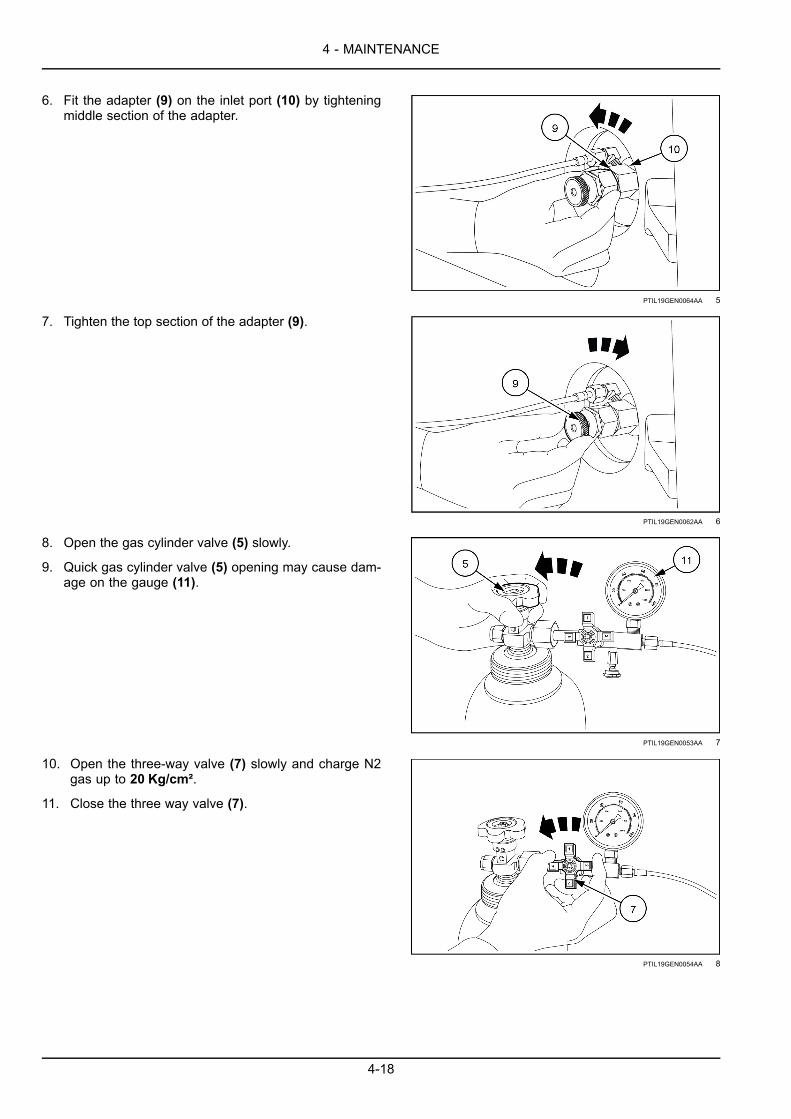
6. Fit the adapter (9) on the inlet port (10) by tighteningmiddle section of the adapter.
PTIL19GEN0064AA 5
7. Tighten the top section of the adapter (9).
PTIL19GEN0062AA 6
8. Open the gas cylinder valve (5) slowly.
9. Quick gas cylinder valve (5) opening may cause dam-age on the gauge (11).
PTIL19GEN0053AA 7
10. Open the three-way valve (7) slowly and charge N2gas up to 20 Kg/cm².
11. Close the three way valve (7).
PTIL19GEN0054AA 8
4-18

4 - MAINTENANCE
12. Drain the gas properly for each model upon ambienttemperature of job site.
PTIL19GEN0055AA 9
13. Close the inlet port (10) by loosening top section ofthe adapter (9).
PTIL19GEN0063AA 10
14. Disassemble the adapter (9) from the inlet port (10) byloosening middle section of the adapter.
PTIL19GEN0064AA 11
15. Assemble the valve cap (2) to the inlet port (10).
PTIL19GEN0065AA 12
4-19

4 - MAINTENANCE
16. Assemble the rubber plug (1).
PTIL19GEN0067AA 13
4-20

4 - MAINTENANCE
ACCUMULATOR GAS CHARGING (CB61, CB62)NOTE: Carry out gas charging only after the breaker has been sufficiently cooled down. Ensure that the breaker islying on the floor and work tool shall not be pushed into power cell.
NOTE: When storing gas bottle, ensure the bottle is not exposed to the sun and its valve is always closed.1. Accumulator gas charging valve is same as back head
gas charging valve.
2. Charging accumulator gas can be done in the sameway as illustrated earlier for back head.
PTIL19GEN0069AA 1
4-21

4 - MAINTENANCE
ACCUMULATOR GAS CHARGING (CB140, CB800)1. Remove the MC cover (1).
PTIL19GEN0070AA 1
2. Remove the valve cap (2).
PTIL19GEN0071AA 2
3. Remove the needle valve cap (3).
PTIL19GEN0072AA 3
4. Connect the hose (4) to the adapter (5).
PTIL19GEN0129AA 4
4-22

4 - MAINTENANCE
5. Close the gas cylinder valve (6) and connect the gascharging kit (7).
6. Close the three-way valve (8) and the drain cock (9).
PTIL19GEN0050AA 5
7. Connect the adapter (10) to the inlet port (11).
PTIL19GEN0073AA 6
8. Open the needle valve (12) with 5 mm L-wrench (13).
PTIL19GEN0074AA 7
9. Open the gas cylinder valve (6) slowly.
10. Quick gas cylinder valve (6) opening may cause dam-age on the gauge (14).
PTIL19GEN0053AA 8
4-23

4 - MAINTENANCE
11. Open the three-way valve (8) slowly and charge N2gas up to 65 Kg/cm².
12. Close the three way valve (8).
PTIL19GEN0054AA 9
13. Drain the gas to 55 – 60 Kg/cm² upon ambient tem-perature of job site.
PTIL19GEN0055AA 10
14. Close the needle valve (12).
PTIL19GEN0075AA 11
15. Remove the gas charging adapter (15).
PTIL19GEN0076AA 12
4-24

4 - MAINTENANCE
16. Assemble the needle valve cap (3).
PTIL19GEN0077AA 13
17. Assemble the valve cap (2).
PTIL19GEN0078AA 14
18. Assemble the MC cover (1).
PTIL19GEN0079AA 15
4-25

4 - MAINTENANCE
CONVERSION TABLE FOR BACK HEAD AND ACCUMULATOR GASPRESSUREConversion table for back head gas pressure
CB62
PTIL19GEN0080AB 1
CB61, CB70
PTIL19GEN0081AB 2
CB20, CB60, CB80, CB140
PTIL19GEN0082AB 3
4-26
4 - MAINTENANCE
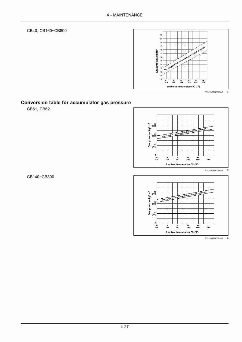
CB40, CB160~CB800
PTIL19GEN0083AB 4
Conversion table for accumulator gas pressureCB61, CB62
PTIL19GEN0084AB 5
CB140~CB800
PTIL19GEN0085AB 6
4-27

4 - MAINTENANCE
PTIL19GEN0086FA 7
1. Accumulator 2. Back head
4-28
4 - MAINTENANCE
STORAGE
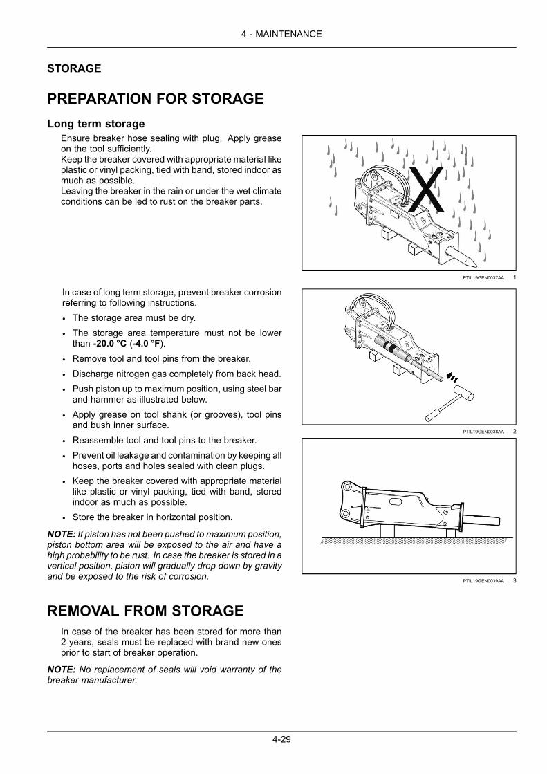
PREPARATION FOR STORAGELong term storage
Ensure breaker hose sealing with plug. Apply greaseon the tool sufficiently.Keep the breaker covered with appropriate material likeplastic or vinyl packing, tied with band, stored indoor asmuch as possible.Leaving the breaker in the rain or under the wet climateconditions can be led to rust on the breaker parts.
PTIL19GEN0037AA 1
In case of long term storage, prevent breaker corrosionreferring to following instructions.
• The storage area must be dry.
• The storage area temperature must not be lowerthan -20.0 °C (-4.0 °F).
• Remove tool and tool pins from the breaker.
• Discharge nitrogen gas completely from back head.
• Push piston up to maximum position, using steel barand hammer as illustrated below.
• Apply grease on tool shank (or grooves), tool pinsand bush inner surface.
• Reassemble tool and tool pins to the breaker.
• Prevent oil leakage and contamination by keeping allhoses, ports and holes sealed with clean plugs.
• Keep the breaker covered with appropriate materiallike plastic or vinyl packing, tied with band, storedindoor as much as possible.
• Store the breaker in horizontal position.
NOTE: If piston has not been pushed to maximum position,piston bottom area will be exposed to the air and have ahigh probability to be rust. In case the breaker is stored in avertical position, piston will gradually drop down by gravityand be exposed to the risk of corrosion.
PTIL19GEN0038AA 2
PTIL19GEN0039AA 3
REMOVAL FROM STORAGEIn case of the breaker has been stored for more than2 years, seals must be replaced with brand new onesprior to start of breaker operation.
NOTE: No replacement of seals will void warranty of thebreaker manufacturer.
4-29

4 - MAINTENANCE
4-30
5 - SPECIFICATIONS
5 - SPECIFICATIONS###_9_###
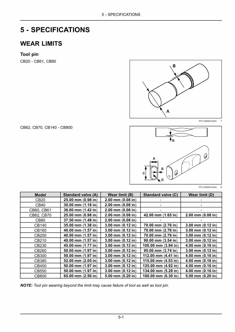
WEAR LIMITSTool pinCB20 - CB61, CB80
PTIL19GEN0102AA 1
CB62, CB70, CB140 - CB800
PTIL19GEN0103AA 2
Model Standard valve (A) Wear limit (B) Standard valve (C) Wear limit (D)CB20 25.00 mm (0.98 in) 2.00 mm (0.08 in) - -CB40 30.00 mm (1.18 in) 2.00 mm (0.08 in) - -
CB60, CB61 36.00 mm (1.42 in) 2.00 mm (0.08 in) - -CB62, CB70 25.00 mm (0.98 in) 2.00 mm (0.08 in) 42.00 mm (1.65 in) 2.00 mm (0.08 in)
CB80 37.50 mm (1.48 in) 2.00 mm (0.08 in) - -CB140 35.00 mm (1.38 in) 3.00 mm (0.12 in) 70.00 mm (2.76 in) 3.00 mm (0.12 in)CB160 40.00 mm (1.57 in) 3.00 mm (0.12 in) 70.00 mm (2.76 in) 3.00 mm (0.12 in)CB200 40.00 mm (1.57 in) 3.00 mm (0.12 in) 70.00 mm (2.76 in) 3.00 mm (0.12 in)CB210 40.00 mm (1.57 in) 3.00 mm (0.12 in) 90.00 mm (3.54 in) 3.00 mm (0.12 in)CB230 45.00 mm (1.77 in) 3.00 mm (0.12 in) 100.00 mm (3.94 in) 4.00 mm (0.16 in)CB260 50.00 mm (1.97 in) 3.00 mm (0.12 in) 95.00 mm (3.74 in) 3.00 mm (0.12 in)CB300 50.00 mm (1.97 in) 3.00 mm (0.12 in) 112.00 mm (4.41 in) 4.00 mm (0.16 in)CB380 52.00 mm (2.05 in) 3.00 mm (0.12 in) 115.00 mm (4.53 in) 4.00 mm (0.16 in)CB400 50.00 mm (1.97 in) 3.00 mm (0.12 in) 125.00 mm (4.92 in) 4.00 mm (0.16 in)CB550 50.00 mm (1.97 in) 3.00 mm (0.12 in) 134.00 mm (5.28 in) 4.00 mm (0.16 in)CB800 65.00 mm (2.56 in) 5.00 mm (0.20 in) 160.00 mm (6.30 in) 5.00 mm (0.20 in)
NOTE: Tool pin wearing beyond the limit may cause failure of tool as well as tool pin.
5-1

5 - SPECIFICATIONS
Upper damperModel Standard valve Wear limit (B)
CB20 - CB61 54.00 mm(2.13 in)
52.00 mm(2.05 in)
CB62 - CB80 78.00 mm(3.07 in)
75.00 mm(2.95 in)
CB140 100.00 mm(3.94 in)
96.00 mm(3.78 in)
CB160 - CB210 110.00 mm(4.33 in)
106.00 mm(4.17 in)
CB230 - CB550 125.00 mm(4.92 in)
121.00 mm(4.76 in)
CB800 147.00 mm(5.79 in)
142.00 mm(5.59 in) PTIL19GEN0104AA 3
NOTE: Upper damper wearing beyond the limit maycause shaking of power cell and various parts failure ofpower cell and housing.
Bottom damperModel Standard valve Wear limit (C)
CB20 - CB61 20.00 mm(0.79 in)
18.00 mm(0.71 in)
CB230 - CB550 25.00 mm(0.98 in)
22.00 mm(0.87 in)
CB800 35.00 mm(1.38 in)
31.00 mm(1.22 in)
PTIL19GEN0105AA 4
NOTE: Upper damper wearing beyond the limit maycause shaking of power cell and various parts failure ofpower cell and housing.
Upper bush
NOTE: The upper bush is assembled inside front headblock (CB62, CB70 & above).
NOTE: The upper bush is built in front head as part offront head block (CB20, CB40, CB60, CB61).
NOTE: Upper bush (1) wearing may affect breaker per-formance decrease and cause piston and tool failure.Therefore the operator should check upper bush wearingamount by periodical monitoring and replace upper bushor front head in case wearing amount has reached thelimit. See wear limit table below.
PTIL19GEN0106AA 5
5-2

5 - SPECIFICATIONS
Measure at 10 mm from the end of upper bush (2).
Model Standard valve(N) Wear limit
CB20 45.00 mm(1.77 in)
50.00 mm(1.97 in)
CB40 57.00 mm(2.24 in)
62.00 mm(2.44 in)
CB60, CB61 70.00 mm(2.76 in)
75.00 mm(2.95 in)
CB62, CB70 75.00 mm(2.95 in)
80.00 mm(3.15 in)
CB80 80.00 mm(3.15 in)
86.00 mm(3.39 in)
CB140 105.00 mm(4.13 in)
111.00 mm(4.37 in)
CB160 115.00 mm(4.53 in)
121.00 mm(4.76 in)
CB200 125.00 mm(4.92 in)
131.00 mm(5.16 in)
CB210, CB230 135.00 mm(5.31 in)
142.00 mm(5.59 in)
CB260 145.00 mm(5.71 in)
153.00 mm(6.02 in)
CB300 150.00 mm(5.91 in)
158.00 mm(6.22 in)
CB380 155.00 mm(6.10 in)
164.00 mm(6.46 in)
CB400 165.00 mm(6.50 in)
174.00 mm(6.85 in)
CB550 175.00 mm(6.89 in)
184.00 mm(7.24 in)
CB800 200.00 mm(7.87 in)
209.00 mm(8.23 in)
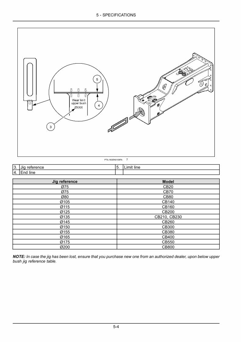
NOTE: For CB62 & above, the jig to measure upper bushwearing is supplied with breaker as standard accessories.As illustrated below, put the jig into the hole of breakerhousing, then replace upper bush if bottom of lower bushtouches the Limit Line of jig.
PTIL19GEN0107AA 6
5-3
5 - SPECIFICATIONS
PTIL19GEN0108FA 7
3. Jig reference 5. Limit line4. End line
Jig reference ModelØ75 CB20Ø75 CB70Ø80 CB80Ø105 CB140Ø115 CB160Ø125 CB200Ø135 CB210, CB230Ø145 CB260Ø150 CB300Ø155 CB380Ø165 CB400Ø175 CB550Ø200 CB800
NOTE: In case the jig has been lost, ensure that you purchase new one from an authorized dealer, upon below upperbush jig reference table.
5-4

5 - SPECIFICATIONS
Lower bush• Measure at 10 mm from the end of lower bush (6).• Lower bush (7).
Model Standard valve(D) Wear limit
CB20 45.00 mm(1.77 in)
48.00 mm(1.89 in)
CB40 57.00 mm(2.24 in)
60.00 mm(2.36 in)
CB60, CB61 70.00 mm(2.76 in)
73.00 mm(2.87 in)
CB62, CB70 75.00 mm(2.95 in)
78.00 mm(3.07 in)
CB80 80.00 mm(3.15 in)
84.00 mm(3.31 in)
CB140 105.00 mm(4.13 in)
109.00 mm(4.29 in)
CB160 115.00 mm(4.53 in)
119.00 mm(4.69 in)
CB200 125.00 mm(4.92 in)
129.0 mm(5.1 in)
CB210, CB230 135.00 mm(5.31 in)
140.00 mm(5.51 in)
CB260 145.00 mm(5.71 in)
151.00 mm(5.94 in)
CB300 150.00 mm(5.91 in)
156.00 mm(6.14 in)
CB380 155.00 mm(6.10 in)
162.00 mm(6.38 in)
CB400 165.00 mm(6.50 in)
172.00 mm(6.77 in)
CB550 175.00 mm(6.89 in)
182.00 mm(7.17 in)
CB800 200.00 mm(7.87 in)
207.00 mm(8.15 in)
NOTE: Upper damper wearing beyond the limit maycause shaking of power cell and various parts failure ofpower cell and housing.
PTIL19GEN0109FA 8
PTIL19GEN0106AA 9
5-5

5 - SPECIFICATIONS
PistonPiston bottom (8).
Model Standard valve(L) Wear limit (K)
CB20 150.00 mm(5.91 in)
149.00 mm(5.87 in)
CB40 168.00 mm(6.61 in)
167.00 mm(6.57 in)
CB60, CB61 177.00 mm(6.97 in)
176.00 mm(6.93 in)
CB62, CB70 210.00 mm(8.27 in)
209.00 mm(8.23 in)
CB80 218.00 mm(8.58 in)
217.00 mm(8.54 in)
CB140 273.00 mm(10.75 in)
272.00 mm(10.71 in)
CB160 290.00 mm(11.42 in)
288.00 mm(11.34 in)
CB200 291.00 mm(11.46 in)
289.00 mm(11.38 in)
CB210 305.00 mm(12.01 in)
303.00 mm(11.93 in)
CB230 311.00 mm(12.24 in)
309.00 mm(12.17 in)
CB260 336.00 mm(13.23 in)
334.00 mm(13.15 in)
CB300 353.00 mm(13.90 in)
351.00 mm(13.82 in)
CB380 363.00 mm(14.29 in)
361.00 mm(14.21 in)
CB400 412.00 mm(16.22 in)
410.00 mm(16.14 in)
CB550 455.00 mm(17.91 in)
453.00 mm(17.83 in)
CB800 462.00 mm(18.19 in)
460.00 mm(18.11 in)
NOTE: Piston wearing is highly sensitive to breaker per-formance. Any piston that has reached wear limit maycausemalfunction of breaker, shall be replaced with brandnew piston.
PTIL19GEN0110AA 10
5-6

5 - SPECIFICATIONS
Tool
Model Standard valve(B) Wear limit (A)
CB20 258.00 mm(10.16 in)
CB40 331.00 mm(13.03 in)
200.00 mm(7.87 in)
CB60, CB61 359.00 mm(14.13 in)
CB62, CB70 368.00 mm(14.49 in)
CB80 454.00 mm(17.87 in)
CB140 532.00 mm(20.94 in)
250.00 mm(9.84 in)
CB160 561.00 mm(22.09 in)
300.00 mm(11.81 in)
CB200 630.00 mm(24.80 in)
CB210 645.00 mm(25.39 in)
350.00 mm(13.78 in)
CB230 674.00 mm(26.54 in)
400.00 mm(15.75 in)
CB260 657.00 mm(25.87 in)
CB300 643.00 mm(25.31 in)
450.00 mm(17.72 in)
CB380 675.00 mm(26.57 in)
CB400 744.00 mm(29.29 in)
500.00 mm(19.69 in)
CB550 781.00 mm(30.75 in)
CB800 835.00 mm(32.87 in)
550.00 mm(21.65 in)
NOTE: Use of tool beyond wear limit will led to shorten-ing life time of housing and also dust/debris entering intobreaker percussion chamber ultimately causing contami-nation failure.
PTIL19GEN0111AA 11
5-7

5 - SPECIFICATIONS
Stopper pin
Model Standard valve(G) Wear limit (H)
CB20 - CB61 10.00 mm(0.39 in)
8.00 mm(0.31 in)
CB62, CB70 15.00 mm(0.59 in)
13.00 mm(0.51 in)
CB80 10.00 mm(0.39 in)
8.00 mm(0.31 in)
CB140 - CB260 17.50 mm(0.69 in)
15.50 mm(0.61 in)
CB300, CB380 21.50 mm(0.85 in)
19.50 mm(0.77 in)
CB400 - CB800 27.50 mm(1.08 in)
25.50 mm(1.00 in)
NOTE: Stopper pin wearing over the limit may cause toolpin, tool and/or bush failures as well as stopper pin failure.
NOTE:When breaker striking force has been delivered tostopper pin over and over, it can be bent or deformed.Heavily bent or deformed stopper pin may not be removedfrom tool pin and bush, which will cause a significantamount of repair time and resource spending. Checkstopper pin condition periodically and replace it withbrand new before too late.
PTIL19GEN0112AA 12
Shell pad
CB20 - CB80Standardvalve (A) Wear limits Standard
valve (B) Wear limits Standardvalve (C) Wear limitsModel
CB20, CB40 12.00 mm(0.47 in)
10.50 mm(0.41 in)
12.00 mm(0.47 in)
10.50 mm(0.41 in)
12.00 mm(0.47 in)
10.50 mm(0.41 in)
CB60 - CB80 15.00 mm(0.59 in)
13.50 mm(0.53 in)
15.00 mm(0.59 in)
13.50 mm(0.53 in)
15.00 mm(0.59 in)
13.50 mm(0.53 in)
CB20, CB40
PTIL19GEN0113AA 13
5-8

5 - SPECIFICATIONS
CB60, CB61
PTIL19GEN0114AA 14
CB62, CB70
PTIL19GEN0115AA 15
CB80
PTIL19GEN0116AA 16
5-9

5 - SPECIFICATIONS
CB140 - CB800Standardvalve (A) Wear limits Standard
valve (B) Wear limits Standardvalve (C) Wear limitsModel
CB140 -CB800
15.00 mm(0.59 in)
13.50 mm(0.53 in)
15.00 mm(0.59 in)
13.50 mm(0.53 in)
15.00 mm(0.59 in)
13.50 mm(0.53 in)
CB140 - CB400
PTIL19GEN0117AA 17
CB550, CB800
PTIL19GEN0118AA 18
NOTE: Shell pad wearing beyond the limit may cause shaking of power cell and various parts failure of power celland housing.
NOTE: Also operating breaker with any missing shell pad may cause shaking of power cell and various parts failureof power cell and housing.
5-10

5 - SPECIFICATIONS
Housing bottom plate
Model Standard valve(X) Wear limit (Y)
CB20 - CB140 25.00 mm(0.98 in)
15.00 mm(0.59 in)
CB160 - CB260 40.00 mm(1.57 in)
20.00 mm(0.79 in)
CB300, CB380 50.00 mm(1.97 in)
25.00 mm(0.98 in)
CB400 60.00 mm(2.36 in)
30.00 mm(1.18 in)
CB550, CB800 80.00 mm(3.15 in)
40.00 mm(1.57 in)
NOTE: Bottom plate wearing over the limit may incurfailure or shorter service life of housing, bottom damperand/or lower bush, shall be reinforced before too late.
PTIL19GEN0119AA 19
5-11

5 - SPECIFICATIONS
SPECIFICATIONSExcavator
Description CB20 CB40 CB60 CB80 CB140138 kg 192 kg 303 kg 499 kg 1018 kgOperating weight* 304 lb 423 lb 668 lb 1100 lb 2244 lb1196 mm 1410 mm 1593 mm 1897 mm 2295 mmOverall length 47.09 in 55.51 in 62.72 in 74.69 in 90.35 in45 mm 57 mm 70 mm 80 mm 105 mmTool diameter 1.57 in 2.24 in 2.76 in 3.15 in 4.13 in
175 Kg/cm² 175 Kg/cm² 175 Kg/cm² 175 Kg/cm² 210 Kg/cm²2nd relief setting pressure** 2500 psi 2500 psi 2500 psi 2500 psi 3000 psi90 – 120 Kg/
cm²90 – 120 Kg/
cm²110 – 165 Kg/
cm²140 – 170 Kg/
cm²140 – 190 Kg/
cm²Operating pressure 1280 –1700 psi
1280 –1700 psi
1565 –2350 psi
1990 –2420 psi
1990 –2700 psi
13 – 30 L/min 20 – 60 L/min 29 – 60 L/min 38 – 85 L/min 68 – 119 L/minOil flow 3.43 – 7.92 US
gpm5.28 –
15.85 US gpm7.66 –
15.85 US gpm10.03 –
22.45 US gpm17.96 –
31.43 US gpmPower mode 400 – 800 bps 350 – 550 bpsBlow rate Speed mode
550 –1000 bps
600 –1500 bps
380 –1000 bps 600 – 1100 bps 600 – 900 bps
10 – 14 Kg/cm² 14 – 16 Kg/cm² 10 – 14 Kg/cm² 10 – 14 Kg/cm² 10 – 14 Kg/cm²Back head gas pressure 142 – 199 psi 199 – 228 psi 142 – 199 psi 142 – 199 psi 142 – 199 psi- - - - 55 – 60 Kg/cm²Accumulator gas pressure - - - - 782 – 853 psi
0.8 – 2.5 t 1.5 – 4.0 t 3 – 6.5 t 4.5 – 8.0 t 10 – 15 tSuitable carrier 1760 – 5500 lb 330 – 8800 lb 6600 –
14300 lb9900 –17600 lb
22000 –33000 lb
NOTE: Above specifications are subject to change without prior notice.
NOTE: * Operating weight includes power cell, housing, tool, breaker bracket, pins and hydraulic hoses only. Oper-ating weight can vary by breaker bracket type.
NOTE: ** Guide for carrier port relief valve pressure setting.
Description CB160 CB200 CB210 CB230 CB2601253 kg 1468 kg 1613 kg 1873 kg 2087 kgOperating weight* 2762 lb 3236 lb 3556 lb 4129 lb 4601 lb2453 mm 2600 mm 2723 mm 2793 mm 2964 mmOverall length 96.57 in 102.36 in 107.20 in 109.93 in 116.69 in115 mm 125 mm 135 mm 135 mm 145 mmTool diameter 4.53 in 4.92 in 5.31 in 5.31 in 5.71 in
210 Kg/cm² 210 Kg/cm² 210 Kg/cm² 210 Kg/cm² 210 Kg/cm²2nd relief setting pressure** 3000 psi 3000 psi 3000 psi 3000 psi 3000 psi140 – 190 Kg/
cm²150 – 190 Kg/
cm²160 – 190 Kg/
cm²160 – 190 Kg/
cm²160 – 190 Kg/
cm²Operating pressure 1990 –2700 psi
2130 –2700 psi
2275 –2700 psi
2275 –2700 psi
2275 –2700 psi
85 – 127 L/min 85 – 131 L/min 102 – 132 L/min
119 – 161 L/min
127 – 178 L/minOil flow 22.45 –
33.54 US gpm22.45 –
34.60 US gpm27 – 34.87 US
gpm31.43 –
42.53 US gpm33.54 –
47.02 US gpmPower mode 320 – 550 bps 320 – 500 bps 320 – 480 bps 340 – 450 bps 270 – 400 bpsBlow rate Speed mode 400 – 700 bps 400 – 650 bps 400 – 600 bps 420 – 550 bps 330 – 500 bps
14 – 16 Kg/cm² 14 – 16 Kg/cm² 14 – 16 Kg/cm² 14 – 16 Kg/cm² 14 – 16 Kg/cm²Back head gas pressure 199 – 228 psi 199 – 228 psi 199 – 228 psi 199 – 228 psi 199 – 228 psi
5-12

5 - SPECIFICATIONS
Description CB160 CB200 CB210 CB230 CB26055 – 60 Kg/cm² 55 – 60 Kg/cm² 55 – 60 Kg/cm² 55 – 60 Kg/cm² 55 – 60 Kg/cm²Accumulator gas pressure 782 – 853 psi 782 – 853 psi 782 – 853 psi 782 – 853 psi 782 – 853 psi
12 – 18 t 16 – 22 t 18 – 24 t 20 – 26 t 24 – 30 tSuitable carrier 26500 –
39700 lb35200 –48500 lb
39700 –52900 lb
44100 –57300 lb
52900 –66100 lb
NOTE: Above specifications are subject to change without prior notice.
NOTE: * Operating weight includes power cell, housing, tool, breaker bracket, pins and hydraulic hoses only. Oper-ating weight can vary by breaker bracket type.
NOTE: ** Guide for carrier port relief valve pressure setting.
Description CB300 CB380 CB400 CB550 CB8002564 kg 2828 kg 3330 kg 4174 kg 5936 kgOperating weight* 5653 lb 6235 lb 7341 lb 9202 lb 13087 lb3044 mm 3174 mm 3322 mm 3610 mm 3981 mmOverall length 119.84 in 124.96 in 132.36 in 142.13 in 156.73 in150 mm 155 mm 165 mm 175 mm 200 mmTool diameter 5.91 in 6.10 in 6.50 in 6.89 in 7.87 in
210 Kg/cm² 230 Kg/cm² 230 Kg/cm² 210 Kg/cm² 250 Kg/cm²2nd relief setting pressure** 3000 psi 3300 psi 3300 psi 3000 psi 3570 psi160 – 190 Kg/
cm²160 – 190 Kg/
cm²150 – 190 Kg/
cm²150 – 190 Kg/
cm²170 – 210 Kg/
cm²Operating pressure 2275 –2700 psi
2275 –2700 psi
2130 –2700 psi
2130 –2700 psi
2420 –3000 psi
153 – 204 L/min
170 – 221 L/min
187 – 238 L/min
204 – 272 L/min
238 – 323 L/minOil flow 40.41 –
53.89 US gpm44.90 –
58.38 US gpm49.40 –
62.88 US gpm53.89 –
71.85 US gpm62.87 –
85.32 US gpmPower mode 250 – 380 bps 230 – 400 bps 230 – 345 bps 230 – 330 bps 220 – 300 bpsBlow rate Speed mode 300 – 450 bps 270 – 470 bps 270 – 410 bps 270 – 500 bps 290 – 400 bps
14 – 16 Kg/cm² 14 – 16 Kg/cm² 10 – 14 Kg/cm² 14 – 16 Kg/cm² 14 – 16 Kg/cm²Back head gas pressure
199 – 228 psi 199 – 228 psi 142 – 199 psi 199 – 228 psi 199 – 228 psi
55 – 60 Kg/cm² 55 – 60 Kg/cm² 55 – 60 Kg/cm² 55 – 60 Kg/cm² 55 – 60 Kg/cm²Accumulator gas pressure
782 – 853 psi 782 – 853 psi 782 – 853 psi 782 – 853 psi 782 – 853 psi25 – 36 t 28 – 42 t 40 – 60 t 40 – 60 t 58 – 100 t
Suitable carrier 55100 –79400 lb
61700 –92600 lb
88200 –132300 lb
88200 –132300 lb
127867 –220462 lb
NOTE: Above specifications are subject to change without prior notice.
NOTE: * Operating weight includes power cell, housing, tool, breaker bracket, pins and hydraulic hoses only. Oper-ating weight can vary by breaker bracket type.
NOTE: ** Guide for carrier port relief valve pressure setting.
5-13

5 - SPECIFICATIONS
Skid steer loaderDescription CB40 CB60 CB70 CB80
270 kg 357 kg 430 kg 542 kgOperating weight* 595 lb 787 lb 948 lb 1195 lb1483 mm 1604 mm 1671 mm 1875 mmOverall length 58.39 in 63.15 in 65.79 in 73.82 in57 mm 70 mm 75 mm 80 mmTool diameter 2.24 in 2.76 in 2.95 in 3.15 in
230 Kg/cm² 230 Kg/cm² 230 Kg/cm² 230 Kg/cm²2nd relief setting pressure** 3300 psi 3300 psi 3300 psi 3300 psi100 – 190 Kg/cm² 110 – 190 Kg/cm² 120 – 190 Kg/cm² 140 – 190 Kg/cm²Operating pressure 1420 – 2700 psi 1560 – 2700 psi 1700 – 2700 psi 1990 – 2700 psi23 – 70 L/min 35 – 70 L/min 40 – 80 L/min 45 – 90 L/min
Oil flow 6.07 – 18.49 USgpm
9.24 – 18.49 USgpm
10.56 – 21.13 USgpm
11.88 – 23.77 USgpm
Power mode 400 – 800 bpsBlow rate Speed mode 600 – 1500 bps 380 – 1000 bps 380 – 900 bps 600 – 1100 bps10 – 12 Kg/cm² 10 – 12 Kg/cm² 10 – 12 Kg/cm² 10 – 14 Kg/cm²Back head gas pressure 142 – 170 psi 142 – 170 psi 142 – 170 psi 142 – 199 psi
- - - -Accumulator gas pressure - - - -1.5 – 4 t 3 – 6.5 t 4.5 – 8 t 4.5 – 8 tSuitable carrier 3300 – 8800 lb 6600 – 14300 lb 9900 – 17600 lb 9900 – 17600 lb
NOTE: Above specifications are subject to change without prior notice.
NOTE: * Operating weight includes power cell, housing, tool, breaker bracket, pins and hydraulic hoses only. Oper-ating weight can vary by breaker bracket type.
NOTE: ** Guide for carrier port relief valve pressure setting.
5-14

5 - SPECIFICATIONS
TLBDescription CB61 CB62
366 kg 441 kgOperating weight* 807 lb 972 lb1552 mm 1648 mmOverall length 61.10 in 64.88 in70 mm 75 mmTool diameter 2.76 in 2.95 in
175 Kg/cm² 175 Kg/cm²2nd relief setting pressure** 2500 psi 2500 psi110 – 165 Kg/cm² 120 – 165 Kg/cm²Operating pressure 1565 – 2350 psi 1700 – 2350 psi29 – 60 L/min 34 – 68 L/minOil flow 7.66 – 15.8 US gpm 8.98 – 17.96 US gpm
Power modeBlow rate Speed mode 380 – 1000 bps 380 – 900 bps
10 – 14 Kg/cm² 16 – 182 Kg/cm²Back head gas pressure 142 – 199 psi 228 – 256 psi40 – 50 Kg/cm² 40 – 50 Kg/cm²Accumulator gas pressure 569 – 711 psi 569 – 711 psi
3 – 6.5 t 4.5 – 8 tSuitable carrier 6600 – 8800 lb 9900 – 17600 lb
NOTE: Above specifications are subject to change without prior notice.
NOTE: * Operating weight includes power cell, housing, tool, breaker bracket, pins and hydraulic hoses only. Oper-ating weight can vary by breaker bracket type.
NOTE: ** Guide for carrier port relief valve pressure setting.
5-15

5 - SPECIFICATIONS
TABLE OF APPLICATIONSA. Excavator
CB20 CB40 CB60 CB80 CB140 CB160CB200CB210CB230
CB260 CB300 CB380CB400 CB550 CB800
CX17C XCX18C XCX26C XCX30C XCX33C XCX37C XCX57C XCX60C X
CX75, CX80 XCX130, CX145C XCX160, CX180 XCX210, CX220,
CX235C X
CX240, CX250,CX260 X
CX300, XCX350, CX370,
CX380 X
CX470, CX490 XCX470ME,CX500 X
CX700 XCX800 X
5-16

5 - SPECIFICATIONS
B. Skid steer loader 1.
Tier 3
CB40 CB60 CB70 CB80SR130 XSR150 X XSR175 X XSV185 X XSR200 X XSR220 X XSV250 X XSR250 X XSV300 X XTR270 X XTR320 X XTV380 X X
2. Tier 4
CB40 CB60 CB70 CB80SR130 XSR160 X XSR175 X XSV185 X XSR210 X X XSR240 X X XSV280 X X XSR250 X X XSR270 X X XSV300 X X XSV340 X X XTR270 X X XTR310 X X XTR340 X X XTV380 X X XTV450 X X X
5-17

5 - SPECIFICATIONS
C. TLB1. Pithampur
CB61 CB62570T X X570ST X XB80B X X770 X X
770EX X X770EX MAG. X X
851EX X X
2. Lecce
CB61 CB62580T S’TYLED X XB90B S’TYLED X X580ST S’TYLED X XB100B S’TYLED X X590ST S’TYLED X XB110B S’TYLED X X695ST S’TYLED X XB115B S’TYLED X X580T CASE DNA X X580ST CASE DNA X X590ST CASE DNA X X695ST CASE DNA X X
3. Burlington
CB61 CB62580N X X580SN X X590SN X X
5-18

6 - ACCESSORIES
6 - ACCESSORIES###_10_###
UNDERWATER KITIntroduction
• This is about requirements of the underwater application breaker.
• It is very important for you to read and understand the instruction before the breaker is put into underwater appli-cation.
• Keep the instructions provided herewith with you all the time.
• When the breaker is operated at underwater application without any proper underwater kit, water comes into per-cussion chamber and cylinder, cause serious damage to seals, cylinder, piston and control valve such as corrosion,scratch and crack as well as a significantly shortened life time of tool, tool pins, upper bush, lower bush, etc.
• Therefore a proper underwater kit should be installed on the breaker and working whenever the breaker works atunder water application.
NOTE: The breaker manufacturer do not supply any underwater kit. All information related with underwater kit tech-nical information, installation, capacity, setting pressure, operation, maintenance, part list, etc. of this Service Manualis only to help the operator understand risks and requirements of underwater application breaker, shall not be inter-preted as breaker manufacturer’s responsibility to warrant underwater kit as well as underwater breaker.
NOTE: Underwater application breaker is not supported by breaker manufacturer’s warranty. Breaker operation atunderwater application shall be carried out at full responsibility of the operator.
Structure of underwater kit
Normally underwater kit consists of air compressor, air supply line, pressure regulator, pressure switch, electric cable,coupling, adaptor, fasteners, etc.
PTIL19GEN0123FA 1
6-1

6 - ACCESSORIES
PTIL19GEN0124FB 2
1. Pressure regulator 4. hydraulic line2. Connect to air compressor 5. Hose coupler3. Air supply line
6-2

6 - ACCESSORIES
Typical underwater kit parts of CB210 class
PTIL19GEN0125GB 3
Item Part name Quantity Remarks1 Adaptor 1 PF1/2" O-RING×PF1/2"5#2 Hose 1 PT1/2"(MALE)×PF1/2"5#(FEMALE)× 25000L×2S3 Quick Coupler Plug 1 1/2", 6605-124 Quick Coupler Socket 1 1/2", 6603-125 Hose 1 PT1/2"(BOTH MALE)×2S×12m6 Female Thread Coupler 3 1/2" CAM-LOCK7 Regulator Assembly 1 1/2" AC4004GS(Air filter + Regulator + Lubricator + P/Switch)8 Electric Cable 1 1.5mm^2-10m9 Hose 1 PT1/2"(BOTH MALE)×2S×20m10 Male Thread Coupler 3 1/2" CAM-LOCK11 Pressure Switch 1 900040112 O-ring 1 1B P18
6-3
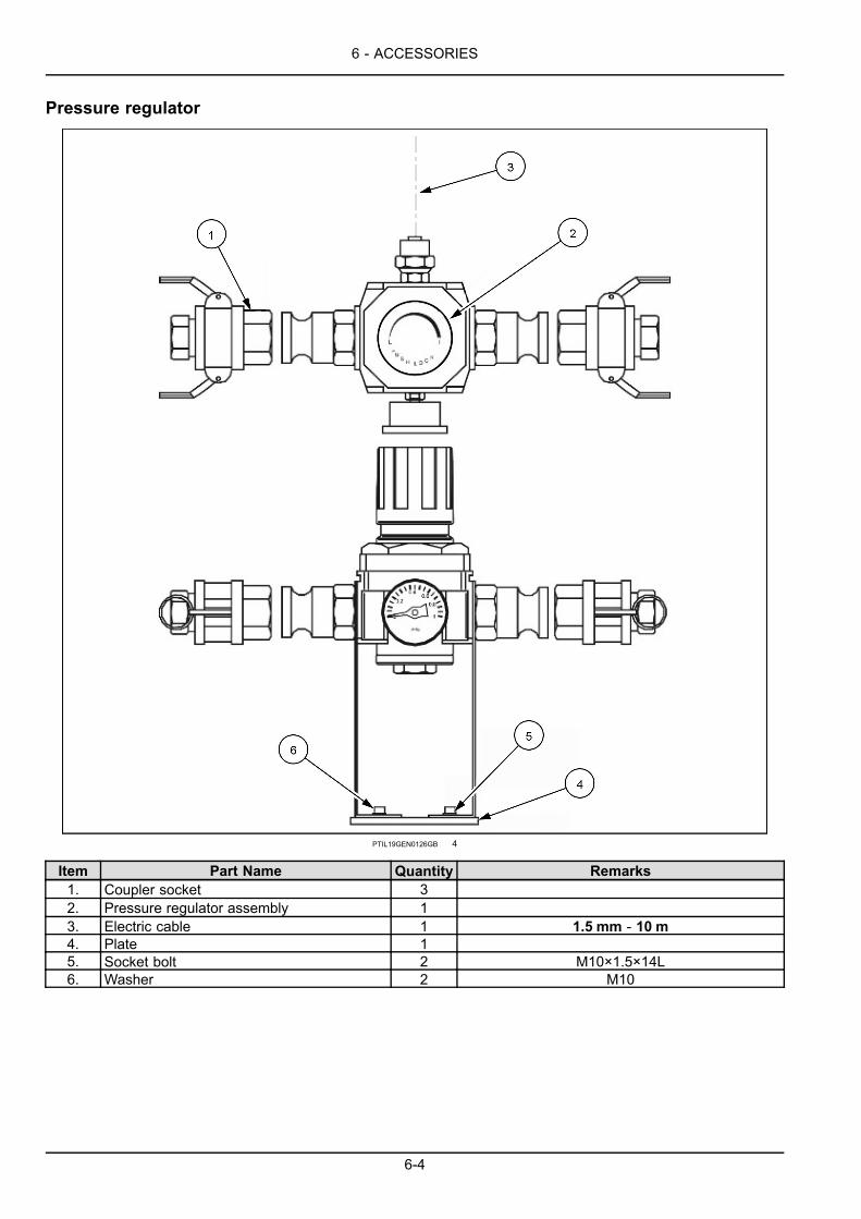
6 - ACCESSORIES
Pressure regulator
PTIL19GEN0126GB 4
Item Part Name Quantity Remarks1. Coupler socket 32. Pressure regulator assembly 13. Electric cable 1 1.5 mm - 10 m4. Plate 15. Socket bolt 2 M10×1.5×14L6. Washer 2 M10
6-4

6 - ACCESSORIES
Technical requirements• Air supply channel is built in the breaker cylinder andfront head blocks as standard for the range CB140 &above range.
• Air supply hose can be fitted to the air inlet port of cylin-der. Insert air supply hose through rubber cover and fitit on the air inlet port.
• Air inlet port size
○ CB140 - CB300 : PF1/2 inch
○ CB380 - CB800 : PF3/4 inch
NOTE: The hoses twisted or folded will not Allow a properair supply to the breaker.
PTIL19GEN0127BA 5
Models CB140 CB160 -CB260
CB300 CB380 CB400 -CB800
Air hose size (inner diameter) 12.7 mm (0.5 in) 19.05 mm (0.75 in)Regulated air pressure 0 – 5.5 bar (max 9 bar)Switching pressure 1.5 bar (Activating pressure switch)
Minimum airpressure 5 bar
Air delivery 90 m³/hr 162 m³/hr 180 m³/hr 180 m³/hr 198 m³/hrAir compressorcapacity
Rated output 12.5 kW (17 Hp) 22 kW (30 Hp) 25 kW (34 Hp) 25 kW(34 Hp) 27 kW (37 Hp)
• Air pressure =(Water depth / 10 m) + 1.5 bar.• Water pressure gets 1 bar at every 10 m water depth.You may calculate air pressure from the formulatedvalue on the above.
• You may also get an idea of proper air pressure levelfrom the chart on the right.
PTIL19GEN0128AA 6
6-5

6 - ACCESSORIES
Requirements of underwater application breaker maintenance
As soon as underwater breaker operating is finished, remove water that remains in percussion chamber
• Operate the breaker at the ground over 10 times with air supply from the compressor.
• Keep supplying compressed air to the breaker for minimum 10 min.• Apply hydraulic oil or anti-rust oil inside percussion chamber with air supply line.
• Apply grease inside percussion chamber, repaint the breaker if necessary.
Following is what you may refer to for maintain underwater application breaker.
Every 30 min. • Grease tool, tool pins, bushes
• Check if tool moves up and down with no difficulty.
• Check function range of air pressure switch.
• Check air hoses and their fitting condition.Daily (8 h) • Remove tool pin and tool condition, remove burrs if any.
• Check if tool was greased sufficiently, grease more frequently if needed.
• Check if the breaker is rust or abnormally worn out, particularly piston face andpercussion chamber.
When the job is over • Completely disassemble breaker and carry out overhauling including but not limitedto seals.
• Check if any breaker parts were damaged or rust, replace if any.
• Check if all underwater kit parts are in good condition and work properly.
6-6
Index
###_Index_###
AACCUMULATOR GAS CHARGING (CB140, CB800) . . . . . . . . . . . . . . . . . . . . . . . . . 4-22ACCUMULATOR GAS CHARGING (CB61, CB62) . . . . . . . . . . . . . . . . . . . . . . . . . . 4-21ANTI BLANK FIRING (AUTO-STOP) . . . . . . . . . . . . . . . . . . . . . . . . . . . . . . . . 3-28AUTO LUBRICATION SYSTEM (ALS). . . . . . . . . . . . . . . . . . . . . . . . . . . . . . . . 4-11
BBACK HEAD GAS CHARGING (CB140 ~ CB800) . . . . . . . . . . . . . . . . . . . . . . . . . . 4-17BACK HEAD GAS CHARGING (CB20 ~ CB80). . . . . . . . . . . . . . . . . . . . . . . . . . . . 4-14
CCHOICE OF TOOLS . . . . . . . . . . . . . . . . . . . . . . . . . . . . . . . . . . . . . . . 3-5CONVERSION TABLE FOR BACK HEAD AND ACCUMULATOR GAS PRESSURE . . . . . . . . . . . 4-26CORRECT MANUAL GREASING. . . . . . . . . . . . . . . . . . . . . . . . . . . . . . . . . . 4-10
EEVERY 10 HOURS OR ONCE A WEEK . . . . . . . . . . . . . . . . . . . . . . . . . . . . . . . 4-3EVERY 2 HOURS . . . . . . . . . . . . . . . . . . . . . . . . . . . . . . . . . . . . . . . . 4-2EVERY 500/600 HOURS . . . . . . . . . . . . . . . . . . . . . . . . . . . . . . . . . . . . . 4-5EVERY 50 HOURS OR ONCE A MONTH . . . . . . . . . . . . . . . . . . . . . . . . . . . . . . 4-4
FForeword . . . . . . . . . . . . . . . . . . . . . . . . . . . . . . . . . . . . . . . . . . . . 1-1
GGENERAL INSTRUCTION. . . . . . . . . . . . . . . . . . . . . . . . . . . . . . . . . . . . . 4-1
HHANDLING THE ATTACHMENT . . . . . . . . . . . . . . . . . . . . . . . . . . . . . . . . . . 3-4
IINCORRECT USE OF THE ATTACHMENT . . . . . . . . . . . . . . . . . . . . . . . . . . . . . 3-31INSTALLING THE ATTACHMENT . . . . . . . . . . . . . . . . . . . . . . . . . . . . . . . . . 3-8
MMAINTENANCE INTERVAL OF CONSUMABLES AND WEAR PARTS . . . . . . . . . . . . . . . . . 4-6MAINTENANCE INTERVAL OF SPECIAL APPLICATION BEAKER . . . . . . . . . . . . . . . . . . . 4-8MOVING THE ATTACHMENT . . . . . . . . . . . . . . . . . . . . . . . . . . . . . . . . . . . 3-36
NNote to the Owner . . . . . . . . . . . . . . . . . . . . . . . . . . . . . . . . . . . . . . . . 1-2
OOIL & LUBRICATION . . . . . . . . . . . . . . . . . . . . . . . . . . . . . . . . . . . . . . . 4-9OPERATING GUIDELINE AND SAFETY . . . . . . . . . . . . . . . . . . . . . . . . . . . . . . 3-1
PPREPARATION FOR STORAGE . . . . . . . . . . . . . . . . . . . . . . . . . . . . . . . . . . 4-29Product identification . . . . . . . . . . . . . . . . . . . . . . . . . . . . . . . . . . . . . . . 1-3Product overview . . . . . . . . . . . . . . . . . . . . . . . . . . . . . . . . . . . . . . . . . 1-4
RREMOVAL FROM STORAGE . . . . . . . . . . . . . . . . . . . . . . . . . . . . . . . . . . . 4-29REMOVING THE ATTACHMENT . . . . . . . . . . . . . . . . . . . . . . . . . . . . . . . . . . 3-30REPLACING A TOOL . . . . . . . . . . . . . . . . . . . . . . . . . . . . . . . . . . . . . . . 3-33
SSAFETY DECALS . . . . . . . . . . . . . . . . . . . . . . . . . . . . . . . . . . . . . . . . 2-5

SAFETY INSTRUCTIONS . . . . . . . . . . . . . . . . . . . . . . . . . . . . . . . . . . . . . 2-1SAFETY PRECAUTIONS . . . . . . . . . . . . . . . . . . . . . . . . . . . . . . . . . . . . . 2-4SPECIFICATIONS . . . . . . . . . . . . . . . . . . . . . . . . . . . . . . . . . . . . . . . . 5-12
TTABLE OF APPLICATIONS . . . . . . . . . . . . . . . . . . . . . . . . . . . . . . . . . . . . 5-16
UUNDERWATER KIT . . . . . . . . . . . . . . . . . . . . . . . . . . . . . . . . . . . . . . . . 6-1USING THE ATTACHMENT . . . . . . . . . . . . . . . . . . . . . . . . . . . . . . . . . . . . 3-9
WWASHING BREAKER . . . . . . . . . . . . . . . . . . . . . . . . . . . . . . . . . . . . . . . 4-9WEAR LIMITS . . . . . . . . . . . . . . . . . . . . . . . . . . . . . . . . . . . . . . . . . . 5-1WORKING TEMPERATURE OF BREAKER . . . . . . . . . . . . . . . . . . . . . . . . . . . . . 3-29

Dealer’s stamp
Case New Holland Construction Equipment (India) Pvt. Ltd. reserves the right to make improvements in design and changes in
specification at any time without notice and without incurring any obligation to install them on units previously sold.
Specifications, descriptions, and illustrative material herein are as accurate as known
at time of puplication, but are subject to change without notice.
Availability of some models and equipment builds varies according to the country
in which the equipment is being used. For exact information about any particular product,
please consult your Case dealer.
© 2019 Case New Holland Construction Equipment (India) Pvt. Ltd. All rights reserved.
Any trademarks referred to herein, in association with goodsand/or services of companies, other than owned by or licensed
to CNH Industrial N.V., its subsidiaries or affiliates, are theproperty of those respective companies.