
OPERATOR'S MANUAL - SCAG Australia
82
OPERATOR’S MANUAL Part No. 03430 Printed 9/2018 Printed in USA © 2019 Scag Power Equipment Division of Metalcraft of Mayville, Inc. Congratulations on owning a Scag mower! This manual contains the operating instructions and safety information for your Scag mower. Reading this manual can provide you with assistance in maintenance and adjustment procedures to keep your mower performing to maximum efficiency. The specific models that this book covers are listed on the inside cover. Before operating your machine, please read all the information enclosed. Model: SVRII-36A-15FS SVRII-36A-19FX SVRII-48V-22FX SVRII-52V-23FX SVRII-52V-25CV-EFI SVRII-61V-25FX SVRII-61V-29CV-EFI
-
Upload
khangminh22 -
Category
Documents
-
view
3 -
download
0
Transcript of OPERATOR'S MANUAL - SCAG Australia

OPERATOR’S MANUAL
Part No. 03430Printed 9/2018Printed in USA
© 2019Scag Power EquipmentDivision of Metalcraft of Mayville, Inc.
Congratulations on owning a Scag mower! This manual contains the operating instructions and safety information for your Scag mower. Reading this manual can provide you with assistance in maintenance and adjustment procedures to keep your mower performing to maximum efficiency. The specific models that this book covers are listed on the inside cover. Before operating your machine, please read all the information enclosed.
Model: SVRII-36A-15FS SVRII-36A-19FX SVRII-48V-22FX SVRII-52V-23FX SVRII-52V-25CV-EFI SVRII-61V-25FX SVRII-61V-29CV-EFI

WARNINGFAILURE TO FOLLOW SAFE OPERATING PRACTICES MAY RESULT
IN SERIOUS INJURY OR DEATH.
• Read this manual completely as well as other manuals that came with your mower.
• ALWAYS FOLLOW OSHA APPROVED OPERATION.
• DO NOT operate on steep slopes.
• Under no circumstances should the machine be operated on slopes greater than 20 degrees. ALWAYS FOLLOW OSHA APPROVED OPERATION.
• Stay two cut widths away from slopes, drop offs, ditches and retaining walls.
• DO NOT back down a slope or ramp.
• DO NOT mow on wet grass. Wet grass reduces traction and steering control.
• Keep all shields in place, especially the grass discharge chute.
• Before performing any maintenance or service, stop the machine and remove the spark plug wire and ignition key.
• If a mechanism becomes clogged, stop the engine before cleaning.
• Keep hands, feet and clothing away from power-driven parts.
• Keep others off the mower (only one person at a time)
REMEMBER - YOUR MOWER IS ONLY AS SAFE AS THE OPERATOR!
HAZARD CONTROL AND ACCIDENT PREVENTION ARE DEPENDENT UPON THE AWARENESS, CONCERN, PRUDENCE, AND PROPER TRAINING OF THE PERSONNEL INVOLVED IN THE OPERATION, TRANSPORT, MAINTENANCE, AND STORAGE OF THE EQUIPMENT.
This manual covers the operating instructions and illustrated parts list for:
SVRII-36A-15FS with a serial number of N5900001 to N5999999
SVRII-36A-19FX with a serial number of N6000001 to N6099999
SVRII-48V-22FX with a serial number of N6100001 to N6199999
SVRII-52V-23FX with a serial number of N6200001 to N6299999
SVRII-52V-25CV-EFI with a serial number of N6300001 to N6399999
SVRII-61V-25FX with a serial number of N6400001 to N6499999
SVRII-61V-29CV-EFI with a serial number of N6500001 to N6599999
Always use the entire serial number listed on the serial number tag when referring to this product.

I
RTable of Contents
Table of ContentsSECTION 1 - GENERAL INFORMATION ...................................................................................1
1.1 INTRODUCTION ...........................................................................................................................................1
1.2 DIRECTION REFERENCE ...........................................................................................................................1
1.3 SERVICING THE ENGINE AND DRIVE TRAIN COMPONENTS .................................................................1
1.4 SYMBOLS ....................................................................................................................................................2
SECTION 2 - SAFETY INFORMATION ......................................................................................32.1 INTRODUCTION ...........................................................................................................................................3
2.2 SIGNAL WORDS ..........................................................................................................................................3
2.3 BEFORE OPERATION CONSIDERATIONS ................................................................................................3
2.4 TESTING THE SAFETY INTERLOCK SYSTEM ..........................................................................................4
2.5 OPERATION CONSIDERATIONS ................................................................................................................5
2.6 MAINTENANCE CONSIDERATIONS & STORAGE ....................................................................................7
2.7 USING A SPARK ARRESTOR .....................................................................................................................8
2.8 SPARK IGNITION SYSTEM .........................................................................................................................8
2.9 SAFETY AND INSTRUCTIONAL DECALS .................................................................................................9
SECTION 3 - SPECIFICATIONS ..............................................................................................103.1 ENGINE ......................................................................................................................................................10
3.2 ELECTRICAL .............................................................................................................................................10
3.3 ENGINE DECK ...........................................................................................................................................10
3.4 CUTTER DECK ..........................................................................................................................................11
3.5 WEIGHTS AND DIMENSIONS ...................................................................................................................11
3.6 PRODUCTIVITY .........................................................................................................................................11
SECTION 4 - OPERATING INSTRUCTIONS ...........................................................................124.1 TIGER EYE INSTRUMENT IDENTIFICATION (EXCLUDES SVRII-36A) ..................................................12
4.2 CONTROLS IDENTIFICATION ..................................................................................................................14
4.3 SAFETY INTERLOCK SYSTEM ................................................................................................................14
4.4 TESTING THE SAFETY INTERLOCK SYSTEM ........................................................................................15
4.5 INITIAL RUN-IN PROCEDURES ................................................................................................................15
4.6 STARTING THE ENGINE ...........................................................................................................................16
4.7 GROUND TRAVEL AND STEERING .........................................................................................................16
4.8 ENGAGING THE DECK DRIVE (CUTTER BLADES) ................................................................................17
4.9 HILLSIDE OPERATION ..............................................................................................................................18
4.10 PARKING THE MOWER ...........................................................................................................................18
4.11 AFTER OPERATION ................................................................................................................................18
4.12 REMOVING CLOGGED MATERIAL ........................................................................................................19
4.13 MOVING MOWER WITH ENGINE STOPPED ..........................................................................................19
4.14 RECOMMENDATIONS FOR MOWING ....................................................................................................19
4.15 ADJUSTING CUTTING HEIGHT ..............................................................................................................19
SECTION 5 - TROUBLESHOOTING CUTTING CONDITIONS ...............................................21
II
R Table of Contents
SECTION 6 - ADJUSTMENTS .................................................................................................246.1 PARKING BRAKE ADJUSTMENT ............................................................................................................24
6.2 TRAVEL ADJUSTMENT .............................................................................................................................24
6.3 THROTTLE CONTROL AND CHOKE ADJUSTMENTS ............................................................................26
6.4 BELT ADJUSTMENTS ...............................................................................................................................26
6.5 BELT ALIGNMENT .....................................................................................................................................26
6.6 CUTTER DECK ADJUSTMENTS ..............................................................................................................26
6.7 ELECTRIC CLUTCH ADJUSTMENT .........................................................................................................31
6.8 OPERATOR CUSHION AND REAR COVER REMOVAL ..........................................................................32
SECTION 7 - MAINTENANCE ..................................................................................................337.1 MAINTENANCE CHART - RECOMMENDED SERVICE INTERVALS ......................................................33
7.2 LUBRICATION ............................................................................................................................................34
7.3 HYDRAULIC SYSTEM ...............................................................................................................................36
7.4 ENGINE OIL ...............................................................................................................................................37
7.5 ENGINE FUEL SYSTEM ............................................................................................................................38
7.6 ENGINE AIR CLEANER .............................................................................................................................39
7.7 BATTERY - ELECTRIC START MODELS..................................................................................................39
7.8 DRIVE BELTS .............................................................................................................................................40
7.9 CUTTER BLADES ......................................................................................................................................40
7.10 TIRES ........................................................................................................................................................42
7.11 BODY AND DECK ....................................................................................................................................42
SECTION 8 - ILLUSTRATED PARTS LIST ..............................................................................43SCAG APPROVED ATTACHMENTS AND ACCESSORIES. ...........................................................................43
36A CUTTER DECK .........................................................................................................................................44
48V, 52V & 61V CUTTER DECKS ....................................................................................................................46
SVRII CUTTER DECK CONTROLS .................................................................................................................48
SVRII SHEET METAL COMPONENTS ............................................................................................................50
SVRII STEERING CONTROLS ........................................................................................................................52
SVRII FUEL SYSTEM ......................................................................................................................................54
SVRII-36A HYDRAULICS AND ENGINE COMPONENTS ..............................................................................56
SVRII-48V / 52V / 61V HYDRAULICS AND ENGINE COMPONENTS............................................................58
SVRII-36A ELECTRICAL SYSTEM .................................................................................................................60
SVRII-36A ELECTRICAL SYSTEM - RECOIL START MODELS....................................................................62
SVRII-48V / 52V / 61V ELECTRICAL SYSTEM ...............................................................................................64
SVRII-36A HYDRAULIC PUMP .......................................................................................................................66
SVRII-48V / 52V / 61V HYDRAULIC PUMP .....................................................................................................68
REPLACEMENT DECALS AND INFORMATION PLATES .............................................................................70
SVRII-36 ELECTRICAL SCHEMATIC - RECOIL START MODELS ................................................................72
SVRII-36 ELECTRICAL SCHEMATIC ..............................................................................................................73
SVRII ELECTRICAL SCHEMATIC - ELECTRIC START MODELS .................................................................74
SVRII-EFI ELECTRICAL SCHEMATIC ............................................................................................................75
KAWASAKI ENGINE ADAPTER ELECTRICAL SCHEMATIC ........................................................................76
LIMITED WARRANTY - COMMERCIAL EQUIPMENT ............................................Back Cover

1
RSection 1
1.1 INTRODUCTION
Your mower was built to the highest standards in the industry. However, the prolonged life and maximum efficiency of your mower depends on you following the operating, maintenance and adjustment instructions in this manual.
If additional information or service is needed, contact your Scag Power Equipment Dealer.
We encourage you to contact your dealer for repairs. All Scag dealers are informed of the latest methods to service this equipment and provide prompt and efficient service in the field or at their service shop. They carry a full line of Scag service parts.
- IMPORTANT -
The replacement of any part on this product by other than the manufacturer's authorized replacement part may adversely affect the performance, durability or safety of this product.
Use of other than original Scag replacement parts will void the warranty.
When ordering parts, always give the model and serial number of your mower. The serial number plate is located on the frame of the machine between the engine and hydraulic pump where shown in Figure 1-1.
R
MODEL
SERIAL
Division of Metalcraft o
f Mayville
, Inc.
Mayville, W
isconsin 53050
Patents Issued and Pending
SERIAL NUMBERPLATE LOCATION
Figure 1-1. Mower Serial Number Plate Location
GENERAL INFORMATIONUSE ONLY SCAG APPROVED ATTACHMENTS AND ACCESSORIES.
Attachments and accessories manufactured by companies other than Scag Power Equipment are not approved for use on this machine. See Section 8-1.
WARNINGFor pictorial clarity, some illustrations and figures in this manual may show shields, guards or plates open or removed. Under no circumstances should your mower be operated without these devices in place.
All information is based upon product information available at the time of approval for printing. Scag Power Equipment reserves the right to make changes at any time without notice and without incurring any obligation.
1.2 DIRECTION REFERENCE
The “Right” and “Left”, “Front” and “Rear” of the machine are referenced from the operator’s right and left when in the normal operating position and facing the forward travel direction.
1.3 SERVICING THE ENGINE AND DRIVE TRAIN COMPONENTS
The detail servicing and repair of the engine and transmission are not covered in this manual; only routine maintenance and general service instructions are provided. For service of these components during the limited warranty period, it is important to contact your Scag dealer or find a local authorized servicing agent of the component manufacturer. Any unauthorized work done on these components during the warranty period may void your warranty.

2
R Section 1
1.4 SYMBOLS
SYMBOL DESCRIPTION SYMBOL DESCRIPTION
Choke
Transmission
Parking Brake
48071S
Spinning Blade
On/Start
Spring Tension on Idler
Off/Stop
Oil
Falling Hazard
Thrown Object Hazard
Fast
Slow
Continuously Variable - Linear
Cutting Element - Basic Symbol
481039S
Pinch Point
Cutting Element - Engage
Hour meter/Elapsed Operating Hours
Cutting Element - Disengage
Crush Hazard.
CE Mark
Keep Bystanders Away
Read Operator's Manual

3
RSection 2
2.1 INTRODUCTION
Your mower is only as safe as the operator. Carelessness or operator error may result in serious bodily injury or death. Hazard control and accident prevention are dependent upon the awareness, concern, prudence, and proper training of the personnel involved in the operation, transport, maintenance and storage of the equipment. Make sure every operator is properly trained and thoroughly familiar with all of the controls before operating the mower. The owner/user can prevent and is responsible for accidents or injuries occurring to themselves, other people or property.
READ THIS OPERATOR’S MANUAL BEFORE ATTEMPTING TO START YOUR MOWER.
A replacement manual is available from your authorized Scag Service Dealer or by contacting Scag Power Equipment, Service Department at P.O. Box 152, Mayville, WI 53050 or contact us via the Internet at www.scag.com. The manual for this machine can be downloaded by using the model and serial number or use the contact form to make your request. Please indicate the complete model and serial number of your Scag product when requesting replacement manuals.
2.2 SIGNAL WORDS
This symbol means “Attention! Become Alert! Your Safety is Involved!" The symbol is used with the following signal words to attract your attention to safety messages found on the decals on the machine and throughout this manual. The message that follows the symbol contains important information about safety. To avoid injury and possible death, carefully read the message! Be sure to fully understand the causes of possible injury or death.
SIGNAL WORD:
It is a distinctive word found on the safety decals on the machine and throughout this manual that alerts the viewer to the existence and relative degree of the hazard.
DANGER
The signal word “DANGER” denotes that an extremely hazardous situation exists on or near the machine that could result in high probability of death or irreparable injury if proper precautions are not taken.
WARNING
The signal word “WARNING” denotes that a hazard exists on or near the machine that can result in injury or death if proper precautions are not taken.
CAUTION
The signal word “CAUTION” is a reminder of safety practices on or near the machine that could result in personal injury if proper precautions are not taken.
Your safety and the safety of others depends significantly upon your knowledge and understanding of all correct operating practices and procedures of this machine.
2.3 BEFORE OPERATION CONSIDERATIONS
WARNINGCheck all hydraulic connections for tightness. Inspect all hydraulic hoses and / or lines to ensure they are in good condition before operating.
1. NEVER allow children to operate this mower. Do not allow adults to operate this machine without proper instructions.
2. Do not mow when children and/or others are present. Keep children out of the mowing area and in the watchful care of a responsible adult other than the operator. Be alert and turn machine off if a child enters the area.
SAFETY INFORMATION

4
R Section 2
3. DO NOT allow children to ride or play on the machine, it is not a toy.
4. Clear the area to be mowed of objects that could be picked up and thrown by the cutter blades.
5. DO NOT carry passengers.
6. DO NOT operate the machine under the influence of alcohol or drugs.
7. If the operator(s) or mechanic(s) cannot read English, it is the owner's responsibility to explain this material to them.
8. DO NOT wear loose fitting clothing. Loose clothing, jewelry or long hair could get tangled in moving parts. Do not operate the machine wearing shorts; always wear adequate protective clothing including long pants. Wearing safety glasses, safety shoes and a helmet is advisable and is required by some local ordinances and insurance regulations.
WARNINGAlways wear hearing protection. Operating this machine over prolonged periods of time can cause loss of hearing.
9. Keep the machine and attachments in good operating condition. Keep all shields and safety devices in place. If a shield, safety device or decal is defective or damaged, repair or replace it before operating the machine.
10. Fuel is flammable; handle it with care. Fill the fuel tank outdoors. Never fill it indoors. Use a funnel or spout to prevent spillage. Clean up any spillage before starting the engine.
11. DO NOT add fuel to a running or hot engine. Allow the engine to cool for several minutes before adding fuel. Never fuel indoors or inside enclosed trailers.
12. Keep flammable objects (cigarettes, matches, etc.), open flames and sparks away from the fuel tank and fuel container. Use only approved containers.
13. Equipment must comply with the latest requirements per SAE J137 and/or ANSI/ASAE S279 when driven on public roads.
14. Do not operate without the side discharge chute installed and in the down position or with an optional grass catcher or mulch plate completely installed.
15. Check the blade mounting bolts at frequent intervals for proper tightness.
16. Make sure all hydraulic fluid connections are tight and all hydraulic hoses and lines are in good condition before starting the machine.
WARNINGThis machine is equipped with an interlock system intended to protect the operator and others from injury. This is accomplished by preventing the engine from starting unless the deck drive is disengaged, the parking brake is engaged, the steering control levers are in the neutral position and the operator is in the operator position. The interlock system shuts off the engine if the operator leaves the operator platform with the steering control levers not in the neutral position and/or the cutter blades engaged and the parking brake not engaged.
17. Be sure the interlock switches are functioning correctly.
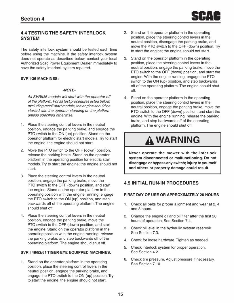
2.4 TESTING THE SAFETY INTERLOCK SYSTEM
The safety interlock system should be tested each time before using the machine. If the safety interlock system does not operate as described below, contact your local Authorized Scag Power Equipment Dealer immediately to have the safety interlock system repaired.
SVRII-36 MACHINES:
-NOTE-
All SVRII36 models will start with the operator off of the platform. For all test procedures listed below, excluding recoil start models, the engine should be started with the operator standing on the platform unless specified otherwise.
1. Place the steering control levers in the neutral position, engage the parking brake, and engage the PTO switch to the ON (up) position. Stand on the operator platform for electric start models. Try to start the engine; the engine should not start.
2. Move the PTO switch to the OFF (down) position, release the parking brake. Stand on the operator platform in the operating position for electric start models. Try to start the engine; the engine should not start.
5
RSection 2
3. Place the steering control levers in the neutral position, engage the parking brake, move the PTO switch to the OFF (down) position, and start the engine. Stand on the operator platform in the operating position with the engine running, engage the PTO switch to the ON (up) position, and step backwards off of the operating platform. The engine should shut off.
4. Place the steering control levers in the neutral position, engage the parking brake, move the PTO switch to the OFF (down) position, and start the engine. Stand on the operator platform in the operating position with the engine running, release the parking brake, and step backwards off of the operating platform. The engine should shut off.
SVRII 48/52/61 TIGER EYE EQUIPPED MACHINES:
1. Stand on the operator platform in the operating position, place the steering control levers in the neutral position, engage the parking brake, and engage the PTO switch to the ON (up) position. Try to start the engine; the engine should not start.
2. Stand on the operator platform in the operating position, place the steering control levers in the neutral position, disengage the parking brake, and move the PTO switch to the OFF (down) position. Try to start the engine; the engine should not start.
3. Stand on the operator platform in the operating position, place the steering control levers in the neutral position, engage the parking brake, move the PTO switch to the OFF (down) position, and start the engine. With the engine running, engage the PTO switch to the ON (up) position, and step backwards off of the operating platform. The engine should shut off.
4. Stand on the operator platform in the operating position, place the steering control levers in the neutral position, engage the parking brake, move the PTO switch to the OFF (down) position, and start the engine. With the engine running, release the parking brake, and step backwards off of the operating platform. The engine should shut off.
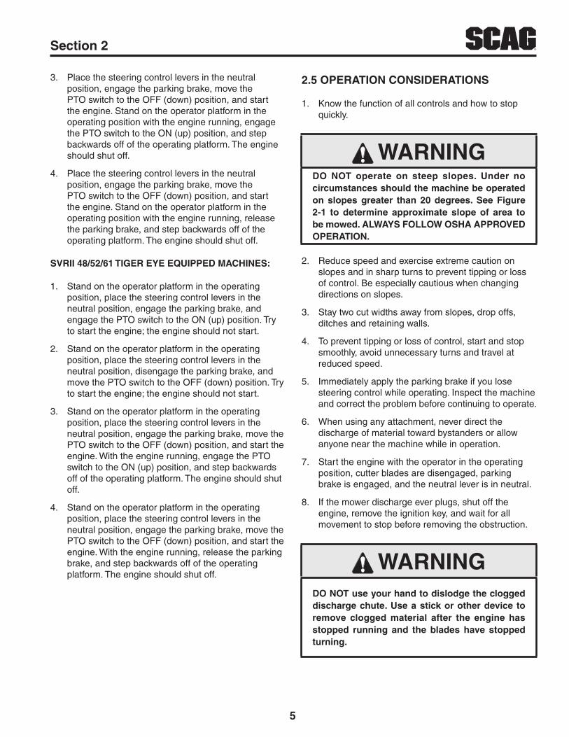
2.5 OPERATION CONSIDERATIONS
1. Know the function of all controls and how to stop quickly.
WARNINGDO NOT operate on steep slopes. Under no circumstances should the machine be operated on slopes greater than 20 degrees. See Figure 2-1 to determine approximate slope of area to be mowed. ALWAYS FOLLOW OSHA APPROVED OPERATION.
2. Reduce speed and exercise extreme caution on slopes and in sharp turns to prevent tipping or loss of control. Be especially cautious when changing directions on slopes.
3. Stay two cut widths away from slopes, drop offs, ditches and retaining walls.
4. To prevent tipping or loss of control, start and stop smoothly, avoid unnecessary turns and travel at reduced speed.
5. Immediately apply the parking brake if you lose steering control while operating. Inspect the machine and correct the problem before continuing to operate.
6. When using any attachment, never direct the discharge of material toward bystanders or allow anyone near the machine while in operation.
7. Start the engine with the operator in the operating position, cutter blades are disengaged, parking brake is engaged, and the neutral lever is in neutral.
8. If the mower discharge ever plugs, shut off the engine, remove the ignition key, and wait for all movement to stop before removing the obstruction.
WARNINGDO NOT use your hand to dislodge the clogged discharge chute. Use a stick or other device to remove clogged material after the engine has stopped running and the blades have stopped turning.

6
R Section 2
9. Be alert for holes, rocks, roots and other hidden hazards in the terrain. Keep away from any drop offs. Beware of overhead obstructions (low limbs, etc.), underground obstacles (sprinklers, pipes, tree roots, etc.). Cautiously enter a new area. Be alert for hidden hazards.
10. Disengage power to cutter deck before backing up. Do not mow in reverse unless absolutely necessary and then only after observation of the entire area behind the mower. If you must mow in reverse, maintain a constant lookout to the rear of the machine and mow slowly.
11. DO NOT turn sharply. Use care when backing up.
12. Disengage power to cutter deck before crossing roads, walks or gravel drives.
13. Mow only in daylight or good artificial light.
14. NEVER raise the deck with the blades engaged.
15. Take all possible precautions when leaving the machine unattended, such as disengaging the mower, stopping the engine, and removing the key.
16. Disengage power to the attachments when transporting or when not in use.
17. The machine and attachments should be stopped and inspected for damage after striking a foreign object, and damage should be repaired before restarting and operating the machine.
5o
10o
15o
20 o
Figure 2-1. Slope Angle Graph
CAUTIONDo not touch the engine or the muffler while the engine is running or immediately after stopping. These areas may be hot enough to cause a burn.
DANGERDO NOT run the engine inside a building or a confined area without proper ventilation. Exhaust fumes are hazardous and contain carbon monoxide which can cause brain injury and death.
18. Keep hands and feet away from cutter blades and moving parts. Contact can injure.
19. Transport the mower using a heavy duty trailer or truck. Ensure the trailer or truck has all of the necessary lighting and markings as required by laws, codes, and ordinances. Secure a trailer with a safety chain.
20. Be cautious when loading and unloading onto trailers or trucks. Use only a full width ramp. Always back on and drive off a trailer.
21. When transporting the mower, make sure the neutral lock lever is in neutral lock, the engine is off with the key removed, the parking brake is engaged and the wheels have been blocked.
22. Tie the mower down securely using the tie down points located on the front and rear of the machine. See Figure 2-2 and 2-3. Secure using straps, chains, cable, or ropes. Both front and rear straps must be directed down and outward from machine.
TIE DOWNPOINT
TIE DOWNPOINT
Figure 2-2. Front Tie Down Points

7
RSection 2
TIE DOWNPOINT
TIE DOWNPOINT
Figure 2-3. Rear Tie Down Points
23. Use care when approaching blind corners, shrubs, trees, or other objects that may obscure vision.
24. NEVER leave the machine running unattended.
2.6 MAINTENANCE CONSIDERATIONS & STORAGE
1. Never make adjustments to the machine with the engine running unless specifically instructed to do so. If the engine is running, keep hands, feet, and clothing away from moving parts.
2. Place the control levers in the neutral position, engage the parking brake, stop engine and remove key or disconnect spark plug wire to prevent accidental starting of the engine when servicing or adjusting the machine. Wait for all movement to stop before adjusting, cleaning or repairing.
3. Remove spark plug wire before making any repairs.
4. Keep all nuts, bolts and screws tight, to ensure the machine is in safe working condition. Check blade mounting bolts frequently to be sure they are tight.
5. Do not change the engine governor settings or overspeed the engine. See the engine operator's manual for information on engine settings.
6. To reduce fire hazard, keep the cutting units, drives, muffler and engine free of grass, leaves, excessive grease, oil and dirt.
7. Park the machine on level ground.
8. NEVER allow untrained personnel to service the machine.
9. Use care when checking blades. Use a Blade Buddy, wrap the blade(s) or wear gloves and USE CAUTION when servicing blades. Only replace blades. NEVER straighten or weld blades.
10. Keep all parts in good working condition. Replace all worn or damaged decals.
11. Use jack stands to support components when required.
12. Carefully release pressure from components with stored energy.
WARNINGHydraulic fluid is under high pressure and can penetrate skin causing injury. If hydraulic fluid is injected into the skin, it must be surgically removed within a few hours by a doctor or gangrene may result.
Keep body and hands away from pinholes or nozzles that eject hydraulic fluid under high pressure. Use paper or cardboard and not hands to search for leaks.
Safely relieve all pressure from the hydraulic system by placing the control levers in the neutral lock position and shutting off the engine before performing any work on the hydraulic system.
If you need service on your hydraulic system, please see your authorized Scag dealer.
13. Let the engine cool before storing.
14. DO NOT store the machine near an open flame.
15. Shut off fuel while storing or transporting.
16. DO NOT store fuel near flames or drain indoors.

8
R Section 2
2.7 USING A SPARK ARRESTOR
The engine in this machine is not equipped with a spark arrestor muffler. It is in violation of California Public Resource Code Section 4442 to use or operate this engine on or near any forest covered, brush covered or grass covered land unless the exhaust system is equipped with a spark arrestor meeting any applicable local or state laws. Other states or federal areas may have similar laws. Check with your state or local authorities for regulations pertaining to these requirements.
2.8 SPARK IGNITION SYSTEM
This spark ignition system complies with Canadian ICES-002.

9
RSection 2
483407
483402
484281483406
2017 SVRII Safety Decals
Molded in Fuel Tank
485819
WARNINGOperation of this equipmentmay create sparks that canstart �res around dry vegetation. A spark arrestor may be required.The operator should contact local �re agencies for laws or regulations relating to�re prevention requirements.
483900
483900(supplied with California models only)
483405
!Avoid injury from burns- Shut off engine- Allow to cool several minutes- Remove cap slowly- Do not over fill
Avoid injury from burns- Shut off engine- Allow to cool several minutes- Remove cap slowly- Do not overfill
EPACentroRLP / Q-08-027A 484377
485877
485910 485911
2.9 SAFETY AND INSTRUCTIONAL DECALS

10
R Section 3
SPECIFICATIONS3.1 ENGINE
General Type ................................................................................................Heavy Duty Industrial/Commercial GasolineModel:
Scag Model SVRII-36A-15FS ..........................................................................................................Kawasaki FS541VScag Model SVRII-36A-19FX ..........................................................................................................Kawasaki FX600VScag Model SVRII-48V-22FX ..........................................................................................................Kawasaki FX691VScag Model SVRII-52V-23FX ..........................................................................................................Kawasaki FX730VScag Model SVRII-52V-25CV-EFI ....................................................................................................... Kohler ECV740Scag Model SVRII-61V-25FX ..........................................................................................................Kawasaki FX801VScag Model SVRII-61V-29CV-EFI ....................................................................................................... Kohler ECV860
Displacement:Kawasaki FS541V .............................................................................................................................................. 603cc Kawasaki FX600V .............................................................................................................................................. 603cc Kawasaki FX690V .............................................................................................................................................. 726ccKawasaki FX730V .............................................................................................................................................. 726ccKohler ECV740 ................................................................................................................................................... 747ccKohler ECV860 ................................................................................................................................................... 824ccKawasaki FX801V .............................................................................................................................................. 852cc
Cylinders ..................................................................................................................................... 2 with Cast-Iron Sleeves Governor ................................................Mechanical Type with Variable Speed Control Set At 3600 RPM (+/- 100 RPM)Idle Speed:
Kawasaki ............................................................................................................................. 1550 RPM (+/- 150 RPM)Kohler .................................................................................................................................... 1800 RPM (+/- 75 RPM)
Fuel ...................................................................................... Non-Leaded Gasoline with a Minimum Octane Rating of 87Oil Pump .............................................................................................. Varies - see engine manufacturer's specificationsStarter:
Kawasaki FS ............................................................................................................................................. Recoil StartKawasaki FX ..............................................................................................Electric Starting with solenoid shift starterKohler ECV .................................................................................................Electric Starting with solenoid shift starter
3.2 ELECTRICAL
Kawasaki FS Starter .......................... Electric Starting with Bendix Shift Starter or Electrical Ignition with Recoil StarterKohler & Kawasaki FX Starter ....................................................................... Electric Starting with Solenoid Shift StarterInterlock Switches ...........................................................Operator Presence, Mower Engagement (PTO), Parking BrakeInstrument Panel ......... .Tiger Eye Advanced Monitoring System, Key Switch, Throttle Lever, Choke Lever, PTO Switch
3.3 ENGINE DECK
Drive System ............................................................................. Hydraulic Drive with Two Variable Displacement Pumps and Two Cast-Iron High Torque Wheel MotorsHydraulic Pumps .............................................Two Hydro-Gear PG Series 10 cc. (36) or PK Series 12 cc. (48 / 52 / 61) Hydraulic Pumps (PK equipped with Fans) with Dump Valves for movement without the engine runningHydraulic Drive Motors ..............................................................................Two Parker Model TJ Cast-Iron Wheel MotorsSteering/Travel Control ..............................................Twin Lever Steering Control with Individual Control to Each WheelParking Brake ...........................................................................Lever Actuated Linkage to Brakes on Both Drive WheelsWheels:
(2) Front Caster ......................................................................................... (36) - 11 x 4-5 Flat Free w/Roller Bearings (48 / 52) 13 x 5 - 6, (61) - 13 x 6.5 - 6 Flat-Free w/Roller Bearings
(2) Drive - ......................................................................(36) 20 x 10 - 8 Four-Ply Pneumatic Tubeless, Radius Edge (48 / 52) 24 x 9.5 - 12, (61) 24 x 12 - 12 Four-Ply Pneumatic Tubeless, Radius EdgeTire Pressure:
Front Caster....................................................................................................................................................Flat-FreeDrive .................................................................................................................................................................. 12 PSI

11
RSection 3
Fuel Tank ........................ 6-3/4 Gallon (36) or 8 Gallon (48 / 52 / 61) Seamless Polyethylene Tank with Large Opening, Fuel Cap and Fuel Gauge Travel Speed:
Forward .................................................................................................................................... (36) - 0 up to 8.5 MPH (48 / 52 / 61) - 0 up to 10.5 MPH
Reverse .............................................................................................................................................. 0 up to 5.0 MPH-NOTE- The machine will travel at speeds up to 8.5 mph, 10 mph or 10.5 mph for transport purposes. For best cutting performance the forward travel speed should be adjusted depending upon the cutting conditions.
3.4 CUTTER DECK
Type ......................................................................................................................Out-Front design with anti-scalp rollersConstruction ............................................................................................................................ Tri-plate deck construction Top of deck consists of three steel plates totaling nearly 1/2" of steel, 7-gauge (3/16") deck skirtTrue Cutting Width:
36 .........................................................................................................................................................35.5" (90.2 cm)48 ..........................................................................................................................................................48" (122.0 cm)52 ..........................................................................................................................................................52" (132.0 cm)61 ..........................................................................................................................................................61" (155.0 cm)
Cutting Height Adjustment ............................................................... Adjustment from, 1-1/2" to 4-1/2" in 1/4" incrementsCutter Blades ............................................................................. 0.197 in. Thick, Milled Edge, Wear Resistant Marbain™Blade Engagement ............................................................Electric Blade Engagement Clutch with Control Panel Switch Connected to the Cutter Deck through a BeltDischarge Opening ...............................................Extra Wide Discharge Opening with Spring-Loaded Discharge ChuteDischarge Chute ...................................................................................................Black, Polypropylene (Plastic), FlexibleSpindles ............................................................................. Cast-Iron Housing, Tapered Roller Bearings with Top Access Grease Fitting and Grease Overfill Relief PoppetSpindle Pulleys ........................................................................................................Split Steel with Tapered Locking Hub Cutter Deck Belts ................................................................................................................... B-section with Kevlar CordsElectric Clutch Type ................................................................................................Ogura Heavy Duty PTO Clutch Brake
3.5 WEIGHTS AND DIMENSIONS 36 48 / 52 61V
Length ..................................................................................... 65-1/4" ................... 67-1/2" / 69-1/2" ....................72-3/4"Tracking Width ............................................................................ 36" ................................ 48" ....................................48"Overall Width w/chute down .................................................... 47-3/4" ................... 61-1/4" / 65-1/4" ....................73-1/2"Overall Width w/chute up ......................................................... 37-1/4" ................... 49-3/4" / 53-3/4" ....................62-3/4"Overall Height ............................................................................. 47" ............................. 47-1/4" ...........................47-1/4"Operating Weight ...................................................................799 - 832# ................. 1015# / 1031# ............1127 - 1135#
3.6 PRODUCTIVITY 36 48 / 52 61 Cutting Width 36" 48" / 52" 61" Acres Per Day 14 18.6 / 20.2 23.7
The preceding chart will aid you in determining how many acres your Scag mower will cut per day. The chart is an estimate based on 8 hours per day cutting time at 6 MPH with a 20% allowance for overlap and turns.

12
R Section 4
WARNINGDo not attempt to operate this mower unless you have read this manual. Learn the location and purpose of all controls and instruments before you operate this mower.
Before operating the mower, familiarize yourself with all mower and engine controls. Knowing the location, function and operation of these controls is important for safe and efficient operation of the mower.
Tiger Eye Advanced Monitoring System is standard equipement on all SVRII-48V, SVRII-52V and SVRII-61V models only. With the key in the on position, before starting the engine, the lights for the Operator Indicator, PTO Indicator, Neutral Indicator and Park Brake Indicator should be illuminated. This indicates there is an operator on the platform, the PTO is off, steering levers are in neutral, and the parking brake is applied. When all the lights are illuminated, the key can be turned to the start position and the mower can be started. See Section 4.3 Safety Interlock System. If any of these indicator lights are not illuminated, the engine will be prevented from starting. If additional information or service is needed, contact your Scag Power Equipment Dealer.
4.1 TIGER EYE INSTRUMENT IDENTIFICATION (EXCLUDES SVRII-36A)
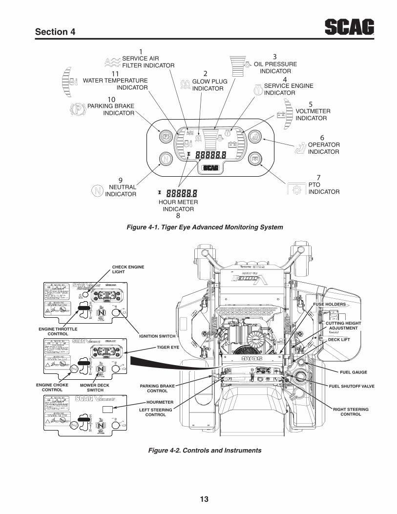
1. Service Air Filter Indicator (Figure 4-1). Optional Accessory. Indicates the condition of the engine air filter. Icon will display when it is time to change the air filter.
2. Glow Plug Indicator (Figure 4-1). Used on Diesel Powered Units Only. Indicator turns on when the key switch is turned to the PREHEAT position. Glow plugs must be preheated for 5 to 10 seconds before starting the engine.
3. Oil Pressure Indicator (Figure 4-1). Used on Diesel Powered Units Only. Indicates engine oil pressure. Reference the engine operator's manual for further information.
OPERATING INSTRUCTIONS4. Service Engine Indicator (Figure 4-1). Indicates
the maintenance reminder for the engine oil change. Has preset maintenance reminder and will start flashing scheduled maintenance 2 hours before preset time and continue flashing until 2 hours after. Automatically resets.
5. Voltmeter Indicator (Figure 4-1). Indicates the condition of the charging system. When the engine is running, in normal operating conditions, the bar graph should be in the 12 to 14 volt range.
6. Operator Indicator (Figure 4-1). Light will illuminate when the operator is on the platform engaging the operator presence switch.
7. PTO Indicator (Figure 4-1). Light will illuminate when the PTO (mower deck) switch is in the OFF position.
8. Hourmeter Indicator (Figure 4-1). Indicates the number of hours the engine has been operated. It only operates when the engine is running. Will start flashing with the Service Engine Indicator at scheduled maintenance 2 hours before preset time and continue flashing until 2 hours after. Automatically resets.
9. Neutral Indicator (Figure 4-1). Light will illuminate when the steering control levers are in the neutral lock position.
10. Park Brake Indicator (Figure 4-1). Light will illuminate when the park brake is in the engaged (ON) position.
11. Water Temperature Indicator (Figure 4-1). Used on Liquid Cooled Models Only. Indicates the operating temperature of the engine. If the engine temperature exceeds the maximum preset value, the indicator will flash and the Park Brake, PTO, Seat and Neutral indicator lights will flash in an alternating pattern.
13
RSection 4
PARKING BRAKEINDICATOR
NEUTRALINDICATOR
OPERATORINDICATOR
PTOINDICATOR
WATER TEMPERATUREINDICATOR
VOLTMETERINDICATOR
SERVICE ENGINEINDICATOR
OIL PRESSUREINDICATOR
GLOW PLUGINDICATOR
SERVICE AIR FILTER INDICATOR
HOUR METERINDICATOR
1
2
3
4
5
6
7
8
9
10
11
Figure 4-1. Tiger Eye Advanced Monitoring System
FUEL GAUGE
FUEL SHUTOFF VALVE
RIGHT STEERINGCONTROL
LEFT STEERINGCONTROL
PARKING BRAKECONTROL
DECK LIFT
CUTTING HEIGHTADJUSTMENT
MOWER DECK SWITCH
IGNITION SWITCH
ENGINE CHOKECONTROL
ENGINE THROTTLECONTROL
TIGER EYE
CHECK ENGINELIGHT
FUSE HOLDERS
HOURMETER
Figure 4-2. Controls and Instruments

14
R Section 4
4.2 CONTROLS IDENTIFICATION
1. Ignition Switch (Figure 4-2). For electric start models, the ignition switch is used to start the engine and has three positions; OFF, ON, and START. For recoil start models, turn the key to the on position before pulling the recoil starter.
2. Mower Deck Switch (Figure 4-2). Used to engage and disengage the mower drive system. Pulling up on the switch will engage the deck drive. Pushing down on the switch will disengage the deck drive.
3. Engine Choke Control (Figure 4-2). Used to start a cold engine.
4. Engine Throttle Control (Figure 4-2). Used to control the engine speed. Pushing the lever forward increases engine speed. Pulling the lever back decreases engine speed. Full back position is the IDLE position. Full forward is the cutting position.
5. Check Engine Light (Figure 4-2). Indicates the operation of the engine sensors on the Fuel Injection Engines (EFI). If a problem occurs with a sensor on the engine, the light will flash a code.See your authorized Scag Dealer for diagnosis and repair.
6. Left Steering Control (Figure 4-2). Used to control the mower's left wheel when traveling forward or reverse. See Section 4.5 for further details regarding the mower's travel controls.
7. Right Steering Control (Figure 4-2). Used to control the mower's right wheel when traveling forward or reverse. See Section 4.5 for further details regarding the mower's travel controls.
8. Parking Brake Control (Figure 4-2). Used to engage and disengage the parking brakes and lock the steering handles in neutral. Pull the lever back to engage the parking brakes. Push the lever forward to disengage the parking brakes.
9. Deck Lift Lever (Figure 4-2). Used to raise and lower the cutter deck.
10. Cutting Height Adjustment (Figure 4-2). Used to set the cutter deck at the desired cutting height.
11. Fuel Tank Gauge (Figure 4-2). Indicates the amount of fuel in the fuel tank.
12. Fuse Holders (Figure 4-2). Two 20-amp fuses protect the mower’s electrical system. To replace fuses, pull fuse out of the socket and install a new fuse.
13. Hourmeter (Figure 4-2) SVRII-36A Only. Indicates the number of hours the engine has been operated. It operates whenever the engine is running. Has preset maintenance reminders for engine and hydraulic system oil changes. Will start flashing scheduled maintenance 2 hours before preset time and continue flashing until 2 hours after. Automatically resets
14. Fuel Shutoff Valve (Figure 4-2). Located on top of the fuel tank. Used to shut off fuel supply to the engine. Rotate the valve counter clockwise to supply fuel from the tank to the engine. Rotate the valve clockwise to shut off the fuel supply to the engine.
15. Dump Valve Controls (Figure 4-3). Located on the hydraulic pumps, used to “free-wheel” the mower. Rotating clockwise until they stop allows the unit to move under hydraulic power. The levers must be in this position and torqued to 7-10 lb-ft during operation of the mower. Rotating counter-clockwise allows the mower to be moved by hand (free-wheeling). See Figure 4-3.
DUMP VALVE LOCATION
Figure 4-3. Dump Valve Controls
4.3 SAFETY INTERLOCK SYSTEM
The mower is equipped with a safety interlock system intended to protect the operator and others from injury. This is accomplished by preventing the engine from starting unless the deck drive is disengaged, the parking brake is engaged, the steering control levers are in the neutral position and the operator is in the operator position. The interlock system shuts off the engine if the operator leaves the operator platform with the steering control levers not in the neutral position and/or the cutter blades engaged and the parking brake not engaged.
15
RSection 4
4.4 TESTING THE SAFETY INTERLOCK SYSTEM
The safety interlock system should be tested each time before using the machine. If the safety interlock system does not operate as described below, contact your local Authorized Scag Power Equipment Dealer immediately to have the safety interlock system repaired.
SVRII-36 MACHINES:
-NOTE-
All SVRII36 models will start with the operator off of the platform. For all test procedures listed below, excluding recoil start models, the engine should be started with the operator standing on the platform unless specified otherwise.
1. Place the steering control levers in the neutral position, engage the parking brake, and engage the PTO switch to the ON (up) position. Stand on the operator platform for electric start models. Try to start the engine; the engine should not start.
2. Move the PTO switch to the OFF (down) position, release the parking brake. Stand on the operator platform in the operating position for electric start models. Try to start the engine; the engine should not start.
3. Place the steering control levers in the neutral position, engage the parking brake, move the PTO switch to the OFF (down) position, and start the engine. Stand on the operator platform in the operating position with the engine running, engage the PTO switch to the ON (up) position, and step backwards off of the operating platform. The engine should shut off.
4. Place the steering control levers in the neutral position, engage the parking brake, move the PTO switch to the OFF (down) position, and start the engine. Stand on the operator platform in the operating position with the engine running, release the parking brake, and step backwards off of the operating platform. The engine should shut off.
SVRII 48/52/61 TIGER EYE EQUIPPED MACHINES:
1. Stand on the operator platform in the operating position, place the steering control levers in the neutral position, engage the parking brake, and engage the PTO switch to the ON (up) position. Try to start the engine; the engine should not start.
2. Stand on the operator platform in the operating position, place the steering control levers in the neutral position, disengage the parking brake, and move the PTO switch to the OFF (down) position. Try to start the engine; the engine should not start.
3. Stand on the operator platform in the operating position, place the steering control levers in the neutral position, engage the parking brake, move the PTO switch to the OFF (down) position, and start the engine. With the engine running, engage the PTO switch to the ON (up) position, and step backwards off of the operating platform. The engine should shut off.
4. Stand on the operator platform in the operating position, place the steering control levers in the neutral position, engage the parking brake, move the PTO switch to the OFF (down) position, and start the engine. With the engine running, release the parking brake, and step backwards off of the operating platform. The engine should shut off.
WARNINGNever operate the mower with the interlock system disconnected or malfunctioning. Do not disengage or bypass any switch; injury to yourself and others or property damage could result.
4.5 INITIAL RUN-IN PROCEDURES
FIRST DAY OF USE OR APPROXIMATELY 20 HOURS
1. Check all belts for proper alignment and wear at 2, 4 and 8 hours.
2. Change the engine oil and oil filter after the first 20 hours of operation. See Section 7.4.
3. Check oil level in the hydraulic system reservoir. See Section 7.3.
4. Check for loose hardware. Tighten as needed.
5. Check interlock system for proper operation. See Section 4.2.
6. Check tire pressure. Adjust pressure if necessary. See Section 7.10.
16
R Section 4
4.6 STARTING THE ENGINE
CAUTIONDO NOT USE STARTING FLUIDS. Use of starting fluids in the air intake system may be potentially explosive or cause a “runaway” engine condition that could result in engine damage and/or personal injury.
1. Be sure the fuel shutoff valve, located by the fuel tank, is completely open. See Section 7.5.
2. Place the steering control levers in the neutral position and disengage the cutter blades.
3. Engage the parking brake.
4. If the engine is cold, choke the engine as needed.
5. Move the engine throttle control to about half engine speed.
6. Turn the ignition key to the start position and start the engine.
7. Allow engine to warm before operating the mower.
4.7 GROUND TRAVEL AND STEERING
- IMPORTANT -
If you are not familiar with the operation of a machine with lever steering and/or hydrostatic transmissions, the steering and ground speed operations should be learned and practiced in an open area, away from buildings, fences, or obstructions. Practice until you are comfortable with the handling of the machine before attempting to mow. Learn the operation on flat ground before operating on slopes.
- IMPORTANT -
Start practicing with a slow engine speed and slow forward travel.
Learn to feather the steering controls to obtain a smooth operating action.
Practice operating the mower until you are comfortable with the controls before proceeding to mow.
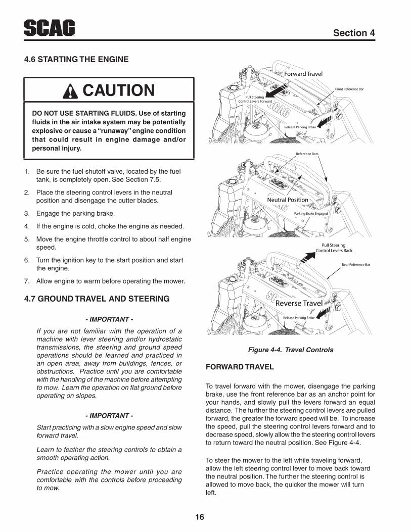
Pull Steering Control Levers Forward
Front Reference Bar
Forward Travel
Reference Bars
Neutral Position
Rear Reference Bar
Pull Steering Control Levers Back
Reverse Travel
Release Parking Brake
Parking Brake Engaged
Release Parking Brake
Figure 4-4. Travel Controls
FORWARD TRAVEL
To travel forward with the mower, disengage the parking brake, use the front reference bar as an anchor point for your hands, and slowly pull the levers forward an equal distance. The further the steering control levers are pulled forward, the greater the forward speed will be. To increase the speed, pull the steering control levers forward and to decrease speed, slowly allow the the steering control levers to return toward the neutral position. See Figure 4-4.
To steer the mower to the left while traveling forward, allow the left steering control lever to move back toward the neutral position. The further the steering control is allowed to move back, the quicker the mower will turn left.
17
RSection 4
To steer the mower to the right while traveling forward, allow the right steering control lever to move back toward the neutral position. The further the steering control is allowed to move back, the quicker the mower will turn right.
To stop the forward travel completely, allow the steering control levers to return to the neutral position. If the mower is to be parked, engage the parking brake.
- NOTE -
Smooth operation of the steering control levers will produce smooth mower operation. While learning the operation of the steering controls, keep the travel speed low.
- IMPORTANT -
Do not travel forward over a curb. The mower will hang up on the curb. Raise the deck and travel backwards over the curb at a 45 degree angle. (See Figure 4-1 item 9 for cutter deck raising description.)
REVERSE TRAVEL
CAUTIONDisengage power to the mower before backing up. Do not mow in reverse unless absolutely necessary and then only after observation of the entire area behind the mower.
CAUTIONBefore backing up, observe the rear for persons and obstructions. Clear the area before backing up. Possible injury or property damage could occur.
To travel in reverse, use the rear reference bar as an anchor for your hands, and slowly pull both steering control handles back. Keep the travel speed low while traveling in reverse. See Figure 4-4
- NOTE -
The mower may not travel straight in reverse. Slight adjustments may need to be made using the steering controls.
To steer left while traveling in reverse, allow the left steering control lever to move forward. The further the control is allowed to move forward, the quicker the mower will turn left.
To steer right while traveling in reverse, allow the right steering control lever to move forward. The further the control is allowed to move forward, the quicker the mower will turn right.
To stop the reverse travel, allow the steering control levers to return to the neutral position. If the mower is to be parked, engage the parking brake.
4.8 ENGAGING THE DECK DRIVE (CUTTER BLADES)
1. Set the throttle at about 3/4 speed. Do not attempt to engage the deck drive at high speed as this shortens the electric clutch life — use only moderate engine speed when engaging the deck drive.
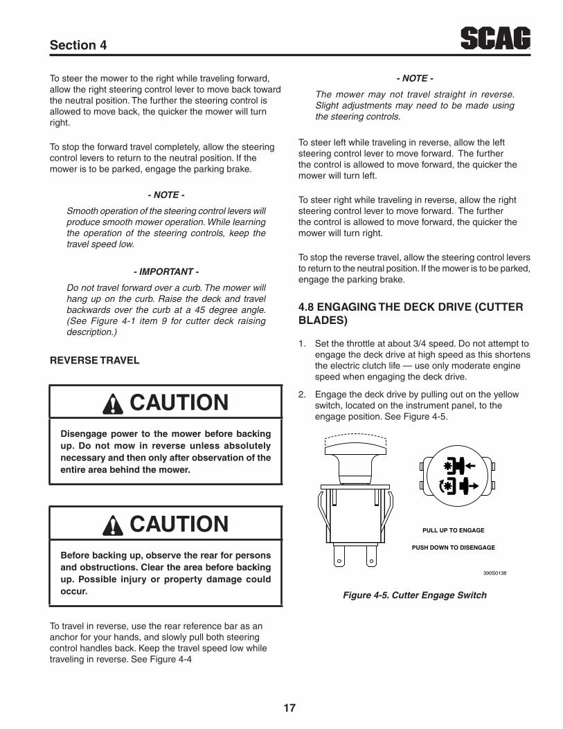
2. Engage the deck drive by pulling out on the yellow switch, located on the instrument panel, to the engage position. See Figure 4-5.
390S0138
PULL UP TO ENGAGE
PUSH DOWN TO DISENGAGE
Figure 4-5. Cutter Engage Switch
18
R Section 4
CAUTIONDisengage power to the mower before backing up. Do not mow in reverse unless absolutely necessary and then only after observation of the entire area behind the mower.
CAUTIONBefore backing up, observe behind the mower for persons and obstructions. Clear the area before backing up. Possible injury or property damage could occur.
- NOTE -
A squealing noise may be heard when engaging or disengaging the deck drive. It is caused by the electric clutch plates meshing as the mower comes up to speed. This is normal.
3. To disengage the deck drive, push the switch in to the disengage position.
4. Always operate the engine at full throttle to properly maintain cutting speed. If the engine starts to lug down, reduce the forward speed and allow the engine to operate at maximum RPM.
4.9 HILLSIDE OPERATION
WARNINGDO NOT operate on steep slopes. Under no circumstances should the machine be operated on slopes greater than 20 degrees. See Figure 2-1, Page 5 to determine approximate slope of area to be mowed. ALWAYS FOLLOW OSHA APPROVED OPERATION.
1. This mower has been designed for good traction and stability under normal mowing conditions. However, caution must be used when traveling on slopes, especially when the grass is wet. Wet grass reduces traction and steering control.
2. Stay two cut widths away from slopes, drop offs, ditches and retaining walls.
3. To prevent tipping or loss of control, do not start or stop suddenly, avoid unnecessary turns and travel at reduced speed. If tires lose traction, disengage blades and proceed slowly off the slope.
4. Avoid sudden starts when mowing uphill. Sudden starts may cause the machine to tip backwards.
5. Loss of traction may occur when traveling down hill. Weight transfers to the front of the machine and may cause the drive wheels to slip causing loss of braking or steering.
6. Never back down hill.
7. Keep tires properly inflated.
4.10 PARKING THE MOWER
1. Park the machine on a flat, level surface only. Do not park the machine on an incline.
2. Place the steering control levers in the neutral position.
3. Disengage the cutter blades.
4. Slow the engine to idle speed.
5. Engage the parking brake.
6. Turn the ignition key to the OFF position and remove the key.
4.11 AFTER OPERATION
1. Wash the entire mower after each use. Do not use high pressure spray or direct the spray onto electrical components.
- IMPORTANT -
Do not wash a hot or running engine. Cold water will damage the engine. Use compressed air to clean the engine if it is hot.
2. Keep the entire mower clean to inhibit serious heat damage to the engine or hydraulic oil circuit.
3. Check the drive belts for proper alignment and any signs of wear. Correct and adjust if necessary.
19
RSection 4
DANGERTo avoid injury from burns, allow the mower to cool before removing the fuel tank cap and refueling.
4. After the mower has cooled down, fill the fuel tank with fresh, clean fuel at the end of every day of operation. See Engine Owner's Manual for proper octane requirements.
5. Check the tire pressure. Adjust pressure if necessary.
4.12 REMOVING CLOGGED MATERIAL
DANGERROTATING BLADES
NEVER PUT YOUR HANDS INTO THE DISCHARGE CHUTE FOR ANY REASON!
Shut off the engine and remove the key and only then use a stick or similar object to remove material if clogging has occurred.
1. If the discharge chute becomes clogged, shut off the engine and remove the ignition key. Using a stick or similar item, dislodge the clogged material. Then resume normal mowing.
4.13 MOVING MOWER WITH ENGINE STOPPED
To “free-wheel” or move the mower around without the engine running, place the dump valve levers in the FREE-WHEEL position. Disengage the parking brake and move the mower by hand. The dump valve levers must be returned to the DRIVE position and torqued to 7-10 ft/lbs to drive the mower.
4.14 RECOMMENDATIONS FOR MOWING
1. Do not mow with dull blades. A dull blade will tear grass, resulting in poor lawn appearance and reduced mowing power.
WARNINGDO NOT operate without Discharge Chute, Mulching Kit, Operator Controlled Discharge Chute (OCDC) or entire Grass Catcher properly installed.
2. The discharge chute must not be removed and must be kept in the lowest position to deflect grass clippings and thrown objects downward. Direct the side discharge away from sidewalks or streets to minimize cleanup of clippings. When mowing close to obstacles, direct the discharge away from the obstacles to reduce the chance of property damage by thrown objects.
3. Cut grass when it is dry and not too tall. Do not cut grass too short (cut off 1/3 or less of existing grass for best appearance). Mow frequently.
4. Keep mower and discharge chute clean.
5. When mowing wet or tall grass, mow the grass twice. Raise the mower to the highest setting for the first pass and then make a second pass to the desired height.
6. Use a slow travel speed for trimming purposes.
7. Operate the engine at full throttle for best cutting. Mowing with a lower RPM causes the mower to tear the grass. The engine is designed to be operated at full speed.
8. Use the alternate stripe pattern for best lawn appearance. Vary the direction of the stripe each time the grass is mowed to avoid wear patterns in the grass.
4.15 ADJUSTING CUTTING HEIGHT
The mower deck can be adjusted from a height of 1-1/2 inch to 4-1/2 inches at 1/4-inch intervals. To adjust the cutting height:
WARNINGDO NOT adjust the cutting height with the mower blades rotating. Disengage the power to the cutter blades, put the steering control levers in the neutral position, apply the parking brake and then adjust cutting height.

20
R Section 4
1. Disengage the power to the cutter blades.
2. Pull the cutter deck lift lever all the way backward until it locks in place. See Figure 4-6.
3. Insert the lanyard pin into the cutting height index at the desired cutting height. Pull backward on the cutter deck lift lever, push and hold the lock button See Figure 4-6. Slowly release the cutter deck lift lever. A deck height decal is located on the cutting height index as an aid in adjusting the deck to the desired height.
CUTTER DECKLIFT LEVER
LANYARD PIN
Figure 4-6. Adjusting Cutting Height

21
RSection 5
CONDITION CAUSE CURE
STRINGERS - OCCASIONAL BLADES OF UNCUT GRASS
Width of Deck
SGB020
Low engine RPM Run engine at full RPM
Ground speed too fast Slow speed to adjust for conditions
Wet grass Cut grass after it has dried out
Dull blades, incorrect sharpening Sharpen blades
Deck plugged, grass accumulation Clean underside of deck
Belts slipping Adjust belt tension
STREAKING - STRIPS OF UNCUT GRASS IN CUTTING PATH
Width of Deck
SGB018
Dull, worn blades Sharpen blades
Incorrect blade sharpening Sharpen blades
Low engine RPM Run engine at full RPM
Belt slipping Adjust belt tension
Deck plugged, grass accumulation Clean underside of deck
Ground speed too fast Slow speed to adjust for conditions
Wet grass Cut grass after it has dried out
Bent blades Replace blades
STREAKING - STRIPS OF UNCUT GRASS BETWEEN CUTTING PATHS
Width of
Deck
Width of
DeckSGB019
Not enough overlapping between rows Increase the overlap of each pass
TROUBLESHOOTING CUTTING CONDITIONS

22
R Section 5
CONDITION CAUSE CURE
U N E V E N C U T O N F L AT GROUND - WAVY HIGH-LOW APPEARANCE, SCALLOPED CUT, OR ROUGH CONTOUR
Width of Deck
SGB020
Lift worn from blade Replace blade
Blade upside down Mount with cutting edge toward ground
Deck plugged, grass accumulation Clean underside of deck
Too much blade angle (deck pitch) Adjust pitch and level
Deck mounted improperly See your authorized SCAG dealer
Bent spindle area See your authorized SCAG dealer
Dull blade Sharpen blade
UNEVEN CUT ON UNEVEN GROUND - WAVY APPEARANCE, HIGH-LOW SCALLOPED CUT, OR ROUGH CONTOUR
Width of Deck
SGB021
Uneven groundMay need to reduce ground speed, raise cutting height, and/or change direction of cut
SLOPING RIDGE ACROSS WIDTH OF CUTTING PATH
Width of Deck
SGB023
Tire pressures not equal Check and adjust tire pressure
Wheels uneven Check and adjust tire pressure
Deck mounted incorrectly See your authorized SCAG dealer
Deck not level side-to side Check for level and correct
TROUBLESHOOTING CUTTING CONDITIONS (CONT'D)

23
RSection 5
CONDITION CAUSE CURE
SCALPING - BLADES HITTING DIRT OR CUTTING VERY CLOSE TO THE GROUND
Width of Deck
SGB022
Low tire pressures Check and adjust pressures
Ground speed too fast Slow speed to adjust for conditions
Cutting too lowMay need to reduce ground speed, raise cutting height, change direction of cut, and/or change pitch and level
Rough terrainMay need to reduce ground speed, raise cutting height, and/or change direction of cut
Ground speed too fast Slow speed to adjust for conditions
Wet grass Cut grass after it has dried out
STEP CUT - RIDGE IN CENTER OF CUTTING PATH
Width of Deck
SGB024
Blades not mounted evenly Adjust pitch and level
Bent blade Replace blade
Internal spindle failure See your authorized SCAG dealer
Mounting of spindle incorrect See your authorized SCAG dealer
SLOPE CUT - SLOPING RIDGES ACROSS WIDTH OF CUTTING PATH
Width of Deck
SGB025
Bent spindle mounting area See your authorized SCAG dealer
Internal spindle failure See your authorized SCAG dealer
Bent deck housing See your authorized SCAG dealer
TROUBLESHOOTING CUTTING CONDITIONS (CONT'D)

24
R Section 6
6.1 PARKING BRAKE ADJUSTMENT
WARNINGDO NOT operate the mower if the parking brake is not operable. Possible severe injury could result.
The parking brake should be adjusted whenever the parking brake lever is placed in the “ENGAGE” position and the parking brake will allow the mower to move. If the following procedures do not allow you to engage the parking brake properly, contact your Scag dealer for further brake adjustments.
1. Park the machine on a flat, level surface. Block the wheels to prevent the machine from moving.
CAUTIONAdjust the brake only enough to hold the machine. Excessive force may cause damage to the machine or brake components.
2. Release the parking brake lever.
3. Look for a gap (approximately 1/4") between the left side drive tire and the brake weldment. See Figure 6-1. Loosen the hardware securing the brake weldment to the brake actuator shaft weldment. Adjust the brake weldment until there is a 1/4" gap between the tire and brake weldment. Tighten the hardware
4. Repeat this procedure on the right side drive tire.
- NOTE -
If this procedure does not achieve proper brake adjustment, please contact your authorized Scag dealer.
ADJUSTMENTS
LOOSENHARDWARE
1/4” GAPNEEDED HERE
RELEASE PARKBRAKE
Figure 6-1. Brake Adjustment
6.2 TRAVEL ADJUSTMENT
Neutral or tracking adjustments will need to be made if:
1. The steering control is in the neutral position and the machine creeps forward or backward. (Neutral Adjustment)
2. The steering control is in the full forward position and the mower pulls to one side or the other when traveling in a forward position. (Tracking Adjustment)

25
RSection 6
NEUTRAL ADJUSTMENT
-NOTE-
Neutral has been set by your Scag dealer at the time of set up and normally does not need to be adjusted. If, however, you find that the neutral has come out of adjustment, follow the procedure below.
1. Be sure the dump valves are in the run position and the steering control levers are in the neutral position.
2. With an operator in the operating position, park the machine on a flat level surface, start the engine and disengage the parking brake.
3. Run the engine at full operating speed and check if the machine creeps forward or backwards.
4. Adjust the LH wheel by loosening the jam nuts on the steering control rod and turning the rod until the drive wheel turns in the forward direction. Turn the rod back until the drive wheel stops moving. Turn the rod an additional 1/2 turn. See Figure 6-2.
LOOSENJAM NUT
ADJUSTHERE
LOOSENJAM NUT
Figure 6-2. Tracking Adjustment (Left Side Shown)
5. Repeat for the RH wheel using the same adjustment procedure listed above.
6. Actuate the steering control levers forward and reverse several times and return them to the neutral position.
7. Check that the drive wheels remained in neutral and readjust if necessary.
8. Check that the steering control levers hit the stop before the pumps reach full stroke. Adjust as needed.
TRACKING ADJUSTMENT
CAUTIONStop the engine and remove the key from the ignition before making any adjustments. Wait for all moving parts to come to a complete stop before beginning work.
CAUTIONThe engine and drive unit can get hot during operation causing burn injuries. Allow the engine and drive components to cool before making any adjustments.
-NOTE-
Before proceeding with this adjustment, be sure that the caster wheels turn freely and that the tire pressure in the drive wheels is correct. If the tire pressure is not correct, the machine will pull to the side with the lower pressure.
1. If at full speed the mower pulls right, it is an indication that the left wheel is turning faster than the right wheel. To adjust this condition, proceed as follows:
A. Stop the machine and place the steering control levers in the neutral position. Loosen the lock nuts securing the ball joints at each end of the LH steering control rod. Rotate the control rod to lengthen the rod and tighten the lock nuts. This will cause the control rod to stroke the LH pump less, slowing down the LH wheel. See Figure 6-2.
26
R Section 6
- NOTE -
If after making the adjustment as outlined in step 1A, the machine creeps forward or backward, the neutral adjustment must be made as described on page 24.
2. If at full speed the mower pulls left, it is an indication that the right wheel is turning faster than the left wheel. To adjust this condition, proceed as follows:
A. Stop the machine and place the steering control levers in the neutral position. Loosen the lock nuts securing the ball joints at each end of the RH steering control rod. Rotate the control rod to lengthen the rod and tighten the lock nuts. This will cause the control rod to stroke the RH pump less, slowing down the RH wheel. The same adjustment is used for the RH side as shown in Figure 6-2.
- NOTE -
If after making the adjustment as outlined in step 2A, the machine creeps forward or backward, the neutral adjustment must be made as described on page 24.
6.3 THROTTLE CONTROL AND CHOKE ADJUSTMENTS
These adjustments must be performed by your Scag dealer to ensure proper and efficient running of the engine. Should either need adjustment, contact your authorized Scag service center.
6.4 BELT ADJUSTMENTS
WARNINGBefore removing any guards, shut the engine off and remove the ignition key. Wait for all moving parts to come to a complete stop before beginning work.
All drive belts and cutter deck belts are spring loaded and self-tensioning. The belts should be checked periodically for proper alignment and wear.
WARNINGIf the pump drive belt fails, steering control will be lost which could result in serious injury or death. Replace the pump drive belt as needed or every 400 hours / 2 years, whichever occurs first.
6.5 BELT ALIGNMENT
Belt alignment is important for proper performance of your Scag mower. If you experience frequent belt wear or breakage, see your authorized Scag service center for belt adjustment.
6.6 CUTTER DECK ADJUSTMENTS
Cutter deck level, pitch and height are set at the factory. However, if these adjustments should ever need to be made, the following procedures will aid in obtaining the proper cutter deck adjustment.
- NOTE -
Before proceeding with the cutter deck adjustments, be sure all tires are properly inflated.
CUTTER DECK LEVEL
The cutter deck should be level from side-to-side for proper cutting performance. To check for level, be sure that the mower is on a flat, level surface, the tires are properly inflated and the cutter deck is set at the most common cutting height that you will use. On the RH side of the machine, check the distance from the top of the cutter deck to the floor. Next check the distance from the top of the cutter deck to the floor on the LH side of the machine. Both measurements should be the same. If the two measurements are different, the cutter deck level must be adjusted as follows:
1. If the cutter deck is lower on one side, loosen the elastic stop nuts securing the deck level links on the front and rear of the lower side. See Figure 6-3.

27
RSection 6
ADJUST HERE
ADJUST HERE
LOOSEN HERE
Figure 6-3. Cutter Deck Level Adjustment
2. Turn the adjustment bolts on the front and rear deck level links clockwise until the cutter deck is level between both sides. See Figure 6-3.
3. Tighten the two (2) elastic stop nuts to secure the cutter deck in the proper position.
CUTTER DECK PITCH
The pitch of the cutter deck should be equal between the front and rear of the cutter deck for proper cutting performance. To check for proper deck pitch, be sure that the mower is on a flat, level surface and the tires are properly inflated.
Check the distance from the top of the cutter deck to the floor at the rear RH side of the cutter deck directly behind the cutter deck hanging chains. Next check the distance from the top of the cutter deck to the floor at the front RH side of the cutter deck directly in front of the cutter deck hanging chains. The measurement at the front of the cutter deck should be the same as the rear of the deck. Make these measurements at the LH side of the cutter deck also. If the measurement at the front of the deck is not the same, the cutter deck pitch must be adjusted as follows:
1. Loosen the elastic stop nuts securing the deck level links on the front of the cutter deck on both sides. See Figure 6-4 and 6-5.
ADJUST HERE
LOOSEN HERE
Figure 6-4. Cutter Deck Pitch Adjustment
2. Turn the adjustment bolts on both sides either clockwise to raise or counter-clockwise to lower the front of the cutter deck until the measurements are equal. Tighten the elastic stop nuts.
ADJUST HERE
LOOSEN HERE
Figure 6-5. Cutter Deck Pitch Adjustment
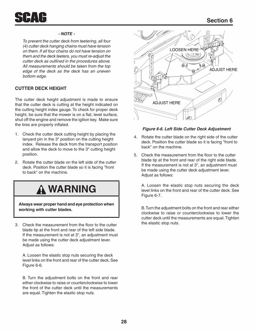
28
R Section 6
- NOTE -
To prevent the cutter deck from teetering, all four (4) cutter deck hanging chains must have tension on them. If all four chains do not have tension on them and the deck teeters, you must re-adjust the cutter deck as outlined in the procedures above. All measurements should be taken from the top edge of the deck as the deck has an uneven bottom edge.
CUTTER DECK HEIGHT
The cutter deck height adjustment is made to ensure that the cutter deck is cutting at the height indicated on the cutting height index gauge. To check for proper deck height, be sure that the mower is on a flat, level surface, shut off the engine and remove the igition key. Make sure the tires are properly inflated.
1. Check the cutter deck cutting height by placing the lanyard pin in the 3" position on the cutting height index. Release the deck from the transport position and allow the deck to move to the 3" cutting height position.
2. Rotate the cutter blade on the left side of the cutter deck. Position the cutter blade so it is facing "front to back" on the machine.
WARNINGAlways wear proper hand and eye protection when working with cutter blades.
3. Check the measurement from the floor to the cutter blade tip at the front and rear of the left side blade. If the measurement is not at 3", an adjustment must be made using the cutter deck adjustment lever. Adjust as follows:
A. Loosen the elastic stop nuts securing the deck level links on the front and rear of the cutter deck. See Figure 6-6.
B. Turn the adjustment bolts on the front and rear either clockwise to raise or counterclockwise to lower the front of the cutter deck until the measurements are equal. Tighten the elastic stop nuts.
ADJUST HERE
ADJUST HERE
LOOSEN HERE
Figure 6-6. Left Side Cutter Deck Adjustment
4. Rotate the cutter blade on the right side of the cutter deck. Position the cutter blade so it is facing "front to back" on the machine.
5. Check the measurement from the floor to the cutter blade tip at the front and rear of the right side blade. If the measurement is not at 3", an adjustment must be made using the cutter deck adjustment lever. Adjust as follows:
A. Loosen the elastic stop nuts securing the deck level links on the front and rear of the cutter deck. See Figure 6-7.
B. Turn the adjustment bolts on the front and rear either clockwise to raise or counterclockwise to lower the cutter deck until the measurements are equal. Tighten the elastic stop nuts.
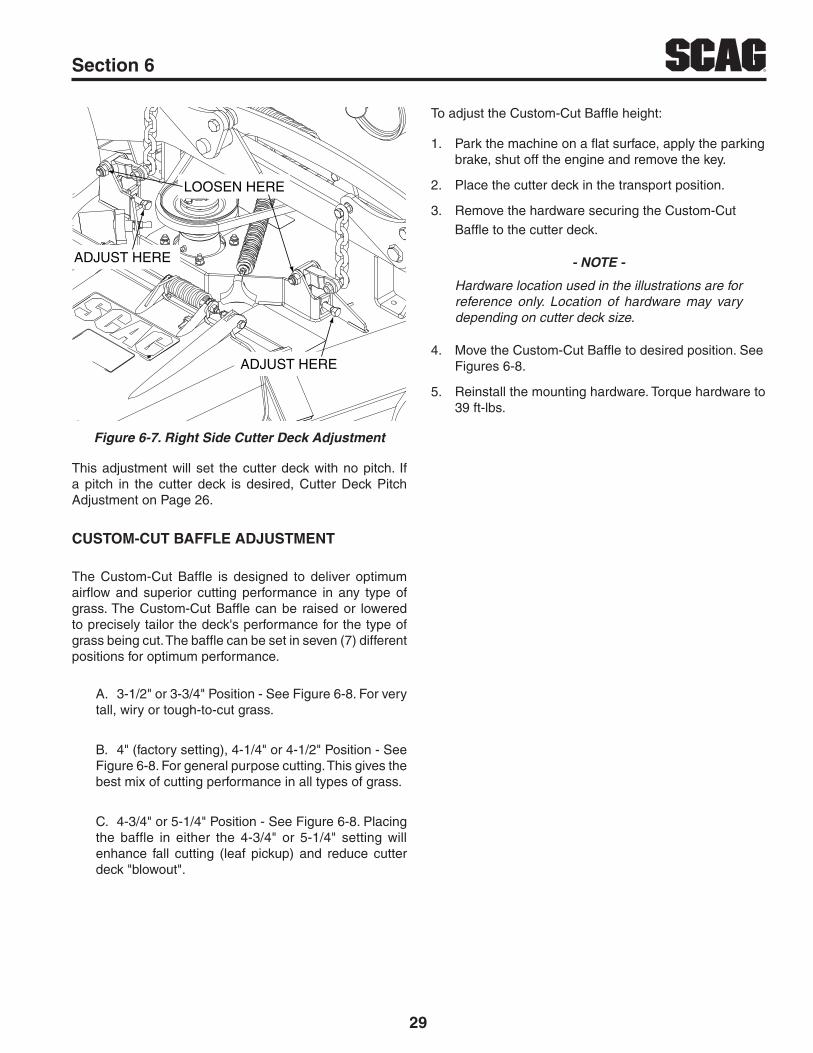
29
RSection 6
ADJUST HERE
ADJUST HERE
LOOSEN HERE
Figure 6-7. Right Side Cutter Deck Adjustment
This adjustment will set the cutter deck with no pitch. If a pitch in the cutter deck is desired, Cutter Deck Pitch Adjustment on Page 26.
CUSTOM-CUT BAFFLE ADJUSTMENT
The Custom-Cut Baffle is designed to deliver optimum airflow and superior cutting performance in any type of grass. The Custom-Cut Baffle can be raised or lowered to precisely tailor the deck's performance for the type of grass being cut. The baffle can be set in seven (7) different positions for optimum performance.
A. 3-1/2" or 3-3/4" Position - See Figure 6-8. For very tall, wiry or tough-to-cut grass.
B. 4" (factory setting), 4-1/4" or 4-1/2" Position - See Figure 6-8. For general purpose cutting. This gives the best mix of cutting performance in all types of grass.
C. 4-3/4" or 5-1/4" Position - See Figure 6-8. Placing the baffle in either the 4-3/4" or 5-1/4" setting will enhance fall cutting (leaf pickup) and reduce cutter deck "blowout".
To adjust the Custom-Cut Baffle height:
1. Park the machine on a flat surface, apply the parking brake, shut off the engine and remove the key.
2. Place the cutter deck in the transport position.
3. Remove the hardware securing the Custom-Cut Baffle to the cutter deck.
- NOTE -
Hardware location used in the illustrations are for reference only. Location of hardware may vary depending on cutter deck size.
4. Move the Custom-Cut Baffle to desired position. See Figures 6-8.
5. Reinstall the mounting hardware. Torque hardware to 39 ft-lbs.

30
R Section 6
1 234
AB
1 23 4
AB
Custom-Cut Baffle Adjustment
Mounting Slot Selected Mounting Hardware LocationSlot “A” Hole 1 Hole 2 Hole 3 Hole 4Height (inches) 3-3/4” 4-1/4” 4-3/4” 5-1/4”
Slot “B” Hole 2 Hole 3 Hole 4Height (inches) 3-1/2” 4” 4-1/2”
Figure 6-8. Custom-Cut Baffle Adjustment

31
RSection 6
ADJUSTMENT NUTS
ADJUSTMENT NUTS
Figure 6-11. Clutch Air Gap Adjustment
This adjustment should be done every 500 hours of operation or annually, whichever comes first. In cases where the machine is heavily used, airgap settings should be checked more often.
If the air gap is too narrow, the clutch armature may drag when disengaged, resulting in premature failure.
If the air gap is too wide, the clutch may be slow to engage as the magnet must pull the armature in from a greater distance.
6.7 ELECTRIC CLUTCH ADJUSTMENT
The electric clutch serves two functions in the operation of the mower. In addition to starting and stopping the power flow to the cutter blades, the clutch also acts as a brake to assist in stopping blade rotation when the PTO is switched off or the operator presence circuit is interrupted.
When the clutch is disengaged, the air gap between the armature and rotor must be adjusted to fifteen thousandths of an inch, 0.015, for proper operation. The airgap adjustment is made at three bolts on the clutch. There are three inspection windows, one next to each adjusting bolt. See Figure 6-9.
INSPECTION WINDOW (x3)
Figure 6-9. Clutch Air Gap Adjustment
1. Locate the inspection windows on the clutch.
2. Place a 0.015 feeler gauge in the slot between the rotor and the armature. See Figure 6-10.
INSERT 0.015 FEELER GAUGE HERE
Figure 6-10. Clutch Air Gap Adjustment
3. Tighten or loosen the adjusting bolt as needed to achieve the 0.015 inch airgap. See Figure 6-11.Perform this operation at all three inspection windows.
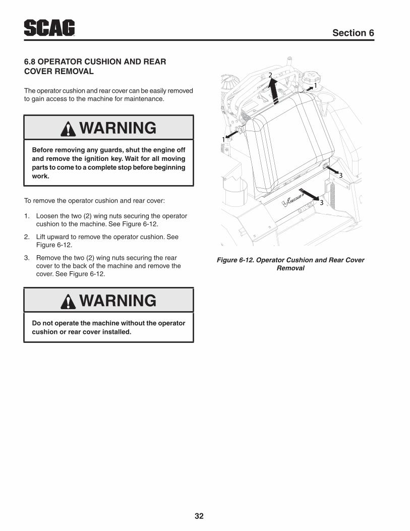
32
R Section 6
6.8 OPERATOR CUSHION AND REAR COVER REMOVAL
The operator cushion and rear cover can be easily removed to gain access to the machine for maintenance.
WARNINGBefore removing any guards, shut the engine off and remove the ignition key. Wait for all moving parts to come to a complete stop before beginning work.
To remove the operator cushion and rear cover:
1. Loosen the two (2) wing nuts securing the operator cushion to the machine. See Figure 6-12.
2. Lift upward to remove the operator cushion. See Figure 6-12.
3. Remove the two (2) wing nuts securing the rear cover to the back of the machine and remove the cover. See Figure 6-12.
WARNINGDo not operate the machine without the operator cushion or rear cover installed.
1
12
3
3
Figure 6-12. Operator Cushion and Rear Cover Removal
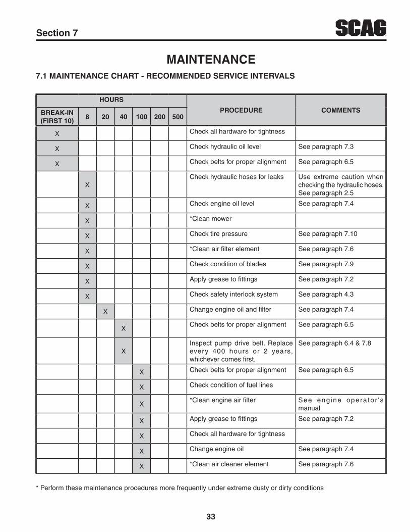
33
RSection 7
7.1 MAINTENANCE CHART - RECOMMENDED SERVICE INTERVALS
HOURS
PROCEDURE COMMENTSBREAK-IN (FIRST 10)
8 20 40 100 200 500
X Check all hardware for tightness
X Check hydraulic oil level See paragraph 7.3
X Check belts for proper alignment See paragraph 6.5
XCheck hydraulic hoses for leaks Use extreme caution when
checking the hydraulic hoses. See paragraph 2.5
X Check engine oil level See paragraph 7.4
X *Clean mower
X Check tire pressure See paragraph 7.10
X *Clean air filter element See paragraph 7.6
X Check condition of blades See paragraph 7.9
X Apply grease to fittings See paragraph 7.2
X Check safety interlock system See paragraph 4.3
X Change engine oil and filter See paragraph 7.4
XCheck belts for proper alignment See paragraph 6.5
XInspect pump drive belt. Replace every 400 hours or 2 years, whichever comes first.
See paragraph 6.4 & 7.8
X Check belts for proper alignment See paragraph 6.5
X Check condition of fuel lines
X*Clean engine air filter See eng ine opera to r ' s
manual
X Apply grease to fittings See paragraph 7.2
X Check all hardware for tightness
X Change engine oil See paragraph 7.4
X *Clean air cleaner element See paragraph 7.6
* Perform these maintenance procedures more frequently under extreme dusty or dirty conditions
MAINTENANCE

34
R Section 7
MAINTENANCE CHART - RECOMMENDED SERVICE INTERVALS (CONT'D)
HOURS
PROCEDURE COMMENTSBREAK-IN (FIRST 10)
8 40 100 200 500
X Check hardware for tightness
X Apply grease to fittings See paragraph 7.2
X Check hydraulic oil level See paragraph 7.3
X Change engine oil See paragraph 7.4
X Change engine oil filter See paragraph 7.4
X Replace engine fuel filter See paragraph 7.5
X Apply grease to fittings See paragraph 7.2
XDrain hydraulic system and replace oil and filter
See paragraph 7.3
X Adjust electric PTO clutch See paragraph 6.7
7.2 LUBRICATION
GREASE FITTING LUBRICATION CHART
LOCATION LUBRICATION INTERVAL LUBRICANTNO. OF
PLACES
1 - Caster Wheel Pivot 500 Hours / Yearly Chassis Grease 2
2 - Caster Wheel Bearings 100 Hours / Monthly Chassis Grease 2
3 - Cutter Deck Bell Cranks 100 Hours / Bi-Weekly Chassis Grease 4
4 - Cutter Deck Spindles 40 Hours / Weekly + US Lithium MP White Grease 2 / 3
5 - Cutter Deck Pusharms 100 Hours / Bi-Weekly Chassis Grease 2
+ Compatible Greases: Mobilgrease XHP 222 Exxon Mobil Ronex MP Exxon Mobil Unirex EP2
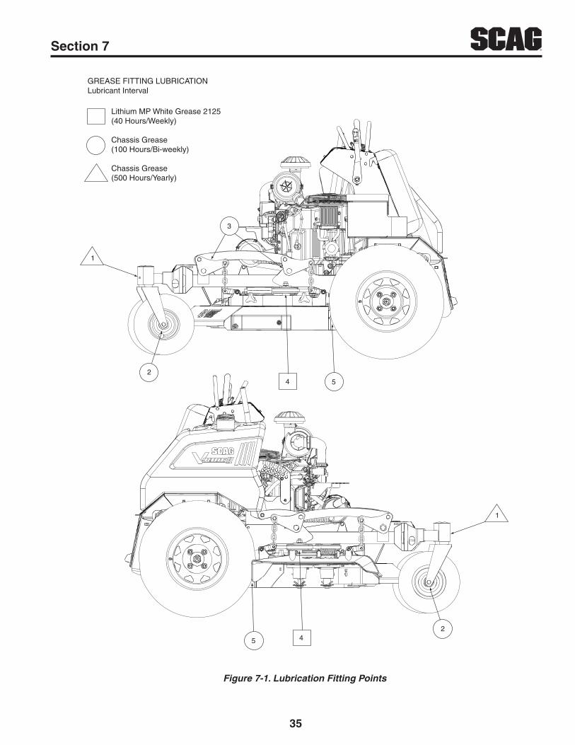
35
RSection 7
Figure 7-1. Lubrication Fitting Points
GREASE FITTING LUBRICATIONLubricant Interval
Lithium MP White Grease 2125(40 Hours/Weekly)
Chassis Grease(100 Hours/Bi-weekly)
Chassis Grease(500 Hours/Yearly)
1
24 5
3
45
2
1

36
R Section 7
B. CHANGING HYDRAULIC OIL
The hydraulic oil should be changed after every 500 hours or annually, whichever occurs first. The oil should also be changed if the color of the fluid has become black or milky. A black color and/or a rancid odor usually indicates possible overheating of the oil, and a milky color usually indicates water in the hydraulic oil.
- IMPORTANT -
The hydraulic oil should be changed if you notice the presence of water or a rancid odor to the hydraulic oil.
1. Park the mower on a level surface, stop the engine and remove the ignition key.
2. Remove the operator cushion and rear cover as outlined in Section 6.8.
3. Place a suitable container under the hydraulic oil filter. Remove the fill cap from the reservoir. Remove the drain plug from the remote oil drain hose. See Figure 7-3. Allow the fluid to drain into the container and properly discard it.
4. Re-install the drain plug into the remote draining hose and be sure it is tight.
- NOTE -
Before refilling the hydraulic oil reservoir the hydraulic oil filter should be changed as outlined in Procedure C "Changing Hydraulic Oil Filter Element".
5. Fill the reservoir to full 2-1/4" inches below the filler neck with 20W50 motor oil.
6. Replace the reservoir fill cap. Start the engine and drive forward and backward for two minutes. Check the oil level in the reservoir. If necessary, add oil to the reservoir.
7.3 HYDRAULIC SYSTEM
A. CHECKING HYDRAULIC OIL LEVEL
The hydraulic oil level should be checked after the first 8 hours of operation. Thereafter, check the oil after every 200 hours of machine operation or monthly, whichever occurs first.
- IMPORTANT -
If the oil level is consistently low, check for leaks and correct immediately.
1. Remove the operator cushion as outlined in Section 6.8.
2. Wipe dirt and contaminants from around the reservoir cap. Remove the cap from the hydraulic oil reservoir.
3. Visually check the level of hydraulic oil. Hydraulic oil must be at least 2-1/4" inches from top of the filler neck. If the level cannot be determined visually, use a clean tape measure to check the level. If the fluid is low, add 20W50 motor oil. DO NOT overfill; (overfilling the oil reservoir may cause oil seepage around the cap area).
4. Clean the fill cap and install it onto the reservoir.
HYDRAULIC OILRESERVOIR
Figure 7-2. Hydraulic Oil Reservoir

37
RSection 7
B. CHANGING ENGINE CRANKCASE OIL
After the first 20 hours of operation, change the engine crankcase oil and replace the oil filter. Thereafter, change the engine crankcase oil after every 100 hours of operation or monthly, whichever occurs first. Refer to the Engine Operator’s Manual furnished with this mower for instructions.
ENGINE OILFILLER & DIPSTICK
ENGINE OILDRAIN
ENGINE OILFILTER
Figure 7-4. Drain Plug, Dipstick and Oil Filter Location
C. CHANGING ENGINE OIL FILTER
After the first 20 hours of operation, replace the engine oil filter. Thereafter, replace the oil filter after every 200 hours of operation or every month, whichever occurs first. Refer to Engine Operator’s Manual for instructions.
HYDRAULIC OILFILTER
DRAIN PLUG
Figure 7-3. Hydraulic Oil Filter
C. CHANGING HYDRAULIC OIL FILTER ELEMENT
The hydraulic oil filter should be changed after every 500 hours of operation or annually, whichever occurs first.
1. Remove the oil filter element. See Figure 7-3.Properly discard the oil filter element. Fill the new filter with clean oil and install the filter. Hand tighten only.
2. Run the engine at idle speed with the speed control lever in neutral for five minutes.
3. Check the oil level in the hydraulic tank. Hydraulic oil must be at least 2-1/4" inches from top of the filler neck. If the level cannot be determined visually, use a clean tape measure to check the level. If the fluid is low, add 20W50 motor oil.
7.4 ENGINE OIL
A. CHECKING ENGINE CRANKCASE OIL LEVEL
The engine oil level should be checked after every 8 hours of operation or daily as instructed in the Engine Operator’s Manual furnished with this mower.

38
R Section 7
DANGERTo avoid injury from burns, allow the mower to cool before changing the oil and removing the filter.
7.5 ENGINE FUEL SYSTEM
DANGERTo avoid injury from burns, allow the mower to cool before removing the fuel tank cap and refueling.
A. FILLING THE FUEL TANK
Fill the fuel tank to the bottom of the filler neck insert (approximately 7 gallons for 36" models or 8 gallons for all other models indicating Full (F) on the fuel gauge) at the beginning of each operating day. See Figure 7-5. Do not overfill. Use clean, fresh unleaded gasoline with a minimum octane rating of 87 and a maximum of 10% Ethanol.
DO NOT use E85 Fuel. Using E85 Fuel will cause severe damage to the engine.
FUEL LEVEL
E F
1/4
1/2
3/4
. ...
.FILLER NECK INSERT
Figure 7-5. C.A.R.B. / EPA Phase 3 Fuel Level
To avoid personal injury or property damage, use extreme care in handling gasoline. Gasoline is extremely flammable and the vapors are explosive.
1. Extinguish all cigarettes, cigars, pipes and other sources of ignition.
2. Use only an approved gasoline container.
3. Never remove the gas cap or add fuel with the engine running. Allow the engine to completely cool before fueling.
4. Never fuel the machine indoors or in an enclosed trailer.
5. Never store the machine or fuel container where there is an open flame, spark or pilot light such as on a water heater or other appliances.
6. Never fill containers inside a vehicle or on a truck or trailer bed with a plastic liner. Always place containers on the ground away from your vehicle before filling.
7. Remove the machine from the truck or trailer and fuel on the ground. If this is not possible, then refuel the machine with a portable container, rather than from a gasoline dispenser nozzle.
8. Keep the nozzle in contact with the rim of fuel tank or container opening at all times until fueling is complete. Do not use a nozzle lock-open device.
9. If fuel is spilled on clothing, change clothing immediately and wash affected skin.
10. Replace gas cap and tighten the fuel cap until it ratchets.
B. REPLACING IN-LINE FUEL FILTER ELEMENTS
The engine fuel filter should be replaced after every 500 hours of operation or annually, whichever occurs first. See Figure 7-6.
1. Close the shutoff valve. Locate the fuel filter and remove the two clamps securing the fuel filter to the fuel hose. Remove the fuel filter.
2. Install a new fuel filter. Be sure it is installed in the proper direction. Secure to the fuel hose using the two clamps.

39
RSection 7
KAWASAKI FUELFILTER LOCATION
Figure 7-6. Kawasaki Fuel Filter Location
7.6 ENGINE AIR CLEANER
A. CLEANING AND/OR REPLACING AIR CLEANER ELEMENT
For any air cleaner, the operating environment dictates the air cleaner service periods. Inspect and clean the air cleaner element after every 100 hours of operation or monthly, whichever occurs first and replace the element if required. See Engine Owner's Manual for service information.
- NOTE -
In extremely dusty conditions it may be necessary to check the element once or twice daily to prevent engine damage.
1. Snap open the two clips securing the air cleaner cover to the air cleaner box. Remove the air cleaner cover, clean the duck bill vent of any dust or debris and set the cover aside.
2. Remove the air cleaner and inspect.
3. Clean or replace the air cleaner as recommended by the engine manufacturer. Replace the air cleaner cover and secure.
4. Replace the air filter cover and be sure to snap the two clips closed.
7.7 BATTERY - ELECTRIC START MODELS
WARNINGLead-acid batteries produce flammable and explosive gases. To avoid personal injury when checking, testing or charging batteries, DO NOT use smoking materials near batteries. Keep arcs, sparks and flames away from batteries. Provide proper ventilation and wear safety glasses.
WARNINGBattery posts, terminals, and related accessories contain lead and lead compounds, chemicals known to cause cancer and reproductive harm. Wash hands after handling.
WARNINGElectric storage battery fluid contains sulfuric acid which is POISON and can cause SEVERE CHEMICAL BURNS. Avoid contact of fluid with eyes, skin, or clothing. Use proper protective gear when handling batteries. DO NOT tip any battery beyond 45° angle in any direction. If fluid contact does occur, follow first aid suggestions below.
BATTERY ELECTROLYTE FIRST AID
External Contact — Flush with water.
Eyes — Flush with water for at least 15 minutes and get medical attention immediately.
Internal — Drink large quantities of water. Follow with Milk Of Magnesia, beaten egg, or vegetable oil. Get medical attention immediately. In case of internal contact, DO NOT give fluids that would induce vomiting.

40
R Section 7
A. CHARGING THE BATTERY
Refer to the battery charger’s manual for specific instructions.
Under normal conditions the engine’s alternator will have no problem keeping a charge on the battery. If the battery has been completely discharged for a long period of time, the alternator may not be able to recharge the battery, and a battery charger will be required.
DO NOT charge a frozen battery. It may explode and cause injury. Let the battery warm before attaching a charger.
Whenever possible, remove the battery from the mower before charging.
WARNINGBATTERIES PRODUCE EXPLOSIVE GASES. Charge the battery in a well ventilated space so gases produced while charging can dissipate.
Charging rates between 3 and 50 amperes are satisfactory if excessive gassing or spewing of electrolyte does not occur or the battery does not feel excessively hot (over 125°F). If spewing or gassing occurs or the temperature exceeds 125°F, the charging rate must be reduced or temporarily stopped to permit cooling.
B. JUMP STARTING
1. The booster battery must be a 12 volt type. If a vehicle is used for jump starting, it must have a negative ground system.
2. When connecting the jumper cables, connect the positive cable to the positive battery post, then connect the negative cable to the negative battery post.
7.8 DRIVE BELTS
All drive belts are spring-loaded and self-tensioning, however after the first 2, 4, 8 and 10 hours of operation, the belts should be checked for proper alignment and wear. Thereafter, check the belts after every 40 hours of operation or weekly, whichever occurs first.
- NOTE -
If you experience frequent belt wear or breakage, see your authorized Scag service center for belt adjustment.
WARNINGIf the pump drive belt fails, steering control will be lost which could result in serious injury or death. Replace the pump drive belt as needed or every 400 hours / 2 years, whichever occurs first.
7.9 CUTTER BLADES
A. BLADE INSPECTION
1. Remove the ignition key before servicing the blades.
2. Raise the mower deck to the highest position. Place the lanyard pin in the highest cutting height position to prevent the cutter deck from falling.
WARNINGAlways wear proper hand and eye protection when working with cutter blades.
3. Check the cutter blades for straightness. If the cutter blades appear bent, they will need to be replaced.
4. Check the cutter blades for wear. If any part of the cutter blade is worn to 1/2 its original thickness, replace the cutter blade.
WARNINGDo not attempt to straighten a bent blade, and never weld a broken or cracked blade. Always replace it with a new blade to assure safety.
5. If a blade cutting edge is dull or nicked, it should be sharpened. Remove the blades for sharpening. See "Blade Replacement."

41
RSection 7
- NOTE -
Keep the blades sharp. Cutting with dull blades not only yields a poor mowing job, but slows the cutting speed of the mower and causes extra wear on the engine and the blade drive by pulling hard.
B. BLADE SHARPENING
- NOTE -
If possible, use a file to sharpen the blade. Using a wheel grinder may burn the blade.
- NOTE -
DO NOT sharpen the blades beyond 1/3 of the width of the blade. See Figure 7-7.
1. Sharpen the cutting edge at the same bevel as the original. See Figure 7-7. Sharpen only the top of the cutting edge to maintain sharpness.
SGB033
Angle Blade Back
Do Not Cut In
X Must NOT Exceed1/3 Blade Width
X
30
Figure 7-7. Blade Sharpening
2. Check the balance of the blade. If the blades are out of balance, vibration and premature wear can occur. The cutter blades should be balanced to 1-1/2 oz-in. See your authorized Scag dealer for blade balancing or special tools, if you choose to balance your own blades.
C. BLADE REPLACEMENT
WARNINGAlways wear proper hand and eye protection when working with cutter blades.
1. Remove the ignition key before replacing the blades.
2. Raise the mower deck to the highest position. Place the lanyard pin in the highest cutting height position to prevent the cutter deck from falling.
3. Secure the cutter blades to prevent them from rotating, (use the optional Blade Buddy tool, P/N 9212, to assist in securing the cutter blades), remove the nut from the blade attaching bolt. Remove the cutter blade, bolt and spacer from the spindle shaft. See Figure 7-8.
- NOTE -
The front of the machine will have to be raised slightly to remove the blade bolt from the cutter spindle.
CAUTIONInspect the cutter blade spacer(s) and washer for wear and/or cupping. Replace the worn parts. Worn spacer(s) and/or washer will not allow proper tightening of the cutter blade and can lead to cutter blade failure, personal injury or property damage.
4. To install the new cutter blade, put the flat washer onto the blade bolt and slide the bolt into the hole in the cutter blade.
- NOTE -
Be sure that the blade is installed with the lift wing pointing toward the top of the deck.
5. Install the spacer onto the blade bolt and insert the bolt into the cutter spindle shaft.
6. Install the hex nut to the blade bolt at the top of the cutter spindle. Secure the blades from rotating and torque to 75 ft/lbs. See Figure 7-8.
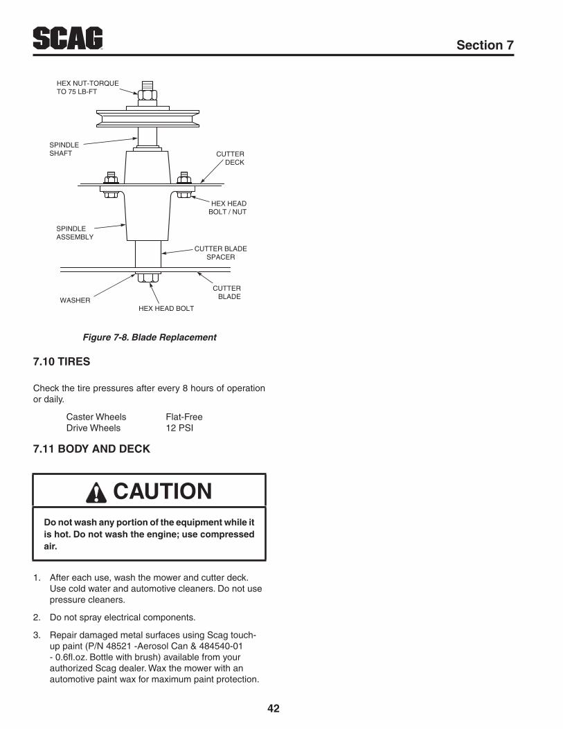
42
R Section 7
WASHERHEX HEAD BOLT
CUTTERBLADE
SPINDLE ASSEMBLY
CUTTER BLADESPACER
HEX HEADBOLT / NUT
CUTTERDECK
SPINDLESHAFT
HEX NUT-TORQUETO 75 LB-FT
Figure 7-8. Blade Replacement
7.10 TIRES
Check the tire pressures after every 8 hours of operation or daily.
Caster Wheels Flat-Free Drive Wheels 12 PSI
7.11 BODY AND DECK
CAUTIONDo not wash any portion of the equipment while it is hot. Do not wash the engine; use compressed air.
1. After each use, wash the mower and cutter deck. Use cold water and automotive cleaners. Do not use pressure cleaners.
2. Do not spray electrical components.
3. Repair damaged metal surfaces using Scag touch-up paint (P/N 48521 -Aerosol Can & 484540-01 - 0.6fl.oz. Bottle with brush) available from your authorized Scag dealer. Wax the mower with an automotive paint wax for maximum paint protection.

43
RSection 8
8.1 SCAG APPROVED ATTACHMENTS AND ACCESSORIES.
Attachments and accessories manufactured by companies other than Scag Power Equipment are not approved for use on this machine.
Scag approved attachments and accessories:
• Mulch Plate (p/n 9258, 9286, 9287, 9288)
• Hurricane Mulch (p/n 9263, 9283, 9284, 9285)
• GC-F4 (p/n 9075)
• SVRII-OCDC (p/n 923N, 923P, 923Q)
• SVRII Lights (p/n 923R)
• Air Filter Indicator (p/n 922U) - 48/52/61 with Kawasaki Engines Only
• Blade Buddy (p/n 9212)
• Chrome Wheel Covers (p/n 920J) - 48/52/61 Only
ILLUSTRATED PARTS LIST

44
R Section 8
36A CUTTER DECK
1
1
2
4
3
8
5
67
7
6
9 3 210
4
811121
6
13 14
13
15
15
1817
1619
16
21
22
23
26
24
27
2928
3032
3133
15 34
34
34
34
20
3536
3738
39
15
2573
71
71 72
70 40
41
42
44
57 45
43 46
47
4849
5051
52
53
48
545556
62
6061
5958
34
34
64
63
1
2265
33
66
323267
68
69

45
RSection 8
36A CUTTER DECK
Ref. No.
Part No. DescriptionRef. No.
Part No. Description
123456789101112131415161718192021222324
2526272829303132333435363738394041424344
04021-0904001-17204020-094892642461504043-0442436748328448321048602348181430774822446298404019-0404001-13604001-62438164840204306304003-0404117-0145223646232346232404021-2248114-0804020-164876304001-7904021-1345172404021-1004001-0948229548552804003-4204110-0304021-1104107-0446298648317404003-1204040-0404021-04
Nut, Elastic Stop 3/8-16Bolt, Hex Head 1/4-20 x 1" Gr.8Nut, 5/8-11Tapered Locking HubBracket, Belt GuideFlatwasher, 3/8-.391 x .938 x .105 HDDustshieldPulley, 5.73" Dia.Pulley, 5" IdlerBelt, Cutter DeckPulley, IdlerSpacerBearingIdler Arm Assembly (Incl. #13)Nut, Serrated Flange 3/8-16Bolt, Hex Head 3/8-16 x 1-1/2" Gr. 8Bolt, Hex Head 3/8-16 x 3-1/4"Pivot, IdlerSpringSpacerBolt, Carriage 5/16-18 x 1"Nut, Flange Elastic Stop 5/16-18Shaft WeldmentPusharm Assembly, LHPusharm Assemblly, RHNut, Elastic Stop 5/16-18 Gr. 8Grease Fitting, 90 DegreeNut, 5/16-18 UNFRod End, 5/8 - Male RHBolt, Hex Head 5/8-11 x 4-1/2"Nut, Elastic Stop 5/8-11Shaft Weldment, Pusharm MountingNut, Elastic Stop 5/16-18Bolt, Hex Head 5/16-18 x 1"Wheel, Anti-ScalpLever, Deck LevelBolt, Carriage 7/16-14 x 2-1/4"U-Nut, 3/8-16Nut, Elastic Stop 7/16-14Bolt, Hex Head 3/8-16 x 2" Special LockCutter Deck w/DecalsPad, WearBolt, Carriage 5/16-18 x 3/4"Flatwasher, 5/16-.344 x .688 x .065Nut, Center Lock 5/16-18
45464748495051525354555657585960616263646566676869
70717273
4616634358948102448102248114-04486774364443312432964810254329748103504063-0804001-1754359048287804043-0604001-4104003-2342378345192604001-1248224504001-15446129546246904001-19804041-1104001-6204030-03
Spindle AssemblySpindle ShaftSeal, Cutter SpindleBearing, TaperedGrease FittingRelief Fitting, Cutter SpindleSpindle HousingSpacer, OutsideSpacer, InsideSeal, Cutter SpindleSpindle BushingNut, 1.06 - 18Key, 1/4 x 1/4 x 2"Bolt, Hex Head 5/16-18 x 1-1/2" Gr. 8Spacer, Spindle BottomCutter Blade, 18"Flatwasher, 5/8-.688 x 1.75 x .134 HDBolt, Hex Head 5/8-11 x 9-1/2"Bolt, Carriage 3/8-16 x 1"Baffle, Flange - 36AShaft WeldmentBolt, Hex Head 5/16-18 x 1-3/4"Spring, Discharge ChuteBolt, Hex Head 5/16-18 x 4-3/4"Discharge Chute Assy.Discharge Chute Assy. (CA)Bolt, Hex Head 3/8-16 x 4-3/4"Flatwasher, 3/8-.406 x 1.50 x .179Bolt, Hex Head 3/8-16 x 3-1/4"Lockwasher, 5/16"

46
R Section 8
48V, 52V & 61V CUTTER DECKS
79
12
1
1
5
672
3
84 3
2
4
9
76 3
2
4
8
11
8
10
14
14
13
179
6
12
12 171615
18
14
15
1920
21
22
3234 33
3523
24 25
2726
2830
3129
36
70
69
73
71
72
7314
37
38
39
40
42
43
4445
4647
48
49
44
505152
58
5756
5554
53
1921
20
6161
61
60
591
64
6463
6765
6668
Excludes 48V
62
3030
74
75 76
7778
3182 82
8183
A
A
61V Only15
1414
80

47
RSection 8
48V, 52V & 61V CUTTER DECKS
Ref. No.
Part No. DescriptionRef. No.
Part No. Description
12345678
910
111213
14151617181920212223
242526272829303132333435363738394041424344
04021-0904001-17204020-094892642461504043-044243674832824832844832864832104839664841004858804832154822446297346297546233304019-0404001-1364368104001-6248402004001-0904117-01459444803846232346232448114-0804020-164876304001-7904021-1345172404021-1004001-0948552804110-0304003-4204021-1104107-0448317604003-1204040-0404021-0446166343589481024481022
Nut, Elastic Stop 3/8-16Bolt, Hex Head 1/4-20 x 1" Gr.8Nut, 5/8-11Tapered HubBracket, Belt GuideFlatwasher, 3/8-.391 x .938 x .105 HDDust ShieldPulley, 5.13" Dia. - 48VPulley, 5.73" Dia. - 52VPulley, 6.32" Dia - 61VPulley, 5" IdlerBelt, Cutter Deck - 48VBelt, Cutter Deck - 52VBelt, Cutter Deck - 61VPulley, 5" IdlerBearingIdler Arm Assy. - 48V (Incl. #12)Idler Arm Assy. - 52V (Incl. #12)Idler Arm Assy. - 61V (Incl. #12)Nut, Serrated Flange 3/8-16Bolt, Hex Head 3/8-16 x 1-1/2" Gr.8Pivot, IdlerBolt, Hex Head 3/8-16 x 3-1/4"SpringBolt, Hex Head 5/16-18 x1"Nut, Flange Elastic Stop 5/16-18Shaft WeldmentGuide RollerPusharm Assy, LHPusharm Assy, RHGrease Fitting, 90 DegreeNut, 5/8-18 UNFRod End, 5/8 Male RHBolt, Hex Head 5/8-11 x 4-1/2"Nut, Elastic Stop 5/8-11Shaft Weldment, Pusharm MountingNut, Elastic Stop 5/16-18Bolt, Hex Head 5/16-18 x 1"Lever, Deck LevelU-Nut, 3/8-16Bolt, Carriage 7/16-14 x 2-1/4"Nut, Elastic Stop 7/16-14 Bolt, Hex Head 3/8-16 x 2" Special LockPad, WearBolt, Carriage 5/16-18 x 3/4"Flatwasher, 5/16-.344 x .688 x .065Nut, Center Lock 5/16-18Spindle AssemblySpindle ShaftSeal, Cutter SpindleBearing, Tapered
454647484950515253545556
575859
606162
636465666768697071727374757677
7879
8081
8283
48114-04486774364443312432964810254329748103504063-0804001-1754359048287748287848288104043-0604001-4142483942484042484104003-2348229546297246297446297648163248100-1542247804003-2604021-0504017-2704030-0304021-2204001-4704001-6204041-3804001-1248224504001-154461844461845461846481625-0142731042730642726442736342736242739942467742420904040-1504021-10
Grease FittingRelief Fitting, Cutter SpindleSpindle HousingSpacer, OutsideSpacer, InsideSeal, Cutter SpindleSpindle BushingNut, 1.06 - 18Key, 1/4 x 1/4 x 2"Bolt, Hex Head 5/16-18 x 1-1/2" Gr.8Spacer, Spindle BottomCutter Blade, 16-1/2" (48V)Cutter Blade, 18" (52V)Cutter Blade, 21" (61V)Flatwasher, 5/8-.688 x 1.75 x .134 HDBolt, Hex Head 5/8-11 x 9-1/2"Baffle, Flange - 48VBaffle, Flange - 52VBaflle, Flange - 61VBolt, Carriage 3/8-16 x 1"Wheel, Anti-ScalpCutter Deck w/Decals - 48VCutter Deck w/Decals - 52VCutter Deck w/Decals - 61VWheel, Anti-Scalp (Incl. #64)Bushing, BronzeBracket, Anti-Scalp WheelBolt, Carriage 3/8-16 x 4"Nut, Center Lock 3/8-16Bolt, Hex Head Serrated Flange 3/8-16 x 1"Lockwasher, 5/16"Nut, Elastic Stop 5/16-18 Gr. 8Bolt, Hex Head 3/8-16 x 5"Bolt, Hex Head 3/8-16 x 3-1/4"Flatwasher, 3/8-.406 x 2.25 x .1875Bolt, Hex Head 5/16-18 x 1-3/4"Spring, Discharge ChuteBolt, Hex Head 5/16-18 x 4-3/4"Discharge Chute Assy. - 48VDischarge Chute Assy. - 52VDischarge Chute Assy. - 61VKnob w/StudBelt Cover, RH - 48VBelt Cover, LH - 48VBelt Cover - 52VBelt Cover, RH - 61VBelt Cover, LH - 61VAnchor Bracket - 61VTurbo Baffle - 48V / 52VTurbo Baffle - 61VFlatwasher, 5/16-.375 x .875 x .083Nut, Elastic Stop 5/16-18
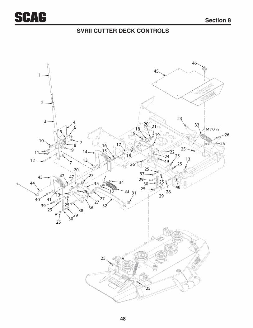
48
R Section 8
SVRII CUTTER DECK CONTROLS
A
A
1
2
3
10
11
12 7
98 7
64
5
14
13
1516 17
18
1918
20
19
21
23
222449
25
2525
2525
25
25
25
25
25
13
61V Only
2525
26
26
3729
29
30
2848
3133
33
32
347
13
35
27
2727
363829
30
2939
4113
40
4443 42 47
20
45
46
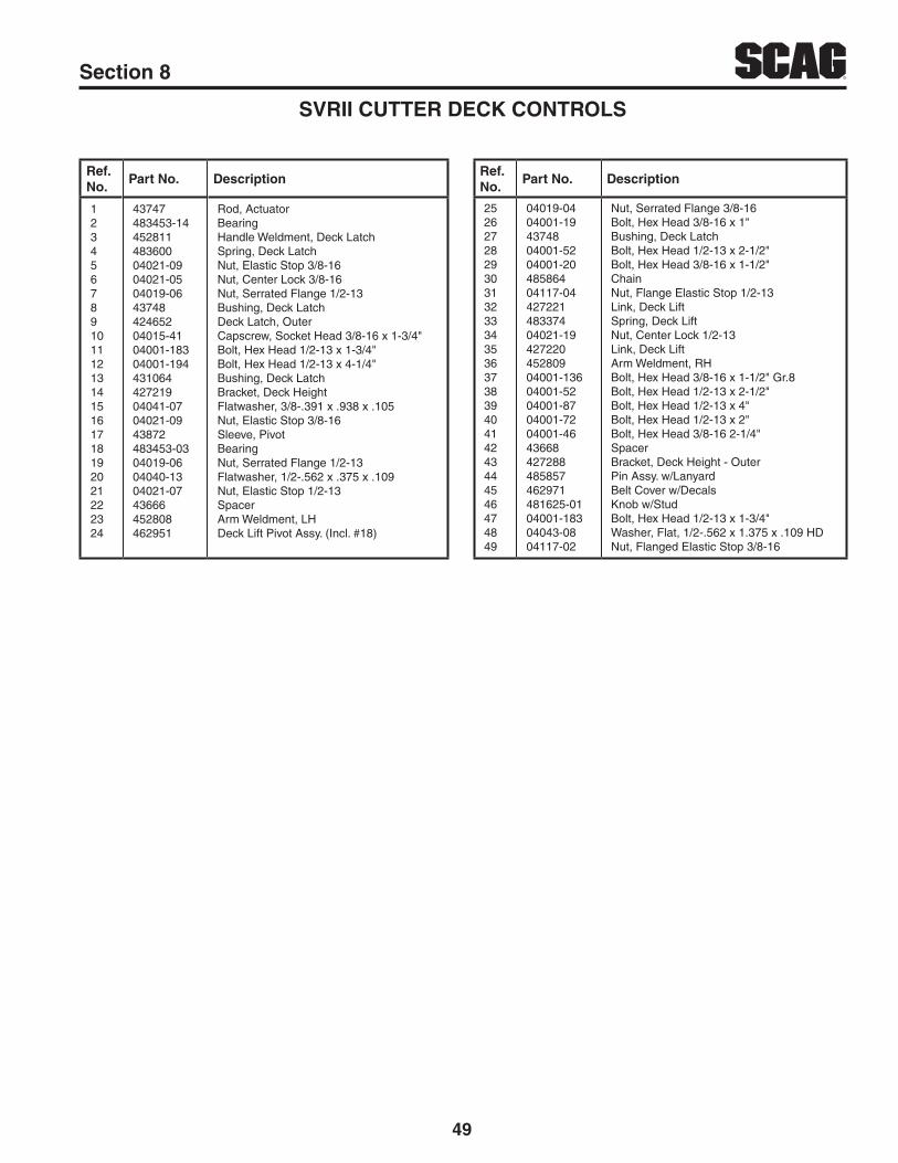
49
RSection 8
SVRII CUTTER DECK CONTROLS
Ref. No.
Part No. DescriptionRef. No.
Part No. Description
123456789101112131415161718192021222324
43747483453-1445281148360004021-0904021-0504019-064374842465204015-4104001-18304001-19443106442721904041-0704021-0943872483453-0304019-0604040-1304021-0743666452808462951
Rod, ActuatorBearingHandle Weldment, Deck LatchSpring, Deck LatchNut, Elastic Stop 3/8-16Nut, Center Lock 3/8-16Nut, Serrated Flange 1/2-13Bushing, Deck LatchDeck Latch, OuterCapscrew, Socket Head 3/8-16 x 1-3/4"Bolt, Hex Head 1/2-13 x 1-3/4"Bolt, Hex Head 1/2-13 x 4-1/4"Bushing, Deck LatchBracket, Deck HeightFlatwasher, 3/8-.391 x .938 x .105Nut, Elastic Stop 3/8-16Sleeve, PivotBearingNut, Serrated Flange 1/2-13Flatwasher, 1/2-.562 x .375 x .109Nut, Elastic Stop 1/2-13SpacerArm Weldment, LHDeck Lift Pivot Assy. (Incl. #18)
25262728293031323334353637383940414243444546474849
04019-0404001-194374804001-5204001-2048586404117-0442722148337404021-1942722045280904001-13604001-5204001-8704001-7204001-4643668427288485857462971481625-0104001-18304043-0804117-02
Nut, Serrated Flange 3/8-16Bolt, Hex Head 3/8-16 x 1"Bushing, Deck LatchBolt, Hex Head 1/2-13 x 2-1/2"Bolt, Hex Head 3/8-16 x 1-1/2"ChainNut, Flange Elastic Stop 1/2-13Link, Deck LiftSpring, Deck LiftNut, Center Lock 1/2-13Link, Deck LiftArm Weldment, RHBolt, Hex Head 3/8-16 x 1-1/2" Gr.8Bolt, Hex Head 1/2-13 x 2-1/2"Bolt, Hex Head 1/2-13 x 4"Bolt, Hex Head 1/2-13 x 2"Bolt, Hex Head 3/8-16 2-1/4"SpacerBracket, Deck Height - OuterPin Assy. w/LanyardBelt Cover w/DecalsKnob w/StudBolt, Hex Head 1/2-13 x 1-3/4"Washer, Flat, 1/2-.562 x 1.375 x .109 HDNut, Flanged Elastic Stop 3/8-16

50
R Section 8
SVRII SHEET METAL COMPONENTS
A
A
B
B
1
2
33
44
6
6
55
7
8
910 11
10 1113
14
10
10
11
11
12
1516
17
17 19
1842
23
22
202122
23
62526
27
2822
3069
3215
3637 34
35
38
39
3940
4041
4142
4318
50
49
485352
54
4644
18
5655
55
5747
5852
45
515960
6162
6262
62
6364
6568
6766
SVRII-36A
32
3133
30

51
RSection 8
SVRII SHEET METAL COMPONENTS
Ref. No.
Part No. DescriptionRef. No.
Part No. Description
123456789
1011121314
151617181920
21222324
25
26
27
28293031323334
353637383940
462971481625-0142718904019-0304001-08481885-0604003-0404024-0345287245283204001-0804030-0342729242728946307646307704003-1204112-0548128404019-0304001-0142725342745704003-0504019-0404003-314629874629644274724272564274814272494844974871704019-0204117-024875504001-114360204021-10462959462949483453-0404001-4504041-074357204001-2143867
Belt Cover w/DecalsKnob w/StudReference BarNut, Serrated Flange 5/16-18Bolt, Hex Head 5/16-18 x 3/4"Knob, 5/16-18Bolt, Carriage 5/16-18 x 1"Nut, Push-On 5/16Handlebar Weldment, SVRII-36Handlebar Weldment, SVRIIBolt, Hex Head 5/16-18 x 3/4"Lockwasher, 5/16"Bracket, Knee Pad - LowerBracket, Knee Pad - UpperOperator Pad Assy, SVRII-36Operator Pad Assy, SVRIIBolt, Carriage 5/16-18 x 3/4"Nut, Spiral Lock 1/2-13Rubber BumperNut, Serrated Flange 5/16-18Bolt, Hex Head 1/4-20 x 3/4"Fender, RHFender, RH - SVRII-36Bolt, Carriage 3/8-16 x 1-1/2"Nut, Serrated Flange 3/8-16Bolt, Carriage 3/8-16 x 3/4"Mainframe Assy. - SVRII-36Mainframe Assy. - SVRIIGuard, Foot - SVRII-36Guard, Foot -SVRIISwitch Bracket, OPC Switch -SVRII-36Switch Bracket, OPC SwitchSwitch, Double Pole OPC - SVRII-36Switch, OPC - SVRIINut, Serrated Flange 1/4-20Nut, Flange Elastic Stop 3/8-16SpringBolt, Hex Head 5/16-18 x 1-1/2"SpacerNut, Elastic Stop 5/16-18Footplate Assy, SVRII-36 (Incl. #35)Footplate Assy, SVRII (Incl. #35)BearingBolt, Hex Head 3/8-16 x 2"Flatwasher, 3/8-.391 x .938 x .105SpacerBolt, Hex Head 3/8-16 x 1-3/4"Mount, Spring
41424344
454647484950515253545556
57
58
5960
6162636465666768
69
48447904021-0904017-3642745642725204003-1242731604003-074866148569242731704040-1404021-0842731804003-0743584921D9277927843844435814358304001-8004001-13404001-16704021-074520344514714516584810254866848419504021-2004001-2804117-0504110-0445287045286145280545280604117-01
Spring, Suspension PlatformNut, Elastic Stop 3/8-16Bolt, Hex Head Serrated Flange 1/2-13 x 1"Fender, LH - SVRII-36Fender, LHBolt, Carriage 5/16-18 x 3/4"Battery Box, LowerBolt, Carriage 1/4-20 x 1/2"Pad, RubberInsulation, Battery CoverBattery Box, UpperFlatwasher, 1/4-.312 x .750 x .065Nut, Elastic Stop 1/4-20Battery Box LatchBolt, Carriage 1/4-20 x 1/2"Spacer, Caster WheelCaster Wheel Assy., 11 x 4 (36)Caster Wheel Assy., 13 x 5 (48 / 52)Caster Wheel Assy., 13 X 6.5 (61)Sleeve, Caster Wheel (36)Sleeve, Caster Wheel (48 / 52)Sleeve, Caster Wheel (61)Bolt, Hex Head 1/2-13 x 6-1/2" (36)Bolt, Hex Head 1/2-13 x 7-1/2" (48 / 52)Bolt, Hex Head 1/2-13 x 9-1/2" (61)Nut, Elastic Stop 1/2-13Yoke Weldment (36)Yoke Weldment (48 / 52)Yoke Weldment (61)Seal, 2" x 1.625 BoreBearing w/ RaceCap, GreaseNut, Elastic Stop 1" - 14 JamBolt, Hex Head 7/16-14 x 1-1/4"Nut, Flange Elastic Stop 7/16-14U-Nut, 3/8-16Caster Support Weldment (36)Caster Support Weldment (48)Caster Support Weldment (52)Caster Support Weldment (61)Nut, Flange Elastic Stop 5/16-18

52
R Section 8
SVRII STEERING CONTROLS
A
A
B
B
1
2
2
1
34
5
38
39
6
78
9 10
1114
912
15813 16
17
1819
13
2021
20
23
13
22
25
15
2432 3231
29
3028
2627
2733343
23
25 2434
3736
35
40

53
RSection 8
SVRII STEERING CONTROLS
Ref. No.
Part No. DescriptionRef. No.
Part No. Description
123456
7891011121314151617
1819
2021
42718904019-0348350404001-6204001-01462912462913436004822404019-0404001-4543102404043-0404021-0904001-1004021-1048584204108-0204001-174397645288345284204003-23452879452829
Reference BarNut, Serrated Flange 5/16-18BearingBolt, Hex Head 3/8-16 x 3-1/4"Bolt, Hex Head 1/4-20 x 3/4"Handlebar Assy., LH (Incl.# 7, 8)Handllevar Assy., RH (Incl. #7, 8)Spacer, BearingBearingNut, Serrated Flange 3/8-16Bolt, Hex Head 3/8-16 x 2"Spacer, ControlsFlatwasher, 3/8-.391 x .938 x .105 HDNut, Elastic Stop 3/8-16Bolt, Hex Head 5/16-18 x 1-1/4"Nut, Elastic Stop 5/16-18Linkage Assy., SteeringHex Head Socket, 5/16-18 x 1" (36)Bolt, Hex Head 5/16-18 x 2"Spacer (excludes SVRII-36A)Brake Paddle Weldment, RH (36)Brake Paddle Weldment, RHBolt, Carriage 3/8-16 x 1"Bellcrank Weldment, Brake (36)Bellcrank Weldment, Brake
22232425262728
2930 3132333435363738
3940
45288204001-3204117-0248100-3004117-0304001-0842753842753946302048154804063-1204012-1504040-0345283004010-1204019-0242726948154548163742237304041-07
Brake Paddle Weldment, LHBolt Hex Head 3/8-16 x 1-1/4"Nut, Flange Elastic Stop 3/8-16Bushing, OiliteNut, Flange Elastic Stop 1/4-20Bolt, Hex Head 5/16-18 x 3/4"Link, Brank Engage (36)Link, Brake EngageBrake Lever Assy. - SVRII (Incl. #30)Grip, Brake LeverKey, Woodruf #604 3/16 x 5/8 Set Screw 1/4-20 x 1/4"Flatwasher, 1/4-.281 x .625 x .065Lock Weldment, NeutralScrew, #10-32 x 3/4" TaptiteNut, Serrated Flange 1/4-20Bracket, Neutral SwitchSwitch, Interlock (36)Switch, InterlockPlate, ThreadedFlatwasher, 3/8-.391 x .938 x .105 (36" models)
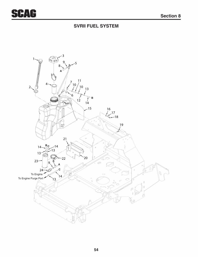
54
R Section 8
SVRII FUEL SYSTEM
To Engine
To Engine Purge Port
A
B
C
A
B
C
1
2
3
4
89 5
6
7
6
1010
11
13
1214
15 1617
18
19
1314
24
9 822
23
1313
14 14
21
20

55
RSection 8
SVRII FUEL SYSTEM
Ref. No.
Part No. DescriptionRef. No.
Part No. Description
1
23
45
6789101112
485914484246484242484286484297-01484079-0148591348389648257148592348361748059-0148059-02484347484343-01
Fuel Gauge Assy., 15-1/2" (36) (Incl. #2)Fuel Gauge Assy., 16-1/2" (Incl. #2)Seal, Fuel GaugeFuel Cap, TetheredFuel Cap, Tethered - CA models onlyTube, Fuel Tank InsertValve, Fuel Shutoff (36)Valve, Fuel ShutoffBushing, .56 VitonRemote VentFuel Hose, 1/4" ID (order by inch)Clamp, Fuel HoseClamp, Fuel Hose 7/32" IDHose, Vapor Recovery 1/4" (order by inch)Mender, 1/4 x 3/16 w/.02 Hole
131415
161718192021 222324
48059-0548434546305246305404040-1504030-0304001-0804003-1242728004019-0348136-17484342*
Clamp, Vapor Recovery Hose 3/16"Hose, Vapor Recovery 3/16"Fuel Tank Assy., SVRII-36 (Incl. #1,2,5,6,7)Fuel Tank Assy., SVRII (Incl. #1,2,5,6,7)Flatwasher, 5/16-.375 x .875 x .083Lockwasher, 5/16"Bolt, Hex Head 5/16-18 x 3/4"Bolt, Carriage 5/16-18 x 3/4"Bracket, Hydro Tank MountingNut, Serrated Flange 5/16-18Clamp, 3-1/2"Carbon CanisterFuel Filter
* Order through Engine Manufacturer

56
R Section 8
SVRII-36A HYDRAULICS AND ENGINE COMPONENTS
E
E
F
G
HJ
F
G
HJ
B
B
K
K
C
D
DC
L
L
A
A
12
3
4
9 10
11
7
81415
56
12
13
16 13 12
16
12
16
161217
18
1612
132416 12 13 15
1421
2220
23
25
26
6867
66
274665 64 63
61 6057 62
58
29
28
3032
32
33
34
35
3738
39
36
31
57
5655
5453
5247
2644
43
41
404245
46
47
4948
4951
50
5947
68
293130
2832
3369 70
19
19
19
19
6971
72 70
73
7475

57
RSection 8
Ref. No.
Part No. DescriptionRef. No.
Part No. Description
1
23456789101112131415161718192021222324252627282930313233
3435
36
3738394041
*485018*48501946294648150748116448257148257248257348257442728004001-0804030-0348136-134881148136-0548351482266-0148386348386248350-0248584748596348771-0248241704001-0848462-0104021-0904001-5248592248450348590348590448572-0248338804063-4004021-1946227504008-014859204859174859184867942221404028-0204102-0304030-05
Engine, 15 HP Kawasaki FSEngine, 19 HP Kawasaki FXHydro Tank Assy., SVRII (Incl. #3,4,5,6,7,8)Insert, Filler NeckCap, Hydraulic TankBushing, .56 VitonFitting, 90 Degree x .38 HoseBushing, .78 VitonFitting, 90 Degree x .50 HoseBracket, Hydro Tank MountingBolt, Hex Head 5/16-18 x 3/4"Lockwasher, 5/16"Clamp, HoseHose, 3/8" Pucklock (order by inch)Clamp, HoseHose, 1/2" Pushlock (order by inch)Elbow, 90 Degree O-RingPump, SVRPump, SVRElbow, 90 DegreeTee, 3/4" O-RingDrain Hose Assy. (Incl. #22)Plug, JIC 3/4-16 UNFFilter HeadBolt, Hex Head 5/16-18 x 3/4"FilterNut, Elastic Stop 3/8-16Bolt, Hex Head 1/2-13 x 2-1/2"Hose Assy., 11-1/4"Hose Assy., 13-1/4"Tube Assy., 1/2 x 2 x 2"Tube Assy., 1/2 x 2 x 3-1/4"Tube, Union 1/2 x 5/8"Wheel MotorKey, Woodruff 3/16 x 3/4" (not shown)Nut, Center Lock 1/2-13Wheel Hub AssemblyWheel StudWheel Assy., 20 x 8 - 10Tire, 20 x 8 - 10Rim w/ ValveHex Castle Nut, 3/4-28Lockwasher, Wheel MotorWheel NutBolt, Hex Head 7/16-20 x 2-1/4" w/ PatchLockwasher, 7/16"
424344454647484950515253545556575859606162636465666768697071727374
75
04041-2846216604063-2804001-5104030-0404043-044629834822448352648380204001-4648321404001-17248208504063-1448264948590248412804001-39436834372004003-1245292304001-3204019-0304001-13604019-04484524484523*484334484620485930483280
485960
Flatwasher, 7/16-.469 x 1.75 x .25Clutch w/TagKey, 1/4 x 1/4 x 3-1/2"Bolt, Hex Head 3/8-16 x 3-3/4"Lockwasher, 3/8"Flatwasher, 3/8-.391 x .938 x 105 HDIdler Arm Assy., Pump Drive - SVRII-36BearingSpring, Transmission IdlerPulley, 4-3/4" OD - 1.125 BoreBolt, Hex Head 3/8-16 x 2-1/4"Pulley, Idler 4"Bolt, Hex Head 1/4-20 x 1" Gr. 8Tapered Hub, 15mm BoreKey, 5 x 5 x 25mmPulley, 5.45 OD - Tapered Bore"Belt, Pump Drive - SVRII-36Pulley, Idler 4"Bolt, Hex Head 5/16-18 x 2-1/4"Pivot, IdlerSpacer, IdlerBolt, Carriage 5/16-18 x 3/4"Anti-Rotation WeldmentBolt, Hex Head 3/8-16 x 1-1/2" Nut, Serrated Flange 5/16-18Bolt, Hex Head 3/8-16 x 1-1/2" Gr.8Nut, Serrated Flange 3/8-16Tube Assy., 1/2 x 4" WideTube Assy., 1/2 x 3" WideExhaust Manifold, 15 HP Kawasaki FSMuffler ClampMuffler, KawasakiOil Drain, SVRII-36Tubing, Oil Drain (now shown) (order by inch)Fitting, M14 to M20 Male
SVRII-36A HYDRAULICS AND ENGINE COMPONENTS
* Order through Engine Manufacturer

58
R Section 8
SVRII-48V / 52V / 61V HYDRAULICS AND ENGINE COMPONENTS
A
A
B
B
C
C
D
D
E
F
F
G
G
H
H
J
J
K
K
L
L
M
M
E7
81415
1
72
73
4
3
2
56
12
13
9 10
11
12
16
16
1616
1312
1514
22
2321
24
26
1312162313171216
32
19
3435
36
33
3331
32
30
62
62
74
38
39
37
40
4142 43
4548
274644
47
58
59
55
55
56 4950 54
51
5253
6057
61596364
65 29
50 28
28 2766
31
33
3334
67
31 20
20
2018
3166
69
71
70
68

59
RSection 8
SVRII-48V / 52V / 61V HYDRAULICS AND ENGINE COMPONENTS
Ref. No.
Part No. DescriptionRef. No.
Part No. Description
1
2345678910111213141516171819202122232425262728293031323334
3536
37
38394041
*485020*485021*485134*485022*48589146294648105748116448257148257248257348257442728004001-0804030-0348136-134881148136-0548351482266-01485838485839485830481203-0248584748587048771-0248241704001-0848462-0104019-0404019-0304001-5242327948579248450948572-0248578804063-2504021-1946292904008-0148585148410448585248595248595348241404061-0604028-0204102-0304030-05
Engine, 22 HP Kawasaki FXEngine, 23 HP Kawasaki FXEngine, 25 HP Kohler EFIEngine, 25 HP Kawasaki FXEngine, 29 HP Kohler EFIHydro Tank Assy., SVRII (Incl. #3,4,5,6,7,8)Insert, Filler NeckCap, Hydro TankBushing, .56 VitonFitting, 90 Degree x .38 HoseBushing, .78 VitonFitting, 90 Degree x .50 HoseBracket, Hydro Tank MountingBolt, Hex Head 5/16-18 x 3/4"Lockwasher, 5/16"Clamp, HoseHose, 3/8" Pushlock (order by inch)Clamp, HoseHose, 1/2" Pushlock (order by inch)Elbow, 90 Degree - O-RingPump, LH - SVRIIPump, RH - SVRIIUnion, O-Ring to JICElbow, JIC SwivelTee, 3/4 O-RingDrain, Hose Assembly (Incl. #23)Plug, JIC 3/4-16 UNFFilter HeadBolt, Hex Head 5/16-18 x 3/4"FilterNut, Serrated Flange 3/8-16Nut, Serrated Flange 5/16-18Bolt, Hex Head 1/2-13 x 2-1/2"Plate, Motor BackingHose Assy., 27-1/2"Hose Assy., 15-1/4"Tube, Union 1/2 x 5/8Wheel Motor, SVRIIKey, Woodruff 5/16 x 1" (not shown)Nut, Center Lock 1/2-13Wheel Hub Assy., SVRIISerrated Bolt, 1/2-20 x 1.563Wheel Assy., 24 x 9.5 - 12 (4-Ply) (48 / 52)Tire, 24 x 9.5 - 12 (4-Ply) (48 / 52)Rim w/Stem (48 / 52)Wheel Assy., 24 x 12 - 12 (4-Ply) (61)Tire, 24 x 12 -12 (4-Ply) (61)Rim w/Stem (61)Pin, Cotter 9/64 x 1"Wheel NutBolt, Hex Head 7/16-20 x 2-1/4" w/ PatchLockwasher, 3/8"
4243
444546474849505152535455565758596061626364
656667
6869
70
71
7273
74
04041-2846216646233904063-2804003-1245292304021-0504001-5448352604021-0904001-17248208504063-14483520482244629694368304001-6204043-0448380248321348264904001-16104001-3204011-07
04001-1104031-0304019-0304030-0448579104025-0404130-0104033-0148580048579948589648588742738042743742743204119-0204001-0804040-0404019-03485564484089482510*48328048680
Flatwasher, 7/16-.469 x 1.75 x .25Clutch w/Tag GT2.5-FE02 (48 / 52)Clutch w/Tag GT3.5-FE05 (61)Key, 1/4 x 1/4 x 3-1/2"Bolt, Carriage 5/16-18 x 3/4"Anti-Rotation BracketNut, Center Lock 3/8-16Bolt, Hex Head 3/8-16 x 3"Spring, Transmission IdlerNut, Elastic Stop 3/8-16Bolt, Hex Head 1/4-20 x 1" Gr.8Tapered Hub, 15mm BoreKey, 5 x 5 x 25mmBelt, TransmissionBearingIdler Arm Assy. (Incl. #55)Pivot, IdlerBolt, Hex Head 3/8-16 x 3-1/4"Flatwasher, 3/8-.391 x .938 x .105 HDPulley, 4.75" OD - 1.125 BorePulley, 4-1/2" IdlerPulley, 5.45" OD - Tapered BoreBolt, Hex Head 3/8-16 x 2-3/4" Full ThreadBolt, Hex Head 3/8-16 x 1-1/4" (Kawasaki)Bolt, Hex Head Self-Tap 3/8-16 x 1-1/4" (Kohler x3 - 25EFI, Kohler x4 - 29EFI)Bolt, Hex Head 5/16-18 x 1-1/2" (Kohler x1)Lockwasher, 5/16" Ext. Tooth (Kohler x1)Nut, Serrated Flange 5/16-18 (Kohler x1)Lockwasher, 3/8"Hose Assy., 30"Nut, N8-1.25 (Kawasaki)Lock Nut, M8-1.25 -8H (Kohler)Lockwasher, M8 Spring (Kawasaki)Muffler, Kawasaki FX - SVRIIMuffler, Kohler CV-EFI - SVRIIMuffler, Kawasaki FX801 - SVRIIMuffler, Kohler, 29 EFI - SVRIIHeatshield, Muffler - Kawasaki FX - SVRIIHeatshield, Muffler - Kawasaki FX801 - SVRIIHeatshield, Muffler - Kohler 29 EFI - SVRIIBolt, M8-1.25 x 20 Flanged HDBolt, Hex Head 5/16-18 x 3/4" - 23HP FXFlatwasher, 5/16-.344 x .688 x .065Nut, Serrated Flange 5/16-18Fan Cover, PumpOil Drain, M20 Thread (Kawasaki)OIl Drain, 3.3" (Kohler 25HP-EFI)Oil Drain (Kohler 29HP-EFI p/n 25 462 13)Tubing, Oil Drain (not shown) (order by inch)Nut, Hex Castle
* Order through Engine Manufacturer** Not available through Scag

60
R Section 8
SVRII-36A ELECTRICAL SYSTEM
GROUND
STARTER
A
A
20
20
KAWASAKI
1
2
345
10 6
8
9
11
12
13
23
14 1516
B
17
18
20 19
2122
2425 35
26
29
24
25
28
27
30
32
31
33
34
7

61
RSection 8
SVRII-36A ELECTRICAL SYSTEM
Ref. No.
Part No. Description
1234567891011121314151617181920212223242526272829303132333435
46206948456548583348397648017-0404011-1446298548017-034879804003-4348397504021-2648610542726948154504010-1204019-0242748148449704003-0246216648395842237348029-2448029-304836654812604001-0104020-0248364248357148258848298483629482543
Key Assy. w/FobHourmeter, InductiveSwitch, PTOChoke ControlNut, Special 5/8-32Screw, 1/4-20 x 3/4" TaptiteInstrument Panel w/Decal - SVRIILockwasher, 5/8" Internal ToothSwitch, KeyBolt, Carriage #10-24 x 1/2"Throttle ControlNut, Elastic Stop #10-24Wire Harness, SVRII-36Bracket, Neutral SwitchSwitch, Interlock - DPDTScrew, #10-24 x 3/4" TaptiteNut, Serrated Flange 1/4-20Switch Bracket, Operator PresenceSwitch, Double Pole - N.O. / N.O.Nut, Serrated Flange 1/4-20Clutch w/Tag GT2.5-FE02Diode, 600V - 6APlate, ThreadedCable, Battery - Black 39"Cable, Battery - Red 44" w/BraidBattery, 350 CCA (not available through Scag)Rubber BootBolt, Hex Head 1/4-20 x 3/4"Nut, 1/4-20Double Fuse Assy. (Incl. #31, 32, 33, 34)Cover, Sealed DoubleClip, WireFuse, 20 AmpFuse HolderWire Harness Adaper - Kawasaki

62
R Section 8
SVRII-36A ELECTRICAL SYSTEM - RECOIL START MODELS
1
2
34
5
610
7
11
8
9
1213
23
14 15
16
17
18
20 19
2122

63
RSection 8
Ref. No.
Part No. Description
1234567891011121314151617181920212223
46206948456648397648583348017-0404011-1446298548017-034860904003-4348397504021-2648610442726948154504010-1204019-0242748148449704003-02462166483958422373
Key Assy., w/FobHourmeterChoke ControlSwitch, PTONut, Special 5/8-32Screw, 1/4-20 x 3/4" TaptiteInstrument Panel w/Decal - SVRII36Lockwasher, 5/8" Internal ToothSwitch, KeyBolt, Carriage #10-24 x 1/2"Throttle CableNut, Elastic Stop #10-24Wire Harness, SVRII Recoil StartBracket, Neutral SwitchSwitch, InterlockScrew, #10-32 x 3/4" TaptiteNut, Serrated Flange 1/4-20Switch Bracket, Operator PresenceSwitch, Double Pole - N.O. / N.O.Bolt, Carriage 1/4-20 x 3/4"Clutch w/Tag GT2.5-FE02Diode, 600V - 6APlate, Threaded
SVRII-36A ELECTRICAL SYSTEM - RECOIL START MODELS

64
R Section 8
SVRII-48V / 52V / 61V ELECTRICAL SYSTEM
SCAG
POW
ER E
QU
IPM
EN
T
20
20
KOHLER EFI ONLY
KAWASAKI
OR
A
GROUND
STARTER
B
A
1 2
3
65
4
8 7
9
36
10
1112 13
37
1417
16
15
18
17
19
16 2021
22
24
23
25
27
23
24
28
26
29 30
31
3233
33
32
3531 34

65
RSection 8
SVRII-48V / 52V / 61V ELECTRICAL SYSTEM
Ref. No.
Part No. Description
12345678910111213
1415161718192021
22232425262728293031323334353637
48472148583346206948397648118248017-0404011-1404003-4348017-034879804021-2648397548607348610642726948163704019-0204001-0104010-124272494871746216646233948395848029-2448029-304836654812604020-0204001-0148364248357148258848298483629485739483643462970422373
Tiger Eye, Cluster GaugeSwitch, PTOKey Assy., w/FobChoke Control (excludes EFI models)Indicator Light (EFI models only)Nut, Special 5/8-32Screw, 1/4-20 x 3/4" TaptiteBolt, Carriage #10-24 x 1/2"Lockwasher, 5/8" Internal ToothSwitch, KeyNut, Elastic Stop #10-24Throttle ControlWire Harness, SVRIIWire Harness, SVRII-EFIBracket, Neutral SwitchSwitch, N/ONut, Serrated Flange 1/4-20Bolt, Hex Head 1/4-20 x 3/4"Screw, #10-32 x 3/4" TaptiteSwitch Bracket, Operator PresenceSwitchClutch w/Tag GT2.5-FE02 (48 / 52)Clutch w/Tag GT3.5--FE05 (61)Diode, 600V - 6ABattery Cable, 39" BlackBattery Cable, 44" Red w/BraidBattery, 350 CCA (not available through Scag)Rubber BootNut, 1/4-20Bolt, Hex Head 1/4-20 x 3/4"Double Fuse Assy,\\\. (Incl. #30, 31, 32, 33)Cover, Sealed DoubleClip, WireFuse, 20 AmpFuse HolderSingle Fuse Assy. (Incl. #31, 33, 35)Cover, Sealed SingleControl Panel w/DecalPlate, Threaded

66
R Section 8
SVRII-36A HYDRAULIC PUMP
Overhaul Seal K
it
1
2
3
4
5
67
8
9
10
28
24
26
11
12
1314
1522
23
20
21
1817
16
19
27
29
25
24
PORT "A"SIDE
PORT "B"SIDE
3031
32 3334
35
36
37
A
A
33

67
RSection 8
SVRII-36A HYDRAULIC PUMP
Ref. No.
Part No. Description
12345678910111213141516171819202122232425262728293031323334353637
HG72598HG70517HG50641HG50969HG54022HG2513027HG50273HG9004101-1340HG5095HG2513030HG70521HG50315HG51161HG50329HG50951HG70331HG2003014HG2003017HG51444HG2003087HG50551HG52866HG2000015HG2510027HG70402HG2513043HG9005110-4400HG9005110-5600HG70525HG52413HG51391HG51561HG44130HG51400HG51394HG52506HG52401
Kit, HousingKit, End CapPin, .219 x 1.000Bolt, M8 X 1.25 mmGasket, HousingKit, Charge PumpGerotor AssemblyO-RingScrew, Socket Head M6 X 1.0 - 20mmKit, By-PassKit, ShaftBearingSeal, 17 x 40 x 7 LipRing, Retaining .156 InternalWasher, 1.23 x 1.57 x .04Kit, Block 10ccSpring, BlockWasher, .59 x .79 x .04Plate, Valve 10ccSwashplateBearing, ThrustArm, TrunionSlot GuideKit, Check Valve (.031 Orifice)Kit, Charge ReliefKit, SealPlug, 7/16-20Plug, 9/16-18Seal KitRTN AssemblyArm, ReturnSpacerWasherScrew, 5/16-24 x 3/4" w/PatchControl ArmNut, Center Lock 5/16-24 UNFSpring, External
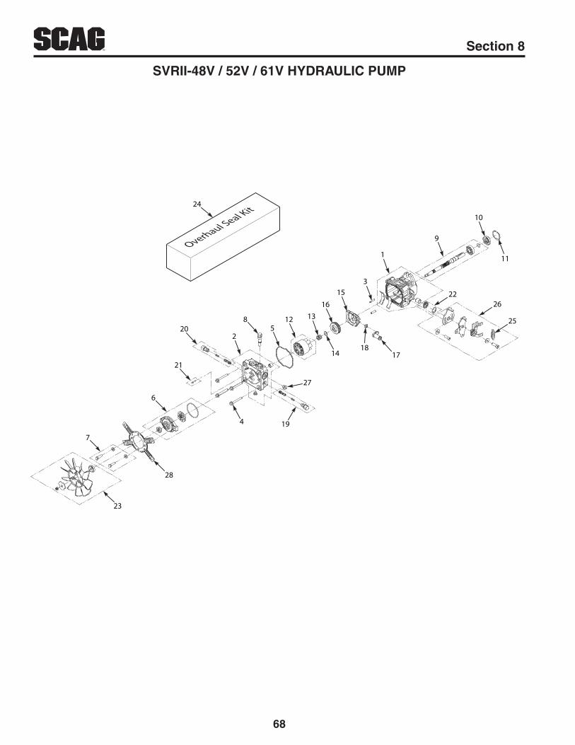
68
R Section 8
SVRII-48V / 52V / 61V HYDRAULIC PUMP
Overhaul Seal Kit
58
220
21
6
24
1
9
10
11
2226
2512 1316
153
27
1418
17
4 19
7
23
28

69
RSection 8
SVRII-48V / 52V / 61V HYDRAULIC PUMP
Ref. No.
Part No. Description
12345678910111213141516171819202122232425262728
HG72267HG72011HG50641HG50969HG54022HG70622HG72254HG2513030HG70620HG51161HG50329HG71971HG2003014HG2003017HG53998HG53502HG52866HG2000015HG70838HG70838HG70403HG2513043HG70811HG70525HG52401HG71716HG9005110-5600HG52355
Kit, HousingKit, End CapPin, .219 x 1.000Bolt, M8 X 1.25 mmGasket, HousingKit, Charge PumpKit, Charge Pump BoltsBy-Pass ValveKit, ShaftSeal, 17 x 40 x 7 LipRing, Retaining .156 InternalKit, Block 12ccSpring, BlockWasher, .59 x .79 x .04SwashplateBearing, ThrustTrunnion ArmSlot GuideKit, Shock Valve - 160 Bar (.031 Orifice)Kit, Shock Valve - 160 Bar (.031 Orifice)Kit, Charge ReliefKit, Seal - Trunnion ArmFan AssemblySeal KitSpringKit, RTNPlug, 9/16-18Bracket, 7"
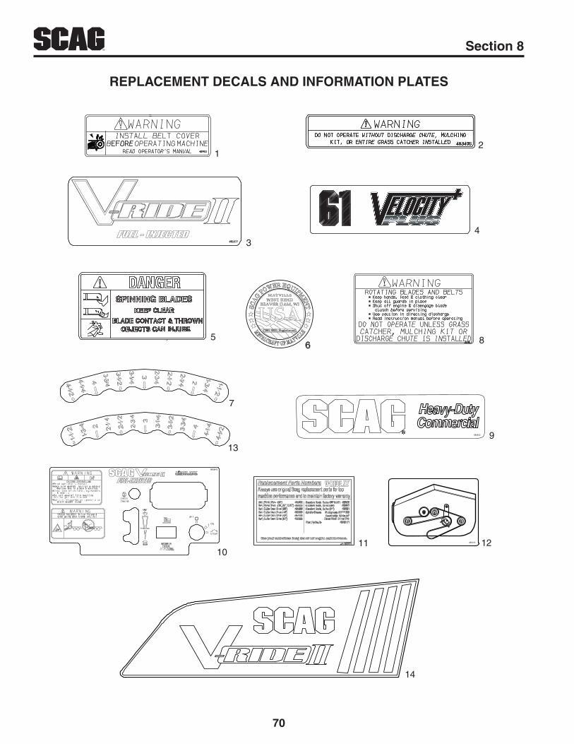
70
R Section 8
REPLACEMENT DECALS AND INFORMATION PLATES
12
85
4
9
Heavy-DutyCommercial
484453
6
485518 12
7
10
13
3
11
14

71
RSection 8
REPLACEMENT DECALS AND INFORMATION PLATES
Ref.No.
Part No. Description
1 483402 Decal, Warning - Belt Cover2 483405 Decal, Warning3 485872 Decal, Belt Cover 485871 Decal, Belt Cover - EFI4 483059 Decal, 36A 483199 Decal, 48V 483200 Decal, 52V 483201 Decal, 61V5 483407 Decal, Spinning Blades6 485403 Decal, Metalcraft - USA7 485798 Decal, Deck Height - Outer8 483406 Decal, Warning - Knives9 484453 Decal, Scag Heavy Duty Commercial10 485910 Decal, Instrument Panel - SVRII36A 485911 Decal, Instrument Panel - SVRII36A - Recoil Start 485877 Decal, Instrument Panel - SVRII 485819 Decal, Instrument Panel - SVRII-EFI11 485974 Decal, SVRII Replacement Parts12 485517 Decal, Belt Routing - SVRII36A 485518 Decal, Belt Routing - SVRII48V, SVRII52V & SVRII61V13 485826 Decal, Deck Height - Inner14 486194 Decal, Scag V-Ride II (Fuel Tank)

72
R Section 8
SVRII-36 ELECTRICAL SCHEMATIC - RECOIL START MODELS(shown with Key Off, PTO Off, Park Brake Applied, OPC Disengaged)
HM
CLUTCH
PTOSWITCH
KEY SWITCH
OPERATORPRESENCE
SWITCH
BRAKEINTERLOCK
SWITCH
HOURMETER
GROUND
TOENGINE
BLUE
YELLOW
BLU
E
BLA
CK
BLA
CK
BLA
CK
BLA
CK
BLA
CK
BLA
CK
WH
ITE
YE
LLO
W
YELLOW
WH
ITE
WHITE
BLA
CK
W/R
ED
ST
RIP
E
BLACK W/RED STRIPE
Position PTO Switch Legend
121110987
654321
121110987
654321
ON (UP)
DOWN (OFF)

73
RSection 8
SVRII-36 ELECTRICAL SCHEMATIC(shown with Key Off, PTO Off, Park Brake Applied, OPC Disengaged)
SM B
GL
AHM
CLUTCH
OFF G + M + ARUN B + L + ASTART B + L + S
Position Key Switch Legend
TOENGINE
HARNESS
+-
BATTERY
“A”
GROUND
PTOSWITCH
KEY SWITCH
20 AMP FUSE
20 AMP FUSE
OPERATORPRESENCE
SWITCH
BRAKEINTERLOCK
SWITCH
HOURMETER
BLUE
YELLOW
BLACK
GREEN
RE
D
BLA
CK
BLU
E
BLACK W/RED STRIPE
BLACK W/RED STRIPE
YELLOW
BLA
CK
BLA
CK
RED
YE
LLO
W
WHITE
WH
ITE
WH
ITEG
RE
EN
BLACK
RED W/YEL STRIPE
GR
EE
N
YELLOW
RED
GREEN
RE
D W
/YE
L S
TR
IPE
RE
D W
/YE
L S
TR
IPE
BLA
CK
W/R
ED
ST
RIP
E
WH
ITE
Position PTO Switch Legend
121110987
654321
121110987
654321
ON (UP)
DOWN (OFF)
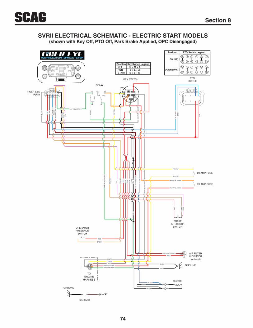
74
R Section 8
SVRII ELECTRICAL SCHEMATIC - ELECTRIC START MODELS(shown with Key Off, PTO Off, Park Brake Applied, OPC Disengaged)
SMB
G L
A
H J K L M N P
A B C D E F G
CLUTCH
TOENGINE
HARNESS
+-
BATTERY
“A”
GROUND
OFF G + M + ARUN B + L + ASTART B + L + S
Position Key Switch Legend
PTOSWITCH
KEY SWITCH
RELAY
TIGER EYEPLUG
20 AMP FUSE
20 AMP FUSE
AIR FILTERINDICATOR
(optional)
GROUND
OPERATORPRESENCE
SWITCH
BRAKEINTERLOCK
SWITCH
OR
AN
GE
BR
OW
N PIN
K
BLA
CK
BLACK
BLA
CK BLA
CK
RED
RE
D
RE
D
LIGH
T B
LUE
WH
ITE
RED W/YEL STRIPE
BLUE
GR
N W
/WH
T S
TR
IPE
GR
EE
N
GRN W/BLK STRIPE
OR
AN
GE
PIN
K
BR
OW
N
RE
DR
ED
RE
D
BLA
CK
BLU
E
WH
ITE
WH
ITE
WHITE
RED
RED
YE
LLOW
YELLOW
YELLOW
YELLOW
RED W/YEL STRIPE
RED W/YEL STRIPE
GRN W/WHT STRIPE
BROWN
RED W/BLACK STRIPE
BLACK
BLACK
RE
D
OR
AN
GE
PIN
K
RE
D
RE
D W
/BLA
CK
ST
RIP
E
LIGH
T B
LUE
BLU
E
Position PTO Switch Legend
121110987
654321
121110987
654321
ON (UP)
DOWN (OFF)
RE
D W
/BLA
CK
ST
RIP
E
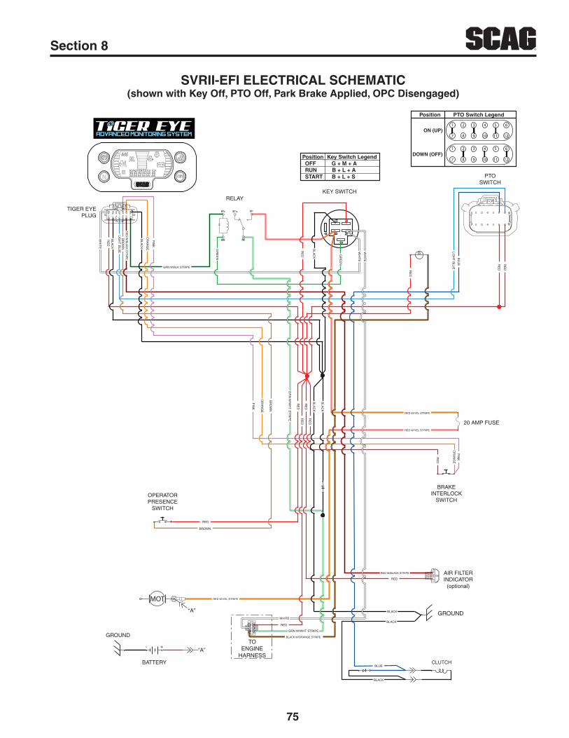
75
RSection 8
SVRII-EFI ELECTRICAL SCHEMATIC(shown with Key Off, PTO Off, Park Brake Applied, OPC Disengaged)
SMB
G L
A
H J K L M N P
A B C D E F G
+-
BATTERY
MOT
“A”
“A”
GROUNDTO
ENGINEHARNESS
CLUTCH
OFF G + M + ARUN B + L + ASTART B + L + S
Position Key Switch Legend
PTOSWITCH
KEY SWITCHRELAY
TIGER EYEPLUG
20 AMP FUSE
AIR FILTERINDICATOR
(optional)
GROUND
OPERATORPRESENCE
SWITCH
BRAKEINTERLOCK
SWITCH
OR
AN
GE
PIN
K
BLA
CK
BLA
CK
RE
D
RE
D
LIGH
T B
LUE
WH
ITE
BLACK
RED W/YEL STRIPE
RED W/YEL STRIPE
GRN W/BLK STRIPE
WH
ITE
WH
ITE
RE
D
GR
EE
N
GR
EE
N
BLA
CK
RE
D
OR
AN
GE
PIN
K
BLA
CK
BR
OW
N
BR
OW
N
RE
DR
ED
RE
DB
LAC
K
RE
D
PIN
KO
RA
NG
E
RED W/BLACK STRIPE
RED
BLACK
BLUE
BLACK
BLACK W/ORANGE STRIPE
GRN W/WHT STRIPE
RED
WHITE
RED W/YEL STRIPE
RED
BROWN
RE
D W
/BLA
CK
ST
RIP
E
GR
N W
/WH
T S
TR
IPE
RE
D
LIGH
T B
LUE
BLU
E RE
D
Position PTO Switch Legend
121110987
654321
121110987
654321
ON (UP)
DOWN (OFF)
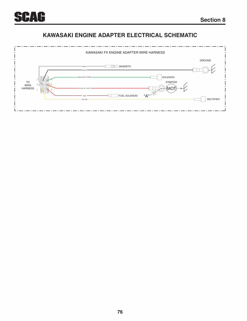
76
R Section 8
KAWASAKI ENGINE ADAPTER ELECTRICAL SCHEMATIC
TOMAIN
HARNESS
GROUND
STARTER
GRN W/WHT STRIPE
YELLOW
WHITE
RED
BLACK
RED W/YEL STRIPE MOT
FUEL SOLENOID
MAGNETO
RECTIFIER
SOLENOID
“A”
KAWASAKI FX ENGINE ADAPTER WIRE HARNESS

LIMITED WARRANTY - COMMERCIAL EQUIPMENTAny part of the Scag commercial mower manufactured by Scag Power Equipment and found, in the reasonable judgment of Scag, to be defective in materials or workmanship, will be repaired or replaced by an Authorized Scag Service Dealer without charge for parts and labor during the periods specified below. This warranty is limited to the original purchaser provided the product was purchased from an Authorized Scag Power Equipment Dealer and is not transferable. Proof of purchase will be required by the dealer to substantiate any warranty claims. All warranty work must be performed by an Authorized Scag Service Dealer.
This warranty is limited to the following specified periods from the date of the original retail purchase for defects in materials or workmanship:
• Wear items including drive belts, blades, hydraulic hoses and tires are warranted for ninety (90) days.• Batteries are covered for ninety (90) days.• Frame and structural components including oil reservoir and oil coolers are warranted for two (2) years (parts and labor) for com-mercial use or three (3) years / 500 hours (whichever comes first) (parts and labor) for non-commercial use.• Cutter decks are warranted against cracking for a period of three (3) years. (parts and labor 1st and 2nd year; parts only 3rd year.) The repair or replacement of the cutter deck will be at the option of Scag Power Equipment. We reserve the right to request compo-nents for evaluation. This warranty does not cover any mower that has been subject to misuse, neglect, negligence, or accident, or that has been operated in any way contrary to the operating instructions as specified in the Operator’s Manual.• Engines and electric starters are covered by the engine manufacturer’s warranty period.• Major drive system components are warranted for two (2) years (parts and labor) for commercial use or three (3) year / 500 hour (whichever comes first) (parts and labor) for non-commercial use by Scag Power Equipment. (commercial and non-commercial war-ranty excludes fittings, hoses, drive belts). The repair or replacement of the hydraulic pump or hydraulic motor will be at the option of Scag Power Equipment. This warranty does not cover any mower that has been subject to misuse, neglect, negligence, or accident, or that has been operated in any way contrary to the operating instructions as specified in the Operator’s Manual.• Electric clutches have a Limited Warranty for two (2) years (parts and labor) for commercial use or three (3) year / 500 hours (whichever comes first) (parts and labor) for non-commercial use.• Spindle assemblies have a Limited Warranty for three years (parts and labor 1st year and 2nd; parts only 3rd year).• Any Scag product used for rental purposes is covered by a 90 day warranty.
The Scag mower, including any defective part must be returned to an Authorized Scag Service Dealer within the warranty period. The expense of delivering the mower to the dealer for warranty work and the expense of returning it to the owner after repair will be paid for by the owner. Scag’s responsibility is limited to making the required repairs and no claim of breach of warranty shall be cause for cancellation or rescission of the contract of sale of any Scag mower. “Non-Commercial” use is defined as a single property owner, where the single property is the residence of the owner of the mower. If the mower is cutting more than the owners single property, it is deemed commercial use and the “non-commercial” warranty does not apply. Scag Power Equipment reserves the right to deny and / or void the non-commercial warranty if it believes it to be in commercial use.
This warranty does not cover any mower that has been subject to misuse, neglect, negligence, or accident, or that has been operated in any way contrary to the operating instructions as specified in the Operator’s Manual. The warranty does not apply to any damage to the mower that is the result of improper maintenance, or to any mower or parts that have not been assembled or installed as specified in the Operator’s Manual and Assembly Manual. The warranty does not cover any mower that has been altered or modified, changing performance or durability. In addition, the warranty does not extend to repairs made necessary by normal wear, or by the use of parts or accessories which, in the reasonable judgment of Scag, are either incompatible with the Scag mower or adversely affect its operation, performance or durability.
Scag Power Equipment reserves the right to change or improve the design of any mower without assuming any obligation to modify any mower previously manufactured. All other implied warranties are limited in duration to the two (2) year for commercial use, three (3) years / 500 hour for non-commercial use or ninety (90) days for mowers used for rental purpose. Accordingly, any such implied warranties including merchantability, fitness for a particular purpose, or otherwise, are disclaimed in their entirety after the expiration of the appropriate two (2) year for commercial use, three (3) years / 500 hour for non-commercial use or ninety day warranty period. Scag’s obligation under this warranty is strictly and exclusively limited to the repair or replacement of defective parts and Scag does not assume or authorize anyone to assume for them any other obligation. Some states do not allow limitations on how long an implied warranty lasts, so the above limitation may not apply to you.
Scag assumes no responsibility for incidental, consequential or other damages including, but not limited to, expense for gasoline, expense of delivering the mower to an Authorized Scag Service Dealer and expense of returning it to the owner, mechanic’s travel time, telephone or telegram charges, rental of a like product during the time warranty repairs are being performed, travel, loss or damage to personal property, loss of revenue, loss of use of the mower, loss of time or inconvenience. Some states do not allow the exclusion or limitation of incidental or consequential damages, so the above limitation or exclusion may not apply to you. This warranty gives you specific legal rights, and you may also have other rights which vary from state to state.

© 2019Scag Power EquipmentDivision of Metalcraft of Mayville, Inc.