Operator's Manual - Loveshaw
79
Little David™ Label Application System LS-800DT Print and Apply Labeling System LSMANUAL-800DT Version: A5 Operator’s Manual
-
Upload
khangminh22 -
Category
Documents
-
view
1 -
download
0
Transcript of Operator's Manual - Loveshaw

Little David™ Label Application System
LS-800DT Print and Apply
Labeling System
LSMANUAL-800DT Version: A5
Operator’s Manual

L I T T L E D A V I D ™ L A B E L A P P L I C A T I O N S Y S T E M
Labeler Operation
Copyright Loveshaw 2002, All Rights Reserved.
Route 296, Box 83 South Canaan, PA 18459
Tel: 1-800-962-2633 • 570-937-4921 Fax: 570-937-4016
www.LOVESHAW.com [email protected]
Loveshaw Europe A Division of ITW LTD.
Unit 9 Brunel Gate West Portway Industrial Estate Andover, Hampshire SP10 3SL
ENGLAND Tel: 264-357511 Fax: 264-355964
www.LOVESHAW.com [email protected]
Thursday, August 28, 2003
All user information is extracted with permission from the complete Operator’s and Maintenance’s Manuals for the various devises that make up the LS800DT System. Separate Manuals are included for each separate unit that was ordered. Please refer to the complete operators and technical manuals of each manufacture for additional detailed operator and technical information. The following web sites supply the user downloadable manuals for reference in an Adobe Acrobat .pdf format: Reliance Electric: SP500 Variable AC Drive http://www.reliance.com/ Hytrol Conveyors: Hytrol Conveyor (Slider Bed Model TA) http://www.hytrol.com/ Sato America (M-8485Se OEM Print Engine) http://www.satoamerica.com/

22
Table of Contents
Chapter 1: Introduction 4
Chapter 2: Operating Safety 5
Chapter 3: Overview 7
Chapter 4: Installation and Threading 11 Chapter 5: Applicator 19
Chapter 6: Mechanical Assembly 34
Chapter 7: Mounting and Pedestals 38 Chapter 8: Product Sensing 46 Chapter 9: Features and Options 53 Low Label Sensor………………………………………………………………………………………53 Light Tower……………………………………………………………………………………………. 53
Chapter 10: Controller Operation 54 Keyboard, Screen………………………………………………………………………………………...54 Power-On and Unlock……………………………………………………………………………………54 Ready……………………………………………………………………………………..……………….55 Memory Clear…………………………………………………………….……………………………….55
Chapter 11: Using Menu Features 56 How Help Menu Features Work…………………………………………………………………………56 Help Menu Feature 1: Adjust…………………………………………………………………………….57 Help Menu Feature 2: Select……………..……………………………………………………………...57 Help Menu Feature 3: Language………………………………...………………………………………58 Help Menu Feature 4: Net #…………………………………………….………………………………..58 Help Menu Feature 5: Speed…………………………………………….………………………………58 Help Menu Feature 6: Unlock Code……………………………………………………………………..58 Help Menu Feature 7: Other……………………………………………..……………………………….59 666 Memory Clear……………………………………..………………………..59
Jog……………………………………………………………………………...…59
Normal Operation; Memory Clear Failures…………………………………...59
33
Chapter 12: Controller Hardware Notes 60 Overview……………………………………………………………………………………………………..60 External Inputs……………………………………………………………………………………………….61 Interconnect Cables Between the PC and the Label Controller………………………………………….62 DIP Switch S2………………………………………………………….…………………………………….64
Chapter 13: Maintenance 67 Bill of Materials………………………………………………………………………………………………69
Chapter 14: Troubleshooting Guide 74 Controller Settings Log………………………………………………………….……………………………75
Chapter 15: Specifications 76
Warranty 78

44
Introduction
hank you for purchasing our Little David™ labeler, the LS-800DT. The LS-800DT is Loveshaw’s automatic multi-function print and apply labeler designed to be versatile enough to suit a variety of carton labeling requirements. All employees who will be required to operate the labeler should read this manual to ensure proper
set-up, more reliable operation and longer machine life. After reading this manual you will know how to perform the following functions:
• How to properly mount the labeler to achieve maximum performance.
• How to thread the labeler and adjust the sensors to apply labels in the most efficient manner.
• How to use the controller interface.
• Troubleshooting and replacement of worn or defective parts.
Throughout this manual there are several illustrations designed to help you perform the tasks described. These illustrations all depict the right-hand version of the labeler machine. To determine the type of labeler you have, face the labeler with the Controller, Printer, LCD and keypad facing you. The side the label is dispensed to is the hand of your labeler. If it dispenses to your right; it is a right-hand machine, if to left; it is a left-hand machine. The designation of your individual machine does not affect any of the procedures or maintenance operations described in this manual. However, a left hand machine will appear as a mirror image of the machine depicted in the illustrations.
This manual contains operator information for Little David Application Equipment and is directed toward the person who sets up and operates the system. You should take the time to read through this manual once before operating it. Thereafter, refer to it as often as necessary.
Take special note of all warnings, cautions, and maintenance instructions. Like any other high quality equipment, the Little David Label Application System functions best when cared for and used properly. Note that only an authorized technician should perform any procedures not described in this manual.
Chapter
1 T I C O N K E Y
1 Important information

Operating Safety
Observe the warnings and cautions below when using the Little David Label Application Systems. Within this manual, a warning indicates that the potential for bodily injury exists, and a caution indicates when the machine may suffer damage.
Instruction: Requirement to System Operation Socket-outlet shall be installed near the equipment and shall be easily accessible.
Fuses marked 3A are of type: 250V, 3.0 Amp, Instant Burn
Fuses marked 8A are of type: 250V, 8.0 Amp, Instant Burn
Warning: Potential Bodily Injury Always turn off the electrical power before clearing jams and/or before performing maintenance.
Avoid liquid or excessive moisture when using the system. Do not operate the system with wet hands, nor in a very humid environment. Do not spill liquid on the system.
Do not touch moving parts. Turning hubs can bruise or scrape, rapidly moving label stock can cut like a knife.
If a problem arises that is not covered in this manual, do not attempt to repair the system yourself, instead, call your nearest service office for immediate and correct care of the equipment. Trained personnel should perform all adjustments and service.
Double Pole / Neutral Fusing
Caution: Potential Machine Damage Do not install the system in direct sunlight.
Do not install the system near a heater or heat emitting equipment.
Provide and use proper electrical power.
Use only Loveshaw Corp tested supplies or those meeting the same criteria. Supplies that do not met Loveshaw Corp standards may
Chapter
2 Instruction:
Instruction:
Warning:
Warning:
Warning:
Warning:
Warning:
Caution:
Caution:
Caution:
Caution:

66
result in poor label application quality and/or may damage the equipment.
Do not operate, maintain, or otherwise use the system, except as described in this manual.
The end of the applicator assembly MUST be secured to the conveyor frame and NOT allowed to hang unsupported. Doing so may result in damage to the labeling machine and will void any and all warranties. Risk of explosion if battery is replaced by an incorrect type. Dispose of used batteries according to the instructions.
Caution:
Caution:
Caution:

77
Overview
Little David LS-800DT Print and Apply System Constructed of heavy-duty industrial aluminum and stainless steel, the LS-800DT is designed to accurately print and apply labels directly to boxes, pallets, or products. Labels can be affixed either automatically or semi-automatically, depending on your requirements. Includes: 908 Labeling Head SATO M-8485Se Printer (numerous other printers are available). Dual Tamp Rotary Air Applicator (Multi-Function Applicator) 30” Post LFLCA-013 Proximity Product Sensor Side of case label application requires optional Vertical Assembly # LSKIT-921. Top of case label application requires optional Delta Assembly # 922A.
Chapter
3

88
Types of Applied Labeling Corner Wrap: Prints and Applies a single label to the Front and Adjacent Side; or Adjacent Side and Back. Dual Tamp: Prints and Applies 2 labels in a single pass of the box or pallet (Front & Side; Side & Back;
Front and Top; Top & Back; Front and Bottom). Single Tamp: Prints and Applies a single label to the Front, Side, Top, Bottom or Back only.
Additional Standard Features of the LS-800DT include: Microprocessor with user interface Next Label Out Feature for true one-to-one applications Modular Component Design Label Placement Accuracy up to +- 1/32” PLC Interface Label Break Detector Sensor The LS800DT automatically prints and applies labels in the following range and specifications: Label Length: ½” minimum to 14” maximum Label Width: 1” minimum to 5.25”maximum Label Thickness: .001” to .010” (Print area is dictated by the printer installed) Label Roll Capacity: 11 7/8” O.D. roll with 3”core Backing paper width: ½” Label Styling Requirements: Die cut 1/8” spacing (inter label gap) minimum.
Mounting System Options: (All mounting posts and bases have same bolt patterns, so you can mix and match) 924-A/925-A: H-Mount Mobile Base with lockable casters and lift-off screws.
(924-A is equipped with 20” vertical pedestal) (925-A is equipped with 30” Vertical pedestal) Call factory for additional heights.
922-A: Adjustable Vertical Mounting Post incorporates a high-pitch adjustment screw for adjustment in two dimensions and is ideal for overhead labeling. (Allows rotation of applicator equipment to affix labels on the top, side, or bottom of target surface. This bracket can be mounted to an existing conveyor, optional base, or “H” mount floor stand.
941: Fixture Base Plate for tabletop operations (approximately 2’x2’). Includes mounting holes for attaching to a workbench. Custom product fixtures can also be provided.
LSKIT-921: Vertical Label Assembly (for Side of Case label application)
99
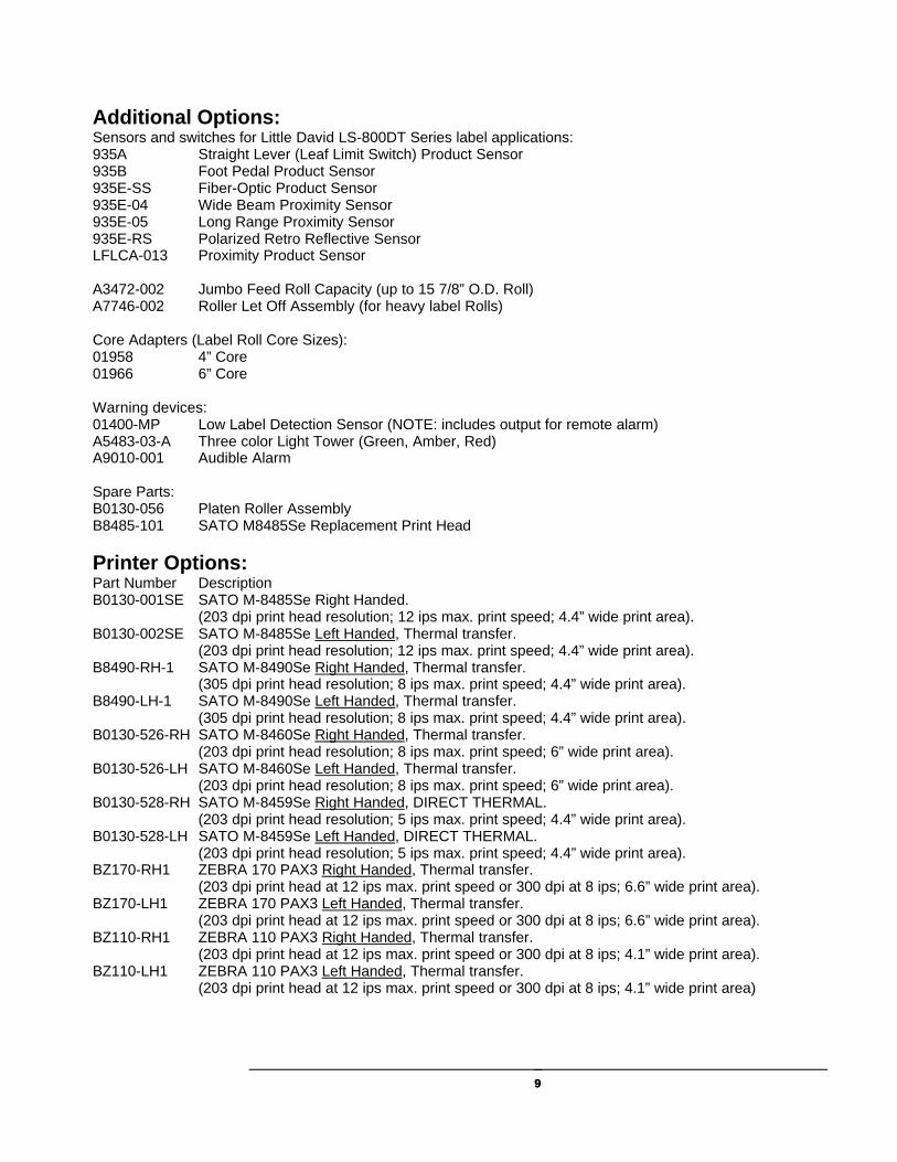
Additional Options: Sensors and switches for Little David LS-800DT Series label applications: 935A Straight Lever (Leaf Limit Switch) Product Sensor 935B Foot Pedal Product Sensor 935E-SS Fiber-Optic Product Sensor 935E-04 Wide Beam Proximity Sensor 935E-05 Long Range Proximity Sensor 935E-RS Polarized Retro Reflective Sensor LFLCA-013 Proximity Product Sensor A3472-002 Jumbo Feed Roll Capacity (up to 15 7/8” O.D. Roll) A7746-002 Roller Let Off Assembly (for heavy label Rolls) Core Adapters (Label Roll Core Sizes): 01958 4” Core 01966 6” Core Warning devices: 01400-MP Low Label Detection Sensor (NOTE: includes output for remote alarm) A5483-03-A Three color Light Tower (Green, Amber, Red) A9010-001 Audible Alarm Spare Parts: B0130-056 Platen Roller Assembly B8485-101 SATO M8485Se Replacement Print Head
Printer Options: Part Number Description B0130-001SE SATO M-8485Se Right Handed. (203 dpi print head resolution; 12 ips max. print speed; 4.4” wide print area). B0130-002SE SATO M-8485Se Left Handed, Thermal transfer. (203 dpi print head resolution; 12 ips max. print speed; 4.4” wide print area). B8490-RH-1 SATO M-8490Se Right Handed, Thermal transfer.
(305 dpi print head resolution; 8 ips max. print speed; 4.4” wide print area). B8490-LH-1 SATO M-8490Se Left Handed, Thermal transfer.
(305 dpi print head resolution; 8 ips max. print speed; 4.4” wide print area). B0130-526-RH SATO M-8460Se Right Handed, Thermal transfer.
(203 dpi print head resolution; 8 ips max. print speed; 6” wide print area). B0130-526-LH SATO M-8460Se Left Handed, Thermal transfer.
(203 dpi print head resolution; 8 ips max. print speed; 6” wide print area). B0130-528-RH SATO M-8459Se Right Handed, DIRECT THERMAL.
(203 dpi print head resolution; 5 ips max. print speed; 4.4” wide print area). B0130-528-LH SATO M-8459Se Left Handed, DIRECT THERMAL.
(203 dpi print head resolution; 5 ips max. print speed; 4.4” wide print area). BZ170-RH1 ZEBRA 170 PAX3 Right Handed, Thermal transfer.
(203 dpi print head at 12 ips max. print speed or 300 dpi at 8 ips; 6.6” wide print area). BZ170-LH1 ZEBRA 170 PAX3 Left Handed, Thermal transfer.
(203 dpi print head at 12 ips max. print speed or 300 dpi at 8 ips; 6.6” wide print area). BZ110-RH1 ZEBRA 110 PAX3 Right Handed, Thermal transfer.
(203 dpi print head at 12 ips max. print speed or 300 dpi at 8 ips; 4.1” wide print area). BZ110-LH1 ZEBRA 110 PAX3 Left Handed, Thermal transfer.
(203 dpi print head at 12 ips max. print speed or 300 dpi at 8 ips; 4.1” wide print area)
1010
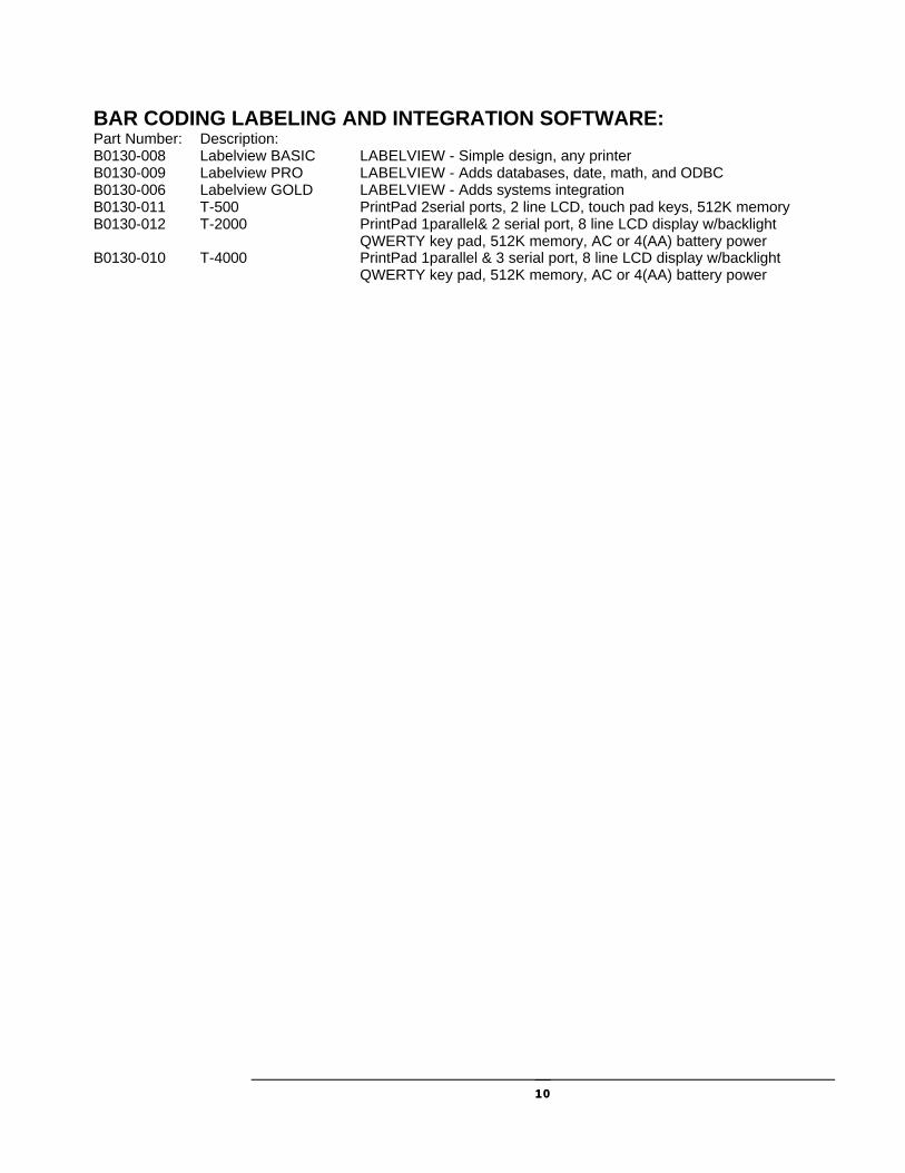
BAR CODING LABELING AND INTEGRATION SOFTWARE: Part Number: Description: B0130-008 Labelview BASIC LABELVIEW - Simple design, any printer B0130-009 Labelview PRO LABELVIEW - Adds databases, date, math, and ODBC B0130-006 Labelview GOLD LABELVIEW - Adds systems integration B0130-011 T-500 PrintPad 2serial ports, 2 line LCD, touch pad keys, 512K memory B0130-012 T-2000 PrintPad 1parallel& 2 serial port, 8 line LCD display w/backlight QWERTY key pad, 512K memory, AC or 4(AA) battery power B0130-010 T-4000 PrintPad 1parallel & 3 serial port, 8 line LCD display w/backlight QWERTY key pad, 512K memory, AC or 4(AA) battery power

1111
Installation & Threading
LS800DT Initial Installation Inspection and Mechanical Adjustments: * Inspect the unit for any loose hardware or cables that may come in contact with any motion of the rotary arm. Position the labeling head in the mounting fixture. 1. Verify there is clean 115 VAC (+/- 10%) electrical power supplied to the conveyor and labeling
system. It is recommended that a dedicated 115VAC (+/-10%) 20 Amp circuit be provided to the labeling system.
2. Ensure that there is clean, dry air being supplied to the regulator of the labeling system.
NOTE: Lack of clean power and air will cause faults with the system and void any warranty.
NOTE: The end of the applicator assembly MUST be secured to the conveyor frame and NOT allowed to hang unsupported. Doing so may result in damage to the labeling machine and will void any and all warranties. Conveyor Installation and Adjustments.
1. Install the "T" Rail at the exit end (Drive End) of the conveyor opposite the chain cover. The reach of the rotary actuator determines the position of the 921-mount casting. Once this is accomplished, place the labeling head with 30-inch pole into the 921 casting and secure for operation.
Chapter
4

1212
2. There are two guide rails on the conveyor system. One is a common rail, which the box is justified to and the other is used for box width adjustments. Place a box on the conveyor to be used as a guide to position the applicator pad. The common rail is the rail positioned on the same side as the LS800DT. 3. With the power turned off to the conveyor and the controller, Print Engine off and no air applied, mechanically position the rotary actuator arm into the desired labeling position. Make adjustments to the head as to the position and tighten for operation. Note: The best head orientation is set up so that the labeling armature pad is positioned at a positive angle to the on coming box. The extreme edge of the pad should contact the box first and then the box should push the pad out of the way to complete the wipe. In the corner wrap mode, the pad should almost roll the label onto the box.
921 Casting Mounted to “T” Rail
1313
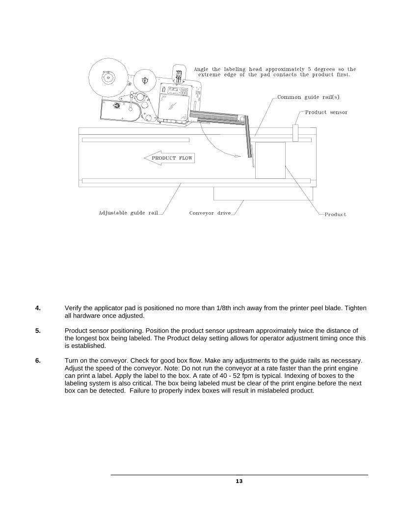
4. Verify the applicator pad is positioned no more than 1/8th inch away from the printer peel blade. Tighten
all hardware once adjusted. 5. Product sensor positioning. Position the product sensor upstream approximately twice the distance of
the longest box being labeled. The Product delay setting allows for operator adjustment timing once this is established.
6. Turn on the conveyor. Check for good box flow. Make any adjustments to the guide rails as necessary.
Adjust the speed of the conveyor. Note: Do not run the conveyor at a rate faster than the print engine can print a label. Apply the label to the box. A rate of 40 - 52 fpm is typical. Indexing of boxes to the labeling system is also critical. The box being labeled must be clear of the print engine before the next box can be detected. Failure to properly index boxes will result in mislabeled product.

1414
Positioning the label on the box. Note: This will be a trial and error process to achieve proper label placement on the box (simply a timing and sequencing of steps).

1515
Loading Stock Follow this procedure to load a new roll of stock.
1. Turn air and power off. 2. After opening the printer cover (not shown), move the head release lever to the OPEN position. 3. Open the label lid, pulling forward on the clip at the front of the lid. 4. Release the label-guide disc from the unwind spindle by lightly turning the disc-lock handle. (The disc lock is a
cam-action clamp requiring very little movement of the handle.) Then slide the label-guide disc off of the unwind spindle. If there is an old stock-roll core on the unwind spindle, remove it.
5. Pull the rewind clip from the rewind spindle, and remove and dispose of any backing paper remaining in the stock path.
6. Strip three to four feet of labels from the backing paper of a new roll. Install the new roll on the unwind spindle, with the labels facing up. (If the labels are wrapped on the outside of the roll, follow PATH A; if they are wrapped on the outside of the roll, follow PATH B.)
7. Push the label-guide disc back onto the unwind spindle until it lightly touches the new roll. Do not bind the new roll between the front and back label-guide discs. Then turn the disc-lock handle to lock the label-guide disc into position.
8. Referring to the illustration on the facing page, thread the backing paper under the dancer roller, over the rewind spindle, under the idler roller, under the label lid, (refer to printer manual for guiding labels into and out of the printer), and over the rewind spindle (beneath the backing paper coming from the unwind spindle), wrapping the excess around the rewind spindle by hand.
9. Replace the rewind clip, taking care to attach only the excess backing to the rewind spindle. 10. If necessary, adjust the web guide until it touches very lightly against the edge of the backing paper. 11. Turn the unwind spindle backwards, to take up any slack stock. 12. Close the label lid. The label indicator on the front of the printer controller should go out. If it does not go out,
open the label lid and push the stock toward the back of the printer, making sure it passes under the label present sensor at the base of the lid. Re-adjust the web guide as described in Step 10, then close the label lid again.
13. Move the head release lever to the CLOSE position.
1616
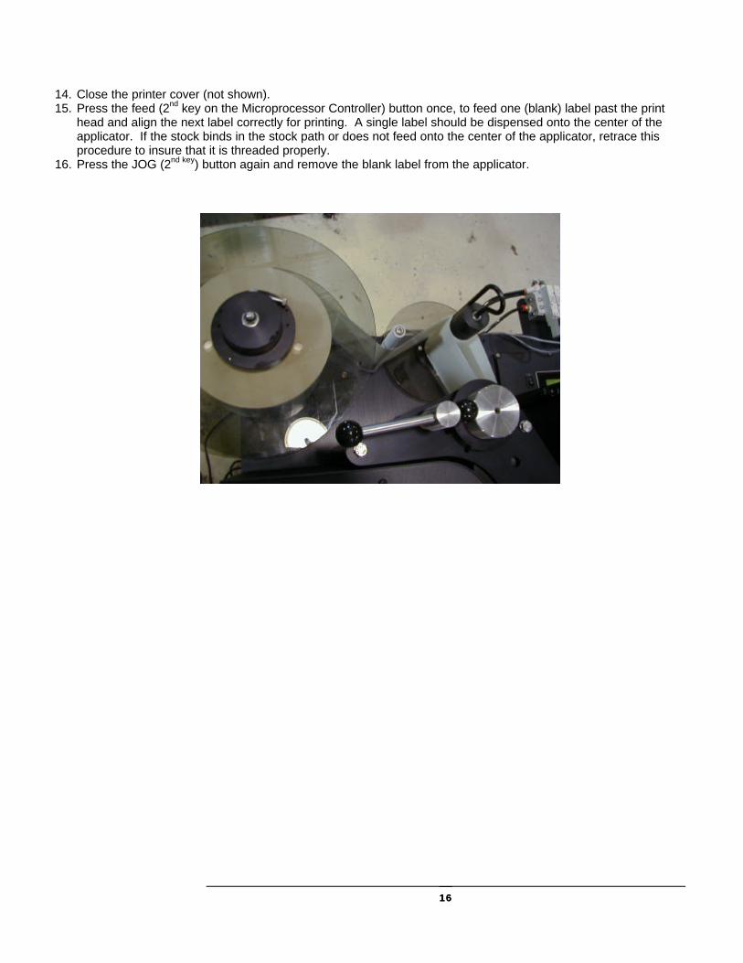
14. Close the printer cover (not shown). 15. Press the feed (2nd key on the Microprocessor Controller) button once, to feed one (blank) label past the print
head and align the next label correctly for printing. A single label should be dispensed onto the center of the applicator. If the stock binds in the stock path or does not feed onto the center of the applicator, retrace this procedure to insure that it is threaded properly.
16. Press the JOG (2nd key) button again and remove the blank label from the applicator.

1717
Startup Procedure To start printing using the LS800DT, perform the following steps:
1. Check that the input air pressure setting is correct for the applicator being used. (It is usually in the range of 40-45 PSI).
2. Power up the host computer. 3. Power up the labeler controller using the switch on the back of the controller. 4. Power on the printer using the power switch on the front control panel (the power indicator on the control
panel should light). 5. Press the feed button on the control panel to feed a single (blank) label past the print head and onto the
applicator pad, which will insure the proper alignment of the first label printed. 6. Unlock the controller and press the Jog button labeled (2nd) to activate the applicator rotary arm (dispose
of the blank label on the pad). 7. Place the printer on-line. An on-line indicator on the control panel may light if an indicator is present.
(Consult your printer manual for details). The printer is now ready to receive communications from the host computer.
Shutdown Procedure Follow the procedure outlined below to shut down the Labeler system.
1. If necessary, press the line button on the front of the printer controller. Printing should cease immediately and the on-line indicator on the controller should go out.
2. Power off the printer (all indicator lights on the control panel should go out). 3. Power off the Labeler Controller using the switch located on the back of the Controller (the LCD
screen will go blank). 4. Power off the host computer.
The Labeler system is now shut down. If any unexpected behavior occurs during the shutdown process, first ensure that the procedure was followed correctly. If the unexpected behavior persists, refer to the TROUBLESHOOTING topic.

1818
Replacing Fuses If a component of the LS800DT fails to operate when powered on, a fuse may be blown. To change a fuse, follow the steps below. WARNING: ALWAYS TURN THE POWER OFF AND REMOVE ALL POWER CORDS BEFORE REPLACING A FUSE. 1. Power off the applicator and the printer (in that order). 2. Disconnect the power cable from the component containing the fuse to be replaced. 3. There is a 3 AMP fuse for the control circuitry in the controller and an 8 AMP fuse for the stepper motor
located on the back of the controller. Use a flat blade screwdriver to twist the inside cap and replace with same AMP rating. There are also two 3 AMP fuses in the CORCOM where the power cord is plugged into the Controller. Remove the cord and use a flat blade screwdriver to lift the compartment open. Replace with same AMP rating fuses.
4. Reconnect the power cables. 5. Power on the applicator and printer (in that order). If the machine still fails to function, the problem may not be with the fuse. Contact a Loveshaw distributor for assistance.

Applicator
Rotary Applicator Introduction The applicator receives labels from the labeling head and applies them to the product. The major components of the Rotary Applicator are the rotary assembly, the air and vacuum assembly, and the input pressure regulator. All three components attach to the frame of the labeling head, and are mounted, positioned, and tested at the factory. The rotary arm assembly is illustrated on next page.
Chapter
5

2020

2121
The events that occur during a single cycle of the label application process are described in detail below. DISPENSING
To dispense a label onto the applicator, the labeling head starts the stock-drive motor. As label stock travels over the edge of the dispense blade, the label begins to separate from the backing.
The label follows the backing paper in its downward turn, but an air stream from the air tube blows the label away from the backing paper and towards the applicator pad at the bottom of the rotary arm assembly.

2222
The motion of the stock over the dispensing blade edge and the force of the air against the bottom of the label continue to peel the label from the backing paper. When the label is almost detached, it strikes the near edge of the applicator pad and hinges toward the pad.
The label is blown flat against the applicator pad and detaches from the backing. The vacuum applied from within the pad holds the label in place. The labeling head then stops both the stock-drive motor and the air blower. The label is now ready for application.
The label remains on the applicator pad until the product sensor, detects the arrival of the product. When this occurs, the product sensor signals the labeling head, which activates the applicator rotary arm. When the rotary arm extends, the applicator pad presses the label onto the product, and the arm retracts to its starting position. At this point, the labeling head dispenses the next label to the applicator, and the cycle repeats itself.
2323
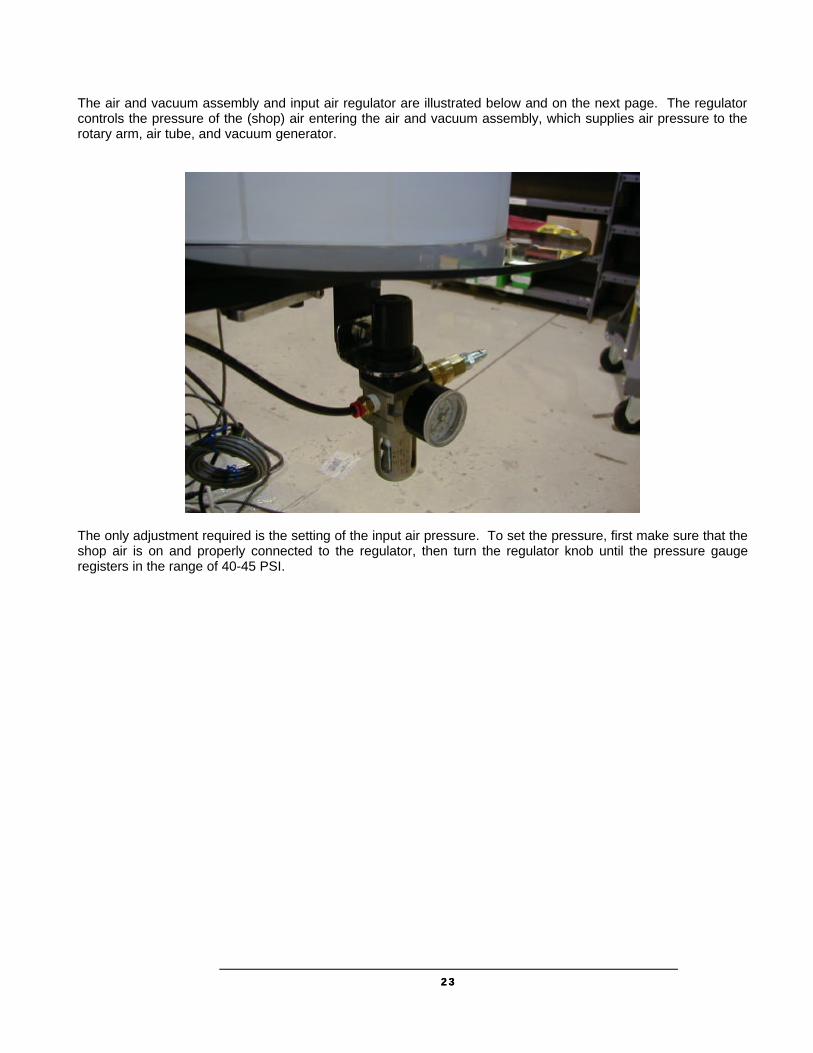
The air and vacuum assembly and input air regulator are illustrated below and on the next page. The regulator controls the pressure of the (shop) air entering the air and vacuum assembly, which supplies air pressure to the rotary arm, air tube, and vacuum generator.
The only adjustment required is the setting of the input air pressure. To set the pressure, first make sure that the shop air is on and properly connected to the regulator, then turn the regulator knob until the pressure gauge registers in the range of 40-45 PSI.

2424

2525

2626
Adjustments The remainder of this chapter describes various adjustments you may need to make to the Rotary Applicator. To properly apply labels, the rotary arm, dispensing blade, and air tube must all be positioned to feed the proper length of label onto the applicator. Unless you change label sizes, you should not need to adjust any of these components. However, if you change label sizes, or if the unit is bumped or treated roughly, you may need to adjust the position of one or more of these components. NOTE: If you move or reposition your LS800DT system, do not lift the unit by the applicator, as the weight of the system may force the rotary arm out of alignment. “ DO NOT MOVE BY REWIND SPINDLE ” When changing label sizes, first load and center the new stock following the “Loading and Centering Stock” procedure, then perform the following adjustments in the sequence in which they are presented.
Changing the Applicator Pad If you change label sizes, you must change the custom-sized applicator pad on the bottom of the rotary arm assembly. To replace the pad, loosen the four bolts shown below on bottom of the pad, remove the old pad, replace with new pad and re-affix bolts.

2727
Adjusting the Rotary Arm Position The Rotary Arm assembly must be positioned correctly relative to the dispensing blade on the labeling-head frame. Before performing this adjustment, be sure that the label sensor is positioned properly, and that the correct custom-sized applicator pad is installed. To move the rotary assembly up or down, or towards or away from the dispensing blade, loosen the appropriate pair of bolts on the mounting plate, move the assembly, and then retighten the bolts.
The correct positioning of the applicator pad relative to the dispensing blade is illustrated to the above. There should be a gap of 1/8” between the dispensing blade and the applicator pad, and the bottom of the applicator pad should be at or just below the middle of the dispensing blade. Do not position the applicator pad above or level with the top of the dispensing blade.

2828
After positioning the rotary arm assembly, position the air tube, as illustrated on the above. Loosen the air tube clamp screw, center the air tube in the stock path, rotate the tube so that the blow holes are directed at a point ¼ to ½ of the way up the applicator pad, and retighten the air tube clamp screw. To test the position of the rotary arm assembly, turn Controller on and unlock it (See Controller Section). Press the Jog button (2nd). The labeling head should dispense a single label onto the applicator pad. The label should be centered on the pad, squared and in line with the stock travel, with the trailing edge of the label just off the dispensing blade (and backing paper). The stock should stop with the next label just at the edge of the dispensing blade. If the label is not positioned properly on the applicator pad, check one or all of the adjustments in this section of this chapter, and repeat the test.

2929
Adjusting the Rotary Arm Flow-Control Valves There are flow-control valves with adjustment knobs located at both the top and bottom of the rotary arm manifold (as shown below). These are factory set, and should not require adjustment under normal circumstances. If it becomes necessary to adjust the pressure at which the rotary arm operates: 1. Use the top knob to adjust the apply-stroke pressure. 2. Use the bottom knob to adjust the retract-stroke.
Rotary Adjustment Vacuum Adjustment

3030
Vacuum Generator (if equipped)
Air Vacuum should be within range of –5 for small labels and –10 for large labels. To adjust pressure; with a label on the pad, covering all vacuum holes, open (more vacuum) or close (less vacuum) the flow control on the manifold until the desired vacuum is attained.
3131

3232
Applicator Pad
When the label is half the size of the applicator pad, change of application from Corner Wrap to Dual Tamp, the back inline flow control to the applicator pad must be turned OFF. Otherwise the label will not stick to the pad.

3333
Applicator Home Sensor
Before starting Adjustment procedure, turn air OFF and turn Labeler Controller ON. The Applicator arm should be in the Home position. Home position is with the applicator pad in front of the printer ready to receive labels. Rotary arm should automatically stop at this position.
Remove the rear plate access by removing the four screws shown above, and take off the plate. Loosen the outside nut on the sensor and push the sensor to the arm (in the home position). Tighten the nuts. Make sure the applicator arm moves freely, if not back off the sensor. Sensor indicator light should come ON in the Home position and then go OFF when the arm swings away. Once the sensor is set replace the rear cover and tighten the bolts securely.
3434
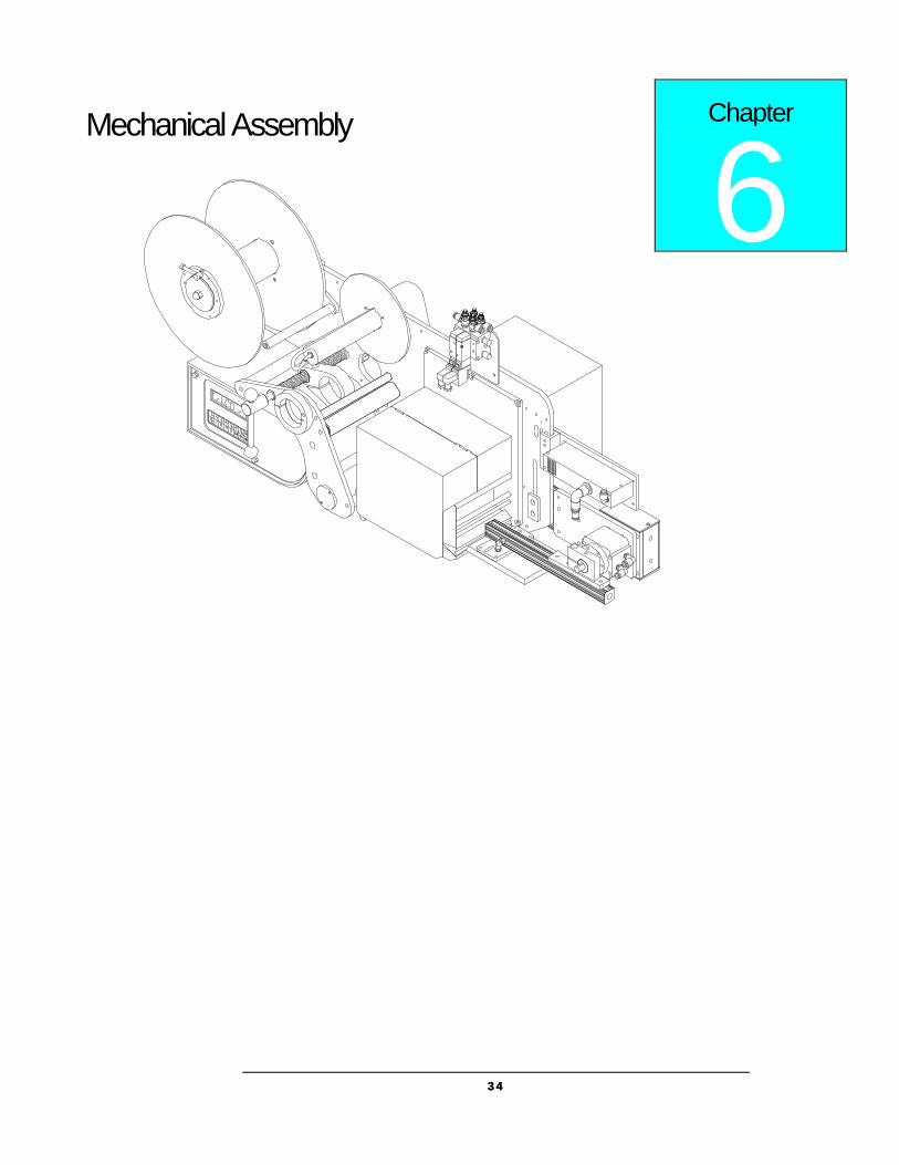
Mechanical Assembly
Chapter
6

3535

3636
Idler

3737
Unit’s Back Side

3838
Mounting and Pedestals
Introduction The following mounting, pedestals and casters and lift-off screws are available for the Little David Application System. Part Description 921 Vertical mounting for apply labels to the side of the product. 922A Horizontal mounting for applying labels to top, side or bottom of the product. 924A/925A H-Mount Floor Base with pedestal 20” or 30” respectively. 926 Casters and Lift-off Screws for the 924A or 925A. Each of these components is described separately in the following sections.
Chapter
7
3939
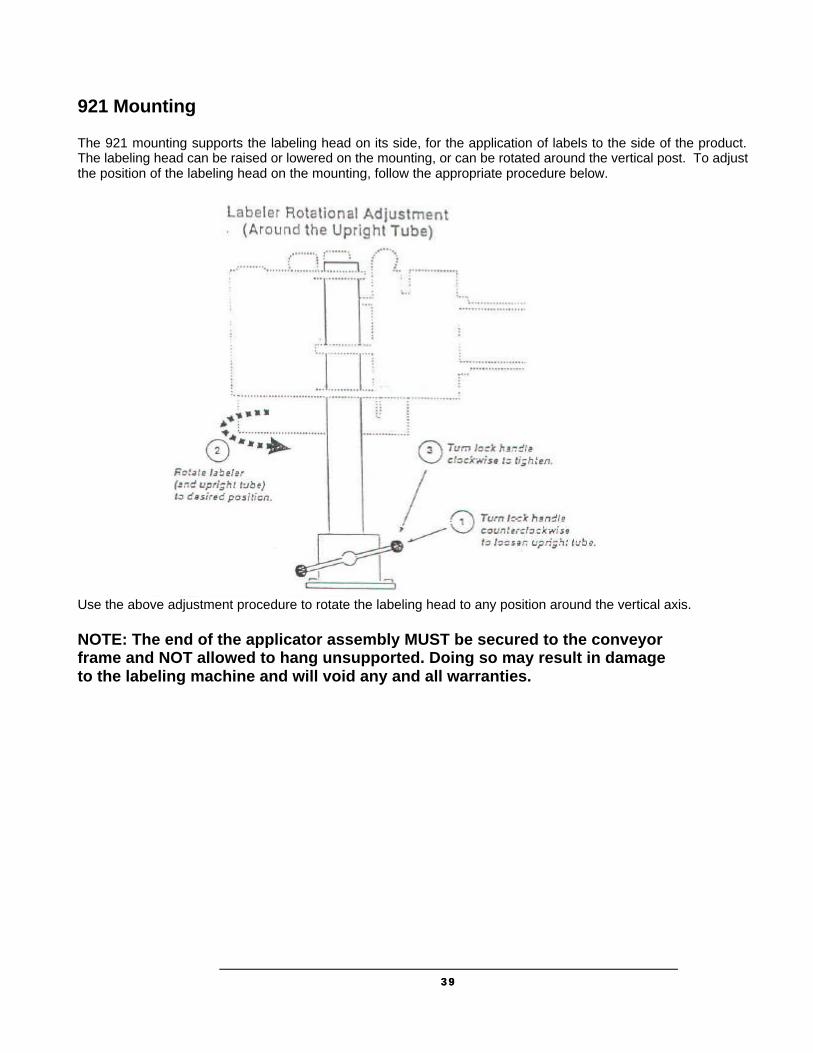
921 Mounting The 921 mounting supports the labeling head on its side, for the application of labels to the side of the product. The labeling head can be raised or lowered on the mounting, or can be rotated around the vertical post. To adjust the position of the labeling head on the mounting, follow the appropriate procedure below.
Use the above adjustment procedure to rotate the labeling head to any position around the vertical axis. NOTE: The end of the applicator assembly MUST be secured to the conveyor frame and NOT allowed to hang unsupported. Doing so may result in damage to the labeling machine and will void any and all warranties.
4040
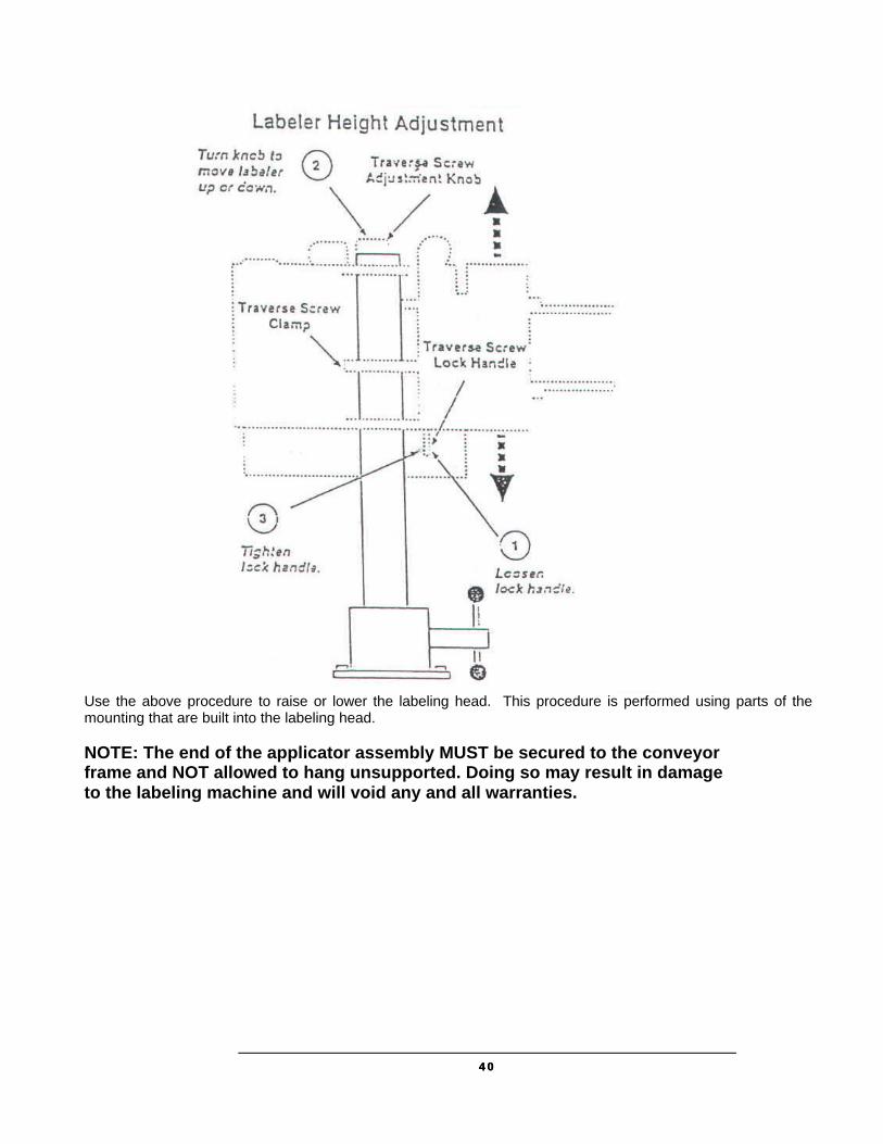
Use the above procedure to raise or lower the labeling head. This procedure is performed using parts of the mounting that are built into the labeling head. NOTE: The end of the applicator assembly MUST be secured to the conveyor frame and NOT allowed to hang unsupported. Doing so may result in damage to the labeling machine and will void any and all warranties.

4141
922 Mounting The 922 mounting supports top, bottom, or side labeling. You can adjust the labeling head to any position around both the vertical and horizontal axis. If your product size or conveyor locations changes, follow the appropriate procedure below to adjust the labeling head on the mounting.
Use the above adjustment procedure to move the labeling head up or down on the vertical tube.
Use this procedure to rotate the labeling head to any angle around the cross tube.

4242
Use the rotational adjustment procedure to rotate the labeling head to any position around the vertical axis.
4343
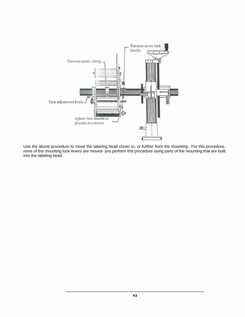
Use the above procedure to move the labeling head closer to, or further from the mounting. For this procedure, none of the mounting lock levers are moved- you perform this procedure using parts of the mounting that are built into the labeling head.

4444
924A and 925A H-Mount Floor Base & Pedestals
The 924A is a H-shaped base with a 20” pedestal. The 925A is a H-shaped base with a 30” pedestal. Either pedestal can be supplied with the 926 Casters and Lift Off Screw option.
To install a mounting in a pedestal, perform the following steps: 1. Loosen the clamp lock handle on the base of the 921 or 922A mounting, and remove the upright tube from the base. 2. Loosen the clamp lock handle at the top of the pedestal. 3. Insert the 921 or 922A upright tube about 3” into the mounting base at the top of the pedestal. 4. Tighten the clamp lock handle at the top of the pedestal. 926 Casters and Lift-off Screws
The 926 Casters and Lift-off Screws can be attached to either the 924A or 925A floor pedestal. Each of the four casters attaches by four bolts. Lift-off screws inserted through the mounting and pedestal base can be raised or lowered.

4545
DIMENSIONAL DRAWINGS
Product Sensing
Proximity Photo-eye
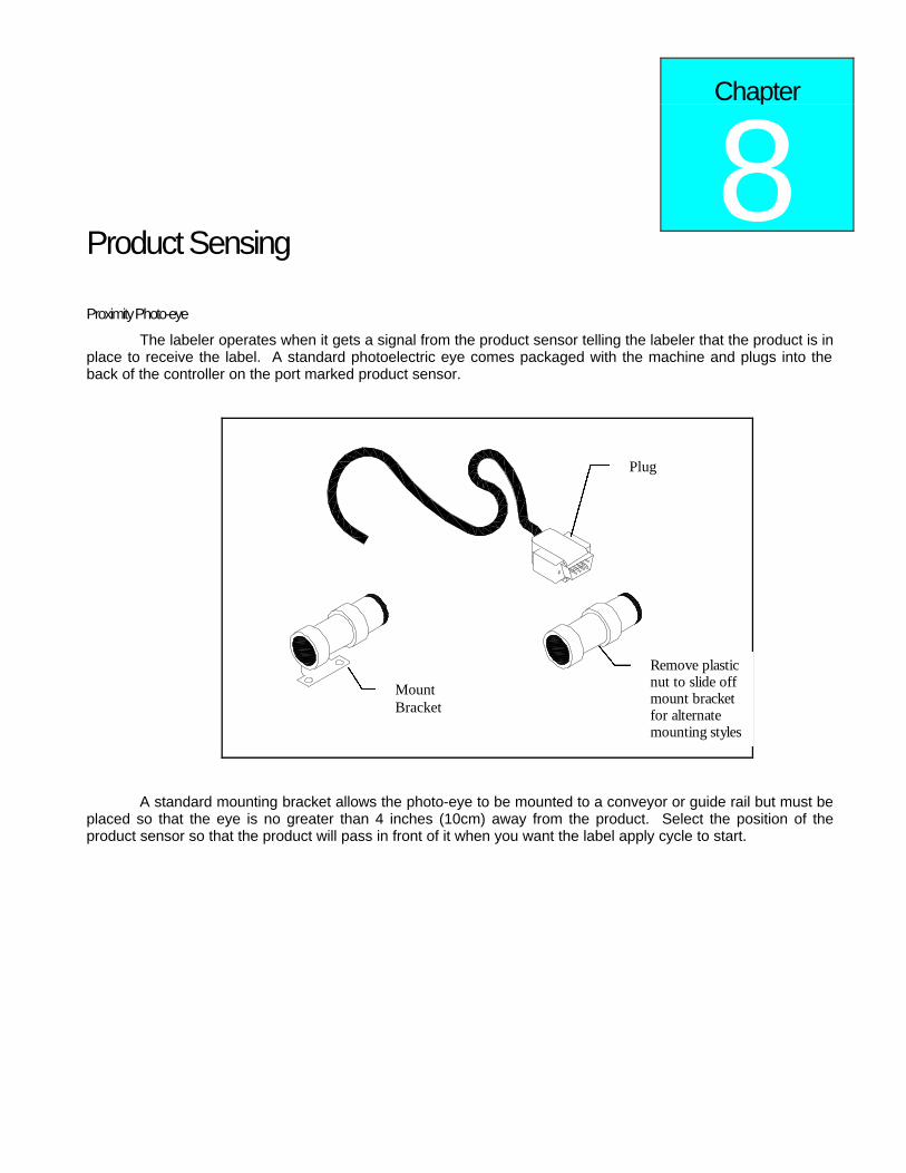
The labeler operates when it gets a signal from the product sensor telling the labeler that the product is in place to receive the label. A standard photoelectric eye comes packaged with the machine and plugs into the back of the controller on the port marked product sensor.
A standard mounting bracket allows the photo-eye to be mounted to a conveyor or guide rail but must be placed so that the eye is no greater than 4 inches (10cm) away from the product. Select the position of the product sensor so that the product will pass in front of it when you want the label apply cycle to start.
Chapter
8
Plug
Mount Bracket
Remove plastic nut to slide off mount bracket for alternate mounting styles

It is possible to adjust the label position on the box by adjusting the time between product detection and label apply. To learn how to do this turn to Help Menu: Adjust in chapter 10
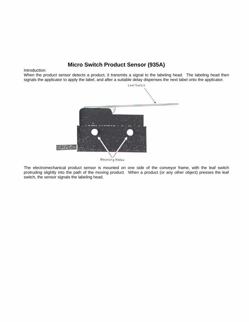
Micro Switch Product Sensor (935A) Introduction: When the product sensor detects a product, it transmits a signal to the labeling head. The labeling head then signals the applicator to apply the label, and after a suitable delay dispenses the next label onto the applicator.
The electromechanical product sensor is mounted on one side of the conveyor frame, with the leaf switch protruding slightly into the path of the moving product. When a product (or any other object) presses the leaf switch, the sensor signals the labeling head.
4949
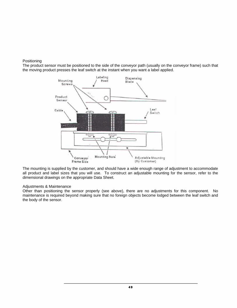
Positioning The product sensor must be positioned to the side of the conveyor path (usually on the conveyor frame) such that the moving product presses the leaf switch at the instant when you want a label applied.
The mounting is supplied by the customer, and should have a wide enough range of adjustment to accommodate all product and label sizes that you will use. To construct an adjustable mounting for the sensor, refer to the dimensional drawings on the appropriate Data Sheet. Adjustments & Maintenance Other than positioning the sensor properly (see above), there are no adjustments for this component. No maintenance is required beyond making sure that no foreign objects become lodged between the leaf switch and the body of the sensor.

5050
Foot Switch Product Sensor (935B) Introduction Foot-switch product sensors are used in applications where the operator must manually position the product for labeling. After positioning the product, the operator activates the electromechanical product sensor by stepping on the foot switch. The sensor then transmits a signal to the labeling head, which signals the applicator to apply the label. After a suitable delay, the labeling head dispenses the next label onto the applicator.
Positioning The Foot-switch product sensor must be positioned on the floor in such a way it can be activated conveniently by the operator. WARNING: Do not place the foot-switch sensor in any location that will cause the operator to be off-balance, or in any position where the operator must look away from moving parts (such as an applicator rotary arm) to activate the sensor. Adjustment & Maintenance Other than positioning the sensor properly (see above), there are no adjustments for this component. No maintenance is required beyond making sure that no foreign objects become lodged in the sensor assembly.

5151
Product Sensor (935E series) Introduction When the product sensor detects a product, it transmits a signal to the labeling head. The labeling head then signals the applicator to apply the label, and after a suitable delay dispenses the next label onto the applicator.
The photoelectric product sensor is mounted on one side of the conveyor frame, with its associated reflector mounted on the other side. The sensor transmits a light beam across the conveyor path and onto the reflector, which reflects the beam back to the sensor. When a product (or any other object) passes between the sensor and the reflector, the sensor signals the labeling head, and the indicator light is turned on. Positioning The product sensor should be positioned on the conveyor frame such that the product blocks the sensor beam at the instant when you want a label applied. Sensitivity Adjustment To adjust the sensitivity of the sensor, follow the procedure outlined below: 1. With the sensor viewing the reflector directly, turn the adjustment knob until the indicator light just turns OFF. Note the position of the adjustment knob. 2. Place a product in front of the beam, and turn the adjustment knob clockwise until the indicator turns ON, or to the maximum. 3. Set the sensitivity between the two points established in the first two steps above.

5252
Troubleshooting: If a product is clear enough, a reflection can be made through the product. If this occurs, turn the sensor slightly so that the beam does not strike the reflector directly (at 90 degrees). If a product is highly reflective and is positioned close to the sensor, the product itself may act as a reflector. When this happens, move the sensor further away from the product.

5353
Features and Options
Optional: Low Label Sensor An option to the LS800 is the low label sensor. This sensor, when plugged in to the controller, will let the unit know when the label stock is in small supply. When the labels run low a message on the controller will let the operator know that new roll of labels will soon need to be placed in the machine.
Optional: Light Tower The light tower is an optional accessory. The light tower should be mounted near the labeler and plugged in to the back of the controller. The Amber LED lights, when the low label sensor indicates that the label roll is low or if the ribbon is low in the printer, giving a highly visible indication to all plant employees that supplies will be needed shortly. When the Red LED lights these supplies are out and labeling will not occur.
Chapter
9

5454
Controller Operation
Keyboard, Screen The special-function keys on the keyboard have the following uses:
• HELP shows the menu; CLEAR exits from the menu, and can be used to delete characters in the data entry screens.
• 2ND is the “jog“ key; pressing this key starts a label-cycle (see Jog below).
• The ááââ arrow keys move through menus and menu features.
• ENTER is used to complete an entry.
Power-On and Unlock When the unit is turned on the startup screen is shown; this appears below.
Labeler model (Passive Mode Shown) Software version
Controller memory status
If locked or clear appears on the memory status line unit parameters must be adjusted before labeling will occur.
To unlock the unit, enter the factory code 5863434 followed by ENTER — except if the Unlock code feature has been used to change the code.
Chapter
10
11

5555
READY If memory wasn’t cleared, or after setting cleared parameters, the normal unit display will appear showing the labeler is ready to operate.
Memory Clear Once the labeler is unlocked, it will usually show the READY legend. If instead the Memory clear message appears, the unit memory is clear and labeling parameters should be set by pressing the 1 key to enter the parameter section; see ADJUST menu, next chapter. Typically all parameter values for your particular labeler installation should be written down in the back of this manual or optionally on a decal somewhere within labeler vicinity of the labeler and those values should be entered at this point; see Adjust below.
11

Using Menu Features
In normal operation, the labeler is simply turned-on and products are moved past its sensor equipment and the labeler responds by applying a label. To adjust system behavior including important labeler parameters, the Help Menu must be accessed with the HELP key. The unit then displays a list of numbered features, one of which may be selected by pressing the number or letter next to it. The entire menu can’t be seen at once, so use the arrow keys to move through it. It is not necessary to move in this way to an entry, it can be selected any time by pressing its associated number.
HELP shows the menu; CLEAR exits from the menu, and can be used to delete characters in features. To exit the help menu, press ENTER, HELP, or CLEAR.
The following text describes each of the features in the help menu by name. The special-function keys on the keyboard have the following uses:
How Help Menu Features Work Selecting a typical feature will produce a prompt and a number, like Feature value: 0. To change the number, use the arrow keys, or press number keys. The system will automatically prevent values too large or small from being entered. When the desired value is set, press ENTER. Many features adjust timing and are set in milliseconds; 1,000 milliseconds equal one second. Several features use a similar arrangement, but only permit 0 or 1 as values, to control an on/off or yes/no labeler function. 1 is on or yes, 0 is off or no. Record all settings values on the chart in the back of this manual.
Chapter
11

5757
Help Menu Feature 1: Adjust The most important feature on the help menu is Adjust, which allows control of labeler parameters. Selecting the feature produces another menu just like the help menu, which is used in the same way and has the following entries. Note that some or all of these features will vary depending on the selected unit (see Help Menu Feature 2: Select) and/or software version.
• Product Delay 1 / 2 controls the time from product detection to start of labeler activity; default setting is 250 milliseconds or ¼ second.
• Apply Solenoid 1 / 2 controls the time to hold the air solenoid ON to apply the label.
• Label Overfeed is the time from label sensor detect until label motor stop. A photoelectric sensor positions the label and stops when the label has moved to the right location. The hardware is deliberately designed so that the sensor detects the label too early so it can be fine tuned with this parameter.
• LLTD Label Delay is the time delay before the label moves.
• Printer Time Out is the time before the printer is expected to be broken.
• Hold-Off controls the minimum time from the end of a labeling cycle to the beginning of the next cycle; this default value is 0.
• Jog Solenoid (Y:1) enables when set to 1 and disables when set to 0, applicator solenoid to cycle.
• Solenoid Signal (Y:1) enable/disables the wait for stop solenoid signal I9 flag wrap around.
• Web Break (Y:1) enable/disables the web break feature.
Help Menu Feature 2: Select Choosing this menu may simply display Not Implemented. If the DIP Switch S2, which is explained in the Controller Hardware section, is set to a NON-UNIT selection a menu will be provided. Scroll thru the selections using the arrow key. Selection 9 will give you more selections.

5858
Help Menu Feature 3: Language The feature determines the language in which the Label Controller menus and other informative screens will be displayed. Pressing the arrow keys will “scroll” to show more of it. Then press the desired number.
Allows selection 1. ENG, 2. ITAL, 3. DEUT, 4. FRAN, 5. ESPA, 6. DUTC, 7. PORT
Available languages are English, Italian, German, French, Spanish, Dutch and Portuguese.
Help Menu Feature 4: Net # Some labeler units can operate within a Loveshaw Corp network, allowing control of multiple units from a central computer. In such networks each unit must have a unique identifying number, which can be set in this feature.
This feature is disabled if set to zero. If set to 1 thru 32 a special network using RS-422 may be possible. This selection changes from the normal RS-232 point to point communications to a network Board. The optional Labels program is required. Labels is a Windows program that runs on PC
computers.
Help Menu Feature 5: Speed This feature sets the feed rate of the label, in inches per minute, to match the conveyor speed. If the feed rate is too slow, the label might tear or drag/pull off the box. If the feed rate is set too fast, the label will crinkle.
Print and Apply speeds are controlled by the printer that has been installed (consult printer manual for specifics).
Help Menu Feature 6: Unlock code The default unlock code 5863434 can be altered with this feature. Note that once it is altered if the new code is forgotten Loveshaw Corp cannot retrieve it and the unit will have to be cleared for features to be accessible again.
11
5959
Help Menu Feature 7: Other This menu contains factory setting specific to your application. Do not alter the settings in this menu unless directed by Loveshaw Corp.
Other Control Functions To clear all memory in the labeler — if for instance, the unlock code has been altered and then lost — turn the unit off, press and hold the number 6, turn the unit on, wait about a second, release the 6, then press 6, 6, followed by CLEAR, HELP, and the down arrow key ââ; if any error is made in pressing the keys, the memory clear does not occur.
It is often desirable to cause the labeler hardware to execute a cycle without actual product processing; this is called a Jog. The 2ND key starts a jog cycle.
The labeler will normally display the READY legend at power-on. When the labeler receives a product signal or the Jog control is used (see above) label cycling will occur and informative messages will appear describing the stages of the cycle.
If, however, memory is clear and parameters have not been adjusted; i.e. if 0 instead of 1 is pressed at power-on in answer to the Memory clear; adjust parameters? question, then subsequently whenever the unit should start a cycle, it will instead produce the memory clear prompt all over again. It is easy to exit this prompt without actually adjusting parameters. Pressing 1 followed by ENTER will leave parameters in a nominal default state, and during installation could cause equipment malfunction.
666 Memory Clear
Jog
Normal Operation;
Memory Clear Failures
Controller Hardware
The Label Controller is a 7" Width 6½" Depth 5½" Height enclosure with a twist front piece. When installed it has a metal cover that protects it and the motor. This controller includes a 2 by 20 character display and 2 x 8 button keypad for data entry. This controller interfaces the Print Trigger Devices, solenoids, and other sensors to signal the Stepper Motor or Printer to apply labels to the product.
Chapter
12

Overview Parts include:
a) MicroJet Controller Board — is the CPU of the package it provides the user with memory and control to the other subsystems.
b) Driver Board — connects to the controller board to provided inputs from sensors and outputs for the Motor AC Board/Stepper Board.
c) The Motor AC and Stepper Board include the voltage power supplies, relays and motor/solenoid controls. These boards provide LED for a visual indication of the motor and solenoids. Two types of motors are available. The AC stepper motor is used with the Motor AC board and DC stepper motor is used with the Stepper board. The power supply on this board has two fuses for the DC
circuitry. A 3Amp fuse for the logic and an 8Amp for the stepper motor/relays (depending on the choice of motor the current draw is 3Amp to 7Amp).
d) A Keypad and LCD screen provide user-friendly interface. Both of these items are on a twistable plate.
e) A power cord is plugged into a CORCOM. The CORCOM is selectable for 110/220. The AC Stepper Motor is voltage specific either 110 or 220/240 VAC. The Stepper Board uses DC Stepper Motor and can allow for any voltage settings. Two 3Amp fuses are used in the CORCOM.
f) An RS-232 port is standard but included is a jumper change to RS-422 network.
6262
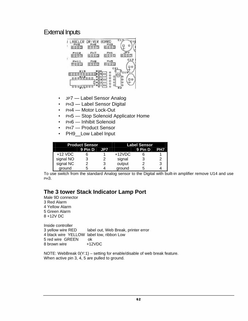
External Inputs
• JP7 — Label Sensor Analog • PH3 — Label Sensor Digital • PH4 — Motor Lock-Out • PH5 — Stop Solenoid Applicator Home • PH6 — Inhibit Solenoid • PH7 — Product Sensor • PH9__Low Label Input
Product Sensor Label Sensor 9 Pin D JP7 9 Pin D PH7
+12 VDC 6 1 +12VDC 6 1 signal NO 3 2 signal 3 2 signal NC 2 3 output 2 3
ground 5 4 ground 5 4 To use switch from the standard Analog sensor to the Digital with built-in amplifier remove U14 and use PH3.
The 3 tower Stack Indicator Lamp Port Male 9D connector 3 Red Alarm 4 Yellow Alarm 5 Green Alarm 8 +12V DC Inside controller 3 yellow wire RED label out, Web Break, printer error 4 black wire YELLOW label low, ribbon Low 5 red wire GREEN ok 8 brown wire +12VDC NOTE: WebBreak 0(Y:1) – setting for enable/disable of web break feature. When active pin 3, 4, 5 are pulled to ground.
6363
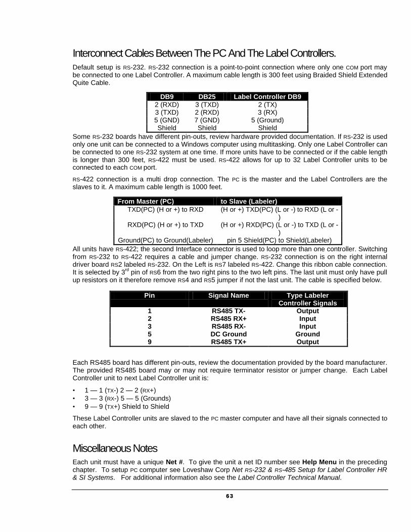
Interconnect Cables Between The PC And The Label Controllers. Default setup is RS-232. RS-232 connection is a point-to-point connection where only one COM port may be connected to one Label Controller. A maximum cable length is 300 feet using Braided Shield Extended Quite Cable.
Some RS-232 boards have different pin-outs, review hardware provided documentation. If RS-232 is used only one unit can be connected to a Windows computer using multitasking. Only one Label Controller can be connected to one RS-232 system at one time. If more units have to be connected or if the cable length is longer than 300 feet, RS-422 must be used. RS-422 allows for up to 32 Label Controller units to be connected to each COM port.
RS-422 connection is a multi drop connection. The PC is the master and the Label Controllers are the slaves to it. A maximum cable length is 1000 feet.
All units have RS-422; the second Interface connector is used to loop more than one controller. Switching from RS-232 to RS-422 requires a cable and jumper change. RS-232 connection is on the right internal driver board RS2 labeled RS-232. On the Left is RS7 labeled RS-422. Change this ribbon cable connection. It is selected by 3rd pin of RS6 from the two right pins to the two left pins. The last unit must only have pull up resistors on it therefore remove RS4 and RS5 jumper if not the last unit. The cable is specified below.
Each RS485 board has different pin-outs, review the documentation provided by the board manufacturer. The provided RS485 board may or may not require terminator resistor or jumper change. Each Label Controller unit to next Label Controller unit is:
• 1 — 1 (TX-) 2 — 2 (RX+) • 3 — 3 (RX-) 5 — 5 (Grounds) • 9 — 9 (TX+) Shield to Shield
These Label Controller units are slaved to the PC master computer and have all their signals connected to each other.
Miscellaneous Notes Each unit must have a unique Net #. To give the unit a net ID number see Help Menu in the preceding chapter. To setup PC computer see Loveshaw Corp Net RS-232 & RS-485 Setup for Label Controller HR & SI Systems. For additional information also see the Label Controller Technical Manual.
DB9 DB25 Label Controller DB9 2 (RXD) 3 (TXD) 2 (TX) 3 (TXD) 2 (RXD) 3 (RX) 5 (GND) 7 (GND) 5 (Ground) Shield Shield Shield
From Master (PC) to Slave (Labeler) TXD(PC) (H or +) to RXD (H or +) TXD(PC) (L or -) to RXD (L or -
) RXD(PC) (H or +) to TXD (H or +) RXD(PC) (L or -) to TXD (L or -
) Ground(PC) to Ground(Labeler) pin 5 Shield(PC) to Shield(Labeler)
Pin Signal Name Type Labeler Controller Signals
1 RS485 TX- Output 2 RS485 RX+ Input 3 RS485 RX- Input 5 DC Ground Ground 9 RS485 TX+ Output
6464
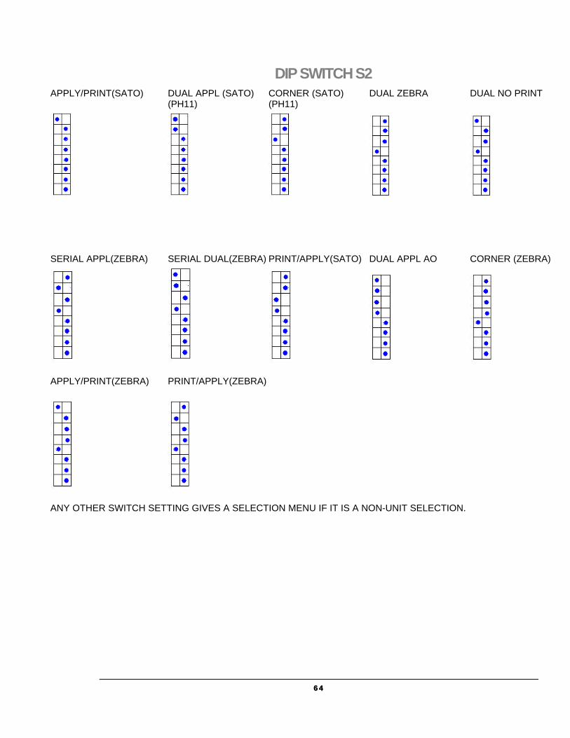
DIP SWITCH S2 APPLY/PRINT(SATO) DUAL APPL (SATO) CORNER (SATO) DUAL ZEBRA DUAL NO PRINT (PH11) (PH11)
SERIAL APPL(ZEBRA) SERIAL DUAL(ZEBRA) PRINT/APPLY(SATO) DUAL APPL AO CORNER (ZEBRA)
APPLY/PRINT(ZEBRA) PRINT/APPLY(ZEBRA)
ANY OTHER SWITCH SETTING GIVES A SELECTION MENU IF IT IS A NON-UNIT SELECTION.

6565
CORCOM To insure proper operating conditions use dedicated AC drops. Do not use extensions. Use Line Conditioners or UPS to protect against surges, noise, and spikes.
Note: Before plugging in the power cord, ensure the power switch is in the OFF position (Press the 0 on the ON/OFF switch). The ON/OFF switch is located the Power Entry Module on the rear of the Labeler controller.
CAUTION: Double Pole/Neutral Fusing.
Socket- outlet shall be installed near the equipment and shall be easily accessible.
6666
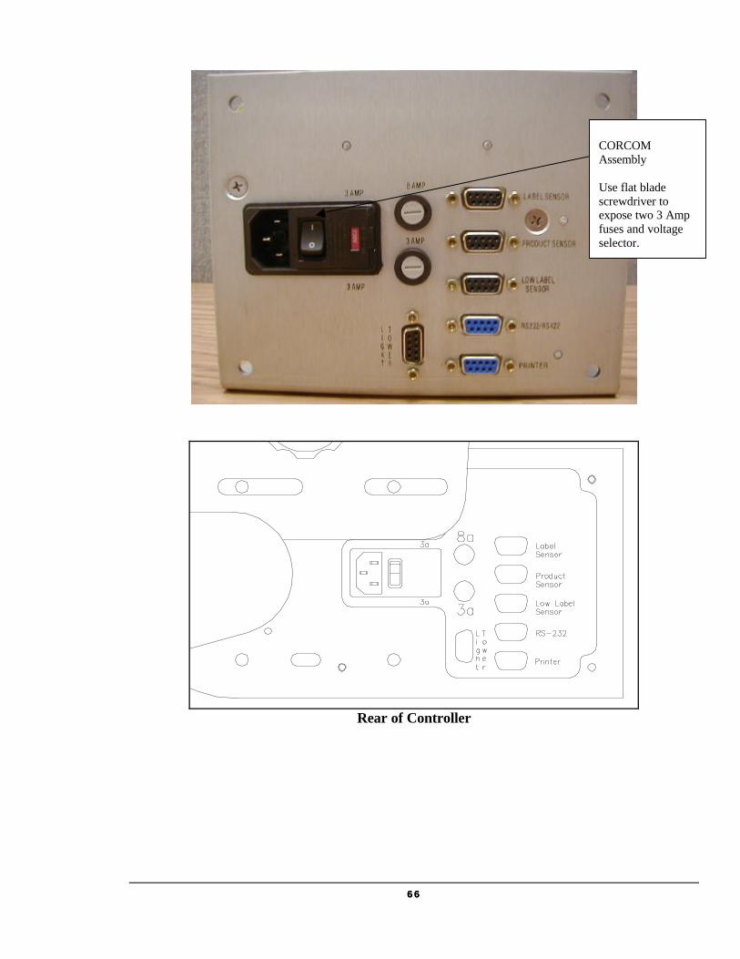
Rear of Controller
CORCOM Assembly Use flat blade screwdriver to expose two 3 Amp fuses and voltage selector.

6767
Maintenance Daily Ensure that the product sensor and label sensor is free of debris. Gently wipe away any dust build up on the lens to ensure reliable product and label sensing.
Peel Blade: Ensure that no adhesive residue is built up on the peel blade. Simply remove and adhesive with Alcohol as required.
Rewind Spindle: Remove excess backing paper as required. Too much backing paper could interfere with proper rewinding and label dispensing.
Note: All bushings are oil-lite and do not require lubrication.
Preventative Maintenance of the Labeling System: (See the complete documentation for detailed maintenance procedures.) Conveyor: Daily - Check for belt tracking, look for frayed edges of the belt. Listen for the chain tension. The chain
should not be loose and rubbing against the chain guard. Monthly - Oil the chain as described in the Hytrol Manual. See the Hytrol maintenance section for further details. Labeling Head: Daily - Check the water trap on the filter regulator. Empty or change Filter as necessary. - Tighten any loose hard ware as necessary. - Check all air line connections. Weekly - Check the condition of the applicator pad. Ensure that the label seats firmly on the pad. - Blow Tube. Ensure the blowholes on the blow tube are oriented so that the label is directed to the applicator pad during a feed cycle. Make corrections as necessary.
Chapter
13
6868
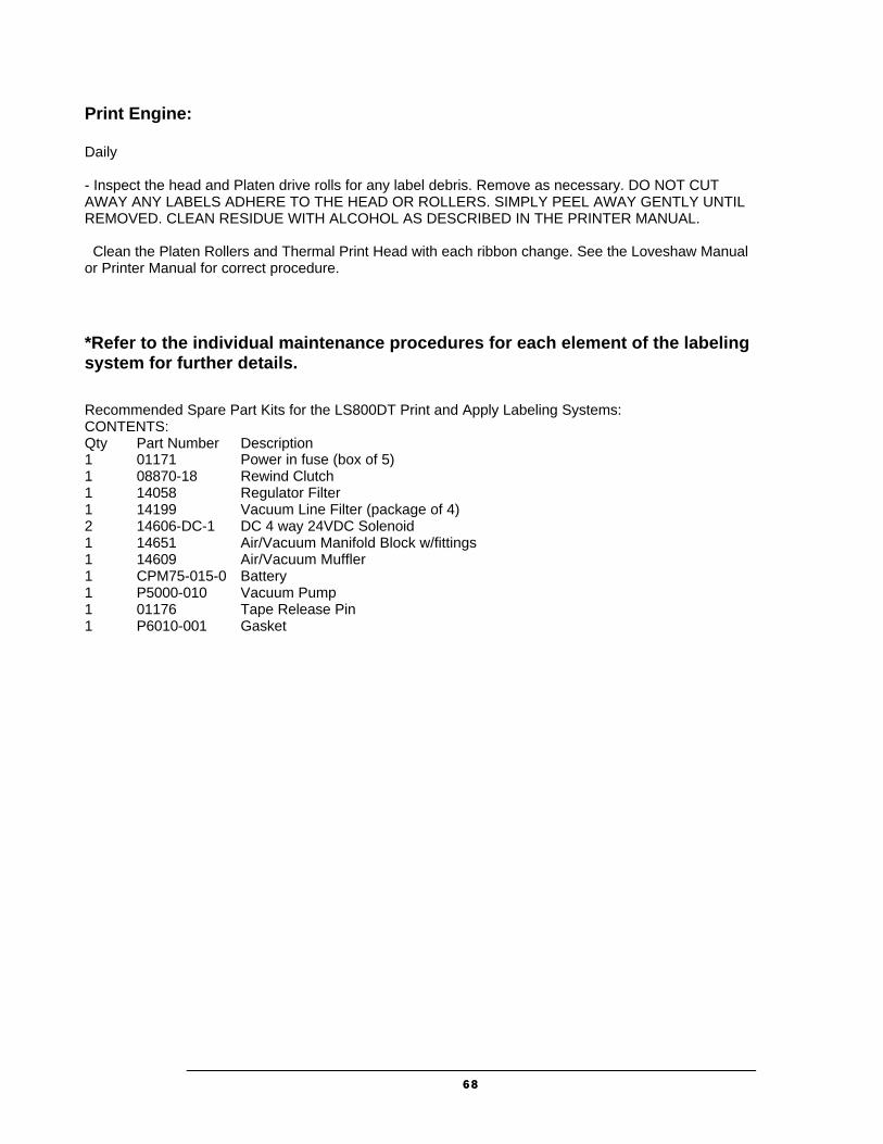
Print Engine: Daily - Inspect the head and Platen drive rolls for any label debris. Remove as necessary. DO NOT CUT AWAY ANY LABELS ADHERE TO THE HEAD OR ROLLERS. SIMPLY PEEL AWAY GENTLY UNTIL REMOVED. CLEAN RESIDUE WITH ALCOHOL AS DESCRIBED IN THE PRINTER MANUAL. Clean the Platen Rollers and Thermal Print Head with each ribbon change. See the Loveshaw Manual or Printer Manual for correct procedure. *Refer to the individual maintenance procedures for each element of the labeling system for further details.
Recommended Spare Part Kits for the LS800DT Print and Apply Labeling Systems: CONTENTS: Qty Part Number Description 1 01171 Power in fuse (box of 5) 1 08870-18 Rewind Clutch 1 14058 Regulator Filter 1 14199 Vacuum Line Filter (package of 4) 2 14606-DC-1 DC 4 way 24VDC Solenoid 1 14651 Air/Vacuum Manifold Block w/fittings 1 14609 Air/Vacuum Muffler 1 CPM75-015-0 Battery 1 P5000-010 Vacuum Pump 1 01176 Tape Release Pin 1 P6010-001 Gasket

6969
Parts List: .LS800DT Right Hand PRINT/APPLY DUAL TAMP WITH MICROPROCESSOR CONTROLS, 8485Se
.LD908-A,MP-SDE 1 EA 908; NO NIP, MICRO, SIDE MOUNT ASSEMBLY CONFIGURATION
B0080-001 1 EA LARGE FRAME PLATE 908
B0080-002 1 EA SMALL FRAME PLATE 908
01041 1 EA PLATE, RUBBER ROLL BEAR. COVER
01601 2 EA BEARING, BALL
M0105-112 1 EA CLAMP, PRINTER
14816 1 EA HOLD DOWN, VACUUM LINE (SOLD AS 6 PK)
21014 2 EA HANDLE, BALL, CLAMPING (SOLD AS 4 PK)
21009 1 EA HANDLE, LEAD SCREW
22910 1 EA KNUCKLE, LEAD SCREW, W/O THREAD
21010-A 1 EA COLLAR, STOP 2 1/4 ID
01040-7 2 EA POST, LABELING HEAD
M0070-030 1 EA ROLLER, IDLER, TEFLON 1 1/4"OD
M0010-017 1 EA SHAFT, IDLER SHAFT 1/2" X 7"
B0120-001 2 EA COLLAR, CLAMP, 1/2x1 1/8 OD
08854 1 EA ROLLER, IDLER, TEFLON, 6.187”L
B0120-019 1 EA COLLAR, SPRING CLOSURE 3/4"I.D.
M0095-001 1 EA CAP, BEARING
M0030-166 1 EA SHAFT, IDLER, 0.499" X 7.75"
M0035-048 1 EA TUBE, IDLER, 2" X 6.314"
M0035-010 1 EA POST, COVER 1/2OD X 1-7/8”
.A0000-118 1 EA ASSEMBLY, IDLER SPROCKET
M25B15-01 1 EA SPROCKET
B0010-024 1 EA BUSHING, BRASS
08872 1 EA MOTOR, DRIVE, 908-8
B0060-004 1 EA SPROCKET
08870-18 1 EA CLUTCH, REWIND
.B0070-004 1 EA ASSEMBLY, CHAIN, 908 PRINT AND APPLY
B0070-003 2-3/4’ CHAIN - DIAMOND (34.4")
B0070-103 2 EA LINK, CONNECTING, SPRING CLIP
B0070-102 1 EA LINK, OFFSET
.01810 1 EA ASSEMBLY, REWIND SPINDLE
M0030-001 1 EA SHAFT, REWIND 8.8 X 5
01024 1 EA ROLLER, REWIND 6 15/16" LONG
.01960 1 EA ASSEMBLY, REWIND DISC
7070
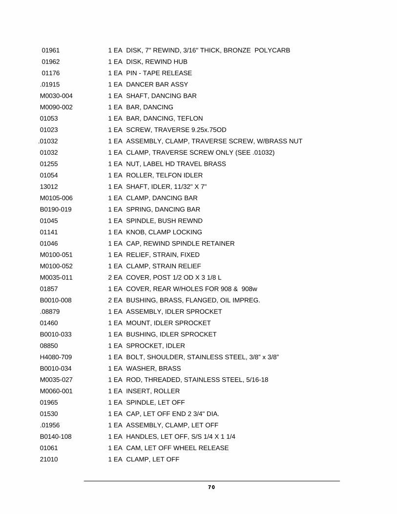
01961 1 EA DISK, 7" REWIND, 3/16" THICK, BRONZE POLYCARB
01962 1 EA DISK, REWIND HUB
01176 1 EA PIN - TAPE RELEASE
.01915 1 EA DANCER BAR ASSY
M0030-004 1 EA SHAFT, DANCING BAR
M0090-002 1 EA BAR, DANCING
01053 1 EA BAR, DANCING, TEFLON
01023 1 EA SCREW, TRAVERSE 9.25x.75OD
.01032 1 EA ASSEMBLY, CLAMP, TRAVERSE SCREW, W/BRASS NUT
01032 1 EA CLAMP, TRAVERSE SCREW ONLY (SEE .01032)
01255 1 EA NUT, LABEL HD TRAVEL BRASS
01054 1 EA ROLLER, TELFON IDLER
13012 1 EA SHAFT, IDLER, 11/32" X 7"
M0105-006 1 EA CLAMP, DANCING BAR
B0190-019 1 EA SPRING, DANCING BAR
01045 1 EA SPINDLE, BUSH REWND
01141 1 EA KNOB, CLAMP LOCKING
01046 1 EA CAP, REWIND SPINDLE RETAINER
M0100-051 1 EA RELIEF, STRAIN, FIXED
M0100-052 1 EA CLAMP, STRAIN RELIEF
M0035-011 2 EA COVER, POST 1/2 OD X 3 1/8 L
01857 1 EA COVER, REAR W/HOLES FOR 908 & 908w
B0010-008 2 EA BUSHING, BRASS, FLANGED, OIL IMPREG.
.08879 1 EA ASSEMBLY, IDLER SPROCKET
01460 1 EA MOUNT, IDLER SPROCKET
B0010-033 1 EA BUSHING, IDLER SPROCKET
08850 1 EA SPROCKET, IDLER
H4080-709 1 EA BOLT, SHOULDER, STAINLESS STEEL, 3/8” x 3/8”
B0010-034 1 EA WASHER, BRASS
M0035-027 1 EA ROD, THREADED, STAINLESS STEEL, 5/16-18
M0060-001 1 EA INSERT, ROLLER
01965 1 EA SPINDLE, LET OFF
01530 1 EA CAP, LET OFF END 2 3/4" DIA.
.01956 1 EA ASSEMBLY, CLAMP, LET OFF
B0140-108 1 EA HANDLES, LET OFF, S/S 1/4 X 1 1/4
01061 1 EA CAM, LET OFF WHEEL RELEASE
21010 1 EA CLAMP, LET OFF
7171
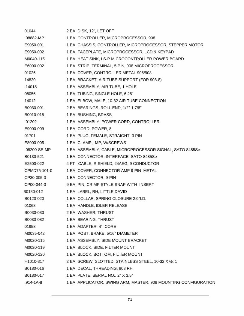
01044 2 EA DISK, 12”, LET OFF
.08882-MP 1 EA CONTROLLER, MICROPROCESSOR, 908
E9050-001 1 EA CHASSIS, CONTROLLER, MICROPROCESSOR, STEPPER MOTOR
E9050-002 1 EA FACEPLATE, MICROPROCESSOR, LCD & KEYPAD
M0040-115 1 EA HEAT SINK, LS-P MICROCONTROLLER POWER BOARD
E6000-002 1 EA STRIP, TERMINAL, 5 PIN, 908 MICROPROCESSOR
01026 1 EA COVER, CONTROLLER METAL 906/908
14820 1 EA BRACKET, AIR TUBE SUPPORT (FOR 908-8)
.14018 1 EA ASSEMBLY, AIR TUBE, 1 HOLE
08056 1 EA TUBING, SINGLE HOLE, 6.25"
14012 1 EA ELBOW, MALE, 10-32 AIR TUBE CONNECTION
B0030-001 2 EA BEARINGS, ROLL END, 1/2"-1 7/8"
B0010-015 1 EA BUSHING, BRASS
.01202 1 EA ASSEMBLY, POWER CORD, CONTROLLER
E9000-009 1 EA CORD, POWER, 8’
01701 1 EA PLUG, FEMALE, STRAIGHT, 3 PIN
E8000-005 1 EA CLAMP, MP, W/SCREWS
.08200-SE-MP 1 EA ASSEMBLY, CABLE, MICROPROCESSOR SIGNAL, SATO 8485Se
B0130-521 1 EA CONNECTOR, INTERFACE, SATO-8485Se
E2500-022 4 FT CABLE, R SHIELD, 24AEG, 9 CONDUCTOR
CPMD75-101-0 1 EA COVER, CONNECTOR AMP 9 PIN METAL
CP30-005-0 1 EA CONNECTOR, 9-PIN
CP00-044-0 9 EA PIN, CRIMP STYLE SNAP WITH INSERT
B0180-012 1 EA LABEL, RH, LITTLE DAVID
B0120-020 1 EA COLLAR, SPRING CLOSURE 2.0"I.D.
01063 1 EA HANDLE, IDLER RELEASE
B0030-083 2 EA WASHER, THRUST
B0030-082 1 EA BEARING, THRUST
01958 1 EA ADAPTER, 4”, CORE
M0035-042 1 EA POST, BRAKE, 5/16” DIAMETER
M0020-115 1 EA ASSEMBLY, SIDE MOUNT BRACKET
M0020-119 1 EA BLOCK, SIDE, FILTER MOUNT
M0020-120 1 EA BLOCK, BOTTOM, FILTER MOUNT
H1010-317 2 EA SCREW, SLOTTED, STAINLESS STEEL, 10-32 X ½: 1
B0180-016 1 EA DECAL, THREADING, 908 RH
B0180-017 1 EA PLATE, SERIAL NO., 2" X 3.5"
.914-1A-8 1 EA APPLICATOR, SWING ARM, MASTER, 908 MOUNTING CONFIGURATION
7272
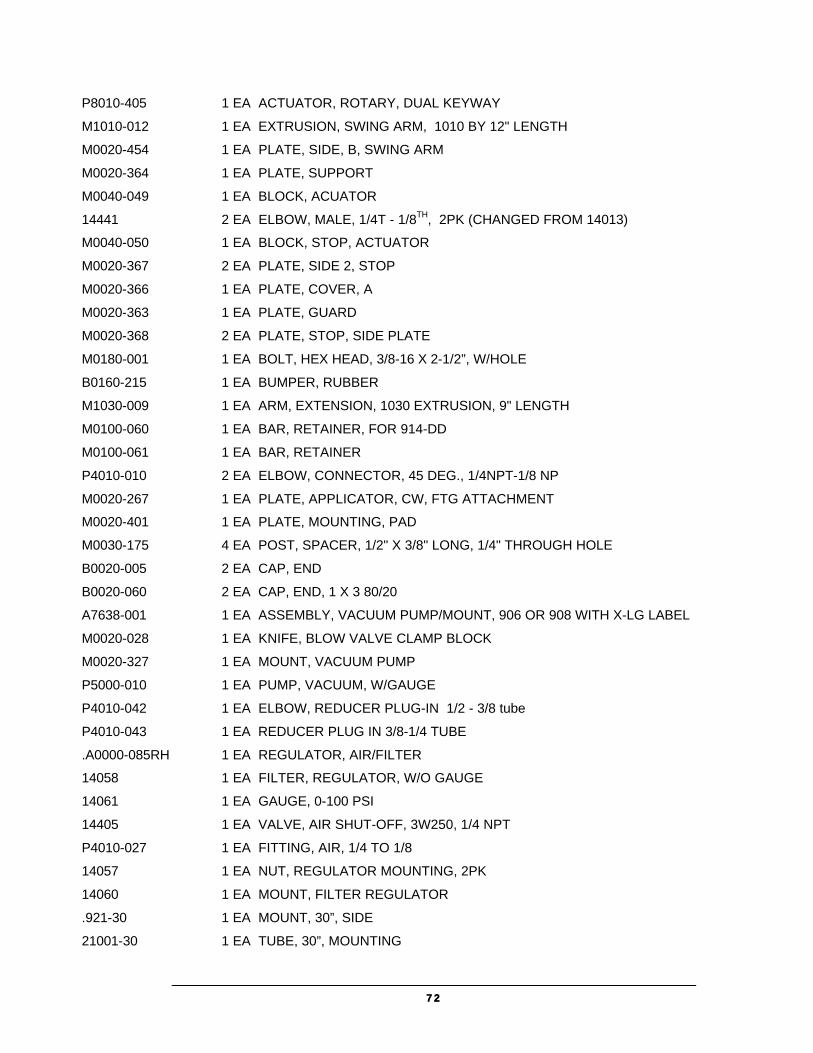
P8010-405 1 EA ACTUATOR, ROTARY, DUAL KEYWAY
M1010-012 1 EA EXTRUSION, SWING ARM, 1010 BY 12" LENGTH
M0020-454 1 EA PLATE, SIDE, B, SWING ARM
M0020-364 1 EA PLATE, SUPPORT
M0040-049 1 EA BLOCK, ACUATOR
14441 2 EA ELBOW, MALE, 1/4T - 1/8TH, 2PK (CHANGED FROM 14013)
M0040-050 1 EA BLOCK, STOP, ACTUATOR
M0020-367 2 EA PLATE, SIDE 2, STOP
M0020-366 1 EA PLATE, COVER, A
M0020-363 1 EA PLATE, GUARD
M0020-368 2 EA PLATE, STOP, SIDE PLATE
M0180-001 1 EA BOLT, HEX HEAD, 3/8-16 X 2-1/2”, W/HOLE
B0160-215 1 EA BUMPER, RUBBER
M1030-009 1 EA ARM, EXTENSION, 1030 EXTRUSION, 9" LENGTH
M0100-060 1 EA BAR, RETAINER, FOR 914-DD
M0100-061 1 EA BAR, RETAINER
P4010-010 2 EA ELBOW, CONNECTOR, 45 DEG., 1/4NPT-1/8 NP
M0020-267 1 EA PLATE, APPLICATOR, CW, FTG ATTACHMENT
M0020-401 1 EA PLATE, MOUNTING, PAD
M0030-175 4 EA POST, SPACER, 1/2" X 3/8" LONG, 1/4" THROUGH HOLE
B0020-005 2 EA CAP, END
B0020-060 2 EA CAP, END, 1 X 3 80/20
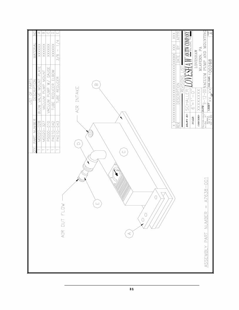
A7638-001 1 EA ASSEMBLY, VACUUM PUMP/MOUNT, 906 OR 908 WITH X-LG LABEL
M0020-028 1 EA KNIFE, BLOW VALVE CLAMP BLOCK
M0020-327 1 EA MOUNT, VACUUM PUMP
P5000-010 1 EA PUMP, VACUUM, W/GAUGE
P4010-042 1 EA ELBOW, REDUCER PLUG-IN 1/2 - 3/8 tube
P4010-043 1 EA REDUCER PLUG IN 3/8-1/4 TUBE
.A0000-085RH 1 EA REGULATOR, AIR/FILTER
14058 1 EA FILTER, REGULATOR, W/O GAUGE
14061 1 EA GAUGE, 0-100 PSI
14405 1 EA VALVE, AIR SHUT-OFF, 3W250, 1/4 NPT
P4010-027 1 EA FITTING, AIR, 1/4 TO 1/8
14057 1 EA NUT, REGULATOR MOUNTING, 2PK
14060 1 EA MOUNT, FILTER REGULATOR
.921-30 1 EA MOUNT, 30”, SIDE
21001-30 1 EA TUBE, 30”, MOUNTING
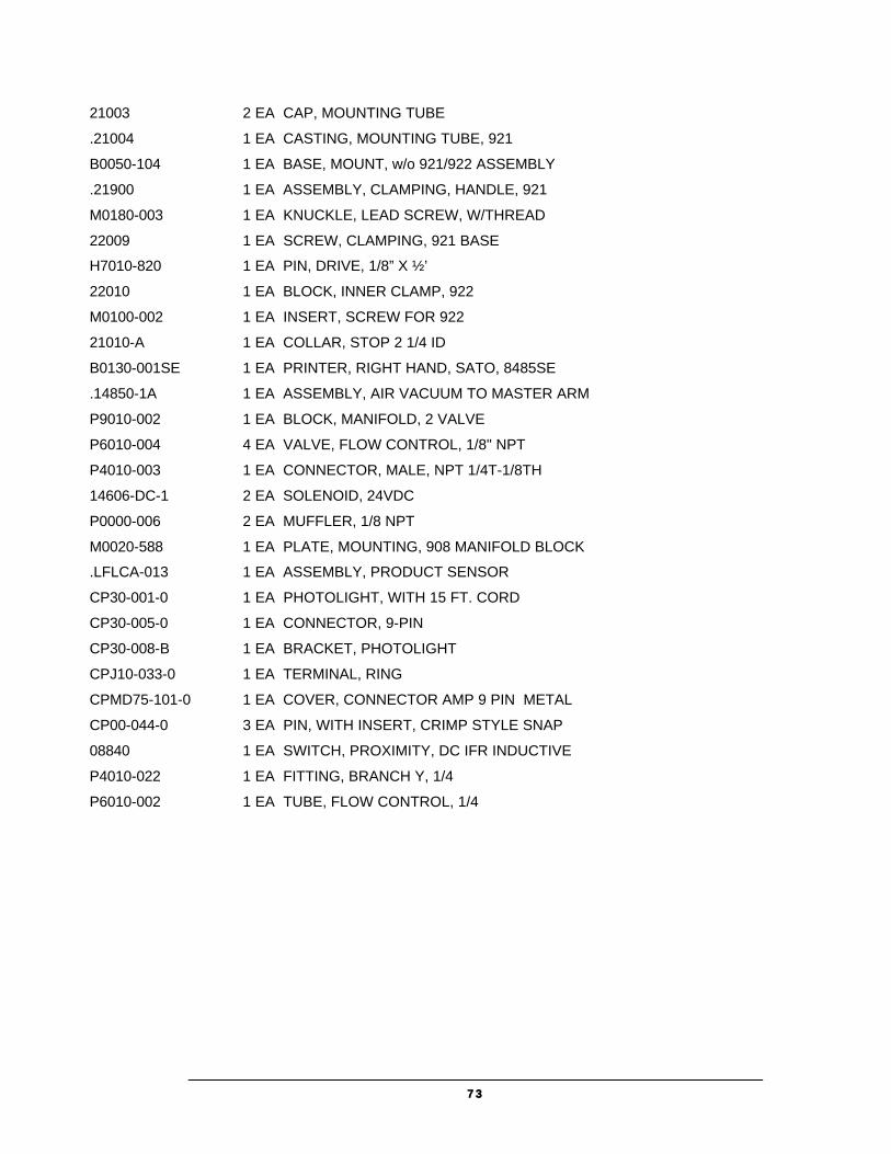
7373
21003 2 EA CAP, MOUNTING TUBE
.21004 1 EA CASTING, MOUNTING TUBE, 921
B0050-104 1 EA BASE, MOUNT, w/o 921/922 ASSEMBLY
.21900 1 EA ASSEMBLY, CLAMPING, HANDLE, 921
M0180-003 1 EA KNUCKLE, LEAD SCREW, W/THREAD
22009 1 EA SCREW, CLAMPING, 921 BASE
H7010-820 1 EA PIN, DRIVE, 1/8” X ½’
22010 1 EA BLOCK, INNER CLAMP, 922
M0100-002 1 EA INSERT, SCREW FOR 922
21010-A 1 EA COLLAR, STOP 2 1/4 ID
B0130-001SE 1 EA PRINTER, RIGHT HAND, SATO, 8485SE
.14850-1A 1 EA ASSEMBLY, AIR VACUUM TO MASTER ARM
P9010-002 1 EA BLOCK, MANIFOLD, 2 VALVE
P6010-004 4 EA VALVE, FLOW CONTROL, 1/8" NPT
P4010-003 1 EA CONNECTOR, MALE, NPT 1/4T-1/8TH
14606-DC-1 2 EA SOLENOID, 24VDC
P0000-006 2 EA MUFFLER, 1/8 NPT
M0020-588 1 EA PLATE, MOUNTING, 908 MANIFOLD BLOCK
.LFLCA-013 1 EA ASSEMBLY, PRODUCT SENSOR
CP30-001-0 1 EA PHOTOLIGHT, WITH 15 FT. CORD
CP30-005-0 1 EA CONNECTOR, 9-PIN
CP30-008-B 1 EA BRACKET, PHOTOLIGHT
CPJ10-033-0 1 EA TERMINAL, RING
CPMD75-101-0 1 EA COVER, CONNECTOR AMP 9 PIN METAL
CP00-044-0 3 EA PIN, WITH INSERT, CRIMP STYLE SNAP
08840 1 EA SWITCH, PROXIMITY, DC IFR INDUCTIVE
P4010-022 1 EA FITTING, BRANCH Y, 1/4
P6010-002 1 EA TUBE, FLOW CONTROL, 1/4

7474
Troubleshooting Guide Ensure label feed is under Dancer bar.
Dancer Bar should have tension, which can be set by adjusting the clamp connected to the spring on back of the labeler.
Brake post on Dancer Bar arm must contact Let Off Disc.
Ensure chain is not too tight.
Ensure that the Let Off Discs do not press too tightly against the side of the label roll.
Make sure that the label web passes through the Photo-eye in printer.
Make sure that the proper settings are being used, consult next page.
Make sure the printer is connected to the labeling machine controller.
Printer must be on-line to enable printing.
Label data/instructions must be loaded to the printer to enable labeling.
Chapter
14

7575
LS800 DT Controller Settings Log Label Size Product Delay
1 / 2 Label Overfeed
LLTD ApplSolenoid
1 / 2 Speed per
Minute Net # Notes:
Defaults = 250 / 250 250 200 /200 1200 0 1 2 3 4 5 6 7 8 9 10 11 12 13 14 15 16 17 18 19 20 21 22 23 24 25 26 27 28 29 30 31 32 33 34 35 36 37 38 39 40 41 42 43 44 45
7676
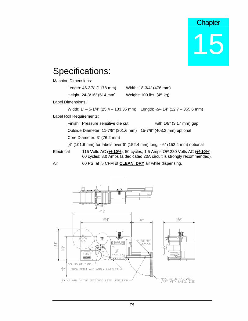
Specifications: Machine Dimensions:
Length: 46-3/8” (1178 mm) Width: 18-3/4” (476 mm)
Height: 24-3/16” (614 mm) Weight: 100 lbs. (45 kg)
Label Dimensions:
Width: 1” – 5-1/4” (25.4 – 133.35 mm) Length: ½” – 14” (12.7 – 355.6 mm)
Label Roll Requirements:
Finish: Pressure sensitive die cut with 1/8” (3.17 mm) gap
Outside Diameter: 11-7/8” (301.6 mm) 15-7/8” (403.2 mm) optional
Core Diameter: 3” (76.2 mm)
[4” (101.6 mm) for labels over 6” (152.4 mm) long] - 6” (152.4 mm) optional
Electrical 115 Volts AC (+/-10%); 50 cycles; 1.5 Amps OR 230 Volts AC (+/-10%); 60 cycles; 3.0 Amps (a dedicated 20A circuit is strongly recommended).
Air 60 PSI at .5 CFM of CLEAN, DRY air while dispensing.
Chapter
15

7777
LABEL CONVERTING SPECIFICATIONS In order to insure the labeling machines function, the following label specifications are offered as part of this proposal. Seller recommends that Buyer include a copy of these specifications with Buyer’s purchase order for labels from Buyer’s label converter. There may be exceptions to these specifications, depending upon the particular label construction used.
• Labels shall be converted with 3 mm + .13 mm minimum spacing between labels, and a minimum side gap of 1.5 mm + .15 mm slit on each side of the label. Maximum media width is determined as appropriate for the print engine selected. Labels shall not be converted with perforations of other separations between labels.
• A standard minimum 76 mm ID core is recommended [101 mm or 152 mm ID cores may also be acceptable]. Standard maximum roll OD shall be 305 mm [rolls up to 406 mm may also be acceptable]. Cores shall be slit cleanly to the final media width, including tolerance, and shall be of such composition so as to resist crushing distortion. The roll end shall not be attached to the core with tape or adhesive.
• Labels shall be wound to the outside of the roll unless otherwise specified. The labels shall be cleanly die cut, waste removed with no nicks or marks to the outside label perimeter, and centered on the backing media. If possible [unless otherwise specified] the labels shall be oriented: (1) to feed the trailing edge perpendicular to the backing media edge; and, (2) to feed the label with its shortest dimension parallel to the feed path.
• There shall be no strike-through or fractures of the backing media by the label processing die which can be detected by ink or marker penetration after wiping. There shall be no tears or cuts on the backing media edges. The backing media shall be of a uniform density and thickness. It shall be sufficiently translucent as to assure reliable gap detection, given the label stock selected.
• All eye marks or sensing notches shall be located with the same tolerance as specified for the labels and located on the backing media as is appropriate for the print engine selected. Eye marks shall be opaque, of a uniform density, and a minimum of 6 mm in width by 3 mm in the feed direction. Sensing notches, if possible, shall be as small as practical and located away from the edge of the backing media.
• The label rolls shall not be wound so tightly as to cause the adhesive to bleed out from around the label edges nor so loosely as to cause roll telescoping. The labels shall be wound with consistent wind tension and shall be flat within 3 mm when measured from a reference surface.
• Where splicing is necessary in the label roll, splicing shall be consistent with the requirement of the automatic labeling machinery. Preferred splices, when required, shall be of a diagonal style, using a clear transparent pressure sensitive tape applied to the back side of the backing web only (non-release coated side). All factory splices shall be removed, unless they meet the preferred splice specification.
• All finished label rolls shall be appropriately marked for identification per customer requirements and shall be packed to assure that the rolls arrive clean, flat and without shipping damage.
• The label adhesive shall be tested thoroughly to insure the compatibility of the label to the Buyer’s product and to have the proper amount of permanence or removability according to Buyer’s specifications. All face stock and adhesive combinations are subject to testing for dispensability on automatic labelers prior to acceptance.

7878
Warranty Loveshaw, an ITW Company
Little David Marking and Coding Products Route 296 Box 83
South Canaan, PA 18459
LITTLE DAVID LABELING SYSTEMS WARRANTY
This warranty is made exclusive of all other warranties and guarantees, written or oral, expressed or implied.
LOVESHAW, an ITW Company, warrants the Little David LS800DT labeling systems to be free of defects in material and workmanship and in compliance with proposed and agreed upon specifications. The warranty shall extend for a period of 365 days from date of delivery. Manufacturers and sellers liability under the warranty shall be limited to repair or replacement, exclusive of shipping charges. In no event shall manufacturer or seller be liable for consequential damages. No statement or recommendation not contained herein shall have force of effect unless in a written agreement signed by officers of the seller and/or the manufacturer.
Note: A policy of Loveshaw, an ITW Company, is to continually improve its products. Therefore, the right is reserved to alter the design and/or specifications of Little David Labeling Equipment at any time without notice.
Above warranty excludes customer selected OEM thermal transfer printer or material handling system. Printer and/or conveyor warranty available under separate cover.
End of Warranty Detail