
OPERATOR'S MANUAL - Brim Tractor
476
OPERATOR’S MANUAL Part number 90453215 2 nd edition English November 2020 Replaces part number 51420356 B95C B95C TC B110C Tier 4B (final) Tractor Loader Backhoe PIN NZHH03067 and after ORIGINAL INSTRUCTIONS
-
Upload
khangminh22 -
Category
Documents
-
view
0 -
download
0
Transcript of OPERATOR'S MANUAL - Brim Tractor

OPERATOR’S MANUAL
Part number 904532152nd edition EnglishNovember 2020Replaces part number 51420356
B95CB95C TCB110CTier 4B (final)Tractor Loader BackhoePIN NZHH03067 and after
ORIGINAL INSTRUCTIONS

Contents
1 GENERAL INFORMATIONNote to the owner. . . . . . . . . . . . . . . . . . . . . . . . . . . . . . . . . . . . . . . . . . . . . . . . . . . . . . . . . . . . . . . . . . . . . . . . . . . 1-1Intended use. . . . . . . . . . . . . . . . . . . . . . . . . . . . . . . . . . . . . . . . . . . . . . . . . . . . . . . . . . . . . . . . . . . . . . . . . . . . . . . . 1-2Electro-Magnetic Compatibility (EMC) . . . . . . . . . . . . . . . . . . . . . . . . . . . . . . . . . . . . . . . . . . . . . . . . . . . . . 1-4Product identification . . . . . . . . . . . . . . . . . . . . . . . . . . . . . . . . . . . . . . . . . . . . . . . . . . . . . . . . . . . . . . . . . . . . . . . 1-4Read the operator's manual . . . . . . . . . . . . . . . . . . . . . . . . . . . . . . . . . . . . . . . . . . . . . . . . . . . . . . . . . . . . . . . . 1-7Operator's manual storage on the machine . . . . . . . . . . . . . . . . . . . . . . . . . . . . . . . . . . . . . . . . . . . . . . . . 1-7Machine orientation. . . . . . . . . . . . . . . . . . . . . . . . . . . . . . . . . . . . . . . . . . . . . . . . . . . . . . . . . . . . . . . . . . . . . . . . . 1-8Component identification . . . . . . . . . . . . . . . . . . . . . . . . . . . . . . . . . . . . . . . . . . . . . . . . . . . . . . . . . . . . . . . . . . . 1-9Selective Catalytic Reduction (SCR) exhaust treatment - Product overview. . . . . . . . . . . . . . 1-11
2 SAFETY INFORMATIONSafety rules and signal word definitions . . . . . . . . . . . . . . . . . . . . . . . . . . . . . . . . . . . . . . . . . . . . . . . . . . . . 2-1Safety rules . . . . . . . . . . . . . . . . . . . . . . . . . . . . . . . . . . . . . . . . . . . . . . . . . . . . . . . . . . . . . . . . . . . . . . . . . . . . . . . . . 2-2Safety rules - Utility precautions . . . . . . . . . . . . . . . . . . . . . . . . . . . . . . . . . . . . . . . . . . . . . . . . . . . . . . . . . . 2-11Safety rules - Fuel handling precautions . . . . . . . . . . . . . . . . . . . . . . . . . . . . . . . . . . . . . . . . . . . . . . . . . . 2-12Safety rules - Specific precautions to this machine . . . . . . . . . . . . . . . . . . . . . . . . . . . . . . . . . . . . . . . 2-13Support strut for loader lift arm . . . . . . . . . . . . . . . . . . . . . . . . . . . . . . . . . . . . . . . . . . . . . . . . . . . . . . . . . . . . 2-14Safety rules - Ductile iron . . . . . . . . . . . . . . . . . . . . . . . . . . . . . . . . . . . . . . . . . . . . . . . . . . . . . . . . . . . . . . . . . 2-17Hand signals. . . . . . . . . . . . . . . . . . . . . . . . . . . . . . . . . . . . . . . . . . . . . . . . . . . . . . . . . . . . . . . . . . . . . . . . . . . . . . . 2-18Ecology and the environment . . . . . . . . . . . . . . . . . . . . . . . . . . . . . . . . . . . . . . . . . . . . . . . . . . . . . . . . . . . . . 2-25Safety signs . . . . . . . . . . . . . . . . . . . . . . . . . . . . . . . . . . . . . . . . . . . . . . . . . . . . . . . . . . . . . . . . . . . . . . . . . . . . . . . 2-26Selective Catalytic Reduction (SCR) decals . . . . . . . . . . . . . . . . . . . . . . . . . . . . . . . . . . . . . . . . . . . . . . 2-41
3 CONTROLS AND INSTRUMENTSACCESS TO OPERATOR'S PLATFORM
Access to operator’s platform . . . . . . . . . . . . . . . . . . . . . . . . . . . . . . . . . . . . . . . . . . . . . . . . . . . . . . . . . . 3-1
OPERATOR'S SEATOperator's seat . . . . . . . . . . . . . . . . . . . . . . . . . . . . . . . . . . . . . . . . . . . . . . . . . . . . . . . . . . . . . . . . . . . . . . . . . 3-4
FORWARD CONTROLSSteering column . . . . . . . . . . . . . . . . . . . . . . . . . . . . . . . . . . . . . . . . . . . . . . . . . . . . . . . . . . . . . . . . . . . . . . . . 3-9Front controls . . . . . . . . . . . . . . . . . . . . . . . . . . . . . . . . . . . . . . . . . . . . . . . . . . . . . . . . . . . . . . . . . . . . . . . . . . 3-10Right-hand side control lever . . . . . . . . . . . . . . . . . . . . . . . . . . . . . . . . . . . . . . . . . . . . . . . . . . . . . . . . . . 3-12Pedal controls . . . . . . . . . . . . . . . . . . . . . . . . . . . . . . . . . . . . . . . . . . . . . . . . . . . . . . . . . . . . . . . . . . . . . . . . . 3-13Transmission controls . . . . . . . . . . . . . . . . . . . . . . . . . . . . . . . . . . . . . . . . . . . . . . . . . . . . . . . . . . . . . . . . . 3-14
RIGHT-HAND SIDE CONTROLSKey start switch. . . . . . . . . . . . . . . . . . . . . . . . . . . . . . . . . . . . . . . . . . . . . . . . . . . . . . . . . . . . . . . . . . . . . . . . 3-21Instrument cluster panel – Side . . . . . . . . . . . . . . . . . . . . . . . . . . . . . . . . . . . . . . . . . . . . . . . . . . . . . . . 3-22

EXTERIOR CONTROLSRotating beacon (Optional) . . . . . . . . . . . . . . . . . . . . . . . . . . . . . . . . . . . . . . . . . . . . . . . . . . . . . . . . . . . 3-25Battery master switch. . . . . . . . . . . . . . . . . . . . . . . . . . . . . . . . . . . . . . . . . . . . . . . . . . . . . . . . . . . . . . . . . . 3-26
INSTRUMENT CLUSTERInstrument cluster . . . . . . . . . . . . . . . . . . . . . . . . . . . . . . . . . . . . . . . . . . . . . . . . . . . . . . . . . . . . . . . . . . . . . 3-27Menu screen display . . . . . . . . . . . . . . . . . . . . . . . . . . . . . . . . . . . . . . . . . . . . . . . . . . . . . . . . . . . . . . . . . . 3-32Selective Catalytic Reduction (SCR) exhaust treatment - Overview . . . . . . . . . . . . . . . . . . 3-37
CAB CONTROLS AND ADJUSTMENTSCab and platform - Control identification . . . . . . . . . . . . . . . . . . . . . . . . . . . . . . . . . . . . . . . . . . . . . . 3-48
LOADER ATTACHMENT CONTROLSLoader attachment control lever. . . . . . . . . . . . . . . . . . . . . . . . . . . . . . . . . . . . . . . . . . . . . . . . . . . . . . . 3-54Loader attachment controls . . . . . . . . . . . . . . . . . . . . . . . . . . . . . . . . . . . . . . . . . . . . . . . . . . . . . . . . . . . 3-55Loader attachment – Operation . . . . . . . . . . . . . . . . . . . . . . . . . . . . . . . . . . . . . . . . . . . . . . . . . . . . . . . 3-56Detent position for loader control auxiliary hydraulics . . . . . . . . . . . . . . . . . . . . . . . . . . . . . . . . . 3-59
BACKHOE ATTACHMENT CONTROLSRemove the backhoe from the stowed position . . . . . . . . . . . . . . . . . . . . . . . . . . . . . . . . . . . . . . . 3-61Place the backhoe in the stowed position . . . . . . . . . . . . . . . . . . . . . . . . . . . . . . . . . . . . . . . . . . . . . 3-67Backhoe attachment mechanical controls version . . . . . . . . . . . . . . . . . . . . . . . . . . . . . . . . . . . . 3-73Backhoe attachment hydraulic controls . . . . . . . . . . . . . . . . . . . . . . . . . . . . . . . . . . . . . . . . . . . . . . . 3-83
CLIMATE CONTROLSHeating and air-conditioning controls. . . . . . . . . . . . . . . . . . . . . . . . . . . . . . . . . . . . . . . . . . . . . . . . . . 3-89Cab air louvers . . . . . . . . . . . . . . . . . . . . . . . . . . . . . . . . . . . . . . . . . . . . . . . . . . . . . . . . . . . . . . . . . . . . . . . . 3-93
4 OPERATING INSTRUCTIONSCOMMISSIONING THE UNIT
Before using the machine . . . . . . . . . . . . . . . . . . . . . . . . . . . . . . . . . . . . . . . . . . . . . . . . . . . . . . . . . . . . . . 4-1Operating the machine . . . . . . . . . . . . . . . . . . . . . . . . . . . . . . . . . . . . . . . . . . . . . . . . . . . . . . . . . . . . . . . . . 4-2Run in period of a new machine. . . . . . . . . . . . . . . . . . . . . . . . . . . . . . . . . . . . . . . . . . . . . . . . . . . . . . . . 4-4
STARTING THE UNITBefore starting the engine . . . . . . . . . . . . . . . . . . . . . . . . . . . . . . . . . . . . . . . . . . . . . . . . . . . . . . . . . . . . . . 4-5Normal engine starting . . . . . . . . . . . . . . . . . . . . . . . . . . . . . . . . . . . . . . . . . . . . . . . . . . . . . . . . . . . . . . . . . 4-6Engine speed . . . . . . . . . . . . . . . . . . . . . . . . . . . . . . . . . . . . . . . . . . . . . . . . . . . . . . . . . . . . . . . . . . . . . . . . . . . 4-7Cold temperature operation . . . . . . . . . . . . . . . . . . . . . . . . . . . . . . . . . . . . . . . . . . . . . . . . . . . . . . . . . . . . 4-8Hot temperature operation . . . . . . . . . . . . . . . . . . . . . . . . . . . . . . . . . . . . . . . . . . . . . . . . . . . . . . . . . . . . 4-10Operating the machine in high altitude . . . . . . . . . . . . . . . . . . . . . . . . . . . . . . . . . . . . . . . . . . . . . . . . 4-11Operating the machine in water . . . . . . . . . . . . . . . . . . . . . . . . . . . . . . . . . . . . . . . . . . . . . . . . . . . . . . . 4-12Assisted starting (Jump-starting) . . . . . . . . . . . . . . . . . . . . . . . . . . . . . . . . . . . . . . . . . . . . . . . . . . . . . . 4-13
STOPPING THE UNITShutting down the engine . . . . . . . . . . . . . . . . . . . . . . . . . . . . . . . . . . . . . . . . . . . . . . . . . . . . . . . . . . . . . 4-15

MOVING THE UNITJob site travel. . . . . . . . . . . . . . . . . . . . . . . . . . . . . . . . . . . . . . . . . . . . . . . . . . . . . . . . . . . . . . . . . . . . . . . . . . 4-16Before operating the machine . . . . . . . . . . . . . . . . . . . . . . . . . . . . . . . . . . . . . . . . . . . . . . . . . . . . . . . . . 4-18Traveling on a hill . . . . . . . . . . . . . . . . . . . . . . . . . . . . . . . . . . . . . . . . . . . . . . . . . . . . . . . . . . . . . . . . . . . . . . 4-19Auto powershift . . . . . . . . . . . . . . . . . . . . . . . . . . . . . . . . . . . . . . . . . . . . . . . . . . . . . . . . . . . . . . . . . . . . . . . . 4-20Four-Wheel Drive (4WD) control switch (if equipped) . . . . . . . . . . . . . . . . . . . . . . . . . . . . . . . . 4-22Differential lock button . . . . . . . . . . . . . . . . . . . . . . . . . . . . . . . . . . . . . . . . . . . . . . . . . . . . . . . . . . . . . . . . . 4-23Glide Ride™ - Two-Wheel Drive (2WD) only . . . . . . . . . . . . . . . . . . . . . . . . . . . . . . . . . . . . . . . . . . 4-24Auto-Glide Ride™ (AGR) – Four-Wheel Drive (4WD) only . . . . . . . . . . . . . . . . . . . . . . . . . . . 4-25
PARKING THE UNITParking the machine. . . . . . . . . . . . . . . . . . . . . . . . . . . . . . . . . . . . . . . . . . . . . . . . . . . . . . . . . . . . . . . . . . . 4-26
5 TRANSPORT OPERATIONSROAD TRANSPORT
Precautions for road travel . . . . . . . . . . . . . . . . . . . . . . . . . . . . . . . . . . . . . . . . . . . . . . . . . . . . . . . . . . . . . 5-1
PREPARING FOR ROAD TRANSPORTPreparing the machine for road travel . . . . . . . . . . . . . . . . . . . . . . . . . . . . . . . . . . . . . . . . . . . . . . . . . . 5-2
SHIPPING TRANSPORTTransporting on a trailer . . . . . . . . . . . . . . . . . . . . . . . . . . . . . . . . . . . . . . . . . . . . . . . . . . . . . . . . . . . . . . . . 5-7Lifting the machine . . . . . . . . . . . . . . . . . . . . . . . . . . . . . . . . . . . . . . . . . . . . . . . . . . . . . . . . . . . . . . . . . . . . . 5-9
RECOVERY TRANSPORTTowing the machine . . . . . . . . . . . . . . . . . . . . . . . . . . . . . . . . . . . . . . . . . . . . . . . . . . . . . . . . . . . . . . . . . . . 5-10
6 WORKING OPERATIONSGENERAL INFORMATION
Forward-Neutral-Reverse (F-N-R) shift sensitivity . . . . . . . . . . . . . . . . . . . . . . . . . . . . . . . . . . . . . 6-1Display brightness . . . . . . . . . . . . . . . . . . . . . . . . . . . . . . . . . . . . . . . . . . . . . . . . . . . . . . . . . . . . . . . . . . . . . . 6-2Maximum throttle/Cold start idle . . . . . . . . . . . . . . . . . . . . . . . . . . . . . . . . . . . . . . . . . . . . . . . . . . . . . . . . 6-3Throttle sensitivity . . . . . . . . . . . . . . . . . . . . . . . . . . . . . . . . . . . . . . . . . . . . . . . . . . . . . . . . . . . . . . . . . . . . . . 6-5Auto engine shutdown time-out adjustment . . . . . . . . . . . . . . . . . . . . . . . . . . . . . . . . . . . . . . . . . . . . 6-6Auto engine protection shutdown setting . . . . . . . . . . . . . . . . . . . . . . . . . . . . . . . . . . . . . . . . . . . . . . . 6-9Auto-Glide Ride™ (AGR) speed thresholds. . . . . . . . . . . . . . . . . . . . . . . . . . . . . . . . . . . . . . . . . . . 6-11
LOADER ATTACHMENTPersonal safety . . . . . . . . . . . . . . . . . . . . . . . . . . . . . . . . . . . . . . . . . . . . . . . . . . . . . . . . . . . . . . . . . . . . 6-12Job layout. . . . . . . . . . . . . . . . . . . . . . . . . . . . . . . . . . . . . . . . . . . . . . . . . . . . . . . . . . . . . . . . . . . . . . . . . . 6-13Operating the loader attachment . . . . . . . . . . . . . . . . . . . . . . . . . . . . . . . . . . . . . . . . . . . . . . . . . . 6-14Loader digging force. . . . . . . . . . . . . . . . . . . . . . . . . . . . . . . . . . . . . . . . . . . . . . . . . . . . . . . . . . . . . . . 6-17Loader attachment safety strut . . . . . . . . . . . . . . . . . . . . . . . . . . . . . . . . . . . . . . . . . . . . . . . . . . . . 6-18Loader bucket Removal . . . . . . . . . . . . . . . . . . . . . . . . . . . . . . . . . . . . . . . . . . . . . . . . . . . . . . . . . . 6-21Loader bucket Installation . . . . . . . . . . . . . . . . . . . . . . . . . . . . . . . . . . . . . . . . . . . . . . . . . . . . . . . . 6-22

Loader bucket with quick coupler (B95CTC) . . . . . . . . . . . . . . . . . . . . . . . . . . . . . . . . . . . . . 6-23Loader bucket with forks (optional) . . . . . . . . . . . . . . . . . . . . . . . . . . . . . . . . . . . . . . . . . . . . . . . 6-25Lifting loads with the loader attachment . . . . . . . . . . . . . . . . . . . . . . . . . . . . . . . . . . . . . . . . . . . 6-27
BACKHOE ATTACHMENTPersonal safety . . . . . . . . . . . . . . . . . . . . . . . . . . . . . . . . . . . . . . . . . . . . . . . . . . . . . . . . . . . . . . . . . . . . 6-29Basic instructions . . . . . . . . . . . . . . . . . . . . . . . . . . . . . . . . . . . . . . . . . . . . . . . . . . . . . . . . . . . . . . . . . . 6-29Backhoe danger area. . . . . . . . . . . . . . . . . . . . . . . . . . . . . . . . . . . . . . . . . . . . . . . . . . . . . . . . . . . . . . 6-30Swing lock . . . . . . . . . . . . . . . . . . . . . . . . . . . . . . . . . . . . . . . . . . . . . . . . . . . . . . . . . . . . . . . . . . . . . . . . . 6-31Basic instructions . . . . . . . . . . . . . . . . . . . . . . . . . . . . . . . . . . . . . . . . . . . . . . . . . . . . . . . . . . . . . . . . . . 6-32Setting the backhoe attachment in working position – center pivot . . . . . . . . . . . . . . . 6-33Stabilizer pads. . . . . . . . . . . . . . . . . . . . . . . . . . . . . . . . . . . . . . . . . . . . . . . . . . . . . . . . . . . . . . . . . . . . . 6-39Operating the backhoe attachment. . . . . . . . . . . . . . . . . . . . . . . . . . . . . . . . . . . . . . . . . . . . . . . . 6-41Backhoe bucket – Remove . . . . . . . . . . . . . . . . . . . . . . . . . . . . . . . . . . . . . . . . . . . . . . . . . . . . . . . 6-47Backhoe bucket – Install . . . . . . . . . . . . . . . . . . . . . . . . . . . . . . . . . . . . . . . . . . . . . . . . . . . . . . . . . . 6-48Backhoe bucket – Digging angle . . . . . . . . . . . . . . . . . . . . . . . . . . . . . . . . . . . . . . . . . . . . . . . . . 6-49Ballasting . . . . . . . . . . . . . . . . . . . . . . . . . . . . . . . . . . . . . . . . . . . . . . . . . . . . . . . . . . . . . . . . . . . . . . . . . . 6-50Lifting loads with backhoe attachment . . . . . . . . . . . . . . . . . . . . . . . . . . . . . . . . . . . . . . . . . . . . 6-53
7 MAINTENANCEGENERAL INFORMATION
Maintenance safety. . . . . . . . . . . . . . . . . . . . . . . . . . . . . . . . . . . . . . . . . . . . . . . . . . . . . . . . . . . . . . . . . . . . . 7-1Fire extinguisher . . . . . . . . . . . . . . . . . . . . . . . . . . . . . . . . . . . . . . . . . . . . . . . . . . . . . . . . . . . . . . . . . . . . . . . . 7-4Capacities - B95C, B95C LR, and B95C TC . . . . . . . . . . . . . . . . . . . . . . . . . . . . . . . . . . . . . . . . . . . 7-5Capacities – B110C . . . . . . . . . . . . . . . . . . . . . . . . . . . . . . . . . . . . . . . . . . . . . . . . . . . . . . . . . . . . . . . . . . . . 7-7Engine hood . . . . . . . . . . . . . . . . . . . . . . . . . . . . . . . . . . . . . . . . . . . . . . . . . . . . . . . . . . . . . . . . . . . . . . . . . . . . 7-9Fuel tank. . . . . . . . . . . . . . . . . . . . . . . . . . . . . . . . . . . . . . . . . . . . . . . . . . . . . . . . . . . . . . . . . . . . . . . . . . . . . . . 7-10General specification - Diesel fuel . . . . . . . . . . . . . . . . . . . . . . . . . . . . . . . . . . . . . . . . . . . . . . . . . . . . 7-10General specification - Biodiesel fuels . . . . . . . . . . . . . . . . . . . . . . . . . . . . . . . . . . . . . . . . . . . . . . . . 7-11Selective Catalytic Reduction (SCR) exhaust treatment - Basic instructions . . . . . . . . . 7-13Hydraulic oil . . . . . . . . . . . . . . . . . . . . . . . . . . . . . . . . . . . . . . . . . . . . . . . . . . . . . . . . . . . . . . . . . . . . . . . . . . . 7-15Recommended engine oil for operating temperature ranges. . . . . . . . . . . . . . . . . . . . . . . . . . 7-17Organic Acid Technology (OAT) coolant. . . . . . . . . . . . . . . . . . . . . . . . . . . . . . . . . . . . . . . . . . . . . . . 7-18Diagnostic/Service tool port . . . . . . . . . . . . . . . . . . . . . . . . . . . . . . . . . . . . . . . . . . . . . . . . . . . . . . . . . . . 7-19Hydraulic diagnostic test ports . . . . . . . . . . . . . . . . . . . . . . . . . . . . . . . . . . . . . . . . . . . . . . . . . . . . . . . . 7-20Work hours and intervals . . . . . . . . . . . . . . . . . . . . . . . . . . . . . . . . . . . . . . . . . . . . . . . . . . . . . . . . . . . . . . 7-22
MAINTENANCE CHARTMaintenance chart . . . . . . . . . . . . . . . . . . . . . . . . . . . . . . . . . . . . . . . . . . . . . . . . . . . . . . . . . . . . . . . . . . . . . 7-23
At warning message displayEngine air filters . . . . . . . . . . . . . . . . . . . . . . . . . . . . . . . . . . . . . . . . . . . . . . . . . . . . . . . . . . . . . . . . . . . . . . . 7-25Hydraulic filter(s) . . . . . . . . . . . . . . . . . . . . . . . . . . . . . . . . . . . . . . . . . . . . . . . . . . . . . . . . . . . . . . . . . . . . . . 7-27Fuel system water separator . . . . . . . . . . . . . . . . . . . . . . . . . . . . . . . . . . . . . . . . . . . . . . . . . . . . . . . . . . 7-29Diesel Exhaust Fluid (DEF)/AdBlue®/ARLA tank - Filling . . . . . . . . . . . . . . . . . . . . . . . . . . . . . 7-31Diesel Exhaust Fluid (DEF)/AdBlue®/ARLA tank - Drain fluid . . . . . . . . . . . . . . . . . . . . . . . . 7-32Hydrocarbon management . . . . . . . . . . . . . . . . . . . . . . . . . . . . . . . . . . . . . . . . . . . . . . . . . . . . . . . . . . . . 7-34

Initial 10 hoursWheels - Check. . . . . . . . . . . . . . . . . . . . . . . . . . . . . . . . . . . . . . . . . . . . . . . . . . . . . . . . . . . . . . . . . . . . . . . . 7-35
Every 10 hoursChecks at start-up and before each workshift (10 hours) . . . . . . . . . . . . . . . . . . . . . . . . . . . . . 7-37Working attachments — Loader attachment . . . . . . . . . . . . . . . . . . . . . . . . . . . . . . . . . . . . . . . . . . 7-38Working attachments — Backhoe attachment . . . . . . . . . . . . . . . . . . . . . . . . . . . . . . . . . . . . . . . . 7-39Windshield washer fluid level — Check . . . . . . . . . . . . . . . . . . . . . . . . . . . . . . . . . . . . . . . . . . . . . . 7-40Engine oil level — Check . . . . . . . . . . . . . . . . . . . . . . . . . . . . . . . . . . . . . . . . . . . . . . . . . . . . . . . . . . . . . 7-41Engine coolant — Check . . . . . . . . . . . . . . . . . . . . . . . . . . . . . . . . . . . . . . . . . . . . . . . . . . . . . . . . . . . . . 7-43Radiator, oil cooler, and condenser — Check . . . . . . . . . . . . . . . . . . . . . . . . . . . . . . . . . . . . . . . . 7-44Alternator — Check . . . . . . . . . . . . . . . . . . . . . . . . . . . . . . . . . . . . . . . . . . . . . . . . . . . . . . . . . . . . . . . . . . . 7-45Hydraulic oil level — Check . . . . . . . . . . . . . . . . . . . . . . . . . . . . . . . . . . . . . . . . . . . . . . . . . . . . . . . . . . . 7-46Hydraulic hoses, tubes, and fittings . . . . . . . . . . . . . . . . . . . . . . . . . . . . . . . . . . . . . . . . . . . . . . . . . . . 7-48
Every 50 hoursWorking attachments - greasing. . . . . . . . . . . . . . . . . . . . . . . . . . . . . . . . . . . . . . . . . . . . . . . . . . . . . . . 7-49Door hinges. . . . . . . . . . . . . . . . . . . . . . . . . . . . . . . . . . . . . . . . . . . . . . . . . . . . . . . . . . . . . . . . . . . . . . . . . . . . 7-50Front axle trunnion . . . . . . . . . . . . . . . . . . . . . . . . . . . . . . . . . . . . . . . . . . . . . . . . . . . . . . . . . . . . . . . . . . . . 7-50Front axle king pins. . . . . . . . . . . . . . . . . . . . . . . . . . . . . . . . . . . . . . . . . . . . . . . . . . . . . . . . . . . . . . . . . . . . 7-51Seat and seat belt . . . . . . . . . . . . . . . . . . . . . . . . . . . . . . . . . . . . . . . . . . . . . . . . . . . . . . . . . . . . . . . . . . . . . 7-52Fuel pre-filter - draining condensation. . . . . . . . . . . . . . . . . . . . . . . . . . . . . . . . . . . . . . . . . . . . . . . . . 7-53Tire pressure . . . . . . . . . . . . . . . . . . . . . . . . . . . . . . . . . . . . . . . . . . . . . . . . . . . . . . . . . . . . . . . . . . . . . . . . . . 7-55
Every 250 hoursDrive shaft lubrication . . . . . . . . . . . . . . . . . . . . . . . . . . . . . . . . . . . . . . . . . . . . . . . . . . . . . . . . . . . . . . . . . 7-59Engine cooling system — Check . . . . . . . . . . . . . . . . . . . . . . . . . . . . . . . . . . . . . . . . . . . . . . . . . . . . . 7-60Fuel tank - Drain fluid. . . . . . . . . . . . . . . . . . . . . . . . . . . . . . . . . . . . . . . . . . . . . . . . . . . . . . . . . . . . . . . . . . 7-61Hydraulic oil tank breather / filler cap - cleaning . . . . . . . . . . . . . . . . . . . . . . . . . . . . . . . . . . . . . . 7-62Transmission oil level. . . . . . . . . . . . . . . . . . . . . . . . . . . . . . . . . . . . . . . . . . . . . . . . . . . . . . . . . . . . . . . . . . 7-63Front axle breather (4WD) - Clean . . . . . . . . . . . . . . . . . . . . . . . . . . . . . . . . . . . . . . . . . . . . . . . . . . . . 7-64Front axle and reduction gear oil level (4WD) . . . . . . . . . . . . . . . . . . . . . . . . . . . . . . . . . . . . . . . . . 7-65Front axle system - Check — (2WD) . . . . . . . . . . . . . . . . . . . . . . . . . . . . . . . . . . . . . . . . . . . . . . . . . 7-67Rear axle oil level - Check. . . . . . . . . . . . . . . . . . . . . . . . . . . . . . . . . . . . . . . . . . . . . . . . . . . . . . . . . . . . . 7-68Rear axle breather. . . . . . . . . . . . . . . . . . . . . . . . . . . . . . . . . . . . . . . . . . . . . . . . . . . . . . . . . . . . . . . . . . . . . 7-69Radiator and condenser - cleaning . . . . . . . . . . . . . . . . . . . . . . . . . . . . . . . . . . . . . . . . . . . . . . . . . . . . 7-70Drive belts - check. . . . . . . . . . . . . . . . . . . . . . . . . . . . . . . . . . . . . . . . . . . . . . . . . . . . . . . . . . . . . . . . . . . . . 7-72Cab air filter. . . . . . . . . . . . . . . . . . . . . . . . . . . . . . . . . . . . . . . . . . . . . . . . . . . . . . . . . . . . . . . . . . . . . . . . . . . . 7-73Heater and evaporator (Air-conditioning system) - Cleaning . . . . . . . . . . . . . . . . . . . . . . . . . 7-76Telescopic dipper . . . . . . . . . . . . . . . . . . . . . . . . . . . . . . . . . . . . . . . . . . . . . . . . . . . . . . . . . . . . . . . . . . . . . . 7-77Battery terminals . . . . . . . . . . . . . . . . . . . . . . . . . . . . . . . . . . . . . . . . . . . . . . . . . . . . . . . . . . . . . . . . . . . . . . 7-78Cab protection system. . . . . . . . . . . . . . . . . . . . . . . . . . . . . . . . . . . . . . . . . . . . . . . . . . . . . . . . . . . . . . . . . 7-80
Every 500 hoursEngine oil and filter . . . . . . . . . . . . . . . . . . . . . . . . . . . . . . . . . . . . . . . . . . . . . . . . . . . . . . . . . . . . . . . . . . . . 7-83Fuel filter. . . . . . . . . . . . . . . . . . . . . . . . . . . . . . . . . . . . . . . . . . . . . . . . . . . . . . . . . . . . . . . . . . . . . . . . . . . . . . . 7-87Fuel prefilter . . . . . . . . . . . . . . . . . . . . . . . . . . . . . . . . . . . . . . . . . . . . . . . . . . . . . . . . . . . . . . . . . . . . . . . . . . . 7-88Diesel Exhaust Fluid (DEF)/AdBlue® tank filler screen . . . . . . . . . . . . . . . . . . . . . . . . . . . . . . . 7-90

Diesel Exhaust Fluid (DEF)/AdBlue® in-line filter . . . . . . . . . . . . . . . . . . . . . . . . . . . . . . . . . . . . . 7-92
Every 1000 hoursHydraulic oil filter . . . . . . . . . . . . . . . . . . . . . . . . . . . . . . . . . . . . . . . . . . . . . . . . . . . . . . . . . . . . . . . . . . . . . . 7-95Hydraulic oil . . . . . . . . . . . . . . . . . . . . . . . . . . . . . . . . . . . . . . . . . . . . . . . . . . . . . . . . . . . . . . . . . . . . . . . . . . . 7-97Power shuttle transmission - Oil change . . . . . . . . . . . . . . . . . . . . . . . . . . . . . . . . . . . . . . . . . . . . . 7-100Power shuttle transmission - Oil filter replacement. . . . . . . . . . . . . . . . . . . . . . . . . . . . . . . . . . . 7-102Power shuttle transmission - Screen filter cleaning . . . . . . . . . . . . . . . . . . . . . . . . . . . . . . . . . . 7-103Powershift transmission - Oil change. . . . . . . . . . . . . . . . . . . . . . . . . . . . . . . . . . . . . . . . . . . . . . . . . 7-105Powershift transmission - Oil filter replacement . . . . . . . . . . . . . . . . . . . . . . . . . . . . . . . . . . . . . . 7-107Front axle fluid - Four-Wheel Drive (4WD) . . . . . . . . . . . . . . . . . . . . . . . . . . . . . . . . . . . . . . . . . . . 7-108Rear axle . . . . . . . . . . . . . . . . . . . . . . . . . . . . . . . . . . . . . . . . . . . . . . . . . . . . . . . . . . . . . . . . . . . . . . . . . . . . . 7-110Machine inspection and cleaning. . . . . . . . . . . . . . . . . . . . . . . . . . . . . . . . . . . . . . . . . . . . . . . . . . . . . 7-111Brake pedal lever - Greasing . . . . . . . . . . . . . . . . . . . . . . . . . . . . . . . . . . . . . . . . . . . . . . . . . . . . . . . . . 7-112Hydraulic cylinders . . . . . . . . . . . . . . . . . . . . . . . . . . . . . . . . . . . . . . . . . . . . . . . . . . . . . . . . . . . . . . . . . . . 7-113Alternator - check. . . . . . . . . . . . . . . . . . . . . . . . . . . . . . . . . . . . . . . . . . . . . . . . . . . . . . . . . . . . . . . . . . . . . 7-114
Every 1500 hours of operation or annuallyEngine breather filter . . . . . . . . . . . . . . . . . . . . . . . . . . . . . . . . . . . . . . . . . . . . . . . . . . . . . . . . . . . . . . . . . 7-115
Every 3000 hoursDiesel Exhaust Fluid (DEF)/AdBlue® supply module filter . . . . . . . . . . . . . . . . . . . . . . . . . . . 7-116
Every 4000 hoursEngine coolant . . . . . . . . . . . . . . . . . . . . . . . . . . . . . . . . . . . . . . . . . . . . . . . . . . . . . . . . . . . . . . . . . . . . . . . 7-122
As requiredDrive belt . . . . . . . . . . . . . . . . . . . . . . . . . . . . . . . . . . . . . . . . . . . . . . . . . . . . . . . . . . . . . . . . . . . . . . . . . . . . . 7-124Air-conditioning compressor drive belt . . . . . . . . . . . . . . . . . . . . . . . . . . . . . . . . . . . . . . . . . . . . . . . 7-126Turbocharger - Check . . . . . . . . . . . . . . . . . . . . . . . . . . . . . . . . . . . . . . . . . . . . . . . . . . . . . . . . . . . . . . . . 7-127Fuel system bleeding . . . . . . . . . . . . . . . . . . . . . . . . . . . . . . . . . . . . . . . . . . . . . . . . . . . . . . . . . . . . . . . . . 7-128Wheels and tires. . . . . . . . . . . . . . . . . . . . . . . . . . . . . . . . . . . . . . . . . . . . . . . . . . . . . . . . . . . . . . . . . . . . . . 7-129Hydraulic system - Release pressure . . . . . . . . . . . . . . . . . . . . . . . . . . . . . . . . . . . . . . . . . . . . . . . . 7-132Bulbs . . . . . . . . . . . . . . . . . . . . . . . . . . . . . . . . . . . . . . . . . . . . . . . . . . . . . . . . . . . . . . . . . . . . . . . . . . . . . . . . . 7-135Fuses and relays – Powershift . . . . . . . . . . . . . . . . . . . . . . . . . . . . . . . . . . . . . . . . . . . . . . . . . . . . . . . 7-137Fuses and relays – Power shuttle . . . . . . . . . . . . . . . . . . . . . . . . . . . . . . . . . . . . . . . . . . . . . . . . . . . 7-143Telematics system fuses (if equipped) . . . . . . . . . . . . . . . . . . . . . . . . . . . . . . . . . . . . . . . . . . . . . . . 7-149Battery removal and installation . . . . . . . . . . . . . . . . . . . . . . . . . . . . . . . . . . . . . . . . . . . . . . . . . . . . . . 7-150Telescopic dipper (if equipped) . . . . . . . . . . . . . . . . . . . . . . . . . . . . . . . . . . . . . . . . . . . . . . . . . . . . . . 7-152Bucket teeth . . . . . . . . . . . . . . . . . . . . . . . . . . . . . . . . . . . . . . . . . . . . . . . . . . . . . . . . . . . . . . . . . . . . . . . . . . 7-153Loader bucket - Self-leveling adjustment. . . . . . . . . . . . . . . . . . . . . . . . . . . . . . . . . . . . . . . . . . . . . 7-154Disable parking brake . . . . . . . . . . . . . . . . . . . . . . . . . . . . . . . . . . . . . . . . . . . . . . . . . . . . . . . . . . . . . . . . 7-156
STORAGEMachine storage. . . . . . . . . . . . . . . . . . . . . . . . . . . . . . . . . . . . . . . . . . . . . . . . . . . . . . . . . . . . . . . . . . 7-158Preparation for use after storage . . . . . . . . . . . . . . . . . . . . . . . . . . . . . . . . . . . . . . . . . . . . . . . . . 7-159

8 TROUBLESHOOTINGFAULT CODE RESOLUTION
Troubleshooting . . . . . . . . . . . . . . . . . . . . . . . . . . . . . . . . . . . . . . . . . . . . . . . . . . . . . . . . . . . . . . . . . . . . 8-1Engine - Troubleshooting. . . . . . . . . . . . . . . . . . . . . . . . . . . . . . . . . . . . . . . . . . . . . . . . . . . . . . . . . . . 8-3Starter motor - Troubleshooting . . . . . . . . . . . . . . . . . . . . . . . . . . . . . . . . . . . . . . . . . . . . . . . . . . . . 8-5Alternator - Troubleshooting . . . . . . . . . . . . . . . . . . . . . . . . . . . . . . . . . . . . . . . . . . . . . . . . . . . . . . . . 8-6Transmission - Troubleshooting . . . . . . . . . . . . . . . . . . . . . . . . . . . . . . . . . . . . . . . . . . . . . . . . . . . . 8-7Axles - Troubleshooting . . . . . . . . . . . . . . . . . . . . . . . . . . . . . . . . . . . . . . . . . . . . . . . . . . . . . . . . . . . 8-10Steering system - Troubleshooting . . . . . . . . . . . . . . . . . . . . . . . . . . . . . . . . . . . . . . . . . . . . . . . . 8-13Hydraulic systems - Troubleshooting. . . . . . . . . . . . . . . . . . . . . . . . . . . . . . . . . . . . . . . . . . . . . . 8-14Loader attachment - Troubleshooting . . . . . . . . . . . . . . . . . . . . . . . . . . . . . . . . . . . . . . . . . . . . . 8-15Backhoe attachment - Troubleshooting . . . . . . . . . . . . . . . . . . . . . . . . . . . . . . . . . . . . . . . . . . . 8-16Swing - Troubleshooting. . . . . . . . . . . . . . . . . . . . . . . . . . . . . . . . . . . . . . . . . . . . . . . . . . . . . . . . . . . 8-17Hydraulic pump - Troubleshooting. . . . . . . . . . . . . . . . . . . . . . . . . . . . . . . . . . . . . . . . . . . . . . . . . 8-18Electrical systems - Troubleshooting . . . . . . . . . . . . . . . . . . . . . . . . . . . . . . . . . . . . . . . . . . . . . . 8-19Cab - Troubleshooting . . . . . . . . . . . . . . . . . . . . . . . . . . . . . . . . . . . . . . . . . . . . . . . . . . . . . . . . . . . . . 8-20Air-conditioning system - Troubleshooting . . . . . . . . . . . . . . . . . . . . . . . . . . . . . . . . . . . . . . . . 8-21
ALARM(S)Display screen messages . . . . . . . . . . . . . . . . . . . . . . . . . . . . . . . . . . . . . . . . . . . . . . . . . . . . . 8-22
9 SPECIFICATIONSCapacities - B95C, B95C LR, and B95C TC . . . . . . . . . . . . . . . . . . . . . . . . . . . . . . . . . . . . . . . . . . . . . . . 9-1Capacities – B110C . . . . . . . . . . . . . . . . . . . . . . . . . . . . . . . . . . . . . . . . . . . . . . . . . . . . . . . . . . . . . . . . . . . . . . . . 9-3Engine . . . . . . . . . . . . . . . . . . . . . . . . . . . . . . . . . . . . . . . . . . . . . . . . . . . . . . . . . . . . . . . . . . . . . . . . . . . . . . . . . . . . . . 9-5Powertrain . . . . . . . . . . . . . . . . . . . . . . . . . . . . . . . . . . . . . . . . . . . . . . . . . . . . . . . . . . . . . . . . . . . . . . . . . . . . . . . . . . 9-7Brakes and controls - General specification. . . . . . . . . . . . . . . . . . . . . . . . . . . . . . . . . . . . . . . . . . . . . . . . 9-8Hydraulics . . . . . . . . . . . . . . . . . . . . . . . . . . . . . . . . . . . . . . . . . . . . . . . . . . . . . . . . . . . . . . . . . . . . . . . . . . . . . . . . . . 9-9Front counterweight . . . . . . . . . . . . . . . . . . . . . . . . . . . . . . . . . . . . . . . . . . . . . . . . . . . . . . . . . . . . . . . . . . . . . . . 9-10Noise and vibration levels . . . . . . . . . . . . . . . . . . . . . . . . . . . . . . . . . . . . . . . . . . . . . . . . . . . . . . . . . . . . . . . . . 9-11Buckets . . . . . . . . . . . . . . . . . . . . . . . . . . . . . . . . . . . . . . . . . . . . . . . . . . . . . . . . . . . . . . . . . . . . . . . . . . . . . . . . . . . . 9-12Tires . . . . . . . . . . . . . . . . . . . . . . . . . . . . . . . . . . . . . . . . . . . . . . . . . . . . . . . . . . . . . . . . . . . . . . . . . . . . . . . . . . . . . . . 9-13Dimensions and performance . . . . . . . . . . . . . . . . . . . . . . . . . . . . . . . . . . . . . . . . . . . . . . . . . . . . . . . . . . . . . 9-15Dimensions and performance – 6 in 1 bucket . . . . . . . . . . . . . . . . . . . . . . . . . . . . . . . . . . . . . . . . . . . . 9-20Backhoe attachment performance . . . . . . . . . . . . . . . . . . . . . . . . . . . . . . . . . . . . . . . . . . . . . . . . . . . . . . . . 9-21Backhoe attachment lifting capacity . . . . . . . . . . . . . . . . . . . . . . . . . . . . . . . . . . . . . . . . . . . . . . . . . . . . . . . 9-25
10 ACCESSORIESMechanical loader bucket quick coupler . . . . . . . . . . . . . . . . . . . . . . . . . . . . . . . . . . . . . . . . . . . . . . . . . . 10-1Mechanical backhoe bucket quick coupler . . . . . . . . . . . . . . . . . . . . . . . . . . . . . . . . . . . . . . . . . . . . . . . . 10-2Backhoe attachment auxiliary hydraulic tools . . . . . . . . . . . . . . . . . . . . . . . . . . . . . . . . . . . . . . . . . . . . . 10-4Hand held auxiliary hydraulic tools . . . . . . . . . . . . . . . . . . . . . . . . . . . . . . . . . . . . . . . . . . . . . . . . . . . . . . . . 10-5Backhoe attachment safety valves . . . . . . . . . . . . . . . . . . . . . . . . . . . . . . . . . . . . . . . . . . . . . . . . . . . . . . . . 10-6Reversible stabilizer pads . . . . . . . . . . . . . . . . . . . . . . . . . . . . . . . . . . . . . . . . . . . . . . . . . . . . . . . . . . . . . . . . . 10-7Telematics - Overview with New Holland FleetForce™ . . . . . . . . . . . . . . . . . . . . . . . . . . . . . . . . . . . 10-8

1 - GENERAL INFORMATION
1 - GENERAL INFORMATION###_1_###
Note to the ownerThis manual contains important information about the safe operation, adjustment, and maintenance of your backhoeloader. Refer to the table of contents in this manual as an outline or guide to information about your machine. Usethe index at the end of this manual for locating specific items about your machine. The backhoe loader conforms tocurrent safety regulations.
Use this manual as a guide. Service your machine properly and at the suggested intervals. Regular maintenance andcorrect operation will ensure that your machine will remain a reliable working tool for a long time. If you need moreinformation, contact your NEW HOLLAND CONSTRUCTION dealer.
DO NOT operate or permit anyone to operate or service this machine until you or the other persons have read andunderstand the safety, operation, and maintenance instructions in this manual. Use only trained operators who havedemonstrated the ability to operate and service this machine correctly and safely.
The information in this manual is provided on the basis of information that was available at the time that the manualwas written. Settings, procedures, part numbers, software, and other items can change. These changes can affectthe service of the machine. Ensure that you have the complete and most current information from your dealer beforeyou start any machine operation.
The operator's manual is to be stored in the manual compartment equipped on this machine. Make sure that thismanual is complete and in good condition. Consult your dealer to obtain additional manuals or manuals in otherlanguages. An Association of Equipment Manufacturers (AEM) safety booklet is included with each machine. Takethe time to read the booklet and understand its content.
Contact your NEW HOLLAND CONSTRUCTION dealer for any further information or assistance about your machine.Your dealer has NEW HOLLAND CONSTRUCTION approved service parts. Your dealer has technicians with specialtraining that know the best methods of repair and maintenance for your machine. NEW HOLLAND CONSTRUCTIONcustomer assistance is also available. Go to www.newholland.com.
Use only approved accessories and attachments designed for your machine. Consult your dealer on changes, addi-tions, or modifications that may be required for your machine. Do not make any unauthorized modifications to yourmachine.
ATTENTION: The fuel system and engine on your machine are designed and built to government emissions stan-dards. Tampering by dealers, customers, operators, and users is strictly prohibited by law. Failure to comply couldresult in government fines, rework charges, invalid warranty, legal action, and possible confiscation of the machineuntil rework to original condition is completed. Engine service and/or repairs must be done by a certified technicianonly!
1-1

1 - GENERAL INFORMATION
Intended useDANGERIllustrations in this manual may show protective shielding open or removed to better illustrate a par-ticular feature or adjustment.Replace all shields before operating the machine.Failure to comply will result in death or serious injury.
D0118A
WARNINGAvoid injury!Using the machine for purposes other than or beyond the intended use is not allowed; for example:- for the transportation of persons,- as a working platform,- for pulling attached loads,- for pulling or transporting loads without the intended working equipment.Failure to comply could result in death or serious injury.
W1142B
CAUTIONEquipment failure could cause accident or injury!Tampering with or changing the setting of any hydraulic system valve is strictly forbidden.Failure to comply could result in minor or moderate injury.
C0160A
Backhoe loaders B95C - B95C LR - B95C TC - B110Chave been designed to perform most earth-moving oper-ations.
If you use this machine for duties involving the use ofattachments, accessories, or special tools, consult yourdealer to make sure that the adaptations or modificationscarried out are in conformity with the machine’s technicalspecifications and with current regulations on safety.
Any modifications or adaptations which are not approvedby the manufacturer may invalidate the machine’s originalconformity with safety requirements.
This machine has been built with the most advanced tech-nology and in accordance with recognized safety rules.
LEEN12T0528AA_1 1
The machine must be used according to its intended use,respecting the safety and precautionary rules, and strictlyfollowing the operating instructions. Any functional disor-ders, especially those affecting the safety of the machine,should therefore be rectified immediately before operat-ing the machine.
The manufacturer/supplier cannot be held responsible forany damage resulting from unintended use. The risk in-volved in such misuse lies entirely with the user.
The current operator’s manual is the user’s guide for cor-rect run-in procedure, use, and maintenance of the ma-chine.
Carefully read this operator’s manual and store it in thecab for quick location and reference.
Instructions concerning safety, operation, and mainte-nance provided in this manual have been developed topermit safe service and operation of this machine.
In the event of queries or suggestions relevant to yourmachine do not hesitate to address to your dealer. Deal-ers have qualified and trained personnel at disposal aswell as original spares, means, and equipment suitableto carry out all necessary maintenance.
Do not use this machine for any purpose or in any man-ner other than as described in the manual, safety signs,or other product safety information provided with the ma-chine. These materials define the machine's intendeduse.
1-2

1 - GENERAL INFORMATION
Spare parts
The “non-genuine” spare parts have not been checked and authorized by the manufacturer. The assembly and/oruse of such products may have negative effects on the machine design features and could impair its operation safety.The manufacturer is not liable for any damage caused by “non-genuine” spare parts or accessories.
NOTE: Each machine is supplied complete with a copy of this manual. Descriptions and illustrations provided hereinare not binding. The manufacturer, provided that the basic characteristics of machine types described and shown inthis manual remain the same, reserves the right to change components, parts and accessories supplied without anycommitment to timely update this publication, and this any time it deems it convenient for improvement purposes ordue to commercial or manufacturing requirements. For exact information, please consult your dealer or contact themanufacturer’s branch offices, who remain at your disposal for further help.
1-3

1 - GENERAL INFORMATION
Electro-Magnetic Compatibility (EMC)Interference may arise as a result of add‐on equipment that may not necessarily meet the required standards. Assuch interference can result in serious malfunction of the unit and/or create unsafe situations, you must observethe following:
• The maximum power of emission equipment (radio, telephones, etc.) must not exceed the limits imposed by thenational authorities of the country where you use the machine
• The electro‐magnetic field generated by the add‐on system should not exceed 24 V/m at any time and at any lo-cation in the proximity of electronic components
• The add‐on equipment must not interfere with the functioning of the on board electronics
Failure to comply with these rules will render the NEW HOLLAND CONSTRUCTION warranty null and void.
Product identificationRecord the Product Identification Numbers (PIN). If needed, give these numbers to your dealer when you need partsor information for your machine. Keep a record of these numbers and your Manufacturer’s Statement of Origin in asafe place. If the machine is stolen, report the numbers to your local law enforcement agency.
Machine identification
Model
PIN
Locate the Product Identification Number (PIN) plate onthe right-hand side beneath the loader lift cylinder pivotpoint.
RAIL15TLB0039AA 1
NOTE: The PIN is also stamped on the right-hand sidechassis rail.
RAIL16TLB0369BA 2
1-4

1 - GENERAL INFORMATION
Engine
Model
PIN
The PIN plate is located on the left-hand side of the oilpan below the water separator.
RAIL11TLB0009AA 3
Power shuttle transmission
Model
PIN
The PIN plate is on the lower right-hand side of the trans-mission. View the PIN plate from under the machine.
LEEN11T0340AA 4
Powershift transmission
Model
PIN
The PIN plate is on the lower right-hand side of the trans-mission. View the PIN plate from under the machine.
LEEN11T0341AA 5
Front axle
Model
PIN
The PIN plate is on the right-hand back side of the axle.View the PIN plate from under the machine.
LEEN11T0342AA 6
1-5

1 - GENERAL INFORMATION
Rear axle
Model
PIN
The PIN plate is on the right-hand front side of the axle.View the PIN plate from under the machine.
LEEN11T0344AA 7
Cab
Cabwith a certified Roll Over Protective Structure (ROPS)and Falling Object Protective Structure (FOPS).
Model
PIN
The PIN plate is on the left-hand side back post inside thecab. LEEN12T0532AA_1 8
Canopy
Model
Canopy with a certified Roll Over Protective Structure(ROPS) and Falling Object Protective Structure (FOPS).
PIN
The PIN plate is on the inside of the upper canopy frame.LEEN12T0533AA_1 9
1-6
1 - GENERAL INFORMATION
Read the operator's manualImproper operation of this machine can cause death or serious injury. Before using the machine, make certainthat every operator
• is instructed in safe and proper use of the machine.
• reads and understands the manual(s) pertaining to the machine.
• reads and understands all safety signs on the machine.
• clears the area of other persons and domestic animals.
• learns and practices safe use of machine controls in a safe, clear area before operating this machine on a job site.
It is your responsibility to observe pertinent laws and regulations and follow NEW HOLLAND CONSTRUCTION in-structions on machine operation and maintenance.
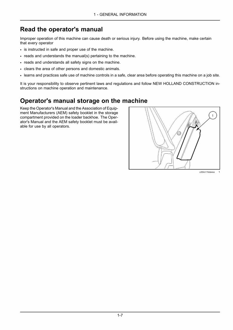
Operator's manual storage on the machineKeep the Operator's Manual and the Association of Equip-ment Manufacturers (AEM) safety booklet in the storagecompartment provided on the loader backhoe. The Oper-ator's Manual and the AEM safety booklet must be avail-able for use by all operators.
LEEN11T0064AA 1
1-7

1 - GENERAL INFORMATION
Machine orientationThe terms right-hand and left-hand, when used in this manual, indicate the right and left sides of the machine as seenfrom the operator's seat.
Operator and seat in the driving and loader operation position1. Front side2. Rear side3. Right-hand side4. Left-hand side
LEEN12T0529AA_1 1
Operator and seat in the backhoe operation position1. Front side2. Rear side3. Right-hand side4. Left-hand side
LEEN12T0530AA_1 2
1-8

1 - GENERAL INFORMATION
Component identification
RAIL15TLB0249FA 1
1. Loader bucket 8. Left-hand side stabilizer2. Loader bucket cylinder and linkage 9. Entry or exit steps3. Cab with Roll Over Protective Structure (ROPS) 10. Fuel tank4. Backhoe dipper or telescopic dipper 11. DIESEL EXHAUST FLUID (DEF)/ADBLUE® tank5. Backhoe bucket 12. Loader arm lift cylinder with safety support strut6. Backhoe boom 13. Loader lift arm7. Backhoe swing tower
1-9

1 - GENERAL INFORMATION
RAIL15TLB0250FA 2
1. Right-hand side stabilizer 6. Battery compartment2. Exhaust stack 7. Entry or exit steps3. Engine hood 8. Rear axle4. Front axle 9. Swing lock pin (lock position)5. Hydraulic tank 10. Backhoe boom lock (hydraulic or mechanical)
1-10
1 - GENERAL INFORMATION
Selective Catalytic Reduction (SCR) exhaust treatment - ProductoverviewWhat is Selective Catalytic Reduction (SCR)?
Your NEW HOLLAND CONSTRUCTION machine is equipped with additional components to comply with nationaland local exhaust emissions requirements. The main components of the SCR system include the SCR catalyst, theDiesel Exhaust Fluid (DEF)/AdBlue® dosing module, and the DEF/ADBLUE® tank.
How does Selective Catalytic Reduction (SCR) work?
During combustion, harmful nitrogen oxide (NOx ) molecules are formed in the exhaust. By injecting a DEF/ADBLUE®solution into the exhaust prior to a catalyst, the NOx can be converted to harmless elemental nitrogen and water. Thishappens when the NOx molecules react inside the catalyst with the heat generated by the engine and the ammoniain the DEF/ADBLUE® solution.
NOTICE: Do not idle the machine with no load for more than 6 h, or damage to the SCR catalyst will occur.
During cold engine operation at low engine coolant and ambient air temperatures, water vapor will be visible from theexhaust. This water vapor will resemble steam or light white smoke, and will dissipate as the engine and machinecomponents warm. This water vapor is considered normal.
NOTE: After engine shutdown, the SCR system will perform a purge cycle, which permits the supply module to con-tinue to run for up to 90 seconds. This is considered normal and requires no action from the operator.
What is Exhaust Gas Recirculation (EGR) and how does it work?
Your NEW HOLLAND CONSTRUCTION machine is equipped with additional components to comply with nationaland local exhaust emissions requirements. The main components of the EGR system include EGR valve, exhausttemperature sensors, differential pressure sensor, and throttle valve actuator.
EGR works by recirculating a portion of the engine ex-haust gasses back into the engine combustion chamberto lower combustion temperatures.
What is Diesel Exhaust Fluid (DEF)/AdBlue®?
DEF/ADBLUE® is a clear, colorless, non-toxic, aqueous urea solution ( 32.5%) with a slight ammonia odor. It is usedto chemically reduce NOx emissions from heavy-duty diesel-powered vehicles. DEF/ADBLUE® is neither explosivenor harmful to the environment. DEF/ADBLUE® is classified under the minimum-risk category of transportable fluids.
International standard ISO 22241-1 defines DEF/ADBLUE® quality. The American Petroleum Insti-tute (API®) has a voluntary certification program forDEF/ADBLUE®. To ensure that DEF/ADBLUE® satis-fies the requirements of ISO 22241, look for the API®DEF Certification Mark™ whenever you purchaseDEF/ADBLUE®. API Diesel Exhaust Fluid CertificationMark is a registered trademark of API in the United Statesand or other countries.
Finding Diesel Exhaust Fluid (DEF)/AdBlue®
Your NEW HOLLAND CONSTRUCTION dealer is fully equipped to accommodate all your DEF/ADBLUE® needs.
New Holland Construction Customer Service:Call 1-888-365-NHCE (1-888-365-6423) or email [email protected].
1-11

1 - GENERAL INFORMATION
Storage, handling, and transportNOTICE: Storage temperatures above 30 °C (86 °F) greatly reduce the shelf life of DEF/ADBLUE®.
DEF/ADBLUE® has a typical shelf life of 6-12 months. See the “Shelf life” table below. In order for DEF/ADBLUE® toremain in a useable condition, storage requirements must be met.
• Store between -11 °C (12 °F) and 30 °C (86 °F).• Use only an approved DEF/ADBLUE® container. Contact your dealer to obtain proper storage container(s).
• Keep container tightly closed.
• Keep container in a cool, well-ventilated area.
• Keep away from heat and direct sunlight.
If the machine will exceed a four month shut down period:1. Key OFF.
NOTE: Allow 2 – 5 min after Key OFF before disconnecting the batteries.2. Drain the DEF/ADBLUE® tank.3. Flush the tank with deionized water.4. Drain the deionized water
NOTICE: Do not disconnect any electrical connections from the DEF/ADBLUE® system.
Machine start-up after extended shutdown:1. Fill the DEF/ADBLUE® tank.2. Replace the main filter in the supply module.3. Start the machine.
Thawing
• Your NEW HOLLAND CONSTRUCTION machine is equipped with an internal tank heater to thaw frozen DEF/ADBLUE®. Your machine will still function until the DEF/ADBLUE® begins to flow. The SCR system will then functionnormally.
NOTE: You may notice a slight reduction in engine torque in high demand situations until the DEF/ADBLUE® is fullythawed.
• Do not heat DEF/ADBLUE® for long periods of time at temperatures above 30 °C (86 °F). This causes the solutionto decompose, which very slowly decreases the expected shelf life.
NOTICE: Do not use an anti-gelling or freeze point improver in your DEF/ADBLUE®. The 32.5% solution is specificallydesigned to provide the optimum NOx reduction properties. Any further blending or adjusting of the DEF/ADBLUE®mixture will lessen its ability to perform correctly and may cause damage to the SCR components.
Handling and supply of additives, if any.
• Personal Protective Equipment (PPE) is not required under normal conditions. If splashing is likely, wear eye pro-tection. For prolonged or repeated contact, impervious gloves are recommended. Follow the precautions listed inthe SAFETY INFORMATION chapter when handling any service fluid.
• No additives are required.
NOTICE: Contaminated DEF/ADBLUE® can affect the performance of your machine. Follow all instructions in thismanual when handling DEF/ADBLUE®.
Shelf lifeConstant ambient storage temperature Minimum shelf life
Less than or equal to 10 °C (50 °F) 36 monthsLess than or equal to 25 °C (77 °F) ¹ 18 monthsLess than or equal to 30 °C (86 °F) 12 monthsLess than or equal to 35 °C (95 °F) 6 months
Greater than 35 °C (95 °F) -²
1-12

1 - GENERAL INFORMATION
Constant ambient storage temperature Minimum shelf life¹ To prevent decomposition of DEF/ADBLUE®, prolonged transportation or storage above 25 °C (77 °F) shouldbe avoided.² Significant loss of shelf life: check every batch before use. See your NEW HOLLAND CONSTRUCTION dealerfor more information on testing.
NOTE: The main factors taken into account to define the shelf life in the table above are the ambient storage tem-perature and the initial alkalinity of DEF/ADBLUE®. The difference in evaporation between vented and non-ventedstorage containers is an additional factor.
NOTE: The information in the Shelf life table is for reference only. Source: ISO 22241-3 Diesel engines - NOx reduc-tion agent AUS 32 - Part 3: Handling, transportation and storage.
Disposal
• Dispose of DEF/ADBLUE® and any filter accumulations in accordance with all applicable Federal, State, and locallaws governing waste disposal.
Hydrocarbon management
If the engine operates at low idle speed for a prolonged period of time, hydrocarbons can accumulate in the SCR cat-alyst. To manage this accumulation, your machine will monitor current conditions and increase idle speed or requestaction from the operator in order to increase the temperature inside the SCR catalyst and eliminate the hydrocarbons.
NOTICE: Unless the Hydrocarbon (HC) level has reached the most critical level (SCR catalyst full ), runningthe unit under load is advantageous for quickly reducing the HC levels.
There are three messages that can be displayed to inform you that hydrocarbon management is active:
Low Idle Increase RecommendedDisplay Audible alert Action
3 consecutive beepsThe Engine Control Unit (ECU) requires the operator toincrease load on the engine or increase engine idle speed to aminimum of 1350 RPM.
Low Idle Increase ActiveDisplay Audible alert Action
5 consecutive beeps
The Engine Control Unit (ECU) will automatically increaseengine idle speed to 1350 RPM.
The Engine Control Module (ECU) will allow automaticHydrocarbon management only if the machine meets thefollowing requirements for 10 min:• the FORWARD-NEUTRAL-REVERSE (F-N-R) lever is keptin the NEUTRAL position
• the park brake is engaged
• the engine idle speed is below 1350 RPMNOTE: This automatic engine idle speed increase is inhibited if any of the conditions are not met or certain featuresare active on the machine. For example: operating the hand or foot throttle.
NOTE: The operator is free to interrupt the auto idle increase and operate the machine. The display may change to
the low idle increase recommended , if the system determines that additional Hydrocarbon (HC) reductionis required.
1-13

1 - GENERAL INFORMATION
SCR Catalyst FullDisplay Audible alert Action
with illumination
Constant audible alarm
1. Place the FORWARD-NEUTRAL-REVERSE (F-N-R) leverin the NEUTRAL position.
2. Engage the park brake.3. Use the hand throttle and manually increase the engine
speed to 1500 RPM.
NOTE: The operator does not need to stay with the machine during the Hydrocarbon management procedure. Oncethe procedure is complete the display message will disappear and the operator may resume machine operation.
NOTE: This procedure may take approximately 1 – 2 h to complete depending on the ambient air temperature.
NOTICE: Do not turn off the engine, drive the machine, or increase the load on the machine to avoid damage to thecatalyst.
US Environmental Protection Agency (EPA) Warranty Statement
FPT Industrial S.p.A. warrants to the ultimate purchaser and each subsequent purchaser that the engine isdesigned, built and equipped so as to conform with US Environmental Protection Agency (EPA) regulationsapplicable at the time of manufacture and that it is free from defects in workmanship or material which wouldcause it not to meet these regulations for a period of:
• 2 years or 1,500 hours of operation, whichever occurs first, for engines less than 19 kW (25 Hp)• 5 years or 3,000 hours of operation, whichever occurs first, for engines greater than or equal to 19 kW (25 Hp)
NOTE: This warranty applies to all units operated in the United States or Canada.
Coverage
The model year, class of diesel engine, and emission application determination for your engine are identified on theEmission Control Information Label. This label is affixed to one of the following areas of the engine: the top of en-gine's rocker arm cover, the right-hand side of the oil pan, and the right-hand side of the engine front gear cover.The warranty period begins on the date the new equipment is sold to the first retail purchaser. The presence of theemission control label is the indication that the engine conforms to the applicable standards. Any emission controlsystem parts which are proven defective during normal use will be repaired or replaced during the warranty period.
The engine owner has responsibility to perform all the required maintenance listed in the Owner's Manual. FPT In-dustrial S.p.A. will not deny an emission warranty claim solely because no record of maintenance exists; however, aclaim may be denied if failure to perform maintenance resulted in the failure of a warranted part.
It is recommended that replacement parts used for maintenance or repairs be FPT Industrial S.p.A. Service Partsto maintain the quality originally designed into your emission certified engine. The use of non- FPT Industrial S.p.A.parts does not invalidate the warranty on other components unless the use of such parts causes damage to warrantedparts.
The manufacturer is liable for damages to other engine components caused by the failure of any warranted emissioncontrol system part. FPT Industrial S.p.A. is not responsible for failures resulting from improper repair or the use ofparts that are not genuine FPT Industrial S.p.A. or FPT Industrial S.p.A. approved parts.
Component coverage
New engines certified for sale and registered will have the following items covered by the emission warranty, depend-ing on the emission level of the engine, if the items were first installed on the new engine as original equipment:
Fuel injection system
• Fuel injection pump
• Fuel injectors
• Fuel injection lines
Air induction system
• Intake manifold
• Turbocharger system (includes exhaust manifold)
• Charge air cooler
1-14

1 - GENERAL INFORMATION
Positive Crankcase Ventilation (PCV) system (ifapplicable)
• PCV valve
• Oil fill cap
Exhaust after treatment Devices (if applicable)
• Diesel Particulate Filter (DPF)
• Selective Catalytic Reduction (SCR)
• Diesel Exhaust Fluid (DEF) tank and dispensing sys-tems
Exhaust Gas Recirculation Systems (EGR)
• EGR valve assembly
• EGR cooler
Cold Start Enrichment Systems
Electronic Control Units, Sensors, Solenoids, and Wiringharnesses used in above systems
Emissions warranty does not cover
• Repairs arising from storage deterioration, failure to maintain the equipment, negligence, alteration, improper useof the equipment, collision or other accident, vandalism, or other casualty, or operation beyond rated capacity orspecification.
• Repairs arising from abuse or neglect, including but not limited to: operation without adequate coolant or lubricants,adjustments to the fuel system outside equipment specifications, over-speeding, improper storage, starting, warm-up, or shutdown practices, incorrect fuel or contaminated fuel, oil or other fluids.
• Normal maintenance services, such as engine tune-ups, engine fuel system cleaning, checks, adjustments, shim-ming, etc.
• Items replaced due to customer demand.
• Labor charges performed by anyone except a dealer authorized by contract to repair the equipment, unless theyqualify under special provisions (i.e. outside labor).
• Any and all travel costs for items such as towing, service calls, or transporting a unit to and from the place wherethe warranty service is performed.
• Normal maintenance costs, including but not limited to: lubricants, coolants, fluids, fuel, filters, and associated labor.Lubricants, filters, and coolants may qualify for warranty reimbursement if they require replacement as a DIRECTRESULT of a defect in material or workmanship.
• Claims involving the inspection or reconditioning of units after storage or prior use.
• Repairs arising from service performed by agents not approved by NEW HOLLAND CONSTRUCTION.
• Repairs arising from any unauthorized modification to the product or the use of non- NEW HOLLAND CONSTRUC-TION parts, implements or attachments.
• Removal, replacement, or installation of non- NEW HOLLAND CONSTRUCTION optional equipment, attachmentsor components.
• Premiums charged for overtime labor costs or out of shop expenses.
• Economic loss including lost profits, crop loss, equipment rental, or other expense.
• Unauthorized modification or updating machines without a warrantable failure.
• Any and all costs of dealer shop supplies incurred with repairs, including but not limited to: solvents, cleaners,anti-seize lubricants, loctite™, sealant, adhesive, oil-dry, shop towels, etc.
• Failure of the machine, its implements or attachments caused by improper field application or loading.
• Any and all costs for coolant, fuel, or lube (oil) analysis including supplies and lab recommendations.
• Cost associated with cleaning of machine in preparation for servicing.
California Emission Control Warranty Statement
Your warranty rights and obligations
California Air Resources Board and FPT Industrial S.p.A. are pleased to explain the emission control system warrantyon 2015 through 2017 off-road diesel engines. In California, new heavy-duty off-road engines must be designed, builtand equipped to meet the State's stringent anti-smog standards. FPT Industrial S.p.A. must warrant the emissioncontrol system on your engine for the periods of time listed below provided there has been no abuse, neglect orimproper maintenance of your engine.
1-15

1 - GENERAL INFORMATION
Your emission control system may include parts such as the fuel injection system and the air induction system. Alsoincluded may be hoses, belts, connectors and other emission-related assemblies.
Where a warrantable condition exists, FPT Industrial S.p.A. will repair your heavy-duty off-road engine at no cost toyou including diagnosis, parts and labor.
MANUFACTURER'S WARRANTY COVERAGE:
The 2015-2017 heavy-duty off-road engines are warranted for 5 years or 3000 hours, whichever comes first. If anyemission-related part on your engine is defective, the part will be repaired or replaced by FPT Industrial S.p.A.
OWNER'S WARRANTY RESPONSIBILITIES:
• As the off-road engine owner, you are responsible for the performance of the required maintenance listed in yourowner's manual. FPT Industrial S.p.A. recommends that you retain all receipts covering maintenance on your off-road engine, but NEW HOLLAND CONSTRUCTION cannot deny warranty solely for the lack of receipts or for yourfailure to ensure the performance of all scheduled maintenance.
• As the off-road engine owner, you should however be aware that FPT Industrial S.p.A. may deny you warrantycoverage if your off-road engine or a part has failed due to abuse, neglect, improper maintenance or unapprovedmodifications.
• Your engine is designed to operate on Ultra Low Sulfur Diesel fuel only. Use of any other fuel may result in yourengine no longer operating in compliance with California's emissions requirements.
• You are responsible for initiating the warranty process. The ARB suggests that you present your off-road engine to aNEW HOLLAND CONSTRUCTION dealer as soon as a problem exists. The warranty repairs should be completedby the dealer as expeditiously as possible.
If you have any questions regarding your warranty rights and responsibilities, you should contact NAFTA TechnicalService Group at 1-630-481-2905 or email: [email protected].
CALIFORNIA EMISSION CONTROL WARRANTY PARTS LIST
Fuel injection system:
• Fuel injection pump
• Fuel injectors
• Fuel injection lines
Air induction system:
• Intake manifold
• Turbocharger system (includes exhaust manifold)
• Charge air cooler
Positive Crankcase Ventilation (PCV) system (ifapplicable)
• PCV valve
• Oil fill cap
Exhaust after treatment Devices (if applicable)
• Diesel Particulate Filter (DPF)
• Selective Catalytic Reduction (SCR)
• Diesel Exhaust Fluid (DEF) tank and dispensing sys-tems
Exhaust Gas Recirculation Systems (EGR)
• EGR valve assembly
• EGR cooler
Cold Start Enrichment Systems
Electronic Control Units, Sensors, Solenoids, and Wiringharnesses used in above systems
Miscellaneous items used in above systems, such ashoses, belts, connectors, tubing, gaskets, and mountinghardware.
Emission Control Information Labels
1-16
2 - SAFETY INFORMATION
2 - SAFETY INFORMATION###_2_###
Safety rules and signal word definitions
Personal safety
This is the safety alert symbol. It is used to alert you to potential personal injury hazards. Obey allsafety messages that follow this symbol to avoid possible death or injury.
Throughout this manual and on machine safety signs, you will find the signal words DANGER, WARNING, and CAU-TION followed by special instructions. These precautions are intended for the personal safety of you and thoseworking with you.
Read and understand all the safety messages in this manual before you operate or service the machine.
DANGER indicates a hazardous situation that, if not avoided, will result in death or serious injury. The colorassociated with DANGER is RED.
WARNING indicates a hazardous situation that, if not avoided, could result in death or serious injury. The colorassociated with WARNING is ORANGE.
CAUTION indicates a hazardous situation that, if not avoided, could result in minor or moderate injury. Thecolor associated with CAUTION is YELLOW.
FAILURE TO FOLLOW DANGER, WARNING, AND CAUTION MESSAGES COULD RESULTIN DEATH OR SERIOUS INJURY.
Machine safetyNOTICE: Notice indicates a situation that, if not avoided, could result in machine damage or property damage. Thecolor associated with Notice is BLUE.
Throughout this manual you will find the signal word Notice followed by special instructions to prevent machine dam-age or property damage. The word Notice is used to address practices not related to personal safety.
InformationNOTE: Note indicates additional information that clarifies steps, procedures, or other information in this manual.
Throughout this manual you will find the word Note followed by additional information about a step, procedure, orother information in the manual. The word Note is not intended to address personal safety or property damage.
2-1

2 - SAFETY INFORMATION
Safety rulesGeneral safety rules
Use caution when you operate the machine on slopes.Raised equipment, full tanks and other loads will changethe center of gravity of the machine. The machine cantip or roll over when near ditches and embankments oruneven surfaces.
Never permit anyone other than the operator to ride onthe machine.
Never operate the machine under the influence of alcoholor drugs, or while you are otherwise impaired.
When digging or using ground-engaging attachments, beaware of buried cables. Contact local utilities to determinethe locations of services.
Pay attention to overhead power lines and hanging obsta-cles. High voltage lines may require significant clearancefor safety.
Hydraulic oil or diesel fuel leaking under pressure canpenetrate the skin, causing serious injury or infection.
• DO NOT use your hand to check for leaks. Use a pieceof cardboard or paper.
• Stop the engine, remove the key, and relieve the pres-sure before you connect or disconnect fluid lines.
• Make sure that all components are in good condition.Tighten all connections before you start the engine orpressurize the system.
• If hydraulic fluid or diesel fuel penetrates the skin, seekmedical attention immediately.
• Continuous long term contact with hydraulic fluid maycause skin cancer. Avoid long term contact and washthe skin promptly with soap and water.
Keep clear of moving parts. Loose clothing, jewelry,watches, long hair, and other loose or hanging items canbecome entangled in moving parts.
Wear protective equipment when appropriate.
DO NOT attempt to remove material from any part of themachine while it is being operated or while componentsare in motion.
Make sure that all guards and shields are in good con-dition and properly installed before you operate the ma-chine. Never operate the machine with shields removed.Always close access doors or panels before you operatethe machine.
Dirty or slippery steps, ladders, walkways, and platformscan cause falls. Make sure these surfaces remain cleanand clear of debris.
A person or pet within the operating area of amachine canbe struck or crushed by the machine or its equipment. DONOT allow anyone to enter the work area.
Raised equipment and/or loads can fall unexpectedly andcrush persons underneath. Never allow anyone to enterthe area underneath raised equipment during operation.
Never operate the engine in enclosed spaces as harmfulexhaust gases may build up.
Before you start the machine, be sure that all controls arein neutral or park lock position with the backhoe swinglock pin in the lock position. The backhoe swing lock pinmust be in the lock position when you are not using thebackhoe.
Start the engine only from the operator’s seat. If youbypass the safety start switch, the engine can start withthe transmission in gear. Do not connect or short acrossterminals on the starter solenoid. Attach jumper cablesas described in the manual. Starting in gear may causedeath or serious injury.
Always keep windows, mirrors, all lighting, andSlow-Moving Vehicle (SMV) emblem clean to provide thebest possible visibility while you operate the machine.
Operate controls only when seated in the operator’s seat,except for those controls expressly intended for use fromother locations.
From the operator's platform, install the backhoe swinglock pin when the backhoe is not in use and before allother operation.
Before you leave the machine:1. Park the machine on a firm, level surface.2. Put all controls in neutral or park lock position.3. Engage the parking brake. Use wheel chocks if re-
quired.4. Lower the loader bucket or other front attachment to
the ground.5. Move the operator’s seat to the backhoe operating
position and choose one of the following backhoepositions:
• Move the backhoe into the stowed position and fromthe operator's seat install the backhoe swing lockpin. See 6-31.
• Lower the backhoe bucket or other attachment tothe ground.
6. Turn off the engine and remove the key.7. Move the operator’s seat into the driving position.
2-2

2 - SAFETY INFORMATION
When, due to exceptional circumstances, you decide tokeep the engine running after you leave the operator’sstation, then you must follow these precautions:
1. Bring the engine to low idle speed.2. Disengage all drive systems.
WARNINGSome components may continue to rundown after you disengage drive systems.Make sure all drive systems are fully disen-gaged.Failure to comply could result in death orserious injury.
W0113A
3. Move the operator’s seat to the backhoe operatingposition and choose one of the following backhoepositions:
○ Move the backhoe into the stowed position and fromthe operator's seat install the backhoe swing lockpin. See 6-31.
○ Lower the backhoe bucket or other attachment tothe ground.
4. Shift the transmission into neutral.5. Apply the parking brake.
General maintenance safety
Do not attempt to clean, lubricate, clear obstructions, ormake adjustments to the machine while it is in motion orwhile the engine is running.
Keep the area used for servicing the machine clean anddry. Clean up spilled fluids.
Service the machine on a firm, level surface.
Install guards and shields after you service the machine.
Close all access doors and install all panels after servicingthe machine.
Always make sure that working area is clear of tools,parts, other persons and pets before you start operatingthe machine.
Unsupported hydraulic cylinders can lose pressure anddrop the equipment, causing a crushing hazard. Do notleave equipment in a raised position while parked or dur-ing service, unless the equipment is securely supported.
Jack or lift the machine only at jack or lift points indicatedin this manual.
Incorrect towing procedures can cause accidents. Whenyou tow a disabled machine follow the procedure in thismanual. Use only rigid tow bars.
Stop the engine, remove the key, and relieve pressurebefore you connect or disconnect fluid lines.
Stop the engine and remove the key before you connector disconnect electrical connections.
Scalding can result from incorrect removal of coolantcaps. Cooling systems operate under pressure. Hotcoolant can spray out if you remove a cap while the sys-tem is hot. Allow the system to cool before you removethe cap. When you remove the cap, turn it slowly to allowpressure to escape before you completely remove thecap.
Replace damaged or worn tubes, hoses, electrical wiring,etc.
The engine, transmission, exhaust components, and hy-draulic lines may become hot during operation. Take carewhen you service such components. Allow surfaces tocool before you handle or disconnect hot components.Wear protective equipment when appropriate.
When welding, follow the instructions in the manual. Al-ways disconnect the battery before you weld on the ma-chine. Always wash your hands after you handle batterycomponents.
2-3

2 - SAFETY INFORMATION
Wheels and tires
Make sure that tires are correctly inflated. Do not exceedany recommended load or pressure. Follow the instruc-tions in the manual for proper tire inflation.
Tires are heavy. Handling tires without proper equipmentcould cause death or serious injury.
Never weld on a wheel with a tire installed. Always re-move the tire completely from the wheel prior to welding.
Always have a qualified tire technician service the tiresand wheels. If a tire has lost all pressure, take the tire and
wheel to a tire shop or your dealer for service. Explosiveseparation of the tire can cause serious injury.
DO NOT weld to a wheel or rim until the tire is completelyremoved. Inflated tires can generate a gas mixture withthe air that can be ignited by high temperatures fromweld-ing procedures performed on the wheel or rim. Removingthe air or loosening the tire on the rim (breaking the bead)will NOT eliminate the hazard. This condition can existwhether tires are inflated or deflated. The tire MUST becompletely removed from the wheel or rim prior to weld-ing the wheel or rim.
Driving on public roads and general transportation safety
Comply with local laws and regulations.
Make sure that the backhoe swing lock pin is in the lockposition. See 6-31 for more information.
Use appropriate lighting to meet local regulations.
Make sure that the Slow-Moving Vehicle (SMV) emblemis visible.
Make sure that the brake pedal latch is engaged. Youmust lock brake pedals together for road travel.
Use safety chains for trailed equipment when safetychains are provided with machine or equipment.
Lift implements and attachments high enough aboveground to prevent accidental contact with road.
When you transport equipment or a machine on a trans-port trailer, make sure that it is properly secured. Be surethe Slow-Moving Vehicle (SMV) on the equipment or ma-chine is covered while being transported on a trailer.
Be aware of overhead structures or power lines and makesure that the machine and/or attachments can pass safelyunder.
Travel speed should be such that you maintain completecontrol and machine stability at all times.
Slow down and signal before turning.
Pull over to allow faster traffic to pass.
Follow correct towing procedure for equipment with orwithout brakes.
Fire and explosion prevention
Fuel or oil that is leaked or spilled on hot surfaces or elec-trical components can cause a fire.
Crop materials, trash, debris, bird nests, or flammablematerial can ignite on hot surfaces.
Always have a fire extinguisher on or near the machine.
Make sure that the fire extinguisher(s) is maintained andserviced according to the manufacturer’s instructions.
At least once each day and at the end of the day, removeall trash and debris from the machine especially aroundhot components such as the engine, transmission, ex-haust, battery, etc. More frequent cleaning of your ma-chine may be necessary depending on the operating en-vironment and conditions.
At least once each day, remove debris accumulationaround moving components such as bearings, pulleys,
belts, gears, cleaning fans, etc. More frequent cleaningof your machine may be necessary depending on theoperating environment and conditions.
Inspect the electrical system for loose connections andfrayed insulation. Repair or replace loose or damagedparts.
Do not store oily rags or other flammable material on themachine.
Do not weld or flame cut any items that contain flammablematerial. Clean items thoroughly with non-flammable sol-vents before welding or flame-cutting.
Do not expose the machine to flames, burning brush, orexplosives.
Promptly investigate any unusual smells or odors thatmay occur during operation of the machine.
2-4

2 - SAFETY INFORMATION
General battery safety
Always wear eye protection when you work with batteries.
Do not create sparks or have open flame near a battery.
Ventilate the area when you charge a battery or use abattery in an enclosed area.
Disconnect the negative (-) terminal first and reconnectthe negative (-) terminal last.
When you weld on the machine, disconnect both termi-nals of the battery.
Do not weld, grind, or smoke near a battery.
When you use auxiliary batteries or connect jumper ca-bles to start the engine, use the procedure shown in theoperator’s manual. Do not short across terminals.
Follow the manufacturer’s instructions when you storeand handle batteries.
Battery post, terminals, and related accessories containlead and lead compounds. Wash hands after handling.
Battery acid causes burns. Batteries contain sulfuric acid.Avoid contact with skin, eyes, or clothing. Antidote (exter-nal): Flush with water. Antidote (eyes): flush with waterfor 15 minutes and seek medical attention immediately.Antidote (internal): Drink large quantities of water or milk.Do not induce vomiting. Seek medical attention immedi-ately.
Keep out of reach of children and other unauthorized per-sons.
Reflectors and warning lights
You must use flashing amber warning lights when youoperate equipment on public roads.
2-5

2 - SAFETY INFORMATION
Seat belts
Seat belts must be worn at all times.
Seat belt inspection and maintenance:
• Keep seat belts in good condition.
• Keep sharp edges and items than can cause damageaway from the belts.
• Periodically check belts, buckles, retractors, tethers,slack take-up system, and mounting bolts for damageand wear.
• Replace all parts that have damage or wear.
• Replace belts that have cuts that can make the beltweak.
• Check that bolts are tight on the seat bracket or mount-ing.
• If the belt is attached to the seat, make sure that theseat or seat brackets are mounted securely.
• Keep seat belts clean and dry.
• Clean belts only with soap solution and warm water.
• Do not use bleach or dye on the belts because this canmake the belts weak.
Fasten/release
1. Pull the right-hand belt strap from the retractor.2. Insert the metal end into the latch mechanism of the
left-hand side of the seat.
RAIL14UTL0054BA 1
3. To release, press the red button on the latch mecha-nism. The seat belt will automatically retract.
RAIL14UTL0054BA 2
2-6
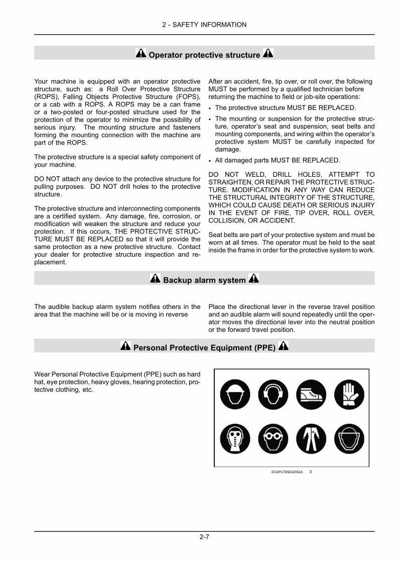
2 - SAFETY INFORMATION
Operator protective structure
Your machine is equipped with an operator protectivestructure, such as: a Roll Over Protective Structure(ROPS), Falling Objects Protective Structure (FOPS),or a cab with a ROPS. A ROPS may be a can frameor a two-posted or four-posted structure used for theprotection of the operator to minimize the possibility ofserious injury. The mounting structure and fastenersforming the mounting connection with the machine arepart of the ROPS.
The protective structure is a special safety component ofyour machine.
DO NOT attach any device to the protective structure forpulling purposes. DO NOT drill holes to the protectivestructure.
The protective structure and interconnecting componentsare a certified system. Any damage, fire, corrosion, ormodification will weaken the structure and reduce yourprotection. If this occurs, THE PROTECTIVE STRUC-TURE MUST BE REPLACED so that it will provide thesame protection as a new protective structure. Contactyour dealer for protective structure inspection and re-placement.
After an accident, fire, tip over, or roll over, the followingMUST be performed by a qualified technician beforereturning the machine to field or job-site operations:
• The protective structure MUST BE REPLACED.
• The mounting or suspension for the protective struc-ture, operator’s seat and suspension, seat belts andmounting components, and wiring within the operator’sprotective system MUST be carefully inspected fordamage.
• All damaged parts MUST BE REPLACED.
DO NOT WELD, DRILL HOLES, ATTEMPT TOSTRAIGHTEN, ORREPAIR THEPROTECTIVE STRUC-TURE. MODIFICATION IN ANY WAY CAN REDUCETHE STRUCTURAL INTEGRITY OF THE STRUCTURE,WHICH COULD CAUSE DEATH OR SERIOUS INJURYIN THE EVENT OF FIRE, TIP OVER, ROLL OVER,COLLISION, OR ACCIDENT.
Seat belts are part of your protective system and must beworn at all times. The operator must be held to the seatinside the frame in order for the protective system to work.
Backup alarm system
The audible backup alarm system notifies others in thearea that the machine will be or is moving in reverse
Place the directional lever in the reverse travel positionand an audible alarm will sound repeatedly until the oper-ator moves the directional lever into the neutral positionor the forward travel position.
Personal Protective Equipment (PPE)
Wear Personal Protective Equipment (PPE) such as hardhat, eye protection, heavy gloves, hearing protection, pro-tective clothing, etc.
DCAPLT5NE020S2A 3
2-7

2 - SAFETY INFORMATION
Do Not Operate tag
Before you start servicing the machine, attach a ‘Do NotOperate’ warning tag to the machine in an area that willbe visible.
RH99E029 4
Hazardous chemicals
If you are exposed to or come in contact with hazardouschemicals you can be seriously injured. The fluids, lu-bricants, paints, adhesives, coolant, etc. required for thefunction of your machine can be hazardous. They maybe attractive and harmful to domestic animals as well ashumans.
Material Safety Data Sheets (MSDS) provide informationabout the chemical substances within a product, safehandling and storage procedures, first aid measures, andprocedures to take in the event of a spill or accidentalrelease. MSDS are available from your dealer.
Before you service your machine check the MSDS foreach lubricant, fluid, etc. used in this machine. This in-formation indicates the associated risks and will help youservice the machine safely. Follow the information in theMSDS, and on manufacturer containers, as well as the in-formation in this manual, when you service the machine.
Dispose of all fluids, filters, and containers in an environ-mentally safe manner according to local laws and regula-tions. Check with local environmental and recycling cen-ters or your dealer for correct disposal information.
Store fluids and filters in accordance with local laws andregulations. Use only appropriate containers for the stor-age of chemicals or petrochemical substances.
Keep out of reach or children or other unauthorized per-sons.
Applied chemicals require additional precautions. Obtaincomplete information from the manufacturer or distributorof the chemicals before you use them.
Utility safety
When digging or using ground-engaging equipment, beaware of buried cables and other services. Contact yourlocal utilities or authorities, as appropriate, to determinethe locations of services.
Make sure that the machine has sufficient clearance topass in all directions. Pay special attention to overheadpower lines and hanging obstacles. High voltage linesmay require significant clearance for safety. Contact localauthorities or utilities to obtain safe clearance distancesfrom high voltage power lines.
Retract raised or extended components, if necessary.Remove or lower radio antennas or other accessories.Should a contact between the machine and an electric
power source occur, the following precautions must betaken:
• Stop the machine movement immediately.
• Apply the parking brake, stop the engine, and removethe key.
• Check if you can safely leave the cab or your actual po-sition without contact with electrical wires. If not, stayin your position and call for help. If you can leave yourposition without touching lines, jump clear of the ma-chine to make sure that you do not make contact withthe ground and the machine at the same time.
• Do not permit anyone to touch the machine until powerhas been shut off to the power lines.
2-8

2 - SAFETY INFORMATION
Electrical storm safety
Do not operate machine during an electrical storm.
If you are on the ground during an electrical storm, stayaway from machinery and equipment. Seek shelter in apermanent, protected structure.
If an electrical storm should strike during operation, re-main in the cab. Do not leave the cab or operator’s plat-form. Do not make contact with the ground or objectsoutside the machine.
Mounting and dismounting
Mount and dismount the machine only at designated lo-cations that have handholds, steps, and/or or ladders.
Do not jump off of the machine.
Make sure that steps, ladders, and platforms remainclean and clear of debris and foreign substances. Injurymay result from slippery surfaces.
Face the machine when you mount and dismount the ma-chine.
Maintain a three-point contact with steps, ladders, andhandholds.
Never mount or dismount from a moving machine.
Do not use the steering wheel or other controls or acces-sories as handholds when you enter or exit the cab oroperator’s platform.
Working at heights
When the normal use and maintenance of the machinerequires you to work at heights:
• Correctly use installed steps, ladders, and railings.
• Never use ladders, steps, or railings while the machineis moving.
• Do not stand on surfaces that are not designated assteps or platforms.
Do not use the machine as a lift, ladder, or platform forworking at heights.
Lifting and overhead loads
Never use loader buckets, forks, etc. or other lifting, han-dling, or digging equipment to lift persons.
Do not use raised equipment as a work platform.
Know the full area of movement of themachine and equip-ment and do not enter or permit anyone to enter the areaof movement while the machine is in operation.
Never enter or permit anyone to enter the area under-neath raised equipment. Equipment and/or loads can fallunexpectedly and crush persons underneath it.
Do not leave equipment in raised position while parkedor during service, unless securely supported. Hydrauliccylinders must be mechanically locked or supported ifthey are left in a raised position for service or access.
Loader buckets, forks, etc. or other lifting, handling, ordigging equipment and its load will change the center ofgravity of the machine. This can cause the machine to tipon slopes or uneven ground.
Load items can fall off the loader bucket or lifting equip-ment and crush the operator. Care must be taken whenlifting a load. Use proper lifting equipment.
Do not lift load higher than necessary. Lower loads totransport. Remember to leave appropriate clearance tothe ground and other obstacles.
Equipment and associated loads can block visibility andcause an accident. Do not operate with insufficient visi-bility.
Keep the load or tool as low as possible while moving themachine around the work site.
Release all hydraulic pressure before servicing the ma-chine.
Youmust knowwhich circuits have accumulators and howto release pressure properly.
Always use the lift arm support strut when servicing themachine with lift arms up.
2-9

2 - SAFETY INFORMATION
Air-conditioning system
• The air-conditioning system is under high pressure. Donot disconnect any lines. The release of high pressurecan cause serious injury.
• The air-conditioning system contains gases that areharmful to the environment when released into the at-
mosphere. Do not attempt to service or repair the sys-tem.
• Only trained service technicians can service, repair,and recharge the air-conditioning system.
2-10

2 - SAFETY INFORMATION
Safety rules - Utility precautions
YOU MUST FOLLOW safety precautions when you worknear buried utility lines.
During operation, it is likely that you will be workingaround or near buried utility lines that may include, butare not limited to:
• Electrical power line
• Gas line
• Water line
• Communication line - telephone or cable television
• Sewer line
NOTE: Before construction work begins it is your respon-sibility to be aware of all utility lines in the area of yourproject and to avoid them.
ALWAYS have all local utility companies mark the locationof their lines.
In U.S.A. and Canada call one of many One Call Sys-tem Director services. If you do not know the local num-ber, call the national number (U.S.A. and Canada only):1-888-258-0808. This number will direct you to the stateor regional utility that assists with excavation activity.
NOTE: Check with local authorities for laws, regulations,and/or strict penalties requiring you to locate and avoidexisting utilities.
Call all utility companies before you performany machine operation
After you locate any buried utility lines, carefully dig a holeto the utility line by hand and/or with automatic vacuumequipment. Verify the location and depth of the line.
Where applicable, know the utility color code.
Electric RedGas, Oil, or Petroleum YellowCommunication, Telephone,Television
Orange
Water BlueSewer Green or BrownProposed Excavation WhiteSurveying PinkReclaimed Water and Slurry Purple
Coordinate all excavation activity with the proper author-ities and professionals before beginning.
2-11

2 - SAFETY INFORMATION
Safety rules - Fuel handling precautions
• Do not smoke or permit open flames while fueling ornear fueling operations.
• Do not fill the fuel tank completely to the top. Allowroom for expansion.
• Clean up spilled fuel immediately and dispose of con-taminated material in an environmentally correct man-ner.
• Tighten the fuel tank cap securely. Should the fuelcap be lost, replace it only with the original manufac-turer's approved cap. Use of a non-approved cap with-out proper venting may result in pressurization of thetank.
• Never use fuel for cleaning purposes.
• Use the correct fuel grade for the operating season.
2-12

2 - SAFETY INFORMATION
Safety rules - Specific precautions to this machine
• From the operator's platform, install the backhoe swinglock pin when the backhoe is not in use and before allother operation.
• When traveling on the road or working with the frontloader keep the backhoe in the stowed position.
• Keep operator's platform clean. Never transport itemsin the operator's platform.
• Keep the load or tool as low as possible while movingthe machine around the work site.
• Adjust the rear window before actuating the backhoehydraulics. The rear window could come into contactwith the control lever.
• Pilot control machines are equipped with two backhoecontrol patterns. You must know which pattern the ma-chine is in, before operating the machine (actuating thehydraulics).
• Release all hydraulic pressure before servicing the ma-chine.
• You must know which circuits have accumulators andhow to release pressure properly.
• Always use the lift arm support strut when servicing themachine with lift arms up.
When using the backhoe:
• Position the stabilizer pads for maximum stability.
• Install a guard rail and warning signs to keep other per-sons away from the machine if operating in an area withreduced visibility, such as a building.
• Place the direction control lever and the transmission inneutral and apply the parking brake before turning theoperator's seat around to the backhoe position.
• Ensure the seat is locked into position.
• Knowwhich control pattern is engaged before actuatingthe hydraulics (pilot control machines only).
• Use caution when swinging the backhoe completely tothe side to prevent contact with the stabilizers.
2-13

2 - SAFETY INFORMATION
Support strut for loader lift armWARNINGCrushing hazard!If you service the machine with the loader lift arms raised, always use the support strut. Remove theretaining pin and place the support strut onto the cylinder rod. Install the retaining pin into the supportstrut. Lower the lift arms onto the support strut.Failure to comply could result in death or serious injury.
W0230A
Machines without the Tool Carrier (TC) optionEngage the loader arm support strut:1. Empty the loader bucket.2. Raise the loader lift arms to the maximum height.3. Stop the engine and remove the starter switch key.4. Remove the split pin (1) and the lock pin (2).
MOLI12LBB0260AB 1
5. Place the strut (3) on the cylinder rod and install thepin (2) and the split pin (1) back into the holes in thestrut.
6. Lower the loader attachment until the safety strut isfirmly against the cylinder.
MOLI12LBB0261AB 2
Disengage the loader arm support strut:1. Raise the loader lift arms to the maximum height.2. Stop the engine and remove the starter switch key.3. Remove the split pin (1) and the lock pin (2).
MOLI12LBB0262AB 3
2-14

2 - SAFETY INFORMATION
4. Remove the strut (3) from the attachment and installthe pin (1) and the split pin (2) back into the holes inthe strut.
5. Start the engine and lower the loader attachment.
MOLI12LBB0263AB 4
2-15

2 - SAFETY INFORMATION
Machines with the Tool Carrier (TC) optionEngage the loader arm support strut:1. Remove the split pins (1) and the safety strut (2) from
the storage position on the loader arm. Put the splitpins back in place.
2. Empty the loader bucket.3. Raise the loader lift arms to the maximum height.4. Stop the engine and remove the starter switch key.5. Place the strut (2) on the cylinder rod and fasten it by
means of the fastening flip (3).6. Lower the loader attachment until the safety strut is
firmly against the cylinder.7.
MOLI12LBB0264AB 5
MOLI12LBB0265AB 6
Disengage the loader arm support strut:1. Raise the loader lift arms to the maximum height.2. Stop the engine and remove the starter switch key.3. Remove the flip (3) and the strut (2) from the cylinder
rod.
MOLI12LBB0265AB 7
4. Start the engine and lower the loader attachment.5. Stop the engine.6. Install the safety strut (2) in the storage position on the
loader arm by means of the split pins (1).
MOLI12LBB0264AB 8
2-16

2 - SAFETY INFORMATION
Safety rules - Ductile iron
DANGERAltering cast ductile iron can cause it to weaken or break.Before you weld, cut, or drill holes on any part of this machine, make sure that the part is not castductile iron.Failure to comply will result in death or serious injury.
D0148A
Altering cast ductile iron can cause it to weaken or break. Unauthorized modifications to cast ductile iron parts cancause death or serious injury. Do not weld, cut, drill, repair, or attach items to cast ductile iron parts on this machine.
Before you weld, cut, or drill holes on any part of this machine, make sure that the part is not cast ductile iron. Seeyour dealer if you do not know if a part is cast ductile iron.
The following items are examples of cast ductile iron parts. There may also be other parts made of cast ductileiron that are not on the list below.
• Two-wheel drive steering link
• Front axle
• Swing tower
• Air-Conditioning (A/C) compressor mounting bracket
Do not make any unauthorized modifications. Consult an authorized dealer before making any changes, additions,or modifications to this machine.
2-17

2 - SAFETY INFORMATION
Hand signalsWhen operating the machine, never attempt to carry out tasks calling for fine control or to work in areas where visibilityis poor or impaired without seeking the assistance of a signal person. Make perfectly sure that you and the signalperson understand the signals to be used.
Start the engine
LEEN11T0005AA 1
Stop the engine
LEEN11T0006AA 2
Come to meWave hands back and forth (palms inward).
LEEN11T0007AA 3
2-18

2 - SAFETY INFORMATION
Move away from meWave hands back and forth (palms outward).
LEEN11T0008AA 4
Go this far
LEEN11T0009AA 5
All stop and hold
LEEN11T0010AA 6
StopMove one hand back and forth.
LEEN12T0534AA 7
2-19

2 - SAFETY INFORMATION
Emergency stopMove both hands back and forth.
LEEN11T0012AA 8
Raise load or bucket
LEEN11T0013AA 9
Lower load or bucket
LEEN11T0014AA 10
Raise load or bucket slowly
LEEN11T0015AA 11
2-20

2 - SAFETY INFORMATION
Lower load or bucket slowly
LEEN11T0016AA 12
Turn machine left swing load leftTo stop movement, stop moving hand and make a fist.
LEEN11T0017AA 13
Turn machine right swing load rightTo stop movement, stop moving hand and make a fist
LEEN11T0018AA 14
Roll back loader bucket
LEEN12T0535AA 15
2-21

2 - SAFETY INFORMATION
Dump loader bucket
LEEN12T0536AA 16
Raise backhoe boom
LEEN11T0019AA 17
Lower backhoe boom
LEEN11T0020AA 18
Backhoe dipper in
LEEN11T0021AA 19
2-22
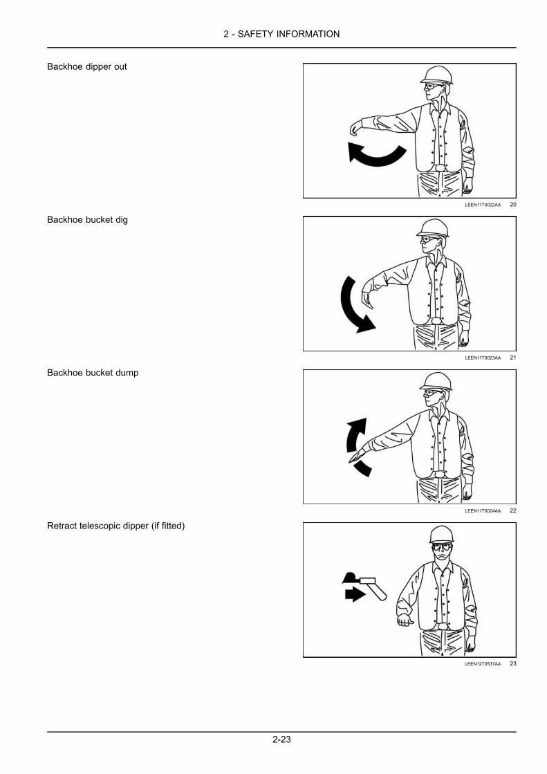
2 - SAFETY INFORMATION
Backhoe dipper out
LEEN11T0022AA 20
Backhoe bucket dig
LEEN11T0023AA 21
Backhoe bucket dump
LEEN11T0024AA 22
Retract telescopic dipper (if fitted)
LEEN12T0537AA 23
2-23

2 - SAFETY INFORMATION
Extend telescopic dipper (if fitted)
LEEN12T0538AA 24
2-24

2 - SAFETY INFORMATION
Ecology and the environmentSoil, air, and water quality is important for all industriesand life in general. When legislation does not yet rule thetreatment of some of the substances that advanced tech-nology requires, sound judgment should govern the useand disposal of products of a chemical and petrochemicalnature.
Familiarize yourself with the relative legislation applica-ble to your country, and make sure that you understandthis legislation. Where no legislation exists, obtain in-formation from suppliers of oils, filters, batteries, fuels,anti-freeze, cleaning agents, etc., with regard to the ef-fect of these substances on man and nature and how tosafely store, use, and dispose of these substances. YourNEW HOLLAND CONSTRUCTION dealer can also pro-vide assistance.
Helpful hints
• Avoid the use of cans or other inappropriate pressur-ized fuel delivery systems to fill tanks. Such deliverysystems may cause considerable spillage.
• In general, avoid skin contact with all fuels, oils, acids,solvents, etc. Most of these products contain sub-stances that may be harmful to your health.
• Modern oils contain additives. Do not burn contami-nated fuels and or waste oils in ordinary heating sys-tems.
• Avoid spillage when you drain fluids such as used en-gine coolant mixtures, engine oil, hydraulic fluid, brakefluid, etc. Do not mix drained brake fluids or fuels withlubricants. Store all drained fluids safely until you candispose of the fluids in a proper way that complies withall local legislation and available resources.
• Do not allow coolant mixtures to get into the soil. Col-lect and dispose of coolant mixtures properly.
• Do not open the air-conditioning system yourself. Itcontains gases that should not be released into the at-mosphere. Your NEW HOLLAND CONSTRUCTIONdealer or air-conditioning specialist has a special ex-tractor for this purpose and can recharge the systemproperly.
• Repair any leaks or defects in the engine cooling sys-tem or hydraulic system immediately.
• Do not increase the pressure in a pressurized circuit asthis may lead to a component failure.
Battery recycling
Batteries and electric accumulators contain severalsubstances that can have a harmful effect on the envi-ronment if the batteries are not properly recycled afteruse. Improper disposal of batteries can contaminatethe soil, groundwater, and waterways. NEW HOLLANDCONSTRUCTION strongly recommends that you returnall used batteries to a NEWHOLLAND CONSTRUCTIONdealer, who will dispose of the used batteries or recyclethe used batteries properly. In some countries, this is alegal requirement.
NHIL14GEN0038AA 1
Mandatory battery recyclingNOTE: The following requirements are mandatory inBrazil.
Batteries are made of lead plates and a sulfuric acid so-lution. Because batteries contain heavy metals such aslead, CONAMA Resolution 401/2008 requires you to re-turn all used batteries to the battery dealer when you re-place any batteries. Do not dispose of batteries in yourhousehold garbage.
Points of sale are obliged to:
• Accept the return of your used batteries
• Store the returned batteries in a suitable location
• Send the returned batteries to the battery manufacturerfor recycling
2-25

2 - SAFETY INFORMATION
Safety signsWARNINGAvoid injury!Make sure safety signs are legible. Clean safety signs regularly. Replace all damaged, missing,painted over, or illegible safety signs. See your dealer for replacement safety signs. If a safety signis on a part that is replaced, make sure the new part has a safety sign.Failure to comply could result in death or serious injury.
W0168A
WARNINGAvoid injury!An illegible or missing safety sign can have far-reaching consequences. Inspect safety signs daily.Clean and replace damaged safety signs as necessary.Failure to comply could result in death or serious injury.
W0167A
The following safety signs are on your machine as a guide for your safety and for the safety of those working with you.Walk around the machine and note the content and the location of all safety signs before you operate your machine.
Keep all safety signs clean and legible. Clean safety signs with a soft cloth, water, and gentle detergent.
NOTICE: Do not use solvent, gasoline, or other harsh chemicals. Solvents, gasoline, and other harsh chemicals maydamage or remove safety signs.
Replace all safety signs that are damaged, missing, painted over, or illegible. If a safety sign is on a part you oryour dealer replaces, make sure that you or your dealer install the safety sign on the new part. See your dealer forreplacement safety signs.
Safety signs that display the “Read operator’s manual”symbol direct you to the operator’s manual for further in-formation regarding maintenance, adjustments, or proce-dures for particular areas of the machine. When a safetysign displays this symbol, consult the appropriate page ofthe operator’s manual.
Safety signs that display the “Read service manual” sym-bol direct you to the service manual. If you doubt yourability to perform service operations, contact your dealer.
2-26

2 - SAFETY INFORMATION
Safety sign locations
RAIL15TLB0251HA 1
When replacing safety signs, be sure to install them in the locations shown. Detailed description of thesafety signs given below:
2-27

2 - SAFETY INFORMATION
NOTE: Safety signs 1 through 5 are viewed from the op-erator’s seat.
(1) Seat beltThis safety sign can be located in the cab.
Part numbers:
English: 85821920French Canadian: 85828063Latin American Spanish: 85828064
WARNING
Crush hazard!
Do not jump if machine tips. Wear seat belt.
Failure to comply could result in death or serious injury.
85821920- 2
2-28

2 - SAFETY INFORMATION
(2) Safety instructionsThis safety sign can be located in the cab.
Part numbers:
English: 85821923French Canadian: 85828065Latin American Spanish: 85828066
WARNING
Misuse hazard!
• Read Operator’s Manual.
• Fasten seat belt.
• No riders.
• Keep others away.
Injury or DEATH to operator and others could occur if in-structions are not followed.
Failure to comply could result in death or serious injury.
85821923_C 3
2-29

2 - SAFETY INFORMATION
(3) Torque converter transmission (only on power shuttle models)This operational instruction sign can be located in the cabon left-hand side.
Part numbers:
English: 47562801
TORQUE CONVERTER TRANSMISSION WITHCLUTCH DISCONNECT
BEFORE STARTING – Place both shuttle (power revers-ing) and gear shift lever in neutral and assure parkingbrake is applied.
TO SHIFT – Select operating gear (1, 2, 3, or 4). Thenuse shuttle lever to select direction of travel
SHUTTLE SHIFTING – Reduce engine speed whenchanging direction of travel from to
CLUTCH DISCONNECT – Press button on loader controlor gear shift levers to disconnect hydraulic clutch duringloader lift cycle or gear changes.
85804091 4
(4) Gearshift lever (only on powershift models)This safety sign can be located in the cab (Right-handside).
Part numbers:
Pictorial: 84148447
This safety sign indicates the operation of the gearshiftlever.
LEEN12T0718AA 5
2-30

2 - SAFETY INFORMATION
(5) Unexpected machine movementThis safety sign can be located on the backhoe controllever in the cab.
Part numbers:
English: 87305413French Canadian: 85828092Latin American Spanish: 85828093
WARNING
Unexpected movement hazard!
Machine equipped with two backhoe control patterns. Be-fore operating verify desired control pattern selected foruse.
Failure to comply could result in death or serious injury.
87305413A 6
(6) High pressure fuelThis safety sign can be located on the left front side of themachine (See Image 1)
Part numbers:
English: 87581010French Canadian: 87596089Latin American Spanish: 87596091
WARNING
Pressurized system hazard!
Do not open high pressure fuel system with engine run-ning. Engine operation causes high fuel pressure.
Failure to comply could result in death or serious injury.
87581010 7
2-31

2 - SAFETY INFORMATION
(7) Tie-down and lift pointsThis safety sign can be located on the left front, rear left,rear right and right front sides of the machine (See Image1)
Part numbers:
Pictorial: 86500514
This safety sign shows the tie-down and lift points to beused when securing the machine for transport or lifting.
87051987A 8
(8) Hot liquid under pressureThis safety sign can be located on the left front and rightfront sides of the machine (See Image 1)
Part numbers:
English: 85821916French Canadian: 85828094Latin American Spanish: 85828095
WARNING
Hot liquid under pressure hazard!
Service when cool.
Failure to comply could result in death or serious injury.
85821916 9
2-32

2 - SAFETY INFORMATION
(9) BatteryThis safety sign can be located on the battery cover onthe right front side of the machine (See Image 1)
Part numbers:
English: 85821917French Canadian: 85828088Latin American Spanish: 85828089
DANGER
Run over hazard!
Read procedures in Operator’s Manual before jump startor service to avoid injury.
Explosion hazard!
Sparks, flames and cigarettes can cause explosion. Weareye protection. Read battery maintenance in Operator’sManual
Poison / Burn hazard!
Avoid contact with battery acid. Read battery mainte-nance in Operator’s Manual. KEEP CHILDREN AWAY
Failure to comply will result in death or serious injury.
85821917_A2 10
(10) Entanglement areaThis safety sign can be located on the left front and rightfront sides of the engine hood (See Image 1)
Part numbers:
English: 85821919French Canadian: 85828090Latin American Spanish: 85828091
WARNING
Entanglement hazard!
Keep clear or stop engine before servicing
Failure to comply could result in death or serious injury.
85821919 11
2-33

2 - SAFETY INFORMATION
(11) Hydraulic oil tankThis safety sign can be located on the hydraulic tank onthe right hand side of the machine (See Image 1)
Part numbers:
Pictorial: 85804341
Make sure that you only fill a reservoir bearing this safetysign with hydraulic fluid.
LEEN12T0726AA 12
(12) Loader lift arm safety supportThis safety sign can be located on the left loader arm (SeeImage 1)
Part numbers:
English: 85821921French Canadian: 85828084Latin American Spanish: 85828085
WARNING
Crush hazard!
Use lift arm support device when servicing machine withraised loader1. Empty loader bucket, raise loader lift arms to maxi-
mum height. Stop engine.2. Remove rear pin in support device. Lower support
device onto cylinder rod.3. Install rear pin in support device.4. Slowly lower lift arms onto support device.
Injury or DEATH could occur IF THIS PROCEDURE is notfollowed and loader lift arms are lowered by accident.
85821921 13
(13) Fuel tank, low sulfur diesel fuelThis safety sign can be located on the fuel tank (See Im-age 1)
Part numbers:
Pictorial: 84319035
This safety sign indicates to make sure that the tank bear-ing this safety sign contains low sulfur diesel fuel only.
LEEN12T0729AA 14
2-34
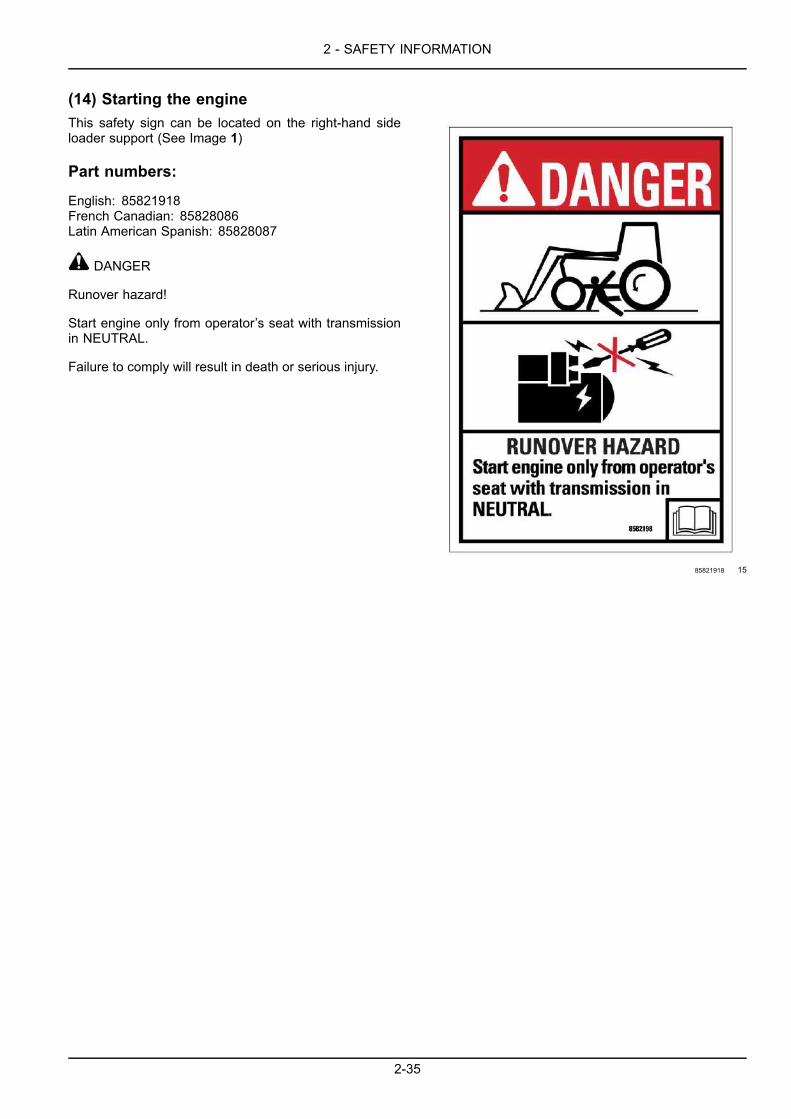
2 - SAFETY INFORMATION
(14) Starting the engineThis safety sign can be located on the right-hand sideloader support (See Image 1)
Part numbers:
English: 85821918French Canadian: 85828086Latin American Spanish: 85828087
DANGER
Runover hazard!
Start engine only from operator’s seat with transmissionin NEUTRAL.
Failure to comply will result in death or serious injury.
85821918 15
2-35

2 - SAFETY INFORMATION
(15) Backhoe attachmentThis safety sign can be located on the right-hand sideloader support (See Image 1)
Part numbers:
English: 85821922French Canadian: 85828080Latin American Spanish: 85828081
DANGER
Crush hazard!
Keep clear
Swinging boom can KILL or Seriously injure.
Do not enter the platform from the rear.
Do not place loose objects inside of cab area.
Start and operate backhoe from operator’s seat ONLY.
Read Operator’s Manual for transport instruction.
Failure to comply will result in death or serious injury.
85821922NA 16
2-36

2 - SAFETY INFORMATION
(16) Precautions for lifting loadsThis safety sign can be located on the left side of the back-hoe boom (See Image 1)
Part numbers:
English: 85821924French Canadian: 85828069Latin American Spanish: 85828070
WARNING
Rollover Crush hazard!
Lifting too heavy a load can cause machine roll over orloss of operator control.
Do not use transport lock while craning to avoid machinedamage and personal injury.
IMPORTANT
• Center and raise boom before engaging or disengagingthe transport lock to avoid vehicle damage.
• Boom may hit raised stabilizer cylinder when swingingto full left or full right
Failure to comply could result in death or serious injury.
85821924 17
(17) StabilizersThis safety sign can be located on the left-hand and theright-hand stabilizers (See Image 1)
Part numbers:
English: 85821927French Canadian: 85828097Latin American Spanish: 85828098
WARNING
Pinch point hazard!
Keep clear.
Failure to comply could result in death or serious injury.
LEEN12T0733BA 18
2-37

2 - SAFETY INFORMATION
(18) Air-conditioning (Optional)This safety sign can be located on the left front side of themachine (See Image 1)
Part numbers:
Pictorial: 85804441
This safety sign indicates that an air-conditioning systemis installed in the machine. The maintenance operationsmust be performed by qualified personnel.
LEEN12T0734BA 19
(19) Air-conditioning (Optional)This safety sign can be located on the left front side of themachine (See Image 1)
Part numbers:
Pictorial: 87324469
CAUTION
Air-conditioning system
Contains “ HFC R134A”. A non ozone depleting refriger-ant and PAG oil. Service, repair or recharging must beperformed by qualified personnel only.
Refrigerant HFC R134A charge 1 kg (2.2 lb)
Failure to comply could result in minor or moderate injury.
LEEN12T0735BA 20
2-38
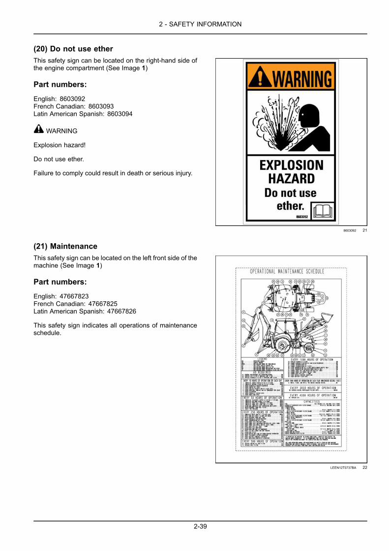
2 - SAFETY INFORMATION
(20) Do not use etherThis safety sign can be located on the right-hand side ofthe engine compartment (See Image 1)
Part numbers:
English: 8603092French Canadian: 8603093Latin American Spanish: 8603094
WARNING
Explosion hazard!
Do not use ether.
Failure to comply could result in death or serious injury.
8603092 21
(21) MaintenanceThis safety sign can be located on the left front side of themachine (See Image 1)
Part numbers:
English: 47667823French Canadian: 47667825Latin American Spanish: 47667826
This safety sign indicates all operations of maintenanceschedule.
LEEN12T0737BA 22
2-39

2 - SAFETY INFORMATION
(22) Support loader lift armsThis safety sign can be located on the right-hand loaderlift arm (See Image 1)
Part numbers:
English: 85821946French Canadian: 85828082Latin American Spanish: 85828083
WARNING
Crush hazard!
Keep clear.
Support loader lift arms during maintenance or repair.
Failure to comply could result in death or serious injury.
LEEN12T0738AA 23
(23) Do not pressure washThis safety sign is located under the engine hood on theleft-hand side and the right-hand side of the fan shroud(See Image 1)
Part numbers:
51512906
IMPORTANT
Do not pressure wash this area. Fan or surrounding area.
51512906 24
2-40

2 - SAFETY INFORMATION
Selective Catalytic Reduction (SCR) decalsOnly fill the DEF/AdBlue® tank with approved
DEF/AdBlue® solution. Do not fill with diesel fuel orwater. Refer to the Operator's Manual.
Quantity: 1English 84284896
84284896_C 1
Location:Near the DEF/AdBlue® fill cap.
RAIL15TLB0021AA 2
Only use Ultra Low Sulfur Diesel (ULSD) fuel.Quantity: 1
English 84319035
84319035_A 3
Location:Near the fuel tank fill cap.
RAIL15TLB0021AA 4
2-41

2 - SAFETY INFORMATION
2-42

3 - CONTROLS AND INSTRUMENTS
3 - CONTROLS AND INSTRUMENTS###_3_###ACCESS TO OPERATOR'S PLATFORM
Access to operator’s platformCAUTIONFall hazard!When entering or exiting the cab, never use the control levers as handholds. Always mount and dis-mount themachine in a safe way. Maintain a three-point contact with steps, ladders, and/or handholds.Failure to comply could result in minor or moderate injury.
C0075B
WARNINGFall hazard!Clean the steps and access handles to remove all traces of grease, oil, mud, and ice (in winter).Failure to comply could result in death or serious injury.
W0139A
Entering the machine:1. Canopy machines proceed to Step 5.2. Use the starter key to unlock the cab door.3. Pull the handle (2) to open the door.4. Fully open the door so that the door grab handle is
within your reach.
WARNINGMoving parts!Make sure all entry and mechanical accessdoors are properly closed before operating themachine.Failure to comply could result in death or se-rious injury.
W0238A RAIL14TLB0456BA 1
5. Use the steps (1) and access handles (2) when enter-ing or leaving the operator’s compartment.
RAIL15TLB0036AA 2
3-1

3 - CONTROLS AND INSTRUMENTS
Cab door windowPartially opened
Raise the handle (1) and push it outwards and downwardsto lock the window in a partially opened position.
Fully opened
With the window closed, raise the handle (1) to the hor-izontal position and then tilt it rearwards to disengage itfrom the pin. Open the window until it engages in the rub-ber locking device.
Closed
Make sure the window handle (1) completely engages inthe lock pin, close the window and then tilt the handledownwards.
MOLI12LBB0134AB 3
Side windowsUse the window handle to open the window until it en-gages in the rubber locking device (1). Pull on the knob(2) to release the window.
NOTICE: Do not leave the windows free to swing but fixthem in latched position.
NOTICE:When opening or closing windows, always holdthem firmly until they are completely locked in position.
MOLI12LBB0135AB 4
3-2

3 - CONTROLS AND INSTRUMENTS
Rear windowOpening the rear window1. Release the rear window pin locks (1). One on each
side.2. Swing the bottom of the window outwards with the both
handles (2).3. Bring the window into horizontal position and lock the
window in position with the latches (3).
NOTICE: Make sure that the window is in a completelylocked position.
Closing the rear window1. Release the latches (3).2. Slowly tilt and lower the window with both handles (2).3. Lock the rear window in the closed position with the
window pin locks (1).
NOTICE: Make sure that the window is in a completelylocked position.
MOLI12LBB0136AB 5
MOLI12LBB0137AB 6
3-3

3 - CONTROLS AND INSTRUMENTS
OPERATOR'S SEAT
Operator's seatTo operate the machine correctly with maximum efficiencyand comfort, check that the operator’s seat and its adjust-ment controls are in good condition and then adjust theseat to suit the operator’s size and weight.
CAUTIONAvoid injury!Before operating the machine, and whenevera new operator takes over, adjust the seat sus-pension to suit the operator’s specific weight.Failure to comply could result in minor ormoderate injury.
C0093A
WARNINGRoll-over hazard!Securely fasten the seat belt. Your machineis equipped with a Roll-Over Protective Struc-ture (ROPS) cab for your protection. The seatbelt can help ensure your safety if it is prop-erly used and maintained. Never wear a seatbelt loosely or with slack in the belt system.Failure to comply could result in death or se-rious injury.
W0376A
NOTE: The seat complies with standard ISO 7096:2000class EM5.
MOLI12LBB0154AA 1
Standard Seat – mechanical suspension
Seat belt
Attach the seat belt, pull and insert the buckle (1) into thesocket (4).
Release the belt, press the button on the socket (3) andretract the seat belt to the resting position.
Armrest angle adjustment
Rotate the knob (2) to set the armrest position inclinewhen in a down position. You may rotate either armrestup or down by lifting or pushing on the armrest.
RAIL18TLB0198BA 2
3-4

3 - CONTROLS AND INSTRUMENTS
Seat back angle adjustment
Adjust the seat back angle. Pull and hold the lever (1)upward, tilt the seat back to obtain the desired positionand then release the lever.
Swing
Lift the lever (2) to rotate the seat between the normaldriving/loader operating position and the backhoe operat-ing position. Release the lever and make sure the seatlocks into position.
RAIL18TLB0192BA 3
Seat fore-and-aft adjustment
Pull up and hold the lever (1) in position, slide the seatback and forth until the desired position is reached andthen release the lever.
Combined height and weight adjustment
Adjust the height and firmness of the seat. Rotate thehandle on the control (3) to obtain the desired height. Ifnecessary use the weight indicator (2) as a guide.
RAIL18TLB0194BA 4
RAIL18TLB0193BA 5
3-5

3 - CONTROLS AND INSTRUMENTS
Deluxe seat – pneumatic suspension with heated seatSeat belt
Pull and insert the buckle (4) into the socket (3).
Press the button (2) on the socket (3) to release thebuckle. Guide the buckle back into position.
Armrest angle adjustment
Rotate the knob (1) to set the armrest position inclinewhen in a down position. You may rotate either armrestup or down by lifting or pushing on the armrest.
RAIL18TLB0199BA 6
Cushion tilt adjustment
Lift handle (1) up and move the cushion to the desireddepth. Release the handle to lock the cushion in place.
Lift up on the handle (2). Move the seat cushion to thedesired angle. Release the handle to lock the cushionangle.
RAIL18TLB0195BA 7
3-6

3 - CONTROLS AND INSTRUMENTS
Heated seat switch
Press the emblem side of the switch (1) to turn onthe heat function. Press the “0” side of the switch to turnoff the heat function.
Lumbar adjustment
Turn the knob (2) to adjust the lumbar back.
Seat back angle adjustment
Adjust the seat back angle. Pull and hold the lever (3)upward, tilt the seat back to obtain the desired positionand then release the lever.
RAIL18TLB0197BA 8
Swing
Lift the lever (1) to rotate the seat between the normaldriving/loader operating position and the backhoe operat-ing position. Release the lever and make sure that theseat locks into position.
Combined height and weight adjustment
Adjust the height and firmness of the seat. Press down onthe lever (3) to reduce the rigidity of the suspension. Pullup on the lever to increase the rigidity of the suspension.With the operator in the seat the indicator (2) will be greenafter the proper adjustments have been made.
RAIL18TLB0196BA 9
3-7

3 - CONTROLS AND INSTRUMENTS
Backrest support extension
Lift up on the backrest extension (1) to the desired posi-tion. Use tab (2) on posts to lower the backrest extension.
RAIL18TLB0200BA 10
3-8
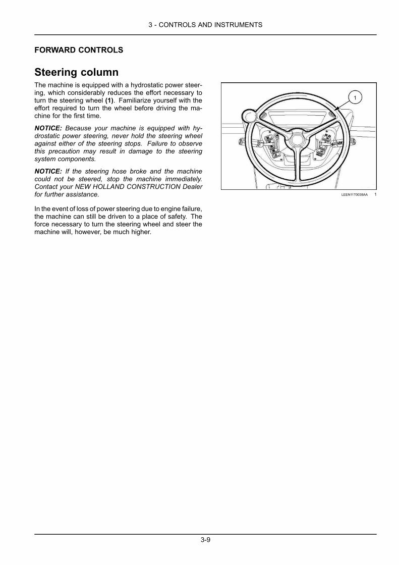
3 - CONTROLS AND INSTRUMENTS
FORWARD CONTROLS
Steering columnThe machine is equipped with a hydrostatic power steer-ing, which considerably reduces the effort necessary toturn the steering wheel (1). Familiarize yourself with theeffort required to turn the wheel before driving the ma-chine for the first time.
NOTICE: Because your machine is equipped with hy-drostatic power steering, never hold the steering wheelagainst either of the steering stops. Failure to observethis precaution may result in damage to the steeringsystem components.
NOTICE: If the steering hose broke and the machinecould not be steered, stop the machine immediately.Contact your NEW HOLLAND CONSTRUCTION Dealerfor further assistance.
In the event of loss of power steering due to engine failure,the machine can still be driven to a place of safety. Theforce necessary to turn the steering wheel and steer themachine will, however, be much higher.
LEEN11T0038AA 1
3-9

3 - CONTROLS AND INSTRUMENTS
Front controls
LEEN11T0010FA 1
(1) Four-Wheel Drive (4WD) switch (optional)Two function switch:
• Power shuttle machines, – Press the blank side to switch for rear wheel drive and braking on rearwheels (for all gears) (control lamp off).
• Powershift machines – Press the blank side to switch for rear wheel drive with braking only on rearwheels (only in first and second gear) (control lamp off); four wheel drive and braking (in third andfourth gear) (control lamp on).
• Press the emblem side of the switch for Four-Wheel Drive (4WD) and braking on all four wheels(control lamp on).
NOTICE: To prevent undue tire wear when traveling on public highways or on any hard surface, disengage 4WD,particularly in 3rd or 4th gear.
(2) Hand-held auxiliary hydraulic attachment switch (Optional)This two position switch:1. Press the blank side of the switch to turn OFF or disable the auxiliary hydraulics (control lamp OFF).2. Press the emblem side to turn ON or enable the auxiliary hydraulic attachments (control lamp ON)..
(3) Blank
(4) Loader attachment lock valve switch (optional)This two position switch:1. First position (control lamp off) condition with blocked valves.2. Second position (control lamp on), by pressing the side with the symbol, the valves are released.
3-10

3 - CONTROLS AND INSTRUMENTS
(5) Rotating beacon switchThis switch has two positions:1. Press the emblem to turn ON the beacon (control lamp off).2. Press the blank side to turn OFF the beacon (control lamp off).
(6) Blank
(7) Blank
(8) Auto or manual shift (optional) - Powershift machines onlyThree position switch
• In situations where manual gearshifting (up or downshift) is required, the automatic gearshift of thepowershift transmission can be overridden with this switch.
• When the manual mode is no longer required, place the switch back to the OFF position to return toautomatic gearshifting.
(9) Horn switch - Powershift machines only• Press the switch to sound the horn.
• Press and hold the switch will sound the horn until the button is released.
(10) Hazard light switchThis switch has two positions button switch:1. Press the emblem to turn ON the hazard lights(control lamp off). Turn signal lights will continuously
flash ON and OFF.2. Press the emblem again to turn OFF the hazard lights (control lamp off).
3-11

3 - CONTROLS AND INSTRUMENTS
Right-hand side control leverLever for direction indicators, main beams, front windshield wiper and washer (cab)Located on the right of the steering wheel, this lever hasfive positions:
Position 0: Neutral.
Position 1: The left-hand direction indicators and the di-rection indicator lamp on the side instrument cluster flashat the same speed.
Position 2: The right-hand direction indicators and the di-rection indicator lamp on the side instrument cluster flashat the same speed.
NOTE: For canopy models the turn signal switch is onthe right-hand side of the steering column. Press up toactivate a left-hand turn. Press down to activate a right-hand turn. The turn signal indicator lamp is in the samelocation as shown.
LEEN11T0041AA 1
Position 3: (Light switch in low beam position) Push thelever downwards to turn on the main beams and the cor-responding indicator lamp.
LEEN11T0042AA 2
Position 4: Turn the knob of the handle counterclockwiseto activate the front windshield wiper.
0 = Stop
I = Normal speed
Position 5: (Momentary action control) Press and holddown the button on the tip of the handle to operate thewindshield washer.
LEEN11T0043AA 3
3-12

3 - CONTROLS AND INSTRUMENTS
Pedal controlsFoot throttle
The foot throttle (1) is under the steering wheel. Use thefoot throttle to increase or decrease engine speed whentraveling. Use the foot throttle to increase or decreasepower for loader operations.
• Press the pedal to increase the engine speed.
• Release the pedal to reduce the engine speed.
NOTE: This pedal is coupled with the hand throttle. Be-fore using the pedal, make sure that the hand throttle is inthe minimum speed position.
NOTICE: Never use this pedal when working with thebackhoe attachment.
MOLI12LBB0125AB 1
Brake pedals
The two brake pedals (1) are equipped with a locking sys-tem (2).
Unlock the brake pedals to assist with turns.
• Press the left-hand pedal to help turn the machine tothe left.
• Press the right-hand pedal to help turn the machine tothe right.
Braking with one pedal only should only be carried out atlow speed.
NOTE: Only use the one pedal braking when traveling atlow speeds. Lock the service brake pedals together foruniform braking and maximum stopping ability.
WARNINGLoss of control hazard!Brake pedals shall be locked together for roadtravel. This ensures uniform brake applicationand maximum stopping ability.Failure to comply could result in death or se-rious injury.
W0308A
To lock the two pedals together, tilt the latch (2) so it en-gages on the right-hand pedal.
MOLI12LBB0128AB 2
3-13

3 - CONTROLS AND INSTRUMENTS
Transmission controlsWARNINGLoss of control hazard!To prevent inadvertent machine movement, take care to avoid accidental contact with the gearshiftlevers. Always stop the engine, firmly apply the parking brake, and place all gearshift levers in neutralbefore leaving the machine.Failure to comply could result in death or serious injury.
W0130A
Power shuttle
RAIL18TLB0066FA 1
(1) Gearshift lever: It is possible to select four forward and four rearward travel speeds.(2) Transmission disconnect button (on gearshift lever): Press and hold when changing gears.(3) Direction control lever: This lever controls the direction the machine will travel.NEUTRAL (N) position, FORWARD (F) travel, or REVERSE (R) travel.
NOTE: In reverse gear an audible alarm device sounds.(4) Horn button: Sounds the horn.(5) Transmission disconnect button (on the backside of the loader control lever): Press and hold, increase theengine speed will provide more power to the loader.
3-14

3 - CONTROLS AND INSTRUMENTS
Manual transmission
The transmission is fully synchronized providing fourforward and four reverse speeds allowing gear ratiochanges on the move. A torque converter is used toconnect the engine to the transmission and the directioncontrol lever (3) enables shifts between forward andreverse travel without disengaging gear ratios.
NOTE: The transmission disconnects when the parkingbrake is ON.
Direction control leverNOTE: Stop the machine from moving before switchingbetween FORWARD and REVERSE travel.
The direction control lever is on the left-hand side ofthe steering column and controls the direction of travelfor the machine.
• The top position (F) is FORWARD. To travel forward, liftthe lever and push completely forward.
• The center position (N) is NEUTRAL. Make sure thatthe direction control lever is in NEUTRAL before youstart the engine or before you operate the backhoe.
• The bottom position (R) is REVERSE. To travel in re-verse, lift the lever and pull completely rearward. Anaudible alarm will sound when in reverse.
NOTE: The engine will not start with the direction controllever in the FORWARD or REVERSE positions.
NOTE: The direction control lever is equipped with aneutral lock to prevent an accidental engagement ofthe transmission. With this design, the direction controllever moves through a “T” slot to the forward or reversepositions.
NOTICE: The direction control lever can be shifted atany engine speed; however, as a safety and precau-tionary measure, the engine must run at approximately1200 RPM.Use the foot accelerator to control engine and groundspeed.
LEEN11T0046AA 2
3-15

3 - CONTROLS AND INSTRUMENTS
Transmission disconnect buttonWARNINGLoss of control hazard!Machines with four-wheel drive engaged ordisengaged should not exceed 50 km/h (31mph) where permitted. Over speeding bytowing or coasting downhill with clutch de-pressed or transmission in neutral may causeloss of control, personal injury to the operatoror bystanders, or mechanical failure.Failure to comply could result in death or se-rious injury.
W0454A
The fully synchronized transmission provides for easy up-ward and downward gear ratio changes on the move.Use the transmission disconnect button to disconnect thepower flow between the engine and transmission. Usethe transmission disconnect button when switch gears orif you need more power during loader operation.
Press and hold the transmission disconnect button (2) onthe gearshift lever (1) to disconnect transmission power.Release the button to engage the transmission.
NOTE: The machine is free to roll when the disconnectbutton is engaged even though the gearshift lever anddirection control lever may be “In Gear”. Use the brakepedals to stop the machine.
NOTICE: Do not use the disconnect switch control tocoast down hill.
LEEN11T0044AA 3
Gearshift lever
The single gearshift lever (1) is used to select any of thefour gear ratios. The transmission disconnect button (2) isdepressed and held as the lever is shifted from one gearto another and then released to reconnect transmissiondrive.
NOTE: The machine is free to roll when the disconnectbutton is engaged even though the gearshift lever anddirection control lever may be “In Gear”.
LEEN11T0044AA 4
3-16

3 - CONTROLS AND INSTRUMENTS
To make upward gear ratio changes1. Press and hold the button (2) on the gearshift lever (1)
while moving the lever from a lower gear to a highergear.
2. Release the button and allow the unit to gain enginespeed and ground speed.
3. Repeat the procedure if necessary.
To make downward gear ratio changes1. Reduce the engine speed.2. Press and hold the button (2) on the gearshift lever (1)
while moving the lever from a higher gear to a lowergear.
3. Release the button and allow the unit to adjust to theengine speed and ground speed.
4. Repeat the procedure if necessary.
NOTICE: Operating the machine in a too high gear orunder a too heavy load will cause the torque converterto slip excessively and overheat. If the machine is over-loaded, the engine speed will not exceed a range of 1800– 2200 RPM at maximum accelerator and the torque con-verter will “stall” bringing the machine to a complete stop.If “stall” does occur, there is still sufficient engine powerto operate the loader attachment; however, to prevent thetransmission from overheating, either reduce the load onthe machine or select a lower gear ratio.
NOTICE: Operating at a “stall” for more than 20 s cancause the transmission to overheat and can possibly dam-age the transmission. If the transmission overheats, theneedle (3) reaches the red field. Shift both the directioncontrol lever and the gearshift lever to neutral. Let the en-gine run idle ( 1000 RPM) until transmission oil cools downenough to have the needle (3) return to correct position.Once the needle is returned to its position, all operationscan be resumed.
RAIL19TLB0004AA 5
3-17

3 - CONTROLS AND INSTRUMENTS
Powershift transmission controls (optional)
RAIL18TLB0067FA 6
(1) Powershift transmission gearshift and direction control lever: This lever controls machine direction and gearselection.(2) Kickdown control: The kickdown control allows the operator to temporarily switch from second gear to first gear,without changing the gear selection control setting.(3) Transmission mode selection switch: Select between manual shift mode or auto-shift mode.(4) Horn button.(5) Transmission disconnect button (on the backside of the loader control lever): press and hold, increase theengine speed will provide more power to the loader.
3-18

3 - CONTROLS AND INSTRUMENTS
Powershift transmission
On powershift transmissions the gear selection control ison the direction control lever on the left-hand side of thesteering wheel.
Direction control leverNOTE: Stop the machine from moving before switchingbetween FORWARD and REVERSE travel.
The direction control lever is on the left-hand side ofthe steering column and controls the direction of travelfor the machine.
• The top position (F) is FORWARD. To travel forward, liftthe lever and push completely forward.
• The center position (N) is NEUTRAL. Make sure thatthe direction control lever is in NEUTRAL before youstart the engine or before you operate the backhoe.
• The bottom position (R) is REVERSE. To travel in re-verse, lift the lever and pull completely rearward. Anaudible alarm will sound when in reverse.
NOTE: The engine will not start with the direction controllever in the FORWARD or REVERSE positions.
NOTE: The direction control lever is equipped with aneutral lock to prevent an accidental engagement ofthe transmission. With this design, the direction controllever moves through a “T” slot to the forward or reversepositions.
LEEN11T0048AA 7
Gear selection
To select a gear, rotate the hand grip to align the numberwith the indicator mark on the control lever. The machineremains in the gear selection until the operator changesthe selection. The operator may select gears withoutstopping the machine.
• (1) First gear: Forward or reverse• (2) Second gear: Forward or reverse• (3) Third gear: Forward or reverse• (4) Fourth gear: Forward only
Engage the auto shift button on the left-hand side of thefront console to allow the Powershift transmission to shiftautomatically. You must select third gear or fourth gearfor auto shift to operate, see 4-20 for more details. Disen-gage auto shift mode to manually shift between gears.
LEEN11T0048AA 8
3-19

3 - CONTROLS AND INSTRUMENTS
Kickdown controlNOTE:Only available on machines with the optional Pow-ershift transmissions.
NOTE: This feature will only activate when in second gear.
Kickdown is used to increase the loader breakout force.The kickdown control lets the operator temporarily switchfrom second gear to first gear, without changing the gearselection control setting. The operator may experience ashort pause or delay before the gear shift occurs.1. Press the button at the end on the control lever to shift
from second to first gear.2. Press the button again to shift back to second gear. LEEN11T0048AA 9
Transmission disconnectionWARNINGLoss of control hazard!Machines with four-wheel drive engaged ordisengaged should not exceed 50 km/h (31mph) where permitted. Over speeding bytowing or coasting downhill with clutch de-pressed or transmission in neutral may causeloss of control, personal injury to the operatoror bystanders, or mechanical failure.Failure to comply could result in death or se-rious injury.
W0454A
Use the transmission disconnect button to disconnectthe power flow between the engine and transmission.1. Press and hold the disconnect button on the backside
of the loader control lever, increase engine speed tosupply the loader with more hydraulic oil for greaterloader power and faster control function.
NOTE: Themachine is free to roll when the disconnectbutton is engaged even though the gearshift lever anddirection control lever may be “In Gear”. Use the brakepedals to stop the machine.
NOTICE: Do not use the disconnect switch control tocoast down hill.
2. Release the disconnect button (1) to engage the trans-mission power.
RAIL18TLB0403BA 10
3-20

3 - CONTROLS AND INSTRUMENTS
RIGHT-HAND SIDE CONTROLS
Key start switchNOTE: The instruments represented may not exactly correspond to the instruments on your machine.
Starter switch keyWARNINGMisuse hazard!Before starting the engine, make sure you arefully aware of the location and the function ofeach control.Failure to comply could result in death or se-rious injury.
W0226A
Located on the right of the operator’s seat (with seat inloader attachment position), this switch has four positions:
Position 1: Not used.
Position 2: Stop.
Position 3: Contact (the audible alarm sounds).
Position 4: Start.
LEEN11T0037AA 1
NOTE: This key can be used to lock the cab doors, theengine guard and the fuel tank plug.
Hand throttleThe hand throttle (1) enables the engine speed to be in-creased or decreased.
NOTICE: Only use the hand throttle to control enginespeed for backhoe operations.
Turn to the to increase the speed.
Turn to the to decrease the speed.
NOTE: Never use the knob (1) during travel on publichighways.
LEEN11T0054AA 2
3-21

3 - CONTROLS AND INSTRUMENTS
Instrument cluster panel – Side
LEEN11T0021FA 1
(1) Front work lightsFront work light switch: This switch has three positions:
• The first position is OFF (control lamp off).
• Second position, by pressing the symbol side (first click) the outer front work lights are turned on(control lamp on).
• Third position, by pressing the symbol side again (second click) the inner front work lights are turnedon too (control lamp on).
(2) Driving lightsDriving light switch: This switch has three positions:
• The first position is OFF (control lamp off).
• Second position, by pressing the symbol side (first click) the instrument cluster panel is powered, theside lights and the low beam indicator lamp are turned on (control lamp on).
• Third position, by pressing the symbol side again (second click) the high beams are enabled and thelow beams and the low beam indicator lamp are turned on (control lamp on).
3-22

3 - CONTROLS AND INSTRUMENTS
(3)Glide Ride™ switch (optional on 2WD models) or Auto-Glide Ride™ switch (Optional on 4WD models)Glide Ride™The Glide Ride™ system control improves the machine comfort during travel, regardless of a full orempty bucket over any type of terrain.It reduces forward and rearward pitching when moving rearwards or forwards and when carrying loads,at the same time increasing productivity and operator comfort.It also reduces impact forces to the machine during operation. Do not use this system while operatingthe loader attachment.Auto-Glide Ride™The Auto-Glide Ride™ system control improves the machine comfort during travel, regardless ofa full or empty bucket over any type of terrain.It reduces forward and rearward pitching when moving rearwards or forwards and when carrying loads,at the same time increasing productivity and operator comfort.It also reduces impact forces to the machine during operation. Do not use this system while operatingthe loader attachment.
This is a three function switch1. Manual ON position. Auto-Glide Ride™ can be left ON at all times, whether loading or roading. Do
not use the ON position while operating the loader attachment or for fine grading operations.2. In the AUTO position, Auto-Glide Ride™ will automatically activate when ground speed is above a
threshold set by the operator. The center position is the automatic and most commonly used position.3. The OFF position. Auto-Glide Ride™ control system is OFF.
NOTE: To change or set the Auto-Glide Ride™ speed thresholds, see “Auto-Glide Ride™ (AGR) speed thresholds- Four-Wheel Drive (4WD) only” 6-11.
(4) Backhoe attachment locking switchBackhoe attachment locking switch:
• The switch is used to lock or unlock the backhoe attachment safety hook in preparation for road travel.
(5) Spring-Applied, Hydraulically-Release (SAHR) brake switchSpring-Applied, Hydraulically-Release (SAHR) brake switch:
• At start up, cycle the switch from the position to the position. Cycle the switch, regardless of theposition the switch was in at startup.
• Press to engage the parking brake (the control lamp on the instrument cluster turns ON).
• Press to release the parking brake (the control lamp on the instrument cluster turns OFF).NOTE: Engage the parking brake before turning off the engine. The parking brake automatically engages when theignition switch is turned off.
(6) Side instrument cluster. See 3-27 for more details.
(7) Up/down switchUp/down switch:
• Press to scroll through the menu or data options shown on the display. The side of the switch youpress determines which way you are scrolling through the menu.
(8) Menu select switch
Use the escape button to return to the previous top menu or escape back to the main screen. Usethe enter button to select specific display screens or store screen-defined configuration settingsto memory.
3-23

3 - CONTROLS AND INSTRUMENTS
(9) Rear windshield wiper and washer switch (cab only)Rear windshield wiper and washer switch: This switch has three positions:
• Press the switch to activate the windshield wiper.
• Press and hold the switch will activate the windshield washer. Release the switch the washer stopsand the wiper operates.
• Press the blank side to turn OFF the wiper.
(10) Combo Auxiliary switch (pilot controls only)Combo Auxiliary switch.:
• Press the top emblem to enable bi-directional auxiliary hydraulics. Use the auxiliary hydraulic control(lever or buttons) for the attachment as normal.
• Press the bottom emblem of the rocker switch to enable uni-directional auxiliary hydraulics. Use theauxiliary hydraulic control (pedal or button) for the attachment as normal.
The auxiliary hydraulic switch enables power for the selected hydraulic flow only. For example, if the switch isenabled for bi-directional control, the uni-directional controls (such as the foot pedal) are disabled. Once the switchis enabled, use the auxiliary hydraulic control for the attachment as normal.
(11) Rear work light switchRear work light switch: This switch has three positions:
• The first position is OFF (control lamp off).
• Second position, by pressing the symbol side (first click) the outer rear work lights are turned on(control lamp on).
• Third position, by pressing the symbol side again (second click) the inner rear work lights are turnedon too (control lamp on).
(12) Blank
(13) Blank
3-24

3 - CONTROLS AND INSTRUMENTS
EXTERIOR CONTROLS
Rotating beacon (Optional)The rotating beacon (1) should be placed on the cab roofand the cable connected to one of the 12 V sockets overthe door on each side of the machine.
NOTICE: The rotating beacon must be installed and op-erated when undertaking road travel
LEEN11T0081AA 1
3-25

3 - CONTROLS AND INSTRUMENTS
Battery master switchNOTICE: Wait at least 60 s after you place the ignitionkey in the OFF position before turning master disconnectswitch to OFF. This allows the machine controllers to shutdown properly.
NOTE: The battery master switch must be switched off atthe end of each working day, for machine service or forany operations on the electrical system.It acts as an anti-theft device when the cab doors andwindows are locked.
Use the master disconnect switch the enable or disableelectrical power from the machine batteries to the electri-cal components. The master disconnect switch (1) is inthe battery compartment.
Turn the master disconnect switch counter-clockwise todisconnect battery power.
Turn the master disconnect switch clockwise to connectbattery power.
NOTICE: Some machine service procedures require anactual terminal disconnect of the batteries. Do not use themaster disconnect switch for those types of procedures,such as welding on the machine.
RAIL15TLB0014AA 1
3-26

3 - CONTROLS AND INSTRUMENTS
INSTRUMENT CLUSTER
Instrument clusterThe vehicle controller, engine controller, and electronic transmission controller, if equipped, on the machine monitorsmachine functions and controls. The control modules also activate warning lamps and audible alarms and displayinformation on the AIC display.
NOTICE: Before starting the machine, turn the key switch to the ON position and wait two seconds before turning thekey switch to the START position. The two second delay is required as it allows the engine controller time to powerup before engine cranking is allowed.
Indicator/warning/danger lampsMachine fault
Warning lamp. Illuminates when amachine fault (vehicle, engine, or electronictransmission controller) has been detected. Aone second audible alarm will sound per keycycle.
RAIL19TLB0004AA 1
Side light and low beam lightsIndicator lamp.Illuminates when the low beam switch is in theON position.Illuminates when the side lamp switches arein the ON position.
RAIL19TLB0004AA 2
Main beam lightsIndicator lamp.Illuminates when the driving lamp switch is inthe ON position.Illuminates when the front and/or rear worklamp switches are in the ON position.
RAIL19TLB0004AA 3
3-27

3 - CONTROLS AND INSTRUMENTS
Direction (turn signal or hazard)Indicator lamp.Illuminates when the turn signals or hazardlights are ON
RAIL19TLB0004AA 4
Low engine oil pressureWarning lamp. Illuminates when, with theengine running, there is no or low oil pressurein the engine. Do not run the engine when thislamp illuminates. A continuous audible alarmwill sound when this condition exists.
RAIL19TLB0004AA 5
Stop engineNOTICE: Always stop the machine and shut down theengine whenever this lamp illuminates. The display willprovide additional information to what the possible faultis.
Danger lamp. Illuminates with a continuousaudible alarm when a critical condition isdetected by the vehicle controller, enginecontroller, or electronic transmission controller,if equipped.
Examples of critical conditions:
• Engine coolant temperature is too high.
• Engine oil pressure is too low or too high.
• Transmission oil pressure is too low.
• Transmission oil temperature is too high.
• Poor DEF/AdBlue® quality.
• Low or no DEF/AdBlue® fluid in the tank.
• After Treatment System (ATS) failure.
• Unauthorized software upgrades (enginede-rate will occur)
• If equipped, the Engine protection shutdownfeature detects a critical error.
RAIL19TLB0004AA 6
3-28

3 - CONTROLS AND INSTRUMENTS
AlternatorWarning lamp. Illuminates when, with theengine running, the alternator is not chargingthe battery.
RAIL19TLB0004AA 7
Parking brakeIndicator lamp. Illuminates when the parkingbrake is set.
RAIL19TLB0004AA 8
Air filter restrictionWarning lamp. Illuminates and a one secondaudible alarm sounds when, with the enginerunning, the air filter element is restricted andrequires service. Clean or replace the primaryfilter and/or replace the secondary filter whenthis lamp illuminates.
RAIL19TLB0004AA 9
Air-conditioning system pressureIndicator lamp. Illuminates when theair-conditioner stops working due to refrigerantpressures that are too high.
RAIL19TLB0004AA 10
3-29

3 - CONTROLS AND INSTRUMENTS
Engine glow plugsIndicator lamp. Illuminates when, with the keyswitch in the ON position, the engine glowplugs are active due to cold temperatures.Wait until the lamp goes off before turning thekey switch to the START position.
RAIL19TLB0004AA 11
Low fuel levelWarning lamp. Illuminates and a one secondaudible alarm sounds when the fuel level islow.
RAIL19TLB0004AA 12
Gauges and metersEngine coolant temperature
Indicates the coolant temperature of theengine. The temperature of the coolant isnormal when the gauge needle is in the greenarea of the gauge. When the gauge needlegoes to the end of the red area (last tick mark),a continuous audible alarm will sound. Stopthe engine and check the level of the coolantin the coolant reservoir, check for debris onthe radiator/oil cooler, and/or check for athermostat that does not operate correctly.
RAIL19TLB0004AA 13
Oil temperature, torque converterIndicates the oil temperature of the torqueconverter. The temperature of the oil is normalwhen the gauge needle is in the green areaof the gauge. When the gauge needle goesto the end of the red area (last tick mark), acontinuous audible alarm will sound.When the gauge needle goes into the redarea, move the direction control lever to theneutral position and run the engine at fullthrottle. If this procedure does not reduce thetemperature of the oil, check the oil level andcheck for obstruction in the radiator and oilcooler.
RAIL19TLB0004AA 14
3-30

3 - CONTROLS AND INSTRUMENTS
TachometerShows the engine speed in Revolutions PerMinute (RPM). Each tick mark on the gauge isequal to 100 RPM. It is recommended that theengine be run in the green area of the gauge.
NOTE: Above the top of the tachometer is a guide fortraveling speeds.
RAIL19TLB0004AA 15
Diesel Exhaust Fluid DEF/AdBlue® levelIndicates the level of DEF/AdBlue® in thereservoir. When the DEF/AdBlue® level islow the instrument cluster will display a refill
symbol.
NOTICE: Low quality DEF/AdBlue® and low DEF/Ad-Blue® fluid levels ofDEF/AdBlue® in the tank will de-ratethe engine. Always maintain high quality fluid and properlevels.
RAIL19TLB0004AA 16
Fuel levelIndicates the level of fuel in the machine.When the fuel level is low, the low fuel levelwarning light also illuminates.
RAIL19TLB0004AA 17
3-31

3 - CONTROLS AND INSTRUMENTS
Menu screen displayDisplay screen
Display screenIn addition to the indicator/warning lamps, the AdvancedInstrument Cluster (AIC) displays information on the dis-play screen. The next few pages describe the standardmenu screens that are used to program machine func-tionality, perform diagnostics, and troubleshooting.
NOTE: Themachine’s electronic controllers communicatewith the Advanced Instrument Cluster (AIC) to notify theoperator of required actions, machine warnings, and as-sist technicians with diagnostics and troubleshooting. Fora list of possible display screen messages not part of thestandard display menu see “Display screen messages”8-22.
RAIL19TLB0004AA 1
Use the two rocker switches on the side console to movethrough the menu screens.
• Escape (1) - Return to the previous top menu or escapeback to the main screen.
• Up arrow (2) - Move backward through the menuscreens.
• Down arrow (3) - Move forward through the menuscreens.
• Enter (4) - Select specific display screens or storescreen-defined configuration settings to memory.
LEEN12T0526FA_4 2
Main screen (engine hour or hourmeter)
On start up, shows the main screen graphic along with themachine hours.
NOTE: You may check the engine hours without the ig-nition key. Press either of the menu selection switchesand the current engine hours will appear in the display for10 s.
RCPH10TLB194AAF 3
3-32

3 - CONTROLS AND INSTRUMENTS
Forward-Neutral-Reverse (F-N-R) sensitivityNOTE: Machines with the optional Powershift transmis-sion only. The factory default setting is 2.
Increase or decrease the sensitivity setting for shiftingbetween Forward-Neutral-Reverse, 1 is least aggressiveand 3 is most aggressive.
NOTE: See “Forward-Neutral-Reverse (F-N-R) shift sen-sitivity” 6-1 for more details.
RCIL10TLB035AAF 4
Display dimmer/brightness
Increase or decease the screen brightness. Four bars aremaximum screen brightness.
NOTE: See “Display brightness” 6-2 for more details.
RCPH10TLB196AAF 5
Service interval
Select the service interval, when reached, displays onthe screen at key up.
• Heavy service hours: 500 – 1000 h at 100 h incre-ments.
• Light service hours: 50 – 500 h at 50 h increments.
NOTE: The screen displays '---' if no service interval isspecified.
RCPH10TLB198AAF 6
Stored fault code
Access the stored fault code information to view reportederror codes, the number of occurrences, and time of lastoccurrence.
RCPH10TLB199AAF 7
3-33

3 - CONTROLS AND INSTRUMENTS
Maximum throttle/cold start idle
Access the Idle Increment screen to adjust the cold startidle and maximum throttle values for special operatingconditions.
NOTE: See “Maximum throttle/Cold start idle” 6-3 formore details.
RCPH10TLB201AAF 8
Machine hardware
Displays machine hardware information.
NOTE: The figure is for example purposes only.
RCPH10TLB422AAF 9
Machine software
Displays machine software information.
NOTE: The figure is for example purposes only.
RCPH10TLB421AAF 10
System battery voltage display
Indicates the condition of the electrical system. The elec-trical system voltage is normal when the display indicatesa voltage range of 11.0 – 15.3 V when the key switch is inthe ON position.
NOTICE:When the charge of the battery is too low or thealternator is not charging enough the display backgroundwill be red in color. Damage to the battery can result if thiscondition continues.
RAIL14TLB1023AA 11
3-34

3 - CONTROLS AND INSTRUMENTS
Throttle sensitivity
Select the sensitivity level for the electronic foot throttle, 1is least aggressive and 3 is most aggressive. Operatorsmay change the electronic throttle sensitivity for workingconditions or personal preference.
NOTE: See “Throttle sensitivity” 6-5 for more details.
RCPH10TLB195AAF 12
Auto engine shutdown time-out
The auto engine shutdown feature allows the operator toprogram the machine to shut down after a set period oftime that the machine is left idle. The default setting is Offbut the operator may enable the feature and set the autoengine shutdown time-out anywhere from 2 – 60 min.
NOTE: The auto engine shutdown time-out feature pro-vides an opportunity for the operator to cancel the shutdown once the display begins the countdown.
See “Auto engine shutdown time-out adjustment” 6-6 fordetails.
RAIL15TLB0066AA 13
Auto engine protection shutdown, ifequipped
The auto engine protection shutdown feature will de-ratethe engine performance or turn off the engine if any oneof the following fault conditions occurs.
• Low engine oil pressure for more than 4 s.• Engine coolant above 110 °C (230 °F) for more than15 s
• Transmission oil above 125 °C (257 °F) for more than15 s
The default setting is On but the operator may choose toturn this feature Off. See 6-9 for details
RAIL14TLB1028AA 14
3-35

3 - CONTROLS AND INSTRUMENTS
Auto-Glide Ride™ (ARC) speed threshold; ifequipped:
Three factory preset speed thresholds available. Speedsare approximate depending on tire size, model, andtransmission type:
• Setting 1 — Ride control activates when the machine ismoving faster than 9.2 km/h (5.7 mph) and deactivateswhen the machine is travelling slower than 7.6 km/h(4.7 mph).
• Setting 2 — Ride control activates when the machine ismoving faster than 9.5 km/h (5.9 mph) and deactivateswhen the machine is travelling slower than 7.9 km/h(4.9 mph).
• Setting 3 — Ride control activates when the machine ismoving faster than 9.9 km/h (6.2 mph) and deactivateswhen the machine is travelling slower than 8.4 km/h(5.2 mph).
Change the speed threshold setting, see “Auto-GlideRide™ (AGR) speed thresholds - Four-Wheel Drive(4WD) only” 6-11 for details.
NOTE: Speed threshold selection does not affect ARC orRide control when ON is selected.
RCPH11TLB001AAD 15
3-36

3 - CONTROLS AND INSTRUMENTS
Selective Catalytic Reduction (SCR) exhaust treatment - OverviewDiesel Exhaust Fluid (DEF)/AdBlue® instrumentation warningATTENTION: The fuel system, exhaust after-treatment system, and engine on your machine are designed and builtto government emissions standards. Tampering by dealers, customers, operators, and users is strictly prohibited bylaw. Failure to comply could result in government fines, rework charges, invalid warranty, legal action, and possibleconfiscation of the machine until rework to original condition is completed. Engine service and/or repairs must bedone by a certified technician only!
Your NEW HOLLAND CONSTRUCTION machine is equipped with a warning system to inform the operator of theDEF/AdBlue® level, system malfunctions, and engine power loss that may result from the SCR system for reducingexhaust emissions.
Warning symbols
Engine power loss occurring SCR failure
DEF/AdBlue® Low DEF/AdBlue® level
Stop engine light Warning/Fault light
During normal operation of your NEW HOLLAND CON-STRUCTIONmachine, the instrument cluster displays theDEF/AdBlue® fluid level (1) at all times.
Warning lights and indicators will be illuminated with awarning on the visual display. The display changes au-tomatically to allow the operator to view the warning indi-cator and display message.
NOTICE: Avoid key-cycles when an active Selective Cat-alytic Reduction (SCR) exhaust treatment error occurs.Key cycles with active errors, will quickly increase thede-rate severity. Once the maximum de-rate level hasbeen reached, the unit will be forced to low idle only. Bestpractice is to move the machine to an area that is easilyaccessible for service or for loading onto a transport vehi-cle.
RAIL19TLB0005AA 1
DEF level inducement displaysDisplay Description Warning lamps and
alarmsCorrective action
DEF/AdBlue® level is less than10% tank volume. No enginepower loss at this level.
One second audiblealarm every 3 minand the DEF gaugeindicator is near or justin the red zone.
Fill DEF/AdBlue® tank.
+
DEF/AdBlue® level is less than5% of tank volume. Moderatetorque reduction and enginespeed reduction will occur. Continuous alarm
and the DEF gaugeindicator is in the redzone.
Fill DEF/AdBlue® tankimmediately. Cycle the keyswitch (or the POWER button)OFF then ON.
3-37

3 - CONTROLS AND INSTRUMENTS
Display Description Warning lamps andalarms
Corrective action
+
DEF/AdBlue® level is empty.Severe torque reduction andengine speed reduction willoccur. Continuous alarm
and the DEF gaugeindicator is on empty..
Fill DEF/AdBlue® tankimmediately. Cycle the keyswitch (or the POWER button)OFF then ON.
DEF quality inducement displaysDisplay Description Warning lamps and
alarmsCorrective action
DEF/AdBlue® quality /concentration is questionable.
One second audiblealarm every 3 min
Drain the DEF/AdBlue® tank.Fill the tank with approvedDEF/AdBlue®. Contact yourauthorized dealer if the failurepersists.
+
DEF/AdBlue® quality /concentration is questionable60 min after the initial warning.Moderate torque reduction andengine speed reduction willoccur.
Continuous alarm
Drain the DEF/AdBlue® tank.Fill the tank with approvedDEF/AdBlue®. Contact yourauthorized dealer if the failurepersists.
+
DEF/AdBlue® quality /concentration is questionable 4 hafter the initial warning. Severetorque reduction and enginespeed reduction will occur. Continuous alarm
Drain the DEF/AdBlue® tank.Fill the tank with approvedDEF/AdBlue®. Contact yourauthorized dealer if the failurepersists.
DEF technical failure inducementDisplay Description Warning lamps and
alarmsCorrective action
SCR fault/failure detected.Torque reduction and enginespeed reduction will occur.
One second audiblealarm every 3 min
Contact your authorized dealerfor repair.
+
SCR fault/failure detected60 min after the initial warning.Moderate torque reduction andengine speed reduction willoccur. Continuous alarm
Contact your authorized dealerfor repair.
+
SCR fault/failure detected 4 hafter the initial warning. Severetorque reduction and enginespeed reduction will occur. Continuous alarm
Contact your authorized dealerfor repair.
3-38

3 - CONTROLS AND INSTRUMENTS
DEF/AdBlue® level faults, failures, and engine power loss levels
NHPH14ENG0567HA 2
3-39

3 - CONTROLS AND INSTRUMENTS
DEF/AdBlue® quality faults, failures, and engine power loss levels
NHPH14ENG0693HA 3
3-40

3 - CONTROLS AND INSTRUMENTS
SCR system technical faults, failures, and engine power loss levels
There are two types of strategies that are applied to your machine based on the type of failure that occurs.
• For electrical failures, use figure 4.• For failures that require the SCR system to be operational, use figure 5 and see the section on validation re-starts.
NOTE: You can restart the engine and receive full engine power up to two times at any point after the machine detectsa fault. However, if the machine detects the same fault within 40 operating hours, torque will be reduced to 50% andthe engine will be reduced to idle immediately. If you attempt a third restart, the engine will be locked at 50% torqueand engine idle. Contact your NEW HOLLAND CONSTRUCTION dealer to reset the engine restart counter andresolve the fault causing the loss of productivity.
3-41

3 - CONTROLS AND INSTRUMENTS
3-42

3 - CONTROLS AND INSTRUMENTS
NHPH14ENG0694JA 4
3-43

3 - CONTROLS AND INSTRUMENTS
NHPH14ENG0566JA 5
3-44

3 - CONTROLS AND INSTRUMENTS
Validation re-starts
Validation re-starts allow operation of the machine for up to 30 min without power loss after a poor DEF/AdBlue®quality or SCR system fault has been detected. Up to three re-starts are permitted. Re-starts are counted ifeither of the following conditions are met:
• Engine speed exceeds 1000 RPM• Engine running time exceeds 5 min
Normal operation will resume if a reset is detected within the 30 min window.
If a reset is not detected within 30 min, power loss will occur as described in the flowcharts.
If all three validation re-starts have been used and the system has not been reset, the machine is limited to 50%torque and engine idle only. See your local authorized NEW HOLLAND CONSTRUCTION dealer for repair.
Follow the sequence in figure 6 to activate validation re-starts.
3-45

3 - CONTROLS AND INSTRUMENTS
NHPH14ENG0568HA 6
3-46

3 - CONTROLS AND INSTRUMENTS
Resetting the Selective Catalytic Reduction (SCR) system
For DEF/AdBlue® storage tank fluid level faults, failures that can cause engine power loss:
• The DEF/AdBlue® tank level must be raised above 12% total volume.
• The key switch must be cycled to the Off position or throttle returned to low idle position.
For DEF/AdBlue® quality and SCR system technical faults, failures that can cause engine power loss:
• To fully reset the system, the component/failure causing the fault must be repaired or replaced.
• Switching off the engine will reset the system and the engine will restart at full power.
• If the same failure is re-detected within 40 h of engine operation, the maximum engine power loss level will beintroduced.
• If the same failure is detected three consecutive times within 40 h of engine operation, maximum engine power losswill remain active after engine restart until the system is repaired.
• Please contact your authorized NEW HOLLAND CONSTRUCTION dealer for service.
3-47

3 - CONTROLS AND INSTRUMENTS
CAB CONTROLS AND ADJUSTMENTS
Cab and platform - Control identificationOperator’s manual storageIn the rear part of the operator’s seat there is a docu-ment storage box (1) where the Operator’s Manual canbe stored.
LEEN11T0064AA 1
Document storage boxUnder the cab roof there is a document storage box (1)where any documents can be stored.
LEEN11T0063AA 2
Operator’s compartment lightThis light is mounted on the roof.
The light turns on when the door opens.
Press OFF to turn off the light when the door is open;press ON to turn on the light when the door is closed.
LEEN11T0065AA 3
3-48

3 - CONTROLS AND INSTRUMENTS
Sun visorUse the tab (1) to pull the sun visor down and place it inthe position required.
Push up the latch (2) to roll up the sun visor.
LEEN11T0066AA 4
Auxiliary 12 V socketAn auxiliary 12 V power socket (1) is located on the cab’sleft-hand post.
LEEN11T0067AA 5
Radio compartment (Optional)On the cab roof there is a compartment (1)where the radiois installed; the radio is provided on demand.
LEEN11T0068AA 6
3-49

3 - CONTROLS AND INSTRUMENTS
Object storage boxLocated on the left-hand side of the cab. This compart-ment (1) is intended for storing objects of various types.
LEEN11T0070AA 7
Front and rear windshield washer reservoirThis reservoir (1) is located on the left-hand side of thecab and has two electric pumps controlled by a switch orby the lever for the direction indicators, main beams, frontwindshield wiper and washer.
NOTE: In cold weather, use a windshield washer with lowtemperature capability.
NOTICE: Never operate the windshield washer when thereservoir is empty, since this may damage the electricpumps.
LEEN11T0069AA 8
3-50

3 - CONTROLS AND INSTRUMENTS
Engine guard handleWARNINGCrushing hazard!Always install the safety lock before workingunder the raised attachment.Failure to comply could result in death or se-rious injury.
W1448A
Open the engine hood:1. Insert the key (1) and turn counter-clockwise.2. Push the key slot on the engine latch to release the
lock (2).3. Use the engine hood lift handles (4), lift, and rotate the
hood (3) into the fully open position.
NOTICE: Before undertaking any road travel, make surethe engine guard is properly locked.
Close and lock the engine hood (figures in reverse order):1. Push the hood down in to the closed position.2. Push the engine latch (2) down into the lock position.3. Insert the key (1) and turn clockwise.
RAIL15TLB0084AA 9
RAIL15TLB0086AA 10
LEEN11T0072AA 11
3-51

3 - CONTROLS AND INSTRUMENTS
Coat hanger hookThe hook (1) fitted on the left-hand cab upright, allows thehanging of possible clothes.
LEEN11T0073AA 12
Air filterThe air filter is located under the operator’s seat.
See 7-73 for the maintenance procedure.
RAIL15TLB0610BA 13
Fire extinguisherDANGERFire hazard!Always have a fire extinguisher on or nearthe machine. Keep the fire extinguisher ingood condition through routine maintenanceand service according to the manufacturer'sinstructions.Failure to complywill result in death or seriousinjury.
D0006A
The fire extinguisher (1) is located to the right of the steer-ing wheel.
On taking delivery of the machine, study the fire extin-guisher operating instructions.
The instructions are printed on the extinguisher.
LEEN11T0077AA 14
3-52

3 - CONTROLS AND INSTRUMENTS
Fuse and relay control unitThe fuse and relay control unit is located under the sideinstrument cluster panel and may be accessed via theright-hand cab door.
The diagnostic socket is located to the left of the fuse andrelay control unit. With this socket, it is possible to haveaccess to the engine data and to detect possible faultswhen connected to the electronic service tool.
LEEN11T0078AA 15
Coded anti-theft switch (Optional)Located on the right-hand console, the switch (1) has ared flashing lamp and makes it possible to disengage theengine anti-start device, using the special electronic key.
If the electronic key is not inserted and you try to start themachine, the display will show an error message after 5seconds.
NOTE: Keep the electronic key with the starter switch key.If all the 5 keys (delivered with the machine] are lost, theycannot be replaced.
LEEN11T0079AA 16
Rearview mirrorsMake sure the right-hand and left-hand rearview mirrors(1) are correctly adjusted before undertaking any travel.
LEEN11T0080AA 17
3-53

3 - CONTROLS AND INSTRUMENTS
LOADER ATTACHMENT CONTROLS
Loader attachment control lever(1) Loader control lever:
Controls the loader attachment movement. See “Loaderattachment controls” 3-55 for more details.
(2) Bucket control, 4-in-1 bucket only:Roll the switch upward to open the bucket (1).Release the switch to stop.
Roll the switch downward to close the bucket(2). Release the switch to stop.
The bucket control switch opens or closes the bucket. Anillustration of the different functions are provided on thedecal with a description.
The bucket control switch can also be adjusted to activatea detent position for specific attachments or working con-ditions. See “Detent position for loader control auxiliaryhydraulics” on 3-59.
RAIL18TLB0403BA 1
(3) Clutch cutout (backside of the loader control lever):
The clutch cutout button lets the engineincrease speed and supply the loader withmore hydraulic oil for greater loader powerand faster control function. When you pushthe clutch cutout button, the transmission isdisengaged from the drive wheels. Releasethe clutch cutout button to engage thetransmission power. The machine can movefreely when the clutch cutout button is pushed.If required, use the service brake to stop themachine.
(4) Differential lock:The differential lock button engages ordisengages the differential lock. To engagethe differential lock, ensure that neither rearwheel is spinning freely and press and holdthe button. Release the button to disengagethe differential lock.
3-54

3 - CONTROLS AND INSTRUMENTS
Loader attachment controlsWARNINGMisuse hazard!Before starting the engine, make sure you arefully aware of the location and the function ofeach control.Failure to comply could result in death or se-rious injury.
W0226A
WARNINGAvoid injury!Before starting the engine, securely fasten theseat belt. The seat belt can help ensure yoursafety if it is properly used and maintained.Never wear a seat belt loosely or with slackin the belt system. Never wear the belt if itis twisted or pinched between the seat struc-tures.Failure to comply could result in death or se-rious injury.
W0142A
With standard loader bucket
Located on the right of the steering wheel, this nine posi-tion lever operates all the loader attachment controls. Thespeed of movement of each control depends on the angleto which the lever is tilted. In the intermediate position,two movements can be obtained simultaneously.
With 4x1 loader bucket
The function of the lever is identical to that of the machinefitted with the standard loader bucket, with the addition ofthe clam control.
3-55

3 - CONTROLS AND INSTRUMENTS
Loader attachment – OperationNeutral and holdWith the lever in the neutral/hold position 0, the attach-ment movement can be stopped. As soon as the lever isreleased, it automatically returns to the neutral position 0and the attachment remains in the position where it waswhen movement stopped.
LEEN12T0554AA 1
Raising the loader attachmentWith the lever in position (1), the attachment rises.
MOLI12LBB0158AB 2
Lowering the loader attachmentWith the lever in position (2), the attachment lowers.
MOLI12LBB0159AB 3
3-56

3 - CONTROLS AND INSTRUMENTS
Loader bucket float controlWith the lever in position (3), the bucket follows the con-tours of the ground without it being necessary to operatethe lever.
NOTE: In this position the lever does not automaticallyreturn to neutral when it is released. It is necessary tomove it manually.
MOLI12LBB0160AB 4
Filling the loader bucketWith the lever in position (4), the bucket rolls back (fills).
MOLI12LBB0161AB 5
Dumping the loader bucketWith the lever in position (5), the bucket rolls forward(dumps).
MOLI12LBB0162AB 6
3-57

3 - CONTROLS AND INSTRUMENTS
Automatic return to loader bucket fillingWith the lever in position (6), the attachment lowers and,simultaneously, the bucket places itself to the digging po-sition.
NOTE: It is possible to adjust the tilt angle for bucket filling.
MOLI12LBB0163AB 7
3-58

3 - CONTROLS AND INSTRUMENTS
Detent position for loader control auxiliary hydraulicsNOTE: Your loader control joystick may not have all options shown.
NOTICE: Continuous hydraulic flow over long periods of time can over heat the hydraulic oil and components.
The switch default configuration is for the switch to spring back to neutral when released from any position. The oper-ator or a service technician may enable a detent position into the loader control auxiliary hydraulic cycle by adjustingthe roller switch.
The detent position will alter the cycle to allow the operator to roll the switch forward into the detent position. Thedetent position will hold open the circuit until the operator rolls the switch out of the detent position.
NOTE: See the attachment manufacturers user guide for operating details. Contact your NEW HOLLAND CON-STRUCTION dealer for a list of approved attachments.
This control operates the opening and closing of the 4x1loader bucket clam.
This control is proportional:
When releasing the roller (7), it automatically returns tothe initial position (neutral) and the bucket remains in theposition where it was when movement stopped.
A. When shifting the roller (7) backward: the loaderbucket clam closes.
B. When shifting the roller (7) forward: the loader bucketclam opens.
MOLI12LBB0164AB 1
Loader control roller detent procedureEnable the detent position for the switch:1. Pry off the cap that covers the switch screw.2. Using a Phillips head screwdriver, remove the screw
(2) that holds the switch (1).
MOLI12LBB0165AB 2
3. Remove the top of the switch (3) .4. Rotate the top of the switch 180° and start the screw
back into the top of the switch.
NOTE: The open U shape should be to the bottom.5. Carefully replace the top of the switch and screw into
position. Do not overtighten.
MOLI12LBB0166AB 3
3-59

3 - CONTROLS AND INSTRUMENTS
6. Test the detent operation:A. Push the switch up. The switch should hold in
place (not spring back to center), as shown.B. Pull the switch out of the detent position.
7. Replace the cap that covers the screw.
NOTE: Take the machine to an open, safe area and testthe switch by moving it through the entire range of motionin both directions.
3-60

3 - CONTROLS AND INSTRUMENTS
BACKHOE ATTACHMENT CONTROLS
Remove the backhoe from the stowed positionWARNINGUnexpected machine movement!Before you use the backhoe attachment, make sure that the machine is resting on the stabilizers.Failure to comply could result in death or serious injury.
W1326A
WARNINGUnexpected machine movement!Pilot controls have two different backhoe controls patterns; before operating the machine, checkwhich control function is active.Failure to comply could result in death or serious injury.
W0185A
WARNINGUnexpected machine movement!With the engine running and only the gear lever in neutral, themachine can engage andmove suddenlyif someone accidentally operates this lever. Place all levers in neutral, disengage the power take-off,lower any implements, and set the parking brake before exiting the machine. Use wheel chocks whenparking on slopes.Failure to comply could result in death or serious injury.
W0057A
NOTE: The instruments represented may not exactly correspond to the instruments on your machine.
NOTE: Before using the backhoe controls, make sure that the operator’s seat is correctly adjusted in the backhoeoperation position.
NOTICE: Do not attempt to use the backhoe if it is in the lock position. Damage of components may occur.
NOTICE: Always place the backhoe in the stowed position when operating the loader or during road transport.
NOTICE: Always install the swing lock pin in the lock position when operating the loader or during road transport.
3-61

3 - CONTROLS AND INSTRUMENTS
Removing the backhoe from the stowed position (mechanical)1. Start the machine.2. Place the direction control lever in NEUTRAL position.3. If applicable, place gearshift control lever in the NEU-
TRAL position.
4. Turn the seat into the backhoe operation position.5. If applicable, open the rear window.6. From the operator’s seat, remove the swing lock pin
and place it in the storage position.
RAIL16TLB1340BA 1
RAIL16TLB1504BA 2
7. Lower the stabilizers to the ground so that the rear tiresare just off the ground.
3-62

3 - CONTROLS AND INSTRUMENTS
8. Move the boom all the way towards you to relievepressure on the boom lock (2).
9. Press the button on the boom lock control lever (1)and move forward to disengage the boom lock.
10. Lower the boom.
RAIL15TLB0050AA 3
RAIL15TLB0051AA 4
11. If applicable, remove the extendable dipper lock pin(1) and place it in the storage position (2).
RAIL15TLB0545BA 5
3-63

3 - CONTROLS AND INSTRUMENTS
Removing the backhoe from the stowed position (hydraulically, if equipped)1. Start the machine.2. Place the direction control lever in NEUTRAL position.3. If applicable, place gearshift control lever in the NEU-
TRAL position.
4. Turn the seat into the backhoe operation position.5. If applicable, open the rear window.6. From the operator’s seat, remove the swing lock pin
and place it in the storage position.
RAIL16TLB1340BA 6
RAIL16TLB1504BA 7
7. Lower the stabilizers to the ground so that the rear tiresare just off the ground.
3-64

3 - CONTROLS AND INSTRUMENTS
8. Place the switch (1) in the OFF position to disengagethe hydraulic boom lock (2) . The indicator lamp (3)(mechanical backhoemodels) or the indicator lamp (4)(pilot backhoe models) turns OFF.
9. Lower the boom.
LEEN11T0311AA 8
RAIL15TLB0547BA 9
MOLI12LBB0249AB 10
3-65

3 - CONTROLS AND INSTRUMENTS
10. If applicable, remove the extendable dipper lock pin(1) and place it in the storage position (2).
RAIL15TLB0545BA 11
3-66

3 - CONTROLS AND INSTRUMENTS
Place the backhoe in the stowed positionWARNINGUnexpected machine movement!Before you use the backhoe attachment, make sure that the machine is resting on the stabilizers.Failure to comply could result in death or serious injury.
W1326A
WARNINGUnexpected machine movement!Pilot controls have two different backhoe controls patterns; before operating the machine, checkwhich control function is active.Failure to comply could result in death or serious injury.
W0185A
WARNINGUnexpected machine movement!With the engine running and only the gear lever in neutral, themachine can engage andmove suddenlyif someone accidentally operates this lever. Place all levers in neutral, disengage the power take-off,lower any implements, and set the parking brake before exiting the machine. Use wheel chocks whenparking on slopes.Failure to comply could result in death or serious injury.
W0057A
NOTE: The instruments represented may not exactly correspond to the instruments on your machine.
NOTE: Before using the backhoe controls, make sure that the operator’s seat is correctly adjusted in the backhoeoperation position.
NOTICE: Do not attempt to use the backhoe if it is in the lock position. Damage of components may occur.
NOTICE: Always place the backhoe in the stowed position when operating the loader or during road transport.
NOTICE: Always install the swing lock pin in the lock position when operating the loader or during road transport.
3-67

3 - CONTROLS AND INSTRUMENTS
Placing the backhoe in the stowed position (mechanical)1. Start the machine.2. Place the direction control lever in NEUTRAL position.3. If applicable, place gearshift control lever in the NEU-
TRAL position.4. Turn the seat into the backhoe operation position.5. Lower the stabilizers to the ground so that the rear tires
are just off the ground.
6. If applicable, fully retract the extendable dipper.7. If applicable, remove the extendable dipper lock pin
from the storage position (2) and place it in the lockposition (1).
8. Roll the dipper arm and attachment inward towards theboom.
RAIL15TLB0545BA 1
9. Retract the boom arm until the boom lock (2) en-gages.
10. Press the button on the boom lock control lever (1)and move it backward to secure the boom lock (2).
RAIL15TLB0052AA 2
RAIL15TLB0048AA 3
3-68

3 - CONTROLS AND INSTRUMENTS
11. If applicable, open the rear window.12. Remove the swing lock pin from the storage location.13. From the operator’s seat, place the swing lock pin in
the lock position.
RAIL16TLB1504BA 4
RAIL16TLB1340BA 5
14. Raise the stabilizers.
3-69

3 - CONTROLS AND INSTRUMENTS
Placing the backhoe in the stowed position (hydraulically, if equipped)1. Start the machine.2. Place the direction control lever in NEUTRAL position.3. If applicable, place gearshift control lever in the NEU-
TRAL position.4. Turn the seat into the backhoe operation position.5. Lower the stabilizers to the ground so that the rear tires
are just off the ground.
6. If applicable, fully retract the extendable dipper.7. If applicable, remove the extendable dipper lock pin
from the storage position (2) and place it in the lockposition (1).
8. Roll the dipper arm and attachment inward towards theboom.
RAIL15TLB0545BA 6
3-70

3 - CONTROLS AND INSTRUMENTS
9. Raise the boom10. Place the switch (1) in the ON position to engage
the hydraulic boom lock (2) . The indicator lamp (3)(mechanical backhoe models) or the indicator lamp(4) (pilot backhoe models) turns ON.
LEEN11T0311AA 7
RAIL15TLB0547BA 8
MOLI12LBB0249AB 9
3-71

3 - CONTROLS AND INSTRUMENTS
11. If applicable, open the rear window.12. Remove the swing lock pin from the storage location.13. From the operator’s seat, place the swing lock pin in
the lock position.
RAIL16TLB1504BA 10
RAIL16TLB1340BA 11
14. Raise the stabilizers.
3-72

3 - CONTROLS AND INSTRUMENTS
Backhoe attachment mechanical controls versionStabilizer mechanical controls
WARNINGUnexpected machine movement!Before you use the backhoe attachment, make sure that the machine is resting on the stabilizers.Failure to comply could result in death or serious injury.
W1326A
Left-hand stabilizer control lever
This lever (A) has three positions:
Position “0”: Neutral. This position stops the movement ofthe left-hand stabilizer. As soon as the lever is released,it automatically returns to the neutral position “0” and theleft-hand stabilizer stops raising or lowering.
Position “1”: The left-hand stabilizer lowers.
Position “2”: The left-hand stabilizer rises.
Right-hand stabilizer control lever
This lever (B) has three positions:
Position “0”: Neutral. This position stops the movement ofthe right-hand stabilizer. As soon as the lever is released,it automatically returns to the neutral position “0” and theright-hand stabilizer stops raising or lowering.
Position “1”: The right-hand stabilizer lowers.
Position “2”: The right-hand stabilizer rises.
NOTE: To raise or lower the two stabilizers at the sametime, operate the two levers simultaneously.
NOTICE: Before machine travel or before using theloader attachment, make sure the stabilizers are com-pletely raised.
LEEN12T0556AA 1
Backhoe mechanical control configurations
These control levers are used to operate the backhoe at-tachment. The speed of movement of each control de-pends on the angle to which the lever is tilted. In the in-termediate position, two movements can be obtained si-multaneously.
Four backhoe attachment control configurations exist,depending on the country concerned:
• Standard configuration
• ISO configuration
• Four lever pattern configuration
• Cross-pattern configuration
The operating pattern of the control levers is different.Check which configuration you have on your machine.
3-73

3 - CONTROLS AND INSTRUMENTS
Standard configuration
Left-hand control lever (boom and swingcontrol)
This lever has five positions and is equipped with a hornbutton (J):
Position “0”: Neutral/hold. This position enables the at-tachment movement to be stopped. As soon as the leveris released, it automatically returns to the neutral position“0” and the attachment remains in the position where itwas when movement stopped.
Position “A”: The boom lowers.
Position “B”: The boom rises.
Position “C”: The backhoe attachment swings to the left.
Position “D”: The backhoe attachment swings to the right.
Right-hand control lever (dipper and bucket/attachment control)
This lever has five positions:
Position “0”: Neutral/hold. This position enables the at-tachment movement to be stopped. As soon as the leveris released, it automatically returns to the neutral position“0” and the attachment remains in the position where itwas when movement stopped.
Position “E”: The backhoe dipper extends.
Position “F”: The backhoe dipper retracts.
Position “G”: The backhoe bucket closes.
Position “H”: The backhoe bucket opens.
3-74

3 - CONTROLS AND INSTRUMENTS
LEEN12T0557HA_1 2
Standard configuration
3-75

3 - CONTROLS AND INSTRUMENTS
ISO configurationLeft-hand control lever (dipper and bucket/attachment control)
This lever has five positions and is equipped with a hornbutton (J):
Position “0”: Neutral/hold. This position enables the at-tachment movement to be stopped. As soon as the leveris released, it automatically returns to the neutral position“0” and the attachment remains in the position where itwas when movement stopped.
Position “A”: The backhoe dipper extends.
Position “B”: The backhoe dipper retracts.
Position “C”: The backhoe attachment swings to the left.
Position “D”: The backhoe attachment swings to the right.
Right-hand control lever (boom and swingcontrol)
This lever has five positions:
Position “0”: Neutral/hold. This position enables the at-tachment movement to be stopped. As soon as the leveris released, it automatically returns to the neutral position“0” and the attachment remains in the position where itwas when movement stopped.
Position “E”: The boom lowers.
Position “F”: The boom rises.
Position “G”: The backhoe bucket closes.
Position “H”: The backhoe bucket opens.
3-76

3 - CONTROLS AND INSTRUMENTS
LEEN12T0558HA_1 3
ISO configuration
3-77

3 - CONTROLS AND INSTRUMENTS
Four-lever pattern configuration
Lever (1) for dipper
This lever has three positions and is equipped with ahorn button (J):Position “0”: Neutral/hold. This position enables theattachment movement to be stopped. As soon as thelever is released, it automatically returns to the neutralposition “0” and the attachment remains in the positionwhere it was when movement stopped.Position “A”: The backhoe dipper extends.Position “B”: The backhoe dipper retracts.
Lever (2) for boom
This lever has three positions:Position “0”: Neutral/hold. This position enables theattachment movement to be stopped. As soon as thelever is released, it automatically returns to the neutralposition “0” and the attachment remains in the positionwhere it was when movement stopped.Position “C”: The boom rises.Position “D”: The boom lowers.
Lever (3) for backhoe bucket
This lever has three positions:Position “0”: Neutral/hold. This position enables theattachment movement to be stopped. As soon as thelever is released, it automatically returns to the neutralposition “0” and the attachment remains in the positionwhere it was when movement stopped.Position “E”: The backhoe bucket closes.Position “F”: The backhoe bucket opens.
Lever (4) for backhoe attachment swing
This lever has three positions:Position “0”: Neutral/hold. This position enables theattachment movement to be stopped. As soon as thelever is released, it automatically returns to the neutralposition “0” and the attachment remains in the positionwhere it was when movement stopped.Position “G”: The backhoe attachment swings to theright.Position “H”: The backhoe attachment swings to theleft.
3-78

3 - CONTROLS AND INSTRUMENTS
LEEN12T0559GA_1 4
Four-lever pattern configuration
3-79

3 - CONTROLS AND INSTRUMENTS
Cross-pattern configurationLeft-hand control lever (boom and swingcontrol)
This lever has five positions and is equipped with a hornbutton (J):
Position “0”: Neutral/hold. This position enables the at-tachment movement to be stopped. As soon as the leveris released, it automatically returns to the neutral position“0” and the attachment remains in the position where itwas when movement stopped.
Position “A”: The boom lowers.
Position “B”: The boom rises.
Position “C”: The backhoe attachment swings to the left.
Position “D”: The backhoe attachment swings to the right.
Right-hand control lever (dipper and bucket/attachment control)
This lever has five positions:
Position “0”: Neutral/hold. This position enables the at-tachment movement to be stopped. As soon as the leveris released, it automatically returns to the neutral position“0” and the attachment remains in the position where itwas when movement stopped.
Position “E”: The backhoe dipper extends.
Position “F”: The backhoe dipper retracts.
Position “G”: The backhoe bucket closes.
Position “H”: The backhoe bucket opens.
3-80

3 - CONTROLS AND INSTRUMENTS
LEEN12T0560HA_1 5
Cross-pattern configuration
3-81

3 - CONTROLS AND INSTRUMENTS
Telescopic dipper mechanical control pedal(if fitted)NOTE: Make sure that the telescopic dipper lock pin is inthe storage position.
This pedal (A) has three positions:
Position “0”: Neutral. This position enables themovementof the telescopic dipper to be stopped.
The pedal automatically returns to this position as soonas it is released.
Position “1”: The telescopic dipper extends.
Position “2”: The telescopic dipper retracts.
NOTE: Operating the backhoe attachment control leversand this pedal simultaneously will enable numerous pos-sibilities of progressive functioning.
RAIL16TLB0502AA 6
Auxiliary attachment control pedal (optional)
This pedal (A) is located to the right of the backhoe at-tachment controls and is used for operating auxiliary at-tachment, such as a hydraulic hammer.
NOTE: You may choose to unplug and store the pedalwhen not in use.
RAIL16TLB0502AA 7
3-82

3 - CONTROLS AND INSTRUMENTS
Backhoe attachment hydraulic controls
MOLI12LBB0178FB 1
1. Control enable switch: With this switch in the ON(lamp on) position, all backhoe attachment hydrauliccontrols are functional.
2. Left-hand hydraulic control lever: The left-hand hy-draulic control lever controls attachment swing andthe boom or the dipper (depending on the control pat-tern adopted).
3. Right-hand hydraulic control lever: The right-handhydraulic control lever controls the bucket and theboom or the dipper (depending on the control patternadopted).
NOTE: The operating speed depends on the angleof movement of the control levers. In intermediateposition, two movements may be obtained simulta-neously.
4. Stabilizer controls: The right-hand control is for theright-hand stabilizer and the left-hand control is forthe left-hand stabilizer.
5. Control pattern change switch: This switch is usedfor changing the standard control pattern to the ISOpattern.
6. Telescopic dipper controls (proportional controls):Press the right-hand button to extend the telescopic
dipper. Press the left-hand button to retract thetelescopic dipper.
7. Wrist rests: The wrist rests may be adjusted to therequired height.
8. Hydraulic control lever support angle adjustment:These controls are used for the fore/aft and left/rightadjustment of the arm.
9. Horn button (Momentary action control).10. Controls of auxiliary bi-directional attachment (If fit-
ted): Proportional buttons for the activation of the ad-ditional attachment.
11. Controls of auxiliary uni-directional attachment (onebutton operation) (If fitted): Proportional button forthe activation of the additional attachment.
12. Decelerator button: By pressing this button, the en-gine rpm sets to low idle. During this phase, the ac-celerator knob and pedal are disabled.By pressing the button again, the engine rpm is re-stored and the accelerator knob and pedal are func-tional again.
3-83

3 - CONTROLS AND INSTRUMENTS
Control enable switch
This control is located on the right-hand control lever.
This switch has three positions:
• Position OFF: (Lamp off) all controls will deactivate.
• Position “1”: By pressing the upper side (lamp off), thestabilizers will activate.
• Position “2”: By pressing the upper side (lamp on)again, all controls will activate.
WARNINGUnexpected machine movement!After using the attachment and before leav-ing the machine, deactivate all the controls bymoving the control enable switch to the OFFposition.Failure to comply could result in death or se-rious injury.
W1327A
NOTE: When the engine is started, the backhoe controlwill default to either OFF or “1” depending on the switchposition.
MOLI12LBB0179AB 2
Control pattern change switch (Boom or dip-per)
Located on the right-hand hydraulic control lever, thisswitch is fitted with a locking device.
The switch is used to change from standard pattern to ISOversion, or vice versa.
To unlock the switch, push the locking device upwards andat the same time press the top of the switch (1). In thisposition, the switch turns on and the controls are in ISOpattern.
The boom and dipper controls on the hydraulic controllevers are now inverted.
Press the bottom of the switch (1) to lock and return tostandard pattern operation.
MOLI12LBB0180AB 3
3-84

3 - CONTROLS AND INSTRUMENTS
Backhoe attachment hydraulic controls
Standard configuration
Backhoe boom and backhoe attachment swing left-handhydraulic control lever.
This hydraulic control lever has five positions:
Position “0”: Neutral/hold. This position enables the at-tachment movement to be stopped. As soon as the hy-draulic control lever is released, it automatically returns tothe neutral position “0” and the attachment remains in theposition where it was when movement stopped.
Position “A”: The boom lowers
Position “B”: The boom rises
Position “C”: The backhoe attachment swings to the left
Position “D”: The backhoe attachment swings to the right
MOLI12LBB0181AB 4
Backhoe dipper and backhoe bucket right-hand hydrauliccontrol lever
This hydraulic control lever has five positions:
Position “0”: Neutral/hold. This position enables the at-tachment movement to be stopped. As soon as the hy-draulic control lever is released, it automatically returns tothe neutral position “0” and the attachment remains in theposition where it was when movement stopped.
Position “E”: The backhoe dipper extends.
Position “F”: The backhoe dipper retracts.
Position “G”: The backhoe bucket closes.
Position “H”: The backhoe bucket opens.
MOLI12LBB0182AB 5
3-85

3 - CONTROLS AND INSTRUMENTS
Stabilizer hydraulic controls
WARNINGUnexpected machine movement!Before you use the backhoe attachment, makesure that the machine is resting on the stabi-lizers.Failure to comply could result in death or se-rious injury.
W1326A
These controls are located on the left-hand hydraulic con-trol lever and may be operated independently or simulta-neously. These controls are proportional, and therefore,the stabilizer speed may vary.
Left-hand stabilizer left-hand control lever
This lever has four positions:
Position “0”: Neutral. This position stops the movementof the left-hand stabilizer. As soon as the lever is releasedfrom positions “1” or “2”, it automatically returns to the neu-tral position “0” and the left-hand stabilizer stops raising orlowering.
When held in position “1”: The left-hand stabilizer lowers.
When held in position “2”: The left-hand stabilizer rises.
Position “3”: Stabilizer auto-up feature (optional). MOLI12LBB0183AB 6
Right-hand stabilizer right-hand controllever
This lever has four positions:
Position “0”: Neutral. This position stops the movementof the right-hand stabilizer. As soon as the lever is re-leased from positions “1” or “2”, it automatically returns tothe neutral position “0” and the right-hand stabilizer stopsraising or lowering.
When held in position “1”: The right-hand stabilizer low-ers.
When held in position “2”: The right-hand stabilizer rises.
Position “3”: Stabilizer auto-up feature (optional).
MOLI12LBB0184AB 7
3-86

3 - CONTROLS AND INSTRUMENTS
Auto-up feature (Optional)
Position “3”: When the levers aremomentarily pulled backto this position and then released, they return to the neu-tral position and the stabilizers automatically rise to roadtravel position, there by leaving your hand free for otherduties. To stop the automatic rise at any time, push or pullthe levers; the rise of the stabilizers stops.
NOTE: The machines not provided with the optionalauto-up feature still have the relevant detent position, butthis does not affect the stabilizer operation in any way.
NOTICE: Before machine travel or before using theloader attachment, make sure the stabilizers are com-pletely raised.
NOTICE: During road travel, the stabilizers must be com-pletely raised and immobilized by means of the pins pro-vided for that purpose.
MOLI12LBB0185AB 8
Telescopic dipper controls (If fitted)
Press and hold down the right-hand button (1) to extendthe telescopic dipper. As soon as the button is releasedthe dipper stops and remains in the position it occupiedwhen the button was released.
Press and hold down the left-hand button (2) to retract thetelescopic dipper. As soon as the button is released thedipper stops and remains in the position it occupied whenthe button was released.
By pressing button (3), it is possible to set the engine rpmto idle run disabling accelerator handle and acceleratorpedal. By pressing again button (3) the engine rpm arerestored and the accelerator handle and accelerator pedalas well.
Before using these controls, make sure the telescopic dip-per is mechanically unlocked.
NOTE: Operating the backhoe attachment control leversand these controls simultaneously will enable numerouspossibilities of progressive functioning.
MOLI12LBB0186AB 9
3-87

3 - CONTROLS AND INSTRUMENTS
Auxiliary uni-directional controls (If fitted)
Press and hold the left-hand proportional button (1) to ac-tivate the attachment hydraulic oil flow.
NOTE: The left-hand proportional button (2) is inoperablewith Uni-driectional option.
MOLI12LBB0187AB 10
Auxiliary bi-directional controls (If fitted)
Press and hold the left-hand button (1) to let the oil flowout of the left-hand side of the boom.
Press and hold the left-hand button (2) to let the oil flowout of the right-hand side of the boom.
MOLI12LBB0187AB 11
Hydraulic control lever support adjustments
Fore and aft
Squeeze the two levers (1), then tilt the hydraulic controllevers to the desired position.
Once the desired position is reached, release the twolevers (1).
MOLI12LBB0188AB 12
Left and right
Loosen the two knobs (2) located in front of each hydrauliccontrol lever support, then tilt the supports to the requiredposition.
Once the adjustment has been carried out, tighten the twoknobs (2).
MOLI12LBB0189AB 13
3-88

3 - CONTROLS AND INSTRUMENTS
CLIMATE CONTROLS
Heating and air-conditioning controlsThe Heating, Ventilation, and Air-Conditioning (HVAC) controls are located on the right-hand side of the cab (opera-tor’s seat in loader attachment position).
Ventilation controlsNOTE: The fan control knob circulates the air inside thecab and does not heat or cool the cab air. Use the heatercontrol knob or optional Air-Conditioning knob to controlcab temperatures.
The four position fan control knob allows the operator tocontrol the air flow inside the cab.
Position 0: Off.
Position 1: Low fan speed.
Position 2: Medium fan speed.
Position 3: High fan speed. RAIL15TLB0536AA 1
Air recirculation with rotary knob (ifequipped)
The air recirculation rotary knob (1) is on the frontright-hand side of the seat base.
• Move the rotary knob (1) clockwise so that it is in avertical to position (3). This will recirculate the air insidethe cab. Minimal air is pulled in from the outside.
• Move the rotary knob (1) counter-clockwise so that it isin a horizontal position (2). This will pull more air intothe cab from outside the cab. Minimal air in the cab isrecirculated.
RAIL15TLB0548BA 2
3-89

3 - CONTROLS AND INSTRUMENTS
HeatingHeater coolant shutoff valve
The heater coolant shutoff valve controls the flow of hotcoolant to the heater.
• In warm ambient temperatures, turn the shutoff valve(1) clockwise to stop hot coolant flow to the heater.
• In cold ambient temperatures, turn the shutoff valve (1)counter-clockwise to allow hot coolant to flow to theheater.
NOTE: In order to use the cab heater, the heater valvemust be in the open position.
RAIL16TLB0369BA 3
MOLI12LBB0190AB 4
Use the temperature control (1) knob to control the tem-perature inside the cab when the heater valve is open.
NOTE: The heater function is OFF when the fan controlknob (2) is in the 0 position.
Turn the temperature control (1) knob clockwise for awarmer temperature setting (red area).
Turn the temperature control (1) knob counter-clockwisefor a colder temperature setting (blue area).
RAIL15TLB0536AA 5
3-90

3 - CONTROLS AND INSTRUMENTS
Air-Conditioning system (Optional)
WARNINGExplosion hazard!Air-conditioning refrigerant boils at -12 °C (10 °F)!-NEVER expose any part of the air-conditioning system to a direct flame or excessive heat.-NEVER disconnect or disassemble any part of the air-conditioning system.Discharging refrigerant gas into the atmosphere is illegal in many countries.Failure to comply could result in death or serious injury.
W0340A
WARNINGEscaping refrigerant may cause frostbite!If you get refrigerant on your skin:-Warm the area with your hand or lukewarm water, 32 - 38 °C (90 - 100 °F).-Cover the area loosely with a bandage to protect the area and the prevent infection.-Seek medical assistance immediately.Failure to comply could result in death or serious injury.
W0341A
WARNINGEscaping refrigerant may cause frostbite!Always wear protective goggles when handling refrigerant. If you get refrigerant in your eye, immedi-ately flush your eyes with water for 15 minutes. Seek medical assistance immediately.Failure to comply could result in death or serious injury.
W0339A
When using the air-conditioning, it is essential that all thewindows of the operator’s compartment are completelyclosed.
To ensure correct operation and full efficiency of the air-conditioning system, it must be used at least once a week,even for a short time.
HFC R134A refrigerant
For technical details, see the decal located on the rightside of the cooler.
LEEN11T0332AA 6
3-91

3 - CONTROLS AND INSTRUMENTS
Climate controls with Air-Conditioning (A/C) (optional)Activate the Air-Conditioning system:1. Start the machine.2. Turn the fan control knob (3) to one of the three fan
speed settings.3. Turn the A/C ON/OFF switch t (2) o the ON position.
NOTE: The A/C symbol (4) on the instrument clusterwill illuminate when the A/C is On.
4. Turn the Air-Conditioning (A/C) temperature controlknob to the desired temperature. Turn the knob clock-wise for warmer air or counter-clockwise for cooler air.
5. Allow the A/C to operate for a few minutes and thenadjust the temperature and fan controls to the desiredsettings.
RAIL15TLB0537AA 7
RAIL19TLB0004AA 8
3-92

3 - CONTROLS AND INSTRUMENTS
Cab air louversAir flow diffusers are connected to the heater system andreceive air from the blower, to direct warm or cold air ontothe windshield and side windows or to the cab interior asrequired.
You can swivel each diffuser to adjust and control the air-flow.
To open a diffuser, press one side of the disc and turn it,as required, to direct the air flow.
The diffusers are located as follows:
• Two on the top of the front control panels (A);• Two to the rear of the seat (C);• Two under the seat, one in front, the other on the rear(D);
• Two on the cab posts, right and left (B);• Two on the ceiling, in front and back of operator’s head(E).
NOTE: The diffusers (B) and (E) are mounted onlywhen air-conditioning system (optional) is fitted.
LEEN11T0002BA 1
LEEN11T0336AA 2
3-93

3 - CONTROLS AND INSTRUMENTS
3-94

4 - OPERATING INSTRUCTIONS
4 - OPERATING INSTRUCTIONS###_4_###COMMISSIONING THE UNIT
Before using the machineNOTICE: Read and familiarize yourself with the instruc-tions and warnings shown in this manual before operatingthe machine.
Before using the machine, some precautions are neces-sary.
Check the levels (engine oil, hydraulic fluid and coolantfluid) and make sure that the various fluids correspond tothe conditions of use.
Carry out the daily maintenance operations.
Walk round the machine, look for any leaks and inspectthe hoses. Tighten or replace any items as required.
Before undertaking road travel, unlock the attachments,completely raise the stabilizers and install the safety sys-tems required by the regulations.
Before road travel or night work, check that the lightingand signaling systems are correctly operating and cor-rectly adjusted.
Check the condition of the tires and the tire pressure.
Clean the steps and access handles.
The presence of oil, mud or ice (winter) can cause acci-dents.
Make sure that the safety signs are always clean.
Clean or replace safety signs which are no longer legible.
Make sure that the engine tilt hood is closed and latchedcorrectly.
Remove anything which might hinder visibility. Clean thewindows and the rearview mirrors.
Make sure that no objects or tools are left on the machineor in the operator’s compartment.
Make sure you know how to evacuate the machine (emer-gency exit via the right-hand door) in case exit through theleft-hand door is impossible.
Make sure that the right-hand door is not locked.
Make sure that nobody is under or on the machine.
The operator should be the only person on the machine.
Make sure that nobody is within the working range of themachine.`
4-1

4 - OPERATING INSTRUCTIONS
Operating the machineWARNINGDriving hazard!Check all controls and safety devices in a safe,open area before starting work.Failure to comply could result in death or se-rious injury.
W0248A
When using the machine, follow the safety precautionsmentioned in this manual.
Start the engine taking into account weather conditions.
Regularly check the hourmeter on the side instrument dis-play to ensure servicing intervals are observed.
If you use the machine under particularly severe condi-tions (dusty or corrosive atmosphere, etc.), reduce theservice intervals.
Make sure that the operator’s seat is correctly adjustedand positioned.
Never operate any control or driving component unlessyou are seated correctly in the operator’s seat with theseat belt adjusted and attached correctly.
WARNINGInhalation hazard! Risk to operators and by-standers.Avoid running the engine in confined areas.Make sure there is adequate ventilation at alltimes.Failure to comply could result in death or se-rious injury.
W0156A
NOTICE: Dust, smoke or fog can reduce visibility andmay cause an accident. Stop or slow down the machineuntil normal visibility is restored.
If there is any operating problem, immediately lower theloader equipment to the ground, engage the parkingbrake and stop the engine.
Find the cause or inform responsible persons and take thenecessary measures to forbid the use of the machine.
When stopping the engine take account of weather con-ditions. See page 4-15.
When parking the machine, see page 4-26.
When loading the machine onto the trailer, see page 5-7.
When towing the machine, see page 5-10.
Road operationNOTICE: Road speed is subject to restrictions accordingto the country. It is the operator’s responsibility to followthe road speed limitations.
Before carrying out any road travel, lock the attachmentsand install the safety systems required by regulations.
The machine must be within the maximum dimensionspermitted on the road in accordance with local road trafficregulations.
Completely raise the stabilizers.
Check that the lighting and signaling systems operate cor-rectly.
Check that the brakes and steering operate correctly.
Check the condition of the tires and the tire pressure.
Never leave the operator’s compartment when the engineis running.
Never use the differential lock.
Job site operation
On job sites on the public highway, use regulation signals,taking into account the working range of the machine.
Local regulations define the number, type and location ofreflective strips.
Be vigilant, be aware of places where other persons areworking close to your working area.
NOTICE: Keep other persons away from the machine.Serious physical injury can result if these instructions arenot observed.
Adapt your driving style to suit the conditions of work(sloping ground or rough ground), the state of the roadand weather conditions.
Operate all controls consistently so the machine workssmoothly.
When traveling at right angles to the slope keep the loaderbucket at ground level.
When traveling in the same direction as the slope, moveonto the slope in low gear (first gear). Never travel down-hill with the gearshift lever in neutral position.
When working on a slope, engage the front drive axle(4WD) if equipped.
NOTICE: Holes, obstacles, debris and other hazards inthe working area can cause serious physical injury. Al-ways walk around and identify all possible hazards beforeoperating the machine in a new working area.
Make sure you know the location of underground pipes orcables before beginning work.
4-2

4 - OPERATING INSTRUCTIONS
NOTICE: Electrical cables, gas pipes, water pipes orother underground installations can cause serious physi-cal injury.
Do not work close to live overhead electric lines with-out first making sure that the minimum distances are ob-served: 5 m (16.4 ft).
4-3

4 - OPERATING INSTRUCTIONS
Run in period of a new machineDuring the first 20 h of operation (new machine or after an engine rebuild), make sure that you:
• Operate the machine with normal loads for the first 8 h.• Do not work the engine hard at stall speeds (wheels slowly turning or stopped and the engine running at full throttle).
• Keep the engine at normal operating temperature.
• Do not run the engine at idle speeds for long periods of time.
• Operating the machine at low idle for prolonged periods, increases the frequency of the Selective Catalyst Reduc-tion (SCR) cleaning process (hydrocarbon management).
• Perform the maintenance procedures listed in the maintenance chart: “Initial 10 hours”, “Every 10 hours or daily”,and the “Initial 20 hours”. If any abnormalities are found contact your NEW HOLLAND CONSTRUCTION dealerimmediately.
After the first 50 operating hours
After the first 50 operating hours, consult your NEW HOLLAND CONSTRUCTION dealer for the 50 h maintenanceinterval.
4-4

4 - OPERATING INSTRUCTIONS
STARTING THE UNIT
Before starting the engineWARNINGInhalation/asphyxiation hazard!Make sure there is proper ventilation before starting the engine.Failure to comply could result in death or serious injury.
W0091A
WARNINGHazard to bystanders!Before you start the engine, make sure that the area surrounding the machine is clear of all persons,and that the backhoe swing lock pin is in the LOCK position.Failure to comply could result in death or serious injury.
W1449B
DANGERAvoid injury!Starting in gear can cause death. Start the engine only from the operator's seat with the transmissioncontrol(s) in neutral.Failure to comply will result in death or serious injury.
D0114A
NOTE: See the “Maintenance Chart” 7-23 for more details on the specific procedures in the following list.
Starting for the first time
Before you start the engine for the first time:
• Make sure the machine is properly lubricated and greased.
• Check the engine oil level, engine coolant level, and transmission oil.
• Check that the machine fuel tank is filled with clean fuel that meets the specifications provided in this manual.
• Check that the machine DEF/AdBlue® tank is filled and that it meets the specifications provided in this manual.
• Remove any water or sediment from the water separator.
• Check the tire air pressure and the wheel bolt torque.
At the start of each day
• Adjust the position of the seat so that all controls may be moved through their entire range of motion.
• Fasten the seat belt.
• In the loader operation position, confirm that you are able to push the brake pedals all the way to the end of pedalaction, while sitting with the seat belt fastened.
• If you are not using the backhoe, confirm that the backhoe boom is in the stowed position and the swing lock pinis in the LOCK position.
• In the backhoe operation position, confirm that you are able to reach all backhoe control levers and switches andthe throttle control. Confirm you can move all necessary controls through their entire range of motion.
4-5

4 - OPERATING INSTRUCTIONS
Normal engine startingNOTICE: If the engine does not start within 30 s, allow the starter to cool for one minute and then begin the procedureagain.
1. Adjust the seat and fasten the seat belt.2. Place the directional control lever in the NEUTRAL position.3. Turn the engine hand throttle to the low idle position.4. Turn the key switch to the ON position and wait for the engine pre-heat lamp to turn off.5. Turn the key switch to the START position to actuate the starter motor.6. If the engine starts and stops, do not actuate the starter motor again until the starter motor stops turning.
7. After the engine starts:A. Check the instrument cluster to make sure that the gauge indications show normal operation.B. Run the engine at 1000 RPM until the coolant temperature is warm.
4-6

4 - OPERATING INSTRUCTIONS
Engine speedIt is recommended that you run the engine at full throttle when operating conditions permit and when safe.
NOTICE: Do not run the engine at idle speed for long periods. This can cause a low operating temperature. Lowoperating temperature can cause acids and deposits in the engine oil.
NOTICE: Operating the machine at low idle for prolonged periods, increases the frequency of the Selective CatalystReduction (SCR) cleaning process (Hydrocarbon management)..
4-7

4 - OPERATING INSTRUCTIONS
Cold temperature operationCold weather conditions cause special problems. During these conditions, your machine will require special attentionto prevent serious damage. Cold weather maintenance will extend the service life of your machine.
To start and operate your machine during cold ambient temperatures, observe the following recommendation/instruc-tions.
Battery and electrical components:
• Ensure the batteries are at full charge.
• If you add water to the batteries, charge the batteries or run the engine for approximately two hours to preventbattery freezing in ambient temperatures below 0 °C (32 °F).
• Inspect the battery cables and terminals. Clean and coat each terminal with a corrosion prevention product.
Engine:
• Use engine oil with the correct viscosity for the ambient temperature range. NEW HOLLAND CONSTRUCTIONrecommends the use of ENGINE OIL FULL SYNTHETIC SAE 0W-40.
• Allow longer warm up periods to bring the machine and components up to operating temperature.
• WARNINGExplosion hazard!DO NOT use ether starting fluid. Explosion, death, serious personal injury, or serious engine damagecould occur.Failure to comply could result in death or serious injury.
W0148B
Pre-heat system, engine glow plugs are standard. Turn the key switch to the ON position, the engine pre-heat lampilluminates as the heater conditions indrawn air. Wait for the lamp to stop illuminating before starting the engine.If the engine fails to start after two attempts, allow the battery to recover for 4 to 5 minutes before repeating theprocedure.
• WARNINGElectrical shock hazard!NEVER use an ungrounded or inadequate extension cord. Always use a functional (three-wire),grounded extension cord rated for the appropriate voltage and current (15 A), with circuit protection ofeither a standard circuit breaker or a Ground Fault Circuit Interrupter (GFCI).Failure to comply could result in death or serious injury.
W0400A
If equipped, plug the engine block heater into 110 V outlet for up to four hours before starting the engine. Unplugthe block heater before continuing with the cold weather start procedure.
Fuel system:
• Check with your dealer for the correct cold weather fuel. In addition to the winter blend NEW HOLLAND CON-STRUCTION recommends the use of a cold weather diesel fuel additive. Follow the directions on the manufactureslabel.
• Check for water in the fuel system. Inspect the water separator every 50 h of operation or when the water in fuel
warning message appears. If water is found, check the fuel tank.
• Fill the fuel tank after each operating day to prevent condensation in the fuel tank and water entering the fuel system.
Cooling system
• Keep the coolant at the correct level in the reservoir and radiator. Use OAT EXTENDED LIFE COOLANT/ANTIFREEZEpremix ( 50% concentrate and 50% distilled water). This mixture protects the engine cooling system to -35 °C(-31 °F).
4-8

4 - OPERATING INSTRUCTIONS
Machine start up in cold weather
Machines at temperatures below -2 °C (29 °F):1. If equipped, plug the engine block heater into an appropriate electrical outlet a few hours before starting the ma-
chine.2. Turn the key switch to the ON position and check the instrument cluster.3. If the machine is equipped with a pre-heat system, wait for the engine pre-heat lamp to stop illuminating.4. Turn the key switch to the START position until the engine starts, then release the key.
NOTE: If the engine fails to start after a maximum of 30 s of cranking, repeat the starting procedure. Do not operatethe starting motor for more than 60 s.
Machines at temperatures of -15 °C (5 °F) or lower:• Do not wait longer than 30 s after the engine pre-heat lamp has stopped illuminating before cranking the engine. Ifthe delay is longer, the start up cycle is aborted and the process must be restarted.
• The Engine Control Unit (ECU) limits the maximum speed of the engine to 1200 RPM until the engine is properlywarmed.
Warm up the hydraulic system
When the temperature is below 4 °C (40 °F) you must warm up the hydraulic system:1. Run the engine at 1000 RPM until the coolant temperature is warm.2. Leave the boom in the transport position with the swing lock pin installed.3. If the machine is equipped with pilot controls, ensure the backhoe and stabilizer control switch is enabled for all
backhoe controls.4. Raise the engine throttle between 1600 – 1800 RPM.5. Place and hold the boom control in the down position.6. While holding the boom control to the end of the levers, stroke cycle the backhoe bucket in and out.
NOTE: Watch the filter restriction indicator lamp. If the oil is too cold the lamp will illuminate while the operatorcycles the functions.
7. Cycle the functions for approximately 30 s.8. Release the controls and leave the machine throttle set for approximately 15 s.9. Repeat steps 6 – 8 until the filter restriction indicator lamp remains off while cycling functions.
NOTE: Immediately after the warm up procedure, the machine may operate a bit slower than normal, but will quicklywarm to normal operating speeds.
4-9

4 - OPERATING INSTRUCTIONS
Hot temperature operationHot weather conditions cause special problems. During these conditions, your machine will require special attentionto prevent serious damage. Hot weather maintenance will extend the service life of your machine.
Use OAT EXTENDED LIFE COOLANT/ANTIFREEZE premix ( 50% concentrate and 50% distilled water)
NOTICE: Prevent damage to the machine follow the list of instructions:
1. Keep the coolant at the correct level in the coolant reservoir and in the radiator.2. See your dealer and have the deaeration cap tested before hot weather starts. Replace the cap as required.3. Clean all dirt and debris from the radiator, coolers, and engine area.4. Check the condition of the fan drive belt.5. Use lubricants of the correct viscosity.
4-10

4 - OPERATING INSTRUCTIONS
Operating the machine in high altitudeAir density decreases as altitude or ambient temperatureincreases.
As a result of this, the engine’s maximum output, qualityof exhaust gas, temperature level and, in extreme cases,starting behavior, are impaired.
Engine can be used at altitudes up to 3000 m (9842 ft)and temperatures up to 50 °C (122 °F) for mobile opera-tions.
If the engine is to operate under more severe conditions(at higher altitudes or temperatures), it will be necessaryto reduce the injected fuel quantity with the resulting lossof engine power.
Observe the following recommendations:
• Maintain the correct coolant level in the coolant reser-voir.
• Check the condition of the cooler plug before startingand replace it if necessary.
• Carefully clean the cooler and the engine.
• Check the condition of the alternator belt and enginefan belt.
• Use lubricants with the recommended degree of viscos-ity.
• Use an appropriate coolant.
MOLI12LBB0250AA 1
4-11

4 - OPERATING INSTRUCTIONS
Operating the machine in water
WARNINGLoss of control hazard!If the machine has to be operated in water,make sure of the following:1. The bed of the stream or stretch of watercan support the weight of the machine.2. The water level is not higher than the centerof the front wheels.3. Never work in fast flowing water.Failure to comply could result in death or se-rious injury.
W1328A
Make sure that the bed of the stream or stretch of watercan support the weight of the machine.
The level of the water must not exceed the height of thecenter of the front wheels.
WARNINGDriving hazard!Do not operate the machine in a fast flowingstream. Fast flowing water can cause you tolose control of the machine.Failure to comply could result in death or se-rious injury.
W0151A
Before taking the machine into the water, pump plenty ofnew grease into the machine’s attachment linkages.
WARNINGDriving hazard!Do not operate the machine in a fast flowingstream. Fast flowing water can cause you tolose control of the machine.Failure to comply could result in death or se-rious injury.
W0151A
4-12

4 - OPERATING INSTRUCTIONS
Assisted starting (Jump-starting)DANGERExplosion hazard and/or run over hazard!Read the procedure in the operator's manual before jump-start or service to avoid injury.Failure to comply will result in death or serious injury.
D0149A
WARNINGExplosion hazard!If battery electrolyte is frozen, attempting to charge the battery or jump-start the engine can cause thebattery to explode. Always keep batteries at full charge to prevent frozen battery electrolyte. Nevercharge a frozen battery.Failure to comply could result in death or serious injury.
W0203A
WARNINGExplosive gas!Batteries emit explosive hydrogen gas and other fumes while charging. Ventilate the charging area.Keep the battery away from sparks, open flames, and other ignition sources. Never charge a frozenbattery.Failure to comply could result in death or serious injury.
W0005A
WARNINGBattery acid causes burns. Batteries contain sulfuric acid.Avoid contact with skin, eyes or clothing. Antidote (external): Flush with water. Antidote (eyes): flushwith water for 15 minutes and seek medical attention immediately. Antidote (internal): Drink largequantities of water or milk. Do not induce vomiting. Seek medical attention immediately.Failure to comply could result in death or serious injury.
W0111A
Things to consider and understand before you attempt the assisted starting procedure:
• A high current flows on connection of the ground cable.
• Connect the ground cable to the frame as far as possible away from the discharged battery.
• During assisted starting operations (by means of an external battery), do not lean over the batteries. Wear goggles.
• Only connect batteries (battery assemblies) with the same voltage.
• Only use tested jumper cables with insulated terminal clips and an adequate lead diameter.
• Ensure that the bodies of the supplying and receiving machines are not in contact. Otherwise a current flow mightresult from connecting the positive poles.
• When performing assisted starting, never use power supplies creating an over-voltage, such as, for example, twoor three batteries in series or devices generating voltages above 12 V.
• Never use welding generators or welding transformers as power sources.
• Position jumper cables in such a way that they cannot be caught by rotating engine components.
Check whether the battery of the receiving machine(discharged battery) is in working order:1. Switch off electrical accessories (lights, fans).2. Insert the ignition key, the warning lamps for the instru-
ment cluster must turn ON.3. If warning lamps do not turn ON, the battery is faulty
(discharged or with a short-circuit inside). In this casethe machine must not be started, as the alternatorwould then be damaged.
4. Install a functional battery before jump-starting.
4-13

4 - OPERATING INSTRUCTIONS
Assisted starting connections
Two persons are required for this procedure. Make surethe person making the connection is wearing hand andface protection.1. Switch off all electrical accessories in receiving ma-
chine and turn key switch to “0”.2. Switch off all accessories in supplying machine
(booster battery) and shut off engine.3. Open the engine hood.4. Remove the red cap from the jump post (1) on the
right-hand side of the engine.5. Connect the red jumper cable to the jump post (1)
on the right-hand of the machine with the dischargedbattery.
6. Connect the other end of the red jumper cable to thepositive terminal on the booster battery.
7. Connect the black jumper cable to the negative ter-minal on the booster battery.
8. Connect the other end of the black jumper cable tothe alternator frame (2) on the machine with the dis-charged battery.
9. Start the engine of the supplying machine.10. Increase RPM.11. Start the engine of the receiving machine.12. If the engine does not start up after 30 s, wait one
minute before restarting.13. After the machine with the discharged battery starts,
activate some of the accessories with high current ab-sorption, such as complete lighting and air-condition-ing.
RAIL16TLB0368BA 1
14. This prevents voltage peaks, which might damageelectronic modules, from occurring when the jumpercables are disconnected.
15. Remove the black jumper cable from the alternatorframe.
16. Remove the other end of the black jumper cable fromthe booster battery.
17. Remove the red jumper cable from the jump post (1).18. Remove the other end of the red jumper cable from
the booster battery.19. Run the engine at moderate speed for about half an
hour. The batteries recharge partially.20. Have the electrical system of the machine checked,
to determine why the batteries were dead.
4-14

4 - OPERATING INSTRUCTIONS
STOPPING THE UNIT
Shutting down the engineNOTE: After you turn off the engine you will continue to hear a clapping or clicking sound this is normal. The SelectiveCatalytic Reduction (SCR) system is clearing the Diesel Exhaust Fluid (DEF)/AdBlue® fluid from the tank lines.
NOTICE: Wait 90 s before turning the master disconnect switch to the Off position.
1. Before you leave the machine, make sure the machine is parked on a level surface. The machine must be onlevel ground before you do scheduled maintenance.
2. Lower the loader bucket to the ground.3. Apply the parking brake and place the direction control lever in the NEUTRAL position.4. Move the backhoe into the stowed position.5. Move the hand throttle to the IDLE position.6. Run the engine at idle speed for 2 min (or more if the engine has been working at full load) to cool the engine
parts evenly.
NOTICE: Shutting down the engine when at a higher RPM than idle will damage the turbocharger.7. Turn the key switch to the OFF position to shut down the engine. Remove the key.8. With the operator's seat in the backhoe operating position, install the backhoe swing lock pin. See 6-31 for more
information.9. Position the seat in the driving position.
Parking on a hillWARNINGEquipment rolling hazard!Always try to park the machine on firm level ground. Avoid parking on slopes. Block the wheels inboth directions.Failure to comply could result in death or serious injury.
W0265A
NOTICE: If you must temporarily park the machine on a hillside, put the front of the machine toward the bottom of thehill. Make sure that the machine is behind an object that will not move.
4-15

4 - OPERATING INSTRUCTIONS
MOVING THE UNIT
Job site travelNOTE: The instruments represented may not exactly correspond to the instruments on your machine.NOTE: After road travel, remove all road safety devicesbefore carrying out any job site travel.
1. Make sure that the engine accelerator knob (2) (ifavailable) is in low idle position.
LEEN11T0149AA 1
2. Make sure the stabilizers are completely raised.3. Make sure the doors are properly closed and that the
engine side guards are locked.4. Adjust the operator’s seat correctly. Fasten the seat
belt (3) correctly and then adjust it.
LEEN11T0109AA 2
5. Check that the direction-of-travel lever (4) is in neutralposition.
6. Start the engine.7. Raise the loader attachment about 20 cm (7.8 in) off
the ground.8. Choose the type of steering and traction necessary to
suit the terrain.
LEEN11T0110AA 3
4-16

4 - OPERATING INSTRUCTIONS
9. (Power shuttle) Press the transmission disconnectbutton (5) and then place the gearshift lever (6) in firstor second gear.
LEEN11T0111AA 4
9. (Powershift) Place the gearshift lever (7) in first orsecond gear.
10. Press the brake pedals down and lower the parkingbrake lever.
LEEN11T0112AA 5
11. Place the direction-of-travel control lever (4) in thedesired position, forward or reverse travel.
12. Release the brake pedals and control the travelspeed with the accelerator pedal.
NOTICE:While traveling, check all gauges and indicator/warning lights frequently.
LEEN11T0113AA 6
4-17

4 - OPERATING INSTRUCTIONS
Before operating the machineWARNINGEquipment failure could cause accident or injury!Before operating the machine, check for correct operation of steering, brakes, hydraulic controls,instruments, and safety equipment. Make sure the transmission control lever is in the neutral position.Make all adjustments before operating the machine.Failure to comply could result in death or serious injury.
W0204A
Check the instrument panel
Turn the key switch to the on position and verify that warning/indicator lights illuminate and turn off as designed.
Test the parking and service brakesNOTE: Review the procedures in their entirety before proceeding. Ensure you allow surplus room for machine travel.
1. To test the parking brake:A. Make sure that the backhoe is in the stowed position with the backhoe swing lock pin in the LOCK position.B. Lock the brake pedals together with the brake pedal lock.C. Move the operator's seat is into the loader operation position and fasten the seat belt.D. Place the direction control lever in NEUTRAL and the transmission in second gear.E. Ensure all hydraulic controls are in the NEUTRAL position.F. Start the engine.G. Disengage Four-Wheel Drive (4WD), if equipped.H. Make sure that the loader bucket and stabilizers are raised in preparation of forward travel.I. Press and hold the service brakes and release the parking brake.J. Place the direction control lever in FORWARD.K. Release the service brakes.L. Increase the engine speed to full throttle.M. Travel forward approximately 8 m (26 ft).N. Engage the parking brake. The machine should come to a stop within 2 m (6.5 ft) of engaging the parking
brake and the transmission should de-clutch. Contact your dealer for service as needed.2. To test the service brakes:
A. Make sure that the backhoe is in the stowed position with the backhoe swing lock pin in the LOCK position.B. Lock the brake pedals together with the brake pedal lock.C. Move the operator's seat is into the loader operation position and fasten the seat belt.D. Place the direction control lever in NEUTRAL and the transmission in second gear.E. Ensure all hydraulic controls are in the NEUTRAL position.F. Start the engine.G. Disengage Four-Wheel Drive (4WD), if equipped.H. Make sure that the loader bucket and stabilizers are raised in preparation of forward travel.I. Press and hold the service brakes and release the parking brake.J. Place the direction control lever in FORWARD.K. Release the service brakes.L. Increase the engine speed to full throttle.M. When the machine is moving at full speed in second gear, push the brake pedals and stop the machine. The
machine must stop smoothly and the brake pedal effort must feel firm. Contact your dealer for service asneeded.
4-18

4 - OPERATING INSTRUCTIONS
Traveling on a hillWARNINGDriving hazard!Hillside operations can be dangerous. Rain, snow, ice, loose gravel, or soft ground, etc. can changethe ground conditions. You must make a judgment if it is safe to operate your machine on any hillsideor ramp.Failure to comply could result in death or serious injury.
W0144A
WARNINGLoss of control hazard!Travel speed should be such that complete control and machine stability is maintained at all times.Where possible, avoid operating near ditches, embankments and holes. Reduce speed when turning,crossing slopes, and on rough, slick, or muddy surfaces.Failure to comply could result in death or serious injury.
W0233A
WARNINGOverturning hazard!Four-wheel drive (4WD) greatly increases traction. Extra caution is needed on slopes. Compared totwo-wheel drive, a 4WD machine maintains traction on steeper slopes, increasing the possibility ofoverturning.Failure to comply could result in death or serious injury.
W0453A
Before you operate the machine on a hill:
• Always put the transmission in a lower gear and test the service brakes.
• Keep engine speed below 2500 RPM• Keep the machine in gear when traveling down a hill.
• Use caution if you must use the clutch cutout when you maneuver the machine.
• Keep loads centered in front of the machine.
4-19
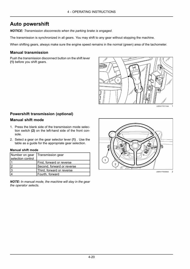
4 - OPERATING INSTRUCTIONS
Auto powershiftNOTICE: Transmission disconnects when the parking brake is engaged.
The transmission is synchronized in all gears. You may shift to any gear without stopping the machine.
When shifting gears, always make sure the engine speed remains in the normal (green) area of the tachometer.
Manual transmissionPush the transmission disconnect button on the shift lever(1) before you shift gears.
LEEN11T0111AA 1
Powershift transmission (optional)Manual shift mode
1. Press the blank side of the transmission mode selec-tion switch (2) on the left-hand side of the front con-sole.
2. Select a gear on the gear selector lever (1) . Use thetable as a guide for the appropriate gear selection.
Manual shift modeNumber on gearselection control
Transmission gear
1 First, forward or reverse2 Second, forward or reverse3 Third, forward or reverse4 Fourth, forward
NOTE: In manual mode, the machine will stay in the gearthe operator selects.
LEEN11T0038AA 2
4-20

4 - OPERATING INSTRUCTIONS
Auto shift mode
1. Press the emblem side of the Transmission mode se-lection switch (2) on the left-hand side of the front con-sole.
2. Select a gear on the gear selector lever (1). Use thetable as a guide for the appropriate gear selection.
NOTE: Automatic shifting is only available in third andfourth gears. Second gear is the lowest gear that theauto shift mode will shift into.
Auto shift modeNumber on gearselection control
Transmission gear
1 First gear only, no automatic shifting2 Second gear only, no automatic
shifting3 Automatic shifting between second
and third gear4 Automatic shifting between second,
third, and fourth gear
NOTE: When operating in automatic mode, some inclineand load conditions may cause the transmission to con-stantly shift. For example shifting from fourth gear to thirdgear and back to fourth gear or shift from third gear tosecond gear and back to third gear. If this shifting occurs,downshift until the transmission discontinues shifting be-tween gears.
NOTE: The Powershift transmission will automatically en-gage Four-Wheel Drive (4WD) to assist in braking whenthe service brake is pressed if the machine is in Two-Wheel Drive (2WD) mode and in third or fourth gear.
LEEN11T0038AA 3
4-21

4 - OPERATING INSTRUCTIONS
Four-Wheel Drive (4WD) control switch (if equipped)Machines with or without four wheel drive should not beallowed to exceed 40 km/h (24.8 mph)
WARNINGLoss of control hazard!Machines with four-wheel drive engaged ordisengaged should not exceed 50 km/h (31mph) where permitted. Over speeding bytowing or coasting downhill with clutch de-pressed or transmission in neutral may causeloss of control, personal injury to the operatoror bystanders, or mechanical failure.Failure to comply could result in death or se-rious injury.
W0454A
4WD switch (1)
This switch has two positions:
• Left position (power shuttle):
• Rear wheel drive and braking on rear wheels for allgears (lamp off).
• Left position (powershift):
• Rear wheel drive with braking only on rear wheels(only in first and second gear) (lamp off); four wheeldrive and braking (in third and fourth gear) (lamp on).
• Right position:
• 4 wheel drive and braking on 4 wheels (lamp on).
NOTE: To prevent undue tire wear when travelling on pub-lic highways or on any hard surface, it is recommendedthat the four wheel drive is disengaged, particularly in 3rdor 4th gear.
NOTICE: 4WD braking is only active with both brake ped-als latched together.
LEEN11T0122AA 1
4-22

4 - OPERATING INSTRUCTIONS
Differential lock buttonNOTICE: Never use the differential lock during road travel.
The differential lock gives equal power to both rear wheels.
It is particularly useful when the wheels have insufficient grip, as in the following cases.
When the machine is stuckMake sure that the rear wheels are not turning.
Press the differential lock button (1) on the loader attach-ment control lever (2).
Use the accelerator pedal to increase the engine speedand then release the differential lock button.
NOTE: The differential is automatically unlocked as soonas the button is released, when the rear wheel grip returnsto normal, with no wheel slip or when one of the brakepedals is operated.
RAIL18TLB0403BA 1
Before crossing a soft or muddy areaWARNINGLoss of control hazard!Avoid using differential lock at speeds above 8 km/h (5 mph). Never use at speeds above 15 km/h (9mph) or at any time when turning the machine.Failure to comply could result in death or serious injury.
W0334A
NOTE: You can engage the differential lock when the machine is moving in a straight line.1. Make sure that the machine is moving in a straight
line and that both rear wheels are turning at the samespeed.
2. Press the differential lock button (1) on the loader at-tachment control lever (2).
3. After you have moved through the area, release thedifferential lock button.
NOTE: You can cause damage to the transmission if youtry to engage the differential lock when the machine isturning or if one of the two rear wheels is rotating fasterthan the other one.
RAIL18TLB0403BA 2
4-23

4 - OPERATING INSTRUCTIONS
Glide Ride™ - Two-Wheel Drive (2WD) onlyWARNINGUnexpected machine movement!Stand clear of the loader arms. If you enable Glide Ride™ or Auto-Glide Ride™ control with the keyswitch in the ON or ACC position, the loader arms can drop slightly due to the hydraulic accumulator.Failure to comply could result in death or serious injury.
W1458C
WARNINGUnexpected machine movement!Stand clear of the machine. If you activate the Glide Ride™ or Auto-Glide Ride™ control while theloader arm applies down force, the machine or load may lower unexpectedly. For example, do notactivate these controls while the loader arm supports or lifts the machine front end off the ground.Failure to comply could result in death or serious injury.
W1459B
Glide Ride™ is an optional feature for machines with Two-Wheel Drive (2WD). When Glide Ride™ is activated, theloader down pressure is limited to the weight of the loader and the attachment (bucket). The weight of the loaderattachment is hydraulically cushioned during transport.
NOTE: Do not use Glide Ride™ when the bucket is used in fine grading operations or when precision placement ofa load suspended from the bucket or other attachment is required.
Before activating Glide Ride™ perform the following actions:
• Place the operator seat in the forward driving position.
• Place the hand throttle control at low idle.
• Only use the foot throttle.
• Make sure that the loader arm is not applying down force.
Activate Glide Ride™:1. Lower the loader bucket to or near the ground line.2. Press the emblem end of the rocker switch to enable
Glide Ride™. The emblem illuminates.3. Disable Glide Ride™, press the blank side of the
rocker switch. The emblem no longer illuminates.
LEEN11T0079AA 1
4-24

4 - OPERATING INSTRUCTIONS
Auto-Glide Ride™ (AGR) – Four-Wheel Drive (4WD) onlyWARNINGUnexpected machine movement!Stand clear of the loader arms. If you enable Glide Ride™ or Auto-Glide Ride™ control with the keyswitch in the ON or ACC position, the loader arms can drop slightly due to the hydraulic accumulator.Failure to comply could result in death or serious injury.
W1458C
WARNINGUnexpected machine movement!Stand clear of the machine. If you activate the Glide Ride™ or Auto-Glide Ride™ control while theloader arm applies down force, the machine or load may lower unexpectedly. For example, do notactivate these controls while the loader arm supports or lifts the machine front end off the ground.Failure to comply could result in death or serious injury.
W1459B
Auto-Glide Ride™ is an optional feature onmachines with Four-Wheel Drive (4WD).WhenAuto-Glide Ride™ (AGR)is active, the loader down pressure is limited to the weight of the loader and the attachment (bucket). The weight ofthe loader attachment is hydraulically cushioned during transport.
NOTE: Auto-Glide Ride™ should not be used for fine grading with the loader bucket, during backhoe operation orwhen precise placement of the loader is required.
NOTE: AGR speed settings can be adjusted to suit the operator’s preference. See “Auto-Glide Ride™ (AGR) speedthresholds” 6-11 for details.
Before activating Auto-Glide Ride™ perform the following actions:
• Face operator seat in the forward driving position.
• Place the hand throttle control at low idle.
• Only use the foot throttle.
• Down force is not being applied with the loader.
Auto-Glide Ride™ (AGR) operation:1. Place the rocker switch in the center position. In the
automatic position, the emblemwill illuminate green in-dicating Auto-Glide Ride™ is functioning anytime themachine is traveling above the default speed thresh-old 9.5 km/h (5.9 mph).
2. Disable Auto-Glide Ride™, press the blank side ofthe rocker switch. The emblem no longer illuminates.
Operator’s may choose to leaveAuto-Glide Ride™ in theAUTO (center) position. The selection will hold even whenpower to the machine has been cycled OFF and ON.
LEEN11T0079AA 1
Manual operation of Auto-Glide Ride™:1. Lower the loader bucket to or near the ground line.2. Press the emblem end of the rocker switch to turn ON
Auto-Glide Ride™. The emblem illuminates.3. Disable the manual operation of Auto-Glide Ride™,
press the blank side of the rocker switch. The emblemno longer illuminates.
4-25

4 - OPERATING INSTRUCTIONS
PARKING THE UNIT
Parking the machineWhen parking the machine, follow the safety precautionsmentioned in this manual.
1. Move the machine to a level and firm ground, awayfrom any soft ground, excavations or poorly shoredcavity.
2. Lower the loader attachment to the ground.3. Place the backhoe attachment in the road travel posi-
tion.4. Place the direction-of-travel lever and gearshift lever
in neutral position.5. Immobilize the machine by means of the parking
brake.
6. Completely raise the stabilizers.7. Stop the engine and remove the starter switch key.8. Release the hydraulic pressure by operating the con-
trol levers in all directions.9. On pilot controlled machines, turn the key to ON and
release the pressure by moving the hydraulic controllevers in all directions.
10. If the unit is on a slope, place blocks under the wheelsin order to prevent the machine from moving.
11. Disconnect the electrical system by disconnectingthe battery master switch.
12. Check that no part of the machine is protruding ontothe public highway. If this cannot be avoided, installsigns in compliance with the relevant regulations.
LEEN12T0640AA 1
4-26

5 - TRANSPORT OPERATIONS
5 - TRANSPORT OPERATIONS###_5_###ROAD TRANSPORT
Precautions for road travelWARNINGAvoid injury!Before starting the engine, securely fasten the seat belt. The seat belt can help ensure your safetyif it is properly used and maintained. Never wear a seat belt loosely or with slack in the belt system.Never wear the belt if it is twisted or pinched between the seat structures.Failure to comply could result in death or serious injury.
W0142A
WARNINGCollision hazard!Collision of high speed road traffic and slow moving machines can cause death or personal injury.On roads use transport lighting according to local laws. Pull over to let faster traffic pass. Slow downand signal before turning off.Failure to comply could result in death or serious injury.
W0408A
NOTICE: Before undertaking any road travel, make surethat the backhoe attachment is in the stowed position andswing lock pin is in the lock position.
5-1

5 - TRANSPORT OPERATIONS
PREPARING FOR ROAD TRANSPORT
Preparing the machine for road travel1. If applicable. make sure that the engine accelerator
knob (1) is in idle position.
LEEN11T0149AA 1
2. Place all transmission controls in the NEUTRAL posi-tion.
3. Start the engine.4. Engage the parking brake.5. Place the seat in the backhoe operation position.6. If applicable unlock the stabilizers.7. Lower the stabilizers to the ground until the rear
wheels are just off the ground.
8. Move the backhoe so that it is in-line with themachine(not perpendicular with the machine).
9. If applicable, retract the telescopic dipper.10. If applicable, place the pin (1) in the dipper lock posi-
tion.11. Retract the backhoe bucket.12. Retract the dipper arm.
RAIL15TLB0545BA 2
5-2

5 - TRANSPORT OPERATIONS
Mechanical transport lock13. Lock the backhoe attachment:
A. Press the button on the backhoe transport lock lever(1) and move it backward to engage the boom lock
B. Retract the boom arm until the transport lock (2) en-gages.
NOTICE: Do not attempt to use the backhoe attachmentwith the boom in the transport position, as this could dam-age the locking system.
RAIL15TLB0052AA 3
RAIL15TLB0048AA 4
Hydraulic transport lock13. Lock the backhoe attachment:
A. Place the switch (1) in the ON position. The indicatorlamp (2) (mechanical backhoe control models) or theindicator lamp (3) (pilot backhoe models) turns on.
B. Retract the boom arm until the transport lock engages.
NOTICE: Do not attempt to use the backhoe attachmentwith the boom in the transport position, as this could dam-age the locking system.
LEEN11T0146AA 5
MOLI12LBB0249AB 6
5-3

5 - TRANSPORT OPERATIONS
14. Raise the stabilizers.15. Raise the loader about 20 cm (7.9 in) above the
ground and roll back the loader bucket completely.
16. Correctly adjust the rearview mirrors (1).
LEEN11T0128AA 7
17. Install the rotating beacon (1) on the cab roof, thenconnect the relative cable and operate the switch.
18. If applicable, make sure that the doors are properlyclosed.
19. Lock the engine hood.
LEEN11T0129AA 8
20. Engage the service brake pedal lock (1) .
MOLI12LBB0231AB 9
21. Adjust the operator’s seat correctly.22. Fasten and adjust the seat belt (1).
MOLI12LBB0232AB 10
5-4

5 - TRANSPORT OPERATIONS
23. If applicable, disengage the Four-Wheel Drive(4WD).
LEEN11T0134AA_1 11
24. Machines with Power shuttle transmission.
A. Press the transmission disconnect button (1) and thenplace the gearshift lever (2) in first gear.
B. Release the button (1).
LEEN11T0135AA_2 12
24. Machines with Powershift transmissions.
A. Place the gearshift lever (1) in first gear.
LEEN11T0136AA 13
25. Disengage the parking brake (1).
LEEN11T0079AA 14
5-5

5 - TRANSPORT OPERATIONS
26. Position the direction-of-travel control lever (1) for-wards.
LEEN11T0138AA 15
27. Release the brake pedals and adjust the travel speedby means of the accelerator pedal (1).
28. Shift gears as necessary.
NOTE: Monitor all gauges and indicator/warning lampsfrequently.
MOLI12LBB0240AB 16
5-6

5 - TRANSPORT OPERATIONS
SHIPPING TRANSPORT
Transporting on a trailerWARNINGTransport hazard!The machine can slip or fall from a ramp or trailer. Make sure the ramp and trailer are not slippery.Remove all oil, grease, ice, etc. Move the machine on or off the trailer with machine centered on thetrailer or ramp.Failure to comply could result in death or serious injury.
W0152A
NOTE: The machine shown may be different from your machine. The procedure is the same.
You must know all the applicable rules or laws for safety in each area that you will travel in. Make sure that the truckand trailer are equipped with the correct safety equipment.
Load the loader backhoe onto a trailer:1. Park on a level surface.2. Put a block at the front and rear of the trailer wheels.
RCPH10TLB056AAF 1
3. Put the backhoe in the stowed position.4. Fasten the seat belt, shift the transmission to first
gear, and slowly drive the machine onto the trailer.5. Lower the loader bucket onto the trailer, shift the
direction control lever to NEUTRAL, and apply theparking brake.
6. Release the backhoe from the stowed position.7. Lower the backhoe bucket or attachment to the floor
of the trailer.8. Place the transmission in NEUTRAL.9. Shut down the engine and remove the key.10. Put a block at the front and rear of each tire of the
loader backhoe.11. If equipped, make sure all windows are completely
closed and secured.
NOTICE: Wind pressure can break the windowlatches or glass.
5-7

5 - TRANSPORT OPERATIONS
12. Use chains and binders to fasten the machine to thetrailer. Use the machine tie down locations.
• Side chassis (both sides):
• Backhoe (both sides):
• Secure the backhoe bucket or attachment to thetrailer.
LEEN12T0647AA 2
13. Measure the distance from the ground to the highestpoint of the machine. You must know the clearanceheight of the machine.
14. After you have driven a few miles, stop the truck andtrailer and check your load. Make sure the chains arestill tight and that the loader backhoe has not movedon the trailer.
Unload the loader backhoe from a trailer:1. Remove the chains and blocks from the loader back-
hoe.2. Fasten the seat belt.3. Start the engine.4. Put the backhoe in the stowed position or raise the
backhoe bucket or attachment off of the trailer floor.5. Raise the loader bucket off of the trailer floor.6. Shift the transmission to first gear, release the parking
brake, and drive slowly off the trailer.
5-8

5 - TRANSPORT OPERATIONS
Lifting the machineNOTICE: Before lifting the machine, it is essential to placethe backhoe attachment in the road travel position.
The hooking points for the machine are shown by signs.
NOTICE: Never use any other hooking points than thoseshown by the signs.
Use suitable slings to lift the machine.
DANGERHeavy objects!Lift and handle all heavy components us-ing lifting equipment with adequate capacity.Always support units or parts with suitableslings or hooks. Make sure the work area isclear of all bystanders.Failure to complywill result in death or seriousinjury.
D0076A
Make sure that the slings are in perfect condition and thatthey can support the weight of the machine.
NOTICE: Do not allow anybody within the machine’sworking range. Never suspend the machine over peoplewho are in proximity.
LEEN12T0647AA 1
5-9

5 - TRANSPORT OPERATIONS
RECOVERY TRANSPORT
Towing the machineWARNINGLoss of control!Only tow at safe speeds. Use caution when making corners or meeting traffic.Failure to comply could result in death or serious injury.
W0126A
WARNINGHazard to bystanders!The operator must be the only person on the machine when towing. Make sure that nobody else is onthe machine or within its working range.Failure to comply could result in death or serious injury.
W0259A
NOTICE: NEW HOLLAND CONSTRUCTION does not recommend towing the machine.
NOTICE: Do not attempt to start the engine while towing the machine. Damage to the drivetrain components willoccur!
If your machine is disabled, repair the machine at the job site unless you are able to move the machine without furtherdamage.
The towing machine must have power, steering, and braking ability to stop both machines. Do not tow the machinein speeds greater than 2.4 km/h (1.5 mph).
Secure the disabled machine to the tow machine as closely as possible.
The disabled machine must only be moved far enough to reach a safe repair location or onto a trailer.
Before you tow a disabled machine, you must be able to answer these questions:
• Does the towing machine have braking and steering capacity for both machines?
• Does the towing hardware, chains, and cables have the proper capacity to move the machine safely?
• Will the disabled machine have steering and braking capability?
• Will moving the machine cause damage to drivetrain or moving parts that lack lubrication?
Additional considerations:
• Be certain that all personnel involved are shielded in the event that towing apparatus might break.
• If the disabled machine has steering and braking capability an operator may be on the machine to help control thetowing of the disabled machine.
• Always block the wheels of the disabled machines before releasing the brakes or drivetrain component.
5-10

5 - TRANSPORT OPERATIONS
Tow procedure - engine runs
1. Engage the parking brake.2. Block the wheels with wheel chocks.3. If applicable place the manual transmission lever in the NEUTRAL position.4. Place the direction control lever in NEUTRAL.5. Place the Four-Wheel Drive (4WD) switch in the off position, if equipped.6. Raise all tools and attachments off the ground.7. Attach a rigid drawbar to the disabled machine.8. Attach the rigid drawbar to the towing machine. Make sure that the towing machine has enough power and braking
ability to move and stop both machines.
9. Remove the wheel chocks.10. Release the parking brake. If the parking brake will not disengage (for any reason), manually disengage the
parking brake. See “Disable parking brake” 7-156.11. Tow the disabled machine a maximum speed of 2.4 km/h (1.5 mph).
Tow procedure - engine does not run
1. Block the wheels with wheel chocks.2. If applicable, place the manual transmission lever in the NEUTRAL position.3. Place the direction control lever in NEUTRAL.4. Attach a rigid drawbar to the disabled machine.5. Attach the rigid drawbar to the towing machine. Make sure the towing machine has enough power and braking
ability to move and stop both machines.6. Disconnect the rear drive shaft (Two-Wheel Drive machines) or both the front and rear drive shafts (Four-Wheel
Drive machines).
NOTE: The machine is equipped with Spring-Applied, Hydraulic-Release (SAHR) parking brake integrated in thetransmission. The parking brake remains engaged if the engine is disabled. Manual disengagement of the parkingbrake is not required for towing with the drive shafts removed.
7. Remove the wheel chocks.8. Tow the disabled machine a maximum speed of 2.4 km/h (1.5 mph).
5-11

5 - TRANSPORT OPERATIONS
5-12

6 - WORKING OPERATIONS
6 - WORKING OPERATIONS###_6_###GENERAL INFORMATION
Forward-Neutral-Reverse (F-N-R) shift sensitivityNOTE: Machines with the optional Powershift transmissions only.Change F-N-R shift sensitivity:1. Press Enter (4) to access the menu screens.2. Press the up arrow (2) or the down arrow (3) to navi-
gate through the menu screens.
LEEN12T0526FA_4 1
3. When the F-N-R shift sensitivity screen displays, pressEnter. The setting bar flashes.
4. Press the up arrow or the down arrow to adjust thesetting, where 1 is least aggressive and 3 is most ag-gressive.
5. Press Enter to save the selection.
RCIL10TLB035AAF 2
6. Use the arrows to navigate to a different menu screenor press Escape (1) until you return the main screen(engine hourmeter).
LEEN12T0526FA_4 3
6-1

6 - WORKING OPERATIONS
Display brightnessAdjust the brightness of the display:1. Press Enter (4) to access the menu screens.2. Press the up arrow (2) or the down arrow (3) to navi-
gate through the menu screens.
LEEN12T0526FA_4 1
3. When the Instrument Cluster Dimmer screen displays,press Enter.
RCPH10TLB196AAF 2
4. Press Enter to access the setting screen.5. Press Enter again. The setting bar flashes.6. Press the up arrow or the down arrow to adjust the
screen brightness.7. Press Enter to save the selection.
RCPH10TLB197AAF 3
8. Press Escape (1) to return to the Instrument ClusterDimmer screen.
9. Use the arrows to navigate to a different menu screenor press Escape until you return the main screen (en-gine hour meter).
LEEN12T0526FA_4 4
6-2

6 - WORKING OPERATIONS
Maximum throttle/Cold start idleThe Idle Increment (engine speed) menu lets the operator configure the cold start idle and/or the maximum enginethrottle settings.
NOTE: The settings do not reset at key cycle.
• Cold start idle - Sets the minimum engine speed (upto 1500 RPM) that the engine idles while cold. For ex-ample, if set to 1500 RPM, the cold engine will idle atthat RPMuntil the engine warms to approximately 20 °C(68 °F). Dealer can adjust the temperature as needed.
RCPH10TLB424AAF 1
• Maximum throttle - Sets the maximum engine speedduring operation. The engine will not exceed thisspeed.
RCPH10TLB423AAF 2
1. Press Enter (4) to access the menu screens.2. Press the up arrow (2) or the down arrow (3) to navi-
gate through the menu screens.
LEEN12T0526FA_4 3
6-3

6 - WORKING OPERATIONS
3. When the Idle Increment screen displays, press Enter.
RCPH10TLB201AAF 4
4. Press the up arrow or the down arrow until the coldstart idle or the maximum throttle screen appears.
5. Press Enter. The setting flashes.6. Press the up arrow or the down arrow to adjust the
setting.7. Press Enter to save the setting.
8. Press Escape (1) until you return to the Idle Incre-ment screen.
9. Press the up arrow or the down arrow to adjust an-other setting, or press Escape to return to the IdleIncrement screen.
10. Use the arrows to navigate to a different menu screenor press Escape until you return the main screen (en-gine hour meter).
LEEN12T0526FA_4 5
6-4

6 - WORKING OPERATIONS
Throttle sensitivityChange the throttle sensitivity:1. Press Enter (4) to access the menu screens.2. Press the up arrow (2) or the down arrow (3) to navi-
gate through the menu screens.
LEEN12T0526FA_4 1
3. When the Throttle Sensitivity screen displays, pressEnter. The setting bar flashes.
4. Press the up arrow or the down arrow to adjust thesetting, where 1 is least aggressive and 3 is most ag-gressive.
5. Press Enter to save the selection.
RCPH10TLB195AAF 2
6. Use the arrows to navigate to a different menu screenor press Escape (1) until you return the main screen(engine hour meter).
LEEN12T0526FA_4 3
6-5

6 - WORKING OPERATIONS
Auto engine shutdown time-out adjustmentNOTE: The default setting is Off.
NOTICE: After the machine has been turned off by this feature it will appear completely off, but there are relays stillconsuming power. So, it is important to turn the key to Off before letting the machine sit for an extended period oftime.
Adjust the auto engine time-out setting:1. Press Enter (4) to access the menu screens.2. Press the up arrow (2) or the down arrow (3) to navi-
gate through the menu screens.
LEEN12T0526FA_4 1
3. When the auto engine time-out screen displays, pressEnter.
RAIL15TLB0066AA 2
6-6

6 - WORKING OPERATIONS
4. Press the Up arrow or the Down arrow to adjust thetime-out setting. The number below the symbol is thetime-out value in minutes or Off.
NOTE:Select betweenOff, range of 2 – 5 min in 1 minincrements, or a range of 5 – 60 min in 5 min incre-ments.
5. Press Enter to save the selection
RAIL14TLB1030AA 3
RAIL14TLB1027AA 4
6. Use the arrows to navigate to a different menu screenor press Escape (1) until you return the main screen(engine hourmeter).
LEEN12T0526FA_4 5
6-7

6 - WORKING OPERATIONS
Stop an auto engine shutdown
The instrument cluster will provide a warning on thedisplay screen during the 1 min period before the enginewill be shut off.
• Press the Escape (1) button to cancel the shutdown.
NOTE: The number below the auto engine shutdown sym-bol indicates the number of seconds that remain beforethe shutdown will occur.
NOTICE: After the machine has been turned off by thisfeature it will appear completely off, but there are relaysstill consuming power. So, it is important to turn the key toOff before letting the machine sit for an extended periodof time.
RAIL14TLB1031AA 6
LEEN12T0526FA_4 7
6-8

6 - WORKING OPERATIONS
Auto engine protection shutdown settingNOTE: The default setting is ON.
NOTICE: After the machine has been turned off by this feature it will appear completely off, but there are relays stillconsuming power. So, it is important to turn the key to OFF before letting the machine sit for an extended period oftime.
Disable or enable auto engine protection shutdown:1. Press Enter (4) to access the menu screens.2. Press the up arrow (2) or the down arrow (3) to navi-
gate through the menu screens.
LEEN12T0526FA_4 1
3. When the auto engine shutdown protection screen dis-plays, press Enter.
RAIL14TLB1028AA 2
4. Press the Up arrow or the Down arrow to disable theauto engine shutdown protection.
NOTE: The procedure is the same to enable the autoengine shutdown protection
5. Press Enter to save the selection
RAIL14TLB1029AA 3
6-9

6 - WORKING OPERATIONS
6. Use the arrows to navigate to a different menu screenor press Escape (1) until you return the main screen(engine hourmeter).
LEEN12T0526FA_4 4
6-10

6 - WORKING OPERATIONS
Auto-Glide Ride™ (AGR) speed thresholdsChange the Auto-Ride Control™ (ARC) speedthreshold:1. Press Enter (4) to access the menu screens.2. Press the up arrow (2) or the down arrow (3) to navi-
gate through the menu screens.
LEEN12T0526FA_4 1
3. When the ARC speed threshold screen displays, pressEnter. The setting bar flashes.
Settinglevel
ARC activates(speeds faster)
ARC deactivates(speeds slower)
1 9.2 km/h (5.7 mph) 7.6 km/h (4.7 mph)2 (default) 9.5 km/h (5.9 mph) 7.9 km/h (4.9 mph)3 9.9 km/h (6.2 mph) 8.4 km/h (5.2 mph)
NOTE: Speeds are approximate depending on tire size,model, and transmission type.
4. Press the up arrow or the down arrow to adjust thespeed threshold setting.
5. Press Enter to save the selection.RCPH11TLB001AAD 2
6. Use the arrows to navigate to a different menu screenor press Escape (1) until you return the main screen(engine hour meter).
LEEN12T0526FA_4 3
6-11

6 - WORKING OPERATIONS
LOADER ATTACHMENT
Personal safetyThis manual contains only basic information that you need to operate the machine, it does not include all possibleconditions for loader operation.
If you are a new operator, always operate in a clear area at a decreased engine speed.
Be a careful operator. You can prevent accidents. Do not allow yourself to become complacent.
Fasten the seat belt before you start the engine.
Confirm that you can reach all controls and move through their entire range of motion with the seat belt fastened.
6-12

6 - WORKING OPERATIONS
Job layoutWARNINGHazard to bystanders!Always know the location of all workers in your area. Warn them before you start operating the ma-chine. Always keep all unauthorized bystanders clear of the work area.Failure to comply could result in death or serious injury.
W0206A
WARNINGHazard to bystanders!Material can spill from a loaded bucket. You must manually roll back a loaded bucket before loweringthe loader. The self-leveling feature does not automatically roll back the bucket.Failure to comply could result in death or serious injury.
W0197A
RCPH10TLB005GAF 1
Machine positioning is very important for efficient cycles.
• Set up the work cycle as short as possible.
• Spend a few minutes leveling off the work area, if necessary. Smooth runways for the machine and a level parkingarea for trucks will speed up the job.
6-13

6 - WORKING OPERATIONS
Operating the loader attachmentThe following instructions do not cover all possible con-ditions of use of the loader attachment. The instructionscontain only basic information to enable you to operatethe machine correctly.
Where possible, always use the loader attachment at fullengine speed.
The first time it is operated, maneuver the machine in aclear area, at low speed.
WARNINGHazard to bystanders!Material can spill from a loaded bucket. Youmust manually roll back a loaded bucket be-fore lowering the loader. The self-levelingfeature does not automatically roll back thebucket.Failure to comply could result in death or se-rious injury.
W0197A
Loading operationsTo fill the bucket from a stock pile, set the bucket in thelevel position and lower the attachment with the controllever to “float” position.
LEEN12T0650AA 1
When the loader has entered the pile, press down thetransmission disconnect button, allow the control leverto move backwards and then simultaneously operate thecontrols to lift and roll back the bucket.
Lift and roll-back of the bucket will increase efficiency as alevel bucket throughout the lifting cycle resists bucket liftand increases break away effort.
NOTE: Do not be concerned if the bucket is not com-pletely filled during each pass. Maximum productivity isdetermined by the amount of material loaded in a givenperiod of time. Time is lost if two or more attempts aremade to fill the bucket on each pass.
LEEN12T0651AA 2
WARNINGFalling objects!Dirt slides can be dangerous. Exercise ex-treme care when undercutting high banks.Watch for falling rocks and cave-ins.Failure to comply could result in death or se-rious injury.
W0021A
6-14

6 - WORKING OPERATIONS
Dump the bucket completely, raise the attachment andthen release the transmission disconnect button.
Keep the bucket position as low as possible, especiallywhen working on sloping or rough ground.
WARNINGLoss of control hazard!A full bucket in the raised position may causethe machine to slide when operating overrough ground. Keep the bucket as low aspossible during operation for better stabilityand visibility. Always operate the machine atslow speeds over rough ground.Failure to comply could result in death or se-rious injury.
W0271A
LEEN12T0652AA 3
Raise the loader high enough to clear any obstructionprior to dumping the load.
After the bucket is dumped, back away while lowering andleveling the bucket, using the return-to-dig feature if re-quired.
LEEN12T0653AA 4
During hard surface operation, place the loader attach-ment lever in “float” position and keep the bucket level.This will permit the bucket to “float” on the contour of theworking surface.
If hydraulic down pressure is exerted, the bucket will wearfaster than normal.
The “float” position will prevent the mixing of surface ma-terial with stockpile material.
It will also reduce the chance of surface gouging whenremoving snow or other material.
When loading from a bank select the highest forward gearwhich will provide the most efficient loading operationwithout going into a “stall”.
Keep the working area free of ruts and holes occasionallyback grading with the bucket using the low rear edge ofthe bucket.
6-15

6 - WORKING OPERATIONS
For site stripping peeling or scraping, use down pressurewith the loader attachment lever in the lowered position,and a slight bucket angle to start the cut. Begin the cut atthe notch approximately 50 mm (1.97 in) deep and holdthe depth by feathering the bucket to adjust the cutting lipup or down as required.
When the machine front tires enter the cut, adjust the liftarms to maintain the correct depth.
Make additional cuts until the desired depth is reached.
Back grade the working area occasionally with the bucketflat and slight down pressure to keep the working areasmooth and free from ruts or holes.
If you move the loader attachment lever for lift cylinder ac-tion without controlling the bucket angle, the bucket maygouge and leave a series of ruts in the surface.
LEEN12T0654AA 5
To backfill a trench efficiently it is necessary to move themaximum amount of soil without losing speed.
If a “stall” occurs downshift or reduce the depth of cut.
If the machine is not working at capacity in the gear se-lected, increase the depth of cut.
Operate at right angles to the trenchwith the loader bucketlevel.
Leave the soil in the bucket as emptying the bucket oneach pass is time-consuming, and leave soil that driftsover the side of the bucket for the final clean up.
One lengthwise clean up is usually sufficient to gain anacceptable grade after backfilling.
When backfilling from a large pile, shovel off the top of thepile, pushing toward the excavation.
Drag some soil rearwards to form a work ramp of the con-venient grade.
If during the backfill operation the machine front wheelsget stuck in a trench dump the bucket and apply downpressure to lift the front wheels from the trench.
Actuate the bucket as engine power is applied to movethe machine rearwards.
NOTE: Progressively shift the loader attachment lever tothe right to obtain maximum bucket down pressure.
NOTICE: The safe working load of the loader attachmentis calculated using a standard bucket; therefore, whenusing another bucket or attachment for lifting or handlinga load, the weight of the bucket or attachment must betaken into account when calculating the rated load of theloader attachment.
Safe working load = 1000 kg (2205 lb).
LEEN12T0655AA_1 6
6-16

6 - WORKING OPERATIONS
Loader digging forceTransmission disconnect button
Press the transmission disconnect button to increase engine speed and supply the loader with more hydraulic oil forgreater loader power and faster control function.
Press and hold the transmission disconnect button on theback of the loader control lever, the transmission will dis-engage from the drive wheels. Release the transmissiondisconnect button to engage the transmission power.
The machine can move freely when the transmission dis-connect button is pressed. Use the service brake to stopthe machine.
RAIL18TLB0403BA 1
Transmission kickdownNOTE: Only available on machines with a Powershift transmission.
Kickdown is used to increase loader breakout force. The kickdown control lets the operator temporarily switch fromsecond gear to first gear without changing the gear selection control setting.
NOTICE: This feature will only activate when second gear is selected in manual shift mode, or when the transmissionis actually in second gear in auto shift mode.
Kickdown button on the directional control lever.1. Press the button at the end on the directional control
lever to shift from second to first gear.
NOTE: The operator may experience a short pause ordelay before the gear shift occurs.
2. Press the button again to shift up to second gear.
LEEN11T0204AA 2
6-17

6 - WORKING OPERATIONS
Loader attachment safety strutWARNINGCrushing hazard!If you service the machine with the loader lift arms raised, always use the support strut. Remove theretaining pin and place the support strut onto the cylinder rod. Install the retaining pin into the supportstrut. Lower the lift arms onto the support strut.Failure to comply could result in death or serious injury.
W0230A
Machines without the Tool Carrier (TC) op-tionEngage the loader arm support strut:1. Empty the loader bucket.2. Raise the loader lift arms to the maximum height.3. Stop the engine and remove the starter switch key.4. Remove the split pin (1) and the lock pin (2).
MOLI12LBB0260AB 1
5. Place the strut (3) on the cylinder rod and install thepin (2) and the split pin (1) back into the holes in thestrut.
6. Lower the loader attachment until the safety strut isfirmly against the cylinder.
MOLI12LBB0261AB 2
6-18

6 - WORKING OPERATIONS
Disengage the loader arm support strut:1. Completely raise the loader attachment and stop the
engine.2. Remove the split pin (1) and the lock pin (2).
MOLI12LBB0262AB 3
3. Remove the strut (3) from the attachment and installthe pin (1) and the split pin (2) back into the holes inthe strut.
4. Start the engine and lower the loader attachment.
MOLI12LBB0263AB 4
6-19

6 - WORKING OPERATIONS
Machines with the Tool Carrier (TC) optionEngage the loader arm support strut:
1. Remove the split pins (1) and the safety strut (2) fromthe arm. Put the split pins back in place.
2. Empty the loader bucket.3. Raise the loader lift arms to the maximum height.4. Stop the engine and remove the starter switch key.5. Place the strut (2) on the cylinder rod and fasten it by
means of the fastening flip (3).6. Lower the loader attachment until the safety strut is
firmly against the cylinder.MOLI12LBB0264AB 5
Disengage the loader arm support strut:1. Completely raise the loader attachment and stop the
engine.2. Remove the flip (3) and the strut (2) from the cylinder
rod.
MOLI12LBB0265AB 6
3. Start the engine and lower the loader attachment.4. Stop the engine.5. Install the safety strut (2) on the loader arm by means
of the split pins (1).
MOLI12LBB0264AB 7
6-20
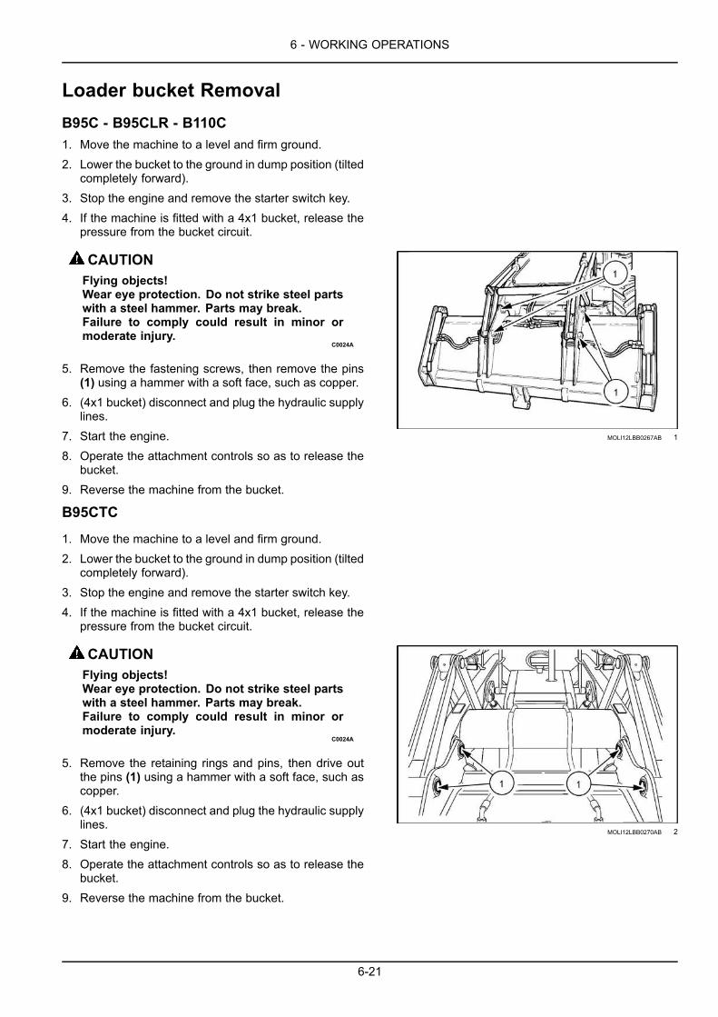
6 - WORKING OPERATIONS
Loader bucket RemovalB95C - B95CLR - B110C1. Move the machine to a level and firm ground.2. Lower the bucket to the ground in dump position (tilted
completely forward).3. Stop the engine and remove the starter switch key.4. If the machine is fitted with a 4x1 bucket, release the
pressure from the bucket circuit.
CAUTIONFlying objects!Wear eye protection. Do not strike steel partswith a steel hammer. Parts may break.Failure to comply could result in minor ormoderate injury.
C0024A
5. Remove the fastening screws, then remove the pins(1) using a hammer with a soft face, such as copper.
6. (4x1 bucket) disconnect and plug the hydraulic supplylines.
7. Start the engine.8. Operate the attachment controls so as to release the
bucket.9. Reverse the machine from the bucket.
MOLI12LBB0267AB 1
B95CTC
1. Move the machine to a level and firm ground.2. Lower the bucket to the ground in dump position (tilted
completely forward).3. Stop the engine and remove the starter switch key.4. If the machine is fitted with a 4x1 bucket, release the
pressure from the bucket circuit.
CAUTIONFlying objects!Wear eye protection. Do not strike steel partswith a steel hammer. Parts may break.Failure to comply could result in minor ormoderate injury.
C0024A
5. Remove the retaining rings and pins, then drive outthe pins (1) using a hammer with a soft face, such ascopper.
6. (4x1 bucket) disconnect and plug the hydraulic supplylines.
7. Start the engine.8. Operate the attachment controls so as to release the
bucket.9. Reverse the machine from the bucket.
MOLI12LBB0270AB 2
6-21

6 - WORKING OPERATIONS
Loader bucket InstallationB95C - B95CLR - B110C1. Make sure all bushings are completely clean. Re-
move any dirt or foreign matter, if necessary.2. Start the engine.3. Use the attachment controls to engage the attach-
ment between the bucket lugs.4. Install the arm/bucket pins (1) and then install the
relevant retaining bolts.5. Use the bucket controls to align the connecting rod
orifices with the bucket lugs.6. Stop the engine and remove the starter switch key.7. (4x1 bucket) release the pressure from the bucket
circuit.8. Install the rod/bucket pins (2), and then install the
relevant retaining bolts.9. (4x1 bucket) remove the plugs and reconnect the hy-
draulic lines.
MOLI12LBB0268AB 1
B95CTC
1. Make sure all bushings are completely clean. Re-move any dirt or foreign matter, if necessary.
2. Start the engine.3. Use the attachment controls to engage the attach-
ment between the bucket lugs.4. Reinstall the arm/bucket pins (1) and then install the
relevant retaining pins and rings.5. Use the bucket controls to align the connecting rod
holes (3) with the bucket lugs.6. Stop the engine and remove the starter switch key.7. (4x1 bucket) release the pressure from the bucket
circuit.8. Install the rod/bucket pins (2) and then install the rel-
evant retaining pins and rings.9. (4x1 bucket) remove the plugs and reconnect the hy-
draulic lines.
MOLI12LBB0271AB 2
6-22

6 - WORKING OPERATIONS
Loader bucket with quick coupler (B95CTC)The loader hydraulic coupler allows the operator to change front end attachments without using special tools or ad-ditional manpower.
Installation1. Make sure the bucket is in a safe area, on a level and
firm ground and with the upper pins in place.2. Tilt the quick coupler forwards and engage the top pins
(1) into the upper hooks (2) of the bucket.
LEEN12T0656AA 1
3. Press and hold the quick coupler switch (3) locatedright-hand side of the steering column.
LEEN11T0122AA 2
4. This will retract the lock pins (5).
LEEN12T0658AA 3
6-23

6 - WORKING OPERATIONS
5. Lift the loader attachment and rotate the quick couplerrearwards until the lock pins (6) are aligned with thelower bores of the bucket.
6. Release the switch (3) allowing the lock pins (5) toengage in the mounting bores of the bucket.
LEEN12T0659AA 4
7. Visually confirm that the lock pins have correctly se-cured the bucket.
8. Make sure the loader bucket is correctly installed be-fore using the loader attachment.
Removal
1. With the attachment resting on the ground, press andhold the switch to disengage the lock pins.
2. Raise the loader attachment off the ground and slowlyrotate the top of the quick coupler outwards until thelock pins are clear of the bucket mounting bores. Re-lease the switch.
3. Slowly lower the loader attachment to the ground whilerotating the top of the quick coupler outwards.
4. When the upper pins of the quick coupler are free fromthe bucket hooks, back away from the bucket.
6-24

6 - WORKING OPERATIONS
Loader bucket with forks (optional)NOTICE: The forks are heavy, so use great care whenswinging them into their working and stowage position.
Install forks in working position
1. Move the bucket to a level and firm ground.2. Stop the engine and remove the starter switch key.3. Deactivate the parking brake.
4. Remove the retained pin and the pin (1).5. Lower the fork (2) manually and carefully until it is lay-
ing in position against the bucket cutting edge.
NOTICE: The forks must be laying against the cuttingedge of the bucket, and never against bucket teeth.
MOLI12LBB0272AB 1
6. Install the pin (1) and the safety pin.7. Repeat the same operations for the other fork.8. Slide the forks until they are suitably spaced for the
intended job.
NOTICE: You must position the forks at the same dis-tance from the center of the bucket.
NOTICE: Never use the forks to lift the machine.
NOTICE: When using the forks with a 4x1 bucket,never attempt to use the bucket jaw opening function.
MOLI12LBB0273AB 2
6-25

6 - WORKING OPERATIONS
Install the forks in rest position1. Rest the loader bucket on a level and firm ground.2. Stop the engine and remove the starter switch key.3. Disengage the parking brake.
4. Remove the retained pin and the pin (1).5. Tilt the fork (2) manually and carefully until it is rear-
wards into transport position.
MOLI12LBB0273AB 3
WARNINGAvoid injury and/or machine damage!When not in use, securely retain the forks intheir proper storage position with the pins andsplit pins.Failure to comply could result in death or se-rious injury.
W1330A
6. Reinstall the pin (1) and the safety pin into their hous-ing.
NOTE: If necessary, slide the fork to the side to bringit into its housing.
7. Repeat the same operations for the other fork.MOLI12LBB0272AB 4
6-26

6 - WORKING OPERATIONS
Lifting loads with the loader attachmentWARNINGHeavy object!ALWAYS use adequate lifting equipment(heavy-duty hoist, loader, or forklift) to lift thecomponent.Failure to comply could result in death or se-rious injury.
W0101A
Loader bucket - with lifting ring
The lifting ring is the only point to which loads may beattached on the loader bucket. The bucket must also bein dumping position.
Loader bucket - without lifting ring
If the loader bucket is not equipped with a factory fittedlifting ring, consult your dealer.
LEEN12T0660AA 1
Use the controls gradually so as to move the attachmentaccurately.
The maximum authorized load must not exceed 1000 kg(2205 lb).
Steady the load a few centimeters above the ground so itis perfectly balanced before carrying out the lifting opera-tion.
Do not allow any person within the working range of themachine.
When moving with a load, be sure to:
• Keep the load as close as possible to the ground andto the machine.
• Always travel at low speed.
• Operate the controls smoothly to obtain precise move-ments and travel.
• In order to reduce the load’s oscillation, avoid slingingit with too long ropes and/or chains.
LEEN12T0661AA 2
6-27

6 - WORKING OPERATIONS
Maximum lifting loads with forks (ifequipped) on loader bucket
CAUTIONEquipment failure could cause accident or in-jury!Never exceed the maximum safe working loadof the loader.Failure to comply could result in minor ormoderate injury.
C0161A
CAUTIONIMPROPER OPERATION OF THIS MACHINECAN CAUSE DEATH OR SERIOUS INJURY.Make sure that you comply with the local lift-ing regulations (if any). Contact your dealerfor more details.Failure to comply could result in minor ormoderate injury.
C0162A
NOTICE:When using a 4 x 1 bucket with forks, make surethat the bucket jaws are closed while lifting a load. Do notattempt to open the bucket jaws with loaded forks.
The machine must be on a firm and level ground and theforks must be in horizontal position.
6-28

6 - WORKING OPERATIONS
BACKHOE ATTACHMENT
Personal safetyThis manual contains only basic information that you need to operate the machine, it does not include all possibleconditions for backhoe operation.
Be a careful operator. You can prevent accidents. Do not allow yourself to become complacent.
Basic instructionsWARNINGUnexpected machine movement!Before you turn the operator's seat around to the backhoe operation position, shift the direction con-trol lever and the transmission to neutral and apply the parking brake.Failure to comply could result in death or serious injury.
W0194A
WARNINGAvoid injury!Operate the backhoe from the operator's seat only. Use caution when swinging boom to the extremeleft or right to avoid possible contact with the stabilizer or the tractor.Failure to comply could result in death or serious injury.
W1557C
NOTICE: Be careful when you swing the backhoe completely to the side. In some positions, the backhoe can contactthe stabilizers and can cause damage.
Dig cycle
The backhoe will dig more material in less time with a smooth, short dig cycle. Keep each dig cycle smooth.
Working on a hillWARNINGOverturning hazard!Be careful when you operate the machine on a hillside. You must be in the operator's seat (loaderoperation position) when you move the machine forward. Always engage the parking brake and shiftthe direction control lever and the transmission to neutral before you operate the backhoe.Failure to comply could result in death or serious injury.
W0220A
WARNINGTip-over hazard!When you operate the machine on a hillside, make the machine level with the stabilizers and place theearth or other material from the trench on the highest side of the trench.Failure to comply could result in death or serious injury.
W0199A
Large loads
When you force the bucket to dig a load that is too large, you will cause a hydraulic stall (dipper control lever pulledback and the bucket is not moving). The main relief valve of the hydraulic system will make a noise when a hydraulicstall occurs.
A hydraulic stall will cause
• Longer cycle times.• An increase in the hydraulic oil temperature.
• An increase in fuel consumption.
6-29
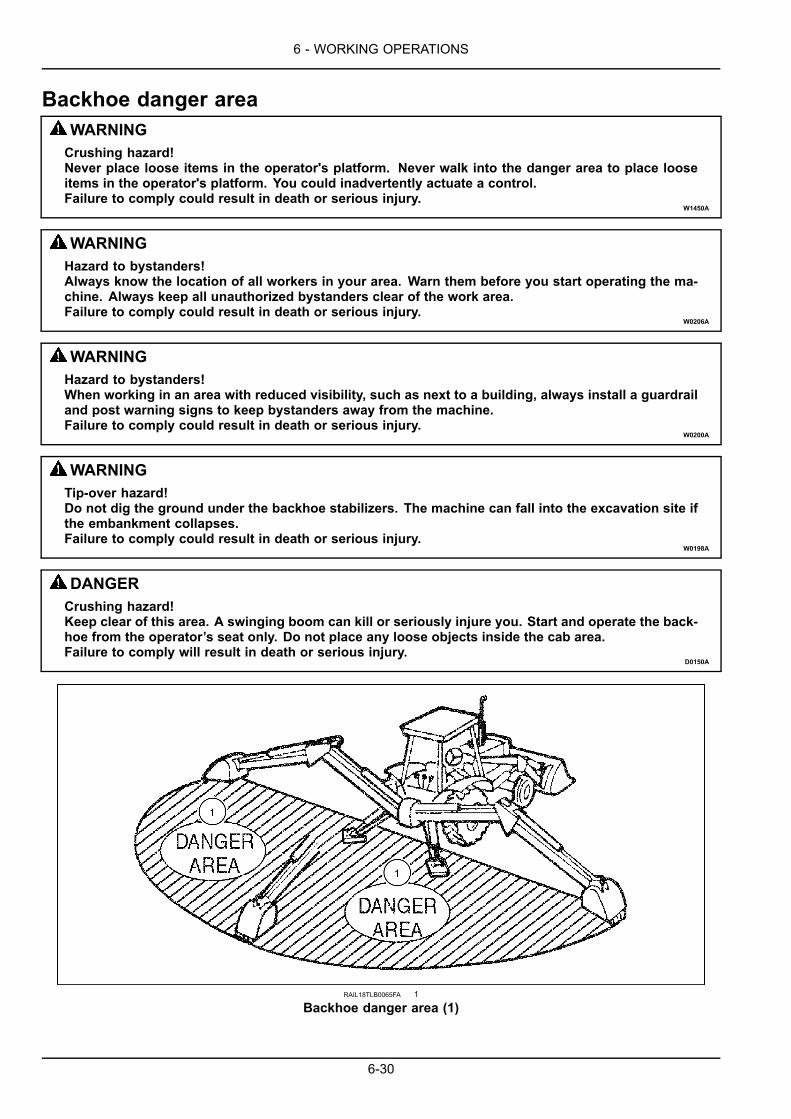
6 - WORKING OPERATIONS
Backhoe danger areaWARNINGCrushing hazard!Never place loose items in the operator's platform. Never walk into the danger area to place looseitems in the operator's platform. You could inadvertently actuate a control.Failure to comply could result in death or serious injury.
W1450A
WARNINGHazard to bystanders!Always know the location of all workers in your area. Warn them before you start operating the ma-chine. Always keep all unauthorized bystanders clear of the work area.Failure to comply could result in death or serious injury.
W0206A
WARNINGHazard to bystanders!When working in an area with reduced visibility, such as next to a building, always install a guardrailand post warning signs to keep bystanders away from the machine.Failure to comply could result in death or serious injury.
W0200A
WARNINGTip-over hazard!Do not dig the ground under the backhoe stabilizers. The machine can fall into the excavation site ifthe embankment collapses.Failure to comply could result in death or serious injury.
W0198A
DANGERCrushing hazard!Keep clear of this area. A swinging boom can kill or seriously injure you. Start and operate the back-hoe from the operator’s seat only. Do not place any loose objects inside the cab area.Failure to comply will result in death or serious injury.
D0150A
RAIL18TLB0065FA 1
Backhoe danger area (1)
6-30

6 - WORKING OPERATIONS
Swing lockInstall the backhoe swing lock pinMake sure the backhoe swing lock pin is in the LOCKposition whenever the backhoe is not in use. To installthe backhoe swing lock pin:1. Place the seat in the backhoe operating position.2. Center the backhoe over the rear of the machine.3. Turn off the engine.4. If applicable, open the rear window.5. Remove the backhoe swing lock pin from the storage
location and place it in the LOCK position.
NOTE: View is from the operator seat facing the backhoe.RAIL15TLB0255AA 1
RAIL16TLB0375BA 2
Remove the backhoe swing lock pin:To remove the backhoe swing lock pin from the LOCKposition.1. Turn off the machine.2. Place the seat in the backhoe operating position.3. If applicable, open the rear window.4. Remove the backhoe swing lock pin from the LOCK
position and place it in the storage position.
NOTICE: After backhoe operations are complete makesure that you put the backhoe in the stowed position withthe swing lock pin in the lock position.
NOTICE: Do NOT operate the machine if the backhoeswing lock is missing or damaged. Before you operatethe machine, contact your dealer for a replacement.
6-31

6 - WORKING OPERATIONS
Basic instructionsWARNINGAvoid injury!Read and follow the instructions in this manual.Failure to comply could result in death or serious injury.
W1212A
The below instructions contain only basic information to enable you to operate the machine correctly. Make sure thatall the safety precautions listed in this manual are followed when the backhoe attachment is used.
The following instructions do not cover all possible condi-tions of use of the backhoe attachment.
NOTICE: To achieve an optimum balance between ma-chine performance and fuel economy, operate the ma-chine at 1600 – 1700 RPM.
NOTICE: The first time it is operated, maneuver the ma-chine in a clear area and at low speed.
Make sure that no other person is in the working range ofthe machine.
Never dig near or under the stabilizers, since the machinecould fall into the excavation.
When working in an area of reduced visibility, for examplenext to a building, place a safety barrier and sign panelsto prevent anyone coming near the machine.
The backhoe attachment will dig more quickly if the workcycle is short and uninterrupted.
Organize your work site so as to obtain a smooth workcycle.
If you try to use the backhoe bucket for digging too widea trench, you may cause a stall situation (where the dip-per control lever is tilted towards the rear but nothing hap-pens).
The hydraulic system main relief valve makes a noisewhen a hydraulic stall occurs.
This overload prolongs the work cycle and it increases thehydraulic fluid temperature.
6-32

6 - WORKING OPERATIONS
Setting the backhoe attachment in working position – center pivotWARNINGUnexpected machine movement!Before you use the backhoe attachment, make sure that the machine is resting on the stabilizers.Failure to comply could result in death or serious injury.
W1326A
WARNINGUnexpected machine movement!Pilot controls have two different backhoe controls patterns; before operating the machine, checkwhich control function is active.Failure to comply could result in death or serious injury.
W0185A
WARNINGUnexpected machine movement!With the engine running and only the gear lever in neutral, themachine can engage andmove suddenlyif someone accidentally operates this lever. Place all levers in neutral, disengage the power take-off,lower any implements, and set the parking brake before exiting the machine. Use wheel chocks whenparking on slopes.Failure to comply could result in death or serious injury.
W0057A
NOTE: The instruments represented may not exactly correspond to the instruments on your machine.
NOTE: Before using the backhoe controls, make sure that the operator’s seat is correctly adjusted in the backhoeoperation position.
NOTICE: Do not attempt to use the backhoe if it is in the lock position. Damage of components may occur.
NOTICE: Always place the backhoe in the stowed position when operating the loader or during road transport.
NOTICE: Always install the swing lock pin in the lock position when operating the loader or during road transport.
6-33

6 - WORKING OPERATIONS
Removing the backhoe from the stowed position (mechanical)1. Start the machine.2. Place the direction control lever in NEUTRAL position.3. If applicable, place gearshift control lever in the NEU-
TRAL position.
4. Turn the seat into the backhoe operation position.5. If applicable, open the rear window.6. From the operator’s seat, remove the swing lock pin
and place it in the storage position.
RAIL16TLB1340BA 1
RAIL16TLB1504BA 2
7. Lower the stabilizers to the ground so that the rear tiresare just off the ground.
6-34

6 - WORKING OPERATIONS
8. Move the boom all the way towards you to relievepressure on the boom lock (2).
9. Press the button on the boom lock control lever (1)and move forward to disengage the boom lock.
10. Lower the boom.
RAIL15TLB0050AA 3
RAIL15TLB0051AA 4
11. If applicable, remove the extendable dipper lock pin(1) and place it in the storage position (2).
RAIL15TLB0545BA 5
6-35

6 - WORKING OPERATIONS
Removing the backhoe from the stowed position (hydraulically, if equipped)1. Start the machine.2. Place the direction control lever in NEUTRAL position.3. If applicable, place gearshift control lever in the NEU-
TRAL position.
4. Turn the seat into the backhoe operation position.5. If applicable, open the rear window.6. From the operator’s seat, remove the swing lock pin
and place it in the storage position.
RAIL16TLB1340BA 6
RAIL16TLB1504BA 7
7. Lower the stabilizers to the ground so that the rear tiresare just off the ground.
6-36

6 - WORKING OPERATIONS
8. Place the switch (1) in the OFF position to disengagethe hydraulic boom lock (2) . The indicator lamp (3)(mechanical backhoemodels) or the indicator lamp (4)(pilot backhoe models) turns OFF.
9. Lower the boom.
LEEN11T0311AA 8
RAIL15TLB0547BA 9
MOLI12LBB0249AB 10
6-37

6 - WORKING OPERATIONS
10. If applicable, remove the extendable dipper lock pin(1) and place it in the storage position (2).
RAIL15TLB0545BA 11
6-38

6 - WORKING OPERATIONS
Stabilizer padsWARNINGTip-over hazard!Put the stabilizers in the operating position before you lower the boom and extend the dipper. Thefront of the machine can raise above the ground and become unstable if the stabilizers are not downin the operating position.Failure to comply could result in death or serious injury.
W0196A
WARNINGTip-over hazard!Before you raise the stabilizers from the operating position, put the backhoe in the transport positionor completely retract the dipper and raise the boom. Make sure the machine tires are touching theground. The machine can become unstable when the tires are not on the ground.Failure to comply could result in death or serious injury.
W0195A
Always position the stabilizer pads for maximum stability. If you dig next to a building, wall etc., change the positionof the stabilizer pads.
Change the position of a stabilizer pad:1. Remove a retaining ring from the pin on each stabilizer pad.2. Use a hammer and drift pin and remove each pin.3. Put the stabilizer pads into position. For correct stabilizer pad position, refer to stabilizer pad positions later in this
section.4. Install the pins and retaining rings.
Stabilizer pad position
NOTE: Examples are shown for right stabilizers (backhoe operation position). Arrow indicates front of machine.
Standard two position stabilizer pads:
• Digging to the side (working next to buildings, walls etc.)
RCPH10TLB419AAF 1
• Maximum stability for digging to the rear and minimumwidth for traveling
RCPH10TLB418AAF 2
6-39

6 - WORKING OPERATIONS
Combination flip-over stabilizer pads:
• Working on paved surfaces (rubber pad down) (1)• Working on unpaved surfaces (rubber pad up) (2)
MOLI12LBB0515AA 3
6-40

6 - WORKING OPERATIONS
Operating the backhoe attachmentDigging method
RCPH10TLB004GAF 1
1. Correct bucket position2. Incorrect bucket position3. Correct trenching method4. Incorrect trenching method
Operating techniquesNOTICE: Never operate any of the backhoe attachmentcontrol levers with arm locked in transport position.
6-41

6 - WORKING OPERATIONS
Filling the backhoe bucketFill the backhoe bucket by maneuvering the dipper. Keepthe bottom of the backhoe bucket parallel to the cut. Thebackhoe bucket teeth and blade must cut the ground likethe blade of a knife. The depth of dig varies depending onthe type of material.
Dump the bucket contents onto the spoil pile, rolling outthe bucket as the pile is approached. Avoid constant jar-ring or hammering-type contact between the spoil pile andbucket as this will cause wear to the bucket pins and bush-ings.
LEEN12T0664AA 2
Moving the machine forwards when workingon flat ground1. It is possible to use the backhoe attachment to move
the machine forward at the same time as the excava-tion.
2. Make sure that the front wheels are straight.3. Set the engine speed to 1000 RPM.4. Release the parking brake.5. Raise the boom and retract the dipper, then move
the boom so as to place the backhoe bucket teethon stable ground.
6. Raise the stabilizers and the loader bucket about20 cm (7.9 in) from the ground.
7. Use the boom and dipper to move the machine.8. After moving the machine, lower the stabilizers and
place the loader bucket on the ground, then level themachine.
9. Use the parking brake to brake the machine.
NOTICE: Only use this procedure on level ground.NEVER use it on sloping ground. On sloping groundit is mandatory to turn the operator’s seat to theloader attachment position to move the machine bythe normal procedure.
10. The machine can be moved sideways in the samefashion, except that the bucket must be flat to supportthe weight of the machine.
11. Use the swing control to move the machine sidewaysto the required position.
LEEN12T0665AA 3
6-42

6 - WORKING OPERATIONS
Telescopic dipperNOTICE: To avoid the risk of damage and to extend theoverall life of machines fitted with a telescopic dipper, ob-serve the following precautions.
When the attachment is used for compacting operations,the telescopic dipper must be fully retracted and locked.
LEEN12T0666AA 4
1. Before returning to normal use, install the pin in work-ing position (1).
2. When you use the hydraulic breaker, make sure thatthe telescopic dipper is retracted and the pin is inlocked position (1).
3. When using a toothed bucket to break hard ground,avoid extending the dipper beyond 0.60 m (1.97 ft).
4. When digging in wet soil or mud and you need to cleanthe bucket, do not knock the bucket against the groundwith the dipper extended.
5. Avoid overloading the attachment by using a bucketwhich is too big in harsh working conditions, as thiswill reduce the useful life of the machine.
MOLI12LBB0288AB 5
6-43

6 - WORKING OPERATIONS
Do not bottom-out the swing cylinder with the dipper ex-tended.
NOTICE: For safety reasons, when working on slopingground, do not swing the boom to dump the bucket con-tents on the side sloping down.
WARNINGUncontrolled equipment movement!Windows can interfere with backhoe controllevers. Make sure the window adjustment islocked into position before actuating the hy-draulics.Failure to comply could result in death or se-rious injury.
W1331A
WARNINGUncontrolled equipment movement!Windows can interfere with backhoe controllevers. Make sure the window adjustment islocked into position before actuating the hy-draulics.Failure to comply could result in death or se-rious injury.
W1331A
WARNINGCrushing hazard!If the machine overturns:1. Always wear your seat belt for protection.2. Remain in the cab. NEVER try to jump fromthe machine.Failure to comply could result in death or se-rious injury.
W1333A
When operating with the dipper fully extended, ensurethat the bucket does not receive a sharp impact which willcause distortion of the cylinder rod.
LEEN12T0667AA 6
6-44

6 - WORKING OPERATIONS
TrenchingTrenching is the most basic backhoe excavating opera-tion.
Other digging operations are merely variations of this ba-sic function (filling the bucket, dumping the bucket andmoving the machine forward).
While trenching, it is generally important to maintain alevel trench bottom. This is accomplished by setting thebucket at the correct angle of approach.
Pull on the dipper lever to maintain the correct cutting an-gle as the bucket is crowding in (1) applying light pressureto the right.
At the same time, pull on the lift lever (2) to relieve downpressure and keep the bucket in the same plane.
Continue the trench bymoving forward. Moving too far willrequire excessive down pressure for digging, plus handclean-up of the trench bottom.
It is better to move a lesser amount that to move too far.
LEEN12T0668AA 7
LEEN12T0669AA 8
When using the backhoe attachment for digging onslopes, if possible, position the attachment uphill. How-ever, if this is not practicable, use the loader or backhoeattachment to cut a level surface into the slope for theuphill wheel and stabilizer, and deposit the spoil from theslot onto the downhill side for the opposite wheel andstabilizer.
When digging always deposit the spoil from the trench onthe uphill side.
NOTICE:When excavating across a slope it is not possi-ble to make use of the loader bucket for added stability.Do not overload the bucket and avoid swinging a loadedbucket to the downhill side of the slope. LEEN12T0670AA 9
To finish the far wall on a straight-walled excavation crowdout the bucket while forcing the bucket down the excava-tion from the boom.
To finish the rear wall crowd in the bucket, while lifting withthe boom, keeping the edges of the bucket horizontal.
LEEN12T0671AA 10
6-45

6 - WORKING OPERATIONS
When finishing straight walls in sandy soil, position a plat-form under the rear tires and stabilizers to distribute theload over a larger area and reduce the possibility of acave-in.
The platformwill also reduce the possibility of themachinecreeping rearwards if hard digging is encountered.
NOTICE: Do not backfill a trench using the swing deviceto swing the bucket sideways. Doing so can damage theboom, swing cylinders or mainframe.
LEEN12T0672AA 11
To backfill a trench, lift the bucket over the spoil pile andthen crowd in the dipper and lift the boom.
Pull both the crowd and boom levers simultaneously forsmooth even backfilling.
LEEN12T0673AA 12
LEEN12T0674AA 13
6-46

6 - WORKING OPERATIONS
Backhoe bucket – Remove1. Move the machine to a level and firm ground.2. Lower the stabilizers and place the bucket on the
ground.3. Stop the engine and remove the starter switch key.
4. CAUTIONFlying objects!Wear eye protection. Do not strike steel partswith a steel hammer. Parts may break.Failure to comply could result in minor ormoderate injury.
C0024A
Remove the lock rings and pins and the rod/bucketlink pin (1).
5. Start the engine.6. Retract the bucket cylinder rod.7. Operate the attachment controls so that the dipper/
bucket pin is not supporting the load of the dipper.8. Stop the engine and remove the starter switch key.9. Remove the lock rings and pins and the arm/bucket
link pin (2).10. Start the engine.11. Operate the attachment controls so as to disconnect
the dipper from the bucket.
LEEN12T0675AA 1
6-47

6 - WORKING OPERATIONS
Backhoe bucket – Install1. Start the engine.2. Extend the bucket cylinder rod to bring the connecting
rod to their housing.3. Reinstall the arm/bucket link pin (2), then install the
lock rings and pins.4. Slightly raise the attachment, then operate the bucket
and dipper control to align the dipper hole with thebucket lugs.
5. Reinstall the rod/bucket link pin (1), then install the lockrings and pins.
LEEN12T0675AA 1
6-48

6 - WORKING OPERATIONS
Backhoe bucket – Digging angleIt is possible to change the backhoe bucket opening an-gle, depending on the work which is to be carried out.
Position (1): Enables the bucket to open by 30° more and,therefore, to dig vertical side trenches closer to the ma-chine.
Position (2): Bucket maximum power.
LEEN12T0676AA 1
6-49

6 - WORKING OPERATIONS
BallastingTire liquid ballasting
Tire size Water Calcium chloride Tire total weight12.5/80-18 89 L (23.51 US gal) 53 kg (117 lb) 142 kg (313 lb)16.9-28 227 L (59.97 US gal) 136 kg (300 lb) 363 kg (800 lb)
NOTE: The tires shown in the table above are for generaloutfit. Therefore, the tires fitted to your machine may varyfrom those shown.
Liquid ballast
Filling the front and rear tires with liquid ballast is a con-venient method of adding weight.
A solution of calcium chloride and water is recommended.This gives a low freezing point and provides a higher den-sity than plain water.
WARNINGHazardous chemicals!SLOWLY add calcium chloride flakes to water,stirring continuously. To avoid a violent reac-tion, NEVER add water to calcium chloride.If any flakes contact the eyes, flush the eyesimmediately with clean, cold water for at least15 minutes. Seek medical assistance immedi-ately.Failure to comply could result in death or se-rious injury.
W0388A
NOTE: When filling a tire with calcium chloride/water so-lution, the valve should be placed at the highest point onthe wheel. The valve should be at the highest point whenchecking or adjusting air pressure if the tire is liquid bal-lasted.
The table above shows the quantity of calcium chlorideand water required for each tire size option and is basedon 0.6 kg (1 lb) of calcium chloride per liter of water to givea 75% fill of the tire. This calcium chloride/water solutionwill give protection from freezing down to an ambient tem-perature of -46 °C (-50.8 °F).
6-50
6 - WORKING OPERATIONS
Weighting limitations
WARNINGOverturning hazard!If the counterweights (of adequate capacity)mentioned in this manual are added, DO NOToperate the loader with the backhoe removed.Operating the unit with less than the recom-mended rear counterweight may cause theunit to become unstable and overturn.Failure to comply could result in death or se-rious injury.
W1332A
If the machine is only fitted with a loader attachment, youmust mount four 453.6 kg (998 lb) weights at the rear ofthe unit to provide counterbalance during loader opera-tion. This provides a total of 1814.4 kg (3992 lb) counter-balance to the rear of the unit.
To obtain sufficient counterbalance for backhoe operation,you can add weight to the unit in the form of cast counter-weights and liquid ballast.
Where additional stability during operation of the back-hoe is required liquid ballast can be added to the tires,as above table.
Because special equipment is required to fill the tires it isrecommended that this be carried out by your dealer.
NOTICE: Only add the quantity of ballast necessary toensure the correct stability. Excess ballast overloads themachine unnecessarily and increases fuel consumption.When adding ballast, do not exceed the maximum loadratings for the tires.
For further information, consult your dealer.
When adding ballast the total weight of the machine in-cluding liquid, cast iron weights and equipment (if fitted)should not exceed the maximum specification.
6-51

6 - WORKING OPERATIONS
Machine weighing
When adding ballast to the machine, do not exceed thegross weight shown on the identification plates.
NOTE: The total weight on the rear axle is measured withonly the rear wheels on the scales, the weight on the frontaxle is measured with only the front wheels on the scales.
LEEN12T0677AA 1
NOTE: The load capacity of the tires may be lower thanthe load capacity of the front axle, if this is the case, thelower value of the two must be used.
Four wheel drive (4WD) front axle maximum permissibleloading inclusive of ballast and loader in the raised posi-tion with no load in the bucket.
Static load rating = 20625 daN (46366.86 lbf).
Dynamic load rating = 8250 daN (18546.74 lbf) [speed40 km/h (24.85 mph)].
Rear axle maximum permissible loading with ballast andbackhoe in the raised position with no load in the bucket.
Static load rating = 18750 daN (42151.69 lbf).
Dynamic load rating = 7500 daN (16860.68 lbf) [speed40 km/h (24.85 mph)].
LEEN12T0678AA 2
6-52

6 - WORKING OPERATIONS
Lifting loads with backhoe attachment1. Move the machine to a level and firm ground.2. Retract the loader bucket completely and then let the
bucket weight press against the ground.3. Lower the loader attachment until the front wheels just
touch the ground without supporting the weight of themachine.
4. Lower the stabilizers until the rear wheels just touchthe ground without supporting the weight of the ma-chine.
5. If the machine is equipped with a telescopic dipper,it is mandatory for it to be completely retracted andmechanically locked.
MOLI12LBB0306AA 1
6. Only use the approved lift hook (1) and mounting tech-nique provided by the manufacturer.
Follow these guidelines before lifting:
• Use slings and chains in perfect conditions. The slingsand chains must be capable to support the load and beequipped with an efficient safety device.
• The maximum authorized load must not exceed1000 kg (2200 lb).
• It is forbidden to weld hooks or lugs to the bottom ofbuckets.
RAIL16TLB0538BA 2
6-53

6 - WORKING OPERATIONS
6-54

7 - MAINTENANCE
7 - MAINTENANCE###_7_###GENERAL INFORMATION
Maintenance safetyWARNINGImproper operation or service of this machine can result in an accident.If you do not understand a maintenance procedure, or doubt your ability to perform a maintenanceprocedure correctly, see your authorized dealer.Failure to comply could result in death or serious injury.
W0157A
WARNINGPressurized system!Before attempting any service procedure, it is your responsibility to know the number of accumulatorson the machine, and the correct procedure for releasing the pressure of each accumulator.Failure to comply could result in death or serious injury.
W0136A
WARNINGPersonal Protective Equipment (PPE) required.When assembling, operating, or servicing the machine, wear protective clothing and PPE necessaryfor the particular procedure. Some PPE that may be necessary includes protective shoes, eye and/orface protection, hard hat, heavy gloves, filter mask, and hearing protection.Failure to comply could result in death or serious injury.
W0353A
NOTICE: While any company can perform necessarymaintenance or repairs on your equipment, NEW HOL-LAND CONSTRUCTION strongly recommends that youuse only authorized NEW HOLLAND CONSTRUCTIONdealers and products that meet given specifications. Im-properly or incorrectly performed maintenance and repairvoids the equipment warranty and may affect serviceintervals.
Perform checks and maintenance operations only afterreading and understanding the instructions and the warn-ings contained in this manual.
Make sure you know the position and function of everycontrol. Operating the controls wrongly can cause seriousphysical injury.
Any modification to this machine without prior authoriza-tion could cause serious injury. Do not make any modifi-cations without authorization. Consult your Dealer.
Carefully observe the maintenance intervals indicated inthis manual.
NOTICE: If you use themachine under particularly severeconditions (dusty or corrosive atmosphere, etc.), reducethe time between the service intervals.
Before performing any operation on the machine, makesure that you have the correct Personal Protective Equip-ment (PPE) to perform the procedure.
LEEN11T0350AA 1
7-1

7 - MAINTENANCE
Machine safety and best practices
WARNINGCrushing hazard!If you service the machine with the loader lift arms raised, always use the support strut. Remove thesupport strut from the storage position and place the strut onto the cylinder rod. Install the retainingbolt entirely into the strut. Lower lift arms onto the support strut.Failure to comply could result in death or serious injury.
W0140A
Follow this procedure for preparing the machine forservice unless the maintenance procedure instructs youotherwise:1. If necessary, remove the loader bucket or attachment.2. If necessary, remove the backhoe bucket or attach-
ment.3. Move the machine to a level and firm ground.4. Lower the loader attachment to the ground with no
down force or raise the loader arm and engage thesafety support strut if engine compartment access isnecessary.
LEEN12T0640AA 2
5. Lower the backhoe bucket to the ground with no downforce or place the backhoe in the stowed position withthe swing lock pin in the lock position.
6. Raise the stabilizers or make sure that they are restingon the ground with no down force..
7. Place the direction-of-travel lever and gearshift leverin the NEUTRAL position.
8. Engage the parking brake.9. Stop the engine.10. Release the hydraulic pressure. See “Hydraulic sys-
tem - Release pressure”7-132 for the complete pro-cedure.
11. Remove the key and attach a DONOTOPERATE tagin a position that all service technicians and machineoperators will notice.
12. Turn the master disconnect switch to OFF.13. Block the wheels.
Personnel
The personnel in charge of the checks and maintenanceoperations must be sufficiently skilled to perform theseoperations on this machine or similar machines.
This skill may be obtained by being trained for severaldays by a technician, for example, or by attending a train-ing course given by qualified instructors.
7-2
7 - MAINTENANCE
Tips and best practicesNOTE: Contact your dealer with any questions regardingthe service and maintenance of this machine.
• Use NEW HOLLAND CONSTRUCTION fluids, lubri-cants, and filters for the best protection and perfor-mance of your machine.
• Perform maintenance procedures in a timely matter.Follow the maintenance chart.
• Dispose of all fluids, lubricants, and filters in compliancewith environmental standards and regulations.
• Wait for the engine, hydraulic systems, and all compo-nents in the area that requires service to cool down.
• Clean the grease fittings before lubricating.
• Before filling oil, clean the area around plugs and fillpoints.
• Make every attempt to prevent dust, dirt, or other con-tainments from entering the hydraulic systems.
• Install all guards and covers after the service procedureis complete.
7-3

7 - MAINTENANCE
Fire extinguisherThe NEW HOLLAND CONSTRUCTION recommends that you keep a fire extinguisher on your machine at all times.A fire extinguisher is available from your dealer.
This dry chemical fire extinguisher has a 2 kg (5 lb) capacity. This type of fire extinguisher is approved for class A, B,and C type fires. The operating temperature is from -54 – 49 °C (-65 – 120 °F).
Fire extinguisher care
• Every month - Inspect the fire extinguisher for damage.Make sure that the gauge is working correctly.
• Once a year - Have the fire equipment representativeinspect the fire extinguisher (refer to standard NFPA-10-1992).
• Every 6 years - Have the dry chemical removed and re-filled by a fire equipment representative (refer to stan-dard NFPA-10 -1992).
• Every 12 years - Have the fire equipment representativehydrostatically test the fire extinguisher (refer to stan-dard NFPA-10 -1992).
7-4

7 - MAINTENANCE
Capacities - B95C, B95C LR, and B95C TCEngine crank caseSpecification:ENGINE OIL SEMI-SYNTHETIC 10W-40( API CJ-4)Capacity:With filter change 8.0 L (8.5 US qt)
Fuel tankSpecification:ASTM D975 GRADE NO. 2-D S15 (No. 2 diesel)Capacity: 131.0 L (34.6 US gal)
Emissions fluid tankSpecification:DIESEL EXHAUST FLUID (DEF)/ADBLUE®Capacity: 13.2 L (3.5 US gal)
Cooling systemSpecification:OAT EXTENDED LIFE COOLANT/ANTIFREEZE( 100% concentrate or 50% concentrate and 50% distilled water)Capacity:With or without heater 24.0 L (25.4 US qt)
Hydraulic systemSpecification:HYDRAULIC TRANSMISSION OIL - PREMIUM orBIODEGRADABLE HYDRAULIC OIL ISO VG 46, DIN 51524 HVLP 46, SYNTHETIC BASECapacity:Total system 142 L (38 US gal)Reservoir refill to sight glass line 51.2 L (13.5 US gal)
TransmissionSpecification:HYDRAULIC TRANSMISSION OIL - PREMIUMCapacity:Manual (powershuttle)
Two-Wheel Drive (2WD) Four-Wheel Drive (4WD)Total system 18.5 L (19.5 US qt) 20.8 L (22.0 US qt)Refill (with or without filter change) 11.9 L (12.6 US qt) 14.4 L (15.2 US qt)
PowershiftFour-Wheel Drive (4WD)
Total system 18.0 L (19.0 US qt)Refill (with or without filter change) 11.4 L (12.0 US qt)NOTE: The master brake cylinder receives fluid from the transmission.
7-5

7 - MAINTENANCE
Front drive axle - Four-Wheel drive (4WD)Specification:PREMIUM TRANSAXLE OIL 80W-140Capacity:Differential 6.5 L (6.9 US qt)Each planetary hub 0.7 L (0.7 US qt)
Rear axle (differential and hubs)Specification:PREMIUM TRANSAXLE OIL 80W-140Capacity: 21.2 L (22.4 US qt)
7-6

7 - MAINTENANCE
Capacities – B110CEngine crank caseSpecification:ENGINE OIL SEMI-SYNTHETIC 10W-40( API CJ-4)Capacity:With filter change 8.0 L (8.5 US qt)
Fuel tankSpecification:ASTM D975 GRADE NO. 2-D S15 (No. 2 diesel)Capacity: 131.0 L (34.6 US gal)
Emissions fluid tankSpecification:DIESEL EXHAUST FLUID (DEF)/ADBLUE®Capacity: 13.2 L (3.5 US gal)
Cooling systemSpecification:OAT EXTENDED LIFE COOLANT/ANTIFREEZE( 100% concentrate or 50% concentrate and 50% distilled water)Capacity:With or without heater 24.0 L (25.4 US qt)
Hydraulic systemSpecification:HYDRAULIC TRANSMISSION OIL - PREMIUM orBIODEGRADABLE HYDRAULIC OIL ISO VG 46, DIN 51524 HVLP 46, SYNTHETIC BASECapacity:Total system 142 L (37.5 US gal)Reservoir refill to sight glass line 51.2 L (13.5 US gal)
TransmissionSpecification:HYDRAULIC TRANSMISSION OIL - PREMIUMCapacity:Manual (powershuttle)
Two-Wheel Drive (2WD) Four-Wheel Drive (4WD)Total system 18.5 L (19.5 US qt) 20.8 L (22.0 US qt)Refill (with or without filter change) 11.9 L (12.6 US qt) 14.4 L (15.2 US qt)
PowershiftFour-Wheel Drive (4WD)
Total system 18.0 L (19.0 US qt)Refill (with or without filter change) 11.4 L (12.0 US qt)NOTE: The master brake cylinder receives fluid from the transmission.
7-7

7 - MAINTENANCE
Front drive axle - Four-Wheel drive (4WD)Specification:PREMIUM TRANSAXLE OIL 80W-140Capacity:Differential 6.5 L (6.9 US qt)Each planetary hub 0.7 L (0.7 US qt)
Rear axle (differential and hubs)Specification:PREMIUM TRANSAXLE OIL 80W-140Capacity: 21.2 L (22.4 US qt)
7-8

7 - MAINTENANCE
Engine hoodNOTICE: It is essential to install the loader attachmentsupport strut before any servicing work is done on theengine.
Open the engine hood:1. Insert the key (1) and turn counter-clockwise.2. Push the key slot on the engine latch to release the
lock (2).3. Use the engine hood lift handles (4), lift, and rotate the
hood (3) into the fully open position.
NOTICE: Before undertaking any road travel, make surethe engine guard is properly locked.
Close and lock the engine hood (figures in reverse order):1. Push the hood down in to the closed position.2. Push the engine latch (2) down into the lock position.3. Insert the key (1) and turn clockwise.
RAIL15TLB0084AA 1
RAIL15TLB0086AA 2
LEEN11T0072AA 3
7-9

7 - MAINTENANCE
Fuel tankThe fuel tank (1) is located on the left-hand side of themachine, under the cab.
NOTE: Fuel tank capacity 131.0 L (34.6 US gal).
Fill the fuel tank through the filler cap (2).
In cold weather, use a fuel suitable to the ambient temper-ature and refill at the end of each working day, in order toprevent condensation.
The filler cap (2) can be unlocked and opened only withthe starter switch key. During installation, make sure it iscorrectly fitted before locking it.
WARNINGFire hazard!When handling diesel fuel, observe the follow-ing precautions:1. Do not smoke.2. Never fill the tank when the engine is run-ning.3. Wipe up spilled fuel immediately.Failure to comply could result in death or se-rious injury.
W0099A
RAIL15TLB0037AA 1
General specification - Diesel fuelOnly use diesel fuel that conforms to North Americanstandard ASTM D975 Grade No. 2-D S15 or equivalentin your engine. Do not use any other low grade dieselfuel.
NOTICE: Use of other low grade diesel fuels will result inloss of engine power, high fuel consumption, and damageto the exhaust aftertreatment system (if equipped).
NOTE:When operating themachine in very cold climates,the use of winter blended fuel is permitted for a short pe-riod of time. See your fuel supplier for winter fuel require-ments in your area.
Fuel conditioner
Diesel fuel conditioner is available from your NEW HOL-LAND CONSTRUCTION dealer. Instructions for the useof the fuel conditioner is on the container.
The use of diesel fuel conditioner will:
• Clean fuel injectors, valves, and manifolds for in-creased service life
• Disperse insoluble gummy deposits that form in the fuelsystem
• Separate moisture from the fuel
• Stabilize fuel in storage
NOTICE: Use only NEW HOLLAND CONSTRUCTIONapproved biocide additives to prevent damage to the ex-haust aftertreatment system (if equipped).
7-10

7 - MAINTENANCE
General specification - Biodiesel fuelsBiodiesel usage in NEW HOLLAND CON-STRUCTION products
Introduction to Fatty Acid Methyl Ester(FAME) biodiesel
FAME biodiesel, called biodiesel fuel in the following sec-tion, consists of a family of fuels derived from vegetableoils treated with methyl esters.
There are two main biodiesel fuel types: RapeseedMethyl Ester (RME) and Soybean Methyl Ester (SME).RME is a blend of rapeseed and sunflower methyl ester,and is the preferred crop in Europe. SME is the preferredcrop in the United States.
Biodiesel fuel is a renewable alternative fuel source. Itsuse and development is promoted worldwide, especiallyin Europe and in the United States.
NOTICE: Your emissions control system is compatiblewith up to 5% biodiesel fuel (B5). Be aware that the useof biodiesel fuel that does not comply with the standardsmentioned in this section could lead to severe damage tothe engine, fuel system or aftertreatment system of yourmachine. The use of non-approved fuels may void NEWHOLLAND CONSTRUCTION Warranty coverage.
Biodiesel can be used to run Tier 4B (final) and Stage IVdiesel engines only when blended with standard dieselfuel:
• B5: indicates the blend of 5% biodiesel and 95% dieselfuels.
• B20: indicates the blend of 20% biodiesel and 80%diesel fuels. Do not use.
Biodiesel fuel has several positive features in comparisonwith diesel fuel:
• Biodiesel fuel adds lubricity to the fuel, which is bene-ficial in many circumstances, particularly as sulfur andaromatics are removed from the fuel.
• Biodiesel has a greater cetane number and burnscleaner.
• Biodiesel produces less particulate matter and reducessmoke emissions.
• Biodiesel is fully biodegradable and non-toxic.
Diesel and biodiesel fuel specifications
Tier 4B (final) and Stage IV diesel fuel specifications arecovered by the following:
• ASTM D975, Standard Specification for Diesel FuelOils. (15 ppm sulfur maximum.)
Biodiesel blends are covered by:
• United States Diesel Fuel Specification ASTM D975 al-lows up to 5% biodiesel since 2009. United States fuel
suppliers are allowed to use up to 5% biodiesel fuel (B5)to supply the network.
• United States Biodiesel Fuel Specification ASTMD7467 provides specifications for diesel and biodieselblends from B5 to B20.
Pure biodiesel blend stock (B100) specification iscovered by the following requirements:
• ASTM D6751 - Standard specification for biodiesel fuelblend stock (B100) for middle distillate fuels.
NOTE: ASTM D6751 specification has been updatedto improve the quality of biodiesel in the market place.
Before raw oil can be converted into usable biodieselfuel, it must undergo transesterification to remove glyc-erides. During the transesterification process, the oilreacts with an alcohol to separate the glycerine fromthe fat or vegetable oil. This process leaves behind twoproducts: methyl ester (the chemical name for biodiesel)and glycerine (a byproduct usually sold for use in soapsor other products).
NOTICE: Biodiesel fuels approved for use in the NEWHOLLAND CONSTRUCTION equipment must be trans-esterified and comply with the latest North America Stan-dard ASTM D6751.
NOTICE: Cold Pressed Biodiesel, Cold Pressed Oil,Straight Vegetable Oil (SVO), or more generally unre-fined vegetable oils used as motor fuel, are fuels that arenormally made from Rapeseed oil or similar high oil con-tent crops. These kinds of fuel are not transesterified, sothey do not fulfil the ASTM D6751 requirements. There isno recognized quality standard available for these typesof fuel. Therefore the use of Cold Pressed Biodiesel,Cold Pressed Oil, Straight Vegetable Oil (SVO), or moregenerally unrefined vegetable oils used as motor fuel areNOT APPROVED at any blend in any NEW HOLLANDCONSTRUCTION product.
NOTICE: Any engine and fuel injection equipment fittedto a NEW HOLLAND CONSTRUCTION vehicle found tohave run with any blend of NON-APPROVED fuel (fuelnot fulfilling the specification described in the requirementASTM D6751) will no longer be covered for Warranty byNEW HOLLAND CONSTRUCTION.
Biodiesel fuel usage conditions
You must stringently follow the biodiesel fuel usage con-ditions. Incorrect application of the biodiesel fuel usageconditions could lead to severe damage to the engine,fuel injection equipment and aftertreatment system.
The main concerns related to operation with biodieselfuels are:
• Filters and injector blockage caused by poor fuel qual-ity.
7-11

7 - MAINTENANCE
• Wear and corrosion of internal components due to wa-ter content, which affects lubricity.
• Deterioration of some rubber sealing compounds in thefuel system.
• Biodiesel oxidation, which can lead to the formation ofdeposits that can harm the fuel injection system.
NOTICE: Any problem in the engine fuel injection equip-ment associated with non-compliance to the followingconditions for biodiesel fuel handling and maintenancewill not be covered for Warranty by NEW HOLLANDCONSTRUCTION.
Purchase biodiesel fuel from a trusted supplier whounderstands the product and maintains acceptable fuelquality. The National Biodiesel Board awards BQ-9000®accreditation to biodiesel marketers and producers thatmeet strict quality and consistency standards. Biodieselusers in North America are strongly encouraged to pur-chase biodiesel blends from the BQ-9000® CertifiedMarketers and sourced from the BQ-9000® AccreditedProducers found on the BQ-9000® website.
The use of biodiesel blends up to B5 will not void theNEW HOLLAND CONSTRUCTION warranty as long asthe following conditions for biodiesel fuel handling andmaintenance are stringently followed:
Biodiesel fuel must be pre-blended by the supplier. Mixingbiodiesel fuels on-site can result in an incorrect mixturethat could damage the engine and/or fuel system.
NOTICE: NEW HOLLAND CONSTRUCTION may voidyour warranty if the problem is associated with poor fuelquality due to improper blending. It is the responsibility ofthe fuel supplier and/or yourself to ensure the right typeof fuel and blend is delivered and used.
Storage
Themachine should not be stored for more than 6monthswith biodiesel in the fuel system. For longer storage time,it is strongly suggested that only regular #2 diesel fuel isused.
NOTE: If storage for longer than 6 months is necessary,the enginemust be run on regular #2 diesel for a minimumof 20 hours to flush the biodiesel fuel out of the fuel systemprior to storage.
Biodiesel is highly hygroscopic and tends to collect watermore than diesel fuel. This increases the risk of algaeand bacteria growth which can cause severe damage tothe fuel injection system. Keep the machine fuel tanksand on-site storage tanks as full as possible to limit theamount of air and water vapors inside the tank. Drainwater from the tanks at least once a week.
NOTICE: Use only NEW HOLLAND CONSTRUCTIONapproved biocide additives on Tier 4B (final) and StageIV engines with an exhaust aftertreatment system.
Limited B10 biodiesel approval
NEW HOLLAND CONSTRUCTION approves the use ofup to B10 on Tier 4B (final) and Stage IV engines onlyin Minnesota (or other States & Provinces) where thestate legislation mandates its usage during the monthsof April to September only and the state legislation man-dates strict compliance of the B10 to specification ASTMD7467. The B10 must consist of a blend of S15 #2DDiesel Fuel per ASTM D975 and B100 blend stock perASTM D6751 only.
7-12

7 - MAINTENANCE
Selective Catalytic Reduction (SCR) exhaust treatment - BasicinstructionsRequirements
The operator must maintain appropriate Diesel Exhaust Fluid (DEF)/AdBlue® levels at all times. No additional main-tenance is required.
NOTICE: Prolonged idling of the machine with no load for more than 6 h will cause damage to the SCR catalyst.
NOTE: See your NEW HOLLAND CONSTRUCTION dealer for replacement components and cleaning agents.
NEW HOLLAND CONSTRUCTION recommends using ENGINE OIL SEMI-SYNTHETIC 10W-40. See Recommendedengine oil for operating temperature ranges for other recommended engine oils, their operating temperature rangesand their required oil change interval.
See “General specification - Biodiesel fuels” for details on biodiesel fuel usage in your NEW HOLLAND CONSTRUC-TION machine.
NOTICE: While any company can perform necessary maintenance or repairs on your equipment, NEW HOLLANDCONSTRUCTION strongly recommends that you use only authorized NEW HOLLAND CONSTRUCTION dealersand products that meet the given specifications. Improperly or incorrectly performed maintenance and repair voidsthe equipment warranty and may affect service intervals.
Diesel Exhaust Fluid (DEF)/AdBlue® refillingThe DEF/ADBLUE® tank (1) is located on the left-handside of the machine, on the front portion of the fuel tankassembly.
The DEF/AdBlue® tank cap (1) can be identified by the“blue” color of the cap. A fitting under the cap preventsthe insertion of a diesel fill nozzle.
NOTE: DEF/ADBLUE® tank capacity 13.2 L (13.9 US qt).
NOTICE: If any DEF/AdBlue® spills or contacts anysurface other than the storage tanks, immediately cleanthe affected surface with clear water. DEF/AdBlue®will cause corrosion on painted and unpainted metallicsurfaces, and may distort some plastic and rubber com-ponents.
RAIL15TLB0037AA 1
It is recommended that DEF/AdBlue® filling equipment should be used having a fill nozzle/pump with the correctlength and diameter, triggered by the magnet in the tank filler neck, and with overfill flow cut out.
This will ensure that:
• The screen in the filler neck will not be damaged.
• Impurities are not entering the DEF/AdBlue® tank. The standardized DEF/AdBlue® nozzle matches the filler neckdiameter.
• The DEF/AdBlue® tank is not overfilled, as the DEF/AdBlue® pump will stop when the DEF/AdBlue® tank is full.
• DEF/AdBlue® is not pumped in the fuel tank, as the DEF/AdBlue® nozzle cannot pump when the magnet is notsensed.
NOTICE: If a warning light has been triggered for low or empty DEF/AdBlue®, the system must be reset by cyclingthe key switch OFF then ON after refilling the DEF/AdBlue® tank.
NOTICE: Refilling with a funnel is not recommended, as this may lead to damage of the screen in the filler neck.
NOTE: The information above has been provided by the International Organization for Standardization (ISO), Docu-ment number ISO 22241-4 Diesel engines - NOx reduction agent AUS 32 - Part 4: Refilling interface.
7-13

7 - MAINTENANCE
Diesel Exhaust Fluid (DEF)/AdBlue® consumptionNOTE: DEF/AdBlue® consumption is highly dependent on engine loads, humidity levels, DEF/AdBlue® fluid concen-tration, and engine speed. The “typical” consumption is only a guideline to verify proper function of the SCR system.NEW HOLLAND CONSTRUCTION recommends to fill the DEF/AdBlue® tanks at every fuel refilling interval.
7-14

7 - MAINTENANCE
Hydraulic oilFor the first filling, the Manufacturer uses HYDRAULICTRANSMISSION OIL - PREMIUM.
Hydraulic oil is not water-soluble; this can cause the for-mation of condensation water in the hydraulic oil tank.Therefore, periodically drain condensation water, espe-cially after the machine has been left unused for a longtime.
Dispose of the drained liquid properly.
Ecological hydraulic oil
The hydraulic system of this machine can be filled alsowith ecological synthetic hydraulic oil (special equipment).In this case, tags reporting special warnings will be ap-plied to the machine.
This synthetic hydraulic oil “ BIODEGRADABLE HYDRAULICOIL ISO VG 46, DIN 51524 HVLP 46, SYNTHETIC BASE”has been tested by the Manufacturer, prior to approvingits use on these machines.
It is also possible to change from mineral hydraulic oilto this synthetic hydraulic oil afterwards. Ecological syn-thetic hydraulic oil must be disposed of properly. It mustbe disposed of as would any other oil.
In case the hydraulic oil is released to the environment, in-form the machine’s owner and the competent authorities.
The use of “ BIODEGRADABLE HYDRAULIC OIL ISO VG 46,DIN 51524 HVLP 46, SYNTHETIC BASE” fluid is only limitedto hydraulic systems.
Do not mix the hydraulic oil with oils of different brands; apossible mix would reduce its biodegradability.
7-15

7 - MAINTENANCE
Hydraulic oil tankThe hydraulic oil tank (1) is located on the right hand sideof the machine, under the cab.
NOTE: Tank capacity fill to the sight glass line is 50.8 L(13.4 US gal).
The oil level can be checked through the sight glass (2).
The hydraulic oil tank can be filled through the fill cap/breather (3). The fill/cap can be removed with a specialwrench (4). The special wrench is supplied with the ma-chine, and is located inside of the door covering the elec-trical master disconnect switch.
RAIL15TLB0013AA 1
RAIL15TLB0083AA 2
RAIL15TLB0082AA 3
7-16

7 - MAINTENANCE
Recommended engine oil for operating temperature rangesNEW HOLLAND CONSTRUCTION prefers the use of ENGINE OIL SBL CJ-4 engine oil in your engine.
You may also use CI-4 ENGINE OIL in your engine.
You may use other engine oils if the engine oils meet API CJ-4 performance requirements.
NEW HOLLAND CONSTRUCTION engine oils exceed API CJ-4 performance requirements.
See the following chart for recommended viscosity at varying ambient air temperature ranges.
NOTE: Do not put performance additives or other oil additive products in the engine crankcase. See dealer for ap-proved engine oil additives, engine oil analysis test package information.
Recommended viscosity grades at varying ambient temperature limits
(H) 0W-40 CJ-4 to CNH MAT3571(H) 0W-40 API CJ-4
(H) 10W-40 CJ-4 to CNH MAT3571(H) 10W-40 API CJ-4
(H) 15W-40 CJ-4 to CNH MAT3572(H) 15W-40 API CJ-4
-40 °C-40 °F
-30 °C-22 °F
-20 °C-4 °F
-10 °C14 °F
0 °C32 °F
10 °C50 °F
20 °C68 °F
30 °C86 °F
40 °C104 °F
50 °C122 °F
(H) = Engine oil pan or coolant block heater recommended in this range
Engine oil and filter service intervals
NEW HOLLAND CONSTRUCTION develops the oil/filter change intervals given in this manual from tests with NEWHOLLAND CONSTRUCTION lubricants/filters.
Engine oil and filter service interval recommendations are based on type of engine oil, oil filter used, sulfur, Bio-dieselcontent of diesel fuel. See diesel fuel recommendations for the approved Diesel fuel sulfur content, Bio-Diesel blends,and fuel specification information.
Always change engine oil and oil filter at the below service intervals or annually whichever comes first
Engine oil and filter service intervalsEngine Oil which meets MAT3571 specification ENGINE OIL SBL CJ-4 600 hoursEngine Oil which meets MAT3572 specification CI-4 ENGINE OIL 500 hoursOther oils which meet API CJ-4 specifications 300 hours
7-17

7 - MAINTENANCE
Organic Acid Technology (OAT) coolantNEW HOLLAND CONSTRUCTION requires the use of a fully formulated Organic Acid Technology (OAT) basedcoolant. OAT EXTENDED LIFE COOLANT/ANTIFREEZE is preferred. The coolant must meet the specifications outlinedin the CNH Industrial material specification MAT3624. Use of coolant not meeting this specification is not allowed.Mixing of different coolant brands is not recommended.
NOTICE:OAT coolant is mandatory for all FPT engines compliant to Tier 4B (final) emissions using Selective CatalyticReduction (SCR). NEVER mix OAT coolant with conventional coolant. Under no circumstances should you top off acooling system with only water. You can use a refractometer to check the concentration level. You should not useSupplemental Coolant Additives (SCA) when using OAT EXTENDED LIFE COOLANT/ANTIFREEZE. Change the coolantsolution at the recommended change interval.
The decal shown is located near the fill point of the cool-ing systemwhenever the factory fill isOAT EXTENDED LIFECOOLANT/ANTIFREEZE. This decal is available in three dif-ferent sizes. See the table below for the associated partnumbers.
NOTE: Organic Acid Technology (OAT) appears yellowin small quantities. OAT coolant can also appear yellowwhen against translucent backgrounds. However, undercertain lighting conditions and backgrounds, such as look-ing into the coolant overflow tank, OAT coolant may ap-pear green. The green appearance is similar to the colorof ethylene glycol coolant. This color appearance is nor-mal, which is not an indication of mixed coolant fill in newunits built after the implementation of OAT coolant.
CNH Industrial partnumber
Size
90393154 50 mm x 50 mm90393165 75 mm x 75 mm90393170 100 mm x 100 mm
90393154 1
Definitions
Conventional coolant:A coolant that relies on inorganic inhibitors such as sil-icates, nitrites, and phosphates for corrosion and cavi-tation protection.
Organic Acid Technology (OAT) coolant:A coolant that relies on inhibitors such as organic acidsalts for corrosion and cavitation protection.
7-18

7 - MAINTENANCE
Diagnostic/Service tool portConnect the Electronic Service Tool (EST) or DATAR to this port to update software and/or perform service and diag-nostic tests.
1. Remove themain fuse cover panel cover from the frontright-hand side console.
RAIL16TLB0532BA 1
2. Unscrew the cap for the diagnostic/service tool port (1)or connect to the FleetForce™ 4-pin connector (2).
3. Install caps and fuse panel cover after diagnostic test-ing is complete.
RAIL15TLB0257BA 2
7-19

7 - MAINTENANCE
Hydraulic diagnostic test portsEasily check the machine’s hydraulic system pressure from two locations on the machine. Each location has hydraulicquick connect diagnostic test port(s). One location is on the left-hand side of the machine above the fuel tank behinda cover panel and the second location is near the right-hand stabilizer on the inside of the chassis.
Hydraulic test port configurationsNOTICE: Always keep the covers on the quick connect test ports when not in use.1. Remove the corner panel on the lower left-hand side
of the operator platform.
RAIL15TLB0023AA 1
2. Wipe clean the quick connect test ports before attach-ing diagnostic equipment. The decal (A) identifies thetest port function.
RAIL15TLB0032AA 2
Machines with backhoe pilot controls:
• Pump output pressure test port (1)• Load sense pressure test port (2)• Pilot pressure test port (3)
84146221 3
7-20

7 - MAINTENANCE
Machines with backhoe mechanical con-trols:
• Load sense pressure test port (1)• Pump output pressure test port (2)• Mechanical pressure test port (3)
84411882 4
Rear port (attenuator hose) – All machines
At the attenuator hose connector test for pump outputpressure, hydraulic flow, or bleed air from the system.
3. After testing is complete make sure all caps on theconnectors are securely in place.
4. If applicable, secure the cover plate to the platform.
RAIL15TLB0003BA 5
RAIL15TLB0004BA 6
7-21
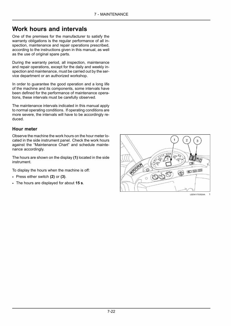
7 - MAINTENANCE
Work hours and intervalsOne of the premises for the manufacturer to satisfy thewarranty obligations is the regular performance of all in-spection, maintenance and repair operations prescribed,according to the instructions given in this manual, as wellas the use of original spare parts.
During the warranty period, all inspection, maintenanceand repair operations, except for the daily and weekly in-spection andmaintenance, must be carried out by the ser-vice department or an authorized workshop.
In order to guarantee the good operation and a long lifeof the machine and its components, some intervals havebeen defined for the performance of maintenance opera-tions, these intervals must be carefully observed.
The maintenance intervals indicated in this manual applyto normal operating conditions. If operating conditions aremore severe, the intervals will have to be accordingly re-duced.
Hour meterObserve themachine the work hours on the hour meter lo-cated in the side instrument panel. Check the work hoursagainst the “Maintenance Chart” and schedule mainte-nance accordingly.
The hours are shown on the display (1) located in the sideinstrument.
To display the hours when the machine is off:
• Press either switch (2) or (3).• The hours are displayed for about 15 s.
LEEN11T0352AA 1
7-22

7 - MAINTENANCE
MAINTENANCE CHART
Maintenance chartDrain fluid CleaningFilling Grease
Check AdjustReplace Change fluid
Maintenance action Page no.At warning message display
Engine air filters x 7-25Hydraulic filter(s) x 7-27Fuel system water separator x 7-29Diesel Exhaust Fluid (DEF)/AdBlue®/ARLA tank - Filling x 7-31Diesel Exhaust Fluid (DEF)/AdBlue®/ARLA tank - Drain fluid x 7-32Hydrocarbon management x 7-34
Initial 10 hoursWheels - Check x 7-35
Every 10 hoursChecks at start-up and before each workshift (10 hours) x 7-37Working attachments - Loader attachment x 7-38Working attachments - Backhoe attachment x 7-39Windshield washer fluid level - Check x 7-40Engine oil level - Check x 7-41Engine coolant - Check x 7-43Radiator, oil cooler, and condenser - Check x 7-44Alternator - Check x 7-45Hydraulic oil level - Check x 7-46Hydraulic hoses, tubes, and fittings x 7-48
Every 50 hoursWorking attachments - greasing x 7-49Door hinges x 7-50Front axle trunnion x 7-50Front axle king pins x 7-51Seat and seat belt x 7-52Fuel pre-filter - draining condensation x 7-53Tire pressure x 7-55
Every 250 hoursDrive shaft lubrication x 7-59Engine cooling system - Check x 7-60Fuel tank - Drain fluid x 7-61Hydraulic oil tank breather / filler cap - cleaning x 7-62Transmission oil level x 7-63Front axle breather (4WD) - Clean x 7-64Front axle and reduction gear oil level (4WD) x 7-65Front axle system - Check - (2WD) x 7-67Rear axle oil level - Check x 7-68Rear axle breather x 7-69Radiator and condenser - cleaning x 7-70Drive belts - check x 7-72Cab air filter x 7-73Heater and evaporator (Air-conditioning system) - Cleaning x 7-76Telescopic dipper x 7-77Battery terminals x 7-78Cab protection system x 7-80
Every 500 hours
7-23

7 - MAINTENANCE
Drain fluid CleaningFilling Grease
Check AdjustReplace Change fluid
Maintenance action Page no.Engine oil and filter x 7-83Fuel filter x 7-87Fuel prefilter x 7-88Diesel Exhaust Fluid (DEF)/AdBlue® tank filler screen x 7-90Diesel Exhaust Fluid (DEF)/AdBlue® in-line filter x 7-92
Every 1000 hoursHydraulic oil filter x 7-95Hydraulic oil x 7-97Power shuttle transmission - Oil change x 7-100Power shuttle transmission - Oil filter replacement x 7-102Power shuttle transmission - Screen filter cleaning x 7-103Powershift transmission - Oil change x 7-105Powershift transmission - Oil filter replacement x 7-107Front axle fluid - Four-Wheel Drive (4WD) x 7-108Rear axle x 7-110Machine inspection and cleaning x 7-111Brake pedal lever - Greasing x 7-112Hydraulic cylinders x 7-113Alternator - check x 7-114
Every 1500 hours of operation or annuallyEngine breather filter x 7-115
Every 3000 hoursDiesel Exhaust Fluid (DEF)/AdBlue® supply module filter x 7-116
Every 4000 hoursEngine coolant x 7-122
As requiredDrive belt x 7-124Air-conditioning compressor drive belt x 7-126Turbocharger - Check x 7-127Fuel system bleeding x 7-128Wheels and tires x 7-129Hydraulic system - Release pressure x 7-132Bulbs x 7-135Fuses and relays - Powershift x 7-137Fuses and relays - Power shuttle x 7-143Telematics system fuses (if equipped) x 7-149Battery removal and installation x 7-150Telescopic dipper (if equipped) x 7-152Bucket teeth x 7-153Loader bucket - Self-leveling adjustment x 7-154Disable parking brake x 7-156
7-24

7 - MAINTENANCE
At warning message display
Engine air filters
Clean or replace the engine air filter whenever the warning lamp remains illuminated while the engine is running.
1. Clean the area around the outside front cover of the airfilter housing.
2. Inspect the air filter housing and components for dam-age.
3. Release the clips that secure the air filter housing coverin place.
RAIL14TLB0979BA 1
4. Remove and inspect the primary filter.A. Replace the filter if you notice damage to the sides
or edges. If you do not notice damage, continue tothe next step.
B. Examine the inside of the filter. If the filter has dustand debris on the inside, replace the filter. If thefilter is clean continue to the next step.
C. Lightly tap the ends of the filter against the palmof your hand. Never tap the ends against a hardsurface.
D. Shine a light inside the filter. Replace the filter ifyou see light spots or deteriorated areas. If nodamage is apparent, use the same filter.
NOTICE: It is okay to clean the primary filter three or fourtimes, however you must replace a damaged filter.
RAIL14TLB0975AA 2
7-25

7 - MAINTENANCE
5. With the primary filter removed, use a lint-free cloth tiedto a stiff rod and wipe the inside of the housing clean.Avoid touching the inner filter.
RAIL14TLB0976AA 3
6. Remove the inner filter only if the outside of it is dirty,replace the inner filter do not clean. Repeat step 5 ifreplacing the inner filter.
RAIL14TLB0976AA 4
7. Dispose of the filters in accordance with local, regional,and federal regulations.
8. If applicable, install the inner air filter. Ensure that youform a tight seal.
9. Install the primary air filter. Ensure that you form a tightseal.
10. Fasten the clips that secure the air filter housing inplace.
11. Start up the engine.
12. Ensure that the warning lamp does not illuminate. Ifthe warning lamp continues to illuminate replace theouter filter. If the problem continues replace the innerfilter.
7-26

7 - MAINTENANCE
Hydraulic filter(s)
NOTICE: Always replace the hydraulic filter whenever the warning lamp remains illuminated while the engine isrunning.
NOTICE: Oil quality and cleanliness are of utmost importance for the reliability and life of the hydraulic system. De-viation from the prescribed oil specification may lead to severe damage and void warranty.Hydraulic oil specification: HYDRAULIC TRANSMISSION OIL - PREMIUM
1. Prepare the machine for service:A. Park on level ground.B. Lower all attachments to the ground.C. Engage park brake.D. Turn off engine.E. Move each hydraulic control levers in all directions
to relieve pressure.
The hydraulic filter is located under the left rear portionof the machine just in front of the rear axle.
RCPH10TLB042AAF 1
2. Use the special wrench and slowly open the hydraulicreservoir cap to relieve system pressure.
RAIL15TLB0083AA 2
7-27

7 - MAINTENANCE
3. Clean the area around the filter head area before re-moving the old filter. Wear eye protection to keep dirtand debris from eyes.
4. Use a filter wrench and remove the old filter. Have asuitable container ready to capture any fluid that mightleak or spill.
5. Dispose of the filter in accordance with local, regional,and federal regulations.
6. Lubricate the gasket of the new filter with clean oil.
7. Install the new filter and turn it clockwise until the gasketcontacts the head of the filter assembly.
8. Continue to tighten the filter for 1/3 turn.RCPH10TLB045AAF 3
9. Tighten the hydraulic reservoir cap.
10. Start up the engine.
11. Ensure the warning lamp does not illuminate.
12. After running for three or four minutes, shut down theengine.
13. Inspect for leaks.
14. Add fluid if necessary.
7-28

7 - MAINTENANCE
Fuel system water separatorDrain the water separator and check the fuel tank when-ever the engine fault indicator lamp (1) illuminates, theaudible alarm sounds, and the water in fuel systemscreen (2) appears in the display.
NOTICE: The indicator lamp only illuminates at potentialproblems. To ensure themachine operates correctly, followthe maintenance service interval guidelines listed on themaintenance decal and in this manual.
RAIL19TLB0004AA 1
NOTE: A clear bowl allows a visible check of the fuel forwater. If water or sediment is present, drain water out ofthe filter and the fuel tank.
RAIL11TLB0009AA 2
1. Remove the wire connector attached to the bottom ofthe drain valve for the water separator.
• Press on the wire clasp that holds the connector tothe drain to remove.
RAIL11TLB0007AA 3
RCPH10TLB031AAF 4
7-29

7 - MAINTENANCE
2. Hold a small container under the water separator andloosen the drain valve.
3. Collect a small amount of fluid and inspect for water orsediment.
4. Drain until water or sediment is no longer present.
5. Close the drain valve.
6. If water or sediment was found in the water separator,drain the fuel tank.A. Place a collection container under the drain plug
and remove the plug.B. After water and sediment are removed, install and
tighten the plug.
NOTE: Drain plug is underneath the machine on the backside of the tank.
RAIL15TLB0035AA 5
7-30

7 - MAINTENANCE
Diesel Exhaust Fluid (DEF)/AdBlue®/ARLA tank - FillingDiesel Exhaust Fluid (DEF)/AdBlue® tank capacity: 13.5 L (3.6 US gal).
When theDiesel Exhaust Fluid (DEF)/AdBlue® lowfluid symbol appears in the display you will also noticeone of the following symbols illuminate on the instru-ment cluster:
Warning symbol and an audible alert. Thesystem detects that the DEF/AdBlue® fluid is toolow.
Stop symbol with an audible alert. The systemdetects that the DEF/AdBlue® fluid is extremelylow. The system will begin to de-rate engine speedand torque.
NOTE: When you refuel your machine also fill the DEF/AdBlue®.
RAIL14TLB1090AA 1
1. Remove the filler cap (1) on the DEF/AdBlue® tank.
2. Fill the tank with DEF/AdBlue®.
NOTICE:Do not remove the tank filler screen and use cau-tion not to damage the filler screen during the fill process.Damage to the filler screen or removal of the filler screenduring the fill processmay allow impurities to enter the SCRsystem and cause a malfunction to occur.
RAIL15TLB0037AA 2
7-31

7 - MAINTENANCE
Diesel Exhaust Fluid (DEF)/AdBlue®/ARLA tank - Drain fluidDiesel Exhaust Fluid (DEF)/AdBlue® tank capacity: 13.5 L (3.6 US gal).
When the Diesel Exhaust Fluid (DEF)/AdBlue® poorquality symbol appears in the display you will also no-tice one of the following symbols illuminate on the in-strument cluster:
Warning symbol and an audible alert. Thesystem detects that the DEF/AdBlue® quality ispoor.
Stop symbol with a constant audible alert.The system detects that the DEF/AdBlue® qual-ity is poor. The system will begin to de-rate enginespeed and torque.
RAIL14TLB1163AA 1
1. Remove the filler cap (1) on the DEF/AdBlue® tank.
RAIL15TLB0037AA 2
2. Remove the cover plate below the DEF/AdBlue® tankdrain plug.
RAIL15TLB0034AA 3
7-32

7 - MAINTENANCE
3. Place a suitable container below theDEF/AdBlue®tank drain plug.
RAIL15TLB0033AA 4
4. Install the DEF/AdBlue® tank drain plug.
5. Install the cover plate.
6. If applicable, clean the “Diesel Exhaust Fluid (DEF)/AdBlue® tank filler screen” 7-90, the “Diesel ExhaustFluid (DEF)/AdBlue® in-line filter” 7-92, and replace the“Diesel Exhaust Fluid (DEF)/AdBlue® supply modulefilter” 7-116.
NOTE: Contact your authorized dealer if your current supply of DEF/AdBlue® is low or the quality is questionable.7. Fill the DEF/AdBlue® with new DEF/AdBlue®.
NOTICE:Do not remove the tank filler screen and use cau-tion not to damage the filler screen during the fill process.Damage to the filler screen or removal of the filler screenduring the fill processmay allow impurities to enter the SCRsystem and cause a malfunction to occur.
8. Operate the machine and monitor. The system mayrequire a validation restart.
NOTICE: If the poor quality symbol continues to appear on the display contact your authorized dealer for assistance.
7-33

7 - MAINTENANCE
Hydrocarbon management
NOTICE: Unless the Hydrocarbon (HC) level has reached the most critical level (SCR catalyst full ), runningthe unit under load is advantageous for quickly reducing the HC levels.If the engine operates at low idle speed for a prolonged period of time, hydrocarbons can accumulate in the SCR cat-alyst. To manage this accumulation, your machine will monitor current conditions and increase idle speed or requestaction from the operator in order to increase the temperature inside the SCR catalyst and eliminate the hydrocarbons.
Low Idle Increase RecommendedDisplay Audible alert Action
3 consecutive beepsThe Engine Control Unit (ECU) requires the operator toincrease load on the engine or increase engine idle speed to aminimum of 1350 RPM.
Low Idle Increase ActiveDisplay Audible alert Action
5 consecutive beeps
The Engine Control Unit (ECU) will automatically increaseengine idle speed to 1350 RPM.
The Engine Control Module (ECU) will allow automaticHydrocarbon management only if the machine meets thefollowing requirements for 10 min:• the FORWARD-NEUTRAL-REVERSE (F-N-R) lever is keptin the NEUTRAL position
• the park brake is engaged
• the engine idle speed is below 1350 RPMNOTE: This automatic engine idle speed increase is inhibited if any of the conditions are not met or certain featuresare active on the machine. For example: operating the hand or foot throttle.
NOTE: The operator is free to interrupt the auto idle increase and operate the machine. The display may change to
the low idle increase recommended , if the system determines that additional Hydrocarbon (HC) reductionis required.
SCR Catalyst FullDisplay Audible alert Action
with illumination
Constant audible alarm
1. Place the FORWARD-NEUTRAL-REVERSE (F-N-R) leverin the NEUTRAL position.
2. Engage the park brake.3. Use the hand throttle and manually increase the engine
speed to 1500 RPM.
NOTE: The operator does not need to stay with the machine during the Hydrocarbon management procedure. Oncethe procedure is complete the display message will disappear and the operator may resume machine operation.
NOTE: This procedure may take approximately 1 – 2 h to complete depending on the ambient air temperature.
NOTICE: Do not turn off the engine, drive the machine, or increase the load on the machine to avoid damage to thecatalyst.
7-34

7 - MAINTENANCE
Initial 10 hours
Wheels - CheckNOTE: Depending on the manufacturing date of your machine the front wheel mounting hardware may be either lugnuts or bolts with washers. Check the wheel torque that is applicable to your machine.
NOTICE: Small variations in the friction force between the wheel and the mounting hardware, such as lubricant, lackof lubricant, paint, surface rust, thread variations, etc., will cause large variations in the clamping force. It has beenshown that the tension on fasteners or lug nuts is directly proportional to the angle of turn on a nut or bolt. Unlikethe automotive industry, our rims do not have a precision centering hub to locate and support the wheel and the lowlength to diameter ratio of the studs make the preload even more critical.
NOTICE: Never use the minimum final torque value to set the torque for a wheel installation. Only use the torqueplus the additional degree angle turn provided in the procedure. The minimum final torque value is only for checkingthe torque 10 h after a wheel installation or on a new machine.Check the torque of the wheel nuts and bolts after the first 10 h of operation of a new machine or after a wheel install.If the nuts and bolts are loose, tighten, and check after an additional 10 h of operation. Repeat until the nuts and boltsremain tight.
Machine preparation1. Move the machine to a level and firm ground.
2. Place the direction-of-travel lever and gearshift lever inneutral position.
3. Engage the parking brake.
4. Stop the engine.
5. Slightly loosen (unlock) the wheel mounting hardwarewhen the tire is still holding the weight of the machine.
6. Start the engine.
7. Use the loader attachment or the rear stabilizers to liftthe machine until the wheel that you will remove is justoff the ground.
8. Stop the engine and remove the starter switch key.
9. Place wedges in front and rear of the tires that you willnot be removing.
10. If applicable, on both sides of the front axle wedgeblocks between the axle and the frame so the axle willnot swivel.
11. Remove all the wheel mounting hardware.
12. Remove the wheel.
13. Install a new wheel, observing the orientation of thetread pattern.
7-35

7 - MAINTENANCE
Rear wheel1. Tighten the five mounting nuts in the sequence
shown until the wheel is snug against the axle hub.2. Tighten the nuts in sequence to a torque of
136 N·m (100 lb ft).3. Tighten the nuts a second time, in sequence, to a
torque of 271 N·m (200 lb ft).4. Tighten the nuts in sequence an additional 30° to
set the preload.5. Repeat the procedure on the remaining fivemount-
ing nuts.
RAIL14FRK0031BA 1
Rear wheel onlyTorque
First sequence 136 N·m (100 lb ft)Second sequence 271 N·m (200 lb ft)Preload Additional 30°Minimum final torque value for checking purposes only 813 N·m (600 lb ft)
Front wheelsNOTICE: Tighten wheel hardware in a crossing pattern (sequence), as shown.
1. Tighten the eight mounting bolts in sequence untilthe wheel is snug against the axle hub.
2. Tighten the bolts in sequence to a torque of122 N·m (90 lb ft).
3. Tighten the bolts in sequence an additional 20° toset the preload.
RAIL14FRK0032BA 2
Front wheels – 2WD and 4WDTire size Torque Minimum final torque value
for checking purposes only11 x 1612 x 16.5
12.5/80 x 1814 x 17.5
122 N·m (90 lb ft) plusan additional 20° to set the preload 330 N·m (243 lb ft)
7-36

7 - MAINTENANCE
Every 10 hours
Checks at start-up and before each workshift (10 hours)Machine - General inspection
Before using the machine, it is recommended to per-form a general inspection.
Externally check the machine and its working attach-ments, checking for possible breaks or damage ofthe components or the structure. Should problems bedetected, contact an authorized workshop to have thenecessary repairs carried out.
Replace the damaged or excessively worn parts withoriginal spare parts.
Keep the machine clean by daily removing the dirt ac-cumulated while working.
Service brakeCheck the operation of the service (pedal) brakes on ahard level surface.
1. Make sure the area is clear of other workers or by-standers.
2. Lock both pedals together with the brake pedal lock.
3. Shift the transmission to 2nd gear.
4. Drive the machine forward at full throttle.
5. When themachine is moving at full speed, remove yourfoot from the throttle and stop the machine.
6. The machine must stop smoothly in a straight line andthe brake pedal effort must feel firm.
NOTICE: If the machine does not stop in a straight line orif the brake pedal effort feels soft, contact your dealer forservice.
Parking brakeThe parking brake is not serviceable. If a reduction ofthe braking action is detected, contact the Service De-partment.
LightsBefore using the machine, it is recommended to checkthat all lights are clean and correctly operating.
Functionality of controls and lightsBefore using the machine, it is recommended to checkthat all controls, instruments and lamps in the operator’scompartment are correctly operating.
Should problems be detected, stop the engine and findthe cause of the anomaly.
7-37

7 - MAINTENANCE
Working attachments — Loader attachmentLoader attachment1. Lubricate the loader attachment.
NOTE: The number of grease points may vary dependingon the type of accessory installed.
Number of grease fittings: 26
LEEN11T0365AA 1
Grease specificationsUse MULTI-PURPOSE MOLY GREASE EXTREME PRES-SURE AND ANTI-WEAR NGLI-2
7-38

7 - MAINTENANCE
Working attachments — Backhoe attachmentBackhoe attachment1. Lubricate the backhoe attachment.
NOTE: The number of grease points may vary dependingon the type of accessory installed.
Number of grease fittings: 30
LEEN11T0367AA 1
Grease specifications2. Use MULTI-PURPOSE MOLY GREASE EXTREME PRES-
SURE AND ANTI-WEAR NGLI-2.
7-39

7 - MAINTENANCE
Windshield washer fluid level — Check1. Move the machine to a level and firm surface.
2. Make sure the machine is in a safe condition.
3. Stop the engine and remove the starter switch key.
4. To check the level of the windshield wiper/washer fluid,open the reservoir cap (1) check the windshield wiper/washer fluid.
5. If the wiper/washer fluid is not visible, then refill thereservoir.
NOTICE: The windshield wiper motor is gravity-fed. Do notremove the rubber tube as damage can be caused if liquidgets into the motor.
LEEN12T0570AA 1
Fluid specification and capacityUse CONCENTRATED WINDSCREEN WASH or a wind-screen washer fluid approved by NEW HOLLANDCONSTRUCTION.
7-40

7 - MAINTENANCE
Engine oil level — Check1. Move the machine to a level and firm surface.
2. Raise the loader attachment and install the safety sup-port strut.
3. Place the backhoe attachment in the road travel posi-tion.
4. Place the direction-of-travel lever and gearshift lever inthe neutral position.
5. Engage the parking brake.
6. Stop the engine and remove the starter switch key.
7. Release any possible residual pressure from the hy-draulic system by moving the control levers in all direc-tions.
8. Unlock and open the engine hood.
9. Remove the dipstick (1), wipe it with a clean cloth andcompletely insert and then remove the dipstick again.
RAIL15TLB0025AA 1
10. Check to the oil level on the dipstick.
LEEN11T0361AA 2
7-41

7 - MAINTENANCE
11. If the oil level is below the add mark, remove the fillercap (2), and add ENGINE OIL SEMI-SYNTHETIC 10W-40to raise the level up to the full mark on the dipstick.
12. Reinstall the filler cap (2).
RAIL15TLB0025AA 3
13. Close and lock the engine hood.
14. Remove the safety support strut and lower the loaderattachment.
Oil specification and capacityUse ENGINE OIL SEMI-SYNTHETIC 10W-40.Engine oil capacity: 8.0 L (8.5 US qt)
NOTICE: For machines operating in cold regions, refer to Page 7-17
7-42

7 - MAINTENANCE
Engine coolant — CheckWARNINGHot liquid under pressure!Scalding can result from fast removal of the radiator cap. Check and service the engine cooling sys-tem according to the maintenance instructions in this manual.Failure to comply could result in death or serious injury.
W0163A
1. Move the machine to a level and firm surface.
2. Lower the loader attachment to the ground.
3. Place the backhoe attachment in the road travel posi-tion.
4. Place the direction-of-travel lever and gearshift lever inthe neutral position.
5. Engage the parking brake.
6. Stop the engine and remove the starter switch key.
7. Wait for the machine to cool down.
8. Unlock and raise the engine hood.
9. Check the level of the fluid in the reservoir (1).
10. The fluid level in the coolant reservoir (1) must bebetween the two marks.
11. If necessary, remove the fill cap (2) and addmoreOATEXTENDED LIFE COOLANT/ANTIFREEZE solution.
RAIL15TLB0026AA 1
12. Lower and lock the engine hood.
Coolant specification and capacityUse OAT EXTENDED LIFE COOLANT/ANTIFREEZE solu-tion.
Capacity: 24.0 L (25.4 US qt)
7-43

7 - MAINTENANCE
Radiator, oil cooler, and condenser — CheckWARNINGHot liquid under pressure!Scalding can result from fast removal of the radiator cap. Check and service the engine cooling sys-tem according to the maintenance instructions in this manual.Failure to comply could result in death or serious injury.
W0163A
1. Move the machine to a level and firm surface.
2. Raise the loader attachment and install the safety sup-port strut.
3. Place the backhoe attachment in the road travel posi-tion.
4. Place the direction-of-travel lever and gearshift lever inthe neutral position.
5. Engage the parking brake.
6. Stop the engine, and remove the starter switch key.
7. Release any possible residual pressure from the hy-draulic system by moving the control levers in all direc-tions.
8. Wait for the machine to cool down.
9. Unlock and raise the engine hood.
10. Inspect the engine coolant radiator, and the air condi-tioning condenser for leaks or damage.
11. Inspect the cooling system and air conditioning sys-tem hoses and lines for leaks and damage.
12. Contact your local authorized dealer for repairs.
13. Lower and lock the engine hood.
14. Remove the safety support strut and lower the loaderattachment.
7-44

7 - MAINTENANCE
Alternator — Check1. Move the machine to a level and firm surface.
2. Raise the loader attachment and install the safety sup-port strut.
3. Place the backhoe attachment in the road travel posi-tion.
4. Place the direction-of-travel lever and gearshift lever inthe neutral position.
5. Engage the parking brake.
6. Stop the engine and remove the starter switch key.
7. Wait for the machine to cool down.
8. Unlock and raise the engine hood.
NOTE: Make sure the terminal protectors are correctly installed.
NOTICE: Do not use steam cleaning devices nor cleaning solvents to clean the alternator.9. Check the alternator (1) for loose external wire connec-
tions, and listen for excessive noise during machine op-eration.
10. If alternator operation is in question, have it checkedby your Authorized Dealer.
RAIL15TLB0040AA 1
11. Lower and lock the engine hood.
12. Remove the safety support strut and lower the loaderattachment.
7-45

7 - MAINTENANCE
Hydraulic oil level — Check1. Move the machine to a level and firm surface.
2. Lower the loader attachment to the ground.
3. Place the backhoe attachment in the road travel posi-tion.
4. Place the direction-of-travel lever and gearshift lever inthe neutral position.
5. Engage the parking brake.
6. Stop the engine and remove the starter switch key.
7. Release any possible residual pressure from the hy-draulic system by moving the control levers in all direc-tions.
8. Check the hydraulic oil level in the tank (1) by means ofthe level sight gauge (2) after waiting for the oil to cooland reach ambient temperature.
RAIL15TLB0039AA 1
9. The hydraulic oil level must reach at least the upper halfof the level sight gauge (2).
RAIL15TLB0013AA 2
7-46

7 - MAINTENANCE
10. If necessary, remove the tank fill cap/breather (3) withthe special wrench (4) and add additional HYDRAULICTRANSMISSION OIL - PREMIUM until the level is correctinside of the level sight gauge.
NOTE: Even when oil level is insufficient, a small quantityof hydraulic oil remains in the lower part of the gauge. Thisdoes not indicate that the level is sufficient.
RAIL15TLB0083AA 3
Oil specificationUse HYDRAULIC TRANSMISSION OIL - PREMIUM.
NOTICE: Oil quality and cleanliness are of utmost importance for the reliability and life of the hydraulic system. De-viation from the prescribed oil specification may lead to severe damage and void the warranty.
7-47

7 - MAINTENANCE
Hydraulic hoses, tubes, and fittingsWARNINGHot liquid under pressure!If leaks are detected in the hydraulic hoses, tubes, or fittings during the inspection, carry out thefollowing before you perform any maintenance activities:1. Stop the engine.2. Release the hydraulic system pressure.Failure to comply could result in death or serious injury.
W1334A
Check the hydraulic system lines and hoses for possibleleaks.
Repair all hydraulic oil leaks promptly to avoid loss ofoil and possible damage and dirt entry into the system.When checking for hydraulic leaks, start and operatethe engine at 1200-1500 RPM.
Remove and install new hoses immediately, if they areseverely damaged by a cut or scrape, swollen at thefittings, or leaking.
If you replace a hydraulic hose or tube, use the followingprocedure.
1. Loosen the fittings (1) and remove the hose or tube,then remove and discard the O-ring seal (2).Immerse the new O-ring into clean hydraulic oil beforeassembly.
2. Install the new O-ring (2) into the fitting (1) and if nec-essary, retain in position using PETROLEUM JELLY. As-semble the new hose or tube and tighten the fitting fin-ger-tight, while holding the tube or hose to prevent itfrom turning. The tube’s or hose’s turning could dam-age the O-ring.
3. Using two suitable wrenches, tighten the fittings tospecification.
NOTICE: When replacing or assembling a pipe or hose,make sure that all elements are perfectly clean and freefrom any trace of dirt. Failure to ensure absolute cleanli-ness will result in the hose / pipe leaking after installationor possible damage to other hydraulic system components.
LEEN11T0359AA 1
To ensure a leak-free joint, do not over-torque or under-torque the fittings.When replacing a hose, it is necessary to bleed air fromthe system. For this purpose, let the engine run at1200–1500 RPM, contemporarily actuating the loaderand backhoe attachment controls for 15 min or until airis bled from the system.
LEEN11T0360AA 2
7-48

7 - MAINTENANCE
Every 50 hours
Working attachments - greasingTelescopic dipper railsNOTICE: Before applying new grease on the sliding surfaces, clean and remove all dirt accumulations and foreignbodies.1. Apply grease on the sliding surface of the telescopic
dipper rails (1).
LEEN12T0686AA 1
Grease specificationsUse MULTI-PURPOSE MOLY GREASE EXTREME PRES-SURE AND ANTI-WEAR NGLI-2.
7-49

7 - MAINTENANCE
Door hinges1. Lubricate the door hinges. The number of grease fit-
tings (1): 4
LEEN11T0373AA 1
Grease specificationsUse MULTI-PURPOSE MOLY GREASE EXTREME PRES-SURE AND ANTI-WEAR NGLI-2.
Front axle trunnionFront axle - Greasing1. Locate the grease fitting (1) at the front of the ma-
chine and lubricate the front axle trunnion with MULTI-PURPOSE MOLY GREASE EXTREME PRESSURE AND ANTI-WEAR NGLI-2. Number of grease fittings (1): 1
RAIL15TLB0045AA 1
Grease specificationsUse MULTI-PURPOSE MOLY GREASE EXTREME PRES-SURE AND ANTI-WEAR NGLI-2
7-50

7 - MAINTENANCE
Front axle king pinsAxle articulations - Greasing1. Locate the grease fittings (1) on the top and bottom
of each side of the front axle. Lubricate the axle ar-ticulation points with MULTI-PURPOSE MOLY GREASEEXTREME PRESSURE AND ANTI-WEAR NGLI-2. Numberof grease fittings (1): 4
LEEN11T0389AA 1
Grease specificationsUse MULTI-PURPOSE MOLY GREASE EXTREME PRES-SURE AND ANTI-WEAR NGLI-2.
7-51

7 - MAINTENANCE
Seat and seat beltSeat suspension and rails - Clean and lubrication1. Check the operation of the operator’s seat and of the
seat belt, and the solidity of the seat belt mountings.
2. Replace parts showing signs of wear or damage.
3. Wipe all moving parts with a clean cloth and apply alight coat of GRAPHITE LUBRICANT NON-STICK for lubri-cation.
LEEN11T0378AA 1
7-52

7 - MAINTENANCE
Fuel pre-filter - draining condensationWARNINGFire hazard! Avoid injury and/or machine damage!During maintenance activities, make sure that the high-pressure fuel lines are not damaged. A fuelleak from the high-pressure fuel lines can cause an accident and/or serious personal injury. If the fuellines are damaged, contact your dealer immediately.Failure to comply could result in death or serious injury.
W1335A
1. Move the machine to a level and firm surface.
2. Raise the loader attachment and install the safety sup-port strut.
3. Place the backhoe attachment in the road travel posi-tion.
4. Place the direction-of-travel lever and gearshift lever inthe neutral position.
5. Engage the parking brake.
6. Stop the engine and remove the starter switch key.
7. Release any possible residual pressure from the hy-draulic system by moving the control levers in all direc-tions.
8. Wait the time necessary to allow the engine and the fuelsystem to cool down.
9. Place a suitable container under the machine.
10. Unlock and raise the engine hood.
11. Locate the fuel filter (1) to drain the water and sed-iments through the drain valve on the bottom of thefilter.
RAIL15TLB0027AA 1
7-53

7 - MAINTENANCE
12. Remove the connector (2) from the bottom of the filter.
13. Install a drain pipe (about 1 m long 3.2 ft) on the drainvalve, (3) and put the other end of the pipe into thecontainer.
14. With engine inoperative, loosen the drain valve abouttwo turns and drain the water and sediment, until onlyclean fuel runs out.
15. Tighten the drain valve without over tightening andinstall the connector.
RAIL15TLB0028AA 2
16. If necessary bleed air from filter (see page 7-25)
NOTE: The drain interval can be increased or decreased, depending on the presence of water and the quantity offuel.17. Lower and lock the engine hood.
18. Remove the safety support strut and lower the loaderattachment.
7-54

7 - MAINTENANCE
Tire pressureWARNINGExplosion hazard!A tire can explode during inflation. Replace a tire if it has any defect(s). Replace a wheel rim that hascracks, wear, or severe rust.Failure to comply could result in death or serious injury.
W0455A
WARNINGExplosion hazard!When inflating tires, use a clip-on air chuck with a gauge, remote valve, and hose long enough toallow you to stand to one side and NOT in front of or over the wheel assembly. Keep others out of theDANGER AREA. Never inflate a tire beyond the maximum allowable pressure printed on the tire.Failure to comply could result in death or serious injury.
W0059A
WARNINGExplosion hazard!Always maintain correct tire pressure as indicated in this manual. DO NOT inflate tires above therecommended pressure. Excessive pressure could result in tire failure.Failure to comply could result in death or serious injury.
W0109A
NOTICE: Check pressure only with cold tires; when tires are warm, the pressure values detected are higher.A too low pressure can reduce the machine’s stabilityand overheat the tires, and could cause:
• tire break;
• tire tread damage;
• internal damage;
• irregular wear and shortened life.An excessive pressure determines a higher sensitive-ness to damage in case of shocks and, in extreme con-ditions, the rim could get deformed or the tire may burst.
NOTE: The tire inflating pressure varies according to theload weighing on the axles.
A. Under inflatedB. Over inflatedC. Correctly inflated
LEEN11T0371AA 1
7-55

7 - MAINTENANCE
Inflating procedure1. Move the machine to a level and firm ground.
2. Lower the loader attachment to the ground.
3. Place the backhoe attachment in the road travel posi-tion.
4. Place the direction-of-travel lever and gearshift lever inneutral position.
5. Immobilize the machine by means of the parking brake.
6. Stop the engine and remove the starter switch key.
7. Insert the self-locking spout of the inflating device (1)into the tire valve.
8. The inflating device is equipped with a pressure gauge(2) which enables, as soon as it is connected, to checkthe pressure value.
9. If pressure is lower than the recommended pressure,inflate.
LEEN11T0372AA 2
7-56

7 - MAINTENANCE
Inflating pressure and allowed carrying capacity tableNOTE: The following tables give the approximate carrying capacity at the indicated tire pressures when traveling ata maximum speed of 30 km/h (19 mph).
INFLATION PRESSURE bar (psi)1.5
(21.8)2.0
(29.0)2.2
(31.9)2.5
(37.7)2.8
(42.0)3.0
(43.5)3.3
(47.8)3.8
(55.1)4.0
(58.0)4.2
(60.9)
MAX LOAD PER TIRE kg (lb)
Front2WD
Tiresize11L–16
ProfileF3
700(1543)
845(1862)
900(1984)
985(2171)
1065(2347)
1120(2469)
1185(2612)
1250(2755)
1350(2976)
1400(3086)
INFLATION PRESSURE bar (psi)0.8(11.6)
1.0(14.5)
1.6(23.2)
2.2(31.9)
2.8(40.6)
3.4(49.3)
MAX LOAD PER TIRE kg (lb)
Front4WD
Tiresize12–16.5
ProfileL5
690(1521)
790(1741)
1040(2292)
1250(2755)
1440(3174)
1610(3549)
INFLATION PRESSURE bar (psi)0.8(11.6)
1.0(14.5)
1.6(23.2)
2.2(31.9)
2.8(40.6)
3.5(50.7)
MAX LOAD PER TIRE kg (lb)
Front4WD
Tiresize14–17.5BeefyB.
ProfileR4
850(1873)
975(2149)
1090(2403)
1180(2601)
1320(2910)
1450(3196)
INFLATION PRESSURE bar (psi)0.8(11.6)
1.6(23.2)
2.0(29.0)
2.8(40.6)
3.1(44.9)
3.5(50.7)
MAX LOAD PER TIRE kg (lb)
Front4WD
Tiresize14–17.5Con-st.
ProfileR4
940(2072)
1410(3108)
1605(3538)
1960(4321)
2080(4585)
2655(5853)
INFLATION PRESSURE bar (psi)1.4
(20.3)1.5
(21.7)1.7
(24.6)2.1
(30.4)2.2
(31.9)
MAX LOAD PER TIRE kg (lb)Rear
Tiresize16.9–24 EZ
ProfileR4
2200(4840)
2325(5115)
2450(5390)
2910(6402)
3120(6878)
INFLATION PRESSURE bar (psi)1.2
(17.4)1.4
(20.3)1.5
(21.7)1.9
(27.5)
MAX LOAD PER TIRE kg (lb)Rear
Tiresize19.5–24
ProfileL4
2520(5555)
2740(6040)
2875(6338)
3410(7517)
INFLATION PRESSURE bar (psi)1.2
(17.4)1.4
(20.3)1.5
(21.7)1.9
(27.5)2.2
(31.9)2.5
(37.7)
MAX LOAD PER TIRE kg (lb)Rear
Tiresize16.9–28 EZ
ProfileR4
2300(5070)
2490(5489)
2620(5776)
3110(6856)
3410(7517)
3580(7893)
7-57

7 - MAINTENANCE
INFLATION PRESSURE bar (psi)1.2
(17.4)1.4
(20.3)1.5
(21.7)1.9
(27.5)2.2
(31.9)3.4
(49.3)
MAX LOAD PER TIRE kg (lb)Rear
Tiresize21L–24 EZ
ProfileR4
2455(5412)
2840(5467)
3005(6624)
3165(6977)
3760(8289)
4030(8884)
7-58

7 - MAINTENANCE
Every 250 hours
Drive shaft lubricationCardan shafts - Greasing1. Move the machine to a level and firm surface.
2. Lower the loader attachment to the ground.
3. Place the backhoe attachment in the road travel posi-tion.
4. Place the direction-of-travel lever and gearshift lever inthe neutral position.
5. Engage the park brake.
6. Stop the engine and remove the starter switch key.
7. Release any possible residual pressure from the hy-draulic system by moving the control levers in all direc-tions.
8. Locate the grease fittings (1) on the cardan shaftsand apply MULTI-PURPOSE MOLY GREASE EXTREMEPRESSURE AND ANTI-WEAR NGLI-2 grease. Number ofgrease fittings (1): 2 (4WD) / 1 (2WD)
NOTE: Only lubricate the shaft, the U-joint does not havea grease fitting.
LEEN11T0391AA 1
7-59

7 - MAINTENANCE
Engine cooling system — CheckCooling system lines - Check1. Move the machine to a level and firm surface.
2. Raise the loader attachment and install the safety sup-port strut.
3. Place the backhoe attachment in the road travel posi-tion.
4. Place the direction-of-travel lever and gearshift lever inthe neutral position.
5. Engage the parking brake.
6. Stop the engine and remove the starter switch key.
7. Release any possible residual hydraulic pressure bymoving the control levers in all directions.
8. Unlock and raise the engine hood.
9. Check all of the engine cooling system lines for possibleleaks.
10. Check the tightness of the collars, fittings, hoses andpipes of the engine cooling system.
11. Repair any leaks or contact your local authorizeddealer for machine service.
12. Lower and lock the engine hood.
13. Remove the safety support strut and lower the loaderattachment.
7-60

7 - MAINTENANCE
Fuel tank - Drain fluid1. Move the machine to a level and firm surface.
2. Lower the loader attachment to the ground.
3. Place the backhoe attachment in the road travel posi-tion.
4. Place the direction-of-travel lever and gearshift lever inthe neutral position.
5. Engage the parking brake.
6. Stop the engine and remove the starter switch key.
7. Release any possible residual hydraulic pressure bymoving the control levers in all directions.
8. Place a container of the appropriate capacity under thefuel tank located on the left side of the machine.
RAIL15TLB0037AA 1
9. Remove the drain plug from the fuel tank and drain thecontaminated fuel and sediment from the tank.
RAIL15TLB0035AA 2
10. When clean fuel flows from the drain, reinstall andsecure the drain plug.
11. Check the fuel level and refill the tank if necessary.
7-61

7 - MAINTENANCE
Hydraulic oil tank breather / filler cap - cleaningCAUTIONFlying debris!Compressed air can propel dirt, rust, etc. into the air. Wear eye and face protection when using com-pressed air.Failure to comply could result in minor or moderate injury.
C0049A
1. Move the machine to a level and firm surface.
2. Lower the loader attachment to the ground.
3. Place the backhoe attachment in the road travel posi-tion.
4. Place the direction-of-travel lever and gearshift lever inthe neutral position.
5. Engage the parking brake.
6. Stop the engine and remove the starter switch key.
7. Release any possible residual hydraulic pressure bymoving the control levers in all directions.
8. Locate the wrench (1) supplied with the machine andclean the area around the filler cap/breather.
RAIL15TLB0082AA 1
9. Use the wrench (1) and remove the cap/breather (2).
10. Make sure that no dirt or foreign bodies enter the hy-draulic oil tank.
11. Use a suitable grease solvent to wash the cap.
12. Leave the cap to air-dry.
13. Reinstall and tighten the cap (2).
RAIL15TLB0083AA 2
7-62

7 - MAINTENANCE
Transmission oil levelNOTICE: Check the oil level with the engine running at low speed and at normal operating temperature.1. Move the machine to a level and firm surface.
2. Raise the loader attachment and install the safety sup-port strut.
3. Place the backhoe attachment in the road travel posi-tion.
4. Place the direction-of-travel lever and gearshift lever inthe neutral position.
5. Engage the parking brake.
6. Stop the engine and remove the starter switch key.
7. Unlock and raise the engine hood.
8. Insert the starter switch key, restart the engine andkeep it at low idle.
9. Extract the dipstick (1), clean it with a clean cloth andcompletely insert it into the tube, then extract it again.
10. If the oil level is below the minimum mark, addHYDRAULIC TRANSMISSION OIL - PREMIUM to raise thelevel to the mark.
11. Stop the engine.
12. Lower and lock the engine tilt hood.
13. Remove the safety support strut and lower the loaderattachment.
RAIL15TLB0029AA 1
Oil specification and CapacitiesUse HYDRAULIC TRANSMISSION OIL - PREMIUM.Capacities
• Machines with power shuttle transmission (2WD):11.9 L (12.6 US qt)
• Machines with power shuttle transmission (4WD):14.4 L (15.2 US qt)
• Machines with powershift transmission: 11.4 L(12.0 US qt)
7-63

7 - MAINTENANCE
Front axle breather (4WD) - Clean1. Move the machine to a level and firm surface.
2. Lower the loader attachment to the ground.
3. Place the backhoe attachment in the road travel posi-tion.
4. Place the direction-of-travel lever and gearshift lever inthe neutral position.
5. Engage the parking brake.
6. Stop the engine and remove the starter switch key.
Front axle breather valve - Cleaning7. Clean the area around the breather valve (1).
8. Loosen and remove the valve.
9. Clean the breather valve (1) with a detergent solution.
NOTICE: Follow the instructions for the detergent solution.
10. Carefully dry the breather valve (1) with compressedair and reinstall it.
11. Reinstall the breather valve.
RAIL15TLB0044AA 1
7-64

7 - MAINTENANCE
Front axle and reduction gear oil level (4WD)1. Move the machine to a level and firm ground.
2. Lower the loader attachment to the ground.
3. Place the backhoe attachment in the road travel posi-tion.
4. Place the direction-of-travel lever and gearshift lever inthe neutral position.
5. Engage the parking brake.
6. Stop the engine and remove the starter switch key.
Axle oil level1. Unscrew and remove the plug (1).
2. Check the level by checking if the oil reaches the heightof the plug hole.
3. If necessary, add additional oil.
4. Insert and tighten the plug (1).
LEEN11T0375AA 1
Oil specification and capacitiesUse PREMIUM TRANSAXLE OIL 80W-140 (MAT 3510) oran oil meeting the below standard: SAE 80W-140
Capacities: 4WD Differential: 6.5 L (6.9 US qt)
7-65
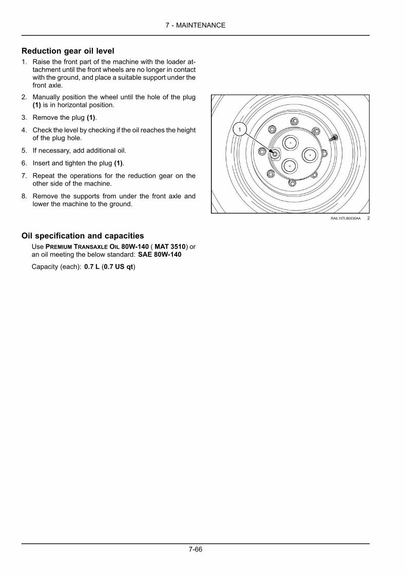
7 - MAINTENANCE
Reduction gear oil level1. Raise the front part of the machine with the loader at-
tachment until the front wheels are no longer in contactwith the ground, and place a suitable support under thefront axle.
2. Manually position the wheel until the hole of the plug(1) is in horizontal position.
3. Remove the plug (1).
4. Check the level by checking if the oil reaches the heightof the plug hole.
5. If necessary, add additional oil.
6. Insert and tighten the plug (1).
7. Repeat the operations for the reduction gear on theother side of the machine.
8. Remove the supports from under the front axle andlower the machine to the ground.
RAIL15TLB0030AA 2
Oil specification and capacitiesUse PREMIUM TRANSAXLE OIL 80W-140 (MAT 3510) oran oil meeting the below standard: SAE 80W-140
Capacity (each): 0.7 L (0.7 US qt)
7-66

7 - MAINTENANCE
Front axle system - Check — (2WD)1. Move the machine to a level and firm surface.
2. Lower the loader attachment to the ground.
3. Place the backhoe attachment in the road travel posi-tion.
4. Place the direction-of-travel lever and gearshift lever inthe neutral position.
5. Engage the parking brake.
Reduction gear oil level1. Raise the front part of the machine with the loader at-
tachment until the front wheels are no longer in contactwith the ground, and place a suitable support under thefront axle.
2. Stop the engine and remove the starter switch key.
3. Manually position the wheel until the hole of the plug(1) is in horizontal position.
4. Remove the plug (1).
5. Check the level by checking if the oil reaches the heightof the plug hole.
6. If necessary, add additional oil.
7. Insert and tighten the plug (1).
8. Repeat the operations for the other reduction gear onthe other side of the machine.
9. Remove the supports from under the font axle andlower the machine to the ground.
RAIL15TLB0030AA 1
Oil specification and capacitiesUse PREMIUM TRANSAXLE OIL 80W-140 (MAT 3510) oran oil meeting the below standard: SAE 80W-140.
Capacity (each): 0.8 L (0.8 US qt)
7-67

7 - MAINTENANCE
Rear axle oil level - Check1. Move the machine to a level and firm surface.
2. Lower the loader attachment to the ground.
3. Place the backhoe attachment in the road travel posi-tion.
4. Place the direction-of-travel lever and gearshift lever inthe neutral position.
5. Engage the parking brake.
6. Stop the engine and remove the starter switch key.
Rear axle - Oil level1. Unscrew and remove the plug (1).
2. Check the level by checking if the oil reaches the heightof the plug hole.
3. If necessary, add additional oil.
4. Insert and tighten the plug (1).
LEEN11T0386AA 1
Oil specification and capacities5. Use PREMIUM TRANSAXLEOIL 80W-140 (MAT 3510) or
an oil meeting the below standard: SAE 80W-140.
Capacity: 21.2 L (22.4 US qt)
7-68

7 - MAINTENANCE
Rear axle breatherRear axle breather valve - Cleaning1. Move the machine to a level and firm surface.
2. Lower the loader attachment to the ground.
3. Place the backhoe attachment in the road travel posi-tion.
4. Place the direction-of-travel lever and gearshift lever inneutral position.
5. Immobilize the machine by means of the parking brake.
6. Stop the engine and remove the starter switch key.
7. Clean the area around the breather valve (1).
8. Loosen and remove the breather valve.
9. Clean the breather valve (1) with a detergent solution.
NOTICE: Follow the instructions for the detergent solution.
10. Carefully dry the breather valve (1) with compressedair.
11. Reinstall the breather valve (1).
LEEN11T0386AA 1
7-69
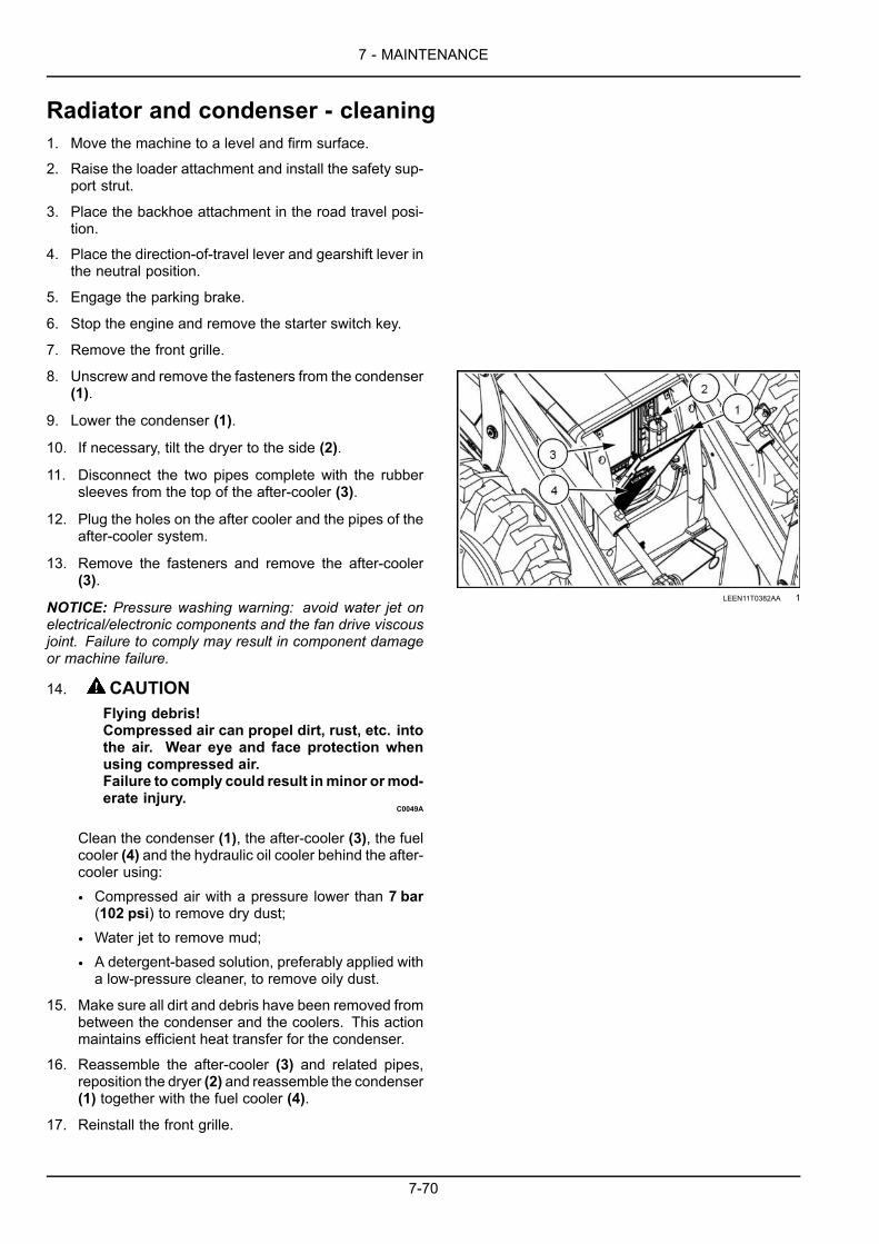
7 - MAINTENANCE
Radiator and condenser - cleaning1. Move the machine to a level and firm surface.
2. Raise the loader attachment and install the safety sup-port strut.
3. Place the backhoe attachment in the road travel posi-tion.
4. Place the direction-of-travel lever and gearshift lever inthe neutral position.
5. Engage the parking brake.
6. Stop the engine and remove the starter switch key.
7. Remove the front grille.
8. Unscrew and remove the fasteners from the condenser(1).
9. Lower the condenser (1).
10. If necessary, tilt the dryer to the side (2).
11. Disconnect the two pipes complete with the rubbersleeves from the top of the after-cooler (3).
12. Plug the holes on the after cooler and the pipes of theafter-cooler system.
13. Remove the fasteners and remove the after-cooler(3).
NOTICE: Pressure washing warning: avoid water jet onelectrical/electronic components and the fan drive viscousjoint. Failure to comply may result in component damageor machine failure.
14. CAUTIONFlying debris!Compressed air can propel dirt, rust, etc. intothe air. Wear eye and face protection whenusing compressed air.Failure to comply could result inminor ormod-erate injury.
C0049A
Clean the condenser (1), the after-cooler (3), the fuelcooler (4) and the hydraulic oil cooler behind the after-cooler using:
• Compressed air with a pressure lower than 7 bar(102 psi) to remove dry dust;
• Water jet to remove mud;
• A detergent-based solution, preferably applied witha low-pressure cleaner, to remove oily dust.
LEEN11T0382AA 1
15. Make sure all dirt and debris have been removed frombetween the condenser and the coolers. This actionmaintains efficient heat transfer for the condenser.
16. Reassemble the after-cooler (3) and related pipes,reposition the dryer (2) and reassemble the condenser(1) together with the fuel cooler (4).
17. Reinstall the front grille.
7-70

7 - MAINTENANCE
18. Remove the safety support strut and lower the loaderattachment.
7-71

7 - MAINTENANCE
Drive belts - check1. Move the machine to a level and firm surface.
2. Raise the loader attachment and install the safety sup-port strut.
3. Place the backhoe attachment in the road travel posi-tion.
4. Place the direction-of-travel lever and gearshift lever inthe neutral position.
5. Engage the parking brake.
6. Stop the engine and remove the starter switch key.
7. Release any possible residual pressure from the hy-draulic system by moving the control levers in all direc-tions.
8. Unlock, and raise the engine hood.
Air-conditioner compressor belt1. Visually check the condition of the belt (1).
2. Replace the belt if it is worn or damaged.
3. Check the belt (1) tension and adjust if necessary. See7-124.
LEEN11T0368AA 1
Drive belt1. Visually check the condition of the belt (1).
2. Replace the belt if it is worn or damaged. See 7-126.
3. To adjust the belt, loosen the bolts (2).
4. Tighten the screw (3) so the top bolt (2) is moved to theend of the slot.
NOTE: This is a self adjusting belt. Further adjustment notrequired.
5. Tighten the bolts (2).
RAIL15TLB0041AA 2
7-72

7 - MAINTENANCE
Cab air filterNOTICE: In humid conditions do not switch on the blower prior to servicing the filter.
1. Park the machine on level ground.
2. Stop the engine and remove the starter switch key.
3. Lift the grid cover (1) upward and remove it from thefilter housing.
RAIL15TLB0610BA 1
4. Remove the filter locking clip (1).
RAIL15TLB0607BA 2
5. Move the filter retaining bracket (2) away from the filter(1).
RAIL15TLB0608BA 3
7-73

7 - MAINTENANCE
6. Gently pull the top of the filter (1) away from the housingand lift the filter out.
NOTE: Replace filter if damage occurs or excessive wearis apparent.
7. Do not clean the filter (1) with air or water pressure.
8. Carefully shake off the filter (1) to remove the surfacedust.
NOTICE: Replace the filter (1) as needed or annually.
NOTICE: Dispose of all fluids filters, and containers in anenvironmentally safe manner and in accordance with locallaws and regulations. Check with local environmental andrecycling centers or your dealer for correct disposal infor-mation.
9. Clean the inside of the filter chamber with a damp lint-free cloth.
RAIL15TLB0609BA 4
10. Fully insert the filter (2).
11. Push and hold the retaining bracket (1) against thefilter (2).
RAIL15TLB0552BA 5
12. Secure the filter position with the locking clip (1).
RAIL15TLB0607BA 6
7-74

7 - MAINTENANCE
13. Slide the grid cover over the filter housing. Make surethat the sliding cover rails (1) engage with the filterhousing rails (2) on both sides.
14. Make sure that the grid cover is evenly and fully in thedown position.
RAIL15TLB0551BA 7
7-75

7 - MAINTENANCE
Heater and evaporator (Air-conditioning system) - CleaningCAUTIONFlying debris!Compressed air can propel dirt, rust, etc. into the air. Wear eye and face protection when using com-pressed air.Failure to comply could result in minor or moderate injury.
C0049A
1. Move the machine to a level and firm ground.
2. Place the direction-of-travel lever and gearshift lever inneutral position.
3. Immobilize the machine with the parking brake.
4. Stop the engine and remove the starter switch key.
5. Remove the operator’s seat.
6. Remove the HVAC cover.
7. Use compressed air not exceeding 7 bar (102 psi).Blow any debris from the heater and evaporator takingcare not to damage the fins.
8. Clean the filter. See 7-73 for details.
NOTE: Clean the filter more frequently when you operatein extremely dusty conditions.
9. Blow any debris off the air intake areas.
10. From underneath the machine check and clear alldrainage valves.
7-76

7 - MAINTENANCE
Telescopic dipperThe telescopic dipper is equipped with adjustable wearpads (4). Adjust the wear pads as follows:
1. Move the machine to a level and firm surface.
2. Lower the loader attachment to the ground.
3. Retract the telescopic dipper and place it on a supportso that the bucket does not rest on the ground.
4. Place the direction-of-travel lever and gearshift lever inneutral position.
5. Engage the parking brake.
6. Stop the engine and remove the starter switch key.
7. Remove a shim (1) from each bolt (2) on only one sideof the dipper.
NOTE: The shims (1) are available under the bolts (2) onboth the sides of the dipper
NOTICE: Remove the shim ONLY from the other side ofthe dipper where shims were removed during the previousadjustment procedure. Contact your dealer, if you are indoubt.
8. Install and torque the bolts (2) to a torque between 350– 400 N·m (258 – 295 lb ft). Check the play again.
9. The play at point (3) should not exceed 1.5 mm(0.06 in).
10. When all adjusting shims have been removed thewear pads (4) will require changing. Consult yourDealer.
LEEN12T0796BA 1
7-77

7 - MAINTENANCE
Battery terminals1. Move the machine to a level and firm surface.
2. Lower the loader attachment to the ground.
3. Place the backhoe attachment in the road travel posi-tion.
4. Place the direction-of-travel lever and gearshift lever inthe neutral position.
5. Engage the parking brake.
6. Stop the engine and remove the starter switch key.
WARNINGBattery gas can explode!To prevent an explosion: 1. Always disconnectthe negative (-) battery cable first. 2. Alwaysconnect the negative (-) battery cable last. 3.Do not short circuit the battery posts with metalobjects. 4. Do not weld, grind, or smoke near abattery.Failure to comply could result in death or seri-ous injury.
W0011A
DANGERExplosion hazard!Batteries emit explosive gases. Always venti-late when using in an enclosed area or whencharging. Keep the battery away from sparks,open flames, and other ignition sources.Failure to comply will result in death or seriousinjury.
D0116A
7. Place the battery switch in OFF position.
RAIL15TLB0014AA 1
7-78

7 - MAINTENANCE
8. Remove the four bolts (1) and the battery cover (2).
RAIL15TLB0073AA 2
RAIL15TLB0074AA 3
9. Check the battery terminals (3) to ensure they are se-cure.
RAIL15TLB0075AA 4
7-79

7 - MAINTENANCE
Cab protection systemThis section provides information about Roll Over Pro-tective Structure (ROPS) and Falling Objects ProtectiveStructure (FOPS).
Always adhere to the safety precautions related to theCab protections systems listed below:
• The machine is provided with a safety structure forthe operator:
• Anti-overturn safety system (ROPS) according todirectives ISO 3471, SAE 1040C
• Safety system against the fall of objects (FOPS)according to the directives ISO 3449, SAE J231protection level 2.
• A ROPS can consist of the cab frame or of a two orfour uprights structure used for the safety of the op-erator, so as to minimize the possibility of severe in-juries. The structure and the fastening devices whichconstitute the connection with the machine are partof the ROPS.
• The protective structure is a special safety compo-nent of your machine.
• DONOT attach any device to the protective structurefor pulling purposes.
• DO NOT drill holes to the Protective Structure.
• The protective structure and interconnecting compo-nents are a certified system. Any damage, fire, cor-rosion or modification will weaken the structure andreduce your protection. If this occurs, the protectivestructure MUST be replaced so that it will providethe same protection as a new Protective Structure.Contact your dealer for Protective Structure inspec-tion and replacement.
• After an accident, fire, tip or roll over, the followingMUST be performed by a qualified technician beforereturning the machine to field or job site operation.
• The protective structure MUST be replaced.
• The mounting or suspension for the ProtectiveStructure, operator seat and suspension, seatbelts and mounting components and wiring withinthe operator’s protective system MUST be care-fully inspected for damage.
• All damaged parts MUST be replaced.
7-80

7 - MAINTENANCE
WARNINGRoll-over hazard!After an accident, fire, tip over, or roll over,a qualified technician MUST replace theRoll-Over Protective Structure (ROPS) beforereturning the machine to the field or job siteoperation.Failure to comply could result in death or seri-ous injury.
W0134A
WARNINGMisuse hazard!Your machine is equipped with an operatorprotective structure. DO NOT weld, drill holes,attempt to straighten, or repair the protectivestructure. Modification in any way can reducethe structural integrity of the structure.Failure to comply could result in death or seri-ous injury.
W0001B
NOTE: For your safety, the machine cab has been de-signed to prevent flame propagation and to limit combus-tions in case of fire. Themachine cab complies to ISO 3795norms.
The Loader has a ROPS/FOPS sign showing the cer-tification of the ROPS/FOPS, gross weight, approval,regulation, and model number of the machine.
LEEN11T0376AA 1
7-81

7 - MAINTENANCE
1. Check and inspect the ROPS/FOPS structure and theseat restraint system every 500 h of operation.
2. Before you operate this machine, always make surethe ROPS/FOPS and operator’s seat belt is correctlyinstalled.
3. The seat belt is an important part of the ROPS/FOPS.You must wear the seat belt at all times when you op-erate the machine.
4. Make sure all hardware that secures the seat to the cabis properly torqued. Make sure all seat belt hardwareis secure and torqued.
5. Torque seat belt hardware to 73 – 87 N·m (53.8 –64.2 lb ft).
6. Keep seat belts away from objects that can damage theseat belts.
7. Keep the seat belts clean. Wash the seat belts only insoap and water. Do not put the seat belts in bleach ordye. This will weaken the seat belt.
LEEN11T0001BA_1 2
Torque specifications for ROPS cabCheck the torque of the mounting bolts for the ROPScanopy and the ROPS cab during the run-in period ofa new machine, as well as at the 500 h maintenanceinterval.
1. Check for cracks, rust, or holes in the ROPS and ROPScomponents. Age, weather, and accidents can causedamage to the ROPS and ROPS parts. If you have anydoubt about the integrity of the ROPS system, see yourNEW HOLLAND CONSTRUCTION Dealer.
WARNINGTip-over hazard!Adding additional weight (buckets, attach-ments, etc.) to the machine can create a tippinghazard. Do not exceed the gross weight indi-cated by the machine specifications.Failure to comply could result in death or seri-ous injury.
W0153A
2. Check the torque of the ROPS mounting bolts. If nec-essary, tighten the bolts to the correct torque.
LEEN11T0377AA 3
Torque specificationsTorque ROPS cab mounting bolts (both sides) to:180 N·m (132 lb ft).Torque seat mounting bolts to: 73 – 87 N·m (53.8 –64.2 lb ft).
NOTE: Torque specifications are for clean, dry threads.
7-82

7 - MAINTENANCE
Every 500 hours
Engine oil and filterWARNINGAvoid injury!Avoid getting engine oil on your skin. In case of skin contact, wash with running water.Failure to comply could result in death or serious injury.
W1336B
WARNINGPressurized system!Never attempt to drain fluids or remove filters when the engine is running. Turn off the engine andrelieve all pressure from pressurized systems before servicing the machine.Failure to comply could result in death or serious injury.
W0905A
1. Move the machine to a level and firm surface.
2. Raise the loader attachment and install the safety sup-port strut.
3. Place the backhoe attachment in the road travel posi-tion.
4. Place the direction-of-travel lever and gearshift lever inthe neutral position.
5. Engage the parking brake.
6. Stop the engine and remove the starter switch key.
7. Unlock and raise the engine hood.
Engine oil and oil filter - Replace8. Remove the cap (1) from the the filler neck.
9. Place a suitable container under the engine crankcasedrain plug located in the engine oil pan.
NOTE: Drain the engine oil when it is still warm. The oil willflow more easily.
RAIL15TLB0025AA 1
7-83

7 - MAINTENANCE
10. Remove the drain plug (2) and drain the engine oilfrom the crankcase.
RAIL15TLB0028AA 2
11. Place a container with suitable capacity under the fil-ter.
NOTE: Perform the fuel filter replacement service at the same time as the engine oil and filter replacement service.The fuel filter must be removed to access the oil filter.12. Use a suitable tool to loosen and remove the cartridge
oil filter (3).
13. Apply a thin layer of clean oil on the seal of the newcartridge oil filter.
LEEN11T0414BA_1 3
NOTICE: DO NOT fill the new filter with oil before installing it.14. Install the new filter (3).
15. Tighten the filter until the seal touches the support (4).Then, by hand, tighten the filter 3/4 of a turn.
NOTICE: Overtightening can damage the filter seal.
7-84

7 - MAINTENANCE
16. Reinstall the drain plug (2).
RAIL15TLB0028AA 4
17. Fill the engine with new oil through the filler neck (1).
RAIL15TLB0025AA 5
18. Run the engine for a few minutes and check for leaks.
NOTE: Always wait 15 min to allow the oil to return to the engine sump before checking the oil level.19. Remove the dipstick (5) to check the engine oil level.
RAIL15TLB0025AA 6
7-85

7 - MAINTENANCE
20. The oil level should be at the full mark. If necessary,add oil to raise the oil level.
LEEN11T0361AA 7
21. Reinstall the cap (1) on the filler neck.
RAIL15TLB0025AA 8
22. Lower and lock the engine hood.
23. Remove the safety support strut and lower the loaderattachment.
Oil specification and capacityUse ENGINE OIL SEMI-SYNTHETIC 10W-40 Engine oilSAE 10W40, MAT3571 engine oil or an oil meeting thefollowing specification: API CJ-4 or ACEA E9.
NOTE: A higher quality oil is accepted.
NOTICE: For machines operating in cold regions, refer to Page 7-17.Engine oil capacity (with filter): 8.0 L (8.5 US qt) .
7-86

7 - MAINTENANCE
Fuel filter1. Move the machine to a level and firm surface.
2. Raise the loader attachment and install the safety sup-port strut.
3. Place the backhoe attachment in the road travel posi-tion.
4. Place the direction-of-travel lever and gearshift lever inthe neutral position.
5. Engage the parking brake.
6. Stop the engine and remove the starter switch key.
7. Open and raise the engine hood.
8. Place a container with suitable capacity under the fuelfilter.
9. Use a suitable tool and remove the fuel filter cartridge(1).
LEEN11T0356AA 1
10. Apply a thin layer of clean oil on the seal (2) of the newfilter cartridge.
11. Install the new filter cartridge (1).
12. Manually tighten the filter cartridge until the sealtouches the filter head.
13. After contact, by hand, tighten the filter cartridge anadditional 3/4 of a turn.
NOTICE: Overtightening can damage the filter seal (2).
14. Bleed the fuel system.
LEEN11T0396AA 2
7-87

7 - MAINTENANCE
Fuel prefilterWARNINGFire hazard! Avoid injury and/or machine damage!During maintenance activities, make sure that the high-pressure fuel lines are not damaged. A fuelleak from the high-pressure fuel lines can cause an accident and/or serious personal injury. If the fuellines are damaged, contact your dealer immediately.Failure to comply could result in death or serious injury.
W1335A
1. Move the machine to a level and firm surface.
2. Raise the loader attachment and install the safety sup-port strut.
3. Place the backhoe attachment in the road travel posi-tion.
4. Place the direction-of-travel lever and gearshift lever inthe neutral position.
5. Engage the parking brake.
6. Stop the engine and remove the starter switch key.
7. Release any possible residual pressure from the hy-draulic system by moving the control levers in all direc-tions.
8. Open and raise the engine hood.
9. Place a container with a suitable capacity under themachine and fuel prefilter cartridge.
10. Disconnect the electric connector (1) under the fuelprefilter cartridge.
RAIL15TLB0028AA 1
7-88

7 - MAINTENANCE
11. Loosen and remove the fuel prefilter cartridge (2).
RAIL15TLB0025AA 2
12. Assemble the new fuel prefilter cartridge.
13. Install and manually tighten the fuel prefilter cartridge(2) until the seal touches the filter head (3).
14. After contact, by hand, tighten the fuel prefilter car-tridge (2) an additional 3/4 of a turn.
NOTICE: Overtightening can damage the filter seal .
LEEN11T0397AA 3
15. Reconnect the electrical connector (1) under the fuelprefilter cartridge.
16. Bleed the fuel system.
RAIL15TLB0028AA 4
7-89

7 - MAINTENANCE
Diesel Exhaust Fluid (DEF)/AdBlue® tank filler screen1. Move the machine to a level and firm surface.
2. Lower the loader attachment to the ground.
3. Place the backhoe attachment in the road travel posi-tion.
4. Place the direction-of-travel lever and gearshift lever inthe neutral position.
5. Engage the parking brake.
6. Stop the engine and remove the starter switch key
7. Switch the master disconnect to the off position.
RAIL15TLB0014AA 1
8. Remove the cap from the DEF/ADBLUE® tank.
RAIL15TLB0060AA 2
7-90

7 - MAINTENANCE
9. Turn the screen filter counter-clockwise and remove.
RAIL15TLB0063AA 3
10. Rinse the screen filter with water.
NOTICE: Inspect the filler screen and replace if damaged.
11. Air or blow dry the screen filter.
RAIL15TLB0064AA 4
12. Fully Insert the screen filter and turn it clockwise.
13. Secure the cap on the tank.
7-91

7 - MAINTENANCE
Diesel Exhaust Fluid (DEF)/AdBlue® in-line filter1. Move the machine to a level and firm surface.
2. Lower the loader attachment to the ground.
3. Place the backhoe attachment in the road travel posi-tion.
4. Place the direction-of-travel lever and gearshift lever inthe neutral position.
5. Engage the parking brake.
6. Stop the engine and remove the starter switch key
7. Switch the master disconnect to the off position.
RAIL15TLB0014AA 1
8. Remove the bolts from the cover plate to access thesending unit.
RAIL15TLB0081AA 2
7-92

7 - MAINTENANCE
9. Locate and remove the quick connect supply (suction)tube.
RAIL15TLB0077AA 3
10. Use a flat needle-nose pliers and pull the filter directlyupward.
RAIL15TLB0079AA 4
11. Clean the filter with water.
RAIL15TLB0078AA 5
7-93

7 - MAINTENANCE
12. Reinstall the filter.
RAIL15TLB0079AA 6
13. Connnect the supply (suction) tube. you will hear itsnap into place.
RAIL15TLB0080AA 7
14. Reinstall the cover for the sending unit.
RAIL15TLB0081AA 8
7-94

7 - MAINTENANCE
Every 1000 hours
Hydraulic oil filter1. Move the machine to a level and firm surface.
2. Lower the loader attachment to the ground.
3. Place the backhoe attachment in the road travel posi-tion.
4. Place the direction-of-travel lever and gearshift lever inthe neutral position.
5. Engage the parking brake.
6. Stop the engine and remove the starter switch key.
7. Release any possible residual pressure from the hy-draulic system by moving the control levers in all direc-tions.
8. Clean the area around the hydraulic filter head (1), lo-cated in front of the rear axle on the left-hand undersideof the machine.
9. Place a suitable container under the machine.
LEEN12T0473AA 1
10. Use a suitable tool to loosen and remove the hydraulicfilter cartridge (2).
LEEN12T0473AA 2
11. Apply a thin layer of oil on the new filter seal.
LEEN11T0396AA 3
7-95

7 - MAINTENANCE
12. Install the new filter cartridge (2).
13. Tighten the filter by hand until the seal touches thefilter head.
14. Then, tighten the filter cartridge an additional to 3/4 ofa turn.
NOTICE: Overtightening can damage the filter seal.
LEEN12T0473AA 4
15. Check that the oil level reaches the middle of thegauge (2). Add additional HYDRAULIC TRANSMISSIONOIL - PREMIUM oil if necessary.
NOTICE: Even when its level is insufficient, a small quan-tity of hydraulic oil remains in the lower part of the gauge.This does not mean that the level is sufficient.
NOTICE: Oil quality and cleanliness are of the utmost im-portance for the reliability and life of the hydraulic system.Deviation from the prescribed oil specification may lead tosevere damage and void warranty.
RAIL15TLB0039AA 5
7-96

7 - MAINTENANCE
Hydraulic oil1. Move the machine to a level and firm surface.
2. Lower the loader attachment to the ground.
3. Place the backhoe attachment in the road travel posi-tion.
4. Place the direction-of-travel lever and gearshift lever inthe neutral position.
5. Engage the parking brake.
6. Stop the engine and remove the starter switch key.
7. Release any possible residual pressure from the hy-draulic system by moving the control levers in all direc-tions.
Draining8. Place a container with suitable capacity under the hy-
draulic oil tank (1).
NOTE:When draining, the hydraulic oil must be at operat-ing temperature.
RAIL15TLB0039AA 1
9. Clean the area around the hydraulic oil tank breather/filler cap (2), and then loosen and remove the breather/filler cap.
RAIL15TLB0083AA 2
7-97

7 - MAINTENANCE
10. Remove the hydraulic oil tank drain plug (3).
11. Drain the hydraulic oil into a suitable container andclean the tank.
12. Reinstall and tighten the drain plug.
RAIL15TLB0179AA 3
Filling13. Fill the hydraulic oil tank with HYDRAULIC
TRANSMISSION OIL - PREMIUM until the level reachesthe middle of the gauge (4).
RAIL15TLB0039AA 4
14. Install and retighten the hydraulic oil tank breather/filler cap (2).
RAIL15TLB0083AA 5
15. Start the engine and operate the loader attachmentand backhoe attachment functions for 3 to 4 minutes.
16. Lower the loader attachment back to the ground andplace the backhoe attachment in the road travel posi-tion.
17. Stop the engine and remove the starter switch key.
7-98

7 - MAINTENANCE
18. Check the hydraulic oil level.
19. The oil must reach the middle of the gauge (4). Ifnecessary, add more oil.
NOTICE: Even when its level is insufficient, a small quan-tity of hydraulic oil remains in the lower part of the gauge.This does not mean that the level is sufficient.
RAIL15TLB0039AA 6
Oil specification and capacityUse HYDRAULIC TRANSMISSION OIL - PREMIUM, to refillthe hydraulic oil tank.
Capacity: 50.8 L (13.4 US gal)
7-99

7 - MAINTENANCE
Power shuttle transmission - Oil change1. Move the machine to a level and firm surface.
2. Raise the loader attachment and install the safety sup-port strut.
3. Place the backhoe attachment in the road travel posi-tion.
4. Place the direction-of-travel lever and gearshift lever inthe neutral position.
5. Engage the parking brake.
6. Stop the engine and remove the starter switch key.
7. Release any possible residual pressure from the hy-draulic system by moving the control levers in all direc-tions.
8. Unlock, open and raise the engine hood.
9. Remove the dipstick (1).
NOTE: Change the oil while the transmission is still warm;the oil will flow more easily.
LEEN11T0356AA 1
10. Place a container with suitable capacity under thetransmission drain plug (2).
11. Loosen and remove the drain plug (2).
12. Let the transmission oil drain completely.
LEEN12T0690AA 2
NOTE: Change the transmission oil filter at this time.13. Install the drain plug (2) and retighten it.14. Fill the transmission with HYDRAULIC TRANSMISSION
OIL - PREMIUM through the dipstick hole.
15. Reinstall the dipstick (1).
16. Check the oil level by means of the dipstick, and addadditional oil if necessary.
17. Drive themachine for a fewminutes in first and secondgear, and then stop the machine with engine running,and the direction-of-travel lever and the transmissiongearshift in the neutral position.
7-100

7 - MAINTENANCE
18. Engage the parking brake.
19. Check the oil level again by means of the dipstick and,if necessary, add more oil.
20. Lower and lock the engine hood.
21. Remove the safety support strut and lower the loaderattachment.
Oil specification and capacitiesUse HYDRAULIC TRANSMISSION OIL - PREMIUM.Capacities: 2WD Total System 18.5 L (19.5 US qt), Re-fill with or without filter change 11.9 L (12.6 US qt).
Capacities: 4WD Total System 20.8 L (22.0 US qt), Re-fill with or without filter change 14.4 L (15.2 US qt).
7-101
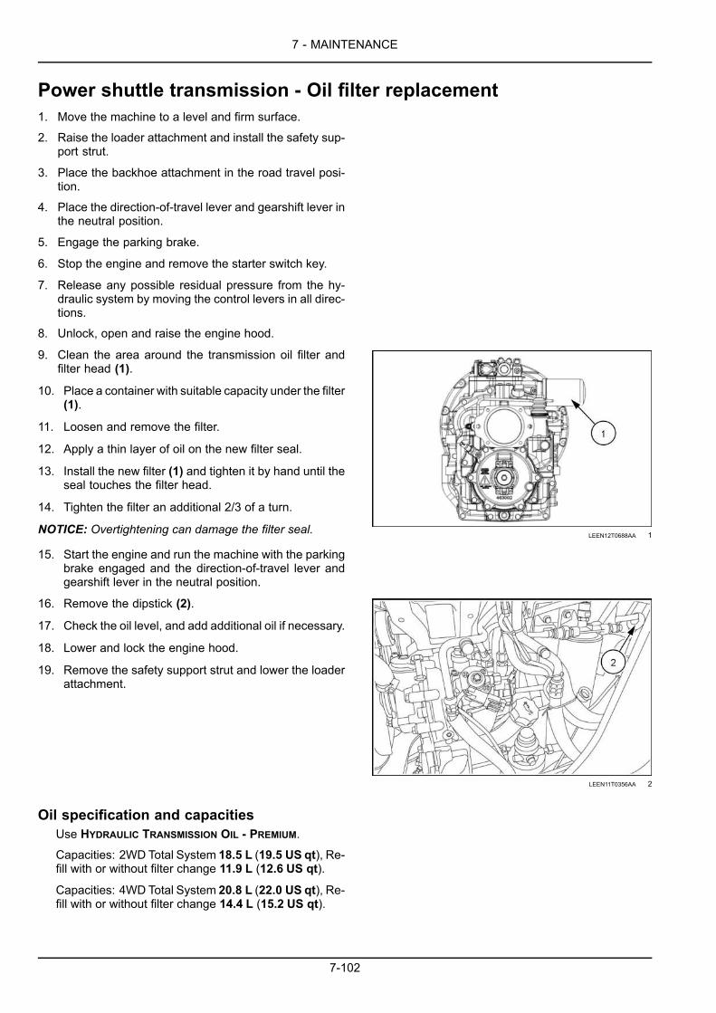
7 - MAINTENANCE
Power shuttle transmission - Oil filter replacement1. Move the machine to a level and firm surface.
2. Raise the loader attachment and install the safety sup-port strut.
3. Place the backhoe attachment in the road travel posi-tion.
4. Place the direction-of-travel lever and gearshift lever inthe neutral position.
5. Engage the parking brake.
6. Stop the engine and remove the starter switch key.
7. Release any possible residual pressure from the hy-draulic system by moving the control levers in all direc-tions.
8. Unlock, open and raise the engine hood.
9. Clean the area around the transmission oil filter andfilter head (1).
10. Place a container with suitable capacity under the filter(1).
11. Loosen and remove the filter.
12. Apply a thin layer of oil on the new filter seal.
13. Install the new filter (1) and tighten it by hand until theseal touches the filter head.
14. Tighten the filter an additional 2/3 of a turn.
NOTICE: Overtightening can damage the filter seal.LEEN12T0688AA 1
15. Start the engine and run the machine with the parkingbrake engaged and the direction-of-travel lever andgearshift lever in the neutral position.
16. Remove the dipstick (2).
17. Check the oil level, and add additional oil if necessary.
18. Lower and lock the engine hood.
19. Remove the safety support strut and lower the loaderattachment.
LEEN11T0356AA 2
Oil specification and capacitiesUse HYDRAULIC TRANSMISSION OIL - PREMIUM.Capacities: 2WD Total System 18.5 L (19.5 US qt), Re-fill with or without filter change 11.9 L (12.6 US qt).
Capacities: 4WD Total System 20.8 L (22.0 US qt), Re-fill with or without filter change 14.4 L (15.2 US qt).
7-102

7 - MAINTENANCE
Power shuttle transmission - Screen filter cleaning1. Move the machine to a level and firm surface.
2. Raise the loader attachment and install the safety sup-port strut.
3. Place the backhoe attachment in the road travel posi-tion.
4. Place the direction-of-travel lever and gearshift lever inthe neutral position.
5. Engage the parking brake.
6. Stop the engine and remove the starter switch key.
7. Release any possible residual pressure from the hy-draulic system by moving the control levers in all direc-tions.
8. Unlock, open and raise the engine hood.
9. Place a container with suitable capacity under thescreen filter.
10. Clean the area around the cover plate (2).
11. Loosen and remove the screws (1).
12. Remove the cover plate (2), check the conditions ofthe O-ring (3) and replace it, if necessary.
13. Remove the screen filter (4).
14. Clean the screen filter with a detergent solution.
NOTICE: Follow the instructions for the detergent solution.
15. CAUTIONFlying debris!Compressed air can propel dirt, rust, etc. intothe air. Wear eye and face protection whenusing compressed air.Failure to comply could result inminor ormod-erate injury.
C0049A
Carefully dry the screen filter (4) with compressed airand reinstall it.
16. Reassemble the cover plate (2) and fasten it bymeansof the screws (1). Tighten the screws to a torque of23 N·m (16.96 lb ft).
LEEN12T0691AA 1
17. Remove the dipstick (5) and top up the oil through thedipstick hole. Then restore the dipstick (5) into place.
18. Start the engine and check for oil leaks.
19. Check the oil level by means of the dipstick and addadditional oil if necessary.
20. Lower and lock the engine hood.
21. Remove the safety support strut and lower the loaderattachment.
LEEN11T0356AA 2
7-103

7 - MAINTENANCE
Oil specification and capacitiesUse HYDRAULIC TRANSMISSION OIL - PREMIUM.Capacities: 2WD Total System 18.5 L (19.5 US qt), Re-fill with or without filter change 11.9 L (12.6 US qt).
Capacities: 4WD Total System 20.8 L (22.0 US qt), Re-fill with or without filter change 14.4 L (15.2 US qt).
7-104

7 - MAINTENANCE
Powershift transmission - Oil change1. Move the machine to a level and firm surface.
2. Raise the loader attachment and install the safety sup-port strut.
3. Place the backhoe attachment in the road travel posi-tion.
4. Place the direction-of-travel lever and gearshift lever inthe neutral position.
5. Engage the parking brake.
6. Stop the engine and remove the starter switch key.
7. Release any possible residual pressure from the hy-draulic system by moving the control levers in all direc-tions.
8. Unlock, open and raise the engine hood.
9. Remove the dipstick (1).
NOTE: Change the oil while the transmission is still warm;the oil will flow more easily.
LEEN11T0356AA 1
10. Place a container with a suitable capacity under thetransmission drain plug (2).
11. Loosen and remove the drain plug (2).
12. Let the transmission oil drain completely.
LEEN11T0408AA_1 2
NOTE: Change the transmission oil filter at this time.13. Install the drain plug (2) and retighten it.14. Fill the transmission with HYDRAULIC TRANSMISSION
OIL - PREMIUM through the dipstick hole.
7-105

7 - MAINTENANCE
15. Reinstall the dipstick (1).
16. Check the oil level by means of the dipstick, and addadditional oil if necessary.
LEEN11T0356AA 3
17. Drive themachine for a fewminutes in first and secondgear. Then stop the machine with the engine running,and the direction-of-travel lever and the transmissiongearshift lever in the neutral position.
18. Engage the parking brake.
19. Check the oil level again by means of the dipstick, andadd additional oil if necessary.
20. Lower and lock the engine hood.
21. Remove the safety support strut and lower the loaderattachment.
Oil specification and capacitiesUse HYDRAULIC TRANSMISSION OIL - PREMIUM.Capacities: 4WD Total System 18.0 L (19.0 US qt), Re-fill with or without filter change 11.4 L (12.0 US qt).
7-106

7 - MAINTENANCE
Powershift transmission - Oil filter replacement1. Move the machine to a level and firm surface.
2. Raise the loader attachment and install the safety sup-port strut.
3. Place the backhoe attachment in the road travel posi-tion.
4. Place the direction-of-travel lever and gearshift lever inthe neutral position.
5. Engage the parking brake.
6. Stop the engine and remove the starter switch key.
7. Release any possible residual pressure from the hy-draulic system by moving the control levers in all direc-tions.
8. Unlock, open and raise the engine hood.
9. Clean the area around the oil filter and filter head (1).
10. Place a container with suitable capacity under the filter(1).
11. Loosen and remove the filter.
12. Apply a thin layer of oil on the new filter seal.
13. Install the new oil filter (1).
14. Tighten the new filter by hand until the seal touchesthe filter head.
15. Tighten the filter by hand an additional 2/3 of a turn.
NOTICE: Overtightening can damage the filter seal. LEEN11T0407AA_4 1
16. Start the engine and run the machine with the parkingbrake engaged and the direction-of-travel lever andgearshift lever in the neutral position.
17. Remove the dipstick (2).
18. Check the oil level, and add additional HYDRAULICTRANSMISSION OIL - PREMIUM as necessary.
19. Lower and lock the engine hood.
20. Remove the safety support strut and lower the loaderattachment.
LEEN11T0356AA 2
Oil specification and capacitiesUse HYDRAULIC TRANSMISSION OIL - PREMIUM.Capacities: 4WD Total System 18.0 L (19.0 US qt), Re-fill with or without filter change 11.4 L (12.0 US qt).
7-107

7 - MAINTENANCE
Front axle fluid - Four-Wheel Drive (4WD)1. Move the machine to a level and firm surface.
2. Lower the loader attachment to the ground.
3. Place the backhoe attachment in the road travel posi-tion.
4. Place the direction-of-travel lever and gearshift lever inthe neutral position.
5. Engage the parking brake.
6. Stop the engine and remove the starter switch key.
Differential oil change - Four-Wheel Drive (4WD)1. Place a container with suitable capacity under the drain
plug (1) of the front axle differential.
2. Loosen and remove the drain plug (1) and the fill plug(2).
3. Completely drain the oil through the hole of the drainplug (1).
4. Install and tighten the drain plug (1).
5. Refill the axle with new PREMIUM TRANSAXLE OIL 80W-140 through the fill hole (2) until the level reaches thehole.
6. Install and tighten the fill hole plug (2). LEEN11T0375AA 1
Oil specification and capacitiesUse PREMIUM TRANSAXLE OIL 80W-140. 4WD Differen-tial Capacity: 6.5 L (6.9 US qt)
Reduction gear oil change - Four-Wheel Drive (4WD)1. Use the loader attachment to raise the front part of the
machine slightly until the front wheels are no longer incontact with the ground.
2. Place a suitable support under the front axle.
3. Manually turn the wheel until the hole of the plug (1) isin the lowest possible position.
4. Place a container with suitable capacity under the plug(1).
5. Loosen and remove the plug (1).
6. Completely drain the oil from the reduction gearthrough the plug hole (1).
LEEN11T0409AA_1 2
7-108
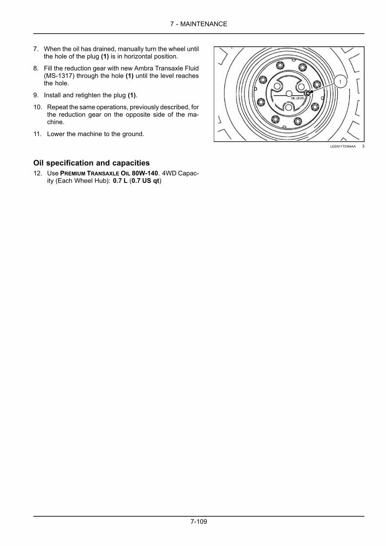
7 - MAINTENANCE
7. When the oil has drained, manually turn the wheel untilthe hole of the plug (1) is in horizontal position.
8. Fill the reduction gear with new Ambra Transaxle Fluid(MS-1317) through the hole (1) until the level reachesthe hole.
9. Install and retighten the plug (1).
10. Repeat the same operations, previously described, forthe reduction gear on the opposite side of the ma-chine.
11. Lower the machine to the ground.
LEEN11T0384AA 3
Oil specification and capacities12. Use PREMIUM TRANSAXLEOIL 80W-140. 4WD Capac-
ity (Each Wheel Hub): 0.7 L (0.7 US qt)
7-109

7 - MAINTENANCE
Rear axleRear axle - Oil change1. Move the machine to a level and firm surface.
2. Lower the loader attachment to the ground.
3. Place the backhoe attachment in the road travel posi-tion.
4. Place the direction-of-travel lever and the gearshiftlever in the neutral position.
5. Engage the parking brake.
6. Stop the engine and remove the starter switch key.
7. Place a container with suitable capacity under the drainplug (1).
8. Loosen and remove the drain plug (1) and the fill andlevel check plug (2).
9. Wait for the oil to drain completely from the axle throughthe drain plug hole of the axle (1).
10. When the oil has completely drained, install the drainplug (1).
11. Fill the axle with PREMIUM TRANSAXLE OIL 80W-140through the hole of the fill and level check plug (2) untilthe level reaches the hole.
12. Install and retighten the plug (2).LEEN11T0386AA 1
Oil specification and capacitiesUse PREMIUM TRANSAXLE OIL 80W-140. Capacity21.2 L (22.4 US qt)
7-110

7 - MAINTENANCE
Machine inspection and cleaningInspection
Externally check the machine and its working attach-ments, checking for possible breaks or damage of thecomponents or the structure.If you find any problems, contact an authorized work-shop to have the necessary repairs carried out.Replace the damaged or excessively worn parts withoriginal spare parts.Check the conditions of the hydraulic lines and makesure there are no leaks. In this case, immediately elim-inate them.
LEEN12T0640AA 1
CleaningA correctly performed periodical maintenance helpspreserving the value of the machine and the warrantyrights in case of possible corrosion damage.
The necessary products for machine care can be pur-chased from the Service Department or Spare Part Ser-vice. Carefully observe all instructions on the packag-ing.
NOTICE: In respect of the environment, the machineshould be washed only at specially provided washing sta-tions equipped with oil and grease separators, if possible.Washing machines outside these stations may be evenforbidden in some regions or countries.
NOTICE:When washing themachine, do not direct the wa-ter jet onto electrical or electronic components or assem-blies. Water sprays or jets may cause malfunctions or thefailure of the entire electrical and electronic system.
7-111

7 - MAINTENANCE
Brake pedal lever - Greasing1. Grease the brake pedal levers (1) by introducing the
new clean grease and expelling the exhaust greaseuntil the new grease starts coming out.
2. Clean all the grease that come out with a cloth.
LEEN11T0411AA_1 1
Grease specificationsUse MULTI-PURPOSE GREASE EXTREME PRESSURE ANDANTI-WEAR NLGI 2 ( MAT 3550) or a grease whichmeets the following standard:
• NLGI 2
NOTE: MULTI-PURPOSE GREASE EXTREME PRESSURE ANDANTI-WEAR NLGI 2 can also be used.
7-112

7 - MAINTENANCE
Hydraulic cylindersThe hydraulic cylinders must not show any kind ofleaks.
The cylinder rods must have a slightly oily aspect inorder to guarantee a long life and a good operation.
Cylinder tightnessA tightness check must be performed after a certainworking period and when the hydraulic system is at nor-mal operating temperature.
Check by performing the following operations:1. Clean the rod and the bearing of the cylinder to be
inspected;2. Work normally for 5 to 10 minutes;3. Extend the cylinder rod;4. Check for leaks.
Cylinder rod inspectionROD APPEARANCE TEST CONCLUSION
Dry Slight traces of oil when a sheet of paper isrubbed on 200 mm (7.87 in) of the rod. Normal
Slightly oily The paper sheet remains stuck when rubbedon the rod. Normal
Oily A sheet of paper placed on the rod remainsstuck. Normal
Very oily or weeping A ring of oil is clearly visible on the rod aftereach rod extension.
Leak Oil drips from the bearing each time thecylinder rod is retracted.
Consult your Dealer
7-113

7 - MAINTENANCE
Alternator - checkNOTICE: Do not use steam cleaning devices nor cleaning solvents to clean the alternator.
Have the alternator (1) checked by your Dealer.
NOTE: Make sure the terminal protectors are correctly in-stalled.
RAIL15TLB0041AA 1
7-114

7 - MAINTENANCE
Every 1500 hours of operation or annually
Engine breather filterChange the engine breather filter every 1500 h or annually, whichever comes first.
1. With cold engine, remove the ventilation pipe (1) fromthe cover (2) after removing the retaining clamp.
2. Loosen the fastening nuts (3) and remove the cover (2).
LEEN11T0398AA 1
3. Remove the filter (4) from the housing and replace ittogether with the gasket.
4. Clean and restore the cover into position on the engineby using a new seal and tighten the fastening nuts (3).
LEEN11T0399AA 2
7-115

7 - MAINTENANCE
Every 3000 hours
Diesel Exhaust Fluid (DEF)/AdBlue® supply module filter1. To access the supply module, remove the corner
shroud.
RAIL15TLB0023AA 1
2. Remove the DEF/AdBlue® tank cover plate.
RAIL15TLB0022AA 2
3. Remove the fuel tank step plate.
RAIL15TLB0020AA 3
7-116

7 - MAINTENANCE
4. Remove the three bolts from the panel to the right-handside of the step, in front of the rear tire.
RAIL15TLB0019AA 4
5. These bolts attach to a bracket that hold the supplymodule in place.
RAIL15TLB0018AA 5
7-117

7 - MAINTENANCE
NOTICE: Pay attention to the location of each tube in thesupply module. Also take care not to damage or loosenthe connectors on the lines. Tubes and connector that havedamage or fit loosely will not connect properly to the supplymodule causing leaks and issues with the Selective Cata-lyst Reduction (SCR) system.
6. Remove three tube quick connectors that attach to thesupply module.
NOTE: You will not be able to pull the supply module com-pletely out to disconnect the tubes. You will need to reachbehind the supply module and disconnect the tubes.
RAIL14TLB0967BA 6
RAIL14TLB0968BA 7
7. Remove the filter cover.
RAIL14TLB0969BA 8
7-118
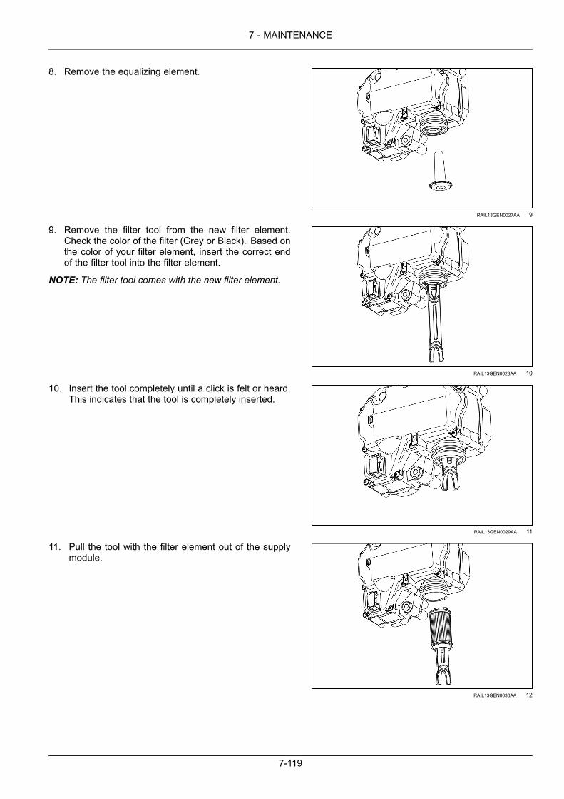
7 - MAINTENANCE
8. Remove the equalizing element.
RAIL13GEN0027AA 9
9. Remove the filter tool from the new filter element.Check the color of the filter (Grey or Black). Based onthe color of your filter element, insert the correct endof the filter tool into the filter element.
NOTE: The filter tool comes with the new filter element.
RAIL13GEN0028AA 10
10. Insert the tool completely until a click is felt or heard.This indicates that the tool is completely inserted.
RAIL13GEN0029AA 11
11. Pull the tool with the filter element out of the supplymodule.
RAIL13GEN0030AA 12
7-119

7 - MAINTENANCE
12. Clean the supply module filter housing and threadswith distilled water.
RAIL13GEN0031AA 13
13. Oil the O-rings on the new filter element. Insert thefilter element fully into the supply module.
RAIL13GEN0032AA 14
14. Install the new equalizing element.
RAIL13GEN0027AA 15
15. Install the filter cover. Torque to 15 – 25 N·m (11 –18 lb ft)
RAIL13GEN0026AA 16
7-120

7 - MAINTENANCE
16. Connect the three connections back to the supplymodule. you will hear them snap in place.
RAIL14TLB0968BA 17
17. Install the bracket and secure the supply module inplace.
RAIL15TLB0018AA 18
RAIL15TLB0019AA 19
7-121

7 - MAINTENANCE
Every 4000 hours
Engine coolantCAUTIONBurn hazard!Hot coolant can spray out if you remove the filler cap while the system is hot. After the system hascooled, turn the filler cap to the first notch and wait for all pressure to release before proceeding.Failure to comply could result in minor or moderate injury.
C0043A
NOTICE: NEVER mix OAT coolant with conventional coolant. Under no circumstances should you top off a coolingsystemwith only water. You can use a refractometer to check the concentration level. Supplemental Coolant Additives(SCA) should not be used when using OAT EXTENDED LIFE COOLANT/ANTIFREEZE.Drain, flush, and replace the engine coolant every 4000 h of operation or every year, whichever comes first.Coolant fluid specification: OAT EXTENDED LIFE COOLANT/ANTIFREEZECoolant fluid capacities:24.0 L (25.4 US qt)
1. Park the machine on level ground.
2. Raise the loader arm and engage the safety support.
3. Shut down the engine and place a 'Do Not Operate' tagon the key switch.
4. Allow time for the engine and the coolant to cool.
5. Remove the front grille.
6. Place a piece of hose onto the radiator drain valve anddrain into a suitable container.
7. WARNINGHot liquid under pressure!Service when cool.Failure to comply could result in death or seri-ous injury.
W1187A
Open the filler cap on the de-aeration reservoir. Openthe filler cap by slowing turning the cap counter-clock-wise until it is removed. It is not necessary to removethe hoses in order to remove the cap.
RAIL14TLB0983BA 1
8. Remove the bolts that secure the coolers.
9. Swing the coolers out and clean of dirt and debris.
10. Check the hoses, elbows, and system components forwear or damage.
11. After cleaning, swing the coolers back in and replacethe bolts.
12. After all the coolant has been drained, close the drainvalve. Do not detach the drain hose.
13. Pour approximately 24.0 L (25.4 US qt) of clean waterinto the de-aeration reservoir until full.
7-122

7 - MAINTENANCE
NOTE: In some situations air pockets in the coolant systemmay prevent you from filling the system to capacity. If thisoccurs remove the de-aeration valve cap this allows the airto escape during the fill procedure. The de-aeration valvecap is on the top right-hand side of the engine below theair filter housing.
NOTE: Do not over fill the coolant system.
RAIL14TLB1164AA 2
14. Secure the filler cap on the de-aeration reservoir. Ifapplicable attach the de-aeration valve cap.
15. Start the engine and run for at least 30 min.
NOTE: Make sure that you activate the heating system (ifequipped) to circulate fluid through the heater core.
16. Remove the de-aeration filler cap.
17. Drain the water from the system.
18. Repeat Steps 13– 17 for a clean system flush.
19. After the radiator flush, close the radiator drain valve,and detach the drain hose.
20. Pour coolant into the de-aeration reservoir until thelevel reaches between the COLD MIN mark and theHOT MAX mark on the tank.
21. Install the filler cap.
22. Start up the engine.
23. Run the engine for a few minutes and stop the enginebefore it reaches operating temperature.
24. Check the system for leaks.
25. Start up the engine again and allow the engine toreach operating temperature.
26. Shut down the engine.
27. Check the fluid level in the de-aeration reservoir.
28. If necessary, allow the components to cool and addcoolant to the reservoir.
7-123

7 - MAINTENANCE
As required
Drive beltReplace the fan drive belt as needed.
Removal1. Remove the air conditioning compressor belt, if
equipped.
2. Loosen the lower alternator bolt (2).
3. Loosen the pivot bolt (1).
83118121 1
4. Loosen the adjustment bolt lock nut (1).
5. Turn the adjustment bolt (2) counter-clockwise, toloosen the belt tension.
RAIL11TLB0004AA 2
6. Slide the belt (1) off of the water pump pulley (2) andremove the belt.
83118121 3
7-124

7 - MAINTENANCE
Install1. Route the drive belt on the pulleys as shown.
83118087 4
2. Setting and securing the fan belt tension:A. Turn the adjustment bolt (1) clockwise, until the
pivot bolt (2) is at the end of the tension bracketslot (3).
NOTE: Special belt design will adjust to the proper tension.
83118121 5
B. Tighten the adjustment bolt lock nut (1) securing theadjustment bolt (2) in position.
RAIL11TLB0004AA 6
3. Torque to 45 – 55 N·m (33 – 41 lb ft):• Pivot bolt (1)• Lower alternator bolt (2)
4. Reinstall the air conditioning compressor belt, if re-moved earlier.
83118121 7
7-125

7 - MAINTENANCE
Air-conditioning compressor drive belt1. Visually check the condition of the belt (1). Replace it
if it is worn or damaged.
2. To release the belt, loosen the mounting hardware ofthe tensioner (3) and loosen the tensioner adjustingscrew (2).
3. Install a new belt.
4. Adjust the belt tension with the tensioner adjustingscrew (2).
LEEN11T0368AA 1
5. Check the belt at the center line of the belt (1)with a belttension gauge. Specification is 122 – 149 N·m (90.0 –109.9 lb ft)
NOTICE: After replacing the drive belt, make an adjustment after the first 10 operating hours.
NOTICE: The belt must not be too tensioned (premature bearing wear) not too slack (premature belt wear).
7-126

7 - MAINTENANCE
Turbocharger - CheckNOTICE: Observe the following recommendations on the adequate lubrication to avoid serious damage to the tur-bocharger bearing.
The following procedure must be observed in order toprevent the turbocharger bearings from deteriorating.
1. Disconnect the inlet and outlet oil pipes from the tur-bocharger and pour some clean engine oil into the oilinlet port, taking care that no contaminants enter theturbocharger.
2. Remove the air inlet tube from the turbocharger andspin the compressor wheel by hand to pre-lubricate thebearings.
3. Reconnect the oil inlet and air inlet tubes but not the oiloutlet.
4. Disconnect the electrical wire to the fuel injection pumpfuel shut-off solenoid.
5. Place a suitable receptacle below the oil outlet port andcrank the engine until oil flows from the outlet port.
6. Reconnect the oil outlet tube using a new gasket andtighten the retaining bolts to the torque.
7. Reconnect the fuel injection pump fuel shut-off solenoidwire.
8. Check the engine oil level and, if necessary, top up.Start the engine and check for oil and air leaks.
9. Observe the oil pressure light. If the oil pressure lampdoes not turn off in the first few seconds of idling, im-mediately stop the engine and consult your Dealer.
10. On every start-up the engine should be allowed to idle( 1000 RPM maximum) for 60 s before operating un-der load, to ensure an adequate oil supply to the tur-bocharger bearing.
11. The engine should also be allowed to idle without loadfor two minutes before shut-down to enable the oil todissipate the heat from the turbocharger bearing.
7-127

7 - MAINTENANCE
Fuel system bleedingWARNINGPressurized system!Only use the bleed screw to bleed air from the fuel system. DO NOT loosen the fuel or injector linesto bleed air. Injury or damage can occur. Fuel or injector lines are under very high pressure.Failure to comply could result in death or serious injury.
W0285A
1. Move the machine to a level and firm ground.
2. Raise the loader attachment and install the safety sup-port strut.
3. Place the backhoe attachment in the road travel posi-tion.
4. Place the direction-of-travel lever and gearshift lever inneutral position.
5. Immobilize the machine by means of the parking brake.
6. Stop the engine and remove the starter switch key.
7. Open and raise the engine tilt hood.LEEN12T0566AA 1
8. From the bottom of the filter, remove the connector (3).
9. Place a container under the prefilter.
10. Open bleed screw (1) on prefilter only and activatehand primer (2) until fuel flows freely from the bleedscrew.
11. This generally takes 35-45 pumps to fill the fuel linesand the prefilter.
12. This can be done in about 30 s.
13. Tighten bleed screw.
14. Dry with cloth the prefilter.
15. Connect the electric connector under the prefilter.
16. Start the engine. Engine should start within 5 s.
17. Lower and lock the engine tilt hood.
18. Remove the safety support strut and lower the loaderattachment.
LEEN11T0355AA 2
LEEN11T0370AA 3
7-128

7 - MAINTENANCE
Wheels and tiresNOTE: Depending on the manufacturing date of your machine the front wheel mounting hardware may be either lugnuts or bolts with washers. Check the wheel torque that is applicable to your machine.
NOTICE: Small variations in the friction force between the wheel and the mounting hardware, such as lubricant, lackof lubricant, paint, surface rust, thread variations, etc., will cause large variations in the clamping force. It has beenshown that the tension on fasteners or lug nuts is directly proportional to the angle of turn on a nut or bolt. Unlikethe automotive industry, our rims do not have a precision centering hub to locate and support the wheel and the lowlength to diameter ratio of the studs make the preload even more critical.
NOTICE: Never use the minimum final torque value to set the torque for a wheel installation. Only use the torqueplus the additional degree angle turn provided in the procedure. The minimum final torque value is only for checkingthe torque 10 h after a wheel installation or on a new machine.Check the torque of the wheel nuts and bolts after the first 10 h of operation of a new machine or after a wheel install.If the nuts and bolts are loose, tighten, and check after an additional 10 h of operation. Repeat until the nuts and boltsremain tight.
Machine preparation1. Move the machine to a level and firm ground.
2. Place the direction-of-travel lever and gearshift lever inneutral position.
3. Engage the parking brake.
4. Stop the engine.
5. Slightly loosen (unlock) the wheel mounting hardwarewhen the tire is still holding the weight of the machine.
6. Start the engine.
7. Use the loader attachment or the rear stabilizers to liftthe machine until the wheel that you will remove is justoff the ground.
8. Stop the engine and remove the starter switch key.
9. Place wedges in front and rear of the tires that you willnot be removing.
10. If applicable, on both sides of the front axle wedgeblocks between the axle and the frame so the axle willnot swivel.
11. Remove all the wheel mounting hardware.
12. Remove the wheel.
13. Install a new wheel, observing the orientation of thetread pattern.
7-129

7 - MAINTENANCE
Rear wheel1. Tighten the five mounting nuts in the sequence
shown until the wheel is snug against the axle hub.2. Tighten the nuts in sequence to a torque of
136 N·m (100 lb ft).3. Tighten the nuts a second time, in sequence, to a
torque of 271 N·m (200 lb ft).4. Tighten the nuts in sequence an additional 30° to
set the preload.5. Repeat the procedure on the remaining fivemount-
ing nuts.
RAIL14FRK0031BA 1
Rear wheel onlyTorque
First sequence 136 N·m (100 lb ft)Second sequence 271 N·m (200 lb ft)Preload Additional 30°Minimum final torque value for checking purposes only 813 N·m (600 lb ft)
Front wheelsNOTICE: Tighten wheel hardware in a crossing pattern (sequence), as shown.
1. Tighten the eight mounting bolts in sequence untilthe wheel is snug against the axle hub.
2. Tighten the bolts in sequence to a torque of122 N·m (90 lb ft).
3. Tighten the bolts in sequence an additional 20° toset the preload.
RAIL14FRK0032BA 2
Front wheels – 2WD and 4WDTire size Torque Minimum final torque value
for checking purposes only11 x 1612 x 16.5
12.5/80 x 1814 x 17.5
122 N·m (90 lb ft) plusan additional 20° to set the preload 330 N·m (243 lb ft)
Wheel toe-in adjustment
Front wheel toe-in1. The front wheel toe-in is preset and adjustment is not
normally necessary.
7-130

7 - MAINTENANCE
2. Periodical checks should bemade to ensure the correcttoe-in is maintained.
Adjustment3. Place the machine on a level ground presenting no el-
ements which could affect adjustments.
4. Steer the wheels to the front.
5. Measure the toe-in by checking the track width betweenthe front of the wheel rim (1) and the rear of the wheelrim (2) at hub height.
6. The correct toe-in measurement is 0 – 6 mm (0 –24 in).
LEEN12T0481AA 3
7. Loosen the lock nut (3) on each wheel tie rod andtighten the nut (4) with a wrench, until the correct wheeltoe-in is obtained.
8. Tighten the locknut (3) and recheck the toe-in.
LEEN12T0482AA 4
Wheel steering angle adjustment screw1. Four adjusting screws (1) are mounted on the axle, two
for each side.
2. The two rear screws are adjustable and set the mini-mum steering angle.
3. The two front screws are adjustable and must be set toavoid the contact of the tires with the machine in caseof maximum steering.
4. To adjust, slacken the locknut (2) and tighten the screw(1) counterclockwise to reduce the steering angle of thewheels or clockwise to increase the steering angle.
5. Tighten the locknut (2) once the adjustment is com-plete. LEEN12T0482AA 5
7-131
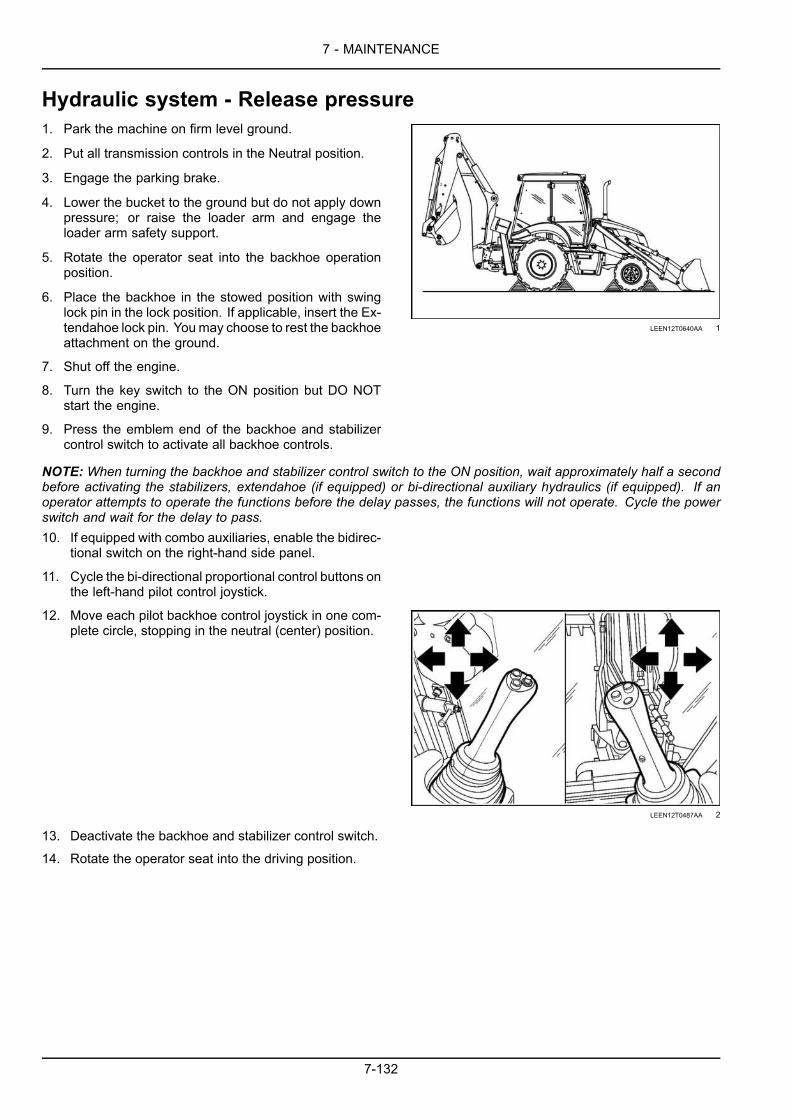
7 - MAINTENANCE
Hydraulic system - Release pressure1. Park the machine on firm level ground.
2. Put all transmission controls in the Neutral position.
3. Engage the parking brake.
4. Lower the bucket to the ground but do not apply downpressure; or raise the loader arm and engage theloader arm safety support.
5. Rotate the operator seat into the backhoe operationposition.
6. Place the backhoe in the stowed position with swinglock pin in the lock position. If applicable, insert the Ex-tendahoe lock pin. Youmay choose to rest the backhoeattachment on the ground.
LEEN12T0640AA 1
7. Shut off the engine.
8. Turn the key switch to the ON position but DO NOTstart the engine.
9. Press the emblem end of the backhoe and stabilizercontrol switch to activate all backhoe controls.
NOTE: When turning the backhoe and stabilizer control switch to the ON position, wait approximately half a secondbefore activating the stabilizers, extendahoe (if equipped) or bi-directional auxiliary hydraulics (if equipped). If anoperator attempts to operate the functions before the delay passes, the functions will not operate. Cycle the powerswitch and wait for the delay to pass.10. If equipped with combo auxiliaries, enable the bidirec-
tional switch on the right-hand side panel.
11. Cycle the bi-directional proportional control buttons onthe left-hand pilot control joystick.
12. Move each pilot backhoe control joystick in one com-plete circle, stopping in the neutral (center) position.
LEEN12T0487AA 2
13. Deactivate the backhoe and stabilizer control switch.
14. Rotate the operator seat into the driving position.
7-132

7 - MAINTENANCE
15. Rotate the loader control joystick in one complete cir-cle, stopping in the neutral (center) position.
RAIL18TLB0403BA 3
16. If applicable, operate the bucket control switch.
17. Turn the key switch to the Off position.
Releasing hydraulic pressure on machines with mechanical backhoe controls1. Park the machine on firm level ground.
2. Put all transmission controls in the Neutral position.
3. Engage the parking brake.
4. Lower the bucket to the ground but do not apply downpressure; or raise the loader arm and engage theloader arm safety support.
5. Rotate the operator seat into the backhoe operationposition.
6. Place the backhoe in the stowed position with swinglock pin in the lock position. If applicable, insert the Ex-tendahoe lock pin. Youmay choose to rest the backhoeattachment on the ground.
LEEN12T0640AA 4
7. Shut off the engine.
8. Turn the key switch to the ON position but DO NOTstart the engine.
9. If equipped with combo auxiliaries, enable the bi-direc-tional switch on the right-hand side panel.
10. Cycle the bi-directional control lever or pedal.
11. Cycle each backhoe control lever in each directionand then release in the neutral position.
LEEN12T0486AA 5
12. Rotate the operator seat into the driving position.
7-133

7 - MAINTENANCE
13. Rotate the loader control joystick in one complete cir-cle, stopping in the neutral (center) position.
RAIL18TLB0403BA 6
14. If applicable, operate the bucket control switch.
15. Turn the key switch to the Off position.
Hydraulic fittings and lines - Replace1. Before replacing the hydraulic fittings and lines, drain
pressure from the hydraulic system.
2. Damaged or leaking lines must be replaced with newlines.
3. Use original spare parts, specially provided to carry outthe necessary functions.
4. Never reinstall used lines or fittings.
5. The drained oil or the waste containing oil must be dis-posed of in an environmentally friendly manner. Do notrelease on the ground or in water.
6. The hydraulic lines should be replaced after six years ofuse. In this way, serious failure dangers are prevented.
7. Tighten the fittings to the prescribed torque values.
7-134

7 - MAINTENANCE
BulbsNOTICE: Never touch a halogen bulb with your fingers.Always use a clean cloth when handling halogen bulbs.
Operator’s compartment light1. Remove the lens (1) unscrewing it by turning 90°
through its central slot.
2. Remove the bulb (2) and install a new bulb.
3. Reinstall the lens (1).Bulb wattage: 10 W
LEEN12T0488AA 1
Switch lighting1. Remove and disconnect the switch concerned.
2. Remove the bulb holder (1). Remove the bulb andinstall a new bulb.
3. Install the bulb holder and the switch.Bulb wattage: 1.2 W
LEEN12T0704AA 2
Beams and turn signals1. Remove the four screws and remove the light assembly
(1).
2. Disconnect the socket from the bulb holder connector.Fold back the clips, remove the defective bulb and re-place it with a bulb of the same wattage.
3. Remove out the bulb holder on the outside of the re-flector to replace the direction indicator bulb.
NOTE: To access the direction indicator bulb, remove thebeam cover fastening screw.
NOTE: The beam can be adjusted vertically and sidewaysby adjusting the slotted screws.
LEEN12T0705AA 3
7-135

7 - MAINTENANCE
Front, side, and rear work lights1. Remove the screws and take off the light assembly (1).
2. Remove the bulb and install a new bulb.
3. Install the light assembly and the screws.Bulb wattage: 55 W
LEEN12T0706AA 4
Rotating beacon (optional)1. Unscrew the lens, remove the bulb and install a bulb.
Install the lens.Bulb wattage: 55 W
LEEN12T0550AA 5
7-136

7 - MAINTENANCE
Fuses and relays – PowershiftNOTICE: NEVER replace a fuse with a fuse of a different rating.
Main fuse and relay panelRemove the main fuse cover panel from the front right-hand side console. The vehicle diagnostic connector(1) and the four pin FleetForce™ (Telematics) diagnos-tic connector (2) are also found in this area.
NOTE: There is a in-line 5 A fuse (F31) on the diagnosticconnector harness (1). You may need to access this fuseby removing the side instrument cluster.
RAIL16TLB0532BA 1
RAIL15TLB0257BA 2
7-137

7 - MAINTENANCE
FusesFuse No. Rating Function
F1A 15 A Rear windshield wiper and rear windshield washerF1B 7.5 A +15 AntitheftF1C 10 A 4wd, automatic manual, TRAX, cut transmission and differential blockF2A 15 A Instrument power supply, switches lamps, seatF2B 15 A Air-conditioningF2C 15 A Pilot controlF3A 3 A Rear right/front left side light, instrument illuminationF3B 3 A Rear left/front right side lights, number plate lightF3C 10 A Glide Ride™, working light , hydraulic speed control , 4x1 clam bucketF4A 7.5 A Stop lights switchF4B 10 A Hand tool button, clam bucket level valve and sensorF4C 10 A Rear excavator lock, side-shift lock, transport blockF5A 15 A External front inner working lightsF5B 10 A Traffic lightsF5C 15 A Main beam fuseF6A 15 A Rotating beaconF6B 7.5 A (+15) flasher warningF6C 7.5 A Rapid attachF7A 10 A (+30) warning, hornF7B 10 A Current intake, radio, roof lampF7C 6 A Front windshield wiperF8A 15 A External rear outer work lightsF8B 15 A External front outer work lightsF8C 15 A External rear Inner work lights
RelaysRelay reference Designation
K10 Optional relayK1A Flasher relayK3 Starting relayK4 Bucket level solenoid valve relayK5 Traffic and main beam lights relayK6 External front inner work light relayK7 External rear Inner work light relayK8 External front outer work light relayK9 External rear outer work light relay
7-138

7 - MAINTENANCE
RAIL14TLB1180GA 3
7-139

7 - MAINTENANCE
Fuse and relay moduleRemove the side instrument cluster panel to expose themini relay and fuse panel.
NOTE: Four-Wheel Steer (4WS) machines will have lessrelays then what is shown.
RAIL15TLB0258BA 4
RAIL15TLB0136AA 5
Fuse or relay reference DesignationK225 Parking brake relay X-225 (not applicable to 4WS)K227 4WD warning light relay X-227K230 Hand hammer relay X-230K232 Glide Ride™ relay X-232K231 Reset parking brake relay X-231 (not applicable to 4WS)K228 Additional relay X-228 (not applicable to 4WS)K14 Transmission cut-off relay X-14F-001 +15 Switched fuse 5 A
Fuse or relay reference DesignationK-464 Main relay X-464
Front working lamps – Diode 1 (D1)Instrument lamp – Diode 2 (D2)
X-520
Rear working lamps – Diode 3 (D3)NOTE:Relay K464 and connector X-520 are not attached to the fuse relay panel shown but are located in the generalarea.
7-140

7 - MAINTENANCE
Engine compartment fuse and relay panelOpen the engine hood and locate the fuse and relaypanel on the left-hand side of the engine.
• X-449 Fuse panel (1)• X-448 Fuse and relay panel (2)• Glow-Plug Control Unit (GCU) (3)• Heater Control Unit (HCU) relay (4)• Engine Control Unit (ECU) relay (5)
RAIL16TLB0366BA 6
X-449 fuse panel (1)Fuse or relay reference Designation
F-010 Glow-plug Control Unit (GCU) 60 A fuse— not usedF-011 Heater Control Unit (HCU) 40 A fuseF-012 Engine Control Unit (ECU) 20 A fuseF-013 Spare 40 A fuseF-014 Sensor power 25 A fuse
X-448 fuse panel (2)Fuse or relay reference Designation
K-102 Starter pilot relayK-103 Start interlock relayK-104 Engine start relayK-105 A/C compressor relayK-106 AUX main relayK-107 SCR main relayF-003 SCR system ignition 7.5 A fuseF-004 Engine Control Unit (ECU) 7.5 A fuseF-005 Tank heater valve and purge module pump 10 A fuseF-007 A/C 10 A fuseF-008 Pump module 10 A fuse
7-141

7 - MAINTENANCE
If the machine is equipped with Air-Conditioning (A/C).On the right-hand side of the engine near the alternatoris a 40 A in-line harness blower fuse (F953/X-953).
RAIL16TLB0369BA 7
Main power fuse moduleOpen the battery compartment door and locate the 80 Amain power fuse.
NOTE: There is a in-line 5 A +30 unswitched fuse (F515)in the FleetForce™ (Telematics) harness near the positivebattery terminal.
RAIL15TLB0014AA 8
7-142

7 - MAINTENANCE
Fuses and relays – Power shuttleNOTICE: NEVER replace a fuse with a fuse of a different rating.
Main fuse and relay panelRemove the main fuse cover panel from the front right-hand side console. The vehicle diagnostic connector(1) and the four pin FleetForce™ (Telematics) diagnos-tic connector (2) are also found in this area.
NOTE: There is a in-line 5 A fuse (F31) on the diagnosticconnector harness (1). You may need to access this fuseby removing the side instrument cluster.
RAIL16TLB0532BA 1
RAIL15TLB0257BA 2
7-143

7 - MAINTENANCE
FusesFuse No. Rating Function
F1A 15 A Rear windshield wiper and rear windshield washerF1B 7.5 A Fuel shut off, +15 antitheft, key switch +15 ECU, reset parking brakeF1C 10 A Stop lights switchF2A 15 A Instrument side panel, switches lampsF2B 15 A Air conditioningF2C 15 A Pilot controlF3A 3 A Rear right/front left side light, instrument illuminationF3B 3 A Rear left/front right side lights, number plate lightF3C 10 A Glide Ride™ switch, rapid attach, working lights switch, 4x1grab ST3F4A – not usedF4B 10 A Hand tool button, clam bucket level valve and sensor, clutch shut off button
and differential block buttonF4C 10 A Rear excavator lock, side-shift lock ,working lights switchF5A 15 A External front inner working lightsF5B 10 A Low beam fuseF5C 15 A Main beam fuseF6A 15 A Rotating beacon lampF6B 7.5 A (+15) emergency lightsF6C 7.5 A Hand tool, 4WDF7A 10 A (+30) warning, hornF7B 10 A Current intake, radio, off lampF7C 15 A Front windshield wiperF8A 15 A External rear outer work lightsF8B 15 A External front outer work lightsF8C 15 A External rear inner work lights
RelaysRelay reference Designation
K1 Forward-reverse speed switch relayK3 Starting relayK4 Bucket level solenoid valve relayK5 Traffic and main beam lights relayK6 External front inner work light relayK7 External rear inner work light relayK8 External front outer work light relayK9 External rear outer work light relayK10 Reverse speed relayK11 Forward speed relayK12 Flasher unit relay
7-144
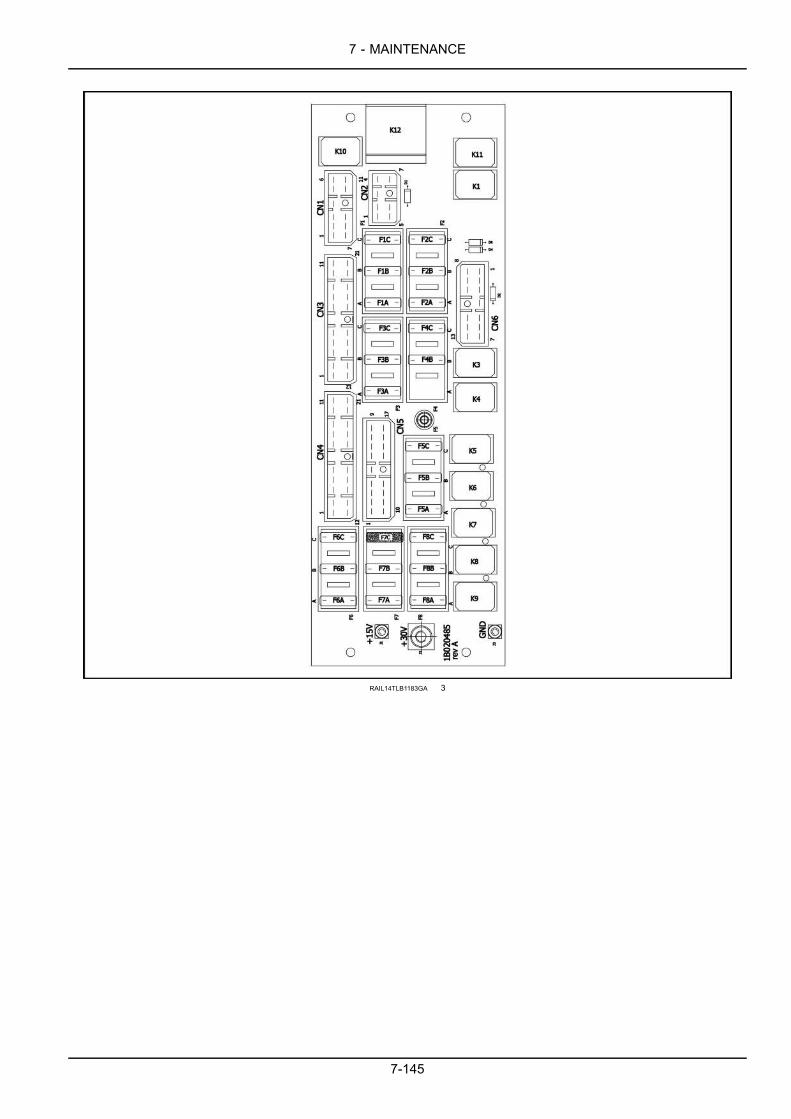
7 - MAINTENANCE
RAIL14TLB1183GA 3
7-145

7 - MAINTENANCE
Side relay and fuse moduleRemove the side instrument cluster panel to expose themini relay and fuse panel.
RAIL15TLB0258BA 4
RAIL15TLB0138AA 5
Fuse or relay reference DesignationK225 Parking brake relay X-225K230 Hand hammer relay X-230K232 Glide Ride™ relay X-232K224 Differential gear lock relay X-224K231 Reset parking brake relay X-231K226 4WD relay X-226K227 Additional relay X-227F-001 +15 Switched fuse 5 A
Fuse or relay reference DesignationK233 Neutral signal inversion for cluster relay X-233K464 Main relay X-464
Front working lamps – Diode 1 (D1)Instrument lamp – Diode 2 (D2)Rear working lamps – Diode 3 (D3)
X-520
Transmission switch B+ 5 A fuse F520NOTE: The relays or fuses in this table are not attached to the fuse relay panel shown.
7-146

7 - MAINTENANCE
Engine compartment fuse and relay panelOpen the engine hood and locate the fuse and relaypanel on the left-hand side of the engine.
• X-449 Fuse panel (1)• X-448 Fuse and relay panel (2)• Glow-Plug Control Unit (GCU) (3)• Heater Control Unit (HCU) relay (4)• Engine Control Unit (ECU) relay (5)
RAIL16TLB0366BA 6
X-449 fuse panel (1)Fuse or relay reference Designation
F-010 Glow-plug Control Unit (GCU) 60 A fuse— not usedF-011 Heater Control Unit (HCU) 40 A fuseF-012 Engine Control Unit (ECU) 20 A fuseF-013 Spare 40 A fuseF-014 Sensor power 25 A fuse
X-448 fuse panel (2)Fuse or relay reference Designation
K-102 Starter pilot relayK-103 Start interlock relayK-104 Engine start relayK-105 A/C compressor relayK-106 AUX main relayK-107 SCR main relayF-003 SCR system ignition 7.5 A fuseF-004 Engine Control Unit (ECU) 7.5 A fuseF-005 Tank heater valve and purge module pump 10 A fuseF-007 A/C 10 A fuseF-008 Pump module 10 A fuse
7-147

7 - MAINTENANCE
If the machine is equipped with Air-Conditioning (A/C).On the right-hand side of the engine near the alternatoris a 40 A in-line harness blower fuse (F953/X-953).
RAIL16TLB0369BA 7
Main power fuse moduleOpen the battery compartment door and locate the 80 Amain power fuse.
NOTE: There is a in-line 5 A +30 unswitched fuse (F515)in the FleetForce™ (Telematics) harness near the positivebattery terminal.
RAIL15TLB0014AA 8
7-148
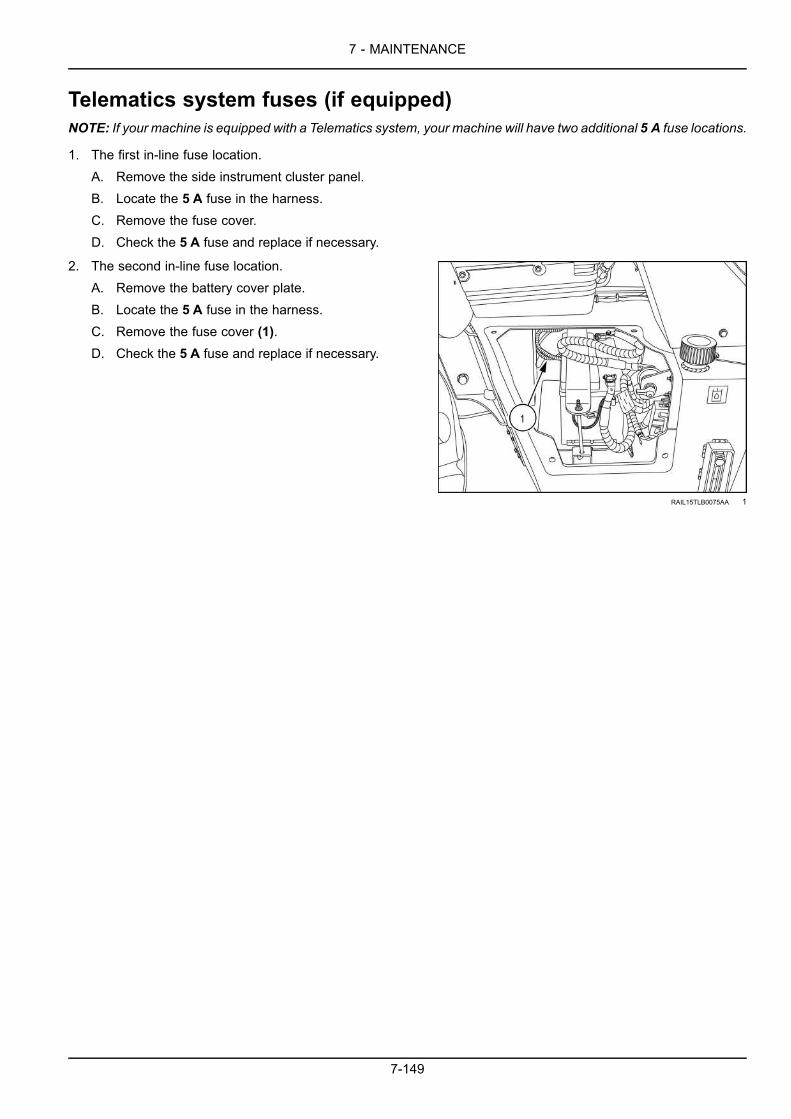
7 - MAINTENANCE
Telematics system fuses (if equipped)NOTE: If your machine is equipped with a Telematics system, your machine will have two additional 5 A fuse locations.
1. The first in-line fuse location.A. Remove the side instrument cluster panel.B. Locate the 5 A fuse in the harness.C. Remove the fuse cover.D. Check the 5 A fuse and replace if necessary.
2. The second in-line fuse location.A. Remove the battery cover plate.B. Locate the 5 A fuse in the harness.C. Remove the fuse cover (1).D. Check the 5 A fuse and replace if necessary.
RAIL15TLB0075AA 1
7-149

7 - MAINTENANCE
Battery removal and installationWARNINGElectrical shock hazard!Do not reverse battery terminals. Connect positive cable ends to positive terminals (+) and negativecable ends to negative terminals (-).Failure to comply could result in death or serious injury.
W0262A
WARNINGBattery gas can explode!To prevent an explosion: 1. Always disconnect the negative (-) battery cable first. 2. Always connectthe negative (-) battery cable last. 3. Do not short circuit the battery posts with metal objects. 4. Donot weld, grind, or smoke near a battery.Failure to comply could result in death or serious injury.
W0011A
1. Move the machine to a level and firm surface.
2. Lower the loader attachment to the ground.
3. Place the backhoe attachment in the road travel posi-tion.
4. Place the direction-of-travel lever and gearshift lever inthe neutral position.
5. Engage the parking brake.
6. Stop the engine and remove the starter switch key.
7. Place the battery switch in the OFF position.
NOTE:Wait at least 60 seconds after key off before turningbattery switch to the off position. This allows the machinecontrollers to shutdown properly.
8. Remove the fasteners (1) and the battery cover (2).
RAIL15TLB0073AA 1
7-150

7 - MAINTENANCE
9. Remove the terminal covers and disconnect the cables,first from the negative terminal (3) then the positive ter-minal (4).
10. Remove the nuts and washers (5), the clamping bar(6) and the battery (7).
11. Install the battery (7).
12. Install the clamping bar (6) and the washers and nuts(5).
13. Clean the cables and the connecting terminals andcoat them with grease.
14. Connect the cables, first to the positive terminal (4),then the negative terminal (3) and install the terminalcovers.
RAIL15TLB0075AA 2
15. Reattach the battery cover (2) and secure it with thefasteners (1).
RAIL15TLB0073AA 3
7-151

7 - MAINTENANCE
Telescopic dipper (if equipped)1. Ensure the drain port (1) in the end of the dipper is kept
clear to prevent accumulation of water inside the unit.
2. Check the hole for hydraulic oil traces, which wouldindicate the presence of a pressure loss in the cylinder.
LEEN12T0501AA 1
7-152

7 - MAINTENANCE
Bucket teethBucket - Loader attachment1. Move the machine to a level and firm ground.
2. Position the loader bucket so that the bucket teeth canbe replaced.
3. Place the direction-of-travel lever and gearshift lever inneutral position.
4. Immobilize the machine by means of the parking brake.
5. Stop the engine and remove the starter switch key.
6. Loosen and remove the screws (2) with the nuts (3).
7. Extract the tooth (1).
8. Clean the area around the tooth.
9. Assemble the new tooth (1).
10. Screw in and tighten the screws (2) with the nuts (3).
LEEN12T0502AA 1
Bucket - Backhoe attachment11. Move the machine to a level and firm ground.
12. Position the backhoe bucket so that the bucket teethcan be replaced.
13. Place the direction-of-travel lever and gearshift leverin neutral position.
14. Immobilize the machine by means of the parkingbrake.
15. Stop the engine and remove the starter switch key.
16. Remove the safety pin (2) using a hammer and apunch or tooth tool.
17. Extract the tooth (1).
18. Clean the area around the tooth holder.
19. Assemble the new tooth (1).
20. Install the safety pin (2).
LEEN12T0695AA 2
7-153

7 - MAINTENANCE
Loader bucket - Self-leveling adjustment1. The self-leveling linkage mounted on the right hand
loader arm and frame automatically controls the angleof the loader bucket during the raising cycle of the liftarms to maintain a constant bucket level. There is noself-leveling during the lowering cycle.
2. Self-leveling begins when the tube (2) on the loaderarm contacts the bell crank (1) and lifts the vertical link-age rod (3).
3. The tie rod then moves the bucket spool to the dumpposition to level the bucket.
LEEN12T0696AA 1
Automatic self-leveling control and adjustment1. Lower the loader attachment to the ground.
2. Disconnect the vertical tie rod (3) at the lower bellcrank.
3. Raise the loader attachment so that the lower bucketpin is 800 mm (31.5 in) above the ground, and fully turnover the bucket to the rear.
LEEN12T0697AA 2
4. Rotate the bell crank (1) till it touches the tube (2) onthe loader arm. Make sure the lower bell crank arm isdirecting upwards.
5. Adjust the length of the vertical rod (3) so that whenreconnected, the end of the loader arm tube remains incontact with the bell crank.
6. Securely tighten the lock nuts on a vertical tie rod.
LEEN12T0698AA 3
7-154

7 - MAINTENANCE
Return-to-dig system1. Return to dig is an electrically activated feature which
enables the operator to automatically return the bucketto a level digging position for a further work cycle withone simple movement of the loader control lever (3).
2. Whenever the bucket is rolled forward to dump the re-turn to dig electrical circuit is completed and the sole-noid on the bucket spool is energized.
3. When the loader bucket control lever (3) is moved di-agonally left to the return to dig position (2) the electro-magnet will hold the bucket spool in the roll back po-sition until the bucket is in the level digging position atwhich time the indicator on the rod of the bucket self-leveling linkage will pass in front of the sensor whichde-energizes the electromagnet on the bucket spoolenabling the spool to return to the neutral position.
LEEN12T0699BA 4
Return to dig sensor - Adjustment1. The return to dig system consists of an electromagnet
mounted on the bucket spool, a sensor (1)mounted ontop of the loader arm and a pointer attached to the tubeof the bucket self-leveling linkage.
2. Place the bucket on the ground in the preferred diggingposition.
3. Adjust the position of the sensor such that when thebucket is in digging position and loader arms are low-ered, half 50% of the sensor face is obscured by theself-leveling linkage pointer.
4. Ensure the face of the sensor (1) is 3 – 6 mm (0.12 –0.24 in) from the pointer (2) on the self-leveling linkage.
5. As a visual aid for the operator, while seated in the cab,the pointer mounted on the loader arm can be seen toalign with the pointer on the self-leveling linkage, whenthe loader arms are lowered and the bucket is in thelevel digging position.
LEEN12T0700AA 5
7-155

7 - MAINTENANCE
Disable parking brakeFor disabled machines, disable the parking brake whenever the parking brake fails to disengage.
1. Chock the wheels to prevent movement.
2. Remove the mat and floor plate.
3. Locate the solenoid block for the parking brake on thetransmission.
4. Clean the area of dirt and debris.
RCPH10TLB064AAF 1
5. Remove the two bolts that secure the solenoid block.
RCPH10TLB065AAF 2
6. Carefully lift up and rotate the solenoid block 90° (1).
7. Reinstall the bolts and tighten the bolts to a torque of20 N·m (15 lb ft).
8. Attach a grease gun (use MULTI-PURPOSE MOLYGREASE EXTREME PRESSURE AND ANTI-WEAR NGLI-2)to the fitting (2) on the solenoid block and pump ap-proximately 65 pumps.
NOTICE: Extreme pressure is NOT needed to release theparking brake. Over pressurization may damage the seals.Moderate effort is required on the grease gun.
RCPH10TLB070AAF 3
9. Carefully remove the wheel chocks, as the machinemay now be moved.
NOTICE: Themachine should be free to roll. If themachinedoes not roll, there may be an issue in the parking brake ordrivetrain. Contact your dealer.
NOTICE: After grease has been used to release the park-ing brake it will be necessary to clean and flush the en-tire system before placing the machine back into operation.Contact your dealer for this procedure.
7-156

7 - MAINTENANCE
10. To enable the parking brake:A. Slowly loosen and remove the two bolts that hold
the solenoid block in position. Grease trapped inthe parking brake will come out under the block.
B. Confirm that the three O-rings are in the correctposition and that all surfaces are free of contam-ination.
C. Return the solenoid block to its original position.D. Reinstall the bolts and tighten the bolts to a
torque of 20 N·m (15 lb ft).E. Test the parking brake to ensure it functions
correctly. For example, the transmission isde-clutched when the parking brake is applied.
7-157

7 - MAINTENANCE
STORAGE
Machine storageIf the machine is to be in storage for more than 30 days, park the machine inside a building. If a building is notavailable, park the machine in a dry area on planks and cover the machine with a waterproof covering.Geographic, environmental and actual storage conditions make it difficult to follow a set storage procedure for allareas and conditions. The following procedure is for a storage period of six months or longer. This procedure is agood starting point but may not be all inclusive. If you have questions about storing your machine, contact your dealer.
1. Inspect the machine for visible signs of wear, break-age or damage. Order any parts required and makethe necessary repairs to avoid delays when starting thenext operating period.
2. Wash the machine.
3. Lubricate the machine at all grease fittings.
4. Paint any area where the paint has been damaged.
5. Drain the fuel tank.
6. Put approximately 8 l (2 US gal) of diesel flushing oil inthe fuel tank. Run the engine until the exhaust smokeis blue white.
7. Drain the flushing oil from the fuel tank.
8. Fill the fuel tank and add diesel fuel conditioner by fol-lowing the directions on the container.
9. Drain the Diesel Exhaust Fluid (DEF)/AdBlue® tank.
10. Move all hydraulic controls to relieve any pressure inthe hydraulic circuits.
11. Change the engine oil and replace the oil filter.
12. Drain the cooling system. Leave the drain valves openand do not tighten the radiator cap.
13. Put a Do Not Operate tag on the instrument panel.
14. Clean or replace the primary element for the air filter.
15. Cover the exposed cylinder rods, valve spools, andany other bare metal parts with a rust and corrosionpreventive.
16. Charge the battery. Remove the battery from the ma-chine and store in a cool dry area where the temper-ature is above freezing 0 °C (32 °F). Make sure thebattery is clean.
NOTE: Check the battery periodically for the correct electrolyte level. Test the electrolyte with a hydrometer. Whenthe hydrometer reading is near 1.215, charge the battery.
7-158

7 - MAINTENANCE
Preparation for use after storageDo not start the engine until Steps 1 through 12 have been done.
1. Change the fuel filters and fill the fuel take if required.
2. Tighten the cooling system drain valves.
3. Fill the engine cooling system.
4. Check the condition of the engine drive belt. Replaceif required.
5. Check the engine oil level.
6. Check the hydraulic oil level.
7. Check the transmission oil level.
8. Lubricate the machine at all grease fittings.
9. Use petroleum base solvent and remove the rust andcorrosion preventive from the hydraulic cylinder rods,valve spools and any other location the preventativewas used.
10. Install a new battery or confirm the battery is charged.
11. Fill the Diesel Exhaust Fluid (DEF)/AdBlue® tank toa minimum of 20% level.
12. If stored longer than four months, change the DEFsupply module filter as shown on 7-116.
13. Bleed the air from the fuel system. Refer to 7-128 inthis manual.
14. Start the engine. It is important that you review the“STARTING THE UNIT” chapter on Page 4-5 in thismanual.
7-159

7 - MAINTENANCE
7-160

8 - TROUBLESHOOTING
8 - TROUBLESHOOTING###_8_###FAULT CODE RESOLUTION
TroubleshootingOften failures are due to improper use or to an irregularmaintenance of the machine.
In case of failure, it is recommended to read the relevantchapter in the manual.
In case no failure cause can be determined or if you arenot able to eliminate the problem, consult the Service De-partment.
When contacting the Service Department, it is importantto describe the failure and all the factors related to it inthemost precise way possible. Precise information allowsquickly finding and eliminating the cause of the problem.
Never perform any operation if not sufficiently skilled forthe job.
These following tables are reported for your guidanceonly.
These tables describe the failures already occurred, theirpossible causes and the remedies to be adopted.
In exceptional cases, a failure described may also haveanother cause.
NOTICE: If any repairs are required beyond routine maintenance, your machine must be returned to your Dealer whohas the correct tools, facilities and knowledge to perform repairs to the correct specification and safety standards.
ProblemHere the failure is described as the consequence of a pre-viously performed observation or activity.
Therefore, observe with extreme care.
Carefully examine the problem.
Ask yourself the following questions:
What symptoms preceded the failure?
What repair or maintenance operations have been previ-ously performed?
Had this failure already occurred?
Is this a single failure or are these more contemporaryfailures?
Possible CauseThe possible causes of the detected failure are indicated.
They are arranged according to the probability degree:the most probable cause is shown at first place.
8-1

8 - TROUBLESHOOTING
CorrectionHere it is explained how to detect and eliminate the causeof the problem.
8-2

8 - TROUBLESHOOTING
Engine - TroubleshootingProblem Possible Cause Correction
The engine does not start. Partially discharged batteries. Check, charge the batteries and, if neces-sary, replace them.
Corroded or loose connections to the bat-tery terminals.
Clean, inspect, tighten the nuts and, if nec-essary, replace the excessively corrodedterminals and nuts.
Dirt or water accumulations in fuel lines. Disconnect the lines and the injection pumpand carefully clean them; if necessary,clean and dry the fuel tank.
No fuel in the tank. Fill the tank.No supply to the injection pump. Check and, if necessary, replace the supply
pump.Air in the fuel system. Check the lines, the fittings, the supply
pump, the filters and the injection pump forthe presence of air, then bleed the system.
Damaged starter motor. Repair or replace the starter motor.The engine stops. Irregular delivery of the supply pump. Contact your dealer.
Dirt or water accumulations in fuel lines. Disconnect the lines and the injection pumpand carefully clean them; if necessary,clean and dry the fuel tank.
Restricted fuel filters. Replace the filter cartridges.Burned or cracked valves. Replace the valves.Air in the fuel system. Check the lines, the fittings, the supply
pump, the filters and the injection pump forthe presence of air, then bleed the system.
Damaged injection pump controls. Replace the damaged parts.The engine overheats. The centrifugal pump of the cooling system
is faulty.Contact your dealer.
Faulty temperature switch. Replace the temperature switch.Radiator partially faulty. Eliminate possible scales by washing,
check and repair possible tube leaks.Scales in coolant passage compartmentsin cylinder heads and crankcase.
Carefully wash.
Centrifugal pump drive belt and fan drivebelt too slack.
Check and adjust belt tension.
Coolant (insufficient quantity). Restore the level in the expansion tank byadding the prescribed fluid.
Incorrect timing of the engine. Check and correctly time the engine.Restricted air filter. Clean the assembly and, if necessary, re-
place the filter element.The engine hasanomalous knocks.
Partially obstructed or damaged injectors. Contact your dealer.
Dirt accumulations in fuel lines. Clean the lines and replace the visiblydented pipes; if necessary, clean the injec-tion pump.
Drive shaft knocks caused by an exces-sive clearance of one or more crankshaftbearings or big end bearings or excessiveshoulder clearance.
Contact your dealer.
Unbalanced drive shaft. Check the alignment and the balance of thedrive shaft and, if necessary, replace it.
Loose flywheel retaining screws. Replace the loose screws and tighten allscrews to the prescribed torque + angle.
Connecting rod axes not parallel. Straighten the connecting rods, check thatthe axes are parallel and, if necessary, re-place the connecting rods.
Cylinder knocks due to anomalous wear. Contact your dealer.
8-3

8 - TROUBLESHOOTING
Problem Possible Cause CorrectionNoisy cylinder pin due to excessive clear-ance in hub and connecting rod bushing.Bushings free in their seat on the connect-ing rod.
Contact your dealer.
Ticking due to noisy distribution. Contact your dealer.Anomalous enginesmoke.
. Contact your dealer.
Difficult starting and poorperformance under allconditions.
High-pressure pump faulty. Contact your dealer.
Difficult start, poorperformance, the engineruns with one cylinderless.
Injector with shutter or solenoid core (me-chanical part) stuck open.
Contact your dealer.
Starting takes tens ofseconds, much whiteexhaust smoke, smell offuel.
Injector (irreversibly) stuck open. Contact your dealer.
Broken high-pressure linefrom pump to CommonRail
Anomalous vibrations caused by a looseline clamping.
Contact your dealer.
The engine operates witha cylinder less, withoutsaving failures in thecontrol unit.
Injector stuck closed. Contact your dealer.
8-4

8 - TROUBLESHOOTING
Starter motor - TroubleshootingProblem Possible Cause Correction
The starter motor doesnot run.
Too low specific density and battery level. Inspect the battery.
Poor ignition switch circuit connection orcontact.
Replace the wiring harness and the ignitionswitch or starter motor runs too slowly.
Malfunction of the coil or of the magneticswitch pull-in cylinder.
Replace the magnetic switch.
The starter motor runningcannot crank the engine.
The pinion gear does not engage with thering gear.
Repair or replace the clutch and the controllever.
Sliding clutch. Replace the clutch.Anomalous noise. Anomalous bushing wear. Replace starter.
Wear on pinion gear or ring gear tooth tips. For ring gear damage contact dealer.Poor pinion gear sliding. Replace starter.
The pinion gear springs. Poor ignition switch return. Replace the ignition switch.Field coil loss. Magneticswitch coil burnt, etc.
Pinion gear disengagement fault caused bya coil short circuit in the magnetic switch.
Replace the magnetic switch.
8-5

8 - TROUBLESHOOTING
Alternator - TroubleshootingProblem Possible Cause Correction
Not recharged. Recharge circuit interrupted (warning lamp,fuse, connector, etc.).
Check the connections of the recharge cir-cuit, clean and tighten the alternator andbattery terminals.
Voltage regulator inefficient. Replace alternator.Rotor winder interrupted. Replace alternator.Worn brushes. Replace alternator.
Recharge insufficient. Slackened fan belt. Supply the correct tension.Voltage regulator faulty. Replace alternator.Excessive wear of rotor rings or brushes. Replace alternator.Short-circuited diodes. Replace alternator.Short-circuited stator winders or rotorwinder.
Replace alternator.
Excessive recharge. Loose circuit connections. Check the connections of battery terminals,starter motor terminals and alternator.
Voltage regulator inefficient. Replace alternator.Ground connection faulty. Check connections for leaks.
8-6
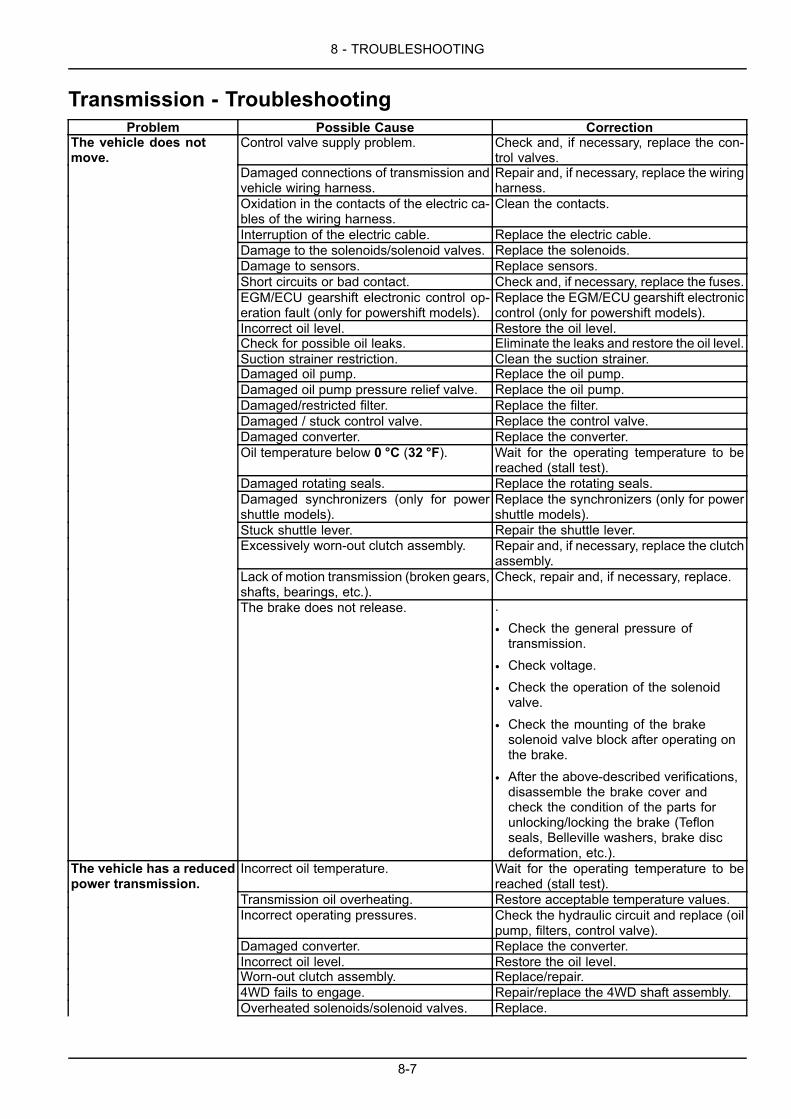
8 - TROUBLESHOOTING
Transmission - TroubleshootingProblem Possible Cause Correction
The vehicle does notmove.
Control valve supply problem. Check and, if necessary, replace the con-trol valves.
Damaged connections of transmission andvehicle wiring harness.
Repair and, if necessary, replace the wiringharness.
Oxidation in the contacts of the electric ca-bles of the wiring harness.
Clean the contacts.
Interruption of the electric cable. Replace the electric cable.Damage to the solenoids/solenoid valves. Replace the solenoids.Damage to sensors. Replace sensors.Short circuits or bad contact. Check and, if necessary, replace the fuses.EGM/ECU gearshift electronic control op-eration fault (only for powershift models).
Replace the EGM/ECU gearshift electroniccontrol (only for powershift models).
Incorrect oil level. Restore the oil level.Check for possible oil leaks. Eliminate the leaks and restore the oil level.Suction strainer restriction. Clean the suction strainer.Damaged oil pump. Replace the oil pump.Damaged oil pump pressure relief valve. Replace the oil pump.Damaged/restricted filter. Replace the filter.Damaged / stuck control valve. Replace the control valve.Damaged converter. Replace the converter.Oil temperature below 0 °C (32 °F). Wait for the operating temperature to be
reached (stall test).Damaged rotating seals. Replace the rotating seals.Damaged synchronizers (only for powershuttle models).
Replace the synchronizers (only for powershuttle models).
Stuck shuttle lever. Repair the shuttle lever.Excessively worn-out clutch assembly. Repair and, if necessary, replace the clutch
assembly.Lack of motion transmission (broken gears,shafts, bearings, etc.).
Check, repair and, if necessary, replace.
The brake does not release. .
• Check the general pressure oftransmission.
• Check voltage.
• Check the operation of the solenoidvalve.
• Check the mounting of the brakesolenoid valve block after operating onthe brake.
• After the above-described verifications,disassemble the brake cover andcheck the condition of the parts forunlocking/locking the brake (Teflonseals, Belleville washers, brake discdeformation, etc.).
The vehicle has a reducedpower transmission.
Incorrect oil temperature. Wait for the operating temperature to bereached (stall test).
Transmission oil overheating. Restore acceptable temperature values.Incorrect operating pressures. Check the hydraulic circuit and replace (oil
pump, filters, control valve).Damaged converter. Replace the converter.Incorrect oil level. Restore the oil level.Worn-out clutch assembly. Replace/repair.4WD fails to engage. Repair/replace the 4WD shaft assembly.Overheated solenoids/solenoid valves. Replace.
8-7

8 - TROUBLESHOOTING
Problem Possible Cause CorrectionDamaged connections of transmission andvehicle wiring harness (only for powershiftmodels).
Repair and, if necessary, replace the con-nections (only for powershift models).
Damaged logic of EGM/ECU gearshiftelectronic control (only for powershift mod-els).
Replace the EGM/ECU (only for powershiftmodels).
Damage to sensors. Replace sensors.Overheating. Damaged cooling system. Repair the cooling system.
Dirty heat exchanger. Clean the heat exchanger.Unintentionally activated parking brake. Deactivate the parking brake.Excessive soil deposit on axle wheel hubs. Clean the axle wheel hubs.Seizure (broken gears, shafts, bearings,etc.).
Check, repair and, if necessary, replace.
Braking force external to transmission: axleoperating problem.
Check and repair the axle.
Dragging of clutch disks. Repair and, if necessary, replace the clutchdisks.
Damaged converter. Replace the converter.Damaged oil thermostat. Replace the oil thermostat.Incorrect oil level. Restore the oil level.Worn-out oil pump. Replace the oil pump.
Wheel rotation with liftedvehicle
Dragging of clutch disks. Repair and, if necessary, replace the clutchdisks.
Low oil temperature (high oil viscosity). Wait for the operating temperature to bereached (stall test).
Incorrect oil gradient. Change oil and filters.Damaged control valve. Replace the control valve.Stuck shuttle lever. Repair and, if necessary, replace the shut-
tle lever.Abnormal noise Damaged converter. Replace the converter.
Damaged oil pump. Replace the oil pump.Ventilation/Cavitation. Check the oil level. Check the oil gradient.Seizure (broken gears, shafts, bearings,etc.).
Check, repair and, if necessary, replace.
Worn-out clutch disks. Replace the clutch disks.Worn-out synchronizer connection (only forpower shuttle models).
Replace the synchronizer connection (onlyfor power shuttle models).
Worn-out 4WD connection (only for powershuttle models).
Replace the 4WD connection (only forpower shuttle models).
Irregular connection. Damaged hydraulic control valve. Replace the control valves.Electrical system fault. Repair the electrical system.Worn-out clutch disks. Replace the clutch disks.Damaged converter. Replace the converter.Low oil temperature (high oil viscosity). Wait for the operating temperature to be
reached (stall test).Overheating. See “overheating”.EGM/ECU gearshift electronic control op-eration fault (only for powershift models).
Replace the EGM/ECU (only for powershiftmodels).
Damaged hydraulic system. Repair the hydraulic system.The gear remainsengaged.
Damaged/stuck shuttle lever. Repair and, if necessary, replace the shut-tle lever.
Electrical system fault. Repair the electrical system.Damaged control valve. Replace the control valve.Damaged hydraulic system. Repair the hydraulic system.Damaged clutch assembly. Repair and, if necessary, replace the clutch
assembly.EGM/ECU gearshift electronic control op-eration fault (only for powershift models).
Replace the EGM/ECU (only for powershiftmodels).
Damaged travel control rod (only for powershuttle models).
Replace the travel control rod (only forpower shuttle models).
8-8

8 - TROUBLESHOOTING
Problem Possible Cause CorrectionDamaged synchronizers (only for powershuttle models).
Replace the synchronizers (only for powershuttle models).
Lack of 4WD powertransmission.
Damaged 4WD connection assembly. Replace the 4WD connection assembly.
Hydraulic system fault. Repair the hydraulic system.Damaged control valve. Replace the control valve.Braking sensor fault. Check and, if necessary, replace the brak-
ing sensors.Electrical system fault. Repair the electrical system.EGM/ECU gearshift electronic control op-eration fault (only for powershift models).
Replace the EGM/ECU (only for powershiftmodels).
Gear fails to engage. Damaged gear control rod (only for powershuttle models).
Replace the gear control rod (only forpower shuttle models).
Damaged synchronizers (only for powershuttle models).
Replace the synchronizers (only for powershuttle models).
Damaged clutch connection assembly(only for powershift models).
Replace the clutch connection assembly(only for powershift models).
Damaged hydraulic system (only for pow-ershift models).
Repair the hydraulic system (only for pow-ershift models).
Damaged control valve (only for powershiftmodels).
Replace the control valve (only for power-shift models).
Damaged pressure sensors (only for pow-ershift models).
Check and, if necessary, replace the sen-sors (only for powershift models).
Electrical system fault (only for powershiftmodels).
Repair the electrical system (only for pow-ershift models).
EGM/ECU gearshift electronic control op-eration fault (only for powershift models).
Replace the EGM/ECU (only for powershiftmodels).
8-9

8 - TROUBLESHOOTING
Axles - TroubleshootingProblem Possible Cause Correction
Wheel vibrations. Incorrect installation. Correct the installation.Defective axle. Inspect and repair the axle.Wrong weight distribution. Distribute the weight differently.Overload. Remove the excessive load.Incorrect tire rotation radius. Replace the tire or adjust pressure on both
tires.Bent axle beam. Replace the axle beam.
Tire resistance. Incorrect installation. Correct the installation.Defective axle. Inspect and repair.Wrong weight distribution. Distribute the weight differently.Overload. Remove the excessive load.Incorrect tire rotation radius. Replace the tire or adjust pressure on both
tires.Bent axle beam. Replace the axle beam.
Broken axle shaft. Incorrect installation. Correct the installation.Defective axle. Inspect and repair.Wrong weight distribution. Distribute the weight differently.Overload. Remove the excessive load.Incorrect tire rotation radius. Replace the tire or adjust pressure on both
tires.Bent axle beam. Replace the axle beam.
Difficult steering; themachine travels ina straight line whilesteering.
Incorrect installation. Correct the installation.
Defective axle. Inspect and repair.Wrong weight distribution. Distribute the weight differently.Overload. Remove the excessive load.Incorrect tire rotation radius. Replace the tire or adjust pressure on both
tires.Bent or broken axle shaft. Replace the axle beam.
No differential action;jamming while steering.
Incorrect installation. Correct the installation.
Bent or broken axle shaft. Replace the axle beam.Excessive noise. Incorrect installation. Correct the installation.
Defective axle. Inspect and repair.Wrong weight distribution. Distribute the weight differently.Overload. Remove the excessive load.Incorrect tire rotation radius. Replace the tire or adjust pressure on both
tires.Bent or broken axle shaft. Replace the axle beam.Incorrect wheel alignment. Check that the structure and the bearings
are in good conditions.Excessive wear of the tire. Incorrect installation. Correct the installation.
Defective axle. Inspect and repair.Wrong weight distribution. Distribute the weight differently.Overload. Remove the excessive load.Incorrect tire rotation radius. Replace the tire or adjust pressure on both
tires.Bent or broken axle shaft. Replace the axle beam.Blocked differential. Check the installation.Excessive steering angle. Reduce the steering angle.Incorrect wheel alignment. Check that the structure and the bearings
are in good conditions.Friction noise. Incorrect installation. Correct the installation.
Bent or broken axle shaft. Replace the axle beam.Damaged or worn axle parts. Replace the damaged axle parts.Incorrect axle part installation. Check the installation.Incorrect adjustment of the bevel gear set. Adjust the bevel gear set.
8-10

8 - TROUBLESHOOTING
Problem Possible Cause CorrectionVibrations during travel. Incorrect installation. Correct the installation.
Defective axle. Inspect and repair.Wrong weight distribution. Distribute the weight differently.Bent or broken axle shaft. Replace the axle beam.
Break towards the outerend of the ring gear tooth.
Excessive gear load compared to the pre-scribed one.
Replace the bevel gear.
Incorrect gear adjustment (excessive back-lash). Loose pinion nut.
Carefully follow the recommended adjust-ment operations for ring gear and pinionbacklash and for tooth mark detection.
Break towards the innerend of the ring gear tooth.
Load crash. Replace the bevel gear.
Incorrect gear adjustment (insufficientbacklash). Loose pinion nut.
Carefully follow the recommended adjust-ment operations for ring gear and pinionbacklash and for tooth mark detection.
Worn-out or scored Pinionteeth and ring gear teeth.
Insufficient lubrication. Replace the bevel gear.
Contaminated lubricant. Incorrect lubricantor poor additives.
Replace the pinion bearings, paying atten-tion to correctly position the ring gear, thepinion and the bearing preloading.
Worn-out pinion bearings that cause anincorrect pinion axial backlash and wrongcontact between pinion and ring gear.
Use proper lubricant, fill up to the correctlevel and change at recommended inter-vals.
Overheated ring gearteeth or pinion teeth.Check if gear teeth havefaded.
Prolonged operation at high temperature. Replace the bevel gear.
Unsuitable lubricant. Low oil level. Con-taminated lubricant.
Use proper lubricant, fill up to the correctlevel and change at recommended inter-vals.
Pitted drive pinion teeth. Extremely intense use. Replace the bevel gear.Insufficient lubrication. Use proper lubricant, fill up to the correct
level and change at recommended inter-vals.
Bent axle beam body. Overloaded vehicle. Vehicle’s accident.Load crash.
Replace the axle beam body.
Worn-out or pittedbearings.
Insufficient lubrication. Replace bearings.
Contaminated lubricant. Extremely intenseuse. Normal wear. Loose pinion nut.
Use proper lubricant, fill up to the correctlevel and change at recommended inter-vals.
Gaskets leak oil. Prolonged operation at excessive oil tem-perature.
Replace the gasket and matching surfaceif damaged.
Oil gasket wrongly installed. Gasket edgecut or scored. Contaminated lubricant.
Use proper lubricant, fill up to the correctlevel and change at recommended inter-vals.
Excessive wear of inputflange spline.
Intense use. Replace the flange.
Loose pinion nut. Check that the pinion spline is not exces-sively worn out.
Axial backlash of pinion. Replace the bevel gear, if necessary.Fatigue break of piniongear tooth. Check if thefracture line is wavy orclearly delineated (stopline).
Intense use. Continuous overload. Replace the bevel gear.
Break of pinion teeth andring gear teeth.
Crash load of differential components. Check and/or replace other differentialcomponents.
Splines of planetarygear worn-out (excessivebacklash).
Intense use. Replace differential gear assembly. Re-place the axle beam, if necessary
8-11

8 - TROUBLESHOOTING
Problem Possible Cause CorrectionWorn or scratched washersurfaces.
Insufficient lubrication. Replace all scratched washers and thosewith a thickness by 0.1 mm (0.004 in)lowerthan the new ones.
Incorrect lubrication. Contaminated lubri-cant.
Use proper lubricant, fill up to the correctlevel and change at recommended inter-vals.
Worn-out inner diameterof pinion tapered rollerbearing.
Intense use. Replace bearing.
Excessive pinion axial play. Check pinion axial backlash.Unsuitable lubrication. Contaminated lubri-cant.
Use proper lubricant, fill up to the correctlevel and change at recommended inter-vals.
Twisted or broken axlebeam.
Intense vehicle operation, overload. Replace the axle beam.
Broken axle beam atwheel flange.
Loose wheel support. Replace the axle beam.
Bent axle beam body. Check the bending of the axle beam body.Make sure that the wheel support is notworn out or wrongly adjusted.
Noise during travel. Excessive backlash between ring gear andpinion.
Adjust the backlash between the ring gearand the pinion.
Worn-out pinion and ring gear. Replace pinion and ring gear.Worn-out pinion bearings. Replace pinion bearings.Loose pinion bearings. Adjust pinion bearings.Excessive pinion axial play. Adjust the axial play of the pinion.Worn-out differential bearings. Replace differential bearings.Loose differential bearings. Adjust the bearings.Ring gear excessively off-set. Replace the ring gear.Low lubricant level. Restore the level.Poor or incorrect lubricant grade. Change lubricant.Bent axle beam. Replace the axle beam.
Noise during idling. Noises emitted by the axle when the ve-hicle is moving are usually heard duringidling, even though they are not too loud.
Adjust the backlash between the ring gearand the pinion or replace pinion and ringgear.
Incorrect backlash between pinion and ringgear (the noise heard while deceleratingdisappears when speed is increased).
Adjust the backlash between the pinion andthe ring gear.
Worn-out pinion spline or input flange. Replace the pinion.Intermittent noise. Damaged ring gear. Replace the bevel gear.
Loose differential box screws. Tighten the screws to torque.Constant noise. Damaged ring gear teeth or pinion teeth. Replace the bevel gear.
Worn-out bearings. Replace the bearings.Worn-out pinion splines. Replace the pinion.Bent axle beam. Replace the axle beam.
Noise while steering. Worn-out differential planetary gears. Replace the planetary gears.Worn-out differential box and/or pins. Replace the differential box.Worn-out differential washers. Replace the washers.Worn-out axle beam splines. Replace the axle beam.
8-12

8 - TROUBLESHOOTING
Steering system - TroubleshootingProblem Possible Cause Correction
No steering or excessiveeffort required to steer.
Incorrect oil level in the tank. Fill with the correct oil type and quantity.Check for loose connections or damagedlines. Bleed the system.
Air in the system. Check the system pressure.Pump relief valve faulty. Replace the relief valve.Worn pump. Replace the pump.Leaking power cylinder. Eliminate the leak.Damaged valve spool. Replace the spool.Broken or damaged steering column. Inspect and repair.Damaged or worn metering element. Replace the metering element.
The steering wanders. Excessive clearance in the ball joints of thesteering connecting rods.
Inspect and replace.
Leaking power cylinder. Eliminate the leak.Control valve spool stuck or worn. Replace the spool.Damaged or worn metering element. Replace the metering element.
Front wheels oscillatingwhen steering.
Leaking power cylinder. Eliminate the leak.
Control valve spool stuck. Replace the spool.Damaged or worn metering element. Replace the metering element.
Noisy pump. Incorrect oil level in the tank. Fill with the correct oil type and quantity.Air in the system. Check for loose connections or damaged
lines. Drain the oil from the system.Water in oil. Drain and change the oil.Worn pump. Replace the pump.
8-13

8 - TROUBLESHOOTING
Hydraulic systems - TroubleshootingProblem Possible Cause Correction
All circuits fail to operate. Pump drive inoperative. Check and repair as necessary.Low oil level. Check the level and top up.Restricted pump suction line. Inspect the suction line and the tank and
repair as necessary.Slow operation or loss ofpower in all circuits.
Worn pump. Make a pump performance test, replaceand reseal as necessary.
Restricted pump suction line. Inspect the suction line and the tank andrepair as necessary.
Load sensing pressure relief valve incor-rectly adjusted.
Make a system pressure test.
Hydraulic speed solenoid valve inopera-tive.
Make a system pressure test.
8-14

8 - TROUBLESHOOTING
Loader attachment - TroubleshootingProblem Possible Cause Correction
The lifting circuit fails tooperate, is slow or losespower.
Valve spool leaking. Inspect the spool and check it for wear orscratches.
Cylinder seals leaking or cylinder barreldamaged.
Inspect and reseal the cylinder.
The bucket fails tooperate, is slow or losespower.
The relief valves are stuck open, set to atoo low value or there is a leak in the seat.
Check the bucket circuit relief valve.
Valve spool leaking. Inspect the spool and check it for wear orscratches.
Cylinder seals leaking or cylinder barreldamaged.
Inspect and reseal the cylinder.
Cylinder leak (spools inneutral).
Damaged cylinder barrel. Inspect and reseal the cylinder.
Internal valve leak. Inspect the spool and check it for wear orscratches.
Hesitation in the raisingmovement of the loaderattachment or of thebucket cylinders whenthe control is initiallyactuated.
Load check valve between control valvesections damaged.
Disassemble and inspect.
8-15

8 - TROUBLESHOOTING
Backhoe attachment - TroubleshootingProblem Possible Cause Correction
The lifting system isinoperative, is too slow,loses power or does nothold.
The lifting circuit relief valve is stuck open,set to a too low value or there is a leak inthe seat.
Test the pressure of the lifting circuit reliefvalve.
Valve spool leaking. Inspect the spool and check it for wear orscratches.
Cylinder seals leaking or cylinder barreldamaged.
Inspect and reseal the cylinder.
The digging control failsto operate, is slow orloses power.
The digging circuit relief valve (cylinderend) is stuck open, set to a too low valueor there is a leak in the seat.
Test the pressure of the digging circuit reliefvalve.
Valve spool leaking. Inspect the spool and check it for wear orscratches.
Cylinder seals leaking or cylinder barreldamaged.
Inspect and reseal the cylinder.
The bucket fails tooperate, is slow or losespower.
The bucket relief valve (rod end) is stuckopen, set to a too low value or there is aleak in the seat.
Test the pressure of the bucket relief valve.
Valve spool leaking. Inspect the spool and check it for wear orscratches.
Cylinder seals leaking or cylinder barreldamaged.
Inspect and reseal the cylinder.
The telescopic dipperfails to operate, is slow orloses power.
The telescopic dipper circuit relief valve(cylinder end) is stuck open, set to a toolow value or there is a leak in the seat.
Test the pressure of the telescopic dipperrelief valve.
Valve spool leaking. Inspect the spool and check it for wear orscratches.
Cylinder seals leaking or cylinder barreldamaged.
Inspect and reseal the cylinder.
Stabilizer pads leaking. Stabilizer safety valve leaking. Inspect and overhaul the stabilizer safetyvalve.
Cylinder seals leaking or cylinder barreldamaged.
Inspect and reseal the cylinder.
8-16

8 - TROUBLESHOOTING
Swing - TroubleshootingProblem Possible Cause Correction
Right or left swing isinoperative, is too slow orloses power.
The swing circuit relief valves are not seat-ing, set to a too low value or there is a leakin the seat.
Test the swing circuit relief valve.
Valve spool leaking. Inspect the spool and check it for wear orscratches.
Cylinder seals leaking or cylinder barreldamaged.
Inspect and reseal the cylinder and the ringnut.
The swing fails to slowdown (bearing stop) atstroke end.
Built-in sliding limiter damaged. Disassemble and inspect.
Cylinder seals leaking or cylinder barreldamaged.
Inspect and reseal the cylinder.
The swing does not stopwhen the control leverreturns to neutral (onedirection only).
The circuit relief valve (return side) is stuckopen, set to a too low value or there is aleak in the seat.
Test the swing circuit relief valve.
Valve spool leaking. Inspect the spool and check it for wear orscratches.
Cylinder leak (spools inneutral).
Internal valve leak. Inspect the spool and check it for wear orscratches.
Cylinder seals leaking or cylinder barreldamaged.
Inspect and reseal the cylinder.
A circuit temporarilylowers when given thecontrol to lift.
Load check valve between control valvesections damaged.
Disassemble and inspect.
8-17

8 - TROUBLESHOOTING
Hydraulic pump - TroubleshootingProblem Possible Cause Correction
Noisy system. Worn or damaged pump gears or pressureplates.
Make a hydraulic pump performance test.
Aeration: air entering the systems at: suc-tion tube, pump shaft, fittings or cylinderring nuts.
Make a hydraulic pump performance test.
Cavitation: system restrictions in the suc-tion line or in the tank filter.
Make a visual check and/or a hydraulicpump performance test.
Water in the system. Check for possible leaks and eliminatethem.
The system relief valve vibrates. Check the system relief valve; adjust andoverhaul, if necessary.
Vibrations in the lines. Visually check.Cold hydraulic oil. Check the hydraulic oil operating tempera-
ture.Wrong oil type. Change the hydraulic oil.
Hydraulic oil drainthrough tank breather.
Tank overfilled. Check the hydraulic oil level.
Aeration: air entering the system at: suc-tion tube, pump shaft, fittings or cylinderring nuts.
Make a hydraulic pump performance test.
Cavitation: Restriction of the suction filterin the tank.
Make a visual check and/or a hydraulicpump performance test.
Oil heating. Low oil quantity. Fill the tank.Contaminated oil. Drain the tank and refill with clean oil.Too high/low setting of the relief valve. Drain the tank and refill with clean oil. Test
relief valves.Oil in system too light. Drain the tank and refill with oil with the
correct viscosity.Oil cooler fins obstructed. Clean the oil cooler.
Oil leaks through the shaftseal.
Worn shaft seal. Replace the shaft seal and inspect thepump.
Foamy oil. Low oil level. Fill the tank.Air in the suction system. Check and tighten the suction lines.Wrong oil type. Change the hydraulic oil.
8-18

8 - TROUBLESHOOTING
Electrical systems - TroubleshootingProblem Possible Cause Correction
The electrical system isinoperative.
Loose or oxidized battery connections. Check that the battery voltage with opencircuit is at least 12.6 V.
Clean and tighten the connections. Sul-fated batteries.
Check the electrolyte level and density.
Battery isolator switch off. Restore the battery isolator switch.The main connection fuse of the machineis blown.
Find the reason of the failure and replacethe connection fuse.
Starter motor speed toolow, the engine cranksslowly.
Loose or corroded connections. Clean and tighten loose connections.
Low battery output voltage. Check that the battery voltage with opencircuit is at least 12.6 V. Check the elec-trolyte level and density.
Incorrect viscosity of the engine oil. Use an oil with correct viscosity for the tem-perature conditions.
Starter motor inoperative. Transmission gearshift lever engaged. Move gearshift lever to neutral.Loose or corroded connections. Clean and tighten loose connections.Dead batteries. Charge or replace the batteries.
The charge indicator lampstays on with the enginerunning.
Low engine idle speed. Increase idle speed.
Loose belt. Check belt tension.Malfunctioning battery. Check that the battery voltage with open
circuit is at least 12.6 V. Check the elec-trolyte level and density.
Malfunctioning alternator. Check the alternator and repair, if neces-sary.
Batteries will not charge. Loose or corroded battery connections. Clean and tighten the connections.Sulfated batteries. Check that the battery voltage with open
circuit is at least 12.6 V. Check the elec-trolyte level and density.
Loose or worn belt. Check the automatic belt tensioner. If nec-essary, replace the belt.
The charge indicatorflashes, indicatingexcessive chargingvoltage.
Malfunctioning alternator. Check the alternator and repair, if neces-sary.
8-19

8 - TROUBLESHOOTING
Cab - TroubleshootingProblem Possible Cause Correction
Dust enters the cab. Improper seal around the filter. Check the seal condition.Restricted filter. Clean or replace the filter.Defective filter. Replace the filter.
The blower motorrevolves too slowly.
Restricted air filter(s). Clean or replace the filter(s).
8-20

8 - TROUBLESHOOTING
Air-conditioning system - TroubleshootingProblem Possible Cause Correction
The system does not cool. Condenser obstructed. Clean the radiator, the oil cooler and thecondenser.
Insufficient coolant. Check sight glass for bubbles. Consultyour Dealer.
Belt slipping or damaged. Check the automatic belt tensioner and beltcondition.
The heater control is in the ON position. Turn the temperature control knob fullycounterclockwise for maximum cooling.
8-21

8 - TROUBLESHOOTING
ALARM(S)
Display screen messagesDisplay Description Action
Warning machine fault is present Contact your dealer for assistance.
Stop the machine a critical error is present. Contact your dealer for assistance
Engine de-rate Contact your dealer for assistance.
Parking brake not released Disengage the parking brake.
Engine oil pressure too low Check the engine oil level. If level is okay andthe warning continues, contact your dealer forassistance.
Hydraulic oil filter blocked Replace the oil filter. See “Hydraulic filter (s)” 7-27
Alternator charging failure Contact your dealer for assistance.
Engine air filter blocked Clean or replace the engine air filters. See “Engineair filters” 7-25.
Transmission oil pressure too high Contact your dealer for assistance.
Transmission oil temperature too high Check the transmission fluid level. If level is okayand the warning continues, contact your dealer forassistance.
Engine coolant temperature too high Check the coolant level. If level is okay andthe warning continues, contact your dealer forassistance.
Low fuel Fill the fuel tank with ASTM D975 GRADE NO. 2-DS15.
Water in fuel Check the water separator. See 7-29.
Low Diesel Exhaust Fluid (DEF)/AdBlue® level Fill the SCR tank with DEF/AdBlue®.
Power Lift™ is not available for use. Make sure the engine is warm, the directional controllever is in Neutral, and the operator seat is locked inthe backhoe operation position. If problem continuescontact your dealer for assistance.
8-22

8 - TROUBLESHOOTING
Display Description ActionController Area Network (CAN) malfunction Contact your dealer for assistance.
Fuel level sensor or transmission temperaturesensor error
Contact your dealer for assistance.
Throttle fault Contact your dealer for assistance.
Battery voltage too high or too low Contact your dealer for assistance.
Air conditioner pressure too high or air conditioningnot functioning
Contact your dealer for assistance.
Validation restarts depleted. Contact your dealer for service.
At key on, indicates a validation restart is required. Contact your dealer for assistance.
After the engine is running, validation restartwarm-up.
Contact your dealer for assistance.
After the engine is running, ATS validation inprogress and remaining time.
Contact your dealer for assistance.
Number of validation restarts remaining. Thesystem will allow up to three validation restartsbefore service is required..
Contact your dealer for assistance.
Validation restart information screen. Contact your dealer for assistance.
DEF/AdBlue® quality is poor.
After Treatment System (ATS) failure.See “Selective Catalytic Reduction (SCR) exhausttreatment - Overview” 3-37.
Low Idle Increase Recommended – The enginecontrol module desires to increase the engine speedwhen operating at lower temperatures or with lighterengine loads in order to elevate SCR temperatures.Low Idle Increase Active – The engine low speedhas been increased to elevate exhaust temperaturesin the SCR catalyst.SCR Catalyst Full – The SCR catalyst has becomeclogged wit hydrocarbon accumulation.
See the “Hydrocarbon management” in the“Selective Catalytic Reduction (SCR) exhausttreatment - Product overview” 2-41.
8-23

8 - TROUBLESHOOTING
8-24

9 - SPECIFICATIONS
9 - SPECIFICATIONS###_9_###
Capacities - B95C, B95C LR, and B95C TCEngine crank caseSpecification:ENGINE OIL SEMI-SYNTHETIC 10W-40( API CJ-4)Capacity:With filter change 8.0 L (8.5 US qt)
Fuel tankSpecification:ASTM D975 GRADE NO. 2-D S15 (No. 2 diesel)Capacity: 131.0 L (34.6 US gal)
Emissions fluid tankSpecification:DIESEL EXHAUST FLUID (DEF)/ADBLUE®Capacity: 13.2 L (3.5 US gal)
Cooling systemSpecification:OAT EXTENDED LIFE COOLANT/ANTIFREEZE( 100% concentrate or 50% concentrate and 50% distilled water)Capacity:With or without heater 24.0 L (25.4 US qt)
Hydraulic systemSpecification:HYDRAULIC TRANSMISSION OIL - PREMIUM orBIODEGRADABLE HYDRAULIC OIL ISO VG 46, DIN 51524 HVLP 46, SYNTHETIC BASECapacity:Total system 142 L (38 US gal)Reservoir refill to sight glass line 51.2 L (13.5 US gal)
TransmissionSpecification:HYDRAULIC TRANSMISSION OIL - PREMIUMCapacity:Manual (powershuttle)
Two-Wheel Drive (2WD) Four-Wheel Drive (4WD)Total system 18.5 L (19.5 US qt) 20.8 L (22.0 US qt)Refill (with or without filter change) 11.9 L (12.6 US qt) 14.4 L (15.2 US qt)
PowershiftFour-Wheel Drive (4WD)
Total system 18.0 L (19.0 US qt)Refill (with or without filter change) 11.4 L (12.0 US qt)NOTE: The master brake cylinder receives fluid from the transmission.
9-1

9 - SPECIFICATIONS
Front drive axle - Four-Wheel drive (4WD)Specification:PREMIUM TRANSAXLE OIL 80W-140Capacity:Differential 6.5 L (6.9 US qt)Each planetary hub 0.7 L (0.7 US qt)
Rear axle (differential and hubs)Specification:PREMIUM TRANSAXLE OIL 80W-140Capacity: 21.2 L (22.4 US qt)
9-2

9 - SPECIFICATIONS
Capacities – B110CEngine crank caseSpecification:ENGINE OIL SEMI-SYNTHETIC 10W-40( API CJ-4)Capacity:With filter change 8.0 L (8.5 US qt)
Fuel tankSpecification:ASTM D975 GRADE NO. 2-D S15 (No. 2 diesel)Capacity: 131.0 L (34.6 US gal)
Emissions fluid tankSpecification:DIESEL EXHAUST FLUID (DEF)/ADBLUE®Capacity: 13.2 L (3.5 US gal)
Cooling systemSpecification:OAT EXTENDED LIFE COOLANT/ANTIFREEZE( 100% concentrate or 50% concentrate and 50% distilled water)Capacity:With or without heater 24.0 L (25.4 US qt)
Hydraulic systemSpecification:HYDRAULIC TRANSMISSION OIL - PREMIUM orBIODEGRADABLE HYDRAULIC OIL ISO VG 46, DIN 51524 HVLP 46, SYNTHETIC BASECapacity:Total system 142 L (37.5 US gal)Reservoir refill to sight glass line 51.2 L (13.5 US gal)
TransmissionSpecification:HYDRAULIC TRANSMISSION OIL - PREMIUMCapacity:Manual (powershuttle)
Two-Wheel Drive (2WD) Four-Wheel Drive (4WD)Total system 18.5 L (19.5 US qt) 20.8 L (22.0 US qt)Refill (with or without filter change) 11.9 L (12.6 US qt) 14.4 L (15.2 US qt)
PowershiftFour-Wheel Drive (4WD)
Total system 18.0 L (19.0 US qt)Refill (with or without filter change) 11.4 L (12.0 US qt)NOTE: The master brake cylinder receives fluid from the transmission.
9-3

9 - SPECIFICATIONS
Front drive axle - Four-Wheel drive (4WD)Specification:PREMIUM TRANSAXLE OIL 80W-140Capacity:Differential 6.5 L (6.9 US qt)Each planetary hub 0.7 L (0.7 US qt)
Rear axle (differential and hubs)Specification:PREMIUM TRANSAXLE OIL 80W-140Capacity: 21.2 L (22.4 US qt)
9-4
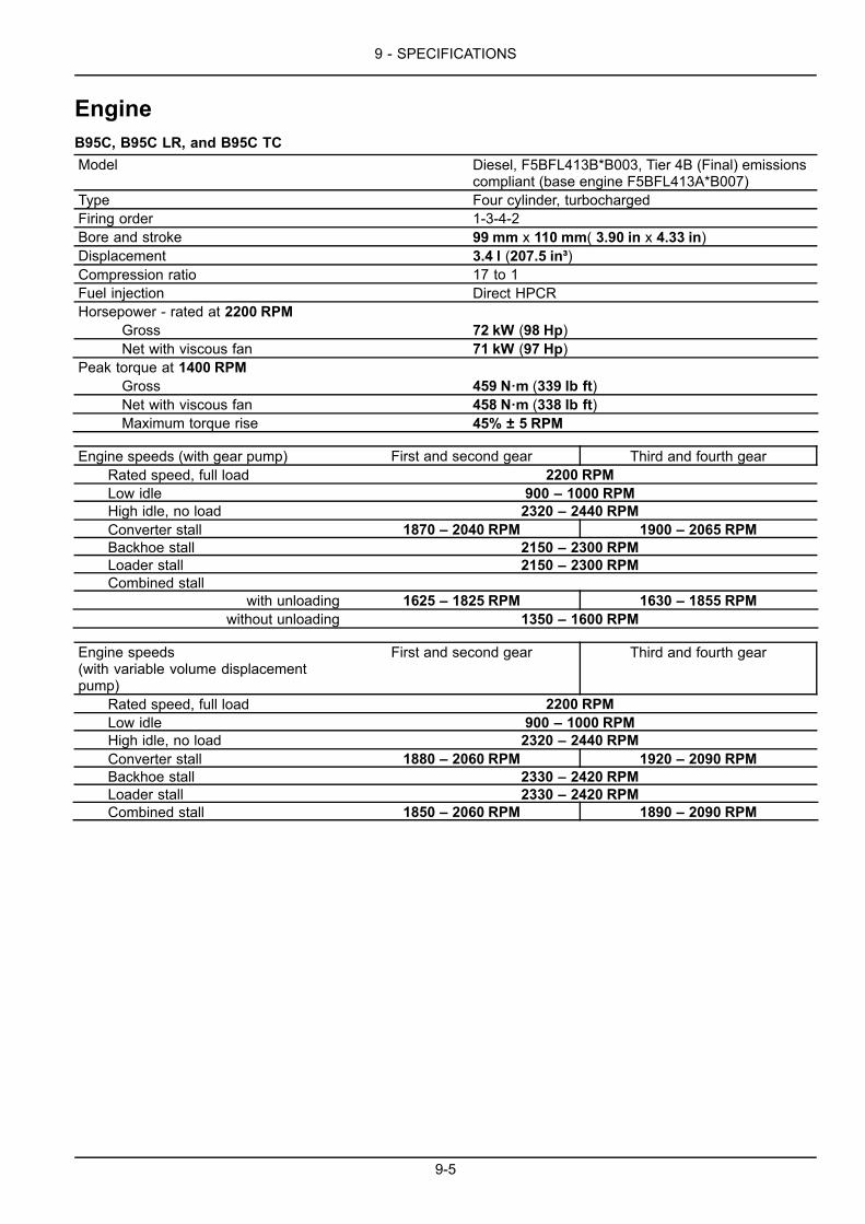
9 - SPECIFICATIONS
EngineB95C, B95C LR, and B95C TCModel Diesel, F5BFL413B*B003, Tier 4B (Final) emissions
compliant (base engine F5BFL413A*B007)Type Four cylinder, turbochargedFiring order 1-3-4-2Bore and stroke 99 mm x 110 mm( 3.90 in x 4.33 in)Displacement 3.4 l (207.5 in³)Compression ratio 17 to 1Fuel injection Direct HPCRHorsepower - rated at 2200 RPM
Gross 72 kW (98 Hp)Net with viscous fan 71 kW (97 Hp)
Peak torque at 1400 RPMGross 459 N·m (339 lb ft)Net with viscous fan 458 N·m (338 lb ft)Maximum torque rise 45% ± 5 RPM
Engine speeds (with gear pump) First and second gear Third and fourth gearRated speed, full load 2200 RPMLow idle 900 – 1000 RPMHigh idle, no load 2320 – 2440 RPMConverter stall 1870 – 2040 RPM 1900 – 2065 RPMBackhoe stall 2150 – 2300 RPMLoader stall 2150 – 2300 RPMCombined stall
with unloading 1625 – 1825 RPM 1630 – 1855 RPMwithout unloading 1350 – 1600 RPM
Engine speeds(with variable volume displacementpump)
First and second gear Third and fourth gear
Rated speed, full load 2200 RPMLow idle 900 – 1000 RPMHigh idle, no load 2320 – 2440 RPMConverter stall 1880 – 2060 RPM 1920 – 2090 RPMBackhoe stall 2330 – 2420 RPMLoader stall 2330 – 2420 RPMCombined stall 1850 – 2060 RPM 1890 – 2090 RPM
9-5

9 - SPECIFICATIONS
B110CModel Diesel, F5BFL413A*B006, Tier 4B (Final) emissions
compliant (base engine F5BFL413A*B007)Type Four cylinder, turbochargedFiring order 1-3-4-2Bore and stroke 99 mm x 110 mm( 3.90 in x 4.33 in)Displacement 3.4 l (207.5 in³)Compression ratio 17 to 1Fuel injection Direct HPCRHorsepower - rated at 2200 RPM
Gross 82 kW (111 Hp)Net with viscous fan 81 kW (110 Hp)
Peak torque at 1400 RPMGross 467 N·m (344 lb ft)Net with viscous fan 466 N·m (344 lb ft)Maximum torque rise 30% ± 5 RPM
Engine speeds (with gear pump) First and second gear Third and fourth gearRated speed, full load 2200 RPMLow idle 900 – 1100 RPMHigh idle, no load 2320 – 2440 RPMConverter stall 1940 – 2040 RPM 1970 – 2085 RPMBackhoe stall 2200 – 2300 RPMLoader stall 2200 – 2300 RPMCombined stall 1840 – 1940 RPM 1860 – 1972 RPM
Engine speeds(with variable volume displacementpump)
First and second gear Third and fourth gear
Rated speed, full load 2200 RPMLow idle 900 – 1000 RPMHigh idle, no load 2320 – 2440 RPMConverter stall 1950 – 2070 RPM 1980 – 2105 RPMBackhoe stall 2300 – 2425 RPMLoader stall 2300 – 2425 RPMCombined stall 1920 – 2070 RPM 1950 – 2105 RPM
9-6

9 - SPECIFICATIONS
PowertrainTRANSMISSION - POWER SHUTTLEModel CARRARO TLB2Type (4x4) 4 forward and 4 reverse travel gearsTorque converter ratio 2.38Transmission ratios:
1st gear forward travel 5.603:1 — reverse travel 4.643:12nd gear forward travel 3.481:1 — reverse travel 2.884:13rd gear forward travel 1.585:1 — reverse travel 1.313:14rd gear forward travel 0.793:1 — reverse travel 0.657:1
TRANSMISSION - POWERSHIFTModel CARRARO TLB2Type (4x4) 4 forward and 3 reverse travel gearsTorque converter ratio 2.38Transmission ratios:
1st gear forward travel 5.533:1 — reverse travel 4.549:12nd gear forward travel 3.359:1 — reverse travel 2.762:13rd gear forward travel 1.533:1 — reverse travel 1.260:14rd gear forward travel 0.811:1
9-7

9 - SPECIFICATIONS
Brakes and controls - General specificationFRONT AXLES
FRONT AXLEModel CNH 26.17Type steering
REAR AXLES
REAR AXLEModel (B95C - B95C TC - B95C LR) CARRARO 28.44Model (B110C) CARRARO 28.50Type rigidDifferential lock electrical
BRAKES
SERVICE BRAKESType Hydraulic foot operated, two disc per side.Total braking surface 1236 cm² (192 in²)
PARKING BRAKEType Spring Applied Hydraulic Release (SAHR) on
transmission output shaft. Electronic console switch.
POWER STEERINGGear pump Hydrostatic, relief valve integrated to pump - LS
operated priority valve on pump outlet.Relief valve setting 172 – 180 bar (2494 – 2610 psi)Capacity 125.0 cm³/rev (7.6 in³/rev)
Variable volume displacement pump Hydrostatic, LS relief valve located in steering unit.Dynamic LS operated priority valve located in loadercontrol valve inlet.
Relief valve setting 170 – 175 bar (2465 – 2538 psi)Capacity 125.0 cm³/rev (7.6 in³/rev)
9-8
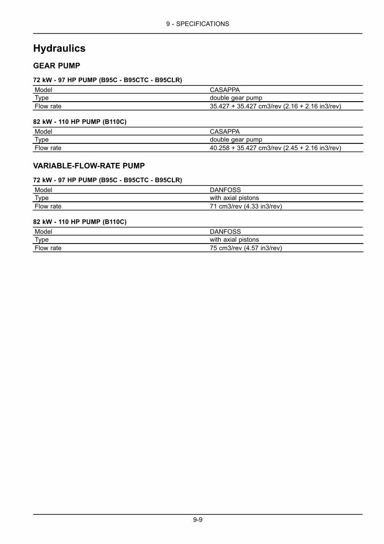
9 - SPECIFICATIONS
HydraulicsGEAR PUMP
72 kW - 97 HP PUMP (B95C - B95CTC - B95CLR)Model CASAPPAType double gear pumpFlow rate 35.427 + 35.427 cm3/rev (2.16 + 2.16 in3/rev)
82 kW - 110 HP PUMP (B110C)Model CASAPPAType double gear pumpFlow rate 40.258 + 35.427 cm3/rev (2.45 + 2.16 in3/rev)
VARIABLE-FLOW-RATE PUMP
72 kW - 97 HP PUMP (B95C - B95CTC - B95CLR)Model DANFOSSType with axial pistonsFlow rate 71 cm3/rev (4.33 in3/rev)
82 kW - 110 HP PUMP (B110C)Model DANFOSSType with axial pistonsFlow rate 75 cm3/rev (4.57 in3/rev)
9-9

9 - SPECIFICATIONS
Front counterweightCOUNTERWEIGHTSmall 159 kg (351 lb)Medium 326 kg (719 lb)Large 442 kg (974 lb)
9-10

9 - SPECIFICATIONS
Noise and vibration levelsNoise levelInternal noise level (LpA) 77 dBExternal noise level (LwA) (B95C - B95C TC - B95C LR) 102 dBExternal noise level (LwA) (B110C) 103 dB
Vibration level inside the cabUpper limbs level lower than 2.5 m/s² (8.20 ft/s²)Abdomen level lower than 0.5 m/s² (1.64 ft/s²)
9-11

9 - SPECIFICATIONS
BucketsLoader buckets
Type 0.88 m³ (31.08 ft³)standard 1 m³ (35.3 ft³) standard 4 x 1 6 x 1 (with forks)
Heapedcapacity 0.88 m³ (31.08 ft³) 1.0 m³ (35.3 ft³) 1.0 m³ (35.3 ft³) 1.0 m³ (35.3 ft³)
Width 2250 mm (88.58 in) 2250 mm (88.58 in) 2250 mm (88.58 in) 2250 mm (88.58 in)Weight 310 kg (683 lb) 400 kg (882 lb) 750 kg (1653 lb) 950 kg (2094 lb)
Backhoe bucketsWidth 305 mm (12 in) 457 mm (17.99 in) 610 mm (24.02 in) 762 mm (30 in) 910 mm (35.83 in)
Capacity 0.067 m³ (2.37 ft³) 0.108 m³ (3.81 ft³) 0.149 m³ (5.26 ft³) 0.190 m³ (6.71 ft³) 0.231 m³ (8.16 ft³)Heapedcapacity 0.081 m³ (2.86 ft³) 0.137 m³ (4.84 ft³) 0.198 m³ (6.99 ft³) 0.260 m³ (9.18 ft³) 0.323 m³ (11.41 ft³)
9-12

9 - SPECIFICATIONS
TiresInflating pressure and allowed carrying capacity tableNOTE: The following tables give the approximate carrying capacity at the indicated tire pressures when traveling ata maximum speed of 30 km/h (19 mph).
INFLATION PRESSURE bar (psi)1.5
(21.7)2.0
(29.0)2.2
(31.9)2.5
(37.7)2.8
(42.0)3.0
(43.5)3.3
(47.8)3.8
(55.1)4.0
(58.0)4.2
(60.9)
MAX LOAD PER TIRE kg (lb)
Front2WD
Tire size11L–16
ProfileF3
700(1543)
845(1862)
900(1984)
985(2171)
1065(2347)
1120(2469)
1185(2612)
1250(2755)
1350(2976)
1400(3086)
INFLATION PRESSURE bar (psi)0.8(11.6)
1.0(14.5)
1.6(23.2)
2.2(31.9)
2.8(40.6)
3.4(49.3)
MAX LOAD PER TIRE kg (lb)
Front4WD
Tire size12–16.5
ProfileL5
690(1521)
790(1741)
1040(2292)
1250(2755)
1440(3174)
1610(3549)
INFLATION PRESSURE bar (psi)0.8(11.6)
1.0(14.5)
1.6(23.2)
2.2(31.9)
2.8(40.6)
3.5(50.7)
MAX LOAD PER TIRE kg (lb)
Front4WD
Tire size14–17.5Beefy B.
ProfileR4
850(1873)
975(2149)
1090(2403)
1180(2601)
1320(2910)
1450(3196)
INFLATION PRESSURE bar (psi)0.8(11.6)
1.6(23.2)
2.0(29.0)
2.8(40.6)
3.1(44.9)
3.5(50.7)
MAX LOAD PER TIRE kg (lb)
Front4WD
Tire size14–17.5Const.
ProfileR4
940(2072)
1410(3108)
1605(3538)
1960(4321)
2080(4585)
2655(5853)
INFLATION PRESSURE bar (psi)1.4
(20.3)1.5
(21.7)1.7
(24.6)2.1
(30.4)2.5
(36.2)
MAX LOAD PER TIRE kg (lb)Rear Tire size
16.9–24 EZProfileR4
2200(4840)
2325(5115)
2450(5390)
2910(6402)
3300(7260)
INFLATION PRESSURE bar (psi)1.2
(17.4)1.4
(20.3)1.5
(21.7)1.9
(27.5)
MAX LOAD PER TIRE kg (lb)Rear Tire size
19.5–24ProfileL4
2520(5555)
2740(6040)
2875(6338)
3410(7517)
9-13

9 - SPECIFICATIONS
INFLATION PRESSURE bar (psi)1.2
(17.4)1.4
(20.3)1.5
(21.7)1.9
(27.5)2.2
(31.9)
MAX LOAD PER TIRE kg (lb)Rear Tire size
16.9–28 EZProfileR4
2300(5070)
2490(5489)
2620(5776)
3110(6856)
3410(7517)
INFLATION PRESSURE bar (psi)1.2
(17.4)1.4
(20.3)1.5
(21.7)1.9
(27.5)2.2
(31.9)3.4
(49.3)
MAX LOAD PER TIRE kg (lb)Rear Tire size
21L–24 EZProfileR4
2455(5412)
2840(5467)
3005(6624)
3165(6977)
3760(8289)
4030(8884)
9-14

9 - SPECIFICATIONS
Dimensions and performanceDimensions
LEEN12T0742FA 1
Front tires 12.5/18Rear tires 18.4–26Standard loader bucket 1 m³ (35.31 ft³)Standard backhoe bucket 914 mm (36.0 in)
A Overall machine length 7030 mm (276.4 in)B Loader bucket reach 1870 mm (73.6 in)C Wheel base 2175 mm (86.0 in)D Backhoe bucket dimensions 2985 mm (117.5 in)E Rear wheel base - backhoe attachment swing support 1120 mm (44.1 in)F Maximum machine height 3875 mm (152.6 in)G Stabilizer width 2300 mm (90.6 in)H Cab height 2950 mm (116.1 in)I Loader bucket width 2250 mm (88.6 in)
9-15

9 - SPECIFICATIONS
Loader attachment performance
B95C TC with standard bucket 1 m³ (35.3 ft³)
LEEN12T0743FA_1 2
A. Maximum height/dimensionsB. Maximum height of loader bucket pin/pivotC. Maximum dumping heightD. Digging depthE. Loader attachment reach when raised in dumping positionα. Angle of lowered closed bucketβ. Angle of closed bucket at maximum heightχ. Dumping angle
Front tires 12.5 - 18 SLR4Rear tires 16.9 - 28 SLR4
A 4233 mm (166.7 in)B 3433 mm (135.2 in)C 2606 mm (102.6 in)D 166 mm (6.5 in)E 844 mm (33.2 in)α 42.9°β 39.9°χ 45°
9-16

9 - SPECIFICATIONS
B95C and B110C with standard bucket 0.88 m³ (31.1 ft³)
LEEN12T0743FA_1 3
A. Maximum height/dimensionsB. Maximum height of loader bucket pin/pivotC. Maximum dumping heightD. Digging depthE. Loader attachment reach when raised in dumping positionα. Angle of lowered closed bucketβ. Angle of closed bucket at maximum heightχ. Dumping angle
Front tires 12.5 - 18Rear tires 16.9 - 28
A 4278 mm (168.4 in)B 3502 mm (137.9 in)C 2756 mm (108.5 in)D 102 mm (4.0 in)E 759 mm (29.9 in)α 39.2°β 43.1°χ 44.5°
9-17

9 - SPECIFICATIONS
B95C and B110C with standard bucket 1 m³ (35.3 ft³)
LEEN12T0743FA_1 4
A. Maximum height/dimensionsB. Maximum height of loader bucket pin/pivotC. Maximum dumping heightD. Digging depthE. Loader attachment reach when raised in dumping positionα. Angle of lowered closed bucketβ. Angle of closed bucket at maximum heightχ. Dumping angle
Front tires 12.5 - 18Rear tires 16.9 - 28
A 4329 mm (170.4 in)B 3502 mm (137.9 in)C 2714 mm (106.9 in)D 102 mm (4.0 in)E 811 mm (31.9 in)α 39.2°β 37.7°χ 44.1°
9-18

9 - SPECIFICATIONS
B95C and B110C with 4x1 bucket 1 m³ (35.3 ft³))
LEEN12T0743FA_1 5
A. Maximum height/dimensionsB. Maximum height of loader bucket pin/pivotC. Maximum dumping heightD. Digging depthE. Loader attachment reach when raised in dumping positionα. Angle of lowered closed bucketβ. Angle of closed bucket at maximum heightχ. Dumping angle
Front tires 12.5 - 18Rear tires 16.9 - 28
A 4478 mm (176.3 in)B 3502 mm (137.9 in)C 2728 mm (107.4 in)D 153 mm (6.0 in)E 780 mm (30.7 in)α 40.8°β 40.3°χ 41.3°
9-19

9 - SPECIFICATIONS
Dimensions and performance – 6 in 1 bucketB95C and B110C
LEEN12T0744FA 1
* Front counterweightA. Maximum height of loader bucket pin/pivot with lifted forksB. Fork maximum heightC. Height of loader bucket pin/pivot with lowered forksD. Fork reach when raisedE. Fork reach when lowered
Front tires 12.5 - 18Rear tires 16.9 - 28
A (6 x 1 bucket) 3502 mm (137.9 in)B (6 x 1 bucket) 3074 mm (121.0 in)C (6 x 1 bucket) 470 mm (18.5 in)D (6 x 1 bucket) 2250 mm (88.6 in)E (6 x 1 bucket) 2726 mm (107.3 in)
9-20

9 - SPECIFICATIONS
Backhoe attachment performanceB95C, B95C TC, and B110C (with short standard dipper)
LEEN12T0745FA_1 1
Front tires 11L-16F3Rear tires 17.5L-24
A Maximum digging height 5443 mm (214.3 in)B Maximum height at full load 3613 mm (142.2 in)C Maximum digging depth 4426 mm (174.3 in)D Digging depth [Length = 2438.4 mm (96.00 in)] 4034 mm (158.8 in)E Digging reach at maximum height 1759 mm (69.3 in)F Maximum reach when loaded 1395 mm (54.9 in)G Maximum digging reach with lowered bucket 5186 mm (204.2 in)α Bucket digging angle 204°
9-21

9 - SPECIFICATIONS
B95C LR and B110C (with long standard dipper)
LEEN12T0745FA_1 2
Front tires 11L-16F3Rear tires 17.5L-24
A Maximum digging height 5634 mm (221.8 in)B Maximum height at full load 3823 mm (150.5 in)C Maximum digging depth 4727 mm (186.1 in)D Digging depth [Length = 2438.4 mm (96.00 in)] 4356 mm (171.5 in)E Digging reach at maximum height 1988 mm (78.3 in)F Maximum reach when loaded 1592 mm (62.7 in)G Maximum digging reach with lowered bucket 5450 mm (214.6 in)α Bucket digging angle 204°
9-22

9 - SPECIFICATIONS
B95C, B95C TC, and B110C (with short telescopic dipper)
LEEN12T0745FA_1 3
Retracted dipperFront tires 11L-16F3Rear tires 17.5L-24
A Maximum digging height 5547 mm (218.4 in)B Maximum height at full load 3737 mm (147.1 in)C Maximum digging depth 4586 mm (180.6 in)D Digging depth [Length = 2438.4 mm (96.00 in)] 4206 mm (165.6 in)E Digging reach at maximum height 1893 mm (74.5 in)F Maximum reach when loaded 1482 mm (58.3 in)G Maximum digging reach with lowered bucket 5327 mm (209.7 in)α Bucket digging angle 204°
Extended dipperFront tires 11L-16F3Rear tires 17.5L-24
A Maximum digging height 6191 mm (243.7 in)B Maximum height at full load 4380 mm (172.4 in)C Maximum digging depth 5623 mm (221.4 in)D Digging depth [Length = 2438.4 mm (96.00 in)] 5310 mm (209.1 in)E Digging reach at maximum height 2737 mm (107.8 in)F Maximum reach when loaded 2326 mm (91.6 in)G Maximum digging reach with lowered bucket 6279 mm (247.2 in)α Bucket digging angle 204°
9-23

9 - SPECIFICATIONS
B95C LR and B110C (with long telescopic dipper)
LEEN12T0745FA_1 4
Retracted dipperFront tires 11L-16F3Rear tires 17.5L-24
A Maximum digging height 5635 mm (221.9 in)B Maximum height at full load 3826 mm (150.6 in)C Maximum digging depth 4735 mm (186.4 in)D Digging depth [Length = 2438.4 mm (96.00 in)] 4364 mm (171.8 in)E Digging reach at maximum height 2079 mm (81.9 in)F Maximum reach when loaded 1604 mm (63.1 in)G Maximum digging reach with lowered bucket 5456 mm (214.8 in)α Bucket digging angle 204°
Extended dipperFront tires 11L-16F3Rear tires 17.5L-24
A Maximum digging height 6456 mm (254.2 in)B Maximum height at full load 4556 mm (179.4 in)C Maximum digging depth 5770 mm (227.2 in)D Digging depth [Length = 2438.4 mm (96.00 in)] 5463 mm (215.1 in)E Digging reach at maximum height 2984 mm (117.5 in)F Maximum reach when loaded 2568 mm (101.1 in)G Maximum digging reach with lowered bucket 6409 mm (252.3 in)α Bucket digging angle 204°
9-24

9 - SPECIFICATIONS
Backhoe attachment lifting capacityLifting capacity - B95C and B95CTC (Short dipper – 14ft in-line cylinder)
Lifting capacity in normal operating mode - SAE ratedThe following table reports the lifting capacities of the dip-per “A” and the boom “B”.
NOTE: The capacities indicated may slightly vary fromone machine to another, according to the accessoriesmounted, the pressure settings and the market require-ments.
Lifting capacities are given in kg (lb) for a standard dipperand a telescopic dipper.
MOLI12LBB0543AB 1
Standard dipper Telescopic dipper (retracted) Telescopic dipper (extended)Dipper A Boom B Dipper A Boom B Dipper A Boom B Height/depth
1624 kg(3580 lb)
838 kg(1847 lb)
+4.9 m(16 ft)
1701 kg(3750 lb)
1389 kg(3062 lb)
950 kg(2094 lb)
+4.6 m(15 ft)
1829 kg(4032 lb)
1589 kg(3503 lb)
1642 kg(3620 lb)
1142 kg(2518 lb)
+4.3 m(14 ft)
2520 kg(5556 lb)
1881 kg(4147 lb)
2249 kg(4958 lb)
1635 kg(3605 lb)
1789 kg(3944 lb)
1174 kg(2588 lb)
+3.7 m(12 ft)
2423 kg(5342 lb)
1850 kg(4079 lb)
2645 kg(5831 lb)
1609 kg(3547 lb)
1762 kg(3885 lb)
1179 kg(2599 lb)
+3.0 m(10 ft)
2472 kg(5450 lb)
1797 kg(3962 lb)
2645 kg(5831 lb)
1556 kg(3430 lb)
1783 kg(3931 lb)
1169 kg(2577 lb)
+2.4 m(8 ft)
2710 kg(5975 lb)
1734 kg(3823 lb)
2645 kg(5831 lb)
1504 kg(3316 lb)
1864 kg(4109 lb)
1153 kg(2542 lb)
+1.8 m(6 ft)
1677 kg(3697 lb)
3645 kg(8036 lb)
1451 kg(3199 lb)
2043 kg(4504 lb)
1132 kg(2496 lb)
+1.2 m(4 ft)
1624 kg(3580 lb)
1399 kg(3084 lb)
2450 kg(5401 lb)
1116 kg(2460 lb)
+0.6 m(2 ft)
1577 kg(3477 lb)
1357 kg(2992 lb)
1095 kg(2414 lb) 0 (ground)
1530 kg(3373 lb)
1315 kg(2899 lb)
1079 kg(2379 lb)
-0.6 m(-2 ft)
1499 kg(3305 lb)
1279 kg(2820 lb)
1069 kg(2357 lb)
-1.2 m(-4 ft)
1472 kg(3245 lb)
1252 kg(2760 lb)
1058 kg(2332 lb)
-1.8 m(-6 ft)
1467 kg(3234 lb)
1242 kg(2738 lb)
1058 kg(2332 lb)
-2.4 m(-8 ft)
1520 kg(3351 lb)
1273 kg(2806 lb)
1074 kg(2368 lb)
-3.0 m(-10 ft)
1624 kg(3580 lb)
1404 kg(3095 lb)
1121 kg(2471 lb)
-3.7 m(-12 ft)
1300 kg(2866 lb)
-4.3 m(-14 ft)
1603 kg(3534 lb)
-4.9 m(-16.1 ft)
9-25

9 - SPECIFICATIONS
Lifting capacity - B95CLR and B110C (Long dipper – 15ft in-line cylinder)
Lifting capacity in normal operating mode - SAE ratedThe following table reports the lifting capacities of the dip-per “A” and the boom “B”.
NOTE: The capacities indicated may slightly vary fromone machine to another, according to the accessoriesmounted, the pressure settings and the market require-ments.
Lifting capacities are given in kg (lb) for a standard dipperand a telescopic dipper.
MOLI12LBB0543AB 2
Standard dipper Telescopic dipper (retracted) Telescopic dipper (extended)Dipper A Boom B Dipper A Boom B Dipper A Boom B Height/depth
840 kg(1852 lb)
+5.2 m(17 ft)
1530 kg(3373 lb)
1095 kg(2414 lb)
+4.9 m(16 ft)
1630 kg(3594 lb)
1440 kg(3175 lb)
1125 kg(2480 lb)
+4.6 m(15 ft)
1810 kg(3990 lb)
1695 kg(3737 lb)
1540 kg(3395 lb)
1185 kg(2612 lb)
+4.3 m(14 ft)
2085 kg(4597 lb)
1865 kg(4112 lb)
1960 kg(4321 lb)
1740 kg(3836 lb)
1505 kg(3318 lb)
1215 kg(2679 lb)
+3.7 m(12 ft)
2010 kg(4431 lb)
1845 kg(4068 lb)
1890 kg(4167 lb)
1720 kg(3792 lb)
1485 kg(3274 lb)
1230 kg(2712 lb)
+3.0 m(10 ft)
2035 kg(4486 lb)
1700 kg(3748 lb)
1910 kg(4211 lb)
1570 kg(3461 lb)
1500 kg(3307 lb)
1215 kg(2679 lb)
+2.4 m(8 ft)
2175 kg(4795 lb)
1605 kg(3538 lb)
2040 kg(4497 lb)
1475 kg(3252 lb)
1550 kg(3417 lb)
1165 kg(2568 lb)
+1.8 m(6 ft)
2575 kg(5677 lb)
1555 kg(3428 lb)
2420 kg(5335 lb)
1425 kg(3142 lb)
1675 kg(3693 lb)
1135 kg(2502 lb)
+1.2 m(4 ft)
1535 kg(3384 lb)
1400 kg(3086 lb)
1905 kg(4200 lb)
1120 kg(2469 lb)
+0.6 m(2 ft)
1545 kg(3406 lb)
1410 kg(3109 lb)
2250 kg(4960 lb)
1120 kg(2469 lb) 0 (ground)
1585 kg(3494 lb)
1445 kg(3186 lb)
1140 kg(2513 lb)
-0.6 m(-2 ft)
1575 kg(3472 lb)
1415 kg(3120 lb)
1150 kg(2535 lb)
-1.2 m(-4 ft)
1560 kg(3439 lb)
1395 kg(3075 lb)
1145 kg(2524 lb)
-1.8 m(-6 ft)
1560 kg(3439 lb)
1385 kg(3053 lb)
1150 kg(2535 lb)
-2.4 m(-8 ft)
1605 kg(3538 lb)
1415 kg(3120 lb)
1165 kg(2568 lb)
-3.0 m(-10 ft)
1855 kg(4090 lb)
1630 kg(3594 lb)
1210 kg(2668 lb)
-3.7 m(-12 ft)
1325 kg(2921 lb)
-4.3 m(-14 ft)
1910 kg(4211 lb)
-4.6 m(-15 ft)
9-26

10 - ACCESSORIES
10 - ACCESSORIES###_10_###
Mechanical loader bucket quick couplerIt is possible to install a quick coupler (1) for the loaderbucket on the loader attachment, using the standardmounting pins (2).
Quick removal and installation of the loaderbucketMake sure the bucket to be installed is in a safe area, ona level and firm ground and with the upper pins in place.
Use the control lever (dumping position) to bring the quickcoupler hooks under the bucket pins (3).
Use the control lever (digging position) to swing the bucketdown onto the lower part of the quick coupler.
Stop the engine and remove the starter switch key.
Install the pins (4) and retaining hardware.
NOTICE: Make sure the loader bucket is correctly in-stalled with all its pins and locking rings before using theloader.
MOLI12LBB0507BB 1
10-1

10 - ACCESSORIES
Mechanical backhoe bucket quick couplerWARNINGEquipment failure could cause accident or injury!Use only authorized auxiliary hydraulic attachments. Always read and understand the manual or in-structions supplied by the manufacturer to avoid injury or damage. Understand the operation andsafety instructions before you attach, remove, or operate the attachment.Failure to comply could result in death or serious injury.
W0231A
WARNINGCrushing hazard!Always use approved attachments. Make sure the attachment is compatible with the machine mount-ing system.Failure to comply could result in death or serious injury.
W0183A
Removing an attachment with a mechanical quick coupler1. Make sure that all unauthorized workers or bystanders
are away from the machine.2. Park the machine on a level surface.3. Lower the stabilizers to the ground.4. Level the machine.5. Roll the bucket outward.6. Extend the boom and dipper.
NOTE: For easier access to the bucket pins later, propup the bucket pin side (3) on a suitable support de-vice (4) capable of evenly supporting the weight of thebucket. Make sure that the bucket pin side is higherthen the bucket teeth side.
7. Lower the backhoe until the bucket is just touching theground or support. Do not apply down force on thebucket.
RAIL16TLB0537BA 1
8. Turn off the engine and remove the key.
9. Insert the handle (2) into the mechanical coupler (1).
10. Pull the handle towards the bucket to release the topof the quick coupler from the bucket.
11. Release and remove the handle from the quick cou-pler.
NOTE: Store the handle in the tool box.
12. Start the engine.
13. Use the backhoe controls to rotate the quick couplerout away from the lower bucket pin.
14. Make sure that you raise the stabilizers before mov-ing the machine.
10-2

10 - ACCESSORIES
Installing an attachment with a mechanical quick coupler1. Make sure that all unauthorized workers or bystanders
are away from the machine.2. Position the backhoe so that you will be able to extend
the backhoe and reach the lower bucket pin (4).
NOTICE: The bucket must have a pin in the maximumpower position (3) otherwise you will not be able toattach the bucket.
3. Lower the stabilizers to the ground.4. Level the machine.5. Extend the backhoe quick coupler to the lower pin (4)
of the bucket.6. Rotate the quick coupler pin hook (5) over the lower
pin (4) on the bucket.7. Pivot the quick coupler upward and engage the upper
pin (3) on the bucket.
NOTE: The pin of the bucket will force open the springof the quick coupler latch (2). After engagement thespring will release the latch around the bucket pin andsecure the bucket to the quick coupler.
RAIL16TLB0536BA 2
WARNINGFalling object hazard!Always visually inspect coupler locking pinsfor proper engagement. An improperly lockedattachment could release and fall.Failure to comply could result in death or se-rious injury.
W0930A
8. Stop the engine and visually inspect the coupler con-nection is fully engaged.
9. Start the engine and use the backhoe controls.Slowly rotate the bucket through its full stroke toconfirm the bucket is secure. Rotate the bucketattachment again this time with more of a quick jerkymovement.
10. Proceed with work operations.
10-3
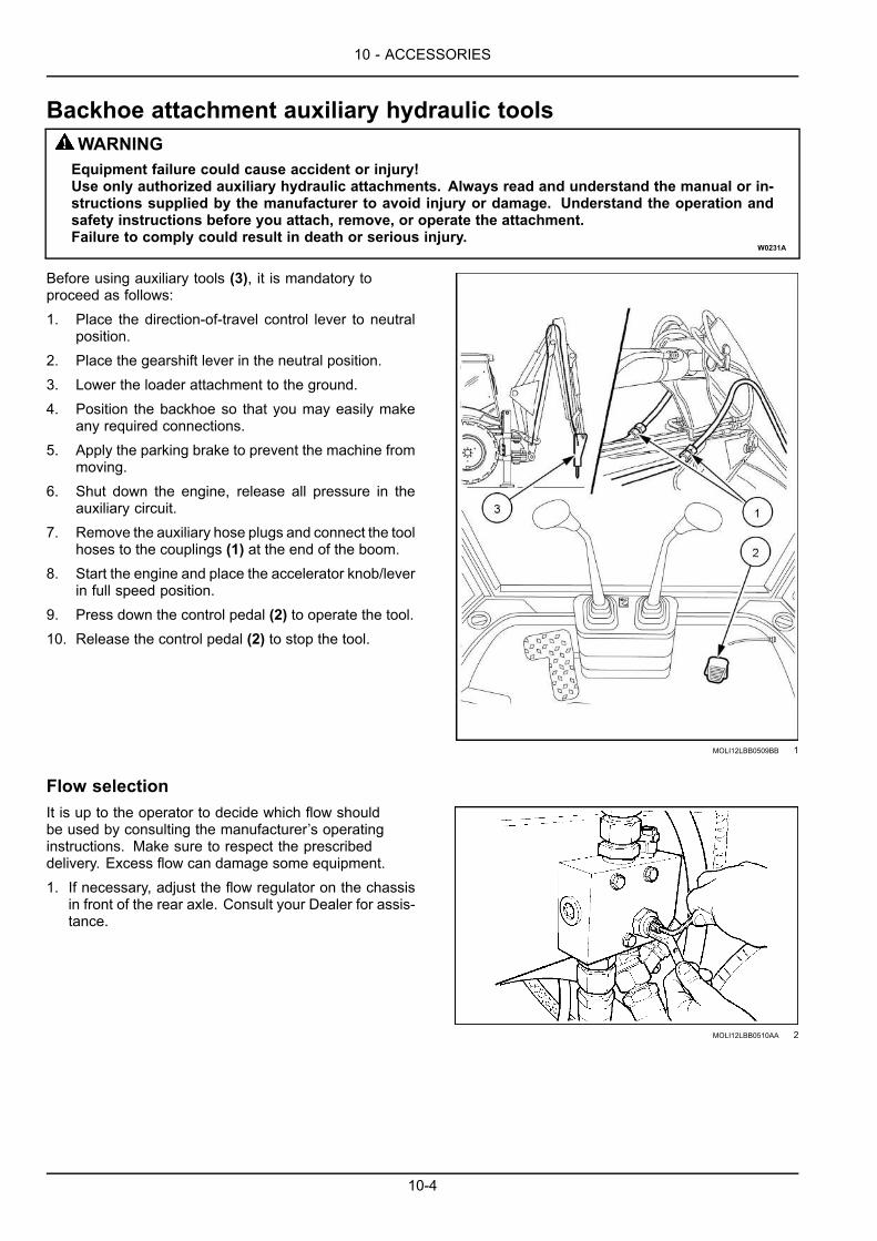
10 - ACCESSORIES
Backhoe attachment auxiliary hydraulic toolsWARNINGEquipment failure could cause accident or injury!Use only authorized auxiliary hydraulic attachments. Always read and understand the manual or in-structions supplied by the manufacturer to avoid injury or damage. Understand the operation andsafety instructions before you attach, remove, or operate the attachment.Failure to comply could result in death or serious injury.
W0231A
Before using auxiliary tools (3), it is mandatory toproceed as follows:1. Place the direction-of-travel control lever to neutral
position.2. Place the gearshift lever in the neutral position.3. Lower the loader attachment to the ground.4. Position the backhoe so that you may easily make
any required connections.5. Apply the parking brake to prevent the machine from
moving.6. Shut down the engine, release all pressure in the
auxiliary circuit.7. Remove the auxiliary hose plugs and connect the tool
hoses to the couplings (1) at the end of the boom.8. Start the engine and place the accelerator knob/lever
in full speed position.9. Press down the control pedal (2) to operate the tool.10. Release the control pedal (2) to stop the tool.
MOLI12LBB0509BB 1
Flow selectionIt is up to the operator to decide which flow shouldbe used by consulting the manufacturer’s operatinginstructions. Make sure to respect the prescribeddelivery. Excess flow can damage some equipment.1. If necessary, adjust the flow regulator on the chassis
in front of the rear axle. Consult your Dealer for assis-tance.
MOLI12LBB0510AA 2
10-4

10 - ACCESSORIES
Hand held auxiliary hydraulic toolsWARNINGEquipment failure could cause accident or injury!Use only authorized auxiliary hydraulic attachments. Always read and understand the manual or in-structions supplied by the manufacturer to avoid injury or damage. Understand the operation andsafety instructions before you attach, remove, or operate the attachment.Failure to comply could result in death or serious injury.
W0231A
Before using auxiliary tools (3), it is mandatory toproceed as follows:1. Place the direction-of-travel control lever to neutral
position.2. Place the gearshift lever in the neutral position.3. Lower the loader attachment to the ground.4. Apply the parking brake to prevent the machine from
moving.5. Shut down the engine, release all pressure in the
auxiliary circuit.6. Place the manual auxiliary hydraulic tool switch (1) in
the OFF position.7. Stop the engine, remove the plugs and connect the
tool hoses to the couplings in front of the fuel tank.Coupling (3) is for the hydraulic oil supply line andcoupling (2) is for the hydraulic oil return line.
8. Start the engine and place the accelerator knob/leverin full speed position.
9. Place the manual auxiliary hydraulic tool switch (1) inthe ON position (lamp on), now it is possible to usethe tool.
10. When the tool is no longer required, place the manualauxiliary hydraulic tool switch (1) back to the OFFposition (lamp off).
LEEN11T0287BA 1
Flow selectionIt is up to the operator to decide which flow shouldbe used by consulting the manufacturer’s operatinginstructions. Make sure to respect the prescribeddelivery. Excess flow can damage some equipment.1. If necessary, adjust the flow regulator on the chassis
in front of the rear axle. Consult your Dealer for assis-tance.
MOLI12LBB0512AA 2
10-5

10 - ACCESSORIES
Backhoe attachment safety valvesThe function of the safety valves (1) is to prevent the at-tachment from falling because of oil leaks in the controlvalve (spool in neutral) or hoses accidentally breaking, aswell as to guarantee a smooth and controlled lowering ofthe attachment in the event of a hose or pipe accidentallybreaking.
MOLI12LBB0513AB 1
10-6
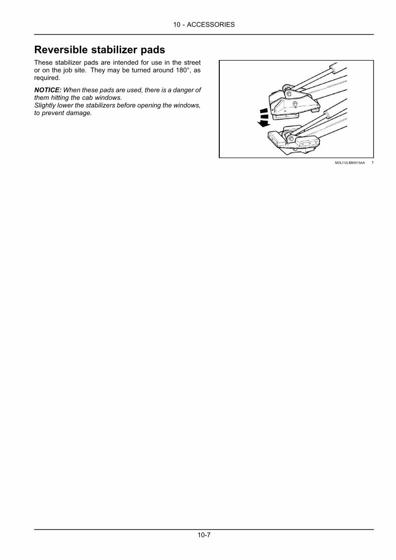
10 - ACCESSORIES
Reversible stabilizer padsThese stabilizer pads are intended for use in the streetor on the job site. They may be turned around 180°, asrequired.
NOTICE:When these pads are used, there is a danger ofthem hitting the cab windows.Slightly lower the stabilizers before opening the windows,to prevent damage.
MOLI12LBB0515AA 1
10-7

10 - ACCESSORIES
Telematics - Overview with New Holland FleetForce™NOTE: The NEW HOLLAND CONSTRUCTIONFleetForce™ website (www.newhollandfleetforce.com) will not beaccessible until the NEW HOLLAND CONSTRUCTIONFleetForce™ subscription for this machine is registered byan authorized NEW HOLLAND CONSTRUCTION dealer. Contact an authorized NEW HOLLAND CONSTRUCTIONdealer for details.
This machine may be equipped with a Telematics system. This is an asset-monitoring system that combines Internet,cellular, and GPS technologies. A transponder unit is mounted on the equipment that wirelessly communicates withthe user interface NEW HOLLAND CONSTRUCTIONFleetForce™ at www.newhollandfleetforce.com. Using cellulartechnology, the transponder can send equipment data, including location, on/off status, usage and production metrics,diagnostic data, movement alarms, unauthorized usage and monitor machine maintenance to the user interface NEWHOLLAND CONSTRUCTIONFleetForce™. The system will help cut costs and keep accurate records.
10-8

Index
###_Index_###
AAccess to operator’s platform. . . . . . . . . . . . . . . . . . . . . . . . . . . . . . . . . . . . 3-1Air-conditioning compressor drive belt . . . . . . . . . . . . . . . . . . . . . . . . . . . . . . . 7-126Air-conditioning system - Troubleshooting . . . . . . . . . . . . . . . . . . . . . . . . . . . . . . 8-21Alternator - check . . . . . . . . . . . . . . . . . . . . . . . . . . . . . . . . . . . . . . . . 7-114Alternator — Check . . . . . . . . . . . . . . . . . . . . . . . . . . . . . . . . . . . . . . . 7-45Alternator - Troubleshooting . . . . . . . . . . . . . . . . . . . . . . . . . . . . . . . . . . . . 8-6Assisted starting (Jump-starting) . . . . . . . . . . . . . . . . . . . . . . . . . . . . . . . . . . 4-13Auto engine protection shutdown setting . . . . . . . . . . . . . . . . . . . . . . . . . . . . . . . 6-9Auto engine shutdown time-out adjustment. . . . . . . . . . . . . . . . . . . . . . . . . . . . . . 6-6Auto-Glide Ride™ (AGR) – Four-Wheel Drive (4WD) only . . . . . . . . . . . . . . . . . . . . . . . 4-25Auto-Glide Ride™ (AGR) speed thresholds . . . . . . . . . . . . . . . . . . . . . . . . . . . . . 6-11Auto powershift . . . . . . . . . . . . . . . . . . . . . . . . . . . . . . . . . . . . . . . . . . 4-20Axles - Troubleshooting . . . . . . . . . . . . . . . . . . . . . . . . . . . . . . . . . . . . . . 8-10
BBackhoe attachment auxiliary hydraulic tools . . . . . . . . . . . . . . . . . . . . . . . . . . . . . 10-4Backhoe attachment hydraulic controls . . . . . . . . . . . . . . . . . . . . . . . . . . . . . . . 3-83Backhoe attachment lifting capacity . . . . . . . . . . . . . . . . . . . . . . . . . . . . . . . . . 9-25Backhoe attachment mechanical controls version . . . . . . . . . . . . . . . . . . . . . . . . . . . 3-73Backhoe attachment performance . . . . . . . . . . . . . . . . . . . . . . . . . . . . . . . . . 9-21Backhoe attachment safety valves . . . . . . . . . . . . . . . . . . . . . . . . . . . . . . . . . 10-6Backhoe attachment - Troubleshooting . . . . . . . . . . . . . . . . . . . . . . . . . . . . . . . 8-16Backhoe bucket – Digging angle . . . . . . . . . . . . . . . . . . . . . . . . . . . . . . . . . . 6-49Backhoe bucket – Install . . . . . . . . . . . . . . . . . . . . . . . . . . . . . . . . . . . . . 6-48Backhoe bucket – Remove . . . . . . . . . . . . . . . . . . . . . . . . . . . . . . . . . . . . 6-47Backhoe danger area . . . . . . . . . . . . . . . . . . . . . . . . . . . . . . . . . . . . . . . 6-30Ballasting . . . . . . . . . . . . . . . . . . . . . . . . . . . . . . . . . . . . . . . . . . . . 6-50Basic instructions . . . . . . . . . . . . . . . . . . . . . . . . . . . . . . . . . . . . . . 6-29, 6-32Battery master switch . . . . . . . . . . . . . . . . . . . . . . . . . . . . . . . . . . . . . . . 3-26Battery removal and installation. . . . . . . . . . . . . . . . . . . . . . . . . . . . . . . . . . 7-150Battery terminals . . . . . . . . . . . . . . . . . . . . . . . . . . . . . . . . . . . . . . . . . 7-78Before operating the machine . . . . . . . . . . . . . . . . . . . . . . . . . . . . . . . . . . . 4-18Before starting the engine . . . . . . . . . . . . . . . . . . . . . . . . . . . . . . . . . . . . . 4-5Before using the machine . . . . . . . . . . . . . . . . . . . . . . . . . . . . . . . . . . . . . 4-1Brake pedal lever - Greasing . . . . . . . . . . . . . . . . . . . . . . . . . . . . . . . . . . . 7-112Brakes and controls - General specification . . . . . . . . . . . . . . . . . . . . . . . . . . . . . 9-8Buckets . . . . . . . . . . . . . . . . . . . . . . . . . . . . . . . . . . . . . . . . . . . . . 9-12Bucket teeth . . . . . . . . . . . . . . . . . . . . . . . . . . . . . . . . . . . . . . . . . . 7-153Bulbs . . . . . . . . . . . . . . . . . . . . . . . . . . . . . . . . . . . . . . . . . . . . . 7-135
CCab air filter . . . . . . . . . . . . . . . . . . . . . . . . . . . . . . . . . . . . . . . . . . . 7-73Cab air louvers . . . . . . . . . . . . . . . . . . . . . . . . . . . . . . . . . . . . . . . . . . 3-93Cab and platform - Control identification . . . . . . . . . . . . . . . . . . . . . . . . . . . . . . . 3-48Cab protection system. . . . . . . . . . . . . . . . . . . . . . . . . . . . . . . . . . . . . . . 7-80Cab - Troubleshooting . . . . . . . . . . . . . . . . . . . . . . . . . . . . . . . . . . . . . . . 8-20Capacities – B110C . . . . . . . . . . . . . . . . . . . . . . . . . . . . . . . . . . . . . 7-7, 9-3Capacities - B95C, B95C LR, and B95C TC . . . . . . . . . . . . . . . . . . . . . . . . . . . 7-5, 9-1Checks at start-up and before each workshift (10 hours) . . . . . . . . . . . . . . . . . . . . . . . . 7-37Cold temperature operation . . . . . . . . . . . . . . . . . . . . . . . . . . . . . . . . . . . . 4-8Component identification . . . . . . . . . . . . . . . . . . . . . . . . . . . . . . . . . . . . . 1-9
DDetent position for loader control auxiliary hydraulics . . . . . . . . . . . . . . . . . . . . . . . . . 3-59Diagnostic/Service tool port . . . . . . . . . . . . . . . . . . . . . . . . . . . . . . . . . . . . 7-19

Diesel Exhaust Fluid (DEF)/AdBlue®/ARLA tank - Drain fluid . . . . . . . . . . . . . . . . . . . . . . 7-32Diesel Exhaust Fluid (DEF)/AdBlue®/ARLA tank - Filling . . . . . . . . . . . . . . . . . . . . . . . . 7-31Diesel Exhaust Fluid (DEF)/AdBlue® in-line filter . . . . . . . . . . . . . . . . . . . . . . . . . . . 7-92Diesel Exhaust Fluid (DEF)/AdBlue® supply module filter . . . . . . . . . . . . . . . . . . . . . . 7-116Diesel Exhaust Fluid (DEF)/AdBlue® tank filler screen . . . . . . . . . . . . . . . . . . . . . . . . . 7-90Differential lock button . . . . . . . . . . . . . . . . . . . . . . . . . . . . . . . . . . . . . . . 4-23Dimensions and performance . . . . . . . . . . . . . . . . . . . . . . . . . . . . . . . . . . . 9-15Dimensions and performance – 6 in 1 bucket . . . . . . . . . . . . . . . . . . . . . . . . . . . . 9-20Disable parking brake . . . . . . . . . . . . . . . . . . . . . . . . . . . . . . . . . . . . . . 7-156Display brightness . . . . . . . . . . . . . . . . . . . . . . . . . . . . . . . . . . . . . . . . 6-2Display screen messages . . . . . . . . . . . . . . . . . . . . . . . . . . . . . . . . . . . . . 8-22Door hinges . . . . . . . . . . . . . . . . . . . . . . . . . . . . . . . . . . . . . . . . . . . 7-50Drive belt . . . . . . . . . . . . . . . . . . . . . . . . . . . . . . . . . . . . . . . . . . . 7-124Drive belts - check . . . . . . . . . . . . . . . . . . . . . . . . . . . . . . . . . . . . . . . . 7-72Drive shaft lubrication . . . . . . . . . . . . . . . . . . . . . . . . . . . . . . . . . . . . . . . 7-59
EEcology and the environment. . . . . . . . . . . . . . . . . . . . . . . . . . . . . . . . . . . . 2-25Electrical systems - Troubleshooting . . . . . . . . . . . . . . . . . . . . . . . . . . . . . . . . 8-19Electro-Magnetic Compatibility (EMC) . . . . . . . . . . . . . . . . . . . . . . . . . . . . . . . . 1-4Engine . . . . . . . . . . . . . . . . . . . . . . . . . . . . . . . . . . . . . . . . . . . . . 9-5Engine air filters . . . . . . . . . . . . . . . . . . . . . . . . . . . . . . . . . . . . . . . . . 7-25Engine breather filter . . . . . . . . . . . . . . . . . . . . . . . . . . . . . . . . . . . . . . 7-115Engine coolant . . . . . . . . . . . . . . . . . . . . . . . . . . . . . . . . . . . . . . . . . 7-122Engine coolant — Check . . . . . . . . . . . . . . . . . . . . . . . . . . . . . . . . . . . . . 7-43Engine cooling system — Check . . . . . . . . . . . . . . . . . . . . . . . . . . . . . . . . . . 7-60Engine hood . . . . . . . . . . . . . . . . . . . . . . . . . . . . . . . . . . . . . . . . . . . 7-9Engine oil and filter . . . . . . . . . . . . . . . . . . . . . . . . . . . . . . . . . . . . . . . . 7-83Engine oil level — Check . . . . . . . . . . . . . . . . . . . . . . . . . . . . . . . . . . . . . 7-41Engine speed . . . . . . . . . . . . . . . . . . . . . . . . . . . . . . . . . . . . . . . . . . 4-7Engine - Troubleshooting . . . . . . . . . . . . . . . . . . . . . . . . . . . . . . . . . . . . . 8-3
FFire extinguisher . . . . . . . . . . . . . . . . . . . . . . . . . . . . . . . . . . . . . . . . . 7-4Forward-Neutral-Reverse (F-N-R) shift sensitivity . . . . . . . . . . . . . . . . . . . . . . . . . . . 6-1Four-Wheel Drive (4WD) control switch (if equipped) . . . . . . . . . . . . . . . . . . . . . . . . . 4-22Front axle and reduction gear oil level (4WD) . . . . . . . . . . . . . . . . . . . . . . . . . . . . . 7-65Front axle breather (4WD) - Clean . . . . . . . . . . . . . . . . . . . . . . . . . . . . . . . . . 7-64Front axle fluid - Four-Wheel Drive (4WD) . . . . . . . . . . . . . . . . . . . . . . . . . . . . . 7-108Front axle king pins . . . . . . . . . . . . . . . . . . . . . . . . . . . . . . . . . . . . . . . . 7-51Front axle system - Check — (2WD) . . . . . . . . . . . . . . . . . . . . . . . . . . . . . . . . 7-67Front axle trunnion . . . . . . . . . . . . . . . . . . . . . . . . . . . . . . . . . . . . . . . . 7-50Front controls . . . . . . . . . . . . . . . . . . . . . . . . . . . . . . . . . . . . . . . . . . 3-10Front counterweight . . . . . . . . . . . . . . . . . . . . . . . . . . . . . . . . . . . . . . . . 9-10Fuel filter . . . . . . . . . . . . . . . . . . . . . . . . . . . . . . . . . . . . . . . . . . . . 7-87Fuel prefilter . . . . . . . . . . . . . . . . . . . . . . . . . . . . . . . . . . . . . . . . . . . 7-88Fuel pre-filter - draining condensation . . . . . . . . . . . . . . . . . . . . . . . . . . . . . . . . 7-53Fuel system bleeding . . . . . . . . . . . . . . . . . . . . . . . . . . . . . . . . . . . . . . 7-128Fuel system water separator . . . . . . . . . . . . . . . . . . . . . . . . . . . . . . . . . . . . 7-29Fuel tank . . . . . . . . . . . . . . . . . . . . . . . . . . . . . . . . . . . . . . . . . . . . 7-10Fuel tank - Drain fluid . . . . . . . . . . . . . . . . . . . . . . . . . . . . . . . . . . . . . . . 7-61Fuses and relays – Powershift . . . . . . . . . . . . . . . . . . . . . . . . . . . . . . . . . . 7-137Fuses and relays – Power shuttle . . . . . . . . . . . . . . . . . . . . . . . . . . . . . . . . 7-143
GGeneral specification - Biodiesel fuels . . . . . . . . . . . . . . . . . . . . . . . . . . . . . . . . 7-11General specification - Diesel fuel . . . . . . . . . . . . . . . . . . . . . . . . . . . . . . . . . 7-10Glide Ride™ - Two-Wheel Drive (2WD) only . . . . . . . . . . . . . . . . . . . . . . . . . . . . . 4-24
HHand held auxiliary hydraulic tools . . . . . . . . . . . . . . . . . . . . . . . . . . . . . . . . . 10-5Hand signals . . . . . . . . . . . . . . . . . . . . . . . . . . . . . . . . . . . . . . . . . . . 2-18Heater and evaporator (Air-conditioning system) - Cleaning . . . . . . . . . . . . . . . . . . . . . . 7-76Heating and air-conditioning controls . . . . . . . . . . . . . . . . . . . . . . . . . . . . . . . . 3-89

Hot temperature operation . . . . . . . . . . . . . . . . . . . . . . . . . . . . . . . . . . . . . 4-10Hydraulic cylinders . . . . . . . . . . . . . . . . . . . . . . . . . . . . . . . . . . . . . . . 7-113Hydraulic diagnostic test ports . . . . . . . . . . . . . . . . . . . . . . . . . . . . . . . . . . . 7-20Hydraulic filter(s) . . . . . . . . . . . . . . . . . . . . . . . . . . . . . . . . . . . . . . . . . 7-27Hydraulic hoses, tubes, and fittings . . . . . . . . . . . . . . . . . . . . . . . . . . . . . . . . . 7-48Hydraulic oil . . . . . . . . . . . . . . . . . . . . . . . . . . . . . . . . . . . . . . . . 7-15, 7-97Hydraulic oil filter . . . . . . . . . . . . . . . . . . . . . . . . . . . . . . . . . . . . . . . . . 7-95Hydraulic oil level — Check . . . . . . . . . . . . . . . . . . . . . . . . . . . . . . . . . . . . 7-46Hydraulic oil tank breather / filler cap - cleaning . . . . . . . . . . . . . . . . . . . . . . . . . . . 7-62Hydraulic pump - Troubleshooting. . . . . . . . . . . . . . . . . . . . . . . . . . . . . . . . . . 8-18Hydraulics . . . . . . . . . . . . . . . . . . . . . . . . . . . . . . . . . . . . . . . . . . . . 9-9Hydraulic system - Release pressure . . . . . . . . . . . . . . . . . . . . . . . . . . . . . . . 7-132Hydraulic systems - Troubleshooting . . . . . . . . . . . . . . . . . . . . . . . . . . . . . . . . 8-14Hydrocarbon management . . . . . . . . . . . . . . . . . . . . . . . . . . . . . . . . . . . . . 7-34
IInstrument cluster. . . . . . . . . . . . . . . . . . . . . . . . . . . . . . . . . . . . . . . . . 3-27Instrument cluster panel – Side . . . . . . . . . . . . . . . . . . . . . . . . . . . . . . . . . . 3-22Intended use . . . . . . . . . . . . . . . . . . . . . . . . . . . . . . . . . . . . . . . . . . . 1-2
JJob layout . . . . . . . . . . . . . . . . . . . . . . . . . . . . . . . . . . . . . . . . . . . . 6-13Job site travel . . . . . . . . . . . . . . . . . . . . . . . . . . . . . . . . . . . . . . . . . . 4-16
KKey start switch . . . . . . . . . . . . . . . . . . . . . . . . . . . . . . . . . . . . . . . . . 3-21
LLifting loads with backhoe attachment . . . . . . . . . . . . . . . . . . . . . . . . . . . . . . . . 6-53Lifting loads with the loader attachment . . . . . . . . . . . . . . . . . . . . . . . . . . . . . . . 6-27Lifting the machine . . . . . . . . . . . . . . . . . . . . . . . . . . . . . . . . . . . . . . . . 5-9Loader attachment control lever . . . . . . . . . . . . . . . . . . . . . . . . . . . . . . . . . . 3-54Loader attachment controls . . . . . . . . . . . . . . . . . . . . . . . . . . . . . . . . . . . . 3-55Loader attachment – Operation . . . . . . . . . . . . . . . . . . . . . . . . . . . . . . . . . . 3-56Loader attachment safety strut . . . . . . . . . . . . . . . . . . . . . . . . . . . . . . . . . . . 6-18Loader attachment - Troubleshooting . . . . . . . . . . . . . . . . . . . . . . . . . . . . . . . . 8-15Loader bucket Installation . . . . . . . . . . . . . . . . . . . . . . . . . . . . . . . . . . . . . 6-22Loader bucket Removal . . . . . . . . . . . . . . . . . . . . . . . . . . . . . . . . . . . . . . 6-21Loader bucket - Self-leveling adjustment . . . . . . . . . . . . . . . . . . . . . . . . . . . . . . 7-154Loader bucket with forks (optional) . . . . . . . . . . . . . . . . . . . . . . . . . . . . . . . . . 6-25Loader bucket with quick coupler (B95CTC) . . . . . . . . . . . . . . . . . . . . . . . . . . . . . 6-23Loader digging force . . . . . . . . . . . . . . . . . . . . . . . . . . . . . . . . . . . . . . . 6-17
MMachine inspection and cleaning . . . . . . . . . . . . . . . . . . . . . . . . . . . . . . . . . 7-111Machine orientation . . . . . . . . . . . . . . . . . . . . . . . . . . . . . . . . . . . . . . . . 1-8Machine storage . . . . . . . . . . . . . . . . . . . . . . . . . . . . . . . . . . . . . . . . 7-158Maintenance chart . . . . . . . . . . . . . . . . . . . . . . . . . . . . . . . . . . . . . . . . 7-23Maintenance safety . . . . . . . . . . . . . . . . . . . . . . . . . . . . . . . . . . . . . . . . 7-1Maximum throttle/Cold start idle . . . . . . . . . . . . . . . . . . . . . . . . . . . . . . . . . . 6-3Mechanical backhoe bucket quick coupler . . . . . . . . . . . . . . . . . . . . . . . . . . . . . . 10-2Mechanical loader bucket quick coupler . . . . . . . . . . . . . . . . . . . . . . . . . . . . . . . 10-1Menu screen display . . . . . . . . . . . . . . . . . . . . . . . . . . . . . . . . . . . . . . . 3-32
NNoise and vibration levels . . . . . . . . . . . . . . . . . . . . . . . . . . . . . . . . . . . . . 9-11Normal engine starting . . . . . . . . . . . . . . . . . . . . . . . . . . . . . . . . . . . . . . 4-6Note to the owner. . . . . . . . . . . . . . . . . . . . . . . . . . . . . . . . . . . . . . . . . 1-1
OOperating the backhoe attachment . . . . . . . . . . . . . . . . . . . . . . . . . . . . . . . . . 6-41Operating the loader attachment . . . . . . . . . . . . . . . . . . . . . . . . . . . . . . . . . . 6-14Operating the machine . . . . . . . . . . . . . . . . . . . . . . . . . . . . . . . . . . . . . . 4-2Operating the machine in high altitude . . . . . . . . . . . . . . . . . . . . . . . . . . . . . . . . 4-11

Operating the machine in water . . . . . . . . . . . . . . . . . . . . . . . . . . . . . . . . . . . 4-12Operator's manual storage on the machine. . . . . . . . . . . . . . . . . . . . . . . . . . . . . . 1-7Operator's seat . . . . . . . . . . . . . . . . . . . . . . . . . . . . . . . . . . . . . . . . . . 3-4Organic Acid Technology (OAT) coolant . . . . . . . . . . . . . . . . . . . . . . . . . . . . . . . 7-18
PParking the machine . . . . . . . . . . . . . . . . . . . . . . . . . . . . . . . . . . . . . . . 4-26Pedal controls . . . . . . . . . . . . . . . . . . . . . . . . . . . . . . . . . . . . . . . . . . 3-13Personal safety . . . . . . . . . . . . . . . . . . . . . . . . . . . . . . . . . . . . . . . 6-12, 6-29Place the backhoe in the stowed position . . . . . . . . . . . . . . . . . . . . . . . . . . . . . . 3-67Powershift transmission - Oil change . . . . . . . . . . . . . . . . . . . . . . . . . . . . . . . 7-105Powershift transmission - Oil filter replacement . . . . . . . . . . . . . . . . . . . . . . . . . . . 7-107Power shuttle transmission - Oil change . . . . . . . . . . . . . . . . . . . . . . . . . . . . . . 7-100Power shuttle transmission - Oil filter replacement . . . . . . . . . . . . . . . . . . . . . . . . . 7-102Power shuttle transmission - Screen filter cleaning . . . . . . . . . . . . . . . . . . . . . . . . . 7-103Powertrain . . . . . . . . . . . . . . . . . . . . . . . . . . . . . . . . . . . . . . . . . . . . 9-7Precautions for road travel . . . . . . . . . . . . . . . . . . . . . . . . . . . . . . . . . . . . . 5-1Preparation for use after storage . . . . . . . . . . . . . . . . . . . . . . . . . . . . . . . . . 7-159Preparing the machine for road travel . . . . . . . . . . . . . . . . . . . . . . . . . . . . . . . . 5-2Product identification . . . . . . . . . . . . . . . . . . . . . . . . . . . . . . . . . . . . . . . 1-4
RRadiator, oil cooler, and condenser — Check . . . . . . . . . . . . . . . . . . . . . . . . . . . . 7-44Radiator and condenser - cleaning . . . . . . . . . . . . . . . . . . . . . . . . . . . . . . . . . 7-70Read the operator's manual . . . . . . . . . . . . . . . . . . . . . . . . . . . . . . . . . . . . 1-7Rear axle . . . . . . . . . . . . . . . . . . . . . . . . . . . . . . . . . . . . . . . . . . . 7-110Rear axle breather . . . . . . . . . . . . . . . . . . . . . . . . . . . . . . . . . . . . . . . . 7-69Rear axle oil level - Check . . . . . . . . . . . . . . . . . . . . . . . . . . . . . . . . . . . . . 7-68Recommended engine oil for operating temperature ranges . . . . . . . . . . . . . . . . . . . . . . 7-17Remove the backhoe from the stowed position . . . . . . . . . . . . . . . . . . . . . . . . . . . . 3-61Reversible stabilizer pads . . . . . . . . . . . . . . . . . . . . . . . . . . . . . . . . . . . . . 10-7Right-hand side control lever . . . . . . . . . . . . . . . . . . . . . . . . . . . . . . . . . . . . 3-12Rotating beacon (Optional) . . . . . . . . . . . . . . . . . . . . . . . . . . . . . . . . . . . . 3-25Run in period of a new machine . . . . . . . . . . . . . . . . . . . . . . . . . . . . . . . . . . 4-4
SSafety rules . . . . . . . . . . . . . . . . . . . . . . . . . . . . . . . . . . . . . . . . . . . 2-2Safety rules and signal word definitions . . . . . . . . . . . . . . . . . . . . . . . . . . . . . . . 2-1Safety rules - Ductile iron . . . . . . . . . . . . . . . . . . . . . . . . . . . . . . . . . . . . . 2-17Safety rules - Fuel handling precautions . . . . . . . . . . . . . . . . . . . . . . . . . . . . . . . 2-12Safety rules - Specific precautions to this machine . . . . . . . . . . . . . . . . . . . . . . . . . . 2-13Safety rules - Utility precautions . . . . . . . . . . . . . . . . . . . . . . . . . . . . . . . . . . 2-11Safety signs . . . . . . . . . . . . . . . . . . . . . . . . . . . . . . . . . . . . . . . . . . . 2-26Seat and seat belt . . . . . . . . . . . . . . . . . . . . . . . . . . . . . . . . . . . . . . . . 7-52Selective Catalytic Reduction (SCR) decals . . . . . . . . . . . . . . . . . . . . . . . . . . . . . 2-41Selective Catalytic Reduction (SCR) exhaust treatment - Basic instructions. . . . . . . . . . . . . . . . 7-13Selective Catalytic Reduction (SCR) exhaust treatment - Overview . . . . . . . . . . . . . . . . . . . 3-37Selective Catalytic Reduction (SCR) exhaust treatment - Product overview . . . . . . . . . . . . . . . . 1-11Setting the backhoe attachment in working position – center pivot . . . . . . . . . . . . . . . . . . . 6-33Shutting down the engine . . . . . . . . . . . . . . . . . . . . . . . . . . . . . . . . . . . . . 4-15Stabilizer pads . . . . . . . . . . . . . . . . . . . . . . . . . . . . . . . . . . . . . . . . . . 6-39Starter motor - Troubleshooting . . . . . . . . . . . . . . . . . . . . . . . . . . . . . . . . . . . 8-5Steering column . . . . . . . . . . . . . . . . . . . . . . . . . . . . . . . . . . . . . . . . . 3-9Steering system - Troubleshooting . . . . . . . . . . . . . . . . . . . . . . . . . . . . . . . . . 8-13Support strut for loader lift arm . . . . . . . . . . . . . . . . . . . . . . . . . . . . . . . . . . . 2-14Swing lock . . . . . . . . . . . . . . . . . . . . . . . . . . . . . . . . . . . . . . . . . . . . 6-31Swing - Troubleshooting . . . . . . . . . . . . . . . . . . . . . . . . . . . . . . . . . . . . . . 8-17
TTelematics - Overview with New Holland FleetForce™ . . . . . . . . . . . . . . . . . . . . . . . . 10-8Telematics system fuses (if equipped) . . . . . . . . . . . . . . . . . . . . . . . . . . . . . . . 7-149Telescopic dipper . . . . . . . . . . . . . . . . . . . . . . . . . . . . . . . . . . . . . . . . . 7-77Telescopic dipper (if equipped) . . . . . . . . . . . . . . . . . . . . . . . . . . . . . . . . . . 7-152Throttle sensitivity . . . . . . . . . . . . . . . . . . . . . . . . . . . . . . . . . . . . . . . . 6-5

Tire pressure . . . . . . . . . . . . . . . . . . . . . . . . . . . . . . . . . . . . . . . . . . . 7-55Tires . . . . . . . . . . . . . . . . . . . . . . . . . . . . . . . . . . . . . . . . . . . . . . 9-13Towing the machine . . . . . . . . . . . . . . . . . . . . . . . . . . . . . . . . . . . . . . . . 5-10Transmission controls . . . . . . . . . . . . . . . . . . . . . . . . . . . . . . . . . . . . . . . 3-14Transmission oil level . . . . . . . . . . . . . . . . . . . . . . . . . . . . . . . . . . . . . . . 7-63Transmission - Troubleshooting. . . . . . . . . . . . . . . . . . . . . . . . . . . . . . . . . . . 8-7Transporting on a trailer . . . . . . . . . . . . . . . . . . . . . . . . . . . . . . . . . . . . . . 5-7Traveling on a hill . . . . . . . . . . . . . . . . . . . . . . . . . . . . . . . . . . . . . . . . . 4-19Troubleshooting . . . . . . . . . . . . . . . . . . . . . . . . . . . . . . . . . . . . . . . . . 8-1Turbocharger - Check . . . . . . . . . . . . . . . . . . . . . . . . . . . . . . . . . . . . . . 7-127
WWheels and tires . . . . . . . . . . . . . . . . . . . . . . . . . . . . . . . . . . . . . . . . 7-129Wheels - Check . . . . . . . . . . . . . . . . . . . . . . . . . . . . . . . . . . . . . . . . . 7-35Windshield washer fluid level — Check . . . . . . . . . . . . . . . . . . . . . . . . . . . . . . . 7-40Work hours and intervals . . . . . . . . . . . . . . . . . . . . . . . . . . . . . . . . . . . . . 7-22Working attachments — Backhoe attachment . . . . . . . . . . . . . . . . . . . . . . . . . . . . 7-39Working attachments - greasing . . . . . . . . . . . . . . . . . . . . . . . . . . . . . . . . . . 7-49Working attachments — Loader attachment . . . . . . . . . . . . . . . . . . . . . . . . . . . . . 7-38

Dealer’s stamp
CNH Industrial America LLC reserves the right to make improvements in design and changes in specifications
at any time without notice and without incurring any obligation to install them on units previously sold.
Specifications, descriptions, and illustrative material herein are as accurate as known
at time of publication, but are subject to change without notice.
Availability of some models and equipment builds varies according to the country
in which the equipment is being used. For exact information about any particular product,
please consult your New Holland dealer.
© 2020 CNH Industrial America LLC. All Rights Reserved.
New Holland is a trademark registered in the United States and many other countries, owned or licensed to CNH Industrial N.V., its subsidiaries or a�liates.
Any trademarks referred to herein, in association with goods and/or services of companies, other than owned by or licensed toCNH Industrial N.V., its subsidiaries or a�liates, are the property of those respective companies.