OPERATOR'S INSTRUCTION - Pearl HiFi
36
, OPERATOR'S INSTRUCTION BOOK MODEL HLV HARDltlGI HIGH SPUD PRECISION , TOOL ROOM LATHE
-
Upload
khangminh22 -
Category
Documents
-
view
0 -
download
0
Transcript of OPERATOR'S INSTRUCTION - Pearl HiFi

,
OPERATOR'S INSTRUCTION BOOK
MODEL HLV HARDltlGI HIGH SPUD PRECISION ,
TOOL ROOM LATHE

MODEL HLV
HARDINGE HIGH SPEED TOOL ROOM LATHE
with
HARDINGE \ DOVETAIL BED 7
SOLID HARDENED AND GROUND STEEL

/'
An example 01 modern turning with work held in a collet. With the Hardings HLV Lathe the collets seat directly in the spindle for maxImum accurocy ond rigidity. For fast, accurate, easy chucking, use collels 10 hold your work - available in round, hexagon ond SQuare fractional sizes from collet stocks in Elmira, New York, and twelve principal cllles.
2
•
•
Precision taper turning is easy when done on the Hardinge HLV Lathe equipped with a taper luminQ' attochment.
3

The smooth, powerful endless V-belt drive of the Harding HLV Lathe, coupled with the high speeds obtained, make small diameter work easy and efficient.
~
This large diameter job uses the large tapped and slotted face plate - one of the many lIems of spindle nose tooling available to increase versatility of the Hardim;;e HLV Lathe.
•
An example of proper flolding of an instrument port for accurate, high speed machining by holding the port in a standard step chuck. See Pages 50, 51, 52 and 53 for full information on step chucks and closers.
5
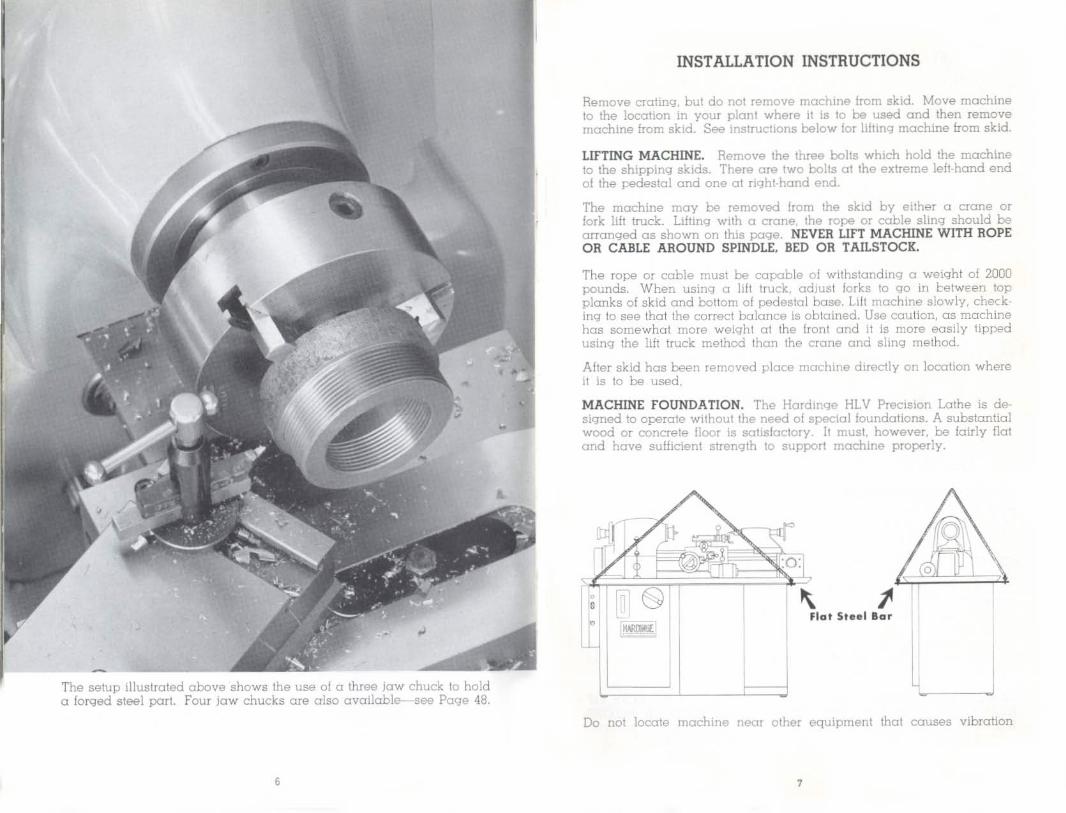
The setup illustrated above shows the use of a three jaw chuck to hold a forged steel porI. Four jaw chucks are also available- -see Page 48.
,
INSTALLATION INSTRUCTIONS
Remove crating, but do not remove machine from skid. Move machine to the location in your plant where it is to be used and then remove machine from skid. See instructions below for lifting machine from skid.
LIFTING MACHINE. Remove the three bolts which hold the machine to the shipping skids. There are two bolts at the extreme left-hand end of the pedestal and one at right·hond end.
The machine may be removed Irom the skid by either a crane or fork lilt truck. Lifting with a crane, the rope or coble sling should be arranged as shown on this page. NEVER LIFT MACHINE WITH ROPE OR CABLE AROUND SPINDLE, BED OR T AILSTOCK.
The rope or coble must be capable 01 Withstanding a weight 01 2000 pounds. When using a lill truck, adjust forks to go in cetw€en top planks 01 skid and bottom 01 pedestal base. Lilt machine slowly, checking to see that the correct balance is obtained. Use caullon, as machine has somewhat more weight 01 the Iront and it is more easily tipped using the lift truck method than the crane and sling method.
After skid has been removed place machine directly on location where it is to be used.
MACHINE FOUNDATION. The Hardinge HLV Precision Lathe is de· signed to operate without the need 01 special foundations. A substantial wood or concrete floor is SQtisfoctory. It must. however, be fairly flat and have sufficient strength 10 support machine properly.
j Flat Steel 8ar
Do nol locale machine noor other equipment that causes vibration
7

INSTALLATION INSTRUCTIONS (Continued)
which will transmit to this machine. as poor work finish will result.
LEVELING MACHINE. The Hordinge HL V Precision Lathe is designed with a three point bearing arrangement between bed and pedestal base. The three point bearing arrangement makes accurate leveling unnecessary. Leveling should be such as to be reasonable and so thot when coolont Is used it will drain back into sump from ends of pon.
There is an adjustable foot 0\ back righi-hand corner of the pedestal base to compensate lor uneven floor conditions. To adjust, loosen the socket set screw and raise or lower the foot with a pin wrench so that all four feet rest firmly on the floor. Tighten socket set screw to retain selling. Should !loor conditions be such that adjustable foot does not toke care of the leveling, use shims under feet of pedestal.
CLEANING MACHINE. Use a cloth or brush to clean this precision machine. DO NOT CLEAN MACHINE WITH COMPRESSED AIR. The use of compressed oir for cleaning a machine reduces the precision \He of the machine. Small particles of dirt and foreign molter can be forced past seals and wipers into the p recision slides and bearings. USE ONt Y CLOTH OR BRUSH TO CLEAN MACHINE. This also applies to daily cleaning of unit after it is in operation.
After machine has been properly located, leveled and bolted 10 lloor, wash off all slushing grease or oil and dirt accumulated in Iransit with naphtha or other good solvent of grease. Clean :'_lotor compartment. Be sure to remove olJ grease from pulleys - wipe pulleys dry. Rotate pulJeys by hand and check to see that all grease is removed. Apply a small amount of oil to brake drum as described on Pages 14 and 15.
ELECTRICAL CONNECTIONS. Before proceeding read instructions 'To Start and Stop Spindle' on Page 11. The machine is shipped com· pletely wired and assembled. It is only necessary to run the electric power line to the bollom of the conlrol panel and allach the wires to the terminal block in the panel. BEFORE CHECKING ROTATION APPLY A COLLET TO THE MACHINE SPINDLE TO ANCHOR THE COLLET CLOSER OR DRAW SPINDLE IN PLACE, OR REMOVE THE COLLET CLOSER OR DRAW SPINDLE FROM THE HEADSTOCK SPINDLE. See Page 17 fo r instructions on "How To Remove Collet Closer." Attach the power line 10 the terminal block in the control panel and check spindle rototion. Spindle should run in the forward direction when control lever "A", Figure 1, Page I I, is in either the left or righl·hand posHlon and forward-reve rse selector switch al fronl of conlrol panel is in Forward position.
BE SURE SPINDLE LOCK PIN " 0 " , Figure \, Page 11, AT REAR OF HEADSTOCK IS IN THE "OUT" OR RELEASED POSITION BEFORE STARTING. Electric power feed for carriage is connected to main control panel and does not require a separate power line.
,
MACHINE SPECIFICATIONS
Spindl. Construction
}
With SUIP Chue:':. Wdl Jaw Chucks
::;PINDLE With Jaw Chuch (Throuqh Spindl.) CAPACITY Wl1h Round 5C HARDINGE Col1~l'
W,th Hexagon 5C HARDJNGE CaUt't. With Square 5C HARDJNGE Collet.
Spindle Nose
Variable Spindle SPfH'ds Swing Over Bed Swing Over Carrlag ... Swing Over CrOSll SUd ... Distance Between <A!nter.:
Tailstock Flush Toil.tock Overhung
Range of Thr<Klds In Gear Bo~ Number 01 Thread Changes in G<Klr Bo~ .
Hardinqe ?reloaded
Eall Beorlng I W to 6w
'" _5 /32"
'" 7i8~
3/4" Hardingo Tapered
125 to 3000 r.p.m_ ll"
'" 5-3/4~
l8" 20"
11 to IC8 27
Actual threads cut through Qear bo~ - . II. I Jl'l. 12. 13. 14, 16. 18, 20, n, 23. 24. 26. '(.7. 28, 32. 36, 40, 44. 46, 48. 52, 54. 56. 64, 72. 80, 108
NOTE; Standard 1Il1ood. in all .tondord Enql'lh sYli(ml are included in the lorl'<,loing gear l':ox Belect!cns
Compound Slide Trovel Power Feed Range Size al Lothe Tool
3" 14 to 7~ per minute
3/B" by I" 3-3/4~ Toil.tock Spindle Travel
Taliitock Spindle Taper No.2 Morse Appro~imale weiqht of machme With rl'qukll equll'ment hltt>d bo>'r,w 125~ IN_
REGULAR EQUIPMENT Th. Hard in ... HLV Loth., I. lu.nlahed campl_'. wi lb ,
• Fully enclosed headslocr. with preloaded bell b<'CITinQ I" :>CIcily spindl9. • Drive Plate and H<Klds~ock Center_ • Lever Co!!el Closer or Draw Splndl(> -'nd Spanner Wreneh • Qukk Change Gear Bo~ reserved lor predslo- cutting of 2i dillmanl InrlKlds. • Set 01 live change qaars. • Completely Endoeed Corriage ond Al'ran. .. . • Independent Electrical Varlabi8 Power r~ Drive lor crmiage and '"foas SlIOB.
• Finger Tip Snap--Up Clutch,,", lor longitudinal und ,'rOSI fe<iKl. • Preloaded Ball B<Klting Lead Scr ... w lor threadlnq onlv. • Automatic Lead Screw Stop wUh odiultabl .top )!larl • Quid-nctlng Tool POtIt SlLd. for threadlng_ • Easy Reading Blo~k and White Feed Screw Dlall. • Easy Reading Black and White Carriage Hondwhe&l 0101. • Solid Full Bearing Carriaqe. • Solid Hardened and Ground Steel Doveta!l Bed WaYI. • Constant full Beo:ring Tailslock with No.2 Morse Taper. • Welded S~eel Bose with oil type chip pan and coolemt lump. • Tool Storage Compartment whh Collet Boord. • Variable Speed Driv ing Unit complete wi th 2-lpeed motor. • Magnetic Electric Conlrol Panel with tronsJonner provldln", liD voila fer push buncn
oontrol clrcuil; time lag thermal overload relay. provide overload protection: low voltaQe protection II also provided, forward and reverse selector SWitch; =m op· eroted, quick moke and quick break .wltche •. Completely wired and asaombled when deUvered.
AddltLortcd tooUn .. Items or •• h own on pgg .. 46 thnl 68
,

OPERATING INSTRUCTIONS
FOR
HARDINGE MODEL HL V LATHE
SPINDLE CONTROL LEVER - Figure I
LOW·STOp·HIGH SPINDLE CONTROL LEVER " A " is connected to a two-speed electric controller located in the electric control panel. Directly behind the lever is a plale indicating three positions LOW-STOP. HIGH. By moving the lever to the left, the brake is released ond the motor and spindle will run 01 the selected "LOW" speed. Moving the
lever to the extreme right also releases the brake and the selected "HIGH" speed is obtained. The lever may be moved directly from LOW 10 HIGH or from HIGH to LOW at any time. When this lever is in the center or " STOP" position, the motor is shut off and the brake is applied.
THREADING CONTROL LEVER FOR CARRIAGE - Figure I.
Lever " 8" controls the direction of carriage movement when threading. Place this lever in the center position as shown before starting machine. See Page 38 for detailed description covering operation of lever "B",
GEAR BOX DISCONNECT KNOB - Figure I.
Knob "C" is used to connect or disconnect the gear box from the head· stock spindle by means of a sliding gear. Turn this knob to the extreme left to disconnect the gear box. Knob should always be in the "'Feed" position before storling machine except when threading See Pogo 30 for positioning for threading.
SPINDLE LOCK PIN - Figure I.
The spindle lock pin "D" Is located near the top and at the back side of the headstock. The pin is held in the "OUT" or released position by a spring ond ball plunger.
10
•
The spindle lock pin is used to hold the headstock spindle stationary when applying or removing spindle nose attachments, adjusting collel closer, lightening draw spindle or when applying and removing work from fixtures or threaded arbor. To engage lock pin, turn spindle by hand and hold lock pin "in" until it engages In one 01 the notches of the spindle assembly. BE SURE TO WITHDRAW LOCK PIN BEFORE STARTING MACHINE.
TO START AND STOP SPINDLE - Figure I.
Pull out spindle lock Pin "D" , Press "START" button in Iront of electric control panel a t left-hand end of pedestal base. Place lever "A" in either the "LOW" or "HIGH" position to start spindle. To "STOP" spindle. place lever " AU in the center position, as shown. Use lever "A" for all starling and stopping of spindle. Press the "STOP" button in the fronl of the electric control panel when finished using lathe, or at the end of the work day. Pressing the "STOP" button disconnects the entire electric control panel from the magnetic starter.
\I
TO TURN SPINDLE BY HAND
When mounting spindle nose tooling or engaging the gear box it is sometimes desirable to rotate the headstock spindle by hand . Also, when selling up or chucking work which requires the work to be indio cated for concentricity, the spindle should be turned by hand. To obtain a free spindle for easy turning 01 the spindle by hand, place lever "A", Figure 1. in the center or stop position. Turn selector switch "G" at the front of the electric control panel to the "OFF" position. Placing the selector switch in the " OFF" position energizes the brake solenoid releasing the spindle drive brake. Electric control panel must be "ON" for solenoid to work.
LUBRICATION OF HEADSTOCK SPINDLE BEARINGS
The headstock spindle is mounted on precision prelooded ball bearings. The prelooding and resulting load carrying capacity is engineered to take radial thrust or end thrust, or a combination of both .
The precision pre loaded ball bearings are grease·packed for life and require no further lubrication. The entire bearing assembly is housed as a unit and is properly sealed to exclude dirt and foreign mailer. The spindle bearing seals are designed to operate at speed without wear or friction.
VARIABLE SPEED DRIVE FOR SPINDLE - Figure I.
The variable speed drive permits the operator to select the spindle speed best suiled for the work. To change the spindle speed place LOW-HIGH lever "A" in either the "LOW" or "HIGH" speed range position . This will start the motor and spindle. Turn variable speed control handwheel "E" to obtain speed desired.
CAUTION: DO NOT TURN HANDWHEEL UNLESS THE MACHINE IS RUNNING.
Speed obtained is shown on spindle speed plate by pointer "F" , Figure I. The low speed range of 125 to 1000 r.p.m. is obtained from the variable speed drive when LOW·HIGH lever "A" is in the extreme lelt or "LOW" speed range position. The high speed range of 375 to 3CXXl r.p.m. is obtained when lever "A" is in the extreme right or "HIGH" speed range pos\Uon.
12
If the work requires the use 01 both the high range and low range,
lever "A" can be moved directly from either position to the other without stopping the spindle. The variable speed control handwheel "E"
can be turned to the spindle speed desired while the tool Is cutting. thus permitting the operator to obtain the required surface finish and production rate.
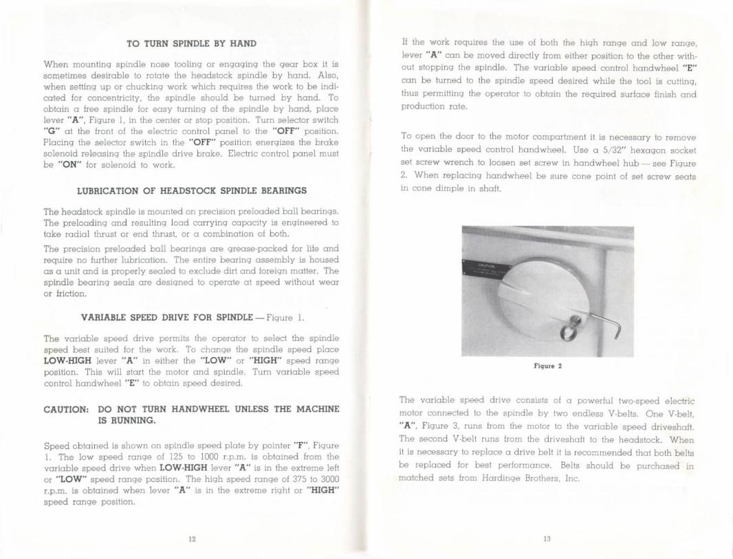
To open the door 10 the motor compartment it is necessary to remove the variab le speed control hand wheel. Use a 5/'32" hexagon socket
set screw wrench to loosen set screw in handwheel hub see Figure
2. When replacing handwheel be sure cone point of set screw soots in cone dimple in shalt.
Flqur. 2
The variable speed drive consists of a powerful two-speed electric
motor connected to the spindle by two endless V·belts. One V-belt, " A", Figure 3, runs from the motor to the variable speed driveshafl.
The second V-belt runs from the driveshalt to the headstock . When
it is necessary to replace a drive beH II Is recommended that both belts
be replaced lor best performance. Belts should be purchased in matched sets from Hardinge Brothers, Inc.
13

Flqllr. 3
SPINDLE DRIVESHAFT BRAKE - Figure 3.
Spindle broke is designed for rapid but gradual stopping of the preci·
sion headstock spindle at all speeds. The LOW·STOP·HIGH Lever
"A", Figure I. controls the broke. The broke is moved away from the broke drum by a solenoid located directiy in front of the motor pulley.
The solenoid is accessible by removing cover "C", Figure 3. The
broke cork "B" , Figure 3, Is forced against the broke drum by means 01 a powerful spring. The spring automatically compensates for cork
wear. However. after considerable use it may be necessary to adjust
the broke. This is easily done by placing the LOW·STOP·HIGH Lever
"A" , Figure I. in the "STOP" position. Then, turn selector switch "G" ,
Figure 1. to the "OFF" position, thus releasing the broke cork from the
broke drum. With the broke in the released position turn threaded plunger "D" with I 4" pin wrench unti l the cork touches the broke
drum. Then bock off one half turn until curve in top of cork is in a
poSition to mote with curve of broke drum.
CAUTION: BE SURE BRAKE CORK DOES NOT TOUCH BRAKE DRUM WHEN IN RELEASED POSITION.
14
After making proper adjustment, as described before, apply a few drops of spindle oil to broke drum. The oil will not materially affect stopping lime and will give added life to broke cork. DO NOT RUN BRAKE CORK DRY.
F1911r. 4
TO ADIUST BELT TENSION
Alter considerable use it may be necessary to adjust the tension on the drive belts. This is accomplished by backing off hexagon lock nut "A" , Figure 4. Tum adjusting screw "B" counter-clockwise to lower motor plate and increase tension on drive belts. Increosing the tension on the motor belt automatically increases the tension on the belt connecting the driveshaft to the heodstock spindle. Make adjustment in small amounts run machine to permit belts to equalize. Then check for tension and lock check nut "A" to rptain final selting.
Tension on belts should not be excessive, belts should deflex to linger pressure approximately I" when properly adjusted. Excessive tension causes rapid belt wear and possibly introduces Vibration.
DRIVE SHAFT BEARINGS are precision ball bearing type, grease packed and sealed, requiring no further attention.
1<

Flqur. S
ADJUSTING COLLET CLOSER - figu re 5.
I. Apply the desired size collet or step chuck to the machine spindle. Be sure the collet or step chuck and spindle are clean.
2. Open collet closer lotch "A" by pressing down at point "B".
3. Slart the collet closer tube on the collet or step chuck and thread about two turns only. To turn the collet closer tube, the operator, using his left hand, turns the black shell guard "C" forward while he holds the collet or step chuck in place with his right hand.
•. Place a work piece in the collet or step chuck.
5. Move lever " 0 " to the extreme left or closed position and then turn shell guard "C" toward the operator until it is drawn up as lor as it will gO by hand. Ii headstock spindle should turn, lock spindle by pressing in spindl~ lock pin.
6. Move lever " 0 " to the right 10 Ihe released position and turn shell guard "C" loward operator so that latch "A" advances two notches on the adiustlng nut "H" Figure 7.
7. Close lalch "A" and test collet closer for tension on work. Should additional gripping pressure on the work be required, open latch "A" and turn shell guard "C" toward operator. For less gripping pressure, turn shell guard "C" away from operator.
16
flqur. 6
~ I flqur. 7 , •
) • .;t
HOW TO REMOVE COLLET CLOSER - Figures 6 and 7.
The collet closer should be removed from the machine when using jaw chucks, face plates. fix ture plates or other nose type hxtures. Running the machine with the collet closer in place and without a collet will cause damage to the collet closer. It is also a good practice to remove the collet closer assembly occasionally and clean the inside of the headstock spindle. This is easily done by the use of a cloth and length of small diameter bar stock.
To remove the collet closer remove link pin "E" . This pin is easily removed by the use 01 a mallet and brass punch, striking pin at the bottom point "F" .
CAUTION: DO NOT REMOVE COLLET CLOSER BY REMOVING SCREW "G", This screw is adjusted properly at the factory for proper operation 01 collet closer. Remove link pin "E", Figure 6, only. Alter removing pin "E" remove collet closer as shown. It is then necessary to remove adjusting nut "H". This is done by pulling nut straight off end of spindle. DO NOT TURN ADJUSTING NUT - IT IS NOT THREADED TO SPINDLE.
APPLYING COLLET CLOSER - Figures 6 and 7
Clean the inside 01 the headstock spindle belore applying collet closer. Also. clean outside diameter at rear of spindle where adjusting nut locates. Clean collet closer lube inside and out.
Apply a film of light oil on outside rear of headstock spindle and apply adjusting nut "H" . Apply a film of light oil on bearing, section ''I'', of collet closer tube and slide closer on machine and insect link pin " EO..
17

HOW TO CHANGE BELTS
The spindle 01 the Hardinge HLV Lathe is driven from the molar by two special malched endless Y-belts. Alter considerable use, it may be necessary to apply new belts to the machine.
IMPORTANT: The headstock lor machines with serial numbers in the Group 124 to 399 must be returned to the factory in Elmira, New York, for bell replacement as these units do not have a quill-type spindle 10 permil the chanQinQ of belts by users. DO NOT ATTEMPT TO REMOVE THE HEADSTOCK SPINDLE ON THESE MACHINES.
The following instructions and drawings on opposite page make chang. ing of belts easy on machines having a serial number of HLV-400 or above:
TO REMOVE SPINDLE, SPINDLE BELT AND MOTOR BELT
1. Wl1h mochiM Tunnin(,l, rMu<'!' spindle speed I( 125 R.P,M_ Ih .. lowl S: SPf'('o sellm,! for variable speoed Inoknlof. Then SlOP mo~hine.
2. loo'Em sel screw " 1.."' and remove hnndwh .... l '"B" to open door.
3. Remove nut "C'. ullnq 0 lullable pry I-:<,r to rais .. metor plotE> nppr(1xlmotely 2" or enouah t( slip motor N,h irom motor 'ur y
4. Loosen &crew '"D" and pull oul pulley Ihoh " E"
S. Remove pulley auembly "r " This is dr:nll h- hrst to remove Ipindle drive bf'lt from pulley uni'- then 'paning ·In th drive Il<lmfl.
ThO!' motl" bell 'on 01 .. b, ren,oved at this 'n
WIsing th. pulley unIt enoug. werinq pulley unl' IhTO gh th
6. Remove lever let - "I[ :>r drow bar I.om heads lock spm<jl
1. Remo"e cover Irom rem 'head ~nd pul Ipmdle dnve ~ It up ,,< rear of heodll(~_
8. Remove snap ring "C " wnh I<"rew driver and pull hondwh .. el " H" off end d s!'tnul •. flemove Woodruff key. wove walh", and spacer " I" ' . .
S. Remove lock IC"rew, tOft'. SE't l<""r(Ow. ,-,nd set "".eWI ' '1'' IhrOUQh "Pf'ninq in rear ,I heod.
HI. Place knob " K " 1< 'Th'f'<]d' posilion.
11. Remove the thlOe IOCkel head ICrews " L'" from fTOni cap.
~~. SUde pulley " M " o~ lor loward the re"r of Ihe spindle as possible. It pulley mmOI be' moved by hand, plm'e wood block belwe('n pulley and hont bea.lnQ balS as shown.
U. Tap on rear end 01 spindle wilh rawhide mallet while puillna the spindle 08lemnly our I.o¥' the front of the headalod, f.ame. The spindle pulley must be held to prevent ill dropping inte the motor c,<,mpar tment ul spindle is removed,
NOTE, As Ihe bearlngl Ie<,ve the headsloek frame, mark them on 1< p WIll 0 pendl • so 11 w!l\ bP possible 10 reassemble the spindle unll in the some .eloll<"'"
IS riglnally olll(Ombled.
IS
WOOD
F
19

Flqur. 9 Flqu •• 10
HOW TO APPLY AND REMOVE SPINDLE NOSE TOOLING
figures 9 and 10
The Hardinge Taper Nose spindle construction is time-proven lor accuracy, durability and lor lost, easy application and removal of spindle nose tooling. The precision ground slow toper holds and aligns all tooling. The pin in all headstock spindle nose tooling engages the bayonet slot "A" , to draw the attachment securely on the toper. Once securely drawn up, the spindle nose attachment is actually driven by the locking action 01 the tapered surface.
BEFORE APPLYING ANY ITEM OF TOOLING TO THE SPINDLE NOSE WIPE THE SPINDLE NOSE AND ATTACHMENT MATING SECTION CLEAN.
TO APPLY the drive plate for driving dog, for example, align key "0", Figure 10, with bayonet slot and slide drive plate on spindle nose. When it is back as for as it will go turn the drive plate clockwise to lock in place. Drive plate shown in Figure 10 is in the locked position. This is determined by the re la tion of the key "0" and spindle reference line "B". Final lightening should be done with a standard pin type spanner wrench. (Use Williams or Armstrong 460. Do not use hammer and punch.)
20
spanner wrench No.
TO REMOVE the drive plate, lurn counler-clockwise with spanner wrench 10 loosen. Continue to turn unlil key "D" is in line with reference mark "E", then remove from spindle by sliding to right off end of spindle.
IMPORTANT -to obtain accurate results from precision spindle nose attachment always be sure the spindle nose and mating section in attachment are CLEAN BEFORE THEY ARE ASSEMBLED TOGETHER.
DO NOT REMOVE KEY " 0 " TO REMOVE SPINDLE NOSE TOOLING, IT IS THE SLOW WAY AND WILL INTERFERE WITH FUTURE ACCURATE OPERATION OF THE ATTACHMENT.
SPINDLE COLLET KEY - Figure 9
The spindle collet key "C", Figure 9, can be removed and replaced, in the event of wear or damage, without removing the headstock, spindle or spindle bearings. Use a 332" hexagon pin wrench to remove lock screw; then remove collet key screw wilh some hexagon pin wrench.
21
--

Fl911.f. 11
22
CARRIAGE AND APRON - Figure II
CARRIAGE HANDWHEEL " A " is used to move carriage along bed
by hand.
CARRIAGE HANDWHEEL DIAL " B" is made 01 a permanent while
material lor easy reading. Friction mounting for rapid, easy selling to zero. Graduations equal .010".
LONGITUDINAL CARRIAGE rEED CLUTCH " C" controls the power
feed for carriage along bed. To engage clutch raise ball har-dled lever
to horizontal position. To release clutch press lever down to the tosi· tion as shown in Figure II.
CROSS FEED SCREW CRANK " D" is used fo r hand feeding cross
slide. Black and while dial on cross slide feed screw is graduated in
.001" and is DIRECT READI NG. (Move the cross slide leed screw one graduation which is equal to .001" and the culling tool will remove
.00 I" from the diameter 01 the work). Dial has friction mounting for ease in setting to zero.
CROSS SLIDE rEED CLUTCH " E" controls the power feed lor the cross
slide. To engage the clutch raise the ball handled lever to the horizon
tal position. To release the clutch press the lever down to the position shown in Figure 11.
COMPOUND SLIDE FEED SCREW CRANK " F" is used to feed the
compound slide. The black and while dial on the compound slide is graduated in .001". The dial has a friction mounting lor rapid, easy setting to zero.
QUICK ACTING HANDLE FOR COMPOUND SLIDE " G" is used when
threading see separate instructions on threading on Pages 38. 39, 40, 41 and 42.
CARRIAGE BED WIPERS " HI " and " Hz" are of hardened and ground
steel mounted 01 both ends of the carriage.
(Continue<! on P09. 24)
23
b
CARRIAGE AND APRON - continued from Page 23
PRESSURE LUBRICATOR RESERVOm calor filled with Sunoco Way Lube No. 2 or equivalent.
"I". Keep this pressure lubrlSocony Mobil GG Vodra Oil
MAINTAIN APRON on LEVEL - in reservoir located at left hand side of apron with Gull No. 667 Socony Mobil Veloclle Oil No. 6 or equivalent.
PRESSURE LUBRICATOR CONTROL "J". To lubricate corriage cnd
bed ways pull plunger 'T' up as for as it will go, then release cnd allow
it to return of Its own accord. Operate pressure oiler as often as required
to keep the bed woys wei with oil.
FOLLOWER REST MOUNTING HOLES uK!", " K2" and UK J" ara
maunllng holes for follower res t. See Page 55 for instructions to mount
follower rest.
HOLES FOR ATTACHING TAPER ATTACHMENT "t "_ see separate
instructions on Pages 56 and 57 for taper turning attachmenl.
HOLE FOR MOUNTING COOLANT ASSEMBLY "M" - see separate
instructions on Pages 66 and 67.
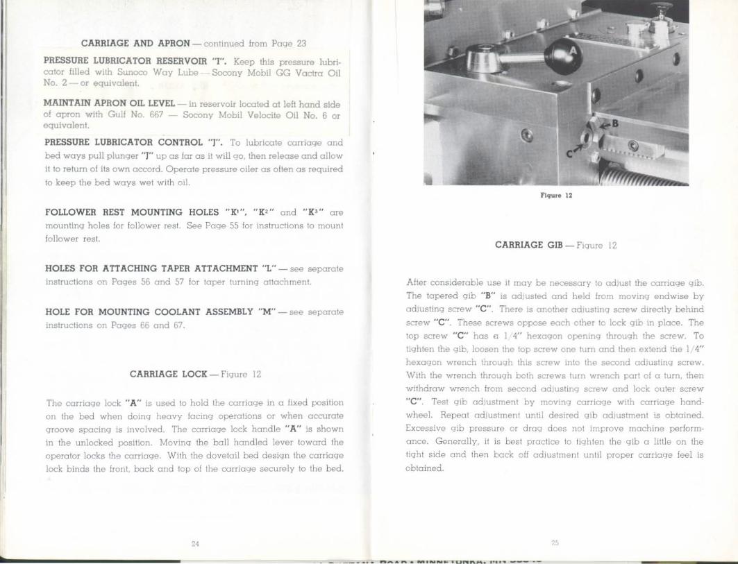
CARRIAGE LOCK - Figure 12
The carriage lock "A" is used to hold the carriage in a fixed position
on the bed when doing heavy facing operations or when accurate
groove spacing is involved. The carriage lock handle " A U is shown
in the unlocked position. Moving the ball handled lever toward the operator locks the corriage. With the dovetail bed design the carriage
lock binds the front, back and top of the carriage securely to the bed.
24
1'lquf. n
CARRIAGE GIB - Figure 12
After considerable use it may be necessary to adjust the carriage gib.
The tapered gib "8" is adjusted and held from moving endwise by
adjusting screw "C". There is another adjusting screw directly behind
screw "C". These screws oppose each other to lock gib in place. The
top screw "C" has c I 4" hexagon opening through the screw. To
tighten the gib, loosen the top screw one tum and then extend the I 4"
hexagon wrench through this screw into the second adjusting screw.
With the wrench through both screws turn wrench part of a turn, then withdraw wrench from second adjusting screw and lock outer screw
"C". Test gib adjustment by moving carriage with carriage hand·
wheeL Repeat adjustment until desired qib adjustment is obtained.
Excessive gib pressure or drag does not improve machine perform· once. Generally, it is best practice to lighten the gib a little on the
tight side and then back off adjustment until proper carriage feel is
obtained.
. ...... --~--

f igure 13
CARRIAGE AND CROSS SLIDE CLUTCH ADJUSTMENT
Figure 13
To adjust the longitudinal carriage feed clutch. loosen screw "A" and swing cover to position shown. exposing the opening through which clu tch adjustment is made. Look down through the opening. with the power feed motor running. see Pages 28 and 29. and watch for an adjusting screw in the rota ting collar within the clutch housing. When the adjusting screw is visible shut off the power feed motor. See seporate instructions on power feed motor conlrol on Pages 28 and 29.
Place a I 8" hexagon wrench "C" into the hollow set screw and loosen screw. CAUTION - do not remove set screw just loosen one turn and do not remove wrench.
Place power feed selector switch to move carriage to the "LEFT" then jog power feed motor by switching power feed "ON" and "OFF" with switch on power feed control panel. This will Ihread collar along the shalt. moving the clutch surfaces closer together.
To release or back the clutch surfaces fur ther apart. jog the power feed motor to the "RIGHT".
26
Lock set screw and remove wrench. Test clutch under power. Several test adjustments may be necessary before desired clutch setting is obtained. Be sure to replace cover "B" to prevent dirt from entering clutch assembly.
To adjust the cross slide feed clutch. use the same procedure as with the longitudinal carriage feed clutch only reverse the jogging rotation. To move the cross slide clutch surfaces together. jog power feed molar to "RIGHT". To release or move clutch surfaces further aport. jog motor to the "LEFT" .
figure 14
CROSS SLIDE AND COMPOUND SLIDE GIB ADJUSTMENT
Figure 14
To adjust the gib. loosen each gib screw lock nul "A". Then advance screw "B" until desired fit is obtained. Each of the five screws must be adjusted individually and the "drag" on the slide checked after each adjustment. Lock each nut "A" to retain setting of gib screws.
Follow the same procedure when adjusting the gib on the compound slide.
(Continued on Page 28)
27

COMPOUND SLIDE LOCK - Figure 14
The compound slide swivels for turning angles. To move the swivel
bose tum eccentric draw bolt "C", Figure 14. with 5 16" hexagon
wrench. Set compound slide to the desired angle and lock securely
with eccentric bolt "C". Tum clockwise to lock.
TO REMOVE CROSS SLIDE
It is good practice to occosionally remove the cross slide. To do this
tum the cross slide feed screw boll handle clockwise until the slide
comes off the bock side of the carriage. With slide removed It Is easy
to lubricate cross feed screw and nut and to clean the slide ways.
Use core when re-engaging the cross feed nut and screw. Bumping
will bend the first thread of the nu t causing it to bind on the screw.
POWER FEED FOR CARRIAGE - Figure IS
The carriage power feed is by a direct ctment, totally enclosed, boll
bearing motor mounted on the oorriage.
110 volt alternating current Is fed. from the main electric control ponel
at the left-hand end of the pedestal bose to the power feed control
p::mel at the right-hand end of the machine - see Figure 15. In the
power feed. control ponel the current is converted by selenium rectifiers
to direct current for the power feed motor. The electric cable from
control ponel to power feed molar is of oil resistant neoprene.
To start the power feed. position the "ON-OFF" toggle switch to the
"ON" positlon. When this is done. the pilot light will Jjght. showing
thai the ponel is on. In the event the pilot light bums out. unscrew
the red plastic shield from the face of the control ponel and replace
bulb with General Electric 1/25 watt Glow-Lamp No. NE51.
28
The "LEFT-RIGHT" toggle SWitch is used to reverse the power feed. motor which reverses the direction of feed of carriage and cross slide. When placed in "LEFT" poSition the carriage will feed toward the left or headstock. When in "RIGHT" posillon carriage will feed toward right.
The "HIGH·LOW" toggle switch chnnyes the speed of the power feed motor. This switch may be changed al any time without stopping the molar. The power feed motor and control panel are protected by a Fusetron in the main conlrol panel 01 the left·hand end of the pedestal bose. An extra Fuselron is provided in the electric control paneL
Specification of fusetron is as follows:
Fuselron Buss No. MOL I-I 4 Ampere
IMPORTANT: Use only Fuselron fuse.
The rate of carriage feed can be increased or decreased by turning feed conlrol knob on control paneL The rote of feed to use is determined. by material being cut, type of cutting tool used. and the work finish required. The role of feed. moy be chonged while the tool is cutting. The numbers on the diol are for repeat reference only.

GEAR BOX FOR THREADING ONLY - Figure 16
Precision threading is an outstanding feature on the Hardinge HLV lathe. The logical separation o f the power feed and lead screw gear box reserves the precision gear box for threading only, assuring maximum precision fo r the lead screw drive.
The all steel gears within the gear box run on shafts mounted on ball bearings. These hearings are grease packed and sealed. requiring no further attention.
TO ENGAGE GEAR BOX
To engage the gear box turn knob "A" clockwise In the direction 01 arrow marked "THREAD". When turning knob "A" the teeth of the sliding gear within the geaf box may not mesh with the headstock spindle gear leeth . If so, turn the headstock spindle by means of spindle hand wheel "8" .
"
IMPORTANT: Before turning spindle release spindle b rake to obtain
free spindle - see instructions on Page 12. While turning spindle also
turn knob " A" to right until a definite click is heard.
IMPORTANT: Knob "A" should always be set in the " Feed" JXlsilion
except when threading, thus disconnecting gear box from headstock spindle.
The Hardinge HLV Lathe quick change gear box permits instant selec· tion 01 27 different threads by shilling a lever and turning a knob.
Knob "C", or the change knob. Figure 16, has three numbered positions
1. 2 and 3. These numbers correspond wilh the \, 2 and 3 given at
the extreme left side of the gear box thread chart plate. The tumbler or nine change handle "E" has nine posilions each lining up with
gear box thread chart plate. Combining the three positions 01 the
three change knob and nine posit ions 01 the tumbler handle. 27 changes are obtained.
THREE CHANGE KNOB - figure 16
When number one 01 knob "e" is in line With the arrow, any thread in row one of thread chart can be selected by changing the tumbler
handle or nine change handle "E" to the desired thread in that row.
The three change knob "C" controls a sliding gear cluster. Number three on the knob, when lined up with the arrow on geaf box chari,
is In the center position. To place knob "C" in the number one JXlsilion, turn to "RIGHT". Turn to "LEFT" to place number two position
in line with arrow.
In the event the slide geaf cluster does not engage the other geafS in the gear box properly 10 b ring the desired number on three cha nge
knob "C" in line with arrow. open the change gear cover "0 " and
turn shaft "A", Figure J7, see Poge 33, by hand until gears mesh properly.
(Contin ued on Pag. 32J
31

TUMBLER HANDLE OR NINE CHANGE HANDLE
Figure 16
To make a selection on the gear box thread chart, pull the spring
.pressured black knob "E" out as far as it wlJl go and lower until it
will move sidewise to the desired notch directly under the thread required. Raise Ihe handle and let plunger drop into hole. If Ihe
lumbler handle will not raise for enough to drop plunger inlo hole,
open change gear cover and rotale shaft " A", Figure 17, see opposite
page, until gears mesh and handle raises permitting plunger to seal.
At the extreme right on the gear chart is on "OUT" position which is
used when change gears are set up outside the gear box for cutting
threads not obtained within quick change gear box.
Fastened to the tumbler handle bracket within the gear box is a 5 16"
round safety bar "C", Figure 17, that extends out through a hole in the left side of the gear box. This bor is to prevent applying change gears
outside the gear box until the tumbler handle is placed in the "OUT"
position.
IMPORTANT
Shift gears only when the machine is not running. Toe Hardinge HLV
Lathe is a smooth running high speed machine and shifling of gears on the gear box when the machine is running will result in damage to
the unit.
Flqllr. 18
OUTSIDE CHANGE GEARS - Figures 17 and 18
The outside change gears are used to cut threads not provided in the quick change gear box. A set of live gears and a bracket are standard equipment with each machine. These gears, when set up to the gear chart- see Page 34. wllJ cut JO threads per inch. Three of the gears are shipped on the brocket and the other two are in place on the shafts as shown in Figure 17; one on the end of the lead screw shaft "A", and the other on the end of the sliding cluster gear shaft "B".
Before selling up change geors, place tumbler in the " OUT" position.
The tumbler gear handle or nine change handle has on interlock arrangement "c" so the outside change gears cannot be engaged unless the tumbler gear handle is in the "OUT" position.
To cut other threads which are not in the gear box, additional gears must be purchased· see Pages 34, 35, 36 and 37 where gearing charts are given for threads from JO 10 250 threads per inch .
IMPORTANT: - With spindle oil lubricate bushings and shafts on change gear bracket each lime a set up is made. If long run threading is involved, lubricate daily.
33

1ST GEAR SCREW 2ND GEAR 1ST GEAR GEAR ON STUD fIRST SECOND
THREADS GEAR GEAR PER SLT fiRST ON ON SCREW INCH UP KNOB GEAR STUD STUD GEAR IDLE ..
32 GEARBOX 33 A 30 33 22 66 44 SCREW 34 A 30 34 22 66 44 GEAR
IDLER 35 A 30 35 22 66 44
IDLER 36 GEARBOX
2ND GEAR 1ST GEAR 37 A 30 37 22 66 44 ON STUD ON STUD I ST GEAR ON STUD 38 A 2 40 38 30 60 44
SET UP "A" SET UP "B" 39 A 30 39 22 66 44 40 GEARBOX 41 A 30 41 22 66 44
t .RS· S[CONL 42 A 2 40 42 30 60 44 liREAOS GEAR GEAR 43 A 30 43 22 66 44
PER SLT "IRS" )N IN SCREVv' INCH UP KNO! GEAR ::;TUD nUD GEAR IDLER 44 GEARBOX
2 22 " 22 " 45 A 30 45 22 66 44
10 A 60 " 3D " 55" 46 GEARBOX II GEARBOX 1112 GEARBOX 47 A 30 47 22 66 44
GEARBOX 48 GEARBOX
12 49 A 30 49 22 66 44 .3 GEARBOX 14 GEARBOX 50 A 2 40 50 30 60 30
A 40 None 30 51 A 30 51 22 66 44
15 60 44 52 GEARBOX 16 GEARBOX 17 A 40 34 30 60 44 53 A 30 53 22 66 44
18 GEARBOX 54 GEARBOX 55 A 30 55 22 66 44
19 A 40 38 30 60 44 56 GEARBOX 20 GEARBOX 57 A 30 57 22 66 40
21 A 40 42 30 60 44 58 A 2 40 58 30 60 30 22 GEARBOX 23 GEARBOX 59 A I 30 59 22 66 40
GEARBOX 60 A 3 40 30 30 60 44
24 61 A 2 40 61 30 60 40 25 A 40 50 30 60 30-26 GEARBOX 62 A 2 30 31 22 66 44
63 A 2 40 42 22 66 44 27 GEARBOX 64 GEARBOX 28 GEARBOX
65 A 2 48 52 22 66 29 A 40 58 30 60 30 30 66 A 2 30 33 22 66 44
30 A 2 40 None 30 60 44 67 B 2 30 40 60 67 40 31 A 30 31 22 66 44 68 A 2 30 34 22 66 44 . fI". 'lear' lupplied al s tandard equipment ... ilh machine.
,. OS

THREADS PER
INCH
69 70 71 72 73 74 75 76 77
78 79 80 81 82 83 84 85 86 87 88 89 90 91 92 93 94 95 96 97 98 99
100 102 104 105 106 108
SIT UP
A A A
A A A A A
A A
A A B A A A
A A B
A B A
A A A A B A
A A A
A A A
KNOB
2 2 3
3 2 2 3 3
2 3
3 2 3 3 2 2 3 2 3
2 3 2 3 2 2 2 3 2
3 3 2
2 2 2
FIRST GEAR
FIRST ON GEAR STUD
40 46 30 35 60 33
GEARBOX 60 33 30 37 40 50 40 38 60 33 30 39 60 33
GEARBOX
40 27 30 41 22 60 40 42 24 34 3D 43 40 29 30 44 22 60 3D 45 22 60 30 46 40 31 30 47 24 38 30 48 22 60 30 49 40 33 40 50 3D 51 3D 52 24 42 3D 53
GEARBOX
36
SECOND GEAR
ON STUD
22 22 22
22 22 22 3D 22 22 22
22 22 83 3D 22 22 22 22 89 22 91 22 22 22 22 22 97 22 22 3D 22 22 22 22
SCREW GEAR
66 66 71
73 66 66 60 77
66 79
66 66 33
60 66 66 66 66 33 66 33 66 66 66 66 66 33 66 66 60 66 66 66 66
IDLER
44 44 3D
3D 44 44 44 3D 44 3D
44 44 55 44 44 44 44 44 55 44 3D 44 44 44 44 44 55 44 44 3D 44 44 44 44
THREADS PER INCH
110 112 114 115 116 118 120 122 124 125 126 128 130 132 134 135 136 138 140 142 144 145 146 148 150 160 170 180 190 200 210 220 230 240 250
SET UP
A A A
A A A
A A A
A A A
A A B
A A A A B A
A B A
A A A
A A A
A A A
A A
KNOB
2 2 2 2 3 2 2 3 3
2 3 3
3 3 3
3 3 3
3 3 3
3 3 3 3 3 3
3 3 3
3 3 3
3 3
FIRST GEAR
3D 3D 3D 24 40 3D 3D 40 3D 24 40 3D 48 30 3D 40 3D 40 3D 22 40 48 22 3D 40 24 24 3D 24 24 24 3D 24 3D 24
37
FIRST GEAR
ON STUD
55 56 57 46 58 59 60 61 31 50 42 32 52 33 40 45 34 46 35 60 48 58 60 37 50 32 34 45 38 40 42 55 46 60 50
SECOND GEAR
ON STUD
22 22 22 22 3D 22 22 3D 22 22 22 22 22 22 60 22 22 22 22 71 22 22 73 22 22 22 22 22 22 22 22 22 22 22 22
SCREW GEAR
66 66 66 66 60 66 66 60 66 66 66 66 66 66 67 66 66 66 66 66 66 66 66 66 66 66 66 66 66 66 66 66 66 66 66
IDLER
44 40 40 44 3D 40 40 40 44 44 44 44 3D 44 40 44 44 44 44 3D 44 3D 30 44 44 44 44 44 44 44 44 44 44 40 44

INSTRUCTIONS FOR THREAD CUTTING
ON
HARDINGE HLV LATHE
The Hardinge HL V Lathe is designed lor rapid and accurate thread cutting. Threads can be cui to a shoulder without fear of running into the shoulder since the automatic stops will stop the carriage 01 a pre
determined point in eilher direction.
Before starting to cut a thread. select the proper cutting speed for the size of thread to be cui and 10 give the besl finish for the particular malerial being used. Maximum recommended. threading speed is 1000 T.p.m .
Set quick change gear box or outside change gears for desired pilch.
Set compound slide at desired angle and position culling tool in compound slide 1001 post.
Sellsl! carriage slop "A" , Figure 19. and right carriage slop "B", Figure 20, in approximote position. Engage lead screw nut "e" by moving ball handled lever "D" from a vertlcal position to position shown.
CAUTION: Lock carriage stops securely before starling to cut threads. Do nol release carriage nut "C" unlil threading operation is completed. Do nol use carriage s lop when heads tock spindle is running in reverse.
Carriage control lever "B" Figure I Page II, when moved 10 the left will cause carriage to move to the left. When the carriage conirol lever is moved to the righi the carriage will move to the right. Carriage can be stopped manually at any lime by placing carriage control lever in the center position as shown in Figure I.
LEFT HAND THREADS - can be cut the same as right hand except cutting pass is made from the headstock toward the tailstock . Carriage control stops are used for left hand threads the same as right hand threads.
(col\!lnlled on poqe 40)
38

THREAD CUTTING - continued
The illustration above shows the threading tool in the correct posiHon to start a threading pass. The carriage stop controlling the travel of the carriage to the right or toward the tailstock end of the machine has been properly set. This setling should always place the tool a short distance from the end 01 the work excessive distance from end of work slows the complete threading operation.
When carriage is at rest and quick acting handle "A" is to the right in the cutting pos ition, feed the cutting tool in the desired number of thousandths for the next threading pass.
Move lever " 0" , Figure 1. \0 the left and carriage will start and move until it contacts stop at headstock end of machine s topping carriage as shown in Figure 22.
THREAD CUTTING - continued
This illustration shows the culler and carriage at the end of the threading pass, Notice thai the threading tool Is close to the shoulder the carriage was slopped in this position by Ihe carriage slop which controls the lead screw. Headstock spindle continues 10 run in the forward direction, Carriage stops cause only the gear box, lead screw and carriage to slop running,
When cutting left-hand threads. start the threading pass next to the shoulder and make the threading pass toward the lailstock.
(Contlnu.d on Paq. 42)

FIgure 23
THREAD CUTTING - continued
Illustrated above is the carriage in Ihe some pJsition on the bed as in
Figure 22 only that quick acting handle " A" on the compound slide
has been moved to the left withdrawing 1001 from work. Alter with·
drowing tool with quick octing handle, the carriage is reversed or
moved to the right to the starting pJsition by moving carriage control
levf>r "B" , Figure I, to the riqht.
Figure l4
TAILSTOCK
The tailslock is securely anchored to the dovetail bed by means of a
mating dovetail section and clamp a t the back.
The hardened and ground spindle has I 8" graduations for the lull
3-1 2" travel. The handwheel has a black and white friction adjustable
dial reading in .001" increments. The spindle tokes standard No. 2
Morse taper shank centers and other tailstock tooling see Pages 61,
62 and 63.
The spindle can be >eked in any pJsitJon by locking lever "A " .
It is good practice t( occasionally remove the tailstock from the
machine. Turn the tails tack upside down and flush the feed screw
with spindle oil through the opening in the bottom of the spindle. This
will also lubricate the feed screw nut. It is also advisable to put a few
drops 01 spindle oil on the outside of the tailstock spindle and wipe the
oil around the entire spindle.

z « -' "-
0: o '3 u.
" I
1(0\
I <II
ii' ~~C,.
I
~I~ 0 " 0
" I
~;;! "'e~§ I i'--~
~9"'~
44
• "
N
'"
l
J
TOOLING
(Extra Equipment)
The next twenly·two pages cover standard tooling
available lor the Hardinq8 HL V Lathe.
All items of toolinq can be either ordered with the
machine or 01 a later date. Standard tooling is
carried in stock. When ordering. specify item by
name as listed in this book and qive machine
serial number .
45

HEADSTOCK SPINDLE TOOLING HEADSTOCK SPINDLE TOOLING :
SC HARDINGE COLLETS
The Hordinge HLV Lathe takes SC HARDINGE collets with capacity of I" round. %" hexagon and 3/4 " square. Hardinge precision collets are manufactured to exact precision standards, and are available In all types and sizes for 011 makes of lathes and milling machines, as well as our own precision machines.
SC HARDINGE PLUG CHUCK
The collet shonk section is finished for direct application to your machine spindle. The nose section is 1-15 32" in diameter and 1·3 4" long. It can be machined in place for the greatest degree of accuracy to suit your particular requirements for special arbors.
-l-\-~Il HU ov.
II£'IWAVS DU.P -8) :!i w;pt;
- I r~ Ii- , ,~ ---I • =r
COLLET F"lXTURE DIMENSIONS
UNIVERSAL COLLET STOP
This stop converts SC HARDINGE collets into solid slop or spring ejector slop collets, without alterat ion of the standard collets. The application of this stop to the collet requires no machining. In other words, aU collels used with Ihis machine can be used in the regular manner or as solid slop collets or as spring ejector slop collets.
LOCK NUT LOCKING PLUGS
.980 TO 1.031
STANDARD Y2-20 THllEA,DJ TO FACE OF
COLLET STOP BODY
Dimension "An is equal to 1-38" and is the maximum depth a part may be chucked using a solid stop. The moximum depth for spring ejector stop is 13 16". This is due to space required for spring ejector construction.
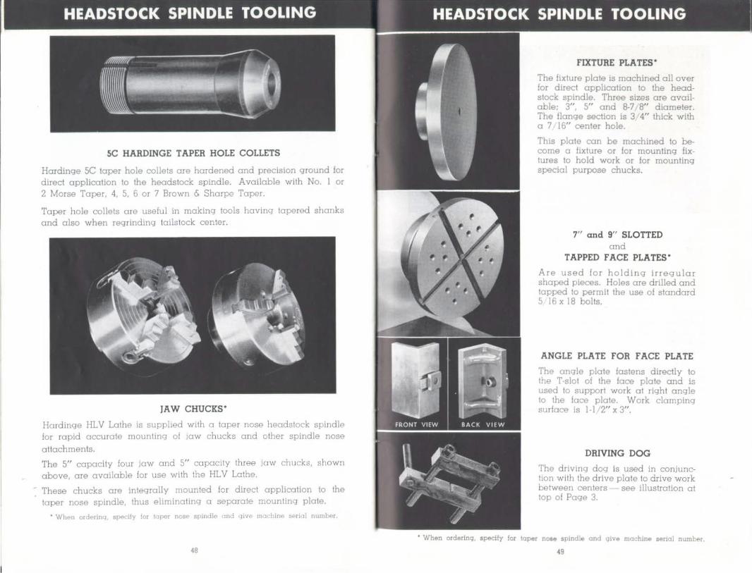
5C HARDINGE TAPER HOLE COLLETS
Hardinge 5C taper hole collets are hardened and precision ground for direct application to the headstock spindle. Available with No. I or 2 Morse Taper, 4, 5, 6 or 7 Brown & Sharpe Taper.
Taper hole collets are useful in making lools having tapered. shanks and also when regrinding tailstock center.
JAW CHUCKS·
Hardinge HLV Lathe is supplied. with a laper nose headstock spindle for rapid accurate mounting of jaw chucks and other spindle nose al1achments.
The 5" capacity four jaw and 5" capacity three jaw chucks, shown above, are available for use wlth the HLV Lathe.
These chucks are integrally mounted for direct application to the taper nose spindle, thus eliminating a separate mounting plate .
• Wh .. n ord"rinq. IIp,,dly lor t(]PN n<~!' spindl!' and giv .. machine s.-ri<l] numb r
FIXTURE PLATES·
The fixture plate is machined all over for direct application \0 the headstock spindle. Three sizes are available; 3", 5" and 8-7,8" diameter. The flange section is 3 4" thick with a 7 16" center hole.
This plate can be machined. to be· come a fixture or for mounting fixtures to hold work or for mounting special purpose chucks.
7" and 9" SLOTTED and
TAPPED FACE PLATES·
Are used for holding irregular shaped pieces. Holes ore drilled. and topped to permit the use of standard 5 16 x 18 bolts.
ANGLE PLATE FOR FACE PLATE
The angle plate fastens directly to the T-slot of the face plate and is used to support work 01 right angle to the face plate. Work clamping surface Is 1·1'2" x 3".
DRIVING DOG
The driving dog is used in conjunchan with the drive plate to drive work between centers see illustration at top of Page 3.
• When ord.,rlnq, llpedfy lor laper naM .plndle and qlve machine serial numb!'r.
49
5C HARDINGE STEP CHUCKS
A step chuck is exceptionally useful for accurately holding work lONer than 1" in diameter up to 6" in diameter. Tubing can be held without crushing or distorting. The s tep chuck will also hold castings, moldings, stompings and machined parts rigidly and accurately. The standard boll bearing lever operated collet closer is used to close the step chuck. The step chuck is closed by the taper on the periphery sealing in the toper of the closer.
We carry 2", 3", 4", 5" and 6" step chucks and closers for all Hardlnge headstocks. They are 3/8" larger in diameter than the rated size, so the fuJI capacity step may be readily applied. Step chucks may be purchased. in finished form, split only, or split and stepped to speci· fications.
Many users purchase step chucks. split only, and then apply the desired steps while the step chuck is in place on the machine, assur· ing dead accuracy of the steps in relation to the headstock spindle.
STEP CHUCK CLOSERS·
A closer is required for each size step chuck. The closer fits directly to the machine spindle and has a taper corresponding to the taper on the periphery of the step chuck for closing the step chuck. A step chuck closer is required for each nominal size step chuck to place the closing pressure over the stepped area of the chuck, result1ng in greater gripping power and accuracy.
With locating pins applied in the step chuck closer and with clearance holes lor the pins drilled in the step chuck. work may be held to predetermined length.
• When ordf'rlnq. sp ·lfy f", 1<'1' .... , nc,se spindt, and qiv .. machine .. ,jal n"ml,.r,
50
ADVANTAGES OF USING STEP CHUCKS
Step chucks. developed by precision Instrument makers, are a lime proven method of holding work, rigidly and accurately. Step chucks toke over on sizes above the regular collet capacity, providing collel· like accuracy, convenience, and precision results as wHh collets.
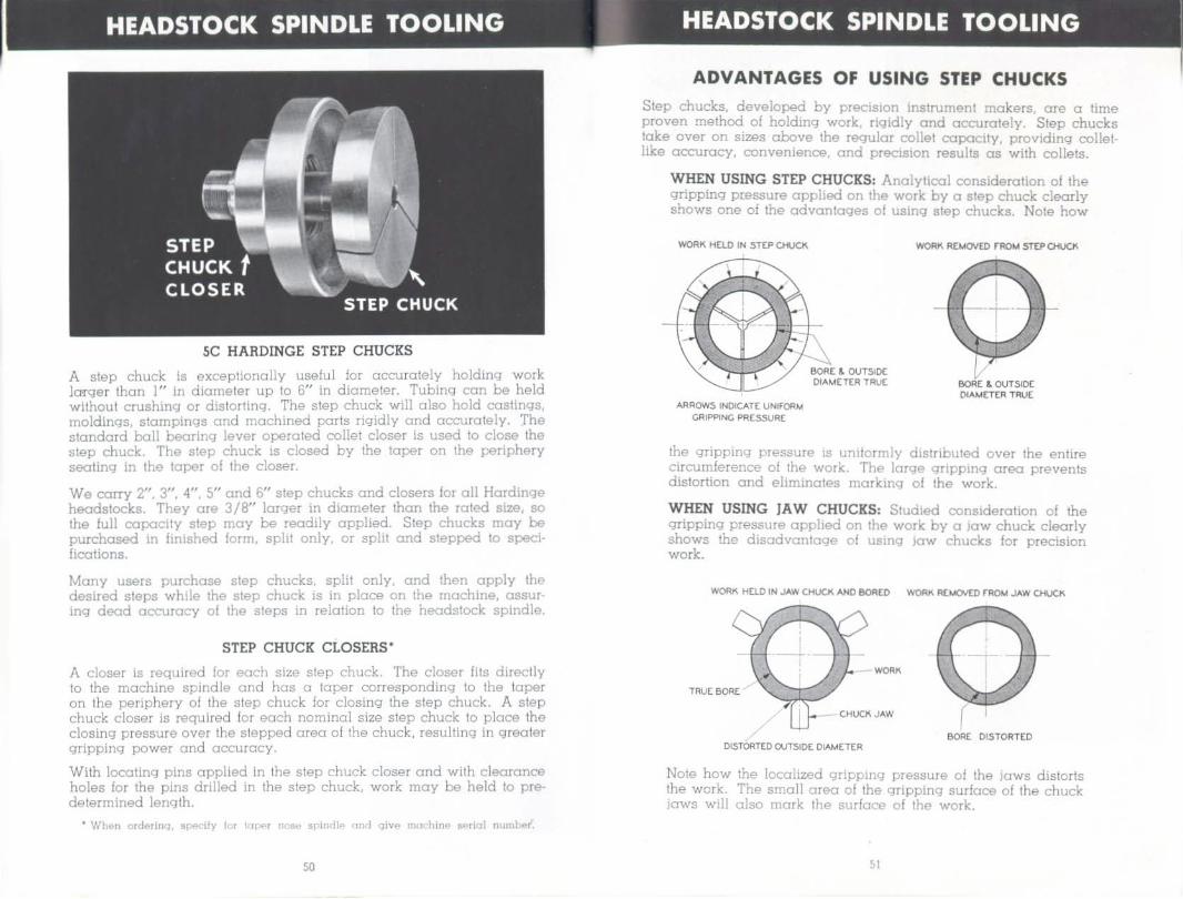
WHEN USING STEP CHUCKS: Analytical consideration of the gripping pressure applied on the work by a step chuck clearly shows one of the advantages 01 using step chucks. Note how
WORK HELD IN STrPOf.JCII.
Al<ROW5 INOICATE UNIFOAM GRIPPING PRESSURE
SORt & OIJTSiOC [)IAMETrR TRV£ BORE & OIJTSIOC
[)iAM(T[R TRUE
the gripping pressure is uniformly distributed over the entire circumference 01 the work. The large gripping- area prevents distortion and eliminates marking- of the work.
WHEN USING fA W CHUCKS: Studied consideration of the gripping pressure applied on the work by a jaw chuck clearly shows the disadvantage of using jaw chucks for precision work.
WORK Hao IN JAW CHUCK ANO eoRED WORK R(1oICl'JEO FR()t,I JAW CHUCK
"""' TRUE50R£
( SORE DISTORTED
OISTOf\TED OUTSiDE DIAMETER
Note how the localized gripping pressure of the jaws distorts the work. The small area of the gripping surface of the chuck jaws will also mark the surface of the work .

INSTRUCTIONS FOR
1. Clean taper nose spindle. Clean bore 01 slep chuck closer. Apply closer to headstock spindle and lighten closer with spanner wrench. (Use Williams or Armstrong sjXlnner wrench No. 460). Do not use punch and hammer.
5. Finish bore to exact size of part to be held. Face bottom of bore in step chuck. If section of part to be held has a sharp corner, undercul corner of bore in step chuck.
2. Clean inside of headstock spindle and ou tside of step chuck. Apply step chuck to spindle and collet closer. With s tep chuck in open position insert three 1 16" diameter wires or shims at outer edges of slots. Close slep chuck be sure wires or shims are securely held by step chuck.
6. Clean bore of step chuck and use part as gage. Pari should fit into step chuck like a goad precision plug gage Iii.
OUT" STEP CHUCKS
3. With sharp carbide boring tool. rough bore slep chuck to approximate size. The step chuck may be rapidly bored on the HLV Lathe by using the plunge cut slepping method.
7. Remove step chuck. Clean slep chuck closer and spindle. Wipe a few drops of oil on angle of step chuck closer and inside spindle. Perform this operation occasionally during a production run to assure accuracy of step chucks.
4. "Stepping aut" of a slep chuck requires care thai bore is not oversize . When "roughing-out" use calipers, set slightly smaller than required size, to check bore diameter.
8. Remove pins or shims from slots of step chuck. Clean each sial of step chuck of all chips and apply step chuck to machine spindle. Adjust lever closer or draw spindle for tension and you are ready to run production.

CARRIAGE TOOLING CARRIAGE TOOLING
AUTOMATIC SQUARE INDEXING TURRET
The squore turret is applied directly to the tool post T-slot of the compound slide. The turret lokes standard 5/16" square 1001 bits. By a simple movement of the ball-handled lever, the turret is automatically unlocked, indexed to the next 1001 position and automatically rslocked, ready for the next machining operation. Accurate indexing is accomplished through a hardened ond precision ground tapered index pin.
MOTOR GRINDER
The motor grinder unit mounts directly to the compound slide T-slot. It can be used for both external and internal grinding. Motor operates on 110 volt, single phase current. When grinding, keep as much of the bed. carriage and apron as possible covered with oil-soaked cloths to prevent abrasive material from causing injury to machine.
FOLLOWER REST
The follower rest is mounted directly to the corriage and is used to support work which, because of its small diameter in relolion to length, may spring away from the cutting tool.
To apply the follower rest to the carriage remove plug screws indicoted os K', K2, K3, figure II. Page 22. Be sure to replace the screws after using follower rest as they keep holes free of chips and will make it easier to mount follower rest the next lime it is required.
The jaw of the follower rest Is adjustable to suit the work diameter.

CARRIAGE and BED TOOLING CARRIAGE and BED TOOLING
TAPER TURNING A TT ACHMENT
The turning or boring of precision tapers is readily accomplished on the Hardinge HL V Lathe by the use of a taper turning attachment. The Hardlnge taper turning attachment is based. on the sine bar principle swiveling the gUide bar from one end. See Page 3 for a typical taper turning setup.
The toper turning attochment mounts directly on the back of the lathe bed and is adjustable along the bed to suit the work.
In operation, the taper turning attachment is moved into position to suit the work. Clean attachment of a ll chips and foreign matter. Then place the cross slide in position so that bolt "A", shown in illustration above, can be placed through anyone of the three holes "B" in the cross slide to engage the slide "e". With the cutting tool in position and taper attachment secured to cross slide, release 9 16" hexagon cap screw "0 " two turns - DO NOT REMOVE CAP SCREW. All adjustments of taper attachment are made with 9 16" wrench.
56
To sel guide bar "E" to the desired. angle. loosen cop screw " f " . Cap screw " F" is located on the under side of the toper attachment body. Swing guide bar "E" to desired. ongle or taper per fool according to graduation view through zero plate " G " ,
Lock guide bar in place with cop screw "r ". Make a lest cut. It may be necessary to move guide bar a very smoll amount to obtain the
exael toper for a blued HI to the toper gage. Loosen cap screw "r " a very small amount and top gUide bar lightly to move it into position to give exact laper. Then lock cop screw "F" tight. When lapping guide bar "E" strike it on hardened pins "H" protruding from the sur· face at the sides of the guide lx u.
Lubricate guide bor with spindle oil.
IMPORTANT: When turning or boring a taper be sure the culling tool is exactly on center; otherwise a true taper will not be produced .
A good place to keep the taper attachment when it is not in use is at the tailstock end of the bed since the majority of the work will be done at the headstock end.
57

CARRIAGE and BED TOOLING ! BED TOOLING
MICROMETER CARRIAGE STOP WITH DIAL INDICATOR
The micrometer carrioge stop is a useful accessory when producing
porls havinq exact shoulder lengths.
A ll Hardlnge HLV Lathes ore now equipped with a lapped hole in
the corriage lor lastening the indicator to the carriage. The bracket
carrying the micrometer mounts directly to the hardened and ground
dovetail bed w ays.
The ind icator reads in .CXXlS" increments . The micrometer reads in
.001 ". Measuremen ts are made with the micrometer. Carriage is
mov ed until the indicator reads zero .
STEADY REST
Long cylindrical work held between centers requires a steady rest io prevent such work from springing away from a culling 1001. A steady
rest is also used when there are machining operahons to be performed on the end of work which prohibits the use of the tailslock center. The three jaws are adjustable and hove an accurate lit in the milled guides of the body. The lop section is hinged to provide ease in loading shoul· der work without disturbing the setling of the jaws. The steady rest has a maximum capacity o f 3".

BED TOOLING TAILSTOCK TOOLING·
RADIUS TURNING ATTACHMENT
This ottachment fastens dIrectly io the dovetail bed, as shown above. and is used for precision turning concave or convex surfaces up to
\.1 2" radius. Useful for turning punches, dies. boll shaped valve seals and special spherical culling lools.
The swivel slide is mounted on precIsIon preioaded ball beanngs for accuracy ond rigidity. The swivel slide moves through 360. Hard· ened feed screws are mounted on preloaded ball bearings and hove adjustable dials graduated in thousandths of an inch.
60
LAMP
This fluorescent lamp is available for use with the Harding HLV Lathe. The lamp fas tens to the back of the lathe bed and operates from the requlor 110 volt light line.
MALE CENTER
This male center hos a II 16" head diameter and is furnished with all Harchnge lailslocks. All centers ore hardened ond ground.
FEMALE CENTER
A female center is used for work that con not have the usual center hole. The II, 16" head has a 60' conical hole I 8" in diameter 01 the large end.
HALF CENTER
A half center is used if tool clearance is desired when turning the full length of a part supported by the tailstock. The head diameter is 11 16".
LARGE CENTER
This center has a head diameter of I n. It is indispensable for support· ing tubing or recessed work too large for the standard male center.
• When ordermq. specify NQ "- Mcrae Taper Shank.
61

TAILSTOCK TOOLING· TOOLING
V CENTER
The swivel V center is constructed so the V block rotales on the shank.
DRILL PLATE
The drill plote, when in place in the lailslock spindle, is used to support
work 01 right angles to the mochine spindle center line. The plale is mode 01 close-grained cast
iron and has a steel taper shonk. The finished face surface is 3-1 2" in diameter.
DRILL CHUCK
We recommend the improved type drill chucks with our toilstocks. We carry 0-1 "8", 0-38" and 0-] 2" sizes in stock mounted ready for use .
• When ordcrinq. specify No 2 Morse Tap<'r S~ lnk.
62
ANTI·FRICTION CENTER FOR T AILSTOCK
This heavy duly anti-friction center has a No.2 Morse Toper shank
for direct application \0 the lailslock spindle. Work can be done
between centers 01 hlQh speed when the anti-friction center is used.
"
ADJUSTABLE HEIGHT CHAIR
The $8Ot of the choir has infinite adjustment to suit the operator and can be adjusted without the use of tools. Unlocking and locking, after adjustment of the choir to correct height position, is automatic through the use of a special boll bearing device. The bock rest is also adjustable.

TOOLING TOOLING
TO CUT METRIC THREADS
By the application 01 a metric ailachment to the gear box, In place of the English bracket lor the outside change gears, metric threads con be cuI. for threoding, follow the same procedure as when selting up English threads as described on Poge 33.
Gears supplied for the English outside gear can also be used in the gear selup for metric threads.
When metric attochment is supplied with machine, a large gear cover Is shipped as standard equipment. When the metric attachment is supplied later, the large cover is supplied to replace the standard
cover.
SCREW GEAR
1ST GEAR
IDLER GEARS
1ST GEAR ON STUD
127 TOOTH
2ND GEAR ON STUD
See Gear Chart on Opposite Page
"
PITCH IN MM
.1
.2
.25
.30
.35
.40
.45 - .50'
.55
.60 _
.65
.70 _
.75
.80 '
.85
.90
.95 1.00 '
1.10 1.20 1.25 -
1.30 1.40 1.50
1.60 1.70 1.75
1.80 1.90 2.00 '
2.25 2.50
2.75 3.00
KNOB
3 2 2 2 3 I
3 3
I 2 2
3 2 2
2 2 2
I 2
I 2
I 2
rlRST GEAR
25 25 25 25 50 25 50 50 25 25 50 50 50 50 50 50 50 50
50 50 50
50 50 50
50 50 50
50 50 50 60 50 50 50
SECOND GEAR ON
STUD
40 40 50
60 70 40 54 60 55 60 65 70 66 56 68 54 76 60
55 60 60
65 70 66 56 68 77
54 76 60 60 65 66 66
IDLER GEAR
50 50 40 40 30 50 30 30 40 40 30 30 30 30 50
30 30 3D • 30 30 30 30 30 30
30 30 30 30 30 30 30 30
30 55
. Pitches that can be CUI wilh ""nd<lrd *>rs IIUpphM with mar-hint! and metric auachment.
SCREW GEAR
50 50 50
50 50 50
30 30 50
50 50 50 22 35 40 30 40 30
50 50 24 50 50 22 35 40 22 30 40 30
32 25 24 22

TOOLING .1 TOOLING
" • r • • •
&. o
COOLANT r ACILITIES
The Hordings HLV Lathe chip p:m has an integral sump built into the sloping bottom chip pan. The coolant facilities can be ordered with the machine or supplied at a laler date and installed by the user.
Coolant is always an advantage when machining tough cutting material. particularly when threading. The use of coolant promotes longer tool life and a better quality of work.
The coolant pump molar is controlled by the selector switch 01 the top 01 the large electric control panel a t the left hand end 01 the ped· estal bose.
The pump will handle most common types of oil or soluble coolants. Oil, as a coolant. is recommended.
CAUTION: When using water soluble coolant. be sure the mixture is proper to prevent rustinq of the machine and work.
Clean the sump regularly. depending upon the type of malerial being machined. When doing dry machining 01 cast iron or other powdery malerial, cover the sump screen to prevent line molerial from mixing with the coolont. To cleon sump remove the lour screws, one in each corner of the screen cover for sump. Lift pump ond screen assembly from sump. Clean sump. Rinse out and drain sump by removing pipe plug from bottom of sump. This plug is easily accessible from the back of the machine .
A metal splash guard for the spindle, as shown In the illustration, is standard equipment with the coolant facilities.

HARDINGE HIGH SPEED PRECISION MILLING MACHINE
Hardinge HLV Lathe and the Hardinge Milling Machine are companion units with interchangeable attachments. abundance of power. speed and accuracy.
The Hardinge Milling Machine is available in both plain and universal models. Descriptive Bulletin TM-UM will be furnished upon request.
"