
BHUEL & KJJER - Pearl HiFi
48
Roughness Me·te> r Type 61 02 and Accessorie.s An instrument specially designed for the measure- ment and control of surface roughness of machin- ed surfaces. It measures the arithmetic average value (C.L.A.) of the roughness, directly in mi- crons as well as in microinches. Variable rough- ness width cut-off. BHUEL & KJJER Ncerum, Denmark . 80 05 00 . BRUKJA, Copenhagen • Telex: 5316 BB 6102
-
Upload
khangminh22 -
Category
Documents
-
view
1 -
download
0
Transcript of BHUEL & KJJER - Pearl HiFi

Roughness Me·te>r Type 61 02
and Accessorie.s
An instrument specially designed for the measurement and control of surface roughness of machined surfaces. It measures the arithmetic average value (C.L.A.) of the roughness, directly in microns as well as in microinches. Variable roughness width cut-off.
BHUEL & KJJER Ncerum, Denmark . ~ 80 05 00 . ~ BRUKJA, Copenhagen • Telex: 5316
BB 6102


Roughness Meter Type 6102
JUNE 1963

Contents Page
Introduction . . . . . . . . . . . . . . . . . . . . . . . . . . . . . . . . . . . . . . . . . . . . . . . . . . . . . . . . . 3
Description . . . . . . . . . . . . . . . . . . . . . . . . . . . . . . . . . . . . . . . . . . . . . . . . . . . . . . . . . . 4
General . . . . . . . . . . . . . . . . . . . . . . . . . . . . . . . . . . . . . . . . . . . . . . . . . . . . . . . . . . 4 Pick-up . . . . . . . . . . . . . . . . . . . . . . . . . . . . . . . . . . . . . . . . . . . . . . . . . . . . . . . . . 5 Amplifier ........................................................ 10 Meter ........................................................... 11 Output Circuits . . . . . . . . . . . . . . . . . . . . . . . . . . . . . . . . . . . . . . . . . . . . . . . . . . 12 Power Supply . . . . . . . . . . . . . . . . . . . . . . . . . . . . . . . . . . . . . . . . . . . . . . . . . . . . 12
Accessories . . . . . . . . . . . . . . . . . . . . . . . . . . . . . . . . . . . . . . . . . . . . . . . . . . . . . . . . . . 13 Motor Drive Type 3910 . . . . . . . . . . . . . . . . . . . . . . . . . . . . . . . . . . . . . . . . . . 13 Fine Surface Pick-up MP 0001 . . . . . . . . . . . . . . . . . . . . . . . . . . . . . . . . . . . . 15 Small Bore Pick-up MP 0002 . . . . . . . . . . . . . . . . . . . . . . . . . . . . . . . . . . . . . . 15 Reference Specimens MA 0014 ........................ , ........... 17
Operation . . . . . . . . . . . . . . . . . . . . . . . . . . . . . . . . . . . . . . . . . . . . . . . . . . . . . . . . . . . 19 Operation Scheme . . . . . . . . . . . . . . . . . . . . . . . . . . . . . . . . . . . . . . . . . . . . . . . . 19 Operation of the Motor Drive . . . . . . . . . . . . . . . . . . . . . . . . . . . . . . . . . . . . 20 Choice of the Pick-up Combination . . . . . . . . . . . . . . . . . . . . . . . . . . . . . . . . 22 Calibration of the Roughness Meter . . . . . . . . . . . . . . . . . . . . . . . . . . . . . . 24 Diamond Stylus Check ............................................ 25
Applications . . . . . . . . . . . . . . . . . . . . . . . . . . . . . . . . . . . . . . . . . . . . . . . . . . . . . . . . . 26 Recording and Oscilloscope Monitoring of Surface Roughness Profile 26 Measurement of the Roughness-Width, Choice of the "Cut-Off" . . . . . . 29 CLA Recording for Production Control ......... . .................. 31 Quality Control of Rotating Machinery ................. . . . ........ 32
Appendix . . . . . . . . . . . . . . . . . . . . . . . . . . . . . . . . . . . . . . . . . . . . . . . . . . . . . . . . . . . . 36 Definitions . . . . . . . . . . . . . . . . . . . . . . . . . . . . . . . . . . . . . . . . . . . . . . . . . . . . . . . 36 Basic definitions of the roughness . . . . . . . . . . . . . . . . . . . . . . . . . . . . . . . . 37 Surface Roughness Symbols . . . . . . . . . . . . . . . . . . . . . . . . . . . . . . . . . . . . . . 39 Scratching Caused by the Pick-up . . . . . . . . . . . . . . . . . . . . . . . . . . . . . . . . 40 Notes on Surface Roughness Control .............................. 41
Specifications . . . . . . . . . . . . . . . . . . . . . . . . . . . . . . . . . . . . . . . . . . . . . . . . . . . . . . . . 4i:$

Introduction The surface finish of engine and machine parts plays an important role in mechanical engineering, :;tnd is closely related to factors such as wear, friction. lubrication, material fatigue, etc.
In the case of ordinary screw-connections, or simple static couplings, the requirements to be met with regards to the surface finish are not very strict. However, wherever mo':ing parts such as rotating axles, pistons, etc. are involved, the finishing p)ays an important role. Therefore the finishing requirements of such parts are normally specified on the drawings, and great care must be taken to obtain the correct surface roughness. Overfinishing of the products leads to extra production costs, and underfinishing will frequently cause rejections and reworking of the products, or-even worsefield failures. (Sec "Notes on Surface Roughness Control" in Appendix, p. 41).
These considerations are the key of the recent development of surface roughness measurements in industry and of the consequent need for reliable and practical equipment well-adapted for production control or investigations in the field. Mechanical-electrical measuring systems, consisting of a small pick-up for tracing the surface connected by means of a simple electrical cable to suitable electronic measuring equipment, are very generally adopted for this purpose because of their flexibility and rapidity of operation.
The Roughness Meter Type 6102 which belongs to the mechanical-electrical type of instruments, is designed primarily for the production control of machined surfaces, but is also well-suited for laboratory investigation work. It enables b,oth relative and absolute measurements to be taken. The only operation to be carried out when relative measurements are made, is to move the pick-up along the surface being checked, and to make sure that the meter indication lies within some predetermined and specified tolerance limits. The instrument can thus be operated by unskilled workshop personnel, after only a few minutes of instruction. Because of its small dimensions and light weight, it can be easily utilized almost anywhere in a factory.

Description General. The Roughness Meter Type 6102 consists of a mechanical-electrical pick-up for tracing the surface plus an electronic amplifier with indicating meter. The instrument is designed in accordance with the American Standard: ASA, B 46. 1-1955. Its principle is based upon the Mean Line definition of surface roughness (M-system) which is recommended by the International Standardization Organization (TC 57, draft no. 221) and recognized in most countries.
Range Switch - -
~~r ~if~ • -,~., , ... ,. ~··· :::;, • '~-- Output Swttch
Cut oft S'fiitch
XIO "., 'Il _ ._
Pick - up input '"='-- + '" '!.!.!•• · ~---- Outpu t
5600+2 6102
Fig. 1. Front view of the Roughness Meter.
Reference Specimen
0
Motor Drive Feed
Wire Guides Pick -up in the Handle
Earthing
Fig. 2. Rear view, with the normal accessories placed in their holders.
The- ·deflection of the meter indicates the Mean Line Average Ra ( C.L.A.) * ) value of the surface roughness directly in micrometers (microns) or microinohes. The maximum sensitivity is 3 microinches , or o.1 micrometer, for full -
4

scale deflection. A four position" Roughness Width Cut-off"·) switch is included in the circuit. The instrument is of the continuously integrating type. To allow recording or analyzing of the measurements, two output circuits are provided, giving either the amplified pick-up signal, or a DC voltage proportional to the Ra (C.L.A.) roughness value. The Pick-up mounted within its handle is stored in a holder at the back of the instrument. The instrument is provided with an extending leaf for use in tilted position.
Pick-up. The pick-Hp normally supplied with the Roughness Meter Type 6102 is the standard Pick-up MP 6100. Two other pick-ups, the Small Bore Pick-up MP 0002, and the Fine Surface Pick-up MP 0001, have been designed for special applications (see Accessories, page 15).
Spherical cavities for snap lock arrangement
6mm 66mm c--------0 a~~~ __ M_P?aO _s~~ / £!!!!(Skid
Diamond stylus
Fig. 3. Drawing of the Pick-up.
~ble plug 5600H
The standard Pick-up MP 6100 fulfills the requirements for a general purpose pick-up and is shown in Fig. 3. It is capable of exploring bores with diameter down to 6.35 mm (1,4"), and when mounted in the Handle (Fig. 23), the
~ i ~ J9j, ~
g 560~6
Fig. 5. Drawing showing the Wire Guides, and how they are mounted on the Handle .
*) Definitions a re reviewed in Appendix, pages 37-39.
5

tracing of flat and convex surfaces is easy to carry out. In addition two Wire Guides which can be mounted on the Pick-up Handle, facilitate measurements on wires or rods of small diameter, down to 1 mm~ ( o.04"~) . See Fig. 5. The Pick-up consists of a stylus, a skid, a mechanical transmission system which transfers the up and down movements of the stylus to a piezo-electric transducing element, a liquid clamping system working by the liquid friction of silicone oil between a blade and a slit in a plastic block, and the necessary electric terminals for connection to the amplifier. See Fig. 6.
pick-up stylus Fig. 6. Sketch showing the principle of operation of the Pick-up. The liquid clamping effect is obtained by capillarity forces of silicone oil between the
friction block M, and the brass blade N.
The accuracy of the pick-up measurements will depend mainly upon the following factors:-
(a) The material and tip radius of the stylus. (b) The radius of the pick-up skid. (c) The stylus pressure. {d) The independence of forces applied to the stylus in the horizontal
direction. (e) The frequency range and the traversing speed of the pick-up.
A brief discussion of these factors follows. (a) In order to obtain great mechanical strength and practically avoid wear to
take place, the material chosen for the stylus tip is diamond. In accordance with the British and American Standards a tip radius of
6

12.5 fl (500 fl") *) has been chosen. It compromises the necessary mechanical strength of the stylus with its ability to follow even finely spaced surface irregulatrities. There obviously exist texture scratches which are too fine to be fully penetrated by a point of 12 fl radius. On most machined surfaces, however, the roughness mainly consists of irregularities with sufficient spacing to be fully penetrated, and the omission of the finer minute scratches is of small importance in the average reading. When comparison measurements are made, even fine ground, lapped or polished surfaces may be checked with the MP 6100. However, when absolute measurements of very fine surfaces arc to be taken, and when recording a graph of a surface profile, the Fine Surface Pick-up MP 0001 should be used. (See page 15).
lb) To provide a reference surface for the Pick-up the housing is supplied with a skid, the radius of which is 10 mm. When the Pick-up is moved along the surface being investigated only the up and down movements of the stylus with respect to the pick-up housing are measured, and therefore the radius of the skid is of the utmost importance. The American Standard specifies that this radius should be at least eight times the roughness width cut-off. The value of 10 mm is approximately 13 times the highest normally used roughness width cut-off value (o.75 mm), and inaccuracies in the measured result caused by vertical movements of the Pick-up head are thus minimized. Also the Handle is supplied with skids, the skid-radius in this case being 8 mm. All skids are chrome or rhodium plated and fine polished to provide the smoothest and most wear-resistant reference surface during measurements. See Fig. 7.
:c) The spring marked A on Fig. 6 provides the necessary static pressure on the stylus. The static stylus pressure must be great enough to obtainsufficiently high acceleration of the pick-up stylus to make it penetrate
5600+1
a b
Fig. 7. Sketch showing the relative positions of the stylus and the skids. (a) Without handle. (b) With handle.
*) 1 p. = 1 micron = 1 micrometer = t0-6 meter = 1o-a mm = o.001 mm. 1 p.11 = 1 p. in. = 1 p.inch = 1 microinch = 10-6 inch = o.000001 inch.
7

into the bottom of the surface "valleys" . The pressure should, on tht
other hand, not be so great that the stylus cuts the "peaks" of the surface thereby causing inaccuracies in the measured result and "scratch· ing" of the surface. The requirements of the Standards allow a maximum of 2 1h grammes. A stylus pressure of maximum 1 gramme has been chosen for the pick-up MP 6100, and a series of experiments have shown, that when metal surfaces are being investigated the "scratching" of the surface as well as measurement errors are negligible. (See Appendix, page 40). The suspen· sian of the mechanical transmission allows a stylus excursion of 1.2 mrn ( o.05 inch) without great change in the stylus pressure.
(d) To ensure that the output from the transducer is independent of forces applied to the stylus in the horizontal direction, the spring A is especially designed to be insensitive to forces acting in its longitudinal directon. The point C, see Fig. 8, then works as a "bearing" , and only tensile forces will be applied to the bearing arrangement marked D, as long as the horizontal forces act in the longitudal direction of the Pick-up.
Tensne force
Hori~orot ~~~~~~~g;t]=:::::1.___jUJ in the length direction of D the pick-up .
Fig. 8. Sketch illustrating the effect of applying a small horizontal force to the pick-up stylus.
Should the Pick-up be moved sideways along the surface, a torque will be developed at D, however , the bearing arrangement is designed to take up this moment, and not transfer it to the piezo-electric bender. Therefore , the measurement accuracy is practically independent of the traversing direction of the Pick-up. Sideways measurement is useful for example in the case of gear notches. See Fig. 22d.
e) The lower limiting frequency of the pick-up is lower than the lowest cut-off frequency of the amplifier and will thus in no way influence the measuring result. This lower limiting frequency is determined by the liquid clamping system, as described in the following:-
8
To obtain a correct electrical output from the piezo-electric transducer, the latter must act as a bar which is clamped at one end and driven by the up and down movement of the stylus at the other end. At very low frequencies, the liquid clamping device will not actually clamp the piezoelectric bender as the friction block M (Fig. 6) will try to follow the movements of the stylus. It is therefore possible to avoid any static or

•
z
slowly variable bending movement on the piezo-electric bender during measurement. However, when the frequency of the stylus movement increases, a frequency is rapidly reached at which the friction block M cannot follow the movements of the stylus, because of the strong capillarity action of the silicone oil, and thus the bender will be clamped to the housing. The corresponding low limit of the traversing speed is easily determined for a given spacing of the surface irregularities (roughness width) , by
Speed (mm/sec) =Frequency (c/ s) X Roughness Width (mm). See also Fig. 9. The upper limit of the traversing speed, which will still ensure correct output to be obtained, is determined by the resonance of the small spring marked B in Fig. 6. (This spring is acting as a "shock-absorber". When the Pick-up is placed on the surface to be investigated, the stylus is pressed upwards in the Pick-up housing, and if this pressure is applied suddenly, the friction block M in the clamping device will not follow the stylus movement. The transducer would then, in the absence of the spring B, be subjected to a shock-force, and might break).
WAVELENGTH (Roughness width) in inches.
0,0001 o.oro3 0,0101 0.,03 or
0,0001 0,0003 0,001 0,003
o.r
0,01
~
10,12 inchfsec. l
lo.o4 inchtsec.l
0 100
~ u ~ 0/0
~ 80 fw L
60
40
20
10 1 SOD 1000
I I ,0102
0.001
C/s
SOD 250 150
r--~ --......_,
""' r---~ ~
"' ~ '\ 1\ \ I\
C"t off ~ Cut off I\ C"t off~ ~r D.075mm 0,25mm - 0,75 mm ig
0,003 inch 0,01 inch N·03inch
\ \ \
\ 1\ \ \ \
\ \ \. I Frequency ~ \
l ~
off h
Traverse ·speed.
1~0 50 25 15 10 5 2.~ 1JS l
0,005 0,0075 O.D25I 0,05 D. 75 0.25 0.5 0. 5 1.2 I 13 mm/sec I
l1 mm;sec I o6ooso
0,002 0,005 0,01 D. 25 0,05 0,1 0,25 0.5
WAVELENGTH ( Roughness width lin mm ____ ____,_
Fig. 9. Transmission characteristic of the Roughness Meter in the case of sinusoidal signals.
9
The first resonance occurs beyond 1800 c/s, and the frequency characteristic (pick-up + amplifier) remains flat up to at least 1500 c/s. This meets the requirements of the Standards and corresponds to a roughness width of o.002 mm ( o.00008 inch) at a traversing speed of 3 mm/sec.
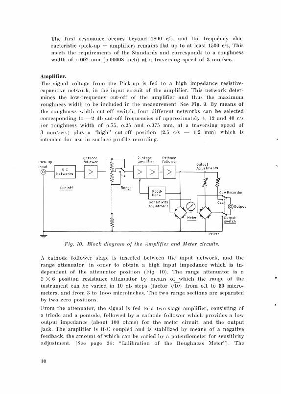
Amplifier. The signal voltage from the Pick-up is fed to a high impedance resistivecapacitive network, in the input circuit of the amplifier. This network determines the low-frequency cut-off of the amplifier and thus the maximum roughness width to be included in the measurement. See Fig. 9. By means of the roughness width cut-off switch, four different networks can be selected corresponding to - 2 db cut-off frequencies of approximately 4, 12 and 40 c/s (or roughness width of o.75, o.25 and o.075 mm, at a traversing speed of 3 mm/sec. ) plus a "high" cut-off position (2.5 c/s - 1.2 mm) which is intended for use in surface profile recording.
Fig. 10. Block diagram of the Amplifier and Meter circuits.
A cathode follow er stage is inserted between the input network, and the range attenuator, in order to obtain a high input impedance which is independent of the attenuator position (Fig. 10). The range attenuator is a 2 X 6 position resistance attenuator by means of which the range of the instrument can be varied in 10 db steps (factor y10) from o.1 to 30 micrometers, and from 3 to 1ooo microinches. The two range sections are separated by two zero positions.
From the attenuator, the signal is fed to a two-stage amplifier, consisting of a triode and a pentode, followed by a cathode follower which provides a low output impedance (about 100 ohms ) for the meter circuit, and the output jack. The amplifier is R-C coupled and is stabilized by means of a negative feedback, the amount of which can be varied by a potentiometer for sensitivity adjustment. (See page 24 : "Calibration of the Roughness Meter"). The
10
•

potentiometer is accessible through a hole marked "Instrument" in the rear plate of the apparatus.
The noise level, with the "Range" switch set to 3 microinches (highest sensitivity), and with the pick-up connected to the input, is less than 3 % of the full-scale deflection.
Meter. The output voltage from the amplifier is rectified and fed to the indicating meter circuit. This circuit is designed in accordance with the requirements of the Standards, and the meter indkates the arithmetic average value of the amplifier input si,gnal. The scale is graduated directly in microinches and micrometers Ra ( C.L.A.).
Two adjustable tolerance pointers make it possible to indicate the desired production tolerances directly on the meter, facilitating routine checks during production, see Fig. 11.
560052
Tolerance Pointers Adjustment
Fig. 11. Drawing of the meter with the adjustable tolerance pointers.
Normally only one of the pointers need be used, as in most cases an overfinish of the surface will be no reason for rejecting the part. The avoidance of overfinish is mainly a question of economy. But in cases where certain questions of lubrication are involved, even technical considerations point at rejection of overfinished parts.
11

Output Circuits. To enable the connection of recording and analyzing instruments to the Roughness Meter, the amplifier output voltage from the cathode follower is fed to a screened output terminal through two different output circuits, which can be selected by means of a toggle switch. See Fig. 10. With the output switch in its upper position, ( "CLA Recorder"), the amplifier output voltage is fed through an adjustment potentiometer and bridge-type average rectifier to the output terminals. This allows the Ra (C.L.A.) roughness value to be recorded for production quality control purposes. (See page 31) . The adjustment potentiometer enables to match the C.L.A. output to DC recorders with various input resistances and consumptions. Correct matching is obtained when the output current corresponding to full-scale deflection on Type 6102 is comprised between o.8 and 2.5 mA (corresponding max. output voltage: 10 to 3 Volts). In the down position ("Oscillograph"), the switch connects the unrectified output voltage to the output terminal through a simple adjustment potentiometer. This output allows the signal from the pick-up to be monitored on an oscilloscope, or recorded photographically, and for example the peak-to-valley value of the roughness to be measured. The maximum available peak-to-valley output voltage is 35 V. Heavier loads than the given values would influence the negative feedback in the amplifier, and in consequence the frequency response. The two output potentiometer adjustments are accessible through holes in the rear plate of the instrument marked "CLA Recorder" and "Oscillograph'' respectively.
Power Supply. The power supply contains a transformer, a silicon diode rectifier, and the necessary filtering components. Operation at line voltages of 100- 115- 127-150-220- 240 volts, and at mains frequencies of 50 to 400 c/s is possible. Operation from a DC power line requires a converter to supply the necessary AC voltage. The power consumption of the amplifier is approximately 15 watts. Due to the great amount of negative feedback employed, mains voltage variations of ± 10 % will have no influence on the measurements. Protection of the instrument is provided by means of a fuse inserted in the primary s·ide of the power transformer. The power line is also connected to an American type socket, at the back of the instrument, in order to feed the Motor Drive Type 3910.
12

Accessories Motor Drive Type 3910.
This Motor Drive is de.signed for automatic drive of the pick-up when surface roughness measurements are carried out with the Roughness Meter Type 6102. Its great simplicity enables unskilled operators to make precision surfaceroughness measurements in step with production.
Fig. 12. Motor Drive Type 3910.
· .~ ... ...., \ ..;;;"""
An illustration of the mechanism in the Motor Drive Type 3910 is shown in Fig. 13. The motor is a 4.5 watts , single-phase synchronous motor. The small gear box, between the motor shaft and the electromagnetic clutch, reduces the motor speed from 3ooo to 2 RPM (at 50 c/ s mains frequency). The electromagnetic clutch consists of an arrangement of two steel plates and two electromagnets, the cores of which are axially mounted on the output shaft of the gear box. When one of the electromagnets is energized, the steel plate is tightly held against the pole pieces causing it to "roll" on the electromagnet. Since the two steel plates are mounted in diametrically opposite positions · on
13

the electromagnets, they need only be alternately energized to drive the pick-up arms back and forth. When an electromagnet is not energized the steel plate remains in contact with the pole pieces and it will slide with very little friction. The linear motion of the plate is in turn directly coupled to the fast traverse pick-up arm (3 mm/sec.- 1h inch/sec.) and through a pantograph type linkage to the slow traverse arm {1 mm/sec.- o .04 inch/sec.).
Fig. 13. Principle of the Motor Drive.
The length of trace can be adjusted from 40 mm (1112 inch) to 1.5 mm (¥!6
inch) for the fast traverse arm, and from 13 mm (lh inch) to o.5 mm (o.02 inch) for the slow traverse arm by means of an adjustable disc, placed on the fast traverse arm. The disc controls a microswitch which switches the exciting current from one electromagnet to the other, the traverse direction of the pick-up being thus reversed . This arrangement ensures constant traversing speed, very short reversing time, and vibrationless operation. In the majority of cases, the speed of 3 mm/sec. is the most suitable one for measurements on machined surfaces. The slow traversing speed allows a shorter traversing length to be used, and gives a better signal-to-noise ratio. The pick-up may be mounted in a pick-up adapter, which is easily pressed o_nto the pick-up mount on the traverse arm, or mounted in an extension rod which fits into the adapter. The extension rod supplied with Type 3910 is 19 em {7~") long. Several extension rods may be coupled together if necessary. The pick-up mount enables the axis of the pick-up housing to be placed at right angle to the traverse arm, and in this way the pick-up can be
14
•

used for cross-measurements in small notches, grooves, etc. (Fig. 22d). The height of the pick-up mount can be adjusted , and the Motor Drive has three adjustable legs, by the combination of which the height of the pick-up over the measuring plane is continuously variable from - 25 mm to +130 mm (-1 inch to +5 inches).
The Motor Drive can be adjusted to line voltages of 115 to 240 V ± 20 %.
Fine Surface Pick-up :MP 0001.
The Fine Surface Pick-up MP 0001 (Fig. 14) is designed to be used in connection with the Roughness Meter 6102 for absolute measurements on very smooth surfaces and for special investigation work as for examnle the recording of surface profiles.
Fig. 14. Fine Surface Pick-up MP 0001.
Tqe stylus tip radius of MP 0001 is approximately 2.5 p, ( 100 p,"), and the stylus pressure is smaller than o.5 gramme. All other outside mechanical dimensions of MP 0001 are exactly the same as for the standard Pick-up MP 6100. This means that the Pick-up handle, the Wire Guides etc. for MP G100 directly fit the MP 0001. The mechanical transmission and the transducing system are also identical, giving the MP 0001 the same operating qualities as the MP 6100. Measurements should be taken with the aid of the l\lotor Drive. Both of the traversing speeds can be used.
Small Bore Pick-up MP 0002.
The Small Bore Pick-up MP 0002 (Fig. 15) has been developed from the standard Pick-up MP 6100 in order to allow exploration of holes and notches of very small dimensions. The skid (radius: 6 mm) and the mechanical transmission arm are contained in a 13 r-. mm ( 1h ;'lch) long probe, the maximum transversal dimension of which is less than ~.~ mm ( o.11 inch). This enables roughness measurements to be easily taken in bores with diameters down to 3 mm (o.12 inch). See Fig. 16, and Fig. 22d.
Fig. 15. Small Bore Pick-up MP 0002.
Hi

The stylus of the MP 0002 is similar to the one of the MP 6100, with a tip radius of 12.5 fl (500 fl 11
) and a static stylus pressure of 1 gramme (maximum). The distance between the stylus tip and the center of the skid is 2.5 mm ( o.1 inch), which determines the minimum possible length of the surfaceor depth of the hole- being explored. *)
~ 2,Bmm~t3mm
~600~ ..
Fig. 16. Operation of the Small Bore Pick-up.
The mechanical transmission and clamping system are basically unchanged. The main housing has the same diameter as the MP 6100, and fits the same coaxial plug. However, the Pick-up MP 0002 cannot be used with the handle, and should be motor driven.
Motor Drive
~---~
Fig. 17. Sketch showing the operation of MP 0002 on a large surface.
From Fig. 17 it is seen that when a roughness measurement is to be taken on a large surface, at a distance from the edge exceeding the length of the pick-up probe (13 mm) , the pick-up must be inclined at a slight angle because of the shape of the pick-up housing. This is of no significance in the measured result.
When driven by the Motor Drive without extension rod, the Pick-up MP 0002 can also be used for measurements on convex surfaces , i.e. rods , with diameter down to about 3 mm ( lfs inch) .
* ) For holes with smaller depth, a reference surface for the skid should be disposed outside the hole.
16
J

•·
Reference Specimens MA 0014. The Reference Specimens MA 0014 consists of two surfaces with R,, (C.L.A.) roughness values of o.45 micrometer (18 microinches) and 6.3 micrometers (250 micro inches) respectively.*) They are made, by an electrolytic process, of nickel supported by a brass base and ultimately covered with a thin plating of hard chrome, giving a high resistance to wear. The calibration accuracy is within ± 2 %.
Fig . 18. Reference Specimens MA 0014.
The reference surfaces (see Fig. 19) are not intended to have the appearance or characteristics of commonly produced surfaces, but are designed for the purpose of calibration and checking of the Roughness Meter .
S600S6
Fig. 19. Profile of the Reference Specimens.
Fig. 20 shows the effect of using a finite stylus radius on the Specimens. The error of the 12 .fl (500 fA- 11
) radius stylus traversing the coarse 250 microinches surface is negligible ( o.2 % low). On the other hand, the error produced on the fine 18 microinches surface is approximately 45 %. The coarse surface is used for calibration of the Roughness Meter. When tracing the coarse reference surface, by means of the Pick-ups MP 6100,
*) The Reference Specimens MA 0014 are individually calibrated, and the calibration value which is printed in the front of each surface can differ slightly from the values given in this description.

250 ,uinches Reference Surface
R = 12 )J meters (SOO)Jinches)
R = 12)Jmeters ( SOO)Jinches)
18 ).I inches Reference Surface
Movement of the Stylus
Movement of the Stylus 560057
Fig. 20. Sketch showing measurements on the Reference Specimens by means of a stylus with finite tip radius.
MP 0001 or MP 0002, the instrument rending is adjusted to the value printed on the specimen.
The fine surface, however, is intended for checking the 12 p, (500 p,") tip radius of the diamond stylus. When it is measured by means of MP 6100 or MP 0002 the meter reading should be at least o.2 micrometer (8 microinches). *) See Calibration, page 25.
It should be noted that generally the effect of the stylus radius is much les'5 pronounced on machined surfaces than on the supplied reference surfaces.
The Reference Specimens are contained in a plastic cover and placed in a holder at the rear of the instrument together with a plastic card on which the main points of operation of the Roughness Meter and Motor Drive are summarized.
*) The Reference Specimens MA 0014 cannot be used for checking the stylus of the pick-up MPOOOl.
18

Operation Operation Scheme.
(1) Make sure that the instrument is adjusted to the correct mains voltage. The Houghness Meter Type 6102 can be operated from AC mains with 100-115- 127- 150- 220-240 volts, 50 to 400 cjs. The power consumption is approximately 15 Watts. The instrument is adjusted to the various mains voltages on a combined fuseholder -voltage selector through an opening in the rear plate. When adjustment is necessary the fuse is removed, and with the aid of a coin the voltage adjuster is rotated until the pointer indicates the correct voltage. Put the fuse back.
(2) Connect the power cable to the mains and turn the toggle switch marked "Power" to " On" .
(3) Allow a minute to warm up. ( 4) Select the correct pick-up combination. See page 23: "Choice of Pick-up
Combination". Connect the shielded cable from the pick-up to the instrument. The length of the cable supplied with the instrument is 1.5 meter (5 feet). If it has to be lengthened, great care should be taken in the shielding of the cable bec~use of the high input impedance of the instrument. A low capacity cable (e.g.< 60 pF/m) is to be used, and the overall length of the shielded connection between the pick-up and the instrument should not exceed 3m (10 feet). A change in the cable length modifies slightly the cut-off conditions, and the sensitivity which must be readjusted (see Calibration).
(5) Turn the switch marked "Cut-off" to the correct setting. If nothing else is specified the position "o.75 mm" ("o.030 inch") is used. This me~ns that at the traversing speed of 3 mm/sec. , only irregularities having a spacing of less than o.75 mm (o.03 inch) are measured. For further information, see Applications, p. 31 , "Choice of the Roughness Width Cut-off".
(6) Turn the switch marked "Range" to a value corresponding to the expected roughness value of the surface.
(7) Wipe clean the surface to be measured so that it is free from abrasive material, grease, etc. This is necessary to ensure accurate reading and to reduce wear on the skids. The surface should have no abnormal flaws.
(8) Place the Pick-up on the surface to be measured. By so doing the meter pointer will deflect to maximum because of the relatively large force acting on the piezo-electric transducer at the moment the Pick-up touches the surface. However, after a couple of seconds the pointer will return
19

to around zero. (If the pointer still deviates appreciably, this might be caused by ambient parasite vibrations. Vibration isolation of the tested part and eventually of the motor drive is then necessary).
(9) With a smooth steady movement of the Pick-up trace the surface to be measured at a speed of approximately 3 mm!sec. (1/s inch/sec.) until a stable deflection is obtained on the indicating meter. The tracing should preferably be done perpendicularly to the direction of lay. (Definition of "lay" is given on page 37). Note: In most cases , the traversing speed is not critical, and can be increased if desired, as the Roughness Meter has a linear frequency characteristic. However, it should not be forgotten that the roughness width cut-off is proportional to the traversing speed, and when changing the speed it should be ascertained that the indications of the meter are the same as when using the standard 3 mm/ sec. speed corresponding to the Cut-off values stated on the panel.
(10) Read the measured surface roughness value from the meter using the proper meter scale. The meter scale to be used is determined by the setting of the switch marked "Range", which indicates full-scale deflection on the meter.
The meter is provided with two adjustable, red tolerance pointers. When the Roughness Meter is used for production control of surface roughness, the pointers can be set by the test department. The operator then just has to note whether the meter deflection is inside or outside the range determined by the position of the red pointers i.e. within the pre-determined tolerances. Hand operation of the pick-up requires some attention. The handle must be held evenly on the surface, and special care must be taken to respect the specified traversing speed, as this determines the "Cut-off" of the measurement. This may be a little troublesome for personnel who have had no previous training in the operation, and in the majority of cases, motor driven operation is preferable.
Operation of the Motor Drive Type 3910.
Operation of the Motor Drive, after it has been adjusted to the correct mains voltage , can be carried out according to the following procedure:-
20
Type 3910
Pick- up Coble adopter
Extension rod Pick- up
Fig. 21. Mounting of the pick-up and extension rod on the Motor Drive.

•
(1) Insert the pick-up adapter in the fast traverse pick-up mount (speed 3 mm/sec.).
(2) Push the micro-plug of the pick-up into the extension rod (if the latter has to be used, if not, see item 4), so that the position of the diamond stylus is lined up with the slit in the rod. (See Fig. 21).
(3) Place the shielded cable inside the extension rod.
(4) Push the pick-up or extension rod into the pick-up adapter. (In the case of the extension rod the slit in the adapter and the slit in the arm are placed opposite to each other). The end of the shielded cable is then led out of the adapter.
(5) Place the pick-up on the surface to be measured, and adjust the height of the pick-up over the surface to be measured by means of the pick-up mount and eventually the three adjustable legs, so that the pick-up arm is parallel to the surface. Make sure Lhat the stylus is perpendicular Lo the surface, when looking towards the end of the pick-up.
(6) Adjust the stroke length of the pick-up by means of the adjustable disc placed on the fast traverse arm. Caution: Care should always be taken when manipulating the pick-up. During measurement the stylus must not be pulled over the edge of the part being checked, as this will damage the stylus.
(7) Connect the Motor Drive to the socket at the back of the instrument.
(8) The Motor Drive is switched on or off when the pushbutton on the top of the instrument is depressed.
(9) Finally connect the shielded cable to the Roughness Meter. The Motor Drive is then ready for use.
Use of the Low Traversing Speed. The slow traverse arm moves with a speed of 1 mm/sec. and is normally used only when measurements are taken on extremely smooth surfaces and for special investigation work. When the lower traversing speed is used, the roughness width cut-off values stated on the front panel of the instrument should be divided by three (resulting cut-off values: o.4 (high), o.25, o.08, o.025 mm - o.016 (high), o.010, o.003, o.001 inch). During measurements one must make certain that the cut-off value employed is suitable. For further information see in Applications: "Measurement of the Roughness Width", p. 29 .
Note on Transverse Measurements.
Since the skid radius is smaller in the transverse than in the longitudinal direction: 3 mm instead of 10 mm for Types MP 6100 - MP 0001 , and 1.5 mm instead· of 6 mm for Type MP 0002, transverse measurements are exact only on surfaces presenting a roughness width smaiier than about o.4 or o.2 mm respectively (usual case).
21
a
b
c
d S6{08f
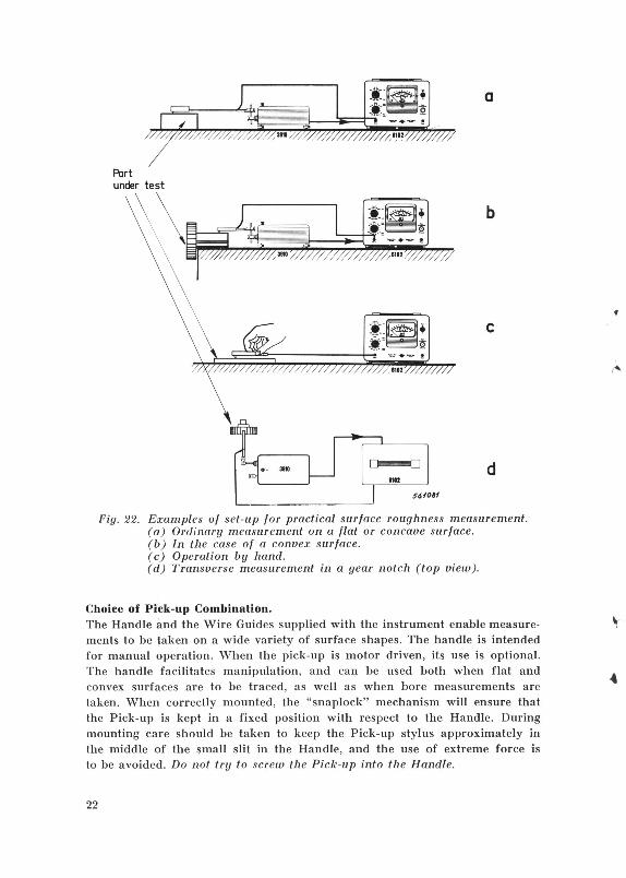
Fig. 22. Examples of set-up for practical surface roughness measurement. (a) Ordinary measurement on a flat or concave surface. (b) In the case of a convex surface. (c) Operation by hand. (d) Transverse measurement in a gear notch (top view).
Choice of Pick-up Combination. The Handle and the Wire Guides supplied with the instrument enable measurements to be taken on a wide variety of surface shapes. The handle is intended for manual operation. When the pick-up is motor driven, its use is optional. The handle facilitates manipulation, and can be used both when flat and convex surfaces are to be traced, as well as when bore measurements are taken. When correctly mounted, the "snaplock" mechanism will ensure that the Pick-up is kept in a fixed position with respect to the Handle. During mounting care should be taken to keep the Pick-up stylus approximately in the middle of the small slit in the Handle, and the use of extreme force is to be avoided. Do not try to screw the Pick-up into the Handle.
22
1"-

Smell Bores
a
Bores from 12J=18mm (23/32") to 0•100mm (4")
b
Concave. Flat or Convex Ports
c
Rods end Wires
d
Fig. 23. Survey of the different ways of mounting the Pick-up.
23

Note: When the pick-up is mounted in the Handle, the stylus is lined up with the centers of the skids. This is an advantage with respect to the disposition of the skid on the pick-up alone (i.e. 3 mm behind the stylus) in certain cases such as the investigation of very small samples (with a length less than 4 mm), and when it is necessary to avoid any phase effect between the movements of the skid and the stylus. See Fig. 7. The different ways of mounting the Pick-up are shown in Fig. 23. Measurements are possible on any curved type surface ranging from 6.35 mm\2> ( 14 "\2>) bores, to 1 mm\2> ( o.04"\Z>) wires with the standard Pick-up MP 6100. For smaller bore diameters (down to 3 mm (o.12") the Pick-up MP 0002 should be used. When measuring roughness on rods or wires (Fig. 23d) two different cases may be considered:-( 1) To measure the surface roughness of rods or wires on which the direction
of lay is tangential the Pick-up is moved along the rod in its axial direction.
(2) To measure drawn rods where the direction of lay is axial, the Handle (with Pick-up and Wire Guides mounted) is affixed to a table or in a vice, and the rod placed in the Wire Guides. The rod is now slowly turned (the tracing speed should remain about 3 mm/sec.), and the surface roughness value read off the instrument meter.
When not in use, the Wire Guides should be fastened above the Pick-up holder at the rear of the instrument, and the screws made fast on the Handle.
Calibration of the Roughness Meter. By employing the Reference Specimens MA 0014 accurate calibration of the Roughness Meter Type 6102 is possible. The following procedure should then be adopted:-
(1) See items (1), (2), and (3) of Operation Scheme, p. 19.
(2) Mount the Pick-up Handle as shown in Fig. 23c.
(3) Turn the switch marked "Cut-off" to the position "o.75 mm" ("o.03 inch") .
(4) Set the switch marked "Range" to "10 Micrometers", (or "300 Micro-inches").
(5) With a smooth, steady movement of the Pick-up trace the coarse patch at a speed of 3 mm/sec. (l;ls inch/sec.) until a relatively stable reading is obtained (after a few seconds). The tracing must be done in a direction approximately perpendicular to lay (i.e. perpendicular to the grooves). The use of the Motor Drive is strongly recommended. See the set-up in Fig. 24.
(6) Read the surface roughness value from the meter. The meter indication should equal the roughness of the specimen; if not, the screwdriver control at the rear of the apparatus marked "Instrument" should be turned until the correct reading is obtained.
24

NOTE: The fine surface of the MA 0014 cannot be used for calibration purposes even when a Fine Surface Pick-up MP 0001 is used.
Diamond Stylus Check. To check the tip radius of the exploring stylus of the Pick-up, which should be 12.5 ft (500 fA-inches), proceed as follows: -
( 1) Calibrate the Roughness Meter as described in the preceeding paragraph.
(2) Turn the switch marked "Cut-off" to position "o.75 mm" ("o.03 inch"}.
(3) Set "Range" switch to "o.3" or "1" Micrometers.
(4} Mount the pick-up on the slow traverse arm of the motor tlrive (1 mm/sec.}.*}
(5) Trace the fine patch of the Reference Specimens MA 0014 until a stable reading is obtained.
If, after correct calibration of the Roughness Meter, the reading is smaller than the minimum indicated on the card following the Reference Specimens (e.g. 8 Microinches), the Pick-up should be returned to the factory for replacement of the stylus.
Motor Drive Power Supply s60o6o
Fig. 24. Set-up for calibration of the Roughness Meter and check of the stylus tip radius.
Case of the Fine Surface Pick-up MP 0001. As it has been outlined in the foot-note of p. 18, the Reference Specimens MA 0014 are not designed for allowing a check of the stylus tip of the MP 0001. It is then necessary to use a microscope enlarging at least 700 times as is done under manufacture at the B & K factory, or to use a Precision Reference Specimen such as the "Caliblock - Mark II" made by EFESCO N.Y. , USA.
*) The speed of 1 mm/sec. (o.04 inchisec.) is the most suitable for this check. The resulting cut-off, o.25 mm (o.Ol inch), is short enough to eliminate the possible waviness on the fine Reference Surface. When operating by hand, the speed of 1 mm/sec. (o.D4 inch/sec.) might be found too slow. Then, a higher speed can be used and the Cut-off reduerr) correspondingly.
25

Applications Recording and Oscilloscope Monitoring of Surface Roughness Profile. For detailed surface roughness investigations, a recording of the true surface profile is necessary in most cases. Many standards recommend, in addition to the measurement of the average value Ra (C.L.A.), the determination of different quantities such as the maximum height (Rmax), the bearing length (Bb), the "ten points height" R. , to characterize a surface. (See B & K Technical Review No. 3-1961). Accurate determination of these quantities can be made on an exact representation of the effective surface profile.
Fig. 25. Photographic recording of a finely turned steel surface obtained by means of Type 6102 (with "high" cut-off and "30 microinches" range) plus an optical writing oscillograph with a film speed of 20 mm/sec. The vertical
amplification is 150 times greater than the horizontal amplification.
In Fig. 25 is shown a photographic recording of a finely turned steel surface (C.L.A. roughness approximately o.7 fh - 28 .!t") traced by means of the Roughness Meter Type 6102. The Fine Surface Pick-up MP 0001 was used in order to trace the surface as closely as possible (this pick-up has a stylus tip radius of 2.5 ft (100 Jh11
) and can readily follow even finely spaced irregularities) and the "Oscillograph" output was connected to a suitable oscillographic recorder. The choice of the recorder is determined by the fact that to each particular irregularity-width (wavelength) on the roughness profile to be recorded corresponds a particular frequency component in the electric signal (frequency = tracing speed/ wavelength} . In general, machined surfaces present irregularities with a large range of widths , and it is therefore an essential condition · for obtaining a true recording that the writing instrument is able to respond to a sufficiently extended range of frequencies . By frequency analysing the signal as described below, it has been found
26

a b Fig. 26. Oscillograms of surface profiles.
(a) Reference Specimen. (b) Turned surface (C.L.A. roughness: Ra = 2 fl).
(c) Ground surface (C.L.A. roughness: Ra = o.3 [l).
56006Z
c
that when tracing typical machined surfaces at a speed of 3 mm/sec most of the frequency components are comprised between 10-20 c/s and a few hundred c/s (i.e. roughness widths comprised between around o.2 and o.Ol mm). It is therefore advisable to employ a recorder which responds without distortion to frequencies of up to at least 200 c/s. This is realized, for example, by oscillographic recorders with optical, dry stylus, or ink vapor writing systems.*)
A picture of a surface profile can also be obtained by monitoring the "Oscillograph" output of the Roughness Meter by means of a cathode ray oscilloscope. Useful information can be obtained in this way, especially on turned surfaces presenting a ctrtain regularity. Some photographs of roughness profile pich•, s obtained on an ordinary oscilloscope are seen in Fig. 26.
Distortion.
Fig. 26(a) , representing the oscilloscopic profile of a preciSIOn reference surface, is meant to illustrate the possible unfidelities of the method. A slight distortion is actually noticed, since the profile, which in reality consists of isoscele triangles, appears curved to the right. This distortion was caused by an important phase shift at low frequencies in the oscilloscope amplifier. It should always be checked when a true surface profile oscillogram is wanted that the measuring chain, from the pick-up to the writing system of the graph, docs not introduce any distortion in the frequency range of interest. The frequency range in which the Roughness Meter itself (pick-up + amplifier) is free from distortion goes up to around looo c/s and is limited at the
*) A list of some of th e most suitable oscillographs available on the international market in HHil is gi Ycn in the B & K Technical Review No. 3-1961.
27

goo r---- ~ f--
1- - 1--
_,_-!- -
1----t- 1 1- t---+---,-cut off . H_iClh''
.... .... ;:_ (/)
Ql
~ .J:: D.. p.-·
5 10 20 so 100 200 500 lXXl o6f082
Fig. 27. Total phase shift, introduced by the Roughness Meter Type 6102, between the movement of the pick-up stylus and the output signal ("Oscillograph" output). The phase shift in the pick-up alone remains less than ± 2°. The phase shift in the oscillograph following the Roughness Meter should be added algebraically to the phase shift in Type 6102. The arrow indicates the
cut-off frequency of Type 6102 in position "High".
lower end to 3- 4 times the cut-off frequency because some phase distortion • ) appears in the input circuit when the frequency characteristics starts falling. The position " High" gives the lowest limit: 8-10 c/s. This will in most cases include all the frequency components of the signals to be recorded, as shown in the following.
Frequency Analysis. Fig. 28 illustrates how the frequency spectrum of an electrical signal can be readily obtained. The analysis of the "Oscillograph" output signal of the Roughness Meter is carried out by means of the Spectrum Recorder Type 3313 which consists of a Spectrometer Type 2112 plus a Level Recorder Type 2305. The Spectrometer is intercalated between the Roughness Meter and the Level Recorder, and the filter switch of the Spectrometer is synchronized with the frequ ency scale on the Recorder. The roughness measurement is then frequency analysed , and the frequency distribution is automatically recorded on the calibrated recording paper. The spectrogram on Fig. 28b was taken during the roughness measurement of a turned brass part, with "Cut-off' o.75 mm (traversing speed 3 mm/sec). It shows a predominant frequency around 40 c/s correspond•ing to a roughness-width (wavelength) of about o.07 mm ( o.003 inch). The spectrogram of the roughness of a ground surface without any pronounced regularity is illustrated in Fig. 28c. From the spectrograms is immediately seen that in the case of the turned part (Fig. 28b) , the tracing speed of 3 mm/sec will suite for profile recording, while in the case of the ground part (Fig. 28c) the tracing speed should be reduced in order to shift downwards the frequ ency if the oscillograph employed does not reach as high frequencies as 500 c/s. With an oscillograph having a high frequency limit of 200 c/s, the profile recording should in
• ) Phase distortion exists when the phase angle deviates appreciably (e.g. ± 10°) fr om being proportional to frequency (or from being zero). Sec Fig. 27.
2R

560066
a. . -
DDOOOODDDDDO DDDDODOD[][]00[ lrG:!,!J•r ..... .10
25
OOOOOO OOOOOOOOOOO OODLlDDO OO
-"""'---.. Brass (turnpdl
Feeding n.emrryro1 30
Cut- off 0.75mm
::""'·-----...., ____ _ LLAFr• 20C/c; ""' 25db w •. "" AD _..._ 3 mmtsec ........,~S..tr,: __ ,,
10 "" 100
b.
lrU~J•r+-'02!
-""'""'---.. Steel Cgrpund l
I::C:-n-;-t -- p--.f7f -:::D-;;-;75:--m- m-:-40 "'
LU..fr• 20C/c; "" 25db w •. "" AD ,..,..._ 3 mm/Sec M.Mp~,,..,..s..lr,: __ ,,
C/s 10
c.
Fig. 28. Frequency analysis of surface roughness.
100 c;s
(a) Set-up. The Spectrometer is provided with a low frequency ((Filter Chassis" ZS 0146.
(b) Frequency distribution of a surface roughness with pronounced regularity. (c) Frequency distribution of a surface roughness with no regularity.
the latter case be taken with a tracing speed of 1 mm/sec instead of the 3 mm/sec used in the frequency analysis .
Measurement of the Roughness 'Vidth. Surfaces can present undulations of all widths, but frequently the "valleys" _nd "peaks" on a machined surface are spaced with a certain degree of regularity. The roughness width is the distance between two successive peaks or valleys. To obtain a correct measurement of the roughness value on a
2!l

!''Jrface p1 esenting a certain rough nus width, the roughness width cut-off of the instrument should be equal to , or larger than the roughness width. In many cases the roughness width can be deduced from the knowledge of the manufacturing process, e.g. Lhc tool feed for a turned part. Otherwise, the roughness widlh can be determined as follows. A first approximalion of the roughness-width may be obtained in a measurement carried out at a constant traversing speed (i.e. with motor drive), by proper use of the " Cut-off" switch of the Roughness Meter. The effect of varying the roughness-width cut-off in a measurement is shown in Fig. 29. The profile at the top is the true movement of the stylus on a surface having a coarse roughness spacing of about 1 mm ( o.04 inch), and the profiles below show the electric signal fed to the meter through the amplifier at three different "Cut-off" settings (o.75, o.25, o.075 mm - o.03, o.01, o.003 inch) . It is clearly seen that the deflection of the met.::r, which indicates the averagP height of the undulations, will decrease when the cut-off width is varied from o.75 to o.0-75 mm. The indications will thus be in the order of 4, 2 and 1 micrometers {160, 80, 40 microinches) respectively. The first result includes most of the coarse irregularities, and all of the fine irregularities of the surface. The measurement based on "Cut-off o.25 mm" ( o,010 inch) excludes the coarse irregularities but includes the fine and medium fine. The third reading, made with the narrowest value of cut-off width, includes only the fine irregularities. Had the surface been made up of irregularities AS fine as
.030
d
.030
Roughness
width cut-off
Indicated
average roughness
True movement
of the stylus
.030 140-170
.010 70-90
.003 38-42
560Q63
Fig. 29. Sketch showing the effect of different settings of the Cut-off switch. (From A.S.A. n 46. 1-19q5, Fig. 17. The average roughness is stated in fA-inches ,
and the roughness width cut-off in inches).
30

those of the bottom trace, the indication of the meter would have been the same for all three "Cut-off" settings. m practice, an estimation of the roughness width is obtained during a surface roughness measurement by rotating the "Cut-off" switch from maximum to minimum, and observing the deflection on the meter. As soon as the deflection falls the region of the roughness width is attained. The roughness width can be evaluated by reading the setting of the switch :~: : rl using the transmission curve in Fig. 9, p. 9. *) If the deflection has fa Len more than 20 %, the roughness width is higher than the present setting of the "Cut-off" switch, and the measurement should be made with a larger "Cut-off" setting. If the deflection falls less than 20 % the roughness width is lower than the "Cut-off" and the measurement can be made with this value of "Cut-off". For detailed roughness-width investigations, a frequency analysis of the roughness should be made. See above.
Choice of the Roughness Width Cut-off. Practically the cut-off should be chosen in order to exclude the waviness (Fig. 35) from the roughness measurement. As stated in "Operation Scheme" item (5 .' p. 19, the roughness width cut-off of o. 75 mm is preferred for most surfaces. However, in special cases care must be taken to choose the "Cut-off" value which will include all the surface irregularities it is desired to assess. In other words, the measurement should be made on a selective basis. For example, in the case of surfaces subject to fatigue failure, irregularities of small width will be important, and a more significant result will be obtained with a short roughness width cut-off. In other cases, such as identifying chatter marks on machined surfaces, or as mechanical parts in which actual contact with a mating surface is important, a long roughness width cut-off should be used. Otherwise, some rules are stipulated in the newer National Standards for the choice of the roughness width cut-off, as a function of the roughness height and of the machining processes.
CLA Recordings for Production Control. Fig. 30 shows a set-up for the production control recording of surface rough· ness. During each measurement the indications on the Roughness Meter are recorded by a DC recorder.*) By means of the key K it is possible to start and stop the recorder and the Motor Drive at the same time. The recording paper being conveniently marked, the transcribed roughness control can thereafter be attached to each tested part. In order to have corresponding indications on the recorder and on the meter, the "CLA Recorder" output of the Roughness Meter must be adjusted before measurements. This is carried
*) From Fig. 9, page 9, it is seen that in the roughness measurement of a surface h aving a roughness width equal to the cut-off value of the Roughness Meter, the indication is attenuated by 20% approximately.
*) Any DC Recorder with voltage and current consumption characteristics fitting with the Roughness Meter CLA Output can be employed. See page 12.
31

out by means of the "CLA Recorder" adjustment of the Roughness Meter (accessible with a screwdriver through a hole in the rear plate) while tracing a Specimen. Deflection on Type 6102 should be comprised between 1 and 10 (upper scale). When investigating long samples on which the full traversing length of the Motor Drive ( 40 mm - 1%6 inches) can be used, the recording also indicates the variations of the finish (i. e. CLA roughness value) along the sample itself. This can give useful information about the manufacturing process.
K
Fig. 30. Set-up for production control and recording of the CLA roughness .
Quality Control of Rotating Machinery. The Roughness Meter Type 6102, being an instrument which measures the average value of small stylus displacements, at frequencies ranging from 4 to 1500 c/s, can also be used as a displacement sensitive Vibration Meter. The range switch indicates the vibration level sensitivities in arithmetical average values of the displacemenl. This corresponds, in the case of sinusoidal vibrations, to peak-to-peak values of :rr; = 3.14 times the values stated on the panel (i.e. o .0003, o.001, o .003, o.01, o.03, o.1 mm). *) During operation the Pick-up housing must be fixed to the part with respect to which the vibration is considered. The Pick-up, mounted into the Handle , can be fastened in a holder by means of the Wire Guide screws. In order to ensure that the stylus movement is free , the distance between the vibrating object and the pick-up housing should be adjusted to approximately 1 mm ( o.04"). In cases where the dimensions of the structure (with respect to which the vibrations are measured) allows it, the pick-up can be simply fastened by means of a mound of wax or plasticine. For instance, the Roughness Meter Type 6102 can be used for checking the
*) The corresponding maximum velocity and acceleration levels are equal to the peak to peak displacement multiplied by :rr; f and 2 :rr;2 f2, respectively (f is the frequency in c/s) . For example, the maximum measurable acceleration level is (for a displacement of o.l mm at 1500 c/s) 4450 m/s/s = 453 g (g = 9.81 m/s/s).
32

performance of rotating machinery, as it enables rapid measurements of eccentricities and wobbling to be taken on rotating axles, shafts , etc. The rotating speed of the tested part should be between 240 and 30ooo r. p.m., in order that the measurement is within the frequency range of the Roughness Meter. The pick-up is placed, as described above , against the piece under test, see Fig. 31. In order to avoid scratching the object being tested by the diamond stylus, and to avoid the roughness of the object being included in the measurement, the pick-up can be easily provided with a gliding contact blade as shown schematically in Fig. 31. To eliminate the frame's vibrations being included in the measurement, the pick-up should be fastened to the bearing frame of the rotating part itself.
Fitting' to the bearin frame
Pick-up in the handle
Stiff contact blade
tested shaft
560069
Fig. 31. Pick-up arrangement for eccentricity measurement.
An interpretation of the eccentricity measurement carried out by means of this arrangement is given on Fig. 32. The measurement includes: (a) the geometric eccentricity of the cross-section of the rotating object at the testing point, (b) the wobbling, due to the bending of the object (especially in the case of relatively long axles or spindles) , (c) the flaws or defects on the surface, (d) the dynamic vibrations that occur in the rotating object. (These vibrations are normally negligible at low rotating speed). The meter of Type 6-102 will indicate the arithmetic average value of these defects. However, the measurement of the maximum value of the eccentricity, and the direct observation of the aspect of the rotating object, can be easily obtained by means of an ordinary cathode-ray oscilloscope connected to the Output of the Roughness Meter (position "Oscillograph"). See the set-up Fig. 33. The vertical deviation scale on the oscilloscope can be calibrated in microinches or micrometers when tracing the 250 ,.uinches Reference Specimen MA 0014. The peak-to-peak deviation on the oscilloscope represents 1ooo ,.uinches = o.001 inch = o.025 mm. (See "Calibration of the Roughness Meter", p. 24). In Fig. 34 are shown photographic copies of the curves obtained on the oscilloscope during an eccentricity measurement carried out on the spindle
33

a. r 180 360°
b.
c. 180 360° X
d.
Fig. 32. Detailed composition of an eccentricity measurement. (a) Geometric eccentricity. (b) Wobbling. (c) Flaw. (d) Movement of the
stylus. (e) Amplified picture on the oscilloscope.
34
The meter indication is the arithmetical average (CLA) of the amplified movement of the stylus
Pick-up MP6100
1112
;@: • • •• • :'j':
X • • • • i>
Oscilloscope ~6111171
Fig. 33. Set-up for eccentricity measurements on a spindle.

of a small electric motor by means of the arrangement described beforehand. The curve (a), showing the movement of the stylus, is roughly sinusoidal in shape, which means probably that the eccentricity at the point of measurement is mainly due to wobbling of the spindle. Also, a flaw is clearly detected immediately after the "top" of the eccentricity curve. Additional information can be obtained from the small irregularities on the sinusoidally shaped curve. For instance, if the irregularities appear to glide on the stabilized main curve, it probably corresponds to a defective ball in the bearing unit. However, before making any interpretation of the irregularities
~ ~ ~ l\j ~
~~ ll Ill rJ ~ ~
a.
Fig. 34. Oscilloscope photographs of an eccentricity measurement on the spindle of a small motor (rotating speed: 120 r.p.m.).
(a) Spindle. (b) Calibration by means of the Reference Specimen MA 0014.
on the oscilloscope picture, it is advisable to observe, by releasing the pick-up stylus (contact blade) from the rotating piece and locking it to the handle, the influence of vibrations and noise. The curve (b) shows the calibration of the screen of the oscilloscope by means of the 250 ,uinches Reference Specimen MA 0014. In this case it was necessary to reduce the sensitivity range of the Roughness Meter by one step to obtain a calibration picture of convenient height. The1;efore, the peak-to-peak height on the figure represents 316 ,uinches (7.9 .,u); and the eccentricity of the spindle is correspondingly 220 ,uinches ( 5.5 .,u). It is possible to detect defects down to a fraction of ,u (less than 40 ,uinches) by means of the previously described arrangement.
35

Appendix Definitions. To characterize practically obtained surfaces, which differ greatly from each other depending upon the production method employed, it has been found necessary to introduce certain standard definitions. Some of the most important are given in the following; (ASA B46.-1.-1955).
Surface. The surface of an object, is the boundary which separates that object from another object or substance.
Nominal Surface. The theoretically accurate design, the shape and extent of which is usually shown and dimensioned on a drawing or descriptive specification.
Surface Irregularities. Deviations from the nominal surface including roughness and waviness .
Profile. The contour of a section perpendicular to a surface, unless some other angle is specified.
Waviness height
Roughness width
Roughness height
Flaw
Roughness width cut-off 51DD7J
Fig. 35. Drawing illustrating the meaning of the standard definitions (from ASA, B 46. 1-1955, Fig. 11).
Roughness.
36
Relatively finely spaced surface irregularities, the height, width, and direction of which, establish the predominant surface pattern. Irregularities produced by cutting edges and machine tool feed may be

considered roughness. The height is rated in micrometers (or microinches) arithmetical average deviation fr~m the mean line; the symbol AA (arithmetic average) or C. L.A. (center line average) being used as descriptive abbreviations. (For the mathematical definition of the C. L.A., see the following paragraph).
Waviness. Irregularities of the surface which are of greater spacing than roughness. These irregularities may result from such factors as machine or work deflections, vibration, heat treatment, or warping strains. The height is rated in mm (or inches) at the pak-to-valley distance. The width is rated in mm (or inches) as the spacing of adjacent waves.
Roughness Width Cut-off.
Lay.
Flaws.
The maximum width in mm (or inches) of surface irregularities to be included in the measurement of roughness height. In general, surfaces will contain irregularities with a large range of widths. Instruments are designed to respond only to irregularity spacing of less than a given value, called the roughness width cut-off.
The direction of the predominant surface pattern, produced by tool marks or grains of the surface ordinary determined by the production method used.
Irregularities which occur at one place, or at relatively infrequent intervals in the surface, e. g. a scratch, ridge, hole, peak, or check.
From Fig. 35 is seen that when measurements are taken it is of the utmost importance to be able to clearly define which property of the surface is actually being measured, and the accuracy of the measured result.
Basic Definitions of the Roughness Value. Theoretically, surface roughness should be investigated on a three-dimensional basis and its "measurement" by means of only one parameter presents a very limited meaning. However, in the practical case of machined surfaces presenting a certain uniformity of configuration, it is possible (for production control purposes) to characterize approximately the "landscape" constituting the roughness by means of a limited number of parameters judiciously chosen for each type of surface. The definitions of the surface roughness parameters to be used in connection with the different machining processes are standardized in most countries and reference should always be made to a standard when specifying roughness measurements*). The definitions and the specifications
*) A survey of the situation of surface roughness standardizations throughout the world per 1st October, 1961 will be found in the B & K Technical Review No. 3-1961, together with the exact definitions of the most commonly employed values and reference systems.
37

of the measuring methods differ from country to country, but it should be kept in mind, when comparing similar standards, that the basical uncertainty coming from the assumption of uniformity of the surface, as outlined above, is in most cases more important than the possible deviations in measured results using slightly different methods. However, a certain unification appears amongst the newly reviewed standards, in accordance with the International Standard Organisation recommendations (draft No. 221, 5th September, 1958). In these recommendations the surface roughness profile is dealt with practically in a similar way as the Roughness Meter Type 6102 does. First, the finite length of profile "L" which is to be taken as averaging sample (roughness-width cut-off) is proposed to be equal to o.08, o.25, o.8, 2.5, 8 or 25 mm depending upon the order of magnitude of the surface irregularities. In ordinary cases , only the smaller values are to be used.**) Secondly, the "Mean Line" of the surface profile is determined as a line parallel to the normal surface for which the areas embraced by the profile above and below the line are equal. This line is also called the "Center Line" in the British and American Standards. Electrical integrating instruments, which are only sensitive to alternating current, refer to the Mean Line of the movement of their stylus. Finally, three quantities are defined for characterizing the roughness depth:
1) Ra = arithmetical average deviation from the mean line.
y
1 ~L Ra = - IYI elL Lo
2) Rmax = maximum distance between two lines parallel to the Mean Line and touching the profile at the highest and lowest points within the sampling length.
3) Rz = average difference between the five highest peaks and the five deepest valleys within the sampling length L.
Rmax
dL L 5610$()
Fig. 36. Schematic representation of the arithmetic average value Ra (C.L.A.) and of the peak-to-valley value Rma:e on an actual surface profile. L = rough
ness width cut-off of the measurement.
* *) The normal cut-off values of TYJ;>e 6102 are actually o.075, o.25 and o.75 mm according to the British and American standards. This deviation, is negligible (within tolerances) .
38

The Roughness Meter Type 6102 measures the average value Ra, and Rmax and R. can be determined from a profile recording (see Applications).
Average Surface Roughness (Ra) Symbols. The wanted roughness value of a surface should be stated on the drawing of the piece being considered. Unfortunately, the surface symbols used in various countries are different, and the meaning of the same symbol might differ from country to country. However, in newer standards there seems to be a tendency to change over from the old triangular symbols to a V-type symbol with indication of the exact Ra value, and eventually additional information about R., Rmax etc. Fig. 37 gives the relationship between the different surface symbols which were in use on 1st August, 1961 , and the arithmetic average (Ra) roughness value. By means of this figure it is possible to relate the symbol directly to
1 000 500 100 50 10 5 1 0.5 0.1 0.05 0.01 0.005 ~ (CLA) reading )lm---. u.I!!U.1.!...1 ._1 1-1 ;_1 -'-I _J.J.I IJ..J.II..J..I ;_I 1-1 ...__..__--l.JI 1U..IIL..I1..J.I..J..1 -'--....L.....---'I..u!!..J..1 J..1 lw1'-'--'--.u.l 1LL1 1..J..1 .~..1 '-1 _.__..____...I 1..ull..u1 I
ARGENTINA1> 1951 rv v w VVi1 ~ BRAZIL1> 1951 rv v w vw wif= CZECHOSLOVAKIA 1960 100 0~ 0.008
rv
rv 25 v 5 w 116 vw 0.25 ww DENMARK 1958 v FINLAND 1959 ~160 Process 0.04
~ ~ 'V"ii"\i ---t
FRANCE1l 1940 rv v w vw GERMANY 1960 250 !;!=-- 0.01
GREAT BRITAIN 1961 1000 100 32..,; 1
1qo v 12 .5 w l~ vw o12 vvw
HUNGARY 1958 10~~~- ~ ~0~ O.Q16
ITALY 1960 ,~ v 3 w o18 vw o
12 ww
s61oo rv 1 4
1oo 0 360 00 9b 000 2~ 0.0 s1 e:Je 114 .. rb
NETHERLANDS 1958 5600 v 1400 v 360 w 90 vw 22 VT'V 5.5 """"" 14 """ 02
POLAND 1958 100 VR0 5 10
0.008
RUMANIA 1957 100 Ra 8: i~
0.008
SWITZERLAND1> 1960 rv v w VVi1
SPAIN 1951 6~ rv 2~ v 10 w ,~6 vw 0.~6 ww U.S A. 1955 1600
32..,..-:: 0.25
U.S.S.R. 1959 80 ov-0.006
8000 4000 2000 1000 500 250 125 63 32 16 8 4 2 1 0.5 0.25 R
0(CLA)reading }J in .-----J~ 1 I I 1 I 1 1 I I 1 1 I 1 I 1 1 I I 1 I 1 1 I I 1 I I 1 I I 1 1 I 1 1 I 1 I I 1 1 1 1 1 I 1 I
5"6/083
Fig. 37. Table of the different Ra (C.L.A.) symbols in use in different countries per 1st August, 1961 (information obtained from the Danish Standard
Association). 1) No limits between the different triangles are given. Indications on the
process can be added on an extension of the symbol. In France, a standard draft has been published in September 1961, which proposes a V-type signal, with indication of the Ra value or of its two limits .
39

the results obtained from measurement with the Roughness Meter Type 6102. More detailed information about surface roughness symbols will be found in the B & K Technical Review No. 3-1961.
"Scratching" Caused by the Pick-up. A common objection to the use of stylus type instruments for measurement of surface roughness is that the stylus scratches the surface being checked. Because of the principle of operation of this type of instrument it must
scratch the surface. However, the magnitude of the scratch will depend upon the static pressure on the stylus , and on the stylus tip radius. With a stylus pressure of the order of 1 gramme and a stylus tip radius of 12 micrometer (500 microinches) the scratch on a metal surface will be almost negligible. Some experiments have shown that no scratch from the stylus could be detected on specimen made from steel and brass, even when examined with a microscope having magnification of 315 times. The Vicker's hardness of these specimens were all greater than 90 kg/mm2. On aluminium alloy with a Vicker's hardness around 85 kg/mm2 a scratch the maximum depth of which was of the order of o.05 micrometer could just be measured in the microscope. (The width of the scratch was measured, and its depth deduced from the knowledge of the stylus radius). All these experiments were carried out on specimens with surface roughness values between 3 and 7 micrometer (average) . Finally, measurements were made on a lead alloy the Vicker's hardness of which, was in the order of 30 kg/mm~. A scratch with a depth of approx. o.05 micrometer was found on a shaped piece having a surface roughness around 8 micrometer average. By increasing the roughness of the surface to a value around 25 micrometer the depth of the scratch was found to be of the order of o.1 micrometer. It should be mentioned that if the Pick-up is pressed hard against the surface, scratches caused by the movement of the skids may be found on the surface. It is therefore of importance, when using hand held operation of the Pick-up, not to press it against the surface with a greater amount of force , than is necessary to ensure a steady movement of the Pick-up head.
Notes on Surface Roughness Control. It has been previously mentioned that surface roughness control is of importance in the production of fast moving machine parts. A variety of different methods may be employed to obtain the desired surface finish and Fig. 38 shows a table indicating the surface roughness available from common production methods. As a small change in one or more of the factors affecting the surface roughness during production can have a marked effect on the surface produced, the values shown in the table should be considered flexible and not hard and fast limits. With regard to the production economy of producing a specified surface roughness, a curve, based on investigations carried out in The United States,
40

Sand casting Permanent mold castine Die castina Hand foraing Drop forainCI Precision forCiinQ Cold rolling Hot rolling Drawing Stamping Sand blasting Flame cutting Sawing Filing Scraping PlaninCI Turning Drilling and Boring Milling Reaming Broach ina Grinding Lapping Honinc:J Superfinish PolishinQ
0,1 )Jmetres _____.
1 110 I I I I I
I I I I I I I
- 1-
I I I I I I I I I
I I I I I I I I
1 T T 1
CLA 1QO 1000
I I
10 100 1.000 10.000 CLA }J inches ---.
Roughness value obtainable by rough finish operations. Roughness values obtainable by normal finish operations. Roughness values obtainable by careful treatment of the surface and when precision finishing methods are employed . Roughness values obtainable by turning and boring using diamond (or hard metal) tools .
,.~9037
Fig. 38. Surface Roughness obtained from common production methods. (Information obtained from Professor K. V. Olsen of the Technical University
of Denmark, Copenhagen).
is shown in Fig. 39. From the curve can be seen that especially in cases where the surface finish is critical, i.e. for surface having a roughness value ( C.L.A.) smaller than 2.5 micrometer ( 100 microinches) the relative production cost increases rapidly with the required surface finish. When only small quantities are produced the economic considerations may not be of the greatest importance, l>ut large scale production will normally call for effective surface roughness control, and the use of a Roughness Meter will then be of invaluable assistance.
41

ln the past, when suitable surface roughness measuring equipment was not available, a common method used in the manufacturing process of more critical machine parts was just to produce the part with the smoothes t obtainable surface. However, a careful study of the "efficiency" of different machine parts as a function of their surface finish will in most cases result in the conclusion that producing a surface smoother than a certain "limit value" determined by the functioning of the part in question, is actually a waste of time and costly production machinery. To be able to determine the most economical methods of tooling, machine set-ups, speeds and feeds , to produce the surface quality required for the machine part in question, actual surface roughness measurements must be taken. The measurements to be carried out in this case are more or less a laboratory job. However, during production the tool wear and difference in uniformity of material might cause the surface roughness of the final products to deviate from the original requirements. In such instances , it is recommended that not only should the test department be supplied with one or more units of the Roughness Meter Type 6102, but the instrument should also be utilized on the production line. Many costly rejections can then be avoided and the effective production rate increased.
Surface roughness in micrometers- CLA .
12,5 10 7,5 5 25
<1l u :J
40 "U
I 1/
~ a.
0 ..... 30 .....
Ill 0 u
ClJ >
20 ..... _g
/I ~
v ----
QJ 1..
QJ ..... 0
10 E X 0 L..
a. a. <!
500 1.00 300 200 100 !f60076
Surface roughness in microinches- C LA .
Pig. 39. Curve showing a rough average relationship between production cost and surface roughness of the finished product.
42

Specification OVER-ALL CHARACTERISTICS
Type of Measurement: "Mean Line Average" roughness height Ra (C.L.A.) both in microns and microinches.
Sensitivity for full scale deflection: six micrometer ranges (o.1-o.3-1-3-10-30 ~m) and six microinches ranges (3-10-30-100~300-1ooo
~inches). Tolerance ± 2 %.
Roughness-width Range: Approximately o.002 to 1.2 mm ( o.00008 to o.05 inch) at a traversing speed of 3 mm/sec ( 1/s inch/sec) (i.e. frequency response flat from 3 to 1500 c/s).
Roughness-width Cut-offs at 3 mm/sec traversing speed: o.075-o.25-o.75-High (1.2 mm approx.), (o.003-o.01-o.03-approx. o.05 inch). Tolerance ± 10%.
Noise Level equivalent to less than o.03 ftm (1.2 ~") in the worse conditions, i.e. with "High" cut-off and the pick-up being motor driven at 3 mm/sec, 1fs in/sec (much lower with 1 mm/sec traversing speed).
PICK-UPS
Type I
MP 6100 I
MP 0002 I
MP 0001
Skid Radius 10 mm (o.4") I
6 mm ( o.24") 10 mm (o.4")
Tip Radius of the 12.5 fA- (500 p,") 12.5 fA- (500 ~") 2.5 fA- (100 p,") Diamond Stylus
Stylus Pressure Max. 1 gramme 1 gramme o .5 gramme
Min. Diameter of Bores 6.35 mm ( o.25") 3 mm (o.12") 6.35 mm ( o.25") the Object being Rods 1 mm ( o.04") 3 mm (o.12") 1 mm ( o.04") measured
Transducing Element P.Z.T.-bender
Temperature Range -20 to + 60°C (-4 to + l40°F)
Humidity Relative humidities of up to 100% will not influence the measurements.
Distance: 3 mm ( 1/s ") 2.5 mm (o.1") 3 mm ( lfs") Stylus-Center of Skid
Weight 7 grammes 6 grammes 7 grammes
Overall Length 69 mm (21¥16") 68 mm (2%") 69 mm (21¥16")
Max. Diam.eter of the 6 mm (1%4") 6 mm (1%4") 6 mm (1%4") Housing

AMPLIFIER AND METER
Frequency Characteristic: Compensating the pick-ups characteristic.
Meter Accuracy: 1 % of full deflection.
Direct Output Impedance: 100 .Q approx.
Maximum Output Voltage: "Oscillograph" output: 35 V peak-to-peak. "CLA Recorder" output: 10 V DC. (3.25 V with the max. current: 2.5 rnA).
Power Supply: 100-115-127-150-220-240 volts ± 10 %, 50 to 400 c/s Consumption around 15 watts.
\\7arm-up Time: About one minute.
Tubes: ECC83 (12AX7), ECF82 (6U8).
Dimensions of Case: 250 X 195 X 190 mm (10 X 7% X 7% inches).
Weight: (with normal accessories), 6 kg (13 lbs.).
ACCESSORIES included in Type 6102
Pick-up MP 6100 with Cable AO 0023. Pick-up Handle DH 0007 (equipped with skids, radius 8 mm, o.32 in.). Set of wire guides, fitting the handle (DK 0018 short and DK 0019 long). Type MA 0014: reference surfaces, in plastic cover (calibrated with ± 2 %
accuracy). 1 Output plug JP 0006. Spares: 1 scale lamp, 3 fuses.
MOTOR DRIVE TYPE 3910
Traverse Speed: 3 mm/sec ( o.12 inch/sec) and 1 mm/sec ( o.04 inch/sec). Continuous back and forth movement.
Traversing Length: Adjustable from 1.5 mm (l!J.6 inc-h) to 40 mm (Ph inch).
Height of Pick-up Adaptor: Adjustable from -25 to +130 mm (-1 to +514 inches).
Extension Rod (Type DH 0027) : Length 19 em (7% inch).
Power Supply: 115-127-150-220-240 V ± 20 %, AC 50 c/s. At 60 c/s the speed is increased by 20 %. Consumption around o.07 A.
Dimensions of Case: 200 X 115 X 75 mm (8 X 4% X 3 inches).
\\7eight: 2.8 kg (6 lbs.).
44


B K
Printed in Copenhagen, Denmark May 1963