User Manual - Master Hire
80
Failure to follow the instructions and procedures in this manual or, misuse of this equipment will VOID its warranty! WARRANTY NOTICE PART NUMBER: KEEP FOR FUTURE REFERENCE USER MANUAL © SULLAIR CORPORATION The information in this manual is current as of its publication date, and applies to compressor serial number: and all subsequent serial numbers. 02250184-068 R00 201205120000 PORTABLE AIR COMPRESSOR 300HH, 375, 375H, 375HH, 425 AND 425H JOHN DEERE STANDARD AND AFTERCOOLED AND FILTERED
-
Upload
khangminh22 -
Category
Documents
-
view
0 -
download
0
Transcript of User Manual - Master Hire

Failure to follow the instructions and procedures in this manual or,
misuse of this equipment will VOID its warranty!
WARRANTY NOTICE
PART NUMBER:
KEEP FORFUTURE REFERENCE
USER MANUAL
©SULLAIR CORPORATIONThe information in this manual is currentas of its publication date, and applies tocompressor serial number:
and all subsequent serial numbers.
02250184-068 R00
201205120000
PORTABLE AIR COMPRESSOR300HH, 375, 375H, 375HH, 425
AND 425HJOHN DEERE STANDARD AND AFTERCOOLED AND FILTERED

AIR CARE SEMINAR TRAINING
Sullair Air Care Seminars are courses that provide hands-on instruction for the proper operation, maintenance,and servicing of Sullair products. Individual seminars on portable compressors and compressor electricalsystems are offered at regular intervals throughout the year at Sullair’s corporate headquarters training facilitylocated at Michigan City, Indiana.
Instruction includes training on the function and installation of Sullair service parts, troubleshooting commonfaults and malfunctions, and actual equipment operation. These seminars are recommended for maintenance,contractor maintenance, and service personnel.
For detailed course outlines, schedule, and cost information contact:
SULLAIR TRAINING DEPARTMENT
1-888-SULLAIR or219-879-5451 (ext. 5623)
- Or Write -
Sullair Corporation3700 E. Michigan Blvd.Michigan City, IN 46360
Attn: Service Training Department.
TABLE OF CONTENTS
SECTION 1—SAFETY 3 1.1 GENERAL
3 1.2 TOWING
6 1.3 PRESSURE RELEASE
7 1.4 FIRE AND EXPLOSION
8 1.5 MOVING PARTS
9 1.6 HOT SURFACES, SHARP EDGES AND SHARP CORNERS
9 1.7 TOXIC AND IRRITATING SUBSTANCES
10 1.8 ELECTRICAL SHOCK
10 1.9 LIFTING
11 1.10 ENTRAPMENT
11 1.11 JUMP STARTING
12 1.12 IMPLEMENTATION OF LOCKOUT/TAGOUT
13 1.13 CALIFORNIA PROPOSITION 65
14 1.14 SYMBOLS AND REFERENCES
SECTION 2—DESCRIPTION 17 2.1 INTRODUCTION
17 2.2 DESCRIPTION OF COMPONENTS
19 2.3 SULLAIR COMPRESSOR UNIT, FUNCTIONAL DESCRIPTION
19 2.4 COMPRESSOR COOLING AND LUBRICATION SYSTEM, FUNCTION-AL DESCRIPTION
20 2.5 COMPRESSOR DISCHARGE SYSTEM, FUNCTIONAL DESCRIPTION
20 2.6 CAPACITY CONTROL SYSTEM, FUNCTIONAL DESCRIPTION
28 2.7 AIR INLET SYSTEM, FUNCTIONAL DESCRIPTION
28 2.8 INSTRUMENT PANEL GROUP, FUNCTIONAL DESCRIPTION
47 2.9 WIRING DIAGRAM
48 2.10 ELECTRICAL SYSTEM, FUNCTIONAL DESCRIPTION
48 2.11 COMPRESSOR SHUTDOWN & WARNING SYSTEM, FUNCTIONAL DE-SCRIPTION
48 2.12 AFTERCOOLED AND FILTERED AIR SYSTEM, FUNCTIONAL DE-SCRIPTION
49 2.13 LISTING OF ENGINE DIAGNOSTIC CODES (DTCS)

TABLE OF CONTENTS
SECTION 3—SPECIFICATIONS 53 3.1 SPECIFICATIONS—300HH, 375, 375H JOHN DEERE
55 3.2 SPECIFICATIONS—375HH, 425 AND 425H JOHN DEERE
56 3.3 LUBRICATION GUIDE— COMPRESSOR
56 3.4 APPLICATION GUIDE
57 3.5 LUBRICATION GUIDE— ENGINE
SECTION 4—GENERAL 59 4.1 GENERAL
59 4.2 PURPOSE OF CONTROLS
60 4.3 INITIAL STARTUP/SHUTDOWN PROCEDURE
60 4.4 RESTART PROCEDURE
SECTION 5—MAINTENANCE 61 5.1 GENERAL
61 5.2 ENGINE COOLANT REQUIREMENTS
62 5.3 MAINTENANCE AFTER INITIAL 50 HOURS OF OPERATION
62 5.4 MAINTENANCE EVERY 50 HOURS
62 5.5 MAINTENANCE EVERY 100 HOURS
62 5.6 MAINTENANCE EVERY 250 HOURS
63 5.7 MAINTENANCE EVERY 1500 HOURS
63 5.8 PART REPLACEMENT AND ADJUSTMENT PROCEDURES
70 5.9 TROUBLE SHOOTING
SECTION 6—NOISE CONTROL 73 6.1 NOISE EMISSIONS WARRANTY
73 6.2 TAMPERING WITH THE NOISE CONTROL SYSTEM IS PROHIBITED
74 6.3 NOISE EMISSIONS MAINTENANCE AND MAINTENANCE RECORD LOG

Section 1
3
SAFETY
1.1 GENERAL
Sullair Corporation designs and manufactures all ofits products so they can be operated safely.However, the responsibility for safe operation restswith those who use and maintain these products. Thefollowing safety precautions are offered as a guidewhich, if conscientiously followed, will minimize thepossibility of accidents throughout the useful life ofthis equipment. Read the CIMA Safety Manualprior to compressor operation and towing, ifapplicable in your area.
The air compressor should be operated only by thosewho have been trained and delegated to do so, andwho have read and understood this Operator’sManual. Failure to follow the instructions, proceduresand safety precautions in this manual can result inaccidents and injuries.
NEVER start the air compressor unless it is safe todo so. DO NOT attempt to operate the aircompressor with a known unsafe condition. Tag theair compressor and render it inoperative bydisconnecting the battery so others who may notknow of the unsafe condition will not attempt tooperate it until the condition is corrected.
Use and operate the air compressor only in fullcompliance with all pertinent OSHA requirementsand/or all pertinent Federal, State and Local codes orrequirements.
DO NOT modify the compressor except with writtenfactory approval.
Each day, walk around the air compressor andinspect for leaks, loose or missing parts, damagedparts or parts out of adjustment. Perform allrecommended daily maintenance.
Inspect for torn, frayed, blistered or otherwisedeteriorated and degraded hoses. Replace asrequired.
1.2 TOWING
PREPARING TO TOW
NOTE
OPERATOR IS REQUIRED TO READ ENTIRE INSTRUCTION MANUAL.
CAUTIONEstimated hose life based on a 5-day 8-hour work week is 3 years. These conditions exist on an 8-hour shift only. Any other operation of the equipment other than 8-hour shifts would shorten the hose life based on hours of operation.
(I)
WARNINGDo NOT tow the compressor should its weight exceed the rated limit of the tow vehicle, as the vehicle may not brake safely with excess weight. See rated limit in tow vehicle Operator's Manual, and review its instructions and other requirements for safe towing.
(I) WHILE NOT TOWED IN THE USUAL SENSE OF THE WORD, MANY OF THESE INSTRUCTIONS ARE DIRECTLY APPLICABLE TO SKID-MOUNTED PORTABLE AIR COMPRESSORS AS WELL.

SECTION 1
4
A. Prior to hitching the air compressor to the towvehicle, inspect all attachment parts and equip-ment, checking for (i) signs of excessive wear orcorrosion, (ii) parts that are cracked, bent,dented or otherwise deformed or degraded, and(iii) loose nuts, bolts or other fasteners. Shouldany such condition be present, DO NOT TOWuntil the problem is corrected.
B. Back the tow vehicle to the compressor and posi-tion it in preparation for coupling the compressor.
C. If the compressor is provided with a drawbarlatched in the vertical upright position, carefullyunlatch drawbar and lower it to engage the cou-pling device. If not, raise drawbar with the jack toengage coupling device or otherwise couple thecompressor to the towing vehicle.
D. Make sure the coupling device is fully engaged,closed and locked.
E. If chains are provided, pass each chain throughits point of attachment on the towing vehicle;then hook each chain to itself by passing thegrab hook over (not through) a link. Cross chainsunder the front of drawbar before passing themthrough points of attachment on towing vehicle tosupport the front of drawbar in case it shouldaccidentally become uncoupled.
F. Make sure that the coupling device and adjacentstructures on the towing vehicle (and also, if uti-lized, chain adjustment, brake and/or electricalinterconnections) DO NOT interfere with orrestrict motion of any part of the compressor,including its coupling device, with respect to thetowing vehicle when maneuvering over anyanticipated terrain.
G. If provided, make sure chain length, brake andelectrical interconnections provide sufficientslack to prevent strain when cornering andmaneuvering, yet are supported so they cannotdrag or rub on road, terrain or towing vehicle sur-faces which might cause wear that could renderthem inoperative.
H. On two-wheeled models, fully retract front screwjack and any rear stabilizer legs. If a caster wheelis provided on the screw jack it is part of thescrew jack, and can not be removed. Follow thesame procedure for stowing away the wheeledjack as you would for the standard screw jack.Pull the pin connecting the jack to the drawbarand raise the screw jack to its full upright posi-tion. Rotate the screw jack to its stowed position,parallel to the drawbar, and reinsert the pin.Make sure the jack is secured in place prior totowing.
WARNINGThis equipment may be tongue heavy. DO NOT attempt to raise or lower the drawbar by hand if the weight is more than you can safely handle.
Use the screw jack provided or a chain fall if you cannot lift or lower it without avoiding injury to yourself or others. Keep hands and fingers clear of the coupling device and all other pinch points. Keep feet clear of drawbar to avoid injury in case it should slip from your hands.
WARNINGThis equipment may be tongue heavy. DO NOT attempt to raise or lower the drawbar by hand if the weight is more than you can safely handle.
CAUTIONRetract the front screw jack only after attaching the compressor to the tow vehi-cle. Raise the screw jack to its full up posi-tion and pull the pin connecting the jack to the drawbar. Rotate the screw jack to its stowed position, parallel to the drawbar, and reinsert the pin. Make sure the jack is secured in place prior to towing.
If a caster wheel is provided on the screw jack it is part of the screw jack and can not be removed. Follow the same procedure for stowing away the wheeled jack as you would for the standard screw jack. Pull the pin connecting the jack to the drawbar and raise the screw jack to its full up position. Rotate the screw jack to its stowed posi-tion, parallel to the drawbar, and reinsert the pin. Make sure the jack is secured in place prior to towing.
SECTION 1
5
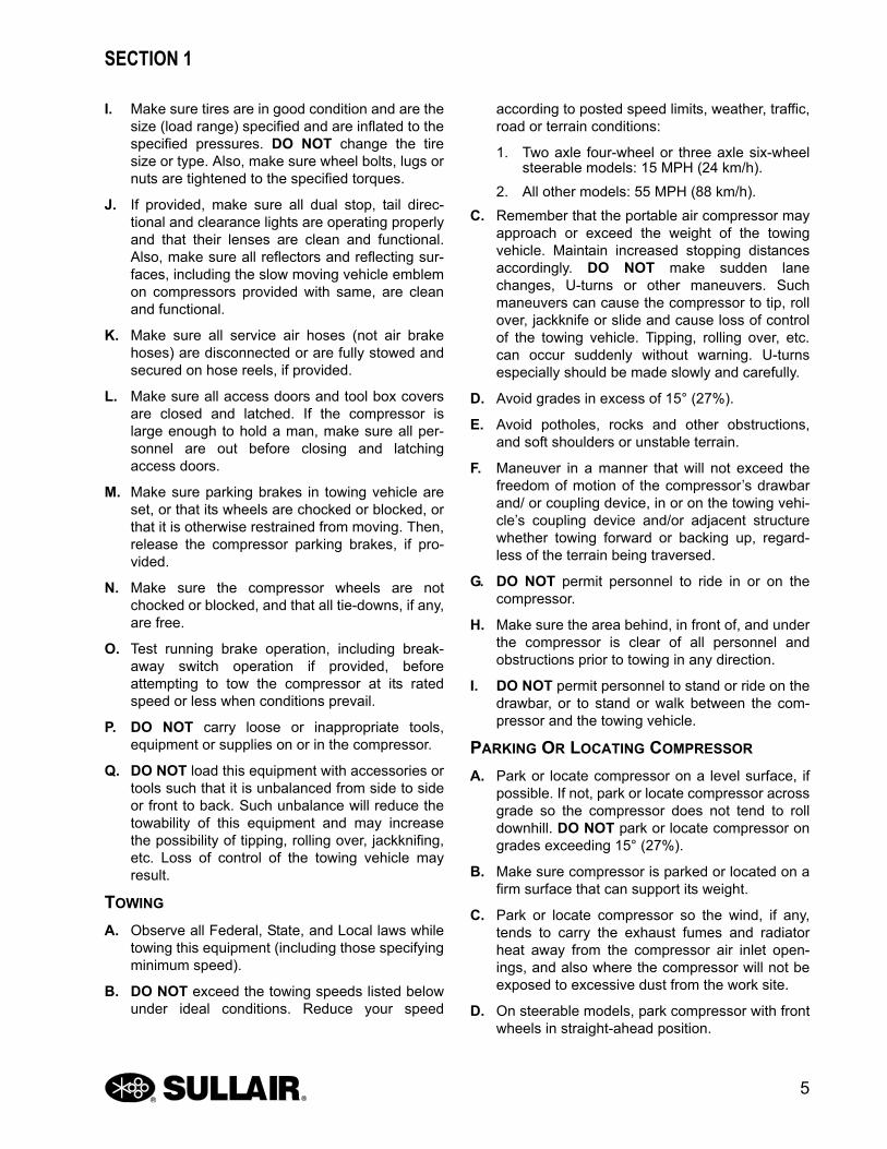
I. Make sure tires are in good condition and are thesize (load range) specified and are inflated to thespecified pressures. DO NOT change the tiresize or type. Also, make sure wheel bolts, lugs ornuts are tightened to the specified torques.
J. If provided, make sure all dual stop, tail direc-tional and clearance lights are operating properlyand that their lenses are clean and functional.Also, make sure all reflectors and reflecting sur-faces, including the slow moving vehicle emblemon compressors provided with same, are cleanand functional.
K. Make sure all service air hoses (not air brakehoses) are disconnected or are fully stowed andsecured on hose reels, if provided.
L. Make sure all access doors and tool box coversare closed and latched. If the compressor islarge enough to hold a man, make sure all per-sonnel are out before closing and latchingaccess doors.
M. Make sure parking brakes in towing vehicle areset, or that its wheels are chocked or blocked, orthat it is otherwise restrained from moving. Then,release the compressor parking brakes, if pro-vided.
N. Make sure the compressor wheels are notchocked or blocked, and that all tie-downs, if any,are free.
O. Test running brake operation, including break-away switch operation if provided, beforeattempting to tow the compressor at its ratedspeed or less when conditions prevail.
P. DO NOT carry loose or inappropriate tools,equipment or supplies on or in the compressor.
Q. DO NOT load this equipment with accessories ortools such that it is unbalanced from side to sideor front to back. Such unbalance will reduce thetowability of this equipment and may increasethe possibility of tipping, rolling over, jackknifing,etc. Loss of control of the towing vehicle mayresult.
TOWING
A. Observe all Federal, State, and Local laws whiletowing this equipment (including those specifyingminimum speed).
B. DO NOT exceed the towing speeds listed belowunder ideal conditions. Reduce your speed
according to posted speed limits, weather, traffic,road or terrain conditions:
1. Two axle four-wheel or three axle six-wheelsteerable models: 15 MPH (24 km/h).
2. All other models: 55 MPH (88 km/h).
C. Remember that the portable air compressor mayapproach or exceed the weight of the towingvehicle. Maintain increased stopping distancesaccordingly. DO NOT make sudden lanechanges, U-turns or other maneuvers. Suchmaneuvers can cause the compressor to tip, rollover, jackknife or slide and cause loss of controlof the towing vehicle. Tipping, rolling over, etc.can occur suddenly without warning. U-turnsespecially should be made slowly and carefully.
D. Avoid grades in excess of 15° (27%).
E. Avoid potholes, rocks and other obstructions,and soft shoulders or unstable terrain.
F. Maneuver in a manner that will not exceed thefreedom of motion of the compressor’s drawbarand/ or coupling device, in or on the towing vehi-cle’s coupling device and/or adjacent structurewhether towing forward or backing up, regard-less of the terrain being traversed.
G. DO NOT permit personnel to ride in or on thecompressor.
H. Make sure the area behind, in front of, and underthe compressor is clear of all personnel andobstructions prior to towing in any direction.
I. DO NOT permit personnel to stand or ride on thedrawbar, or to stand or walk between the com-pressor and the towing vehicle.
PARKING OR LOCATING COMPRESSOR
A. Park or locate compressor on a level surface, ifpossible. If not, park or locate compressor acrossgrade so the compressor does not tend to rolldownhill. DO NOT park or locate compressor ongrades exceeding 15° (27%).
B. Make sure compressor is parked or located on afirm surface that can support its weight.
C. Park or locate compressor so the wind, if any,tends to carry the exhaust fumes and radiatorheat away from the compressor air inlet open-ings, and also where the compressor will not beexposed to excessive dust from the work site.
D. On steerable models, park compressor with frontwheels in straight-ahead position.

SECTION 1
6
E. Set parking brakes and disconnect breakawayswitch cable and all other interconnecting electri-cal and/or brake connections, if provided.
F. Block or chock both sides of all wheels.
G. If provided, unhook chains and remove themfrom the points of chain attachment on the towingvehicle, then hook chains to bail on drawbar orwrap chains around the drawbar and hook themto themselves to keep chains off the groundwhich might accelerate rusting.
H. Lower front screw jack and/or any front and rearstabilizer legs. Make sure the surface they con-tact has sufficient load bearing capability to sup-port the weight of the compressor.
I. If a caster wheel is provided on the screw jack, itis part of the screw jack and cannot be removed.Follow the same procedure for stowing away the
wheeled jack as you would for the standard screwjack. Raise the screw jack to its full upright posi-tion and pull the pin connecting the jack to thedrawbar. Rotate the screw jack to its stowed posi-tion, parallel to the drawbar and reinsert the pin.Make sure the jack is secured in place prior totowing.
J. Disconnect coupling device, keeping hands andfingers clear of all pinch points. If the compressoris provided with a drawbar, DO NOT attempt to liftthe drawbar or if hinged, to raise it to the uprightposition by hand, if the weight is more than youcan safely handle. Use a screwjack or chain fall ifyou cannot lift or raise the drawbar without avoid-ing injury to yourself or others.
K. Move the towing vehicle well clear of the parkedcompressor and erect hazard indicators, barri-cades and/or flares (if at night) if compressor isparked on or adjacent to public roads. Park so asnot to interfere with traffic.
1.3 PRESSURE RELEASE
A. Open the pressure relief valve at least weekly tomake sure it is not blocked, closed, obstructed orotherwise disabled.
B. Install an appropriate flow-limiting valve betweenthe compressor service air outlet and the shutoff(throttle) valve, when an air hose exceeding 1/2"(13 mm) inside diameter is to be connected to theshutoff (throttle) valve, to reduce pressure in caseof hose failure, per OSHA Standard 29 CFR1926.302 (b) (7) or any applicable Federal, Stateand Local codes, standards and regulations.
C. When the hose is to be used to supply a manifold,install an additional appropriate flow-limiting valvebetween the manifold and each air hose exceed-ing 1/2" (13 mm) inside diameter that is to be con-nected to the manifold to reduce pressure in caseof hose failure.
D. Provide an appropriate flow-limiting valve for eachadditional 75 feet (23 m) of hose in runs of airhose exceeding 1/2" (13 mm) inside diameter toreduce pressure in case of hose failure.
WARNINGThis equipment may be tongue heavy. DO NOT attempt to raise or lower the drawbar by hand if the weight is more than you can safely handle.
CAUTIONRetract the front screw jack only after attaching the compressor to the tow vehi-cle. Raise the screw jack to its full up posi-tion and pull the pin connecting the jack to the drawbar. Rotate the screw jack to its stowed position, parallel to the drawbar, and reinsert the pin. Make sure the jack is secured in place prior to towing.
On two-wheeled models, fully retract front screw jack and any rear stabilizer legs. If a caster wheel is provided on the screw jack it is part of the screw jack and can not be removed. Follow the same procedure for stowing away the wheeled jack as you would for the standard screw jack. Pull the pin connecting the jack to the drawbar and raise the screw jack to its full up position. Rotate the screw jack to its stowed posi-tion, parallel to the drawbar, and reinsert the pin. Make sure the jack is secured in place prior to towing.
NOTEWhile not towed in the usual sense of the word, many of these instructions are directly applicable to skidmounted porta-ble air compressors as well.

SECTION 1
7
E. Flow-limiting valves are listed by pipe size andrated CFM. Select appropriate valve accordingly.
F. DO NOT use tools that are rated below the maxi-mum rating of this compressor. Select tools, airhoses, pipes, valves, filters and other fittingsaccordingly. DO NOT exceed manufacturer’srated safe operating pressures for these items.
G. Secure all hose connections by wire, chain orother suitable retaining device to prevent tools orhose ends from being accidentally disconnectedand expelled.
H. Open fluid filler cap only when compressor is notrunning and is not pressurized. Shut down thecompressor and bleed the sump (receiver) tozero internal pressure before removing the cap.
I. Vent all internal pressure prior to opening anyline, fitting, hose, valve, drain plug, connection orother component, such as filters and line oilers,and before attempting to refill optional air lineanti-icer systems with antifreeze compound.
J. Keep personnel out of line with and away fromthe discharge opening of hoses, tools or otherpoints of compressed air discharge.
K. DO NOT use air at pressures higher than 30 psig(2.1 bar) for cleaning purposes, and then onlywith effective chip guarding and personal protec-tive equipment per OSHA Standard 29 CFR1910.242 (b) or any applicable Federal, Stateand Local codes, standards and regulations.
L. DO NOT engage in horseplay with air hoses asdeath or serious injury may result.
M. This equipment is supplied with an ASMEdesigned pressure vessel protected by an ASMErated relief valve. Lift the handle once a week tomake sure the valve is functional. DO NOT liftthe handle while machine is under pressure.
N. If the machine is installed in an enclosed area itis necessary to vent the relief valve to the outsideof the structure or to an area of non-exposure.
O. DO NOT remove radiator filler cap until the cool-ant temperature is below its boiling point. Thenloosen cap slowly to its stop to relieve anyexcess pressure and make sure coolant is notboiling before removing cap completely. Removeradiator filler cap only when cool enough to touchwith a bare hand.
P. The ethyl ether in the replaceable cylinders usedin diesel ether starting aid systems (optional) is
under pressure. DO NOT puncture or incineratethose cylinders. DO NOT attempt to remove thecenter valve core or side pressure relief valvefrom these cylinders regardless of whether theyare full or empty.
Q. If a manual blowdown valve is provided on thereceiver, open the valve to ensure all internalpressure has been vented prior to servicing anypressurized component of the compressor air/fluid system.
1.4 FIRE AND EXPLOSION
A. Refuel at a service station or from a fuel tankdesigned for its intended purpose. If this is notpossible, ground the compressor to the dis-penser prior to refueling.
B. Clean up spills of fuel, fluid, battery electrolyte orcoolant immediately if such spills occur.
C. Shut off air compressor and allow it to cool. Thenkeep sparks, flames and other sources of ignitionaway and DO NOT permit smoking in the vicinitywhen adding fuel, checking or adding electrolyteto batteries, checking or adding fluid, checkingdiesel engine ether starting aid systems, replac-ing cylinders, or when refilling air line anti-icersystems antifreeze compound.
D. DO NOT permit liquids, including air line anti-icersystem antifreeze compound or fluid film, toaccumulate on bottom covers or on, under oraround acoustical material, or on any external orinternal surfaces of the air compressor. Wipedown using an aqueous industrial cleaner orsteam clean as required. If necessary, removeacoustical material, clean all surfaces and thenreplace acoustical material. Any acoustical mate-rial with a protective covering that has been tornor punctured should be replaced immediately toprevent accumulation of liquids or fluid film withinthe material. DO NOT use flammable solventsfor cleaning purposes.
WARNINGDo not attempt to operate the compressor in any classification of hazardous environ-ment or potentially explosive atmosphere unless the compressor has been specially designed and manufactured for that duty.

SECTION 1
8
E. Disconnect the grounded (negative) battery con-nection prior to attempting any repairs or clean-ing inside the enclosure. Tag the batteryconnections so others will not unexpectedlyreconnect it.
F. Keep electrical wiring, including the battery ter-minals and other terminals, in good condition.Replace any wiring that has cracked, cutabraded or otherwise degraded insulation or ter-minals that are worn, discolored or corroded.Keep all terminals clean and tight.
G. Turn off battery charger before making or break-ing connections to the battery.
H. Keep grounded conductive objects such as toolsaway from exposed live electrical parts such asterminals to avoid arcing which might serve as asource of ignition.
I. Replace damaged fuel tanks or lines immediatelyrather than attempt to weld or otherwise repairthem. DO NOT store or attempt to operate thecompressor with any known leaks in the fuel sys-tem. Tag the compressor and render it inopera-tive until repair can be made.
J. Remove any acoustical material or other materialthat may be damaged by heat or that may sup-port combustion prior to attempting weld repairs.Remove diesel engine ether starting aid cylin-ders and air line anti-icer system componentscontaining antifreeze compound, prior toattempting weld repairs in any place other thanthe fuel system. DO NOT weld on or near thefuel system.
K. Keep a suitable, fully charged class BC or ABCfire extinguisher or extinguishers nearby whenservicing and operating the compressor.
L. Keep oily rags, trash, leaves, litter or other com-bustibles out of and away from the compressor.
M. Open all access doors and allow the enclosure toventilate thoroughly prior to attempting to startthe engine.
N. DO NOT operate compressor under low over-hanging leaves or permit such leaves to contacthot exhaust system surfaces when operating thecompressor in forested areas.
O. Ethyl ether used in diesel engine ether startingaid systems is extremely flammable. Change cyl-inders, or maintain or troubleshoot these sys-tems only in well-ventilated areas away from
heat, open flame or sparks. DO NOT install,store or otherwise expose ether cylinders to tem-peratures above 160 °F (71 °C). Remove ethercylinder from the compressor when operating inambient temperatures above 60 °F (16 °C).
P. DO NOT attempt to use ether as a starting aid ingasoline engines or diesel engines with glowplugs as serious personnel injury or propertydamage may result.
Q. DO NOT spray ether into compressor air filter orinto an air filter that serves both the engine andthe compressor as serious damage to the com-pressor or personal injury may result.
R. Antifreeze compound used in air line anti-icersystems contains methanol which is flammable.Use systems and refill with compound only inwell-ventilated areas away from heat, openflames or sparks. DO NOT expose any part ofthese systems or the antifreeze compound totemperatures above 150 °F (66 °C). Vapors fromthe antifreeze compound are heavier than air.DO NOT store compound or discharge treatedair in confined or unventilated areas. DO NOTstore containers of antifreeze compound in directsunlight.
S. Store flammable fluids and materials away fromyour work area. Know where fire extinguishersare and how to use them, and for what type offire they are intended. Check readiness of firesuppression systems and detectors if soequipped.
1.5 MOVING PARTS
A. Keep hands, arms and other parts of the bodyand also clothing away from belts, pulleys andother moving parts.
B. DO NOT attempt to operate the compressor withthe fan or other guards removed.
C. Wear snug-fitting clothing and confine long hairwhen working around this compressor, especiallywhen exposed to hot or moving parts inside theenclosure.
D. Keep access doors closed except when makingrepairs or adjustments, performing service orwhen starting or stopping the compressor.
E. Make sure all personnel are out of the way andclear of the compressor prior to attempting tostart or operate it.

SECTION 1
9
F. Shut off engine before adding fuel, fluid, coolantlubricants, air line antifreeze compound or bat-tery electrolyte, or before replacing ether startingaid cylinders.
G. Disconnect the grounded negative battery con-nection to prevent accidental engine operationprior to attempting repairs or adjustments. Tagthe battery connection so others will not unex-pectedly reconnect it.
H. When adjusting the controls, it may require oper-ation of the equipment during adjustment. DONOT come in contact with any moving partswhile adjusting the control regulator and settingthe engine RPM. Make all other adjustments withthe engine shut off. When necessary, makeadjustment, other than setting control regulatorand engine RPM, with the engine shut off. If nec-essary, start the engine and check adjustment. Ifadjustment is incorrect, shut engine off, readjust,then restart the engine to recheck adjustment.
I. Keep hands, feet, floors, controls and walkingsurfaces clean and free of fluid, water, antifreezeor other liquids to minimize possibility of slips andfalls.
1.6 HOT SURFACES, SHARP EDGES AND SHARP CORNERS
A. Avoid bodily contact with hot fluid, hot coolant,hot surfaces and sharp edges and corners.
B. Keep all parts of the body away from all points ofair discharge and away from hot exhaust gases.
C. Wear personal protective equipment includinggloves and head covering when working in, on oraround the compressor.
D. Keep a first aid kit handy. Seek medical assis-tance promptly in case of injury. DO NOT ignoresmall cuts and burns as they may lead to infec-tion.
1.7 TOXIC AND IRRITATING SUBSTANCES
A. DO NOT use air from this compressor for respi-ration (breathing) except in full compliance withOSHA Standards 29 CFR 1920 and any otherFederal, State or Local codes or regulations.
B. DO NOT use air line anti-icer systems in air linessupplying respirators or other breathing air utili-zation equipment and DO NOT discharge airfrom these systems into unventilated or otherconfined areas.
C. Operate the compressor only in open or well-ventilated areas.
D. If the compressor is operated indoors, dischargeengine exhaust fumes outdoors.
E. Locate the compressor so that exhaust fumesare not apt to be carried towards personnel, airintakes servicing personnel areas or towards theair intake of any portable or stationary compres-sor.
F. Fuels, fluids, coolants, lubricants and batteryelectrolyte used in the compressor are typical ofthe industry. Care should be taken to avoid acci-dental ingestions and/or skin contact. In theevent of ingestion, seek medical treatmentpromptly. DO NOT induce vomiting if fuel isingested. Wash with soap and water in the eventof skin contact.
G. Wear an acid-resistant apron and a face shield orgoggles when servicing the battery. If electrolyte
DANGER
INHALATION HAZARD!
Death or serious injury can result from inhaling compressed air without using proper safety equipment. See OSHA stan-dards and/or any applicable Federal, State, and Local codes, standards and regulations on safety equipment.

SECTION 1
10
is spilled on skin or clothing, immediately flushwith large quantities of water.
H. Ethyl ether used in diesel engine ether startingaid systems is toxic, harmful or fatal if swallowed.Avoid contact with the skin or eyes and avoidbreathing the fumes. If swallowed, DO NOTinduce vomiting and call a physician immediately.
I. Wear goggles or a full face shield when testingether starting aid systems or when adding anti-freeze compound to air line anti-icer systems.Keep openings of valve or atomizer tube of etherstarting aid system pointed away from yourselfand other personnel.
J. If ethyl ether or air line anti-icer system anti-freeze compound enters the eyes or if fumes irri-tate the eyes, they should be washed with largequantities of clean water for 15 minutes. A physi-cian, preferably any eye specialist, should becontacted immediately.
K. DO NOT store ether cylinders or air line anti-icersystem antifreeze compound in operator’s cabsor in other similar confined areas.
L. The antifreeze compound used in air line anti-icer systems contains methanol and is toxic,harmful or fatal if swallowed. Avoid contact withthe skin or eyes and avoid breathing the fumes. Ifswallowed, induce vomiting by administering atablespoon of salt in a glass of clean warm water.Do this until vomit is clear, then administer twotablespoons of baking soda in a glass of cleanwater. Have patient lay down and cover eyes toexclude light. Call a physician immediately.
1.8 ELECTRICAL SHOCK
A. Keep the towing vehicle or equipment carrier,compressor hoses, tools and all personnel atleast 10 feet (3 m) from power lines and buriedcables.
B. Keep all parts of the body and any hand-heldtools or other conductive objects away fromexposed live parts of electrical system. Maintaindry footing, stand on insulating surfaces and DONOT contact any other portion of the compressorwhen making adjustments or repairs to exposedlive parts of the electrical system.
C. Attempt repairs only in clean, dry and well-lightedand ventilated areas.
D. Stay clear of the compressor during electricalstorms! It can attract lightning.
1.9 LIFTING
A. If the compressor is provided with a lifting bail,then lift by the bail provided. If no bail is provided,then lift by sling. Compressors to be air lifted byhelicopter must not be supported by the liftingbail, but by slings instead. In any event, lift only infull compliance with OSHA Standards 29 CFR1910 subpart N or any other Local, State, Militaryand Federal regulations that may apply.
B. Inspect lifting bail and points of attachment forcracked welds and for cracked, bent, corroded orotherwise degraded members and for loose boltsor nuts prior to lifting.
C. Make sure entire lifting, rigging and supportingstructure has been inspected, is in good condi-tion and has a rated capacity of at least the netweight of the compressor plus an additional 10%allowance for weight of water, snow, ice, mud,stored tools, and equipment. If your are unsureof the weight, then weigh compressor before lift-ing.
D. Make sure lifting hook has a functional safetylatch or equivalent, and is fully engaged andlatched on the bail.
E. Use guide ropes or equivalent to prevent twistingor swinging of the compressor once it has beenlifted clear of the ground.
F. DO NOT attempt to lift in high winds.
G. Keep all personnel out from under and awayfrom the compressor whenever it is suspended.
H. Lift compressor no higher than necessary.
I. Keep lift operator in constant attendance when-ever compressor is suspended.
J. Set compressor down only on a level surfacecapable of supporting at least its net weight plusan additional 10% allowance for the weight ofwater, snow, ice, mud, stored tools, and/or equip-ment.
K. If the compressor is provided with parkingbrakes, make sure they are set, and in anyevent, block or chock both sides of all runningwheels before disengaging the lifting hook.

SECTION 1
11
1.10 ENTRAPMENT
A. Make sure all personnel are out of compressorbefore closing and engaging enclosure doors.
B. If the compressor is large enough to hold a manand if it is necessary to enter it to perform serviceadjustments, inform other personnel beforedoing so, or else secure the access door in theopen position to avoid the possibility of othersclosing and possibly latching the door with per-sonnel inside.
1.11 JUMP STARTING
A. Observe all safety precautions mentioned else-where in this manual.
B. Batteries may contain hydrogen gas which isflammable and explosive. Keep flames, sparksand other sources of ignition away.
C. Batteries contain acid which is corrosive and poi-sonous. DO NOT allow battery acid to contacteyes, skin, fabrics or painted surfaces as seriouspersonal injury or property damage could result.Flush any contacted areas thoroughly with waterimmediately. Always wear an acid-resistantapron and face shield when attempting to jumpstart the compressor.
D. Remove all vent caps (if so equipped) from thebattery or batteries in the compressor. DO NOTpermit dirt or foreign matter to enter the opencells.
E. Check fluid level. If low, bring fluid to proper levelbefore attempting to jump start (not applicable tomaintenance-free batteries).
F. DO NOT attempt to jump start if fluid is frozen orslushy. Bring batteries up to at least 60 °F (16°C) before attempting to jump start or it mayexplode.
G. Cover open cells of all compressor batteries withclean dampened cloths before attempting tojump start.
H. Attempt to jump start only with a vehicle having anegative ground electrical system with the samevoltage, and is also equipped with a battery orbatteries of comparable size or larger than sup-plied in the compressor. DO NOT attempt tojump start using motor generator sets, welders orother sources of DC power as serious damagemay result.
I. Bring the starting vehicle alongside the compres-sor, but DO NOT permit metal to metal contactbetween the compressor and the starting vehicle.
J. Set the parking brakes of both the compressor (ifprovided) and the starting vehicle or otherwiseblock both sides of all wheels.
K. Place the starting vehicle in neutral or park, turnoff all non-essential accessory electrical loadsand start its engine.
L. Use only jumper cables that are clean, in goodcondition and are heavy enough to handle thestarting current.
M. Avoid accidental contact between jumper cableterminal clips or clamps and any metallic portionof either the compressor or the starting vehicle tominimize the possibility of uncontrolled arcingwhich might serve as a source of ignition.
N. Positive battery terminals are usually identifiedby a plus (+) sign on the terminal and the lettersPOS adjacent to the terminal. Negative batteryterminals are usually identified by the lettersNEG adjacent to the terminal or a negative (-)sign.
O. Connect one end of a jumper cable to the posi-tive (POS) (+) battery terminal in the startingvehicle. When jump starting 24V compressorsand if the starting vehicle is provided with two (2)12V batteries connected in series, connect thejumper cable to the positive (POS) (+) terminal ofthe ungrounded battery.
P. Connect the other end of the same jumper cableto the positive (POS) (+) terminal of the startermotor battery in the compressor when jump start-ing 24V compressors, to the positive (POS) (+)terminal of the ungrounded battery in the com-pressor.
Q. Connect one end of the other jumper cable to thegrounded negative (NEG) (-) terminal of the bat-tery in the starting vehicle. When jump starting24V compressors and if the starting vehicle isprovided with two (2) 12V batteries connected inseries, connect the jumper cable to the negative(NEG) (-) terminal of the grounded battery.
R. Check your connections. DO NOT attempt tostart a 24V compressor with one 12V battery inthe starting vehicle. DO NOT apply 24V to one12V battery in the compressor.
S. Connect the other end of this same jumper cableto a clean portion of the compressor engine

SECTION 1
12
block away from fuel lines, the crank casebreather opening and the battery.
T. Start the compressor in accordance with normalprocedure. Avoid prolonged cranking.
U. Allow the compressor to warm up. When thecompressor is warm and operating smoothly atnormal idle RPM, disconnect the jumper cablefrom the engine block in the compressor, thendisconnect the other end of this same cable fromthe grounded negative (NEG) (-) terminal of thebattery in the starting vehicle. Then disconnectthe other jumper cable from the positive (POS)(+) terminal of the battery in the compressor, or ifprovided with two (2) 12V batteries connected inseries, from the ungrounded battery in the com-pressor, and finally, disconnect the other end ofthis same jumper cable from the positive (POS)(+) terminal of the battery in the starting vehicleor from the positive (POS) (+) terminal of theungrounded battery in the starting vehicle, if it isprovided with two (2) 12V batteries connected inseries.
V. Remove and carefully dispose of the dampenedcloths, as they may now be contaminated withacid, then replace all vent caps.
1.12 IMPLEMENTATION OF LOCKOUT/TAGOUT
The energy control procedure defines actionsnecessary to lockout a power source of any machineto be repaired, serviced or set-up, where unexpectedmotion, or an electrical or other energy source, wouldcause personal injury or equipment damage. Thepower source on any machine shall be locked out byeach employee doing the work except when motionis necessary during setup, adjustment or trouble-shooting.
A. The established procedures for the application ofenergy control shall cover the following elementsand actions and shall be initiated only by Autho-rized Persons and done in the followingsequence:
1. Review the equipment or machine to belocked and tagged out.
2. Alert operator and supervisor of whichmachine is to be worked on, and that powerand utilities will be turned off.
3. Check to make certain no one is operatingthe machine before turning off the power.
4. Turn off the equipment using normalshutdown procedure.
5. Disconnect the energy sources:
a. Air and hydraulic lines should be bled,drained and cleaned out. There shouldbe no pressure in these lines or in thereservoir tanks. Lockout or tag lines orvalves.
b. Any mechanism under tension or pres-sure, such as springs, should bereleased and locked out or tagged.
c. Block any load or machine part prior toworking under it.
d. Electrical circuits should be checked withcalibrated electrical testing equipmentand stored energy and electrical capaci-tors should be safely discharged.
6. Lockout and/or Tagout each energy sourceusing the proper energy isolating devicesand tags. Place lockout hasp and padlock ortag at the point of power disconnect wherelockout is required by each personperforming work. Each person shall beprovided with their own padlock and havepossession of the only key. If more than oneperson is working on a machine each personshall affix personal lock and tag using amulti-lock device.
7. Tagout devices shall be used only whenpower sources are not capable of beinglocked out by use of padlocks and lockouthasp devices. The name of the personaffixing tag to power source must be on tagalong with date tag was placed on powersource.
8. Release stored energy and bring theequipment to a “zero mechanical state”.
9. Verify Isolation: Before work is started, testequipment to ensure power is disconnected.
B. General Security
1. The lock shall be removed by the“Authorized” person who put the lock on theenergy-isolating device. No one other thanthe person/persons placing padlocks andlockout hasps on power shall removepadlock and lockout hasps and restorepower. However, when the authorizedperson who applied the lock is unavailable toremove it his/her Supervisor may removepadlock/padlocks and lockout hasps andrestore power only if it is first:
SECTION 1
13
a. verified that no person will be exposed todanger.
b. verified that the “Authorized” person whoapplied the device is not in the facility.
c. noted that all reasonable efforts to con-tact the “Authorized” person have beenmade to inform him or her that the lock-out or tagout device has been removed.
d. ensured that the “Authorized” person isnotified of lock removal before returningto work.
2. Tagout System—Tags are warning devicesaffixed at points of power disconnect and arenot to be removed by anyone other that theperson placing tag on power lockout. Tagsshall never be by-passed, ignored, orotherwise defeated
1.13 CALIFORNIA PROPOSITION 65
WARNINGCALIFORNIA PROPOSITION 65 WARNING
Diesel engine exhaust and some of its con-stituents are known to the State of Califor-nia to cause cancer, birth defects and other reproductive harm.
Battery posts, terminals and related acces-sories contain lead and other compounds known to the State of California to cause cancer and birth defects and other repro-ductive harm. Wash hands after handling.

SECTION 1
14
1.14 SYMBOLS AND REFERENCES
The symbols below may or may not be used. Pleaserefer to the decals set forth on the machine forapplicable symbols.
Safety Symbols-1 T4
DIESEL PARTICULATE FILTER
REGENERATION INHIBIT
HIGH EXHAUST SYS. TEMP
WAIT TO START
REMOTE START
CABIN LIGHTS
/ iT4
/ iT4
/ iT4

SECTION 1
15
Safety Symbols-2

SECTION 1
16
Safety Symbols-3
Section 2
300HH, 375, 375H, 375HH, 425 AND 425H USER MANUAL R00
17
DESCRIPTION2.1 INTRODUCTION
The Sullair 300HH, 375, 375H, 375HH, 425, and425H CFM Standard and Aftercooled Portable AirCompressors offer superior performance, reliabilityand require a minimal amount of maintenance.Compared to other compressors, Sullair’s are uniquein terms of reliability and durability. Compressorinternal components require no routine maintenanceinspections.
2.2 DESCRIPTION OF COMPONENTS
Figure 2-1 shows the main components andsubassemblies of the Sullair 300HH, 375, 375H,375HH, 425, and 425H Standard and AftercooledPortable Air Compressors. These packages includea heavy duty rotary screw air compressor, adiesel engine, fuel tank, compressor inletsystem, compressor cooling and lubricationsystem, compressor discharge system, capacitycontrol system, instrument panel and electricalsystem. A low profile canopy offers improvedhandling and mobility. Large side service doorsprovide easy access to all serviceable components.

300HH, 375, 375H, 375HH, 425 AND 425H USER MANUAL R00 SECTION 2
18
SU_0000673
1. Radiator/Fluid Cooler Assembly
2. Radiator/Fluid Cooler Assembly WithAir To Air Aftercooler
3. Lifting Bail
4. Engine Air Filter
5. Compressor Air Filter
6. Fuel Tank
7. Battery Shutoff Switch
8. Service Valves
9. Serial Number Plate Location
10. Receiver Tank
11. Minimum Pressure/Check Valve
12. Engine Exhaust Muffler
13. Moisture Separator
14. Optional Discharge Air Filters
Figure 2-1: Sullair Rotary Screw Portable Air Compressor— John Deere Standard and Aftercooled Models
SECTION 2 300HH, 375, 375H, 375HH, 425 AND 425H USER MANUAL R00
19
The control system can easily be adjusted forpressures from 80 to 125 psig (5.6 to 8.6 bar) forstandard machines, from 80 to 150 psig (5.6 to 10.3bar) for “H” machines and from 80 psig to 200 psig(5.6 to 13.8 bar) for “HH” machines. The compressorunit is driven by an industrial diesel engine designedto provide enough horsepower to provide anadequate reserve under rated conditions.
Refer to the Engine Operator’s Manual for a moredetailed description of the engine. The enginecooling system is comprised of a radiator, charge aircooler, high capacity fan, and thermostat. The highcapacity fan pushes air through the radiator tomaintain the engine’s specified operatingtemperature. The same fan also cools the fluid in thecompressor cooling and lubrication system.
The engine radiator, charge air cooler, and thecompressor fluid cooler are next to each otherallowing the fan air to push through all threesimultaneously. As air passes through the fluidcooler, the heat of compression is removed from thefluid. The compressor’s high capacity fuel tankcontains enough fuel for one eight hour shift undernormal operating conditions.
2.3 SULLAIR COMPRESSOR UNIT, FUNCTIONAL DESCRIPTION
Sullair compressors are single-stage, positivedisplacement, flood lubricated-type compressors thatprovide continuous (pulse-free) compression to meetvarious demand loads. Sullair compressors requireno routine maintenance or inspection of their internalparts or systems. The compressor works by injectingfluid into the compressor unit where it mixes directlywith the air as the rotors turn: the rotor’s rotationcompresses the air. The fluid flow has three mainfunctions:
1. It acts as a coolant, to control the rise of airtemperature which is generated by compres-sion (heat of compression).
2. Seals the leakage paths between the rotorsand the stator and also between the rotorsthemselves.
3. Lubricates the rotors allowing one rotor todirectly drive the other.
After the air fluid mixture is discharged from thecompressor unit, the fluid is separated from the air.At this time, the air flows to the service line and thefluid is cooled in preparation for re-injection.
2.4 COMPRESSOR COOLING AND LUBRICATION SYSTEM, FUNCTIONAL DESCRIPTION
Refer to Figure 2-2. The compressor cooling andlubrication system is designed to provide adequatelubrication as well as maintain the proper operatingtemperature of the compressor. In addition to thefluid cooler and interconnecting piping, the systemconsists also of three other components: a fluid filter,thermal valve, and a fan which perform the followingfunctions:
• The fluid filter removes and collects any contami-nants in the fluid.
• The thermal valve functions as a temperature regu-lator directing fluid either to the cooler or to thecompressor unit.
• The fan pushes air through the cooler dissipatingthe heat resulting from compression of the fluid.
The functions of the lubrication system are explainedin more detail below. Fluid is used in the system as acoolant and as a lubricant: the sump serves as thefluid reservoir. At start-up, fluid flows from the sumpto the fluid thermal valve. Fluid circulation is achievedby forcing the fluid from the high pressure region ofthe sump to a lower pressure area in the compressorunit. A minimum pressure device (See CompressorDischarge System, Functional Description on page20) is provided to assure adequate fluid flow underall conditions. When entering the thermal valve uponstart-up, the fluid temperature is cool and thus it isnot necessary to route it through the cooler. The fluidflows through the fluid filter and on to the compressorunit bypassing the cooler. As the compressorcontinues to operate, the temperature of the fluidrises and the thermostatic control opens, allowing aportion of the fluid into the cooler.
When the temperature reaches 155°F (68°C), thethermostat is fully open allowing all fluid entering thethermal valve to flow to the cooler.
The cooler is a radiator type that works in concertwith the engine fan. The fan pushes air through thecooler removing the heat from the fluid. From thecooler, the fluid is then routed back through the fluidfilter. All fluid flowing to the compressor unit passesthrough this filter. The fluid leaving the filter flows tothe compressor unit where it lubricates, seals andcools the compression chamber; and lubricates thebearings and gears.

300HH, 375, 375H, 375HH, 425 AND 425H USER MANUAL R00 SECTION 2
20
1. Fluid Cooler
2. Engine
3. Compressor
4. Thermal Valve
5. Fluid Filter
6. Receiver Tank
Figure 2-2: Compressor Cooling andLubrication System
2.5 COMPRESSOR DISCHARGE SYSTEM, FUNCTIONAL DESCRIPTION
Refer to Figure 2-3. The Sullair compressor unitdischarges a compressed air/fluid mixture into thereceiver tank. The receiver tank has three functions:
1. It acts as a primary fluid separator.
2. Serves as the compressor fluid reservoir.
3. Houses the air/fluid separator.
The compressed air/fluid mixture enters the receivertank and is directed against the side of the sump.Because of a change of direction and reduction ofvelocity, large droplets of fluid separate and fall to thebottom of the sump. The small amount of fluidremaining in the compressed air collects on thesurface of the separator element as the compressedair flows through the separator. As more fluid collectson the element surface, it then flows to the bottom ofthe separator. A return line (or scavenge tube) leadsfrom the bottom of the separator element to the inletregion of the compressor unit. Fluid collecting on thebottom of the separator element is returned to the
compressor by the pressure difference between thearea surrounding the separator element and thecompressor inlet. An orifice (protected by a strainer)is included in this return line to assure proper andunobstructed flow. The receiver tank is code rated at250 psig (17.1 bar) working pressure. A minimumpressure device located downstream from theseparator, ensures a minimum receiver pressure of80 psig (5.5 bar) during all conditions. Keeping thispressure level stable is necessary for proper air/fluidseparation and proper fluid circulation. A pressurerelief valve (located on the wet side of the separator)is set to open if the sump pressure exceeds 250 psig(17.1 bar).
Fluid is added to the receiver tank through a cappedfluid filler.
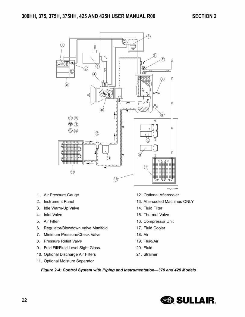
2.6 CAPACITY CONTROL SYSTEM, FUNCTIONAL DESCRIPTION
Refer to Figure 2-4, Figure 2-5 or Figure 2-6. Thepurpose of the control system is to regulate theamount of air intake and match it to the demand(required output) on the compressor. The controlsystem consists of a pressure regulating valve(s), airinlet valve, system blowdown valve, pressuretransducer, speed control module, and tubingconnecting the various components of thecompressor and engine. The functional descriptionsof the control system are described by relating themto four distinct phases of operation. They apply toany control system with the exception of those withspecified pressures which are dependent onpressure requirements. The given values apply to acompressor with an operating pressure range of 100to 110 psig (6.9 to 7.6 bar).
START—0 TO 40 PSIG (0 TO 2.8 BAR)
When the compressor is started, the sump pressurequickly rises from 0 to 40 psig (0 to 2.8 bar). Duringthis period the pressure regulator valve is inactive. Atthis pressure range the idle warm-up control keeps
32
1
4
5 6
SU_0000664
WARNINGDO NOT remove caps, plugs and/or other components when the ocmpressor is run-ning or pressurized. Stop the compressor and relieve all internal pressure before removing these items.

SECTION 2 300HH, 375, 375H, 375HH, 425 AND 425H USER MANUAL R00
21
the inlet valve closed for engine idle operation. Within30 seconds of starting the compressor (theinstrument panel annunciator light goes off after 30seconds) turn the handle of the warm-up selectorvalve (located on the instrument panel) from the
START to the RUN position. The inlet valve is fullyopen due to inlet pressure, and the compressoroperates at full capacity. When the compressoroperates at full capacity, the engine runs at fullspeed.
STANDARD MODEL
AFTERCOOLED MODEL
1
2 3
4
5
6
7
8
9
10
11
12
SU_0000665
13
14
1. Engine
2. Strainer
3. Minimum Pressure/Check Valve
4. Service Air Outlet
5. Receiver Tank
6. Separator Element
7. Non-Aftercooled/Aftercooled Service AirValve
8. Service Air Outlet
9. Receiver Tank
10. Optional Discharge Air Filters
11. Moisture Separator
12. Aftercooler
13. Air
14. Fluid/Air
Figure 2-3: Compressor Discharge System—Standard and Aftercooled Models
300HH, 375, 375H, 375HH, 425 AND 425H USER MANUAL R00 SECTION 2
22
����������
�
�
�
�
�
�
��
��
�
��
�
��
��
��
�
��
�
�
1. Air Pressure Gauge
2. Instrument Panel
3. Idle Warm-Up Valve
4. Inlet Valve
5. Air Filter
6. Regulator/Blowdown Valve Manifold
7. Minimum Pressure/Check Valve
8. Pressure Relief Valve
9. Fuid Fill/Fluid Level Sight Glass
10. Optional Discharge Air Filters
11. Optional Moisture Separator
12. Optional Aftercooler
13. Aftercooled Machines ONLY
14. Fluid Filter
15. Thermal Valve
16. Compressor Unit
17. Fluid Cooler
18. Air
19. Fluid/Air
20. Fluid
21. Strainer
Figure 2-4: Control System with Piping and Instrumentation—375 and 425 Models

SECTION 2 300HH, 375, 375H, 375HH, 425 AND 425H USER MANUAL R00
23
����������
�
��
�
�
��
�
��
���
���
�
�
��
��
�
��
�
�
1. Air Pressure Gauge
2. Idle Warm-Up Control Selector Valve
3. Low Pressure Regulator Valve
4. High Pressure Regulator/BlowdownValve Manifold
5. Instrument Panel
6. High/Low Pressure Selector Switch
7. Air Filter
8. Orifice
9. Silencer
10. Inlet Valve
11. Strainer
12. Minimum Pressure/Check Valve
13. Pressure Relief Valve
14. Compressor Unit
15. Fluid Fill/Fluid Level Sight Glass
16. Optional Discharge Air Filters
17. Optional Moisture Separator
18. Optional Aftercooler
19. Aftercooled Machines ONLY
20. Fluid Filter
21. Thermal Valve
22. Fluid Cooler
23. Air
24. Fluid/Air
25. Fluid
Figure 2-5: Control System with Piping and Instrumentation—300HH, 375H, 375HH and 425H Models

300HH, 375, 375H, 375HH, 425 AND 425H USER MANUAL R00 SECTION 2
24
Figure 2-6: Piping and Instrumentation

SECTION 2 300HH, 375, 375H, 375HH, 425 AND 425H USER MANUAL R00
25
1. Filter, Air
2. Gauge, Filter Restriction (Optional)
3. Inlet Valve
4. Compressor
5. Gauge, Temperature
6. Switch, Temperature
8. Valve, Relief
9. Receiver, Air/Oil
10. Glass, Sight Oil Level
11. Indicator, Delta-P
12. Valve, Minimum Pressure/Check
13. Valve, Ball
14. Cooler, Air
15. Separator, Moisture
16. Trap, Drain
17. Orifice
18. Valve, Blowdown N.C.
19. Strainer
21. Valve, Thermal Bypass
22. Cooler, Oil
23. Filter, Oil
27. Gauge, Pressure
28. Valve, Pressure Regulator
29. Valve, 3-Way Selector
31. Valve, Check
32. Transducer, Pressure
T1 Compressor Discharge Temperature Switch

300HH, 375, 375H, 375HH, 425 AND 425H USER MANUAL R00 SECTION 2
26
Figure 2-7: Piping and Instrumentation

SECTION 2 300HH, 375, 375H, 375HH, 425 AND 425H USER MANUAL R00
27
1. Turbocharger, Compressor
2. Cooler, Air
3. Muffler, Engine
4. Fuel Level Sender
5. Rain Cap, Exhaust System
6. Fuel Filter W/ Water Separator
7. Fuel Transfer Pump (Internal To Engine)
8. Hand Operated Fuel Priming Pump
9. Filter, Fuel
10. Gauge, Fuel Level
11. Fuel Tank Cap W/Vent
12. Thermostat, Thermocord (Optional)
13. Kit, Ether Assembly
14. Oil Pump (Integral To Engine)
15. By-Pass Valve (Internal To Engine)
16. Cooler, Oil (Internal To Engine)
17. Filter, Oil
18. Water Pump (Integral To Engine)
19. Radiator, Engine
20. Engine Thermostat (Integral To Engine)
21. Inlet Manifold Air Press Sensor (Turbo Boost)
23. Sensor, Fuel Pressure
24. Sensor, Fuel Temperature
25. Sensor, Coolant Temperature
26. Sensor, Engine Oil Pressure
27. Sensor, Cam Speed Timing
28. Sensor, Crank Speed Timing
29. Jacket Water Heater (Optional)
30. Oil Level (Dipstick)
31. Filter, Air
32. Tank, Fuel
33. Engine Oil Pan
34. Gauge, Filter Restriction
L1 Coolant Level
L2 Fuel Level
L3 Oil Level (Dipstick)
P5 Inlet Manifold Air Pressure
P6 Fuel Pressure
P7 Oil Pressure
T8 Fuel Temperature
T9 Coolant Temperature
S1 Cam Speed
S2 Crank SpeedS2 Crank Speed

300HH, 375, 375H, 375HH, 425 AND 425H USER MANUAL R00 SECTION 2
28
1. Engine Air Filter
2. Compressor Air Filter
3. Air Inlet Valve
4. Compressor
5. Engine
Figure 2-8: Air Inlet System—John Deere
NORMAL OPERATION – 80 TO 100 PSIG (5.6 TO 6.9 BAR) OR 80 TO 150 PSIG (5.6 TO 10.3 BAR) FOR H MACHINES OR 80 TO 200 PSIG (5.6 TO 13.8 BAR) FOR HH MACHINES
When the warm-up control selector valve handle ismoved to the RUN position, the sump pressure risesabove 80 psig (5.6 bar). At this time, the inlet valveremains fully open for maximum air output. Theengine will continue to run at full speed during thisphase of operation.
MODULATION – 100 TO 110 PSIG (6.9 TO 7.5 BAR) OR 150 TO 165 PSIG (10.3 TO 11.4 BAR) FOR H MACHINES OR 200 TO 220 PSIG (13.8 TO 15.2 BAR) FOR HH MACHINES
If the demand on the compressor is less than itsrated capacity, the service line pressure will riseabove 100 psig (6.9 bar) - low or single pressurerating: 150 psig (10.3 bar) for “H” rating or 200 psig(13.8 bar) for “HH” dual or high pressure rating. Thepressure regulating valve gradually opens, applyingpressure to the inlet valve piston and pressuretransducer. This causes the inlet valve to partially
close and reduces the engine speed. As the pressureincreases, the inlet valve piston will further close theinlet valve and the engine speed will decrease until itreaches its preset idle speed. When the demand onthe compressor increases, the sump pressure fallsbelow 110 psig (7.6 bar) or 165 psig (11.4 bar) for “H”machines, or 220 psig (15.2 bar) for “HH” ones. Thepressure regulating valve closes, the air inlet valveopens fully, and the engine speed increases to itspreset full load rating.
Between the pressure regulating valve and the inletvalve, there is a small orifice that vents a smallamount of air into the atmosphere when the pressureregulating valve is open. This allows changes in airoutput to conform to air demand. This orifice alsodischarges any accumulated moisture from theregulator.Shutdown
The blowdown valve is normally closed. At shutdownthe back pressure in the compressor inlet signals theblowdown valve to vent the sump pressure into theatmosphere.
2.7 AIR INLET SYSTEM, FUNCTIONAL DESCRIPTION
Refer to Figure 2-8. The air inlet system consists oftwo air filters, a compressor air inlet valve andinterconnecting piping to the engine and thecompressor.
The air filters are three-stage dry element type filtersthat are capable of cleaning extremely dirty air.However, when operating in dirty environments, thefilters should be checked more frequently.
See Air Filter Maintenance on page 64 for Air FilterMaintenance Procedures.
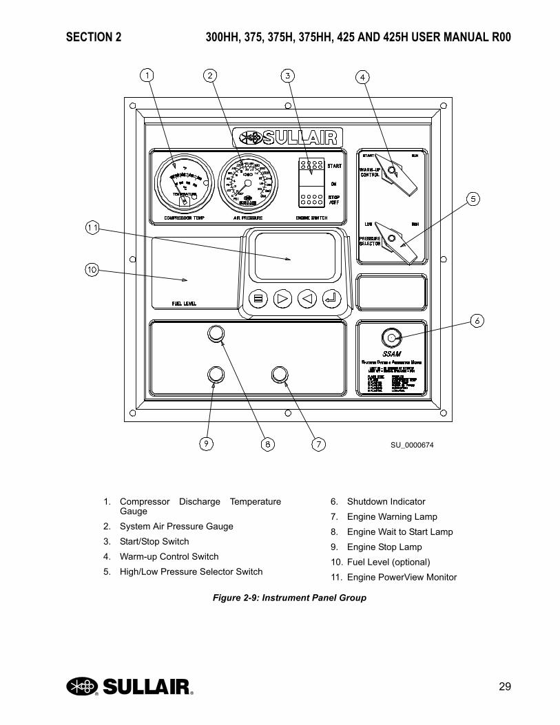
2.8 INSTRUMENT PANEL GROUP, FUNCTIONAL DESCRIPTION
Refer to Figure 2-9. The instrument panel groupconsists of a molded panel containing an: airpressure gauge, compressor temperature gauge,ignition/start switch, PowerView, annunciator light,idle warm-up control, engine shutdown light, enginewarning light, and a wait to start light. A high-lowpressure selector valve is located on the panel for“H” and “HH” compressors.
1
2
3
4
5
SU_0000668
SECTION 2 300HH, 375, 375H, 375HH, 425 AND 425H USER MANUAL R00
29
SU_0000674
1. Compressor Discharge TemperatureGauge
2. System Air Pressure Gauge
3. Start/Stop Switch
4. Warm-up Control Switch
5. High/Low Pressure Selector Switch
6. Shutdown Indicator
7. Engine Warning Lamp
8. Engine Wait to Start Lamp
9. Engine Stop Lamp
10. Fuel Level (optional)
11. Engine PowerView Monitor
Figure 2-9: Instrument Panel Group

300HH, 375, 375H, 375HH, 425 AND 425H USER MANUAL R00 SECTION 2
30
Refer to Figure 2-9 for the locations of the followingindicators and controls:
1. The compressor discharge temperaturegauge monitors the temperature of the air/oil mixture in the sump.
2. The air pressure gauge continuously moni-tors the sump pressure under various loadconditions.
3. The engine switch energizes the systemand starts the compressor. The engineswitch is pressed to the ON position to ener-gize the electrical system, and pressedmomentarily to the START position toengage the starter and start the compres-sor.
4. The idle warm-up control is turned fromSTART to RUN after sufficient warm-up isachieved for full compressor operation.
5. The pressure selector valve on “H” com-pressors allows the selection of the com-pressor operating pressure range, 80 to 110psig (5.6 to 7.6 bar) or 80 to 165 psig (5.6 to11.4 bar) for “H” models, or 80 to 220 psig(5.6 to 15.2 bar) for “HH” models.
6. The shutdown indicator light indicatesengine and compressor safety shutdownstatus.
7. The engine warning lamp indicates when anabnormal condition exists. It is not neces-sary to shutdown the engine immediately,but the problem should be corrected assoon as possible.
8. The engine wait to start lamp is illuminatedwhen conditions are not right for starting.
9. The engine stop lamp signals when theengine should be stopped immediately or assoon as possible to prevent engine dam-age. Correct the problem before restarting.
10. The fuel level gauge indicates the fluid levelin the fuel tank.
11. The PowerView® is a multifunction tool thatallows operators to view a wide range ofengine parameters and engine servicecodes.

SECTION 2 300HH, 375, 375H, 375HH, 425 AND 425H USER MANUAL R00
31
USING THE OPTIONAL DIAGNOSTIC GAUGE TO ACCESS ENGINE INFORMATION
Refer to Figure 2-10. The diagnostic gauge (Figure2-10, [1]) displays engine function and trouble codes(DTCs). The display can be set for either English ormetric units. It is linked to the electronic controlsystem sensors and allows the operator to monitorengine functions and troubleshoot malfunctions.Press the menu key (Figure 2-10, [2]) to view variousengine functions in sequence. The following is a listof engine parameters the gauge can display:
• Engine hours
• Engine rpm
• System voltage
• Percent engine load at current rpm
• Coolant temperature
• Oil pressure
• Throttle position
• Intake manifold temperature
• Current fuel consumption
• Active service (diagnostic) codes
• Stored service (diagnostic) codes from the engine
• Set units for display
• View the engine configuration parameters
NOTEEngine parameters that can be displayed depend upon the engine application. Six readout languages are available and can be selected during gauge setup. The diagnos-tic gauge has a graphical backlit Liquid Crystal Display (LCD) screen. The display can show a single parameter or four simul-taneously (in four quadrants). Two arrow keys (Figure 2-10, [3]) scroll through the engine parameter list and menu items. The enter key (Figure 2-10, [4]) selects items. The red (Figure 2-10, [5]) and amber (Figure 2-10, [6]) lights alert the operator to an active trouble code condition.
NOTEWhen viewing engine codes through the PowerView, the SSAM will display a four flash fault code after 30 seconds.
SU_0000687
Figure 2-10: Diagnostic Gauge
1. Diagnostic Gauge
2. Menu Key
3. Arrow Keys
4. Enter Key
5. Red STOP ENGINE Indicator Light
6. Amber WARNING Indicator Light

300HH, 375, 375H, 375HH, 425 AND 425H USER MANUAL R00 SECTION 2
32
1. Turn the switch to the ON position. Begin-ning at the single or four parameter enginedisplay, press the MENU key.
2. The first seven items of the Main Menu willbe displayed.
3. Pressing the arrow keys will scroll throughthe menu selections.
4. Pressing the right arrow key will scroll downto reveal the last items of the Main Menuscreen, highlighting the next item down.
5. Use the arrow keys to scroll to the desiredmenu item or press the Menu Button to exitthe Main Menu and return to the engineparameter display.
NOTEWhen viewing engine codes through the PowerView, the SSAM will display a four flash fault code after 30 seconds.
NOTEIf the engine is not running, the diagnostic screens can be viewed but they will not show any operating or performance data. Once the engine is started, the screens will display the enegine’s operating information.
1000 RPMENG RPM
57 PSI
1800 RPMENG RPM 57 F
COOL TEMP
12.4 VDC BAT VOLT
OIL PRES
Menu KeyPV101 SU_0000492
COOL TEMP
Figure 2-11
MENU DISPLAYPV101 SU_0000493
GO TO 1-UP DISPLAYEXHAUST FILTERENGINE SPEED CONTROLLANGUAGESSTORED CODESENGINE CONFIGURATIONSETUP 1-UP DISPLAY
Figure 2-12
PV101 SU_0000494
GO TO 1-UP DISPLAYEXHAUST FILTERENGINE SPEED CONTROLLANGUAGESSTORED CODESENGINE CONFIGURATIONSETUP 1-UP DISPLAY
Figure 2-13
PV101 SU_0000495
SETUP 1-UP DISPLAYSETUP 4-UP DISPLAYSELECT UNITSADJUST BACKLIGHTADJUST CONTRASTUTILITIES
Figure 2-14
Use Arrow Buttons to Scroll / Quadrant DisplayPV101 SU_0000496
GO TO 1-UP DISPLAYEXHAUST FILTERENGINE SPEED CONTROLLANGUAGESSTORED CODESENGINE CONFIGURATIONSETUP 1-UP DISPLAY
1000 RPMENG RPM
57 PSI
57 FCOOL TEMP
12.4 VDC BAT VOLT
OIL PRES
Figure 2-15

SECTION 2 300HH, 375, 375H, 375HH, 425 AND 425H USER MANUAL R00
33
ENGINE CONFIGURATION DATA
1. Turn the switch to the ON position. Startingat the single or four engine parameter dis-play, press the Menu key.
2. The Main Menu will be displayed. Use thearrow keys to scroll through the menu untilENGINE CONFIG is highlighted.
3. Once the ENGINE CONFIG menu item hasbeen highlighted, press the Enter key to viewthe engine configuration data.
4. Use the arrow keys to scroll through theengine configuration data.
5. Press the Menu key to return to the MainMenu.
6. Press the Menu key to exit the Main Menuand return to the engine parameter display.
NOTEThe engine configuration data is a read only function.
1800 RPMENG RPM
Menu KeyPV101 SU_0000497
COOL TEMP
1000 RPMENG RPM
57 PSI
57 FCOOL TEMP
12.4 VDC BAT VOLT
OIL PRES
Figure 2-16
SELECT ENGINE CONFIGURATIONPV101 SU_0000498
GO TO 1-UP DISPLAYEXHAUST FILTERENGINE SPEED CONTROLLANGUAGESSTORED CODESENGINE CONFIGURATIONSETUP 1-UP DISPLAY
Figure 2-17
Enter KeyPV101 SU_0000499
GO TO 1-UP DISPLAYEXHAUST FILTERENGINE SPEED CONTROLLANGUAGESSTORED CODESENGINE CONFIGURATIONSETUP 1-UP DISPLAY
Figure 2-18
800 RPM
Use Arrow Keys to ScrollPV101 SU_0000500
ENGINE SPEED PT 1
< NEXT >
Figure 2-19
800 RPM
Return to Main MenuPV101 SU_0000501
ENGINE SPEED PT 1
< NEXT >
Figure 2-20
Exit Main MenuPV101 SU_0000502
1000 RPMENG RPM
57 PSI
1800 RPMENG RPM 57 F
COOL TEMP
12.4 VDC BAT VOLT
OIL PRES
COOL TEMP
Figure 2-21
300HH, 375, 375H, 375HH, 425 AND 425H USER MANUAL R00 SECTION 2
34
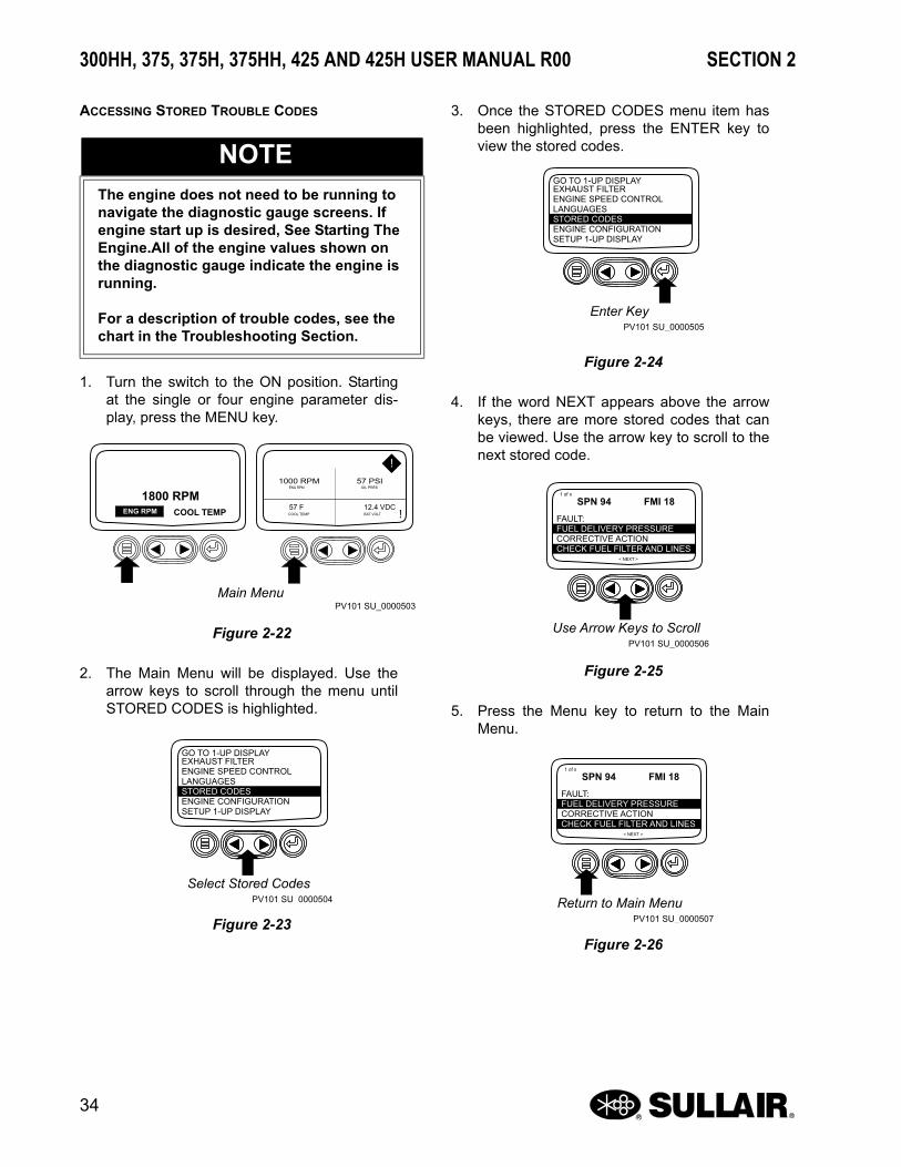
ACCESSING STORED TROUBLE CODES
1. Turn the switch to the ON position. Startingat the single or four engine parameter dis-play, press the MENU key.
2. The Main Menu will be displayed. Use thearrow keys to scroll through the menu untilSTORED CODES is highlighted.
3. Once the STORED CODES menu item hasbeen highlighted, press the ENTER key toview the stored codes.
4. If the word NEXT appears above the arrowkeys, there are more stored codes that canbe viewed. Use the arrow key to scroll to thenext stored code.
5. Press the Menu key to return to the MainMenu.
NOTEThe engine does not need to be running to navigate the diagnostic gauge screens. If engine start up is desired, See Starting The Engine.All of the engine values shown on the diagnostic gauge indicate the engine is running.
For a description of trouble codes, see the chart in the Troubleshooting Section.
1800 RPMENG RPM
Main MenuPV101 SU_0000503
COOL TEMP
1000 RPMENG RPM
57 PSI
57 FCOOL TEMP
12.4 VDC BAT VOLT
OIL PRES
Figure 2-22
PV101 SU_0000504
Select Stored Codes
GO TO 1-UP DISPLAYEXHAUST FILTERENGINE SPEED CONTROLLANGUAGESSTORED CODESENGINE CONFIGURATIONSETUP 1-UP DISPLAY
Figure 2-23
PV101 SU_0000505
Enter Key
GO TO 1-UP DISPLAYEXHAUST FILTERENGINE SPEED CONTROLLANGUAGESSTORED CODESENGINE CONFIGURATIONSETUP 1-UP DISPLAY
Figure 2-24
PV101 SU_0000506
FAULT:FUEL DELIVERY PRESSURECORRECTIVE ACTIONCHECK FUEL FILTER AND LINES
< NEXT >
Use Arrow Keys to Scroll
SPN 94 FMI 181 of x
Figure 2-25
PV101 SU_0000507
FAULT:FUEL DELIVERY PRESSURECORRECTIVE ACTIONCHECK FUEL FILTER AND LINES
< NEXT >
Return to Main Menu
SPN 94 FMI 181 of x
Figure 2-26

SECTION 2 300HH, 375, 375H, 375HH, 425 AND 425H USER MANUAL R00
35
6. Press the Menu key to exit the Main Menuand return the engine parameter display.
ACCESSING ACTIVE TROUBLE CODES
1. During normal operation the single or fourparameter screen will be displayed.
2. When the diagnostic gauge receives a trou-ble code from an engine control unit, the sin-gle or four parameter screen will be replacedwith a WARNING message. The SPN andFMI number will be displayed along with adescription of the problem and the requiredcorrective action.
IMPORTANT: Ignoring active trouble codescan result in severe engine damage.
3. If the word NEXT appears above the arrowkeys, there are more trouble codes that canbe viewed by using the arrow keys to scrollto the next trouble code
IMPORTANT: Ignoring active trouble codescan result in severe engine damage.
4. To acknowledge and hide the code andreturn to the single or four parameter display,press the ENTER key.
NOTEThe engine does not need to be running to navigate the diagnostic gauge screens. If engine start up is desired, See Starting The Engine. All of the engine values shown on the diagnostic gauge indicate the engine is running.
For a description of trouble codes, see the chart in the Troubleshooting Section.
Exit Main MenuPV101 SU_0000697
1000 RPMENG RPM
57 PSI
1800 RPMENG RPM 57 F
COOL TEMP
12.4 VDC BAT VOLT
OIL PRES
COOL TEMP
Figure 2-27
Normal OperationPV101 SU_0000508
1000 RPMENG RPM
57 PSI
1800 RPMENG RPM 57 F
COOL TEMP
12.4 VDC BAT VOLT
OIL PRES
COOL TEMP
Figure 2-28
PV101 SU_0000509
FAULT:FUEL DELIVERY PRESSURECORRECTIVE ACTIONCHECK FUEL FILTER AND LINES
< NEXT >
Active Trouble Codes Displayed
SPN 94 FMI 181 of x
Figure 2-29
PV101 SU_0000510
FAULT:FUEL DELIVERY PRESSURECORRECTIVE ACTIONCHECK FUEL FILTER AND LINES
< NEXT >
Use Arrow Keys to Scroll
SPN 94 FMI 181 of x
Figure 2-30

300HH, 375, 375H, 375HH, 425 AND 425H USER MANUAL R00 SECTION 2
36
IMPORTANT: Ignoring active trouble codescan result in severe engine damage.
5. The display will return to the single or fourparameter display, but the display will con-tain the warning icon. Pressing the ENTERkey will redisplay the hidden trouble code.
6. Pressing the ENTER key once again willhide the trouble code and return the screento the single or four parameter display.
7. The single or four parameter screen will dis-play the warning icon until the trouble codecondition is corrected.
ENGINE SHUTDOWN CODES
1. During normal operation the single or fourparameter screen will be displayed.
2. When the diagnostic gauge receives asevere trouble code from the engine controlunit, the single of four parameter screen willbe replaced with a SHUTDOWN message.The SPN and FMI number will be displayedalong with a description of the problem andthe required corrective action.
If the word NEXT appears above the arrowkeys, there are more trouble codes that canbe viewed by using the arrow keys to scrollto the next trouble code.
PV101 SU_0000511
FAULT:FUEL DELIVERY PRESSURECORRECTIVE ACTIONCHECK FUEL FILTER AND LINES
< NEXT >
Hide Trouble Codes
SPN 94WARNING
FMI 181 of x
Figure 2-31
1800 RPMENG RPM
PV101 SU_0000698
COOL TEMP
Active Trouble Code Condition
1000 RPMENG RPM
57 PSI
57 FCOOL TEMP
12.4 VDC BAT VOLT
OIL PRES
Figure 2-32
PV101 SU_0000512
FAULT:FUEL DELIVERY PRESSURECORRECTIVE ACTIONCHECK FUEL FILTER AND LINES
< NEXT >
Enter Key
SPN 94WARNING
FMI 181 of x
Figure 2-33
1800 RPMENG RPM
Active Trouble Code ConditionPV101 SU_0000513
COOL TEMP
1000 RPMENG RPM
57 PSI
57 FCOOL TEMP
12.4 VDC BAT VOLT
OIL PRES
Figure 2-34
PV101 SU_0000514
Normal Operation
1800 RPMENG RPM COOL TEMP
1000 RPMENG RPM
57 PSI
57 FCOOL TEMP
12.4 VDC BAT VOLT
OIL PRES
Figure 2-35

SECTION 2 300HH, 375, 375H, 375HH, 425 AND 425H USER MANUAL R00
37
3. To acknowledge and hide the trouble codeand return to the single or four parameterdisplay, press the ENTER key.
IMPORTANT: Ignoring active troublecodes can result in severe engine dam-age.
4. The display will return to the single or fourparameter display, but the display will con-tain the SHUTDOWN icon. Pressing theENTER key will redisplay the hidden troublecode.
IMPORTANT: Ignoring active troublecodes can result in severe engine dam-age
.
5. Pressing the ENTER key once again willhide the trouble code and return the screento the single or four parameter display.
6. The single or four parameter screen will dis-play the shutdown icon until the trouble codeis corrected
IMPORTANT: Ignoring active troublecodes can result in severe engine dam-age.
PV101 SU_0000515
FAULT:FUEL DELIVERY PRESSURECORRECTIVE ACTIONCHECK FUEL FILTER AND LINES
< NEXT >
Shutdown Message
SPN 100SHUTDOWN
FMI 11 of x
Figure 2-36
PV101 SU_0000516
FAULT:FUEL DELIVERY PRESSURECORRECTIVE ACTIONCHECK FUEL FILTER AND LINES
< NEXT >
Hide Trouble Code
SPN 100SHUTDOWN
FMI 11 of x
Figure 2-37
1800 RPMENG RPM
PV101 SU_0000517
COOL TEMP
Flashing Shutdown Icon
1000 RPMENG RPM
57 PSI
57 FCOOL TEMP
12.4 VDC BAT VOLT
OIL PRES
Figure 2-38
PV101 SU_0000518
FAULT:FUEL DELIVERY PRESSURECORRECTIVE ACTIONCHECK FUEL FILTER AND LINES
< NEXT >
Redisplay Trouble Codes
SPN 100SHUTDOWN
FMI 11 of x
Figure 2-39
PV101 SU_0000677
Shutdown Icon
1800 RPMENG RPM COOL TEMP
1000 RPMENG RPM
57 PSI
57 FCOOL TEMP
12.4 VDC BAT VOLT
OIL PRES
Figure 2-40
300HH, 375, 375H, 375HH, 425 AND 425H USER MANUAL R00 SECTION 2
38
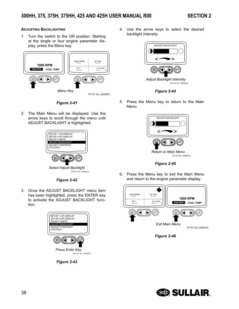
ADJUSTING BACKLIGHTING
1. Turn the switch to the ON position. Startingat the single or four engine parameter dis-play, press the Menu key.
2. The Main Menu will be displayed. Use thearrow keys to scroll through the menu untilADJUST BACKLIGHT is highlighted.
3. Once the ADJUST BACKLIGHT menu itemhas been highlighted, press the ENTER keyto activate the ADJUST BACKLIGHT func-tion.
4. Use the arrow keys to select the desiredbacklight intensity.
5. Press the Menu key to return to the MainMenu.
6. Press the Menu key to exit the Main Menuand return to the engine parameter display.
Menu KeyPV101 SU_0000520
1800 RPMENG RPM COOL TEMP
1000 RPMENG RPM
57 PSI
57 FCOOL TEMP
12.4 VDC BAT VOLT
OIL PRES
Figure 2-41
PV101 SU 0000521
Select Adjust Backlight
ADJUST BACKLIGHT
SETUP 1-UP DISPLAYSETUP 4-UP DISPLAYSELECT UNITS
ADJUST CONTRASTUTILITIES
Figure 2-42
PV101 SU 0000522
Press Enter Key
ADJUST BACKLIGHT
SETUP 1-UP DISPLAYSETUP 4-UP DISPLAYSELECT UNITS
ADJUST CONTRASTUTILITIES
Figure 2-43
PV101 SU 0000523
ADJUST BACKLIGHT
Adjust Backlight Intensity
< >
Figure 2-44
PV101 SU 0000524
ADJUST BACKLIGHT
Return to Main Menu
< >
Figure 2-45
Exit Main MenuPV101 SU_0000519
1800 RPMENG RPM COOL TEMP
1000 RPMENG RPM
57 PSI
57 FCOOL TEMP
12.4 VDC BAT VOLT
OIL PRES
Figure 2-46

SECTION 2 300HH, 375, 375H, 375HH, 425 AND 425H USER MANUAL R00
39
ADJUSTING CONTRAST
1. Turn the switch to the ON position. Startingat the single or four engine parameter dis-play, press the Menu key.
2. The Main Menu will be displayed. Use thearrow keys to scroll through the menu untilADJUST CONTRAST is highlighted.
3. Once the ADJUST CONTRAST menu itemhas been highlighted, press the ENTER keyto activate the ADJUST CONTRAST func-tion.
4. Use the arrow keys to select the desired con-trast intensity.
5. Press the Menu key to return to the MainMenu.
6. Press the Menu key to exit the Main Menuand return to the engine parameter display.
Menu KeyPV101 SU_0000525
1000 RPMENG RPM
57 PSI
1800 RPMENG RPM 57 F
COOL TEMP
12.4 VDC BAT VOLT
OIL PRES
COOL TEMP
Figure 2-47
Select Adjust ContrastPV101 SU_0000526
LANGUAGES
GO TO 1-UP DISPLAY
SETUP 1-UP DISPLAY
EXHAUST FILTERENGINE SPEED CONTROL
STORED CODESENGINE CONFIGURATION
Figure 2-48
PV101 SU 0000527
Select Adjust Contrast
ADJUST BACKLIGHT
SETUP 1-UP DISPLAYSETUP 4-UP DISPLAYSELECT UNITS
ADJUST CONTRASTUTILITIES
Figure 2-49
PV101 SU 0000528
ADJUST CONTRAST
Adjust Contrast Intensity
< >
Figure 2-50
PV101 SU 0000529
ADJUST CONTRAST
Return to Main Menu
< >
Figure 2-51
Exit Main MenuPV101 SU_0000530
1000 RPMENG RPM
57 PSI
1800 RPMENG RPM 57 F
COOL TEMP
12.4 VDC BAT VOLT
OIL PRES
COOL TEMP
Figure 2-52
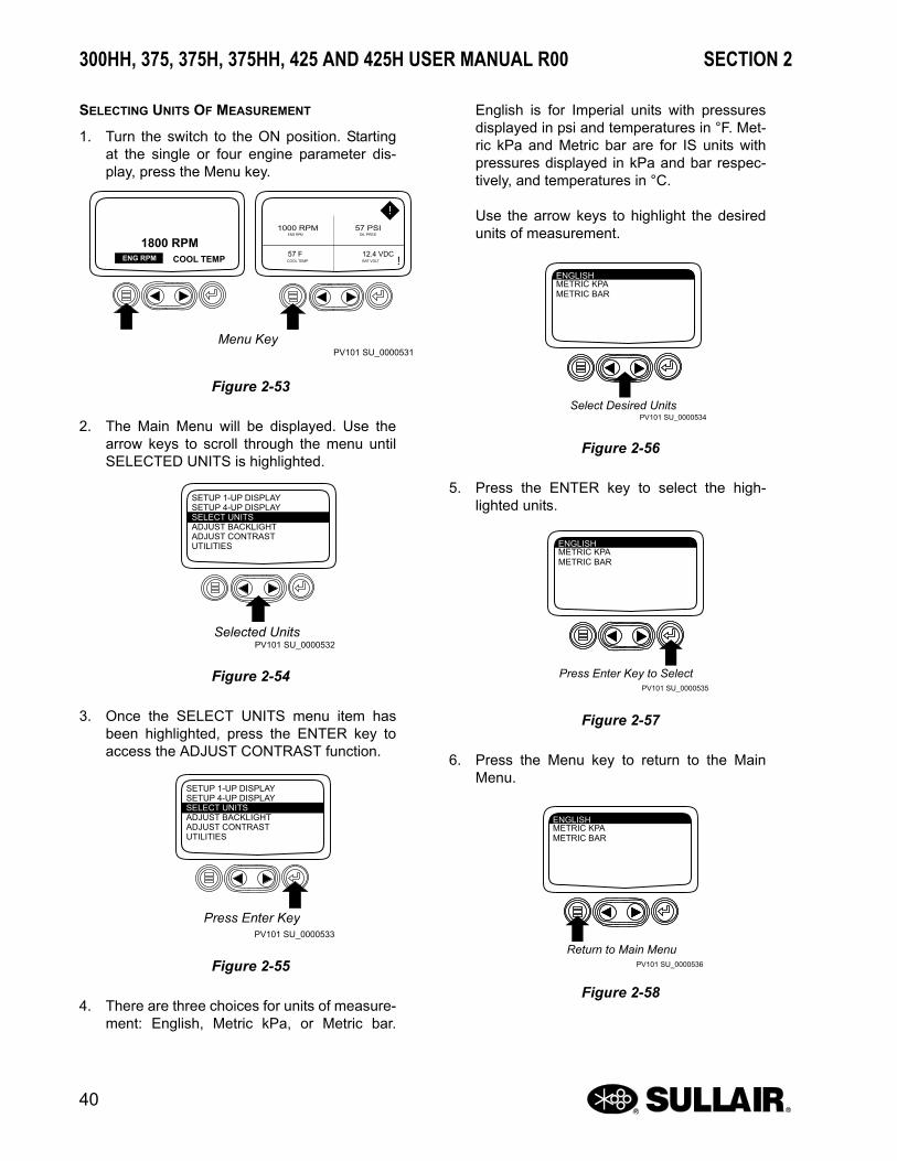
300HH, 375, 375H, 375HH, 425 AND 425H USER MANUAL R00 SECTION 2
40
SELECTING UNITS OF MEASUREMENT
1. Turn the switch to the ON position. Startingat the single or four engine parameter dis-play, press the Menu key.
2. The Main Menu will be displayed. Use thearrow keys to scroll through the menu untilSELECTED UNITS is highlighted.
3. Once the SELECT UNITS menu item hasbeen highlighted, press the ENTER key toaccess the ADJUST CONTRAST function.
4. There are three choices for units of measure-ment: English, Metric kPa, or Metric bar.
English is for Imperial units with pressuresdisplayed in psi and temperatures in °F. Met-ric kPa and Metric bar are for IS units withpressures displayed in kPa and bar respec-tively, and temperatures in °C.
Use the arrow keys to highlight the desiredunits of measurement.
5. Press the ENTER key to select the high-lighted units.
6. Press the Menu key to return to the MainMenu.
Menu KeyPV101 SU_0000531
1000 RPMENG RPM
57 PSI
1800 RPMENG RPM 57 F
COOL TEMP
12.4 VDC BAT VOLT
OIL PRES
COOL TEMP
Figure 2-53
Selected UnitsPV101 SU_0000532
ADJUST BACKLIGHT
SETUP 1-UP DISPLAYSETUP 4-UP DISPLAYSELECT UNITS
ADJUST CONTRASTUTILITIES
Figure 2-54
Press Enter KeyPV101 SU_0000533
ADJUST BACKLIGHT
SETUP 1-UP DISPLAYSETUP 4-UP DISPLAYSELECT UNITS
ADJUST CONTRASTUTILITIES
Figure 2-55
PV101 SU_0000534
ENGLISHMETRIC KPAMETRIC BAR
Select Desired Units
Figure 2-56
PV101 SU_0000535
ENGLISHMETRIC KPAMETRIC BAR
Press Enter Key to Select
Figure 2-57
PV101 SU_0000536
ENGLISHMETRIC KPAMETRIC BAR
Return to Main Menu
Figure 2-58
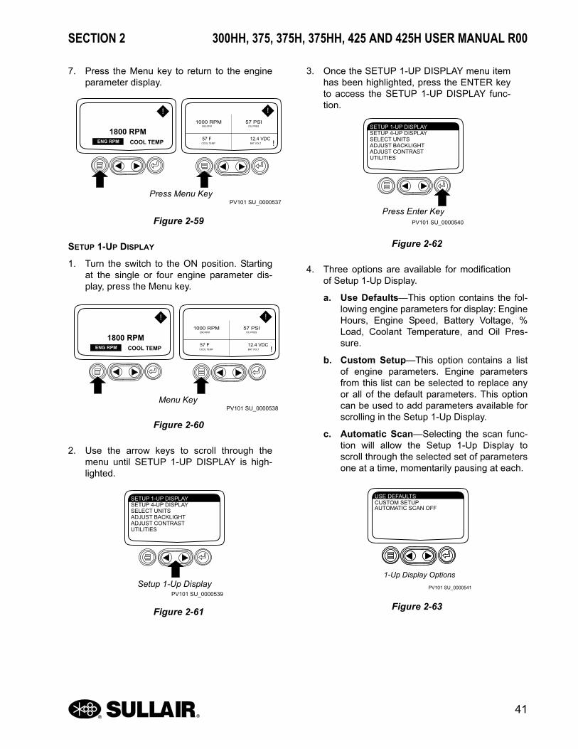
SECTION 2 300HH, 375, 375H, 375HH, 425 AND 425H USER MANUAL R00
41
7. Press the Menu key to return to the engineparameter display.
SETUP 1-UP DISPLAY
1. Turn the switch to the ON position. Startingat the single or four engine parameter dis-play, press the Menu key.
2. Use the arrow keys to scroll through themenu until SETUP 1-UP DISPLAY is high-lighted.
3. Once the SETUP 1-UP DISPLAY menu itemhas been highlighted, press the ENTER keyto access the SETUP 1-UP DISPLAY func-tion.
4. Three options are available for modificationof Setup 1-Up Display.
a. Use Defaults—This option contains the fol-lowing engine parameters for display: EngineHours, Engine Speed, Battery Voltage, %Load, Coolant Temperature, and Oil Pres-sure.
b. Custom Setup—This option contains a listof engine parameters. Engine parametersfrom this list can be selected to replace anyor all of the default parameters. This optioncan be used to add parameters available forscrolling in the Setup 1-Up Display.
c. Automatic Scan—Selecting the scan func-tion will allow the Setup 1-Up Display toscroll through the selected set of parametersone at a time, momentarily pausing at each.
Press Menu KeyPV101 SU_0000537
1800 RPMENG RPM COOL TEMP
1000 RPMENG RPM
57 PSI
57 FCOOL TEMP
12.4 VDC BAT VOLT
OIL PRES
Figure 2-59
Menu KeyPV101 SU_0000538
1800 RPMENG RPM COOL TEMP
1000 RPMENG RPM
57 PSI
57 FCOOL TEMP
12.4 VDC BAT VOLT
OIL PRES
Figure 2-60
Setup 1-Up DisplayPV101 SU_0000539
SETUP 1-UP DISPLAYSETUP 4-UP DISPLAYSELECT UNITSADJUST BACKLIGHTADJUST CONTRASTUTILITIES
Figure 2-61
Press Enter KeyPV101 SU_0000540
SETUP 1-UP DISPLAYSETUP 4-UP DISPLAYSELECT UNITSADJUST BACKLIGHTADJUST CONTRASTUTILITIES
Figure 2-62
PV101 SU_0000541
USE DEFAULTSCUSTOM SETUPAUTOMATIC SCAN OFF
1-Up Display Options
Figure 2-63

300HH, 375, 375H, 375HH, 425 AND 425H USER MANUAL R00 SECTION 2
42
5. Use Defaults—To select USE DEFAULTSuse the arrow keys to scroll to and highlightUSE DEFAULTS in the menu display.
6. Press the ENTER key to activate the USEDEFAULTS function.
7. The display parameters are reset to the fac-tory defaults, then the display will return tothe SETUP 1- UP DISPLAY menu.
8. Custom Setup – To perform a custom setupof the SETUP 1-UP DISPLAY, use the arrow
buttons to scroll and highlight CUSTOMSETUP on the display.
9. Press the ENTER key to display a list ofengine parameters.
10. Use the arrow keys to scroll and highlight aselected parameter (parameter with a num-ber to the right of it).
11. Press the ENTER key to deselect theselected parameter, removing it from the list
PV101 SU_0000542
USE DEFAULTSCUSTOM SETUPAUTOMATIC SCAN OFF
Select Defaults
Figure 2-64
PV101 SU_0000543
USE DEFAULTSCUSTOM SETUPAUTOMATIC SCAN OFF
Defaults Selected
Figure 2-65
PV101 SU_0000544
RESTORED TODEFAULTS
Restored to Defaults
Figure 2-66
PV101 SU_0000545
USE DEFAULTSCUSTOM SETUPAUTOMATIC SCAN OFF
Selected Custom Setup
Figure 2-67
PV101 SU_0000546
USE DEFAULTSCUSTOM SETUPAUTOMATIC SCAN OFF
Engine Parameters
Figure 2-68
Select ParametersPV101 SU_0000547
ACCELERATOR PEDAL POSITIONPERCENT LOAD AT CURRENT RPMACTUAL ENGINE TORQUEENGINE SPEEDTOTAL ENGINE HOURSTOTAL FUEL USEDENGINE COOLANT TEMPERATUREFUEL TEMPERATUREENGINE OIL PRESSURE
This number indicates the order of display for the parameters and that the parameter is selected for the display.
1
5
16
2
3
Figure 2-69

SECTION 2 300HH, 375, 375H, 375HH, 425 AND 425H USER MANUAL R00
43
of parameters being displayed on theSETUP 1-UP DISPLAY.
12. Use the arrow keys to scroll and highlight thedesired parameter that has not beenselected for display (parameter with a num-ber to the right of it).
13. Press the ENTER key to select the parame-ter for inclusion in the Single Engine Param-eter Display.
14. Continue to scroll through and select addi-tional parameters for the custom SETUP 1-UP DISPLAY . Press the Menu key at anytime to return to the Custom Setup menu.
15. Automatic Scan—Selecting the scan func-tion will allow the SETUP 1-UP DISPLAY toscroll through the selected set of parametersone at a time. Use the arrow keys to scroll tothe AUTOMATIC SCAN function.
16. Press the ENTER key to toggle the AUTO-MATIC SCAN function on.
17. Press the ENTER key again to toggle theAUTOMATIC SCAN function off.
18. Once the USE DEFAULTS, CUSTOMSETUP and AUTOMATIC SCAN functions
Deselect ParametersPV101 SU_0000548
ACCELERATOR PEDAL POSITIONPERCENT LOAD AT CURRENT RPMACTUAL ENGINE TORQUEENGINE SPEEDTOTAL ENGINE HOURSTOTAL FUEL USEDENGINE COOLANT TEMPERATUREFUEL TEMPERATUREENGINE OIL PRESSURE
1
5
16
2
3
Figure 2-70
Select Desired ParametersPV101 SU_0000549
This number now indicates the new order of display for the parameters.
ACCELERATOR PEDAL POSITIONPERCENT LOAD AT CURRENT RPMACTUAL ENGINE TORQUEENGINE SPEEDTOTAL ENGINE HOURSTOTAL FUEL USEDENGINE COOLANT TEMPERATUREFUEL TEMPERATUREENGINE OIL PRESSURE
1
5
16
2
3
Figure 2-71
Select Parameters for DisplayPV101 SU_0000550
ACCELERATOR PEDAL POSITIONPERCENT LOAD AT CURRENT RPMACTUAL ENGINE TORQUEENGINE SPEEDTOTAL ENGINE HOURSTOTAL FUEL USEDENGINE COOLANT TEMPERATUREFUEL TEMPERATUREENGINE OIL PRESSURE
1
5
16
2
3
Figure 2-72
PV101 SU_0000551
USE DEFAULTSCUSTOM SETUPAUTOMATIC SCAN OFF
Automatic Scan Off
Figure 2-73
PV101 SU_0000552
USE DEFAULTSCUSTOM SETUPAUTOMATIC SCAN ON
Automatic Scan On
Figure 2-74
PV101 SU_0000688
USE DEFAULTSCUSTOM SETUPAUTOMATIC SCAN OFF
Automatic Scan Off
Figure 2-75

300HH, 375, 375H, 375HH, 425 AND 425H USER MANUAL R00 SECTION 2
44
have been set, press the Menu key to returnto the Main Menu.
19. Press the Menu key to exit the Main Menuand return to the engine parameter display.
SETUP 4-UP DISPLAY
1. Turn the switch to the ON position. From thesingle or four engine parameter display,press the Menu key.
2. The Main Menu will be displayed. Use thearrow keys to scroll through the menu untilSETUP 4-UP DISPLAY is highlighted.
3. Once the SETUP 4-UP DISPLAY menu itemhas been highlighted, press the ENTER keyto activate the SETUP 4-UP DISPLAY menu.
4. Two options are available for the SETUP 4-UP DISPLAY.
a. Use Defaults—This option contains the fol-lowing engine parameters for display: EngineSpeed, Battery Voltage, Coolant Tempera-ture, and Oil Pressure.
b. Custom Setup—This option contains a listof engine parameters. Engine parameters
PV101 SU_0000553
USE DEFAULTSCUSTOM SETUPAUTOMATIC SCAN ON
Menu Key
Figure 2-76
PV101 SU_0000552
USE DEFAULTSCUSTOM SETUPAUTOMATIC SCAN ON
Automatic Scan On
Figure 2-77
Menu KeyPV101 SU_0000555
1000 RPMENG RPM
57 PSI
0 %LOAD@ RPM 57 F
COOL TEMP
12.4 VDC BAT VOLT
OIL PRES
ENG HRS
Figure 2-78
Menu DisplayPV101 SU_0000556
SETUP 1-UP DISPLAYSETUP 4-UP DISPLAYSELECT UNITSADJUST BACKLIGHTADJUST CONTRASTUTILITIES
Figure 2-79
Press Enter KeyPV101 SU_0000557
SETUP 1-UP DISPLAYSETUP 4-UP DISPLAYSELECT UNITSADJUST BACKLIGHTADJUST CONTRASTUTILITIES
Figure 2-80

SECTION 2 300HH, 375, 375H, 375HH, 425 AND 425H USER MANUAL R00
45
from this list can be selected to replace anyor all of the default parameters.
5. To reset the display parameters to the factorydefaults, scroll to and highlight USEDEFAULTS. Press the ENTER key to acti-vate the USE DEFAULTS function. A mes-sage indicating the display parameters arereset to the factory defaults will be displayed,then the display will return to the SETUP 4-UP DISPLAY menu.
6. Custom Setup – To perform a custom setupof the SETUP 4-UP DISPLAY, use the arrowbuttons to scroll and highlight CUSTOMSETUP on the display.
7. The quadrant with the highlighted parametervalue is the current selected parameter. Usethe arrow keys to highlight the value in thequadrant you wish to change to a newparameter.
8. Press the ENTER key and a list of engineparameters will be displayed.
9. The parameter that is highlighted is theselected parameter for the screen. Use thearrow keys to highlight the new parameter tobe placed in the SETUP 4-UP DISPLAY.
PV101 SU_0000558
USE DEFAULTSCUSTOM SETUP
Select Factory Defaults
Figure 2-81
PV101 SU_0000559
RESTORED TODEFAULTS
Restored to Defaults
Figure 2-82
PV101 SU_0000560
USE DEFAULTSCUSTOM SETUP
Custom Setup
Figure 2-83
Select ParametersPV101 SU_0000561
1000 RPMENG RPM
57 PSI
57 FCOOL TEMP
12.4 VDCBAT VOLT
OIL PRES
Figure 2-84
List of Engine ParametersPV101 SU_0000562
1000 RPMENG RPM
57 PSI
57 FCOOL TEMP
12.4 VDCBAT VOLT
OIL PRES
Figure 2-85
Select Desired Engine ParameterPV101 SU_0000563
Note the number to the right of the selected parameter indicates the quadrant in which it is displayed. 1 = Upper Left Quadrant2 = Lower Left Quadrant3 = Upper Right Quadrant4 = Lower Right Quadrant
ENGINE OIL PRESSUREFUEL RATEINTAKE TEMPERATUREBATTERY POTENTIAL VOLTAGEENGINE DESIRED OP SPEEDMACHINE HOURS
3
4
2
Figure 2-86

300HH, 375, 375H, 375HH, 425 AND 425H USER MANUAL R00 SECTION 2
46
10. Press the ENTER key to change theselected parameter in the quadrant to thenew parameter.
11. Use the Menu key to return to the SETUP 4-UP DISPLAY screen.
12. The selected quadrant has now changed tothe new selected parameter.
13. Repeat the parameter selection process untilall spaces are as desired.
14. Press the Menu key to return to the MainMenu.
15. Press the Menu key to exit the Main Menuand return to the engine parameter display.
Enter Selected ParameterPV101 SU_0000564
ENGINE OIL PRESSURE 3
4
FUEL RATEINTAKE TEMPERATUREBATTERY POTENTIAL VOLTAGEENGINE DESIRED OP SPEEDMACHINE HOURS
Figure 2-87
Return to 4-Up Custom SetupPV101 SU_0000565
Note the number to the right of the selected parameter indicating that the parameter is now assigned to that display location.
ENGINE OIL PRESSURE 3
4
FUEL RATEINTAKE TEMPERATUREBATTERY POTENTIAL VOLTAGEENGINE DESIRED OP SPEEDMACHINE HOURS
Figure 2-88
4-Up DisplayPV101 SU_0000566
1000 RPMENG RPM
57 PSI
57 FCOOL TEMP
0.0 G/HRFUEL RATE
OIL PRES
Figure 2-89
Return to Main MenuPV101 SU_0000567
1000 RPMENG RPM
57 PSI
57 FCOOL TEMP
0.0 G/HR FUEL RATE
OIL PRES
Figure 2-90
Select Remaining ParametersPV101 SU_0000568
SETUP 1-UP DISPLAYSETUP 4-UP DISPLAYSELECT UNITSADJUST BACKLIGHTADJUST CONTRASTUTILITIES
1000 RPMENG RPM
57 PSI
57 FCOOL TEMP
0.0 G/HRFUEL RATE
OIL PRES
Figure 2-91

SECTION 2 300HH, 375, 375H, 375HH, 425 AND 425H USER MANUAL R00
47
2.9 WIRING DIAGRAM

300HH, 375, 375H, 375HH, 425 AND 425H USER MANUAL R00 SECTION 2
48
2.10 ELECTRICAL SYSTEM, FUNCTIONAL DESCRIPTION
The electrical system consists of the basic electricalelements required to operate the compressor andalso has a system feature that automatically shutsdown the compressor when a malfunction occurs.The system’s components include: an engine starter,battery, alternator/ voltage regulator, and a fuelsolenoid. It also has a compressor dischargetemperature switch that will shut the compressordown if the compressor temperature exceeds 250° F(121° C). It has an oil pressure switch that will shutdown the compressor if the engine oil pressure goestoo low. An underspeed sensor shuts down thecompressor if the engine speed falls below 1500 rpmand a low fuel level switch shuts down the enginewhen fuel level is low to prevent running the enginedry (out of fuel). The engine is also equipped with anECM (electronic control module).
2.11 COMPRESSOR SHUTDOWN & WARNING SYSTEM, FUNCTIONAL DESCRIPTION
The Shutdown System and Annunciator Module(SSAM) continuously monitors the status of thecompressor. In the event of a shutdown condition,the SSAM will shut down the compressor and display(flashing) the appropriate code on the instrumentpanel annunciator light. The display will continueflashing until the ignition switch is turned OFF. Theshutdown codes are:
• One flash: high compressor discharge temperature
• Two flashes: high engine coolant temperature
• Three flashes: low engine oil pressure
• Four flashes: low engine speed
• Five flashes: low fuel level
The SSAM also provides startup logic for thecompressor. When the ignition switch is in the ONposition, the annunciator light will illuminate for 30seconds. During this 30 second period, pressing theignition switch will engage the engine starter. The lowengine speed switch is inactive during this startuptime interval. By the end of these 30 seconds, theannunciator light goes out and the engine STARTcycle is disabled. At this time the system runs allsafety checks including low fuel level.
The engine is equipped with an electronic speedcontrol and has a shutdown protection/diagnosticcapability. A variety of sensors and a speed controlmodule interface with the ECM. These sensors
include the following: oil pressure, coolanttemperature, intake manifold, fuel temperature,timing cranking; and a remote shutdown switch. Theengine speed control module consists of the moduleand a pressure transducer. The pressure transducersenses the compressor control pressure and as thecontrol pressure increases, the speed control moduledecreases the engine speed by lowering the outputvoltage to the ECM.
2.12 AFTERCOOLED AND FILTERED AIR SYSTEM, FUNCTIONAL DESCRIPTION
Refer to Figure 2-3. The purpose of the aftercooledsystem is to operate the air compressor in conditionswhen compressed air temperature is required to bewithin 20° to 25°F (13° to 17°C) of the ambienttemperature.
A selector valve is provided on all aftercooledcompressors. Choosing the aftercooled aircompletely forces the airflow from the receiver tankto the aftercooler. The ambient air which is drawnthrough the aftercooler by the engine fan, cools thecompressed air as it passes through the aftercoolercore. Cooled air enters the moisture separator wherecondensation is removed from the cooler air anddischarged. This condensate does carry some oiland it should be disposed of properly inaccordance with local regulations.
From the moisture separator the air enters the(optional) first stage filter. Particles and additionalwater are removed from the first stage filter. Thecondensate should be drained and stored in asuitable container. From the first stage filter, the airenters the (optional) second stage filter. This filterremoves smaller particles and any additional water.The condensate should be drained and stored ina suitable container. Upon compressor shutdown,the filters will drain to clear the condensate from thesystem. This will prevent freezing in cold conditions.
NOTEThe aftercooler system should not be operated when the ambient temperature is below 32°F (0°C). To operate in the non-aftercooled mode close the aftercooler selector valve completely.

SECTION 2 300HH, 375, 375H, 375HH, 425 AND 425H USER MANUAL R00
49
2.13 LISTING OF ENGINE DIAGNOSTIC CODES (DTCS)
Trouble Codes
NOTENot all of these codes are used on all OEM engine applications.Third column below is for Blink Code retrieval method only.
DTCs Listing in Ascending SPN/FMI Codes
SPN FMIBlink Code
Description of Fault Corrective Action
28 3 15 Throttle #3 Signal Out of Range High Check Sensor and Wiring
4 — Throttle #3 Signal Out of Range Low Check Sensor and Wiring
29 3 13 Throttle #2 Signal Out of Range Low Check Sensor and Wiring
4 — Throttle #2 Signal Out of Range Low Check Sensor and Wiring
84 31 — Vehicle Speed Signal Unreliable Contact Servicing Dealer
91 3 11 Throttle #1 Signal Out of Range High Check Switch and Wiring
4 12 Throttle #1 Signal Out of Range Low Check Switch and Wiring
9 — Throttle #1 Communication Signal Erratic Check Sensor and Wiring
94 3 27 Low Pressure Fuel Signal Out of Range High Check Sensor and Wiring
4 28 Low Pressure Fuel Signal Out of Range Low Check Sensor and Wiring
10 88 Low Pressure Fuel Rate of Change Abnormal Contact Servicing Dealer
13 — Low Pressure Fuel Out of Calibration Contact Servicing Dealer
17 85 High Pressure Fuel System—Pressure Slightly Low Contact Servicing Dealer
97 0 — Water in Fuel Continuously Detected Contact Servicing Dealer
3 — Water in Fuel Signal Out of Range High Check Sensor and Wiring
4 — Water in Fuel Signal Out of Range Low Check Sensor and Wiring
16 — Water in Fuel Detected Stop and Drain Water Separator
100 1 75 Engine Oil Pressure Signal Extremely Low Check Oil Level
3 23 Engine Oil Pressure Signal Out of Range High Check Sensor and Wiring
4 24 Engine Oil Pressure Signal Out of Range Low Check Sensor and Wiring
18 74 Engine Oil Pressure Signal Moderately Low Check Oil Level
105 0 — Intake Manifold Air Temp Signal Extremely High Check Air Cleaner, Aftercooler or Room Temp

NOTES
50
3 25 Intake Manifold Air Temp Signal Out of Range High Check Sensor and Wiring
4 26 Intake Manifold Air Temp Signal Out of Range Low Check Sensor and Wiring
16 55 Intake Manifold Air Temp Signal Moderately High Check Air Cleaner, Aftercooler or Room Temp
107 0 — Air Filter Pressure Differential Extremely High Check for Plugged Air Filter
110 0 63 Engine Coolant Temp Extremely High Check Cooling System, Reduce Power
3 18 Engine Coolant Temp Signal Out of Range High Check Sensor and Wiring
4 19 Engine Coolant Temp Signal Out of Range Low Check Sensor and Wiring
15 61 Engine Coolant Temp Signal Slightly High Check Cooling System, Reduce Power
16 62 Engine Coolant Temp Signal Moderately High Check Cooling System, Reduce Power
111 1 64 Engine Coolant Level Low Check Operator’s Manual “Adding Coolant”
158 17 54 ECU Power Down Error (internal ECU problem) Contact Servicing Dealer
160 2 — Axle Speed Unreliable Contact Servicing Dealer
174 0 — Fuel Temp Signal Extremely High Add Fuel or Switch Fuel Tanks
3 37 Fuel Temp Signal Out of Range High Check Sensor and Wiring
4 38 Fuel Temp Signal Out of Range Low Check Sensor and Wiring
16 71 Fuel Temp Signal Moderately High Add Fuel or Switch Fuel Tanks
189 0 — Engine Speed Derate Condition Exists Check Fault Codes/Contact Servicing Dealer
190 0 42 Engine Speed Extremely High Reduce Engine Speed
16 42 Engine Speed Moderately High Reduce Engine Speed
611 3 98 Injector Shorted to Power Check Wiring
4 99 Injector Shorted to Ground Check Wiring
620 3 98 Sensor Supply 2 Voltage High Check Wiring
4 22 Sensor Supply 2 Voltage Low Check Wiring
627 1 97 All Injector Currents Are Low Check Battery Voltage and Wiring
629 13 — ECU Programming Error Contact Service Dealer
636 2 44 Engine Position Sensor Signal Unreliable Check Sensor and Wiring
8 43 Engine Position Sensor Signal Missing Check Sensor and Wiring
10 44 Engine Position Sensor Signal Rate of Change—Abnormal
Check Sensor and Wiring
637 2 39 Engine Timing Sensor Signal Unreliable Check Sensor and Wiring

SECTION 2 300HH, 375, 375H, 375HH, 425 AND 425H USER MANUAL R00
51
637 7 45 Engine Position Sensor Signal Rate of Change—Abnormal
Check Sensor and Wiring
8 41 Engine Timing Sensor Signal Missing Check Sensor Wiring
10 39 Engine Timing Signal Rate of Change—Abnormal Check Sensor and Wiring
639 13 — CAN Bus Error (Communication Network Problem) Contact Servicing Dealer
651 5 31 Injector Number 1 Circuit Has High Resistance Check Injector Wiring or Injector Sole-noid
6 91 Injector Number 1 Circuit Has Low Resistance Check Injector Wiring or Injector Sole-noid
7 65 Injector Number 1 Not Responding Injector Failed or Flow Limiter Closed
652 5 29 Injector Number 2 Circuit Has High Resistance Check Injector Wiring or Injector Sole-noid
6 92 Injector Number 2 Circuit Has Low Resistance Check Injector Wiring or Injector Sole-noid
7 65 Injector Number 2 Not Responding Injector Failed or Flow Limiter Closed
653 5 17 Injector Number 3 Circuit Has High Resistance Check Injector Wiring or Injector Sole-noid
6 93 Injector Number 3 Circuit Has Low Resistance Check Injector Wiring or Injector Sole-noid
7 65 Injector Number 3 Not Responding Injector Failed or Flow Limiter Closed
654 5 34 Injector Number 4 Circuit Has High Resistance Check Injector Wiring or Injector Sole-noid
6 94 Injector Number 4 Circuit Has Low Resistance Check Injector Wiring or Injector Sole-noid
7 59 Injector Number 4 Not Responding Injector Failed or Flow Limiter Closed
655 5 35 Injector Number 5 Circuit Has High Resistance Check Injector Wiring or Injector Sole-noid
6 95 Injector Number 5 Circuit Has Low Resistance Check Injector Wiring or Injector Sole-noid
7 56 Injector Number 5 Not Responding Injector Failed or Flow Limiter Closed
656 5 35 Injector Number 6 Circuit Has High Resistance Check Injector Wiring or Injector Sole-noid
6 96 Injector Number 6 Circuit Has Low Resistance Check Injector Wiring or Injector Sole-noid
7 68 Injector Number 6 Not Responding Injector Failed or Flow limiter Closed
898 9 — Vehicle Speed or Torque Message Unreliable Contact Servicing Dealer
970 31 83 External Shutdown Commanded Not Engine Fault—Check Other Shut-down Devices—SSAM Module
971 31 84 External Fuel Derate Switch Active Not Engine Fault—Check Other Shut-down Devices—SSAM Module

NOTES
52
1069 9 — Tire Size Invalid Contact Servicing Dealer
31 — Tire Size Error Contact Servicing Dealer
1079 3 51 Sensor Supply 1 Voltage High Check Wiring
4 52 Sensor Supply 1 Voltage Low Check Wiring
1080 3 49 Fuel Rail Pressure Sensor Supply Voltage High Check Wiring
4 48 Fuel Rail Pressure Sensor Supply Voltage Low Check Wiring
1109 31 — Engine Protection Shutdown Warning Shutdown Engine/Check Fault Codes
110 31 82 Engine Protection Shutdown Shutdown Engine/Check Fault Codes
1347 3 79 High Pres Fuel Pump Control Valve Signal Out of Range High
Contact Servicing Dealer
5 77 High Pres Fuel Solenoid # 1 Circuit Has High Resis-tance
Check Pump Wiring
7 78 High Pres Fuel Pump Not Able to Meet Required Rail Pres
Check Fuel Filter and Lines
1568 2 — Requested Torque Curve Signal Unreliable Contact Servicing Dealer
1569 31 — Engine in Derate Condition Check Fault Codes
200 13 — Security Violation Contact Servicing Dealer
N/A N/A 32 When reading blink codes, signifies start of active codes
N/A N/A 33 When reading blink codes, signifies start of stored codes
N/A N/A 88 When reading blink codes, signifies that no fault codes are in the buffer

Section 3
300HH, 375, 375H, 375HH, 425 AND 425H USER MANUAL R00
53
SPECIFICATIONS3.1 SPECIFICATIONS—300HH, 375, 375H JOHN DEERE
Table 3-1: Overall Specifications
Model SeriesLength (I) Width Height (II) Weight (wet)
in mm in mm in mm lb kg300HH, 375, 375H
2-Wheel (III)156.2 3967.5 77.2 1960.9 74.0 1879.6 4440* 2014.0*
300HH, 375, 375HLess Running Gear
98.8 2509.5 59.3 1506.2 63.6 1615.4 4195* 1902.9*
(l) Length over drawbar for 2-wheel version, (III) American models. *Add 115 lbs (52 kg) for Aftercooled Version
Table 3-2: Compressor Specifications
Compressor 300HH 375 375HType Rotary Screw Rotary Screw Rotary Screw
Maximum Operating Pressure
200 psig (13.8 bar) 125 psig (8.6 bar) 150 psig (10.3 bar)
Pressure Delivery300 Free CFM(142 L/S)
375 Free CFM(177 L/S)
375 Free CFM(177 L/S)
Rated Pressure 200 psig (13.8 bar) 100 psig (6.9 bar) 150 psig (10.3 bar)
CoolingPressurized Compressor Fluid
Pressurized Compressor Fluid
Pressurized Compressor Fluid
Lubricating Compressor Fluid
See Figure 3.3 See Figure 3.3 See Figure 3.3
Sump Capacity7 US gallons(26.5 liters)
7 US gallons(26.5 liters)
7 US gallons(26.5 liters)
Track Width67.5"(1714.5 mm)
67.5"(1714.5 mm)
67.5"(1714.5 mm)
Tire Size (Load Range) H78 x 15ST (D) H78 x 15ST (D) H78 x 15ST (D)Tire Pressure 65 psig (4.4 bar) 65 psig (4.4 bar) 65 psig (4.4 bar)Wheel Size 15 x 6JJ 15 x 6JJ 15 x 6JJLug Nut Torque 60 ft-lbs (81 Nm) 60 ft-lbs (81 Nm) 60 ft-lbs (81 Nm)Operating Tilt (maximum) 15° 15° 15°Electrical System 12 volt 12 volt 12 voltCompressor Discharge Temperature
Shutdown 250°F (121°C) Shutdown 250°F (121°C) Shutdown 250°F (121°C)
Service Valves (American) (2) 3/4” (2) 3/4” (2) 3/4”Service Valves (CE) (3) 3/4” + (1) 1-1/4” (3) 3/4” + (1) 1-1/4” (3) 3/4” + (1) 1-1/4”Maximum Towing Speed 55 mph (88 kmph) 55 mph (88 kmph) 55 mph (88 kmph)
Axle Rating5000 lbs(2268 kg)
5000 lbs(2268 kg)
5000 lbs(2268 kg)
Sound Level (US EPA)1 76 dBA 76 dBA 76 dBA
Soun dLevel (CE)2 71 dBA 71 dBA1 Sound level measured per U.S. CFR Ch. 1 Part 2042 Sound level measure per 2000/14/EC Outdoor Noise Directive(III) American models.

300HH, 375, 375H, 375HH, 425 AND 425H USER MANUAL R00 SECTION 3
54
Table 3-3: Engine Specifcations
Engine 300HH 375 375HType Diesel Diesel Diesel
Make John Deere John Deere John Deere
Model JD4045HF285 JD4045HF285 JD4045HF285
Displacement 275 cu/in (4.5L) 275 cu/in (4.5L) 275 cu/in (4.5L)
Cylinders 4 4 4
Bore x Stroke4.19 x 5.00(106 mm x 127 mm)
4.19 x 5.00(106 mm x 127 mm)
4.19 x 5.00(106 mm x 127 mm)
Rated Speed 2200 rpm 2200 rpm 2200 rpm
Rated Power 140HP/104kW 140HP/104kW 140HP/104kW
Type of Motor OilSee Engine Operator Manual
See Engine Operator Manual
See Engine Operator Manual
Fuel Tank Capacity56 gallons(212 liters)
56 gallons(212 liters)
56 gallons(212 liters)
Radiator Capacity 4 gallons (15 liters) 4 gallons (15 liters) 4 gallons (15 liters)
Engine Water Temperature Shutdown 230°F (110°C) Shutdown 230°F (110°C) Shutdown 230°F (110°C)
Minimum Idle Speed 1600 rpm (II) 1600 rpm (II) 1600 rpm (II)
Alternator Rating 65 amp 65 amp 65 amp
(II) DO NOT allow engine idle rpm to drop below minimum idle speed. Compressor and/or coupling damage will occur. The compressor is equipped with a Low Speed Shutdown System that will shutdown the compressor if engine speed falls below 1500 rpm.
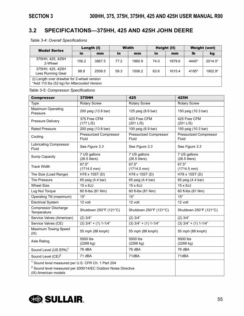
SECTION 3 300HH, 375, 375H, 375HH, 425 AND 425H USER MANUAL R00
55
3.2 SPECIFICATIONS—375HH, 425 AND 425H JOHN DEERE
Table 3-4: Overall Specifications
Model SeriesLength (I) Width Height (II) Weight (wet)
in mm in mm in mm lb kg375HH, 425, 425H
2-Wheel156.2 3967.5 77.2 1960.9 74.0 1879.6 4440* 2014.0*
375HH, 425, 425HLess Running Gear
98.8 2509.5 59.3 1506.2 63.6 1615.4 4195* 1902.9*
(l) Length over drawbar for 2-wheel version *Add 115 lbs (52 kg) for Aftercooled Version
Table 3-5: Compressor Specifications
Compressor 375HH 425 425HType Rotary Screw Rotary Screw Rotary Screw
Maximum Operating Pressure
200 psig (13.8 bar) 125 psig (8.6 bar) 150 psig (10.3 bar)
Pressure Delivery375 Free CFM(177 L/S)
425 Free CFM(201 L/S)
425 Free CFM(201 L/S)
Rated Pressure 200 psig (13.8 bar) 100 psig (6.9 bar) 150 psig (10.3 bar)
CoolingPressurized Compressor Fluid
Pressurized Compressor Fluid
Pressurized Compressor Fluid
Lubricating Compressor Fluid
See Figure 3.3 See Figure 3.3 See Figure 3.3
Sump Capacity7 US gallons(26.5 liters)
7 US gallons(26.5 liters)
7 US gallons(26.5 liters)
Track Width67.5"(1714.5 mm)
67.5"(1714.5 mm)
67.5"(1714.5 mm)
Tire Size (Load Range) H78 x 15ST (D) H78 x 15ST (D) H78 x 15ST (D)
Tire Pressure 65 psig (4.4 bar) 65 psig (4.4 bar) 65 psig (4.4 bar)
Wheel Size 15 x 6JJ 15 x 6JJ 15 x 6JJ
Lug Nut Torque 60 ft-lbs (81 Nm) 60 ft-lbs (81 Nm) 60 ft-lbs (81 Nm)
Operating Tilt (maximum) 15° 15° 15°
Electrical System 12 volt 12 volt 12 volt
Compressor Discharge Temperature
Shutdown 250°F (121°C) Shutdown 250°F (121°C) Shutdown 250°F (121°C)
Service Valves (American) (2) 3/4” (2) 3/4” (2) 3/4”
Service Valves (CE) (3) 3/4” + (1) 1-1/4” (3) 3/4” + (1) 1-1/4” (3) 3/4” + (1) 1-1/4”
Maximum Towing Speed (III)
55 mph (88 kmph) 55 mph (88 kmph) 55 mph (88 kmph)
Axle Rating5000 lbs(2268 kg)
5000 lbs(2268 kg)
5000 lbs(2268 kg)
Sound Level (US EPA)1 76 dBA 76 dBA 76 dBA
Sound Level (CE)2 71 dBA 71dBA 71dBA
1 Sound level measured per U.S. CFR Ch. 1 Part 2042 Sound level measured per 2000/14/EC Outdoor Noise Directive(III) American models
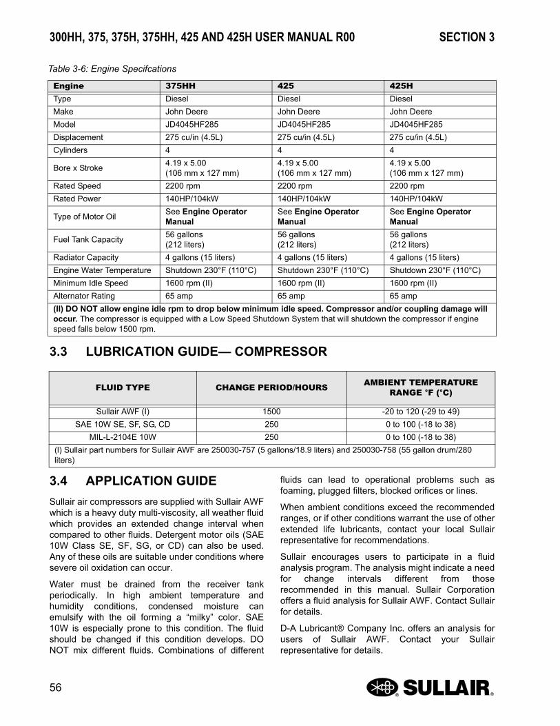
300HH, 375, 375H, 375HH, 425 AND 425H USER MANUAL R00 SECTION 3
56
3.3 LUBRICATION GUIDE— COMPRESSOR
3.4 APPLICATION GUIDE
Sullair air compressors are supplied with Sullair AWFwhich is a heavy duty multi-viscosity, all weather fluidwhich provides an extended change interval whencompared to other fluids. Detergent motor oils (SAE10W Class SE, SF, SG, or CD) can also be used.Any of these oils are suitable under conditions wheresevere oil oxidation can occur.
Water must be drained from the receiver tankperiodically. In high ambient temperature andhumidity conditions, condensed moisture canemulsify with the oil forming a “milky” color. SAE10W is especially prone to this condition. The fluidshould be changed if this condition develops. DONOT mix different fluids. Combinations of different
fluids can lead to operational problems such asfoaming, plugged filters, blocked orifices or lines.
When ambient conditions exceed the recommendedranges, or if other conditions warrant the use of otherextended life lubricants, contact your local Sullairrepresentative for recommendations.
Sullair encourages users to participate in a fluidanalysis program. The analysis might indicate a needfor change intervals different from thoserecommended in this manual. Sullair Corporationoffers a fluid analysis for Sullair AWF. Contact Sullairfor details.
D-A Lubricant® Company Inc. offers an analysis forusers of Sullair AWF. Contact your Sullairrepresentative for details.
Table 3-6: Engine Specifcations
Engine 375HH 425 425HType Diesel Diesel Diesel
Make John Deere John Deere John Deere
Model JD4045HF285 JD4045HF285 JD4045HF285
Displacement 275 cu/in (4.5L) 275 cu/in (4.5L) 275 cu/in (4.5L)
Cylinders 4 4 4
Bore x Stroke4.19 x 5.00(106 mm x 127 mm)
4.19 x 5.00(106 mm x 127 mm)
4.19 x 5.00(106 mm x 127 mm)
Rated Speed 2200 rpm 2200 rpm 2200 rpm
Rated Power 140HP/104kW 140HP/104kW 140HP/104kW
Type of Motor OilSee Engine Operator Manual
See Engine Operator Manual
See Engine Operator Manual
Fuel Tank Capacity56 gallons(212 liters)
56 gallons(212 liters)
56 gallons(212 liters)
Radiator Capacity 4 gallons (15 liters) 4 gallons (15 liters) 4 gallons (15 liters)
Engine Water Temperature Shutdown 230°F (110°C) Shutdown 230°F (110°C) Shutdown 230°F (110°C)
Minimum Idle Speed 1600 rpm (II) 1600 rpm (II) 1600 rpm (II)
Alternator Rating 65 amp 65 amp 65 amp
(II) DO NOT allow engine idle rpm to drop below minimum idle speed. Compressor and/or coupling damage will occur. The compressor is equipped with a Low Speed Shutdown System that will shutdown the compressor if engine speed falls below 1500 rpm.
FLUID TYPE CHANGE PERIOD/HOURS AMBIENT TEMPERATURE RANGE °F (°C)
Sullair AWF (I) 1500 -20 to 120 (-29 to 49)
SAE 10W SE, SF, SG, CD 250 0 to 100 (-18 to 38)
MIL-L-2104E 10W 250 0 to 100 (-18 to 38)
(l) Sullair part numbers for Sullair AWF are 250030-757 (5 gallons/18.9 liters) and 250030-758 (55 gallon drum/280 liters)

SECTION 3 300HH, 375, 375H, 375HH, 425 AND 425H USER MANUAL R00
57
3.5 LUBRICATION GUIDE— ENGINE
Refer to the Engine Operator’s Manual for oil
specifications.
1. Fluid Fill Port
2. Sight Glass
3. Receiver Tank
Figure 3-1
NOTEProper Compressor Fluid Level
Visible halfway in fluid sight glass when checked on a level surface with the com-pressor not running.
SU_0000699

NOTES
58

Section 4
300HH, 375, 375H, 375HH, 425 AND 425H USER MANUAL R00
59
GENERAL4.1 GENERAL
While Sullair has built into this compressor acomplete set of controls and indicators that allow theoperator to control and monitor the compressor’soperation and performance. Operators should learnto recognize indications which identify a servicerequirement or conditions that could lead to (or show)a (current) malfunction. Before starting thecompressor, read this section thoroughly to gainfamiliarity with the controls and indicators—theirfunction and location.
4.2 PURPOSE OF CONTROLS
CONTROL OR INDICATOR PURPOSE
ENGINE SWITCH
Press this switch to the ON (ignition) position toenergize the electrical system of the compressor.Press the switch to the START position tomomentarily engage the starter and start thecompressor. Press the switch to the OFF position toshut the compressor down. This switch is located onthe instrument panel.
EMERGENCY STOP SWITCH
Press in case of emergency when immediateshutdown is required.
PRESSURE TRANSDUCER
Monitors the system control pressure.
SPEED MODULE
Monitors the pressure transducer output anddetermines the appropriate speed signal for theengine.
AIR PRESSURE GAUGE
Continuously monitors the pressure inside thereceiver tank at various load and unload conditions.
FLUID SIGHT LEVEL GLASS
Indicates the fluid level in the receiver tank. Properlevel is marked halfway up the sight glass. Check thelevel when the compressor is shutdown and on levelground.
COMPRESSOR DISCHARGE TEMPERATURE SWITCH
Opens the electrical circuit to shut down thecompressor when the discharge temperaturereaches a specific value (See Specifications on page53 and on page 55).
THERMAL VALVE
Functions as a temperature regulator by directing thecompressor fluid either to the cooler or to thecompressor unit.
MINIMUM PRESSURE DEVICE
Maintains the minimum of 80 psig (5.6 bar) in thecompressor sump.
PRESSURE RELIEF VALVE
Vents sump pressure to the atmosphere if pressureinside the sump exceeds 250 psig (17.3 bar).
AIR INLET VALVE
Regulates the amount of air allowed to enter the aircompressor inlet. Regulation is determined by asignal from the pressure regulator(s).
PRESSURE REGULATOR(S)
Allows the pressure signal to reach the engine speedtransducer and the air inlet valve to control airdelivery according to demand.
DISCHARGE AIR FILTER DIFFERENTIAL PRESSURE GAUGE (OPTIONAL AFTERCOOLED AND FILTERED MODELS ONLY)
Monitors the air filter (first and second stage)condition. A reading over 10 psig (0.7 bar) in the redzone indicates the air filters require servicing.
SHUTDOWN SYSTEM/ANNUNCIATOR MODULE (SSAM)
Monitors the compressor safety system forconditions requiring shutdown. The annunciator onthe instrument control will flash the applicableshutdown code.
BLOWDOWN VALVE
Vents sump pressure to the atmosphere atshutdown.

300HH, 375, 375H, 375HH, 425 AND 425H USER MANUAL R00 SECTION 4
60
IDLE WARM-UP CONTROL
Keeps the compressor inlet valve closed for reducedcompressor load at start-up. When the compressor iswarmed-up, the handle is turned from the START tothe RUN position for full operation.
PRESSURE SELECTOR SWITCH (H AND HH MODELS)
Sets compressor operation in the LOW range from80 to 110 psig (5.6 to 7.6 bar), or in the HIGH rangefrom 80 to 165 psig (5.6 to 11.4 bar) on H models,and from 80 to 220 psig (5.6 to 15.2 bar) on HHmodels.
4.3 INITIAL STARTUP/SHUTDOWN PROCEDURE
STARTUP
Perform the following actions when starting thecompressor for the first time:
1. Ensure that the compressor is on a level surface.(If the compressor is on an uneven surface, thefluid sight gauge readings will not be accurate,and it will not be possible to determine if fluid lev-els are too low.) (I)
2. Check the oil and fluid levels in the engine andcompressor: add oil and/or fluid if necessary.
3. Fill the fuel tank and drain any water from the fuel/water separator.
4. Crack open one service line.
5. Place the WARM-UP control in the START posi-tion.
6. Place the PRESSURE SELECTOR switch to theLOW position (H and HH models).
7. Press the ENGINE SWITCH to the ON position.
8. Momentarily press the ENGINE SWITCH to theSTART position to engage the starter: release theswitch when the engine starts.
9. After 30 seconds (the annunciator light will go offafter 30 seconds) Turn the IDLE WARM-UPSWITCH from START to RUN to put the compres-sor in full operation.
10. Close all doors to maintain proper noise level.
(I) See Section 5.2 for proper engine coolant.
SHUTDOWN
1. Close the service valves and run the com-pressor for approximately five minutes toallow the compressor to cool down.
2. Place the pressure selector switch in the lowposition (H and HH models)
3. Press the ENGINE SWITCH to the OFF position afterfive minutes. When an emergency shutdown is required,IMMEDIATELY press the EMERGENCY SHUTDOWNBUTTON.
4.4 RESTART PROCEDURE
After running and shutting down the compressor forthe first time, perform the following actions whenrestarting the compressor:
1. Check engine oil, engine coolant, and fuel levels.
2. Check the compressor fluid level (sight glass) anddrain any water from the fuel/water separator.
3. Check the dust collectors and clean if necessary.
4. Crack open the service valve.
5. Place the WARM-UP control in the START posi-tion.
6. Place the PRESSURE SELECTOR switch to theLOW position (H and HH models).
7. Press the ENGINE SWITCH to the ON position.
8. Momentarily press the ENGINE SWITCH to theSTART position to engage the starter: release theswitch when the engine starts.
9. After 30 seconds (the annunciator light will go offafter 30 seconds) Turn the IDLE WARM-UPSWITCH from START to RUN to put the compres-sor in full operation.
10. Close all doors to maintain proper noise level.
11. To shut down the compressor, see Section 4.3:Initial Startup/Shutdown Procedure.
WARNINGDO NOT us aerosol types of starting aids such as ether.
Such use could result in an explosion and personal injury.
If the engine fails to start within 30 seconds, release the starter switch or button and wait two minutes to allow the starting motor o cool before attempting to start the engine again.

Section 5
61
300HH, 375, 375H, 375HH, 425 AND 425H USER MANUAL R00
MAINTENANCE
5.1 GENERAL
Consistent and correctly performed maintenance willensure the compressor’s performance and extend itsoperational life. See Part Replacement AndAdjustment Procedures on page 63 for a detaileddescription of specific compressor components.Before performing maintenance actions, read theCIMA Safety Manual, if applicable. For enginemaintenance requirements and procedures, refer tothe Engine Operator’s Manual.
5.2 ENGINE COOLANT REQUIREMENTS
This machine is factory filled with Mobil DelvacExtended Life Coolant. It is an ethylene glycol based,OAT inhibited coolant. This coolant is able to protectthe cooling system from freezing, extend the boilingpoint, provide corrosion protection for all metalswithin the cooling system; especially for systems withaluminum radiators, provide liner cavitationprotection for heavy duty diesel engines, and be safeto use with all seals/gasket materials.
This coolant should never be mixed with a differentcoolant type, color, or brand. If radiator coolant is tobe added, for any reason, be sure that the coolantadded is the same as what is in the cooling system,as well as what is recommended.
The Engine Coolant type should follow theserecommended specifications:
• Organic acid technology (OAT)
• Premixed coolant pH range of 8.0 to 9.5.
• Contains no silicates, phosphates, borates,nitrates and amines
• Solution states that it is formulated for usein heavy duty diesel applications
• Protects all standard metals within the cool-ing system (i.e. brass, copper, steel, solder,cast iron, and aluminum.)
• Meets specification requirements of currentindustry standards which include: ASTM D3306, Cat EC-1
WARNINGDO NOT remove caps. Plugs and/or other components when the compressor is run-ning or pressurized. Shutdown the com-pressor before removing any components.
WARNINGFollow lockout/tagout procedures of Sec-tion 1 SAFETY.
WARNINGPlease note: not following the recommen-dations of the coolant requirements may induce cooling system inefficiencies which may result in engine overheating. Nonrec-ommended coolant can drastically reduce the life expectancy of the cooling circuit and engine.

300HH, 375, 375H, 375HH, 425 AND 425H USER MANUAL R00 SECTION 5
62
• Meets or exceeds performance require-ments of current industry standards whichinclude: ASTM D 6210, John Deere H24A2and H24C2.
If you are not sure of the coolant that is installedoriginally or want to change to a different type, thecooling system must be cleaned with a commercialcleaning agent (such as CAT Cooling SystemCleaner p/n 4C-4611) and then completely flushedand filled with water (preferably distilled) severaltimes to remove all traces of cleaner and old coolant.Finally, fill the system with the recommended coolantusing only one brand/type. Cross contamination,which is caused by adding different types of enginecoolants, may result in the depletion or dropout ofcoolant additives; thus leaving cooling systemsurfaces unprotected against corrosion.
Corrosion to radiator surfaces may reduce coolingefficiency and radiator life expectancy. It isextremely important to evacuate/purge all air withinthe cooling system before replacing the radiator cap.
Engine coolant must not only maintain proper freezeprotection levels but also maintain proper corrosioninhibitor levels. Please contact the coolantmanufacture for specifics on testing methods andsuggested coolant maintenance intervals.
*(using manufactures extender additive to system at3 years or 6000 hours)
5.3 MAINTENANCE AFTER INITIAL 50 HOURS OF OPERATION
After the initial 50 hours of operation, the followingmaintenance actions are required to eliminatecontaminants from the system:
1. Clean the return line orifice and change thestrainer.
2. Change the compressor fluid filter.
3. Check the Engine Operator’s Manual for ser-vice requirements.
4. Check the fuel filter for water.
5. Confirm that the sump cover bolts are tight-ened to 160 lb-ft (215N•m).
5.4 MAINTENANCE EVERY 50 HOURS
1. Inspect air filter elements and replace if nec-essary.
2. Check the fuel filter for water.
5.5 MAINTENANCE EVERY 100 HOURS
1. Clean the radiator and cooler exterior sur-faces.
2. Check the Engine Operator’s Manual for ser-vice requirements.
5.6 MAINTENANCE EVERY 250 HOURS
1. Check fan belt tension.
2. Clean the radiator and cooler exterior sur-faces. (Where dust and other atmosphericcontaminants are present, it might be neces-sary to clean these parts more frequently.)
3. Check the Engine Operator’s Manual for ser-vice requirements.
4. Change the engine oil and filter.:
5. Change the compressor fluid if it is not Sul-lair AWF
a. Run the compressor for five to ten minutes towarm the fluid.
b. Shut the compressor down and relieve allinternal pressure.
c. Drain the fluid sump by removing the plug, oropening the valve at the bottom of the sumptank.
Coolant Service Life
Coolant Type Service Life
Mobil Delvac EXTENDED LIFE Coolant/Antifreeze
*Six Years/12,000 Hours
Caterpillar ELC *Six Years/12,000 Hours
NOTEThe fluid change period varies by fluid brand. Refer to the Lubrication Guide— Compressor on page 56.

SECTION 5 300HH, 375, 375H, 375HH, 425 AND 425H USER MANUAL R00
63
d. Remove any dirt from the fluid filter capbefore filling the sump.
e. Fill the receiver tank with fluid in accordancewith the specifications in Section 3.
6. Clean or replace the return line strainer.
7. Change the air filter primary elements.
8. Change the compressor fluid filter.
9. Clean the return line orifice.
10. Change the fuel filter. (If the filter tends toclog more often than what is expected,change the filter more frequently.)
11. Change the engine fuel/water separator.
12. Check the engine rpm idle speed. The idlespeed should be at the specified minimumidle speed listed in Section 3.
5.7 MAINTENANCE EVERY 1500 HOURS
1. If the compressor fluid is Sullair AWF,change the fluid and replace the fluid filterelement. (See Compressor Fluid Filter Ele-ment Replacement on page 63.)
2. Service the engine cooling system.
3. Lubricate axle bearings on wheel-mountedunits.
5.8 PART REPLACEMENT AND ADJUSTMENT PROCEDURES
COMPRESSOR FLUID CHANGE PROCEDURE
1. Run the compressor five to ten minutes towarm the fluid.
2. Shut the compressor down and relieve allinternal pressure.
3. Drain the fluid sump by removing the plug, oropening the valve at the bottom of the sumptank.
4. Change the compressor fluid and replace thefluid filter element (For element replacementsee the filter servicing procedure in this Sec-tion.)
5. Fill the sump with fluid in accordance withthe specifications in Section 3.
COMPRESSOR FLUID FILTER ELEMENT REPLACEMENT
Refer to Figure 5-1.
1. Remove the old element with a strapwrench.
2. Clean the gasket seating surface.
3. Apply a light coating of fluid to the new gas-ket.
4. Hand tighten the new element (P/N 250025-525) until the new gasket is seated.
5. Continue tightening the element by hand anadditional 1⁄2 to 3⁄4 turn.
6. Restart the compressor and check for leaks.
WARNINGOperating the compressor at below its mini-mum specified idle speed will damage the compressor. Operating the compressor in this condition will cause coupling and/or compressor failure.

300HH, 375, 375H, 375HH, 425 AND 425H USER MANUAL R00 SECTION 5
64
AIR FILTER MAINTENANCE
Refer to Figure 5-2. Air filter maintenance should beperformed as often as conditions require. If the filtersare equipped with optional maintenance indicators,change the filters every time the indicators show achange is necessary.
AIR FILTER REPLACEMENT
1. Loosen and remove the air filter and cover.
2. Remove the primary and secondary ele-ments.
3. Clean the body, inside and out, with a dampcloth.
4. Reinstall (if clean) or replace the secondaryelement.
5. Replace the new primary filter element.
6. Reposition the cover and lock it into the posi-tion.
7. Reset the filter restriction indicator (ifequipped).
2
1
SU_0000669
1. Filter Head
2. Fluid Filter
Figure 5-1: Fluid Filter
SU_0000678
1. Filter Body
2. Filter Cover
3. Safety (Secondary) Element**
4. Primary Element*
*Replacement Primary Element
P/N 02250164-532
**Replacement Safety (Secondary) Element
P/N 02250164-533
Figure 5-2: Air Filter

SECTION 5 300HH, 375, 375H, 375HH, 425 AND 425H USER MANUAL R00
65
ELEMENT INSPECTION
1. Insert a bright light source into the elementand look for any light leaks which indicatethe presence of damage (holes, cracks, etc.)
2. Inspect all gaskets and gasket contact sur-faces of the housing and replace any dam-aged ones.
3. Store clean elements for later use in a cleancontainer.
4. After installing the element, inspect andtighten all air inlet connections before operat-ing the compressor.
SEPARATOR ELEMENT REPLACEMENT
Refer to Figure 5-3. When compressor fluidcarryover is evident, after replacing or inspecting thefluid return line strainer and orifice, the blowdownvalve and checking the oil; and all are in satisfactorycondition, the separator element must be replacedwith Kit number 250034-087 (element for air/fluidseparator).
1. Disconnect all sump cover piping connec-tions to permit removal (return line, serviceline, etc.).
2. Remove the fluid return line from the fittingon the cover.
3. Remove the eight (8) cover bolts and wash-ers and lift the cover off the sump.
4. Remove the separator element.
5. Scrape the old gasket material from thecover and the flange on the sump. Do notallow the scrapings to fall into the tank.
6. Install the new element.
7. Replace the sump cover and bolts. Lightlytighten all the bolts and then graduallytighten them alternating between bolts whichare diagonally opposite each other. Torquethe bolts to 160 ft-lbs (215 N•m).
8. Reconnect all piping. The fluid return linetube should extend to the bottom of the sep-arator element which will ensure properreturn line flow.
9. Clean the fluid return line strainer and clearthe orifice before starting the compressor.
10. After 24 hours of operation, tighten the sumpcover bolts to the value given in step 7.
PROCEDURE FOR SETTING SPEED AND PRESSURE CONTROLS ON PORTABLE COMPRESSORS EQUIPPED WITH POPPET VALVES
Refer to Figure 5-4 and Figure 5-5. Before adjustingthe compressor’s control system, the rated full-loadpressure and the high/low rpm settings must bedetermined. This information is provided in Section 3or can be obtained by contacting a Sullairrepresentative.
1
2
3
4
5
SU_0000670
1. Capscrew
2. Washer
3. Cover
4. Separator Element with Gaskets
5. Receiver Tank
Figure 5-3: Air/Fluid Separator

300HH, 375, 375H, 375HH, 425 AND 425H USER MANUAL R00 SECTION 5
66
The following procedure applies to a compressorwith full- load pressure rating of 100 psig (6.9 bar).
1. Remove the speed control module (mountedon lifting bail) mounting screws and lift themodule away from the mounting surface.Turn the module over to expose the enginespeed adjustment buttons.
2. Start the compressor and allow the engine towarm- up to its normal operating tempera-ture with the service valve closed.
3. With service valve closed, set the engine lowspeed (idle) to it’s specified setting with theLO (+) or LO (-) buttons on the speed controlmodule. Holding the LO (+) button willincrease the idle speed: holding the LO (-)butting decreases the idle speed setting.
4. Adjust the pressure regulator setting to main-tain 115 psig (8 bar) receiver tank pressure.
5. Gradually open the service valve to atmo-sphere until the engine speed increases andthe receiver tank pressure stabilizes at 100psig (6.9 bar). Adjust the engine high idlespeed to its specified setting with the HI (+)or HI (-) buttons on the speed control mod-ule. Holding the HI (+) button will increasethe high idle speed: holding the HI (-) buttingdecreases the high idle speed setting.
6. Open the service valve to 100 psig (6.9)(rated full- load pressure) and recheck maxi-mum engine speed and control response.Close the service valve and allow the com-pressor to cycle and recheck the low engineidle speed.
7. To reset the speed control module to thedefault values, press the LO (+) and LO (-)buttons at the same time.
1. Compressor Unit
2. Air Pressure Gauge
3. Warm-Up Control Valve
4. Receiver Tank
5. Pressure Regulator/Blowdown Manifold
6. Oil Return Line
7. Blowdown Line (To Fitting At Filter Hose)
Figure 5-4: Control System Adjustment—Standard Pressure
WARNINGOperating the compressor at below its mini-mum specified idle speed will damage the compressor. Operating the compressor in this condition will cause coupling and/or compressor failure.

SECTION 5 300HH, 375, 375H, 375HH, 425 AND 425H USER MANUAL R00
67
1. Compressor Unit
2. Air Pressure Gauge
3. Warm-Up Control Valve
4. High/Low Pressure Valve
5. Receiver/Sump Tank
6. Pressure Regulator/Blowdown Manifold
7. Oil Return Line
8. Blowdown Line (To Fitting At Filter Hose)
Note: For additional clarification see page 30 of the Parts Manual.
Figure 5-5: Control System Adjustment – Dual Pressure

300HH, 375, 375H, 375HH, 425 AND 425H USER MANUAL R00 SECTION 5
68
The following steps apply to “H” and “HH”compressors equipped with dual pressure controls.
1. Start the compressor and allow the engine towarm up to its normal operating temperaturewith the service valve closed and the pres-sure selector valve set to the LOW position.
2. Follow the procedure for setting the controlsto 100 psig (6.9 bar) rated full load pressureas describe in preceding steps 2 through 6.
3. Turn the pressure selector valve to the HIGHposition with the service valve closed.
4. Adjust the high pressure regulator so that thecompressor maintains a receiver tank pres-sure of 165 psig (11.4 bar) on “H” models or220 psig (15.2 bar) on “HH” models.
5. Gradually open the service valve to atmo-sphere until the engine speed increases andthe receiver tank pressure stabilizes at 150psig (10.3 bar) on “H” models or 200 psig on“HH” models. At this point the engine shouldbe operating at its rated speed. If necessaryuse the HI (+) or HI (-) buttons on the speedcontrol module to set the specified idlespeed.
BEARING LUBRICATION (AMERICAN MODELS)
Refer to Figure 5-6. Proper lubrication of the portablecompressor’s bearing axle is critical to its proper
function and reduction of wear on this part. Wheelbearings should be lubricated at least every 12months, or more, to ensure proper performance andminimize wear. Use a wheel bearing grease thatconforms to MILSPEC MIL-G-10924 or a hightemperature one such as lithium complex NLGIconsistency #2.
Axles with the E-Z Lube feature can be periodicallylubricated without removing the hubs from the axle.This feature consists of axle spindles that have beenfitted with a grease zerk in their ends. When greaseis pumped into the zerk, it is channeled to the innerbearing and then flows back to the outer bearing, andthen back out of the grease cap hold (see Figure 5-6).
1. Remove the rubber cap from the greasecap’s end.
2. Using a full charged grease gun, place thegun onto the grease zerk located on the endof the spindle. Make sure the nozzle is fullyengaged on the fitting.
3. Pump grease into the zerk. The old greasewill be displaced and flow out of the caparound the grease gun nozzle.
4. When the new grease starts flowing out ofthe cap, disengage the gun and wipe off anyexcess off the cap; and replace the rubberplug.
SU_0000671
1
2
4
5
6
7
3
1. Rubber Plug
2. Outer Bearing
3. Grease Flow
4. Grease Fitting
5. Metal End Cap
6. Inner Bearing
7. Spring Loaded Double Lip Seal
Figure 5-6: Typical E-Z Lube Axle (American model shown)

SECTION 5 300HH, 375, 375H, 375HH, 425 AND 425H USER MANUAL R00
69
FIRST AND SECOND STAGE DISCHARGE AIR FILTER MAINTENANCE—AFTERCOOLED & FILTERED MODELS
GENERAL
Refer to Figure 5-7. Familiarity with the filtrationprocess and the unit’s monitoring system (consistingof a compete set of gauges) will enable the operatorto locate and analyze malfunctions.
The first and second stage filter element should bechanged when the pressure drop reaches the redband on the pressure differential gauge.
DAILY OPERATION
Check the automatic drain trap daily to ensure it isoperating properly.
FIRST AND SECOND STAGE ELEMENT REPLACEMENT
1. Depressurize the filter and remove the filterhousing.
2. Remove the element.
3. Clean the inside of the filter housing, if nec-essary.
4. Install a new element and gaskets (P/N 02250153-294 FIRST STAGE)(P/N 02250153-305 SECOND STAGE)
5. Reassemble the unit and check for air leaks.
6. Record the initial pressure drop when thecompressor is started.
SAFETY
TOXIC AND IRRITATING SUBSTANCES
DO NOT use air from this filter as a source forrespiration (breathing air) except when in compliancewith OSHA STANDARDS 29 CFR 1910, and all otherapplicable Federal, state, or local codes orregulations.
1. O-Ring
2. Filter Element
3. Filter Housing
Figure 5-7: First and Second Stage Discharge Air Filter (Optional)
These filters will not remove water vapor, oil vapor,carbon monoxide, or other toxic gases.
The first stage filter efficiently removes contaminantssuch as ash, dust, water aerosols, lubricant mist,carbon particles, rust and other contaminants (0.3microns and larger).
The second stage filter removes particulates and alllubricant aerosols of 0.01 micron size and larger.
DESIGN RATINGS
Design ratings are 150°F (66°C) maximum air inlettemperature. All welded filter housings are codestamped for 250 psig (17.3 bar) maximum workingpressure.
WARNINGDeath or serious injury can result from inhaling compressed air without using proper safety equipment. (See applicable OSHA Standards)
1
1
23 SU_0000680

300HH, 375, 375H, 375HH, 425 AND 425H USER MANUAL R00 SECTION 5
70
5.9 TROUBLE SHOOTING
The following Trouble Shooting chart is based upondata obtained from factory tests and information fromthe field. It lists symptoms, probable causes andremedies. This chart does not cover all possiblemalfunctions or cases of abnormal operation. Beforeundertaking repairs or replacement actions, analyzeall of the available data.
Performing a detailed visual inspection in all casescan prevent additional damage or abnormaloperation.
Always:
1. Check for loose wiring or connections.
2. Check for damaged piping.
3. Check for heat damage to parts (electricalshort circuits can cause heat damage) whichcan appear as discolorations or the presenceof a burnt odor.
If the troubleshooting remedy does not work, or themalfunction is not covered in this Trouble Shootingchart, contact your nearest Sullair representative orSullair for technical assistance.
Table 5-1: Troubleshooting
ENGINE STOPS, DOES NOT CRANK OR CRANKS BUT DOES NOT START
SYMPTOM PROBABLE CAUSE REMEDY
NO SSAM FLASH CODE Low voltage or battery disconnected Check battery cables and tighten if loose
Check ground wire for proper attachment to frame. Tighten if required.
Recharge or replace battery if required.
Blown fuse in wiring harness Remove and inspect fuse. Replace if necessary.
Instrument panel connectors loose or disconnected.
Check instrument panel connectors and reattach if required
Check instrument panel wires for broken connections or corrosion. Clean and/or replace if damaged.
Faulty SSAM module Replace the module
SSAM FLASH CODE: ONE FLASH Compressor temperature switch is open
Check wiring connection to the switch and tighten if loose
Check switch continuity to ground and replace if necessary
Low receiver tank fluid level Add fluid to receiver tank as required
Loose or broken fan belt Tighten or replace belt
Cooling air flow is insufficient, dirty fluid cooler core
Clean core thoroughly and check for proper ventilation
Clogged compressor fluid filter Change fluid filter element
Faulty fluid thermostat Change fluid thermostat element
Plugged fluid cooler tube (internal) Replace cooler

SECTION 5 300HH, 375, 375H, 375HH, 425 AND 425H USER MANUAL R00
71
SSAM FLASH CODE: TWO FLASHES
Engine coolant temperature switch is open
Check wiring connection to the switch and tighten if necessary
Check switch continuity to ground and replace if necessary
Cooling air flow is insufficient Clean cooler and check for proper ventilation
Loose or broken fan belt Tighten or replace belt
Low engine coolant Fill with proper water/glycol mixture as required
Faulty water pump Change pump
Defective engine thermostat Change thermostat element
Engine problems might be present Refer to the Engine Operator’s Manual
SSAM FLASH CODE:THREE FLASHES
Engine oil pressure switch is open Check wiring connection to switch and tighten if necessary
Install gauge in parallel with the switch. Replace the switch if the pressure exceeds 15 psig and stays open. If the pressure is less than 15 psig, refer to the Engine Operator’s Manual.
SSAM FLASH CODE:FOUR FLASHES
Did not start compressor within the 30 seconds from turning the ignition switch to the ON position
After turning the ignition switch to the ON position, press the switch to the START position within 30 seconds
Low battery voltage Check the battery cables and tighten if necessary
Recharge or replace battery if necessary
No fuel Refuel
Water or dirt in the fuel and/or filter Drain water from the fuel/water separators on the fuel filters. Siphon water from the fuel tank and clean the tank if necessary
Plugged air filter Clean and replace if necessary
Plugged fuel filter Replace the fuel filter
Engine problems Turn the compressor OFF. Use the PowerView menu to determine the engine fault. Ignore the SSAM Flash Code. See the Engine Warning/Shutdown Table for probable causes
Check alternator "W" terminal 7.5 +/- 2.50 VAC > than 300HZ.
Starter solenoid relay does not engage
Check wiring and tighten all connectors
Replace relay
No input frequency from alternator Check alternator “W” terminal (7.5 ± 2.50 VAC greater than 300 HZ)
SSAM FLASH CODE: FIVE FLASHES
No fuel Check fuel level and fill tank if empty
Defective fuel switch Replace switch

300HH, 375, 375H, 375HH, 425 AND 425H USER MANUAL R00 SECTION 5
72
Compressor does not achieve full discharge pressure
Run/start switch not in run position For compressors with idle warm-up controls, switch toggle to RUN for full operation
Air demand is excessive Check service lines for leaks or open valves
Dirty air filter Check the filter and change the element if required
Defective pressure regulator Check the diaphragm and replace with Kit if necessary
Defective idle warm-up control Replace control
Engine Warning/Shutdown lamp flashing—engine is derating
Turn the compressor OFF. Use PowerView menu and arrow keys to determine engine fault. Ignore the SSAM Flash Code. See the Engine Warning/Shutdown table for probable cause
Improper unloading with an excessive pressure build-up causing the pressure relief valve to open
Pressure regulating valve is set too high
Readjust
Control system leak causing loss of pressure signal
Check control lines
Defective pressure regulating valve. Repair valve (kit available)
Inlet valve jammed Free or replace valve
Restriction in the control system Check all control lines and components—ice and/or other contaminants could be the cause
Defective pressure relief valve opens when pressure is too low
Replace the pressure relief valve
Defective pressure regulator Check the diaphragm and replace with Kit if necessary
Insufficient air delivery Run/start switch not in run position For compressors with idle warm-up controls, switch toggle to RUN for full operation
Plugged air filter Replace
Defective idle warm-up control Replace control
Plugged air/fluid separator Replace separator element and also change compressor fluid and fluid filter
Defective pressure regulator Adjust or repair
Engine speed too low Readjust engine speed
Engine Warning/Shutdown lamp flashing—engine is derating
Turn the compressor OFF. Use PowerView menu and arrow keys to determine engine fault. Ignore the SSAM Flash Code. See the Engine Warning/Shutdown table for probable cause
Excessive compressor fluid consumption
Clogged return line Clear orifice and return line strainer
Lubrication system leak Check all pipes, connections and components
Separator element damaged or malfunctioning
Change separator element

Section 6
73
300HH, 375, 375H, 375HH, 425 AND 425H USER MANUAL R00
NOISE CONTROL6.1 NOISE EMISSIONS
WARRANTY
Sullair Corporation warrants to the ultimatepurchaser and each subsequent purchaser that thisair compressor was designed, built and equipped toconform at the time of sale to the first retailpurchaser, with all applicable noise controlregulations.
This warranty is not limited to any particular part,component, or system of the air compressor. Defectsin the design, assembly, or in any part, component,or system of the compressor which, at the time ofsale to the first retail purchaser, caused noiseemissions to exceed Federal standards are coveredby this warranty for the life of the air compressor.
6.2 TAMPERING WITH THE NOISE CONTROL SYSTEM IS PROHIBITED
U.S. Law prohibits the following acts or the causingthereof:
1. The removal or rendering inoperative by anypersons, other than for purposes of mainte-nance, repair, or replacement, of any deviceor element of design incorporated into anynew compressor for the purpose of noisecontrol prior to its sale or delivery to the ulti-mate purchaser or while it is in use.
2. The use of the compressor after such deviceor element of design has been removed orrendered inoperative by any person.
Among those acts included in the prohibition againsttampering are the acts listed below:
1. Removal or rendering inoperative any of thefollowing:
a. Engine exhaust system or parts thereof
b. Compressor air intake system or part thereof
c. Enclosure of part thereof
2. Removal of any of the following:
a. Vibration isolators
b. Control silencer
c. Floor panel
d. Fan shroud
e. Acoustical materials including fiberglassfoam or foam tape
3. Operation with canopy doors open for anypurpose other than starting, stopping, adjust-ment, repair, replacement of parts or mainte-nance.

300HH, 375, 375H, 375HH, 425 AND 425H USER MANUAL R00 SECTION 6
74
6.3 NOISE EMISSIONS MAINTENANCE AND MAINTENANCE RECORD LOG
The following instructions and maintenance recordlog book, for the proper maintenance, use and repairof this compressor, is intended to prevent noiseemission degradation.
NOISE EMISSION MAINTENANCE AND MAINTENANCE RECORD LOG1. ANNUAL MUFFLER AND EXHAUST SYSTEM INSPECTION
At least annually inspect muffler(s) and engine exhaust system to make sure all parts are securely mounted, that all joints and connections are tight, and that the muffler is in good condition. DO NOT operate compressor with defective exhaust system. Remove and replace any defective parts by ordering with part numbers indicated in the Parts List.
Maintenance Performed
By
Location
Date
Maintenance Performed
By
Location
Date
2. ANNUAL AIR FILTER(S) AND AIR INLET SYSTEM INSPECTION
In addition to the instructions in the Maintenance section of the Operator’s Manual, the air filter(s) and entire air inlet system should be inspected at least annually, to make sure all parts are securely mounted, that all joints and connections are tight, that there are no other leaks in the system, and that the filter element(s) are intact. DO NOT operate compressor with defective air inlet system. Remove and replace defective parts by ordering with part numbers indicated in the Parts List.
Maintenance Performed
By
Location
Date
Maintenance Performed
By
Location
Date

SECTION 6 300HH, 375, 375H, 375HH, 425 AND 425H USER MANUAL R00
75
3. ANNUAL ENGINE VIBRATION MOUNT INSPECTION
At least annually inspect engine vibration mounts for security of attachment and to make sure the resilient parts are intact. DO NOT operate compressor with defective engine mounting system. Remove and replace defective parts by ordering with part numbers indicated in Parts List.
Maintenance Performed
By
Location
Date
Maintenance Performed
By
Location
Date
4. ANNUAL FRAME, CANOPY, AND PARTS INSPECTION
At least annually inspect frame, canopy and parts, for security of attachment. Make sure there are not any missing or deformed members, including all hinged doors, covers and their fastening devices. DO NOT operate compressor with defective frame, canopy and parts. Remove and replace defective parts by ordering with part numbers indicated in Parts List.
Maintenance Performed
By
Location
Date
Maintenance Performed
By
Location
Date
5. ANNUAL ACOUSTICAL MATERIALS INSPECTION
At least annually inspect all acoustical materials, if any, for security of attachment. Make sure that there is not any material missing or damaged (refer to Parts List). Clean or replace, if necessary. DO NOT operate compressor with defective acoustical material. Remove and replace defective parts by ordering with part numbers indicated in the Parts List.
Maintenance Performed
By
Location
Date
Maintenance Performed
By
Location
Date

300HH, 375, 375H, 375HH, 425 AND 425H USER MANUAL R00 SECTION 6
76
6. ANNUAL INSPECTIONS FOR PROPER OPERATION OF ALL SYSTEMS.
In addition to other instructions in the Operator’s Manual, at least annually, operate compressor and inspect to make sure all systems are operating properly and that engine runs at rated speed and pressure. DO NOT operate malfunctioning or improperly adjusted compressor. Repair or adjust, per instructions in Operator’s Manual, as required.
Maintenance Performed
By
Location
Date
Maintenance Performed
By
Location
Date

NOTES

Printed in the U.S.A.Specifications subject to change
without prior notice.E12EP
Always air. Always there.
SULLAIR CORPORATION3700 East Michigan Boulevard • Michigan City, Indiana, 46360 U.S.A.
Telephone: 1-219-879-5451
WWW.SULLAIR.COM