Case-CX145CSR-Operator-Manual.pdf - Complete Hire
306
CX145C SR Part number 47510027 1 st edition English April 2013 Replaces part number 47482502 Crawler Excavator OPERATOR’S MANUAL ORIGINAL INSTRUCTIONS - according to Directive 2006/42/EC, Annex I 1.7.4.1
-
Upload
khangminh22 -
Category
Documents
-
view
0 -
download
0
Transcript of Case-CX145CSR-Operator-Manual.pdf - Complete Hire

CX145C SR
Part number 475100271st edition English
April 2013Replaces part number 47482502
Crawler Excavator
OPERATOR’S MANUAL
ORIGINAL INSTRUCTIONS - according to Directive 2006/42/EC, Annex I 1.7.4.1
Contents
1 GENERAL INFORMATIONSafety rules . . . . . . . . . . . . . . . . . . . . . . . . . . . . . . . . . . . . . . . . . . . . . . . . . . . . . . . . . . . . . . . . . . . . . . . . . . . . . . . . . 1-1Safety rules . . . . . . . . . . . . . . . . . . . . . . . . . . . . . . . . . . . . . . . . . . . . . . . . . . . . . . . . . . . . . . . . . . . . . . . . . . . . . . . . . 1-2Note to the Owner . . . . . . . . . . . . . . . . . . . . . . . . . . . . . . . . . . . . . . . . . . . . . . . . . . . . . . . . . . . . . . . . . . . . . . . . . . 1-3Product identification . . . . . . . . . . . . . . . . . . . . . . . . . . . . . . . . . . . . . . . . . . . . . . . . . . . . . . . . . . . . . . . . . . . . . . . 1-5Left, right, front and rear of the machine . . . . . . . . . . . . . . . . . . . . . . . . . . . . . . . . . . . . . . . . . . . . . . . . . . . 1-9Electro-magnetic interference (EMC). . . . . . . . . . . . . . . . . . . . . . . . . . . . . . . . . . . . . . . . . . . . . . . . . . . . . . . 1-9Description of the main components . . . . . . . . . . . . . . . . . . . . . . . . . . . . . . . . . . . . . . . . . . . . . . . . . . . . . . 1-10
2 SAFETY INFORMATIONSafety rules . . . . . . . . . . . . . . . . . . . . . . . . . . . . . . . . . . . . . . . . . . . . . . . . . . . . . . . . . . . . . . . . . . . . . . . . . . . . . . . . . 2-1Safety decals . . . . . . . . . . . . . . . . . . . . . . . . . . . . . . . . . . . . . . . . . . . . . . . . . . . . . . . . . . . . . . . . . . . . . . . . . . . . . . . 2-8Hand signals. . . . . . . . . . . . . . . . . . . . . . . . . . . . . . . . . . . . . . . . . . . . . . . . . . . . . . . . . . . . . . . . . . . . . . . . . . . . . . . 2-28
3 CONTROLS/INSTRUMENTSACCESS TO OPERATOR'S PLATFORM
Frame - Access/Exit . . . . . . . . . . . . . . . . . . . . . . . . . . . . . . . . . . . . . . . . . . . . . . . . . . . . . . . . . . . . . . . . . . . . 3-1Position of the operator’s compartment controls and accessories . . . . . . . . . . . . . . . . . . . . . 3-3
OPERATOR'S SEATAir suspension seat adjustments . . . . . . . . . . . . . . . . . . . . . . . . . . . . . . . . . . . . . . . . . . . . . . . . . . . . . . . 3-5
FORWARD CONTROLSHand control levers and pedals . . . . . . . . . . . . . . . . . . . . . . . . . . . . . . . . . . . . . . . . . . . . . . . . . . . . . . . . 3-9Windshield . . . . . . . . . . . . . . . . . . . . . . . . . . . . . . . . . . . . . . . . . . . . . . . . . . . . . . . . . . . . . . . . . . . . . . . . . . . . . 3-16Front lower window . . . . . . . . . . . . . . . . . . . . . . . . . . . . . . . . . . . . . . . . . . . . . . . . . . . . . . . . . . . . . . . . . . . . 3-17Front right-hand console . . . . . . . . . . . . . . . . . . . . . . . . . . . . . . . . . . . . . . . . . . . . . . . . . . . . . . . . . . . . . . 3-18Cigarette lighter or electrical socket (24 volts) . . . . . . . . . . . . . . . . . . . . . . . . . . . . . . . . . . . . . . . . 3-18System display and function control panel . . . . . . . . . . . . . . . . . . . . . . . . . . . . . . . . . . . . . . . . . . . . 3-19Monitor switches. . . . . . . . . . . . . . . . . . . . . . . . . . . . . . . . . . . . . . . . . . . . . . . . . . . . . . . . . . . . . . . . . . . . . . . 3-24Menu screen display . . . . . . . . . . . . . . . . . . . . . . . . . . . . . . . . . . . . . . . . . . . . . . . . . . . . . . . . . . . . . . . . . . 3-27Diesel particulate diffuser (DPD) . . . . . . . . . . . . . . . . . . . . . . . . . . . . . . . . . . . . . . . . . . . . . . . . . . . . . . 3-37Clock adjustment . . . . . . . . . . . . . . . . . . . . . . . . . . . . . . . . . . . . . . . . . . . . . . . . . . . . . . . . . . . . . . . . . . . . . . 3-48
LEFT-HAND SIDE CONTROLSLeft-hand control arm. . . . . . . . . . . . . . . . . . . . . . . . . . . . . . . . . . . . . . . . . . . . . . . . . . . . . . . . . . . . . . . . . . 3-49Function cancellation lever . . . . . . . . . . . . . . . . . . . . . . . . . . . . . . . . . . . . . . . . . . . . . . . . . . . . . . . . . . . . 3-51Heating, ventilation or air-conditioning control . . . . . . . . . . . . . . . . . . . . . . . . . . . . . . . . . . . . . . . . 3-52Emergency exit hammer . . . . . . . . . . . . . . . . . . . . . . . . . . . . . . . . . . . . . . . . . . . . . . . . . . . . . . . . . . . . . . 3-56Tool quick coupler locking and unlocking control switch (Optional) . . . . . . . . . . . . . . . . . . . 3-56Sliding windows on door. . . . . . . . . . . . . . . . . . . . . . . . . . . . . . . . . . . . . . . . . . . . . . . . . . . . . . . . . . . . . . . 3-57Magazine rack . . . . . . . . . . . . . . . . . . . . . . . . . . . . . . . . . . . . . . . . . . . . . . . . . . . . . . . . . . . . . . . . . . . . . . . . . 3-57Coat hanger hook . . . . . . . . . . . . . . . . . . . . . . . . . . . . . . . . . . . . . . . . . . . . . . . . . . . . . . . . . . . . . . . . . . . . . 3-57
RIGHT-HAND SIDE CONTROLSRight-hand control arm . . . . . . . . . . . . . . . . . . . . . . . . . . . . . . . . . . . . . . . . . . . . . . . . . . . . . . . . . . . . . . . . 3-58Cab radio . . . . . . . . . . . . . . . . . . . . . . . . . . . . . . . . . . . . . . . . . . . . . . . . . . . . . . . . . . . . . . . . . . . . . . . . . . . . . . 3-60Right-hand console . . . . . . . . . . . . . . . . . . . . . . . . . . . . . . . . . . . . . . . . . . . . . . . . . . . . . . . . . . . . . . . . . . . . 3-62Cup holder . . . . . . . . . . . . . . . . . . . . . . . . . . . . . . . . . . . . . . . . . . . . . . . . . . . . . . . . . . . . . . . . . . . . . . . . . . . . . 3-62Dozer blade control lever (standard machine only) . . . . . . . . . . . . . . . . . . . . . . . . . . . . . . . . . . . 3-63
REARWARD CONTROLSFuse box. . . . . . . . . . . . . . . . . . . . . . . . . . . . . . . . . . . . . . . . . . . . . . . . . . . . . . . . . . . . . . . . . . . . . . . . . . . . . . . 3-64
OVERHEAD CONTROLSRoof curtain. . . . . . . . . . . . . . . . . . . . . . . . . . . . . . . . . . . . . . . . . . . . . . . . . . . . . . . . . . . . . . . . . . . . . . . . . . . . 3-65Roof hatch . . . . . . . . . . . . . . . . . . . . . . . . . . . . . . . . . . . . . . . . . . . . . . . . . . . . . . . . . . . . . . . . . . . . . . . . . . . . . 3-65Sun shield (optional) . . . . . . . . . . . . . . . . . . . . . . . . . . . . . . . . . . . . . . . . . . . . . . . . . . . . . . . . . . . . . . . . . . 3-66Cab internal lighting . . . . . . . . . . . . . . . . . . . . . . . . . . . . . . . . . . . . . . . . . . . . . . . . . . . . . . . . . . . . . . . . . . . 3-66
EXTERIOR CONTROLSFuel tank. . . . . . . . . . . . . . . . . . . . . . . . . . . . . . . . . . . . . . . . . . . . . . . . . . . . . . . . . . . . . . . . . . . . . . . . . . . . . . . 3-67Rear view mirrors. . . . . . . . . . . . . . . . . . . . . . . . . . . . . . . . . . . . . . . . . . . . . . . . . . . . . . . . . . . . . . . . . . . . . . 3-68Rear view camera . . . . . . . . . . . . . . . . . . . . . . . . . . . . . . . . . . . . . . . . . . . . . . . . . . . . . . . . . . . . . . . . . . . . . 3-71Side doors . . . . . . . . . . . . . . . . . . . . . . . . . . . . . . . . . . . . . . . . . . . . . . . . . . . . . . . . . . . . . . . . . . . . . . . . . . . . . 3-72Battery master switch (if equipped) . . . . . . . . . . . . . . . . . . . . . . . . . . . . . . . . . . . . . . . . . . . . . . . . . . . 3-73Engine hood . . . . . . . . . . . . . . . . . . . . . . . . . . . . . . . . . . . . . . . . . . . . . . . . . . . . . . . . . . . . . . . . . . . . . . . . . . . 3-74Lower panels . . . . . . . . . . . . . . . . . . . . . . . . . . . . . . . . . . . . . . . . . . . . . . . . . . . . . . . . . . . . . . . . . . . . . . . . . . 3-75Windshield washer reservoir . . . . . . . . . . . . . . . . . . . . . . . . . . . . . . . . . . . . . . . . . . . . . . . . . . . . . . . . . . 3-75Load handling eyes. . . . . . . . . . . . . . . . . . . . . . . . . . . . . . . . . . . . . . . . . . . . . . . . . . . . . . . . . . . . . . . . . . . . 3-76Towing holes. . . . . . . . . . . . . . . . . . . . . . . . . . . . . . . . . . . . . . . . . . . . . . . . . . . . . . . . . . . . . . . . . . . . . . . . . . . 3-77Safety valves (optional) . . . . . . . . . . . . . . . . . . . . . . . . . . . . . . . . . . . . . . . . . . . . . . . . . . . . . . . . . . . . . . . 3-78Optional tool supply valves (optional) . . . . . . . . . . . . . . . . . . . . . . . . . . . . . . . . . . . . . . . . . . . . . . . . . 3-78Fuel tank filler pump (if equipped) . . . . . . . . . . . . . . . . . . . . . . . . . . . . . . . . . . . . . . . . . . . . . . . . . . . . 3-79Cab protection (ROPS and FOPS) . . . . . . . . . . . . . . . . . . . . . . . . . . . . . . . . . . . . . . . . . . . . . . . . . . . . 3-81
4 OPERATING INSTRUCTIONSCOMMISSIONING THE UNIT
Cab - Operating . . . . . . . . . . . . . . . . . . . . . . . . . . . . . . . . . . . . . . . . . . . . . . . . . . . . . . . . . . . . . . . . . . . . . . . . 4-1Cab - Running-in Procedure. . . . . . . . . . . . . . . . . . . . . . . . . . . . . . . . . . . . . . . . . . . . . . . . . . . . . . . . . . . . 4-3
STARTING THE UNITAnti-theft protection. . . . . . . . . . . . . . . . . . . . . . . . . . . . . . . . . . . . . . . . . . . . . . . . . . . . . . . . . . . . . . . . . . . . . 4-4Starting the engine . . . . . . . . . . . . . . . . . . . . . . . . . . . . . . . . . . . . . . . . . . . . . . . . . . . . . . . . . . . . . . . . . . . . . 4-7Bringing the machine up to operating temperature. . . . . . . . . . . . . . . . . . . . . . . . . . . . . . . . . . . . . 4-9Engine operation . . . . . . . . . . . . . . . . . . . . . . . . . . . . . . . . . . . . . . . . . . . . . . . . . . . . . . . . . . . . . . . . . . . . . . 4-10Operating the machine in hot or cold weather. . . . . . . . . . . . . . . . . . . . . . . . . . . . . . . . . . . . . . . . . 4-11Machine operation. . . . . . . . . . . . . . . . . . . . . . . . . . . . . . . . . . . . . . . . . . . . . . . . . . . . . . . . . . . . . . . . . . . . . 4-12
STOPPING THE UNITStopping the engine . . . . . . . . . . . . . . . . . . . . . . . . . . . . . . . . . . . . . . . . . . . . . . . . . . . . . . . . . . . . . . . . . . . 4-14
MOVING THE UNITMachine travel . . . . . . . . . . . . . . . . . . . . . . . . . . . . . . . . . . . . . . . . . . . . . . . . . . . . . . . . . . . . . . . . . . . . . . . . . 4-15Handling the machine . . . . . . . . . . . . . . . . . . . . . . . . . . . . . . . . . . . . . . . . . . . . . . . . . . . . . . . . . . . . . . . . . 4-18Load handling . . . . . . . . . . . . . . . . . . . . . . . . . . . . . . . . . . . . . . . . . . . . . . . . . . . . . . . . . . . . . . . . . . . . . . . . . 4-20Operating the machine . . . . . . . . . . . . . . . . . . . . . . . . . . . . . . . . . . . . . . . . . . . . . . . . . . . . . . . . . . . . . . . . 4-22Quick coupler (optional) . . . . . . . . . . . . . . . . . . . . . . . . . . . . . . . . . . . . . . . . . . . . . . . . . . . . . . . . . . . . . . 4-24Lowering the attachment in the event of a failure . . . . . . . . . . . . . . . . . . . . . . . . . . . . . . . . . . . . . 4-29Adjustment and mounting of rear view mirrors . . . . . . . . . . . . . . . . . . . . . . . . . . . . . . . . . . . . . . . . 4-30Auxiliary hydraulic circuits . . . . . . . . . . . . . . . . . . . . . . . . . . . . . . . . . . . . . . . . . . . . . . . . . . . . . . . . . . . . . 4-34Optional hand control levers configuration . . . . . . . . . . . . . . . . . . . . . . . . . . . . . . . . . . . . . . . . . . . . 4-45
PARKING THE UNITParking the machine. . . . . . . . . . . . . . . . . . . . . . . . . . . . . . . . . . . . . . . . . . . . . . . . . . . . . . . . . . . . . . . . . . . 4-46
5 TRANSPORT OPERATIONSSHIPPING TRANSPORT
Transporting the machine . . . . . . . . . . . . . . . . . . . . . . . . . . . . . . . . . . . . . . . . . . . . . . . . . . . . . . . . . . . . . . 5-1Tie downs for shipping — Procedure . . . . . . . . . . . . . . . . . . . . . . . . . . . . . . . . . . . . . . . . . . . . . . . . . . 5-6Transport setting for long arm machine . . . . . . . . . . . . . . . . . . . . . . . . . . . . . . . . . . . . . . . . . . . . . . . . 5-8Towing . . . . . . . . . . . . . . . . . . . . . . . . . . . . . . . . . . . . . . . . . . . . . . . . . . . . . . . . . . . . . . . . . . . . . . . . . . . . . . . . . . 5-9
6 MAINTENANCEGENERAL INFORMATION
Basic instructions . . . . . . . . . . . . . . . . . . . . . . . . . . . . . . . . . . . . . . . . . . . . . . . . . . . . . . . . . . . . . . . . . . . . . . . 6-1Fluids, fuels and lubricants . . . . . . . . . . . . . . . . . . . . . . . . . . . . . . . . . . . . . . . . . . . . . . . . . . . . . . . . . . . . . 6-5Fluid capacities and lubricant specifications . . . . . . . . . . . . . . . . . . . . . . . . . . . . . . . . . . . . . . . . . . . 6-9Grease points. . . . . . . . . . . . . . . . . . . . . . . . . . . . . . . . . . . . . . . . . . . . . . . . . . . . . . . . . . . . . . . . . . . . . . . . . . 6-10Levels. . . . . . . . . . . . . . . . . . . . . . . . . . . . . . . . . . . . . . . . . . . . . . . . . . . . . . . . . . . . . . . . . . . . . . . . . . . . . . . . . . 6-22Engine . . . . . . . . . . . . . . . . . . . . . . . . . . . . . . . . . . . . . . . . . . . . . . . . . . . . . . . . . . . . . . . . . . . . . . . . . . . . . . . . . 6-24Cooling system . . . . . . . . . . . . . . . . . . . . . . . . . . . . . . . . . . . . . . . . . . . . . . . . . . . . . . . . . . . . . . . . . . . . . . . . 6-27Fuel system. . . . . . . . . . . . . . . . . . . . . . . . . . . . . . . . . . . . . . . . . . . . . . . . . . . . . . . . . . . . . . . . . . . . . . . . . . . . 6-30Releasing pressure in the hydraulic system. . . . . . . . . . . . . . . . . . . . . . . . . . . . . . . . . . . . . . . . . . . 6-37Hydraulic circuit. . . . . . . . . . . . . . . . . . . . . . . . . . . . . . . . . . . . . . . . . . . . . . . . . . . . . . . . . . . . . . . . . . . . . . . . 6-39Air filter . . . . . . . . . . . . . . . . . . . . . . . . . . . . . . . . . . . . . . . . . . . . . . . . . . . . . . . . . . . . . . . . . . . . . . . . . . . . . . . . 6-48Swing reduction gear . . . . . . . . . . . . . . . . . . . . . . . . . . . . . . . . . . . . . . . . . . . . . . . . . . . . . . . . . . . . . . . . . . 6-51Travel reduction gears. . . . . . . . . . . . . . . . . . . . . . . . . . . . . . . . . . . . . . . . . . . . . . . . . . . . . . . . . . . . . . . . . 6-54Tracks . . . . . . . . . . . . . . . . . . . . . . . . . . . . . . . . . . . . . . . . . . . . . . . . . . . . . . . . . . . . . . . . . . . . . . . . . . . . . . . . . 6-56Track rollers and idler wheels . . . . . . . . . . . . . . . . . . . . . . . . . . . . . . . . . . . . . . . . . . . . . . . . . . . . . . . . . 6-59Radiator and coolers . . . . . . . . . . . . . . . . . . . . . . . . . . . . . . . . . . . . . . . . . . . . . . . . . . . . . . . . . . . . . . . . . . 6-60Fan and alternator drive belt . . . . . . . . . . . . . . . . . . . . . . . . . . . . . . . . . . . . . . . . . . . . . . . . . . . . . . . . . . 6-62Adjustment of engine valve rocker clearances . . . . . . . . . . . . . . . . . . . . . . . . . . . . . . . . . . . . . . . . 6-63Fuel tank filter . . . . . . . . . . . . . . . . . . . . . . . . . . . . . . . . . . . . . . . . . . . . . . . . . . . . . . . . . . . . . . . . . . . . . . . . . 6-64

Fire extinguisher (not supplied) . . . . . . . . . . . . . . . . . . . . . . . . . . . . . . . . . . . . . . . . . . . . . . . . . . . . . . . 6-64Protecting the Electrical/Electronic Systems During Charging or Welding . . . . . . . . . . . . 6-65Cab protection (ROPS and FOPS) (optional) . . . . . . . . . . . . . . . . . . . . . . . . . . . . . . . . . . . . . . . . . 6-66Machine inspection and cleaning. . . . . . . . . . . . . . . . . . . . . . . . . . . . . . . . . . . . . . . . . . . . . . . . . . . . . . 6-66Checking the machine settings . . . . . . . . . . . . . . . . . . . . . . . . . . . . . . . . . . . . . . . . . . . . . . . . . . . . . . . . 6-66Plastic and resin parts . . . . . . . . . . . . . . . . . . . . . . . . . . . . . . . . . . . . . . . . . . . . . . . . . . . . . . . . . . . . . . . . . 6-67Checking the cylinders for leaks. . . . . . . . . . . . . . . . . . . . . . . . . . . . . . . . . . . . . . . . . . . . . . . . . . . . . . . 6-67Tooth tip wear limits on the backhoe bucket. . . . . . . . . . . . . . . . . . . . . . . . . . . . . . . . . . . . . . . . . . . 6-67Replacing a tooth on a backhoe bucket . . . . . . . . . . . . . . . . . . . . . . . . . . . . . . . . . . . . . . . . . . . . . . . 6-68Replacing a backhoe bucket . . . . . . . . . . . . . . . . . . . . . . . . . . . . . . . . . . . . . . . . . . . . . . . . . . . . . . . . . . 6-69Checking the opening of the quick coupler locking hook (optional) . . . . . . . . . . . . . . . . . . 6-71Air conditioning . . . . . . . . . . . . . . . . . . . . . . . . . . . . . . . . . . . . . . . . . . . . . . . . . . . . . . . . . . . . . . . . . . . . . . . . 6-73Diesel particulate diffuser (DPD) . . . . . . . . . . . . . . . . . . . . . . . . . . . . . . . . . . . . . . . . . . . . . . . . . . . . . . 6-76Gas spring inspection . . . . . . . . . . . . . . . . . . . . . . . . . . . . . . . . . . . . . . . . . . . . . . . . . . . . . . . . . . . . . . . . . 6-76Torque specifications . . . . . . . . . . . . . . . . . . . . . . . . . . . . . . . . . . . . . . . . . . . . . . . . . . . . . . . . . . . . . . . . . . 6-77Fuses . . . . . . . . . . . . . . . . . . . . . . . . . . . . . . . . . . . . . . . . . . . . . . . . . . . . . . . . . . . . . . . . . . . . . . . . . . . . . . . . . . 6-78Batteries . . . . . . . . . . . . . . . . . . . . . . . . . . . . . . . . . . . . . . . . . . . . . . . . . . . . . . . . . . . . . . . . . . . . . . . . . . . . . . . 6-80Alternator . . . . . . . . . . . . . . . . . . . . . . . . . . . . . . . . . . . . . . . . . . . . . . . . . . . . . . . . . . . . . . . . . . . . . . . . . . . . . . 6-84Starter motor . . . . . . . . . . . . . . . . . . . . . . . . . . . . . . . . . . . . . . . . . . . . . . . . . . . . . . . . . . . . . . . . . . . . . . . . . . 6-84Bulb replacement . . . . . . . . . . . . . . . . . . . . . . . . . . . . . . . . . . . . . . . . . . . . . . . . . . . . . . . . . . . . . . . . . . . . . . 6-85
MAINTENANCE CHARTMaintenance Chart . . . . . . . . . . . . . . . . . . . . . . . . . . . . . . . . . . . . . . . . . . . . . . . . . . . . . . . . . . . . . . . . . . . . 6-87
STORAGEPreparing for storage . . . . . . . . . . . . . . . . . . . . . . . . . . . . . . . . . . . . . . . . . . . . . . . . . . . . . . . . . . . . . . 6-90Periodic checks. . . . . . . . . . . . . . . . . . . . . . . . . . . . . . . . . . . . . . . . . . . . . . . . . . . . . . . . . . . . . . . . . . . . 6-91Starting up after storage. . . . . . . . . . . . . . . . . . . . . . . . . . . . . . . . . . . . . . . . . . . . . . . . . . . . . . . . . . . 6-92
7 TROUBLESHOOTINGFAULT CODE RESOLUTION
Engine troubleshooting . . . . . . . . . . . . . . . . . . . . . . . . . . . . . . . . . . . . . . . . . . . . . . . . . . . . . . . . . . . . . 7-1
8 SPECIFICATIONSGeneral specification . . . . . . . . . . . . . . . . . . . . . . . . . . . . . . . . . . . . . . . . . . . . . . . . . . . . . . . . . . . . . . . . . . . . . . . 8-1Noise level . . . . . . . . . . . . . . . . . . . . . . . . . . . . . . . . . . . . . . . . . . . . . . . . . . . . . . . . . . . . . . . . . . . . . . . . . . . . . . . . . . 8-4Weight . . . . . . . . . . . . . . . . . . . . . . . . . . . . . . . . . . . . . . . . . . . . . . . . . . . . . . . . . . . . . . . . . . . . . . . . . . . . . . . . . . . . . . 8-5Dimension . . . . . . . . . . . . . . . . . . . . . . . . . . . . . . . . . . . . . . . . . . . . . . . . . . . . . . . . . . . . . . . . . . . . . . . . . . . . . . . . . . 8-6

1 - GENERAL INFORMATION
1 - GENERAL INFORMATION###_1_###
Safety rules
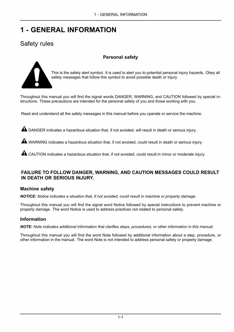
Personal safety
This is the safety alert symbol. It is used to alert you to potential personal injury hazards. Obey allsafety messages that follow this symbol to avoid possible death or injury.
Throughout this manual you will find the signal words DANGER, WARNING, and CAUTION followed by special in-structions. These precautions are intended for the personal safety of you and those working with you.
Read and understand all the safety messages in this manual before you operate or service the machine.
DANGER indicates a hazardous situation that, if not avoided, will result in death or serious injury.
WARNING indicates a hazardous situation that, if not avoided, could result in death or serious injury.
CAUTION indicates a hazardous situation that, if not avoided, could result in minor or moderate injury.
FAILURE TO FOLLOW DANGER, WARNING, AND CAUTION MESSAGES COULD RESULTIN DEATH OR SERIOUS INJURY.
Machine safetyNOTICE: Notice indicates a situation that, if not avoided, could result in machine or property damage.
Throughout this manual you will find the signal word Notice followed by special instructions to prevent machine orproperty damage. The word Notice is used to address practices not related to personal safety.
InformationNOTE: Note indicates additional information that clarifies steps, procedures, or other information in this manual.
Throughout this manual you will find the word Note followed by additional information about a step, procedure, orother information in the manual. The word Note is not intended to address personal safety or property damage.
1-1

1 - GENERAL INFORMATION
Safety rulesCALIFORNIA
PROPOSITION 65 WARNINGDiesel engine exhaust and some of its constituentsare known to the State of California to cause cancer,
birth defects and other reproductive harm.Battery post, terminals and related accessories
contain lead and lead compounds.Wash hands after handling
1-2
1 - GENERAL INFORMATION
Note to the OwnerImproper operation of this machine can cause injury or death. Before using this machine, make certain that everyoperator:
• Is instructed in safe and proper use of the machine.
• Reads and understands the Manual(s) pertaining to the machine.
• Reads and understands ALL Safety Decals on the machine.
• Clears the area of other persons.
• Learns and practices safe use of machine controls in a safe, clear area before operating this machine on a job site.
It is your responsibility to observe pertinent laws and regulations and follow CASE CONSTRUCTION instructions onmachine operation and maintenance.
Your machine has been designed and built to the highest standards of quality. It conforms to all current safety reg-ulations. However, the risk of accidents can never be completely excluded. That is why it is essential to observeelementary safety rules and precautions.
Read this manual carefully, paying particular attention to the instructions concerning safety, operation and mainte-nance so as to avoid the risk of injury while operating or servicing the machine.
The standard attachments and tools of this machine are designed to carry out all kinds of earthmoving and rehan-dling operations. If you want to use this machine to handle a load (pipes, culverts, formwork, etc.), make sure thatit is designed to carry out this kind of work. For this type of application, the machine must be equipped with safetyvalves, a load handling chart corresponding to the type of machine and its attachment and a load fixing point. All legalrequirements must also be strictly observed.
Do not use this machine for any application or purpose other than those described in this manual. If the machine isto be used for work involving the use of special attachments, accessories or equipment, consult your CASE CON-STRUCTION Dealer in order to make sure that any adaptations or modifications made are in keeping with the ma-chine's technical specifications and with prevailing safety requirements.
Any modification or adaptation which is not approved by the manufacturer may invalidate the machine's initial confor-mity with safety requirements.
The machine must undergo regular inspections, the frequency of which varies according to the type of use. Consultyour CASE CONSTRUCTION Dealer.
ATTENTION: The engine and fuel system on your machine is designed and built to government emissions standards.Tampering by dealers, customers, operators and users is STRICTLY PROHIBITED BY LAW. Failure to comply couldresult in government fines, rework charges, invalid warranty, legal action and possible confiscation of the machineuntil rework to original condition is completed. Engine service and/or repairs must be done by a certified technicianonly.
Your CASE CONSTRUCTION Dealer is at your disposal for any further information. He will also provide any after-sales service you may require, and genuine CASE CONSTRUCTION spare parts, your guarantee of quality andmatch. CASE CONSTRUCTION customer assistance is also available. Call 1-866-54-CASE6 (1-866-542-2736) oremail [email protected].
You can obtain manuals on the operation, maintenance and repair of your machine from your CASECONSTRUCTIONDealer. To ensure quick and efficient service, consult your CASE CONSTRUCTION Dealer for assistance in orderingthe correct manuals for your machine.
Your CASE CONSTRUCTION Dealer can provide after-sales service and genuine CASE CONSTRUCTION spareparts, your guarantee of quality and match.
CNH America LLC. Company reserves the right to make changes in the specification and design of the machinewithout prior notice and without incurring any obligation to modify units previously sold.
The description of the models shown in this manual has been made in accordance with the technical specificationsknown as of the date of design of this document.
1-3

1 - GENERAL INFORMATION
All data given in this manual is subject to production variations. Dimensions and weights are provided with approxi-mate values and the machine fitting shown in the illustrations may not correspond with standard models. For preciseinformation on specific machine models and versions, please consult your CASE CONSTRUCTION Dealer.
Reproduction or translation, even partial, is prohibited without written authorization from CNH America LLC. Com-pany.
1-4
1 - GENERAL INFORMATION
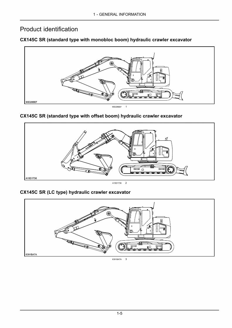
Product identificationCX145C SR (standard type with monobloc boom) hydraulic crawler excavator
90D28BEF 1
CX145C SR (standard type with offset boom) hydraulic crawler excavator
A15D1736 2
CX145C SR (LC type) hydraulic crawler excavator
6391BA7A 3
1-5
1 - GENERAL INFORMATION
Pin plates
When ordering parts, obtaining information or assistance, always supply your CASE CONSTRUCTION Dealer withthe type and serial number of your machine or accessories.
Write the following in the spaces below: the type, serial number and year of manufacture of your machine, accessoriesand the serial numbers of the various hydraulic and mechanical components.
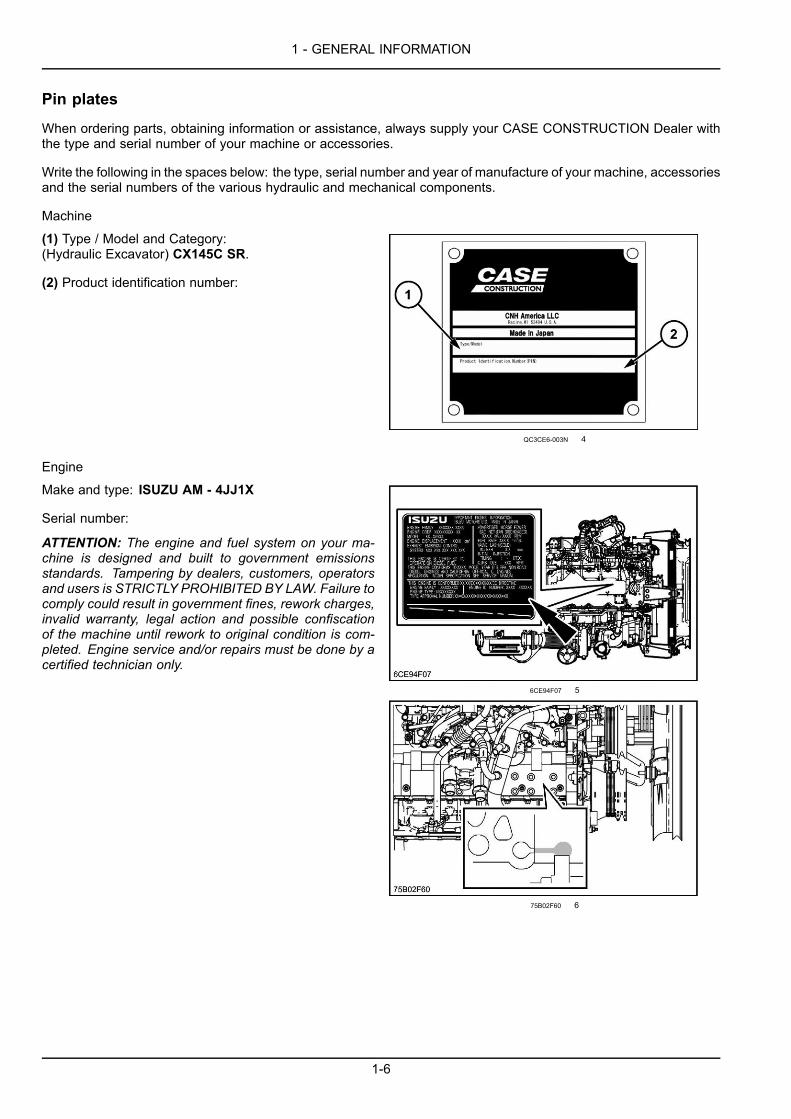
Machine
(1) Type / Model and Category:(Hydraulic Excavator) CX145C SR.
(2) Product identification number:
QC3CE6-003N 4
Engine
Make and type: ISUZU AM - 4JJ1X
Serial number:
ATTENTION: The engine and fuel system on your ma-chine is designed and built to government emissionsstandards. Tampering by dealers, customers, operatorsand users is STRICTLY PROHIBITED BY LAW. Failure tocomply could result in government fines, rework charges,invalid warranty, legal action and possible confiscationof the machine until rework to original condition is com-pleted. Engine service and/or repairs must be done by acertified technician only.
6CE94F07 5
75B02F60 6
1-6
1 - GENERAL INFORMATION
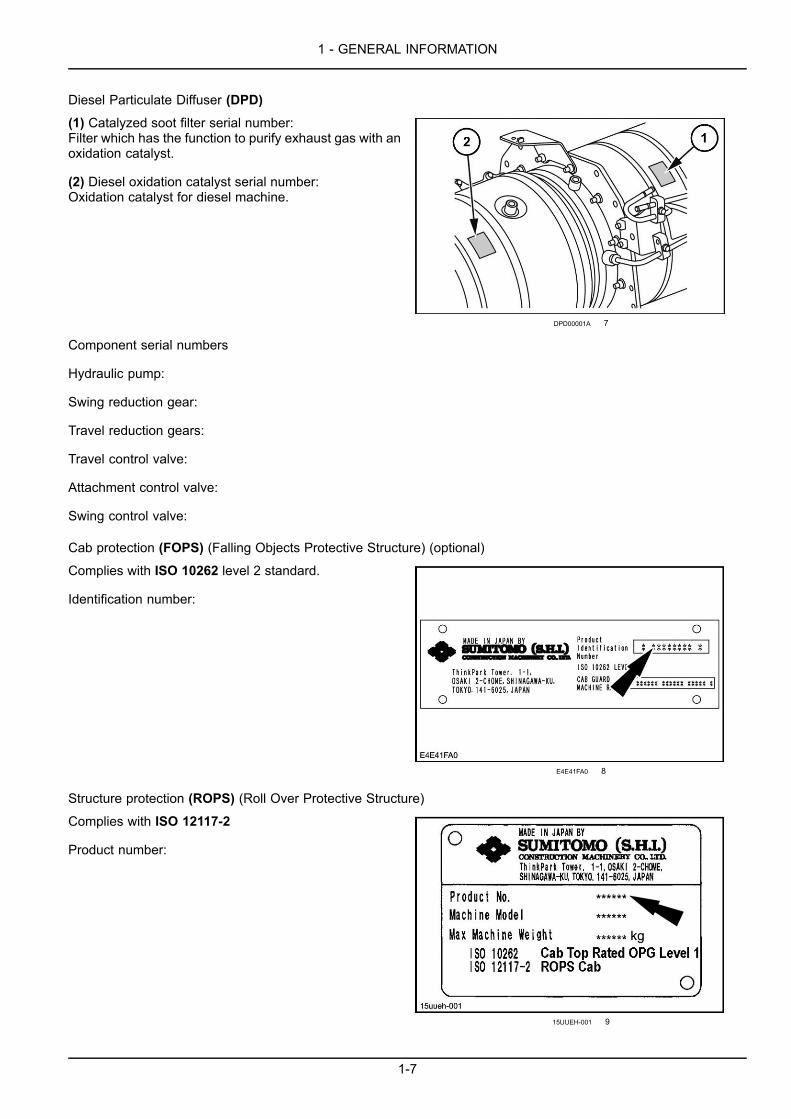
Diesel Particulate Diffuser (DPD)
(1) Catalyzed soot filter serial number:Filter which has the function to purify exhaust gas with anoxidation catalyst.
(2) Diesel oxidation catalyst serial number:Oxidation catalyst for diesel machine.
DPD00001A 7
Component serial numbers
Hydraulic pump:
Swing reduction gear:
Travel reduction gears:
Travel control valve:
Attachment control valve:
Swing control valve:
Cab protection (FOPS) (Falling Objects Protective Structure) (optional)
Complies with ISO 10262 level 2 standard.
Identification number:
E4E41FA0 8
Structure protection (ROPS) (Roll Over Protective Structure)
Complies with ISO 12117-2
Product number:
15UUEH-001 9
1-7

1 - GENERAL INFORMATION
Quick coupler (optional)
(1) Serial number:
(2) Weight:
(3) Working pressure:
(4) Type:
(5) Part number:
(6) Date of manufacture:
(7) SWL (Safe Working Load):
QC0001 10
1-8

1 - GENERAL INFORMATION
Left, right, front and rear of the machineThe terms "Right-hand", "Left-hand", "Front" and "Rear"are used in this manual to indicate the sides as they areseen from the operator's seat when the cab is over theidler wheels.
ATTENTION: The illustration opposite shows themachinein normal travel position. In normal travel position, the cabis over the idler wheels. The travel reduction gears are atthe rear of the upperstructure.
(A) Front
(B) Rear
(C) Right-hand side
(D) Left-hand side
(E) Travel motors
(F) Idler wheels
C891F8C9 1
Electro-magnetic interference (EMC)Interference may arise as a result of add‐on equipment which may not necessarily meet the required standards. Assuch interference can result in serious malfunction of the unit and/or create unsafe situations, you must observe thefollowing:
• The maximum power of emission equipment (radio, telephones, etc.) must not exceed the limits imposed by thenational authorities of the country where you use the machine.
• The electro‐magnetic field generated by the add‐on system should not exceed 24 V/m at any time and at anylocation in the proximity of electronic components.
• The add‐on equipment must not interfere with the functioning of the on board electronics.
Failure to comply with these rules will render the CASE CONSTRUCTION warranty null and void.
1-9
1 - GENERAL INFORMATION
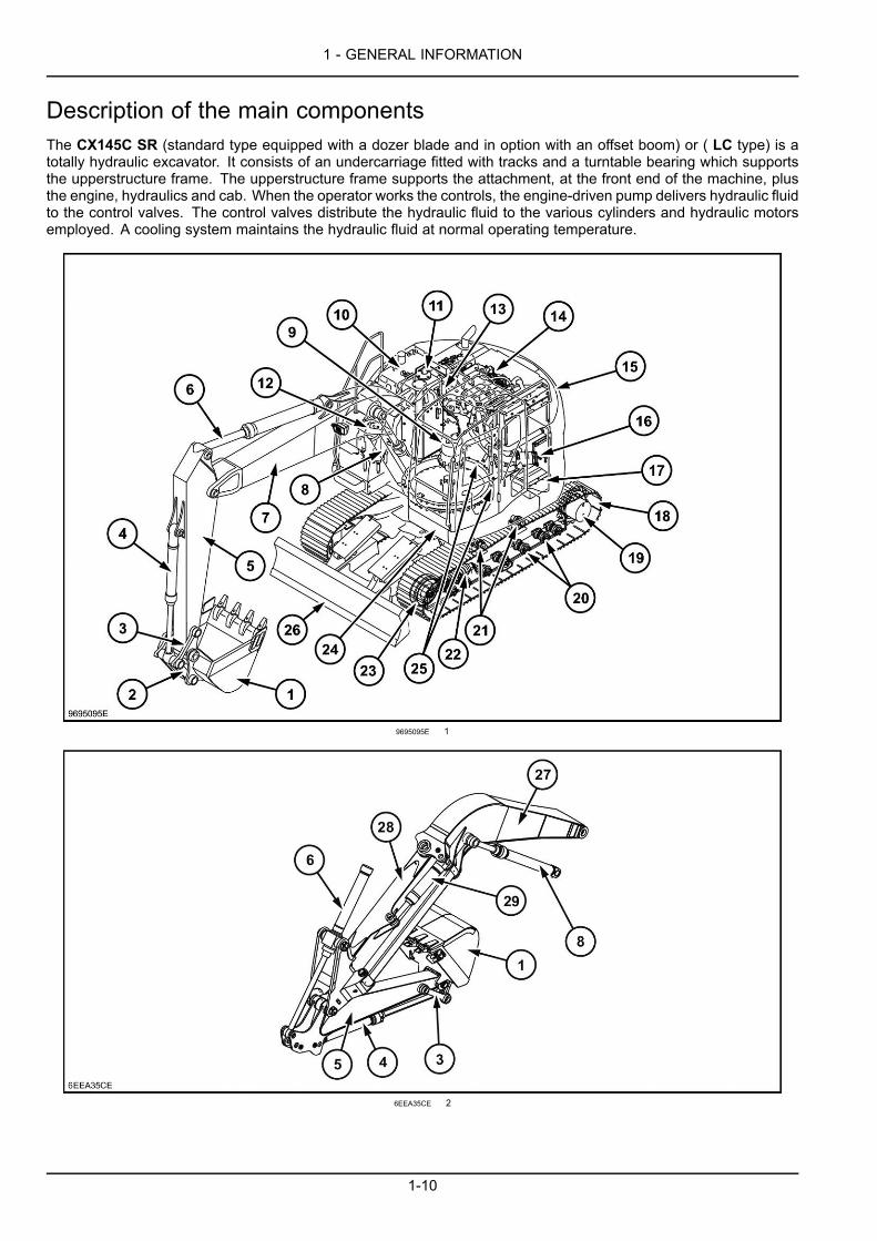
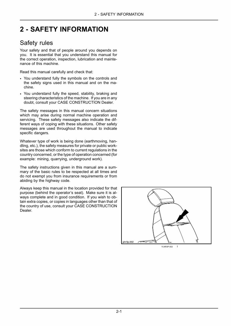
Description of the main componentsThe CX145C SR (standard type equipped with a dozer blade and in option with an offset boom) or ( LC type) is atotally hydraulic excavator. It consists of an undercarriage fitted with tracks and a turntable bearing which supportsthe upperstructure frame. The upperstructure frame supports the attachment, at the front end of the machine, plusthe engine, hydraulics and cab. When the operator works the controls, the engine-driven pump delivers hydraulic fluidto the control valves. The control valves distribute the hydraulic fluid to the various cylinders and hydraulic motorsemployed. A cooling system maintains the hydraulic fluid at normal operating temperature.
9695095E 1
6EEA35CE 2
1-10

1 - GENERAL INFORMATION
1. Backhoe bucket2. Connecting rod3. Yokes4. Backhoe bucket cylinder5. Arm6. Arm cylinder7. Boom8. Boom cylinders9. Swing reduction gear10. Fuel tank11. Hydraulic reservoir12. Control valve13. Hydraulic pump14. Engine compartment15. Counterweight16. Air filter17. Batteries18. Tracks19. Travel reduction gears20. Lower rollers21. Upper rollers22. Tension shock absorbers23. Idler wheels24. Cab/Operator's compartment25. Swing components26. Dozer blade (standard machine only)27. Fixed boom (standard machine with offset boom)28. Moving boom (standard machine with offset boom)29. Offset boom cylinder (standard machine with offset boom)
1-11

1 - GENERAL INFORMATION
1-12
2 - SAFETY INFORMATION
2 - SAFETY INFORMATION###_2_###
Safety rulesYour safety and that of people around you depends onyou. It is essential that you understand this manual forthe correct operation, inspection, lubrication and mainte-nance of this machine.
Read this manual carefully and check that:
• You understand fully the symbols on the controls andthe safety signs used in this manual and on the ma-chine.
• You understand fully the speed, stability, braking andsteering characteristics of themachine. If you are in anydoubt, consult your CASE CONSTRUCTION Dealer.
The safety messages in this manual concern situationswhich may arise during normal machine operation andservicing. These safety messages also indicate the dif-ferent ways of coping with these situations. Other safetymessages are used throughout the manual to indicatespecific dangers.
Whatever type of work is being done (earthmoving, han-dling, etc.), the safety measures for private or public work-sites are those which conform to current regulations in thecountry concerned, or the type of operation concerned (forexample: mining, quarrying, underground work).
The safety instructions given in this manual are a sum-mary of the basic rules to be respected at all times anddo not exempt you from insurance requirements or fromabiding by the highway code.
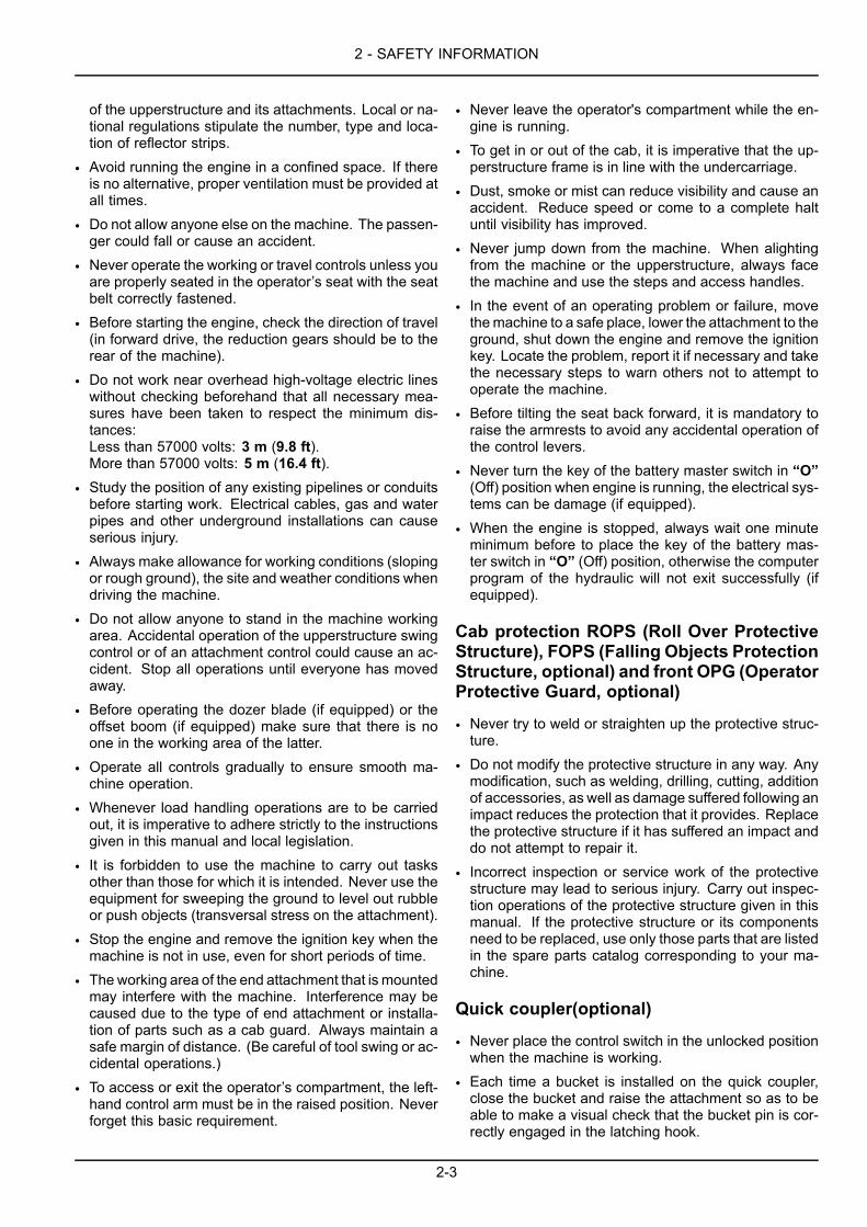
Always keep this manual in the location provided for thatpurpose (behind the operator’s seat). Make sure it is al-ways complete and in good condition. If you wish to ob-tain extra copies, or copies in languages other than that ofthe country of use, consult your CASE CONSTRUCTIONDealer.
YLNR3P-002 1
2-1

2 - SAFETY INFORMATION
Before using the machine
• Avoid loose fitting clothing, loose or uncovered longhair, jewelry or any other items which could get caughtup in machinery.
• Different types of job will require different types of pro-tective equipment. Items such as hard hats, safetyshoes, heavy gloves, reflector type jackets, respirators,ear protection and eye protection may be required. Be-fore starting a job, determine what protective equip-ment will be necessary. Use this equipment at all times.
• Do not attempt to operate this machine unless you havefirst read and perfectly understood the safetymessagesand instructions appearing in this manual.
• Operating the machine requires full attention and careon the part of the operator can avoid accidents. Getto know the machine's possibilities and limitations andthe working space required. There are areas of poorvisibility in the working range of the machine. Havesomeone guide you for all areas where visibility is notperfect.
• Grease, oil, mud or (in winter) ice on the steps andaccess handles can cause accidents. Make sure theyare kept clean at all times.
• Every day, inspect the machine to detect any signs ofhydraulic fluid leakage. Tighten the connections or re-place any defective components as necessary.
• Remove any obstructions which hinder visibility. Keepthe windshield, rear view mirror and windows clean atall times.
• Make sure the windshield wiper works correctly.
• Make sure you are perfectly familiar with hand signalsin daily use on the worksite to be able to obtain helpwith tight maneuvers or when carrying out operationswhere visibility is poor.
• Before undertaking any travel or working operationsduring hours of darkness, make sure the lighting andsignalling equipment is fully operative.
• Before any travel operation, make sure that the doorsand hoods are properly latched.
• Check that no tools or other items have been left on themachine (be it on the undercarriage or the upperstruc-ture) or in the operator's compartment.
• The operator must be alone on the machine at all times.Do not allow anyone to stand on or around themachine.
• To get in or out of the cab, it is imperative that the up-perstructure frame is in line with the undercarriage.
• When alighting from or getting into the operator's com-partment, always face the machine and use the stepsand access handles.
• Be sure you know the position and function of eachcontrol. Incorrect operation of the controls can causeserious injuries.
• Check all controls and safety devices in a safe, openarea before starting work.
• Keep away from dangerous areas such as ditches,overhangs, rocky areas, etc. Make a survey of thework-site and determine the possible dangers beforeusing the machine.
• Before parking the machine, make sure that the groundis stable. Plan the worksite so that the ground is flat,hard and level.
• Before moving the machine to work in a new area, walkaround to determine all possible causes of accidentsthere. Holes, obstacles, debris and other danger risksin the working area can cause serious injury.
• Be ready to meet emergencies. Always carry a first aidkit and if possible, fire extinguisher (not supplied) withineasy reach on board. Make sure the fire extinguisheris regularly serviced in conformance with the manufac-turer's instructions.
• Check the fastening of the main components: counter-weight, turntable bearing and operator's compartment.In the event of problems, consult your CASE CON-STRUCTION Dealer.
• Make sure you understand the symbols used on themachine safety decals. Keep the decals clean so thatthey are perfectly legible at all times.
• Work out a means of convenient escape from the ma-chine (emergency exit via the windshield or the rearwindow glass) in the event of the machine turning overor tipping over or the cab door being jammed.
• Make sure you are perfectly familiar with traffic regu-lations and special safety equipment requirements be-fore transporting this machine on a public highway.
• When loading trucks, never swing the load over thetruck cab.
• Before undertaking any travel on the job site, make surethe itinerary to be followed is completely safe. If bridgesare to be crossed, make sure they are perfectly capableof supporting the weight of the machine.
• Always steer around large obstacles such as boulders,big trees, etc.
Quick coupler (optional)
• It is mandatory for the switch to be in the locked positionwhen operating the machine.
• Every day, check that the locking bar functions correctlyand that it is not fouled by foreign matter. Clean thelocking system if necessary.
• If you are obliged to use the quick coupler with bucketsnot manufactured by CASE CONSTRUCTION, makesure the diameter of the pins and the width betweenthe bucket lugs meet the dimensions needed to fit thequick coupler (pins, washers, bushings, etc.). Consultyour CASE CONSTRUCTION Dealer.
Operating the machine
• When working on a public highway, use standard traf-fic signs and take into consideration the working range
2-2
2 - SAFETY INFORMATION
of the upperstructure and its attachments. Local or na-tional regulations stipulate the number, type and loca-tion of reflector strips.
• Avoid running the engine in a confined space. If thereis no alternative, proper ventilation must be provided atall times.
• Do not allow anyone else on the machine. The passen-ger could fall or cause an accident.
• Never operate the working or travel controls unless youare properly seated in the operator’s seat with the seatbelt correctly fastened.
• Before starting the engine, check the direction of travel(in forward drive, the reduction gears should be to therear of the machine).
• Do not work near overhead high-voltage electric lineswithout checking beforehand that all necessary mea-sures have been taken to respect the minimum dis-tances:Less than 57000 volts: 3 m (9.8 ft).More than 57000 volts: 5 m (16.4 ft).
• Study the position of any existing pipelines or conduitsbefore starting work. Electrical cables, gas and waterpipes and other underground installations can causeserious injury.
• Always make allowance for working conditions (slopingor rough ground), the site and weather conditions whendriving the machine.
• Do not allow anyone to stand in the machine workingarea. Accidental operation of the upperstructure swingcontrol or of an attachment control could cause an ac-cident. Stop all operations until everyone has movedaway.
• Before operating the dozer blade (if equipped) or theoffset boom (if equipped) make sure that there is noone in the working area of the latter.
• Operate all controls gradually to ensure smooth ma-chine operation.
• Whenever load handling operations are to be carriedout, it is imperative to adhere strictly to the instructionsgiven in this manual and local legislation.
• It is forbidden to use the machine to carry out tasksother than those for which it is intended. Never use theequipment for sweeping the ground to level out rubbleor push objects (transversal stress on the attachment).
• Stop the engine and remove the ignition key when themachine is not in use, even for short periods of time.
• The working area of the end attachment that is mountedmay interfere with the machine. Interference may becaused due to the type of end attachment or installa-tion of parts such as a cab guard. Always maintain asafe margin of distance. (Be careful of tool swing or ac-cidental operations.)
• To access or exit the operator’s compartment, the left-hand control arm must be in the raised position. Neverforget this basic requirement.
• Never leave the operator's compartment while the en-gine is running.
• To get in or out of the cab, it is imperative that the up-perstructure frame is in line with the undercarriage.
• Dust, smoke or mist can reduce visibility and cause anaccident. Reduce speed or come to a complete haltuntil visibility has improved.
• Never jump down from the machine. When alightingfrom the machine or the upperstructure, always facethe machine and use the steps and access handles.
• In the event of an operating problem or failure, movethemachine to a safe place, lower the attachment to theground, shut down the engine and remove the ignitionkey. Locate the problem, report it if necessary and takethe necessary steps to warn others not to attempt tooperate the machine.
• Before tilting the seat back forward, it is mandatory toraise the armrests to avoid any accidental operation ofthe control levers.
• Never turn the key of the battery master switch in “O”(Off) position when engine is running, the electrical sys-tems can be damage (if equipped).
• When the engine is stopped, always wait one minuteminimum before to place the key of the battery mas-ter switch in “O” (Off) position, otherwise the computerprogram of the hydraulic will not exit successfully (ifequipped).
Cab protection ROPS (Roll Over ProtectiveStructure), FOPS (Falling Objects ProtectionStructure, optional) and front OPG (OperatorProtective Guard, optional)
• Never try to weld or straighten up the protective struc-ture.
• Do not modify the protective structure in any way. Anymodification, such as welding, drilling, cutting, additionof accessories, as well as damage suffered following animpact reduces the protection that it provides. Replacethe protective structure if it has suffered an impact anddo not attempt to repair it.
• Incorrect inspection or service work of the protectivestructure may lead to serious injury. Carry out inspec-tion operations of the protective structure given in thismanual. If the protective structure or its componentsneed to be replaced, use only those parts that are listedin the spare parts catalog corresponding to your ma-chine.
Quick coupler(optional)
• Never place the control switch in the unlocked positionwhen the machine is working.
• Each time a bucket is installed on the quick coupler,close the bucket and raise the attachment so as to beable to make a visual check that the bucket pin is cor-rectly engaged in the latching hook.
2-3
2 - SAFETY INFORMATION
• The quick coupler modifies the working range of themachine. In certain attachment positions the tool mayfoul the machine. Always leave a safety distance.
• Never carry out load handling using the front or rearanchoring points used to install the tool on the quickcoupler.
• Never put your hands inside the quick coupler andnever attempt to adjust or repair the quick coupler ifthe engine is running.
Parking the machine
When parking the machine, proceed as follows:1. Position the machine on flat, level ground, away from
soft ground, excavations or poorly shored cavities.2. Place the upperstructure and the attachment in line
with the undercarriage, retract the attachment and digthe bucket into the ground.
3. Lower the dozer blade (if equipped) until it rests on theground.
4. Stop the engine and remove the ignition key.5. You must place the function cancellation lever in
raised position before leaving the operator’s compart-ment.
6. Lock the cab door.7. Make sure that the hoods and doors are properly
latched.8. Check that no part of the machine is encroaching on
the highway. If this cannot be avoided, install the nec-essary regulation signalling equipment.
Maintenance and adjustments
• Do not try to service this machine unless you havefirst read and perfectly understood the safetymessagesand instructions featuring in this manual.
• When carrying out service work always wear suitabledress. Avoid loose-fitting clothing.
• Release pressure completely in the hydraulic systembefore disconnecting the hydraulic piping. Hydraulic oilescaping under pressure can cause serious injury.
• Before doing maintenance work on the machine, shutdown the engine and allow it to cool down. Otherwise,you could be burned.
• Before commencing any work on the machine, place a"Do not operate" tag on the right-hand control arm.
• Always wear eye protection when using a tool thatmight project metal particles. Use a hammer with asoft face, such as copper, for installing pins.
• Badly carried out maintenance or adjustments cancause serious injuries. If you do not understand aservicing or adjustment procedure, consult your CASECONSTRUCTION Dealer.
• If the attachment is raised or if the machine moves with-out an operator, serious injury can result. Before car-rying out maintenance on this machine, proceed as fol-lows:Park the machine on flat, level ground.Lower the attachment until it is resting on the ground.Lower the dozer blade (if equipped) until it rests on theground.Stop the engine and remove the ignition key.Lock the tracks to prevent any machine movement.
• Any unauthorized modifications made to this ma-chine can cause serious injury. Do not undertakeany modifications without first consulting your CASECONSTRUCTION Dealer. Any modifications mademust be in conformity with the technical specificationsof the machine and any current safety legislation re-quirements.
• Do not modify the Diesel Particulate Diffuser (DPD) andthe exhaust system. Changing the orientation, lengthor diameter of the exhaust pipe would adversely affectthe exhaust system's exhaust emission reduction func-tion.
• Certain components of the machine are subject totype approval. When replacing such components,it is mandatory to make sure that they conform toregulations. For safety's sake, use genuine CASECONSTRUCTION parts.
• Pressurized hydraulic fluid or grease which penetratesthe skin can cause serious injury. Take the neces-sary safety precautions (safety clothing and protectionfor face and hands) to avoid such risks. Also, beforeusing these products, read the manufacturer's instruc-tions concerning their use. If hydraulic fluid penetratesthe skin, call a doctor immediately.
• Coolant solution is toxic.Avoid contact with skin, eyes and clothing.Antidote:External: rinse thoroughly with water and removesoiled clothes.Internal: do not induce vomiting. Rinse the mouth outwith water. Seek medical advice.Eyes: rinse thoroughly with water and seek medicaladvice.
• The pressure in the track tension cylinders is high. Fol-low the procedure described in this manual carefully forincreasing or reducing track tension.
• When carrying out a welding operation on the undercar-riage or upperstructure carriage as authorized by themanufacturer and in accordance with his instructions,disconnect the batteries, disconnect the alternator B+and D+ terminal wires and connect the welding appa-ratus earth cable to the component on which the weld-ing operation is to be performed. Never connect thewelding apparatus to the undercarriage when weldingon the upperstructure (or vice-versa). Never connectthe welding apparatus earth to a component of the hy-draulic system.
• When using compressed air, take the necessary pre-cautions to protect your face.
2-4
2 - SAFETY INFORMATION
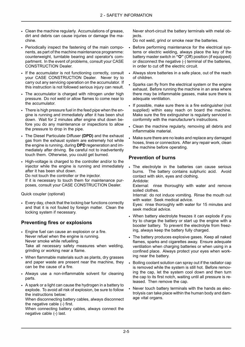
• Clean the machine regularly. Accumulations of grease,dirt and debris can cause injuries or damage the ma-chine.
• Periodically inspect the fastening of the main compo-nents, as part of themachinemaintenance programme:counterweight, turntable bearing and operator's com-partment. In the event of problems, consult your CASECONSTRUCTION Dealer.
• If the accumulator is not functioning correctly, consultyour CASE CONSTRUCTION Dealer. Never try tocarry out any servicing operation on the accumulator. Ifthis instruction is not followed serious injury can result.
• The accumulator is charged with nitrogen under highpressure. Do not weld or allow flames to come near tothe accumulator.
• There is high pressure fuel in the feed pipe when the en-gine is running and immediately after it has been shutdown. Wait for 2 minutes after engine shut down be-fore you do any maintenance or inspections to allowthe pressure to drop in the pipe.
• The Diesel Particulate Diffuser (DPD) and the exhaustgas from the exhaust system are extremely hot whilethe engine is running, duringDPD regeneration and im-mediately after driving. Be careful not to inadvertentlytouch them. Otherwise, you could get burned.
• High-voltage is charged to the controller and/or to theinjector while the engine is running and immediatelyafter it has been shut down.Do not touch the controller or the injector.If it is necessary to touch them for maintenance pur-poses, consult your CASE CONSTRUCTION Dealer.
Quick coupler (optional)
• Every day, check that the locking bar functions correctlyand that it is not fouled by foreign matter. Clean thelocking system if necessary.
Preventing fires or explosions
• Engine fuel can cause an explosion or a fire.Never refuel when the engine is running.Never smoke while refuelling.Take all necessary safety measures when welding,grinding or working near a flame.
• When flammable materials such as plants, dry grassesand paper waste are present near the machine, theycan be the cause of a fire.
• Always use a non-inflammable solvent for cleaningparts.
• A spark or a light can cause the hydrogen in a battery toexplode. To avoid all risk of explosion, be sure to followthe instructions below:When disconnecting battery cables, always disconnectthe negative cable (-) first.When connecting battery cables, always connect thenegative cable (-) last.
Never short-circuit the battery terminals with metal ob-jects.Do not weld, grind or smoke near the batteries.
• Before performing maintenance for the electrical sys-tems or electric welding, always place the key of thebattery master switch in “O” (Off) position (if equipped)or disconnect the negative (-) terminal of the batteries,in order to cut off the electric circuit.
• Always store batteries in a safe place, out of the reachof children.
• Sparks can fly from the electrical system or the engineexhaust. Before running the machine in an area wherethere may be inflammable gasses, make sure there isadequate ventilation.
• If possible, make sure there is a fire extinguisher (notsupplied) within easy reach on board the machine.Make sure the fire extinguisher is regularly serviced inconformity with the manufacturer's instructions.
• Clean the machine regularly, removing all debris andinflammable material.
• Make sure there are no leaks and replace any damagedhoses, lines or connectors. After any repair work, cleanthe machine before operating.
Prevention of burns
• The electrolyte in the batteries can cause seriousburns. The battery contains sulphuric acid. Avoidcontact with skin, eyes and clothing.Antidote:External: rinse thoroughly with water and removesoiled clothes.Internal: do not induce vomiting. Rinse the mouth outwith water. Seek medical advice.Eyes: rinse thoroughly with water for 15 minutes andseek medical advice.
• When battery electrolyte freezes it can explode if youtry to charge the battery or start up the engine with abooster battery. To prevent the electrolyte from freez-ing, always keep the battery fully charged.
• The battery produces explosive gases. Keep all nakedflames, sparks and cigarettes away. Ensure adequateventilation when charging batteries or when using in aconfined place. Always protect your eyes when work-ing near the battery.
• Boiling coolant solution can spray out if the radiator capis removed while the system is still hot. Before remov-ing the cap, let the system cool down and then turnthe cap to its first notch, waiting until all pressure is re-leased. Then remove the cap.
• Never touch battery terminals with the hands as elec-trolysis can take place within the human body and dam-age vital organs.
2-5

2 - SAFETY INFORMATION
Using an implement other than a bucket
• When using a special implement (hydraulic breaker,cutter crusher etc.), refer to the operator's manual pro-vided with the implement.
Implement operation and maintenance
• For the implement operation and maintenance, refer tothe operator's manual provided with the implement.
Safety area
The safety area is the space necessary for the machine tooperate at the maximum range of the tool and at full swing360 ° plus 2 m.
(1) Working area.
(2) Safety area.
TD673F-001 2
2-6
2 - SAFETY INFORMATION
Utility safety
Safety precautions must be followed when working near buried utility lines.
During operation it is likely that you will be working around or near buried utility lines which may include, but are notlimited to:
• Electrical Power Line• Gas Line• Water Line• Communication Line - Telephone or Cable Television
ATTENTION: Before beginning any trenching, or other construction work it is your responsibility to be aware of allsuch utility lines buried in the area of your project and to avoid them.
Always have all local utility companies mark the location of their lines.
In U.S.A. and Canada call one of many One Call System Directory services. If you do not know the local number, callthe national number (U.S.A. and Canada only): 1-888-258-0808.
Check with local authorities for laws, regulations and/or strict penalties requiring you to locate and avoid existingutilities.
ATTENTION: Call all local utility companies before you perform any machine operation.
Know the utility color code (U.S.A. and Canada):
Electric : RedGas, Oil, or Petroleum : YellowCommunication, Telephone, Television : OrangeWater : BlueSewer : Green/BrownProposed Excavation : WhiteSurveying : PinkReclaimed Water and Slurry : Purple
After locating the utility lines, carefully dig a hole by hand and/or automatic vacuum equipment to the utility line toverify the location and depth of the line.
2-7
2 - SAFETY INFORMATION
Safety decalsWARNINGAvoid injury!An illegible or missing decal can have far-reaching consequences. Inspect decals daily.Failure to comply could result in death or serious injury.
W0228A
WARNINGAvoid injury!Make sure decals are perfectly legible. Clean decals regularly. Replace all damaged, missing, paintedover, or illegible decals. See your dealer for replacement decals. When replacing parts bearing decals,be sure to put new decals on each new part.Failure to comply could result in death or serious injury.
W0229A
The following safety decals are placed on your machine as a guide for your safety and for those working with you.Walk around the machine and note the content and location of these safety decals before operating your machine.
Keep safety decals clean and legible. Clean safety decals with a soft cloth, water, and a gentle detergent. Do not usesolvent, gasoline, or other harsh chemicals. Solvents, gasoline, and other harsh chemicals may damage or removesafety decals.
Replace all safety decals that are damaged, missing, painted over, or illegible. If a safety decal is on a part thatis replaced, make sure the safety decal is installed on the new part. See your CASE CONSTRUCTION Dealer forreplacement safety decals.
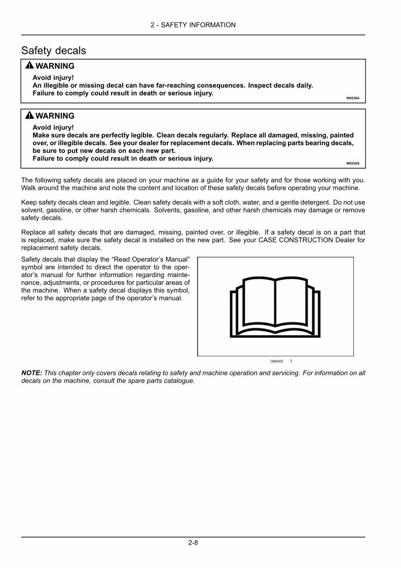
Safety decals that display the “Read Operator’s Manual”symbol are intended to direct the operator to the oper-ator’s manual for further information regarding mainte-nance, adjustments, or procedures for particular areas ofthe machine. When a safety decal displays this symbol,refer to the appropriate page of the operator’s manual.
OM0000 1
NOTE: This chapter only covers decals relating to safety and machine operation and servicing. For information on alldecals on the machine, consult the spare parts catalogue.
2-8
2 - SAFETY INFORMATION
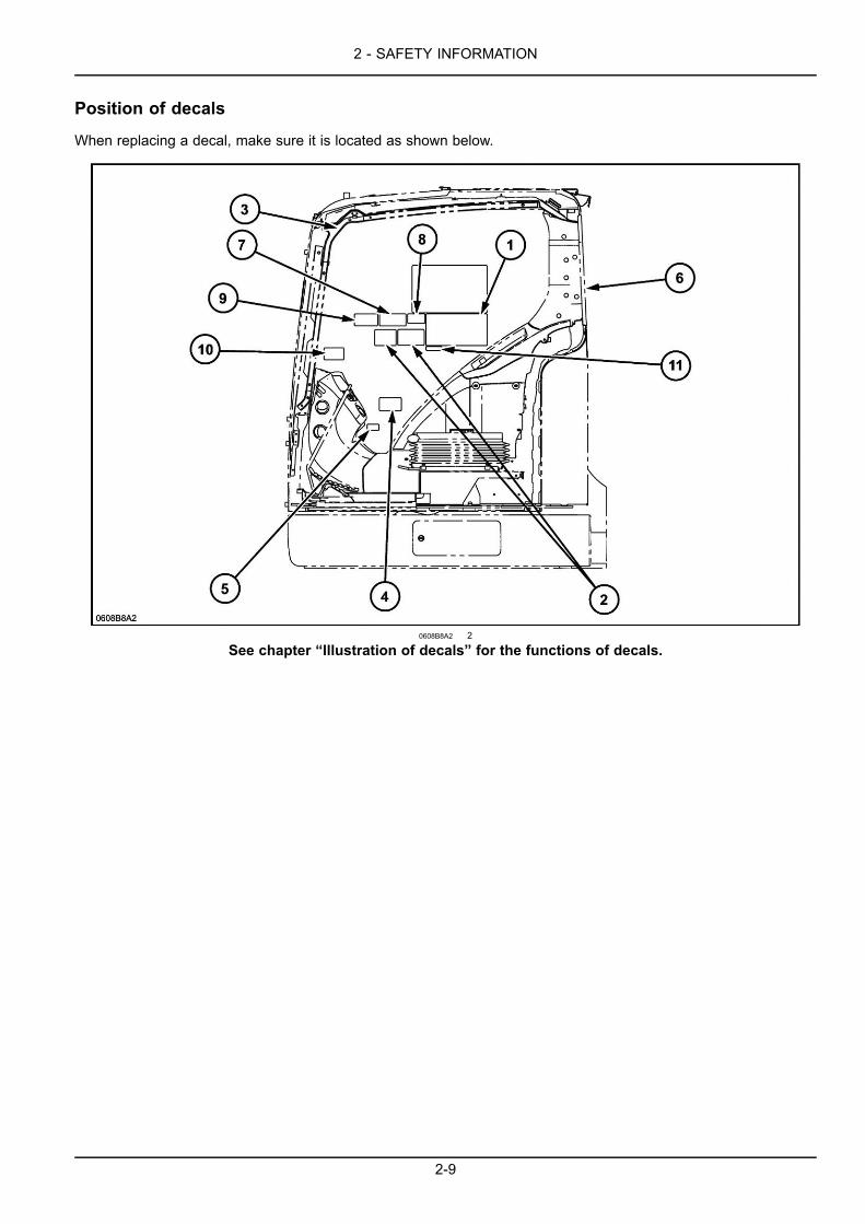
Position of decals
When replacing a decal, make sure it is located as shown below.
0608B8A2 2
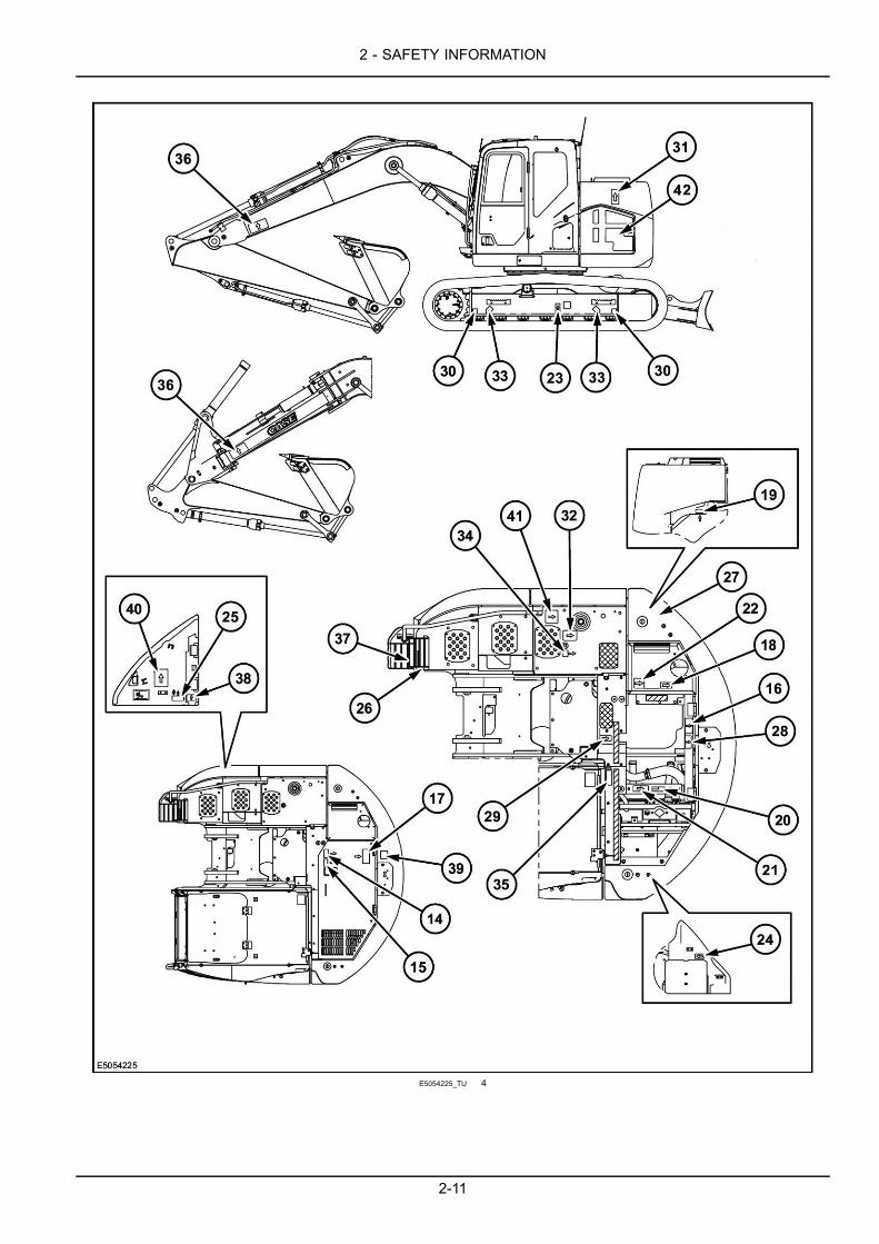
See chapter “Illustration of decals” for the functions of decals.
2-9
2 - SAFETY INFORMATION
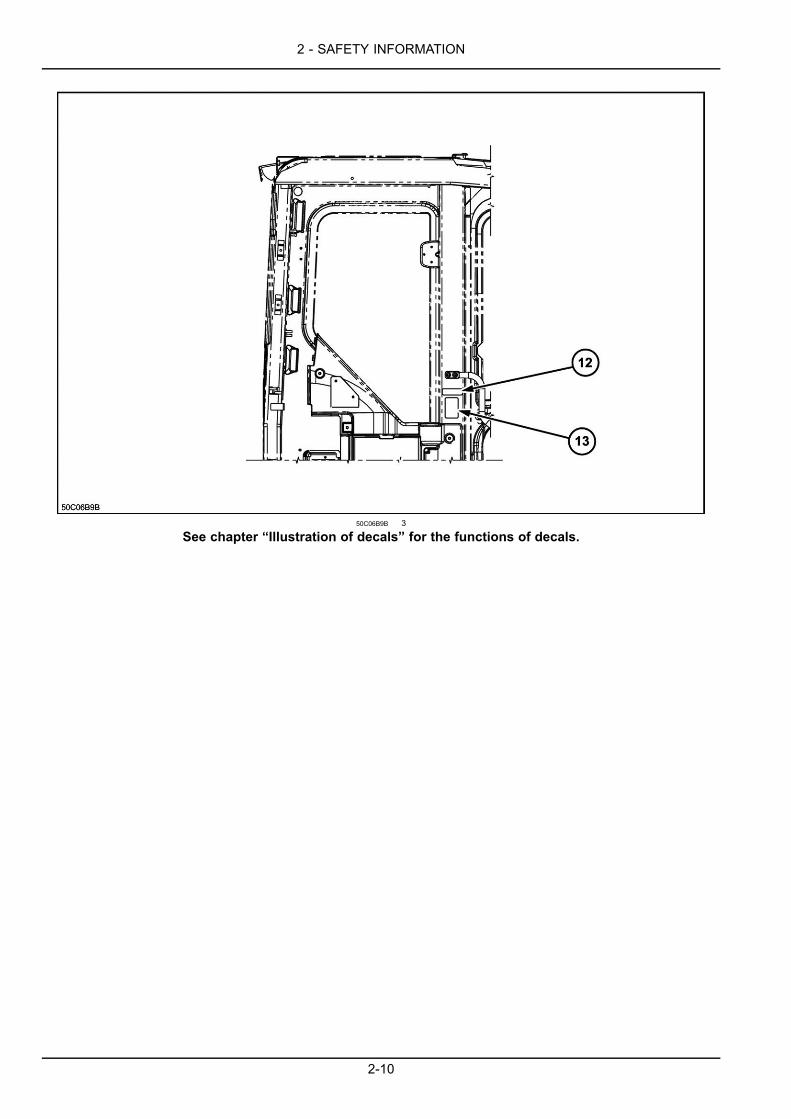
50C06B9B 3
See chapter “Illustration of decals” for the functions of decals.
2-10
2 - SAFETY INFORMATION
E5054225_TU 4
2-11

2 - SAFETY INFORMATION
Illustration of decals
Table of safety precautions
Part number: KHP19130
5D47E601 5
Tool interference
This decal draws attention to the fact that, in certain po-sitions, there can be interference of the tool between theattachment and the operator's compartment. Always ob-serve aminimum safety distance between the tool and theoperator's compartment (in case of swinging or accidentalmovements).
X411GJ-001 6
2-12
2 - SAFETY INFORMATION
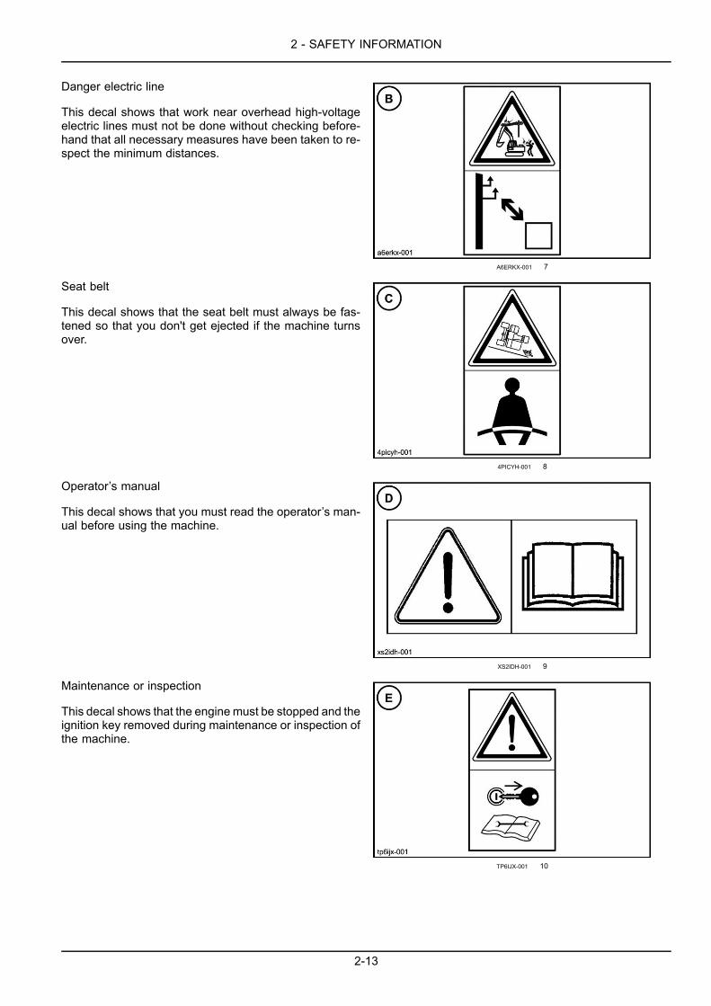
Danger electric line
This decal shows that work near overhead high-voltageelectric lines must not be done without checking before-hand that all necessary measures have been taken to re-spect the minimum distances.
A6ERKX-001 7
Seat belt
This decal shows that the seat belt must always be fas-tened so that you don't get ejected if the machine turnsover.
4PICYH-001 8
Operator’s manual
This decal shows that you must read the operator’s man-ual before using the machine.
XS2IDH-001 9
Maintenance or inspection
This decal shows that the engine must be stopped and theignition key removed during maintenance or inspection ofthe machine.
TP6IJX-001 10
2-13
2 - SAFETY INFORMATION
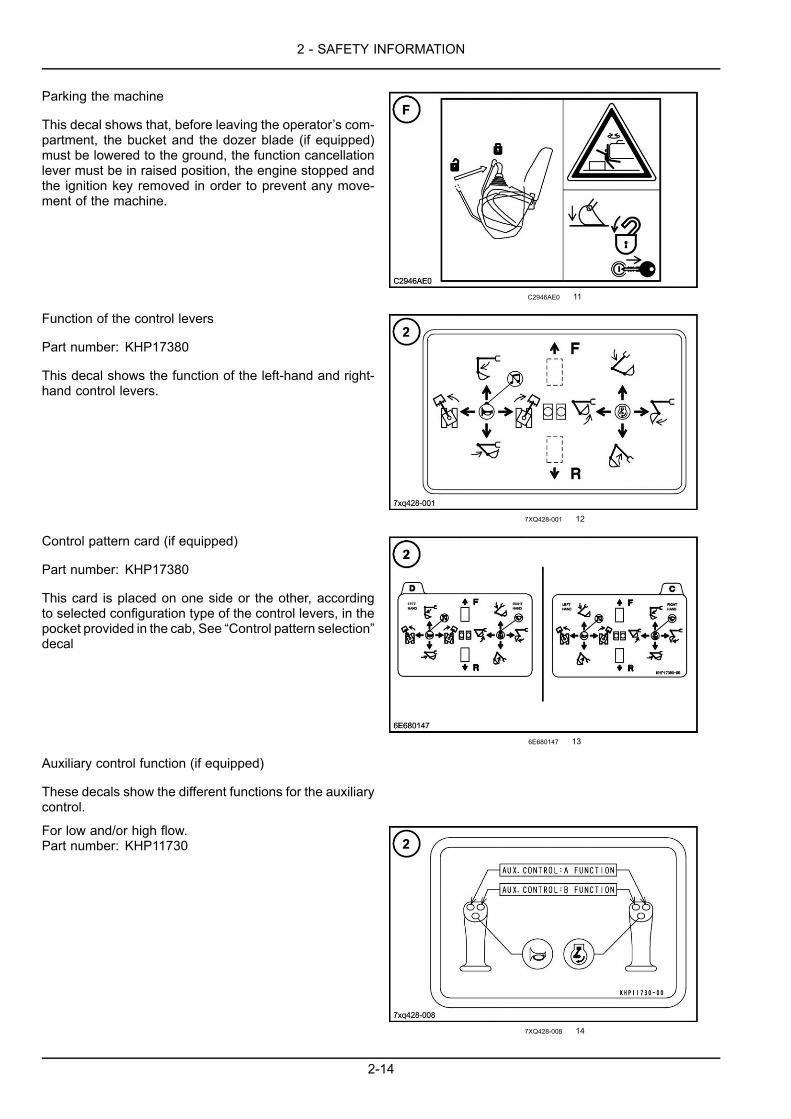
Parking the machine
This decal shows that, before leaving the operator’s com-partment, the bucket and the dozer blade (if equipped)must be lowered to the ground, the function cancellationlever must be in raised position, the engine stopped andthe ignition key removed in order to prevent any move-ment of the machine.
C2946AE0 11
Function of the control levers
Part number: KHP17380
This decal shows the function of the left-hand and right-hand control levers.
7XQ428-001 12
Control pattern card (if equipped)
Part number: KHP17380
This card is placed on one side or the other, accordingto selected configuration type of the control levers, in thepocket provided in the cab, See “Control pattern selection”decal
6E680147 13
Auxiliary control function (if equipped)
These decals show the different functions for the auxiliarycontrol.
For low and/or high flow.Part number: KHP11730
7XQ428-008 14
2-14
2 - SAFETY INFORMATION
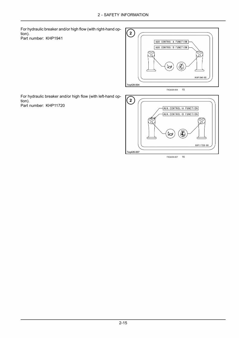
For hydraulic breaker and/or high flow (with right-hand op-tion).Part number: KHP1941
7XQ428-004 15
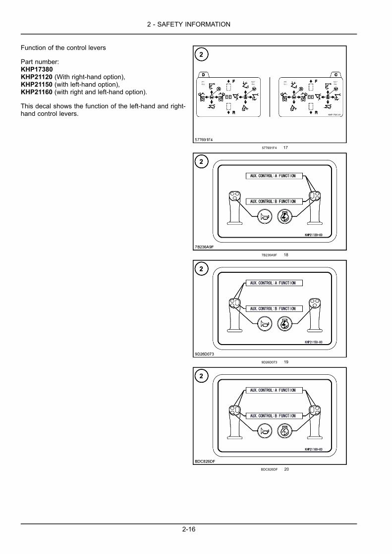
For hydraulic breaker and/or high flow (with left-hand op-tion).Part number: KHP11720
7XQ428-007 16
2-15
2 - SAFETY INFORMATION
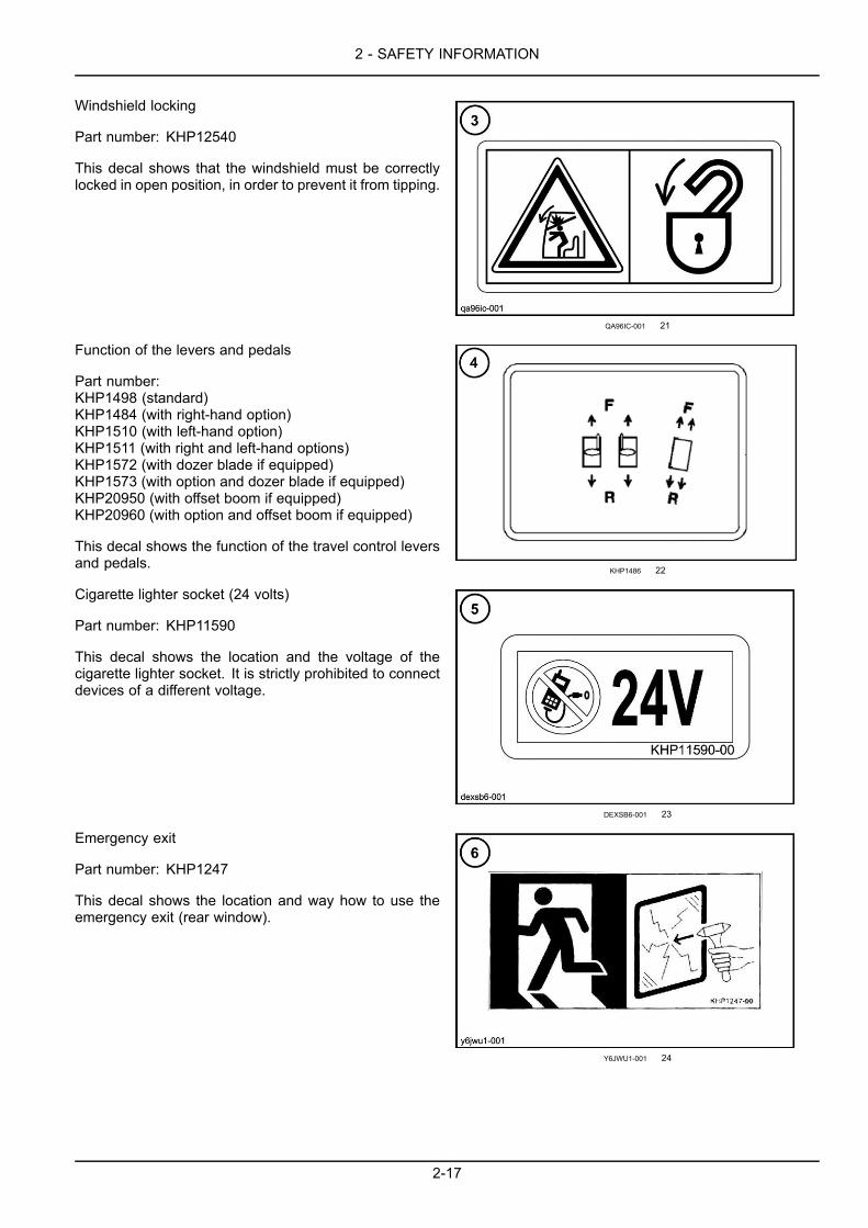
Function of the control levers
Part number:KHP17380KHP21120 (With right-hand option),KHP21150 (with left-hand option),KHP21160 (with right and left-hand option).
This decal shows the function of the left-hand and right-hand control levers.
577691F4 17
7B236A9F 18
9D26D073 19
BDC826DF 20
2-16
2 - SAFETY INFORMATION
Windshield locking
Part number: KHP12540
This decal shows that the windshield must be correctlylocked in open position, in order to prevent it from tipping.
QA96IC-001 21
Function of the levers and pedals
Part number:KHP1498 (standard)KHP1484 (with right-hand option)KHP1510 (with left-hand option)KHP1511 (with right and left-hand options)KHP1572 (with dozer blade if equipped)KHP1573 (with option and dozer blade if equipped)KHP20950 (with offset boom if equipped)KHP20960 (with option and offset boom if equipped)
This decal shows the function of the travel control leversand pedals.
KHP1486 22
Cigarette lighter socket (24 volts)
Part number: KHP11590
This decal shows the location and the voltage of thecigarette lighter socket. It is strictly prohibited to connectdevices of a different voltage.
DEXSB6-001 23
Emergency exit
Part number: KHP1247
This decal shows the location and way how to use theemergency exit (rear window).
Y6JWU1-001 24
2-17

2 - SAFETY INFORMATION
Control pattern selector (if equipped)
Part number: KHP18200
This machine is equipped with a control pattern selec-tor. Do not operate unless control pattern card in thisholder matches selector valve position. See “Control pat-tern cards” decal (2).
NZU4ZU-002 25
Diesel Particulate Diffuser (DPD)
Part number: KHP18140
This decal shows that you must read the operator’s man-ual before using the Diesel Particulate Diffuser system.
BA43936A 26
Free swing
Part number: KHP18370
This decal indicates that it is necessary to read the oper-ators manual when the free swing is used.
650BE50C 27
Dozer blade interference (standard machine only)
Part number: KHP1384
This decal draws attention to the fact that, in certain po-sitions, there can be interference between the boom andthe dozer blade. Always observe a minimum safety dis-tance between the boom and the dozer blade (accidentalmovements).
7C37A1FD 28
2-18
2 - SAFETY INFORMATION
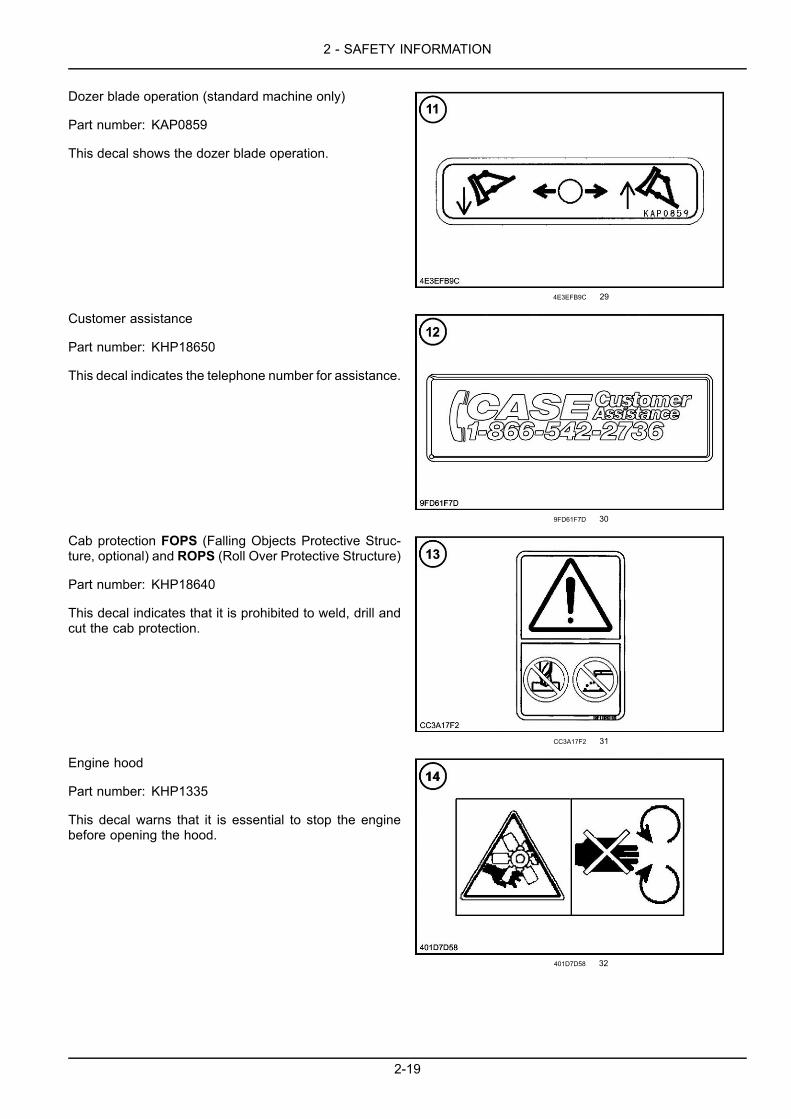
Dozer blade operation (standard machine only)
Part number: KAP0859
This decal shows the dozer blade operation.
4E3EFB9C 29
Customer assistance
Part number: KHP18650
This decal indicates the telephone number for assistance.
9FD61F7D 30
Cab protection FOPS (Falling Objects Protective Struc-ture, optional) and ROPS (Roll Over Protective Structure)
Part number: KHP18640
This decal indicates that it is prohibited to weld, drill andcut the cab protection.
CC3A17F2 31
Engine hood
Part number: KHP1335
This decal warns that it is essential to stop the enginebefore opening the hood.
401D7D58 32
2-19
2 - SAFETY INFORMATION
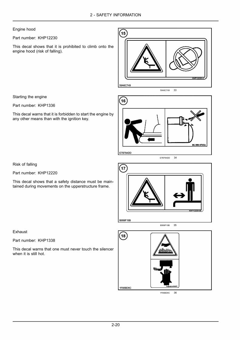
Engine hood
Part number: KHP12230
This decal shows that it is prohibited to climb onto theengine hood (risk of falling).
59A6C749 33
Starting the engine
Part number: KHP1336
This decal warns that it is forbidden to start the engine byany other means than with the ignition key.
E7B784DD 34
Risk of falling
Part number: KHP12220
This decal shows that a safety distance must be main-tained during movements on the upperstructure frame.
B999F19B 35
Exhaust
Part number: KHP1338
This decal warns that one must never touch the silencerwhen it is still hot.
1F66BD6C 36
2-20
2 - SAFETY INFORMATION
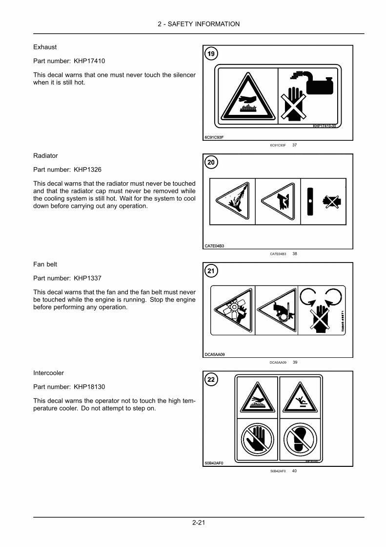
Exhaust
Part number: KHP17410
This decal warns that one must never touch the silencerwhen it is still hot.
6C91C93F 37
Radiator
Part number: KHP1326
This decal warns that the radiator must never be touchedand that the radiator cap must never be removed whilethe cooling system is still hot. Wait for the system to cooldown before carrying out any operation.
CA7E04B3 38
Fan belt
Part number: KHP1337
This decal warns that the fan and the fan belt must neverbe touched while the engine is running. Stop the enginebefore performing any operation.
DCA5AA09 39
Intercooler
Part number: KHP18130
This decal warns the operator not to touch the high tem-perature cooler. Do not attempt to step on.
50B42AF0 40
2-21
2 - SAFETY INFORMATION
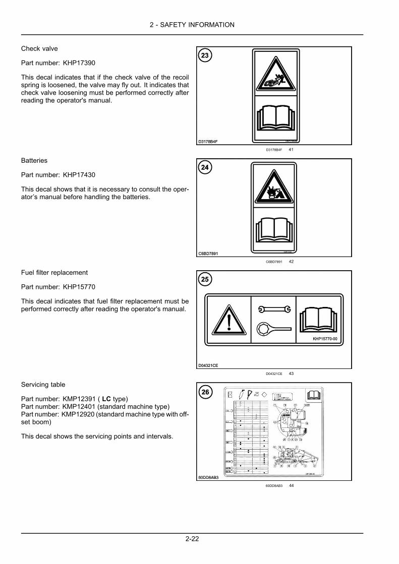
Check valve
Part number: KHP17390
This decal indicates that if the check valve of the recoilspring is loosened, the valve may fly out. It indicates thatcheck valve loosening must be performed correctly afterreading the operator's manual.
D3178B4F 41
Batteries
Part number: KHP17430
This decal shows that it is necessary to consult the oper-ator’s manual before handling the batteries.
C6BD7891 42
Fuel filter replacement
Part number: KHP15770
This decal indicates that fuel filter replacement must beperformed correctly after reading the operator's manual.
D04321CE 43
Servicing table
Part number: KMP12391 ( LC type)Part number: KMP12401 (standard machine type)Part number: KMP12920 (standard machine type with off-set boom)
This decal shows the servicing points and intervals.
60DD8AB3 44
2-22

2 - SAFETY INFORMATION
Accumulator
This decal warns that the accumulator is filled with gasunder high pressure and that one must not bring a flameor weld close to the accumulator. For any service work,consult your CASE CONSTRUCTION Dealer.
42D5FE5F 45
High pressure common rail
Part number: KHP13160
This decal indicates that the high-pressure valve of thecommon rail must not be loosened, because the enginefuel system is highly pressurized. It indicates that high-pressure fuel may spray out dangerously.
275A6D39 46
Engine operation
Part number: KHP17440
This decal warns the operator not to step on the engine.It indicates that engine maintenance must be performedcorrectly after reading the operator's manual.
06BE768D 47
Tie down point
Part number: KHP15200
This decal shows the tie-down points for transporting themachine.
6F7BCB1C 48
2-23
2 - SAFETY INFORMATION
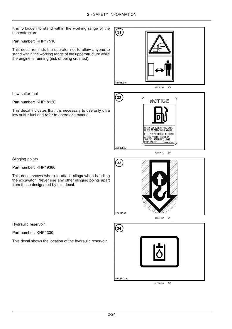
It is forbidden to stand within the working range of theupperstructure
Part number: KHP17510
This decal reminds the operator not to allow anyone tostand within the working range of the upperstructure whilethe engine is running (risk of being crushed).
8E01E2AF 49
Low sulfur fuel
Part number: KHP18120
This decal indicates that it is necessary to use only ultralow sulfur fuel and refer to operator's manual.
A054864D 50
Slinging points
Part number: KHP19380
This decal shows where to attach slings when handlingthe excavator. Never use any other slinging points apartfrom those designated by this decal.
20A61537 51
Hydraulic reservoir
Part number: KHP1330
This decal shows the location of the hydraulic reservoir.
81C8ED1A 52
2-24
2 - SAFETY INFORMATION
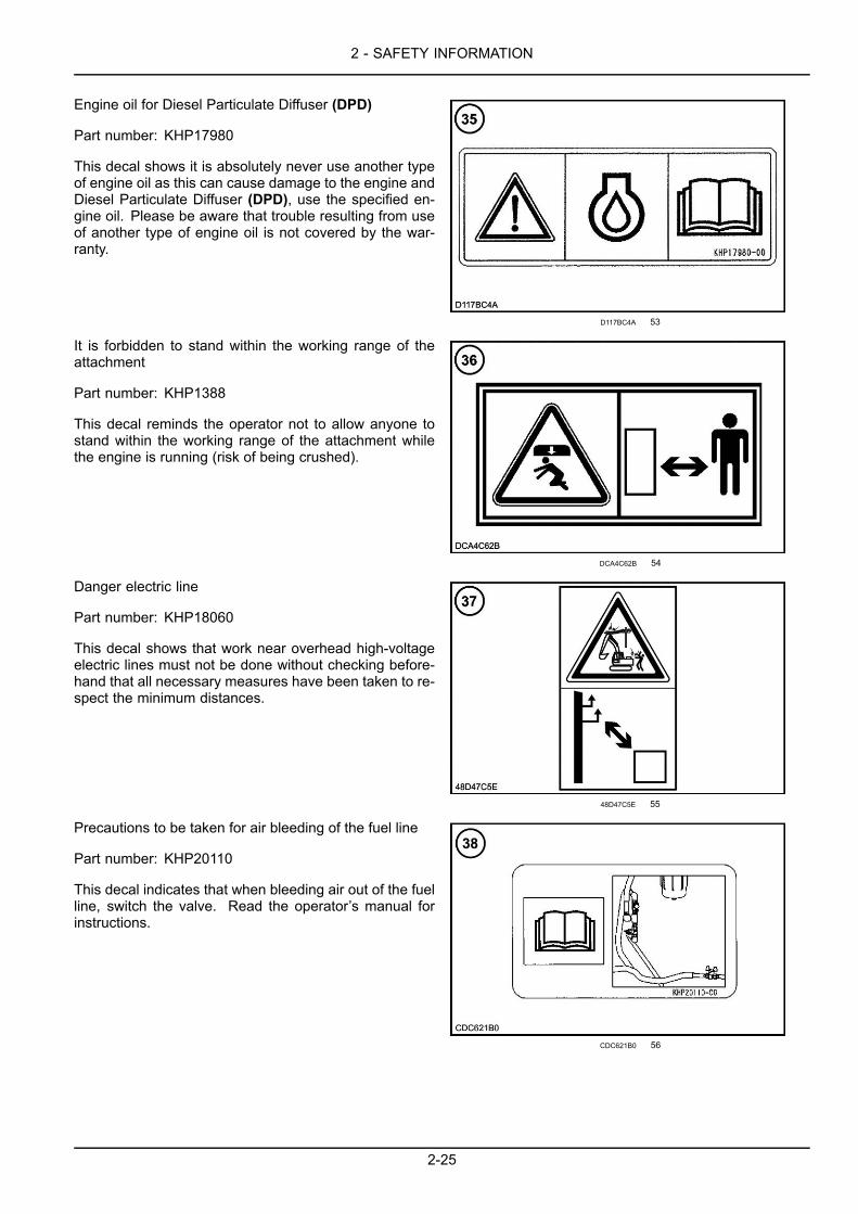
Engine oil for Diesel Particulate Diffuser (DPD)
Part number: KHP17980
This decal shows it is absolutely never use another typeof engine oil as this can cause damage to the engine andDiesel Particulate Diffuser (DPD), use the specified en-gine oil. Please be aware that trouble resulting from useof another type of engine oil is not covered by the war-ranty.
D117BC4A 53
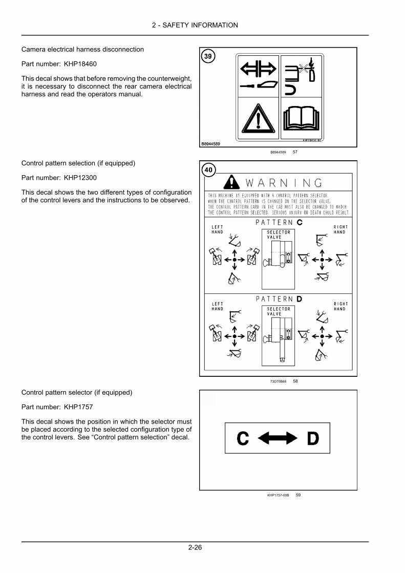
It is forbidden to stand within the working range of theattachment
Part number: KHP1388
This decal reminds the operator not to allow anyone tostand within the working range of the attachment whilethe engine is running (risk of being crushed).
DCA4C62B 54
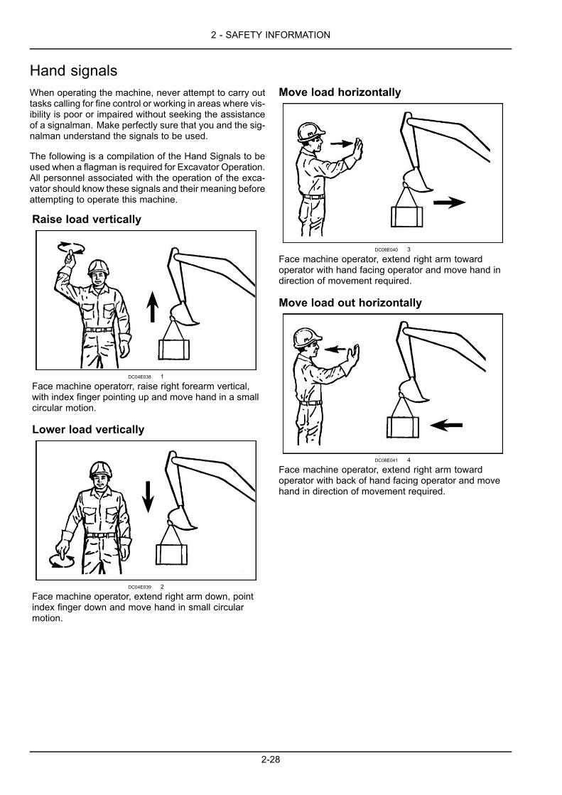
Danger electric line
Part number: KHP18060
This decal shows that work near overhead high-voltageelectric lines must not be done without checking before-hand that all necessary measures have been taken to re-spect the minimum distances.
48D47C5E 55
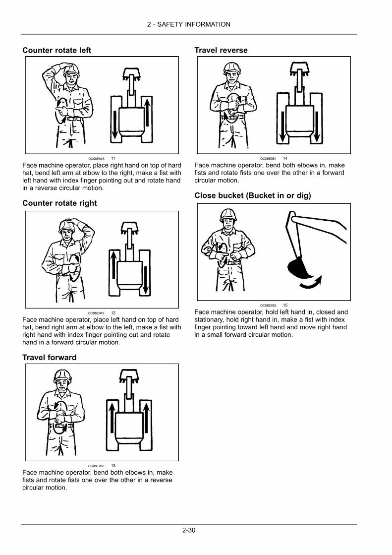
Precautions to be taken for air bleeding of the fuel line
Part number: KHP20110
This decal indicates that when bleeding air out of the fuelline, switch the valve. Read the operator’s manual forinstructions.
CDC621B0 56
2-25
2 - SAFETY INFORMATION
Camera electrical harness disconnection
Part number: KHP18460
This decal shows that before removing the counterweight,it is necessary to disconnect the rear camera electricalharness and read the operators manual.
B8944589 57
Control pattern selection (if equipped)
Part number: KHP12300
This decal shows the two different types of configurationof the control levers and the instructions to be observed.
73D70B68 58
Control pattern selector (if equipped)
Part number: KHP1757
This decal shows the position in which the selector mustbe placed according to the selected configuration type ofthe control levers. See “Control pattern selection” decal.
KHP1757-00B 59
2-26

2 - SAFETY INFORMATION
Fuel tank
Part number: KHP17840
This decal shows the location of the fuel tank and thatsuitable fuel must be used.
EFC5F8C2B 60
Quick coupler (optional)
This decal shows the precautions to be taken to ensurethat the implement is correctly installed on the quick cou-pler.
COUPL-001 61
Battery Disconnect Switch
Part number: KHP22050
This decal indicates that battery disconnect switch mustbe disconnected after reading the operator's manual.
B2013_TU145_NA 62
2-27
2 - SAFETY INFORMATION
Hand signalsWhen operating the machine, never attempt to carry outtasks calling for fine control or working in areas where vis-ibility is poor or impaired without seeking the assistanceof a signalman. Make perfectly sure that you and the sig-nalman understand the signals to be used.
The following is a compilation of the Hand Signals to beused when a flagman is required for Excavator Operation.All personnel associated with the operation of the exca-vator should know these signals and their meaning beforeattempting to operate this machine.
Raise load vertically
DC04E038 1
Face machine operatorr, raise right forearm vertical,with index finger pointing up and move hand in a smallcircular motion.
Lower load vertically
DC04E039 2
Face machine operator, extend right arm down, pointindex finger down and move hand in small circularmotion.
Move load horizontally
DC08E040 3
Face machine operator, extend right arm towardoperator with hand facing operator and move hand indirection of movement required.
Move load out horizontally
DC08E041 4
Face machine operator, extend right arm towardoperator with back of hand facing operator and movehand in direction of movement required.
2-28

2 - SAFETY INFORMATION
Raise boom
DC08E042 5
Face machine operator, extend right arm outhorizontally from shoulder, make a fist with thumb up.
Lower boom
DC08E043 6
Face machine operator, extend right arm outhorizontally from shoulder, make a fist with thumbdown.
Swing left
DC08E044 7
Face machine operator, extend right arm outhorizontally from shoulder, make a fist with index fingerpointing in swing direction.
Swing right
DC08E045 8
Face machine operator, extend left arm out horizontallyfrom shoulder, make a fist with index finger pointing inswing direction.
Arm in
DC08E046 9
Face machine operator, bend at elbows with armsfacing operator, make fists and point thumbs in towardeach other.
Arm out
DC08E047 10
Face machine operator, bend at elbows with armsfacing operator, make fists and point thumbs out awayfrom each other.
2-29
2 - SAFETY INFORMATION
Counter rotate left
DC08E048 11
Face machine operator, place right hand on top of hardhat, bend left arm at elbow to the right, make a fist withleft hand with index finger pointing out and rotate handin a reverse circular motion.
Counter rotate right
DC08E049 12
Face machine operator, place left hand on top of hardhat, bend right arm at elbow to the left, make a fist withright hand with index finger pointing out and rotatehand in a forward circular motion.
Travel forward
DC08E050 13
Face machine operator, bend both elbows in, makefists and rotate fists one over the other in a reversecircular motion.
Travel reverse
DC08E051 14
Face machine operator, bend both elbows in, makefists and rotate fists one over the other in a forwardcircular motion.
Close bucket (Bucket in or dig)
DC08E052 15
Face machine operator, hold left hand in, closed andstationary, hold right hand in, make a fist with indexfinger pointing toward left hand and move right handin a small forward circular motion.
2-30
2 - SAFETY INFORMATION
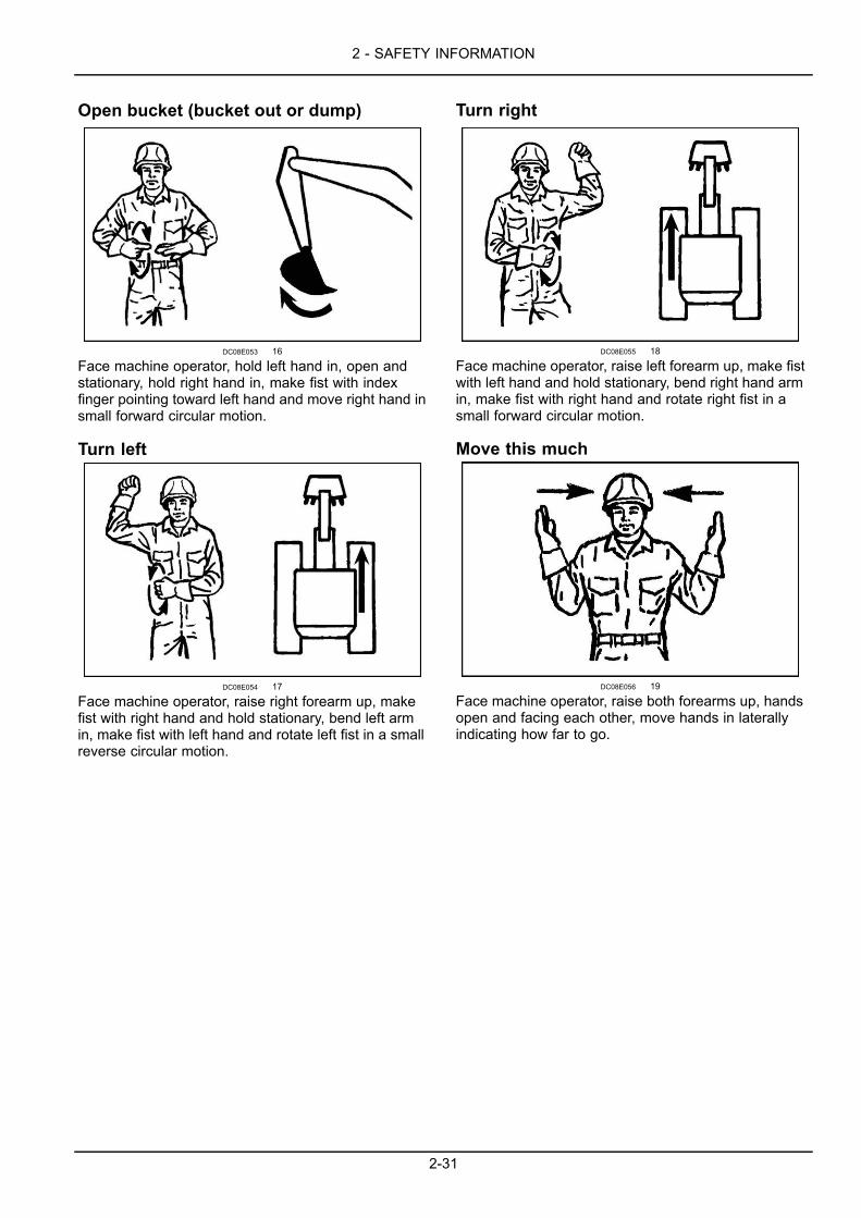
Open bucket (bucket out or dump)
DC08E053 16
Face machine operator, hold left hand in, open andstationary, hold right hand in, make fist with indexfinger pointing toward left hand and move right hand insmall forward circular motion.
Turn left
DC08E054 17
Face machine operator, raise right forearm up, makefist with right hand and hold stationary, bend left armin, make fist with left hand and rotate left fist in a smallreverse circular motion.
Turn right
DC08E055 18
Face machine operator, raise left forearm up, make fistwith left hand and hold stationary, bend right hand armin, make fist with right hand and rotate right fist in asmall forward circular motion.
Move this much
DC08E056 19
Face machine operator, raise both forearms up, handsopen and facing each other, move hands in laterallyindicating how far to go.
2-31
2 - SAFETY INFORMATION
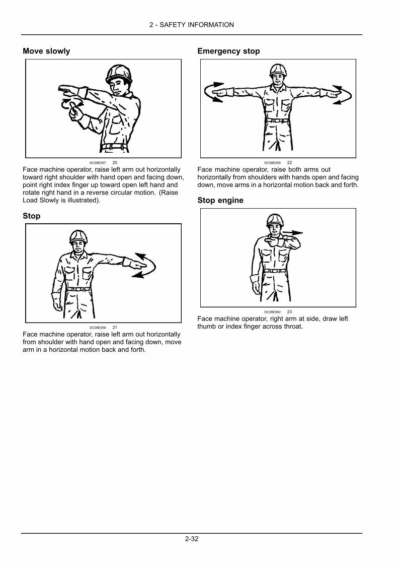
Move slowly
DC08E057 20
Face machine operator, raise left arm out horizontallytoward right shoulder with hand open and facing down,point right index finger up toward open left hand androtate right hand in a reverse circular motion. (RaiseLoad Slowly is illustrated).
Stop
DC08E058 21
Face machine operator, raise left arm out horizontallyfrom shoulder with hand open and facing down, movearm in a horizontal motion back and forth.
Emergency stop
DC08E059 22
Face machine operator, raise both arms outhorizontally from shoulders with hands open and facingdown, move arms in a horizontal motion back and forth.
Stop engine
DC08E060 23
Face machine operator, right arm at side, draw leftthumb or index finger across throat.
2-32
3 - CONTROLS/INSTRUMENTS
3 - CONTROLS/INSTRUMENTS###_3_###ACCESS TO OPERATOR'S PLATFORM
Frame - Access/ExitCab door
CAUTIONPinch hazard!Be careful not to get your hand, clothes, etc. caught in the door when closing it.Failure to comply could result in minor or moderate injury.
C0046A
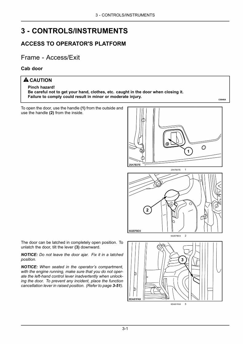
To open the door, use the handle (1) from the outside anduse the handle (2) from the inside.
25A7B37E 1
602EFBD3 2
The door can be latched in completely open position. Tounlatch the door, tilt the lever (3) downward.
NOTICE: Do not leave the door ajar. Fix it in a latchedposition.
NOTICE: When seated in the operator’s compartment,with the engine running, make sure that you do not oper-ate the left-hand control lever inadvertently when unlock-ing the door. To prevent any incident, place the functioncancellation lever in raised position. (Refer to page 3-51).
6DA81FA9 3
3-1
3 - CONTROLS/INSTRUMENTS
Steps and access handles
WARNINGFall hazard!In order to enter or exit the cab, the upper structure frame must be in line with the undercarriage.Failure to comply could result in death or serious injury.
W0225A
WARNINGFall hazard!Clean the steps and access handles to remove all traces of grease, oil, mud, and ice (in winter).Failure to comply could result in death or serious injury.
W0139A
WARNINGFall hazard!Jumping on or off the machine could cause an injury. Always face the machine, use the handrailsand steps, and get on or off slowly. Maintain a three-point contact to avoid falling: both hands on thehandrails and one foot on the step, or one hand on the handrail and both feet on the steps.Failure to comply could result in death or serious injury.
W0141A
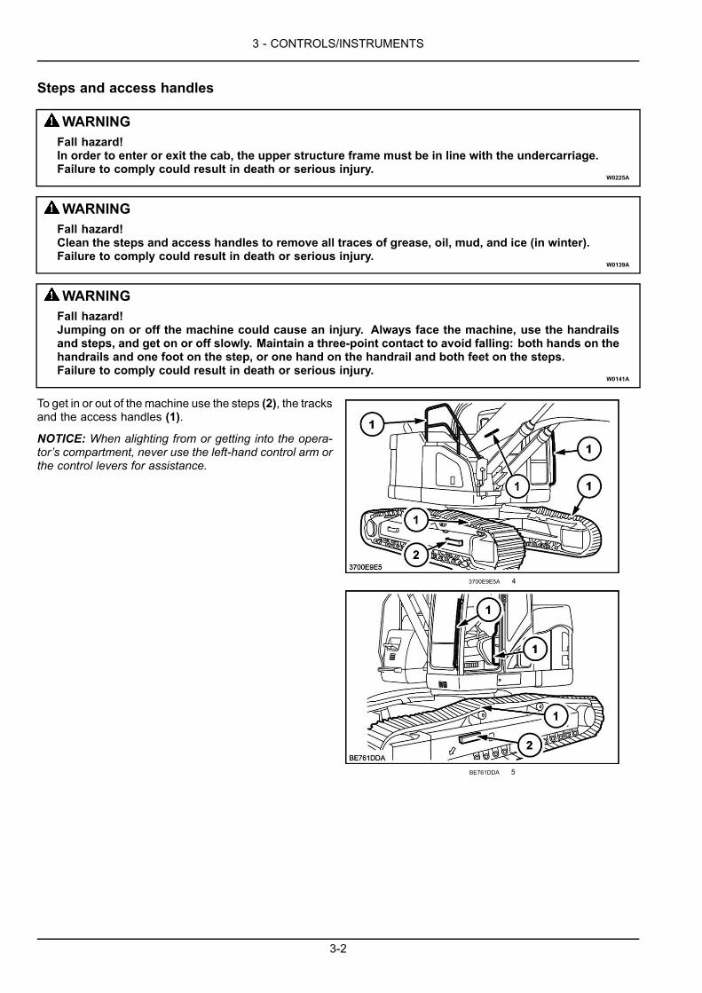
To get in or out of the machine use the steps (2), the tracksand the access handles (1).
NOTICE: When alighting from or getting into the opera-tor’s compartment, never use the left-hand control arm orthe control levers for assistance.
3700E9E5A 4
BE761DDA 5
3-2

3 - CONTROLS/INSTRUMENTS
Position of the operator’s compartment controls and accessoriesWARNINGMisuse hazard!Before starting the engine, make sure you are fully aware of the location and the function of eachcontrol.Failure to comply could result in death or serious injury.
W0226A
96B5C1C9X 1
3-3

3 - CONTROLS/INSTRUMENTS
1. Operator's seat2. Left-hand control arm3. Emergency shutdown switch4. Air conditioning control switch5. Function cancellation lever6. Left-hand control lever, arm and upperstructure swing controls7. Footrest or option pedal8. Travel control levers and pedals9. Footrest or option pedal or offset boom pedal (if equipped)10. Front right-hand console monitor display11. Right-hand console12. Right-hand control lever, boom and bucket controls13. Right-hand switch panel14. Air vents15. Fuse box16. Travel control pedal17. Dozer blade control lever (standard machine only)
3-4
3 - CONTROLS/INSTRUMENTS
OPERATOR'S SEAT
Air suspension seat adjustmentsIn order to operate the machine correctly and with maximum efficiency and comfort, adjust the seat to suit the weightand size of the operator.
NOTE: The adjustment of the seat can only be carried out when the operator is seated in the seat, the engine is shutdown and the ignition key is set to "ACC" (accessory current supply).
398F5A5D 1
1. Combined height and weight adjustment2. Weight adjustment indicator3. Fore/aft adjustment4. Seat back angle adjustment5. Lumbar support adjustment
6. Seat and control arm assembly fore and aft adjust-ment
7. Armrest angle adjustment8. Headrest adjustment9. Seat belt
3-5
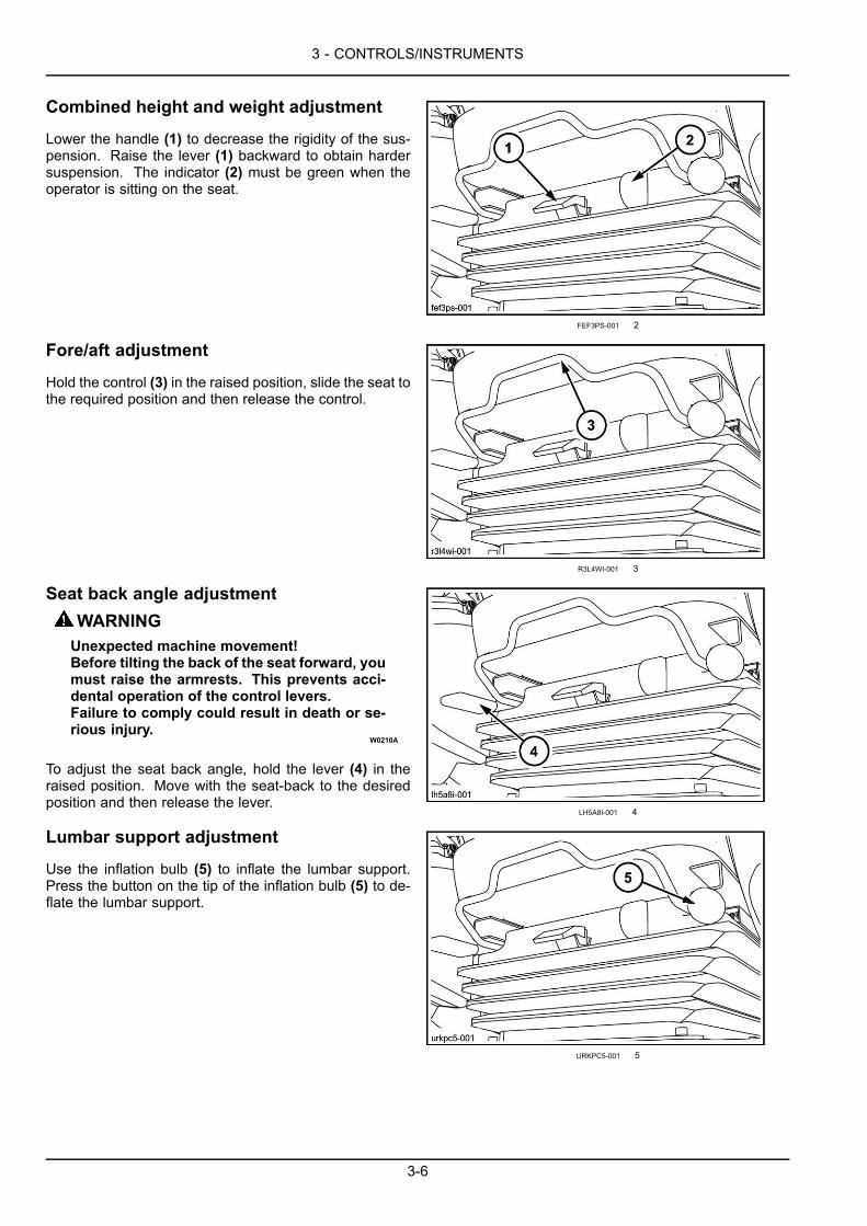
3 - CONTROLS/INSTRUMENTS
Combined height and weight adjustment
Lower the handle (1) to decrease the rigidity of the sus-pension. Raise the lever (1) backward to obtain hardersuspension. The indicator (2) must be green when theoperator is sitting on the seat.
FEF3PS-001 2
Fore/aft adjustment
Hold the control (3) in the raised position, slide the seat tothe required position and then release the control.
R3L4WI-001 3
Seat back angle adjustmentWARNINGUnexpected machine movement!Before tilting the back of the seat forward, youmust raise the armrests. This prevents acci-dental operation of the control levers.Failure to comply could result in death or se-rious injury.
W0210A
To adjust the seat back angle, hold the lever (4) in theraised position. Move with the seat-back to the desiredposition and then release the lever.
LH5A8I-001 4
Lumbar support adjustment
Use the inflation bulb (5) to inflate the lumbar support.Press the button on the tip of the inflation bulb (5) to de-flate the lumbar support.
URKPC5-001 5
3-6

3 - CONTROLS/INSTRUMENTS
Seat and control arm assembly fore and aftadjustment
Pull the control (6) upwards, and slide the seat and controlarm assembly to the desired position, then release thecontrol.
3VH81N-001 6
Armrest angle adjustment
Raise the armrest and adjust to the desired angle usingthe knob (7), then lower the armrest.
C492932B 7
Headrest adjustment
The headrest (8) can be adjusted upward and downwardand backward and forward.
NOTE: To make the headrest return to its initial position(to the rear), tilt it completely forward and then release it.
M6KYEG-001 8
3-7
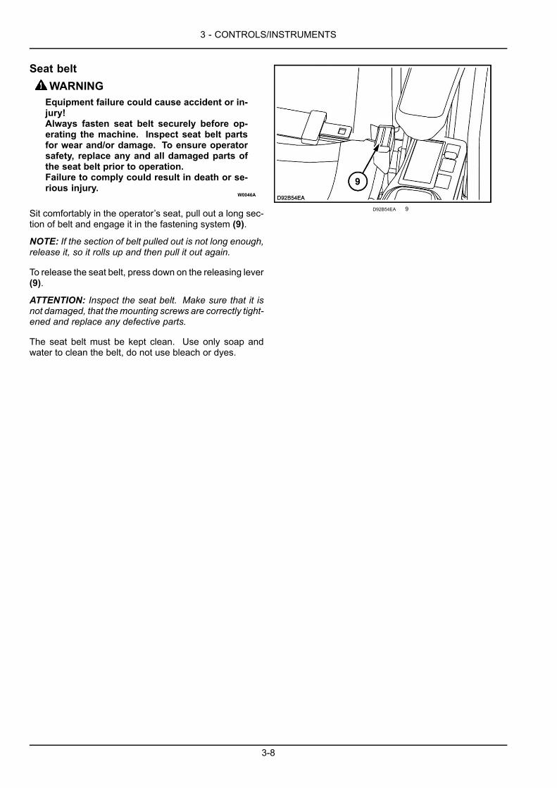
3 - CONTROLS/INSTRUMENTS
Seat beltWARNINGEquipment failure could cause accident or in-jury!Always fasten seat belt securely before op-erating the machine. Inspect seat belt partsfor wear and/or damage. To ensure operatorsafety, replace any and all damaged parts ofthe seat belt prior to operation.Failure to comply could result in death or se-rious injury.
W0046A
Sit comfortably in the operator’s seat, pull out a long sec-tion of belt and engage it in the fastening system (9).
NOTE: If the section of belt pulled out is not long enough,release it, so it rolls up and then pull it out again.
To release the seat belt, press down on the releasing lever(9).
ATTENTION: Inspect the seat belt. Make sure that it isnot damaged, that themounting screws are correctly tight-ened and replace any defective parts.
The seat belt must be kept clean. Use only soap andwater to clean the belt, do not use bleach or dyes.
D92B54EA 9
3-8
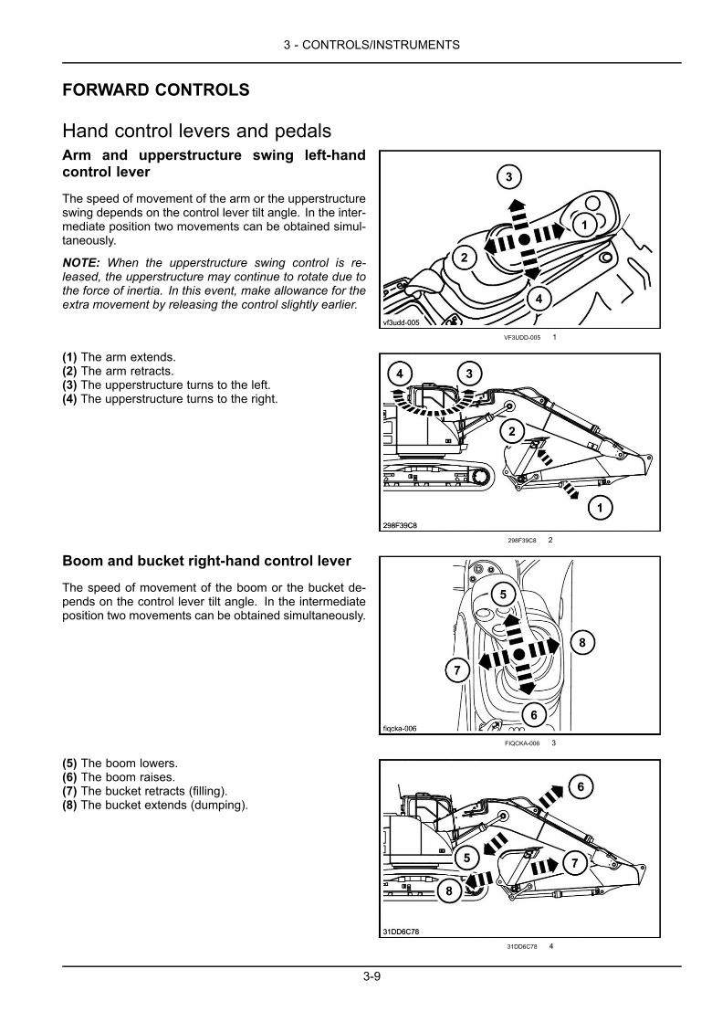
3 - CONTROLS/INSTRUMENTS
FORWARD CONTROLS
Hand control levers and pedalsArm and upperstructure swing left-handcontrol lever
The speed of movement of the arm or the upperstructureswing depends on the control lever tilt angle. In the inter-mediate position two movements can be obtained simul-taneously.
NOTE: When the upperstructure swing control is re-leased, the upperstructure may continue to rotate due tothe force of inertia. In this event, make allowance for theextra movement by releasing the control slightly earlier.
VF3UDD-005 1
(1) The arm extends.(2) The arm retracts.(3) The upperstructure turns to the left.(4) The upperstructure turns to the right.
298F39C8 2
Boom and bucket right-hand control lever
The speed of movement of the boom or the bucket de-pends on the control lever tilt angle. In the intermediateposition two movements can be obtained simultaneously.
FIQCKA-006 3
(5) The boom lowers.(6) The boom raises.(7) The bucket retracts (filling).(8) The bucket extends (dumping).
31DD6C78 4
3-9
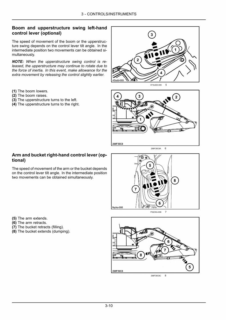
3 - CONTROLS/INSTRUMENTS
Boom and upperstructure swing left-handcontrol lever (optional)
The speed of movement of the boom or the upperstruc-ture swing depends on the control lever tilt angle. In theintermediate position two movements can be obtained si-multaneously.
NOTE: When the upperstructure swing control is re-leased, the upperstructure may continue to rotate due tothe force of inertia. In this event, make allowance for theextra movement by releasing the control slightly earlier.
VF3UDD-005 5
(1) The boom lowers.(2) The boom raises.(3) The upperstructure turns to the left.(4) The upperstructure turns to the right.
298F39C8A 6
Arm and bucket right-hand control lever (op-tional)
The speed of movement of the arm or the bucket dependson the control lever tilt angle. In the intermediate positiontwo movements can be obtained simultaneously.
FIQCKA-006 7
(5) The arm extends.(6) The arm retracts.(7) The bucket retracts (filling).(8) The bucket extends (dumping).
298F39C8C 8
3-10
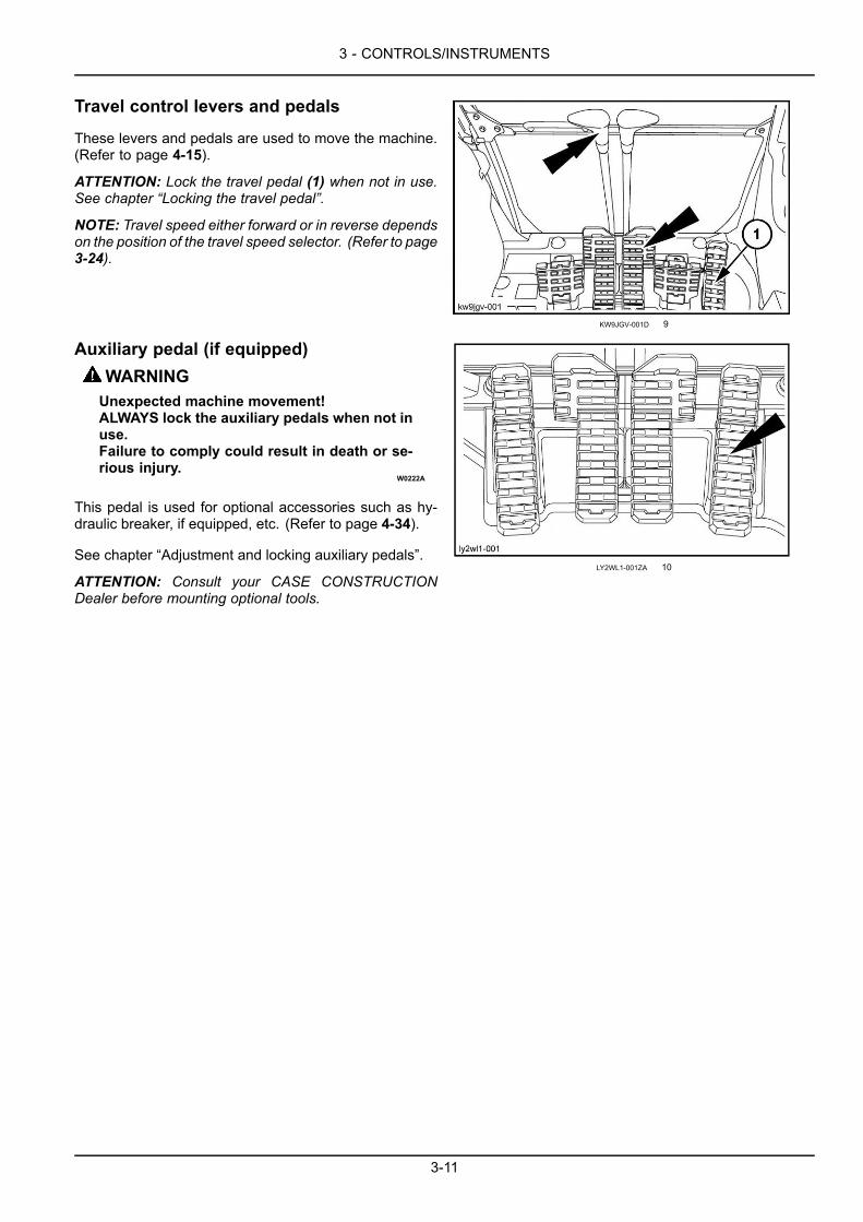
3 - CONTROLS/INSTRUMENTS
Travel control levers and pedals
These levers and pedals are used to move the machine.(Refer to page 4-15).
ATTENTION: Lock the travel pedal (1) when not in use.See chapter “Locking the travel pedal”.
NOTE: Travel speed either forward or in reverse dependson the position of the travel speed selector. (Refer to page3-24).
KW9JGV-001D 9
Auxiliary pedal (if equipped)WARNINGUnexpected machine movement!ALWAYS lock the auxiliary pedals when not inuse.Failure to comply could result in death or se-rious injury.
W0222A
This pedal is used for optional accessories such as hy-draulic breaker, if equipped, etc. (Refer to page 4-34).
See chapter “Adjustment and locking auxiliary pedals”.
ATTENTION: Consult your CASE CONSTRUCTIONDealer before mounting optional tools.
LY2WL1-001ZA 10
3-11

3 - CONTROLS/INSTRUMENTS
Low flow hydraulic circuit control pedal (ifequipped)
WARNINGUnexpected machine movement!ALWAYS lock the auxiliary pedals when not inuse.Failure to comply could result in death or se-rious injury.
W0222A
This pedal is used to direct the clamshell.
(1) The clamshell turns to the right.(2) The clamshell turns to the left.
See chapter “Adjustment and locking auxiliary pedals”.
ATTENTION: Consult your CASE CONSTRUCTIONDealer before mounting optional tools.
LY2WL1-001 11
Low flow hydraulic circuit proportionalswitch (if equipped)
This switch is used for optional accessories such asclamshell, if equipped, etc.
NOTICE: Consult your CASE CONSTRUCTION Dealerto select the optional accessory compatible with your ma-chine and to correctly adjust the flow required for its use.
3208F2E6 12
3-12

3 - CONTROLS/INSTRUMENTS
Offset boom pedal (if equipped)WARNINGUnexpected machine movement!ALWAYS lock the auxiliary pedals when not inuse.Failure to comply could result in death or se-rious injury.
W0222A
This pedal is used to adjust the offset boom.
(1) The offset boom pivots to the right.(2) The offset boom pivots to the left.(3) The pedal is locked. (Place the protection on the pedalto lock it).(4) The pedal is unlocked. (Place the protection forwardsto use the pedal).
8C23A635 13
877A4C2E 14
Footrest
GTQCYL-001C 15
Locking the travel pedalWhen the travel pedal is not used, it is necessary to lockthe pedal.
For locking the pedal, engage the locking pin (1) in thelocking hole (2).
SNKQ6K-003A 16
3-13

3 - CONTROLS/INSTRUMENTS
For using the pedal, place the locking pin (1) in this posi-tion.
SNKQ6K-001 17
NOTE: If the locking pin (1) is in position (3), only forwardtravel is possible.
SNKQ6K-002A 18
Adjustment and locking the auxiliary pedals(if equipped)
WARNINGUnexpected machine movement!Shut down the engine before adjusting theauxiliary pedals.Failure to comply could result in death or se-rious injury.
W0277A
The adjustment of auxiliary pedals is adapted for use withthe accessory installed on the attachment.
Accessory using two pedal flows can be operated in twodirections, the locking pin (1) is removed.
SNKQ6K-001 19
3-14
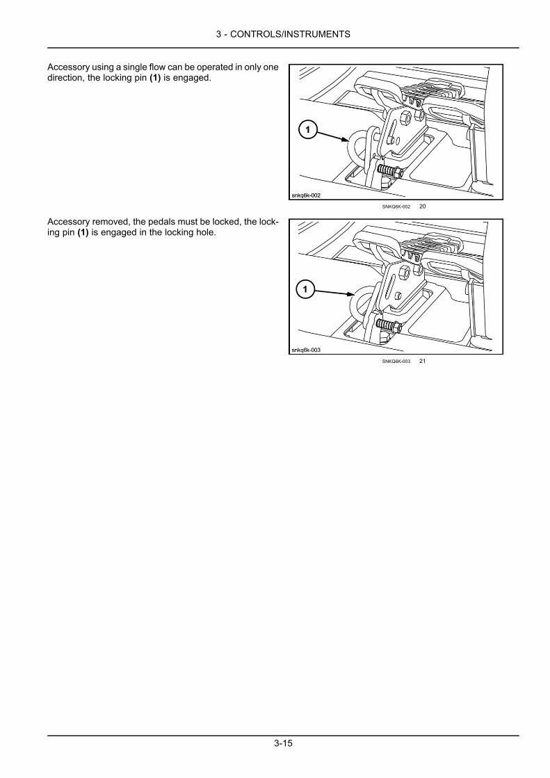
3 - CONTROLS/INSTRUMENTS
Accessory using a single flow can be operated in only onedirection, the locking pin (1) is engaged.
SNKQ6K-002 20
Accessory removed, the pedals must be locked, the lock-ing pin (1) is engaged in the locking hole.
SNKQ6K-003 21
3-15
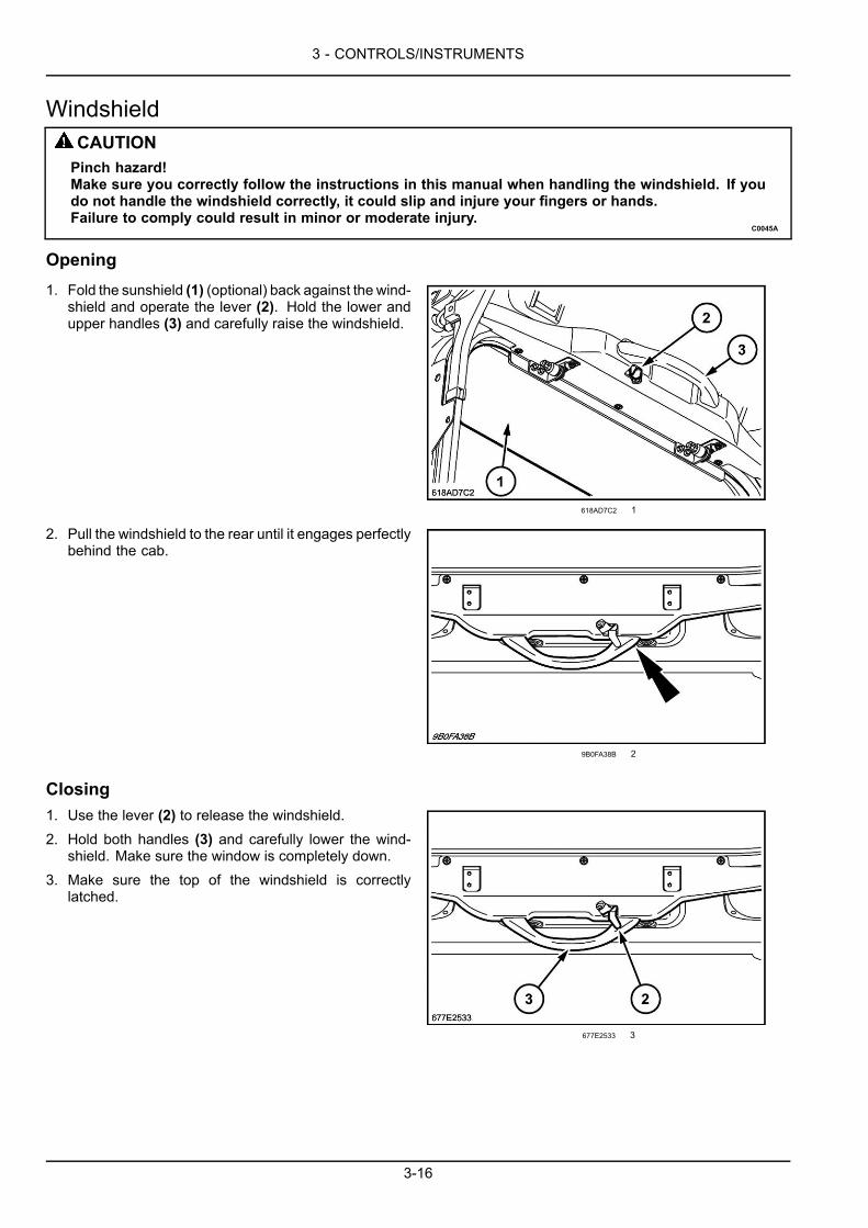
3 - CONTROLS/INSTRUMENTS
WindshieldCAUTIONPinch hazard!Make sure you correctly follow the instructions in this manual when handling the windshield. If youdo not handle the windshield correctly, it could slip and injure your fingers or hands.Failure to comply could result in minor or moderate injury.
C0045A
Opening1. Fold the sunshield (1) (optional) back against the wind-
shield and operate the lever (2). Hold the lower andupper handles (3) and carefully raise the windshield.
618AD7C2 1
2. Pull the windshield to the rear until it engages perfectlybehind the cab.
9B0FA38B 2
Closing1. Use the lever (2) to release the windshield.2. Hold both handles (3) and carefully lower the wind-
shield. Make sure the window is completely down.3. Make sure the top of the windshield is correctly
latched.
677E2533 3
3-16

3 - CONTROLS/INSTRUMENTS
Front lower windowThe front lower window may only be removed when thewindshield is open.
1. Remove the window from its housing by sliding it up-ward.
1193950E 1
2. Place the window in the storage position provided tothe left of the operator's seat and then engage it cor-rectly.
D0F9C4B9 2
3-17

3 - CONTROLS/INSTRUMENTS
Front right-hand console1. Temperature probe
Do not place objects on top of it.2. Monitor display
Clock, Fuel Meter, Coolant Water Thermo meter, Hy-draulic Oil Thermo meter.Displays the function selection status.Displays the machine status.Displays the back monitor.Displays the machine maintenance status.
3. Monitor switchSelects the machine status. The monitor display canbe switched.
4. Air ventsThe air vents control the circulation and direction of airflow. The air vents are opened and controlled manu-ally.
ATTENTION: The air vents must always be openwhen the air conditioning is in use.
6L2VLK-002 1
Cigarette lighter or electrical socket (24 volts)The ignition key being in the “On” position, press thenrelease the cigarette lighter (4).
ATTENTION: Do not keep the cigarette lighter pushed in,to avoid damage.
NOTICE: If the cigarette lighter does not move outwards30 seconds after pressing it in, pull it out manually, sinceotherwise the electrical circuit could be damaged; consultyour CASE CONSTRUCTION Dealer.
NOTE: Once the cigarette lighter has been removed fromits socket, the latter can be used as a 24 volts electricalsocket.
NOTICE: It is strictly prohibited to connect devices of adifferent voltage.
4C8F36CE 1
3-18
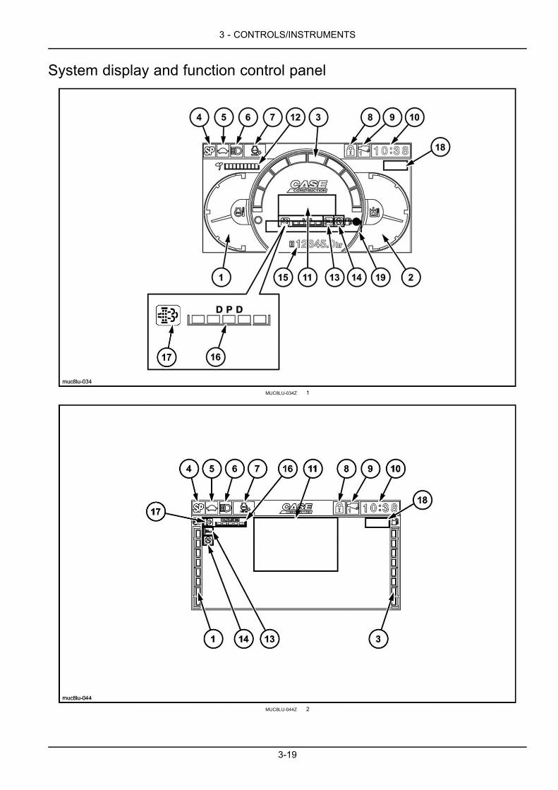
3 - CONTROLS/INSTRUMENTS
System display and function control panel
MUC8LU-034Z 1
MUC8LU-044Z 2
3-19
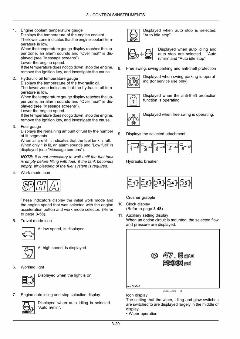
3 - CONTROLS/INSTRUMENTS
1. Engine coolant temperature gaugeDisplays the temperature of the engine coolant.The lower zone indicates that the engine coolant tem-perature is low.When the temperature gauge display reaches the up-per zone, an alarm sounds and "Over heat" is dis-played (see "Message screens").Lower the engine speed.If the temperature does not go down, stop the engine,remove the ignition key, and investigate the cause.
2. Hydraulic oil temperature gaugeDisplays the temperature of the hydraulic oil.The lower zone indicates that the hydraulic oil tem-perature is low.When the temperature gauge display reaches the up-per zone, an alarm sounds and "Over heat" is dis-played (see "Message screens").Lower the engine speed.If the temperature does not go down, stop the engine,remove the ignition key, and investigate the cause.
3. Fuel gaugeDisplays the remaining amount of fuel by the numberof lit segments.When all are lit, it indicates that the fuel tank is full.When only 1 is lit, an alarm sounds and "Low fuel" isdisplayed (see "Message screens").
NOTE: It is not necessary to wait until the fuel tankis empty before filling with fuel. If the tank becomesempty, air bleeding of the fuel system is required.
4. Work mode icon
These indicators display the initial work mode andthe engine speed that was selected with the engineacceleration button and work mode selector. (Referto page 3-58).
5. Travel mode icon
At low speed, is displayed.
At high speed, is displayed.
6. Working light
Displayed when the light is on.
7. Engine auto idling and stop selection display
Displayed when auto idling is selected.“Auto n/min”.
Displayed when auto stop is selected.“Auto idle stop”.
Displayed when auto idling andauto stop are selected. “Auton/min” and “Auto idle stop”.
8. Free swing, swing parking and anti-theft protection
Displayed when swing parking is operat-ing (for service use only).
Displayed when the anti-theft protectionfunction is operating.
Displayed when free swing is operating.
9. Displays the selected attachment
Hydraulic breaker
Crusher grapple10. Clock display
(Refer to page 3-48).11. Auxiliary setting display
When an option circuit is mounted, the selected flowand pressure are displayed.
MUC8LU-043Z 3
Icon displayThe setting that the wiper, idling and glow switchesare switched to are displayed largely in the middle ofdisplay.• Wiper operation
3-20

3 - CONTROLS/INSTRUMENTS
Displayed when the wiper operation is switched.
1st speed
2nd speed
Stop
• Idle modeDisplayed when the engine auto idling and idle stopoperations are switched.
Auto idling
Auto idle stop
Auto idling and idle stop
• Pre-heating (glowing)
12. Eco gaugeThe number of indicators on this gauge increaseswhen the operating state is energy-saving operation.If high-load operations are performed, the number ofgauge indicators decreases.The state of energy-saving operations is indicated.• No mechanical abnormalities will occur even if thenumber of gauge indicators decreases. However, tohelp conserve the environment, try to perform en-ergy-saving operations within the green range, solong as doing so does not hinder work.Key points for energy-saving operations• Try to use H mode or A mode instead of SP mode.• Avoid sharp lever operations.• Avoid high load and relief operations.• Use auto idle and one-touch idle.Also, use idle stop to stop unnecessary idling.Ask your CASE CONSTRUCTION Dealer about howto turn the eco gauge display “On” and “Off”.
13. Auto pressure boost icon
Displayed when the maximum outputstate is entered automatically for the at-tachment.
14. Mute icon
Displayed when the radio volume ismuted.
15. Hour meterThe hour meter displays the engine operation time inunits of 0.1 hr. (6 min.).
16. DPD (Diesel Particulate Diffuser) gaugeIndicates the state of the DPD filter. When 5 gaugeindicators are lit, DPD regeneration is performed.(Refer to page 3-37).
17. Display during DPD (Diesel Particulate Diffuser) re-generation
During automatic regeneration: GreenDuring manual regeneration: YellowRefer to page 3-37 for details.
18. Fuel economy display and DTC (Diagnostic TroubleCode) displayThe time/fuel consumption at that time “gph” is dis-played.The DTC (Diagnostic Trouble Code) is displayedhere.
19. Message screens
MUC8LU-042Z 4
This section of the display screen shows informationicons andmessages that change according to the setapplication of the machine.An alarm also sounds when some of thesemessagesare displayed.The following section describes the icons, mes-sages, and their corresponding explanations.
NOTICE: If a message is displayed, perform mainte-nance according to the message.
ATTENTION: If the message is still displayed aftermaintenance, consult your CASE CONSTRUCTIONDealer.
NOTE: The language of the displayed messages canbe changed, consult your CASE CONSTRUCTIONDealer.
• Low oil pressure
3-21
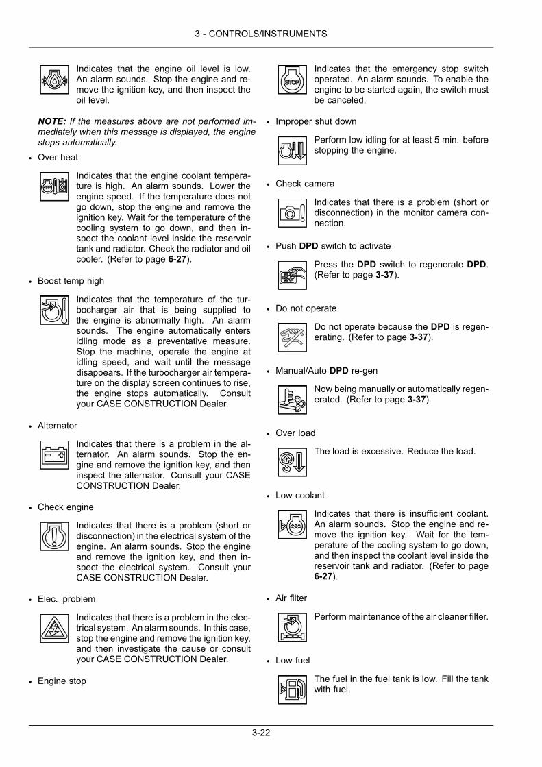
3 - CONTROLS/INSTRUMENTS
Indicates that the engine oil level is low.An alarm sounds. Stop the engine and re-move the ignition key, and then inspect theoil level.
NOTE: If the measures above are not performed im-mediately when this message is displayed, the enginestops automatically.
• Over heat
Indicates that the engine coolant tempera-ture is high. An alarm sounds. Lower theengine speed. If the temperature does notgo down, stop the engine and remove theignition key. Wait for the temperature of thecooling system to go down, and then in-spect the coolant level inside the reservoirtank and radiator. Check the radiator and oilcooler. (Refer to page 6-27).
• Boost temp high
Indicates that the temperature of the tur-bocharger air that is being supplied tothe engine is abnormally high. An alarmsounds. The engine automatically entersidling mode as a preventative measure.Stop the machine, operate the engine atidling speed, and wait until the messagedisappears. If the turbocharger air tempera-ture on the display screen continues to rise,the engine stops automatically. Consultyour CASE CONSTRUCTION Dealer.
• Alternator
Indicates that there is a problem in the al-ternator. An alarm sounds. Stop the en-gine and remove the ignition key, and theninspect the alternator. Consult your CASECONSTRUCTION Dealer.
• Check engine
Indicates that there is a problem (short ordisconnection) in the electrical system of theengine. An alarm sounds. Stop the engineand remove the ignition key, and then in-spect the electrical system. Consult yourCASE CONSTRUCTION Dealer.
• Elec. problem
Indicates that there is a problem in the elec-trical system. An alarm sounds. In this case,stop the engine and remove the ignition key,and then investigate the cause or consultyour CASE CONSTRUCTION Dealer.
• Engine stop
Indicates that the emergency stop switchoperated. An alarm sounds. To enable theengine to be started again, the switch mustbe canceled.
• Improper shut down
Perform low idling for at least 5 min. beforestopping the engine.
• Check camera
Indicates that there is a problem (short ordisconnection) in the monitor camera con-nection.
• Push DPD switch to activate
Press the DPD switch to regenerate DPD.(Refer to page 3-37).
• Do not operate
Do not operate because the DPD is regen-erating. (Refer to page 3-37).
• Manual/Auto DPD re-gen
Now being manually or automatically regen-erated. (Refer to page 3-37).
• Over load
The load is excessive. Reduce the load.
• Low coolant
Indicates that there is insufficient coolant.An alarm sounds. Stop the engine and re-move the ignition key. Wait for the tem-perature of the cooling system to go down,and then inspect the coolant level inside thereservoir tank and radiator. (Refer to page6-27).
• Air filter
Performmaintenance of the air cleaner filter.
• Low fuel
The fuel in the fuel tank is low. Fill the tankwith fuel.
3-22
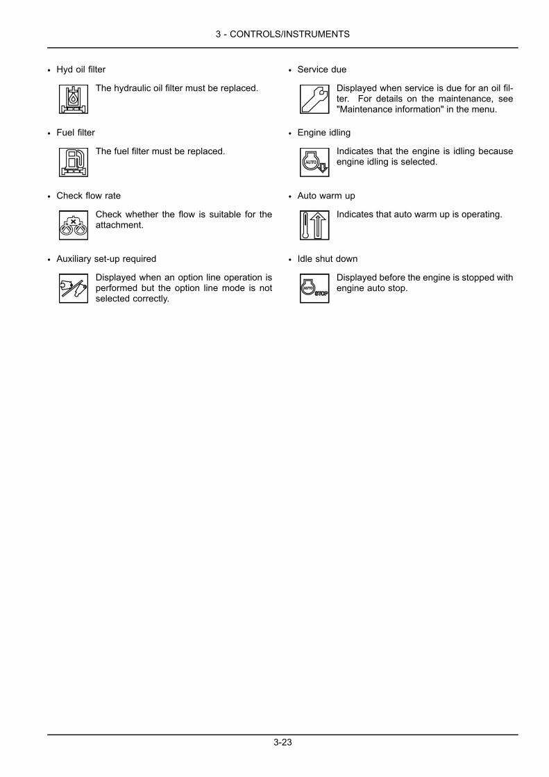
3 - CONTROLS/INSTRUMENTS
• Hyd oil filter
The hydraulic oil filter must be replaced.
• Fuel filter
The fuel filter must be replaced.
• Check flow rate
Check whether the flow is suitable for theattachment.
• Auxiliary set-up required
Displayed when an option line operation isperformed but the option line mode is notselected correctly.
• Service due
Displayed when service is due for an oil fil-ter. For details on the maintenance, see"Maintenance information" in the menu.
• Engine idling
Indicates that the engine is idling becauseengine idling is selected.
• Auto warm up
Indicates that auto warm up is operating.
• Idle shut down
Displayed before the engine is stopped withengine auto stop.
3-23
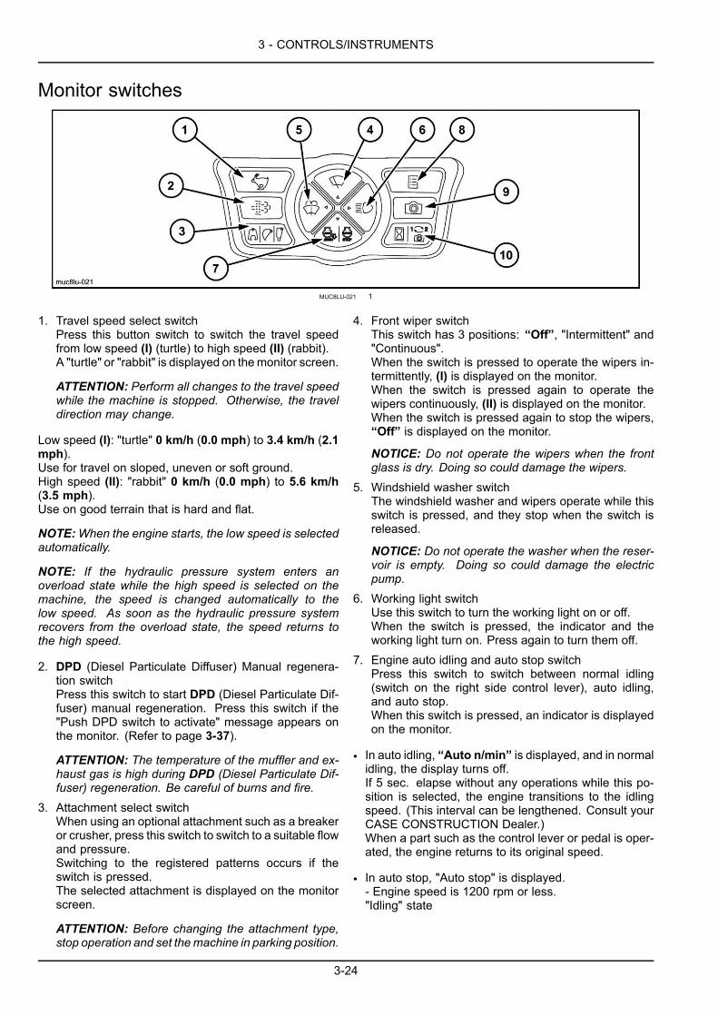
3 - CONTROLS/INSTRUMENTS
Monitor switches
MUC8LU-021 1
1. Travel speed select switchPress this button switch to switch the travel speedfrom low speed (I) (turtle) to high speed (II) (rabbit).A "turtle" or "rabbit" is displayed on themonitor screen.
ATTENTION: Perform all changes to the travel speedwhile the machine is stopped. Otherwise, the traveldirection may change.
Low speed (I): "turtle" 0 km/h (0.0 mph) to 3.4 km/h (2.1mph).Use for travel on sloped, uneven or soft ground.High speed (II): "rabbit" 0 km/h (0.0 mph) to 5.6 km/h(3.5 mph).Use on good terrain that is hard and flat.
NOTE:When the engine starts, the low speed is selectedautomatically.
NOTE: If the hydraulic pressure system enters anoverload state while the high speed is selected on themachine, the speed is changed automatically to thelow speed. As soon as the hydraulic pressure systemrecovers from the overload state, the speed returns tothe high speed.
2. DPD (Diesel Particulate Diffuser) Manual regenera-tion switchPress this switch to start DPD (Diesel Particulate Dif-fuser) manual regeneration. Press this switch if the"Push DPD switch to activate" message appears onthe monitor. (Refer to page 3-37).
ATTENTION: The temperature of the muffler and ex-haust gas is high during DPD (Diesel Particulate Dif-fuser) regeneration. Be careful of burns and fire.
3. Attachment select switchWhen using an optional attachment such as a breakeror crusher, press this switch to switch to a suitable flowand pressure.Switching to the registered patterns occurs if theswitch is pressed.The selected attachment is displayed on the monitorscreen.
ATTENTION: Before changing the attachment type,stop operation and set themachine in parking position.
4. Front wiper switchThis switch has 3 positions: “Off”, "Intermittent" and"Continuous".When the switch is pressed to operate the wipers in-termittently, (I) is displayed on the monitor.When the switch is pressed again to operate thewipers continuously, (II) is displayed on the monitor.When the switch is pressed again to stop the wipers,“Off” is displayed on the monitor.
NOTICE: Do not operate the wipers when the frontglass is dry. Doing so could damage the wipers.
5. Windshield washer switchThe windshield washer and wipers operate while thisswitch is pressed, and they stop when the switch isreleased.
NOTICE: Do not operate the washer when the reser-voir is empty. Doing so could damage the electricpump.
6. Working light switchUse this switch to turn the working light on or off.When the switch is pressed, the indicator and theworking light turn on. Press again to turn them off.
7. Engine auto idling and auto stop switchPress this switch to switch between normal idling(switch on the right side control lever), auto idling,and auto stop.When this switch is pressed, an indicator is displayedon the monitor.
• In auto idling, “Auto n/min” is displayed, and in normalidling, the display turns off.If 5 sec. elapse without any operations while this po-sition is selected, the engine transitions to the idlingspeed. (This interval can be lengthened. Consult yourCASE CONSTRUCTION Dealer.)When a part such as the control lever or pedal is oper-ated, the engine returns to its original speed.
• In auto stop, "Auto stop" is displayed.- Engine speed is 1200 rpm or less."Idling" state
3-24
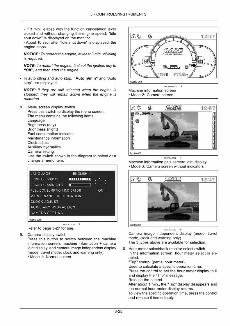
3 - CONTROLS/INSTRUMENTS
- If 3 min. elapse with the function cancellation leverclosed and without changing the engine speed, "Idleshut down" is displayed on the monitor.- About 10 sec. after "Idle shut down" is displayed, theengine stops.
NOTICE: To protect the engine, at least 3 min. of idlingis required.
NOTE: To restart the engine, first set the ignition key to“Off”, and then start the engine.
• In auto idling and auto stop, “Auto n/min” and "Autostop" are displayed.
NOTE: If they are still selected when the engine isstopped, they will remain active when the engine isrestarted.
8. Menu screen display switchPress this switch to display the menu screen.The menu contains the following items.LanguageBrightness (day)Brightness (night)Fuel consumption indicatorMaintenance informationClock adjustAuxiliary hydraulicsCamera settingUse the switch shown in the diagram to select or achange a menu item.
MUC8LU-026 2
Refer to page 3-27 for use.9. Camera display switch
Press this button to switch between the machineinformation screen, machine information + camerajoint display, and camera image independent display(mode, travel mode, clock and warning only).• Mode 1: Normal screen
MUC8LU-003Z 3
Machine information screen• Mode 2: Camera screen
3PZT8U-003Z 4
Machine information plus camera joint display• Mode 3: Camera screen without indicators
3PZT8U-004Z 5
Camera image independent display (mode, travelmode, clock and warning only)The 3 types above are available for selection.
10. Hour meter select/back monitor select switchIn the information screen, hour meter select is en-abled."Trip" control (partial hour meter)Used to calculate a specific operation time.Press the control to set the hour meter display to 0and display the "Trip" message.Release the control.After about 1 min., the "Trip" display disappears andthe normal hour meter display returns.To view the specific operation time, press the controland release it immediately.
3-25

3 - CONTROLS/INSTRUMENTS
To cancel the specific operation time, press and holdthe control for about 2 sec.The specific time display returns to 0.
NOTE: If the key is switched “Off”, the hour metergoes out. If the hour meter button is pressed after
the key is switched “Off”, only the hour meter will bedisplayed for 20 seconds.
NOTE:When a camera image is displayed, the cam-era image is switched each time the camera selectswitch is pressed. Refer to page 3-27.
3-26
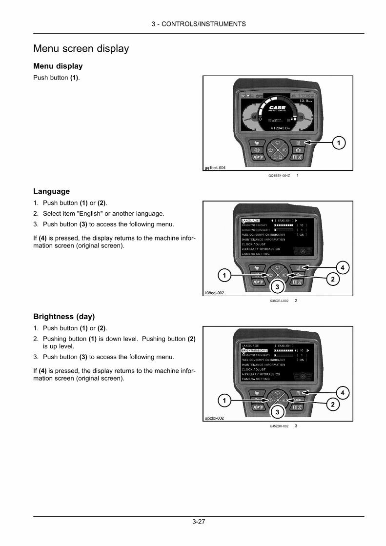
3 - CONTROLS/INSTRUMENTS
Menu screen displayMenu displayPush button (1).
GQ1BE4-004Z 1
Language1. Push button (1) or (2).2. Select item "English" or another language.3. Push button (3) to access the following menu.
If (4) is pressed, the display returns to the machine infor-mation screen (original screen).
K38QEJ-002 2
Brightness (day)1. Push button (1) or (2).2. Pushing button (1) is down level. Pushing button (2)
is up level.3. Push button (3) to access the following menu.
If (4) is pressed, the display returns to the machine infor-mation screen (original screen).
UJ5ZBX-002 3
3-27
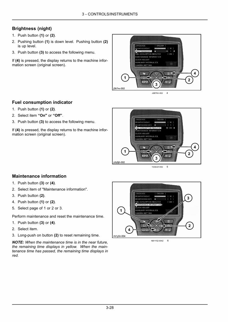
3 - CONTROLS/INSTRUMENTS
Brightness (night)1. Push button (1) or (2).2. Pushing button (1) is down level. Pushing button (2)
is up level.3. Push button (3) to access the following menu.
If (4) is pressed, the display returns to the machine infor-mation screen (original screen).
J2B7NV-002 4
Fuel consumption indicator1. Push button (1) or (2).2. Select item “On" or “Off”.3. Push button (3) to access the following menu.
If (4) is pressed, the display returns to the machine infor-mation screen (original screen).
Y2Q5JH-002 5
Maintenance information1. Push button (3) or (4).2. Select item of "Maintenance information".3. Push button (2).4. Push button (1) or (2).5. Select page of 1 or 2 or 3.
Perform maintenance and reset the maintenance time.1. Push button (3) or (4).2. Select item.3. Long-push on button (2) to reset remaining time.
NOTE: When the maintenance time is in the near future,the remaining time displays in yellow. When the main-tenance time has passed, the remaining time displays inred.
NB1Y5Z-004Z 6
3-28
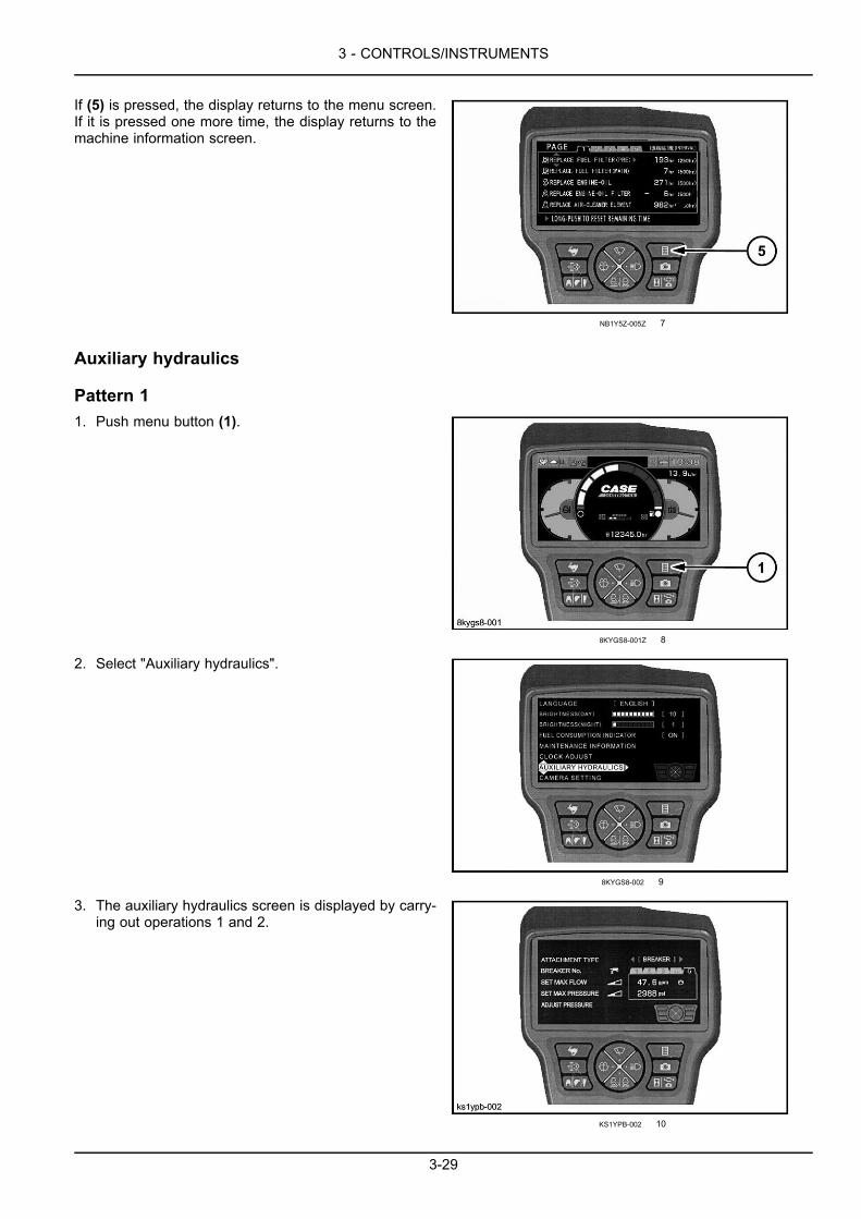
3 - CONTROLS/INSTRUMENTS
If (5) is pressed, the display returns to the menu screen.If it is pressed one more time, the display returns to themachine information screen.
NB1Y5Z-005Z 7
Auxiliary hydraulics
Pattern 11. Push menu button (1).
8KYGS8-001Z 8
2. Select "Auxiliary hydraulics".
8KYGS8-002 9
3. The auxiliary hydraulics screen is displayed by carry-ing out operations 1 and 2.
KS1YPB-002 10
3-29
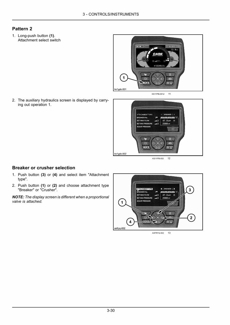
3 - CONTROLS/INSTRUMENTS
Pattern 21. Long-push button (1).
Attachment select switch
KS1YPB-001Z 11
2. The auxiliary hydraulics screen is displayed by carry-ing out operation 1.
KS1YPB-002 12
Breaker or crusher selection1. Push button (3) or (4) and select item "Attachment
type".2. Push button (1) or (2) and choose attachment type
"Breaker" or "Crusher".
NOTE: The display screen is different when a proportionalvalve is attached.
AXFRYQ-002 13
3-30
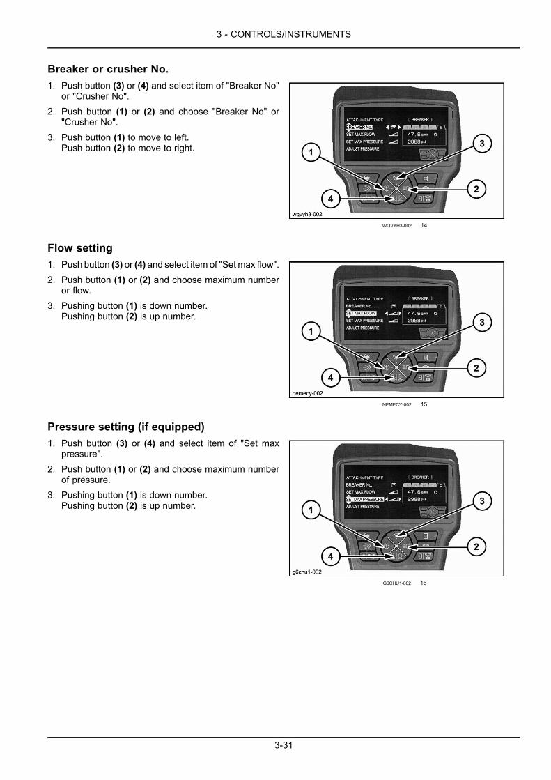
3 - CONTROLS/INSTRUMENTS
Breaker or crusher No.1. Push button (3) or (4) and select item of "Breaker No"
or "Crusher No".2. Push button (1) or (2) and choose "Breaker No" or
"Crusher No".3. Push button (1) to move to left.
Push button (2) to move to right.
WQVYH3-002 14
Flow setting1. Push button (3) or (4) and select item of "Set max flow".2. Push button (1) or (2) and choose maximum number
or flow.3. Pushing button (1) is down number.
Pushing button (2) is up number.
NEMECY-002 15
Pressure setting (if equipped)1. Push button (3) or (4) and select item of "Set max
pressure".2. Push button (1) or (2) and choose maximum number
of pressure.3. Pushing button (1) is down number.
Pushing button (2) is up number.
G6CHU1-002 16
3-31
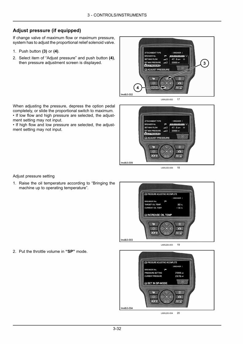
3 - CONTROLS/INSTRUMENTS
Adjust pressure (if equipped)If change valve of maximum flow or maximum pressure,system has to adjust the proportional relief solenoid valve.
1. Push button (3) or (4).2. Select item of “Adjust pressure” and push button (4),
then pressure adjustment screen is displayed.
LMXLB3-002 17
When adjusting the pressure, depress the option pedalcompletely, or slide the proportional switch to maximum.• If low flow and high pressure are selected, the adjust-ment setting may not input.• If high flow and low pressure are selected, the adjust-ment setting may not input.
LMXLB3-009 18
Adjust pressure setting
1. Raise the oil temperature according to “Bringing themachine up to operating temperature”.
LMXLB3-003 19
2. Put the throttle volume in “SP” mode.
LMXLB3-004 20
3-32
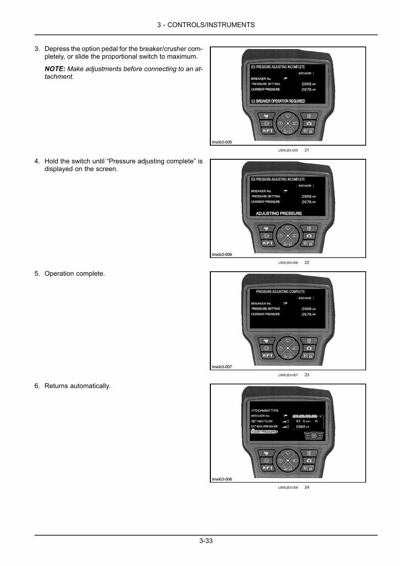
3 - CONTROLS/INSTRUMENTS
3. Depress the option pedal for the breaker/crusher com-pletely, or slide the proportional switch to maximum.
NOTE: Make adjustments before connecting to an at-tachment.
LMXLB3-005 21
4. Hold the switch until “Pressure adjusting complete” isdisplayed on the screen.
LMXLB3-006 22
5. Operation complete.
LMXLB3-007 23
6. Returns automatically.
LMXLB3-008 24
3-33

3 - CONTROLS/INSTRUMENTS
Camera setting
Menu display/camera setting1. Push button (3) or (4) and select item of "Camera set-
ting".2. Push button (2).
NOTE: A maximum of 3 cameras can be installed. Con-sult your CASE CONSTRUCTIONDealer if you would liketo install an additional camera.
CS1NXY-001 25
3-34
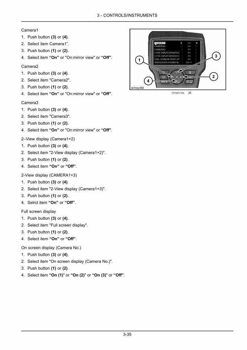
3 - CONTROLS/INSTRUMENTS
Camera11. Push button (3) or (4).2. Select item Camera1”.3. Push button (1) or (2).4. Select item “On” or "On:mirror view" or “Off”.
Camera21. Push button (3) or (4).2. Select item "Camera2".3. Push button (1) or (2).4. Select item “On” or "On:mirror view" or “Off”.
Camera31. Push button (3) or (4).2. Select item "Camera3".3. Push button (1) or (2).4. Select item “On” or "On:mirror view" or “Off”.
2–View display (Camera1+2)1. Push button (3) or (4).2. Select item "2-View display (Camera1+2)".3. Push button (1) or (2).4. Select item “On” or “Off”.
2-View display (CAMERA1+3)1. Push button (3) or (4).2. Select item "2-View display (Camera1+3)".3. Push button (1) or (2).4. Selrct item “On” or “Off”.
Full screen display1. Push button (3) or (4).2. Select item "Full screen display".3. Push button (1) or (2).4. Select item “On” or “Off”.
On screen display (Camera No.)1. Push button (3) or (4).2. Select item "On screen display (Camera No.)".3. Push button (1) or (2).4. Select item “On (1)" or “On (2)" or “On (3)" or “Off”.
CS1NXY-002 26
3-35
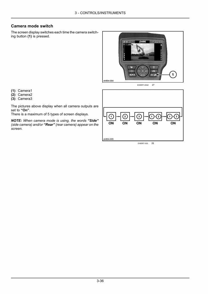
3 - CONTROLS/INSTRUMENTS
Camera mode switchThe screen display switches each time the camera switch-ing button (1) is pressed.
EH85RT-004Z 27
(1): Camera1(2): Camera2(3): Camera3
The pictures above display when all camera outputs areset to “On”.There is a maximum of 5 types of screen displays.
NOTE: When camera mode is using, the words “Side”(side camera) and/or “Rear” (rear camera) appear on thescreen.
EH85RT-005 28
3-36
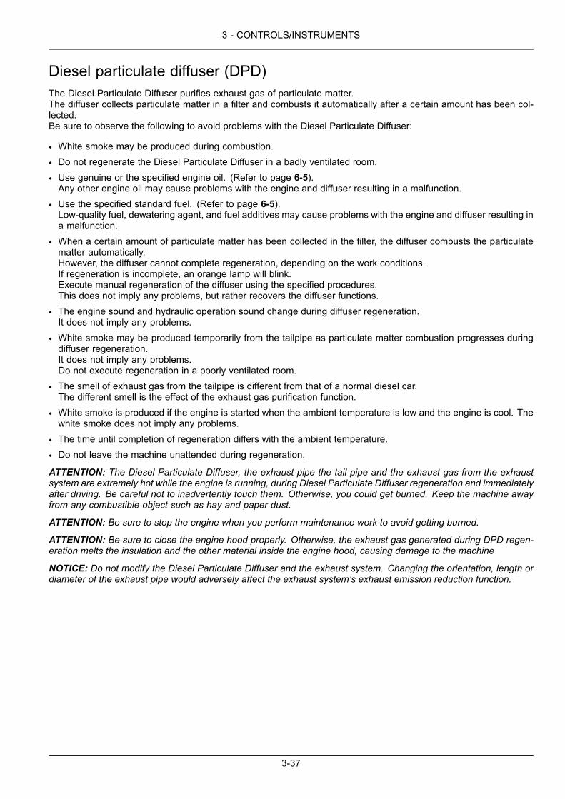
3 - CONTROLS/INSTRUMENTS
Diesel particulate diffuser (DPD)The Diesel Particulate Diffuser purifies exhaust gas of particulate matter.The diffuser collects particulate matter in a filter and combusts it automatically after a certain amount has been col-lected.Be sure to observe the following to avoid problems with the Diesel Particulate Diffuser:
• White smoke may be produced during combustion.
• Do not regenerate the Diesel Particulate Diffuser in a badly ventilated room.
• Use genuine or the specified engine oil. (Refer to page 6-5).Any other engine oil may cause problems with the engine and diffuser resulting in a malfunction.
• Use the specified standard fuel. (Refer to page 6-5).Low-quality fuel, dewatering agent, and fuel additives may cause problems with the engine and diffuser resulting ina malfunction.
• When a certain amount of particulate matter has been collected in the filter, the diffuser combusts the particulatematter automatically.However, the diffuser cannot complete regeneration, depending on the work conditions.If regeneration is incomplete, an orange lamp will blink.Execute manual regeneration of the diffuser using the specified procedures.This does not imply any problems, but rather recovers the diffuser functions.
• The engine sound and hydraulic operation sound change during diffuser regeneration.It does not imply any problems.
• White smoke may be produced temporarily from the tailpipe as particulate matter combustion progresses duringdiffuser regeneration.It does not imply any problems.Do not execute regeneration in a poorly ventilated room.
• The smell of exhaust gas from the tailpipe is different from that of a normal diesel car.The different smell is the effect of the exhaust gas purification function.
• White smoke is produced if the engine is started when the ambient temperature is low and the engine is cool. Thewhite smoke does not imply any problems.
• The time until completion of regeneration differs with the ambient temperature.
• Do not leave the machine unattended during regeneration.
ATTENTION: The Diesel Particulate Diffuser, the exhaust pipe the tail pipe and the exhaust gas from the exhaustsystem are extremely hot while the engine is running, during Diesel Particulate Diffuser regeneration and immediatelyafter driving. Be careful not to inadvertently touch them. Otherwise, you could get burned. Keep the machine awayfrom any combustible object such as hay and paper dust.
ATTENTION: Be sure to stop the engine when you perform maintenance work to avoid getting burned.
ATTENTION: Be sure to close the engine hood properly. Otherwise, the exhaust gas generated during DPD regen-eration melts the insulation and the other material inside the engine hood, causing damage to the machine
NOTICE: Do not modify the Diesel Particulate Diffuser and the exhaust system. Changing the orientation, length ordiameter of the exhaust pipe would adversely affect the exhaust system’s exhaust emission reduction function.
3-37

3 - CONTROLS/INSTRUMENTS
Diesel Particulate Diffuser
ATRG3F-001 1
1. Lamp
Normal operation: OffAutomatic regeneration: GreenManual regeneration request: Blinking orangeManual regeneration: OrangeDPD trouble: Red
2. Gauge
Normal operation: Collected particulate matter amount is indicated.In automatic regeneration: Remaining regeneration time is displayed.In manual regeneration: Remaining regeneration time is displayed.
3. Message
Displayed during automatic regeneration, manual regeneration and when a manual regeneration request is issued.
4. Switch
Used to start manual regeneration.
3-38

3 - CONTROLS/INSTRUMENTS
Automatic regeneration
4FKEJV-001ZA 2
The machine may be operated normally during automatic regeneration.
• No switch operation is required.
• The engine sound changes during automatic regeneration.This does not imply any problems.
• If the machine is not used for a long time even though the engine is running, operation may change into manualregeneration, since automatic regeneration does not start or is not completed normally.Stop the engine if the machine is not used for a long time.
1. The gauge becomes full.Automatic regeneration starts.
• The green lamp is lit.
• The buzzer sounds for 2 seconds.
• The following message is displayed cyclically.
Auto DPD Re-gen
Minimum regeneration time: 8 minutes
NOTE: The regeneration time will differ depending on the conditions.
2. The gauge becomes zero.
• The lamp goes out.
• Automatic regeneration is complete.
3-39

3 - CONTROLS/INSTRUMENTS
Suspending automatic regeneration
4FKEJV-001ZA 3
Automatic regeneration is suspended if the Diesel Particulate Diffuser switch is pressed during regeneration.If the switch is held for 3 seconds or more during automatic regeneration, operation moves to optional manual regen-eration. (The orange lamp blinks.)Do not press the switch again if manual regeneration is not wanted.The orange lamp goes out.The diffuser may become faulty if operation is continued when automatic regeneration is suspended for a long time.Move to a safe place as quickly as possible and execute regeneration. Operation changes to manual regeneration ifautomatic regeneration is suspended for a long time.
1. In automatic regeneration
• The green lamp is lit.
• The following message is displayed cyclically.
Auto DPD Re-gen
2. Carry out either of the following.
• Pressing the switch.
Push DPD switch to activate
3. Automatic regeneration is suspended.
• The green lamp goes out.
• The following message is displayed.
Push DPD switch to activate
4. Press the switch once to restart automatic regeneration.
• Automatic regeneration restarts within several seconds.
3-40

3 - CONTROLS/INSTRUMENTS
Automatic regeneration (necessity of cooling)
4FKEJV-001ZA 4
If the exhaust temperature (water temperature) is high, the Diesel Particulate Diffuser may be broken.Thus, automatic regeneration will not start.
When cooling is necessary:
• The green lamp blinks.
• The indicator blinks.
• The buzzer sounds for 2 seconds
• The following message is displayed.
Auto DPD Re-gen
Carry out either of the following if the lamp and the indicator blink.
1. Stop machine operation and carry out cooling.
When cooling is completed, the lamp and the indicator are lit.
After cooling is completed:
• The green lamp is lit.
• The indicator is lit.
• The buzzer sounds 2 seconds.
• The following message is displayed.
Auto DPD Re-gen
Automatic regeneration starts.
2. Press the switch to suspend automatic regeneration.
NOTE: Automatic regeneration changes into manual regeneration if it is suspended for a long time.
Press the switch.
• The green lamp goes off.
• The following message is displayed.
Push DPD switch to activate
3-41
3 - CONTROLS/INSTRUMENTS
Automatic regeneration is suspended.
Carry out cooling after completion of work.
Press the switch again to restart automatic regeneration.
• The green lamp is lit.
• The indicator is lit.
• The buzzer sounds 2 seconds.
• The following message is displayed.
Auto DPD Re-gen
Automatic regeneration starts.
3-42

3 - CONTROLS/INSTRUMENTS
Manual regeneration
XNNFHF-001Z 5
Normal operation is disabled in manual regeneration.
When manual regeneration starts, engine revolutions are reduced automatically and the engine sound and hydraulicoperation sound change.These do not imply any problems.
If operation continues when the orange lamp blinks, the diffuser may be faulty.Move to a safe place as quickly as possible and execute regeneration.
ATTENTION: If the switch is not pressed for a long time, the orange lamp changes from slow to fast blinking. If theswitch is not pressed at this time, the engine problem warning lamp goes on and the diffuser needs to be repaired.
NOTE: Consult your CASE CONSTRUCTION Dealer if a red DPD icon is displayed.
Manual regeneration finishes earlier immediately after the machine runs than when the engine is cool.
The water temperature may rise during manual regeneration.
1. The orange lamp blinks.
• The buzzer sounds for 2 seconds.
• The following message is displayed.
Push DPD switch to activate
2. Move the machine to a safe place with no combustible objects.
• Set the function cancellation lever to the lock position (safety bar retracted).
• Press the switch.
3. Manual regeneration starts.
• The orange lamp is lit.
• The buzzer sounds for 2 seconds.
• The following messages are displayed cyclically.
Manual DPD Re-gen
Do not operate
3-43

3 - CONTROLS/INSTRUMENTS
Regeneration time: 20 to 25 minutes.
NOTE: The regeneration time may differ depending on the conditions.
4. The gauge becomes zero.
• The lamp goes out.
• Manual regeneration is complete.
3-44
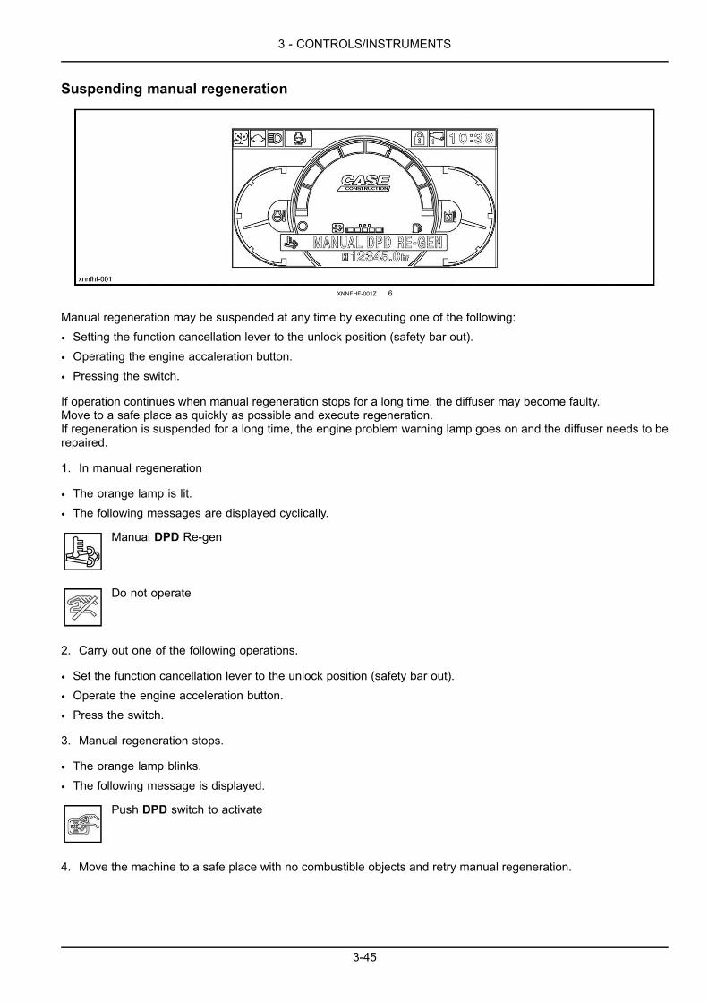
3 - CONTROLS/INSTRUMENTS
Suspending manual regeneration
XNNFHF-001Z 6
Manual regeneration may be suspended at any time by executing one of the following:
• Setting the function cancellation lever to the unlock position (safety bar out).
• Operating the engine accaleration button.
• Pressing the switch.
If operation continues when manual regeneration stops for a long time, the diffuser may become faulty.Move to a safe place as quickly as possible and execute regeneration.If regeneration is suspended for a long time, the engine problem warning lamp goes on and the diffuser needs to berepaired.
1. In manual regeneration
• The orange lamp is lit.
• The following messages are displayed cyclically.
Manual DPD Re-gen
Do not operate
2. Carry out one of the following operations.
• Set the function cancellation lever to the unlock position (safety bar out).
• Operate the engine acceleration button.
• Press the switch.
3. Manual regeneration stops.
• The orange lamp blinks.
• The following message is displayed.
Push DPD switch to activate
4. Move the machine to a safe place with no combustible objects and retry manual regeneration.
3-45

3 - CONTROLS/INSTRUMENTS
Optional manual regeneration
XNNFHF-001Z 7
If the machine is not used for a long time when the engine is operating in automatic regeneration, automatic regener-ation may not start or complete normally.In such a case, manual regeneration may be completed automatically by stopping automatic regeneration and exe-cuting optional manual regeneration.Note that the machine cannot be operated in optional manual regeneration and the regeneration time takes longer.When the switch is held for 3 seconds when automatic regeneration is stopped, the orange lamp blinks for 10 secondsand operation changes into manual regeneration.When the switch is pressed again while the orange lamp is blinking, manual regeneration starts.Do not press the switch if manual regeneration should not be started.The blinking orange lamp goes out 10 seconds later.
1. In automatic regeneration.
• The green lamp is lit.
• The following message is displayed cyclically.
Auto DPD Re-gen
2. Pressing the switch.3. Automatic regeneration stops.
• The green lamp goes out.
• The following message is displayed.
Push DPD switch to activate
4. Move the machine to a safe place with no combustible objects.
• Set the function cancellation lever to the lock position (safety bar retracted).
5. Hold the switch for 3 seconds to move to optional manual regeneration.6. Moves to manual regeneration.
• The orange lamp blinks.
• The buzzer sounds for 2 seconds.
• The following message is displayed.
Push DPD switch to activate
3-46

3 - CONTROLS/INSTRUMENTS
7. Press the switch while the lamp is blinking (blinking lasts for 10 seconds).
NOTE: If you do not need to perform manual regeneration, do not press the switch. The lamp will stop blinking andgo out after 10 seconds. The following message is displayed again.
Push DPD switch to activate
8. Manual regeneration starts.
• The orange lamp is lit.
• The buzzer sounds for 2 seconds.
• The following messages are displayed cyclically.
Manual DPD Re-gen
Do not operate
Regeneration time: 20 to 25 minutes.
9. Manual regeneration is complete.
• The gauge becomes zero.
• The lamp goes out.
3-47

3 - CONTROLS/INSTRUMENTS
Clock adjustment1. Press the menu button (1) to display the menu screen.
ETGEOB-001 1
2. Select "Clock adjust" in the menu screen by pressingbuttons (2) to (3) and enter by pressing button (5).
ETGE0B-004 2
3. Set the time on "Hour : Minutes" by pressing buttons(2) to (3) and (4) to (5) and return to the menu screenby pressing (1).
ETGEOB-005 3
3-48
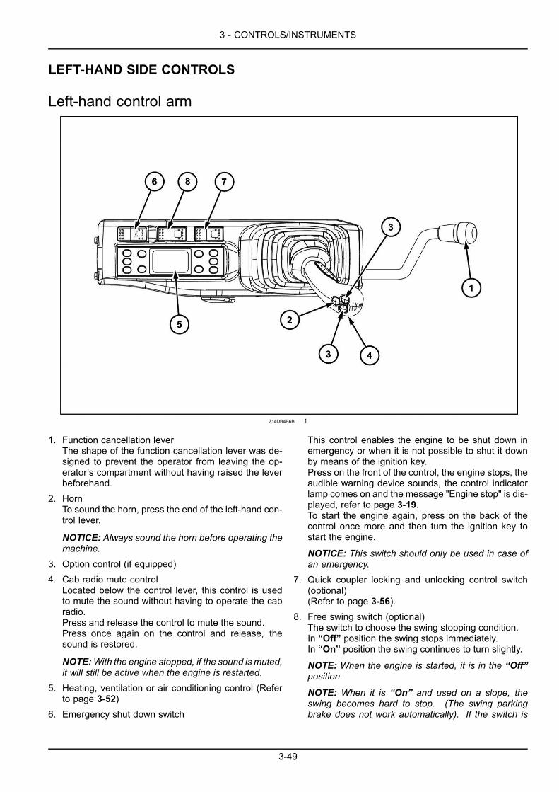
3 - CONTROLS/INSTRUMENTS
LEFT-HAND SIDE CONTROLS
Left-hand control arm
714DB4B6B 1
1. Function cancellation leverThe shape of the function cancellation lever was de-signed to prevent the operator from leaving the op-erator’s compartment without having raised the leverbeforehand.
2. HornTo sound the horn, press the end of the left-hand con-trol lever.
NOTICE: Always sound the horn before operating themachine.
3. Option control (if equipped)4. Cab radio mute control
Located below the control lever, this control is usedto mute the sound without having to operate the cabradio.Press and release the control to mute the sound.Press once again on the control and release, thesound is restored.
NOTE:With the engine stopped, if the sound is muted,it will still be active when the engine is restarted.
5. Heating, ventilation or air conditioning control (Referto page 3-52)
6. Emergency shut down switch
This control enables the engine to be shut down inemergency or when it is not possible to shut it downby means of the ignition key.Press on the front of the control, the engine stops, theaudible warning device sounds, the control indicatorlamp comes on and the message "Engine stop" is dis-played, refer to page 3-19.To start the engine again, press on the back of thecontrol once more and then turn the ignition key tostart the engine.
NOTICE: This switch should only be used in case ofan emergency.
7. Quick coupler locking and unlocking control switch(optional)(Refer to page 3-56).
8. Free swing switch (optional)The switch to choose the swing stopping condition.In “Off” position the swing stops immediately.In “On” position the swing continues to turn slightly.
NOTE: When the engine is started, it is in the “Off”position.
NOTE: When it is “On” and used on a slope, theswing becomes hard to stop. (The swing parkingbrake does not work automatically). If the switch is
3-49
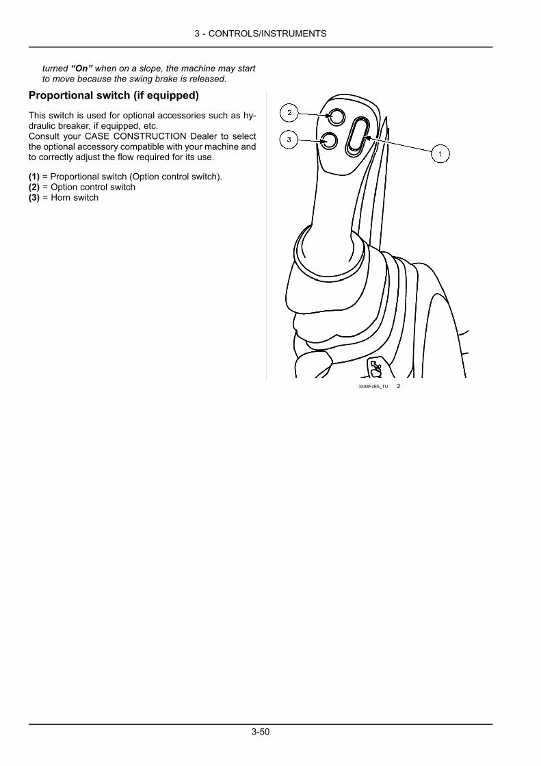
3 - CONTROLS/INSTRUMENTS
turned “On” when on a slope, the machine may startto move because the swing brake is released.
Proportional switch (if equipped)
This switch is used for optional accessories such as hy-draulic breaker, if equipped, etc.Consult your CASE CONSTRUCTION Dealer to selectthe optional accessory compatible with your machine andto correctly adjust the flow required for its use.
(1) = Proportional switch (Option control switch).(2) = Option control switch(3) = Horn switch
3208F2E6_TU 2
3-50
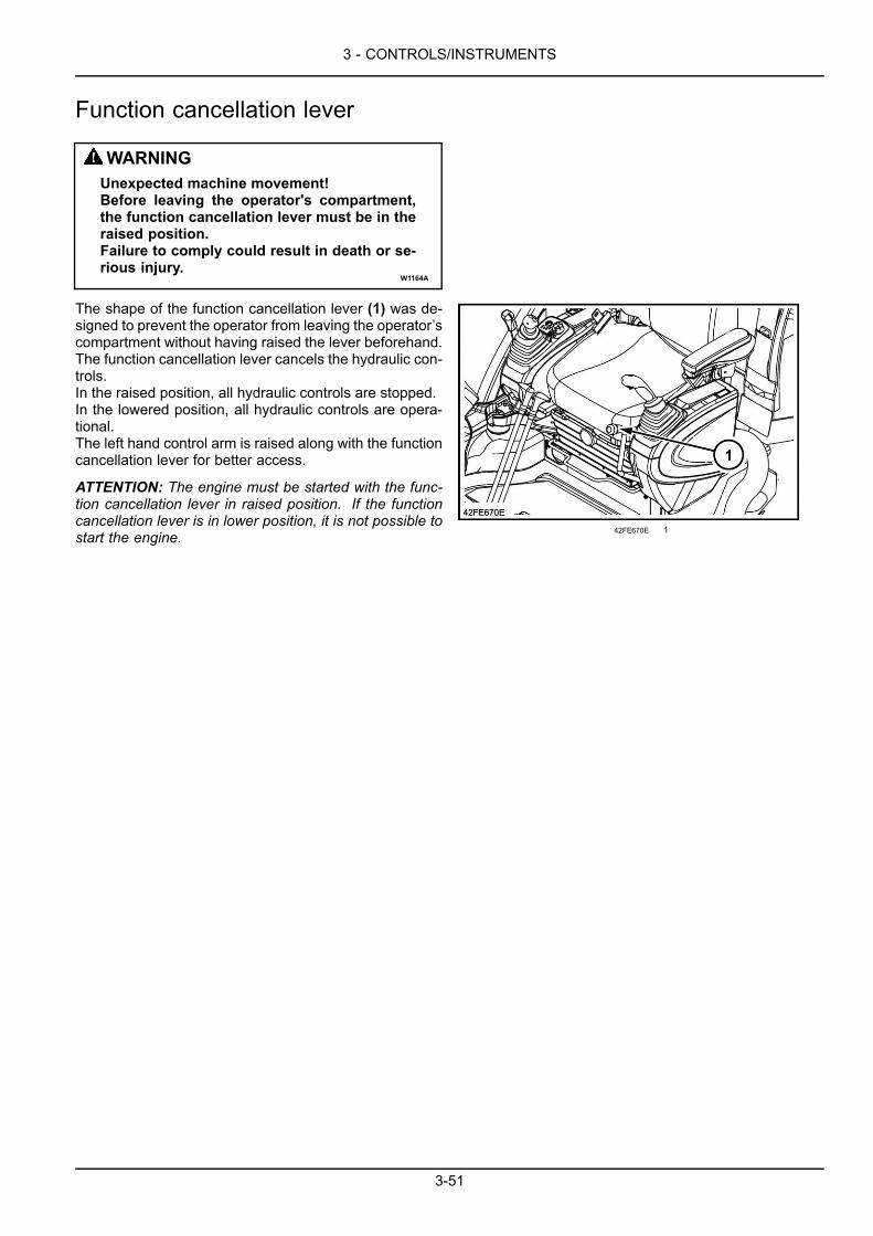
3 - CONTROLS/INSTRUMENTS
Function cancellation lever
WARNINGUnexpected machine movement!Before leaving the operator's compartment,the function cancellation lever must be in theraised position.Failure to comply could result in death or se-rious injury.
W1164A
The shape of the function cancellation lever (1) was de-signed to prevent the operator from leaving the operator’scompartment without having raised the lever beforehand.The function cancellation lever cancels the hydraulic con-trols.In the raised position, all hydraulic controls are stopped.In the lowered position, all hydraulic controls are opera-tional.The left hand control arm is raised along with the functioncancellation lever for better access.
ATTENTION: The engine must be started with the func-tion cancellation lever in raised position. If the functioncancellation lever is in lower position, it is not possible tostart the engine. 42FE670E 1
3-51

3 - CONTROLS/INSTRUMENTS
Heating, ventilation or air-conditioning control
BB5EU2-001 1
1. On/Off2. Automatic3. Temperature4. Ventilation5. Air conditioning
6. Windshield defroster7. Air flow direction8. Air recycling9. Display screen
On/Off
This push-button (1) is for turning the system On or Off.
NOTICE:When the system is turned On it will operate atthe same setting as the one selected previously.
KAPW1A-002 2
3-52
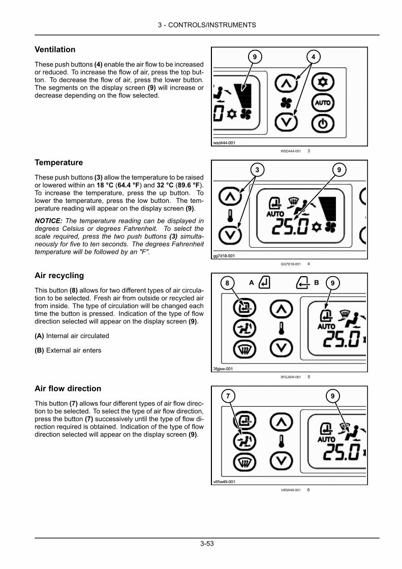
3 - CONTROLS/INSTRUMENTS
Ventilation
These push buttons (4) enable the air flow to be increasedor reduced. To increase the flow of air, press the top but-ton. To decrease the flow of air, press the lower button.The segments on the display screen (9) will increase ordecrease depending on the flow selected.
WSD444-001 3
Temperature
These push buttons (3) allow the temperature to be raisedor lowered within an 18 °C (64.4 °F) and 32 °C (89.6 °F).To increase the temperature, press the up button. Tolower the temperature, press the low button. The tem-perature reading will appear on the display screen (9).
NOTICE: The temperature reading can be displayed indegrees Celsius or degrees Fahrenheit. To select thescale required, press the two push buttons (3) simulta-neously for five to ten seconds. The degrees Fahrenheittemperature will be followed by an "F".
GG7D18-001 4
Air recycling
This button (8) allows for two different types of air circula-tion to be selected. Fresh air from outside or recycled airfrom inside. The type of circulation will be changed eachtime the button is pressed. Indication of the type of flowdirection selected will appear on the display screen (9).
(A) Internal air circulated
(B) External air enters
3FGJSW-001 5
Air flow direction
This button (7) allows four different types of air flow direc-tion to be selected. To select the type of air flow direction,press the button (7) successively until the type of flow di-rection required is obtained. Indication of the type of flowdirection selected will appear on the display screen (9).
V85W49-001 6
3-53
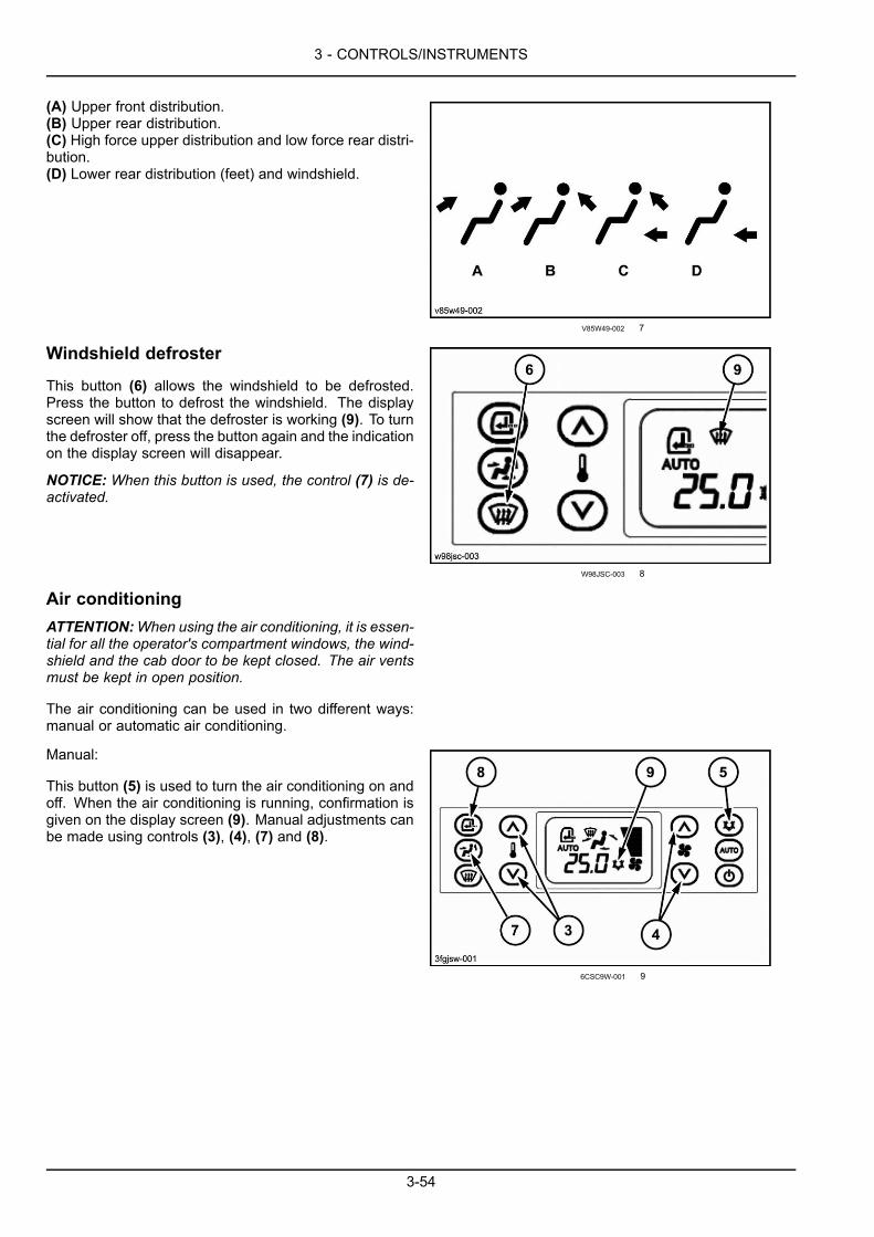
3 - CONTROLS/INSTRUMENTS
(A) Upper front distribution.(B) Upper rear distribution.(C) High force upper distribution and low force rear distri-bution.(D) Lower rear distribution (feet) and windshield.
V85W49-002 7
Windshield defroster
This button (6) allows the windshield to be defrosted.Press the button to defrost the windshield. The displayscreen will show that the defroster is working (9). To turnthe defroster off, press the button again and the indicationon the display screen will disappear.
NOTICE: When this button is used, the control (7) is de-activated.
W98JSC-003 8
Air conditioningATTENTION:When using the air conditioning, it is essen-tial for all the operator's compartment windows, the wind-shield and the cab door to be kept closed. The air ventsmust be kept in open position.
The air conditioning can be used in two different ways:manual or automatic air conditioning.
Manual:
This button (5) is used to turn the air conditioning on andoff. When the air conditioning is running, confirmation isgiven on the display screen (9). Manual adjustments canbe made using controls (3), (4), (7) and (8).
6CSC9W-001 9
3-54
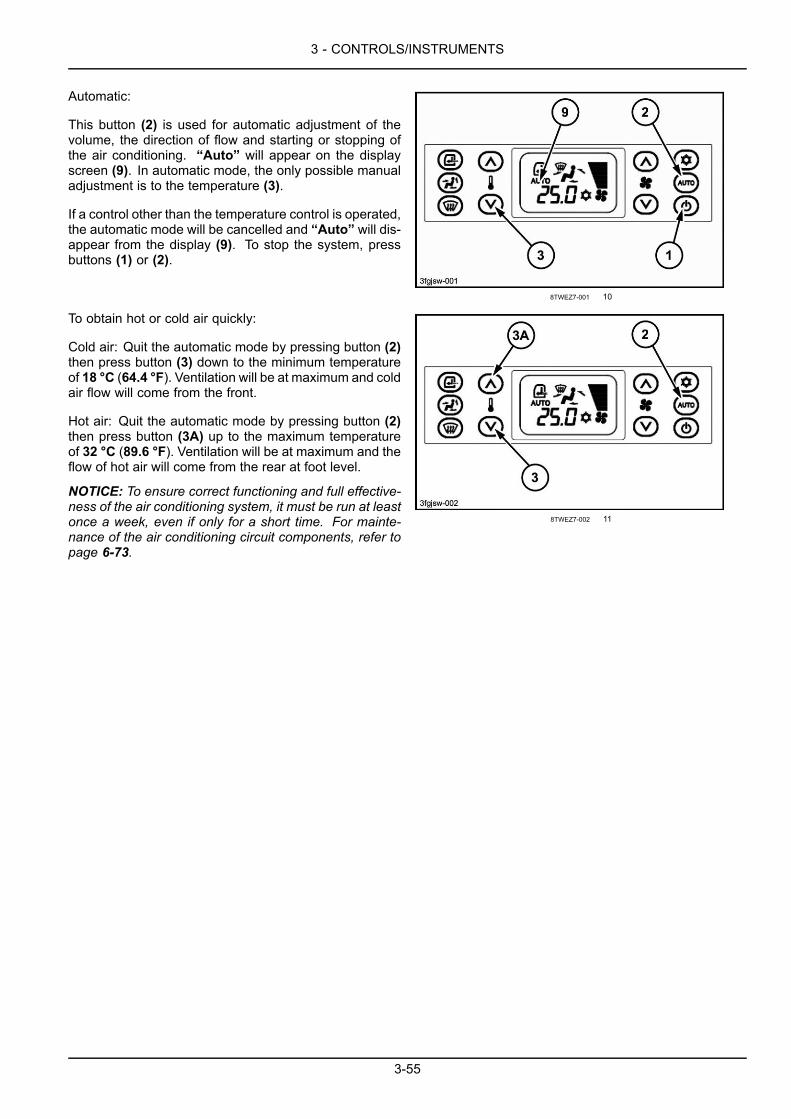
3 - CONTROLS/INSTRUMENTS
Automatic:
This button (2) is used for automatic adjustment of thevolume, the direction of flow and starting or stopping ofthe air conditioning. “Auto” will appear on the displayscreen (9). In automatic mode, the only possible manualadjustment is to the temperature (3).
If a control other than the temperature control is operated,the automatic mode will be cancelled and “Auto” will dis-appear from the display (9). To stop the system, pressbuttons (1) or (2).
8TWEZ7-001 10
To obtain hot or cold air quickly:
Cold air: Quit the automatic mode by pressing button (2)then press button (3) down to the minimum temperatureof 18 °C (64.4 °F). Ventilation will be at maximum and coldair flow will come from the front.
Hot air: Quit the automatic mode by pressing button (2)then press button (3A) up to the maximum temperatureof 32 °C (89.6 °F). Ventilation will be at maximum and theflow of hot air will come from the rear at foot level.
NOTICE: To ensure correct functioning and full effective-ness of the air conditioning system, it must be run at leastonce a week, even if only for a short time. For mainte-nance of the air conditioning circuit components, refer topage 6-73.
8TWEZ7-002 11
3-55
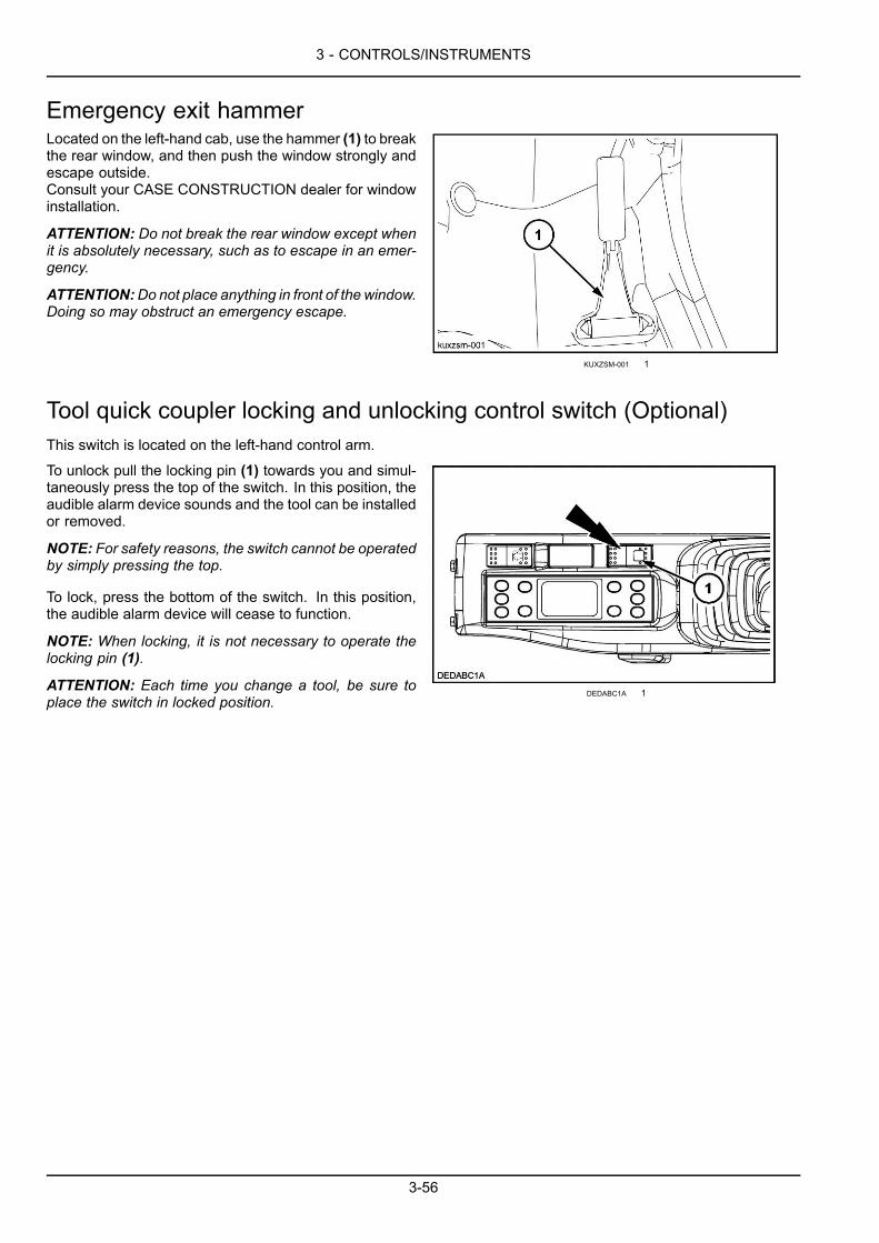
3 - CONTROLS/INSTRUMENTS
Emergency exit hammerLocated on the left-hand cab, use the hammer (1) to breakthe rear window, and then push the window strongly andescape outside.Consult your CASE CONSTRUCTION dealer for windowinstallation.
ATTENTION: Do not break the rear window except whenit is absolutely necessary, such as to escape in an emer-gency.
ATTENTION:Do not place anything in front of the window.Doing so may obstruct an emergency escape.
KUXZSM-001 1
Tool quick coupler locking and unlocking control switch (Optional)This switch is located on the left-hand control arm.
To unlock pull the locking pin (1) towards you and simul-taneously press the top of the switch. In this position, theaudible alarm device sounds and the tool can be installedor removed.
NOTE: For safety reasons, the switch cannot be operatedby simply pressing the top.
To lock, press the bottom of the switch. In this position,the audible alarm device will cease to function.
NOTE: When locking, it is not necessary to operate thelocking pin (1).
ATTENTION: Each time you change a tool, be sure toplace the switch in locked position.
DEDABC1A 1
3-56

3 - CONTROLS/INSTRUMENTS
Sliding windows on doorWhen the locks are released, the windows can be openedand closed to the left or right as required.
219CEA58 1
Magazine rackLocated on the left-hand side, behind the operator’s seat.
30B46DEB 1
Coat hanger hookThe hook is on the rear left-hand cab upright.
NOTICE: Take care not to obscure the view with clothesthat are too bulky.
A00CDBA6 1
3-57
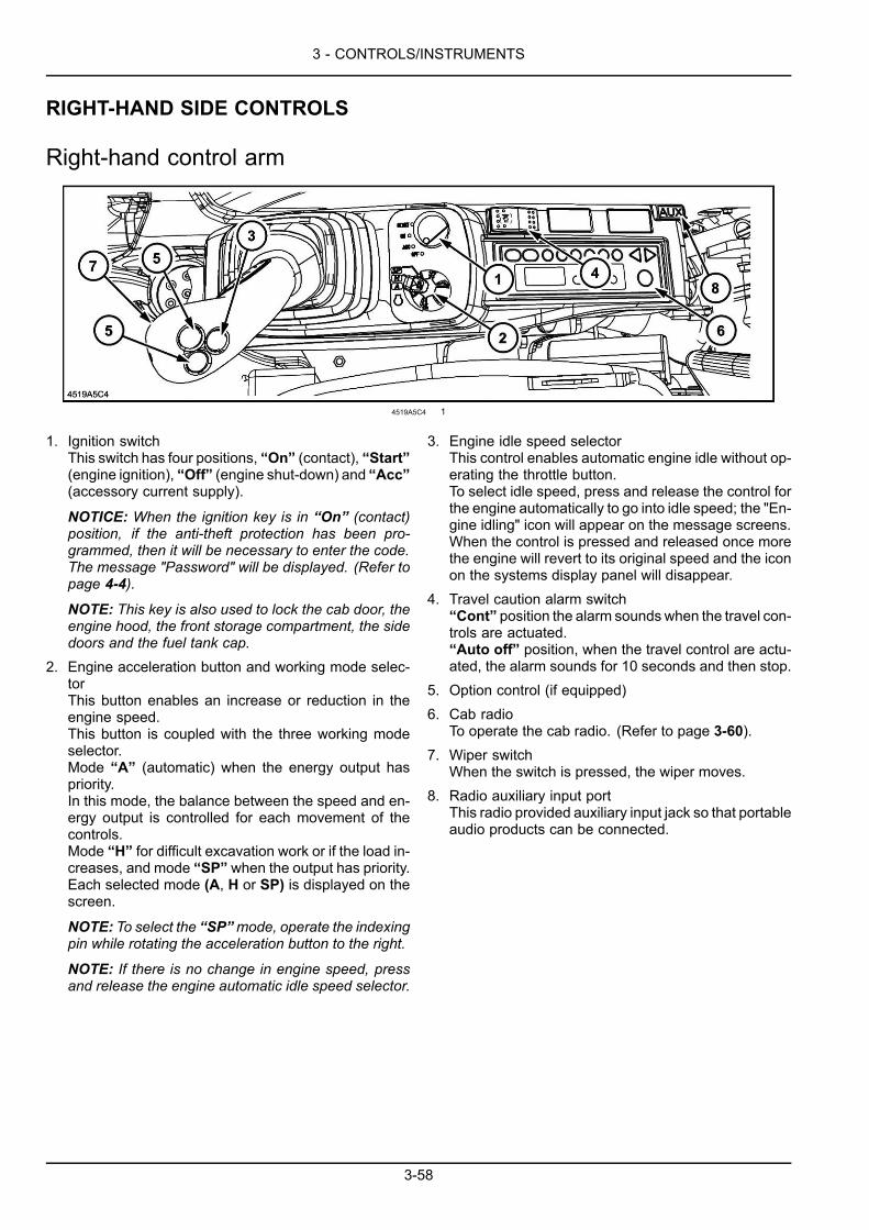
3 - CONTROLS/INSTRUMENTS
RIGHT-HAND SIDE CONTROLS
Right-hand control arm
4519A5C4 1
1. Ignition switchThis switch has four positions, “On” (contact), “Start”(engine ignition), “Off” (engine shut-down) and “Acc”(accessory current supply).
NOTICE: When the ignition key is in “On” (contact)position, if the anti-theft protection has been pro-grammed, then it will be necessary to enter the code.The message "Password" will be displayed. (Refer topage 4-4).
NOTE: This key is also used to lock the cab door, theengine hood, the front storage compartment, the sidedoors and the fuel tank cap.
2. Engine acceleration button and working mode selec-torThis button enables an increase or reduction in theengine speed.This button is coupled with the three working modeselector.Mode “A” (automatic) when the energy output haspriority.In this mode, the balance between the speed and en-ergy output is controlled for each movement of thecontrols.Mode “H” for difficult excavation work or if the load in-creases, and mode “SP” when the output has priority.Each selected mode (A, H or SP) is displayed on thescreen.
NOTE: To select the “SP”mode, operate the indexingpin while rotating the acceleration button to the right.
NOTE: If there is no change in engine speed, pressand release the engine automatic idle speed selector.
3. Engine idle speed selectorThis control enables automatic engine idle without op-erating the throttle button.To select idle speed, press and release the control forthe engine automatically to go into idle speed; the "En-gine idling" icon will appear on the message screens.When the control is pressed and released once morethe engine will revert to its original speed and the iconon the systems display panel will disappear.
4. Travel caution alarm switch“Cont” position the alarm soundswhen the travel con-trols are actuated.“Auto off” position, when the travel control are actu-ated, the alarm sounds for 10 seconds and then stop.
5. Option control (if equipped)6. Cab radio
To operate the cab radio. (Refer to page 3-60).7. Wiper switch
When the switch is pressed, the wiper moves.8. Radio auxiliary input port
This radio provided auxiliary input jack so that portableaudio products can be connected.
3-58
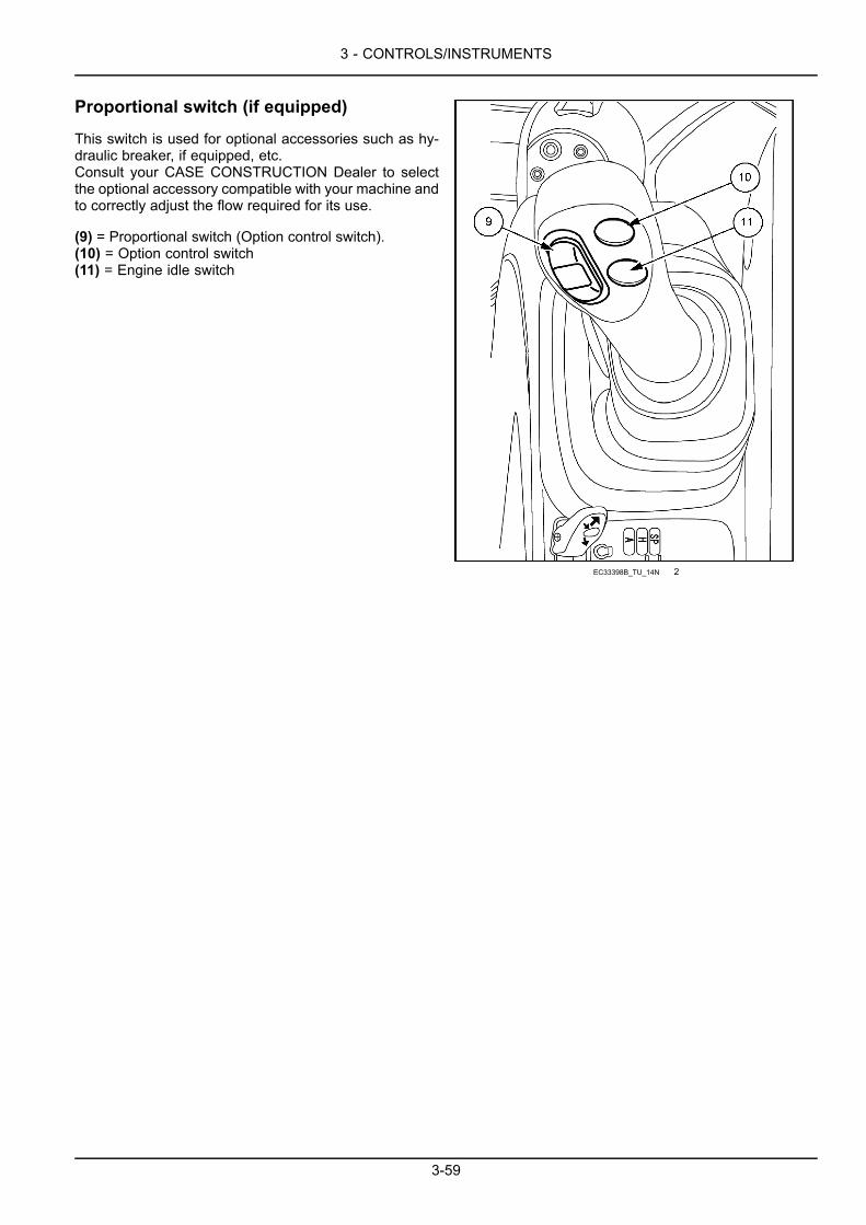
3 - CONTROLS/INSTRUMENTS
Proportional switch (if equipped)
This switch is used for optional accessories such as hy-draulic breaker, if equipped, etc.Consult your CASE CONSTRUCTION Dealer to selectthe optional accessory compatible with your machine andto correctly adjust the flow required for its use.
(9) = Proportional switch (Option control switch).(10) = Option control switch(11) = Engine idle switch
EC33398B_TU_14N 2
3-59
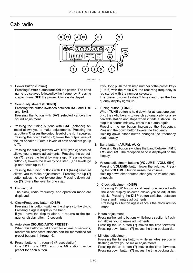
3 - CONTROLS/INSTRUMENTS
Cab radio
L7XJ42-001A 1
1. Power button (Power)Pressing Power button turnsON the power. The bandname is displayed followed by the frequency. Pressingit again turns OFF the power. Clock is displayed.
2. Sound adjustment (SOUND)Pressing this button switches between BAL and TREand BAS.Pressing the button with BAS selected cancels thesound adjustment.
• Pressing the tuning buttons with BAL (balance) se-lected allows you to make adjustments. Pressing theup button (7) raises the output level of the right speaker.Pressing the down button (7) lower the output level ofthe left speaker. (Output levels of both speakers go upto 7).
• Pressing the tuning buttons with TRE (treble) selectedallows you to make adjustments. Pressing the up but-ton (7) raises the level by one step. Pressing downbutton (7) lowers the level by one step. (The levels goup and down up to 7).
• Pressing the tuning buttons with BAS (bass) selectedallows you to make adjustments. Pressing the up (7)button raises the level by one step. Pressing down but-ton (7) lowers the level by one step.
3. Display unitThe clock, radio frequency, and operation mode aredisplayed.
4. Clock/Frequency button (DISP)Pressing this button switches the display to the clock.Pressing it again displays the band.If you leave the display alone, it returns to the fre-quency display after 1.5 seconds.
5. Auto store (SOUND/AUTO PRESET)When this button is held down for at least 2 seconds,receivable broadcast stations can be memorized forpreset buttons 1 through 6.
6. Preset buttons 1 through 6 (Preset station)One FM1 , one FM2 , and one AM station can bepreset for each button.
If you long push the desired number of the preset keys(1 to 6) with the radio ON, the receiving frequency isregistered with the number selected.The preset display flashes 3 times and then the fre-quency display lights up.
7. Tuning button (TUNE)When TUNE button is held down for at least one sec-ond, the radio begins to search automatically for a re-ceivable station and stops when it finds a station. Tostop this search midway, press this button again.Pressing the up button increases the frequency.Pressing the down button lowers the frequency.Holding down either button changes the frequencycontinuously.
8. Band button (AM/FM, AUX)Pressing this button switches the band between FM1,FM2 and AM. The reception band is displayed on thedisplay.
9. Volume adjustment buttons (VOLUME-, VOLUME+)Pressing VOLUME- button lower the volume. Press-ing the VOLUME+ button raises the volume.Holding down either button changes the volume con-tinuously.
10. Clock adjustment (DISP)Pressing DISP button for at least one second withthe clock display selected allows you to adjust theclock. Pressing the DISP button switches betweenhours and minutes adjustments.Pressing this button again cancels the clock adjust-ment.
• Hours adjustmentPressing the tuning buttons while hours section is flash-ing allows you to make adjustments.Pressing the up button (7) moves the time forwards.Pressing down button (7) moves the time backwards.
• Minutes adjustmentPressing the tuning buttons while minutes section isflashing allows you to make adjustments.Pressing the up button (7) moves the time forwards.Pressing down button (7) moves the time backwards.
3-60
3 - CONTROLS/INSTRUMENTS
11. External input switch button (AUX)Pressing AM, FM and AUX buttons for at least onesecond switches from the radio you are currently lis-tening to the input connected to the external inputjack (12) and displays AUX on the display. Pressingit again returns to the original radio reception.
12. External input jack (AUX IN) vehicle; Body sideWhen using this jack, use any commercially-avail-able stereo mini-plug cord (D3.5) to plug it to theheadphone terminal of your portable audio device orthe like.
Listen to the radio
1. Turn ON ACC switch to ON position and press Powerbutton.
2. Select desired band MW or AM by band switch.3. Select desired frequency by presest button or tuning
buttons.4. Adjust desired volume level by VOLUME+ or VOL-
UME- down buttons.5. Press Tone button, if higher sound is not desired.6. To turn off the radio, press Power button.
Manual tuning
Pressing either tuning buttons shifts the receiving fre-quency by step.
Seek tuning
Pressing either of the tuning button more than 3 seconds,Seek function will start and find next available station andthen stop at the frequency.
Presetting desired station into memory
Select desired band FM or AM.The tune-in desired station by Seek tuning or Manual tun-ing.Press desired number 1 to 6 of button more than 3 sec-onds, display will indicate the channel number and finishthe preset operation.
NOTE: If either of the preset buttons pressed more than2 seconds while cannel number is not indicated on thedisplay, preset frequency of the specific memory will bechanged.In case battery back-up line is cut off due to replacingbattery or any other reason, previously stored memorieswill be erased and the presetting procedure should bedone again.The radio is capable to store 6 stations of FM and 6 sta-tions of AM.
Auto store memory
During radio mode, pressing this button and release willautomatically scan the current band and store availablestations to preset memory 1 to 6.
ATTENTION: The operation of Auto Store Memory willerase previously memorized stations. In case, not storedin stored in desired preset button, please follow manualpresetting.
AUX Audio connection
This radio provided AUX input jack so that portable audioproducts can be connected.Be sure to use 3.5 mm (0.1 in) stereo mini-plug for theexternal input jack.Pressing AUX button will change over between radiofunction and AUX function.During AUX mode, AUX will be indicated on the display.The volume control of portable audio products should beadjusted approximately same as currently listening radiosound volume.Then the sound volume can be adjusted by volume con-trol of this radio.Please do not connect higher output sources thanportable audio headphone output.
Time set
Press Clock button and indicate clock on display.Pressing Tune-up button to adjust minutes and pressingTune-down Button to adjust hours.
NOTE: Battely back-upmodels do not have clock functionand the button is disabled.
Reset function
If the frequency display is wrong or switching is not pos-sible, reset the unit. While pressing AUX button, pressVOLUME+ and VOLUME- buttons at the same time re-sets the unit. ("0" is displayed for a moment, then the unitis reset.) The clock and the preset stations are also re-set..When the wires are disconnected, the preset stations areretained in memory.
Clearing memory
If the connection to the battery is cut off by turning the bat-tery connect switch key to "O" (OFF position), performingmaintenance for the machine, or removing the radio, thestations stored on the radio presets will be all cleared ina few days. If so, set the stations again.
3-61
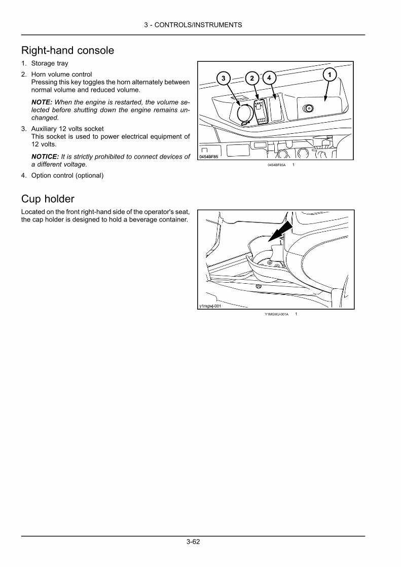
3 - CONTROLS/INSTRUMENTS
Right-hand console1. Storage tray2. Horn volume control
Pressing this key toggles the horn alternately betweennormal volume and reduced volume.
NOTE: When the engine is restarted, the volume se-lected before shutting down the engine remains un-changed.
3. Auxiliary 12 volts socketThis socket is used to power electrical equipment of12 volts.
NOTICE: It is strictly prohibited to connect devices ofa different voltage.
4. Option control (optional)
0454BF85A 1
Cup holderLocated on the front right-hand side of the operator's seat,the cap holder is designed to hold a beverage container.
Y1MGWJ-001A 1
3-62
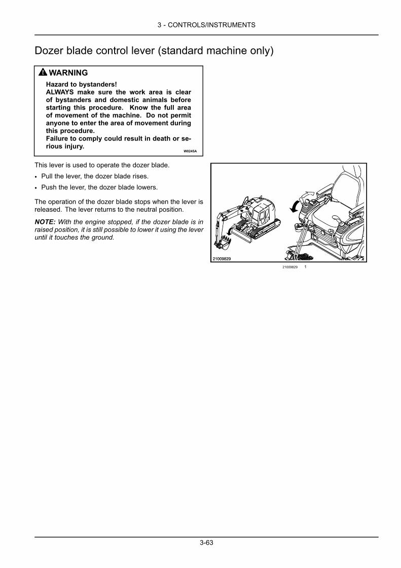
3 - CONTROLS/INSTRUMENTS
Dozer blade control lever (standard machine only)
WARNINGHazard to bystanders!ALWAYS make sure the work area is clearof bystanders and domestic animals beforestarting this procedure. Know the full areaof movement of the machine. Do not permitanyone to enter the area of movement duringthis procedure.Failure to comply could result in death or se-rious injury.
W0245A
This lever is used to operate the dozer blade.
• Pull the lever, the dozer blade rises.
• Push the lever, the dozer blade lowers.
The operation of the dozer blade stops when the lever isreleased. The lever returns to the neutral position.
NOTE: With the engine stopped, if the dozer blade is inraised position, it is still possible to lower it using the leveruntil it touches the ground.
21009829 1
3-63
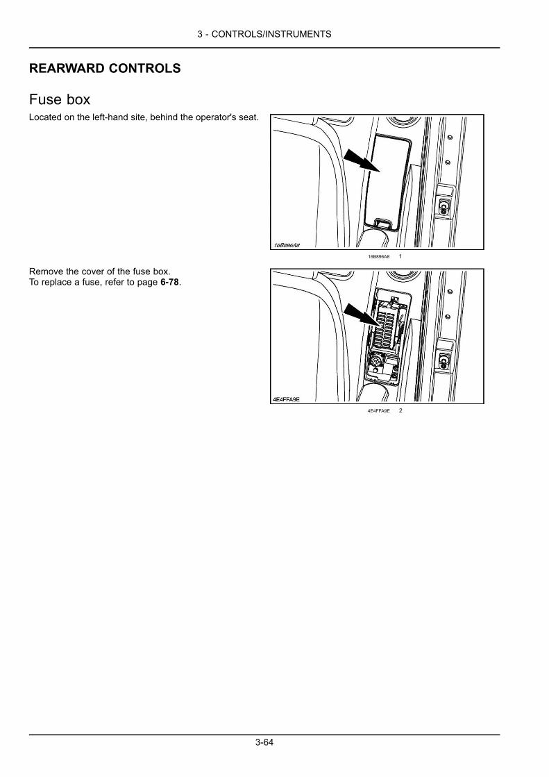
3 - CONTROLS/INSTRUMENTS
REARWARD CONTROLS
Fuse boxLocated on the left-hand site, behind the operator's seat.
16B896A8 1
Remove the cover of the fuse box.To replace a fuse, refer to page 6-78.
4E4FFA9E 2
3-64

3 - CONTROLS/INSTRUMENTS
OVERHEAD CONTROLS
Roof curtainTo open the roof curtain, slide it toward the rear using thehandles. To close the curtain slide it toward the front.
9977F62C 1
Roof hatchOpen the roof curtain. To open the roof hatch, operatethe two handles and push the handles. To close the roofhatch, pull the two handles until engagement.
NOTICE: Since roof hatch opening is assisted by two gasstruts, simply follow through the closing movement with-out pulling or trying to hold it back.
3EFD9403 1
3-65
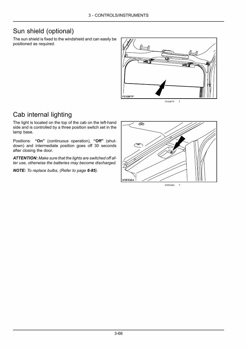
3 - CONTROLS/INSTRUMENTS
Sun shield (optional)The sun shield is fixed to the windshield and can easily bepositioned as required.
F5108F7F 1
Cab internal lightingThe light is located on the top of the cab on the left-handside and is controlled by a three position switch set in thelamp base.
Positions: “On” (continuous operation), “Off” (shut-down) and intermediate position goes off 30 secondsafter closing the door.
ATTENTION:Make sure that the lights are switched off af-ter use, otherwise the batteries may become discharged.
NOTE: To replace bulbs, (Refer to page 6-85).
878F63EA 1
3-66

3 - CONTROLS/INSTRUMENTS
EXTERIOR CONTROLS
Fuel tankWARNINGFire hazard!When handling diesel fuel, observe the following precautions:1. Do not smoke.2. Never fill the tank when the engine is running.3. Wipe up spilled fuel immediately.Failure to comply could result in death or serious injury.
W0099A
The fuel tank capacity is:200 l (52.8 US gal).
Use suitable fuel. (Refer to page 6-5).
NOTICE: Do not put a moisture elimination product (wa-ter draining agent) in the fuel tank. (It may damage theengine).
NOTE: Clean around the fuel cap before refuelling and donot remove the filter located in the filler orifice. (Refer topage 6-64).
NOTE: In cold weather, use fuel corresponding to the am-bient temperature. (Refer to page 6-5).
ATTENTION: In cold weather, fill the fuel tank after eachworking day to prevent the formation of condensation.
When installing the fuel cap, make sure that it is correctlyplaced in the notches and then lock it by turning it upagainst the stop.
NOTE: Use the ignition key to lock the fuel cap.
6989FB00 1
The fuel tank is equipped with a max level visual gauge.
3-67
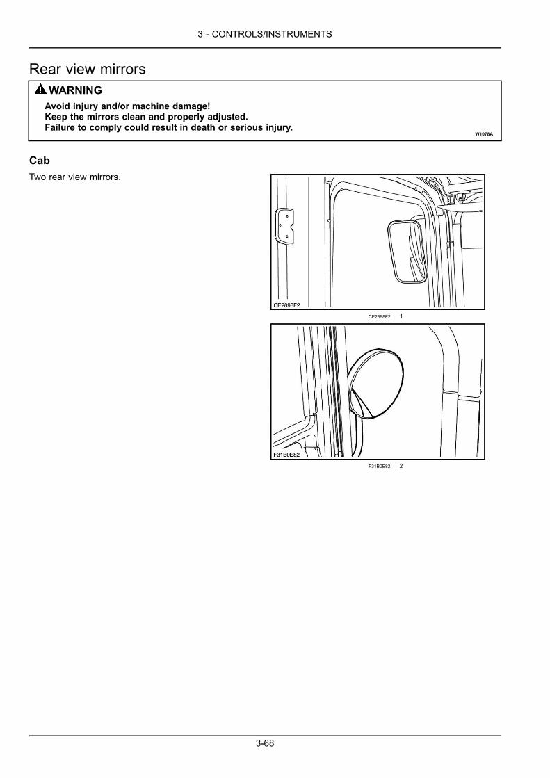
3 - CONTROLS/INSTRUMENTS
Rear view mirrorsWARNINGAvoid injury and/or machine damage!Keep the mirrors clean and properly adjusted.Failure to comply could result in death or serious injury.
W1078A
CabTwo rear view mirrors.
CE2898F2 1
F31B0E82 2
3-68
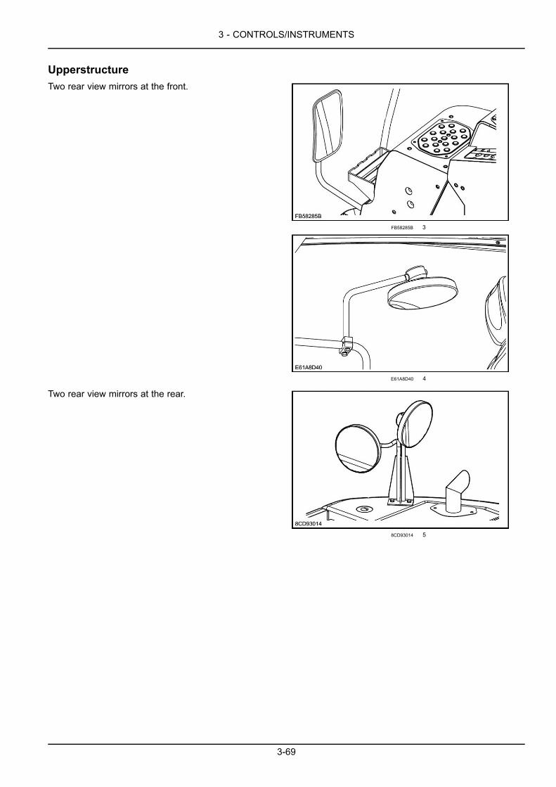
3 - CONTROLS/INSTRUMENTS
UpperstructureTwo rear view mirrors at the front.
FB58285B 3
E61A8D40 4
Two rear view mirrors at the rear.
8CD93014 5
3-69
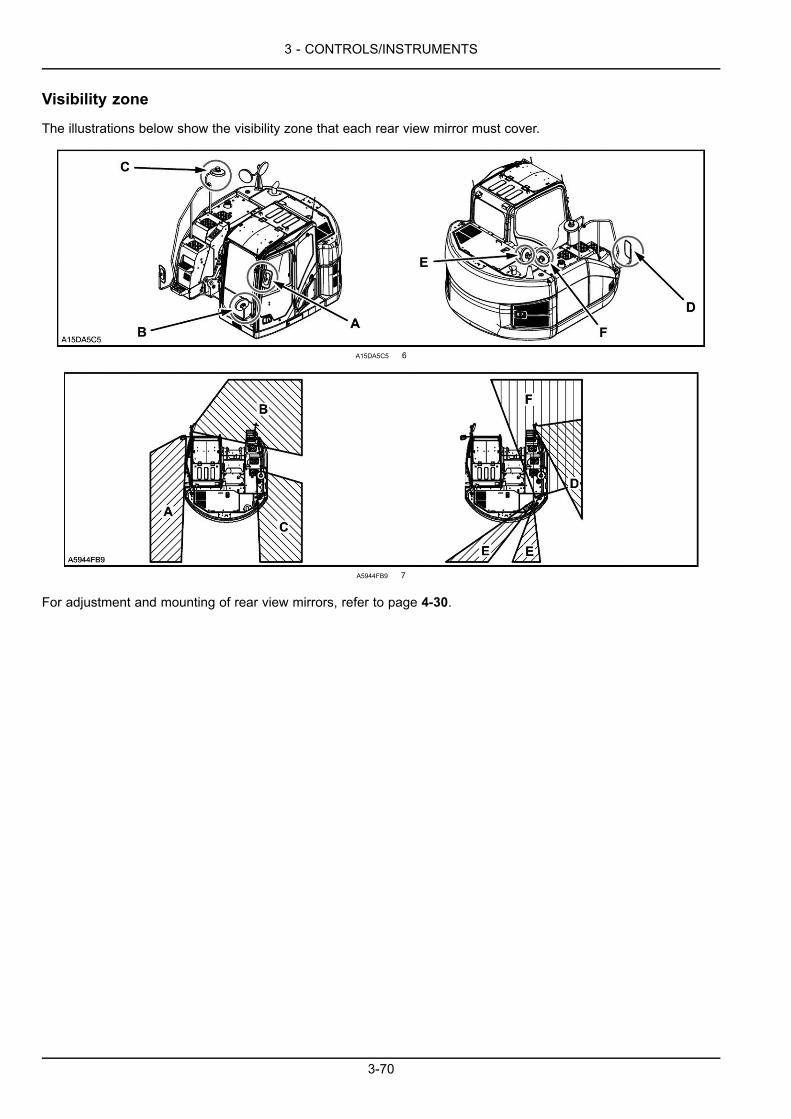
3 - CONTROLS/INSTRUMENTS
Visibility zone
The illustrations below show the visibility zone that each rear view mirror must cover.
A15DA5C5 6
A5944FB9 7
For adjustment and mounting of rear view mirrors, refer to page 4-30.
3-70
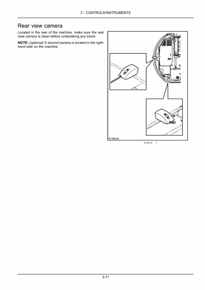
3 - CONTROLS/INSTRUMENTS
Rear view cameraLocated in the rear of the machine, make sure the rearview camera is clean before undertaking any travel.
NOTE: (optional) A second camera is located in the right-hand side on the machine.
E77BE10C 1
3-71
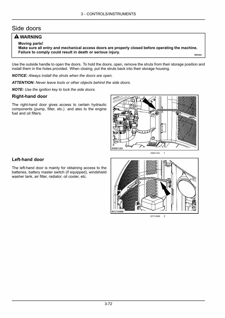
3 - CONTROLS/INSTRUMENTS
Side doorsWARNINGMoving parts!Make sure all entry and mechanical access doors are properly closed before operating the machine.Failure to comply could result in death or serious injury.
W0238A
Use the outside handle to open the doors. To hold the doors, open, remove the struts from their storage position andinstall them in the holes provided. When closing, put the struts back into their storage housing.
NOTICE: Always install the struts when the doors are open.
ATTENTION: Never leave tools or other objects behind the side doors.
NOTE: Use the ignition key to lock the side doors.
Right-hand door
The right-hand door gives access to certain hydrauliccomponents (pump, filter, etc.) and also to the enginefuel and oil filters.
EB9D1262 1
Left-hand door
The left-hand door is mainly for obtaining access to thebatteries, battery master switch (if equipped), windshieldwasher tank, air filter, radiator, oil cooler, etc.
B7C7A5BB 2
3-72
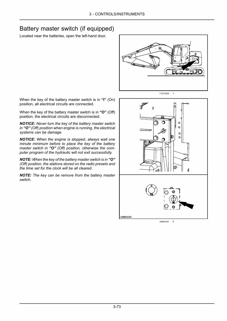
3 - CONTROLS/INSTRUMENTS
Battery master switch (if equipped)Located near the batteries, open the left-hand door.
71DCD62B 1
When the key of the battery master switch is in “I” (On)position, all electrical circuits are connected.
When the key of the battery master switch is in “O” (Off)position, the electrical circuits are disconnected.
NOTICE: Never turn the key of the battery master switchin “O” (Off) position when engine is running, the electricalsystems can be damage.
NOTICE: When the engine is stopped, always wait oneminute minimum before to place the key of the batterymaster switch in “O” (Off) position, otherwise the com-puter program of the hydraulic will not exit successfully.
NOTE:When the key of the batterymaster switch is in “O”(Off) position, the stations stored on the radio presets andthe time set for the clock will be all cleared.
NOTE: The key can be remove from the battery masterswitch.
408B33AD 2
3-73
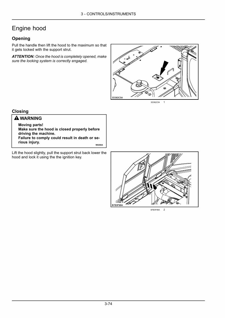
3 - CONTROLS/INSTRUMENTS
Engine hoodOpeningPull the handle then lift the hood to the maximum so thatit gets locked with the support strut.
ATTENTION:Once the hood is completely opened, makesure the locking system is correctly engaged.
3D382C54 1
ClosingWARNINGMoving parts!Make sure the hood is closed properly beforedriving the machine.Failure to comply could result in death or se-rious injury.
W0280A
Lift the hood slightly, pull the support strut back lower thehood and lock it using the the ignition key.
B7B3F98A 2
3-74

3 - CONTROLS/INSTRUMENTS
Lower panels
WARNINGMoving parts!Make sure the lower panels are properlyclosed before driving the machine.Failure to comply could result in death or se-rious injury.
W0910A
Located under the upperstructure frame, these panelsprovide access to certain machine components.
ATTENTION: Do not run the machine with the panels re-moved.
8D120A48 1
Windshield washer reservoirThis reservoir, located in the rear left-hand compartment,is equipped with an electric pump which is operated fromthe monitor switches, refer to page 3-24.
NOTICE: Never operate the windshield washer controlwhen the reservoir is empty. This could cause damageto the electric pump.
Remove the cap to add windshield washing fluid.
NOTE: In cold weather, add anti-freeze to the windshieldwasher water.
JMSFSF-001 1
3-75
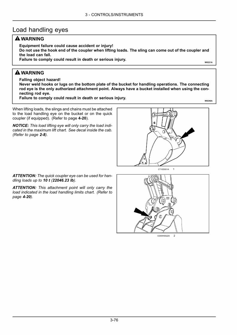
3 - CONTROLS/INSTRUMENTS
Load handling eyesWARNINGEquipment failure could cause accident or injury!Do not use the hook end of the coupler when lifting loads. The sling can come out of the coupler andthe load can fall.Failure to comply could result in death or serious injury.
W0221A
WARNINGFalling object hazard!Never weld hooks or lugs on the bottom plate of the bucket for handling operations. The connectingrod eye is the only authorized attachment point. Always have a bucket installed when using the con-necting rod eye.Failure to comply could result in death or serious injury.
W0246A
When lifting loads, the slings and chains must be attachedto the load handling eye on the bucket or on the quickcoupler (if equipped). (Refer to page 4-20).
NOTICE: This load lifting eye will only carry the load indi-cated in the maximum lift chart. See decal inside the cab.(Refer to page 2-8).
CT10D001A 1
ATTENTION: The quick coupler eye can be used for han-dling loads up to 10 t (22046.23 lb).
ATTENTION: This attachment point will only carry theload indicated in the load handling limits chart. (Refer topage 4-20).
CD00H002ZA 2
3-76
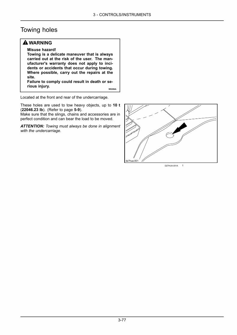
3 - CONTROLS/INSTRUMENTS
Towing holes
WARNINGMisuse hazard!Towing is a delicate maneuver that is alwayscarried out at the risk of the user. The man-ufacturer's warranty does not apply to inci-dents or accidents that occur during towing.Where possible, carry out the repairs at thesite.Failure to comply could result in death or se-rious injury.
W0286A
Located at the front and rear of the undercarriage.
These holes are used to tow heavy objects, up to 10 t(22046.23 lb). (Refer to page 5-9).Make sure that the slings, chains and accessories are inperfect condition and can bear the load to be moved.
ATTENTION: Towing must always be done in alignmentwith the undercarriage.
DZ7HUA-001A 1
3-77
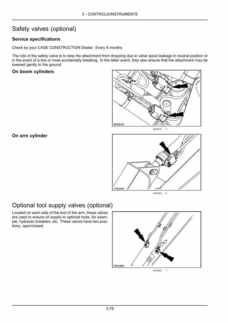
3 - CONTROLS/INSTRUMENTS
Safety valves (optional)Service specifications
Check by your CASE CONSTRUCTION Dealer: Every 6 months
The role of the safety valve is to stop the attachment from dropping due to valve spool leakage in neutral position orin the event of a line or hose accidentally breaking. In the latter event, they also ensure that the attachment may belowered gently to the ground.
On boom cylinders
35B7B12F 1
On arm cylinder
3F69328A 2
Optional tool supply valves (optional)Located on each side of the end of the arm, these valvesare used to ensure oil supply to optional tools, for exam-ple, hydraulic breakers, etc. These valves have two posi-tions, open/closed.
7D0D3887 1
3-78
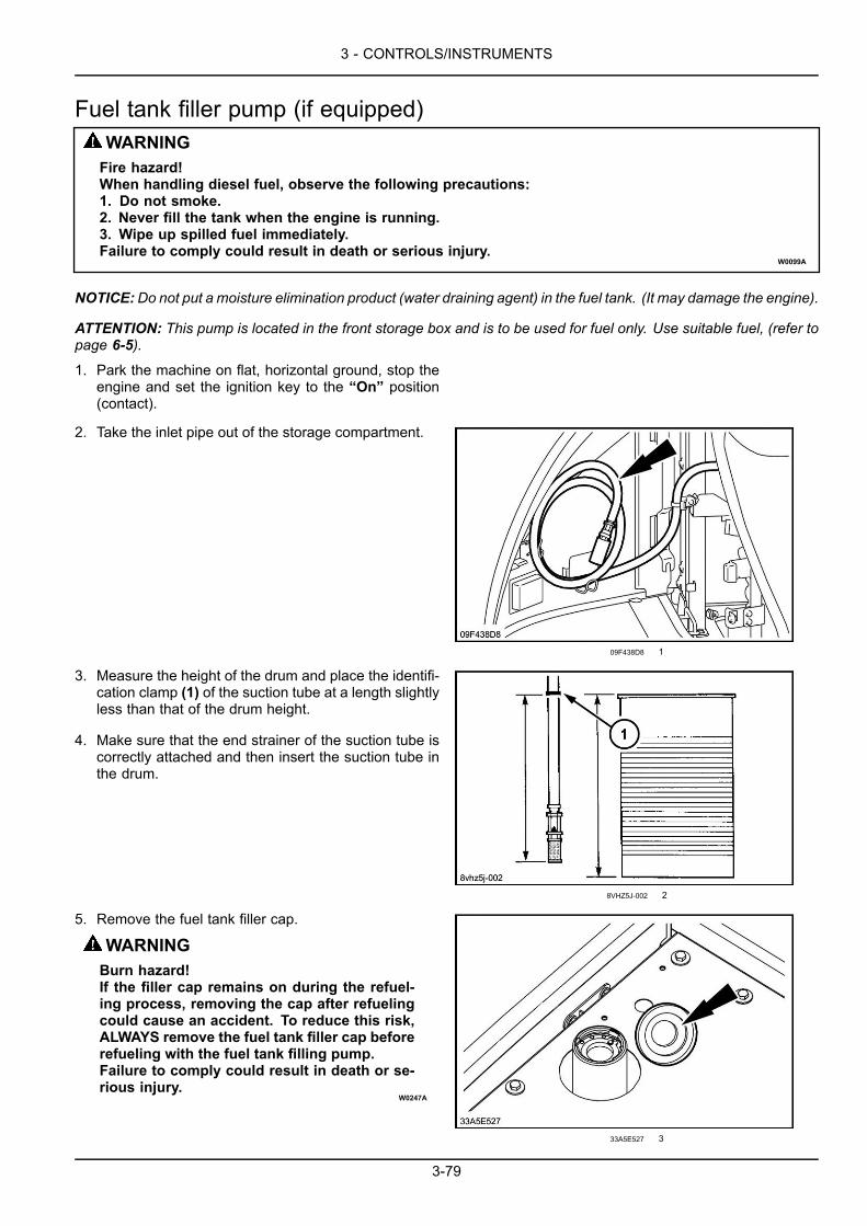
3 - CONTROLS/INSTRUMENTS
Fuel tank filler pump (if equipped)WARNINGFire hazard!When handling diesel fuel, observe the following precautions:1. Do not smoke.2. Never fill the tank when the engine is running.3. Wipe up spilled fuel immediately.Failure to comply could result in death or serious injury.
W0099A
NOTICE:Do not put a moisture elimination product (water draining agent) in the fuel tank. (It may damage the engine).
ATTENTION: This pump is located in the front storage box and is to be used for fuel only. Use suitable fuel, (refer topage 6-5).
1. Park the machine on flat, horizontal ground, stop theengine and set the ignition key to the “On” position(contact).
2. Take the inlet pipe out of the storage compartment.
09F438D8 1
3. Measure the height of the drum and place the identifi-cation clamp (1) of the suction tube at a length slightlyless than that of the drum height.
4. Make sure that the end strainer of the suction tube iscorrectly attached and then insert the suction tube inthe drum.
8VHZ5J-002 2
5. Remove the fuel tank filler cap.
WARNINGBurn hazard!If the filler cap remains on during the refuel-ing process, removing the cap after refuelingcould cause an accident. To reduce this risk,ALWAYS remove the fuel tank filler cap beforerefueling with the fuel tank filling pump.Failure to comply could result in death or se-rious injury.
W0247A
33A5E527 3
3-79

3 - CONTROLS/INSTRUMENTS
6. Select the filling method using the selector switch lo-cated to the right of the filling pump.“Auto” mode, the pump stops filling automaticallyand the audible alarm sounds when the fuel tank isfull.“Manual” mode, monitor the filling by means of thereservoir gauge and stop when necessary.
7. Turn the switch located on the pump to the “On” po-sition (start). Filling begins.
NOTE: It is possible to stop filling at any time forany reason (empty drum, for example) by turning theswitch to the “Off” position.
8. When the fuel tank is full, turn the switch and theselector switch to the “Off” position (stopped). In“Auto” mode, the audible alarm device will cease tofunction.
9. Run the pump for a few moments to empty the pipeoutside the drum. Clean and replace the inlet pipe inthe front storage compartment.
10. Refit the fuel tank filler cap.11. Place the ignition key in “Off” position.
398C7463 4
NOTE: The pump is equipped with a 10 A fuse.
5F5DAB92 5
3-80
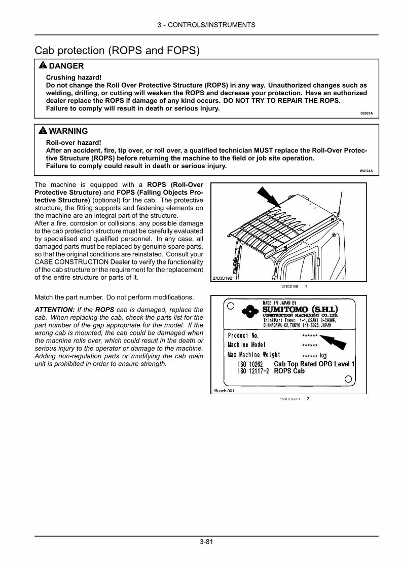
3 - CONTROLS/INSTRUMENTS
Cab protection (ROPS and FOPS)DANGERCrushing hazard!Do not change the Roll Over Protective Structure (ROPS) in any way. Unauthorized changes such aswelding, drilling, or cutting will weaken the ROPS and decrease your protection. Have an authorizeddealer replace the ROPS if damage of any kind occurs. DO NOT TRY TO REPAIR THE ROPS.Failure to comply will result in death or serious injury.
D0037A
WARNINGRoll-over hazard!After an accident, fire, tip over, or roll over, a qualified technician MUST replace the Roll-Over Protec-tive Structure (ROPS) before returning the machine to the field or job site operation.Failure to comply could result in death or serious injury.
W0134A
The machine is equipped with a ROPS (Roll-OverProtective Structure) and FOPS (Falling Objects Pro-tective Structure) (optional) for the cab. The protectivestructure, the fitting supports and fastening elements onthe machine are an integral part of the structure.After a fire, corrosion or collisions, any possible damageto the cab protection structure must be carefully evaluatedby specialised and qualified personnel. In any case, alldamaged parts must be replaced by genuine spare parts,so that the original conditions are reinstated. Consult yourCASE CONSTRUCTION Dealer to verify the functionalityof the cab structure or the requirement for the replacementof the entire structure or parts of it.
27B3D19B 1
Match the part number. Do not perform modifications.
ATTENTION: If the ROPS cab is damaged, replace thecab. When replacing the cab, check the parts list for thepart number of the gap appropriate for the model. If thewrong cab is mounted, the cab could be damaged whenthe machine rolls over, which could result in the death orserious injury to the operator or damage to the machine.Adding non-regulation parts or modifying the cab mainunit is prohibited in order to ensure strength.
15UUEH-001 2
3-81

3 - CONTROLS/INSTRUMENTS
3-82
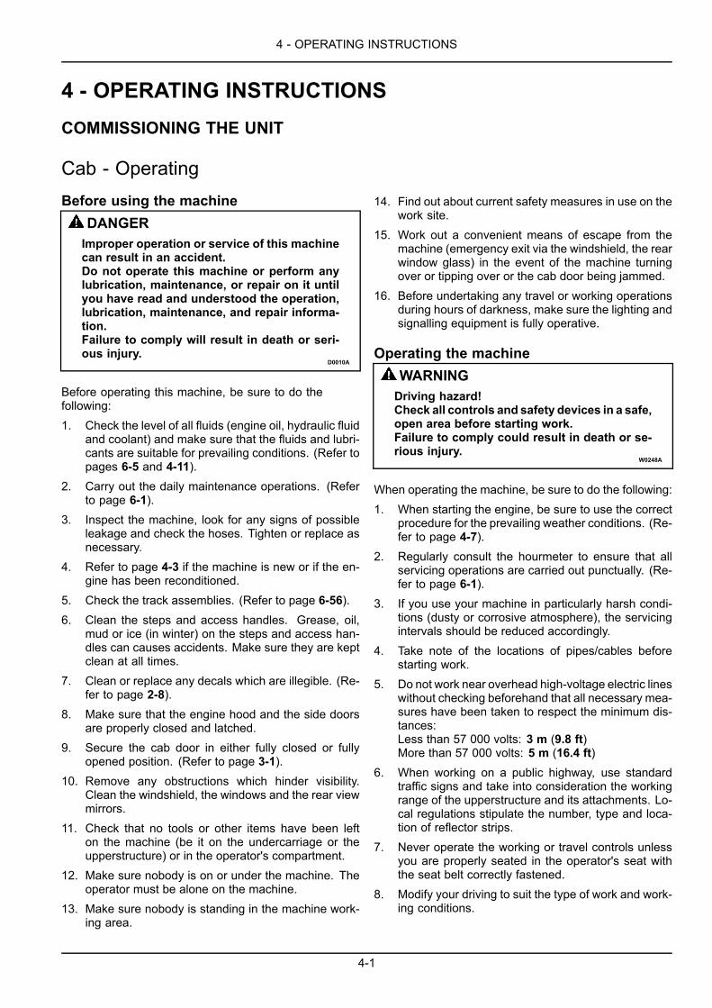
4 - OPERATING INSTRUCTIONS
4 - OPERATING INSTRUCTIONS###_4_###COMMISSIONING THE UNIT
Cab - OperatingBefore using the machine
DANGERImproper operation or service of this machinecan result in an accident.Do not operate this machine or perform anylubrication, maintenance, or repair on it untilyou have read and understood the operation,lubrication, maintenance, and repair informa-tion.Failure to comply will result in death or seri-ous injury.
D0010A
Before operating this machine, be sure to do thefollowing:1. Check the level of all fluids (engine oil, hydraulic fluid
and coolant) and make sure that the fluids and lubri-cants are suitable for prevailing conditions. (Refer topages 6-5 and 4-11).
2. Carry out the daily maintenance operations. (Referto page 6-1).
3. Inspect the machine, look for any signs of possibleleakage and check the hoses. Tighten or replace asnecessary.
4. Refer to page 4-3 if the machine is new or if the en-gine has been reconditioned.
5. Check the track assemblies. (Refer to page 6-56).6. Clean the steps and access handles. Grease, oil,
mud or ice (in winter) on the steps and access han-dles can causes accidents. Make sure they are keptclean at all times.
7. Clean or replace any decals which are illegible. (Re-fer to page 2-8).
8. Make sure that the engine hood and the side doorsare properly closed and latched.
9. Secure the cab door in either fully closed or fullyopened position. (Refer to page 3-1).
10. Remove any obstructions which hinder visibility.Clean the windshield, the windows and the rear viewmirrors.
11. Check that no tools or other items have been lefton the machine (be it on the undercarriage or theupperstructure) or in the operator's compartment.
12. Make sure nobody is on or under the machine. Theoperator must be alone on the machine.
13. Make sure nobody is standing in the machine work-ing area.
14. Find out about current safety measures in use on thework site.
15. Work out a convenient means of escape from themachine (emergency exit via the windshield, the rearwindow glass) in the event of the machine turningover or tipping over or the cab door being jammed.
16. Before undertaking any travel or working operationsduring hours of darkness, make sure the lighting andsignalling equipment is fully operative.
Operating the machineWARNINGDriving hazard!Check all controls and safety devices in a safe,open area before starting work.Failure to comply could result in death or se-rious injury.
W0248A
When operating the machine, be sure to do the following:1. When starting the engine, be sure to use the correct
procedure for the prevailing weather conditions. (Re-fer to page 4-7).
2. Regularly consult the hourmeter to ensure that allservicing operations are carried out punctually. (Re-fer to page 6-1).
3. If you use your machine in particularly harsh condi-tions (dusty or corrosive atmosphere), the servicingintervals should be reduced accordingly.
4. Take note of the locations of pipes/cables beforestarting work.
5. Do not work near overhead high-voltage electric lineswithout checking beforehand that all necessary mea-sures have been taken to respect the minimum dis-tances:Less than 57 000 volts: 3 m (9.8 ft)More than 57 000 volts: 5 m (16.4 ft)
6. When working on a public highway, use standardtraffic signs and take into consideration the workingrange of the upperstructure and its attachments. Lo-cal regulations stipulate the number, type and loca-tion of reflector strips.
7. Never operate the working or travel controls unlessyou are properly seated in the operator's seat withthe seat belt correctly fastened.
8. Modify your driving to suit the type of work and work-ing conditions.
4-1
4 - OPERATING INSTRUCTIONS
9. Do not allow anyone within the machine's operatingradius. Stop all operations until everyone has movedaway.
10. Refer to page 4-3 if the machine is new or if the en-gine has been reconditioned.
11. Operate all controls gradually to ensure smooth ma-chine operation.
12. Refer to page 4-22 if the machine will be standing inwater during use.
13. Refer to page 5-1 when driving the machine onto atrailer.
14. Refer to page 4-20 when it is necessary to lift themachine.
15. Refer to page 5-9 when it is necessary to tow themachine.
16. In some configurations, the working range of the at-tachment allows the tool to interfere with the ma-chine. Always maintain a safe minimum distance be-tween the tool and the machine.
17. Never use the attachment for sweeping the ground tolevel out rubble or push objects (transversal stress onthe attachment).
18. Avoid running the engine in a confined space. If thereis no alternative, proper ventilation must be providedat all times.
19. Dust, smoke or mist can reduce visibility and causean accident. Reduce speed or come to a completehalt until visibility has improved.
20. In the event of an operation problem or failure, movethe machine to a safe place, lower the attachmentand dozer blade (if equipped) to the ground, stop theengine, remove the ignition key. Locate the problem,report it if necessary and take the necessary steps towarn others not to attempt to operate the machine.
21. Do not stop the engine without taking prevailingweather conditions into consideration. (Refer topage 4-14).
22. Refer to page 4-46 when you have to park the ma-chine.
23. Whenever load handling operations are to be carriedout, it is imperative to adhere strictly to the instruc-tions given in this manual and local legislation. (Re-fer to page 4-20).
4-2
4 - OPERATING INSTRUCTIONS
Cab - Running-in ProcedureYour machine will last longer and will give better and moreeconomical performance if you pay particular attention tothe engine during the first twenty hours of operation.
During this period:
• Warm up the engine before using it under load.
• Do not run the engine for a long period at idle speed.
• Check all instruments frequently.
• Check the oil levels and coolant solution level fre-quently.
During the run-in period, the following checks and servic-ing operations should be carried out in addition to thosespecified in the service schedule:
After the first 50 hours
Check the pad screws are tightened to the correct torque.(Refer to page 6-56).
Check all nuts and screws are tightened to the correcttorque. (Refer to page 6-77).
(If equipped) Check the cab protective structure. (Referto page 6-66).
After the first 250 hours
Replace the pilot circuit filter and the return filter. (Referto page 6-39).
Replace the oil in the travel reduction gears. (Refer topage 6-54).
Replace the oil in the swing reduction gear. (Refer to page6-51).
4-3
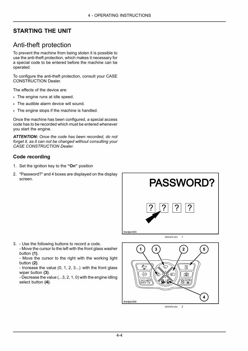
4 - OPERATING INSTRUCTIONS
STARTING THE UNIT
Anti-theft protectionTo prevent the machine from being stolen it is possible touse the anti-theft protection, which makes it necessary fora special code to be entered before the machine can beoperated.
To configure the anti-theft protection, consult your CASECONSTRUCTION Dealer.
The effects of the device are:
• The engine runs at idle speed.
• The audible alarm device will sound.
• The engine stops if the machine is handled.
Once the machine has been configured, a special accesscode has to be recorded which must be entered wheneveryou start the engine.
ATTENTION: Once the code has been recorded, do notforget it, as it can not be changed without consulting yourCASE CONSTRUCTION Dealer.
Code recording
1. Set the ignition key to the “On” position
2. "Password?" and 4 boxes are displayed on the displayscreen.
3RW3PD-003 1
3. - Use the following buttons to record a code.- Move the cursor to the left with the front glass washerbutton (1).- Move the cursor to the right with the working lightbutton (2).- Increase the value (0, 1, 2, 3...) with the front glasswiper button (3).- Decrease the value (...3, 2, 1, 0) with the engine idlingselect button (4).
3RW3PD-004 2
4-4
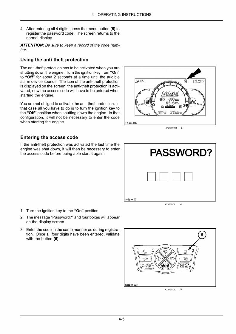
4 - OPERATING INSTRUCTIONS
4. After entering all 4 digits, press the menu button (5) toregister the password code. The screen returns to thenormal display.
ATTENTION: Be sure to keep a record of the code num-ber.
Using the anti-theft protectionThe anti-theft protection has to be activated when you areshutting down the engine. Turn the ignition key from “On”to “Off” for about 2 seconds at a time until the audiblealarm device sounds. The icon of the anti-theft protectionis displayed on the screen, the anti-theft protection is acti-vated, now the access code will have to be entered whenstarting the engine.
You are not obliged to activate the anti-theft protection. Inthat case all you have to do is to turn the ignition key tothe “Off” position when shutting down the engine. In thatconfiguration, it will not be necessary to enter the codewhen starting the engine.
12K2R4-002Z 3
Entering the access codeIf the anti-theft protection was activated the last time theengine was shut down, it will then be necessary to enterthe access code before being able start it again.
AZ8P3X-001 4
1. Turn the ignition key to the “On” position.2. The message "Password?" and four boxes will appear
on the display screen.
3. Enter the code in the same manner as during registra-tion. Once all four digits have been entered, validatewith the button (5).
AZ8P3X-003 5
4-5

4 - OPERATING INSTRUCTIONS
If the access code has been entered correctly, the iconof the anti-theft protection will disappear from the screenand it will be possible to start the engine.If the code is wrong or if the code is different from the oneregistered, the message “Error” is displayed, the opera-tion has to be restarted.Place the ignition key in the “Off” position and repeatSteps 1 to 3.
NOTE: If the anti-theft protection was activated the lasttime the engine was turned off, it will still be possible tostart the machine without the access code, or with thewrong code, but the engine will run at idle speed, and willstop if the machine is handled.
AZ8P3X-002 6
4-6
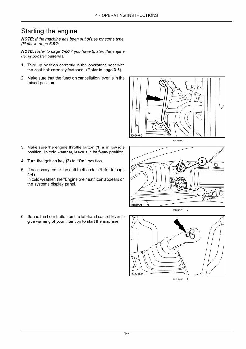
4 - OPERATING INSTRUCTIONS
Starting the engineNOTE: If the machine has been out of use for some time.(Refer to page 6-92).
NOTE: Refer to page 6-80 if you have to start the engineusing booster batteries.
1. Take up position correctly in the operator's seat withthe seat belt correctly fastened. (Refer to page 3-5).
2. Make sure that the function cancellation lever is in theraised position.
80856A8C 1
3. Make sure the engine throttle button (1) is in low idleposition. In cold weather, leave it in half-way position.
4. Turn the ignition key (2) to “On” position.
5. If necessary, enter the anti-theft code. (Refer to page4-4).In cold weather, the "Engine pre heat" icon appears onthe systems display panel.
84BB2A7F 2
6. Sound the horn button on the left-hand control lever togive warning of your intention to start the machine.
B4C1F546 3
4-7
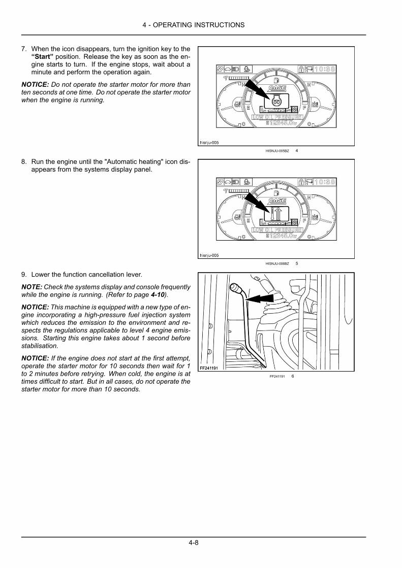
4 - OPERATING INSTRUCTIONS
7. When the icon disappears, turn the ignition key to the“Start” position. Release the key as soon as the en-gine starts to turn. If the engine stops, wait about aminute and perform the operation again.
NOTICE: Do not operate the starter motor for more thanten seconds at one time. Do not operate the starter motorwhen the engine is running.
HISNJU-005BZ 4
8. Run the engine until the "Automatic heating" icon dis-appears from the systems display panel.
HISNJU-006BZ 5
9. Lower the function cancellation lever.
NOTE:Check the systems display and console frequentlywhile the engine is running. (Refer to page 4-10).
NOTICE: This machine is equipped with a new type of en-gine incorporating a high-pressure fuel injection systemwhich reduces the emission to the environment and re-spects the regulations applicable to level 4 engine emis-sions. Starting this engine takes about 1 second beforestabilisation.
NOTICE: If the engine does not start at the first attempt,operate the starter motor for 10 seconds then wait for 1to 2 minutes before retrying. When cold, the engine is attimes difficult to start. But in all cases, do not operate thestarter motor for more than 10 seconds.
FF241191 6
4-8

4 - OPERATING INSTRUCTIONS
Bringing the machine up to operating temperatureNOTICE: Normal operating temperature of the hydraulic fluid is between 50 °C (122.0 °F) and 80 °C (176.0 °F), inthe middle of the temperature indicator.
After starting the engine and before using the machine, allow the hydraulic fluid to reach a temperature of 20 °C (68.0°F), as indicated by the appearance of the first two segments on the hydraulic fluid temperature indicator. (Refer topage 3-19).
Engine automatic warm-up
Once the engine has started, the warming-up process begins automatically. At first, engine speed is held at a pre-determined, low level. As the temperature increases, engine speed increases in proportion. It is possible to interruptthe warming-up process at any time, simply by manually changing engine speed or by operating one of the controllevers. Warming-up takes approximately 5 to 10 minutes.
Manual engine warm-up
With the engine throttle button a quarter open, start the engine and allow it to run approximately for 5 to 10 minutes.When the coolant temperature reaches the second segment, carry out the hydraulic fluid warm-up procedure.
Hydraulic fluid warm-up
1. Turn the engine throttle button to half-open position. Lower the function cancellation lever. Operate the bucketcontrol slowly until the bucket is completely closed. Operate the arm retracting control slowly until the arm iscompletely retracted and hold the control in this position for 30 seconds. During this time the temperature of thehydraulic fluid will increase.
2. After 30 seconds, extend the arm completely and hold the control in this position a further 30 seconds.3. Continue the arm extending and retracting procedure until the temperature rises (first two segments of the tem-
perature indicator).4. Operate the travel and attachment controls three or four times to circulate the hydraulic fluid.
4-9
4 - OPERATING INSTRUCTIONS
Engine operationWARNINGHot liquid under pressure!Fuel in the high pressure fuel line is still under pressure immediately after you shut down the engine.Before performing any maintenance or inspection, wait for 2 minutes after engine shutdown to allowthe pressure to drop.Failure to comply could result in death or serious injury.
W0249A
WARNINGElectrical shock hazard!High voltage is charged to the controller and/or to the injector while the engine is running and im-mediately after shutdown. DO NOT touch the controller or the injector. Consult your dealer if it isnecessary to touch these parts for maintenance purposes.Failure to comply could result in death or serious injury.
W0250A
When the engine has started and before beginning work, the following procedure must be observed:1. Let the engine idle for about five minutes until it has warmed up.2. Move the engine throttle button to the maximum speed position.
Once normal operating temperature has been reached, check the following:
• The exhaust smoke is normal.
• There is no abnormal noise or vibration.
• There are no oil, fuel or water leaks.
The engine should be run at full speed when operating conditions permit.
The operating speed of the machine and of the attachment should be controlled by means of the control levers.
Check the systems display and console regularly.
Stop the engine immediately if one of the following situations occurs:
• Sudden increase or decrease in engine speed.
• Abnormal noise.
• Black smoke at the exhaust.
• A message appears on the display screen and the audible alarm device sounds.
4-10
4 - OPERATING INSTRUCTIONS
Operating the machine in hot or cold weatherIn cold weather
Follow the recommendations shown below:
Batteries
• They should be fully charged.
Fuel
• To prevent condensation forming and water getting intothe fuel system, fill the fuel tank after each day's workand drain off any water before starting the next day'swork.
• To prevent crystals forming at -2 °C (35.6 °F), use fuelwhich is rated for the ambient temperature or add anappropriate antifreeze to the fuel. (Refer to page 6-5).
Engine oil
• It should be of the right viscosity for the ambient tem-perature. (Refer to page 6-5).
Hydraulic fluid
• The viscosity must correspond to the ambient temper-ature conditions. (Refer to page 6-5).
Coolant solution
• It must have specifications corresponding to the ambi-ent temperature. (Refer to page 6-5).
In hot weather
Follow the recommendations made below:
• Keep the coolant at the correct level in the coolantreservoir and in the radiator.
• Use the correct solution of ethylene glycol and water inthe cooling system.
• Test the radiator cap before hot weather starts. Re-place the cap as required.
• Clean all dirt and debris from the radiator, cooler andengine area.
• Check the condition of the fan drive belt.
• Check the dust valve in the air cleaner frequently duringextreme dust conditions.
• Use lubricants of the correct viscosity. (Refer to page6-5).
4-11
4 - OPERATING INSTRUCTIONS
Machine operationOperating instructions
WARNINGMisuse hazard!Follow the operating instructions in this chapter. Any other practice that has not received the priorapproval of the manufacturer is considered to be strictly forbidden.Failure to comply could result in death or serious injury.
W0281A
Watch carefully and make sure you are aware of placeswhere other people are working in your work area. Keepall other people away from the machine. Serious injurycan result if these instructions are not followed.
Take note of the locations of pipes/cables before startingwork. Electrical cables, gas and water pipes and otherunderground installations can cause serious injury.
Modify your driving to suit working conditions (sloping orrough ground), the nature of the ground and weather con-ditions.
On steeply sloping ground, keep engine at maximumspeed.
When travelling at right angles to the slope, move on tothe slope at low speed. Never reduce engine speed whentravelling down slopes.
Holes, obstacles, debris and other danger risks in theworking area can cause serious injury. Inspect and noteall possible risks before driving the machine in a newworking area.
Do not work near overhead high-voltage electric lineswithout checking beforehand that all necessary measureshave been taken to respect the minimum distances:Less than 57 000 volts: 3 m (9.8 ft).More than 57 000 volts: 5 m (16.4 ft).
Never hit or push material with the sides of the bucket.
Never sweep the ground with the bucket to level rubble.
When operating the control levers, a whistling sound willbe heard if the control lever is held in position while thecorresponding cylinder is at the end of its stroke. In thiscase release the control lever.
When ditching along the edge of a road, it may be nec-essary to change the attachment offset in relation to themachine. Check from time to time and correct if neces-sary.
If earth or mud stays stuck inside the bucket, open andclose the bucket several times so as to loosen the earthor the mud.
After work, remove any mud and clean the machine.
When operating the attachment, take care that the bucketdoes not hit the dozer blade (if equipped).
Take care not to hit the dozer blade (if equipped) againstrocks.
When using the upperstructure swing, never change thedirection of swing too suddenly.
If the operation of the dozer blade (if equipped) is notnecessary, always make sure that it is in maximum raisedposition.
During filling in operations, operate the two travel leverswith your left hand while operating the dozer blade controllever (if equipped) with your right hand.
When climbing up a slope, place the bucket about 40 cm(15.7 in) above the ground. When travelling down a slopeit is recommended to place the bucket on the ground toprevent the machine from sliding.
Avoid turning the machine on steep slopes.
Never swing the upperstructure on slopes of 15 ° in thedirection of travel or 10 ° at right angles to the direction oftravel.
The following operations are likely to damage themachine. You are therefore advised to avoid them:
• Excavation using the weight of the machine as a forceof impact.
• Excavation using the machine’s travel force.
OperationATTENTION:Do not operate the engine with the machineat 35 °. The engine or hydraulic devices may be dam-aged.
The maximum slope climbing ability is 35 ° 70 %. Thisvalue varies depending on the track type and the roadsurface, limit travelling to slopes of 30 ° or less.1. Sit in the operator's seat and adjust it so that all the
controls are readily accessible then fasten your safetybelt.
2. Make sure the cab door is firmly latched in the openor closed position.
3. Sound the horn.
4-12

4 - OPERATING INSTRUCTIONS
4. Start the engine, taking into consideration the prevail-ing weather conditions.
5. Check all indicator lamps and gauges are operatingcorrectly.
6. Lower the function cancellation lever.7. Try out all the controls in a safe, open area.
4-13
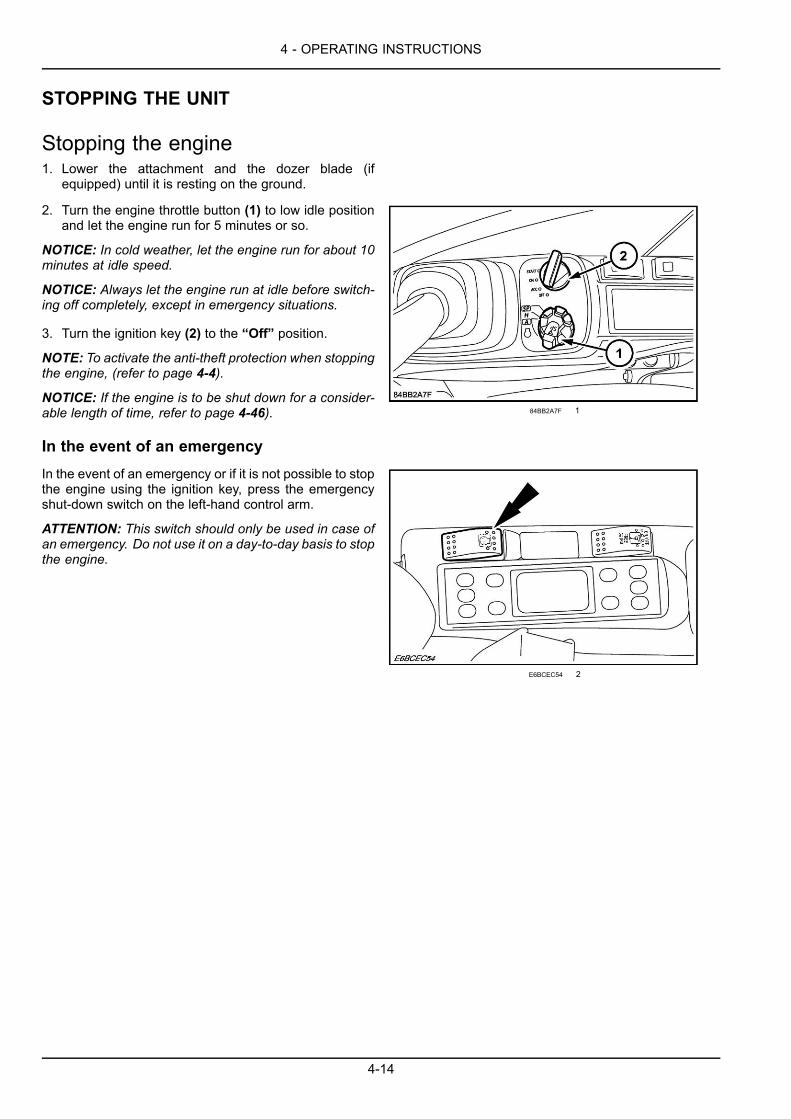
4 - OPERATING INSTRUCTIONS
STOPPING THE UNIT
Stopping the engine1. Lower the attachment and the dozer blade (if
equipped) until it is resting on the ground.
2. Turn the engine throttle button (1) to low idle positionand let the engine run for 5 minutes or so.
NOTICE: In cold weather, let the engine run for about 10minutes at idle speed.
NOTICE: Always let the engine run at idle before switch-ing off completely, except in emergency situations.
3. Turn the ignition key (2) to the “Off” position.
NOTE: To activate the anti-theft protection when stoppingthe engine, (refer to page 4-4).
NOTICE: If the engine is to be shut down for a consider-able length of time, refer to page 4-46).
In the event of an emergency
84BB2A7F 1
In the event of an emergency or if it is not possible to stopthe engine using the ignition key, press the emergencyshut-down switch on the left-hand control arm.
ATTENTION: This switch should only be used in case ofan emergency. Do not use it on a day-to-day basis to stopthe engine.
E6BCEC54 2
4-14
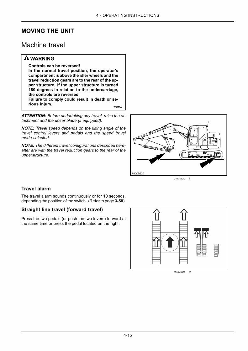
4 - OPERATING INSTRUCTIONS
MOVING THE UNIT
Machine travel
WARNINGControls can be reversed!In the normal travel position, the operator'scompartment is above the idler wheels and thetravel reduction gears are to the rear of the up-per structure. If the upper structure is turned180 degrees in relation to the undercarriage,the controls are reversed.Failure to comply could result in death or se-rious injury.
W0289A
ATTENTION: Before undertaking any travel, raise the at-tachment and the dozer blade (if equipped).
NOTE: Travel speed depends on the tilting angle of thetravel control levers and pedals and the speed travelmode selected.
NOTE: The different travel configurations described here-after are with the travel reduction gears to the rear of theupperstructure.
71DCD62A 1
Travel alarmThe travel alarm sounds continuously or for 10 seconds,depending the position of the switch. (Refer to page 3-58).
Straight line travel (forward travel)
Press the two pedals (or push the two levers) forward atthe same time or press the pedal located on the right.
CS98M546Z 2
4-15

4 - OPERATING INSTRUCTIONS
Straight line travel (reverse travel)
Press the two pedals (or push the two levers) rearward atthe same time.
TVJAZI-002 3
Turning to the left (forward travel)
Simply press the right-hand pedal or the right-hand leverforward.
3USM2U-001 4
Turning to the right (forward travel)
Simply press the left-hand pedal or the left-hand lever for-ward.
VEWP8J-001 5
Turning to the left (reverse travel)
Simply press the right-hand pedal or the right-hand leverrearward.
ZTP4TE-001 6
4-16
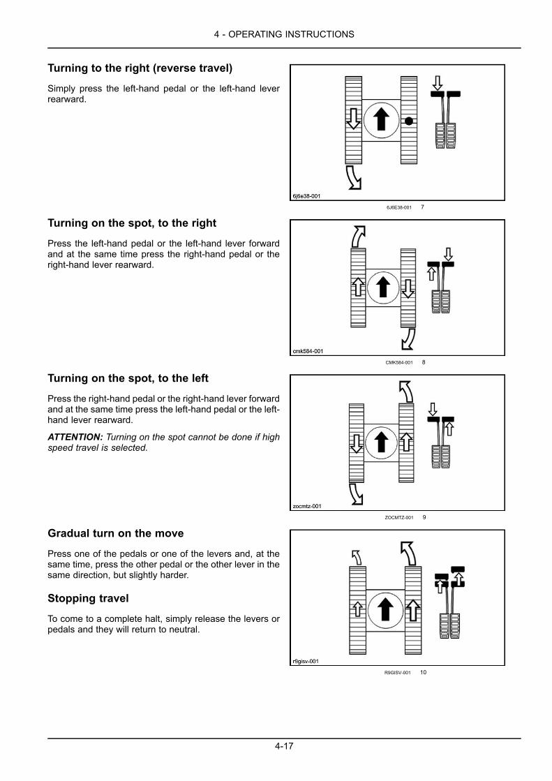
4 - OPERATING INSTRUCTIONS
Turning to the right (reverse travel)
Simply press the left-hand pedal or the left-hand leverrearward.
6J6E38-001 7
Turning on the spot, to the right
Press the left-hand pedal or the left-hand lever forwardand at the same time press the right-hand pedal or theright-hand lever rearward.
CMK584-001 8
Turning on the spot, to the left
Press the right-hand pedal or the right-hand lever forwardand at the same time press the left-hand pedal or the left-hand lever rearward.
ATTENTION: Turning on the spot cannot be done if highspeed travel is selected.
ZOCMTZ-001 9
Gradual turn on the move
Press one of the pedals or one of the levers and, at thesame time, press the other pedal or the other lever in thesame direction, but slightly harder.
Stopping travel
To come to a complete halt, simply release the levers orpedals and they will return to neutral.
R9GISV-001 10
4-17

4 - OPERATING INSTRUCTIONS
Handling the machineWARNINGImproper operation or service of this machine can result in an accident.Assign a supervisor to direct worksite operations. Agree on all safety measures, procedures, andsuitable hand signals.Failure to comply could result in death or serious injury.
W0287A
WARNINGCrushing hazard!The lifting systems must be operated by qualified personnel who are aware of the correct proceduresto follow. Make sure all lifting equipment is in good condition, and all hooks are equipped with safetylatches.Failure to comply could result in death or serious injury.
W0256A
WARNINGCrushing hazard!This operation may be dangerous. You are advised to wear suitable clothing and respect all relevantsafety messages.Failure to comply could result in death or serious injury.
W0283A
WARNINGHazard to bystanders!ALWAYS make sure the work area is clear of bystanders and domestic animals before starting thisprocedure. Know the full area of movement of the machine. Do not permit anyone to enter the areaof movement during this procedure.Failure to comply could result in death or serious injury.
W0245A
4-18
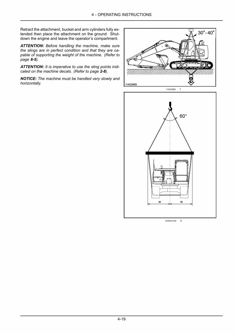
4 - OPERATING INSTRUCTIONS
Retract the attachment, bucket and arm cylinders fully ex-tended then place the attachment on the ground. Shut-down the engine and leave the operator’s compartment.
ATTENTION: Before handling the machine, make surethe slings are in perfect condition and that they are ca-pable of supporting the weight of the machine. (Refer topage 8-5).
ATTENTION: It is imperative to use the sling points indi-cated on the machine decals. (Refer to page 2-8).
NOTICE: The machine must be handled very slowly andhorizontally.
11AD25EB 1
3OS524-002 2
4-19

4 - OPERATING INSTRUCTIONS
Load handlingWARNINGCrushing hazard!During load handling operations, it is very important to adhere strictly to the instructions given in thismanual and local legislation.Failure to comply could result in death or serious injury.
W0257A
ATTENTION: This machine is not a crane. Be very careful when you lift a load.
NOTICE: The loads given are valid for the total working range height at the reach point indicated.
The load handling chart (located in the cab) shows the different permitted loads which can be lifted, depending on thereach and the type of attachment on the machine.
The machine must be on a flat level, hard surface.
Only the load lift eye on the bucket may be used.
CT10D001A 1
If this machine is to be used to lift loads, for safety purposes, it is recommended that the machine is properly equipped.Contact your CASECONSTRUCTION dealer and install a Hose Burst Check Valve on your machine’s boom cylinders.This system prevents the sudden lowering of the load in the event of a failure of a hydraulic hose, line, or fitting in theboom hydraulic system. Such a failure can cause personal injury or death.
• Know and understand each signal from the signal person before you start.
• Always know the location of all persons in your work area before you start.
• Make certain there is no damage to the lifting device and rigging parts.
• Make certain the lifting device has the appropriate tensile strength for the load being lifted.
• Do not exceed either the radius or the height restrictions shown on the lift capacity charts posted in the cab.
• Be careful to balance the load correctly.
• Always move the load slowly. Do not move the load over the top of persons. Keep all persons away from the load.
• When the load is raised, keep all persons away until the load is placed on blocks or on the ground.
ATTENTION: It is extremely dangerous if the load lifted begins to swing. The upper structure should be centered overthe load to help prevent dangerous swinging.
4-20

4 - OPERATING INSTRUCTIONS
Handling the load with the quick coupler (optional)The load with the quick coupler must be handled with thebucket cylinder rod completely extended.
ATTENTION: Maintain this position throughout the loadhandling operation.
W1UFZ2-001A 2
The handling eye must be able to be seen from the cabthroughout the load handling operation.
ATTENTION: It is strictly forbidden to use the front or rearfixing points (1) of the quick coupler to handle the load.
NOTE: The quick coupler eye can be used for handlingloads up to 10 t.
W1UFZ2-002B 3
4-21
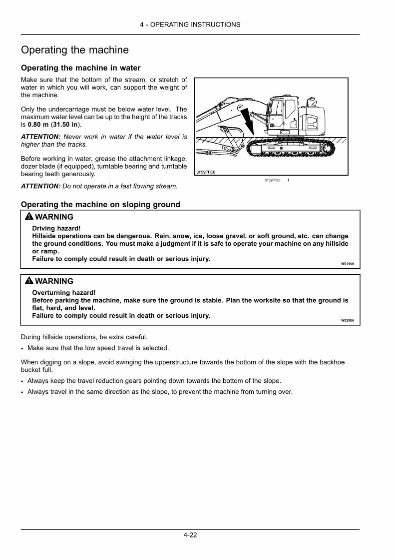
4 - OPERATING INSTRUCTIONS
Operating the machineOperating the machine in waterMake sure that the bottom of the stream, or stretch ofwater in which you will work, can support the weight ofthe machine.
Only the undercarriage must be below water level. Themaximum water level can be up to the height of the tracksis 0.80 m (31.50 in).
ATTENTION: Never work in water if the water level ishigher than the tracks.
Before working in water, grease the attachment linkage,dozer blade (if equipped), turntable bearing and turntablebearing teeth generously.
ATTENTION: Do not operate in a fast flowing stream.0F59FFE6 1
Operating the machine on sloping groundWARNINGDriving hazard!Hillside operations can be dangerous. Rain, snow, ice, loose gravel, or soft ground, etc. can changethe ground conditions. You must make a judgment if it is safe to operate your machine on any hillsideor ramp.Failure to comply could result in death or serious injury.
W0144A
WARNINGOverturning hazard!Before parking the machine, make sure the ground is stable. Plan the worksite so that the ground isflat, hard, and level.Failure to comply could result in death or serious injury.
W0258A
During hillside operations, be extra careful.
• Make sure that the low speed travel is selected.
When digging on a slope, avoid swinging the upperstructure towards the bottom of the slope with the backhoebucket full.
• Always keep the travel reduction gears pointing down towards the bottom of the slope.
• Always travel in the same direction as the slope, to prevent the machine from turning over.
4-22

4 - OPERATING INSTRUCTIONS
Operating the backhoe bucket
Filling
Fill the backhoe bucket by manoeuvring the arm. Keep the bottom of the backhoe bucket parallel to the cut. Thebackhoe bucket teeth and blade must cut the ground like the blade of a knife. The depth of dig varies depending onthe type of material.
Excavating method
UJAY1P-001 2
UJAY1P-002 3
1. Correct2. Incorrect. The backhoe bucket will dig in and cause a stall.3. Incorrect. The backhoe bucket is pushed upwards. This will also increase the cycle time.
Operating the offset boom (if equipped)When the arm is operated, the position of the rear armcylinder changes. Be careful not touch hoses or pipes onthe attachment.
BB1FCDB4 4
4-23
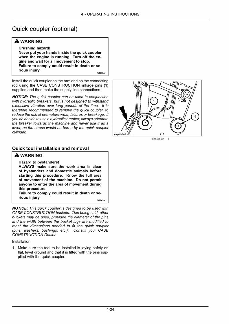
4 - OPERATING INSTRUCTIONS
Quick coupler (optional)
WARNINGCrushing hazard!Never put your hands inside the quick couplerwhen the engine is running. Turn off the en-gine and wait for all movement to stop.Failure to comply could result in death or se-rious injury.
W0252A
Install the quick coupler on the arm and on the connectingrod using the CASE CONSTRUCTION linkage pins (1)supplied and then make the supply line connections.
NOTICE: The quick coupler can be used in conjunctionwith hydraulic breakers, but is not designed to withstandexcessive vibration over long periods of the time. It istherefore recommended to remove the quick coupler, toreduce the risk of premature wear, failures or breakage. Ifyou do decide to use a hydraulic breaker, always orientatethe breaker towards the machine and never use it as alever, as the stress would be borne by the quick couplercylinder.
XOQMIB-002 1
Quick tool installation and removalWARNINGHazard to bystanders!ALWAYS make sure the work area is clearof bystanders and domestic animals beforestarting this procedure. Know the full areaof movement of the machine. Do not permitanyone to enter the area of movement duringthis procedure.Failure to comply could result in death or se-rious injury.
W0245A
NOTICE: This quick coupler is designed to be used withCASE CONSTRUCTION buckets. This being said, otherbuckets may be used, provided the diameter of the pinsand the width between the bucket lugs are modified tomeet the dimensions needed to fit the quick coupler(pins, washers, bushings, etc.). Consult your CASECONSTRUCTION Dealer.
Installation1. Make sure the tool to be installed is laying safely on
flat, level ground and that it is fitted with the pins sup-plied with the quick coupler.
4-24
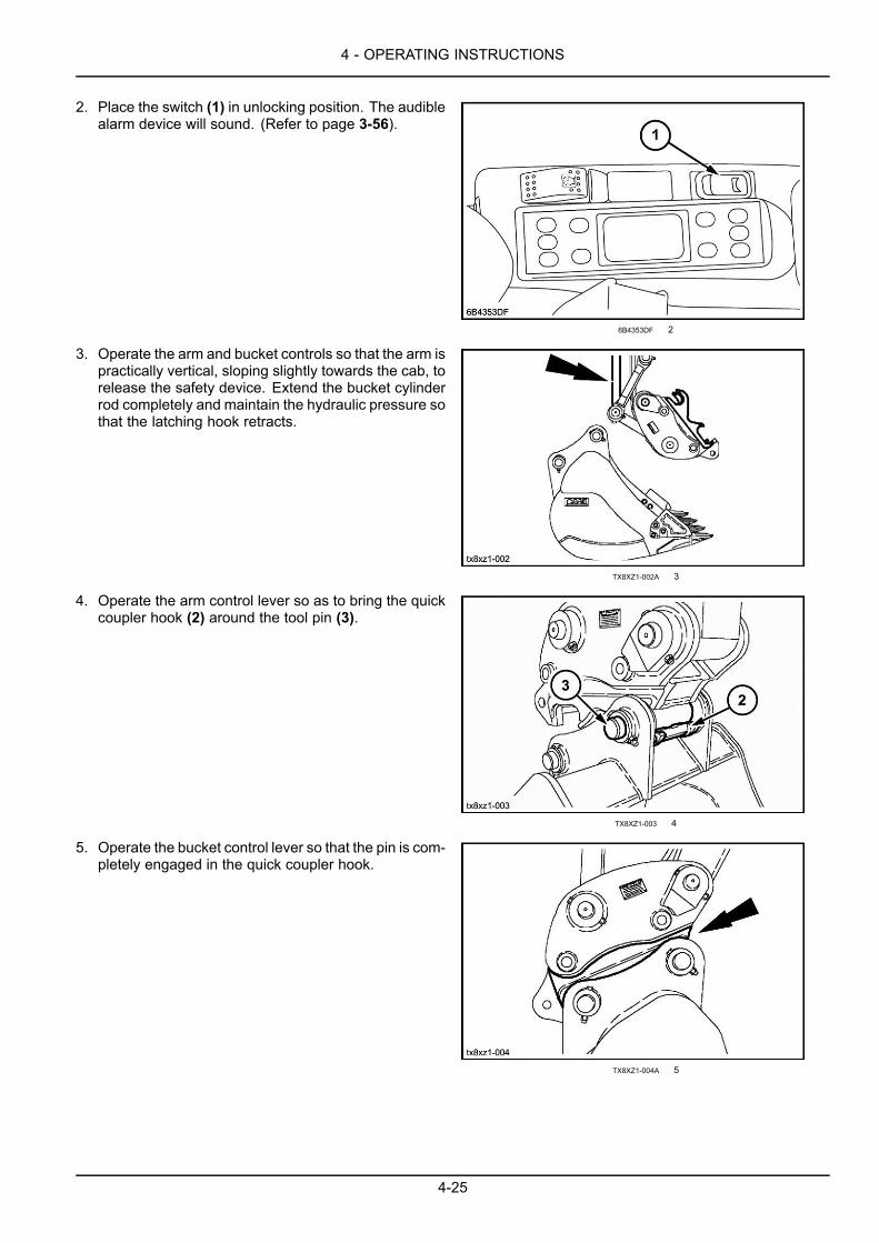
4 - OPERATING INSTRUCTIONS
2. Place the switch (1) in unlocking position. The audiblealarm device will sound. (Refer to page 3-56).
6B4353DF 2
3. Operate the arm and bucket controls so that the arm ispractically vertical, sloping slightly towards the cab, torelease the safety device. Extend the bucket cylinderrod completely and maintain the hydraulic pressure sothat the latching hook retracts.
TX8XZ1-002A 3
4. Operate the arm control lever so as to bring the quickcoupler hook (2) around the tool pin (3).
TX8XZ1-003 4
5. Operate the bucket control lever so that the pin is com-pletely engaged in the quick coupler hook.
TX8XZ1-004A 5
4-25
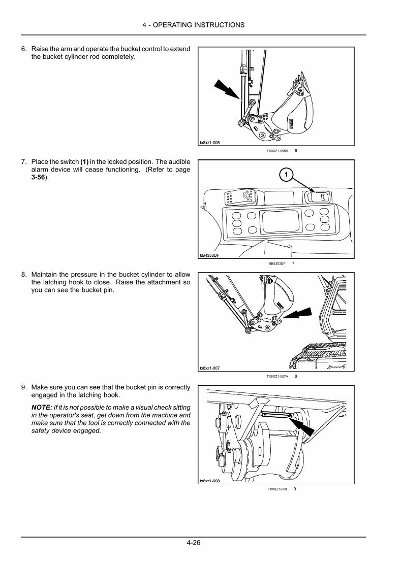
4 - OPERATING INSTRUCTIONS
6. Raise the arm and operate the bucket control to extendthe bucket cylinder rod completely.
TX8XZ1-005A 6
7. Place the switch (1) in the locked position. The audiblealarm device will cease functioning. (Refer to page3-56).
6B4353DF 7
8. Maintain the pressure in the bucket cylinder to allowthe latching hook to close. Raise the attachment soyou can see the bucket pin.
TX8XZ1-007A 8
9. Make sure you can see that the bucket pin is correctlyengaged in the latching hook.
NOTE: If it is not possible tomake a visual check sittingin the operator's seat, get down from the machine andmake sure that the tool is correctly connected with thesafety device engaged.
TX8XZ1-008 9
4-26
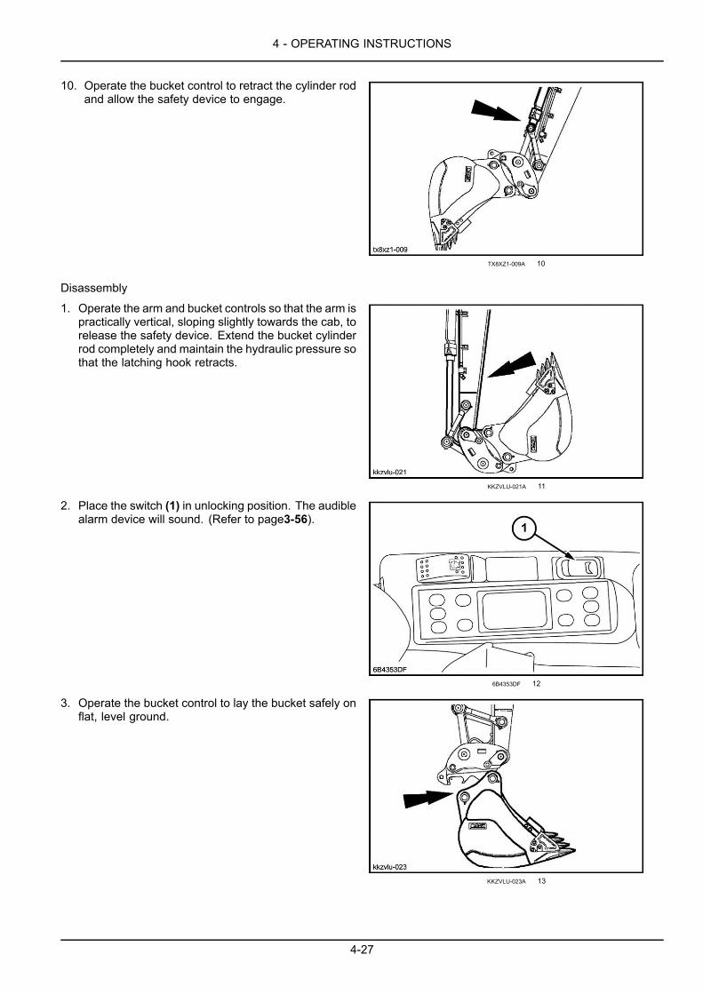
4 - OPERATING INSTRUCTIONS
10. Operate the bucket control to retract the cylinder rodand allow the safety device to engage.
TX8XZ1-009A 10
Disassembly
1. Operate the arm and bucket controls so that the arm ispractically vertical, sloping slightly towards the cab, torelease the safety device. Extend the bucket cylinderrod completely and maintain the hydraulic pressure sothat the latching hook retracts.
KKZVLU-021A 11
2. Place the switch (1) in unlocking position. The audiblealarm device will sound. (Refer to page3-56).
6B4353DF 12
3. Operate the bucket control to lay the bucket safely onflat, level ground.
KKZVLU-023A 13
4-27
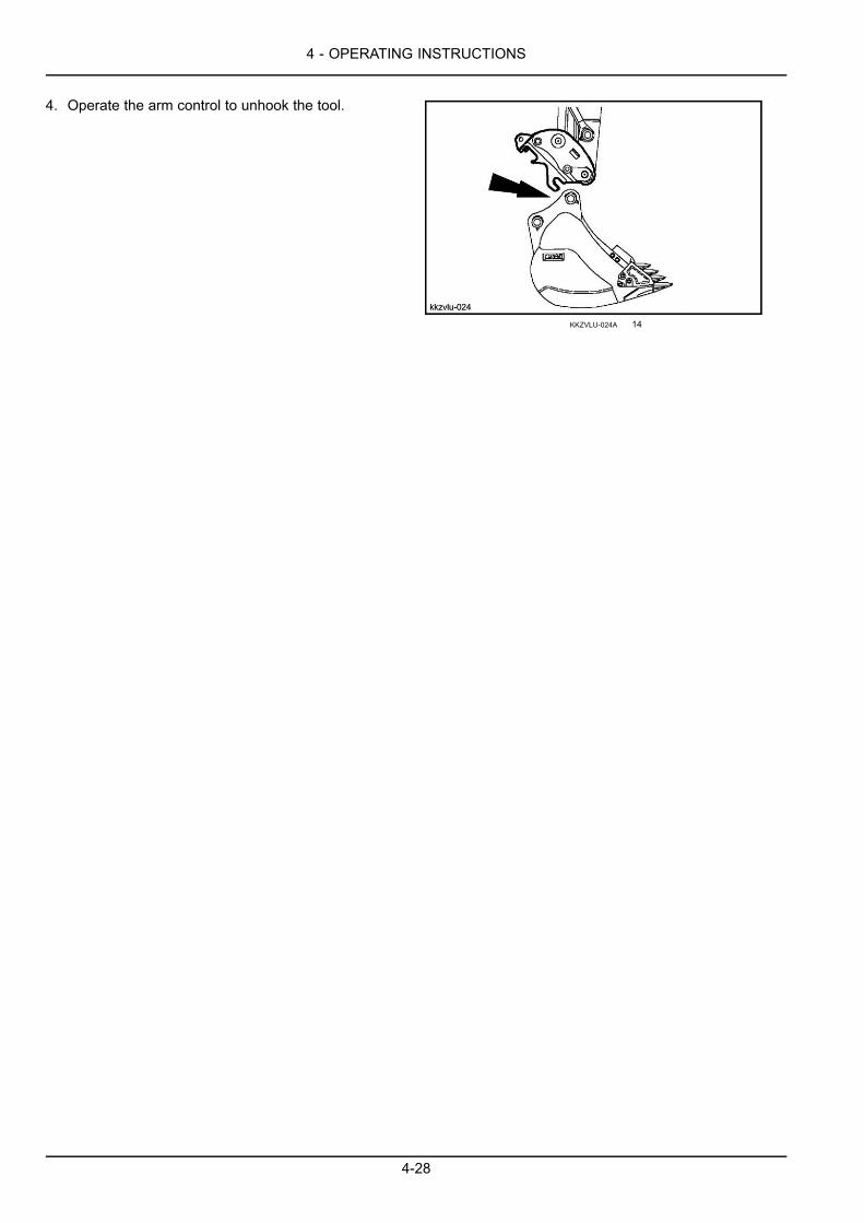
4 - OPERATING INSTRUCTIONS
4. Operate the arm control to unhook the tool.
KKZVLU-024A 14
4-28

4 - OPERATING INSTRUCTIONS
Lowering the attachment in the event of a failureIf the engine breaks down, use the following procedure tolower the attachment:
1. Turn the ignition key to the “On” position.
3F901DF6 1
2. Lower the function cancellation lever.
FF241191 2
3. Place the control lever(s) in the position correspondingto the downward movement required.
D5075429 3
4-29
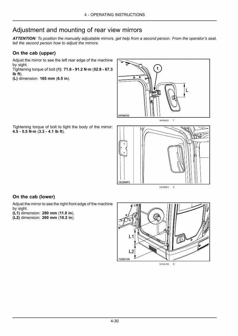
4 - OPERATING INSTRUCTIONS
Adjustment and mounting of rear view mirrorsATTENTION: To position the manually adjustable mirrors, get help from a second person. From the operator’s seat,tell the second person how to adjust the mirrors.
On the cab (upper)Adjust the mirror to see the left rear edge of the machineby sight.Tightening torque of bolt (1): 71.6 - 91.2 N·m (52.8 - 67.3lb ft).(L) dimension: 165 mm (6.5 in).
64F68433 1
Tightening torque of bolt to tight the body of the mirror:4.5 - 5.5 N·m (3.3 - 4.1 lb ft).
CE2898F2 2
On the cab (lower)Adjust the mirror to see the right front edge of the machineby sight.(L1) dimension: 280 mm (11.0 in).(L2) dimension: 260 mm (10.2 in).
9472A1D5 3
4-30

4 - OPERATING INSTRUCTIONS
Tightening torque of bolt to tight the body of the mirror:4.5 - 5.5 N·m (3.3 - 4.1 lb ft).
F31B0E82 4
On the upperstructure (front)Adjust the mirror to see the right front edge of the machineby sight.(L) dimension: 310 mm (12.2 in).
200515AA 5
Tightening torque of bolt to tight the body of the mirror:4.5 - 5.5 N·m (3.3 - 4.1 lb ft).
FB58285B 6
On the upperstructure (rear)Adjust the mirror to see the right rear edge of the machineby sight.(L) dimension: 280 mm (11.0 in).
BE1F04E1 7
4-31
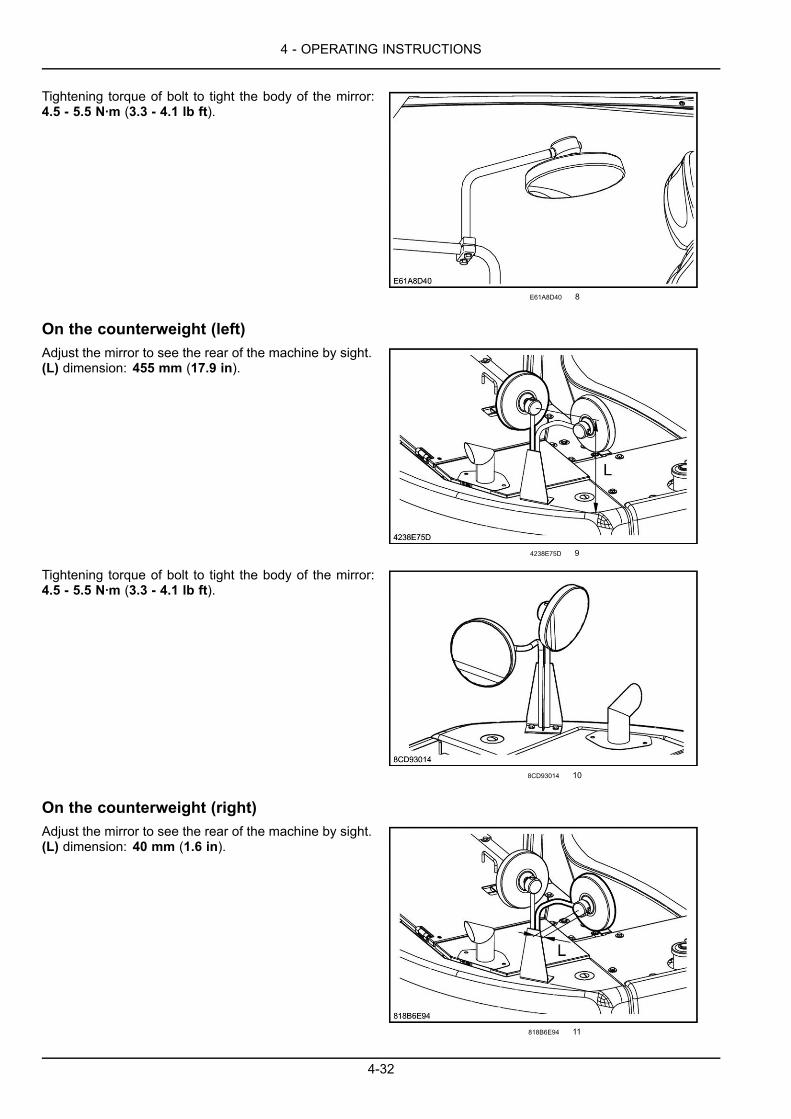
4 - OPERATING INSTRUCTIONS
Tightening torque of bolt to tight the body of the mirror:4.5 - 5.5 N·m (3.3 - 4.1 lb ft).
E61A8D40 8
On the counterweight (left)Adjust the mirror to see the rear of the machine by sight.(L) dimension: 455 mm (17.9 in).
4238E75D 9
Tightening torque of bolt to tight the body of the mirror:4.5 - 5.5 N·m (3.3 - 4.1 lb ft).
8CD93014 10
On the counterweight (right)Adjust the mirror to see the rear of the machine by sight.(L) dimension: 40 mm (1.6 in).
818B6E94 11
4-32
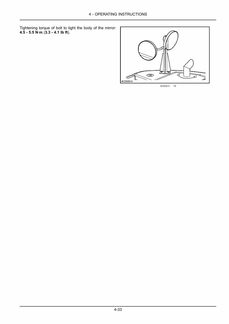
4 - OPERATING INSTRUCTIONS
Tightening torque of bolt to tight the body of the mirror:4.5 - 5.5 N·m (3.3 - 4.1 lb ft).
8CD93014 12
4-33
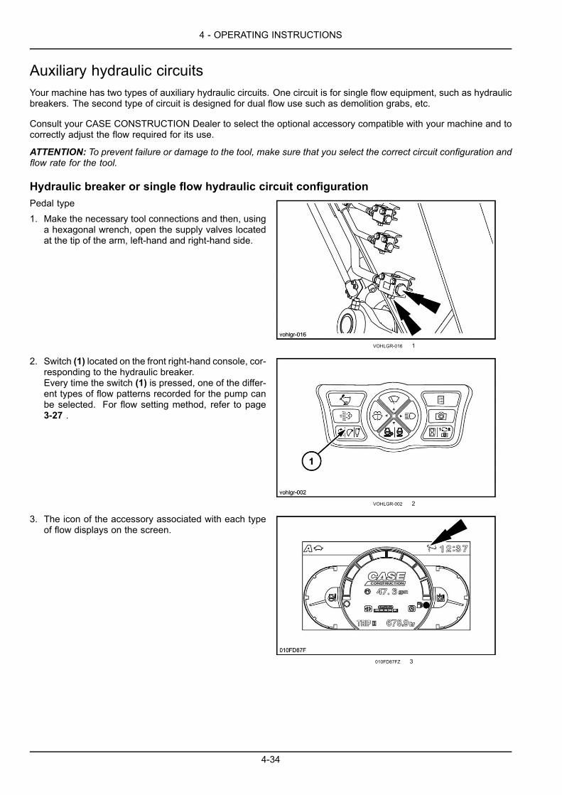
4 - OPERATING INSTRUCTIONS
Auxiliary hydraulic circuitsYour machine has two types of auxiliary hydraulic circuits. One circuit is for single flow equipment, such as hydraulicbreakers. The second type of circuit is designed for dual flow use such as demolition grabs, etc.
Consult your CASE CONSTRUCTION Dealer to select the optional accessory compatible with your machine and tocorrectly adjust the flow required for its use.
ATTENTION: To prevent failure or damage to the tool, make sure that you select the correct circuit configuration andflow rate for the tool.
Hydraulic breaker or single flow hydraulic circuit configurationPedal type1. Make the necessary tool connections and then, using
a hexagonal wrench, open the supply valves locatedat the tip of the arm, left-hand and right-hand side.
VOHLGR-016 1
2. Switch (1) located on the front right-hand console, cor-responding to the hydraulic breaker.Every time the switch (1) is pressed, one of the differ-ent types of flow patterns recorded for the pump canbe selected. For flow setting method, refer to page3-27 .
VOHLGR-002 2
3. The icon of the accessory associated with each typeof flow displays on the screen.
010FD87FZ 3
4-34
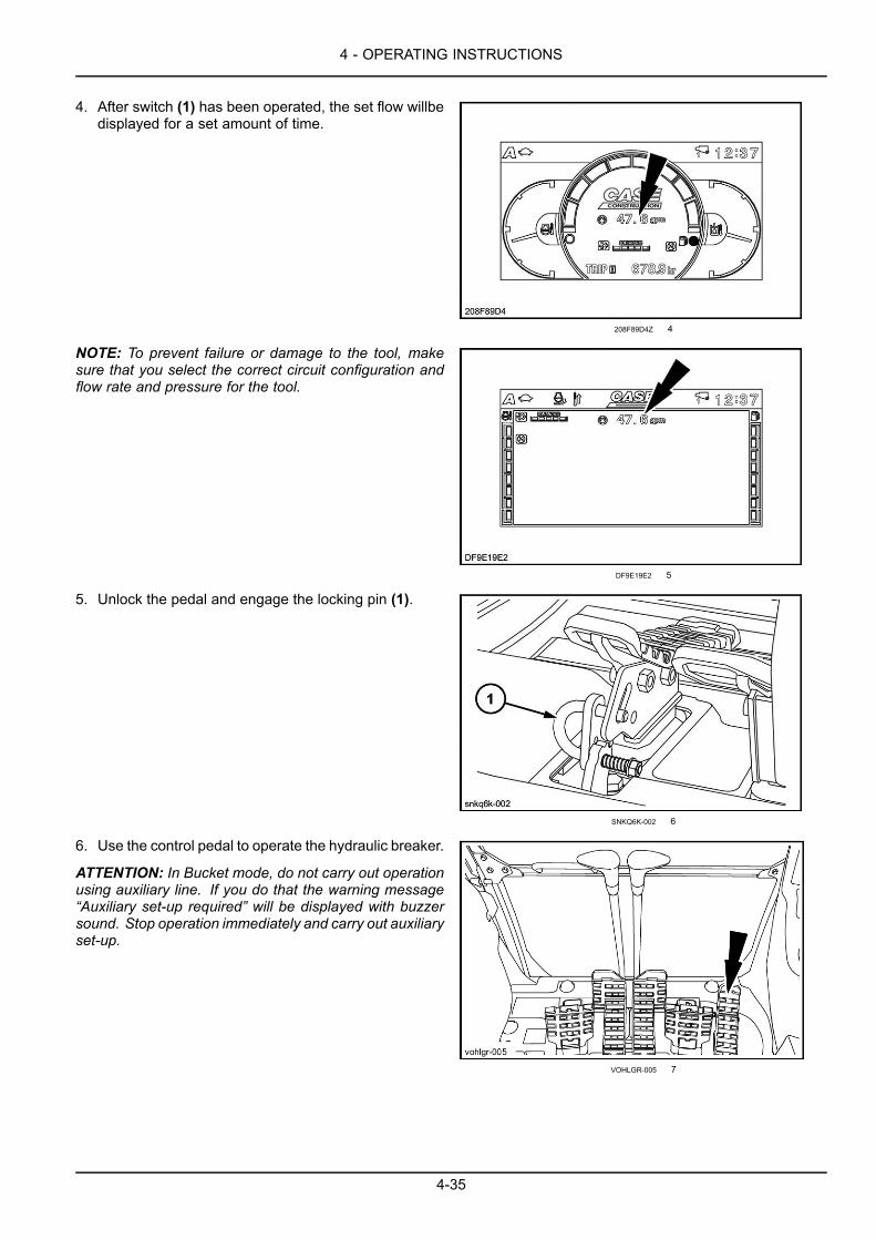
4 - OPERATING INSTRUCTIONS
4. After switch (1) has been operated, the set flow willbedisplayed for a set amount of time.
208F89D4Z 4
NOTE: To prevent failure or damage to the tool, makesure that you select the correct circuit configuration andflow rate and pressure for the tool.
DF9E19E2 5
5. Unlock the pedal and engage the locking pin (1).
SNKQ6K-002 6
6. Use the control pedal to operate the hydraulic breaker.
ATTENTION: In Bucket mode, do not carry out operationusing auxiliary line. If you do that the warning message“Auxiliary set-up required” will be displayed with buzzersound. Stop operation immediately and carry out auxiliaryset-up.
VOHLGR-005 7
4-35
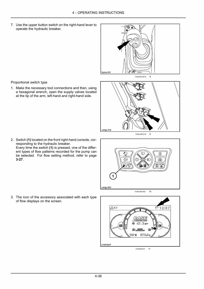
4 - OPERATING INSTRUCTIONS
7. Use the upper button switch on the right-hand lever tooperate the hydraulic breaker.
FIQCKA-001A 8
Proportional switch type1. Make the necessary tool connections and then, using
a hexagonal wrench, open the supply valves locatedat the tip of the arm, left-hand and right-hand side.
VOHLGR-016 9
2. Switch (1) located on the front right-hand console, cor-responding to the hydraulic breaker.Every time the switch (1) is pressed, one of the differ-ent types of flow patterns recorded for the pump canbe selected. For flow setting method, refer to page3-27.
VOHLGR-002 10
3. The icon of the accessory associated with each typeof flow displays on the screen.
010FD87FZ 11
4-36
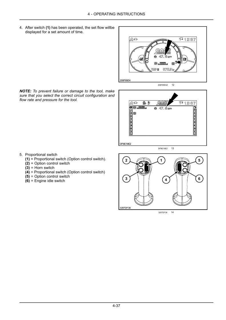
4 - OPERATING INSTRUCTIONS
4. After switch (1) has been operated, the set flow willbedisplayed for a set amount of time.
208F89D4Z 12
NOTE: To prevent failure or damage to the tool, makesure that you select the correct circuit configuration andflow rate and pressure for the tool.
DF9E19E2 13
5. Proportional switch(1) = Proportional switch (Option control switch).(2) = Option control switch(3) = Horn switch(4) = Proportional switch (Option control switch)(5) = Option control switch(6) = Engine idle switch
3207DF38 14
4-37
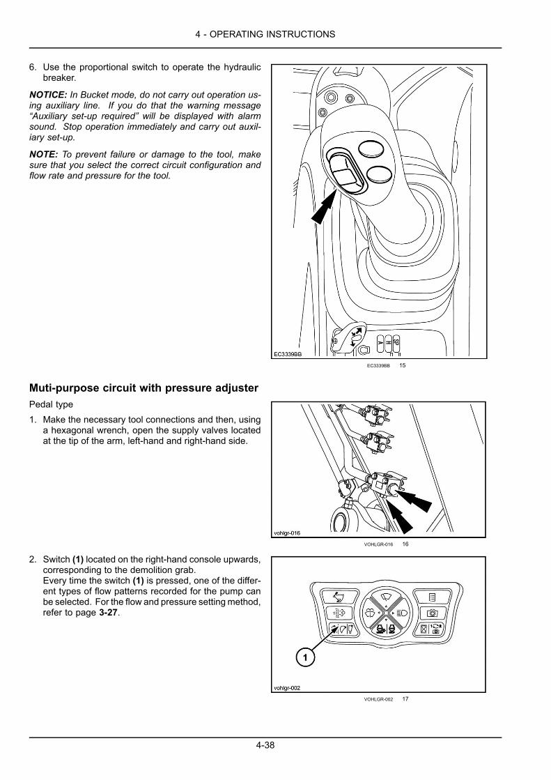
4 - OPERATING INSTRUCTIONS
6. Use the proportional switch to operate the hydraulicbreaker.
NOTICE: In Bucket mode, do not carry out operation us-ing auxiliary line. If you do that the warning message“Auxiliary set-up required” will be displayed with alarmsound. Stop operation immediately and carry out auxil-iary set-up.
NOTE: To prevent failure or damage to the tool, makesure that you select the correct circuit configuration andflow rate and pressure for the tool.
EC3339BB 15
Muti-purpose circuit with pressure adjusterPedal type1. Make the necessary tool connections and then, using
a hexagonal wrench, open the supply valves locatedat the tip of the arm, left-hand and right-hand side.
VOHLGR-016 16
2. Switch (1) located on the right-hand console upwards,corresponding to the demolition grab.Every time the switch (1) is pressed, one of the differ-ent types of flow patterns recorded for the pump canbe selected. For the flow and pressure settingmethod,refer to page 3-27.
VOHLGR-002 17
4-38
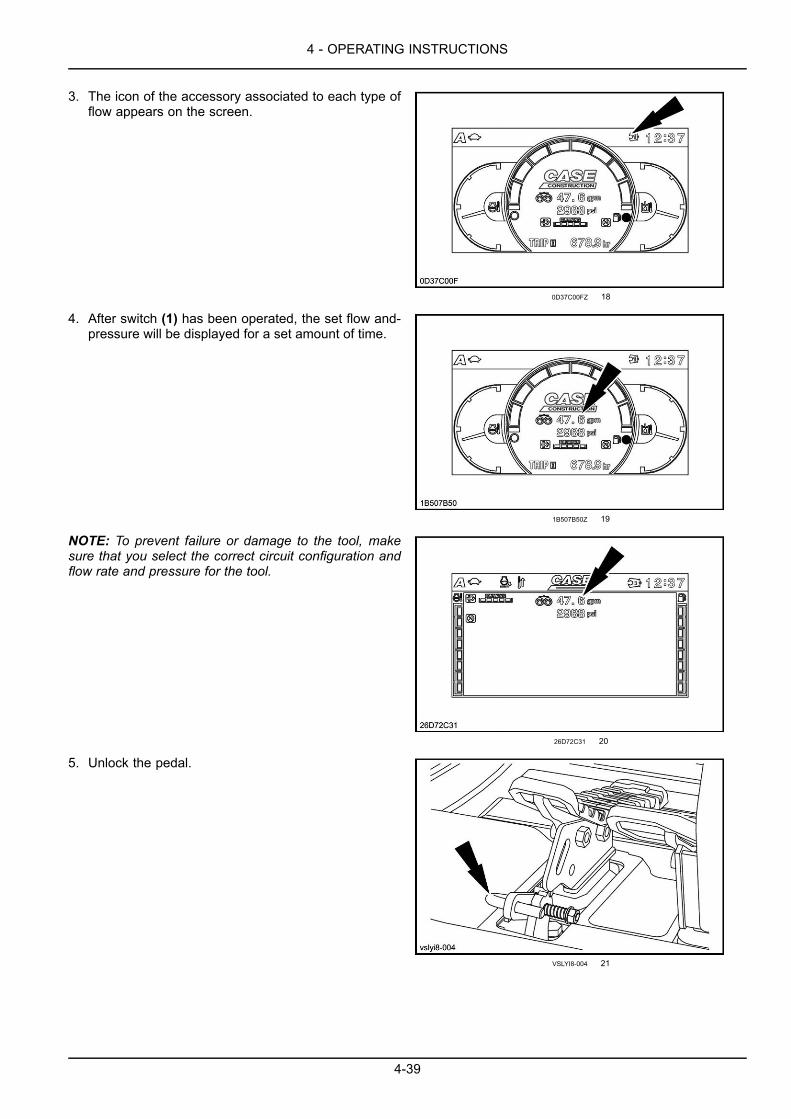
4 - OPERATING INSTRUCTIONS
3. The icon of the accessory associated to each type offlow appears on the screen.
0D37C00FZ 18
4. After switch (1) has been operated, the set flow and-pressure will be displayed for a set amount of time.
1B507B50Z 19
NOTE: To prevent failure or damage to the tool, makesure that you select the correct circuit configuration andflow rate and pressure for the tool.
26D72C31 20
5. Unlock the pedal.
VSLYI8-004 21
4-39

4 - OPERATING INSTRUCTIONS
6. Use the control pedal to operate the concrete crusher.
NOTE: To prevent failure or damage to the tool, makesure that you select the correct circuit configuration andflow rate and pressure for the tool.
ATTENTION: In bucket mode, do not carry out operationusing auxiliary line. If you do that, the warning message“Auxiliary set-up required” will be displayed with intermit-tent whistle sound. Stop operation immediately and carryout auxiliary set-up.
VOHLGR-005 22
Proportional switch type1. Make the necessary tool connections and then, using
a hexagonal wrench, open the supply valves locatedat the tip of the arm, left-hand and right-hand side.
VOHLGR-016 23
2. Switch (1) located on the right-hand console upwards,corresponding to the demolition grab.Every time the switch (1) is pressed, one of the differ-ent types of flow patterns recorded for the pump canbe selected. For the flow and pressure settingmethod,refer to page 3-27.
VOHLGR-002 24
3. The icon of the accessory associated to each type offlow appears on the screen.
0D37C00FZ 25
4-40
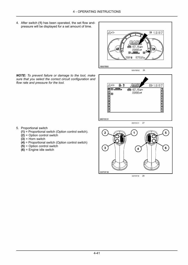
4 - OPERATING INSTRUCTIONS
4. After switch (1) has been operated, the set flow and-pressure will be displayed for a set amount of time.
1B507B50Z 26
NOTE: To prevent failure or damage to the tool, makesure that you select the correct circuit configuration andflow rate and pressure for the tool.
26D72C31 27
5. Proportional switch(1) = Proportional switch (Option control switch).(2) = Option control switch(3) = Horn switch(4) = Proportional switch (Option control switch)(5) = Option control switch(6) = Engine idle switch
3207DF38 28
4-41
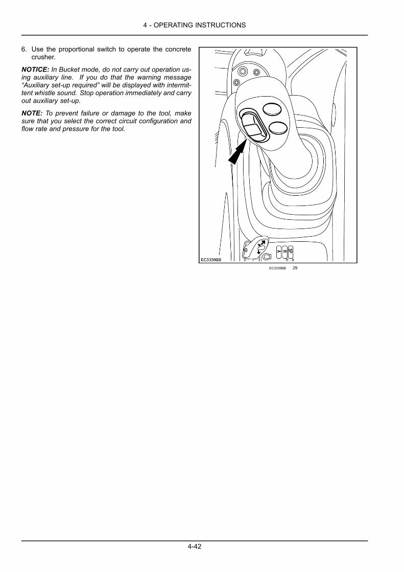
4 - OPERATING INSTRUCTIONS
6. Use the proportional switch to operate the concretecrusher.
NOTICE: In Bucket mode, do not carry out operation us-ing auxiliary line. If you do that the warning message“Auxiliary set-up required” will be displayed with intermit-tent whistle sound. Stop operation immediately and carryout auxiliary set-up.
NOTE: To prevent failure or damage to the tool, makesure that you select the correct circuit configuration andflow rate and pressure for the tool.
EC3339BB 29
4-42
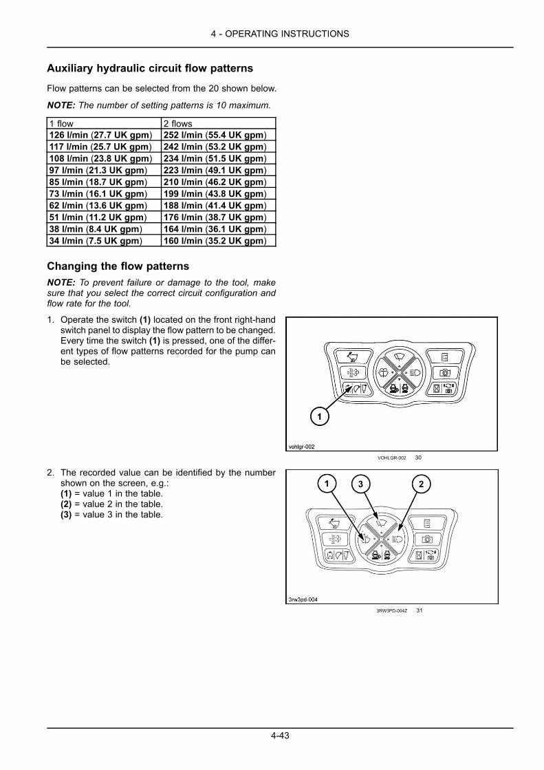
4 - OPERATING INSTRUCTIONS
Auxiliary hydraulic circuit flow patterns
Flow patterns can be selected from the 20 shown below.
NOTE: The number of setting patterns is 10 maximum.
1 flow 2 flows126 l/min (27.7 UK gpm) 252 l/min (55.4 UK gpm)117 l/min (25.7 UK gpm) 242 l/min (53.2 UK gpm)108 l/min (23.8 UK gpm) 234 l/min (51.5 UK gpm)97 l/min (21.3 UK gpm) 223 l/min (49.1 UK gpm)85 l/min (18.7 UK gpm) 210 l/min (46.2 UK gpm)73 l/min (16.1 UK gpm) 199 l/min (43.8 UK gpm)62 l/min (13.6 UK gpm) 188 l/min (41.4 UK gpm)51 l/min (11.2 UK gpm) 176 l/min (38.7 UK gpm)38 l/min (8.4 UK gpm) 164 l/min (36.1 UK gpm)34 l/min (7.5 UK gpm) 160 l/min (35.2 UK gpm)
Changing the flow patternsNOTE: To prevent failure or damage to the tool, makesure that you select the correct circuit configuration andflow rate for the tool.
1. Operate the switch (1) located on the front right-handswitch panel to display the flow pattern to be changed.Every time the switch (1) is pressed, one of the differ-ent types of flow patterns recorded for the pump canbe selected.
VOHLGR-002 30
2. The recorded value can be identified by the numbershown on the screen, e.g.:(1) = value 1 in the table.(2) = value 2 in the table.(3) = value 3 in the table.
3RW3PD-004Z 31
4-43

4 - OPERATING INSTRUCTIONS
3. Operate the windshield wiper switch (1) to show theprevious pattern.Operate the auto idling switch (2) to show the followingpattern.
4. Operate the travel speed switch (3) to record.
3RW3PD-004C 32
4-44

4 - OPERATING INSTRUCTIONS
Optional hand control levers configurationThe switches can be wired by your CASE CONSTRUCTION Dealer to control either single function or dual functionhydraulic configurations.
The machine can have two types of auxiliary hydraulic circuits. One circuit can be used for single flow equipment, suchas hydraulic breakers. The second type of circuit is intended for use with single flow or double flow (with continuousflow) for use with demolition concrete crushers, etc.
The optional control buttons can be used to activate and control the system for multipurpose tools such as a crusher,nibbler, etc. Additionally they can be configured to regulate the preset hydraulic oil flow for the specific tool whenpressed.
See your CASE CONSTRUCTION Dealer for specific options and controls for hydraulic hammers, breakers, nibblers,or other special attachments.
Left-hand control leverThe left hand control lever can control four machine oper-ations for the operator’s convenience.The radio mute switch is located on the underneath sideof the left hand control lever, while button (3) enables thehorn.Two additional function switches (1) and (2) are availablefor optional use.
NZIMV6-002B 1
Right-hand control leverThe right hand control lever controls the engine idle speedselector (6). This button enables automatic engine idlewithout operating the throttle button.To select idle speed, press and release the control for theengine automatically to go into idle speed.The message “Engine idling” will appear on the displaypanel.When the control is pressed and released once more theengine will revert to its original speed and the messageon the display panel will disappear.The two additional buttons (4) and (5) on the right handcontrol lever are for optional tools such as a hydraulichammer, breakers, or other special attachments.
FIQCKA-001C 2
4-45
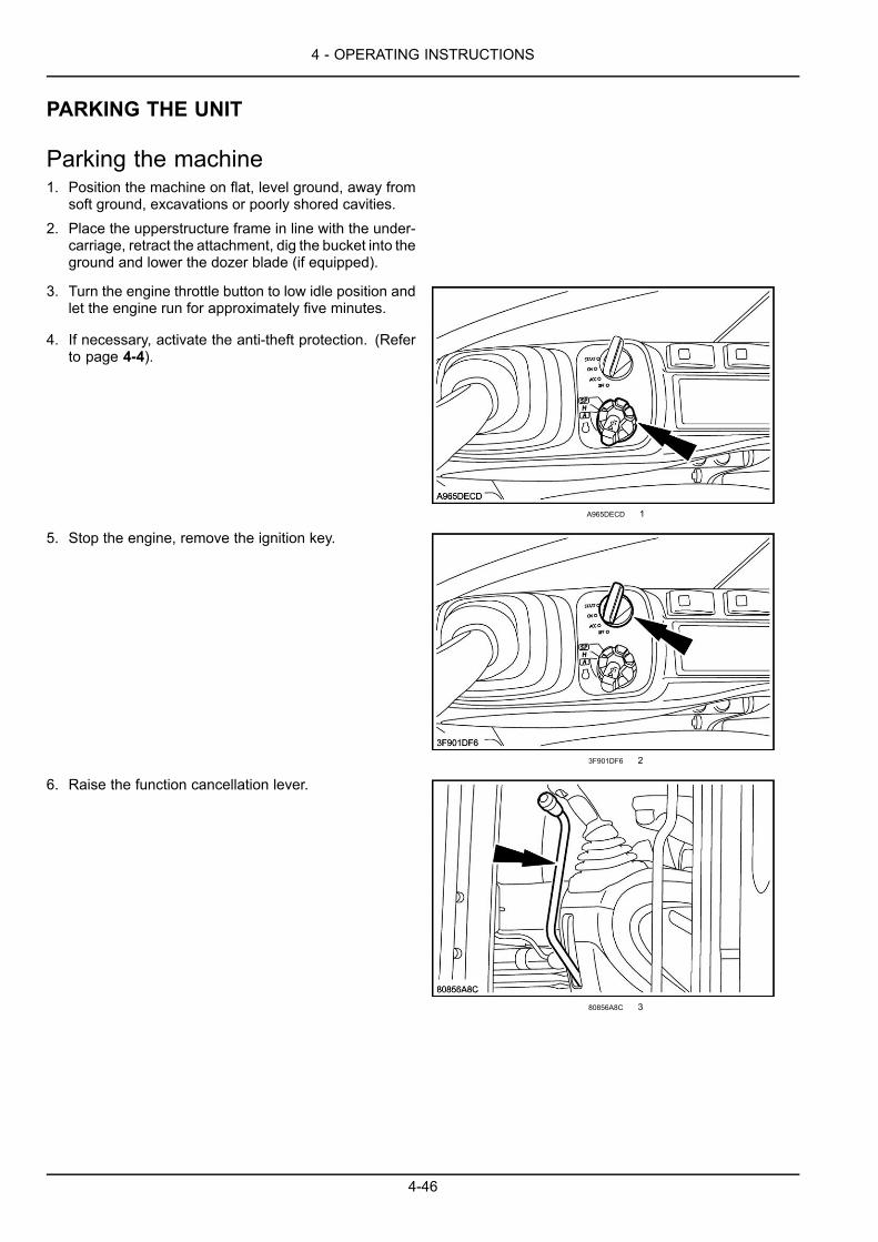
4 - OPERATING INSTRUCTIONS
PARKING THE UNIT
Parking the machine1. Position the machine on flat, level ground, away from
soft ground, excavations or poorly shored cavities.2. Place the upperstructure frame in line with the under-
carriage, retract the attachment, dig the bucket into theground and lower the dozer blade (if equipped).
3. Turn the engine throttle button to low idle position andlet the engine run for approximately five minutes.
4. If necessary, activate the anti-theft protection. (Referto page 4-4).
A965DECD 1
5. Stop the engine, remove the ignition key.
3F901DF6 2
6. Raise the function cancellation lever.
80856A8C 3
4-46
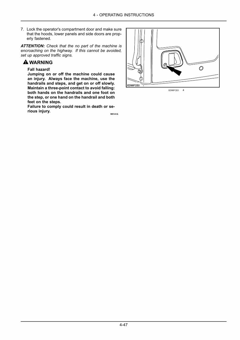
4 - OPERATING INSTRUCTIONS
7. Lock the operator's compartment door and make surethat the hoods, lower panels and side doors are prop-erly fastened.
ATTENTION: Check that the no part of the machine isencroaching on the highway. If this cannot be avoided,set up approved traffic signs.
WARNINGFall hazard!Jumping on or off the machine could causean injury. Always face the machine, use thehandrails and steps, and get on or off slowly.Maintain a three-point contact to avoid falling:both hands on the handrails and one foot onthe step, or one hand on the handrail and bothfeet on the steps.Failure to comply could result in death or se-rious injury.
W0141A
ED96FCE0 4
4-47

4 - OPERATING INSTRUCTIONS
4-48
5 - TRANSPORT OPERATIONS
5 - TRANSPORT OPERATIONS###_5_###SHIPPING TRANSPORT
Transporting the machineATTENTION: For transporting the machine without attachment, the counterweight must be removed, consult yourCASE CONSTRUCTION Dealer.
Removing the attachment from the machine
WARNINGImproper operation or service of this machine can result in an accident.Assign a supervisor to direct worksite operations. Agree on all safety measures, procedures, andsuitable hand signals.Failure to comply could result in death or serious injury.
W0287A
WARNINGCrushing hazard!The lifting systems must be operated by qualified personnel who are aware of the correct proceduresto follow. Make sure all lifting equipment is in good condition, and all hooks are equipped with safetylatches.Failure to comply could result in death or serious injury.
W0256A
WARNINGCrushing hazard!This operation may be dangerous. You are advised to wear suitable clothing and respect all relevantsafety messages.Failure to comply could result in death or serious injury.
W0283A
WARNINGPressurized system!Before removing the attachment from the machine, make sure the air pressure and hydraulic oil pres-sure are at zero.Failure to comply could result in death or serious injury.
W0284A
The use of lifting systems is necessary for removal and installation of the machine attachment and counterweight.Refer to the Service Manual or consult your CASE CONSTRUCTION Dealer.
NOTICE: Prevent dust and contamination entering open circuits. Any contamination of circuits can cause malfunctionof the machine.
By rail
Since transport by rail is subject to special regulations, consult an approved organization.
5-1

5 - TRANSPORT OPERATIONS
On a trailer
WARNINGTransport hazard!The machine can slip or fall from a ramp or trailer. Make sure the ramp and trailer are not slippery.Remove all oil, grease, ice, etc. Move the machine on or off the trailer with machine centered on thetrailer or ramp.Failure to comply could result in death or serious injury.
W0152A
WARNINGTip-over hazard!The counterweight MUST be removed before transporting the machine without an attachment. Con-sult you dealer.Failure to comply could result in death or serious injury.
W0260A
ATTENTION: Make sure you know the safety rules and regulations before transporting the machine. Make sure bothtrailer and machine are fitted with the right safety equipment.
Loading
1. Place a block behind the trailer wheels. Install thetrailer side extensions (if equipped).
UUDO6A-001 1
2. Select the automatic engine idle function (1). Theidling display on the monitor goes off.
UUDO6A-002 2
5-2
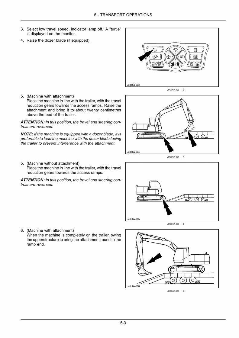
5 - TRANSPORT OPERATIONS
3. Select low travel speed, indicator lamp off. A "turtle"is displayed on the monitor.
4. Raise the dozer blade (if equipped).
UUDO6A-003 3
5. (Machine with attachment)Place the machine in line with the trailer, with the travelreduction gears towards the access ramps. Raise theattachment and bring it to about twenty centimetresabove the bed of the trailer.
ATTENTION: In this position, the travel and steering con-trols are reversed.
NOTE: If the machine is equipped with a dozer blade, it ispreferable to load the machine with the dozer blade facingthe trailer to prevent interference with the attachment.
UUDO6A-004 4
5. (Machine without attachment)Place the machine in line with the trailer, with the travelreduction gears towards the access ramps.
ATTENTION: In this position, the travel and steering con-trols are reversed.
UUDO6A-005 5
6. (Machine with attachment)When the machine is completely on the trailer, swingthe upperstructure to bring the attachment round to theramp end.
UUDO6A-006 6
5-3
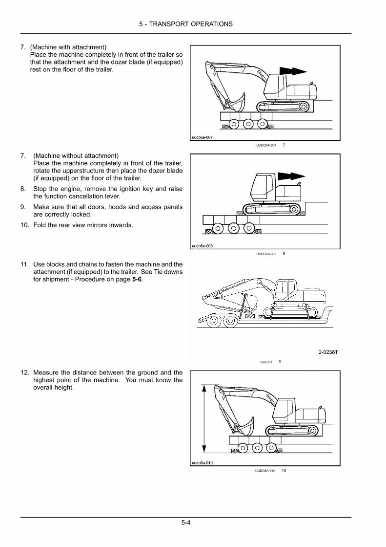
5 - TRANSPORT OPERATIONS
7. (Machine with attachment)Place the machine completely in front of the trailer sothat the attachment and the dozer blade (if equipped)rest on the floor of the trailer.
UUDO6A-007 7
7. (Machine without attachment)Place the machine completely in front of the trailer,rotate the upperstructure then place the dozer blade(if equipped) on the floor of the trailer.
8. Stop the engine, remove the ignition key and raisethe function cancellation lever.
9. Make sure that all doors, hoods and access panelsare correctly locked.
10. Fold the rear view mirrors inwards.
UUDO6A-008 8
11. Use blocks and chains to fasten the machine and theattachment (if equipped) to the trailer. See Tie downsfor shipment - Procedure on page 5-6.
2-0238T 9
12. Measure the distance between the ground and thehighest point of the machine. You must know theoverall height.
UUDO6A-010 10
5-4
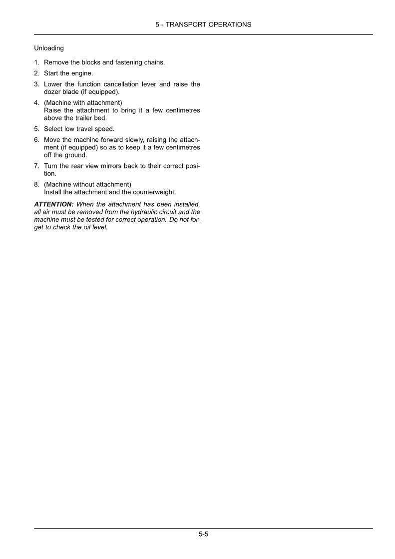
5 - TRANSPORT OPERATIONS
Unloading
1. Remove the blocks and fastening chains.2. Start the engine.3. Lower the function cancellation lever and raise the
dozer blade (if equipped).4. (Machine with attachment)
Raise the attachment to bring it a few centimetresabove the trailer bed.
5. Select low travel speed.6. Move the machine forward slowly, raising the attach-
ment (if equipped) so as to keep it a few centimetresoff the ground.
7. Turn the rear view mirrors back to their correct posi-tion.
8. (Machine without attachment)Install the attachment and the counterweight.
ATTENTION: When the attachment has been installed,all air must be removed from the hydraulic circuit and themachine must be tested for correct operation. Do not for-get to check the oil level.
5-5
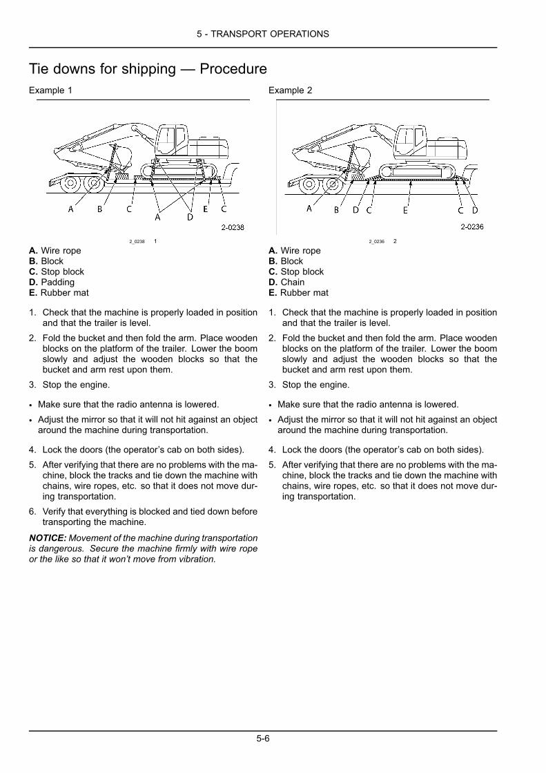
5 - TRANSPORT OPERATIONS
Tie downs for shipping — ProcedureExample 1
2_0238 1
A. Wire ropeB. BlockC. Stop blockD. PaddingE. Rubber mat
1. Check that the machine is properly loaded in positionand that the trailer is level.
2. Fold the bucket and then fold the arm. Place woodenblocks on the platform of the trailer. Lower the boomslowly and adjust the wooden blocks so that thebucket and arm rest upon them.
3. Stop the engine.
• Make sure that the radio antenna is lowered.
• Adjust the mirror so that it will not hit against an objectaround the machine during transportation.
4. Lock the doors (the operator’s cab on both sides).5. After verifying that there are no problems with the ma-
chine, block the tracks and tie down the machine withchains, wire ropes, etc. so that it does not move dur-ing transportation.
6. Verify that everything is blocked and tied down beforetransporting the machine.
NOTICE:Movement of the machine during transportationis dangerous. Secure the machine firmly with wire ropeor the like so that it won’t move from vibration.
Example 2
2_0236 2
A. Wire ropeB. BlockC. Stop blockD. ChainE. Rubber mat
1. Check that the machine is properly loaded in positionand that the trailer is level.
2. Fold the bucket and then fold the arm. Place woodenblocks on the platform of the trailer. Lower the boomslowly and adjust the wooden blocks so that thebucket and arm rest upon them.
3. Stop the engine.
• Make sure that the radio antenna is lowered.
• Adjust the mirror so that it will not hit against an objectaround the machine during transportation.
4. Lock the doors (the operator’s cab on both sides).5. After verifying that there are no problems with the ma-
chine, block the tracks and tie down the machine withchains, wire ropes, etc. so that it does not move dur-ing transportation.
5-6

5 - TRANSPORT OPERATIONS
6. To secure the lower frame, install chains to the installa-tion holes for transporting the lower. Cross and tightlypull the chains to attach the other ends of chains tothe trailer. Also, secure the front and rear of lowerwith chains.
2_0239 3
7. For machines with blade, install chains to the installa-tion holes at the top ends of blade, cross and tightlypill the chains to attach the other ends of chains to thetrailer.
2_0237 4
A. Wire ropeB. BlockC. Stop blockD. ChainE. Rubber mat
8. Verify that everything is blocked and tied down beforetransporting the machine.
NOTICE:Movement of the machine during transportationis dangerous. Secure the machine firmly with wire ropeor the like so that it won’t move from vibration.
5-7
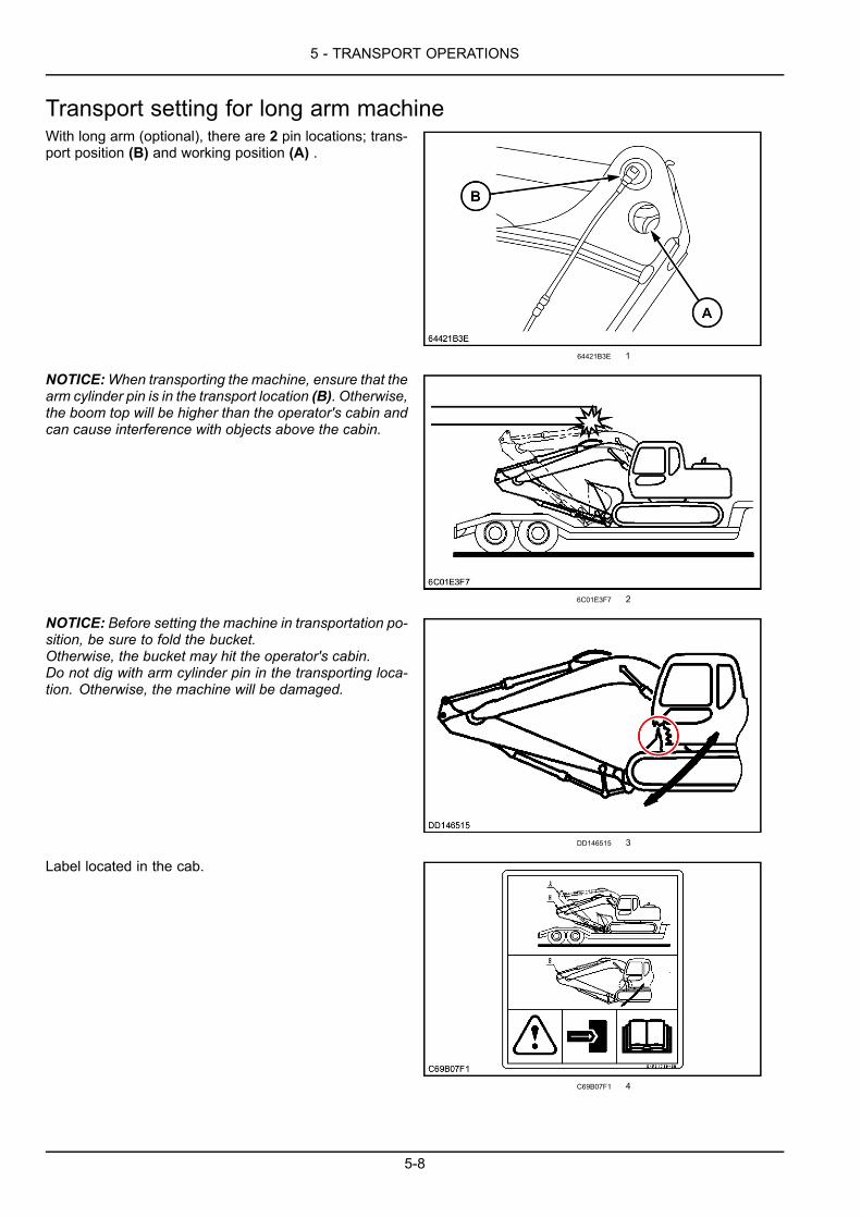
5 - TRANSPORT OPERATIONS
Transport setting for long arm machineWith long arm (optional), there are 2 pin locations; trans-port position (B) and working position (A) .
64421B3E 1
NOTICE:When transporting the machine, ensure that thearm cylinder pin is in the transport location (B). Otherwise,the boom top will be higher than the operator's cabin andcan cause interference with objects above the cabin.
6C01E3F7 2
NOTICE: Before setting the machine in transportation po-sition, be sure to fold the bucket.Otherwise, the bucket may hit the operator's cabin.Do not dig with arm cylinder pin in the transporting loca-tion. Otherwise, the machine will be damaged.
DD146515 3
Label located in the cab.
C69B07F1 4
5-8
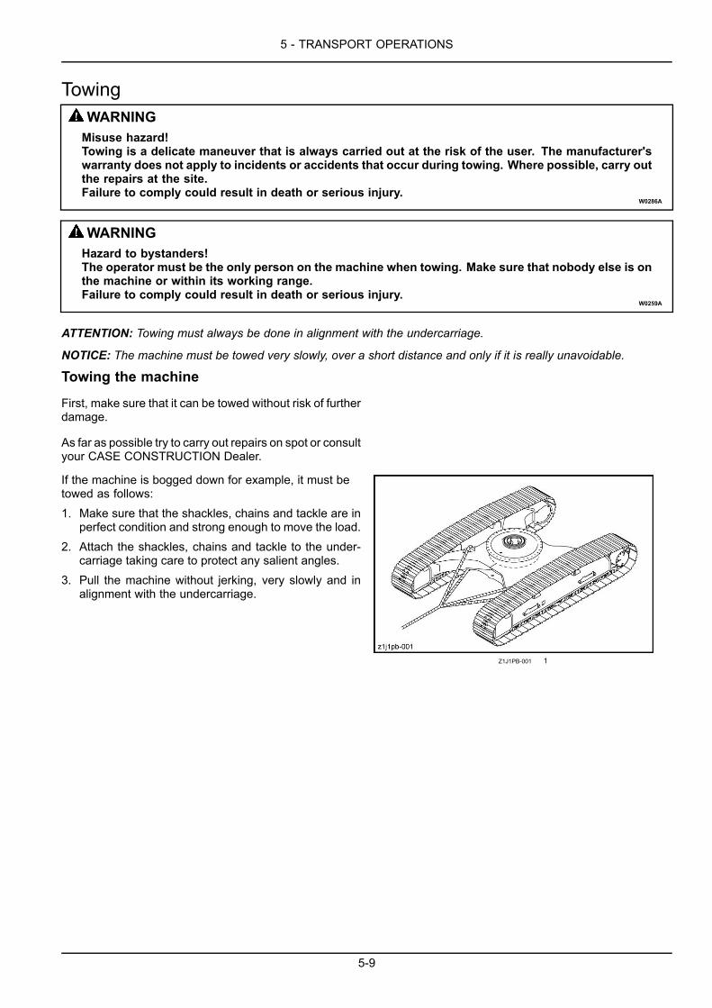
5 - TRANSPORT OPERATIONS
TowingWARNINGMisuse hazard!Towing is a delicate maneuver that is always carried out at the risk of the user. The manufacturer'swarranty does not apply to incidents or accidents that occur during towing. Where possible, carry outthe repairs at the site.Failure to comply could result in death or serious injury.
W0286A
WARNINGHazard to bystanders!The operator must be the only person on the machine when towing. Make sure that nobody else is onthe machine or within its working range.Failure to comply could result in death or serious injury.
W0259A
ATTENTION: Towing must always be done in alignment with the undercarriage.
NOTICE: The machine must be towed very slowly, over a short distance and only if it is really unavoidable.
Towing the machine
First, make sure that it can be towed without risk of furtherdamage.
As far as possible try to carry out repairs on spot or consultyour CASE CONSTRUCTION Dealer.
If the machine is bogged down for example, it must betowed as follows:1. Make sure that the shackles, chains and tackle are in
perfect condition and strong enough to move the load.2. Attach the shackles, chains and tackle to the under-
carriage taking care to protect any salient angles.3. Pull the machine without jerking, very slowly and in
alignment with the undercarriage.
Z1J1PB-001 1
5-9
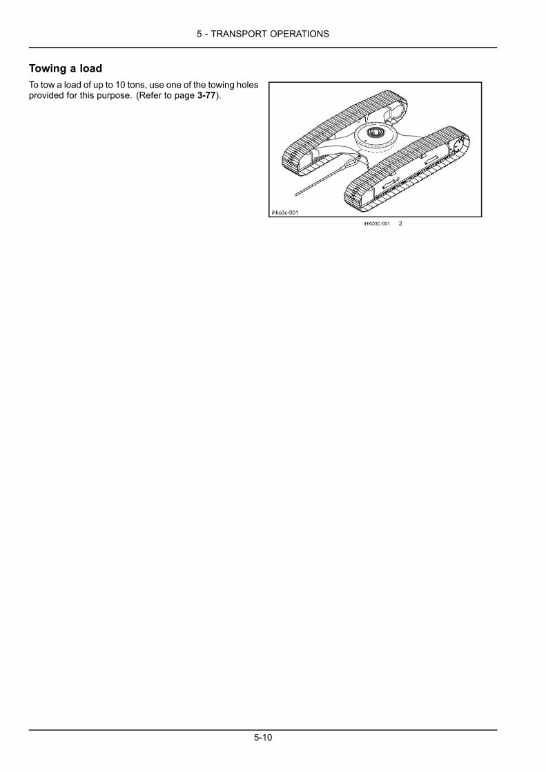
5 - TRANSPORT OPERATIONS
Towing a loadTo tow a load of up to 10 tons, use one of the towing holesprovided for this purpose. (Refer to page 3-77).
IHKO3C-001 2
5-10
6 - MAINTENANCE
6 - MAINTENANCE###_7_###GENERAL INFORMATION
Basic instructionsServicing instructions
WARNINGImproper operation or service of this machine can result in an accident.If you do not understand a maintenance procedure, or doubt your ability to perform a maintenanceprocedure correctly, see your authorized dealer.Failure to comply could result in death or serious injury.
W0157A
WARNINGImproper operation or service of this machine can result in an accident.Raised equipment or machine movement without an operator can cause serious injury. Always do thefollowing before performing any maintenance:Park the machine on flat, level ground.Lower the attachment to the ground.Shut down the engine and remove the ignition key.Lock the tracks.Failure to comply could result in death or serious injury.
W0944D
NOTICE: Be sure all the service operations in this section are carried out punctually at the intervals given, in order toensure optimum performance levels and maximum safety when using the machine.
• Respect the maintenance intervals by checking the hourmeter every day. Before starting maintenance, park themachine on flat, firm ground, away from any obstacles, with the arm retracted and the bucket on the ground. Lowerthe dozer blade (if equipped) until it rests on the ground. Unless otherwise specified, all maintenance operationsmust be carried out with the engine stopped, and the key removed from the ignition key. It is preferable to wait forall circuits to cool down before starting work.
• Clean the grease fittings before lubrication. Clean around plugs and filler holes before adding fluid. No dust ordirt must enter the components or the circuits. Wear suitable clothing and remember to use the necessary safetyequipment.
• When carrying out service work on the machine, place a "Do not operate" tag on the instrument panel. Never climbdown from the operator's compartment leaving the engine running.
• Remove the necessary lower panels during maintenance of certain machine components.
WARNINGMoving parts!Make sure the lower panels are properly closed before driving the machine.Failure to comply could result in death or serious injury.
W0910A
Any modification to this machine without prior authorization could cause serious injury. Do not make any modificationswithout authorization. Consult your CASE CONSTRUCTION Dealer.
NOTICE: If you use your machine in particularly harsh conditions (dusty or corrosive atmosphere, etc.), the servicingintervals should be reduced accordingly.
NOTICE: Take particular care to replace all filters regularly. Clean filters mean longer engine running life.
ATTENTION: Oil and fluid should not be thrown on the ground. They must be stored and removed by a companywhich is responsible for their recycling or their disposal.
6-1
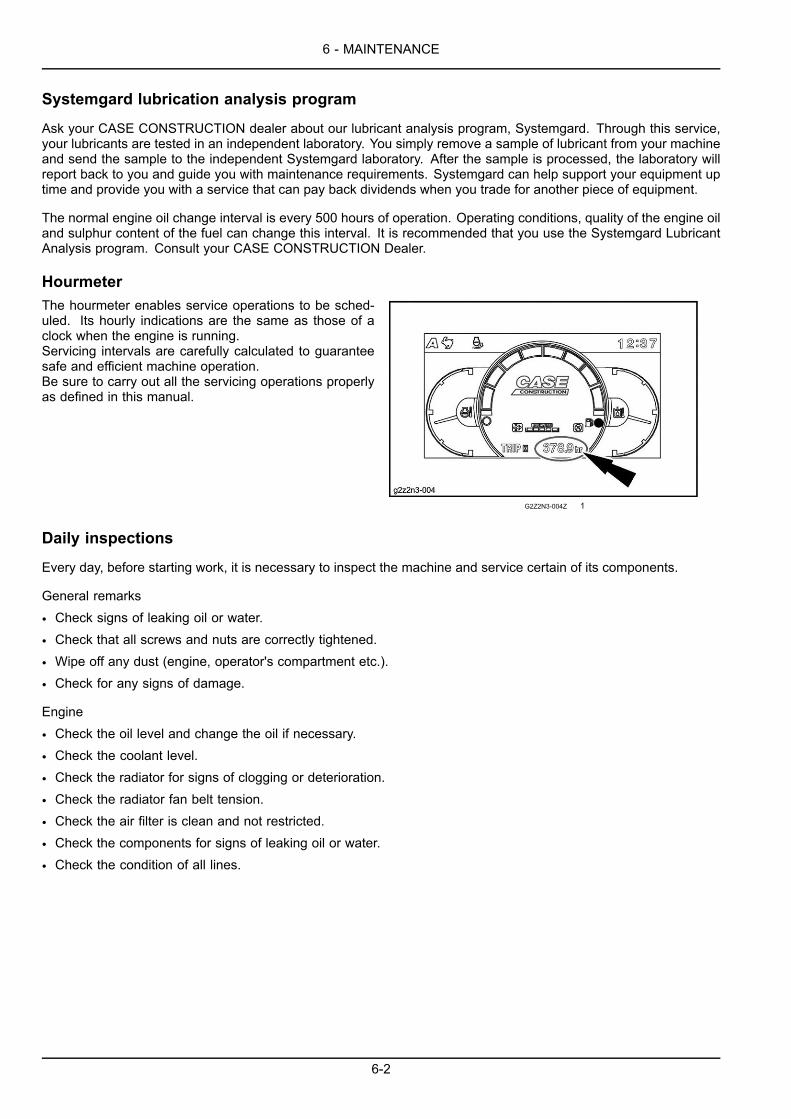
6 - MAINTENANCE
Systemgard lubrication analysis program
Ask your CASE CONSTRUCTION dealer about our lubricant analysis program, Systemgard. Through this service,your lubricants are tested in an independent laboratory. You simply remove a sample of lubricant from your machineand send the sample to the independent Systemgard laboratory. After the sample is processed, the laboratory willreport back to you and guide you with maintenance requirements. Systemgard can help support your equipment uptime and provide you with a service that can pay back dividends when you trade for another piece of equipment.
The normal engine oil change interval is every 500 hours of operation. Operating conditions, quality of the engine oiland sulphur content of the fuel can change this interval. It is recommended that you use the Systemgard LubricantAnalysis program. Consult your CASE CONSTRUCTION Dealer.
HourmeterThe hourmeter enables service operations to be sched-uled. Its hourly indications are the same as those of aclock when the engine is running.Servicing intervals are carefully calculated to guaranteesafe and efficient machine operation.Be sure to carry out all the servicing operations properlyas defined in this manual.
G2Z2N3-004Z 1
Daily inspections
Every day, before starting work, it is necessary to inspect the machine and service certain of its components.
General remarks
• Check signs of leaking oil or water.
• Check that all screws and nuts are correctly tightened.
• Wipe off any dust (engine, operator's compartment etc.).
• Check for any signs of damage.
Engine
• Check the oil level and change the oil if necessary.
• Check the coolant level.
• Check the radiator for signs of clogging or deterioration.
• Check the radiator fan belt tension.
• Check the air filter is clean and not restricted.
• Check the components for signs of leaking oil or water.
• Check the condition of all lines.
6-2

6 - MAINTENANCE
Upperstructure
• Check the fuel tank level.
• Check the hydraulic reservoir level.
• Check that the hydraulic oil is clean.
• Check the components for signs of leaking oil or water.
• Check the condition of all lines.
• Make sure there are no electrical short circuits.
• Check the battery connections are properly tightened.
• Adjust the rear view mirrors.
• Check the cameras.
Undercarriage
• Check the pad hardware.
• Check the condition of the tracks.
• Check that the upper and lower track rollers and the idler wheels are not leaking oil.
Attachment
• Check the cylinders are not leaking oil.
• Check the condition of all lines.
• Check the condition of the bucket teeth.
After starting the engine
• Did the engine start correctly? Are the exhaust fumes normal? Any strange noises?
• Check for abnormal noise on the hydraulic components.
• Check the components for signs of leaking oil or water.
• Check the audible alarm devices, working lights and windshield wipers.
• Check that all circuits (travel, swing and tool) are functioning correctly.
ATTENTION: If the slightest defect is found, repair it immediately before using the machine or consult your CASECONSTRUCTION Dealer.
6-3
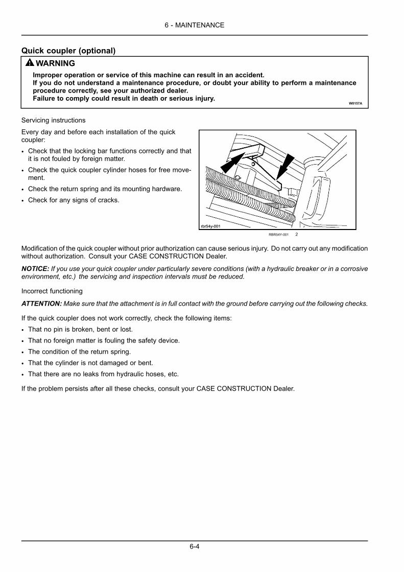
6 - MAINTENANCE
Quick coupler (optional)WARNINGImproper operation or service of this machine can result in an accident.If you do not understand a maintenance procedure, or doubt your ability to perform a maintenanceprocedure correctly, see your authorized dealer.Failure to comply could result in death or serious injury.
W0157A
Servicing instructions
Every day and before each installation of the quickcoupler:
• Check that the locking bar functions correctly and thatit is not fouled by foreign matter.
• Check the quick coupler cylinder hoses for free move-ment.
• Check the return spring and its mounting hardware.
• Check for any signs of cracks.
RBR54Y-001 2
Modification of the quick coupler without prior authorization can cause serious injury. Do not carry out any modificationwithout authorization. Consult your CASE CONSTRUCTION Dealer.
NOTICE: If you use your quick coupler under particularly severe conditions (with a hydraulic breaker or in a corrosiveenvironment, etc.) the servicing and inspection intervals must be reduced.
Incorrect functioning
ATTENTION:Make sure that the attachment is in full contact with the ground before carrying out the following checks.
If the quick coupler does not work correctly, check the following items:
• That no pin is broken, bent or lost.
• That no foreign matter is fouling the safety device.
• The condition of the return spring.
• That the cylinder is not damaged or bent.
• That there are no leaks from hydraulic hoses, etc.
If the problem persists after all these checks, consult your CASE CONSTRUCTION Dealer.
6-4
6 - MAINTENANCE
Fluids, fuels and lubricantsLubricants must have the correct properties for each application.
NOTICE: The conditions of use for individual fluids and lubricants must be respected.
ATTENTION:When using the machine in a hot or cold region, consult your CASE CONSTRUCTION Dealer.
Hydraulic fluid
CASE AKCELA HYDRAULIC EXCAVATOR FLUID is specially designed for high pressure applications and for the CASECONSTRUCTION hydraulic system. The type of fluid to be used depends on the ambient temperature.
Temperate climates:
-20 °C (-4.0 °F) to 40 °C (104.0 °F).CASE AKCELA HYDRAULIC EXCAVATOR FLUID(MS1230. ISO VG 46. DIN 51524 PART 2 HV)
Hot climates:
0 °C (32.0 °F) to 50 °C (122.0 °F).CASE AKCELA HYDRAULIC EXCAVATOR FLUID "HOT CLIMATE"(MS 1216. ISO VG 68. DIN 51524 PART 3 CATEGORY HVLP)
Cold climates:
-25 °C (-13.0 °F) to 20 °C (68.0 °F).CASE AKCELA HYDRAULIC EXCAVATOR FLUID "COLD CLIMATE"(MS 1216. ISO VG 32. DIN 51524 PART 2)
Biodegradable fluid:
-30 °C (-22.0 °F) to 40 °C (104.0 °F).This yellow-coloured fluid is miscible with standard fluid. If used to change standard fluid, it is advisable to drain thecircuit completely before refilling with this fluid.CASE AKCELA HYDRAULIC EXCAVATOR FLUID BIO(MS 1230. ISO VG 46. DIN 51524 PART 2 HV)
Transmission component oil
Extreme pressure oil used for enclosed transmission components.CASE AKCELA GEAR 135 H EP 80W-90(SAE 80W-90. API GL 5. MIL-L-2105 D. MS 1316. ZF TE-ML 05A)
Grease
CASE AKCELA 251H EP MULTI-PURPOSE GREASE (NLGI 2)"Extreme Pressure" multipurpose grease with lithium soap and calcium.
Engine oil
The CASE TUTELA LE ENGINEOIL is recommended for your engine. This oil ensures correct lubrication of your enginein all working conditions.
If the CASE TUTELA LE ENGINE OIL cannot be obtained, use the oil corresponding to one of the following categories:ACEA E6. API CJ-4.
6-5
6 - MAINTENANCE
Fuel
The fuel must conform to Interim Tier 4/Stage 3B. Exhaust Gas Control Regulations.
Use grade number 2-D (S15) fuel.
Using other types of fuel may lead to stalled engine output or deterioration in fuel economy.
During cold weather, lower than -7 °C (19.4 °F), it is temporarily acceptable to use a mixture of No. 1-D (S15) andNo. 2- D (S15).
Consult the fuel supplier or the CASE CONSTRUCTION Dealer.
If the temperature drops below the fuel cloud point, output deficiency or engine start problems may occur due to waxcrystals.
Conditions applicable to diesel fuel. The diesel fuel used must:
• be free from dust particles, even minute ones,
• have the proper viscosity,
• have a high cetane number,
• present great fluidity at low temperatures,
• have low sulphur content,
• have very little residual carbon.
Recommended conditions that can be applied to diesel fuel:
• JIS (Japanese Industrial Standard): No. 2
• DIN (Deutsche Industrie Normen): DIN 51601
• SAE (Society of Automotive Enginneers) based on SAE-J-313C : No. 2-D (S15)
• BS (British Standard) based on B-1S/2869-1970: Class A
• EN 590 (less than 10 ppm sulfur)
• Or fuel specified by the country using these standards and this machine.
ATTENTION: EPA (Environmental Protection Agency), regulation requires ultra low sulfur fuel only.
ATTENTION: If a serious problem occurs when other fuels are used, the warranty is invalidated.Using a non-recommended fuel may lead to damage of the fuel injection pump, injector, DPD (Diesel ParticulateDiffuser), and other fuel supply systems or to the engine.
ATTENTION: The CASE CONSTRUCTION company assumes no responsability for these damages.
Note that the warranty will not be applied for these damages.
6-6

6 - MAINTENANCE
It is recommended that the following safety information be considered in order to prevent damage to the enginefuel supply system.
• Some fuel suppliers mix old engine oil and diesel fuel.
• Makers of larger engine permit the use of this kind of fuel.
• However, do not use diesel fuel contaminated with engine oil in customer's engines.
• Not only will this fuel damage the engine, it may also have a negative impact on the exhaust gas purification function.
• Before using diesel fuel, confirm with the supplier whether the fuel complies with the above specifications.
NOTICE: Consult the supplier or the CASE CONSTRUCTION Dealer regarding appropriate use of fuel additives.
ATTENTION: In order to prevent condensation during cold weather, fill the fuel tank to full after the completing theday's work.
Fuel storage:
Long storage can lead to the accumulation of impurities and condensation in the fuel. Engine trouble can often betraced to the presence of water in the fuel.
The storage tank must be placed outside and the temperature of the fuel should be kept as low as possible. Drain offwater and impurities regularly.
Biodiesel fuel
Fatty Acid Methyl Ester Biodiesel (Biodiesel Fuel) consists of a family of fuels derived from vegetable oils treated withmethyl esters.
ATTENTION: Biodiesel Fuel blends are approved for your engine only if they comply with EN14214 SpecificationStandards or ASTM D6751.
ATTENTION: It is imperative that you check which blend is approved for your engine with your CASE CONSTRUC-TION Dealer. Be aware that the use of Biodiesel Fuel that does not comply with the Standards mentioned abovecould lead to severe damage to the engine and fuel system of your machine. The use of fuels that are not approvedmay void CASE CONSTRUCTION Warranty coverage.
Biodiesel Fuel Usage Conditions:
ATTENTION: The Biodiesel Fuel must meet the fuel Specification mentioned above.
Biodiesel Fuel must be purchased from a trusted supplier that understands the product and maintains good fuel qual-ity. Biodiesel Fuel must be pre-blended by the supplier. Mixing Biodiesel Fuels on-site can result incorrect mixturethat can lead to problems with both engine and fuel system.
Engine performance is affected by the use of Biodiesel Fuel. There may be up to 12 % reduction in power or torquedepending on the blend used.
ATTENTION: DO NOT modify the engine and/or injection pump settings to recover the reduced performance.
The reduced power must be accepted if using any Biodiesel Fuel blend.
6-7
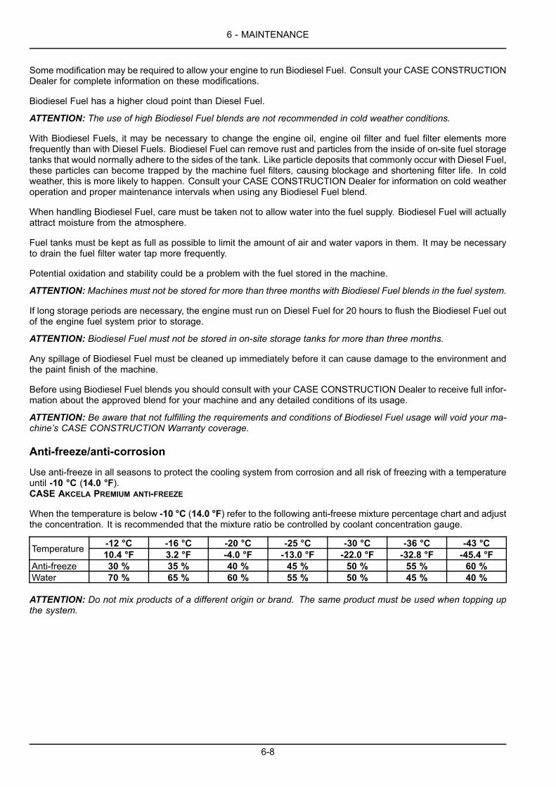
6 - MAINTENANCE
Some modification may be required to allow your engine to run Biodiesel Fuel. Consult your CASE CONSTRUCTIONDealer for complete information on these modifications.
Biodiesel Fuel has a higher cloud point than Diesel Fuel.
ATTENTION: The use of high Biodiesel Fuel blends are not recommended in cold weather conditions.
With Biodiesel Fuels, it may be necessary to change the engine oil, engine oil filter and fuel filter elements morefrequently than with Diesel Fuels. Biodiesel Fuel can remove rust and particles from the inside of on-site fuel storagetanks that would normally adhere to the sides of the tank. Like particle deposits that commonly occur with Diesel Fuel,these particles can become trapped by the machine fuel filters, causing blockage and shortening filter life. In coldweather, this is more likely to happen. Consult your CASE CONSTRUCTION Dealer for information on cold weatheroperation and proper maintenance intervals when using any Biodiesel Fuel blend.
When handling Biodiesel Fuel, care must be taken not to allow water into the fuel supply. Biodiesel Fuel will actuallyattract moisture from the atmosphere.
Fuel tanks must be kept as full as possible to limit the amount of air and water vapors in them. It may be necessaryto drain the fuel filter water tap more frequently.
Potential oxidation and stability could be a problem with the fuel stored in the machine.
ATTENTION: Machines must not be stored for more than three months with Biodiesel Fuel blends in the fuel system.
If long storage periods are necessary, the engine must run on Diesel Fuel for 20 hours to flush the Biodiesel Fuel outof the engine fuel system prior to storage.
ATTENTION: Biodiesel Fuel must not be stored in on-site storage tanks for more than three months.
Any spillage of Biodiesel Fuel must be cleaned up immediately before it can cause damage to the environment andthe paint finish of the machine.
Before using Biodiesel Fuel blends you should consult with your CASE CONSTRUCTION Dealer to receive full infor-mation about the approved blend for your machine and any detailed conditions of its usage.
ATTENTION: Be aware that not fulfilling the requirements and conditions of Biodiesel Fuel usage will void your ma-chine’s CASE CONSTRUCTION Warranty coverage.
Anti-freeze/anti-corrosion
Use anti-freeze in all seasons to protect the cooling system from corrosion and all risk of freezing with a temperatureuntil -10 °C (14.0 °F).CASE AKCELA PREMIUM ANTI-FREEZE
When the temperature is below -10 °C (14.0 °F) refer to the following anti-freese mixture percentage chart and adjustthe concentration. It is recommended that the mixture ratio be controlled by coolant concentration gauge.
-12 °C -16 °C -20 °C -25 °C -30 °C -36 °C -43 °CTemperature 10.4 °F 3.2 °F -4.0 °F -13.0 °F -22.0 °F -32.8 °F -45.4 °FAnti-freeze 30 % 35 % 40 % 45 % 50 % 55 % 60 %Water 70 % 65 % 60 % 55 % 50 % 45 % 40 %
ATTENTION: Do not mix products of a different origin or brand. The same product must be used when topping upthe system.
6-8
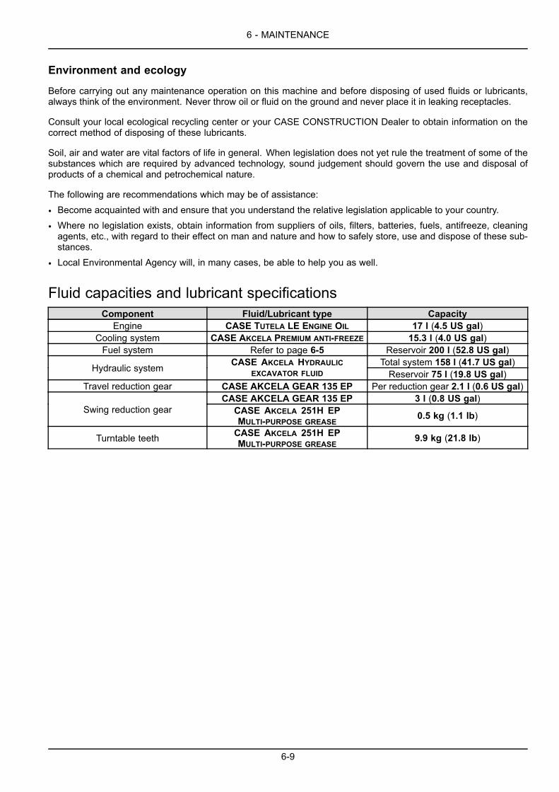
6 - MAINTENANCE
Environment and ecology
Before carrying out any maintenance operation on this machine and before disposing of used fluids or lubricants,always think of the environment. Never throw oil or fluid on the ground and never place it in leaking receptacles.
Consult your local ecological recycling center or your CASE CONSTRUCTION Dealer to obtain information on thecorrect method of disposing of these lubricants.
Soil, air and water are vital factors of life in general. When legislation does not yet rule the treatment of some of thesubstances which are required by advanced technology, sound judgement should govern the use and disposal ofproducts of a chemical and petrochemical nature.
The following are recommendations which may be of assistance:
• Become acquainted with and ensure that you understand the relative legislation applicable to your country.
• Where no legislation exists, obtain information from suppliers of oils, filters, batteries, fuels, antifreeze, cleaningagents, etc., with regard to their effect on man and nature and how to safely store, use and dispose of these sub-stances.
• Local Environmental Agency will, in many cases, be able to help you as well.
Fluid capacities and lubricant specificationsComponent Fluid/Lubricant type Capacity
Engine CASE TUTELA LE ENGINE OIL 17 l (4.5 US gal)Cooling system CASE AKCELA PREMIUM ANTI-FREEZE 15.3 l (4.0 US gal)Fuel system Refer to page 6-5 Reservoir 200 l (52.8 US gal)
Total system 158 l (41.7 US gal)Hydraulic system CASE AKCELA HYDRAULICEXCAVATOR FLUID Reservoir 75 l (19.8 US gal)
Travel reduction gear CASE AKCELA GEAR 135 EP Per reduction gear 2.1 l (0.6 US gal)CASE AKCELA GEAR 135 EP 3 l (0.8 US gal)
Swing reduction gear CASE AKCELA 251H EPMULTI-PURPOSE GREASE
0.5 kg (1.1 lb)
Turntable teeth CASE AKCELA 251H EPMULTI-PURPOSE GREASE
9.9 kg (21.8 lb)
6-9

6 - MAINTENANCE
Grease pointsType of grease: (refer to page 6-5)
NOTE: The numbers within brackets mentioned on the right of the description indicate the number of lubrication points.
NOTE: After lubrication, refit the protective and indicating plastic caps to the grease fittings.
Machine
1E981954A 1
Every 50 hours (standard machine only)Dozer blade: (8)Dozer blade cylinders: (4)
94E155A8 2
6-10
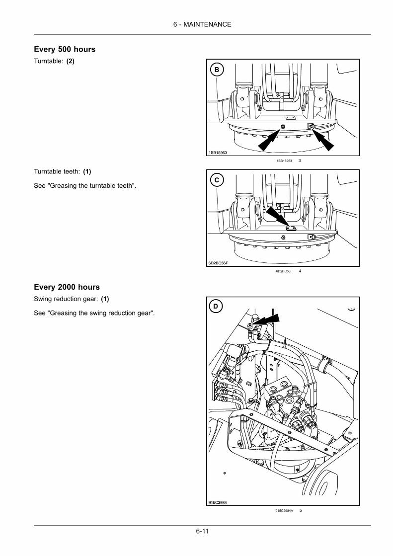
6 - MAINTENANCE
Every 500 hoursTurntable: (2)
1BB18963 3
Turntable teeth: (1)
See "Greasing the turntable teeth".
6D2BC56F 4
Every 2000 hoursSwing reduction gear: (1)
See "Greasing the swing reduction gear".
915C2984A 5
6-11
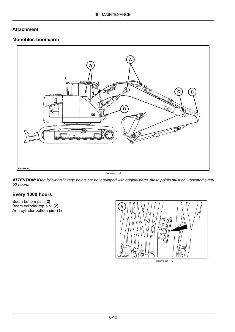
6 - MAINTENANCE
Attachment
Monobloc boom/arm
DBF801AC 6
ATTENTION: If the following linkage points are not equipped with original parts, these points must be lubricated every50 hours.
Every 1000 hoursBoom bottom pin: (2)Boom cylinder top pin: (2)Arm cylinder bottom pin: (1)
8U6DVD-001 7
6-12

6 - MAINTENANCE
Every 1000 hoursBoom cylinder bottom pin: (2)
8U6DVD-002 8
Boom/arm linkage: (2)
8U6DVD-003 9
Arm cylinder top pin: (1)
8U6DVD-004A 10
6-13
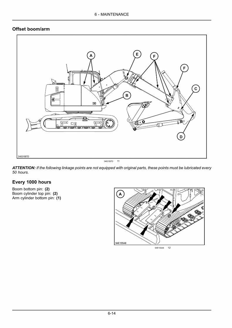
6 - MAINTENANCE
Offset boom/arm
34631B7D 11
ATTENTION: If the following linkage points are not equipped with original parts, these points must be lubricated every50 hours.
Every 1000 hoursBoom bottom pin: (2)Boom cylinder top pin: (2)Arm cylinder bottom pin: (1)
94E155A8 12
6-14

6 - MAINTENANCE
Every 1000 hoursBoom cylinder bottom pin: (2)
8U6DVD-002 13
Boom/arm linkage: (3)
8U6DVD-003 14
Arm cylinder top pin: (1)
8U6DVD-004A 15
Every 50 hoursBoom cylinder top pin: (2)
DB521CB7 16
6-15
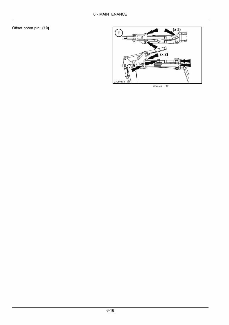
6 - MAINTENANCE
Offset boom pin: (10)
07C803C9 17
6-16
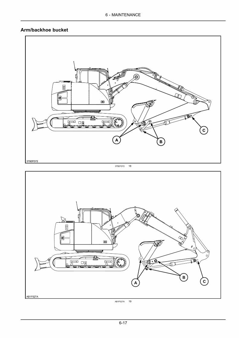
6 - MAINTENANCE
Arm/backhoe bucket
375EFD72 18
AB1F527A 19
6-17
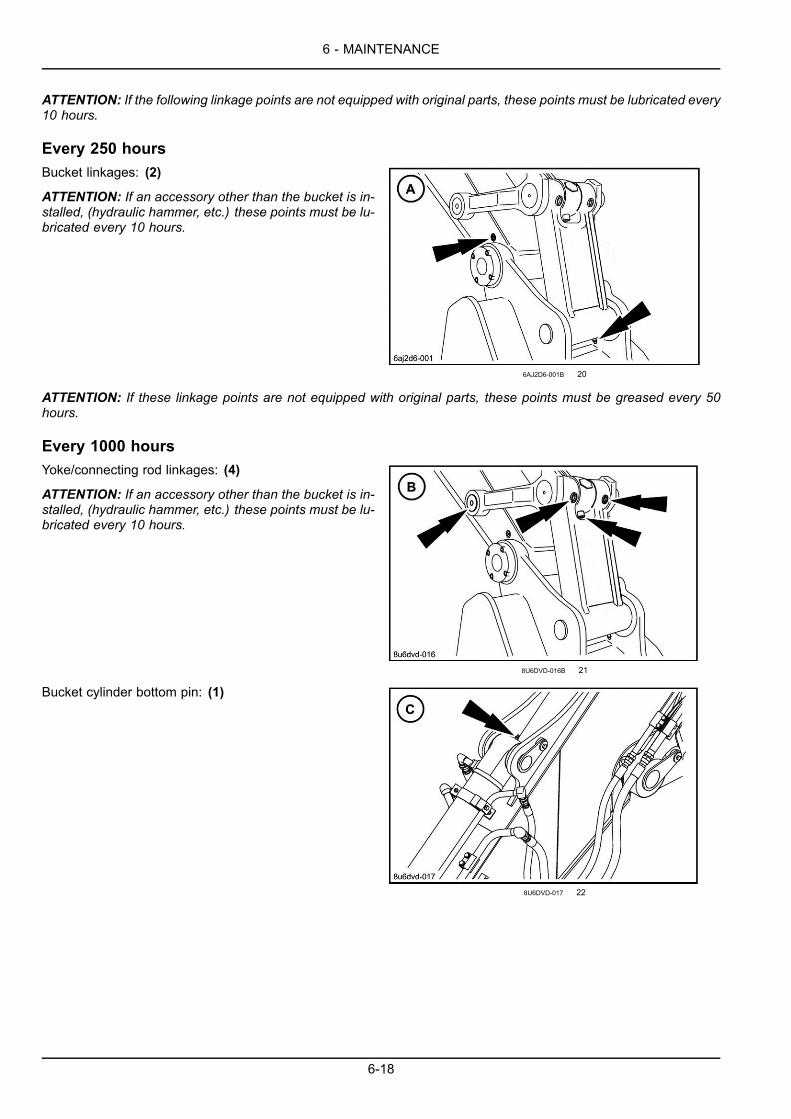
6 - MAINTENANCE
ATTENTION: If the following linkage points are not equipped with original parts, these points must be lubricated every10 hours.
Every 250 hoursBucket linkages: (2)
ATTENTION: If an accessory other than the bucket is in-stalled, (hydraulic hammer, etc.) these points must be lu-bricated every 10 hours.
6AJ2D6-001B 20
ATTENTION: If these linkage points are not equipped with original parts, these points must be greased every 50hours.
Every 1000 hoursYoke/connecting rod linkages: (4)
ATTENTION: If an accessory other than the bucket is in-stalled, (hydraulic hammer, etc.) these points must be lu-bricated every 10 hours.
8U6DVD-016B 21
Bucket cylinder bottom pin: (1)
8U6DVD-017 22
6-18
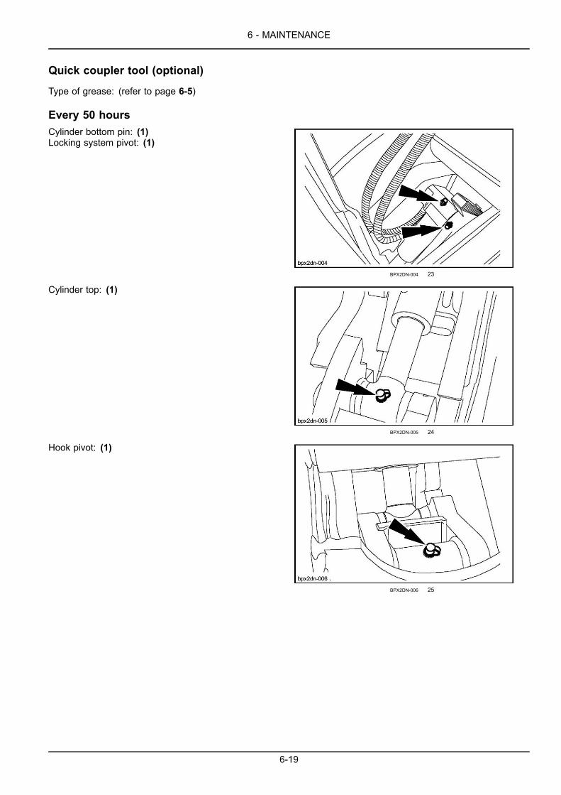
6 - MAINTENANCE
Quick coupler tool (optional)
Type of grease: (refer to page 6-5)
Every 50 hoursCylinder bottom pin: (1)Locking system pivot: (1)
BPX2DN-004 23
Cylinder top: (1)
BPX2DN-005 24
Hook pivot: (1)
BPX2DN-006 25
6-19
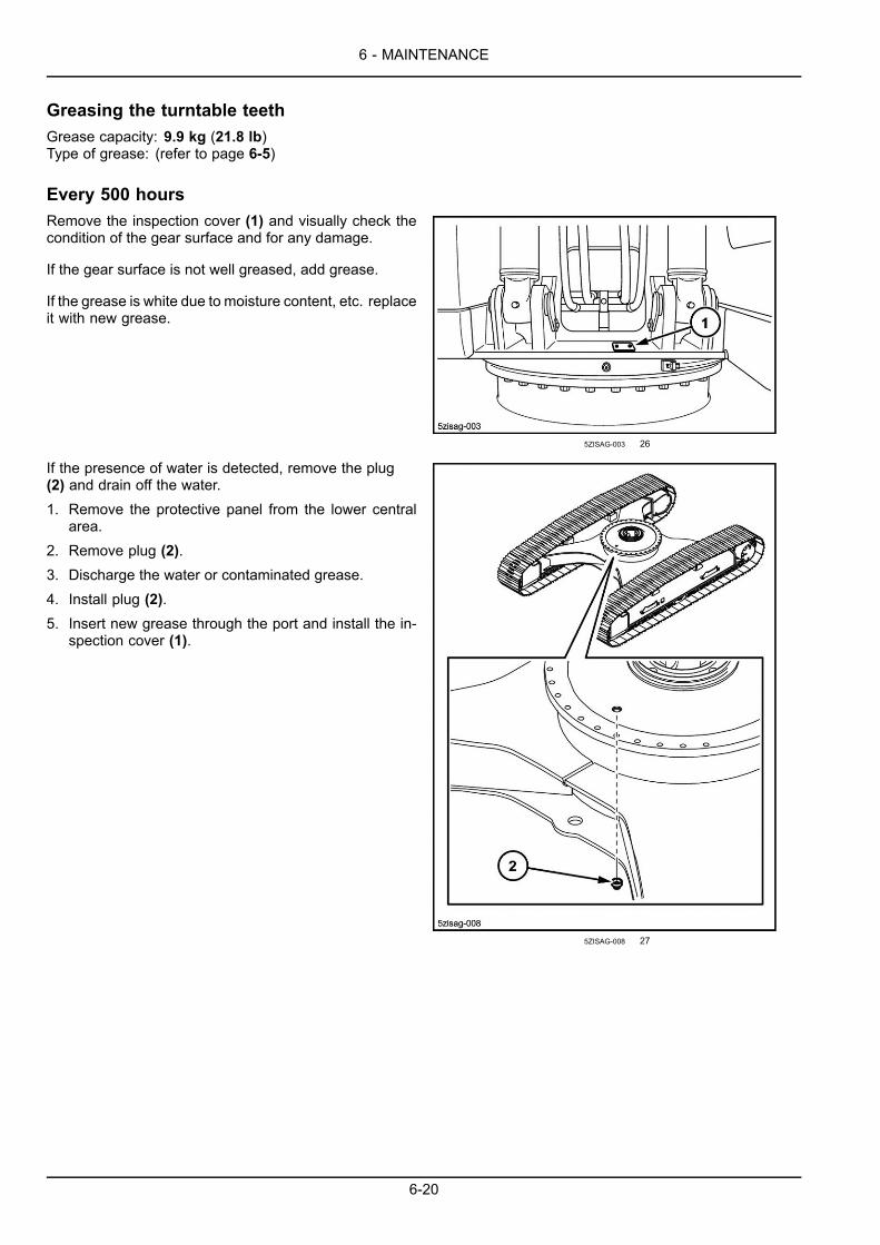
6 - MAINTENANCE
Greasing the turntable teethGrease capacity: 9.9 kg (21.8 lb)Type of grease: (refer to page 6-5)
Every 500 hoursRemove the inspection cover (1) and visually check thecondition of the gear surface and for any damage.
If the gear surface is not well greased, add grease.
If the grease is white due to moisture content, etc. replaceit with new grease.
5ZISAG-003 26
If the presence of water is detected, remove the plug(2) and drain off the water.1. Remove the protective panel from the lower central
area.2. Remove plug (2).3. Discharge the water or contaminated grease.4. Install plug (2).5. Insert new grease through the port and install the in-
spection cover (1).
5ZISAG-008 27
6-20
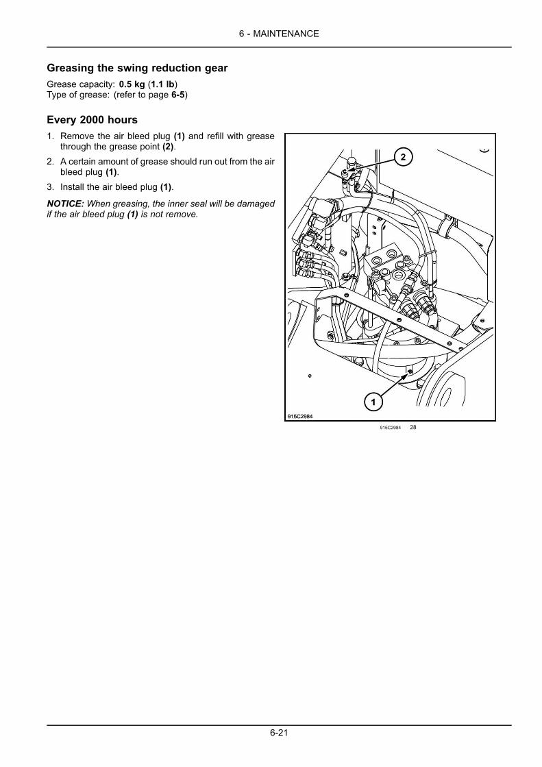
6 - MAINTENANCE
Greasing the swing reduction gearGrease capacity: 0.5 kg (1.1 lb)Type of grease: (refer to page 6-5)
Every 2000 hours1. Remove the air bleed plug (1) and refill with grease
through the grease point (2).2. A certain amount of grease should run out from the air
bleed plug (1).3. Install the air bleed plug (1).
NOTICE:When greasing, the inner seal will be damagedif the air bleed plug (1) is not remove.
915C2984 28
6-21

6 - MAINTENANCE
LevelsType of fluids and lubricants: (Refer to page 6-5)
NOTE: The numbers within brackets mentioned on the right of the description indicate the number of levels.
Every 10 hoursEngine oil: (1)Refer to page 6-24.
64980658 1
Coolant solution expansion reservoir: (1)Refer to page 6-27.
9F2D39EE 2
Hydraulic reservoir: (1)Refer to page 6-39.
A2EC4214 3
6-22
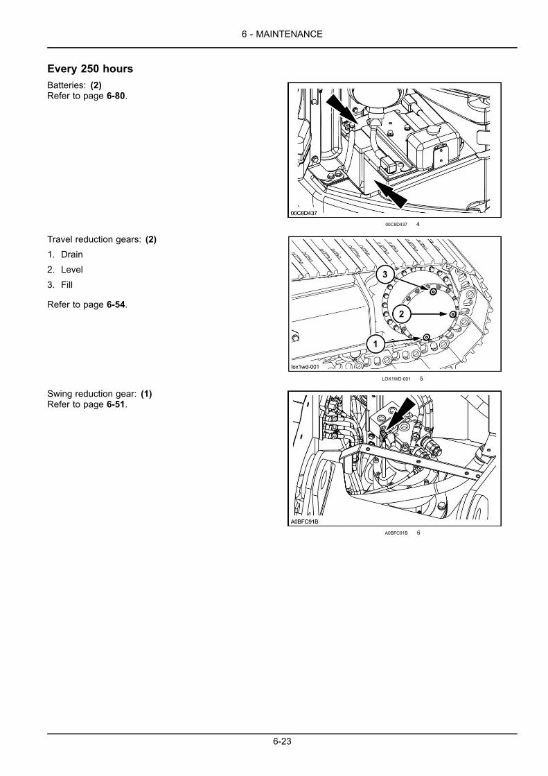
6 - MAINTENANCE
Every 250 hoursBatteries: (2)Refer to page 6-80.
00C8D437 4
Travel reduction gears: (2)1. Drain2. Level3. Fill
Refer to page 6-54.
LOX1WD-001 5
Swing reduction gear: (1)Refer to page 6-51.
A0BFC91B 6
6-23
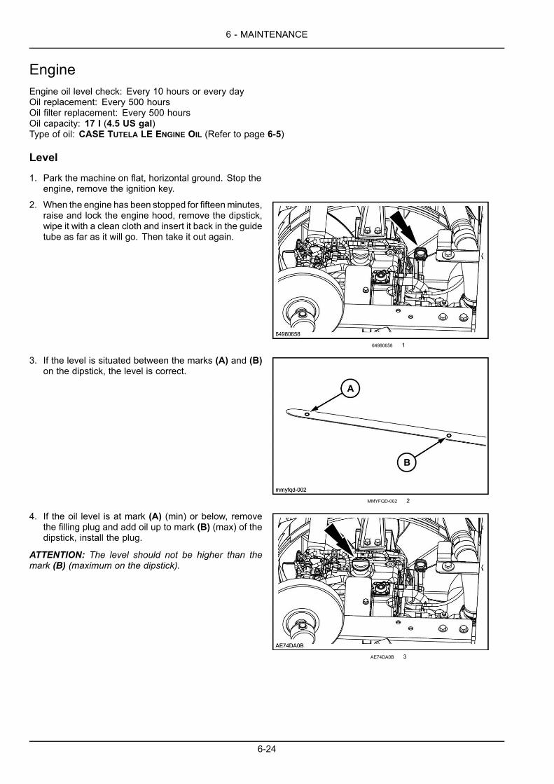
6 - MAINTENANCE
EngineEngine oil level check: Every 10 hours or every dayOil replacement: Every 500 hoursOil filter replacement: Every 500 hoursOil capacity: 17 l (4.5 US gal)Type of oil: CASE TUTELA LE ENGINE OIL (Refer to page 6-5)
Level
1. Park the machine on flat, horizontal ground. Stop theengine, remove the ignition key.
2. When the engine has been stopped for fifteenminutes,raise and lock the engine hood, remove the dipstick,wipe it with a clean cloth and insert it back in the guidetube as far as it will go. Then take it out again.
64980658 1
3. If the level is situated between the marks (A) and (B)on the dipstick, the level is correct.
MMYFQD-002 2
4. If the oil level is at mark (A) (min) or below, removethe filling plug and add oil up to mark (B) (max) of thedipstick, install the plug.
ATTENTION: The level should not be higher than themark (B) (maximum on the dipstick).
AE74DA0B 3
6-24
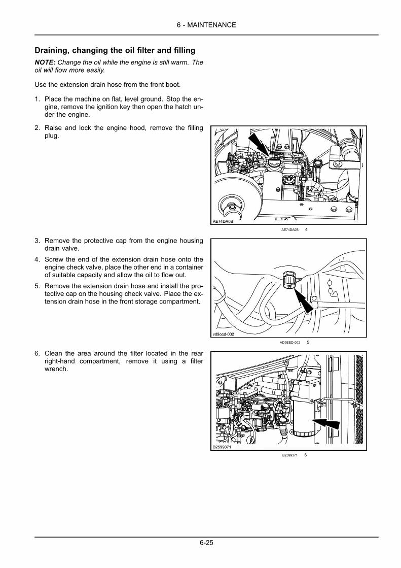
6 - MAINTENANCE
Draining, changing the oil filter and fillingNOTE: Change the oil while the engine is still warm. Theoil will flow more easily.
Use the extension drain hose from the front boot.
1. Place the machine on flat, level ground. Stop the en-gine, remove the ignition key then open the hatch un-der the engine.
2. Raise and lock the engine hood, remove the fillingplug.
AE74DA0B 4
3. Remove the protective cap from the engine housingdrain valve.
4. Screw the end of the extension drain hose onto theengine check valve, place the other end in a containerof suitable capacity and allow the oil to flow out.
5. Remove the extension drain hose and install the pro-tective cap on the housing check valve. Place the ex-tension drain hose in the front storage compartment.
VD9EED-002 5
6. Clean the area around the filter located in the rearright-hand compartment, remove it using a filterwrench.
B2599371 6
6-25
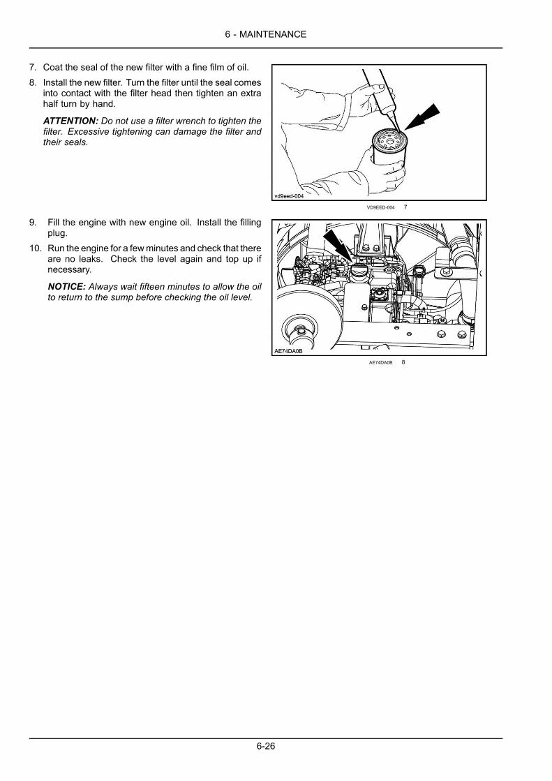
6 - MAINTENANCE
7. Coat the seal of the new filter with a fine film of oil.8. Install the new filter. Turn the filter until the seal comes
into contact with the filter head then tighten an extrahalf turn by hand.
ATTENTION: Do not use a filter wrench to tighten thefilter. Excessive tightening can damage the filter andtheir seals.
VD9EED-004 7
9. Fill the engine with new engine oil. Install the fillingplug.
10. Run the engine for a fewminutes and check that thereare no leaks. Check the level again and top up ifnecessary.
NOTICE: Always wait fifteen minutes to allow the oilto return to the sump before checking the oil level.
AE74DA0B 8
6-26
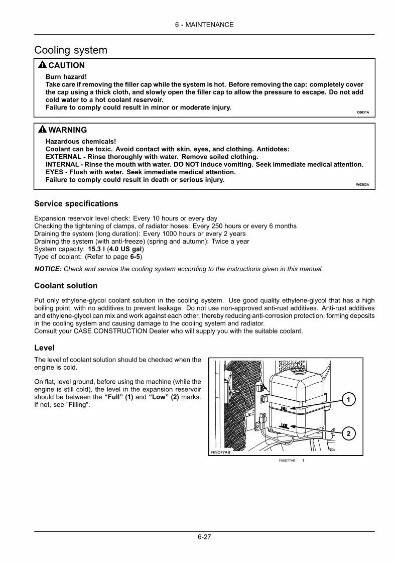
6 - MAINTENANCE
Cooling systemCAUTIONBurn hazard!Take care if removing the filler cap while the system is hot. Before removing the cap: completely coverthe cap using a thick cloth, and slowly open the filler cap to allow the pressure to escape. Do not addcold water to a hot coolant reservoir.Failure to comply could result in minor or moderate injury.
C0031A
WARNINGHazardous chemicals!Coolant can be toxic. Avoid contact with skin, eyes, and clothing. Antidotes:EXTERNAL - Rinse thoroughly with water. Remove soiled clothing.INTERNAL - Rinse the mouth with water. DO NOT induce vomiting. Seek immediate medical attention.EYES - Flush with water. Seek immediate medical attention.Failure to comply could result in death or serious injury.
W0282A
Service specifications
Expansion reservoir level check: Every 10 hours or every dayChecking the tightening of clamps, of radiator hoses: Every 250 hours or every 6 monthsDraining the system (long duration): Every 1000 hours or every 2 yearsDraining the system (with anti-freeze) (spring and autumn): Twice a yearSystem capacity: 15.3 l (4.0 US gal)Type of coolant: (Refer to page 6-5)
NOTICE: Check and service the cooling system according to the instructions given in this manual.
Coolant solution
Put only ethylene-glycol coolant solution in the cooling system. Use good quality ethylene-glycol that has a highboiling point, with no additives to prevent leakage. Do not use non-approved anti-rust additives. Anti-rust additivesand ethylene-glycol can mix and work against each other, thereby reducing anti-corrosion protection, forming depositsin the cooling system and causing damage to the cooling system and radiator.Consult your CASE CONSTRUCTION Dealer who will supply you with the suitable coolant.
LevelThe level of coolant solution should be checked when theengine is cold.
On flat, level ground, before using the machine (while theengine is still cold), the level in the expansion reservoirshould be between the “Full” (1) and “Low” (2) marks.If not, see "Filling".
F69D77AB 1
6-27

6 - MAINTENANCE
DrainingCAUTIONBurn hazard!Hot coolant can spray out if you remove thefiller cap while the system is hot. After thesystem has cooled, turn the filler cap to thefirst notch and wait for all pressure to releasebefore proceeding.Failure to comply could result in minor ormoderate injury.
C0043A
1. Remove the radiator plug.
6B55FBBE 2
2. Open the radiator drain valve located on the engineside of the radiator.
9BBEE5B4 3
3. Open the drain plug located on the engine block.
NOTE: Have a receptacle of a suitable capacity ready.
K272V1-008 4
6-28

6 - MAINTENANCE
Rinsing
1. Close the drain valve once the radiator is completelyempty. Close the plug on the engine block.
2. Fill the system with clean water. Install the radiatorcap.
3. Start the engine. Run the engine at a speed slightlyhigher than idle speed for ten minutes to bring the en-gine temperature up to about 80 °C (176.0 °F) .
4. Stop the engine and remove the ignition key.5. Drain the system once more.6. Repeat Steps 1 to 5 until the water drained is clear.
Filling1. Fill with coolant solution via the radiator until overflow-
ing and install the radiator cap.
6B55FBBE 5
2. Fill the expansion reservoir to the “Full” mark andinstall the cap.
ATTENTION: Use the correct coolant solution.3. Run the engine at idle speed for about five minutes.
Add coolant solution if the level in the expansion reser-voir drops.
ATTENTION:Do not fill the expansion reservoir abovethe “Full” mark.
9F2D39EE 6
6-29
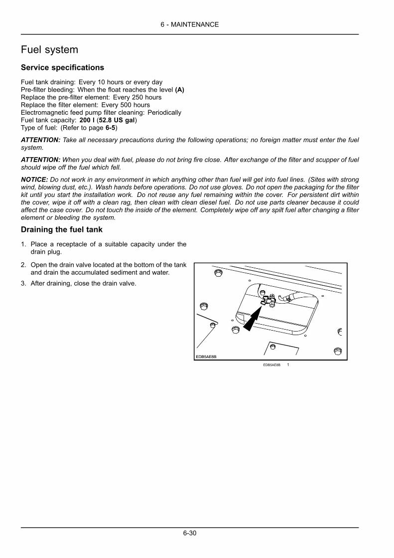
6 - MAINTENANCE
Fuel systemService specifications
Fuel tank draining: Every 10 hours or every dayPre-filter bleeding: When the float reaches the level (A)Replace the pre-filter element: Every 250 hoursReplace the filter element: Every 500 hoursElectromagnetic feed pump filter cleaning: PeriodicallyFuel tank capacity: 200 l (52.8 US gal)Type of fuel: (Refer to page 6-5)
ATTENTION: Take all necessary precautions during the following operations; no foreign matter must enter the fuelsystem.
ATTENTION:When you deal with fuel, please do not bring fire close. After exchange of the filter and scupper of fuelshould wipe off the fuel which fell.
NOTICE: Do not work in any environment in which anything other than fuel will get into fuel lines. (Sites with strongwind, blowing dust, etc.). Wash hands before operations. Do not use gloves. Do not open the packaging for the filterkit until you start the installation work. Do not reuse any fuel remaining within the cover. For persistent dirt withinthe cover, wipe it off with a clean rag, then clean with clean diesel fuel. Do not use parts cleaner because it couldaffect the case cover. Do not touch the inside of the element. Completely wipe off any spilt fuel after changing a filterelement or bleeding the system.
Draining the fuel tank
1. Place a receptacle of a suitable capacity under thedrain plug.
2. Open the drain valve located at the bottom of the tankand drain the accumulated sediment and water.
3. After draining, close the drain valve.
EDB5AE8B 1
6-30
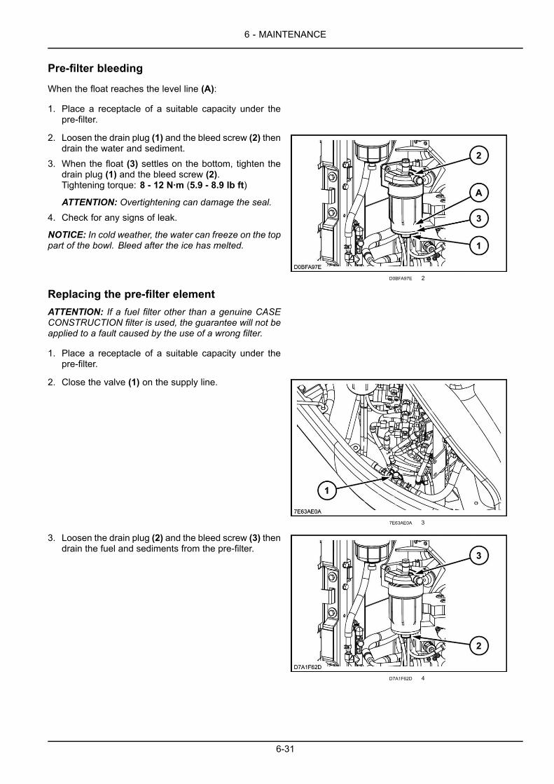
6 - MAINTENANCE
Pre-filter bleeding
When the float reaches the level line (A):
1. Place a receptacle of a suitable capacity under thepre-filter.
2. Loosen the drain plug (1) and the bleed screw (2) thendrain the water and sediment.
3. When the float (3) settles on the bottom, tighten thedrain plug (1) and the bleed screw (2).Tightening torque: 8 - 12 N·m (5.9 - 8.9 lb ft)
ATTENTION: Overtightening can damage the seal.4. Check for any signs of leak.
NOTICE: In cold weather, the water can freeze on the toppart of the bowl. Bleed after the ice has melted.
D0BFA97E 2
Replacing the pre-filter elementATTENTION: If a fuel filter other than a genuine CASECONSTRUCTION filter is used, the guarantee will not beapplied to a fault caused by the use of a wrong filter.
1. Place a receptacle of a suitable capacity under thepre-filter.
2. Close the valve (1) on the supply line.
7E63AE0A 3
3. Loosen the drain plug (2) and the bleed screw (3) thendrain the fuel and sediments from the pre-filter.
D7A1F62D 4
6-31
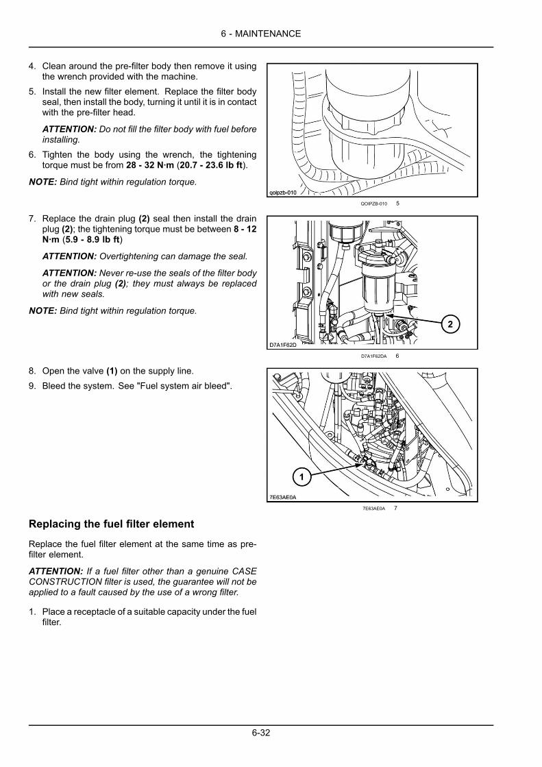
6 - MAINTENANCE
4. Clean around the pre-filter body then remove it usingthe wrench provided with the machine.
5. Install the new filter element. Replace the filter bodyseal, then install the body, turning it until it is in contactwith the pre-filter head.
ATTENTION: Do not fill the filter body with fuel beforeinstalling.
6. Tighten the body using the wrench, the tighteningtorque must be from 28 - 32 N·m (20.7 - 23.6 lb ft).
NOTE: Bind tight within regulation torque.
QOIPZB-010 5
7. Replace the drain plug (2) seal then install the drainplug (2); the tightening torque must be between 8 - 12N·m (5.9 - 8.9 lb ft)
ATTENTION: Overtightening can damage the seal.
ATTENTION: Never re-use the seals of the filter bodyor the drain plug (2); they must always be replacedwith new seals.
NOTE: Bind tight within regulation torque.
D7A1F62DA 6
8. Open the valve (1) on the supply line.9. Bleed the system. See "Fuel system air bleed".
7E63AE0A 7
Replacing the fuel filter element
Replace the fuel filter element at the same time as pre-filter element.
ATTENTION: If a fuel filter other than a genuine CASECONSTRUCTION filter is used, the guarantee will not beapplied to a fault caused by the use of a wrong filter.
1. Place a receptacle of a suitable capacity under the fuelfilter.
6-32
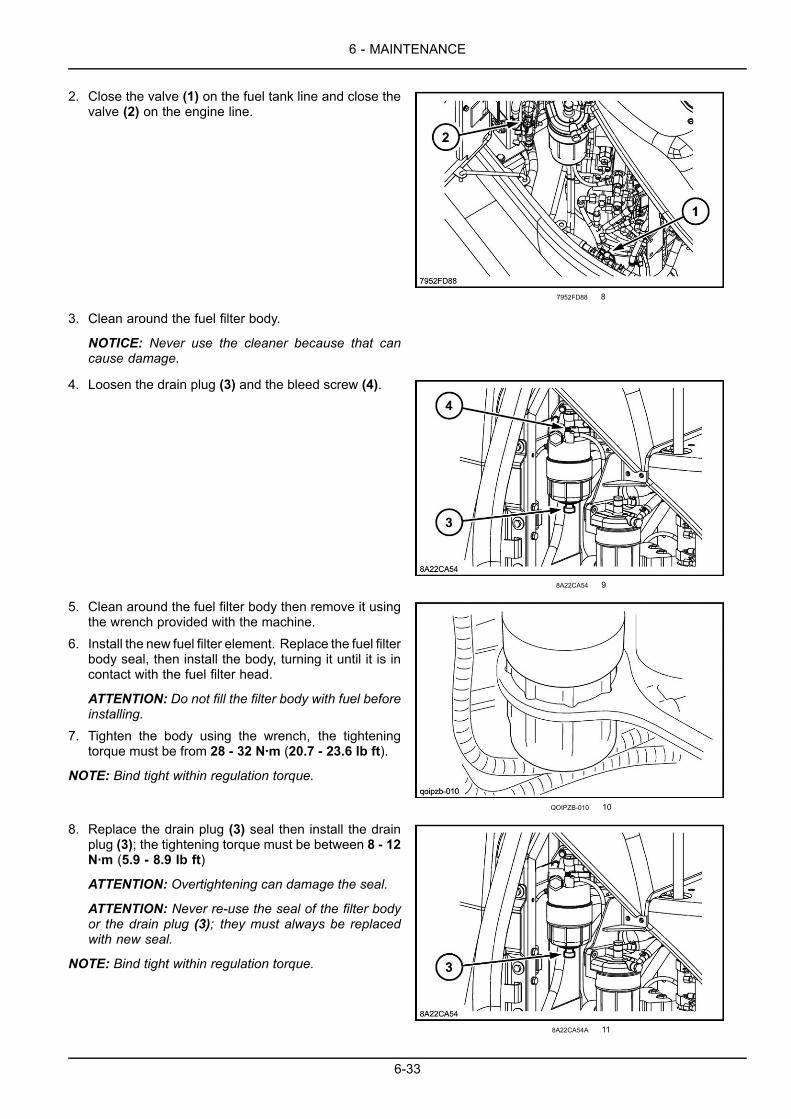
6 - MAINTENANCE
2. Close the valve (1) on the fuel tank line and close thevalve (2) on the engine line.
7952FD88 8
3. Clean around the fuel filter body.
NOTICE: Never use the cleaner because that cancause damage.
4. Loosen the drain plug (3) and the bleed screw (4).
8A22CA54 9
5. Clean around the fuel filter body then remove it usingthe wrench provided with the machine.
6. Install the new fuel filter element. Replace the fuel filterbody seal, then install the body, turning it until it is incontact with the fuel filter head.
ATTENTION: Do not fill the filter body with fuel beforeinstalling.
7. Tighten the body using the wrench, the tighteningtorque must be from 28 - 32 N·m (20.7 - 23.6 lb ft).
NOTE: Bind tight within regulation torque.
QOIPZB-010 10
8. Replace the drain plug (3) seal then install the drainplug (3); the tightening torque must be between 8 - 12N·m (5.9 - 8.9 lb ft)
ATTENTION: Overtightening can damage the seal.
ATTENTION: Never re-use the seal of the filter bodyor the drain plug (3); they must always be replacedwith new seal.
NOTE: Bind tight within regulation torque.
8A22CA54A 11
6-33

6 - MAINTENANCE
9. Open the valve (1) on the fuel tank line and open thevalve (2) on the engine line.
7952FD88 12
Fuel system air bleedNOTICE: When the fuel tank has been emptied after re-placement and/or draining water of the pre-fuel filter or thefuel filter (4) has been carried out, be sure to bleed air asthis may prevent fuel flow because of air entering inside.
60A45B56 13
1. Place a receiving container under the end of fuel drainhose.
2. Set each cock of (A), (B) and (C) as follows.Cock (A) (fuel tank): OpenCock (B) (engine): CloseCock (C) (drain): Open
75C1814E 14
3. Loosen the air bleeding plug (2) on fuel filter. Do notloosen the air bleeding plug of the pre fuel filter.
4. Insert the key into the ignition switch and turn the key tothe “On” position. Electromagnet feed pump operatesby this.
ATTENTION: Do not turn “On” the ignition key formore than 5 minutes unless bleeding air has beencompleted. Otherwise, this may cause breakdown ofthe electromagnetic fuel pump.
5. Turn the handle of the feed pump (1) to the left and itwill spring up due to the spring inside the handle.
A0178EC5 15
6-34

6 - MAINTENANCE
6. Move this handle and expel from the drain hose (3) thefuel with which air bubbles were mixed. This action isthe back-up of electromagnet feed pump (4). Movethis handle until air bubbles are lose in fuel.
7. Turn “Off” the ignition key.
CD6F0D2F 16
8. Next, tighten the air bleeding plug (2)which had beenloosened in step 3 and continue to move the feedpump (1) handle. When the handle becomes difficultto move, air bleeding is completed. Air bleeding : 8 -12 N·m (5.9 - 8.9 lb ft).
9. Push in the handle of the feed pump (1) to return it toits original position.
10. Turn “On” the ignition key to operate the electromag-netic feed pump draining the contaminant (impurities)in the fuel pipes for more than 30 seconds.
A0178EC5A 17
11. Set each cock of (A), (B) and (C) as follows.Cock (A) (fuel tank): OpenCock (B) (engine): OpenCock (C) (drain): Close
12. Completely wipe off any spilled fuel, start the engineand check for any fuel leakage.
ATTENTION: Tightening it with torque exceeding thespecified may cause the rubber section of gasket tobe damaged.
75C1814E 18
Cleaning the electromagnetic feed pump filter1. Located near the fuel filter, place a receptacle of suit-
able capacity under the electromagnetic feed pump.
2268DA34 19
6-35

6 - MAINTENANCE
2. Close the valve on the supply line then remove theelectromagnetic feed pump.
5DD96F84 20
3. Open the pump body and extract the filter (3) and theseals (2) and (4).
WARNINGFlying debris!Compressed air can propel dirt, rust, etc. intothe air. Wear eye and face protection whenusing compressed air.Failure to comply could result in death or se-rious injury.
W0307A
4. Clean the filter with compressed air. Check the filterand replace it if necessary. Replace the seals with newseals.
5. Carefully clean the body (5) and the cover (1). No dirtmust remain in the supply pump.
6. Re-assemble, taking care to install the seals in thecorrect order then re-install the pump.
7. Open the valve on the supply line.8. Bleed the system. See "Replacing the fuel filter ele-
ment".
EQFU5N-003A 21
6-36

6 - MAINTENANCE
Releasing pressure in the hydraulic systemATTENTION: Before carrying out any work on the hy-draulic system, there should be no pressure in any of thecircuits.
1. Place the machine on flat, level ground, lower the at-tachment to the ground and stop the engine.
2. Turn the ignition key to the “On” position.
3F901DF6 1
3. Lower the function cancellation lever.
FF241191 2
4. Operate the control levers from right to left and front torear a dozen times approximately.
5. Turn the ignition key to the “Off” position (shut down).
D5075429 3
6-37

6 - MAINTENANCE
6. Press the button on top of the breather on the hydraulicreservoir to release any residual pressure.
DF79A0FC 4
6-38
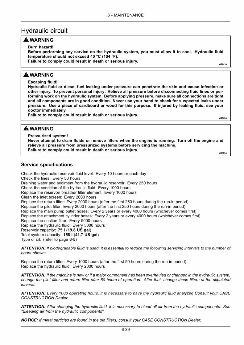
6 - MAINTENANCE
Hydraulic circuitWARNINGBurn hazard!Before performing any service on the hydraulic system, you must allow it to cool. Hydraulic fluidtemperature should not exceed 40 °C (104 °F).Failure to comply could result in death or serious injury.
W0241A
WARNINGEscaping fluid!Hydraulic fluid or diesel fuel leaking under pressure can penetrate the skin and cause infection orother injury. To prevent personal injury: Relieve all pressure before disconnecting fluid lines or per-forming work on the hydraulic system. Before applying pressure, make sure all connections are tightand all components are in good condition. Never use your hand to check for suspected leaks underpressure. Use a piece of cardboard or wood for this purpose. If injured by leaking fluid, see yourdoctor immediately.Failure to comply could result in death or serious injury.
W0178A
WARNINGPressurized system!Never attempt to drain fluids or remove filters when the engine is running. Turn off the engine andrelieve all pressure from pressurized systems before servicing the machine.Failure to comply could result in death or serious injury.
W0905A
Service specifications
Check the hydraulic reservoir fluid level: Every 10 hours or each dayCheck the lines: Every 50 hoursDraining water and sediment from the hydraulic reservoir: Every 250 hoursCheck the condition of the hydraulic fluid: Every 1000 hoursReplace the reservoir breather filter element: Every 1000 hoursClean the inlet screen: Every 2000 hoursReplace the return filter: Every 2000 hours (after the first 250 hours during the run-in period)Replace the pilot filter: Every 2000 hours (after the first 250 hours during the run-in period)Replace the main pump outlet hoses: Every 2 years or every 4000 hours (whichever comes first)Replace the attachment cylinder hoses: Every 2 years or every 4000 hours (whichever comes first)Replace the suction filter: Every 5000 hoursReplace the hydraulic fluid: Every 5000 hoursReservoir capacity: 75 l (19.8 US gal)Total system capacity: 158 l (41.7 US gal)Type of oil: (refer to page 6-5)
ATTENTION: If biodegradable fluid is used, it is essential to reduce the following servicing intervals to the number ofhours shown:
Replace the return filter: Every 1000 hours (after the first 50 hours during the run-in period)Replace the hydraulic fluid: Every 2000 hours
ATTENTION: If the machine is new or if a major component has been overhauled or changed in the hydraulic system,change the pilot filter and return filter after 50 hours of operation. After that, change these filters at the stipulatedinterval.
ATTENTION: Every 1000 operating hours, it is necessary to have the hydraulic fluid analyzed Consult your CASECONSTRUCTION Dealer.
ATTENTION: After changing the hydraulic fluid, it is necessary to bleed all air from the hydraulic components. See"Bleeding air from the hydraulic components".
NOTICE: If metal particles are found in the old filters, consult your CASE CONSTRUCTION Dealer.
6-39
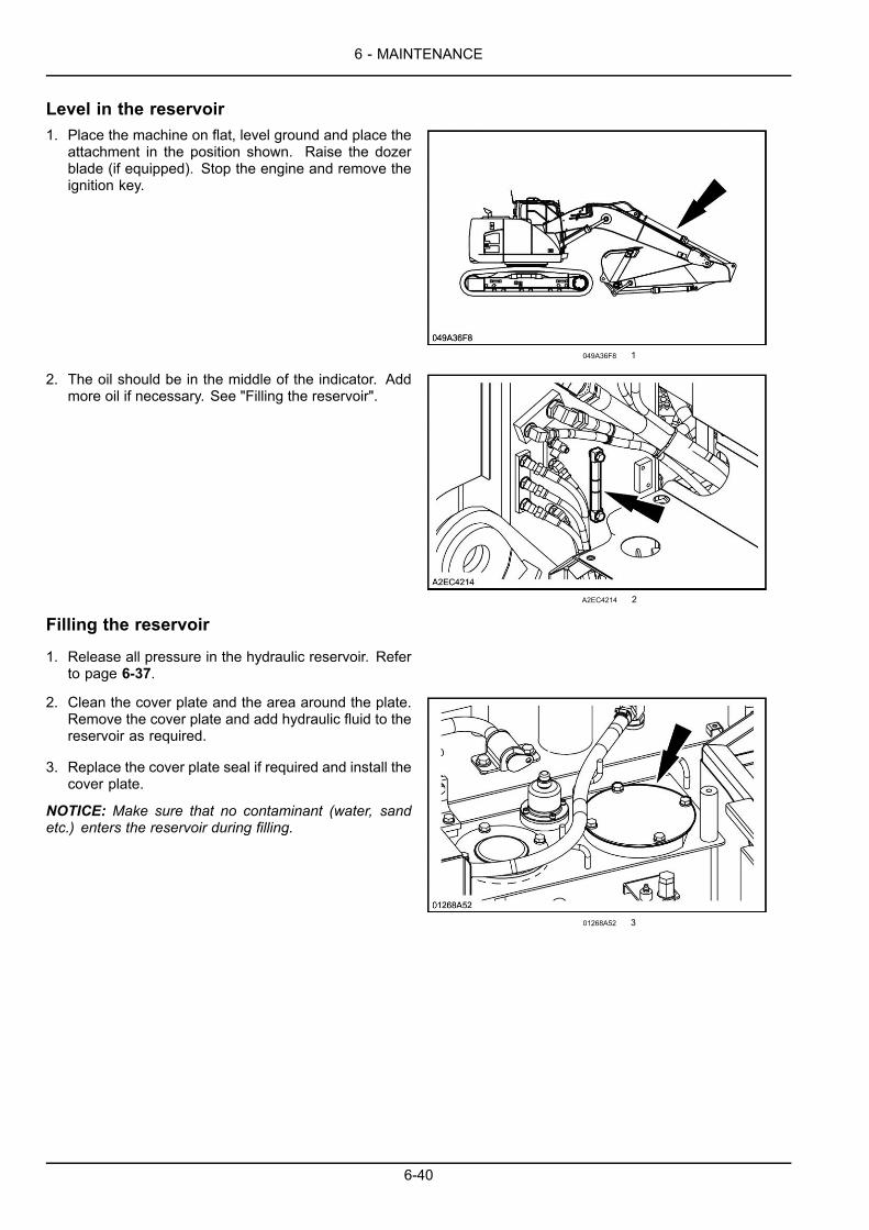
6 - MAINTENANCE
Level in the reservoir1. Place the machine on flat, level ground and place the
attachment in the position shown. Raise the dozerblade (if equipped). Stop the engine and remove theignition key.
049A36F8 1
2. The oil should be in the middle of the indicator. Addmore oil if necessary. See "Filling the reservoir".
A2EC4214 2
Filling the reservoir
1. Release all pressure in the hydraulic reservoir. Referto page 6-37.
2. Clean the cover plate and the area around the plate.Remove the cover plate and add hydraulic fluid to thereservoir as required.
3. Replace the cover plate seal if required and install thecover plate.
NOTICE: Make sure that no contaminant (water, sandetc.) enters the reservoir during filling.
01268A52 3
6-40
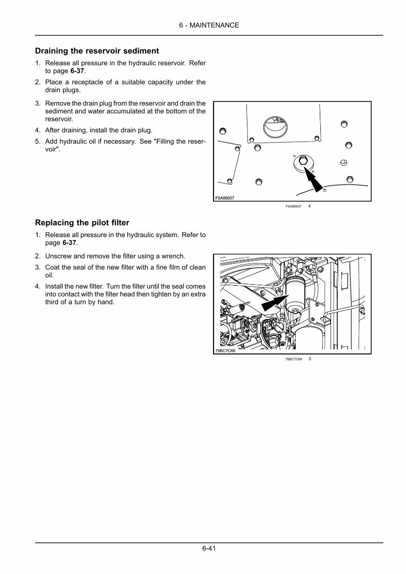
6 - MAINTENANCE
Draining the reservoir sediment1. Release all pressure in the hydraulic reservoir. Refer
to page 6-37.2. Place a receptacle of a suitable capacity under the
drain plugs.
3. Remove the drain plug from the reservoir and drain thesediment and water accumulated at the bottom of thereservoir.
4. After draining, install the drain plug.5. Add hydraulic oil if necessary. See "Filling the reser-
voir".
F5A86937 4
Replacing the pilot filter1. Release all pressure in the hydraulic system. Refer to
page 6-37.
2. Unscrew and remove the filter using a wrench.3. Coat the seal of the new filter with a fine film of clean
oil.4. Install the new filter. Turn the filter until the seal comes
into contact with the filter head then tighten by an extrathird of a turn by hand.
76BC7C66 5
6-41
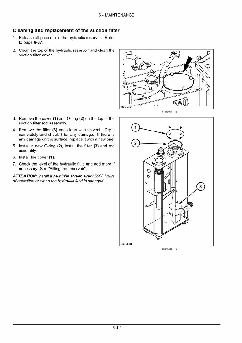
6 - MAINTENANCE
Cleaning and replacement of the suction filter1. Release all pressure in the hydraulic reservoir. Refer
to page 6-37.
2. Clean the top of the hydraulic reservoir and clean thesuction filter cover.
01268A52 6
3. Remove the cover (1) and O-ring (2) on the top of thesuction filter rod assembly.
4. Remove the filter (3) and clean with solvent. Dry itcompletely and check it for any damage. If there isany damage on the surface, replace it with a new one.
5. Install a new O-ring (2), install the filter (3) and rodassembly.
6. Install the cover (1).7. Check the level of the hydraulic fluid and add more if
necessary. See "Filling the reservoir".
ATTENTION: Install a new inlet screen every 5000 hoursof operation or when the hydraulic fluid is changed.
68672B3B 7
6-42

6 - MAINTENANCE
Replacing the return filter1. Release all pressure in the hydraulic reservoir. Refer
to page 6-37.
2. Clean the top of the hydraulic reservoir and clean thereturn filter cover.
74AC7A7E 8
3. Remove the cover (1), O-ring (2) and compressionspring (3).
4. Take out the filter (4).5. Install a new filter (4).6. Check O-ring (2) and change it if worn or damaged.7. Install the compression spring (3) and the cover (1).8. Check the level of the hydraulic fluid and add more if
necessary. See "Filling the reservoir".
BA099A67 9
Replacing the reservoir breather filter element1. Press the button (1) to release all pressure in the hy-
draulic reservoir.
452EE801 10
6-43
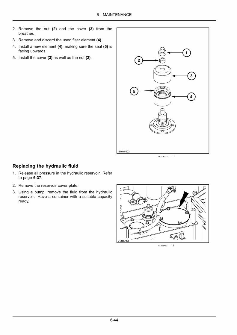
6 - MAINTENANCE
2. Remove the nut (2) and the cover (3) from thebreather.
3. Remove and discard the used filter element (4).4. Install a new element (4), making sure the seal (5) is
facing upwards.5. Install the cover (3) as well as the nut (2).
19IXC6-002 11
Replacing the hydraulic fluid1. Release all pressure in the hydraulic reservoir. Refer
to page 6-37.
2. Remove the reservoir cover plate.3. Using a pump, remove the fluid from the hydraulic
reservoir. Have a container with a suitable capacityready.
01268A52 12
6-44
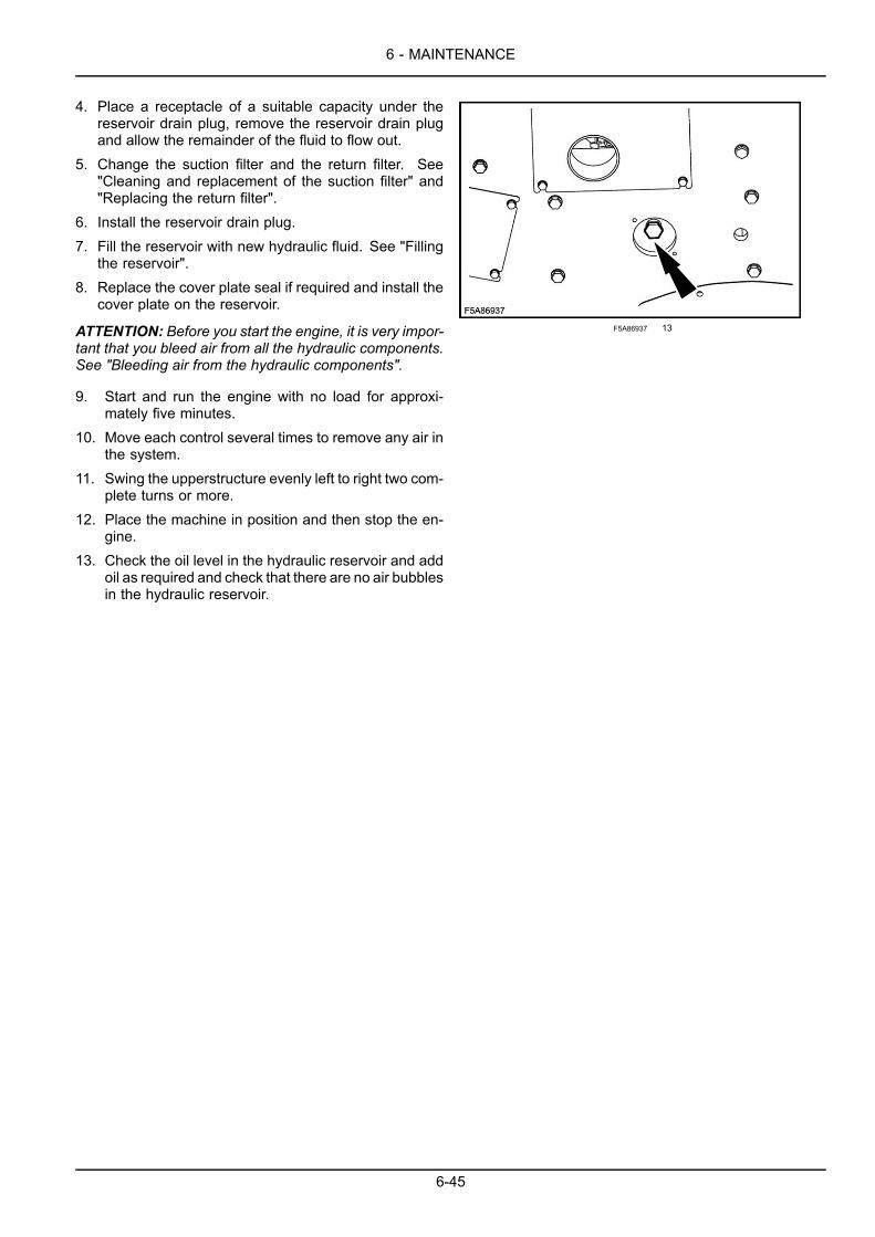
6 - MAINTENANCE
4. Place a receptacle of a suitable capacity under thereservoir drain plug, remove the reservoir drain plugand allow the remainder of the fluid to flow out.
5. Change the suction filter and the return filter. See"Cleaning and replacement of the suction filter" and"Replacing the return filter".
6. Install the reservoir drain plug.7. Fill the reservoir with new hydraulic fluid. See "Filling
the reservoir".8. Replace the cover plate seal if required and install the
cover plate on the reservoir.
ATTENTION: Before you start the engine, it is very impor-tant that you bleed air from all the hydraulic components.See "Bleeding air from the hydraulic components".
9. Start and run the engine with no load for approxi-mately five minutes.
10. Move each control several times to remove any air inthe system.
11. Swing the upperstructure evenly left to right two com-plete turns or more.
12. Place the machine in position and then stop the en-gine.
13. Check the oil level in the hydraulic reservoir and addoil as required and check that there are no air bubblesin the hydraulic reservoir.
F5A86937 13
6-45

6 - MAINTENANCE
Bleeding air from the hydraulic componentsNOTE: After bleeding air from the components, stop theengine for five minutes and check there are no bubbles atthe surface of the hydraulic fluid in the reservoir.
Hydraulic pump
• Using a solvent, clean the periphery of the air bleedplug. Loosen the air bleed plug, remove the plug if thefluid does not flow.
• Fill the pump with new clean hydraulic fluid. Install andtighten the air bleed plug.
• Start the engine and run it at low idle speed. Loosenthe air bleed plug on the pump. Tighten the plug whenair free fluid comes out of the bleed plug hole. Cleanthe area completely.
177757F2 14
DEE63D04 15
Swing motor
• Start the engine and run it at low idle speed. Loosen thedrain port andmake sure hydraulic fluid runs out. If nec-essary, stop the engine and add oil via the orifice. Installthe plug without tightening, then start the engine andrun it at low idle speed, leaving it to run until oil beginsto run from the orifice. Tighten the air bleed plug com-pletely. Swing the upperstructure at least twice com-pletely to the right and twice completely to the left.
• After complete bleeding, stop the engine for five min-utes then check that there are no air bubbles in the hy-draulic reservoir.
0AD962FF 16
Attachment cylinders
• Start the engine and run it at low idle speed. Extend andretract the attachment cylinder rods four or five timeswithout bringing them to end of stroke. Then repeatthe operation three or four times, this time bringing thecylinder rods to end of stroke.
6-46

6 - MAINTENANCE
Replacing the hydraulic filters and fluid when a hydraulic breaker is used (optional)
When using the hydraulic breaker, hydraulic fluid deteriorates more quickly than during ordinary digging. Check thehydraulic fluid level more frequently. In addition, when changing the filters, also check the condition of the hydraulicfluid.
Using the following graph as a reference, determine the intervals for changing the hydraulic fluid and filters, dependingon the frequency of use of the hydraulic breaker.
Percentage of use 100% 40% 20% 10%Interval in hours 10 100 600 10 300 1500 10 600 300 10 800 4000
Service pointsHydraulic fluid (1) (3) (1) (3) (1) (3) (1) (3)Return circuit filter (3) (3) (3) (3)Inlet filter (2) (3) (2) (3) (2) (3) (2) (3)Pilot filter (3) (3) (3) (3)Hydraulic fluid condition 200H 300H 600H 800H
(1) Check the level(2) Clean or replace(3) Replace
Checking the hydraulic system piping
Make sure there are no leaks from the hydraulic system hoses, pipes, plugs, connections and fittings and check thatall nuts and screws are correctly tightened. In the event of problems, repair, change or tighten the component(s)concerned.
6-47
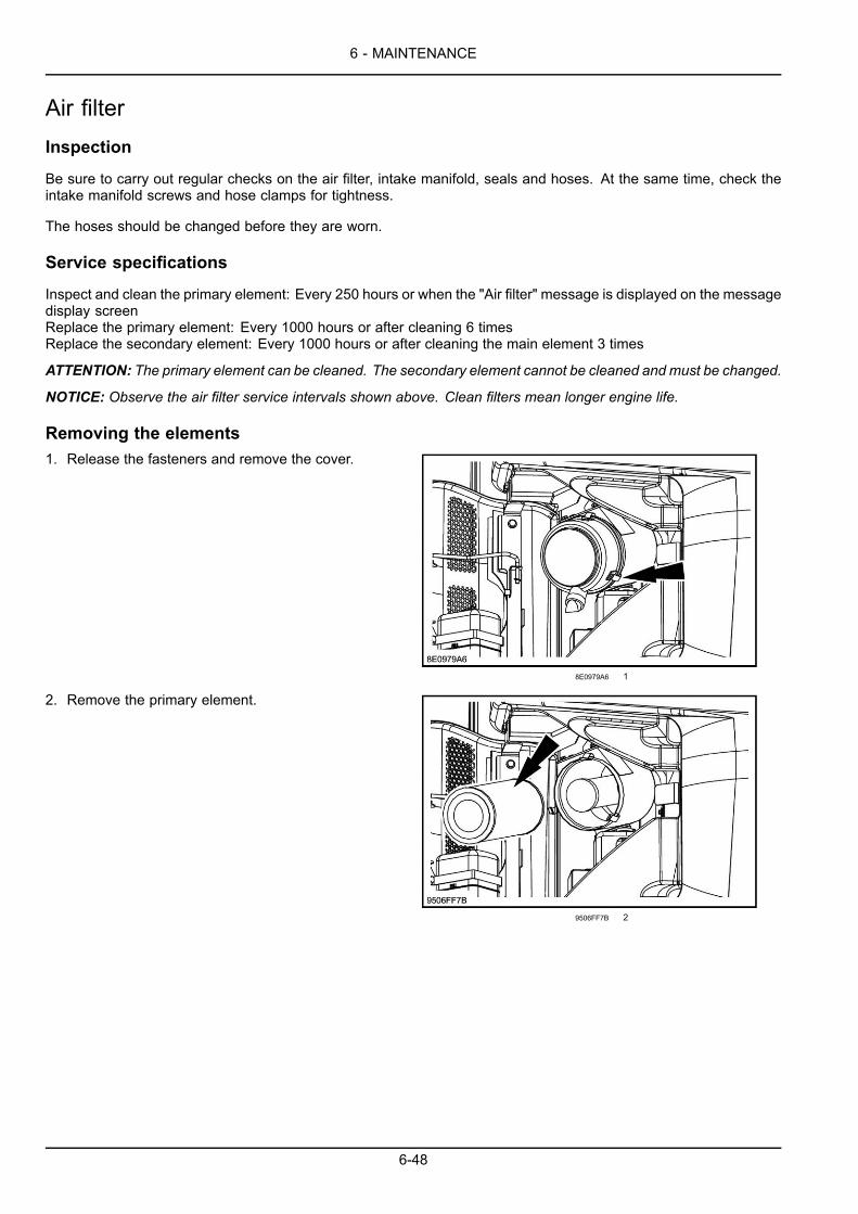
6 - MAINTENANCE
Air filterInspection
Be sure to carry out regular checks on the air filter, intake manifold, seals and hoses. At the same time, check theintake manifold screws and hose clamps for tightness.
The hoses should be changed before they are worn.
Service specifications
Inspect and clean the primary element: Every 250 hours or when the "Air filter" message is displayed on the messagedisplay screenReplace the primary element: Every 1000 hours or after cleaning 6 timesReplace the secondary element: Every 1000 hours or after cleaning the main element 3 times
ATTENTION: The primary element can be cleaned. The secondary element cannot be cleaned and must be changed.
NOTICE: Observe the air filter service intervals shown above. Clean filters mean longer engine life.
Removing the elements1. Release the fasteners and remove the cover.
8E0979A6 1
2. Remove the primary element.
9506FF7B 2
6-48

6 - MAINTENANCE
3. Remove the secondary element if it needs changing.
ATTENTION: The secondary element must be changed,not cleaned.
BABB4864 3
Cleaning the primary elementWARNINGFlying debris!Compressed air can propel dirt, rust, etc. intothe air. Wear eye and face protection whenusing compressed air.Failure to comply could result in death or se-rious injury.
W0307A
If the primary element is dry:
Blow compressed air from the inside towards the outsideat very low pressure. The compressed air nozzle shouldbe held at least 3 cm from the inside wall of the element.Cleaning is completed once no more dust comes out ofthe primary element.
ATTENTION: Compressed air pressure should not ex-ceed 7 bar.
ATTENTION: Do not use compressed air if there is oil orsoot in the element.
OESMY5-001 4
If the cartridge is greasy:
Clean it in water with a suitable detergent (consult yourCASE CONSTRUCTION Dealer). Instructions for usingthe detergent are printed on the packaging.
NOTE: Allow the element to dry completely before in-stalling it. It is advisable to keep a spare, clean elementready for installation on the air filter while the cleaned el-ement is drying.
OESMY5-002 5
6-49
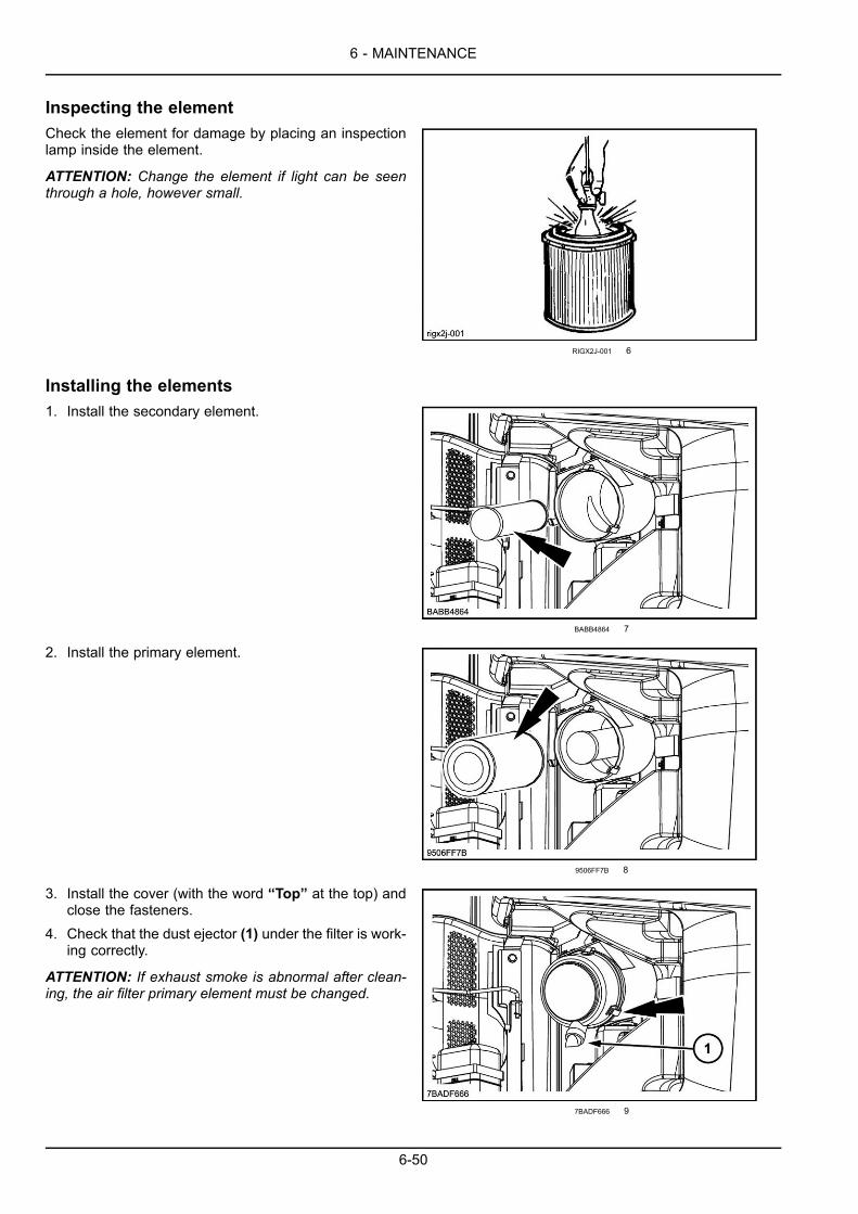
6 - MAINTENANCE
Inspecting the elementCheck the element for damage by placing an inspectionlamp inside the element.
ATTENTION: Change the element if light can be seenthrough a hole, however small.
RIGX2J-001 6
Installing the elements1. Install the secondary element.
BABB4864 7
2. Install the primary element.
9506FF7B 8
3. Install the cover (with the word “Top” at the top) andclose the fasteners.
4. Check that the dust ejector (1) under the filter is work-ing correctly.
ATTENTION: If exhaust smoke is abnormal after clean-ing, the air filter primary element must be changed.
7BADF666 9
6-50

6 - MAINTENANCE
Swing reduction gearWARNINGHot surface possible!Wait for all components to cool before performing any operation.Failure to comply could result in death or serious injury.
W0251A
Service specifications
Oil level check: Every 250 hoursOil drain: Every 1000 hours (after the first 250 hours during the run-in period)Oil capacity: 3 l (0.8 US gal)Greasing: Every 2000 hoursGrease capacity: 0.5 kg (1.1 lb)Type of oil and grease: (Refer to page 6-5)
Level
1. Park the machine on flat, horizontal ground. Stop theengine and remove the ignition key.
2. Remove the dipstick (2). The oil should come up tothe hatched area. If necessary, add more oil throughthe filler hole (1).
3. Install the dipstick.
FA3DE3BF 1
6-51

6 - MAINTENANCE
Draining and refilling
1. Park the machine on flat, horizontal ground. Stop theengine and remove the ignition key.
2. Remove the dipstick (2) and the filler plug (1).
FA3DE3BF 2
3. Place a receptacle of a suitable capacity under theupperstructure frame, remove the oil drain plug (3) andallow the oil to flow out.
NOTE: The oil takes a relatively long time to drain.
ATTENTION: Check the condition of the drained oil. Ifit contains metal filings or foreign matter, consult yourCASE CONSTRUCTION Dealer.
4. Install the drain plug (3).
9DD2D467 3
6-52

6 - MAINTENANCE
5. Add oil through the filler hole (1) until the level is cor-rect.
6. Install the dipstick (2) and the filler plug (1).7. Wait ten minutes and then use the dipstick (2) to check
the oil level again. If necessary, add more oil throughthe filler hole (1).
FA3DE3BF 4
Greasing1. Remove the air bleed plug (1) and refill with grease
through the grease point (2).2. A certain amount of grease should run out from the air
bleed plug (1).3. Install the air bleed plug (1).
NOTICE:When greasing, the inner seal will be damagedif the air bleed plug (1) is not remove.
915C2984 5
6-53
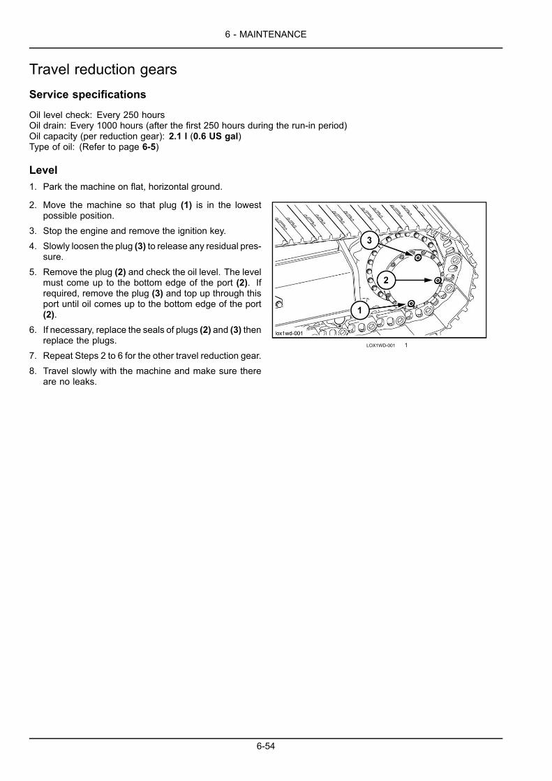
6 - MAINTENANCE
Travel reduction gearsService specifications
Oil level check: Every 250 hoursOil drain: Every 1000 hours (after the first 250 hours during the run-in period)Oil capacity (per reduction gear): 2.1 l (0.6 US gal)Type of oil: (Refer to page 6-5)
Level1. Park the machine on flat, horizontal ground.
2. Move the machine so that plug (1) is in the lowestpossible position.
3. Stop the engine and remove the ignition key.4. Slowly loosen the plug (3) to release any residual pres-
sure.5. Remove the plug (2) and check the oil level. The level
must come up to the bottom edge of the port (2). Ifrequired, remove the plug (3) and top up through thisport until oil comes up to the bottom edge of the port(2).
6. If necessary, replace the seals of plugs (2) and (3) thenreplace the plugs.
7. Repeat Steps 2 to 6 for the other travel reduction gear.8. Travel slowly with the machine and make sure there
are no leaks.
LOX1WD-001 1
6-54

6 - MAINTENANCE
Draining and refilling1. Park the machine on flat, horizontal ground.
2. Move the machine so that plug (1) is in the lowestpossible position.
3. Shut down the engine and remove the ignition key.4. Place a receptacle of suitable capacity under the
travel reduction gear.5. Slowly loosen the plug (3) to release any residual
pressure then remove the three plugs.6. Allow the oil to drain.
ATTENTION: Check the condition of the drained oil.If it contains metal filings or foreign matter, consultyour CASE CONSTRUCTION Dealer.
7. If required, replace the plug seals.8. Install the plug (1), fill with oil through the port (3)
until oil comes up to the bottom edge of port (2), theninstall the plugs (2) and (3).
9. Repeat Steps 2 to 8 for the other travel reductiongear.
10. Travel slowly with the machine and make sure thereare no leaks.
LOX1WD-001 2
6-55

6 - MAINTENANCE
TracksService specifications
Clean: Periodically and when the machine has been working in mudCheck tension: PeriodicallyCheck steel pad screw torques: Every 250 hours (after the first 50 hours during the run-in period)
ATTENTION: If the tracks are too tight, they wear quickly. If tracks are not tight enough, they wear quickly and thelinks can catch on the sprocket wheel or slide off the idler wheel or the sprocket wheel. Clean the tracks after work.
Cleaning
When the machine has been working in mud, a reductionin temperature can cause the mud to solidify.
1. Place the upperstructure at right angles to the under-carriage. Use the attachment to press on the groundand lower the boom until the track is raised off theground. Then place a block beneath the undercarriageto relieve the attachment.
WARNINGTip-over hazard!Only raise the track as little as necessary.Failure to comply could result in death or se-rious injury.
W0276A
NOTE: (Standard machine only) The machine can belifted by completely lowering the dozer blade and by usingthe attachment as a support on the ground, opposite thedozer blade.
3CA47630 1
2. Turn the engine throttle button to maximum speed po-sition.
A965DECD 2
3. Use the travel speed selector to select high speed.
UUDO6A-003Z 3
6-56

6 - MAINTENANCE
4. Operate the travel control lever for the raised trackforward and then in reverse, to remove the mud.
5. With the track raised, check the track tension.6. Repeat Steps 1 to 5 for the other track.
SOEUXT-010 4
Checking the tension1. If the track is not yet raised, put the machine into the
required position by proceeding in the same manneras for cleaning. See "Cleaning".
2. Use the travel control lever to operate the raised trackin reverse for a few moments.
3. Stop the engine and remove the ignition key.
4. Measure the sag of the track at the center between thebase of the undercarriage and the pad.The value must be between: 240 mm (9.4 in) and 270mm (10.6 in).
5. Adjust the tension if necessary and then lower theraised track to the ground.
6. Repeat Steps 1 to 5 for the other track.
1IUTUH-001 5
Adjusting the tensionNOTE: This operation is to be carried out after the tensionhas been checked.
To increase tension
1. Clean the grease fitting adaptor and the grease fitting.
2. Connect the grease pump. Inject grease to obtain theright amount of track tension.The value must be between: 240 mm (9.4 in) and 270mm (10.6 in).
3. Remove the grease pump and clean the grease fitting.4. Repeat Steps 1 to 3 for the other track.
1V7EYE-002 6
6-57
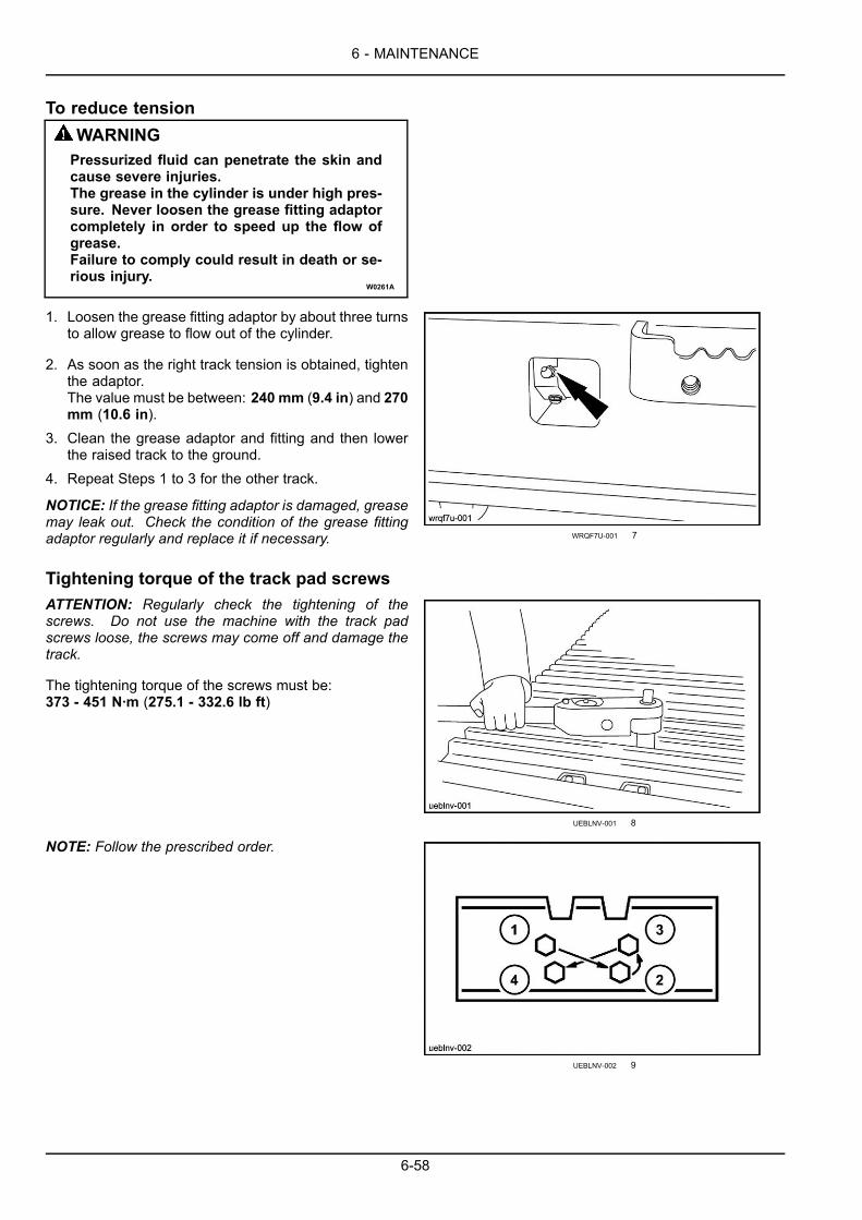
6 - MAINTENANCE
To reduce tensionWARNINGPressurized fluid can penetrate the skin andcause severe injuries.The grease in the cylinder is under high pres-sure. Never loosen the grease fitting adaptorcompletely in order to speed up the flow ofgrease.Failure to comply could result in death or se-rious injury.
W0261A
1. Loosen the grease fitting adaptor by about three turnsto allow grease to flow out of the cylinder.
2. As soon as the right track tension is obtained, tightenthe adaptor.The value must be between: 240 mm (9.4 in) and 270mm (10.6 in).
3. Clean the grease adaptor and fitting and then lowerthe raised track to the ground.
4. Repeat Steps 1 to 3 for the other track.
NOTICE: If the grease fitting adaptor is damaged, greasemay leak out. Check the condition of the grease fittingadaptor regularly and replace it if necessary. WRQF7U-001 7
Tightening torque of the track pad screwsATTENTION: Regularly check the tightening of thescrews. Do not use the machine with the track padscrews loose, the screws may come off and damage thetrack.
The tightening torque of the screws must be:373 - 451 N·m (275.1 - 332.6 lb ft)
UEBLNV-001 8
NOTE: Follow the prescribed order.
UEBLNV-002 9
6-58
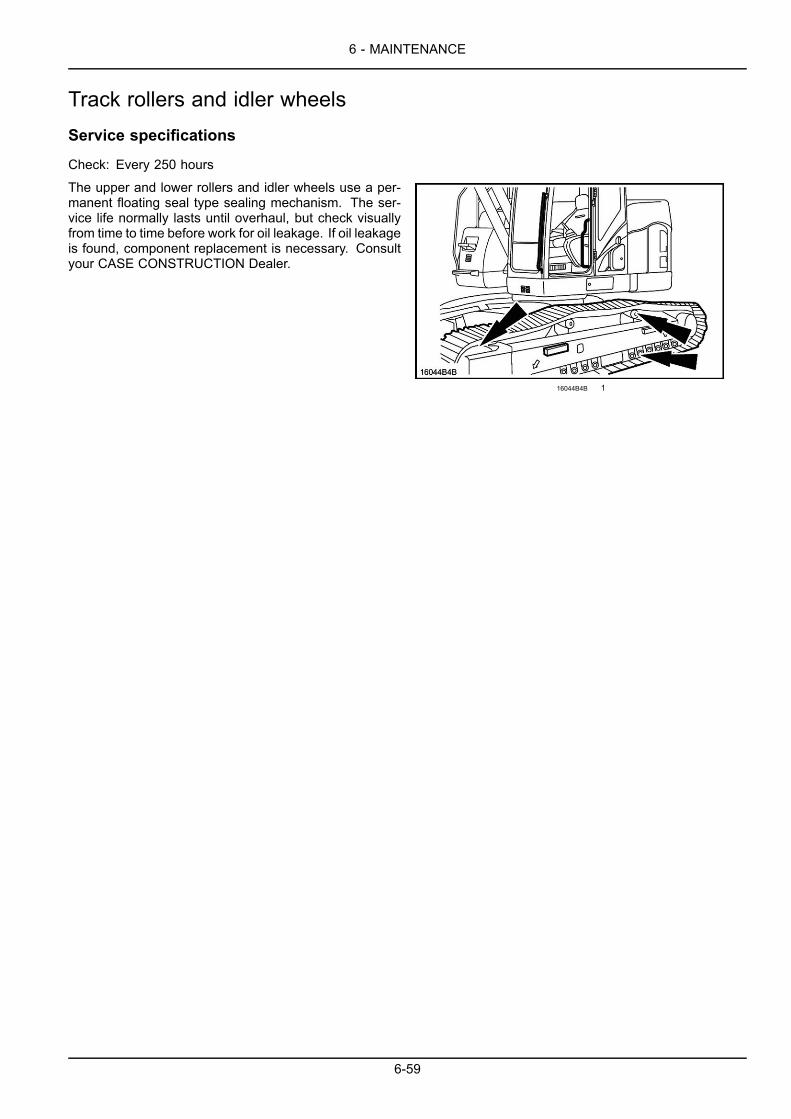
6 - MAINTENANCE
Track rollers and idler wheelsService specifications
Check: Every 250 hours
The upper and lower rollers and idler wheels use a per-manent floating seal type sealing mechanism. The ser-vice life normally lasts until overhaul, but check visuallyfrom time to time before work for oil leakage. If oil leakageis found, component replacement is necessary. Consultyour CASE CONSTRUCTION Dealer.
16044B4B 1
6-59

6 - MAINTENANCE
Radiator and coolersService specifications
Check for leakage: Every 10 hours or every dayClean: Every 500 hours
Cleaning
1. Stop the engine and remove the ignition key.
2. Open the rear left-hand side door and block it with thesupporting strut.
B7C7A5BB 1
3. Remove the one tach clip (1) and remove the protec-tion grilles (2).
WARNINGFlying debris!Compressed air can propel dirt, rust, etc. intothe air. Wear eye and face protection whenusing compressed air.Failure to comply could result in death or se-rious injury.
W0307A
4. Clean the radiators and the oil coolers:Dry dust: use compressed air.Mud: use a water jet.Greasy dust: use perchlorethylene.
ATTENTION: The use of trichlorethylene is strictly for-bidden.
BB3F4DEF 2
6-60
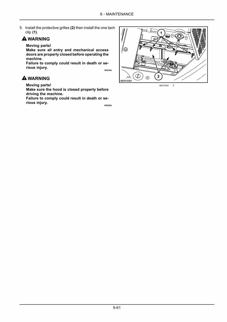
6 - MAINTENANCE
5. Install the protective grilles (2) then install the one tachclip (1).
WARNINGMoving parts!Make sure all entry and mechanical accessdoors are properly closed before operating themachine.Failure to comply could result in death or se-rious injury.
W0238A
WARNINGMoving parts!Make sure the hood is closed properly beforedriving the machine.Failure to comply could result in death or se-rious injury.
W0280A
BB3F4DEF 3
6-61

6 - MAINTENANCE
Fan and alternator drive beltService specifications
Visual check: Every 10 hours or every dayCheck belt tension: Every 250 hours
Checking the tensionNOTICE: If the engine runs with the belt slack, the beltcan slip in its housing and cause the engine to overheator the battery to receive insufficient charge.
DF0113DC 1
With engine shut down and the ignition key removed, useyour finger to exert a pressure of about 10 kg (22.0 lb) atthe centre of the belt.The tension slack should be between about 6 mm (0.2 in)and 8 mm (0.3 in).
NOTE: Check if there are any signs of wear damage tothe pulleys or the belt. Check carefully to ensure that thebelt is correctly positioned in the pulley grooves. If the beltis stretched, cracked or frayed, it must be replaced.
1IUTUH-003 2
Adjusting the tensionRemove the retaining screws (1) and (2). Use the adjust-ment screws (3) to move the alternator outwards until belttension is correct. Tighten the alternator mounting bolts(1) and (2).
B1D02065 3
6-62

6 - MAINTENANCE
Replacing the belt
If the belt breaks, the message "Alternator" is displayedon the message screens. Shut down the engine, removethe ignition key and change the belt.
Remove the retaining screws (1) and (2). Use the adjust-ment screw (3) to push the alternator inward.
Remove the worn belt.
Install a new belt.
Adjust the belt using the screw (3).
Retighten the retaining screws (1) and (2).
Run the engine for about an hour and then check the belttension again.
B1D02065 4
Adjustment of engine valve rocker clearancesService specifications
Check: Every 1000 hours
NOTE: Ask your CASE CONSTRUCTION Dealer to check this.
6-63
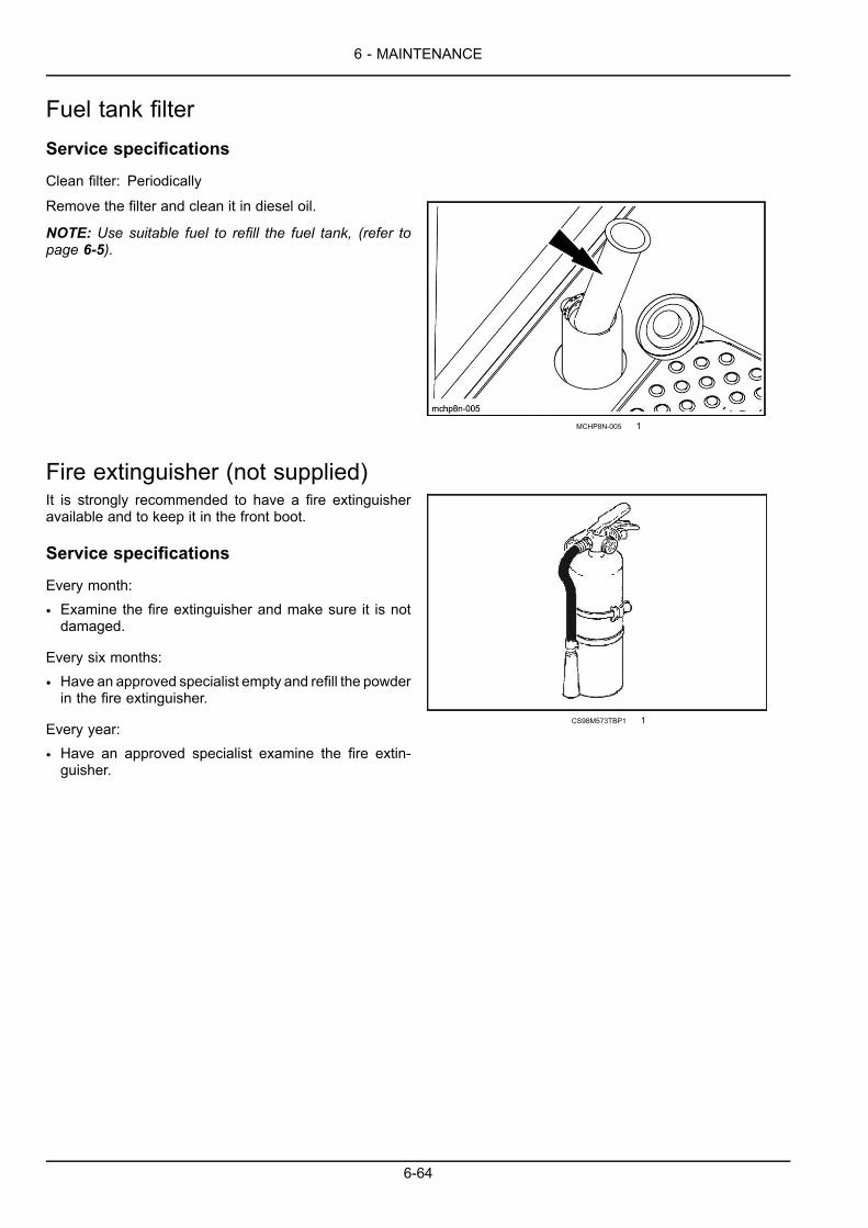
6 - MAINTENANCE
Fuel tank filterService specifications
Clean filter: Periodically
Remove the filter and clean it in diesel oil.
NOTE: Use suitable fuel to refill the fuel tank, (refer topage 6-5).
MCHP8N-005 1
Fire extinguisher (not supplied)It is strongly recommended to have a fire extinguisheravailable and to keep it in the front boot.
Service specifications
Every month:
• Examine the fire extinguisher and make sure it is notdamaged.
Every six months:
• Have an approved specialist empty and refill the powderin the fire extinguisher.
Every year:
• Have an approved specialist examine the fire extin-guisher.
CS98M573TBP1 1
6-64
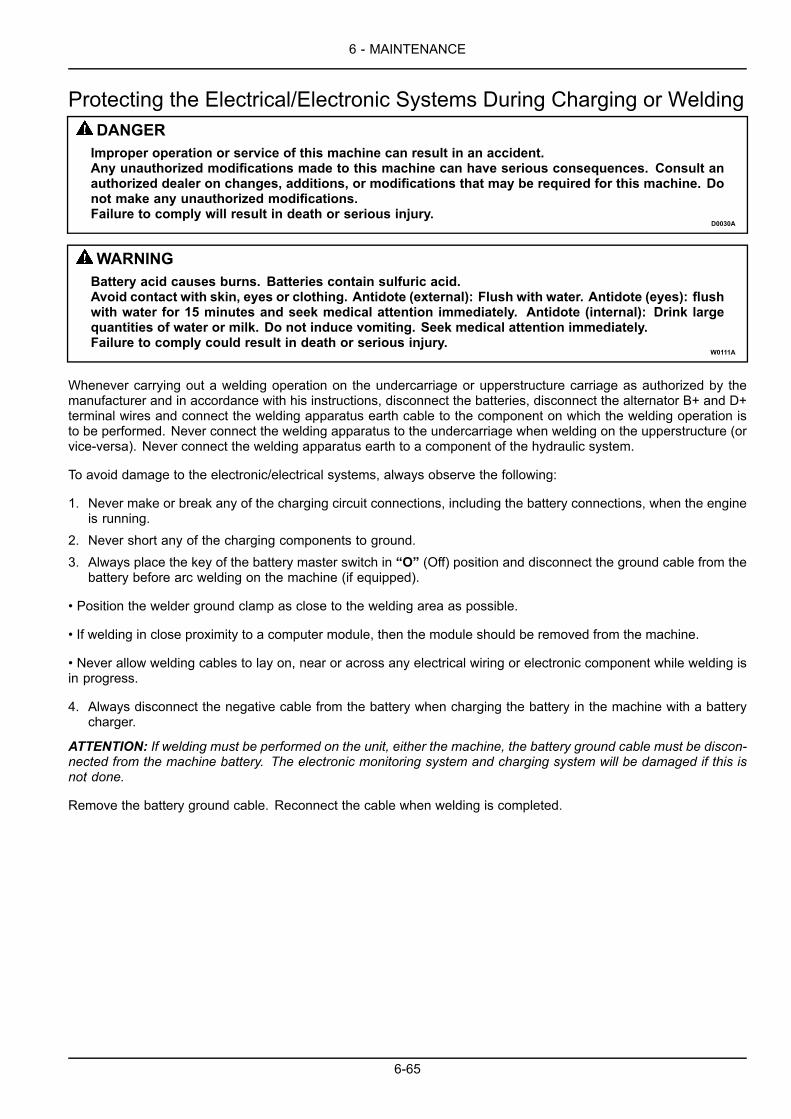
6 - MAINTENANCE
Protecting the Electrical/Electronic Systems During Charging or WeldingDANGERImproper operation or service of this machine can result in an accident.Any unauthorized modifications made to this machine can have serious consequences. Consult anauthorized dealer on changes, additions, or modifications that may be required for this machine. Donot make any unauthorized modifications.Failure to comply will result in death or serious injury.
D0030A
WARNINGBattery acid causes burns. Batteries contain sulfuric acid.Avoid contact with skin, eyes or clothing. Antidote (external): Flush with water. Antidote (eyes): flushwith water for 15 minutes and seek medical attention immediately. Antidote (internal): Drink largequantities of water or milk. Do not induce vomiting. Seek medical attention immediately.Failure to comply could result in death or serious injury.
W0111A
Whenever carrying out a welding operation on the undercarriage or upperstructure carriage as authorized by themanufacturer and in accordance with his instructions, disconnect the batteries, disconnect the alternator B+ and D+terminal wires and connect the welding apparatus earth cable to the component on which the welding operation isto be performed. Never connect the welding apparatus to the undercarriage when welding on the upperstructure (orvice-versa). Never connect the welding apparatus earth to a component of the hydraulic system.
To avoid damage to the electronic/electrical systems, always observe the following:
1. Never make or break any of the charging circuit connections, including the battery connections, when the engineis running.
2. Never short any of the charging components to ground.3. Always place the key of the battery master switch in “O” (Off) position and disconnect the ground cable from the
battery before arc welding on the machine (if equipped).
• Position the welder ground clamp as close to the welding area as possible.
• If welding in close proximity to a computer module, then the module should be removed from the machine.
• Never allow welding cables to lay on, near or across any electrical wiring or electronic component while welding isin progress.
4. Always disconnect the negative cable from the battery when charging the battery in the machine with a batterycharger.
ATTENTION: If welding must be performed on the unit, either the machine, the battery ground cable must be discon-nected from the machine battery. The electronic monitoring system and charging system will be damaged if this isnot done.
Remove the battery ground cable. Reconnect the cable when welding is completed.
6-65
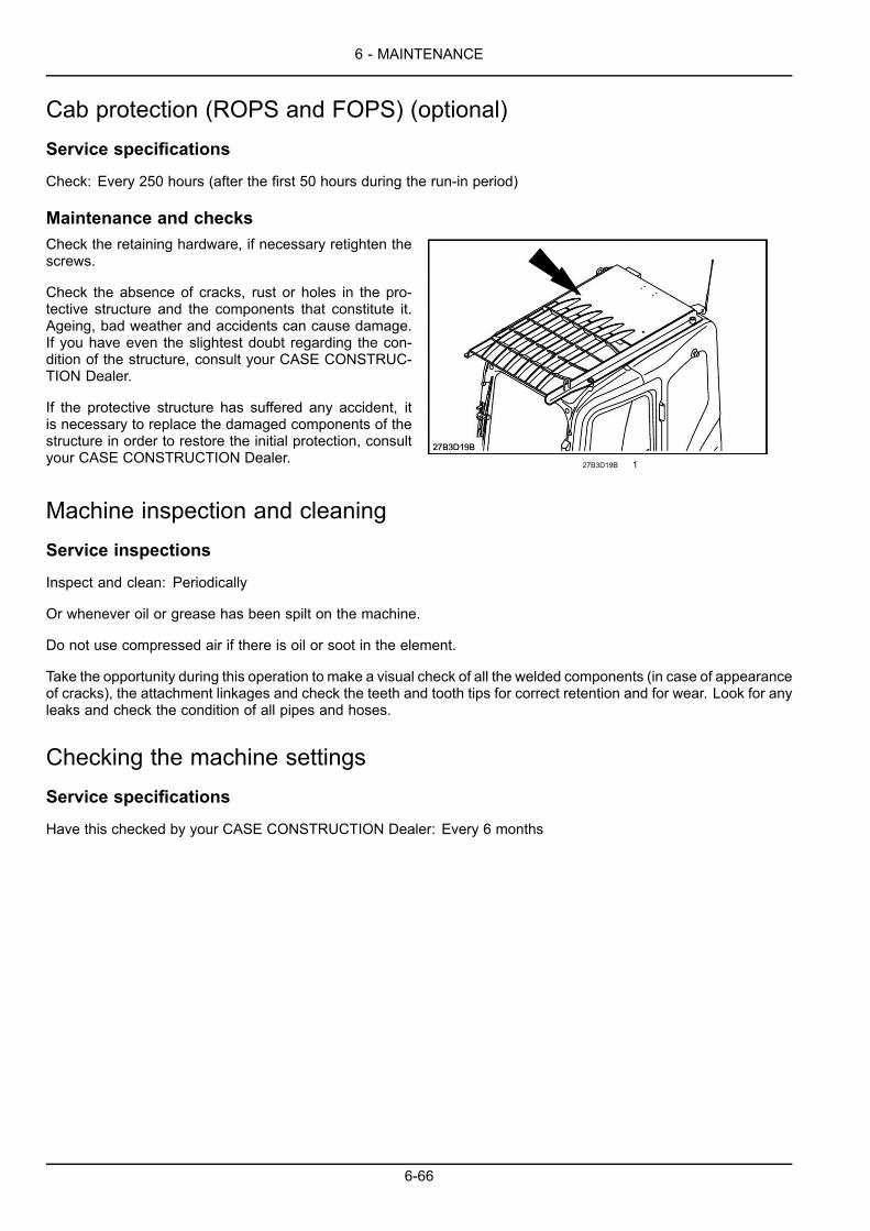
6 - MAINTENANCE
Cab protection (ROPS and FOPS) (optional)Service specifications
Check: Every 250 hours (after the first 50 hours during the run-in period)
Maintenance and checksCheck the retaining hardware, if necessary retighten thescrews.
Check the absence of cracks, rust or holes in the pro-tective structure and the components that constitute it.Ageing, bad weather and accidents can cause damage.If you have even the slightest doubt regarding the con-dition of the structure, consult your CASE CONSTRUC-TION Dealer.
If the protective structure has suffered any accident, itis necessary to replace the damaged components of thestructure in order to restore the initial protection, consultyour CASE CONSTRUCTION Dealer.
27B3D19B 1
Machine inspection and cleaningService inspections
Inspect and clean: Periodically
Or whenever oil or grease has been spilt on the machine.
Do not use compressed air if there is oil or soot in the element.
Take the opportunity during this operation to make a visual check of all the welded components (in case of appearanceof cracks), the attachment linkages and check the teeth and tooth tips for correct retention and for wear. Look for anyleaks and check the condition of all pipes and hoses.
Checking the machine settingsService specifications
Have this checked by your CASE CONSTRUCTION Dealer: Every 6 months
6-66
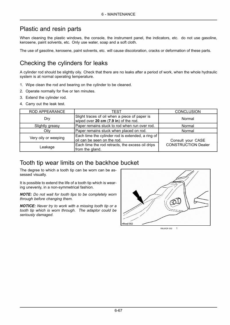
6 - MAINTENANCE
Plastic and resin partsWhen cleaning the plastic windows, the console, the instrument panel, the indicators, etc. do not use gasoline,kerosene, paint solvents, etc. Only use water, soap and a soft cloth.
The use of gasoline, kerosene, paint solvents, etc. will cause discoloration, cracks or deformation of these parts.
Checking the cylinders for leaksA cylinder rod should be slightly oily. Check that there are no leaks after a period of work, when the whole hydraulicsystem is at normal operating temperature.
1. Wipe clean the rod and bearing on the cylinder to be cleaned.2. Operate normally for five or ten minutes.3. Extend the cylinder rod.4. Carry out the leak test.
ROD APPEARANCE TEST CONCLUSION
Dry Slight traces of oil when a piece of paper iswiped over 20 cm (7.9 in) of the rod. Normal
Slightly greasy Paper remains stuck to rod when run over rod. NormalOily Paper remains stuck when placed on rod. Normal
Very oily or weeping Each time the cylinder rod is extended, a ring ofoil can be seen on the rod.
Leakage Each time the rod retracts, the excess oil dripsfrom the gland.
Consult your CASECONSTRUCTION Dealer
Tooth tip wear limits on the backhoe bucketThe degree to which a tooth tip can be worn can be as-sessed visually.
It is possible to extend the life of a tooth tip which is wear-ing unevenly, in a non-symmetrical fashion.
NOTE: Do not wait for tooth tips to be completely wornthrough before changing them.
NOTICE: Never try to work with a missing tooth tip or atooth tip which is worn through. The adaptor could beseriously damaged.
R8LWQF-002 1
6-67

6 - MAINTENANCE
Replacing a tooth on a backhoe bucketRemoval
1. Place the bucket a few centimetres above the ground.Stop the engine and remove the ignition key.
2. Turn the locking stud 90 ° in the clockwise directionusing a hexagonal wrench.
3. Remove the locking pin then remove the worn toothtip.
C319Z9-012 1
Installation
1. Clean the mating surface on the adaptor.
2. Engage a new tooth tip right up to the stop and hold itin position.
3. Engage the locking pin until it is flush with the tooth tip.
TX8XZ1-020 2
4. Turn the locking stud 90 ° in the anti-clockwise direc-tion using a hexagonal wrench.
NOTE: When replacing a tooth tip, it is advisable to re-place the locking pin at the same time.
TX8XZ1-021 3
6-68
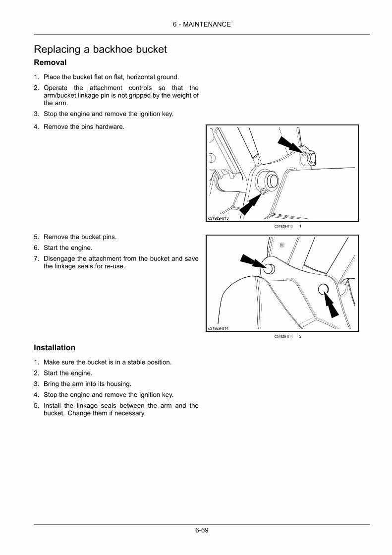
6 - MAINTENANCE
Replacing a backhoe bucketRemoval
1. Place the bucket flat on flat, horizontal ground.2. Operate the attachment controls so that the
arm/bucket linkage pin is not gripped by the weight ofthe arm.
3. Stop the engine and remove the ignition key.
4. Remove the pins hardware.
C319Z9-013 1
5. Remove the bucket pins.6. Start the engine.7. Disengage the attachment from the bucket and save
the linkage seals for re-use.
C319Z9-014 2
Installation
1. Make sure the bucket is in a stable position.2. Start the engine.3. Bring the arm into its housing.4. Stop the engine and remove the ignition key.5. Install the linkage seals between the arm and the
bucket. Change them if necessary.
6-69
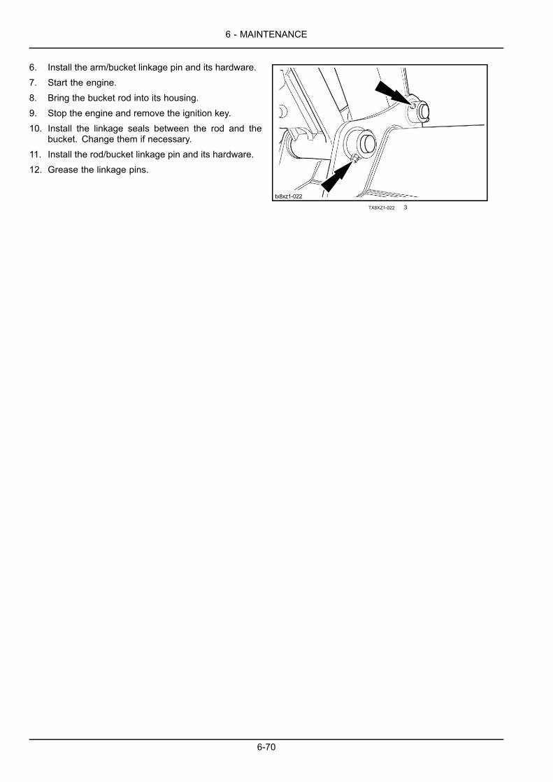
6 - MAINTENANCE
6. Install the arm/bucket linkage pin and its hardware.7. Start the engine.8. Bring the bucket rod into its housing.9. Stop the engine and remove the ignition key.10. Install the linkage seals between the rod and the
bucket. Change them if necessary.11. Install the rod/bucket linkage pin and its hardware.12. Grease the linkage pins.
TX8XZ1-022 3
6-70

6 - MAINTENANCE
Checking the opening of the quick coupler locking hook (optional)WARNINGImproper operation or service of this machine can result in an accident.If you do not understand a maintenance procedure, or doubt your ability to perform a maintenanceprocedure correctly, see your authorized dealer.Failure to comply could result in death or serious injury.
W0157A
Service specifications
Check: Weekly and each time the quick coupler is installed
ATTENTION: It is imperative to carry out this check once a week and each time the quick coupler is installed.
1. Place the switch (1) in unlocking position. The audiblealarm device will sound. (Refer to page 3-56).
6B4353DF 1
2. Operate the bucket control to retract the cylinder rodcompletely and maintain the hydraulic pressure so thelatching hook retracts and comes upagainst the lock-ing bar.
MCHP8N-007 2
6-71
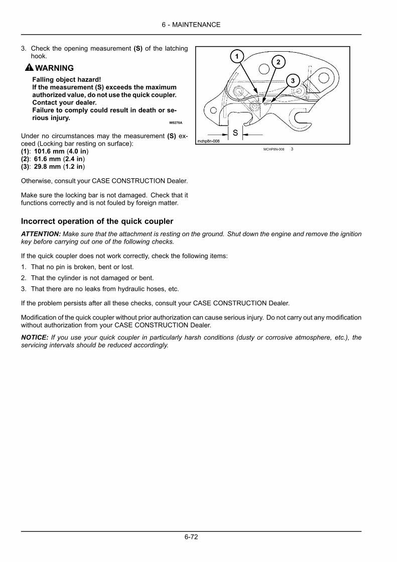
6 - MAINTENANCE
3. Check the opening measurement (S) of the latchinghook.
WARNINGFalling object hazard!If the measurement (S) exceeds the maximumauthorized value, do not use the quick coupler.Contact your dealer.Failure to comply could result in death or se-rious injury.
W0270A
Under no circumstances may the measurement (S) ex-ceed (Locking bar resting on surface):(1): 101.6 mm (4.0 in)(2): 61.6 mm (2.4 in)(3): 29.8 mm (1.2 in)
Otherwise, consult your CASE CONSTRUCTION Dealer.
Make sure the locking bar is not damaged. Check that itfunctions correctly and is not fouled by foreign matter.
MCHP8N-008 3
Incorrect operation of the quick couplerATTENTION: Make sure that the attachment is resting on the ground. Shut down the engine and remove the ignitionkey before carrying out one of the following checks.
If the quick coupler does not work correctly, check the following items:1. That no pin is broken, bent or lost.2. That the cylinder is not damaged or bent.3. That there are no leaks from hydraulic hoses, etc.
If the problem persists after all these checks, consult your CASE CONSTRUCTION Dealer.
Modification of the quick coupler without prior authorization can cause serious injury. Do not carry out any modificationwithout authorization from your CASE CONSTRUCTION Dealer.
NOTICE: If you use your quick coupler in particularly harsh conditions (dusty or corrosive atmosphere, etc.), theservicing intervals should be reduced accordingly.
6-72
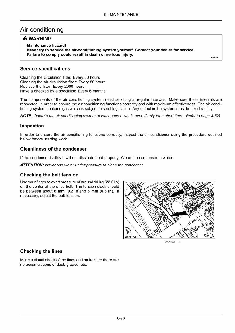
6 - MAINTENANCE
Air conditioningWARNINGMaintenance hazard!Never try to service the air-conditioning system yourself. Contact your dealer for service.Failure to comply could result in death or serious injury.
W0268A
Service specifications
Cleaning the circulation filter: Every 50 hoursCleaning the air circulation filter: Every 50 hoursReplace the filter: Every 2000 hoursHave a checked by a specialist: Every 6 months
The components of the air conditioning system need servicing at regular intervals. Make sure these intervals arerespected, in order to ensure the air conditioning functions correctly and with maximum effectiveness. The air condi-tioning system contains gas which is subject to strict legislation. Any defect in the system must be fixed rapidly.
NOTE: Operate the air conditioning system at least once a week, even if only for a short time. (Refer to page 3-52).
Inspection
In order to ensure the air conditioning functions correctly, inspect the air conditioner using the procedure outlinedbelow before starting work.
Cleanliness of the condenser
If the condenser is dirty it will not dissipate heat properly. Clean the condenser in water.
ATTENTION: Never use water under pressure to clean the condenser.
Checking the belt tensionUse your finger to exert pressure of around 10 kg (22.0 lb)on the center of the drive belt. The tension slack shouldbe between about 6 mm (0.2 in)and 8 mm (0.3 in). Ifnecessary, adjust the belt tension.
305AFFA2 1
Checking the lines
Make a visual check of the lines and make sure there areno accumulations of dust, grease, etc.
6-73
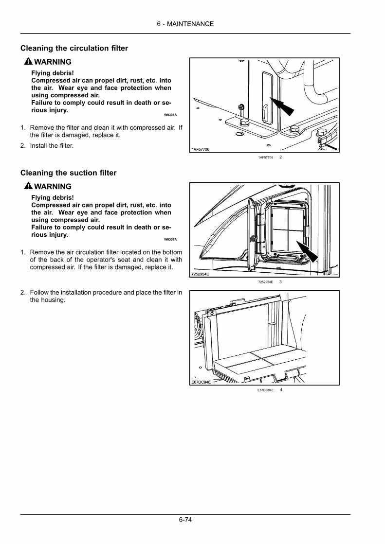
6 - MAINTENANCE
Cleaning the circulation filter
WARNINGFlying debris!Compressed air can propel dirt, rust, etc. intothe air. Wear eye and face protection whenusing compressed air.Failure to comply could result in death or se-rious injury.
W0307A
1. Remove the filter and clean it with compressed air. Ifthe filter is damaged, replace it.
2. Install the filter.1AF57706 2
Cleaning the suction filter
WARNINGFlying debris!Compressed air can propel dirt, rust, etc. intothe air. Wear eye and face protection whenusing compressed air.Failure to comply could result in death or se-rious injury.
W0307A
1. Remove the air circulation filter located on the bottomof the back of the operator's seat and clean it withcompressed air. If the filter is damaged, replace it.
7252954E 3
2. Follow the installation procedure and place the filter inthe housing.
E67DC94E 4
6-74
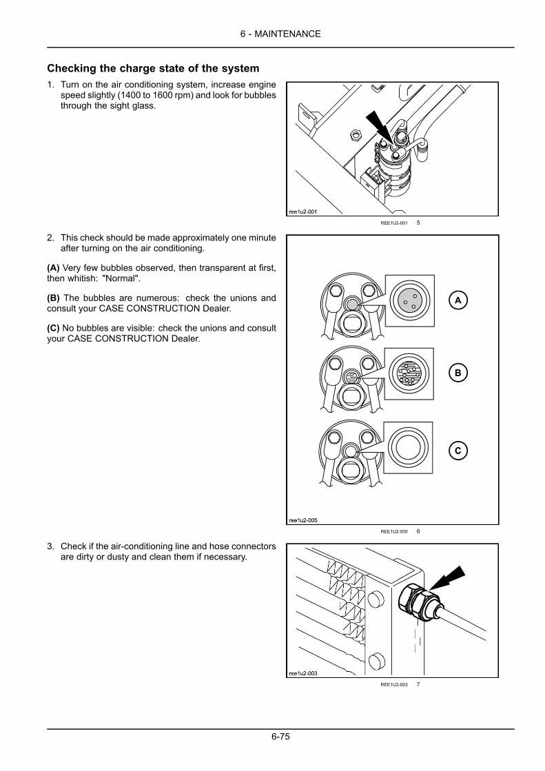
6 - MAINTENANCE
Checking the charge state of the system1. Turn on the air conditioning system, increase engine
speed slightly (1400 to 1600 rpm) and look for bubblesthrough the sight glass.
REE1U2-001 5
2. This check should be made approximately one minuteafter turning on the air conditioning.
(A) Very few bubbles observed, then transparent at first,then whitish: "Normal".
(B) The bubbles are numerous: check the unions andconsult your CASE CONSTRUCTION Dealer.
(C) No bubbles are visible: check the unions and consultyour CASE CONSTRUCTION Dealer.
REE1U2-005 6
3. Check if the air-conditioning line and hose connectorsare dirty or dusty and clean them if necessary.
REE1U2-003 7
6-75
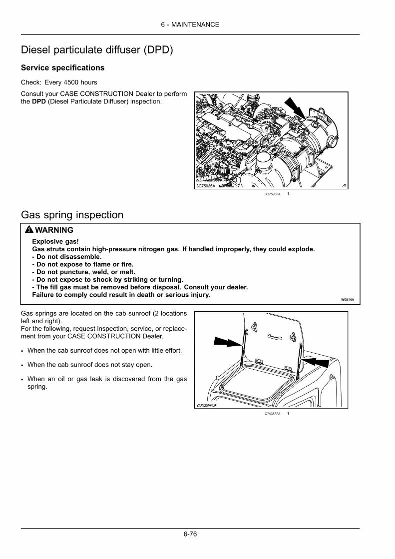
6 - MAINTENANCE
Diesel particulate diffuser (DPD)Service specifications
Check: Every 4500 hours
Consult your CASE CONSTRUCTION Dealer to performthe DPD (Diesel Particulate Diffuser) inspection.
3C75936A 1
Gas spring inspectionWARNINGExplosive gas!Gas struts contain high-pressure nitrogen gas. If handled improperly, they could explode.- Do not disassemble.- Do not expose to flame or fire.- Do not puncture, weld, or melt.- Do not expose to shock by striking or turning.- The fill gas must be removed before disposal. Consult your dealer.Failure to comply could result in death or serious injury.
W0914A
Gas springs are located on the cab sunroof (2 locationsleft and right).For the following, request inspection, service, or replace-ment from your CASE CONSTRUCTION Dealer.
• When the cab sunroof does not open with little effort.
• When the cab sunroof does not stay open.
• When an oil or gas leak is discovered from the gasspring.
C7438FA5 1
6-76
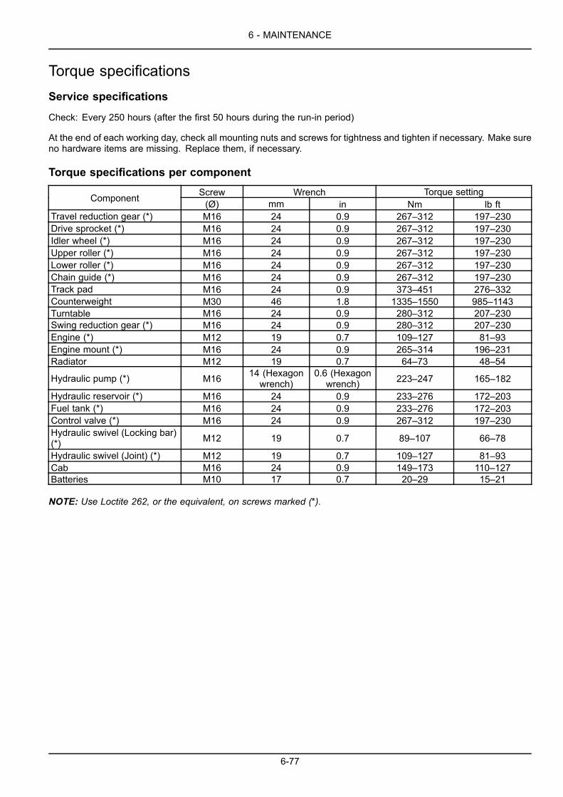
6 - MAINTENANCE
Torque specificationsService specifications
Check: Every 250 hours (after the first 50 hours during the run-in period)
At the end of each working day, check all mounting nuts and screws for tightness and tighten if necessary. Make sureno hardware items are missing. Replace them, if necessary.
Torque specifications per component
Screw Wrench Torque settingComponent (Ø) mm in Nm lb ftTravel reduction gear (*) M16 24 0.9 267–312 197–230Drive sprocket (*) M16 24 0.9 267–312 197–230Idler wheel (*) M16 24 0.9 267–312 197–230Upper roller (*) M16 24 0.9 267–312 197–230Lower roller (*) M16 24 0.9 267–312 197–230Chain guide (*) M16 24 0.9 267–312 197–230Track pad M16 24 0.9 373–451 276–332Counterweight M30 46 1.8 1335–1550 985–1143Turntable M16 24 0.9 280–312 207–230Swing reduction gear (*) M16 24 0.9 280–312 207–230Engine (*) M12 19 0.7 109–127 81–93Engine mount (*) M16 24 0.9 265–314 196–231Radiator M12 19 0.7 64–73 48–54
Hydraulic pump (*) M16 14 (Hexagonwrench)
0.6 (Hexagonwrench) 223–247 165–182
Hydraulic reservoir (*) M16 24 0.9 233–276 172–203Fuel tank (*) M16 24 0.9 233–276 172–203Control valve (*) M16 24 0.9 267–312 197–230Hydraulic swivel (Locking bar)(*) M12 19 0.7 89–107 66–78
Hydraulic swivel (Joint) (*) M12 19 0.7 109–127 81–93Cab M16 24 0.9 149–173 110–127Batteries M10 17 0.7 20–29 15–21
NOTE: Use Loctite 262, or the equivalent, on screws marked (*).
6-77
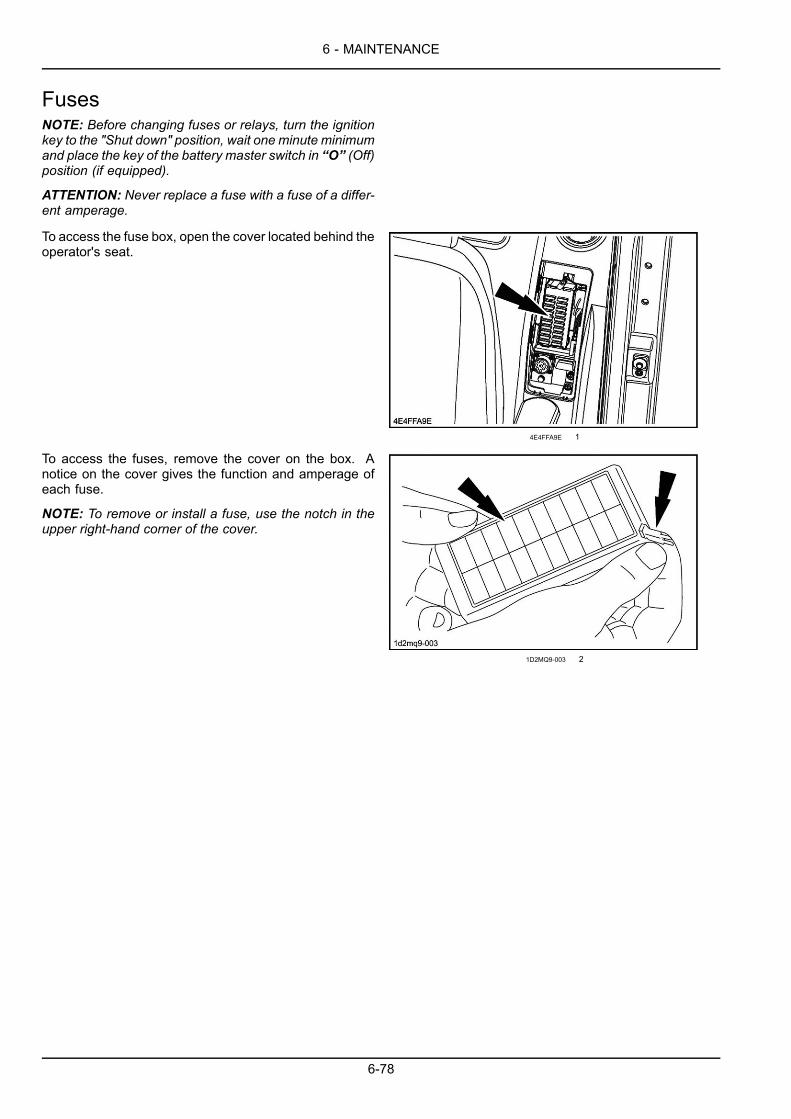
6 - MAINTENANCE
FusesNOTE: Before changing fuses or relays, turn the ignitionkey to the "Shut down" position, wait one minute minimumand place the key of the battery master switch in “O” (Off)position (if equipped).
ATTENTION: Never replace a fuse with a fuse of a differ-ent amperage.
To access the fuse box, open the cover located behind theoperator's seat.
4E4FFA9E 1
To access the fuses, remove the cover on the box. Anotice on the cover gives the function and amperage ofeach fuse.
NOTE: To remove or install a fuse, use the notch in theupper right-hand corner of the cover.
1D2MQ9-003 2
6-78

6 - MAINTENANCE
Fuse functions(1) Key switch: 15 A
(2) Engine computer: 20 A
(3) Spare: 10 A
(4) Back-up (radio, room lamp): 10 A
(5) Function cancellation lever: 10 A
(6) Solenoid: 10 A
(7) Horn: 10 A
(8) Cab top light: 15 A
(9) Boom, house light: 15 A
(10) Spare: 15 A
(11) Wiper, washer: 15 A
(12) Travel alarm, rotary light: 10 A
(13) Cigar lighter, seat suspension: 10 A
(14) DC converter: 10 A
(15) Air conditioner unit: 5 A
(16) Air conditioner blower motor: 15 A
(17) Air conditioner compressor: 5 A
(18) Spare: 10 A
(19) Feed pump: 15 A
(20) Option line solenoid: 10 A
8FPEPL-002 3
NOTE: A fuse of 5 A , located on the rear of the operator’s seat, is used for GPS system (optional).
6-79

6 - MAINTENANCE
BatteriesWARNINGImproper operation or service of this machine can result in an accident.Before working on any component(s) of the electrical circuit, put the ignition key in the off (shut down)position. When disconnecting batteries, always disconnect the negative (-) cable first. When recon-necting batteries, always connect the negative (-) cable last.Failure to comply could result in death or serious injury.
W0943A
WARNINGBattery acid causes burns. Batteries contain sulfuric acid.Avoid contact with skin, eyes or clothing. Antidote (external): Flush with water. Antidote (eyes): flushwith water for 15 minutes and seek medical attention immediately. Antidote (internal): Drink largequantities of water or milk. Do not induce vomiting. Seek medical attention immediately.Failure to comply could result in death or serious injury.
W0111A
WARNINGBattery gas can explode!To prevent an explosion: 1. Always disconnect the negative (-) battery cable first. 2. Always connectthe negative (-) battery cable last. 3. Do not short circuit the battery posts with metal objects. 4. Donot weld, grind, or smoke near a battery.Failure to comply could result in death or serious injury.
W0011A
WARNINGExplosive gas!Batteries emit explosive hydrogen gas and other fumes while charging. Ventilate the charging area.Keep the battery away from sparks, open flames, and other ignition sources. Never charge a frozenbattery.Failure to comply could result in death or serious injury.
W0005A
Service specifications
Checking the charge state: Every 250 hoursElectrolyte level check: Every 250 hours
NOTE: When starting the machine with booster batteries, see "Connecting booster batteries".
6-80
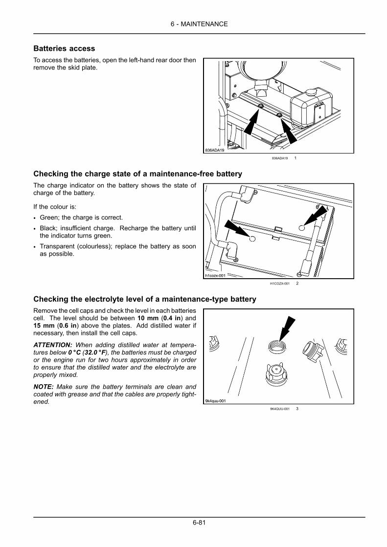
6 - MAINTENANCE
Batteries accessTo access the batteries, open the left-hand rear door thenremove the skid plate.
836ADA19 1
Checking the charge state of a maintenance-free batteryThe charge indicator on the battery shows the state ofcharge of the battery.
If the colour is:
• Green; the charge is correct.
• Black; insufficient charge. Recharge the battery untilthe indicator turns green.
• Transparent (colourless); replace the battery as soonas possible.
H1COZX-001 2
Checking the electrolyte level of a maintenance-type batteryRemove the cell caps and check the level in each batteriescell. The level should be between 10 mm (0.4 in) and15 mm (0.6 in) above the plates. Add distilled water ifnecessary, then install the cell caps.
ATTENTION: When adding distilled water at tempera-tures below 0 °C (32.0 °F), the batteries must be chargedor the engine run for two hours approximately in orderto ensure that the distilled water and the electrolyte areproperly mixed.
NOTE: Make sure the battery terminals are clean andcoated with grease and that the cables are properly tight-ened.
9K4QUU-001 3
6-81

6 - MAINTENANCE
Changing a batteryWARNINGElectrical shock hazard!Do not reverse battery terminals. Connect positive cable ends to positive terminals (+) and negativecable ends to negative terminals (-).Failure to comply could result in death or serious injury.
W0262A
WARNINGHazard to bystanders!Always store batteries in a safe location. Keep out of reach of children and other unauthorized per-sons.Failure to comply could result in death or serious injury.
W0224A
WARNINGBattery acid causes burns. Batteries contain sulfuric acid.Battery electrolyte contains sulfuric acid. Contact with skin and eyes could result in severe irritationand burns. Always wear splash-proof goggles and protective clothing (gloves and aprons). Washhands after handling.Failure to comply could result in death or serious injury.
W0120A
1. Place the key of the battery master switch in “O” (Off)position (if equipped).
2. Remove the terminal protection caps, disconnect ca-bles (negative terminals) and then cables (positive ter-minals). Remove the anti-sulphate pellets and the bat-tery clips.
3. Install a new battery, put back its clips.4. Clean the cables and battery terminals and coat them
with grease.5. Install new anti-sulphate pellets, reconnect positive
cable ends to positive terminals and then negative ca-ble ends to negative terminals. Install the terminal pro-tection caps.
6. Install the skid plate.7. Place the key of the battery master switch in “I” (On)
position (if equipped).
7B22AE44 4
6-82
6 - MAINTENANCE
Connecting booster batteriesWARNINGImproper operation or service of this machine can result in an accident.An error connecting auxiliary starting cables or short-circuiting battery terminals can cause an acci-dent. Connect auxiliary starting cables as instructed in this manual.Failure to comply could result in death or serious injury.
W0263A
Make sure that the booster battery voltage corresponds to the voltage system of the machine (24 volts).
1. Place the key of the battery master switch in “O” (Off) position (if equipped).2. Remove the terminal sleeves.3. Connect the positive (+) cable to the positive (+) terminal on the first machine battery.4. Connect the negative (-) cable to the negative (-) terminal on the second machine battery.5. Place the key of the battery master switch in “I” (On) position (if equipped).6. Start the engine.7. Remove the booster battery negative (-) cable and then the positive (+) cable.8. Install the terminal sleeves.
6-83
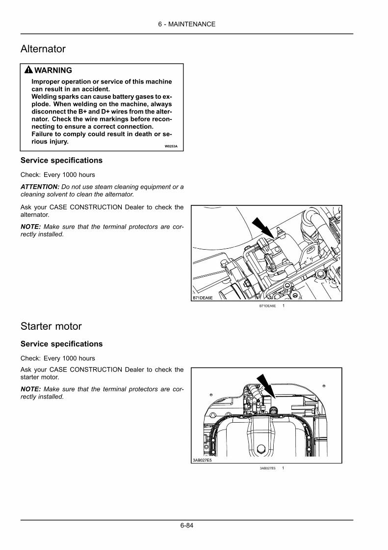
6 - MAINTENANCE
Alternator
WARNINGImproper operation or service of this machinecan result in an accident.Welding sparks can cause battery gases to ex-plode. When welding on the machine, alwaysdisconnect the B+ and D+ wires from the alter-nator. Check the wire markings before recon-necting to ensure a correct connection.Failure to comply could result in death or se-rious injury.
W0253A
Service specifications
Check: Every 1000 hours
ATTENTION: Do not use steam cleaning equipment or acleaning solvent to clean the alternator.
Ask your CASE CONSTRUCTION Dealer to check thealternator.
NOTE: Make sure that the terminal protectors are cor-rectly installed.
B71DEA6E 1
Starter motorService specifications
Check: Every 1000 hours
Ask your CASE CONSTRUCTION Dealer to check thestarter motor.
NOTE: Make sure that the terminal protectors are cor-rectly installed.
3AB027E5 1
6-84

6 - MAINTENANCE
Bulb replacementOperator’s compartment lighting1. Remove the cover.2. Remove the bulb and install a bulb of the same
wattage ( 10 W).3. Install the cover.
8YHY9K-001 1
Attachment working light1. Remove the 4 retaining screws.
WNNEYW-001 2
2. Tilt the working light and disconnect the plug.
WNNEYW-002 3
6-85

6 - MAINTENANCE
3. Pull the clip outward, remove the bulb and install a bulbof the same wattage ( 70 W).
ATTENTION: Never put your fingers on a tungsten iodidebulb.
4. Install the clip and reconnect the plug.5. Put the working light back into position and install the
mounting screws.
WNNEYW-003 4
Upperstructure and cab headlight1. Disconnect the plug.
PV5ETN-003 5
2. Remove the four screws and tilt the headlight.
PV5ETN-004 6
3. Pull the clip outward, remove the bulb and install a bulbof the same wattage ( 70 W).
ATTENTION: Never put your fingers on a tungsten iodidebulb.
4. Install the clip, put the headlamp back in position andinstall the screws and the plug.
PV5ETN-005 7
6-86
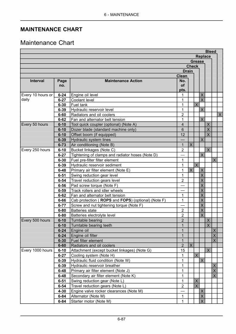
6 - MAINTENANCE
MAINTENANCE CHART
Maintenance ChartBleed
ReplaceGrease
CheckDrain
CleanInterval Page
no.Maintenance Action No.
ofpts.
6-24 Engine oil level 1 X6-27 Coolant level 1 X6-30 Fuel tank 1 X6-39 Hydraulic reservoir level 1 X6-60 Radiators and oil coolers 2 X
Every 10 hours ordaily
6-62 Fan and alternator belt tension 1 X6-10 Tool quick coupler (optional) (Note A) 4 X6-10 Dozer blade (standard machine only) 6 X6-10 Offset boom (if equipped) 12 X6-39 Hydraulic system lines — X
Every 50 hours
6-73 Air conditioning (Note B) 1 X6-10 Bucket linkages (Note C) 2 X6-27 Tightening of clamps and radiator hoses (Note D) — X6-30 Fuel pre-filter filter element 1 X6-39 Hydraulic reservoir sediment 1 X6-48 Primary air filter element (Note E) 1 X X6-51 Swing reduction gear level 1 X6-54 Travel reduction gears level 2 X6-56 Pad screw torque (Note F) — X6-59 Track rollers and idler wheels — X6-62 Fan and alternator belt tension 1 X6-66 Cab protection ( ROPS and FOPS) (optional) (Note F) 1 X6-77 Screw and nut tightening torque (Note F) — X6-80 Batteries state 2 X
Every 250 hours
6-80 Batteries electrolyte level 2 X6-10 Turntable bearing 2 X6-10 Turntable bearing teeth 1 X6-24 Engine oil 1 X6-24 Engine oil filter 1 X6-30 Fuel filter element 1 X
Every 500 hours
6-60 Radiators and oil coolers 2 X6-10 Attachment (except bucket linkages) (Note G) 15 X6-27 Cooling system (Note H) 1 X6-39 Hydraulic fluid condition (Note W) 1 X6-39 Hydraulic reservoir breather 1 X6-48 Primary air filter element (Note J) 1 X6-48 Secondary air filter element (Note K) 1 X6-51 Swing reduction gear (Note L) 1 X6-54 Travel reduction gears (Note L) 2 X4-30 Engine valve rocker clearances (Note M) — X6-84 Alternator (Note M) 1 X
Every 1000 hours
6-84 Starter motor (Note M) 1 X
6-87
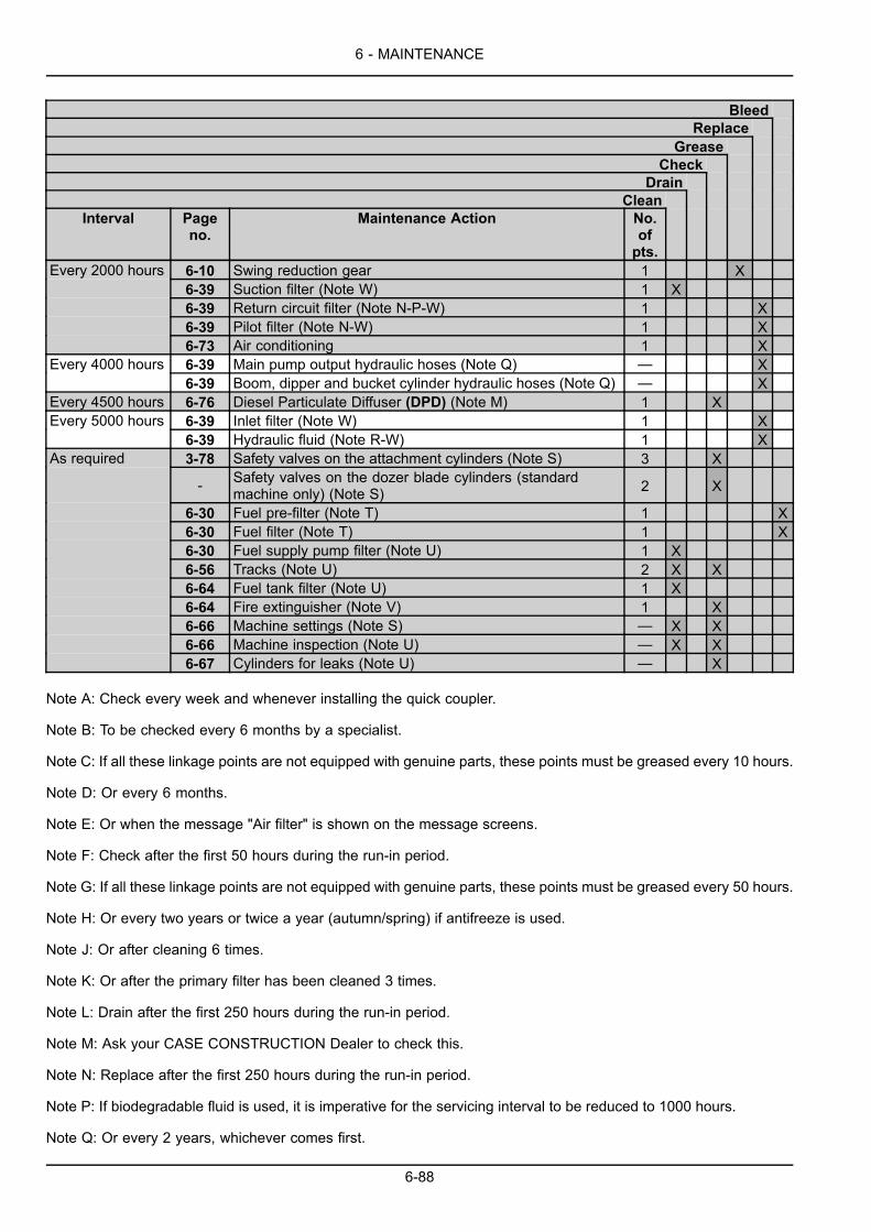
6 - MAINTENANCE
BleedReplace
GreaseCheck
DrainClean
Interval Pageno.
Maintenance Action No.ofpts.
6-10 Swing reduction gear 1 X6-39 Suction filter (Note W) 1 X6-39 Return circuit filter (Note N-P-W) 1 X6-39 Pilot filter (Note N-W) 1 X
Every 2000 hours
6-73 Air conditioning 1 X6-39 Main pump output hydraulic hoses (Note Q) — XEvery 4000 hours6-39 Boom, dipper and bucket cylinder hydraulic hoses (Note Q) — X
Every 4500 hours 6-76 Diesel Particulate Diffuser (DPD) (Note M) 1 X6-39 Inlet filter (Note W) 1 XEvery 5000 hours6-39 Hydraulic fluid (Note R-W) 1 X3-78 Safety valves on the attachment cylinders (Note S) 3 X
- Safety valves on the dozer blade cylinders (standardmachine only) (Note S) 2 X
6-30 Fuel pre-filter (Note T) 1 X6-30 Fuel filter (Note T) 1 X6-30 Fuel supply pump filter (Note U) 1 X6-56 Tracks (Note U) 2 X X6-64 Fuel tank filter (Note U) 1 X6-64 Fire extinguisher (Note V) 1 X6-66 Machine settings (Note S) — X X6-66 Machine inspection (Note U) — X X
As required
6-67 Cylinders for leaks (Note U) — X
Note A: Check every week and whenever installing the quick coupler.
Note B: To be checked every 6 months by a specialist.
Note C: If all these linkage points are not equipped with genuine parts, these points must be greased every 10 hours.
Note D: Or every 6 months.
Note E: Or when the message "Air filter" is shown on the message screens.
Note F: Check after the first 50 hours during the run-in period.
Note G: If all these linkage points are not equipped with genuine parts, these points must be greased every 50 hours.
Note H: Or every two years or twice a year (autumn/spring) if antifreeze is used.
Note J: Or after cleaning 6 times.
Note K: Or after the primary filter has been cleaned 3 times.
Note L: Drain after the first 250 hours during the run-in period.
Note M: Ask your CASE CONSTRUCTION Dealer to check this.
Note N: Replace after the first 250 hours during the run-in period.
Note P: If biodegradable fluid is used, it is imperative for the servicing interval to be reduced to 1000 hours.
Note Q: Or every 2 years, whichever comes first.
6-88

6 - MAINTENANCE
Note R: If biodegradable fluid is used, it is imperative for the servicing interval to be reduced to 2000 hours.
Note S: Have this checked every 6 months by your CASE CONSTRUCTION Dealer.
Note T: When the float reaches the level line (A).
Note U: Periodically.
Note V: Check once a month and have it checked every 6 months by a specialist.
Note W: If the machine is equipped with a hydraulic breaker, it is imperative that the servicing intervals are reduced,refer to page 6-39.
NOTE: Once the machine has completed 500 hours (then 1000 hours, 1500 hours, etc.) the message "Service due"will appear on the screen (refer to page 3-19) by way of a reminder that service work is due. (It is possible to increasethis lapse of time. Consult your CASE CONSTRUCTION Dealer).
6-89
6 - MAINTENANCE
STORAGE
Preparing for storageThe following procedure applies when the machine is to be stored for a month or more. Store the machine on flat,level ground, inside a building or, if not possible, outside and covered with a tarpaulin. Before storing the machine,carry out the following operations:
1. Clean the machine.
2. Make sure that the machine has no damaged ormissing parts. Replace them if necessary.
3. Retract the cylinder rods as for as possible andlower the boom until the attachment is resting on theground. Lower the dozer blade (if equipped) to theground.
4. Grease the machine thoroughly. The exposed sur-faces of the cylinder rods should be greased or cov-ered with a protective film. Consult your CASE CON-STRUCTION Dealer.
NOTE: When the machine resumes service, the film willdisappear automatically.
5. While the engine is still warm, drain the oil sump,replace the oil filter and fill with specified oil. Checkthe oil level and add more if necessary.
6. Clean or replace the air filter element.
7. Check the level of coolant solution. If the machineis within 100 hours of the next scheduled coolantchange, change the coolant now.
8. Remove the batteries, clean the battery housingsand make sure not to leave any traces of acid. Storethe batteries safely in a cool and dry location, wherethe temperature is higher than 0 °C (32.0 °F) or dis-connect the cable from the negative (-) terminal.
9. Paint any areas where the paintwork is not good.
10. Plug the air filter inlet and the exhaust pipe.
11. Remove the ignition key and place a "Do not operate"label on the right-hand control arm and then place thefunction cancellation lever in the raised position.
12. Lock the hoods, side doors and the cab door.
6-90
6 - MAINTENANCE
Periodic checksWARNINGInhalation hazard! Risk to operators and bystanders.Avoid running the engine in confined areas. Make sure there is adequate ventilation at all times.Failure to comply could result in death or serious injury.
W0156A
Every month, check:
1. The battery charge and recharge the batteries if re-quired.
2. The levels and top up if necessary.
3. The condition of all lines, connectors and clamps(rust). Grease if necessary.
4. The condition of the paintwork. Apply a coat of anti-rust treatment where necessary.
5. Unplug the air filter inlet and the exhaust pipe.
6. Run the engine at low speed following the startingup procedure and operate the attachment, swing andtravel controls.
7. The grease on the cylinder rods.
8. Plug the air filter inlet and the exhaust pipe.
6-91
6 - MAINTENANCE
Starting up after storageWARNINGUnexpected machine movement!Before starting the engine, make sure all controls are in the neutral position.Failure to comply could result in death or serious injury.
W0311A
WARNINGInhalation hazard! Risk to operators and bystanders.Avoid running the engine in confined areas. Make sure there is adequate ventilation at all times.Failure to comply could result in death or serious injury.
W0156A
1. Drain the fuel tank, the pre-filter and the fuel filter,replace the filter elements if necessary.
2. Fill the fuel tank with suitable fuel. (Refer to page6-5).
3. Install the batteries or reconnect the cable to the neg-ative (-) terminal.
4. Grease the machine thoroughly.
5. Check the condition of the fan drive belt and replaceit if necessary.
6. Check the condition of the air conditioning drive beltand replace it if necessary.
7. Check the cooling system level and addmore coolantif necessary.
8. Check the engine oil level and add more oil if neces-sary.
9. Check the hydraulic fluid level and add more fluid ifnecessary.
10. Check the travel reduction gears and swing reductiongear oil level and add more oil if necessary.
11. Clean the cylinder rods.
12. Unplug the air filter inlet and the exhaust pipe.
13. Remove the "Do not operate" tag and start the en-gine, following the starting up procedure.
14. Check all the indicators and lamps carefully.
NOTICE: Check the machine and the engine for leaks or for any parts that are broken, defective or missing.
6-92

7 - TROUBLESHOOTING
7 - TROUBLESHOOTING###_8_###FAULT CODE RESOLUTION
Engine troubleshootingNOTE: This chapter shows how to easily diagnose problems relating to the engine and describes the solutions to beadopted. If you are unable to determine the cause of the failure, or if the latter is difficult to rectify, consult your CASECONSTRUCTION Dealer.
PROBLEM POSSIBLE CAUSE SOLUTIONBattery master switch in “O” (Off)position (if equipped)
Place the battery master switch in “I”(On) position (if equipped)
Battery is running out Charge or replaceDisconnection, looseness, orcorrosion of the battery terminals
Repair the corroded area, and thentighten securely
Starter ground wire terminaldetached, loose, or corroded
Repair the corroded area, and thentighten securely
Engine oil viscosity is too high Replace it with oil with appropriateviscosity
Engine does not start. Starter doesnot rotate or rotation is weak.
Starter or electrical system faulty Consult your CASE CONSTRUCTIONDealer
Battery master switch in “O” (Off)position (if equipped)
Place the battery master switch in “I”(On) position (if equipped)
No fuel in fuel tank Check that there is no fuel leakageand refuel
Air intrusion in the fuel system Remove the air
Clogging of the fuel filter Remove moisture and replace theelement
Fuel is frozen Warm up the fuel pipe with hot water,or wait until the air temperature rises
Failure of the supply pump Consult your CASE CONSTRUCTIONDealer
Clogging of the supply pump strainer Clean the strainerFailure of the engine control systemPreheating system faulty
Consult your CASE CONSTRUCTIONDealer
Engine does not start. Starter turnsover.
Overflow valve remains open Clean or replace the supply pump, fuelfilter or fuel port overflow valve
Clogging of the fuel filter Remove moisture and replace theelement
Clogging of the pre-fuel filter Clean or replace the element
Failure of the engine control system Consult your CASE CONSTRUCTIONDealer
Clogging of the air cleaner Clean or replace the element
Failure of the supply pump Consult your CASE CONSTRUCTIONDealer
The engine starts, but stopsimmediately.
Clogging of the supply pump strainer Clean the strainer
Failure of the fuel system Consult your CASE CONSTRUCTIONDealer
Water or air intrusion in the fuelsystem Remove the airEngine revolution is unstable.
Failure of the engine control system Consult your CASE CONSTRUCTIONDealer
Engine rotation does not increase. Clogging of the fuel filter Remove moisture and replace theelement
7-1
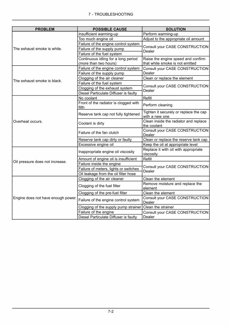
7 - TROUBLESHOOTING
PROBLEM POSSIBLE CAUSE SOLUTIONInsufficient warming-up Perform warming-upToo much engine oil Adjust to the appropriate oil amountFailure of the engine control systemFailure of the supply pumpFailure of the fuel system
Consult your CASE CONSTRUCTIONDealerThe exhaust smoke is white.
Continuous idling for a long period(more than two hours)
Raise the engine speed and confirmthat white smoke is not emitted
Failure of the engine control systemFailure of the supply pump
Consult your CASE CONSTRUCTIONDealer
Clogging of the air cleaner Clean or replace the elementFailure of the fuel systemClogging of the exhaust system
The exhaust smoke is black.
Diesel Particulate Diffuser is faulty
Consult your CASE CONSTRUCTIONDealer
No coolant RefillFront of the radiator is clogged withfilth Perform cleaning
Reserve tank cap not fully tightened Tighten it securely or replace the capwith a new one
Coolant is dirty Clean inside the radiator and replacethe coolant
Failure of the fan clutch Consult your CASE CONSTRUCTIONDealer
Reserve tank cap dirty or faulty Clean or replace the reserve tank cap
Overheat occurs.
Excessive engine oil Keep the oil at appropriate level
Inappropriate engine oil viscosity Replace it with oil with appropriateviscosity
Amount of engine oil is insufficient RefillFailure inside the engineFailure of meters, lights or switches
Oil pressure does not increase.
Oil leakage from the oil filter hose
Consult your CASE CONSTRUCTIONDealer
Clogging of the air cleaner Clean the element
Clogging of the fuel filter Remove moisture and replace theelement
Clogging of the pre-fuel filter Clean the element
Failure of the engine control system Consult your CASE CONSTRUCTIONDealer
Clogging of the supply pump strainer Clean the strainerFailure of the engine
Engine does not have enough power.
Diesel Particulate Diffuser is faultyConsult your CASE CONSTRUCTIONDealer
7-2
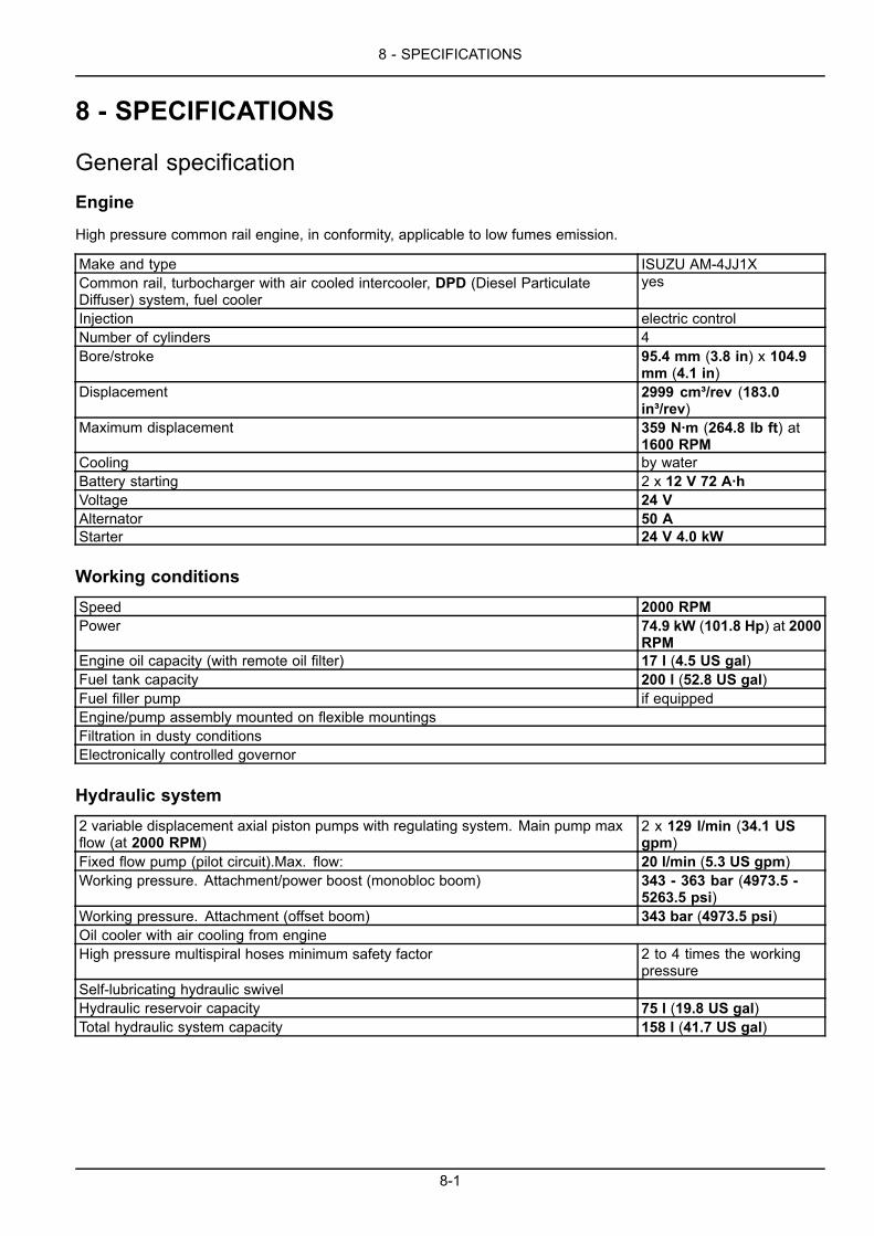
8 - SPECIFICATIONS
8 - SPECIFICATIONS###_9_###
General specificationEngine
High pressure common rail engine, in conformity, applicable to low fumes emission.
Make and type ISUZU AM-4JJ1XCommon rail, turbocharger with air cooled intercooler, DPD (Diesel ParticulateDiffuser) system, fuel cooler
yes
Injection electric controlNumber of cylinders 4Bore/stroke 95.4 mm (3.8 in) x 104.9
mm (4.1 in)Displacement 2999 cm³/rev (183.0
in³/rev)Maximum displacement 359 N·m (264.8 lb ft) at
1600 RPMCooling by waterBattery starting 2 x 12 V 72 A·hVoltage 24 VAlternator 50 AStarter 24 V 4.0 kW
Working conditionsSpeed 2000 RPMPower 74.9 kW (101.8 Hp) at 2000
RPMEngine oil capacity (with remote oil filter) 17 l (4.5 US gal)Fuel tank capacity 200 l (52.8 US gal)Fuel filler pump if equippedEngine/pump assembly mounted on flexible mountingsFiltration in dusty conditionsElectronically controlled governor
Hydraulic system2 variable displacement axial piston pumps with regulating system. Main pump maxflow (at 2000 RPM)
2 x 129 l/min (34.1 USgpm)
Fixed flow pump (pilot circuit).Max. flow: 20 l/min (5.3 US gpm)Working pressure. Attachment/power boost (monobloc boom) 343 - 363 bar (4973.5 -
5263.5 psi)Working pressure. Attachment (offset boom) 343 bar (4973.5 psi)Oil cooler with air cooling from engineHigh pressure multispiral hoses minimum safety factor 2 to 4 times the working
pressureSelf-lubricating hydraulic swivelHydraulic reservoir capacity 75 l (19.8 US gal)Total hydraulic system capacity 158 l (41.7 US gal)
8-1
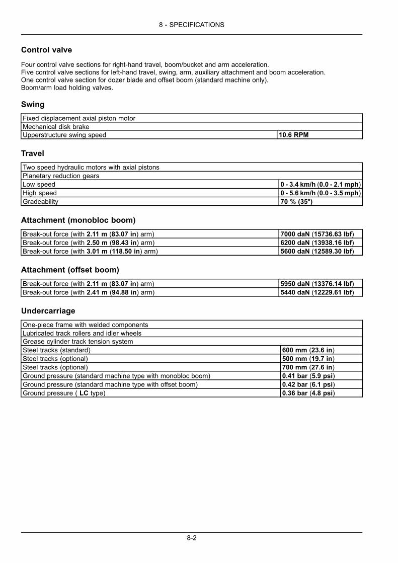
8 - SPECIFICATIONS
Control valve
Four control valve sections for right-hand travel, boom/bucket and arm acceleration.Five control valve sections for left-hand travel, swing, arm, auxiliary attachment and boom acceleration.One control valve section for dozer blade and offset boom (standard machine only).Boom/arm load holding valves.
SwingFixed displacement axial piston motorMechanical disk brakeUpperstructure swing speed 10.6 RPM
TravelTwo speed hydraulic motors with axial pistonsPlanetary reduction gearsLow speed 0 - 3.4 km/h (0.0 - 2.1 mph)High speed 0 - 5.6 km/h (0.0 - 3.5 mph)Gradeability 70 % (35°)
Attachment (monobloc boom)Break-out force (with 2.11 m (83.07 in) arm) 7000 daN (15736.63 lbf)Break-out force (with 2.50 m (98.43 in) arm) 6200 daN (13938.16 lbf)Break-out force (with 3.01 m (118.50 in) arm) 5600 daN (12589.30 lbf)
Attachment (offset boom)Break-out force (with 2.11 m (83.07 in) arm) 5950 daN (13376.14 lbf)Break-out force (with 2.41 m (94.88 in) arm) 5440 daN (12229.61 lbf)
UndercarriageOne-piece frame with welded componentsLubricated track rollers and idler wheelsGrease cylinder track tension systemSteel tracks (standard) 600 mm (23.6 in)Steel tracks (optional) 500 mm (19.7 in)Steel tracks (optional) 700 mm (27.6 in)Ground pressure (standard machine type with monobloc boom) 0.41 bar (5.9 psi)Ground pressure (standard machine type with offset boom) 0.42 bar (6.1 psi)Ground pressure ( LC type) 0.36 bar (4.8 psi)
8-2

8 - SPECIFICATIONS
Safety devicesControl for lowering attachments in case of engine failureControls are disabled by lifting the function cancellation lever or the left-hand control armEngine emergency shut-down, anti-theft protectionSafety glass, dual hornInertia reel type safety beltRear view mirror (cab side and right side)Rear view cameraRight view camera optionalBattery master switch (if equipped)ROPS: Roll Over Protective StructureFOPS: Falling Objects Protective Structure (level 2) optionalOPG: Operator’s Protective Guard (front cab) optionalSafety valves optionalFire extinguisher optionalTravel alarm
Operator's compartment
Deluxe operator's seat with armrests, inertia type safety belt, multi-position adjustment and headrest.Speed programmer, also provides automatic speed change.Single-speed wiper plus intermittent mode, washers, heating, defrost, ventilation/air conditioning, cab lights, cigarettelighter, screen control camera back.
Hydraulically assisted controlsAttachment and swing 2 control leversTravel 3foot pedalsDozer blade (standard machine only) 1 lever
Working lightsOne on upperstructure 24 V, 70 WOne on attachment 24 V, 70 WTwo on cab 24 V, 70 W
CabSmooth and round shape design cab, fabricated by press workFoldaway windscreenSafety glass for all windowsShock-less cab suspension by 4–point fluid mountingBuilt-in type full color LCD monitor displayMembrane switch on monitor displayFloor matAuto air conditioningSun shield optionalSliding front window with auto lockRadio with auto tunerRoof curtainRoof hatchWindshield protection grid optionalROPS: Roll Over Protective StructureFOPS: Falling Objects Protective Structure (level 2) optionalOPG: Operator’s Protective Guard (front cab) optionalAnti-vandalism protection optional
8-3

8 - SPECIFICATIONS
Noise levelGuaranteed by the manufacturer.Outside the operator's compartment (Lwa).Sound power level 99 dB (A).Inside the operator's compartment (Lpa).Sound power level 73 dB (A) : Weighted sound pressure level at the cab measured with the cab door and windowsclosed and with the heating/ventilation system fan at maximum speed.
8-4
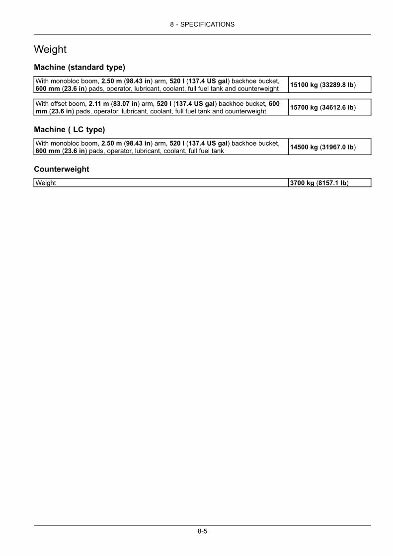
8 - SPECIFICATIONS
WeightMachine (standard type)With monobloc boom, 2.50 m (98.43 in) arm, 520 l (137.4 US gal) backhoe bucket,600 mm (23.6 in) pads, operator, lubricant, coolant, full fuel tank and counterweight 15100 kg (33289.8 lb)
With offset boom, 2.11 m (83.07 in) arm, 520 l (137.4 US gal) backhoe bucket, 600mm (23.6 in) pads, operator, lubricant, coolant, full fuel tank and counterweight 15700 kg (34612.6 lb)
Machine ( LC type)With monobloc boom, 2.50 m (98.43 in) arm, 520 l (137.4 US gal) backhoe bucket,600 mm (23.6 in) pads, operator, lubricant, coolant, full fuel tank 14500 kg (31967.0 lb)
CounterweightWeight 3700 kg (8157.1 lb)
8-5
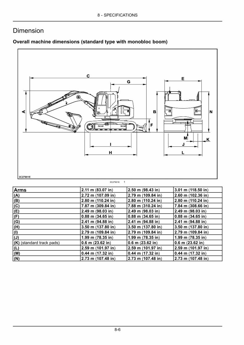
8 - SPECIFICATIONS
DimensionOverall machine dimensions (standard type with monobloc boom)
0C27901E 1
Arms 2.11 m (83.07 in) 2.50 m (98.43 in) 3.01 m (118.50 in)(A) 2.72 m (107.09 in) 2.79 m (109.84 in) 2.60 m (102.36 in)(B) 2.80 m (110.24 in) 2.80 m (110.24 in) 2.80 m (110.24 in)(C) 7.87 m (309.84 in) 7.88 m (310.24 in) 7.84 m (308.66 in)(E) 2.49 m (98.03 in) 2.49 m (98.03 in) 2.49 m (98.03 in)(F) 0.88 m (34.65 in) 0.88 m (34.65 in) 0.88 m (34.65 in)(G) 2.41 m (94.88 in) 2.41 m (94.88 in) 2.41 m (94.88 in)(H) 3.50 m (137.80 in) 3.50 m (137.80 in) 3.50 m (137.80 in)(I) 2.79 m (109.84 in) 2.79 m (109.84 in) 2.79 m (109.84 in)(J) 1.99 m (78.35 in) 1.99 m (78.35 in) 1.99 m (78.35 in)(K) (standard track pads) 0.6 m (23.62 in) 0.6 m (23.62 in) 0.6 m (23.62 in)(L) 2.59 m (101.97 in) 2.59 m (101.97 in) 2.59 m (101.97 in)(M) 0.44 m (17.32 in) 0.44 m (17.32 in) 0.44 m (17.32 in)(N) 2.73 m (107.48 in) 2.73 m (107.48 in) 2.73 m (107.48 in)
8-6
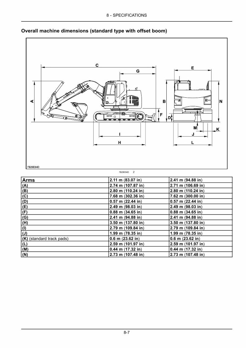
8 - SPECIFICATIONS
Overall machine dimensions (standard type with offset boom)
7B29E94D 2
Arms 2.11 m (83.07 in) 2.41 m (94.88 in)(A) 2.74 m (107.87 in) 2.71 m (106.69 in)(B) 2.80 m (110.24 in) 2.80 m (110.24 in)(C) 7.68 m (302.36 in) 7.62 m (300.00 in)(D) 0.57 m (22.44 in) 0.57 m (22.44 in)(E) 2.49 m (98.03 in) 2.49 m (98.03 in)(F) 0.88 m (34.65 in) 0.88 m (34.65 in)(G) 2.41 m (94.88 in) 2.41 m (94.88 in)(H) 3.50 m (137.80 in) 3.50 m (137.80 in)(I) 2.79 m (109.84 in) 2.79 m (109.84 in)(J) 1.99 m (78.35 in) 1.99 m (78.35 in)(K) (standard track pads) 0.6 m (23.62 in) 0.6 m (23.62 in)(L) 2.59 m (101.97 in) 2.59 m (101.97 in)(M) 0.44 m (17.32 in) 0.44 m (17.32 in)(N) 2.73 m (107.48 in) 2.73 m (107.48 in)
8-7
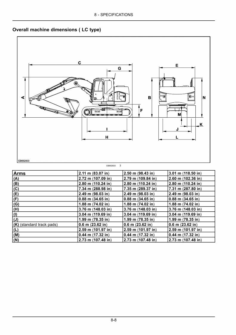
8 - SPECIFICATIONS
Overall machine dimensions ( LC type)
EB692603 3
Arms 2.11 m (83.07 in) 2.50 m (98.43 in) 3.01 m (118.50 in)(A) 2.72 m (107.09 in) 2.79 m (109.84 in) 2.60 m (102.36 in)(B) 2.80 m (110.24 in) 2.80 m (110.24 in) 2.80 m (110.24 in)(C) 7.34 m (288.98 in) 7.35 m (289.37 in) 7.31 m (287.80 in)(E) 2.49 m (98.03 in) 2.49 m (98.03 in) 2.49 m (98.03 in)(F) 0.88 m (34.65 in) 0.88 m (34.65 in) 0.88 m (34.65 in)(G) 1.88 m (74.02 in) 1.88 m (74.02 in) 1.88 m (74.02 in)(H) 3.76 m (148.03 in) 3.76 m (148.03 in) 3.76 m (148.03 in)(I) 3.04 m (119.69 in) 3.04 m (119.69 in) 3.04 m (119.69 in)(J) 1.99 m (78.35 in) 1.99 m (78.35 in) 1.99 m (78.35 in)(K) (standard track pads) 0.6 m (23.62 in) 0.6 m (23.62 in) 0.6 m (23.62 in)(L) 2.59 m (101.97 in) 2.59 m (101.97 in) 2.59 m (101.97 in)(M) 0.44 m (17.32 in) 0.44 m (17.32 in) 0.44 m (17.32 in)(N) 2.73 m (107.48 in) 2.73 m (107.48 in) 2.73 m (107.48 in)
8-8
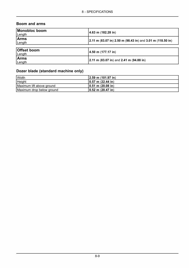
8 - SPECIFICATIONS
Boom and arms
Monobloc boomLength 4.63 m (182.28 in)
ArmsLength 2.11 m (83.07 in) 2.50 m (98.43 in) and 3.01 m (118.50 in)
Offset boomLength 4.50 m (177.17 in)
ArmsLength 2.11 m (83.07 in) and 2.41 m (94.88 in)
Dozer blade (standard machine only)
Width 2.59 m (101.97 in)Height 0.57 m (22.44 in)Maximum lift above ground 0.51 m (20.08 in)Maximum drop below ground 0.52 m (20.47 in)
8-9
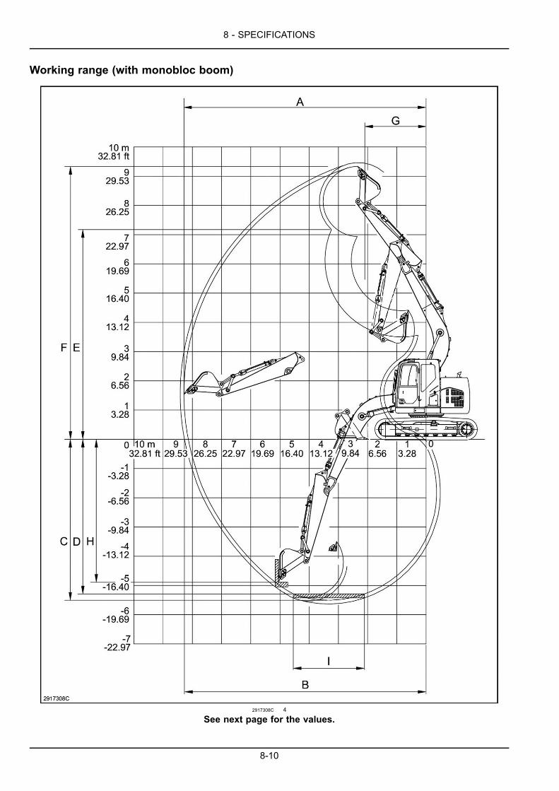
8 - SPECIFICATIONS
Working range (with monobloc boom)
2917308C 4
See next page for the values.
8-10

8 - SPECIFICATIONS
Arms 2.11 m (83.07 in) 2.50 m (98.43 in) 3.01 m (118.50 in)(A) (Maximum digging reach) 7.94 m (312.60 in) 8.29 m (326.38 in) 8.74 m (344.09 in)(B) (Maximum digging reach atground level) 7.78 m (306.30 in) 8.14 m (320.47 in) 8.60 m (338.58 in)
(C) (Maximum digging depth) 5.11 m (201.18 in) 5.51 m (216.93 in) 6.01 m (236.61 in)(D) (Maximum digging depth overa length of 2.44 m (96.06 in) ) 4.87 m (191.73 in) 5.29 m (208.27 in) 5.83 m (229.53 in)
(E) (Maximum dump height) 6.66 m (262.20 in) 6.94 m (273.23 in) 7.29 m (287.01 in)(F) (Maximum working height) 9.06 m (356.69 in) 9.34 m (367.72 in) 9.69 m (381.50 in)(G) (Minimum attachment swingradius) 1.89 m (74.41 in) 1.95 m (76.77 in) 2.33 m (91.73 in)
(H) (Maximum digging depth on avertical face) 4.56 m (179.53 in) 4.90 m (192.91 in) 5.28 m (207.87 in)
(I) (Maximum length offlat-bottomed trench) 2.44 m (96.06 in) 2.44 m (96.06 in) 2.44 m (96.06 in)
8-11
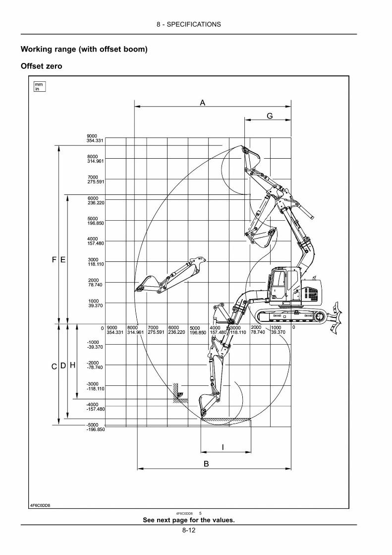
8 - SPECIFICATIONS
Working range (with offset boom)
Offset zero
4F6C0DD8 5
See next page for the values.8-12

8 - SPECIFICATIONS
Arms 2.11 m (83.07 in) 2.41 m (94.88 in)(A) (Maximum digging reach) 7.59 m (298.82 in) 7.84 m (308.66 in)(B) (Maximum digging reach at ground level) 7.43 m (292.52 in) 7.69 m (302.76 in)(C) (Maximum digging depth) 4.91 m (193.31 in) 5.21 m (205.12 in)(D) (Maximum digging depth over a length of2.44 m (96.06 in) ) 4.59 m (180.71 in) 4.90 m (192.91 in)
(E) (Maximum dump height) 6.25 m (246.06 in) 6.43 m (253.15 in)(F) (Maximum working height) 8.63 m (339.76 in) 8.81 m (346.85 in)(G) (Minimum attachment swing radius) 2.22 m (87.40 in) 2.44 m (96.06 in)(H) (Maximum digging depth on a verticalface) 3.61 m (142.13 in) 3.91 m (153.94 in)
(I) (Maximum length of flat-bottomed trench) 2.44 m (96.06 in) 2.44 m (96.06 in)
8-13

8 - SPECIFICATIONS
Offset maximum (left)
EACB5F36 6
See next page for the value.
8-14
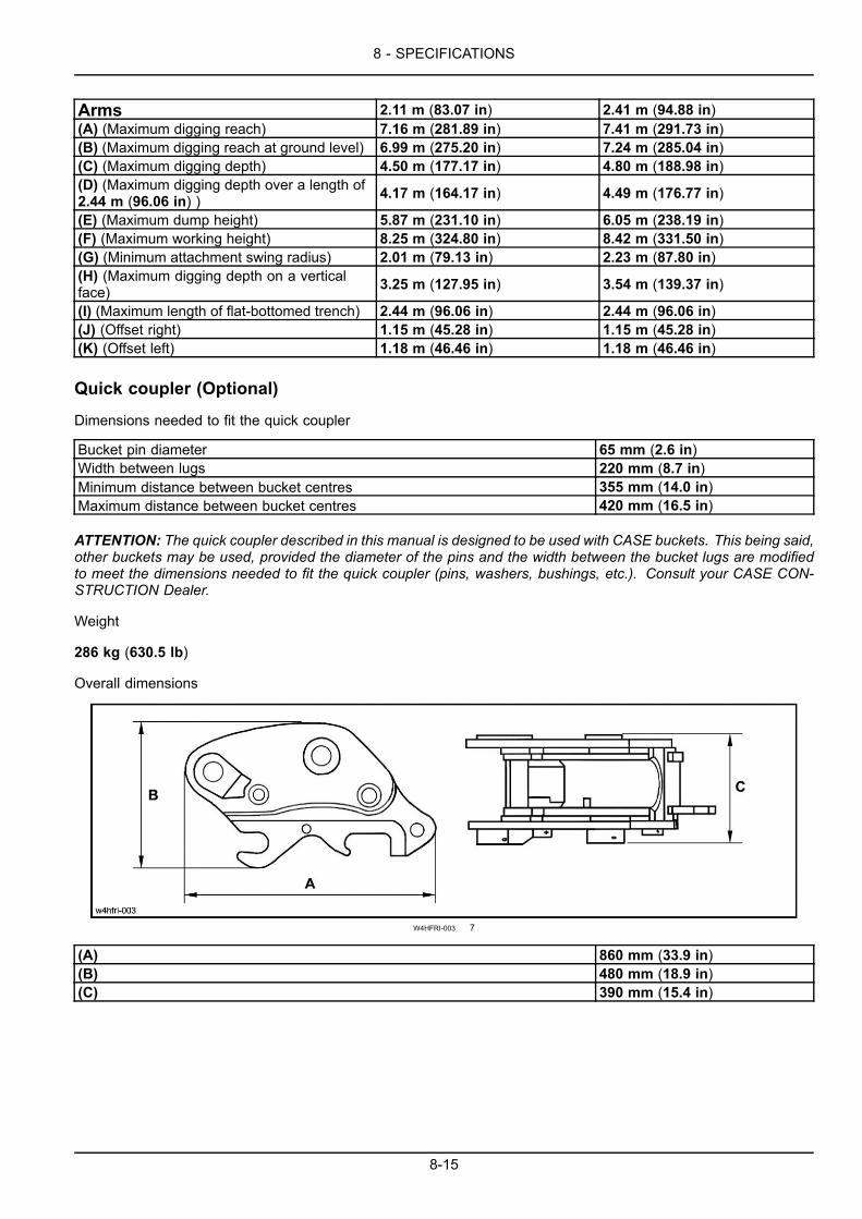
8 - SPECIFICATIONS
Arms 2.11 m (83.07 in) 2.41 m (94.88 in)(A) (Maximum digging reach) 7.16 m (281.89 in) 7.41 m (291.73 in)(B) (Maximum digging reach at ground level) 6.99 m (275.20 in) 7.24 m (285.04 in)(C) (Maximum digging depth) 4.50 m (177.17 in) 4.80 m (188.98 in)(D) (Maximum digging depth over a length of2.44 m (96.06 in) ) 4.17 m (164.17 in) 4.49 m (176.77 in)
(E) (Maximum dump height) 5.87 m (231.10 in) 6.05 m (238.19 in)(F) (Maximum working height) 8.25 m (324.80 in) 8.42 m (331.50 in)(G) (Minimum attachment swing radius) 2.01 m (79.13 in) 2.23 m (87.80 in)(H) (Maximum digging depth on a verticalface) 3.25 m (127.95 in) 3.54 m (139.37 in)
(I) (Maximum length of flat-bottomed trench) 2.44 m (96.06 in) 2.44 m (96.06 in)(J) (Offset right) 1.15 m (45.28 in) 1.15 m (45.28 in)(K) (Offset left) 1.18 m (46.46 in) 1.18 m (46.46 in)
Quick coupler (Optional)
Dimensions needed to fit the quick coupler
Bucket pin diameter 65 mm (2.6 in)Width between lugs 220 mm (8.7 in)Minimum distance between bucket centres 355 mm (14.0 in)Maximum distance between bucket centres 420 mm (16.5 in)
ATTENTION: The quick coupler described in this manual is designed to be used with CASE buckets. This being said,other buckets may be used, provided the diameter of the pins and the width between the bucket lugs are modifiedto meet the dimensions needed to fit the quick coupler (pins, washers, bushings, etc.). Consult your CASE CON-STRUCTION Dealer.
Weight
286 kg (630.5 lb)
Overall dimensions
W4HFRI-003 7
(A) 860 mm (33.9 in)(B) 480 mm (18.9 in)(C) 390 mm (15.4 in)
8-15

8 - SPECIFICATIONS
8-16

Index
###_Index_###
ACCESS TO OPERATOR'S PLATFORM . . . . . . . . . . . . . . . . . . . . . . . . . . . . . . . . . . . . . . . . . . . . . . . . . . . . . . 3-1Frame - Access/Exit. . . . . . . . . . . . . . . . . . . . . . . . . . . . . . . . . . . . . . . . . . . . . . . . . . . . . . . . . . . . . . . . . . . . . . . . . . . . . 3-1Position of the operator’s compartment controls and accessories. . . . . . . . . . . . . . . . . . . . . . . . . . . . . . . . . . . . . . 3-3
COMMISSIONING THE UNIT . . . . . . . . . . . . . . . . . . . . . . . . . . . . . . . . . . . . . . . . . . . . . . . . . . . . . . . . . . . . . . . . . . 4-1Cab - Operating . . . . . . . . . . . . . . . . . . . . . . . . . . . . . . . . . . . . . . . . . . . . . . . . . . . . . . . . . . . . . . . . . . . . . . . . . . . . . . . . 4-1Cab - Running-in Procedure. . . . . . . . . . . . . . . . . . . . . . . . . . . . . . . . . . . . . . . . . . . . . . . . . . . . . . . . . . . . . . . . . . . . . . 4-3
CONTROLS/INSTRUMENTS . . . . . . . . . . . . . . . . . . . . . . . . . . . . . . . . . . . . . . . . . . . . . . . . . . . . . . . . . . . . . . . . . . 3-1Air suspension seat adjustments. . . . . . . . . . . . . . . . . . . . . . . . . . . . . . . . . . . . . . . . . . . . . . . . . . . . . . . . . . . . . . . . . . 3-5Battery master switch (if equipped) . . . . . . . . . . . . . . . . . . . . . . . . . . . . . . . . . . . . . . . . . . . . . . . . . . . . . . . . . . . . . . 3-73Cab internal lighting . . . . . . . . . . . . . . . . . . . . . . . . . . . . . . . . . . . . . . . . . . . . . . . . . . . . . . . . . . . . . . . . . . . . . . . . . . . . 3-66Cab protection (ROPS and FOPS) . . . . . . . . . . . . . . . . . . . . . . . . . . . . . . . . . . . . . . . . . . . . . . . . . . . . . . . . . . . . . . . 3-81Cab radio . . . . . . . . . . . . . . . . . . . . . . . . . . . . . . . . . . . . . . . . . . . . . . . . . . . . . . . . . . . . . . . . . . . . . . . . . . . . . . . . . . . . . 3-60Cigarette lighter or electrical socket (24 volts) . . . . . . . . . . . . . . . . . . . . . . . . . . . . . . . . . . . . . . . . . . . . . . . . . . . . . 3-18Clock adjustment . . . . . . . . . . . . . . . . . . . . . . . . . . . . . . . . . . . . . . . . . . . . . . . . . . . . . . . . . . . . . . . . . . . . . . . . . . . . . . 3-48Coat hanger hook. . . . . . . . . . . . . . . . . . . . . . . . . . . . . . . . . . . . . . . . . . . . . . . . . . . . . . . . . . . . . . . . . . . . . . . . . . . . . . 3-57Cup holder . . . . . . . . . . . . . . . . . . . . . . . . . . . . . . . . . . . . . . . . . . . . . . . . . . . . . . . . . . . . . . . . . . . . . . . . . . . . . . . . . . . . 3-62Diesel particulate diffuser (DPD) . . . . . . . . . . . . . . . . . . . . . . . . . . . . . . . . . . . . . . . . . . . . . . . . . . . . . . . . . . . . . . . . . 3-37Dozer blade control lever (standard machine only) . . . . . . . . . . . . . . . . . . . . . . . . . . . . . . . . . . . . . . . . . . . . . . . . . 3-63Emergency exit hammer . . . . . . . . . . . . . . . . . . . . . . . . . . . . . . . . . . . . . . . . . . . . . . . . . . . . . . . . . . . . . . . . . . . . . . . . 3-56Engine hood . . . . . . . . . . . . . . . . . . . . . . . . . . . . . . . . . . . . . . . . . . . . . . . . . . . . . . . . . . . . . . . . . . . . . . . . . . . . . . . . . . 3-74Frame - Access/Exit. . . . . . . . . . . . . . . . . . . . . . . . . . . . . . . . . . . . . . . . . . . . . . . . . . . . . . . . . . . . . . . . . . . . . . . . . . . . . 3-1Front lower window . . . . . . . . . . . . . . . . . . . . . . . . . . . . . . . . . . . . . . . . . . . . . . . . . . . . . . . . . . . . . . . . . . . . . . . . . . . . 3-17Front right-hand console . . . . . . . . . . . . . . . . . . . . . . . . . . . . . . . . . . . . . . . . . . . . . . . . . . . . . . . . . . . . . . . . . . . . . . . . 3-18Fuel tank . . . . . . . . . . . . . . . . . . . . . . . . . . . . . . . . . . . . . . . . . . . . . . . . . . . . . . . . . . . . . . . . . . . . . . . . . . . . . . . . . . . . . 3-67Fuel tank filler pump (if equipped) . . . . . . . . . . . . . . . . . . . . . . . . . . . . . . . . . . . . . . . . . . . . . . . . . . . . . . . . . . . . . . . 3-79Function cancellation lever . . . . . . . . . . . . . . . . . . . . . . . . . . . . . . . . . . . . . . . . . . . . . . . . . . . . . . . . . . . . . . . . . . . . . . 3-51Fuse box . . . . . . . . . . . . . . . . . . . . . . . . . . . . . . . . . . . . . . . . . . . . . . . . . . . . . . . . . . . . . . . . . . . . . . . . . . . . . . . . . . . . . 3-64Hand control levers and pedals . . . . . . . . . . . . . . . . . . . . . . . . . . . . . . . . . . . . . . . . . . . . . . . . . . . . . . . . . . . . . . . . . . . 3-9Heating, ventilation or air-conditioning control . . . . . . . . . . . . . . . . . . . . . . . . . . . . . . . . . . . . . . . . . . . . . . . . . . . . . 3-52Left-hand control arm . . . . . . . . . . . . . . . . . . . . . . . . . . . . . . . . . . . . . . . . . . . . . . . . . . . . . . . . . . . . . . . . . . . . . . . . . . 3-49Load handling eyes . . . . . . . . . . . . . . . . . . . . . . . . . . . . . . . . . . . . . . . . . . . . . . . . . . . . . . . . . . . . . . . . . . . . . . . . . . . . 3-76Lower panels. . . . . . . . . . . . . . . . . . . . . . . . . . . . . . . . . . . . . . . . . . . . . . . . . . . . . . . . . . . . . . . . . . . . . . . . . . . . . . . . . . 3-75Magazine rack . . . . . . . . . . . . . . . . . . . . . . . . . . . . . . . . . . . . . . . . . . . . . . . . . . . . . . . . . . . . . . . . . . . . . . . . . . . . . . . . 3-57Menu screen display . . . . . . . . . . . . . . . . . . . . . . . . . . . . . . . . . . . . . . . . . . . . . . . . . . . . . . . . . . . . . . . . . . . . . . . . . . . 3-27Monitor switches. . . . . . . . . . . . . . . . . . . . . . . . . . . . . . . . . . . . . . . . . . . . . . . . . . . . . . . . . . . . . . . . . . . . . . . . . . . . . . . 3-24Optional tool supply valves (optional) . . . . . . . . . . . . . . . . . . . . . . . . . . . . . . . . . . . . . . . . . . . . . . . . . . . . . . . . . . . . 3-78Position of the operator’s compartment controls and accessories. . . . . . . . . . . . . . . . . . . . . . . . . . . . . . . . . . . . . . 3-3Rear view camera . . . . . . . . . . . . . . . . . . . . . . . . . . . . . . . . . . . . . . . . . . . . . . . . . . . . . . . . . . . . . . . . . . . . . . . . . . . . . 3-71Rear view mirrors . . . . . . . . . . . . . . . . . . . . . . . . . . . . . . . . . . . . . . . . . . . . . . . . . . . . . . . . . . . . . . . . . . . . . . . . . . . . . . 3-68Right-hand console . . . . . . . . . . . . . . . . . . . . . . . . . . . . . . . . . . . . . . . . . . . . . . . . . . . . . . . . . . . . . . . . . . . . . . . . . . . . 3-62Right-hand control arm . . . . . . . . . . . . . . . . . . . . . . . . . . . . . . . . . . . . . . . . . . . . . . . . . . . . . . . . . . . . . . . . . . . . . . . . . 3-58Roof curtain . . . . . . . . . . . . . . . . . . . . . . . . . . . . . . . . . . . . . . . . . . . . . . . . . . . . . . . . . . . . . . . . . . . . . . . . . . . . . . . . . . . 3-65Roof hatch . . . . . . . . . . . . . . . . . . . . . . . . . . . . . . . . . . . . . . . . . . . . . . . . . . . . . . . . . . . . . . . . . . . . . . . . . . . . . . . . . . . . 3-65Safety valves (optional) . . . . . . . . . . . . . . . . . . . . . . . . . . . . . . . . . . . . . . . . . . . . . . . . . . . . . . . . . . . . . . . . . . . . . . . . 3-78Side doors . . . . . . . . . . . . . . . . . . . . . . . . . . . . . . . . . . . . . . . . . . . . . . . . . . . . . . . . . . . . . . . . . . . . . . . . . . . . . . . . . . . . 3-72Sliding windows on door . . . . . . . . . . . . . . . . . . . . . . . . . . . . . . . . . . . . . . . . . . . . . . . . . . . . . . . . . . . . . . . . . . . . . . . . 3-57Sun shield (optional) . . . . . . . . . . . . . . . . . . . . . . . . . . . . . . . . . . . . . . . . . . . . . . . . . . . . . . . . . . . . . . . . . . . . . . . . . . . 3-66System display and function control panel. . . . . . . . . . . . . . . . . . . . . . . . . . . . . . . . . . . . . . . . . . . . . . . . . . . . . . . . . 3-19Tool quick coupler locking and unlocking control switch (Optional) . . . . . . . . . . . . . . . . . . . . . . . . . . . . . . . . . . . 3-56Towing holes . . . . . . . . . . . . . . . . . . . . . . . . . . . . . . . . . . . . . . . . . . . . . . . . . . . . . . . . . . . . . . . . . . . . . . . . . . . . . . . . . . 3-77Windshield . . . . . . . . . . . . . . . . . . . . . . . . . . . . . . . . . . . . . . . . . . . . . . . . . . . . . . . . . . . . . . . . . . . . . . . . . . . . . . . . . . . . 3-16Windshield washer reservoir . . . . . . . . . . . . . . . . . . . . . . . . . . . . . . . . . . . . . . . . . . . . . . . . . . . . . . . . . . . . . . . . . . . . 3-75
EXTERIOR CONTROLS . . . . . . . . . . . . . . . . . . . . . . . . . . . . . . . . . . . . . . . . . . . . . . . . . . . . . . . . . . . . . . . . . . . . . . 3-67Battery master switch (if equipped) . . . . . . . . . . . . . . . . . . . . . . . . . . . . . . . . . . . . . . . . . . . . . . . . . . . . . . . . . . . . . . 3-73Cab protection (ROPS and FOPS) . . . . . . . . . . . . . . . . . . . . . . . . . . . . . . . . . . . . . . . . . . . . . . . . . . . . . . . . . . . . . . . 3-81

Engine hood . . . . . . . . . . . . . . . . . . . . . . . . . . . . . . . . . . . . . . . . . . . . . . . . . . . . . . . . . . . . . . . . . . . . . . . . . . . . . . . . . . 3-74Fuel tank . . . . . . . . . . . . . . . . . . . . . . . . . . . . . . . . . . . . . . . . . . . . . . . . . . . . . . . . . . . . . . . . . . . . . . . . . . . . . . . . . . . . . 3-67Fuel tank filler pump (if equipped) . . . . . . . . . . . . . . . . . . . . . . . . . . . . . . . . . . . . . . . . . . . . . . . . . . . . . . . . . . . . . . . 3-79Load handling eyes . . . . . . . . . . . . . . . . . . . . . . . . . . . . . . . . . . . . . . . . . . . . . . . . . . . . . . . . . . . . . . . . . . . . . . . . . . . . 3-76Lower panels. . . . . . . . . . . . . . . . . . . . . . . . . . . . . . . . . . . . . . . . . . . . . . . . . . . . . . . . . . . . . . . . . . . . . . . . . . . . . . . . . . 3-75Optional tool supply valves (optional) . . . . . . . . . . . . . . . . . . . . . . . . . . . . . . . . . . . . . . . . . . . . . . . . . . . . . . . . . . . . 3-78Rear view camera . . . . . . . . . . . . . . . . . . . . . . . . . . . . . . . . . . . . . . . . . . . . . . . . . . . . . . . . . . . . . . . . . . . . . . . . . . . . . 3-71Rear view mirrors . . . . . . . . . . . . . . . . . . . . . . . . . . . . . . . . . . . . . . . . . . . . . . . . . . . . . . . . . . . . . . . . . . . . . . . . . . . . . . 3-68Safety valves (optional) . . . . . . . . . . . . . . . . . . . . . . . . . . . . . . . . . . . . . . . . . . . . . . . . . . . . . . . . . . . . . . . . . . . . . . . . 3-78Side doors . . . . . . . . . . . . . . . . . . . . . . . . . . . . . . . . . . . . . . . . . . . . . . . . . . . . . . . . . . . . . . . . . . . . . . . . . . . . . . . . . . . . 3-72Towing holes . . . . . . . . . . . . . . . . . . . . . . . . . . . . . . . . . . . . . . . . . . . . . . . . . . . . . . . . . . . . . . . . . . . . . . . . . . . . . . . . . . 3-77Windshield washer reservoir . . . . . . . . . . . . . . . . . . . . . . . . . . . . . . . . . . . . . . . . . . . . . . . . . . . . . . . . . . . . . . . . . . . . 3-75
FAULT CODE RESOLUTION . . . . . . . . . . . . . . . . . . . . . . . . . . . . . . . . . . . . . . . . . . . . . . . . . . . . . . . . . . . . . . . . . . 7-1Engine troubleshooting . . . . . . . . . . . . . . . . . . . . . . . . . . . . . . . . . . . . . . . . . . . . . . . . . . . . . . . . . . . . . . . . . . . . . . . . . . 7-1
FORWARD CONTROLS . . . . . . . . . . . . . . . . . . . . . . . . . . . . . . . . . . . . . . . . . . . . . . . . . . . . . . . . . . . . . . . . . . . . . . . 3-9Cigarette lighter or electrical socket (24 volts) . . . . . . . . . . . . . . . . . . . . . . . . . . . . . . . . . . . . . . . . . . . . . . . . . . . . . 3-18Clock adjustment . . . . . . . . . . . . . . . . . . . . . . . . . . . . . . . . . . . . . . . . . . . . . . . . . . . . . . . . . . . . . . . . . . . . . . . . . . . . . . 3-48Diesel particulate diffuser (DPD) . . . . . . . . . . . . . . . . . . . . . . . . . . . . . . . . . . . . . . . . . . . . . . . . . . . . . . . . . . . . . . . . . 3-37Front lower window . . . . . . . . . . . . . . . . . . . . . . . . . . . . . . . . . . . . . . . . . . . . . . . . . . . . . . . . . . . . . . . . . . . . . . . . . . . . 3-17Front right-hand console . . . . . . . . . . . . . . . . . . . . . . . . . . . . . . . . . . . . . . . . . . . . . . . . . . . . . . . . . . . . . . . . . . . . . . . . 3-18Hand control levers and pedals . . . . . . . . . . . . . . . . . . . . . . . . . . . . . . . . . . . . . . . . . . . . . . . . . . . . . . . . . . . . . . . . . . . 3-9Menu screen display . . . . . . . . . . . . . . . . . . . . . . . . . . . . . . . . . . . . . . . . . . . . . . . . . . . . . . . . . . . . . . . . . . . . . . . . . . . 3-27Monitor switches. . . . . . . . . . . . . . . . . . . . . . . . . . . . . . . . . . . . . . . . . . . . . . . . . . . . . . . . . . . . . . . . . . . . . . . . . . . . . . . 3-24System display and function control panel. . . . . . . . . . . . . . . . . . . . . . . . . . . . . . . . . . . . . . . . . . . . . . . . . . . . . . . . . 3-19Windshield . . . . . . . . . . . . . . . . . . . . . . . . . . . . . . . . . . . . . . . . . . . . . . . . . . . . . . . . . . . . . . . . . . . . . . . . . . . . . . . . . . . . 3-16
GENERAL INFORMATION . . . . . . . . . . . . . . . . . . . . . . . . . . . . . . . . . . . . . . . . . . . . . . . . . . . . . . . . . . . . . . . . . . . . . 1-1Description of the main components. . . . . . . . . . . . . . . . . . . . . . . . . . . . . . . . . . . . . . . . . . . . . . . . . . . . . . . . . . . . . . 1-10Electro-magnetic interference (EMC) . . . . . . . . . . . . . . . . . . . . . . . . . . . . . . . . . . . . . . . . . . . . . . . . . . . . . . . . . . . . . . 1-9Left, right, front and rear of the machine . . . . . . . . . . . . . . . . . . . . . . . . . . . . . . . . . . . . . . . . . . . . . . . . . . . . . . . . . . . 1-9Note to the Owner . . . . . . . . . . . . . . . . . . . . . . . . . . . . . . . . . . . . . . . . . . . . . . . . . . . . . . . . . . . . . . . . . . . . . . . . . . . . . . 1-3Product identification . . . . . . . . . . . . . . . . . . . . . . . . . . . . . . . . . . . . . . . . . . . . . . . . . . . . . . . . . . . . . . . . . . . . . . . . . . . . 1-5Safety rules . . . . . . . . . . . . . . . . . . . . . . . . . . . . . . . . . . . . . . . . . . . . . . . . . . . . . . . . . . . . . . . . . . . . . . . . . . . . . . . . . . . . 1-1Safety rules . . . . . . . . . . . . . . . . . . . . . . . . . . . . . . . . . . . . . . . . . . . . . . . . . . . . . . . . . . . . . . . . . . . . . . . . . . . . . . . . . . . . 1-2
GENERAL INFORMATION . . . . . . . . . . . . . . . . . . . . . . . . . . . . . . . . . . . . . . . . . . . . . . . . . . . . . . . . . . . . . . . . . . . . . 6-1Adjustment of engine valve rocker clearances . . . . . . . . . . . . . . . . . . . . . . . . . . . . . . . . . . . . . . . . . . . . . . . . . . . . . 6-63Air conditioning . . . . . . . . . . . . . . . . . . . . . . . . . . . . . . . . . . . . . . . . . . . . . . . . . . . . . . . . . . . . . . . . . . . . . . . . . . . . . . . . 6-73Air filter . . . . . . . . . . . . . . . . . . . . . . . . . . . . . . . . . . . . . . . . . . . . . . . . . . . . . . . . . . . . . . . . . . . . . . . . . . . . . . . . . . . . . . . 6-48Alternator . . . . . . . . . . . . . . . . . . . . . . . . . . . . . . . . . . . . . . . . . . . . . . . . . . . . . . . . . . . . . . . . . . . . . . . . . . . . . . . . . . . . . 6-84Basic instructions . . . . . . . . . . . . . . . . . . . . . . . . . . . . . . . . . . . . . . . . . . . . . . . . . . . . . . . . . . . . . . . . . . . . . . . . . . . . . . . 6-1Batteries. . . . . . . . . . . . . . . . . . . . . . . . . . . . . . . . . . . . . . . . . . . . . . . . . . . . . . . . . . . . . . . . . . . . . . . . . . . . . . . . . . . . . . 6-80Bulb replacement . . . . . . . . . . . . . . . . . . . . . . . . . . . . . . . . . . . . . . . . . . . . . . . . . . . . . . . . . . . . . . . . . . . . . . . . . . . . . . 6-85Cab protection (ROPS and FOPS) (optional) . . . . . . . . . . . . . . . . . . . . . . . . . . . . . . . . . . . . . . . . . . . . . . . . . . . . . . 6-66Checking the cylinders for leaks . . . . . . . . . . . . . . . . . . . . . . . . . . . . . . . . . . . . . . . . . . . . . . . . . . . . . . . . . . . . . . . . . 6-67Checking the machine settings . . . . . . . . . . . . . . . . . . . . . . . . . . . . . . . . . . . . . . . . . . . . . . . . . . . . . . . . . . . . . . . . . . 6-66Checking the opening of the quick coupler locking hook (optional) . . . . . . . . . . . . . . . . . . . . . . . . . . . . . . . . . . . 6-71Cooling system . . . . . . . . . . . . . . . . . . . . . . . . . . . . . . . . . . . . . . . . . . . . . . . . . . . . . . . . . . . . . . . . . . . . . . . . . . . . . . . . 6-27Diesel particulate diffuser (DPD) . . . . . . . . . . . . . . . . . . . . . . . . . . . . . . . . . . . . . . . . . . . . . . . . . . . . . . . . . . . . . . . . . 6-76Engine . . . . . . . . . . . . . . . . . . . . . . . . . . . . . . . . . . . . . . . . . . . . . . . . . . . . . . . . . . . . . . . . . . . . . . . . . . . . . . . . . . . . . . . 6-24Fan and alternator drive belt . . . . . . . . . . . . . . . . . . . . . . . . . . . . . . . . . . . . . . . . . . . . . . . . . . . . . . . . . . . . . . . . . . . . 6-62Fire extinguisher (not supplied) . . . . . . . . . . . . . . . . . . . . . . . . . . . . . . . . . . . . . . . . . . . . . . . . . . . . . . . . . . . . . . . . . 6-64Fluid capacities and lubricant specifications . . . . . . . . . . . . . . . . . . . . . . . . . . . . . . . . . . . . . . . . . . . . . . . . . . . . . . . . 6-9Fluids, fuels and lubricants . . . . . . . . . . . . . . . . . . . . . . . . . . . . . . . . . . . . . . . . . . . . . . . . . . . . . . . . . . . . . . . . . . . . . . . 6-5Fuel system. . . . . . . . . . . . . . . . . . . . . . . . . . . . . . . . . . . . . . . . . . . . . . . . . . . . . . . . . . . . . . . . . . . . . . . . . . . . . . . . . . . 6-30Fuel tank filter . . . . . . . . . . . . . . . . . . . . . . . . . . . . . . . . . . . . . . . . . . . . . . . . . . . . . . . . . . . . . . . . . . . . . . . . . . . . . . . . . 6-64Fuses . . . . . . . . . . . . . . . . . . . . . . . . . . . . . . . . . . . . . . . . . . . . . . . . . . . . . . . . . . . . . . . . . . . . . . . . . . . . . . . . . . . . . . . . 6-78Gas spring inspection . . . . . . . . . . . . . . . . . . . . . . . . . . . . . . . . . . . . . . . . . . . . . . . . . . . . . . . . . . . . . . . . . . . . . . . . . . 6-76Grease points . . . . . . . . . . . . . . . . . . . . . . . . . . . . . . . . . . . . . . . . . . . . . . . . . . . . . . . . . . . . . . . . . . . . . . . . . . . . . . . . . 6-10Hydraulic circuit . . . . . . . . . . . . . . . . . . . . . . . . . . . . . . . . . . . . . . . . . . . . . . . . . . . . . . . . . . . . . . . . . . . . . . . . . . . . . . . 6-39Levels . . . . . . . . . . . . . . . . . . . . . . . . . . . . . . . . . . . . . . . . . . . . . . . . . . . . . . . . . . . . . . . . . . . . . . . . . . . . . . . . . . . . . . . . 6-22Machine inspection and cleaning . . . . . . . . . . . . . . . . . . . . . . . . . . . . . . . . . . . . . . . . . . . . . . . . . . . . . . . . . . . . . . . . 6-66

Plastic and resin parts . . . . . . . . . . . . . . . . . . . . . . . . . . . . . . . . . . . . . . . . . . . . . . . . . . . . . . . . . . . . . . . . . . . . . . . . . . 6-67Protecting the Electrical/Electronic Systems During Charging or Welding . . . . . . . . . . . . . . . . . . . . . . . . . . . . . . 6-65Radiator and coolers . . . . . . . . . . . . . . . . . . . . . . . . . . . . . . . . . . . . . . . . . . . . . . . . . . . . . . . . . . . . . . . . . . . . . . . . . . . 6-60Releasing pressure in the hydraulic system . . . . . . . . . . . . . . . . . . . . . . . . . . . . . . . . . . . . . . . . . . . . . . . . . . . . . . . 6-37Replacing a backhoe bucket . . . . . . . . . . . . . . . . . . . . . . . . . . . . . . . . . . . . . . . . . . . . . . . . . . . . . . . . . . . . . . . . . . . . 6-69Replacing a tooth on a backhoe bucket . . . . . . . . . . . . . . . . . . . . . . . . . . . . . . . . . . . . . . . . . . . . . . . . . . . . . . . . . . . 6-68Starter motor . . . . . . . . . . . . . . . . . . . . . . . . . . . . . . . . . . . . . . . . . . . . . . . . . . . . . . . . . . . . . . . . . . . . . . . . . . . . . . . . . . 6-84Swing reduction gear. . . . . . . . . . . . . . . . . . . . . . . . . . . . . . . . . . . . . . . . . . . . . . . . . . . . . . . . . . . . . . . . . . . . . . . . . . . 6-51Tooth tip wear limits on the backhoe bucket . . . . . . . . . . . . . . . . . . . . . . . . . . . . . . . . . . . . . . . . . . . . . . . . . . . . . . . 6-67Torque specifications . . . . . . . . . . . . . . . . . . . . . . . . . . . . . . . . . . . . . . . . . . . . . . . . . . . . . . . . . . . . . . . . . . . . . . . . . . . 6-77Track rollers and idler wheels. . . . . . . . . . . . . . . . . . . . . . . . . . . . . . . . . . . . . . . . . . . . . . . . . . . . . . . . . . . . . . . . . . . . 6-59Tracks. . . . . . . . . . . . . . . . . . . . . . . . . . . . . . . . . . . . . . . . . . . . . . . . . . . . . . . . . . . . . . . . . . . . . . . . . . . . . . . . . . . . . . . . 6-56Travel reduction gears. . . . . . . . . . . . . . . . . . . . . . . . . . . . . . . . . . . . . . . . . . . . . . . . . . . . . . . . . . . . . . . . . . . . . . . . . . 6-54
LEFT-HAND SIDE CONTROLS . . . . . . . . . . . . . . . . . . . . . . . . . . . . . . . . . . . . . . . . . . . . . . . . . . . . . . . . . . . . . . . 3-49Coat hanger hook. . . . . . . . . . . . . . . . . . . . . . . . . . . . . . . . . . . . . . . . . . . . . . . . . . . . . . . . . . . . . . . . . . . . . . . . . . . . . . 3-57Emergency exit hammer . . . . . . . . . . . . . . . . . . . . . . . . . . . . . . . . . . . . . . . . . . . . . . . . . . . . . . . . . . . . . . . . . . . . . . . . 3-56Function cancellation lever . . . . . . . . . . . . . . . . . . . . . . . . . . . . . . . . . . . . . . . . . . . . . . . . . . . . . . . . . . . . . . . . . . . . . . 3-51Heating, ventilation or air-conditioning control . . . . . . . . . . . . . . . . . . . . . . . . . . . . . . . . . . . . . . . . . . . . . . . . . . . . . 3-52Left-hand control arm . . . . . . . . . . . . . . . . . . . . . . . . . . . . . . . . . . . . . . . . . . . . . . . . . . . . . . . . . . . . . . . . . . . . . . . . . . 3-49Magazine rack . . . . . . . . . . . . . . . . . . . . . . . . . . . . . . . . . . . . . . . . . . . . . . . . . . . . . . . . . . . . . . . . . . . . . . . . . . . . . . . . 3-57Sliding windows on door . . . . . . . . . . . . . . . . . . . . . . . . . . . . . . . . . . . . . . . . . . . . . . . . . . . . . . . . . . . . . . . . . . . . . . . . 3-57Tool quick coupler locking and unlocking control switch (Optional) . . . . . . . . . . . . . . . . . . . . . . . . . . . . . . . . . . . 3-56
MAINTENANCE . . . . . . . . . . . . . . . . . . . . . . . . . . . . . . . . . . . . . . . . . . . . . . . . . . . . . . . . . . . . . . . . . . . . . . . . . . . . . . . . 6-1Adjustment of engine valve rocker clearances . . . . . . . . . . . . . . . . . . . . . . . . . . . . . . . . . . . . . . . . . . . . . . . . . . . . . 6-63Air conditioning . . . . . . . . . . . . . . . . . . . . . . . . . . . . . . . . . . . . . . . . . . . . . . . . . . . . . . . . . . . . . . . . . . . . . . . . . . . . . . . . 6-73Air filter . . . . . . . . . . . . . . . . . . . . . . . . . . . . . . . . . . . . . . . . . . . . . . . . . . . . . . . . . . . . . . . . . . . . . . . . . . . . . . . . . . . . . . . 6-48Alternator . . . . . . . . . . . . . . . . . . . . . . . . . . . . . . . . . . . . . . . . . . . . . . . . . . . . . . . . . . . . . . . . . . . . . . . . . . . . . . . . . . . . . 6-84Basic instructions . . . . . . . . . . . . . . . . . . . . . . . . . . . . . . . . . . . . . . . . . . . . . . . . . . . . . . . . . . . . . . . . . . . . . . . . . . . . . . . 6-1Batteries. . . . . . . . . . . . . . . . . . . . . . . . . . . . . . . . . . . . . . . . . . . . . . . . . . . . . . . . . . . . . . . . . . . . . . . . . . . . . . . . . . . . . . 6-80Bulb replacement . . . . . . . . . . . . . . . . . . . . . . . . . . . . . . . . . . . . . . . . . . . . . . . . . . . . . . . . . . . . . . . . . . . . . . . . . . . . . . 6-85Cab protection (ROPS and FOPS) (optional) . . . . . . . . . . . . . . . . . . . . . . . . . . . . . . . . . . . . . . . . . . . . . . . . . . . . . . 6-66Checking the cylinders for leaks . . . . . . . . . . . . . . . . . . . . . . . . . . . . . . . . . . . . . . . . . . . . . . . . . . . . . . . . . . . . . . . . . 6-67Checking the machine settings . . . . . . . . . . . . . . . . . . . . . . . . . . . . . . . . . . . . . . . . . . . . . . . . . . . . . . . . . . . . . . . . . . 6-66Checking the opening of the quick coupler locking hook (optional) . . . . . . . . . . . . . . . . . . . . . . . . . . . . . . . . . . . 6-71Cooling system . . . . . . . . . . . . . . . . . . . . . . . . . . . . . . . . . . . . . . . . . . . . . . . . . . . . . . . . . . . . . . . . . . . . . . . . . . . . . . . . 6-27Diesel particulate diffuser (DPD) . . . . . . . . . . . . . . . . . . . . . . . . . . . . . . . . . . . . . . . . . . . . . . . . . . . . . . . . . . . . . . . . . 6-76Engine . . . . . . . . . . . . . . . . . . . . . . . . . . . . . . . . . . . . . . . . . . . . . . . . . . . . . . . . . . . . . . . . . . . . . . . . . . . . . . . . . . . . . . . 6-24Fan and alternator drive belt . . . . . . . . . . . . . . . . . . . . . . . . . . . . . . . . . . . . . . . . . . . . . . . . . . . . . . . . . . . . . . . . . . . . 6-62Fire extinguisher (not supplied) . . . . . . . . . . . . . . . . . . . . . . . . . . . . . . . . . . . . . . . . . . . . . . . . . . . . . . . . . . . . . . . . . 6-64Fluid capacities and lubricant specifications . . . . . . . . . . . . . . . . . . . . . . . . . . . . . . . . . . . . . . . . . . . . . . . . . . . . . . . . 6-9Fluids, fuels and lubricants . . . . . . . . . . . . . . . . . . . . . . . . . . . . . . . . . . . . . . . . . . . . . . . . . . . . . . . . . . . . . . . . . . . . . . . 6-5Fuel system. . . . . . . . . . . . . . . . . . . . . . . . . . . . . . . . . . . . . . . . . . . . . . . . . . . . . . . . . . . . . . . . . . . . . . . . . . . . . . . . . . . 6-30Fuel tank filter . . . . . . . . . . . . . . . . . . . . . . . . . . . . . . . . . . . . . . . . . . . . . . . . . . . . . . . . . . . . . . . . . . . . . . . . . . . . . . . . . 6-64Fuses . . . . . . . . . . . . . . . . . . . . . . . . . . . . . . . . . . . . . . . . . . . . . . . . . . . . . . . . . . . . . . . . . . . . . . . . . . . . . . . . . . . . . . . . 6-78Gas spring inspection . . . . . . . . . . . . . . . . . . . . . . . . . . . . . . . . . . . . . . . . . . . . . . . . . . . . . . . . . . . . . . . . . . . . . . . . . . 6-76Grease points . . . . . . . . . . . . . . . . . . . . . . . . . . . . . . . . . . . . . . . . . . . . . . . . . . . . . . . . . . . . . . . . . . . . . . . . . . . . . . . . . 6-10Hydraulic circuit . . . . . . . . . . . . . . . . . . . . . . . . . . . . . . . . . . . . . . . . . . . . . . . . . . . . . . . . . . . . . . . . . . . . . . . . . . . . . . . 6-39Levels . . . . . . . . . . . . . . . . . . . . . . . . . . . . . . . . . . . . . . . . . . . . . . . . . . . . . . . . . . . . . . . . . . . . . . . . . . . . . . . . . . . . . . . . 6-22Machine inspection and cleaning . . . . . . . . . . . . . . . . . . . . . . . . . . . . . . . . . . . . . . . . . . . . . . . . . . . . . . . . . . . . . . . . 6-66Maintenance Chart. . . . . . . . . . . . . . . . . . . . . . . . . . . . . . . . . . . . . . . . . . . . . . . . . . . . . . . . . . . . . . . . . . . . . . . . . . . . . 6-87Periodic checks . . . . . . . . . . . . . . . . . . . . . . . . . . . . . . . . . . . . . . . . . . . . . . . . . . . . . . . . . . . . . . . . . . . . . . . . . . . . . . . 6-91Plastic and resin parts . . . . . . . . . . . . . . . . . . . . . . . . . . . . . . . . . . . . . . . . . . . . . . . . . . . . . . . . . . . . . . . . . . . . . . . . . . 6-67Preparing for storage. . . . . . . . . . . . . . . . . . . . . . . . . . . . . . . . . . . . . . . . . . . . . . . . . . . . . . . . . . . . . . . . . . . . . . . . . . . 6-90Protecting the Electrical/Electronic Systems During Charging or Welding . . . . . . . . . . . . . . . . . . . . . . . . . . . . . . 6-65Radiator and coolers . . . . . . . . . . . . . . . . . . . . . . . . . . . . . . . . . . . . . . . . . . . . . . . . . . . . . . . . . . . . . . . . . . . . . . . . . . . 6-60Releasing pressure in the hydraulic system . . . . . . . . . . . . . . . . . . . . . . . . . . . . . . . . . . . . . . . . . . . . . . . . . . . . . . . 6-37Replacing a backhoe bucket . . . . . . . . . . . . . . . . . . . . . . . . . . . . . . . . . . . . . . . . . . . . . . . . . . . . . . . . . . . . . . . . . . . . 6-69Replacing a tooth on a backhoe bucket . . . . . . . . . . . . . . . . . . . . . . . . . . . . . . . . . . . . . . . . . . . . . . . . . . . . . . . . . . . 6-68Starter motor . . . . . . . . . . . . . . . . . . . . . . . . . . . . . . . . . . . . . . . . . . . . . . . . . . . . . . . . . . . . . . . . . . . . . . . . . . . . . . . . . . 6-84Starting up after storage . . . . . . . . . . . . . . . . . . . . . . . . . . . . . . . . . . . . . . . . . . . . . . . . . . . . . . . . . . . . . . . . . . . . . . . . 6-92Swing reduction gear. . . . . . . . . . . . . . . . . . . . . . . . . . . . . . . . . . . . . . . . . . . . . . . . . . . . . . . . . . . . . . . . . . . . . . . . . . . 6-51Tooth tip wear limits on the backhoe bucket . . . . . . . . . . . . . . . . . . . . . . . . . . . . . . . . . . . . . . . . . . . . . . . . . . . . . . . 6-67
Torque specifications . . . . . . . . . . . . . . . . . . . . . . . . . . . . . . . . . . . . . . . . . . . . . . . . . . . . . . . . . . . . . . . . . . . . . . . . . . . 6-77Track rollers and idler wheels. . . . . . . . . . . . . . . . . . . . . . . . . . . . . . . . . . . . . . . . . . . . . . . . . . . . . . . . . . . . . . . . . . . . 6-59Tracks. . . . . . . . . . . . . . . . . . . . . . . . . . . . . . . . . . . . . . . . . . . . . . . . . . . . . . . . . . . . . . . . . . . . . . . . . . . . . . . . . . . . . . . . 6-56Travel reduction gears. . . . . . . . . . . . . . . . . . . . . . . . . . . . . . . . . . . . . . . . . . . . . . . . . . . . . . . . . . . . . . . . . . . . . . . . . . 6-54
MAINTENANCE CHART . . . . . . . . . . . . . . . . . . . . . . . . . . . . . . . . . . . . . . . . . . . . . . . . . . . . . . . . . . . . . . . . . . . . . . 6-87Maintenance Chart. . . . . . . . . . . . . . . . . . . . . . . . . . . . . . . . . . . . . . . . . . . . . . . . . . . . . . . . . . . . . . . . . . . . . . . . . . . . . 6-87
MOVING THE UNIT . . . . . . . . . . . . . . . . . . . . . . . . . . . . . . . . . . . . . . . . . . . . . . . . . . . . . . . . . . . . . . . . . . . . . . . . . . . 4-15Adjustment and mounting of rear view mirrors . . . . . . . . . . . . . . . . . . . . . . . . . . . . . . . . . . . . . . . . . . . . . . . . . . . . . 4-30Auxiliary hydraulic circuits. . . . . . . . . . . . . . . . . . . . . . . . . . . . . . . . . . . . . . . . . . . . . . . . . . . . . . . . . . . . . . . . . . . . . . . 4-34Handling the machine . . . . . . . . . . . . . . . . . . . . . . . . . . . . . . . . . . . . . . . . . . . . . . . . . . . . . . . . . . . . . . . . . . . . . . . . . . 4-18Load handling . . . . . . . . . . . . . . . . . . . . . . . . . . . . . . . . . . . . . . . . . . . . . . . . . . . . . . . . . . . . . . . . . . . . . . . . . . . . . . . . . 4-20Lowering the attachment in the event of a failure . . . . . . . . . . . . . . . . . . . . . . . . . . . . . . . . . . . . . . . . . . . . . . . . . . . 4-29Machine travel . . . . . . . . . . . . . . . . . . . . . . . . . . . . . . . . . . . . . . . . . . . . . . . . . . . . . . . . . . . . . . . . . . . . . . . . . . . . . . . . 4-15Operating the machine . . . . . . . . . . . . . . . . . . . . . . . . . . . . . . . . . . . . . . . . . . . . . . . . . . . . . . . . . . . . . . . . . . . . . . . . . 4-22Optional hand control levers configuration. . . . . . . . . . . . . . . . . . . . . . . . . . . . . . . . . . . . . . . . . . . . . . . . . . . . . . . . . 4-45Quick coupler (optional) . . . . . . . . . . . . . . . . . . . . . . . . . . . . . . . . . . . . . . . . . . . . . . . . . . . . . . . . . . . . . . . . . . . . . . . . 4-24
OPERATING INSTRUCTIONS . . . . . . . . . . . . . . . . . . . . . . . . . . . . . . . . . . . . . . . . . . . . . . . . . . . . . . . . . . . . . . . . . 4-1Adjustment and mounting of rear view mirrors . . . . . . . . . . . . . . . . . . . . . . . . . . . . . . . . . . . . . . . . . . . . . . . . . . . . . 4-30Anti-theft protection . . . . . . . . . . . . . . . . . . . . . . . . . . . . . . . . . . . . . . . . . . . . . . . . . . . . . . . . . . . . . . . . . . . . . . . . . . . . . 4-4Auxiliary hydraulic circuits. . . . . . . . . . . . . . . . . . . . . . . . . . . . . . . . . . . . . . . . . . . . . . . . . . . . . . . . . . . . . . . . . . . . . . . 4-34Bringing the machine up to operating temperature . . . . . . . . . . . . . . . . . . . . . . . . . . . . . . . . . . . . . . . . . . . . . . . . . . 4-9Cab - Operating . . . . . . . . . . . . . . . . . . . . . . . . . . . . . . . . . . . . . . . . . . . . . . . . . . . . . . . . . . . . . . . . . . . . . . . . . . . . . . . . 4-1Cab - Running-in Procedure. . . . . . . . . . . . . . . . . . . . . . . . . . . . . . . . . . . . . . . . . . . . . . . . . . . . . . . . . . . . . . . . . . . . . . 4-3Engine operation . . . . . . . . . . . . . . . . . . . . . . . . . . . . . . . . . . . . . . . . . . . . . . . . . . . . . . . . . . . . . . . . . . . . . . . . . . . . . . 4-10Handling the machine . . . . . . . . . . . . . . . . . . . . . . . . . . . . . . . . . . . . . . . . . . . . . . . . . . . . . . . . . . . . . . . . . . . . . . . . . . 4-18Load handling . . . . . . . . . . . . . . . . . . . . . . . . . . . . . . . . . . . . . . . . . . . . . . . . . . . . . . . . . . . . . . . . . . . . . . . . . . . . . . . . . 4-20Lowering the attachment in the event of a failure . . . . . . . . . . . . . . . . . . . . . . . . . . . . . . . . . . . . . . . . . . . . . . . . . . . 4-29Machine operation . . . . . . . . . . . . . . . . . . . . . . . . . . . . . . . . . . . . . . . . . . . . . . . . . . . . . . . . . . . . . . . . . . . . . . . . . . . . . 4-12Machine travel . . . . . . . . . . . . . . . . . . . . . . . . . . . . . . . . . . . . . . . . . . . . . . . . . . . . . . . . . . . . . . . . . . . . . . . . . . . . . . . . 4-15Operating the machine . . . . . . . . . . . . . . . . . . . . . . . . . . . . . . . . . . . . . . . . . . . . . . . . . . . . . . . . . . . . . . . . . . . . . . . . . 4-22Operating the machine in hot or cold weather. . . . . . . . . . . . . . . . . . . . . . . . . . . . . . . . . . . . . . . . . . . . . . . . . . . . . . 4-11Optional hand control levers configuration. . . . . . . . . . . . . . . . . . . . . . . . . . . . . . . . . . . . . . . . . . . . . . . . . . . . . . . . . 4-45Parking the machine . . . . . . . . . . . . . . . . . . . . . . . . . . . . . . . . . . . . . . . . . . . . . . . . . . . . . . . . . . . . . . . . . . . . . . . . . . . 4-46Quick coupler (optional) . . . . . . . . . . . . . . . . . . . . . . . . . . . . . . . . . . . . . . . . . . . . . . . . . . . . . . . . . . . . . . . . . . . . . . . . 4-24Starting the engine. . . . . . . . . . . . . . . . . . . . . . . . . . . . . . . . . . . . . . . . . . . . . . . . . . . . . . . . . . . . . . . . . . . . . . . . . . . . . . 4-7Stopping the engine. . . . . . . . . . . . . . . . . . . . . . . . . . . . . . . . . . . . . . . . . . . . . . . . . . . . . . . . . . . . . . . . . . . . . . . . . . . . 4-14
OPERATOR'S SEAT . . . . . . . . . . . . . . . . . . . . . . . . . . . . . . . . . . . . . . . . . . . . . . . . . . . . . . . . . . . . . . . . . . . . . . . . . . . 3-5Air suspension seat adjustments. . . . . . . . . . . . . . . . . . . . . . . . . . . . . . . . . . . . . . . . . . . . . . . . . . . . . . . . . . . . . . . . . . 3-5
OVERHEAD CONTROLS . . . . . . . . . . . . . . . . . . . . . . . . . . . . . . . . . . . . . . . . . . . . . . . . . . . . . . . . . . . . . . . . . . . . . 3-65Cab internal lighting . . . . . . . . . . . . . . . . . . . . . . . . . . . . . . . . . . . . . . . . . . . . . . . . . . . . . . . . . . . . . . . . . . . . . . . . . . . . 3-66Roof curtain . . . . . . . . . . . . . . . . . . . . . . . . . . . . . . . . . . . . . . . . . . . . . . . . . . . . . . . . . . . . . . . . . . . . . . . . . . . . . . . . . . . 3-65Roof hatch . . . . . . . . . . . . . . . . . . . . . . . . . . . . . . . . . . . . . . . . . . . . . . . . . . . . . . . . . . . . . . . . . . . . . . . . . . . . . . . . . . . . 3-65Sun shield (optional) . . . . . . . . . . . . . . . . . . . . . . . . . . . . . . . . . . . . . . . . . . . . . . . . . . . . . . . . . . . . . . . . . . . . . . . . . . . 3-66
PARKING THE UNIT . . . . . . . . . . . . . . . . . . . . . . . . . . . . . . . . . . . . . . . . . . . . . . . . . . . . . . . . . . . . . . . . . . . . . . . . . . 4-46Parking the machine . . . . . . . . . . . . . . . . . . . . . . . . . . . . . . . . . . . . . . . . . . . . . . . . . . . . . . . . . . . . . . . . . . . . . . . . . . . 4-46
REARWARD CONTROLS. . . . . . . . . . . . . . . . . . . . . . . . . . . . . . . . . . . . . . . . . . . . . . . . . . . . . . . . . . . . . . . . . . . . . 3-64Fuse box . . . . . . . . . . . . . . . . . . . . . . . . . . . . . . . . . . . . . . . . . . . . . . . . . . . . . . . . . . . . . . . . . . . . . . . . . . . . . . . . . . . . . 3-64
RIGHT-HAND SIDE CONTROLS . . . . . . . . . . . . . . . . . . . . . . . . . . . . . . . . . . . . . . . . . . . . . . . . . . . . . . . . . . . . . 3-58Cab radio . . . . . . . . . . . . . . . . . . . . . . . . . . . . . . . . . . . . . . . . . . . . . . . . . . . . . . . . . . . . . . . . . . . . . . . . . . . . . . . . . . . . . 3-60Cup holder . . . . . . . . . . . . . . . . . . . . . . . . . . . . . . . . . . . . . . . . . . . . . . . . . . . . . . . . . . . . . . . . . . . . . . . . . . . . . . . . . . . . 3-62Dozer blade control lever (standard machine only) . . . . . . . . . . . . . . . . . . . . . . . . . . . . . . . . . . . . . . . . . . . . . . . . . 3-63Right-hand console . . . . . . . . . . . . . . . . . . . . . . . . . . . . . . . . . . . . . . . . . . . . . . . . . . . . . . . . . . . . . . . . . . . . . . . . . . . . 3-62Right-hand control arm . . . . . . . . . . . . . . . . . . . . . . . . . . . . . . . . . . . . . . . . . . . . . . . . . . . . . . . . . . . . . . . . . . . . . . . . . 3-58
SAFETY INFORMATION . . . . . . . . . . . . . . . . . . . . . . . . . . . . . . . . . . . . . . . . . . . . . . . . . . . . . . . . . . . . . . . . . . . . . . . 2-1Hand signals . . . . . . . . . . . . . . . . . . . . . . . . . . . . . . . . . . . . . . . . . . . . . . . . . . . . . . . . . . . . . . . . . . . . . . . . . . . . . . . . . . 2-28
Safety decals . . . . . . . . . . . . . . . . . . . . . . . . . . . . . . . . . . . . . . . . . . . . . . . . . . . . . . . . . . . . . . . . . . . . . . . . . . . . . . . . . . 2-8Safety rules . . . . . . . . . . . . . . . . . . . . . . . . . . . . . . . . . . . . . . . . . . . . . . . . . . . . . . . . . . . . . . . . . . . . . . . . . . . . . . . . . . . . 2-1
SHIPPING TRANSPORT. . . . . . . . . . . . . . . . . . . . . . . . . . . . . . . . . . . . . . . . . . . . . . . . . . . . . . . . . . . . . . . . . . . . . . . 5-1Tie downs for shipping — Procedure . . . . . . . . . . . . . . . . . . . . . . . . . . . . . . . . . . . . . . . . . . . . . . . . . . . . . . . . . . . . . . 5-6Towing . . . . . . . . . . . . . . . . . . . . . . . . . . . . . . . . . . . . . . . . . . . . . . . . . . . . . . . . . . . . . . . . . . . . . . . . . . . . . . . . . . . . . . . . 5-9Transport setting for long arm machine . . . . . . . . . . . . . . . . . . . . . . . . . . . . . . . . . . . . . . . . . . . . . . . . . . . . . . . . . . . . 5-8Transporting the machine . . . . . . . . . . . . . . . . . . . . . . . . . . . . . . . . . . . . . . . . . . . . . . . . . . . . . . . . . . . . . . . . . . . . . . . . 5-1
SPECIFICATIONS. . . . . . . . . . . . . . . . . . . . . . . . . . . . . . . . . . . . . . . . . . . . . . . . . . . . . . . . . . . . . . . . . . . . . . . . . . . . . . 8-1Dimension . . . . . . . . . . . . . . . . . . . . . . . . . . . . . . . . . . . . . . . . . . . . . . . . . . . . . . . . . . . . . . . . . . . . . . . . . . . . . . . . . . . . . 8-6General specification . . . . . . . . . . . . . . . . . . . . . . . . . . . . . . . . . . . . . . . . . . . . . . . . . . . . . . . . . . . . . . . . . . . . . . . . . . . . 8-1Noise level . . . . . . . . . . . . . . . . . . . . . . . . . . . . . . . . . . . . . . . . . . . . . . . . . . . . . . . . . . . . . . . . . . . . . . . . . . . . . . . . . . . . . 8-4Weight . . . . . . . . . . . . . . . . . . . . . . . . . . . . . . . . . . . . . . . . . . . . . . . . . . . . . . . . . . . . . . . . . . . . . . . . . . . . . . . . . . . . . . . . 8-5
STARTING THE UNIT . . . . . . . . . . . . . . . . . . . . . . . . . . . . . . . . . . . . . . . . . . . . . . . . . . . . . . . . . . . . . . . . . . . . . . . . . . 4-4Anti-theft protection . . . . . . . . . . . . . . . . . . . . . . . . . . . . . . . . . . . . . . . . . . . . . . . . . . . . . . . . . . . . . . . . . . . . . . . . . . . . . 4-4Bringing the machine up to operating temperature . . . . . . . . . . . . . . . . . . . . . . . . . . . . . . . . . . . . . . . . . . . . . . . . . . 4-9Engine operation . . . . . . . . . . . . . . . . . . . . . . . . . . . . . . . . . . . . . . . . . . . . . . . . . . . . . . . . . . . . . . . . . . . . . . . . . . . . . . 4-10Machine operation . . . . . . . . . . . . . . . . . . . . . . . . . . . . . . . . . . . . . . . . . . . . . . . . . . . . . . . . . . . . . . . . . . . . . . . . . . . . . 4-12Operating the machine in hot or cold weather. . . . . . . . . . . . . . . . . . . . . . . . . . . . . . . . . . . . . . . . . . . . . . . . . . . . . . 4-11Starting the engine. . . . . . . . . . . . . . . . . . . . . . . . . . . . . . . . . . . . . . . . . . . . . . . . . . . . . . . . . . . . . . . . . . . . . . . . . . . . . . 4-7
STOPPING THE UNIT . . . . . . . . . . . . . . . . . . . . . . . . . . . . . . . . . . . . . . . . . . . . . . . . . . . . . . . . . . . . . . . . . . . . . . . . 4-14Stopping the engine. . . . . . . . . . . . . . . . . . . . . . . . . . . . . . . . . . . . . . . . . . . . . . . . . . . . . . . . . . . . . . . . . . . . . . . . . . . . 4-14
STORAGE . . . . . . . . . . . . . . . . . . . . . . . . . . . . . . . . . . . . . . . . . . . . . . . . . . . . . . . . . . . . . . . . . . . . . . . . . . . . . . . . . . . . . 6-90Periodic checks . . . . . . . . . . . . . . . . . . . . . . . . . . . . . . . . . . . . . . . . . . . . . . . . . . . . . . . . . . . . . . . . . . . . . . . . . . . . . . . 6-91Preparing for storage. . . . . . . . . . . . . . . . . . . . . . . . . . . . . . . . . . . . . . . . . . . . . . . . . . . . . . . . . . . . . . . . . . . . . . . . . . . 6-90Starting up after storage . . . . . . . . . . . . . . . . . . . . . . . . . . . . . . . . . . . . . . . . . . . . . . . . . . . . . . . . . . . . . . . . . . . . . . . . 6-92
TRANSPORT OPERATIONS. . . . . . . . . . . . . . . . . . . . . . . . . . . . . . . . . . . . . . . . . . . . . . . . . . . . . . . . . . . . . . . . . . . 5-1Tie downs for shipping — Procedure . . . . . . . . . . . . . . . . . . . . . . . . . . . . . . . . . . . . . . . . . . . . . . . . . . . . . . . . . . . . . . 5-6Towing . . . . . . . . . . . . . . . . . . . . . . . . . . . . . . . . . . . . . . . . . . . . . . . . . . . . . . . . . . . . . . . . . . . . . . . . . . . . . . . . . . . . . . . . 5-9Transport setting for long arm machine . . . . . . . . . . . . . . . . . . . . . . . . . . . . . . . . . . . . . . . . . . . . . . . . . . . . . . . . . . . . 5-8Transporting the machine . . . . . . . . . . . . . . . . . . . . . . . . . . . . . . . . . . . . . . . . . . . . . . . . . . . . . . . . . . . . . . . . . . . . . . . . 5-1
TROUBLESHOOTING . . . . . . . . . . . . . . . . . . . . . . . . . . . . . . . . . . . . . . . . . . . . . . . . . . . . . . . . . . . . . . . . . . . . . . . . . 7-1Engine troubleshooting . . . . . . . . . . . . . . . . . . . . . . . . . . . . . . . . . . . . . . . . . . . . . . . . . . . . . . . . . . . . . . . . . . . . . . . . . . 7-1
CNH Europe Holding S.A. reserves the right to make improvements in design and changes in specifications
at any time without notice and without incurring any obligation to install them on units previously sold.
Specifications, descriptions, and illustrative material herein are as accurate as known
at time of publication, but are subject to change without notice.
Availability of some models and equipment builds varies according to the country
in which the equipment is being used. For exact information about any particular product,
please consult your Case dealer.
Dealer’s stamp
Copyright © 2013 CNH Europe Holding S.A. All Rights Reserved.Case is a registered trademark of CNH Europe Holding S.A.
Boulevard Royal, 24 L-2449 Luxembourg.