BiG-Pack-870HDP-XC-HS-Operator-Manual.pdf - Kubota
390
Original operating instructions BiG PACK Baler BiG PACK 870 HDP BiG PACK 870 HDP XC (from serial no.: 830852) Order no.: 150 000 170 00 en 03.09.2014
-
Upload
khangminh22 -
Category
Documents
-
view
0 -
download
0
Transcript of BiG-Pack-870HDP-XC-HS-Operator-Manual.pdf - Kubota

Ori
gin
al
op
era
tin
g i
ns
tru
cti
on
s
BiG PACK Baler
BiG PACK 870 HDP BiG PACK 870 HDP XC
(from serial no.: 830852)
Order no.: 150 000 170 00 en
03.09.2014

Table of Contents
2
Pos: 1 /BA/Konformitätserklärungen/Großpackenpressen/NEU ab 2010/Big Pack 870 HDP Baureihe @ 272\mod_1403516452380_78.docx @ 2050900 @ @ 1
EC Declaration of Conformity
We Maschinenfabrik Bernard Krone GmbH Heinrich-Krone-Str. 10, D-48480 Spelle
hereby declare as manufacturer of the product named below, on our sole responsibility,
that the
Machine: Krone Big Pack Baler Type/Types: Big Pack 870 HDP; Big Pack 870 HDP XC
to which this declaration refers is in compliance with the relevant provisions of
EC Directive 2006/42/EC (Machinery) and EC Directive 2004/108/EC (EMC) . The signing Managing Director is authorised to compile the technical documents. Spelle, Germany, 16.07.2014
Dr.-Ing. Josef Horstmann (Managing Director Design & Development)
Year of manufacture: Mach. no.:
Pos: 2 /Layout Module /---------------Seitenumbruch---------------- @ 0\mod_1196175311226_0.docx @ 4165 @ @ 1

Table of Contents
3
Pos: 3 /Überschriften/Überschriften 1/F-J/Inhaltsverzeichnis @ 31\mod_1251969952727_78.docx @ 302165 @ 1 @ 1
1 Table of Contents Pos: 4 /BA/Inhaltsverzeichnis Sprachenneutral @ 10\mod_1221574899104_0.docx @ 135495 @ @ 1
1 Table of Contents ................................................................................................................................... 3
2 Foreword ............................................................................................................................................... 11
3 To this Document ................................................................................................................................. 12
3.1 Validity .............................................................................................................................................. 12
3.2 Target group of this document ......................................................................................................... 12
3.3 How to use this document ................................................................................................................ 12
3.4 Directional information ..................................................................................................................... 12
3.4.1 Direction Information ................................................................................................................. 12
3.5 Identifying Symbols in the Operating Instructions ............................................................................ 13
3.6 Identification of the hazard warnings ................................................................................................ 13
4 Safety ..................................................................................................................................................... 14
4.1 Purpose of Use ................................................................................................................................. 14
4.2 Intended Use .................................................................................................................................... 14
4.3 Basic safety instructions ................................................................................................................... 15
4.3.1 Importance of the operating instructions ................................................................................... 15
4.3.2 Personnel qualification .............................................................................................................. 15
4.3.3 Children in danger ..................................................................................................................... 16
4.3.4 Connect the machine to the tractor ........................................................................................... 16
4.3.5 Structural changes to the machine ........................................................................................... 16
4.3.6 Additional equipment and spare parts ...................................................................................... 16
4.3.7 Workstations and passengers ................................................................................................... 16
4.3.8 Operational safety: Technically perfect condition ..................................................................... 17
4.3.9 Danger zones ............................................................................................................................ 18
4.3.10 Keeping safety devices functional ............................................................................................. 20
4.3.11 Personal protective equipment ................................................................................................. 20
4.3.12 Safety signs on the machine ..................................................................................................... 21
4.3.13 Traffic safety .............................................................................................................................. 21
4.3.14 Parking the machine safely ....................................................................................................... 22
4.3.15 Consumables ............................................................................................................................ 22
4.3.16 Dangers associated with the operational environment ............................................................. 22
4.3.17 Sources of danger on the machine ........................................................................................... 23
4.3.18 Dangers associated with certain activities: Climbing up and down .......................................... 24
4.3.19 Dangers associated with certain activities: Work on the machine ............................................ 24
4.3.20 Dangers associated with certain activities: Working on wheels and tyres ................................ 25
4.3.21 Behaviour in hazardous situations and when accidents occur ................................................. 25
4.4 Safety routines ................................................................................................................................. 26
4.4.1 Stopping and securing the machine .......................................................................................... 26
4.4.2 Supporting lifted machine and machine parts securely ............................................................ 26
4.4.3 Coupling the machine safely ..................................................................................................... 27
4.4.4 Uncoupling the machine safely ................................................................................................. 27
4.4.5 Preparing the machine for repair, maintenance and adjustment work ..................................... 28
4.4.6 Starting the machine safely ....................................................................................................... 28
4.5 Safety stickers on the machine ........................................................................................................ 29
4.6 Position of the General Information Labels on the Machine ............................................................ 40
4.6.1 Re-Ordering the Adhesive Safety and Information Labels ....................................................... 41
4.6.2 Affixing the Adhesive Safety and Information Labels ............................................................... 41

Table of Contents
4
4.6.3 Contact ...................................................................................................................................... 41
4.7 Safety Equipment ............................................................................................................................. 42
4.7.1 Ladder ....................................................................................................................................... 42
4.7.2 Fire extinguisher ........................................................................................................................ 42
4.7.3 Wheel chocks ............................................................................................................................ 43
4.8 Parking brake ................................................................................................................................... 43
4.9 Flywheel brake ................................................................................................................................. 44
4.10 Parking Jack ..................................................................................................................................... 44
4.10.1 Hydraulic parking jack (optional) ............................................................................................... 45
4.11 Shut-Off Valve Pick-up ..................................................................................................................... 46
5 Machine Description ............................................................................................................................ 48
5.1 Machine overview ............................................................................................................................. 48
5.1.1 Left Side of the BiG Pack Baler with Tandem Axle ................................................................... 48
5.2 Identification Plate ............................................................................................................................ 52
5.3 Information Required for Questions and Orders .............................................................................. 52
5.3.1 Contact ...................................................................................................................................... 52
5.4 Description of the Baling Process .................................................................................................... 53
5.5 Compacting the BiG Bale ................................................................................................................. 54
5.6 MultiBale Design .............................................................................................................................. 55
5.7 Drives ............................................................................................................................................... 57
5.7.1 Main drive .................................................................................................................................. 57
5.8 Overload Protections on the Machine .............................................................................................. 59
5.8.1 Main drive .................................................................................................................................. 59
5.8.2 Feeder Packer ........................................................................................................................... 59
5.8.3 Cutting System Drive for the Design with XC Cutting System .................................................. 60
5.8.4 Pick-up Drive ............................................................................................................................. 60
5.8.5 Needle Yoke .............................................................................................................................. 61
5.9 Pick-up ............................................................................................................................................. 61
5.10 Roller crop guide .............................................................................................................................. 62
5.11 Cutting system .................................................................................................................................. 62
5.11.1 General ..................................................................................................................................... 62
5.11.2 Cutting Length ........................................................................................................................... 62
5.12 Hydraulic system .............................................................................................................................. 63
5.13 Pressure Limiting Valve Block (On-Board Hydraulic System) ......................................................... 64
5.14 Twine ................................................................................................................................................ 65
5.14.1 Electrical twine empty display for lower thread ......................................................................... 66
5.14.2 Twine motion indicator upper twine (double knotter) ................................................................ 67
5.14.3 Electrical Knotter Monitoring ..................................................................................................... 67
5.15 Knotter Gear ..................................................................................................................................... 68
5.16 Bale Ejector / Bale Chute ................................................................................................................. 69
5.16.1 Medium Version Electronics Design ......................................................................................... 69
5.16.2 For Comfort Version Electronics Design: .................................................................................. 70
5.17 Compressed-air reservoir ................................................................................................................. 71
5.18 Technical data .................................................................................................................................. 72
5.19 Consumables ................................................................................................................................... 77
5.19.1 Filling Quantities and Lubrication Designations for Gearboxes ................................................ 77
5.19.2 Oil quantities and designations for the on-board hydraulic system .......................................... 78
5.19.3 Oil quantities and designations for the compressor .................................................................. 78
6 Control and Display Elements ............................................................................................................ 79

Table of Contents
5
6.1 Connecting the hydraulic lines ......................................................................................................... 79
7 Commissioning..................................................................................................................................... 81
7.1 Attaching Hydraulic Parking Jack ..................................................................................................... 82
7.2 Electrical power supply .................................................................................................................... 84
7.3 Adjusting the drawbar height ............................................................................................................ 85
7.4 Adjusting the height of the drive train ............................................................................................... 86
7.5 Shortening Universal Shaft .............................................................................................................. 87
7.6 Adjusting the hydraulic system ......................................................................................................... 92
7.6.1 Operating the Machine without LS (Load-Sensing Connection) ............................................... 92
7.6.2 Operating the Machine via LS (Load-Sensing Connection) ..................................................... 92
7.7 Setting the bale chute ...................................................................................................................... 93
8 Start-up .................................................................................................................................................. 94
8.1 Connect the machine to the tractor .................................................................................................. 95
8.1.1 Install the PTO shaft.................................................................................................................. 96
8.2 Hydraulics ......................................................................................................................................... 98
8.2.1 Connecting the hydraulic lines .................................................................................................. 98
8.3 Hydraulic brake (Export) ................................................................................................................ 100
8.4 Hydraulic Brake (Export France) .................................................................................................... 101
8.5 Compressed Air Connections for the Compressed Air Brake ........................................................ 102
8.6 Electrical connections .................................................................................................................... 103
8.6.1 Connecting the terminal (on tractors without ISOBUS system) .............................................. 103
8.6.2 Connecting the Terminal (on tractors with integrated ISOBUS system) ................................. 104
8.7 Lighting ........................................................................................................................................... 105
8.8 Using the safety chain .................................................................................................................... 105
9 Driving and Transport ........................................................................................................................ 107
9.1 Preparations for road travel ............................................................................................................ 108
9.1.1 Roller chute hydraulically activated ......................................................................................... 109
9.1.2 Bale chute in transport position (optional) .............................................................................. 109
9.1.3 Checking the lighting system .................................................................................................. 110
9.1.4 Parking brake .......................................................................................................................... 110
9.2 Handling the Coaster/Steering Axle (Special Equipment) ............................................................. 111
9.2.1 Operating the Machine via LS (Load-Sensing Connection) ................................................... 113
9.2.2 Operating the Machine without LS (Load-Sensing Connection) ............................................. 113
9.2.3 Moving the machine without hydraulic connections ................................................................ 114
9.3 Moving ............................................................................................................................................ 115
9.4 Switching off the machine .............................................................................................................. 116
9.4.1 Stowing the compressed air hoses ......................................................................................... 117
9.4.2 Parking brake .......................................................................................................................... 118
9.4.3 Wheel chocks .......................................................................................................................... 118
10 KRONE ISOBUS Terminal .................................................................................................................. 119
10.1 Installing the terminal into cabin ..................................................................................................... 120
10.2 ISOBUS Short Cut Button .............................................................................................................. 121
10.2.1 Connecting the Multi-Function Lever to the CCI Terminal (on tractors without ISOBUS system)123
10.2.2 Switching the terminal on / off when the machine is not connected ....................................... 124
10.2.3 Switching the terminal on / off when the machine is connected ............................................. 125
10.2.3.1 Start screen ...................................................................................................................... 125
10.3 Display design ................................................................................................................................ 126
10.3.1 Displays in the main window ................................................................................................... 130

Table of Contents
6
10.4 Bringing up the Basic Screens ....................................................................................................... 134
11 KRONE ISOBUS Terminal - Machine Functions .............................................................................. 135
11.1.1 Switching the warning beacon on/off ...................................................................................... 135
11.1.2 Bringing up the Second Page of the Function Keys ............................................................... 135
11.1.3 Bringing up the First Page of the Function Keys .................................................................... 135
11.1.4 Switching Working Floodlights On and Off ............................................................................. 135
11.1.5 Locking / Releasing Steering Axle .......................................................................................... 136
11.1.6 Switching the starting aid on/off .............................................................................................. 136
11.1.7 Bringing up a Menu Level ....................................................................................................... 136
11.1.8 Opening/closing the bale channel flaps .................................................................................. 136
11.1.9 Lower bale chute ..................................................................................................................... 137
11.1.10 Automatic bale ejection ........................................................................................................... 137
11.1.11 Bringing up “Customer Counter” Menu ................................................................................... 137
11.1.12 Open the automatic/manual mode home screen .................................................................... 137
11.1.13 Reset bale length to zero ........................................................................................................ 137
11.1.14 Trigger knotter ......................................................................................................................... 137
11.1.15 Release/lower/raise blade bar ................................................................................................ 138
11.1.16 Setting the target bale channel flap pressure ......................................................................... 139
11.1.17 Setting the bale length ............................................................................................................ 140
11.1.18 Setting the number of MultiBales (MultiBale only) .................................................................. 141
12 KRONE ISOBUS Terminal - Menus ................................................................................................... 142
12.1 Menu level ...................................................................................................................................... 142
12.1.1 Calling up the menu level ........................................................................................................ 144
12.2 Main menu 1 "Settings" .................................................................................................................. 145
12.2.1 Menu 1-1 „Knotter Settings“ .................................................................................................... 146
12.2.2 Menu 1-1-1 „Correction Value for Bale Length“ ...................................................................... 147
12.2.3 Menu 1-1-2 „Knotter Signal“ .................................................................................................... 148
12.2.4 Menu 1-1-3 "Knotter control" ................................................................................................... 149
12.2.4.1 Menu 1-1-5 „Bales / Blow“ ............................................................................................... 150
12.2.4.2 Menu 1-1-6 „Blow Time“ .................................................................................................. 151
12.2.5 Menu 1-2 silage agents / optional ........................................................................................... 152
12.2.6 Menu 1-3 „Sensitivity of the Direction Display“ ....................................................................... 153
12.2.7 Menu 1-4 „Central Lubrication“ ............................................................................................... 154
12.2.8 Menu 1-5 „Moisture Measuring“ .............................................................................................. 156
12.2.9 Menu 1-6 „Bale Balance“ ........................................................................................................ 158
12.2.9.1 Adjusting the Bale Balance .............................................................................................. 159
12.2.9.2 Zeros ................................................................................................................................ 159
12.2.10 Menu 1-8 "Set correction value for humidity measurement" ................................................... 160
12.3 main menu 2 „counters“ ................................................................................................................. 161
12.3.1 Menu 2-1 "Customer counter" ................................................................................................. 162
12.3.1.1 Menu 2-1-1 Detailed counter ........................................................................................... 164
12.3.2 Menu 2-2 „Total Bale Counter“ ............................................................................................... 166
12.4 Main menu 4 "Service" ................................................................................................................... 168
12.4.1 Menu 4-2 „Manual sensor test“ ............................................................................................... 169
12.4.2 Actuator test ............................................................................................................................ 177
12.4.3 Menu 4-4 Manual actuator test ............................................................................................... 177
12.4.4 Menu 4-6 „Diagnostics Driving Speed / Motion Direction Display“ ......................................... 182
12.4.5 Menu 4-7 „Diagnostics Auxiliary (AUX)“ ................................................................................. 183
12.5 Main menu 5 'Information' .............................................................................................................. 184

Table of Contents
7
12.6 Main Menu 6 Technician ................................................................................................................ 185
12.7 Main menu 9 "Virtual Terminal (VT)" .............................................................................................. 186
12.7.1 Menu 9-2 „Switching Between the Terminals“ ........................................................................ 187
12.7.2 Menu 9-3 „Configuration Main Window“ ................................................................................. 188
12.8 Alarm Message .............................................................................................................................. 190
12.8.1 Alarm messages ..................................................................................................................... 191
13 ISOBUS operation .............................................................................................................................. 199
13.1 Mounting ISOBUS Terminal ........................................................................................................... 200
13.1.1 Connection Terminal to Tractor .............................................................................................. 200
13.1.2 Connection Tractor to Machine ............................................................................................... 200
13.2 Differing functions to KRONE ISOBUS terminal CCI ..................................................................... 201
13.2.1 Menu 4-6 “Diagnostics driving speed display/direction of travel display” ............................... 202
13.2.2 Menu 4-7 “Diagnostics Auxiliary (AUX)” ................................................................................. 203
13.3 Main menu 9 "ISO settings info" .................................................................................................... 204
13.3.1 Menu 9-1 "Softkeys ISO terminal" .......................................................................................... 205
13.3.2 Menu 9-2 „Switching Between the Terminals“ ........................................................................ 206
13.4 ISOBUS „Auxiliary“-function (AUX) ................................................................................................ 207
13.4.1 Example of a joystick assignment for Fendt (default setting) ................................................. 208
13.4.2 Recommended assignment of a WTK- multi-function lever ................................................... 209
14 Operation ............................................................................................................................................. 211
14.1 Preparation for Baling .................................................................................................................... 211
14.2 Tying unit ........................................................................................................................................ 213
14.2.1 Setting the tying twine in place ............................................................................................... 213
14.2.2 Threading in the Lower Twine ................................................................................................. 217
14.2.3 Threading in the Upper Twine ................................................................................................. 218
14.2.4 Threading in the Lower Twine ................................................................................................. 222
14.2.5 Threading in the Upper Twine ................................................................................................. 223
14.3 Pick-up ........................................................................................................................................... 225
14.4 Lifting / Lowering Bale Chute ......................................................................................................... 226
14.5 Operating Bale Ejector ................................................................................................................... 228
14.6 Parking Jack ................................................................................................................................... 230
14.7 Hydraulic parking jack .................................................................................................................... 231
14.8 Bale brake ...................................................................................................................................... 232
14.8.1 Working floodlight .................................................................................................................... 233
14.9 Initiating the Tying Process Manually............................................................................................. 234
14.10 Finishing Tying Process Manually .................................................................................................. 234
14.11 Removing blockages ...................................................................................................................... 235
15 Settings ............................................................................................................................................... 236
15.1 Pick-up ........................................................................................................................................... 237
15.2 Default Setting (Working Height Setting) ....................................................................................... 237
15.2.1 Setting the Ground Pressure of the Guide Wheels ................................................................. 238
15.2.2 Driving with Pick-up in fixed position ....................................................................................... 239
15.3 Roller crop guide ............................................................................................................................ 240
15.4 Setting the needles......................................................................................................................... 241
15.4.1 Lateral setting of the needles .................................................................................................. 241
15.4.2 Setting the height of the needles on the knotter ..................................................................... 242
15.4.3 Top dead centre of the needles .............................................................................................. 243
15.5 Adjusting the MultiBale ................................................................................................................... 244

Table of Contents
8
15.5.1 Setting the position of the second needle yoke ...................................................................... 244
15.5.2 Setting the stop ....................................................................................................................... 244
15.5.3 Setting the height of the needle yoke brake ........................................................................... 244
15.5.4 Setting the locking (frame) ...................................................................................................... 245
15.5.5 Setting the lockings of the needle yoke .................................................................................. 245
15.5.6 Setting the rubber pad between the needle yokes ................................................................. 246
15.5.7 Possible setting errors and their elimination (MultiBale) ......................................................... 246
15.6 Checking / adjusting position of needles – baling ram ................................................................... 247
15.7 Checking / Setting Upper Needle ................................................................................................... 248
15.8 Checking / Setting Twine Bar ......................................................................................................... 249
15.8.1 Checking / Setting the Twine Bar to the Lower Needle (Needle Yoke) .................................. 249
15.9 Checking / Setting Twine Bar to the Channel Slot ......................................................................... 250
15.10 Tensioning/relieving the upper needle shaft .................................................................................. 252
15.11 Tensioning/relieving the twine locking shaft ................................................................................... 253
15.11.1 Adjusting the knotter shaft brake ............................................................................................ 253
15.12 Setting the Twine Brake ................................................................................................................. 254
15.12.1 Setting the twine tension on the upper twine strand (double knotter) ..................................... 255
15.12.2 Setting the twine tension of the lower twine strand (double knotter) ...................................... 256
15.13 Knotter ............................................................................................................................................ 257
15.13.1 Locking/releasing the tying process ........................................................................................ 257
15.13.2 Start-up ................................................................................................................................... 258
15.13.3 Double knotter ......................................................................................................................... 258
15.13.4 Setting the Knotter Hook ......................................................................................................... 258
15.13.5 Setting of twine retainer .......................................................................................................... 259
15.13.6 Setting the Holding Force of the Twine Retainer .................................................................... 260
15.14 Adjusting the baling ram ................................................................................................................. 262
15.14.1 Setting the baling ram blades ................................................................................................. 262
15.14.2 Cleaning the running rails ....................................................................................................... 263
15.14.3 Lateral setting of the plunger .................................................................................................. 264
15.15 Adjusting the Packer Relative to the Plunger ................................................................................. 266
15.15.1 Description of components ..................................................................................................... 266
15.15.2 Checking packer coupling ....................................................................................................... 268
15.15.3 Moving Packer Strip into Position ........................................................................................... 268
15.15.4 Moving Baling Ram into Position ............................................................................................ 269
15.16 Description of components VFS system (variable filling system) .................................................. 270
15.16.1 Presetting threaded rod / stop for the feeler rocker ................................................................ 271
15.16.2 Zero position (VFS system) .................................................................................................... 272
15.16.3 Adjusting the zeroizing device ................................................................................................ 273
15.16.4 Adjusting the rubber pad on the zeroizing device ................................................................... 273
15.16.5 Adjusting the spring in the zeroizing device ............................................................................ 274
15.16.6 Adjusting the triggering sensitivity ........................................................................................... 275
15.16.7 Adjusting the feeler rocker ...................................................................................................... 276
15.16.8 Adjusting the feeler rocker stop .............................................................................................. 277
15.16.9 Absorbing mechanism ............................................................................................................ 279
15.17 Basic setting of the band brake (flywheel) ..................................................................................... 280
15.18 Adjusting the chop length ............................................................................................................... 281
16 Maintenance ........................................................................................................................................ 285
16.1 Spare Parts .................................................................................................................................... 285
16.2 Maintenance table .......................................................................................................................... 286

Table of Contents
9
16.3 Tightening Torques ........................................................................................................................ 288
16.4 Tightening Torques (Countersunk Screws) ................................................................................... 289
16.5 Blade Changing .............................................................................................................................. 290
16.6 Lifting .............................................................................................................................................. 292
16.6.1 Eyebolts for lifting .................................................................................................................... 292
16.6.2 Lifting ....................................................................................................................................... 292
16.7 Cleaning ......................................................................................................................................... 293
16.8 Drive chains .................................................................................................................................... 294
16.8.1 Conveyor roller (I) ................................................................................................................... 294
16.8.2 Pick-up drive (II) ...................................................................................................................... 294
16.8.3 Pick-up drive (III) ..................................................................................................................... 295
16.9 Tyres .............................................................................................................................................. 296
16.9.1 Checking and maintaining tyres .............................................................................................. 297
17 Maintenance - hydraulic system ....................................................................................................... 298
17.1.1 On-board hydraulic system ..................................................................................................... 299
17.2 High-pressure filter ......................................................................................................................... 300
17.3 Emergency Manual Activation ........................................................................................................ 301
17.4 Comfort Hydraulic Block Diagram .................................................................................................. 302
17.5 Examples of Emergency Manual Activation ................................................................................... 303
17.5.1 Raising / Lowering the roller chute .......................................................................................... 303
17.6 Pressing force control (with emergency manual activation) .......................................................... 304
17.6.1 Setting the baling pressure ..................................................................................................... 304
17.6.2 Releasing the bale channel chamber (comfort) ...................................................................... 304
18 Maintenance - Gearbox ...................................................................................................................... 305
18.1 Main gearbox .................................................................................................................................. 305
18.2 Packer gearbox .............................................................................................................................. 306
18.3 Transfer gearbox ............................................................................................................................ 307
18.4 Pick-up gearbox ............................................................................................................................. 308
18.5 Cutting system drive gear .............................................................................................................. 309
19 Maintenance - Brake System ............................................................................................................. 311
19.1 Compressed-air reservoir ............................................................................................................... 312
19.1.1 Checking the drain valve ......................................................................................................... 312
19.1.2 Retighten tensioning belts ....................................................................................................... 312
19.2 Adjusting the transfer mechanism .................................................................................................. 313
19.2.1 Pneumatic brake cylinders ...................................................................................................... 314
19.3 Air filter for pneumatic cylinder (only MultiBale) ............................................................................. 315
19.4 Replacing Rollers/Cam Follower Rollers ....................................................................................... 315
20 Maintenance Compressor ................................................................................................................. 316
20.1 Compressor .................................................................................................................................... 316
21 Maintenance – lubrication ................................................................................................................. 318
21.1 Lubricants ....................................................................................................................................... 319
21.2 General ........................................................................................................................................... 319
21.3 Lubricating the PTO shaft .............................................................................................................. 320
21.4 Lubricating the rollers for the blade lever ....................................................................................... 321
21.5 Manual lubrication points on the machine ...................................................................................... 322
22 Maintenance – Central Lubrication................................................................................................... 326
22.1.1 Automatic centralised lubrication system (optional) ................................................................ 326
23 Maintenance – electrical system ....................................................................................................... 328

Table of Contents
10
23.1 Position of sensors (right side of the machine) .............................................................................. 328
23.2 Position of sensors (left side of machine) ...................................................................................... 330
23.2.1 Adjusting the Sensors ............................................................................................................. 332
23.2.1.1 Namur sensor d = 8 mm .................................................................................................. 332
23.2.1.2 Namur sensor d = 12 mm ................................................................................................ 332
23.2.1.3 Namur sensor d = 30 mm ................................................................................................ 333
24 Placing in Storage .............................................................................................................................. 334
24.1 At the End of the Harvest Season .................................................................................................. 335
24.2 Before the Start of the New Season ............................................................................................... 336
24.2.1 Overload coupling on flywheel ................................................................................................ 337
25 Malfunctions - Causes and Remedies .............................................................................................. 338
25.1 General malfunctions ..................................................................................................................... 339
25.2 Malfunctions on the knotter ............................................................................................................ 342
25.2.1 Single knotter .......................................................................................................................... 342
25.2.2 Double knotter ......................................................................................................................... 345
25.3 Troubleshooting in the central lubrication ...................................................................................... 356
26 Appendix ............................................................................................................................................. 358
26.1 Hydraulic System Circuit Diagrams ................................................................................................ 358
26.2 On-Board Hydraulic System for Medium Version Electronics ....................................................... 358
26.3 On-Board Hydraulic System for Comfort Version Electronics ....................................................... 359
26.4 Work Hydraulics Medium Version Electronics ............................................................................... 360
26.5 Work Hydraulics Comfort Version Electronics ............................................................................... 361
26.6 Electrical circuit diagram ................................................................................................................ 362
27 Index .................................................................................................................................................... 363
Pos: 5 /Layout Module /---------------Seitenumbruch---------------- @ 0\mod_1196175311226_0.docx @ 4165 @ @ 1

Foreword
11
Pos: 6.1 /Überschriften/Überschriften 1/U-Z/Vorwort @ 0\mod_1195627720123_78.docx @ 982 @ 1 @ 1
2 Foreword Pos: 6.2 /BA/Vorwort/Großpackenpressen/Verehrter Kunde BiG Pack @ 17\mod_1236162357058_78.docx @ 201236 @ @ 1
Dear Customer! By purchasing your BiG PACK baler, you have acquired a quality product from KRONE. We are grateful for the confidence you have invested in us in buying this machine. It is important to read the operating instructions very carefully before you start operating the machine to allow you to use the BiG PACK baler to its full capacity. The contents of this manual are laid out in such a way that you should be able to perform any task by following the instructions step by step. It contains extensive notes and information about maintenance, how to use the machine safely, secure working methods, special precautionary measures and available accessories. This information and these instructions are essential, important and useful for the operational safety, reliability and durability of the BiG PACK baler.
Pos: 6.3 /BA/Vorwort/Großpackenpressen/Weiterer Verlauf BiG Pack @ 17\mod_1236162359418_78.docx @ 201261 @ @ 1
Note In the operating instructions which follow, the “BiG PACK baler“ will also be referred to as the "machine".
Pos: 6.4 /BA/Vorwort/Beachten Sie für Maschine @ 0\mod_1195626904076_78.docx @ 944 @ @ 1
Please note: The operating instructions are part of your machine. Only operate this machine after you have been trained to do so and according to these instructions. It is essential to observe the safety instructions! It is also necessary to observe the relevant accident prevention regulations and other generally recognised regulations concerning safety, occupational health and road traffic. All information, illustrations and technical data in these operating instructions correspond to the latest state at the time of publication. We reserve the right to make design changes at any time and without notification of reasons. Should you for any reason not be able to use these operating instructions either wholly or partially, you can receive a replacement set of operating instructions for your machine by quoting the number supplied overleaf. We hope that you will be satisfied with your KRONE machine. Maschinenfabrik Bernard Krone GmbH Spelle
Pos: 7 /Layout Module /---------------Seitenumbruch---------------- @ 0\mod_1196175311226_0.docx @ 4165 @ @ 1

To this Document
12
Pos: 8 /Überschriften/Überschriften 1/U-Z/Zu diesem Dokument @ 107\mod_1334231929021_78.docx @ 965257 @ 1 @ 1
3 To this Document Pos: 9 /BA/Einleitung/Gültigkeit/Grosspackenpresse/Gültigkeit BiG Pack 870 HDP @ 230\mod_1393330550090_78.docx @ 1843682 @ 2 @ 1
3.1 Validity
These operating instructions apply to Big Pack Square Balers of the following types: BiG PACK 870 HDP BiG PACK 870 HDP XC In the HighSpeed design.
Pos: 10 /Überschriften/Überschriften 2/U-Z/Zielgruppe dieses Dokuments @ 187\mod_1380113123454_78.docx @ 1609723 @ 1 @ 1
3.2 Target group of this document Pos: 11 /BA/Zu diesem Dokument/Zielgruppe @ 188\mod_1380114987653_78.docx @ 1610148 @ @ 1
This document is intended for the farmer and for other users who have no agricultural training but who have been instructed in the use of the machine.
Pos: 12 /Überschriften/Überschriften 2/P-T/So benutzen Sie dieses Dokument @ 188\mod_1380548350021_78.docx @ 1614365 @ 1 @ 1
3.3 How to use this document Pos: 13 /BA/Zu diesem Dokument/So benutzen Sie diese Anleitung @ 188\mod_1380548527264_78.docx @ 1614394 @ @ 1
Table of contents/headers: The table of contents, as well as the headers in these instructions, are used for quick navigation in the chapters. Index: You can use the index to find specific information on the required subject via keywords which are in alphabetical order. The index is on the last page of these instructions. Cross-references: Cross-references to another place in the operating instructions or to another document are in the text and specify the chapter and subchapter or section. The name of the subchapter or section is in quotation marks. Example: Check that all screws on the machine are tight, see chapter Maintenance, "Tightening torques for hexagonal head screws". The subchapter or the section can be found via an entry in the table of contents and in the index.
Pos: 14 /Überschriften/Überschriften 2/P-T/Richtungsangaben @ 188\mod_1380608167162_78.docx @ 1615005 @ 2 @ 1
3.4 Directional information Pos: 15 /BA/Zu diesem Dokument/Richtungsangaben_mit Überschrift 3. Ebene @ 110\mod_1336024650492_78.docx @ 979274 @ 3 @ 1
3.4.1 Direction Information
Direction information in these operating instructions such as front, rear, right and left always applies in direction of travel.
Pos: 16 /BA/Zu diesem Dokument/Richtungs- und Orientierungsangaben @ 188\mod_1380609039179_78.docx @ 1615134 @ @ 1
Directional information in these operating instructions, such as front, rear, right and left, applies in the direction of travel of the machine. Orientation information concerning a diagram of a machine detail refers to the diagram itself and is not relative to the direction of travel.
Pos: 17 /Layout Module /---------------Seitenumbruch---------------- @ 0\mod_1196175311226_0.docx @ 4165 @ @ 1

To this Document
13
Pos: 18 /BA/Sicherheit/6. Überarbeitete Warnhinweise/Kennzeichnung von Hinweisen in der Betriebsanleitung Einführungstext (2012-07-27 09:59:06) @ 0\mod_1195637804826_78.docx @ 1098 @ 2 @ 1
3.5 Identifying Symbols in the Operating Instructions
The safety instructions contained in this manual which could result in personal injury if not followed are identified by the general danger sign:
Pos: 19 /BA/Sicherheit/6. Überarbeitete Warnhinweise/Kennzeichnung der Gefahrenhinweise (2012-07-26 15:10:30) @ 28\mod_1250244370070_78.docx @ 274714 @ 1 @ 1
3.6 Identification of the hazard warnings
Danger!
DANGER! - Type and source of the hazard! Effect: Danger to life or serious injuries. • Measures for hazard prevention Warning !
WARNING! - Type and source of the hazard! Effect: Injuries, serious material damage. • Measures for hazard prevention Caution!
CAUTION! - Type and source of the hazard! Effect: Property damage • Measures for risk prevention.
Pos: 20 /BA/Sicherheit/6. Überarbeitete Warnhinweise/Allgemeine Funktionshinweise (2012-07-26 15:24:39) @ 0\mod_1196869714452_78.docx @ 15185 @ @ 1
General function instructions are indicated as follows: Note!
Note - Type and source of the note Effect: Economic advantage of the machine • Actions to be taken
Instructions which are attached to the machine need to be followed and kept fully legible.
Pos: 21 /Layout Module /---------------Seitenumbruch---------------- @ 0\mod_1196175311226_0.docx @ 4165 @ @ 1

Safety
14
Pos: 22 /Überschriften/Überschriften 1/P-T/Sicherheit @ 0\mod_1195566748646_78.docx @ 635 @ 3 @ 1
4 Safety Pos: 23 /Überschriften/Überschriften 2/U-Z/Verwendungszweck @ 1\mod_1201707246738_78.docx @ 54055 @ 2 @ 1
4.1 Purpose of Use Pos: 24 /BA/Maschinenbeschreibung/Maschinenübersicht/Großpackenpressen/Verwendungszweck BiG Pack HS Baureihe @ 93\mod_1327323688288_78.docx @ 786957 @ @ 1
KRONE Big Pack square balers are machines for collecting and baling cut crops (grass, hay, leguminous vegetation and straw, etc.) on farms. They are towed behind agricultural tractors of sufficient power that are also equipped with suitable interfaces for the installation and operation of the machine (see the introductory chapter "Technical Data" / "General Technical Description). The crop must be set down in rows on the field to be collected. Then it must only be collected with the pick-up by driving over the swath.
Pos: 25 /BA/Maschinenbeschreibung/Maschinenübersicht/Großpackenpressen/Aufnahme und Pressung nicht genannter Pressgüter @ 17\mod_1236170563105_78.docx @ 201591 @ @ 1
WARNING! – Intake and baling of pressing material not mentioned! Effect: Damage to the machine Collecting and baling materials that are not cited here is permitted only in agreement with the manufacturer. The basic requirements in any case are swath form loading of the crops and automatic intake by the Pick-up as it passes over them.
Pos: 26.1 /Überschriften/Überschriften 2/A-E/Bestimmungsgemäßer Gebrauch (alt) @ 0\mod_1196401545090_78.docx @ 7728 @ 3 @ 1
4.2 Intended Use Pos: 26.2 /BA/Einleitung/Bestimmungsgemäßer Gebrauch/Grosspackenpresse/Bestimmungsgemäßer Gebrauch BiG Pack @ 93\mod_1327324692481_78.docx @ 787043 @ @ 1
The Big Pack square baler is built exclusively for customary use in agricultural work (see the introduction "Intended Use"). The machine must only be used by persons who meet the requirements listed in the chapter on safety "Personnel Qualifications and Training". These operating instructions are part of the machine. The machine is designed exclusively for use in accordance with these operating instructions. Using the machine for work or applications that are not described in these operating instructions can lead to severe injuries or death of persons and damage to the machine and other property. Such work and applications are prohibited.
Pos: 26.3 /BA/Einleitung/Bestimmungsgemäßer Gebrauch/Nicht bestimmungs gemäss (2012-03-19 16:41:15) @ 0\mod_1196401324340_78.docx @ 7690 @ @ 1
Any use of the machine for other purposes is deemed not to be in accordance with intended use. The manufacturer shall not be liable for any resulting damage; the user alone shall bear the risk. Operation in accordance with intended use also includes observing the operating, maintenance and service instructions specified by the manufacturer. Unauthorised modifications to the machine may affect the properties of the machine or disrupt proper operation. For this reason, unauthorised modifications shall exclude any liability of the manufacturer for consequential damage.
Pos: 27 /Layout Module /---------------Seitenumbruch---------------- @ 0\mod_1196175311226_0.docx @ 4165 @ @ 1

Safety
15
Pos: 28.1 /Überschriften/Überschriften 2/F-J/Grundlegende Sicherheitshinweise @ 186\mod_1380009482364_78.docx @ 1606585 @ 2 @ 1
4.3 Basic safety instructions Pos: 28.2 /BA/Sicherheit/1. Grundlegende Sicherheitshinweise/Nichtbeachtung der SiHi und WaHi (Einführtext Grundlegende SiHi) @ 175\mod_1372834139379_78.docx @ 1504793 @ @ 1
Non-compliance with the safety instructions and warnings Non-compliance with the safety instructions and warnings may result in injuries and damage to the environment and property.
Pos: 28.3 /Überschriften/Überschriften 3/A-E/BBedeutung der Betriebsanleitung @ 186\mod_1380011391583_78.docx @ 1606670 @ 2 @ 1
4.3.1 Importance of the operating instructions Pos: 28.4 /BA/Sicherheit/1. Grundlegende Sicherheitshinweise/Bedeutung der Betriebsanleitung @ 175\mod_1372834861914_78.docx @ 1504822 @ @ 1
The operating instructions are an important document and a part of the machine. They are intended for the user and contain information relevant to safety. Only the procedures indicated in the operating instructions are reliable. If the operating instructions are not followed, people may be seriously injured or killed. • Before using the machine for the first time, read and follow all the "Basic safety instructions"
in the chapter Safety. • Before working, also read and observe the respective sections in the operating instructions. • Retain the operating instructions and ensure that they are always available. • Hand over the operating instructions to subsequent users.
Pos: 28.5 /Überschriften/Überschriften 3/P-T/Personalqualifikation @ 187\mod_1380011550253_78.docx @ 1606703 @ 2 @ 1
4.3.2 Personnel qualification Pos: 28.6 /BA/Sicherheit/1. Grundlegende Sicherheitshinweise/Personalqualifikation @ 176\mod_1372840611484_78.docx @ 1505639 @ @ 1
If the machine is not used properly, people may be seriously injured or killed. To avoid accidents, each person who works with the machine must satisfy the following minimum requirements: – He is physically capable of controlling the machine. – He can work safely with the machine in accordance with these operating instructions. – He understands the method of operation of the machine within the scope of his work and
can identify and avoid the dangers associated with the work. – He has read the operating instructions and can implement the information in the operating
instructions accordingly. – He is familiar with driving vehicles safely. – For road travel he has adequate knowledge of the highway code and has the stipulated
driving licence.
Pos: 28.7 /Layout Module /---------------Seitenumbruch---------------- @ 0\mod_1196175311226_0.docx @ 4165 @ @ 1

Safety
16
Pos: 28.8 /Überschriften/Überschriften 3/K-O/Kinder in Gefahr @ 187\mod_1380011650765_78.docx @ 1606732 @ 3 @ 1
4.3.3 Children in danger Pos: 28.9 /BA/Sicherheit/1. Grundlegende Sicherheitshinweise/Kinder in Gefahr (Anhängegerät, Anbaugerät, Anhänger) @ 176\mod_1372842540941_78.docx @ 1505758 @ @ 1
Children cannot assess danger and behave unpredictably. As a result, children are especially at risk. • Keep children away from the machine. • Keep children away from consumables. • Especially before starting up and moving the machine, ensure that there are no children in
the danger zone.
Pos: 28.10 /Überschriften/Überschriften 3/K-OMaschine an den Traktor ankuppeln @ 279\mod_1405347497196_78.docx @ 2150065 @ 3 @ 1
4.3.4 Connect the machine to the tractor Pos: 28.11 /BA/Sicherheit/1. Grundlegende Sicherheitshinweise/Ankuppeln der Maschine an den Traktor (Geräte u. Anhänger) @ 279\mod_1405409566743_78.docx @ 2150645 @ @ 1
If the tractor and the machine are not correctly connected, there is a risk of causing serious accidents. • When connecting front attachments or trailers, follow all operating instructions:
– The operating instructions for the tractor – The operating instructions for the machine – The operating instructions for the universal shaft
• Follow the coupling instructions, see chapter on starting up "Connect the machine to the tractor".
• Note the modified driving behaviour of the combination.
Pos: 28.12 /Überschriften/Überschriften 3/A-E/BBauliche Änderungen an der Maschine @ 187\mod_1380011874486_78.docx @ 1606786 @ 3 @ 1
4.3.5 Structural changes to the machine Pos: 28.13 /BA/Sicherheit/1. Grundlegende Sicherheitshinweise/Bauliche Änderungen an der Maschine @ 176\mod_1372843690190_78.docx @ 1506085 @ @ 1
Structural changes and enhancements may impair the functionality and operational safety of the machine. As a result, people may be seriously injured or killed. • Have structural changes and enhancements performed by an authorised service centre
only.
Pos: 28.14 /Überschriften/Überschriften 3/U-Z/Zusatzausrüstungen und Ersatzteile @ 187\mod_1380012000801_78.docx @ 1606819 @ 3 @ 1
4.3.6 Additional equipment and spare parts Pos: 28.15 /BA/Sicherheit/1. Grundlegende Sicherheitshinweise/Zusatzausrüstungen und Ersatzteile @ 176\mod_1372844184073_78.docx @ 1506194 @ @ 1
Additional equipment and spare parts, which do not comply with the requirements of the manufacturer, may impair the operational safety of the machine and cause accidents. • To ensure operational safety, use original or standard parts which comply with the
requirements of the manufacturer. If in doubt, have parts verified by the dealer or manufacturer.
Pos: 28.16 /Überschriften/Überschriften 3/A-E/AArbeitsplätze und mitfahrende Personen @ 187\mod_1380012130656_78.docx @ 1606849 @ 3 @ 1
4.3.7 Workstations and passengers Pos: 28.17 /BA/Sicherheit/1. Grundlegende Sicherheitshinweise/Arbeitsplätze - Kontrolle über die fahrende Maschine @ 176\mod_1372850001832_78.docx @ 1506413 @ @ 1
Control of the moving machine The moving machine requires the driver to react quickly at any time. Otherwise, the machine may move in an uncontrolled manner and seriously injure or kill people. • Start the engine from the driver's seat only. • Never leave the driver's seat while the machine is moving. • Never climb in or out of the machine while it is moving.
Pos: 28.18 /BA/Sicherheit/1. Grundlegende Sicherheitshinweise/Arbeitsplätze - Mitfahrende Personen (Gerät und Anhänger) @ 176\mod_1372850186689_78.docx @ 1506442 @ @ 1
Passengers Passengers may be seriously injured by the machine or fall off the machine and get run over. Ejected objects may strike and injure passengers. • Never let people ride on the machine.
Pos: 28.19 /Layout Module /---------------Seitenumbruch---------------- @ 0\mod_1196175311226_0.docx @ 4165 @ @ 1

Safety
17
Pos: 28.20 /Überschriften/Überschriften 3/A-E/BBetriebssicherheit: Technisch einwandfreier Zustand @ 187\mod_1380012216128_78.docx @ 1606877 @ 3 @ 1
4.3.8 Operational safety: Technically perfect condition Pos: 28.21 /BA/Sicherheit/1. Grundlegende Sicherheitshinweise/Betriebssicherheit - Betrieb nur nach ordnungsgemäßer Inbetriebnahme @ 176\mod_1372854464728_78.docx @ 1506530 @ @ 1
Operation only when the machine has been started up correctly If the machine is not started up correctly according to these operating instructions, the operational safety of the machine is not ensured. As a result, accidents may occur and people may be seriously injured or killed. • Do not use the machine unless it has been started up correctly, see chapter Start-up.
Pos: 28.22 /BA/Sicherheit/1. Grundlegende Sicherheitshinweise/Betriebssicherheit - Technisch einwandfreier Zustand der Maschine @ 176\mod_1372854718958_78.docx @ 1506559 @ @ 1
Technically perfect condition of the machine Improper maintenance and adjustment may affect the operational safety of the machine and cause accidents. As a result, people may be seriously injured or killed. • Perform all maintenance and adjustment work according to the chapters Maintenance and
Adjustment. • Before performing any maintenance or adjustment work, shut down and safeguard the
machine, see chapter Safety "Shutting down and safeguarding the machine".
Pos: 28.23 /BA/Sicherheit/1. Grundlegende Sicherheitshinweise/Betriebssicherheit - Gefahr durch Schäden an der Maschine @ 176\mod_1372856430313_78.docx @ 1506618 @ @ 1
Danger resulting from damage to the machine Damage to the machine may impair the operational safety of the machine and cause accidents. As a result, people may be seriously injured or killed. The following parts of the machine are particularly important for safety: – Brakes – Steering – Safety devices – Connecting devices – Lighting – Hydraulic system – Tyres – Universal shaft If there are doubts about the operational safety of the machine, for example due to leaking consumables, visible damage or an unexpected change to the driving behaviour: • Shut down and safeguard the machine, see chapter Safety, "Shutting down and
safeguarding the machine". • Immediately eliminate potential causes of damage, for example heavy soiling, or tighten
slack screws. • Determine the cause of damage according to these operating instructions, see chapter
Malfunctions – Cause and remedy. • If possible, repair the damage according to these operating instructions. • In the case of damage which may affect operational safety and cannot be repaired
according to these operating instructions: Have damage repaired by a qualified service centre.
Pos: 28.24 /Layout Module /---------------Seitenumbruch---------------- @ 0\mod_1196175311226_0.docx @ 4165 @ @ 1

Safety
18
Pos: 28.25 /BA/Sicherheit/1. Grundlegende Sicherheitshinweise/Betriebssicherheit - Technische Grenzwerte @ 176\mod_1372857251111_78.docx @ 1506647 @ @ 1
Technical limit values If the technical limit values of the machine are not observed, the machine may be damaged. As a result, accidents may occur and people may be seriously injured or killed. Observance of the following technical limit values is particularly important for safety: – Permitted gross weight – Maximum axle loads – Maximum payloads – Maximum trailer load – Maximum bearing load – Maximum transport height – Maximum speed • Observe limit values, see chapter Description of machine, "Technical data".
Pos: 28.26 /Überschriften/Überschriften 3/F-J/Gefahrenbereiche @ 187\mod_1380012427290_78.docx @ 1606906 @ 3 @ 1
4.3.9 Danger zones Pos: 28.27 /BA/Sicherheit/1. Grundlegende Sicherheitshinweise/Gefahrenbereiche rund um Anhängegerät, Anbaugerät o. Anhänger T1 @ 176\mod_1372858104099_78.docx @ 1506686 @ @ 1
Danger zones on the tractor and the machine The area around the tractor and the machine is a danger zone. There are the following hazards in this danger zone: – The tractor and the machine may start moving or rolling away and run over people. – If the power lifter is unintentionally actuated, the machine may make hazardous
movements. – Defective or insecurely attached electrical cables may cause fatal electric shocks. – Defective or insecurely attached hydraulic or pneumatic lines may become detached and
flail around. Hydraulic oil may escape under high pressure and cause serious injuries to the skin or face.
– Clothing may become caught and wrapped around an exposed PTO shaft or a damaged or incorrectly installed universal shaft.
– When the drive is switched on, machine parts may rotate or swivel. – Hydraulically raised machine parts may descend unnoticed and slowly.
Pos: 28.28 /BA/Sicherheit/1. Grundlegende Sicherheitshinweise/Gefahrenbereiche rund um Anhängegerät, Anbaugerät o. Anhänger T2 @ 273\mod_1404140364724_78.docx @ 2059727 @ @ 1
If the danger zone is not observed, people may be seriously injured or killed. • Keep people away from the danger zone of the tractor and the machine. • Do not switch on the drives and engine until there is nobody in the danger zone. The safety clearance is:
– 3 metres on either side of the machine. – 5 metres behind the machine.
• Before working in front of and behind the tractor and in the danger zone of the machine: • Shut down and safeguard the machine, see chapter Safety, "Shutting down and safeguarding the machine". This also applies to brief inspection work. Many serious accidents in front of and behind the tractor and the machine occur due to negligence and running machines.
• Consider the information in all relevant operating instructions. – The operating instructions for the tractor – The operating instructions for the machine – The operating instructions for the universal shaft
Pos: 28.29 /Layout Module /---------------Seitenumbruch---------------- @ 0\mod_1196175311226_0.docx @ 4165 @ @ 1

Safety
19
Pos: 28.30 /BA/Sicherheit/1. Grundlegende Sicherheitshinweise/Gefahrenbereich zwischen Traktor und Maschine @ 176\mod_1372930525648_78.docx @ 1507354 @ @ 1
Danger zone between tractor and machine People standing between the tractor and machine may be seriously injured or killed if the tractor rolls away or by machine movements: • Before starting all work between the tractor and machine: • Shut down and safeguard
the machine, see chapter Safety, "Shutting down and safeguarding the machine". This also applies to brief inspection work. Many serious accidents occur due to negligence and running machines.
• If the power lifter has to be actuated, keep all people away from the area of movement of the power lifter.
Pos: 28.31 /BA/Sicherheit/1. Grundlegende Sicherheitshinweise/Gefahrenbereich bei eingeschaltetem Antrieb @ 176\mod_1372940161761_78.docx @ 1507966 @ @ 1
Danger zone when drive switched on When the drive is switched on, there is a danger to life from rotating and swivelling machine parts. There must be nobody in the danger zone of the machine. • Before starting the machine, direct all people out of the danger zone of the machine. • If a hazardous situation arises, switch off drives and diesel engine immediately.
Pos: 28.32 /BA/Sicherheit/1. Grundlegende Sicherheitshinweise/Gefahrenbereich Zapfwelle @ 274\mod_1404279102405_78.docx @ 2061635 @ @ 1
Danger zone of the P.T.O. shaft People may be caught, pulled in and seriously injured by the PTO shaft and the driven components. Before engaging the PTO shaft: • Make sure that all safety devices are fitted and in the protection position. • Ensure that the selected speed and direction of rotation of the PTO shaft match the
permitted speed and direction of rotation of the machine. • Ensure that nobody is in the danger zone of the PTO shaft or the universal shaft. • If the angles are too large, switch off the PTO shaft. The machine may be damaged. Parts
may be flung out and cause injury to persons. • If the PTO shaft is not required, switch off the PTO shaft.
Pos: 28.33 /BA/Sicherheit/1. Grundlegende Sicherheitshinweise/Gefahrenbereich Gelenkwelle @ 176\mod_1372945619081_78.docx @ 1508114 @ @ 1
Danger zone universal shaft People may become caught by the universal shaft, pulled in and seriously injured. • Ensure that the universal shaft guards are attached and functional. • Ensure that nobody is in the danger zone of the PTO shaft or the universal shaft. • Provide the section tube and universal shaft guards with adequate cover. • Allow the universal shaft locks to engage. • Attach the chains to prevent the universal shaft guards from rotating with the shaft. • Follow the operating instructions for the universal shaft.
Pos: 28.34 /Layout Module /---------------Seitenumbruch---------------- @ 0\mod_1196175311226_0.docx @ 4165 @ @ 1

Safety
20
Pos: 28.35 /BA/Sicherheit/1. Grundlegende Sicherheitshinweise/Gefahrenbereich Nachlaufende Maschinenteile - BiG PACK @ 273\mod_1404138597567_78.docx @ 2059669 @ @ 1
Danger zone due to coasting machine parts When the drives have been switched off, the following machine parts will coast: – Universal shaft – Flywheel – Baling ram – Pick-up – Packer – Cutting system – Main gearbox – Tying – Drive chains When machine parts are coasting, people may be seriously injured or killed. • Shut down and safeguard the machine, see chapter Safety, "Shutting down and
safeguarding the machine". • Do not touch machine parts until they have come to a standstill.
Pos: 28.36 /Überschriften/Überschriften 3/P-T/Schutzvorrichtungen funktionsfähig halten @ 187\mod_1380021062004_78.docx @ 1607105 @ 3 @ 1
4.3.10 Keeping safety devices functional Pos: 28.37 /BA/Sicherheit/1. Grundlegende Sicherheitshinweise/Schutzvorrichtungen funktionsfähig halten @ 176\mod_1373004721530_78.docx @ 1508355 @ @ 1
If safety devices are missing or damaged, people may be seriously injured or killed by moving machine parts. • Replace damaged safety devices. • Re-install all removed safety devices and all other parts and move them into protective
position before starting up the machine. • If it is doubtful whether all safety devices have been correctly installed and are functional,
have a service centre check them.
Pos: 28.38 /Überschriften/Überschriften 3/P-T/Persönliche Schutzeinrichtung @ 187\mod_1380021186541_78.docx @ 1607134 @ 2 @ 1
4.3.11 Personal protective equipment Pos: 28.39 /BA/Sicherheit/1. Grundlegende Sicherheitshinweise/Persönliche Schutzeinrichtung @ 176\mod_1373005494184_78.docx @ 1508384 @ @ 1
The wearing of personal protective equipment is an important safety measure. Missing or unsuitable personal protective equipment increases health risks and injuries. Personal protective equipment is for example: – Work gloves – Safety boots – Protective clothing – Breathing protection – Hearing protection – Face and eye protection • Specify and provide personal protective equipment for the particular job. • Use only personal protective equipment which is in proper condition and offers effective
protection. • Adjust personal protective equipment to the person, for example the size.
Pos: 28.40 /Layout Module /---------------Seitenumbruch---------------- @ 0\mod_1196175311226_0.docx @ 4165 @ @ 1

Safety
21
Pos: 28.41 /BA/Sicherheit/1. Grundlegende Sicherheitshinweise/Geeignete Kleidung tragen @ 176\mod_1373011520074_78.docx @ 1508413 @ @ 1
Wear suitable clothing Loose clothing increases the risk of it becoming caught or wrapped around rotating parts and of it becoming caught on protruding parts. As a result, people may be seriously injured or killed. • Wear tight-fitting clothing. • Never wear rings, chains or other items of jewellery. • Cover long hair with a hairnet. • Wear sturdy shoes or protective work boots.
Pos: 28.42 /Überschriften/Überschriften 3/P-T/Sicherheitskennzeichnungen an der Maschine @ 187\mod_1380021311979_78.docx @ 1607165 @ 2 @ 1
4.3.12 Safety signs on the machine Pos: 28.43 /BA/Sicherheit/1. Grundlegende Sicherheitshinweise/Sicherheitskennzeichnungen an der Maschine @ 176\mod_1373014574852_78.docx @ 1508510 @ @ 1
Safety stickers on the machine warn of hazards in danger areas and are an important component of the safety equipment of the machine. Missing safety stickers increase the risk of serious and fatal injuries. • Clean dirty safety stickers. • After cleaning, always check that safety stickers are complete and legible. • Immediately replace missing, damaged and unrecognisable safety stickers. • Provide spare parts with the designated safety stickers. Description, explanation and order numbers of the safety stickers, see chapter Safety, "Safety stickers on the machine".
Pos: 28.44 /Überschriften/Überschriften 3/U-Z/Verkehrssicherheit @ 187\mod_1380021550886_78.docx @ 1607192 @ 3 @ 1
4.3.13 Traffic safety Pos: 28.45 /BA/Sicherheit/1. Grundlegende Sicherheitshinweise/Verkehrssicherheit - Gefahren beim Fahren auf Straße und Feld (anghängte Geräte) @ 176\mod_1373012859846_78.docx @ 1508442 @ @ 1
Dangers when driving on roads and in fields The attached or coupled work machine changes the handling characteristics of the tractor. The handling characteristics are also dependent on the operational state, the filling or loading and on the ground condition. If the driver does not consider changed handling characteristics, he may cause accidents. • Observe procedures for driving on roads and in fields, see chapter "Driving and
transportation".
Pos: 28.46 /BA/Sicherheit/1. Grundlegende Sicherheitshinweise/Verkehrssicherheit - Maschine für die Straßenfahrt vorbereiten @ 176\mod_1373015125051_78.docx @ 1508569 @ @ 1
Prepare the machine for road travel If the machine is not prepared properly for road travel, serious accidents may occur with traffic. • Before travelling on the road, always prepare the machine for road travel, see chapter
Driving and transportation, "Preparations for road travel".
Pos: 28.47 /BA/Sicherheit/1. Grundlegende Sicherheitshinweise/Verkehrssicherheit - Kippgefahr @ 176\mod_1373015315156_78.docx @ 1508598 @ @ 1
Danger of overturning The machine may overturn when driving on slopes. As a result, accidents may occur and people may be seriously injured or killed. The risk of overturning depends on many factors. • Observe procedures for driving, see chapter Driving and transportation.
Pos: 28.48 /Layout Module /---------------Seitenumbruch---------------- @ 0\mod_1196175311226_0.docx @ 4165 @ @ 1

Safety
22
Pos: 28.49 /Überschriften/Überschriften 3/K-O/Maschine sicher abstellen @ 187\mod_1380021652951_78.docx @ 1607221 @ 2 @ 1
4.3.14 Parking the machine safely Pos: 28.50 /BA/Sicherheit/1. Grundlegende Sicherheitshinweise/Maschine sicher abstellen @ 176\mod_1373262472095_78.docx @ 1509055 @ @ 1
The parked machine may overturn. People may be crushed and killed. • Park the machine on a stable and even surface. • Before adjusting, repairing, servicing or cleaning the machine, ensure that it is securely
positioned. If in doubt, support the machine. • In the chapter Driving and transportation note the section "Parking the machine".
Pos: 28.51 /BA/Sicherheit/1. Grundlegende Sicherheitshinweise/Maschine sicher abstellen - Unbeaufsichtigtes abstellen (Selbstfahrer) @ 176\mod_1373262985831_78.docx @ 1509084 @ @ 1
Unattended parking Adults and children are at risk from an inadequately secured and unattended parked machine with or without a connected front attachment or trailer. • Before leaving the machine: Shut down and safeguard the machine, see chapter Safety,
"Shutting down and safeguarding the machine".
Pos: 28.52 /Überschriften/Überschriften 3/A-E/BBetriebsstoffe @ 187\mod_1380021996500_78.docx @ 1607250 @ 3 @ 1
4.3.15 Consumables Pos: 28.53 /BA/Sicherheit/1. Grundlegende Sicherheitshinweise/Betriebsstoffe - Ungeeignete Betriebsstoffe @ 176\mod_1373263550539_78.docx @ 1509142 @ @ 1
Unsuitable consumables Consumables which do not comply with the requirements of the manufacturer, may impair the operational safety of the machine and cause accidents. • Use only consumables which comply with the requirements. For the requirements of fuels, see chapter Description of machine, "Consumables".
Pos: 28.54 /BA/Sicherheit/1. Grundlegende Sicherheitshinweise/Betriebsstoffe - Umweltschutz und Entsorgung @ 177\mod_1373269285239_78.docx @ 1509460 @ @ 1
Protection of the environment and disposal Consumables such as diesel fuel, brake fluid, antifreeze and lubricants may damage the environment and the health of people. • Do not release consumables into the environment. • Absorb leaked consumables with an absorbent material or with sand, place in a liquid-tight
labelled container and dispose of according to the official regulations.
Pos: 28.55 /Überschriften/Überschriften 3/F-J/Gefahren durch die Einsatzumgebung @ 187\mod_1380022686858_78.docx @ 1607388 @ 2 @ 1
4.3.16 Dangers associated with the operational environment Pos: 28.56 /BA/Sicherheit/1. Grundlegende Sicherheitshinweise/Gefahren durch Einsatzumgebung - Brandgefahr @ 177\mod_1373270833368_78.docx @ 1509548 @ @ 1
Danger of fire Pos: 28.57 /BA/Sicherheit/1. Grundlegende Sicherheitshinweise/Gefahren durch Einsatzumgebung - Brandgefahr mit Feuerlöscher @ 274\mod_1404225784886_78.docx @ 2061541 @ @ 1
Combustible materials can accumulate in the machine due to operation or animals such as rodents or nesting birds. The danger of soiling applies in particular when working in dry or turbulent conditions. Dust, soiling and harvest residues can ignite on hot parts and cause fires that can seriously injure or kill persons.
• Check and clean the machine every day before using it for the first time.
• Regularly check and clean the machine during the working day. • Keep the fire extinguisher ready to use at all times.
Pos: 28.58 /Layout Module /---------------Seitenumbruch---------------- @ 0\mod_1196175311226_0.docx @ 4165 @ @ 1

Safety
23
Pos: 28.59 /Überschriften/Überschriften 3/F-J/Gefahrenquellen an der Maschine @ 187\mod_1380022841201_78.docx @ 1607417 @ 3 @ 1
4.3.17 Sources of danger on the machine Pos: 28.60 /BA/Sicherheit/1. Grundlegende Sicherheitshinweise/Gefahrenquellen - Lärm (Traktor und Maschine) @ 177\mod_1373274607867_78.docx @ 1509694 @ @ 1
Noise may damage your health When working continuously with the machine, health may be damaged, such as hardness of hearing, deafness or tinnitus. When the machine is used at high speed, the noise level also increases. • Before starting up the combination of tractor and machine, estimate the risk caused by
noise. Depending on the ambient conditions, working hours and the working and operating conditions of the machine, specify and use suitable hearing protection. In doing so, consider the sound pressure level, see chapter Description of machine, "Technical Data".
• Specify rules for the use of hearing protection and for the working time. • During operation, keep the windows and doors of the cabin closed. • Remove the hearing protection when travelling on the road.
Pos: 28.61 /BA/Sicherheit/1. Grundlegende Sicherheitshinweise/Gefahrenquellen - Flüssigkeiten unter Druck -nur Hydrauliköl @ 244\mod_1395751930792_78.docx @ 1906831 @ @ 1
Liquids under pressure The following liquids are under high pressure: – Hydraulic oil Liquids under high pressure may penetrate the body through the skin and cause serious injuries. • If a damaged pressure system is suspected, immediately contact a qualified service centre. • Never search for leaks with bare hands. Even a pin-sized hole may cause serious injuries. • Keep body and face away from leaks. • If liquids penetrate the body, immediately consult a doctor. The liquid must be removed from
the body as quickly as possible. Danger of infection!
Pos: 28.62 /BA/Sicherheit/1. Grundlegende Sicherheitshinweise/Gefahrenquellen - Heiße Flüssigkeiten @ 177\mod_1373282065737_78.docx @ 1509989 @ @ 1
Hot liquids Risk of burns and scalding from hot liquids! • When draining hot consumables, wear protective gloves. • If required, leave liquids and machine parts to cool down before performing repair,
maintenance and cleaning work.
Pos: 28.63 /BA/Sicherheit/1. Grundlegende Sicherheitshinweise/Gefahrenquellen - beschädigte Druckluftanlage @ 177\mod_1373282282319_78.docx @ 1510018 @ @ 1
A damaged compressed air system may damage your health Damaged compressed air hoses in the compressed air system may cause hoses to tear off. Flailing hoses may cause serious injuries. • If it is suspected that the compressed air system is damaged, immediately contact a service
centre.
Pos: 28.64 /Layout Module /---------------Seitenumbruch---------------- @ 0\mod_1196175311226_0.docx @ 4165 @ @ 1

Safety
24
Pos: 28.65 /Überschriften/Überschriften 3/F-J/Gefahren bei bestimmten Tätigkeiten: Auf- und Absteigen @ 187\mod_1380022928541_78.docx @ 1607506 @ 3 @ 1
4.3.18 Dangers associated with certain activities: Climbing up and down Pos: 28.66 /BA/Sicherheit/1. Grundlegende Sicherheitshinweise/Gefahren bei best. Tätigkeiten: Auf- und Absteigen @ 177\mod_1373283265859_78.docx @ 1510105 @ @ 1
Climbing up and down safely People who behave carelessly when climbing up and down may fall off the ladder. People, who climb onto the machine without using the designated ladders, may slip, fall and seriously injure themselves. Dirt as well as operating fluids and lubricants may cause you to lose your footing. • Always keep the steps and platforms clean and in a proper condition to prevent people from
losing their footing. • Never climb up and down while the machine is moving. • Face the machine when climbing up and down. • When climbing up and down, maintain a three-point contact with the steps and hand rails
(always two hands and one foot or two feet and one hand on the machine). • When climbing up and down, never use the controls as handles. Inadvertent activation of
the controls may cause functions to be unintentionally actuated which could be hazardous. • When climbing down, never jump off the machine. • Climb up and down using only the steps and platforms designated in these operating
instructions, see chapter Description of machine, "Ladders".
Pos: 28.67 /Überschriften/Überschriften 3/F-J/Gefahren bei bestimmten Tätigkeiten: Arbeiten an der Maschine @ 187\mod_1380023025765_78.docx @ 1607595 @ 3 @ 1
4.3.19 Dangers associated with certain activities: Work on the machine Pos: 28.68 /BA/Sicherheit/1. Grundlegende Sicherheitshinweise/Gefahren bei best. Tätigkeiten: Arbeiten an der Maschine-Arbeiten nur an der stillgestzten Maschine @ 177\mod_1373284611057_78.docx @ 1510164 @ @ 1
Work on the machine only when it has been shut down If the machine has not been shut down and safeguarded, parts may move unintentionally or the machine may start moving. As a result, people may be seriously injured or killed. • Before performing any work on the machine, such as making adjustments, cleaning,
preparing for road travel, preparing for work, servicing or rectifying malfunctions, shut down and safeguard the machine, see chapter Safety "Shutting down and safeguarding the machine".
Pos: 28.69 /BA/Sicherheit/1. Grundlegende Sicherheitshinweise/Gefahren bei best. Tätigkeiten: Arbeiten an der Maschine-Instandhaltungs- u. Reparaturarbeiten @ 177\mod_1373285121161_78.docx @ 1510223 @ @ 1
Maintenance and repair work Incorrect maintenance and repair work will endanger operational safety. As a result, accidents may occur and people may be seriously injured or killed. • Only perform work which is described in these operating instructions. Before performing any
work, shut down and safeguard the machine, see chapter Safety, "Shutting down and safeguarding the machine".
• All other maintenance and repair work may be performed by a qualified service centre only.
Pos: 28.70 /BA/Sicherheit/1. Grundlegende Sicherheitshinweise/Gefahren bei best. Tätigkeiten: Angehobene Maschinen @ 273\mod_1404141383470_78.docx @ 2059826 @ @ 1
Raised machine and machine parts The raised machine may accidentally drop, roll away or overturn and crush or kill people. • Do not stand under the raised machine. First put the machine down. • Before performing any work under the machine, securely support the machine, see chapter
Safety "Securely supporting the raised machine and machine parts". • Before performing any work on or under raised machine parts, lower the machine parts or
secure them mechanically with rigid safety supports or with a hydraulic shut-off device to prevent them from dropping.
Pos: 28.71 /Layout Module /---------------Seitenumbruch---------------- @ 0\mod_1196175311226_0.docx @ 4165 @ @ 1

Safety
25
Pos: 28.72 /BA/Sicherheit/1. Grundlegende Sicherheitshinweise/Gefahren bei best. Tätigkeiten: Gefahr durch Schweißarbeiten - Außer Selbstfahrer @ 244\mod_1395756512013_78.docx @ 1907210 @ @ 1
Danger associated with welding work Improper welding work will endanger the operational safety of the machine. As a result, accidents may occur and people may be seriously injured or killed. • Before performing welding work on the machine, obtain the consent of KRONE customer
service and, if required, identify alternatives. • Have welding work performed by experienced technicians only.
Pos: 28.73 /Überschriften/Überschriften 3/F-J/Gefahren bei bestimmten Tätigkeiten: Arbeiten an Rädern und Reifen @ 187\mod_1380023183993_78.docx @ 1607653 @ 3 @ 1
4.3.20 Dangers associated with certain activities: Working on wheels and tyres Pos: 28.74 /BA/Sicherheit/1. Grundlegende Sicherheitshinweise/Gefahren bei best. Tätigkeiten: Arbeiten an Rädern und Reifen @ 177\mod_1373290205171_78.docx @ 1510669 @ @ 1
Fitting/removing wheels and tyres Improper fitting or removal will endanger operational safety. As a result, accidents may occur and people may be seriously injured or killed. The fitting of wheels and tyres requires adequate knowledge and approved tools. • If there is a lack of knowledge, have the wheels and tyres fitted by the KRONE dealer or by
a qualified tyre service. • When fitting tyres on the wheel rims, never exceed the maximum permitted pressure
specified by the tyre manufacturers, otherwise the tyre or even the wheel rim may explode. • When fitting the wheels, tighten the wheel nuts to the stipulated torque, see chapter
Maintenance "Tyres".
Pos: 28.75 /Überschriften/Überschriften 3/U-Z/Verhalten in Gefahrensituationen und bei Unfällen @ 187\mod_1380023393504_78.docx @ 1607682 @ 3 @ 1
4.3.21 Behaviour in hazardous situations and when accidents occur Pos: 28.76 /BA/Sicherheit/1. Grundlegende Sicherheitshinweise/Verhalten in Gefahrensituationen und bei Unfällen @ 177\mod_1373291508723_78.docx @ 1510758 @ @ 1
Neglected or incorrect procedures in hazardous situations may obstruct or prevent the rescue of people in danger. Difficult rescue conditions will impair the chances of helping and healing the injured. • In principle: Switch off the machine. • Gain an overview of the hazardous situation and identify the cause of the hazard. • Safeguard the accident location. • Rescue people from the danger zone. • Withdraw from the danger zone and do not enter again. • Alert rescue teams and, if possible, fetch help. • Take immediate life-saving measures.
Pos: 29 /Layout Module /---------------Seitenumbruch---------------- @ 0\mod_1196175311226_0.docx @ 4165 @ @ 1

Safety
26
Pos: 30.1 /Überschriften/Überschriften 2/P-T/Sicherheitsroutinen @ 187\mod_1380089318480_78.docx @ 1608182 @ 2 @ 1
4.4 Safety routines Pos: 30.2 /Überschriften/Überschriften 3/K-O/Maschine stillsetzen und sichern @ 190\mod_1381323544614_78.docx @ 1624780 @ 3 @ 1
4.4.1 Stopping and securing the machine Pos: 30.3 /BA/Sicherheit/3. Sicherheitsroutinen/Maschine stillsetzen und sichern -BiG PACK_ALTE FORM @ 273\mod_1403681244258_78.docx @ 2054109 @ @ 1
WARNING! Crush hazard due to movement of the machine or machine parts! If the machine has not been shut down, the machine or machine parts may move unintentionally. As a result, people may be seriously injured or killed. • Before and after leaving the tractor cab: Shut down and secure the machine and tractor.
To park the machine safely: • Park the machine on a stable and even surface. • Switch off the drives and wait until coasting parts have come to a standstill. • Turn off the tractor engine, remove the ignition key and take it with you. • Use the parking brakes to secure the machine and tractor from rolling away. • Apply the flywheel brake at the machine.
Pos: 30.4 /Überschriften/Überschriften 3/A-E/AAngehobene Maschine und Maschinenteile sicher unterbauen @ 190\mod_1381323662799_78.docx @ 1624809 @ 2 @ 1
4.4.2 Supporting lifted machine and machine parts securely Pos: 30.5 /BA/Sicherheit/3. Sicherheitsroutinen/Angehobene Maschine und Maschinenteile sicher unterbauen_ALTE FORM @ 277\mod_1404810762702_78.docx @ 2077603 @ @ 1
WARNING! Risk of injury due to movement of the machine or machine parts If the machine is not supported securely, the machine or machine parts may roll, fall or drop. As a result, people may be seriously injured or killed. • Before working on or under raised components: Securely support machine or machine
parts. To securely support the machine or machine parts: • Shut down and safeguard the machine, see chapter Safety, "Shutting down and
safeguarding the machine". • Before performing any work on or under raised machine parts, lower the machine parts or
secure them mechanically with rigid safety supports (e.g. support stand, crane) or with a hydraulic shut-off device (e.g. stop cock) to prevent them from dropping.
• Never support the machine or machine parts with materials which can buckle. • Never support the machine or machine parts with hollow blocks or bricks. Hollow blocks or
bricks may break under continuous load. • Never work under the machine or machine parts which are held up by a car jack.
Pos: 30.6 /Layout Module /---------------Seitenumbruch---------------- @ 0\mod_1196175311226_0.docx @ 4165 @ @ 1

Safety
27
Pos: 30.7 /Überschriften/Überschriften 3/K-O/Maschine sicher ankuppeln @ 274\mod_1404282415732_78.docx @ 2062014 @ 3 @ 1
4.4.3 Coupling the machine safely Pos: 30.8 /BA/Sicherheit/3. Sicherheitsroutinen/Maschine an den Traktor ankuppeln (BiG PACK) @ 273\mod_1404105657612_78.docx @ 2057995 @ @ 1
WARNING! Risk of injury when coupling the machine The machine or machine parts may move unintentionally while the machine is coupled to the tractor. As a result, people may be seriously injured or killed. • When coupling the machine, perform the following steps: • Never stand between the tractor and the machine while coupling the machine to the tractor. • Depressurise the tractor hydraulics. • Switch off the electronic systems. • Shut down and safeguard the machine, see chapter Safety, "Shutting down and
safeguarding the machine". • Only couple the hydraulic hoses if the hydraulic systems on the tractor and the machine are
depressurised. • Couple the compressed air braking system, depending on the version of the machine. • Couple the hydraulic brake, depending on the version of the machine. • Couple and secure the universal shaft. • Connect the lighting cable. • Connect the power cable. • Connect the terminal.
Pos: 30.9 /Überschriften/Überschriften 3/K-O/Maschine sicher abkuppeln @ 274\mod_1404282542952_78.docx @ 2062072 @ 3 @ 1
4.4.4 Uncoupling the machine safely Pos: 30.10 /BA/Sicherheit/3. Sicherheitsroutinen/Maschine vom Traktor abkuppeln - mit Elektronik, mit Bremsen @ 273\mod_1404106986183_78.docx @ 2058054 @ @ 1
WARNING! Risk of injury when uncoupling the machine The machine or machine parts may move unintentionally while the machine is being uncoupled. As a result, people may be seriously injured or killed. • When uncoupling the machine, perform the following steps: • Shut down and safeguard the machine, see chapter Safety, "Shutting down and
safeguarding the machine". • Lower the support jack. • Depressurise the tractor hydraulics. • Switch off the electronic systems. • Only uncouple the hydraulic hoses if the hydraulic systems on the tractor and the machine
are depressurised. • Uncouple the compressed air brake, depending on the version of the machine. • Uncouple the hydraulic brake, depending on the version of the machine. • Disconnect the lighting cable from the tractor. • Disconnect the power cable from the tractor. • Uncouple the universal shaft and place it on the holder provided. • Never stand between the tractor and the machine when uncoupling the machine from the
tractor.
Pos: 30.11 /Layout Module /---------------Seitenumbruch---------------- @ 0\mod_1196175311226_0.docx @ 4165 @ @ 1
Safety
28
Pos: 30.12 /Überschriften/Überschriften 3/K-O/Maschine für Instandhaltungs-, Reparatur-, Wartungs- und Einstellarbeiten vorbereiten @ 274\mod_1404283183227_78.docx @ 2062418 @ 3 @ 1
4.4.5 Preparing the machine for repair, maintenance and adjustment work Pos: 30.13 /BA/Sicherheit/3. Sicherheitsroutinen/Maschine für Instandhaltungs-, Reparatur-, Wartungs- und Einstellarbeiten vorbereiten @ 272\mod_1403522290336_78.docx @ 2051115 @ @ 1
WARNING! Risk of injury during repair, maintenance and adjustment work on the machine. If the machine has not been shut down, the machine or machine parts may move unintentionally. As a result, people may be seriously injured or killed. If the machine is not supported securely, the machine or machine parts may roll, fall or drop. As a result, people may be seriously injured or killed. • Before starting repair, maintenance and adjustment work, perform the following steps: • Shut down and safeguard the machine, see chapter Safety, "Shutting down and
safeguarding the machine". • The raised machine or machine parts must be securely supported, see chapter Safety
"Securely supporting the raised machine and machine parts".
Pos: 30.14 /Überschriften/Überschriften 3/K-O/Maschine sicher in Betrieb nehmen @ 274\mod_1404282899544_78.docx @ 2062230 @ 3 @ 1
4.4.6 Starting the machine safely Pos: 30.15 /BA/Sicherheit/3. Sicherheitsroutinen/Maschine sicher in Betrieb nehmen - 1000 1/min, mit Elektronik, mit Bremsen @ 273\mod_1404115308383_78.docx @ 2058503 @ @ 1
WARNING! Risk of injury when starting up the machine If the machine is not started safely, the machine or machine parts may move unintentionally. As a result, people may be seriously injured or killed. • Before starting up the machine, ensure that the following prerequisites are met: – The hydraulic lines are coupled. – The compressed air brake is coupled (depending on equipment). – The hydraulic brake is connected (depending on equipment). – The universal shaft is coupled and secured. – The lighting system is connected. – The terminal is connected. – The safety chain is attached (not stipulated in all countries). – All safety devices are fitted, in proper condition and in the protection position. – The PTO speed of 1000 rpm is not exceeded. – The universal shaft prescribed by the manufacturer is used. – The hoses, cables and ropes are laid out so that they do not chafe, are not under tension,
pinched or come into contact with other components (e.g. tractor tyres). – The flywheel brake is released. – Machine parts of the tractor do not come into contact with parts of the machine (especially
when turning). – No persons are standing in the danger zone of the machine.
Pos: 31 /Layout Module /---------------Seitenumbruch---------------- @ 0\mod_1196175311226_0.docx @ 4165 @ @ 1

Safety
29
Pos: 32 /Überschriften/Überschriften 2/P-T/Sicherheitsaufkleber an der Maschine @ 190\mod_1381331374791_78.docx @ 1624956 @ 2 @ 1
4.5 Safety stickers on the machine Pos: 33 /BA/Sicherheit/2. Vorangestellte Warnhinweise/Warnung - Beschädigte oder unlesbare Warnbildzeichen @ 120\mod_1343305789479_78.docx @ 1099853 @ @ 1
WARNING! Danger of injury on machine parts if danger zones have not been marked when warning pictograms are missing, damaged or illegible. Danger of injury due to dangerous parts and other residual risks as users or third parties enter the danger area or reach into it as they are not aware of the danger. • Immediately replace damaged or illegible labels. • Following repair work, always attach appropriate adhesive safety labels to all the replaced,
modified or repaired components. • Never clean areas carrying an adhesive safety label using a high-pressure cleaner. Familiarise yourself with the statement of the warning pictograms. The adjacent text and
the selected location on the machine provide information on the special danger spots on the machine.
Pos: 34 /BA/Sicherheit/Großpackenpressen/Sicherheit Einführung BiG Pack @ 273\mod_1403690043254_78.docx @ 2054816 @ @ 1
The KRONE BiG PACK baler is equipped with all safety devices (protective equipment). However, it is not possible to eliminate all potential hazards on this machine as this would impair its full functional capability. Hazard warnings are attached to the machine in the relevant areas to warn against any dangers. The safety instructions are provided in the form of so-called warning pictograms. Important information on the position of these safety signs and what they mean is given below!
Pos: 35 /Layout Module /---------------Seitenumbruch---------------- @ 0\mod_1196175311226_0.docx @ 4165 @ @ 1

Safety
30
Pos: 36.1 /BA/Sicherheit/Aufkleber/Großpackenpresse/BiG PACK 870 HDP / 870 HDP XC/Sicherheitsaufkleber BiG Pack 870 HDP Bild linke Seite @ 274\mod_1404299581149_78.docx @ 2063834 @ @ 1 L
2
8*
BPHS0270
1 3 4 7 7*6 6 6
6
10*
6
9 95 9
Fig. 1 left-hand side of the machine Pos: 36.2 /Layout Module /---------------Seitenumbruch---------------- @ 0\mod_1196175311226_0.docx @ 4165 @ @ 1

Safety
31
Pos: 36.3 /BA/Sicherheit/4. Sicherheitsaufkleber/EU - ISO /939/939 471 1 (1x) Bestell-Nr. @ 189\mod_1381220124664_78.docx @ 1622309 @ @ 1
1) Order no. 939 471 1 (1x) Pos: 36.4 /BA/Sicherheit/4. Sicherheitsaufkleber/EU - ISO /939/939 471 1 Bild/Text Immer als ersten Sicherheitsaufkleber benutzen @ 189\mod_1381212141744_78.docx @ 1621596 @ @ 1 L
Danger due to incorrect operation and lack of knowledge Incorrect operation and lack of knowledge of the machine as well as incorrect behaviour in hazardous situations is risking the life of the operator and third parties. • Before starting up the machine, read and follow the operating
instructions and safety instructions.
Pos: 36.5 /BA/Sicherheit/4. Sicherheitsaufkleber/EU - ISO /939/939 101 4 (1x) Bestell-Nr. @ 198\mod_1384850393482_78.docx @ 1672362 @ @ 1
2) Order no. 939 101 4 (1x) Pos: 36.6 /BA/Sicherheit/4. Sicherheitsaufkleber/EU - ISO /939/939 101 4 Bild/Text @ 198\mod_1384850409063_78.docx @ 1672391 @ @ 1
MAX. 1000/ min
MAX. 200 bar
939 101-4
Danger due to exceeding the maximum permissible PTO speed or the maximum permissible operating pressure. If the permissible PTO speed is exceeded, machine parts may be destroyed or flung out. If the maximum permissible operating pressure is exceeded, hydraulic components may be damaged. As a result, people may be seriously or fatally injured. • Observe the permissible PTO speed. • Observe the permissible operating pressure.
Pos: 36.7 /BA/Sicherheit/4. Sicherheitsaufkleber/EU - ISO /939/939 520 1 (1x) Bestell-Nr. @ 200\mod_1385457758221_78.docx @ 1683506 @ @ 1
3) Order no. 939 520 1 (1x) Pos: 36.8 /BA/Sicherheit/4. Sicherheitsaufkleber/EU - ISO /939/939 520 1 Bild/Text @ 200\mod_1385457791955_78.docx @ 1683535 @ @ 1 L
939 520-1
Danger due to rotating auger. There is a danger of becoming caught or wrapped around the rotating auger. • Never reach into the rotating auger. • Keep a sufficient distance from moving machine parts.
Pos: 36.9 /BA/Sicherheit/4. Sicherheitsaufkleber/EU - ISO /939/939 407 1 (1x) Bestell-Nr. @ 198\mod_1384851380982_78.docx @ 1672645 @ @ 1
4) Order no. 939 407 1 (1x) Pos: 36.10 /BA/Sicherheit/4. Sicherheitsaufkleber/EU - ISO /939/939 407 1 Bild/Text @ 198\mod_1384851397131_78.docx @ 1672674 @ @ 1
Danger due to rotating pick-up. There is a danger of being drawn in if you approach the danger zone and if you use your hands or feet to clear clogging. • Before working on the pick-up, switch off the PTO shaft and
the engine.
Pos: 36.11 /Layout Module /---------------Seitenumbruch---------------- @ 0\mod_1196175311226_0.docx @ 4165 @ @ 1

Safety
32
Pos: 36.12 /BA/Sicherheit/Aufkleber/Großpackenpresse/BiG PACK 870 HDP / 870 HDP XC/Sicherheitsaufkleber BiG Pack 870 HDP Bild linke Seite @ 274\mod_1404299581149_78.docx @ 2063834 @ @ 1 L
2
8*
BPHS0270
1 3 4 7 7*6 6 6
6
10*
6
9 95 9
Fig. 2 left-hand side of the machine Pos: 36.13 /Layout Module /---------------Seitenumbruch---------------- @ 0\mod_1196175311226_0.docx @ 4165 @ @ 1

Safety
33
Pos: 36.14 /BA/Sicherheit/4. Sicherheitsaufkleber/EU - ISO /939/939 408 2 (1x) Bestell-Nr. @ 198\mod_1384852186096_78.docx @ 1672881 @ @ 1
5) Order no. 939 408 2 (1x) Pos: 36.15 /BA/Sicherheit/4. Sicherheitsaufkleber/EU - ISO /939/939 408 2 Bild/Text @ 199\mod_1384852227681_78.docx @ 1672939 @ @ 1
Danger due to rotating machine parts. When climbing onto the machine while the PTO shaft is running, there is a risk of being pulled in by rotating machine parts. • Before climbing onto the machine, switch off the PTO shaft
and the engine.
Pos: 36.16 /BA/Sicherheit/4. Sicherheitsaufkleber/EU - ISO /942/942 002 4 (5x) Bestell-Nr. @ 219\mod_1391076373748_78.docx @ 1775582 @ @ 1
6) Order no. 942 002 4 (5x) Pos: 36.17 /BA/Sicherheit/4. Sicherheitsaufkleber/EU - ISO /942/942 002 4 Bild/Text @ 189\mod_1381212442497_78.docx @ 1621655 @ @ 1
Danger due to rotating machine parts. When the machine is running, there is a risk of injury due to rotating machine parts. • Before starting up, move the guards into their protective
position.
Pos: 36.18 /BA/Sicherheit/4. Sicherheitsaufkleber/EU - ISO /942/942 196 1 (1x) Bestell-Nr. @ 203\mod_1386061414722_78.docx @ 1698171 @ @ 1
7) Order no. 942 196 1 (1x) Pos: 36.19 /Abkürzungen /Bei Ausführung mit Schneidwerk @ 157\mod_1364379388830_78.docx @ 1387653 @ @ 1
Design with cutting system Pos: 36.20 /BA/Sicherheit/4. Sicherheitsaufkleber/EU - ISO /942/942 196 1 Bild/Text @ 203\mod_1386061378150_78.docx @ 1698142 @ @ 1
942 196 -1
Danger due to crushing and shearing Risk of injury due to crush and shear points on moving machine parts. • While parts are moving, never reach into areas where there is
a risk of being crushed.
Pos: 36.21 /BA/Sicherheit/4. Sicherheitsaufkleber/EU - ISO /942/942 210 0 (1x) Bestell-Nr. @ 190\mod_1381298003506_78.docx @ 1623565 @ @ 1
8) Order no. 942 210 0 (1x) Pos: 36.22 /Abkürzungen /Bei Ausführung mit Kompressor @ 274\mod_1404300587178_78.docx @ 2063863 @ @ 1
For design with compressor Pos: 36.23 /BA/Sicherheit/4. Sicherheitsaufkleber/EU - ISO /942/942 210 0 Bild/Text @ 190\mod_1381298018264_78.docx @ 1623594 @ @ 1
Danger due to hot surfaces. There is a risk of burns from touching hot surfaces. • Keep a sufficient distance as long as surfaces are hot.
Pos: 36.24 /Layout Module /---------------Seitenumbruch---------------- @ 0\mod_1196175311226_0.docx @ 4165 @ @ 1

Safety
34
Pos: 36.25 /BA/Sicherheit/Aufkleber/Großpackenpresse/BiG PACK 870 HDP / 870 HDP XC/Sicherheitsaufkleber BiG Pack 870 HDP Bild linke Seite @ 274\mod_1404299581149_78.docx @ 2063834 @ @ 1 L
2
8*
BPHS0270
1 3 4 7 7*6 6 6
6
10*
6
9 95 9
Fig. 3 left-hand side of the machine Pos: 36.26 /Layout Module /---------------Seitenumbruch---------------- @ 0\mod_1196175311226_0.docx @ 4165 @ @ 1

Safety
35
Pos: 36.27 /BA/Sicherheit/4. Sicherheitsaufkleber/EU - ISO /942/942 459 0 (3x) Bestell-Nr. @ 274\mod_1404299329209_78.docx @ 2063805 @ @ 1
9) Order no. 942 459 0 (3x) Pos: 36.28 /BA/Sicherheit/4. Sicherheitsaufkleber/EU - ISO /942/942 459 0 Bild/Text @ 189\mod_1381214888144_78.docx @ 1622041 @ @ 1 L
942 459-0
Danger due to crushing or shearing Risk of injury due to crushing or shearing points on moving machine parts. • While parts are moving, never reach into areas where there is
a risk of being crushed.
Pos: 36.29 /BA/Sicherheit/4. Sicherheitsaufkleber/EU - ISO /939/939 529 0 (1x) Bestell-Nr. @ 190\mod_1381300558727_78.docx @ 1623897 @ @ 1
10) Order no. 939 529 0 (1x) Pos: 36.30 /Abkürzungen /Nur für Frankreich @ 274\mod_1404300705996_78.docx @ 2063892 @ @ 1
For France only Pos: 36.31 /BA/Sicherheit/4. Sicherheitsaufkleber/EU - ISO /939/939 529 0 Bild/Text @ 190\mod_1381300572720_78.docx @ 1623926 @ @ 1
Danger due to high-pressure liquid. The accumulator is under gas and oil pressure. If the accumulator is not removed or repaired properly, there is a risk of injury. • Before removing and repairing the accumulator, follow the
information in the operating instructions. • The accumulator may be removed and repaired by a service
centre only.
Pos: 37 /Layout Module /---------------Seitenumbruch---------------- @ 0\mod_1196175311226_0.docx @ 4165 @ @ 1

Safety
36
Pos: 38.1 /BA/Sicherheit/Aufkleber/Großpackenpresse/BiG PACK 870 HDP / 870 HDP XC/Sicherheitsaufkleber BiG Pack 870 HDP Bild rechte Seite @ 274\mod_1404300881280_78.docx @ 2063949 @ @ 1 L
16
16
BPHS0271
15 15
13
15
13
14
11
12
13
13
17
Fig. 4 Right-hand side of the machine Pos: 38.2 /Layout Module /---------------Seitenumbruch---------------- @ 0\mod_1196175311226_0.docx @ 4165 @ @ 1

Safety
37
Pos: 38.3 /BA/Sicherheit/4. Sicherheitsaufkleber/EU - ISO /939/939 520 1 (1x) Bestell-Nr. @ 200\mod_1385457758221_78.docx @ 1683506 @ @ 1
11) Order no. 939 520 1 (1x) Pos: 38.4 /BA/Sicherheit/4. Sicherheitsaufkleber/EU - ISO /939/939 520 1 Bild/Text @ 200\mod_1385457791955_78.docx @ 1683535 @ @ 1 L
939 520-1
Danger due to rotating auger. There is a danger of becoming caught or wrapped around the rotating auger. • Never reach into the rotating auger. • Keep a sufficient distance from moving machine parts.
Pos: 38.5 /BA/Sicherheit/4. Sicherheitsaufkleber/EU - ISO /939/939 407 1 (1x) Bestell-Nr. @ 198\mod_1384851380982_78.docx @ 1672645 @ @ 1
12) Order no. 939 407 1 (1x) Pos: 38.6 /BA/Sicherheit/4. Sicherheitsaufkleber/EU - ISO /939/939 407 1 Bild/Text @ 198\mod_1384851397131_78.docx @ 1672674 @ @ 1
Danger due to rotating pick-up. There is a danger of being drawn in if you approach the danger zone and if you use your hands or feet to clear clogging. • Before working on the pick-up, switch off the PTO shaft and
the engine.
Pos: 38.7 /BA/Sicherheit/4. Sicherheitsaufkleber/EU - ISO /942/942 002 4 (4x) Bestell-Nr. @ 219\mod_1391076364640_78.docx @ 1775553 @ @ 1
13) Order no. 942 002 4 (4x) Pos: 38.8 /BA/Sicherheit/4. Sicherheitsaufkleber/EU - ISO /942/942 002 4 Bild/Text @ 189\mod_1381212442497_78.docx @ 1621655 @ @ 1
Danger due to rotating machine parts. When the machine is running, there is a risk of injury due to rotating machine parts. • Before starting up, move the guards into their protective
position.
Pos: 38.9 /BA/Sicherheit/4. Sicherheitsaufkleber/EU - ISO /942/942 196 1 (1x) Bestell-Nr. @ 203\mod_1386061414722_78.docx @ 1698171 @ @ 1
14) Order no. 942 196 1 (1x) Pos: 38.10 /Abkürzungen /Bei Ausführung mit Schneidwerk @ 157\mod_1364379388830_78.docx @ 1387653 @ @ 1
Design with cutting system Pos: 38.11 /BA/Sicherheit/4. Sicherheitsaufkleber/EU - ISO /942/942 196 1 Bild/Text @ 203\mod_1386061378150_78.docx @ 1698142 @ @ 1
942 196 -1
Danger due to crushing and shearing Risk of injury due to crush and shear points on moving machine parts. • While parts are moving, never reach into areas where there is
a risk of being crushed.
Pos: 38.12 /Layout Module /---------------Seitenumbruch---------------- @ 0\mod_1196175311226_0.docx @ 4165 @ @ 1

Safety
38
Pos: 38.13 /BA/Sicherheit/Aufkleber/Großpackenpresse/BiG PACK 870 HDP / 870 HDP XC/Sicherheitsaufkleber BiG Pack 870 HDP Bild rechte Seite @ 274\mod_1404300881280_78.docx @ 2063949 @ @ 1 L
16
16
BPHS0271
15 15
13
15
13
14
11
12
13
13
17
Fig. 5 Right-hand side of the machine Pos: 38.14 /Layout Module /---------------Seitenumbruch---------------- @ 0\mod_1196175311226_0.docx @ 4165 @ @ 1

Safety
39
Pos: 38.15 /BA/Sicherheit/4. Sicherheitsaufkleber/EU - ISO /942/942 459 0 (3x) Bestell-Nr. @ 274\mod_1404299329209_78.docx @ 2063805 @ @ 1
15) Order no. 942 459 0 (3x) Pos: 38.16 /BA/Sicherheit/4. Sicherheitsaufkleber/EU - ISO /942/942 459 0 Bild/Text @ 189\mod_1381214888144_78.docx @ 1622041 @ @ 1 L
942 459-0
Danger due to crushing or shearing Risk of injury due to crushing or shearing points on moving machine parts. • While parts are moving, never reach into areas where there is
a risk of being crushed.
Pos: 38.17 /BA/Sicherheit/4. Sicherheitsaufkleber/EU - ISO /939/939 469 1 (2x) Bestell-Nr. @ 271\mod_1402898367602_78.docx @ 2044173 @ @ 1
16) Order no. 939 469 1 (2x) Pos: 38.18 /BA/Sicherheit/4. Sicherheitsaufkleber/EU - ISO /939/939 469 1 Bild/Text @ 200\mod_1385456794853_78.docx @ 1683380 @ @ 1
Danger due to impacts or crushing Danger to life from machine parts folding down or lowering. • Ensure that there is nobody in the swivel range of the machine
parts. • Maintain distance from moving machine parts.
Pos: 38.19 /BA/Sicherheit/4. Sicherheitsaufkleber/EU - ISO /942/942 002 4 (1x) Bestell-Nr. @ 189\mod_1381220137082_78.docx @ 1622338 @ @ 1
17) Order no. 942 002 4 (1x) Pos: 38.20 /Abkürzungen /Bei Ausführung mit Knotergebläse @ 274\mod_1404301313798_78.docx @ 2064038 @ @ 1
For design with knotter blower Pos: 38.21 /BA/Sicherheit/4. Sicherheitsaufkleber/EU - ISO /942/942 002 4 Bild/Text @ 189\mod_1381212442497_78.docx @ 1621655 @ @ 1
Danger due to rotating machine parts. When the machine is running, there is a risk of injury due to rotating machine parts. • Before starting up, move the guards into their protective
position.
Pos: 41 /Layout Module /---------------Seitenumbruch---------------- @ 0\mod_1196175311226_0.docx @ 4165 @ @ 1
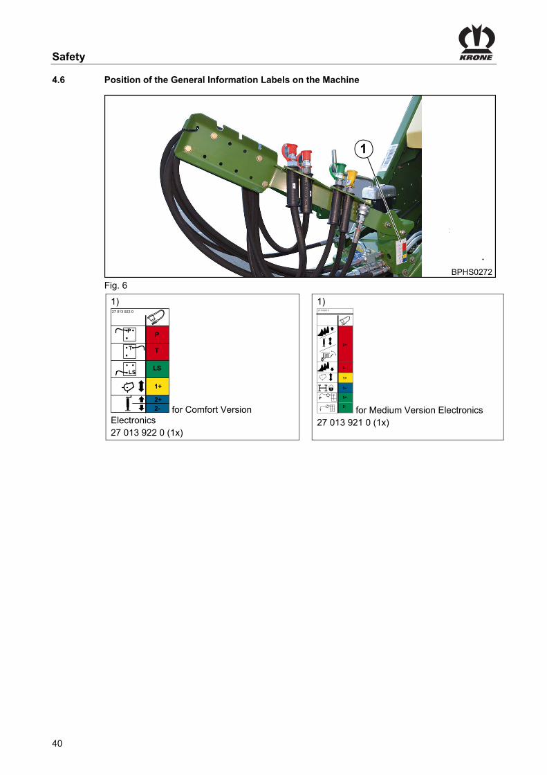
Safety
40
Pos: 54 /Überschriften/Überschriften 2/K-O/Lage der allgemeinen Hinweisaufkleber an der Maschine @ 0\mod_1195635067920_78.docx @ 1039 @ 2 @ 1
4.6 Position of the General Information Labels on the Machine Pos: 55 /BA/Sicherheit/Aufkleber/Großpackenpresse/BiG PACK 870 HDP / 870 HDP XC/Hinweisaufkleber: Bild für alle BiG PACK´s @ 270\mod_1402473391856_78.docx @ 2039271 @ @ 1
1
BPHS0272
Fig. 6 Pos: 56 /BA/Sicherheit/Aufkleber/Großpackenpresse/890 / 1270 / 1290 / 1290 HDP/Hinweisaufkleber: Aufkleber BiG Pack 870_890_1270_1290 HS Baureihe @ 280\mod_1405512356708_78.docx @ 2154885 @ @ 1 GL
1)
1+
2+2-
P
T
LS
P
27 013 922 0
for Comfort Version Electronics 27 013 922 0 (1x)
1)
1+
2+
2-
3+
5+
5-
27 013 921 0
T
P
for Medium Version Electronics 27 013 921 0 (1x)
Pos: 57 /Layout Module /---------------Seitenumbruch---------------- @ 0\mod_1196175311226_0.docx @ 4165 @ @ 1

Safety
41
Pos: 58 /BA/Sicherheit/6. Überarbeitete Warnhinweise/Hinweis - Nachbestellung/ Anbringung Aufkleber @ 0\mod_1195637337107_78.docx @ 1079 @ 23 @ 1
4.6.1 Re-Ordering the Adhesive Safety and Information Labels
Note Every adhesive safety and information label is assigned an order number and can be ordered directly from the manufacturer or from an authorized dealer (see Section "Contact").
4.6.2 Affixing the Adhesive Safety and Information Labels
Note - Affixing an adhesive label Effect: Adhesion of the label • The surface for affixing the adhesive label must be clean and free of dirt, oil and grease.
Pos: 59 /Überschriften/Überschriften 3/A-E/A/Ansprechpartner @ 0\mod_1195569394286_78.docx @ 839 @ 2 @ 1
4.6.3 Contact Pos: 60 /BA/Adressen/Adresse Maschinenfabrik KRONE Spelle @ 0\mod_1195568531083_78.docx @ 734 @ @ 1
Maschinenfabrik Bernard Krone GmbH Heinrich-Krone-Strasse 10 D-48480 Spelle (Germany) Telephone: + 49 (0) 59 77/935-0 (Head Office) Fax.: + 49 (0) 59 77/935-339 (Head Office) Fax.: + 49 (0) 59 77/935-239 (Spare parts - domestic) Fax.: + 49 (0) 59 77/935-359 (Spare parts - export) Email: [email protected]
Pos: 63 /Layout Module /---------------Seitenumbruch---------------- @ 0\mod_1196175311226_0.docx @ 4165 @ @ 1

Safety
42
Pos: 64.1 /Überschriften/Überschriften 2/P-T/Sicherheitsausstattung @ 17\mod_1236613960651_78.docx @ 205812 @ 2 @ 1
4.7 Safety Equipment Pos: 64.2 /Überschriften/Überschriften 3/A-E/AAufstiegsleiter @ 17\mod_1236246728956_78.docx @ 203788 @ 3 @ 1
4.7.1 Ladder Pos: 64.3 /BA/Sicherheit/Aufstiegsleiter/Aufstiegsleiter BiG Pack Bild 870 Baureihe @ 246\mod_1396352298300_78.docx @ 1922950 @ @ 1
1BPHS0266
Fig. 7 Pos: 64.4 /BA/Sicherheit/Aufstiegsleiter/Aufstiegsleiter BiG Pack Text @ 17\mod_1236249494878_78.docx @ 203912 @ @ 1
There is a ladder (1) on the left side of the machine at the rear next to the baling channel that can be used, among other things, for maintenance work on the knotting mechanism.
Pos: 64.5 /Überschriften/Überschriften 3/F-J/Feuerlöscher @ 17\mod_1236247698456_78.docx @ 203839 @ 3 @ 1
4.7.2 Fire extinguisher Pos: 64.6 /BA/Sicherheit/Feuerlöscher/Feuerlöscher Big Pack Bild HS Baureihe @ 62\mod_1299480241001_78.docx @ 571585 @ @ 1
1
BPHS0008
Fig.8 Pos: 64.7 /BA/Sicherheit/Feuerlöscher/Feuerlöscher Text BiG Pack @ 62\mod_1299479944306_78.docx @ 571558 @ @ 1
The machine is equipped with a fire distinguisher (1) ex works. The fire extinguisher (1) is at the front of the drawbar on the left when facing in the direction of travel.
Pos: 64.8 /BA/Sicherheit/Feuerlöscher/Feuerlöscher allgemeiner Text @ 17\mod_1236248193988_78.docx @ 203864 @ @ 1
• Place the fire extinguisher (1) in the provided position on the machine before start-up Have the fire extinguisher registered. This is the only way to ensure that all the required inspections (every two years) will be performed. The inspection intervals may differ from one country to another. In this case, the instructions on the fire extinguisher of the respective countries shall be applicable. • Follow the instructions of the respective countries
Pos: 64.9 /Layout Module /---------------Seitenumbruch---------------- @ 0\mod_1196175311226_0.docx @ 4165 @ @ 1

Safety
43
Pos: 64.10 /Überschriften/Überschriften 3/U-Z/Unterlegkeile @ 33\mod_1254202555660_78.docx @ 318451 @ 3 @ 1
4.7.3 Wheel chocks Pos: 64.11 /BA/Fahren und Transport/Großpackenpresse/Unterlegkeile Bild BP 870 Baureihe @ 246\mod_1396353819558_78.docx @ 1923069 @ @ 1
1BPHS0267
Fig. 9 Pos: 64.12 /BA/Fahren und Transport/Großpackenpresse/Unterlegkeile Text BP HS Baureihe @ 71\mod_1305799627493_78.docx @ 640727 @ @ 1
The wheel chocks (1) are located at the rear on the right and left next to the bale channel chamber • Always place the wheel chocks (1) in front of and behind the wheels (this will prevent the
machine from rolling away).
Note If the machine has a guided coast-down tandem axle (optional), it must be secured with wheel chocks on the front axle to prevent it from rolling away.
Pos: 64.13 /Überschriften/Überschriften 2/P-T/Standbremse / Feststellbremse @ 17\mod_1236322437416_78.docx @ 204755 @ 2 @ 1
4.8 Parking brake Pos: 64.14 /BA/Inbetriebnahme/Feststellbremse/Feststellbremse Bild BiG Pack 890_1270_1290 HS Baureihe @ 92\mod_1326881975736_78.docx @ 782991 @ @ 1
1
BPHS0009_1
Fig. 10 Pos: 64.15 /BA/Inbetriebnahme/Feststellbremse/Standbremse/Feststellbremse Anbringungsort BiG Pack @ 17\mod_1236321925979_78.docx @ 204676 @ @ 1
The crank (1) of the parking brake is located at the rear side of the BiG PACK baler under the baling channel.
Pos: 64.16 /BA/Inbetriebnahme/Feststellbremse/Feststellbremse @ 6\mod_1214898707168_78.docx @ 96756 @ @ 1
The parking brake is used to secure the machine from rolling away accidentally, especially when the machine is disconnected from the tractor. Set the parking brake: • Turn the crank clockwise until the resistance grows noticeably greater. Release the parking brake: • Turn the crank anti-clockwise until the brake cable is slightly slack.
Pos: 64.17 /BA/Inbetriebnahme/Feststellbremse/Hinweis Feststellbremse/Unterlegkeile @ 6\mod_1214899429153_78.docx @ 96796 @ @ 1
Note To prevent the machine from rolling away, use the wheel chocks in addition to the parking brake.
Pos: 64.18 /Layout Module /---------------Seitenumbruch---------------- @ 0\mod_1196175311226_0.docx @ 4165 @ @ 1

Safety
44
Pos: 64.19 /Überschriften/Überschriften 2/P-T/Schwungradbremse @ 71\mod_1305785577816_78.docx @ 639924 @ 2 @ 1
4.9 Flywheel brake Pos: 64.20 /BA/Erstinbetriebnahme/Großpackenpressen/Schwungradbremse/Schwungradbremse Bild BiG PACK 870 Baureihe @ 246\mod_1396360844078_78.docx @ 1923687 @ @ 1
1 1
BPHS0268
Fig. 11 Pos: 64.21 /BA/Erstinbetriebnahme/Großpackenpressen/Schwungradbremse/Schwungradbremse Text @ 71\mod_1305793488785_78.docx @ 640110 @ @ 1
Pos. a = flywheel unbraked Pos. b = flywheel braked The flywheel brake of the flywheel is located at the left side of the machine on the drawbar. The flywheel brake (1) avoids an unexpected start-up of the movable parts of the baler during maintenance works. The flywheel is retained by a brake strap. • To activate the flywheel brake move the brake lever (1) on the flywheel from position
(a = unbraked) into position (b = braked). The flywheel is now braked. When the electronics are turned on, the machine emits a horn signal.
Pos: 64.22 /Überschriften/Überschriften 2/P-T/Stützfuß @ 175\mod_1372676754261_78.docx @ 1502329 @ 3 @ 1
4.10 Parking Jack Pos: 64.23 /BA/Erstinbetriebnahme/Großpackenpressen/Abstellstütze/Abstellstütze Standfläche vergrößern @ 17\mod_1236319619729_78.docx @ 204459 @ @ 1
Note If the ground is soft, enlarge the footprint of the parking jack by placing a wooden plank underneath.
Pos: 64.24 /BA/Erstinbetriebnahme/Großpackenpressen/Abstellstütze/Abstellstütze Bild BiG PAck 870 @ 246\mod_1396364779691_78.docx @ 1924066 @ @ 1
1
BPHS0268
Fig. 12 Pos: 64.25 /BA/Erstinbetriebnahme/Großpackenpressen/Abstellstütze/Auf Abstellstütze abgestellt @ 17\mod_1236318204666_78.docx @ 204361 @ @ 1
As long as the machine is not connected to the tractor, the drawbar is supported on the parking support.
Pos: 64.26 /Layout Module /---------------Seitenumbruch---------------- @ 0\mod_1196175311226_0.docx @ 4165 @ @ 1

Safety
45
Pos: 64.27 /Überschriften/Überschriften 3/F-J/Hydraulischer Stützfuß (optional) @ 17\mod_1236320698604_78.docx @ 204559 @ 3 @ 1
4.10.1 Hydraulic parking jack (optional) Pos: 64.28 /BA/Erstinbetriebnahme/Großpackenpressen/Abstellstütze/Abstellstütze Standfläche vergrößern @ 17\mod_1236319619729_78.docx @ 204459 @ @ 1
Note If the ground is soft, enlarge the footprint of the parking jack by placing a wooden plank underneath.
Pos: 64.29 /BA/Erstinbetriebnahme/Großpackenpressen/Abstellstütze/Hydraulischer Stützfuß Bild @ 282\mod_1406722993466_78.docx @ 2175570 @ @ 1
Fig. 13 Pos: 64.30 /BA/Erstinbetriebnahme/Großpackenpressen/Abstellstütze/Auf Abstellstütze abgestellt @ 17\mod_1236318204666_78.docx @ 204361 @ @ 1
As long as the machine is not connected to the tractor, the drawbar is supported on the parking support.
Pos: 64.31 /BA/Maschinenbeschreibung/Maschinenübersicht/Großpackenpressen/Medium - Elektronik @ 61\mod_1299223169539_78.docx @ 570971 @ @ 1
Medium Version Electronics Pos: 64.32 /BA/Erstinbetriebnahme/Großpackenpressen/Abstellstütze/Hydraulischer Stützfuß Medium Elektronik Bild HS Baureihe @ 92\mod_1326870734408_78.docx @ 782789 @ @ 1
BPHS0012
2
BPHS0014_1
Fig.14 Pos: 64.33 /BA/Erstinbetriebnahme/Großpackenpressen/Abstellstütze/Hydraulischer Stützfuß bei Medium- elektronik allgemein 1290 HDP II Baureihe @ 150\mod_1362046460167_78.docx @ 1343045 @ @ 1
In order to deploy the hydraulic parking jack the shut-off valve at the rear of the machine must first be closed.
Pos: 64.34 /BA/Erstinbetriebnahme/Großpackenpressen/Abstellstütze/Hydraulischer Stützfuß bei Medium- elektronik allgemein 1290 HDP II Baureihe T2 @ 171\mod_1370421411357_78.docx @ 1477222 @ @ 1
The hydraulic parking jack is retracted and extended via lever (2).
Pos: 64.35 /BA/Maschinenbeschreibung/Maschinenübersicht/Großpackenpressen/Komfort - Elektronik @ 61\mod_1299223046976_78.docx @ 570919 @ @ 1
Comfort - Electronic Pos: 64.36 /BA/Erstinbetriebnahme/Großpackenpressen/Abstellstütze/Hydraulischer Stützfuß bei Komfor- elektronik allgemein doppeltwirkendes Steuergerät/Absperrhahn @ 270\mod_1402585019003_78.docx @ 2042238 @ @ 1
The hydraulic support jack is actuated from the double-acting control unit (blue 2+/blue 2-). Stop cock on the support jack The stop cock on the support jack is designed as a safety component to prevent the unintentional actuation of the support jack. Always close the stop cock when transporting the machine; the lever points in the direction of the line.
Pos: 64.37 /Layout Module /---------------Seitenumbruch---------------- @ 0\mod_1196175311226_0.docx @ 4165 @ @ 1

Safety
46
Pos: 64.38 /Überschriften/Überschriften 2/A-E/Absperrhahn Pick-up @ 155\mod_1363682265328_78.docx @ 1373791 @ 2 @ 1
4.11 Shut-Off Valve Pick-up Pos: 64.39 /BA/Erstinbetriebnahme/Großpackenpressen/Absperrhahn Pick-up Bild mit Legende @ 155\mod_1363682181297_78.docx @ 1373728 @ @ 1
Fig. 15
Position (a) pick-up released Position (b) pick-up locked
Pos: 64.40 /BA/Erstinbetriebnahme/Großpackenpressen/Absperrhahn Pick-up sperren Text @ 152\mod_1362738275226_78.docx @ 1357414 @ @ 1
Always lock the pick-up via shut-off valve (1) when transporting the machine or when working under the baler. The shut-off valve is located on the left front machine side on the drawbar.
Pos: 65 /Layout Module /---------------Seitenumbruch---------------- @ 0\mod_1196175311226_0.docx @ 4165 @ @ 1

Safety
47
Pos: 66 /Layout Module /Diese Seite ist bewusst freigelassen worden. @ 1\mod_1201783680373_78.docx @ 54443 @ @ 1
This page has been left blank deliberately!! Pos: 67 /Layout Module /---------------Seitenumbruch---------------- @ 0\mod_1196175311226_0.docx @ 4165 @ @ 1

Machine Description
48
Pos: 68.1 /Überschriften/Überschriften 1/K-O/Maschinenbeschreibung @ 107\mod_1334231806004_78.docx @ 965201 @ 2 @ 1
5 Machine Description Pos: 68.2 /Überschriften/Überschriften 2/K-O/Maschinenübersicht @ 0\mod_1195565731130_78.docx @ 555 @ 3 @ 1
5.1 Machine overview Pos: 68.3 /BA/Maschinenbeschreibung/Maschinenübersicht/Großpackenpressen/Maschinenübersicht linke Seite mit Tandemachse Bild BP 890_1270_1290 HS Baureihe @ 190\mod_1381732621836_78.docx @ 1628834 @ 2 @ 1
5.1.1 Left Side of the BiG Pack Baler with Tandem Axle
BPHS0002_2
25
5 6 7 11
8
1312 14
15
16
171819202123 22
3332
32 4
31
28 2724
26
9 101
2930
Fig. 16 Pos: 68.4 /Layout Module /---------------Seitenumbruch---------------- @ 0\mod_1196175311226_0.docx @ 4165 @ @ 1

Machine Description
49
Pos: 68.5 /BA/Maschinenbeschreibung/Maschinenübersicht/Großpackenpressen/Maschinenübersicht linke Seite mit Tandemachse BP 890_1270_1290 HS @ 191\mod_1381732849098_78.docx @ 1628893 @ @ 1
1 Wide-angle universal shaft 2 Hydraulic oil storage tank
3 Fire extinguisher 4 Compressed air reservoir for the compressed air brake version
5 Control valve block (work hydraulics) for comfort version electronics design only
6 Job computer
7 Twine box left 8 Twine brake
9 Twine motion indicator (upper twine) 10 Tying unit (double knotter)
11 Manual release knotter and knotter shaft lock
12 Wheel chock
13 Moisture measurement (optional) 14 Bale chute (optionally fitted with bale balance)
15 Mechanical locking of the roller chute
16 12V socket
17 Crank for parking brake 18 Manual operation: Comfort version electronics: Bale chute and bale ejector Medium version electronics: Bale chute, bale ejector and parking jack
19 Tandem unit coaster/steering axle 20 Twine control and tensioning system (lower twine)
21 Packer drum drive 22 Cutting system (optional)
23 Pressure limiting valve on-board hydraulic system
24 Pick-up jockey wheel
25 Parking brake “flywheel” 26 Feed drive roller
27 Roller crop guide 28 Parking jack
29 Angular gear with start-up device 30 Towing eye
31 Stopcock for pick-up 32 Support for quick couplings and plug
33 Tool box
Pos: 68.6 /Layout Module /---------------Seitenumbruch---------------- @ 0\mod_1196175311226_0.docx @ 4165 @ @ 1

Machine Description
50
Pos: 68.7 /BA/Maschinenbeschreibung/Maschinenübersicht/Großpackenpressen/Maschinenübersicht rechte Seite mit Tandemachse Bild BP 890_1270_1290 HS Baureihe @ 191\mod_1381736430462_78.docx @ 1629035 @ @ 1
Right-hand Side of the Machine
3
BPHS0003_2
9 810
61 2
711
5
4
Fig. 17 Pos: 68.8 /Layout Module /---------------Seitenumbruch---------------- @ 0\mod_1196175311226_0.docx @ 4165 @ @ 1

Machine Description
51
Pos: 68.9 /BA/Maschinenbeschreibung/Maschinenübersicht/Großpackenpressen/Maschinenübersicht rechte Seite Nachlauf-Lenkachse Text BP 890_1270_1290 HS 7 4x4 @ 191\mod_1381736499559_78.docx @ 1629074 @ @ 1
1) Moisture measurement (optional) 2) Central lubrication (grease)
3) Twine brake 4) Twine box right
5) Compressed air reservoir (knotter cleaning)
6) Stopcock caster axle (optional)
7) Drawbar 8) Pick-up drive
9) Cutting system drive 10) Variable filling system (VFS)
11) Wheel chock
Pos: 68.10 /Layout Module /---------------Seitenumbruch---------------- @ 0\mod_1196175311226_0.docx @ 4165 @ @ 1

Machine Description
52
Pos: 68.11 /Überschriften/Überschriften 2/K-O/Kennzeichnung @ 0\mod_1195564622099_78.docx @ 496 @ 2 @ 1
5.2 Identification Plate Pos: 68.12 /BA/Einleitung/Kennzeichnung/BiG Pack/Kennzeichnung BiG PAck @ 17\mod_1236164057449_78.docx @ 201362 @ @ 1
BPXC0100
Maschinenfabrik Bernard Krone GmbHHeinrich-Krone-Str. 10 D-48480 Spelle
Made inGermany
Fig. 18 The machine data are located on the type plate (1). This is located on right-hand side of the machine.
Pos: 68.13 /BA/Einleitung/Kennzeichnung/Angaben für Anfrage und Bestellungen_Fahrzeugident-Nr. @ 0\mod_1195565119708_78.docx @ 515 @ 2 @ 1
5.3 Information Required for Questions and Orders
Type
Year of manufacture
Vehicle ID number
Note The entire identification plate represents a legal document and should not be altered or rendered illegible!
When asking questions concerning the machine or ordering spare parts, be sure to provide type designation, vehicle ID number and the year of manufacture : To ensure that these data are always available, we recommend that you enter them in the fields above.
Note Authentic KRONE spare parts and accessories authorised by the manufacturer help to ensure safety. The use of spare parts, accessories and other devices which are not manufactured, tested or approved by KRONE will result in the revoking of the liability for damages resulting thereof.
Pos: 68.14 /Überschriften/Überschriften 3/A-E/AAnsprechpartner @ 0\mod_1195569394286_78.docx @ 839 @ 3 @ 1
5.3.1 Contact Pos: 68.15 /BA/Adressen/Adresse Maschinenfabrik KRONE Spelle @ 0\mod_1195568531083_78.docx @ 734 @ @ 1
Maschinenfabrik Bernard Krone GmbH Heinrich-Krone-Strasse 10 D-48480 Spelle (Germany) Telephone: + 49 (0) 59 77/935-0 (Head Office) Fax.: + 49 (0) 59 77/935-339 (Head Office) Fax.: + 49 (0) 59 77/935-239 (Spare parts - domestic) Fax.: + 49 (0) 59 77/935-359 (Spare parts - export) Email: [email protected]
Pos: 68.16 /Layout Module /---------------Seitenumbruch---------------- @ 0\mod_1196175311226_0.docx @ 4165 @ @ 1

Machine Description
53
Pos: 68.17 /BA/Maschinenbeschreibung/Maschinenübersicht/Großpackenpressen/Beschreibung Pressvorgang @ 153\mod_1363008350826_78.docx @ 1359371 @ 2 @ 1
5.4 Description of the Baling Process
When switching on the terminal, the terminal shows at first the manual mode basic screen. Starting with an empty bale channel In manual mode, pre-set the target bale channel flap pressure to 50 bar / 725 PSI (in case of dry crops, e. g. straw) and to 25 bar / 362 PSI (in case of silage). Do not pick up the swath until the set target bale channel flap pressure is reached in the terminal to ensure that the bale is complete and to prevent the bale channel flaps from bending out of shape. Press two bales in manual mode to fill the bale channel completely. To always achieve the same solidity of bales automatically with materials of different properties (for example with differing moisture content of materials on the same field), you should then switch into Automatic mode. In automatic mode, the target force of pressure must be set to a high enough level so that the bale has the desired bale firmness. The contact pressure of the bale channel flaps in the bale channel is controlled automatically by the job computer so that the pre-selected baling force is reached. As the material becomes moister, it becomes more difficult to compress the bales. Because of this, the bale channel flap pressure is reduced somewhat. As the material becomes drier, the bale channel flap pressure increases again. Thus the pressure display may deviate significantly in the display. Bale quality and bale firmness remain constant. Starting with full bale channel Do not switch to automatic mode until the target bale channel flap pressure has been reached in manual mode. If baling should be done in manual mode, do only pick up the swath if the target bale channel flap pressure has been reached.
Pos: 68.18 /Layout Module /---------------Seitenumbruch---------------- @ 0\mod_1196175311226_0.docx @ 4165 @ @ 1

Machine Description
54
Pos: 68.19 /BA/Maschinenbeschreibung/Maschinenübersicht/Großpackenpressen/Verdichten des Großpackens alle BiG PACK´s @ 151\mod_1362137260923_78.docx @ 1345221 @ 3 @ 1
5.5 Compacting the BiG Bale
The machine enables pressing hay and straw to a highly compacted big bale (square balers). The square baler is compacted in eight steps. 1. The crop is picked up by the pick-up. 2. The roller crop guide with the feed drive roller behind ensures a trouble-free pick-up of the
crop. Design without cutting system: • The integrated feed drive roller conveys the crop to the packer drum. Design with cutting system: • The integrated feed drive roller conveys the crop to the cutting rotor and then further to
the packer drum. 3. The packer drum fills the packer channel as well as the conveyor channel. 4. When a determined filling level has been reached, the feeler rocker is swung back and the
bale channel is filled via the feeder packer with the crop. 5. The crop is pressed in the bale channel to a highly compacted big bale. 6. The knotting mechanism is triggered and the big bale is tied after the set bale length has
been reached. 7. The next big bale conveys the big bale further to the bale chute. From the bale chute, the
big bale is laid down on the field. 8. The last big bale is conveyed to the bale chute via the bale ejector.
Pos: 68.20 /Layout Module /---------------Seitenumbruch---------------- @ 0\mod_1196175311226_0.docx @ 4165 @ @ 1

Machine Description
55
Pos: 68.21 /BA/Bedienung /Großpackenpresse/Asführung MultiBale (optional) HS Baureihe @ 190\mod_1381392160650_78.docx @ 1625439 @ 2 @ 1
5.6 MultiBale Design
I
Fig. 19 For the MultiBale version, the big bales are held together by 4 twines and the small bales are held together by 2 twines each. If the MultiBale function is turned off, the conventional big bale is still bound up by 6 twines. If the MultiBale function has been preselected, the small bales are wrapped with the front needle yoke (1). The entire bale is tied with the needle yoke (2) that is connected in the rear. A pneumatic cylinder (3) is used to couple the individual needle yokes. The cylinder activates the interlock ratchet mechanism (5). The control block of the pneumatic cylinder (3) is controlled directly by the comfort version electronics. In case of MultiBale design, the number of small bales is limited to six units in the factory. The minimum length of the small bales is set to 45 cm. This results in a variable length of the small bale from 45 cm to 135 cm if the total length (270 cm) of the big bale is at a maximum. Therefore, the set number of small bales depends on the bale length and the minimum length of the small bales. If you want to increase the number of small bales to max. 9 units, please contact your KRONE dealer. In case of 9 small bales, the variable length of the small bales is 30 cm to 135 cm. If you have set more than 6 small bales, problems with the knotter may increasingly occur. The bale length and the number of layers are set from the tractor via the terminal, refer to chapter Terminal “Setting the Number of MultiBales”.
Note • To minimise wear in the single parts, lock the both needle yokes via perforated bar (4) if the
MultiBale function is not required for an extended period of time. • This function will not be executed if the MultiBale function is selected on the terminal with
locked needle yoke. An error message appears in the display of the terminal. • As the total bale is held by four twines, make sure when working with a machine with
MultiBale that a high-quality twine (100-130 m/kg) is used. • Disconnect the twines (a,c,d,f) in order to loosen the total bale into small bales.
Pos: 68.22 /BA/Bedienung /Großpackenpresse/Schichtdicke ermitteln MultiBale @ 190\mod_1381329569792_78.docx @ 1624902 @ @ 1

Machine Description
56
Fig. 20
a) Big bale / length of the big bale
b) Small bale / length of the small bale
c) Layer thickness of the small bale / number of layers
The bale length and the number of small bales (from 2 to 9) must only be set at the beginning of a bale to get ideal small bales. The layer thicknesses of the small bales must be a multiple of the length of the small bale. It must be read on the display while the swath is picked-up. The layer thickness depends on the travelling speed and the uniformity of the swath. The faster you drive, the thicker the layer thickness. It is more difficult to get an ideal small bale if the travelling speed is high. It is not possible to select layer thicknesses of more than 17 cm / 6.6 inch. The determined layer thickness must be maintained during the entire baling process. The length of the small bale is determined by the length of the big bale (a) divided by the number of small bales. Example: The desired bale length is 240 cm / 94 inch. The number of the desired small bales is 5 units. Determining the length of the small bales
b = a / 5 (a= 240 cm / 5 = 48 cm) b = a / 6 (a= 94 inch / 6 = 19 inch)
Determining the layer thickness Based on a length of the small bale of 48 cm / 19 inch in this example, the following layer thicknesses result depending on the number of layers: The layer thickness is calculated from the length of the small bale divided by the number (z) of the desired layers. c = a / z
Number (z) of layers Layer thickness (c) in cm/inch Evaluation
2 24 cm / 9 inch -
3 16 cm / 6 inch o
4 12 cm / 5 inch ++
5 10 cm / 4 inch +
6 8 cm / 3 inch ++
7 7 cm / 2.7 inch ++
8 6 cm / 2.4 inch ++
9 5 cm / 2 inch -
Pos: 68.23 /Layout Module /---------------Seitenumbruch---------------- @ 0\mod_1196175311226_0.docx @ 4165 @ @ 1

Machine Description
57
Pos: 68.24 /Überschriften/Überschriften 2/A-E/Antriebe @ 20\mod_1238751478183_78.docx @ 225045 @ 3 @ 1
5.7 Drives Pos: 68.25 /Überschriften/Überschriften 3/F-J/Hauptantrieb @ 20\mod_1238751529465_78.docx @ 225070 @ 2 @ 1
5.7.1 Main drive Pos: 68.26 /BA/Bedienung /Großpackenpresse/Antriebe/Hauptantrieb allgemein 1000 U/min HS Typen T1 @ 191\mod_1381825794687_78.docx @ 1631289 @ @ 1
1
2
3
4
5
Fig. 21 The maximum drive speed must not exceed 1000 rpm. The drive universal shaft (1) transmits the drive output of the tractor further to the intermediate bearing (2). The intermediate bearing transmits the force further to the intermediate universal shaft (3). The intermediate universal shaft drives the flywheel (4). The flywheel drives the main gearbox (5). The main gearbox The main gearbox distributes the force further to the right and left and drives the following gearboxes:
Pos: 68.27 /Überschriften/linke Maschinenseite @ 60\mod_1297934981687_78.docx @ 562715 @ @ 1
Left-hand Side of the Machine Pos: 68.28 /BA/Bedienung /Großpackenpresse/Antriebe/Hauptantrieb allgemein 1000 U/min HS Typen T2 @ 192\mod_1382020040164_78.docx @ 1636691 @ @ 1
Fig. 22 The main gearbox drives the transfer gearbox (1). The transfer gearbox drives the packer gearbox (2) and the knotter gear (3).
Pos: 68.29 /Layout Module /---------------Seitenumbruch---------------- @ 0\mod_1196175311226_0.docx @ 4165 @ @ 1

Machine Description
58
Pos: 68.30 /Überschriften/rechte Maschinenseite @ 60\mod_1297935179130_78.docx @ 562741 @ @ 1
Right-hand Side of the Machine Pos: 68.31 /Abkürzungen /Bei Ausführung mit Schneidwerk @ 157\mod_1364379388830_78.docx @ 1387653 @ @ 1
Design with cutting system Pos: 68.32 /BA/Bedienung /Großpackenpresse/Antriebe/Hauptantrieb allgemein 1000 U/min HS Typen T3 @ 192\mod_1382020204775_78.docx @ 1636720 @ @ 1
Fig. 23 The main gearbox drives the upper angular gear (1). The upper angular gear drives the intermediate shaft (2). The intermediate shaft transmits the torque via overload coupling (3) onto the cutting system gearbox (4). The cutting system gear drives the cutting system.
Pos: 68.33 /Abkürzungen /Bei Ausführung ohne Schneidwerk @ 157\mod_1364379318831_78.docx @ 1387595 @ @ 1
Design without cutting system Pos: 68.34 /BA/Bedienung /Großpackenpresse/Antriebe/Hauptantrieb allgemein 1000 U/min HS Typen T4 @ 192\mod_1382020424090_78.docx @ 1636749 @ @ 1
Fig. 24 The main gearbox drives the upper angular gear (1). The upper angular gear drives the universal shaft (2). The universal shaft transmits the torque to the pick-up gearbox (3). The pick-up gearbox drives the pick-up.
Pos: 68.35 /Layout Module /---------------Seitenumbruch---------------- @ 0\mod_1196175311226_0.docx @ 4165 @ @ 1

Machine Description
59
Pos: 68.36 /Überschriften/Überschriften 2/U-Z/Überlastsicherung an der Maschine @ 155\mod_1363674757378_78.docx @ 1373335 @ 2 @ 1
5.8 Overload Protections on the Machine Pos: 68.37 /BA/Bedienung /Großpackenpresse/Überlastsicherungen / Kupplungen / Sternratsche / Scherschraube/Überlastsicherungen an der Maschine: Nachfolgende Komponenten werden geschützt @ 155\mod_1363346950723_78.docx @ 1371086 @ @ 1
The following components are protected by overload protections against damages.
Pos: 68.38 /Überschriften/Überschriften 3/F-J/Hauptantrieb @ 20\mod_1238751529465_78.docx @ 225070 @ 3 @ 1
5.8.1 Main drive Pos: 68.39 /BA/Bedienung /Großpackenpresse/Überlastsicherungen / Kupplungen / Sternratsche / Scherschraube/Überlastsicherung am Schwungrad Bild 1270/1290/1290 HDP/4x4 HS Baureihe @ 191\mod_1381830017074_78.docx @ 1631697 @ @ 1
Fig. 25 Pos: 68.40 /BA/Bedienung /Großpackenpresse/Überlastsicherungen / Kupplungen / Sternratsche / Scherschraube/Überlastsicherung am Schwungrad @ 155\mod_1363675408463_78.docx @ 1373538 @ @ 1
A friction clutch (1) and a cam-type clutch (2) are located on the flywheel. The friction clutch (1) protects the tractor, the drive PTO shaft and the intermediate universal shaft against load peaks. The cam-type clutch (2) protects the machine against load peaks.
Pos: 68.41 /BA/Bedienung /Großpackenpresse/Antriebe/Hauptantrieb Nockenschaltkupplung Hinweis @ 20\mod_1238753739308_78.docx @ 225139 @ @ 1
Note As soon as the coupling responds, stop the tractor, disengage the P.T.O. shaft without delay and brake the flywheel. After the fault is rectified, the cam-type clutch engages again automatically.
Pos: 68.42 /Überschriften/Überschriften 3/P-T/Rafferantrieb @ 155\mod_1363676783571_78.docx @ 1373596 @ 3 @ 1
5.8.2 Feeder Packer Pos: 68.43 /BA/Bedienung /Großpackenpresse/Überlastsicherungen / Kupplungen / Sternratsche / Scherschraube/Überlastsicherung am Raffergetriebe Bild mit gelber Walterscheid Kupplung @ 191\mod_1381831362300_78.docx @ 1631861 @ @ 1
Fig. 26 Pos: 68.44 /BA/Bedienung /Großpackenpresse/Überlastsicherungen / Kupplungen / Sternratsche / Scherschraube/Überlastsicherung am Raffergetriebe @ 155\mod_1363675259453_78.docx @ 1373480 @ @ 1
A cam-type clutch is located on the packer gearbox. The cam-type clutch protects the packer gearbox against load peaks.
Pos: 68.45 /BA/Bedienung /Großpackenpresse/Überlastsicherungen / Kupplungen / Sternratsche / Scherschraube/Hinweis Überlastkupplung angesprochen @ 136\mod_1353062689925_78.docx @ 1213829 @ @ 1
Note As soon as the overload coupling responds, stop the tractor and reduce the speed until the machine has cleared itself again. The overload coupling now automatically resumes its work. An error message appears in the display of the control unit.
Pos: 68.46 /Layout Module /---------------Seitenumbruch---------------- @ 0\mod_1196175311226_0.docx @ 4165 @ @ 1
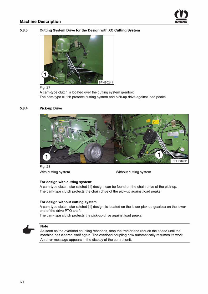
Machine Description
60
Pos: 68.47 /Überschriften/Überschriften 3/P-T/Schneidwerkantrieb @ 192\mod_1382011621479_78.docx @ 1635994 @ 3 @ 1
5.8.3 Cutting System Drive for the Design with XC Cutting System Pos: 68.48 /BA/Bedienung /Großpackenpresse/Überlastsicherungen / Kupplungen / Sternratsche / Scherschraube/Überlastsicherung des Schneidwerks und der Pick-up, Ausführung HS mit Schneidwerk @ 136\mod_1353063267793_78.docx @ 1213945 @ @ 1
Fig. 27 A cam-type clutch is located over the cutting system gearbox. The cam-type clutch protects cutting system and pick-up drive against load peaks.
Pos: 68.49 /Überschriften/Überschriften 3/P-T/Pick-up Antrieb @ 155\mod_1363676829227_78.docx @ 1373624 @ 3 @ 1
5.8.4 Pick-up Drive Pos: 68.50 /BA/Bedienung /Großpackenpresse/Überlastsicherungen / Kupplungen / Sternratsche / Scherschraube/Überlastsicherung der Pick-up Bild mit Legende HS Maschinen @ 191\mod_1381831704061_78.docx @ 1631894 @ @ 1
1 1
Fig. 28
With cutting system Without cutting system
Pos: 68.51 /BA/Bedienung /Großpackenpresse/Überlastsicherungen / Kupplungen / Sternratsche / Scherschraube/Überlastsicherung der Pick-up, bei Ausführung mit Schneidwerk @ 155\mod_1363675037552_78.docx @ 1373392 @ @ 1
For design with cutting system: A cam-type clutch, star ratchet (1) design, can be found on the chain drive of the pick-up. The cam-type clutch protects the chain drive of the pick-up against load peaks.
Pos: 68.52 /BA/Bedienung /Großpackenpresse/Überlastsicherungen / Kupplungen / Sternratsche / Scherschraube/Überlastsicherung der Pick-up, bei Ausführung ohne Schneidwerk @ 155\mod_1363674948297_78.docx @ 1373364 @ @ 1
For design without cutting system A cam-type clutch, star ratchet (1) design, is located on the lower pick-up gearbox on the lower end of the drive PTO shaft. The cam-type clutch protects the pick-up drive against load peaks.
Pos: 68.53 /BA/Bedienung /Großpackenpresse/Überlastsicherungen / Kupplungen / Sternratsche / Scherschraube/Hinweis Überlastkupplung angesprochen @ 136\mod_1353062689925_78.docx @ 1213829 @ @ 1
Note As soon as the overload coupling responds, stop the tractor and reduce the speed until the machine has cleared itself again. The overload coupling now automatically resumes its work. An error message appears in the display of the control unit.
Pos: 68.54 /Layout Module /---------------Seitenumbruch---------------- @ 0\mod_1196175311226_0.docx @ 4165 @ @ 1

Machine Description
61
Pos: 68.55 /Überschriften/Überschriften 3/K-O/Nadelschwinge @ 158\mod_1365140055004_78.docx @ 1405035 @ 2 @ 1
5.8.5 Needle Yoke Pos: 68.56 /BA/Bedienung /Großpackenpresse/Überlastsicherungen / Kupplungen / Sternratsche / Scherschraube/Überlastsicherung der Nadelschwinge / Scherschraube Bild alle HS-Typen außer 1290 HDP II @ 192\mod_1382077992442_78.docx @ 1637526 @ @ 1
Fig. 29 Pos: 68.57 /BA/Bedienung /Großpackenpresse/Überlastsicherungen / Kupplungen / Sternratsche / Scherschraube/Überlastsicherung der Nadelschwinge / Scherschraube alle HS-Typen außer 1290 HDP II @ 191\mod_1381737358783_78.docx @ 1629117 @ @ 1
Shear screw The connecting rod (1) of the needle yoke is secured by a shear screw, left-hand side of the machine. The shear screw protects the needles and the needle yokes against load peaks.
Pos: 68.58 /Überschriften/Überschriften 2/P-T/Pick-up @ 55\mod_1292568679348_78.docx @ 521315 @ 2 @ 1
5.9 Pick-up Pos: 68.59 /BA/Maschinenbeschreibung/Maschinenübersicht/Funktionsweise/Großpackenpressen/Pick-up Funktionsbeschreibung Bild 1290 HDP II ohne XC @ 157\mod_1364315127180_78.docx @ 1385997 @ @ 1
Fig. 30
1) Pick-up 2) Guide wheel
3) Spring 4) Depth limiter
Pos: 68.60 /BA/Maschinenbeschreibung/Maschinenübersicht/Funktionsweise/Großpackenpressen/Pick-up Funktionsbeschreibung T1 bei Ausführung ohne Schneidwerk @ 168\mod_1367991064915_78.docx @ 1452404 @ @ 1
The pick-up is used to pick up the crop. The pick-up starts to rotate by turning on the PTO shaft.
Pos: 68.61 /BA/Maschinenbeschreibung/Maschinenübersicht/Funktionsweise/Großpackenpressen/Pick-up Funktionsbeschreibung T2 @ 151\mod_1362580095635_78.docx @ 1353783 @ @ 1
The pick-up is lifted and lowered by the single-acting control unit on the tractor. The pick-up is equipped with guide wheels. The working height of the pick-up is adjusted via these guide wheels. The working height of the pick-up can be limited downwards on both sides of the machine via the depth limiter. This makes it possible to drive the machine without guide wheels with the pick-up in fixed position. The ground pressure of the guide wheels can be adapted to the ground conditions via the spring.
Pos: 68.62 /Layout Module /---------------Seitenumbruch---------------- @ 0\mod_1196175311226_0.docx @ 4165 @ @ 1

Machine Description
62
Pos: 68.63 /Überschriften/Überschriften 2/P-T/Rollenniederhalter @ 0\mod_1201163046930_78.docx @ 51122 @ 3 @ 1
5.10 Roller crop guide Pos: 68.64 /BA/Maschinenbeschreibung/Maschinenübersicht/Funktionsweise/Großpackenpressen/Rollenniederhalter mit Einzugwalze Funktionsbeschreibung Bild HS Baureihe @ 208\mod_1386843347201_78.docx @ 1718143 @ @ 1
Fig. 31
1) Feed drive roller 2) Holding-down device roller
3) Roller crop guide 4) Retaining chain
5) Spring
Pos: 68.65 /BA/Maschinenbeschreibung/Maschinenübersicht/Funktionsweise/Großpackenpressen/Rollenniederhalter mit Einzugwalze Funktionsbeschreibung @ 152\mod_1362637505506_78.docx @ 1354015 @ @ 1
The roller crop guide and the feed drive roller ensure the regulation when conveying the crop. They ensure a continuous crop collection by the pick-up. The height of the roller crop guide can be adjusted via retaining chain (height of the swath). Much crops: Hook in roller crop guide higher Less crops: Hook in roller crop guide lower The ground pressure of the holding-down device roller on the swath is set by the spring. Dry crops: Increase ground pressure Moist crops: Reduce ground pressure
Pos: 68.66 /Überschriften/Überschriften 2/P-T/Schneidwerk @ 20\mod_1238593156760_78.docx @ 223560 @ 2 @ 1
5.11 Cutting system Pos: 68.67 /BA/Maschinenbeschreibung/Schneidwerk/Allgemeines Schneidwerk BigPack ohne Blindmesser @ 91\mod_1326705764014_78.docx @ 780502 @ 1 @ 1
5.11.1 General
The Big Pack XC has a cutting system with a cutting cylinder and fixed blades. Cutting allows for improved further processing of the big pack and makes it possible to increase the density of baled material. The blades can be swivelled out of the conveyor channel from the tractor hydraulically if there are blockages. Each blade is separately protected against overload. The machine can also be used without blades. The cutting cylinder then takes over the function of a conveyor between the pick-up and the pre-baling channel.
Pos: 68.68 /Überschriften/Überschriften 3/P-T/Schnittlänge @ 280\mod_1405513151074_78.docx @ 2154911 @ 3 @ 1
5.11.2 Cutting Length Pos: 68.69 /BA/Maschinenbeschreibung/Schneidwerk/Schnittlänge BigPack BiG PACK 890 HS / 870 HDP mit 16 Messer @ 192\mod_1382080824345_78.docx @ 1637759 @ @ 1
The cutting system can be fitted with max. 16 blades. The blades are subdivided into two groups (upper blade control system and lower blade control system). The theoretical cutting length is, with full equipping, 44 mm. The cutting length is determined by the number of used blades and the position of blade control systems. In case of full equipping, 0, 8, 8 or 16 blades can optionally be set via the upper and the lower blade control system.
Pos: 68.70 /Layout Module /---------------Seitenumbruch---------------- @ 0\mod_1196175311226_0.docx @ 4165 @ @ 1
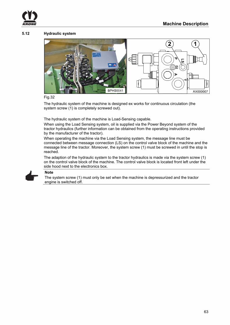
Machine Description
63
Pos: 68.71 /Überschriften/Überschriften 2/F-J/Hydrauliksystem @ 274\mod_1404363871846_78.docx @ 2064995 @ 2 @ 1
5.12 Hydraulic system Pos: 68.72 /BA/Wartung/Load-Sensing/Großpackenpresse/Bild Load-Sensing Anschluss HS Baureihe @ 64\mod_1300278753983_78.docx @ 582789 @ @ 1
Fig.32 Pos: 68.73 /BA/Wartung/Load-Sensing/Das Hydrauliksystem der Maschine ist werksseitig auf Dauerumlauf @ 121\mod_1343828402858_78.docx @ 1108849 @ @ 1
The hydraulic system of the machine is designed ex works for continuous circulation (the system screw (1) is completely screwed out).
Pos: 68.74 /BA/Wartung/Load-Sensing/Maschine ist Load-Sensing fähig @ 121\mod_1343827288765_78.docx @ 1108791 @ @ 1
The hydraulic system of the machine is Load-Sensing capable. When using the Load Sensing system, oil is supplied via the Power Beyond system of the tractor hydraulics (further information can be obtained from the operating instructions provided by the manufacturer of the tractor). When operating the machine via the Load Sensing system, the message line must be connected between message connection (LS) on the control valve block of the machine and the message line of the tractor. Moreover, the system screw (1) must be screwed in until the stop is reached.
Pos: 68.75 /BA/Wartung/Load-Sensing/Großpackenpresse/Anpassen des Hydrauliksystems an die Traktorhydraulik @ 151\mod_1362464892689_78.docx @ 1348965 @ @ 1
The adaption of the hydraulic system to the tractor hydraulics is made via the system screw (1) on the control valve block of the machine. The control valve block is located front left under the side hood next to the electronics box.
Pos: 68.76 /BA/Wartung/Load-Sensing/Hinweis Nur im drucklosen Zustand der Maschine Systemschraube einstellen @ 121\mod_1343831248507_78.docx @ 1108878 @ @ 1
Note The system screw (1) must only be set when the machine is depressurized and the tractor engine is switched off.
Pos: 68.77 /Layout Module /---------------Seitenumbruch---------------- @ 0\mod_1196175311226_0.docx @ 4165 @ @ 1
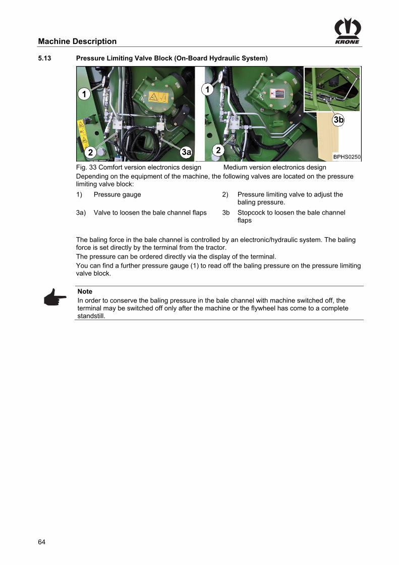
Machine Description
64
Pos: 68.78 /BA/Maschinenbeschreibung/BiG PAck/Preßkraftregulierung / Druckbegrenzungsventil-Block 890/1270/1290/1290 HDP (HS) @ 194\mod_1383579575073_78.docx @ 1650652 @ 1 @ 1
5.13 Pressure Limiting Valve Block (On-Board Hydraulic System)
Fig. 33 Comfort version electronics design Medium version electronics design Depending on the equipment of the machine, the following valves are located on the pressure limiting valve block:
1) Pressure gauge 2) Pressure limiting valve to adjust the baling pressure.
3a) Valve to loosen the bale channel flaps 3b Stopcock to loosen the bale channel flaps
The baling force in the bale channel is controlled by an electronic/hydraulic system. The baling force is set directly by the terminal from the tractor. The pressure can be ordered directly via the display of the terminal. You can find a further pressure gauge (1) to read off the baling pressure on the pressure limiting valve block.
Pos: 68.79 /BA/Info-Center/CCI-ISOBUS-Terminal/Ein- Ausschalten des Terminal s/Hinweis Ausschalten des Terminal Um den Pressdruck aufrecht zu erhalten BiG Pack @ 152\mod_1362639559715_78.docx @ 1354150 @ @ 1
Note In order to conserve the baling pressure in the bale channel with machine switched off, the terminal may be switched off only after the machine or the flywheel has come to a complete standstill.
Pos: 68.80 /Layout Module /---------------Seitenumbruch---------------- @ 0\mod_1196175311226_0.docx @ 4165 @ @ 1

Machine Description
65
Pos: 68.81 /Überschriften/Überschriften 2/A-E/Bindegarn @ 20\mod_1238751359527_78.docx @ 225020 @ 2 @ 1
5.14 Twine Pos: 68.82 /Überschriften/linke Maschinenseite @ 60\mod_1297934981687_78.docx @ 562715 @ @ 1
Left-hand Side of the Machine Pos: 68.83 /BA/Einstellungen/Großpackenpresse/Bindegarn einfädeln/Bindeeinrichtung 6 Doppelknoter/Bidegarn verbinden im Garnkasten6 Doppelknoter Bild 16 Rollen 3 Ober-/ Unterfäden @ 208\mod_1386927926341_78.docx @ 1720302 @ @ 1
3a 2a 1a
3b 2b 1b 3b 3c 2c
3a 2a 2b
2c
2a 2b
1c
1a 1b
Fig. 34
1) Twine rolls for upper twine 2) Twine rolls for lower twine
Pos: 68.84 /Überschriften/rechte Maschinenseite @ 60\mod_1297935179130_78.docx @ 562741 @ @ 1
Right-hand Side of the Machine Pos: 68.85 /BA/Einstellungen/Großpackenpresse/Bindegarn einfädeln/Bindeeinrichtung 5 Doppelknoter 870 HDP/Bidegarn verbinden im Garnkasten 5 Doppelknoter Bild 16 Rollen 2 Ober-/ Unterfäden rechte Seite @ 270\mod_1402489906275_78.docx @ 2039830 @ @ 1
4a5a4c
4b5b4d4b5b5d
4a5a5c
Fig. 35
1) Twine rolls for upper twine 2) Twine rolls for lower twine
Pos: 68.86 /BA/Einstellungen/Großpackenpresse/Bindegarn einfädeln/Bindeeinrichtung 5 Doppelknoter 870 HDP/Bindeeinrichtung allgemein 5 Doppelknoter 16 Rollen @ 230\mod_1393332538174_78.docx @ 1843800 @ @ 1
The large-square baler is equipped with twine boxes on both sides of the machine. Each is capable of holding 16 rolls of tying twine. Of these, the twine rolls identified with an (R) are spare rolls. Each of the five knotters is fed with an upper twine and a lower twine. The five knotters are numbered from left to right. From the left twine box, three upper twines and three lower twines are fed to the knotters (1, 2, 3). One upper twine and one lower twine is fed to each knotter (1, 2, 3). From the right-hand twine box, two upper twines and two lower twines are feed to the knotters (4, 5). One upper twine and one lower twine is fed to each of the knotters (4, 5). Twice as many twine rolls are provided for the lower twine because approx. double the amount of lower twine is required to reach around the underside and both ends of the bale. The upper twine only encompasses the upper side of the bale. To ensure sufficient tying safety, you must be careful only to use synthetic twine that has a running length of 100-130 m/kg.
Pos: 68.87 /BA/Einstellungen/Großpackenpresse/Bindegarn einfädeln/Hinweis Verwenden Sie nur KRONE Original Bindegarn @ 32\mod_1253083955561_78.docx @ 308448 @ @ 1
Note Only use original KRONE twine
Pos: 68.88 /Layout Module /---------------Seitenumbruch---------------- @ 0\mod_1196175311226_0.docx @ 4165 @ @ 1

Machine Description
66
Pos: 68.89 /BA/Bedienung /Großpackenpresse/Elektrische Garnfehlanzeige Unterfaden @ 270\mod_1402586863488_78.docx @ 2042267 @ 3 @ 1
5.14.1 Electrical twine empty display for lower thread
Fig. 36 If the end of the lower twine is reached or has been torn, the stretching twine tensioners (1) come to rest on the pivoting angle (2). An acoustic warning signal sounds on the terminal. An error message will appear in the display.
Note The acoustic warning signal can be switched off while the twine is threaded in, see chapter KRONE ISOBUS Terminal "Alarm message".
Pos: 68.90 /Layout Module /---------------Seitenumbruch---------------- @ 0\mod_1196175311226_0.docx @ 4165 @ @ 1

Machine Description
67
Pos: 68.91 /BA/Bedienung /Großpackenpresse/Garnlaufanzeige Oberfaden (Doppelknoter) @ 20\mod_1238741788902_78.docx @ 224916 @ 3 @ 1
5.14.2 Twine motion indicator upper twine (double knotter)
Fig. 37 The upper twine motion is monitored by reflectors (twine motion indicator) positioned above the machine. While the bale is being formed, the twine motion indicator should move back and forth in a pulsing cycle. All indicators generally rise and lower at the same time except in the event of a malfunction. A malfunction of this nature is indicated by the fact that the twine motion indicator that is featuring a malfunction will not be in the same position as the other indicators. The following malfunctions can be indicated: The twine motion indicators are staying up: • Twine has wound around the knotter hook • The needle has not caught the upper strand of twine (twine will not be cut through) • The knot has been left hanging on the knotter hook (after the tying is complete, one twine
motion indicator remains down longer than the other) The twine motion indicators are staying down: • Twine tension is too low • The upper twine strand is torn • The knotter hook has not tied a knot
Pos: 68.92 /Überschriften/Überschriften 3/A-E/EElektrische Knoterkontrolle @ 168\mod_1367993462294_78.docx @ 1452492 @ 3 @ 1
5.14.3 Electrical Knotter Monitoring Pos: 68.93 /BA/Bedienung /Großpackenpresse/Knoterkontrolle alle BiG PACK´s @ 168\mod_1367993641881_78.docx @ 1452550 @ @ 1
BPHS0015
Fig. 38 The machine is equipped with an electrical knotter monitoring. In this process, each knotter is monitored individually by a sensor (1). If an error occurs on the knotter, the appropriate error message appears in the display of the operation terminal. The knotters are numbered in direction of travel from the left to the right from 1 to 8.
Pos: 68.94 /Layout Module /---------------Seitenumbruch---------------- @ 0\mod_1196175311226_0.docx @ 4165 @ @ 1
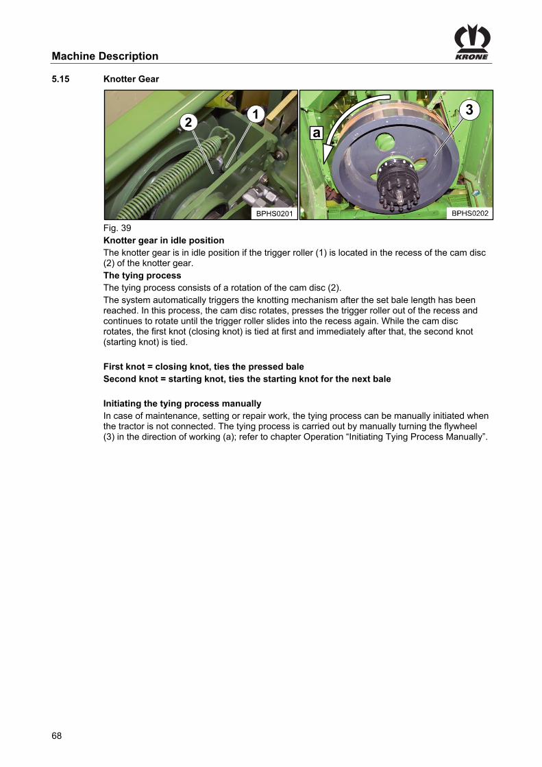
Machine Description
68
Pos: 68.95 /BA/Bedienung /Großpackenpresse/Knotergetriebe / Ruhestellung / Bindevorgang von Hand auslösen @ 168\mod_1367993844032_78.docx @ 1452575 @ 2 @ 1
5.15 Knotter Gear
3
a
Fig. 39 Knotter gear in idle position The knotter gear is in idle position if the trigger roller (1) is located in the recess of the cam disc (2) of the knotter gear. The tying process The tying process consists of a rotation of the cam disc (2). The system automatically triggers the knotting mechanism after the set bale length has been reached. In this process, the cam disc rotates, presses the trigger roller out of the recess and continues to rotate until the trigger roller slides into the recess again. While the cam disc rotates, the first knot (closing knot) is tied at first and immediately after that, the second knot (starting knot) is tied. First knot = closing knot, ties the pressed bale Second knot = starting knot, ties the starting knot for the next bale Initiating the tying process manually In case of maintenance, setting or repair work, the tying process can be manually initiated when the tractor is not connected. The tying process is carried out by manually turning the flywheel (3) in the direction of working (a); refer to chapter Operation “Initiating Tying Process Manually”.
Pos: 68.96 /Layout Module /---------------Seitenumbruch---------------- @ 0\mod_1196175311226_0.docx @ 4165 @ @ 1

Machine Description
69
Pos: 68.97 /BA/Maschinenbeschreibung/Maschinenübersicht/Funktionsweise/Großpackenpressen/Ballenausschieber / Rollenschurre betätigen Einführtext BP 890_1270_1290_1290 HDP_4x4 @ 173\mod_1371025842883_78.docx @ 1484464 @ 3 @ 1
5.16 Bale Ejector / Bale Chute
Fig. 40 Bale ejector (1) The operation of the bale ejector or the bale chute depends on the machine design (medium version electronics or comfort version electronics), refer to chapter Operation “Operating the Bale Chute”.
Pos: 68.98 /BA/Maschinenbeschreibung/Maschinenübersicht/Funktionsweise/Großpackenpressen/Ballenausschieber / Rollenschurre betätigen bei Ausführung Medium-Elektronik @ 152\mod_1362724438588_78.docx @ 1357153 @ 2 @ 1
5.16.1 Medium Version Electronics Design
Fig. 41 The operating control device is located on the rear left machine side on the yoke. The control levers (3, 4) are released or locked via shut-off valves (1, 2). The bale chute is lowered or lifted via control lever (3). The bale ejector is moved to the rear or to the front via control lever (4).
Pos: 68.99 /Layout Module /---------------Seitenumbruch---------------- @ 0\mod_1196175311226_0.docx @ 4165 @ @ 1
BPHS02521

Machine Description
70
Pos: 68.100 /BA/Maschinenbeschreibung/Maschinenübersicht/Funktionsweise/Großpackenpressen/Ballenausschieber / Rollenschurre betätigen bei Ausführung Komfort-Elektronik @ 157\mod_1364316843931_78.docx @ 1386057 @ 2 @ 1
5.16.2 For Comfort Version Electronics Design:
1
3
4
5
52
Fig. 42 On machines with comfort version electronics, external buttons (1, 2) are installed on the rear left machine side. The bale ejector is manually actuated via the buttons (3, 4). The bale chute is, however, manually actuated via the buttons (5, 6). Actuating the bale ejector The bale ejector is moved to the front via button (3). Button (4) has several functions. If the bale channel flaps have not been released, then they can be released now by pressing the button. If the bale channel flaps have been released, 10 bale ejection processes are carried out by pressing the button. The bale ejector moves backward when the bale channel flaps are released and the button is pressed and held. Activating bale chute The bale chute is lifted to transport position via button (5). The bale chute is lowered into working position via button (6).
Pos: 68.101 /Layout Module /---------------Seitenumbruch---------------- @ 0\mod_1196175311226_0.docx @ 4165 @ @ 1

Machine Description
71
Pos: 68.102 /Überschriften/Überschriften 2/A-E/Druckluftbehälter @ 12\mod_1224144256075_78.docx @ 150965 @ 2 @ 1
5.17 Compressed-air reservoir Pos: 68.103 /BA/Wartung/Druckluftbehälter/Druckluftbehälter Bild BP 890/1270/1290 HS Baureihe Maschbeschreibung @ 62\mod_1299662280569_78.docx @ 574094 @ @ 1
4
BPHS0018
2
3 1
Fig.43 Pos: 68.104 /BA/Wartung/Druckluftbehälter/Druckluftbehälter Text Zusatz Big Pack HS Baureihe @ 62\mod_1299662408501_78.docx @ 574121 @ @ 1
• Big pack square balers equipped with a compressed air brake have two compressed air storage tank (1x compressed air storage tank (2) for the compressed air brake / 1x compressed air storage tank (4) for knotter cleaning).
• Big pack square balers equipped with a hydraulic brake have one compressed air storage tank (4) (1x for knotter cleaning).
• For big pack square balers equipped with a pressurized air brake the compressed air storage tank (2) for the brake system is on the right hand side of the machine. It is connected with the compressed air storage tank (4) for knotter cleaning through a compressed air line (1). The compressed air storage tank (4) for knotter cleaning (compressed air brake / hydraulic brake) can be found on the right hand side above the twine box on the frame.
Pos: 69 /Layout Module /---------------Seitenumbruch---------------- @ 0\mod_1196175311226_0.docx @ 4165 @ @ 1

Machine Description
72
Pos: 70 /Überschriften/Überschriften 2/P-T/Technische Daten @ 7\mod_1216639197520_78.docx @ 105916 @ 2 @ 1
5.18 Technical data Pos: 71.1 /BA/Einleitung/Technische Daten/Grosspackenpresse/BiG PACK 870_890_1270_1290 HS_1290 HDP HS/BiG PACK 870 HDP/Technische Daten: Abmessungen in Transportstellung BiG PACK 870 HDP @ 270\mod_1402587034071_78.docx @ 2042300 @ @ 1
Dimensions
Height 3075 mm
Length of transport position 7930 mm
Length of working position 9180 mm
Width with tyres 710/45-22.5 single axle 2600 mm
Width with tyres 500/50-17 tandem axle 2550 mm
Width with tyres 550/45-22.5 tandem axle 2600 mm
Width with tyres 620/40- R22.5 tandem axle 2670 mm
Pos: 71.2 /BA/Einleitung/Technische Daten/Grosspackenpresse/BiG PACK 870_890_1270_1290 HS_1290 HDP HS/BiG PACK 870 HDP/Technische Daten: Gewicht BiG PACK 870 @ 233\mod_1393925742360_78.docx @ 1857323 @ @ 1
Weight*
Tandem axle without cutting system 9050 kg
Tandem axle with cutting system 9600 kg
*) depending on how the machine is fitted
Pos: 71.3 /BA/Einleitung/Technische Daten/Grosspackenpresse/BiG PACK 870_890_1270_1290 HS_1290 HDP HS/BiG PACK 870 HDP/Technische Daten: Spurbreite BiG PACK 870 HDP @ 270\mod_1402587192496_78.docx @ 2042329 @ @ 1
Track width
Tandem axle 2040 mm
Pos: 71.4 /BA/Einleitung/Technische Daten/Grosspackenpresse/BiG PACK 870_890_1270_1290 HS_1290 HDP HS/BiG PACK 870 HDP/Technische Daten: zulässige Höchstgeschwindigkeit 870 HDP @ 270\mod_1402635891702_78.docx @ 2042365 @ @ 1
Maximum permissible speed *
Tandem axle, compressed air brake 50 km/h/60 km/h**
Tandem axle, hydraulic brake 50 km/h
*) The maximum speed depends on the statutory regulations in each country. **) Depending on tyres
Pos: 71.5 /BA/Einleitung/Technische Daten/Grosspackenpresse/BiG PACK 870_890_1270_1290 HS_1290 HDP HS/BiG PACK 890 HS/Technische Daten: Active Pick-up BiG PACK 890 @ 136\mod_1353327394196_78.docx @ 1215754 @ @ 1
Active pick-up
Scattering width 1950 mm
Scattering width (wide pick-up optional) 2350 mm
Tine carrier 5 units
Number of tines (double tines per tine carrier) 16 units
Feed Roller crop guide and intake roller
Feed lateral (right / left) Conveyor auger
Height adjustment via perforated bar on the supporting wheel
Pos: 71.6 /Layout Module /---------------Seitenumbruch---------------- @ 0\mod_1196175311226_0.docx @ 4165 @ @ 1

Machine Description
73
Pos: 71.7 /BA/Einleitung/Technische Daten/Grosspackenpresse/BiG PACK 870_890_1270_1290 HS_1290 HDP HS/BiG PACK 890 HS/Technische Daten: Schneidwerk (XC) BiG PACK 870 HDP / 890 @ 136\mod_1353327676778_78.docx @ 1215842 @ @ 1
XC Cutting System
Number of blades 16
Blade group control system 0, 8, 8, 16
Minimum cutting length 44 mm
Single blade locking device Standard
Fitting via lateral extending cutting system inlet trays Standard
Pos: 71.8 /BA/Einleitung/Technische Daten/Grosspackenpresse/BiG PACK 870_890_1270_1290 HS_1290 HDP HS/Technische Daten: Preßgutzuführung alle HS Maschinen @ 136\mod_1353327509510_78.docx @ 1215783 @ @ 1
Crop feed / Variable filling system
Self feed Through packer drum
Packer drum 4x feed rakes 1x switchable feeder strip
On XC design, a cutting system is also connected ahead.
Pos: 71.9 /BA/Einleitung/Technische Daten/Grosspackenpresse/BiG PACK 870_890_1270_1290 HS_1290 HDP HS/BiG PACK 870 HDP/Technische Daten: Preßkolben BiG PACK 870 HDP @ 230\mod_1393334954972_78.docx @ 1843949 @ @ 1
Baling ram
Stroke length 750 mm
Strokes per minute 49
Bearing (rollers) 4 units.
Blade on the plunger 6 units.
Setting the baling density Electronic-hydraulic force control (can be set from the tractor).
Pos: 71.10 /BA/Einleitung/Technische Daten/Grosspackenpresse/BiG PACK 870_890_1270_1290 HS_1290 HDP HS/BiG PACK 870 HDP/Technische Daten: Preßkanal BiG PACK 870 HDP @ 230\mod_1393335511272_78.docx @ 1844008 @ @ 1
Bale channel / bale dimensions
Height 700 mm
Width 800 mm
Bale length (continuously adjustable) 1000 mm to 2700 mm
Pos: 71.11 /BA/Einleitung/Technische Daten/Grosspackenpresse/BiG PACK 870_890_1270_1290 HS_1290 HDP HS/BiG PACK 870 HDP/Technische Daten: Bindeeinrichtung BiG PACK 870 HDP @ 230\mod_1393338340302_78.docx @ 1844214 @ @ 1
Tying unit
Twine box on both sides For 16 twine rolls
Twine (synthetic twines) 100-130 m/kg
Knotter monitoring Twine empty display (lower twine / upper twine)
Electrical control with acoustic signal.
Twine motion indicator upper twine Visual via reflectors
Starting the tying process Automatic or manual
Number of knotter apparatus 5
Knotter cleaning Compressed air
Pos: 71.12 /Layout Module /---------------Seitenumbruch---------------- @ 0\mod_1196175311226_0.docx @ 4165 @ @ 1

Machine Description
74
Pos: 71.13 /BA/Einleitung/Technische Daten/Grosspackenpresse/BiG PACK 870_890_1270_1290 HS_1290 HDP HS/BiG PACK 870 HDP/Technische Daten: Überlastsicherung / Scherschraube BiG PACK 870 HDP @ 230\mod_1393335652866_78.docx @ 1844066 @ @ 1
Overload protection
Friction clutch drive 2400 Nm
Overload coupling flywheel 5500 Nm
Overload coupling pick-up without cutting system 1000 Nm
Overload coupling pick-up with cutting system 1200 Nm
Overload coupling cutting system 7000 Nm
Overload coupling packer 14500 Nm
Shear screw (cheese head screw) on the left needle connecting rod
M10 x 70-12.9 DIN EN ISO 4762
Pos: 71.14 /BA/Einleitung/Technische Daten/Grosspackenpresse/Technische Daten: Antriebsgelenkwelle Alle HS Typen und 1290 HDP II @ 192\mod_1382338388236_78.docx @ 1639345 @ @ 1
Universal shaft
Wide-angle (mount on tractor side) series 1 3/8“, Z=6
1 3/8“, Z=21
Wide-angle (mount on tractor side) optional 1 3/4“, Z=6
1 3/4“, Z=20
Pos: 71.15 /BA/Einleitung/Technische Daten/Grosspackenpresse/BiG PACK 870_890_1270_1290 HS_1290 HDP HS/Technische Daten: Anhängungen Stützlasten 870/890/1270/1290/1290 HDP/ 4x4 @ 190\mod_1381417622769_78.docx @ 1627248 @ @ 1
Hitch Permissible supported load
Towing eye Ø 40 mm ISO 5692-2 / like DIN 11026 2000 kg
Ball head hitch (K80) 2500 kg
Turnable towing eye Ø 76.2 mm CUNA F3 (only export) 2000 kg
Hitch connection Ø 50 mm ISO 20019 / like DIN 9678 (only export)
2000 kg
Ball Hitch (only export) 2500 kg
Pos: 71.16 /BA/Einleitung/Technische Daten/Grosspackenpresse/BiG PACK 870_890_1270_1290 HS_1290 HDP HS/Technische Daten: Bremsen @ 136\mod_1353328126803_78.docx @ 1215988 @ @ 1
Brakes
Hydraulic brake (depending on country) Connection for hydraulic brake system required (max. operating pressure 120 bar / 1740 PSI)
Compressed air brake Dual-line brake system
Parking brake Operation by hand crank
Pos: 71.17 /Layout Module /---------------Seitenumbruch---------------- @ 0\mod_1196175311226_0.docx @ 4165 @ @ 1

Machine Description
75
Pos: 71.18 /BA/Einleitung/Technische Daten/Grosspackenpresse/BiG PACK 870_890_1270_1290 HS_1290 HDP HS/BiG PACK 870 HDP/Technische Daten: Mindestanforderung an den Traktor BiG PACK 870 HDP @ 230\mod_1393335844647_78.docx @ 1844095 @ @ 1
Minimum tractor requirements
Power requirement without cutting system 88 kW (120 PS)
Power requirement with cutting system 103 kW (140 PS)
PTO speed max. 1000 rpm
Max. operating pressure of the hydraulic system 200 bar
Pos: 71.19 /BA/Einleitung/Technische Daten/Grosspackenpresse/BiG PACK 870_890_1270_1290 HS_1290 HDP HS/Technische Daten: Elektrische Anschlüsse Alle HS Typen und HDP II @ 137\mod_1353328670081_78.docx @ 1216104 @ @ 1
Electrical connections
Lighting 12 V 7-pin socket
Power supply of the machine 12 V 3-pin socket
ISOBUS capable yes
Pos: 71.20 /BA/Einleitung/Technische Daten/Grosspackenpresse/BiG PACK 870_890_1270_1290 HS_1290 HDP HS/Technische Daten: Hydraulikanschlüsse Medium-Elektronik 870/ 890 HS/1270 HS/1290 HS @ 192\mod_1382342499575_78.docx @ 1639613 @ @ 1
Hydraulic connections for medium version electronics
Control valve block 1x double-action control unit
Pick-up lifting 1x single-action control unit
With coaster/steering axle 1x single-action control unit
Pos: 71.21 /BA/Einleitung/Technische Daten/Grosspackenpresse/BiG PACK 870_890_1270_1290 HS_1290 HDP HS/BiG PACK 870 HDP/Technische Daten: Hydraulikanschlüsse Komfort-Elektronik HDP II und 890 HDP @ 230\mod_1393342229514_78.docx @ 1844919 @ @ 1
Hydraulic connections for comfort version electronics
Control-valve block 1x double-action control unit
Alternatively 1x single-action control unit
1x unpressurised return flow to the tank
Raising the pick-up 1x single-action control unit
Raising/lowering support jack 1x double-action control unit
Load Sensing connection on the machine Standard
Pos: 71.22 /Layout Module /---------------Seitenumbruch---------------- @ 0\mod_1196175311226_0.docx @ 4165 @ @ 1

Machine Description
76
Pos: 71.23 /BA/Einleitung/Technische Daten/Grosspackenpresse/BiG PACK 870_890_1270_1290 HS_1290 HDP HS/BiG PACK 870 HDP/Technische Daten: Bereifung 870 HDP @ 270\mod_1402636674253_78.docx @ 2042423 @ @ 1
Tyre identification Minimum pressure [bar]
Vmax<= 10 km/h
Maximum pressure [bar]
Recommended tyre pressure* (bar)
Guide wheels: 15x6.00 - 6 10 PR 3.7 1.5 Tandem Axle: 500/50-17 149 A8 1.2 3.5 3.5 550/45-22.5 16 PR 1.2 2.8 2.8 620/40 R 22.5 148 D 1.0 3.2 2.0
Pos: 71.24 /BA/Wartung/Reifen/Reifen-Luftdruck Empfehlung Big Pack @ 24\mod_1241509590008_78.docx @ 245611 @ @ 1
*) This recommendation applies especially to the typical mixture of operation (field/road) at the maximum permitted machine speed.
If necessary, the tyre air pressure can be reduced to the minimum air pressure. However, the associated maximum speed must then be observed.
Pos: 72 /BA/Einleitung/Technische Daten/Grosspackenpresse/BiG PACK 1290 HDP II/Technische Daten: Ausrüstung der Maschine (optional) Alle HS Typen außer BiG PACK 1290 HDP II @ 191\mod_1381738222577_78.docx @ 1629246 @ @ 1
Equipment of the maschine (optional)
Additional working floodlights
Moisture measurement
Special marking (France)
ISOBUS cable
Video system
Second camera
CCI terminal 100
Cable set for CCI terminal 100
Multi-function lever ISOBUS AUX
Pos: 73 /BA/Einleitung/Technische Daten/Technische Daten: Luftschallemission @ 132\mod_1349850785653_78.docx @ 1174615 @ @ 1
Airborne Sound Emission
Equivalent continuous pneumatic level recorder less than 70 d B(A)
Pos: 74 /Layout Module /---------------Seitenumbruch---------------- @ 0\mod_1196175311226_0.docx @ 4165 @ @ 1

Machine Description
77
Pos: 75.1 /Überschriften/Überschriften 2/A-E/Betriebsstoffe @ 174\mod_1371620600320_78.docx @ 1490571 @ 2 @ 1
5.19 Consumables Pos: 75.2 /Überschriften/Überschriften 3/F-J/Füllmengen und Schmiermittelbezeichnungen der Getriebe @ 33\mod_1254230622207_78.docx @ 318675 @ 3 @ 1
5.19.1 Filling Quantities and Lubrication Designations for Gearboxes Pos: 75.3 /BA/Wartung/Umwelt/Hinweis Entsorgen / Lagern von Schmierstoffen Umwelt @ 32\mod_1253100514124_78.docx @ 311746 @ @ 1
ENVIRONMENT! - Disposal and storage of lubricants Effect: Environmental damage • Store lubricants in eligible containers according to statutory provisions • Dispose used lubricants according to statutory provisions
Pos: 75.4 /BA/Einleitung/Technische Daten/Grosspackenpresse/BiG PACK 870_890_1270_1290 HS_1290 HDP HS/Technische Daten: Betriebsstoffe Getriebe BiG Pack 870 HDP @ 230\mod_1393340160954_78.docx @ 1844358 @ @ 1
Designation Filling quantity [litres]
Filtered lubricants Bio-degradable lubricants
Main gearbox 15.5 l SAE 90 GL 4 or Esso-Spartan EP 150 EP 150 Shell Omala Oil 150 Fuchs – EP 85 W90 Castrol EPX 90
On request
Packer gearbox 4 l
Knotter/packer transfer gearbox 1 l
Pick-up gearbox top bottom
0.5 l
Cutting system gear top bottom
2.8 l 2.7 l
Pos: 75.5 /Layout Module /---------------Seitenumbruch---------------- @ 0\mod_1196175311226_0.docx @ 4165 @ @ 1

Machine Description
78
Pos: 75.6 /Überschriften/Überschriften 3/F-J/Füllmenge und Ölbezeichnung der Bordhydraulik @ 17\mod_1236177374918_78.docx @ 201862 @ 3 @ 1
5.19.2 Oil quantities and designations for the on-board hydraulic system Pos: 75.7 /BA/Wartung/Umwelt/Hinweis Entsorgen / Lagern von Öle und Ölfilter Umwelt @ 32\mod_1253101375171_78.docx @ 311770 @ @ 1
ENVIRONMENT! - Disposal and storage of used lubricants and oil filters Effect: Environmental damage Store or dispose used oil and oil filters according to statutory provisions.
Pos: 75.8 /BA/Wartung/Zeitintervalle bei Bioölen einhalten @ 10\mod_1222336982598_78.docx @ 140714 @ @ 1
Note - Observe maintenance intervals Effect: Long expected service life of machine • With bio-degradable oils always observe the change intervals because of the ageing of the
oils.
Pos: 75.9 /BA/Wartung/Großpackenpressen/Technische Daten: Füllmenge und Ölbezeichnung der Bordhydraulik @ 17\mod_1236178420965_78.docx @ 201932 @ @ 1
Quantity ltr.
Designation/brand Bio-degradable lubricants
Oil container on baler 15
Fuchs Renolin MR 46 MC BP Energol SHF 46 Shell Tellus 46 Esso Univis N 46 Aral Vitan VS 46
on request
Pos: 75.10 /Überschriften/Überschriften 3/F-J/Füllmenge und Ölbezeichnung des Kompressors @ 17\mod_1236177427355_78.docx @ 201887 @ 3 @ 1
5.19.3 Oil quantities and designations for the compressor Pos: 75.11 /BA/Wartung/Großpackenpressen/Technische Daten: Füllmenge und Ölbezeichnung des Kompressors @ 17\mod_1236178607105_78.docx @ 201957 @ @ 1
Quantity ltr. Designation/brand
Bio-degradable lubricants
Up to the top
dipstick marking (0.2)
Standard engine oil SAE 20 or 20 W 40
on request
Pos: 76 /Layout Module /---------------Seitenumbruch---------------- @ 0\mod_1196175311226_0.docx @ 4165 @ @ 1

Control and Display Elements
79
Pos: 77 /Überschriften/Überschriften 1/A-E/Bedien- und Anzeigeelemente @ 107\mod_1334231983896_78.docx @ 965285 @ 1 @ 1
6 Control and Display Elements Pos: 78 /Überschriften/Überschriften 2/A-E/Anschluss der Hydraulikleitungen @ 168\mod_1367993003329_78.docx @ 1452465 @ 2 @ 1
6.1 Connecting the hydraulic lines Pos: 79 /BA/Maschinenbeschreibung/Maschinenübersicht/Großpackenpressen/Komfort - Elektronik @ 61\mod_1299223046976_78.docx @ 570919 @ @ 1
Comfort - Electronic Pos: 80 /BA/Inbetriebnahme/Großpackenpresse/Hydraulik/Hydraulikanschluss Tabelle Komfort-Elektronik Big Pack HS Baureihe @ 231\mod_1393398849264_78.docx @ 1846587 @ @ 1
PP Connection for control block – Red P: Pressure line, nominal width 15
TT Connection for control block – Red T: Return line, nominal width 18
LSLS
Connection for control block – Green LS: Load-sensing line, nominal width 12 For additional information, please refer to the tractor manufacturer's operating instructions.
1+
Single-action control unit (yellow 1+): Yellow 1+: – Pressure: Raising the pick-up – Float position: Lower pick-up
2+
2-
Double-action control unit (blue 2+ / blue 2-) – Blue 2+: Raising support jack – Blue 2-: Lowering support jack
Pos: 81 /BA/Maschinenbeschreibung/Maschinenübersicht/Großpackenpressen/Medium - Elektronik @ 61\mod_1299223169539_78.docx @ 570971 @ @ 1
Medium Version Electronics Pos: 82 /BA/Inbetriebnahme/Großpackenpresse/Hydraulik/Hydraulikanschluss Tabelle Medium-Elektronik Big Pack HS Baureihe @ 231\mod_1393398878447_78.docx @ 1846616 @ @ 1
2+
Connection for control block – Red 2+: Close blade bar, raise/lower support jack, open/close roller
chute, deploy/retract bale ejector
2-
Connection for control block – Red 2-: Open blade bar
1+
Single-action control unit (yellow 1+): Yellow 1+: – Pressure: Raising the pick-up – Float position: Lower pick-up
3+
Single-action control unit (blue 3+): Blue 3+: – Pressure: Locking the steering axle – Float position: • Releasing the steering axle
5+P
Connection for starting aid – Green 5+: Single-action control unit
5-T
Connection for starting aid – Green 5-: Return line
Pos: 83 /Layout Module /---------------Seitenumbruch---------------- @ 0\mod_1196175311226_0.docx @ 4165 @ @ 1

Control and Display Elements
80
Pos: 84 /Layout Module /Diese Seite ist bewusst freigelassen worden. @ 1\mod_1201783680373_78.docx @ 54443 @ @ 1
This page has been left blank deliberately!! Pos: 85 /Layout Module /---------------Seitenumbruch---------------- @ 0\mod_1196175311226_0.docx @ 4165 @ @ 1

Commissioning
81
Pos: 86.1 /Überschriften/Überschriften 1/A-E/Erstinbetriebnahme @ 0\mod_1196314201498_78.docx @ 5855 @ 1 @ 1
7 Commissioning Pos: 86.2 /BA/Sicherheit/7. Gefahrenhinweise alt/Erstinbetriebnahme/Warnung - Erstinbetriebnahme AX / MX/ TX/ ZX @ 111\mod_1336724783740_78.docx @ 987284 @ @ 1
WARNING! Risk of accident or damage to the machine due to an incorrect initial operation! Only an authorized service technician is permitted to carry out the initial operation.
Pos: 86.3 /BA/Sicherheit/2. Vorangestellte Warnhinweise/WARNUNG - Nichtbeachtung der grundlegenden Sicherheitshinweise alte Form @ 254\mod_1397485793575_78.docx @ 1953347 @ @ 1
WARNING! If the basic safety instructions are not followed, people may be seriously injured or killed. • To avoid accidents, the basic safety instructions in the chapter Safety must have been
read and followed, see chapter Safety "Basic safety instructions".
Pos: 86.4 /BA/Sicherheit/2. Vorangestellte Warnhinweise/Warnung - Nichtbeachtung der Sicherheitsroutinen alte Form @ 273\mod_1404117435996_78.docx @ 2058712 @ @ 1
WARNING! If the safety routines are not adhered to, people may be seriously injured or killed. • To avoid accidents, the safety routines in the chapter Safety must be read and followed,
see chapter Safety "Safety routines".
Pos: 86.5 /BA/Sicherheit/2. Vorangestellte Warnhinweise/Warnung - Maschine sicher abstellen ohne Traktor_Feststellbremse und Unterlegkeile @ 274\mod_1404214703082_78.docx @ 2060841 @ @ 1
WARNING! Risk of injury due to the unsecured machine rolling away! If the machine is not secured against rolling away when it has been switched off, there is a risk of people being injured by the machine rolling away in an uncontrolled manner. • Secure the machine against rolling away with the parking brake and wheel chocks. • Apply the flywheel brake at the machine.
Pos: 86.6 /BA/Erstinbetriebnahme/Großpackenpressen/Schwungradbremse/Warnung - Schwungradbremse @ 272\mod_1403527213260_78.docx @ 2051587 @ @ 1
WARNING! There is an increased risk of injury if the flywheel brake is not applied. If the flywheel brake is not applied, parts may start to move unexpectedly. As a result, people may be seriously injured or killed. Always apply the flywheel brake before • coupling or uncoupling the universal shaft. • carrying out maintenance, adjustment or repair work. • rectifying malfunctions.
Pos: 86.7 /BA/Erstinbetriebnahme/Großpackenpressen/Folgende Arbeitsschritte werden in diesem Kapitel beschrieben BiG PACK 1290 HDP II @ 151\mod_1362394831309_78.docx @ 1347824 @ @ 1
The following work steps are described in this chapter: – Attaching the hydraulic parking jack. – Attaching the power supply to the tractor. – Height adaption of the drawbar. – Height adaption of the drive train. – Length adaption of the universal shaft to the tractor. – Adapting the hydraulic system. – Setting the bale chute.
Pos: 86.8 /Layout Module /---------------Seitenumbruch---------------- @ 0\mod_1196175311226_0.docx @ 4165 @ @ 1

Commissioning
82
Pos: 86.9 /Überschriften/Überschriften 2/F-J/Hydraulischen Stützfuß anbauen @ 193\mod_1383215414302_78.docx @ 1646685 @ 2 @ 1
7.1 Attaching Hydraulic Parking Jack Pos: 86.10 /BA/Erstinbetriebnahme/Großpackenpressen/Bei Ausführung hydraulischer Stützfuß @ 193\mod_1383214866332_78.docx @ 1646602 @ @ 1
With hydraulic parking jack design.
Pos: 86.11 /BA/Erstinbetriebnahme/Großpackenpressen/Hydraulischen Stützfuß anbauen Bild @ 193\mod_1383214808495_78.docx @ 1646573 @ @ 1
Fig. 44 Pos: 86.12 /BA/Erstinbetriebnahme/Großpackenpressen/Hydraulischen Stützfuß anbauen Text T1 @ 193\mod_1383214768463_78.docx @ 1646544 @ @ 1
• Attach the crane to the suspension point (I) on the drawbar. • To lift the parking jack (2), slightly raise the drawbar, shift parking jack entirely upwards and
secure with socket pin (3). • To lower the drawbar down onto the ground, lay adequately dimensioned square blocks
under the front drawbar beam (4) and lower the drawbar. • Lay the hydraulic hoses (5) to the outside. • To remove the parking jack, screw out the four screws (6), remove the parking jack and put
it aside. • Insert the hydraulic parking jack (7) on the same position. • To lift the hydraulic parking jack, attach the parking jack with the crane (II) and raise it. • Mount screws (6) and detent edged washers and secure with detent edged washers and
nuts. Tighten the screws with an appropriate tightening torque.
Pos: 86.13 /Layout Module /---------------Seitenumbruch---------------- @ 0\mod_1196175311226_0.docx @ 4165 @ @ 1

Commissioning
83
Pos: 86.14 /BA/Erstinbetriebnahme/Großpackenpressen/Hydraulischen Stützfuß anbauen T2 @ 169\mod_1369381329007_78.docx @ 1464043 @ @ 1
Attaching hydraulic hoses.
a b
Fig. 45
a) Retracting parking jack connection b) Extending parking jack connection
Collect escaping oil in a suitable container. • Screw provided unions (8) in the parking jack. • Unscrew the hydraulic hoses from the double nipple (9).
Note With comfort version electronics design The upper line is screwed on connection “a”. The lower line is screwed on connection “b”. For medium version electronics design The hydraulic line marked with S1 on the hydraulic block is screwed on connection “a”. The hydraulic line marked with S2 on the hydraulic block is screwed on connection “a”.
• Screw the hydraulic hoses (5) on the unions (8). • Connect the hydraulic hoses on tractor side. Checking the “Lifting / lowering drawbar” function. The hydraulic hoses (5) on the parking jack must be replaced if the “Lifting /lowering” functions are interchanged. • Lower the parking jack until the machine is in horizontal position.
Pos: 86.15 /Layout Module /---------------Seitenumbruch---------------- @ 0\mod_1196175311226_0.docx @ 4165 @ @ 1

Commissioning
84
Pos: 86.16 /Überschriften/Überschriften 2/P-T/Spannungsversorgung @ 28\mod_1250578107003_78.docx @ 275490 @ 2 @ 1
7.2 Electrical power supply Pos: 86.17 /BA/Erstinbetriebnahme/Spannungsversorgung/Dauerstromsteckdose Bild @ 36\mod_1260454934575_78.docx @ 336632 @ @ 1
SW2000058
12
3
Fig. 46 Pos: 86.18 /BA/Erstinbetriebnahme/Spannungsversorgung/Steckdose an die 12V Batterie des Schleppers anschließen @ 36\mod_1260450375075_78.docx @ 336557 @ @ 1
The machine requires a voltage source for the power supplyof the on-board computer (control unit). A socket (12V DIN 9680) for installation on the tractor is part of the scope of supply. The socket has to be attached in order to provide the machine with the required electricity for start-up. Connect the socket included with delivery (1) directly to the 12V battery of the tractor • Connect the connector terminal (2) of the red cable (+) directly to the “+” terminal of the
tractor battery. • Connect the connector terminal (3) of the black cable (-) directly to the “-” terminal of the
tractor battery. Pos: 86.19 /Layout Module /---------------Seitenumbruch---------------- @ 0\mod_1196175311226_0.docx @ 4165 @ @ 1

Commissioning
85
Pos: 86.20 /Überschriften/Überschriften 2/F-J/Höhenanpassung der Deichsel @ 17\mod_1236255816988_78.docx @ 204061 @ 2 @ 1
7.3 Adjusting the drawbar height Pos: 86.21 /BA/Erstinbetriebnahme/Großpackenpressen/Einstellung der Anhängehöhe 4x4 @ 108\mod_1334732430989_78.docx @ 970024 @ @ 1
Fig. 47 Always adjust the hitching device of the machine to the tractor used. Always couple the machine horizontally to ensure that the pick-up collects the crop evenly. The cross-member is used as a reference edge to align the machine (6). Before making the setting: • Place the machine on the parking support • Secure the machine against the possibility of rolling back. • Uncouple the machine from the tractor • Using a spirit level, align the machine horizontally Setting the towing ring: • Unscrew the screws (1) • Adjust the height of the towing ring (2) to the height of the tractor hitch • Fit and tighten the screws (1)

Commissioning
86
If the adjustment of the towing ring is not adequate, adjust the side parts (4). To do this: • Unscrew the screws (3) • Adjust the height of the front parts of the drawbar (4) to the height of the tractor hitch • Fit and tighten the screws (3) Changing the drawbar hitch The drawbar is set as standard as the bottom hitch (a). To set as top attachment (b), rotate both front parts of the drawbar (4) by 180 degrees. To do this: • Unscrew the screws (3) • Remove the front parts of the drawbar (4) and rotate by 180 degrees • Using the screws (3), attach the turned front parts of the drawbar between the drawbar (5)
and tighten the screws
Pos: 86.22 /BA/Wartung/Hinweis Anzugsmomente beachten (siehe Kapitel Wartung „Drehmomente“). @ 26\mod_1245736259299_78.docx @ 263361 @ @ 1
Note Mind the tightening torques (refer to chapter Maintenance “Tightening torques”).
Pos: 86.23 /BA/Erstinbetriebnahme/Großpackenpressen/Höhenanpassung des Antriebsstrangs @ 32\mod_1253688399975_78.docx @ 316233 @ 2 @ 1
7.4 Adjusting the height of the drive train
Fig. 48 The universally-jointed drive shaft (1) between the intermediate bearing (2) and the tractor transfuses the power of the tractor to the intermediate bearing. In order to have an ideal power transmission the articulation angle of the universally-jointed drive shaft must be as small as possible in the range of the intermediate bearing. After adjusting the height of the drawbar check the articulation angle of the universally-jointed drive shaft in the range of the intermediate bearing, and if necessary adapt it. To do this: • Use an eligible auxiliary means in order to support the intermediate bearing during the
whole adjustment process • Remove the screws (3) of the intermediate bearing • Move intermediate bearing (2) in the hole pattern • Assemble and tighten the screws (3)
Pos: 86.24 /Layout Module /---------------Seitenumbruch---------------- @ 0\mod_1196175311226_0.docx @ 4165 @ @ 1

Commissioning
87
Pos: 86.25 /Überschriften/Überschriften 2/F-J/Gelenkwelle kürzen @ 274\mod_1404372446709_78.docx @ 2065920 @ 2 @ 1
7.5 Shortening Universal Shaft Pos: 86.26 /BA/Sicherheit/8. Voraussetzungen/Handlungsanweisung für alle Maschinen/Handlungsanweisung: Maschine stillsetzen und sichern @ 274\mod_1404365253849_78.docx @ 2065151 @ @ 1
• Shut down and safeguard the machine, see chapter Safety -> Safety routines, "Shutting down and safeguarding the machine".
Pos: 86.27 /BA/Erstinbetriebnahme/Gelenkwelle/Großpackenpressen/Gelenkwelle kürzen T1 @ 170\mod_1369729045894_78.docx @ 1467963 @ @ 1
The both PTO shaft halves must let push together in the narrowest position (turn with maximum steering angle and simultaneous driving a slope up or down). The ends of the both section tubes must not touch each other in this process. In this process, the displacement path (overlapping) must at least be 220 mm, both in straight-ahead driving and when cornering.
Fig. 49 Inner PTO shaft half Outer PTO shaft half
1) Section tube inside 2) Raceway inside
3) Fastening screw 4) Guard tube inside
5) Guard tube outside 6) Protective sleeve
7) Section tube outside 8) Raceway outside
9) Slide ring 10) Retaining spring
• Disassemble the PTO shaft halves. Inner PTO shaft half • Screw out the fastening screws and remove the inner protective tube. • Widen the raceway inside and remove it. Outer PTO shaft half • Screw out the screws of the protective sleeve as well as the screws of the protective tube
outside. • Remove the protective tube outside. • Remove the protective sleeve. • Unhook the retaining spring and leave it in one of the two bore holes of the slide ring to
ensure that the retaining spring does not get lost. • Widen the raceway outside and the slide ring and remove them.
Pos: 86.28 /Layout Module /---------------Seitenumbruch---------------- @ 0\mod_1196175311226_0.docx @ 4165 @ @ 1

Commissioning
88
Pos: 86.29 /BA/Erstinbetriebnahme/Gelenkwelle/Großpackenpressen/Gelenkwelle kürzen Teil 2 @ 170\mod_1369728951081_78.docx @ 1467935 @ @ 1
X+2cmX
Fig. 50 • Connect the machine without universal shaft to the tractor • Move the machine to the narrowest position (driving around curves). • Switch off the engine of the tractor, remove the ignition key and secure the tractor and the
machine from rolling away. • Attach the PTO shaft halves on tractor side and on machine side. Determining the overlap (X) • Determine the dimension “X”. • The determined dimension „X+2cm“ must be transferred to the protective tubes and to the
section tubes of the PTO shaft halves.
CAUTION! The carry over dimension X+2cm must not pass the grease emersion bore holes (a) at the section tube inside as the end piece is destroyed when shortening. Increase the dimension x+2cm by 2cm if it passes the grease emersion bore holes.
• Shorten the protective tubes and the section tubes, deburr them from the outside and from
the inside and remove the chips. • To obtain a complete Teflon coating, melt the Teflon coating at the end of the section tubes
somewhat with the lighter.
Pos: 86.30 /Layout Module /---------------Seitenumbruch---------------- @ 0\mod_1196175311226_0.docx @ 4165 @ @ 1

Commissioning
89
Pos: 86.31 /BA/Erstinbetriebnahme/Gelenkwelle/Großpackenpressen/Mit innerer Schmierleitung @ 170\mod_1369728863034_78.docx @ 1467827 @ @ 1
With inner lubrication line The inner lubrication lines may be cut when shortening the section tube inside. If this is the case, the lubrication lines must be removed and adjusted and a new access hole must be drilled.
4mm
a
a
a) b)
c) d)
Fig. 51
1) Section tube inside 2) Grease nipple
3) Lubrication line (I) 4) Separated section tube inside
5) Roll pins 6) Lubrication line (II)
7) End piece
• Screw out the grease nipple and pull the lubrication line (I) out of the section tube. • Shorten the lubrication line (I) by a = 5 cm. From the separated section tube • Tap out the roll pins to the inside. • Pull the lubrication line (II) out of the section tube and remove the end piece. • Attach the end piece onto the shortened lubrication line (I). Drill a bore hole Ø 4 mm with a distance of a = 5 cm into the section tube, top and bottom. Make certain the bore holes and the bore hole of the grease nipple are on the same side. • Insert the lubrication line, screw in the grease nipple and drive in the roll pins.
Pos: 86.32 /Layout Module /---------------Seitenumbruch---------------- @ 0\mod_1196175311226_0.docx @ 4165 @ @ 1

Commissioning
90
Pos: 86.33 /BA/Erstinbetriebnahme/Gelenkwelle/Großpackenpressen/Gelenkhälften montieren @ 170\mod_1369728798111_78.docx @ 1467799 @ @ 1
Installing the PTO shaft halves
Fig. 52 Inner PTO shaft half Outer PTO shaft half
1) Section tube inside 2) Raceway inside
3) Fastening screw 4) Guard tube inside
5) Guard tube outside 6) Protective sleeve
7) Section tube outside 8) Raceway outside
9) Slide ring 10) Retaining spring
Inner PTO shaft half • Grease the raceway seat. • Insert the raceway inside into the groove. • Slide on the protective tube inside and secure with fastening screws. Outer PTO shaft half • Grease the raceway seat and the slide ring seat. • Insert the raceway outside into the groove. • Position the slide ring and hook the retaining spring in place in the both bore holes of the
slide ring. • Slide on the protective sleeve and secure with fastening screws. • Slide on the protective tube outside and secure with fastening screws.
Pos: 86.34 /Layout Module /---------------Seitenumbruch---------------- @ 0\mod_1196175311226_0.docx @ 4165 @ @ 1

Commissioning
91
Pos: 86.35 /BA/Erstinbetriebnahme/Gelenkwelle/Großpackenpressen/Verschiebeweg (Überlappung) ermitteln @ 170\mod_1369728715377_78.docx @ 1467771 @ @ 1
Determining the displacement path (overlapping)
X1 X2
Fig. 53 • Lay the both PTO shaft halves in front of one another, the outer section tube is in front of
the inner section tube. • Determine dimension X1. • Slide PTO shaft halves into one another as far as they will go and attach a marking (2) at
the end of the protective tube outside. • Connect the universal shaft on tractor and on machine side, move the machine to the
farthest position (straight-ahead driving). • Determine dimension X2. Calculating the displacement path “V” (overlapping): V = X1- X2 The displacement path (overlapping) must be at least V ≥ 220 mm. Check the shortened universal shaft when driving around curves. • Perform the right and left turn slowly with the tractor. In this process, mind the marking (2). The protective tube outside must not touch the marking (2) in the narrowest position (turn with maximum steering angle and simultaneous driving up and driving down a slope). If the protective tube outside touches the marking, shorten the both PTO shaft halves by the same length as described above until the protective tube outside does not touch the marking any more.
Pos: 86.36 /Layout Module /---------------Seitenumbruch---------------- @ 0\mod_1196175311226_0.docx @ 4165 @ @ 1

Commissioning
92
Pos: 86.37 /Überschriften/Überschriften 2/A-E/Anpassen des Hydrauliksystems @ 1\mod_1201241743588_78.docx @ 52013 @ 2 @ 1
7.6 Adjusting the hydraulic system Pos: 86.38 /BA/Wartung/Load-Sensing/Großpackenpresse/Bild Load-Sensing Anschluss HS Baureihe @ 64\mod_1300278753983_78.docx @ 582789 @ @ 1
Fig.54 Pos: 86.39 /BA/Maschinenbeschreibung/BiG PAck/Handlungsanweisung: Hydrauliksysteme Traktor-Maschine drucklos / Maschine stillsetzen und sichern @ 274\mod_1404364138167_78.docx @ 2065053 @ @ 1
• Switch the control units on the tractor to float position. • Depressurise the hydraulic system on the tractor and the machine. • Shut down and safeguard the machine, see chapter Safety -> Safety routines, "Shutting
down and safeguarding the machine".
Pos: 86.40 /Überschriften/Überschriften 3/A-E/BBetrieb der Maschine ohne LS (Load-Sensing-Anschluss) @ 91\mod_1326699351886_78.docx @ 780162 @ 3 @ 1
7.6.1 Operating the Machine without LS (Load-Sensing Connection) Pos: 86.41 /BA/Wartung/Load-Sensing/Systemschraube (1) ganz herausdrehen @ 63\mod_1299739012796_78.docx @ 575371 @ @ 1
Unscrew the system screw (1) as far as it will go for: • Tractor with an open (constant-current) hydraulic system (for additional information, please
refer to the tractor manufacturer's operating instructions) • Tractors with LS pump and non-activated load-sensing system
Pos: 86.42 /BA/Wartung/Load-Sensing/Hinweis Einstellung ist vom Werk aus gegeben @ 63\mod_1299738968068_78.docx @ 575344 @ @ 1
Note This adjustment is set when the unit leaves the factory.
Pos: 86.43 /Überschriften/Überschriften 3/A-E/BBetrieb der Maschine über LS (Load-Sensing-Anschluss) @ 91\mod_1326699464848_78.docx @ 780190 @ 3 @ 1
7.6.2 Operating the Machine via LS (Load-Sensing Connection) Pos: 86.44 /BA/Wartung/Load-Sensing/Systemschraube (1) ganz hereindrehen @ 63\mod_1299738923981_78.docx @ 575317 @ @ 1
Screw the system screw (1) as far as it will go for: • Tractors with closed (constant pressure or load sensing) Hydraulic system (For more
information, please refer to the tractor manufacturer's operating instructions) • Tractors with LS pump and message line that is connected
Pos: 86.45 /Layout Module /---------------Seitenumbruch---------------- @ 0\mod_1196175311226_0.docx @ 4165 @ @ 1

Commissioning
93
Pos: 86.46 /BA/Einstellungen/Großpackenpresse/Packenschurre einstellen @ 24\mod_1241442284883_78.docx @ 244974 @ 2 @ 1
7.7 Setting the bale chute
Fig. 55 When it is unfolded, the bale chute represents an extension of the bale channel chamber. For big bales to be set down on the ground correctly, the back edge of the bale chute must not be too high above the ground. Otherwise the bales will be damaged when they are placed on the ground. • The inclination of the bale chute to the ground can be sued to adjust the length of the
retaining chain (2) of the bale chute • To do this, adjust the nut (1) on either side of the baling channel
Pos: 86.47 /BA/Einstellungen/Großpackenpresse/Hinweis Ballenwaage kalibrieren @ 92\mod_1326782125428_78.docx @ 781789 @ @ 1
Note If the inclination of the bale chute is changed, the bale scale must be recalibrated if the machine has one (see chapter on KRONE ISOBUS terminal CCI "Calibrating the Bale Scale").
Pos: 87 /Layout Module /---------------Seitenumbruch---------------- @ 0\mod_1196175311226_0.docx @ 4165 @ @ 1

Start-up
94
Pos: 88.1 /Überschriften/Überschriften 1/F-J/Inbetriebnahme @ 0\mod_1196327075811_78.docx @ 6375 @ 1 @ 1
8 Start-up Pos: 88.2 /BA/Sicherheit/2. Vorangestellte Warnhinweise/WARNUNG - Nichtbeachtung der grundlegenden Sicherheitshinweise alte Form @ 254\mod_1397485793575_78.docx @ 1953347 @ @ 1
WARNING! If the basic safety instructions are not followed, people may be seriously injured or killed. • To avoid accidents, the basic safety instructions in the chapter Safety must have been
read and followed, see chapter Safety "Basic safety instructions".
Pos: 88.3 /BA/Sicherheit/2. Vorangestellte Warnhinweise/Warnung - Nichtbeachtung der Sicherheitsroutinen alte Form @ 273\mod_1404117435996_78.docx @ 2058712 @ @ 1
WARNING! If the safety routines are not adhered to, people may be seriously injured or killed. • To avoid accidents, the safety routines in the chapter Safety must be read and followed,
see chapter Safety "Safety routines".
Pos: 88.4 /BA/Inbetriebnahme/Großpackenpresse/Folgende Arbeitsschritte werden in diesem Kapitel beschrieben BiG PACK 1290 HDP II @ 152\mod_1362992347688_78.docx @ 1358414 @ @ 1
The following work steps are described in this chapter: – Mounting onto the tractor. – Installing PTO shaft. – Connecting the hydraulic lines. – Connecting the hydraulic brake, export – Connecting the hydraulic brake, export France – Connecting the hydraulic connection for locking the coaster/steering axle. – Connecting the compressed air connections for the compressed air brake. – Connecting the terminal. – Connecting the lighting.
Pos: 88.5 /Layout Module /---------------Seitenumbruch---------------- @ 0\mod_1196175311226_0.docx @ 4165 @ @ 1

Start-up
95
Pos: 88.6 /Überschriften/Überschriften 2/K-O/Maschine an den Traktor ankuppeln @ 279\mod_1405350506791_78.docx @ 2150095 @ 2 @ 1
8.1 Connect the machine to the tractor Pos: 88.7 /BA/Erstinbetriebnahme/Großpackenpressen/Anhängen an den Traktor alle BiG PACK´außer 1290 HDP II Bild @ 282\mod_1406700271355_78.docx @ 2175007 @ @ 1
Fig. 56 Pos: 88.8 /BA/Erstinbetriebnahme/Großpackenpressen/Anhängen an den Traktor BiG PACK 1290 HDP II Text @ 151\mod_1362393041351_78.docx @ 1347211 @ @ 1
Prerequisite: – The hitching device of the machine is adapted to the hitching device of the tractor; refer to
chapter Initial Operation „Height Adaption of the Drawbar“. – The height of the drive train of the machine to the tractor is adapted; refer to chapter Initial
Operation “Height Adaption of the Drive Train”. – The universal shaft is adapted to the tractor; refer to chapter Initial Operation “Universal
Shaft”. – The hydraulic system is adapted to the tractor; refer to chapter Initial Operation “Adapting
the Hydraulic System”. – The machine is in horizontal position. • Hitch and secure the machine according to the operating instructions of the tractor
manufacturer to the hitching device of the tractor. Pos: 88.9 /Layout Module /---------------Seitenumbruch---------------- @ 0\mod_1196175311226_0.docx @ 4165 @ @ 1

Start-up
96
Pos: 88.10 /Überschriften/Überschriften 3/F-J/Gelenkwelle montieren @ 11\mod_1223358863095_78.docx @ 145571 @ 3 @ 1
8.1.1 Install the PTO shaft Pos: 88.11 /BA/Erstinbetriebnahme/Großpackenpressen/Schwungradbremse/Warnung - Schwungradbremse @ 272\mod_1403527213260_78.docx @ 2051587 @ @ 1
WARNING! There is an increased risk of injury if the flywheel brake is not applied. If the flywheel brake is not applied, parts may start to move unexpectedly. As a result, people may be seriously injured or killed. Always apply the flywheel brake before • coupling or uncoupling the universal shaft. • carrying out maintenance, adjustment or repair work. • rectifying malfunctions.
Pos: 88.12 /BA/Sicherheit/8. Voraussetzungen/Handlungsanweisung für alle Maschinen/Handlungsanweisung: Maschine stillsetzen und sichern @ 274\mod_1404365253849_78.docx @ 2065151 @ @ 1
• Shut down and safeguard the machine, see chapter Safety -> Safety routines, "Shutting down and safeguarding the machine".
Pos: 88.13 /BA/Erstinbetriebnahme/Gelenkwelle/Traktorwechsel Gelenkwellenlänge beachten @ 6\mod_1214996938591_78.docx @ 97742 @ @ 1
Caution! - Changing the tractor Effect: Damage to the machine When using the machine for the first time and whenever changing the tractor Check PTO shaft for the correct length. If the length of the PTO shaft does not match the tractor, always observe the chapter entitled "Adjusting the length of the PTO shaft".
Pos: 88.14 /BA/Sicherheit/Gelenkwelle/Achtung - Gelenkwelle nicht richtig aufgesteckt @ 17\mod_1236260255331_78.docx @ 204283 @ @ 1
CAUTION! - The universal shaft is not put on correctly. Effect: Damage to the universal shaft or the machine • Make certain that the universal shaft is properly secured after installation and locked into
place • Use only the universal shaft included with delivery from the factory • Before engaging the P.T.O always release the flywheel parking brake first
Pos: 88.15 /BA/Inbetriebnahme/Großpackenpresse/Anbau Gelenkwelle alle BiG PACK´s außer 1290 HDP II Bild @ 282\mod_1406711195065_78.docx @ 2175287 @ @ 1
Fig. 57 Pos: 88.16 /BA/Inbetriebnahme/Großpackenpresse/Anbau Gelenkwelle BiG PACK Text @ 282\mod_1406711401092_78.docx @ 2175347 @ @ 1
The wide-angle coupling is attached on tractor side. On machine side • Install the universal shaft (1) on the drive journal of the angular gear. • Fasten the retaining chain (2) on the guard cup. On tractor side • Slide the wide-angle coupling onto the tractor PTO shaft and secure it. • Fasten the retaining chain (3) on the tractor.
Pos: 88.17 /Layout Module /---------------Seitenumbruch---------------- @ 0\mod_1196175311226_0.docx @ 4165 @ @ 1

Start-up
97
Pos: 88.18 /BA/Inbetriebnahme/Achtung Materialschäden an der Gelenkwelle durch Aufrollen der Haltekette @ 172\mod_1370444584247_78.docx @ 1479120 @ @ 1
CAUTION! Material damages if the retaining chain coils up. Fasten the retaining chain so that it surrounds the guard funnel in each working position by maximum 90°.
Pos: 88.19 /BA/Inbetriebnahme/Großpackenpresse/Anbau Gelenkwelle Auf ausreichend Freiraum im Schwenkbereich der Gelenkwelle achten. @ 172\mod_1370444743813_78.docx @ 1479168 @ @ 1
Fig. 58 • Make certain there is sufficient free room in the swivel range of the universal shaft in all
operating states. Contact with parts of the tractor or device may result in destruction.
Pos: 88.20 /BA/Sicherheit/Gelenkwelle/Achtung - Schwenkbereich/Freiraum überprüfen @ 9\mod_1220536308930_78.docx @ 126898 @ @ 1
Caution! - Swivel range of the PTO shaft Effect: Damage to the tractor or the machine • Check the swivel range and clearance of the PTO shaft!
Pos: 88.21 /Layout Module /---------------Seitenumbruch---------------- @ 0\mod_1196175311226_0.docx @ 4165 @ @ 1

Start-up
98
Pos: 88.22 /Überschriften/Überschriften 2/F-J/Hydraulik @ 0\mod_1199776034950_78.docx @ 34205 @ 2 @ 1
8.2 Hydraulics Pos: 88.23 /BA/Sicherheit/Hydraulik/WARNUNG - Vertauschen der Hydraulikkleitungen, wenn DW @ 168\mod_1368508723414_78.docx @ 1456727 @ @ 1
WARNING! - If the hydraulic hoses are interchanged when connecting them to the hydraulic system of the tractor, the functions will be interchanged as well. Effect: Injuries, serious damage to the machine • Identify the hydraulic connections. • Always ensure correct connection between the machine and the tractor. • When connecting and removing the hydraulic hoses to and from the tractor hydraulics take
care that the hydraulics are pressureless both on the tractor side and the machine side.
Pos: 88.24 /BA/Sicherheit/Hydraulik/Achtung - Verschmutzung der Hydraulikanlage @ 2\mod_1202393336803_78.docx @ 59155 @ @ 1
Caution! - Soiling of the hydraulic system Effect: Damages to the machine • When connecting the quick couplings, ensure that these are clean and dry. • Note chafing areas or points of contact.
Pos: 88.25 /BA/Inbetriebnahme/Hydraulikkupplungen anschließen alle Maschinen/Hinweis Hydraulikaufkleber an der Maschine beachten @ 204\mod_1386153225929_78.docx @ 1701911 @ @ 1
Note Connect hydraulic hoses correctly. • The hydraulic hoses are marked with numbers and coloured dust caps.
Pos: 88.26 /Überschriften/Überschriften 3/F-J/Hydraulikleitungen anschließen @ 0\mod_1199777037794_78.docx @ 34244 @ 3 @ 1
8.2.1 Connecting the hydraulic lines Pos: 88.27 /BA/Inbetriebnahme/Großpackenpresse/Hydraulik/Hydraulikanschluss Bild BiG Pack 870 HDP @ 271\mod_1402645320277_78.docx @ 2042669 @ @ 1
Fig. 59 Pos: 88.28 /BA/Maschinenbeschreibung/Maschinenübersicht/Großpackenpressen/Komfort - Elektronik @ 61\mod_1299223046976_78.docx @ 570919 @ @ 1
Comfort - Electronic Pos: 88.29 /BA/Maschinenbeschreibung/BiG PAck/Handlungsanweisung: Hydrauliksysteme Traktor-Maschine drucklos / Maschine stillsetzen und sichern @ 274\mod_1404364138167_78.docx @ 2065053 @ @ 1
• Switch the control units on the tractor to float position. • Depressurise the hydraulic system on the tractor and the machine. • Shut down and safeguard the machine, see chapter Safety -> Safety routines, "Shutting
down and safeguarding the machine".
Pos: 88.30 /BA/Inbetriebnahme/Hydraulikkupplungen anschließen alle Maschinen/Hydraulikkupplungen anschließen Traktor mit Load-Sensing Pumpe und angeschlossener Meldeleitung (LS) @ 233\mod_1393926427740_78.docx @ 1857352 @ @ 1
Tractor with Load Sensing pump and connected signal line (LS): • Connect the pressure line (red P) to the Power Beyond system connection on the tractor. • Connect the return-flow line (red T) to the unpressurised return flow on the tractor. • Tighten the system screw on the control-valve block all the way. • Connect the signal line (green LS) to the Load Sensing connection on the tractor.
Pos: 88.31 /Layout Module /---------------Seitenumbruch---------------- @ 0\mod_1196175311226_0.docx @ 4165 @ @ 1

Start-up
99
Pos: 88.32 /BA/Inbetriebnahme/Hydraulikkupplungen anschließen alle Maschinen/Hydraulikkupplungen anschließen Traktor mit Konstant-Druckpumpe @ 233\mod_1393927927848_78.docx @ 1857619 @ @ 1
Tractor with constant pressure pump: • Connect the pressure line (red P) to a single-action control unit on the tractor. • Connect the return-flow line (red T) to the unpressurised return flow on the tractor. Alternatively, the pressure line and the return-flow line can be connected to a double-action control unit. • Unscrew the system screw on the control-valve block all the way. • Place the signal line (green LS) into the retainer on the machine.
Pos: 88.33 /BA/Inbetriebnahme/Hydraulikkupplungen anschließen alle Maschinen/Hydraulikkupplungen anschließen Traktor mit Konstant-Strompumpe/ Load-Sensing System ohne Power Beyo @ 233\mod_1393928194268_78.docx @ 1857648 @ @ 1
Tractor with constant flow pump: • Connect the pressure line (red P) to a single-action control unit on the tractor. • Connect the return-flow line (red T) to the unpressurised return flow on the tractor. Alternatively, the pressure line and the return-flow line can be connected to a double-action control unit. • Unscrew the system screw on the control-valve block all the way. • Place the signal line (green LS) into the retainer on the machine.
Pos: 88.34 /BA/Inbetriebnahme/Hydraulikkupplungen anschließen alle Maschinen/Hydraulikkupplungen anschließen gelb 1+ @ 233\mod_1393926920068_78.docx @ 1857411 @ @ 1
• Connect the hydraulic coupling (yellow 1+) on the machine to a single-action control unit on the tractor.
Pos: 88.35 /BA/Inbetriebnahme/Hydraulikkupplungen anschließen alle Maschinen/Hydraulikkupplungen anschließen blau 2+/2- @ 213\mod_1390207385983_78.docx @ 1749306 @ @ 1
• Connect the hydraulic couplings (blue 2+ / blue 2-) of the machine to a double-action control unit of the tractor.
Pos: 88.36 /BA/Maschinenbeschreibung/Maschinenübersicht/Großpackenpressen/Medium - Elektronik @ 61\mod_1299223169539_78.docx @ 570971 @ @ 1
Medium Version Electronics Pos: 88.37 /BA/Maschinenbeschreibung/BiG PAck/Handlungsanweisung: Hydrauliksysteme Traktor-Maschine drucklos / Maschine stillsetzen und sichern @ 274\mod_1404364138167_78.docx @ 2065053 @ @ 1
• Switch the control units on the tractor to float position. • Depressurise the hydraulic system on the tractor and the machine. • Shut down and safeguard the machine, see chapter Safety -> Safety routines, "Shutting
down and safeguarding the machine".
Pos: 88.38 /BA/Inbetriebnahme/Hydraulikkupplungen anschließen alle Maschinen/Hydraulikkupplungen anschließen rot 2+/2- @ 233\mod_1393928870581_78.docx @ 1857677 @ @ 1
• Connect the hydraulic couplings (red 2+/red 2-) on the machine to a double-action control unit on the tractor.
Pos: 88.39 /BA/Inbetriebnahme/Hydraulikkupplungen anschließen alle Maschinen/Hydraulikkupplungen anschließen gelb 1+ @ 233\mod_1393926920068_78.docx @ 1857411 @ @ 1
• Connect the hydraulic coupling (yellow 1+) on the machine to a single-action control unit on the tractor.
Pos: 88.40 /BA/Inbetriebnahme/Hydraulikkupplungen anschließen alle Maschinen/Hydraulikkupplungen anschließen blau 3+ @ 233\mod_1393928960878_78.docx @ 1857816 @ @ 1
• Connect the hydraulic coupling (blue 3+) on the machine to a single-action control unit on the tractor.
Pos: 88.41 /BA/Inbetriebnahme/Hydraulikkupplungen anschließen alle Maschinen/Hydraulikkupplungen anschließen Anlaufhilfe @ 233\mod_1393929034665_78.docx @ 1857905 @ @ 1
Starting aid • Connect the hydraulic coupling (green 5+) to a single-action control unit on the tractor. • Connect the hydraulic line (green 5-) to the unpressurised return flow on the tractor. Alternatively, the hydraulic couplings (green 5+/green 5-) can be connected to a double-action control unit.
Pos: 88.42 /Layout Module /---------------Seitenumbruch---------------- @ 0\mod_1196175311226_0.docx @ 4165 @ @ 1

Start-up
100
Pos: 88.43 /Überschriften/Überschriften 2/F-J/Hydraulische Bremse (Export) @ 17\mod_1236332990291_78.docx @ 204927 @ 2 @ 1
8.3 Hydraulic brake (Export) Pos: 88.44 /BA/Inbetriebnahme/Hydraulische Bremse/Hydraulische Bremse Export Bild BiG Pack 870 @ 271\mod_1402645961427_78.docx @ 2042698 @ @ 1
Fig. 60 Pos: 88.45 /BA/Sicherheit/8. Voraussetzungen/Handlungsanweisung für alle Maschinen/Handlungsanweisung: Maschine stillsetzen und sichern @ 274\mod_1404365253849_78.docx @ 2065151 @ @ 1
• Shut down and safeguard the machine, see chapter Safety -> Safety routines, "Shutting down and safeguarding the machine".
Pos: 88.46 /BA/Inbetriebnahme/Hydraulische Bremse/Hydraulische Bremse (Export) @ 17\mod_1236333662166_78.docx @ 204952 @ @ 1
A hydraulic brake is provided for certain export versions. In this version, the corresponding hydraulic hose is connected with the control valve on the tractor side. The brake is activated by actuating the tractor brake pedal.
Pos: 88.47 /Layout Module /---------------Seitenumbruch---------------- @ 0\mod_1196175311226_0.docx @ 4165 @ @ 1
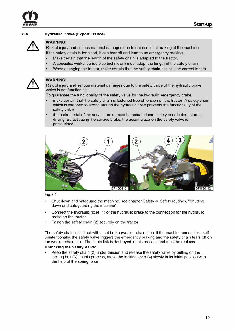
Start-up
101
Pos: 88.48 /Überschriften/Überschriften 2/F-J/Hydraulische Bremse (Export Frankreich) @ 129\mod_1346767988893_78.docx @ 1155782 @ 2 @ 1
8.4 Hydraulic Brake (Export France) Pos: 88.49 /BA/Sicherheit/Bremsen/Warnung - hydraulische Bremse Frankreichausstattung Sicherheitskette zu kurz @ 129\mod_1346767273286_78.docx @ 1155665 @ @ 1
WARNING! Risk of injury and serious material damages due to unintentional braking of the machine If the safety chain is too short, it can tear off and lead to an emergency braking. • Make certain that the length of the safety chain is adapted to the tractor. • A specialist workshop (service technician) must adapt the length of the safety chain • When changing the tractor, make certain that the safety chain has still the correct length
Pos: 88.50 /BA/Sicherheit/Bremsen/Warnung - hydraulische Bremse Frankreichausstattung nicht funktionierendes Sicherheitsventil @ 129\mod_1346767725757_78.docx @ 1155753 @ @ 1
WARNING! Risk of injury and serious material damages due to the safety valve of the hydraulic brake which is not functioning. To guarantee the functionality of the safety valve for the hydraulic emergency brake, • make certain that the safety chain is fastened free of tension on the tractor. A safety chain
which is wrapped to strong around the hydraulic hose prevents the functionality of the safety valve
• the brake pedal of the service brake must be actuated completely once before starting driving. By activating the service brake, the accumulator on the safety valve is pressurised.
Pos: 88.51 /BA/Inbetriebnahme/Hydraulische Bremse/Hydraulische Bremse (Export Frankreich) Bild BiG PACK @ 129\mod_1346768208301_78.docx @ 1155841 @ @ 1
Fig. 61 Pos: 88.52 /BA/Sicherheit/8. Voraussetzungen/Handlungsanweisung für alle Maschinen/Handlungsanweisung: Maschine stillsetzen und sichern @ 274\mod_1404365253849_78.docx @ 2065151 @ @ 1
• Shut down and safeguard the machine, see chapter Safety -> Safety routines, "Shutting down and safeguarding the machine".
Pos: 88.53 /BA/Inbetriebnahme/Hydraulische Bremse/Hydraulische Bremse (Export Frankreich) Text @ 129\mod_1346768337674_78.docx @ 1155900 @ @ 1
• Connect the hydraulic hose (1) of the hydraulic brake to the connection for the hydraulic brake on the tractor
• Fasten the safety chain (2) securely on the tractor The safety chain is laid out with a set brake (weaker chain link). If the machine uncouples itself unintentionally, the safety valve triggers the emergency braking and the safety chain tears off on the weaker chain link . The chain link is destroyed in this process and must be replaced. Unlocking the Safety Valve: • Keep the safety chain (2) under tension and release the safety valve by pulling on the
locking bolt (3). In this process, move the locking lever (4) slowly in its initial position with the help of the spring force.
Pos: 88.54 /Layout Module /---------------Seitenumbruch---------------- @ 0\mod_1196175311226_0.docx @ 4165 @ @ 1
2
BPHS0113
1 2
BPHS0112
34

Start-up
102
Pos: 88.55 /Überschriften/Überschriften 2/A-E/Druckluftanschlüsse bei Druckluftbremse @ 0\mod_1201161304258_78.docx @ 51103 @ 2 @ 1
8.5 Compressed Air Connections for the Compressed Air Brake Pos: 88.56 /BA/Inbetriebnahme/Druckluftbremse/Zweileitungssystem @ 5\mod_1213850550416_78.docx @ 89668 @ @ 1
The machine features a dual-line compressed-air braking system. • The coupling heads are connected to the machine for attachment of the reservoir (red) and
brake line (yellow) of the tractor. Pos: 88.57 /BA/Sicherheit/8. Voraussetzungen/Handlungsanweisung für alle Maschinen/Handlungsanweisung: Maschine stillsetzen und sichern @ 274\mod_1404365253849_78.docx @ 2065151 @ @ 1
• Shut down and safeguard the machine, see chapter Safety -> Safety routines, "Shutting down and safeguarding the machine".
Pos: 88.58 /BA/Inbetriebnahme/Druckluftbremse/Druckluftanschlüsse bei Druckluftbremse @ 0\mod_1199781319294_78.docx @ 34484 @ @ 1
ZX400003
Figure 62 Insert the coloured compressed air hose couplings (1) into the correspondingly coloured couplings on the tractor.
Note Always connect the yellow coupling head first, then the red one. Detach the couplings in reverse order.
Pos: 88.59 /Layout Module /---------------Seitenumbruch---------------- @ 0\mod_1196175311226_0.docx @ 4165 @ @ 1

Start-up
103
Pos: 88.60 /Überschriften/Überschriften 2/A-E/Elektrische Anschlüsse @ 17\mod_1236579932558_78.docx @ 205175 @ 2 @ 1
8.6 Electrical connections Pos: 88.61 /BA/Sicherheit/8. Voraussetzungen/Handlungsanweisung für alle Maschinen/Handlungsanweisung: Maschine stillsetzen und sichern @ 274\mod_1404365253849_78.docx @ 2065151 @ @ 1
• Shut down and safeguard the machine, see chapter Safety -> Safety routines, "Shutting down and safeguarding the machine".
Pos: 88.62 /BA/Info-Center/CCI-ISOBUS-Terminal/Terminal anschließen (ohne ISO Schlepper) @ 43\mod_1274882231640_78.docx @ 387925 @ 3 @ 1
8.6.1 Connecting the terminal (on tractors without ISOBUS system)
Fig. 63 Connection terminal to machine
Note The connection of terminal to machine takes place via a provided cable set (5) (article no. 20 081 224 0). • Connect plug (2) of cable set (5) with socket (1) (CAN1-IN) of the terminal • Connect plug (6) (7-pole) of cable set (5) with socket (7) (7-pole) of the machine • Connect connector plug (4) (article no. 00 302 300 0 included in scope of delivery) with
socket (3) (CAN1-OUT) of the terminal Connection tractor to machine
Note The connection of tractor to machine takes place via a provided power cable (8) (article no. 20 080 601 0). • Connect plug (9) of power cable (8) with continuous current socket (10) of the tractor • Connect plug (11) (2-pole) of power cable (8) with socket (12) (2-pole) of the machine
Pos: 88.63 /Layout Module /---------------Seitenumbruch---------------- @ 0\mod_1196175311226_0.docx @ 4165 @ @ 1

Start-up
104
Pos: 88.64 /BA/Info-Center/CCI-ISOBUS-Terminal/Terminal anschließen (vorgerüsteteter ISO Schlepper) @ 172\mod_1370518477799_78.docx @ 1480570 @ 3 @ 1
8.6.2 Connecting the Terminal (on tractors with integrated ISOBUS system)
6
5
1
2
3
4
CC00014
147
369
7
9
10
11 13
12
5
14
8
Fig. 64 Connection terminal to tractor
Note The terminal is connected to the tractor via a special cable set (5) which can be ordered by stating the KRONE article no. 20 081 223 0. • Connect plug (2) of cable set (5) with socket (1) (CAN1-IN) of the terminal. • Connect plug (4) of cable set (5) with socket (3) (CAN1-out) of the terminal. • Connect ISO plug (6) (9-pole) of cable set (5) with the ISO socket (7) (9-pole) located in the
tractor cabin. Connection tractor to machine
Note The tractor is connected to the machine via cable set (14) which can be ordered by stating KRONE article no. 20 080 384 0. • Connect ISO-plug (9) (9-pole) of cable set (14) with the outer ISO socket (8) (9-pole) on
tractor side. • Connect plug (10) (7-pole) of cable set (14) with socket (11) (7-pole) of the machine. • Connect plug (12) (2-pole) of cable set (14) with socket (13) (2-pole) of the machine.
Pos: 88.65 /Layout Module /---------------Seitenumbruch---------------- @ 0\mod_1196175311226_0.docx @ 4165 @ @ 1

Start-up
105
Pos: 88.66 /Überschriften/Überschriften 2/A-E/Beleuchtung @ 0\mod_1195658399935_78.docx @ 1881 @ 2 @ 1
8.7 Lighting Pos: 88.67 /BA/Inbetriebnahme/Großpackenpresse/Beleuchtung/Beleuchtung anschließen Bild HDP II @ 171\mod_1370344610812_78.docx @ 1475988 @ @ 1
BPHS0216
1
23
Fig. 65 Pos: 88.68 /BA/Sicherheit/8. Voraussetzungen/Handlungsanweisung für alle Maschinen/Handlungsanweisung: Maschine stillsetzen und sichern @ 274\mod_1404365253849_78.docx @ 2065151 @ @ 1
• Shut down and safeguard the machine, see chapter Safety -> Safety routines, "Shutting down and safeguarding the machine".
Pos: 88.69 /BA/Inbetriebnahme/Schwader/Anschluss Beleuchtung/Anschluss Beleuchtung Text @ 36\mod_1260783798936_78.docx @ 336718 @ @ 1
The lighting system is connected via the 7-pin connection cable (1). To do this: • Insert the 7-pin plug of the connection cable (1) into the relevant socket (2) of the tractor. • Insert the 7-pin connection cable plug (1) into the appropriate socket (3) of the machine. • Position the cable so that it will not come in contact with the wheels.
Pos: 88.70 /BA/Inbetriebnahme/Schwader/Hinweis Sauberkeit der Stecker und Steckdosen @ 2\mod_1202399563131_78.docx @ 59273 @ @ 1
Note Before inserting the plugs, make certain the plugs and sockets are clean and dry. Dirt and moisture may result in short circuits!
Pos: 88.71.1 /Überschriften/Überschriften 2/P-T/Sicherungskette verwenden @ 6\mod_1214542336632_78.docx @ 94799 @ 2 @ 1
8.8 Using the safety chain Pos: 88.71.2 /BA/Inbetriebnahme/Sicherungskette USA/WARNUNG - Falsch dimensionierte Sicherungskette verwendet mit Variante @ 180\mod_1376576652355_78.docx @ 1547873 @ @ 1
WARNING! When using a wrongly dimensioned safety chain, the safety chain may tear if the machine loosens unintentionally. This can result in serious accidents. • Always use a safety chain with a minimum tensile strength of 178 kN (40.000 lbf).
Pos: 88.71.3 /BA/Inbetriebnahme/Sicherungskette USA/Hinweis Sicherungskette Länderabhängig @ 6\mod_1214999654856_78.docx @ 97933 @ @ 1
Note Using the safety chain Attachment of the safety chain is not stipulated in all countries.
Pos: 88.71.4 /BA/Inbetriebnahme/Sicherungskette USA/Sicherungskette verwenden @ 207\mod_1386742973026_78.docx @ 1714836 @ @ 1
The safety chain is used as an additional safety precaution for trailed devices, should they become detached from the drawbar during transport. Attach the safety chain with the respective mounting parts to the hitching device on the tractor or to another specified connection point. The safety chain should have just enough play to be able to go around curves.
Pos: 88.71.5 /Beipacks/Sonstige/Sicherungskette 178 kN/Sicherungskette montieren BiG Pack Bild @ 147\mod_1361184126131_78.docx @ 1320037 @ @ 1
2
1
Fig. 66 Pos: 88.71.6 /BA/Sicherheit/8. Voraussetzungen/Handlungsanweisung für alle Maschinen/Handlungsanweisung: Maschine stillsetzen und sichern @ 274\mod_1404365253849_78.docx @ 2065151 @ @ 1

Start-up
106
• Shut down and safeguard the machine, see chapter Safety -> Safety routines, "Shutting down and safeguarding the machine".
Pos: 88.71.7 /Beipacks/Sonstige/Sicherungskette 178 kN/Sicherheitskette mit Schäkel an Großpackenpresse montieren Text @ 149\mod_1361521338690_78.docx @ 1332633 @ @ 1
• Install safety chain (1) with shackle (2) on the big pack baler.
Pos: 88.71.8 /Beipacks/Sonstige/Sicherungskette 178 kN/Sicherungskette an den Traktor montieren Bild @ 147\mod_1361181563288_78.docx @ 1319688 @ @ 1
ba
Fig. 67 Pos: 88.71.9 /Beipacks/Sonstige/Sicherungskette 89kN/Sicherungskette am Traktor montieren Text @ 150\mod_1362048347829_78.docx @ 1343318 @ @ 1
• Install safety chain (1) on an eligible position (for example: a or b) on the tractor.
Pos: 89 /Layout Module /---------------Seitenumbruch---------------- @ 0\mod_1196175311226_0.docx @ 4165 @ @ 1

Driving and Transport
107
Pos: 90.1 /Überschriften/Überschriften 1/F-J/Fahren und Transport @ 0\mod_1196330049217_78.docx @ 6553 @ 1 @ 1
9 Driving and Transport Pos: 90.2 /BA/Sicherheit/2. Vorangestellte Warnhinweise/WARNUNG - Nichtbeachtung der grundlegenden Sicherheitshinweise alte Form @ 254\mod_1397485793575_78.docx @ 1953347 @ @ 1
WARNING! If the basic safety instructions are not followed, people may be seriously injured or killed. • To avoid accidents, the basic safety instructions in the chapter Safety must have been
read and followed, see chapter Safety "Basic safety instructions".
Pos: 90.3 /BA/Sicherheit/2. Vorangestellte Warnhinweise/Warnung - Nichtbeachtung der Sicherheitsroutinen alte Form @ 273\mod_1404117435996_78.docx @ 2058712 @ @ 1
WARNING! If the safety routines are not adhered to, people may be seriously injured or killed. • To avoid accidents, the safety routines in the chapter Safety must be read and followed,
see chapter Safety "Safety routines".
Pos: 90.4 /BA/Sicherheit/Fahren und Transport/Warnung - Straßenfahrt Unfallgefahr durch nicht verriegelte Steuerventile des Traktors @ 274\mod_1404213302399_78.docx @ 2060724 @ @ 1
WARNING! There is a risk of accidents if the control valves on the tractor are not locked. If the control valves are not locked, machine components may be activated unintentionally. This can result in serious accidents. • To prevent functions being triggered accidentally, the control valves on the tractor must be
switched to neutral and locked during road transport journeys.
Pos: 90.5 /BA/Sicherheit/2. Vorangestellte Warnhinweise/Warnung - Gefahren bei Kurvenfahrten mit angehängter Maschine @ 273\mod_1403678392890_78.docx @ 2053902 @ @ 1
WARNING! Danger when cornering with a machine hitched When cornering, the hitched machine swings out further than the tractor. This can lead to accidents. • Take the greater swivel range into account. • When turning, take account of people, oncoming traffic and obstacles.
Pos: 90.6 /Layout Module /---------------Seitenumbruch---------------- @ 0\mod_1196175311226_0.docx @ 4165 @ @ 1

Driving and Transport
108
Pos: 90.7 /Überschriften/Überschriften 2/U-Z/Vorbereitungen zur Straßenfahrt @ 25\mod_1244092605963_78.docx @ 254666 @ 2 @ 1
9.1 Preparations for road travel Pos: 90.8 /BA/Fahren und Transport/Großpackenpresse/Prüfen Sie vor der Straßenfahrt, dass BiG PACK 890_1270_1290_4x4 HS @ 191\mod_1381742405762_78.docx @ 1629843 @ @ 1
Before road travel, make certain – the PTO shaft is switched off. – the machine is fully and correctly hitched to the tractor; refer to chapter “Start-Up”. – all guards are closed and locked. – the folding ladder is folded in; refer to chapter Machine Description “Ladder”, only with 13t
axle. – the bale channel is empty. – the pick-up is lifted and secured by the stopcock; refer to chapter Operation “Pick-up”. – the bale chute is raised into transport position and secured; refer to chapter Operation
“Lifting / Lowering Bale Chute”. – the parking jack is retracted; refer to chapter Operation “Hydraulic Parking Jack”. – the parking brake is released; refer to chapter Driving and Transport “Parking Brake”. – the control valves on the tractor are in neutral position and locked. – the brake is working properly. – the lighting is working properly; refer to chapter Driving and Transport “Checking Lighting
System”. – the tyres do not show any cuts or breaks. – the tyres have the correct tyre pressure.
Pos: 90.9 /BA/Fahren und Transport/Großpackenpresse/Folgende Arbeitsschritte werden in diesem Kapitel beschrieben Fahren und Transport @ 157\mod_1364375905147_78.docx @ 1387035 @ @ 1
The following work steps are described in this chapter: – Checking the lighting system. – Releasing the parking brake. – Handling of the trailing axle, medium electronics or comfort electronics. – Moving the machine without hydraulic connection. – Moving the machine without connected compressed air brake. – Switching off the machine. – Applying the parking brake. – Fitting wheel chocks.
Pos: 90.10 /Layout Module /---------------Seitenumbruch---------------- @ 0\mod_1196175311226_0.docx @ 4165 @ @ 1

Driving and Transport
109
Pos: 90.11 /Überschriften/Überschriften 3/F-J/Hydraulisch betätigte Rollenschurre @ 25\mod_1244092719994_78.docx @ 254690 @ 3 @ 1
9.1.1 Roller chute hydraulically activated Pos: 90.12 /BA/Fahren und Transport/Großpackenpresse/HydraulischRollenschurre Bild 870 HDP Baureihe @ 270\mod_1402485959956_78.docx @ 2039588 @ @ 1
1
BPHS02742
Fig. 68 Pos: 90.13 /BA/Fahren und Transport/Großpackenpresse/Hydraulisch betätigte Rollenschurre Text @ 17\mod_1236588072917_78.docx @ 205441 @ @ 1
• Fold in the hydraulically activated roller chute (1) hydraulically After it is folded in, make certain that the mechanical lock (2) has snapped into place.
Pos: 90.14 /BA/Fahren und Transport/Großpackenpresse/Packenschurre in Transportstellung (optional) @ 17\mod_1236588178980_78.docx @ 205465 @ 3 @ 1
9.1.2 Bale chute in transport position (optional)
Fig. 69 • To bring the bale chute into the transport position, the unfolded chute must be folded up and
secured with the retaining chains (4) Pos: 90.15 /Layout Module /---------------Seitenumbruch---------------- @ 0\mod_1196175311226_0.docx @ 4165 @ @ 1

Driving and Transport
110
Pos: 90.16 /Überschriften/Überschriften 3/A-E/BBeleuchtungsanlage prüfen @ 25\mod_1244090937463_78.docx @ 254566 @ 3 @ 1
9.1.3 Checking the lighting system Pos: 90.17 /BA/Fahren und Transport/Großpackenpresse/Beleuchtungsanlage prüfen Bild BP 890_1270_1290 Hs Baureihe @ 62\mod_1299574637575_78.docx @ 572905 @ @ 1
2
BPHS0011
1
Fig.70 Pos: 90.18 /BA/Fahren und Transport/Großpackenpresse/Beleuchtungsanlage prüfen Text @ 17\mod_1236588258401_78.docx @ 205489 @ @ 1
• Check the function of the tail lights (2) and rear reflectors (1) and clean them • The same applies to the yellow reflectors located on the sides of the machine and the front
white side lights Pos: 90.19 /Überschriften/Überschriften 3/P-T/Standbremse / Feststellbremse @ 25\mod_1242719474426_78.docx @ 253706 @ 3 @ 1
9.1.4 Parking brake Pos: 90.20 /BA/Inbetriebnahme/Feststellbremse/Feststellbremse Bild BiG Pack 890_1270_1290 HS Baureihe @ 92\mod_1326881975736_78.docx @ 782991 @ @ 1
1
BPHS0009_1
Fig. 71 Pos: 90.21 /BA/Inbetriebnahme/Feststellbremse/Standbremse lösen @ 62\mod_1299576787373_78.docx @ 572965 @ @ 1
Release the parking brake: • Turn the crank anti-clockwise until the brake cable is slightly slack.
Pos: 90.22 /Layout Module /---------------Seitenumbruch---------------- @ 0\mod_1196175311226_0.docx @ 4165 @ @ 1

Driving and Transport
111
Pos: 90.23 /Überschriften/Überschriften 2/F-J/Handhabung der Nachlauf-Lenkachse (Sonderausstattung) @ 0\mod_1201167915356_78.docx @ 51383 @ 2 @ 1
9.2 Handling the Coaster/Steering Axle (Special Equipment) Pos: 90.24 /BA/Inbetriebnahme/Großpackenpresse/Hydraulik/Hinweis: Benutzerhinweise des Traktorherstellers zum Parallelbetrieb beachten. @ 233\mod_1393930674316_78.docx @ 1858122 @ @ 1
Note Observe the user instructions provided by the tractor manufacturer for parallel operation of the tractor control units! The locking cylinder of the steering axle must be connected before or at the same time as the other hydraulic supply elements of the machine!
Pos: 90.25 /BA/Fahren und Transport/Nachlauf-Lenkachse/Nachlauflenkachse AX und MX Ladewagen/Vor Rückwärtsfahrt Nachlauf-Lenkachse in Geradeausstellung bringen und verriegeln @ 60\mod_1297781900981_78.docx @ 561023 @ @ 1
Before reversing, move coaster/steering axle to a straight position and lock.
Pos: 90.26 /BA/Fahren und Transport/Nachlauf-Lenkachse/Nachlauflenkachse AX und MX Ladewagen/Hinweis Bei kritischen Fahrsituationen das einlenken der Räder unterbinden @ 60\mod_1297786543427_78.docx @ 561373 @ @ 1
Note On the coaster/steering axle, the rear wheels are turned in by friction between the wheels and the soil. In critical driving situations (e.g. driving over a bunker silo, reversing or driving on slopes) where a straight line cannot be maintained, the wheels must be prevented from turning in by locking the locking cylinder.
Pos: 90.27 /BA/Fahren und Transport/Nachlauf-Lenkachse/Nachlauf-Lenkachse Big Pack/Kritische Fahrsituationen können sein BiG PAck @ 62\mod_1299579627648_78.docx @ 573018 @ @ 1
Critical driving situations could include: • driving on steep slopes • driving on soil that is not solid enough • driving fast and straight ahead at speeds in excess of 30 km/h
Pos: 90.28 /Layout Module /---------------Seitenumbruch---------------- @ 0\mod_1196175311226_0.docx @ 4165 @ @ 1

Driving and Transport
112
Pos: 90.29 /BA/Fahren und Transport/Nachlauf-Lenkachse/Nachlauflenkachse AX und MX Ladewagen/Verriegeln der Nachlauf-Lenkachse @ 60\mod_1297786258507_78.docx @ 561294 @ @ 1
Locking the coaster/steering axle To lock the coaster/steering axle:
Pos: 90.30 /BA/Maschinenbeschreibung/Maschinenübersicht/Großpackenpressen/Medium - Elektronik @ 61\mod_1299223169539_78.docx @ 570971 @ @ 1
Medium Version Electronics Pos: 90.31 /BA/Fahren und Transport/Nachlauf-Lenkachse/Nachlauflenkachse AX und MX Ladewagen/Verriegeln der Nachlauf-Lenkachse bei einfachwirkendem Hydraulik-Anschluss @ 60\mod_1297838187149_78.docx @ 561432 @ @ 1
With single action hydraulic connection • Pressurise the single action control unit and drive the tractor a short distance straight
forward until the steered wheels are straight • Leave the single action control unit for the coaster/steering axle pressurised (the locking
cylinder prevents the wheels from turning in)
Pos: 90.32 /BA/Fahren und Transport/Nachlauf-Lenkachse/Hinweis: Der aktuelle Zustand wird in der Statuszeile (1) im Display angezeigt @ 62\mod_1299586402629_78.docx @ 573154 @ @ 1
Note The current status is shown in the status line (I) of the display.
= Axle locked = Axle released
Pos: 90.33 /BA/Fahren und Transport/Nachlauf-Lenkachse/Nachlauflenkachse AX und MX Ladewagen/Entriegeln der Nachlauf-Lenkachse bei einachwirkendem Hydraulik-Anschluss @ 60\mod_1297785948415_78.docx @ 561242 @ @ 1
Unlocking the coaster/steering axle with a single action hydraulic connection When driving forwards, the locking cylinder for the coaster/steering axle can be released: • Depressurise the single action control unit for the coaster/steering axle (locking cylinder)
and set the hydraulic control lever to "Lower" This can largely prevent scraping of the tyres when cornering.
Pos: 90.34 /BA/Fahren und Transport/Nachlauf-Lenkachse/Nachlauf-Lenkachse Big Pack/Bild Nachlauf-Lenkachse Absperrhahn @ 64\mod_1300285158431_78.docx @ 582983 @ @ 1
1
BPHS0043
I
II
Fig.72 Pos: 90.35 /BA/Fahren und Transport/Großpackenpresse/Hinweis Absperrhahn geöffnet @ 25\mod_1242741065410_78.docx @ 254146 @ @ 1
Note Make certain, that the shut-off valve (1) is in position (I) (opened) during use of machine.
Pos: 90.36 /Layout Module /---------------Seitenumbruch---------------- @ 0\mod_1196175311226_0.docx @ 4165 @ @ 1

Driving and Transport
113
Pos: 90.37 /BA/Maschinenbeschreibung/Maschinenübersicht/Großpackenpressen/Komfort - Elektronik @ 61\mod_1299223046976_78.docx @ 570919 @ @ 1
Comfort - Electronic Pos: 90.38 /Überschriften/Überschriften 3/A-E/BBetrieb der Maschine über LS (Load-Sensing-Anschluss) @ 91\mod_1326699464848_78.docx @ 780190 @ 3 @ 1
9.2.1 Operating the Machine via LS (Load-Sensing Connection) Pos: 90.39 /BA/Fahren und Transport/Nachlauf-Lenkachse/Nachlauf-Lenkachse Big Pack/Nachlauf-Lenkachse verriegeln Komfort Elektronik über Load Sensing @ 91\mod_1326702544634_78.docx @ 780363 @ @ 1
• Press the function key for and drive the tractor a short distance straight forward until
the steered wheels are straight. The symbol appears on the display (coaster/steering axle locked).
Pos: 90.40 /BA/Fahren und Transport/Nachlauf-Lenkachse/Hinweis: Der aktuelle Zustand wird in der Statuszeile (1) im Display angezeigt @ 62\mod_1299586402629_78.docx @ 573154 @ @ 1
Note The current status is shown in the status line (I) of the display.
= Axle locked = Axle released
Pos: 90.41 /BA/Fahren und Transport/Nachlauf-Lenkachse/Nachlauf-Lenkachse Big Pack/Hinweis: Solange sich der Druck an den Arretierzylinder aufbaut blinkt das Softkey @ 62\mod_1299587033250_78.docx @ 573181 @ @ 1
Note While the pressure is increasing in the locking cylinders the softkey flashes. As soon as the
pressure has built up the softkey freezes and the coaster/steering axle is locked.
Pos: 90.42 /Überschriften/Überschriften 3/A-E/BBetrieb der Maschine ohne LS (Load-Sensing-Anschluss) @ 91\mod_1326699351886_78.docx @ 780162 @ 3 @ 1
9.2.2 Operating the Machine without LS (Load-Sensing Connection) Pos: 90.43 /BA/Fahren und Transport/Nachlauf-Lenkachse/Nachlauf-Lenkachse Big Pack/Nachlauf-Lenkachse verriegeln Komfort Elektronik ohne Load Sensing @ 91\mod_1326702885195_78.docx @ 780451 @ @ 1
• Pressurise the pressure line.
• Press the function key for and drive the tractor a short distance straight forward until
the steered wheels are straight. Leave the pressure on the pressure line until the icon appears in the display (coaster/steering axle locked)
• The hydraulic system (pressure line) can now be switched to depressurised Pos: 90.44 /BA/Fahren und Transport/Nachlauf-Lenkachse/Hinweis: Der aktuelle Zustand wird in der Statuszeile (1) im Display angezeigt @ 62\mod_1299586402629_78.docx @ 573154 @ @ 1
Note The current status is shown in the status line (I) of the display.
= Axle locked = Axle released
Pos: 90.45 /BA/Fahren und Transport/Nachlauf-Lenkachse/Nachlauf-Lenkachse Big Pack/Hinweis: Solange sich der Druck an den Arretierzylinder aufbaut blinkt das Softkey @ 62\mod_1299587033250_78.docx @ 573181 @ @ 1
Note While the pressure is increasing in the locking cylinders the softkey flashes. As soon as the
pressure has built up the softkey freezes and the coaster/steering axle is locked.
Pos: 90.46 /BA/Fahren und Transport/Nachlauf-Lenkachse/Nachlauf-Lenkachse Big Pack/Nachlauf-Lenkachse entriegeln Komfort Elektronik @ 62\mod_1299581981710_78.docx @ 573071 @ @ 1
Unlocking the coaster/steering axle for Comfort version Electronics
• The coaster/steering axle is released by pressing the function key for . The symbol appears on the display (coaster/steering axle released).
Pos: 90.47 /BA/Fahren und Transport/Nachlauf-Lenkachse/Hinweis: Der aktuelle Zustand wird in der Statuszeile (1) im Display angezeigt @ 62\mod_1299586402629_78.docx @ 573154 @ @ 1
Note The current status is shown in the status line (I) of the display.
= Axle locked = Axle released
Pos: 90.48 /Layout Module /---------------Seitenumbruch---------------- @ 0\mod_1196175311226_0.docx @ 4165 @ @ 1

Driving and Transport
114
Pos: 90.49 /BA/Fahren und Transport/Nachlauf-Lenkachse/Nachlauf-Lenkachse Big Pack/Bei Option Nachlauf-Lenkachse rangieren HS Baureihe @ 62\mod_1299593571338_78.docx @ 573301 @ 3 @ 1
9.2.3 Moving the machine without hydraulic connections
In order to be able to move the machine even when the hydraulic lines are not connected, the locking cylinder of the coaster/steering axle must be supplied with pressure before disconnection and the steered wheels aligned by driving straight ahead.
Pos: 90.50 /BA/Fahren und Transport/Nachlauf-Lenkachse/Nachlauf-Lenkachse Big Pack/Rangieren bei Medium Elektronik @ 64\mod_1300285419164_78.docx @ 583009 @ @ 1
1
BPHS0043
I
II
Fig.73 In addition for the Medium Electronics version, the shut-off valve (1) for the coaster/steering axle must be closed (setting II) before disconnection.
Pos: 90.51 /Layout Module /---------------Seitenumbruch---------------- @ 0\mod_1196175311226_0.docx @ 4165 @ @ 1

Driving and Transport
115
Pos: 90.52.1 /Überschriften/Überschriften 2/P-T/Rangieren @ 13\mod_1225364693769_78.docx @ 155850 @ 2 @ 1
9.3 Moving Pos: 90.52.2 /Abkürzungen /Bei Ausführung Druckluftbremse @ 168\mod_1368456181882_78.docx @ 1456665 @ @ 1
With compressed air brake design Pos: 90.52.3 /BA/Sicherheit/2. Vorangestellte Warnhinweise/Warnung - Rangieren der Maschine ohne angeschlossene Druckluftbremsanlage @ 273\mod_1403782282064_78.docx @ 2057109 @ @ 1
WARNING! There is a risk of injury when manoeuvring the machine without the compressed air braking system connected. A machine without a connected compressed air braking system loses its braking characteristics. As a result, people may be seriously injured or killed. • Moving the machine in public road traffic without the compressed air braking system
connected is prohibited.
Pos: 90.52.4 /BA/Wartung/Bremsanlage/Rangieren/Rangieren ohne angeschlossene Druckluftbremse @ 13\mod_1225362041347_78.docx @ 155702 @ @ 1
It is not easy to move the machine if the hoses of the compressed air brake are not connected to a brake system.
Pos: 90.52.5 /BA/Wartung/Bremsanlage/Rangieren/Rangieren Bild BiG PAck @ 208\mod_1386934470292_78.docx @ 1720778 @ @ 1
BPHS02653
2
1a
b
Fig. 74 Pos: 90.52.6 /BA/Wartung/Bremsanlage/Rangieren/Löseventil befindet sich BiG Pack @ 17\mod_1236589219870_78.docx @ 205591 @ @ 1
The release valve is on the front right under the side hood. If a minimum pressure of 4 bar (58 PSI) is available in the reservoir (2) of the brake system of the machine, then the brake can be released by pressing the push button (1) on the release valve into the position (a). As soon as the hoses are again connected to a compressed air brake system, the push button is pushed back automatically into its starting position (b).
Pos: 90.52.7 /BA/Wartung/Bremsanlage/Rangieren/Luftdruck im Vorratsbehälter unter 4 bar gefallen @ 17\mod_1236589531089_78.docx @ 205610 @ @ 1
If the air pressure in the storage tank (2) has dropped below 4 bar (58 PSI) , the residual pressure must also be let off by operating the drain valve (3). Only now can the machine be moved.
Pos: 90.53 /Layout Module /---------------Seitenumbruch---------------- @ 0\mod_1196175311226_0.docx @ 4165 @ @ 1
Driving and Transport
116
Pos: 90.54 /Überschriften/Überschriften 2/K-O/Maschine abstellen @ 196\mod_1384184875882_78.docx @ 1661525 @ 2 @ 1
9.4 Switching off the machine Pos: 90.55 /BA/Sicherheit/2. Vorangestellte Warnhinweise/Warnung - Maschine sicher abstellen ohne Traktor_Feststellbremse und Unterlegkeile @ 274\mod_1404214703082_78.docx @ 2060841 @ @ 1
WARNING! Risk of injury due to the unsecured machine rolling away! If the machine is not secured against rolling away when it has been switched off, there is a risk of people being injured by the machine rolling away in an uncontrolled manner. • Secure the machine against rolling away with the parking brake and wheel chocks. • Apply the flywheel brake at the machine.
Pos: 90.56 /BA/Fahren und Transport/Großpackenpresse/Abstellen der Maschine @ 169\mod_1368683547889_78.docx @ 1460065 @ @ 1
• Switch off the tractor engine, remove the ignition key and secure the tractor from rolling away.
• Wait until all moving parts stop. • Apply the flywheel brake. • Apply the parking brake. • Fit the wheel chock. • Parking jack has to be lowered until the towing eye of the ball attachment Ø80 does not rest
on the hitch of the tractor any more. • Loosen safety chains of the universal shaft on tractor side. • Disconnect the universal shaft on tractor side and put it down on the holder provided for that
purpose. • Pull off the lighting cable. • Remove the power supply cable for the terminal. • Disconnect the hydraulic lines and attach them to the support of the machine. With compressed air brake design: • Disconnect the red coupling head and attach it to the support of the machine. • Disconnect the yellow coupling head and attach it to the support of the machine. With hydraulic brake design (export): • Disconnect the connection for hydraulic brake and attach it to the support of the machine With hydraulic brake design (export France): • Loosen safety chain on tractor side. • Disconnect the connection for the hydraulic brake and attach it to the support of the
machine.
Pos: 90.57 /Layout Module /---------------Seitenumbruch---------------- @ 0\mod_1196175311226_0.docx @ 4165 @ @ 1

Driving and Transport
117
Pos: 90.58 /Überschriften/Überschriften 3/A-E/DDruckluftschläuche ablegen @ 279\mod_1405072075407_78.docx @ 2148036 @ 3 @ 1
9.4.1 Stowing the compressed air hoses Pos: 90.59 /BA/Inbetriebnahme/Druckluftbremse/Druckluftschläuche ablegen Bild BiG Pack @ 279\mod_1405071878377_78.docx @ 2147992 @ @ 1
Fig. 75 Pos: 90.60 /BA/Inbetriebnahme/Druckluftbremse/Druckluftschläuche ablegen Text BiG Pack @ 279\mod_1405073904536_78.docx @ 2148151 @ @ 1
• Hang the compressed air hose (1) onto the holder (2). Pos: 90.61 /Layout Module /---------------Seitenumbruch---------------- @ 0\mod_1196175311226_0.docx @ 4165 @ @ 1

Driving and Transport
118
Pos: 90.62 /Überschriften/Überschriften 3/P-T/Standbremse / Feststellbremse @ 25\mod_1242719474426_78.docx @ 253706 @ 3 @ 1
9.4.2 Parking brake Pos: 90.63 /BA/Inbetriebnahme/Feststellbremse/Feststellbremse Bild BiG Pack 890_1270_1290 HS Baureihe @ 92\mod_1326881975736_78.docx @ 782991 @ @ 1
1
BPHS0009_1
Fig. 76 Pos: 90.64 /BA/Inbetriebnahme/Feststellbremse/Standbremse anziehen @ 62\mod_1299577105794_78.docx @ 572992 @ @ 1
Set the parking brake: • Turn the crank clockwise until the resistance grows noticeably greater.
Pos: 90.65 /BA/Inbetriebnahme/Feststellbremse/Hinweis Feststellbremse/Unterlegkeile @ 6\mod_1214899429153_78.docx @ 96796 @ @ 1
Note To prevent the machine from rolling away, use the wheel chocks in addition to the parking brake.
Pos: 90.66 /Überschriften/Überschriften 3/U-Z/Unterlegkeile @ 33\mod_1254202555660_78.docx @ 318451 @ 3 @ 1
9.4.3 Wheel chocks Pos: 90.67 /BA/Fahren und Transport/Großpackenpresse/Unterlegkeile Bild BP 890_1270_1290 HS Baureihe @ 63\mod_1299668510278_78.docx @ 574581 @ @ 1
1BPHS0024
Fig.77 Pos: 90.68 /BA/Fahren und Transport/Großpackenpresse/Unterlegkeile Text BP HS Baureihe @ 71\mod_1305799627493_78.docx @ 640727 @ @ 1
The wheel chocks (1) are located at the rear on the right and left next to the bale channel chamber • Always place the wheel chocks (1) in front of and behind the wheels (this will prevent the
machine from rolling away).
Note If the machine has a guided coast-down tandem axle (optional), it must be secured with wheel chocks on the front axle to prevent it from rolling away.
Pos: 91 /Layout Module /---------------Seitenumbruch---------------- @ 0\mod_1196175311226_0.docx @ 4165 @ @ 1

KRONE ISOBUS Terminal
119
Pos: 92.1 /Überschriften/Überschriften 1/K-O/KRONE ISOBUS-Terminal @ 185\mod_1379578612990_78.docx @ 1598079 @ 1 @ 1
10 KRONE ISOBUS Terminal Pos: 92.2 /BA/Info-Center/CCI-ISOBUS-Terminal/Hinweis Im weiteren Verlauf Terminal auch als Bedieneinheit bezeichnet @ 46\mod_1281680416671_78.docx @ 445465 @ @ 1
Note In the operating instructions which follow, the terminal will also be referred to as the "control unit".
Pos: 92.3 /BA/Sicherheit/7. Gefahrenhinweise alt/Achtung - Bedieneinheit schützen @ 0\mod_1200308247867_78.docx @ 39598 @ @ 1
Caution! - Protect Control Unit. Effect: Damage to the control unit • The control unit must be protected against water. • If the machine is not used for an extended period of time (for example during the winter),
the control unit must be stored in a dry place. • For mounting and repair jobs, especially for welding jobs on the machine, disconnect the
power supply to the control unit. Overvoltage can damage the control unit.
Pos: 92.4 /BA/Info-Center/CCI-ISOBUS-Terminal/CCI-BiG Pack/Allgemeine Beschreibung (Die elektronische Ausstattung der Maschine ........) Text/Bild @ 43\mod_1274868004640_78.docx @ 387798 @ @ 1
F1
F2
F3
F4
F5
F6
F7
F8
F9
F10
F11F11
F12
ESC
CC000013
3
Fig. 78 The electronic equipment of the machine consists essentially of the job computer (1), the terminal (3) and the control and function elements. The job computer (1) is located on the front left of the machine under the side hood. Its functions are: • Regulation of the baling density • Bale counter • Control of the actuators installed on the machine • Transfer of alarm messages • Sensor system/actuator diagnostics The control unit (3) communicates information to the driver and performs settings to operate the machine. This information is received and further processed by the job computer.
Pos: 92.5 /Layout Module /---------------Seitenumbruch---------------- @ 0\mod_1196175311226_0.docx @ 4165 @ @ 1

KRONE ISOBUS Terminal
120
Pos: 92.6 /Überschriften/Überschriften 2/P-T/Terminal in Kabine einbauen @ 47\mod_1285163419265_78.docx @ 455855 @ 2 @ 1
10.1 Installing the terminal into cabin Pos: 92.7 /BA/Info-Center/CCI-ISOBUS-Terminal/Hinweis für den Anbau des Terminals, in die Traktorkabine... @ 47\mod_1285163596984_78.docx @ 455881 @ @ 1
Note Please mind the terminal operating instructions included with delivery for the installation of the terminal into the tractor cabin.
BetriebsanleitungVersion: 1.0
CC-ISOBUSISOBUS-Terminal CCI 100/200
Fig. 79 Pos: 92.8 /Layout Module /---------------Seitenumbruch---------------- @ 0\mod_1196175311226_0.docx @ 4165 @ @ 1

KRONE ISOBUS Terminal
121
Pos: 92.9.1 /Überschriften/Überschriften 2/F-J/ISOBUS Short Cut Button @ 47\mod_1285564773000_78.docx @ 456410 @ 2 @ 1
10.2 ISOBUS Short Cut Button Pos: 92.9.2 /BA/Info-Center/CCI-ISOBUS-Terminal/Module für Beipack/ISOBUS Short Cut Button/ISOBUS Short Cut Button_2 Gefahr @ 46\mod_1282643782875_78.docx @ 447376 @ @ 1
DANGER! – risk of injury by running machine! Your machine supports the ISOBUS short cut button. • By actuation of the ISOBUS short cut button (1) the machine functions are switched off in
order to be able to initiate a secure condition of the machine in hazardous situations. Process oriented procedures perform to the end. Therefore, machine parts continue to run after actuating the ISOBUS short cut button. This can lead to injuries
• The ISOBUS short cut button does in no case interfere with tractor functions, i.e. neither universal shaft functions nor hydraulic functions will be affected in any way! Therefore, the machine can continue to run after actuating the ISOBUS short cut button. This can lead to injuries
Pos: 92.9.3 /BA/Info-Center/CCI-ISOBUS-Terminal/Module für Beipack/ISOBUS Short Cut Button/ISOBUS Short Cut Button_wird betätigt_BiG Pack HS Baureihe @ 63\mod_1299760195099_78.docx @ 575780 @ @ 1
By hitting the ISOBUS Short Cut Button (as emergency pushbutton) (1) on the terminal a STOP signal is sent to the ISOBUS. This signal is evaluated by your connected ISOBUS machine in order to trigger automatic measures in a hazard situation. Activating the ISOBUS Short Cut Button will call up the appropriate alarm screen on the display.
F1
F2
F3
F4
F5
F6
F7
F8
F9
F10
F11F11
F12
ESC
CC000070
ISB1
Fig.80 The job computer will then block the following functions on the machine side. • Lift/Lower blade bar (depending on machine configuration) • Retract/Extend/Automatic bale ejector (depending on machine configuration) • Lift/Lower bale chute (depending on machine configuration) • Trigger knotting motor • MultiBale switchover (for MultiBale) • Knotter cleaning mechanism
CAUTION!
Process oriented operations (e.g baling operation) run on until completed even when the ISOBUS Short Cut Button is hit. This is potentially hazardous.
Pos: 92.9.4 /Layout Module /---------------Seitenumbruch---------------- @ 0\mod_1196175311226_0.docx @ 4165 @ @ 1

KRONE ISOBUS Terminal
122
Pos: 92.9.5 /BA/Info-Center/CCI-ISOBUS-Terminal/Module für Beipack/ISOBUS Short Cut Button/ISOBUS Short Cut Button_wird gelöst @ 120\mod_1342516466580_78.docx @ 1088224 @ @ 1
If the ISOBUS short cut button is deactivated again, the following message will appear in the display:
F1
F2
F3
F4
F5
F6
F7
F8
F9
F10
F11F11
F12
ESC
CC000071
ISB
OK
12
Fig. 81
The alarm mask is exited by actuating the function key . It is only now that all functions of the machine are available again.
Pos: 92.10 /Layout Module /---------------Seitenumbruch---------------- @ 0\mod_1196175311226_0.docx @ 4165 @ @ 1

KRONE ISOBUS Terminal
123
Pos: 92.11 /Überschriften/Überschriften 3/K-O/Multifunktionshebel an CCI Terminal anschließen (Traktor ohne ISOBUS System) @ 150\mod_1361884898237_78.docx @ 1341095 @ 3 @ 1
10.2.1 Connecting the Multi-Function Lever to the CCI Terminal (on tractors without ISOBUS system)
Pos: 92.12 /BA/Info-Center/CCI-ISOBUS-Terminal/Multifunktionshebel an CCI Terminal anschließen (Traktor ohne ISOBUS System) Bild @ 150\mod_1361884200857_78.docx @ 1341002 @ @ 1
CC000546
5
1
2
9
3
4
7
8
6
Fig. 82
Pos: 92.13 /BA/Info-Center/CCI-ISOBUS-Terminal/Multifunktionshebel an CCI Terminal anschließen (Traktor ohne ISOBUS System) Hinweis @ 150\mod_1361884381393_78.docx @ 1341031 @ @ 1
Note The terminal is connected to the multi-function lever via a special cable set (9) which can be ordered by stating the Krone product no. 20 081 676 0.
Pos: 92.14 /BA/Info-Center/CCI-ISOBUS-Terminal/Multifunktionshebel an CCI Terminal anschließen (Traktor ohne ISOBUS System) Text @ 150\mod_1361884014200_78.docx @ 1340973 @ @ 1
• Connect plug (2) of cable set (9) with the socket (1) (CAN1-IN) of the terminal • Connect socket (3) of cable set (9) with the plug (4) of the cable set (5) • Connect ISO plug (8) (9-pole) of cable set (9) with the ISO socket (7) (9-pole) of the multi-
function lever • Connect plug (6) (7-pole) of cable set (5) with the socket (7) (7-pole) of the machine
Pos: 92.15 /Layout Module /---------------Seitenumbruch---------------- @ 0\mod_1196175311226_0.docx @ 4165 @ @ 1

KRONE ISOBUS Terminal
124
Pos: 92.16 /Überschriften/Überschriften 3/A-E/EEin- Ausschalten des Terminals bei nicht angeschlossener Maschine @ 43\mod_1275290766562_78.docx @ 389835 @ 3 @ 1
10.2.2 Switching the terminal on / off when the machine is not connected Pos: 92.17 /BA/Info-Center/CCI-ISOBUS-Terminal/CCI-BiG Pack/Ein- Ausschalten Bild mit nicht angeschlossener Maschine @ 43\mod_1275291241781_78.docx @ 389860 @ @ 1
Fig. 83 Pos: 92.18 /BA/Info-Center/CCI-ISOBUS-Terminal/Ein- Ausschalten des Terminal s/Hinweis Bevor Sie das Terminal zum ersten Mal... @ 43\mod_1273657536203_78.docx @ 384008 @ @ 1
Note Before switching the terminal on for the first time make sure that the connections on the device are fastened right and securely.
By pressing and holding (for approx. 2 sec.) the key (1) (ON/OFF) the terminal will be switched on or off.
Pos: 92.19 /BA/Info-Center/CCI-ISOBUS-Terminal/Ein- Ausschalten des Terminal s/Hinweis Für weitere Angaben zur Funktionsweise Handbuch beachten @ 47\mod_1285155240781_78.docx @ 455819 @ @ 1
Note For further information on the functioning of the ISOBUS terminal CCI refer to the terminal operating instructions included with delivery.
BetriebsanleitungVersion: 1.0
CC-ISOBUSISOBUS-Terminal CCI 100/200
Fig. 84 Pos: 92.20 /Layout Module /---------------Seitenumbruch---------------- @ 0\mod_1196175311226_0.docx @ 4165 @ @ 1

KRONE ISOBUS Terminal
125
Pos: 92.21 /Überschriften/Überschriften 3/A-E/EEin- Ausschalten des Terminals bei angeschlossener Maschine @ 43\mod_1274866210140_78.docx @ 387724 @ 3 @ 1
10.2.3 Switching the terminal on / off when the machine is connected Pos: 92.22 /Überschriften/Überschriften 4/P-T/Startbild @ 50\mod_1287737794484_78.docx @ 475246 @ 4 @ 1
10.2.3.1 Start screen Pos: 92.23 /BA/Info-Center/CCI-ISOBUS-Terminal/CCI-BiG Pack/Ein- Ausschalten Bild mit angeschlossener Maschine BiG Pack @ 43\mod_1274866563531_78.docx @ 387748 @ @ 1
F1
F2
F3
F4
F5
F6
F7
F8
F9
F10
F11F11
F12
ESC
1
CC000011
Fig. 85 Pos: 92.24 /BA/Info-Center/CCI-ISOBUS-Terminal/Ein- Ausschalten des Terminal s/Hinweis Bevor Sie das Terminal zum ersten Mal... @ 43\mod_1273657536203_78.docx @ 384008 @ @ 1
Note Before switching the terminal on for the first time make sure that the connections on the device are fastened right and securely.
By pressing and holding (for approx. 2 sec.) the key (1) (ON/OFF) the terminal will be switched on or off.
Pos: 92.25 /BA/Info-Center/CCI-ISOBUS-Terminal/Ein- Ausschalten des Terminal s/Hinweis Vor der Erstbenutzung @ 43\mod_1274852823031_78.docx @ 387615 @ @ 1
Note - Prior to first use When switching on for the first time the configuration of the specific menu of the machine is uploaded into the terminal. The loading may take a few minutes. The configuration will be saved on the memory of the terminal.
Pos: 92.26 /BA/Info-Center/CCI-ISOBUS-Terminal/Ein- Ausschalten des Terminal s/Ein- Ausschalten nach dem Ladevorgang wird im Display das „Straßenbild“ angezeigt. @ 43\mod_1274853526062_78.docx @ 387639 @ @ 1
• The “start-up screen” is shown in the display after the loading process The terminal is now ready for operation.
Pos: 92.27 /Layout Module /---------------Seitenumbruch---------------- @ 0\mod_1196175311226_0.docx @ 4165 @ @ 1

KRONE ISOBUS Terminal
126
Pos: 92.28 /BA/Info-Center/CCI-ISOBUS-Terminal/CCI-BiG Pack/Display Aufbau BiG PACK @ 277\mod_1404897827483_78.docx @ 2080425 @ 2 @ 1
10.3 Display design
F1
F2
F3
F4
F5
F6
F7
F8
F9
F10
F11F11
F12
CC
0007
39
Fig. 86 The display on the operator terminal is divided into the following areas: Status line (I) – The status displays for the machine. Function keys (II) (F1 to F12) The machine is operated using the function keys. The softkeys (graphics) associated with the function keys are touch-enabled. Main window (III) Values shown in colour (figures) in the main window can be selected using the touch function. There are three main window views: – The start screen. – The manual mode home screen. – The automatic mode home screen.
Pos: 92.29 /Layout Module /---------------Seitenumbruch---------------- @ 0\mod_1196175311226_0.docx @ 4165 @ @ 1

KRONE ISOBUS Terminal
127
Pos: 92.30 /Überschriften/Statuszeile @ 69\mod_1305099328425_78.docx @ 633369 @ @ 1
Status Line Pos: 92.31 /BA/Info-Center/CCI-ISOBUS-Terminal/CCI-BiG Pack/Grundbild Handbetrieb/Statuszeile BiG PACK/Statuszeile Bild BiG PACK @ 277\mod_1404898224897_78.docx @ 2080455 @ @ 1
F1
F2
F3
F4
F5
F6
F7
F8
F9
F10
F11F11
F12
CC000901
Fig. 87 Pos: 92.32 /BA/Info-Center/CCI-ISOBUS-Terminal/CCI-BiG Pack/Grundbild Handbetrieb/Statuszeile BiG PACK/Statuszeile (I) je nach Ausstattung @ 279\mod_1405004473604_78.docx @ 2086989 @ @ 1
Status line (I) The top line (I) of the display shows current status indicators for the machine (depending on equipment):
Pos: 92.33 /BA/Info-Center/CCI-ISOBUS-Terminal/CCI-BiG Pack/Grundbild Handbetrieb/Statuszeile BiG PACK/Statuszeile (I) oberste Zeile HS und 1290 HDP II Baureihe @ 277\mod_1404821008011_78.docx @ 2078406 @ @ 1
Graphics Meaning Information
Alarm message is pending
Bale chute up
Bale chute down
Blades are active: – Cutting in progress
Blades are inactive – Cutting not in progress.
Axle locked
Axle released
Deploy bale ejector
Retract bale ejector
Machine duty Flashing: – Low load Inverted: – Max. load – If not inverted during baling =>
check packer feed sensor
Silage additive system off
Silage additive system on
Bale channel flaps open – The graphic flashes.
Bale channel flaps closed
Pos: 92.34 /Layout Module /---------------Seitenumbruch---------------- @ 0\mod_1196175311226_0.docx @ 4165 @ @ 1

KRONE ISOBUS Terminal
128
Pos: 92.35 /BA/Info-Center/CCI-ISOBUS-Terminal/CCI-Ladewagen/Softkeys für die Funktionstasten/Beschreibung der Grafiken (II) für Funktonstasten (F1 bis F12) @ 49\mod_1287391403187_78.docx @ 466056 @ @ 1
Description of the symbols (II) for the function keys (F1 to F12) Pos: 92.36 /BA/Info-Center/CCI-ISOBUS-Terminal/CCI-BiG Pack/Funktionstasten F1 bis F 12/Funktionstasten beschreiben Bild BiG PACK @ 277\mod_1404899007935_78.docx @ 2080574 @ @ 1
F1
F2
F3
F4
F5
F6
F7
F8
F9
F10
F11F11
F12
CC000902
1/2
Fig. 88 Pos: 92.37 /BA/Info-Center/CCI-ISOBUS-Terminal/CCI-BiG Pack/Funktionstasten F1 bis F 12/Beschreibung aller Funktionstasten Big PACK T1 @ 277\mod_1404811032853_78.docx @ 2077694 @ @ 1
Softkey Meaning Information
Switch off warning beacon – Warning beacon is switched on.
Switch on warning beacon – Warning beacon is switched off.
1/2
Open second page of function keys
– When the PTO shaft is running, the display switches automatically to the second page to make the operational function keys available.
2/2
Open first page of function keys – When the PTO shaft is not running, the display switches automatically to the first page to make the maintenance function keys available.
Switch working light off – Working lights are switched on.
Switch working light on – Working lights are switched off.
Releasing the steering axle
– Softkey flashing: Steering axle will be locked.
– Softkey solid: Steering axle is locked.
Locking the steering axle
– Softkey flashing: Steering axle will be released.
– Softkey solid: Steering axle is released.
Pos: 92.38 /Layout Module /---------------Seitenumbruch---------------- @ 0\mod_1196175311226_0.docx @ 4165 @ @ 1

KRONE ISOBUS Terminal
129
Pos: 92.39 /BA/Info-Center/CCI-ISOBUS-Terminal/CCI-BiG Pack/Funktionstasten F1 bis F 12/Beschreibung aller Funktionstasten Big PACK T2 @ 277\mod_1404828928526_78.docx @ 2079664 @ @ 1
Softkey Meaning Information
Release starting aid – Starting aid is deactivated.
Activate starting aid
– Starting aid is released, softkey is solid.
– If the starting aid is not activated within 5 seconds, the system switches off the release.
Switch off starting aid
– The starting aid runs, the softkey flashes.
– If the speed of the starting aid is reached, the system switches the starting aid off.
Call up the machine menu level
Lower bale chute
Automatic bale ejection
– Press once, bale channel flaps are opened.
– Press twice, 10 bale ejection operations are carried out
Open the customer counter menu
Switch to automatic mode – The machine is in manual mode
Switch to manual mode – The machine is in automatic
mode
Reset current bale length to zero.
– Keep softkey pressed down for 2 seconds.
Trigger knotter
Release blade bar – The softkeys , are released in the display.
Raising the blade bar
Lower blade bar
Close bale channel flaps – Bale channel flaps are opened
Open bale channel flaps – Bale channel flaps are closed
Pos: 92.40 /Layout Module /---------------Seitenumbruch---------------- @ 0\mod_1196175311226_0.docx @ 4165 @ @ 1

KRONE ISOBUS Terminal
130
Pos: 92.41 /BA/Info-Center/CCI-ISOBUS-Terminal/CCI-Ladewagen/Anzeigen im Hauptfenster/Anzeigen im Hauptfenster @ 49\mod_1287401716750_78.docx @ 468327 @ 3 @ 1
10.3.1 Displays in the main window Pos: 92.42 /BA/Info-Center/CCI-ISOBUS-Terminal/CCI-BiG Pack/Grundbild Handbetrieb/Anzeigen im Hauptfenster/Hauptfenster (III) Bild BiG PACK @ 277\mod_1404900283098_78.docx @ 2080727 @ @ 1
CC000073_2
1
2
A
3
5 6
4
Fig. 89 Pos: 92.43 /BA/Info-Center/CCI-ISOBUS-Terminal/CCI-BiG Pack/Grundbild Handbetrieb/Anzeigen im Hauptfenster/Anzeigen im Hauptfenster (III) linke Spalte HS Baureihe T1 @ 277\mod_1404824229880_78.docx @ 2079165 @ @ 1
Left column (A):
Graphics Meaning Information
Current force of pressure – Only in manual mode
– In % (100% = max.).
Current bale channel flap pressure – Only in automatic mode – In bar or PSI, depending on set
unit of measure Metric/US
2 Total number of bales – The adjoining number indicates
the current customer counter.
Current PTO speed – rpm
Current layer thickness – In cm or inch (only for electr. bale
length setting)
Number of layers per bale
Crop humidity
Bale weight – of the bale last weighed
Ø Average weight of the weighed bales
Total weight of all bales
Pos: 92.44 /Layout Module /---------------Seitenumbruch---------------- @ 0\mod_1196175311226_0.docx @ 4165 @ @ 1

KRONE ISOBUS Terminal
131
Pos: 92.45 /BA/Info-Center/CCI-ISOBUS-Terminal/CCI-BiG Pack/Grundbild Handbetrieb/Anzeigen im Hauptfenster/Anzeigen im Hauptfenster (III) linke Spalte HS Baureihe T2 @ 279\mod_1405058360314_78.docx @ 2146751 @ @ 1
Graphics Meaning Information
Bale length counter – Metric in metres
– US unit of measure in feet
Number of uncut bales
Number of cut bales – Only for machines equipped with a cutting system
Appears briefly after a knot is tied – If activated, a horn sound is heard for approx. one second, see chapter Menu 1-2 "Knotter signal"
Operating hours counter – Counts only when PTO shaft is
running.
Pos: 92.46 /BA/Info-Center/CCI-ISOBUS-Terminal/CCI-BiG Pack/Grundbild Handbetrieb/Anzeigen im Hauptfenster/Anzeigen im Hauptfenster individuell einrichten @ 99\mod_1329898963530_78.docx @ 884259 @ @ 1
The displays in the main window (left column (A)) can be arranged individually. The procedure is described in the chapter menu 9-3 “Configuration Main Window”.
Pos: 92.47 /Layout Module /---------------Seitenumbruch---------------- @ 0\mod_1196175311226_0.docx @ 4165 @ @ 1

KRONE ISOBUS Terminal
132
Pos: 92.48 /BA/Info-Center/CCI-ISOBUS-Terminal/CCI-BiG Pack/Grundbild Handbetrieb/Anzeigen im Hauptfenster/Hauptfenster (III) Bild BiG PACK @ 277\mod_1404900283098_78.docx @ 2080727 @ @ 1
CC000073_2
1
2
A
3
5 6
4
Fig. 90 Pos: 92.49 /BA/Info-Center/CCI-ISOBUS-Terminal/CCI-BiG Pack/Grundbild Handbetrieb/Anzeigen im Hauptfenster/Anzeigen im Hauptfenster (III) rechte Spalte HS Baureihe @ 277\mod_1404900533253_78.docx @ 2080786 @ @ 1
Right column
Graphics Meaning Information
Bale channel flap pressure
Manual mode (A) – In bar or PSI, depending on set unit of measure
Metric/US. – The value (1) in the bar display indicates the
current bale channel flap pressure. – The value (2) in the bar display and the marks
(2) in the bar display indicate the set target bale channel flap pressure.
– The value (2) is touch-enabled.
Force of pressure Automatic mode (B) – In % – The value (1) in the bar display indicates the
current force of pressure. – The value (2) in the bar display and the marks
(2) in the bar display indicate the set target force of pressure.
– The pressure indication in the display can fluctuate significantly. The control system will not work unless the packer is supplying forage to the plunger.
– The bale channel flap pressure is automatically set by the system based on the measured plunger force.
– The value (2) is touch-enabled.

KRONE ISOBUS Terminal
133
Graphics Meaning Information
Direction of travel indicator
Arrows in front of the display. – The arrows have three different sizes, numbered
1-3. The arrows (left/right) indicate to the driver the side
he/she should correct towards and by how much when driving over the swath so that the bale chamber will be evenly filled.
80/200 cm
Bale length display – The first value (3) indicates the current bale length.
– The second value (4) indicates the set target bale length.
2/4
MultiBale – Optional – The first value (5) indicates the current number
of small bales. – The second value (6) indicates the target
number of small bales. – A brief horn sound is heard after each small bale
is bound. – If the entire bale is ready, a longer and louder
horn sound is heard.
Pos: 92.50 /BA/Info-Center/CCI-ISOBUS-Terminal/CCI-BiG Pack/Grundbild Handbetrieb/Anzeigen im Hauptfenster/Spalte rechts Hinweis Fahrtrichtungsanzeige kann angepasst werden @ 277\mod_1404903652191_78.docx @ 2080875 @ @ 1
Note If the direction of travel indicators are too strong or too weak, they can still be adjusted, see chapter KRONE ISOBUS Terminal Menu 1-3 "Sensitivity of direction display".
Pos: 92.51 /Layout Module /---------------Seitenumbruch---------------- @ 0\mod_1196175311226_0.docx @ 4165 @ @ 1

KRONE ISOBUS Terminal
134
Pos: 92.52 /Überschriften/Überschriften 2/F-J/Grundbilder aufrufen @ 183\mod_1378197123777_78.docx @ 1570062 @ 2 @ 1
10.4 Bringing up the Basic Screens Pos: 92.53 /BA/Info-Center/CCI-ISOBUS-Terminal/CCI-BiG Pack/Ein- Ausschalten Bild mit angeschlossener Maschine BiG PACK_1 @ 277\mod_1404905218045_78.docx @ 2081322 @ @ 1
F1
F2
F3
F4
F5
F6
F7
F8
F9
F10
F11F11
F12
ESC
1
CC000011
Fig. 91 Pos: 92.54 /BA/Info-Center/CCI-ISOBUS-Terminal/Ein- Ausschalten des Terminal s/Umschalten Straßenbild auf Grundbild Handbetrieb Big Pack @ 278\mod_1404907173146_78.docx @ 2081871 @ @ 1
• To select the home screen, press . Either the "Manual mode" or the "Automatic mode" home screen is displayed. Depending on whether the system was running in manual or automatic mode the last time the terminal was switched off.
Pos: 92.55 /BA/Info-Center/CCI-ISOBUS-Terminal/CCI-BiG Pack/Grundbilder aufrufen Bild BiG PACK @ 278\mod_1404907852495_78.docx @ 2081960 @ @ 1
F1
F2
F3
F4
F5
F6
F7
F8
F9
F10
F11F11
F12
1/2
F1
F2
F3
F4
F5
F6
F7
F8
F9
F10
F11F11
F12
2/2
CC000086_1
Fig. 92
The manual mode home screen Automatic mode basic screen
Pos: 92.56 /BA/Info-Center/CCI-ISOBUS-Terminal/CCI-BiG Pack/Grundbilder aufrufen BiG PACK @ 277\mod_1404904468733_78.docx @ 2081053 @ @ 1
Automatic Mode
• To select the "Automatic mode" home screen, press .
The display switches from to . Manual mode
• To select the "Manual mode" home screen, press .
The display switches from to .
Pos: 92.57 /Layout Module /---------------Seitenumbruch---------------- @ 0\mod_1196175311226_0.docx @ 4165 @ @ 1

KRONE ISOBUS Terminal - Machine Functions
135
Pos: 92.58 /Überschriften/Überschriften 1/K-O/KRONE ISOBUS-Terminal CCI / Maschinefunktionen @ 279\mod_1405008157795_78.docx @ 2145667 @ 1 @ 1
11 KRONE ISOBUS Terminal - Machine Functions Pos: 92.59.1 /Überschriften/Überschriften 3/P-T/Rundumleuchte ein- /ausschalten @ 278\mod_1404978397725_78.docx @ 2083853 @ 3 @ 1
11.1.1 Switching the warning beacon on/off Pos: 92.59.2 /BA/Info-Center/CCI-ISOBUS-Terminal/CCI-BiG Pack/Funktionstasten F1 bis F 12/Rundumleuchte ein- / ausschalten @ 278\mod_1404978535177_78.docx @ 2083891 @ @ 1
Switching ON
• To switch on the warning beacon, press .
The display switches from to . Switching off
• To switch off the warning beacon, press .
The display switches from to .
Pos: 92.59.3 /BA/Info-Center/CCI-ISOBUS-Terminal/CCI-Ladewagen/Grundbild Ladevorgang/Zweite Seite / Erste Seite der Funktionstasten aufrufen @ 183\mod_1378197867045_78.docx @ 1570210 @ 33 @ 1
11.1.2 Bringing up the Second Page of the Function Keys
• Press the function key for softkey 1/2 to bring up further functions for the machine.
11.1.3 Bringing up the First Page of the Function Keys
• Press the function key for softkey 2/2 to bring up the previous functions for the machine.
Pos: 92.59.4 /Überschriften/Überschriften 3/A-E/AArbeitsscheinwerfer ein- /ausschalten @ 183\mod_1378131463155_78.docx @ 1568917 @ 3 @ 1
11.1.4 Switching Working Floodlights On and Off Pos: 92.59.5 /BA/Info-Center/CCI-ISOBUS-Terminal/CCI-BiG Pack/Funktionstasten F1 bis F 12/Arbeitsscheinwerfer ein- /ausschalten @ 278\mod_1404979014382_78.docx @ 2083950 @ @ 1
Switching ON
• To switch on the working lights, press .
The display switches from to . Switching off
• To switch off the working lights, press .
The display switches from to .
Pos: 92.59.6 /Layout Module /---------------Seitenumbruch---------------- @ 0\mod_1196175311226_0.docx @ 4165 @ @ 1

KRONE ISOBUS Terminal - Machine Functions
136
Pos: 92.59.7 /Überschriften/Überschriften 3/K-O/Lenkachse sperren / lösen @ 183\mod_1378103869006_78.docx @ 1568283 @ 3 @ 1
11.1.5 Locking / Releasing Steering Axle Pos: 92.59.8 /BA/Info-Center/CCI-ISOBUS-Terminal/CCI-BiG Pack/Funktionstasten F1 bis F 12/Seite 1/2 F4 Nachlauf- Lenkachse sperren/lösen @ 183\mod_1378194590723_78.docx @ 1570005 @ @ 1
Releasing
• Press the function key for softkey to release the coaster/steering axle. The softkey flashes until the coaster/steering axle is released. In the display, the softkey
changes from to . Locking
• Press the function key for softkey to lock the coaster/steering axle. The softkey flashes until the coaster/steering axle is locked. In the display, the softkey changes
from to .
Pos: 92.59.9 /Überschriften/Überschriften 3/A-E/AAnlaufhilfe zu- /abschalten @ 278\mod_1404979554893_78.docx @ 2083979 @ 3 @ 1
11.1.6 Switching the starting aid on/off Pos: 92.59.10 /BA/Info-Center/CCI-ISOBUS-Terminal/CCI-BiG Pack/Funktionstasten F1 bis F 12/Anlaufhilfe freischalten @ 276\mod_1404745503165_78.docx @ 2075265 @ @ 1
Release
• To release the starting aid, press .
The display switches from to . The softkey is solid. Pos: 92.59.11 /Layout Module /----------------Leerzeile 5 Pt.-------------------- @ 120\mod_1342592918145_0.docx @ 1092566 @ @ 1
Pos: 92.59.12 /BA/Info-Center/CCI-ISOBUS-Terminal/CCI-BiG Pack/Funktionstasten F1 bis F 12/Anlaufhilfe zuschalten @ 276\mod_1404795690133_78.docx @ 2075385 @ @ 1
Switching on
• To switch on the starting aid, press .
The softkey flashes. Pos: 92.59.13 /Layout Module /----------------Leerzeile 5 Pt.-------------------- @ 120\mod_1342592918145_0.docx @ 1092566 @ @ 1
Pos: 92.59.14 /BA/Info-Center/CCI-ISOBUS-Terminal/CCI-BiG Pack/Funktionstasten F1 bis F 12/Anlaufhilfe abschalten @ 276\mod_1404748015102_78.docx @ 2075294 @ @ 1
Switching off
• To switch off the starting aid, press .
The display switches from to . Pos: 92.59.15 /Layout Module /----------------Leerzeile 5 Pt.-------------------- @ 120\mod_1342592918145_0.docx @ 1092566 @ @ 1
Pos: 92.59.16 /Überschriften/Überschriften 3/K-O/Menüebene aufrufen @ 33\mod_1255076738228_78.docx @ 321575 @ 3 @ 1
11.1.7 Bringing up a Menu Level Pos: 92.59.17 /BA/Info-Center/CCI-ISOBUS-Terminal/CCI-Ladewagen/Grundbild Ladevorgang/Menüebene der Maschine aufrufen Schnellzugriff @ 183\mod_1378199150489_78.docx @ 1570238 @ @ 1
• To bring up the menu level of the machine, press the function key for softkey , the menu level of the machine is displayed.
If you need any further information, refer to chapter “Bringing up Menu Level”.
Pos: 92.59.18 /Überschriften/Überschriften 3/P-T/Pressklappen öffnen / schließen @ 278\mod_1404982872318_78.docx @ 2084165 @ 3 @ 1
11.1.8 Opening/closing the bale channel flaps Pos: 92.59.19 /BA/Info-Center/CCI-ISOBUS-Terminal/CCI-BiG Pack/Funktionstasten F1 bis F 12/Pressklappen lösen / schließen HS Typen außer 1290 HDP II @ 278\mod_1404983025394_78.docx @ 2084193 @ @ 1
Releasing
• To loosen the bale channel flaps, press .
The display switches from to . Closing
• To close the bale channel flaps, press .
The display switches from to .
Pos: 92.59.20 /Layout Module /---------------Seitenumbruch---------------- @ 0\mod_1196175311226_0.docx @ 4165 @ @ 1

KRONE ISOBUS Terminal - Machine Functions
137
Pos: 92.59.21 /BA/Info-Center/CCI-ISOBUS-Terminal/CCI-BiG Pack/Funktionstasten F1 bis F 12/Ballenschurre senken @ 278\mod_1404983696363_78.docx @ 2084222 @ 3 @ 1
11.1.9 Lower bale chute
• To lower the bale chute, press . Pos: 92.59.22 /Überschriften/Überschriften 3/A-E/BBallenausschieberautomatik @ 278\mod_1404984190910_78.docx @ 2084280 @ 3 @ 1
11.1.10 Automatic bale ejection Pos: 92.59.23 /BA/Info-Center/CCI-ISOBUS-Terminal/CCI-BiG Pack/Funktionstasten F1 bis F 12/Ballenausschieberautomatik @ 278\mod_1404983953097_78.docx @ 2084251 @ @ 1
• To execute bale ejections, press 1x. The bale channel flaps are opened.
• To execute 10 bale ejections, press again. The symbol is highlighted in grey.
Pos: 92.59.24 /BA/Info-Center/CCI-ISOBUS-Terminal/Menü Kundenzähler“ aufrufen Schnellzugriff @ 183\mod_1378132069617_78.docx @ 1569005 @ 3 @ 1
11.1.11 Bringing up “Customer Counter” Menu
Press the function key for softkey to bring up the “Customer Counter” menu, the “Customer Counter” menu is displayed. For information regarding the settings, refer to menu 2-1 “Customer Counter”.
Pos: 92.59.25 /Überschriften/Überschriften 3/F-J/Grundbild Automatik- /Handbetrieb aufrufen @ 278\mod_1404984875683_78.docx @ 2084308 @ 3 @ 1
11.1.12 Open the automatic/manual mode home screen Pos: 92.59.26 /BA/Info-Center/CCI-ISOBUS-Terminal/CCI-BiG Pack/Grundbilder aufrufen BiG PACK @ 277\mod_1404904468733_78.docx @ 2081053 @ @ 1
Automatic Mode
• To select the "Automatic mode" home screen, press .
The display switches from to . Manual mode
• To select the "Manual mode" home screen, press .
The display switches from to .
Pos: 92.59.27 /Überschriften/Überschriften 3/A-E/BBallenlänge auf Null zurücksetzen @ 278\mod_1404985845617_78.docx @ 2084337 @ 3 @ 1
11.1.13 Reset bale length to zero Pos: 92.59.28 /BA/Info-Center/CCI-ISOBUS-Terminal/CCI-BiG Pack/Funktionstasten F1 bis F 12/Aktuelle Ballenlänge auf Null zurücksetzen @ 278\mod_1404986081014_78.docx @ 2084425 @ @ 1
• To reset the current bale length to zero, keep pressed for approx. 2 seconds.
Pos: 92.59.29 /Überschriften/Überschriften 3/K-O/Knoter auslösen @ 278\mod_1404986448388_78.docx @ 2084454 @ 3 @ 1
11.1.14 Trigger knotter Pos: 92.59.30 /BA/Info-Center/CCI-ISOBUS-Terminal/CCI-BiG Pack/Funktionstasten F1 bis F 12/Knoter auslösen @ 278\mod_1404986546003_78.docx @ 2084482 @ @ 1
• To trigger the knotter, press .
Pos: 92.59.31 /Layout Module /---------------Seitenumbruch---------------- @ 0\mod_1196175311226_0.docx @ 4165 @ @ 1

KRONE ISOBUS Terminal - Machine Functions
138
Pos: 92.59.32 /Überschriften/Überschriften 3/K-O/Messerbalken freigeben / senken / heben @ 278\mod_1404991720592_78.docx @ 2084605 @ 3 @ 1
11.1.15 Release/lower/raise blade bar Pos: 92.59.33 /BA/Info-Center/CCI-ISOBUS-Terminal/CCI-BiG Pack/Funktionstasten F1 bis F 12/Messerbalken freischalten @ 278\mod_1404986899370_78.docx @ 2084511 @ @ 1
Release
• To release the blade bar, press .
The softkeys , are shown in the display. Pos: 92.59.34 /Layout Module /----------------Leerzeile 5 Pt.-------------------- @ 120\mod_1342592918145_0.docx @ 1092566 @ @ 1
Pos: 92.59.35 /BA/Info-Center/CCI-ISOBUS-Terminal/CCI-BiG Pack/Funktionstasten F1 bis F 12/Messerbalken heben @ 279\mod_1405059049526_78.docx @ 2146781 @ @ 1
Raise
• To raise the blade bar, press . Pos: 92.59.36 /Layout Module /----------------Leerzeile 5 Pt.-------------------- @ 120\mod_1342592918145_0.docx @ 1092566 @ @ 1
Pos: 92.59.37 /BA/Info-Center/CCI-ISOBUS-Terminal/CCI-BiG Pack/Funktionstasten F1 bis F 12/Messerbalken senken @ 279\mod_1405059055432_78.docx @ 2146811 @ @ 1
Lower
• To lower the blade bar, press . Pos: 92.59.38 /Layout Module /----------------Leerzeile 5 Pt.-------------------- @ 120\mod_1342592918145_0.docx @ 1092566 @ @ 1
Pos: 92.60 /Layout Module /---------------Seitenumbruch---------------- @ 0\mod_1196175311226_0.docx @ 4165 @ @ 1

KRONE ISOBUS Terminal - Machine Functions
139
Pos: 92.61.1 /BA/Info-Center/Großpackenpresse/Grundbild Handbetrieb/Einstellen des Soll-Pressklappendrucks @ 18\mod_1237390053275_78.docx @ 210173 @ 3 @ 1
11.1.16 Setting the target bale channel flap pressure Pos: 92.61.2 /BA/Info-Center/Großpackenpresse/Grundbild Handbetrieb/Warnung zu hoher Druck @ 18\mod_1237389601150_78.docx @ 210149 @ @ 1
WARNING! – Pressure too high! Effect: Damage to the machine • If the pressure is set too high, the machine could be subjected to a mechanical overload
during baling that could result in destroying it To avoid this, the bale channel flap pressure should be reduced to a non-critical value just before the overload. After a few seconds, it is possible to return to the pressure set by the user.
• If overload occurs the target bale channel flap pressure must be reduced
Pos: 92.61.3 /BA/Info-Center/Großpackenpresse/Grundbild Handbetrieb/Einstellen des Soll-Pressklappendrucks Einführung @ 18\mod_1237390125510_78.docx @ 210197 @ @ 1
The user will give the pressure in the manual mode. The pressure is built up immediately if the P.T.O. shaft is running and the machine is stopped. The pressure display barely fluctuates in the display.
Pos: 92.61.4 /BA/Info-Center/CCI-ISOBUS-Terminal/CCI-BiG Pack/Grundbild Handbetrieb/Soll-Pressklappendruck einstellen @ 43\mod_1275042144156_78.docx @ 389591 @ @ 1
Setting the target bale channel flap pressure Pos: 92.61.5 /BA/Info-Center/CCI-ISOBUS-Terminal/CCI-BiG Pack/Grundbild Handbetrieb/Einstellen des Soll-Pressklappendrucks Bild HS Baureihe @ 99\mod_1329893724573_78.docx @ 883917 @ @ 1
F1
F2
F3
F4
F5
F6
F7
F8
F9
F10
F11F11
F12
1/2
Fig.93 Pos: 92.61.6 /BA/Info-Center/CCI-ISOBUS-Terminal/CCI-BiG Pack/Scroll-Rad anwählen,springen,erhöhen bzw. verringern,speichern @ 43\mod_1275295180531_78.docx @ 390064 @ @ 1
• You can use the scroll wheel to select the desired selection (A) (the selection box is highlighted in color)
• Pressing the scroll wheel allows you to jump to the selection box (the selection box is highlighted in color)
• Turning the scroll wheel increases or reduces the value • Pressing the scroll wheel causes the setting to be applied and returns you from the
selection box
Pos: 92.61.7 /BA/Info-Center/CCI-ISOBUS-Terminal/CCI-Rundballenpressen/Grundbild/Hinweis Einstellung über Touchscreen @ 79\mod_1315290154790_78.docx @ 701913 @ @ 1
Note The values can also be set via the touchscreen.
Pos: 92.61.8 /Layout Module /---------------Seitenumbruch---------------- @ 0\mod_1196175311226_0.docx @ 4165 @ @ 1

KRONE ISOBUS Terminal - Machine Functions
140
Pos: 92.61.9 /Überschriften/Überschriften 3/A-E/EEinstellen der Ballenlänge @ 282\mod_1406527087584_78.docx @ 2171591 @ 3 @ 1
11.1.17 Setting the bale length Pos: 92.61.10 /BA/Info-Center/CCI-ISOBUS-Terminal/CCI-BiG Pack/Grundbild Handbetrieb/Einstellen der Ballenlänge Handbetrieb Bild HS Baureihe @ 99\mod_1329894194876_78.docx @ 883945 @ @ 1
F1
F2
F3
F4
F5
F6
F7
F8
F9
F10
F11F11
F12
1/2
Fig.94 Pos: 92.61.11 /BA/Info-Center/CCI-ISOBUS-Terminal/CCI-BiG Pack/Grundbild Handbetrieb/Einstellen der Ballenlänge Handbetrieb HS Baureihe @ 282\mod_1406528830666_78.docx @ 2171652 @ @ 1
Note (BP 890;1270;1290) The bale length can be set in the range from 100 - 270 cm (39 - 106 inches). (BP 1290 HDP; BP 4x4) The bale length can be set in the range from 100 - 320 cm (39 - 126 inch).
Note Only adjust the bale length at the start of a bale, otherwise in-between lengths could arise.
Pos: 92.61.12 /BA/Info-Center/CCI-ISOBUS-Terminal/CCI-BiG Pack/Scroll-Rad anwählen,springen,erhöhen bzw. verringern,speichern @ 43\mod_1275295180531_78.docx @ 390064 @ @ 1
• You can use the scroll wheel to select the desired selection (A) (the selection box is highlighted in color)
• Pressing the scroll wheel allows you to jump to the selection box (the selection box is highlighted in color)
• Turning the scroll wheel increases or reduces the value • Pressing the scroll wheel causes the setting to be applied and returns you from the
selection box
Pos: 92.61.13 /BA/Info-Center/CCI-ISOBUS-Terminal/CCI-Rundballenpressen/Grundbild/Hinweis Einstellung über Touchscreen @ 79\mod_1315290154790_78.docx @ 701913 @ @ 1
Note The values can also be set via the touchscreen.
Pos: 92.61.14 /Layout Module /---------------Seitenumbruch---------------- @ 0\mod_1196175311226_0.docx @ 4165 @ @ 1
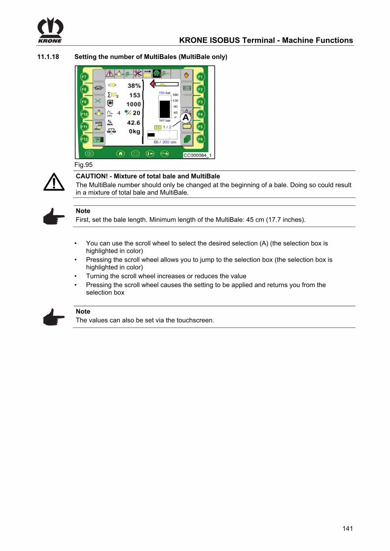
KRONE ISOBUS Terminal - Machine Functions
141
Pos: 92.61.15 /Überschriften/Überschriften 3/A-E/EEinstellen der Multibaleanzahl @ 282\mod_1406527717541_78.docx @ 2171621 @ 3 @ 1
11.1.18 Setting the number of MultiBales (MultiBale only) Pos: 92.61.16 /BA/Info-Center/CCI-ISOBUS-Terminal/CCI-BiG Pack/Grundbild Handbetrieb/Einstellen der Multibaleanzahl Handbetrieb Bild HS Baureihe @ 99\mod_1329897393476_78.docx @ 884193 @ @ 1
F1
F2
F3
F4
F5
F6
F7
F8
F9
F10
F11F11
F12
1/2
Fig.95 Pos: 92.61.17 /BA/Info-Center/CCI-ISOBUS-Terminal/CCI-BiG Pack/Grundbild Handbetrieb/Einstellen der Multibaleanzahl Handbetrieb @ 282\mod_1406529245316_78.docx @ 2171682 @ @ 1
CAUTION! - Mixture of total bale and MultiBale The MultiBale number should only be changed at the beginning of a bale. Doing so could result in a mixture of total bale and MultiBale.
Note First, set the bale length. Minimum length of the MultiBale: 45 cm (17.7 inches).
Pos: 92.61.18 /BA/Info-Center/CCI-ISOBUS-Terminal/CCI-BiG Pack/Scroll-Rad anwählen,springen,erhöhen bzw. verringern,speichern @ 43\mod_1275295180531_78.docx @ 390064 @ @ 1
• You can use the scroll wheel to select the desired selection (A) (the selection box is highlighted in color)
• Pressing the scroll wheel allows you to jump to the selection box (the selection box is highlighted in color)
• Turning the scroll wheel increases or reduces the value • Pressing the scroll wheel causes the setting to be applied and returns you from the
selection box
Pos: 92.61.19 /BA/Info-Center/CCI-ISOBUS-Terminal/CCI-Rundballenpressen/Grundbild/Hinweis Einstellung über Touchscreen @ 79\mod_1315290154790_78.docx @ 701913 @ @ 1
Note The values can also be set via the touchscreen.
Pos: 92.62 /Layout Module /---------------Seitenumbruch---------------- @ 0\mod_1196175311226_0.docx @ 4165 @ @ 1

KRONE ISOBUS Terminal - Menus
142
Pos: 92.63 /Überschriften/Überschriften 1/K-O/KRONE ISOBUS-Terminal - Menüs @ 264\mod_1400144961624_78.docx @ 2009119 @ 1 @ 1
12 KRONE ISOBUS Terminal - Menus Pos: 92.64 /Überschriften/Überschriften 2/K-O/Menüebene @ 80\mod_1315900872940_78.docx @ 708317 @ 2 @ 1
12.1 Menu level Pos: 92.65 /BA/Info-Center/CCI-ISOBUS-Terminal/CCI-BiG Pack/Menüebene Kurzüberblick Maschine HS Baureihe @ 269\mod_1401267166799_78.docx @ 2031049 @ @ 1
Main menu Sub-menu Sub-menu Designation
1
Settings
1-1
Knotter settings
1-1-1 Bale length correction value
1-1-2 Knotter signal
1-1-3 Knotter monitoring
1-1-5 Bales/blowing
1-1-6 Blow time
1-2
Silage additive system
1-3
Sensitivity of direction display
1-4
Central lubrication system
1-5
Humidity measurement
1-6
Bale scales
1-8
Set correction value for humidity measurement
2
Counter
2-1
Customer counter
2-2
Total counter

KRONE ISOBUS Terminal - Menus
143
Main menu Sub-menu Sub-menu Designation
4
Service
4-2
Manual sensor test
4-4
Manual actuator test
4-6
Diagnostics for travelling speed/direction of travel indicator
4-7
Auxiliary diagnostics (AUX)
5
Info
6
Technician
9
Virtual terminal (VT)
9-1
ISOBUS terminal softkeys
9-2
Switching between terminals
9-3 ABC
Main window configuration
Pos: 92.66 /Layout Module /---------------Seitenumbruch---------------- @ 0\mod_1196175311226_0.docx @ 4165 @ @ 1

KRONE ISOBUS Terminal - Menus
144
Pos: 92.67 /Überschriften/Überschriften 2/K-O/Menüebene aufrufen @ 44\mod_1275977054046_78.docx @ 394176 @ 3 @ 1
12.1.1 Calling up the menu level Pos: 92.68 /BA/Info-Center/CCI-ISOBUS-Terminal/CCI-BiG Pack/Menüebene aufrufen Bild HS Baureihe @ 99\mod_1329901887761_78.docx @ 884502 @ @ 1
CC000028
1F1
F2
F3
F4
F5
F6
F7
F8
F9
F10
F11F11
F12
2/2
CC000086_1
Fig.96 Pos: 92.69 /BA/Info-Center/CCI-ISOBUS-Terminal/CCI-BiG Pack/Menüebene aufrufen CCI @ 43\mod_1275299708140_78.docx @ 390706 @ @ 1
By pressing the function key in the main window you get into the menu level of the machine. The menu level is shown in the display.
Pos: 92.70 /BA/Info-Center/CCI-ISOBUS-Terminal/CCI-BiG Pack/Menüebene Überblick Hauptmenüs (6) @ 168\mod_1368451627137_78.docx @ 1456396 @ @ 1
The menu level is divided into six main menus:
= Main menu 1 "Settings"
= Main menu 2 "Counter"
= Main menu 4 "Service"
= Main menu 5 "Information"
= Main menu 6 "Technician"
= Main menu 9 "Virtual Terminal (VT)"
Select the desired main menu by pressing function key or . The symbol is highlighted in grey.
• Pressing function key brings up the menu level of the selected main menu
• Pressing function key closes the menu currently displayed
• Pressing function key and holding it down brings up the basic screen Pos: 92.71 /Layout Module /---------------Seitenumbruch---------------- @ 0\mod_1196175311226_0.docx @ 4165 @ @ 1

KRONE ISOBUS Terminal - Menus
145
Pos: 92.72 /BA/Info-Center/CCI-ISOBUS-Terminal/CCI-BiG Pack/Hauptmenüs/Hauptmenü 1 Einstellungen/Hauptmenü „Einstellungen“ HS Baureihe @ 276\mod_1404801853027_78.docx @ 2076256 @ 2 @ 1
12.2 Main menu 1 "Settings"
CC000028
1
CC000054_1
1-1
Fig. 97
• To select the menu level, press from the home screen.
• Use or to select the main menu 1 ( ), the symbol is highlighted in grey
• Press The display shows menu level 1 "Settings". Menu level 1 "Settings" is divided into up to 6 menus, depending on the configuration of the machine:
= Menu 1-1 "Knotter settings"
= Menu 1-2 "Silage agent"
= Menu 1-3 "Sensitivity of direction display"
= Menu 1-4 "Central lubrication"
= Menu 1-5 "Humidity measurement"
= Menu 1-6 "Bale scales"
= Menu 1-8 "Humidity measurement correction value"
Pos: 92.73 /Layout Module /---------------Seitenumbruch---------------- @ 0\mod_1196175311226_0.docx @ 4165 @ @ 1

KRONE ISOBUS Terminal - Menus
146
Pos: 92.74 /BA/Info-Center/CCI-ISOBUS-Terminal/CCI-BiG Pack/Hauptmenüs/Hauptmenü 1 Einstellungen/Menü 1-1 „Knotereinstellungen“ HS Baureihe @ 99\mod_1329907098199_78.docx @ 884813 @ 3 @ 1
12.2.1 Menu 1-1 „Knotter Settings“
CC000054_1
1-1
Fig. 98 Calling the Menu Main menu 1 “Settings” is called.
• Select menu 1-1 by pressing function key or , the symbol is highlighted in grey
• Press function key The display shows menu 1-1 “Knotter Settings”. The menu level 1-1 “Knotter Settings" is divided into up to 5 menus, depending on how the machine is equipped:
Menu 1-1-1 “Correction value for bale length”
Menu 1-1-2 “Knotter signal”
Menu 1-1-3 “Knotter monitoring”
Menu 1-1-5 “Bales / blow” (with electronic knotter triggering)
Menu 1-1-6 "Blow time"
Pos: 92.75 /Layout Module /---------------Seitenumbruch---------------- @ 0\mod_1196175311226_0.docx @ 4165 @ @ 1

KRONE ISOBUS Terminal - Menus
147
Pos: 92.76 /BA/Info-Center/CCI-ISOBUS-Terminal/CCI-BiG Pack/Hauptmenüs/Hauptmenü 1 Einstellungen/Menü 1-1-1 „Korrekturwert Ballenlänge“ HS Baureihe @ 99\mod_1329994073656_78.docx @ 886978 @ 3 @ 1
12.2.2 Menu 1-1-1 „Correction Value for Bale Length“
CC0000100
Fig. 99 Because of different properties of materials (for example straw or silage), the actual bale length can differ from the pre-set setpoint. The correction value can be used to correct this deviation. Factory setting: 100% Calling the Menu The main menu 1-1 “Knotter Setting” is called.
• Select menu 1-1-1 by pressing function key or , the symbol is highlighted in grey
• Press function key The display shows menu 1-1-1 “Correction Value Bale Length”.
The bar display and the percentage value show the set correction value. The symbol in the upper line indicates that the displayed value is saved. Setting and Saving the Correction Value If the bale is too long, reduce the correction value. If the bale is too short, increase the correction value.
• Set the desired correction value with the function key or . The symbol in the top line goes out
• Press the function key . The set correction value is saved and the symbol appears in the upper line
• By pressing the function key , the value of the factory setting is displayed (press
function key , the value of the factory setting is saved, the symbol in the upper line appears)
• Pressing the function key closes the called up menu
• Pressing the function key and holding it down brings up the basic screen Pos: 92.77 /Layout Module /---------------Seitenumbruch---------------- @ 0\mod_1196175311226_0.docx @ 4165 @ @ 1

KRONE ISOBUS Terminal - Menus
148
Pos: 92.78 /BA/Info-Center/CCI-ISOBUS-Terminal/CCI-BiG Pack/Hauptmenüs/Hauptmenü 1 Einstellungen/Menü 1-1-2 Knotersignal @ 99\mod_1330000507245_78.docx @ 887432 @ 3 @ 1
12.2.3 Menu 1-1-2 „Knotter Signal“
Fig. 100 Activation/deactivation of the audio signal when a knot has been completed. Calling the Menu The main menu 1-1 “Knotter Settings” is called up.
• Select menu 1-1-2 by pressing function key or , the symbol is highlighted in grey
• Press function key The display shows menu 1-1-2 “Knotter signal". The current status is displayed as an icon:
= Knotter signal activated
= Knotter signal deactivated
The symbol in the upper line indicates that the displayed status is saved. Changing and Saving Status
• Set the status accordingly via function key or , the symbol in the upper line goes out
• Press function key , the set status is saved, the symbol in the upper line appears
• The called up menu is closed by pressing function key • Pressing the function key and holding it down brings up the basic screen
Pos: 92.79 /Layout Module /---------------Seitenumbruch---------------- @ 0\mod_1196175311226_0.docx @ 4165 @ @ 1
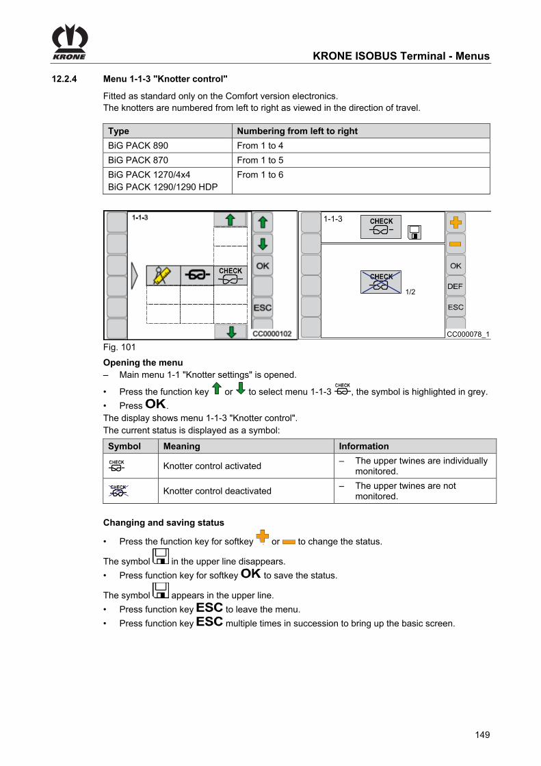
KRONE ISOBUS Terminal - Menus
149
Pos: 92.80 /Überschriften/Überschriften 3/K-O/Menü 1-1-3 „Knoterkontrolle“ @ 281\mod_1405947360130_78.docx @ 2161165 @ 3 @ 1
12.2.4 Menu 1-1-3 "Knotter control" Pos: 92.81 /BA/Info-Center/CCI-ISOBUS-Terminal/CCI-BiG Pack/Hauptmenüs/Hauptmenü 1 Einstellungen/Menü 1-1-3 „Knoterkontrolle“ Nur bei Ausführung Komfort-Elektronil serienmäßig @ 281\mod_1405936615345_78.docx @ 2160829 @ @ 1
Fitted as standard only on the Comfort version electronics. Pos: 92.82 /BA/Info-Center/CCI-ISOBUS-Terminal/CCI-BiG Pack/Hauptmenüs/Hauptmenü 1 Einstellungen/Menü 1-1-3 „Knoterkontrolle“ Einführung Tabelle 890/1270/1290/1290HDP @ 281\mod_1405946869628_78.docx @ 2161135 @ @ 1
The knotters are numbered from left to right as viewed in the direction of travel.
Type Numbering from left to right
BiG PACK 890 From 1 to 4
BiG PACK 870 From 1 to 5
BiG PACK 1270/4x4 BiG PACK 1290/1290 HDP
From 1 to 6
Pos: 92.83 /BA/Info-Center/CCI-ISOBUS-Terminal/CCI-BiG Pack/Hauptmenüs/Hauptmenü 1 Einstellungen/Menü 1-1-3 „Knoterkontrolle“ Bild @ 281\mod_1405946808761_78.docx @ 2161105 @ @ 1
CC000078_1
1-1-3
1/2
Fig. 101 Pos: 92.84 /BA/Info-Center/CCI-ISOBUS-Terminal/CCI-BiG Pack/Hauptmenüs/Hauptmenü 1 Einstellungen/Menü 1-1-3 „Knoterkontrolle“ Menü aufrufen @ 281\mod_1405946384273_78.docx @ 2161075 @ @ 1
Opening the menu – Main menu 1-1 "Knotter settings" is opened.
• Press the function key or to select menu 1-1-3 , the symbol is highlighted in grey.
• Press . The display shows menu 1-1-3 "Knotter control". The current status is displayed as a symbol:
Pos: 92.85 /BA/Info-Center/CCI-ISOBUS-Terminal/CCI-BiG Pack/Hauptmenüs/Hauptmenü 1 Einstellungen/Menü 1-1-3 „Knoterkontrolle“ Tabelle Grafiken @ 281\mod_1405943410188_78.docx @ 2160945 @ @ 1
Symbol Meaning Information
Knotter control activated – The upper twines are individually
monitored.
Knotter control deactivated – The upper twines are not
monitored.
Pos: 92.86 /BA/Info-Center/CCI-ISOBUS-Terminal/Status ändern und speichern mit + und - @ 189\mod_1380725906960_78.docx @ 1619276 @ @ 1
Changing and saving status
• Press the function key for softkey or to change the status.
The symbol in the upper line disappears.
• Press function key for softkey to save the status.
The symbol appears in the upper line.
• Press function key to leave the menu.
• Press function key multiple times in succession to bring up the basic screen.
Pos: 92.87 /Layout Module /---------------Seitenumbruch---------------- @ 0\mod_1196175311226_0.docx @ 4165 @ @ 1

KRONE ISOBUS Terminal - Menus
150
Pos: 92.88 /BA/Info-Center/CCI-ISOBUS-Terminal/CCI-BiG Pack/Hauptmenüs/Hauptmenü 1 Einstellungen/Menü 1-1-5 „Ballen / Blasen“ @ 99\mod_1330002387961_78.docx @ 887677 @ 4 @ 1
12.2.4.1 Menu 1-1-5 „Bales / Blow“
CC0000103
1-1-5
Fig. 102 (For machines with electronic knotter triggering) Dust and accumulated crop material is removed from the knotters by compressed air at regular intervals (depending on the number of bales produced). 0.5 to 3 bales can be set. If the setting 0.5 is selected, blowing is carried out at the half of the bale and at the end of the bale. Setting the Number of Bales Calling the Menu The main menu 1-1 “Knotter Settings” is called up.
• Select menu 1-1-51..n
by pressing function key or , the symbol is highlighted in grey
• Press function key The display shows menu 1-1-5 "Bales / blow". The bar display and the value (A) show the preselected bale number.
The symbol in the upper line indicates that the displayed value is saved.
• Set the desired number of bales with function key or . The symbol in the top line disappears
• Press function key , the set value is saved, the symbol appears in the upper line
• By pressing the function key , the value of the factory setting is displayed (press
function key , the value of the factory setting is saved, the symbol in the upper line appears)
• Pressing the function key closes the called up menu
• Pressing the function key and holding it down brings up the basic screen
Pos: 92.89 /Layout Module /---------------Seitenumbruch---------------- @ 0\mod_1196175311226_0.docx @ 4165 @ @ 1
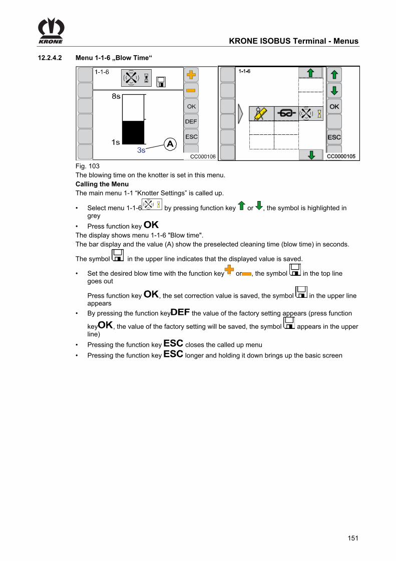
KRONE ISOBUS Terminal - Menus
151
Pos: 92.90 /BA/Info-Center/CCI-ISOBUS-Terminal/CCI-BiG Pack/Hauptmenüs/Hauptmenü 1 Einstellungen/Menü 1-1-6 „Blaszeit“ @ 99\mod_1330004064344_78.docx @ 887794 @ 4 @ 1
12.2.4.2 Menu 1-1-6 „Blow Time“
Fig. 103 The blowing time on the knotter is set in this menu. Calling the Menu The main menu 1-1 “Knotter Settings” is called up.
• Select menu 1-1-6 by pressing function key or , the symbol is highlighted in grey
• Press function key The display shows menu 1-1-6 "Blow time". The bar display and the value (A) show the preselected cleaning time (blow time) in seconds.
The symbol in the upper line indicates that the displayed value is saved.
• Set the desired blow time with the function key or , the symbol in the top line goes out
Press function key , the set correction value is saved, the symbol in the upper line appears
• By pressing the function key the value of the factory setting appears (press function
key , the value of the factory setting will be saved, the symbol appears in the upper line)
• Pressing the function key closes the called up menu
• Pressing the function key longer and holding it down brings up the basic screen
Pos: 92.91 /Layout Module /---------------Seitenumbruch---------------- @ 0\mod_1196175311226_0.docx @ 4165 @ @ 1

KRONE ISOBUS Terminal - Menus
152
Pos: 92.92 /BA/Info-Center/CCI-ISOBUS-Terminal/CCI-Ladewagen/Hauptmenüs/Bis 2013/Hauptmenü 1 Einstellungen/Menü 1-2 Silagemittel @ 50\mod_1287564144906_78.docx @ 473259 @ 3 @ 1
12.2.5 Menu 1-2 silage agents / optional
CC000423_1
1-2
CC000424
1-2
3/3
Fig. 104
Note The connection (max. 2 amperes) for the silage agent device is located close to the job computer. (approx. 0.5 m in cable harness 1X1).
Displaying the menu Main menu 1 “Settings” is displayed.
• You can select menu 1-2 with the function key or . The symbol is highlighted in grey.
• Press function key The display shows menu 1-2 “Silage agents". The current status is displayed as an icon:
Silage agents off
Silage agents on (continuous operation)
Silage agents automatic mode (silage agents on if the pick-up is in float position)
The icon in the upper line indicates that the displayed status is saved. Changing and saving status
• Set the status with the function key or in a way that the symbol in the top line goes out
• Press the function key . The set status is saved and the symbol appears in the upper line
• Pressing the function key closes the called up menu
• Pressing the function key and holding it down brings up the basic screen
Pos: 92.93 /Layout Module /---------------Seitenumbruch---------------- @ 0\mod_1196175311226_0.docx @ 4165 @ @ 1

KRONE ISOBUS Terminal - Menus
153
Pos: 92.94 /BA/Info-Center/CCI-ISOBUS-Terminal/CCI-BiG Pack/Hauptmenüs/Hauptmenü 1 Einstellungen/Menü 1-3 „Empfindlichkeit-Richtungsanzeige“ @ 99\mod_1330004944548_78.docx @ 887919 @ 3 @ 1
12.2.6 Menu 1-3 „Sensitivity of the Direction Display“
CC000107
1-3
Fig. 105 Setting the sensitivity of the direction display. Calling the Menu Main menu 1 “Settings” is called.
• Select menu 1-3 by pressing function key or , the symbol is highlighted in grey
• Press function key The display shows menu 1-3 “Sensitivity of the Direction Display”. The bar display shows the set sensitivity. The higher the bar, the greater the sensitivity of the
direction display. The symbol in the upper line indicates that the displayed value is saved. Setting and saving the sensitivity of the direction display. The higher the sensitivity of the direction display is set, the stronger the indications for the
direction of motion in the form of arrows (1) ( ).
• Set the sensitivity by using function key or , the symbol in the upper line goes out
• Press function key , the set sensitivity is saved, the symbol in the upper line appears
• Pressing the function key closes the called up menu
• Pressing the function key longer and holding it down brings up the basic screen
Pos: 92.95 /Layout Module /---------------Seitenumbruch---------------- @ 0\mod_1196175311226_0.docx @ 4165 @ @ 1

KRONE ISOBUS Terminal - Menus
154
Pos: 92.96 /BA/Info-Center/CCI-ISOBUS-Terminal/CCI-BiG Pack/Hauptmenüs/Hauptmenü 1 Einstellungen/Menü 1-4 „Zentralschmierung“ T1/2 HS Baureihe @ 99\mod_1330005723595_78.docx @ 888108 @ 3 @ 1
12.2.7 Menu 1-4 „Central Lubrication“
Fig. 106 (For machines with central lubrication) Setting of the lubrication intervals and the lubrication duration. Calling the Menu Main menu 1 “Settings” is called.
• By pressing function key or , select menu 1-4 , the symbol is highlighted in grey
• Press function key The display shows menu 1-4 “Central Lubrication”. The current status is displayed as an icon: The display shows menu 1-4 “Central Lubrication”. The upper value (A) indicates the time for the lubrication duration whereas the lower value (B) shows the time for the lubrication pause.
The symbol in the upper line indicates that the displayed value is saved. The lubrication duration can be increased by some minutes. Central lubrication is set to optimal levels at the factory. Factory Setting: Lubrication duration: 20 min (A) Lubrication pause: 5 min (B) Capacity of the container 4.5 kg
Pos: 92.97 /Layout Module /---------------Seitenumbruch---------------- @ 0\mod_1196175311226_0.docx @ 4165 @ @ 1

KRONE ISOBUS Terminal - Menus
155
Pos: 92.98 /BA/Info-Center/CCI-ISOBUS-Terminal/CCI-BiG Pack/Hauptmenüs/Hauptmenü 1 Einstellungen/Menü „Zentralschmierung“ T2/2 @ 44\mod_1275371639750_78.docx @ 391129 @ @ 1
• Set the lubrication duration with the function key or , the symbol in the top line goes out
• Press the function key . The set time is saved and the symbol appears in the upper line
• By pressing the function key the value of the factory setting appears (press function
keyv, the value of the factory setting will be saved, the symbol appears in the upper line)
Initiate the lubrication process manually
• By pressing the function key the lubrication process is started for the set duration of lubrication
• Pressing the function key closes the called up menu
• Pressing the function key and holding it down brings up the basic screen
Pos: 92.99 /Layout Module /---------------Seitenumbruch---------------- @ 0\mod_1196175311226_0.docx @ 4165 @ @ 1

KRONE ISOBUS Terminal - Menus
156
Pos: 92.100 /BA/Info-Center/CCI-ISOBUS-Terminal/CCI-BiG Pack/Hauptmenüs/Hauptmenü 1 Einstellungen/Menü 1-5 „Feuchtigkeitsmessung“ @ 120\mod_1342617756034_78.docx @ 1092801 @ 3 @ 1
12.2.8 Menu 1-5 „Moisture Measuring“
CC000556
1-5
Fig. 107 In the menu 1-5 “Moisture Measuring” the value is set starting at which the message “136 crop too moist” appears in the display. Moreover the message for the display can be deactivated or activated in this menu. Calling the Menu Main menu 1 “Settings” is displayed.
• Select menu 1-5 by pressing function key or , the symbol is highlighted in grey
• Press function key The display shows menu 1-5 “Moisture Measuring”.
The bar display and the percentage value show the set value. The symbol in the upper line indicates that the displayed value is saved. Changing and Saving the Value
• Set the value via function key or , the symbol in the upper line goes out
• Press function key , the set value is saved, the symbol in the upper line appears
• Pressing the function key closes the called up menu
• Pressing the function key and holding it down brings up the basic screen Activating / Deactivating Message “136 Crop Too Moist” OFF / ON = Deactivating / Activating the Message • Press function key ON to deactivate the message (the symbol OFF appears in the display) • Press function key OFF to activate the message (the symbol ON appears in the display)
Pos: 92.101 /Layout Module /---------------Seitenumbruch---------------- @ 0\mod_1196175311226_0.docx @ 4165 @ @ 1

KRONE ISOBUS Terminal - Menus
157
Pos: 92.102 /Layout Module /Diese Seite ist bewusst freigelassen worden. @ 1\mod_1201783680373_78.docx @ 54443 @ @ 1
This page has been left blank deliberately!! Pos: 92.103 /Layout Module /---------------Seitenumbruch---------------- @ 0\mod_1196175311226_0.docx @ 4165 @ @ 1

KRONE ISOBUS Terminal - Menus
158
Pos: 92.104 /BA/Info-Center/CCI-ISOBUS-Terminal/CCI-BiG Pack/Hauptmenüs/Hauptmenü 1 Einstellungen/Menü 1-6 „Ballenwaage“ T1 @ 109\mod_1335347896210_78.docx @ 976087 @ 3 @ 1
12.2.9 Menu 1-6 „Bale Balance“
CC000558
1-6
Fig. 108 Calling the Menu Main menu 1 “Settings” is called.
• By pressing the function key or , select menu 1-6 , the symbol is highlighted in grey
• Press function key The display shows menu 1-6 “Bale Balance”.
The percentage value (1) shows the set limit range. The symbol in the upper line indicates that the displayed value is saved.
Pos: 92.105 /Layout Module /---------------Seitenumbruch---------------- @ 0\mod_1196175311226_0.docx @ 4165 @ @ 1

KRONE ISOBUS Terminal - Menus
159
Pos: 92.106 /BA/Info-Center/CCI-ISOBUS-Terminal/CCI-BiG Pack/Hauptmenüs/Hauptmenü 1 Einstellungen/Menü 1-6 „Ballenwaage“ T2 justieren @ 109\mod_1335353555144_78.docx @ 976146 @ 4 @ 1
12.2.9.1 Adjusting the Bale Balance
The bale balance can be readjusted in the limit range from 95% to 105% To do this: • Stop the machine • Fit a calibrated sample weight (250 to 300 kg) onto the empty bale balance Readjust the bale balance if the display value (2) in the display deviates from the sample weight To do this:
• Change value (1) via function key or until the value (2) corresponds to the weight of
the sample weight (the symbol in the upper line goes out)
Note If the limit range is not sufficient to adjust the bale balance, please contact the customer service.
• Press function key , the set value is saved, the symbol in the upper line appears
• Pressing the function key closes the called up menu
• Pressing the function key and holding it down brings up the basic screen Pos: 92.107 /BA/Info-Center/CCI-ISOBUS-Terminal/CCI-BiG Pack/Hauptmenüs/Hauptmenü 1 Einstellungen/Menü 1-6 „Ballenwaage“ T3 Nullen @ 111\mod_1337006033753_78.docx @ 989762 @ 4 @ 1
12.2.9.2 Zeros
“Zero” the force sensor if no bale (weight) is on the bale balance but a value is displayed in line (2)
Note Resetting (zeros) may only be made if the bale balance is without load.
• Set the force sensor back to zero by pressing the function key
Pos: 92.108 /Layout Module /---------------Seitenumbruch---------------- @ 0\mod_1196175311226_0.docx @ 4165 @ @ 1

KRONE ISOBUS Terminal - Menus
160
Pos: 92.109 /BA/Info-Center/CCI-ISOBUS-Terminal/CCI-BiG Pack/Hauptmenüs/Hauptmenü 1 Einstellungen/Menü 1-8 „Korrekturwert für Feuchtigkeitsmessung einstellen“ @ 276\mod_1404804757946_78.docx @ 2076311 @ 3 @ 1
12.2.10 Menu 1-8 "Set correction value for humidity measurement"
CC000899
1-8
CC000990
1-8
1
2
Fig. 109 The value (1) displayed may deviate due to different measurement procedures. The correction value (2) can be used to correct this deviation. A correction value of +10 to -10 can be entered for the humidity measurement. Opening the menu Main menu 1 "Settings" appears.
• Use or to select the menu 1-8 , the symbol is highlighted in grey.
• Press . The display shows the menu 1-8 "Set correction value for humidity measurement".
The symbol in the upper line indicates that the displayed value is saved. Change and save value
• To increase the correction value, press . • To reduce the correction value, press .
• To reset the correction value to zero, press .
The symbol in the upper line disappears
• To save the correction value, press .
The symbol in the top line appears.
Pos: 92.110 /Layout Module /---------------Seitenumbruch---------------- @ 0\mod_1196175311226_0.docx @ 4165 @ @ 1

KRONE ISOBUS Terminal - Menus
161
Pos: 92.111 /BA/Info-Center/CCI-ISOBUS-Terminal/CCI-BiG Pack/Hauptmenüs/Hauptmenü 2 Zähler/Hauptmenü 2 Zähler @ 44\mod_1275385420046_78.docx @ 391433 @ 2 @ 1
12.3 main menu 2 „counters“
CC000036
2
Fig. 110 Calling the main menu
• By pressing the function key in the basic screen you get into the menu level of the machine
• You can select main menu 2 ( ) with function key or . The symbol is highlighted in grey.
• Press function key The display shows menu level 2 "Counters". Menu level 2 "Counters" is divided into two menus:
= menu 2-1 "Customer counter"
= menu 2-2 "Total counter" Pos: 92.112 /Layout Module /---------------Seitenumbruch---------------- @ 0\mod_1196175311226_0.docx @ 4165 @ @ 1

KRONE ISOBUS Terminal - Menus
162
Pos: 92.113 /BA/Info-Center/CCI-ISOBUS-Terminal/CCI-BiG Pack/Hauptmenüs/Hauptmenü 2 Zähler/Kundenzähler/Menü 2-1 Kundenzähler HS Baureihe @ 278\mod_1404994394121_78.docx @ 2084980 @ 3 @ 1
12.3.1 Menu 2-1 "Customer counter"
CC000062
2-1
32
27
15
6
7.2 t
6.1 t
3.4 t
1.4 t CC000560_1
12:
Fig. 111 Opening the menu Main menu 2 "Counter" is opened
• Use or to select the menu 2-1 , the symbol is highlighted in grey
• Press The display shows menu 2-1 "Customer counter".
Pos: 92.114 /BA/Info-Center/CCI-ISOBUS-Terminal/CCI-BiG Pack/Hauptmenüs/Hauptmenü 2 Zähler/Kundenzähler/Menü 2-1 Kundenzähler Beschreibung Anzeigebereich BiG PACK @ 278\mod_1404994707722_78.docx @ 2085039 @ @ 1
Symbol Meaning Information
Selected customer counter – 1 to 20 customer counters. – The activated customer counter is
highlighted in grey. – The selected customer counter is the
one between the lines. – The selected customer counter does
not have to be activated. – The customer counter is activated in
the menu 2-1-1 "Detailed counter". – In the menu 2-1-1 "Detailed counter",
additional data records for the customer counter are displayed.
Pos: 92.115 /BA/Info-Center/CCI-ISOBUS-Terminal/CCI-BiG Pack/Hauptmenüs/Hauptmenü 2 Zähler/Kundenzähler/Menü 2-1 Kundenzähler Beschreibung Softkeys/Funktionstasten BiG PACK @ 278\mod_1404995939577_78.docx @ 2085307 @ @ 1
Softkey Meaning Information
Scroll up
Scroll down 12:
Display detailed counter – Additional counter information for the selected customer counter is displayed.
Confirm selection – Activate customer counter
Exit menu – Pressing the key and holding it down brings up the home screen.
Delete data records – All data records for the selected
customer counter are set to zero.
Delete all data records – All data records for all customer counters are set to zero.
Pos: 92.116 /Layout Module /---------------Seitenumbruch---------------- @ 0\mod_1196175311226_0.docx @ 4165 @ @ 1

KRONE ISOBUS Terminal - Menus
163
Pos: 92.117 /BA/Info-Center/CCI-ISOBUS-Terminal/CCI-BiG Pack/Hauptmenüs/Hauptmenü 2 Zähler/Kundenzähler/Kundenzähler (einzeln) löschen @ 109\mod_1335937748931_78.docx @ 978219 @ @ 1
Deleting the Customer Counter The customer counter to be deleted must not be the activated customer counter.
• Press function key or to position the customer counter to be deleted between the two crossbars (in this case customer counter 3)
• By pressing function key , all datasets from the selected customer counter are set to 0
Pos: 92.118 /BA/Info-Center/CCI-ISOBUS-Terminal/CCI-BiG Pack/Hauptmenüs/Hauptmenü 2 Zähler/Kundenzähler/Kundenzähler (alle) löschen @ 109\mod_1335937567086_78.docx @ 978191 @ @ 1
Deleting all Customer Counters • By pressing function key (for approx. 2 sec.) for , all datasets of all customer counters
are set to zero
Pos: 92.119 /BA/Info-Center/CCI-ISOBUS-Terminal/CCI-BiG Pack/Hauptmenüs/Hauptmenü 2 Zähler/Detailzähler/Detailzähler aufrufen BiG PACK @ 278\mod_1404995875432_78.docx @ 2085278 @ @ 1
Opening the detailed counter
• To select the detailed counter, press 12: .
Pos: 92.120 /Layout Module /---------------Seitenumbruch---------------- @ 0\mod_1196175311226_0.docx @ 4165 @ @ 1

KRONE ISOBUS Terminal - Menus
164
Pos: 92.121 /BA/Info-Center/CCI-ISOBUS-Terminal/CCI-BiG Pack/Hauptmenüs/Hauptmenü 2 Zähler/Detailzähler/Detailzähler ÜS @ 278\mod_1404998124419_78.docx @ 2085515 @ 4 @ 1
12.3.1.1 Menu 2-1-1 Detailed counter Pos: 92.122 /BA/Info-Center/CCI-ISOBUS-Terminal/CCI-BiG Pack/Hauptmenüs/Hauptmenü 2 Zähler/Detailzähler/Menü 2-1-1 Detailzähler BILD @ 278\mod_1404999558215_78.docx @ 2085883 @ @ 1
CC000037_2
2-1-1
Fig. 112 Pos: 92.123 /BA/Info-Center/CCI-ISOBUS-Terminal/CCI-BiG Pack/Hauptmenüs/Hauptmenü 2 Zähler/Detailzähler/Menü 2-1-1 Detailzähler Voraussetzung/Detailzähler aufrufen/ Kundenzähler aufrufen @ 278\mod_1405002030987_78.docx @ 2086741 @ @ 1
Prerequisite: The menu 2-1 "Customer counter" is opened.
• To select the detailed counter, press 12:
• To select the customer counter, press
Pos: 92.124 /BA/Info-Center/CCI-ISOBUS-Terminal/CCI-BiG Pack/Hauptmenüs/Hauptmenü 2 Zähler/Detailzähler/Menü 2-1-1 Detailzähler Beschreibung Anzeigebereich BiG PACK @ 278\mod_1404998716142_78.docx @ 2085674 @ @ 1
Pos: 92.125 /Layout Module /---------------Seitenumbruch---------------- @ 0\mod_1196175311226_0.docx @ 4165 @ @ 1
Graphic Meaning Information
Total number of bales
Number of uncut bales
Number of cut bales Only for machines equipped with a
cutting system
Operating hours counter Counts only when the PTO shaft is
running.
2 Selected customer counter – 1 to 20 customer counters. – The activated customer counter is
highlighted in grey. – The selected customer counter is the
one between the lines. – The selected customer counter does
not have to be activated. – The customer counter is activated in
the menu 2-1-1 "Detailed counter". – In the menu 2-1-1 "Detailed counter",
additional data records for the customer counter are displayed.
Bale length counter
– Metric in metres
– US unit of measure in feet
Knot counter For the MultiBale version – incl. MultiBale knots
Total weight of all bales – For the bale scales version
Ø Average weight of the weighed bales
– For the bale scales version

KRONE ISOBUS Terminal - Menus
165
Pos: 92.126 /BA/Info-Center/CCI-ISOBUS-Terminal/CCI-BiG Pack/Hauptmenüs/Hauptmenü 2 Zähler/Detailzähler/Menü 2-1-1 Detailzähler Beschreibung Softkeys BiG PACK @ 279\mod_1405002488270_78.docx @ 2086799 @ @ 1
Pos: 92.127 /BA/Info-Center/CCI-ISOBUS-Terminal/CCI-Swadro/Swadro 1400/Hauptmenüs/Hauptmenü 2 Zähler/Kundenzähler aktivieren aus Menü 2-1-1 heraus @ 188\mod_1380184405511_78.docx @ 1611611 @ @ 1
Activating customer counter
• Select the desired customer counter (A) by pressing the function key for softkey or .
• Press the function key for softkey . The desired customer counter (here customer counter 2) is highlighted in grey.
Pos: 92.128 /BA/Info-Center/CCI-ISOBUS-Terminal/CCI-BiG Pack/Hauptmenüs/Hauptmenü 2 Zähler/Detailzähler/Ballenanzahl verändern @ 111\mod_1337006487911_78.docx @ 989786 @ @ 1
Changing the Bale Number
• Press function key or to select the desired customer counter (A) (the customer counter must not be activated)
• Select the counter to be changed (cut bale, uncut bale) via function key or
• Increase the number of bales by pressing function key
• Reduce the number of bales by pressing function key At the same time, the season and daily counters are also changed in menu 2-2 "Total Bale Counter”, as well as the length counter, the knot counter and the bale weight (for bale balance design).
Pos: 92.129 /BA/Info-Center/CCI-ISOBUS-Terminal/CCI-BiG Pack/Hauptmenüs/Hauptmenü 2 Zähler/Kundenzähler/Kundenzähler löschen aus Menü 2-1-1 heraus @ 44\mod_1275465544203_78.docx @ 391700 @ @ 1
Deleting the customer counter
• Press function key or to select the desired customer counter (A) (the customer counter must not be activated)
• By pressing the function key the selected customer counter is set to zero
• Pressing the function key closes the called up menu
• Pressing the function key and holding it down brings up the basic screen
Pos: 92.130 /Layout Module /---------------Seitenumbruch---------------- @ 0\mod_1196175311226_0.docx @ 4165 @ @ 1
Softkeys Meaning Information
Scroll up
Scroll down
Confirm selection
Exit menu – Pressing the key and holding it down brings up the home screen.
Increase number of bales
Decrease number of bales
Uncut bales
Cut bales

KRONE ISOBUS Terminal - Menus
166
Pos: 92.131 /BA/Info-Center/CCI-ISOBUS-Terminal/CCI-BiG Pack/Hauptmenüs/Hauptmenü 2 Zähler/Menü 2-2 „Gesamtballenzähler“ @ 109\mod_1335431017537_78.docx @ 977112 @ 3 @ 1
12.3.2 Menu 2-2 „Total Bale Counter“
CC000063
2-2
Fig. 113 Calling the Menu Main menu 2 “Counter” is called
• By pressing function key or , select menu 2-2 , the symbol is highlighted in grey
• Press function key
The display shows menu 2-2 “Total Bale Counter”. The total number of bales is the sum of all pressed bales. They are not assigned to any customer counter. Meaning of the Symbols:
= Total number of bales
= Number of uncut bales
= Number of cut bales (only for machines with X-Cut)
= Operating hours counter (counts only when P.T.O. shaft is running)
= Bale counter (cannot be deleted)
1 = Season counter 1 (can be deleted)
2 = Daily counter 2 (can be deleted)
Pos: 92.132 /Layout Module /---------------Seitenumbruch---------------- @ 0\mod_1196175311226_0.docx @ 4165 @ @ 1

KRONE ISOBUS Terminal - Menus
167
Pos: 92.133 /BA/Info-Center/CCI-ISOBUS-Terminal/CCI-BiG Pack/Hauptmenüs/Hauptmenü 2 Zähler/Gesamtballenzähler bei Ausführung Ballenwaage @ 109\mod_1335431929332_78.docx @ 977175 @ @ 1
Total Bale Counter for Bale Balance Design
Fig. 114 For bale balance design, the total bale counter is divided into two pages. The second page of
the total bale counter is displayed by pressing the function key for . You can get one page
back by activating the function key .
Pos: 92.134 /BA/Info-Center/CCI-ISOBUS-Terminal/CCI-BiG Pack/Hauptmenüs/Hauptmenü 2 Zähler/Symbolbedeutung Seite 2 bei Ausführung Ballenwaage Gesamtballenzähler @ 109\mod_1335432760751_78.docx @ 977204 @ @ 1
Meaning of the Symbols Page 2 (Optional):
= Total counter (total weight of all pressed bales, cannot be deleted)
1 = Season counter 1 (can be deleted)
2 = Daily counter 2 (can be deleted)
Pos: 92.135 /BA/Info-Center/CCI-ISOBUS-Terminal/CCI-BiG Pack/Hauptmenüs/Hauptmenü 2 Zähler/Saisonzähler 1, bzw. Tageszähler 2 löschen @ 44\mod_1275471364593_78.docx @ 391813 @ @ 1
Deleting season counter 1 or daily counter 2
• Pressing the function key 1 sets season counter 1 to zero
• Pressing the function key 2 sets season counter 2 to zero
• Pressing the function key closes the called up menu
• Pressing the function key and holding it down brings up the basic screen
Pos: 92.136 /Layout Module /---------------Seitenumbruch---------------- @ 0\mod_1196175311226_0.docx @ 4165 @ @ 1

KRONE ISOBUS Terminal - Menus
168
Pos: 92.137 /Überschriften/Überschriften 2/F-J/Hauptmenü 4 Service @ 34\mod_1255339497523_78.docx @ 322336 @ 2 @ 1
12.4 Main menu 4 "Service" Pos: 92.138 /BA/Info-Center/CCI-ISOBUS-Terminal/CCI-BiG Pack/Hauptmenüs/Hauptmenü 4 Service/Hauptmenü 4 Service 4 Untermenüs @ 109\mod_1335271291270_78.docx @ 974949 @ @ 1
4-2
CC000553 CC000039
4
Fig. 115 Calling the Main Menu
• Call up menu level by pressing the function key in the basic screen
• By pressing function key or , select main menu 4 ( ), the symbol is highlighted in grey
• Press function key The display shows menu level 4 “Service”. Menu level 4 "Service" is divided into four menus:
= Menu 4-2 “Manual sensor test”
= Menu 4-4 “Manual actuator test”
= Menu 4-6 "Diagnostics of driving speed/motion direction display"
= Menu 4-7 “Diagnostics Auxiliary (AUX)“
Pos: 92.139 /Layout Module /---------------Seitenumbruch---------------- @ 0\mod_1196175311226_0.docx @ 4165 @ @ 1
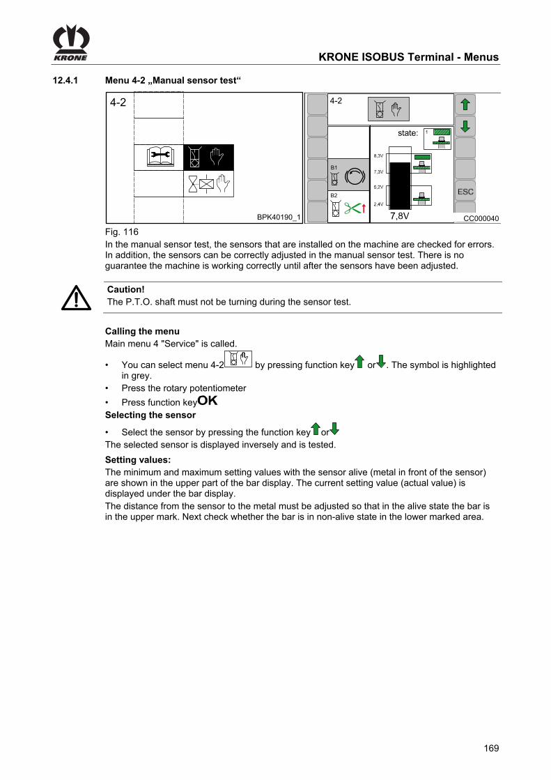
KRONE ISOBUS Terminal - Menus
169
Pos: 92.140 /BA/Info-Center/CCI-ISOBUS-Terminal/CCI-BiG Pack/Hauptmenüs/Hauptmenü 4 Service/Menü 4-2 Sensortest Hand @ 44\mod_1275483833375_78.docx @ 391921 @ 3 @ 1
12.4.1 Menu 4-2 „Manual sensor test“
BPK40190_1
4-2
CC000040
4-2
1
B1
B2
Fig. 116 In the manual sensor test, the sensors that are installed on the machine are checked for errors. In addition, the sensors can be correctly adjusted in the manual sensor test. There is no guarantee the machine is working correctly until after the sensors have been adjusted.
Caution! The P.T.O. shaft must not be turning during the sensor test.
Calling the menu Main menu 4 "Service" is called.
• You can select menu 4-2 by pressing function key or . The symbol is highlighted in grey.
• Press the rotary potentiometer
• Press function key Selecting the sensor
• Select the sensor by pressing the function key or The selected sensor is displayed inversely and is tested.
Pos: 92.141 /BA/Info-Center/Schwader/Bedieneinheit - Komfort/Swadro 1400/Hauptmenüs/Hauptmenü 4 Service/Einstellwerte Sensor allgemeiner Text @ 6\mod_1215416779856_78.docx @ 101137 @ @ 1
Setting values: The minimum and maximum setting values with the sensor alive (metal in front of the sensor) are shown in the upper part of the bar display. The current setting value (actual value) is displayed under the bar display. The distance from the sensor to the metal must be adjusted so that in the alive state the bar is in the upper mark. Next check whether the bar is in non-alive state in the lower marked area.
Pos: 92.142 /Layout Module /---------------Seitenumbruch---------------- @ 0\mod_1196175311226_0.docx @ 4165 @ @ 1

KRONE ISOBUS Terminal - Menus
170
Pos: 92.143 /BA/Info-Center/Sensoren/Diagnose Namursensoren @ 19\mod_1238072125300_78.docx @ 214095 @ @ 1
Diagnostics – Namur sensors Pos: 92.144 /BA/Info-Center/Sensoren/Mögliche Sensoren (je nach Ausstattung der Maschine) @ 19\mod_1238071336628_78.docx @ 214010 @ @ 1
Possible sensors (depending on how the machine is equipped) Pos: 92.145 /BA/Info-Center/CCI-ISOBUS-Terminal/CCI-BiG Pack/Hauptmenüs/Hauptmenü 4 Service/Auflistung der möglichen Sensoren 1 bis 23 1290 HDP II @ 144\mod_1359387977930_78.docx @ 1292223 @ @ 1
No. Sensor symbol
Description No. Sensor symbol
Description
B1 B1
Flywheel brake B9
B9Needle connecting rod on left
B2
Blade bar up B10B10
Knotter monitoring
B3 B3
Central lubrication B11
B11
Bale chute
B4 B4
Measuring B12
B12
Setting down bales
B5 B5
Calibration B13
B13Needle connecting rod on right
B6 B6
?
Packer monitoring B14
B14
Bale ejector
B7 B7
Packer feed B20
B20
Pick-up
B8 B8
Twine monitoring B23
B23
Pick-up position
Pos: 92.146 /BA/Info-Center/CCI-ISOBUS-Terminal/CCI-BiG Pack/Hauptmenüs/Hauptmenü 4 Service/Auflistung der möglichen Sensoren zusäzlich bei HS Baureihe @ 64\mod_1300097312003_78.docx @ 578245 @ @ 1
No. Sensor symbol
Description No. Sensor symbol
Description
B22 B22
Bale on chute B43
B43
3 Knotter 3
B32 B32
Blades active B44
B44
4 Knotter 4
B41 B41
1
Knotter 1 B45B45
5 Knotter 5
B42 B42
2
Knotter 2 B46B46
6
Knotter 6
Pos: 92.147 /BA/Info-Center/Sensoren/Statusanzeigen/Statusanzeigen Sensor (1,2,3,4) farbig @ 189\mod_1380721227163_78.docx @ 1618866 @ @ 1
State:
1 Alive (iron)
2Not alive (no iron)
3 Broken cable 4 Short circuit
Pos: 92.148 /BA/Info-Center/CCI-ISOBUS-Terminal/CCI-BiG Pack/Hauptmenüs/ESC drücken um Menü Service 4 zu schließen bzw. zum Grundbild zugelangen @ 44\mod_1275893530687_78.docx @ 393687 @ @ 1
• Pressing the function key closes the called up menu The display shows menu level 4 "Service".
• Pressing the function key and holding it down brings up the basic screen
Pos: 92.149 /Layout Module /---------------Seitenumbruch---------------- @ 0\mod_1196175311226_0.docx @ 4165 @ @ 1

KRONE ISOBUS Terminal - Menus
171
Pos: 92.150 /BA/Info-Center/Sensoren/Diagnose Taster @ 19\mod_1238078012972_78.docx @ 214752 @ @ 1
Diagnostics for buttons Pos: 92.151 /BA/Info-Center/CCI-ISOBUS-Terminal/CCI-BiG Pack/Hauptmenüs/Hauptmenü 4 Service/Diagnose Taster Bild @ 44\mod_1275563738453_78.docx @ 393135 @ @ 1
CC000042
4-2
S5
S6
S3
5
Fig. 117 Pos: 92.152 /BA/Info-Center/Sensoren/Einstellwerte Tastertest Hand @ 19\mod_1238078727722_78.docx @ 214806 @ @ 1
Setting values: When the button is pressed, the bar must be in the lower marked area of the bar display. When the button is released, it should be in the upper area.
Pos: 92.153 /BA/Info-Center/Sensoren/Mögliche Taster (je nach Ausstattung der Maschine) @ 19\mod_1238078872222_78.docx @ 214852 @ @ 1
Possible buttons (depending on how the machine is equipped) Pos: 92.154 /BA/Info-Center/CCI-ISOBUS-Terminal/CCI-BiG Pack/Hauptmenüs/Hauptmenü 4 Service/Auflistung der möglichen Taster @ 44\mod_1276146538671_78.docx @ 395701 @ @ 1
No. Symbol Description No. Symbol Description
S1 S1
Blade bar up button S4
S4
Bale ejector out button
S2 S2
Blade bar down button S5
S5 Bale chute button up
S3 S3
Bale ejector in button S6
S6
Bale chute down button
Pos: 92.155 /BA/Info-Center/Sensoren/Statusanzeigen/Statusanzeigen Taster (3,4,5,6) @ 19\mod_1238078089253_78.docx @ 214781 @ @ 1
State :
Cable brake
5Pressed
Short circuit
6Not pressed
Pos: 92.156 /BA/Info-Center/CCI-ISOBUS-Terminal/CCI-BiG Pack/Hauptmenüs/ESC drücken um Menü Service 4 zu schließen bzw. zum Grundbild zugelangen @ 44\mod_1275893530687_78.docx @ 393687 @ @ 1
• Pressing the function key closes the called up menu The display shows menu level 4 "Service".
• Pressing the function key and holding it down brings up the basic screen
Pos: 92.157 /Layout Module /---------------Seitenumbruch---------------- @ 0\mod_1196175311226_0.docx @ 4165 @ @ 1

KRONE ISOBUS Terminal - Menus
172
Pos: 92.158 /BA/Info-Center/Sensoren/Diagnose analoge Sensoren @ 19\mod_1238132263369_78.docx @ 214965 @ @ 1
Diagnostics – analogue sensors Pos: 92.159 /BA/Info-Center/CCI-ISOBUS-Terminal/CCI-BiG Pack/Hauptmenüs/Hauptmenü 4 Service/Diagnose analoge Sensoren Bild HS Baureihe @ 64\mod_1300107364514_78.docx @ 579589 @ @ 1
4-2
B56
B38
B22
4-2
B15
S2
B17
CC000079
a
CH1
OK
12
3
Fig.118 Pos: 92.160 /BA/Info-Center/Sensoren/Einstellwerte analoge Sensoren Hand @ 19\mod_1238132357119_78.docx @ 214994 @ @ 1
Setting values: The bar must be inside the marked area of the bar display.
Pos: 92.161 /BA/Info-Center/Sensoren/Mögliche analoge Sensoren (je nach Ausstattung der Maschine) @ 19\mod_1238132689353_78.docx @ 215041 @ @ 1
Possible analogue sensors (depending on how the machine is equipped) Pos: 92.162 /BA/Info-Center/CCI-ISOBUS-Terminal/CCI-BiG Pack/Hauptmenüs/Hauptmenü 4 Service/Auflistung der möglichen analogen Sensoren @ 44\mod_1276158149921_78.docx @ 396424 @ @ 1
No. Symbol Description
B15 B15
Star wheel (rotate star wheel: The bar must always be in the marked area for a full rotation)
B17 B17
Bale channel flap pressure (the bar must be in the lower marked area at 0 bar)
B21 B21
MultiBale (the system tests whether the sensor is defective. The setting must be made in the fitter settings)
Pos: 92.163 /BA/Info-Center/CCI-ISOBUS-Terminal/CCI-BiG Pack/Hauptmenüs/Hauptmenü 4 Service/Auflistung der möglichen analogen Sensoren zusätzlich B 38 bei HS Baureihe @ 64\mod_1300108751234_78.docx @ 579700 @ @ 1
No. Symbol Description
B38 B38
a
Acceleration sensor (to compensate for shocks)
Pos: 92.164 /Layout Module /---------------Seitenumbruch---------------- @ 0\mod_1196175311226_0.docx @ 4165 @ @ 1

KRONE ISOBUS Terminal - Menus
173
Pos: 92.165 /BA/Info-Center/Großpackenpresse/Hauptmenüs/Hauptmenü 4 Service/Einstellwert Sensor B 38 (Beschleunigungssensor) für HS BAureihe @ 64\mod_1300101141100_78.docx @ 579167 @ @ 1
Sensor B 38 (acceleration sensor) The sensor B38 for detecting acceleration is pre-set in the factory. The two bars (1, 2) must be inside the marked area (3) of the bar display. Heavy loads and the settling of components may give rise to the need for subsequent calibration if the bar (2) within the marked area (3) is larger or smaller than the bar (1) while the chute is lowered. To do this: • Lower the bale chute.
• Keep function key pressed down for about 2 seconds.
The left hand bar (1) takes on the value of the right hand bar (2). The symbol shows that the value has been stored.
Pos: 92.166 /BA/Info-Center/Sensoren/Statusanzeigen/Statusanzeige analoge Sensoren (7,8) @ 19\mod_1238133054056_78.docx @ 215095 @ @ 1
State:
Broken cable or short circuit
Defect in the sensor or job computer
Pos: 92.167 /BA/Info-Center/CCI-ISOBUS-Terminal/CCI-BiG Pack/Hauptmenüs/ESC drücken um Menü Service 4 zu schließen bzw. zum Grundbild zugelangen @ 44\mod_1275893530687_78.docx @ 393687 @ @ 1
• Pressing the function key closes the called up menu The display shows menu level 4 "Service".
• Pressing the function key and holding it down brings up the basic screen
Pos: 92.168 /Layout Module /---------------Seitenumbruch---------------- @ 0\mod_1196175311226_0.docx @ 4165 @ @ 1

KRONE ISOBUS Terminal - Menus
174
Pos: 92.169 /BA/Info-Center/Sensoren/Diagnose Kraftsensoren @ 19\mod_1238136713228_78.docx @ 215126 @ @ 1
Diagnostics – force sensors Pos: 92.170 /BA/Info-Center/CCI-ISOBUS-Terminal/CCI-BiG Pack/Hauptmenüs/Hauptmenü 4 Service/Diagnose Kraftsensoren Bild HS Baureihe @ 64\mod_1300109741270_78.docx @ 579782 @ @ 1
4-2
B55
B56
B38
CC000080
a
CH2
CH1
OK
12
3
4-2
B18
B21
B19
L
R
Fig.119 Pos: 92.171 /BA/Info-Center/Sensoren/Einstellwerte Kraftsensoren Hand HS Baureihe @ 64\mod_1300108375627_78.docx @ 579650 @ @ 1
Setting values: The bar must be inside the marked area of the bar display.
Pos: 92.172 /BA/Info-Center/Sensoren/Krafsensoren je nach Ausstattung der Maschine @ 64\mod_1300108606325_78.docx @ 579673 @ @ 1
Force sensors (depending on machine configuration) Pos: 92.173 /BA/Info-Center/CCI-ISOBUS-Terminal/CCI-BiG Pack/Hauptmenüs/Hauptmenü 4 Service/Auflistung der möglichen Kraftsensoren @ 44\mod_1276150363812_78.docx @ 395996 @ @ 1
No. Symbol Description
B18 B18 L
Plunger force, left
B19 B19 R
Plunger force, right
Pos: 92.174 /BA/Info-Center/CCI-ISOBUS-Terminal/CCI-BiG Pack/Hauptmenüs/Hauptmenü 4 Service/Auflistung der möglichen Kraftsensoren zusätzlich bei HS Baureihe @ 64\mod_1300108988572_78.docx @ 579727 @ @ 1
No. Symbol Description
B55 B55
CH2
Rear bale chute
B56 B56
CH1
Front bale chute
Pos: 92.175 /Layout Module /---------------Seitenumbruch---------------- @ 0\mod_1196175311226_0.docx @ 4165 @ @ 1

KRONE ISOBUS Terminal - Menus
175
Pos: 92.176 /BA/Info-Center/Großpackenpresse/Hauptmenüs/Hauptmenü 4 Service/Einstellwert Sensor B 55/56 (Kraftsensor) für HS BAureihe @ 64\mod_1300109830543_78.docx @ 579813 @ @ 1
Sensor B55 / B56 The sensors B55 / B56 for weighing the bale on the chute are pre-set in the factory. The two bars (1, 2) must be inside the marked area (3) of the bar display. Heavy loads and the settling of components may give rise to the need for subsequent calibration if the bar (2) within the marked area (3) is larger or smaller than the bar (1). To do this:
• Keep function key pressed down for about 2 seconds.
The left hand bar (1) takes on the value of the right hand bar (2). The symbol shows that the value has been stored.
Pos: 92.177 /BA/Info-Center/Sensoren/Statusanzeigen/Statusanzeigen Kraftsensor @ 19\mod_1238137064775_78.docx @ 215205 @ @ 1
State:
Broken cable or short circuit
Defect in the sensor / force measurement amplifier or job computer Pos: 92.178 /BA/Info-Center/CCI-ISOBUS-Terminal/CCI-BiG Pack/Hauptmenüs/ESC drücken um Menü Service 4 zu schließen bzw. zum Grundbild zugelangen @ 44\mod_1275893530687_78.docx @ 393687 @ @ 1
• Pressing the function key closes the called up menu The display shows menu level 4 "Service".
• Pressing the function key and holding it down brings up the basic screen
Pos: 92.179 /Layout Module /---------------Seitenumbruch---------------- @ 0\mod_1196175311226_0.docx @ 4165 @ @ 1

KRONE ISOBUS Terminal - Menus
176
Pos: 92.180 /BA/Info-Center/CCI-ISOBUS-Terminal/CCI-BiG Pack/Hauptmenüs/Hauptmenü 4 Service/Diagnose Versorgungsspannungen @ 44\mod_1275633269890_78.docx @ 393329 @ @ 1
Diagnostics power supply voltages
4-2
U1
CC000045
Fig. 120
No. Sensor symbol Description
U1 U1
Supply voltage
Nominal voltages: • 12V Ges: 12 - 14.5 V • 12V Term: 12 - 14.5 V • 12V Si: 12 – 14.5 V • 12V ana: 12 – 14.5 V • 8V dig: 8.5 - 9.1 V • 12V Pow2: 12 - 14.5 V • 12V Pow3: 12 - 14.5 V
Pos: 92.181 /BA/Info-Center/CCI-ISOBUS-Terminal/CCI-BiG Pack/Hauptmenüs/ESC drücken um Menü Service 4 zu schließen bzw. zum Grundbild zugelangen @ 44\mod_1275893530687_78.docx @ 393687 @ @ 1
• Pressing the function key closes the called up menu The display shows menu level 4 "Service".
• Pressing the function key and holding it down brings up the basic screen
Pos: 92.182 /Layout Module /---------------Seitenumbruch---------------- @ 0\mod_1196175311226_0.docx @ 4165 @ @ 1
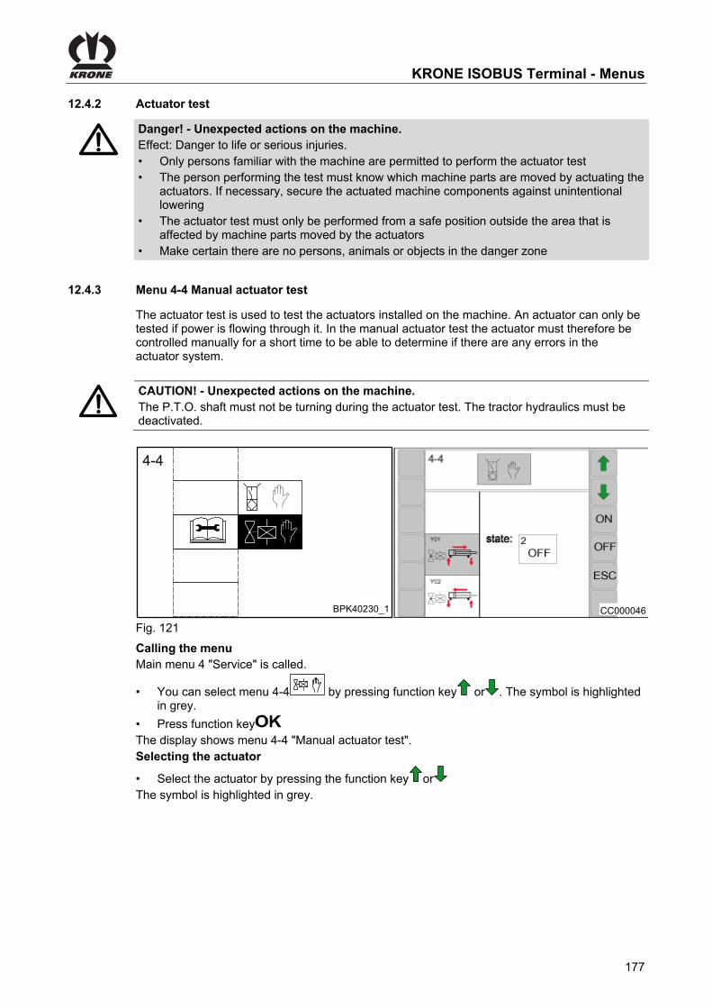
KRONE ISOBUS Terminal - Menus
177
Pos: 92.183 /Überschriften/Überschriften 3/A-E/AAktortest @ 0\mod_1200916990791_78.docx @ 47833 @ 3 @ 1
12.4.2 Actuator test Pos: 92.184 /BA/Sicherheit/7. Gefahrenhinweise alt/Gefahr - Aktortest @ 47\mod_1285134152781_78.docx @ 455729 @ @ 1
Danger! - Unexpected actions on the machine. Effect: Danger to life or serious injuries. • Only persons familiar with the machine are permitted to perform the actuator test • The person performing the test must know which machine parts are moved by actuating the
actuators. If necessary, secure the actuated machine components against unintentional lowering
• The actuator test must only be performed from a safe position outside the area that is affected by machine parts moved by the actuators
• Make certain there are no persons, animals or objects in the danger zone
Pos: 92.185 /Überschriften/Überschriften 3/K-O/Menü 4-4 Aktortest Hand @ 44\mod_1275637010843_78.docx @ 393380 @ 3 @ 1
12.4.3 Menu 4-4 Manual actuator test Pos: 92.186 /BA/Info-Center/Großpackenpresse/Hauptmenüs/Hauptmenü 4 Service/Menü 4-4 Aktortest Hand Einführungstext @ 44\mod_1275637366437_78.docx @ 393405 @ @ 1
The actuator test is used to test the actuators installed on the machine. An actuator can only be tested if power is flowing through it. In the manual actuator test the actuator must therefore be controlled manually for a short time to be able to determine if there are any errors in the actuator system.
Pos: 92.187 /BA/Info-Center/Großpackenpresse/Hauptmenüs/Hauptmenü 4 Service/Menü 4-4 Aktortest Hand Achtung @ 44\mod_1275637929203_78.docx @ 393455 @ @ 1
CAUTION! - Unexpected actions on the machine. The P.T.O. shaft must not be turning during the actuator test. The tractor hydraulics must be deactivated.
Pos: 92.188 /BA/Info-Center/CCI-ISOBUS-Terminal/CCI-BiG Pack/Hauptmenüs/Hauptmenü 4 Service/Menü 4-4 Aktortest Bild @ 44\mod_1275642425859_78.docx @ 393530 @ @ 1
BPK40230_1
4-4 4-4
CC000046
Fig. 121 Pos: 92.189 /BA/Info-Center/CCI-ISOBUS-Terminal/CCI-BiG Pack/Hauptmenüs/Hauptmenü 4 Service/Menü 4-4 Aktortest Hand Menü aufrufen / Aktor wählen @ 44\mod_1275888726125_78.docx @ 393585 @ @ 1
Calling the menu Main menu 4 "Service" is called.
• You can select menu 4-4 by pressing function key or . The symbol is highlighted in grey.
• Press function key The display shows menu 4-4 "Manual actuator test". Selecting the actuator
• Select the actuator by pressing the function key or The symbol is highlighted in grey.
Pos: 92.190 /Layout Module /---------------Seitenumbruch---------------- @ 0\mod_1196175311226_0.docx @ 4165 @ @ 1

KRONE ISOBUS Terminal - Menus
178
Pos: 92.191 /BA/Info-Center/CCI-ISOBUS-Terminal/CCI-BiG Pack/Hauptmenüs/Hauptmenü 4 Service/Diagnose digitale Aktoren @ 44\mod_1275889088109_78.docx @ 393610 @ @ 1
Diagnostics – digital actuators Errors are only displayed if the actuator is turned on and a test is possible for the actuator (see the table called "Possible digital actuators"). The actuators can also be checked on the LED at the plug, if necessary.
• Press function key
Pos: 92.192 /BA/Info-Center/Sensoren/Mögliche digitale Aktoren (je nach Ausstattung der Maschine) @ 19\mod_1238420935128_78.docx @ 217969 @ @ 1
Possible digital actuators (depending on how the machine is equipped) Pos: 92.193 /BA/Info-Center/CCI-ISOBUS-Terminal/CCI-BiG Pack/Hauptmenüs/Hauptmenü 4 Service/Auflistung der möglichen digitalen Aktoren @ 44\mod_1276156405140_78.docx @ 396397 @ @ 1
No. Sensor symbol
Description No. Sensor symbol
Description
Y01
Main valve Y09
Valve to open bale channel flaps
Y02
Main valve Y14 BigBale (error detection
is not possible)
Y03
Bale chute Y15
MultiBale (error detection is not possible)
Y04
Bale chute Y30
Knotter cleaning (error detection is not possible)
Y05
Bale ejector Y31 Central lubrication
Y06
Bale ejector M1
Knotter triggering (error detection is not possible)
Y07
Blade bar
Y08
Blade bar
Pos: 92.194 /BA/Info-Center/CCI-ISOBUS-Terminal/CCI-BiG Pack/Hauptmenüs/Hauptmenü 4 Service/Auflistung der möglichen digitalen Aktoren zusätzlich für HS BAureihe @ 279\mod_1405407491044_78.docx @ 2150458 @ @ 1
No. Actuator symbol
Description No. Actuator symbol
Description
Y20
Lock axle H2 Working light (knotter
area)
H1
Working light (pick-up area)
K100
Pos: 92.195 /BA/Info-Center/CCI-ISOBUS-Terminal/CCI-BiG Pack/Hauptmenüs/Hauptmenü 4 Service/Auflistung der möglichen digitalen Aktoren zusätzlich A1 Schmiermittelanlge @ 279\mod_1405409081885_78.docx @ 2150551 @ @ 1
No. Actuator symbol
Description No. Actuator symbol
Description
A1
Lubricant system
Pos: 92.196 /Layout Module /---------------Seitenumbruch---------------- @ 0\mod_1196175311226_0.docx @ 4165 @ @ 1

KRONE ISOBUS Terminal - Menus
179
Pos: 92.197 /BA/Info-Center/Sensoren/Statusanzeigen/Statusanzeige digitaler Aktoren (1,2,3,4) @ 19\mod_1238477852587_78.docx @ 218655 @ @ 1
State:
Actuator on
Actuator off
General actuator error
No power supply; fuse is probably defective
Pos: 92.198 /BA/Info-Center/CCI-ISOBUS-Terminal/CCI-BiG Pack/Hauptmenüs/ESC drücken um Menü Service 4 zu schließen bzw. zum Grundbild zugelangen @ 44\mod_1275893530687_78.docx @ 393687 @ @ 1
• Pressing the function key closes the called up menu The display shows menu level 4 "Service".
• Pressing the function key and holding it down brings up the basic screen
Pos: 92.199 /Layout Module /---------------Seitenumbruch---------------- @ 0\mod_1196175311226_0.docx @ 4165 @ @ 1

KRONE ISOBUS Terminal - Menus
180
Pos: 92.200 /BA/Info-Center/CCI-ISOBUS-Terminal/CCI-BiG Pack/Hauptmenüs/Hauptmenü 4 Service/Diagnose analoge Aktoren HS Baureihe @ 64\mod_1300169028051_78.docx @ 580255 @ @ 1
Diagnostics analogue actuators
4-4
PWM: 300I= 0mA
CC000047
Fig.122 A current (in mA) can be created with the PWM value (in parts per thousand). With a value of PWM = 500, the current should be between 500 mA and 3000 mA (depending on the valve that is used and the operating temperature).
• Pressing the function key increases the PWM. • Pressing the function key decreases the PWM. Possible analogue actuators
No. Symbol Description
Y11
Pressure limitation valve
Y17
Start-up aid
State:
actuator ON
actuator OFF
No power supply; fuse is probably defective
Pos: 92.201 /BA/Info-Center/CCI-ISOBUS-Terminal/CCI-BiG Pack/Hauptmenüs/ESC drücken um Menü Service 4 zu schließen bzw. zum Grundbild zugelangen @ 44\mod_1275893530687_78.docx @ 393687 @ @ 1
• Pressing the function key closes the called up menu The display shows menu level 4 "Service".
• Pressing the function key and holding it down brings up the basic screen
Pos: 92.202 /Layout Module /---------------Seitenumbruch---------------- @ 0\mod_1196175311226_0.docx @ 4165 @ @ 1

KRONE ISOBUS Terminal - Menus
181
Pos: 92.203 /BA/Info-Center/Sensoren/Diagnose Drucksensor @ 115\mod_1339653067227_78.docx @ 1011904 @ @ 1
Diagnostics Pressure Sensors Pos: 92.204 /BA/Info-Center/Sensoren/Mögliche Sensoren (je nach Ausstattung der Maschine) @ 19\mod_1238071336628_78.docx @ 214010 @ @ 1
Possible sensors (depending on how the machine is equipped) Pos: 92.205 /BA/Info-Center/Sensoren/Drucksensor Achse gesperrt B36 @ 120\mod_1342685713553_78.docx @ 1093155 @ @ 1
No. Sensor symbol Description
B36 B36
Axle locked
Pos: 92.206 /BA/Info-Center/Sensoren/Statusanzeigen/Statusanzeige Drucksensor Achse @ 120\mod_1342618393636_78.docx @ 1092834 @ @ 1
State: 1
p>100bar Axle locked
2
p<100barAxle released
Pos: 92.207 /Layout Module /---------------Seitenumbruch---------------- @ 0\mod_1196175311226_0.docx @ 4165 @ @ 1

KRONE ISOBUS Terminal - Menus
182
Pos: 92.208 /BA/Info-Center/CCI-ISOBUS-Terminal/Menü 4-6 Diagnose Fahrgeschw/Fahrtrichung/Menü 4-6 Diagnose Fahrgeschwindigkeits- /Fahrtrichtungsanzeige T1 @ 109\mod_1335273978199_78.docx @ 975069 @ 3 @ 1
12.4.4 Menu 4-6 „Diagnostics Driving Speed / Motion Direction Display“
The tractor must transfer the driving speed and the direction of travel onto the ISO-Bus.
ZX400057_1
4-6
1
2
3
4
4-6
CC000554
Fig. 123 Calling the Menu Main menu 4 “Service” is called
• By pressing function key or , select menu 4-6 , the symbol is highlighted in grey
• Press function key The display shows menu 4-6 „Diagnostics Driving Speed/Motion Direction Display“.
Pos: 92.209 /BA/Info-Center/CCI-ISOBUS-Terminal/Menü 4-6 Diagnose Fahrgeschw/Fahrtrichung/Menü 4-6 Symbolerklärungen BiG PACK T2 540 UPM @ 109\mod_1335433351661_78.docx @ 977263 @ @ 1
Explanation of Symbols: 1) <--- 0 = Forward travel 0 ---> = Reverse travel 2) 25.5 km/h= Speed when driving forward -25.5 km/h= Speed when driving backward 3) 540 RPM = PTO speed 4)
Parameter (ISO-Bus evaluation) selected
Parameter (ISO-Bus evaluation) not selected
• Use the ESCkey to close the menu currently displayed The display shows menu level 4 “Service”.
Pos: 92.210 /Layout Module /---------------Seitenumbruch---------------- @ 0\mod_1196175311226_0.docx @ 4165 @ @ 1

KRONE ISOBUS Terminal - Menus
183
Pos: 92.211 /BA/Info-Center/CCI-ISOBUS-Terminal/Menü 4-7 Diagnose Auxiliary (AUX)/Menü 4-7 Diagnose Auxiliary (AUX) T1 @ 109\mod_1335433715718_78.docx @ 977292 @ 3 @ 1
12.4.5 Menu 4-7 „Diagnostics Auxiliary (AUX)“
ZX400058
4-74-7
CC000555
Fig. 124 Calling the Menu Main menu 4 “Serice” is called
• By pressing function key or , select menu 4-7 , the symbol is highlighted in grey
• Press function key The display shows menu 4-7 “Diagnostics Auxiliary (AUX)”.
Pos: 92.212 /BA/Info-Center/CCI-ISOBUS-Terminal/Menü 4-7 Diagnose Auxiliary (AUX)/Menü 4-7 Diagnose Auxillary Belegung am Multifunktionshebel T2 @ 109\mod_1335435155329_78.docx @ 977400 @ @ 1
A figure of the multi-function lever appears in the display. When activating a function on the multi-function lever, only the assigned symbol will appear in the display. The function itself is not performed.
• Use the ESCkey to close the menu currently displayed The display shows menu level 4 “Service”.
Pos: 92.213 /Layout Module /---------------Seitenumbruch---------------- @ 0\mod_1196175311226_0.docx @ 4165 @ @ 1

KRONE ISOBUS Terminal - Menus
184
Pos: 92.214 /BA/Info-Center/CCI-ISOBUS-Terminal/CCI-BiG Pack/Hauptmenüs/Hauptmenü 5 Info/Hauptmenü 5 Info HS Baureihe @ 64\mod_1300112474713_78.docx @ 580091 @ 2 @ 1
12.5 Main menu 5 'Information'
CC000050
5
CC000081
5-1
1290 HS
SW: 2008128701:150200445_0
ISO 2:150200446_00
Fig.125 Calling the main menu
• Access the menu level by pressing the function key on the basic screen.
• Select the main menu 5 ( )by pressing the function key or . The symbol is highlighted in grey.
• Press function key . The display shows menu 5 'Information'. Page 5-1: Complete software version of the machine
• 1290 HS = machine type • SW = complete software version of the machine
• = job computer version • ISO= ISO software version
Pos: 92.215 /BA/Info-Center/CCI-ISOBUS-Terminal/CCI-BiG Pack/Hauptmenüs/ESC drücken um Menü Info 5 zu schließen bzw. zum Grundbild zugelangen @ 44\mod_1275908986375_78.docx @ 393962 @ @ 1
• Pressing the function key closes the called up menu The display shows menu level 5 "Info".
• Pressing the function key and holding it down brings up the basic screen
Pos: 92.216 /Layout Module /---------------Seitenumbruch---------------- @ 0\mod_1196175311226_0.docx @ 4165 @ @ 1

KRONE ISOBUS Terminal - Menus
185
Pos: 92.217 /BA/Info-Center/CCI-ISOBUS-Terminal/CCI-BiG Pack/Hauptmenüs/Hauptmenü 6 Monteur/Hauptmenü 6 Monteur @ 135\mod_1351678746690_78.docx @ 1203319 @ 2 @ 1
12.6 Main Menu 6 Technician
Calling the Main Menu
CC000051
6
CC000052_1
15-6
054536
0000
Fig. 126
• By pressing function key in the basic screen you get into the menu level
• Select main menu 6 by pressing function key or . The symbol is highlighted in grey.
• Press function key Main menu 6 "Technician" is password-protected. The display shows the password query.
Pos: 92.218 /Layout Module /---------------Seitenumbruch---------------- @ 0\mod_1196175311226_0.docx @ 4165 @ @ 1

KRONE ISOBUS Terminal - Menus
186
Pos: 92.219 /BA/Info-Center/CCI-ISOBUS-Terminal/Menü 9 ISO-Einstellungen/Hauptmenü 9 Virtual Terminal/Hauptmenü 9 VT @ 80\mod_1315399643122_78.docx @ 704281 @ 2 @ 1
12.7 Main menu 9 "Virtual Terminal (VT)"
CC000474
Fig. 127 Calling the main menu
• Press function key to access the menu level via the basic screen
• Press function key or to select main menu 9 ( ). The icon is colour highlighted
• Press function key The display shows menu level 9 "Virtual Terminal (VT)".
Pos: 92.220 /BA/Info-Center/CCI-ISOBUS-Terminal/Menü 9 ISO-Einstellungen/Hauptmenü 9 Virtual Terminal/Das Hauptmenü 9 zeigt je nach Ausstattung der Maschine folgende Menüs an @ 109\mod_1335506092707_78.docx @ 977873 @ @ 1
The menu level 9 “Virtual Terminal (VT)„ shows the following menus depending on how the machine is equipped:
Pos: 92.221 /BA/Info-Center/CCI-ISOBUS-Terminal/Menü 9 ISO-Einstellungen/Optionale Anzeige Menü 9-1 / 10 Tasten auf 5 Tasten @ 109\mod_1335505873339_78.docx @ 977844 @ @ 1
= Menu 9-1 “Softkeys ISO Terminal” (appears only in case of terminals with less than 10 keys)
Pos: 92.222 /BA/Info-Center/CCI-ISOBUS-Terminal/Menü 9 ISO-Einstellungen/Optionale Anzeige Menü 9-2 Umschalten zwischen Terminals @ 109\mod_1335509462126_78.docx @ 977901 @ @ 1
= Menu 9-2
Switching between Terminals” (appears only if several ISO terminals are connected)
Pos: 92.223 /BA/Info-Center/CCI-ISOBUS-Terminal/Menü 9 ISO-Einstellungen/Optionale Anzeige Menü 9-3 Konfiguration Hauptfenster @ 109\mod_1335448707203_78.docx @ 977756 @ @ 1
ABC
= Menu 9-3 Configuration Basic Screen
Pos: 92.224 /Layout Module /---------------Seitenumbruch---------------- @ 0\mod_1196175311226_0.docx @ 4165 @ @ 1
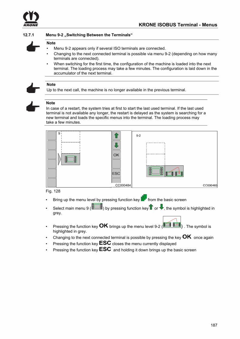
KRONE ISOBUS Terminal - Menus
187
Pos: 92.225 /BA/Info-Center/CCI-ISOBUS-Terminal/Menü 9 ISO-Einstellungen/Menü 9-2 Terminalwechsel @ 119\mod_1342087866195_78.docx @ 1070148 @ 3 @ 1
12.7.1 Menu 9-2 „Switching Between the Terminals“
Note • Menu 9-2 appears only if several ISO terminals are connected. • Changing to the next connected terminal is possible via menu 9-2 (depending on how many
terminals are connected). • When switching for the first time, the configuration of the machine is loaded into the next
terminal. The loading process may take a few minutes. The configuration is laid down in the accumulator of the next terminal.
Note Up to the next call, the machine is no longer available in the previous terminal.
Note In case of a restart, the system tries at first to start the last used terminal. If the last used terminal is not available any longer, the restart is delayed as the system is searching for a new terminal and loads the specific menus into the terminal. The loading process may take a few minutes.
CC000484
9
Fig. 128
• Bring up the menu level by pressing function key from the basic screen
• Select main menu 9 ( ) by pressing function key or , the symbol is highlighted in grey.
• Pressing the function key brings up the menu level 9-2 ( ) . The symbol is highlighted in grey.
• Changing to the next connected terminal is possible by pressing the key once again
• Pressing the function key closes the menu currently displayed
• Pressing the function key and holding it down brings up the basic screen Pos: 92.226 /Layout Module /---------------Seitenumbruch---------------- @ 0\mod_1196175311226_0.docx @ 4165 @ @ 1

KRONE ISOBUS Terminal - Menus
188
Pos: 92.227 /BA/Info-Center/CCI-ISOBUS-Terminal/Menü 9 ISO-Einstellungen/Menü 9-3 Konfiguration Hauptfenster aufrufen @ 146\mod_1360049968330_78.docx @ 1306011 @ 3 @ 1
12.7.2 Menu 9-3 „Configuration Main Window“
In menu 9-3 you can determine which displays shall be shown in the main window (left column). Up to 7 display elements can be displayed at the same time in the main window. Depending on how the machine is equipped, you can select from up to 13 display elements which 7 display elements shall be shown in the main window. Moreover you can configure the main window individually on 2 pages (for example for 2 drivers).
Fig. 129 The main menu 9 „Virtual Terminal (VT)“ is called
• Select menu 9-3 (ABC ) by pressing function key or , the symbol is highlighted in
colour
• Press function key The display shows menu 9-3 “Configuration Main Window”.
Pos: 92.228 /BA/Info-Center/CCI-ISOBUS-Terminal/Menü 9 ISO-Einstellungen/Menü 9-3 Hauptfenster konfigurieren: Vorgehensweise @ 144\mod_1359472370928_78.docx @ 1294588 @ @ 1
Configuring Main Window:
• Call up the page to be configured by pressing function key or
• By pressing function key or , move the rectangle (1) into the desired row (1-7)
• Select the desired selection element via function key or , the new display element
appears in the display and the symbol in the upper line goes out
• Press function key , the display symbol is saved, the symbol in the upper line appears
• Pressing the function key closes the called up menu
• Pressing the function key and holding it down brings up the basic screen Bringing up the Factory Setting:
• The factory setting is called up and saved by pressing and holding the function key (for approx. 2 seconds)
Pos: 92.229 /Layout Module /---------------Seitenumbruch---------------- @ 0\mod_1196175311226_0.docx @ 4165 @ @ 1

KRONE ISOBUS Terminal - Menus
189
Pos: 92.230 /BA/Info-Center/CCI-ISOBUS-Terminal/Menü 9 ISO-Einstellungen/Menü 9-3 Mögliche Auswahlelemente für das Hauptfenster (je nach Ausstattung der Maschine) @ 146\mod_1360146285555_78.docx @ 1308004 @ @ 1
Possible selection elements for the main window (depending on how the machine is equipped)
Pos: 92.231 /BA/Info-Center/CCI-ISOBUS-Terminal/CCI-BiG Pack/Grundbild Handbetrieb/Anzeigen im Hauptfenster/Anzeigen im Hauptfenster (III) linke Spalte HS Baureihe T1 @ 277\mod_1404824229880_78.docx @ 2079165 @ @ 1
Left column (A):
Graphics Meaning Information
Current force of pressure – Only in manual mode
– In % (100% = max.).
Current bale channel flap pressure – Only in automatic mode – In bar or PSI, depending on set
unit of measure Metric/US
2 Total number of bales – The adjoining number indicates
the current customer counter.
Current PTO speed – rpm
Current layer thickness – In cm or inch (only for electr. bale
length setting)
Number of layers per bale
Crop humidity
Bale weight – of the bale last weighed
Ø Average weight of the weighed bales
Total weight of all bales
Pos: 92.232 /BA/Info-Center/CCI-ISOBUS-Terminal/CCI-BiG Pack/Grundbild Handbetrieb/Anzeigen im Hauptfenster/Anzeigen im Hauptfenster (III) linke Spalte HS Baureihe T2 @ 279\mod_1405058360314_78.docx @ 2146751 @ @ 1
Graphics Meaning Information
Bale length counter – Metric in metres
– US unit of measure in feet
Number of uncut bales
Number of cut bales – Only for machines equipped with a cutting system
Appears briefly after a knot is tied – If activated, a horn sound is heard for approx. one second, see chapter Menu 1-2 "Knotter signal"
Operating hours counter – Counts only when PTO shaft is
running.
Pos: 92.233 /Layout Module /---------------Seitenumbruch---------------- @ 0\mod_1196175311226_0.docx @ 4165 @ @ 1

KRONE ISOBUS Terminal - Menus
190
Pos: 92.234 /BA/Info-Center/CCI-ISOBUS-Terminal/CCI-BiG Pack/Hauptmenüs/Alarmmeldungen/Alarmeldung allgemein @ 189\mod_1381224126492_78.docx @ 1622617 @ 2 @ 1
12.8 Alarm Message
F1
F2
F3
F4
F5
F6
F7
F8
F9
F10
F11F11
F12
CC000053_1
KBT
A03
Fig. 130 Alarm message If a malfunction occurs on the machine, an alarm message appears in the display and an audio signal is heard at the same time (constant horn signal). Description, possible cause and remedy are shown in the chapter entitled “Alarm Messages”.
Note All functions in the covered menu are still active. The softkeys covered by the alarm message are deactivated. To reset alarm:
• To reset the alarm, press function key for softkey , the acoustic signal is stopped. If the malfunction occurs again, the alarm message will also appear again.
Pos: 92.235 /Layout Module /---------------Seitenumbruch---------------- @ 0\mod_1196175311226_0.docx @ 4165 @ @ 1

KRONE ISOBUS Terminal - Menus
191
Pos: 92.236 /Überschriften/Überschriften 3/A-E/AAlarmmeldungen @ 34\mod_1255441373066_78.docx @ 323566 @ 3 @ 1
12.8.1 Alarm messages Pos: 92.237 /BA/Info-Center/Großpackenpresse/Hauptmenüs/Alarmmeldungen/1) Alarmmeldungen Tabelle allgemein A01 - A17 HS Baureihe @ 64\mod_1300112639026_78.docx @ 580114 @ @ 1
No. Screen Description Possible cause Remedy
A01
Fuse 2 defective Short circuit at the outputs
Replace the fuse and then test all actuators in the actuator test to determine whether an actuator has a short circuit.
A02
Fuse 3 defective (self-repairing)
Short circuit in electrical power supply for sensors.
Check wiring to Multi-Bale potentiometer, star wheel, pressure sensor and force measurement amplifier.
A03
CAN connection between terminal and job computer interrupted
CAN wiring defective Check the CAN wiring
A04
EEPROM error Job computer defective Replace the job computer
A05
CAN connection broken between job computer and Krone I/O computer
CAN wiring defective Krone I/O computer inactive
Check the CAN wiring Check the cables. Replace Krone I/O computer
A11
CAN connection broken between job computer and Krone measurement force computer (KMV1)
CAN wiring defective Krone measurement force computer (KMV1) inactive
Check the CAN wiring Check the cables. Replace Krone measurement force computer (KMV1).
A12
CAN connection broken between job computer and Krone measurement force computer (KMV2)
CAN wiring defective Krone measurement force computer (KMV2) inactive
Check the CAN wiring Check the cables. Replace Krone measurement force computer (KMV2).
A14
Undervoltage
- Tractor battery defective - Tractor dynamo too weak - 12-V power supply too weak on the tractor side or not correctly connected with the battery
Connect the KRONE connection cable directly to the tractor battery
A15
Overvoltage Tractor dynamo defective
Check dynamo
A17
CAN connection broken between job computer and Krone humidity measurement computer (RMC)
CAN wiring defective Krone humidity measurement computer (RMC) inactive
Check the CAN wiring Check the cables. Replace Krone humidity measurement computer (RMC).
Pos: 92.238 /Layout Module /---------------Seitenumbruch---------------- @ 0\mod_1196175311226_0.docx @ 4165 @ @ 1
KMV1
KMV2
RMC

KRONE ISOBUS Terminal - Menus
192
Pos: 92.239 /BA/Info-Center/Großpackenpresse/Hauptmenüs/Alarmmeldungen/2) Alarmmeldungen Tabelle allgemein 0 - 9 @ 19\mod_1238504387040_78.docx @ 220236 @ @ 1
No. Image Description Possible cause Remedy
0
Twine monitoring - Twine torn - Twine end
Checking the twine and twine tensioner
1
Packer monitoring Blockage in the intake area of the packer
Stop the traction drive immediately Reduce P.T.O. speed until the blockage is cleared
2
Pressing force exceeded, left sensor
Pressing force exceeded If the machine could be subject to a mechanical overload because the pressure is too high, the bale channel flap pressure is lowered to a non-critical value just before the overload. The amount of reduction depends on the material being baled. The reduction is less for straw than for silage.
The following measures must be taken: 1. In manual mode: -Lower the pressure 2. In Automatic mode: If the alarm occurs quite frequently, reduce the pressing force setting slightly
3
Force of pressure exceeded, right sensor
4
Knotter monitoring
- Knotter is not functioning properly - Sensor set incorrectly
- Check the knotter and knotter triggering - Set the knotter monitoring sensor correctly
5
Measurement monitoring
Sensor measuring defective or set incorrectly
Adjust the sensor correctly
6
Calibration monitoring
Sensor calibration defective or set incorrectly
Adjust the sensor correctly
7
Flywheel brake Flywheel brake applied Release the flywheel brake
8
Needle connecting rod
Shear screw ruptured
- Replace the shear screw - Check needles - Check the swivel range of the needles - Check the twine guide
9
Bale chute Bale chute up and P.T.O. shaft is turning
- Lower bale chute
Pos: 92.240 /Layout Module /---------------Seitenumbruch---------------- @ 0\mod_1196175311226_0.docx @ 4165 @ @ 1

KRONE ISOBUS Terminal - Menus
193
Pos: 92.241 /BA/Info-Center/Großpackenpresse/Hauptmenüs/Alarmmeldungen/3) Alarmmeldungen Tabelle allgemein 10-37 HS Baureihe @ 192\mod_1382344116641_78.docx @ 1639667 @ @ 1
No.
Figure Possible cause Remedy
10
– An error on the pressure limiting valve.
– The pressure sensor is defective.
– Switch off the PTO shaft. – Check the pressure limiting valve
for blockage.
11
– The PTO shaft is turning upon entry into sensor or actuator diagnostics or during diagnostics.
– Switch off the PTO shaft immediately.
– Perform diagnostics with the PTO shaft stopped.
12
– The blade bar is down during baling.
– Raise the blade bar.
16
– The pick-up or the cutting system does not turn.
– Blockage in the area of the pick-up or the cutting system.
– Check mechanics. – Remove the blockage.
17
– The knotter motor has not triggered any knots or the knotter sensor is not set correctly.
– Check the electrical system of the knotter motor.
– Check the mechanics in the area of the knotter triggering.
– Adjust the knotter sensor correctly.
18
– It is not possible to set the both positions Multibale or total bale.
– No compressed air present. – Adjust the Multibale sensor
correctly. – Check the mechanics in the area
of the knotter triggering. – Error on the Multibale valve (valve
jammed, coil defective). – Check the electronics in the area
of the multibale interlock.
19
– The packer feed sensor is adjusted incorrectly.
– Adjust the sensor correctly.
20
– The bale ejector has been activated even though the bale chute is still up.
– Lower the bale chute first and then activate the bale ejector.
21
– The sensors for measuring and calibrating are probably mixed up.
– Exchange the plug for the sensors for measuring and calibrating.
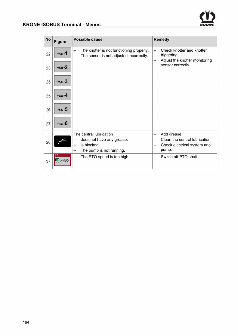
KRONE ISOBUS Terminal - Menus
194
No.
Figure Possible cause Remedy
22
– The knotter is not functioning properly. – The sensor is not adjusted incorrectly.
– Check knotter and knotter triggering.
– Adjust the knotter monitoring sensor correctly.
23
25
25
26
27
28
The central lubrication – does not have any grease. – is blocked. – The pump is not running.
– Add grease. – Clean the central lubrication. – Check electrical system and
pump.
37
37
MAX– The PTO speed is too high. – Switch off PTO shaft.
Pos: 92.242 /Layout Module /---------------Seitenumbruch---------------- @ 0\mod_1196175311226_0.docx @ 4165 @ @ 1
1
2
3
4
5
6

KRONE ISOBUS Terminal - Menus
195
Pos: 92.243 /BA/Info-Center/Großpackenpresse/Hauptmenüs/Alarmmeldungen/4) Alarmmeldungen Tabelle allgemein 101-113 @ 19\mod_1238506114415_78.docx @ 220281 @ @ 1
No. Image Description Possible cause Remedy
101
Twine monitoring sensor
Sensor or line defective
Perform a sensor test Check the sensor and line for damage
-
102
Packer monitoring sensors
103
Packer feed sensor
104
Upper blade bar sensor, top
105
Cutter sensor active
106
Knotter monitoring sensor
107
Measuring force sensor
108
Calibration force sensor
109
Sensor flywheel brake
110
Needle connecting rod sensor
111
Bale chute sensor
112
Force sensor, right
Sensor, measurement amplifier or line defective
Check the sensor and line for damage
113
Force sensor, left Sensor, measurement amplifier or line defective
Check the sensor and line for damage
Pos: 92.244 /Layout Module /---------------Seitenumbruch---------------- @ 0\mod_1196175311226_0.docx @ 4165 @ @ 1

KRONE ISOBUS Terminal - Menus
196
Pos: 92.245 /BA/Info-Center/Großpackenpresse/Hauptmenüs/Alarmmeldungen/5) Alarmmeldungen Tabelle allgemein 114-125 HS Baureihe @ 64\mod_1300117151504_78.docx @ 580168 @ @ 1
No. Screen Description Possible cause Remedy
114
Hydraulic pressure sensor
Sensor or supply line defective - Perform a sensor test - Check the sensor and line for damage.
115
Sensor for setting down bales
Sensor or supply line defective - Perform a sensor test - Check the sensor and line for damage.
116
Sensor for bale ejector
Sensor or supply line defective - Perform a sensor test - Check the sensor and line for damage.
117
Star wheel sensor Sensor (rotary potentiometer) or line defective
- Perform a sensor test - Check the sensor and line for damage.
118
Pick-up sensor Sensor or supply line defective - Perform a sensor test - Check the sensor and line for damage.
119
Bale chute up feeler
Feeler or supply line defective - Perform a sensor test - Check the feeler and line for damage.
120
Bale chute down feeler
Feeler or supply line defective - Perform a sensor test - Check the feeler and line for damage.
121
Bale ejector feeler out
Feeler or supply line defective - Perform a sensor test - Check the feeler and line for damage.
122
Bale ejector feeler in
Feeler or supply line defective - Perform a sensor test - Check the feeler and line for damage.
123
Blade bar up feeler
Feeler or supply line defective - Perform a sensor test - Check the feeler and line for damage.
124
Blade bar down feeler
Feeler or supply line defective - Perform a sensor test - Check the feeler and line for damage.
125
MultiBale sensor Sensor (rotary potentiometer) or line defective
- Perform a sensor test - Check the sensor and line for damage.
Pos: 92.246 /Layout Module /---------------Seitenumbruch---------------- @ 0\mod_1196175311226_0.docx @ 4165 @ @ 1

KRONE ISOBUS Terminal - Menus
197
Pos: 92.247 /BA/Info-Center/Großpackenpresse/Hauptmenüs/Alarmmeldungen/6) Alarmmeldungen Tabelle allgemein 126-149 HS Baureihe @ 64\mod_1300117366608_78.docx @ 580195 @ @ 1
No. Screen Description Possible cause Remedy
126
Sensor knotter 1
Sensor or supply line defective - Perform a sensor test - Check the sensor and line for damage.
127
Sensor knotter 2
128
Sensor knotter 3
129
Sensor knotter 4
130
Sensor knotter 5
131
Sensor knotter 6
132
Sensor - central lubrication
146
Sensor bale on chute
147
Sensor acceleration
148
Force sensor front bale chute
149
Force sensor rear bale chute
Pos: 93 /Layout Module /---------------Seitenumbruch---------------- @ 0\mod_1196175311226_0.docx @ 4165 @ @ 1
B41
1
B42
2
B43
3
B44
4
B45
5
B46
6
B22
B38
a
B56
CH1
B55
CH2

KRONE ISOBUS Terminal - Menus
198
Pos: 94 /Layout Module /Diese Seite ist bewusst freigelassen worden. @ 1\mod_1201783680373_78.docx @ 54443 @ @ 1
This page has been left blank deliberately!! Pos: 95 /Layout Module /---------------Seitenumbruch---------------- @ 0\mod_1196175311226_0.docx @ 4165 @ @ 1

ISOBUS operation
199
Pos: 96.1 /Überschriften/Überschriften 1/F-J/ISOBUS-Bedienung @ 33\mod_1254285737011_78.docx @ 318705 @ 1 @ 1
13 ISOBUS operation Pos: 96.2 /BA/Info-Center/Iso-Bedienung/Allgemeines zu ISOBUS Systemen @ 48\mod_1286197286984_78.docx @ 459741 @ @ 1
General aspects The ISOBUS system is an internationally standardized communication system for agricultural machines and systems. The designation of the related series of standards is: ISO 11783. The agricultural ISOBUS system makes an information and data exchange between tractor and device of different manufacturers possible. To this end, both, the necessary plug connections and the signals are standardized which are necessary for the communication and command transmission. The system also enables the operation of machines with control units (terminal) which are already existent on the tractor or have been attached in the tractor cabin. The relevant details can be found in the technical documentation of the control unit or on the device itself. Those KRONE machines which are ISOBUS equipped are adapted to this system.
Note The KRONE ISOBUS systems pass the ISOBUS COMPATIBILITY TEST (DLG/VDMA) on a regular basis. The operation of this machine requires at least implementation level 3 of the ISOBUS system.
Pos: 96.3 /BA/Info-Center/Iso-Bedienung/Gefahr durch nicht von KRONE gelieferte Terminals / Bedieneinheiten @ 48\mod_1286197403750_78.docx @ 459766 @ @ 1
DANGER! When using terminals and other control units which have not been delivered by KRONE mind that the user: • has to take the responsibility for the use of KRONE machines when using the machine on
control units (terminal / other control elements) which have not been delivered by KRONE • must check the machine before operation on all machine functions, if they are performed as
described in the enclosed operating instructions • as possible, should only couple those systems to each other which have passed a
DLG/VDMA test (so called ISOBUS COMPATIBILITY TEST) before • has to follow the operating and safety instructions of the supplier of the ISOBUS control unit
(e.g. terminal) • must guarantee that the control elements and machine control systems fit together
according to the IL (IL= Implementation Level; describes the compatibility status of the different software versions) (requirement: IL same or higher)
Pos: 96.4 /Layout Module /---------------Seitenumbruch---------------- @ 0\mod_1196175311226_0.docx @ 4165 @ @ 1

ISOBUS operation
200
Pos: 96.5 /BA/Info-Center/Iso-Bedienung/BigPack/ISO-Bedienung_Anbau @ 252\mod_1397068204319_78.docx @ 1943554 @ 233 @ 1
13.1 Mounting ISOBUS Terminal
3
4
5 7
61
2
Fig. 131
CAUTION! Failure of control unit. When installing, make certain that the connection cables are not tight when cornering and that they do not touch the tractor wheels or any other parts of tractor or machine.
13.1.1 Connection Terminal to Tractor
Note For further details on the attachment, consult the operating instructions of the ISOBUS terminal manufacturer.
13.1.2 Connection Tractor to Machine
• Connect ISO-plug (3) (9-pole) of cable set (1) with outer ISO-socket (2) (9-pole) on tractor side
• Connect plug (4) (7-pole) of cable set (1) with socket (5) (7-pole) of the machine • Connect plug (6) (2-pole) of cable set (1) with socket (7) (2-pole) of the machine
Pos: 96.6 /Layout Module /---------------Seitenumbruch---------------- @ 0\mod_1196175311226_0.docx @ 4165 @ @ 1

ISOBUS operation
201
Pos: 96.7 /BA/Info-Center/Iso-Bedienung/BigPack/Abweichende Funktionen zum KRONE ISOBUS-Termina CCI @ 47\mod_1285223499328_78.docx @ 455993 @ 2 @ 1
13.2 Differing functions to KRONE ISOBUS terminal CCI
Via the accessory unit, the ISOBUS control unit will provide information and control functions to the display of the ISOBUS terminal. Operation with an ISOBUS terminal is analogue to the KRONE ISOBUS terminal CCI. Prior to start-up, refer to the operating instructions for the method of operation of the KRONE ISOBUS terminal CCI. A fundamental difference to the KRONE ISOBUS terminal CCI is the arrangement of the softkeys, which are determined by the selected ISOBUS terminal. Only the functions that differ from the KRONE ISOBUS terminal CCI are described in the following.
Pos: 96.8 /BA/Info-Center/Iso-Bedienung/BigPack/Abweichende Funktionen CCI_Terminal Pressklappen @ 47\mod_1285233314609_78.docx @ 456042 @ @ 1
Note The values for “Bale channel flap pressure/force”, “Bale length” and “Number of MultiBales” which are set by the scroll wheel in the basic screen on the KRONE ISOBUS terminal CCI, are set on the ISO terminal with the selection key predetermined by the ISO terminal (refer to the operating instructions of the ISO terminal manufacturer).
Pos: 96.9 /BA/Info-Center/Iso-Bedienung/Abweichende Funktionen CCI_Term Menüpunkt 1-4 „Kontrast“ @ 48\mod_1286276672656_78.docx @ 460458 @ @ 1
Note Menu item 1-4 "Contrast" of the KRONE control cannot be called up on the ISOBUS terminal. A setting is performed directly via the ISOBUS terminal (if applicable) (refer to operating instructions of the ISOBUS terminal manufacturer). If necessary, acoustic signals must be enabled from the terminal (refer to operating instructions of the ISOBUS terminal manufacturer).
Pos: 96.10 /Layout Module /---------------Seitenumbruch---------------- @ 0\mod_1196175311226_0.docx @ 4165 @ @ 1

ISOBUS operation
202
Pos: 96.11 /BA/Info-Center/CCI-ISOBUS-Terminal/Menü 4-6 Diagnose Fahrgeschw/Fahrtrichung/Menü 4-6 Diagnose Fahrgeschwindigkeits- /Fahrtrichtungsanzeige Ladewagen @ 49\mod_1286952423531_78.docx @ 463801 @ 3 @ 1
13.2.1 Menu 4-6 “Diagnostics driving speed display/direction of travel display”
The tractor must transfer the travelling speed and direction of travel on the ISO bus.
ZX400056_1 ZX400057_1
4-6
1
2
3
4
Fig. 132
Call up main menu "Maintenance" with the key
• You can select menu 4-6 with the keys . The symbol is highlighted in grey.
• Call up the menu with the OK key.
The display shows menu 4-6 "Driving speed display / direction of travel display". Explanation of symbols: 1) <--- 0 = Driving forward 0 ---> = Reversing 2) 25.5 km/h= Speed driving forward -25.5 km/h= Reversing speed 3) 540 RPM= PTO speed 4)
Parameter (ISO-Bus Evaluation) selected
Parameter (ISO-Bus Evaluation) not selected
• You can use the key ESC
to close the menu currently displayed. The display shows menu level 4 "Service".
Pos: 96.12 /Layout Module /---------------Seitenumbruch---------------- @ 0\mod_1196175311226_0.docx @ 4165 @ @ 1

ISOBUS operation
203
Pos: 96.13 /BA/Info-Center/CCI-ISOBUS-Terminal/Menü 4-7 Diagnose Auxiliary (AUX)/Menü 4-7 Diagnose Auxillary Belegung am Multifunktionshebel_Lad @ 48\mod_1286350819750_78.docx @ 461253 @ 3 @ 1
13.2.2 Menu 4-7 “Diagnostics Auxiliary (AUX)”
ZX400058
4-7
Fig. 133
Call up main menu "Maintenance" with the key
• You can select menu 4- by pressing the keys . The symbol is highlighted in grey.
• Call up the menu with the OK key.
The display shows menu 4-7 “Diagnostics Auxiliary (AUX)” . A representation of the multi-function lever appears in the display. When activating a function on the multi-function lever, only the assigned symbol will appear in the display. The function itself is not performed.
• You can use the key ESC to close the menu currently displayed. The display shows menu level 4 "Service".
Pos: 96.14 /Layout Module /---------------Seitenumbruch---------------- @ 0\mod_1196175311226_0.docx @ 4165 @ @ 1

ISOBUS operation
204
Pos: 96.15 /BA/Info-Center/CCI-ISOBUS-Terminal/Menü 9 ISO-Einstellungen/Hauptmenü 9 ISO-Einstellungen @ 83\mod_1317125969482_78.docx @ 727355 @ 2 @ 1
13.3 Main menu 9 "ISO settings info"
CC000484
9
Fig. 134 Calling the main menu
• Press function key to access the menu level via the basic screen
• Press function key or to select main menu 9 ( ).tο σύμβολο επισημαίνεται με γκρι χρώμα.
• Press function key The display shows menu level 9 "ISO settings". Menu level 9 "SO settings" optionally displays the following menus:
= Menu 9-1 "Softkeys ISO terminal" (appears only on terminals with less than 10 keys"
or
= Menu 9-2
Switching between terminals" (appears only when multiple ISO terminals are connected)
Pos: 96.16 /Layout Module /---------------Seitenumbruch---------------- @ 0\mod_1196175311226_0.docx @ 4165 @ @ 1

ISOBUS operation
205
Pos: 96.17 /BA/Info-Center/CCI-ISOBUS-Terminal/Menü 9 ISO-Einstellungen/Menü 9-1 Softkeys ISO-Terminal weniger 10 Tasten @ 83\mod_1317116511667_78.docx @ 727008 @ 3 @ 1
13.3.1 Menu 9-1 "Softkeys ISO terminal"
Note The menu 9-1 only appears on ISO terminals with less than 10 keys
In menu 9-1, the basic screen (for ISO terminals with less than 10 keys) is set to 5 or 10 softkey buttons. During the change-over to 10 softkey buttons, additional softkeys will be virtually included and can be reached by scrolling.
Note For ISO terminals with less than 10 keys, an additional ISO joystick is recommended for the convenient operation of the attached machines. For the assignment of the joystick, please refer to Section "Example of a joystick assignment".
Pos: 96.18 /BA/Info-Center/CCI-ISOBUS-Terminal/Menü 9 ISO-Einstellungen/Menü 9-1 im ISO-Terminal aufrufen 10Tasten @ 83\mod_1317116618767_78.docx @ 727036 @ @ 1
ZX400107
Fig. 135 Main menu 9 "ISO Settings" appears.
• Press the key to open menu 9-1 ( ) The display shows menu 9-1 "Softkeys ISO terminal". The current status is displayed as a symbol:
Change the basic screen to 5 softkey buttons
Change the basic screen to 10 softkey buttons
The icon in the upper line indicates that the displayed status is saved. Change and save status
• Set the desired status with the or key. The icon in the top line goes out.
• Press the key. The set status is saved and the icon appears in the upper line.
• You can use the key to close the menu currently displayed.
• Pressing the key for a little longer calls up the basic screen Pos: 96.19 /Layout Module /---------------Seitenumbruch---------------- @ 0\mod_1196175311226_0.docx @ 4165 @ @ 1
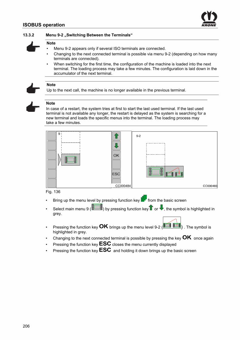
ISOBUS operation
206
Pos: 96.20 /BA/Info-Center/CCI-ISOBUS-Terminal/Menü 9 ISO-Einstellungen/Menü 9-2 Terminalwechsel @ 119\mod_1342087866195_78.docx @ 1070148 @ 3 @ 1
13.3.2 Menu 9-2 „Switching Between the Terminals“
Note • Menu 9-2 appears only if several ISO terminals are connected. • Changing to the next connected terminal is possible via menu 9-2 (depending on how many
terminals are connected). • When switching for the first time, the configuration of the machine is loaded into the next
terminal. The loading process may take a few minutes. The configuration is laid down in the accumulator of the next terminal.
Note Up to the next call, the machine is no longer available in the previous terminal.
Note In case of a restart, the system tries at first to start the last used terminal. If the last used terminal is not available any longer, the restart is delayed as the system is searching for a new terminal and loads the specific menus into the terminal. The loading process may take a few minutes.
CC000484
9
Fig. 136
• Bring up the menu level by pressing function key from the basic screen
• Select main menu 9 ( ) by pressing function key or , the symbol is highlighted in grey.
• Pressing the function key brings up the menu level 9-2 ( ) . The symbol is highlighted in grey.
• Changing to the next connected terminal is possible by pressing the key once again
• Pressing the function key closes the menu currently displayed
• Pressing the function key and holding it down brings up the basic screen Pos: 96.21 /Layout Module /---------------Seitenumbruch---------------- @ 0\mod_1196175311226_0.docx @ 4165 @ @ 1

ISOBUS operation
207
Pos: 96.22 /Überschriften/Überschriften 1/A-E/ISOBUS „Auxiliary“-Funktion (AUX) @ 48\mod_1286278825265_78.docx @ 460508 @ 2 @ 1
13.4 ISOBUS „Auxiliary“-function (AUX) Pos: 96.23 /BA/Info-Center/Iso-Bedienung/Hinweis Terminal die Auxilliary unterstützen @ 48\mod_1286278420671_78.docx @ 460483 @ @ 1
Note There are terminals which support the additional function “auxiliary” (AUX). With this function, programmable keys of the peripheral equipment (e.g. multi-function levers ...) can be assigned with functions of the connected job computers. A programmable key can also be assigned with several different functions. If key assignments are saved, accordant menus will appear on the screen when switching on the terminal.
Pos: 96.24 /BA/Info-Center/Iso-Bedienung/Je nach Ausstattung folgende Auxiliary zur Verfügung @ 117\mod_1341220429561_78.docx @ 1021464 @ @ 1
Depending on how the machine is fitted, the following functions are available in the Auxiliary menu (AUX):
Pos: 96.25 /BA/Info-Center/Iso-Bedienung/BigPack/Folgende Funktionen stehen im Menü Auxiliary (AUX) zur Verfügung Tabelle @ 116\mod_1340960807451_78.docx @ 1020514 @ @ 1
Auxiliary Functions (Graphic display):
Function:
Lift blade bar
Lower blade bar
Increase baling pressure / baling force
Reduce baling pressure / baling force
Switching between manual/automatic mode
Starting aid start / stop
Lock / release steering axle
Pos: 96.26 /BA/Info-Center/Iso-Bedienung/Hinweis Für weitere Vorgaben bitte die Betriebsanleitung des verwendeten Terminals beachten @ 87\mod_1321000865882_78.docx @ 750002 @ @ 1
Note For further guidelines, please refer to the operating instructions of the terminal being used.
Pos: 96.27 /Layout Module /---------------Seitenumbruch---------------- @ 0\mod_1196175311226_0.docx @ 4165 @ @ 1

ISOBUS operation
208
Pos: 96.28 /Überschriften/Überschriften 3/A-E/BBeispiel einer Joystick-Belegung bei Fendt (Default-Einstellung) @ 117\mod_1341214720469_78.docx @ 1021106 @ 3 @ 1
13.4.1 Example of a joystick assignment for Fendt (default setting) Pos: 96.29 /BA/Info-Center/Iso-Bedienung/Achtung - weiter Vorgehensweise Betriebsanleitung @ 117\mod_1341215429970_78.docx @ 1021135 @ @ 1
CAUTION! For the remainder of the procedure, refer to the operating instructions of the operating terminal manufacturer.
Pos: 96.30 /BA/Info-Center/Iso-Bedienung/BigPack/Joystick-Belegung bei Fendt (Default-Einstellung) Bild BiG PACK @ 117\mod_1341216452057_78.docx @ 1021194 @ @ 1
BPK41019_1
Fig. 137 Pos: 96.31 /Layout Module /---------------Seitenumbruch---------------- @ 0\mod_1196175311226_0.docx @ 4165 @ @ 1

ISOBUS operation
209
Pos: 96.32 /Überschriften/Überschriften 3/A-E/EEmpfohlene Belegung eines WTK- Multifunktionshebels @ 117\mod_1341221253128_78.docx @ 1021492 @ 3 @ 1
13.4.2 Recommended assignment of a WTK- multi-function lever Pos: 96.33 /BA/Info-Center/Iso-Bedienung/Achtung - weiter Vorgehensweise Betriebsanleitung @ 117\mod_1341215429970_78.docx @ 1021135 @ @ 1
CAUTION! For the remainder of the procedure, refer to the operating instructions of the operating terminal manufacturer.
Pos: 96.34 /BA/Info-Center/Iso-Bedienung/BigPack/Joystick-Belegung WTK Bild BiG PACK @ 117\mod_1341221992568_78.docx @ 1021611 @ @ 1
1
2
BPK41020
Fig. 138 Pos: 97 /Layout Module /---------------Seitenumbruch---------------- @ 0\mod_1196175311226_0.docx @ 4165 @ @ 1

ISOBUS operation
210
Pos: 98 /Layout Module /Diese Seite ist bewusst freigelassen worden. @ 1\mod_1201783680373_78.docx @ 54443 @ @ 1
This page has been left blank deliberately!! Pos: 99 /Layout Module /---------------Seitenumbruch---------------- @ 0\mod_1196175311226_0.docx @ 4165 @ @ 1

Operation
211
Pos: 100.1 /Überschriften/Überschriften 1/A-E/Bedienung @ 0\mod_1199789505403_78.docx @ 34825 @ 1 @ 1
14 Operation Pos: 100.2 /BA/Sicherheit/2. Vorangestellte Warnhinweise/WARNUNG - Nichtbeachtung der grundlegenden Sicherheitshinweise alte Form @ 254\mod_1397485793575_78.docx @ 1953347 @ @ 1
WARNING! If the basic safety instructions are not followed, people may be seriously injured or killed. • To avoid accidents, the basic safety instructions in the chapter Safety must have been
read and followed, see chapter Safety "Basic safety instructions".
Pos: 100.3 /BA/Sicherheit/2. Vorangestellte Warnhinweise/Warnung - Nichtbeachtung der Sicherheitsroutinen alte Form @ 273\mod_1404117435996_78.docx @ 2058712 @ @ 1
WARNING! If the safety routines are not adhered to, people may be seriously injured or killed. • To avoid accidents, the safety routines in the chapter Safety must be read and followed,
see chapter Safety "Safety routines".
Pos: 100.4 /BA/Bedienung /Großpackenpresse/Pressen vorbereiten @ 169\mod_1368617367071_78.docx @ 1459414 @ 2 @ 1
14.1 Preparation for Baling
Before starting baling, check to make certain – the residual bale ejector is in the front position. – the bale brake is locked. – the twine reserves are adequate. – the correct cutting length is set, for the cutting system version. – the working height of the pick-up is set. – the correct bale length is set via the terminal. – the knotter shaft is unlocked as otherwise an endless bale will be pressed. • Lower the bale chute to working position. • Lower the pick-up to working position. • Set the bale length as well as the baling pressure via the terminal.
Pos: 100.5 /Layout Module /---------------Seitenumbruch---------------- @ 0\mod_1196175311226_0.docx @ 4165 @ @ 1

Operation
212
Pos: 100.6 /BA/Bedienung /Großpackenpresse/Mit dem Pressen beginnen / nach dem Pressen @ 166\mod_1367223499536_78.docx @ 1441233 @ @ 1
Starting baling Prerequisite: – The conditions mentioned in “Preparation for Baling” and “Before starting baling, check to
make certain ...” are fulfilled. Baling • Turn on the P.T.O. shaft at minimum speed. • Slowly increase the P.T.O. speed to 1000 min-1. • Wait until the pre-selected bale channel flap pressure is reached in the terminal before
driving up into the swath for the first time. The bale channel must be completely filled in order to bale in automatic mode. This is best accomplished by baling the first two bales in manual mode. • Switch to automatic mode in the terminal after the second bale has been baled. • Adjust the baling force in automatic mode. After baling • Release the bale brake on the bale chute for the bales which have been tied at last,
optional. • Lay down the bales being tied at last on the field. • Clean the machine. • Prepare the machine for road travel.
Pos: 100.7 /Layout Module /---------------Seitenumbruch---------------- @ 0\mod_1196175311226_0.docx @ 4165 @ @ 1

Operation
213
Pos: 100.8 /Überschriften/Überschriften 2/A-E/Bindeeinrichtung @ 20\mod_1239003005331_78.docx @ 225610 @ 2 @ 1
14.2 Tying unit Pos: 100.9 /BA/Einstellungen/Großpackenpresse/Bindegarn einfädeln/Bindegarn einlegen @ 275\mod_1404376981999_78.docx @ 2066534 @ 3 @ 1
14.2.1 Setting the tying twine in place
The process of setting the tying twine in place is identical for the left and right side of the baler. The procedure described below for setting the tying twines in place therefore applies to both side of the baler. The machine must be stopped while the twine is prepared and inserted: • Shut down and safeguard the machine, see chapter Safety -> Safety routines, "Shutting
down and safeguarding the machine". • Secure the knotter shaft by moving the safety lever (1).
Pos: 100.10 /BA/Einstellungen/Großpackenpresse/Bindegarn einfädeln/Knoterwelle sichern HS Baureihe @ 71\mod_1305873545803_78.docx @ 641641 @ @ 1
Secure knotter shaft
12 2
a
b
BPHS0059
b
a 1Fig. 139 Each time before you set new tying twine in place, the knotter shaft must be secured so that the needle yoke cannot be put in motion. To do this: • To do this, move the safety lever (1) from position (a) to position (b) and set it down on the
journal (2)
Pos: 100.11 /BA/Einstellungen/Großpackenpresse/Bindegarn einfädeln/Hinweis Abstellen des Bindegarns in die Garnkästen @ 20\mod_1239008751331_78.docx @ 226534 @ @ 1
Note When placing the tying twine in the twine box, make certain that the labeling on the rolls can be read. Make certain the side marked "Up" is facing up.
Pos: 100.12 /BA/Einstellungen/Großpackenpresse/Bindegarn einfädeln/Hinweis Endlosballen gepresst @ 92\mod_1326728080272_78.docx @ 781560 @ @ 1
Note The safety lever (2) must be in position (a) for the baling process! Otherwise an endless bale will be formed when the knotter shaft is secured.
Pos: 100.13 /Layout Module /---------------Seitenumbruch---------------- @ 0\mod_1196175311226_0.docx @ 4165 @ @ 1

Operation
214
Pos: 100.14.1 /Überschriften/linke Maschinenseite @ 60\mod_1297934981687_78.docx @ 562715 @ @ 1
Left-hand Side of the Machine Pos: 100.14.2 /BA/Einstellungen/Großpackenpresse/Bindegarn einfädeln/Bindeeinrichtung 6 Doppelknoter/Bindegarn verbinden allgemeine Beschreibung 6 Doppelknoter @ 175\mod_1372829465941_78.docx @ 1504555 @ @ 1
Connecting twine
Each of the front six twine rolls (1) provides three upper twines. Each of the rear nine twine rolls (2) provides three lower twines. During the baling process, each knotter is fed with an upper twine and a lower twine.
Pos: 100.14.3 /BA/Einstellungen/Großpackenpresse/Bindegarn einfädeln/Bindeeinrichtung 6 Doppelknoter/Bidegarn verbinden im Garnkasten6 Doppelknoter Bild 16 Rollen 3 Ober-/ Unterfäden @ 208\mod_1386927926341_78.docx @ 1720302 @ @ 1
3a 2a 1a
3b 2b 1b 3b 3c 2c
3a 2a 2b
2c
2a 2b
1c
1a 1b
Fig. 140
1) Twine rolls for upper twine 2) Twine rolls for lower twine
Pos: 100.14.4 /BA/Einstellungen/Großpackenpresse/Bindegarn einfädeln/Bindeeinrichtung 6 Doppelknoter/Oberfaden verbinden (3 Oberfäden) @ 175\mod_1372837354779_78.docx @ 1504914 @ @ 1
Connecting upper twine (1) Make certain the upper twines never cross.
Pos: 100.14.5 /BA/Einstellungen/Großpackenpresse/Bindegarn einfädeln/Garnrollen Oberfaden verbinden 1a mit 1b (2 Oberfäden) und (3 Oberfäden) @ 175\mod_1372837795593_78.docx @ 1504943 @ @ 1
Connecting twine roll 1a with twine roll 1b 1 Guide the beginning of the twine roll (1a) over the upper eye through the twine brake out of
the twine box. 2 Connect the beginning of the twine of twine roll (1b) by a reef knot with the end of the twine
of twine roll (1a). 3 Shorten the end of the reef knot to x = 15 - 20 mm.
Pos: 100.14.6 /BA/Einstellungen/Großpackenpresse/Bindegarn einfädeln/Garnrollen Oberfaden verbinden 2a mit 2b (2 Oberfäden) und (3 Oberfäden) @ 175\mod_1372837797032_78.docx @ 1504972 @ @ 1
Connecting twine roll 2a with twine roll 2b 1 Guide the beginning of the twine of twine roll (2a) over the upper eye through the twine
brake out of the twine box. 2 Connect the beginning of the twine roll (2b) by a reef knot with the end of the twine of twine
roll (2a). 3 Shorten the end of the reef knot to x = 15 - 20 mm.
Pos: 100.14.7 /BA/Einstellungen/Großpackenpresse/Bindegarn einfädeln/Bindeeinrichtung 6 Doppelknoter/Garnrollen Oberfaden verbinden 3a mit 3b (3Oberfäden) @ 176\mod_1372837798440_78.docx @ 1505001 @ @ 1
Connecting twine roll 3a with twine roll 3b 1 Guide the beginning of the twine of twine roll (3a) over the upper eye through the twine
brake out of the twine box. 2 The beginning of the twine of twine roll (3b) must be connected with the end of the twine of
the twine roll (3a) by a reef knot. 3 Shorten the ends of the reef knot to x = 15 - 20 mm.
Pos: 100.14.8 /Layout Module /---------------Seitenumbruch---------------- @ 0\mod_1196175311226_0.docx @ 4165 @ @ 1

Operation
215
Pos: 100.14.9 /BA/Einstellungen/Großpackenpresse/Bindegarn einfädeln/Unterfaden verbinden (2) @ 154\mod_1363266953393_78.docx @ 1367551 @ @ 1
Connecting lower twine (2)
Pos: 100.14.10 /BA/Einstellungen/Großpackenpresse/Bindegarn einfädeln/Bindeeinrichtung 6 Doppelknoter/Bidegarn verbinden im Garnkasten6 Doppelknoter Bild 16 Rollen 3 Ober-/ Unterfäden @ 208\mod_1386927926341_78.docx @ 1720302 @ @ 1
3a 2a 1a
3b 2b 1b 3b 3c 2c
3a 2a 2b
2c
2a 2b
1c
1a 1b
Fig. 141
1) Twine rolls for upper twine 2) Twine rolls for lower twine
Pos: 100.14.11 /BA/Einstellungen/Großpackenpresse/Bindegarn einfädeln/Bindeeinrichtung 6 Doppelknoter/Garnrollen Unterfaden verbinden 1a, 1b und 1c (3 Unterfäden) @ 208\mod_1386930452886_78.docx @ 1720450 @ @ 1
Connecting twine rolls 1a, 1b, and 1c with each other 1 Guide the beginning of the twine of twine roll (1a) over the blue eye above and further to the
front to the next blue eye. From the blue eye, guide the twine further through the twine brake out of the twine box.
2 Guide the beginning of the twine of twine roll (1b) through the blue eye above and connect it with the end of the twine on twine roll (1a) by a reef knot.
3 Connect the beginning of the twine of twine roll (1c) with the end of the twine of twine roll (1b) by a reef knot.
4 Shorten the ends of all reef knots to x = 15 - 20 mm.
Pos: 100.14.12 /BA/Einstellungen/Großpackenpresse/Bindegarn einfädeln/Bindeeinrichtung 6 Doppelknoter/Garnrollen Unterfaden verbinden 2a, 2b und 2c (3 Unterfäden) @ 176\mod_1372838380071_78.docx @ 1505289 @ @ 1
Connecting twine rolls 2a, 2b, 3c and 2c with each other 1 Guide the beginning of the twine of twine roll (2a) over the green eye above through the
twine brake out of the twine box. 2 Guide the beginning of the twine of twine roll (2b) through the green eye above and connect
it with the end of the twine of twine roll (2a) by a reef knot. 3 Connect the beginning of the twine of twine roll (2c) with the end of the twine of twine roll
(2b) by a reef knot. 4 Shorten the ends of all reef knots to x = 15 - 20 mm.
Pos: 100.14.13 /Layout Module /---------------Seitenumbruch---------------- @ 0\mod_1196175311226_0.docx @ 4165 @ @ 1

Operation
216
Pos: 100.14.14 /BA/Einstellungen/Großpackenpresse/Bindegarn einfädeln/Bindeeinrichtung 6 Doppelknoter/Garnrollen Unterfaden verbinden 3a, 3b und 3c (3 Unterfäden) @ 208\mod_1386931126571_78.docx @ 1720479 @ @ 1
Connecting twine rolls 3a, 3b, and 3c with each other 1 Guide the beginning of the twine of twine roll (3a) over the red eye above through the twine
brake out of the twine box. 2 Connect the beginning of the twine of twine roll (3b) with the end of the twine of twine roll
(3a) by a reef knot. 3 Guide the beginning of the twine of twine roll (3c) through the red eye above further to the
front to the next red eye and connect it with the end of the twine on twine roll (3b) by a reef knot.
4 Shorten the ends of all reef knots to x = 15 - 20 mm.
Pos: 100.14.15 /BA/Einstellungen/Großpackenpresse/Bindegarn einfädeln/Hinweis Reverserollen (R) @ 20\mod_1239010206160_78.docx @ 227020 @ @ 1
Note The twine rolls (R) are auxiliary rolls. They must not be connected with other rolls.
Pos: 100.14.16 /Layout Module /---------------Seitenumbruch---------------- @ 0\mod_1196175311226_0.docx @ 4165 @ @ 1

Operation
217
Pos: 100.14.17 /Überschriften/Überschriften 3/U-Z/Unterfaden einfädeln @ 154\mod_1363274391674_78.docx @ 1369094 @ 3 @ 1
14.2.2 Threading in the Lower Twine Pos: 100.14.18 /BA/Einstellungen/Großpackenpresse/Bindegarn einfädeln/Unterfaden vom Garkasten zur unteren Garnführung weiterführen. @ 154\mod_1363274502562_78.docx @ 1369122 @ @ 1
Then guide the lower twine from the twine box to the lower twine guide. Pos: 100.14.19 /BA/Einstellungen/Großpackenpresse/Bindegarn einfädeln/Bindeeinrichtung 6 Doppelknoter/Unterfaden einfädeln Bild 1 BiG PACK 1270 HS/1290 HS/ 1290 HDP HS @ 176\mod_1372839792475_78.docx @ 1505347 @ @ 1
BPHS0251
86
3 2 11 2 3
2 13
887
Fig. 142 Pos: 100.14.20 /BA/Einstellungen/Großpackenpresse/Bindegarn einfädeln/Bindeeinrichtung 6 Doppelknoter/Unterfaden einfädeln T1 3 Unterfäden @ 176\mod_1372839947094_78.docx @ 1505556 @ @ 1
Make certain the lower twines never cross. • Then guide the three lower twines (1, 2, 3) coming from the twine box (6) to the twine guide
top (7). • Guide the three lower twines from the top through the eyes of the twine guide top and
further to the twine guide frame (8). • Guide the three lower twines from the outside through the eyes of the twine guide frame
and then guide them to the lower twine brake.
Pos: 100.14.21 /BA/Einstellungen/Großpackenpresse/Bindegarn einfädeln/Unterfaden von der unteren Garnführung zu den Nadeln weiterführen @ 154\mod_1363274809338_78.docx @ 1369226 @ @ 1
Then guide the lower twine from the lower twine guide to the needles. Pos: 100.14.22 /BA/Einstellungen/Großpackenpresse/Bindegarn einfädeln/Bindeeinrichtung 5 Doppelknoter 870 HDP/Unterfaden einfädeln Bild 2 870 HDP rechte Seite @ 270\mod_1402493562573_78.docx @ 2040152 @ @ 1
BPHS0277
1 2 3 4 5
8
7
10
9
12
13
11
Fig. 143 Pos: 100.14.23 /BA/Einstellungen/Großpackenpresse/Bindegarn einfädeln/Bindeeinrichtung 6 Doppelknoter/Unterfaden einfädeln T2 4x4 @ 176\mod_1372840132369_78.docx @ 1505614 @ @ 1
• Guide the lower twine coming from the twine guide frame through the lower eye (7) of the twine brake (8) through the twine brake and then to the upper eye (9) of the twine brake.
• Guide the lower twine further through the eye of the twine tension springs (10). • Pull the lower twine upwards and guide it between the rollers (11) of the needle (12). • Pull the lower twine down to the frame (13) and knot it on the frame.
Pos: 100.14.24 /Layout Module /---------------Seitenumbruch---------------- @ 0\mod_1196175311226_0.docx @ 4165 @ @ 1

Operation
218
Pos: 100.14.25 /Überschriften/Überschriften 3/K-O/Oberfaden einfädeln @ 154\mod_1363276173731_78.docx @ 1369401 @ 3 @ 1
14.2.3 Threading in the Upper Twine Pos: 100.14.26 /BA/Einstellungen/Großpackenpresse/Bindegarn einfädeln/Oberfaden vom Garkasten zur oberen Garnführung weiterführen @ 154\mod_1363276378790_78.docx @ 1369487 @ @ 1
Then guide the upper twine from the twine box to the upper twine guide.
Pos: 100.14.27 /BA/Einstellungen/Großpackenpresse/Bindegarn einfädeln/Bindeeinrichtung 5 Doppelknoter 870 HDP/Oberfaden einfädeln Bild 1 (2Oberfäden 1,2,3) linke @ 270\mod_1402565548076_78.docx @ 2041003 @ @ 1
BPHS02791 2 3
3
123
7
5
1
2
8
9
Fig. 144 Pos: 100.14.28 /BA/Einstellungen/Großpackenpresse/Bindegarn einfädeln/Bindeeinrichtung 6 Doppelknoter/Oberfaden einfädeln T1 (3Oberfäden) @ 176\mod_1372849283300_78.docx @ 1506321 @ @ 1
Make certain the upper twines never cross. • Guide the three upper twines (1, 2, 3) coming from the twine box (5) to the upper twine
guide (7). • Guide the three upper twines through the eyes of the upper twine guide and guide them
further to the twine brakes on the knotters.
Pos: 100.14.29 /BA/Einstellungen/Großpackenpresse/Bindegarn einfädeln/Oberfaden von der oberen Garnführung zu den Obernadeln weiterführen @ 155\mod_1363328978763_78.docx @ 1369805 @ @ 1
Guide the upper twine from the upper twine guide to the upper needles
Pos: 100.14.30 /BA/Einstellungen/Großpackenpresse/Bindegarn einfädeln/Bindeeinrichtung 6 Doppelknoter/Oberfaden einfädeln T2 (3 Oberfäden) @ 176\mod_1372849526153_78.docx @ 1506350 @ @ 1
• Guide the four upper twines coming from the upper twine guide (7) through the rear eyes (8) and then through the twine brake (9).
Pos: 100.14.31 /Layout Module /---------------Seitenumbruch---------------- @ 0\mod_1196175311226_0.docx @ 4165 @ @ 1

Operation
219
Pos: 100.14.32 /BA/Einstellungen/Großpackenpresse/Bindegarn einfädeln/Oberfaden einfädeln Bild 3 @ 155\mod_1363329246968_78.docx @ 1369890 @ @ 1
9
10 13
12
BPHS0127
11
Fig. 145 Pos: 100.14.33 /BA/Einstellungen/Großpackenpresse/Bindegarn einfädeln/Oberfaden einfädeln T3 @ 155\mod_1363329332881_78.docx @ 1369919 @ @ 1
• Guide the upper twine from the twine brake (9) through the eye (10) of the tensioning arm (11).
• Pull the upper twine towards the bottom and guide it between the rollers (12) of the upper needle (13).
Pos: 100.14.34 /BA/Einstellungen/Großpackenpresse/Bindegarn einfädeln/Oberfaden einfädeln T3 Ist der Presskanal leer @ 164\mod_1366274056012_78.docx @ 1429143 @ @ 1
If the bale channel is empty • Knot the upper twine with the lower twine in the middle of the bale chamber. Or • Guide the upper twine under the crossbeam of the knotting mechanism and knot it on the
crossbeam of the upper bale channel flap. • To tension the tensioning arm (11), pull back the upper twine in front of the twine eye (8).
Pos: 100.14.35 /BA/Einstellungen/Großpackenpresse/Bindegarn einfädeln/Oberfaden einfädeln T3 Ist der Presskanal gefüllt @ 164\mod_1366273990684_78.docx @ 1429114 @ @ 1
If the bale channel is filled • Read the actual bale length on the terminal. If the difference between actual bale length and target bale length is > 50 cm • Let the loose twine end of the upper twine hang down approx. 50cm in the bale channel. The tensioning arm (11) is tensioned when the twine is caught in the crop at subsequent baling. If the difference between actual bale length and target bale length is < 50 cm • Guide the upper twine under the crossbeam of the knotting mechanism and knot it on the
crossbeam of the upper bale channel flap. • To tension the tensioning arm (11), pull back the upper twine in front of the twine eye (8).
Pos: 100.15 /Layout Module /---------------Seitenumbruch---------------- @ 0\mod_1196175311226_0.docx @ 4165 @ @ 1

Operation
220
Pos: 100.16.1 /Überschriften/rechte Maschinenseite @ 60\mod_1297935179130_78.docx @ 562741 @ @ 1
Right-hand Side of the Machine Pos: 100.16.2 /BA/Einstellungen/Großpackenpresse/Bindegarn einfädeln/Bindeeinrichtung 4 Doppelknoter 890 HS/Bindegarn verbinden allgemeine Beschreibung 4 Doppelknoter @ 191\mod_1381844742544_78.docx @ 1632370 @ @ 1
Connecting twine
Each of the front four twine rolls (1) provides two upper twines. Each of the rear eight twine rolls (2) provides two lower twines. During the baling process, each knotter is fed with an upper twine and a lower twine.
Pos: 100.16.3 /BA/Einstellungen/Großpackenpresse/Bindegarn einfädeln/Bindeeinrichtung 5 Doppelknoter 870 HDP/Bidegarn verbinden im Garnkasten 5 Doppelknoter Bild 16 Rollen 2 Ober-/ Unterfäden rechte Seite @ 270\mod_1402489906275_78.docx @ 2039830 @ @ 1
4a5a4c
4b5b4d4b5b5d
4a5a5c
Fig. 146
1) Twine rolls for upper twine 2) Twine rolls for lower twine
Pos: 100.16.4 /BA/Einstellungen/Großpackenpresse/Bindegarn einfädeln/Bindeeinrichtung 4 Doppelknoter 890 HS/Oberfaden verbinden (2 Oberfäden) @ 191\mod_1381844889417_78.docx @ 1632399 @ @ 1
Connecting upper twine (1) Make certain the both upper twines never cross.
Pos: 100.16.5 /BA/Einstellungen/Großpackenpresse/Bindegarn einfädeln/Bindeeinrichtung 5 Doppelknoter 870 HDP/Garnrollen Oberfaden verbinden 4a mit 4b (2 Oberfäden) rechte Seite @ 270\mod_1402490736645_78.docx @ 2039889 @ @ 1
Connecting twine roll 4a to twine roll 4b 1 Thread the start of the twine from twine roll (4a) through the upper eye through the twine
brake and out of the twine boxes. 2 Tie the start of the twine from the twine roll (4b) in a reef knot to the end of the twine from
the twine roll (4a). 3 Shorten the ends of the reef knot to x = 15 - 20 mm.
Pos: 100.16.6 /BA/Einstellungen/Großpackenpresse/Bindegarn einfädeln/Bindeeinrichtung 5 Doppelknoter 870 HDP/Garnrollen Oberfaden verbinden 5a mit 5b (2 Oberfäden) rechte Seite @ 270\mod_1402491106613_78.docx @ 2039918 @ @ 1
Connecting twine roll 5a to twine roll 5b 1 Thread the start of the twine from twine roll (5a) through the upper eye through the twine
brake and out of the twine boxes. 2 Tie the start of the twine from the twine roll (5b) in a reef knot to the end of the twine from
the twine roll (5a). 3 Shorten the ends of the reef knot to x = 15 - 20 mm.
Pos: 100.16.7 /Layout Module /---------------Seitenumbruch---------------- @ 0\mod_1196175311226_0.docx @ 4165 @ @ 1

Operation
221
Pos: 100.16.8 /BA/Einstellungen/Großpackenpresse/Bindegarn einfädeln/Unterfaden verbinden (2) @ 154\mod_1363266953393_78.docx @ 1367551 @ @ 1
Connecting lower twine (2)
Pos: 100.16.9 /BA/Einstellungen/Großpackenpresse/Bindegarn einfädeln/Bindeeinrichtung 5 Doppelknoter 870 HDP/Bidegarn verbinden im Garnkasten 5 Doppelknoter Bild 16 Rollen 2 Ober-/ Unterfäden rechte Seite @ 270\mod_1402489906275_78.docx @ 2039830 @ @ 1
4a5a4c
4b5b4d4b5b5d
4a5a5c
Fig. 147
1) Twine rolls for upper twine 2) Twine rolls for lower twine
Pos: 100.16.10 /BA/Einstellungen/Großpackenpresse/Bindegarn einfädeln/Bindeeinrichtung 5 Doppelknoter 870 HDP/Garnrollen Unterfaden verbinden 4a, 4b, 4c und 4d (2Unterfäden) rechte Seite @ 270\mod_1402491217642_78.docx @ 2039947 @ @ 1
Connecting twine rolls 4a, 4b, 4c and 4d to each other
1 Thread the start of the twine from twine roll (4a) out of the twine box through the green eye above and through the twine brake.
2 Tie the start of the twine from the twine roll (4b) in a reef knot to the end of the twine from the twine roll (4a).
3 Thread the start of the twine from the twine roll (4c) through the green eye above and tie it in a reef knot to the end of the twine from the twine roll (4b).
4 Tie the start of the twine from the twine roll (4d) in a reef knot to the end of the twine from the twine roll (4c).
5 Shorten the ends of all reef knots to x = 15 - 10 mm.
Pos: 100.16.11 /BA/Einstellungen/Großpackenpresse/Bindegarn einfädeln/Bindeeinrichtung 5 Doppelknoter 870 HDP/Garnrollen Unterfaden verbinden 5a, 5b, 5c und 5d (2Unterfäden) rechte Seite @ 270\mod_1402491358807_78.docx @ 2039976 @ @ 1
Connecting twine rolls 5a, 5b, 5c and 5d to each other
1 Thread the start of the twine from twine roll (5a) out of the twine box through the green eye above and through the twine brake.
2 Tie the start of the twine from the twine roll (5b) in a reef knot to the end of the twine from the twine roll (5a).
3 Thread the start of the twine from the twine roll (5c) through the red eye above and tie it in a reef knot to the end of the twine from the twine roll (5b).
4 Tie the start of the twine from the twine roll (5d) in a reef knot to the end of the twine from the twine roll (5c).
5 Shorten the ends of all reef knots to x = 15 - 20 mm.
Pos: 100.16.12 /BA/Einstellungen/Großpackenpresse/Bindegarn einfädeln/Hinweis Reverserollen (R) @ 20\mod_1239010206160_78.docx @ 227020 @ @ 1
Note The twine rolls (R) are auxiliary rolls. They must not be connected with other rolls.
Pos: 100.16.13 /Layout Module /---------------Seitenumbruch---------------- @ 0\mod_1196175311226_0.docx @ 4165 @ @ 1
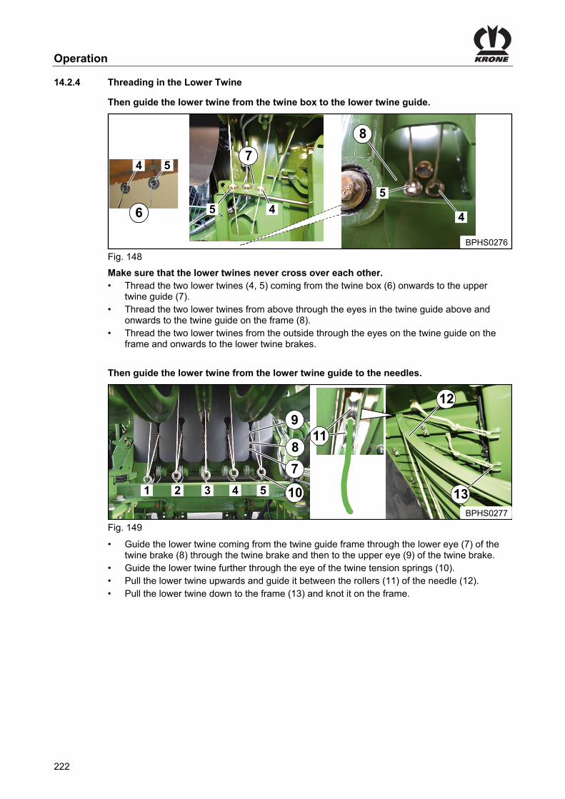
Operation
222
Pos: 100.16.14 /Überschriften/Überschriften 3/U-Z/Unterfaden einfädeln @ 154\mod_1363274391674_78.docx @ 1369094 @ 3 @ 1
14.2.4 Threading in the Lower Twine Pos: 100.16.15 /BA/Einstellungen/Großpackenpresse/Bindegarn einfädeln/Unterfaden vom Garkasten zur unteren Garnführung weiterführen. @ 154\mod_1363274502562_78.docx @ 1369122 @ @ 1
Then guide the lower twine from the twine box to the lower twine guide. Pos: 100.16.16 /BA/Einstellungen/Großpackenpresse/Bindegarn einfädeln/Bindeeinrichtung 5 Doppelknoter 870 HDP/Unterfaden einfädeln Bild 1 870 HDP rechte Seite @ 270\mod_1402491826816_78.docx @ 2040034 @ @ 1
86
4 5
BPHS0276
5 4
87
88
5
4
Fig. 148 Pos: 100.16.17 /BA/Einstellungen/Großpackenpresse/Bindegarn einfädeln/Bindeeinrichtung 5 Doppelknoter 870 HDP/Unterfaden (4,5) einfädeln T1 2 Unterfäden rechte Seite @ 270\mod_1402493460339_78.docx @ 2040123 @ @ 1
Make sure that the lower twines never cross over each other. • Thread the two lower twines (4, 5) coming from the twine box (6) onwards to the upper
twine guide (7). • Thread the two lower twines from above through the eyes in the twine guide above and
onwards to the twine guide on the frame (8). • Thread the two lower twines from the outside through the eyes on the twine guide on the
frame and onwards to the lower twine brakes.
Pos: 100.16.18 /BA/Einstellungen/Großpackenpresse/Bindegarn einfädeln/Unterfaden von der unteren Garnführung zu den Nadeln weiterführen @ 154\mod_1363274809338_78.docx @ 1369226 @ @ 1
Then guide the lower twine from the lower twine guide to the needles. Pos: 100.16.19 /BA/Einstellungen/Großpackenpresse/Bindegarn einfädeln/Bindeeinrichtung 5 Doppelknoter 870 HDP/Unterfaden einfädeln Bild 2 870 HDP rechte Seite @ 270\mod_1402493562573_78.docx @ 2040152 @ @ 1
BPHS0277
1 2 3 4 5
8
7
10
9
12
13
11
Fig. 149 Pos: 100.16.20 /BA/Einstellungen/Großpackenpresse/Bindegarn einfädeln/Bindeeinrichtung 6 Doppelknoter/Unterfaden einfädeln T2 4x4 @ 176\mod_1372840132369_78.docx @ 1505614 @ @ 1
• Guide the lower twine coming from the twine guide frame through the lower eye (7) of the twine brake (8) through the twine brake and then to the upper eye (9) of the twine brake.
• Guide the lower twine further through the eye of the twine tension springs (10). • Pull the lower twine upwards and guide it between the rollers (11) of the needle (12). • Pull the lower twine down to the frame (13) and knot it on the frame.
Pos: 100.16.21 /Layout Module /---------------Seitenumbruch---------------- @ 0\mod_1196175311226_0.docx @ 4165 @ @ 1

Operation
223
Pos: 100.16.22 /Überschriften/Überschriften 3/K-O/Oberfaden einfädeln @ 154\mod_1363276173731_78.docx @ 1369401 @ 3 @ 1
14.2.5 Threading in the Upper Twine Pos: 100.16.23 /BA/Einstellungen/Großpackenpresse/Bindegarn einfädeln/Oberfaden vom Garkasten zur oberen Garnführung weiterführen @ 154\mod_1363276378790_78.docx @ 1369487 @ @ 1
Then guide the upper twine from the twine box to the upper twine guide.
Pos: 100.16.24 /BA/Einstellungen/Großpackenpresse/Bindegarn einfädeln/Bindeeinrichtung 5 Doppelknoter 870 HDP/Oberfaden einfädeln Bild 1 (2Oberfäden 4,5) rechte Seite @ 270\mod_1402564451388_78.docx @ 2040735 @ @ 1
BPHS02784 5
45
7
5
4
5
8
9
Fig. 150 Pos: 100.16.25 /BA/Einstellungen/Großpackenpresse/Bindegarn einfädeln/Bindeeinrichtung 5 Doppelknoter 870 HDP/Oberfaden einfädeln T1 (2Oberfäden 4,5) rechte Seite @ 270\mod_1402564516124_78.docx @ 2040764 @ @ 1
Make sure that the upper twines never cross over each other. • Thread the two upper twines (4, 5) coming from the twine box (5) onwards to the upper
twine guide (7). • Thread the two upper twines through the eyes on the upper twine guide and onwards to the
twine brakes at the knotters.
Pos: 100.16.26 /BA/Einstellungen/Großpackenpresse/Bindegarn einfädeln/Oberfaden von der oberen Garnführung zu den Obernadeln weiterführen @ 155\mod_1363328978763_78.docx @ 1369805 @ @ 1
Guide the upper twine from the upper twine guide to the upper needles
Pos: 100.16.27 /BA/Einstellungen/Großpackenpresse/Bindegarn einfädeln/Bindeeinrichtung 4 Doppelknoter 890 HS/Oberfaden einfädeln T2 (2Oberfäden) @ 191\mod_1381848276432_78.docx @ 1632624 @ @ 1
• Guide the both upper twines coming from the upper twine guide (7) through the rear eyes (8) and through the twine brake (9).
Pos: 100.16.28 /Layout Module /---------------Seitenumbruch---------------- @ 0\mod_1196175311226_0.docx @ 4165 @ @ 1

Operation
224
Pos: 100.16.29 /BA/Einstellungen/Großpackenpresse/Bindegarn einfädeln/Oberfaden einfädeln Bild 3 @ 155\mod_1363329246968_78.docx @ 1369890 @ @ 1
9
10 13
12
BPHS0127
11
Fig. 151 Pos: 100.16.30 /BA/Einstellungen/Großpackenpresse/Bindegarn einfädeln/Oberfaden einfädeln T3 @ 155\mod_1363329332881_78.docx @ 1369919 @ @ 1
• Guide the upper twine from the twine brake (9) through the eye (10) of the tensioning arm (11).
• Pull the upper twine towards the bottom and guide it between the rollers (12) of the upper needle (13).
Pos: 100.16.31 /BA/Einstellungen/Großpackenpresse/Bindegarn einfädeln/Oberfaden einfädeln T3 Ist der Presskanal leer @ 164\mod_1366274056012_78.docx @ 1429143 @ @ 1
If the bale channel is empty • Knot the upper twine with the lower twine in the middle of the bale chamber. Or • Guide the upper twine under the crossbeam of the knotting mechanism and knot it on the
crossbeam of the upper bale channel flap. • To tension the tensioning arm (11), pull back the upper twine in front of the twine eye (8).
Pos: 100.16.32 /BA/Einstellungen/Großpackenpresse/Bindegarn einfädeln/Oberfaden einfädeln T3 Ist der Presskanal gefüllt @ 164\mod_1366273990684_78.docx @ 1429114 @ @ 1
If the bale channel is filled • Read the actual bale length on the terminal. If the difference between actual bale length and target bale length is > 50 cm • Let the loose twine end of the upper twine hang down approx. 50cm in the bale channel. The tensioning arm (11) is tensioned when the twine is caught in the crop at subsequent baling. If the difference between actual bale length and target bale length is < 50 cm • Guide the upper twine under the crossbeam of the knotting mechanism and knot it on the
crossbeam of the upper bale channel flap. • To tension the tensioning arm (11), pull back the upper twine in front of the twine eye (8).
Pos: 100.17 /Layout Module /---------------Seitenumbruch---------------- @ 0\mod_1196175311226_0.docx @ 4165 @ @ 1

Operation
225
Pos: 100.18 /Überschriften/Überschriften 2/P-T/Pick up @ 1\mod_1201791975201_0.docx @ 54586 @ 2 @ 1
14.3 Pick-up Pos: 100.19 /BA/Erstinbetriebnahme/Großpackenpressen/Absperrhahn Pick-up Bild mit Legende @ 155\mod_1363682181297_78.docx @ 1373728 @ @ 1
Fig. 152
Position (a) pick-up released Position (b) pick-up locked
Pos: 100.20 /BA/Sicherheit/8. Voraussetzungen/Handlungsanweisung für alle Maschinen/Handlungsanweisung: Maschine stillsetzen und sichern @ 274\mod_1404365253849_78.docx @ 2065151 @ @ 1
• Shut down and safeguard the machine, see chapter Safety -> Safety routines, "Shutting down and safeguarding the machine".
Pos: 100.21 /BA/Bedienung /Großpackenpresse/Pick-up/Bedienung Pick-up heben / senken @ 152\mod_1362669449546_78.docx @ 1356754 @ @ 1
• Reverse the shut-off valve (1) from position “b” to position “a” to release the pick-up. • Reverse the shut-off valve (1) from position “a” to position “b” to lock the pick-up. Lowering the pick-up • Move the single-acting control unit (red 2) to float position to move the pick-up to working
position. Lifting the pick-up • Activate the single-acting control unit (red 2) to move the pick-up to transport position.
Pos: 100.22 /BA/Einstellungen/Pick-up / Rollenniederhalter/Hinweis Fahren im Vorgewende @ 20\mod_1238578490213_78.docx @ 221874 @ @ 1
Note Lift the Pick-up for driving in the headland or when driving backward!
Pos: 100.23 /Layout Module /---------------Seitenumbruch---------------- @ 0\mod_1196175311226_0.docx @ 4165 @ @ 1

Operation
226
Pos: 100.24.1 /Überschriften/Überschriften 2/A-E/Ballenschurre heben / senken @ 280\mod_1405498834845_78.docx @ 2154218 @ 2 @ 1
14.4 Lifting / Lowering Bale Chute Pos: 100.24.2 /BA/Sicherheit/2. Vorangestellte Warnhinweise/Warnung - Verletzungsgefahr, wenn bei laufendem Traktormotor Funktionen direkt an der Maschine ausge @ 274\mod_1404304877568_78.docx @ 2064063 @ @ 1
WARNING! There is an increased risk of injury if functions are performed directly at the machine while the tractor engine is running. If functions are performed directly at the machine while the tractor engine is running, people standing in the danger zone can be crushed or killed. • Only operate the machine while the tractor engine is running if
– The PTO shaft is switched off and coasting machine parts have come to a standstill. – The tractor is secured to prevent it rolling away. – The parking brake and the flywheel brake on the machine are applied. – The person operating the machine knows which functions are executed by the various
operations. – The person operating the machine is standing outside the radius of action of the
moving parts of the machine. – No other persons are standing in the danger zone.
Pos: 100.24.3 /BA/Bedienung /Großpackenpresse/Hydraulisch klappbare Rollenschurre/Bedienung Rollenschurre heben / senken Einführtext @ 280\mod_1405500298873_78.docx @ 2154305 @ @ 1
The operation of the bale chute (1) depends on the version you have (medium version electronics or comfort version electronics).
Pos: 100.24.4 /BA/Bedienung /Großpackenpresse/Hydraulisch klappbare Rollenschurre/Bedienung Rollenschurre heben / senken Medium-Elektronik @ 152\mod_1362730919078_78.docx @ 1357301 @ @ 1
Medium Design
Fig. 153 Position a = fold up bale chute Position b = fold down bale chute The shut-off valve (3) must be closed.
• Actuate the control unit (red 4). • Unlock the mechanical locking (1) of the bale chute. • Open the shut-off valve (2). Lowering into working position • Tighten the safety sleeve (4) and move the control lever (5) towards the bottom into position
(b). Lifting into transport position • Tighten the safety sleeve (4) and move the control lever (5) towards the top into position (a)
until the locking closes.
Pos: 100.24.5 /Layout Module /---------------Seitenumbruch---------------- @ 0\mod_1196175311226_0.docx @ 4165 @ @ 1

Operation
227
Pos: 100.24.6 /BA/Bedienung /Großpackenpresse/Hydraulisch klappbare Rollenschurre/Bedienung Rollenschurre heben/senken (bei Ausführung Komfort) Text @ 152\mod_1362670859498_78.docx @ 1356898 @ @ 1
Comfort Design Via the terminal
BPHS0138
Fig. 154 Via the terminal, the bale chute can be lowered merely into working position. • Activate the control unit (red 1). • Unlock the mechanical locking (1) of the bale chute.
• Press „ “ function key to lower the bale chute to working position. To lift the bale chute into transport position, an external button has to be used. Via the external buttons
2
3
Fig. 155 • Activate the control unit (red 1). • Release the mechanical locking (1) of the bale chute. Lowering into working position. • Press button (2) to lower the bale chute into working position. Lifting into transport position. • Press button (3) until the locking closes.
Pos: 100.25 /Layout Module /---------------Seitenumbruch---------------- @ 0\mod_1196175311226_0.docx @ 4165 @ @ 1

Operation
228
Pos: 100.26 /Überschriften/Überschriften 2/A-E/Ballenausschieber bedienen @ 168\mod_1368535471051_78.docx @ 1458201 @ 2 @ 1
14.5 Operating Bale Ejector Pos: 100.27 /BA/Sicherheit/2. Vorangestellte Warnhinweise/Warnung - Verletzungsgefahr, wenn bei laufendem Traktormotor Funktionen direkt an der Maschine ausge @ 274\mod_1404304877568_78.docx @ 2064063 @ @ 1
WARNING! There is an increased risk of injury if functions are performed directly at the machine while the tractor engine is running. If functions are performed directly at the machine while the tractor engine is running, people standing in the danger zone can be crushed or killed. • Only operate the machine while the tractor engine is running if
– The PTO shaft is switched off and coasting machine parts have come to a standstill. – The tractor is secured to prevent it rolling away. – The parking brake and the flywheel brake on the machine are applied. – The person operating the machine knows which functions are executed by the various
operations. – The person operating the machine is standing outside the radius of action of the
moving parts of the machine. – No other persons are standing in the danger zone.
Pos: 100.28 /BA/Bedienung /Großpackenpresse/Ballenausschieber/Ballenausschieber bedienen Medium-Elektronik @ 152\mod_1362731209452_78.docx @ 1357360 @ @ 1
Operating the bale ejector (medium version electronics design)
Fig. 156 Position a = move bale ejector forward Position b = move bale ejector backward
• Activate the control unit (red 4). • Open shut-off valves (2) and (3). Moving bale ejector forward • Tighten safety sleeve (4) and move the control lever (5) upwards into position (a). Moving bale ejector backward • Tighten safety sleeve (4) and move the control lever (5) towards the bottom into position (b).
Pos: 100.29 /BA/Bedienung /Großpackenpresse/Ballenausschieber/Hinweis: Ballenausschieber nach vorne verfahren @ 157\mod_1364368277097_78.docx @ 1386384 @ @ 1
Note After ejection of the bale it is absolutely essential to move the bale ejector to the forward position and to close the shut-off valves (2 and 3).
Pos: 100.30 /Layout Module /---------------Seitenumbruch---------------- @ 0\mod_1196175311226_0.docx @ 4165 @ @ 1

Operation
229
Pos: 100.31 /BA/Bedienung /Großpackenpresse/Ballenausschieber/Ballenausschieber bedienen, bei Ausführung Komfort Text @ 152\mod_1362731210093_78.docx @ 1357385 @ @ 1
Operating the bale ejector via the operation terminal, for comfort version electronics design
BPHS0138 When activating the bale ejector, 10 bales are always ejected via the terminal. • Activate the control unit (red 1). If the bale channel flaps are not released
• Press
AUTO
function key to release the bale channel flaps. If the bale channel flaps are released
• Press
AUTO
function key to eject 10 bales. Repeat the process until every tied bale is out of the bale channel. Push the bale that has been tied at last manually from the bale chute.
Pos: 100.32 /BA/Bedienung /Großpackenpresse/Ballenausschieber/Ballenausschieber bedienen, bei Ausführung Komfort-Elektronik über Taster @ 168\mod_1368535081932_78.docx @ 1458058 @ @ 1
Operate the bale ejector via the external buttons.
1
2
Fig. 157 • Activate the control unit (red 1). The button (1) has several functions. If the bale channel flaps are not loosened • Press button (1) once to release the bale channel flaps. If the bale channel flaps are released • Press button (1) to eject 10 bales. Moving bale ejector backward • Press button (1) and hold it to move the bale ejector backward. Moving bale ejector forward • Press button (2) and hold it to move the bale ejector forward.
Pos: 100.33 /Layout Module /---------------Seitenumbruch---------------- @ 0\mod_1196175311226_0.docx @ 4165 @ @ 1

Operation
230
Pos: 100.34 /Überschriften/Überschriften 2/P-T/Stützfuß @ 175\mod_1372676754261_78.docx @ 1502329 @ 2 @ 1
14.6 Parking Jack Pos: 100.35 /BA/Erstinbetriebnahme/Großpackenpressen/Abstellstütze/Abstellstütze Standfläche vergrößern @ 17\mod_1236319619729_78.docx @ 204459 @ @ 1
Note If the ground is soft, enlarge the footprint of the parking jack by placing a wooden plank underneath.
Pos: 100.36 /BA/Erstinbetriebnahme/Großpackenpressen/Abstellstütze/Abstellstütze Bild BiG PAck @ 17\mod_1236319721776_78.docx @ 204483 @ @ 1
BPXC0109_1
2
4
5
3
1
Fig. 158 Pos: 100.37 /BA/Erstinbetriebnahme/Großpackenpressen/Abstellstütze/Abstellstütze hochdrehen: @ 17\mod_1236318602807_78.docx @ 204411 @ @ 1
To raise the parking support: • As soon as the machine is connected to the tractor, turn the crank (1) several revolutions
clockwise until there is no more weight on the parking jack (3) • Withdraw the locking bolt (5) on the lower part of the parking support (2), push in the
parking support and secure it in position (4) with the bolt • Then crank the parking support up all the way
Pos: 100.38 /BA/Erstinbetriebnahme/Großpackenpressen/Abstellstütze/Abstellstütze runter drehen @ 17\mod_1236319486963_78.docx @ 204435 @ @ 1
To lower the parking support (to support the drawbar): • To disconnect the machine from the tractor, first lower the raised parking support (2) a few
revolutions with the crank (1) • Pull out the bolt (5) and extend the lower part of the parking support. Secure with the bolt
(5) Pos: 100.39 /Layout Module /---------------Seitenumbruch---------------- @ 0\mod_1196175311226_0.docx @ 4165 @ @ 1

Operation
231
Pos: 100.40 /Überschriften/Überschriften 2/F-J/Hydraulischer Stützfuß @ 108\mod_1335163952883_78.docx @ 972995 @ 2 @ 1
14.7 Hydraulic parking jack Pos: 100.41 /BA/Erstinbetriebnahme/Großpackenpressen/Abstellstütze/Abstellstütze Standfläche vergrößern @ 17\mod_1236319619729_78.docx @ 204459 @ @ 1
Note If the ground is soft, enlarge the footprint of the parking jack by placing a wooden plank underneath.
Pos: 100.42 /BA/Maschinenbeschreibung/Maschinenübersicht/Großpackenpressen/Komfort - Elektronik @ 61\mod_1299223046976_78.docx @ 570919 @ @ 1
Comfort - Electronic Pos: 100.43 /BA/Erstinbetriebnahme/Großpackenpressen/Abstellstütze/Hydraulischer Stützfuß Bild @ 282\mod_1406722993466_78.docx @ 2175570 @ @ 1
Fig. 159 Pos: 100.44 /BA/Erstinbetriebnahme/Großpackenpressen/Abstellstütze/Hydraulischer Stützfuß: aus- einfahren über doppelwirkendes Steuergerät (blau2+/blau2-) @ 233\mod_1393935604131_78.docx @ 1858361 @ @ 1
Extending/retracting the support jack: Extend • Activate the double-acting control unit (blue 2+) until the support jack comes firmly to rest on
the ground. Retract • Activate the double-acting control unit (blue 2-) until the support jack is retracted.
Pos: 100.45 /BA/Maschinenbeschreibung/Maschinenübersicht/Großpackenpressen/Medium - Elektronik @ 61\mod_1299223169539_78.docx @ 570971 @ @ 1
Medium Version Electronics Pos: 100.46 /BA/Erstinbetriebnahme/Großpackenpressen/Abstellstütze/Hydraulischer Stützfuß Medium Elektronik Bild HS Baureihe @ 92\mod_1326870734408_78.docx @ 782789 @ @ 1
BPHS0012
2
BPHS0014_1
Fig.160 Pos: 100.47 /BA/Erstinbetriebnahme/Großpackenpressen/Abstellstütze/Hydraulischer Stützfuß ein- ausfahren HS Baureihe Medium-Elektronik Stuergerät Rot P @ 271\mod_1403002578574_78.docx @ 2046451 @ @ 1
Extending/retracting the support jack: • Close the stop cock (1). • To apply pressure to the control block, activate the control unit (red P). Extend • Operate the lever (2) until the support jack comes firmly to rest on the ground. Retract • Operate the lever (2) until the support jack is retracted.
Pos: 100.48 /Layout Module /---------------Seitenumbruch---------------- @ 0\mod_1196175311226_0.docx @ 4165 @ @ 1

Operation
232
Pos: 100.49 /BA/Bedienung /Großpackenpresse/Ballenbremse/Ballenbremse @ 90\mod_1323357448359_78.docx @ 770823 @ 2 @ 1
14.8 Bale brake
Only in connection with bale scale
ba 1
BPHS0068
Fig. 161 The bale brake (1) is used to lock the first two rollers of the roller chute. This is necessary to achieve accurate weight recording of bales. Lever in position a = rollers locked Lever in position b = rollers rotate freely
Note The bale brake must be released for the last bale to ensure it can be set down with no problems.
Pos: 100.50 /Layout Module /---------------Seitenumbruch---------------- @ 0\mod_1196175311226_0.docx @ 4165 @ @ 1
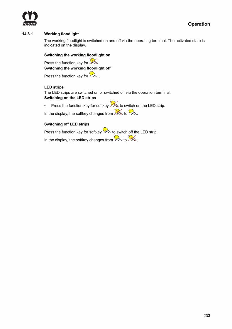
Operation
233
Pos: 100.51 /BA/Inbetriebnahme/Großpackenpresse/Arbeitsscheinwerfer HS Baureihe @ 168\mod_1368521414653_78.docx @ 1457150 @ 3 @ 1
14.8.1 Working floodlight
The working floodlight is switched on and off via the operating terminal. The activated state is indicated on the display. Switching the working floodlight on
Press the function key for . Switching the working floodlight off
Press the function key for .
Pos: 100.52 /BA/Inbetriebnahme/Großpackenpresse/LED-Leisten ein-/ ausschalten @ 192\mod_1382000672852_78.docx @ 1635715 @ @ 1
LED strips The LED strips are switched on or switched off via the operation terminal. Switching on the LED strips
• Press the function key for softkey to switch on the LED strip.
In the display, the softkey changes from to . Switching off LED strips
Press the function key for softkey to switch off the LED strip.
In the display, the softkey changes from to .
Pos: 100.53 /Layout Module /---------------Seitenumbruch---------------- @ 0\mod_1196175311226_0.docx @ 4165 @ @ 1

Operation
234
Pos: 100.54 /BA/Bedienung /Großpackenpresse/Bindevorgang von Hand auslösen @ 170\mod_1369744285660_78.docx @ 1468817 @ 2 @ 1
14.9 Initiating the Tying Process Manually
Fig. 162 It is only necessary to trigger the tying process manually when performing maintenance, adjustment and repair tasks. Prerequisite: – The tractor is disconnected. Initiating the tying process: • Swivel the safety lever (1) down. • Move lever (2) to the rear to initiate the tying process.
Pos: 100.55 /BA/Bedienung /Großpackenpresse/Bindevorgang von Hand beenden @ 170\mod_1369831994895_78.docx @ 1471160 @ 2 @ 1
14.10 Finishing Tying Process Manually
3
a
Fig. 163 Prerequisite: – The tractor is disconnected. – The tying process has been initiated; refer to chapter Operation “Initiating Tying Process
Manually”. A tying process consists of a rotation of the cam track. • Turn the flywheel (3) manually in the working direction (a) until the trigger roller (1) slides in
the recess of the cam disc (2). Knotter gear in idle position The knotter gear is in idle position if the trigger roller (1) is in the recess of the cam track (2) of the knotter gear.
Pos: 100.56 /Layout Module /---------------Seitenumbruch---------------- @ 0\mod_1196175311226_0.docx @ 4165 @ @ 1

Operation
235
Pos: 100.57 /BA/Einstellungen/Schneidwerk/Verstopfungen entfernen Big Pack @ 20\mod_1238654439288_78.docx @ 224033 @ 2 @ 1
14.11 Removing blockages
• Wait until all moving components stop • Apply the flywheel brake • Lower the cutting system with the tractor hydraulics (with the Comfort electronics system:
Activate the tractor hydraulics and hold down “Lower blade bar” on the control unit display or on the machine buttons until the cutting system is lowered all the way down)
CAUTION! - Sharp parts Effect: severe risk of injury Always wear protective gloves when removing blockages.
Note Due to too low ground clearance, the cutting system must immediately be lifted after removal of the blockage, otherwise the cutting system inlet tray will be damaged. Should the cutting system inlet tray be extremely dirty, clean it before lifting.
• Remove blockage • Raise the cutting system with the tractor hydraulics (with the comfort electronics system:
Activate the tractor hydraulics and hold down “Lift blade bar” on the control unit display or on the machine buttons until the cutting system is lifted all the way).
Pos: 100.58 /BA/Einstellungen/Schneidwerk/Bei Ausführung Medium – Elektronik muss der Absperrhahn (1) geschlossen sein Bild @ 92\mod_1326880442080_78.docx @ 782967 @ @ 1
BPHS0014_1
Fig. 164 Pos: 100.59 /BA/Einstellungen/Schneidwerk/Bei Ausführung Medium – Elektronik muss der Absperrhahn (1) geschlossen sein @ 62\mod_1299599111686_78.docx @ 573490 @ @ 1
Note With the Medium electronics version the shut-off valve (1) must be closed so that the cutting system can be lowered or raised via the tractor's hydraulic system. The shut-off valve is to be found on the rear left-hand side of the machine, near the parking brake.
Pos: 101 /Layout Module /---------------Seitenumbruch---------------- @ 0\mod_1196175311226_0.docx @ 4165 @ @ 1

Settings
236
Pos: 102.1 /Überschriften/Überschriften 1/A-E/Einstellungen @ 0\mod_1199868783862_78.docx @ 36141 @ 1 @ 1
15 Settings Pos: 102.2 /BA/Sicherheit/2. Vorangestellte Warnhinweise/WARNUNG - Nichtbeachtung der grundlegenden Sicherheitshinweise alte Form @ 254\mod_1397485793575_78.docx @ 1953347 @ @ 1
WARNING! If the basic safety instructions are not followed, people may be seriously injured or killed. • To avoid accidents, the basic safety instructions in the chapter Safety must have been
read and followed, see chapter Safety "Basic safety instructions".
Pos: 102.3 /BA/Sicherheit/2. Vorangestellte Warnhinweise/Warnung - Nichtbeachtung der Sicherheitsroutinen alte Form @ 273\mod_1404117435996_78.docx @ 2058712 @ @ 1
WARNING! If the safety routines are not adhered to, people may be seriously injured or killed. • To avoid accidents, the safety routines in the chapter Safety must be read and followed,
see chapter Safety "Safety routines".
Pos: 102.4 /BA/Einstellungen/Großpackenpresse/Folgende Arbeitsschritte werden in diesem Kapitel beschrieben BiG PACK 1290 HDP II @ 279\mod_1405418552502_78.docx @ 2151934 @ @ 1
The following work steps are described in this chapter: – Adjusting the pick-up working height. – Adjusting the ground pressure of the guide wheels. – Driving with a fixed pick-up. – Adjusting the roller crop guide. – Adjusting the side needles. – Checking/adjusting the needle yoke brake. – Checking/adjusting the needles – baling ram position. – Checking/adjusting the upper needles. – Checking/adjusting the twine bar. – Checking/adjusting the twine bar relative to the channel slot. – Checking the encroachment of the twine bar at the second knot. – Tensioning/relieving the upper needle shaft. – Tensioning/relieving the twine locking shaft. – Adjusting the knotter shaft brake. – Adjusting the twine brake. – Adjusting the knotter. – Adjusting the baling ram. – Adjusting the packer relative to the baling ram. – Checking the packer coupling. – Adjusting the Variable Fill System (VFS). – The default setting of the belt brake. – Adjusting the chop length, with the knife drawers fully equipped – Adjusting the chop length, depending on the number of knives in the drawers.
Pos: 102.5 /Layout Module /---------------Seitenumbruch---------------- @ 0\mod_1196175311226_0.docx @ 4165 @ @ 1
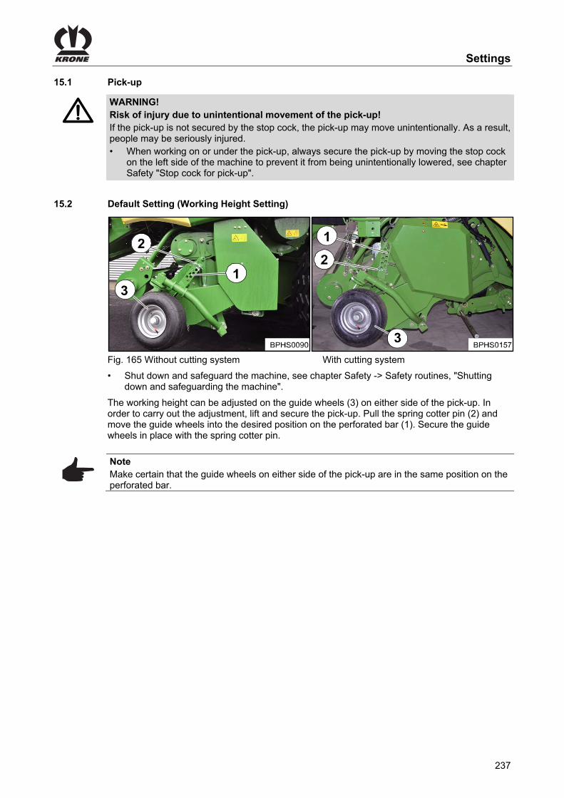
Settings
237
Pos: 102.6 /Überschriften/Überschriften 2/P-T/Pick up @ 1\mod_1201791975201_0.docx @ 54586 @ 2 @ 1
15.1 Pick-up Pos: 102.7 /BA/Sicherheit/Pick-up / Rollenniederhalter/Warnung - Arbeiten an bzw. unter der Pick-up @ 274\mod_1404215879490_78.docx @ 2060866 @ @ 1
WARNING! Risk of injury due to unintentional movement of the pick-up! If the pick-up is not secured by the stop cock, the pick-up may move unintentionally. As a result, people may be seriously injured. • When working on or under the pick-up, always secure the pick-up by moving the stop cock
on the left side of the machine to prevent it from being unintentionally lowered, see chapter Safety "Stop cock for pick-up".
Pos: 102.8 /Überschriften/Überschriften 2/F-J/Grundeinstellung (einstellen der Arbeitshöhe) @ 19\mod_1238576636385_78.docx @ 221585 @ 2 @ 1
15.2 Default Setting (Working Height Setting) Pos: 102.9 /BA/Einstellungen/Pick-up / Rollenniederhalter/Pick-up Grundeinstellung Bild Big Pack 1290 HDP II mit Legende @ 157\mod_1364382697898_78.docx @ 1387945 @ @ 1
Fig. 165 Without cutting system With cutting system Pos: 102.10 /BA/Sicherheit/8. Voraussetzungen/Handlungsanweisung für alle Maschinen/Handlungsanweisung: Maschine stillsetzen und sichern @ 274\mod_1404365253849_78.docx @ 2065151 @ @ 1
• Shut down and safeguard the machine, see chapter Safety -> Safety routines, "Shutting down and safeguarding the machine".
Pos: 102.11 /BA/Einstellungen/Pick-up / Rollenniederhalter/Pick-up Grundeinstellung Text @ 20\mod_1238577186541_78.docx @ 221681 @ @ 1
The working height can be adjusted on the guide wheels (3) on either side of the pick-up. In order to carry out the adjustment, lift and secure the pick-up. Pull the spring cotter pin (2) and move the guide wheels into the desired position on the perforated bar (1). Secure the guide wheels in place with the spring cotter pin.
Note Make certain that the guide wheels on either side of the pick-up are in the same position on the perforated bar.
Pos: 102.12 /Layout Module /---------------Seitenumbruch---------------- @ 0\mod_1196175311226_0.docx @ 4165 @ @ 1

Settings
238
Pos: 102.13 /Überschriften/Überschriften 3/A-E/AAuflagedruck der Tasträder einstellen @ 157\mod_1364377544872_78.docx @ 1387272 @ 3 @ 1
15.2.1 Setting the Ground Pressure of the Guide Wheels Pos: 102.14 /BA/Einstellungen/Pick-up / Rollenniederhalter/Auflagedruck der Tasträder 1290 HDP II Bild Ausführung ohne Schneidwerk @ 157\mod_1364377057422_78.docx @ 1387153 @ @ 1
aFig. 166
Pos: 102.15 /BA/Sicherheit/8. Voraussetzungen/Handlungsanweisung für alle Maschinen/Handlungsanweisung: Maschine stillsetzen und sichern @ 274\mod_1404365253849_78.docx @ 2065151 @ @ 1
• Shut down and safeguard the machine, see chapter Safety -> Safety routines, "Shutting down and safeguarding the machine".
Pos: 102.16 /BA/Einstellungen/Pick-up / Rollenniederhalter/Auflagedruck der Tasträder Hinweis Feder gleich einstellen @ 157\mod_1364378097424_78.docx @ 1387474 @ @ 1
Note Increasing dimension a => Ground pressure of the guide wheels becomes less Reducing dimension a => Ground pressure of the guide wheels becomes greater Adjust dimension “a” equally for both springs (right and left sides of the machine).
Pos: 102.17 /BA/Einstellungen/Pick-up / Rollenniederhalter/Auflagedruck der Tasträder Text Ausführung ohne Schneidwerk @ 157\mod_1364378157935_78.docx @ 1387503 @ @ 1
• Open protective cover. • Increase or reduce the dimension a via nut (2). • Close protective cover.
Pos: 102.18 /Layout Module /---------------Seitenumbruch---------------- @ 0\mod_1196175311226_0.docx @ 4165 @ @ 1

Settings
239
Pos: 102.19 /Überschriften/Überschriften 3/F-J/Fahren mit feststehender Pick-up @ 71\mod_1305804535480_78.docx @ 640896 @ 3 @ 1
15.2.2 Driving with Pick-up in fixed position Pos: 102.20 /BA/Sicherheit/8. Voraussetzungen/Handlungsanweisung für alle Maschinen/Handlungsanweisung: Maschine stillsetzen und sichern @ 274\mod_1404365253849_78.docx @ 2065151 @ @ 1
• Shut down and safeguard the machine, see chapter Safety -> Safety routines, "Shutting down and safeguarding the machine".
Pos: 102.21 /BA/Einstellungen/Pick-up / Rollenniederhalter/Fahren mit feststehender Pick-up Bild 4x4 @ 71\mod_1305805323853_78.docx @ 640982 @ @ 1
Fig. 167 Pos: 102.22 /BA/Einstellungen/Pick-up / Rollenniederhalter/Fahren mit feststehender Pick-up Text BP 4x4 @ 107\mod_1334556393201_78.docx @ 966224 @ @ 1
The working height of the pick-up can be manually limited downwards by moving the depth limiters (1) on both sides of the machine. This makes it possible to drive the machine without guide wheels with the pick-up in fixed position. To perform a setting: • Open twine box (only model BiG PACK 4x4) • Open pick-up guard (3) • Remove the cotter pin 2 with washer • By moving the depth limiter (1), set the required position • Secure depth limiter with washer and cotter pin
Note Make certain that the depth limiter is in the same position on both sides of the pick-up.
Pos: 102.23 /Layout Module /---------------Seitenumbruch---------------- @ 0\mod_1196175311226_0.docx @ 4165 @ @ 1
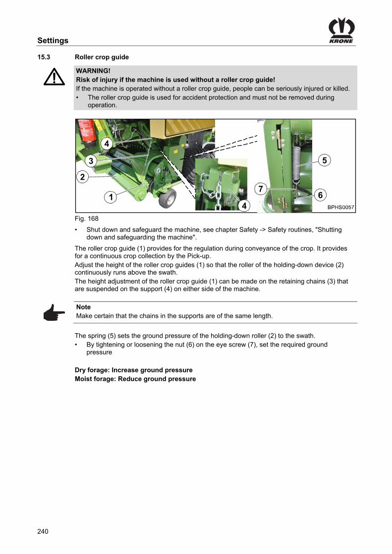
Settings
240
Pos: 102.24 /Überschriften/Überschriften 2/P-T/Rollenniederhalter @ 0\mod_1201163046930_78.docx @ 51122 @ 2 @ 1
15.3 Roller crop guide Pos: 102.25 /BA/Sicherheit/Pick-up / Rollenniederhalter/Warnung! - Abbau des Rollenniederhalters @ 274\mod_1404216918043_78.docx @ 2060895 @ @ 1
WARNING! Risk of injury if the machine is used without a roller crop guide! If the machine is operated without a roller crop guide, people can be seriously injured or killed. • The roller crop guide is used for accident protection and must not be removed during
operation.
Pos: 102.26 /BA/Einstellungen/Pick-up / Rollenniederhalter/Rollenniederhalter Bild BiG Pack 4x4 HS @ 71\mod_1305807701420_78.docx @ 641126 @ @ 1
Fig. 168 Pos: 102.27 /BA/Sicherheit/8. Voraussetzungen/Handlungsanweisung für alle Maschinen/Handlungsanweisung: Maschine stillsetzen und sichern @ 274\mod_1404365253849_78.docx @ 2065151 @ @ 1
• Shut down and safeguard the machine, see chapter Safety -> Safety routines, "Shutting down and safeguarding the machine".
Pos: 102.28 /BA/Einstellungen/Pick-up / Rollenniederhalter/Rollenniederhalter Höheneinstellung @ 20\mod_1238588056307_78.docx @ 223090 @ @ 1
The roller crop guide (1) provides for the regulation during conveyance of the crop. It provides for a continuous crop collection by the Pick-up. Adjust the height of the roller crop guides (1) so that the roller of the holding-down device (2) continuously runs above the swath. The height adjustment of the roller crop guide (1) can be made on the retaining chains (3) that are suspended on the support (4) on either side of the machine.
Note Make certain that the chains in the supports are of the same length.
Pos: 102.29 /BA/Einstellungen/Pick-up / Rollenniederhalter/Auflagedruck der Niederhalterolle BP 12130 HS @ 71\mod_1305807916536_78.docx @ 641184 @ @ 1
The spring (5) sets the ground pressure of the holding-down roller (2) to the swath. • By tightening or loosening the nut (6) on the eye screw (7), set the required ground
pressure Dry forage: Increase ground pressure Moist forage: Reduce ground pressure
Pos: 102.30 /Layout Module /---------------Seitenumbruch---------------- @ 0\mod_1196175311226_0.docx @ 4165 @ @ 1

Settings
241
Pos: 102.31 /BA/Einstellungen/Großpackenpresse/Nadeleinstellungen/Nadeleinstellung ÜS @ 21\mod_1239103867040_78.docx @ 229569 @ 2 @ 1
15.4 Setting the needles Pos: 102.32 /BA/Einstellungen/Großpackenpresse/Nadeleinstellungen/Seitliche Einstellung der Nadeln ÜS @ 25\mod_1242369497056_78.docx @ 253521 @ 3 @ 1
15.4.1 Lateral setting of the needles Pos: 102.33 /BA/Einstellungen/Großpackenpresse/Nadeleinstellungen/Achtung Einstellungen der Nadel / Nadelschwinge nicht überprüft @ 21\mod_1239103937727_78.docx @ 229593 @ @ 1
CAUTION! – After setting the needles / needle yoke not checked Effect: Considerable damages to the machine After setting the needles pass once manually through the tying process. In doing so, the needles and needle yoke must not come in contact with the frame, baling ram or other parts during the upward or downward motion.
Pos: 102.34 /BA/Einstellungen/Großpackenpresse/Nadeleinstellungen/Seitliche Einstellung der Nadeln @ 21\mod_1239091172524_78.docx @ 228761 @ @ 1
Fig. 169 Place the needles (1) so they are centered in the oblong holes of the needle yoke, align then with the needle slots in the bale channel chamber floor and fasten them in place with the screws (2). • Trigger the tying process manually with machine at a standstill • Turn the needle yoke manually on the flywheel in working direction upwards until the
needles are taken up into the needle slots of the baling ram • Tighten the flywheel brake to lock the needles in this position • In this position move the baling ram to the side with a mounting lever to check whether the
needle may possibly be touching the needle slots of the baling ram on the side • If necessary, loosen the screws (2) • Align the needles to the needle slots of the baling ram and tighten the screws (2)
• Loosen the flywheel and turn the needle yoke manually on the flywheel further upwards into working position (the needles must be taken up in the centre of the channel slots during rising and they must slightly be positioned on the knotter blocks in direction of travel lateral right)
If that is not the case: • Tighten the flywheel brake to lock the needles in this position • Loosen the screws (2) • Align the needles to the channel slots and tighten the screws (2)
Pos: 102.35 /Layout Module /---------------Seitenumbruch---------------- @ 0\mod_1196175311226_0.docx @ 4165 @ @ 1

Settings
242
Pos: 102.36 /Überschriften/Überschriften 3/F-J/Höhe der Nadeln am Knoter einstellen @ 26\mod_1245326395230_78.docx @ 260901 @ 3 @ 1
15.4.2 Setting the height of the needles on the knotter Pos: 102.37 /BA/Einstellungen/Großpackenpresse/Nadeleinstellungen/Höhe der Nadeln am Knoter Bild nur Doppelknoter @ 172\mod_1370590544056_78.docx @ 1481262 @ @ 1
1
2
3
4
5
7
a
b
6
Fig. 170 Pos: 102.38 /BA/Einstellungen/Großpackenpresse/Nadeleinstellungen/Höhe der Nadeln am Knoter einstellen Text @ 21\mod_1239091936086_78.docx @ 228832 @ @ 1
Note Only make adjustments with the twine threaded in!
• Trigger the tying process manually with machine at a standstill • Turn the needle yoke on the flywheel manually upwards into working position until the lower
roll in the needle tip is located above the cleaners (6) of the tappet (2) (I) • Tighten the flywheel brake to lock the needles (4) in this position
Note The distance "a" from the lower edge of the needle roll to the upper edge of the cleaning disc with twine must be between 1 and 3 mm.
If this dimension ”a” is not reached, it can be corrected by adjusting the screws (7). When the needles enter the knotter, they should touch the knotter on the right in the driving direction.
Pos: 102.39 /Layout Module /---------------Seitenumbruch---------------- @ 0\mod_1196175311226_0.docx @ 4165 @ @ 1

Settings
243
Pos: 102.40 /BA/Einstellungen/Großpackenpresse/Nadeleinstellungen/Oberer Totpunkt der Nadeln @ 21\mod_1239093619118_78.docx @ 228856 @ 3 @ 1
15.4.3 Top dead centre of the needles
To be able to check the upper dead point of the needles, turn the needle yoke up to its highest position (dead centre point) (II). The needles (4) protrude out from the knotter. The distance "b" between the upper edge of the drive disc (2) and the mid-point of the lower roll on the needle point should be at least b = x mm with twine. If the setting is not correct, it should be corrected by shortening or lengthening the needle connecting rod (3). The needles should not touch the cleaners (6) of the tappet (2) in their highest position.
Pos: 102.41 /BA/Einstellungen/Großpackenpresse/Nadeleinstellungen/Oberer Totpunkt Mass b nur Doppelknoter B=105-115 mm @ 26\mod_1245327003183_78.docx @ 261001 @ @ 1
Double knotter: b = 105 - 115 mm
Pos: 102.42 /Layout Module /---------------Seitenumbruch---------------- @ 0\mod_1196175311226_0.docx @ 4165 @ @ 1

Settings
244
Pos: 102.43.1 /Überschriften/Überschriften 2/K-O/Multi-Bale einstellen @ 272\mod_1403516170463_78.docx @ 2050813 @ 2 @ 1
15.5 Adjusting the MultiBale Pos: 102.43.2 /BA/Einstellungen/Großpackenpresse/MutiBale/Position zweite Nadelschwinge / Anschlag Bild @ 24\mod_1241443960165_78.docx @ 245076 @ @ 1
Fig. 171 Pos: 102.43.3 /BA/Einstellungen/Großpackenpresse/MutiBale/Einstellung Position zweite Nadelschwinge @ 24\mod_1241444369290_78.docx @ 245100 @ 3 @ 1
15.5.1 Setting the position of the second needle yoke
The tube (2) of the needle yoke (3) has to be located in the trough (4). If this is not the case, please proceed as follows: • Check the knotter needle setting relative to the knotter, and adjust, if and when necessary
(refer to chapter Settings "Needle setting"). • Adjust the needle yoke brake (1) in longitudinal position in the oblong hole (15) so that the
tube (2) of the needle yoke (3) is in the end setting of the tie immediately after the trough (4) of the needle yoke brake (1)
Pos: 102.43.4 /BA/Einstellungen/Großpackenpresse/MutiBale/Einstellung Anschlag @ 24\mod_1241445271930_78.docx @ 245124 @ 3 @ 1
15.5.2 Setting the stop
• In this setting the distance between the tube (2) of the needle yoke (3) and the obstruction should be (5) x = 8 - 15 mm. Adjust the stop (5) if necessary using washers (6)
Pos: 102.43.5 /BA/Einstellungen/Großpackenpresse/MutiBale/Einstellung Höhe der Nadelschwingenbremse @ 24\mod_1241498230617_78.docx @ 245177 @ 3 @ 1
15.5.3 Setting the height of the needle yoke brake
Fig. 172 • During the infeed of the needle yoke (3), the roller (7) of the needle yoke brake (1) has to
make contact with the lower third of the tube (2). The height of the needle yoke brake (1) can be changed by placing washers under the clamping screw stop (8).
• Pre-tension the spring (9) of the needle yoke brake (1) to a dimension y = 115 - 120 mm
Pos: 102.43.6 /Layout Module /---------------Seitenumbruch---------------- @ 0\mod_1196175311226_0.docx @ 4165 @ @ 1

Settings
245
Pos: 102.43.7 /BA/Einstellungen/Großpackenpresse/MutiBale/Einstellung Verriegelung (Rahmen) @ 24\mod_1241498609820_78.docx @ 245279 @ 3 @ 1
15.5.4 Setting the locking (frame)
Fig. 173 • Set the support tube (10) so that the distance between the locking (11) and the support tube
(10) is Z = 15-35 mm
Pos: 102.43.8 /BA/Einstellungen/Großpackenpresse/MutiBale/Einstellung Verriegelungen der Nadelschwingen @ 24\mod_1241501736055_78.docx @ 245306 @ 3 @ 1
15.5.5 Setting the lockings of the needle yoke
Fig. 174 In order to ensure a safe lock of the second needle yoke (13), the locking (11) (as shown in the figure above) has to have a distance of U = 3 – 7 mm to the pin (12) of the needle yoke (14).
Pos: 102.43.9 /Layout Module /---------------Seitenumbruch---------------- @ 0\mod_1196175311226_0.docx @ 4165 @ @ 1

Settings
246
Pos: 102.43.10 /BA/Einstellungen/Großpackenpresse/MutiBale/Einstellung Gummipuffer zwischen den Nadelschwingen @ 24\mod_1241501934539_78.docx @ 245332 @ 3 @ 1
15.5.6 Setting the rubber pad between the needle yokes
Fig. 175 Setting the distance U By adding or removing compensation washers (16) between the rubber pad (17) and the needle yoke (18) the spacing is increased or decreased.
Note After having set the rubber pads, the setting of the stop has to be checked (refer to chapter "Setting the stop”).
Pos: 102.43.11 /BA/Einstellungen/Großpackenpresse/MutiBale/Mögliche Einstellfehler und deren Behebung (Multi-Bale) @ 24\mod_1241502437023_78.docx @ 245356 @ 3 @ 1
15.5.7 Possible setting errors and their elimination (MultiBale)
Malfunction Possible cause Remedy
Needle yoke (2) recoils back out forward from the needle yoke brake (1).
The spring (9) of the needle yoke brake (1) is too weakly tightened.
Tighten spring with more torque.
Needle yoke brake (1) is installed too far forward in the direction of travel.
Install the needle yoke brake further to the rear.
The stop (5) of the needle yoke brake (1) is installed too far forward.
Install the stop (5) further to the rear
The tube (2) of the needle yoke (3) is not running over the infeed surface (7) into the needle yoke brake (1).
Spring (9) of the needle yoke brake (1) is overtightened.
Tighten spring less tightly.
Needle yoke brake (1) is installed too far back in the direction of travel.
Install the needle yoke brake further forward.
The journal (12) of the needle yoke (14) is not reliably seized by the locking (11).
The needle yoke brake (1) or the stop (5) is installed too far back in the direction of travel.
Install the needle yoke brake (1) or the stop (5) further forward.
Setting of needle connecting rod not correct.
Correct the setting of the needle connecting rod.
Pos: 102.44 /Layout Module /---------------Seitenumbruch---------------- @ 0\mod_1196175311226_0.docx @ 4165 @ @ 1

Settings
247
Pos: 102.45 /BA/Einstellungen/Großpackenpresse/Nadeleinstellungen/Position Nadeln – Preßkolben prüfen @ 150\mod_1362057381079_78.docx @ 1343393 @ 2 @ 1
15.6 Checking / adjusting position of needles – baling ram
a
a
b
Fig. 176 Check: • Completely release spring tension of the needle yoke brake • Manually actuate the tying process while the machine is at a standstill • Manually rotate flywheel mass until the needle points (1) have reached the upper edge (b)
of the fixed retainers (3) in the bale channel floor • Block the needles in this position and apply the flywheel brake • The dimension “a” (baling ram front edge to needle tip) must be 60 – 90 mm If this is not the case:
Note Set dimension "a" only in baling direction of the baling ram (2) (see arrow in fig.).
• Remove drive cardan shaft from the knotter gear • Manually rotate flywheel mass (baling ram moves in baling direction) until dimension
a = 60 – 90 mm • Attach drive cardan shaft to the knotter shaft and secure • Manually actuate the tying process again while the machine is at a standstill • Check position of needles – baling ram again • Set spring tension of the needle yoke brake
Pos: 102.46 /Layout Module /---------------Seitenumbruch---------------- @ 0\mod_1196175311226_0.docx @ 4165 @ @ 1

Settings
248
Pos: 102.47 /Überschriften/Überschriften 2/K-O/Obernadel prüfen / einstellen @ 271\mod_1402649470033_78.docx @ 2042940 @ 2 @ 1
15.7 Checking / Setting Upper Needle Pos: 102.48 /BA/Einstellungen/Großpackenpresse/Nadeleinstellungen/Obernadel prüfen / einstellen Vorraussetzung @ 271\mod_1402649988061_78.docx @ 2043118 @ @ 1
Prerequisite: – The upper needle is tensioned, see chapter Settings "Tensioning/relieving the upper
needle". – The twine locking shaft is tensioned, see chapter Settings "Tensioning/relieving the twine
locking shaft". Pos: 102.49 /BA/Einstellungen/Großpackenpresse/Nadeleinstellungen/Obernadel prüfen / einstellen @ 271\mod_1402649909701_78.docx @ 2043089 @ @ 1
5
6
4
Fig. 177 • Make a catch hook (1). • In order to simulate a tied bale, pull the twine (2) with the catch hook out of the bale channel
and fix it on the top on the bale channel flap with a shaft (3) (screwdriver). • To tighten the tensioning arm (4), pull back the upper twine (5) in front of the twine eye (6). • Initiate the baling process manually when the machine is at a standstill. • Turn the flywheel manually to the working direction until the upper needle (7) raises. • Turn the flywheel manually in the direction of working until the needle (8) nearly touches the
upper twine (5). At this point in time, the upper twine (5) must be centred in front of the needle (8). If the upper twine is not centred in front of the needle: • If the upper twine is centred in front of the needle, align the upper needle by using a
mounting lever. If the upper twine is centred in front of the needle:
Fig. 178 • Turn the flywheel manually to the direction of working until the trigger roller (9) is in the
recess of the knotter gear (idle position). The knotting process is finished now. The upper twine moves slightly to the right while the flywheel continues to rotate. This is structurally determined as the needle guides the upper twine into the blade lever.
Pos: 102.50 /Layout Module /---------------Seitenumbruch---------------- @ 0\mod_1196175311226_0.docx @ 4165 @ @ 1

Settings
249
Pos: 102.51 /BA/Einstellungen/Großpackenpresse/Garnriegel/Garnriegel prüfen einstellen Einführtext @ 170\mod_1369723043694_78.docx @ 1467443 @ 2 @ 1
15.8 Checking / Setting Twine Bar
The twine bar moves the twine away from the needle and pushes it against the knotter hook. If the twine is not grasped by the twine bar, the knotter hook cannot pick-up the twine.
Pos: 102.52 /BA/Einstellungen/Großpackenpresse/Garnriegel/Garnriegels zur Unternadel prüfen / einstellen BiG PACK 1290 HDP II @ 169\mod_1369643661123_78.docx @ 1465679 @ 3 @ 1
15.8.1 Checking / Setting the Twine Bar to the Lower Needle (Needle Yoke)
If the twine bar to the lower needle is set, the settings described in chapter Settings “Checking / Setting Twine Bar to the Channel Slot” and “Checking Twine Bar Overreach on the Second Knot” must be performed.
2
13
4
4 1
Fig. 179 Prerequisite: – The twine shaft is released, refer to chapter Settings “Tensioning / Releasing Twine Bar Shaft”. – The tying process is triggered manually; refer to chapter Operation “Triggering Tying
Process Manually”. Checking twine bar • Turn the flywheel manually in the working direction until the lower needle (1) (needle yoke)
is just in front of the twine driver (2). • Tighten the flywheel brake. • Pull the cotter pin and swing up the knotter, repeat the process for all knotters. • Swivel the twine bar (3) to the middle of the lower needle (1) by turning the twine bar shaft
and measure the dimension “a”. If the dimension “a” is 2 - 4 mm, the twine bar is correctly set. If the dimension “a” is not 2 - 4 mm, the twine bar must be set. Setting twine bar To do this: • Loosen the nuts (4) • Move the twine bar (3) until the dimension “a” is 2 to 4 mm. • Tighten the nuts (4). • Swivel the knotter down and secure with cotter pin. Repeat this process for all twine bars. • Release the flywheel brake. • Finish the tying process manually; refer to chapter Operation “Finishing Tying Process
Manually”. • Tighten the flywheel brake. • Tighten twine bar shaft, refer to chapter Settings “Tightening / Releasing Twine Bar Shaft”.
Pos: 102.53 /Layout Module /---------------Seitenumbruch---------------- @ 0\mod_1196175311226_0.docx @ 4165 @ @ 1

Settings
250
Pos: 102.54 /BA/Einstellungen/Großpackenpresse/Garnriegel/Garnriegel zum Kanalschlitz prüfen / einstellen BiG PACK 1290 HDP II @ 170\mod_1369665315981_78.docx @ 1466997 @ 2 @ 1
15.9 Checking / Setting Twine Bar to the Channel Slot
Fig. 180 Prerequisite: – The machine is disconnected from the tractor. – The flywheel brake is applied. – The knotter gear is in idle position; refer to chapter Operation “Finishing Knotter Process
Manually”. Checking the twine bar to the channel slot • Pull the cotter pin and swing up the knotter, repeat the process for all knotters. • Press the twine bar (1) manually to the channel slot (b). • Measure dimension “a”, measured between twine bar tip and channel slot. If dimension “a” is 0 - 5 mm, the twine bar is correctly set. If dimension “a” is not 0 - 5 mm, the twine bar must be set. Setting twine bar To do this: • Unscrew counter nut (2) and screw (4) of the joint bearing. • Turn joint head (3) until dimension “a” is 0 - 5 mm. • Tighten counter nut (2) and screw (4). Repeat this process for all twine bars. Check that the twine bar moves easily. • Release the twine bar shaft, refer to chapter Settings “Tensioning / Releasing Twine Bar
Shaft”. • Rotate the twine bar back and forth manually. The twine bar is correctly set if it is easy to rotate the twine bar back and forth. If it is hard to rotate the twine bar back and forth, there are several causes: 1. The control linkage is crooked, replace the control linkage. 2. The joint bearing is rusted, replace the joint bearing. 3. The axial play in the twine bar shaft is too low, remove the shim ring. Remedy cause 1 to 3 and check or set the twine bar again, refer to chapter Settings “Checking / Setting the Twine Bar to the Lower Needle”. • Swivel the knotter down and secure with cotter pin. Repeat this process for all knotters. Repeat this process for all twine bars. • Tighten twine bar shaft, refer to chapter Settings “Tightening / Releasing Twine Bar Shaft”.
Pos: 102.55 /Layout Module /---------------Seitenumbruch---------------- @ 0\mod_1196175311226_0.docx @ 4165 @ @ 1

Settings
251
Pos: 102.56 /BA/Einstellungen/Großpackenpresse/Garnriegel/Garnriegel Übergriff am 2ten Knoten prüfen HDP II @ 170\mod_1369666372743_78.docx @ 1467026 @ @ 1
Checking the overreach of the twine bars on the second knot
Fig. 181 Prerequisite: – The first knot (closing knot) must have been made manually. Checking • Turn the flywheel manually in the working direction until the twine bar (1) swivels over the
channel slots for the second time. • As soon as the twine bar grasps the twine, tighten the flywheel brake to lock the needles in
this position. Measuring the overreach (distance twine tip to twine) The twine bar is correctly adjusted if the dimension „a“ is between 5 and 10 mm. If the dimension „a“ is not 5 - 10 mm, the twine bar must be re-adjusted; refer to chapter Settings “Setting Twine Bar to Lower Needle (needle yoke)”. Check the overreach on all twine bars.
Pos: 102.57 /Layout Module /---------------Seitenumbruch---------------- @ 0\mod_1196175311226_0.docx @ 4165 @ @ 1

Settings
252
Pos: 102.58 /BA/Einstellungen/Großpackenpresse/Garnriegel/Obernadelwellle spannen / entspannen BiG PACK 870 HDP b=235 mm @ 271\mod_1402655757439_78.docx @ 2043500 @ 2 @ 1
15.10 Tensioning/relieving the upper needle shaft
2
3
1
Fig. 182 The upper needle shaft (1) is tensioned or relieved by means of the spring (2). Prerequisite: – The knotter gear is in the idle position, see chapter Settings "Adjusting the needle yoke
brake". – The flywheel brake is applied. Tensioning • To tension the spring (2), tighten the nut (3) until dimension "b" = 235 mm, measured
between the eyes of the spring. Relieving • To relieve the spring (2), unwind the nut (3) to the thread end of the eyebolt.
Pos: 102.59 /Layout Module /---------------Seitenumbruch---------------- @ 0\mod_1196175311226_0.docx @ 4165 @ @ 1

Settings
253
Pos: 102.60 /BA/Einstellungen/Großpackenpresse/Garnriegel/Garnriegelwelle spannen / entspannen BiG PACK 870 HDP b=285 mm @ 271\mod_1402651614865_78.docx @ 2043322 @ 2 @ 1
15.11 Tensioning/relieving the twine locking shaft
2
3
1
Fig. 183 The twine locking shaft (1) is tensioned or relieved by means of the spring (2). Prerequisite: – The knotter gear is in the idle position, see chapter Settings "Adjusting the needle yoke
brake". – The flywheel brake is applied. Tensioning the twine locking shaft • To tension the spring (2), tighten the nut (3) until dimension "b" = 285 mm, measured
between the eyes of the spring. Relieving the twine locking shaft • To relieve the spring (2), unwind the nut (3) to the thread end of the eyebolt.
Pos: 102.61 /BA/Einstellungen/Großpackenpresse/Garnriegel/Einstellung der Knoterwellenbremse 20 mm @ 271\mod_1402654053149_78.docx @ 2043441 @ 3 @ 1
15.11.1 Adjusting the knotter shaft brake
Fig. 184 • Tension the springs (1) until dimension a= approx. 20 mm.
Pos: 102.62 /Layout Module /---------------Seitenumbruch---------------- @ 0\mod_1196175311226_0.docx @ 4165 @ @ 1

Settings
254
Pos: 102.63 /Überschriften/Überschriften 2/F-J/Garnbremse einstellen @ 127\mod_1346138729566_78.docx @ 1147164 @ 2 @ 1
15.12 Setting the Twine Brake Pos: 102.64 /BA/Einstellungen/Großpackenpresse/Garnbremse/Garnbremse Bild alle HS-Typen außer HDP II @ 192\mod_1382085040686_78.docx @ 1638076 @ @ 1
Fig. 185 Pos: 102.65 /BA/Einstellungen/Großpackenpresse/Garnbremse/Garnbremse Einführtext Doppelknoter HS Baureihe @ 192\mod_1382085182284_78.docx @ 1638136 @ @ 1
The twine brakes (2) can be found in the twine boxes. The twine brakes held stiff the upper twines from the twine box to the upper twine brakes or the lower twines from the twine box to the lower twine brakes. The drawing tension of the twine brake should always be set to a high enough level so that the upper twines or lower twines are stiff but that they can be pulled easily. Different types of twine may have different friction properties. Therefore the drawing tension of the twine strand must be checked when changing the type of twine.
Pos: 102.66 /BA/Einstellungen/Großpackenpresse/Garnbremse/Voreinstellung X = 30 – 35 mm @ 24\mod_1240994506555_78.docx @ 241501 @ @ 1
Pre-setting X = 30 – 35 mm Pos: 102.67 /BA/Einstellungen/Großpackenpresse/Garnbremse/Garnbremse im Garnkasten Zugspannung erhöhen / verringern @ 157\mod_1364399783445_78.docx @ 1389046 @ @ 1
• Increase or reduce dimension “X” to increase or reduce the drawing tension.
Pos: 102.68 /Layout Module /---------------Seitenumbruch---------------- @ 0\mod_1196175311226_0.docx @ 4165 @ @ 1

Settings
255
Pos: 102.69 /BA/Einstellungen/Großpackenpresse/Garnbremse/Garnspannung am oberen Garnstrang (Doppelknoter) @ 24\mod_1240995388836_78.docx @ 241628 @ 3 @ 1
15.12.1 Setting the twine tension on the upper twine strand (double knotter)
Fig. 186 The upper strands of twine (1) should be held by the brakes (2) up to a tensile force of 100 - 120 N. Before the twine brakes will allow the twine to slip through, the twine tension arm (3) should move downward against the spring force until the twine (1) is guided through the eye of the tension arm (4) almost without moving to the side. Testing the twine tension: • Tie the cord (1) onto a spring balance The spring balance has to indicate 100 - 120 N
shortly before the cord slips through. You can increase the tension by turning the wing nut (5) tighter. To reduce the tension, loosen the wing nut. The dimension "X" is based on the tying twine selected and must be determined in each individual case by testing in the twine strand. A pretension of the twine strand that is too high may cause knotter errors and place too heavy a load on the components involved. Pre-setting X = 65 mm
Pos: 102.70 /Layout Module /---------------Seitenumbruch---------------- @ 0\mod_1196175311226_0.docx @ 4165 @ @ 1

Settings
256
Pos: 102.71 /BA/Einstellungen/Großpackenpresse/Garnbremse/Garnspannung am unteren Garnstrang Doppelknoter @ 24\mod_1240996666196_78.docx @ 241703 @ 3 @ 1
15.12.2 Setting the twine tension of the lower twine strand (double knotter)
Fig. 187 The twine brakes (1) for the lower twine strand are behind the packer under the bale channel chamber. You can increase the tension by turning the wing nut (2) tighter. To reduce the tension, loosen the wing nut. Pre-setting X= 70 mm Testing the drawing tension: 1. Thread in the twine according to instructions. 2. Trigger the tying process manually with machine at a standstill. 3. Turn the needle yoke manually on the flywheel in working direction upwards until the
needles reached their upper dead point (refer to chapter “Upper dead point of the needles”). 4. Tighten the flywheel brake to lock the needles in this position. 5. Pull the twine about 200 mm out of the needle and cut it. 6. Pull the strand of twine slowly and evenly until the twine tension springs have reached their
highest position under the channel. 7. As the twine is held, the twine tension springs must remain in this position without any twine
being able to be pulled back by the brake. 8. The brake must allow twine to slip through if there is a slight increase in the tensile force.
Pos: 102.72 /Layout Module /---------------Seitenumbruch---------------- @ 0\mod_1196175311226_0.docx @ 4165 @ @ 1

Settings
257
Pos: 102.73 /Überschriften/Überschriften 2/K-O/Knoter @ 24\mod_1241083059412_78.docx @ 242902 @ 2 @ 1
15.13 Knotter Pos: 102.74 /BA/Sicherheit/7. Gefahrenhinweise alt/Großpackenpresse/WARNUNG - Lebensgefahr durch ungewolltes Auslösen der Bindeeinrichtung. @ 273\mod_1403694855615_78.docx @ 2054965 @ @ 1
WARNING! Danger to life due to unintentional triggering of the twine tying device. If the tying process is not locked to facilitate maintenance, adjustment and repair work on the knotter, the tying process may be triggered unintentionally. As a result, people may be seriously injured or killed. • To facilitate maintenance, adjustment and repair work on the knotter, always secure the
knotter shaft with the safety lever to prevent unintentional triggering of tying.
Pos: 102.75 /BA/Einstellungen/Großpackenpresse/Knoter/Bindevorgang sperren HS @ 273\mod_1403696768365_78.docx @ 2055170 @ 3 @ 1
15.13.1 Locking/releasing the tying process
12 2
a
b
BPHS0059
b
a 1Fig. 188 To avoid unintentionally triggering the tying process during maintenance, adjustment and repair work on the knotter, the tying process must be locked. Locking the tying process • To lock the tying process, move the safety lever (1) from position (a) to position (b) and set
it down on the journal (2). Releasing the tying process • To release the tying process, move the safety lever (1) from position (b) to position (a).
Pos: 102.76 /BA/Einstellungen/Großpackenpresse/Bindegarn einfädeln/Hinweis Endlosballen gepresst @ 92\mod_1326728080272_78.docx @ 781560 @ @ 1
Note The safety lever (2) must be in position (a) for the baling process! Otherwise an endless bale will be formed when the knotter shaft is secured.
Pos: 102.77 /Layout Module /---------------Seitenumbruch---------------- @ 0\mod_1196175311226_0.docx @ 4165 @ @ 1
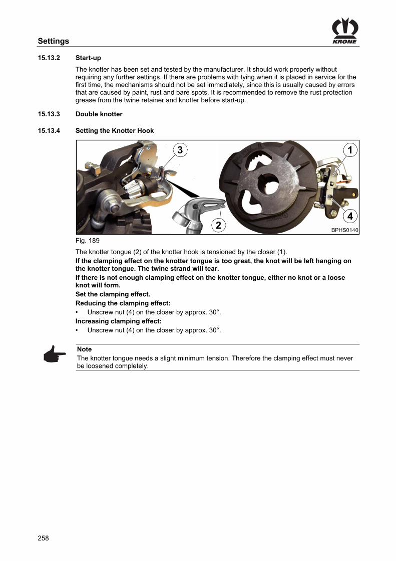
Settings
258
Pos: 102.78 /BA/Einstellungen/Großpackenpresse/Knoter/Inbetriebnahme Knoter @ 24\mod_1241083585365_78.docx @ 242950 @ 3 @ 1
15.13.2 Start-up
The knotter has been set and tested by the manufacturer. It should work properly without requiring any further settings. If there are problems with tying when it is placed in service for the first time, the mechanisms should not be set immediately, since this is usually caused by errors that are caused by paint, rust and bare spots. It is recommended to remove the rust protection grease from the twine retainer and knotter before start-up.
Pos: 102.79.1 /Überschriften/Überschriften 3/A-E/DDoppelknoter @ 24\mod_1241099544678_78.docx @ 243310 @ 3 @ 1
15.13.3 Double knotter Pos: 102.79.2 /Überschriften/Überschriften 3/K-O/Knüpferhakens einstellen @ 156\mod_1363867882250_78.docx @ 1378155 @ 3 @ 1
15.13.4 Setting the Knotter Hook Pos: 102.79.3 /BA/Einstellungen/Großpackenpresse/Knoter/Doppelknoter/Knüpferhaken Doppelknoter Bild 1290 HDP II @ 156\mod_1363864056928_78.docx @ 1377963 @ @ 1
Fig. 189 Pos: 102.79.4 /BA/Einstellungen/Großpackenpresse/Knoter/Doppelknoter/Knüpferhaken einstellen @ 156\mod_1363864342258_78.docx @ 1378122 @ @ 1
The knotter tongue (2) of the knotter hook is tensioned by the closer (1). If the clamping effect on the knotter tongue is too great, the knot will be left hanging on the knotter tongue. The twine strand will tear. If there is not enough clamping effect on the knotter tongue, either no knot or a loose knot will form. Set the clamping effect. Reducing the clamping effect: • Unscrew nut (4) on the closer by approx. 30°. Increasing clamping effect: • Unscrew nut (4) on the closer by approx. 30°.
Note The knotter tongue needs a slight minimum tension. Therefore the clamping effect must never be loosened completely.
Pos: 102.79.5 /Layout Module /---------------Seitenumbruch---------------- @ 0\mod_1196175311226_0.docx @ 4165 @ @ 1

Settings
259
Pos: 102.79.6 /Überschriften/Überschriften 3/A-E/EEinstellung Garnhalter @ 47\mod_1285054111875_78.docx @ 455539 @ 3 @ 1
15.13.5 Setting of twine retainer Pos: 102.79.7 /BA/Einstellungen/Großpackenpresse/Knoter/Doppelknoter/Garnhalter Doppelknoter Bild 1290 HDP II @ 156\mod_1363880514392_78.docx @ 1379138 @ @ 1
a
Fig. 190 Pos: 102.79.8 /BA/Einstellungen/Großpackenpresse/Knoter/Garnhalter Text Einfachknoter / Doppelknoter Raspe @ 47\mod_1285053711171_78.docx @ 455513 @ @ 1
Setting the twine driver The function of the twine driver (5) depends on the position of its indentation opposite the twine disc cleaner (7). The twine driver (5) has been set to a = 0-2 mm as a default setting ex works. • If the indentation on the twine driver (5) is positioned too far forward (clockwise), the
twine cannot be snagged by the twine driver as it is being guided along by the needle.
• On the other hand, if the indentation on the twine driver (5) is positioned too far back (anticlockwise), the twine strand may become wound up on the knotter hook or it may not be possible for it to be snagged by the knotter tongue.
Setting the twine driver (5) The indentation of the twine driver (5) has to be located at the position shown. Then: • Undo the nut (4) until the nut (4) is flush with the thread end of the auger • Undo the auger by means of a slight knock against the nut (4) • Adjust to a = 0-2 mm by turning the auger • Tighten nut (4)
Note At least two tying processes must be performed to check for the correct position of the indentation.
Pos: 102.79.9 /Layout Module /---------------Seitenumbruch---------------- @ 0\mod_1196175311226_0.docx @ 4165 @ @ 1

Settings
260
Pos: 102.79.10 /Überschriften/Überschriften 3/F-J/Haltekraft des Garnhalters einstellen @ 156\mod_1363935243159_78.docx @ 1379375 @ 3 @ 1
15.13.6 Setting the Holding Force of the Twine Retainer Pos: 102.79.11 /BA/Einstellungen/Großpackenpresse/Knoter/Doppelknoter/Haltekraft des Garnhalters einstellen Bild 1290 HDP II @ 156\mod_1363935328168_78.docx @ 1379399 @ @ 1
a
Fig. 191 Pos: 102.79.12 /BA/Einstellungen/Großpackenpresse/Knoter/Doppelknoter/Haltekraft des Garnhalters einstellen 1290 HDP II @ 156\mod_1363935592347_78.docx @ 1379428 @ @ 1
The twine retainer (4) should only clamp the twine securely enough so that it is not pulled out of the twine retainer mechanism during the tying process. If the clamping effect is too great, it will tear the twine into shreds. The setting of the holding force is preset in the factory. The type and moisture content of baling material and its baling density as well as the tying twine that is selected all require different settings, which have to be determined by trial and error under actual working conditions. To do this: • Loosen the counter nut (3) • Ensure stronger or weaker pre-tensioning of the twine retainer springs (2) via screw (1)
(approx. half a turn) • Tighten counter nut (3).
Pos: 102.79.13 /Layout Module /---------------Seitenumbruch---------------- @ 0\mod_1196175311226_0.docx @ 4165 @ @ 1

Settings
261
Pos: 102.79.14 /BA/Einstellungen/Großpackenpresse/Knoter/Doppelknoter/Messerhebel (Doppelknoter) Bild 1290 HDP II @ 157\mod_1364281746617_78.docx @ 1384061 @ @ 1
a
I
Fig. 192 Pos: 102.79.15 /BA/Einstellungen/Großpackenpresse/Knoter/Messerhebel Text Einfachknoter / Doppelknoter Raspe @ 47\mod_1285058951359_78.docx @ 455617 @ @ 1
The blade lever (1) must be aligned so that the knotter hook (2) can turn freely without touching the blade lever at any point on the blade lever. However at the same time, the extractor comb (3) of the blade lever must evenly touch the back of the knotter hook (2). The distance between the extractor comb of the blade lever and the knotter hook tip should be a = 15 to 18 mm in the blade lever dead centre point. The blade lever has reached the dead centre when the blade lever roller has reached the highest point on the cam (4) in the knotter disc (5). The areas of the blade lever that guide the twine strands (the designated area (I)) must be smoothed and rounded to prevent the twine from tearing. The blade lever must be replaced as soon as there is wear (formation of grooves) on the marked area.
Pos: 102.79.16 /BA/Einstellungen/Großpackenpresse/Knoter/Doppelknoter/Garnmesser nachschleifen @ 24\mod_1241419081711_78.docx @ 243564 @ @ 1
BP 380-7-097
Fig. 193 It is essential to ensure that the cutting edge of the twine blade is regrounded as soon as the twine ends are being cut to unequal lengths or are frayed. The blade must be replaced if it is broken or worn too much.
Pos: 102.80 /Layout Module /---------------Seitenumbruch---------------- @ 0\mod_1196175311226_0.docx @ 4165 @ @ 1
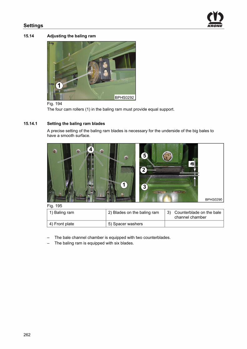
Settings
262
Pos: 102.81.1 /Überschriften/Überschriften 2/P-T/Preßkolben einstellen @ 282\mod_1406108748655_78.docx @ 2165825 @ 2 @ 1
15.14 Adjusting the baling ram Pos: 102.81.2 /BA/Einstellungen/Großpackenpresse/Presskolbeneinstellung/Preßkolbeneinstellung Bild 890 / HDP 870 @ 271\mod_1403009088027_78.docx @ 2046610 @ @ 1
Fig. 194 The four cam rollers (1) in the baling ram must provide equal support.
Pos: 102.81.3 /BA/Einstellungen/Großpackenpresse/Presskolbeneinstellung/Einstellung der Preßkolbenmesser ÜS mit Einführtext @ 172\mod_1370430153723_78.docx @ 1478090 @ 3 @ 1
15.14.1 Setting the baling ram blades
A precise setting of the baling ram blades is necessary for the underside of the big bales to have a smooth surface.
Pos: 102.81.4 /BA/Einstellungen/Großpackenpresse/Presskolbeneinstellung/Messer am Presskolben einstellen Bild 1290 HDP II / HDP 870 @ 272\mod_1403076710403_78.docx @ 2047692 @ @ 1
1 3
5
2
4
Fig. 195
1) Baling ram 2) Blades on the baling ram 3) Counterblade on the bale channel chamber
4) Front plate 5) Spacer washers
Pos: 102.81.5 /BA/Einstellungen/Großpackenpresse/Presskolbeneinstellung/Anzahl Messer am Presskolben (6Stück) Anzahl der Gegenschneide (2) BiG PACK 870 @ 271\mod_1403009348478_78.docx @ 2046639 @ @ 1
– The bale channel chamber is equipped with two counterblades. – The baling ram is equipped with six blades.
Pos: 102.81.6 /Layout Module /---------------Seitenumbruch---------------- @ 0\mod_1196175311226_0.docx @ 4165 @ @ 1

Settings
263
Pos: 102.81.7 /BA/Einstellungen/Großpackenpresse/Presskolbeneinstellung/Einstellung der Preßkolbenmesser BiG Pack 1290 HDP II / 870 @ 271\mod_1403009739054_78.docx @ 2046668 @ @ 1
• Release the flywheel brake and turn the flywheel manually in the direction of operation until the blades are above the counterblade.
• To secure the baling ram, tighten the flywheel brake. • Measure the dimension "a" between the blade and counterblade. If the dimension "a" = 2 to 4 mm, the blades are correctly set. If the dimension "a" is not 2 to 4 mm, spacer washers must be inserted or removed. • Release the flywheel brake and turn the flywheel manually in the direction of operation until
the blades are freely accessible. • To secure the baling ram, tighten the flywheel brake. • Unscrew the front plates. • Loosen the bolts on the blade and add or remove spacer washers until the
dimension "a" = 2 to 4 mm. • Tighten the bolts and screw on the front plates. • Release the flywheel brake and turn the flywheel manually in the direction of operation until
the blades are above the counterblade. • To secure the baling ram, tighten the flywheel brake. • Measure the dimension "a" between the blade and counterblade. If the dimension "a" = 2 to 4 mm, the blades are correctly set. If the dimension "a" is not 2 to 4 mm, repeat the process until the dimension "a" = 2 to 4 mm.
Pos: 102.81.8 /BA/Einstellungen/Großpackenpresse/Presskolbeneinstellung/Laufschienenreinigung @ 24\mod_1241423347774_78.docx @ 243762 @ 3 @ 1
15.14.2 Cleaning the running rails
Fig. 196 The cleaning rails (2) are positioned on the four rollers (3). They remove dirt deposits from the running rails of the baling ram. To adjust, loosen the screws (1) and adjust the cleaning rails to the dimension a = 1 - 2 mm. Tighten the screws again.
Note The cleaning rails (2) must be able to tilt easily on the roller axis!
Pos: 102.81.9 /BA/Einstellungen/Großpackenpresse/Presskolbeneinstellung/Seitliche Einstellung des Kolbens @ 24\mod_1241423485915_78.docx @ 243786 @ 3 @ 1

Settings
264
15.14.3 Lateral setting of the plunger
Fig. 197 The baling ram must be aligned in the centre of the bale channel chamber. Make sure that the plunger moves freely and does not scrub against the fixed scrapers in the bottom of the channel and below the knotter mechanism. To align the plunger laterally, the plunger (2) can be moved to its forward-most position by turning the flywheel. The plunger (2) can be aligned laterally with compensating plates (1) (283-676-0) that are mounted between the plunger (2) and the sliding discs (3). The plunger should have a gap dimension of a = 1 - 2 mm at the narrowest point of the bale channel chamber.
Pos: 102.81.10 /Layout Module /---------------Seitenumbruch---------------- @ 0\mod_1196175311226_0.docx @ 4165 @ @ 1

Settings
265
Pos: 102.81.11 /Layout Module /Diese Seite ist bewusst freigelassen worden. @ 1\mod_1201783680373_78.docx @ 54443 @ @ 1
This page has been left blank deliberately!! Pos: 102.81.12 /Layout Module /---------------Seitenumbruch---------------- @ 0\mod_1196175311226_0.docx @ 4165 @ @ 1

Settings
266
Pos: 102.81.13 /Überschriften/Überschriften 2/P-T/Raffer zum Presskolben einstellen @ 107\mod_1334638713108_78.docx @ 968035 @ 2 @ 1
15.15 Adjusting the Packer Relative to the Plunger Pos: 102.81.14 /Überschriften/Überschriften 3/A-E/BBaugruppenbeschreibung @ 107\mod_1334639066023_78.docx @ 968123 @ 3 @ 1
15.15.1 Description of components Pos: 102.81.15 /BA/Einstellungen/Großpackenpresse/Presskolbeneinstellung/Raffer zum Presskolben alle HS TYpen außer 1290 HDP II Bild mit Legende @ 192\mod_1382087044802_78.docx @ 1638478 @ @ 1
10
8
7
9
X
Fig. 198
1) Packer 2) Baling ram 3) Piston rod
4) Packer strip 5) Feeder strip 6) Control window
7) Packer coupling 8) Packer gearbox 9) Chain coupling
10) Transfer gearbox 11) Main gearbox 12) Flywheel
13) Crank arm
a) Extended position (rear dead point)
Pos: 102.81.16 /Layout Module /---------------Seitenumbruch---------------- @ 0\mod_1196175311226_0.docx @ 4165 @ @ 1

Settings
267
Pos: 102.81.17 /BA/Einstellungen/Großpackenpresse/Presskolbeneinstellung/Raffer zum Preßkolben Vorgehensweise alle HS TYpen außer 1290 HDP @ 192\mod_1382092377530_78.docx @ 1638885 @ @ 1
Adjusting packer to baling ram is only necessary if the following parts have been disassembled: – Packer coupling (7), packer gearbox (8), chain coupling (9), – Transfer gearbox (10) (or removal of the drive train transfer gearbox to main gearbox (11)) – Crank arm (13) from the main gearbox The packer (1) is correctly set to the baling ram (2) if the piston rod (3) is in its extended position (a) and the large packer strip roller (4) running in front of the feeder strip (5) is X=6cm under the control window (6). Prerequisites: – The packer coupling is locked in place, refer to chapter entitled “Checking Packer
Coupling”. – The VFS system is in zero position, refer to chapter entitled Settings “Zero Position”. – Move packer strip (4) into position, refer to chapter Settings “Moving Packer Strip into
Position”. – Move the baling ram into position, refer to chapter Settings “Moving Baling Ram into
Position”. Pos: 102.81.18 /Layout Module /---------------Seitenumbruch---------------- @ 0\mod_1196175311226_0.docx @ 4165 @ @ 1

Settings
268
Pos: 102.81.19 /BA/Einstellungen/Großpackenpresse/Presskolbeneinstellung/Rafferkupplung überprüfen Einrastung der BP 4x4 Baureihe @ 74\mod_1308666241589_78.docx @ 657137 @ 3 @ 1
15.15.2 Checking packer coupling
Fig. 199
Note The packer coupling is correctly engaged when the outer marks (1) on the packer coupling are aligned with the mark (2) on the inner ring of the packer coupling.
Pos: 102.81.20 /Überschriften/Überschriften 3/P-T/Rafferleiste in Position bringen @ 171\mod_1369995210446_78.docx @ 1473367 @ 3 @ 1
15.15.3 Moving Packer Strip into Position Pos: 102.81.21 /BA/Einstellungen/Großpackenpresse/Presskolbeneinstellung/Rafferleiste in Position bringen alle HS Typen außer 1290 HDP II Bild @ 193\mod_1382601591739_78.docx @ 1641391 @ @ 1
X
Fig. 200 Pos: 102.81.22 /BA/Einstellungen/Großpackenpresse/Presskolbeneinstellung/Rafferleiste in Position bringen Text T1 alle HS TYpen außer 1290 HDP @ 192\mod_1382092229393_78.docx @ 1638732 @ @ 1
• Turn the packer into working direction by turning the flywheel manually until the large packer strip roller (4) running in front of the feeder strip (5) is X=6cm below the control window (6).
• Secure the packer in this position with a mounting lever. • Tighten the flywheel brake
Pos: 102.81.23 /Layout Module /---------------Seitenumbruch---------------- @ 0\mod_1196175311226_0.docx @ 4165 @ @ 1

Settings
269
Pos: 102.81.24 /BA/Einstellungen/Großpackenpresse/Presskolbeneinstellung/Presskolben in Position bringen Text T2 alle HS TYpen außer 1290 HDP @ 192\mod_1382092469255_78.docx @ 1638910 @ 3 @ 1
15.15.4 Moving Baling Ram into Position
13
14
4
X
3
5
12
6
Fig. 201 Prerequisite: – The packer strip is in position, refer to chapter Settings “Moving Packer Strip into Position” Procedure • Remove the protection (13) of the chain coupling. • Remove the roller chain (14) from the chain coupling. • Release the flywheel brake. • Move the piston rod (3) to extended position (a) (rear dead point) by turning on the flywheel
(12) in the working direction. • Tighten the flywheel brake. • Position the roller chain (14) of the chain coupling and secure it. • Install the guard (13) on the chain coupling. • Remove the mounting lever. Checking the setting: • Release the flywheel brake • Turn through the machine manually in the working direction one complete time on the
flywheel until the piston rod (3) is in its extended position (a) (rear dead point). The packer (1) is correctly set to the baling ram (2) if the piston rod (3) is in its extended position (a) and the large packer strip roller (4) running in front of the feeder strip (5) is X=6cm under the control window (6). If this is not the case, set packer to baling ram again (refer to chapter Settings “Setting Packer to Baling Ram“).
Pos: 102.82 /Layout Module /---------------Seitenumbruch---------------- @ 0\mod_1196175311226_0.docx @ 4165 @ @ 1

Settings
270
Pos: 102.83.1 /Überschriften/Überschriften 2/A-E/Baugruppenbeschreibung VFS-System @ 107\mod_1334228116715_78.docx @ 965082 @ 2 @ 1
15.16 Description of components VFS system (variable filling system) Pos: 102.83.2 /BA/Einstellungen/Großpackenpresse/Variables Füllsystem VFS/HS-Baureihe/Baugruppenenbeschreibung VFS-System Bild 870 HDP mit Legende @ 272\mod_1403189589160_78.docx @ 2049155 @ @ 1
Fig. 202
Item Designation Item Designation
1) Feeler rocker 2) Threaded rod
3) Adjusting screw (anvil) 4 Anvil
5) Grooved ball bearing (anvil) 6) Trigger ratchet
7) Cam disc 8) Roller (zeroizing device)
9) Zeroizing device 10) Stop
11) Packer tray 12) Slotted brake jaw
13) Brake plate 14) Spring (triggering sensitivity)
15) Spring (zeroizing device) 16) Rubber pad
Pos: 102.83.3 /Layout Module /---------------Seitenumbruch---------------- @ 0\mod_1196175311226_0.docx @ 4165 @ @ 1

Settings
271
Pos: 102.83.4 /Überschriften/Überschriften 3/U-Z/Voreinstellung Geweindestange / Anschlag @ 107\mod_1334225437831_78.docx @ 964998 @ 3 @ 1
15.16.1 Presetting threaded rod / stop for the feeler rocker Pos: 102.83.5 /BA/Einstellungen/Großpackenpresse/Variables Füllsystem VFS/HS-Baureihe/Voreinstellung Gewindestange Anschlag Bild HS-Baureihe @ 272\mod_1403259294758_78.docx @ 2049999 @ @ 1
Pos.4
Pos.3
Pos.2
Pos.1
Fig. 203 Pos: 102.83.6 /BA/Einstellungen/Großpackenpresse/Variables Füllsystem VFS/HS-Baureihe/Voreinstellung Gewindestange Anschlag Achtung @ 272\mod_1403260029631_78.docx @ 2050115 @ @ 1
ATTENTION! Damage to the machine To avoid damaging the machine, never misplace the threaded rod (2) into the bore (b).
Pos: 102.83.7 /BA/Einstellungen/Großpackenpresse/Variables Füllsystem VFS/HS-Baureihe/Voreinstellung Gewindestange Anschlag Achtung bei Ausführung Multi-Bale @ 272\mod_1403260139102_78.docx @ 2050144 @ @ 1
ATTENTION! Damage to the machine To avoid damaging the machine, never change the position of the feeler rocker (1) on the MultiBale version.
Pos: 102.83.8 /BA/Einstellungen/Großpackenpresse/Variables Füllsystem VFS/HS-Baureihe/Voreinstellung Gewindestange Anschlag Hinweis BP 870 HDP / BP 1270 @ 272\mod_1403259915832_78.docx @ 2050087 @ @ 1
Note The feeler rocker (1) has been installed in position 1 at the factory.
Pos: 102.83.9 /BA/Einstellungen/Großpackenpresse/Variables Füllsystem VFS/HS-Baureihe/Voreinstellung Gewindestange Anschlag Text @ 272\mod_1403259872815_78.docx @ 2050058 @ @ 1
The VFS system must be adjusted if • the bale channel chamber does not fill up sufficiently (the filling of the bale upwards must be
improved) • the overload clutch of the packer responds too frequently Procedure: • Move VFS system to zero position and check settings (see chapter Settings "Zero position") • Check and, if required, adjust triggering sensitivity (see chapter Settings "Adjusting
triggering sensitivity")
Pos: 102.83.10 /Layout Module /---------------Seitenumbruch---------------- @ 0\mod_1196175311226_0.docx @ 4165 @ @ 1

Settings
272
Pos: 102.83.11 /Überschriften/Überschriften 3/K-O/Nullstellung (VFS-System) @ 107\mod_1334225251167_78.docx @ 964914 @ 3 @ 1
15.16.2 Zero position (VFS system) Pos: 102.83.12 /BA/Einstellungen/Großpackenpresse/Variables Füllsystem VFS/BiG PACK 4x4/Nullstellung Bild @ 107\mod_1334225327515_78.docx @ 964942 @ @ 1
Fig. 204 Pos: 102.83.13 /BA/Einstellungen/Großpackenpresse/Variables Füllsystem VFS/BiG PACK 4x4/Nullstellung Text @ 107\mod_1334225374626_78.docx @ 964970 @ @ 1
Manually rotate the packer in the direction of operation �by turning the flywheel until the roller (8) has engaged in the zeroizing device (9). (The VF system is now in the zero position.)
Note The zero position has been correctly set when • the anvil (4) is positioned on the set screw (3) • the middle of the roller of the grooved ball bearing (5) is positioned B = 10 mm from
the tip of the trigger cam disc (6) on the trigger cam disc • the feeler rocker (1) is C = 10 – 15 mm from the edge of the packer tray (11)
Check settings and if required correct as follows: • Adjust the set screw (3) until the middle of the roller of the grooved ball bearing (5) is
positioned B = 10 mm from the tip of the trigger cam disc (6) on the trigger cam disc
Note If dimension B cannot be set, check and, if required, adjust the absorbing mechanism (see Settings section “Adjusting the absorbing mechanism”).
• Adjust the threaded rod (2) until the feeler rocker (1) is C = 10 – 15 mm from the edge of the
packer tray (11)
Pos: 102.83.14 /Layout Module /---------------Seitenumbruch---------------- @ 0\mod_1196175311226_0.docx @ 4165 @ @ 1

Settings
273
Pos: 102.83.15 /Überschriften/Überschriften 3/K-O/Nullsteller einstellen @ 272\mod_1403255157802_78.docx @ 2049702 @ 3 @ 1
15.16.3 Adjusting the zeroizing device Pos: 102.83.16 /BA/Einstellungen/Großpackenpresse/Variables Füllsystem VFS/HS-Baureihe/Nullsteller einstellen Bild BP 870 @ 272\mod_1403255205278_78.docx @ 2049730 @ @ 1
A
Fig. 205 Pos: 102.83.17 /BA/Einstellungen/Großpackenpresse/Variables Füllsystem VFS/HS-Baureihe/Nullsteller einstellen @ 272\mod_1403082433259_78.docx @ 2048405 @ @ 1
Adjusting the zeroizing device The zeroizing device is set to the zero position, see chapter Settings "Adjusting the Variable Fill System" ->"Zero position". • Relieve the spring (15). • Loosen the screw (1). • Swivel the zeroizing device (9) up manually. • Swivel the cam disc (7) manually as far as possible in direction A and hold it there. • Swivel the zeroizing device (9) down and turn the eccentric plate (2) until the roller (8) is
positioned in the lower area (B) of the zeroizing device. • To secure the eccentric plate so that it cannot move, tighten the bolt (1). • Release the cam disc. The roller for the zeroizing device swivels into the upper area (C) of the zeroizing device. • Tension the spring (15), see chapter Settings "Adjusting the spring of the zeroizing device". • Adjust the rubber pad for the zeroizing device, see chapter Settings "Adjusting the rubber
pad for the zeroizing device". Checking the clearance of the ratchet • Rotate the packer once completely by turning the flywheel manually in the direction of
operation. The ratchet must not move during the entire operation.
Pos: 102.83.18 /BA/Einstellungen/Großpackenpresse/Variables Füllsystem VFS/HS-Baureihe/Gummipuffer Nullsteller einstellen @ 272\mod_1403255849512_78.docx @ 2049760 @ 3 @ 1
15.16.4 Adjusting the rubber pad on the zeroizing device
Fig. 206 • Add or remove washers under the rubber pad (16) until dimension A = 0 to 2 mm.
Pos: 102.83.19 /Layout Module /---------------Seitenumbruch---------------- @ 0\mod_1196175311226_0.docx @ 4165 @ @ 1

Settings
274
Pos: 102.83.20 /Überschriften/Überschriften 3/F-JFeder Nullsteller einstellen @ 272\mod_1403254977399_78.docx @ 2049669 @ 3 @ 1
15.16.5 Adjusting the spring in the zeroizing device Pos: 102.83.21 /BA/Einstellungen/Großpackenpresse/Variables Füllsystem VFS/HS-Baureihe/Einstellung der Feder des Nullstellers Bild BP 870 HS Baureihe @ 272\mod_1403242280555_78.docx @ 2049330 @ @ 1
Fig. 207 Pos: 102.83.22 /BA/Einstellungen/Großpackenpresse/Variables Füllsystem VFS/BiG PACK 4x4/Nullsteller Feder Text @ 107\mod_1334225201961_78.docx @ 964856 @ @ 1
The spring (15) is adjusted in the zero position (see Settings section “Zero position”). The spring has been set to A = 185 mm at the factory. Check and, if required, adjust dimension A: • Pretension the spring (15) to a dimension of "A" = 185 mm
Pos: 102.83.23 /Layout Module /---------------Seitenumbruch---------------- @ 0\mod_1196175311226_0.docx @ 4165 @ @ 1

Settings
275
Pos: 102.83.24 /Überschriften/Überschriften 3/A-E/AAuslöseempfindlichkeit einstellen @ 107\mod_1334224827926_78.docx @ 964716 @ 3 @ 1
15.16.6 Adjusting the triggering sensitivity Pos: 102.83.25 /BA/Einstellungen/Großpackenpresse/Variables Füllsystem VFS/BiG PACK 4x4/Auslöseempfindlichkeit einstellen Bild @ 107\mod_1334224882129_78.docx @ 964744 @ @ 1
Fig. 208 Pos: 102.83.26 /BA/Einstellungen/Großpackenpresse/Variables Füllsystem VFS/BiG PACK 4x4/Auslöseempfindlichkeit einstellen Text @ 107\mod_1334224956644_78.docx @ 964772 @ @ 1
The spring (14) is used to adjust the triggering sensitivity of the feeler rocker. When the feeler rocker has been swung out, the spring pulls the feeler rocker back again (zero position). The spring length has been preset to C = 205 – 210 mm at the factory. The higher the spring tension, the more forage is collected in the bale channel chamber.
Note • Increase the spring tension if the bale channel chamber does not fill up sufficiently
(the filling of the bale upwards must be improved) • Reduce the spring tension if the overload coupling of the packer responds too
frequently
Increasing / reducing the spring tension: • Unscrew the screw joint (16). Reduce dimension C (reduce spring tension) Increase dimension C (increase spring tension) • Tighten the screw connection (16)
Pos: 102.83.27 /BA/Einstellungen/Großpackenpresse/Variables Füllsystem VFS/BiG PACK 4x4/Auslöseempfindlichkeit Hinweis wann die Tastschwinge versetzt werden muss @ 172\mod_1370434630327_78.docx @ 1478555 @ @ 1
hten the screw connection (16)
Note If the bale shape is still not satisfactory after the spring has been tensioned to the maximum, install the feeler rocker in the next higher position (see Settings section “Adjusting the feeler rocker”) If the overload protection still responds too frequently after the spring tension has been reduced to the maximum, install the feeler rocker in the next lower position (see Settings section “Adjusting the feeler rocker”)
Pos: 102.83.28 /BA/Einstellungen/Großpackenpresse/Variables Füllsystem VFS/BiG PACK 4x4/Auslöseempfindlichkeit Hinweis "Schlecht ausgefüllte Ballenecken...." @ 172\mod_1370435132973_78.docx @ 1478613 @ @ 1
Note Poorly filled out bale corners are usually the result of unfavourable swath shapes or driving to one side.
If the spring tension is too high, the result may be blocking up the packer and thus reducing throughput.
Pos: 102.83.29 /Layout Module /---------------Seitenumbruch---------------- @ 0\mod_1196175311226_0.docx @ 4165 @ @ 1

Settings
276
Pos: 102.83.30 /Überschriften/Überschriften 3/P-T/Tastschwinge versetzen @ 107\mod_1334224192633_78.docx @ 964517 @ 3 @ 1
15.16.7 Adjusting the feeler rocker Pos: 102.83.31 /BA/Einstellungen/Großpackenpresse/Variables Füllsystem VFS/HS-Baureihe/Voreinstellung Gewindestange Anschlag Achtung bei Ausführung Multi-Bale @ 272\mod_1403260139102_78.docx @ 2050144 @ @ 1
ATTENTION! Damage to the machine To avoid damaging the machine, never change the position of the feeler rocker (1) on the MultiBale version.
Pos: 102.83.32 /BA/Einstellungen/Großpackenpresse/Variables Füllsystem VFS/BiG PACK 1290 HDP II/Tastschwinge versetzen Teil1 BiG PACK 1290 HDP II @ 170\mod_1369902758142_78.docx @ 1471992 @ @ 1
Install the feeler rocker (1) into the positions (1-4) depending on the operating conditions.
CAUTION! Damages to the machine Never move the threaded rod (2) into the bore hole (b) since damage to the machine may occur.
Pos: 102.83.33 /BA/Einstellungen/Großpackenpresse/Variables Füllsystem VFS/BiG PACK 4x4/Auslöseempfindlichkeit Hinweis wann die Tastschwinge versetzt werden muss @ 172\mod_1370434630327_78.docx @ 1478555 @ @ 1
hten the screw connection (16)
Note If the bale shape is still not satisfactory after the spring has been tensioned to the maximum, install the feeler rocker in the next higher position (see Settings section “Adjusting the feeler rocker”) If the overload protection still responds too frequently after the spring tension has been reduced to the maximum, install the feeler rocker in the next lower position (see Settings section “Adjusting the feeler rocker”)
Pos: 102.83.34 /BA/Einstellungen/Großpackenpresse/Variables Füllsystem VFS/HS-Baureihe/Voreinstellung Gewindestange Anschlag Bild HS-Baureihe @ 272\mod_1403259294758_78.docx @ 2049999 @ @ 1
Pos.4
Pos.3
Pos.2
Pos.1
Fig. 209 Pos: 102.83.35 /BA/Einstellungen/Großpackenpresse/Variables Füllsystem VFS/BiG PACK 4x4/Tastschwinge versetzen Hinweis 1 @ 107\mod_1334224608802_78.docx @ 964632 @ @ 1
Note Only move the feeler rocker (1) if the triggering sensitivity can no longer be adjusted with the spring (14) (see Settings section “Adjusting the triggering sensitivity”).
Pos: 102.83.36 /BA/Einstellungen/Großpackenpresse/Variables Füllsystem VFS/BiG PACK 4x4/Tastschwinge versetzen Handlungsanweisung 1 @ 107\mod_1334224662927_78.docx @ 964660 @ @ 1
• Loosen the hexagonal head screw (17) • Move the feeler rocker (1) into the required position • Tighten the hexagonal head screw (17)
Pos: 102.83.37 /Layout Module /---------------Seitenumbruch---------------- @ 0\mod_1196175311226_0.docx @ 4165 @ @ 1

Settings
277
Pos: 102.83.38 /BA/Einstellungen/Großpackenpresse/Variables Füllsystem VFS/BiG PACK 1290 HDP II/Tastschwinge versetzen Hinweis 2 1290 HDP II @ 170\mod_1369903454290_78.docx @ 1472081 @ @ 1
Note After moving the feeler rocker, check or if necessary adjust the following settings. • Check the zero position (see chapter Settings “Zero Position”) • Check the actuating sensitivity and adjust if, if necessary; refer to chapter Settings “Setting
the Actuating Sensitivity”. • Check the stop for feeler rocker and adjust it, if necessary; refer to chapter Settings
“Setting Stop Feeler Rocker”. • Check the absorbing mechanism and adjust it, if necessary, refer to chapter Settings
„Setting the Absorbing Mechanism“.
Pos: 102.83.39 /Überschriften/Überschriften 3/A-E/AAnschlag Tastschwinge einstellen @ 107\mod_1334223782493_78.docx @ 964433 @ 3 @ 1
15.16.8 Adjusting the feeler rocker stop Pos: 102.83.40 /BA/Einstellungen/Großpackenpresse/Variables Füllsystem VFS/BiG PACK 1290 HDP II/Anschlag Tastschwinge einstellen Bild BiG PACK 1290 HDP II @ 170\mod_1369905088718_78.docx @ 1472190 @ @ 1
E
Fig. 210 Pos: 102.83.41 /BA/Einstellungen/Großpackenpresse/Variables Füllsystem VFS/BiG PACK 1290 HDP II/Anschlag Tastschwinge einstellen Text BiG PACK 1290 HDP II @ 170\mod_1369905490116_78.docx @ 1472219 @ @ 1
• Loosen the nuts (19) and move the stop to the rear. • Pull the feeler rocker (1) manually to the rear to initiate the VFS system. • Turn the flywheel manually in the working direction until the grooved ball bearing (5) is on
the highest position (area “C”). In this position, the tines (18) of the feeler rocker must be outside (a) the packer tray (11). • Check if the tines (18) are outside (a) the packer tray (11). If the tines are not outside the packer tray: • Correct the length of the threaded rod until the tines are outside the packer tray. Setting the stop: • Move the stop (10) until the dimension “E” is 2 mm. • Tighten the nuts (19).
Pos: 102.83.42 /Layout Module /---------------Seitenumbruch---------------- @ 0\mod_1196175311226_0.docx @ 4165 @ @ 1

Settings
278
Pos: 102.83.43 /BA/Einstellungen/Großpackenpresse/Variables Füllsystem VFS/BiG PACK 1290 HDP II/Anschlag Tastschwinge einstellen Text Maß F prüfen BiG PACK 1290 HDP II @ 171\mod_1370242686695_78.docx @ 1473784 @ @ 1
Checking dimension „F“:
F
Fig. 211 • Pull the feeler rocker to the stop (10). • Determine dimension „F“ in this position, measured between grooved ball bearing and cam
disc. The stop is adjusted properly if dimension „F“ is 5 mm. If dimension „F“ is not 5 mm, move the stop. If dimension “F” cannot be adjusted, the absorbing mechanism impedes the rotating path of the feeler rocker. Adjust the brake yoke of the absorbing mechanism; refer to chapter Settings “Absorbing Mechanism”.
Pos: 102.83.44 /Layout Module /---------------Seitenumbruch---------------- @ 0\mod_1196175311226_0.docx @ 4165 @ @ 1

Settings
279
Pos: 102.83.45 /Überschriften/Überschriften 3/A-E/DDämpungseinrichtung @ 73\mod_1308655794889_78.docx @ 656567 @ 3 @ 1
15.16.9 Absorbing mechanism Pos: 102.83.46 /BA/Einstellungen/Großpackenpresse/Variables Füllsystem VFS/BiG PACK 4x4/Dämpungseinrichtung Bild BP 4x4 @ 107\mod_1334223246406_78.docx @ 964371 @ @ 1
Fig. 212 Pos: 102.83.47 /BA/Einstellungen/Großpackenpresse/Variables Füllsystem VFS/BiG PACK 4x4/Dämpungseinrichtung Text 4x4 Baureihe @ 107\mod_1334223449756_78.docx @ 964400 @ @ 1
The absorbing mechanism prevents the feeler rocker from triggering the VFS clutch unintentionally by recoiling back against it. The slotted brake jaw (12) is used to adjust the length of the braking path in the two stop positions. Stop positions mean: Stop position A : VFS system is in zero position Stop position B: VFS system has been actuated (the tines of the feeler rocker must be outside the packer tray). Checking the absorbing mechanism: • Manually move the packer to the zero position by rotating the flywheel (see Settings section
“Zero position”). Measure and note down dimension A between the edge of the anvil (4) and the brake plate (13). • Pull the feeler rocker back, the VFS system actuates • Rotate flywheel until the grooved ball bearing is at the highest position (area “C”) of the cam
disc (see Settings section “Adjusting the feeler rocker stop”) Measure and note down dimension B between the edge of the anvil (4) and the brake plate (13). Dimension A and dimension B must be identical. If dimension A and dimension B are not identical, adjust slotted brake jaw until the dimensions are identical. To do this: • Loosen the screw connection (20) • Push slotted brake jaw • Tighten screw connection Pre-tension the spring (1) on the brake to a dimension of D = 50 mm (simple spring length).
Pos: 102.84 /Layout Module /---------------Seitenumbruch---------------- @ 0\mod_1196175311226_0.docx @ 4165 @ @ 1

Settings
280
Pos: 102.85 /BA/Einstellungen/Großpackenpresse/Grundeinstellung der Bandbremse (Schwungrad) @ 24\mod_1241440070086_78.docx @ 244924 @ 2 @ 1
15.17 Basic setting of the band brake (flywheel)
BPXC0168
1
a
Fig. 213 The band brake is positioned on the left side of the flywheel. If the braking action is no longer adequate when the band brake is applied, it can be readjusted by lengthening the spindle (1). Basic setting: Dimension a = 182 mm
Pos: 102.86 /Layout Module /---------------Seitenumbruch---------------- @ 0\mod_1196175311226_0.docx @ 4165 @ @ 1
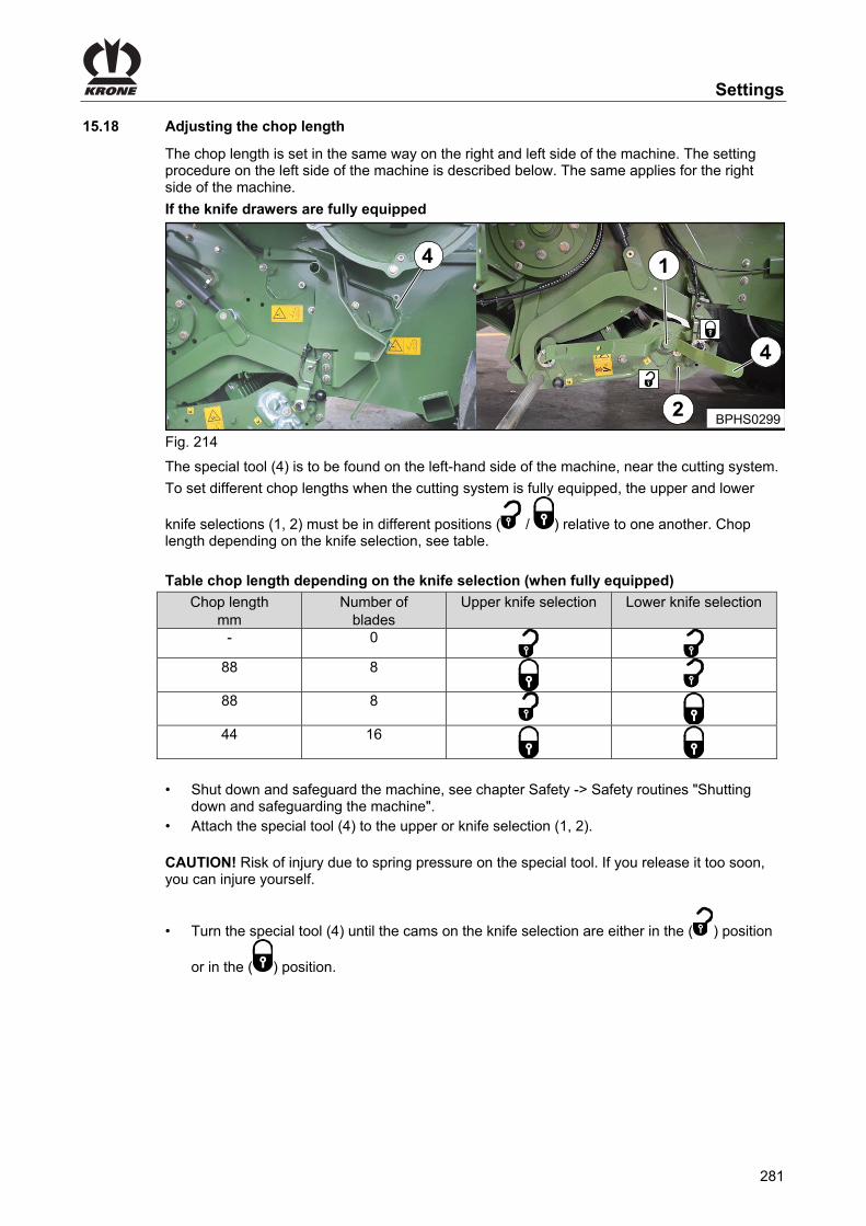
Settings
281
Pos: 102.87 /Überschriften/Überschriften 2/P-T/Schnittlänge einstellen @ 275\mod_1404396419814_78.docx @ 2067708 @ 2 @ 1
15.18 Adjusting the chop length Pos: 102.88 /BA/Einstellungen/Schneidwerk/Schnittlänge einstellen/Vollbestückung/Schnittlänge einstellen: Allgemein von der linken Seite Big Pack @ 279\mod_1405066787213_78.docx @ 2147503 @ @ 1
The chop length is set in the same way on the right and left side of the machine. The setting procedure on the left side of the machine is described below. The same applies for the right side of the machine.
Pos: 102.89 /BA/Einstellungen/Schneidwerk/Schnittlänge einstellen/Vollbestückung/Bei Vollbestückung der Messerkassette @ 275\mod_1404456429078_78.docx @ 2068551 @ @ 1
If the knife drawers are fully equipped Pos: 102.90 /BA/Einstellungen/Schneidwerk/Schnittlänge einstellen/Vollbestückung/Schnittlänge einstellen Bild @ 275\mod_1404399343354_78.docx @ 2067944 @ @ 1
4
BPHS0299
Fig. 214 Pos: 102.91 /BA/Einstellungen/Schneidwerk/Schnittlänge einstellen/Vollbestückung/Das Hilfswerkzeug (4) befindet sich an der linken Maschinenseite, in Nähe des Schneidwerks. @ 275\mod_1404456286163_78.docx @ 2068523 @ @ 1
The special tool (4) is to be found on the left-hand side of the machine, near the cutting system. Pos: 102.92 /BA/Einstellungen/Schneidwerk/Schnittlänge einstellen/Vollbestückung/Schnittlänge einstellen T1 in Abhängigkeit der Messerschaltung @ 275\mod_1404399346135_78.docx @ 2067973 @ @ 1
To set different chop lengths when the cutting system is fully equipped, the upper and lower
knife selections (1, 2) must be in different positions ( / ) relative to one another. Chop length depending on the knife selection, see table.
Pos: 102.93 /BA/Einstellungen/Schneidwerk/Schnittlänge einstellen/Vollbestückung/Schnittlänge Tabelle Messerschaltung BigPack mit 16 Messer @ 275\mod_1404400014028_78.docx @ 2067998 @ @ 1
Table chop length depending on the knife selection (when fully equipped)
Chop length mm
Number of blades
Upper knife selection Lower knife selection
- 0
88 8
88 8
44 16
Pos: 102.94 /BA/Einstellungen/Schneidwerk/Schnittlänge einstellen/Vollbestückung/Schnittlänge einstellen T2 @ 275\mod_1404394430217_78.docx @ 2067736 @ @ 1
• Shut down and safeguard the machine, see chapter Safety -> Safety routines "Shutting down and safeguarding the machine".
• Attach the special tool (4) to the upper or knife selection (1, 2). CAUTION! Risk of injury due to spring pressure on the special tool. If you release it too soon, you can injure yourself.
• Turn the special tool (4) until the cams on the knife selection are either in the ( ) position
or in the ( ) position. Pos: 102.95 /Layout Module /---------------Seitenumbruch---------------- @ 0\mod_1196175311226_0.docx @ 4165 @ @ 1
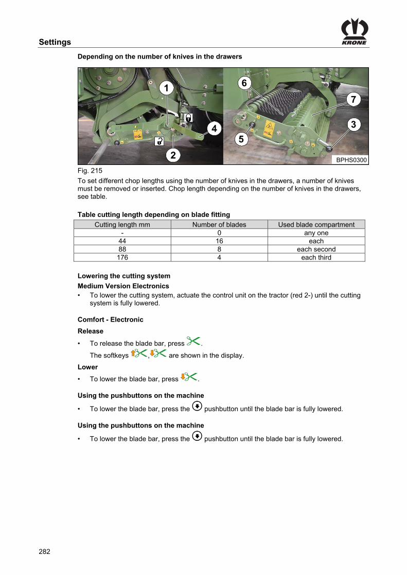
Settings
282
Pos: 102.96 /BA/Einstellungen/Schneidwerk/Schnittlänge einstellen/Vollbestückung/In Abhängigkeit der Messerbestückung in den Messerkassetten @ 279\mod_1405067044479_78.docx @ 2147647 @ @ 1
Depending on the number of knives in the drawers Pos: 102.97 /Layout Module /----------------Leerzeile 5 Pt.-------------------- @ 120\mod_1342592918145_0.docx @ 1092566 @ @ 1
Pos: 102.98 /BA/Wartung/Schneidwerk/Messerwechsel Bild @ 275\mod_1404401306487_78.docx @ 2068091 @ @ 1
5
BPHS0300
3
6
Fig. 215 Pos: 102.99 /BA/Einstellungen/Schneidwerk/Schnittlänge einstellen/Vollbestückung/Schnittlänge einstellen T1 in Abhängigkeit der Messerbestückung @ 275\mod_1404470280193_78.docx @ 2069803 @ @ 1
To set different chop lengths using the number of knives in the drawers, a number of knives must be removed or inserted. Chop length depending on the number of knives in the drawers, see table.
Pos: 102.100 /BA/Einstellungen/Schneidwerk/Schnittlänge einstellen/Schnittlänge Tabelle durch Messerbestückung BigPack HS mit 16 Messer @ 192\mod_1382081539305_78.docx @ 1637876 @ @ 1
Table cutting length depending on blade fitting
Cutting length mm Number of blades Used blade compartment - 0 any one
44 16 each 88 8 each second 176 4 each third
Pos: 102.101 /BA/Wartung/Schneidwerk/Schneidwerk absenken zÜ @ 275\mod_1404468973233_78.docx @ 2069532 @ @ 1
Lowering the cutting system Pos: 102.102 /BA/Wartung/Schneidwerk/Schneidwerk absenken: Medium – Elektronik @ 275\mod_1404468190618_78.docx @ 2069507 @ @ 1
Medium Version Electronics • To lower the cutting system, actuate the control unit on the tractor (red 2-) until the cutting
system is fully lowered. Pos: 102.103 /Layout Module /----------------Leerzeile 5 Pt.-------------------- @ 120\mod_1342592918145_0.docx @ 1092566 @ @ 1
Pos: 102.104 /BA/Maschinenbeschreibung/Maschinenübersicht/Großpackenpressen/Komfort - Elektronik @ 61\mod_1299223046976_78.docx @ 570919 @ @ 1
Comfort - Electronic Pos: 102.105 /BA/Info-Center/CCI-ISOBUS-Terminal/CCI-BiG Pack/Funktionstasten F1 bis F 12/Messerbalken freischalten @ 278\mod_1404986899370_78.docx @ 2084511 @ @ 1
Release
• To release the blade bar, press .
The softkeys , are shown in the display. Pos: 102.106 /BA/Info-Center/CCI-ISOBUS-Terminal/CCI-BiG Pack/Funktionstasten F1 bis F 12/Messerbalken senken @ 279\mod_1405059055432_78.docx @ 2146811 @ @ 1
Lower
• To lower the blade bar, press . Pos: 102.107 /Layout Module /----------------Leerzeile 5 Pt.-------------------- @ 120\mod_1342592918145_0.docx @ 1092566 @ @ 1
Pos: 102.108 /BA/Wartung/Schneidwerk/Schneidwerk absenken: Komfort-Elektronik Über die Tasten @ 275\mod_1404467742434_78.docx @ 2069479 @ @ 1
Using the pushbuttons on the machine
• To lower the blade bar, press the pushbutton until the blade bar is fully lowered. Pos: 102.109 /Layout Module /----------------Leerzeile 5 Pt.-------------------- @ 120\mod_1342592918145_0.docx @ 1092566 @ @ 1
Pos: 102.110 /BA/Wartung/Schneidwerk/Schneidwerk absenken: Komfort-Elektronik Über die Tasten @ 275\mod_1404467742434_78.docx @ 2069479 @ @ 1
Using the pushbuttons on the machine
• To lower the blade bar, press the pushbutton until the blade bar is fully lowered. Pos: 102.111 /Layout Module /---------------Seitenumbruch---------------- @ 0\mod_1196175311226_0.docx @ 4165 @ @ 1

Settings
283
Pos: 102.112 /BA/Wartung/Schneidwerk/Einzelmessersicherung entlasten @ 275\mod_1404467559772_78.docx @ 2069451 @ @ 1
Releasing the single blade locking device • Shut down and safeguard the machine, see chapter Safety -> Safety routines "Shutting
down and safeguarding the machine". • Attach the special tool (4) to the upper or knife selection (1, 2).
CAUTION! Risk of injury due to spring pressure on the special tool. If you release it too soon, you can injure yourself.
• Turn the special tool (4) until the cams on the upper and lower knife selection are in the () position.
Pos: 102.113 /Layout Module /---------------Seitenumbruch---------------- @ 0\mod_1196175311226_0.docx @ 4165 @ @ 1

Settings
284
Pos: 102.114 /BA/Wartung/Schneidwerk/Messerkassette herausziehen @ 275\mod_1404467519024_78.docx @ 2069423 @ @ 1
Removing the knife drawer (7) • To remove the knife drawer, unlock the locking lever (3) and pull the knife drawer out
sideways as far as the stop. Pos: 102.115 /Layout Module /----------------Leerzeile 5 Pt.-------------------- @ 120\mod_1342592918145_0.docx @ 1092566 @ @ 1
Pos: 102.116 /BA/Wartung/Schneidwerk/Messerwelle entriegeln @ 275\mod_1404467406452_78.docx @ 2069395 @ @ 1
Unlocking the blade shaft
• To unlock the blade shaft, move the locking lever (5) to position ( ). Pos: 102.117 /Layout Module /----------------Leerzeile 5 Pt.-------------------- @ 120\mod_1342592918145_0.docx @ 1092566 @ @ 1
Pos: 102.118 /BA/Wartung/Schneidwerk/Messer entnehmen / einsetzen @ 275\mod_1404467247194_78.docx @ 2069367 @ @ 1
Removing/replacing blades
CAUTION! Danger from sharp blades. Wear gloves.
• Remove the blade (6) vertically upwards. • Insert the new blade vertically from above.
Pos: 102.119 /Layout Module /----------------Leerzeile 5 Pt.-------------------- @ 120\mod_1342592918145_0.docx @ 1092566 @ @ 1
Pos: 102.120 /BA/Wartung/Schneidwerk/Messerwelle verriegeln @ 275\mod_1404467169917_78.docx @ 2069339 @ @ 1
Locking the blade shaft
• To lock the blade shaft, move the locking lever (5) to position ( ). • Push in the knife drawer until the locking lever (3) automatically catches in place. • Insert the special tool into the holder on the machine
Pos: 102.121 /Layout Module /----------------Leerzeile 5 Pt.-------------------- @ 120\mod_1342592918145_0.docx @ 1092566 @ @ 1
Pos: 102.122 /BA/Wartung/Schneidwerk/Schneidwerk anheben zÜ @ 279\mod_1405063605495_78.docx @ 2147011 @ @ 1
Raising the cutting system Pos: 102.123 /BA/Wartung/Schneidwerk/Schneidwerk anheben: Medium – Elektronik @ 279\mod_1405063657778_78.docx @ 2147045 @ @ 1
Medium Version Electronics • To raise the cutting system, actuate the control unit on the tractor (red 2-) until the cutting
system is fully raised. Pos: 102.124 /BA/Maschinenbeschreibung/Maschinenübersicht/Großpackenpressen/Komfort - Elektronik @ 61\mod_1299223046976_78.docx @ 570919 @ @ 1
Comfort - Electronic Pos: 102.125 /BA/Info-Center/CCI-ISOBUS-Terminal/CCI-BiG Pack/Funktionstasten F1 bis F 12/Messerbalken freischalten @ 278\mod_1404986899370_78.docx @ 2084511 @ @ 1
Release
• To release the blade bar, press .
The softkeys , are shown in the display. Pos: 102.126 /BA/Info-Center/CCI-ISOBUS-Terminal/CCI-BiG Pack/Funktionstasten F1 bis F 12/Messerbalken heben @ 279\mod_1405059049526_78.docx @ 2146781 @ @ 1
Raise
• To raise the blade bar, press . Pos: 102.127 /BA/Wartung/Schneidwerk/Schneidwerk anheben: Komfort-Elektronik Über die Tasten @ 279\mod_1405064009645_78.docx @ 2147105 @ @ 1
Using the pushbuttons on the machine
• To raise the blade bar, press the pushbutton until the blade bar is fully raised. Pos: 103 /Layout Module /---------------Seitenumbruch---------------- @ 0\mod_1196175311226_0.docx @ 4165 @ @ 1

Maintenance
285
Pos: 104 /Überschriften/Überschriften 1/U-Z/Wartung @ 0\mod_1199883581050_78.docx @ 36685 @ 1 @ 1
16 Maintenance Pos: 105.1 /BA/Sicherheit/2. Vorangestellte Warnhinweise/WARNUNG - Nichtbeachtung der grundlegenden Sicherheitshinweise alte Form @ 254\mod_1397485793575_78.docx @ 1953347 @ @ 1
WARNING! If the basic safety instructions are not followed, people may be seriously injured or killed. • To avoid accidents, the basic safety instructions in the chapter Safety must have been
read and followed, see chapter Safety "Basic safety instructions".
Pos: 105.2 /BA/Sicherheit/2. Vorangestellte Warnhinweise/Warnung - Nichtbeachtung der Sicherheitsroutinen alte Form @ 273\mod_1404117435996_78.docx @ 2058712 @ @ 1
WARNING! If the safety routines are not adhered to, people may be seriously injured or killed. • To avoid accidents, the safety routines in the chapter Safety must be read and followed,
see chapter Safety "Safety routines".
Pos: 105.3 /Überschriften/Überschriften 2/A-E/Ersatzteile @ 0\mod_1196782991234_78.docx @ 14927 @ 2 @ 1
16.1 Spare Parts Pos: 105.4 /BA/Sicherheit/7. Gefahrenhinweise alt/Mähwerke/Gefahr - Verwendung von nicht zugelassenen Ersatzteilen @ 0\mod_1196783037140_78.docx @ 14946 @ @ 1
Danger! - Using non-approved spare parts. Effect: Danger to life, serious injuries or loss of warranty claims as well as exclusion of liability • Use only authentic KRONE spare parts and accessories authorised by the manufacturer.
The use of spare parts, accessories or additional equipment not manufactured, tested or approved by KRONE will exclude any liability for consequential damage.
Pos: 105.5 /BA/Wartung/Hinweis Verschleiß verringern @ 0\mod_1199953505303_78.docx @ 37204 @ @ 1
Note To ensure problem-free operation of the machine and to reduce wear and tear, specific maintenance and upkeep intervals must be observed. These include cleaning, greasing, lubricating and oiling parts and components.
Pos: 105.6 /BA/Wartung/Umwelt/Hinweis Entsorgen / Lagern von Öle und Ölfilter Umwelt @ 32\mod_1253101375171_78.docx @ 311770 @ @ 1
ENVIRONMENT! - Disposal and storage of used lubricants and oil filters Effect: Environmental damage Store or dispose used oil and oil filters according to statutory provisions.
Pos: 105.7 /BA/Wartung/Umwelt/Hinweis Entsorgen / Lagern von Schmierstoffen Umwelt @ 32\mod_1253100514124_78.docx @ 311746 @ @ 1
ENVIRONMENT! - Disposal and storage of lubricants Effect: Environmental damage • Store lubricants in eligible containers according to statutory provisions • Dispose used lubricants according to statutory provisions
Pos: 105.8 /Layout Module /---------------Seitenumbruch---------------- @ 0\mod_1196175311226_0.docx @ 4165 @ @ 1
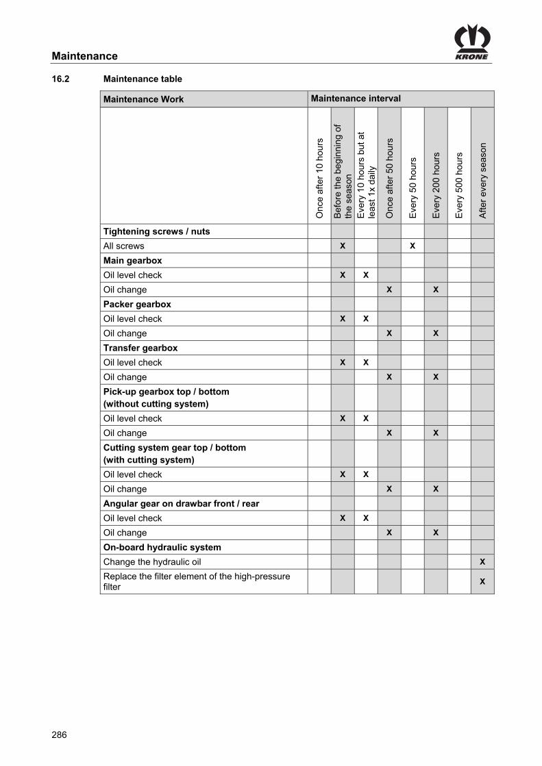
Maintenance
286
Pos: 105.9 /Überschriften/Überschriften 2/U-Z/Wartungstabelle @ 65\mod_1300369413064_78.docx @ 583966 @ 2 @ 1
16.2 Maintenance table Pos: 105.10 /BA/Wartung/Großpackenpressen/Wartungstabelle 1290 HDP II T1 @ 158\mod_1364472985841_78.docx @ 1390724 @ @ 1
Maintenance Work Maintenance interval
Onc
e af
ter
10 h
ours
Bef
ore
the
begi
nnin
g of
th
e se
ason
E
very
10
hour
s bu
t at
leas
t 1x
daily
Onc
e af
ter
50 h
ours
Eve
ry 5
0 ho
urs
Eve
ry 2
00 h
ours
Eve
ry 5
00 h
ours
Afte
r ev
ery
seas
on
Tightening screws / nuts
All screws X X
Main gearbox
Oil level check X X
Oil change X X
Packer gearbox
Oil level check X X
Oil change X X
Transfer gearbox
Oil level check X X
Oil change X X
Pick-up gearbox top / bottom (without cutting system)
Oil level check X X
Oil change X X
Cutting system gear top / bottom (with cutting system)
Oil level check X X
Oil change X X
Angular gear on drawbar front / rear
Oil level check X X
Oil change X X
On-board hydraulic system
Change the hydraulic oil X
Replace the filter element of the high-pressure filter
X
Pos: 105.11 /Layout Module /---------------Seitenumbruch---------------- @ 0\mod_1196175311226_0.docx @ 4165 @ @ 1

Maintenance
287
Pos: 105.12 /BA/Wartung/Großpackenpressen/Wartungstabelle 1290 HDP II T2 @ 171\mod_1370243929901_78.docx @ 1473813 @ @ 1
Maintenance work Maintenance interval
Onc
e af
ter
10 h
ours
Bef
ore
the
begi
nnin
g of
th
e se
ason
E
very
10
hour
s bu
t at
leas
t 1x
daily
Onc
e af
ter
50 h
ours
Eve
ry 5
0 ho
urs
Eve
ry 2
00 h
ours
Eve
ry 5
00 h
ours
Afte
r ev
ery
seas
on
Tyres
Tighten wheel nuts X X X
Check tyre pressure X X X
Check tyres visually for cuts and breaks X
Compressor
Clean suction air filter X
Oil level check X
Oil change X X
Brake
Check the functionality of the brake system X
Drain the compressed air reservoir X X
Check the linkage setter X X
Pneumatic brake cylinders Every two years
Have brake pads checked by a specialist workshop
X
Check air filter for pipes X
Hydraulics
Check hydraulic hoses X
Change high-pressure filter filter insert X
Checking / retightening drive chains
Conveyor roller X
Pick-up drive X
Checking / changing blades X X
Checking parts
Check the bearing play of the rollers/cam follower rollers
X X
Check the functionality of the central lubrication X X
Cleaning the machine
Knotter, packer control system, flywheel X
Belt drives
Check belts visually for cracks X
Pos: 105.13 /Layout Module /---------------Seitenumbruch---------------- @ 0\mod_1196175311226_0.docx @ 4165 @ @ 1

Maintenance
288
Pos: 105.14 /Überschriften/Überschriften 2/A-E/Anzugsdrehmomente @ 45\mod_1277103093968_78.docx @ 410970 @ 2 @ 1
16.3 Tightening Torques Pos: 105.15 /BA/Wartung/Drehmomente / Anzugsmomente/Drehmomente @ 45\mod_1277102920578_78.docx @ 410945 @ @ 1
The tightening torque MA is stated in Nm (unless otherwise indicated).
A = Thread size (The stability class can be seen on the head of the screw.)
A Ø
5.6 6.8 8.8 10.9 12.9
MA (Nm)
M 4 2.2 3 4.4 5.1
M 5 4.5 5.9 8.7 10
M 6 7.6 10 15 18
M 8 18 25 36 43
M 10 29 37 49 72 84
M12 42 64 85 125 145
M14 100 135 200 235
M14x1.5 145 215 255
M 16 160 210 310 365
M16x1.5 225 330 390
M 20 425 610 710
M 24 730 1050 1220
M 24x1.5 350
M 24x2 800 1150 1350
M 27 1100 1550 1800
M 27x2 1150 1650 1950
M30 1450 2100 2450
NOTE
The table above does not apply to countersunk screws with a hexagonal socket head if the countersunk screw is tightened with the hexagonal socket head.
Pos: 105.16 /Layout Module /---------------Seitenumbruch---------------- @ 0\mod_1196175311226_0.docx @ 4165 @ @ 1
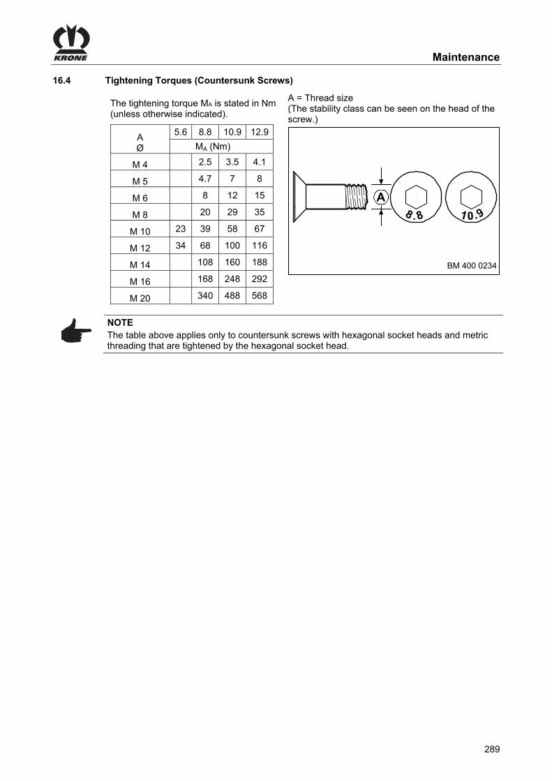
Maintenance
289
Pos: 105.17 /Überschriften/Überschriften 2/A-E/Anzugsdrehmomente über Innensechskant @ 45\mod_1277106415765_78.docx @ 411230 @ 2 @ 1
16.4 Tightening Torques (Countersunk Screws) Pos: 105.18 /BA/Wartung/Drehmomente / Anzugsmomente/Drehmomente über Innensechskant @ 45\mod_1277106232328_78.docx @ 411205 @ @ 1
The tightening torque MA is stated in Nm (unless otherwise indicated).
A = Thread size (The stability class can be seen on the head of the screw.)
A Ø
5.6 8.8 10.9 12.9
MA (Nm)
M 4 2.5 3.5 4.1
M 5 4.7 7 8
M 6 8 12 15
M 8 20 29 35
M 10 23 39 58 67
M 12 34 68 100 116
M 14 108 160 188
M 16 168 248 292
M 20 340 488 568
A
BM 400 0234
NOTE The table above applies only to countersunk screws with hexagonal socket heads and metric threading that are tightened by the hexagonal socket head.
Pos: 105.19 /Layout Module /---------------Seitenumbruch---------------- @ 0\mod_1196175311226_0.docx @ 4165 @ @ 1

Maintenance
290
Pos: 105.20 /Überschriften/Überschriften 2/K-O/Messerwechsel @ 8\mod_1219657285958_78.docx @ 119937 @ 2 @ 1
16.5 Blade Changing Pos: 105.21 /BA/Wartung/Schneidwerk/Messerwechsel allgemein von der linken Seite Big Pack @ 275\mod_1404469078762_78.docx @ 2069681 @ @ 1
Blades are changed in the same way on the right and left side of the machine. The procedure used on the left side of the machine is described below. The same applies for the right side of the machine.
Pos: 105.22 /Layout Module /----------------Leerzeile 5 Pt.-------------------- @ 120\mod_1342592918145_0.docx @ 1092566 @ @ 1
Pos: 105.23 /BA/Wartung/Schneidwerk/Achtung - Schneidwerk hochfahren @ 275\mod_1404469396832_78.docx @ 2069710 @ @ 1
ATTENTION! You many damage the cutting system if you raise it without first retracting and locking the knife drawers. • Ensure that both knife drawers are properly pushed in and locked before the cutting
system is raised.
Pos: 105.24.1 /BA/Wartung/Schneidwerk/Messerwechsel Bild @ 275\mod_1404401306487_78.docx @ 2068091 @ @ 1
5
BPHS0300
3
6
Fig. 216 Pos: 105.24.2 /BA/Wartung/Schneidwerk/Schneidwerk absenken zÜ @ 275\mod_1404468973233_78.docx @ 2069532 @ @ 1
Lowering the cutting system Pos: 105.24.3 /BA/Wartung/Schneidwerk/Schneidwerk absenken: Medium – Elektronik @ 275\mod_1404468190618_78.docx @ 2069507 @ @ 1
Medium Version Electronics • To lower the cutting system, actuate the control unit on the tractor (red 2-) until the cutting
system is fully lowered. Pos: 105.24.4 /Layout Module /----------------Leerzeile 5 Pt.-------------------- @ 120\mod_1342592918145_0.docx @ 1092566 @ @ 1
Pos: 105.24.5 /BA/Maschinenbeschreibung/Maschinenübersicht/Großpackenpressen/Komfort - Elektronik @ 61\mod_1299223046976_78.docx @ 570919 @ @ 1
Comfort - Electronic Pos: 105.24.6 /BA/Info-Center/CCI-ISOBUS-Terminal/CCI-BiG Pack/Funktionstasten F1 bis F 12/Messerbalken freischalten @ 278\mod_1404986899370_78.docx @ 2084511 @ @ 1
Release
• To release the blade bar, press .
The softkeys , are shown in the display. Pos: 105.24.7 /BA/Info-Center/CCI-ISOBUS-Terminal/CCI-BiG Pack/Funktionstasten F1 bis F 12/Messerbalken senken @ 279\mod_1405059055432_78.docx @ 2146811 @ @ 1
Lower
• To lower the blade bar, press . Pos: 105.24.8 /Layout Module /----------------Leerzeile 5 Pt.-------------------- @ 120\mod_1342592918145_0.docx @ 1092566 @ @ 1
Pos: 105.24.9 /BA/Wartung/Schneidwerk/Schneidwerk absenken: Komfort-Elektronik Über die Tasten @ 275\mod_1404467742434_78.docx @ 2069479 @ @ 1
Using the pushbuttons on the machine
• To lower the blade bar, press the pushbutton until the blade bar is fully lowered. Pos: 105.24.10 /Layout Module /----------------Leerzeile 5 Pt.-------------------- @ 120\mod_1342592918145_0.docx @ 1092566 @ @ 1
Pos: 105.24.11 /BA/Wartung/Schneidwerk/Einzelmessersicherung entlasten @ 275\mod_1404467559772_78.docx @ 2069451 @ @ 1
Releasing the single blade locking device • Shut down and safeguard the machine, see chapter Safety -> Safety routines "Shutting
down and safeguarding the machine". • Attach the special tool (4) to the upper or knife selection (1, 2).
CAUTION! Risk of injury due to spring pressure on the special tool. If you release it too soon, you can injure yourself.
• Turn the special tool (4) until the cams on the upper and lower knife selection are in the () position.
Pos: 105.24.12 /Layout Module /---------------Seitenumbruch---------------- @ 0\mod_1196175311226_0.docx @ 4165 @ @ 1

Maintenance
291
Pos: 105.24.13 /BA/Wartung/Schneidwerk/Messerkassette herausziehen @ 275\mod_1404467519024_78.docx @ 2069423 @ @ 1
Removing the knife drawer (7) • To remove the knife drawer, unlock the locking lever (3) and pull the knife drawer out
sideways as far as the stop. Pos: 105.24.14 /Layout Module /----------------Leerzeile 5 Pt.-------------------- @ 120\mod_1342592918145_0.docx @ 1092566 @ @ 1
Pos: 105.24.15 /BA/Wartung/Schneidwerk/Messerwelle entriegeln @ 275\mod_1404467406452_78.docx @ 2069395 @ @ 1
Unlocking the blade shaft
• To unlock the blade shaft, move the locking lever (5) to position ( ). Pos: 105.24.16 /Layout Module /----------------Leerzeile 5 Pt.-------------------- @ 120\mod_1342592918145_0.docx @ 1092566 @ @ 1
Pos: 105.24.17 /BA/Wartung/Schneidwerk/Messer entnehmen / einsetzen @ 275\mod_1404467247194_78.docx @ 2069367 @ @ 1
Removing/replacing blades
CAUTION! Danger from sharp blades. Wear gloves.
• Remove the blade (6) vertically upwards. • Insert the new blade vertically from above.
Pos: 105.24.18 /Layout Module /----------------Leerzeile 5 Pt.-------------------- @ 120\mod_1342592918145_0.docx @ 1092566 @ @ 1
Pos: 105.24.19 /BA/Wartung/Schneidwerk/Messerwelle verriegeln @ 275\mod_1404467169917_78.docx @ 2069339 @ @ 1
Locking the blade shaft
• To lock the blade shaft, move the locking lever (5) to position ( ). • Push in the knife drawer until the locking lever (3) automatically catches in place. • Insert the special tool into the holder on the machine
Pos: 105.24.20 /Layout Module /----------------Leerzeile 5 Pt.-------------------- @ 120\mod_1342592918145_0.docx @ 1092566 @ @ 1
Pos: 105.24.21 /BA/Wartung/Schneidwerk/Schneidwerk anheben zÜ @ 279\mod_1405063605495_78.docx @ 2147011 @ @ 1
Raising the cutting system Pos: 105.24.22 /BA/Wartung/Schneidwerk/Schneidwerk anheben: Medium – Elektronik @ 279\mod_1405063657778_78.docx @ 2147045 @ @ 1
Medium Version Electronics • To raise the cutting system, actuate the control unit on the tractor (red 2-) until the cutting
system is fully raised. Pos: 105.24.23 /BA/Maschinenbeschreibung/Maschinenübersicht/Großpackenpressen/Komfort - Elektronik @ 61\mod_1299223046976_78.docx @ 570919 @ @ 1
Comfort - Electronic Pos: 105.24.24 /BA/Info-Center/CCI-ISOBUS-Terminal/CCI-BiG Pack/Funktionstasten F1 bis F 12/Messerbalken freischalten @ 278\mod_1404986899370_78.docx @ 2084511 @ @ 1
Release
• To release the blade bar, press .
The softkeys , are shown in the display. Pos: 105.24.25 /BA/Info-Center/CCI-ISOBUS-Terminal/CCI-BiG Pack/Funktionstasten F1 bis F 12/Messerbalken heben @ 279\mod_1405059049526_78.docx @ 2146781 @ @ 1
Raise
• To raise the blade bar, press . Pos: 105.24.26 /BA/Wartung/Schneidwerk/Schneidwerk anheben: Komfort-Elektronik Über die Tasten @ 279\mod_1405064009645_78.docx @ 2147105 @ @ 1
Using the pushbuttons on the machine
• To raise the blade bar, press the pushbutton until the blade bar is fully raised. Pos: 105.24.27 /Layout Module /----------------Leerzeile 5 Pt.-------------------- @ 120\mod_1342592918145_0.docx @ 1092566 @ @ 1
Pos: 105.24.28 /BA/Wartung/Schneidwerk/Schnittlänge einstellen: Um die Schnittlänge einzustellen, siehe Kapitel Einstellungen @ 275\mod_1404467074889_78.docx @ 2069253 @ @ 1
Adjusting the chop length To adjust the chop length, see chapter Settings "Adjusting the chop length".
Pos: 105.25 /Layout Module /---------------Seitenumbruch---------------- @ 0\mod_1196175311226_0.docx @ 4165 @ @ 1

Maintenance
292
Pos: 105.26 /Überschriften/Überschriften 2/A-E/Anheben @ 33\mod_1254380091415_78.docx @ 319041 @ 2 @ 1
16.6 Lifting Pos: 105.27 /BA/Wartung/Anheben/Anheben Bild BiG PACK 870 HDP @ 280\mod_1405487668091_78.docx @ 2153878 @ @ 1
BPHS0302
RH+LH
942 012-1
RH+LH
942 012-1
Fig. 217 RH = right-hand side of the machine LH = left-hand side of the machine
Pos: 105.28 /BA/Sicherheit/8. Voraussetzungen/Handlungsanweisung für alle Maschinen/Handlungsanweisung: Maschine stillsetzen und sichern @ 274\mod_1404365253849_78.docx @ 2065151 @ @ 1
• Shut down and safeguard the machine, see chapter Safety -> Safety routines, "Shutting down and safeguarding the machine".
Pos: 105.29 /BA/Wartung/Anheben/Anheben der Maschine BigPack @ 280\mod_1405587188041_78.docx @ 2156401 @ 33 @ 1
16.6.1 Eyebolts for lifting
The baler is fitted with four eyebolts for lifting: – Two eyebolts are located in the front area of the drawbar (1), on the right and left side of the
machine. – Two eyebolts are located at the rear at the yoke (2), on the right and left side of the
machine.
16.6.2 Lifting
Before lifting, make sure that – the flywheel brake is applied. – the parking support (support jack) is in the transport position. – the roller chute (bale chute) is folded in. – the pick-up is raised – the self-steering axle is locked, optional. – all safety devices are locked. – the lifting beams have a minimum load-bearing capacity, depending on the permitted gross
weight of the machine. Weight of the machine, see chapter Description of machine "Technical Data". • Attach the chains on the lifting beams to the four eyebolts on the baler. Make sure that the chain hooks are correctly placed on the stop points.
Pos: 105.30 /Layout Module /---------------Seitenumbruch---------------- @ 0\mod_1196175311226_0.docx @ 4165 @ @ 1

Maintenance
293
Pos: 105.31 /Überschriften/Überschriften 2/P-T/Reinigung @ 24\mod_1241504803133_78.docx @ 245455 @ 2 @ 1
16.7 Cleaning Pos: 105.32 /BA/Sicherheit/6. Überarbeitete Warnhinweise/Warnung - Reinigung mit Druckluft_alt @ 0\mod_1196770018125_78.docx @ 13211 @ @ 1
Warning! - Cleaning with compressed air! Effect: Loss of eyesight! • Keep people well away from the working area. • Wear suitable work clothes to perform cleaning jobs with compressed air (for example eye
protection).
Pos: 105.33 /BA/Wartung/Großpackenpressen/Reinigung @ 24\mod_1241505488117_78.docx @ 245479 @ @ 1
The BiG PACK baler, especially the knotter, must be cleaned of chaff and dust after every use. Under very dry working conditions, the cleaning must be repeated several times a day. The packer control system and the flywheel must also be cleaned daily of chaff and dust.
Pos: 105.34 /BA/Sicherheit/8. Voraussetzungen/Handlungsanweisung für alle Maschinen/Handlungsanweisung: Maschine stillsetzen und sichern @ 274\mod_1404365253849_78.docx @ 2065151 @ @ 1
• Shut down and safeguard the machine, see chapter Safety -> Safety routines, "Shutting down and safeguarding the machine".
Pos: 105.35 /Layout Module /---------------Seitenumbruch---------------- @ 0\mod_1196175311226_0.docx @ 4165 @ @ 1

Maintenance
294
Pos: 105.36 /Überschriften/Überschriften 2/A-E/Antriebsketten @ 27\mod_1246355234599_78.docx @ 267399 @ 2 @ 1
16.8 Drive chains Pos: 105.37 /BA/Wartung/Antriebsketten (Ketten)/Antriebsketten allgemein @ 107\mod_1334563877892_78.docx @ 966387 @ @ 1
• Regularly check the pretension of the drive chains (especially on new drive chains) • Shorten chains which have become too long by taking out a chain link
Pos: 105.38 /BA/Sicherheit/8. Voraussetzungen/Handlungsanweisung für alle Maschinen/Handlungsanweisung: Maschine stillsetzen und sichern @ 274\mod_1404365253849_78.docx @ 2065151 @ @ 1
• Shut down and safeguard the machine, see chapter Safety -> Safety routines, "Shutting down and safeguarding the machine".
Pos: 105.39 /BA/Wartung/Antriebsketten (Ketten)/Förderwalze (I) bei Ausführung ohne Schneidwerk @ 107\mod_1334579131627_78.docx @ 967455 @ 3 @ 1
16.8.1 Conveyor roller (I)
a
I
Fig. 218 Right-hand side of the machine At the factory the spring has been preset (1) to a = 100 mm. • Open the protective cover on the right side of the machine • By tightening the nut (2), increase the tension of the spring (1) • Close protective cover
Pos: 105.40 /BA/Wartung/Antriebsketten (Ketten)/Pick-up Antrieb (II) bei Ausführung ohne Schneidwerk @ 107\mod_1334579399032_78.docx @ 967483 @ 3 @ 1
16.8.2 Pick-up drive (II)
a
II
Fig. 219 Right-hand side of the machine At the factory the spring has been preset (1) to a = 60 mm. • Open the protective cover on the right side of the machine • Unscrew the counter nut (2) • By tightening the nut (3), increase the tension of the spring (1) • Secure the nut (3) with the counter nut (2) • Close protective cover
Pos: 105.41 /BA/Wartung/Antriebsketten (Ketten)/Pick-up Antrieb (III) bei Ausführung ohne Schneidwerk @ 107\mod_1334579563077_78.docx @ 967511 @ 3 @ 1

Maintenance
295
16.8.3 Pick-up drive (III)
a III
III
Fig. 220 Right and left sides of the machine At the factory the spring has been preset (1) to a = 60 mm. • Open the protective cover on the right or left side of the machine • Unscrew the counter nut (2) • By screwing in the bolt (3), increase the tension of the spring (1) • Secure the bolt (3) with the counter nut (2) • Close protective cover
Pos: 105.42 /Layout Module /---------------Seitenumbruch---------------- @ 0\mod_1196175311226_0.docx @ 4165 @ @ 1

Maintenance
296
Pos: 105.43 /Überschriften/Überschriften 2/P-T/Reifen @ 0\mod_1197357995667_78.docx @ 18075 @ 2 @ 1
16.9 Tyres Pos: 105.44 /BA/Sicherheit/7. Gefahrenhinweise alt/Warnung - Falsche Reifenmontage @ 0\mod_1197358162433_78.docx @ 18132 @ @ 1
Warning! - Tyre fitting incorrect Effect: Injuries or damage to the machine • Fitting tyres requires sufficient knowledge and the availability of proper tools! • If tyres are not correctly fitted, it could explode when pumped up. This can cause serious
injury. If you do not have sufficient experience of fitting tyres, have tyres fitted by the KRONE dealer or a qualified tyre specialist.
• When fitting tyres on the wheel rims, the maximum pressure given by the tyre manufacturer must not be exceeded. The tyre or even the wheel rim could explode and/or burst.
• If the tyre heels do not fit properly when the maximum permitted pressure is reached, let out the air, align tyres, lubricate the tyre heels and pump up the tyre again.
• Detailed information about how to fit tyres onto agricultural machinery can be obtained from the tyre manufacturers.
Pos: 105.45 /BA/Wartung/Reifen/Anziehdrehmoment @ 0\mod_1199955905460_78.docx @ 37340 @ @ 1
Tightening Torque
Threading Key size in mm
Number of bolts per hub - pieces
Max. tightening torque
black galvan.
M12 x 1.5 19 4/5 95 Nm 95 Nm
M14 x 1.5 22 5 125 Nm 125 Nm
M18 x 1.5 24 6 290 Nm 320 Nm
M20 x 1.5 27 8 380 Nm 420 Nm
M20 x 1,5 30 8 380 Nm 420 Nm
M22 x 1.5 32 8/10 510 Nm 560 Nm
M22 x 2 32 10 460 Nm 505 Nm
Pos: 105.46 /Layout Module /---------------Seitenumbruch---------------- @ 0\mod_1196175311226_0.docx @ 4165 @ @ 1

Maintenance
297
Pos: 105.47 /Überschriften/Überschriften 3/P-T/Reifen prüfen und pflegen @ 0\mod_1197358037214_78.docx @ 18094 @ 3 @ 1
16.9.1 Checking and maintaining tyres Pos: 105.48 /BA/Wartung/Reifen/Reihenfolge Bild 6-Loch @ 4\mod_1213086131413_78.docx @ 86197 @ @ 1
1
KS-0-034
6
2
4 5
3
Fig. 221 Pos: 105.49 /BA/Sicherheit/8. Voraussetzungen/Handlungsanweisung für alle Maschinen/Handlungsanweisung: Maschine stillsetzen und sichern @ 274\mod_1404365253849_78.docx @ 2065151 @ @ 1
• Shut down and safeguard the machine, see chapter Safety -> Safety routines, "Shutting down and safeguarding the machine".
Pos: 105.50 /BA/Wartung/Reifen/Reifen prüfen und pflegen nach Wartungstabelle @ 134\mod_1350480797454_78.docx @ 1187905 @ @ 1
When loosening and tightening the wheel nuts, observe the order indicated in the illustration. Check the wheel nuts: According to the maintenance table Check the tyre air pressure: According to the maintenance table
Pos: 106 /Layout Module /---------------Seitenumbruch---------------- @ 0\mod_1196175311226_0.docx @ 4165 @ @ 1

Maintenance - hydraulic system
298
Pos: 107 /Überschriften/Überschriften 1/U-Z/Wartung - Hydraulik @ 2\mod_1203057943713_78.docx @ 64474 @ 1 @ 1
17 Maintenance - hydraulic system Pos: 108 /BA/Sicherheit/2. Vorangestellte Warnhinweise/Warnung - Flüssigkeiten unter Druck / Umgang mit Leckagen @ 273\mod_1403616315353_78.docx @ 2053221 @ @ 1
WARNING! – Risk of injury as a result of incorrect handling of liquids under high pressure. Effect: Escaping high-pressure liquids can penetrate the skin and cause serious injury. Repair work on the hydraulic system may only be performed by authorised KRONE
professional workshops. • Depressurise the system before disconnecting lines. • When searching for leaks, use suitable aids and wear protective goggles. • High-pressure liquid that is escaping from a small opening is virtually invisible. Therefore,
you should use a piece of cardboard or something similar when searching for leaks. Protect your hands and body.
• If liquid penetrates the skin, consult a doctor immediately. The liquid must be removed from the body as quickly as possible. Danger of infection! Physicians who are not familiar with this area must consult appropriate information from a competent medical source.
• Check hydraulic hoses regularly and replace if there are any signs of damage or ageing! The replacement lines must comply with the requirements of the device manufacturer.
• Ensure that all line connections are tight before the pressure in the system builds up again.
Pos: 109 /BA/Sicherheit/Hydraulik/WARNUNG - Hydraulikschlauchleitungen unterliegen einer Alterung @ 256\mod_1397735975770_78.docx @ 1965100 @ @ 1
WARNING! – Hydraulic hose lines are subject to ageing Effect: Danger to life or serious injuries The characteristics of the lines change depending on pressure, heat load and the effect of UV rays. The date of manufacture appears on the hydraulic hoses. This way the age can be ascertained quickly. By law the hydraulic lines must be replaced after six years. Use original spare parts when replacing hydraulic hoses!
Pos: 110 /BA/Wartung/Großpackenpressen/Hydraulikanlage / Bordhydraulik/Hinweis zu Hydraulikarbeiten @ 24\mod_1241518053726_78.docx @ 245734 @ @ 1
Note • When working on the hydraulic system, absolute cleanliness is essential • Check the hydraulic oil level each time before placing the machine in operation • Observe the intervals for replacing the hydraulic oil and hydraulic oil filter • The used oil must be disposed of correctly
Pos: 111 /Layout Module /---------------Seitenumbruch---------------- @ 0\mod_1196175311226_0.docx @ 4165 @ @ 1

Maintenance - hydraulic system
299
Pos: 112 /Überschriften/Überschriften 3/A-E/B/Bordhydraulik @ 24\mod_1241518305195_78.docx @ 245758 @ 3 @ 1
17.1.1 On-board hydraulic system Pos: 113 /BA/Wartung/Umwelt/Hinweis Entsorgen / Lagern von Öle und Ölfilter Umwelt @ 32\mod_1253101375171_78.docx @ 311770 @ @ 1
ENVIRONMENT! - Disposal and storage of used lubricants and oil filters Effect: Environmental damage Store or dispose used oil and oil filters according to statutory provisions.
Pos: 114 /BA/Wartung/Großpackenpressen/Hydraulikanlage / Bordhydraulik/Bordhydraulik Öl wechseln Bild 890_1270_1290 @ 193\mod_1382619807192_78.docx @ 1641912 @ @ 1
Fig. 222
1) Dipstick / oil filling hole 2) Hydraulic tank
3) Drain plug
Pos: 115 /BA/Wartung/Großpackenpressen/Hydraulikanlage / Bordhydraulik/Bordhydraulik Öl wechseln @ 191\mod_1381903768902_78.docx @ 1633028 @ @ 1
To do this: • Stop the machine. • Apply the flywheel brake. • Open bale channel flaps. The hydraulic cylinders of the bale channel flaps must be completely retracted. • Provide a suitable container for oil change. • Unscrew the drain plug. • Collect the oil in a suitable container. • Screw in drain plug. • Screw out dipstick and fill in hydraulic oil. • Check the oil level with dipstick.
Pos: 116 /BA/Wartung/Ölkontrolle_Wechsel/Ölqualität /Ölmenge: siehe Kapitel Technische Daten @ 134\mod_1350483480921_78.docx @ 1188085 @ @ 1
Oil Quality / Amount of Oil: Refer to Chapter Technical Data “Lubricants” Pos: 117 /BA/Wartung/Ölkontrolle_Wechsel/Ölkontrolle NEU über Kontrollschraube @ 140\mod_1355141753680_78.docx @ 1244582 @ @ 1
Oil level check: • Screw out inspection screw. • Oil level up to control hole. If the oil reaches the control hole: • Screw in the inspection screw and tighten it securely. If the oil does not reach the control hole: • Screw out filler plug. • Top up oil via oil filling hole until the control hole is reached. • Screw in the inspection screw and the filler plug and tighten them securely.
Pos: 118 /Layout Module /---------------Seitenumbruch---------------- @ 0\mod_1196175311226_0.docx @ 4165 @ @ 1

Maintenance - hydraulic system
300
Pos: 119.1 /Überschriften/Überschriften 2/F-J/Hochdruckfilter @ 26\mod_1245836423991_78.docx @ 264126 @ 2 @ 1
17.2 High-pressure filter Pos: 119.2 /BA/Wartung/Hochdruckfilter/Mitteldruckfilter optische Verschmutzungsanzeige @ 32\mod_1253092558858_78.docx @ 309853 @ @ 1
The filter takes up depositions of solid particles of the hydraulic system. The filtering of the hydraulic circuit serves as a prevention of damages on components of the circuit. The filter is equipped with an optical contamination indicator (7). The contamination indicator (7) informs optical about the degree of contamination of the filter
Pos: 119.3 /BA/Wartung/Hochdruckfilter/Hinweis Verschmutzungsanzeige vor jedem Arbeitseinsatz kontrollieren @ 32\mod_1253093743968_78.docx @ 310077 @ @ 1
Note Check the contamination indicator before the machine is used and exchange the contaminated filter element if necessary.
Pos: 119.4 /BA/Wartung/Hochdruckfilter/Wann muss er Filter gewechselt werden @ 33\mod_1254315575151_78.docx @ 318964 @ @ 1
When starting in cold condition the button on the contamination indicator (7) could hop out. Only press the button back in after achieving the operating temperature. In case it immediately hops out again, the filter element needs to be changed.
Pos: 119.5 /BA/Wartung/Hochdruckfilter/Hochdruckfilter bei Komfort_Hydraulik Bild_BiG Pack HS @ 92\mod_1326884096807_78.docx @ 783111 @ @ 1
1
2
5
3
4
EIN
AUS
Fig. 223 Pos: 119.6 /BA/Wartung/Hochdruckfilter/Filterelement wechseln @ 26\mod_1245841608710_78.docx @ 264205 @ @ 1
Replacing the Filter Element
Pos: 119.7 /BA/Wartung/Hochdruckfilter/Ort Hochdruckfilter Bordhydraulik/ Arbeitshydraulik BiGPack @ 27\mod_1245907775757_78.docx @ 264401 @ @ 1
The filter (6) of the on-board hydraulic system is located in front of the twine box on the left side of the machine. The filter (6.1) for the work hydraulics is located in the front area of the drawbar.
Pos: 119.8 /BA/Wartung/Umwelt/Hinweis Entsorgen / Lagern von Öle und Ölfilter Umwelt @ 32\mod_1253101375171_78.docx @ 311770 @ @ 1
ENVIRONMENT! - Disposal and storage of used lubricants and oil filters Effect: Environmental damage Store or dispose used oil and oil filters according to statutory provisions.
Pos: 119.9 /BA/Wartung/Hochdruckfilter/Mitteldruckfilterelement wechseln(mit Verschmutzungsanzeige) Text @ 175\mod_1372656347161_78.docx @ 1501445 @ @ 1
Collect escaping oil in a suitable container. • Relieve all pressure from the hydraulic system. • Unscrew the bottom part of the filter (4) from the top part of the filter (1), clean it and make
certain that it is not damaged.• • Remove the filter element (3) and replace it by a new one with identical properties. • Push a new filter element (3) onto the valve sleeve (5). • Check the O-ring seal (2) and, if necessary, replace it by a new one with identical
properties. • Screw the bottom part of the filter (4) onto the top part of the filter until the stop is reached
and turn it back one quarter of a revolution. • Charge the hydraulic system with pressure and check it for leaks.
Pos: 120 /Layout Module /---------------Seitenumbruch---------------- @ 0\mod_1196175311226_0.docx @ 4165 @ @ 1

Maintenance - hydraulic system
301
Pos: 121 /BA/Wartung/Load-Sensing/Großpackenpresse/Not-Handbetätigung HS Baureihe @ 63\mod_1299838530165_78.docx @ 576700 @ 2 @ 1
17.3 Emergency Manual Activation
The electromagnetic valve block for the In-cab Comfort kitis located at the front on the left under the side cover next to the electronics box. In the event the electrical system should fail completely, the valves are equipped with an <<Emergency manual activation>>. Comfort Electronics: • The valves (Y3 to Y8, Y18,Y19 and Y20) are activated by turning in the knurled head screw. • The valves (Y1,Y2 and Y17) are be activated with the help of a pointed object by pressing in
on the valve. Pos: 122 /Layout Module /---------------Seitenumbruch---------------- @ 0\mod_1196175311226_0.docx @ 4165 @ @ 1

Maintenance - hydraulic system
302
Pos: 123 /BA/Wartung/Load-Sensing/Großpackenpresse/Schaubild Hydraulikblock-Komfort 870_890_1270_1290 HS Baureihe @ 234\mod_1394095664274_78.docx @ 1866116 @ 2 @ 1
17.4 Comfort Hydraulic Block Diagram
1.) 2.) 3.)Not-Handbetätigung
27 008 228 1
Y8
Y20
Y4
Y7
Y6 Y5
Y1 Y2
Y17
Y3
Magnetventile
Funktionen
Funktionsschaubild
Y4 Y5 Y8Y6 Y7Y3 Y20Y17Y2Y1Fkt.1Fkt.2
ON
OFF
n.b
Fig.224
Y1 Raise/lower Y7,Y8 Cutting system
Y2 Raise/lower Y17 Start-up aid
Y3/Y4 Roller chute Y20 Steering axle locked
Y5/Y6 Bale ejector n.a. not assigned
Pos: 124 /Layout Module /---------------Seitenumbruch---------------- @ 0\mod_1196175311226_0.docx @ 4165 @ @ 1

Maintenance - hydraulic system
303
Pos: 125 /Überschriften/Überschriften 2/A-E/Beispiele zur Not-Hand-Betätigung @ 0\mod_1199946148163_78.docx @ 36985 @ 2 @ 1
17.5 Examples of Emergency Manual Activation Pos: 126 /BA/Sicherheit/7. Gefahrenhinweise alt/Ladewagen/WARNUNG! Bedienung der Maschine über die Not-Hand-Betätigung @ 274\mod_1404217792675_78.docx @ 2061048 @ @ 1
WARNING! There is an increased risk of injury if you operate the machine using the emergency manual activation. When the machine is operated using the emergency manual activation, functions are executed immediately without safety prompts. This means there is an increased risk of injury. • Only persons who are familiar with the machine are permitted to perform an emergency
manual activation. • The person performing the test must know which machine parts are moved by controlling
the valves. • The manipulation of the valves must only be carried out from a safe position outside the
range of the machine parts which are moved by the actuators. • Make certain there are no persons, animals or objects in the danger zone.
Pos: 127 /BA/Wartung/Load-Sensing/Großpackenpresse/Not-Hand-Betätigung Beispiele HS Baureihe @ 63\mod_1299751430828_78.docx @ 575507 @ 3 @ 1
To perform a function (for example raising/lowering the roller chute) the correct valves must be activated. For the valves to be switched, see diagram (Comfort hydraulic block). The following section contains a description of an example based on the Comfort version.
17.5.1 Raising / Lowering the roller chute
• Screw in the starwheel screw on valve (Y03, Y04) 'roller chute'. To raise: • Using a pointed object, press in the magnetic plunger of valve (Y1) 'Control valve' and keep
it pressed in. To lower: • Using a pointed object, press in the magnetic plunger of valve (Y2) 'Control valve' and keep
it pressed in.
Note After emergency manual activation has been executed, the knurled head screws for emergency manual activation must be completely screwed out again!
Note For lifting operations (cutting system / parking jack / roller chute) the control valve must be kept pressed in after the function is executed until the knurled head screws have been completely screwed out to release the valves.
Pos: 128 /Layout Module /---------------Seitenumbruch---------------- @ 0\mod_1196175311226_0.docx @ 4165 @ @ 1

Maintenance - hydraulic system
304
Pos: 129.1 /Überschriften/Überschriften 2/P-T/Presskraftregelung (bei Not-Hand-Betätigung) @ 24\mod_1241612862815_78.docx @ 246772 @ 2 @ 1
17.6 Pressing force control (with emergency manual activation) Pos: 129.2 /BA/Wartung/Großpackenpressen/Hydraulikanlage / Bordhydraulik/Warnung - Presskraftregelung im Notbetrieb @ 274\mod_1404218701576_78.docx @ 2061073 @ @ 1
Warning! There is an increased risk of injury if adjust the force of pressure in emergency mode. The force of pressure can be adjusted in emergency mode while the machine is running. As a result, people may be caught by machine components and seriously injured or killed. • Ensure that the machine can be turned off immediately if there is danger. • Special caution must be exercised when making the adjustment.
Pos: 129.3 /BA/Wartung/Großpackenpressen/Hydraulikanlage / Bordhydraulik/Einstellen Pressdruck / Presskanal lösen Bild @ 24\mod_1241612327331_78.docx @ 246699 @ @ 1
Fig. 225 Setting the baling pressure Releasing the bale channel
chamber
Pos: 129.4 /BA/Wartung/Großpackenpressen/Hydraulikanlage / Bordhydraulik/Presskraft einstellen im Notbetrieb Einführtext @ 274\mod_1404220039645_78.docx @ 2061421 @ @ 1
If the electronics fail, you can continue to work with the machine for a short time in emergency mode. The force of pressure is adjusted while the machine is running.
Pos: 129.5 /BA/Wartung/Großpackenpressen/Hydraulikanlage / Bordhydraulik/Achtung! - Schäden an der Maschine, durch überschreiten der Presskraft. @ 274\mod_1404220579001_78.docx @ 2061484 @ @ 1
ATTENTION! Exceeding the force of pressure may damage the machine. Without electronic control, the maximum force of pressure can be exceeded. This can lead to significant damage to the machine. • Never work for a long time without the electronic control system.
Pos: 129.6 /BA/Wartung/Großpackenpressen/Hydraulikanlage / Bordhydraulik/Einstellen des Pressdruckes @ 24\mod_1241612910315_78.docx @ 246797 @ 3 @ 1
17.6.1 Setting the baling pressure
The baling pressure on the bale channel chamber flaps can be adjusted on the hydraulic control block (1) on the left side of the machine under the side hood. To perform a setting: • Set the desired pressure by slowly screwing in the knurled head screw (2) (the pressure is
limited to a maximum of about 100 bar / 1450 PSI) • Read the pressure on the pressure gauge (4)
Pos: 129.7 /BA/Wartung/Großpackenpressen/Hydraulikanlage / Bordhydraulik/Hinweis Rändelschraube ganz herausdrehen @ 24\mod_1241613166065_78.docx @ 246845 @ @ 1
Note After emergency manual activation has been performed, the knurled head screw (2) must be completely screwed out again.
Pos: 129.8 /BA/Wartung/Großpackenpressen/Hydraulikanlage / Bordhydraulik/Presskanal lösen (Komfort) @ 24\mod_1241613287237_78.docx @ 246869 @ 3 @ 1
17.6.2 Releasing the bale channel chamber (comfort)
The "Release bale channel flaps" seat valve is located on the right next to the hydraulic control block (1) for pressing force control on the left side of the machine under the side hood. To perform a setting: • The bale channel chamber flaps loosen by slowly screwing in the knurled head screw (2) as
far as it will go Pos: 130 /Layout Module /---------------Seitenumbruch---------------- @ 0\mod_1196175311226_0.docx @ 4165 @ @ 1

Maintenance - Gearbox
305
Pos: 131.1 /Überschriften/Überschriften 1/U-Z/Wartung - Getriebe @ 2\mod_1203058202823_78.docx @ 64495 @ 1 @ 1
18 Maintenance - Gearbox Pos: 131.2 /BA/Wartung/Ölkontrolle_Wechsel/Großpackenpresse/waagerechte Stellung @ 172\mod_1370436011231_78.docx @ 1478697 @ @ 1
Note When checking the oil level on the gearboxes, make sure that the big pack baler is in horizontal position. Use the lower edges of the cross-members as a reference edge.
Pos: 131.3 /Überschriften/Überschriften 2/F-J/Hauptgetriebe @ 0\mod_1197005740033_78.docx @ 15416 @ 2 @ 1
18.1 Main gearbox Pos: 131.4 /BA/Wartung/Ölkontrolle_Wechsel/Großpackenpresse/Hauptgetriebe_Bild mit Legende HS-Baugruppe @ 193\mod_1382615999973_78.docx @ 1641747 @ @ 1
Fig. 226
1) Viewing glass 2) Drain plug
3) Filler plug / oil filling hole
Pos: 131.5 /BA/Wartung/Ölkontrolle_Wechsel/Ölkontrolle / Ölwechsel Intervall: siehe Kapitel Wartung „Wartungstabelle“ @ 134\mod_1350483605921_78.docx @ 1188115 @ @ 1
Interval for oil level check and oil change: refer to chapter Maintenance “Maintenance Table” Pos: 131.6 /BA/Wartung/Ölkontrolle_Wechsel/Ölqualität /Ölmenge: siehe Kapitel Technische Daten @ 134\mod_1350483480921_78.docx @ 1188085 @ @ 1
Oil Quality / Amount of Oil: Refer to Chapter Technical Data “Lubricants” Pos: 131.7 /BA/Wartung/Ölkontrolle_Wechsel/Altölentsorgung: siehe Kapitel Sicherheit „Betriebsstoffe“ @ 280\mod_1405428392269_78.docx @ 2152765 @ @ 1
Used oil disposal: see chapter Safety "Consumables" Pos: 131.8 /BA/Sicherheit/8. Voraussetzungen/Handlungsanweisung für alle Maschinen/Handlungsanweisung: Maschine stillsetzen und sichern @ 274\mod_1404365253849_78.docx @ 2065151 @ @ 1
• Shut down and safeguard the machine, see chapter Safety -> Safety routines, "Shutting down and safeguarding the machine".
Pos: 131.9 /BA/Wartung/Ölkontrolle_Wechsel/Ölkontrolle NEU über Schauglas @ 140\mod_1355143186009_78.docx @ 1244755 @ @ 1
Oil level check: • Oil level to the centre of the viewing glass. If the oil does not reach the centre of the viewing glass: • Screw out filler plug. • Top up oil via oil filling hole until the centre of the viewing glass is reached. • Screw in filler plug and tighten it securely.
Pos: 131.10 /BA/Wartung/Ölkontrolle_Wechsel/Ölwechsel NEU wenn Schauglas @ 140\mod_1355143515970_78.docx @ 1244815 @ @ 1
Oil change: Collect escaping oil in a suitable container. • Screw out filler plug. • Screw out oil drain plug and drain the oil. • Screw in oil drain plug and tighten it securely. • Top up new oil via oil filling hole until the centre of the viewing glass is reached. • Screw in filler plug and tighten it securely.
Pos: 131.11 /Layout Module /---------------Seitenumbruch---------------- @ 0\mod_1196175311226_0.docx @ 4165 @ @ 1

Maintenance - Gearbox
306
Pos: 131.12 /Überschriften/Überschriften 2/P-T/Raffergetriebe @ 24\mod_1241584428737_78.docx @ 245996 @ 2 @ 1
18.2 Packer gearbox Pos: 131.13 /BA/Wartung/Ölkontrolle_Wechsel/Großpackenpresse/Raffergetriebe Anbringungsort @ 24\mod_1241585198221_78.docx @ 246121 @ @ 1
The packer gearbox (3) is located on the left side of the machine. Pos: 131.14 /BA/Wartung/Ölkontrolle_Wechsel/Großpackenpresse/Raffergetriebe Bild mit Legende 1290 HDP II @ 158\mod_1364484537954_78.docx @ 1391829 @ @ 1
Fig. 227
1) Inspection screw / control hole 2) Drain plug
Pos: 131.15 /BA/Wartung/Ölkontrolle_Wechsel/Ölkontrolle / Ölwechsel Intervall: siehe Kapitel Wartung „Wartungstabelle“ @ 134\mod_1350483605921_78.docx @ 1188115 @ @ 1
Interval for oil level check and oil change: refer to chapter Maintenance “Maintenance Table” Pos: 131.16 /BA/Wartung/Ölkontrolle_Wechsel/Ölqualität /Ölmenge: siehe Kapitel Technische Daten @ 134\mod_1350483480921_78.docx @ 1188085 @ @ 1
Oil Quality / Amount of Oil: Refer to Chapter Technical Data “Lubricants” Pos: 131.17 /BA/Wartung/Ölkontrolle_Wechsel/Altölentsorgung: siehe Kapitel Sicherheit „Betriebsstoffe“ @ 280\mod_1405428392269_78.docx @ 2152765 @ @ 1
Used oil disposal: see chapter Safety "Consumables" Pos: 131.18 /BA/Sicherheit/8. Voraussetzungen/Handlungsanweisung für alle Maschinen/Handlungsanweisung: Maschine stillsetzen und sichern @ 274\mod_1404365253849_78.docx @ 2065151 @ @ 1
• Shut down and safeguard the machine, see chapter Safety -> Safety routines, "Shutting down and safeguarding the machine".
Pos: 131.19 /BA/Wartung/Ölkontrolle_Wechsel/Ölkontrolle NEU über Kontrollschraube ohne Einfüllschraube @ 158\mod_1364483633589_78.docx @ 1391741 @ @ 1
Oil level check: • Screw out inspection screw. • Oil level up to control hole. If the oil reaches the control hole: • Screw in the inspection screw and tighten it securely. If the oil does not reach the control hole: • Top up oil via control hole until the control hole is reached. • Screw in the inspection screw and tighten it securely.
Pos: 131.20 /BA/Wartung/Ölkontrolle_Wechsel/Ölwechsel NEU ohne Einfüllschraube @ 158\mod_1364483760090_78.docx @ 1391770 @ @ 1
Oil change: Collect escaping oil in a suitable container. • Screw out oil drain plug and drain the oil. • Screw out inspection screw. • Screw in oil drain plug and tighten it securely. • Top up new oil via control hole until the control hole is reached. • Screw in the inspection screw and tighten it securely.
Pos: 131.21 /Layout Module /---------------Seitenumbruch---------------- @ 0\mod_1196175311226_0.docx @ 4165 @ @ 1

Maintenance - Gearbox
307
Pos: 131.22 /Überschriften/Überschriften 2/U-Z/Verteilergetriebe @ 2\mod_1202991526780_78.docx @ 64104 @ 2 @ 1
18.3 Transfer gearbox Pos: 131.23 /BA/Wartung/Ölkontrolle_Wechsel/Großpackenpresse/Verteilergetriebe Anbringungsort @ 24\mod_1241586943378_78.docx @ 246170 @ @ 1
The transfer gearbox (3) is located on the left side of the machine. Pos: 131.24 /BA/Wartung/Ölkontrolle_Wechsel/Großpackenpresse/Verteilergetriebe Bild mit Legende 1290 HDP II @ 158\mod_1364967330135_78.docx @ 1394795 @ @ 1
Fig. 228
1) Inspection screw / control hole 2) Filler plug / filling hole
3) Drain plug
Pos: 131.25 /BA/Wartung/Ölkontrolle_Wechsel/Ölkontrolle / Ölwechsel Intervall: siehe Kapitel Wartung „Wartungstabelle“ @ 134\mod_1350483605921_78.docx @ 1188115 @ @ 1
Interval for oil level check and oil change: refer to chapter Maintenance “Maintenance Table” Pos: 131.26 /BA/Wartung/Ölkontrolle_Wechsel/Ölqualität /Ölmenge: siehe Kapitel Technische Daten @ 134\mod_1350483480921_78.docx @ 1188085 @ @ 1
Oil Quality / Amount of Oil: Refer to Chapter Technical Data “Lubricants” Pos: 131.27 /BA/Wartung/Ölkontrolle_Wechsel/Altölentsorgung: siehe Kapitel Sicherheit „Betriebsstoffe“ @ 280\mod_1405428392269_78.docx @ 2152765 @ @ 1
Used oil disposal: see chapter Safety "Consumables" Pos: 131.28 /BA/Sicherheit/8. Voraussetzungen/Handlungsanweisung für alle Maschinen/Handlungsanweisung: Maschine stillsetzen und sichern @ 274\mod_1404365253849_78.docx @ 2065151 @ @ 1
• Shut down and safeguard the machine, see chapter Safety -> Safety routines, "Shutting down and safeguarding the machine".
Pos: 131.29 /BA/Wartung/Ölkontrolle_Wechsel/Ölkontrolle NEU über Kontrollschraube @ 140\mod_1355141753680_78.docx @ 1244582 @ @ 1
Oil level check: • Screw out inspection screw. • Oil level up to control hole. If the oil reaches the control hole: • Screw in the inspection screw and tighten it securely. If the oil does not reach the control hole: • Screw out filler plug. • Top up oil via oil filling hole until the control hole is reached. • Screw in the inspection screw and the filler plug and tighten them securely.
Pos: 131.30 /BA/Wartung/Ölkontrolle_Wechsel/Ölwechsel NEU @ 140\mod_1355142057277_78.docx @ 1244610 @ @ 1
Oil change: Collect escaping oil in a suitable container. • Screw out oil drain plug and drain the oil. • Screw out inspection screw and filler plug. • Screw in oil drain plug and tighten it securely. • Top up new oil via oil filling hole until the control hole is reached. • Screw in the inspection screw and the filler plug and tighten them securely.
Pos: 131.31 /Layout Module /---------------Seitenumbruch---------------- @ 0\mod_1196175311226_0.docx @ 4165 @ @ 1

Maintenance - Gearbox
308
Pos: 131.32 /Überschriften/Überschriften 2/P-T/Pick-up Getriebe @ 24\mod_1241589499831_78.docx @ 246271 @ 2 @ 1
18.4 Pick-up gearbox Pos: 131.33 /Abkürzungen /Bei Ausführung ohne Schneidwerk @ 157\mod_1364379318831_78.docx @ 1387595 @ @ 1
Design without cutting system Pos: 131.34 /BA/Wartung/Ölkontrolle_Wechsel/Großpackenpresse/Pick-up Getriebe Anbringungsort @ 24\mod_1241589606081_78.docx @ 246295 @ @ 1
The upper (4a) and lower (4b) Pick-up gearboxes are located on the right side of the machine. Pos: 131.35 /BA/Wartung/Ölkontrolle_Wechsel/Großpackenpresse/Pick-up Getriebe oben/unten Bild mitLegende 4x4 / 1290 HDPII @ 158\mod_1364993139471_78.docx @ 1395904 @ @ 1
12
3
Fig. 229
1) Inspection screw / control hole 2) Drain plug
3) Filler plug / filling hole 4a) Pick-up gearbox top
4b) Pick-up gearbox bottom
Pos: 131.36 /BA/Wartung/Ölkontrolle_Wechsel/Ölkontrolle / Ölwechsel Intervall: siehe Kapitel Wartung „Wartungstabelle“ @ 134\mod_1350483605921_78.docx @ 1188115 @ @ 1
Interval for oil level check and oil change: refer to chapter Maintenance “Maintenance Table” Pos: 131.37 /BA/Wartung/Ölkontrolle_Wechsel/Ölqualität /Ölmenge: siehe Kapitel Technische Daten @ 134\mod_1350483480921_78.docx @ 1188085 @ @ 1
Oil Quality / Amount of Oil: Refer to Chapter Technical Data “Lubricants” Pos: 131.38 /BA/Wartung/Ölkontrolle_Wechsel/Altölentsorgung: siehe Kapitel Sicherheit „Betriebsstoffe“ @ 280\mod_1405428392269_78.docx @ 2152765 @ @ 1
Used oil disposal: see chapter Safety "Consumables" Pos: 131.39 /BA/Sicherheit/8. Voraussetzungen/Handlungsanweisung für alle Maschinen/Handlungsanweisung: Maschine stillsetzen und sichern @ 274\mod_1404365253849_78.docx @ 2065151 @ @ 1
• Shut down and safeguard the machine, see chapter Safety -> Safety routines, "Shutting down and safeguarding the machine".
Pos: 131.40 /BA/Wartung/Ölkontrolle_Wechsel/Ölkontrolle NEU über Kontrollschraube @ 140\mod_1355141753680_78.docx @ 1244582 @ @ 1
Oil level check: • Screw out inspection screw. • Oil level up to control hole. If the oil reaches the control hole: • Screw in the inspection screw and tighten it securely. If the oil does not reach the control hole: • Screw out filler plug. • Top up oil via oil filling hole until the control hole is reached. • Screw in the inspection screw and the filler plug and tighten them securely.
Pos: 131.41 /BA/Wartung/Ölkontrolle_Wechsel/Ölwechsel NEU @ 140\mod_1355142057277_78.docx @ 1244610 @ @ 1
Oil change: Collect escaping oil in a suitable container. • Screw out oil drain plug and drain the oil. • Screw out inspection screw and filler plug. • Screw in oil drain plug and tighten it securely. • Top up new oil via oil filling hole until the control hole is reached. • Screw in the inspection screw and the filler plug and tighten them securely.
Pos: 131.42 /Layout Module /---------------Seitenumbruch---------------- @ 0\mod_1196175311226_0.docx @ 4165 @ @ 1

Maintenance - Gearbox
309
Pos: 131.43 /Überschriften/Überschriften 2/P-T/Schneidwerksantriebsgetriebe @ 24\mod_1241595072471_78.docx @ 246450 @ 2 @ 1
18.5 Cutting system drive gear Pos: 131.44 /Abkürzungen /Bei Ausführung mit Schneidwerk @ 157\mod_1364379388830_78.docx @ 1387653 @ @ 1
Design with cutting system Pos: 131.45 /BA/Wartung/Ölkontrolle_Wechsel/Großpackenpresse/Schneidwerkgetriebe Anbringungsort @ 193\mod_1383224898575_78.docx @ 1646771 @ @ 1
The cutting system gear is located on the right-hand side of the machine. It consists of the upper angular gear (4a) and the lower cutting system gear (4b).
Pos: 131.46 /BA/Wartung/Ölkontrolle_Wechsel/Großpackenpresse/Pick-up Schneidwerksantriebsgetriebe 4x4 Bild @ 175\mod_1372685595789_78.docx @ 1503003 @ @ 1
Fig. 230
1) Inspection screw / control hole 2) Drain plug
3) Filler plug / oil filling hole 4a) Angular gearbox
4b) Cutting system gear
Pos: 131.47 /BA/Wartung/Ölkontrolle_Wechsel/Ölkontrolle / Ölwechsel Intervall: siehe Kapitel Wartung „Wartungstabelle“ @ 134\mod_1350483605921_78.docx @ 1188115 @ @ 1
Interval for oil level check and oil change: refer to chapter Maintenance “Maintenance Table” Pos: 131.48 /BA/Wartung/Ölkontrolle_Wechsel/Ölqualität /Ölmenge: siehe Kapitel Technische Daten @ 134\mod_1350483480921_78.docx @ 1188085 @ @ 1
Oil Quality / Amount of Oil: Refer to Chapter Technical Data “Lubricants” Pos: 131.49 /BA/Wartung/Ölkontrolle_Wechsel/Altölentsorgung: siehe Kapitel Sicherheit „Betriebsstoffe“ @ 280\mod_1405428392269_78.docx @ 2152765 @ @ 1
Used oil disposal: see chapter Safety "Consumables" Pos: 131.50 /BA/Wartung/Ölkontrolle_Wechsel/Großpackenpresse/Winkelgetriebe Zwischenüberschrift @ 24\mod_1241596135128_78.docx @ 246524 @ @ 1
Angular gear Pos: 131.51 /BA/Sicherheit/8. Voraussetzungen/Handlungsanweisung für alle Maschinen/Handlungsanweisung: Maschine stillsetzen und sichern @ 274\mod_1404365253849_78.docx @ 2065151 @ @ 1
• Shut down and safeguard the machine, see chapter Safety -> Safety routines, "Shutting down and safeguarding the machine".
Pos: 131.52 /BA/Wartung/Ölkontrolle_Wechsel/Ölkontrolle NEU über Kontrollschraube ohne Einfüllschraube @ 158\mod_1364483633589_78.docx @ 1391741 @ @ 1
Oil level check: • Screw out inspection screw. • Oil level up to control hole. If the oil reaches the control hole: • Screw in the inspection screw and tighten it securely. If the oil does not reach the control hole: • Top up oil via control hole until the control hole is reached. • Screw in the inspection screw and tighten it securely.
Pos: 131.53 /BA/Wartung/Ölkontrolle_Wechsel/Ölwechsel NEU ohne Einfüllschraube @ 158\mod_1364483760090_78.docx @ 1391770 @ @ 1
Oil change: Collect escaping oil in a suitable container. • Screw out oil drain plug and drain the oil. • Screw out inspection screw. • Screw in oil drain plug and tighten it securely. • Top up new oil via control hole until the control hole is reached. • Screw in the inspection screw and tighten it securely.
Pos: 131.54 /Layout Module /---------------Seitenumbruch---------------- @ 0\mod_1196175311226_0.docx @ 4165 @ @ 1

Maintenance - Gearbox
310
Pos: 131.55 /BA/Wartung/Ölkontrolle_Wechsel/Großpackenpresse/Schneidwerkgetriebe Zwischenüberschrift @ 193\mod_1383225102226_78.docx @ 1646814 @ @ 1
Cutting system gear Pos: 131.56 /BA/Wartung/Ölkontrolle_Wechsel/Großpackenpresse/Pick-up Schneidwerksantriebsgetriebe 4x4 Bild @ 175\mod_1372685595789_78.docx @ 1503003 @ @ 1
Fig. 231
1) Inspection screw / control hole 2) Drain plug
3) Filler plug / oil filling hole 4a) Angular gearbox
4b) Cutting system gear
Pos: 131.57 /BA/Wartung/Ölkontrolle_Wechsel/Ölkontrolle / Ölwechsel Intervall: siehe Kapitel Wartung „Wartungstabelle“ @ 134\mod_1350483605921_78.docx @ 1188115 @ @ 1
Interval for oil level check and oil change: refer to chapter Maintenance “Maintenance Table” Pos: 131.58 /BA/Wartung/Ölkontrolle_Wechsel/Ölqualität /Ölmenge: siehe Kapitel Technische Daten @ 134\mod_1350483480921_78.docx @ 1188085 @ @ 1
Oil Quality / Amount of Oil: Refer to Chapter Technical Data “Lubricants” Pos: 131.59 /BA/Wartung/Ölkontrolle_Wechsel/Altölentsorgung: siehe Kapitel Sicherheit „Betriebsstoffe“ @ 280\mod_1405428392269_78.docx @ 2152765 @ @ 1
Used oil disposal: see chapter Safety "Consumables" Pos: 131.60 /BA/Sicherheit/8. Voraussetzungen/Handlungsanweisung für alle Maschinen/Handlungsanweisung: Maschine stillsetzen und sichern @ 274\mod_1404365253849_78.docx @ 2065151 @ @ 1
• Shut down and safeguard the machine, see chapter Safety -> Safety routines, "Shutting down and safeguarding the machine".
Pos: 131.61 /BA/Wartung/Ölkontrolle_Wechsel/Ölkontrolle NEU über Kontrollschraube @ 140\mod_1355141753680_78.docx @ 1244582 @ @ 1
Oil level check: • Screw out inspection screw. • Oil level up to control hole. If the oil reaches the control hole: • Screw in the inspection screw and tighten it securely. If the oil does not reach the control hole: • Screw out filler plug. • Top up oil via oil filling hole until the control hole is reached. • Screw in the inspection screw and the filler plug and tighten them securely.
Pos: 131.62 /BA/Wartung/Ölkontrolle_Wechsel/Ölwechsel NEU @ 140\mod_1355142057277_78.docx @ 1244610 @ @ 1
Oil change: Collect escaping oil in a suitable container. • Screw out oil drain plug and drain the oil. • Screw out inspection screw and filler plug. • Screw in oil drain plug and tighten it securely. • Top up new oil via oil filling hole until the control hole is reached. • Screw in the inspection screw and the filler plug and tighten them securely.
Pos: 132 /Layout Module /---------------Seitenumbruch---------------- @ 0\mod_1196175311226_0.docx @ 4165 @ @ 1

Maintenance - Brake System
311
Pos: 133.1 /Überschriften/Überschriften 1/U-Z/Wartung-Bremsanlage @ 0\mod_1200990675284_78.docx @ 49608 @ 1 @ 1
19 Maintenance - Brake System Pos: 133.2 /BA/Sicherheit/2. Vorangestellte Warnhinweise/WARNUNG - Nichtbeachtung der grundlegenden Sicherheitshinweise alte Form @ 254\mod_1397485793575_78.docx @ 1953347 @ @ 1
WARNING! If the basic safety instructions are not followed, people may be seriously injured or killed. • To avoid accidents, the basic safety instructions in the chapter Safety must have been
read and followed, see chapter Safety "Basic safety instructions".
Pos: 133.3 /BA/Sicherheit/2. Vorangestellte Warnhinweise/Warnung - Nichtbeachtung der Sicherheitsroutinen alte Form @ 273\mod_1404117435996_78.docx @ 2058712 @ @ 1
WARNING! If the safety routines are not adhered to, people may be seriously injured or killed. • To avoid accidents, the safety routines in the chapter Safety must be read and followed,
see chapter Safety "Safety routines".
Pos: 133.4 /BA/Sicherheit/Bremsen/WARNUNG - Bremsanlage @ 273\mod_1403676268419_78.docx @ 2053696 @ @ 1
WARNING! Risk of injury resulting from damage to the brake system Damage to the brake system may impair the operational safety of the machine and cause accidents. As a result, people may be seriously injured or killed. • Adjustment and repair work on the brake system must only be performed by authorised
professional workshops or recognised brake services. • Have the brakes checked regularly by a specialist workshop. • Have damaged or worn brake hoses replaced immediately by a specialist workshop. • Irregularities or malfunctions in the brake system must be rectified immediately by a
specialist workshop. • Only a machine with an intact brake system may be used for work in the field or for
travelling on roads. • No changes may be made to the brake system without the approval of KRONE. • KRONE is not responsible for natural wear, defects caused by overload or changes made
to the brake system.
Pos: 133.5 /Layout Module /---------------Seitenumbruch---------------- @ 0\mod_1196175311226_0.docx @ 4165 @ @ 1

Maintenance - Brake System
312
Pos: 133.6 /Überschriften/Überschriften 2/A-E/Druckluftbehälter @ 12\mod_1224144256075_78.docx @ 150965 @ 2 @ 1
19.1 Compressed-air reservoir Pos: 133.7 /BA/Sicherheit/2. Vorangestellte Warnhinweise/Warnung - Druckluftbehälter beschädigte oder korrodiert - Alte Form @ 275\mod_1404385710309_78.docx @ 2066945 @ @ 1
WARNING! Risk of injury from corroded or damaged compressed air reservoirs. Damaged or corroded compressed air reservoirs may burst and cause serious injuries. • Observe the inspection intervals according to the maintenance table, see chapter
Maintenance Engine "Maintenance table". • Have damaged or corroded compressed air reservoirs replaced immediately by a service
centre.
Pos: 133.8 /BA/Wartung/Druckluftbehälter/Druckluftbehälter Bild BP 890/1270/1290 HS Baureihe Wartung @ 275\mod_1404387210039_78.docx @ 2067156 @ @ 1
2
BPHS0298
5
1
3
4
Fig. 232 Pos: 133.9 /BA/Wartung/Druckluftbehälter/Druckluftbehälter Legende BiG PACK @ 275\mod_1404386828236_78.docx @ 2067127 @ @ 1
1) Compressed air reservoirs, on the compressed air brake version
2) Compressed air reservoirs for knotter cleaning
3) Tensioning belts 4) Nuts
5) Drain valve
Pos: 133.10 /BA/Wartung/Druckluftanlage/Druck abbauen außer Selbstfahrer @ 275\mod_1404386459686_78.docx @ 2067102 @ @ 1
Reducing the pressure
• Shut down and safeguard the machine, see chapter Safety -> Safety routines, "Shutting down and safeguarding the machine".
• Activate the drain valve on the compressed air reservoir until the excess pressure is reduced.
Pos: 133.11 /BA/Wartung/Druckluftanlage/Druckluftbehälter kontrollieren @ 257\mod_1398158474882_78.docx @ 1968253 @ @ 1
Checking the compressed air reservoir Have the interior area of the compressed air reservoir checked in accordance with national requirements. A check is recommended at intervals of 2 years.
Pos: 133.12 /Überschriften/Überschriften 3/A-E/EEntwässerungsventil kontrollieren @ 52\mod_1289391310593_78.docx @ 503391 @ 3 @ 1
19.1.1 Checking the drain valve Pos: 133.13 /BA/Sicherheit/2. Vorangestellte Warnhinweise/Achtung - Wasser in der Anlage - ALTE FORM @ 275\mod_1404390143372_78.docx @ 2067365 @ @ 1
ATTENTION! Water in the plant will cause corrosion damage. • Check and clean the drain valve according to the maintenance table, see chapter
Maintenance "Maintenance table". • Immediately replace a defective drain valve.
Pos: 133.14 /BA/Wartung/Druckluftbehälter/Entwässerungsventil - außer Selbstfahrer @ 275\mod_1404390322578_78.docx @ 2067424 @ @ 1
• Shut down and safeguard the machine, see chapter Safety -> Safety routines, "Shutting down and safeguarding the machine".
• Open the drain valve and allow the condensation to run out. • Check the drain valve, clean it and screw it back in.
Pos: 133.15 /BA/Wartung/Druckluftbehälter/Spannbänder nachziehen @ 52\mod_1289385925093_78.docx @ 503198 @ 3 @ 1
19.1.2 Retighten tensioning belts
• Check the tensioning belts (3) of the compressed air reservoir to ensure they are properly seated
• If necessary, retighten the tensioning belts with the nuts (4) Pos: 133.16 /Layout Module /---------------Seitenumbruch---------------- @ 0\mod_1196175311226_0.docx @ 4165 @ @ 1

Maintenance - Brake System
313
Pos: 133.17 /Überschriften/Überschriften 2/U-Z/Übertragungseinrichtung einstellen @ 275\mod_1404391929258_78.docx @ 2067590 @ 2 @ 1
19.2 Adjusting the transfer mechanism Pos: 133.18 /BA/Wartung/Druckluftbehälter/Erhöhte Unfallgefahr bei ungenügenden technische Kenntnisse für Einstell- und Reparaturarbeiten. @ 275\mod_1404380923105_78.docx @ 2066856 @ @ 1
WARNING! Insufficient technical knowledge to carry out adjustment and repair work poses an increased risk of injury. Insufficient knowledge of the brake system may impair the operational safety of the machine and cause accidents. As a result, people may be seriously injured or killed. • Adjustment and repair work on the brake system must only be performed by authorised
professional workshops.
Pos: 133.19 /BA/Wartung/Bremsanlage/Gestängesteller Bild BigPack @ 275\mod_1404381528757_78.docx @ 2066914 @ @ 1
Fig. 233 Pos: 133.20 /BA/Wartung/Bremsanlage/Übertragungseinrichtung einstellen @ 275\mod_1404392540031_78.docx @ 2067618 @ @ 1
After the first few kilometres of driving, the transfer mechanisms and the brake linings of the brake drum will have adjusted. The play resulting from this must be compensated for.
Pos: 133.21 /BA/Wartung/Druckluftbehälter/Die Einstellung darf nur von autorisierten Fachwerkstätten durchgeführt werden. @ 275\mod_1404391090294_78.docx @ 2067562 @ @ 1
The setting may only be performed by authorised professional workshops. Pos: 133.22 /Layout Module /---------------Seitenumbruch---------------- @ 0\mod_1196175311226_0.docx @ 4165 @ @ 1

Maintenance - Brake System
314
Pos: 133.23 /Überschriften/Überschriften 3/P-T/Pneumatische Bremszylinder @ 24\mod_1241618324893_78.docx @ 246996 @ 3 @ 1
19.2.1 Pneumatic brake cylinders Pos: 133.24 /BA/Wartung/Druckluftbehälter/Erhöhte Unfallgefahr bei ungenügenden technische Kenntnisse für Einstell- und Reparaturarbeiten. @ 275\mod_1404380923105_78.docx @ 2066856 @ @ 1
WARNING! Insufficient technical knowledge to carry out adjustment and repair work poses an increased risk of injury. Insufficient knowledge of the brake system may impair the operational safety of the machine and cause accidents. As a result, people may be seriously injured or killed. • Adjustment and repair work on the brake system must only be performed by authorised
professional workshops.
Pos: 133.25 /BA/Wartung/Bremsanlage/Pneumatische Bremszylinder/Pneumatische Bremszylinder Bild @ 24\mod_1241617359784_78.docx @ 247068 @ @ 1
Fig. 234 Pos: 133.26 /BA/Wartung/Bremsanlage/Pneumatische Bremszylinder/Wartung der pneumatischen Bremszylinder ist nicht notwendig @ 24\mod_1241618432721_78.docx @ 247044 @ @ 1
No special maintenance is required for the brake cylinders (1). At least once every two years the membrane brake cylinders should be removed, disassembled, cleaned, fitted with new wear parts and reassembled.
Pos: 133.27 /BA/Wartung/Druckluftbehälter/Die Einstellung darf nur von autorisierten Fachwerkstätten durchgeführt werden. @ 275\mod_1404391090294_78.docx @ 2067562 @ @ 1
The setting may only be performed by authorised professional workshops. Pos: 134 /Layout Module /---------------Seitenumbruch---------------- @ 0\mod_1196175311226_0.docx @ 4165 @ @ 1

Maintenance - Brake System
315
Pos: 135 /BA/Wartung/Großpackenpressen/Luftfilter für Pneumatikzylinder @ 24\mod_1241674208133_78.docx @ 247225 @ 2 @ 1
19.3 Air filter for pneumatic cylinder (only MultiBale)
Fig. 235 The air filter (1) for pneumatic cylinders is on the left in the twine box (as seen facing direction of travel).
Note Clean the air filter (1) once a year.
Pos: 136 /BA/Wartung/Großpackenpressen/Austausch der Lauf- /bzw. Steuerrollen HS Baureihe @ 184\mod_1378876426525_78.docx @ 1581621 @ 2 @ 1
19.4 Replacing Rollers/Cam Follower Rollers
BPHS0036
4
3
Fig.236 Rollers/Cam follower rollers are subject to high mechanical stress in the feed packer drum. Because of this, they must be replaced when there is increased wear (bearing play). To do this: • Turn the packer by hand until the roller or cam follower roller to be replaced can be released
through the opening (3) with the help of a hexagonal socket head screw. • Release the roller /cam follower roller • Turn the packer further until the loosened roller / cam follower roller can be removed through
the opening (4). • Remove the roller /cam follower roller through opening (4) and install a new roller /cam
follower roller in the reverse order. Tightening torques: Large guide roller: Ø 72 (M24 x 1.5) = 220 Nm Small guide roller: Ø 47 (M 20 x 1.5) = 120 Nm
Pos: 137 /Layout Module /---------------Seitenumbruch---------------- @ 0\mod_1196175311226_0.docx @ 4165 @ @ 1

Maintenance Compressor
316
Pos: 138 /Überschriften/Überschriften 1/U-Z/Wartung-Kompressor @ 193\mod_1382686806036_78.docx @ 1642725 @ 1 @ 1
20 Maintenance Compressor Pos: 139 /Überschriften/Überschriften 2/K-O/Kompressor @ 24\mod_1241673489914_78.docx @ 247170 @ 2 @ 1
20.1 Compressor Pos: 140 /BA/Wartung/Kompressor/Kompressor BiG PACK @ 24\mod_1241619350753_78.docx @ 247117 @ @ 1
Fig. 237 The supply of compressed air for knotter cleaning is provided through a compressor (1) mounted between the drawbar beams (1) (except for balers equipped with pneumatic brakes)
Note On balers with pneumatic brakes the pneumatic connection of the tractor undertakes the filling of the compressed air reservoir for the knotter cleaning.
The compressor is driven via a V-belt pulley (3) mounted on the flywheel and a V-belt (2). The tension on the V-belt can be changed by moving the compressor in the oblong holes (5). The oil level in the compressor must be checked daily prior to use by means of the dipstick (4). Top up with oil (engine oil SAE 20) if necessary. The specification of the oil that is required is listed in the "Technical data".
Note The suction air filter (6) must be cleaned at least once a day or several times a day in case of high dust load. For heavy accumulations of dirt in the filter, the aspiration port (7) can be placed directly on the cabin roof of the tractor using a retrofit kit (order no. 287 363).
Filter cleaning • Move the retaining bracket (8) on the air filter (6) up/down • Remove the cover (10) • Remove the filter cartridge (9), shake it out and blow it out from the inside to the outside
with an air jet • Further dismantle the cover (10) and shake it out • Install the filter cartridge • Place the cover on the filter and secure it in place with retaining brackets
Note Make sure, that the filter housing seals tightly with the air filter.
Pos: 141 /Layout Module /---------------Seitenumbruch---------------- @ 0\mod_1196175311226_0.docx @ 4165 @ @ 1

Maintenance Compressor
317
Pos: 142 /BA/Wartung/Kompressor/Kompressor-Ölstand Bild @ 193\mod_1382683006840_78.docx @ 1642404 @ @ 1
1
2X
Y
1
Fig. 238
1) Oil dip stick / oil filling hole 2) Drain plug
Pos: 143 /BA/Wartung/Ölkontrolle_Wechsel/Ölkontrolle / Ölwechsel Intervall: siehe Kapitel Wartung „Wartungstabelle“ @ 134\mod_1350483605921_78.docx @ 1188115 @ @ 1
Interval for oil level check and oil change: refer to chapter Maintenance “Maintenance Table” Pos: 144 /BA/Wartung/Ölkontrolle_Wechsel/Ölqualität /Ölmenge: siehe Kapitel Technische Daten @ 134\mod_1350483480921_78.docx @ 1188085 @ @ 1
Oil Quality / Amount of Oil: Refer to Chapter Technical Data “Lubricants” Pos: 145 /BA/Wartung/Kompressor/Kompressor-Ölstand prüfen / nachfüllen Text @ 193\mod_1382682923612_78.docx @ 1642375 @ @ 1
Clean the oil dip stick with a non-fibrous cloth. Oil level check: • Thoroughly clean the area around the oil dip stick. • Pull out the oil dip stick, clean it and insert it completely. • Pull out the oil dip stick and check the oil level. The oil level is OK if it is between the markings „(Y)“ and „(X)“. • Insert the oil dip stick. Top up oil if the oil level is below the marking “(Y)”. To do this: • Top up the oil via filling hole until the marking “(X)” is reached. • Insert the oil dip stick.
Pos: 146 /BA/Wartung/Kompressor/Kompressor- Ölwechsel Text @ 193\mod_1382683113127_78.docx @ 1642463 @ @ 1
Oil change: Collect escaping oil in a suitable container. • Pull out the oil dip stick and clean it. • Screw out oil drain plug and drain the oil. • Screw in oil drain plug and tighten it securely. • Top up new oil via oil filling hole until the marking “(X)” is reached. • Insert the oil dip stick.
Pos: 147 /Layout Module /---------------Seitenumbruch---------------- @ 0\mod_1196175311226_0.docx @ 4165 @ @ 1

Maintenance – lubrication
318
Pos: 148.1 /Überschriften/Überschriften 1/U-Z/Wartung - Schmierung @ 24\mod_1241675457008_78.docx @ 247325 @ 1 @ 1
21 Maintenance – lubrication Pos: 148.2 /BA/Sicherheit/2. Vorangestellte Warnhinweise/WARNUNG - Nichtbeachtung der grundlegenden Sicherheitshinweise alte Form @ 254\mod_1397485793575_78.docx @ 1953347 @ @ 1
WARNING! If the basic safety instructions are not followed, people may be seriously injured or killed. • To avoid accidents, the basic safety instructions in the chapter Safety must have been
read and followed, see chapter Safety "Basic safety instructions".
Pos: 148.3 /BA/Sicherheit/2. Vorangestellte Warnhinweise/Warnung - Nichtbeachtung der Sicherheitsroutinen alte Form @ 273\mod_1404117435996_78.docx @ 2058712 @ @ 1
WARNING! If the safety routines are not adhered to, people may be seriously injured or killed. • To avoid accidents, the safety routines in the chapter Safety must be read and followed,
see chapter Safety "Safety routines".
Pos: 148.4 /BA/Wartung/Umwelt/Hinweis Entsorgen / Lagern von Schmierstoffen Umwelt @ 32\mod_1253100514124_78.docx @ 311746 @ @ 1
ENVIRONMENT! - Disposal and storage of lubricants Effect: Environmental damage • Store lubricants in eligible containers according to statutory provisions • Dispose used lubricants according to statutory provisions
Pos: 148.5 /Layout Module /---------------Seitenumbruch---------------- @ 0\mod_1196175311226_0.docx @ 4165 @ @ 1

Maintenance – lubrication
319
Pos: 148.6 /Überschriften/Überschriften 2/P-T/Schmierfette / Schmieröle @ 24\mod_1241676102945_78.docx @ 247353 @ 2 @ 1
21.1 Lubricants Pos: 148.7 /BA/Wartung/Großpackenpressen/Schmierung / Schmierplan/Allgemeines wenn nur automatische Zentralschmierung vorhanden @ 92\mod_1326782898523_78.docx @ 781812 @ 2 @ 1
21.2 General
All machines are equipped with automatic central lubrication. Soft, supple NLGI Class 2 lithium soap greases in accordance with DIN 51825 should be used as lubricating greases. We recommend that you do not use lubricating greases with any other base material.
Pos: 148.8 /BA/Wartung/Großpackenpressen/Schmierung / Schmierplan/Hinweis Keine Verwendung von graphithaltigen Fetten / nicht unterschiedliche Fette verwenden @ 92\mod_1326783047534_78.docx @ 781840 @ @ 1
Note Do not use greases containing graphite! There may be problems when different greases are mixed together!
Pos: 148.9 /BA/Wartung/Großpackenpressen/Schmierung / Schmierplan/Tabelle Schmierstoffe @ 24\mod_1241681229992_78.docx @ 247460 @ @ 1
Manufacturer Lubricants based on mineral oil
Bio-lubricants
ARAL Long-term grease H
On request
BP Energrease LS-EP2 DEA Glissando EP2 FINA Marson EPL 2A Shell Alvania Ep2 ESSO EGL 3144
Pos: 148.10 /BA/Wartung/Großpackenpressen/Schmierung / Schmierplan/Abschmieren Text allgemein die nicht von der Zentralschmierung versorgt werden @ 92\mod_1326783702604_78.docx @ 781896 @ @ 1
The lubrication points on the machine that are not supplied by central lubrication must be lubricated regularly. The position of the lubrication points and the lubrication intervals can be seen in the lubrication charts in the operating instructions. Remove the grease that comes out of the bearing points after lubrication.
Pos: 148.11 /BA/Wartung/Großpackenpressen/Schmierung / Schmierplan/Schmierintervalle Bild @ 24\mod_1241683935492_78.docx @ 247583 @ @ 1
BP 380-7-088
939 450-1939 212-1
1050
Fig. 239 Pos: 148.12 /BA/Wartung/Großpackenpressen/Schmierung / Schmierplan/Schmierintervalle Bedeutung 10h,50h,200h @ 24\mod_1241683871742_78.docx @ 247559 @ @ 1
Lubrication intervals: 10 h corresponds to about once a day 50 h corresponds to about once a week 200 h corresponds to about once a year
Pos: 148.13 /Layout Module /---------------Seitenumbruch---------------- @ 0\mod_1196175311226_0.docx @ 4165 @ @ 1

Maintenance – lubrication
320
Pos: 148.14 /Überschriften/Überschriften 2/A-E/Abschmieren der Gelenkwelle @ 0\mod_1197359496183_78.docx @ 18251 @ 2 @ 1
21.3 Lubricating the PTO shaft Pos: 148.15 /BA/Wartung/Gelenkwelle schmieren/Abschmieren Gelenkwelle Hübe Bild BiG PACK 870HDP/890/1270/1290 HS @ 235\mod_1394108706107_78.docx @ 1867530 @ @ 1
Fig. 240 Pos: 148.16 /BA/Wartung/Gelenkwelle schmieren/Abschmieren Gelenkwelle über Hübe @ 24\mod_1241688603680_78.docx @ 247738 @ @ 1
Universal shafts must be lubricated with multi-purpose grease every 50 hours at designated lubrication points. The figure above shows the number of pump pulses per lubrication point. Follow the operating instructions of the universal shaft manufacturer.
Pos: 148.17 /BA/Wartung/Gelenkwelle schmieren/Abschmieren Gelenkwelle über Hübe: ein Hub entspicht ca. 2g @ 235\mod_1394108892081_78.docx @ 1867583 @ @ 1
One stroke corresponds to approx. 2 g grease.
Pos: 148.18 /Layout Module /---------------Seitenumbruch---------------- @ 0\mod_1196175311226_0.docx @ 4165 @ @ 1

Maintenance – lubrication
321
Pos: 148.19 /BA/Wartung/Großpackenpressen/Schmierung / Schmierplan/Laufrollen der Messerhebel abschmieren @ 24\mod_1241695903648_78.docx @ 247898 @ 2 @ 1
21.4 Lubricating the rollers for the blade lever
Fig. 241 • Lower the cutting system with the tractor hydraulics (with the comfort electronics system:
Activate the tractor hydraulics and hold down “Lower blade bar” on the control unit display or on the machine buttons until the cutting system is lowered all the way down)
• Remove the ignition key and turn off the electrical system on the control unit • Apply the flywheel brake • Secure the tractor and machine against rolling • Unlock the cutting system half and remove it as far as the stop (right hand and left hand
machine side) • Lubricate all grease nipples for the rollers of the blade levers • Push in the half of the cutting system on the side (right hand and left hand side of the
machine) until the locking lever (3) snaps into place by itself • Raise the cutting system hydraulically
Pos: 148.20 /Layout Module /---------------Seitenumbruch---------------- @ 0\mod_1196175311226_0.docx @ 4165 @ @ 1

Maintenance – lubrication
322
Pos: 148.21 /Überschriften/Überschriften 2/K-O/Manuelle Schmierstellen an der Maschine @ 71\mod_1306129743268_78.docx @ 642769 @ 2 @ 1
21.5 Manual lubrication points on the machine Pos: 148.22 /Überschriften/linke Maschinenseite @ 60\mod_1297934981687_78.docx @ 562715 @ @ 1
Left-hand Side of the Machine Pos: 148.23 /BA/Wartung/Großpackenpressen/Schmierung / Schmierplan/Schmierstellen links Ausführung Schneidwerk Bild 870 HDP @ 270\mod_1402578642035_78.docx @ 2042030 @ @ 1
BPHS0282
3
6
7
811
18
31
9
Fig. 242 Left-hand side of the machine Every 50 hours
3
7 8
COLAERT unit

Maintenance – lubrication
323
91)
31
Every 200 hours
6
11
18
1) Only for version with a cutting system
Pos: 148.24 /Layout Module /---------------Seitenumbruch---------------- @ 0\mod_1196175311226_0.docx @ 4165 @ @ 1

Maintenance – lubrication
324
Pos: 148.25 /Überschriften/rechte Maschinenseite @ 60\mod_1297935179130_78.docx @ 562741 @ @ 1
Right-hand Side of the Machine Pos: 148.26 /BA/Wartung/Großpackenpressen/Schmierung / Schmierplan/Schmierstellen rechts Ausführung Bild 870 HDP @ 270\mod_1402578722569_78.docx @ 2042089 @ @ 1
BPHS0283
303332
367 8 11
34
27 25
Fig. 243 Right hand side of the machine Every 50 hours
7 8
COLAERT unit
252)
1)30
2)30

Maintenance – lubrication
325
Every 200 hours
11
27 34
351)
1) Only for version with a cutting system 2) Only for version without a cutting system
Pos: 149 /Layout Module /---------------Seitenumbruch---------------- @ 0\mod_1196175311226_0.docx @ 4165 @ @ 1

Maintenance – Central Lubrication
326
Pos: 150 /Überschriften/Überschriften 1/U-Z/Wartung - Zentralschmierung @ 0\mod_1197378235308_78.docx @ 19471 @ 1 @ 1
22 Maintenance – Central Lubrication Pos: 151.1 /Überschriften/Überschriften 3/A-E/AAutomatische Zentralschmierung (optional) @ 24\mod_1241763215353_78.docx @ 248355 @ 3 @ 1
22.1.1 Automatic centralised lubrication system (optional) Pos: 151.2 /BA/Wartung/Zentralschmieranlage/BEKA-MAX/Funktionsbeschreibung der BEKA-MAX-Fett-Zentralschmieranlage @ 24\mod_1241765421322_78.docx @ 248475 @ @ 1
Functional description of the BEKA-MAX grease central lubrication system The BEKA-MAX grease central lubrication system is a progressive system. Progressive means that all lubrication points included in the central lubricating system are lubricated one after the other. Lubricating the lubrication points one after the other makes it very easy to monitor a progressive central lubrication system with an excess pressure valve. If a lubrication point does not take any grease from the distributor, the progressive distributor is blocked and a pressure of 280 bar /4060 PSI builds up in the central lubrication system. Grease emerging on the excess pressure valve of the pump element indicates a blockage.
Pos: 151.3 /BA/Wartung/Zentralschmieranlage/BEKA-MAX/Hinweis Im Display der erscheint eine Fehlermeldung @ 24\mod_1241765352135_78.docx @ 248451 @ @ 1
Note An error message will appear in the display.
Pos: 151.4 /BA/Wartung/Zentralschmieranlage/BEKA-MAX/Aufbau der BEKA-MAX-Fett-Zentralschmieranlage @ 24\mod_1241765294885_78.docx @ 248427 @ @ 1
Layout of the BEKA-MAX grease central lubrication system An electrically driven EP-1 plunger pump pumps lubricant to the main progressive distributor. The task of this element is to distribute grease to the sub-progressive distributors at the correct ratio. The sub-progressive distributors then pump the grease to the individual lubrication points.
Fig. 244 2) See-through reservoir 6) Auxiliary progressive distributor 3) Filling nipple 7) Main line 4) Excess pressure valve 8) Lubrication lines 5) Main progressive distributor 9) Lubrication points
Pos: 151.5 /BA/Wartung/Zentralschmieranlage/BEKA-MAX/Beschreibung der Steuerung @ 24\mod_1241765198103_78.docx @ 248403 @ @ 1
Description of the control unit Lubricating and pause times are regulated by the control unit in the driver's cab of the tractor (refer to chapter Info-Center “Menu 1-5 central lubrication”).
Pos: 152 /Layout Module /---------------Seitenumbruch---------------- @ 0\mod_1196175311226_0.docx @ 4165 @ @ 1

Maintenance – Central Lubrication
327
Pos: 153 /Layout Module /Diese Seite ist bewusst freigelassen worden. @ 1\mod_1201783680373_78.docx @ 54443 @ @ 1
This page has been left blank deliberately!! Pos: 154 /Layout Module /---------------Seitenumbruch---------------- @ 0\mod_1196175311226_0.docx @ 4165 @ @ 1

Maintenance – electrical system
328
Pos: 155 /Überschriften/Überschriften 1/U-Z/Wartung - Elektrik @ 0\mod_1197362427261_78.docx @ 18572 @ 1 @ 1
23 Maintenance – electrical system Pos: 156 /BA/Wartung/Großpackenpressen/Sensoren/Lage der Sensoren rechte Maschinenseite BP 870 HDP @ 270\mod_1402574614064_78.docx @ 2041736 @ 2 @ 1
23.1 Position of sensors (right side of the machine)
BPHS0280
B15
B7B13
B22
B56
B55 B10 B4/B5B12
B14
B36
Fig. 245
B4
B5
B7 B10
B13
B14
B15 B36
B55
B12
B22
B56

Maintenance – electrical system
329
No. Sensor Designation No. Sensor Designation
B4 Measuring B5 Calibration
B7 Packer feed B10 Knotter monitoring
B12 Setting down bales B13 Needle connecting rod on right
B14 Bale ejector B15 Star wheel
B22 Bale on chute B36 Steering axle
B55 Rear bale chute B56 Front bale chute
Pos: 157 /Layout Module /---------------Seitenumbruch---------------- @ 0\mod_1196175311226_0.docx @ 4165 @ @ 1

Maintenance – electrical system
330
Pos: 158 /BA/Wartung/Großpackenpressen/Sensoren/Lage der Sensoren linke Maschinenseite BP 870 HDP @ 270\mod_1402576820223_78.docx @ 2041915 @ 2 @ 1
23.2 Position of sensors (left side of machine)
BPHS0281
B1
B17
B9B8 B11
B6B18 B19
B30
B3B41-46
B17B23B17B20
B38
Fig. 246
B1
B41B3
B48
B3
B47 B46 B45 B44 B43 B42 B41
B6
B8
B9
B11
B17
B18B19
B20
B23
B30 B38

Maintenance – electrical system
331
No. Sensor Designation No. Sensor Designation
B1 Flywheel brake B3 Central lubrication
B6 Packer monitoring B8 Twine monitoring
B9 Needle connecting rod on left B11 Bale chute
B17 Bale channel flap pressure B18 Plunger force, right
B19 Plunger force, left B20 Pick-up
B23 Pick-up position B30 PTO speed
B38 Acceleration sensor B41 to B45
Upper twine monitoring
Pos: 159 /Layout Module /---------------Seitenumbruch---------------- @ 0\mod_1196175311226_0.docx @ 4165 @ @ 1

Maintenance – electrical system
332
Pos: 160 /Überschriften/Überschriften 3/A-E/E/Einstellung der Sensoren @ 0\mod_1199962173428_78.docx @ 37635 @ 3 @ 1
23.2.1 Adjusting the Sensors Pos: 161 /BA/Wartung/Sensoren/Namursensor d = 08 mm @ 24\mod_1241770312369_78.docx @ 248607 @ 4 @ 1
23.2.1.1 Namur sensor d = 8 mm
aBP-VFS-088-12
1
3
Figure 247: The dimension between the encoder (2) and the sensor (1) must be "a" = 0,5 mm . Setting • Loosen the nuts on either side of the sensor. • Turn the nuts until dimension "a" = 0,5 mm is reached. • Tighten the nuts again.
Pos: 162 /BA/Wartung/Sensoren/Namursensor d = 12 mm @ 0\mod_1199962247038_78.docx @ 37654 @ 4 @ 1
23.2.1.2 Namur sensor d = 12 mm
aBP-VFS-088-12
1
3
Figure 248 The dimension between the encoder (2) and the sensor (1) must be "a" = 2 mm . Setting • Loosen the nuts on either side of the sensor. • Turn the nuts until dimension "a" = 2 mm is reached. • Tighten the nuts again.
Pos: 163 /BA/Wartung/Sensoren/Namursensor d = 30 mm a= 5mm @ 0\mod_1199962520100_78.docx @ 37673 @ 4 @ 1

Maintenance – electrical system
333
23.2.1.3 Namur sensor d = 30 mm
a
BPXC0172
2
1
3
Figure 249 The dimension between the encoder (2) and the sensor (1) must be "a" = 5 mm . Setting • Loosen the nuts on either side of the sensor. • Turn the nuts until dimension "a" = 5 mm is reached. • Tighten the nuts again.
Pos: 164 /Layout Module /---------------Seitenumbruch---------------- @ 0\mod_1196175311226_0.docx @ 4165 @ @ 1

Placing in Storage
334
Pos: 165.1 /Überschriften/Überschriften 1/A-E/Einlagerung @ 0\mod_1197385459120_78.docx @ 19966 @ 1 @ 1
24 Placing in Storage Pos: 165.2 /BA/Sicherheit/2. Vorangestellte Warnhinweise/WARNUNG - Nichtbeachtung der grundlegenden Sicherheitshinweise alte Form @ 254\mod_1397485793575_78.docx @ 1953347 @ @ 1
WARNING! If the basic safety instructions are not followed, people may be seriously injured or killed. • To avoid accidents, the basic safety instructions in the chapter Safety must have been
read and followed, see chapter Safety "Basic safety instructions".
Pos: 165.3 /BA/Sicherheit/2. Vorangestellte Warnhinweise/Warnung - Nichtbeachtung der Sicherheitsroutinen alte Form @ 273\mod_1404117435996_78.docx @ 2058712 @ @ 1
WARNING! If the safety routines are not adhered to, people may be seriously injured or killed. • To avoid accidents, the safety routines in the chapter Safety must be read and followed,
see chapter Safety "Safety routines".
Pos: 165.4 /Layout Module /---------------Seitenumbruch---------------- @ 0\mod_1196175311226_0.docx @ 4165 @ @ 1

Placing in Storage
335
Pos: 165.5 /Überschriften/Überschriften 2/A-E/Am Ende der Erntesaison @ 0\mod_1197385501276_78.docx @ 19985 @ 2 @ 1
24.1 At the End of the Harvest Season Pos: 165.6 /BA/Einlagerung/Großpackenpresse/Stand- und Schwungradbremse lösen. Kondenswasser aus den Druckluftbehältern ablassen. @ 25\mod_1242723794676_78.docx @ 253825 @ @ 1
Release the parking brake and flywheel brake. Drain out condensed water from the compressed air reservoir.
Pos: 165.7 /BA/Einlagerung/Ladewagen/Einlagerung allgemein @ 265\mod_1400485978488_78.docx @ 2012854 @ @ 1
Before placing the machine in winter storage, clean it inside and outside thoroughly. To do this, use a high-pressure cleaner. Do not hold the stream of water directly on the bearing points. After cleaning is completed, lubricate all grease nipples. Do not wipe off any grease that comes out of bearing points. The hardened grease will provide additional protection against moisture. Check chains and sprocket wheels for wear. Oil and tighten cleaned chains. Check all movable parts such as deflection rolls, joints, tensioning rolls, etc. to make certain they move easily. If necessary, dismount, clean, grease and remount. If necessary, replace with new parts. Only use original KRONE spare parts. Disassemble the universal shaft. Lubricate the inner tubes and the guard tubes with grease. Grease the lubrication nipples on the universal joint and grease the bearing rings of the protective tubes. Park the machine in a dry location, but not in the vicinity of artificial fertilisers or livestock buildings. Repair places with damaged paint and preserve all bare metal places thoroughly with rust protection agent.
Caution! The machine should only be placed on blocks with a suitable vehicle lifting device. Make certain that the machine is stable and safe when it is on blocks.
To remove load from the tyres, set the machine on blocks. Protect the tyres against external influences such as oil, grease and direct sunlight, etc. Perform the necessary repair tasks during the time immediately after the harvest season. Draw up a list of all spare parts you will need. This will make it easier for your KRONE dealer to process your orders and you will be certain that your machine will be ready for use at the beginning of the next season.
Pos: 165.8 /Layout Module /---------------Seitenumbruch---------------- @ 0\mod_1196175311226_0.docx @ 4165 @ @ 1

Placing in Storage
336
Pos: 165.9 /Überschriften/Überschriften 2/U-Z/Vor Beginn der neuen Saison @ 0\mod_1197386024448_78.docx @ 20081 @ 2 @ 1
24.2 Before the Start of the New Season Pos: 165.10 /BA/Sicherheit/2. Vorangestellte Warnhinweise/WARNUNG - Nichtbeachtung der grundlegenden Sicherheitshinweise alte Form @ 254\mod_1397485793575_78.docx @ 1953347 @ @ 1
WARNING! If the basic safety instructions are not followed, people may be seriously injured or killed. • To avoid accidents, the basic safety instructions in the chapter Safety must have been
read and followed, see chapter Safety "Basic safety instructions".
Pos: 165.11 /BA/Sicherheit/2. Vorangestellte Warnhinweise/Warnung - Nichtbeachtung der Sicherheitsroutinen alte Form @ 273\mod_1404117435996_78.docx @ 2058712 @ @ 1
WARNING! If the safety routines are not adhered to, people may be seriously injured or killed. • To avoid accidents, the safety routines in the chapter Safety must be read and followed,
see chapter Safety "Safety routines".
Pos: 165.12 /BA/Einlagerung/Großpackenpresse/Vor der Saisaon @ 17\mod_1236582596980_78.docx @ 205298 @ @ 1
• Before placing the machine into service again, initiate the knotting process manually and run through the baler manually. As you do so, check the functionality of the knotter and the needles
• Clean the knotter of materials used to preserve it during storage (vegetable oils) • Remove the grease from the twine retainer drive disc and clean • Grease all lubrication points and oil the chains. Wipe away grease that has come out of
lubrication points • Replace the oil in all gearboxes • Check hydraulic hoses and lines for leaks and replace them if necessary • Check the air pressure in the tyres and refill if necessary. • Check all screws to make certain they are tight or retighten them if necessary • Check all electrical connection cables and the lighting. Repair or replace if necessary • Check the entire setting of the machine and correct if necessary • Check the operating functions • Check the functionality of the knotter shaft brake (to the right on the knotter shaft) • Re-read the operating instructions thoroughly
Pos: 165.13 /Layout Module /---------------Seitenumbruch---------------- @ 0\mod_1196175311226_0.docx @ 4165 @ @ 1

Placing in Storage
337
Pos: 165.14 /Überschriften/Überschriften 3/U-Z/Überlastkupplung am Schwungrad @ 46\mod_1282047883734_78.docx @ 445914 @ 3 @ 1
24.2.1 Overload coupling on flywheel Pos: 165.15 /BA/Einlagerung/Großpackenpresse/Überlastkupplung am Schwungrad Hinweis @ 46\mod_1282048018156_78.docx @ 445940 @ @ 1
Note After the machine has been idle for long periods of time, the linings of the overload coupling (1) may adhere to friction surfaces. Vent the overload coupling before use.
Pos: 165.16 /BA/Einlagerung/Großpackenpresse/Überlastkupplung am Schwungrad BYPY 890/1270/890 (XC) 16,6 mm @ 92\mod_1326899205089_78.docx @ 783250 @ @ 1
Procedure for types BiG Pack 890 (XC) BiG Pack 1270 (XC) and BiG Pack 1290(XC)
Fig. 250 • The overload coupling is on the flywheel (3) • To vent it, release the nuts (2) on the overload coupling (1) until the disc spring (4) is
released • Turn the universal shaft manually around once • Afterwards, retighten the nuts crosswise until the setting dimension X = 16,6 mm is set
Pos: 165.17 /BA/Einlagerung/Großpackenpresse/Überlastkupplung am Schwungrad BYPY 1290 HDP(XC) BP 12130 / 4x4 @ 46\mod_1282044788109_78.docx @ 445861 @ @ 1
Procedure for types BiG Pack 1290 HDP/XC / Big Pack 4x4 and BiG Pack 12130
Fig. 251 • The overload coupling is located on the flywheel (3) • To vent it, release the nuts (2) on the overload coupling (1) until the compression springs
are released • Turn the universal shaft manually around once • Afterwards, retighten the nuts crosswise until the setting dimension X = 75.8 mm is set
(measured from the outer edge of the disc (4)) Pos: 166 /Layout Module /---------------Seitenumbruch---------------- @ 0\mod_1196175311226_0.docx @ 4165 @ @ 1

Malfunctions - Causes and Remedies
338
Pos: 167.1 /Überschriften/Überschriften 1/P-T/Störungen - Ursachen und Behebung @ 0\mod_1200296925180_78.docx @ 39459 @ 1 @ 1
25 Malfunctions - Causes and Remedies Pos: 167.2 /BA/Sicherheit/2. Vorangestellte Warnhinweise/WARNUNG - Nichtbeachtung der grundlegenden Sicherheitshinweise alte Form @ 254\mod_1397485793575_78.docx @ 1953347 @ @ 1
WARNING! If the basic safety instructions are not followed, people may be seriously injured or killed. • To avoid accidents, the basic safety instructions in the chapter Safety must have been
read and followed, see chapter Safety "Basic safety instructions".
Pos: 167.3 /BA/Sicherheit/2. Vorangestellte Warnhinweise/Warnung - Nichtbeachtung der Sicherheitsroutinen alte Form @ 273\mod_1404117435996_78.docx @ 2058712 @ @ 1
WARNING! If the safety routines are not adhered to, people may be seriously injured or killed. • To avoid accidents, the safety routines in the chapter Safety must be read and followed,
see chapter Safety "Safety routines".
Pos: 167.4 /Layout Module /---------------Seitenumbruch---------------- @ 0\mod_1196175311226_0.docx @ 4165 @ @ 1

Malfunctions - Causes and Remedies
339
Pos: 167.5 /Überschriften/Überschriften 2/A-E/Allgemeine Störungen @ 24\mod_1241775122213_78.docx @ 248807 @ 2 @ 1
25.1 General malfunctions Pos: 167.6 /BA/Störungen - Ursachen und Behebung/Großpackenpressen/Tabellarische Auflistung Allgemein @ 24\mod_1241771540713_78.docx @ 248658 @ @ 1
Malfunction Cause and/or remedy
Baling ram/tying unit does not move.
1. Bring the tractor to a stop immediately. 2. The cam-type clutch is engaging again at a low speed. 3. Reduce the pressing force. 4. Check the speed of the tractor universal shaft. 5. Remove the needle from the bale channel chamber
and replace the shear screw in the knotter and needle drive if necessary.
Knotter needles fall back. 1. Apply the knotter shaft brake securely.
Bale too loose. 1. Increase the pressing force.
Bale too tight. 1. Reduce the pressing force.
Packer does not move.
1. Overload coupling slips - reduce the engine speed. 2. Bring the tractor and machine to a stop and clear the
blockage. 3. Reduce travelling speed.
Pick-up does not move.
1. Overload coupling slips - turn off P.T.O. drive and clear blockage.
2. Reduce travelling speed. 3. Drive over the swath in the centre.
Cutting rotor and Pick-up do not move.
1. Blockage in the area of the rotor, cam-type clutch in the rotor drive train slips.
2. Reduce the engine speed. Coupling is engaging again at low speed.
3. Swivelling out the blades. 4. If the rotor does not start running free by itself, stop the
tractor and machine and clear the blockage. 5. Reduce travelling speed.
Needle yoke does not move. 1. The connecting rod (1) of the needle yoke is secured by a shear screw (2).
2. Check whether the shear screw is broken. 3. If necessary, replace with a M10 x 55, DIN 931-10.9
screw.
Pos: 167.7 /Layout Module /---------------Seitenumbruch---------------- @ 0\mod_1196175311226_0.docx @ 4165 @ @ 1

Malfunctions - Causes and Remedies
340
Pos: 167.8 /BA/Störungen - Ursachen und Behebung/Großpackenpressen/Tabellarische Auflistung Hydraulikblock entlüften T1 @ 116\mod_1340791155161_78.docx @ 1019481 @ @ 1
Malfunction Cause and/or remedy
The tractor does not start or starts just badly if the Load Sensing line is connected.
1
BPHS0111
Y17
Cause: Air in the hydraulic system of the machine Remedy: Vent the hydraulic block comfort
Prerequisite: • Turn off the PTO shaft • Secure the machine and the tractor against rolling • Apply the flywheel brake
If the tractor starts badly To do this: • Remove the plastic cover (1) on the valve (Y17) • Loosen the inner threaded pin M4 with two revolutions • Collect escaping hydraulic oil in a suitable container and dispose of it correctly • Start the tractor engine and charge the hydraulic system with pressure • Switch on the terminal and execute the function “remaining bale ejector” via the terminal
until the escaping oil is free of bubbles • Tighten the threaded pin M4 when the escaping oil is free of bubbles • Attach plastic cover on the valve (Y17)
If the tractor does not start To do this: • Switch on the terminal
• Execute several functions one after another (e.g. remaining bale ejector, chute) to release the hydraulic system
• Start the engine of the tractor • Should the tractor engine still not start yet, please contact your KRONE dealer or
KRONE customer service • Charge the hydraulic system with pressure when the tractor engine starts
• Remove the plastic cover (1) on the valve (Y17) • Loosen the inner threaded pin M4 with two revolutions • Collect escaping hydraulic oil in a suitable container and dispose of it correctly • Execute function “remaining bale ejector” via the terminal until the escaping hydraulic oil
is free of bubbles • Screw in the threaded pin M4 when the escaping hydraulic oil is free of bubbles • Attach plastic cover on the valve (Y17)
Pos: 167.9 /Layout Module /---------------Seitenumbruch---------------- @ 0\mod_1196175311226_0.docx @ 4165 @ @ 1

Malfunctions - Causes and Remedies
341
Pos: 167.10 /BA/Störungen - Ursachen und Behebung/Großpackenpressen/Tabellarische Auflistung Hydraulikblock T2 @ 117\mod_1341229890870_78.docx @ 1021720 @ @ 1
Malfunction Cause and/or remedy
Hydraulic functions do not move up to the final position (for example hydraulic parking jack, bale ejector etc.)
Cause: Some tractors have a compensation bore hole on tractor side for Load Sensing function. In combination with the comfort hydraulic block, the tractor cannot build up the required hydraulic pressure. Remedy: Contact an authorized service technician as the compensation drill hole must be locked on tractor side to solve this problem.
Pos: 167.11 /Layout Module /---------------Seitenumbruch---------------- @ 0\mod_1196175311226_0.docx @ 4165 @ @ 1

Malfunctions - Causes and Remedies
342
Pos: 167.12 /Überschriften/Überschriften 2/P-T/Störungen am Knoter @ 24\mod_1241775183869_78.docx @ 248831 @ 2 @ 1
25.2 Malfunctions on the knotter Pos: 167.13 /Überschriften/Überschriften 3/A-E/EEinfachknoter @ 24\mod_1241083809568_78.docx @ 242978 @ 3 @ 1
25.2.1 Single knotter Pos: 167.14 /BA/Störungen - Ursachen und Behebung/Großpackenpressen/Hinweis Knoterstörungen Einfachknoter @ 24\mod_1241774955431_78.docx @ 248783 @ @ 1
Note The most frequent knotter malfunctions are caused by minor problems that you can eliminate yourself in most cases. The errors may often be found in twine quality, twine guide, twine tension, position of the tying needles or twine bar. The following illustrations of faults are intended to help you recognise the causes of malfunctions.
Pos: 167.15 /BA/Störungen - Ursachen und Behebung/Großpackenpressen/Tabellarische Auflistung Einfachknoter T1 @ 24\mod_1241773704306_78.docx @ 248762 @ @ 1
Malfunction Cause and/or remedy
Knotter coil: (twine has wound around the knotter hook and is torn)
1. Readjust the twine brake. Clean or replace if necessary.
2. Readjust the knotter shaft brake.
3. Remove wound up twine.
4. Check and readjust the twine bar.
BP 380-7-138
Knot tied: one end of the knot is longer than the other or the longer end is tied into the knot.
1. Sharpen or replace dull or nicked twine blade.
2. Not enough tension on the closer — tension the spring with the hexagonal head screw (do not tighten on block).
3. Not enough tension on the twine retainer — tension the spring with the hexagonal head screw (do not tighten on block).
4. Replace worn twine drivers or twine retainer parts.
5. If the packing density is too great — reduce the baling pressure.
6. If twine tension is too great — loosen twine brake on the twine box.
Knot too loose with two cleanly cut ends. 1. Increase the tension on the knotter hook or replace it.
Ends of knots frayed. Knots only in the twine strand guided up by the knotter needle.
1. Dull twine blade — sharpen the cutting edge of the twine blade or replace the blade.
2. Not enough tension on the twine retainer — tension the spring by tightening the hexagonal head screw (do not tighten on block).
3. If the packing density is too great — reduce the baling pressure.
4. Replace worn twine driver or twine retainer parts.
Pos: 167.16 /Layout Module /---------------Seitenumbruch---------------- @ 0\mod_1196175311226_0.docx @ 4165 @ @ 1

Malfunctions - Causes and Remedies
343
Pos: 167.17 /BA/Störungen - Ursachen und Behebung/Großpackenpressen/Tabellarische Auflistung Einfachknoter T2 @ 24\mod_1241775278072_78.docx @ 248859 @ @ 1
Malfunction Cause and/or remedy
Knots only in the twine strand that runs over the upper bale side.
1. Incorrect position of knotter needle — change seating of knotter needle on the yoke.
2. Incorrect position of twine bar — adjust the position of the twine bar on the knotting mechanism.
3. Incorrect swivel range of the twine bar — adjust the linkage to the twine bar.
4. Broken or deformed retainer springs in the knotting mechanism — replace springs.
5. Not enough twine tension — tension the twine brake springs.
No knot or a knot with very short ends that usually slip through the knot loop.
1. Not enough tension on the knotter hook closer — tension closer for knotter hook.
2. Knotter hook worn — replace knotter hook.
3. Too much tension on the twine retainer — reduce tension on springs by loosening the hexagonal head screws.
Knots are left hanging on the knotter hook.
1. Too high tension on the knotter hook closer — release closer for knotter hook.
2. Too much distance between the extractor comb on the blade lever and the back of the knotter hook — align the blade lever with a light tap of the hammer.
3. Surface of the knotter hook is rough — replace the knotter hook.
4. Incorrect setting for the twine bar — correct it.
5. If the scraper path of the blade lever is not long enough (the blade lever can be deformed by a dull twine blade) — remove the blade lever and align it, or replace it if necessary. Check the cams on the knotter disc for wear and replace the disc, if necessary.
6. Twine tension too low — increase the baling density. Set the twine brakes on the twine box (1 - 2 revolutions), increase the baling length.
Pos: 167.18 /Layout Module /---------------Seitenumbruch---------------- @ 0\mod_1196175311226_0.docx @ 4165 @ @ 1

Malfunctions - Causes and Remedies
344
Pos: 167.19 /BA/Störungen - Ursachen und Behebung/Großpackenpressen/Tabellarische Auflistung Einfachknoter T3 @ 24\mod_1241777135041_78.docx @ 248936 @ @ 1
Malfunction Cause and/or remedy
Twine is tearing or shows signs of abrasion in places:
1. Right next to the knot. 1. Rough twine guiding edges on the blade lever — smooth the edges.
2. At a distance of 40-50 mm from the knot. 2. Rough twine guide edges.
3. At a distance of 60-80 mm from the knot. 3. Rough or worn knotter needle roll — smooth the edges. Smooth the rough rear side of the twine bar.
4. At a distance of 800-1000 mm from the knot. 4. Rough twine guide edges in the lower area of the baling needle — smooth the edges.
Twine around an improperly tied bale is knotted around the twine strand of the bale that immediately preceded it.
1. The twine has not been inserted in the twine retainer because the distance between the needle and twine driver is too great — correct the position of the knotter needle.
2. The twine driver and twine retainer do not form an opening for receiving the twine — correct the position of the twine driver and replace the worn driver.
Twine is tearing inside the knot.
1. Too big a gap between the scraper comb on the blade lever and the back of the knotter hook — align the blade lever with a light tap of the hammer.
2. Too much tension on the twine retainer — reduce tension on springs by loosening the hexagonal head screw.
3. Too much force of pressure.
Pos: 167.20 /Layout Module /---------------Seitenumbruch---------------- @ 0\mod_1196175311226_0.docx @ 4165 @ @ 1

Malfunctions - Causes and Remedies
345
Pos: 167.21 /Überschriften/Überschriften 3/A-E/DDoppelknoter @ 24\mod_1241099544678_78.docx @ 243310 @ 3 @ 1
25.2.2 Double knotter Pos: 167.22 /BA/Störungen - Ursachen und Behebung/Großpackenpressen/Fehlerursache Knoterstörungen Doppelknoter allgemeiner Text @ 24\mod_1241779382291_78.docx @ 248957 @ @ 1
Experience has shown that a majority of tying problems are the result of insufficient twine tension. Check the twine path and twine tension before starting work. The following list shows the most frequent malfunctions, their cause and a note on how to eliminate them. Otherwise reference is made to the chapter in which the topic in question is explained in greater detail.
Pos: 167.23 /Layout Module /---------------Seitenumbruch---------------- @ 0\mod_1196175311226_0.docx @ 4165 @ @ 1
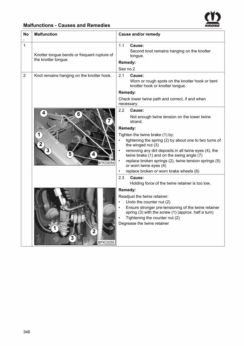
Malfunctions - Causes and Remedies
346
Pos: 167.24 /BA/Störungen - Ursachen und Behebung/Großpackenpressen/Störungen-Ursachen-Behebung Doppelknoter T1 @ 24\mod_1242027120229_78.docx @ 249022 @ @ 1
No.
Malfunction Cause and/or remedy
1
Knotter tongue bends or frequent rupture of the knotter tongue.
1.1 Cause: Second knot remains hanging on the knotter tongue.
Remedy:
See no.2
2 Knot remains hanging on the knotter hook.
2.1 Cause: Worn or rough spots on the knotter hook or bent knotter hook or knotter tongue.
Remedy:
Check lower twine path and correct, if and when necessary.
2.2 Cause:
Not enough twine tension on the lower twine strand.
Remedy:
Tighten the twine brake (1) by: • tightening the spring (2) by about one to two turns of
the winged nut (3) • removing any dirt deposits in all twine eyes (4), the
twine brake (1) and on the swing angle (7) • replace broken springs (2), twine tension springs (5)
or worn twine eyes (4) • replace broken or worn brake wheels (6)
2.3 Cause: Holding force of the twine retainer is too low.
BPXC0255
1
32
Remedy:
Readjust the twine retainer: • Undo the counter nut (2) • Ensure stronger pre-tensioning of the twine retainer
spring (3) with the screw (1) (approx. half a turn) • Tightening the counter nut (2) Degrease the twine retainer
Pos: 167.25 /Layout Module /---------------Seitenumbruch---------------- @ 0\mod_1196175311226_0.docx @ 4165 @ @ 1

Malfunctions - Causes and Remedies
347
Pos: 167.26 /BA/Störungen - Ursachen und Behebung/Großpackenpressen/Störungen-Ursachen-Behebung Doppelknoter T2 @ 24\mod_1242029551448_78.docx @ 249073 @ @ 1
No.
Malfunction Cause and/or remedy
2 Knot remains hanging on the knotter hook.
BPXC0259
4
1
2 32.4 Cause:
Excessive tension on the knotter tongue.
Remedy:
Undo the knotter tongue (3) in the following way: • First use a screwdriver to get a feel for the
pretensioning force present Place the screwdriver (4) below the knotter tongue (3) and determine the tension present by turning the screwdriver).
• Undo nut (2) on the leaf spring (1) by about 60° • Place the screwdriver (4) below the knotter tongue
(3) and determine the newly set tension present by turning the screwdriver
The knotter tongue (3) needs a slight minimum tension, for this reason never undo completely.
BPXC0256
6
1 32
42.5 Cause:
Not enough twine tension on the upper twine strand.
Remedy:
Tighten the twine brake (1) by: • tightening the spring (2) by about one to two turns of
the winged nut (3) • removing any dirt deposits in all twine eyes (4) and
the twine brake (1) • replacing broken springs (2) or worn twine eyes (4) • replacing broken or worn brake wheels (6) • checking the free movement of the tensioning arm
(5) (cf. malfunction No. 6.3, picture BPXC0263)
Pos: 167.27 /Layout Module /---------------Seitenumbruch---------------- @ 0\mod_1196175311226_0.docx @ 4165 @ @ 1

Malfunctions - Causes and Remedies
348
Pos: 167.28 /BA/Störungen - Ursachen und Behebung/Großpackenpressen/Störungen-Ursachen-Behebung Doppelknoter T3 @ 24\mod_1242030761307_78.docx @ 249150 @ @ 1
No.
Malfunction Cause and/or remedy
2 Knot remains hanging on the knotter hook. 2.6 Cause: Blade lever too far away from the knotter hook.
Remedy:
Adjusting the blade lever: • Swivel the knotter block up until the blade lever (1)
passes beyond the knotter hook (2) • Use a hammer to carefully set the blade lever (1) so
that the extractor comb (3) of the blade lever evenly touches the back of the knotter hook (2)
When swinging the knotter up, a slight resistance has to be noticeable when the blade lever passes over the knotter nib
23
1
4
BPXC0257
2.7 Cause:
Blade lever has axial play.
Remedy:
Tighten the nut (1) of the blade lever bolt (2); otherwise replace the blade lever (3) or the bearing sleeve of the blade lever bolt.
2.8 Cause:
The extractor comb of the blade lever does not run over the centre of the knotter hook.
Remedy:
Adjusting the blade lever: (cf. malfunction no. 2.5; picture BPXC0260) • Replace the blade lever
2.9 Cause:
Blunt extractor blade of the blade lever.
Remedy:
Adjust or sharpen the cutting blade (4) or replace the blade, if and when necessary.
2.10 Cause:
Twine driver disc set to far ahead.
Check the setting and readjust it if necessary (refer to chapter Settings double knotter “Twine retainer”).
Pos: 167.29 /Layout Module /---------------Seitenumbruch---------------- @ 0\mod_1196175311226_0.docx @ 4165 @ @ 1

Malfunctions - Causes and Remedies
349
Pos: 167.30 /BA/Störungen - Ursachen und Behebung/Großpackenpressen/Störungen-Ursachen-Behebung Doppelknoter T4 @ 25\mod_1242033232885_78.docx @ 249228 @ @ 1
No.
Malfunction Cause and/or remedy
3 First knot: (closing knot): Present only in the upper twine strand.
3.1 Cause: The twine bar has not caught the lower twine strand.
Remedy:
Readjust the twine bar(refer to chapter "Setting the twine bar (double knotter)”) Checking the needle setting (refer to chapter settings “Needle setting”).
4 First knot: (closing knot) twine winds around the knotter hook.
4.1 Cause: The lower needle grasps to the left on the upper twine.
Remedy:
Align the upper needle slightly to the left: • Release the knotter and turn the flywheel until the
upper needle lifts • Use a mounting lever (2) to align the upper needle
(1) to the left by about 1 - 2 mm
4.2 Cause:
Twine driver disc starts working too late.
Remedy:
Put the twine driver disc forward by turning clockwise (see chapter Settings double knotter “Twine retainer”). Please ensure that the knotter needle makes contact to the knotter in the topmost position (refer to chapter Settings “Upper dead point of the needles” (double knotter))
5 First knot: (Schließknoten) Upper twine is running through from one bale to the next. Knot in the lower twine strand
5.1 Cause: The lower needle grasps to the right on the upper twine:
Remedy:
Align the upper needle slightly to the right: • Release the knotter and turn the flywheel until the
upper needle lifts • Use a mounting lever (2) to align the upper needle
(1) to the right by about 1 - 2 mm
Pos: 167.31 /Layout Module /---------------Seitenumbruch---------------- @ 0\mod_1196175311226_0.docx @ 4165 @ @ 1

Malfunctions - Causes and Remedies
350
Pos: 167.32 /BA/Störungen - Ursachen und Behebung/Großpackenpressen/Störungen-Ursachen-Behebung Doppelknoter T5 @ 25\mod_1242035576557_78.docx @ 249567 @ @ 1
No.
Malfunction Cause and/or remedy
6
Second knot: (Starting knot) Knot is present only on the lower twine strand (no knot on the upper twine strand).
6.1 Cause: The twine bar is adjusted too far away from the upper needle and was unable to catch the upper twine strand.
Remedy: Set the twine bar in the direction of the upper needle. CAUTION: When setting the twine bar, check for collision with the upper needle and the knotter needle (refer to chapter "Setting the twine bar (double knotter)").
6.2 Cause:
Spring of the upper tensioning arm broken or disconnected.
Remedy: Replace the spring (1) or fasten it in place again.
6.3 Cause: The tensioning arm does not work correctly.
Remedy: Check the tensioning arm (2) for free space from top to bottom, and align, if and when necessary or place the central lubrication line (3) elsewhere.
6.4 Cause: Control unit in upper needle defective. Roller is not following the cam disc. The upper needle does not move down far enough.
Remedy:
Replace the roller (1) or ensure the upper needle is running easily. Check the spring (2).
6.5 Cause:
Blockage of the upper twine run.
Remedy:
Check the twine run from the knotter to the twine roller in the twine box inclusively.
6.6 Cause:
Twine tension on the upper twine strand
Remedy: Undo the twine brake (1) in the following way: • undoing the spring (2) by about one to two turns of
the winged nut (3) (cf. malfunction no. 2.2.)
6.7. Cause: Holding force of the twine retainer is too low.
Remedy: Readjust the twine retainer (cf. malfunction no. 2.2).
Pos: 167.33 /Layout Module /---------------Seitenumbruch---------------- @ 0\mod_1196175311226_0.docx @ 4165 @ @ 1

Malfunctions - Causes and Remedies
351
Pos: 167.34 /BA/Störungen - Ursachen und Behebung/Großpackenpressen/Störungen-Ursachen-Behebung Doppelknoter T6 @ 25\mod_1242036861416_78.docx @ 249592 @ @ 1
No.
Malfunction Cause and/or remedy
7 Second knot: (Starting knot) Knot is present only on the upper twine strand (no knot on the lower twine strand).
7.1 Cause: The lower twine tension springs are not working properly.
Remedy:
Ensure free room for the lower twine tension springs (5). Tighten the twine brake (1) by: • tightening the spring (2) by about one to two turns of
the winged nut (3)
7.2 Cause:
Not enough needle overrun in the upper dead point.
Remedy:
Check the needle setting (refer to chapter settings "Needle setting").
7.3 Cause:
The twine bar is not working precisely or is adjusted incorrectly.
Remedy:
Check the twine bar settings (refer to chapter "Setting the twine bar (double knotter)").
Pos: 167.35 /Layout Module /---------------Seitenumbruch---------------- @ 0\mod_1196175311226_0.docx @ 4165 @ @ 1

Malfunctions - Causes and Remedies
352
Pos: 167.36 /BA/Störungen - Ursachen und Behebung/Großpackenpressen/Störungen-Ursachen-Behebung Doppelknoter T7 @ 25\mod_1242040506416_78.docx @ 249617 @ @ 1
No.
Malfunction Cause and/or remedy
8 Second knot: (Starting knot) Twine winds around the knotter hook.
8.1 Cause: The upper tensioning arms are not working properly.
• Tension path is blocked • Tension is not sufficient
Remedy:
Check the upper tensioning arms for easy running. • Clear the tension path (cf. malfunction no. 6; picture
BPXC0263) • Increase the tension (cf. malfunction No. 2; picture
BPXC0256)
8.2 Cause:
Lower twine tension spring broken or released.
Remedy:
Replace the spring or mount it securely again (cf. malfunction no. 2.1; picture BPXC0254).
8.3 Cause:
Insufficient twine tension on the lower twine strand.
Remedy:
Increase the tension (cf. malfunction no. 2.1; picture BPXC0254).
8.4 Cause: Twine driver disc starts working too late.
Remedy:
Put the twine driver disc forward by turning clockwise (refer to chapter Settings double knotter “Twine retainer”).
8.5 Cause: Needle overrun in the upper dead point is too big.
Remedy:
Check the needle settings (refer to chapter Settings "Setting the upper dead centre of the needles (double knotter)").
Pos: 167.37 /Layout Module /---------------Seitenumbruch---------------- @ 0\mod_1196175311226_0.docx @ 4165 @ @ 1

Malfunctions - Causes and Remedies
353
Pos: 167.38 /BA/Störungen - Ursachen und Behebung/Großpackenpressen/Störungen-Ursachen-Behebung Doppelknoter T8 @ 25\mod_1242041192745_78.docx @ 249642 @ @ 1 No.
Malfunction Cause and/or remedy
9 No knot present, neither on the upper nor on the lower twine strand.
7
BPXC0270
6
9.1 Cause: Twine bar is not activated.
Remedy:
Check the twine bar mechanism and its settings (refer to chapter Settings "Setting the twine bar (double knotter)”).
9.2 Cause:
Damaged knotter tongue.
Remedy:
Replace the knotter tongue (1).
9.3 Cause:
Insufficient tension on the knotter tongue.
Remedy:
Increase the tension on the knotter tongue (1). To do this: • Tighten nut (2) on the leaf spring (3) by about 60° (cf.
malfunction no. 2.3)
9.4 Cause: Twine retainer springs too tight or Twine strands are cut through in the twine retainer
Remedy:
Loosen the twine retainer spring setting. To do this: • Undo the counter nut (4) • Ensure weaker pre-tensioning of the twine retainer
spring (5) with the screw (6) (approx. half a turn) Remove accumulations of dirt or chaff under the twine retainer springs (5).
9.5 Cause: The knotter hook is not turning.
Remedy:
Exchange the pin (6) of the knotter hook drive wheel (7).
Pos: 167.39 /Layout Module /---------------Seitenumbruch---------------- @ 0\mod_1196175311226_0.docx @ 4165 @ @ 1

Malfunctions - Causes and Remedies
354
Pos: 167.40 /BA/Störungen - Ursachen und Behebung/Großpackenpressen/Störungen-Ursachen-Behebung Doppelknoter T9 @ 25\mod_1242042248604_78.docx @ 249667 @ @ 1
No.
Malfunction Cause and/or remedy
10 Knot ends too short. The knot often gets wound up (generally the second knot).
10.1 Cause: Insufficient tension on the knotter tongue.
Remedy:
Increase the tension on the knotter tongue (1) (cf. malfunction no. 9 picture BPXC0267).
10.2 Cause: Incorrect twine tension.
Remedy:
• Check the twine path To make the knot ends longer, the lower twine tension should generally be increased first (cf. malfunction no. 2 picture BPXC0254).
• In case this is not enough the upper twine tension must be increased
11 Twine is no longer threaded through the knotter needle, but it is tied to the last bale.
11.1 Cause: Twine tension spring is bent
Remedy:
Align the twine spring (1) centrically to the twine brake (2) and the knotter needle (3).
Pos: 167.41 /Layout Module /---------------Seitenumbruch---------------- @ 0\mod_1196175311226_0.docx @ 4165 @ @ 1

Malfunctions - Causes and Remedies
355
Pos: 167.42 /BA/Störungen - Ursachen und Behebung/Großpackenpressen/Störungen-Ursachen-Behebung Doppelknoter T10 @ 25\mod_1242042811416_78.docx @ 249692 @ @ 1
No.
Malfunction Cause and/or remedy
12 Shear screw on the needle connecting rod breaks frequently. As a result the needle yoke stops.
Cause: Strong wear of the twine guide eyes.
Remedy: Exchange the twine guide eyes (1) and replace the shear screw (2) on the needle connecting rod.
13 The baler can no longer be operated via the terminal.
Cause: Faulty operation or faulty connection for operation.
Remedy:
Unscrew the terminal cable from the socket (1) located to the left (as seen in direction of travel) on the metal cover close to the flywheel. Connect the plug for emergency mode (2) to the socket (1). After 10 seconds, emergency mode is activated with the following settings: • Old nominal length • Automatic mode • Last target force to be set
Pos: 167.43 /Layout Module /---------------Seitenumbruch---------------- @ 0\mod_1196175311226_0.docx @ 4165 @ @ 1

Malfunctions - Causes and Remedies
356
Pos: 167.44 /Überschriften/Überschriften 2/F-J/Fehlersuche in der Zentralschmierung @ 25\mod_1242052030604_78.docx @ 249788 @ 2 @ 1
25.3 Troubleshooting in the central lubrication Pos: 167.45 /BA/Störungen - Ursachen und Behebung/Großpackenpressen/Störungen-Ursachen-Behebung Zentralschmierung T1 @ 25\mod_1242051129385_78.docx @ 249717 @ @ 1
Malfunction Cause and/or remedy
Blockage in the system or in any bearing connected to it. Manually activated systems. The hand lever cannot be moved or is hard to move.
Find out what is causing the blockage and eliminate the cause. PROCEDURE First check whether the conveyor pump is working and is supplying lubricant to the main distributor. To do this, loosen the pump outlet and activate the pump. When the pump is working properly, connect the pump outlet again. (Conclusion: there is no problem with the pump). Let the pump work until the next blockage or until the next time the pressure rises inadmissibly. Leave the pressure level as is. One after the other, loosen the threaded input connections on the subdistributors or on the main distributor, and for single-level systems the threaded input connections. The distributor from which lubricant suddenly leaks when the threaded input connection is loosened under pressure will lead to the source of the fault. The threaded input connections have to be screwed tight again. The corresponding threaded bearing input connections should be loosened one after the other. The bearing from which lubricant suddenly leaks when its threaded input connection is loosened under pressure is the blocked bearing. Eliminate the blockage on the bearing.
Blockage in the distributor After you have loosened all outlets of the main distributor and/or the subdistributors, no lubricant leaks from the outlets. The distributor is blocked.
Replace the blocked distributor. If necessary, the distributor can be cleaned if the following conditions are met. The workplace must be clean. Remove all tube end screwed pieces. Remove the plunger lock screws with a strong screwdriver. If necessary loosen them by tapping with a hammer. Drive out the plungers with a soft mandrel (with a diameter of less than 6 mm, if possible made of plastic). Very important: You must keep a record of which plunger belongs in which drill hole, since the plungers must not be interchanged. Thoroughly rinse the distributor body several times in grease-dissolving agent and blow it out with compressed air. There are diagonal channels with a diameter of 1.5 mm on the ends of the threading. You can press through them with a wire or pin. Rinse and blow out the distributor several times. There could be hardened grease in the plunger lock screws. This must be removed. Assemble the distributor. All the copper discs must be replaced. Before screwing in the tube outlet threaded pieces, you should pump out the distributor with a hand pump or similar tool, if possible pumping oil through it several times. The counter pressure in the distributor should not be any greater than 25 bar as you do this. Any higher counter pressure means that the distributor is not clean or than the plunger drill hole is damaged. If the operating pressure of the distributor does not sink below 25 bar / 362,5 PSI in spite of all your efforts, the distributor should be replaced.

Malfunctions - Causes and Remedies
357
Pos: 169 /Überschriften/Überschriften 1/A-E/Entsorgung der Maschine @ 274\mod_1404207309028_78.docx @ 2060455 @ 1 @ 1 Pos: 171 /Layout Module /---------------Seitenumbruch---------------- @ 0\mod_1196175311226_0.docx @ 4165 @ @ 1

Appendix
358
Pos: 172 /Überschriften/Überschriften 1/A-E/Anhang @ 1\mod_1202278612285_78.docx @ 58360 @ 1 @ 1
26 Appendix Pos: 173 /Überschriften/Überschriften 2/F-J/Hydraulikschaltplan @ 11\mod_1223527787398_78.docx @ 147580 @ 2 @ 1
26.1 Hydraulic System Circuit Diagrams Pos: 174 /BA/Anhang/Großpackenpresse/Bordhydraulik für Medium-Elektronik HS Baureihe @ 194\mod_1383644199349_78.docx @ 1651623 @ 2 @ 1
26.2 On-Board Hydraulic System for Medium Version Electronics
1)
3)
2)
Fig. 252
1. Main gearbox 2. Bale channel
3. Pressure limiting valve
Pos: 175 /Layout Module /---------------Seitenumbruch---------------- @ 0\mod_1196175311226_0.docx @ 4165 @ @ 1

Appendix
359
Pos: 176 /BA/Anhang/Großpackenpresse/Bordhydraulik für Komfort-Elektronik HS Baureihe @ 195\mod_1383644714292_78.docx @ 1651824 @ 2 @ 1
26.3 On-Board Hydraulic System for Comfort Version Electronics
1)
4)
3)
2)
Fig. 253
1. Main gearbox 2. Bale channel
3. Pressure limiting valve 4. Release valve
Pos: 177 /Layout Module /---------------Seitenumbruch---------------- @ 0\mod_1196175311226_0.docx @ 4165 @ @ 1

Appendix
360
Pos: 178 /Überschriften/Überschriften 2/A-E/Arbeitshydraulik für Medium-Elektronik @ 280\mod_1405583937453_78.docx @ 2156301 @ 2 @ 1
26.4 Work Hydraulics Medium Version Electronics Pos: 179 /BA/Anhang/Großpackenpresse/Arbeitshydraulik für Medium-Elektronik HS Baureihe Bild @ 280\mod_1405584573219_78.docx @ 2156331 @ @ 1
10)
Sta
ndar
dT
rakt
orhy
drau
lik
Ein
gang
sblo
ck3)
Stü
tzfu
ssau
f / a
b
Lenk
achs
esp
erre
n
Mes
serb
alke
nau
f / z
u
Bal
lena
ussc
hieb
erei
n- /
ausf
ahre
n
Rol
lens
chur
reau
f / z
u
4)
5)
6)
7)
8)
Anl
aufh
ilfeH
aupt
getr
iebe
Sch
wun
grad
1)
2)11
)K
ugel
hahn
nur
für
Geb
rauc
hde
s B
alle
naus
schi
eber
s un
dde
r R
olle
nsch
urre
öffe
n!W
ähre
nd d
es P
ress
vorg
ange
s sc
hlie
ßen
Pic
k-up
runt
er /
rauf
9)
Fig. 254 Pos: 180 /BA/Anhang/Großpackenpresse/Arbeitshydraulik für Medium-Elektronik HS Baureihe Legende @ 280\mod_1405583503868_78.docx @ 2156271 @ @ 1
1. Start-up device 2. Main gearbox flywheel
3. Input block 4. Parking jack up / down
5. Locking the steering axle 6. Blade bar open / closed
7. Retracting / extending bale ejector 8. Roller chute open / closed
9. Pick-up up / down 10. Standard tractor hydraulics
11. Only open the ball valve for using bale ejector and roller chute! Close it during baling process
Pos: 181 /Layout Module /---------------Seitenumbruch---------------- @ 0\mod_1196175311226_0.docx @ 4165 @ @ 1

Appendix
361
Pos: 182 /Überschriften/Überschriften 2/A-E/Arbeitshydraulik für Komfort-Elektronik @ 280\mod_1405574137485_78.docx @ 2155721 @ 2 @ 1
26.5 Work Hydraulics Comfort Version Electronics Pos: 183 /BA/Anhang/Großpackenpresse/Arbeitshydraulik für Komfort-Elektronik HS Baureihe Bild @ 280\mod_1405583010026_78.docx @ 2156211 @ @ 1
Anl
aufh
ilfe H
aupt
getr
iebe
Sch
wun
grad
1)
2)
3) K
omfo
rtve
ntilb
lock
Stü
tzfu
ssau
f / a
b
Lenk
achs
esp
erre
nM
esse
rlade
auf /
zu
Bal
lena
ussc
hieb
ere
in-
/ a
usf
ah
ren
Rol
lens
chur
reau
f /
zu
8)
4)5)
6)7)
Pic
k-up
auf /
ab
9)
11)
10)
Fig. 255 Pos: 184 /BA/Anhang/Großpackenpresse/Arbeitshydraulik für Komfort-Elektronik HS Baureihe Legende @ 280\mod_1405573705773_78.docx @ 2155681 @ @ 1
1. Starting aid 2. Main gearbox flywheel
3. Comfort block 4. Locking the steering axle
5. Blade bar open/closed 6. Bale ejector deploy/retract
7. Roller chute open/closed 8. Support jack up/down
9. Pick-up down/up 10. Standard tractor hydraulics
11. Unscrew the system screw fully for constant flow. Turn Power Beyond system and (LS) all the way in.
Pos: 185 /Layout Module /---------------Seitenumbruch---------------- @ 0\mod_1196175311226_0.docx @ 4165 @ @ 1

362
Pos: 186 /Überschriften/Überschriften 2/A-E/Elektroschaltplan @ 11\mod_1223544391539_78.docx @ 147914 @ 2 @ 1
26.6 Electrical circuit diagram Pos: 187 /BA/Anhang/Großpackenpresse/Schaltpläne Im Anhang finden Sie den die Schaltpläne zur Maschine @ 65\mod_1300357621479_78.docx @ 583741 @ @ 1
You will find the electrical circuit diagram for the machine in the appendix.
=== Ende der Liste für Textmarke Inhalt ===


α
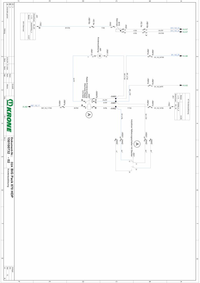


Index
363
27 Index
A
Absorbing mechanism ...................................... 279
Activating customer counter ............................. 165
Active pick-up ..................................................... 72
Actuator test ...................................................... 177
Additional equipment and spare parts ................ 16
Adjusting the Bale Balance ............................... 159
Adjusting the baling ram ................................... 262
Adjusting the chop length ................................. 281
Adjusting the drawbar height .............................. 85
Adjusting the feeler rocker ................................ 276
Adjusting the feeler rocker stop ........................ 277
Adjusting the height of the drive train ................. 86
Adjusting the hydraulic system ........................... 92
Adjusting the knotter shaft brake ...................... 253
Adjusting the MultiBale ..................................... 244
Adjusting the Packer Relative to the Plunger ... 266
Adjusting the rubber pad on the zeroizing device ...................................................................... 273
Adjusting the Sensors ....................................... 332
Adjusting the spring in the zeroizing device ..... 274
Adjusting the Transfer Mechanism ................... 313
Adjusting the triggering sensitivity .................... 275
Adjusting the zeroizing device .......................... 273
Affixing the Adhesive Safety and Information Labels ............................................................. 41
Air filter for pneumatic cylinder (only MultiBale)315
Alarm Message ................................................. 190
Alarm messages ............................................... 191
Appendix ........................................................... 358
At the End of the Harvest Season .................... 335
Attaching Hydraulic Parking Jack ....................... 82
Automatic bale ejection..................................... 137
Automatic centralised lubrication system (optional) ...................................................................... 326
Auxiliary-function (AUX).................................... 207
B
Bale Balance ..................................................... 158
Bale brake ......................................................... 232
Bale channel ....................................................... 73
Bale Chute .......................................................... 69
Bale chute in transport position (optional) ........ 109
Bale Ejector ........................................................ 69
Baling Process .................................................... 53
Baling ram ........................................................... 73
Basic safety instructions ..................................... 15
Basic setting feeler rocker ............................... 271
Basic setting of the band brake (flywheel) ....... 280
Before the Start of the New Season ................ 336
Behaviour in hazardous situations and when accidents occur .............................................. 25
Blade Changing ............................................... 290
Brakes ................................................................ 74
Bringing up a Menu Level ................................ 136
Bringing up Customer Counter ........................ 137
Bringing up the Basic Screens ......................... 134
C
Calling up the menu level ................................ 144
Changing the Bale Number ............................. 165
Checking / adjusting position of needles – baling ram ............................................................... 247
Checking and maintaining tyres ....................... 297
Checking packer coupling ................................ 268
Checking the lighting system ........................... 110
Checking Twine Bar ......................................... 249
Checking Twine Bar to the Channel Slot ......... 250
Checking Upper Needle ................................... 248
Children in danger .............................................. 16
Cleaning ........................................................... 293
Cleaning the running rails ................................ 263
Comfort Hydraulic Block Diagram .................... 302
Commissioning .................................................. 81
Compressed Air Connections for the Compressed Air Brake ...................................................... 102
Compressed-air reservoir ................................ 312
Compressed-air reservoir .......................... 71, 312
Compressor ..................................................... 316
Configuration Main Window ............................. 188
Connect the machine to the tractor .............. 16, 95
Connecting lower twine ............................ 215, 221
Connecting the hydraulic lines ..................... 79, 98
Connecting the Multi-Function Lever to the CCI Terminal ....................................................... 123
Connecting the Terminal with ISOBUS ............ 104
Connecting the terminal without ISOBUS ........ 103
Connecting twine) .................................... 214, 220
Connecting upper twine ........................... 214, 220
Consumables ............................................... 22, 77
Contact ......................................................... 41, 52
Control and Display Elements ........................... 79
Conveyor roller ................................................. 294
Coupling the machine safely .............................. 27
Crop feed ........................................................... 73

364
Customer counter ............................................. 162
Cutting Length .................................................... 62
Cutting system .................................................... 62
Cutting System Drive .......................................... 60
Cutting system drive gear ................................. 309
D
Danger zones ..................................................... 18
Dangers associated with certain activities
Climbing up and down .................................... 24
Dangers associated with certain activities
Work on the machine ...................................... 24
Dangers associated with certain activities
Working on wheels and tyres .......................... 25
Dangers associated with the operational environment .................................................... 22
Description of components ............................... 266
Diagnostics – analogue sensors ....................... 172
Diagnostics – digital actuators .......................... 178
Diagnostics – force sensors ............................. 174
Diagnostics – Namur sensors ........................... 170
Diagnostics analogue actuators ....................... 180
Diagnostics Auxiliary (AUX) .............................. 183
Diagnostics for buttons ..................................... 171
Diagnostics power supply voltages .................. 176
Differing functions to KRONE ISOBUS terminal CCI ................................................................ 201
Dimensions ......................................................... 72
Direction Information ........................................... 12
Directional information ........................................ 12
Double knotter .......................................... 258, 345
Drain valve ........................................................ 312
Drives .................................................................. 57
Driving and Transport ....................................... 107
Driving with Pick-up in fixed position ................ 239
E
Electrical circuit diagram ................................... 362
Electrical connections ................................. 75, 103
Electrical Knotter Monitoring ............................... 67
Electrical twine empty display for lower thread .. 66
Emergency Manual Activation .......................... 301
Example of a joystick assignment for Fendt (default setting) ............................................. 208
Examples of Emergency Manual Activation ..... 303
F
Feeder Packer .................................................... 59
Feeler rocker ..................................................... 277
Filling Quantities and Lubrication Designations for Gearboxes ...................................................... 77
Finishing Tying Process Manually .................... 234
Fire extinguisher ................................................ 42
Flywheel brake ................................................... 44
G
General malfunctions ....................................... 339
H
Handling the Coaster/Steering Axle ................. 111
High-pressure filter ........................................... 300
How to use this document ................................. 12
Hydraulic brake (Export) .................................. 100
Hydraulic Brake (France) ................................. 101
Hydraulic connections ........................................ 75
Hydraulic Connections ....................................... 75
Hydraulic parking jack ...................................... 231
Hydraulic parking jack (optional) ........................ 45
Hydraulic system ................................................ 63
Hydraulic System Circuit Diagrams ................. 358
Hydraulics .......................................................... 98
I
Identification Plate .............................................. 52
Identifying Symbols in the Operating Instructions ....................................................................... 13
Idle position ...................................................... 234
Idle Position ....................................................... 68
Importance of the operating instructions............ 15
Information Required for Questions and Orders 52
Initiating the Tying Process Manually .............. 234
Install the PTO shaft .......................................... 96
Installing the terminal into the cabin ................ 120
Intended Use ...................................................... 14
ISOBUS operation ........................................... 199
ISOBUS Short Cut Button ................................ 121
ISOBUS Terminal - Menus .............................. 142
ISOBUS-Terminal ............................................ 119
K
Keeping safety devices functional ..................... 20
Knotter ............................................................. 257
Knotter Gear ...................................................... 68
Knotter Monitoring .............................................. 67
KRONE ISOBUS Terminal - Machine Functions ..................................................................... 135
L
Ladder ................................................................ 42
Lateral setting of the plunger ........................... 264
LED strips ........................................................ 233
Lifting ............................................................... 292
Lifting Bale Chute ............................................. 226
Lighting ............................................................ 105
Locking Steering Axle ...................................... 136

365
Locking the Coaster/Steering Axle ................... 136
Locking the tying process ................................. 257
Lower bale chute .............................................. 137
Lower blade bar ................................................ 138
Lowering Bale Chute ........................................ 226
Lubricants ......................................................... 319
Lubricating the PTO shaft ................................. 320
Lubricating the rollers for the blade lever ......... 321
M
Machine overview ............................................... 48
Main drive ..................................................... 57, 59
Main gearbox .................................................... 305
Main menu 1 Settings ....................................... 145
main menu 2 counters ...................................... 161
Main menu 4 Service ........................................ 168
Main menu 5 'Information'................................. 184
Main menu 9 ............................................. 186, 204
Main window ..................................................... 130
Maintenance ..................................................... 285
Maintenance - Brake System ........................... 311
Maintenance – Central Lubrication ................... 326
Maintenance – electrical system ...................... 328
Maintenance - hydraulic system ....................... 298
Maintenance - lubrication ................................. 318
Maintenance Compressor ................................ 316
Maintenance table ............................................ 286
Malfunctions - Causes and Remedies .............. 338
Malfunctions on the knotter .............................. 342
Manual actuator test ......................................... 177
Maximum permissible speed .............................. 72
Menu 1-1 Knotter Settings ................................ 146
Menu 1-1-1 Correction Value for Bale Length .. 147
Menu 1-1-2 Knotter Signal ................................ 148
Menu 1-1-3 Knotter control ............................... 149
Menu 1-1-5 Bales / Blow .................................. 150
Menu 1-1-6 Blow Time...................................... 151
Menu 1-2 silage agents / optional ..................... 152
Menu 1-3 Sensitivity of the Direction Display ... 153
Menu 1-4 Central Lubrication ........................... 154
Menu 1-5 Moisture Measuring .......................... 156
Menu 1-6 Bale Balance .................................... 158
Menu 1-8 ........................................................... 160
Menu 2-1 Customer counter ............................. 162
Menu 2-1-1 Detailed counter ............................ 164
Menu 2-2 ........................................................... 166
Menu 4-2 Manual sensor test ........................... 169
Menu 4-6 Diagnostics driving speed display/direction of travel display .................. 202
Menu 4-7 ........................................................... 203
Menu Level ...................................................... 142
Minimum tractor requirements ........................... 75
Moisture Measuring ......................................... 156
Mounting ISOBUS Terminal ............................ 200
Moving ............................................................. 115
Moving Baling Ram into Position ..................... 269
Moving Packer Strip into Position .................... 268
Moving the machine without hydraulic connections ..................................................................... 114
MultiBale ............................................................ 55
MultiBale Design ................................................ 55
N
Needle Yoke ...................................................... 61
O
Oil change compressor .................................... 317
Oil level check compressor .............................. 317
Oil quantities and designations for the compressor ....................................................................... 78
Oil quantities and designations for the on-board hydraulic system ............................................ 78
On-board hydraulic system .............................. 299
On-Board Hydraulic System for Comfort Version Electronics ................................................... 359
On-Board Hydraulic System for Medium Version Electronics ................................................... 358
Open the automatic mode home screen.......... 137
Open the manual mode home screen ............. 137
Opening/closing the bale channel flaps ........... 136
Operating Bale Ejector ..................................... 228
Operating the Machine via LS (Load-Sensing Connection) ............................................ 92, 113
Operating the Machine without LS (Load-Sensing Connection) ............................................ 92, 113
Operation ......................................................... 211
Operational safety: Technically perfect condition ....................................................................... 17
Overload coupling on flywheel ......................... 337
Overload protection............................................ 74
Overload Protections ......................................... 59
P
Packer gearbox ................................................ 306
Parking brake ..................................... 43, 110, 118
Parking Jack .............................................. 44, 230
Parking the machine safely ................................ 22
Personal protective equipment .......................... 20
Personnel qualification ....................................... 15
Pick-up ..................................................... 225, 237
Pick-up Drive ...................................................... 60
Pick-up gearbox ............................................... 308
Placing in Storage ............................................ 334

366
Pneumatic brake cylinders ............................... 314
Position of sensors (left side of machine) ......... 330
Position of sensors (right side of the machine) 328
Position of the General Information Labels on the Machine .......................................................... 40
Possible setting errors and their elimination (MultiBale) ..................................................... 246
Preparations for road travel .............................. 108
Preparing the machine for repair, maintenance and adjustment work ....................................... 28
Presetting stop .................................................. 271
Presetting threaded rod .................................... 271
Pressing force control (with emergency manual activation) ..................................................... 304
Pressure Sensors ............................................. 181
Purpose of Use ................................................... 14
R
Raise blade bar ................................................. 138
Release blade bar ............................................. 138
Releasing Steering Axle ................................... 136
Releasing the Coaster/Steering Axle ................ 136
Releasing the tying process ............................. 257
Relieving the twine locking shaft ...................... 253
Relieving the upper needle shaft ...................... 252
Removing blockages ........................................ 235
Re-Ordering the Adhesive Safety and Information Labels ............................................................. 41
Replacing Rollers/Cam Follower Rollers .......... 315
Reset bale length to zero .................................. 137
Roller chute hydraulically activated .................. 109
Roller crop guide ......................................... 62, 240
S
Safety .................................................................. 14
Safety routines .................................................... 26
Safety signs on the machine .............................. 21
Safety stickers on the machine ........................... 29
Secure knotter shaft .......................................... 213
Setting of twine retainer .................................... 259
Setting the bale chute ......................................... 93
Setting the bale length ...................................... 140
Setting the baling ram blades ........................... 262
Setting the Ground Pressure of the Guide Wheels ...................................................................... 238
Setting the height of the needles on the knotter ...................................................................... 242
Setting the Holding Force of the Twine Retainer ...................................................................... 260
Setting the Knotter Hook .................................. 258
Setting the needles ........................................... 241
Setting the number of MultiBales (MultiBale only) ..................................................................... 141
Setting the target bale channel flap pressure .. 139
Setting the Twine Brake ................................... 254
Setting the twine tension of the lower twine strand (double knotter) ............................................ 256
Setting the twine tension on the upper twine strand (double knotter) ................................. 255
Setting the tying twine in place ........................ 213
Setting Twine Bar ............................................. 249
Setting Twine Bar to the Channel Slot ............. 250
Setting Upper Needle....................................... 248
Settings ............................................................ 236
Shear screw ....................................................... 61
Shortening Universal Shaft ................................ 87
Shut-Off Valve Pick-Up ...................................... 46
Single knotter ................................................... 342
Sources of danger on the machine .................... 23
Spare Parts ...................................................... 285
Start screen ...................................................... 125
Starting the machine safely ............................... 28
Start-up .............................................................. 94
Status Line ....................................................... 127
Stopping and securing the machine .................. 26
Stowing the compressed air hoses .................. 117
Structural changes to the machine .................... 16
Supporting lifted machine and machine parts securely .......................................................... 26
Switching off the machine ................................ 116
Switching the starting aid on/off ....................... 136
Switching the terminal on / off when the machine is connected ................................................. 125
Switching the terminal on / off when the machine is not connected ........................................... 124
Switching the warning beacon on/off ............... 135
Switching Working Floodlights Off ................... 135
Switching Working Floodlights On ................... 135
T
Target group of this document ........................... 12
Technical data .................................................... 72
Technical data active pick-up ............................ 72
Technical data bale channel .............................. 73
Technical data baling ram .................................. 73
Technical data brakes ........................................ 74
Technical data crop feed ................................... 73
Technical data dimensions ................................ 72
Technical data electrical connections ................ 75
Technical data hydraulic connections ................ 75
Technical Data Hydraulic Connections .............. 75
Technical data maximum permissible speed ..... 72

367
Technical data minimum tractor requirements ... 75
Technical data overload protection ..................... 74
Technical data track width .................................. 72
Technical data tying unit ..................................... 73
Technical data universal shaft ............................ 74
Technical data variable filling system ................. 73
Technical data weight ......................................... 72
Technician ........................................................ 185
Tensioning belts ................................................ 312
Tensioning the twine locking shaft .................... 253
Tensioning the upper needle shaft ................... 252
The setting for the spring in the zeroizing device ...................................................................... 274
Threading in the Lower Twine .................. 217, 222
Threading in the Upper Twine .................. 218, 223
Tightening Torques ........................................... 288
Tightening Torques (Countersunk Screws) ...... 289
Top dead centre of the needles ........................ 243
Track width ......................................................... 72
Traffic safety ....................................................... 21
Transfer gearbox .............................................. 307
Trigger knotter .................................................. 137
Troubleshooting in the central lubrication ......... 356
Twine .................................................................. 65
Twine motion indicator upper twine (double knotter) ........................................................... 67
Tying unit ................................................... 73, 213
Tyres ................................................................ 296
U
Uncoupling the machine safely .......................... 27
Universal shaft ................................................... 74
Using the safety chain ..................................... 105
V
Variable filling system ................................ 73, 270
VFS system ...................................................... 270
W
Weight ................................................................ 72
Wheel chocks ............................................. 43, 118
Work Hydraulics Comfort Version Electronics . 361
Work Hydraulics Medium Version Electronics . 360
Working floodlight ............................................ 233
Workstations and passengers ........................... 16
WTK- multi-function leverl ................................ 209
Z
Zero position (VFS system) ............................. 272
Zeros ................................................................ 159


MaschinenfabrikBernard Krone GmbHHeinrich-Krone-Straße 10, D-48480 SpellePostfach 11 63, D-48478 Spelle
Phone +49 (0) 59 77/935-0Fax +49 (0) 59 77/935-339Internet: http://www.krone.deeMail: [email protected]


![XC series PLC User manual[Instruction] - KALATEC](https://static.fdokumen.com/doc/165x107/6316c313f68b807f880362ed/xc-series-plc-user-manualinstruction-kalatec.jpg)