Linea Jurisprudencial Parejas Sexo Constitucional Hernadandez 2014
Upload
khangminh22Category
view
1download
0
Linea HS Series Camera User’s Manual Monochrome, Color and Multifield TDI Line Scan
sensors | cameras | frame grabbers | processors | software | vision solutions
03-032-20296-01
Revision 01 www.teledynedalsa.com

This document does not contain information whose export/transfer/disclosure
is restricted by the Canadian Export Control regulation.
©2021 Teledyne Digital Imaging, Inc.
All information provided in this manual is believed to be accurate and reliable. No
responsibility is assumed by Teledyne DALSA for its use. Teledyne DALSA reserves the right
to make changes to this information without notice. Reproduction of this manual in whole or
in part, by any means, is prohibited without prior permission having been obtained from
Teledyne DALSA.
Microsoft and Windows are registered trademarks of Microsoft Corporation in the United
States and other countries. Windows, Windows 7, Windows 8 are trademarks of Microsoft
Corporation.
All other trademarks or intellectual property mentioned herein belong to their respective
owners.
Document Date: April 7, 2021
Document Number: 03-032-20296-01
About Teledyne DALSA
Teledyne DALSA, a business unit of Teledyne Digital Imaging Inc., is an international high-
aperformance semiconductor and Electronics Company that designs, develops,
manufactures, and markets digital imaging products and solutions, in addition to providing
wafer foundry services.
Teledyne DALSA offers the widest range of machine vision components in the world. From
industry-leading image sensors through powerful and sophisticated cameras, frame
grabbers, vision processors and software to easy-to-use vision appliances and custom vision
modules.
Linea HS Series Camera User's Manual Contents • 3
Contents FIGURES 6
LINEA HS SERIES CAMERAS 8 DESCRIPTION 8
Color and Multifield Technology 9 CAMERA HIGHLIGHTS 10
Common Features 10 Resolution 10 Programmability 10 Applications 10
PART NUMBERS AND SOFTWARE REQUIREMENTS 11 SPECIFICATIONS 13
Common Camera Specifications 13 Monochrome 300kHz Models 14 Monochrome 400kHz Models 16 Color and Multifield Models 17 Super Resolution Monochrome Model 18 Performance 1) 18 Environmental Specifications 18 Flash Memory Size 19 Certification & Compliance 19
SPECIFICATIONS: MONOCHROME MODELS 20 Responsivity & QE 20 Camera Input Power 22
SPECIFICATIONS: COLOR MODEL 24 Responsivity & QE 24 Camera Input Power 24
SPECIFICATIONS: MULTIFIELD MODEL 26 Responsivity & QE 26 Camera Input Power 27
SPECIFICATIONS: SUPER RESOLUTION 32K MODEL 28 Responsivity & QE 28 Camera Input Power 29
LINEA HS DARK CURRENT 30 CAMERA PROCESSING CHAIN 32 SUPPORTED INDUSTRY STANDARDS 32
GenICam™ 32 Camera Link HS 33 Data Cables 34
MECHANICAL DRAWINGS 36 PRECAUTIONS 40
Electrostatic Discharge and the CMOS Sensor 40 INSTALL & CONFIGURE FRAME GRABBER & SOFTWARE 41
Using Sapera CamExpert 41 CamExpert Panes 42
SETTING UP FOR IMAGING 44 Camera I / O Connectors 44
4 • Contents Linea HS Series Camera User's Manual
Powering the Camera 44 Power and GPIO Connections 45 Establishing Camera Communications 48 Selecting the Data Format 48 Establishing Data Integrity 49
CAMERA PERFORMANCE AND FEATURES 50 SYNCHRONIZING TO OBJECT MOTION 50
Acquiring Images: Triggering the Camera 50 Measuring Line (Trigger) Rate 51 Maximum Line Rate 51 Minimum Line Rate 52 Scan Direction 52 Camera Orientation 54 Spatial Correction 55 Alignment Markers 62 Parallax Correction: Using the Camera at Non-Perpendicular Angles to the
Object 63 Imaging Modes 65 TDI Mode 65 High Dynamic Range (HDR) 66 High Full Well 66 Area Mode 66 Multifield Modes 66 32k Super Resolution Modes 67 Internal Trigger Mode 68
ESTABLISHING THE OPTIMAL RESPONSE 69 Exposure Control by Light Source Strobe 69 Image Response Uniformity & Flat Field Calibration 72 Saving & Loading a PRNU Set Only 73 Setting Custom Flat Field Coefficients 73 Flat Field Calibration Filter 74 Flat Field Calibration Regions of Interest 74
IMAGE FILTERS 75 Kernels 75 Image Filter Contrast Ratio 75
BINNING 76 USING AREA OF INTEREST (AOIS) 77
Steps to Setup Area of Interest 78 Rules for Setting Areas of Interest 78
ENHANCEMENT OF INTEREST (EOIS) REGIONS 79 CUSTOMIZED LINEARITY RESPONSE (LUT) 80
How to Generate LUT with CamExpert 81 ADJUSTING RESPONSIVITY AND CONTRAST ENHANCEMENT 83
Black Level 84 CHANGING OUTPUT CONFIGURATION 84
Pixel Format 84 RED PIXEL ALIGNMENT 85
Red Shift X and Y 86 SAVING & RESTORING CAMERA SETUP CONFIGURATIONS 88
Active Settings for Current Operation 89 User Setting 89 Factory Settings 89
Linea HS Series Camera User's Manual Contents • 5
Default Setting 89
APPENDIX A: GENICAM COMMANDS 90 CAMERA INFORMATION CATEGORY 91
Camera Information Feature Descriptions 91 Built-In Self-Test Codes (BIST) 94 Camera Power-Up Configuration Selection Dialog 94 Camera Power-up Configuration 94 User Set Configuration Management 95
CAMERA CONTROL CATEGORY 96 Camera Control Feature Descriptions 96
DIGITAL IO CONTROL CATEGORY 100 Digital IO Control Feature Descriptions 100
FLAT FIELD CATEGORY 103 Flat Field Control Feature Description 103 Image Filter Mode 105
IMAGE FORMAT CONTROL CATEGORY 106 Image Format Control Feature Description 106
FILE ACCESS CONTROL CATEGORY 109 File Access Control Feature Descriptions 109 File Access via the CamExpert Tool 111 CLHS File Transfer Protocol 112 Upload File to Camera 113 Download a List of Camera Parameters 113
TRANSPORT LAYER CONTROL CATEGORY 114 Transport Layer Feature Descriptions 114
ACQUISITION AND TRANSFER CONTROL CATEGORY 116 Acquisition and Transfer Control Feature Descriptions 116
APPENDIX B: TROUBLE SHOOTING GUIDE 117 DIAGNOSTIC TOOLS 117 RESOLVING CAMERA ISSUES 120
Communications 120 Image Quality Issues 121 Power Supply Issues 124 Causes for Overheating & Power Shut Down 125
DECLARATIONS OF CONFORMITY 126 FCC Statement of Conformance 126 CE and UKCA Declaration of Conformity 126
DOCUMENT REVISION HISTORY 127
CONTACT INFORMATION 128 SALES INFORMATION 128 TECHNICAL SUPPORT 128

6 • Contents Linea HS Series Camera User's Manual
Figures Figure 1: 4k & 8K Monochrome Models Spectral Responsivity & QE 20 Figure 2: 13k and 16K Monochrome Models Spectral Responsivity & QE 21 Figure 3: Standard 4k and 8k Models Power vs. Input Voltage 22 Figure 4: Standard 13k and 16k Models Power Vs. Input Voltage 22 Figure 5. HL-HM-16K40H-00-R Power Vs. Input Voltage 23 Figure 6: Color Model Spectral Responsivity and QE 24 Figure 8: Color Model Power Vs. Input Voltage 25 Figure 9: Multifield Model Spectral Responsivity 26 Figure 10: Multifield Model QE 27 Figure 11: Multifield Model Power Vs. Input Voltage 27 Figure 12: Super Resolution Model Spectral Responsivity & QE, 32k SR Mapped, 1x gain 28 Figure 13. Super Resolution Model Power Vs. Input Voltage 29 Figure 14. Typical Dark Signal vs. Line Rate 30 Figure 15. Line Period vs. Dark Signal 31 Figure 16: Digital data processing chain 32 Figure 17: Linea HS Dual LC/SFP+ Connector Configuration 33 Figure 18: Single CLHS Connector Configuration 33 Figure 19:HL-FM-04K30H-00-R and HL-FM-08K30H-00-R Mechanical Drawing 36 Figure 20: HL-HM-08K30H-00-R and HL-HM-08K40H-00-R Mechanical Drawing 37 Figure 21: HL-FM-13K18H-00-R and HL-FM-16K15A-00-R Mechanical Drawing 38 Figure 22: HL-HM-13K30H-00-R, HL-HM-16K30H-00-R, HL-HM-16K40H-00-R and HL-HF-16K10T-
00-R Mechanical Drawing 39 Figure 23: CamExpert Frame Grabber Control Window 42 Figure 24. Camera I / O Connectors: CX4 (left) & LC Fiber Optic (right) 44 Figure 25: 12-pin Hirose Pin Numbering 45 Figure 26: GPIO cable accessory #CR-GENC-IOP00 47 Figure 27. Image with incorrect scan direction 53 Figure 28: Example of Object Movement and Camera Direction 54 Figure 29: Spatial Correction 55 Figure 30. Standard and High-Speed Camera Line Spacing – Forward Scan Direction 56 Figure 31. Standard and High-Speed Camera Line Spacing – Reverse Scan Direction 57 Figure 32. Multifield Camera Line Spacing – Forward Scan Direction 58 Figure 33. Standard and High-Speed Camera Line Spacing – Reverse Scan Direction 59 Figure 34. Super Resolution Camera Line Spacing – Forward Scan Direction 60 Figure 35. Super Resolution Camera Line Spacing – Reverse Scan Direction 61 Figure 36: Alignment Markers 62 Figure 37: Camera Angle Parallax 63 Figure 38: Parallax Effect on Sensor Arrays Output 64 Figure 39: Strobe Timing 69 Figure 40 GPIO functionality block diagram 71 Figure 41: 1 x 3 kernel 75 Figure 42: 1 x 5 kernel 75 Figure 43: 2x2 Binning 76 Figure 44: Enhancement of Interest 79 Figure 45: Black Level, Gain and System Gain Processing Chain 83 Figure 46: Red Pixel Artifacts 85 Figure 47: Align Red X Shift and Align Red Y Shift 86 Figure 48: Effect of Align Red X / Y Shift Settings 87 Figure 49. Relationship Between Camera Settings 88 Figure 50 Example CamExpert Camera Information Panel 91 Figure 51: CamExpert Power-Up Configuration Dialog 94
Linea HS Series Camera User's Manual Contents • 7
Figure 52: Camera Control Panel 96 Figure 53 Digital I/O Control Panel 100 Figure 54: Flat Field Panel 103 Figure 55: Image Format Panel 106 Figure 56: File Access Control Panel 109 Figure 57: File Access Control Tool 111 Figure 58: File Upload Completed Message Box 111 Figure 59: Transport Layer Panel 114 Figure 60: Acquisition & Transfer Control Panel 116 Figure 61: CamExpert Voltage & Temperature Features 117 Figure 62: CamExpert Test Pattern Feature 118
8 • Linea HS Series Cameras Linea HS Series Camera User's Manual
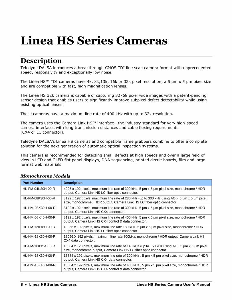
Linea HS Series Cameras
Description Teledyne DALSA introduces a breakthrough CMOS TDI line scan camera format with unprecedented
speed, responsivity and exceptionally low noise.
The Linea HS™ TDI cameras have 4k, 8k,13k, 16k or 32k pixel resolution, a 5 µm x 5 µm pixel size
and are compatible with fast, high magnification lenses.
The Linea HS 32k camera is capable of capturing 32768 pixel wide images with a patent-pending
sensor design that enables users to significantly improve subpixel defect detectability while using
existing optical lenses.
These cameras have a maximum line rate of 400 kHz with up to 32k resolution.
The camera uses the Camera Link HS™ interface—the industry standard for very high-speed
camera interfaces with long transmission distances and cable flexing requirements
(CX4 or LC connector).
Teledyne DALSA’s Linea HS cameras and compatible frame grabbers combine to offer a complete
solution for the next generation of automatic optical inspection systems.
This camera is recommended for detecting small defects at high speeds and over a large field of
view in LCD and OLED flat panel displays, DNA sequencing, printed circuit boards, film and large
format web materials.
Monochrome Models
Part Number Description
HL-FM-04K30H-00-R 4096 x 192 pixels, maximum line rate of 300 kHz, 5 µm x 5 µm pixel size, monochrome / HDR output, Camera Link HS LC fiber optic connector.
HL-FM-08K30H-00-R 8192 x 192 pixels, maximum line rate of 280 kHz (up to 300 kHz using AOI), 5 µm x 5 µm pixel size, monochrome / HDR output, Camera Link HS LC fiber optic connector.
HL-HM-08K30H-00-R 8192 x 192 pixels, maximum line rate of 300 kHz, 5 µm x 5 µm pixel size, monochrome / HDR output, Camera Link HS CX4 connector.
HL-HM-08K40H-00-R 8192 x 192 pixels, maximum line rate of 400 kHz, 5 µm x 5 µm pixel size, monochrome / HDR output, Camera Link HS CX4 control & data connector.
HL-FM-13K18H-00-R 13056 x 192 pixels, maximum line rate 180 kHz, 5 µm x 5 µm pixel size, monochrome / HDR output, Camera Link HS LC fiber optic connector.
HL-HM-13K30H-00-R 13056 X 192 pixels, maximum line rate 300kHz, monochrome / HDR output, Camera Link HS CX4 data connector.
HL-FM-16K15A-00-R 16384 x 128 pixels, maximum line rate of 143 kHz (up to 150 kHz using AOI, 5 µm x 5 µm pixel size, monochrome output, Camera Link HS LC fiber optic connector.
HL-HM-16K30H-00-R 16384 x 192 pixels, maximum line rate of 300 kHz , 5 µm x 5 µm pixel size, monochrome / HDR output, Camera Link HS CX4 data connector.
HL-HM-16K40H-00-R 16384 x 192 pixels, maximum line rate of 400 kHz , 5 µm x 5 µm pixel size, monochrome / HDR output, Camera Link HS CX4 control & data connector.
Linea HS Series Camera User's Manual Linea HS Series Cameras • 9
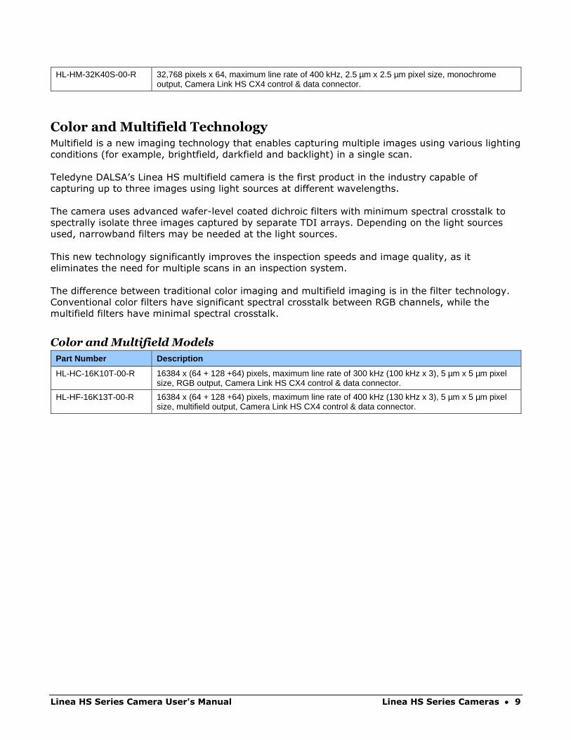
HL-HM-32K40S-00-R 32,768 pixels x 64, maximum line rate of 400 kHz, 2.5 µm x 2.5 µm pixel size, monochrome output, Camera Link HS CX4 control & data connector.
Color and Multifield Technology Multifield is a new imaging technology that enables capturing multiple images using various lighting
conditions (for example, brightfield, darkfield and backlight) in a single scan.
Teledyne DALSA’s Linea HS multifield camera is the first product in the industry capable of
capturing up to three images using light sources at different wavelengths.
The camera uses advanced wafer-level coated dichroic filters with minimum spectral crosstalk to
spectrally isolate three images captured by separate TDI arrays. Depending on the light sources
used, narrowband filters may be needed at the light sources.
This new technology significantly improves the inspection speeds and image quality, as it
eliminates the need for multiple scans in an inspection system.
The difference between traditional color imaging and multifield imaging is in the filter technology.
Conventional color filters have significant spectral crosstalk between RGB channels, while the
multifield filters have minimal spectral crosstalk.
Color and Multifield Models
Part Number Description
HL-HC-16K10T-00-R 16384 x (64 + 128 +64) pixels, maximum line rate of 300 kHz (100 kHz x 3), 5 µm x 5 µm pixel size, RGB output, Camera Link HS CX4 control & data connector.
HL-HF-16K13T-00-R 16384 x (64 + 128 +64) pixels, maximum line rate of 400 kHz (130 kHz x 3), 5 µm x 5 µm pixel size, multifield output, Camera Link HS CX4 control & data connector.

10 • Linea HS Series Cameras Linea HS Series Camera User's Manual
Camera Highlights
Common Features • Highly sensitive CMOS TDI
• Up to 400 kHz line rates
• Very low noise
• Bidirectionality
• Horizontal and Vertical Binning
• Robust Camera Link HS interface
• CX4 or LC Camera Link HS control & data connector
• Smart lens shading correction
• High dynamic LUT mode
Resolution • Monochrome Models: 4K, 8K, 13K, 16K 32k pixel resolution
• Color and Mulitifield Model: 16K pixel resolution
Programmability • Multiple areas of interest for data reduction
• Region of interest for easy calibration of lens and shading correction
• Smart lens shading correction
• Test patterns & diagnostics
Applications • Flat panel LCD and OLED display inspection
• Web inspection
• Printed circuit board inspection
• Pathology
• DNA sequencing
• High throughput and high-resolution applications
Linea HS Series Camera User's Manual Linea HS Series Cameras • 11
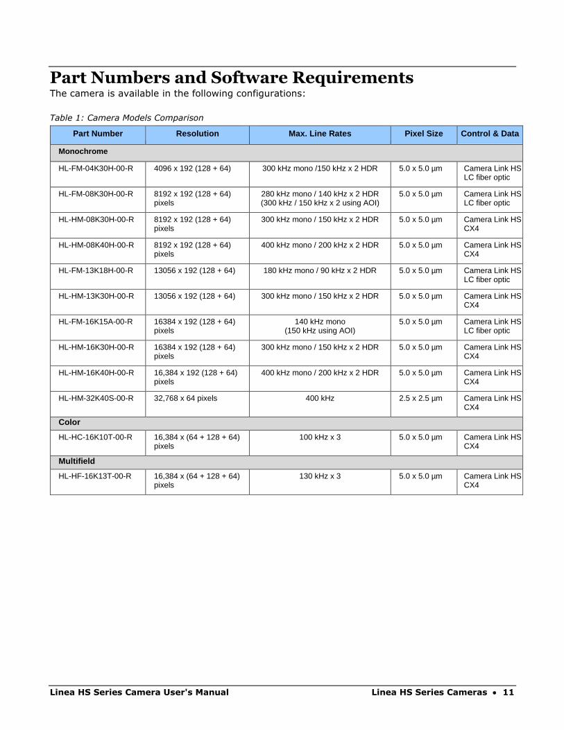
Part Numbers and Software Requirements The camera is available in the following configurations:
Table 1: Camera Models Comparison
Part Number Resolution Max. Line Rates Pixel Size Control & Data
Monochrome
HL-FM-04K30H-00-R 4096 x 192 (128 + 64) 300 kHz mono /150 kHz x 2 HDR 5.0 x 5.0 µm Camera Link HS LC fiber optic
HL-FM-08K30H-00-R 8192 x 192 (128 + 64) pixels
280 kHz mono / 140 kHz x 2 HDR (300 kHz / 150 kHz x 2 using AOI)
5.0 x 5.0 µm Camera Link HS LC fiber optic
HL-HM-08K30H-00-R 8192 x 192 (128 + 64) pixels
300 kHz mono / 150 kHz x 2 HDR 5.0 x 5.0 µm Camera Link HS CX4
HL-HM-08K40H-00-R 8192 x 192 (128 + 64) pixels
400 kHz mono / 200 kHz x 2 HDR 5.0 x 5.0 µm Camera Link HS CX4
HL-FM-13K18H-00-R 13056 x 192 (128 + 64) 180 kHz mono / 90 kHz x 2 HDR 5.0 x 5.0 µm Camera Link HS LC fiber optic
HL-HM-13K30H-00-R 13056 x 192 (128 + 64) 300 kHz mono / 150 kHz x 2 HDR 5.0 x 5.0 µm Camera Link HS CX4
HL-FM-16K15A-00-R 16384 x 192 (128 + 64) pixels
140 kHz mono (150 kHz using AOI)
5.0 x 5.0 µm Camera Link HS LC fiber optic
HL-HM-16K30H-00-R 16384 x 192 (128 + 64) pixels
300 kHz mono / 150 kHz x 2 HDR 5.0 x 5.0 µm Camera Link HS CX4
HL-HM-16K40H-00-R 16,384 x 192 (128 + 64) pixels
400 kHz mono / 200 kHz x 2 HDR 5.0 x 5.0 µm Camera Link HS CX4
HL-HM-32K40S-00-R 32,768 x 64 pixels 400 kHz 2.5 x 2.5 µm Camera Link HS CX4
Color
HL-HC-16K10T-00-R 16,384 x (64 + 128 + 64) pixels
100 kHz x 3 5.0 x 5.0 µm Camera Link HS CX4
Multifield
HL-HF-16K13T-00-R 16,384 x (64 + 128 + 64) pixels
130 kHz x 3 5.0 x 5.0 µm Camera Link HS CX4
12 • Linea HS Series Cameras Linea HS Series Camera User's Manual
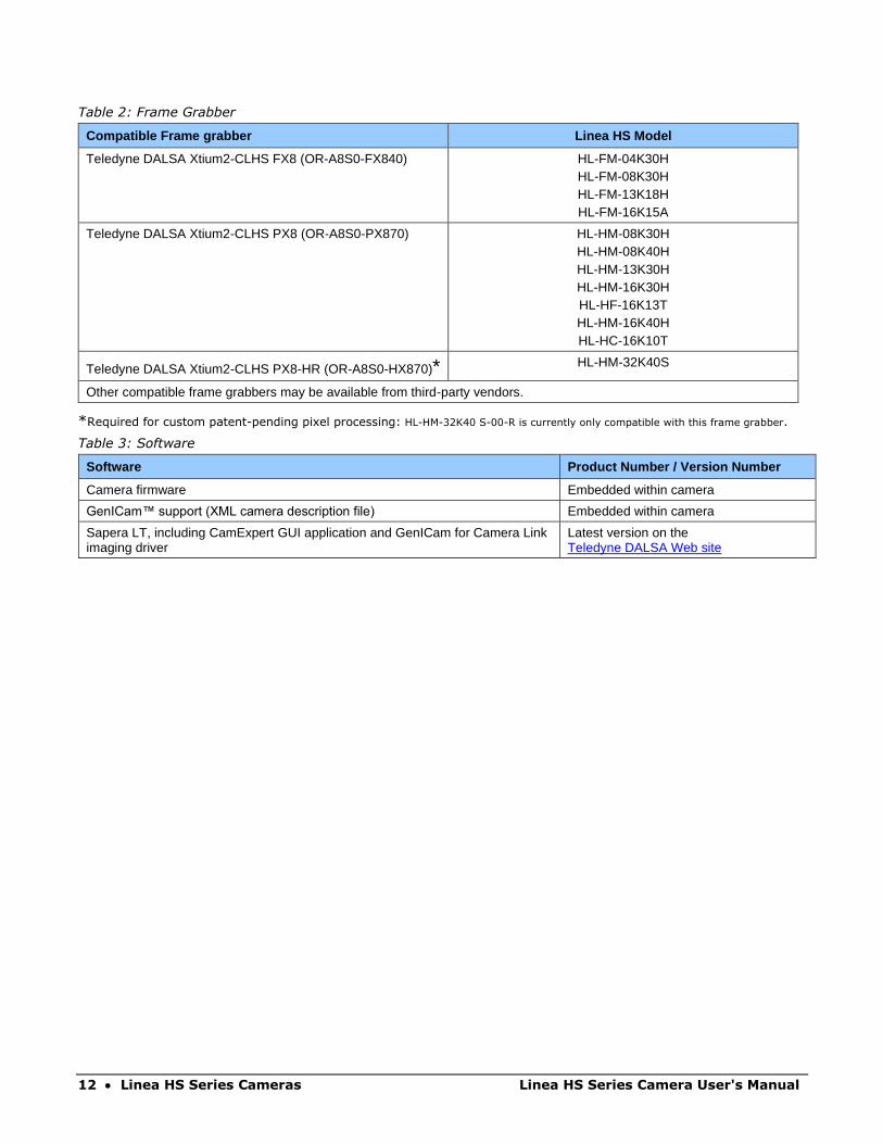
Table 2: Frame Grabber
Compatible Frame grabber Linea HS Model
Teledyne DALSA Xtium2-CLHS FX8 (OR-A8S0-FX840) HL-FM-04K30H HL-FM-08K30H HL-FM-13K18H HL-FM-16K15A
Teledyne DALSA Xtium2-CLHS PX8 (OR-A8S0-PX870) HL-HM-08K30H HL-HM-08K40H HL-HM-13K30H HL-HM-16K30H HL-HF-16K13T HL-HM-16K40H HL-HC-16K10T
Teledyne DALSA Xtium2-CLHS PX8-HR (OR-A8S0-HX870)* HL-HM-32K40S
Other compatible frame grabbers may be available from third-party vendors.
*Required for custom patent-pending pixel processing: HL-HM-32K40 S-00-R is currently only compatible with this frame grabber.
Table 3: Software
Software Product Number / Version Number
Camera firmware Embedded within camera
GenICam™ support (XML camera description file) Embedded within camera
Sapera LT, including CamExpert GUI application and GenICam for Camera Link imaging driver
Latest version on the Teledyne DALSA Web site
Linea HS Series Camera User's Manual Linea HS Series Cameras • 13
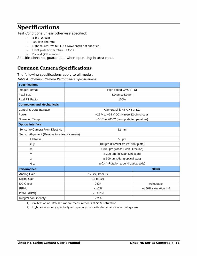
Specifications Test Conditions unless otherwise specified:
• 8-bit, 1x gain
• 100 kHz line rate
• Light source: White LED if wavelength not specified
• Front plate temperature: +45º C
• DN = digital number
Specifications not guaranteed when operating in area mode
Common Camera Specifications
The following specifications apply to all models.
Table 4: Common Camera Performance Specifications
Specifications
Imager Format High speed CMOS TDI
Pixel Size 5.0 µm x 5.0 µm
Pixel Fill Factor 100%
Connectors and Mechanicals
Control & Data Interface Camera Link HS CX4 or LC
Power +12 V to +24 V DC, Hirose 12-pin circular
Operating Temp +0 °C to +65°C (front plate temperature)
Optical Interface
Sensor to Camera Front Distance 12 mm
Sensor Alignment (Relative to sides of camera)
Flatness 50 µm
y 100 µm (Parallelism vs. front plate)
x ± 300 µm (Cross-Scan Direction)
y ± 300 µm (In-Scan Direction)
z ± 300 µm (Along optical axis)
z ± 0.4° (Rotation around optical axis)
Performance Notes
Analog Gain 1x, 2x, 4x or 8x
Digital Gain 1x to 10x
DC Offset 0 DN Adjustable
PRNU < ±2% At 50% saturation (1,2)
DSNU (FPN) < ±2 DN
Integral non-linearity < 2%
1) Calibration at 80% saturation, measurements at 50% saturation
2) Light sources vary spectrally and spatially: re-calibrate cameras in actual system

14 • Linea HS Series Cameras Linea HS Series Camera User's Manual
Monochrome 300kHz Models
The following specifications apply to the standard Linea HS models:
• HL-FM-04K30H
• HL-FM-13K18H
• HL-HM-13K30H
Specifications HL-FM-04K30H HL-FM-13K18H HL-HM-13K30H
Resolution 4096 x (128+64)
13056 x 128
13056 x (128+64)
Line Rate, maximum 300 kHz (mono) 150 kHz x 2 (HDR)
180 kHz (mono) 90 kHz x2 (HDR)
300 kHz (mono) 150 kHz x 2 (HDR)
Line rate, min 10 kHz
Bit Depth 8-bit or 12-bit selectable
Connectors and Mechanicals HL-FM-04K30H HL-FM-13K18H HL-HM-13K30H
Typical Power Dissipation 17 W 22 W 30 W
Size Width (cross scan) Height (in scan) Depth (optical axis)
76 mm 76 mm 85 mm
97 mm 140.5 mm 78.6 mm
97 mm 140.5 mm 78.6 mm
Mass < 500 g 1.2 kg 1.2 kg
Optical Interface HL-FM-04K30H HL-FM-13K18H HL-HM-13K30H
Lens Mount M58 x 0.75 mm M90 x 1 mm M90 x 1 mm
Performance 1) Notes
Random Noise < 0.2 DN rms (10 e-) Typical (1)
Peak Responsivity 500 DN/nJ/cm2 (8K models) 600 DN/nJ/cm2 (16K models)
@670 nm
Dynamic Range 70 dB Typical
Full Well 25,000 e- Typical
SEE 0.5 nJ/cm2 At 670 nm
NEE 0.4 pJ/cm2 At 670 nm
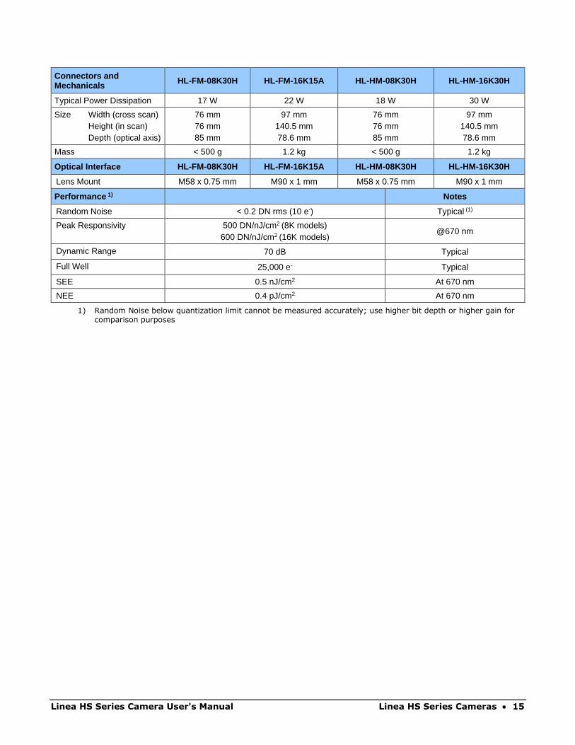
The following specifications apply to the standard Linea HS models:
• HL-FM-08K30H
• HL-FM-16K15A
• HL-HM-08K30H
• HL-HM-16K30H
Table 5: Standard Camera Models Performance Specifications
Specifications HL-FM-08K30H HL-FM-16K15A HL-HM-08K30H HL-HM-16K30H
Resolution 8192 x (128+64)
16384 x 128
8192 x (128+64)
16384 x (128+64)
Line Rate, maximum 300 kHz (mono) 150 kHz x 2 (HDR)
150 kHz 300 kHz (mono)
150 kHz x 2 (HDR) 300 kHz (mono)
150 kHz x 2 (HDR)
Line rate, min 10 kHz
Bit Depth 8-bit or 12-bit selectable
Linea HS Series Camera User's Manual Linea HS Series Cameras • 15
Connectors and Mechanicals HL-FM-08K30H HL-FM-16K15A HL-HM-08K30H HL-HM-16K30H
Typical Power Dissipation 17 W 22 W 18 W 30 W
Size Width (cross scan) Height (in scan) Depth (optical axis)
76 mm 76 mm 85 mm
97 mm 140.5 mm 78.6 mm
76 mm 76 mm 85 mm
97 mm 140.5 mm 78.6 mm
Mass < 500 g 1.2 kg < 500 g 1.2 kg
Optical Interface HL-FM-08K30H HL-FM-16K15A HL-HM-08K30H HL-HM-16K30H
Lens Mount M58 x 0.75 mm M90 x 1 mm M58 x 0.75 mm M90 x 1 mm
Performance 1) Notes
Random Noise < 0.2 DN rms (10 e-) Typical (1)
Peak Responsivity 500 DN/nJ/cm2 (8K models) 600 DN/nJ/cm2 (16K models)
@670 nm
Dynamic Range 70 dB Typical
Full Well 25,000 e- Typical
SEE 0.5 nJ/cm2 At 670 nm
NEE 0.4 pJ/cm2 At 670 nm
1) Random Noise below quantization limit cannot be measured accurately; use higher bit depth or higher gain for comparison purposes
16 • Linea HS Series Cameras Linea HS Series Camera User's Manual
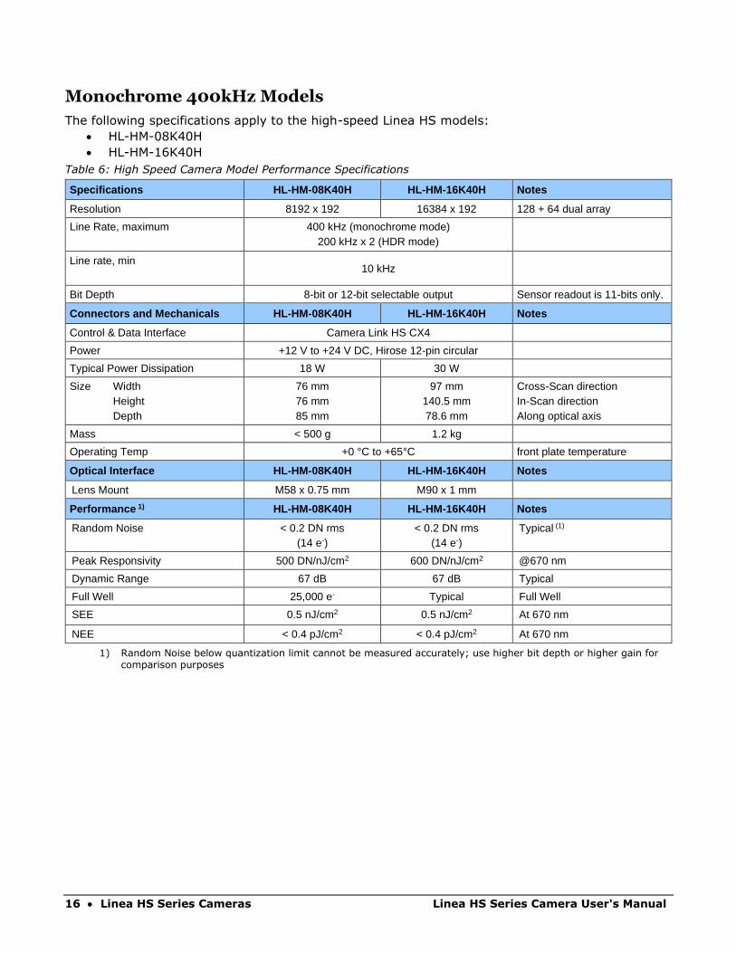
Monochrome 400kHz Models
The following specifications apply to the high-speed Linea HS models:
• HL-HM-08K40H
• HL-HM-16K40H
Table 6: High Speed Camera Model Performance Specifications
Specifications HL-HM-08K40H HL-HM-16K40H Notes
Resolution 8192 x 192 16384 x 192 128 + 64 dual array
Line Rate, maximum 400 kHz (monochrome mode) 200 kHz x 2 (HDR mode)
Line rate, min 10 kHz
Bit Depth 8-bit or 12-bit selectable output Sensor readout is 11-bits only.
Connectors and Mechanicals HL-HM-08K40H HL-HM-16K40H Notes
Control & Data Interface Camera Link HS CX4
Power +12 V to +24 V DC, Hirose 12-pin circular
Typical Power Dissipation 18 W 30 W
Size Width Height Depth
76 mm 76 mm 85 mm
97 mm 140.5 mm 78.6 mm
Cross-Scan direction In-Scan direction Along optical axis
Mass < 500 g 1.2 kg
Operating Temp +0 °C to +65°C front plate temperature
Optical Interface HL-HM-08K40H HL-HM-16K40H Notes
Lens Mount M58 x 0.75 mm M90 x 1 mm
Performance 1) HL-HM-08K40H HL-HM-16K40H Notes
Random Noise < 0.2 DN rms (14 e-)
< 0.2 DN rms (14 e-)
Typical (1)
Peak Responsivity 500 DN/nJ/cm2 600 DN/nJ/cm2 @670 nm
Dynamic Range 67 dB 67 dB Typical
Full Well 25,000 e- Typical Full Well
SEE 0.5 nJ/cm2 0.5 nJ/cm2 At 670 nm
NEE < 0.4 pJ/cm2 < 0.4 pJ/cm2 At 670 nm
1) Random Noise below quantization limit cannot be measured accurately; use higher bit depth or higher gain for comparison purposes

Linea HS Series Camera User's Manual Linea HS Series Cameras • 17
Color and Multifield Models
The following specifications apply to the color and multifield Linea HS models:
• HL-HF-16K13T
• HL-HC-16K10T
Table 7: Color and Multifield Camera Model Performance Specifications
Specifications HL-HC-16k10T HL-HF-16K13T Notes
Resolution 16,84 x (64+128+64) 16,384 x (64+128+64) 3 TDI arrays 64 + 128 + 64 stages
Line Rate, maximum 100kHz x 3 130 kHz x 3
Line rate, min 10 kHz x 3 Limited by dark current
Bit Depth 8-bit or 12-bit selectable
Connectors and Mechanicals
HL-HC-16k10T HL-HF-16K13T Notes
Typical Power Dissipation
30W 30 W
Size Width Height Depth
97 mm 140.5 mm 78.6 mm
97 mm 140.5 mm 78.6 mm
Cross-Scan direction In-Scan direction Along optical axis
Mass 1.2 kg 1.2 kg
Optical Interface HL-HC-16k10T HL-HF-16K13T Notes
Lens Mount M90 x 1 mm M90 x 1 mm
Performance 1) HL-HC-16k10T HL-HF-16K13T Notes
Random Noise < 0.2 DN rms (10 e-)
< 0.2 DN rms (10 e-)
Typical 2)
Peak Responsivity Blue 180
Green 230 Red 290
Blue 180
Green 230 Red 290
DN / nJ / cm2 8-bit
Digital Gain 1x to 10x 1x to 10x
Dynamic Range 69 dB 69 dB Typical
Full Well 25,000 e- 25,000 e- Typical
SEE Blue 1.3 nJ/cm2
Green 1 nJ/cm2 Red 0.8 nJ/cm2
Blue 1.3 nJ/cm2
Green 1 nJ/cm2 Red 0.8 nJ/cm2
At 460 nm At 560 nm At 660 nm
NEE Blue 0.5 pJ/cm2
Green 0.4 pJ/cm2 Red 0.3 pJ/cm2
Blue 0.5 pJ/cm2
Green 0.4 pJ/cm2 Red 0.3 pJ/cm2
At 460 nm At 560 nm At 660 nm
1) Random Noise below quantization limit cannot be measured accurately; use higher bit depth or higher gain for comparison purposes
18 • Linea HS Series Cameras Linea HS Series Camera User's Manual
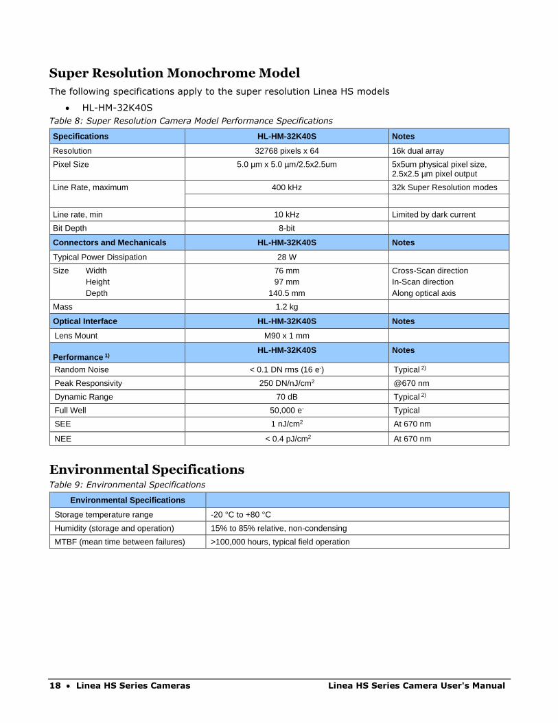
Super Resolution Monochrome Model
The following specifications apply to the super resolution Linea HS models
• HL-HM-32K40S
Table 8: Super Resolution Camera Model Performance Specifications
Specifications HL-HM-32K40S Notes
Resolution 32768 pixels x 64 16k dual array
Pixel Size 5.0 µm x 5.0 µm/2.5x2.5um 5x5um physical pixel size, 2.5x2.5 µm pixel output
Line Rate, maximum 400 kHz 32k Super Resolution modes
Line rate, min 10 kHz Limited by dark current
Bit Depth 8-bit
Connectors and Mechanicals HL-HM-32K40S Notes
Typical Power Dissipation 28 W
Size Width Height Depth
76 mm 97 mm
140.5 mm
Cross-Scan direction In-Scan direction Along optical axis
Mass 1.2 kg
Optical Interface HL-HM-32K40S Notes
Lens Mount M90 x 1 mm
Performance 1) HL-HM-32K40S Notes
Random Noise < 0.1 DN rms (16 e-) Typical 2)
Peak Responsivity 250 DN/nJ/cm2 @670 nm
Dynamic Range 70 dB Typical 2)
Full Well 50,000 e- Typical
SEE 1 nJ/cm2 At 670 nm
NEE < 0.4 pJ/cm2 At 670 nm
Environmental Specifications Table 9: Environmental Specifications
Environmental Specifications
Storage temperature range -20 °C to +80 °C
Humidity (storage and operation) 15% to 85% relative, non-condensing
MTBF (mean time between failures) >100,000 hours, typical field operation
Linea HS Series Camera User's Manual Linea HS Series Cameras • 19
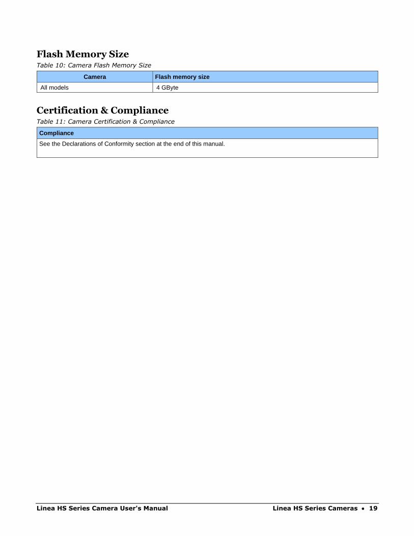
Flash Memory Size Table 10: Camera Flash Memory Size
Camera Flash memory size
All models 4 GByte
Certification & Compliance Table 11: Camera Certification & Compliance
Compliance
See the Declarations of Conformity section at the end of this manual.
20 • Linea HS Series Cameras Linea HS Series Camera User's Manual
Specifications: Monochrome Models The following specifications apply to these Linea HS models:
• HL-FM-04K30H-00-R
• HL-FM-08K30H-00-R
• HL-HM-08K30H-00-R
• HL-HM-08K40H-00-R
• HL-FM-13K18H-00-R
• HL-HM-13K30H-00-R
• HL-FM-16K15A-00-R
• HL-HM-16K30H-00-R
• HL-HM-16K40H-00-R
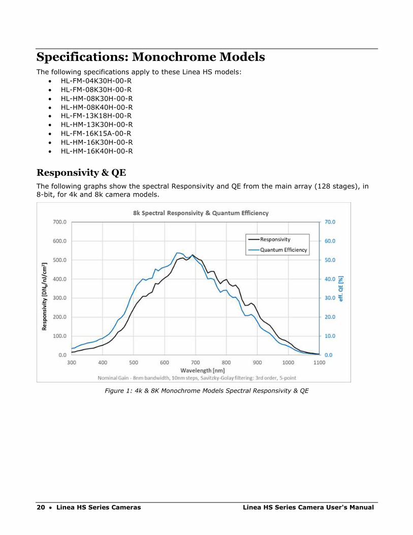
Responsivity & QE
The following graphs show the spectral Responsivity and QE from the main array (128 stages), in
8-bit, for 4k and 8k camera models.
Figure 1: 4k & 8K Monochrome Models Spectral Responsivity & QE
Linea HS Series Camera User's Manual Linea HS Series Cameras • 21
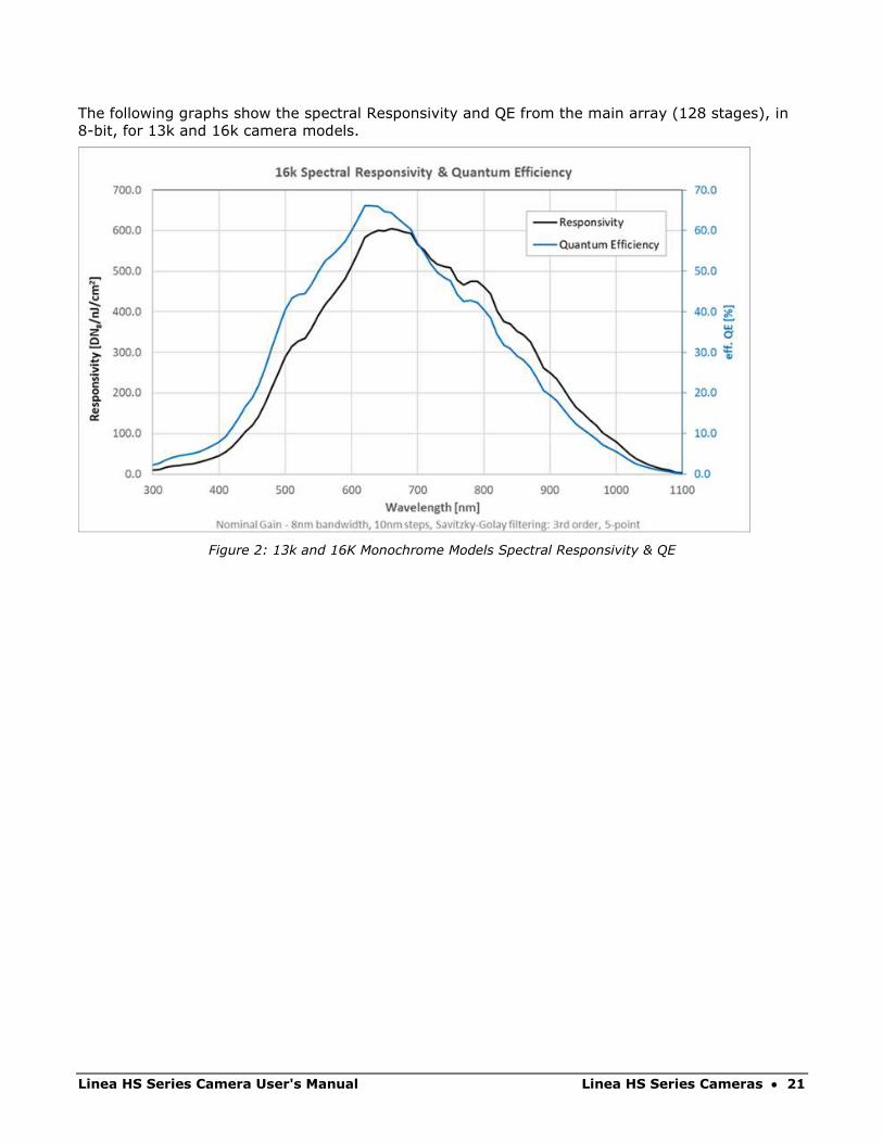
The following graphs show the spectral Responsivity and QE from the main array (128 stages), in
8-bit, for 13k and 16k camera models.
Figure 2: 13k and 16K Monochrome Models Spectral Responsivity & QE

22 • Linea HS Series Cameras Linea HS Series Camera User's Manual
Camera Input Power
The following graphs detail the power vs. input voltage for model HL-HM and HL-FM models.
Figure 3: Standard 4k and 8k Models Power vs. Input Voltage
Figure 4: Standard 13k and 16k Models Power Vs. Input Voltage
Test conditions: Max line rate for model, TDI Mode—128, Bit Mode—8, Black Level—31,
Temperature—Ambient
Linea HS Series Camera User's Manual Linea HS Series Cameras • 23
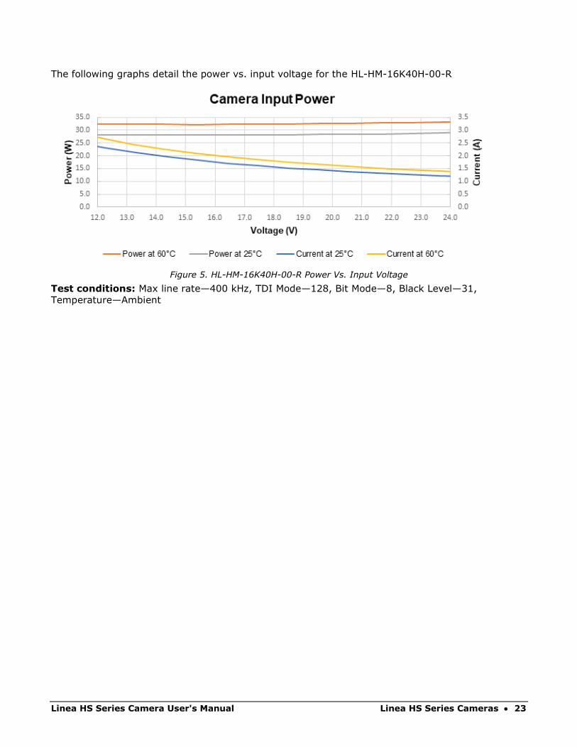
The following graphs detail the power vs. input voltage for the HL-HM-16K40H-00-R
Figure 5. HL-HM-16K40H-00-R Power Vs. Input Voltage
Test conditions: Max line rate—400 kHz, TDI Mode—128, Bit Mode—8, Black Level—31,
Temperature—Ambient
24 • Linea HS Series Cameras Linea HS Series Camera User's Manual
Specifications: Color Model The following specifications apply to the color Linea HS model:
• HL-HC-16K10T-00-R
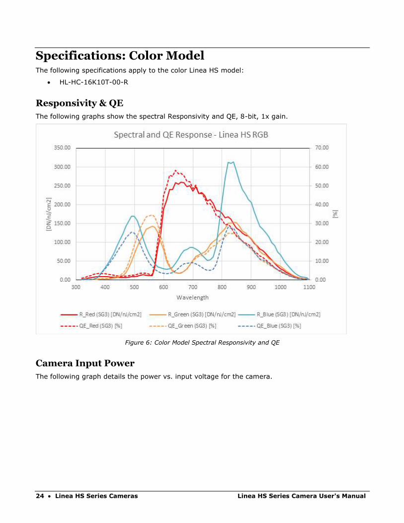
Responsivity & QE
The following graphs show the spectral Responsivity and QE, 8-bit, 1x gain.
Figure 6: Color Model Spectral Responsivity and QE
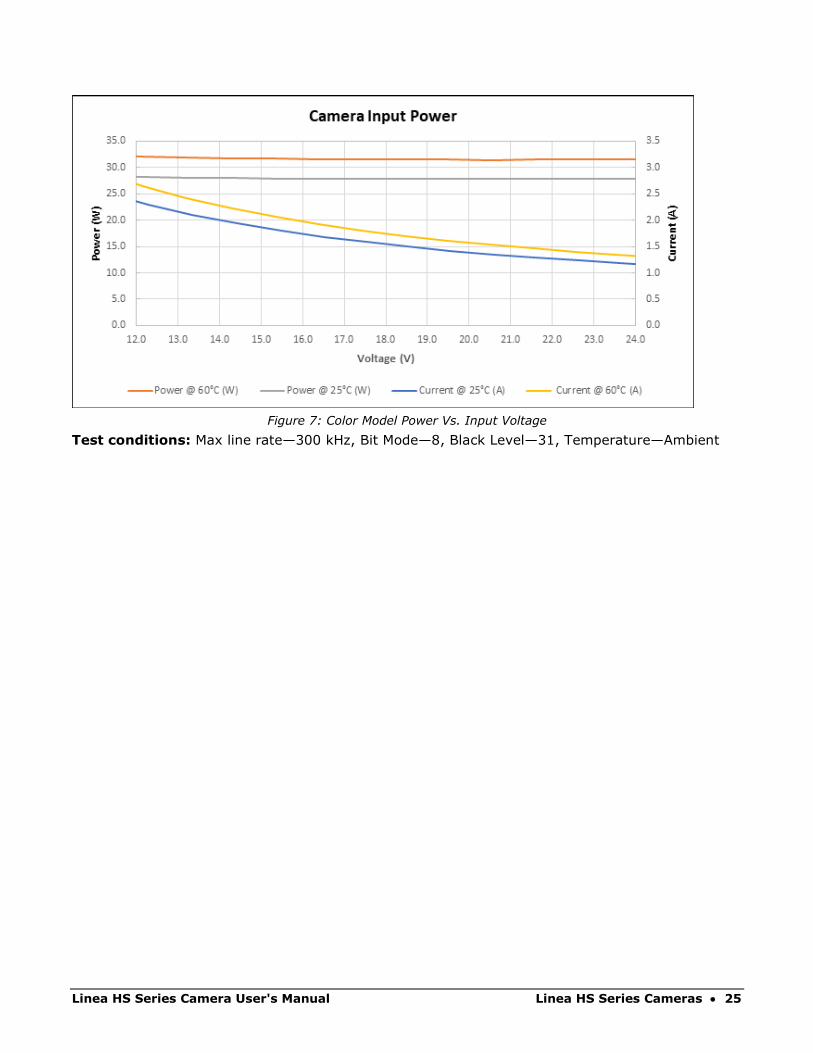
Camera Input Power
The following graph details the power vs. input voltage for the camera.
Linea HS Series Camera User's Manual Linea HS Series Cameras • 25
Figure 7: Color Model Power Vs. Input Voltage
Test conditions: Max line rate—300 kHz, Bit Mode—8, Black Level—31, Temperature—Ambient

26 • Linea HS Series Cameras Linea HS Series Camera User's Manual
Specifications: Multifield Model The following specifications apply to the multifield Linea HS model:
• HL-HF-16K13T
Responsivity & QE
The following graphs show the spectral Responsivity and QE, 8-bit, 1x gain.
Figure 8: Multifield Model Spectral Responsivity

Linea HS Series Camera User's Manual Linea HS Series Cameras • 27
Figure 9: Multifield Model QE
Camera Input Power
The following graph details the power vs. input voltage for the camera.
Figure 10: Multifield Model Power Vs. Input Voltage
Test conditions: Max line rate—300 kHz, Bit Mode—8, Black Level—31, Temperature—Ambient

28 • Linea HS Series Cameras Linea HS Series Camera User's Manual
Specifications: Super Resolution 32k Model The following specifications apply to the super resolution Linea HS model:
• HL-HM-32K40S-00-R
Responsivity & QE
The following graphs show the spectral responsivity and QE in 32k super resolution mode; for 16k
modes, multiply responsivity values by 2.
Figure 11: Super Resolution Model Spectral Responsivity & QE, 32k SR Mapped, 1x gain
Linea HS Series Camera User's Manual Linea HS Series Cameras • 29
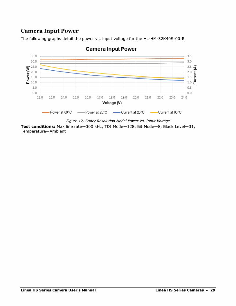
Camera Input Power
The following graphs detail the power vs. input voltage for the HL-HM-32K40S-00-R
Figure 12. Super Resolution Model Power Vs. Input Voltage
Test conditions: Max line rate—300 kHz, TDI Mode—128, Bit Mode—8, Black Level—31,
Temperature—Ambient
30 • Linea HS Series Cameras Linea HS Series Camera User's Manual
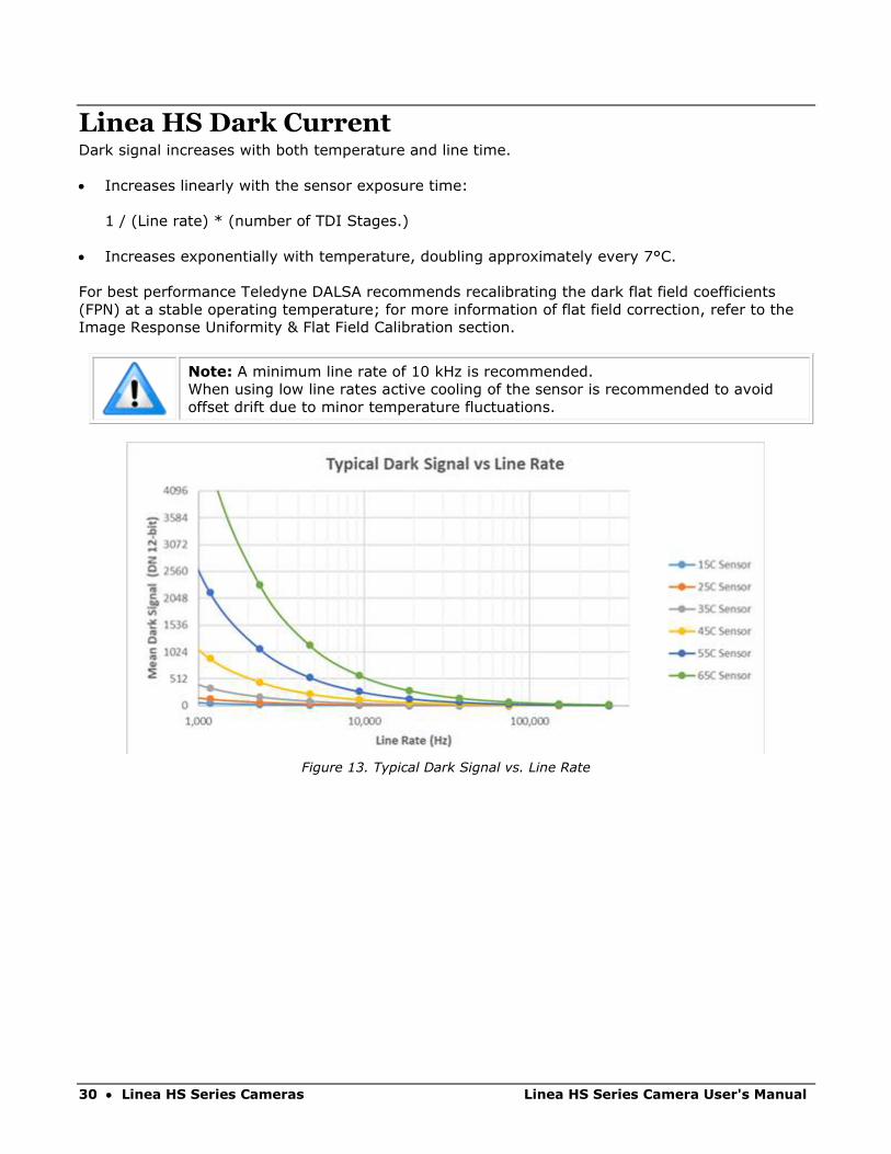
Linea HS Dark Current Dark signal increases with both temperature and line time.
• Increases linearly with the sensor exposure time:
1 / (Line rate) * (number of TDI Stages.)
• Increases exponentially with temperature, doubling approximately every 7°C.
For best performance Teledyne DALSA recommends recalibrating the dark flat field coefficients
(FPN) at a stable operating temperature; for more information of flat field correction, refer to the
Image Response Uniformity & Flat Field Calibration section.
Note: A minimum line rate of 10 kHz is recommended.
When using low line rates active cooling of the sensor is recommended to avoid
offset drift due to minor temperature fluctuations.
Figure 13. Typical Dark Signal vs. Line Rate
Linea HS Series Camera User's Manual Linea HS Series Cameras • 31
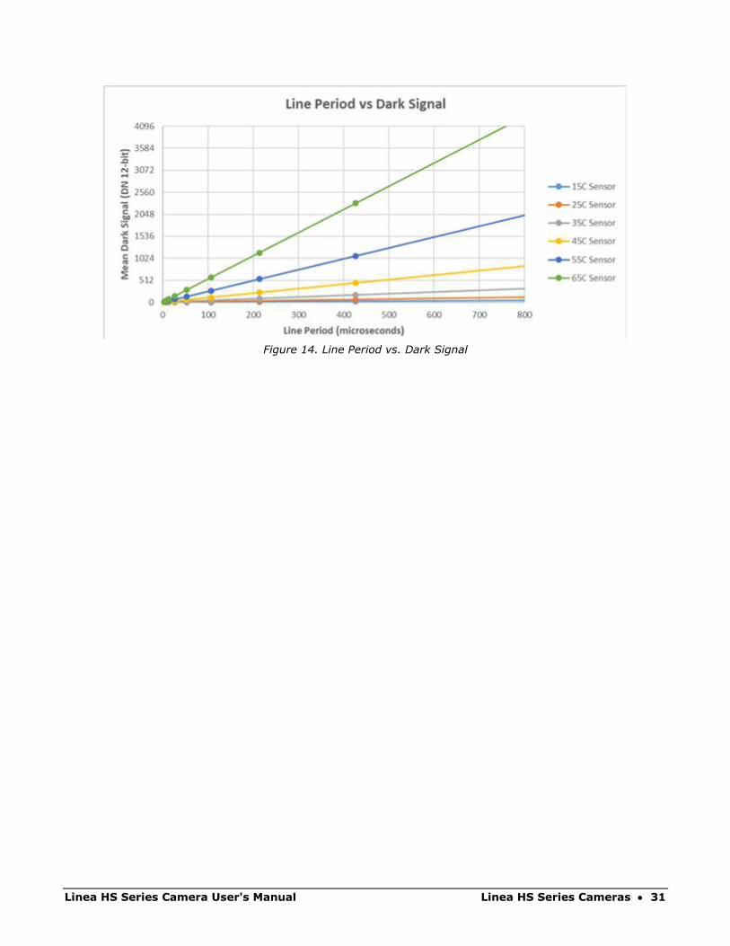
Figure 14. Line Period vs. Dark Signal

32 • Linea HS Series Cameras Linea HS Series Camera User's Manual
Camera Processing Chain The diagram below details the sequence of user-adjustable, arithmetic operations performed on the
camera sensor data. These adjustments are using camera features outlined in the ‘Review of
Camera Performance and Features’ section.
X X X+/-- X + +
Digital Processing
video
user FPN
flat field correction
black level
(offset)
gain
systemgain
EOIoffset
+/-
EOIgain
filter
verticalbinning
horizontalbinning
LUT
output video
Figure 15: Digital data processing chain
Supported Industry Standards
GenICam™ The camera is GenICam compliant and implements a superset of the GenICam Standard Features
Naming Convention specification V1.5.
This description takes the form of an XML device description file using the syntax defined by the
GenApi module of the GenICam specification. The camera uses the GenICam Generic Control
Protocol (GenCP V1.0) to communicate over the Camera Link HS command lane.
For more information see www.genicam.org.
Linea HS Series Camera User's Manual Linea HS Series Cameras • 33
Camera Link HS The camera is Camera Link HS version 1.0 compliant. Camera Link HS is the next generation of
high-performance communications standards. It is used where an industrial digital camera
interfaces with a single or multiple frame grabbers and with data rates exceeding those supported
by the standard Camera Link.
The Linea HS cameras come with two different output mediums; CX4 AOC Data Cables or LC Fiber
Optic (HL-FM cameras only)
HL-FM camera models use two LC connectors for data output. These two LC connectors are part of
the SFP+ standard but in the case of Linea HS camera the SFP+ modules are built into the camera.
Either one or both SFP+ modules can be used but using only one SFP+ / fiber optic will sacrifice
available bandwidth.
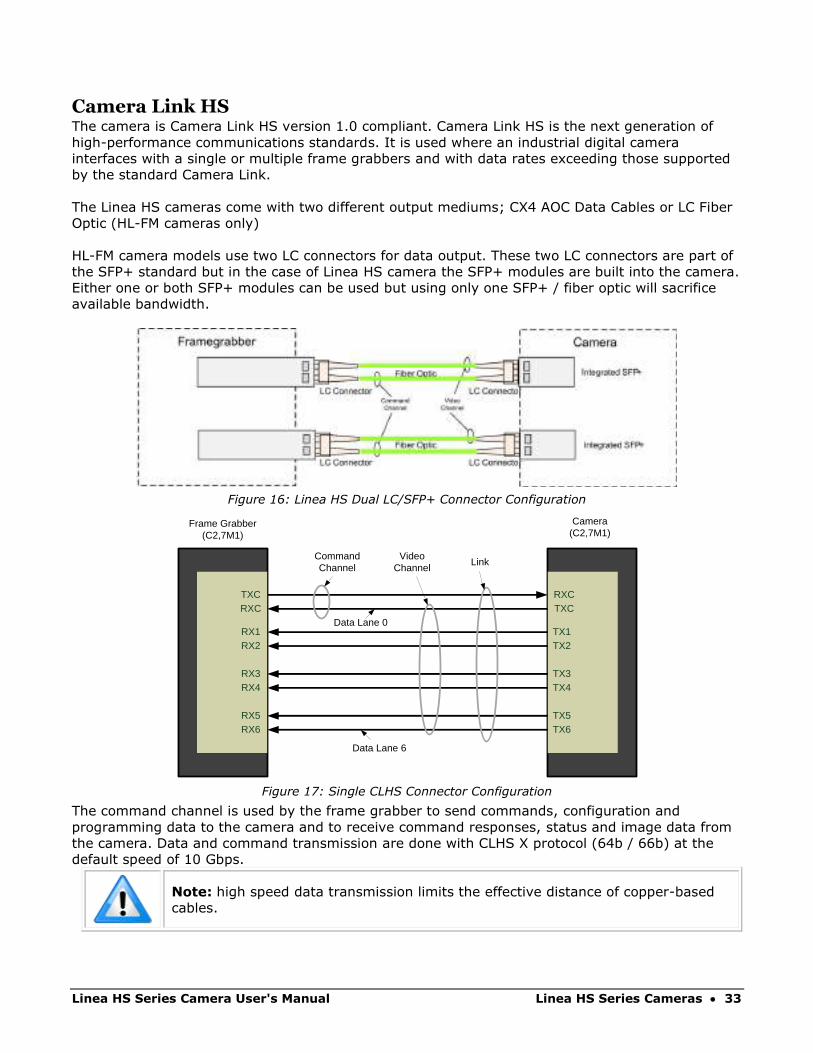
Figure 16: Linea HS Dual LC/SFP+ Connector Configuration
Figure 17: Single CLHS Connector Configuration
The command channel is used by the frame grabber to send commands, configuration and
programming data to the camera and to receive command responses, status and image data from
the camera. Data and command transmission are done with CLHS X protocol (64b / 66b) at the
default speed of 10 Gbps.
Note: high speed data transmission limits the effective distance of copper-based
cables.
RXCTXC
TX1TX2
TX3TX4
TX5TX6
TXCRXC
RX1RX2
RX3RX4
RX5RX6
Data Lane 6
Data Lane 0
CommandChannel
VideoChannel
Link
Camera(C2,7M1)
Frame Grabber(C2,7M1)
34 • Linea HS Series Cameras Linea HS Series Camera User's Manual
Data Cables
LC Fiber Optic (HL-FM Cameras)
Used by the following camera models:
• HL-FM-04K30H-00-R
• HL-FM-08K30H-00-R
• HL-FM-13K18H-00-R
• HL-FM-16K15A-00-R
The fiber optic cables for the HL-FM camera models require LC connections on both ends of the
cable. The frame grabber requires the LC connector to be plugged into an SFP+ transceiver
module.
LC is a small-form factor fiber optic connector that uses a 1.25 mm ferrule, half the size of a
standard connector. These cables are in wide use in the telecommunications industry and available
in many lengths.
The distance through which the data can be transmitted depends on the type of fiber optic used.
Recommended fiber optic cables are types OM3 and OM4.
OM4 is used for distances > 300 m, but also requires SFP+ transceiver module changes.
Contact Teledyne DALSA Support for more information on recommended cables.
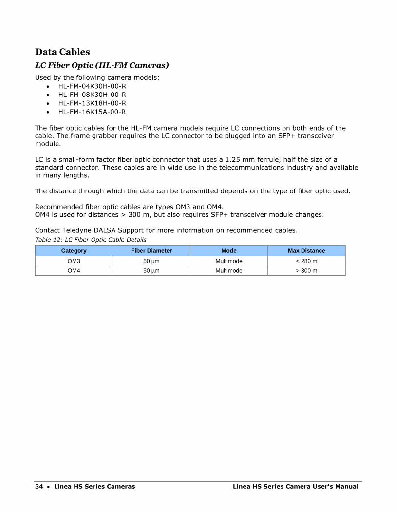
Table 12: LC Fiber Optic Cable Details
Category Fiber Diameter Mode Max Distance
OM3 50 µm Multimode < 280 m
OM4 50 µm Multimode > 300 m

Linea HS Series Camera User's Manual Linea HS Series Cameras • 35
CX4 AOC Data Cables
Used by the following camera models:
• HL-HM-08K30H-00-R
• HL-HM-13K30H-00-R
• HL-HM-16K30H-00-R
• HL-HM-08K40H-00-R
• HL-HM-32K40S-00-R
• HL-HM-16k10T-00-R
• HL-HF-16K13T-00-R
Camera Link HS CX4 AOC (Active Optical Cable) cables are made to handle very high data rates.
These cables accept the same electrical inputs as traditional copper cables, but also use optical
fibers. AOC uses electrical-to-optical conversion on the cable ends to improve speed and distance
performance of the cable without sacrificing compatibility with standard electrical interfaces.
Camera Link HS cables can be bought from an OEM. OEM cables are also available for applications
where flexing is present. Please refer to Teledyne DALSA’s website (www.teledynedalsa.com) for a
list of recommended cable vendors and for part numbers.
Each data cable is used for sending image data to and accepting command data from the frame
grabber. Command data includes GenICam compliant messages, trigger timing and general
purpose I/O, such as direction control.
Note: data transmits at 10 Gbps which limits the effective distance of copper-
based cables.

36 • Linea HS Series Cameras Linea HS Series Camera User's Manual
Mechanical Drawings
Figure 18:HL-FM-04K30H-00-R and HL-FM-08K30H-00-R Mechanical Drawing

Linea HS Series Camera User's Manual Linea HS Series Cameras • 37
Figure 19: HL-HM-08K30H-00-R and HL-HM-08K40H-00-R Mechanical Drawing
38 • Linea HS Series Cameras Linea HS Series Camera User's Manual
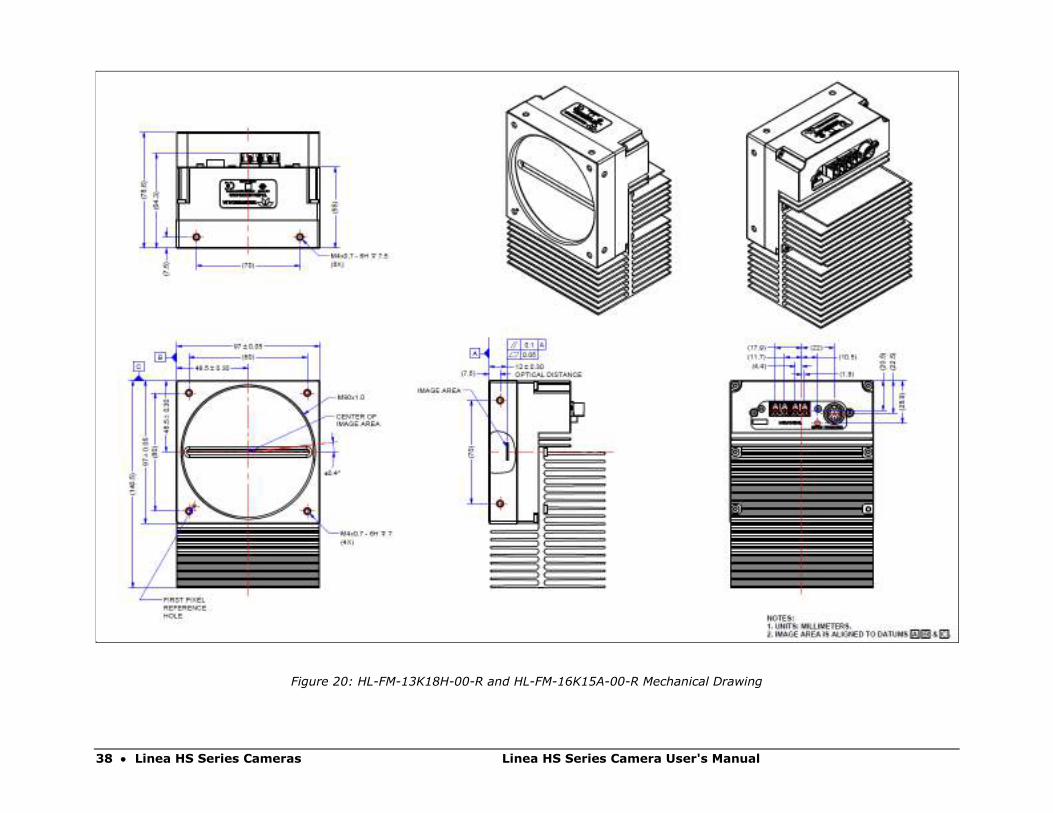
Figure 20: HL-FM-13K18H-00-R and HL-FM-16K15A-00-R Mechanical Drawing
Linea HS Series Camera User's Manual Linea HS Series Cameras • 39
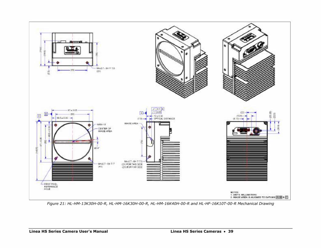
Figure 21: HL-HM-13K30H-00-R, HL-HM-16K30H-00-R, HL-HM-16K40H-00-R and HL-HF-16K10T-00-R Mechanical Drawing

40 • Linea HS Series Cameras Linea HS Series Camera User's Manual
Precautions Read these precautions before using the camera.
Confirm that the camera’s packaging is undamaged before opening it. If the packaging is damaged
please contact the related logistics personnel.
Do not open the housing of the camera. The warranty is voided if the housing is opened.
Keep the camera’s front plate temperature in a range of 0 °C to +65 °C during operation. The
camera can measure its internal temperature. Use this feature to record the internal temperature
of the camera when it is mounted in your system and operating under the worst-case conditions.
The camera will stop outputting data if its internal temperature reaches +80 °C.
Do not operate the camera in the vicinity of strong electromagnetic fields. In addition, avoid
electrostatic discharging, violent vibration and excess moisture.
To clean the device, avoid electrostatic charging by using a dry, clean absorbent cotton cloth
dampened with a small quantity of pure alcohol. Do not use methylated alcohol. To clean the
surface of the camera housing, use a soft, dry cloth. To remove severe stains, use a soft cloth
dampened with a small quantity of neutral detergent and then wipe dry. Do not use volatile
solvents such as benzene and thinners, as they can damage the surface finish.
Though this camera supports hot plugging, it is recommended that you power down and disconnect
power to the camera before you add or replace system components.
Electrostatic Discharge and the CMOS Sensor Image sensors and the camera’s housing can be susceptible to damage from severe electrostatic
discharge (ESD). Electrostatic charge introduced to the sensor window surface can induce charge
buildup on the underside of the window. The charge normally dissipates within 24 hours and the
sensor returns to normal operation.
Linea HS Series Camera User's Manual Linea HS Series Cameras • 41
Install & Configure Frame Grabber & Software Because of the high bandwidth of these cameras, a compatible Teledyne DALSA frame grabber
(Xtium2-CLHS PX8 (OR-A8S0-PX870)), or equivalent, is recommended. The frame grabber
requirements for the 8K and 16K camera differ. Follow the manufacturer’s installation instructions.
For more details see the Teledyne DALSA website:
http://www.teledynedalsa.com/en/products/imaging/frame-grabbers
A GenICam compliant XML device description file is embedded with the camera firmware. It allows
GenICam compliant applications to recognize the camera’s capabilities, once connected.
Installing Sapera LT gives you access to the CamExpert GUI, a GenICam compliant application.
Using Sapera CamExpert CamExpert is the camera interfacing tool supported by the Sapera library. When used with the
camera, CamExpert allows a user to test all camera operating modes. In addition, CamExpert can
be used to save the camera’s user settings configurations to the camera or to save multiple
configurations as individual camera parameter files on the host system (*.ccf).
CamExpert can also be used to upgrade the camera’s software.
An important component of CamExpert is its live acquisition display window. This window allows
verification of timing or control parameters in real-time, without need for a separate acquisition
program.
The central section of CamExpert provides access to the camera features and parameters.
Note: The availability of features depends on the CamExpert user setting. Not all
features are available to all users. The examples shown are for illustrative
purposes and may not entirely reflect the features and parameters available from
the camera model used in your application.

42 • Linea HS Series Cameras Linea HS Series Camera User's Manual
CamExpert Panes CamExpert, first instance: select Camera Link HS using the Device drop-down menu.
Figure 22: CamExpert Frame Grabber Control Window
The CamExpert application uses panes to organize the selection and configuration of camera files
or acquisition parameters.
Device Selector pane: View and select from any installed Sapera acquisition device. Once a
device is selected, CamExpert will only show acquisition parameters for that device. Optionally,
select a camera file included with the Sapera installation or saved previously.
Parameters pane: Allows the viewing or changing of all acquisition parameters supported by the
acquisition device. CamExpert displays parameters only if those parameters are supported by the
installed device. This avoids confusion by eliminating parameter choices when they do not apply to
the hardware in use.
Display pane: Provides a live or single frame acquisition display. Frame buffer parameters are
shown in an information bar above the image window.

Linea HS Series Camera User's Manual Linea HS Series Cameras • 43
Control Buttons: The display pane includes CamExpert control buttons. These are:
Acquisition control button: Click once to start live grab, click again to stop.
Single frame grab: Click to acquire one frame from device.
Trigger button: With the I/O control parameters set to Trigger Enabled, click to send a single trigger command.
CamExpert display controls: (these do not modify the frame buffer data) Stretch image to fit, set image display to original size, or zoom the image to virtually any size and ratio.
Histogram / Profile tool: Select to view a histogram or line/column profile during live acquisition or in a still image.
Output Message Pane: Displays messages from CamExpert or the device driver.
At this point you are ready to start operating the camera, acquire images, set camera functions
and save settings.
44 • Linea HS Series Cameras Linea HS Series Camera User's Manual
Setting Up for Imaging
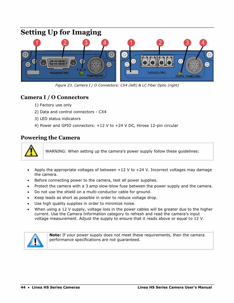
Figure 23. Camera I / O Connectors: CX4 (left) & LC Fiber Optic (right)
Camera I / O Connectors
1) Factory use only
2) Data and control connectors - CX4
3) LED status indicators
4) Power and GPIO connectors: +12 V to +24 V DC, Hirose 12-pin circular
Powering the Camera
WARNING: When setting up the camera’s power supply follow these guidelines:
• Apply the appropriate voltages of between +12 V to +24 V. Incorrect voltages may damage
the camera.
• Before connecting power to the camera, test all power supplies.
• Protect the camera with a 3 amp slow-blow fuse between the power supply and the camera.
• Do not use the shield on a multi-conductor cable for ground.
• Keep leads as short as possible in order to reduce voltage drop.
• Use high quality supplies in order to minimize noise.
• When using a 12 V supply, voltage loss in the power cables will be greater due to the higher
current. Use the Camera Information category to refresh and read the camera’s input
voltage measurement. Adjust the supply to ensure that it reads above or equal to 12 V.
Note: If your power supply does not meet these requirements, then the camera
performance specifications are not guaranteed.
Linea HS Series Camera User's Manual Linea HS Series Cameras • 45
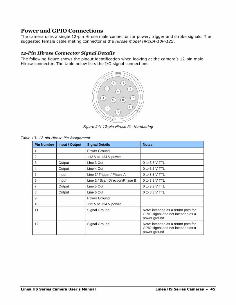
Power and GPIO Connections The camera uses a single 12-pin Hirose male connector for power, trigger and strobe signals. The
suggested female cable mating connector is the Hirose model HR10A-10P-12S.
12-Pin Hirose Connector Signal Details
The following figure shows the pinout identification when looking at the camera’s 12-pin male
Hirose connector. The table below lists the I/O signal connections.
1
46
71211
3
210
8
9
5
Figure 24: 12-pin Hirose Pin Numbering
Table 13: 12-pin Hirose Pin Assignment
Pin Number Input / Output Signal Details Notes
1 Power Ground
2 +12 V to +24 V power
3 Output Line 3 Out 0 to 3.3 V TTL
4 Output Line 4 Out 0 to 3.3 V TTL
5 Input Line 1/ Trigger / Phase A 0 to 3.3 V TTL
6 Input Line 2 / Scan Direction/Phase B 0 to 3.3 V TTL
7 Output Line 5 Out 0 to 3.3 V TTL
8 Output Line 6 Out 0 to 3.3 V TTL
9 Power Ground
10 +12 V to +24 V power
11 Signal Ground Note: intended as a return path for GPIO signal and not intended as a power ground
12 Signal Ground Note: intended as a return path for GPIO signal and not intended as a power ground
46 • Linea HS Series Cameras Linea HS Series Camera User's Manual
The wire gauge of the power cable should be sufficient to accommodate a surge during power-up of
at least 3 amps with a minimum voltage drop between the power supply and camera. The camera
can accept any voltage between +12 and +24 Volts. If there is a voltage drop between the power
supply and camera, ensure that the power supply voltage is at least 12 Volts plus this voltage drop.
The camera input supply voltage can be read using CamExpert. Refer to the section on Voltage &
Temperature Measurement for more details.
External Input Electrical Characteristics Table 14: External Input Electrical Characteristics
Switching Voltage
Input Level Standard Low to high High to low Input Impedance
3.3 V TTL 2.1 V 1 V 10 K Ω
External Input Timing Reference Table 15: External Input Timing Reference
Input Level Standard Max Input Frequency
Min Pulse Width
Input Current Maximum Signal Propagation Delay @ 60oC
3.3 V TTL 20 MHz 25 ns <250 µA 0 to 3.3 V <100 ns
3.3 V to 0 <100 ns
External Output Electrical Characteristics Table 16: External Output Electrical Characteristics
Output Level Standard VOL VOH
3.3 V TTL <0.4 V @ 10 mA* >3.1 V @ 10 mA*
*See Linear Technology data sheet LTC2854
External Output Timing Reference Table 17: External Output Timing Reference
Output Level Standard Max Output Frequency
Min Pulse Width
Output Current Maximum Signal Propagation Delay @ 60oC
3.3 V TTL Line rate dependent
25 ns <180 mA 0 to 3.3 V <100 ns
3.3 V to 0 <100 ns
To reduce the chance of stress and vibration on the cables, we recommend that you
use cable clamps, placed close to the camera, when setting up your imaging
system. Stress or vibration of the heavy CLHS AOC cables may damage the
camera’s connectors.
Linea HS Series Camera User's Manual Linea HS Series Cameras • 47
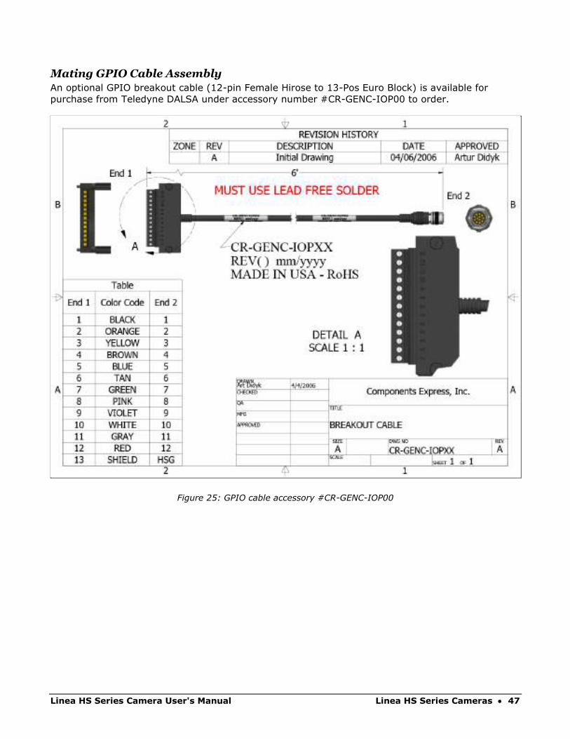
Mating GPIO Cable Assembly
An optional GPIO breakout cable (12-pin Female Hirose to 13-Pos Euro Block) is available for
purchase from Teledyne DALSA under accessory number #CR-GENC-IOP00 to order.
Figure 25: GPIO cable accessory #CR-GENC-IOP00
48 • Linea HS Series Cameras Linea HS Series Camera User's Manual
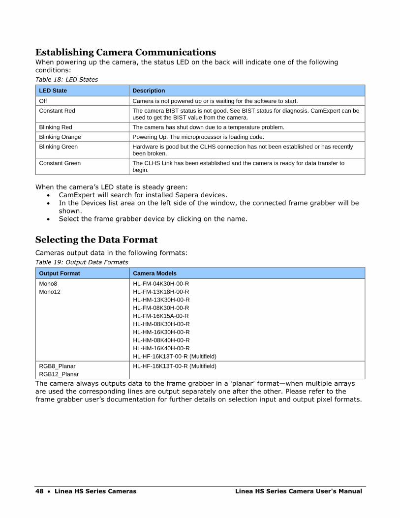
Establishing Camera Communications When powering up the camera, the status LED on the back will indicate one of the following
conditions:
Table 18: LED States
LED State Description
Off Camera is not powered up or is waiting for the software to start.
Constant Red The camera BIST status is not good. See BIST status for diagnosis. CamExpert can be used to get the BIST value from the camera.
Blinking Red The camera has shut down due to a temperature problem.
Blinking Orange Powering Up. The microprocessor is loading code.
Blinking Green Hardware is good but the CLHS connection has not been established or has recently been broken.
Constant Green The CLHS Link has been established and the camera is ready for data transfer to begin.
When the camera’s LED state is steady green:
• CamExpert will search for installed Sapera devices.
• In the Devices list area on the left side of the window, the connected frame grabber will be
shown.
• Select the frame grabber device by clicking on the name.
Selecting the Data Format
Cameras output data in the following formats:
Table 19: Output Data Formats
Output Format Camera Models
Mono8 Mono12
HL-FM-04K30H-00-R HL-FM-13K18H-00-R HL-HM-13K30H-00-R HL-FM-08K30H-00-R HL-FM-16K15A-00-R HL-HM-08K30H-00-R HL-HM-16K30H-00-R HL-HM-08K40H-00-R HL-HM-16K40H-00-R HL-HF-16K13T-00-R (Multifield)
RGB8_Planar RGB12_Planar
HL-HF-16K13T-00-R (Multifield)
The camera always outputs data to the frame grabber in a ‘planar’ format—when multiple arrays
are used the corresponding lines are output separately one after the other. Please refer to the
frame grabber user’s documentation for further details on selection input and output pixel formats.
Linea HS Series Camera User's Manual Linea HS Series Cameras • 49
Establishing Data Integrity • Use the camera’s internal triggering. This allows for initial imaging with a static object and
no encoder input is required.
• Enable the camera to output a test pattern.
• Use a frame grabber CamExpert instance to capture, display and analyze the test pattern
image to verify the integrity of the connection. If the test pattern is not correct, check the
cable connections and the frame grabber setup.
• Disable the test pattern output.

50 • Camera Performance and Features Linea HS Series Camera User's Manual
Camera Performance and Features This section is intended to be a progressive introduction to camera features, including explanations
of how to use them effectively.
Synchronizing to Object Motion
Acquiring Images: Triggering the Camera Related Features: TriggerMode, TriggerSource, TriggerActivation
Several different methods can be used to trigger image acquisition in the camera:
Internal Trigger
The simplest method is to set the Trigger Mode feature to “Internal”. This results in the camera
being triggered by an internal timer, which can be adjusted using the Acquisition Line Rate feature.
External Triggers
When the Trigger Mode feature is set to “External”, the camera triggers come from a different
source selected through the Trigger Source feature.
The available sources for the triggers are from pin 5 of the GPIO connector, from the Camera Link
HS frame grabber, or from the rotary encoder feature (using pin 5 and pin 6 of the GPIO
connector).
Use the Trigger Activation feature to select the edge that triggers the camera. The options are:
Rising Edge, Falling Edge or Any Edge. When using Any Edge be careful that the time between
edges does not exceed the maximum line rate of the camera. If the line rate is exceeded one of
those edges will be ignored.
CamExpert can be used to configure the frame grabber for routing the encoder signal from the
frame grabber input to the trigger input of the camera via the Camera Link HS data cable.
Line Rate & Synchronization
A continuous stream of encoder trigger pulses, synchronized to the object motion, establishes the
line rate. The faster the object’s motion is, the higher the line rate. The camera can accommodate
triggers up to its specified maximum frequency. If the maximum frequency is exceeded, the
camera will continue to output image data at the maximum specified. The result will be that some
trigger pulses will be missed and there will be an associated distortion (compression in the scan
direction) of the image data. When the line rate returns to or below the maximum specified, then
normal imaging will be reestablished.
Linea HS Series Camera User's Manual Camera Performance and Features • 51
Measuring Line (Trigger) Rate See Camera Control Category in Appendix A for GenICam features associated with this section and
how to use them.
Related Feature: measuredLineRate
The Measured Line Rate command is used to read the line (trigger) rate being applied, externally
or internally, to the camera.
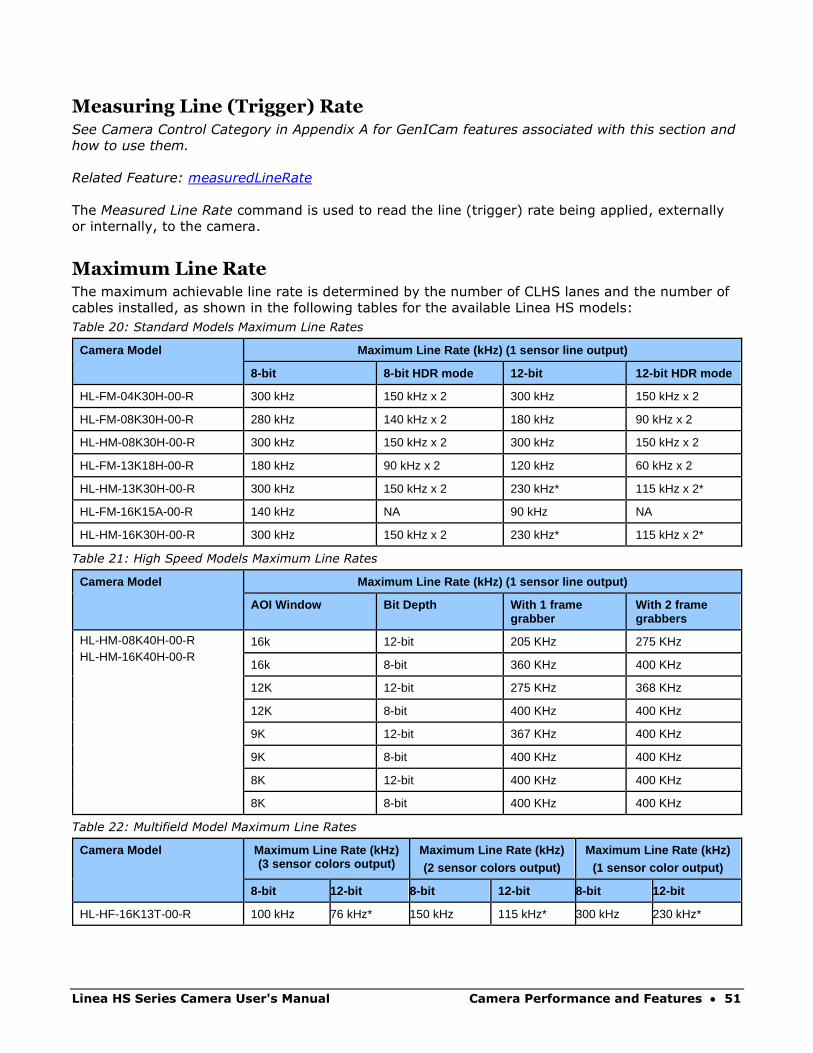
Maximum Line Rate The maximum achievable line rate is determined by the number of CLHS lanes and the number of
cables installed, as shown in the following tables for the available Linea HS models:
Table 20: Standard Models Maximum Line Rates
Camera Model Maximum Line Rate (kHz) (1 sensor line output)
8-bit 8-bit HDR mode 12-bit 12-bit HDR mode
HL-FM-04K30H-00-R 300 kHz 150 kHz x 2 300 kHz 150 kHz x 2
HL-FM-08K30H-00-R 280 kHz 140 kHz x 2 180 kHz 90 kHz x 2
HL-HM-08K30H-00-R 300 kHz 150 kHz x 2 300 kHz 150 kHz x 2
HL-FM-13K18H-00-R 180 kHz 90 kHz x 2 120 kHz 60 kHz x 2
HL-HM-13K30H-00-R 300 kHz 150 kHz x 2 230 kHz* 115 kHz x 2*
HL-FM-16K15A-00-R 140 kHz NA 90 kHz NA
HL-HM-16K30H-00-R 300 kHz 150 kHz x 2 230 kHz* 115 kHz x 2*
Table 21: High Speed Models Maximum Line Rates
Camera Model Maximum Line Rate (kHz) (1 sensor line output)
AOI Window Bit Depth With 1 frame grabber
With 2 frame grabbers
HL-HM-08K40H-00-R HL-HM-16K40H-00-R
16k 12-bit 205 KHz 275 KHz
16k 8-bit 360 KHz 400 KHz
12K 12-bit 275 KHz 368 KHz
12K 8-bit 400 KHz 400 KHz
9K 12-bit 367 KHz 400 KHz
9K 8-bit 400 KHz 400 KHz
8K 12-bit 400 KHz 400 KHz
8K 8-bit 400 KHz 400 KHz
Table 22: Multifield Model Maximum Line Rates
Camera Model Maximum Line Rate (kHz) (3 sensor colors output)
Maximum Line Rate (kHz) (2 sensor colors output)
Maximum Line Rate (kHz) (1 sensor color output)
8-bit 12-bit 8-bit 12-bit 8-bit 12-bit
HL-HF-16K13T-00-R 100 kHz 76 kHz* 150 kHz 115 kHz* 300 kHz 230 kHz*
52 • Camera Performance and Features Linea HS Series Camera User's Manual
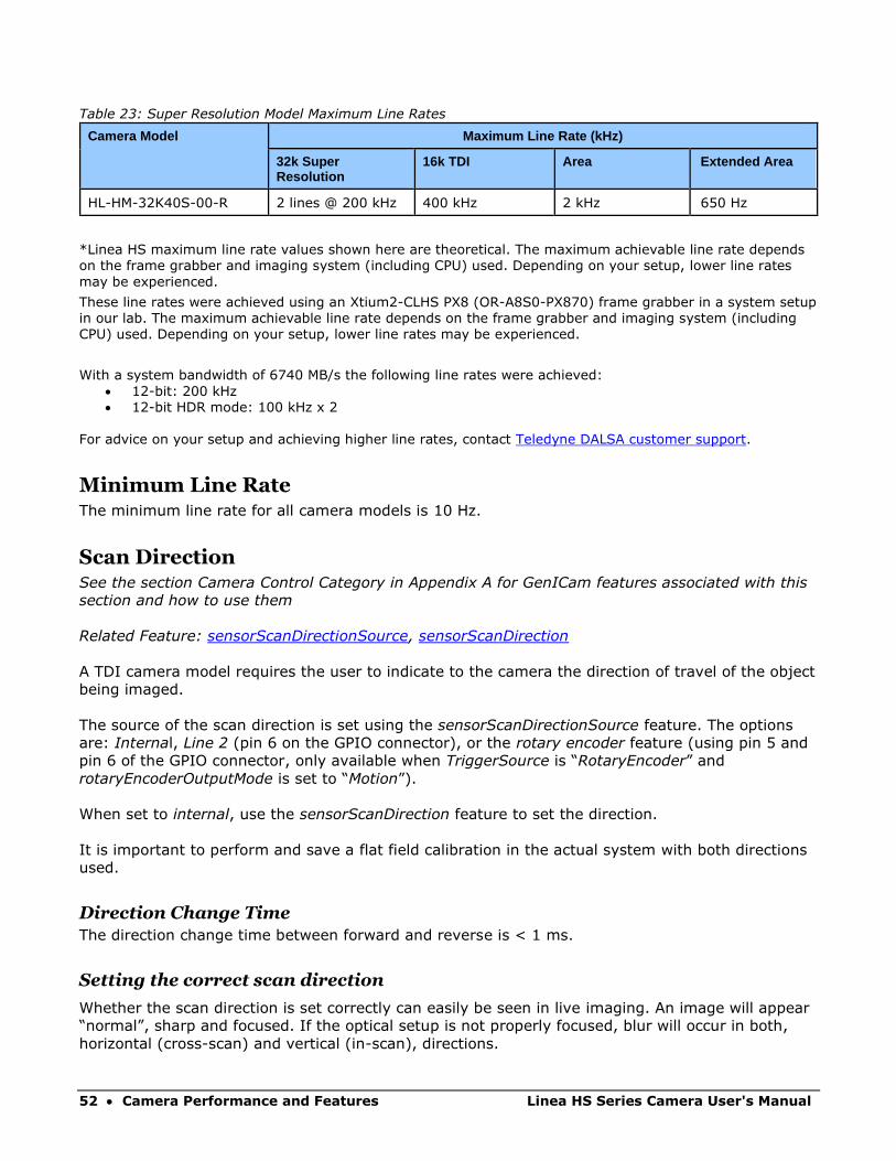
Table 23: Super Resolution Model Maximum Line Rates
Camera Model Maximum Line Rate (kHz)
32k Super Resolution
16k TDI Area Extended Area
HL-HM-32K40S-00-R 2 lines @ 200 kHz 400 kHz 2 kHz 650 Hz
*Linea HS maximum line rate values shown here are theoretical. The maximum achievable line rate depends on the frame grabber and imaging system (including CPU) used. Depending on your setup, lower line rates
may be experienced.
These line rates were achieved using an Xtium2-CLHS PX8 (OR-A8S0-PX870) frame grabber in a system setup in our lab. The maximum achievable line rate depends on the frame grabber and imaging system (including CPU) used. Depending on your setup, lower line rates may be experienced.
With a system bandwidth of 6740 MB/s the following line rates were achieved:
• 12-bit: 200 kHz • 12-bit HDR mode: 100 kHz x 2
For advice on your setup and achieving higher line rates, contact Teledyne DALSA customer support.
Minimum Line Rate The minimum line rate for all camera models is 10 Hz.
Scan Direction See the section Camera Control Category in Appendix A for GenICam features associated with this
section and how to use them
Related Feature: sensorScanDirectionSource, sensorScanDirection
A TDI camera model requires the user to indicate to the camera the direction of travel of the object
being imaged.
The source of the scan direction is set using the sensorScanDirectionSource feature. The options
are: Internal, Line 2 (pin 6 on the GPIO connector), or the rotary encoder feature (using pin 5 and
pin 6 of the GPIO connector, only available when TriggerSource is “RotaryEncoder” and
rotaryEncoderOutputMode is set to “Motion”).
When set to internal, use the sensorScanDirection feature to set the direction.
It is important to perform and save a flat field calibration in the actual system with both directions
used.
Direction Change Time
The direction change time between forward and reverse is < 1 ms.
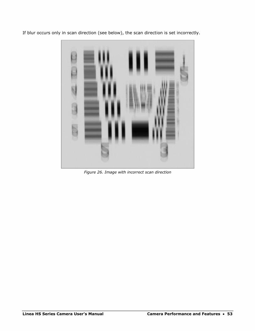
Setting the correct scan direction
Whether the scan direction is set correctly can easily be seen in live imaging. An image will appear
“normal”, sharp and focused. If the optical setup is not properly focused, blur will occur in both,
horizontal (cross-scan) and vertical (in-scan), directions.
Linea HS Series Camera User's Manual Camera Performance and Features • 53
If blur occurs only in scan direction (see below), the scan direction is set incorrectly.
Figure 26. Image with incorrect scan direction

54 • Camera Performance and Features Linea HS Series Camera User's Manual
Camera Orientation The diagram below shows the orientation of forward and reverse with respect to the camera body.
Note: The diagram assumes the use of a lens on the camera, which inverts the
image.
Figure 27: Example of Object Movement and Camera Direction
The diagram shows the designated camera direction. However, due to the characteristics of the
lens, the direction of the objects motion is opposite to the image motion direction.
Some inspection systems require that the scan direction change at regular intervals. For example,
scanning a panel forwards, coming to a stop and then scanning backward as the camera’s field of
view is progressively indexed over the entire panel.
It is necessary for the system to over-scan the area being imaged by at least the 128 stages of the
TDI sensor before the direction is changed. This ensures that valid data will be generated on the
return path as the camera’s field of view reaches the area to be inspected.
Linea HS Series Camera User's Manual Camera Performance and Features • 55
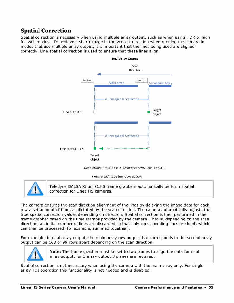
Spatial Correction Spatial correction is necessary when using multiple array output, such as when using HDR or high
full well modes. To achieve a sharp image in the vertical direction when running the camera in
modes that use multiple array output, it is important that the lines being used are aligned
correctly. Line spatial correction is used to ensure that these lines align.
Target object
Scan Direction
n lines spatial correction
Line output 1
Line output 1 + n
Target object
n lines spatial correction
Main array Secondary Array
Main Array Output 1 + n = Secondary Array Line Output 1
Readout Readout
Dual Array Output
Figure 28: Spatial Correction
Teledyne DALSA Xtium CLHS frame grabbers automatically perform spatial
correction for Linea HS cameras.
The camera ensures the scan direction alignment of the lines by delaying the image data for each
row a set amount of time, as dictated by the scan direction. The camera automatically adjusts the
true spatial correction values depending on direction. Spatial correction is then performed in the
frame grabber based on the time stamps provided by the camera. That is, depending on the scan
direction, an initial number of lines are discarded so that only corresponding lines are kept, which
can then be processed (for example, summed together).
For example, in dual array output, the main array row output that corresponds to the second array
output can be 163 or 99 rows apart depending on the scan direction.
Note: The frame grabber must be set to two planes to align the data for dual
array output; for 3 array output 3 planes are required.
Spatial correction is not necessary when using the camera with the main array only. For single
array TDI operation this functionality is not needed and is disabled.
56 • Camera Performance and Features Linea HS Series Camera User's Manual
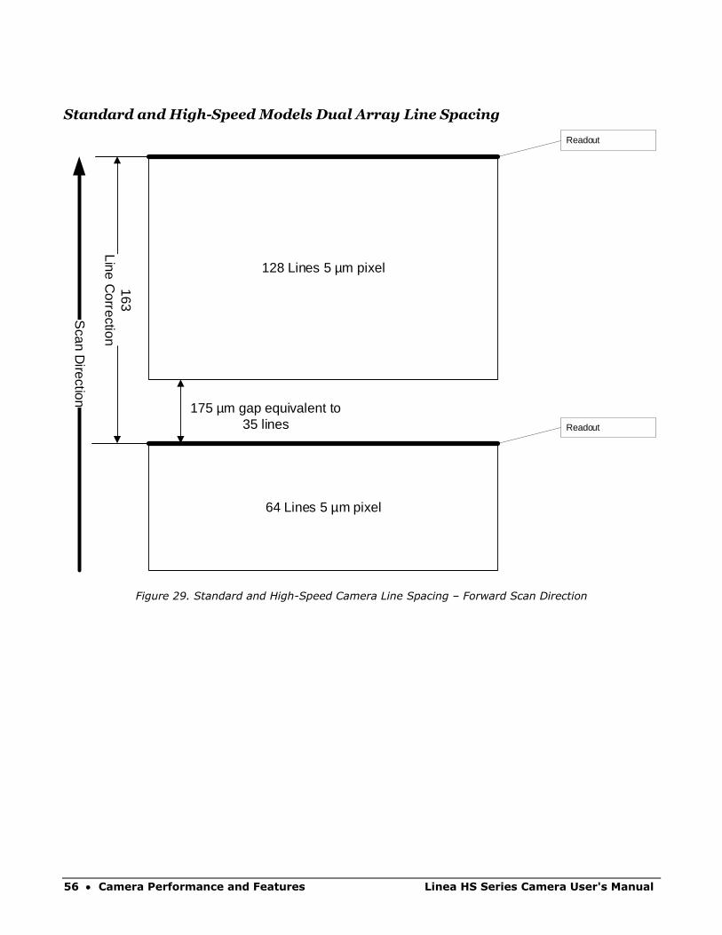
Standard and High-Speed Models Dual Array Line Spacing
64 Lines 5 µm pixel
128 Lines 5 µm pixel
Scan D
irection
Readout
Readout
175 µm gap equivalent to 35 lines
163Line C
orrection
Figure 29. Standard and High-Speed Camera Line Spacing – Forward Scan Direction
Linea HS Series Camera User's Manual Camera Performance and Features • 57
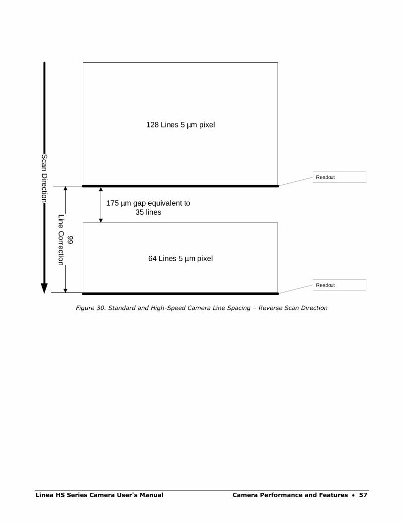
64 Lines 5 µm pixel
128 Lines 5 µm pixel
Scan D
irection
Readout
Readout
175 µm gap equivalent to 35 lines
99Line C
orrection
Figure 30. Standard and High-Speed Camera Line Spacing – Reverse Scan Direction
58 • Camera Performance and Features Linea HS Series Camera User's Manual
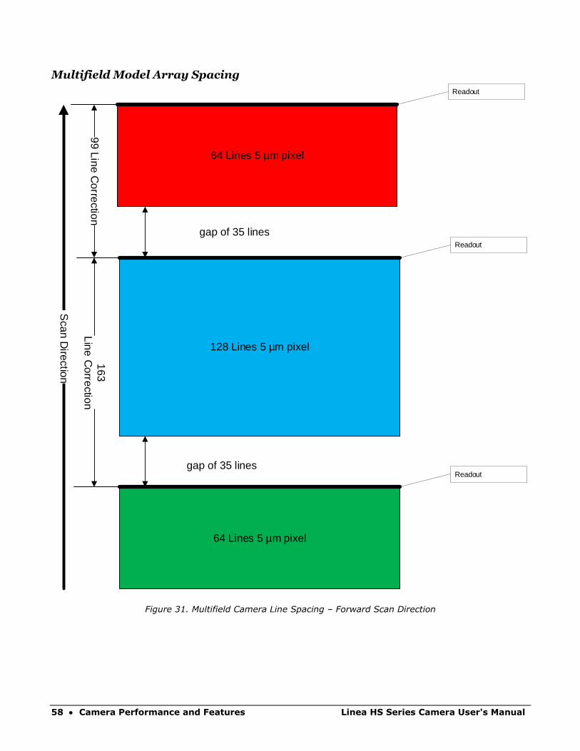
Multifield Model Array Spacing
64 Lines 5 µm pixel
128 Lines 5 µm pixel
Scan D
irection
Readout
Readoutgap of 35 lines
163Line C
orrection
64 Lines 5 µm pixel
Readout
99 Line Correction
gap of 35 lines
Figure 31. Multifield Camera Line Spacing – Forward Scan Direction
Linea HS Series Camera User's Manual Camera Performance and Features • 59
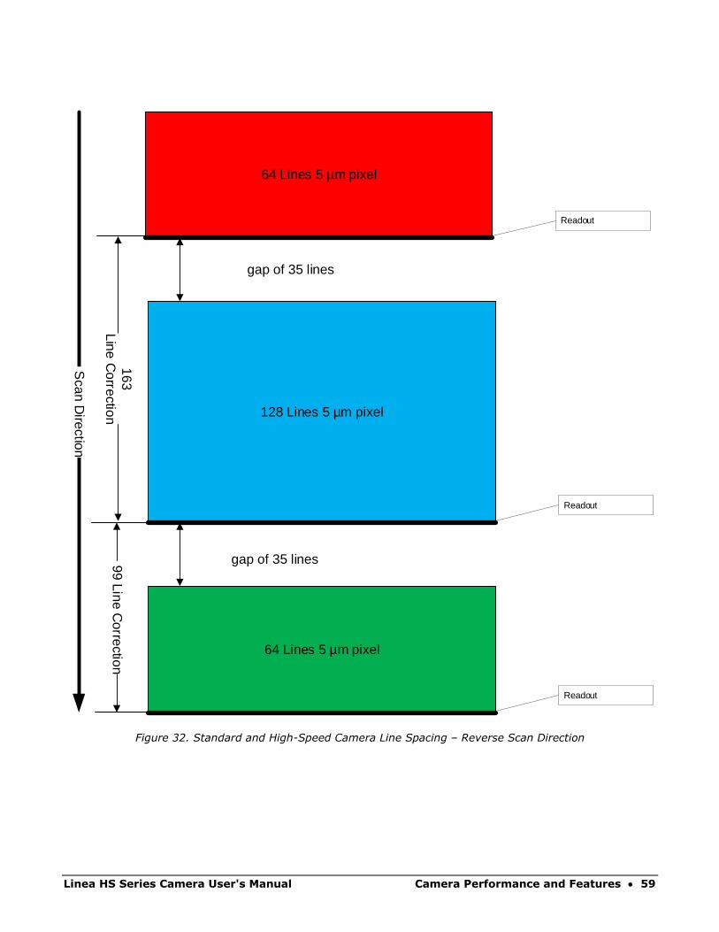
64 Lines 5 µm pixel
128 Lines 5 µm pixel
Scan D
irection
Readout
Readout
gap of 35 lines
64 Lines 5 µm pixel
Readout
99 Line Correction
gap of 35 lines
163Line C
orrection
Figure 32. Standard and High-Speed Camera Line Spacing – Reverse Scan Direction
60 • Camera Performance and Features Linea HS Series Camera User's Manual
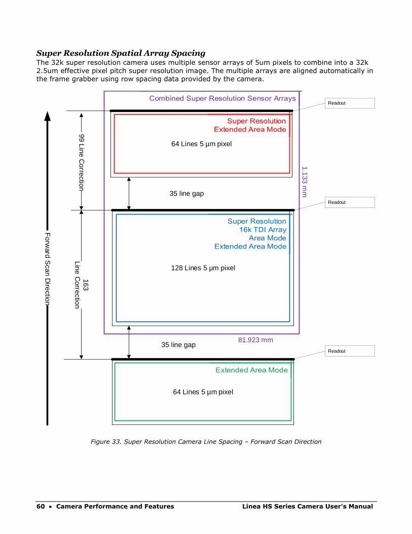
Super Resolution Spatial Array Spacing The 32k super resolution camera uses multiple sensor arrays of 5um pixels to combine into a 32k
2.5um effective pixel pitch super resolution image. The multiple arrays are aligned automatically in
the frame grabber using row spacing data provided by the camera.
64 Lines 5 µm pixel
128 Lines 5 µm pixel
Forw
ard Scan D
irection
35 line gap
64 Lines 5 µm pixel
35 line gap
81.923 mm
1.133 mm
99 Line Correction
Readout
Readout
Readout
163Line C
orrection
Figure 33. Super Resolution Camera Line Spacing – Forward Scan Direction
Linea HS Series Camera User's Manual Camera Performance and Features • 61
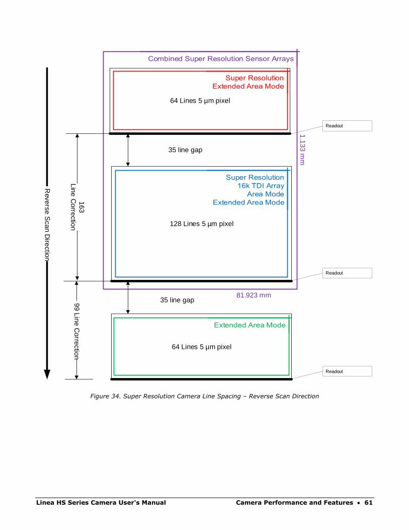
64 Lines 5 µm pixel
128 Lines 5 µm pixel
Reverse S
can Direction
35 line gap
64 Lines 5 µm pixel
35 line gap
81.923 mm
1.133 mm
99 Line Correction
163Line C
orrection
Readout
Readout
Readout
Figure 34. Super Resolution Camera Line Spacing – Reverse Scan Direction

62 • Camera Performance and Features Linea HS Series Camera User's Manual
Alignment Markers See the section Camera Control Category in Appendix A for GenICam features associated with this
section and how to use them.
Related Features: alignmentMarkerEnable, alignmentMarkerVerticalSpacing,
alignmentMarkerVerticalOffset, alignmentMarkerHorizontalSpacing,
alignmentMarkerHorizontalOffset and alignmentMarkerBlack
Use alignment markers to assist in aligning the camera to ensure that all sensor columns align
vertically given the target object movement. Sensor alignment is important since up to 128
columns in an array are summed in TDI operation; misaligned columns can result in blurred or
smeared images. When enabled, alignment markers are displayed as graphic overlays in the image
output.
Figure 35: Alignment Markers
Linea HS Series Camera User's Manual Camera Performance and Features • 63
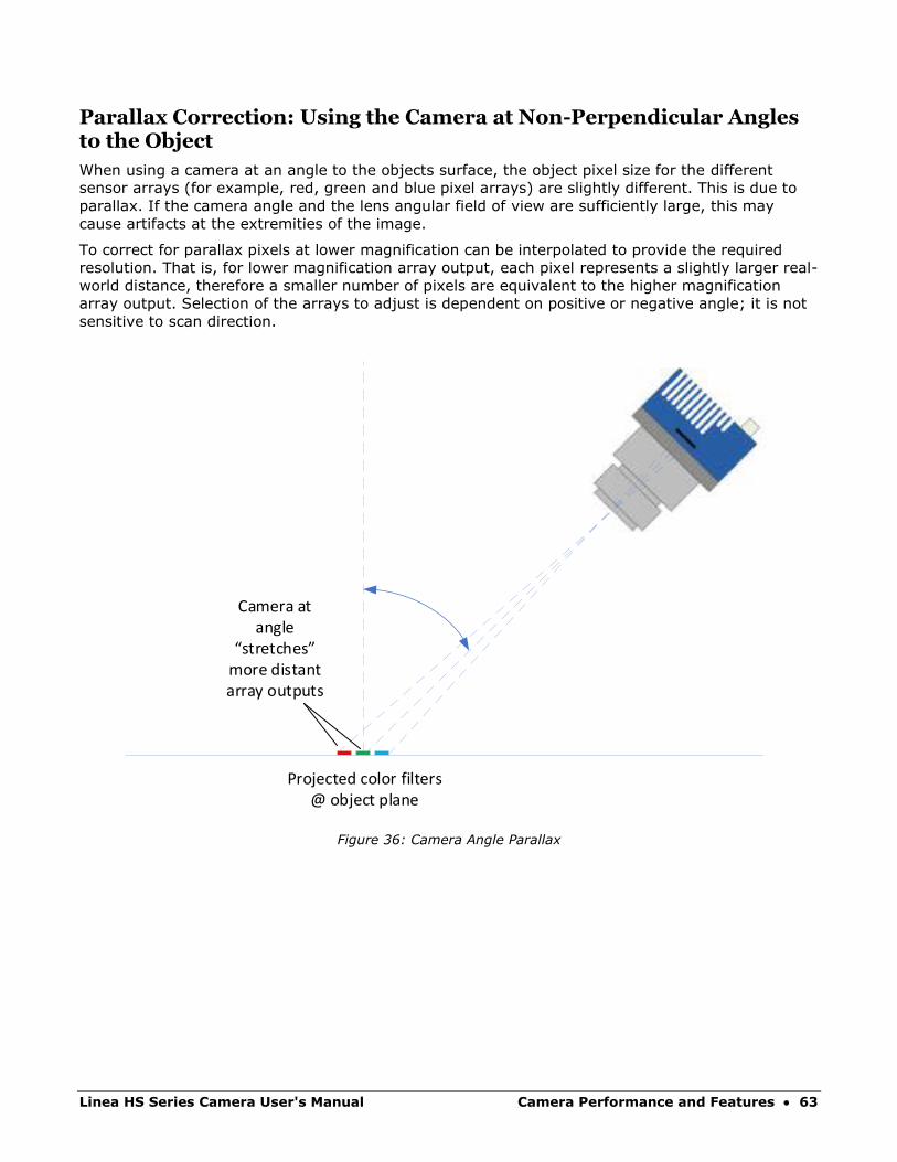
Parallax Correction: Using the Camera at Non-Perpendicular Angles to the Object
When using a camera at an angle to the objects surface, the object pixel size for the different
sensor arrays (for example, red, green and blue pixel arrays) are slightly different. This is due to
parallax. If the camera angle and the lens angular field of view are sufficiently large, this may
cause artifacts at the extremities of the image.
To correct for parallax pixels at lower magnification can be interpolated to provide the required
resolution. That is, for lower magnification array output, each pixel represents a slightly larger real-
world distance, therefore a smaller number of pixels are equivalent to the higher magnification
array output. Selection of the arrays to adjust is dependent on positive or negative angle; it is not
sensitive to scan direction.
Camera at angle
stretches more distant array outputs
Projected color filters @ object plane
Figure 36: Camera Angle Parallax

64 • Camera Performance and Features Linea HS Series Camera User's Manual
Highermagnification
Lowermagnification
Sensor resolution (n pixels)
Sensor resolution(n pixels)
Interpolate lower magnification line to achieve higher
magnification resolution
Figure 37: Parallax Effect on Sensor Arrays Output
For example, with a sensor resolution of 8192 pixels, if the lower magnification equivalent distance
is 8185 pixels, these pixels would be interpolated (in other words, stretched) to provide 8192
pixels, such that all pixels represent the same real-world measurement.
Note: Parallax correction of the individual arrays cannot be performed due to the
row summing in the sensor. Therefore, at high angles, a degradation in MTF at the
end pixels may occur.
Linea HS Series Camera User's Manual Camera Performance and Features • 65
Imaging Modes See the section Camera Control Category in Appendix A for GenICam features associated with this
section and how to use them.
Relevant Features: sensorTDIModeSelection
The Linea HS standard and high-speed models are capable of being run in four different modes:
TDI, TDI HDR (High Dynamic Range), TDI HFW (High Full Well) and TDI Area mode.
The Multifield camera is capable of being run in the following modes: TDI RGB, TDI Red, TDI
Green, TDI Blue, TDI Red Green, TDI Red Blue, TDI Green Blue and TDI Area.
The Linea HS 32k super resolution model is capable of being run in five different modes: 32k SR
Detail Restored, 32k SR Mapped, TDI, TDI Area mode and TDI Extended Area.
TDI Mode TDI mode is the default operating mode for the camera. The camera combines multiple exposures
of an object as it passes each row in the array into one high sensitivity image. In this mode the
main 128 stage array is used, and the full 300 kHz line rate can be achieved.
TDI Stage Selections
When operating in different TDI modes the number of stages in the array is adjusted, resulting in
different responsivities.
In TDI mode, the main array is configurable to 128 or 64 stages; secondary arrays are not used.
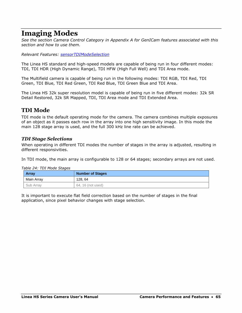
Table 24: TDI Mode Stages
Array Number of Stages
Main Array 128, 64
Sub Array 64, 16 (not used)
It is important to execute flat field correction based on the number of stages in the final
application, since pixel behavior changes with stage selection.
66 • Camera Performance and Features Linea HS Series Camera User's Manual
High Dynamic Range (HDR) HDR enables imaging of (exceedingly) bright and dark areas in a single scan, replacing dual-scan
setups with dedicated cycles. Simultaneous capture improves system throughput (no overhead
from direction change) and stability / repeatability (close association between dark & bright
image).
Note: In HDR mode image data is collected from 2 TDI arrays; the camera
outputs two rows that will have to be combined to create an HDR image. This
limits the maximum line rate to 150 kHz x 2 (or 200 kHz x 2 for high speed
models).
To adapt to the imaged scene dynamic range, the HDR ratio can be selected, as shown in the table
below. This ratio controls the number of stages used in each TDI pixel array.
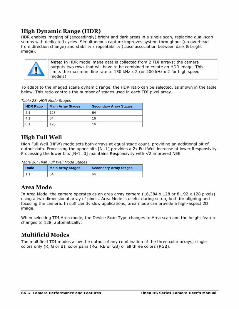
Table 25: HDR Mode Stages
HDR Ratio Main Array Stages Secondary Array Stages
2:1 128 64
4:1 64 16
8:1 128 16
High Full Well High Full Well (HFW) mode sets both arrays at equal stage count, providing an additional bit of
output data. Processing the upper bits [N..1] provides a 2x Full Well increase at lower Responsivity.
Processing the lower bits [N-1…0] maintains Responsivity with √2 improved NEE
Table 26: High Full Well Mode Stages
Ratio Main Array Stages Secondary Array Stages
1:1 64 64
Area Mode In Area Mode, the camera operates as an area array camera (16,384 x 128 or 8,192 x 128 pixels)
using a two-dimensional array of pixels. Area Mode is useful during setup, both for aligning and
focusing the camera. In sufficiently slow applications, area mode can provide a high-aspect 2D
image.
When selecting TDI Area mode, the Device Scan Type changes to Area scan and the height feature
changes to 128, automatically.
Multifield Modes The multifield TDI modes allow the output of any combination of the three color arrays; single
colors only (R, G or B), color pairs (RG, RB or GB) or all three colors (RGB).
Linea HS Series Camera User's Manual Camera Performance and Features • 67
32k Super Resolution Modes Unlike typical bilinear or bicubic interpolation methods, Teledyne DALSA’s proprietary and patent-
pending super resolution system derives a balanced, artifact free 32k image that provides higher
detectability, especially for small defects, high MTF (modulation transfer function, also known as
spatial frequency response), low noise and high SNR, all with the responsivity of a 5um pixel. The
combination of camera, CLHS interface and High-Resolution frame grabber enables this
functionality up to 150kHz line rate.
32k SR Mapped
The SR mapped function utilizes the first stage in Teledyne DALSA’s patented processing chain. The
high-resolution image is created, benefitting the system with higher Full Well, higher SNR and
lower noise.
This mode provides the lowest level of data processing in the Teledyne DALSA system and hence
poses the lowest risk of affecting subsequent user data processing.
Use this mode in the initial setup to evaluate whether your system benefits enough from the 32k
SR operation and to avoid conflicts for your algorithms.
32k SR Detail Restored
The Detail Restored mode, when selected, enables the “SR Strength” (srStrength) parameter for
user adjustment.
With “Detail Restored”, the full Teledyne DALSA patented processing chain is activated. Sub-pixel
information is extracted and enhanced via the “strength” parameter. This function gradually
increases the system MTF and provides higher effective SNR for small and sub-pixel defects without
affecting noise significantly.
It is highly recommended that the user tests these settings in their own application and adjust the
“strength” (between 0 and 1) to identify the best balance between enhanced detection (higher SNR
for given defects) and potential false positives that subsequent algorithms may identify.
Extended Area Mode
In Extended Area Mode each of the three sensor arrays is output as separate imaging planes. Each
output is 16384 x 128 pixels. However, as the top and bottom arrays have 64 rows, the bottom
half of their images will be blanked out.

68 • Camera Performance and Features Linea HS Series Camera User's Manual
Internal Trigger Mode See the section Camera Control Category in Appendix A for GenICam features associated with this
section and how to use them
Related Feature: AcquisitionFrameRate, AcquisitionLineRate
In the different TDI Modes use the following features to set the internal trigger rate:
Standard Models
Table 27: Standard Models Internal Trigger Rate Features
TDI Mode Trigger Rate Feature Maximum
TDI AcquisitionLineRate 300 kHz
HDR / HFW AcquisitionLineRate 150 kHz
Area AcquisitionFrameRate 2 kHz
High Speed Models
Table 28: High Speed Models Internal Trigger Rate Features
TDI Mode Trigger Rate Feature Maximum
TDI AcquisitionLineRate 400 kHz
HDR / HFW AcquisitionLineRate 200 kHz
Area AcquisitionFrameRate 2 kHz
Multi-Area AcquisitionFrameRate 650 kHz
Multifield Model
Table 29: Multifield Model Internal Trigger Rate Features
TDI Mode Trigger Rate Feature Maximum
TDI (One color) AcquisitionLineRate 300 kHz
TDI (Two colors) AcquisitionLineRate 150 kHz
TDI (Three colors) AcquisitionLineRate 100 kHz
Area AcquisitionFrameRate 2 kHz
Multi Area AcquisitionFrameRate 650 Hz
Super Resolution 32k Model
Table 30: Super Resolution Model Internal Trigger Rate Features
TDI Mode Trigger Rate Feature Maximum
32k Modes AcquisitionLineRate 150 kHz
16k TDI AcquisitionLineRate 300 kHz
Area AcquisitionFrameRate 2 kHz
Multi Area AcquisitionFrameRate 650 Hz

Linea HS Series Camera User's Manual Camera Performance and Features • 69
Establishing the Optimal Response An important camera performance characteristic is its responsivity and associated noise level at the
system’s maximum line rate and with the required illumination and lens configuration.
Responsivity and noise performance can be assessed using a stationary, plain white target under
bright field illumination. However, to accurately evaluate the camera’s real-life performance, it is
important that the setup is representative of the final system configuration.
The ideal test setup meets the following conditions:
• The lens is in focus, at the desired magnification and with the desired aperture.
• The illumination intensity is equal to that of the inspection system and aligned with the
camera’s field of view.
• The camera is operated with an exposure time that will allow the maximum line rate of the
system to be achieved. The camera’s internal line rate generator and exposure control can
be used for a stationary target.
Exposure Control by Light Source Strobe Relevant Features: outputLineSource, outputLinePulseDelay, outputLinePulseDuration, LineInverter
Note: TDI sensors do not have exposure control built in. Pixels continuously
convert photons to electrons.
After receiving a line trigger, the camera instructs the sensor to execute the
analog read operation. During this time incoming photons are still detected and
may associate with the current or subsequent line. This effect is negligible when
constant lighting is used.
When using strobed lighting, assure a minimum delay of 1.4 s between the rising
edge of EXSYNC and powering-on of the light source.
Using the GPIO controls the camera can be set up to strobe a light source effectively giving
exposure control. Figure 38 shows an example of an output signal used as a strobe signal.
Camera Trigger
Sensor Trigger
Output Line3,4,5 or 6
Trigger Delay
Output DelaySet to Trigger Delay + 1.6 µs
Output Duration
Output Strobe Control Example
Figure 38: Strobe Timing

70 • Camera Performance and Features Linea HS Series Camera User's Manual
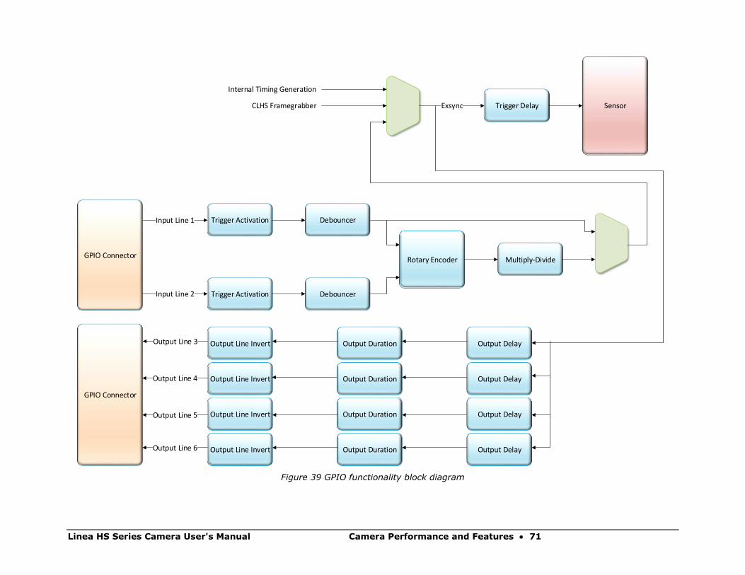
The camera logic enables simplified control of external, pulsed light sources to assure reliable
timing association.
For this purpose, the trigger signal received from the system is managed by the camera to trigger
sensor response and data processing. In addition, an Exposure Active signal is generated and can
be supplied to any of the GPIO outputs. This allows triggering or timing external light sources.
The following diagram illustrates the logical control signal flow in the Linea HS series camera
family.
The outputLineSource, outputLinePulseDuration, outputLinePulseDelay, and LineInvert features
allow the user to control a strobe light source in order to coordinate with the sensor exposure.
Linea HS Series Camera User's Manual Camera Performance and Features • 71
SensorTrigger DelayExsync
Internal Timing Generation
CLHS Framegrabber
Multiply-DivideRotary Encoder
Trigger Activation Debouncer
DebouncerTrigger Activation
Input Line 1
Input Line 2
GPIO Connector
Output Line InvertOutput Line 3
GPIO Connector
Output DelayOutput Duration
Output Line 4
Output Line 5
Output Line 6
Output Line Invert
Output Line Invert
Output Line Invert
Output Duration
Output Duration
Output Duration
Output Delay
Output Delay
Output Delay
Figure 39 GPIO functionality block diagram
72 • Camera Performance and Features Linea HS Series Camera User's Manual
Image Response Uniformity & Flat Field Calibration See the section Flat Field Category in Appendix A for GenICam features associated with this section
and how to use them.
Related Features: flatfieldCalibrationFPN, flatfieldCalibrationPRNU, flatfieldCorrectionAlgorithm,
flatfieldCalibrationTarget
Images commonly have lower response at the edges of the camera’s field of view compared to its
center. This is a result of lens vignetting and structure in the illumination source.
Diffusing elements in the light path removes structure in the illumination and may improve edge-
responsivity.
Decreasing the lens aperture can also improve edge-responsivity, if barrel vignetting (a shadow
cast on the sensor by the focus helical or extension tubes) is present.
The camera can compensate for edge roll-off and other optical non-uniformities by using flat field
calibration.
• When performing Flat Field (PRNU) calibration, the camera should be imaging a front
illuminated white target or rear bright field illumination source. The optical setup should be
as per the inspection system, including lens magnification, aperture, illumination intensity,
spectral content and illuminator beam structure.
• Flat field calibration should be performed when the camera temperature has stabilized.
• Flat field calibration will adjust all pixels to have the same value as the peak pixel value or
target level, as per the calibration mode selected.
• If the flat field calibration is set to a target level that is lower than the peak value and the
system gain is set to a low value, then it is possible that the sensor will maximize its output
before the camera’s output reaches 255 DN. This can be seen when a portion of the output
stops increasing before reaching 255 DN with increasing illumination and the PRNU
deteriorates. This effect can be resolved by decreasing the light level or exposure control
time.
Following a flat field calibration, all pixels should be at their un-calibrated peak value or target
value. Changing gain values now allows the user to make refinements to the operating responsivity
level.
Note: The best flat field calibration can be achieved by performing it at the mid
DN level of the working range used in the operation. Any flat field error associated
with residual non-linearity in the pixel will be halved as compared to performing a
calibration at the peak value of the operating range. A simple way of performing
this is to reduce exposure time to half what is used in the operation in order to get
the mid DN level for flat field calibration. Once complete, return the exposure time
to its original setting.
Linea HS Series Camera User's Manual Camera Performance and Features • 73
Those areas of the image where high roll-off is present will show higher noise levels after flat field
calibration due to the higher gain values of the correction coefficients. Flat field calibration can only
compensate for up to an 8:1 variation. If the variation exceeds 8:1 then the line profile after
calibration will include pixels that are below the un-calibrated peak level.
Note: The Linea camera has many different modes of operation. It is strongly
recommended that the camera be flat fielded for that mode of operation that is intended including direction of scan
Saving & Loading a PRNU Set Only See the Flat Field Category in Appendix A for GenICam features associated with this section and
how to use them.
Related Features: flatfieldCorrectionCurrentActiveSet, flatfieldCalibrationSave,
flatfieldCalibrationLoad
A user set includes all the “settings” (for example, gain, line rate), FPN (Fixed Pattern Noise) and
PRNU (Photo Response Non-Uniformity) coefficients and a LUT. These three features let you
save/load just the PRNU coefficients. Loading a complete user set takes approximately 1 second
while loading only the user PRNU coefficients takes less than 200 milliseconds.
Use the User PRNU Set Selector parameter to select the set you want to save or load. There are 17
sets available—16 user and 1 factory.
The Factory Set is read-only and contains all ones. Loading the Factory Set is a good way to clear
the user PRNU.
Save the current user PRNU coefficients using the “Save User PRNU Set” command. Load the user
PRNU coefficients from the set specified using the “User PRNU Set Selector” and the “Load User
PRNU Set” command features.
Setting Custom Flat Field Coefficients Flat Field (PRNU) coefficients can be custom modified and uploaded to the camera. They can also
be downloaded from the camera.
To upload or download coefficients, use File Access Control Category > Upload / Download File >
Settings and then select Miscellaneous > Current PRNU to download / upload a file.
The PRNU coefficients are used by the camera as soon as they are uploaded. To avoid loss at
power up or while changing row settings, the uploaded coefficients should be saved to one of the
available user sets.
74 • Camera Performance and Features Linea HS Series Camera User's Manual
Flat Field Calibration Filter See the Flat Field Category in Appendix A for GenICam features associated with this section and
how to use them.
Related Feature: flatfieldCorrectionAlgorithm
If a sheet of material is being used as a white target, it must be completely free of blemishes and
texture.
The presence of dirt or texture will generate a variation in the image that will be incorporated into
the calibration coefficients of the camera. Further, once the target is removed, or moved, vertical
stripes will be present in the scanned image.
Dirt or texture that has dark characteristics will appear as bright vertical lines. Dirt or texture that
has bright characteristics will appear as dark vertical lines.
One way to minimize this effect is to have the white target in motion during the calibration process.
This has the result of averaging out any dirt or texture present. If this is not possible, the camera
has a feature where a flat field calibration filter can be applied while generating the flat field
correction coefficients—which can minimize the effects of dirt.
Note: This filter is only capable of compensating for small, occasional contaminants. It will not overcome large features in a target’s texture.
Flat Field Calibration Regions of Interest See the section Flat Field Category in Appendix A for GenICam features associated with this section
and how to use them.
Related Features: flatfieldCalibrationROIOffsetX, flatfieldCalibrationROIWidth
There are occasions when the camera’s field of view includes areas that are beyond the material to
be inspected.
This may occur when cameras image off the edge of a panel or web or when an inspection system
is imaging multiple lanes of material. The edge of the material or area between lanes may not be
illuminated in the same way as the areas of inspection and, therefore, will cause problems with a
flat field calibration.
The camera can accommodate these “no inspection zones” by defining a Region of Interest (ROI)
where flat field calibration is performed. Image data outside the ROI is ignored by the flat field
calibration algorithm. The ROI is selected by the user and with the pixel boundaries defined by the
pixel start address and pixel width and then followed by initiating flat field calibration for that
region. Once set, another ROI can be defined and flat field calibrated.
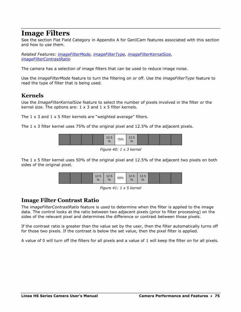
Linea HS Series Camera User's Manual Camera Performance and Features • 75
Image Filters
See the section Flat Field Category in Appendix A for GenICam features associated with this section
and how to use them.
Related Features: imageFilterMode, imageFilterType, imageFilterKernalSize,
imageFilterContrastRatio
The camera has a selection of image filters that can be used to reduce image noise.
Use the imageFilterMode feature to turn the filtering on or off. Use the imageFilterType feature to
read the type of filter that is being used.
Kernels Use the ImageFilterKernalSize feature to select the number of pixels involved in the filter or the
kernel size. The options are: 1 x 3 and 1 x 5 filter kernels.
The 1 x 3 and 1 x 5 filter kernels are “weighted average” filters.
The 1 x 3 filter kernel uses 75% of the original pixel and 12.5% of the adjacent pixels.
12.5%
75%12.5%
Figure 40: 1 x 3 kernel
The 1 x 5 filter kernel uses 50% of the original pixel and 12.5% of the adjacent two pixels on both
sides of the original pixel.
12.5%
50%12.5%
12.5%
12.5%
Figure 41: 1 x 5 kernel
Image Filter Contrast Ratio The imageFilterContrastRatio feature is used to determine when the filter is applied to the image
data. The control looks at the ratio between two adjacent pixels (prior to filter processing) on the
sides of the relevant pixel and determines the difference or contrast between those pixels.
If the contrast ratio is greater than the value set by the user, then the filter automatically turns off
for those two pixels. If the contrast is below the set value, then the pixel filter is applied.
A value of 0 will turn off the filters for all pixels and a value of 1 will keep the filter on for all pixels.

76 • Camera Performance and Features Linea HS Series Camera User's Manual
Binning See the section Image Format Control Category in Appendix A for GenICam features associated
with this section and how to use them.
Related Features: BinningHorizontal and BinningVertical
In certain applications, lower image resolution may be acceptable if the desired defect detection
can still be achieved. This accommodation can result in higher scan speeds, as the effective
distance travelled per encoder pulse is increased due to the larger object pixel size. The camera
has a binning feature that produces rapid adjustment to a lower object pixel resolution without
having to change the optics, illumination intensity, or encoder pulse resolution.
Binning is a process whereby adjacent pixels are summed. The camera supports 1x, 2x, and 4x
horizontal and vertical binning. Vertical binning is only available in TDI single plane mode.
Horizontal binning is achieved by summing adjacent pixels in the same line. Therefore, 2x binning
results in the object pixel doubling in size horizontally. In addition, since adjacent pixels are
summer (not averaged), the image gets brighter. That is, 1x2 and 2x1 are twice as bright, 2x2 is
four times brighter, and so forth.
Horizontal 2x binning will halve the amount of image data out of the camera. This can be used to
save processing bandwidth in the host and storage space by creating smaller image file sizes.
Figure 42: 2x2 Binning
For the camera, the default binning value is 1 x 1.
Note: Binning parameters can only be changed when image transfer to the frame
grabber is stopped. Refer to the Acquisition and Transfer Control Category in
the appendix for details on stopping and starting the acquisition.
Linea HS Series Camera User's Manual Camera Performance and Features • 77
Using Area of Interest (AOIs) Reduce Image Data & Enhance Performance
See the section Image Format Control Category and Acquisition and Transfer Control Category in
Appendix A for GenICam features associated with this section and how to use them
Related Features: multipleROICount, multipleROISelector, multipleROIOffsetX, multipleROIWidth,
AcquisitionStart, AcquisitionStop and AcquisitionStatus
If the camera’s field of view includes areas that are not needed for inspection (also refer to the
description in the Flat Field Calibration Region of Interest section) then the user may want to
ignore this superfluous image data.
Eliminating unwanted image data that is visible in the camera’s field of view reduces the amount of
information the host computer needs to process. This may result in an increase to the maximum
allowable line rate when using 12-bit output data.
The camera can accommodate up to four AOIs. Image data outside the AOIs is discarded. Each AOI
is user selected and its pixel boundaries defined. The camera assembles the individual AOI’s into
one contiguous image line with a width equal to the sum of the individual AOIs. The frame grabber
will need to be adjusted to accommodate the smaller overall image width. As the host computer
defined the size of each individual AOI, it will be able to extract and process each individual AOI
from the single larger image.
Note: AOIs are not supported by the Linea HS 32k Super Resolution model (HL-HM-
32K15S-00-R).

78 • Camera Performance and Features Linea HS Series Camera User's Manual
Steps to Setup Area of Interest 1. Plan your AOIs.
2. Stop acquisition, using the AcquisitionStop feature. In CamExpert this feature is available in
the Acquisition and Transfer Control category:
The AcquisitionStatus feature displays the current status as Acquiring or Not Acquiring.
3. Set the number of AOIs using the AOI Count Horizontal (multipleROICount) feature. In
CamExpert AOI related features are available in the Image Format category:
4. Select the first AOI and set the offset and width.
5. If the other AOIs are large you may need to select them first and reduce their widths.
6. Repeat for each AOI in turn.
7. Start acquisition, using the AcquisitionStart feature.
Rules for Setting Areas of Interest The rules are dictated by how image data is organized for transmission over the available CLHS
data lanes. The camera / XML will enforce these rules, truncating entered values where necessary.
Note: AOI parameters can only be changed when image transfer to the frame
grabber is stopped. Refer to the Acquisition and Transfer Control Category in the
appendix for details on stopping and starting the acquisition.
• Acquisition must be stopped to change the AOI configuration.
• 1-4 AOIs can be selected.
• Minimum width is 96 pixels per AOI.
o Minimum total of all AOI widths summed together must be at least 1,024.
• Maximum width of all AOI widths summed together must be no more than = 16,384.
o Maximum 8k bytes per CLHS lane.
• AOI width step size is 32 pixels.
• The offset of each AOI may be 0 to (16,384 – 96 = 16,288).
o Overlapping AOIs are allowed.
• Offset and width for individual AOI's will "push" one another.
o For example, if AOI has offset 0, width 16,384, and the offset is changed to 4096,
then the width will be "pushed" to 12,288.
o AOI's only affect one another by limiting the maximum width.
• AOIs are concatenated together in numerical order and sent to the frame grabber starting
at column zero. If the AOI count is reduced to less than the current AOI count, the AOI
selector will be changed to the largest of the new AOI count available.
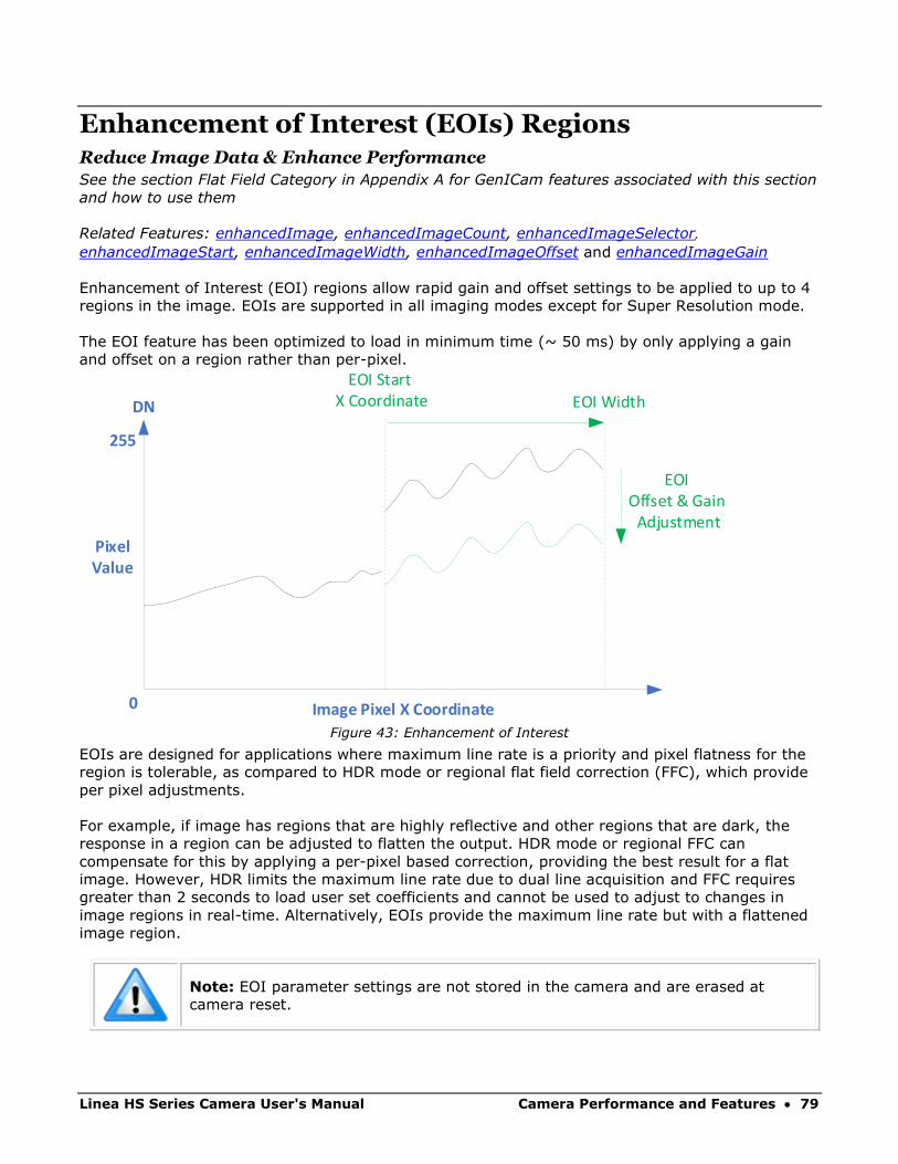
Linea HS Series Camera User's Manual Camera Performance and Features • 79
Enhancement of Interest (EOIs) Regions Reduce Image Data & Enhance Performance
See the section Flat Field Category in Appendix A for GenICam features associated with this section
and how to use them
Related Features: enhancedImage, enhancedImageCount, enhancedImageSelector,
enhancedImageStart, enhancedImageWidth, enhancedImageOffset and enhancedImageGain
Enhancement of Interest (EOI) regions allow rapid gain and offset settings to be applied to up to 4
regions in the image. EOIs are supported in all imaging modes except for Super Resolution mode.
The EOI feature has been optimized to load in minimum time (~ 50 ms) by only applying a gain
and offset on a region rather than per-pixel.
DN
Image Pixel X Coordinate0
255
EOI Start X Coordinate EOI Width
EOI Offset & Gain Adjustment
PixelValue
Figure 43: Enhancement of Interest
EOIs are designed for applications where maximum line rate is a priority and pixel flatness for the
region is tolerable, as compared to HDR mode or regional flat field correction (FFC), which provide
per pixel adjustments.
For example, if image has regions that are highly reflective and other regions that are dark, the
response in a region can be adjusted to flatten the output. HDR mode or regional FFC can
compensate for this by applying a per-pixel based correction, providing the best result for a flat
image. However, HDR limits the maximum line rate due to dual line acquisition and FFC requires
greater than 2 seconds to load user set coefficients and cannot be used to adjust to changes in
image regions in real-time. Alternatively, EOIs provide the maximum line rate but with a flattened
image region.
Note: EOI parameter settings are not stored in the camera and are erased at
camera reset.

80 • Camera Performance and Features Linea HS Series Camera User's Manual
Customized Linearity Response (LUT) See the section Flat Field Category in Appendix A for GenICam features associated with this section
and how to use them
Related Features: lutMode and gammaCorrection
Note: These features may only be useful in applications that use the frame
grabber’s Mono Image Buffer Format. (See the Pixel Format section.)
The camera allows the user to access a LUT (Look Up Table) to allow the user to customize the
linearity of how the camera responds. This can be done by uploading a LUT to the camera using
the file transfer features or by using the gammaCorrection feature.
The gamma correction value can be adjusted by the user at any time.
When the LUT is enabled, there is no change in maximum line rate or amount of data output from
the camera. The LUT can be used with any mode of the camera. Further, when the LUT is enabled,
it is recommended that the fixed Offset available in the Camera Control category be set to zero.
To upload a LUT, use File Access Control Category > Upload / Download File > Settings and select
Look Up Table to upload a file.
The file format is described in 03-084-20133 Linea Binary File Format which can be obtained from
Teledyne DALSA Technical Support. This document also includes Excel spreadsheet examples.
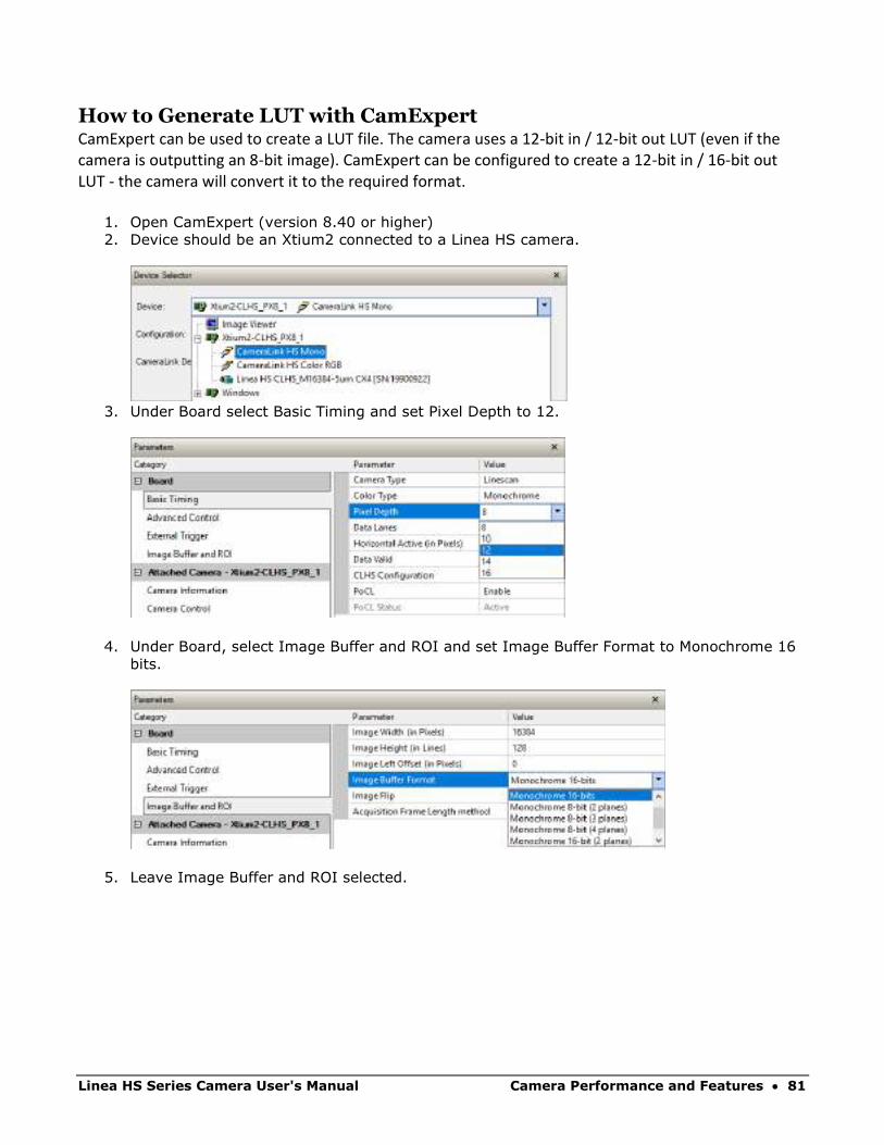
Linea HS Series Camera User's Manual Camera Performance and Features • 81
How to Generate LUT with CamExpert CamExpert can be used to create a LUT file. The camera uses a 12-bit in / 12-bit out LUT (even if the camera is outputting an 8-bit image). CamExpert can be configured to create a 12-bit in / 16-bit out LUT - the camera will convert it to the required format.
1. Open CamExpert (version 8.40 or higher)
2. Device should be an Xtium2 connected to a Linea HS camera.
3. Under Board select Basic Timing and set Pixel Depth to 12.
4. Under Board, select Image Buffer and ROI and set Image Buffer Format to Monochrome 16
bits.
5. Leave Image Buffer and ROI selected.
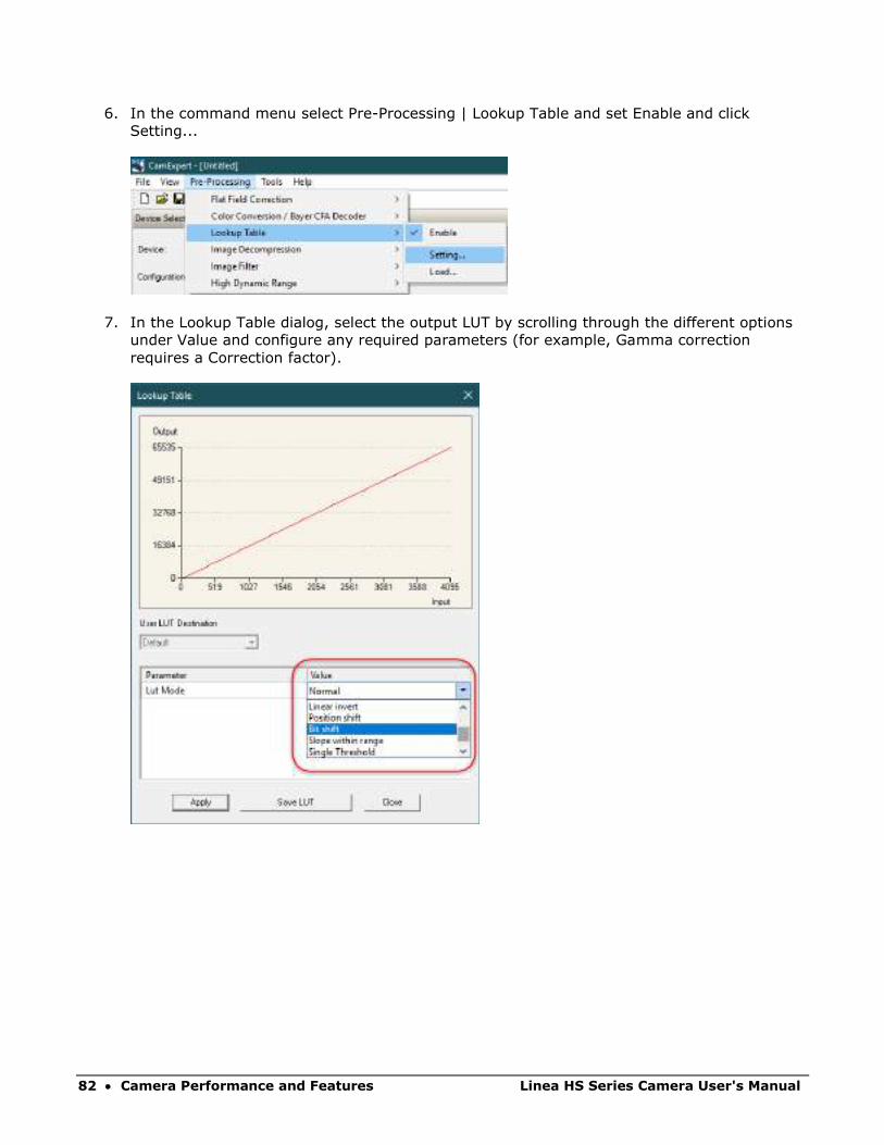
82 • Camera Performance and Features Linea HS Series Camera User's Manual
6. In the command menu select Pre-Processing | Lookup Table and set Enable and click
Setting...
7. In the Lookup Table dialog, select the output LUT by scrolling through the different options
under Value and configure any required parameters (for example, Gamma correction
requires a Correction factor).
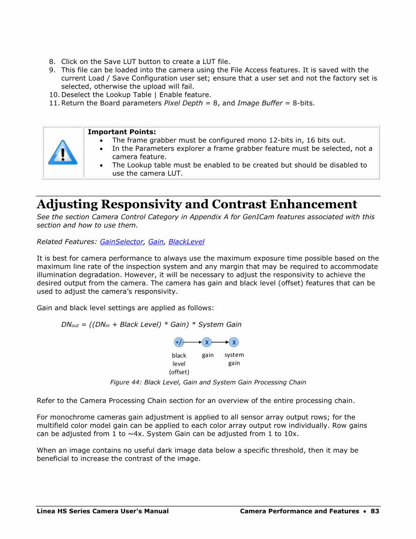
Linea HS Series Camera User's Manual Camera Performance and Features • 83
8. Click on the Save LUT button to create a LUT file.
9. This file can be loaded into the camera using the File Access features. It is saved with the
current Load / Save Configuration user set; ensure that a user set and not the factory set is
selected, otherwise the upload will fail.
10. Deselect the Lookup Table | Enable feature.
11. Return the Board parameters Pixel Depth = 8, and Image Buffer = 8-bits.
• Important Points:
• The frame grabber must be configured mono 12-bits in, 16 bits out.
• In the Parameters explorer a frame grabber feature must be selected, not a
camera feature.
• The Lookup table must be enabled to be created but should be disabled to
use the camera LUT.
Adjusting Responsivity and Contrast Enhancement See the section Camera Control Category in Appendix A for GenICam features associated with this
section and how to use them.
Related Features: GainSelector, Gain, BlackLevel
It is best for camera performance to always use the maximum exposure time possible based on the
maximum line rate of the inspection system and any margin that may be required to accommodate
illumination degradation. However, it will be necessary to adjust the responsivity to achieve the
desired output from the camera. The camera has gain and black level (offset) features that can be
used to adjust the camera’s responsivity.
Gain and black level settings are applied as follows:
DNout = ((DNin + Black Level) * Gain) * System Gain
X X+/-
black level
(offset)
gain systemgain
Figure 44: Black Level, Gain and System Gain Processing Chain
Refer to the Camera Processing Chain section for an overview of the entire processing chain.
For monochrome cameras gain adjustment is applied to all sensor array output rows; for the
multifield color model gain can be applied to each color array output row individually. Row gains
can be adjusted from 1 to ~4x. System Gain can be adjusted from 1 to 10x.
When an image contains no useful dark image data below a specific threshold, then it may be
beneficial to increase the contrast of the image.
84 • Camera Performance and Features Linea HS Series Camera User's Manual
Black Level The camera has a black level (offset) feature that allows a specified level to be subtracted from the
image data. The gain feature can then be used to return the peak image data to near output
saturation with the result being increased image contrast.
First, determine the offset value to subtract from the image with the current gain setting. Then set
this as a negative offset value and apply additional gain to achieve the desired peak image data
values.
Note: A positive offset value is not useful for contrast enhancement. However, it
can be used while measuring the dark noise level of the camera to ensure zero
clipping is not present.
Changing Output Configuration
Pixel Format See the section Image Format Control Category in Appendix A for GenICam features associated
with this section and how to use them
Related Feature: PixelFormat, AcquisitionStart and AcquisitionStop
The camera can output video data as 8-bit or 12-bit.
Use the Mono8 Pixel Format to process image data as one, or two separate image planes.
Note: Pixel Format, and associated features, can only be changed when the image
transfer to the frame grabber is stopped. Refer to the Acquisition and Transfer
Control Category in the appendix for details on stopping and starting the
acquisition.
For example, to change from 8-bit to 12-bit pixel format:
1. In Acquisition and Transfer Control category, set Stop Acquisition.
2. In Image Format category, set Pixel Format to Mono 12 (or BGR 12 if supported).
3. In the host frame grabber configuration, set Pixel Depth to 12.
4. In Acquisition and Transfer Control category, set Start Acquisition.
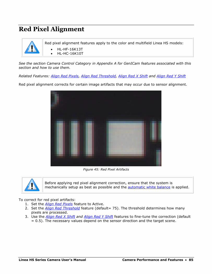
Linea HS Series Camera User's Manual Camera Performance and Features • 85
Red Pixel Alignment
Red pixel alignment features apply to the color and multifield Linea HS models:
• HL-HF-16K13T
• HL-HC-16K10T
See the section Camera Control Category in Appendix A for GenICam features associated with this
section and how to use them.
Related Features: Align Red Pixels, Align Red Threshold, Align Red X Shift and Align Red Y Shift
Red pixel alignment corrects for certain image artifacts that may occur due to sensor alignment.
Figure 45: Red Pixel Artifacts
Before applying red pixel alignment correction, ensure that the system is
mechanically setup as best as possible and the automatic white balance is applied.
To correct for red pixel artifacts:
1. Set the Align Red Pixels feature to Active.
2. Set the Align Red Threshold feature (default= 75). The threshold determines how many
pixels are processed.
3. Use the Align Red X Shift and Align Red Y Shift features to fine-tune the correction (default
= 0.5). The necessary values depend on the sensor direction and the target scene.
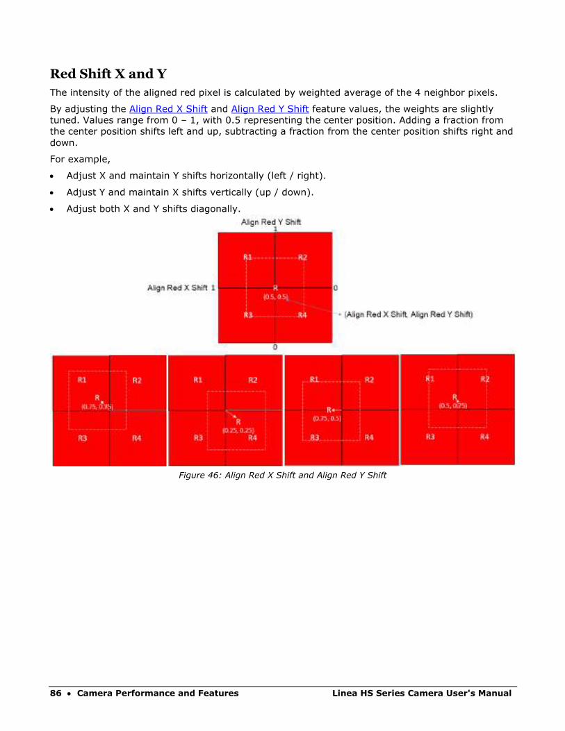
86 • Camera Performance and Features Linea HS Series Camera User's Manual
Red Shift X and Y
The intensity of the aligned red pixel is calculated by weighted average of the 4 neighbor pixels.
By adjusting the Align Red X Shift and Align Red Y Shift feature values, the weights are slightly
tuned. Values range from 0 – 1, with 0.5 representing the center position. Adding a fraction from
the center position shifts left and up, subtracting a fraction from the center position shifts right and
down.
For example,
• Adjust X and maintain Y shifts horizontally (left / right).
• Adjust Y and maintain X shifts vertically (up / down).
• Adjust both X and Y shifts diagonally.
Figure 46: Align Red X Shift and Align Red Y Shift

Linea HS Series Camera User's Manual Camera Performance and Features • 87
The following images demonstrate the effect of the red shift X and Y feature settings.
Original Image
Align Red Shift X = 0.5, Align Red Shift Y = 0.5
(default values)
Align Red Shift X = 0.5, Align Red Shift Y = 0.8
Figure 47: Effect of Align Red X / Y Shift Settings

88 • Camera Performance and Features Linea HS Series Camera User's Manual
Saving & Restoring Camera Setup Configurations See the section Camera Information Category in Appendix A for GenICam features associated with
this section and how to use them
Related Features: UserSetSelector, UserSet1 thru UserSet16, UserSetDefaultSelector,
UserSetLoad, UserSetSave
An inspection system may use multiple illumination, resolution and responsivity configurations in
order to cover the different types of inspection it performs. The camera includes 16 user sets
where camera setup information can be saved to and restored from—either at power up or
dynamically during inspection.
The settings active during the current operation can be saved (and thereby become the user
setting) using the user set save feature.
A previously saved user setting (User Set 1 to 16) or the factory settings can be restored using the
user set selector and user set load features.
Either the factory setting or one of the user settings can be selected as the default setting, by
selecting the set in the user set default selector (Camera Power-up configuration option in the
Power-up configuration dialog accessed from the Camera Information category). The set selected is
selected as the default setting and is the set that is loaded and becomes active when the camera is
reset or powered up.
The relationship between these four settings is illustrated in Figure 48. Relationship Between
Camera Settings:
Figure 48. Relationship Between Camera Settings
Factory Setting Active Setting
By GenIcam Command 1 . Select a ‘User Set’ 2 . Initiate a ‘User Set Load’
User Setting
By GenIcam Command 1 . Select a ‘User Set’ 2 . Initiate a ‘User Set Save’
By GenIcam Command 1 . Select a ‘Factory Set’ 2 . Initiate a ‘User Set Load’
By GenIcam GenIcam Command 1 . Select ‘Default Set’ as Factory ( Saves Automatically )
By GenIcam Command 1 . Select ‘Default Set’ as Uset Set # ( Saves Automatically )
Power Up Or Reset
Power Up Or Reset
GenIcam Input
Linea HS Series Camera User's Manual Camera Performance and Features • 89
Active Settings for Current Operation Active settings are those settings used while the camera is running and include all unsaved
changes made by GenICam input to the settings.
These active settings are stored in the camera’s volatile memory and will be lost and cannot be
restored if the camera resets, is powered down or loses power during operation.
To save these settings so that they can be restored next time you power up the camera or to
protect against losing them in the case of power loss, you must save the current settings using the
user set save parameter. Once saved, the current settings become the selected user set.
User Setting The user setting is the saved set of camera configurations that you can customize, resave, and
restore. By default, the user settings are shipped with the same settings as the factory set.
The command user set save saves the current settings to non-volatile memory as a user set. The
camera automatically restores the user set configured as the default set when it powers up.
To restore a saved user set, set the user set selector to the set you want to restore and then select
the user set load parameter.
Factory Settings The factory setting is the camera settings that were shipped with the camera and which load during
the camera’s first power-up. To load or restore the original factory settings, at any time, select the
factory setting parameter and then select the user set load parameter.
Note: By default, the user settings are set to the factory settings.
Default Setting Either the factory or one of the user settings can be used as the default setting, by selecting the
set to use in the user set default selector. The chosen set automatically becomes the default
setting and is the set loaded when the camera is reset or powered up.
90 • Appendix A: GenICam Commands Linea HS Series Camera User's Manual
Appendix A: GenICam Commands This appendix lists the available GenICam camera features. The user may access these features
using the CamExpert interface or equivalent GUI.
Features listed in the description table but tagged as Invisible are typically reserved for Teledyne
DALSA Support or third-party software usage, and not typically required by end user applications.
The following feature tables describe these parameters along with their view attributes and in
which version of the device the feature was introduced. Additionally, the Device Version column will
indicate which parameter is a member of the DALSA Features Naming Convention (using the tag
DFNC), versus the GenICam Standard Features Naming Convention (SFNC tag not shown).
In the CamExpert Panes, parameters in gray are read only, either always or due to another
parameter being disabled. Parameters in black are user set in CamExpert or programmable via an
imaging application
Note: The CamExpert examples shown for illustrative purposes and may not
entirely reflect the features and parameters available from the camera model used
in your application.

Linea HS Series Camera User's Manual Appendix A: GenICam Commands • 91
Camera Information Category Camera information can be retrieved via a controlling application. Parameters such as camera
model, firmware version, etc. are read to uniquely identify the connected camera. These features
are typically read-only.
The Camera Information Category groups information specific to the individual camera. In this
category the number of features shown is identical whether the view is Beginner, Expert, or Guru.
Figure 49 Example CamExpert Camera Information Panel
Camera Information Feature Descriptions
Display Name Feature Description View
Model Name DeviceModelName Displays the device model name. (RO) Beginner
Vendor Name DeviceVendorName Displays the device vendor name. (RO) Beginner
Manufacturer part number
deviceManufacturesPartNumber
Displays the device vendor part number. (RO) Beginner DFNC
Manufacturer Info DeviceManufacturerInfo This feature provides extended manufacturer information about the device. Indicates if it is a standard product or a custom camera(RO)
Beginner
Manufacturer Name DeviceVendorName Displays the device vendor name. (RO) Beginner
Firmware Version DeviceVersion Displays the device firmware version. This tag will also highlight if the firmware is a beta or custom design. (RO)
Beginner
Serial Number DeviceID Displays the device’s factory set camera serial number. (RO) Beginner
Device User ID DeviceUserID Feature to store user-programmable identifier of up to 31 characters. The default factory setting is the camera serial number. (RW)
Beginner
Power-on Status deviceBISTStatus Determine the status of the device using the ‘Built-In Self Test’ (BIST). Possible return values are device-specific. (RO)
See Built-In Self-Test Codes for status code details.
Beginner DFNC
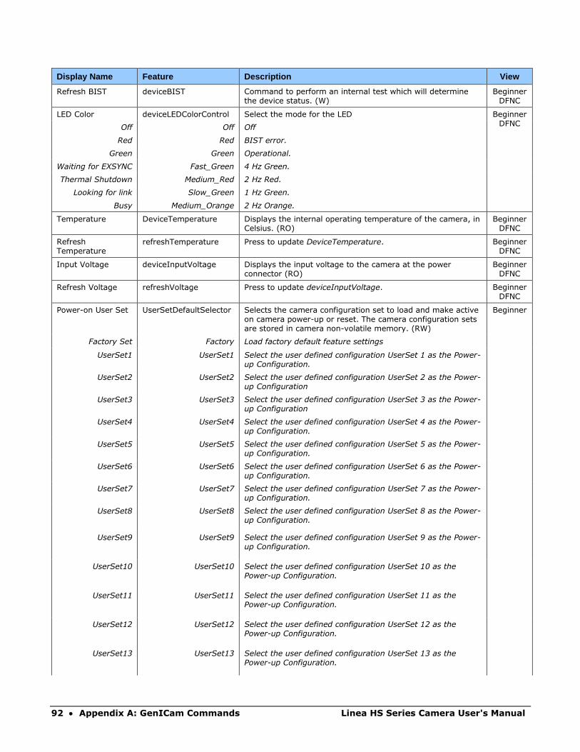
92 • Appendix A: GenICam Commands Linea HS Series Camera User's Manual
Display Name Feature Description View
Refresh BIST deviceBIST Command to perform an internal test which will determine the device status. (W)
Beginner DFNC
LED Color deviceLEDColorControl Select the mode for the LED Beginner DFNC
Off Off Off
Red Red BIST error.
Green Green Operational.
Waiting for EXSYNC Fast_Green 4 Hz Green.
Thermal Shutdown Medium_Red 2 Hz Red.
Looking for link Slow_Green 1 Hz Green.
Busy Medium_Orange 2 Hz Orange.
Temperature DeviceTemperature Displays the internal operating temperature of the camera, in Celsius. (RO)
Beginner DFNC
Refresh Temperature
refreshTemperature Press to update DeviceTemperature. Beginner DFNC
Input Voltage deviceInputVoltage Displays the input voltage to the camera at the power connector (RO)
Beginner DFNC
Refresh Voltage refreshVoltage Press to update deviceInputVoltage. Beginner DFNC
Power-on User Set UserSetDefaultSelector Selects the camera configuration set to load and make active on camera power-up or reset. The camera configuration sets are stored in camera non-volatile memory. (RW)
Beginner
Factory Set Factory Load factory default feature settings
UserSet1 UserSet1 Select the user defined configuration UserSet 1 as the Power-up Configuration.
UserSet2 UserSet2 Select the user defined configuration UserSet 2 as the Power-up Configuration
UserSet3 UserSet3 Select the user defined configuration UserSet 3 as the Power-up Configuration
UserSet4 UserSet4 Select the user defined configuration UserSet 4 as the Power-up Configuration.
UserSet5 UserSet5 Select the user defined configuration UserSet 5 as the Power-up Configuration.
UserSet6 UserSet6 Select the user defined configuration UserSet 6 as the Power-up Configuration.
UserSet7 UserSet7 Select the user defined configuration UserSet 7 as the Power-up Configuration.
UserSet8 UserSet8 Select the user defined configuration UserSet 8 as the Power-up Configuration.
UserSet9 UserSet9 Select the user defined configuration UserSet 9 as the Power-up Configuration.
UserSet10 UserSet10 Select the user defined configuration UserSet 10 as the Power-up Configuration.
UserSet11 UserSet11 Select the user defined configuration UserSet 11 as the Power-up Configuration.
UserSet12 UserSet12 Select the user defined configuration UserSet 12 as the Power-up Configuration.
UserSet13 UserSet13 Select the user defined configuration UserSet 13 as the Power-up Configuration.
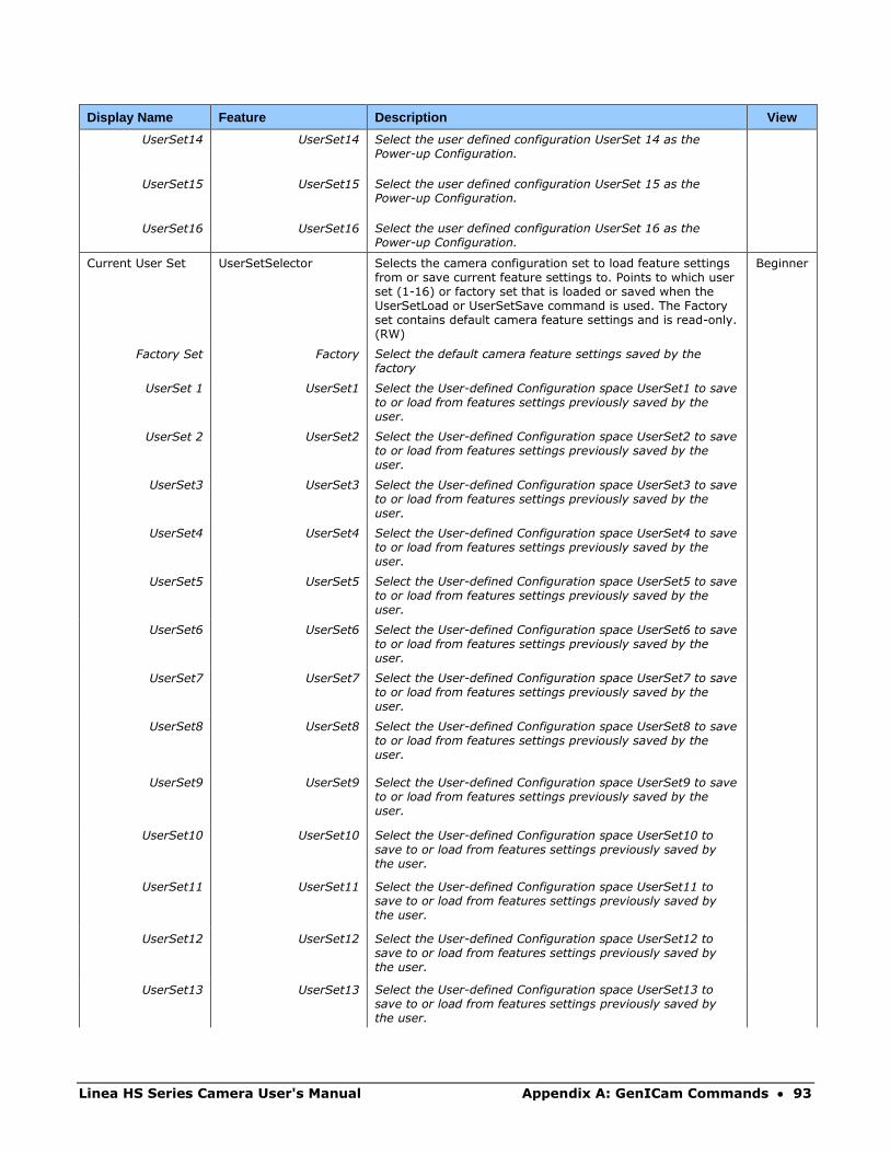
Linea HS Series Camera User's Manual Appendix A: GenICam Commands • 93
Display Name Feature Description View
UserSet14 UserSet14 Select the user defined configuration UserSet 14 as the Power-up Configuration.
UserSet15 UserSet15 Select the user defined configuration UserSet 15 as the Power-up Configuration.
UserSet16 UserSet16 Select the user defined configuration UserSet 16 as the Power-up Configuration.
Current User Set UserSetSelector Selects the camera configuration set to load feature settings from or save current feature settings to. Points to which user set (1-16) or factory set that is loaded or saved when the UserSetLoad or UserSetSave command is used. The Factory set contains default camera feature settings and is read-only. (RW)
Beginner
Factory Set Factory Select the default camera feature settings saved by the factory
UserSet 1 UserSet1 Select the User-defined Configuration space UserSet1 to save to or load from features settings previously saved by the user.
UserSet 2 UserSet2 Select the User-defined Configuration space UserSet2 to save to or load from features settings previously saved by the user.
UserSet3 UserSet3 Select the User-defined Configuration space UserSet3 to save to or load from features settings previously saved by the user.
UserSet4 UserSet4 Select the User-defined Configuration space UserSet4 to save to or load from features settings previously saved by the user.
UserSet5 UserSet5 Select the User-defined Configuration space UserSet5 to save to or load from features settings previously saved by the user.
UserSet6 UserSet6 Select the User-defined Configuration space UserSet6 to save to or load from features settings previously saved by the user.
UserSet7 UserSet7 Select the User-defined Configuration space UserSet7 to save to or load from features settings previously saved by the user.
UserSet8 UserSet8 Select the User-defined Configuration space UserSet8 to save to or load from features settings previously saved by the user.
UserSet9 UserSet9 Select the User-defined Configuration space UserSet9 to save to or load from features settings previously saved by the user.
UserSet10 UserSet10 Select the User-defined Configuration space UserSet10 to save to or load from features settings previously saved by the user.
UserSet11 UserSet11 Select the User-defined Configuration space UserSet11 to save to or load from features settings previously saved by the user.
UserSet12 UserSet12 Select the User-defined Configuration space UserSet12 to save to or load from features settings previously saved by the user.
UserSet13 UserSet13 Select the User-defined Configuration space UserSet13 to save to or load from features settings previously saved by the user.
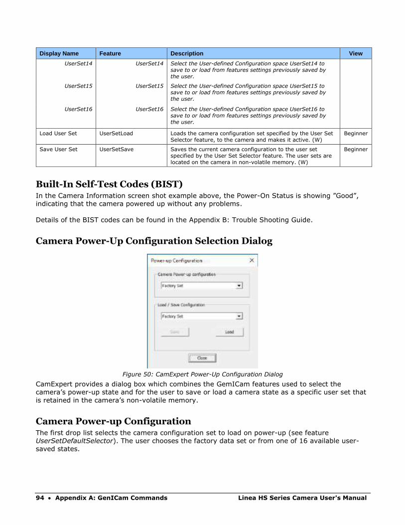
94 • Appendix A: GenICam Commands Linea HS Series Camera User's Manual
Display Name Feature Description View
UserSet14 UserSet14 Select the User-defined Configuration space UserSet14 to save to or load from features settings previously saved by the user.
UserSet15 UserSet15 Select the User-defined Configuration space UserSet15 to save to or load from features settings previously saved by the user.
UserSet16 UserSet16 Select the User-defined Configuration space UserSet16 to save to or load from features settings previously saved by the user.
Load User Set UserSetLoad Loads the camera configuration set specified by the User Set Selector feature, to the camera and makes it active. (W)
Beginner
Save User Set UserSetSave Saves the current camera configuration to the user set specified by the User Set Selector feature. The user sets are located on the camera in non-volatile memory. (W)
Beginner
Built-In Self-Test Codes (BIST) In the Camera Information screen shot example above, the Power-On Status is showing ”Good”,
indicating that the camera powered up without any problems.
Details of the BIST codes can be found in the Appendix B: Trouble Shooting Guide.
Camera Power-Up Configuration Selection Dialog
Figure 50: CamExpert Power-Up Configuration Dialog
CamExpert provides a dialog box which combines the GemICam features used to select the
camera’s power-up state and for the user to save or load a camera state as a specific user set that
is retained in the camera’s non-volatile memory.
Camera Power-up Configuration The first drop list selects the camera configuration set to load on power-up (see feature
UserSetDefaultSelector). The user chooses the factory data set or from one of 16 available user-
saved states.

Linea HS Series Camera User's Manual Appendix A: GenICam Commands • 95
User Set Configuration Management The second drop list allows the user to change the camera configuration any time after a power-up
(see feature UserSetSelector). To reset the camera to the factory configuration, select Factory Set
and click Load. To save a current camera configuration, select User Set 1 to 16 and click Save.
Select a saved user set and click Load to restore a saved configuration.
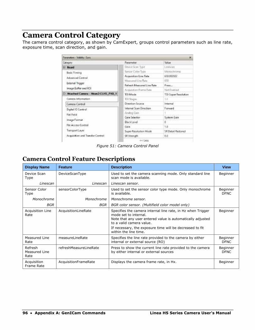
96 • Appendix A: GenICam Commands Linea HS Series Camera User's Manual
Camera Control Category The camera control category, as shown by CamExpert, groups control parameters such as line rate,
exposure time, scan direction, and gain.
Figure 51: Camera Control Panel
Camera Control Feature Descriptions
Display Name Feature Description View
Device Scan Type
DeviceScanType Used to set the camera scanning mode. Only standard line scan mode is available.
Beginner
Linescan Linescan Linescan sensor.
Sensor Color Type
sensorColorType Used to set the sensor color type mode. Only monochrome is available.
Beginner DFNC
Monochrome Monochrome Monochrome sensor.
BGR BGR BGR color sensor. (Multifield color model only)
Acquisition Line Rate
AcquisitionLineRate Specifies the camera internal line rate, in Hz when Trigger mode set to internal. Note that any user entered value is automatically adjusted to a valid camera value.
If necessary, the exposure time will be decreased to fit within the line time.
Beginner
Measured Line Rate
measureLineRate Specifies the line rate provided to the camera by either internal or external source (RO)
Beginner DFNC
Refresh Measured Line Rate
refreshMeasureLineRate Press to show the current line rate provided to the camera by either internal or external sources
Beginner DFNC
Acquisition Frame Rate
AcquisitionFrameRate Displays the camera frame rate, in Hx. Beginner
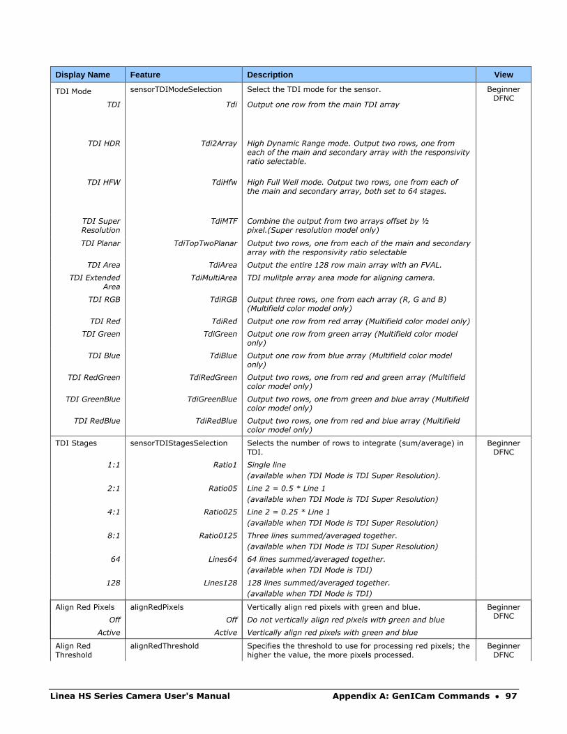
Linea HS Series Camera User's Manual Appendix A: GenICam Commands • 97
Display Name Feature Description View
TDI Mode sensorTDIModeSelection Select the TDI mode for the sensor. Beginner DFNC
TDI Tdi Output one row from the main TDI array
TDI HDR Tdi2Array High Dynamic Range mode. Output two rows, one from each of the main and secondary array with the responsivity ratio selectable.
TDI HFW TdiHfw High Full Well mode. Output two rows, one from each of the main and secondary array, both set to 64 stages.
TDI Super Resolution
TdiMTF Combine the output from two arrays offset by ½ pixel.(Super resolution model only)
TDI Planar TdiTopTwoPlanar Output two rows, one from each of the main and secondary array with the responsivity ratio selectable
TDI Area TdiArea Output the entire 128 row main array with an FVAL.
TDI Extended Area
TdiMultiArea TDI mulitple array area mode for aligning camera.
TDI RGB TdiRGB Output three rows, one from each array (R, G and B) (Multifield color model only)
TDI Red TdiRed Output one row from red array (Multifield color model only)
TDI Green TdiGreen Output one row from green array (Multifield color model only)
TDI Blue TdiBlue Output one row from blue array (Multifield color model only)
TDI RedGreen TdiRedGreen Output two rows, one from red and green array (Multifield color model only)
TDI GreenBlue TdiGreenBlue Output two rows, one from green and blue array (Multifield color model only)
TDI RedBlue TdiRedBlue Output two rows, one from red and blue array (Multifield color model only)
TDI Stages sensorTDIStagesSelection Selects the number of rows to integrate (sum/average) in TDI.
Beginner DFNC
1:1 Ratio1 Single line
(available when TDI Mode is TDI Super Resolution).
2:1 Ratio05 Line 2 = 0.5 * Line 1
(available when TDI Mode is TDI Super Resolution)
4:1 Ratio025 Line 2 = 0.25 * Line 1
(available when TDI Mode is TDI Super Resolution)
8:1 Ratio0125 Three lines summed/averaged together.
(available when TDI Mode is TDI Super Resolution)
64 Lines64 64 lines summed/averaged together.
(available when TDI Mode is TDI)
128 Lines128 128 lines summed/averaged together.
(available when TDI Mode is TDI)
Align Red Pixels alignRedPixels Vertically align red pixels with green and blue. Beginner DFNC
Off Off Do not vertically align red pixels with green and blue
Active Active Vertically align red pixels with green and blue
Align Red Threshold
alignRedThreshold Specifies the threshold to use for processing red pixels; the higher the value, the more pixels processed.
Beginner DFNC
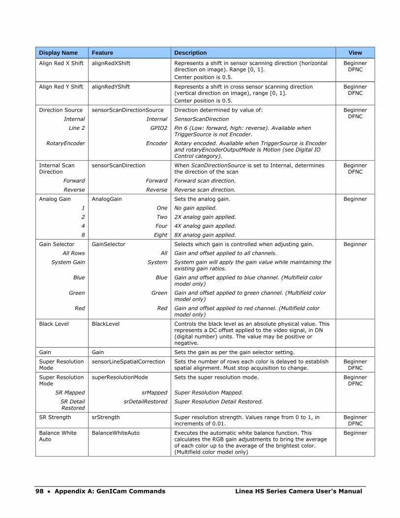
98 • Appendix A: GenICam Commands Linea HS Series Camera User's Manual
Display Name Feature Description View
Align Red X Shift alignRedXShift Represents a shift in sensor scanning direction (horizontal direction on image). Range [0, 1].
Center position is 0.5.
Beginner DFNC
Align Red Y Shift alignRedYShift Represents a shift in cross sensor scanning direction (vertical direction on image), range [0, 1].
Center position is 0.5.
Beginner DFNC
Direction Source sensorScanDirectionSource Direction determined by value of: Beginner DFNC
Internal Internal SensorScanDirection
Line 2 GPIO2 Pin 6 (Low: forward, high: reverse). Available when TriggerSource is not Encoder.
RotaryEncoder Encoder Rotary encoded. Available when TriggerSource is Encoder and rotaryEncoderOutputMode is Motion (see Digital IO Control category).
Internal Scan Direction
sensorScanDirection When ScanDirectionSource is set to Internal, determines the direction of the scan
Beginner DFNC
Forward Forward Forward scan direction.
Reverse Reverse Reverse scan direction.
Analog Gain AnalogGain Sets the analog gain. Beginner
1 One No gain applied.
2 Two 2X analog gain applied.
4 Four 4X analog gain applied.
8 Eight 8X analog gain applied.
Gain Selector GainSelector Selects which gain is controlled when adjusting gain. Beginner
All Rows All Gain and offset applied to all channels.
System Gain System System gain will apply the gain value while maintaining the existing gain ratios.
Blue Blue Gain and offset applied to blue channel. (Multifield color model only)
Green Green Gain and offset applied to green channel. (Multifield color model only)
Red Red Gain and offset applied to red channel. (Multifield color model only)
Black Level BlackLevel Controls the black level as an absolute physical value. This represents a DC offset applied to the video signal, in DN (digital number) units. The value may be positive or negative.
Gain Gain Sets the gain as per the gain selector setting.
Super Resolution Mode
sensorLineSpatialCorrection Sets the number of rows each color is delayed to establish spatial alignment. Must stop acquisition to change.
Beginner DFNC
Super Resolution Mode
superResolutionMode Sets the super resolution mode. Beginner DFNC
SR Mapped srMapped Super Resolution Mapped.
SR Detail Restored
srDetailRestored Super Resolution Detail Restored.
SR Strength srStrength Super resolution strength. Values range from 0 to 1, in increments of 0.01.
Beginner DFNC
Balance White Auto
BalanceWhiteAuto Executes the automatic white balance function. This calculates the RGB gain adjustments to bring the average of each color up to the average of the brightest color. (Multifield color model only)
Beginner
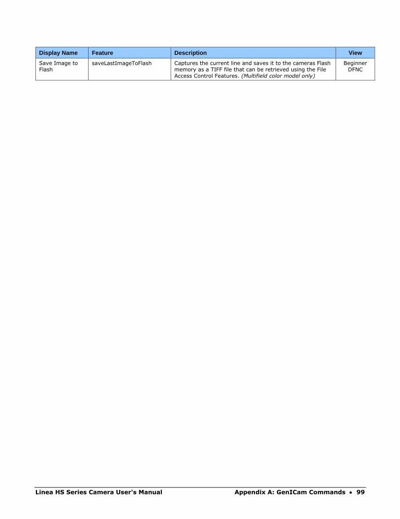
Linea HS Series Camera User's Manual Appendix A: GenICam Commands • 99
Display Name Feature Description View
Save Image to Flash
saveLastImageToFlash Captures the current line and saves it to the cameras Flash memory as a TIFF file that can be retrieved using the File Access Control Features. (Multifield color model only)
Beginner DFNC
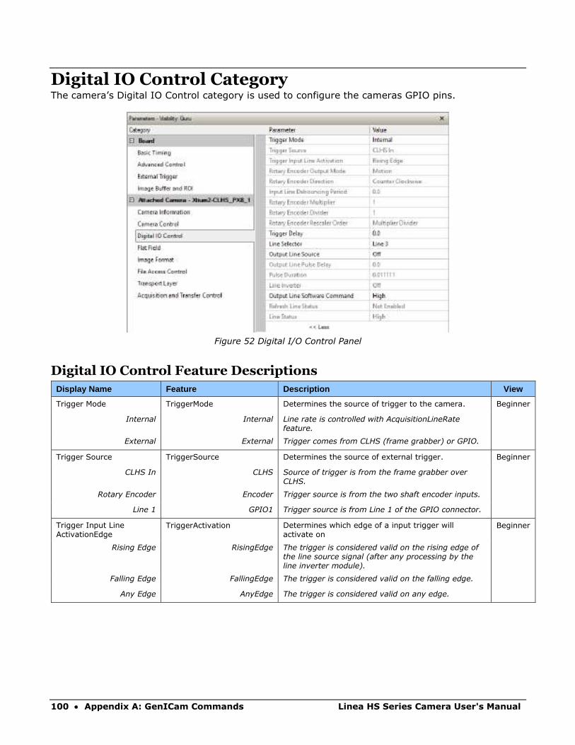
100 • Appendix A: GenICam Commands Linea HS Series Camera User's Manual
Digital IO Control Category The camera’s Digital IO Control category is used to configure the cameras GPIO pins.
Figure 52 Digital I/O Control Panel
Digital IO Control Feature Descriptions
Display Name Feature Description View
Trigger Mode TriggerMode Determines the source of trigger to the camera. Beginner
Internal Internal Line rate is controlled with AcquisitionLineRate feature.
External External Trigger comes from CLHS (frame grabber) or GPIO.
Trigger Source TriggerSource Determines the source of external trigger. Beginner
CLHS In CLHS Source of trigger is from the frame grabber over CLHS.
Rotary Encoder Encoder Trigger source is from the two shaft encoder inputs.
Line 1 GPIO1 Trigger source is from Line 1 of the GPIO connector.
Trigger Input Line ActivationEdge
TriggerActivation Determines which edge of a input trigger will activate on
Beginner
Rising Edge RisingEdge The trigger is considered valid on the rising edge of the line source signal (after any processing by the line inverter module).
Falling Edge FallingEdge The trigger is considered valid on the falling edge.
Any Edge AnyEdge The trigger is considered valid on any edge.

Linea HS Series Camera User's Manual Appendix A: GenICam Commands • 101
Display Name Feature Description View
Rotary Encoder Direction rotaryEncoderDirection Specifies the phase which defines the encoder forward direction.
Beginner DFNC
Counter Clockwise CounterClockwise Inspection goes forward when the rotary encoder direction is counter clockwise (phase A is ahead of phase B).
Clockwise Clockwise Inspection goes forward when the rotary encoder direction is clockwise (phase B is ahead of phase A).
Rotary Encoder Output Mode
rotaryEncoderOutputMode Specifies the conditions for the Rotary Encoder interface to generate a valid Encoder output signal.
Beginner DFNC
Position Position Triggers are generated at all new position increments in the selected direction. If the encoder reverses no trigger events are generated until it has again passed the position where the reversal started.
Motion Motion The triggers are generated for all motion increments in either direction.
Input Line Debouncing Period
lineDebouncingPeriod Specifies the minimum delay before an input line voltage transition is recognizing as a signal transition.
Beginner DFNC
Rotary Encoder Multiplier rotaryEncoderMultiplier Specifies a multiplication factor for the rotary encoder output pulse generator.
Beginner
Rotary Encoder Divisor rotaryEncoderDivider Specifies a division factor for the rotary encoder output pulse generator.
Beginner DFNC
Rotary Encoder Rescaler Order
rotaryEncoderRescalerOrder Specifies the order that the multiplier and divider are applied.
Beginner DFNC
Multiplier Divider multiplierDivider The signal is multiplied before been divided.
Divider Multiplier dividerMultiplier The signal is divided before been multiplied
Trigger Delay TriggerDelay Allows the trigger to the sensor to be delayed relative to camera input trigger
Beginner
Line Selector LineSelector Selects the physical line (or pin) of the external device connector to configure.
Beginner
Line 1
Line 2
Line 3
Line 4
Line 5
Line 6
GPIO1
GPIO2
GPIO3
GPIO4
GPIO5
GPIO6
Index of the physical line and associated I/O control block to use.
Output Line Source outputLineSource Selects which features control the output on the selected line.
Beginner DFNC
Off Off Line output level is controlled by the outputLineSoftwareCmd feature.
On On Line output level is controlled by outputLinePulseDelay, outputLinePulseDuration, and LineInverter features.
Output Line Pulse Delay outputLinePulseDelay Sets the delay (in µs) before the output line pulse signal. Enabled by the OutputLineSource feature.
Beginner DFNC
Pulse Duration outputLinePulseDuration Sets the width (duration) of the output line pulse in microseconds.
Beginner DFNC
Line Inverter LineInverter Controls whether to invert the polarity of the selected input or output line signal.
Beginner
Off Off The line signal is not inverted.
On On The line signal is inverted.
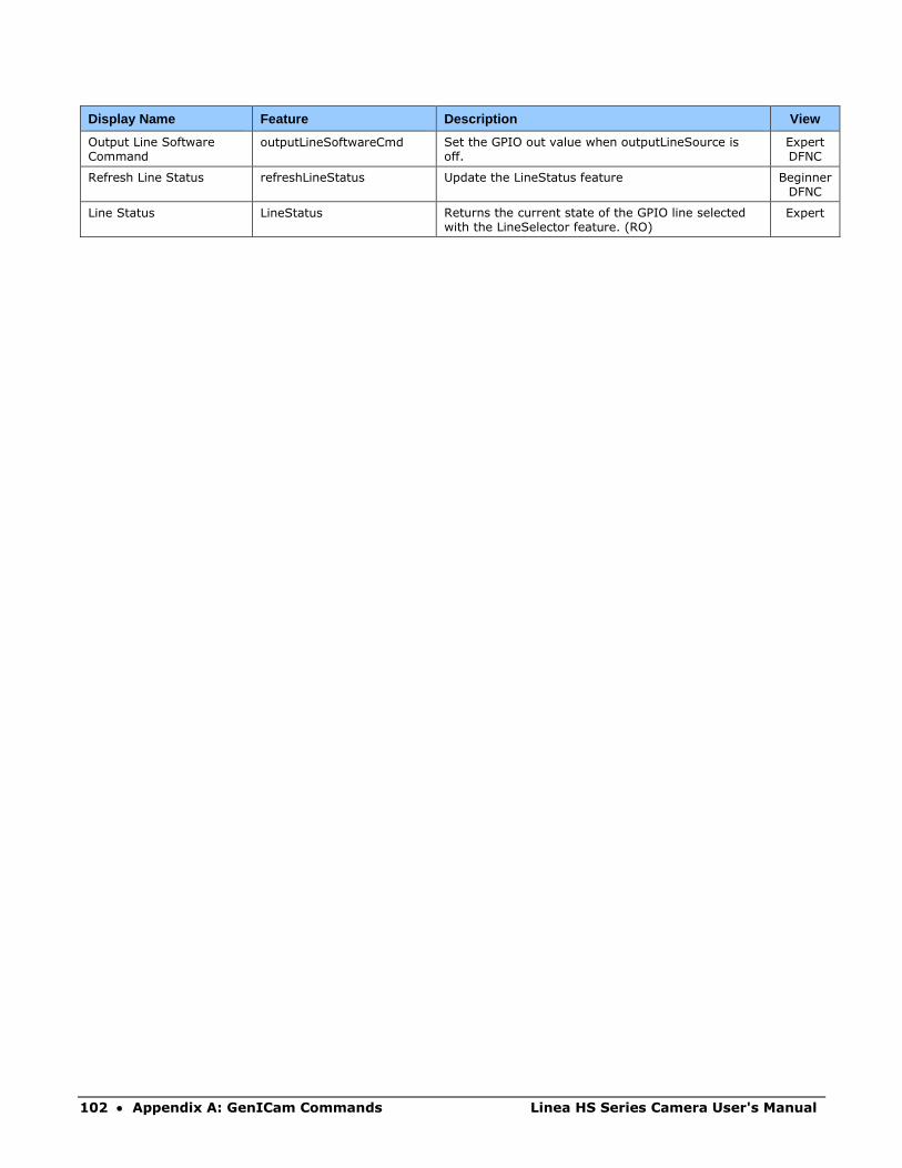
102 • Appendix A: GenICam Commands Linea HS Series Camera User's Manual
Display Name Feature Description View
Output Line Software Command
outputLineSoftwareCmd Set the GPIO out value when outputLineSource is off.
Expert DFNC
Refresh Line Status refreshLineStatus Update the LineStatus feature Beginner DFNC
Line Status LineStatus Returns the current state of the GPIO line selected with the LineSelector feature. (RO)
Expert
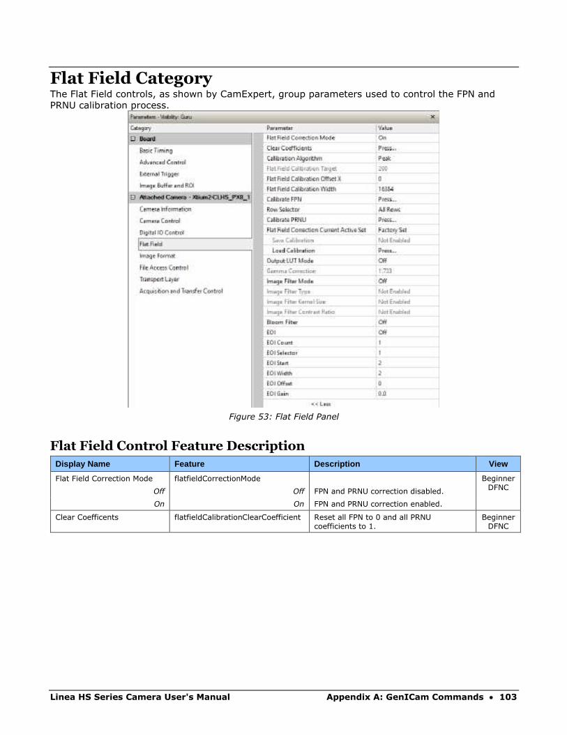
Linea HS Series Camera User's Manual Appendix A: GenICam Commands • 103
Flat Field Category The Flat Field controls, as shown by CamExpert, group parameters used to control the FPN and
PRNU calibration process.
Figure 53: Flat Field Panel
Flat Field Control Feature Description
Display Name Feature Description View
Flat Field Correction Mode flatfieldCorrectionMode Beginner DFNC
Off Off FPN and PRNU correction disabled.
On On FPN and PRNU correction enabled.
Clear Coefficents flatfieldCalibrationClearCoefficient Reset all FPN to 0 and all PRNU coefficients to 1.
Beginner DFNC
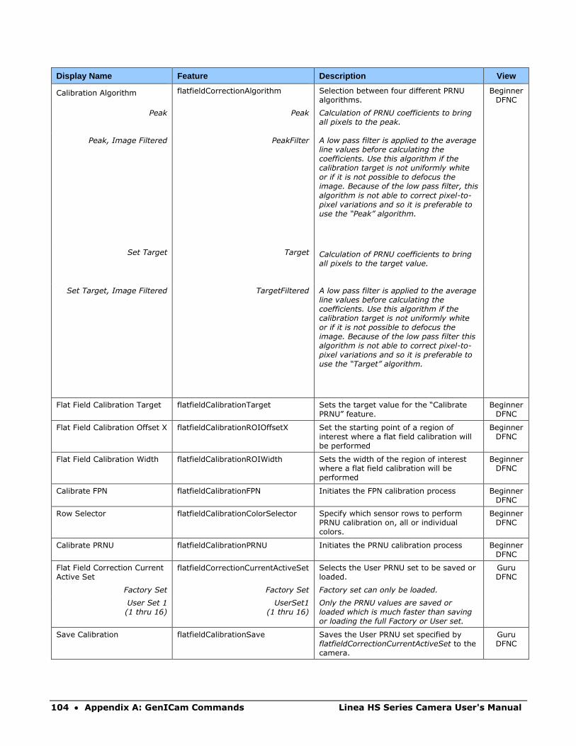
104 • Appendix A: GenICam Commands Linea HS Series Camera User's Manual
Display Name Feature Description View
Calibration Algorithm flatfieldCorrectionAlgorithm Selection between four different PRNU algorithms.
Beginner DFNC
Peak Peak Calculation of PRNU coefficients to bring all pixels to the peak.
Peak, Image Filtered PeakFilter A low pass filter is applied to the average line values before calculating the coefficients. Use this algorithm if the calibration target is not uniformly white or if it is not possible to defocus the image. Because of the low pass filter, this
algorithm is not able to correct pixel-to-pixel variations and so it is preferable to use the “Peak” algorithm.
Set Target Target Calculation of PRNU coefficients to bring all pixels to the target value.
Set Target, Image Filtered TargetFiltered A low pass filter is applied to the average line values before calculating the coefficients. Use this algorithm if the calibration target is not uniformly white or if it is not possible to defocus the image. Because of the low pass filter this algorithm is not able to correct pixel-to-pixel variations and so it is preferable to use the “Target” algorithm.
Flat Field Calibration Target flatfieldCalibrationTarget Sets the target value for the “Calibrate PRNU” feature.
Beginner DFNC
Flat Field Calibration Offset X flatfieldCalibrationROIOffsetX Set the starting point of a region of interest where a flat field calibration will be performed
Beginner DFNC
Flat Field Calibration Width flatfieldCalibrationROIWidth Sets the width of the region of interest where a flat field calibration will be performed
Beginner DFNC
Calibrate FPN flatfieldCalibrationFPN Initiates the FPN calibration process Beginner DFNC
Row Selector flatfieldCalibrationColorSelector Specify which sensor rows to perform PRNU calibration on, all or individual colors.
Beginner DFNC
Calibrate PRNU flatfieldCalibrationPRNU Initiates the PRNU calibration process Beginner DFNC
Flat Field Correction Current Active Set
flatfieldCorrectionCurrentActiveSet Selects the User PRNU set to be saved or loaded.
Guru DFNC
Factory Set Factory Set Factory set can only be loaded.
User Set 1 (1 thru 16)
UserSet1 (1 thru 16)
Only the PRNU values are saved or loaded which is much faster than saving or loading the full Factory or User set.
Save Calibration flatfieldCalibrationSave Saves the User PRNU set specified by flatfieldCorrectionCurrentActiveSet to the camera.
Guru DFNC
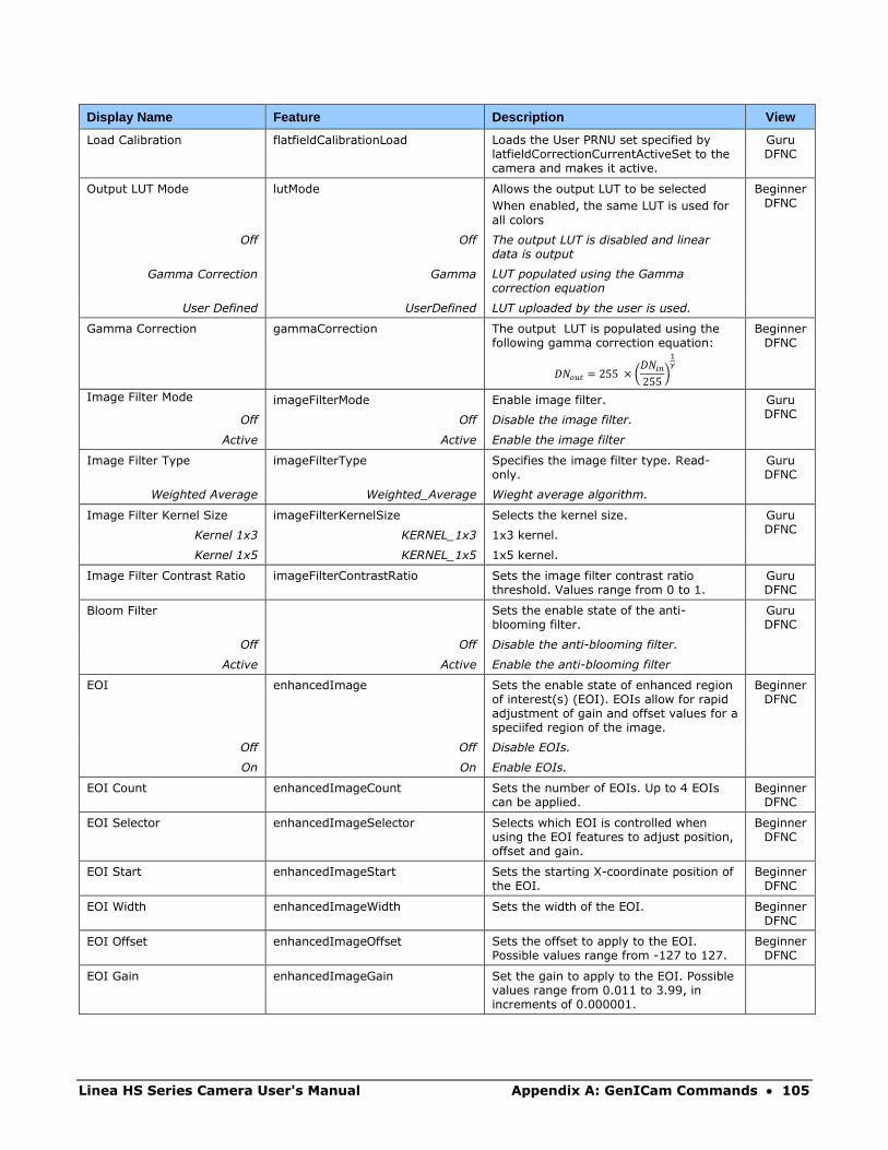
Linea HS Series Camera User's Manual Appendix A: GenICam Commands • 105
Display Name Feature Description View
Load Calibration flatfieldCalibrationLoad Loads the User PRNU set specified by latfieldCorrectionCurrentActiveSet to the camera and makes it active.
Guru DFNC
Output LUT Mode lutMode Allows the output LUT to be selected
When enabled, the same LUT is used for
all colors
Beginner DFNC
Off Off The output LUT is disabled and linear data is output
Gamma Correction Gamma LUT populated using the Gamma correction equation
User Defined UserDefined LUT uploaded by the user is used.
Gamma Correction gammaCorrection The output LUT is populated using the following gamma correction equation:
𝐷𝑁𝑜𝑢𝑡 = 255 × (𝐷𝑁𝑖𝑛
255)
1𝛾
Beginner DFNC
Image Filter Mode imageFilterMode Enable image filter. Guru DFNC
Off Off Disable the image filter.
Active Active Enable the image filter
Image Filter Type imageFilterType Specifies the image filter type. Read-only.
Guru DFNC
Weighted Average Weighted_Average Wieght average algorithm.
Image Filter Kernel Size imageFilterKernelSize Selects the kernel size. Guru DFNC
Kernel 1x3 KERNEL_1x3 1x3 kernel.
Kernel 1x5 KERNEL_1x5 1x5 kernel.
Image Filter Contrast Ratio imageFilterContrastRatio Sets the image filter contrast ratio threshold. Values range from 0 to 1.
Guru DFNC
Bloom Filter Sets the enable state of the anti-blooming filter.
Guru DFNC
Off Off Disable the anti-blooming filter.
Active Active Enable the anti-blooming filter
EOI enhancedImage Sets the enable state of enhanced region of interest(s) (EOI). EOIs allow for rapid adjustment of gain and offset values for a speciifed region of the image.
Beginner DFNC
Off Off Disable EOIs.
On On Enable EOIs.
EOI Count enhancedImageCount Sets the number of EOIs. Up to 4 EOIs can be applied.
Beginner DFNC
EOI Selector enhancedImageSelector Selects which EOI is controlled when using the EOI features to adjust position, offset and gain.
Beginner DFNC
EOI Start enhancedImageStart Sets the starting X-coordinate position of the EOI.
Beginner DFNC
EOI Width enhancedImageWidth Sets the width of the EOI. Beginner DFNC
EOI Offset enhancedImageOffset Sets the offset to apply to the EOI. Possible values range from -127 to 127.
Beginner DFNC
EOI Gain enhancedImageGain Set the gain to apply to the EOI. Possible values range from 0.011 to 3.99, in increments of 0.000001.
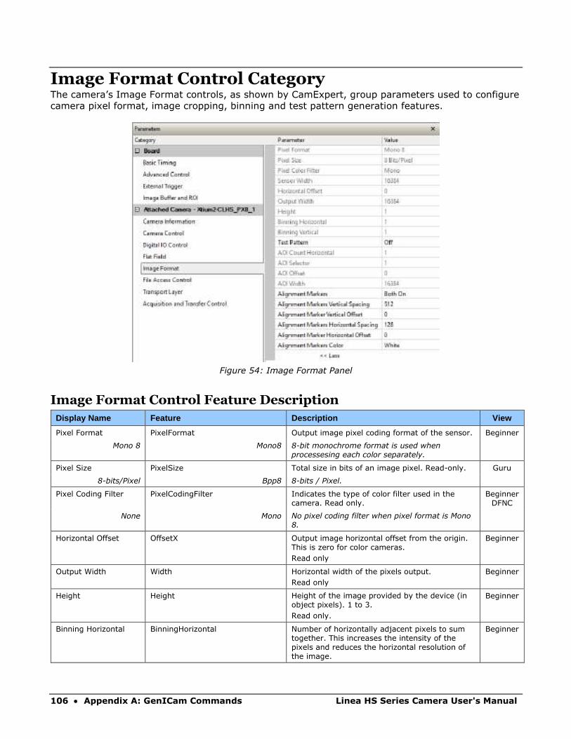
106 • Appendix A: GenICam Commands Linea HS Series Camera User's Manual
Image Format Control Category The camera’s Image Format controls, as shown by CamExpert, group parameters used to configure
camera pixel format, image cropping, binning and test pattern generation features.
Figure 54: Image Format Panel
Image Format Control Feature Description
Display Name Feature Description View
Pixel Format PixelFormat Output image pixel coding format of the sensor. Beginner
Mono 8 Mono8 8-bit monochrome format is used when processesing each color separately.
Pixel Size PixelSize Total size in bits of an image pixel. Read-only. Guru
8-bits/Pixel Bpp8 8-bits / Pixel.
Pixel Coding Filter PixelCodingFilter Indicates the type of color filter used in the camera. Read only.
Beginner DFNC
None Mono No pixel coding filter when pixel format is Mono 8.
Horizontal Offset OffsetX Output image horizontal offset from the origin. This is zero for color cameras.
Read only
Beginner
Output Width Width Horizontal width of the pixels output.
Read only
Beginner
Height Height Height of the image provided by the device (in object pixels). 1 to 3.
Read only.
Beginner
Binning Horizontal BinningHorizontal Number of horizontally adjacent pixels to sum together. This increases the intensity of the pixels and reduces the horizontal resolution of the image.
Beginner

Linea HS Series Camera User's Manual Appendix A: GenICam Commands • 107
Binning Vertical BinningVertical Number of vertically adjacent pixels to sum together. This increases the intensity of the pixels and reduces the vertical resolution of the image. Only available in TDI single plane mode.
Beginner
Test Pattern TestImageSelector Selects the type of test image that is sent by the camera.
Note. Grey images are displayed so that any bit error will immediately be apparent as a color.
Beginner
Off Off Selects sensor video to be output
Each Tap Fixed EachTapFixed Selects a grey scale value that is increased every 512 pixels.
Grey Horizontal Ramp Grey Horizontal Ramp Selects a grey scale ramp
Grey Vertical Ramp Grey Vertical Ramp Selects a grey scale ramp progressively for each row.
Grey Diagonal Ramp Grey Diagonal Ramp Selects a combination of horizontal and vertical raps to form a diagonal grey scale.
User Pattern User Pattern User can define a test pattern by uploading to the camera a PRNU file using the FileAccess > Miscellaneous > User PRNU feature. The PRNU coefficient will be applied to a midscale (128 DN) test image.
Contact Teledyne DALSA support for an Excel file that can help with this.
AOI Count multipleROICount Specifies the number of AOIs output. Beginner DFNC
AOI Selector multipleROISelector Select the AOI to contorl when setting the AOI Offset & AOI Width.
Beginner DFNC
AOI Offset multipleROIOffsetX Location of the start of the AOI to be output. Multiple of 32.
Beginner DFNC
AOI Width multipleROIWidth Width of the AOI, in pixels. Minimum is 96 per lane.
For example, if there is only one AOI spread across the 5 lanes then the minimum is 5 x 96 = 480.
Maximum of the sum of AOI width’s is the sensor width. For example, for a 16k sensor, if there are two AOIs with the first 12k wide, then the second can be no wider than 4k.
Beginner DFNC
Alignment Markers alignmentMarkerEnable To assist with camera alignment, alignment markers can be enabled in the output.
Beginner DFNC
Off Off Disable alignment markers
Vertical On Vertical Enable Vertical Alignment Markers only
Horizontal On Horizontal Enable Horizontal Alignment Markers only
Both On Both Enable Vertical and Horizontal Alignment Markers
Alignment Marker Vertical Spacing
alignmentMarkerVerticalSpacing Vertical spacing between alignment markers, in pixels.
Beginner DFNC
64 Ver64 64 pixels between vertical alignment markers
128 Ver128 128 pixels between vertical alignment
256 Ver256 256 pixels between vertical alignment markers
512 Ver512 512 pixels between vertical alignment markers
Alignment Marker Vertical Offset
alignmentMarkerVerticalOffset Pixel count before first vertical alignment marker.
Integer between 0 and alignmentMarkerVerticalSpacing value.
Beginner DFNC
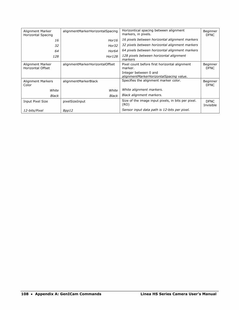
108 • Appendix A: GenICam Commands Linea HS Series Camera User's Manual
Alignment Marker Horizontal Spacing
alignmentMarkerHorizontalSpacing Horizontical spacing between alignment markers, in pixels.
Beginner DFNC
16 Hor16 16 pixels between horizontal alignment markers
32 Hor32 32 pixels between horizontal alignment markers
64 Hor64 64 pixels between horizontal alignment markers
128 Hor128 128 pixels between horizontal alignment markers
Alignment Marker Horizontal Offset
alignmentMarkerHorizontalOffset Pixel count before first horizontal alignment marker.
Integer between 0 and alignmentMarkerHorizontalSpacing value.
Beginner DFNC
Alignment Markers Color
alignmentMarkerBlack Specifies the alignment marker color. Beginner DFNC
White White White alignment markers.
Black Black Black alignment markers.
Input Pixel Size pixelSizeInput Size of the image input pixels, in bits per pixel. (RO)
DFNC Invisible
12-bits/Pixel Bpp12 Sensor input data path is 12-bits per pixel.

Linea HS Series Camera User's Manual Appendix A: GenICam Commands • 109
File Access Control Category The File Access control in CamExpert allows the user to quickly upload and download of various
data files to/from the connected the camera. The supported data files for the camera include
firmware updates and Flat Field coefficients.
Note: The communication performance when reading and writing large files can be
improved by stopping image acquisition during the transfer
Figure 55: File Access Control Panel
File Access Control Feature Descriptions
Display Name Feature Description View
File Selector FileSelector Selects the file to access. The files which are accessible are listed in the XML:
Beginner
All Firmware Firmware1 Upload micro code, FPGA code & XML as a single file to the camera which will execute on the next camera reboot cycle.
User Set User_Set Use UserSetSelector to specify which user set to access.
Output LUT Output_LUT Use UserSetSelector to specify which LUT to access.
User PRNU User_PRNU Use UserSetSelector to specify which user PRNU to access.
User FPN User_FPN Use UserSetSelector to specify which user FPN to access.
Current PRNU Cur_PRNU Accesses the PRNU coefficients that are currently being used by the camera (not necessarily saved).
Camera_Data CameraData Download camera information and send for customer support.
File Operation Selector
FileOperationSelector Selects the operation for the selected file in the device. This operation is executed when the File Operation Execute feature is called.
Guru
Open Open Select the Open operation - executed by FileOperationExecute.
Close Close Select the Close operation - executed by FileOperationExecute.
Read Read Select the Read operation - executed by FileOperationExecute.
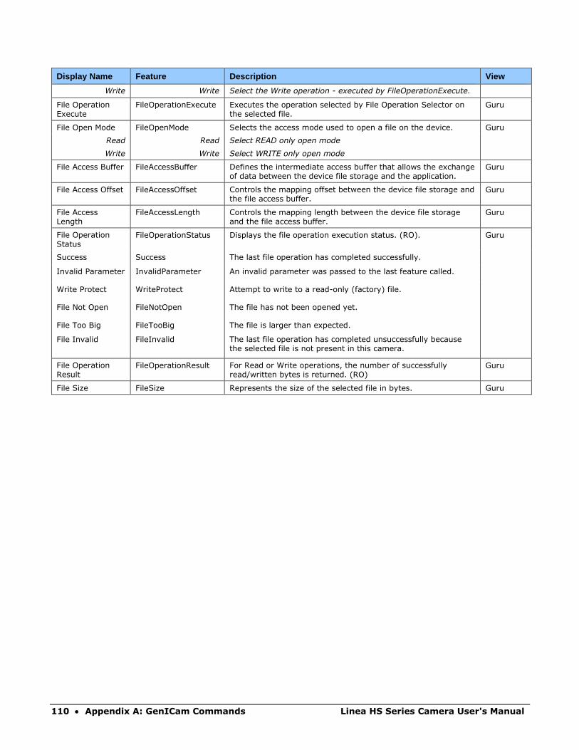
110 • Appendix A: GenICam Commands Linea HS Series Camera User's Manual
Display Name Feature Description View
Write Write Select the Write operation - executed by FileOperationExecute.
File Operation Execute
FileOperationExecute Executes the operation selected by File Operation Selector on the selected file.
Guru
File Open Mode FileOpenMode Selects the access mode used to open a file on the device. Guru
Read Read Select READ only open mode
Write Write Select WRITE only open mode
File Access Buffer FileAccessBuffer Defines the intermediate access buffer that allows the exchange of data between the device file storage and the application.
Guru
File Access Offset FileAccessOffset Controls the mapping offset between the device file storage and the file access buffer.
Guru
File Access Length
FileAccessLength Controls the mapping length between the device file storage and the file access buffer.
Guru
File Operation Status
FileOperationStatus Displays the file operation execution status. (RO). Guru
Success Success The last file operation has completed successfully.
Invalid Parameter InvalidParameter An invalid parameter was passed to the last feature called.
Write Protect WriteProtect Attempt to write to a read-only (factory) file.
File Not Open FileNotOpen The file has not been opened yet.
File Too Big FileTooBig The file is larger than expected.
File Invalid FileInvalid The last file operation has completed unsuccessfully because the selected file is not present in this camera.
File Operation Result
FileOperationResult For Read or Write operations, the number of successfully read/written bytes is returned. (RO)
Guru
File Size FileSize Represents the size of the selected file in bytes. Guru

Linea HS Series Camera User's Manual Appendix A: GenICam Commands • 111
File Access via the CamExpert Tool Click on the “Setting…” button to show the File Access Control dialog box.
Figure 56: File Access Control Tool
From the Type drop menu, select the file type that will be uploaded to the camera or downloaded
from the camera.
From the File Selector drop menu, select the file to be uploaded or downloaded.
To upload a file, click the Browse button to open a typical Windows Explorer window.
a. Select the specific file from the system drive or from a network location.
b. Click the Upload button to execute the file transfer to the camera.
Alternatively, click the Download button and then specify the location where the file should be
stored.
Firmware changes require that the camera be powered down and then back up. When the firmware
update is successfully completed, a message box is displayed to reset the camera.
Figure 57: File Upload Completed Message Box
Caution: Do not interrupt the file transfer by powering down the camera or closing CamExpert.
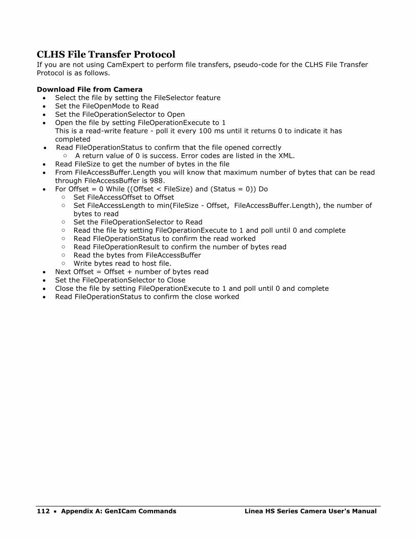
112 • Appendix A: GenICam Commands Linea HS Series Camera User's Manual
CLHS File Transfer Protocol If you are not using CamExpert to perform file transfers, pseudo-code for the CLHS File Transfer
Protocol is as follows.
Download File from Camera
• Select the file by setting the FileSelector feature
• Set the FileOpenMode to Read
• Set the FileOperationSelector to Open
• Open the file by setting FileOperationExecute to 1
This is a read-write feature - poll it every 100 ms until it returns 0 to indicate it has
completed
• Read FileOperationStatus to confirm that the file opened correctly o A return value of 0 is success. Error codes are listed in the XML.
• Read FileSize to get the number of bytes in the file
• From FileAccessBuffer.Length you will know that maximum number of bytes that can be read
through FileAccessBuffer is 988.
• For Offset = 0 While ((Offset < FileSize) and (Status = 0)) Do o Set FileAccessOffset to Offset o Set FileAccessLength to min(FileSize - Offset, FileAccessBuffer.Length), the number of
bytes to read o Set the FileOperationSelector to Read o Read the file by setting FileOperationExecute to 1 and poll until 0 and complete o Read FileOperationStatus to confirm the read worked o Read FileOperationResult to confirm the number of bytes read o Read the bytes from FileAccessBuffer o Write bytes read to host file.
• Next Offset = Offset + number of bytes read
• Set the FileOperationSelector to Close
• Close the file by setting FileOperationExecute to 1 and poll until 0 and complete
• Read FileOperationStatus to confirm the close worked
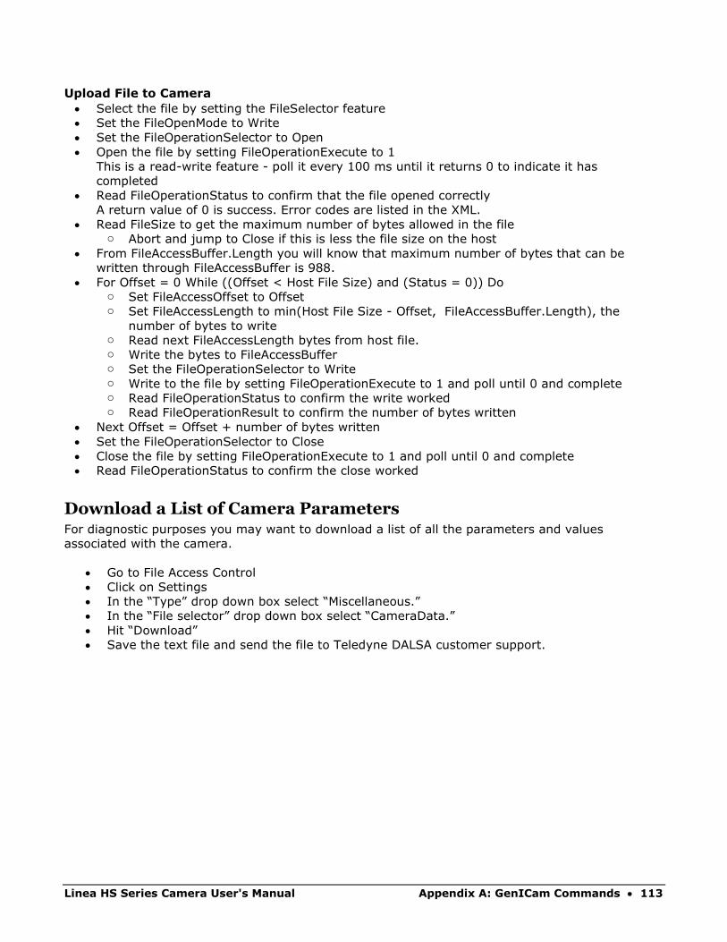
Linea HS Series Camera User's Manual Appendix A: GenICam Commands • 113
Upload File to Camera
• Select the file by setting the FileSelector feature
• Set the FileOpenMode to Write
• Set the FileOperationSelector to Open
• Open the file by setting FileOperationExecute to 1
This is a read-write feature - poll it every 100 ms until it returns 0 to indicate it has
completed
• Read FileOperationStatus to confirm that the file opened correctly
A return value of 0 is success. Error codes are listed in the XML.
• Read FileSize to get the maximum number of bytes allowed in the file o Abort and jump to Close if this is less the file size on the host
• From FileAccessBuffer.Length you will know that maximum number of bytes that can be
written through FileAccessBuffer is 988.
• For Offset = 0 While ((Offset < Host File Size) and (Status = 0)) Do o Set FileAccessOffset to Offset o Set FileAccessLength to min(Host File Size - Offset, FileAccessBuffer.Length), the
number of bytes to write o Read next FileAccessLength bytes from host file. o Write the bytes to FileAccessBuffer o Set the FileOperationSelector to Write o Write to the file by setting FileOperationExecute to 1 and poll until 0 and complete o Read FileOperationStatus to confirm the write worked o Read FileOperationResult to confirm the number of bytes written
• Next Offset = Offset + number of bytes written
• Set the FileOperationSelector to Close
• Close the file by setting FileOperationExecute to 1 and poll until 0 and complete
• Read FileOperationStatus to confirm the close worked
Download a List of Camera Parameters For diagnostic purposes you may want to download a list of all the parameters and values
associated with the camera.
• Go to File Access Control
• Click on Settings
• In the “Type” drop down box select “Miscellaneous.”
• In the “File selector” drop down box select “CameraData.”
• Hit “Download”
• Save the text file and send the file to Teledyne DALSA customer support.
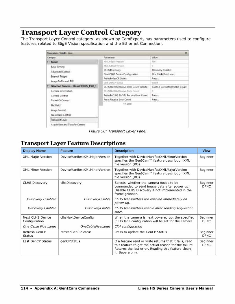
114 • Appendix A: GenICam Commands Linea HS Series Camera User's Manual
Transport Layer Control Category The Transport Layer Control category, as shown by CamExpert, has parameters used to configure
features related to GigE Vision specification and the Ethernet Connection.
Figure 58: Transport Layer Panel
Transport Layer Feature Descriptions
Display Name Feature Description View
XML Major Version DeviceManifestXMLMajorVersion Together with DeviceManifestXMLMinorVersion specifies the GenICam™ feature description XML file version (RO)
Beginner
XML Minor Version DeviceManifestXMLMinorVersion Together with DeviceManifestXMLMajorVersion specifies the GenICam™ feature description XML file version (RO)
Beginner
CLHS Discovery clhsDiscovery Selects whether the camera needs to be commanded to send image data after power up. Disable CLHS Discovery if not implemented in the frame grabber.
Beginner DFNC
Discovery Disabled DiscoveryDisable CLHS transmitters are enabled immediately on power up.
Discovery Enabled DiscoveryEnable CLHS transmitters enable after sending Acquisition start.
Next CLHS Device Configuration
clhsNextDeviceConfig When the camera is next powered up, the specified CLHS lane configuration will be set for the camera.
Beginner DFNC
One Cable Five Lanes OneCableFiveLanes CX4 configuration
Refresh GenCP Status
refreshGenCPStatus Press to update the GenCP Status. Beginner DFNC
Last GenCP Status genCPStatus If a feature read or write returns that it fails, read this feature to get the actual reason for the failure Returns the last error. Reading this feature clears it. Sapera only.
Beginner DFNC

Linea HS Series Camera User's Manual Appendix A: GenICam Commands • 115
CLHS 8b/10b Receive Error Count Selector
clhsErrorCountSelector Select the error to count Guru DFNC
Cable A Corrupted Packet Count
CorruptedPacketCntA Count of corrupted packets on cable A.
Cable A Corrected Packet Count
CorrectedPacketCntA Count of corrected packets on cable A.
Cable B Corrupted Packet Count
CorruptedPacketCntB Count of corrupted packets on cable B.
Cable B Corrected Packet Count
CorrectedPacketCntB Count of corrected packets on cable B.
CLHS 8b/10b Receive Error Count
clhsErrorCount CLHS 8b/10b Receive Error Count Guru DFNC
Refresh CLHS 8b/10b Receive Error Count
clhsErrorCountRefresh Refresh the selected clhsErrorCount value. Guru DFNC
Reset Receive Error Count
clhsErrorCountReset Reset the selected clhsErrorCount value to 0. Guru DFNC
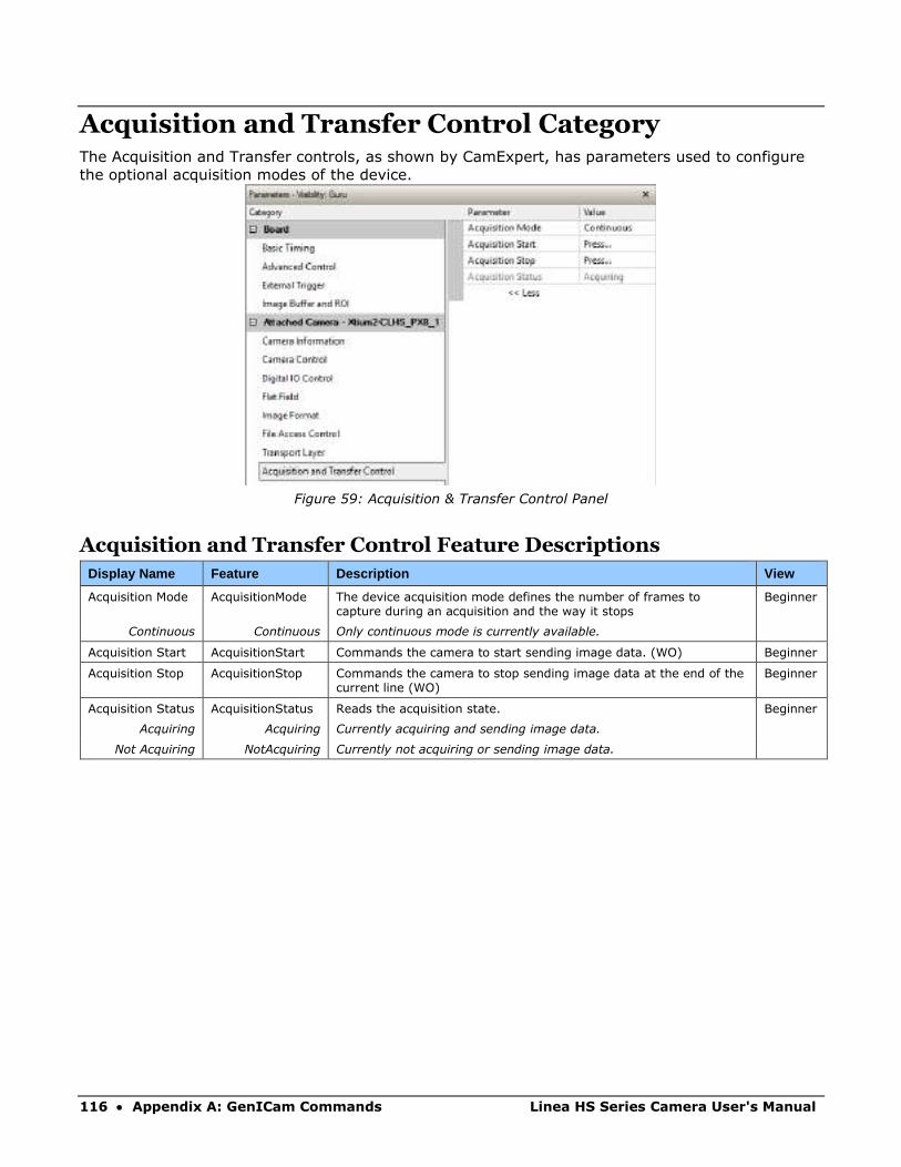
116 • Appendix A: GenICam Commands Linea HS Series Camera User's Manual
Acquisition and Transfer Control Category The Acquisition and Transfer controls, as shown by CamExpert, has parameters used to configure
the optional acquisition modes of the device.
Figure 59: Acquisition & Transfer Control Panel
Acquisition and Transfer Control Feature Descriptions
Display Name Feature Description View
Acquisition Mode AcquisitionMode The device acquisition mode defines the number of frames to capture during an acquisition and the way it stops
Beginner
Continuous Continuous Only continuous mode is currently available.
Acquisition Start AcquisitionStart Commands the camera to start sending image data. (WO) Beginner
Acquisition Stop AcquisitionStop Commands the camera to stop sending image data at the end of the current line (WO)
Beginner
Acquisition Status AcquisitionStatus Reads the acquisition state. Beginner
Acquiring Acquiring Currently acquiring and sending image data.
Not Acquiring NotAcquiring Currently not acquiring or sending image data.

Linea HS Series Camera User's Manual Appendix B: Trouble Shooting Guide • 117
Appendix B: Trouble Shooting Guide
Diagnostic Tools Camera Data File
The camera data file includes the operational configuration and status of the camera
This text file can be downloaded from the camera and forwarded to Teledyne DALSA Technical
Customer support team to aid in diagnosis of any reported issues. See the Saving & Restoring
Camera Setup Configurations section for details on downloading the Camera Data file.
Voltage & Temperature Measurement
The camera can measure the input supply voltage at the power connector and the internal
temperature. Both of these features are accessed using the CamExpert > Camera Information tab.
Press the associated refresh button for a real-time measurement.
Figure 60: CamExpert Voltage & Temperature Features
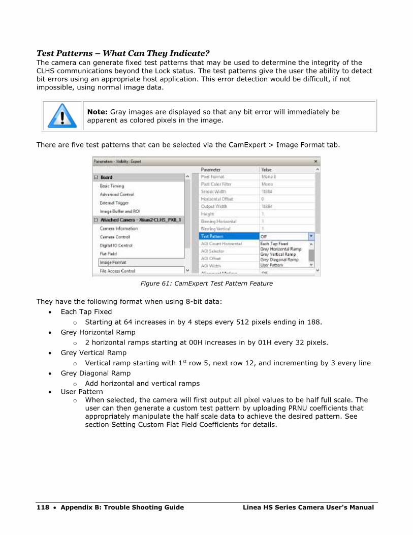
118 • Appendix B: Trouble Shooting Guide Linea HS Series Camera User's Manual
Test Patterns – What Can They Indicate? The camera can generate fixed test patterns that may be used to determine the integrity of the
CLHS communications beyond the Lock status. The test patterns give the user the ability to detect
bit errors using an appropriate host application. This error detection would be difficult, if not
impossible, using normal image data.
Note: Gray images are displayed so that any bit error will immediately be
apparent as colored pixels in the image.
There are five test patterns that can be selected via the CamExpert > Image Format tab.
Figure 61: CamExpert Test Pattern Feature
They have the following format when using 8-bit data:
• Each Tap Fixed
o Starting at 64 increases in by 4 steps every 512 pixels ending in 188.
• Grey Horizontal Ramp
o 2 horizontal ramps starting at 00H increases in by 01H every 32 pixels.
• Grey Vertical Ramp
o Vertical ramp starting with 1st row 5, next row 12, and incrementing by 3 every line
• Grey Diagonal Ramp
o Add horizontal and vertical ramps
• User Pattern
o When selected, the camera will first output all pixel values to be half full scale. The
user can then generate a custom test pattern by uploading PRNU coefficients that
appropriately manipulate the half scale data to achieve the desired pattern. See
section Setting Custom Flat Field Coefficients for details.
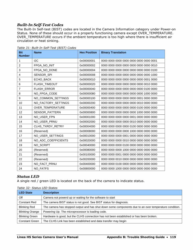
Linea HS Series Camera User's Manual Appendix B: Trouble Shooting Guide • 119
Built-In Self-Test Codes The Built-In Self-test (BIST) codes are located in the Camera Information category under Power-on
Status. None of these should occur in a properly functioning camera except OVER_TEMPERATURE.
OVER_TEMPERATURE occurs if the ambient temperature is too high where there is insufficient air
circulation or heat sinking.
Table 31: Built-In Self-Test (BIST) Codes
Bit Number
Name Hex Position Binary Translation
1 I2C 0x00000001 0000 0000 0000 0000 0000 0000 0000 0001
2 FPGA_NO_INIT 0x00000002 0000 0000 0000 0000 0000 0000 0000 0010
3 FPGA_NO_DONE 0x00000004 0000 0000 0000 0000 0000 0000 0000 0100
4 SENSOR_SPI 0x00000008 0000 0000 0000 0000 0000 0000 0000 1000
5 ECHO_BACK 0x00000010 0000 0000 0000 0000 0000 0000 0001 0000
6 FLASH_TIMEOUT 0x00000020 0000 0000 0000 0000 0000 0000 0010 0000
7 FLASH_ERROR 0x00000040 0000 0000 0000 0000 0000 0000 0100 0000
8 NO_FPGA_CODE 0x00000080 0000 0000 0000 0000 0000 0000 1000 0000
9 NO_COMMON_SETTINGS 0x00000100 0000 0000 0000 0000 0000 0001 0000 0000
10 NO_FACTORY_SETTINGS 0x00000200 0000 0000 0000 0000 0000 0010 0000 0000
11 OVER_TEMPERATURE 0x00000400 0000 0000 0000 0000 0000 0100 0000 0000
12 SENSOR_PATTERN 0x00000800 0000 0000 0000 0000 0000 1000 0000 0000
13 NO_USER_FPN 0x00001000 0000 0000 0000 0000 0001 0000 0000 0000
14 NO_USER_PRNU 0x00002000 0000 0000 0000 0000 0010 0000 0000 0000
15 CLHS_TXRDY_RETRY 0x00004000 0000 0000 0000 0000 0100 0000 0000 0000
16 (Reserved) 0x00008000 0000 0000 0000 0000 1000 0000 0000 0000
17 NO_USER_SETTINGS 0x00010000 0000 0000 0000 0001 0000 0000 0000 0000
18 NO_ADC_COEFFICIENTS 0x00020000 0000 0000 0000 0010 0000 0000 0000 0000
19 NO_SCRIPT 0x00040000 0000 0000 0000 0100 0000 0000 0000 0000
20 (Reserved) 0x00080000 0000 0000 0000 1000 0000 0000 0000 0000
21 (Reserved) 0x00100000 0000 0000 0001 0000 0000 0000 0000 0000
22 (Reserved) 0x00200000 0000 0000 0010 0000 0000 0000 0000 0000
23 NO_FACT_PRNU 0x00400000 0000 0000 0100 0000 0000 0000 0000 0000
24 NO_FATFS 0x00800000 0000 0000 1000 0000 0000 0000 0000 0000
Status LED A single red / green LED is located on the back of the camera to indicate status.
Table 32: Status LED States
LED State Description
Off Camera not powerd up or waiting for the software to start
Constant Red The camera BIST status is not good. See BIST status for diagnosis.
Blinking Red The camera has stopped output and has shut down some components due to an over temperature condition.
Blinking Orange Powering Up. The microprocessor is loading code.
Blinking Green Hardware is good, but the CLHS connection has not been established or has been broken.
Constant Green The CLHS Link has been established and data transfer may begin

120 • Appendix B: Trouble Shooting Guide Linea HS Series Camera User's Manual
Resolving Camera Issues
Communications
No Camera Features when Starting CamExpert
If the camera’s CamExpert is opened and no features are listed, then the camera may be
experiencing lane lock issues.
While using the frame grabber in CamExpert you should be able to see a row of status indicators
below the image display area that indicates the status of the CLHS communications. These
indicators include seven lane lock status and a line valid (LVAL) status.
If the status for one or more lane locks is red, then there is likely an issue with the CLHS
connectors at the camera and / or frame grabber. Ensure that the connectors are fully engaged
and that the jack screws are tightened. Ensure that you are also using the recommended cables.
No LVAL
If the LVAL status is red and all lane locks are green, then there may be an issue with the camera
receiving the encoder pulses.
• From the camera’s CamExpert > Digital I / O Control tab, select Internal Trigger Mode and
set the CamExpert > Camera Control tab Acquisition Line Rate to the maximum that will be
used.
The trigger signal from the frame grabber will not be used and the LVAL status should now be
green. This will confirm the integrity of the image data portion of the CLHS cabling and connectors.
From the camera’s CamExpert > Digital I / O Control tab, select External Trigger Mode.
From the Frame Grabber CamExpert > Advanced tab, select the Line Sync Source to be Internal
Line Trigger and the Internal Line Trigger frequency to the maximum that will be used.
The trigger source is now being generated by the frame grabber and the LVAL status should be
green. This will confirm the integrity of the General Purpose I / O portion of the CLHS cabling and
connectors.
From the Frame Grabber CamExpert > Advanced tab, select the Line Sync Source to be External
Line Trigger and select the Line Trigger Method to Method 2 under the same tab.
From the Frame Grabber CamExpert > External Trigger tab, select External Trigger to be enabled.
If LVAL status turns red, check the following:
a. Is the transport system moving such that encoder pulses are being generated?
b. Has the encoder signal been connected to the correct pins of the I/O connector of the
frame grabber? See the Xtium2-CLHS frame grabber user manual for details.
c. Do the encoder signal levels conform to the requirements outlined in the Xtium2-
CLHS frame grabber user manual?
Linea HS Series Camera User's Manual Appendix B: Trouble Shooting Guide • 121
Image Quality Issues
Vertical Lines Appear in Image after Calibration
The purpose of flat field calibration is to compensate for the lens edge roll-off and imperfections in
the illumination profiles by creating a uniform response. When performing a flat field calibration,
the camera must be imaging a flat white target that is illuminated by the actual lighting used in the
application. Though the camera compensates for illumination imperfection, it will also compensate
for imperfections such as dust, scratches, paper grain, etc. in the white reference. Once the white
reference is removed and the camera images the material to be inspected, any white reference
imperfections will appear as vertical stripes in the image. If the white reference had imperfections
that caused dark features, there will be a bright vertical line during normal imaging. Similarly,
bright features will cause dark lines. It can be very difficult to achieve a perfectly uniform, defect-
free white reference. The following two approaches can help in minimizing the effects of white
reference defects:
• Move the white reference closer to or further away from the object plane such that it is out
of focus. This can be effective if the illumination profile changes minimally when relocating
the white reference.
If the white reference must be located at the object plane, then move the white reference in the
scan direction or sideways when flat field calibration is being performed. The camera averages
several thousand lines when capturing calibration reference images so any small imperfections are
averaged out.
Use the cameras flat field calibration filter feature, as detailed in the Flat Field Calibration Filter
section. This algorithm implements a low pass moving average that covers several adjacent pixels.
This filter can help minimize the effects of minor imperfections in the white reference. Note: this
filter is NOT USED in normal imaging.
Over Time, Pixels Developing Low Response
When flat field calibration is performed using a white reference, as per the guidelines in the user
manual, all pixels should achieve the same response. However, over time dust in the lens
extension tube may migrate to the sensor surface and reduce the response of some pixels.
If the dust particles are small, they may have only a minor effect on responsivity, but still create
vertical dark lines that interfere with defect detection and that need to be corrected.
Because repeating the flat field calibration with a white reference may not be practical while the
camera installed in the system, the camera has a feature where the flat field coefficients can be
downloaded to the host PC and adjusted using a suitable application, such as Microsoft Excel. (See
section Setting Custom Flat Field Coefficients for details.)
If the location of the pixel returning a low response can be identified from the image, then the
correction coefficient of that pixel can be adjusted, saved as a new file, and then uploaded to the
camera; thereby correcting the image without performing a flat field calibration.
See the File Access via the CamExpert Tool for details on downloading and uploading camera files
using CamExpert.
Note: Dust accumulation on the lens will not cause vertical lines. However, a
heavy accumulation of dust on the lens will eventually degrade the camera’s
responsivity and focus quality.
122 • Appendix B: Trouble Shooting Guide Linea HS Series Camera User's Manual
Smeared & Distorted Images
To achieve a well-defined image, the multiple lines are summed together and delayed in a manner
that matches the motion of the image across the sensor.
This synchronization is achieved by sending an external synchronization (EXSYNC) signal to the
camera, where one pulse is generated when the object moves by the size of one object pixel. See
‘External Trigger Mode’ in the user manual.
Any transport motion that is not correctly reflected in the EXSYNC pulses will cause image
distortion in the scan direction. For standard line scan cameras, this type of image distortion may
not greatly affect edge sharpness and small defect contrast; thereby having minimal impact on
defect detection. However, TDI image quality is more sensitive to object motion synchronization
errors.
The following subsections discuss causes of poor image quality resulting from the EXSYNC signal
not accurately reflecting the object motion.
Continuously Smeared, Compressed or Stretched Images
When accurate synchronization is not achieved, the image appears smeared in the scan direction.
If the EXSYNC pulses are coming too fast, then the image will appear smeared and stretched in the
machine direction. If the pulses are too slow, then the image will appear smeared and compressed.
Check the resolution of the encoder used to generate the EXSYNC pulses, along with the size of the
rollers, pulleys, gearing, etc. to ensure that one pulse is generated for one pixel size of travel of
the object.
It is also important that the direction of image travel across the sensor is matched to the camera’s
scan direction, as set by the user. See ‘Scan Direction’ in the user manual for more information.
If the scan direction is incorrect, then the image will have a significant smear and color artifacts in
the scan direction. Changing the scan direction to the opposite direction should resolve this
problem.
Refer to the Camera Orientation section for more information on how to determine the correct
direction orientation for the camera.
Note: The lens has a reversing effect on motion. That is, if an object passes the
lens-outfitted camera from left to right, the image on the sensor will pass from
right to left. The diagrams in the user manual take the lens effect into account.

Linea HS Series Camera User's Manual Appendix B: Trouble Shooting Guide • 123
Randomly Compressed Images It is possible that when the scan speed nears the maximum allowed, based on the exposure time
used, the image will be randomly compressed and possibly smeared for short periods in the scan
direction.
This is indicative of the inspection systems transport mechanism dynamics causing momentary
over-speed conditions. The camera can tolerate very short durations of over-speed, but if it lasts
too long, then the camera can only maintain its maximum line rate, and some EXSYNC pulses will
be ignored, resulting in the occasional compressed image.
The loss EXSYNC due to over-speed may also cause horizontal color artifacts.
Over-speeding may be due to inertia and / or backlash in the mechanical drive mechanism, causing
variations around the target speed.
The greater the speed variation, the lower the target speed needs to be to avoid over-speed
conditions. If the speed variation can be reduced by eliminating the backlash in the transport
mechanism and / or optimizing the motor controller characteristics, then a higher target speed will
be achievable.
Distorted Image when Slowing Down Changing Direction The camera must align the rows in a fashion that accurately follows the object motion.
When the scan direction changes, then the process must reverse to match the reversed image
motion across the sensor.
Only when all rows being accumulated have received the same image will the output be correct.
Prior to this some lines have been exposed to one direction and other lines exposed to the opposite
direction in the accumulated output.
124 • Appendix B: Trouble Shooting Guide Linea HS Series Camera User's Manual
Power Supply Issues For safe and reliable operation, the camera input supply must be +12 V to +24 V DC.
The power supply to the camera should be suitably current limited, as per the applied input
voltage.
Assume a worst-case power consumption of +24 W and a 150% current rating for the breaker or
fuse.
Note: The camera will not start to draw current until the input supply is above
approximately 10.5 V and 200 ms has elapsed. If the power supply stabilizes in
less than 200 ms, then inrush current will not exceed normal operating current.
It is important to consider how much voltage loss occurs in the power supply cabling to the
camera, particularly if the power cable is long and the supply is operating at +12 V where the
current draw is highest.
Reading the input supply voltage as measured by the camera will give an indication of the supply
drop being experienced.
The camera tolerates “hot” unplugging and plugging.
The camera has been designed to protect against accidental application of an incorrect input
supply, up to reasonable limits.
With the following input power issues, the status LED will be OFF:
• The camera will protect against the application of voltages above approximately +28 V. If
the overvoltage protection threshold is exceeded, then power is turned off to the camera’s
internal circuitry. The power supply must be recycled to recover camera operation. The
input protection circuitry is rated up to an absolute maximum of +30 V. Beyond this
voltage, the camera may be damaged.
• The camera will also protect against the accidental application of a reverse input supply up
to a maximum of -30 V. Beyond this voltage, the camera may be damaged.

Linea HS Series Camera User's Manual Appendix B: Trouble Shooting Guide • 125
Causes for Overheating & Power Shut Down For reliable operation, the camera’s face plate temperature should be kept below +65 °C and the
internal temperature kept below +70 °C.
Many applications, such as in clean rooms, cannot tolerate the use of forced air cooling (fans) and
therefore must rely on convection.
The camera’s body has been designed with integrated heat fins to assist with convection cooling.
The fins are sufficient to keep the camera at an acceptable temperature if convection flow is
unimpeded.
The camera also benefits from conducting heat away from the body via the face plate into the lens
extension tubes and camera mount. It is therefore important not to restrict convection airflow
around the camera body, especially the fins and the lens assembly and camera mount. Lowering
the ambient temperature will equally lower the camera’s temperature.
If the camera’s internal temperature exceeds +80 °C, then the camera will partially shut down to
protect itself against damage.
Commands can still be sent to the camera to read the temperature, but the image sensor will not
be operational and LVAL in response to line triggers will not be generated.
Additionally, the camera’s power will reduce to approximately 70% of normal operation. If the
camera’s temperature continues to rise, at +90 °C the camera will further reduce it power to
approximately 30% of normal operation and any communication with the camera will not be
possible.
The only means to recover from a thermal shutdown is to turn the camera’s power off. Once the
camera has cooled down, the camera data can be restored by reapplying power to the camera.

126 • Declarations of Conformity Linea HS Series Camera User's Manual
Declarations of Conformity Copies of the Declarations of Conformity documents are available on the product page on the
Teledyne DALSA website or by request.
FCC Statement of Conformance This equipment complies with Part 15 of the FCC rules. Operation is subject to the following
conditions:
1. The product may not cause harmful interference; and
2. The product must accept any interference received, including interference that may cause
undesired operation.
FCC Class A Product
This equipment has been tested and found to comply with the limits for a Class A digital device,
pursuant to part 15 of the FCC Rules. These limits are designed to provide reasonable protection
against harmful interference when the equipment is operated in a commercial environment. This
equipment generates, uses, and can radiate radio frequency energy and, if not installed and used
in accordance with the instruction manual, may cause harmful interference to radio
communications. Operation of this equipment in a residential area is likely to cause harmful
interference in which case the user will be required to correct the interference at his own expense.
Changes or modifications not expressly approved by the party responsible for compliance could void
the user's authority to operate the equipment.
This equipment is intended to be a component of a larger industrial system.
CE and UKCA Declaration of Conformity Teledyne DALSA declares that this product complies with applicable standards and regulations.
Changes or modifications not expressly approved by the party responsible for compliance could void
the user's authority to operate the equipment.
This product is intended to be a component of a larger system and must be installed as per
instructions to ensure compliance.
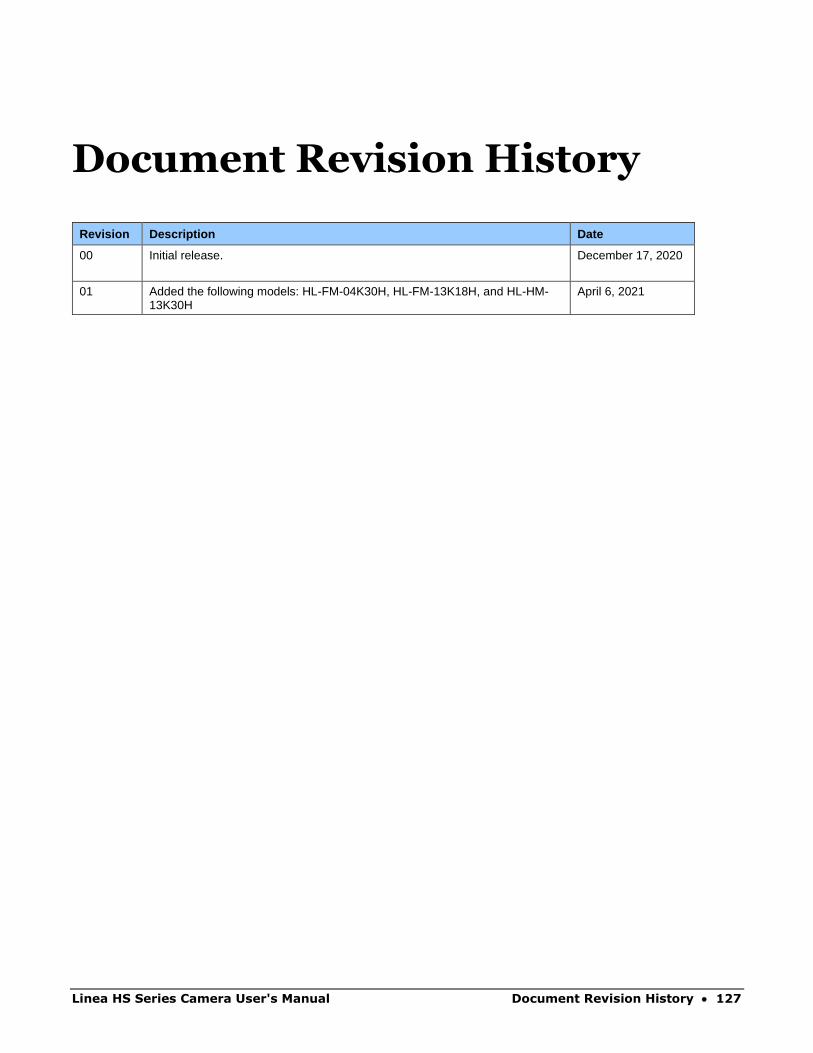
Linea HS Series Camera User's Manual Document Revision History • 127
Document Revision History
Revision Description Date
00 Initial release. December 17, 2020
01 Added the following models: HL-FM-04K30H, HL-FM-13K18H, and HL-HM-13K30H
April 6, 2021
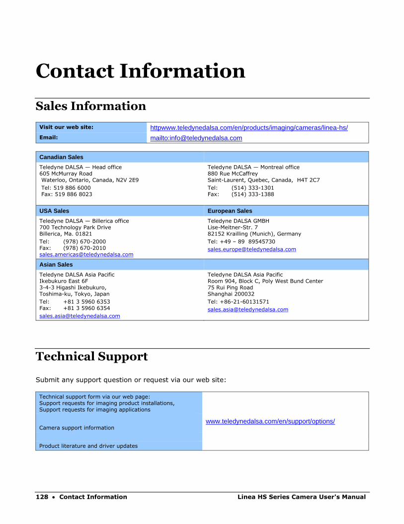
128 • Contact Information Linea HS Series Camera User's Manual
Contact Information
Sales Information
Visit our web site: httpwww.teledynedalsa.com/en/products/imaging/cameras/linea-hs/ Email: mailto:[email protected]
Canadian Sales
Teledyne DALSA — Head office 605 McMurray Road Waterloo, Ontario, Canada, N2V 2E9
Tel: 519 886 6000 Fax: 519 886 8023
Teledyne DALSA — Montreal office 880 Rue McCaffrey Saint-Laurent, Quebec, Canada, H4T 2C7
Tel: (514) 333-1301 Fax: (514) 333-1388
USA Sales European Sales
Teledyne DALSA — Billerica office 700 Technology Park Drive Billerica, Ma. 01821
Tel: (978) 670-2000 Fax: (978) 670-2010 [email protected]
Teledyne DALSA GMBH Lise-Meitner-Str. 7 82152 Krailling (Munich), Germany
Tel: +49 – 89 89545730
Asian Sales
Teledyne DALSA Asia Pacific Ikebukuro East 6F 3-4-3 Higashi Ikebukuro, Toshima-ku, Tokyo, Japan
Tel: +81 3 5960 6353 Fax: +81 3 5960 6354
Teledyne DALSA Asia Pacific Room 904, Block C, Poly West Bund Center 75 Rui Ping Road Shanghai 200032
Tel: +86-21-60131571
Technical Support
Submit any support question or request via our web site:
Technical support form via our web page: Support requests for imaging product installations, Support requests for imaging applications
www.teledynedalsa.com/en/support/options/
Camera support information
Product literature and driver updates
Copyright © 2022 FDOKUMEN