WBTP and SOX Scrubber Retrofit Presentation sname
49
Engineering Excellence for your Business 22 ND February 2018, Athens Greece
-
Upload
khangminh22 -
Category
Documents
-
view
6 -
download
0
Transcript of WBTP and SOX Scrubber Retrofit Presentation sname

Engineering Excellencefor your Business
22ND February 2018, Athens Greece

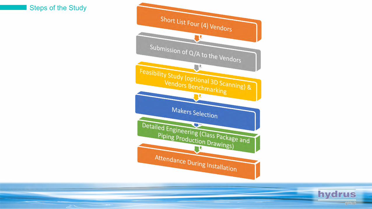
Steps of the Study
1 Week
Initiation of the project Maker of BWTS has been selected
For Sele
ction of B
WTS Mak
er
2-3 Weeks

Feasibility Study
1 Week
Duration 2-3 Weeks
Maker 1 Maker 2
One final selected Maker or Short list of two Makers
On-Board Inspection
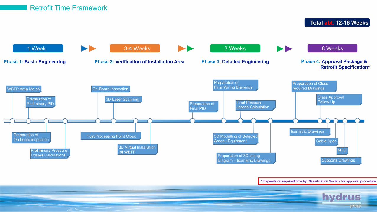
Retrofit Time Framework
Phase 1: Basic Engineering
1 Week 3-4 Weeks 3 Weeks 8 Weeks
Phase 2: Verification of Installation Area Phase 3: Detailed Engineering Phase 4: Approval Package &Retrofit Specification*
WBTP Area Match
Preparation of On-board inspection
Preparation of Preliminary PID
Preliminary Pressure Losses Calculations
3D Laser Scanning
Post Processing Point Cloud
3D Virtual Installationof WBTP
Preparation of Final PID
Preparation of Final Wiring Drawings
Final Pressure Losses Calculation
3D Modelling of SelectedAreas - Equipment
Preparation of 3D piping Diagram – Isometric Drawings
Preparation of Class required Drawings
Class Approval Follow Up
Isometric Drawings
MTO
Cable Spec
Supports Drawings
* Depends on required time by Classification Society for approval procedure
Total abt. 12-16 Weeks

The Study
LIABILITY
Maker??Engineering Company??Shipyard??
RETROFIT STUDY
CONSULTING COMPANY TECHNICAL DEPARTMENT OF OWNERSMAKER
Turn Key SolutionMay Absorb the Cost of the Engineering Study
Appoint the study to a Consultant
CONS. COMPANY 1 CONS. COMPANY 3 CONS. COMPANY 2
SHIPYARD

Phase 1 – Basic Engineering
• Engine Room Arrangement• Steering Gear Arrangement• General Arrangement• Pump Room Arrangement• Engine Casing Arrangement• Available Plot Plans
• PID of Ballast System E/R and Hull Part• PID of Bilge System• PID of Compressed Air, Fresh/Sea Water System• Available Piping Arrangement Drawings
Required Data By the COMPANY Model of WBTP will be selected 1
Arrangement and Piping Drawings from 82k DWT Bulk Carrier
1x Ballast Pumps Capacity (One Common Syst.)2x Ballast Pump Capacity (One Common Syst.)1x BWTP for each Pump

Phase 1 – Basic Engineering
Possible Area of Installation of WBTP will be marked Arrangement Drawings will be updated in line with WBTP Equipment layout(s)
2
2x1000m3/h WBP
FilterTRO-N Unit
TRO Sampling Unit
C2E Units
Preliminary PID of Ballast/Bilge3
Preliminary Pressure Losses Calculation for Ballast System4
• Ballast Pipe Pressure Losses• Ballasting and De-ballasting
Rates
Filter
C2E Units
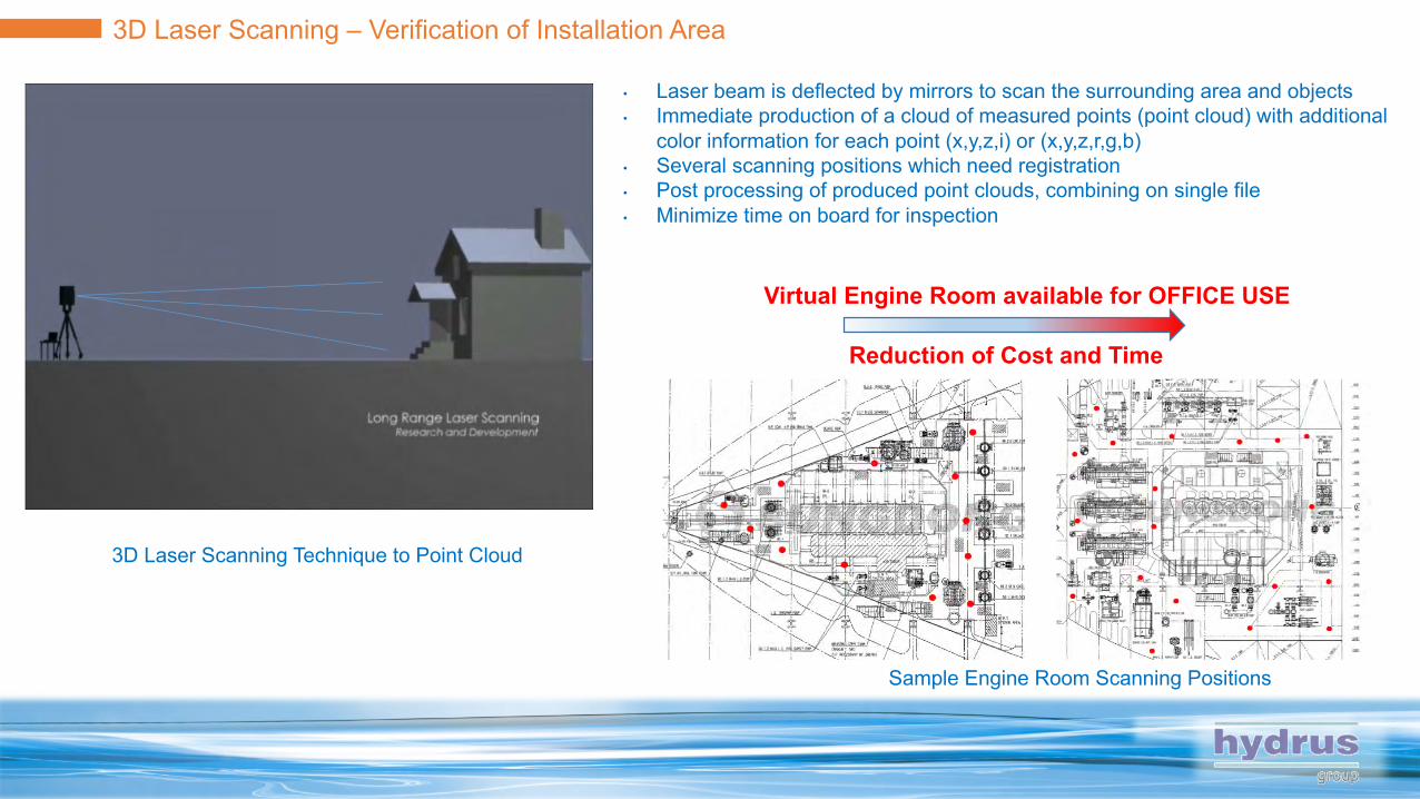
3D Laser Scanning Technique to Point Cloud
3D Laser Scanning – Verification of Installation Area
Sample Engine Room Scanning Positions
• Laser beam is deflected by mirrors to scan the surrounding area and objects• Immediate production of a cloud of measured points (point cloud) with additional
color information for each point (x,y,z,i) or (x,y,z,r,g,b)• Several scanning positions which need registration• Post processing of produced point clouds, combining on single file• Minimize time on board for inspection
Virtual Engine Room available for OFFICE USE
Reduction of Cost and Time
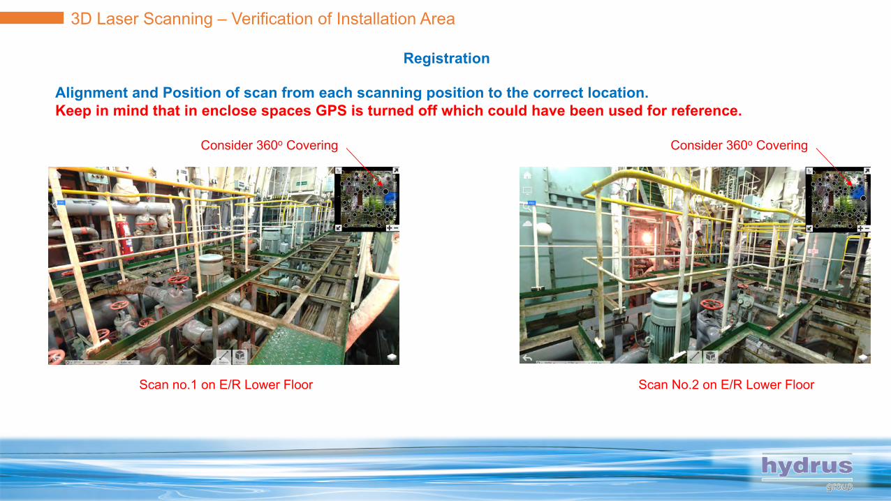
3D Laser Scanning – Verification of Installation Area
Registration
Scan no.1 on E/R Lower Floor Scan No.2 on E/R Lower Floor
Consider 360o Covering Consider 360o Covering
Alignment and Position of scan from each scanning position to the correct location. Keep in mind that in enclose spaces GPS is turned off which could have been used for reference.
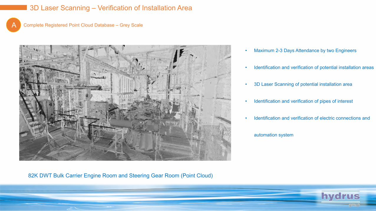
82K DWT Bulk Carrier Engine Room and Steering Gear Room (Point Cloud)
Complete Registered Point Cloud Database – Grey ScaleA
3D Laser Scanning – Verification of Installation Area
• Maximum 2-3 Days Attendance by two Engineers
• Identification and verification of potential installation areas
• 3D Laser Scanning of potential installation area
• Identification and verification of pipes of interest
• Identification and verification of electric connections and
automation system

115K DWT Tankers Pump Room(Point Cloud)
Complete Registered Point Cloud Database – ColoredB
3D Laser Scanning – Verification of Installation Area
• Maximum 2-3 Days Attendance by two Engineers
• Identification and verification of potential installation areas
• 3D Laser Scanning of potential installation area
• Identification and verification of pipes of interest
• Identification and verification of electric connections and
automation system
3D Laser Scanner by and
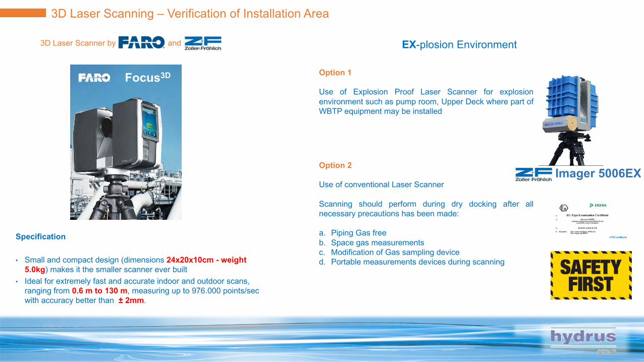
3D Laser Scanning – Verification of Installation Area
Specification
• Small and compact design (dimensions 24x20x10cm - weight5.0kg) makes it the smaller scanner ever built
• Ideal for extremely fast and accurate indoor and outdoor scans, ranging from 0.6 m to 130 m, measuring up to 976.000 points/secwith accuracy better than ± 2mm.
EX-plosion Environment
Focus3D
Imager 5006EX
Option 1
Use of Explosion Proof Laser Scanner for explosionenvironment such as pump room, Upper Deck where part ofWBTP equipment may be installed
Option 2
Use of conventional Laser Scanner
Scanning should perform during dry docking after allnecessary precautions has been made:
a. Piping Gas freeb. Space gas measurementsc. Modification of Gas sampling deviced. Portable measurements devices during scanning
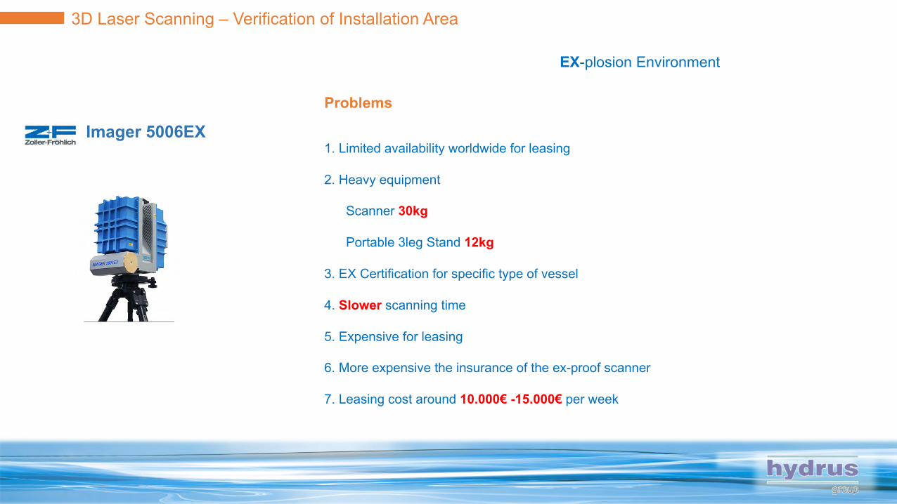
3D Laser Scanning – Verification of Installation Area
EX-plosion Environment
Focus3D
Imager 5006EXProblems
1. Limited availability worldwide for leasing
2. Heavy equipment
Scanner 30kg
Portable 3leg Stand 12kg
3. EX Certification for specific type of vessel
4. Slower scanning time
5. Expensive for leasing
6. More expensive the insurance of the ex-proof scanner
7. Leasing cost around 10.000€ -15.000€ per week
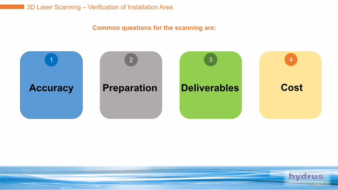
3D Laser Scanning – Verification of Installation Area
Common questions for the scanning are:
Accuracy Preparation CostDeliverables
1 2 3 4

3D Laser Scanning – Verification of Installation Area
Accuracy (of What????)
Accuracy of the scanning2/3mm @ 100m
Actually less than 1mm inside E/R or Pump Room
Accuracy of the registration2/3mm from scan position to scan position
Depends on the
post processing software
the operator of the scanner during scanning
post processing engineer expertise
Accuracy of the measurementDepends on the registration and on the operator of the viewer
Hint: Always request together the point cloud deliverable and the
report of the post processing software at the end of the
registration. Whatever is less than 2/3mm in 3-axis and more than
0.1o-0.5o angle is unacceptable
12
3
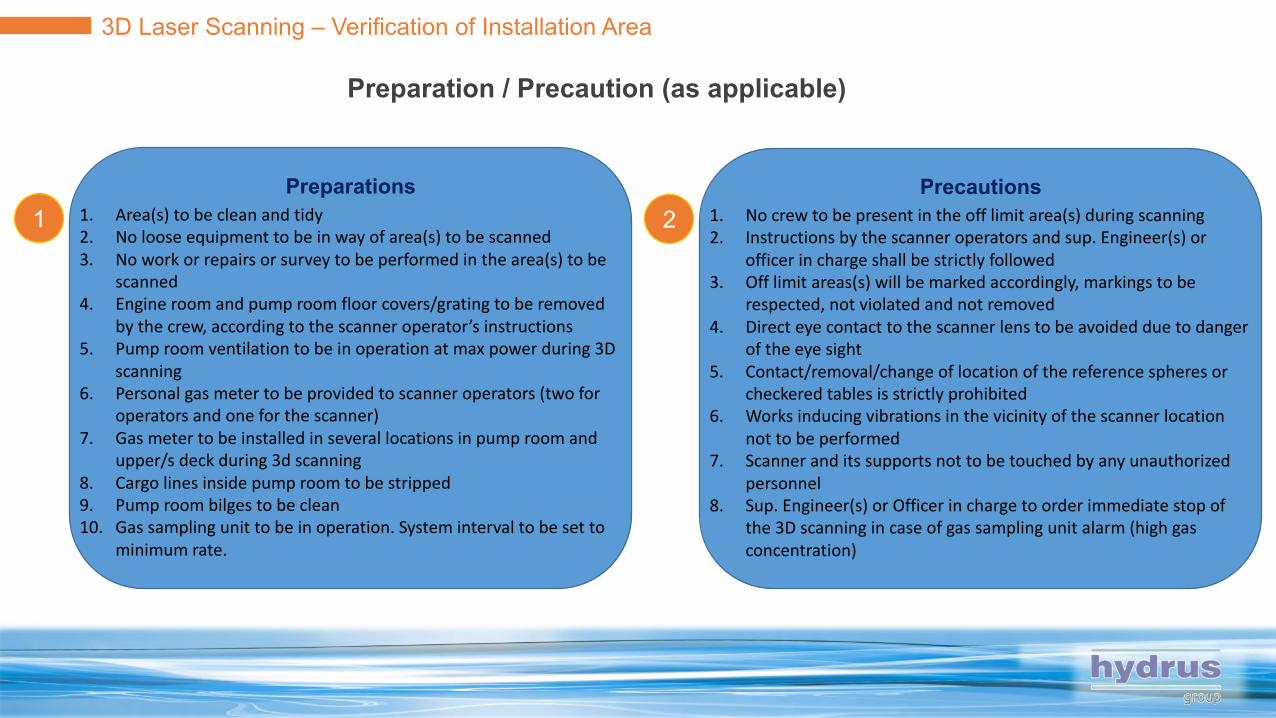
3D Laser Scanning – Verification of Installation Area
Preparation / Precaution (as applicable)
Preparations1. Area(s) to be clean and tidy2. No loose equipment to be in way of area(s) to be scanned3. No work or repairs or survey to be performed in the area(s) to be
scanned4. Engine room and pump room floor covers/grating to be removed
by the crew, according to the scanner operator’s instructions5. Pump room ventilation to be in operation at max power during 3D
scanning6. Personal gas meter to be provided to scanner operators (two for
operators and one for the scanner)7. Gas meter to be installed in several locations in pump room and
upper/s deck during 3d scanning 8. Cargo lines inside pump room to be stripped9. Pump room bilges to be clean10. Gas sampling unit to be in operation. System interval to be set to
minimum rate.
1Precautions
1. No crew to be present in the off limit area(s) during scanning2. Instructions by the scanner operators and sup. Engineer(s) or
officer in charge shall be strictly followed3. Off limit areas(s) will be marked accordingly, markings to be
respected, not violated and not removed4. Direct eye contact to the scanner lens to be avoided due to danger
of the eye sight5. Contact/removal/change of location of the reference spheres or
checkered tables is strictly prohibited6. Works inducing vibrations in the vicinity of the scanner location
not to be performed7. Scanner and its supports not to be touched by any unauthorized
personnel 8. Sup. Engineer(s) or Officer in charge to order immediate stop of
the 3D scanning in case of gas sampling unit alarm (high gas concentration)
2
3D Laser Scanning – Verification of Installation Area
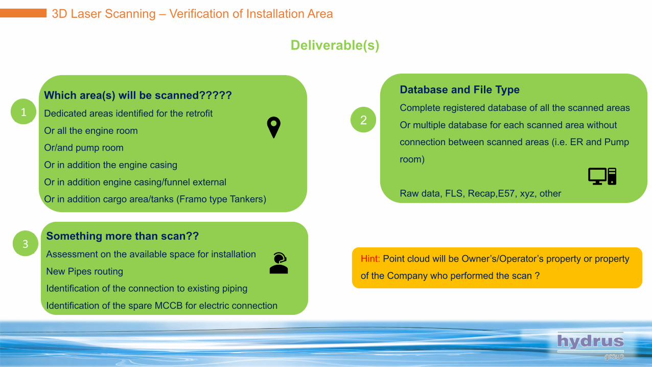
Deliverable(s)
Which area(s) will be scanned?????Dedicated areas identified for the retrofit
Or all the engine room
Or/and pump room
Or in addition the engine casing
Or in addition engine casing/funnel external
Or in addition cargo area/tanks (Framo type Tankers)
Database and File TypeComplete registered database of all the scanned areas
Or multiple database for each scanned area without
connection between scanned areas (i.e. ER and Pump
room)
Raw data, FLS, Recap,E57, xyz, other
Something more than scan??Assessment on the available space for installation
New Pipes routing
Identification of the connection to existing piping
Identification of the spare MCCB for electric connection
Hint: Point cloud will be Owner’s/Operator’s property or property
of the Company who performed the scan ?
12
3

3D Laser Scanning – Verification of Installation Area
COST (for non Ex proof??)
Define what you pay forFor the Scanning
For the Scanning and the Post Processing
For Scanning and the Post Processing in which file format
For Scanning and the Post Processing and the report of the scanning
1000$ block
fee per vessel
6500$-8000$
block fee per
vessel
400-1000$ / (day and operator)
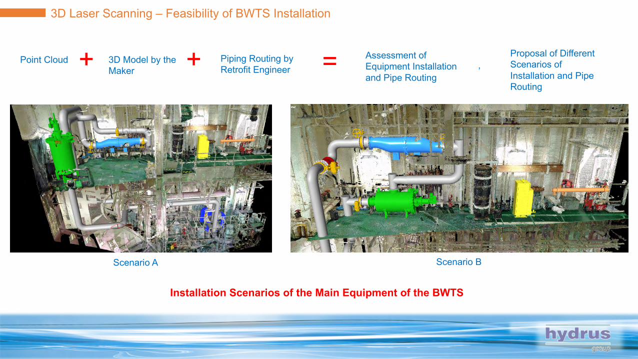
3D Laser Scanning – Feasibility of BWTS Installation
Point Cloud 3D Model by the Maker
Piping Routing by Retrofit Engineer+ + = Assessment of
Equipment Installation and Pipe Routing
Proposal of Different Scenarios of Installation and Pipe Routing
,
Scenario A Scenario B
Installation Scenarios of the Main Equipment of the BWTS

3D Laser Scanning – Feasibility of BWTS Installation
Point Cloud 3D Model by the Maker
Piping Routing by Retrofit Engineer+ + = Assessment of
Equipment Installation and Pipe Routing
Proposal of Different Scenarios of Installation and Pipe Routing
,
Scenario A Scenario BRouting Scenarios of the Main Pipes

3D Laser Scanning – Feasibility of BWTS Installation
Point Cloud 3D Model by the Maker
Piping Routing by Retrofit Engineer+ + = Assessment of
Equipment Installation and Pipe Routing
Proposal of Different Scenarios of Installation and Pipe Routing
,
Scenario A Scenario BMaintenance Space Consideration
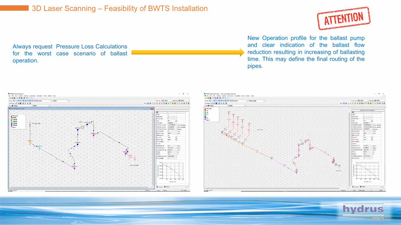
3D Laser Scanning – Feasibility of BWTS Installation
Always request Pressure Loss Calculationsfor the worst case scenario of ballastoperation.
New Operation profile for the ballast pumpand clear indication of the ballast flowreduction resulting in increasing of ballastingtime. This may define the final routing of thepipes.

Phase 3 – Detailed Engineering
1
Class
Drawings
Revision
Calculations 3D Modeling
1 2 3 4

Phase 3 – Detailed Engineering
1Class Drawing Revision1
Final Drawings (Depends on Classification Society Requirements)
• Revised Diagram of Ballast System
• Revised Diagram of Bilge System
• Revised Wiring Diagram of Power System
• Revised Wiring Diagram of Alarm System
• Equipment Supports Structural Drawings
• Machinery Arrangement / Pump Rom Arrangement
• Arrangement of Electrical Equipment
• Ballast Management Plan
Tricky Part
• Response time of Makers for submitting the general drawings
• Piping System Drawings may be changed due to actual arrangement of the
valves and Pipes
• Operation of the ballasting System should not interfere by the installation of
the new equipment
• Specification of the valves and pipes on specific spool pieces should be re-
assessed for hydraulic shock and for the design pressure rating
• Existing valves and pumps/equipment should be safeguarded by the
increased pressure
• Auxiliary equipment of BWTS have special arrangement requirements
• Corrosion of pipes and Spool Piece
• APT ballasting
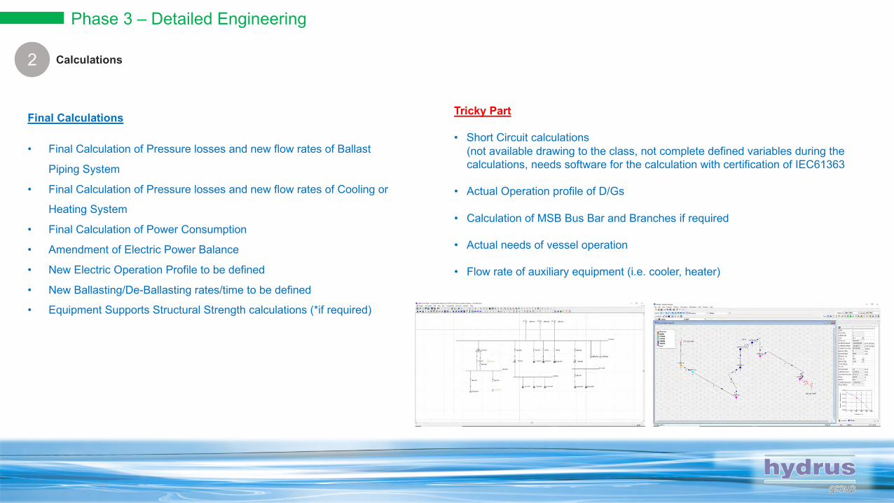
Phase 3 – Detailed Engineering
1Calculations2
Final Calculations
• Final Calculation of Pressure losses and new flow rates of Ballast
Piping System
• Final Calculation of Pressure losses and new flow rates of Cooling or
Heating System
• Final Calculation of Power Consumption
• Amendment of Electric Power Balance
• New Electric Operation Profile to be defined
• New Ballasting/De-Ballasting rates/time to be defined
• Equipment Supports Structural Strength calculations (*if required)
Tricky Part
• Short Circuit calculations (not available drawing to the class, not complete defined variables during the calculations, needs software for the calculation with certification of IEC61363
• Actual Operation profile of D/Gs
• Calculation of MSB Bus Bar and Branches if required
• Actual needs of vessel operation
• Flow rate of auxiliary equipment (i.e. cooler, heater)
Phase 3 – Detailed Engineering
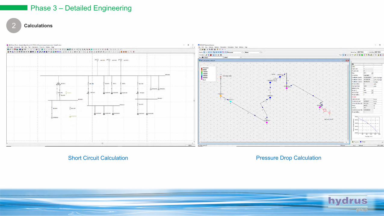
1Calculations2
Short Circuit Calculation Pressure Drop Calculation
Phase 3 – Detailed Engineering
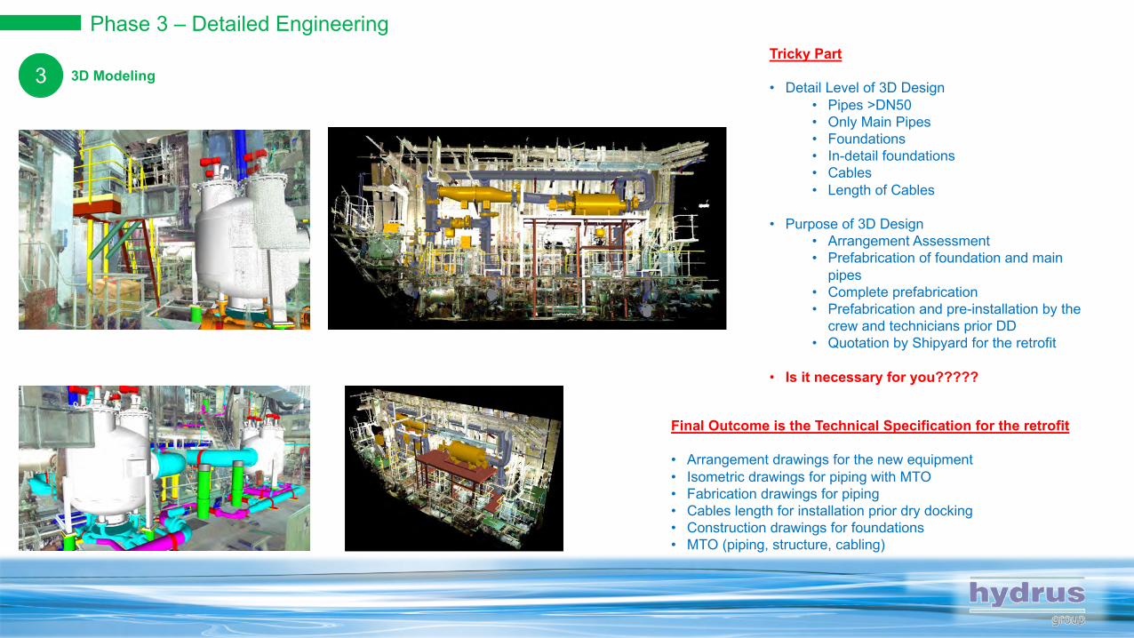
13D Modeling3Tricky Part
• Detail Level of 3D Design• Pipes >DN50 • Only Main Pipes• Foundations• In-detail foundations• Cables• Length of Cables
• Purpose of 3D Design• Arrangement Assessment• Prefabrication of foundation and main
pipes• Complete prefabrication• Prefabrication and pre-installation by the
crew and technicians prior DD• Quotation by Shipyard for the retrofit
• Is it necessary for you?????
Final Outcome is the Technical Specification for the retrofit
• Arrangement drawings for the new equipment• Isometric drawings for piping with MTO• Fabrication drawings for piping• Cables length for installation prior dry docking• Construction drawings for foundations• MTO (piping, structure, cabling)
Phase 3 – Detailed Engineering
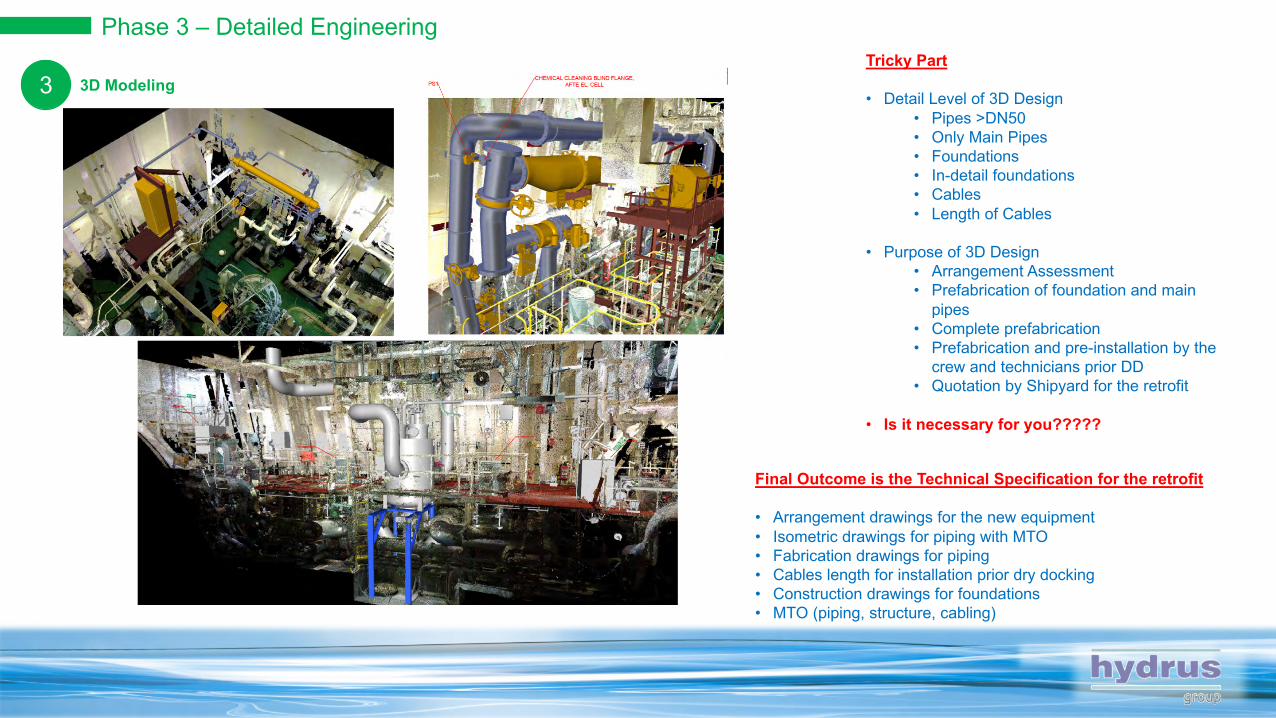
13D Modeling3Tricky Part
• Detail Level of 3D Design• Pipes >DN50 • Only Main Pipes• Foundations• In-detail foundations• Cables• Length of Cables
• Purpose of 3D Design• Arrangement Assessment• Prefabrication of foundation and main
pipes• Complete prefabrication• Prefabrication and pre-installation by the
crew and technicians prior DD• Quotation by Shipyard for the retrofit
• Is it necessary for you?????
Final Outcome is the Technical Specification for the retrofit
• Arrangement drawings for the new equipment• Isometric drawings for piping with MTO• Fabrication drawings for piping• Cables length for installation prior dry docking• Construction drawings for foundations• MTO (piping, structure, cabling)

Phase 3 – Detailed Engineering
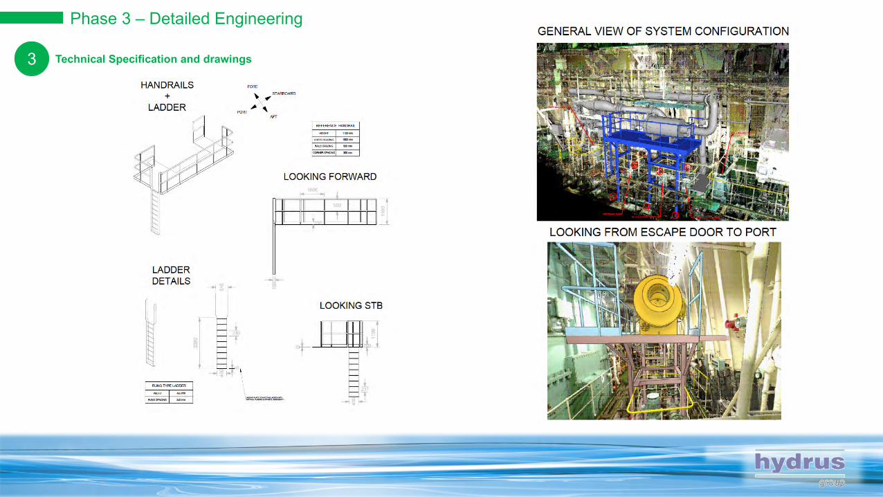
1Technical Specification and drawings3
Phase 3 – Detailed Engineering
1Technical Specification and drawings3

Phase 3 – Detailed Engineering
1Technical Specification and drawings3
Assembly Drawing Connection(s) Drawing

Phase 3 – Detailed Engineering
1Technical Specification and drawings3
Tricky Part
• Spool Pieces• Final adjustment on board (field weld for flanges, extra length)• Pipe fitting compatible with selected shipyard and Maker
Isometric Drawing with MTO Fabrication Drawing
Phase 3 – Detailed Engineering
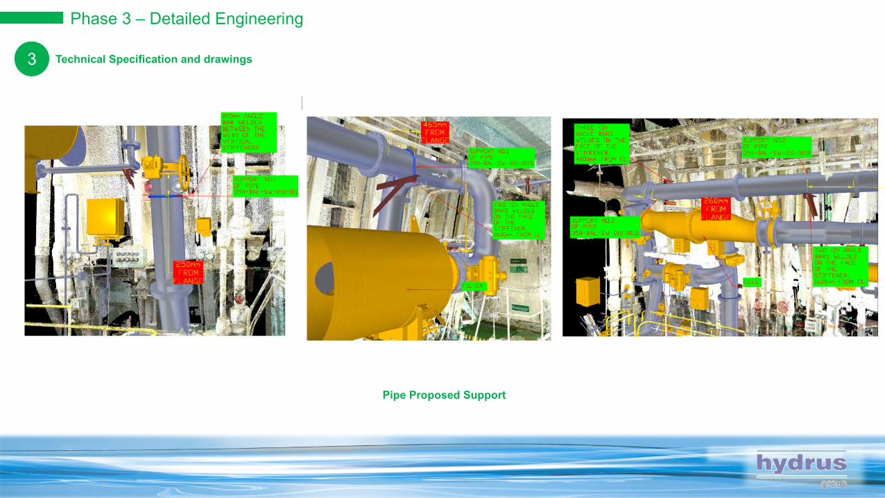
1Technical Specification and drawings3
Pipe Proposed Support
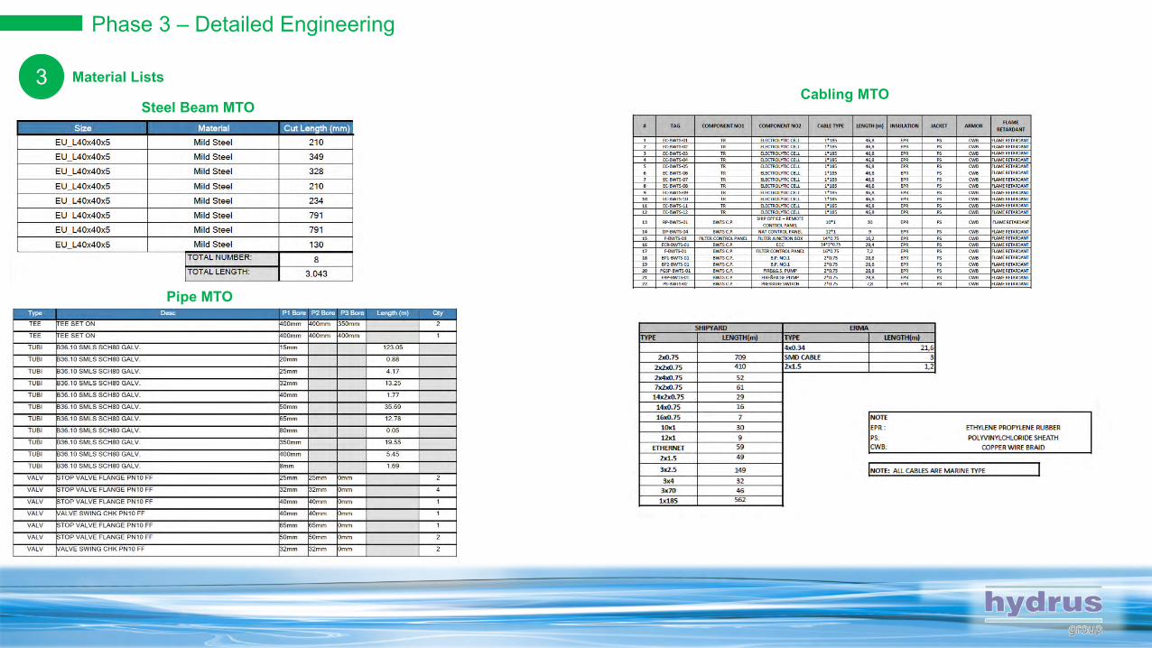
Phase 3 – Detailed Engineering
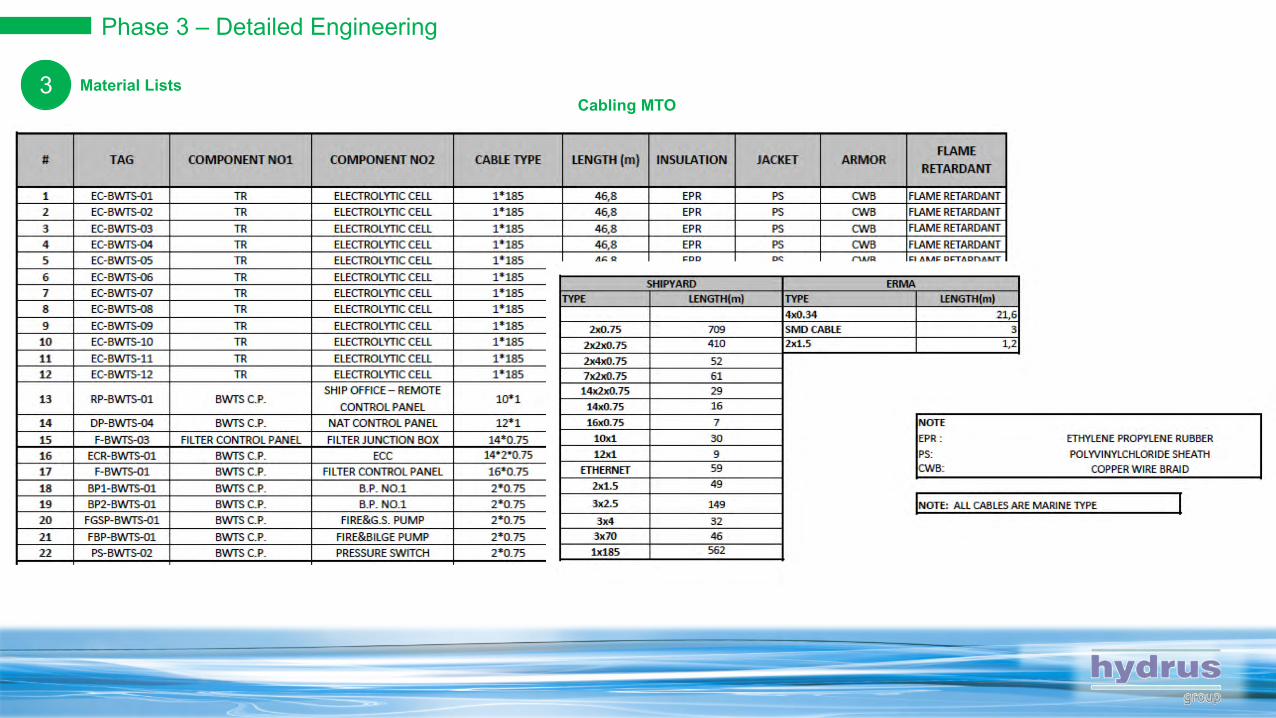
1Material Lists3
Pipe MTO
Steel Beam MTOCabling MTO
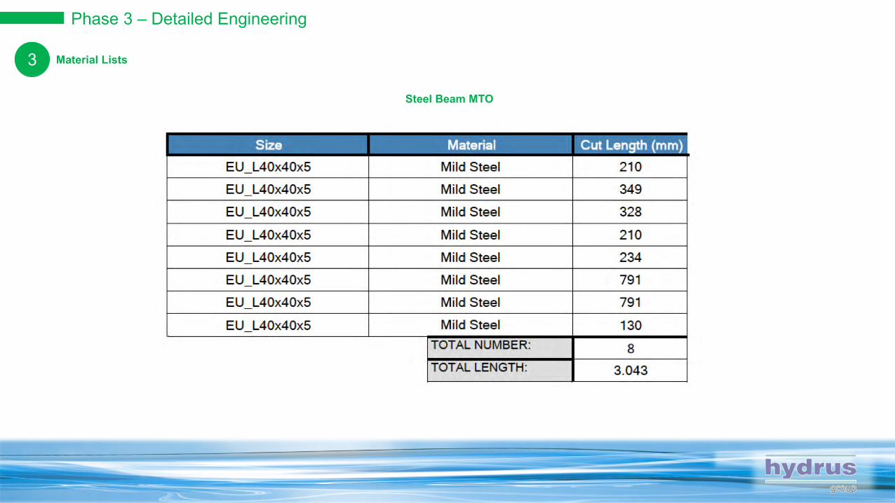
Phase 3 – Detailed Engineering
1Material Lists3
Steel Beam MTO
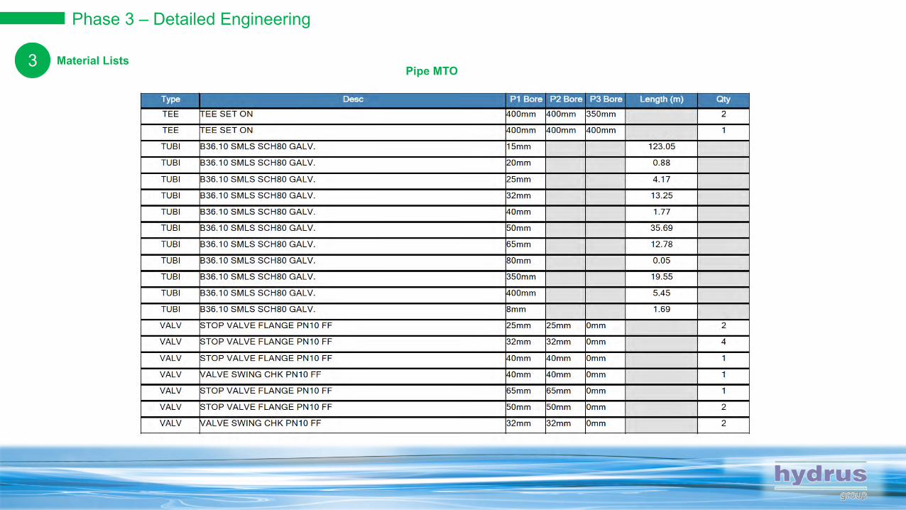
Phase 3 – Detailed Engineering
1Material Lists3Pipe MTO
Phase 3 – Detailed Engineering
1Material Lists3Cabling MTO
1 Week
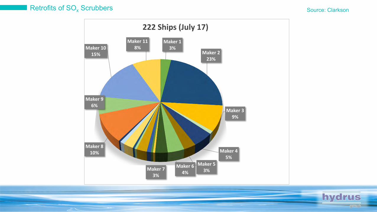
Retrofits of SOx Scrubbers Source: Clarkson
Maker 13%
Maker 223%
Maker 39%
Maker 45%
Maker 53%
Maker 64%Maker 7
3%
Maker 810%
Maker 96%
Maker 1015%
Maker 118%
222 Ships (July 17)

1 Week
New Orders with SOx Scrubber Source: Clarkson
Maker 110% Maker 2
3%
Maker 33%
Maker 41%
Maker 549%
Maker 63%
Maker 711%
Maker 811%
Maker 99%
75 SHIPS (JULY 17)
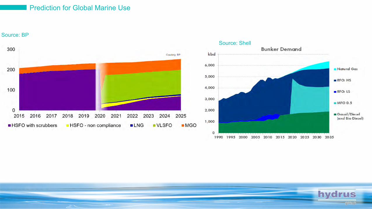
Prediction for Global Marine Use
1 Week
Source: BPSource: Shell
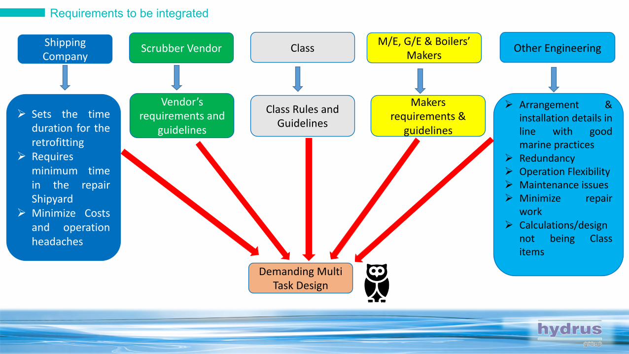
Requirements to be integrated
1 Week
Shipping Company
Scrubber Vendor ClassM/E, G/E & Boilers’
Makers
Demanding Multi Task Design
Vendor’s requirements and
guidelines
Other Engineering
Class Rules and Guidelines
Makers requirements &
guidelines
Ø Arrangement &installation details inline with goodmarine practices
Ø RedundancyØ Operation FlexibilityØ Maintenance issuesØ Minimize repair
workØ Calculations/design
not being Classitems
Ø Sets the timeduration for theretrofitting
Ø Requiresminimum timein the repairShipyard
Ø Minimize Costsand operationheadaches
Steps of the Study
1 Week

Keep in mind
1 WeekØ Shipping Company should define the design Exhaust Gas flow (kg/hr), Exhaust Gas inlet temperature, SW alkalinity and temperature.
Ø Maximum design temperature to be defined and cover with sufficient margin the actual most demanding case (i.e. G/Es at low loads during Tropical Conditions)
Ø Clearly indicate compliance with vessel’s Class Rules. It is highly recommended to assess Vendor’s offered scope of supply with Class Rules prior to confirming order. In case of non compliance in an aspect, operation restrictions could be required and/or additional equipment/cost.
Ø In case of Dry Running, the unrestricted duration of dry running and the maximum allowable exhaust gas temperature should be defined.
Ø Auxiliaries’ Specification (e.g. Dampers, valves, pumps) to be assessedØ Guarantee terms should be assessed. Guarantee based on running hours to be requested.Ø In case of Boiler(s) connection, special consideration together with Boiler’s Maker should be given in respect
to the back pressure. In-line forced fan shall be required in case of retrofitting projects.Ø In case of Auxiliary Boiler(s) connection, special consideration should be given in respect to the IGS
operation.
Offered Technical Specification
Keep in mind
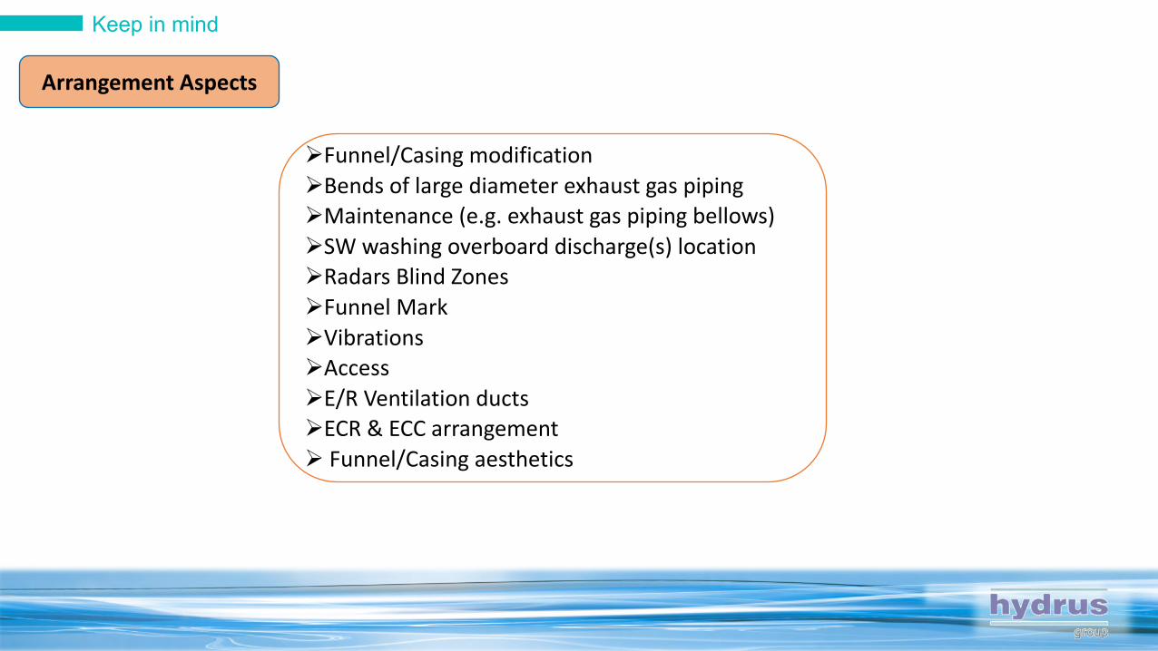
1 Week ØFunnel/Casing modificationØBends of large diameter exhaust gas piping ØMaintenance (e.g. exhaust gas piping bellows)ØSW washing overboard discharge(s) locationØRadars Blind ZonesØFunnel MarkØVibrationsØAccessØE/R Ventilation ductsØECR & ECC arrangementØ Funnel/Casing aesthetics
Arrangement Aspects
Keep in mind
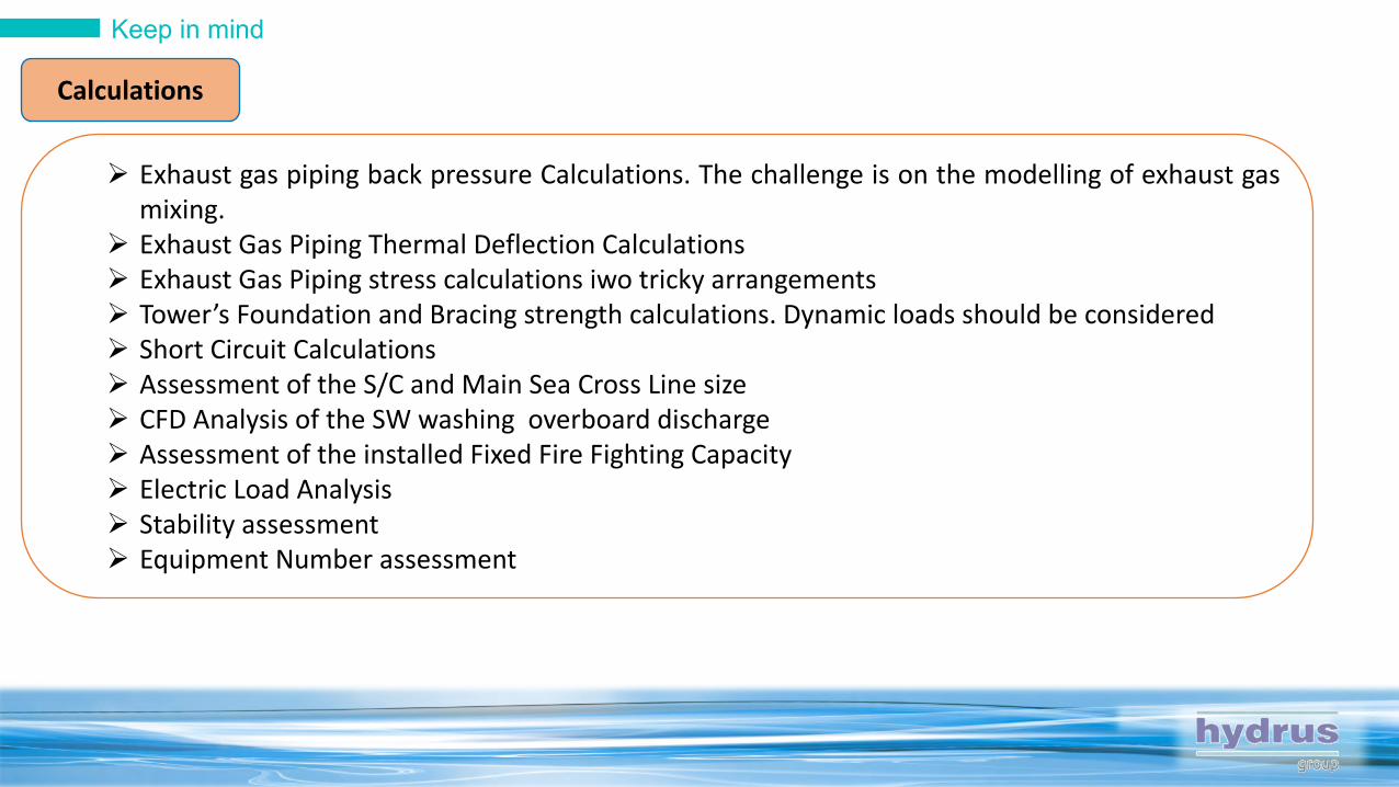
1 WeekØ Exhaust gas piping back pressure Calculations. The challenge is on the modelling of exhaust gasmixing.
Ø Exhaust Gas Piping Thermal Deflection CalculationsØ Exhaust Gas Piping stress calculations iwo tricky arrangementsØ Tower’s Foundation and Bracing strength calculations. Dynamic loads should be consideredØ Short Circuit CalculationsØ Assessment of the S/C and Main Sea Cross Line sizeØ CFD Analysis of the SW washing overboard dischargeØ Assessment of the installed Fixed Fire Fighting CapacityØ Electric Load AnalysisØ Stability assessmentØ Equipment Number assessment
Calculations

Keep in mind
1 WeekØ In case of In-Line scrubber the necessity of the exhaust gas by-passØ Redundancy Issues (e.g. 1x100% SW Washing pump or 2x100% SW Washing pumps)Ø Approval of Vendors DrawingsØ Safety issues in respect to M/E, G/Es & Boilers OperationØ Inducing operation restrictions by the Class should be avoidedØ E/R Unmanned Operation (i.e. interface with AMS)Ø Safety Devices and Alarm DevicesØ Class should define the Rules’ Edition that is applicable for the SOx Scrubber
Retrofitting.
Class Aspects

Keep in mind
1 WeekØ Makers, Class, Shipyard & Shipping company are involved. Tests’
Scheme should be prepared and mutually agreed well in advanceØ M/E, G/Es & Boilers’ transient operation profiles should be checkedØ Tests with the vessel chartered may be required. Ø HFO with 3.5% sulphur should be availableØ Exhaust gas back pressure measurements should be carried out in line
with M/E Makers GuidelinesØ SW water temperature and alkalinity to be close to the design values
On Board Testing
Keep in mind
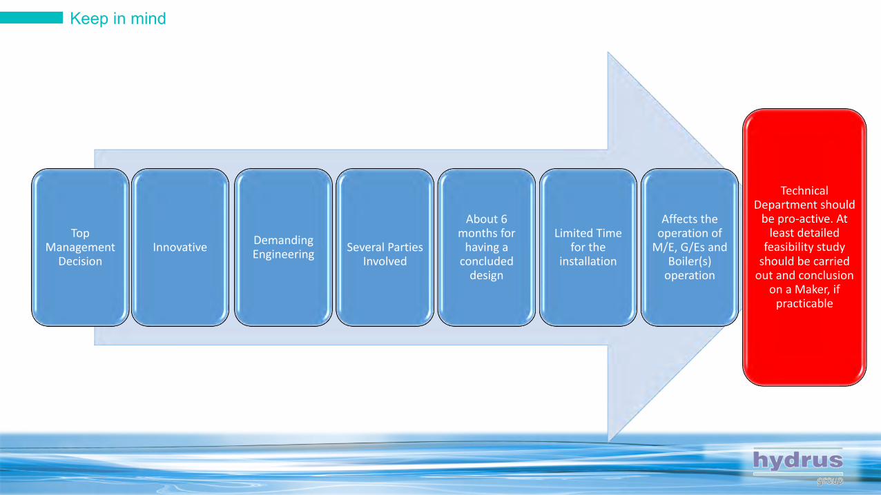
InnovativeTop
Management Decision
Demanding Engineering Several Parties
Involved
About 6 months for
having a concluded
design
Limited Time for the
installation
Affects the operation of
M/E, G/Es and Boiler(s)
operation
Technical Department should
be pro-active. At least detailed
feasibility study should be carried
out and conclusion on a Maker, if
practicable