
Assessment of Cockpit Interface Concepts for Data Link Retrofit
114
NASA Contractor Report 187615 NASA-CR-187615 19920008293 Assessment of Cockpit Interface Concepts for Data Link Retrofit Hugh W. McCauley William L. Miles John P. Dwyer Jeffery B. Erickson Douglas Aircraft Company Long Beach, California Contract NASI-18028 January 1992 and i Space Administration Langley Research Center Hampton, Virginia 23665-5225 LIBRARY COpy Fc:B 2 7 1992 LANGLEY RESEARCH CENTER , LIBRARY NASA " HAMPTON VIRGINIA KOT TO RE TAXZN FROM TIIB "ocr-:
-
Upload
khangminh22 -
Category
Documents
-
view
2 -
download
0
Transcript of Assessment of Cockpit Interface Concepts for Data Link Retrofit
NASA Contractor Report 187615
NASA-CR-187615 19920008293
Assessment of Cockpit Interface Concepts for Data Link Retrofit
Hugh W. McCauley William L. Miles John P. Dwyer Jeffery B. Erickson
Douglas Aircraft Company Long Beach, California
Contract NASI-18028 January 1992
~ and i \\~I\tiII~~~~~~I~\~nOO\n\ Space Administration
Langley Research Center Hampton, Virginia 23665-5225
LIBRARY COpy Fc:B 2 7 1992
LANGLEY RESEARCH CENTER , LIBRARY NASA
" HAMPTON VIRGINIA
KOT TO RE TAXZN FROM TIIB "ocr-:
Assessment of Cockpit Interface Concepts for Data Link
NASA Contractor Report 187615
Errata
Due to an error during final typesetting, somewhere between the computer and its less-than-perfect human operator, Figure lIon page 47 of the subject report was mysteriously replaced by a second copy of Figure 13.
The enclosed leaf (page 47 and 48) contains the correct Figure 11.
Please either replace the entire leaf containing page 47 and page 48, or cut out and paste the correct Figure 11 over the incorrect figure on page 47.
The authors regret this inconvenience.
Hugo McCauley Bill Miles Jack Dwyer Jeff Erickson
Douglas Aircraft Company Long Beach, California February 21, 1992
NASA Contractor Report 187615
Assessment of Cockpit Interface Concepts for Data Link Retrofit
Hugh W. McCauley William L. Miles John P. Dwyer Jeffery B. Erickson
Douglas Aircraft Company Long Beach, California
Contract NASI-18028 January 1992
NI\SI\ National Aeronautics and Space Administration
Langley Research Center Hampton, Virginia 23665-5225

This Page Intentionally left Blank
--------------------;-- ----
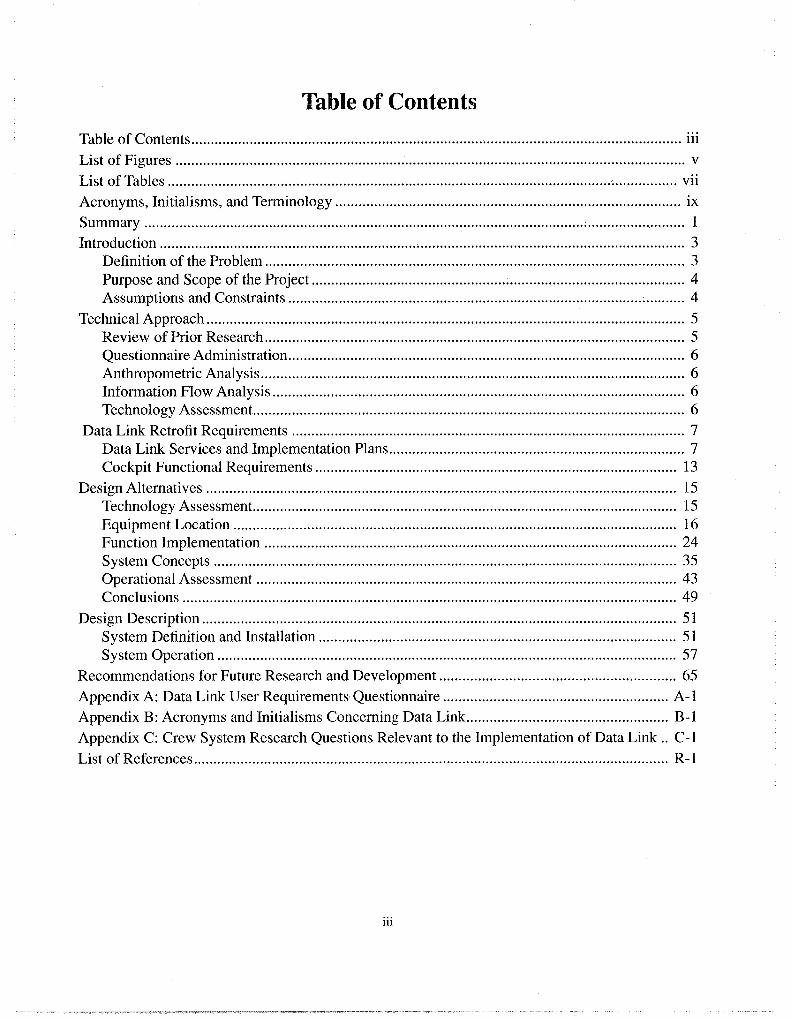
Table of Contents
Table of Contents .............................................................................................................................. iii
List of Figures ................................................................................................................................. .. v List of Tables .................................................................................................................. ; ................ vii
Acronyms, Initialisms, and Terminology ......................................................................................... ix Summary ................................................................................................................. : .......................... 1 Introduction..................................................................................................................... .................. 3
Definition of the Problem ............................................................................................................ 3 Purpose and Scope of the Project................................................................................................ 4 Assumptions and Constraints ........................................................................................... ; .......... 4
Technical Approach.......................................................................................................................... . 5 Review of Prior Research ............................................................................................................ 5 Questionnaire Administration ...................................................................................................... 6 Anthropometric Analysis ............................................................................................................. 6 Information Flow Analysis .......................................................................................................... 6 Technology Assessment. .............................................................................................................. 6
Data Link Retrofit Requirements ..................................................................................................... 7 Data Link Services and Implementation Plans ............................................................................ 7 Cockpit Functional Requirements....... ............... ......... ............... ...... ......... ..... ...... ............... ...... 13
Design Alternatives ......................................................................................................................... 15 Technology Assessment. ............................................................................................................ 15 Equipment Location.................................................................................................................. 16 Function Implementation .......................................................................................................... 24 System Concepts ....................................................................................................................... 35 Operational Assessment ............................................................................................................ 43 Conclusions ............................................................................................................................... 49
Design Description .......................................................................................................................... 51 System Definition and Installation ............................................................................................ 51 System Operation ...................................................................................................................... 57
Recommendations for Future Research and Development............................................................. 65 Appendix A: Data Link User Requirements Questionnaire .......................................................... A-I Appendix B: Acronyms and Initialisms Concerning Data Link .................................................... B-1 Appendix C: Crew System Research Questions Relevant to the Implementation of Data Link .. C-l List of References.................................................................................................................... ...... R-l
iii

This Page Intentionally Left Blank
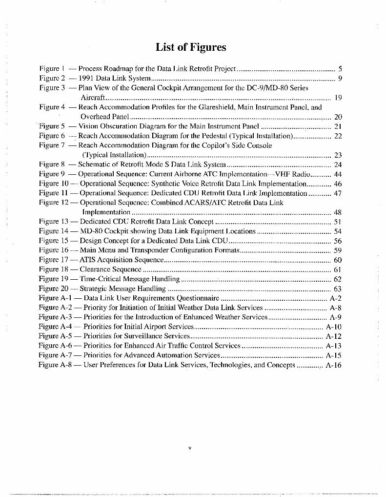
List of Figures
Figure 1 - Process Roadmap for the Data Link Retrofit Project.. .................................................. 5 Figure 2 - 1991 Data Link System ................................................................................................. 9 Figure 3 - Plan View of the General Cockpit Arrangement for the DC-9/MD-80 Series
Aircraft .................................................................................................. : .................... 19 Figure 4 - Reach Accommodation Profiles for the Glareshield, Main Instrument Panel, and
Overhead Panel .......................................................................................................... 20 ''Figure 5 - Vision Obscuration Diagram for the Main Instrument Panel ..................................... 21 Figure 6 -. Reach Accommodation Diagram for the Pedestal (Typical Installation) .................... 22 Figure 7 - Reach Accommodation Diagram for the Copilot's Side Console
(Typical Installation) ................................................................................................. 23 Figure 8 - Schematic of Retrofit Mode S Data Link System ....................................................... 24 Figure 9 - Operational Sequence: Current Airborne ATC Implementation-VHF Radio ........... 44 Figure 10 - Operational Sequence: Synthetic Voice Retrofit Data Link Implementation ............. 46 Figure 11 - Operational Sequence: Dedicated CDU Retrofit Data Link Implementation ............ 47 Figure 12 - Operational Sequence: Combined ACARS/ATC Retrofit Data Link
Implementation ......................................................................................................... 48 Figure 13 - Dedicated CDU Retrofit Data Link Concept ............................................................. 51 Figure 14 - MD-80 Cockpit showing Data Link Equipment Locations....................................... 54 Figure 15 - Design Concept for a Dedicated Data Link CDU ...................................................... 56 Figure 16 - Main Menu and Transponder Configuration Formats ................................................ 59 Figure 17 - ATIS Acquisition Sequence ........................................................................................ 60 Figure 18 - Clearance Sequence................................................................................................... 61 Figure 19 - Time-Critical Message Handling ............................................................................... 62 Figure 20 - Strategic Message Handling ...................................................................................... 63 Figure A-I - Data Link User Requirements Questionnaire ........................................................ A -2 Figure A-2 - Priority for Initiation of Initial Weather Data Link Services ................................. A-8 Figure A-3 - Priorities for the Introduction of Enhanced Weather Services ............................... A-9 Figure A-4 - Priorities for Initial Airport Services .................................................................... A-lQ Figure A-5 - Priorities for Surveillance Services ...................................................................... A-12 Figure A-6 - Priorities for Enhanced Air Traffic Control Services ........................................... A-13 Figure A-7 - Priorities for Advanced Automation Services ...................................................... A-15 Figure A-8 - User Preferences for Data Link Services, Technologies, and Concepts .............. A-16
v

This Page Intentionally left Blank
----------
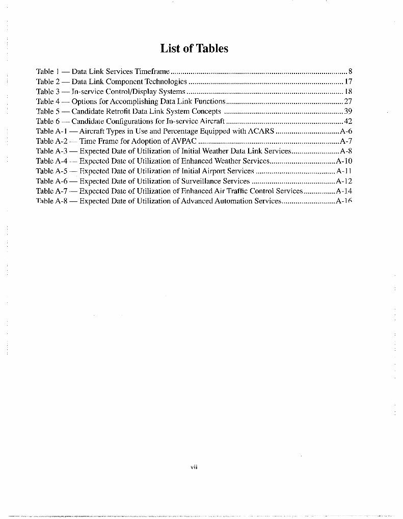
List of Tables
Table 1 - Data Link Services Timeframe ......................................................................................... 8 Table 2 - Data Link Component Technologies .............................................................................. 17 Table 3 - In-service ControllDisplay Systems ............................................................................... 18 Table 4 - Options for Accomplishing Data Link Functions ........................................................... 27 Table 5 - Candidate Retrofit Data Link System Concepts ............................................................ 39 Table 6 - Candidate Configurations for In-service Aircraft ........................................................... 42 Table A-I - Aircraft Types in Use and Percentage Equipped with ACARS ................................ A-6 Table A-2 - Time Frame for Adoption of AVPAC ....................................................................... A-7 Table A-3 - Expected Date of Utilization of Initial Weather Data Link Services ........................ A-8 Table A-4 - Expected Date of Utilization of Enhanced Weather Services ................................. A-to Table A-5 - Expected Date of Utilization of Initial Airport Services ........................................ A-II Table A-6 - Expected Date of Utilization of Surveillance Services .......................................... A-12 Table A -7 - Expected Date of Utilization of Enhanced Air Traffic Control Services ................ A -14 Table A-8 - Expected Date of Utilization of Advanced Automation Services ........................... A-l r.
VB

This Page Intentionally Left Blank
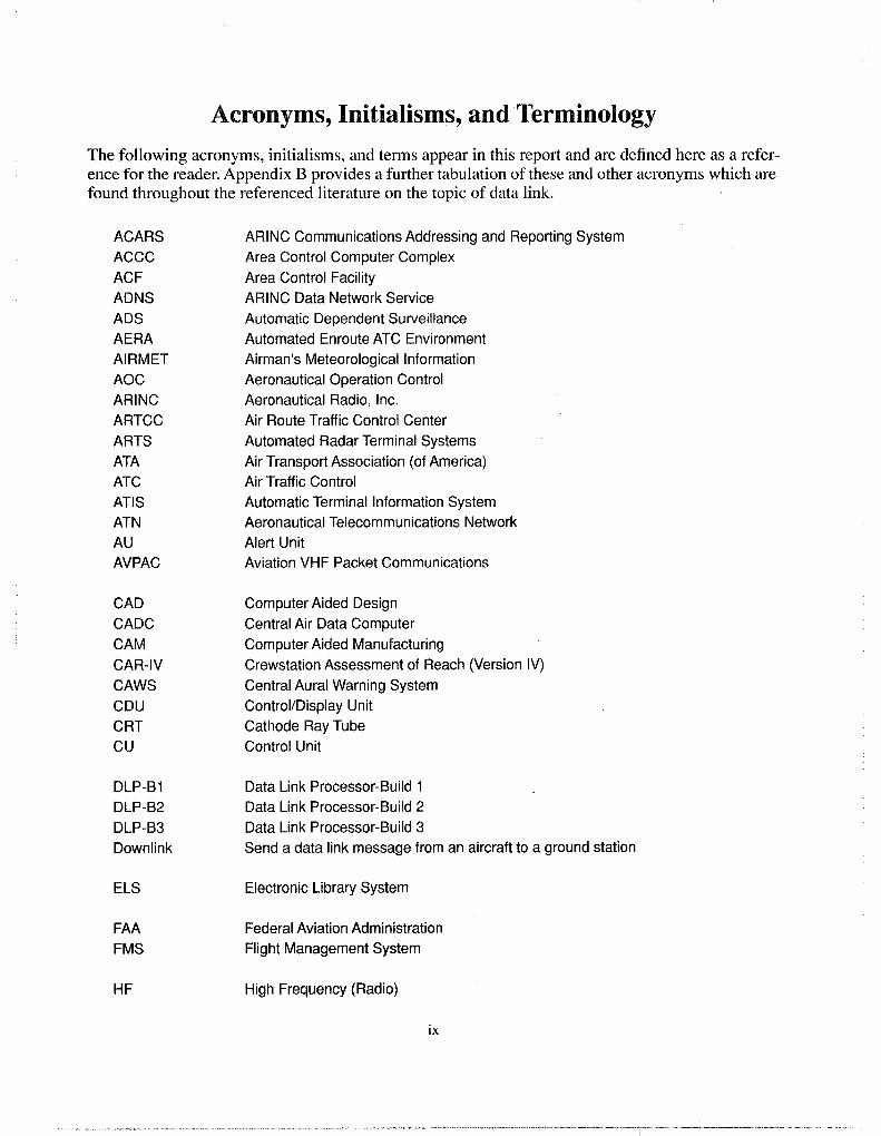
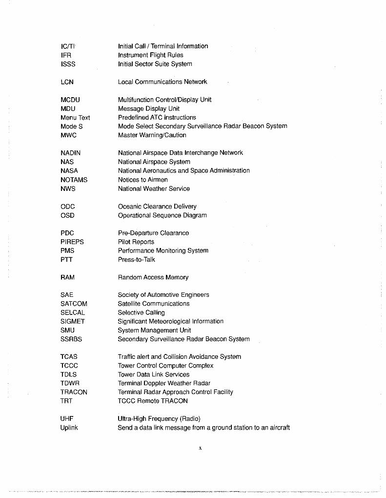
Acronyms, Initialisms, and Terminology
The following acronyms, initialisms, and terms appear in this report and are defined here as a reference for the reader. Appendix B provides a further tabulation of these and other acronyms which are found throughout the referenced literature on the topic of data link.
ACARS
ACCC
ACF
ADNS
ADS
AERA
AIRMET
AOC
ARINC
ARTCC
ARTS
ATA
ATC
ATIS
ATN
AU
AVPAC
CAD
CADC
CAM
CAR-IV
CAWS
CDU
CRT
CU
DLP-B1
DLP-B2
DLP-B3
Downlink
ELS
FAA
FMS
HF
ARINC Communications Addressing and Reporting System
Area Control Computer Complex
Area Control Facility
ARINC Data Network Service
Automatic Dependent Surveillance
Automated Enroute ATC Environment
Airman's Meteorological Information
Aeronautical Operation Control
Aeronautical Radio, Inc.
Air Route Traffic Control Center
Automated Radar Terminal Systems
Air Transport Association (of America)
Air Traffic Control
Automatic Terminal Information System Aeronautical Telecommunications Network
Alert Unit Aviation VHF Packet Communications
Computer Aided Design
Central Air Data Computer
Computer Aided Manufacturing
Crewstation Assessment of Reach (Version IV)
Central Aural Warning System
Control/Display Unit
Cathode Ray Tube
Control Unit
Data Link Processor-Build 1
Data Link Processor-Build 2
Data Link Processor-Build 3 Send a data link message from an aircraft to a ground station
Electronic Library System
Federal Aviation Administration
Flight Management System
High Frequency (RadiO)
ix
Icm IFR
ISSS
LCN
MCDU MDU
Menu Text
Mode S
MWC
NADIN
NAS NASA
NOTAMS
NWS
ODC
OSD
PDC
PIREPS PMS
PTT
RAM
SAE
SATCOM
SELCAL
SIGMET
SMU
SSRBS
TCAS
TCCC
TDLS TDWR
TRACON
TRT
UHF
Uplink
Initial Call / Terminal Information
Instrument Flight Rules
Initial Sector Suite System
Local Communications Network
Multifunction Control/Display Unit
Message Display Unit
Predefined ATC instructions Mode Select Secondary Surveillance Radar Beacon System
Master Warning/Caution
National Airspace Data Interchange Network
National Airspace System National Aeronautics and Space Administration
Notices to Airmen
National Weather Service
Oceanic Clearance Delivery
Operational Sequence Diagram
Pre-Departure Clearance
Pilot Reports
Performance Monitoring System
Press-to-Talk
Random Access Memory
Society of Automotive Engineers
Satellite Communications
Selective Calling
Significant Meteorological Information
System Management Unit
Secondary Surveillance Radar Beacon System
Traffic alert and Collision Avoidance System
Tower Control Computer Complex
Tower Data Link Services
Terminal Doppler Weather Radar
Terminal Radar Approach Control Facility
TCCC Remote TRACON
Ultra-High Frequency (Radio)
Send a data link message from a ground station to an aircraft
x
VHF VORTAC
WX
Zone 1 Reach
Zone 2 Reach
Zone 3 Reach
Very High Frequency (Radio) VHF Omnidirectional Radio RangelTactical Air Navigation System
Weather
The reach achievable by the crewmember when seated at the design eye reference location with shoulder harness locked and with no "straining" against the harness. This condition generally only occurs in military aircraft during high-G maneuvers or during a catapult launch. The reach achievable by the crewmember when seated at the design eye reference location while "straining" against a locked shoulder harness. The reach achievable by the crewmember when seated at the design eye reference location with shoulder harness unlocked or with no shoulder harness.
xi
Assessment of Cockpit Interface Concepts for Data Link Retrofit
Hugh W. McCauley William L. Miles
John P. Dwyer Jeffery B. Erickson
Crew Systems Technology Douglas Aircraft Company
Summary
In an attempt to solve the problem of the increased communications demands of increased air traffic, while maintaining safe operations, the Federal Aviation Administration (FAA) plans to implement throughout the National Airspace System (NAS) a digital communication system between air traffic control (ATC) stations on the ground and aircraft cockpits. This system, known as "data link," will provide a rapid and partially automated means of sending and receiving most standardized ATC messages.
Maximum system benefit can be realized if all aircraft operating in the NAS are equipped with and use data link as their primary means of communications. Many aircraft in development, and some of those currently entering service, have the capability for data link built in. However, the majority of aircraft now operating in the NAS, and which will be in service for many more years, were not designed with data link in mind and will have to be retrofitted for this capability.
The purpose of this project, performed under contract to NASA Langley Research Center, was to examine the problem of the retrofit of older generation, "minimally equipped" aircraft cockpits with data link capability, to identify alternative concepts for accomplishing retrofit, and to assess these concepts from a crew systems technology and human factors viewpoint.
The research identified and assessed eight data link component technologies from which four viable alternative retrofit concepts were determined. These four are:
• A control/display unit (CDU) dedicated to FAA/ATC data link
• A multifunction CDU combining ACARS with FAA/ATC data link
• Synthetic voice (used alone and in combination with other displays)
• Hard-copy printer (used in combination with synthetic voice or other displays)
With no intention of excluding other concepts from consideration for data link retrofit, the dedicated FAA/ATC data link CDU concept was described in further detail to illustrate how a retrofit crew interface might be used in service.

This Page Intentionally Left Blank
Introduction
Definition of the Problem
In recent years, the rapid expansion of commercial air travel has imposed increasing demands for improvement in the capacity and operating efficiency of the National Airspace System. The impact of this accelerated growth has been particularly evident in the area of communications between aircraft and ground facilities. Voice radio channels, which provide the primary communications medium for air traffic control, have become overburdened. This problem is most acute in the terminal area where air traffic congestion is greatest. In the current operating environment, the ability to transfer information in a timely, accurate manner has obvious implications for the safety and efficiency of air traffic management.
This increased demand, combined with the highly competitive nature of the air transport business has produced similar trends with regard to company communications between airline ground facilities and operating aircraft. The need for increased operating efficiency and passenger convenience has created compelling economic reasons for the airlines to actively pursue improved means for communicating company operational data such as gate assignments, connecting flight schedules and equipment maintenance requirements.
Recent developments in communications and data processing technology offer potential solutions to these challenging problems. Emerging communications technologies such as digital data link provide alternative media to supplement or replace conventional voice communications. Electronic multifunction display and control devices such as flat panels, touch-sensitive screens and synthetic voice provide an array of options for improving the operator interface both in the cockpit and at ground-based facilities. The wide range of alternatives and inherent flexibility of digital electronic technology have stimulated considerable discussion on the part of the airlines and regulatory agencies regarding the optimum human interface for data link communications.
In recognition of the technical challenges presented by the air to ground communications problem, the National Aeronautics and Space Administration has undertaken a comprehensive program of research directed toward resolution of the key issues. The effort at NASA Langley Research Center has focused primarily on optimization of the cockpit interface for data link. Development and testing accomplished under this program has emphasized crew interface concepts suitable for use in aircraft equipped with modern digital avionics and electronic displays. Work completed to date has demonstrated the utility and feasibility of accommodating basic data link services in current and future cockpits [Ref. 1,2, and 3].
While this research has helped to advance the technology readiness for full-scale data link implementation, it is recognized that FAA plans for near term introduction of limited services may require a number of older aircraft to be upgraded to enable them to function effectively in a data link environment. In order to realize the full benefits of data link communications, all aircraft under positive control should be equipped in a manner that is fullY'compatible with the facilities and procedures used by the ATC system. The cockpit interface for retrofit of existing aircraft must be carefully designed for optimum utilization of available resources to maintain crew workload within acceptable limits for all phases of flight. The design solution must also be practical to install, operate and maintain within the physical and technological constraints of conventional cockpits.
3
Purpose and Scope of the Project
The research described in this report was intended to deal with the problem of retrofitting a crew interface for data link into earlier model transport aircraft. The primary objective of the project was to provide the capability for pilots to perform essential communications tasks associated with basic, near-term data link services. The study investigated plans for data link implementation to derive relevant functional requirements and design constraints. Available display and control technologies were reviewed for potential applicability to the retrofit problem. Alternative cockpit configurations were then defined and compared analytically to determine their relative strengths and weaknesses. One design concept was selected for further definition in order to illustrate how basic data link functions might be implemented in an older model aircraft. Finally, recommendations were developed for further evaluation of the candidate retrofit concepts in subsequent simulator tests and flight demonstrations.
Assumptions and Constraints
In order to provide an overall framework for conduct of the investigation, several basic assumptions were established at the outset. These assumptions were intended to provide a basis for common understanding among the study participants as to the scope and focus of the investigation and to help assure that the most important technical issues would be fully addressed within the resources available for the project. These assumptions are summarized below.
Crew Complement. The data link concepts were designed to be operable by a crew of two pilots. This was considered appropriate since it represents the minimum crew normally used in commercial air transport operations. It should be noted that this assumption implies that all flight-critical crew duties can be accomplished by a single crewmember in the event that one pilot is incapacitated.
Aircraft Onboard Equipment. Some aircraft currently in service are equipped with digitized cockpit interfaces that might be adapted to perform some data link ATC functions. While these alternatives are described and evaluated in this report, the primary focus of this project was on the definition of a retrofit configuration suitable for minimally equipped aircraft, assuming no preexisting multifunction display or control capability.
Aircraft Type. Project funding constraints did not permit the design of unique retrofit concepts for all possible models of aircraft. A representative aircraft was therefore adopted as a baseline for assessment of equipment configuration alternatives. The aircraft selected was the McDonnell Douglas DC-9 / MD-80 series transport.
Technology Availability. Consideration of design alternatives was limited to those employing low risk, readily available technology based on the assumption that installation of flight-qualified retrofit hardware would be initiated in the mid-1990s time frame. The scope of the study was confined to the design of the crew interface and did not include an assessment of avionics system requirements or other equipment interfaces.
Aircraft Certification. It was assumed that certification of the retrofit concepts would be based on compliance with present Federal Air Regulations [Ref. 4.] with guidance provided by FAA Advisory Circular 20-XX, Airworthiness Approval of Airborne Data Link Systems, dated March 29, 1990 (currently in draft form).
4
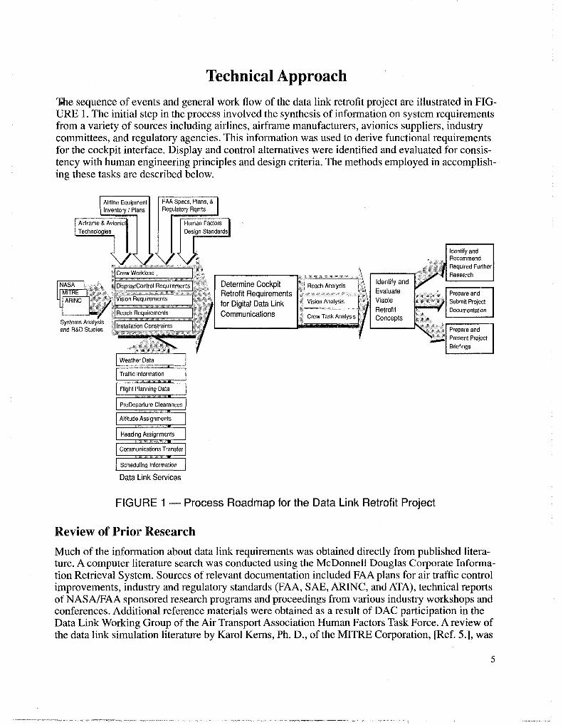
Technical Approach Tehe sequence of events and general work flow of the data link retrofit project are illustrated in FIGURE 1. The initial step in the process involved the synthesis of information on system requirements from a variety of sources including airlines, airframe manufacturers, avionics suppliers, industry committees, and regulatory agencies. This information was used to derive functional requirements for the cockpit interface. Display and control alternatives were identified and evaluated for consistency with human engineering principles and design criteria. The methods employed in accomplishing these tasks are described below.
Data Link Services
Determine Cockpit Retrofit Requirements 1/~(:c==;;::;J:'C~~/
for Digital Data Link Communications
Identify and Recommend Required Further
r------,:;:f:(;;'t~z'l Research
Prepare and Submit Project Documentation
Prepare and Present Project Briefings
FIGURE 1 - Process Roadmap for the Data Link Retrofit Project
Review of Prior Research
Much of the information about data link requirements was obtained directly from published literature. A computer literature search was conducted using the McDonnell Douglas Corporate Information Retrieval System. Sources of relevant documentation included FAA plans for air traffic control improvements, industry and regulatory standards (FAA, SAE, ARINC, and ATA), technical reports of NASA/FAA sponsored research programs and proceedings from various industry workshops and conferences. Additional reference materials were obtained as a result of DAC participation in the Data Link Working Group of the Air Transport Association Human Factors Task Force. A review of the data link simulation literature by Karol Kerns, Ph. D., of the MITRE Corporation, [Ref. 5.], was
5
found to be a particularly valuable source of information. A complete list of references is provided on page R -1 of this report.
Questionnaire Administration
To provide a balanced perspective on key data link retrofit issues, the opinions of several subject matter experts were sought. A structured questionnaire was prepared and administered to a sample of interested parties with the assistance of the ATA Data Link Working Group. While the number of participants was limited, the questionnaire responses and written comments provided valuable insights. This information supplemented and enriched the data obtained in the literature review. Some interesting differences of opinion regarding data link implementation plans and priorities also surfaced. Opinions of subject matter experts and highlights of the literature review are summarized in the section entitled Data Link Retrofit Requirements, on page 7 of this report. The questionnaire format and a detailed tabulation of responses are also provided in Appendix A.
Anthropometric Analysis
To determine design requirements for pilot accessibility of displays and controls, an anthropometric analysis was conducted. The analysis addressed both reach and vision accommodation within the constraints of the baseline aircraft geometry. Those areas in the cockpit providing unobstructed visibility for displays and manual access for controls were identified. Accessible regions were defined for 5th through 95th centile aviators using body dimensions of the 1985 male and female populations as defined by the NASA Anthropometric Source Book [Ref. 6.]. Three-dimensional reach envelopes were constructed utilizing data derived from the Crewstation Assessment of Reach, Version IV (CAR-IV) computer program [Ref. 7.]. Envelopes for shoulder harness locked and unlocked restraint conditions were determined and drawn in a CAD/CAM program. This analysis provided the basis for evaluating candidate equipment locations in the baseline aircraft.
Information Flow Analysis
An information flow analysis was conducted to assess the impact of various equipment configurations on cockpit resource utilization. The analysis employed a technique known as operational sequence diagrams (OSDs). These diagrams describe the distribution of tasks among crew resources (perceptual, cognitive, motor, etc.) and aircraft automation (sensors, processors, etc.). The diagrams were also used to compare design alternatives in terms of task demands imposed on crew body channels (visual, auditory, etc.). OSDs were constructed for each of the candidate equipment configurations to identify qualitative differences in resource utilization.
Technology Assessment
Display and control technologies were reviewed for potential application to the cockpit interface problem. The advantages and disadvantages of each technology were identified and summarized in a tabular format to facilitate comparisons. Evaluation criteria were based on operational utility and ability to meet system functional requirements with minimal development risk. No attempt was made to assess relative costs. The results of the technology assessment are summarized in the section entitled Technology Assessment, on page 15 of this report.
6
Data Link Retrofit Requirements
This section addresses the system compatibility, interfacing, and functional requirements which must be met to realize a viable retrofit data link system. Subsections below outline the types of data link services, their sources (facilities, networks, etc.), and the schedule for their introduction. Also discussed are the classes of existing aircraft with which a retrofit data link system would have to be compatible. Finally, functional requirements based on the services to be provided are defined in preparation for a discussion of potential design solutions in the next section.
Data Link Services and Implementation Plans
The FAA plans to phase in aeronautical digital data link services over several years commensurate with the development, maturation, and availability of appropriate communications technologies. Human factors concerns about operations in both the cockpit and at air traffic control stations, as well as other technological issues, will have to be resolved. Testing, demonstration of concepts, and operational evaluation we be required before each service is fully implemented. Safety of the flying public and time and economic constraints of equipment introduction and aircraft retrofit are other factors which will affect the implementation of new services. Another major factor in the scheduling of data link service introduction is the training of both air crews and controllers.
Data link services can be categorized by the three areas of control from which they originate: Tower Data Link Services (TDLS); Terminal Radar Approach Control (TRACON) Data Link Services; and Air Route Traffic Control Center (ARTCC) Data Link Services. Additional categories of data link are those concerned with airline company business and operations.
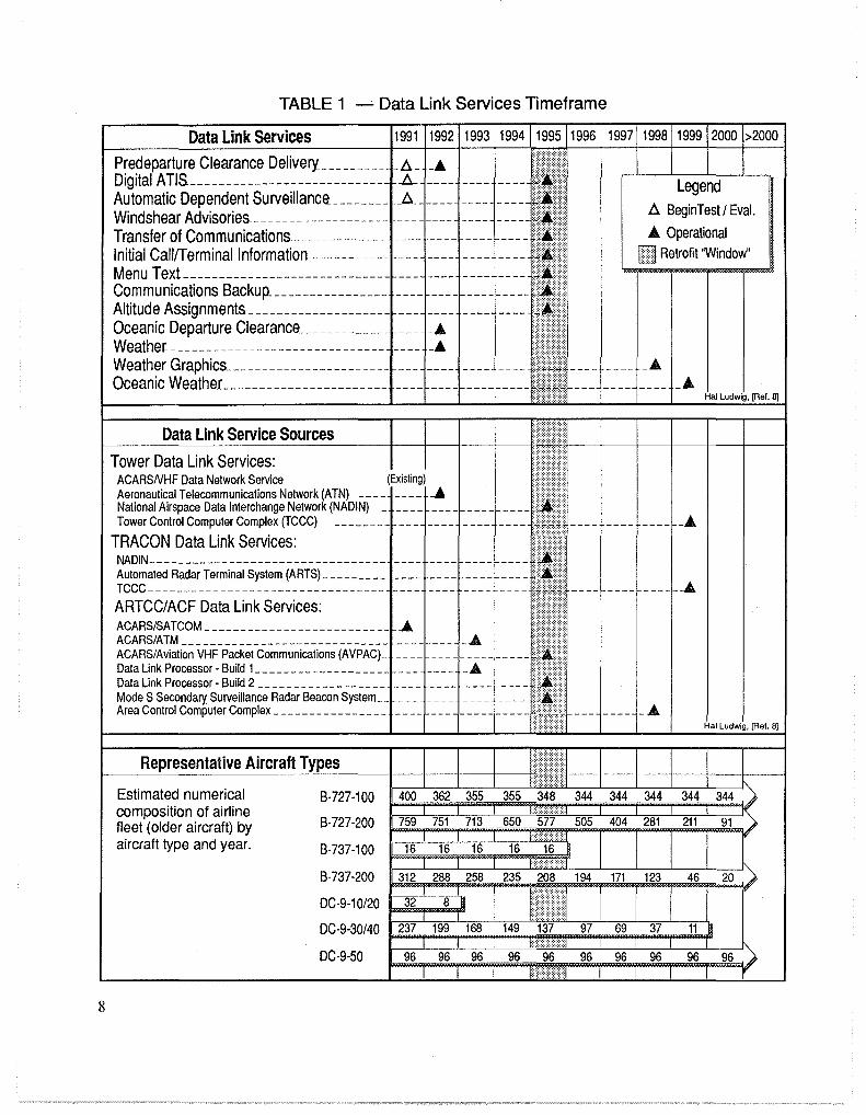
TABLE 1 illustrates a proposed schedule of the data link services to be provided by the FAA according to a presentation on data link evolution by Hal Ludwig of the FAA, [Ref. 8.]. The second section of the table indicates the data link communications facilities that will enable the listed services to be provided, grouped by the three areas of control enumerated above. The expected servicelife time-lines of several representative aircraft models are also shown in the table. This data was derived from sources within Douglas Aircraft Company and from the research done for the FAA by Michael Pomykacz of CTA, Inc., [Ref. 9.]. The shaded area on the chart shows the initial implementation of most of the data link services and thus permits the identification of which aircraft are logical candidates for data link retrofit. Conversely, it shows which aircraft models are unrealistic candidates from the viewpoint of remaining life expectancy.
From the table and the description of the various services which follows, it is evident that services to be offered before 1995 require a minimum of existing ACARS transmit/receive and printer technology for utilization. In the remainder of this section we discuss the data link service implementation plans relating to each of the three types of ATC facilities.
Planned Tower Data Link Services
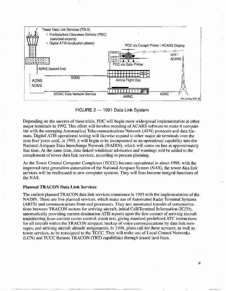
Initial test implementation of Predeparture Clearance Delivery (PDC) and digitally encoded Automatic Terminal Information Service (ATIS) messages is already underway. These services are being demonstrated at Chicago O'Hare and Dallas-Fort Worth international airports, making use of the existing ARINC Data Network Service (ADNS) and ACARSNHF equipment currently in the inventories of two major air carriers. A schematic diagram of the test operation, which bears close resemblance to what would be the initial fully operational arrangement, is shown in FIGURE 2.
7
8
TABLE 1 - Data Link Services Timeframe
Data Link Services 1991 1992
Predeparture Clearance Delivel)'._________ t:..--.A Digital ATIS--------------------------- A. Automatic Dependent Surveillanca ________ ~ Windshear Advisories.---------------- -- --Transfer of Communications.-------------Initial CalifTerminallnformatiorl---- ------ - --Menu Text---------------------------- --- ---- ----Communications Backup-________________ ___ ___ ---Altitude Assignments___________________ _ _____ _ Oceanic Departure Clearance____________ ----.A Weathet------------------------ ----- ----.A Weather Graphics______________________ _ __ Oceanic WeatheL ________________________ _
Data Link Service Sources
Tower Data Link Services: ACARSNHF Data Network Service i Aeronautical Telecommunications Network (ATN) - - - - -.A National Airspace Data Interchange Network (NADIN) _ _ __ Tower Control Computer Complex (TCCC) _ _ _ _ _ _ _ _ _ _ _ _ _ _ _ __ _
TRACON Data Link Services: NADIN---- _____________________________ ----
Automated Radar Terminal System (ARTS) _ _ _ _ _ _ _ _ _ _ __ _ TCCC--------------- ----------- --- ----
ARTCC/ACF Data Link Services: ACARS/SATCOM _ ______ _____ ____________ _ A. ACARS/ATM __ _ ___________ _______ ________ ___ _ .... ACARS/Aviation VHF Packet Communications (AVPAC) ____ _ Data Link Processor - Build L__________ _______ ___ _ ___ &. Data Link Processor - Build 2 _ _ _ _ ___ _ __ _ __ _ __ __ _ ___ _ __ Mode S Secondary Surveillance Radar Beacon System_ _ _ _ _ __ Area Control Computer Complex- _____________________ _
Representative Aircraft Types
Estimated numerical composition of airline fleet (older aircraft) by aircraft type and year.
8-727-100
8-727-200
8-737-100
8-737-200
DC-9-10/20 1J=oiO....,.. ....... .,a
1999 2000
Legend t:.. 8eginTest / Eval.
&. Operational III Retrofit "Window"
[Ref. 8]
---- --- ---- -&.
---- ---- --- -.A
--- ---- - ....
DC-9-30/40 ~~ ........ ~~ ........ ~~~...,....~~~~~
DC-9-50
Tower Data Link Services (TDLS)
ADNS NODE
• Predeparture Clearance Delivery (PDC) (selected airports)
• Digital ATIS (evaluation phase)
ADNS
ARINC Data Network Service
PDC via Cockpit Printer / ACARS Display
PDC via Gate Printer
Airline Flight Ops
ADNS
VHF/ ACARS
Hal Ludwig, [Ref. 8)
FIGURE 2 -1991 Data Link System
Depending on the success of these trials, PDC will begin more widespread implementation at other major terminals in 1992. This effort will involve recoding of ACARS software to make it compatible with the emerging Aeronautical Telecommunications Network (ATN) protocols and data formats. Digital ATIS operational testing will likewise expand to other major air terminals over the next four years until, in 1995, it will begin to be incorporated as an operational capability into the National Airspace Data Interchange Network (NADIN), which will come on line at approximately that time. At the same time, data linked windshear advisories and warnings will be added to the complement of tower data link services, according to present planning.
As the Tower Control Computer Complexes (TCCC) become operational in about 1998, with the improved next generation automation of the National Airspace System (NAS), the tower data link services will be reallocated to new computer systems. They will thus become integral functions of the NAS.
Planned TRACON Data Link Services
The earliest planned TRACON data link services commence in 1995 with the implementation of the NADIN. There are five planned services, which make use of Automated Radar Terminal Systems (ARTS) and communications front-end processors. They are: automated transfer of communications between TRACON sectors for arriving aircraft; Initial Callfferminal Information (ICffl), automatically providing current destination ATIS reports upon the first contact of arriving aircraft transitioning from enroute center control; menu text, giving standard predefined ATC instructions for all aircraft within the TRACON airspace; backup of voice communications by data link messages; and arriving aircraft altitude assignments. In 1998, plans call for these services, as well as tower services, to be reassigned to the TCCC. They will make use of Local Control Networks (LCN) and TCCC Remote TRACON (TRT) capabilities through leased land lines.
9
Planned ARTCC Data Link Services
Planned data link services in the enroute environment vary somewhat depending on whether they occur in the continental or transoceanic airspace. For example, testing has begun on the use of data nnk to provide continuous Automatic Dependent Surveillance (ADS) of aircraft status and position on selected trans-Pacific oceanic routes, replacing the use of HF radio communications. This service will depend initially on ACARSNHF equipment interfacing with satellite communications (SATCOM) for the beyond line-of-sight route segments, and will be performed automatically without requiring crew intervention.
Within the continental NAS, where continuous radar surveillance is assured, the plan is to make major use of the Mode S discrete address Secondary Surveillance Radar Beacon System (SSRBS) for the bulk of enroute tactical and strategic ATC information transfer. In 1992, the introduction of initial Data Link Processor-Build 1 (DLP-Bl) units into selected ARTCCs will provide enroute weather information via Mode S in standard National Weather Service (NWS) character formats.
In this same time frame, ARINCNHF interfaced with SATCOM will provide Oceanic Departure Clearance (ODC) delivery services, while ADS trials will expand to the trans-Pacific airspace. Then, in 1993, ATN-compatible ADS will be introduced on a demonstration basis, incorporating a two-way message data link to be used initially for step-climb/descent clearances.
1995 will see a major upgrade in operational data link capability, with the integration ofNADIN, new NAS host computers, Mode S SSRBS, and Data Link Processors-Build 2 (DLP-B2) into the ARTCC facilities, along with the upgrading of the ARINC system to the Aviation VHF Packet Communications (AVPAC) data format. These improvements will consolidate enroute data link services and provide such capabilities as automated transfer of communications (between centers and between sectors within center airspace) for transiting aircraft. Other improvements are message backup of voice communications; menu text; altitude assignments; enroute weather; and ADS (for oceanic operations or flights into continental areas, where continuous radar surveillance is unavailable, such as Mexico).
The Initial Sector Suite System (lSSS), to be introduced as part of the NAS next-generation automation upgrade in 1996, will incorporate and be compatible with these services but will not add any additional services. In 1998, ARTCC data link services will transition to the Area Control Computer Complex (ACCC) and the Data Link Processor-Build 3 (DLP-B3), as this system becomes opera-· tional, and will be expanded to include enroute ICrrI and graphical weather data communication capabilities. Data link transmission of oceanic weather information via SATCOM from coastal NWS stations and foreign weather data sources is presently scheduled for a 1999 introduction.
Other Candidate Data Link Services
In addition to the data link services planned by the FAA for implementation and enumerated above, the airline survey identified several candidate services that were felt to be needed by a majority of the respondents (see Appendix A for details). Priority candidates for early implementation include:
• Hazardous weather advisories (AIRMETS, flight precautions)
• Pilot reports (PIREPS)
• Terminal forecasts
10
• Winds and temperatures aloft
• Surface Observations
• Fix crossing restrictions
• Notices to Airmen (NOTAMS)
• Significant Weather (SIGMET)
• Flight plan filing and amendments
It is expected that the company and passenger data link services currently provided by ACARS will be expanded as the technology improves. Functions in this area that are currently provided or appear attractive include:
• Crew assignments
• Scheduling changes
• Gate changes
• Maintenance information. Automatic downlink of onboard systems status, particularly for those items requiring frequent maintenance actions.
• Airline customer services via data link
o Personal messages
o Connecting flight information
o Airborne telephone communication
o Special meal requests
o Ground transportation information
o Medical emergency information (requests for ambulances, wheel chairs, etc.)
Digital Data Link Communication Channels.
The digital data link communications system envisioned by the FAA will initially utilize some of the existing data link communication channels, but plans include improvements and the addition of other channels. Following is a description of the major communications channels in use today and projected for the era of data link operations.
• ARINC Communications Addressing and Reporting System (ACARS) is currently in use for data link communication of strategic enroute clearances, airline company dispatch, maintenance, scheduling, and other similar information. Because of its present use in a majority of the aircraft operating in the NAS, it is expected to playa major role in the early implementation of data link. ACARS, in its present configuration, is limited both in its message capacity and its ability to handle time-critical (tactical) messages. In order to be used for tactical data link communications, it would have to be substantially enhanced.
11
• High Frequency (HF) Radio (ARINC) system is currently the primary means of communicationin the oceanic environment, being capable of communications beyond visual range of the transmitting stations. It is quite limited, particularly for time-critical communications, and is not considered to be a major factor in data link system planning.
• Satellite Communications (SATCOM) will probably be the primary channel for oceanic use of data link and is expected to become a major channel in the domestic environment as well, particularly as it improves with more and better satellites being placed in orbit in connection with the Global Positioning System (GPS).
• Ultra, High Frequency (UHF) Radio is the current command radio system for military aviation voice communications. UHF band voice communications are supported in the NAS to accommodate military traffic. However, data link application of the UHF band is currently restricted to such uses as the Navy Tactical Data System (NTDS), where it has been in use for several years. It is not expected that UHF data link will be utilized by the commercial sector to any great extent. Incorporation into the overall system is expected to permit its use by military aircraft operating in the NAS.
• Very High Frequency (VHF) Radio is the frequency band utilized by ACARS and essentially all civil aeronautical voice communication throughout the NAS. It will undoubtedly continue to be used in this capacity.
• Mode Select (Mode S) Secondary Surveillance Radar Beacon System is a major part of the FAA's data link system plans and is expected to be the main channel for terminal area and domestic enroute data link communications.
Candidate Aircraft for Data Link Retrofit
The bottom of TABLE 1 estimates fleet size for various older technology aircraft over time as the result of hull retirements due to reaching design life (or facing such forced retirement criteria as FAA engine noise reduction deadlines). Some models will be virtually out of service by the mid-1990s. This is significant because, as was indicated above, most data link services and supporting facilities are planned to be operational at about that time. Thus, aircraft such as the earliest DC-9s (Series 10/20) and B-737-100s are probably not good candidates on which to base retrofit data link system development. Series 30 and later DC-9s (including early MD-80s), B-727s (100 and 200), and B-737-200s will be in use at least through the end of the current decade, suggesting that these models are probably suitable candidates. Most of these aircraft have relatively unsophisticated navigation, autoflight, and communications systems, providing perhaps the most challenge in developing and integrating a physically and operationally satisfactory data link capability. Many of these models incorporate some form of ACARSNHF data link equipment, which would provide some of the early data link services identified above without requiring modification.
If we focus on the DC-9/MD-80 aircraft now in service and scheduled to remain so into at least the early years of the next century (a large number, incidentally), we find at least four significant variations: (1) basic aircraft without existing ACARS or other multifunction contrOl/display units (CDU); (2) aircraft with ACARS installed; (3) aircraft with a flight or performance management system (F/PMS) CDU installed; and (4) aircraft with both ACARS and F/pMS CDUs. Since we have available at Douglas significant detailed information on DC-9/MD-80 variants in each of these four classes-and since these aircraft are both likely candidates and reflect the problems, issues, and
12
challenges inherent in devising and integrating a retrofitable data link installation-we have elected to concentrate the efforts in this study on the DC-9/MD-80 crew interfaces for data link.
In order for these aircraft to operate safely and economically in the NAS for the next ten to twenty years, a capable, retrofitable airborne data link system will be required. This system, at a minimum, will have to be compatible with the Mode S SSRBS. In all likelihood, it will require an interface with the expanding capabilities of the ACARS and ATN networks to provide full functionality. Of course, if it is to be viable, it is mandatory that the retrofit data link system be economical to develop, certify, purchase, and operate. In the sections to follow, we will consider how the goals of functionality and affordability may be met. Initially, however, we must determine the functional requirements for a useful airborne data link system and the physical requirements and constraints that are typical of retrofit installations of such equipment in existing older technology transport aircraft.
Cockpit Functional Requirements
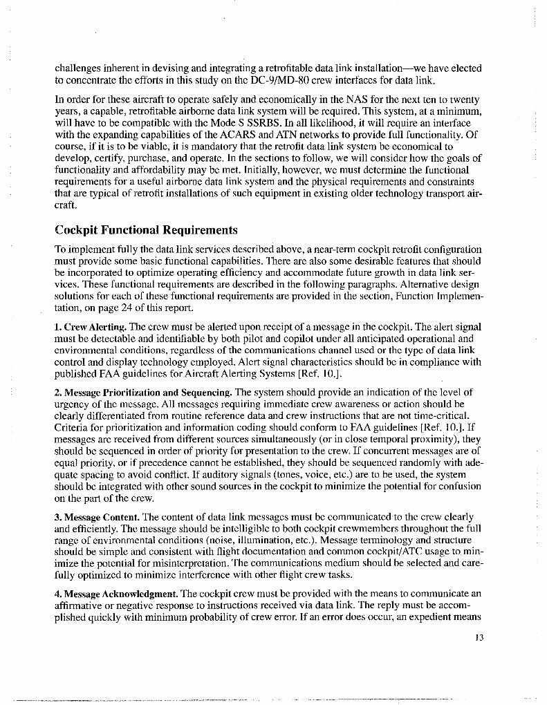
To implement fully the data link services described above, a near-term cockpit retrofit configuration must provide some basic functional capabilities. There are also some desirable features that should be incorporated to optimize operating efficiency and accommodate future growth in data link services. These functional requirements are described in the following paragraphs. Alternative design solutions for each of these functional requirements are provided in the section, Function Implementation, on page 24 of this report.
1. Crew Alerting. The crew must be alerted upon receipt of a message in the cockpit. The alert signal must be detectable and identifiable by both pilot and copilot under all anticipated operational and environmental conditions, regardless of the communications channel used or the type of data link control and display technology employed. Alert signal characteristics should be in compliance with published FAA guidelines for Aircraft Alerting Systems [Ref. 10.].
2. Message Prioritization and Sequencing. The system should provide an indication of the level of urgency of the message. All messages requiring immediate crew awareness or action should be clearly differentiated from routine reference data and crew instructions that are not time-critical. Criteria for prioritization and information coding should conform to FAA guidelines [Ref. 10.]. If messages are received from different sources simultaneously (or in close temporal proximity), they should be sequenced in order of priority for presentation to the crew. If concurrent messages are of equal priority, or if precedence cannot be established, they should be sequenced randomly with adequate spacing to avoid conflict. If auditory signals (tones, voice, etc.) are to be used, the system should be integrated with other sound sources in the cockpit to minimize the potential for confusion on the part of the crew.
3. Message Content. The content of data link messages must be communicated to the crew clearly and efficiently. The message should be intelligible to both cockpit crewmembers throughout the full range of environmental conditions (noise, illumination; etc.). Message terminology and structure should be simple and consistent with flight documentation and common cockpit/ ATC usage to minimize the potential for misinterpretation. The communications medium should be selected and carefully optimized to minimize interference with other flight crew tasks.
4. Message Acknowledgment. The cockpit crew must be provided with the means to communicate an affirmative or negative response to instructions received via data link. The reply must be accomplished quickly with minimum probability of crew error. If an error does occur, an expedient means
13
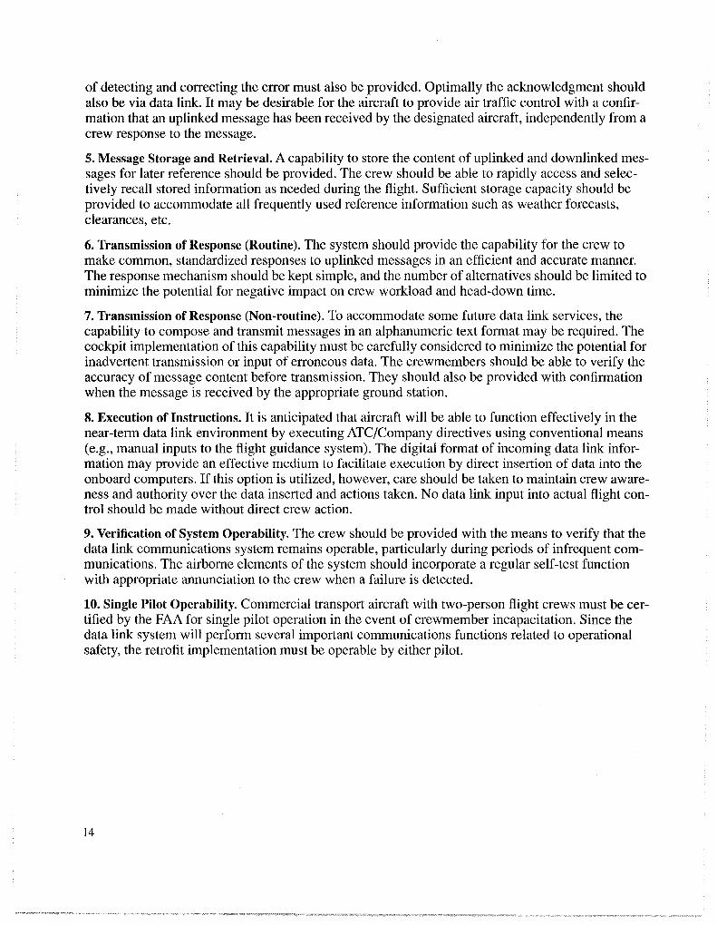
of detecting and correcting the error must also be provided. Optimally the acknowledgment should also be via data link. It may be desirable for the aircraft to provide air traffic control with a confirmation that an uplinked message has been received by the designated aircraft, independently from a crew response to the message.
S. Message Storage and Retrieval. A capability to store the content of up linked and down linked messages for later reference should be provided. The crew should be able to rapidly access and selectively recall stored information as needed during the flight. Sufficient storage capacity should be provided to accommodate all frequently used reference information such as weather forecasts, clearances, etc.
6. Transmission of Response (Routine). The system should provide the capability for the crew to make common, standardized responses to uplinked messages in an efficient and accurate manner. The response mechanism should be kept simple, and the number of alternatives should be limited to minimize the potential for negative impact on crew workload and head-down time.
7. Transmission of Response (Non-routine). To accommodate some future data link services, the capability to compose and transmit messages in an alphanumeric text format may be required. The cockpit implementation of this capability must be carefully considered to minimize the potential for inadvertent transmission or input of erroneous data. The crewmembers should be able to verify the accuracy of message content before transmission. They should also be provided with confirmation when the message is received by the appropriate ground station.
8. Execution of Instructions. It is anticipated that aircraft will be able to function effectively in the near-term data link environment by executing ATC/Company directives using conventional means (e.g., manual inputs to the flight guidance system). The digital format of incoming data link information may provide an effective medium to facilitate execution by direct insertion of data into the onboard computers. If this option is utilized, however, care should be taken to maintain crew awareness and authority over the data inserted and actions taken. No data link input into actual flight control should be made without direct crew action.
9. Verification of System Operability. The crew should be provided with the means to verify that the data link communications system remains operable, particularly during periods of infrequent communications. The airborne elements of the system should incorporate a regular self-test function with appropriate annunciation to the crew when a failure is detected.
10. Single Pilot Operability. Commercial transport aircraft with two-person flight crews must be certified by the FAA for single pilot operation in the event of crewmember incapacitation. Since the data link system will perform several important communications functions related to operational safety, the retrofit implementation must be operable by either pilot.
14
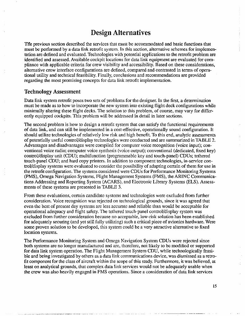
Design Alternatives TH'e previous section described the selVices that must be accommodated and basic functions that must be performed by a data link retrofit system. In this section, alternative schemes for implementation are defined and evaluated. Technologies with potential applications to the retrofit problem are identified and assessed. Available cockpit locations for data link equipment are evaluated for compliance with applicable criteria for crew visibility and accessibility. Based on these considerations, alternative crew interface configurations are defined, compared and contrasted in terms of operational utility and technical feasibility. Finally, conclusions and recommendations are provided regarding the most promising concepts for data link retrofit implementation.
Technology Assessment
Data link system retrofit poses two sets of problems for the designer. In the first, a determination must be made as to how to incorporate the new system into existing flight deck configurations while minimally altering these flight decks. The solution to this problem, of course, may vary for differently equipped cockpits. This problem will be addressed in detail in later sections.
The second problem is how to design a retrofit system that can satisfy the functional requirements of data link, and can still be implemented in a cost-effective, operationally sound configuration. It should utilize technologies of relatively low risk and high benefit. To this end, analytic assessments of potentially useful control/display technologies were conducted and are summarized in TABLE 2. Advantages and disadvantages were compiled for computer voice recognition (voice input); conventional voice radio; computer voice synthesis (voice output); conventional (dedicated, fixed key) control/display unit (CDU); multifunction (programmable key and touch-panel) CDUs; tethered touch-panel CDU; and hard copy printers. In addition to component technologies, in-selVice control/display systems were evaluated to consider the possibility of adapting certain of them for use in the retrofit configuration. The systems considered were CDUs for Performance Monitoring Systems (PMS), Omega Navigation Systems, Flight Management Systems (FMS), the ARINC Communications Addressing and Reporting System (ACARS), and Electronic Library Systems (ELS). Assessments of these systems are presented in TABLE 3.
From these evaluations, certain candidate systems and technologies were excluded from further consideration. Voice recognition was rejected on technological grounds, since it was agreed that even the best of present day systems are less accurate and reliable than would be acceptable for operational adequacy and flight safety. The tethered touch-panel control/display system was excluded from further consideration because no acceptable, low-risk solution has been established for adequately securing (and yet still fully utilizing) such a critical piece of avionics hardware. Were some proven solution to be developed, this system could be a very attractive alternative to fixed location systems.
The Performance Monitoring System and Omega Navigation System CDUs were rejected since both systems are no longer manufactured and are, therefore, not likely to be modified or supported for data link system operation. The Flight Management System CDU, while technologically feasible and being investigated by others as a data link communications device, was dismissed as a retrofit component for the class of aircraft within the scope of this study. Furthermore, it was believed, at least on analytical grounds, that complex data link selVices would not be adequately usable when the crew was also heavily engaged in FMS operations. Since a consideration of data link selVices
15
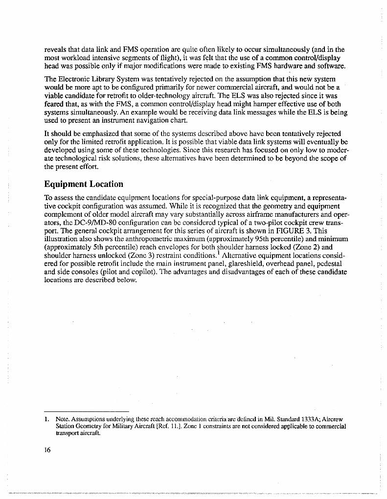
reveals that data link and FMS operation are quite often likely to occur simultaneously (and in the most workload intensive segments of flight), it was felt that the use of a common control/display head was possible only if major modifications were made to existing FMS hardware and software.
The Electronic Library System was tentatively rejected on the assumption that this new system would be more apt to be configured primarily for newer commercial aircraft, and would not be a viable candidate for retrofit to older-technology aircraft. The ELS was also rejected since it was feared that, as with the FMS, a common control/display head might hamper effective use of both systems simultaneously. An example would be receiving data link messages while the ELS is being used to present an instrument navigation chart.
It should be emphasized that some of the systems described above have been tentatively rejected only for the limited retrofit application. It is possible that viable data link systems will eventually be developed using some of these technologies. Since this research has focused on only low to moderate technological risk solutions, these alternatives have been determined to be beyond the scope of the present effort.
Equipment Location
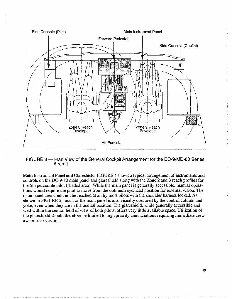
To assess the candidate equipment locations for special-purpose data link equ~pment, a representative cockpit configuration was assumed. While it is recognized that the geometry and equipment complement of older model aircraft may vary substantially across airframe manufacturers and operators, the DC-9/MD-80 configuration can be considered typical of a two-pilot cockpit crew transport. The general cockpit arrangement for this series of aircraft is shown in FIGURE 3. This illustration also shows the anthropometric maximum (approximately 95th percentile) and minimum (approximately 5th percentile) reach envelopes for both shoulder harness locked Clone 2) and shoulder harness unlocked (Zone 3) restraint conditions.1 Alternative equipment locations considered for possible retrofit include the main instrument panel, glareshield, overhead panel, pedestal and side consoles (pilot and copilot). The advantages and disadvantages of each of these candidate locations are described below.
1. Note. Assumptions underlying these reach accommodation criteria are defined in Mil. Standard 1333A; Aircrew Station Geometry for Military Aircraft [Ref. 11.]. Zone 1 constraints are not considered applicable to commercial transport aircraft.
16
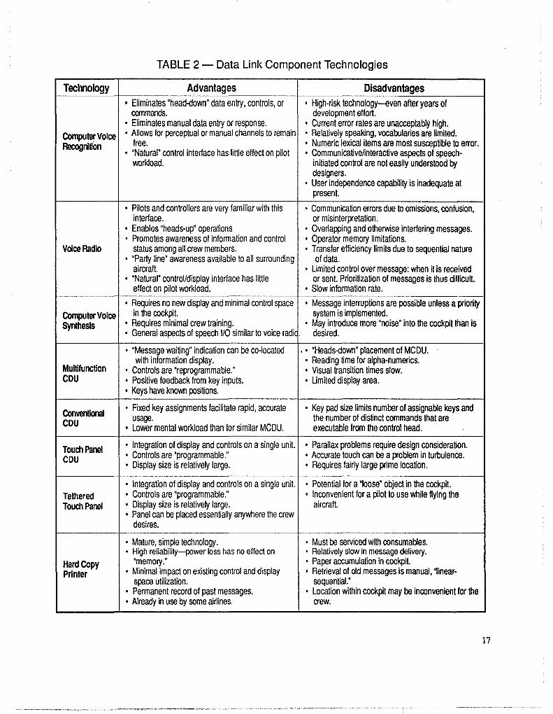
TABLE 2 - Data Link Component Technologies
Technology Advantages Disadvantages o Eliminates "head-down" data entry, controls, or o High-risk technology-€ven after years of
commands. development effort. o Eliminates manual data entry or response. o Current error rates are unacceptably high.
COmputE!!" Voice • Allows for perceptual or manual channels to remain • Relatively speaking, vocabularies are limited. RecognHon free. o Numeric lexical items are most susceptible to error.
o "Natural" control interface has little effect on pilot • Communicativeflnteractive aspects of speech-workload. initiated control are not easily understood by
designers. o User independence capability is inadequate at
present.
• Pilots and controllers are very familiar with this o Communication errors due to omissions, confusion, interface. or misinterpretation.
o Enables "heads-up" operations • Overlapping and otherwise interfering messages. o Promotes awareness of information and control o Operator memory limitations.
Voice Radio status among all crew members. o Transfer efficiency limits due to sequential nature o "Party line" awareness available to all surrounding of data.
aircraft. o Limited control over message: when it is received o "Natural" control/display interface has little or sent. Prioritization of messages is thus difficult.
effect on pilot workload. o Slow information rate.
o Requires no new display and minimal control space o Message interruptions are possible unless a priority COmputer Voice in the cockpit. system is implemented. Synthesis o Requires minimal crew training. o May introduce more "noise" into the cockpit than is
o General aspects of speech 1/0 similar to voice radic . desired.
o "Message waiting" indication can be co-located ' • "Heads-down" placement of MCDU.
Multifunction with information display. • Reading time for alpha-numerics.
o Controls are "reprogram mabie." o Visual transition times slow. CDU o Positive feedback from key inputs. o Limited display area.
o Keys have known positions.
Convendonal o Fixed key aSSignments facilitate rapid, accurate o Key pad size limits number of assignable keys and
CDU usage. the number of distinct commands that are o Lower mental workload than for similar MCDU. executable from the control head.
Touch Panel o Integration of display and controls on a single unit. o Parallax problems require design consideration.
CDU o Controls are ·programmable." o Accurate touch can be a problem in turbulence. o Display size is relatively large. o Requires fairly large prime location.
o Integration of display and controls on a single unit. o Potential for a "loose" object in the cockpit. Tethered o Controls are "programmable." o Inconvenient for a pilot to use while flying the Touch Panel o Display size is relatively large. aircraft.
o Panel can be placed essentially anywhere the crew desires.
o Mature, simple technology. o Must be serviced with consumables. • High reliability-power loss has no effect on • Relatively slow in message delivery.
Hard COpy "memory." • Paper accumulation in cockpit. Printer • Minimal impact on existing control and display o Retrieval of old messages is manual, "linear-
space utilization. sequential." o Permanent record of past messages. o Location within cockpit may be inconvenient for the o Already in use by some airlines. crew.
17
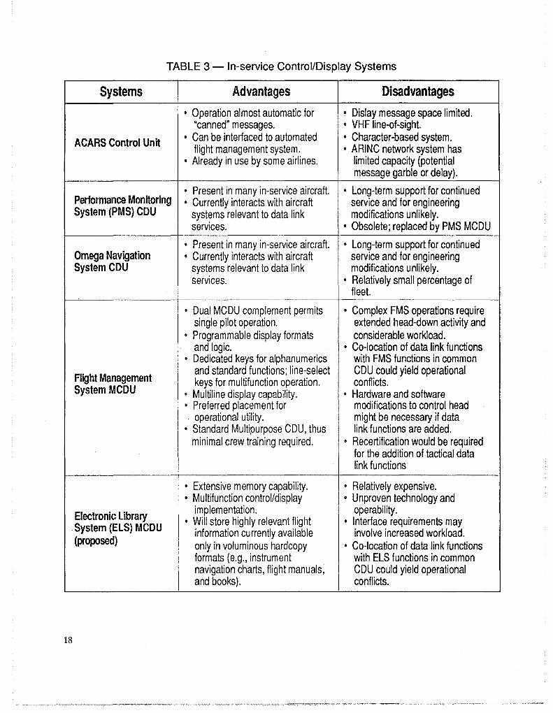
TABLE 3 -In-service Control/Display Systems
Systems Advantages Disadvantages
• Operation almost automatic for • Dislay message space limited. "canned" messages. • VHF line-of-sight.
ACARS Control Unit • Can be interfaced to automated • Character-based system. flight management system. • ARINC network system has
• Already in use by some airlines. limited capacity (potential message garble or delay).
Performance Monitoring • Present in many in-service aircraft. • Long-term support for continued • Currently interacts with aircraft service and for engineering
System (PMS) CDU systems relevant to data link modifications unlikely. services. • Obsolete; replaced by PMS MCDU
• Present in many in-service aircraft. • Long-term support for continued Omega Navigation • Currently interacts with aircraft service and for engineering System CDU systems relevant to data link modifications unlikely.
services. • Relatively small percentage of fleet.
• Dual MCDU complement permits • Complex FMS operations require single pilot operation. extended head-down activity and
• Programmable display formats considerable workload. and logic. • Co-location of data link functions
• Dedicated keys for alphanumerics with FMS functions in common
Flight Management and standard functions; line-select CDU could yield operational keys for multifunction operation. conflicts.
System MCDU • Multiline display capability. • Hardware and software • Preferred placement for modifications to control head
operational utility. might be necessary if data • Standard Multipurpose CDU, thus link functions are added.
minimal crew training required. • Recertification would be required for the addition of tactical data link functions
• Extensive memory capability. • Relatively expensive. • Multifunction control/display • Unproven technology and
Electronic Library implementation. operability.
• Will store highly relevant flight • Interface requirements may System (ELS) MCDU information currently available involve increased workload. (proposed) only in voluminous hardcopy • Co-location of data link functions
formats (e.g., instrument with ELS functions in common navigation charts, flight manuals, CDU could yield operational and books). conflicts.
18
Side Console (Pilot) Main Instrument Panel
Forward Pedestal
Side Console (Copilot)
Aft Pedestal
FIGURE 3 - Plan View of the General Cockpit Arrangement for the DC-9/MD-80 Series Aircraft
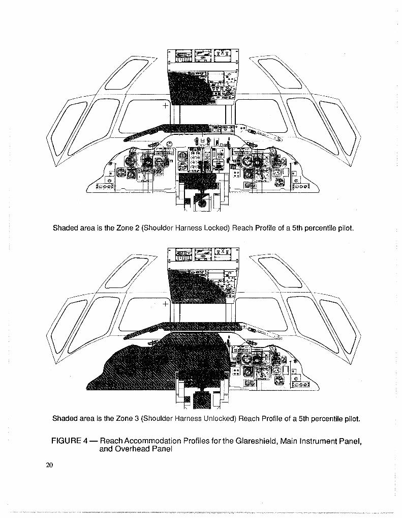
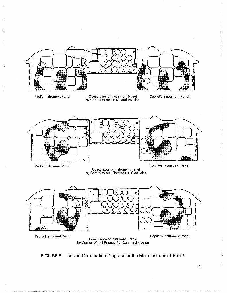
Main Instrument Panel and Glareshield. FIGURE 4 shows a typical arrangement of instruments and controls on the DC-9-80 main panel and glareshield along with the Zone 2 and 3 reach profiles for the 5th percentile pilot (shaded area). While the main panel is generally accessible, manual operations would require the pilot to move from the optimum eye/head position for external vision. The main panel area could not be reached at all by most pilots with the shoulder harness locked. As shown in FIGURE 5, much of the main panel is also visually obscured by the control column and yoke, even when they are in the neutral position. The glare shield, while generally accessible and well within the central field of view of both pilots, offers very little available space. Utilization of the glare shield should therefore be limited to high priority annunciations requiring immediate crew awareness or action.
19
Shaded area is the Zone 2 (Shoulder Harness Locked) Reach Profile of a 5th percentile pilot.
Shaded area is the Zone 3 (Shoulder Harness Unlocked) Reach Profile of a 5th percentile pilot,
FIGURE 4 - ReachAccommodation Profiles for the Glareshield, Main Instrument Panel, and Overhead Panel
20
Pilot's Instrument Panel
Pilot's Instrument Panel
Pilot's Instrument Panel
Obscuration of Instrument Panel by Control Wheel in Neutral Position
Obscuration of Instrument Panel by Control Wheel Rotated 600 Clockwise
Obscuration of Instrument Panel by Control Wheel Rotated 600 Counterclockwise
Copilot's Instrument Panel
Copilot's Instrument Panel
Copilot's Instrument Panel
FIGURE 5 - Vision Obscuration Diagram for the Main Instrument Panel
21
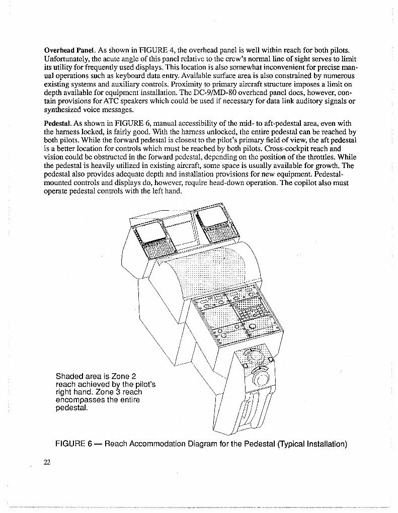
Overhead Panel. As shown in FIGURE 4, the overhead panel is well within reach for both pilots. Unfortunately, the acute angle of this panel relative to. the crew's normal line of sight serves to limit its utility for frequently used displays. This location is also somewhat inconvenient for precise manual operations such as keyboard data entry. Available surface area is also constrained by numerous existing systems and auxiliary controls. Proximity to primary aircraft structure imposes a limit on depth available for equipment installation. The DC-9/MD-80 overhead panel does, however, contain provisions for ATC speakers which could be used if necessary for data link auditory signals or synthesized voice messages.
Pedestal. As shown in FIGURE 6, manual accessibility of the mid- to aft-pedestal area, even with the harness locked, is fairly good. With the harness unlocked, the entire pedestal can be reached by both pilots. While the forward pedestal is closest to the pilot's primary field of view, the aft pedestal is a better location for controls which must be reached by both pilots. Cross-cockpit reach and vision could be obstructed in the forward pedestal, depending on the position of the throttles. While the pedestal is heavily utilized in existing aircraft, some space is usually available for growth. The . pedestal also provides adequate depth and installation provisions for new equipment. Pedestalmounted controls and displays do, however, require head-down operation. The copilot also must operate pedestal controls with the left hand.
22
Shaded area is Zone 2 reach achieved by the pilot's right hand. Zone 3 reach encompasses the entire pedestal.
FIGURE 6 - Reach Accommodation Diagram for the Pedestal (Typical Installation)

Side Consoles. FIGURE 7 shows the copilot's console arrangement for a DC-9-80 aircraft. The pilot's console differs in detail, but the equipment location alternatives are similar. The consoles are essentially within the Zone 3 reach constraints. The illustration shows examples of possible locations for a tethered touch panel CDU and a hard-copy printer. While the side consoles provide some available surface area, depth for equipment installation is limited by aircraft structure. Utilization of side consoles for data link displays and controls would necessitate duplication of all flight-critical communications functions on both sides of the cockpit. It should also be noted that side console installation would require left-hand operation by the pilot in the left seat. The present DC-9-80 console configuration provides for Central Aural Warning System (CAWS) speakers which could be used for data link auditory signals and voice messages. This speaker location is considered optimum to minimize potential confusion between conventional voice radio traffic (overhead speakers) and synthesized voice messages [Ref. 10.].
Shaded area is CopilOt's Zone 2 reach. The entire console can be reached with the harness unlocked.
G
CAWS Speaker
FIGURE 7 - Reach Accommodation Diagram·for the Copilot's Side Console (Typical Installation)
23
Function Implementation
Functional Model for Data Link Retrofit Applications
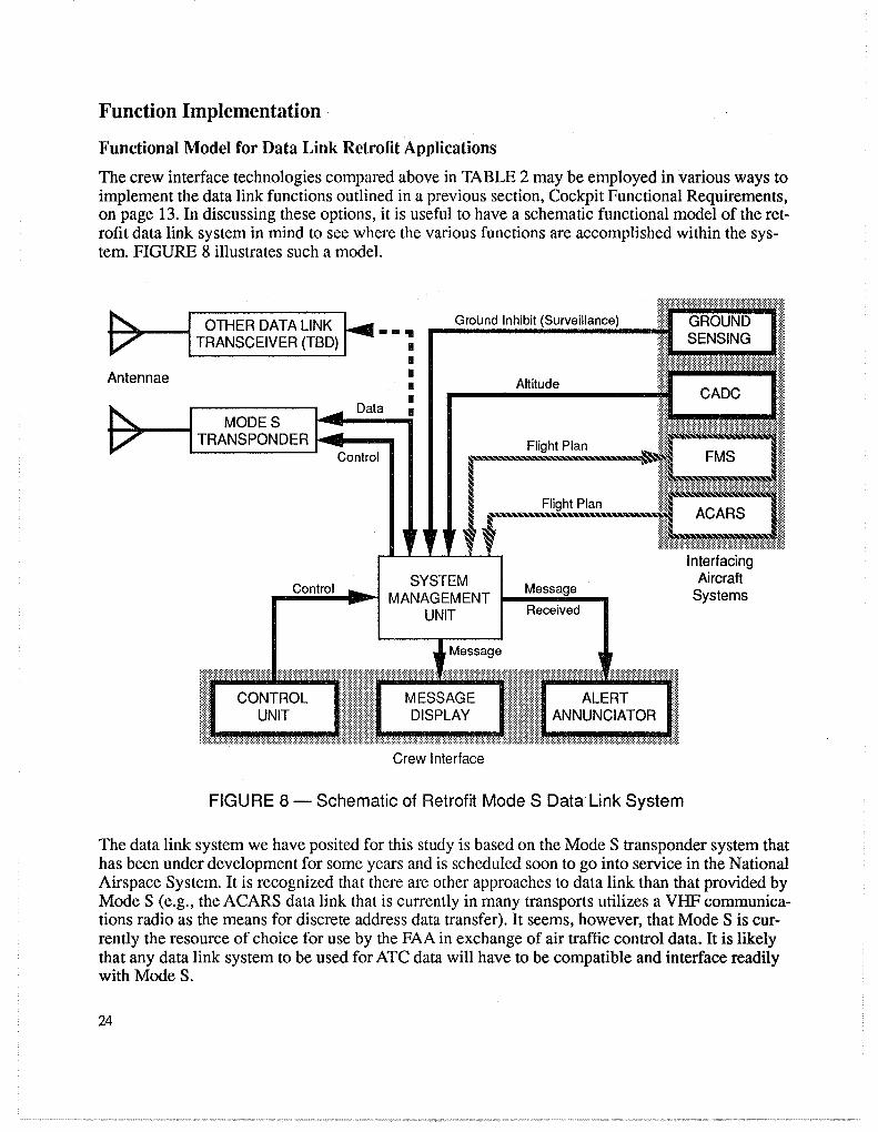
The crew interface technologies compared above in TABLE 2 may be employed in various ways to implement the data link functions outlined in a previous section, Cockpit Functional Requirements, on page 13. In discussing these options, it is useful to have a schematic functional model of the retrofit data link system in mind to see where the various functions are accomplished within the system. FIGURE 8 illustrates such a model.
Antennae
OTHER DATA LINK TRANSCEIVER (TBD)
Ground Inhibit
MODES
_ .. • • • •
Data • • TRANSPONDER ..... 1--..
Control
Control SYSTEM .... iiioiiii.ii-.. ... .-; MANAGEMENT
CONTROL UNIT
UNIT
MESSAGE DISPLAY
Crew Interface
Altitude
Flight Plan
Plan
Received
FIGURE 8 - Schematic of Retrofit Mode S Data Link System
Interfacing Aircraft
Systems
The data link system we have posited for this study is based on the Mode S transponder system that has been under development for some years and is scheduled soon to go into service in the National Airspace System. It is recognized that there are other approaches to data link than that provided by Mode S (e.g., the ACARS data link that is currently in many transports utilizes a VHF communications radio as the means for discrete address data transfer). It seems, however, that Mode S is currently the resource of choice for use by the FAA in exchange of air traffic control data. It is likely that any data link system to be used for ATC data will have to be compatible and interface readily with Mode S.
24
Mode S incorporates two separate functions: an accurate aircraft positioning capability via a secondary radar beacon; and a modem for transfer of digitally encoded data either ground-to-air or airto'!.ground [Ref. 12.]. Both capabilities make use of a discrete addressing function that allows positioning and other data to be passed to and from individual aircraft without interfering with other aircraft in the system. For purposes of this project, we are concerned with the data transfer function.
The basic system shown in FIGURE 8 consists of the Mode S transponder unit and its associated antenna together with a system management unit (SMU) and several crew and aircraft interfaces that must be accommodated. The Mode S transponder receives a formatted series of messages during the time the aircraft is within the beam width of the transmitting radar antenna. Some of the information in each transmission is involved with establishing or maintaining the discrete address relationship with the facility in whose airspace the aircraft resides. Other information provides the interrogation to which the transponder responds for identification and positioning. These transactions constitute the surveillance function, and are carried out automatically. The remaining data, however, constitute the data link instructions and information that are being passed to the aircraft. These data flow through a bus to the SMU which contains buffers and logic to store and code the data for delivery to the crew. The SMU also generates discrete signals to initiate an alt~rt that tells the crew that a message has been received.
The crew interface consists of the three lower units in FIGURE 8. We will discuss in a later section the pros and cons concerning how these functions might be implemented. For now, however, it will suffice to point out the crew interface functions and discuss their roles in the data link transactions. The Alert Unit (AU) is activated by a discrete signal from the SMU, indicating a message that requires the crew's attention has been received. Thus, the AU must be capable of attracting the crew's attention. The Message Display Unit (MDU) receives digitally encoded data from the SMU and converts it to a form that is intelligible to the crew. The Control Unit (CU) provides a means for the crew to enter commands and data into the SMU for controlling the system and for responding to the messages received over the data link. In this implementation, the CU controls not only the data link functions, but also the transponder functions that are allocated to crew control (for example, inserting the assigned identification code; changing the aircraft flight number identifier; or enabling! disabling the altitude reporting function). Thus, a separate transponder control head is not required, saving some panel space in the cockpit.
A second category of interface is illustrated by the four boxes in the upper right of FIGURE 8, specifically those required for other aircraft systems. There may be other aircraft functions that must interface with the Mode S data link in addition to those indicated. However, the ones shown serve to illustrate the point that a retrofit installation is not likely to be a stand-alone facility, and that its inclusion may result in necessary changes to already installed and certificated systems. The ground sensing system-usually based on a "squat switch" on the aircraft landing gear-provides a discrete signal to the SMU that inhibits surveillance responses when the aircraft is on the ground, thus taking useless data off the controller's radar display. Notice, however, that the data link functions are not disabled by this signal, since such data as weather forecasts, ATIS, and preflight clearances must be obtainable while the aircraft is on the ground. A second necessary interface is with the Central Air Data Computer which provides the encoded altitude information to the transponder for position reporting.
Also indicated in FIGURE 8 are two system interfaces that may not be on all Mode S data link retrofit installation aircraft. However, if either or both are present, an interface with the data link system may be advantageous. The ARINC Communications Addressing and Reporting System
25
(ACARS) provides a means of transmitting information that may be useful in ATC data link transactions. For example, ACARS could be used to forward the flight plan route filed by the air carrier dispatch group to the SMU and the display for comparison to the clearance actually granted by ATC (which is frequently different). In fact, some of the data in the filed plan could be extracted for the clearance request message that is sent over the data link to the clearance delivery function at the departure airport [Ref. 13.]. Without the ACARS interface, the crew would have to reenter this data manually, referring to a hard copy of the flight plan, or revert to using the communications radio for the request. A similar argument could be made for interfacing with the Flight Management System (FMS). Most of these units presently require manual programming. If programming has already been accomplished, then it would be convenient to extract data from the FMS for composing requests on the data link, rather than having to enter the data twice. On the other hand, if data link instructions call for modification of the flight plan that is currently in the FMS, then an interface could allow the modification instructions to be passed directly to the FMS from the data link. This would preclude requiring manual transfer of the new clearance by the crew.
Functional Options for Implementation of Data Link
TABLE 4 provides a summary of how the previously discussed technologies could be used to implement the principal airborne data link functions. The functions are listed in the left column of the table. The middle column contains a brief indication of how each function is currently accomplished in non-data link equipped aircraft. This information is shown for reference and to provide a standard of comparison for evaluating the data link options. Only those options that appear to provide a benefit to the crew or to air traffic flow operations over the current approach are likely to receive serious consideration. Finally, the right column summarizes the technology options that appear to have merit for implementing the function in a retrofit data link application. Following is a discussion of the options and a rationale for the selection of system configuration concepts.
Alert the Crew. Alerting may be accomplished either visually or aurally. In some critical situations, perhaps both may be used to ensure that the crew's attention is attracted. Of maximum importance among requirements for an alerting device is its conspicuity. A visual alert, such as a signal light or annunciator, must be placed in a position that is likely to be always within the field of view of the crew. The glareshield location next to the master caution and warning annunciators is an appropriate site for a data link alert annunciator. Clearly, this requirement rules out the option of simply presenting the message as it arrives, unless the message display itself is located in a prime location (which, considering the space required, is unlikely). Aural alerts-tones or synthetic voice-have the advantage that they do not require the crew to be looking in any particular direction to be perceived. However, they may be masked by (and may mask) other aural information in the transport cockpit, such as aural warnings or communication radio traffic.
Specialized visual alerts can usually be readily distinguished from other devices requiring visual perception. However, with aural alerts the designer must be careful to provide a signal that is discriminable from the many coded sounds already in the cockpit. It must be recognizable as the alert for the data link function, as opposed to another purpose. This is difficult to accomplish with the multitude of sounds used in today's cockpits for various annunciation functions. An interesting example is the chime sound used for the ACARS data link in modern transports. An identical chime is also used to alert the crew for selective call (SELCAL) and cabin attendant call. Thus, the crew is forced to make a secondary discrimination when the chime is heard, to distinguish which of these functions is being annunciated. Synthetic voice aural alerts have the advantage that a universally understood code-natural language-is used, so that discrimination is high. Synthetic voice
26

TABLE 4 - Options for Accomplishing Data Link Functions
Functions . Non-Data Link Options for Environment Data Link
Alert Crew to Incoming First part of controller transmission is Aural tone: Message. aircraft call sign. • Unique sound required
Attend all messages after own call sign. Aural synthetic voice: • Call sign
Monitor or ignore messages not attached • Other standard word/phrase to own call sign Imay attend other messages if the content is deemed useful Visual: ("party line")I. • Annunciator light
- Prominent location (e.g. glareshield) - Flashing vs. steady
• Message or symbol appears on display - Display in prominent location - Flashing vs. steady
Prioritize/Sequence Content of message determines priority. Categorize messages by time and/or safety or Multiple Messages operational criticality:
Sequencing depends on pilots' • Non-control/Strategic controlfT actical control. remembering multiple messages or writing • Use buffer to store low criticality messages down information. until pilot selects display ("message waiting"
cue). Communications radio not inhibited by • Display critical messages immediately as onboard aural (tone or voice) warnings. received. Warnings may mask messages (and • Multiline display for multiple critical messages vice-versa). (if necessary, oldest messages scrolled off to
buffer ahead of non-critical messages).
No categories: • Chronological presentation on display • Oldest messages scroll off display as new
ones arrive - Messages retained in memory - Messages output to printer - Messages lost
Perceive Message Messages perceived as spoken language. Visual presentation of messages Content • Alphanumerics
Subject to variations in pronunciation by • Use of abbreviations and symbols controllers. • Printer vs. display formats
Aural presentation of messages • Synthetic voice • Ability to store and replay
27
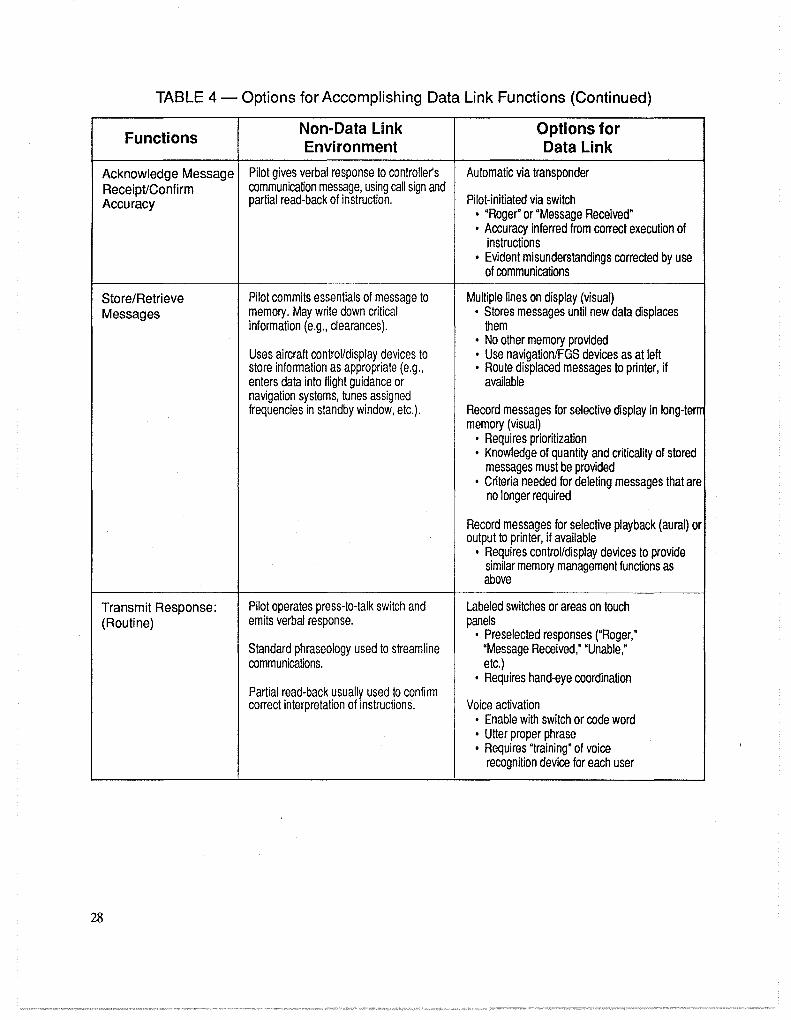
TABLE 4 - Options for Accomplishing Data Link Functions (Continued)
Functions Non-Data Link Options for Environment Data Link
Acknowledge Message Pilot gives verbal response to controller's Automatic via transponder Receipt/Confirm communication message, using call sign and Accuracy partial read-back of instruction. Pilot-initiated via switch
• "Roger" or "Message Received" • Accuracy inferred from correct execution of
instructions • Evident misunderstandings corrected by use
of communications
Store/Retrieve Pilot commits essentials of message to Multiple lines on display (visual) Messages memory. May write down critical • Stores messages until new data displaces
information (e.g., clearances). them • No other memory provided
Uses aircraft control/display devices to • Use navigation/FGS devices as at left store information as appropriate (e.g., • Route displaced messages to printer, if enters data into flight guidance or available navigation systems, tunes assigned frequencies in standby window, etc.). Record messages for selective display in long-terrr
memory (visual) • Requires prioritization • Knowledge of quantity and criticality of stored
messages must be provided • Criteria needed for deleting messages that are
no longer required
Record messages for selective playback (aural) or output to printer, if available
• Requires control/display devices to provide similar memory management functions as above
Transmit Response: Pilot operates press-to-talk switch and Labeled switches or areas on touch (Routine) emits verbal response. panels
• Preselected responses ("Roger," Standard phraseology used to streamline "Message Received," "Unable," communications. etc.)
• Requires hand-eye coordination Partial read-back usually used to confirm correct interpretation of instructions. Voice activation
• Enable with switch or code word • Utter proper phrase • Requires "training" of voice
recognition device for each user
28
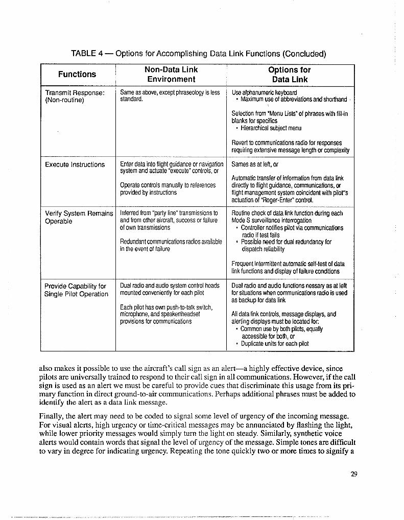
TABLE 4 - Options for Accomplishing Data Link Functions (Concluded)
Functions Non-Data Link Options for Environment Data Link
Transmit Response: Same as above, except phraseology is less Use alphanumeric keyboard (Non-routine) standard. • Maximum use of abbreviations and shorthand
'.
Selection from "Menu Lists" of phrases with fill-in blanks for specifics
• Hierarchical subject menu
Revert to communications radio for responses requiring extensive message length or complexity
Execute Instructions Enter data into flight guidance or navigation Sames as at left, or system and actuate "execute" controls, or
Automatic transfer of information from data link Operate controls manually to references directly to flight guidance, communications, or provided by instructions flight management system coincident with pilo!"s
actuation of "Roger-Enter" control.
Verify System Remains Inferred from "party line" transmissions to Routine check of data link function during each Operable and from other aircraft, success or failure Mode S surveillance interrogation
of own transmissions • Controller notifies pilot via communications radio if test fails
Redundant communications radios available • Possible need for dual redundancy for in the event of failure dispatch reliability
Frequent intermittent automatic self-test of data link functions and display of failure conditions
Provide Capability for Dual radio and audio system control heads Dual radio and audio functions nessary as at left Single Pilot Operation mounted conveniently for each pilot for situations when communications radio is used
as backup for data link Each pilot has own push-to-talk switch, microphone, and speaker/headset All data link controls, message displays, and provisions for communications alerting displays must be located for:
• Common use by both pilots, equally accessible for both, or
• Duplicate units for each pilot
also makes it possible to use the aircraft's call sign as an alert-a highly effective device, since pilots are universally trained to respond to their call sign in all communications. However, if the call sign is used as an alert we must be careful to provide cues that discriminate this usage from its primary function in direct ground-to-air communications. Perhaps additional phrases must be added to identify the alert as a data link message.
Finally, the alert may need to be coded to signal some level of urgency of the incoming message. For visual alerts, high urgency or time-critical messages may be annunciated by flashing the light, while lower priority messages would simply turn the light on steady. Similarly, synthetic voice alerts would contain words that signal the level of urgency of the message. Simple tones are difficult to vary in degree for indicating urgency. Repeating the tone quickly two or more times to signify a
29
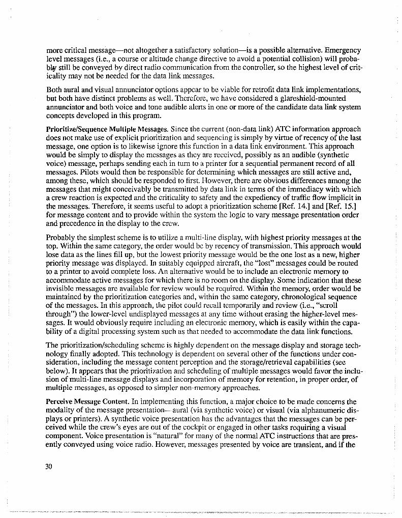
more critical message-not altogether a satisfactory solution-is a possible alternative. Emergency level messages (i.e., a course or altitude change directive to avoid a potential collision) will probab~ still be conveyed by direct radio communication from the controller, so the highest level of criticality may not be needed for the data link messages.
Both aural and visual annunciator options appear to be viable for retrofit data link implementations, but both have distinct problems as well. Therefore, we have considered a glareshield-mounted annunciator and both voice and tone audible alerts in one or more of the candidate data link system concepts developed in this program.
Prioritize/Sequence Multiple Messages. Since the current (non-data link) ATC information approach does not make use of explicit prioritization and sequencing is simply by virtue of recency of the last message, one option is to likewise ignore this function in a data link environment. This approach would be simply to display the messages as they are received, possibly as an audible (synthetic voice) message, perhaps sending each in turn to a printer for a sequential permanent record of all messages. Pilots would then be responsible for determining which messages are still active and, among these, which should be responded to first. However, there are obvious differences among the messages that might conceivably be transmitted by data link in terms of the immediacy with which a crew reaction is expected and the criticality to safety and the expediency of traffic flow implicit in the messages. Therefore, it seems useful to adopt a prioritization scheme [Ref. 14.] and [Ref. 15.] for message content and to provide within the system the logic to vary message presentation order and precedence in the display to the crew.
Probably the simplest scheme is to utilize a multi-line display, with highest priority messages at the top. Within the same category, the order would be by recency of transmission. This approach would lose data as the lines fill up, but the lowest priority message would be the one lost as a new, higher priority message was displayed. In suitably equipped aircraft, the "lost" messages could be routed to a printer to avoid complete loss. An alternative would be to include an electronic memory to accommodate active messages for which there is no room on the display. Some indication that these invisible messages are available for review would be required. Within the memory, order would be maintained by the prioritization categories and, within the same category, chronological sequence of the messages. In this approach, the pilot could recall temporarily and review (i.e., "scroll through") the lower-level undisplayed messages at any time without erasing the higher-level messages. It would obviously require including an electronic memory, which is easily within the capability of a digital processing system such as that needed to accommodate the data link functions.
The prioritization/scheduling scheme is highly dependent on the message display and storage technology finally adopted. This technology is dependent on several other of the functions under consideration, including the message content perception and the storage/retrieval capabilities (see below). It appears that the prioritization and scheduling of multiple messages would favor the inclusion of multi-line message displays and incorporation of memory for retention, in proper order, of multiple messages, as opposed to simpler non-memory approaches.
Perceive Message Content. In implementing this function, a major choice to be made concerns the modality of the message presentation-aural (via synthetic voice) or visual (via alphanumeric displays or printers). A synthetic voice presentation has the advantages that the messages can be perceived while the crew's eyes are out of the cockpit or engaged in other tasks requiring a visual component. Voice presentation is "natural" for many of the normal ATC instructions that are presently conveyed using voice radio. However, messages presented by voice are transient, and if the
30
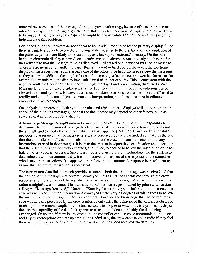
crew misses some part of the message during its presentation (e.g., because of masking noise or interference by other aural signals) either a mistake may be made or a "say again" request will have to be made. A memory playback capability might be a worthwhile addition for an aural system to help alleviate this problem.
For the visual option, printers do not appear to be an adequate choice for the primary display. Since there is usually a delay between the buffering of the message to the display and the completion of the printout, printers are likely to be used only as a backup or "external" memory. On the other hand, an electronic display can produce an entire message almost instantaneously and has the further advantage that the message remains displayed until erased or superseded by another message. There is also no need to handle the paper that is inherent in hard copies. However, the electronic display of messages does require at least one of the pilots to be head-down to review the messages as they occur. In addition, the length of some of the messages (clearances and weather forecasts, for example) demands that the display have substantial character capacity. This is consistent with the need for multiple lines of data to support multiple messages and prioritization, discussed above. Message length (and hence display size) can be kept to a minimum through the judicious use of abbreviations and symbols. However, care must be taken to make sure that the "shorthand" used is readily understood, is not subject to erroneous interpretation, and doesn't require inordinate amounts of time to decipher.
On analysis, it appears that both synthetic voice and alphanumeric displays will support communication of the data link messages, and that the final choice may depend on other factors, such as space availability for electronic displays.
Acknowledge Message Receipt/Confirm Accuracy. The Mode S system has built in capability to determine that the transmitted message has been successfully received by the transponder aboard the aircraft, and to notify the controller that this has happened [Ref. 12.]. However, this capability provides no assurance that the message is actually perceived by the crew and, if so, that it is the one that the controller actually sent. It is also required that the crew indicate their intent about any instructions carried in the messages. It is up to the crew to interpret the local situation and determine that the instructions can be safely executed, and, if not, to decline to follow the instruction or negotiate an alternative, if necessary. Since it is impossible, using current technology, for the system to determine crew intent automatically, it cannot convey this aspect of the response to the controller who issued the instructions. It is apparent, therefore, that the automatic response is insufficient to assure that the entire transaction is successful.
The current non-data link approach provides assurance both that the message was received and that the content of the message was correctly conveyed. This assurance is achieved through the crew response and the accuracy of the read-back of essentials of the message. Moreover, it does so in a rather straightforward manner. The transmission of brief messages initiated by pilot switch action ("Roger," "Message Received," "Unable," "Standby," etc.) conveys the information that some message was received. Further information is conveyed by the varying degrees of willingness to follow the instruction in the message, if that is its content. However, the knowledge that the correct message was actually perceived by the crew is inferred only after the behavior of the aircraft is observed to change in the manner implied by the instruction. The degree to which this is a problem is dependent on the capability of the data link system to transmit and decode reliably the data being exchanged. Of course, if there is any question, the controller can use voice communication to correct any misperceptions or clear up ambiguities. Similarly, the crew can use voice radio if they feel there is anything questionable about the instruction that has been received via data link.
31
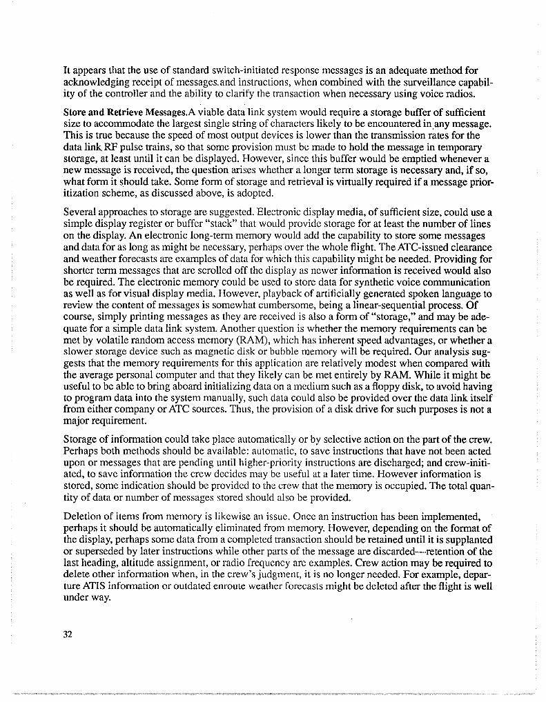
It appears that the use of standard switch-initiated response messages is an adequate method for acknowledging receipt of messages. and instructions, when combined with the surveillance capability of the controller and the ability to clarify the transaction when necessary using voice radios.
Store and Retrieve Messages.A viable data link system would require a storage buffer of sufficient size to accommodate the largest single string of characters likely to be encountered in.any message. This is true because the speed of most output devices is lower than the transmission rates for the data link RF pulse trains, so that some provision must be made to hold the message in temporary storage, at least until it can be displayed. However, since this buffer would be emptied whenever a new message is received, the question arises whether a longer term storage is necessary and, if so, what form it s,hould take. Some form of storage and retrieval is virtually required if a message prioritization scheme, as discussed above, is adopted.
Several approaches to storage are suggested. Electronic display media, of sufficient size, could use a simple display register or buffer "stack" that would provide storage for at least the number of lines on the display. An electronic long-term memory would add the capability to store some messages and data for as long as might be necessary, perhaps over the whole flight. The ATC-issued clearance and weather forecasts are examples of data for which this capability might be needed. Providing for shorter term messages that are scrolled off the display as newer information is received would also be required. The electronic memory could be used to store data for synthetic voice communication as well as for visual display media. However, playback of artificially generated spoken language to review the content of messages is somewhat cumbersome, being a linear-sequential process. Of course, simply printing messages as they are received is also a form of "storage," and may be adequate for a simple data link system. Another question is whether the memory requirements can be met by volatile random access memory (RAM), which has inherent speed advantages, or whether a slower storage device such as magnetic disk or bubble memory will be required. Our analysis suggests that the memory requirements for this application are relatively modest when compared with the average personal computer and that they likely can be met entirely by RAM. While it might be useful to be able to bring aboard initializing data on a medium such as a floppy disk, to avoid having to program data into the system manually, such data could also be provided over the data link itself from either company or ATC sources. Thus, the provision of a disk drive for such purposes is not a major requirement.
Storage of information could take place automatically or by selective action on the part of the crew. Perhaps both methods should be available: automatic, to save instructions that have not been acted upon or messages that are pending until higher-priority instructions are discharged; and crew-initiated, to save information the crew decides may be useful at a later time. However information is stored, some indication should be provided to the crew that the memory is occupied. The total quantity of data or number of messages stored should also be provided.
Deletion of items from memory is likewise an issue. Once an instruction has been implemented, perhaps it should be automatically eliminated from memory. However, depending on the format of the display, perhaps some data from a completed transaction should be retained until it is supplanted or superseded by later instructions while other parts of the message are discarded-retention of the last heading, altitude assignment, or radio frequency are examples. Crew action may be required to delete other information when, in the crew's judgment, it is no longer needed. For example, departure ATIS information or outdated enroute weather forecasts might be deleted after the flight is well under way.
32
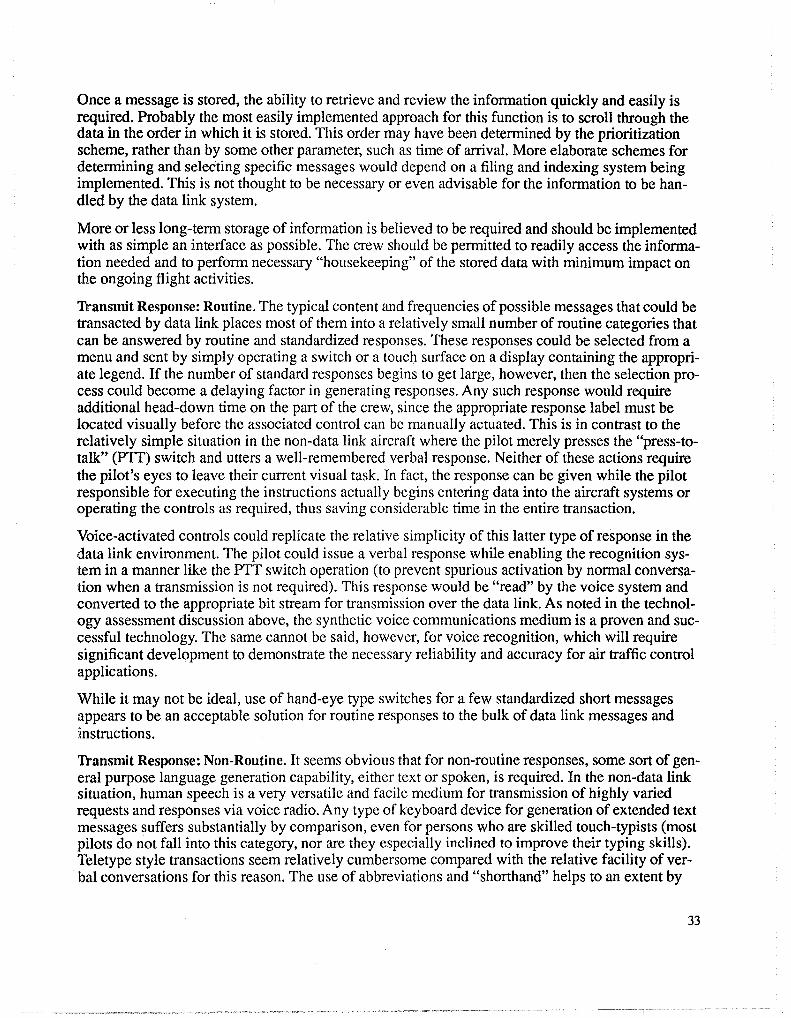
Once a message is stored, the ability to retrieve and review the information quickly and easily is required. Probably the most easily implemented approach for this function is to scroll through the data in the order in which it is stored. This order may have been determined by the prioritization scheme, rather than by some other parameter, such as time of arrival. More elaborate schemes for determining and selecting specific messages would depend on a filing and indexing system being implemented. This is not thought to be necessary or even advisable for the information to be handled by the data link system.
More or less long-term storage of information is believed to be required and should be implemented with as simple an interface as possible. The crew should be permitted to readily access the information needed and to perform necessary "housekeeping" of the stored data with minimum impact on the ongoing flight activities.
Transmit Response: Routine. The typical content and frequencies of possible messages that could be transacted by data link places most of them into a relatively small number of routine categories that can be answered by routine and standardized responses. These responses could be selected from a menu and sent by simply operating a switch or a touch surface on a display containing the appropriate legend. If the number of standard responses begins to get large, however, then the selection process could become a delaying factor in generating responses. Any such response would require additional head-down time on the part of the crew, since the appropriate response label must be located visually before the associated control can be manually actuated. This is in contrast to the relatively simple situation in the non-data link aircraft where the pilot merely presses the "press-totalk" (PIT) switch and utters a well-remembered verbal response. Neither of these actions require the pilot's eyes to leave their current visual task. In fact, the response can be given while the pilot responsible for executing the instructions actually begins entering data into the aircraft systems or operating the controls as required, thus saving considerable time in the entire transaction.
Voice-activated controls could replicate the relative simplicity of this latter type of response in the data link environment. The pilot could issue a verbal response while enabling the recognition system in a manner like the PTT switch operation (to prevent spurious activation by normal conversation when a transmission is not required). This response would be "read" by the voice system and converted to the appropriate bit stream for transmission over the data link. As noted in the technology assessment discussion above, the synthetic voice communications medium is a proven and successful technology. The same cannot be said, however, for voice recognition, which will require significant development to demonstrate the necessary reliability and accuracy for air traffic control applications.
While it may not be ideal, use of hand-eye type switches for a few standardized short messages appears to be an acceptable solution for routine responses to the bulk of data link messages and instructions.
Transmit Response: Non-Routine. It seems obvious that for non-routine responses, some sort of general purpose language generation capability, either text or spoken, is required. In the non-data link situation, human speech is a very versatile and facile medium for transmission of highly varied requests and responses via voice radio. Any type of keyboard device for generation of extended text messages suffers substantially by comparison, even for persons who are skilled touch-typists (most pilots do not fall into this category, nor are they especially inclined to improve their typing skills). Teletype style transactions seem relatively cumbersome compared with the relative facility of verbal conversations for this reason. The use of abbreviations and "shorthand" helps to an extent by
33
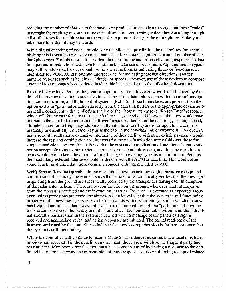
reducing the number of characters that have to be produced to encode a message, but these "codes" may make the resulting messages more difficult and time-consuming to decipher. Searching through a list of phrases for an abbreviation to avoid the requirement to type the entire phrase is likely to take more time than it may be worth.
While digital encoding of vocal emissions by the pilots is a possibility, the technology for accomplishing this is even less well-developed than is that for voice recognition of a small number of standard phonemes. For this reason, it is evident that non-routine and, especially, long responses to data link queries or instructions will have to continue to make use of voice radio. Alphanumeric keypads may still be advisable for occasional use for such functions as indicating three- or five-character identifiers for VORTAC stations and intersections; for indicating cardinal directions; and for numeric responses such as headings, altitudes or speeds. However, use of these devices to compose extended text messages is considered inadvisable because of excessive pilot head-down time.
Execute Instructions. Perhaps the greatest opportunity to minimize crew workload induced by data linked instructions lies in the extensive interfacing of the data link system with the aircraft navigation, communication, and flight control systems [Ref. 15.]. If such interfaces are present, then the option exists to "gate" information directly from the data link buffers to the appropriate device automatically, coincident with the pilot's actuation of the "Roger" response (a "Roger-Enter" response), which will be the case for most of the tactical messages received. Otherwise, the crew would have to operate the data link to indicate the "Roger" response; then enter the data (e.g., heading, speed, altitude, center radio frequency, etc.) manually into the aircraft systems; or operate the controls manually in essentially the same way as is the case in the non-data link environment. However, in many retrofit installations, extensive interfacing of the data link with other existing systems would increase the test and certification requirements for the new installation many fold over those for a simple stand-alone system. It is believed that the costs and complication of such interfacing would not be acceptable to many air carrier customers for the data link system, and thus the retrofit concepts would tend to keep the amount of interfacing with existing systems to a minimum. Perhaps the most likely external interface would be the one with the ACARS data link. This would offer some benefit in sharing data from company sources with that provided by ATe.
Verify System Remains Operable. In the discussion above on acknowledging message receipt and confirmation of accuracy, the Mode S surveillance function automatically verifies that the messages originating from the ground are successfully received by the transponder during each interception of the radar antenna beam. There is also confirmation on the ground whenever a return response from the aircraft is received and the instruction that was "Rogered" is executed as expected. However, unless provisions are made, the aircrew has no knowledge that the system is still functioning properly until a new message is received. Contrast this with the current system, in which the crew has frequent assurances that the overall system is operational through the "party line" of ongoing transmissions between the facility and other aircraft. In the non-data link environment, the individual aircraft's participation in the system is verified when a message bearing their call sign is received and appropriate verbal and action responses are initiated. The partial read-back of the instructions issued by the controller to indicate the crew's comprehension is further assurance that the system is still functioning.
While the controller will continue to receive Mode S surveillance responses that indicate his transmissions are successful in the data link environment, the aircrew wi11lose the frequent party line reassurances. Moreover, since the crew must have some means of indicating a response to the data linked instructions anyway, the transmission of these responses closely following receipt of related
34
instructions will convey to the controller that the crew has received and understood the message. This may not be as succinct as a verbatim read-back, however. In certain circumstances there may be substantial time between data link transactions during which failures could occur and go undett!cted by means of the transactions themselves. Both the crew and the controller may be unaware of airborne system failures upstream of the transponder. While the controller might resort to use of voice radio after several repeats of the same message fail to elicit a response (assuming that the surveillance transactions are progressing normally on each scan of the antenna), it seems evident that a relatively frequent airborne system self-test should be incorporated. Timely warning of the crew that the data link is inoperative and that an alternate means of communication is required should also be appropriately annunciated.
Provide for Single Pilot Operation. The data link system must be fully operable by either pilot from his own station in the two-crew aircraft. Important ATC messages may be received at any time, including times when one of the pilots is absent from the flight deck, or in the possible situation of an incapacitated pilot due to illness or accident. The data link installation must be ergonomically configured for frequent usage from either pilot position. For example, the approach that has been adopted for installation of ACARS data link units, which in many instances places the· controls, displays, printers, and facilities in such a position that they are readily usable only from the right seat, would be unacceptable for a Mode S data link installation.
In the current non-data link environment, in which the VHF voice radios are the medium for ATC information exchange, dual radio tuning heads, audio control panels, and microphone and headphone connections are provided that are equally usable by both pilots. In some instances, these devices are located in commonly reachable areas usable by both pilots (for example, on the pedestal between the pilots); in others, they are located in areas reachable by only one crewmember, but in such cases, duplicate units are provided. The data link installation would require these same communications facilities for the situation when the data link must be backed up by voice communications. In addition, the data link control/display unit(s) must either be located in a common access area between the pilots, or else dual, equally accessible units must be provided at each pilot station.
Having considered how the functional requirements for a retrofit Mode S data link can be met by the available and emerging technologies, we now turn to defining several specific candidate configurations for data link installations in actual existing transport aircraft. In the following section, several system concepts are defined and their application to various aircraft with different equipment complements are discussed.
System Concepts
The analysis of the functional requirements of data link and the major options available serve to constrain the number of viable candidate configurations to be considered for retrofit. In the section to follow, we will first outline the equipment complements and location options available for these candidates and then describe how each configuration would satisfy the system's functional requirements. Next, consideration will be given to determining which configurations are best suited for various classes of in-service aircraft. Subsequent analyses will then be conducted to determine the most promising configurations.
Synthetic Voice Display Configuration. One configuration that has received substantial attention for data link retrofit is the use of a computer-generated synthetic voice read out of uplinked ATC messages. In the configuration considered here, the synthetic voice communication would be accompa-
35
nied by synthetic voice annunciation and an option for either a minimally capable (able to send only "Roger," "Unable," and "Standby" replies) or a fully capable (i.e., free-text data entry) controVinput device.
The synthetic voice system would be optimized for intelligibility. First, voice outputs would be articulate and of excellent acoustic quality. Second, the sound volume of the voice message would be set to overcome cockpit noise and interfering sound sources. To further guard against the possibility of aural channel interference and confusion, the data link speech output would be acoustically distinct from competing vocal message media such as voice radio communications, crew speech, and other vocal annunciations and advisories.
There are two areas of concern about message content in a synthetic voice implementation. First, it is important that message formats (i.e., phrases uttered) be complete yet concise, unambiguous, and as similar to natural voice communication formats as possible. This is important to facilitate transfer of training and to avoid errors. Second, effective repetition or other means of emphasizing message content and message priority and criticality must be incorporated into the formatting scheme adopted for information uplink.
The use of a voice synthesis annunciation system has several advantages over the more typical visual annunciator. For example, having a synthetic voice annunciation immediately preceding a synthetic voice message greatly facilitates the pilot's ability to quickly and completely attend to the incoming information. The annunciation may be as simple as using the aircraft's call sign in the same manner as now used in a voice communication environment. The use of a synthetic voice annunciation substantially lessens the potential for momentary confusion or visual distraction that would be possible with the employment of only a visual annunciator.
The decision to use a synthetic speech annunciation (such as the synthetic speaking of the call sign) instead of an aural alert was made, in part, to avoid contributing to the proliferation of aural signals already present in many current aircraft. Also, synthetic speech was seen as superior to aural alerts in that important classification and prioritization information (e.g., "AA-330, data link message, priority number one.") could be delivered more directly via a voice annunciation (and therefore be more directly understood) than via an aural alert since the pilot would not have to memorize yet another set of tone-to-meaning relationships to operate the data link system effectively.
Two versions of control capability are proposed for this configuration. In the minimal capability version, the crew's ability to downlink information is limited to "Roger," "Unable," and "Standby" messages delivered via some manual control provision. In this version, more elaborate messages (e.g., when negotiating a clearance with ATC) would still be communicated using voice radio. In the second version, the control device would be able to send more elaborate information, including free-text messages. This version would require alphanumeric data entry capability, some scratch pad display, and message selection/transmission controls (e.g., buttons) in addition to the "Roger," "Unable," and "Standby" messages.
Options for placement of this control unit will differ depending on the cockpit configuration under consideration. The control head for minimal capability could obviously be placed in severallocations. In rough order of preference, the principal possibilities are: the glareshield; outboard and forward (near the audio panels on the DC-9/MD-80 aircraft); the forward pedestal; and the aft pedestal, as far forward as room permits. Candidate locations for the full capability control unit are, of course, more limited. Assuming that a retrofit configuration would be designed to minimally perturbate existing cockpits, possible locations are probably limited to the forward and aft pedestals.
36
As with all the data link configuration candidates, the presence of at least one printer and the continued employment of voice radio are assumed.
Dedicated Data Link MCDU. In this configuration, an MCDU is dedicated to data link activities. The preferred technology for this MCDU would depend on space limitations, but would typically be a flat-panel display operated with dedicated push buttons (for frequently used functions and for alphanumeric data entry) and multifunction bezel switches (for line selection, etc.). The best layout for this MCDU would be similar to an FMS CDU, both in display area and control key fields. The overall box size for the unit would be approximately 6 x 8 inches for forward pedestal placement (in MD-80-c1ass aircraft) and 6 X 9 inches for aft pedestal placement. An annunciation 'light would be located in some conspicuous location such as on the glareshield or on the main instrument panel.
The alternative technology for this MCDU would be a touch-sensitive, flat panel unit. Message display, "Acknowledge/RogerlUnable" functions, data entry, and menu-select control would all be conducted in different display/control fields ("pages"), using software addressable touch-sensitive inputs. With this MCDU, system operations might necessitate a substantial dependence on menuselect control at the expense of the frequent use of free-field (typed) messages. While such an implementation would, in general, have more impact on downlink than on uplink messages, and more impact on extended than on basic data link services, it may be adequate for the majority of data link services. In support of this contention, Knox and Scanlon [Ref. 3.] reported very positive initial evaluations by pilots in a flight test simulation of a touch-panel data link configuration.
Combined ACARSlData Link MCDU. This configuration is recommended when ACARS is already resident on the flight deck and space limitations preclude the installation of a dedicated ATC data link MCDU. As the name suggests, in this configuration, the existing ACARS CDU is replaced with an MCDU capable of accommodating both ACARS and ATC data link activities. Analogously to the dedicated data link MCDU, the particular MCDU preferred depends on two factors, the current location of the ACARS CDU and the room available in and surrounding that location.
In cases where the existing ACARS unit only occupies enough room for a one-for-one replacement of the CDU head (usually a 4 1/2 x 6 inch area), a touch-sensitive, flat panel MCDU should be considered. Since this unit would be similar to the one contemplated for the dedicated MCDU (except for the requirement that ACARS operation also be supported), the same concerns regarding touch panel operation apply here as well.
When there is room for a larger replacement unit, a flat panel conventional MCDU similar to the one recommended for the dedicated data link MCDU is preferred. The principal difference for the combined configuration is, of course, the incorporation of ACARS functions. This requirement would have consequences for both hardware (additional control elements), and for software logic and formats (e.g., management of mUltiple messages and prioritization display indicators). While these modifications would indeed require a fairly detailed design and development effort, preliminary analysis suggests that a common MCDU could adequately accommodate both digital communication functions.
Combined FMSlData Link MCDU. A fourth approach was also considered but was not carried on into the analytical assessment phases that follow in view of several significant developmental and operational risks. This was the option of modifying an existing FMS to incorporate data link functions and to interface as necessary with the Mode S and other onboard systems. This approach appeared to be particularly attractive on such aircraft as the MD-88, which has dual FMS CDUs but which has very little additional panel area available for installing an additional specialized data link
37
CDU. Of course, a modified FMS CDU would only be practical for use in aircraft presently equipped with, or destined to be upgraded to, an FMS in the future. It would not be feasible for operators seeking a minimum cost solution to the data link retrofit problem alone. Therefore, the modified FMS CDU is only a partial solution. One or more of the other options would have to be developed in addition to cover the entire spectrum of potential retrofit applications. Moreover, adding data link functions to the FMS would likely result in substantial operational complication.
Many FMS-equipped aircraft mount dual CDUs-allowing one unit to serve for data link functions while the other remains in FMS mode. The fact that the same crewmember (the "pilot not flying") would, in many instances, have to operate both systems simultaneously in a coordinated way (e.g., to check routing or enter route data in response to a data link instructions) requires access to both units from the same crew position. As is noted elsewhere, the forward pedestal locations of the FMS CDUs used in most aircraft does not promote easy access by one pilot to the opposite pilot's unit for this type of operation. Finally, and perhaps most telling, the substantial hardware and software changes required to integrate the data link functions into an existing FMS would invalidate the current FAA certification. This requirement would introduce a costly recertification process to assure that safety and integrity of the FMS functions are not affected by interaction with data link activities. In view of the relatively limited applicability of this option, the costs involved in recertification would probably be difficult to recover over the life of the retrofit program and would therefore appear to be prohibitive. For these reasons, the modified FMS CDU was discarded as a viable candidate, and further assessments were limited to the three more generally applicable concepts described above.
To determine how the configuration candidates would satisfy the functional requirements of the data link system, a detailed analysis of the implementations of individual functions was conducted for each of the three candidates. The results of this analysis are presented in TABLE 5. Inspection of the table reveals that, at the level of system functions, the dedicated MCDU and the touch-panel MCDU configurations yield essentially identical implementation options for the majority of data link functions. It is apparent that these arrangements offer implementations of the required functions which are quite distinct from the voice synthesis solutions. Finally, this analysis shows that, for the voice synthesis configuration, free-text downlink capability can only be accomplished by the inclusion of a full capability data entry unit (or, of course, by the use of voice radio communication). This option, then, begins to encounter the same space limitations problems faced by the two MCDU candidates, and any inherent advantages of a voice synthesis approach are, therefore, diminished. Forthis reason, it was concluded that the voice synthesis option makes most sense only if we consider a data link capability largely limited to routine ("Roger," "Unable," "Standby") downlinks. In this configuration, services such as clearance negotiations would probably be conducted over voice radio.
38
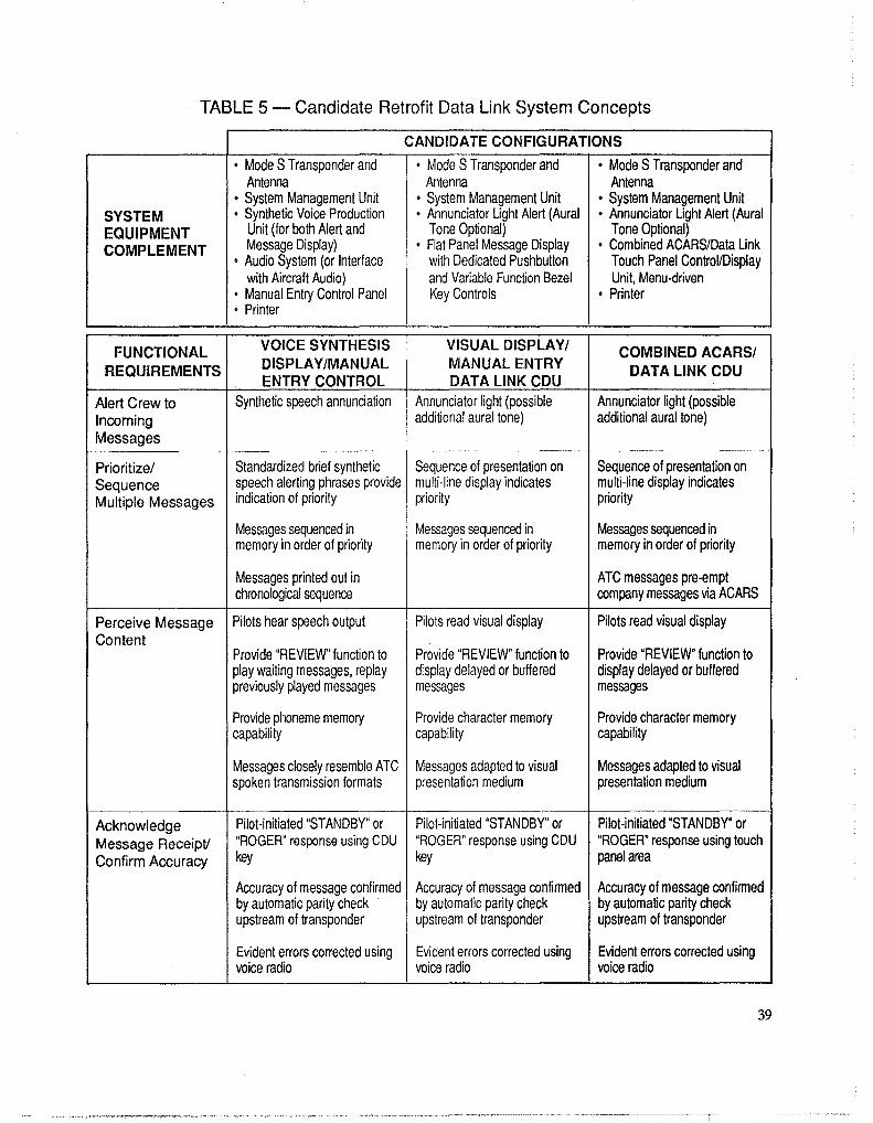
TABLE 5 - Candidate Retrofit Data Link System Concepts
CANDIDATE CONFIGURATIONS
• Mode S Transponder and • Mode S Transponder and • Mode S Transponder and Antenna Antenna Antenna
• System Management Unit • System Management Unit • System Management Unit SYSTEM • Synthetic Voice Production • Annunciator Light Alert (Aural • Annunciator Light Alert (Aural EQUIPMENT Unit (for both Alert and Tone Optional) Tone Optional) COMPLEMENT Message Display) • Flat Panel Message Display • Combined ACARS/Data Link
• Audio System (or Interface with Dedicated Pushbutton Touch Panel Control/Display with Aircraft Audio) and Variable Function Bezel Unit, Menu-driven
• Manual Entry Control Panel Key Controls • Printer • Printer
FUNCTIONAL VOICE SYNTHESIS VISUAL DISPLAY/ COMBINED ACARS/ REQUIREMENTS DISPLAY/MANUAL MANUAL ENTRY DATA LINK CDU
ENTRY CONTROL DATA LINK CDU
Alert Crew to Synthetic speech annunciation Annunciator light (possible Annunciator light (possible Incoming additional aural tone) additional aural tone) Messages
Prioritize/ Standardized brief synthetic Sequence of presentation on Sequence of presentation on Sequence speech alerting phrases provide multi-line display indicates multi-line display indicates Multiple Messages indication of priority priority priority
Messages sequenced in Messages sequenced in Messages sequenced in memory in order of priority memory in order of priority memory in order of priority
Messages printed out in ATC messages pre-empt chronological sequence company messages via ACARS
Perceive Message Pilots hear speech output Pilots read visual display Pilots read visual display Content
Provide "REVIEW" function to Provide "REVIEW" function to Provide "REVIEW· function to play waiting messages, replay display delayed or buffered display delayed or buffered previously played messages messages messages
Provide phoneme memory Provide character memory Provide character memory capability capability capability
Messages closely resemble ATC Messages adapted to visual Messages adapted to visual spoken transmission formats presentation medium presentation medium
Acknowledge Pilot-initiated "STANDBY" or Pilot-initiated "STANDBY" or Pilot-initiated ·STANDBY· or Message ReceipV "ROGER" response using CDU "ROGER" response using CDU "ROGER" response using touch Confirm Accuracy key key panel area
Accuracy of message confirmed Accuracy of message confirmed Accuracy of message confirmed by automatic parity check by automatic parity check by automatic parity check upstream of transponder upstream of transponder upstream of transponder
Evident errors corrected using Evident errors corrected using Evident errors corrected using voice radio voice radio voice radio
39

TABLE 5- Candidate Retrofit Data Link System Concepts (Continued)
CANDIDATE CONFIGURATIONS
FUNCTIONAL VOICE SYNTHESIS VISUAL DISPLAY/
COMBINED ACARS/ REQUIREMENTS
DISPLAY/MANUAL MANUAL ENTRY DATA LINK CDU
ENTRY CONTROL DATA LINK CDU
Store and Incoming messages stored in Incoming messages stored in Incoming messages stored in Retrieve computer random access memory computer random access memor) computer random access memory Messages
Highest priority messages Highest priority messages Highest priority messages automatically played using voice automatically displayed in CDU automatically displayed in CDU synthesis immediately upon immediately upon receipt immediately upon receipt receipt
Multiple stored messages Multiple stored messages Multiple stored messages accessible for playback in accessible by "scrolling" through accessible by "scrolling" through priority sequence using memory in priority sequence memory or by use of menus "REVIEW" function
Stored messages tagged with Stored messages tagged with Stored messages tagged with time and priority labels time and priority labels time and priority labels
Outdated messages deleted on Outdated messages deleted on Outdated messages deleted on crew's initiative crew's initiative crew's initiative
Printer required for recording of Messages output to printer in ACARS information; may also be chronological sequence as backup for ATC data received
Transmit Response: Pilot-initiated responses using Pilot-initiated responses using Pilot-initiated responses using (Routine) dedicated keys for short, dedicated or variable function variable function touch panel for
standardized messages line keys for short, standardized short, standardized messages messages
Voice radio backup Voice radio backup Voice radio backup
Transmit Use voice radio for all May use limited menuing May use limited menuing Response: non-routine responses capablilty for some non-routine capablilty for some non-routine (Non-routine) responses responses
Use voice radio for most Use voice radio for most non-routine responses non-routine responses
Execute Crew manually transfers Crew manually transfers Crew manually transfers Instructions uplinked datalinstructions for uplinked datalinstructions for uplinked data/instructions for
immediate action to onboard immediate action to onboard immediate action to onboard systems, then executes systems, then executes systems, then executes instructions instructions instructions
Crew maintains extended life Crew maintains extended life Crew maintains extended life data/instructions in computer datalinstructions in computer datalinstructions in computer memory and on printouts for memory for future use memory and on printouts for future use future use
40

TABLE 5 - Candidate Retrofit Data Link System Concepts (Concluded)
CANDIDATE CONFIGURATIONS
FUNCTIONAL VOICE SYNTHESIS VISUAL DISPLAYI COMBINED ACARS/ REQUIREMENTS DISPLAY IMANUAL MANUAL ENTRY DATA LINK CDU ENTRY CONTROL DATA LINK CDU
Verify System Data link SMU conducts Data link SMU conducts Data link SMU conducts Remains Operable frequent automatic self- checks frequent automatic self- checks frequent automatic self- checks
of onboard system operablilty of onboard system operablilty of onboard system operablilty
Uplinked messages contain Uplinked messages contain Uplinked messages contain system tests for controller's system tests for controller's system tests for controller's information information information
Synthetic voice annunciation System inoperative message System inoperative message when system fails test appears on display when test is appears on display when test is
failed failed
Provide Capability Control head located on CDU located on pedestal CDU located on pedestal for Single Pilot pedestal between pilots between pilots (preferably on between pilots (preferably on Operation forward pedestal) forward pedestal)
Speakers for alert annunciation and msgs audible to both pilots Alert annunciator located on Alert annunciator located on
glare shield in front of each pilot glare shield in front of each pilot Printer located on aft pedestal (if not feasible, two printers Printer location not critical located outboard must be because it is backup provision provided) only
Provision for holding printer tapes accessible to both pilots
Each of the three candidate configurations was evaluated as to its relative appropriateness for possible integration into four classes of in-service aircraft. The aircraft classes considered for retrofit were: Aircraft possessing neither an ACARS nor an FMS unit (referred to as "minimally equipped"); aircraft equipped with only an ACARS unit; aircraft with only an FMS unit; and aircraft possessing both ACARS and FMS units. These classes of aircraft were chosen since their flight decks constitute a representative cross-section of the ergonomic situations most likely to be faced in retrofit efforts. The results of these analyses are presented in TABLE 6.
As is apparent from inspection of the table, space constraints become progressively more severe as the aircraft to be retrofitted become more technologically advanced (i.e., more heavily equipped). In fact, for some aircraft, certain configuration candidates may simply not be possible because of space limitations. Also clear from the analysis is that, in several cases, ergonomically preferred locations (e.g., forward placement of MCDUs) may be cost prohibitive or operationally unacceptable. Because of this, the analysis summarized in the table shows which alternative locations should be considered when the more preferred locations are unavailable.
41
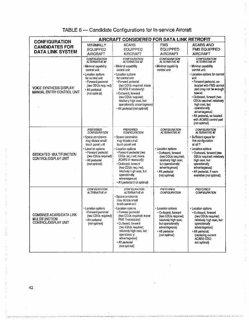
TABLE 6 - Candidate Configurations for In-service Aircraft
CONFIGURATION AIRCRAFT CONSIDERED FOR DATA LINK RETROFIT
CANDIDATES FOR MINIMALLY ACARS FMS ACARSAND
DATA LINK SYSTEM EQUIPPED EQUIPPED EQUIPPED FMS EQUIPPED AIRCRAFT AIRCRAFT AIRCRAFT AIRCRAFT
CONFIGURA TION CONFIGURA TlON CONFIGURA TlON CONFIGURA TlON ALTERNATIVE #2 AL TERNA TlVE #2 AL TERNA TlVE #2 AL TERNA TlVE #1
• Minimal capability • Minimal capability • Minimal capability • Minimal capability control unit control unit control unit control unit
• Location options • Location options • Location options for control for control unit for control unit unit • Forward pedestal • Forward pedestal • Forward pedestal, co-
VOICE SYNTHESIS DISPLAY/ (two CDUs required) (two CDUs required; move located with FMS control
o Aft pedestal ACARS if necessary) pad (may not be enough MANUAL ENTRY CONTROL UNIT (not optimal) o Outboard, forward space)
(two CDUs required; o Outboard, forward (two relatively high cost, but CD Us required; relatively operationally advantageous) high cost, but
o Aft pedestal (not optimal) operationally advantageous)
o Aft pedestal, co-located with ACARS control pad (not optimal)
PREFERRED PREFERRED CONFIGURA TION CONFIGURA T/oN CONFIGURA TlON CONFIGURA TlON AL TERNA TlVE #1 AL TERNA TlVE #2
• Space constraints • Space constraints • Sufficient space for may dictate small may dictate small this configuration touch-panel unit touch-panel unit at all ?
• Location options • Location options • Location options • Location options
DEDICATED MULTIFUNCTION • Forward pedestal • Forward pedestal (two o Outboard, forward o Outboard, forward (two
CONTROUDISPLA Y UNIT (two CDUs required) CDUs required; move (two CD Us required; CD Us required; relatively
o Aft pedestal ACARS if necessary) relatively high cost, high cosL but (not optimal) o Outboard, forward but operationally operationally
(two CDUs required; advantageous) advantageous) relatively high cost, but o Aft pedestal o Aft pedestal, if room operationally (not optimal) available (not optimal) advantageous)
o Aft pedestal (not optimal)
CONFIGURATION CONFIGURA TlON PREFERRED PREFERRED ALTERNATIVE #1 ALTERNATIVE #1 CONFIGURA TlON CONFIGURA T/oN
• Space constraints may dictate small touch-panel unit
• Location options • Location options • Location options • Location options
COMBINED ACARS/DATA LINK • Forward pedes tal • Forward pedestal o Outboard, forward o Outboard, forward
(two CD Us required) (two CDUs required; move (two CDUs required; (two CDUs required; MULTIFUNCTION o Aft pedestal PMS if necessary) relatively high cost, relatively high cost, but CONTROUDISPLAY UNIT (not optimal) o Outboard, forward but operationally operationally
(two CDUs required; advantageous) advantageous) relatively high cost, but o Aft pedestal o Aft pedestal, operationally (not optimal) (replacing current advantageous) ACARSCDU;
o Aft pedestal not optimal) (not optimal)
42
Operational Assessment
We now consider a brief assessment of the operational sequence involved in utilizing the three retrofit configuration concepts outlined in the previous section, with the goal of selecting one concept for further definition and perhaps future test and evaluation. The approach is to look at each concept in turn as it performs the same tactical ATe instructional transaction. Qualitative differences will be noted between the concepts and between the data link and the present VHF radio approach for carrying out the same functions. In this assessment we make use of an operational sequence diagram (OSD) that delineates the flow of activities over time of aircraft sensors, aircraft "effectors" (means of carrying out pilot or automation-based commands), and human resources provided by the crew. The format of the diagrams is explained below in the first section outlining the operational sequence for ATe information transfer using the present non-data link, VHF radio system. Further details of the use of this techniques are found in Reference 16.
Current Operations: VHF Radio. FIGURE 9 diagrams the first of four similar assessments for a typical ATC/aircraft interchange involving a simple tactical ATe instruction and reply, followed by the execution of the instruction contained in the transmitted message. The transaction described might be for such common instructions as altitude change, speed change, proceed direct to a waypoint, heading change, ATe sector or center handoff, etc. Such transactions are routine and well-adapted to data link implementation, and they constitute quantitatively the bulk of all ATe interactions over the course of a typical commercial flight. The diagram format groups aircraft sensor activities (mainly voice or data link radio facilities) in the left column, aircraft effector or command execution facilities in the right column, and aircrew activities in the center, grouped by major human resource channels-perceptual, motor, or cognitive. While we are aware this is a rather simplistic model of what is a complex series of psychological and physiological processes, we have found this breakdown to be useful in analyzing the salient differences between the various crew interface concepts, each of which taxes different human capabilities. In the diagrams, time flows from top to bottom, and while the different activities or functions are symbolized by similar round-cornered blocks, the reader should not infer from this that any two activities are necessarily weighted equally in any way. The comparison within and between diagrams is purely qualitative in nature.
We begin the assessment with a consideration of the way in which routine tactical ATe transactions are currently carried out. This sequence will provide a basis for comparing the possible advantages and disadvantages of the three data link concepts that follow. Qualitative differences between this series of activities and those necessary to accomplish the same functions using the various data link implementations will be observed. The sequence shown in FIGURE 9 begins with the reception of a voice message over the VHF radio which is assumed to be tuned to a particular ATC center frequency and being monitored by the crew. The ATe message is received in real time by the VHF radio. The usual format for such messages begins with the aircraft's call sign, followed in turn by the call sign of the facility issuing the message, then by the instruction or information itself. Since the message is composed of sequential speech, there is an inherent delay between each of these parts of the overall message. This is fortunate, for it allows the various parts of the message to perform different functions. For example, the call sign is first perceived by the crew aurally and recognized. This serves to alert the crew that a message intended for them will follow immediately. The call sign also serves to "address" the message, since the crew routinely listens to radio traffic intended for other aircraft, prefixed by their call signs. Other call signs cue the local crew to essentially ignore those messages. Thus, hearing their own call sign induces the crew to allot the cognitive and perceptual resources to attend to the succeeding message.
43
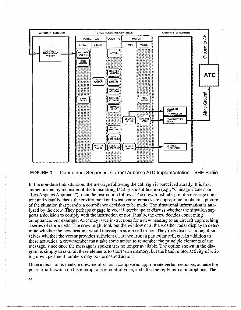
AIRCRAFT SENSORS
VHF COMM 1 RADIO MESSAGE
RECEIVED
CREW RESOURCE CHANNELS AIRCRAFT EFFECTORS
ATe
FIGURE 9 - Operational Sequence: Current Airborne ATC Implementation-VHF Radio
In the non-data link situation, the message following the call sign is perceived aurally. It is first authenticated by inclusion of the transmitting facility's identification (e.g., "Chicago Center" or "Los Angeles Approach"); then the instruction follows. The crew must interpret the message content and visually check the environment and whatever references are appropriate to obtain a picture of the situation that permits a compliance decision to be made. The situational information is analyzed by the crew. They perhaps engage in vocal interchange to discuss whether the situation supports a decision to comply with the instruction or not. Finally, the crew decides concerning compliance. For example, ATC may issue instructions for a new heading to an aircraft approaching a series of storm cells. The crew might look out the window or at the weather radar display to determine whether the new heading would intercept a storm cell or not. They may discuss among themselves whether the vector provides sufficient clearance from a particular cell, etc. In addition to these activities, a crewmember must take some action to remember the principle elements of the message, since once the message is spoken it is no longer available. The option shown in the diagram is simply to commit these elements to short term memory, but the hand, motor activity of writing down pertinent numbers may be the desired action.
Once a decision is made, a crewmember must compose an appropriate verbal response, actuate the push-to-talk switch on his microphone or control yoke, and utter the reply into a microphone. The
44
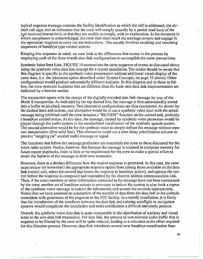
typical response message contains the facility identification to which the call is addressed, the aircraft call sign, and an indication that the crew will comply (usually by a partial read-back of the j'lst-received instruction); or that they are unable to comply, with an explanation. In the instances in which compliance is acknowledged, the crew then must recall the message content and engage in the operations required to carry out the instructions. This usually involves recalling and executing sequences of hand/eye type control actions.
Keeping this sequence in mind, we now look at the differences that accrue in the process by employing each of the three retrofit data link configurations to accomplish the same transactions.
Synthetic Voice Data Link. FIGURE 10 summarizes the same sequence of events as discussed above using the synthetic voice data link concept for a retrofit installation. The reader should be aware that this diagram is specific to the synthetic voice presentation without additional visual display of the same data, (Le. the minimum option described under System Concepts, on page 35 above). Other configurations would produce substantially different analyses. In this diagram and in those to follow, the crew resource functions that are different from the basic non-data link implementation are indicated by a heavier outline.
The transaction opens with the receipt of the digitally encoded data link message by way of the Mode S transponder. As indicated by the top dashed line, the message is first automatically stored into a buffer or playback memory. Two alternative configurations are then considered. As shown by the dashed lines and actions, one alternative would be to use a synthetic voice alert with the actual message being inhibited until the crew actuates a "REVIEW" function on the control unit, probably a hand/eye control action. At this time, the message, created by synthetic voice phonemes would be played through the audio system in the standardized vocalization of the synthetic speech system. The second alternative would be for the synthetic voice to simply deliver the message without separate annunciation (first solid line). This alternative could use a time delay prioritization scheme to prevent "stepping on" another audio message or signal.
The functions that follow the message production are essentially the same as those discussed for the voice radio system. Notice, however, that because the message is retained in computer memory for future repeat playbacks, there is little or no requirement for the crew to make a special effort to retain the features of the message in their own memories.
However, there is a distinct difference how the routine response is generated. In this case, the crew must review (or remember) the appropriate response option from among those available on the data link control unit, select the control that issues the response (a hand/eye action), and operate the control before the response is composed and transmitted by the discrete address communication link. Then, if the exact numbers or other information contained in the message have not been memorized by the crew, another set of hand/eye actions is necessary to induce the system to play back a repeat of the synthetic voice message to extract the information and actuate the controls appropriately. Notice that we have assumed no automation of the transfer of data from the data link to the controls coincident with generation of the response to the ATC facility. In a retrofit installation, it is likely that the introduction of the interfaces between the data link and existing autoflight or navigation systems would complicate the installation and make certification a difficult and costly process.
Overall, the synthetic voice data link is quite comparable in the distribution of auditory and visual tasks to the non-data link transaction. For data link, the amount of non-relevant audio traffic that is required to be filtered by the crew will be quite reduced, leading to a reduction in the effort required for this filtration process. However, data link introduces several new hand/eye coordination func-
45
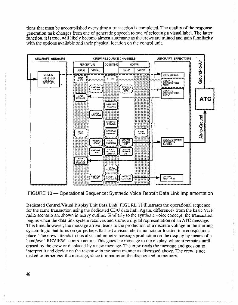
tions that must be accomplished every time a transaction is completed. The quality of the response generation task changes from one of generating speech to one of selecting a visual label. The latter function, it is true, wi11likely become almost automatic as the crews are trained and gain familiarity with the options available and their physical location on the control unit.
AIRCRAFT SENSORS
MODES DATA LINK MESSAGE RECEIVED
CREW RESOURCE CHANNELS AIRCRAFT EFFECTORS
ATe
FIGURE 10- Operational Sequence: Synthetic Voice Retrofit Data Link Implementation
Dedicated ControllVisual Display Unit Data Link. FIGURE 11 illustrates the operational sequence for the same transaction using the dedicated CDU data link. Again, differences from the basic VHF radio scenario are shown in heavy outline. Similarly to the synthetic voice concept, the transaction begins when the data link system receives and stores a digital representation of an ATe message. This time, however, the message arrival leads to the production of a discrete voltage in the alerting system logic that turns on (or perhaps flashes) a visual alert annunciator located in a conspicuous place. The crew attends to this alert and initiates message production on the display by means of a hand/eye "REVIEW" control action. This gates the message to the display, where it remains until erased by the crew or displaced by a new message. The crew reads the message and goes on to interpret it and decide on the response in the same manner as discussed above. The crew is not tasked to remember the message, since it remains on the display and in memory.
46
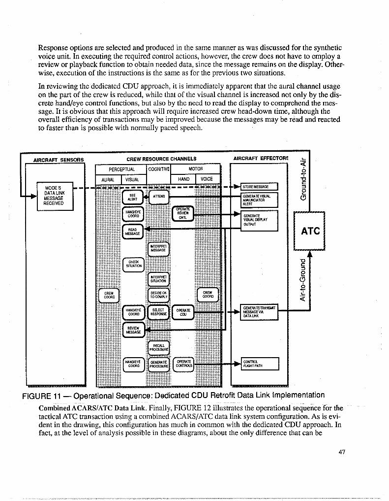
Response options are selected and produced in the same manner as was discussed for the synthetic voice unit. In executing the required control actions, however, the crew does not have to employ a review or playback function to obtain needed data, since the message remains on the display. Otherwise, execution of the instructions is the same as for the previous two situations.
In reviewing the dedicated CDU approach, it is immediately apparent that the aural channel usage on the part of the crew is reduced, while that of the visual channel is increased not only by the discrete hand/eye control functions, but also by the need to read the display to comprehend the message. It is obvious that this approach will require increased crew head-down time, although the· overall efficiency of transactions may be improved because the messages may be read and reacted to faster than is possible with normally paced speech.
AIRCRAFT SENSORS
MODES DATA LINK MESSAGE RECEIVED
CREW RESOURCE CHANNELS
PERCEPTUAL COGNITIVE MOTO~
AIRCRAFT EFFECTORS .... « , o '"i' "0 c :::J e
CJ
ATe
FIGURE 11 - Operational Sequence: Dedicated CDU Retrofit Data Link Implementation
Combined ACARS/ATC Data Link. Finally, FIGURE 12 illustrates the operational sequence for the tactical ATC transaction using a combined ACARS/ ATC data link system configuration. As is evident in the drawing, this configuration has much in common with the dedicated CDU approach. In fact, at the level of analysis possible in these diagrams, about the only difference that can be
47
observed is the possible necessity for the crew to switch manually from ACARS to ATC mode should an ATC message arrive while an ACARS transaction is in progress. The unit would, of course, have the capability to continue to receive and store the ACARS message for later review whenever it becomes necessary to make this switch.
The remarks made above evaluating the dedicated cnu concept apply equally to the combined ACARS/ATC data link approach, i.e., much more visual tasking is evident than with either the synthetic voice data link or the basic VHF radio transactions. However, total workload may be lower by virtue of the reduced total transaction time made available by not having to wait while voice messages are completed.
48
AIRCRAFT SENSORS
MODES DATA LINK MESSAGE RECEIVED
PERCEPTUAL
CREW RESOURCE CHANNEL
COONITIVE MOTOR
AIRCRAFT EFFECTORS
OUTPUT
GENERATEfTRANSMrT MESSAGE VIA DATA LINK
ATe
"0 c ::J o ....
(!) I o -~ ~
FIGURE 12 - Operational Sequence: Combined ACARS/ATC Retrofit Data Link Implementation
Conclusions The qualitative operational assessment does not provide a definitive selection for the most viable and effective retrofit data link concept. However, when combined with the difficulty of obtaining certification and compatibility with installation constraints, the operational issues discussed contribute to the selection of one candidate that appears to represent a workable compromise.
In general, it appears that the dedicated CDU with flat panel display surface would be the most viable candidate for retrofit implementation in the "minimally equipped" aircraft. The technology is risk-free-the control key concepts have been proven in service in such applications as flight and performance management systems, not to mention several VHF supplementary data link systems (ACARS). Color flat panel display technology is well advanced in development, especially in the sizes to which the data link CDU is limited by the available installation space (largely, the aft and forward pedestal standard instrument rails). For these reasons, the conventional CDU may be easiest to certify. It is also significant, for certification, that the data link in this concept is entirely dedicated to FANATC functions, typically critical to flight safety. It does not attempt to integrate ATC functions with company functions (such as those presently performed by ACARS), which primarily deal with business-related information. Based on these considerations, this concept is the one we have elected to explore in more detail in the following design definition section.
Having done this, however, we recognize there may be limitations to the conventional technology approach that could be addressed by the other approaches considered. We were unable to recommend the voice synthesis approach, although that technology is well developed and has been used for some time in voice warning systems. This is primarily because the operational effectiveness of empl01'ing the approach as the only information presentation medium cannot be ascertained analytically. However, this approach provides an attractive option because of the limited amount of cockpit panel space it consumes. Moreover, it tends to make use of a relatively underutilized crew resource-the auditory channel-and thereby contributes to reduced crew head-down time while handling ATC transactions, and perhaps could be integrated more readily into ongoing operations in view of its potential similarity to present voice-based ATC/aircraft interaction. For these reasons, we recommend that further empirical research be conducted, probably making use of full mission flight simulation, to explore the full range of data link functions and how their performance is affected by the use of the synthetic voice medium.
Another potential limitation of the selected conventional CDU approach is that it occupies the most panel space of the three candidates considered for a given set of functions or capabilities. In fact, as was discussed in the installation constraints section, it may be impossible to install a full-function, dedicated key, data link CDU in the growth space available on some of the better-equipped aircraft (for example, the MD-88 with both ACARS and FMS already installed).
The touch panel technology suggested for the combinedATC/ACARS approach appears to have the capability, through varying the functionality of the entire surface and utilizing that surface for both display and control functions, to minimize the amount of active area (hence panel size) that is required to accomplish a given set of transactions when compared to the dedicated CDU. Moreover, there appear to be only minor operational differences between ATC transactions using the dedicated key CDU and those using a touch panel approach. Questions arise concerning display size (message
2. NASA LaRC has already performed simulator and fl ight evaluations of synthetic voice in conjunction with a separate primary visual display of the data link information, [Ref. 3.].
49

visibility) and touch accuracy in turbulence for ATC tactical usage. However, because of the apparent potential utility of the touch panel technology in overcoming space limitations, we would recommend that it, too, receive further empirical research and development for data link retrofit coflsiderations, both in the combined ACARS/ATC configuration and in the simpler ATe-only role.
50
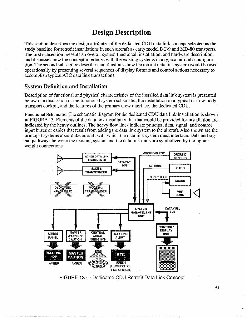
Design Description
This section describes the design attributes of the dedicated CDU data link concept selected as the study baseline for retrofit installations in such aircraft as early model DC-9 and MD-80 transports. The first subsection presents an overall system functional, installation, and hardware description, and discusses how the concept interfaces with the existing systems in a typical aircraft configuration. The second subsection describes and illustrates how the retrofit data link system would be used operationally by presenting several sequences of display formats and control actions necessary to accomplish typical ATC data link transactions.
System Definition and Installation
Description of functional and physical characteristics of the installed data link system is presented below in a discussion of the functional system schematic, the installation in a typical narrow-body transport cockpit, and the features of the primary crew interface, the dedieated CDU.
Functional Schematic. The schematic diagram for the dedicated CDU data link installation is shown in FIGURE 13. Elements of the data link installation kit that would be provided for installation are indicated by the heavy outlines. The heavy flow lines indicate principal data, signal, and control input buses or cables that result from adding the data link system to the aircraft. Also shown are the principal systems aboard the aircraft with which the data link system must interface. Data and signal pathways between the existing system and the data link units are symbolized by the lighter weight connections.
GROUND INHIBIT t---:=!)-----i OTHER DATA LINK ~ .... __ ...
TRANSCEIVER
AMBER AMBER
MODES TRANSPONDER
DATA/CNTL BUS ALTITUDE
SYSTEM DATAlCNTL ... ___ ........ MANAGEMENT ............ BUS
UNIT
CONTROL! DISPLAY
UNIT
FIGURE 13 - Dedicated CDU Retrofit Data Link Concept
51
The data link installation consists broadly of three major functional units (some functions may be duplicated forredundancy/reliability, but are not shown as duplicates in the diagram) together with the necessary interconnecting wiringicabling to provide signal, data and power to the system as required. The major units are the System Management Unit (SMU), the Alert Annunciator, and the Control/Display Unit (CDU). In addition to these principal elements and interfaces, the data link installation requires interfaces with and modifications to several existing systems, as s~own in the light outline units and connections in FIGURE 13. These interfaces and modifications will be discussed at appropriate points in the following paragraphs. For this discussion, we have ignored service and utility interfaces, such as electrical power, cooling, etc., to concentrate on the functional relationships between and among system elements.
The heart of the system is the SMU, which houses the primary data processing, signal conversion, data encoding/decoding, memory, and control logic functions that determine the workings of data link transactions. The SMU receives and transmits data over a high-speed electronic bus connected to the Mode S transponder, the assumed signal source for all ATC-derived data link messages. Notice that the Mode S transponder unit replaces the current Mode A/C surveillance-only transponder completely, and that the dedicated control head for the transponder is likewise eliminated; as will be Hlustrated below, the data link control functions are accommodated by the multifunction CDU, so the dedicated control head may be removed, freeing up needed panel area. It is assumed that the data bus is an acceptable medium for sending digitally encoded control signals to the transponder as well as for exchanging incoming and outgoing messages between the SMU and the transponder. If not, additional control signal pathways would be provided between the two units.
When an ATC message is appended to the normal Mode S radar interrogation received at the transponder, that unit passes on the encoded message to the SMU in addition to automatically carrying out its surveillance response function. The SMU stores th~ data after analyzing its content and, depending on the nature of the message (e.g., whether it is a time-critical, high-priority "tactical" instruction or a somewhat less critical "strategic" message), generates an appropriate discrete alert signal that is sent off to the alerting functions. This "Message received" signal triggers the visual Alert Annunciator (bearing the label ATe in the diagram) and simultaneously initiates a tone within the existing Central Aural Warning System (CAWS). Variations in the visual alert presentation to signal the relative urgency of the message-perhaps flashing for critical messages and steady for non-critical--can be provided. The CAWS interaction implies that a unique tone or sound for data link applications has been added to the complement of existing alerts-such as stall warning, altitude alert, etc.-as an integral part of the data link installation.
Because the ATC function is critical to safe flight in the NAS environment, the SMU also carries out repeated self-tests to assure continued safe and accurate data link operation. If at any time a failure is discovered that cannot be remedied by some automatic or crew-aided work-around, a "Test Fail" signal is generated and passed to both the Master Warning/Caution (MWC) system and the related Annunciator Panel on the forward overhead instrument panel. The signal turns on the Master Caution (amber) lights on the glareshield in front of each pilot and illuminates a new "Data Link Inop" annunciator in the Annunciator Panel, thus informing the crew that they must revert to voice radio for further ATC interaction. While the modification to the MWC system is minimal, the incorporation of data link causes an additional annunciator and control logic to be added to the existing Annunciator Panel.
Of course, the primary interface between the crew and the SMU is the CDU. Its function is to provide information from ATC facilities to the crew in a timely and useful manner, and to permit the
52
crew in turn to operate the system and transmit necessary data to the various ATC functions. The details of the crew interaction with the CDU will be presented in the next section. Here it is sufficient to point out that messages flow both ways between the SMU and CDU over an electronic data bus that also serves to transmit coded instructions for carrying out the various SMU and transponder functions.
As was noted above (FIGURE 8), the surveillance function of the transponder requires inputs from the Ground Sensing and Central Air Data Computer (CADC) subsystems for inhibiting transponder responses while the aircraft is on the ground and for reporting altitude, respectively. These functions are carried out by signals input to the SMU from the systems for relay to the transponder. In addition, if the aircraft has an ACARS data link system for company information exchange, a relatively simple input option may be included to extract flight plan or other information from that source. Such an interface would likely save the crew the considerable time and effort required to program necessary data into the CDU manually for such purposes as requesting predeparture clearances, weather reports/forecasts from enroute stations, etc. Notice, however, that the CDU is not used to transmit data to ACARS. We have taken the position that, in the simplest retrofit situation, the ACARS unit would remain functional. This seems a reasonable stance because to provide the ability to accommodate ACARS functions in the data link CDU would complicate certification efforts due to the mixing of traffic control (i.e., regulatory) and company (i.e., economic) data functions. With the relatively simple, one-way interface option shown, however, it would be possible to add the capability to receive data over the VHF data link network in addition to that provided by the local ATC facility, thus perhaps adding versatility to the data link installation.
Installation. The installation of the crew interface elements of the retrofit data link system in the DC-9/MD-80 is illustrated in FIGURE 14. The SMU and Mode S transponder units are installed in the avionics bay below the floor and ahead of the baggage hold, and therefore do not appear in this diagram. The elements with which the crew interact include the alert annunciators on the glareshield, the CDU(s), and the existing CAWS audio speakers. In addition, the data link system makes use of the master caution annunciators and adds one annunciator light (Data Link Inop) to the overhead annunciator panel.
The alert annunciators are installed in the edge of the glareshield immediately in front of each pilot, immediately along side of the master caution and master warning annunciators. This area is the most visible to the crew for alerting purposes of any available area in the cockpit. The Data Link Inop annunciator makes use of growth space in the existing annunciator panel immediately above the center windshield. The aural tone alert is produced by the existing captain's and first officer's CAWS audio speakers located near the floor on the left and right side walls of the cockpit, respectively. This location provides spatial separation from the overhead-mounted loudspeakers used for voice communications, reducing audio interference between simultaneous presentations of tones and voice traffic.
Two basic options are shown for the installation of the CDU. As was noted above, the typical area reserved for growth in most .of the DC-9/MD-80 aircraft that is also readily accessible to both pilots is largely confined to the center pedestal forward and aft of the throttle quadrant. Equal accessibility to this system by both pilots to accommodate single pilot operation is absolutely necessary. These areas incorporate standard instrument installation rails for equipment packages approximately six inches wide and varying in length in 3/8 inch increments. From human engineering consider ations, from either pilot's position, the forward pedestal location is preferable, because it is better for handeye coordination and reach accommodation. However, because of the width of the forward pedestal
53
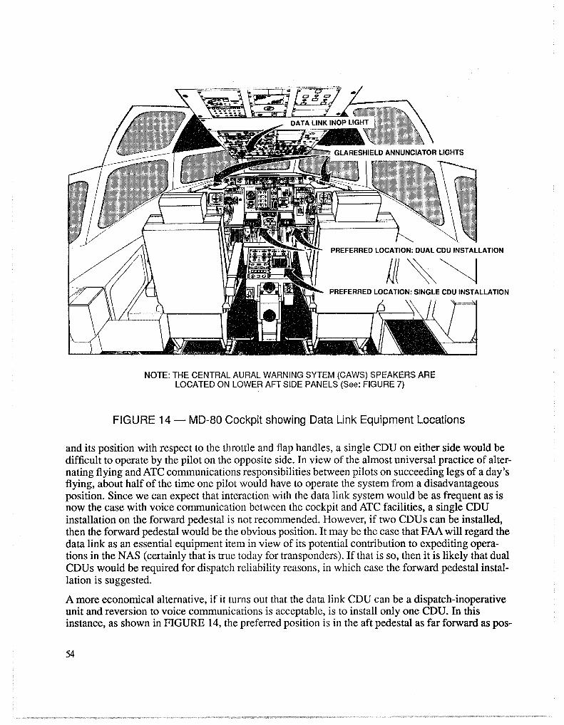
NOTE: THE CENTRAL AURAL WARNING SYTEM (CAWS) SPEAKERS ARE LOCATED ON LOWER AFT SIDE PANELS (See: FIGURE 7)
FIGURE 14 - MD-80 Cockpit showing Data Link Equipment Locations
and its position with respect to the throttle and flap handles, a single CDU on either side would be difficult to operate by the pilot on the opposite side. In view of the almost universal practice of alternating flying andATC communications responsibilities between pilots on succeeding legs of a day's flying, about half of the time one pilot would have to operate the system from a disadvantageous position. Since we can expect that interaction with the data link system would be as frequent as is now the case with voice communication between the cockpit and ATC facilities, a single CDU installation on the forward pedestal is not recommended. However, if two CDU s can be installed, then the forward pedestal would be the obvious position. It may be the case that FAA will regard the data link as an essential equipment item in view of its potential contribution to expediting operations in the NAS (certainly that is true today for transponders). If that is so, then it is likely that dual CDUs would be required for dispatch reliability reasons, in which case the forward pedestal installation is suggested.
A more economical alternative, if it turns out that the data link CDU can be a dispatch-inoperative unit and reversion to voice communications is acceptable, is to install only one CDU. In this instance, as shown in FIGURE 14, the preferred position is in the aft pedestal as far forward as pos-
54
sible. While this position is not as good as the forward pedestal location, it still may be reached easily by either pilot because the pedestal is narrower at that point and the throttle and flap controls do not interfere with access. This is the position of the VHF radio tuning heads on virtually all existing tr®sports, which receive heavy use in current operations. It is at least acceptable, if not optimal, for a high-activity hand-eye control function. In fact, considering the importance of both the voice radio and data link in the near-term data link environment, perhaps an installation with the VHF tuning heads adjacent to the data link cnu on the aft pedestal would be ideal.
The point should be made that, due to the size of the cnu necessary to accomplish the data link functions, at least some relocation of existing units on the pedestal will likely have to be made. While some panel space is gained by elimination of a separate transponder control head, it may be necessary to disturb existing installations to accumulate enough space in one area for installation of the CnU(s). The option of separating cnu functions into separate modules (say, into a display unit and a control unit) was considered to reduce the requirement for relocating presently installed units. However, this approach was rejected in view of the human factors ramifications of the spatial separation of these elements and the introduction of more difficult and complex installation and integration requirements, possibly resulting in higher development and certification costs.
ControllDisplay Unit. A preliminary design concept for the dedicated key data link cnu concept is shown in FIGURE 15. This concept is compatible with the ARINC standard instrument rail system used in most transport aircraft for cockpit avionics installations. The overall dimensions thus reflect the constraints of this system; however, within these constraints, the cnu is designed to provide adequate area for the required controls and displays. The size is minimized to make the installation compatible with the maximum number of different aircraft.
The design of this unit is at a very early stage. Therefore, the physical configuration and functioning of the cnu should be considered as conceptual only and subject to change as more in depth study and development is accomplished. The purpose of this design exercise is to provide sufficient definition to permit us to explore the differences and similarities between a cnu approach suitable for retrofit compared with that proposed for installation in the more modern, glass-cockpit aircraft. The operation of the cnu will be considered in some detail in the following section. Here we will describe briefly the major features of the hardware configuration, as called out in FIGURE 15.
Response Switches. The function of these illuminated push-button legend switches is to provide for the routine responses likely to constitute the bulk of the data link interactions in operational use.Often, instructional messages that appear on the display will simply require the crew to indicate ability to comply, or to ask the controller to standby while a decision is made. These controls permit response in this manner with the simple pressing of a button. Also included is a Main Menu control, which allows the crew to return to the main menu page of the display from any point in the hierarchy of menus that may be in use. Thus, if at any time a crewmember is unsure of the position in the menu structure, it is easy to go back to the top to retrace the steps.
Flat Panel Display Surface. A high-resolution flat panel color display is proposed for use in the cnu that is compatible with pixel-based character and graphic symbology. Although cathode ray tube (CRT) video units similar to those used in current FMS and PMS displays might be adequate for this purpose, color flat panel technology, especially in the relatively small sizes used in this application, is available. Flat panel displays represent significant advantages in form factor, power consumption, and heat dissipation. While the information we have examined suggests that the content of most data link messages will be character-based, there may be many functions that can better be communicated by graphics or symbols. We feel that the system should include graphics display
55
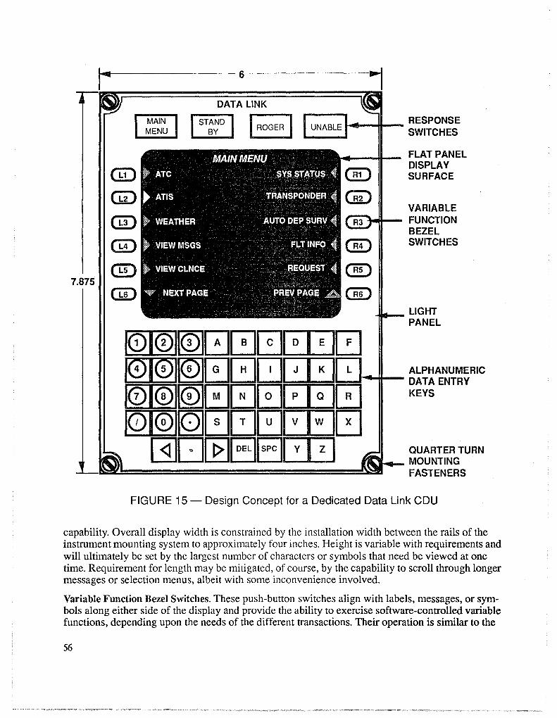
7.875
~--------------------6------------------~~
DATA LINK
rMAiN1 ~
I STAND I BY
~--ft-- RESPONSE SWITCHES
CIT)
GV aD @)
@)
aD
D E
L
R
X
FLAT PANEL DISPLAY SURFACE
VARIABLE FUNCTION BEZEL SWITCHES
LIGHT PANEL
ALPHANUMERIC DATA ENTRY KEYS
QUARTER TURN MOUNTING FASTENERS
FIGURE 15 - Design Concept for a Dedicated Data Link CDU
capability. Overall display width is constrained by the installation width between the rails of the instrument mounting system to approximately four inches. Height is variable with requirements and will ultimately be set by the largest number of characters or symbols that need be viewed at one time. Requirement for length may be mitigated, of course, by the capability to scroll through longer messages or selection menus, albeit with some inconvenience involved.
Variable Function Bezel Switches. These push-button switches align with labels, messages, or symbols along either side of the display and provide the ability to exercise software-controlled variable functions, depending upon the needs of the different transactions. Their operation is similar to the
56
line switches used on FMS/pMS units and on military electronic displays. The use of variable function controls adds powerful flexibility to the interactions between the messages and control functions and the crew. In many ways, the bezel switches can duplicate touch panel capabilities without the complication of the touch panel overlay.
Light Panel. A standard acrylic edge-lighted panel is used for illumination of switch legends and labels during night operations.
Alphanumeric Data Entry Keys. This sequential character keyboard provides the crew with the capability to enter uppercase letters or numbers in various fields of the display while initiating or responding to messages. This capability is not intended for "typing" extended text messages, since such transactions would more easily be accomplished through voice radio communications. Rather, the keypad is necessary to compose the character codes that identify navaids, waypoints, weather stations, airports, etc.; and to insert numbers for headings, altitudes, speeds, and the like. The keyboard also contains function keys necessary for editing character fields on the screen, allowing the crew to make minor changes to existing data to save time, where that is possible.
System Operation
This section provides a description of retrofit data link system operations through a consideration of several typical transactions and the display formats and data that would appear during the transactions. The examples are given in the form of figures that show the sequences of control actions and the resulting displays involved in accomplishing data link communications and system control functions. Again, the reader is cautioned to regard the formats and features shown as preliminary. Further analysis and empirical study may very well reveal different approaches that may provide better operations than those illustrated. However, we do feel that the functions shown below are representative of the sorts of activities that are typical for utilizing data link in ATe and system management operations.
Referring to any of the figures below, several common format features can be discerned. In general, whenever a label is associated with a line key, this fact is indicated by a triangle symbol between the label and the key. "Active" keys-those that will initiate a control action or function-are represented by filled gray triangles. Inactive keys-which require some additional system action to enable their operation-are denoted by an unfilled gray triangle. When an active line key is pressed, the symbol turns white (and may blink in certain circumstances) to indicate that a control action has taken place. When no symbol is shown between characters on the display and a line key, then the key is disabled. Lines of characters may fall between the lines opposite the keys. These characters are for display only and typically do not label control functions. Some of the screen formats feature "Next Page" and "Prev(ious) Page" labels which, when active, allow the user to advance to lower levels in the menu hierarchy or to go back to a superordinate level, as appropriate. Of course, the user can at any time press the "Main Menu" response key and return to the main menu from any level in the menu hierarchy. Ocasionally, the format will inhibit this capability, as when a mandatory response to a time-critical instruction is pending. Another common symbology is the "Scroll" label between two adjacent vertical line keys. This arrangement allows the user to move character lines on the screen up or down to review messages or menu lists that are too large to fit on a single screen.
Screen or page titles are centered at the top of the screen. The bottom center of the screen contains prompts that may require the user's attention, such as a message waiting for review. Text or data
57
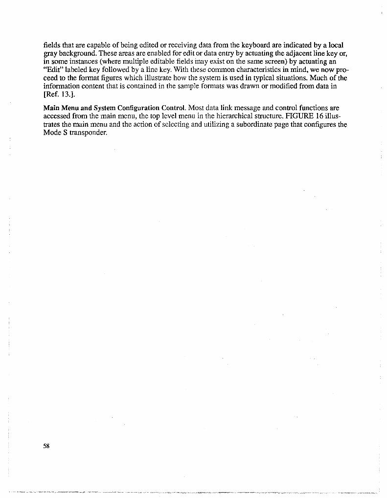
fields that are capable of being edited or receiving data from the keyboard are indicated by a local gray background. These areas are enabled for edit or data entry by actuating the adjacent line key or, in some instances (where multiple editable fields may exist on the same screen) by actuating an "Edit" labeled key followed by a line key. With these common characteristics in mind, we now proceed to the format figures which illustrate how the system is used in typical situations. Much of the information content that is contained in the sample formats was drawn or modified from data in [Ref. 13.].
Main Menu and System Configuration Control. Most data link message and control functions are accessed from the main menu, the top level menu in the hierarchical structure. FIGURE 16 illustrates the main menu and the action of selecting and utilizing a subordinate page that configures the Mode S transponder.
58
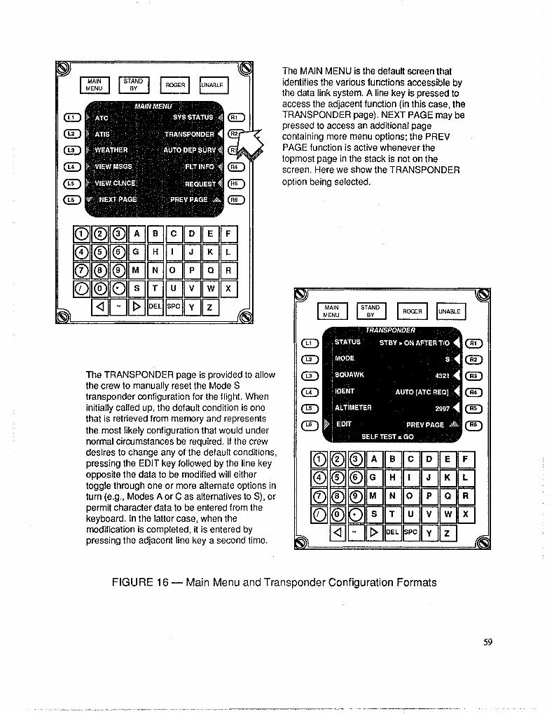
(IT)
@)
@
@
@) @
The TRANSPONDER page is provided to allow the crew to manually reset the Mode S transponder configuration for the flight. When initially called up, the default condition is one that is retrieved from memory and represents the most likely configuration that would under normal circumstances be required. If the crew desires to change any of the default conditions, pressing the EDIT key followed by the line key opposite the data to be modified will either toggle through one or more alternate options in turn (e.g., Modes A or C as alternatives to S), or permit character data to be entered from the keyboard. In the latter case, when the modification is completed, it is entered by pressing the adjacent line key a second time.
The MAIN MENU is the default screen that identifies the various functions accessible by the data link system. A line key is pressed to access the adjacent function (in this case, the TRANSPONDER page). NEXT PAGE may be pressed to access an additional page containing more menu options; the PREV PAGE function is active whenever the topmost page in the stack is not on the screen. Here we show the TRANSPONDER option being selected.
@)
@)
@
@
@)
®
FIGURE 16 - Main Menu and Transponder Configuration Formats
59
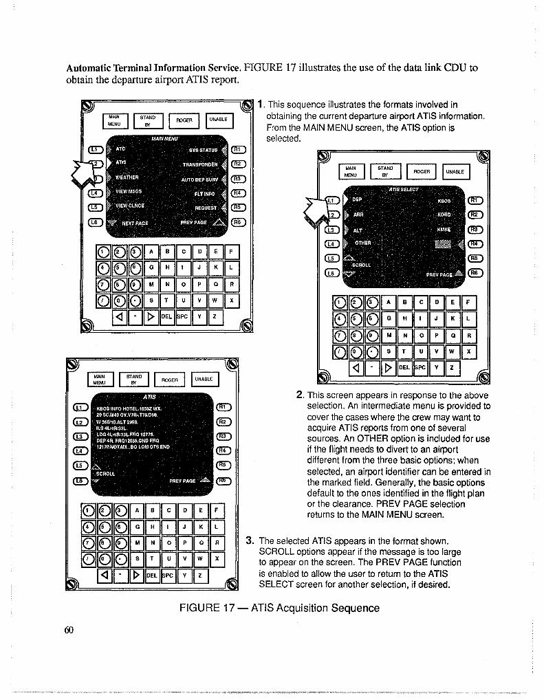
Automatic Terminal Information Service. FIGURE 17 illustrates the use of the data link CDU to obtain the departure airport ATIS report.
60
~rsTANDl~ ~~L=:.J
r;:;AiNl rsr;::Ni)l r:::::::-J I UNABLE I ~~~
1. This sequence illustrates the formats involved in obtaining the current departure airport ATIS information. From the MAIN MENU screen, the ATIS option is selected.
fMAiNl rs;:;iNiJl r=:lROG ~~L-=:J
2. This screen appears in response to the above selection. An intermediate menu is provided to cover the cases where the crew may want to acquire ATIS reports from one of several sources. An OTHER option is included for use if the flight needs to divert to an airport different from the three basic options; when selected, an airport identifier can be entered in the marked field. Generally, the basic options default to the ones identified in the flight plan or the clearance. PREY PAGE selection returns to the MAIN MENU screen.
3. The selected ATIS appears in the format shown. SCROLL options appear if the message is too large to appear on the screen. The PREY PAGE function is enabled to allow the user to return to the ATIS SELECT screen for another selection, if desired.
FIGURE 17 - ATIS Acquisition Sequence
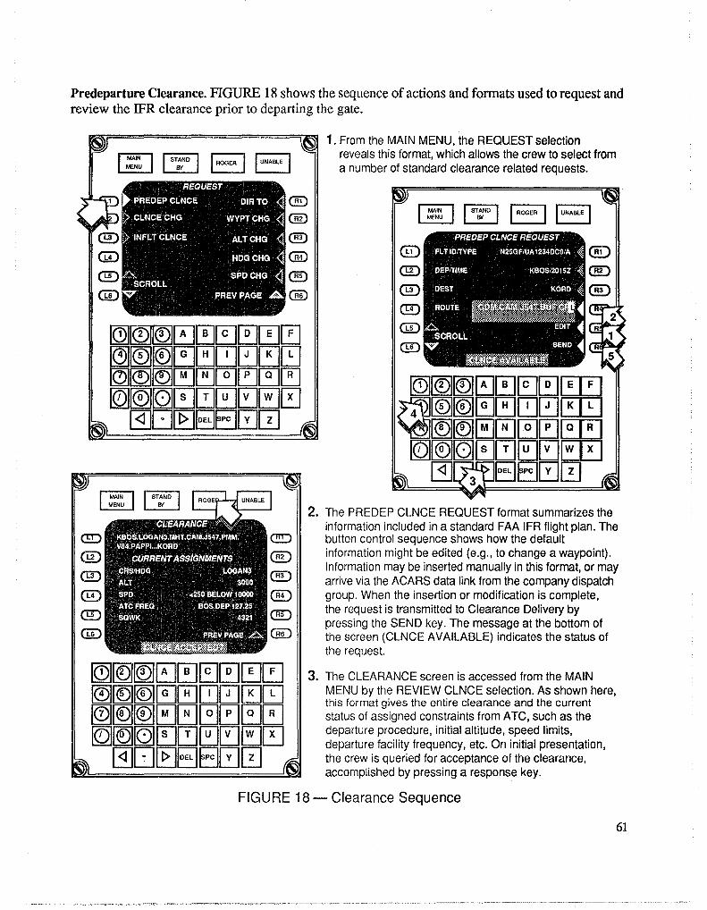
Predeparture Clearance. FIGURE 18 shows the sequence of actions and formats used to request and review the IFR clearance prior to departing the gate.
® @
® @
@)
(ill
1. From the MAIN MENU, the REQUEST selection reveals this format, which allows the crew to select from a number of standard clearance related requests.
2. The PREDEP CLNCE REQUEST format summarizes the information included in a standard FAA IFR flight plan. The button control sequence shows how the default information might be edited (e.g., to change a waypoint). Information may be inserted manually in this format, or may arrive via the ACARS data link from the company dispatch group. When the insertion or modification is complete, the request is transmitted to Clearance Delivery by pressing the SEND key. The message at the bottom of the screen (CLNCE AVAILABLE) indicates the status of the request.
3. The CLEARANCE screen is accessed from the MAIN MENU by the REVIEW CLNCE selection. As shown here, this format gives the entire clearance and the current status of assigned constraints from ATC, such as the departure procedure, initial altitude, speed limits, departure facility frequency, etc. On initial presentation, the crew is queried for acceptance of the clearance, accomplished by pressing a response key.
FIGURE 18 - Clearance Sequence
61
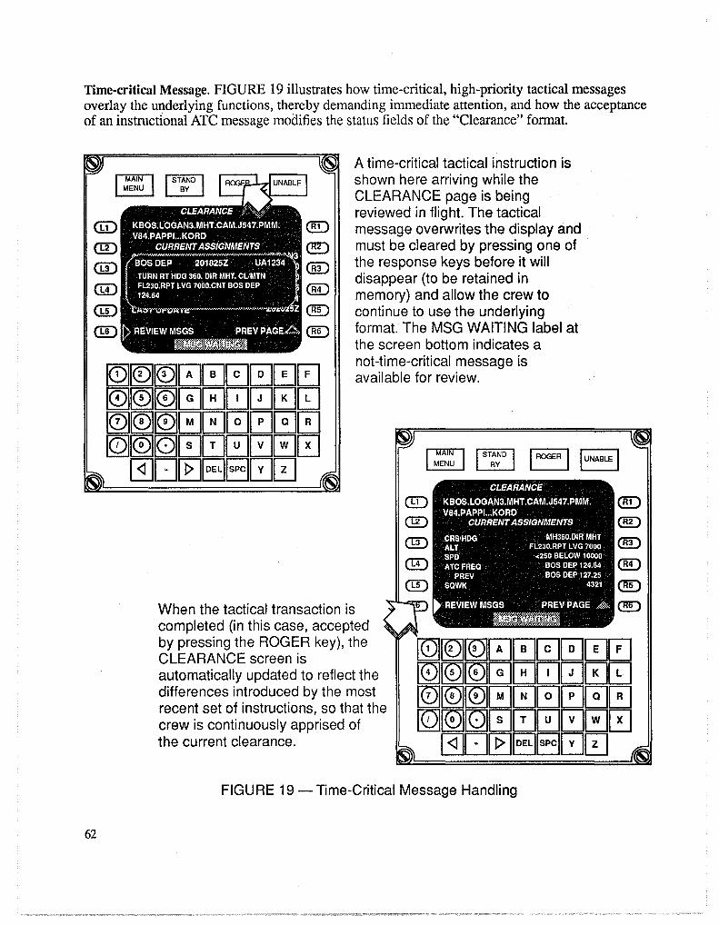
Time-critical Message. FIGURE 19 illustrates how time-critical, high-priority tactical messages overlay the underlying functions, thereby demanding immediate attention, and how the acceptance of an instructional ATC message modifies the status fields of the "Clearance" format.
(ill
@)
@)
@
CID @
[Q] ~ ~ 10
62
(D
0 0 0
13"'" \;J A
0 G
0 M
8 s
~~ 0~
N 0
T U
A time-critical tactical instruction is shown here arriving while the CLEARANCE page is being reviewed in flight. The tactical message overwrites the display and must be cleared by pressing one of the response keys before it will disappear (to be retained in memory) and allow the crew to continue to use the underlying format. The MSG WAITING label at the screen bottom indicates a not-time-critical message is available for review.
When the tactical transaction is completed (in this case, accepted by pressing the ROGER key), the CLEARANCE screen is automatically updated to reflect the differences introduced by the most recent set of instructions, so that the crew is continuously apprised of the current clearance.
FIGURE 19 - Time-Critical Message Handling
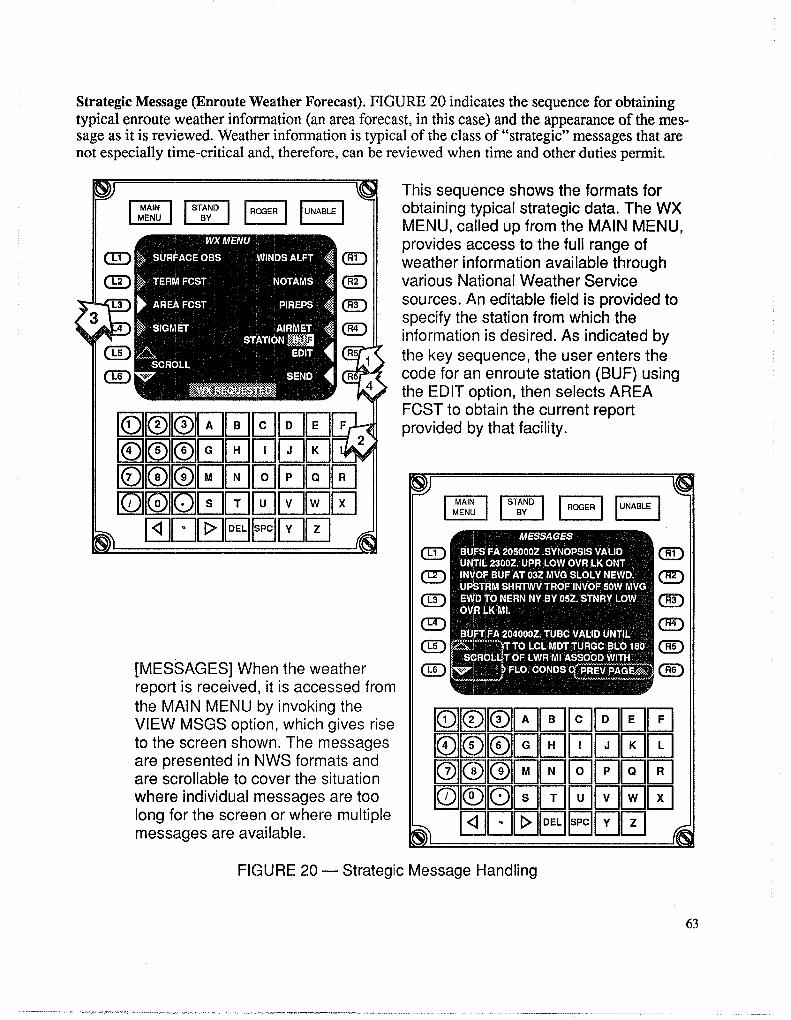
Strategic Message (En route Weather Forecast). FIGURE 20 indicates the sequence for obtaining typical enroute weather information (an area forecast, in this case) and the appearance of the message as it is reviewed. Weather information is typical of the class of "strategic" messages that are not especially time-critical and, therefore, can be reviewed when time and other duties permit.
[MESSAGES] When the weather report is received, it is accessed from the MAIN MENU by invoking the VIEW MSGS option, which gives rise to the screen shown. The messages are presented in NWS formats and are scrollable to cover the situation where individual messages are too long for the screen or where multiple messages are available.
This sequence shows the formats for obtaining typical strategic data. The WX MENU, called up from the MAIN MENU, provides access to the full range of weather information available through various National Weather Service sources. An editable field is provided to specify the station from which the information is desired. As indicated by the key sequence, the user enters the code for an enroute station (BUF) using the EDIT option, then selects AREA FeST to obtain the current report provided by that facility.
~ MENU I STAND I BY I ROOER I IUNABLE I
em em ® (!!!)
@) ® CE!) C!!!)
@) ® @) @)
FIGURE 20 - Strategic Message Handling
63
In this section we have reviewed a preliminary design for a representative retrofit data link system installation. We have seen how a system can be installed in narrow-body transports typical of those currently serving in present-day commercial fleets. We have also shown how such a system could be operated to accomplish some of the functions that will characterize ATC operations in the data link environment. As far as can be determined analytically, a data link system such as the one discussed here appears to be entirely feasible for retrofit into those categories of older aircraft mentioned in this study. Feasibility is from the standpoints of physical installation, interfaces with currently installed equipment and with the flight crew, and expected ATC data link operations. This is not to say, however, that the design of certifiable retrofit data link systems should proceed without further analytical and, in particular, empirical research activity. In the following section we identify several topics for further research that have emerged during the present effort.
64
Recommendations for Future Research and Development THis study has investigated several alternative schemes for satisfying the requirements for a cockpit data link interface suitable for retrofit to existing transport aircraft. One possible equipment configuration, specifically tailored for retrofit of a "minimally equipped" aircraft, was further defined and described. While this purely analytical approach has provided some useful insights into the nature and complexity of the retrofit problem, the conclusions of this work should be considered preliminary. The operational utility of any new crew interface can only be fully evaluated through dynamic, man-in-the-Ioop testing in a relatively realistic environment. There are clearly some significant system design issues that can only be satisfactorily resolved through empirical testing. In the view of the study team, the following represent the most critical unresolved issues about data link cockpit retrofit implementation.
1. Touch Panel Interface vs. Conventional CDU. The versatility of a multifunction display medium with a touch-sensitive surface provides a wide range of alternatives for the cockpit interface designer. Research conducted by NASA Langley Research Center [Ref. 3.] has demonstrated the utility of this approach to data link communications in the context of a modern, highly integrated electronic cockpit. This research has shown how a flexible, large format display and control medium can be utilized to simplify the operator's perceptual and cognitive tasks. The touch panel approach may, however, have some disadvantages relative to the more conventional programmable keyboard with multifunction push buttons, especially in the tight space constraints of the typical retrofit installation. For example, touch panels provide little tactile feedback and may be susceptible to inadvertent activation under some operational conditions. The practical significance of these issues cannot be fully ascertained without further testing. A comparative simulator evaluation of these two design concepts would be the logical next step.
2. The Role of Synthetic Voice as an Output Device. As discussed previously, synthetic voice offers some potential benefits as an output medium for data link communications in the cockpit. These include its attention-getting value, ability to penetrate noise, independence of head/eye orientation and compatibility with current pilot procedures and training. Operational experience with synthesized voice in the cockpit (i.e. voice warning systems) suggests that voice should be utilized selectively to avoid crew distraction or interference with other vocal/auditory tasks. Some of the possible uses for synthetic voice in a data link retrofit system are as follows:
• Use voice as an alert annunciation only.
• Use voice as an indicator of message urgency or relative priority.
• Use voice as a medium for output of time-critical ATC messages.
• Use voice as the primary output medium for all data link communications.
• Use voice as a redundant communications channel for a visual display system (continuous or selectable at pilot's discretion).
• Use voice as a device for recall and review of stored messages.
While prior NASA research has investigated synthetic voice for uplink of ATC messages [Ref. 17.], further research is required to determine the optimum utilization of voice as an integral part of a cockpit data link system. The decision whether or not to use synthetic voice to perform some or all
65

of these functions should be based on evaluation of a range of options in a realistic simulator environment.
3. The Role of the Hard Copy Printer. Some airlines have expressed a strong preference for incorporating a printer as part of a data link retrofit system. While printers have significant limitations both as a display medium and as a storage device, they are readily available as "off the shelf' equipment and many aircraft already have them installed. Consideration should be given to the use of a hard copy printer as part of a minimum cost/minimum capability retrofit solution.
While the issues described above seem to represent the most critical concerns for cockpit retrofit of a data link communications capability, this study has also surfaced several other issues that may warrant further investigation or empirical testing. These issues are documented in Appendix C of this report.
66
Appendix A
Data Link User Requirements Questionnaire
To better detem1ine the user requirements and the scope of the data link retrofit problem, Douglas Aircraft Company informally contacted several airline representatives who were known to be knowledgeable about digital data link communications by virtue of their participation in data linkoriented studies, symposia, or meetings. Most were active members of the Air Transport Association Data Link Working Group. They were invited to respond to a questionnaire as subject matter experts, and their responses have been treated as judgments and opinions of knowledgeable persons and not as those of company representatives.
Respondents included representatives from both passenger and cargo-only carriers in the United States and Canada. It was emphasized to the airline representatives that the questionnaire was part of a NASA research project and was not a Douglas Aircraft Company market survey. Eight questionnaires were completed and returned of approximately fifteen distributed. A copy of the questionnaire is shown in FIGURE A-1.
To minimize the time required to complete the questionnaire, most questions required only a check mark to indicate the respondent's opinion. The last four questions were open-ended to allow the respondent to elaborate on the point of view and to permit addressing of any pertinent issues that may have been overlooked in the preparation of the other questions.
Data Summarization
The responses have been tabulated, and the results are shown on tables and bar graphs. Although all participants did not respond to all questions, the percentage responding was calculated with an N of 8, the total number of participants.
A-I
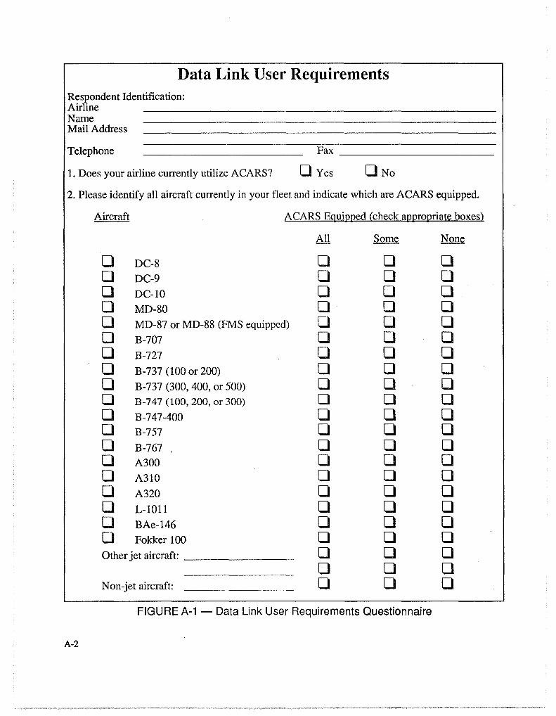
Data Link User Requirements Respondent Identification: Airline Name Mail Address
Telephone Fax
1. Does your airline currently utilize ACARS? o Yes ONo
2. Please identify all aircraft currently in your fleet and indicate which are ACARS equipped.
Aircraft ACARS Equipped (check appropriate boxes)
All Some None
0 DC-8 0 0 0 0 DC-9 0 0 0 0 DC-lO 0 0 0 0 MD-80 0 0 0 0 MD-87 or MD-88 (FMS equipped) 0 0 0 0 B-707 0 0 0 0 B-727 0 0 0 0 B-737 (100 or 200) 0 0 0 0 B-737 (300, 400, or 500) 0 0 0 0 B-747 (100,200, or 300) 0 0 0 0 B-747-400 0 0 0 0 B-757 0 0 0 0 B-767 0 0 0 0 A300 0 0 0 0 A3l0 0 0 0 0 A320 0 0 0 0 L-1011 0 0 0 0 BAe-146 0 0 0 0 Fokker 100 0 0 0 Other jet aircraft: 0 0 0
0 0 0 Non-jet aircraft: 0 0 0
FIGURE A-1 - Data Link User Requirements Questionnaire
A-2
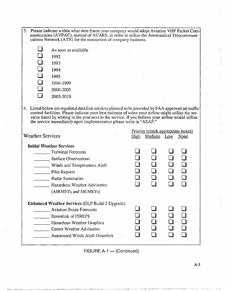
3. Please indicate within what time frame your company would adopt Aviation VHF Packet Com munications (AVPAC), instead of ACARS, in order to utilize the Aeronautical Telecommunications Network (ATN) for the transaction of company business.
0 As soon as available
0 1992
0 1993
0 1994
0 1995
0 1996-1999
0 2000-2005
0 2005-2010
4. Listed below are regulated data link services planned to be provided by FAA approved air traffic control facilities. Please indicate your best estimate of when your airline might utilize the services listed by writing in the year next to the service. If you believe your airline would utilize the service immediately upon implementation please write in "ASAP."
Weather Services
Initial Weather Services ___ Terminal Forecasts
___ Surface Observations
___ Winds and Temperatures Aloft
___ Pilot Reports
___ Radar Summaries
___ Hazardous Weather Advisories
(AIRMETs and SIGMETs)
Enhanced Weather Services (DLP Build-2 Upgrade) ___ Aviation Route Forecasts
___ Downlink of PIREPS
___ Hazardous Weather Graphics
___ Center Weather Advisories
___ Automated Winds Aloft Downlink
Priority (check appropriate boxes) High Medium Low None
o o o o o o
o o o o o
o o o o o o
o o o o o
o o o o o o
o o o o o
o o o o o o
o o o o o
FIGURE A-1 - (Continued)
A-3

Air-traffic Control Services High Medium Low None
Initial Airport Services 0 0 0 0 Automated Terminal Information
Services (A TIS) 0 0 0 0 Pre-Departure Clearances
Runway Surface Winds 0 0 0 0 Wind Shear Advisories 0 0 0 0 Surveillance Services Automatic Safety Advisories 0 0 0 0
• Enroute Minimum Safe Altitude Warnings (EMSA W)
• Specific Use Airspace • Positive Control Area • Terminal Control Area
Flight Assistance 0 0 0 0 • Bearing and Distance to Waypoint • Uplink of Aircraft State Vector
Designated Traffic Report 0 0 0 0 Enhanced Air-traffic Control Services
Transfer of Communications 0 0 0 0 Restricted Altitude Assignments 0 0 0 0 Speed Assignments 0 0 0 0 Crossing Restrictions 0 0 0 0 Altitude Confirmation 0 0 0 0 Aircraft Identification 0 0 0 0 Downlink of Aircraft State 0 0 0 0 VFR Flight Following 0 0 0 0 NOTAMS (Notice to Airmen) 0 0 0 0
Advanced Automation Services Enroute Metering 0 0 0 0 Sector Probe Request 0 0 0 0 Flow Management Advisories 0 0 0 0 Out of Conformance Check 0 0 0 0 Auto Flight Service 0 0 0 0 Flight Plan Filing and Amendment 0 0 0 0
• Random Route Request • Altitude & Speed Profile Requests
0 0 0 0 Flight Management Computer/ AERA Data Transfers Downlink of TCAS Information 0 0 0 0
FIGURE A-1 - (Continued)
A-4
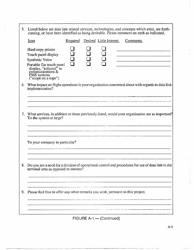
5. Listed below are data link related services, technologies, and concepts which exist, are forthcoming, or have been identified as being desirable. Please comment on each as indicated.
Required Desired Little Interest
Hard copy printer 0 Touch panel display 0 Synthetic Voice 0 Portable flat touch panel 0
display, '.'tet~ered" to commumcatIOns & FMS systems ("scope on a rope")
o o o o
o o o o
Comments
6. What impact on flight operations is your organization concerned about with regards to data link implementation?
7. What services, in addition to those previously listed, would your organization see as important? To the system at large?
To your company in particular?
8. Do you see a need for a division of operational control and procedures for use of data link in the terminal area as opposed to enroute?
9. Please feel free to offer any other remarks you wish, pertinent to this project.
FIGURE A-1 - (Continued)
A-5
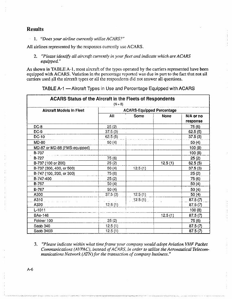
Results
1. "Does your airline currently utilize A CARS?"
All airlines represented by the responses currently use ACARS.
2. "Please identify all aircraft currently in your fleet and indicate which are ACARS equipped."
As shown in TABLE A-I, most aircraft of the types operated by the carriers represented have been equipped with ACARS. Variation in the percentage reported was due in part to the fact that not all carriers used ;tIl the aircraft types or all the respondents did not answer all questions.
A-6
TABLE A-1 - Aircraft Types in Use and Percentage Equipped with ACARS
ACARS Status of the Aircraft in the Fleets of Respondents (N=8)
Aircraft Models in Fleet ACARS-Equipped Percentage
All Some None N/A or no response
DC-8 25 (2) 75 (6) DC-9 37.5 (3) 62.5 (5) DC-10 62.5 (5) 37.5 (3)
MD-80 50 (4) 50 (4) MD-87 or MD-88 (FMS-equipped) 100 (8) 8-707 100 (8) 8-727 75 (6) 25 (2) 8-737 (100 or 200) 25 (2) 12.5 (1) 62.5 (5) 8-737 (300, 400, or 500) 50 (4) 12.5 (1) 37.5 (3)
8-747 (100, 200, or 300) 75 (6) 25 (2) 8-747-400 25 (2) 75 (6) 8-757 50 (4) 50 (4)
8-767 50 (4) 50 (4) A300 37.5 (3) 12.5(1) 50 (4)
A310 12.5 (1) 87.5 (7) A320 12.5(1) 87.5 (7)
L-1011 100 (8)
8Ae-146 12.5(1) 87.5 (7) Fokker100 25 (2) 75 (6)
Saab 340 12.5(1) 87.5 (7) Saab 3408 12.5(1) 87.5 (7)
3. "Please indicate within what time frame your company would adopt Aviation VHF Packet Communications (AVPAC), instead of ACARS, in order to utilize the Aeronautical Telecommunications Network (ATN)for the transaction of company business."
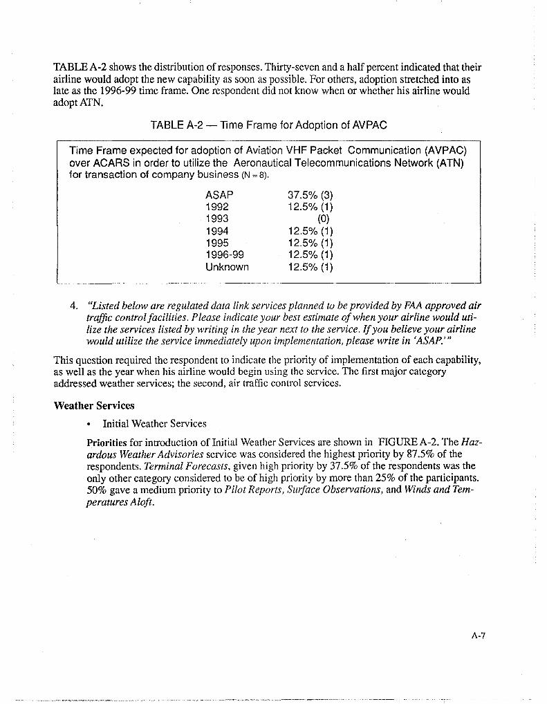
TABLE A-2 shows the distribution of responses. Thirty-seven and a half percent indicated that their airline would adopt the new capability as soon as possible. For others, adoption stretched into as late as the 1996-99 time frame. One respondent did not know when or whether his airline would adoptATN.
TABLE A-2 -Time Frame for Adoption of AVPAC
Time Frame expected for adoption of Aviation VHF Packet Communication (AVPAC) over ACARS in order to utilize the Aeronautical Telecommunications Network (ATN) for transaction of company business (N = 8).
ASAP 1992 1993 1994 1995 1996-99 Unknown
37.5% (3) 12.5% (1)
(0) 12.5% (1) 12.5% (1) 12.5% (1) 12.5% (1)
4. ((Listed below are regulated data link services planned to be provided by FAA approved air traffic control facilities. Please indicate your best estimate of when your airline would utilize the services listed by writing in the year next to the service. If you believe your airline would utilize the service immediately upon implementation, please write in (ASAP.'"
This question required the respondent to indicate the priority of implementation of each capability, as well as the year when his airline would begin using the service. The first major category addressed weather services; the second, air traffic control services.
Weather Services
• Initial Weather Services
Priorities for introduction of Initial Weather Services are shown in FIGURE A-2. The Hazardous Weather Advisories service was considered the highest priority by 87.5% of the respondents. Terminal Forecasts, given high priority by 37.5% of the respondents was the only other category considered to be of high priority by more than 25% of the participants. 50% gave a medium priority to Pilot Reports, Surface Observations, and Winds and Temperatures Aloft.
A-7
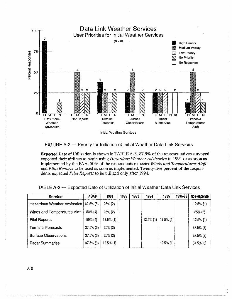
$ c: 8. II)
rP. 'E Q)
~ Q)
D..
100
7
Hazardous Weather Advisories
Data Link Weather Services User Priorities for Initial Weather SeNices
(N=8)
Pilot Reports Terminal Forecasts
Surface Observations
Initial Weather Services
Radar Summaries
• mJ ~ ~ D
High Priority
Medium Priority
Low Priority
No Priority
No Response
Winds & Temperatures
Aloft
FIGURE A-2 - Priority for Initiation of Initial Weather Data Link SeNices
Expected Date of Utilization is shown in TABLE A-3. 87.5% of the representatives surveyed expected their airlines to begin using Hazardous Weather Advisories in 1991 or as soon as implemented by the FAA. 50% of the respondents expected Winds and Temperatures Aloft and Pilot Reports to be used as soon as implemented. Twenty-five percent of the respondents expected Pilot Reports to be utilized only after 1994.
TABLE A-3 - Expected Date of Utilization of Initial Weather Data Link SeNices
Service ASAP 1991 1992 1993 1994 1995 1996·99 No Response
Hazardous Weather Advisories 62.5% (5) 25%(2) 12.5% (1)
Winds and Temperatures Aloft 50%(4) 25%(2) 25% (2)
Pilot Reports 50%(4) 12.5%(1) 12.5%(1) 12.5% (1) 12.5% (1)
Terminal Forecasts 37.5% (3) 25%(2) 37.5% (3)
Surface Observations 37.5% (3) 25%(2) 37.5% (3)
Radar Summaries 37.5% (3) 12.5%(1) 12.5% (1) 37.5% (3)
A·8
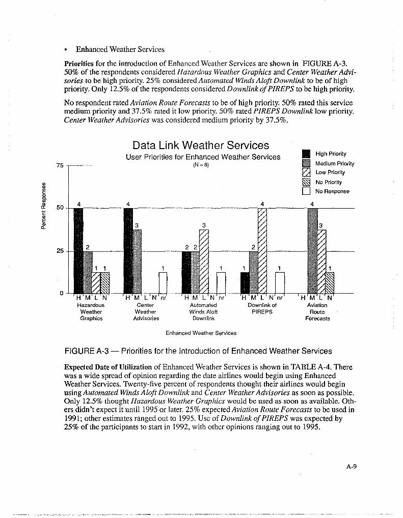
75
I/)
51 c: a I/) Q)
50 a:: C Q)
e 8:.
25
o
• Enhanced Weather Services
Priorities for the introduction of Enhanced Weather Services are shown in FIGURE A-3. 50% of the respondents considered Hazardous Weather Graphics and Center Weather Advisories to be high priority. 25% considered Automated Winds Aloft Downlink to be of high priority. Only 12.5% of the respondents considered Downlink of PI REPS to be high priority.
No respondent rated Aviation Route Forecasts to be of high priority. 50% rated this service medium priority and 37.5% rated it low priority. 50% rated PIREPS Downlink low priority. Center Weather Advisories was considered medium priority by 37.5%.
4
Data Link Weather Services User Priorities for Enhanced Weather Services
(N=8)
4 4
• High Priority
tm Medium Priority
~ Low Priority
~ No Priority
D No Response
4 --------- ---------------------------~~---------
Hazardous Weather Graphics
Center Weather Advisories
Automated Winds Aloft
Downlink
Enhanced Weather Services
Downlink of PIREPS
Aviation Route
Forecasts
FIGURE A-3 - Priorities for the Introduction of Enhanced Weather Services
Expected Date of Utilization of Enhanced Weather Services is shown in TABLE A-4. There was a wide spread of opinion regarding the date airlines would begin using Enhanced Weather Services. Twenty-five percent of respondents thought their airlines would begin using Automated Winds Aloft Downlink and Center Weather Advisories as soon as possible. Only 12.5% thought Hazardous Weather Graphics would be used as soon as available. Others didn't expect it unti11995 or later. 25% expected Aviation Route Forecasts to be used in 1991; other estimates ranged out to 1995. Use of Downlink of PIREPS was expected by 25% of the participants to start in 1992, with other opinions ranging out to 1995.
A-9
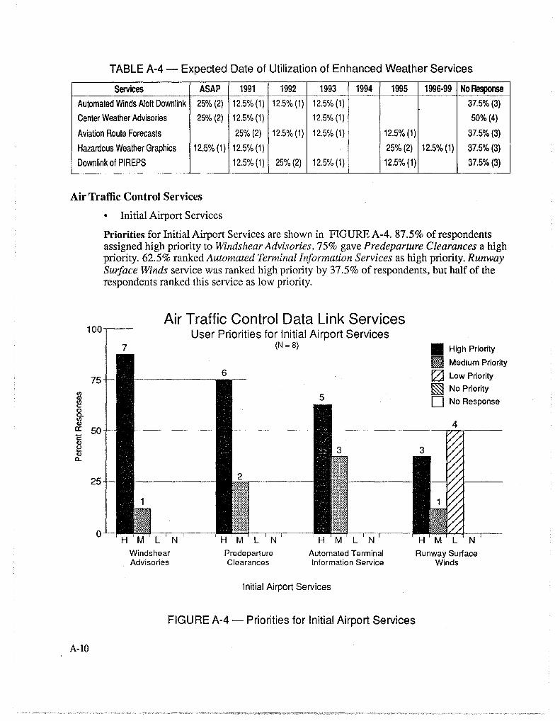
TABLE A-4 - Expected Date of Utilization of Enhanced Weather Services
Services ASAP 1991 1992 1993 1994 1995 1996·99 No Response
Automated Winds Aloft Downlink 25%(2) 12.5%(1) 12.5% (1) 12.5% (1) 37.5% (3)
Center Weather Advisories 25% (2) 12.5% (1) 12.5% (1) 50% (4)
Aviation Route Forecasts 25%(2) 12.5% (1) 12.5%(1) 12.5% (1) 37.5% (3)
Hazardous Weather Graphics 125%(1) 125% (1) 25%(2) 12.5% (1) 37.5%(3)
Downlink of PIREPS 12.5%(1) 25%(2) 12.5%(1) 12.5% (1) 37.5% (3)
Air Traffic Control Services
100
75 (/) Q) (/) c: 8. (/) Q)
a: 50 "E Q)
~ Q)
Cl..
25
o
A-lO
• Initial Airport Services
Priorities for Initial Airport Services are shown in FIGURE A-4. 87.5% of respondents assigned high priority to Windshear Advisories. 75% gave Predeparture Clearances a high priority. 62.5% ranked Automated Terminal Information Services as high priority. Runway Surface Winds service was ranked high priority by 37.5% of respondents, but half of the respondents ranked this service as low priority.
7
Air Traffic Control Data Link Services User Priorities for Initial Airport Services
Windshear Advisories
Predeparture Clearances
(N = 8)
L N Automated Terminal Information Service
Initial Airport Services
FIGURE A-4 - Priorities for Initial Airport Services
• High Priority
II Medium Priority
tZI Low Priority
~ No Priority
D No Response
Runway Surface Winds
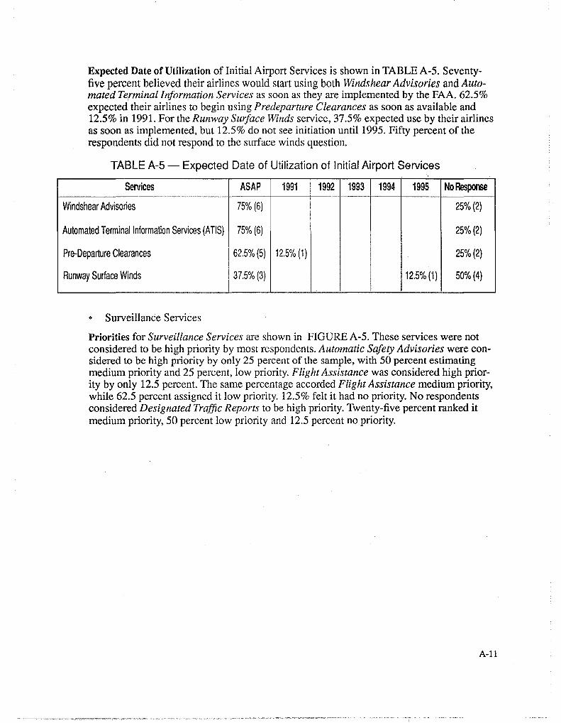
Expected Date of Utilization of Initial Airport Services is shown in TABLE A-5. Seventyfive percent believed their airlines would start using both Winds hear Advisories and Automated Terminal Information Services as soon as they are implemented by the FAA. 62.5% expected their airlines to begin using Predeparture Clearances as soon as available and 12.5% in 1991. For the Runway Surface Winds service, 37.5% expected use by their airlines as soon as implemented, but 12.5% do not see initiation until 1995. Fifty percent of the respondents did not respond to the surface winds question.
TABLE A-5 - Expected Date of Utilization of Initial Airport Services
Services ASAP 1991 1992 1993 1994 1995 No Response
Windshear Advisories 75%(6) 25%(2)
Automated Terminal Information Services (ATIS) 75%(6) 25%(2)
Pre-Departure Clearances 62.5%(5) 12.5% (1) 25% (2)
Runway Surface Winds 37.5%(3) 12.5%(1) 50% (4)
• Surveillance Services
Priorities for Surveillance Services are shown in FIGURE A-5. These services were not considered to be high priority by most respondents. Automatic Safety Advisories were considered to be high priority by only 25 percent of the sample, with 50 percent estimating medium priority and 25 percent, low priority. Flight Assistance was considered high priority by only 12.5 percent. The same percentage accorded Flight Assistance medium priority, while 62.5 percent assigned it low priority. 12.5% felt it had no priority. No respondents considered Designated Traffic Reports to be high priority. Twenty-five percent ranked it medium priority, 50 percent low priority and 12.5 percent no priority.
A-ll
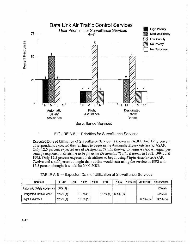
If) Q) If) c: 0 Co If) Q)
a: -c:
~ Q) a..
75
50
25
o
Data Link Air Traffic Control Services User Priorities for Surveillance Services
(N=8)
Automatic Safety
Advisories
5
Flight Assistance
Surveillance Services
Designated Traffic Report
FIGURE A-5 - Priorities for Surveillance Services
II High Priority
II Medium Priority
!ZI Low Priority
~ No Priority
D No Response
1
nr
Expected Date of Utilization of Surveillance Services is shown in TABLE A-6. Fifty percent of respondents expected their airlines to begin using Automatic Safety Advisories ASAP. Only 12.S percent expected use of Designated Traffic Reports to begin ASAP. An equal percentage expected their airline to begin using Designated Traffic Reports in 1992, 1994, and 1995. Only 12.S percent expected their airlines to begin using Flight Assistance ASAP. Twelve and a half percent thought their airline would start using the service in 1992 and 12.S percent thought it would be 2000-200S.
TABLE A-6 - Expected Date of Utilization of Surveillance Services
Services ASAP 1991 1992 1993 1994 1995 1996-99 2000-2005 No Response
Automatic Safety Advisories 50%(4) 50% (4)
Designated Traffic Report 12.5%(1) 12.5% (1) 12.5%(1) 12.5% (1) 50% (4)
Flight Assistance 12.5% (1) 12.5% (1) 12.5%(1) 62.5% (5)
A-12
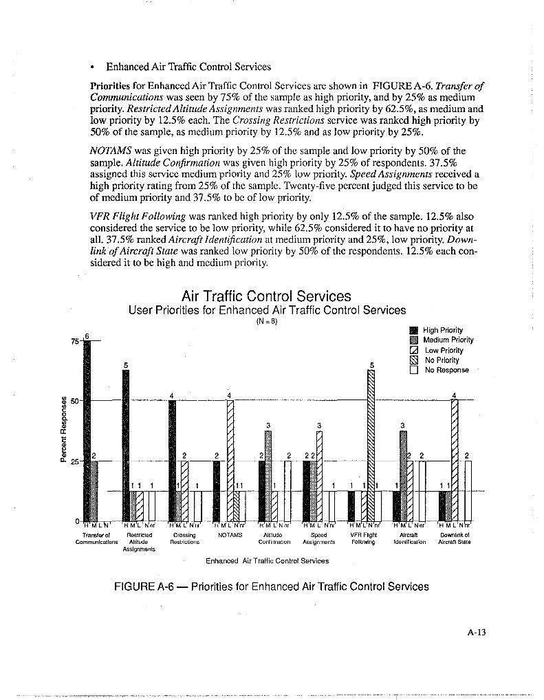
6
• Enhanced Air Traffic Control Services
Priorities for Enhanced Air Traffic Control Services are shown in FIGURE A -6. Transfer of Communications was seen by 75% of the sample as high priority, and by 25% as medium priority. Restricted Altitude Assignments was ranked high priority by 62.5%, as medium and low priority by 12.5% each. The Crossing Restrictions service was ranked high priority by 50% of the sample, as medium priority by 12.5% and as low priority by 25%.
NOTAMS was given high priority by 25% of the sample and low priority by 50% of the sample. Altitude Confirmation was given high priority by 25% of respondents. 37.5% assigned this service medium priority and 25% low priority. Speed Assignments received a high priority rating from 25% of the sample. Twenty-five percent judged this service to be of medium priority and 37.5% to be of low priority.
VFR Flight Following was ranked high priority by only 12.5% of the sample. 12.5% also considered the service to be low priority, while 62.5% considered it to have no priority at all. 37.5% ranked Aircraft Identification at medium priority and 25%, low priority. Downlink of Aircraft State was ranked low priority by 50% of the respondents. 12.5% each considered it to be high and medium priority.
5
Air Traffic Control Services User Priorities for Enhanced Air Traffic Control Services
(N =8)
5
• High Priority D:!I Medium Priority ILl Low Priority ~ No Priority o No Response
~ ~-~----~------~--------~----------------------~------------~--III C
8. 8l Ii 'E ~ CD a.
Transfer of Restricted Communications Altttude
Assignments
Crossing Restrictions
NOTAMS Altitude Speed VFR Flight Alrcmft Downlink of Confirmation ASSignments Following Identification Alrcmft State
Enhanced Air Traffic Control Services
FIGURE A-6 - Priorities for Enhanced Air Traffic Control Services
A-13
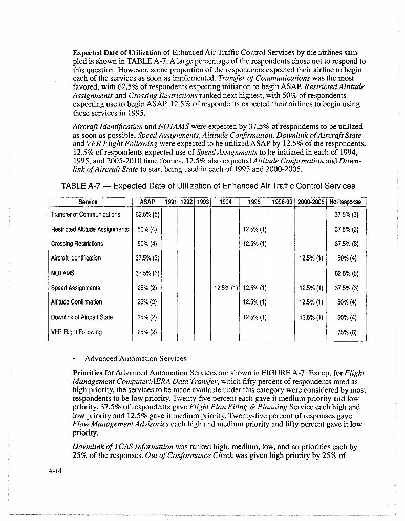
Expected Date of Utilization of Enhanced Air Traffic Control Services by the airlines sampled is shown in TABLE A-7. A large percentage of the respondents chose not to respond to this question. However, some proportion of the respondents expected their airline to begin each of the services as soon as implemented. Transfer of Communications was the most favored, with 62.5% of respondents expecting initiation to begin ASAP. Restricted Altitude Assignments and Crossing Restrictions ranked next highest, with 50% of respondents expecting use to begin ASAP. 12.5% of respondents expected their airlines to begin using these services in 1995.
Aircraft Identification and NOTAMS were expected by 37.5% of respondents to be utilized as soon as possible. Speed Assignments, Altitude Confirmation, Downlink of Aircraft State and VF R F lig ht Following were expected to be utilized ASAP by 12.5% of the respondents. 12.5% of respondents expected use of Speed Assignments to be initiated in each of 1994, 1995, and 2005-2010 time frames. 12.5% also expected Altitude Confirmation and Downlink of Aircraft State to start being used in each of 1995 and 2000-2005.
TABLE A-7 - Expected Date of Utilization of Enhanced Air Traffic Control Services
service ASAP 1991 1992 1993 1994 1995 1996·99 2000·2005 No Response
Transfer of Communications 62.5%(5) 37.5% (3)
Restricted Altitude Assignments 50%(4) 12.5% (1) 37.5% (3)
Crossing Restrictions 50%(4) 12.5% (1) 37.5% (3)
Aircraft Identification 37.5% (3) 12.5% (1) 50% (4)
NOTAMS 37.5% (3) 62.5% (5)
Speed ASSignments 25%(2) 12.5% (1) 12.5% (1) 12.5% (1) 37.5% (3)
Altitude Confirmation 25%(2) 12.5% (1) 12.5% (1) 50% (4)
Downlink of Aircraft State 25%(2) 12.5%(1) 12.5% (1) 50% (4)
VFR Flight Following 25%(2) 75% (6)
A-14
• Advanced Automation Services
Priorities for Advanced Automation Services are shown in FIGURE A-7. Except for Flight Management ComputerlAERA Data Transfer, which fifty percent of respondents rated as high priority, the services to be made available under this category were considered by most respondents to be low priority. Twenty-five percent each gave it medium priority and low priority. 37.5% of respondents gave Flight Plan Filing & Planning Service each high and low priority and 12.5% gave it medium priority. Twenty-five percent of responses gave Flow Management Advisories each high and medium priority and fifty percent gave it low priority.
Downlink of TCAS Information was ranked high, medium, low, and no priorities each by 25% of the responses. Out of Conformance Check was given high priority by 25% of
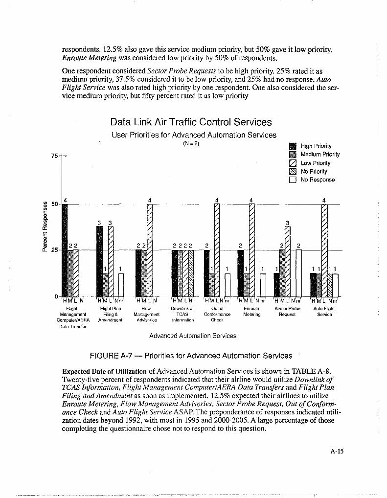
75
respondents. 12.5% also gave this service medium priority, but 50% gave it low priority. Enroute Metering was considered low priority by 50% of respondents.
One respondent considered Sector Probe Requests to be high priority. 25% rated it as medium priority, 37.5% considered it to be low priority, and 25% had no response. Auto Flight Service was also rated high priority by one respondent. One also considered the service medium priority, but fifty percent rated it as low priority
Data Link Air Traffic Control Services User Priorities for Advanced Automation Services
(N = 8) • High Priority mI Medium Priority
12:1 Low Priority ~ No Priority o No Response
4 4 4 4 4 ~ 50 -------------------~,---------------~-------~~--------------.~--VI c 8. VI
t1. c: ~ ~ 25
a Flight
Management Computer/AERA
Data Transfer
Flight Plan Filing &
Amendment
Flow Management
Advisories
Downlink of TCAS
Information
Out of Conformance
Check
Enroute Metering
Sector Probe Request
Auto Flight Service
Advanced Automation Services
FIGURE A-7 - Priorities for Advanced Automation Services
Expected Date of Utilization of Advanced Automation Services is shown in TABLE A-8. Twenty-five percent of respondents indicated that their airline would utilize Downlink of TCAS Information, Flight Management ComputerlAERA Data Transfers and Flight Plan Filing and Amendment as soon as implemented. 12.5% expected their airlines to utilize Enroute Metering, Flow Management Advisories, Sector Probe Request, Out ofConformance Check and Auto Flight Service ASAP. The preponderance of responses indicated utilization dates beyond 1992, with most in 1995 and 2000-2005. A large percentage of those completing the questionnaire chose not to respond to this question.
A-I5
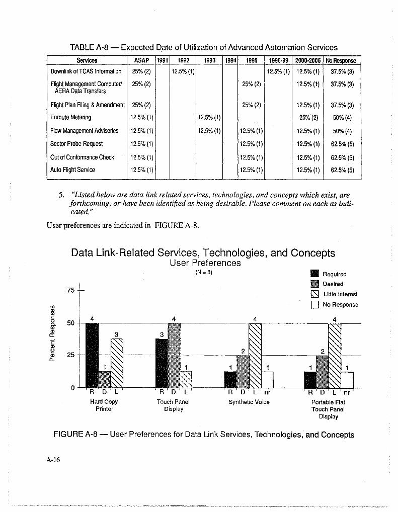
TABLE A-8 - Expected qate of Utilization of Advanced Automation Services
Services ASAP 1991 1992 1993 1994 1995 1996·99 2000·2005 No Response
Downlink of TCAS Information 25%(2) 12.5% (1) 12.5% (1) 12.5% (1) 37.5% (3)
Flight Management Computer! 25% (2) 25%(2) 12.5% (1') 37.5%(3) AERA Data Transfers
Flight Plan Filing & Amendment 25% (2) 25%(2) 12.5% (1) 37.5% (3)
Enroute Metering 12.5% (1) 12.5% (1) 25%'(2) 50% (4)
Flow Management Advisories 12.5% (1) 12.5%(1) 12.5%(1) 12.5% (1) 50% (4)
Sector Probe Request 12.5% (1) 12.5%(1) 12.5% (1) 62.5% (5)
Out of Conformance Check 12.5% (1) 12.5%(1) 12.5% (1) 62.5%(5)
Auto Flight Service 12.5% (1) 12.5%(1) 12.5% (1) 62.5%(5)
5. "Listed below are data link related services, technologies, and concepts which exist, are forthcoming, or have been identified as being desirable. Please comment on each as indicated."
User preferences are indicated in FIGURE A-S.
Data Link-Related Services, Technologies, and Concepts User Preferences
75
(/)
8 c 8. 50 (/) Q)
a: -c Q)
~ Q) 25 c..
o
4
Hard Copy Printer
Touch Panel Display
(N = 8)
Synthetic Voice
• Required
II Desired
~ Little Interest
D No Response
Portable Flat Touch Panel
Display
FIGURE A-8 - User Preferences for Data Link Services, Technologies, and Concepts
A-16
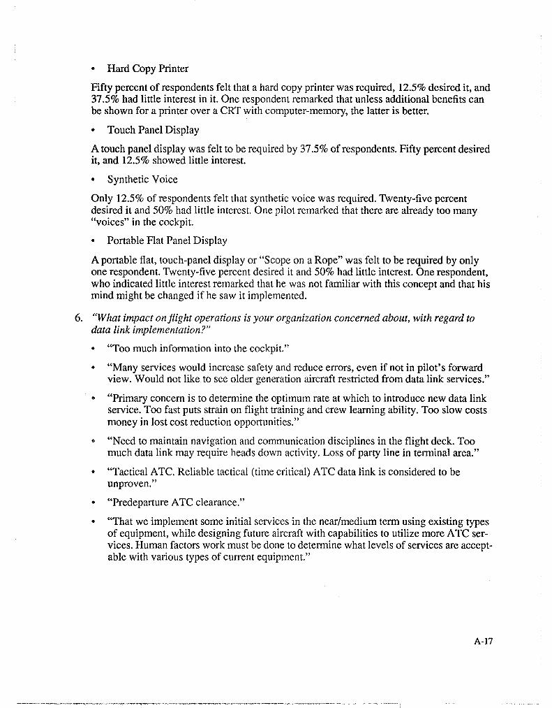
• Hard Copy Printer
Fifty percent of respondents felt that a hard copy printer was required, 12.5% desired it, and 37.5% had little interest in it. One respondent remarked that unless additional benefits can be shown for a printer over a CRT with computer-memory, the latter is better.
• Touch Panel Display
A touch panel display was felt to be required by 37.5% of respondents. Fifty percent desired it, and 12.5% showed little interest.
• Synthetic Voice
Only 12.5% of respondents felt that synthetic voice was required. Twenty-five percent desired it and 50% had little interest. One pilot remarked that there are already too many "voices" in the cockpit.
• Portable Flat Panel Display
A portable fiat, touch-panel display or "Scope on a Rope" was felt to be required by only one respondent. Twenty-five percent desired it and 50% had little interest. One respondent, who indicated little interest remarked that he was not familiar with this concept and that his mind might be changed if he saw it implemented.
6. "What impact onjUght operations is your organization concerned about, with regard to data link implementation?"
• "Too much information into the cockpit."
• "Many services would increase safety and reduce errors, even if not in pilot's forward view. Would not like to see older generation aircraft restricted from data link services."
• "Primary concern is to determine the optimum rate at which to introduce new data link service. Too fast puts strain on flight training and crew learning ability. Too slow costs money in lost cost reduction opportunities."
• "Need to maintain navigation and communication disciplines in the flight deck. Too much data link may require heads down activity. Loss of party line in terminal area."
• "Tactical ATC. Reliable tactical (time critical) ATC data link is considered to be unproven."
• "Predeparture ATC clearance."
• "That we implement some initial services in the near/medium term using existing types of equipment, while designing future aircraft with capabilities to utilize more A TC services. Human factors work must be done to determine what levels of services are acceptable with various types of current equipment."
A-I7
7. "What services, in addition to those previously listed, would your organization see as important? "
"To the system at large?"
• "TCAS approach with data link 'welcome' and guidelines."
• "Better means of free text data link composition for AOC, ATC, etc."
• "Two way data link communications with the ATC controller over a mature ground network to allow for surveillance monitoring and uplink of conflict advisories (traffic in the area)."
• "Inter-center coordination by direct communication with flight-critical in Europe."
• "ADS oceanic program-two way communications via satellite (data primarily with voice backup) in oceanic or non-VHF coverage areas."
"To your company in particular?"
• "To keep all present AOC applications and allow any future additions."
• "Need to consider compatibility with ELS implementation."
• "Digital A TIS, followed by simple enhancements, e.g., transfer of communication, weather products, etc."
• "Any significant change to A TC clearance to be copied to flight dispatch. Dispatcher issues new clearance when ATC changes route."
• "The oceanic ATC communication is a priority for us (particularly in the Pacific). I could get more excited about a 'real' enroute service such as Transfer of Communication domestically, than Predeparture Clearance or ATIS, since it should relieve frequency congestion and improve controller efficiency."
8. "Do you see a need for a division of operational control and procedures for use of data link in the terminal area as opposed to enroute?"
A-IS
• "No, they should be the same."
• "Unless VFR traffic is restricted from the terminal area, a more sophisticated cockpit implementation would be required, such as synthetic voice or a HUD display."
• "Yes. The problems and opportunities (potential solutions) are distinctly different, but both share two common threads: (1) need for moving toward ATC management by exception, and (2) responsiveness to pilot needs."
• "Yes. Use voice in terminal because of criticality. Maybe do TDWR or closely spaced approach. Go around instructions via data link."
• "Yes. There are many [more] rapid tactical commands provided in the terminal area than in the enroute area. Data link for enroute first, then add to each sector for climb/descent before adding to terminal area."
• "Uplinking the proposed route, including probable speed and altitude restrictions, would pennit much more efficient flight management."
• "I tend not to focus on tenninal vs. enroute, but instead time-critical vs. non-time-critical. I believe the key to evaluating any incremental service is the total turnaround time (required vs. actual) from the time a controller or pilot first 'thinks' a communication until it can be generated, communicated, understood, and replied, or acknowledged and understood on the back side. Having said that, it is logical that the tenninal airspace will have more time constraints than enroute, but I think we should be open to any beneficial service that can be done more efficiently with data than with voice."
9. UPlease feel free to offer any other remarks you wish, pertinent to this project."
• "Our airline advocates studies on data link messages processed on the FMS unit. There must be no conflicts in screen management or interruption of NAv processes. Time management of FMS screen procedures must be reviewed by the Human Factors people under real operations conditions."
• "Much of the Atlantic north of 600 N is covered by VHF data link. Let's get off HF and VHF voice and move to data link for position reports, etc."
• "This is a key project/study in my opinion, because it addresses real, near-tenn potential use of incremental data link services! The 2010 solution must be worked as well, but the possibility of real economic and safety benefits first lies in initial and subsequent services. Implementing the first phase of services will enable us to evaluate benefits and fine-tune our course for the longer term, AERA-type environment."
Discussion
All air carriers represented in the study currently use ACARS. In addition, most aircraft of the types operated by these airlines are equipped with ACARS.
As shown in TABLE A-2, 37.5% of the sample would begin use of VHF Packet Communications instead of ACARS as soon as available. Of the remaining four respondents, the time for implementation ranged from 1992 through 1999, with one unsure of when the capability would be adopted.
Weather Services
• Initial Weather Services
Based on the responses the order of implementation desired for Initial Weather Services appears to be:
1. Hazardous Weather Advisories 2. Pilot Reports 3. Surface Observations 4. Winds and Temperatures Aloft 5. Tenninal Forecasts 6. Radar Summaries
A-19
The preponderance of respondents indicated that their airlines would begin using the FAA-provided data link services as soon as possible.
• Enhanced Weather Services
Hazardous Weather Graphics and Center Weather Advisories were ranked high priority by 50% of respondents, while Aviation Route Forecasts was ranked medium priority by 50%, with no one ranking it high priority. Again, based on the distribution in FIGURE A-3, the order of implementation of the Enhanced Weather Services would appear to be:
1. Center Weather Advisories 2. Hazardous Weather Graphics 3. Aviation Route Forecasts 4. Downlink of PlREPS 5. Automated Winds Aloft Downlink
There is a wide spread in expected date of use by the airlines, as shown in TABLE A-4. Only Automated Winds Aloft Downlink, Center Weather Advisories, and Hazardous Weather Graphics are expected by the respondents to be used by their airlines as soon as implemented.
Air Traffic Control Services
A-20
• Initial Airport Services
All the initial airport services were given high priority. There was essentially complete agreement by all respondents that Winds hear Advisories was their highest priority, closely followed by Predeparture Clearances. However, most respondents indicated that their airlines would use the capabilities as soon as implemented, with Winds hear Advisories and Automated Terminal Information Services garnering 75% of the responses. Predeparture Clearances was next with 62.5%, while Runway Surface Winds was chosen by only 37.5%.
• Surveillance Services
Most respondents did not accord these services high priority. Of the three services, Automatic Safety Advisories, Flight Assistance, and Designated Traffic Report, only Automatic Safety Advisories would be used ASAP by most of the airlines represented (50%). Estimates of when use of the other two services would begin ranged out to 2000-2005.
• Enhanced Air Traffic Control Services
Of the nine services rated, only three dominated other rankings as high priority. These were Transfer of Communications, Restricted Altitude Assignments, and Crossing Restrictions. The remaining six were considered by most of the respondents as low or medium priority. One (VFR Flight Following) was considered by 62.5% of respondents to have no priority at all. There was no difference of opinion regarding the use of Transfer of Communications. All who responded felt it would be used by their airline ASAP. All
but one respondent felt the same way about Restricted A Ititude Assignments and Crossing Restrictions. While some proportion felt each service would be used as soon as possible by their particular carrier, initial use of some services stretched out to 2005.
• Advanced Automation Services
Except for Flight Management ComputerlAERA Data Transfer, most respondents considered these services to be oflow priority. Only 25% thought their airline would use the services of the Downlink of TCAS Information, Flight Management ComputerlAERA D?lta Transfers, and Flight Plan Filing and Amendment ASAP. The rest stretched out to 2005. About Downlink ofTCAS Information, one respondent said "That will depend upon what the FAA means to use this information for."
• Data Link-Related Services, Technologies and Concepts
The hardcopy printer and the touch panel display were considered to be required by 50% and 37.5%, respectively. Synthetic voice and the portable flat touch panel display attracted little interest by most.
A-21
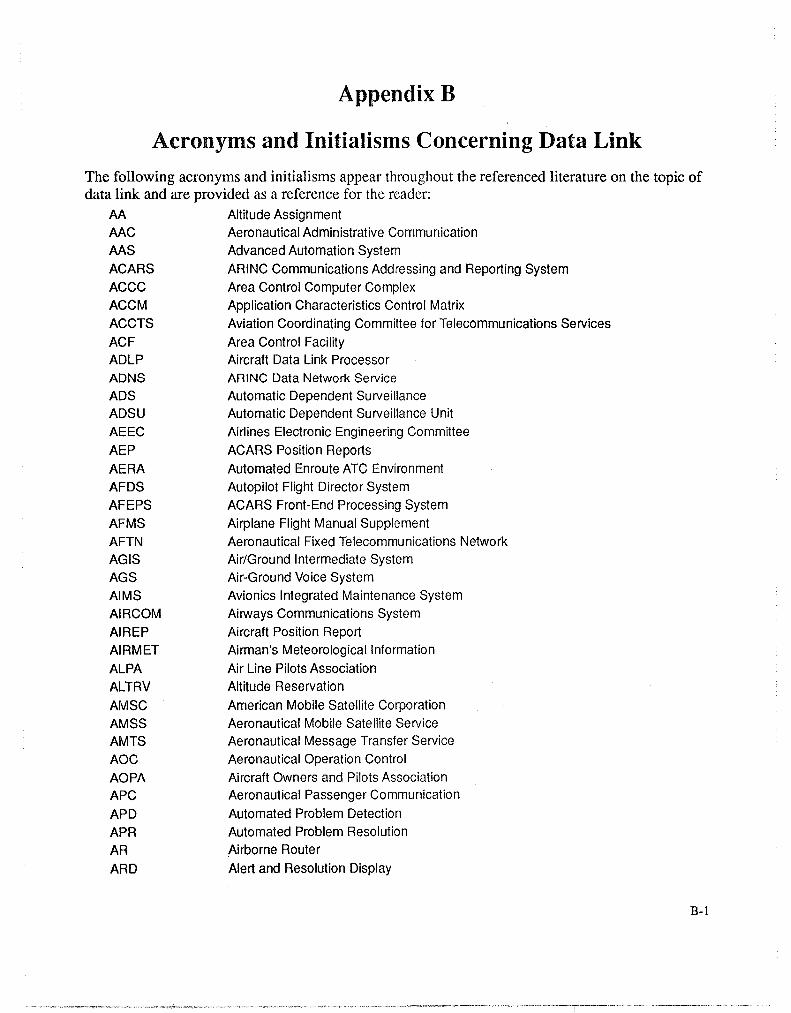
Appendix B
Acronyms and Initialisms Concerning Data Link
The following acronyms and initialisms appear throughout the referenced literature on the topic of data link and are provided as a reference for the reader:
M Altitude Assignment MC Aeronautical Administrative Communication MS Advanced Automation System ACARS ARINC Communications Addressing and Reporting System ACCC Area Control Computer Complex ACCM Application Characteristics Control Matrix ACCTS Aviation Coordinating Committee for Telecommunications Services
ACF Area Control Facility ADLP Aircraft Data Link Processor ADNS ADS ADSU
AEEC AEP
AERA AFDS AFEPS
AFMS AFTN AGIS AGS AIMS AIRCOM
AIREP AIRMET
ALPA ALTRV
AMSC AMSS AMTS AOC
AOPA APC
APD APR AR
ARD
ARINC Data Network Service Automatic Dependent Surveillance Automatic Dependent Surveillance Unit Airlines Electronic Engineering Committee
ACARS Position Reports
Automated Enroute ATC Environment Autopilot Flight Director System ACARS Front-End Processing System Airplane Flight Manual Supplement Aeronautical Fixed Telecommunications Network Air/Ground Intermediate System Air-Ground Voice System Avionics Integrated Maintenance System Airways Communications System
Aircraft Position Report Airman's Meteorological Information
Air Line Pilots Association Altitude Reservation
American Mobile Satellite Corporation Aeronautical Mobile Satellite Service Aeronautical Message Transfer Service Aeronautical Operation Control
Aircraft Owners and Pilots Association Aeronautical Passenger Communication
Automated Problem Detection Automated Problem Resolution Airborne Router
Alert and Resolution Display
B-1
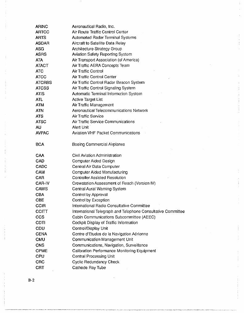
ARINC ARTCC ARTS
ASDAR
ASG ASRS
ATA ATACT
ATC
ATCC
ATCRBS ATCSS
ATIS
ATL ATM
ATN
ATS
ATSC
AU
AVPAC
BCA
CM
CAD CADC
CAM CAR
CAR-IV
CAWS
CBA
CBE
CCIR
CCITT
CCS CDTI
CDU CENA CMU
CNS
CPME CPU
CRC
CRT
B-2
Aeronautical Radio, Inc. Air Route Traffic Control Center
Automated Radar Terminal Systems
Aircraft to Satellite Data Relay
Architecture Strategy Group Aviation Safety Reporting System
Air Transport Association (of America)
Air Traffic AERA Concepts Team
Air Traffic Control
Air Traffic Control Center
Air Traffic Control Radar Beacon System Air Traffic Control Signaling System
Automatic Terminal Information System
Active Target List Air Traffic Management
Aeronautical Telecommunications Network
Air Traffic Service
Air Traffic Service Communications
Alert Unit
Aviation VHF Packet Communications
Boeing Commercial Airplanes
Civil Aviation Administration
Computer Aided Design
Central Air Data Computer
Computer Aided Manufacturing Controller Assisted Resolution
Crewstation Assessment of Reach (Version IV)
Central Aural Warning System
Control by Approval Control by Exception
International Radio Consultative Committee
International Telegraph and Telephone Consultative Committee
Cabin Communications Subcommittee (AEEC)
Cockpit Display of Traffic Information
Control/Display Unit
Centre d'Etudes de la Navigation Aerienne Communication Management Unit
Communications, Navigation, Surveillance Calibration Performance Monitoring Equipment
Central Processing Unit
Cyclic Redundancy Check
Cathode Ray Tube
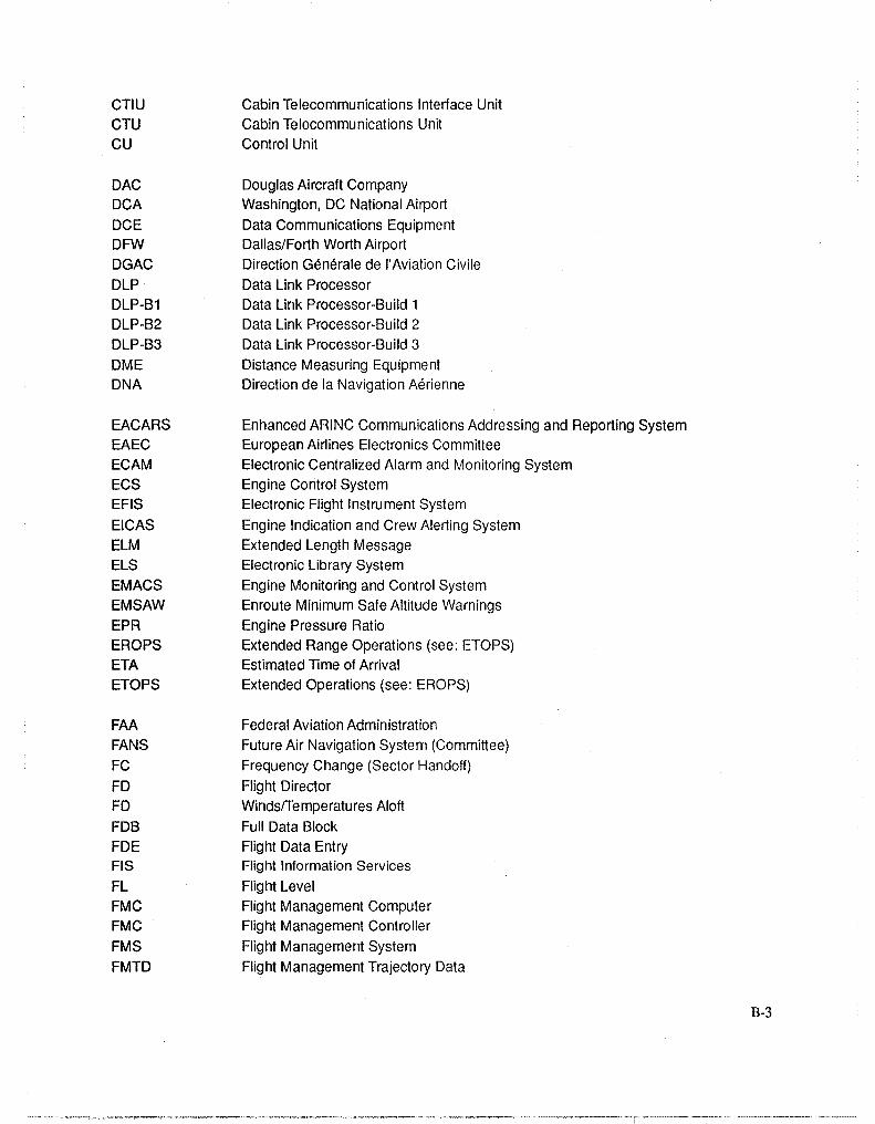
CTIU
CTU
CU
DAC DCA
DCE DFW
DGAC
DLP DLP-B1 DLP-B2
DLP-B3
DME DNA
EACARS EAEC
ECAM
ECS EFIS
EICAS
ELM
ELS
EMACS EM SAW
EPR EROPS
ETA
ETOPS
FAA
FANS
FC
FD FD
FOB
FOE FIS
FL FMC FMC
FMS
FMTD
Cabin Telecommunications Interface Unit Cabin Telecommunications Unit
Control Unit
Douglas Aircraft Company Washington, DC National Airport
Data Communications Equipment Dallas/Forth Worth Airport
Direction Generale de l'Aviation Civile
Data Link Processor Data Link Processor-Build 1 Data Link Processor-Build 2
Data Link Processor-Build 3
Distance Measuring Equipment Direction de la Navigation Mrienne
Enhanced ARINC Communications Addressing and Reporting System European Airlines Electronics Committee
Electronic Centralized Alarm and Monitoring System
Engine Control System Electronic Flight Instrument System
Engine Indication and Crew Alerting System
Extended Length Message
Electronic Library System
Engine Monitoring and Control System
Enroute Minimum Safe Altitude Warnings
Engine Pressure Ratio Extended Range Operations (see: ETOPS)
Estimated Time of Arrival
Extended Operations (see: EROPS)
Federal Aviation Administration
Future Air Navigation System (Committee)
Frequency Change (Sector Handoff)
Flight Director WindslTemperatures Aloft
Full Data Block Flight Data Entry Flight Information Services
Flight Level
Flight Management Computer Flight Management Controller
Flight Management System
Flight Management Trajectory Data
B-3
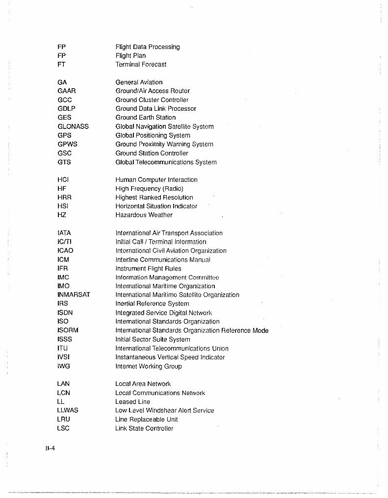
FP FP FT
GA GAAR
GCC GDLP
GES
GLONASS
GPS GPWS
GSC GTS
HCI HF
HRR HSI HZ
lATA IC/TI
ICAO
ICM IFR IMC IMO INMARSAT
IRS
ISDN ISO
ISORM
ISSS
ITU IVSI
IWG
LAN
LCN
LL LLWAS
LRU
LSC
B-4
Flight Data Processing Flight Plan Terminal Forecast
General Aviation Ground/Air Access Router
Ground Cluster Controller Ground Data Link Processor
Ground Earth Station
Global Navigation Satellite System Global Positioning System Ground Proximity Warning System
Ground Station Controller
Global Telecommunications System
Human Computer Interaction High Frequency (RadiO)
Highest Ranked Resolution Horizontal Situation Indicator Hazardous Weather
International Air Transport Association Initial Call I Terminal Information
International Civil Aviation Organization
Interline Communications Manual Instrument Flight Rules Information Management Committee International Maritime Organization International Maritime Satellite Organization Inertial Reference System
Integrated Service Digital Network International Standards Organization
International Standards Organization Reference Mode
Initial Sector Suite System
International Telecommunications Union Instantaneous Vertical Speed Indicator
Internet Working Group
Local Area Network
Local Communications Network
Leased Line Low Level Winds hear Alert Service
Line Replaceable Unit
Link State Controller
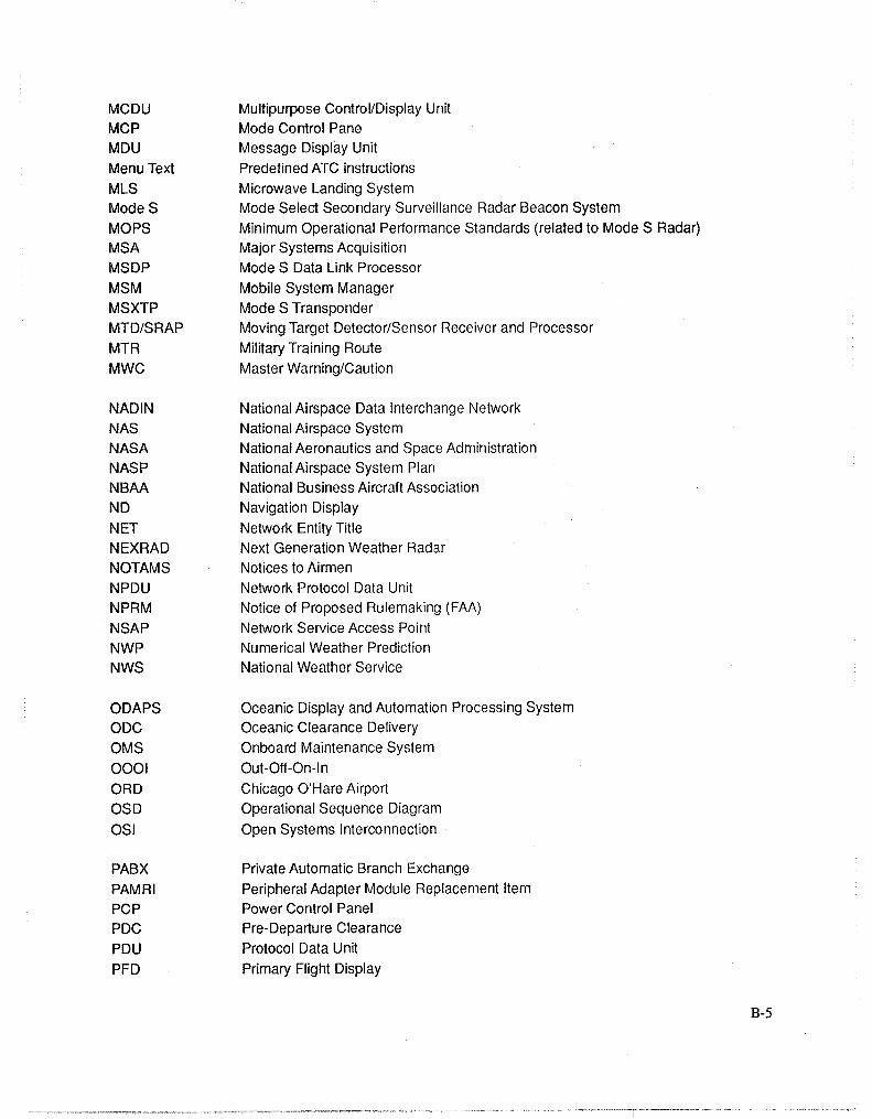
MCDU MCP MDU
Menu Text
MLS ModeS
MOPS MSA
MSDP
MSM
MSXTP MTD/SRAP
MTR
MWC
NADIN
NAS
NASA NASP NBAA
ND
NET NEXRAD
NOTAMS
NPDU
NPRM
NSAP
NWP NWS
ODAPS ODC
OMS
0001 ORD
OSD
OSI
PABX
PAMRI PCP PDC
PDU
PFD
Multipurpose Control/Display Unit Mode Control Pane Message Display Unit
Predefined ATC instructions
Microwave Landing System Mode Select Secondary Surveillance Radar Beacon System
Minimum Operational Performance Standards (related to Mode S Radar) Major Systems Acquisition
Mode S Data Link Processor
Mobile System Manager
Mode S Transponder Moving Target Detector/Sensor Receiver and Processor
Military Training Route
Master Warning/Caution
National Airspace Data Interchange Network
National Airspace System National Aeronautics and Space Administration
National Airspace System Plan National Business Aircraft Association Navigation Display
Network Entity Title Next Generation Weather Radar
Notices to Airmen
Network Protocol Data Unit Notice of Proposed Rulemaking (FAA)
Network Service Access Point Numerical Weather Prediction National Weather Service
Oceanic Display and Automation Processing System Oceanic Clearance Delivery
Onboard Maintenance System
Out-Off-On-In
Chicago O'Hare Airport
Operational Sequence Diagram
Open Systems Interconnection
Private Automatic Branch Exchange
Peripheral Adapter Module Replacement Item Power Control Panel Pre-Departure Clearance
Protocol Data Unit
Primary Flight Display
B-5
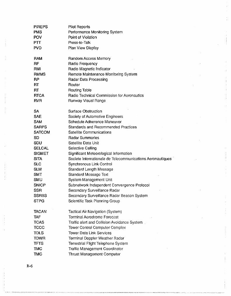
PIREPS PMS
POV PIT
PVD
RAM RF RMI
RMMS
RP
RT
RT
RTCA RVR
SA
SAE
SAM SARPS SATCOM
SD SDU SELCAL
SIGMET
SITA
SLC SLM SMT SMU
SNICP SSR SSRBS
STPG
TACAN
TAF
TCAS TCCC
TDLS
TDWR TFTS
TMC
TMC
B-6
Pilot Reports Performance Monitoring System
Point of Violation Press-to-Talk
Plan View Display
Random Access Memory Radio Frequency Radio Magnetic Indicator
Remote Maintenance Monitoring System Radar Data Processing
Router
Routing Table
Radio Technical Commission for Aeronautics Runway Visual Range
Surface Obstruction
Society of Automotive Engineers
Schedule Adherence Maneuver Standards and Recommended Practices
Satellite Communications
Radar Summaries Satellite Data Unit Selective Calling
Significant Meteorological Information
Societe Internationale de Telecommunications Aeronautiques
Synchronous Link Control Standard Length Message
Standard Message Text System Management Unit
Subnetwork Independent Convergence Protocol Secondary Surveillance Radar
Secondary Surveillance Radar Beacon System
Scientific Task Planning Group
Tactical Air Navigation (System)
Terminal Aerodrome Forecast Traffic alert and Collision Avoidance System
Tower Control Computer Complex
Tower Data Link Services
Terminal Doppler Weather Radar Terrestrial Flight Telephone System
Traffic Management Coordinator
Thrust Management Computer
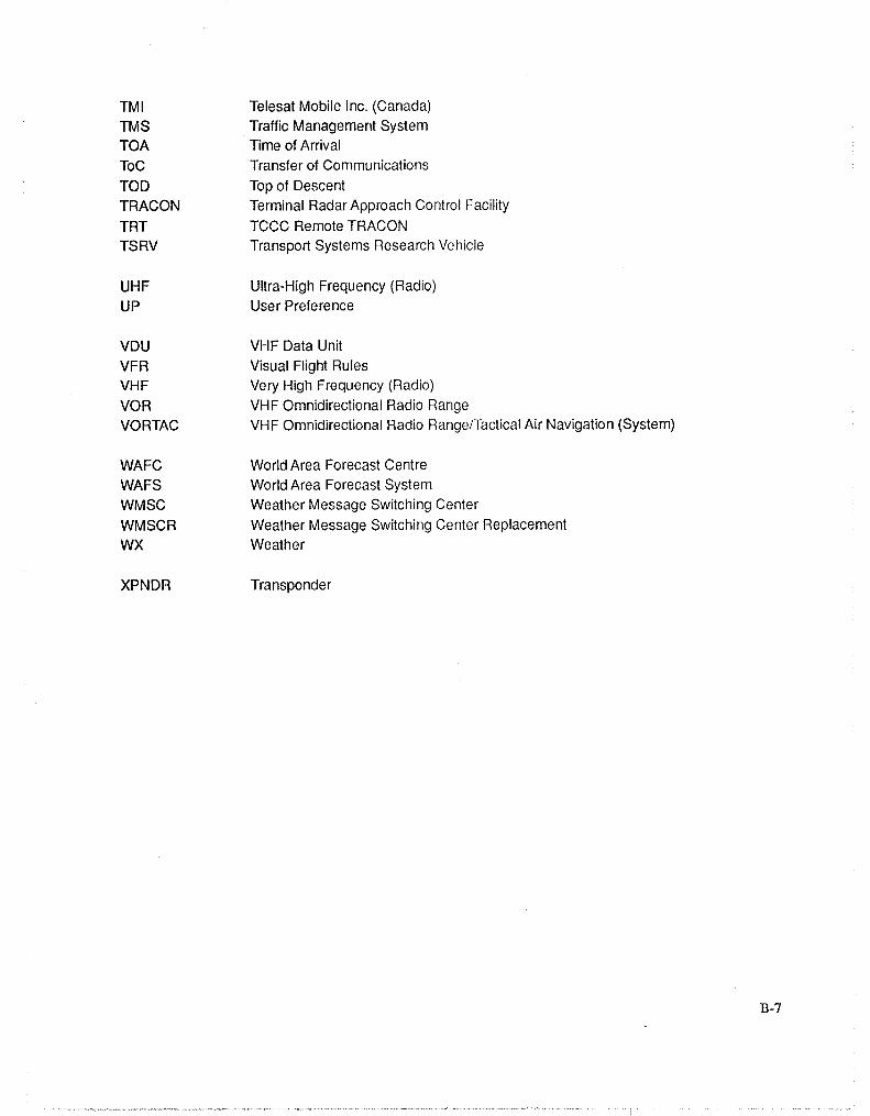
TMI TMS TOA
ToC
TOO TRACON
TRT TSRV
UHF UP
VDU
VFR VHF
VOR VORTAC
WAFC
WAFS WMSC
WMSCR
WX
XPNDR
Telesat Mobile Inc. (Canada) Traffic Management System Time of Arrival
Transfer of Communications
Top of Descent Terminal Radar Approach Control Facility
TCCC Remote TRACON Transport Systems Research Vehicle
Ultra-High Frequency (Radio) User Preference
VHF Data Unit
Visual Flight Rules Very High Frequency (Radio)
VHF Omnidirectional Radio Range VHF Omnidirectional Radio RangelTactical Air Navigation (System)
World Area Forecast Centre
World Area Forecast System
Weather Message Switching Center
Weather Message Switching Center Replacement
Weather
Transponder
B-7
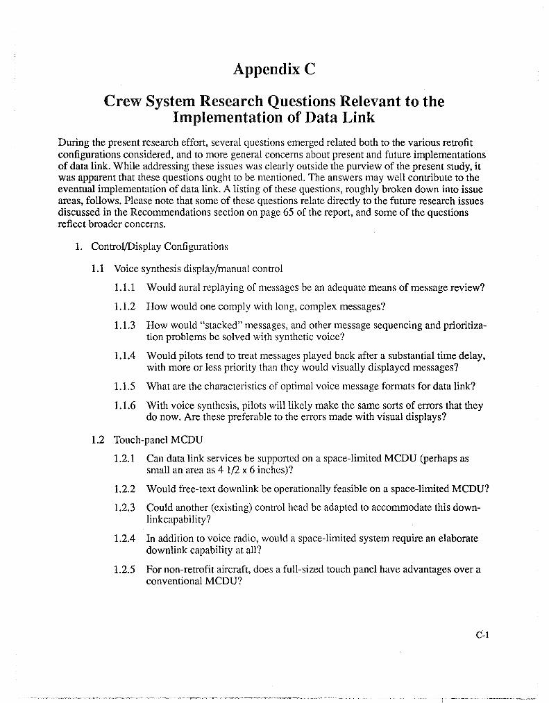
Appendix C
Crew System Research Questions Relevant to the Implementation of Data Link
During the present research effort, several questions emerged related both to the various retrofit configurations considered, and to more general concerns about present and future implementations of data link. While addressing these issues was clearly outside the purview of the present study, it was apparent that these questions ought to be mentioned. The answers may well contribute to the eventual implementation of data link. A listing of these questions, roughly broken down into issue areas, follows. Please note that some of these questions relate directly to the future research issues discussed in the Recommendations section on page 65 of the report, and some of the questions reflect broader concerns.
1. Control/Display Configurations
1.1 Voice synthesis display/manual control
1.1.1 Would aural replaying of messages be an adequate means of message review?
1.1.2 How would one comply with long, complex messages?
1.1.3 How would "stacked" messages, and other message sequencing and prioritization problems be solved with synthetic voice?
1.1.4 Would pilots tend to treat messages played back after a substantial time delay, with more or less priority than they would visually displayed messages?
1.1.5 What are the characteristics of optimal voice message formats for data link?
1.1.6 With voice synthesis, pilots will likely make the same sorts of errors that they do now. Are these preferable to the errors made with visual displays?
1.2 Touch-panel MCDU
1.2.1 Can data link services be supported on a space-limited MCDU (perhaps as small an area as 4 1/2 x 6 inches)?
1.2.2 Would free-text downlink be operationally feasible on a space-limited MCDU?
1.2.3 Could another (existing) control head be adapted to accommodate this downlinkcapability?
1.2.4 In addition to voice radio, would a space-limited system require an elaborate downlink capability at all?
1.2.5 For non-retrofit aircraft, does a full-sized touch panel have advantages over a conventional MCDU?
C-I
C-2
2. Format Design
2.1 What is the optimal employment of data entry and menu-select controls for data link?
2.2 What are the functional requirements of data link that will influence software format logic?
2.3 If data link co-resides with ACARS or FMS, what "turn-taking" routines are needed in the software?
2.4 What are the format requirements for message "stacking" and message prioritization? How will "stacking" coordinate with prioritization?
2.5 For MCDUs which combine ACARS and data link functions, should ACARS operation use adapted ACARS formats and control routines, or would it make more sense to develop a common interface format for ACARS and data link messages (and let the system translate ACARS traffic in and out of ACARS protocols)?
2.6 What are the criteria for data link message prioritization?
2.7 How will the scheme for data link message prioritization coordinate with other onboard alert prioritization systems?
3. Operational Adequacy
3.1 What are the mental workload and situational awareness characteristics present during data link activity? During key entry versus during menu selection?
3.2 What are the interface and integration issues with other systems (e.g., voice communication, FMS)?
3.3 What are the operational consequences of heads-down activity with data link usage? When is workload highest?
3.4 What sorts of errors (and how many of them) can be expected with data link operation?
4. Data Link Services
4.1 Will retrofit systems be able to support fully all services anticipated by the FAA?
4.2 How will retrofit implementations of these services differ from modern data link systems (e.g., in the MD-12 and the B-777)? Will there be transfer of training problems between the two data link implementations?
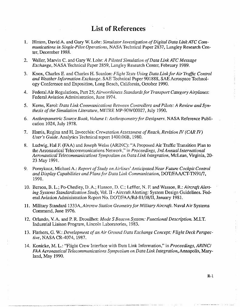
List of References
1. Hinton, David A. and Gary W. Lohr: Simulator Investigation of Digital Data Link ATC Communications in Single-Pilot Operations, NASA Technical Paper 2837, Langley Research Center, December 1988.
2. Waller, Marvin C. and Gary W. Lohr: A Piloted Simulation of Data Link ATC Message Exchange, NASA Technical Paper 2859, Langley Research Center, February 1989.
3. Knox, Charles E. and Charles H. Scanlon: Flight Tests Using Data Linkfor AirTraffic Control and Weather Information Exchange. SAE Technical Paper 901888, SAE Aerospace Technology Conference and Exposition, Long Beach, California, October 1990.
4. Federal Air Regulations, Part 25; Airworthiness Standards for Transport Category Airplanes: Federal Aviation Administration, June 1974.
5. Kerns, Karol: Data Link Communications Between Controllers and Pilots: A Review and Synthesis of the Simulation Literature, MITRE MP-90W00027, July 1990.
6. Anthropometric Source Book, Volume I: Anthropometry for Designers. NASA Reference Publication 1024, July 1978.
7. Harris, Regina and H. Iavecchia: Crewstation Assessment of Reach, Revision IV (CAR IV) User's Guide. Analytics Technical report 1400.06B, 1980.
8. Ludwig, Hal F. (FAA) and Joseph Weiss (ARINC): "A Proposed Air Traffic Transition Plan to the Aeronautical Telecommunications Network," in Proceedings, 3rd Annual International Aeronautical Telecommunications Symposium on Data Link Integration, McLean, Virginia, 20-23 May 1991.
9. Pomykacz, Michael A.: Report of Study on Airlines' Anticipated Near Future Cockpit Control and Display Capabilities and Plans for Data Link Communication, DOT/FAA/Cf-TN91n, 1991.
10. Berson, B. L.; Po-Chedley, D. A.; Hanson, D. c.; Leffler, N. F. and Wasson, R.: Aircraft Alerting Systems Standardization Study, Vol. II - Aircraft Alerting: System Design Guidelines. FederalAviation Administration Report No. DOT/FAA/Rd-81/38/lI, January 1981.
11. Military Standard 1333A, Aircrew Station Geometry for Military Aircraft. Naval Air Systems Command, June 1976.
12. Orlando, V. A. and P. R. Drouilhet: Mode S Beacon System: Functional Description. M.LT. Industrial Liaison Program, Lincoln Laboratories, 1983.
13. Flathers, G. W.: Development of an Air Ground Data Exchange Concept: Flight Deck Perspective, NASA CR-4074, 1987.
14. Konicke, M. L.: "Flight Crew Interface with Data Link Information," in Proceedings, ARINC! FAA Aeronautical Telecommunications Symposium on Data Link Integration, Annapolis, Maryland, May 1990.
R-l
15. Corwin, William H. and William L. Miles: "Human Factors Considerations of Data Link," Douglas Aircraft Company Paper No. 8460, in Proceedings, ARINCIFAA Aeronautical Telecommunications Symposium on Data Link Integration, Annapolis, Maryland, May 1990.
16. Corwin, WilliamH. and HugoW. McCauley: ConsiderationsfortheRetrofitofDataLink, SAE Technical Paper 901886, SAE Aerospace Technology Conference and Exposition, Long Beach, California, October 1990.
17. Waller, Marvin C: "A Study of Data Link Compatible Communications for Unequipped Aircraft" in Proceedings of ARINCIFAA Aeronautical Telecommunications Symposium on Data Link Integration, Annapolis, Maryland, May 1990.
R-2
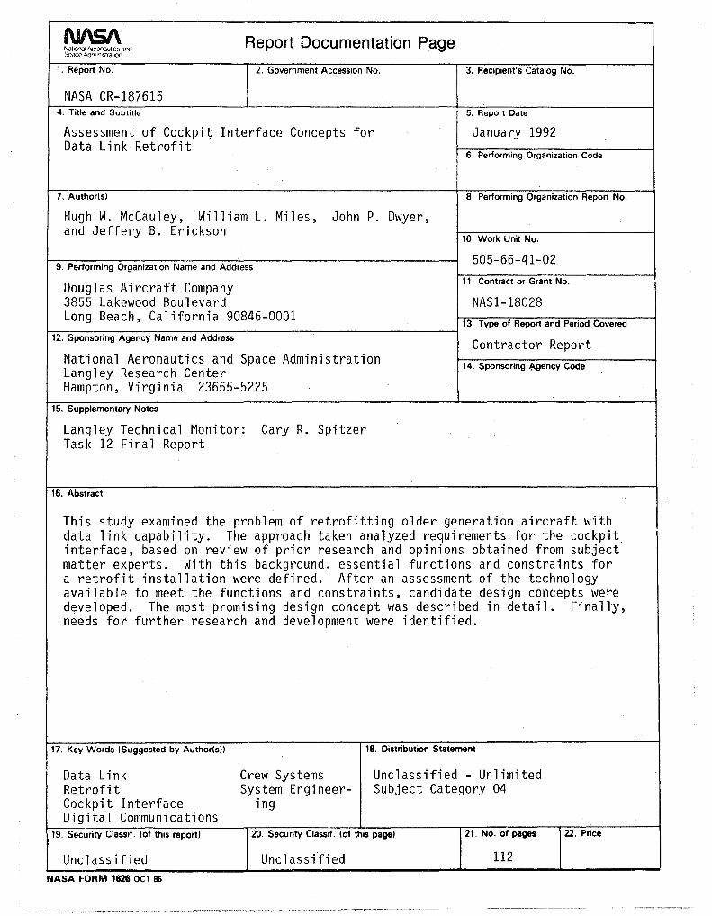
NI\SI\ Report Documentation Page 1\\l1<Jna1 A€ronaulcs and Soace >\on-un'Slr afl()n
1. Report No. 2. Government Accession No. 3. Recipient's Catalog No.
NASA CR-187615 4. Title and Subtitle 5. Report Date
Assessment of Cockpit Interface Concepts for January 1992 Data Link Retrofit
6. Performing Organization Code
7. Author(s) 8. Performing Organization Report No.
Hugh W. McCauley, William L. Miles, John P. Dwyer, and Jeffery B. Erickson
10. Work Unit No.
9. Performing Organization Name and Address 505-66-41-02
Douglas Aircraft Company 11. Contract or Grant No.
3855 Lakewood Boulevard NASl-18028 Long Beach, California 90846-0001
13. Type of Report and Period Covered
12. Sponsoring Agency Name and Address Contractor Report National Aeronautics and Space Administration
14. Sponsoring ft,.gency Code Langley Research Center Hampton, Virginia 23655-5225
15. Supplementary Notes
Langley Technical Monitor: Cary R. Spitzer Task 12 Final Report
16. Abstract
This study examined the problem of retrofitting older generation aircraft with data link capability. The approach taken analyzed requirements for the cockpit interface, based on review of prior research and opinions obtained from subject matter experts. With this background, essential functions and constraints for a retrofit installation were defined. After an assessment of the technology available to meet the functions and constraints, candidate design concepts were developed. The most promising design concept was described in detail. Fi na lly, needs for further research and development were identified.
17. Key Words (Suggested by Author(s)) 18. Distribution Statement
Data Link Crew Systems Unclassified - Unlimited Retrofit System Engineer- Subject Category 04 Cockpit Interface ing Digital Communications
19. Security Classif. (of this report) 20. Security Classif. (of this page) 21. No. of pages 22. Price
Unclassified Unclassified 112 NASA FORM 1626 OCT 86
PREPARATION OF THE REPORT DOCUMENTATION PAGE
The last page of a report facing the third cover is the Report Documentation Page, RDP. Information presented on this page is used in announcing and cataloging reports as well as preparing the cover and title page. Thus it is important that the information be correct. Instructions for filling in each block of the form are as follows:
Block 1. Report No. NASA report series number, if preassigned.
Block 2. Government Accession No. Leave blank.
Block 3. Recipient's Catalog No. Reserved for use by each report recipient.
Block 4. Title and Subtitle. Typed in caps and lower case with dash or period separating subtitle from title.
Block 5. Report Date. Approximate month and year the report will be published.
Block 6. Performing Organization Code. Leave blank.
Block 7. Author(s). Provide full names exactly as they are to appear on the title page. If applicable, the word editor should follow a name.
Block 8. Performing Organization Report No. NASA installation report control number and, if desired, the nonNASA performing organization report control number ..
Block 9. Performing Organization Name and Address. Provide affiliation (NASA program office, NASA installation, or contractor name) of authors.
Block 10. Work Unit No. Provide Research and Technology Objectives and Plans (RTOP) number.
Block 11. Contract or Grant No. Provide when applicable.
Block 12. Sponsoring Agency Name and Address. National Aeronautics and Space Administration, Washington, D.C. 20546-0001. If contractor report, add NASA installation or HQ program office.
Block 13. Type of Report and Period Covered. NASA formal report series; for Contractor Report also list type (interim, final) and period covered when applicable.
Block 14. Sponsoring Agency Code. Leave blank.
Block 15. Supplementary Notes. Information not included elsewhere: affiliation of authors if additional space is re-
quired for block 9, notice of work sponsored by another agency, monitor of contract, information about supplements (film, data tapes, etc.), meeting site and date for presented papers, journal to which an article has been submitted, note of a report made from a thesis, appendix by author other than shown in block 7.
Block 16. Abstract. The abstract should be informative rather than descriptive and should state the objectives of the investigation, the methods employed (e.g., simulation, experiment, or remote sensing), the results obtained, and the conclusions reached.
Block 17. Key Words. Identifying words or phrases to be used in cataloging the report.
Block 18. Distribution Statement. Indicate whether report is available to public or not. If not to be controlled, use "Unclassified-Unlimited." If controlled availability is required, list the category approved on the Document Availability Authorization Form (see NHB 2200.2, Form FF427). Also specify subject category (see "Table of Contents" in a current issue of STAR), in which report is to be distributed. --
Block 19. Security Classification (of this report). Self -explanatory.
Block 20. Security Classification (of this pagel. Self-explanatory.
Block 21. No. of Pages. Count front matter pages beginning with iii, text pages including internal blank pages, and the RDP, but not the title page or the back of the title page.
Block 22; Price Code. If block 18 shows "UnclassifiedUnlimited," provide the NTIS price code (see "NTIS Price Schedules" in a current issue of STAR) and at the bottom of the form add either "For sale by the National Technical Information Service, Springfield, VA 22161-2171" or "For sale by the Superintendent of Documents, U.S. Government Printing Office, Washington, DC 20402-0001," whichever is appropriate.

End of Document