Chapter 7: Data Link Control Data Link Control Protocols
38
1 CS420/520 Axel Krings Sequence 7 Page 1 Chapter 7: Data Link Control Data Link Control Protocols • Need layer of logic above Physical to manage exchange of data over a link. Requirements and objectives for effective data communication between two directly connected transmitting-receiving stations: Frame synchronization Flow control Error control Addressing Control and data Link management
-
Upload
khangminh22 -
Category
Documents
-
view
0 -
download
0
Transcript of Chapter 7: Data Link Control Data Link Control Protocols

1
CS420/520 Axel Krings Sequence 7Page 1
Chapter 7: Data Link Control
Data Link Control Protocols• Need layer of logic above Physical to manage exchange
of data over a link. Requirements and objectives for effective data communication between two directly connected transmitting-receiving stations:
Frame synchronization
Flow control
Error control
Addressing
Control and data
Link management

2
CS420/520 Axel Krings Sequence 7Page 3
Background information
Just to get a feeling for the bigger picture, let’s look at a historic example and start with the physical layerBegin(...
—let’s consider the physical layer and the characteristics of interfaces
—Let’s just quickly go though this to the …)END slide
CS420/520 Axel Krings Sequence 7Page 4
Line Configuration• Topology
— Physical arrangement of stations on medium— Point to point— Multi point
• Computer and terminals, local area network• Half duplex
— Only one station may transmit at a time— Requires one data path
• Full duplex— Simultaneous transmission and reception between two stations— Requires two data paths (or echo canceling)

3
CS420/520 Axel Krings Sequence 7Page 5
Traditional Configurations
CS420/520 Axel Krings Sequence 7Page 6
Interfacing• Data processing devices (or data terminal
equipment, DTE) do not (usually) include data transmission facilities
• Need an interface called data circuit terminating equipment (DCE)—e.g. modem, NIC
• DCE transmits bits on medium• DCE communicates data and control info with
DTE—Done over interchange circuits—Clear interface standards required

4
CS420/520 Axel Krings Sequence 7Page 7
Data Communications Interfacing
CS420/520 Axel Krings Sequence 7Page 8
Characteristics of Interface• Mechanical
—Connection plugs • Electrical
—Voltage, timing, encoding• Functional
—Data, control, timing, grounding• Procedural
—Sequence of events

5
CS420/520 Axel Krings Sequence 7Page 9
V.24/EIA-232-F• ITU-T v.24
• Only specifies functional and procedural—References other standards for electrical and
mechanical• EIA-232-F (USA) (first issued in 1962)
—RS-232 —Mechanical ISO 2110—Electrical v.28—Functional v.24—Procedural v.24
EIA = Electronic Industry AllianceRS-232 first issued in 1962V.24 issued in 1996V.28 issued in 1993
ITU = Intl. Telecom. UnionITU-T = ITU Telecom. Standardization Sector
CS420/520 Axel Krings Sequence 7Page 10
Mechanical Specification

6
CS420/520 Axel Krings Sequence 7Page 11
Electrical Specification• Digital signals• Values interpreted as data or control, depending
on circuit• Less than -3V is binary 1, more than +3V is
binary 0 (NRZ-L)• For control,
—less than -3V is off, —more than +3V is on
• Signal rate < 20kbps• Distance <15m
CS420/520 Axel Krings Sequence 7Page 12
Functional Specification• Circuits grouped in categories
—Data—Control—Timing—Ground
• One circuit in each direction—Full duplex
• Two secondary data circuits—Allow halt or flow control in half duplex operation
• DTE = data terminal equipment• DCE = data circuit-terminal equipment

7
CS420/520 Axel Krings Sequence 7Page 13
Functional Specification
CS420/520 Axel Krings Sequence 7Page 14
Functional Specification

8
CS420/520 Axel Krings Sequence 7Page 15
Local and Remote Loopback
CS420/520 Axel Krings Sequence 7Page 16
Procedural Specification• Example: Asynchronous private line modem• When turned on and ready, modem (DCE) asserts DCE
ready• When DTE ready to send data, it asserts Request to
Send— Also inhibits receive mode in half duplex
• Modem responds when ready by asserting Clear to Send• DTE sends data• When data arrives, local modem asserts Receive Line
Signal Detector and delivers data

9
CS420/520 Axel Krings Sequence 7Page 17
Dial Up Operation (1)
CS420/520 Axel Krings Sequence 7Page 18
Dial Up Operation (2)

10
CS420/520 Axel Krings Sequence 7Page 19
Dial Up Operation (3)
CS420/520 Axel Krings Sequence 7Page 20
Null Modem

11
CS420/520 Axel Krings Sequence 7Page 21
…and then there was ISDN. Physical Interface Diagram
IntegratedServiceDigitalNetwork
CS420/520 Axel Krings Sequence 7Page 22
ISDN Physical Interface• Connection between
—terminal equipment (c.f. DTE) and —network terminating equipment (c.f. DCE)
• ISO 8877• Cables terminate in matching connectors with 8
contacts• Transmit/receive carry both data and control

12
CS420/520 Axel Krings Sequence 7Page 23
ISDN Electrical Specification• Balanced transmission
— Carried on two lines, e.g. twisted pair— Signals as currents down one conductor and up the other— Differential signaling— Value depends on direction of voltage— Tolerates more noise and generates less— (Unbalanced, e.g. RS-232 uses single signal line and ground)— Data encoding depends on data rate— Basic rate 192kbps
• uses pseudoternary — Primary rate: two options
• 1.544 Mbps uses AMI and B8ZS• 2.048 Mbps uses AMI and HDB3• reason for different schemes is historical, no advantage of
disadvantage
CS420/520 Axel Krings Sequence 7Page 24
End of Background Information…)END

13
CS420/520 Axel Krings Sequence 7Page 25
Flow Control• Ensuring the sending entity does not overwhelm
the receiving entity—Preventing buffer overflow
• Transmission time—Time taken to emit all bits into medium
• Propagation time—Time for a bit to traverse the link
CS420/520 Axel Krings Sequence 7Page 26
Model of Frame Transmission
Frame 1
Source Destination
Tim
e
Frame 1
Frame 2
Frame 2Frame 3
Frame 3Frame 4
Frame 4
Frame 5
(a) Error-free transmission
Figure 7.1 Model of Frame Transmission
Frame 5
Frame 1
Source Destination
Frame 1
Frame 2
Frame 3
Frame 3Frame 4
Garbledframe
¥
Frame 5
(b) Transmission withlosses and errors
Frame 5

14
CS420/520 Axel Krings Sequence 7Page 27
Data Link Basics
• Flow Control—Define:
• L = length of a message (frame, packets, etc.) in bits• R = bit rate of the A to B link in bps• x = time to transmit a packet = L/R seconds• P = propagation delay from A to B in seconds
—Two basic protocols• Stop and wait• Sliding window
CS420/520 Axel Krings Sequence 7Page 28
Stop and Wait• Source transmits frame• Destination receives frame and replies with
acknowledgement• Source waits for ACK before sending next frame• Destination can stop flow by not send ACK• Works well for a few large frames

15
CS420/520 Axel Krings Sequence 7Page 29
Fragmentation• Large block of data may be split into small
frames—Limited buffer size—Errors detected sooner (when whole frame received)—On error, retransmission of smaller frames is needed—Prevents one station occupying medium for long
periods• Stop and wait becomes inadequate
CS420/520 Axel Krings Sequence 7Page 30
Data Link Basics
• Stop and Wait Flow Control—also called Idle RQ (Repeat Request)—after A sends a message (packet), it waits for an ACK
from B before sending the next packet.—analysis:
1. At time (t0), A starts transmission of first bit in packet:
2. At time (t0 + x), A finished packet transmissionP
x

16
CS420/520 Axel Krings Sequence 7Page 31
Data Link Basics
P
3. At time (t0 + x + P), last bit of packet reaches B, true for both P > x and P < x
4. At time (t0 + x + P + y), last bit of ACK leaves B, given mbits in ACK packet and y = m/R seconds
5. At time (t0 + x + P + y + P), last bit of ACK reaches A and A can start next packet transmission
y
ACK
P
CS420/520 Axel Krings Sequence 7Page 32
Data Link Basics
• Link Utilization:—Maximum Utilization of A - B link
€
U =x
x + y + 2P= data transmission time/overhead time
=x
x + 2P, neglecting y
=1
1+ 2 Px( )
=1
1+ 2a, a = P
x( ) is normalized propagation delay

17
CS420/520 Axel Krings Sequence 7Page 33
Data Link Basics
• How many bits are �stuck� in the media?
where:B = length of the link in bitsR = rate of the link, in bpsd = length in mv = velocity of propagation, in m/s€
B = R dv
CS420/520 Axel Krings Sequence 7Page 34
Sliding Windows Flow Control• Allow multiple frames to be in transit• Receiver has buffer of size W• Transmitter can send up to W frames without
ACK• Each frame is numbered• ACK includes number of next frame expected• Sequence number bounded by size of field (k)
—Frames are numbered modulo 2k

18
Page 35
Sliding Window Diagram
Figure 7.3 Sliding-Window Depiction
0• • • 1 2 3 4 5 6 7 0 1 2 3 4 5 6 7 • • •
Window of framesthat may be transmittedFrames already transmitted
Frames buffereduntil acknowledged
Last frametransmitted
Last frameacknowledged
Framesequencenumber
Window shrinks fromtrailing edge asframes are sent
Window expandsfrom leading edgeas ACKs are received
(a) Sender's perspective
0• • • 1 2 3 4 5 6 7 0 1 2 3 4 5 6 7 • • •
Window of framesthat may be acceptedFrames already received
Last framereceived
Last frameacknowledged
Window shrinks fromtrailing edge asframes are received
Window expandsfrom leading edgeas ACKs are sent
(b) Receiver's perspectiveCS420/520 Axel Krings Sequence 7
CS420/520 Axel Krings Sequence 7Page 36
Example Sliding Window
F0
F1
F2
RR 3
F3
F4
F5
F6RR 4
Source System A Destination System B
Figure 7.4 Example of a Sliding-Window Protocol
0 1 2 3 4 5 6 7 0 1 2 3 4 5 6 7 0 1 2 3 4 5 6 7 0 1 2 3 4 5 6 7
0 1 2 3 4 5 6 7 0 1 2 3 4 5 6 7
0 1 2 3 4 5 6 7 0 1 2 3 4 5 6 7
0 1 2 3 4 5 6 7 0 1 2 3 4 5 6 7
0 1 2 3 4 5 6 7 0 1 2 3 4 5 6 7
0 1 2 3 4 5 6 7 0 1 2 3 4 5 6 7
0 1 2 3 4 5 6 7 0 1 2 3 4 5 6 7
0 1 2 3 4 5 6 7 0 1 2 3 4 5 6 7
0 1 2 3 4 5 6 7 0 1 2 3 4 5 6 7

19
CS420/520 Axel Krings Sequence 7Page 37
Sliding Window Enhancements• Receiver can acknowledge frames without
permitting further transmission (Receive Not Ready)
• Must send a normal acknowledge to resume• If duplex, use piggybacking
—If no data to send, use acknowledgement frame—If data but no acknowledgement to send, send last
acknowledgement number again, or have ACK valid flag (TCP)
CS420/520 Axel Krings Sequence 7Page 38
Error Control• Detection and correction of errors• Lost frames• Damaged frames• Automatic repeat request
—Error detection—Positive acknowledgment—Retransmission after timeout—Negative acknowledgement and retransmission

20
CS420/520 Axel Krings Sequence 7Page 39
Automatic Repeat Request (ARQ)
Three common approaches:
1.Stop and wait2.Go back N3.Selective reject (selective retransmission)
CS420/520 Axel Krings Sequence 7Page 40
Stop and Wait• Source transmits single frame• Wait for ACK• If received frame damaged, discard it
—Transmitter has timeout—If no ACK within timeout, retransmit
• If ACK damaged,transmitter will not recognize it—Transmitter will retransmit—Receive gets two copies of frame—Use ACK0 and ACK1

21
CS420/520 Axel Krings Sequence 7Page 41
Stop and Wait -Diagram
Frame numbers alternatebetween 0 and 1
Stop and Wait is:+ simple- inefficient
CS420/520 Axel Krings Sequence 7Page 42
Go Back N (1)• Most commonly used error control• Based on sliding window• If no error, ACK as usual with next frame
expected• Use window to control number of outstanding
frames• If error, reply with rejection
—Discard that frame and all future frames until error frame received correctly
—Transmitter must go back and retransmit that frame and all subsequent frames

22
CS420/520 Axel Krings Sequence 7Page 43
Go Back N - Damaged Frame• Receiver detects error in frame i• Receiver sends rejection-i• Transmitter gets rejection-i• Transmitter retransmits frame i and all
subsequent frames
CS420/520 Axel Krings Sequence 7Page 44
Go Back N - Lost Frame (1)• Frame i is lost• Transmitter sends i+1• Receiver gets frame i+1 out of sequence• Receiver send reject i• Transmitter goes back to frame i and
retransmits

23
CS420/520 Axel Krings Sequence 7Page 45
Go Back N - Lost Frame (2)• Frame i lost and no additional frame sent
—Receiver gets nothing and returns neither acknowledgement nor rejection
—Transmitter times out and sends acknowledgement frame with P bit set to 1
—Receiver interprets this as command which it acknowledges with the number of the next frame it expects (frame i )
—Transmitter then retransmits frame i
CS420/520 Axel Krings Sequence 7Page 46
Go Back N - Damaged Acknowledgement• Receiver gets frame i and send
acknowledgement (i+1) which is lost—Acknowledgements are cumulative, so next
acknowledgement (i+n) may arrive before transmitter times out on frame i
—If transmitter times out, it sends acknowledgement with P bit set as before
—This can be repeated a number of times before a reset procedure is initiated

24
CS420/520 Axel Krings Sequence 7Page 47
Go Back N - Damaged Rejection• As for lost frame (2)
CS420/520 Axel Krings Sequence 7Page 48
Go Back N -Diagram

25
CS420/520 Axel Krings Sequence 7Page 49
Selective Reject• Also called selective retransmission• Only rejected frames are retransmitted• Subsequent frames are accepted by the receiver
and buffered• Minimizes retransmission• Receiver must maintain large enough buffer• More complex log mechanism in transmitter
CS420/520 Axel Krings Sequence 7Page 50
Selective Reject -Diagram

26
CS420/520 Axel Krings Sequence 7Page 51
Data Link Basics
Performance: Stop & Wait ARQ—note that utilization U = Tf/Tt where:
• Tf = time for transmitter to emit a single frame• Tt = total time line is engaged in transmission of 1 frame
—for error free Stop & Wait:
—for errors, U = Tf /(NrTt ), where Nr is the expected number of transmissions of a particular frame
UT
T Ta U
af
f p
TTp
f=
+= =
+21
1 2, if then
UN ar
=+
11 2( )
CS420/520 Axel Krings Sequence 7Page 52
Data Link Basics• Assume P = probability a single frame is in error.• Further assume ACKs and NAKs are never in error.• The probability that we have i transmissions of a frame is:
Pi-1(1-P) • Therefore:
• For Stop & Wait then:
N iP PPr
i
i= − =
−−
=
∞∑ 1
11 1
1( )
U Pa
=−
+
11 2

27
CS420/520 Axel Krings Sequence 7Page 53
Data Link Basics— For Sliding Window:
— For Selective Repeat we have:
— For Go-Back-N we have to consider all retransmitted:
UN aN aN
a=
≥ +
< +"#$ +
1 2 12 12 1
UP N a
N aN Pa
=− ≥ +
< +#$%
−+
1 2 12 11
2 1( )
UN a
N a
PaP
N Pa P NP
=≥ +
< +
"
#$
%$
−+
−+ − +
11 2
11 2 1
2 1
2 1( )( )( )
CS420/520 Axel Krings Sequence 7Page 54
Data Link Basics
— For Go-Back-N we have to consider all retransmissions. Then Nr is the expected number of transmitted frames to successfully transmit one frame. Each error generates requirement to retransmit K frames.
N f i P Pri
i= −−
=
∞
∑ ( ) ( )1
11
with f i i K K Ki( ) ( ) ( )= + − = − +1 1 1
N K P P K iP Pri
i
i
i= − − + −−
=
∞−
=
∞
∑ ∑( ) ( ) ( )1 1 11
1
1
1
N KKP
P KPPr = − +
−=
− +
−1
111
we get
then
r rr
irr
i
i
i
i
i
i= =
−=
−=
∞−
=
∞−
=
∞
∑ ∑ ∑0
1
1
1
12
11
11
and ( )with
Total # frames transmitted if original frame must be transmitted i times
28
CS420/520 Axel Krings Sequence 7Page 55
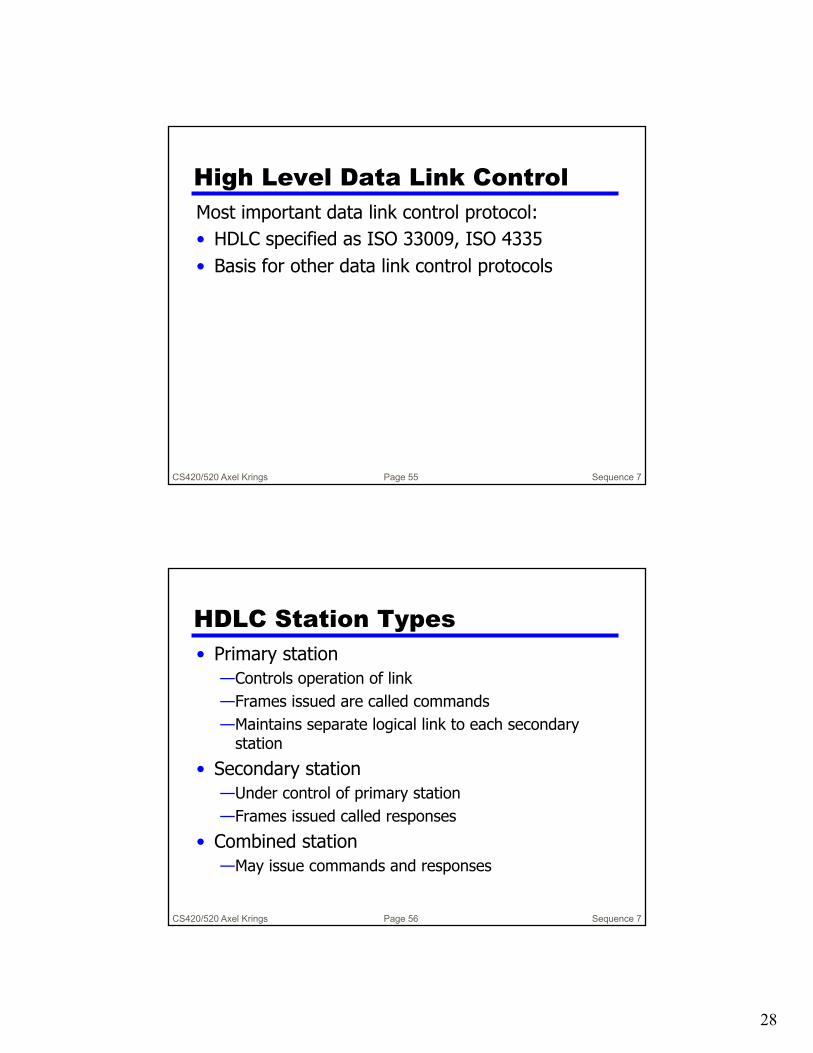
High Level Data Link ControlMost important data link control protocol: • HDLC specified as ISO 33009, ISO 4335• Basis for other data link control protocols
CS420/520 Axel Krings Sequence 7Page 56
HDLC Station Types• Primary station
—Controls operation of link—Frames issued are called commands—Maintains separate logical link to each secondary
station• Secondary station
—Under control of primary station—Frames issued called responses
• Combined station—May issue commands and responses

29
CS420/520 Axel Krings Sequence 7Page 57
HDLC Link Configurations• Unbalanced
—One primary and one or more secondary stations
—Supports full duplex and half duplex• Balanced
—Two combined stations—Supports full duplex and half duplex
CS420/520 Axel Krings Sequence 7Page 58
HDLC Transfer Modes (1)• Normal Response Mode (NRM)
—Unbalanced configuration—Primary initiates transfer to secondary—Secondary may only transmit data in
response to command from primary—Used on multi-drop lines—Host computer is primary—Terminals is secondary

30
CS420/520 Axel Krings Sequence 7Page 59
HDLC Transfer Modes (2)• Asynchronous Balanced Mode (ABM)
—Most widely used—Balanced configuration—Either station may initiate transmission
without receiving permission—No polling overhead
CS420/520 Axel Krings Sequence 7Page 60
HDLC Transfer Modes (3)• Asynchronous Response Mode (ARM)
—Rarely used—Unbalanced configuration—Secondary may initiate transmission
without permission form primary—Primary responsible for line

31
CS420/520 Axel Krings Sequence 7Page 61
Frame Structure• Synchronous transmission• All transmissions in frames• Single frame format for all data and
control exchanges
CS420/520 Axel Krings Sequence 7Page 62
Frame Structure

32
CS420/520 Axel Krings Sequence 7Page 63
Flag Fields• Delimit frame at both ends• 01111110• May close one frame and open another• Receiver hunts for flag sequence to synchronize• Bit stuffing used to avoid confusion with data containing
01111110— 0 inserted after every sequence of five 1s— If receiver detects five 1s it checks next bit— If 0, it is deleted— If 1 and seventh bit is 0, accept as flag— If sixth and seventh bits 1, sender is indicating abort
CS420/520 Axel Krings Sequence 7Page 64
Bit Stuffing• Example with
possible errors

33
CS420/520 Axel Krings Sequence 7Page 65
Address Field• Identifies secondary station that transmitted or will
receive frame• Usually 8 bits long• May be extended to multiples of 7 bits
— Leftmost bit indicates if it is is the last octet (1) or not (0)• Address 11111111 allows a primary to broadcast a
frame for reception by all secondaries
CS420/520 Axel Krings Sequence 7Page 66
Control Field• Different for different frame type
—Information - data to be transmitted to user (next layer up)• Flow and error control piggybacked on information
frames—Supervisory - ARQ when piggyback not used—Unnumbered - supplementary link control
• First one or two bits of control filed identify frame type
• Remaining bits explained later

34
CS420/520 Axel Krings Sequence 7Page 67
Control Field Diagram
CS420/520 Axel Krings Sequence 7Page 68
Poll/Final Bit• Use depends on context• Command frame
—P bit—1 to solicit (poll) response from peer
• Response frame—F bit—1 indicates response to soliciting command

35
CS420/520 Axel Krings Sequence 7Page 69
Information Field• Only in information and some
unnumbered frames• Must contain integral number of octets• Variable length
CS420/520 Axel Krings Sequence 7Page 70
Frame Check Sequence Fields• FCS• Error detection code calculated from the
remaining bits of the frame, exclusive of flags
• Normal code is 16 bit CRC-CCITT• Optional 32 bit CRC

36
HDLC OperationIn
itial
izat
ion
Signals the other side that initialization is requestedSpecifies which of the three modes (NRM, ABM, ARM) is requestedSpecifies whether 3-or 7-bit sequence numbers are to be used D
ata
Tran
sfer
The N(S) and N(R) fields of the I-frame are sequence numbers that support flow control and error controlAn HDLC module will number them sequentiallyReceive Ready (RR) is used when there is no reverse user data traffic
Dis
conn
ect
Either module can initiate• Either on its own
initiative if there is some sort of fault, or at the request of its higher-layer user
Sends disconnect (DISC) frameRemote entity replies with a UAAny outstanding unacknowledged I-frames may be lost• Recovery is the
responsibility of higher layers
Ø Consists of the exchange of I-frames, S-frames and U-frames and involves three phases:
Name Command/ Response
Description
Information (I) C/R Exchange user data
Supervisory (S)
Receive ready (RR) C/R Positive acknowledgment; ready to receive I-frame
Receive not ready (RNR) C/R Positive acknowledgment; not ready to receive
Reject (REJ) C/R Negative acknowledgment; go back N
Selective reject (SREJ) C/R Negative acknowledgment; selective reject
Unnumbered (U)
Set normal response/extended mode (SNRM/SNRME)
C Set mode; extended = 7-bit sequence numbers
Set asynchronous response/extended mode (SARM/SARME)
C Set mode; extended = 7-bit sequence numbers
Set asynchronous balanced/extended mode (SABM, SABME)
C Set mode; extended = 7-bit sequence numbers
Set initialization mode (SIM) C Initialize link control functions in addressed station
Disconnect (DISC) C Terminate logical link connection
Unnumbered Acknowledgment (UA) R Acknowledge acceptance of one of the set-mode commands
Disconnected mode (DM) R Responder is in disconnected mode
Request disconnect (RD) R Request for DISC command
Request initialization mode (RIM) R Initialization needed; request for SIM command
Unnumbered information (UI) C/R Used to exchange control information
Unnumbered poll (UP) C Used to solicit control information
Reset (RSET) C Used for recovery; resets N(R), N(S)
Exchange identification (XID) C/R Used to request/report status
Test (TEST) C/R Exchange identical information fields for testing
Frame reject (FRMR) R Report receipt of unacceptable frame
Table 7.1
HDLC Command
sand
Responses
(Table can be found on page 230 in the textbook)

37
CS420/520 Axel Krings Sequence 7Page 73
Examples of Operation (1)
A BI, 0, 0
I, 1, 1I, 2, 1
I, 3, 2
RR, 4
I, 0, 1
I, 1, 3
I, 3, 4I, 2, 4
(b) Two-way data exchange
A B
RNR, 4
RNR, 4, F
RR, 4, F
I, 3, 0
RR, 0, P
I, 4, 0
RR, 0, P
(c) Busy condition
A BI, 3, 0
I, 4, 0
I, 5, 0
I, 4, 0
I, 6, 0
I, 5, 0
REJ, 4
(d) Reject recovery
A BI, 2, 0
RR, 0, P
I, 3, 0
RR, 3
RR, 4
RR, 3, F
(e) Timeout recovery
Time-out
A BSABM
SABM
UA
DISC
UA
(a) Link setup and disconnect
•••
I, 3, 0
Time-out
Figure 7.9 Examples of HDLC Operation
N(S) N(R)
CS420/520 Axel Krings Sequence 7Page 74
Examples of Operation (2)
A BI, 0, 0
I, 1, 1I, 2, 1
I, 3, 2
RR, 4
I, 0, 1
I, 1, 3
I, 3, 4I, 2, 4
(b) Two-way data exchange
A B
RNR, 4
RNR, 4, F
RR, 4, F
I, 3, 0
RR, 0, P
I, 4, 0
RR, 0, P
(c) Busy condition
A BI, 3, 0
I, 4, 0
I, 5, 0
I, 4, 0
I, 6, 0
I, 5, 0
REJ, 4
(d) Reject recovery
A BI, 2, 0
RR, 0, P
I, 3, 0
RR, 3
RR, 4
RR, 3, F
(e) Timeout recovery
Time-out
A BSABM
SABM
UA
DISC
UA
(a) Link setup and disconnect
•••
I, 3, 0
Time-out
Figure 7.9 Examples of HDLC Operation
N(S) N(R)

38
Summary• introduced need for data link protocols
—which included background on interfacing• flow control• error control• HDLC