27-relay-timer-switch.pdf - AutomationDirect
79
Up-to-date price list: www.automationdirect.com/pricelist FREE Technical Support: www.automationdirect.com/support FREE Videos: www.automationdirect.com/videos FREE Documentation: www.automationdirect.com/documentation FREE CAD drawings: www.automationdirect.com/cad Relays and Timers In this interactive PDF you can: • Use bookmarks to navigate by product category • Use bookmarks to save, search, print or e-mail the catalog section • Click on part #s to link directly to our online store for current pricing, specs, stocking information and more Relays and Timers www.automationdirect.com/relays mREL-1 For latest prices, please check AutomationDirect.com
-
Upload
khangminh22 -
Category
Documents
-
view
1 -
download
0
Transcript of 27-relay-timer-switch.pdf - AutomationDirect

Up-to-date price list:www.automationdirect.com/pricelist
FREE Technical Support:www.automationdirect.com/support
FREE Videos:www.automationdirect.com/videos
FREE Documentation:www.automationdirect.com/documentation
FREE CAD drawings:www.automationdirect.com/cad
Relays and Timers
In this interactive PDF you can:• Use bookmarks to navigate
by product category
• Use bookmarks to save, search, print or e-mail the catalog section
• Click on part #s to link directly to our online store for current pricing, specs, stocking information and more
Relays and Timersw w w . a u t o m a t i o n d i r e c t . c o m / r e l a y s mREL-1
For latest prices, please check AutomationDirect.com
Plug-in Octal Cube Relays
750R Series
750R series cube relays with standard octal base, offer high-current capability (10A) with a compact design. Available in 12 VAC, 24 VAC, 120 VAC, 240 VAC and 12 VDC, 24 VDC coil voltages.
Cube Relays
78 Series
78 series cube relays, with a 15A contact rating, are ideal for applications demanding high power control in various factory machines and control panels. Available in 24 VAC, 120 VAC, 240 VAC and 24 VDC coil voltages.
Open-Style Power Relays
AD Series
AD-PR40 series power relays are an open construc-tion design with high power contacts capable of switching up to 40A. SPDT, DPST and DPDT models are available.
Plug-in Hazardous Location Octal and Square/Cube Relays
H782/H750 Series
H782/H750 series hermetically sealed, ice cube style relays are designed for applications requiring hermetically sealed units for hazardous factory locations. (Class I, Div. 2 Groups A, B, C, D).
Electromechanical Square/Cube Relays
QL Series: General purpose relays designed for a wide range of applications. Units plug into DIN-rail mountable relay sockets, with a 10A contact rating. Ideal for electric control panels requiring stable and reliable relays.
QM Series: General purpose relays with a 5A DPDT or 3A 4PDT contact rating, designed for use in applications from power to sequence controls in various factory machines and control panels.
Our general purpose industrial relays are a low-cost way of adding control and isolation relays to any application. Electromechanical relays are available in cube, open and card styles for a diverse range of installation requirements. Cube relays are available with standard linear or octal base connection patterns. Solid state relays available include hazardouse location, socket-mount, DIN-rail mount and panel-mount styles.
All relays feature LED indicators for easy troubleshooting.
A Full Lineup of Control Relays
E l e c t r o m e c h a n i c a l
Relays and Timers 1 - 8 0 0 - 6 3 3 - 0 4 0 5mREL-2
For latest prices, please check AutomationDirect.com

Panel Mount Hockey Puck Relays
AD-SSR6 Series
Socket Mount Relays
AD-70S2 Series
These solid state relays, with DC input/AC output and 4A contact ratings, plug into a DIN-rail mountable relay socket or can be wired with the quick-connect terminals.
DIN Rail Mount Relays
AD-HSSR8 HAZLOC Series
Low price combined with industry-demanded quality make our relays one of the best values in automa-tion.
Our manufacturers ensure that nothing is spared in the design and production of our products. By offering them direct to you, AutomAtionDirect makes certain that you get the same or better quality than other brands at a great price.
Check the technical specifications on the
following pages to choose the right relay for your application.
Two-year warranty
Integral heat sink
Finger safe cover
LEDstatus lamp
Mechanical status flag for
contact closure
Mechanical push to test
Socket compatibility
Small size
Slim/Card Relay
RS Series
Solid State Relays
Electromechanical Relays
RS series relays are compact, space-saving, relay terminal modules containing four or six relays with one N.O. contact each.
These relay-and-terminal modules are ideal for inter-facing electronic control devices with output devices.
LED for input coil
Quality built into every relay at an affordable price.
Lock-down door for circuit testing
78 Series
IdentificationLabel
S o l i d S t a t e
AD-SSR Series - Solid state relays are energy efficient current switching devices in a slim, space-saving housing. These relays carry 10 or 65 Amp loads, and are DIN-rail or panel-mountable.
DIN Rail Mount Relays
AD-SSR Series
AD-SSR6 series Class 6 solid state relays have are energy-efficient, with high load ratings up to 75 amps in a finger-safe “Hockey Puck” housing.
Class 8 AD-HSSR8 HAZLOC series in a slim, space-saving housing (in 8A, 10A, 15A models) with the approval for hazardous locations (Class 1, Div. 2, Groups A, B, C, D).
A Full Lineup of Control Relays
Relays and Timersw w w . a u t o m a t i o n d i r e c t . c o m / r e l a y s mREL-3
For latest prices, please check AutomationDirect.com
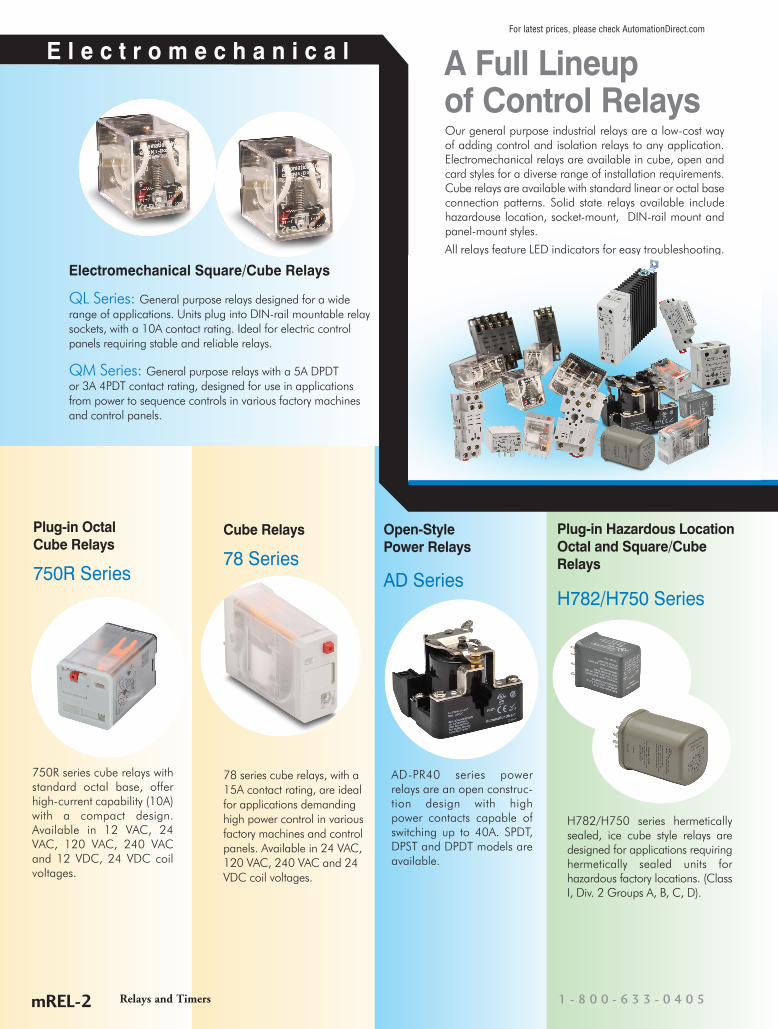
Electromechanical Relay Selection Guide
Specification QL Series QM Series RS Series Card RelaysCoil Voltages 110/120VAC, 220VAC, 24VDC 110/120VAC, 220VAC, 24VDC 24VDC
Configuration 2PDT, 4PDT 2PDT, 4PDT SPST (up to six relays)
Contact Rating 10A 5A DPDT ; 3A 4PDT 5A
Base Socket 8 or 14 pin spade terminal 8 or 14 pin spade terminal -Agency Approvals UL Recognized (#E222847), CE Certified
(9667186-9811), CSA Certified (218218)UL Recognized (#E222847), CE Certified(9667186-9811), CSA Certified (218218)
UL Recognized (E44592), CSA (LR20479)TUV (R95551729)
Prices starting at $10.00 $4.75 $30.50
Specification 78 Series H782 Series 750R Series
Coil Voltages 110/120VAC, 220VAC, 12VAC, 12VDC,24VAC, 24VDC
120VAC, 240VAC, 12VAC, 12VDC,24VAC, 24VDC
120VAC, 240VAC, 12VAC, 12VDC,24VAC, 24VDC
Configuration SPDT, DPDT, 3PDT, 4PDT 4PDT DPDT, 3PDT
Contact Rating 12 to 15A 3A, 5A 10A
Base Socket 5, 8,11 or 14 pin spade terminal 14 pin spade terminal 11 pin
Agency Approvals UL Recognized (E191059), CE, CSA 244610(See specifications for additional information)
UL Recognized (E344123), cULus when used with782-4C-SKT socket, CSA, CE, RoHS
UL Recognized file E191059, CE,CSA Certified 244610
Prices starting at $4.50 $25.50 $7.75
Specification H750 Series AD-PR Series
Coil Voltages 120VAC, 240VAC, 12VAC, 12VDC,24VAC, 24VDC
120VAC, 240VAC, 12VDC,24VAC, 24VDC
Configuration DPDT or 3PDT SPDT, DPST, DPDT
Contact Rating 12A 40A
Base Socket 8-pin or 11-pin spade terminal, Panel mount
Agency Approvals UL Recognized (E344123), cULus when usedwith 750 sockets, RoHS
UL Recognized E191059, CE Certified(9667186-9811), CSA Certified 244610, RoHS
Prices starting at $34.75 $14.75
Relays and Timersw w w . a u t o m a t i o n d i r e c t . c o m / r e l a y s tREL-1
For latest prices, please check AutomationDirect.com

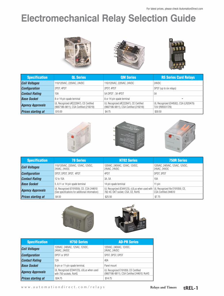
QL Series Electromechanical Relay Selection Guide
QL Series Selection Guide
Part Number Price Coil Voltage Configuration Contact RatingDimensions (see page
24-7)Relay Socket Part Number Price
Dimensions (see page
24-13)QL2N1-A120 $10.00
110/120VAC2PDT 10A Figure 1 SQL08D $4.00 Figure 3
QL4N1-A120 $12.00 4PDT 10A Figure 2 SQL14D $4.50 Figure 4
QL2N1-A220 $10.00220VAC
2PDT 10A Figure 1 SQL08D $4.00 Figure 3
QL4N1-A220 $12.50 4PDT 10A Figure 2 SQL14D $4.50 Figure 4
QL2N1-D24 $10.00
24VDC
2PDT 10A Figure 1 SQL08D $4.00 Figure 3
QL2X1-D24 $12.00 2PDT 10A Figure 1 SQL08D $4.00 Figure 3
QL4N1-D24 $11.50 4PDT 10A Figure 2 SQL14D $4.50 Figure 4
QL4X1-D24 $15.50 4PDT 10A Figure 2 SQL14D $4.50 Figure 4
Features• Small package design• ARC Barrier equipped• Silver Cadmium Oxide contact• High dielectric strength (1,800 VAC)• High reliability and long life• Ultra-high sensitivity with quick
response time (25 ms max.)• High vibration and shock resistance
• LED indicator on all models, so you can easily see if relay is working properly without using a voltmeter
• Diode protection available on 24 VDC models, which protects contacts and electronic components from back EMF
• UL recognized, CE certified, CSA approv-al pending
• DPDT and 4PDT models
QL series relays are general purpose relays designed for a wide range of applications, from power to sequence controls in various factory machines and control panels. They are ideal for electric control panels requiring stable and reliable relays.
• Order sOcket separately
Relays and Timers 1 - 8 0 0 - 6 3 3 - 0 4 0 5tREL-2
For latest prices, please check AutomationDirect.com
QL Series Electromechanical Relay SpecificationsQL Series Specification Table
Part Numbers
QL2N
1-A1
20
QL2N
1-A2
20
QL4N
1-A1
20
QL4N
1-A2
20
QL2N
1-D2
4
QL2X
1-D2
4
QL4N
1-D2
4
QL4X
1-D2
4
Contact Specifications
Current Rating 10A
Contact Type DPDT 4PDT DPDT 4PDT
Terminal Type Spade Plug-In Socket
Rated Max. Resistive Load 10A@110VAC/10A@24VDC
Rated Max. Inductive Load 7.5 A@110VAC/ 5A@24VDC
Minimum Recommended Load 1mA @ 5VDC
Max. Switching Cap. (Resistive Load) 1,100VAC/240W
Max. Switching Cap. (Inductive Load) 825VAC/120W
Max. Contact Rating 250VAC/125VDC
Coil Specifications
Options LED IndicatorLED Indicator/
Diode Protection
LED Indicator LED Indicator/Diode Protection
Coil Input Voltage 110/120VAC 220/240VAC 110/120VAC 220/240VAC 24VDC
Rated Current at 50Hz 9.9 /10.8 mA 6.2/6.8 mA 17/19 mA 11.5/13.1 mA 36.9 mA 69mA
Rated Current at 60Hz 8.4/9.2 mA 5.3/5.8 mA 18/16.4 mA 9.8/11.2 mA 36.9 mA 69mA
Coil Resistance 4.43kq 12.95kq 2.2kq 6.7kq 650q 350q
Power Consumption Approx. 0.9W to 1.1W (at 60Hz) Approx. 0.9W
Dropout Voltage (% of rated voltage) Min. 30% Min. 10%
Pick-Up Voltage (Must operate voltage) Max. 80% of the rated coil voltage
Max. Voltage (Max. continuous voltage) 110% of the rated coil voltage
Min. Operating Voltage 80% of the rated coil voltage
General Specifications
Service LifeMechanical: AC: Min. 50 million operations; DC: Min. 100 million operations (at operating frequency of 18,000 operations/hour)
Electrical: DPDT: Min. 500k operations; 4PDT: Min. 200k operations (at operating frequency of 1,800 operations/hour)
Operate Time 25ms max
Release Time 25ms max
Ambient Temperature -25° C to 70° C (-13° F to 158° F)
Ambient Humidity 45% to 85% Relative Humidity
Contact Material Silver Cadmium Oxide
Contact Resistance 50mq max.
Operating Frequency Mechanical 18,000 operations/hour; Electrical 1,800 operations/hour
Vibration Resistance 10Hz to 55Hz at double amplitude of 1.0mm
Shock Resistance 1,000m/s2 (approx. 100G)
Weight 35g (1.24oz.)
Agency Approvals and Standards UL Recognized (#E222847), CE Certified (9667186-9811), CSA Certified (218218)
Relays and Timersw w w . a u t o m a t i o n d i r e c t . c o m / r e l a y s tREL-3
For latest prices, please check AutomationDirect.com

QL Series Wiring Diagrams and Derating CurvesWiring Diagrams
4PDT
7 8
1
3
5
24
6
QL2N1-AC
QL2N1-A120 QL2N1-A220
7 8
1
3
5
24
6
QL2N1-DC
(-) (+)
QL2N1-D24 QL2X1-D24
13
1
5
9
2
6
10
3
7
11
4
8
12
14
QL4N1-AC
13
1
5
9
2
6
10
3
7
11
4
8
12
14
QL4N1-DC
(-) (+)13
1
5
9
2
6
10
3
7
11
4
8
12
14
QL4-X1
(-) (+)
QL4X1-D24QL4N1-D24QL4N1-A120 QL4N1-A220
Max. Switching capacity
Rat
ed o
pera
ting
curr
ent (
A)
10
5
1
0.5
0.1
5 10 50 100 500Rated operating voltage (V)
AC resistive
AC inductivep.f = 0.4
DC inductiveL/R = 7ms
DC resistive
QL 4PDT
2PDT
8
1
3
5
2
4
6
QL2-X1
7 (-) (+)
Derating Curves
Max. Switching capacity
Rat
ed o
pera
ting
curr
ent (
A)
10
5
1
0.5
0.1
5 10 50 100 500Rated operating voltage (V)
AC resistive
AC inductivep.f = 0.4
DC inductiveL/R = 7ms
DC resistive
QL DPDTQL 2PDT
Relays and Timers 1 - 8 0 0 - 6 3 3 - 0 4 0 5tREL-4
For latest prices, please check AutomationDirect.com

QL Series Dimensional Drawings
Max . 36.0 [1.42]
0.5
[0.0
2]5.
0[0
.20]
3.0 [ 0.12]
6.4 0.25] Max. 21.5[0.85]
5.75
[0.2
3]
Max
. 28
.0 [
1.10
]14 - 3.0 [0.12] 1 2
3 4
5 6
7 8
Dimensionsmm [inches]
Figure 1 QL2
14 - 3.0 Dia. holes
6.4[.25]
3.0[0.12]
5.0
[0.2
0]
0.5
[0.0
2]
41.5 [1.63]
Max
. 28
.0 [
1.10
]1 2 3 4
5 6 7 89 10 11 12
Max.Max. 36.0 [1.42]
Figure 2 QL4
Relays and Timersw w w . a u t o m a t i o n d i r e c t . c o m / r e l a y s tREL-5
For latest prices, please check AutomationDirect.com

QM Series Electromechanical Relay Selection Guide
Features• Small package design• DPDT has a fine silver contact with 5A
capability• 4PDT has a gold-plated silver contact with
3A capability• High dielectric strength (1,800 VAC)• High reliability and long life• Ultra-high sensitivity with quick response
time (20 ms max.)• High vibration and shock resistance
• LED indicator on all models, so you can easily see if relay is working properly without using a voltmeter
• Diode protection on some 24 VDC models protects contacts and electronic components from back EMF
• UL recognized, CE certified, CSA certified (218218)
QM Series Selection Guide
Part Number Price Coil Voltage Configuration Contact RatingDimensions (see page
24-11)Relay Socket Part Number Price
Dimensions (see page
24-13)QM2N1-A120 $4.75
110/120VAC2PDT 5A Figure 1 SQM08D $3.25 Figure 5
QM4N1-A120 $4.75 4PDT 3A Figure 2 SQM14D $3.25 Figure 6
QM2N1-A220 $4.75220VAC
2PDT 5A Figure 1 SQM08D $3.25 Figure 5
QM4N1-A220 $8.25 4PDT 3A Figure 2 SQM14D $3.25 Figure 6
QM2N1-D24 $4.75
24VDC
2PDT 5A Figure 1 SQM08D $3.25 Figure 5
QM2X1-D24 $9.25 2PDT 5A Figure 1 SQM08D $3.25 Figure 5
QM4N1-D24 $4.75 4PDT 3A Figure 2 SQM14D $3.25 Figure 6
QM4X1-D24 $9.25 4PDT 3A Figure 2 SQM14D $3.25 Figure 6
QM series relays are general purpose relays designed for a wide range of applications, from power to sequence controls in various factory machines and control panels. They are ideal for electric control panels requiring stable and reliable relays.
• Order sOcket separately
Relays and Timers 1 - 8 0 0 - 6 3 3 - 0 4 0 5tREL-6
For latest prices, please check AutomationDirect.com

QM Series Electromechanical Relay SpecificationsQM Series Specification Table
Part Numbers
QM2N
1-A1
20
QM2N
1-A2
20
QM4N
1-A1
20
QM4N
1-A2
20
QM2N
1-D2
4
QM2X
1-D2
4
QM4N
1-D2
4
QM4X
1-D2
4
Contact Specifications
Current Rating 5A 3A 5A 3A
Contact Type DPDT 4PDT DPDT 4PDT
Terminal Type Spade plug-in socket
Rated Max. Resistive Load 5A @ 220VAC/5A @ 24VDC 3A @ 220VAC/3A @ 24VDC 5A @ 220VAC/5A @ 24VDC 3A @ 220VAC/3A @ 24VDC
Rated Max. Inductive Load 2A @ 220VAC/2A @ 24VDC 1.5 A @ 220VAC/0.8 A @ 24VDC 2A @ 220VAC/2A @ 24VDC 1.5A @ 220VAC/0.8 A @ 24VDC
Minimum Recommended Load 1mA @ 1VDC
Max. Switching Cap. (Resistive Load) 1,100VA/120W 660VA/72W 1,100VA/120W 660VA/72W
Max. Switching Cap. (Inductive Load) 440VA/48W 176VA/36W 440VA/48W 176VA/36W
Max. Contact Rating 250VAC/125VDC 250VAC/125VDC
Coil Specifications
Options LED IndicatorLED Indicator/
Diode Protection
LED Indicator LED Indicator/Diode Protection
Coil Input Voltage 110/120 VAC 220/240 VAC 110/120 VAC 220/240 VAC 24VDC
Rated Current at 50Hz 9.9 /10.8 mA 6.2/6.8 mA 9.9/10.8 mA 6.2/6.8 mA36.9 mA
Rated Current at 60Hz 8.4/ 9.2 mA 5.3/5.8 mA 8.4/9.2 mA 5.3/5.8 mA
Coil Resistance 4.43 kq 12.95 kq 4.43 kq 12.95 kq 650q
Power Consumption Approx. 0.9 W to 1.1 W (at 60Hz) Approx. 0.9 W
Dropout Voltage (% of rated voltage) Min. 30% Min. 10%
Pick-Up Voltage (Must operate voltage) Max. 80% of the rated coil voltage
Max. Voltage (Max. continuous voltage) 110% of the rated coil voltage
Min. Operating Voltage 80% of the rated coil voltage
General Specifications
Service Life Mechanical: AC: Min. 50 million operations; DC: Min. 100 million operations (at operating frequency of 18,000 operations/hour)
Electrical: DPDT: Min. 500k operations; 4PDT: Min. 200k operations (at operating frequency of 1,800 operations/hour)
Operate Time 20ms max
Release Time 20ms max
Ambient Temperature -25° C to 75° C (-13° F to 167° F)
Ambient Humidity 45% RH to 85% RH
Contact Material Fine Silver Gold-plated Silver Fine Silver Gold-plated Silver
Contact Resistance 50mq max
Operating Frequency Mechanical: 18,000 operations/hour; Electrical: 1,800 operations/hour
Vibration Resistance 10Hz to 55Hz at double amplitude of 1.0mm
Shock Resistance 1,000m/s2 (approx. 100G)
Weight 35g (1.24oz.)
Agency Approvals and Standards UL Recognized (#E222847), CE Certified (9667186-9811), CSA Certified (218218)
Relays and Timersw w w . a u t o m a t i o n d i r e c t . c o m / r e l a y s tREL-7
For latest prices, please check AutomationDirect.com

QM Series Wiring Diagrams and Derating Curves
13 14
1
5
9
4
8
12
QM2N1-AC
13-
1
5
9
2
6
10
4
8
12
3
7
11
QM4-X1
+ 1413 14
1
5
9
2
6
10
4
8
12
3
7
11
QM4N1-AC
Wiring diagrams
Derating curves
QM2N1-A120 QM2N1-A220 QM2X1-D24
QM4X1-D24
QM2N1-D24
QM4N1-D24QM4N1-A120 QM4N1-A220
13 14
1
5
9
4
8
12
QM2-X1
+-13- 14
1
5
9
4
8
12
QM2N1-DC
+
13 14
1
5
9
2
6
10
4
8
12
3
7
11
QM4N1-DC
- +
Max. Switching capacity
Rat
ed o
pera
ting
curr
ent (
A)
10
5
1
0.5
0.1
5 10 50 100 500Rated operating voltage (V)
QM DPDT
AC resistive
AC inductivep.f = 0.4
DC inductiveL/R = 7ms
DC resistive
Max. Switching capacity
Rat
ed o
pera
ting
curr
ent (
A)
10
5
1
0.5
0.1
5 10 50 100 500Rated operating voltage (V)
QM 4PDT
3
AC resistive
AC inductivep.f = 0.4
DC inductiveL/R = 7ms
DC resistive
DPDT 4PDT
Relays and Timers 1 - 8 0 0 - 6 3 3 - 0 4 0 5tREL-8
For latest prices, please check AutomationDirect.com

QM Series Dimensional Drawings
Figure 1. QM2 Series Dimensions Figure 2. QM4 Series Dimensions
8 -Dia. 1. 2 [0.05] x 3 Holes
2.6
[0.1
0]0.
5[0
.02]
0.5[0.02]
6.0[0.24]
Max. 36.0 [1.42]
Max. 21.5[0.85]
Max
. 28
.0 [1
.10]
6.3
[0.2
5]
0.5[0.02]
Max. [1.42] 0[0.24]
Max. 21.5[0.85]
Max
. 28
.0[1
.10]
6.3
[0.2
5]
0.5
[0.0
2]2.
6[0
.10]
14 - Dia. 1.2 [0.05] x 3 Holes
6.36.0
Figure 1 QM2 Series
Figure 2 QM4 Series
Dimensions mm [inches]
Relays and Timersw w w . a u t o m a t i o n d i r e c t . c o m / r e l a y s tREL-9
For latest prices, please check AutomationDirect.com

Sockets for QL/QM Series Relays
Din-rail mounting, DPDT, for use with QL2 series relays
$4.00
Din-rail mounting, DPDT, for use with QM2 series relays
$3.25
Din-rail mounting, 4PDT, for use with QM4 series relays
$3.25
Din-rail mounting, 4PDT, for use with QL4 series relays
$4.50
SQL08D SQL14D
Note: Order sockets separately; holding clips are included with sockets.
SQM08D SQM14D
6.2
[0.2
4]
4.6 [0.18]
49.9 [1.96]
5.0
[0.2
0]
10.7[0.42]
10.0[0.39]
7.0
[0.2
8]
45.5[1.79]
4.5[0.18]
16.0[0.63]
4.5
[0.1
8]
Holding ClipsHolding clips for the QL2, QL4, QM2 and QM4 series relays can be removed by pushing the side of the inserting hole with a sharp object.
Holding Clip Dimensions mm [in] Holding clip for QL4 series relays is included with SQL14D sockets.
Holding Clip Dimensions mm [in] Holding clip for QL2, QM2 and QM4 series relays is included with SQL08D, SQM08D and SQM14D sockets.
Relay
Holding Clip
Socket
Insert holding clip into the slots provided on the socket.
Relays and Timers 1 - 8 0 0 - 6 3 3 - 0 4 0 5tREL-10
For latest prices, please check AutomationDirect.com

Socket Dimensions for QL/QM Series Relays
Figure 5 SQM08D (for QM2 Series Relays)
3
4 Dia.
3
17.6
72.1 35 29 35.4 75.55
8
20.2
34
6 5
12
34
56
78
Top View
58.1
62.4
71.9
35.5
38.9
7.1 2.9
30
19
4 3 2 1
8 7 6 5
12 11 10 9
14 13
45
6 578
9101112
Top View
Top ViewTop View
29.46
72
7 7 7
24
29.5
2835.5
75.2
30
17.3
3 2 1
8 7 6 5
12 11 10 9
4 14 13
8 7 6 5
12 11 10 9
Figure 3 SQL08D (for QL2 Series Relays)
Figure 6 SQM14D (for QM4 Series Relays)
Figure 4 SQL14D (for QL4 Series Relays)
Dimensionsmm
Relays and Timersw w w . a u t o m a t i o n d i r e c t . c o m / r e l a y s tREL-11
For latest prices, please check AutomationDirect.com

RS Series Electromechanical Relay Selection Guide
RB105-DE TY3 RZ4N
RS Series Card Relay Selection Guide
Part Number Price Description Dimensions and Wiring Diagrams
RS4N-DE $30.50 Card relay (4 relays included; 4 commons), mounted in socket, 24VDC coil, SPST, 5A rating. TY3 included; (can only be wired one way for proper operation of LEDs) Figure 3
RS6N-DE $40.50 Card relay (6 relays included; 2 commons; 3 relays per common), mounted in socket, 24VDC coil, SPST, 5A rating. TY3 included. Figure 4
RB105-DE $28.50 Spare relays (package of 10) for the RS series Relays. 24V DC coil, SPST, 5A rating. Figure 1
TY3 $8.50 Relay remover for RS series relays. Package of 10. -
RZ4N $16.50 Terminal guard for RS series relays. Package of 10. Figure 2
RS4N-DE
4 relays
Terminal Module
Relays and Timers 1 - 8 0 0 - 6 3 3 - 0 4 0 5tREL-12
For latest prices, please check AutomationDirect.com

RS Series Relay Specifications
RS4N-DE and RS6N-DE Series Card Relay Specifications TableContact 1 NO / SPST
Contact Resistance 30mq or less (before use)
Contact Material Silver alloy (gold-plated)
Min. Operating Voltage and Current 0.1 VDC, 1mA
Rated Thermal Current 5A
Max. Make/Break Current (Resistive Load)250VAC, 5A 30VDC, 5A
120VDC, 0.5 A
Max. Make/Break Current (Pilot Duty)120VAC, 1A 30VDC, 2A
120VDC, 0.2 A
Operating Time 10ms or less at rated voltage
Release Time 10ms or less at rated voltage
Insulation Resistance 100Mq (at 500VDC megger)
Dielectric Strength
Between Contact and Coil 2000VAC 1 minute
Between Contacts of Same Pole 750VAC 1 minute
Between Contacts of Different Pole 2000VAC 1 minute
Between Coils of Different Pole 500VAC 1 minute
VibrationMalfunction Durability 10 to 55Hz, 1mm double amplitude
Mechanical Durability 10 to 55Hz, 1.5mm double amplitude
ShockMalfunction Durability 100m/s2
Mechanical Durability 1000m/s2
Life Expectancy
Mechanical 20 million operations
Electrical
Voltage Make Current (A)
Break Current (A) Operations
220VAC (inductive load) 220VAC (resistive load) 24VDC (inductive load) 24VDC (resistive load)
2 (cos ø = 0.7) 3 (cos ø = 1.0) 1 (T = 15ms) 5 (T = 1ms or less)
2 (cos ø = 0.3 - 0.4) 3 (cos ø = 1.0) 1 (T = 15ms) 5 (T = 1ms or less)
100,000 130,000 150,000 100,000
Terminal Wire Capacity Max wire gauge AWG14
Ambient Temperature -25 to + 55° C (no icing)
Terminal Torque Specification 0.8 - 0.9 N·m
RS series relays are compact, space-saving relay terminal modules containing four or six card relays with one normally open contact each. These relay-and-ter-minal modules are ideal for interfacing electronic control devices (such as PLCs or photoelectric sensors) with output devices.
RS6N-DE $40.50
RS4N-DE $30.50
Features:• Compact size of 34 mm wide by 69 mm
long, including screw terminals• Input terminals are located in the upper
part and output terminals in the lower part of the module to separate them from each other, making wiring easy
• RB105 plug-in relays and TP04 sockets make maintenance easy
• Built-in coil surge-suppression diodes and operation indicator LEDs simplify circuit design and maintenance
• The module is easily-mounted on a 35 mm DIN rail
• The RS4N module includes two standard accessory jumper plates, which are convenient for common wiring of terminals
RS6N-DE
Relays and Timersw w w . a u t o m a t i o n d i r e c t . c o m / r e l a y s tREL-13
For latest prices, please check AutomationDirect.com

Electromechanical Relay RB105-DE Specifications
These spare relays are for replace-ment in RS4N-DE and RS6N-DE relay modules (5 mm). Bifurcated contacts ensure high contact reliability, allowing use in low-level circuits.
RB105-DE $28.50
Features• Narrow, miniature size and light
weight reduces space on the DIN rail• UL, CSA, CE, and TUV approved• Low power consumption• Can be operated with a non-polarity
magnet• Flux-tight construction
RB105-DE
RB105-DE Card Relay Specification TableOperating Time 10ms or less at rated voltage
Release Time 10ms or less at rated voltage
Insulation Resistance 100Mq (at 500VDC megger)
Dielectric Strength 750VAC 1 minute between open contacts2000VAC 1 minute between contact and coil
Impulse 4,500V or more 1.2 x 50µs between contact and coil
Electrical Life Expectancy
AC: 100,000 operations at 220VAC 2A, inductive load130,000 operations at 220VAC 3A, resistive load
DC: 150,000 operations at 24VDC 1A, inductive load
100,000 operations at 24VDC 5A, resistive load
Mechanical Life Expectancy 20 million operations
Ambient Temperature -25° C to 55° C (no icing)
Thermal Current 5A
Make and Break Current (Resistive Load) 250VAC, 5A30VDC, 5A
Operating Coil
Rated voltage 24VDC
Pick-up voltage 70% of rated coil voltage
Drop-out voltage 5% of rated coil voltage
Power consumption 200mW
Coil resistance 2880q
Maximum Wire Size 14 AWG (2.5 mm²)
Relays and Timers 1 - 8 0 0 - 6 3 3 - 0 4 0 5tREL-14
For latest prices, please check AutomationDirect.com

RS Series Relay Remover and Protective Cover
34
69
6.5
(35)13.2
3
RZ4N
To remove a relay from the terminal module, use the TY3 relay remover. RS4N-DE and RS6N-DE modules include a TY3 relay remover. Pull the relay in a direc-tion perpendicular to the terminal module surface. Incorrectly removing or mounting a relay may damage the relay pins and pin jacks of the module.
TY3 $8.50
A protective cover fits over the RS4N-DE or RS6N-DE module and protects the terminals.
RZ4N $16.50
PC board drilling (View from back side)
Internal wiring diagram
5.08 max
21.3 max
20
0.5 0.5
1
0.3
2-0.7
1.3 7.62 7.62 2.54
2-0.5
3.8
max
12.6
max
1.2 Dia. 0.1
7.62 7.62 2.54
2.54
2.54
Figure 1 RB105-DE
Figure 2 RZ4N (Terminal guard for RS Series)
Relay remover, TY3 Optional protective cover, RZ4N
Dimensions mm
Relays and Timersw w w . a u t o m a t i o n d i r e c t . c o m / r e l a y s tREL-15
For latest prices, please check AutomationDirect.com
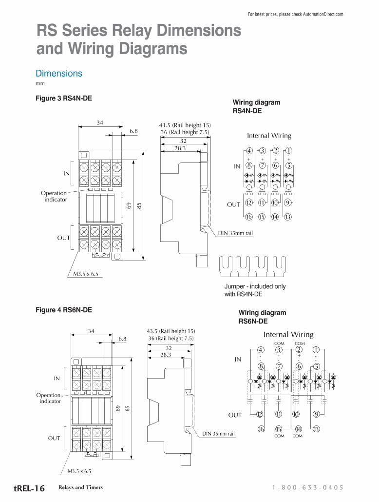
RS Series Relay Dimensions and Wiring Diagrams
43.5 (Rail height 15)
Internal Wiring32
36 (Rail height 7.5)
28.3
6.834
69 85
IN
OUT
Operationindicator
M3.5 x 6.5
DIN 35mm rail
IN
OUT
16
12
15
11
14
10
13
9
Jumper
+-4 3 2 1
8 7 6 5+-
+-
+-
Wiring diagram RS4N-DE
3228.3
6.834
69 85
IN
OUT
Operationindicator
M3.5 x 6.5
43.5 (Rail height 15)36 (Rail height 7.5)
DIN 35mm rail
4 3+ +
2- -
----
1
8 7 6 5
12
16
11
15
10
14
9
13
IN
COM
COM COM
COM
Internal Wiring
OUT
Figure 3 RS4N-DE
Figure 4 RS6N-DE Wiring diagram RS6N-DE
Jumper - included only with RS4N-DE
Dimensionsmm
Relays and Timers 1 - 8 0 0 - 6 3 3 - 0 4 0 5tREL-16
For latest prices, please check AutomationDirect.com

78 Series Electromechanical Relay Selection Guide
Specification 781 Series 782 Series 783 Series 784 Series
Coil Voltages 120VAC, 240VAC, 12VAC, 12VDC, 24VAC, 24VDC
120VAC, 240VAC, 12VAC, 12VDC, 24VAC, 24VDC
120VAC, 240VAC, 12VAC, 12VDC, 24VAC, 24VDC
120VAC, 240VAC, 12VAC, 12VDC, 24VAC, 24VDC
Configuration SPDT DPDT 3PDT 4PDT
Contact Rating 15A 15A 15A 15A
Base Socket 5 pin spade terminal 8 pin spade terminal 11 pin spade terminal 14 pin spade terminal
Agency ApprovalsUL Recognized (E191059), CE, IEC Std 947-4-1 and 947-5-1, CSA 244610
UL Recognized (E191059), CE, IEC Std 947-4-1 and 947-5-1, CSA 244610
UL Recognized (E191059), CE, IEC Std 947-4-1 and 947-5-1, CSA 244610
UL Recognized (E191059), CE, CSA 244610
Prices starting at $4.50 $5.50 $5.75 $7.25
78 Series Relays Selection GuideNOTE: Not recommended for low current switching. Find contacts’ Minimum Switching Requirement on following page.
For low current switching, please see the QM4N1 and QM4X1 series.
Part Number Price Coil Voltage Configuration Dimensions Relay Socket Part Number Price Dimensions
781-1C-12D $4.75 12VDC
SPDT Figure 1 781-1C-SKT $4.00 Figure 5
781-1C-12A $4.75 12VAC781-1C-24D $4.50 24VDC781-1C-24A $4.75 24VAC781-1C-120A $4.75 120VAC781-1C-240A $5.25 240VAC782-2C-12D $5.50 12VDC
DPDT Figure 2 782-2C-SKT $4.00 Figure 6
782-2C-12A $5.50 12VAC782-2C-24D $5.50 24VDC782-2C-24A $5.75 24VAC782-2C-120A $5.75 120VAC782-2C-240A $6.25 240VAC783-3C-12D $5.75 12VDC
3PDT Figure 3 783-3C-SKT $4.50 Figure 7
783-3C-12A $7.75 12VAC783-3C-24D $8.25 24VDC783-3C-24A $8.25 24VAC783-3C-120A $8.25 120VAC783-3C-240A $8.25 240VAC784-4C-12D $7.25 12VDC
4PDT Figure 4 784-4C-SKT-1 $4.75 Figure 8
784-4C-12A $9.50 12VAC784-4C-24D $7.50 24VDC784-4C-24A $7.50 24VAC784-4C-120A $7.50 120VAC784-4C-240A $7.50 240VAC
These ice cube style relays are power relays designed for applications demanding high power control in various factory machines and control panels. They are ideal for electrical control panels requiring stable and reliable relays.
Features• Small package design• Silver alloy gold flashed
contact• High open contact dielectric strength
(up to 2500V rms)• High reliability and long life• High vibration and shock resistance• LED indicator on all models, so you can
easily see if the relay is working properly without using a voltmeter
• Flag indicator shows relay status in manual or powered condition
• A pushbutton allows manual operation of the relay without the need for power to the coil
• Lock-Down door, when activated, holds pushbutton and contacts in the “operate” position, allowing circuits to be analyzed.
• SPDT, DPDT, 3PDT and 4PDT models• Finger grip cover allows easier removal
of relays from sockets than conventional relays
• I.D. tag/write labels for identifying relays in multi-relay circuits
Relays and Timersw w w . a u t o m a t i o n d i r e c t . c o m / r e l a y s tREL-17
For latest prices, please check AutomationDirect.com

78 Series Electromechanical Relay Specifications
781 Series Contact Ratings (current)Resistive *Motor Load
Voltage Nominal UL CSA UL28VDC 15A 15A 12A ---120VAC 15A 15A 15A 1/2Hp
277VAC 15A 12A 12A 1Hp
782 Series Contact Ratings (current)Resistive *Motor Load
Voltage Nominal UL CSA UL28VDC 15A 15A 12A ---120VAC 15A 15A 15A 1/2Hp
277VAC 15A 12A 12A 1Hp
NEMA Mechanical Switching Ratings and Test Values for AC Control Circuit Contacts
Contact Rating Designation
Thermal Continuous Test Current (A)
Maximum AC Current, 50/60Hz (A)Voltamperes
120 Volts 240 Volts 480 Volts 600 VoltsMake Break Make Break Make Break Make Break Make Break
B300 5 30 3.00 15 1.50 --- --- --- --- 3600 360
This chart is provided as a guideline only, and the ratings and values are not guaranteed to be accurate. It is the users’ responsibility to properly size their control circuit devices. The chart values are from NEMA Standard ICS 5-2000, Table 1-4-1.
*Note: These devices are rated for 1,000 cycles when used in a motor application. (Per Table 45.1, UL 508).
**Note: UL listed when used with sockets 781-1C-SKT, 782-2C-SKT, 783-3C-SKT, 784-4C-SKT, or 784-4C-SKT-1. Current limited to rating of relay or socket, whichever is less.
78 Series Relay Specification Table
Part Numbers
781-
1C-1
2D
781-
1C-1
2A
781-
1C-2
4D
781-
1C-2
4A
781-
1C-1
20A
781-
1C-2
40A
782-
2C-1
2D
782-
2C-1
2A
782-
2C-2
4D
782-
2C-2
4A
782-
2C-1
20A
782-
2C-2
40A
General Specifications
*Service Life: Mechanical / Electrical Operations Mechanical: 10,000,000 operations unpowered
Electrical: 100,000 operations @ rated resistive load
Operating Temperature -40°C to 55°C (-40°F to 131°F)
Response Time 20ms
Vibration Resistance ± 1mm (10-35 Hz) and 3gn (35-50Hz)
Shock Resistance 15gn
Weight 26g (0.92 oz) 36g (1.27 oz)
**Agency Approvals and Standards UL Recognized File E191059, CE, CSA
Environmental Protection IP40
NEMA B300 Pilot Duty Rated Yes
Coil SpecificationsStandard Mechanical flag indicator, LED Indicator, lockable push to test button
Coil Input Voltage 12VDC 12VAC 24VDC 24VAC 120VAC 240VAC 12VDC 12VAC 24VDC 24VAC 120VAC 240VAC
Coil Resistance 115q 44q 450q 177q 4.43kq 17.72kq 177q 44q 640q 177q 4.43 kq 17.72 kq
Power Consumption 1.4 W DC, 1.9 VAC
1.15 W DC, 1.4 VAC
Dropout Voltage (% of nominal voltage or more) 10% 15% 10% 15% 10% 15% 10% 15%
Pull-in Voltage (% of nominal voltage or less) 85% 85% 85% 85% 80% 85% 80% 85%
Max. Voltage (Max. continuous voltage) 110% of the rated coil voltage
Contact SpecificationsContact Type SPDT DPDT
Contact Material Silver alloy, gold flashed
Minimum Switching Requirement 10mA @ 17VDC
Max. Contact Rating Refer to Contact Ratings charts.
Dielectric Strength Between Contacts Between coil contact: 2000V rms; Between poles 2000V rms; Between contacts 1500V rms
Relays and Timers 1 - 8 0 0 - 6 3 3 - 0 4 0 5tREL-18
For latest prices, please check AutomationDirect.com

78 Series Electromechanical Relay Specifications
783 Series Contact Ratings (current)Resistive *Motor Load
Voltage Nominal UL CSA UL28VDC 15A 15A 15A @ 28VDC
30A max total –
120VAC 15A – 15A 1/2 hp
277VAC 15A 15A 15A @ 150VAC 30A max total
1hp 2hp max total
784 Series Contact Ratings (current)Resistive *Motor Load
Voltage Nominal UL CSA UL28VDC 15A 15A 15A @ 28VDC
30A max total –
120VAC 15A – 15A 1/2Hp
277VAC 15A 15A 15A @ 150VAC 30A max total
1hp 2hp max total
78 Series Relay Specification Table
Part Numbers
783-
3C-1
2D
783-
3C-1
2A
783-
3C-2
4D
783-
3C-2
4A
783-
3C-1
20A
783-
3C-2
40A
784-
4C-1
2D
784-
4C-1
2A
784-
4C-2
4D
784-
4C-2
4A
784-
4C-1
20A
784-
4C-2
40A
General Specifications
*Service Life: Mechanical / Electrical Operations Mechanical: 10,000,000 operations unpowered
Electrical: 100,000 operations @ rated resistive load
Operating Temperature -40°C to 55°C (-40°F to 131°F)
Response Time 20ms
Vibration Resistance ± 1mm (10-35 Hz) and 3gn (35-100 Hz)
Shock Resistance 15gn
Weight 60g (2.12 oz) 80g (2.82 oz)
**Agency Approvals and Standards UL Recognized File E191059, CE, CSA
Environmental Protection IP40
NEMA B300 Pilot Duty Rated Yes
Coil SpecificationsStandard Mechanical flag indicator, LED Indicator, lockable push to test button
Coil Input Voltage 12VDC 12VAC 24VDC 24VAC 120VAC 240VAC 12VDC 12VAC 24VDC 24VAC 120VAC 240VAC
Coil Resistance 80q 30q 320q 110q 2.88 kq 11.3 kq 76q 20q 303q 80q 2.1 kq 8kq
Power Consumption 1.85 W DC, 2.05 VAC
1.5 W DC, 1.5 VAC
Dropout Voltage (% of nominal voltage or more) 10% 15% 10% 15% 10% 15% 10% 15%
Pull-in Voltage (% of nominal voltage or less) 80% 85% 80% 85% 80% 85% 80% 85%
Max. Voltage (Max. continuous voltage) 110% of the rated coil voltage
Contact SpecificationsContact Type 3PDT 4PDT
Contact Material Silver alloy, gold flashed
Minimum Switching Requirement 10mA @ 17VDC
Max. Contact Rating Refer to Contact Ratings charts.
Dielectric Strength Between Contacts Between coil and contacts: 2000V rms; Between poles: 2000V rms; Between contacts: 1500V rms
*Note: These devices are rated for 1,000 cycles when applied to a motor application. (Per Table 46.1` UL 508)
*Note: These devices are rated for 1,000 cycles when used in a motor application. (Per Table 45.1, UL 508).
**Note: UL listed when used with sockets 781-1C-SKT, 782-2C-SKT, 783-3C-SKT, 784-4C-SKT, or 784-4C-SKT-1. Current limited to rating of relay or socket, whichever is less.
Relays and Timersw w w . a u t o m a t i o n d i r e c t . c o m / r e l a y s tREL-19
For latest prices, please check AutomationDirect.com
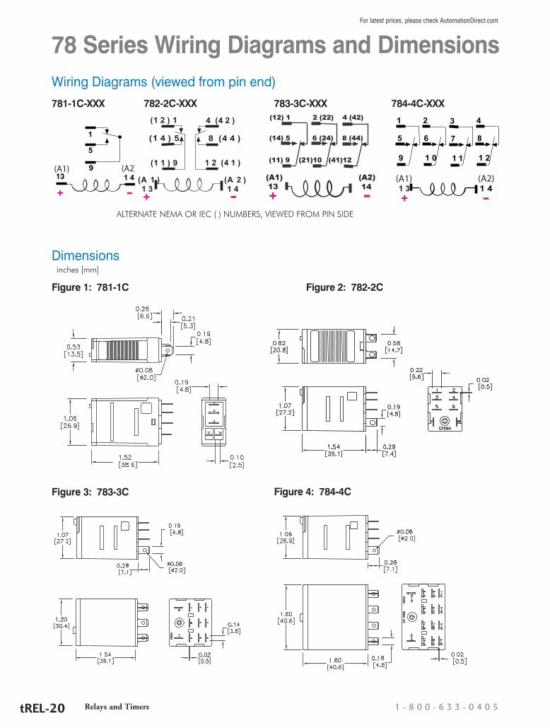
78 Series Wiring Diagrams and DimensionsWiring Diagrams (viewed from pin end)
13 1 4
1
9
5
(A1) (A2)
781-1C-XXX4 (4 2 )(1 2 ) 1
1 3
(1 4 ) 5 8 (4 4 )
1 4
1 2 (4 1 )(1 1 ) 9
(A 1 ) (A 2 )
782-2C-XXX 784-4C-XXX783-3C-XXX1
5
9
1 4
2
6
1 0
3
7
1 1
4
8
1 2
(A1) (A2)1 3
(12) 1 2 (22) 4 (42)
(14) 5 6 (24) 8 (44)
(11) 9 (21)10 (41)12
(A1) (A2) 13 14
Dimensions inches [mm]
ALTERNATE NEMA OR IEC ( ) NUMBERS, VIEWED FROM PIN SIDE
Figure 1: 781-1C
Figure 4: 784-4C
Figure 2: 782-2C
Figure 3: 783-3C
Relays and Timers 1 - 8 0 0 - 6 3 3 - 0 4 0 5tREL-20
For latest prices, please check AutomationDirect.com
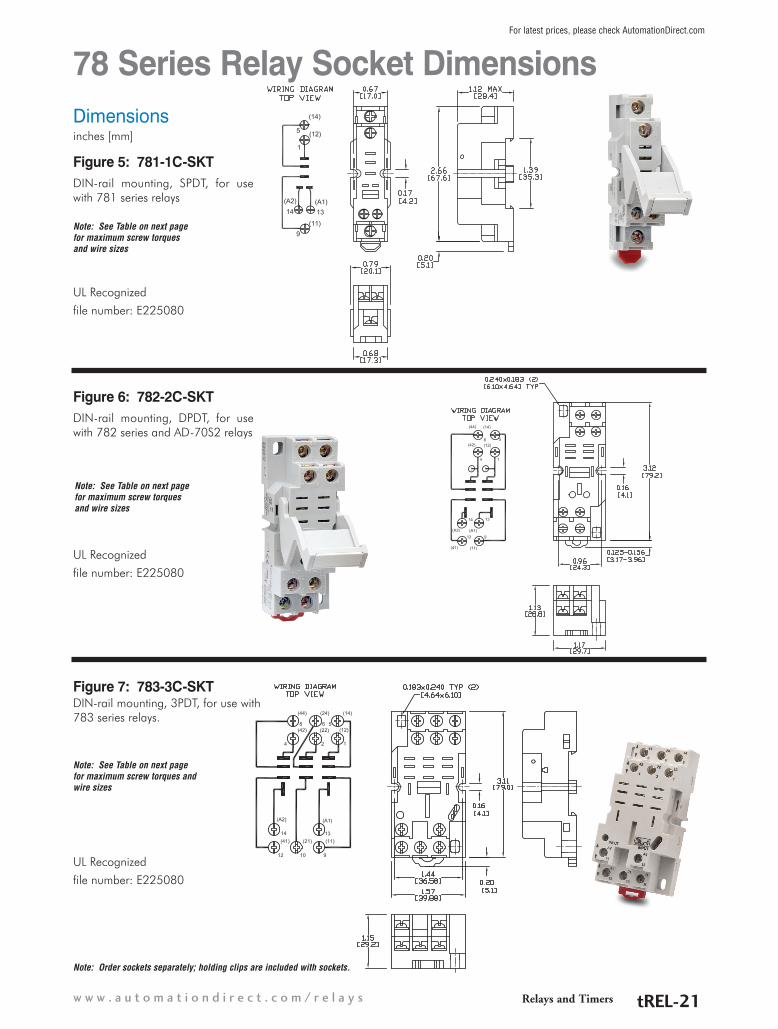
DIN-rail mounting, SPDT, for use with 781 series relays
Figure 5: 781-1C-SKT
DIN-rail mounting, DPDT, for use with 782 series and AD-70S2 relays
Figure 6: 782-2C-SKT
Figure 7: 783-3C-SKT
Note: See Table on next page for maximum screw torques and wire sizes
Note: See Table on next page for maximum screw torques and wire sizes
Note: See Table on next page for maximum screw torques and wire sizes
Dimensionsinches [mm]
UL Recognized
file number: E225080
UL Recognized
file number: E225080
UL Recognized
file number: E225080
DIN-rail mounting, 3PDT, for use with 783 series relays.
Note: Order sockets separately; holding clips are included with sockets.
78 Series Relay Socket Dimensions
Relays and Timersw w w . a u t o m a t i o n d i r e c t . c o m / r e l a y s tREL-21
For latest prices, please check AutomationDirect.com

78 Series Relay Socket Dimensions
Figure 8: 784-4C-SKT-1
DIN-rail mounting, 4PDT, for use with 784 series relays.
Note: Order sockets separately; holding clips are included with sockets.
Note: See table below for maximum screw torques and wire sizes
Part Number Price Maximum Screw Torques Maximum Wire Sizes
781-1C-SKT $4.00 Terminals 13, 14: 7 in·lbs/0.8 N·mTerminals 1, 5, 9: 9 in·lbs/1.0 N·m
Terminals 13, 14: 18 to 20 AWG, solid or stranded, one or two identical wires
Terminals 1, 5, 9: 12 to 20 AWG, solid or stranded, one or two identical wires
782-2C-SKT $4.00
All terminals: 9 in·lbs/1.0 N·m All terminals: 12 to 20 AWG, solid or stranded, one or two identical wires783-3C-SKT $4.50
784-4C-SKT-1 $4.75
Dimensionsinches [mm]
UL Recognized
file number: E225080
Relays and Timers 1 - 8 0 0 - 6 3 3 - 0 4 0 5tREL-22
For latest prices, please check AutomationDirect.com

H782 Series Hermetically Sealed Electromechanical Relay Selection Guide
These ice cube style relays are designed for applications requiring hermetically sealed units for hazardous factory locations. (Class I, Div. 2 Groups A, B, C, D).
Specification H782 Series
Coil Voltages 120VAC, 240VAC, 12VAC, 12VDC,24VAC, 24VDC
Configuration 4PDT
Contact Rating 3A, 5A
Base Socket 14 pin spade terminal
Agency ApprovalsUL Recognized (E344123), cULus when used with 782-4C-SKT socket, CSA, CE, RoHS
Prices starting at $25.50
782 Series Hermetically Sealed Relays Selection Guide
Part Number Price Coil Voltage Configuration Contact Rating Dimensions Relay Socket Part Number Price Dimensions
H782-4C3-12D $35.00 12VDC
4PDT
3A
Figure 1 782-4C-SKT $3.75 Figure 2
H782-4C3-12A $25.50 12VAC
H782-4C3-24D $35.00 24VDC
H782-4C3-24A $34.75 24VAC
H782-4C3-120A $40.25 120VAC
H782-4C3-240A $29.00 240VAC
H782-4C5-12D $35.50 12VDC
5A
H782-4C5-12A $38.50 12VAC
H782-4C5-24D $35.50 24VDC
H782-4C5-24A $28.25 24VAC
H782-4C5-120A $39.75 120VAC
H782-4C5-240A $42.25 240VAC
Features• Hermetically sealed for use in
hazardous locations (Class I, Div. 2 Groups A, B, C, D)
• Small package design• Silver alloy contacts• High reliability and long life• High vibration and shock resistance• Sealed for washdown conditions• 4PDT models
H782-4C3-12A shown
Relays and Timersw w w . a u t o m a t i o n d i r e c t . c o m / r e l a y s tREL-23
For latest prices, please check AutomationDirect.com

H782 Series Hermetically Sealed Electromechanical Relay Specifications
782 Series Contact Ratings (current)Resistive *Motor Load
Voltage Nominal UL CSA UL30VAC 3A 3A 3A120VAC 3A 3A 3A 1/10 HP
240VAC 3A 3A 3A 1/10 HP
782 Series Contact Ratings (current)Resistive *Motor Load
Voltage Nominal UL CSA UL30VAC 5A 5A 5A120VAC 5A 5A 5A
240VAC 5A 5A 5A
H782 Series Hermetically Sealed Relay Specification Table
Part Numbers
H782
-4C3
-12D
H782
-4C3
-12A
H782
-4C3
-24D
H782
-4C3
-24A
H782
-4C3
-120
A
H782
-4C3
-240
A
H782
-4C5
-12D
H782
-4C5
-12A
H782
-4C5
-24D
H782
-4C5
-24A
H782
-4C5
-120
A
H782
-4C5
-240
A
General Specifications
*Service Life: Mechanical / Electrical Operations Mechanical: 10,000,000 operations unpowered
Electrical life:100,000 operations @ rated resistive load
Operating Temperature -40°C to 70°C (-40°F to 158°F)
Response Time 20ms
Vibration Resistance 6 gn at 10–55 Hz
Shock Resistance 10 G’s
Weight 45g (1.59 oz)
**Agency Approvals and Standards UL Recognized File E344123, CE, CSA, RoHS
Environmental Protection IP67 (Class I, Div. 2; Groups A, B, C, D; T5 Temp Code for Hazardous Locations)
NEMA B300 Pilot Duty Rated Yes
Coil SpecificationsCoil Input Voltage 12VDC 12VAC 24VDC 24VAC 120VAC 240VAC 12VDC 12VAC 24VDC 24VAC 120VAC 240VAC
Coil Resistance 160q 43q 650q 160q 3.9kq 12kq 160q 43q 650q 160q 3.9kq 12kq
Power Consumption 0.9W DC; 1.2 VAC
Dropout Voltage (% of nominal voltage or more) 30% AC, 10%DC
Pull-in Voltage (% of nominal voltage or less) 80% AC, 75% DC
Max. Voltage (Max. continuous voltage) 110% of the rated coil voltage
Contact SpecificationsContact Type 4PDT
Contact Material Fine silver, gold flashed Silver alloy
Minimum Switching Requirement 10mA @ 5VDC 100mA @ 5VDC
Max. Contact Rating Refer to Contact Ratings charts.
Dielectric Strength Between Contacts Between Coil and Contact = 1600V rms ; Between Poles = 1600V rms
*Note: These devices are rated for 1,000 cycles when used in a motor application. (Per Table 45.1, UL 508).
**Note: UL listed when used with socket 782-4C-SKT. Current limited to rating of relay or socket, whichever is less.
Relays and Timers 1 - 8 0 0 - 6 3 3 - 0 4 0 5tREL-24
For latest prices, please check AutomationDirect.com

H782 Series Hermetically Sealed Electromechanical Relay Dimensions
0.312 (7.92) LONG#3-48 THREAD
782 HERMETIC MOUNTING OPTIONS
1.28 MAX(32.54)
1.16 MAX(29.36)
0.25(6.35)
0.91 MAX(23.1)
0.02(0.508)
A113
11 21 31
A214
41
3212
342414
9 10 11
5 6 7
22
44
12
8
421 2 3 4
0.02(0.508)
IECNEMA
Wiring DiagramBottom View
Wiring
Figure 1: H782-4C3-xx and H782-4C5-xx
Dimensionsinches [mm]
Relays and Timersw w w . a u t o m a t i o n d i r e c t . c o m / r e l a y s tREL-25
For latest prices, please check AutomationDirect.com
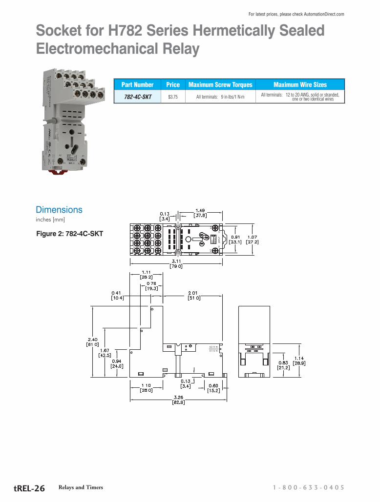
Socket for H782 Series Hermetically Sealed Electromechanical Relay
Part Number Price Maximum Screw Torques Maximum Wire Sizes
782-4C-SKT $3.75 All terminals: 9 in·lbs/1 N·m All terminals: 12 to 20 AWG, solid or stranded, one or two identical wires
Figure 2: 782-4C-SKT
Dimensionsinches [mm]
Relays and Timers 1 - 8 0 0 - 6 3 3 - 0 4 0 5tREL-26
For latest prices, please check AutomationDirect.com

750R Series Electromechanical Relay Selection Guide
750R Series Relay Selection Guide
Part Number Price Coil Voltage Configuration Contact Rating Dimensions Terminals Relay Socket Part Number Price
750R-2C-12D $7.75 12VDC
DPDT 10A Figure 1 8-pin 750-2C-SKT $4.25
750R-2C-12A $9.25 12VAC
750R-2C-24D $7.75 24VDC
750R-2C-24A $8.00 24VAC
750R-2C-120A $8.00 120VAC
750R-2C-240A $8.50 240VAC
750R-3C-12D $9.00 12VDC
3PDT 10A Figure 2 11-pin 750-3C-SKT $4.75750R-3C-24D $9.00 24VDC
750R-3C-24A $9.25 24VAC
750R-3C-120A $9.25 120VAC
750R-3C-240A $9.75 240VAC
14
11
A1
12 22
24
A2
211
2
3
4 5
6
7
8
12
3
4
56
7
8
9
1011
11
A1
14
12
2221
24
32
34
A2
31
Features• Octal base design• Silver alloy, gold flashed
contacts• High open contact dielectric strength
(1500 Vrms)• High reliability and long life• High vibration and shock resistance• Flag indicator shows relay status in manual or powered condition
• LED indicator on all models, so you can
easily see if relay is working properly without using a voltmeter
• A pushbutton allows manual operation of the relay without the need for power to the coil
• I.D. tag/write label for identifying relays in multi-relay circuits
750R series relays are general purpose relays designed for a wide range of applications, from power to sequence controls in various factory machines and control panels. They are ideal for electrical control panels requiring stable and reliable relays.
Note: Order socket separately. 750-2C-SKT/750-3C-SKT socket torque 9 lb·in/ 1.0 N·m
Dimensions inches [mm] Wiring
750R-2C-xxx wiring diagram
750R-3C-xxx wiring diagram
Figure 1: 750R-2C-xxx
Figure 2: 750R-3C-xxx
Note: Contacts and coil shown are internal to the relay
Note: Contacts and coil shown are internal to the relay
Note: Red numbers indicate IEC designations
Relays and Timersw w w . a u t o m a t i o n d i r e c t . c o m / r e l a y s tREL-27
For latest prices, please check AutomationDirect.com

750R Series Specification Table
Part Numbers
750R
-2C-
12D
750R
-2C-
12A
750R
-2C-
24D
750R
-2C-
24A
750R
-2C-
120A
750R
-2C-
240A
750R
-3C-
12D
750R
-3C-
24D
750R
-3C-
24A
750R
-3C-
120A
750R
-3C-
240A
General SpecificationsService Life Mechanical: 5 million operations, Electrical: 100,000 operations @ rated resistive load
Operating Temperature -40°C to 55°C (-40°F to 131°F)
Response Time 20ms
Vibration Resistance +/- 1mm (10 -35 Hz) and 3 g-n (35 -150 Hz)
Shock Resistance 10 G’s
Weight 83g (2.93 oz)*Agency Approvals and Standards UL Recognized file E191059, CE, CSA Certified 2742760
Environmental Protection IP40
Coil SpecificationsStandard LED Indicator
Coil Input Voltage 12VDC 12VAC50/60 Hz 24VDC 24VAC
50/60 Hz120VAC50/60 Hz
240VAC50/60 Hz 12VDC 24VDC 24VAC
50/60 Hz120VAC50/60 Hz
240VAC50/60 Hz
Coil Resistance 120q 16.9 q 470q 72q 1.7 kq 6.8 kq 120q 470q 72q 1.7 kq 6.8 kq
Power Consumption 3VA (60Hz) AC, 1.4 W DC
Dropout Voltage (% of rated voltage) 15% AC, 10% DC
Pull-in Voltage Max. 85% (AC), 80% (DC) of nominal voltage or less
Max. Voltage (Max. continuous voltage) 110% of the rated coil voltage
Contact SpecificationsContact Type DPDT 3PDT
Contact Material Silver alloy, gold flashedMinimum Switching Requirement 10mA @ 17VDC
Contact Rating Refer to Contact Ratings chartDielectric Strength Between Contacts 1500 Vrms
*Note: UL listed when used with sockets 750-2C-SKT, 750-3C-SKT. Current limited to rating of relay or socket, whichever is less.
750R Series Electromechanical Relay Specifications
To obtain the most current agency approval information, see the Agency Approval Checklist section on the specific part number's web page at www.AutomationDirect.com
750R Series Rated Switching CurrentUL
Resistive 10A @ 277VAC, 200k cycles / 10A @ 30VDC, 200k cycles
Motor 1/3HP @ 120VAC, 6k cycles / 1HP @ 277VAC, 6k cycles
Pilot Duty B300, 6k cycles
IECNO: 10A at 250VAC, NC: 5A at 250VACNO: 10A at 28VDC, NC: 5A at 28VDC
Relays and Timers 1 - 8 0 0 - 6 3 3 - 0 4 0 5tREL-28
For latest prices, please check AutomationDirect.com

H750 Series Hermetically Sealed Electromechanical Relay Selection Guide
H750 series hermetically sealed relays are designed for use in hazardous applications. (Class 1, Div 2, Groups A, B, C,
D).
Features• Hermetically sealed for use in
hazardous locations (Class 1, Div 2, Groups A, B, C, D)
• Octal base design • Silver Cadmium Oxide, gold flashed
contacts• High open contact dielectric strength
(1,500V rms)• High reliability and long life• High vibration and shock resistance• DPDT and 3PDT models
Specification H750 Series
Coil Voltages 120VAC, 240VAC, 12VAC, 12VDC,24VAC, 24VDC
Configuration DPDT or 3PDT
Contact Rating 12A
Base Socket 8-pin or 11-pin spade terminal,
Agency ApprovalsUL Recognized (E344123), cULus when used with 750 sockets RoHS
Prices starting at $34.75
H750-2C-12D shown
H750 Series Hermetically Sealed Relay Selection Guide
Part Number Price Coil Voltage Configuration Contact Rating Dimensions Relay Socket Part Number Price
H750-2C-12D $45.00 12VDC
DPDT
12A
Figure 1 750-2C-SKT $4.25
H750-2C-12A $34.75 12VAC
H750-2C-24D $45.00 24VDC
H750-2C-24A $47.25 24VAC
H750-2C-120A $47.25 120VAC
H750-2C-240A $40.75 240VAC
H750-3C-12D $35.25 12VDC
3PDT Figure 2 750-3C-SKT $4.75
H750-3C-12A $50.50 12VAC
H750-3C-24D $48.25 24VDC
H750-3C-24A $37.00 24VAC
H750-3C-120A $50.50 120VAC
Note: Order socket separately. 750-2C-SKT/750-3C-SKT socket torque 9 lb·in/ 1.0 N·m
Relays and Timersw w w . a u t o m a t i o n d i r e c t . c o m / r e l a y s tREL-29
For latest prices, please check AutomationDirect.com

H750 Series Hermetically Sealed Electromechanical Relay Specifications
75 Series Contact Ratings (current)
Resistive Motor Load
Voltage Nominal UL CSA UL28VDC 12A 12A 12A ---
120VAC 12A 12A 12A 1/3Hp
240VAC 12A 12A 12A 1/2Hp
*Note: UL listed when used with sockets 750-2C-SKT, 750-3C-SKT. Current limited to rating of relay or socket, whichever is less.
H750 Series Hermetically Sealed Relays Specification Table
Part Numbers
H750
-2C-
12D
H750
-2C-
12A
H750
-2C-
24D
H750
-2C-
24A
H750
-2C-
120A
H750
-2C-
240A
H750
-3C-
12D
H750
-3C-
12A
H750
-3C-
24D
H750
-3C-
24A
H750
-3C-
120A
General Specifications
Service Life Mechanical: 10 million operations
Electrical: 100,000 operations @ rated resistive load
Operating Temperature -40°C to 55°C (-40°F to 131°F)
Response Time 20 ms
Vibration Resistance 3 gn at 35–150 Hz
Shock Resistance 10 G
Weight 130g (4.6 oz)
*Agency Approvals and Standards UL Recognized file E344123, CSA 244610, RoHS
Environmental Protection IP67 (Class I, Div. 2; Groups A, B, C, D; T5 (DC) and T4A (AC) Temperature Codes)
NEMA B300 Pilot Duty Rated Yes
Coil SpecificationsStandard LED Indicator
Coil Input Voltage 12VDC 12VAC50/60 Hz 24VDC 24VAC
50/60 Hz120VAC50/60 Hz
240VAC50/60 Hz 12VDC 12VAC
50/60 Hz 24VDC 24VAC50/60 Hz
120VAC50/60 Hz
Coil Resistance 120q 18q 470q 72q 1.7 kq 7.2 kq 120q 18q 470q 72q 1.7 kq
Power Consumption 2.75 VA (60Hz) AC, 1.2 W DC
Dropout Voltage (% of rated voltage) 10% (AC); 15% (DC)
Pull-in Voltage 85% (AC); 80% (DC)
Max. Voltage (Max. continuous voltage) 110% of the rated coil voltage
Contact SpecificationsContact Type DPDT 3PDT
Contact Material Silver alloy
Minimum Switching Requirement 100mA @ 5VDC
Contact Rating Refer to Contact Ratings charts
Dielectric Strength Between Contacts Between Coil and Contact: 1600V rms; Between Poles: 1600V rms; Between Open Contacts: 1500V rms
Relays and Timers 1 - 8 0 0 - 6 3 3 - 0 4 0 5tREL-30
For latest prices, please check AutomationDirect.com

H750 Series Hermetically Sealed Electromechanical Relay Specifications
Dimensions inches [mm]
4 56
781
2
3
(A1) (A2)
H750-2C-xxx wiring diagram
H750-3C-xxx wiring diagram
45 6
10111
23
87
9
Note: Contacts and coil shown are internal to the relay
Wiring
Figure 1: H750-2C Series 8-pin
Figure 2: H750-3C Series 11-pin
Note: Contacts and coil shown are internal to the relay
Note: Contacts and coil shown are internal to the relay
Relays and Timersw w w . a u t o m a t i o n d i r e c t . c o m / r e l a y s tREL-31
For latest prices, please check AutomationDirect.com

750R Series Socket Dimensions
Figure 3: 750-2C-SKT
Figure 4: 750-3C-SKT
Bus Connector
AccessoryPart Number Description Price
33-796-1Coil bus connector used to connect multiple relays in parallel. Package includes 5 pairs of bus bars to connect up to 5 relays together.
$3.25
Dimensions inches [mm]
Wiring
Wiring
Relays and Timers 1 - 8 0 0 - 6 3 3 - 0 4 0 5tREL-32
For latest prices, please check AutomationDirect.com

Protection Device Selection Guide
Part Number Price Description Nominal Input Voltage
Dimensions & Package
Mating Socket
AD-ASMD-250 $9.75 Protection diode module for 784 and 75 series relays. Plug-in modules come in package of 5. 6-250VDC
Figure 1
783-3C-SKT784-4C-SKT-1750-2C-SKT750-3C-SKT
AD-ASMM-24 $8.00 MOV module for 784 and 75 series relays that operate at 24VAC coil voltage. Package includes 5 modules. 24VAC/VDC
AD-ASMM-120 $8.00 MOV module for 784 and 75 series relays that operate at 120VAC coil voltage. Package includes 5 modules. 120VAC/VDC
AD-ASMM-240 $8.00 MOV module for 784 and 75 series relays that operate at 240VAC coil voltage. Package includes 5 modules. 240VAC/VDC
AD-BSMD-250 $8.00 Protection diode module for 782 series relays. Plug-in modules come in package of 5. 6-250VDC
Figure 2 782-2C-SKTAD-BSMM-24 $8.00 MOV module for 782 series relays that operate at 24VAC coil voltage. Package includes 5
modules. 24VAC/VDC
AD-BSMM-120 $8.00 MOV module for 782 series relays that operate at 120VAC coil voltage. Package includes 5 modules. 120VAC/VDC
AD-BSMM-240 $8.00 MOV module for 782 series relays that operate at 240VAC coil voltage. Package includes 5 modules. 240VAC/VDC
Figure 1 Figure 2
1.37(34.7)
1.45(38.8)
0.384(9.82)
0.490(12.4)
0.900(22.8)
0.34(8.63)
A2 A1M.O.V .
A2 A1
DIODE
Packaged M.O.V.s and Diodes
Accessory dimensions inches [mm]
OverviewMetal Oxide Varistors (MOV) and Diode circuits are offered as convenient plug-in modules. Plugging a module into the relay socket connects the circuit in parallel with the relay coil. No addi-tional wiring is required.
Modules fit within the maximum dimen-sions of the relay and socket.
Features• MOVs protect by shunting potentially
damaging electrical spikes away from the relay coil. Ideal for AC and DC applications.
• Diodes protect external drive circuitry from inductive voltages generated when removing coil voltage. Ideal for DC applications. Polarity sensitive.
ApplicationMany PLC systems control one or more inductive load devices. These inductive loads (devices with a coil) generate transient voltages when they are de-en-ergized with a relay contact. When a relay contact is closed it “bounces”, which causes the coil to energize and de-energize until the “bouncing” stops. The transient voltage which is gener-ated is much larger in amplitude than the supply voltage, especially with a DC supply voltage.
When switching a DC-supplied induc-tive load the full supply voltage is always present when the relay contact opens (or “bounces”). When switching an AC-supplied inductive load, if the voltage is not zero when the relay contact opens, there is energy stored in the inductor that is released when the voltage to the inductor is suddenly removed. This release of energy is what produces transient voltages.
When inductive load devices (motors, motor starters, interposing relays, solenoids, valves, etc.) are controlled with relay contacts, it is recommended that a surge suppression device be connected directly across the coil of the field device. If the inductive device has plug-type connectors, the suppression device can be installed on the terminal block of the relay output.
Metal oxide varistors (MOV) and diodes are devices which provide good surge and transient suppression of AC and DC powered coils.
Relays and Timersw w w . a u t o m a t i o n d i r e c t . c o m / r e l a y s tREL-33
For latest prices, please check AutomationDirect.com

Figure 2 AD-PR40-2A-xx
Power Relays
Power Relay Selection GuidePart Number Price Coil Voltage Configuration Contact Rating DimensionsAD-PR40-1C-12D $14.75 12VDC
SPDT
40A
Figure 1AD-PR40-1C-24D $15.75 24VDC
AD-PR40-1C-24A $18.00 24VAC
AD-PR40-1C-120A $16.25 120VAC
AD-PR40-1C-240A $18.50 240VAC
AD-PR40-2A-12D $17.50 12VDC
DPST Figure 2AD-PR40-2A-24D $17.50 24VDC
AD-PR40-2A-24A $17.25 24VAC
AD-PR40-2A-120A $17.25 120VAC
AD-PR40-2A-240A $17.75 240VAC
AD-PR40-2C-12D $19.25 12VDC
DPDT Figure 3AD-PR40-2C-24D $19.75 24VDC
AD-PR40-2C-24A $19.75 24VAC
AD-PR40-2C-120A $19.50 120VAC
AD-PR40-2C-240A $19.75 240VAC
Features• High power contacts capable of switching up to 40A• Open construction• SPDT, DPST and DPDT models• Riveted construction for high reliability• Maximum contact voltage up to 600V
SPDT DPDT DPST
22
12
A1
A2 11
2124
14
A1
A2 11
2124
14
14
12
A1
A2 11
WiringAD-PR40-1C-xxxx AD-PR40-2C-xxxx AD-PR40-2A-xxxx
Figure 1 AD-PR40-1C-xx
Dimensions inches [mm]
AD-PR40-1C-12D shown
Relays and Timers 1 - 8 0 0 - 6 3 3 - 0 4 0 5tREL-34
For latest prices, please check AutomationDirect.com

Figure 3 AD-PR40-2C-xx
Power Relays SpecificationsPower Relays Specification Table
Part Numbers
AD-P
R40-
1C-1
2D
AD-P
R40-
1C-2
4D
AD-P
R40-
1C-2
4A
AD-P
R40-
1C-1
20A
AD-
PR40
-1C-
240A
AD-
PR40
-2A-
12D
AD-
PR40
-2A-
24D
AD-
PR40
-2A-
24A
AD-
PR40
-2A-
120A
AD-
PR40
-2A-
240A
AD-P
R40-
2C-1
2D
AD-
PR40
-2C-
24D
AD-
PR40
-2C-
24A
AD-
PR40
-2C-
120A
AD-
PR40
-2C-
240A
General Specifications
Service Life Mechanical: 1 million operations AC and DC
Electrical (resistive): 50,000 operations @ 300VAC;100,000 @ 28VDCOperating Temperature -55°C to 55°C (-67°F to 131°F)Response Time 30msWeight 227g ( 8oz) to 312g (11oz)Agency Approvals and Standards UL Recognized E191059, CE Certified (9667186-9811), CSA Certified 244610, RoHSEnvironmental Protection Not applicable to open relaysPilot Duty A600Terminal Wire Max 10AWGTerminal Torque 11 to 15 in·lb (1.2 to 1.7 N·m)
Coil Specifications
Coil Input Voltage 12VDC 24VDC24VAC50/60
Hz
120VAC50/60 Hz
240VAC50/60 Hz 12VDC 24VDC
24VAC50/60
Hz
120VAC50/60 Hz
240VAC50/60 Hz 12VDC 24VDC 24VAC
50/60 Hz120VAC50/60 Hz
240VAC50/60 Hz
Coil Resistance 70q 290q 12q 290q 1.2 kq 70q 290q 12q 290q 1.2 kq 70q 290q 12q 290q 1.2 kq
Power Consumption 10VA (AC) , 4.0W DCDropout Voltage (% of rated voltage) Min. 10%Pull-in Voltage Max. 85% of nominal voltage or less AC, Max. 80% of nominal voltage or less DCMax. Voltage (continuous voltage) 110% of the rated coil voltage
Contact SpecificationsContact Type SPDT DPST (N.O.) DPDTContact Material Silver Alloy, gold flashed
Contact Rating
40A, 300 VAC / 28 VDC5A, 480 / 600 VAC
2hp each pole 120-600 VAC2hp sw. 2 poles 120-600 VAC
15A TUNG. 120 VACMinimum Switching Requirement 1A @ 5VAC/VDCMaximum Switching Voltage 600VDielectric Strength Between Contacts Between coil and contact: 2200V ; Between poles: 2200V ; Between open contacts: 1500V
Dimensions inches [mm]
Relays and Timersw w w . a u t o m a t i o n d i r e c t . c o m / r e l a y s tREL-35
For latest prices, please check AutomationDirect.com

AD Series Solid State Relays
AD-70S2-04B shown
AD-SSR210-22-DCZ shown
A solid state relay is a relay with an isolated input and output, whose func-tions are achieved by using electronic components without the use of moving parts (vs. electromechanical relays).
OperationSolid state relays (SSR) are similar to electromechanical relays, in that both use a control circuit and a separate circuit for switching the load. When voltage is applied to the input of the SSR, the relay is energized by a light-emitting diode. The light from the diode is beamed into a light sensitive semiconductor which, in the case of zero voltage crossover relays, signals the control circuit to turn on the output of the solid state switch at the next zero voltage crossover.
Solid State Relay FeaturesSolid state relays have features which electromechanical relays do not, such as:
• Long life• Shock and vibration resistant• No generation of RFI, EMI• No contact bounce• Arcless switching• No acoustic noise• Zero crossing or random switching types• IC compatibility• Immunity to humidity, salt spray and dirt• UL # E222847• CSA # 2742910
AD-SSR Features • AC & DC input• AC output• 10 or 25 amp loads• Photo isolated zero voltage switching• 4000 Vrms isolation input to output• Internal RC (snubber) network• RFI suppression• Integral safety cover and heatsink• DIN-rail mounting or panel-mount
AD-70S2 Features • DC input• AC output• Up to 4 amp loads• Optically isolated• Quick connect terminal, or panel mount
when inserted into DIN-rail mountable socket
Relays and Timers 1 - 8 0 0 - 6 3 3 - 0 4 0 5tREL-36
For latest prices, please check AutomationDirect.com

Solid State Relay Selection Guide
Part Number Price Description Switching Type
Dimensions & Derating
ChartsRelay Socket Part Number Price Socket
Dimensions
AD-SSR210-22-ACZ $39.00Solid state DIN-rail mount relay with 10A contact rating. Coil voltage 90-280 VAC. Load voltage is 24-280 VAC. Finger-safe design and LED status lamp. SPST normally open.
Zero Cross
Figure 1
N/A N/A N/A
AD-SSR210-22-DCZ $39.00Solid state DIN-rail mount relay with 10A contact rating. Coil voltage 4-32 VDC. Load voltage is 24-280 VAC. Finger-safe design and LED status lamp. SPST normally open.
AD-SSR230-22-ACZ $59.00Solid state DIN-rail mount relay with 30A contact rating. Coil voltage 90-280 VAC. Load voltage is 24-280 VAC. Finger-safe design and LED status lamp. SPST normally open.
AD-SSR230-22-DCZ $59.00Solid state DIN-rail mount relay with 30A contact rating. Coil voltage 4-32 VDC. Load voltage is 24-280 VAC. Finger-safe design and LED status lamp. SPST normally open.
AD-SSR610-22-ACZ $41.25Solid state DIN-rail mount relay with 10A contact rating. Coil voltage 90-280 VAC. Load voltage is 48-660 VAC. Finger-safe design and LED status lamp. SPST normally open.
AD-SSR610-22-DCZ $37.50Solid state DIN-rail mount relay with 10A contact rating. Coil voltage 4-32 VDC. Load voltage is 48-660 VAC. Finger-safe design and LED status lamp. SPST normally open.
AD-SSR630-22-ACZ $58.50Solid state DIN-rail mount relay with 30A contact rating. Coil voltage 90-280 VAC. Load voltage is 48-660 VAC. Finger-safe design and LED status lamp. SPST normally open.
AD-SSR630-22-DCZ $54.00Solid state DIN-rail mount relay with 30A contact rating. Coil voltage 4-32 VDC. Load voltage is 48-660 VAC. Finger-safe design and LED status lamp. SPST normally open.
AD-SSR210-22-ACR $39.00Solid state DIN-rail mount relay with 10A contact rating. Coil voltage 90-280 VAC. Load voltage is 24-280 VAC. Finger-safe design and LED status lamp. SPST normally open.
Random Switching
AD-SSR210-22-DCR $39.00Solid state DIN-rail mount relay with 10A contact rating. Coil voltage 4-32 VDC. Load voltage is 24-280 VAC. Finger-safe design and LED status lamp. SPST normally open.
AD-SSR230-22-ACR $45.00Solid state DIN-rail mount relay with 30A contact rating. Coil voltage 90-280 VAC. Load voltage is 24-280 VAC. Finger-safe design and LED status lamp. SPST normally open.
AD-SSR230-22-DCR $45.00Solid state DIN-rail mount relay with 30A contact rating. Coil voltage 4-32 VDC. Load voltage is 24-280 VAC. Finger-safe design and LED status lamp. SPST normally open.
AD-SSR610-22-ACR $39.00Solid state DIN-rail mount relay with 10A contact rating. Coil voltage 90-280 VAC. Load voltage is 48-660 VAC. Finger-safe design and LED status lamp. SPST normally open.
AD-SSR610-22-DCR $39.00Solid state DIN-rail mount relay with 10A contact rating. Coil voltage 4-32 VDC. Load voltage is 48-660 VAC. Finger-safe design and LED status lamp. SPST normally open.
AD-SSR630-22-ACR $49.00Solid state DIN-rail mount relay with 30A contact rating. Coil voltage 90-280 VAC. Load voltage is 48-660 VAC. Finger-safe design and LED status lamp. SPST normally open.
AD-SSR630-22-DCR $49.00Solid state DIN-rail mount relay with 30A contact rating. Coil voltage 4-32 VDC. Load voltage is 48-660 VAC. Finger-safe design and LED status lamp. SPST normally open.
AD-SSR245-45-ACZ $73.75Solid state DIN-rail mount relay with 45A contact rating. Coil voltage 90-140 VAC. Load voltage is 24-280 VAC. Finger-safe design and LED status lamp. SPST normally open.
Zero Cross
Figure 2
AD-SSR245-45-DCZ $73.25Solid state DIN-rail mount relay with 45A contact rating. Coil voltage 3-32 VDC. Load voltage is 24-280 VAC. Finger-safe design and LED status lamp. SPST normally open.
AD-SSR645-45-ACZ $75.00Solid state DIN-rail mount relay with 45A contact rating. Coil voltage 90-140 VAC. Load voltage is 48-660 VAC. Finger-safe design and LED status lamp. SPST normally open.
AD-SSR645-45-DCZ $75.00Solid state DIN-rail mount relay with 45A contact rating. Coil voltage 3-32 VDC. Load voltage is 48-660 VAC. Finger-safe design and LED status lamp. SPST normally open.
AD-SSR665-45-ACZ $65.00Solid state DIN-rail mount relay with 65A contact rating. Coil voltage 90-140 VAC. Load voltage is 48-660 VAC. Finger-safe design and LED status lamp. SPST normally open.
AD-SSR665-45-DCZ $65.00Solid state DIN-rail mount relay with 65A contact rating. Coil voltage 3-32 VDC. Load voltage is 48-660 VAC. Finger-safe design and LED status lamp. SPST normally open.
AD-70S2-04B $20.00 Solid state plug-in relay with 4A contact rating. Coil voltage is 3-30 VDC. Load voltage is 24-140 VAC. SPST normally open.
Figure 3
782-2C-SKT(see wiring
diagram on next page)
$4.00 Figure 6 *AD-70S2-04C $20.00 Solid state plug-in relay with 4A contact rating. Coil voltage is 3-30 VDC. Load voltage is 24-280 VAC. SPST normally open.
AD-70S2-04D $20.00 Solid state plug-in relay with 4A contact rating. Coil voltage is 3-30 VDC. Load voltage is 8-50 VAC. SPST normally open.
*NOTE: See 78 Series Relays Socket dimensions.
AD Series Solid State Relay Selection Guide
Relays and Timersw w w . a u t o m a t i o n d i r e c t . c o m / r e l a y s tREL-37
For latest prices, please check AutomationDirect.com

AD Series Solid State Relay SpecificationsSpecifications
Part Number
AD-S
SR24
5-45
-DCZ
AD-S
SR21
0-22
-DCZ
AD-S
SR23
0-22
-DCZ
AD-S
SR21
0-22
-DCR
AD-S
SR23
0-22
-DCR
AD-S
SR61
0-22
-DCZ
AD-S
SR63
0-22
-DCZ
AD-S
SR64
5-45
-DCZ
AD-S
SR66
5-45
-DCZ
AD-S
SR61
0-22
-DCR
AD-S
SR63
0-22
-DCR
AD-S
SR21
0-22
-ACZ
AD-S
SR23
0-22
-ACZ
AD-S
SR21
0-22
-ACR
AD-S
SR23
0-22
-ACR
AD-S
SR61
0-22
-ACZ
AD-S
SR63
0-22
-ACZ
AD-S
SR64
5-45
-ACZ
AD-S
SR61
0-22
-ACR
AD-S
SR63
0-22
-ACR
AD-S
SR24
5-45
-ACZ
AD-S
SR66
5-45
-ACZ
Input CharacteristicsControl Voltage Range 3-32
VDC 4-32 VDC 90-280 VAC 90-140 VAC
90-280 VAC 90-140 VAC
Typical Input Current 8-12 mA 2-4 mA Maximum Turn-On Voltage 4VDC 90 VrmsMinimum Turn-Off Voltage 1VDC 10 Vrms
Output CharacteristicsOutput Type SCR
Switching Type Zero Cross Random Switching Zero Cross Random
SwitchingZero
CrossRandom
Switching Zero Cross Random Switching Zero Cross
Output Voltage 24-280 VAC 48-660 VAC 24-280 VAC 48-660 VAC 24-280 VAC 48-660 VAC
Load Current Range 10-45A 65A
Transient Over-Voltage 600Vpk 1200Vpk 600Vpk 1200Vpk 600Vpk 1200Vpk
Maximum Surge Current10A: 120Apk;
30/45A: 625Apk;(at 16.6 ms)
625Apk(at 16.6 ms)
10A: 120Apk;30/45A: 625Apk;
(at 16.6 ms)
625Apk(at 16.6 ms)
10A: 120Apk;30/45A:625Apk;
(at 16.6 ms)
625Apk(at 16.6 ms)
Maximum On-State Voltage Drop at Rated Current 1.6 Vpk
Maximum I²T for Fusing (8.3 ms)10A: 60 A2sec;20A: 260 A2sec;
30/45A: 1620 A2sec1620 A2sec
10A: 60 A2sec;20A: 260 A2sec;
30/45A: 1620 A2sec1620 A2sec
10A: 60 A2sec;20A: 260
A2sec;30/45A: 1620
A2sec
1620 A2sec
Maximum Off-State Leakage Current at Rated Current 10mA 1mA 10mA 1mA 10mA 1mA
Maximum Rate of Rise Off State Voltage (dv/dt) 500 V/us
Max Response Time (On and Off) 1/2 cycle
General CharacteristicsElectrical Life N/A for solid state relaysOperating Temperature Range -40°C to 80°C (-40°F to 176°F) - derating appliesFrequency Input: no frequency limitation / output: snubber 48-63 HzStorage Temperature Range -40°C to 125°C (-40°F to 257°F)Weight 10/20/30 A: 272g (9.6 oz); 45A: 482g (17oz)Input Indication Green LEDEncapsulation Thermally conductive epoxyInput Terminal Screw Torque 10/20/30 A: 5.0-6.0 in·lb (0.6-0.7 N·m); 45A: 5.0-6.0 in·lb (0.6-0.7 N·m)Output Terminal Screw Torque 10/20/30 A: 5.0-6.0 in·lb (0.6-0.7 N·m); 45A: 10.0-15.0 in·lb (1.1-1.7 N·m)Mount Type 35mm DIN rail and panel mountMaximum Wire Size 8AWGAgency Approvals E222847 UL Recognized, CE, CSA 2742910
AD-SSRxxx-xx wiring diagram
A1 (-)
A2 (+)12 (41)8 (44)
AD-70S2-xx wiring diagram
To obtain the most current agency approval information, see the Agency Approval Checklist section on the specific part number's web page at www.AutomationDirect.com
Please see our website www.AutomationDirect.com for complete engineering drawings.
INPUT
OUTPUT
3 + - 4
12
Relays and Timers 1 - 8 0 0 - 6 3 3 - 0 4 0 5tREL-38
For latest prices, please check AutomationDirect.com

SSR Series Dimensions & Derating Charts
20
15
25
30
35
45
40
10
5
100 30 50 70 9020 40 60 80
LO
AD
CU
RR
EN
T (
AM
PS
)
MAXIMUM AMBIENT TEMPERATURE (C°)
AD-SSR 30 A
AD-SSR 45 A
AD-SSR 20 A
AD-SSR 10 A
50
55
65
60
AD-SSR 65 A
AD-SSR Series
AD-70S2 Series
AD-SSR Series derating chart
AD-70S2 Series derating charts
Figure 1
Figure 3
Note: Recommended spacing between multiple SSRs is 0.75 inch.
Dimensions inches [mm]
Figure 2
Please see our website www.AutomationDirect.com for complete engineering drawings.
AMBIENT TEMPERATURE (C°)-40 -20 0 20 40 60 80 100
87654321
LOA
D C
UR
REN
T (A
MPS
)
Maximum Continuous Current vs. Ambient Temperature
Relays and Timersw w w . a u t o m a t i o n d i r e c t . c o m / r e l a y s tREL-39
For latest prices, please check AutomationDirect.com

Class 6 Solid State Relay Selection Guide
Part Number Price Type Input Voltage Load Voltage Configuration Contact Rating
AD-SSR610-AC-280A $18.25 N.O. SCR 90 to 280 VAC
24 to 280 VAC
SPST
10AAD-SSR610-DC-280A $16.25 N.O. SCR 3 to 32 VDC
AD-SSR6T10-DC-280A $16.25 N.O. TRIAC 3 to 32 VDC
AD-SSR625-AC-280A $23.50 N.O. SCR 90 to 280 VAC
25AAD-SSR625-DC-280A $17.50 N.O. SCR 3 to 32 VDC
AD-SSR6T25-DC-280A $18.50 N.O. TRIAC 3 to 32 VDC
AD-SSR640-AC-280A $25.50 N.O. SCR 90 to 280 VAC
40AAD-SSR640-DC-280A $24.50 N.O. SCR 3 to 32 VDC
AD-SSR6T40-DC-280A $22.75 N.O. TRIAC 3 to 32 VDC
AD-SSR650-AC-280A $29.75 N.O. SCR 90 to 280 VAC 50A
AD-SSR650-DC-280A $29.75 N.O. SCR 3 to 32 VDC
AD-SSR675-AC-280A $41.00 N.O. SCR 90 to 280 VAC 75A
AD-SSR675-DC-280A $41.00 N.O. SCR 3 to 32 VDC
AD-SSR6M12-DC-200D $17.25 N.O. MOSFET 3.5 to 32 VDC
3 to 200 VDC
12A
AD-SSR6M25-DC-200D $40.00 N.O. MOSFET 3.5 to 32 VDC 25A
AD-SSR6M40-DC-200D $40.00 N.O. MOSFET 3.5 to 32 VDC 40A
AD-SSR610-AC-480A $14.50 N.O. SCR 90 to 280 VAC
48 to 480 VAC
10AAD-SSR610-DC-480A $14.50 N.O. SCR 3 to 32 VDC
AD-SSR6T10-DC-480A $14.50 N.O. TRIAC 3 to 32 VDC
AD-SSR625-AC-480A $18.75 N.O. SCR 90 to 280 VAC
25AAD-SSR625-DC-480A $17.75 N.O. SCR 3 to 32 VDC
AD-SSR6T25-DC-480A $19.00 N.O. TRIAC 3 to 32 VDC
AD-SSR640-AC-480A $32.00 N.O. SCR 90 to 280 VAC
40AAD-SSR640-DC-480A $30.00 N.O. SCR 3 to 32 VDC
AD-SSR6T40-DC-480A $22.75 N.O. TRIAC 3 to 32 VDC
AD Series Class 6 Solid State Relays
The Class 6 solid state relays offer an ener-gy-efficient alternative to standard electro-mechanical relays.
Switching types include DC switching for low-voltage DC loads and Zero Cross for resistive AC loads where the output ener-gizes/de-energizes when control voltage is near zero.
Switching devices include: MOSFET for DC loads, Triac and SCR for AC loads.
Features• Finger-safe “Hockey Puck” housing• Solid-state circuitry• High load ratings up to 75 amps• Input indicating LED• Optically coupled circuits• Panel mount• Thermal pad included with each relay
Note: Thermal pad included with each relay.
AD-SSR610-AC-280A shown
Relays and Timers 1 - 8 0 0 - 6 3 3 - 0 4 0 5tREL-40
For latest prices, please check AutomationDirect.com
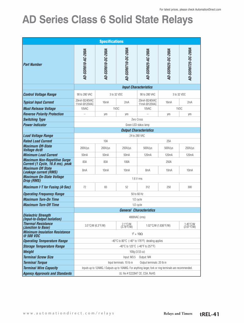
Specifications
Part Number
AD-S
SR61
0-AC
-280
A
AD-S
SR61
0-DC
-280
A
AD-S
SR6T
10-D
C-28
0A
AD-S
SR62
5-AC
-280
A
AD-S
SR62
5-DC
-280
A
AD-S
SR6T
25-D
C-28
0A
Input Characteristics
Control Voltage Range 90 to 280 VAC 3 to 32 VDC 90 to 280 VAC 3 to 32 VDC
Typical Input Current 20mA @240VAC11mA @120VAC 16mA 2mA 20mA @240VAC
11mA @120VAC 16mA 2mA
Must Release Voltage 10VAC 1VDC 10VAC 1VDC
Reverse Polarity Protection – yes yes – yes yes
Switching Type Zero Cross
Power Indicator Green LED status lamp
Output CharacteristicsLoad Voltage Range 24 to 280 VAC
Rated Load Current 10A 25A
Maximum Off-State Voltage dv/dt 200V/µs 200V/µs 250V/µs 500V/µs 500V/µs 250V/µs
Minimum Load Current 50mA 50mA 50mA 120mA 120mA 120mA
Maximum Non-Repetitive Surge Current (1 Cycle, 16.6 ms), peak 83A 83A 100A 250A
Maximum Off State Leakage current (RMS) 8mA 10mA 10mA 8mA 10mA 10mA
Maximum On-State Voltage Drop (RMS) 1.6 V rms
Maximum I 2T for Fusing (A2Sec) 72 83 52 312 250 300
Operating Frequency Range 50 to 60 Hz
Maximum Turn-On Time 1/2 cycle
Maximum Turn-Off Time 1/2 cycle
General CharacteristicsDielectric Strength (Input-to-Output Isolation) 4000VAC (rms)
Thermal Resistance (Junction to Base) 3.5°C/W (6.3°F/W) 2.1°C/W
(3.78°F/W) 1.02°C/W (1.836°F/W) 1.45°C/W (2.61°F/W)
Minimum Insulation Resistance @ 500 VDC 1E + 10q
Operating Temperature Range -40°C to 80°C (-40° to 176°F) derating applies
Storage Temperature Range -40°C to 125°C (-40°F to 257°F)
Weight 100g (3.53 oz)
Terminal Screw Size Input: M3.5 Output: M4
Terminal Torque Input terminals: 10 lb·in Output terminals: 20 lb·in
Terminal Wire Capacity Inputs up to 12AWG / Outputs up to 10AWG. For anything larger, fork or ring terminals are recommended.
Agency Approvals and Standards UL file # E222847 CE, CSA, RoHS
AD Series Class 6 Solid State Relays
Relays and Timersw w w . a u t o m a t i o n d i r e c t . c o m / r e l a y s tREL-41
For latest prices, please check AutomationDirect.com

Specifications
Part Number
AD-S
SR64
0-AC
-280
A
AD-S
SR64
0-DC
-280
A
AD-S
SR6T
40-D
C-28
0A
AD-S
SR65
0-AC
-280
A
AD-S
SR65
0-DC
-280
A
AD-S
SR67
5-AC
-280
A
AD-S
SR67
5-DC
-280
A
Input Characteristics
Control Voltage Range 90 to 280 VAC 3 to 32 VDC 90 to 280 VAC 3 to 32 VDC 90 to 280 VAC 3 to 32 VDC
Typical Input Current 20mA @240VAC11mA @120VAC 16mA 2mA 4mA @240VAC
2mA @120VAC 10mA 4mA @240VAC2mA @120VAC 10mA
Must Release Voltage 10VAC 1VDC 10VAC 1VDC 10VAC 1VDC
Reverse Polarity Protection – yes yes – yes – yes
Switching Type Zero Cross
Power Indicator Green LED status lamp
Output CharacteristicsLoad Voltage Range 24 to 280 VAC
Rated Load Current 40A 50A 75A
Maximum Off-State Voltage dv/dt 500V/µs 500V/µs 250V/µs 500V/µs 500V/µs 500V/µs 500V/µs
Minimum Load Current 250mA 250mA 50mA 40mA 150mA 40mA 250mA
Maximum Non-Repetitive Surge Current (1 Cycle, 16.6 ms), peak 625A 625A 250A 625A 625A 1000A 1000A
Maximum Off State Leakage current (RMS) 10mA 10mA 10mA 10mA 1mA 10mA 1mA
Maximum On-State Voltage Drop (RMS) 1.6 V rms
Maximum I 2T for Fusing (A2Sec) 1250 625 488 1620 1620 4150 4150
Operating Frequency Range 50 to 60 Hz
Maximum Turn-On Time 1/2 cycle 10ms 1/2 cycle 10ms 1/2 cycle
Maximum Turn-Off Time 1/2 cycle 40ms 1/2 cycle 40ms 1/2 cycle
General CharacteristicsDielectric Strength (Input-to-Output Isolation) 4000VAC (rms)
Thermal Resistance (Junction to Base) 0.9°C/W (1.62°F/W) 0.95°C/W
(1.71°F/W) 0.63°C/W (1.134°F/W) 0.31°C/W (0.558°F)
Minimum Insulation Resistance @ 500 VDC 1E + 10q 1E + 9q
Operating Temperature Range -40°C to 80°C (-40° to 176°F) derating applies
Storage Temperature Range -40°C to 125°C (-40°F to 257°F)
Weight 100g (3.53 oz)
Terminal Screw Size Input: M3.5 Output: M4
Terminal Torque Input terminals: 10 lb·in Output terminals: 20 lb·in
Terminal Wire Capacity Inputs up to 12AWG / Outputs up to 10AWG. For anything larger, fork or ring terminals are recommended.
Agency Approvals and Standards UL file # E222847 CE, CSA, RoHS
AD Series Class 6 Solid State Relays
Relays and Timers 1 - 8 0 0 - 6 3 3 - 0 4 0 5tREL-42
For latest prices, please check AutomationDirect.com

AD Series Class 6 Solid State Relays
Specifications
Part Number
AD-S
SR6M
12-D
C-20
0D
AD-S
SR6M
25-D
C-20
0D
AD-S
SR6M
40-D
C-20
0D
AD-S
SR61
0-AC
-480
A
AD-S
SR61
0-DC
-480
A
AD-S
SR6T
10-D
C-48
0A
Input Characteristics
Control Voltage Range 3.5 to 32 VDC 90 to 280 VAC 3 to 32 VDC
Typical Input Current 10mA 20mA @240VAC11mA @120VAC 16mA
Must Release Voltage 1VDC 10VAC 1VDC
Reverse Polarity Protection no – no
Switching Type DC Zero Cross
Power Indicator Green LED status lamp
Output CharacteristicsLoad Voltage Range 3 to 200 VDC 48 to 480 VAC
Rated Load Current 12A 25A 40A 10A
Maximum Off-State Voltage dv/dt – 200V/µs
Minimum Load Current 20mA 50mA 150mA 50mA
Maximum Non-Repetitive Surge Current (1 Cycle, 16.6 ms), peak 27A 50A 90A 83A 83A 100A
Maximum Off State Leakage current (RMS) 8mA 10mA 8mA 8mA
Typical On-State Voltage Drop (RMS) 2.8 VDC (@ 40A load) 1.7 V rms 1.6 V rms 1.6 V rms
Maximum I 2T for Fusing (A2Sec) – 72 72 35
Operating Frequency Range – 50 to 60 Hz
Maximum Turn-On Time 300µs 600µs 600µs 1/2 cycle 8.3 ms 1/2 cycle
Maximum Turn-Off Time 1ms 1/2 cycle 8.3 ms 1/2 cycle
General CharacteristicsDielectric Strength (Input-to-Output Isolation) 2500VAC (rms) 4000VAC (rms)
Thermal Resistance (Junction to Base)
1.03°C/W (1.854°F/W) 1.06°C/W (1.908°F/W) 3°C/W (5.4°F/W) 2.9°C/W (5.22°F/W)
Minimum Insulation Resistance @ 500 VDC 1E + 10q
Operating Temperature Range -40°C to 80°C (-40°F to 176°F) (derating applies)
Storage Temperature Range -40°C to 100°C (-40°F to 212°F) -40°C to 100°C (-40°F to 212°F)
Weight 110g (3.88 oz) 135g (4.76 oz) 135g (4.76 oz) 100g (3.53 oz)
Terminal Screw Size Input: M3.5 Output: M4
Terminal Torque Input terminals: 10 lb·in. Output terminals: 20 lb·in
Terminal Wire Capacity Inputs up to 12AWG / Outputs up to 10AWG. For anything larger, fork or ring terminals are recommended.
Agency Approvals and Standards UL file # E222847, CE, CSA, RoHS
Relays and Timersw w w . a u t o m a t i o n d i r e c t . c o m / r e l a y s tREL-43
For latest prices, please check AutomationDirect.com

AD Series Class 6 Solid State Relays
Specifications
Part Number
AD-S
SR62
5-AC
-480
A
AD-S
SR62
5-DC
-480
A
AD-S
SR6T
25-D
C-48
0A
AD-S
SR64
0-AC
-480
A
AD-S
SR64
0-DC
-480
A
AD-S
SR6T
40-D
C-48
0A
Input Characteristics
Control Voltage Range 90 to 280 VAC 3 to 32 VDC 90 to 280 VAC 3 to 32 VDC
Typical Input Current 20mA @240VAC11mA @120VAC 16mA 20mA @240VAC
11mA @120VAC 16mA
Must Release Voltage 10VAC 1VDC 10VAC 1VDC
Reverse Polarity Protection – no – no
Switching Type Zero Cross
Power Indicator Green LED status lamp
Output CharacteristicsLoad Voltage Range 48 to 480 VAC
Rated Load Current 25A 40A
Maximum Off-State Voltage dv/dt 300V/µs 500V/µs 250V/µs 500V/µs 500V/µs 250V/µs
Minimum Load Current 120mA 120mA 20mA 250mA 250mA 250mA
Maximum Non-Repetitive Surge Current (1 Cycle, 16.6 ms), peak 250A 250A 250A 625A 625A 300A
Maximum Off State Leakage current (RMS) 10mA 8mA 8mA 10mA 8mA 8mA
Typical On-State Voltage Drop (RMS) 1.7 V rms 1.6 V rms 1.6 V rms 1.7 V rms 1.6 V rms 1.6 V rms
Maximum I 2T for Fusing (A2Sec) 312 312 200 1250 1250 250
Operating Frequency Range 50/60 Hz
Maximum Turn-On Time 8.3 ms 1/2 cycle 1/2 cycle 1/2 cycle 1/2 cycle 1/2 cycle
Maximum Turn-Off Time 8.3 ms 1/2 cycle 1/2 cycle 1/2 cycle 1/2 cycle 1/2 cycle
General CharacteristicsDielectric Strength (Input-to-Output Isolation) 4000VAC (rms)
Thermal Resistance (Junction to Base) 1.02°C/W (1.836°F/W) 1.2°C/W
(2.16°F/W) 0.9°C/W (1.62°F/W) 0.95°C/W (1.71°F/W)
Minimum Insulation Resistance @ 500 VDC 1E + 10q
Operating Temperature Range -40°C to 80°C (-40°F to 176°F) (derating applies)
Storage Temperature Range -40°C to 100°C (-40°F to 212°F)
Weight 100g (3.53 oz)
Terminal Screw Size Input: M3.5 Output: M4
Terminal Torque Input terminals: 10 lb·in. Output terminals: 20 lb·in
Terminal Wire Capacity Inputs up to 12AWG / Outputs up to 10AWG. For anything larger, fork or ring terminals are recommended.
Agency Approvals and Standards UL file # E222847, CE, CSA, RoHS
Relays and Timers 1 - 8 0 0 - 6 3 3 - 0 4 0 5tREL-44
For latest prices, please check AutomationDirect.com

AD Series Class 6 Solid State Relays Dimensions & Derating ChartsDimensionsinches [mm]
1.5 ºC/W
0.14 ºC/W
0.14 ºC/W (50A)
12 A MOSFET 25/40 A MOSFET
0
50
40
30
20
10
10 20 30 40 50 60 70 80
Load
Cur
rent
(Arm
s)
Mounted on heat sink with0.5 ºC/W thermal resistance
0
50
40
30
20
10
10 20 30 40 50 60 70 80
Load
Cur
rent
(Arm
s)
Mounted on heat sink with3.2 ºC/W thermal resistance
Mounted on heat sink with0.5 ºC/W thermal resistance
Derating Charts
AD-SSR6Mxx-DC-200DAD-SSR6xx-xC-xxxA
Note: Charts are based on using a thermal transfer medium such as the included thermal pad
Relays and Timersw w w . a u t o m a t i o n d i r e c t . c o m / r e l a y s tREL-45
For latest prices, please check AutomationDirect.com

AD Series Class 6 Solid State Relays Accessory
Accessory for SSR6 Solid State RelayPart Number Price Description
AD-SSR-THERM-PAD $18.00 Thermal mounting pad for AD-SSR6 solid state relays ONLY. 10/pk.
Dimensionsinches [mm]
Relays and Timers 1 - 8 0 0 - 6 3 3 - 0 4 0 5tREL-46
For latest prices, please check AutomationDirect.com

Class 8 Solid State Relay Selection Guide
Part Number Price Configuration Input Voltage Load Voltage Switching Device Contact Rating
AD-SSR810-AC-28Z $25.50
SPST-NO
90 to 280 VAC
24 to 280 VAC
SCR 10A
AD-SSR810-AC-28R $27.75
AD-SSR810-DC-28Z $20.253 to 32 VDC
AD-SSR810-DC-28R $20.50
AD-SSR810-DC-28RN $21.75 SPST-NC 3 to 32 VDC
AD-SSR810-AC-48Z $25.50
SPST-NO
90 to 280 VAC
48 to 480 VACAD-SSR810-AC-48R $32.00
AD-SSR810-DC-48Z $20.753 to 32 VDC
AD-SSR810-DC-48R $22.75
AD-SSR810-AC-60Z $32.2590 to 280 VAC
48 to 600 VACAD-SSR810-AC-60R $33.00
AD-SSR810-DC-60Z $24.503 to 32 VDC
AD-SSR810-DC-60R $24.50
AD Series Class 8 Solid State Relays
AD-SSR810-AC-28Z shown
Features• Internal heat sink• Finger-safe terminals• DIN and panel mounting• Optically coupled circuit
The Class 8 solid state relays offer energy efficient current switching in a slim housing ideal for space-saving applica-tions.
Switching types include Zero Cross for resistive AC loads where the output energizes/de-energizes when control voltage nears zero, and Random for AC loads where the output switches instantaneously with the actual voltage.
All Class 8 solid state relays use an SCR, which is suited for AC load applications, as the switching device .
Relays and Timersw w w . a u t o m a t i o n d i r e c t . c o m / r e l a y s tREL-47
For latest prices, please check AutomationDirect.com

Specifications
Part Number
AD-S
SR81
0-AC
-28Z
AD-S
SR81
0-AC
-28R
AD-S
SR81
0-DC
-28Z
AD-S
SR81
0-DC
-28R
AD-S
SR81
0-DC
-28R
N
AD-S
SR81
0-AC
-48Z
AD-S
SR81
0-AC
-48R
AD-S
SR81
0-DC
-48Z
AD-S
SR81
0-DC
-48R
AD-S
SR81
0-AC
-60Z
AD-S
SR81
0-AC
-60R
AD-S
SR81
0-DC
-60Z
AD-S
SR81
0-DC
-60R
Input CharacteristicsControl Voltage Range 90 to 280 VAC 3 to 32 VDC 90 to 280 VAC 3 to 32 VDC 90 to 280 VAC 3 to 32 VDC
Typical Input Current 12mA 16mA 12mA 12mA 16mA 12mA 16mA
Must Release Voltage 10VAC 1VDC 10VAC 1VDC 10VAC 1VDC
Reverse Polarity Protection – Yes – Yes – Yes
Switching Type Zero Cross Random Zero
Cross Random Random Zero Cross Random Zero
Cross Random Zero Cross Random Zero
Cross Random
Input Indicator Green LED status lamp
Output CharacteristicsLoad Voltage Range 24 to 280 VAC 48 to 480 VAC 48 to 600 VAC
Rated Load Current 10A
Maximum Off-State Voltage dv/dt 500V/µs 200V/µs 350V/µs 200V/µs
Minimum Load Current 50mA
Non-Repetitive Surge Current (1 Cycle) 500A
Maximum Off State Leakage current (RMS) 10mA
Typical On-State Voltage Drop (RMS) 1.25 VAC
Maximum I 2T for Fusing (A2Sec) 1250 850 600
RMS Overload Current/Sec 24A
Contact Configuration SPST N.O. SPST N.C. SPST N.O.
Maximum Turn-On Time 8.3 ms
Maximum Turn-Off Time 8.3 ms
General CharacteristicsDielectric Strength (Terminal to Chassis) 2500VAC
Thermal Resistance (Junction to Case) 0.66°C/W (33.19°F/W)
Internal Heat Sink 4°C/W (39.2°F/W)
Operating Temperature Range -30°C to 80°C (-22°F to 176°F)
Storage Temperature Range -40°C to 100°C (-40°F to 212°F)
Weight 127g (4.1 oz)
Terminal Torque 7.1 lb·in (0.8 N·m) max
Terminal Wire Capacity 14AWG (2.5 mm2) max
Agency Approvals and Standards UL file # E222847, CE, CSA, RoHS
Environmental Protection IP20
AD Series Class 8 Solid State Relays
Relays and Timers 1 - 8 0 0 - 6 3 3 - 0 4 0 5tREL-48
For latest prices, please check AutomationDirect.com

AD Series Class 8 Solid State Relays Dimensions & Derating ChartsDimensionsinches [mm]
14
12
10
8
6
4
2
00º 10º 20º 30º 40º 50º 60º 70º 80º 90 º
MAX. AMBIENT TEMPERATURE (ºC)
1.8
10 AMP STYLE
LOA
D C
UR
RE
NT
(AM
PS
RM
S)
* Indicates current cut-off.
*
Derating Chart
Note: A minimum spacing of 17.5 mm (0.7 in) between adjacent AD Series Class 8 relays is required in order to achieve the maximum ratings. A 0mm spacing will result in a 50% reduction in the de-rating.
Wiring Diagram
Relays and Timersw w w . a u t o m a t i o n d i r e c t . c o m / r e l a y s tREL-49
For latest prices, please check AutomationDirect.com

Class 8 Hermetically-sealed Solid State Relay Selection Guide
Part Number Price Switching Device Input Voltage Load Voltage Configuration Contact Rating
AD-HSSR815-DC-05 $56.75MOSFET 3.5 to 32 VDC
3 to 50 VDC
SPST N.O.
15A
AD-HSSR808-DC-15 $55.25 3 to 150 VDC 8A
AD-HSSR810-AC-28 $56.00
SCR
90 to 280 VAC24 to 280 VAC
10A
AD-HSSR810-DC-28 $54.50 3 to 32 VDC
AD-HSSR810-AC-48 $56.75 90 to 280 VAC48 to 480 VAC
AD-HSSR810-DC-48 $55.25 3 to 32 VDC
AD-HSSR810-AC-60 $42.75 90 to 280 VAC48 to 600 VAC
AD-HSSR810-DC-60 $56.75 3 to 32 VDC
AD Series Class 8 Solid State Relays for Hazardous Locations
AD-HSSR808-DC-15 shown
The Class 8 Hazardous Location series is similar to the Class 8 series with the added feature of being approved for hazardous locations (Class 1, Div. 2, Groups A, B, C, D).
Switching types include DC switching for DC loads and Zero Cross for resistive AC loads where the output energizes/de-energizes when the control voltage nears zero.
Switching devices include MOSFET for DC loads and SCR for AC loads.
Features• For use in hazardous locations
(Class I, Div 2, Groups A, B, C, D)• Internal Heat Sink• Finger-safe terminals• DIN and panel mounting• Optically coupled circuit
Relays and Timers 1 - 8 0 0 - 6 3 3 - 0 4 0 5tREL-50
For latest prices, please check AutomationDirect.com

AD Series Class 8 Solid State Relays for Hazardous Locations
Specifications
Part Number
AD-H
SSR8
15-D
C-05
AD-H
SSR8
08-D
C-15
AD-H
SSR8
10-A
C-28
AD-H
SSR8
10-D
C-28
AD-H
SSR8
10-A
C-48
AD-H
SSR8
10-D
C-48
AD-H
SSR8
10-A
C-60
AD-H
SSR8
10-D
C-60
Input Characteristics
Control Voltage Range 3.5 to 32 VDC 90 to 280 VAC 3 to 32 VDC 90 to 280 VAC 3 to 32 VDC 90 to 280 VAC 3 to 32 VDC
Typical Input Current 12mA 12mA 16mA 12mA 16mA 12mA 16mA
Must Release Voltage 1VDC 10VAC 1VDC 10VAC 1VDC 10VAC 1VDC
Reverse Polarity Protection Yes — Yes — Yes — Yes
Nominal Input Impedance Current Limiter 16 to 25 kΩ Current Limiter 16 to 25 kΩ Current
Limiter 16 to 25 kΩ Current Limiter
Switching Type DC Zero Cross
Input Indicator Green LED status lamp
Output CharacteristicsLoad Voltage Range 3 to 50 VDC 3 to 150 VDC 24 to 280 VAC 48 to 480 VAC 48 to 600 VAC
Rated Load Current 15A 8A 10A
Maximum Off-State Voltage dv/dt – – 500 V/µs 350 V/µs 500 V/µs
Minimum Load Current 20mA 50mA
Non-Repetitive Surge Current (1 Cycle) 50A 35A 500A
Maximum Off State Leakage current (RMS) 0.25 mA 10mA
Typical On-State Voltage Drop (RMS) N/A 1.25 VAC
Maximum I 2T for Fusing (A2Sec) – – 1250 850 600
RMS Overload Current/Sec 24A 17A 24A
Maximum Turn-On Time 5ms 8.3 ms
Maximum Turn-Off Time 5ms 8.3 ms
General CharacteristicsDielectric Strength Terminals to Chassis 2500 V rms
Thermal Resistance Junction to Case
1.4°C/W (34.52°F/W)
0.5°C/W (32.9°F/W) 0.66°C/W (33.19°F/W)
Internal Heat Sink 4.0°C/W (39.2°F/W)
Operating Temperature Range -30 to 80°C (-22 to 176°F) (derating applies)
Storage Temperature Range -40 to 100°C (-40 to 212°F)
Weight 127.1 g (4.1 oz)
Terminal Torque 7.1 in·lb (0.8 N·m) maximum
Terminal Wire Capacity 14AWG (2.5mm2) max
Agency Approvals and Standards UL file # E344125, CE, RoHS
Environmental Protections IP20 (Class I, Div. 2 Groups A, B, C, D)
Relays and Timersw w w . a u t o m a t i o n d i r e c t . c o m / r e l a y s tREL-51
For latest prices, please check AutomationDirect.com

AD Series Class 8 Solid State Relays for Hazardous Locations Dimensions and Derating Charts Dimensionsinches [mm]
De-Rating Curves
AMBIENT TEMPERATURE IN °C
LOA
D C
UR
RE
NT
IN A
MP
ER
ES 14
16
12
10
8
6
4
2
13
15
11
9
7
5
3
1
0 10 20 30 40 50 60 70 80 905 15 25 35 45 55 65 75 85
Note: A minimum spacing of 17.5 mm (0.7 in) between adjacent 861 relays is required in order to achieve the maximum ratings.
Derating ChartWiring Diagram
Note: A minimum spacing of 17.5 mm (0.7 in) between adjacent AD Series Class 8 relays is required in order to achieve the maximum ratings. A 0mm spacing will result in a 50% reduction in the de-rating.
Relays and Timers 1 - 8 0 0 - 6 3 3 - 0 4 0 5tREL-52
For latest prices, please check AutomationDirect.com

Operation mode selector
Operation mode indication window
Power on indication (Green)
Output indication (Red)
Time unit indication window
Time unit selectorTiming range selector
Fuji multi-mode timers with full featuresEase of use: As the time range is adjusted, the corresponding display changes.
Full functionality: Up to four output modes can be selected simply with the turn of a screw. All outputs contain 5A, DPDT relays.
LED indicators
Miniature DIN timers are small and accurateSmall size: Under one inch wide
Easy operation: A simple dial allows easy setup for the operator.
Accuracy: The timer will perform its timing function with repeatable accuracy of +/- 1% of the setting.
Koyo digital timers: powerful but easy to useThis full-function timer has all the bells and whistles, including full programmability:
Timing ranges and modes: Seconds to hours time ranges with decimal selection and up and down timing modes accommodate a wide range of applications.
Output modes: Five output modes, from on-delay to one-shot, use a reliable 2A relay to operate the controlled device.
Tamper-proof: Key protection can be set for individual keys to prevent unintentional changes by the operator.
Output LED (red)
Protection LED (red)
Current value LED (red)
Set value LED (red)
Preset value LED (green)
Digit keysRST key
DisplayManual dial Time setting Output LED indicator
Manual dial Time setting Power LED indicator Output LED indicator Output mode setting
4-digit green LED display for time setting 4-Digit red LED display for current time Output LED indicator Programming indicators
Input Power 100-120 VAC or 24 VDC 100-240 VAC or 24 VDC/AC 85-260 VAC or 10-26 VDC
Inputs Timed signalReset signal Start signal Gate signal Timed signal
Start signal Reset signal Timed signal
Outputs Normally-open DPDTNormally-closed DPDT
Normally-open DPDTNormally-closed DPDT
1 SPDTDC NPN transistor
Contact Rating 3 A @ 240 VAC (resistive load) 5 A @ 250 VAC (resistive load) Mechanical: 2 A @ 220 VACTransistor: 100 mA @ 24 VDC
Output Modes On-delayOn-delay Flicker One shot Off-delay
On-delay Flicker One shot Off-delayAccumulation
Time Ranges 0.4 seconds to 60 minutes 0.05 seconds to 60 hours 0.001 seconds to 999.9 hours
Enclosure Rating NEMA 1 NEMA 1 IP65 - faceplate
Agency Approvals UL/CSA/CE/TUV UL/CSA/CE/TUV UL/CSA/CE
Price starting at $37.50 starting at $46.50 starting at $100.00
ST7P Series MS4S Series KT-V4S Series
Timers for all Applications
Relays and Timersw w w . a u t o m a t i o n d i r e c t . c o m / r e l a y s tREL-53
For latest prices, please check AutomationDirect.com

Product Selection Guide
Part Number Description Voltage Time Range Price
MS4SM-AP-ADC Multi-mode timer with selectable timing range from 0.05s to 60 hours. Input power is 100 - 240 VAC. DPDT relay output. 11-pin connection. UL, CSA , TÜV approved. Note: Socket mounts must be purchased separately
100-240 VAC
0.05 seconds to 60 hours $50.50
MS4SA-AP-ADC On-delay timer with selectable timing range from 0.05s to 60 hours. Input power is 100 - 240 VAC. DPDT relay output. 8-pin connection. UL, CSA, TÜV approved. Note: Socket mounts must be purchased separately
0.05 seconds to 60 hours $50.50
MS4SC-AP-ADC On-delay timer with selectable timing range from 0.05s to 60 hours. Input power is 100 - 240 VAC. SPDT timed relay output and SPDT instantaneous relay output. 8-pin connection. UL, CSA, TÜV approved
0.05 seconds to 60 hours $50.50
MS4SM-CE-ADC Multi-mode timer with selectable timing range from 0.05s to 60 hours. Input power is 24 VDC/AC DPDT relay output. 11-pin connection. UL, CSA , TÜV approved. Note: Socket mounts must be purchased separately
24 VDC/AC
0.05 seconds to 60 hours $50.50
MS4SA-CE-ADC On-delay timer with selectable timing range from 0.05s to 60 hours. Input power is 24 VDC/AC. DPDT relay output. 8-pin connection. UL, CSA, TÜV approved. Note: Socket mounts must be purchased separately
0.05 seconds to 60 hours $50.50
MS4SC-CE-ADCOn-delay timer with selectable timing range from 0.05s to 60 hours. Input power is 24 VDC/AC. SPDT timed relay output and SPDT instantaneous relay output. 8-pin connection. UL, CSA, TÜV approved. Note: Socket mounts must be purchased separately
0.05 seconds to 60 hours $46.50
TP411X DIN rail/surface mount socket for MS4SM series timers. UL, CSA, TÜV approved
N/A N/A
$7.00
TP411SBA Panel mount socket for MS4SM series timers. UL, CSA, TÜV approved, requires PANEL-16* $7.00
TP48X DIN rail/surface mount socket for MS4SA and MS4SC series timers. UL, CSA, TÜV approved $7.00
TP48SB Panel mount socket for MS4SA and MS4SC series timers. UL, CSA, TÜV approved, requires PANEL-16* $7.00
PANEL-16 Mounting clip for 1/16th DIN timers and temperature/process controllers, for door (flush) mounting. 5 clips per package $11.50
Fuji 1/16 DIN Super Timers OverviewThe MS4S series super timers are 1/16 DIN style timing relays designed for process control, machine tool control, safety control and many other types of applications. The timers are plug-in 8-pin or 11-pin surface/DIN-rail mount-able with up to four selectable modes of operation and four selectable timing ranges.
FeaturesMS4SM Series
• Multi-mode timer with mode indication. On-delay (PO), flicker (FL), one-shot (OS), or signal off-delay (SF)
• 11-pin plug-in with start, reset and gate (interrupt) input signals and a DPDT con-tact output
• Timing range from 0.05 seconds to 60 hours
• Timer scale with selectable ranges of 0-6, 0-12, 0-30 and 0-60
• Timing units in selectable ranges of 0.1s, sec, min and hrs
• Power on LED indicator (green) flickers during timing operation, UP (red) LED is on when normally open contact is closed
MS4SA Series• On-delay timer• 8-pin plug-in with a DPDT contact output• Timing range from 0.05 seconds to 60
hours
• Timer scale with selectable ranges of 0-6, 0-12, 0-30 and 0-60
• Timing units in selectable ranges of 0.1s, sec, min and hrs
• Power on LED indicator (green) flickers during timing operation, UP (red) LED is on when normally open contact is closed
MS4SC Series• On-delay timer• 8-pin plug-in with a SPDT timed contact
output and a SPDT instantaneous contact output
• Timing range from 0.05 seconds to 60 hours
• Timer scale with selectable ranges of 0-6, 0-12, 0-30 and 0-60
• Timing units in selectable ranges of 0.1s, sec, min and hrs
• Power on LED indicator (green) flickers during timing operation, UP (red) LED is on when normally open contact is closed
Dimensions (timer and socket assembly)Control
*Panel clips for mounting through a door are optional and must be purchased seperately.
mm [inches]
Relays and Timers 1 - 8 0 0 - 6 3 3 - 0 4 0 5tREL-54
For latest prices, please check AutomationDirect.com

SpecificationsApprovals UL file no.: E44592, CSA file no.: LR20479, TÜV license no: R9551800
Repeat Accuracy ±0.3% at maximum setting time
Reset Time 0.1 second or less
Operating Voltage Range
85-264 VAC 50/60Hz MS4SM-AP-ADC MS4SA-AP-ADC MS4SC-AP-ADC
20.4-26.4 VDC/AC MS4SM-CE-ADC MS4SA-CE-ADC MS4SC-CE-ADC
Operating Temperature Range -10 to +55°C (14 to 131°F) (no icing)
Humidity 35 to 85% (no condensation)
Contact Ratings 5A at 30VDC resistive load, 1A @ 30VDC inductive load, 5A @ 250VAC resistive load, 2.5 A @ 120VAC inductive load
Power Consumption Approx. 10VA for AC; 1W at 24VDC
Insulation Resistance 100Mq at 500VDC insulation tested
Dielectric Strength2000VAC 1 min. between current carrying part and non-current carrying part2000VAC 1 min. between output contact and control circuit1000VAC 1 min. between open contacts
Vibration Malfunction durability: 10 to 55Hz, 0.5mm double amplitudeMechanical durability: 10 to 55Hz, 0.75mm double amplitude
Shock Malfunction durability: 100m/s²Mechanical durability: 500m/s²
Life Expectancy Mechanical: 20 million operations (No load operation cycle: 1800/hr.)Electrical: 100,000 operations at 250 VAC 5 A resistive load (operation cycle: 1800/hr)
Weight Approx. 100g (3.527 oz)
Fuji 1/16 DIN Super Timers
MS4SM-AP-ADC MS4SM-CE-ADC
MS4SA-AP-ADC MS4SA-CE-ADC
MS4SC-AP-ADC MS4SC-CE-ADC
TP48SB*TP48XTP411X TP411SBA*
*When using panel mount sockets TP411SBA and TP48SB, mounting clip PANEL-16 is required and must be purchsed seperately.
Relays and Timersw w w . a u t o m a t i o n d i r e c t . c o m / r e l a y s tREL-55
For latest prices, please check AutomationDirect.com

Timing and Wiring Diagrams
MS4SM
1. On-delay PO
With power off turn the mode selector until PO is displayed.When power is on, applying the start signal turns thetimed N.O. (normally open) contact on after the set timehas elapsed.
� When using a power-on start, pins 2 and 6 (start signal) mustbe jumpered together
2 . Flicker FL
� With power off, turn the mode selector until FL is displayed.When power is on, applying the start signal turns thetimed contact on and off repeatedly at the set timeintervals.
3. One-shot OS
With power off, turn the mode selector until OS is displayed.When power is on, applying the start signal instantlyturns the timed N.O. contact on and turns it off after the settime has elapsed.
4. Signal off-delay SF
With power off, turn the mode selector until SF is displayed.When power is on, applying the start signal instantlyturns the timed N.O. contact on. Removing the start signalturns the contact off after the set time has elapsed.
MS4SA On-delay
When power is applied, the timed N.O. contacts make afterthe set time has elapsed.When power is removed, the contacts reset.
MS4SC On-delay
Timed contactWhen power is applied, the N.O. contact makes after theset time has elapsed. When power is removed, thecontacts reset.Instantaneous contactWhen power is applied, the N.O. contact makes instantly.When power is removed, the contacts reset.
Signal start Power on start
Power 2-10
Start signal 2-6
Reset signal 2-7
Indicator POWER
Indicator OUTPUT
Timed NC 1-4 11-8
Timed NO 1-3 11-9
T T T
T T T TT-a
Power 2-10
Start signal 2-6
Reset signal 2-7
Indicator POWER
Indicator OUTPUT
Timed NC 1-4 11-8
Timed NO 1-3 11-9
T TT-a T-a
Power 2-10
Start signal 2-6
Reset signal 2-7
Indicator POWER
Indicator OUTPUT
Timed NC 1-4 11-8
Timed NO 1-3 11-9
TT-a T-aT-a
Power 2-10
Start signal 2-6
Reset signal 2-7
Indicator POWER
Indicator OUTPUT
Timed NC 1-4 11-8
Timed NO 1-3 11-9
2-7
T1-3 8-6
1-4 8-5
Power
Timed NO
Timed NC
Power
(+) / L1
5
6
4
3
2
1 8
7
NC NC
NO NO
COM COM
2-7 T
8-6
8-5
1-3
1-4
Power
Timed NO
Timed NC
Inst. NO
Inst. NC Power
5
6
4
3
2
1 8
7
NC NC
NO NO
COM COM
56
4
3
21 11
10
9
8
7
Power
Resetsignal
Startsignal
Gatesignal
�
��
��
�
�
�
�
��
Notes: 1. T= set time. t = time period within set time. 2. The gate signal is used to interrupt the timing operation.
(-) / Neutral
(-) / Neutral (+) / L1
(-) / Neutral (+) / L1
� When using a power-on start, pins 2 and 6 (start signal) mustbe jumpered together
�� To make timer output a signal as soon as power is turned on, turn timer dial fully counter-clockwise.
� To make timer output a signal as soon as power is turned on, turn timer dial fully counter-clockwise.
� To make timer output a signal as soon as power is turned on, turn timer dial fully counter-clockwise.
Fuji 1/16 DIN Timers Timing and Wiring Diagrams
Relays and Timers 1 - 8 0 0 - 6 3 3 - 0 4 0 5tREL-56
For latest prices, please check AutomationDirect.com

Cutout for panel mounting TP48SB and TP411SBA sockets using PANEL-16 mounting clips
Fuji 1/16 DIN Super Timers Dimensions MS4SM MS4SA and MS4SC Side View
All dimensions in mm [inches]
Socket for MS4SA, MS4SC (8-pin) TP48X
Socket for MS4SA, MS4SC, (8-pin) TP48SB
Socket for MS4SM (11-pin) TP411X
Socket for MS4SM (11-pin) TP411SBA
Relays and Timersw w w . a u t o m a t i o n d i r e c t . c o m / r e l a y s tREL-57
For latest prices, please check AutomationDirect.com

Fuji Miniature DIN Super TimersOverviewThe ST7P is a compact and highly accurate timer. It is an on-delay oper-ation type with a single timing range. These timers are designed to opti-mize mounting space in small areas. Mounting is by DIN rail or by securing directly to a panel with a fastener.
Features• Highly accurate, with a repeat
accuracy within ±1% at maximum setting time
• ST7P models offer a number of timing ranges. Please see Selection Guide below
• Large dial makes time setting easy• LED indicators make it easy to monitor
timer operation• ST7P series meets UL and
CSA standards
Product Selection Guide
Part Number Description Voltage Time Range Price
ST7P-2A15S-ADC Mini-DIN on-delay timer with timing range of 0.4s to 5s. Input power is 100-120 VAC. DPDT relay output. UL, CSA, TÜV approved
100-120VAC
0.4 seconds to 5 seconds $38.50
ST7P-2A13T-ADC Mini-DIN on-delay timer with timing range of 2s to 30s. Input power is 100-120 VAC. DPDT relay output. UL, CSA, TÜV approved 2 seconds to 30 seconds $38.50
ST7P-2A16T-ADC Mini-DIN on-delay timer with timing range of 4s to 60s. Input power is 100-120 VAC. DPDT relay output. UL, CSA, TÜV approved 4 seconds to 60 seconds $38.50
ST7P-2A11N-ADC Mini-DIN on-delay timer with timing range of 1 min. to 10 min. Input power is 100-120 VAC. DPDT relay output. UL, CSA, TÜV approved 1 minute to 10 minutes $38.50
ST7P-2A16N-ADC Mini-DIN on-delay timer with timing range of 4 min. to 60 min. Input power is 100-120 VAC. DPDT relay output. UL, CSA, TÜV approved 4 minutes to 60 minutes $38.50
ST7P-2DE5S-ADC Mini-DIN on-delay timer with timing range of 0.4s to 5s. Input power is 24 VDC. DPDT relay output. UL, CSA, TÜV approved
24VDC
0.4 seconds to 5 seconds $38.50
ST7P-2DE3T-ADC Mini-DIN on-delay timer with timing range of 2s to 30s. Input power is 24 VDC. DPDT relay output. UL, CSA, TÜV approved 2 seconds to 30 seconds $38.50
ST7P-2DE6T-ADC Mini-DIN on-delay timer with timing range of 4s to 60s. Input power is 24 VDC. DPDT relay output. UL, CSA, TÜV approved 4 seconds to 60 seconds $38.50
ST7P-2DE1N-ADC Mini-DIN on-delay timer with timing range of 1 min. to 10 min. Input power is 24 VDC. DPDT relay output. UL, CSA, TÜV approved 1 minute to 10 minutes $37.50
ST7P-2DE6N-ADC Mini-DIN on-delay timer with timing range of 4 min. to 60 min. Input power is 24 VDC. DPDT relay output. UL, CSA, TÜV approved 4 minutes to 60 minutes $37.50
TP88X2 DIN rail/surface mount socket for ST7P series timers. UL, CSA, TÜV approved N/A N/A $7.00
Dimensions (timer and socket assembly)Control
Relays and Timers 1 - 8 0 0 - 6 3 3 - 0 4 0 5tREL-58
For latest prices, please check AutomationDirect.com

Fuji Miniature DIN Super Timer Specifications
SpecificationsApprovals UL file no.: Body - E44592, Socket - E90265; TÜV license no: R9551799
Repeat Accuracy ±01% at maximum setting time
Reset Time 0.1 second or less
Maximum Operating Cycle 1800 cycles/hour
Operating Voltage Range
85-132 VAC 50/60 Hz ST7P-2A15S-ADC ST7P-2A13T-ADC ST7P-2A16T-ADC ST7P-2A11N-ADC ST7P-2A16N-ADC
20.4-26.4 VDC ST7P-2DE5S-ADC ST7P-2DE3T-ADC ST7P-2DE6T-ADC ST7P-2DE1N-ADC ST7P-2DE6N-ADC
Operating Temperature Range -10 to +50°C (14 to 122°F)
Humidity 35 to 85% (no condensation)
Contact Ratings 3A @ 240 VAC resistive load, 1 A @120 VAC inductive load; 3A @ 30 VDC resistive load, 0.5 A @ 30 VDC inductive load
Power Consumption Approx. 1.2 VA at 100 VAC, approx. 1.5 VA at 200 VAC, 1.1 W at 24 VDC.
Insulation Resistance 100Mq at 500 VDC insulation tested
Surge Voltage* 3000 Volts
Dielectric Strength2000 VAC 1 min. between current carrying part and non-current carrying part2000 VAC 1 min. between output contact and control circuit1000 VAC 1 min. between open contacts
Vibration Malfunction durability: 10 to 55Hz, 0.5mm double amplitudeMechanical durability: 10 to 55Hz, 0.7mm double amplitude
Shock Malfunction durability: 50m/s2
Mechanical durability: 1000m/s2
Life Expectancy Mechanical: 50 million operations (No load; operation cycle 1800/hr.)Electrical: 500,000 operations (3A @ 220 VAC, resistive load; operation cycle 1800/hr.)
Weight 36.288 g (1.28 oz.)
* Note: If surge voltage exceeds 3000V, use surge suppressors.
Relays and Timersw w w . a u t o m a t i o n d i r e c t . c o m / r e l a y s tREL-59
For latest prices, please check AutomationDirect.com

Fuji Miniature DIN Timers, Dimensions, Timing and Wiring
tTimed NO (9-5)(12-8)
Timed NC (9-1)(12-4)
Power (13-14)1
5
9
13
4
8
12
14
INPUT
Sockets/Screw Terminal and Rail Mounting
48
1412
15
139
Wiring Diagram Timing Diagram
(-) /Neutral
(+) / L1
Dimensions - ST7P Timer
All dimensions in mm [inches]
Dimensions - TP88X2 Socket Panel Mounting
Relays and Timers 1 - 8 0 0 - 6 3 3 - 0 4 0 5tREL-60
For latest prices, please check AutomationDirect.com

Product Selection Guide
Part Number Description Number of Digits Source Voltage Time Range Price
KT-V4S-D* Digital timer with 10 types of time ranges (see specifications). Input power is 100-240 VAC. UL and CSA approved.
4100-240 VAC
0.001 second to 999.9 hours$100.00
KT-V4S-C-D* Digital timer with 10 types of time ranges (see specifications). Input power is 12-24 VDC. UL and CSA approved 12-24 VDC $100.00
Accessories
Part Number Description Price
PANEL-16 Mounting clip for 1/16th DIN timers and temperature/process controllers, for door (flush) mounting. 5 clips per package $11.50
OverviewKoyo digital timers offer flexible features at a great price. A large, easy to read display is offered in a small 1/16 DIN size. The large, bright red LED display has a 12 mm character display height which allows it to be seen easily from a distance and at an angle. In addition, set values use a green LED display to differentiate from timing values. Basic function settings are made with digital switches. Detailed settings are selected with digital keys, so operation is easy.
Features• Tamper-proof: key protection can be set
for individual keys to prevent a malfunc-tion or tampering
• Battery-less memory retention: EEPROM is used to retain values in memory, so there is no need for battery maintenance
• Maintenance has been reduced via removable terminals. After wiring, the terminal cover provides a safe barrier for worry-free use
• Power source for a DC sensor: you can source the power for the sensor from the built-in power source which sup-plies 60 mA at 24 VDC
• Wide operating AC voltage range of 85-264 VAC
• Various types of time ranges: covers ten types of time ranges with times of 0.001 second to 999.9 hours
• Five types of operating modes: settings of on-delay, off-delay, one-shot, accu-mulation and flicker
• Flush door/panel mounting• Display of elapsed time/remaining time• IP65 protective structure: front cover
panel is made of a clear membrane, so operation with wet or dirty hands can be worry-free
• Fully CE and UL compliant
KT-V4S-D KT-V4S-C-D
Koyo Digital Timers
* Units ship with a panel mounting clip for door (flush) mounting.
WiringTerminal wiring diagrams
2 3 5DC output 1 7 Reset Input
8 9 10 11 12
0V
COM N.C. N.O.
1
3 5
7 Reset Input
8 9 10 11 12
0V
COM N.C. N.O. +Power In Power In
24VDC, 60mASensor supply
Start Input
Start Input
DC output
KT-V4S-D KT-V4S-C-D
Relays and Timersw w w . a u t o m a t i o n d i r e c t . c o m / r e l a y s tREL-61
For latest prices, please check AutomationDirect.com

General SpecificationsPower AC Power DC PowerPart Number KT-V4S-D KT-V4S-C-D
Approvals UL listed, CSA listedUL recognized only with Class II power supply; CSA: EN61010-1 and EMI: EN55-11, EMS: EN50082-2. If product has DC power supply, an EMI/EMC filter must be installed on the power supply.
Source Voltage 100-240 VAC, 50/60 Hz 12-24 VDC
Permitted Power Fluctuation 85-264 VAC 10-26.4 VDC
Power Consumption Approx. 11 VA Approx. 4W
Sensor Power 24 VDC (20-28 V) 60mA (less than 10%p-p ripple noise) N/A
Memory Backup upon Power Failure EEPROM writing up to 100,000 times; Memory duration: 10 years
Ambient Temperature -10-50°C (14 to 122°F)
Storage Temperature -20-70°C (-4 to 158°F) (with no icing)
Ambient Humidity 35-85% RH non-condensing
Withstand Voltage 2 kVAC for one minute
Vibration Resistance Durability: Displacement amplitude 0.5mm 10-55 Hz along three axes Operating vibration: Displacement amplitude 0.35mm 10-55 Hz along three axes
Impact Resistance Durability: 490 m/s2 along three axes Operating impact: 98 m/s2 along three axes
Noise Resistance AC power between terminals ±1.5 kV (pulse width 1µs and rise time 1ns)
DC power between terminals ± 1.0 kV (pulse width 1 µ s and rise time 1 ns)
Protective Structure IP65 (front panel only) when mounted in appropriate enclosure
Weight Approx. 150g (5.291 oz.) Approx. 110g (3.88 oz.)
TerminalsConforming wiring 0.25-1.65 mm2 24 to 16 gauge
Permitted Torque 0.5 N·m (0.369 ft·lb)
Performance SpecificationCategory Timer
Operational Format On-delay, off-delay, one-shot, accumulator, and flicker (with alarm output)
Number of Digits 4 digits
Display Current values: red LED, character height 12mm; Preset value: green LED, character height: 7mm
Time Range 0.001s-9.999s/0.01s-99.99s/0.1s-999.9 s/1s-9999 s/1 s-99 min 59 s/1 min-9999 min/1 h-9999 h/ 1 min-99 h 59 min/0.1 min-999.9 min/0.1h-999.9 h
Display Elapsed time/remaining time
Timer Precision 0.013% or ±15ms (using large values)
Input
Input logic: negative logic (no voltage input) positive logic (voltage input)
Input resistance: positive logic 15 kq; negative logic 3.3 kq (AC power)/1.8 kq (DC power)
Input voltage: “L” 0-3V “H” 7-30 V
Start Input Response Less than 15ms / 5ms / 1ms
External Reset Min. signal amplitude 5ms
Output
DC output: NPN open collector output/24 V 100 mA. Withstand voltage 35 V.Residual voltage less than 1.5 VRelay output: 1 SPDT 220 VAC 2A (resistive load). 3A @ 30 VDC, minimum 10mA @ 5 VDC
Output Duration (flicker) 10-9990 ms variable every 10ms
Installation 1/16 DIN flush door/panel mount
Koyo Digital Timers Specifications
Dimensionsmm[inches]
Relays and Timers 1 - 8 0 0 - 6 3 3 - 0 4 0 5tREL-62
For latest prices, please check AutomationDirect.com
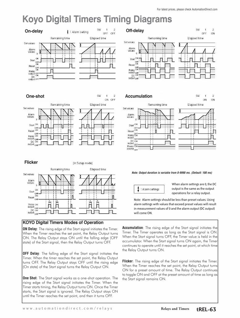
KOYO Digital Timers Modes of OperationON Delay: The rising edge of the Start signal initiates the Timer. When the Timer reaches the set point, the Relay Output turns ON. The Relay Output stays ON until the falling edge (OFF state) of the Start signal, then the Relay Output turns OFF.
OFF Delay: The falling edge of the Start signal initiates the Timer. When the timer reaches the set point, the Relay Output turns OFF. The Relay Output stays OFF until the rising edge (On state) of the Start signal turns the Relay Output ON.
One Shot: The Start signal works as a one-shot operation. The rising edge of the Start signal initiates the Timer. When the Timer starts timing, the Relay Output turns ON. Once the Timer starts, the Start signal is ignored. The Relay Output stays ON until the Timer reaches the set point, and then it turns OFF.
Accumulation: The rising edge of the Start signal initiates the Timer. The Timer operates as long as the Start signal is ON. When the Start signal turns OFF, the Timer value is held in the accumulator. When the Start signal turns ON again, the Timer continues to operate until it reaches the set point, at which time the Relay Output turns ON.
Flicker: The rising edge of the Start signal initiates the Timer. When the Timer reaches the set point, the Relay Output turns ON for a preset amount of time. The Relay Output continues to toggle ON and OFF at the preset amount of time as long as the Start signal remains ON.
Koyo Digital Timers Timing Diagrams
Note: Output duration is variable from 0-9990 ms. (Default: 100 ms)
When alarm settings are 0, the DC output is the same as the output operations for a relay output.
Note: Alarm settings should be less than preset values. Using alarm settings with values that exceed preset values will result in measurement values of 0 and the alarm output (DC output) will come ON.
On-delay Off-delay
One-shot Accumulation
Flicker
Relays and Timersw w w . a u t o m a t i o n d i r e c t . c o m / r e l a y s tREL-63
For latest prices, please check AutomationDirect.com

Features• Can operate as a digital counter, timer, combination
timer + counter or tachometer• Accepts voltage and non-voltage inputs from a wide
variety of NPN, PNP, or dry contact sensors• Selectable counting speeds from 1 to 10,000 cycles
persecond• Multiple transistor and relay outputs can operate as
momentary or maintained • Double-line, 6-digit, 2-color LCD display • Easy configuration with externally accessible DIP
switches or the lockable keypad• Display decimal point selection • Available in 100-240VAC and 24VDC powered
models • UL508 listed (E311366), cULus, CE marked
CTT Series - Digital Counter / Timer / Tachometer
The CTT series is an extremely versa-tile multi-function device that is easily configured for operation as a digital counter, timer, combination timer + counter, or tachometer. Both voltage and non-voltage inputs are accepted from a wide variety of sensor types with NPN, PNP, or dry contact outputs. The first output on the CTT is a single-pole,
single-throw relay and NPN transistor that operate concurrently. The second CTT output can be ordered as either a single-pole, double throw relay or NPN transistor. Parameters are easily set using the externally accessible DIP switches or the lockable keypad. The double-line, 6-digit, two-color LCD display shows the counter, timer, or tachometer
present values, setting values and menu parameters during set-up. Additional individual indicators are provided for inputs, outputs and functions. The stan-dard 1/16 DIN size, with included panel mounting clip and gasket, make panel mounting a snap. The CTT is available in 100-240VAC and 24VDC powered models.
Visit www.autOmatiOndirect.cOm tO dOwnlOad the free cOmprehensiVe ctt series manual.
E311366A lot of functionality in one powerful little unit!
Counter Functions Counter Input Modes Counter Output Modes
1-Stage Up Select from eleven (11) different output modes (F, N, C, R, K, P, Q, A, S, T, D)2-Stage Down
Batch Up / Command Down
Total Up/ Down
Dual Quadrature
Addition
Subtraction
Timer Functions (Up or Down)
Signal On Delay 1 Repeat Cycle
Signal On Delay 2 Repeat Cycle Hold
Signal Off Delay Repeat Cycle 2
Signal On Signal Cumulate
Power On Delay Signal Twin On-Start
Power On Delay Hold Signal Twin Off-Start
Tachometer Output Modes
Select from four (4) different output modes2Lo/1Lo2Lo/1Hi2Hi/1Lo2Hi/1Hi
Timer + Counter
Timer Functions (Up or Down) Counter Input Modes Counter Output Modes
Signal On Delay 1 Up Select from eight (8) different out-put modes (F, N, C, R, K, P, Q, A)Signal On Delay 2 Down
Signal Off Delay
Signal On
Power On Delay
Power On Delay Hold
Repeat Cycle
Repeat Cycle Hold
Counter/Timer/ Tachometer Functions
Relays and Timers 1 - 8 0 0 - 6 3 3 - 0 4 0 5tREL-64
For latest prices, please check AutomationDirect.com

0V CP1CP2/ GATE
+12V RST1RST2/ START
0V CP1CP2/ GATE
+12V RST1RST2/ START
N.O.
COM
LOAD +V0VN.C.N.O. COM
CTT-1C-D24
OUT 2
21.6 to26.4 VDC
Load
21.6 to26.4 VDC
OUT 1
OUT 2
CTT-AN-D24N.O.
COM 0V
LOAD
OUT 1
0V
LOAD 0V CP1CP2/ GATE
+12V RST1RST2/ START
0V CP1CP2/ GATE
+12V RST1RST2/ START
N.O.
COM
LOAD +V0V
CTT-1C-A120
OUT 2
AC100 to 240V50/60Hz
Load
AC100 to 240V50/60Hz
OUT 1
OUT 2
CTT-AN-A120N.O.
COM 0V
LOAD
OUT 1
0V
LOAD
N.O. COM
POW
ER S
OU
RCE
12VD
C @
100
mA
POW
ER S
OU
RCE
12VD
C @
100
mA
POW
ER S
OU
RCE
12VD
C @
100
mA
POW
ER S
OU
RCE
12VD
C @
100
mA
N.C.
109
321
1514
876
131211
54
109
321
1514
876
131211
54
109
1514
876
131211
54
109
321
1514
876
131211
54321
+- +- S S
Wiring
Digital Counter / Timer / TachometerPart Number Description Pcs/Pkg Wt (lb) Price
CTT-AN-D24 Counter / Timer / Tachometer, Output 1 NPN & SPST relay, Output 2 NPN, 24 VDC powered, panel mounting clip is included* 1 0.4 $74.00
CTT-AN-A120 Counter / Timer / Tachometer, Output 1 NPN & SPST relay, Output 2 NPN, 100-264 VAC powered, panel mounting clip is included* 1 0.4 $74.00
CTT-1C-D24 Counter / Timer / Tachometer, Output 1 NPN & SPST relay, Output 2 SPDT relay, 24 VDC powered, panel mounting clip is included* 1 0.4 $74.00
CTT-1C-A120 Counter / Timer / Tachometer, Output 1 NPN & SPST relay, Output 2 SPDT relay, 100-264 VAC powered, panel mounting clip is included* 1 0.4 $74.00
Digital Counter / Timer / Tachometer General SpecificationsInput Power Requirements 100 to 240 VAC 50/60 Hz 24 VDC
Operation Voltage Range 85 to 264 VAC 21.6 to 26.4 VDC
Power Consumption Less than 10VA
Power Source 12VDC w10%, 100mA
Display Double-line, 6-digit LCD display (SV = 8mm, PV = 6mm)
Input Signal NPN ON impedance 1K ohm max. ON residual voltage: 2V max.PNP 4.5 to 30VDC, low level: 0 to 2VDC
Output 1 Relay: SPST max. 250VAC, 5A (resistive load), 4A (inductive load); Transistor: NPN open collector. When 100mA @ 30VDC, residual voltage = 1.5VDC max
Output 2CTT-1C-xxx Relay: SPDT max. 250VAC, 5A (resistive load), 4A (inductive load)
CTT-AN-xxx Transistor: NPN open collector. When 100mA @ 30VDC residual voltage = 1.5VDC max
Life ExpectancyMechanical 10,000,000 operations (frequency 18,000 operations/hr)
Electrical 100,000 operations (frequency 900 operations/hr)
Output Switching Time 2 milliseconds max
Dielectric Strength 2000VAC 50/60 Hz for 1 minute
Vibration Resistance Without damage: 10 ~ 55 Hz, amplitude = 0.75 mm, 3 axes for 2 hours
Shock Resistance Without damage: drop 4 times, 300m/s² 3 edges, 6 surfaces and 1 corner
Ambient Temperature +32°F to +122°F (0°C to +50°C)
Storage Temperature -4°F to +149°F (-20°C to +65°C)
Altitude 2000m or less
IP Rating IP 66 (with proper enclosure installation)
Case Materials Case = ABS Plastic, Lens = Polycarbonate
Ambient Humidity 35% to 85% RH (non-condensing)
Memory Backup upon Power Failure EEPROM writing up to 100,000 times; Memory duration: 10 years
TerminalsConforming Wiring 0.25-1.65mm² (24 to 16 AWG)
Permitted Torque 0.5 N·m (0.369 ft·lb)
Agency Approvals UL508 listed (E311366), cULus, CE marked
CTT Series - Digital Counter / Timer / Tachometer
* Spare panel clips part number PANEL-16
Relays and Timersw w w . a u t o m a t i o n d i r e c t . c o m / r e l a y s tREL-65
For latest prices, please check AutomationDirect.com

MODE
45.00[1.77]
45.00[1.77]
65.00[2.56]
60.00[2.36]
1
6
11
2
7
12
3
8
13
4
9
14
5
10
15
44.80[1.76]
44.80[1.76]
6.35[0.25]
44.80[1.76]
CTT AUTOMATIONDIRECT .com
RST2
RST1 K/P2 K/P1 OUT2 OUT1
LOCK RESET
44.80[1.76]
79.35[3.12]
6.35[0.25]
47.85[1.88]
47.85[1.88]
79.35[3.12]
CTT Series Dimensionsmm [inches]
Reset 2 indicatorReset 1 indicator
Key protect 2 indicator
Output 2 indicator
Key protect 1 indicator
Output 1 indicator
Special function indicator
Lock keyReset key
Mode and number shift key
PV(Present Value) display
SV(Set Value) display
Timer function indicatorCounter function indicatorTachometer function indicator
Up/Down key
CTT AUTOMATIONDIRECT .com
Display, Indicators & Keys
LCD Display and IndicatorsRST 1/2 Light on when reset signal is detected BATCH “Batch Counting Mode” in Counter
K/P 1/2 Light on when key-protected mode is enabled SET 1 2 SV1, SV2 display
OUT 1/2 Light on when output is executing TAC Light on in Tachometer function
H M S Hour, minute, second, unit of timer, displayed in Timer function CNT Light on in Counter function
TOTAL “Total Counting Mode” in Counter function TMR Light on in Timer function
CTT Series - Digital Counter / Timer / Tachometer
Relays and Timers 1 - 8 0 0 - 6 3 3 - 0 4 0 5tREL-66
For latest prices, please check AutomationDirect.com

CTT Series - Digital Counter / Timer / Tachometer
Counter Performance SpecificationsCounter Functions 1-Stage Counting, 2-Stage Counting, Batch Counting, Total Counting, Dual Counting (See descriptions below)
Input Modes Counting Up, Counting Down, Counting Up / Command Counting Down, Counting Up / Counting Down, Quadrature, Addition, Subtraction (see descriptions below)
Output Modes F, N, C, R, K, P, Q, A, S, T, D (For explanation see the manual available at www.AutomationDirect.com)
Timer Precision Power On start max 0.01% 0.05 sec. Signal start max 0.01% 0.03 sec
Start Input Response Less than 15ms / 5ms / 1ms
External Reset Minimum reset input signal width 1ms or 20ms (selectable)
Output Duration (flicker) 10-9990ms variable every 10ms
Number of Digits 6 digits on each line
Display Current values: red LED, character height 8mm; Preset value: green LED character height 6mm
Counting up
Prohibit
01
23
4
HL
HL
0
CP1
CP2
Present Value
CP1: Counter input CP2: Counter input prohibited
Note: has to be larger than width of min. Input signal
Counting Up
With the input signal OFF at input CP2, each leadingedge of the input signal at CP1 will increment the count present value PV by 1. Turning ON the input signal at CP2 will prohibit the input signal at CP1 fromincrementing the PV.
Prohibit
01
23
45
HL
HL
0
CP1
CP2
Present Value
CP1: Counter input prohibited CP2: Counter input
Note: has to be larger than width of min. Input signal
With the input signal ON at input CP1, each trailingedge of the input signal at CP2 will increment thecount present value PV by 1. Turning OFF the inputsignal at CP1 will prohibit the input signal at CP1 fromincrementing the PV.
Counter Input Modes
1-Stage Counting A single count setting value SV is available in 1-Stage Counting. Both Outputs 1 and 2 operate concurrently and will turn ON momentarily or will be maintained ON depending on the Output Mode selected.
2-Stage Counting In 2-Stage Counting, count setting value SV1 controls Output 1 and count setting value SV2 controls Output 2. Outputs will turn ON momentarily or will be maintained ON depending on the output mode selected.
Batch Counting In Batch Counting, count setting value SV controls Output 2 which will turn ON momentarily or will be maintained ON depending on the output mode selected. Count setting value BATCH SV controls Output 1which will be maintained ON.
Total CountingA single count setting value SV is available in Total Counting. Both Outputs 1 and 2 operate concurrently and will turn ON momentarily or will be maintained ON depending on the Output Mode selected.
Dual CountingA single count setting value SV is available in Dual Counting. Both Outputs 1 and 2 operate concurrently and will turn ON momentarily or will be maintained ON depending on the Output Mode selected.
Counter Functions
Relays and Timersw w w . a u t o m a t i o n d i r e c t . c o m / r e l a y s tREL-67
For latest prices, please check AutomationDirect.com

Counting down
Prohibit
n
n-2n-1
n-4n-3
HLCP1
CP2
Present Value
0
HL
CP1: Counter input CP2: Counter input prohibited
Note: has to be larger than width of min. Input signal
Counting Down
With the input signal OFF at input CP2, each leadingedge of the input signal at CP1 will decrement the count present value PV by 1. Turning ON the input signal at CP2 will prohibit the input signal at CP1 from decrementing the PV.
With the input signal ON at input CP1, each trailingedge of the input signal at CP2 will decrement thecount present value PV by 1. Turning OFF the input signal at CP1 will prohibit the input signal at CP2 fromdecrementing the PV.
Prohibit
nn-1
n-2n-3
n-4n-5
HL
HL
CP1
CP2
0
Present Value
CP1: Counter input prohibited CP2: Counter input
Note: has to be larger than width of min. Input signal
CTT Series - Digital Counter / Timer / Tachometer
Counting Up / Command Counting Down
With the input signal OFF at input CP2, each leadingedge of the input signal at CP1 will increment thecount present value PV by 1.
With the input signal ON at input CP2, each leadingedge of the input signal at CP1 will decrement thecount present value PV by 1.
Counting Up/Command Counting Down
Counting Up / Counting Down
Each leading edge of the input signal at CP1will increment the count present value PV by 1.
Each leading edge of the input signal at CP2will decrement the count present value PV by 1.
Counting up/down
Counting Up / Counting DownEach leading edge of the input signal at CP1will increment the count present value PV by 1.
Each leading edge of the input signal at CP2will decrement the count present value PV by 1.
Quadrature input
0
1 12 2
3
HLCP1
CP2
PresentValue
0Note: has to be larger than width of 1/2 min. input signal.
HL
0
Quadrature
When the quadrature input signal at CP1leads the input signal at CP2, the trailingedge of CP2 will increment the countpresent value PV by 1.
When the quadrature input signal at CP2leads the input signal at CP1, the leading edge of CP2 will decrement the countpresent value PV by 1.
SubtractionEach leading edge of the input signal at CP1will increment the count present value PVby 1.Each leading edge of the input signal at CP2will decrement the count present value PVby 1.
AdditionEach leading edge of the input signal at CP1will increment the count present value PVby 1.Each leading edge of the input signal at CP1will increment the count present value PVby 1.
Relays and Timers 1 - 8 0 0 - 6 3 3 - 0 4 0 5tREL-68
For latest prices, please check AutomationDirect.com

CTT Series - Digital Counter / Timer / Tachometer
Timer Performance Specifications
Timer Functions Signal On Delay 1, Signal On Delay 2, Signal Off Delay, Signal On, Power On Delay, Power On Delay Hold, Repeat Cycle, Repeat Cycle Hold, Repeat Cycle 2, Signal Cumulate, Signal Twin On Start, Signal Twin Off Start (See time charts below).
Number of Digits 6 digits on each line
Display Present values: red LED, character height 8mm; Set value: green LED, character height: 6mm
Time Range
Setting Range Units Maximumsec. 0.01 ~ 9,999.99 A unit = 10ms 9,999.99 secs.
sec. 0.1 ~ 99,999.9 A unit = 0.1 sec. 99,999.9 secs.
sec. 1 ~ 999,999 A unit = 1 sec. 999,999 secs.
min., sec. 0.01 ~ 9,959.99 A unit = 0.01 sec. 5,999.99 secs.
min., sec. 0.1 ~ 99,959.9 A unit = 0.1 sec. 59,999.9 secs.
min. 0.1 ~ 99,999.9 A unit = 0.1 min. 99,999.9 mins.
min. 1 ~ 999,999 A unit = 1 min. 999,999 mins.
hr., min., sec. 1 ~ 995,959 A unit =1 sec. 359,999 secs. (100 hrs.)
hr., min. 1 ~ 999,959 A unit =1 min. 35,999,999 secs. (10,000 hrs.)
hr. 1 ~ 999,999 A unit = 1 hr. 699,999 hrs.
Display Elapsed time / remaining time
Timer Power ON start max w0.01% w0.05 sec, Signal start max w0.01% w0.03 sec
Start Input Response Less than 15ms / 5ms / 1ms
External Reset Minimum reset input signal width 1ms or 20ms (selectable)
Output Duration (flicker) 10-9990ms variable every 10ms
Timing Charts
Signal On Delay 1 (Sond1)With power applied to the CTT, the leading edge of the input signal at START will begin the timing period setting value SV (timing up or down based on parameter (t modE) or by DIP switch 2). At the end of the timing period both outputs will turn ON momentarily for the time set in the output pulse width parameter (tout1) or will be maintained ON if the output pulse width parameter (tout1) is set to 0.00. The trailing edge of the “start” signal has no effect on the outputs or timing period.
The leading edge of a “reset” input signal at RST1 will turn OFF the outputs and reset the timing period. The “reset” signal minimum pulse width is set by reset pulse width param-eter ( rtSr ) or DIP Switch 8.
The leading edge of a “pause” input signal at GATE will pause the timing period after it has been started. The timing period will continue after the trailing edge of the external switch “pause” (Gate) signal.
When power is removed, both outputs will turn OFF and the timing period will be reset.
Power signal
Start signal
Pause signal
Reset
Up
Down0
0
SV
SV
Signal On Delay 1
t tOutput signal
Relays and Timersw w w . a u t o m a t i o n d i r e c t . c o m / r e l a y s tREL-69
For latest prices, please check AutomationDirect.com

CTT Series - Digital Counter / Timer / TachometerSignal On Delay 2 (Sond2)
With power applied to the CTT, the leading edge of the input signal at START will begin the timing period setting value SV (timing up or down based on parameter (t modE) or by DIP switch 2). At the end of the timing period both outputs will turn ON momentarily for the time set in the output pulse width parameter (tout1) or will be maintained ON if the output pulse width parameter (tout1) is set to 0.00. The trailing edge of the “start” signal will turn OFF the outputs and reset the timing period.
The leading edge of a “reset” input signal at RST1 will turn OFF the outputs and reset the timing period. The “reset” signal minimum pulse width is set by reset pulse width parameter ( rtSr ) or DIP Switch 8.
The leading edge of a “pause” input signal at GATE will pause the timing period after it has been started. The timing period will continue after the trailing edge of the external switch “pause” (Gate) signal.
When power is removed, both outputs will turn OFF and the timing period will be reset.
Power signal
Start signal
Pause signal
Reset
Output signal
Up
Down
0
0
SV
SV
Signal On Delay 2
tt
Signal Off Delay (Soffd)With power applied to the CTT, the leading edge of the input signal at START will immediately turn ON the outputs. The trailing edge of the “start” signal will begin the timing period setting value SV (timing up or down based on parameter (t modE) or by DIP switch 2). At the end of the timing period both outputs will turn OFF. The leading edge of a “start” signal applied during a previously initiated timing period will reset the timing period.
The leading edge of a “reset” input signal at RST1 will turn OFF the outputs and reset the timing period. The “reset” signal minimum pulse width is set by reset pulse width parameter ( rtSr ) or DIP Switch 8.
The leading edge of a “pause” input signal at GATE will pause the timing period after it has been started. The timing period will continue after the trailing edge of the external switch “pause” (Gate) signal.
When power is removed, both outputs will turn OFF and the timing period will be reset.
Power signal
Start signal
Pause signal
Reset
Output signal
SV
0Up
DownSV
0Signal Off Delay
Signal On (Son)With power applied to the CTT, the leading edge of the input signal at START will immediately turn ON the outputs and begin the timing period setting value SV (timing up or down based on parameter (t modE) or by DIP switch 2). The trailing edge of the “start” signal has no effect on the outputs or timing period. At the end of the timing period both outputs will turn OFF and the timing period will reset. The leading edge of a “start” signal applied during a previ-ously initiated timing period will not reset the timing period.
The leading edge of a “reset” input signal at RST1 will turn OFF the outputs and reset the timing period. The “reset” signal minimum pulse width is set by reset pulse width parameter ( rtSr ) or DIP Switch 8.
The leading edge of a “pause” input signal at GATE will pause the timing period after it has been started. The timing period will continue after the trailing edge of the external switch “pause” (Gate) signal.
When power is removed, both outputs will turn OFF and the timing period will be reset.
Power signal
Start signal
Pause signal
Reset
Output signal
SV
0Up
DownSV
0Signal On
Relays and Timers 1 - 8 0 0 - 6 3 3 - 0 4 0 5tREL-70
For latest prices, please check AutomationDirect.com

CTT Series - Digital Counter / Timer / TachometerPower On Delay (Pond)
When power is applied to the CTT, the timing period setting value SV will begin (timing up or down based on parameter (t modE). At the end of the timing period both outputs will turn ON momentarily for the time set in the output pulse width parameter (tout1) or will be maintained ON if the output pulse width parameter (tout1) is set to 0.00.
The leading edge of a “reset” input signal at RST1 will turn OFF the outputs and reset the timing period. The “reset” signal minimum pulse width is set by reset pulse width parameter ( rtSr ).
The leading edge of a “pause” input signal at GATE or signal at START will pause the timing period after it has been started. The timing period will continue after the trailing edge of the external switch “pause” (Gate) or “start” signal.
When power is removed, both outputs will turn OFF and the timing period will be reset.
Power signal
Start signal
Pause signal
Reset
Output signal
Up
Down
SV
SV
0
0Power On Delay
t t t
Power On Delay HOLD (PondH)When power is applied to the CTT, the timing period setting value SV will begin (timing up or down based on parameter (t modE). At the end of the timing period both outputs will turn ON momentarily for the time set in the output pulse width parameter (tout1) or will be maintained ON if the output pulse width parameter (tout1) is set to 0.00.
The leading edge of a “reset” input signal at RST1 will turn OFF the outputs and reset the timing period. The “reset” signal minimum pulse width is set by reset pulse width parameter ( rtSr ).
The leading edge of a “pause” input signal at GATE or signal at START will pause the timing period after it has been started. The timing period will continue after the trailing edge of the “pause” (Gate) or “start” signal.
When power is removed, both outputs will turn OFF. The last state of the outputs and the last value of the current timing period will be “stored” in eeprom when power is removed. When power is reapplied the outputs will return to their last state and timing will resume from the last value of the timing period.
Power signal
Start signal
Pause signal
Reset
Output signal
Up
DownSV
SV
0
0Power On Delay Hold
t t t t
Relays and Timersw w w . a u t o m a t i o n d i r e c t . c o m / r e l a y s tREL-71
For latest prices, please check AutomationDirect.com

Power signal
Start signal
Pause signal
Reset
Output signal
Up
DownSV
SV
0
0Repeat Cycle Hold Timer output set as 0
Power signal
Start signal
Pause signal
Reset
Output signal
Up
DownSV
SV
0
0RCYH timer output not set as 0
t t t
CTT Series - Digital Counter / Timer / TachometerRepeat Cycle (rCy)
With power applied to the CTT, the leading edge of the input signal at START will begin the timing period setting value SV (timing up or down based on parameter (t modE). At the end of the timing period, the timing period will reset and repeat automatically.
If the output pulse width parameter (tout1) is set to 0.00 both outputs will turn ON at the end of the first timing period, turn OFF at the end of the next timing period, turn ON at the end of the next timing period, etc.
If the output pulse width parameter (tout1) is set to >0.00 both outputs will turn ON momentarily for the time set in the output pulse width parameter (tout1) at the beginning of the each timing period.
The trailing edge of the “start” signal has no effect on the outputs or timing period.
The leading edge of a “reset” input signal at RST1 will turn OFF the outputs and reset the timing period. The “reset” signal minimum pulse width is set by reset pulse width parameter ( rtSr ). The leading edge of a new “start” signal is necessary to restart the cycle.
The leading edge of a “pause” input signal at GATE will pause the timing period after it has been started. The timing period will continue after the trailing edge of the external switch “pause” (Gate) signal.
When power is removed, both outputs will turn OFF and the timing period will be reset.
Power signal
Start signal
Pause signal
Reset
Output signal
Up
DownSV
SV
Repeat Cycle
0
0timer output set as 0
Power signal
Start signal
Pause signal
Output signal
Up
Down SV
SV
Repeat Cycle
ttt
timer output not set as 0
Reset
Repeat Cycle HOLD (rCyH)With power applied to the CTT, the leading edge of the input signal at START will begin the timing period setting value SV (timing up or down based on parameter (t
modE). At the end of the timing period, the timing period will reset and repeat automatically.
If the output pulse width parameter (tout1) is set to 0, both outputs will turn ON at the end of the first timing period, turn OFF at the end of the next timing period, turn ON at the end of the next timing period, etc.
If the output pulse width parameter (tout1) is set to >0.00, both outputs will turn ON momentarily for the time set in the output pulse width parameter (tout1) at the beginning of the each timing period.
The trailing edge of the “start” signal has no effect on the outputs or timing period.
The leading edge of a “reset” input signal at RST1 will turn OFF the outputs and reset the timing period. The “reset” signal minimum pulse width is set by reset pulse width parameter ( rtSr ). The leading edge of a new “start” signal is necessary to restart the cycle.
The leading edge of a “pause” input signal at GATE will pause the timing period after it has been started. The timing period will continue after the trailing edge of the external switch “pause” (Gate) signal.
When power is removed, both outputs will turn OFF. The last state of the outputs and the last value of the current timing period will be “stored” in Eeprom when power is removed. When power is reapplied the outputs will return to their last state and timing will resume from the last value of the timing period by the leading edge of a new “start” signal.
Relays and Timers 1 - 8 0 0 - 6 3 3 - 0 4 0 5tREL-72
For latest prices, please check AutomationDirect.com

CTT Series - Digital Counter / Timer / TachometerRepeat Cycle 2 (rCy2)
With power applied to the CTT, the leading edge of the input signal at START will begin the timing period timing up or down based on parameter (t modE). At the end of the timing period, the timing period will reset and repeat automatically.
Both outputs will turn ON at the beginning of the first timing period and turn OFF when the timing period reaches time period setting SV2. The outputs will turn ON again when the time period reaches time period setting SV1.
The trailing edge of the “start” signal has no effect on the outputs or timing period.
The leading edge of a “reset” input signal at RST1 will turn OFF the outputs and reset the timing period. The “reset” signal minimum pulse width is set by reset pulse width parameter ( rtSr ). The leading edge of a new “start” signal is neces-sary to restart the cycle.
The leading edge of a “pause” input signal at GATE will pause the timing period after it has been started. The timing period will continue after the trailing edge of the external switch “pause” (Gate) signal.
When power is removed, both outputs will turn OFF and the timing period will be reset.
Power signal
Start signal
Pause signal
Reset
Output signal
Up
DownSV1
SV1
SV2
SV2
0
0
Repeat Cycle 2
Signal Cumulate (SCon)With power applied to the CTT, the leading edge of the input signal at START will begin the timing period setting value SV timing up or down based on parameter (t modE). The trailing edge of the “start” signal will pause the timing period. The leading edge of a subsequent “start” signal will resume timing from the last value of the timing period. At the end of the timing period both outputs will turn ON.
The leading edge of a “reset” input signal at RST1 will turn OFF the outputs and reset the timing period. The “reset” signal minimum pulse width is set by reset pulse width parameter ( rtSr ).
The leading edge of a “pause” input signal at GATE will pause the timing period after it has been started. The timing period will continue after the trailing edge of the external switch “pause” (Gate) signal.
When power is removed, both outputs will turn OFF. The last state of the outputs and the last value of the current timing period will be “stored” when power is removed. When power is reapplied the outputs will return to their last state and timing will resume from the last value of the timing period by the leading edge of a new “start” signal.
Power signal
Start signal
Pause signal
Reset
Output signal
Up
Down0
SV
SV
0
Signal Cumulate
Relays and Timersw w w . a u t o m a t i o n d i r e c t . c o m / r e l a y s tREL-73
For latest prices, please check AutomationDirect.com

CTT Series - Digital Counter / Timer / TachometerSignal Twin ON-Start (Ston)
With power applied to the CTT, the leading edge of the input signal at START will turn ON the outputs and begin the timing period timing up or down based on parameter (t modE). When the timing period reaches time setting SV2 the outputs will turn OFF and the time period will reset and restart automatically. When the time period now reaches time setting SV1 the outputs will turn ON again and the time period will reset and repeat automatically.
The trailing edge of the “start” signal has no effect on the outputs or timing period.
The leading edge of a “reset” input signal at RST1 will turn OFF the outputs and reset the timing period. The “reset” signal minimum pulse width is set by reset pulse width parameter ( rtSr ). The leading edge of a new “start” signal is necessary to restart the cycle.
The leading edge of a “pause” input signal at GATE will pause the timing period after it has been started. The timing period will continue after the trailing edge of the external switch “pause” (Gate) signal.
When power is removed, both outputs will turn OFF and the timing period will be reset.
Power signal
Start signal
Pause signal
Reset
Output signal
Up
Down
SV1
SV2
SV1
0
0
SV2
Signal Twin ON-Start
Signal Twin OFF-Start (StoFF)With power applied to the CTT, the leading edge of an input signal at START will begin the timing period timing up or down based on parameter (t modE). When the timing period reaches time setting SV1 the outputs will turn ON and the time period will reset and restart auto-matically. When the time period now reaches time setting SV2 the outputs will turn OFF again and the time period will reset and repeat automatically.
The trailing edge of the “start” signal has no effect on the outputs or timing period.
The leading edge of a “reset” input signal at RST1 will turn OFF the outputs and reset the timing period. The “reset” signal minimum pulse width is set by reset pulse width parameter ( rtSr ). The leading edge of a new “start” signal is necessary to restart the cycle.
The leading edge of a “pause” input signal at GATE will pause the timing period after it has been started. The timing period will continue after the trailing edge of the external switch “pause” (Gate) signal.
When power is removed, both outputs will turn OFF and the timing period will be reset.
Power signal
Start signal
Pause signal
Reset
Output signal
Up
Down
SV1
SV1
SV2
SV20
0
Signal Twin OFF-Start
Relays and Timers 1 - 8 0 0 - 6 3 3 - 0 4 0 5tREL-74
For latest prices, please check AutomationDirect.com

Tachometer Performance SpecificationsOutput Modes 2Lo1Lo, 2Lo1Hi, 2Hi1Lo, and 2Hi1Hi (See tachometer output mode charts below).
Number of Digits 6 digits on each line
Input Frequency 1Hz, 30Hz, 200Hz, 1kHz, 5kHz, 10kHz
Display Present values: red LED, character height: 8mm; Set value: green LED, character height: 6mm
Timer Precision Power ON start Max w 0.01% w0.05 sec, Signal start Max w0.01% w0.03
Start Input Response Less than 15ms / 5ms / 1ms
External Reset Minimum reset input signal width 1ms or 20ms (selectable)
Output Duration (Flicker) 10-9990ms variable every 10ms
iH1oL2 oL1oL2
OUT2 set value
Measurement value
OUT1 set value
OUT1
OUT2OUT1 set value : OUT1 ON
Measurement value OUT2 set value : OUT2 ON
(LO-LO)
OUT2 set value
Measurement value
OUT1 set value
OUT1
OUT2
Measurement value OUT1 set value : OUT1 ONMeasurement value OUT2 set value : OUT2 ON
(LO-HI)
iH1iH2 oL1iH2
OUT2 set value
Measurement value
OUT1 set value
OUT1
OUT2
(HI-LO)
Measurement value OUT1 set value : OUT1 ONMeasurement value OUT2 set value : OUT2 ON
OUT2 set value
Measurement value
OUT1 set value
OUT1
OUT2
(HI-HI)
Measurement value OUT1 set value : OUT1 ONMeasurement value OUT2 set value : OUT2 ON
Counter Example: Using the counter feature of the CTT to count the total number of pieces in a box to signal a conveyor to advance to the next station.
Counting Input
Output 1
ResetCount
CTT Series - Digital Counter / Timer / Tachometer
Tachometer Output Mode Charts
Relays and Timersw w w . a u t o m a t i o n d i r e c t . c o m / r e l a y s tREL-75
For latest prices, please check AutomationDirect.com

Output 1
Reset
Output 1
ResetLimitSwitchStartsTimer
Timer Example:A basic Timer used to control the clamp time of a compression model press. When the operator signals, the mold is loaded with material. When a start button is pressed, the hydraulic cylinder closes the press to make a limit switch which starts the CTT timing. Upon completion of the timer cycle, Output 1 is turned on and the press is opened by the hydraulic cylinder.
Tachometer Example:Using PSCALE to convert pulses into engineering units
The PSCALE feature of the CTT is very useful in converting the pulsed signal from an encoder or sensor into a usable unit of measurement.
For example, if connecting a proximity switch to the CTT to monitor the speed of a motor using a sensing gear, there is a simple calculation to convert the pulses from the sensor to Motor RPMs.
Using the following formula, you can calculate a PSCALE value to change a pulse signal into RPMs. First, obtain the pulses per revolution (ppr) or number of teeth on the sensing gear.
For example, in the illustration below, there are 38 teeth on the gear or 38 ppr. If the gear is coupled directly to the motor, this is all that is required to perform the calculation.
PSCALE = 60/ppr or 60/38
PSCALE = 1.579
With the PSCALE set to 1.579 for every 38 input cycles the CTT will display a value of 1.
CTT Series - Digital Counter / Timer / Tachometer
Relays and Timers 1 - 8 0 0 - 6 3 3 - 0 4 0 5tREL-76
For latest prices, please check AutomationDirect.com