WAN2 - Frame Relay - TU Wien, ICT
53
-
Upload
khangminh22 -
Category
Documents
-
view
0 -
download
0
Transcript of WAN2 - Frame Relay - TU Wien, ICT

1
2005/03/11(C) Herbert Haas
Frame Relay
Bigger, Longer, Uncut
2
2(C) Herbert Haas 2005/03/11
What is Frame Relay?
� Connection-oriented packet switching
(Virtual Circuit)
� WAN Technology
� Specifies User to Network Interface (UNI)
� Does notnot specify network itself (!)
Sounds
like X.25 ...?
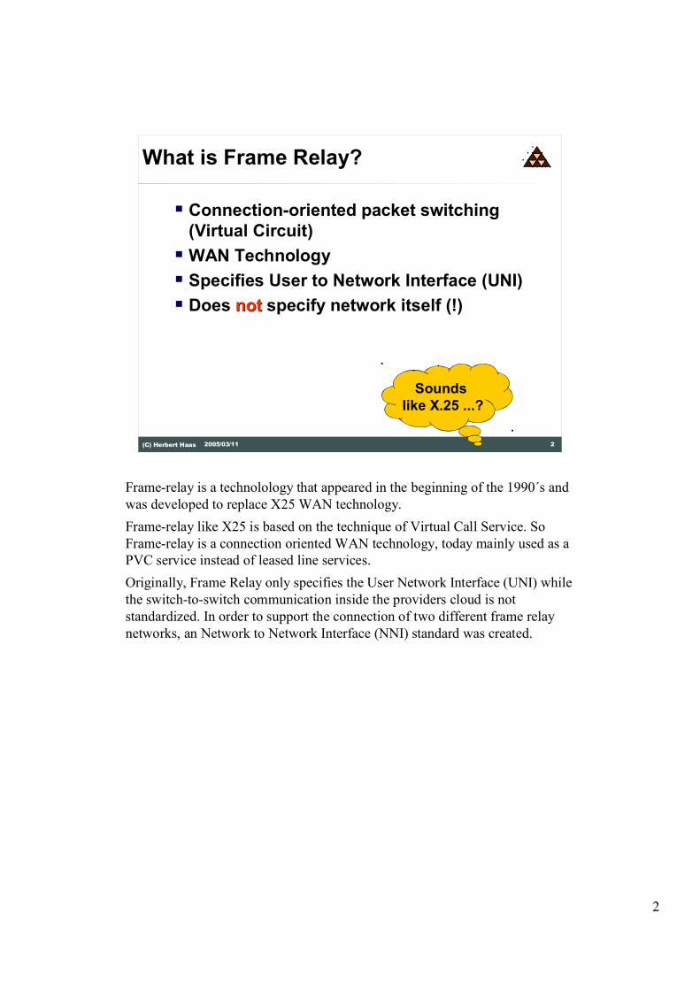
Frame-relay is a technolology that appeared in the beginning of the 1990´s and
was developed to replace X25 WAN technology.
Frame-relay like X25 is based on the technique of Virtual Call Service. So
Frame-relay is a connection oriented WAN technology, today mainly used as a
PVC service instead of leased line services.
Originally, Frame Relay only specifies the User Network Interface (UNI) while
the switch-to-switch communication inside the providers cloud is not
standardized. In order to support the connection of two different frame relay
networks, an Network to Network Interface (NNI) standard was created.

3
3(C) Herbert Haas 2005/03/11
Basic Difference to X.25
� Reduced overhead
� No error recovery (!)
� Hence much faster
� Requires reliable links (!)
� Outband signaling
� Good for bursty and variable traffic
� Quality of Service Ideas
� Congestion control
The most important difference to X.25 is the lack of error recovery and flow
control. Note that X.25 performs error recovery and flow control on each link
(other than TCP for example). Obviously this extreme reliable service suffers
on delays. But Frame Relay is an ISDN application�and ISDN provides
reliable physical links, so why use ARQ techniques on lower layers at all?
The second important difference is that X.25 send virtual circuit service
packets and data packets in the same virtual circuit. This is called "Inband
Signaling". Frame Relay establishes a dedicated virtual circuit for signaling
purposes only.
Thirdly, Frame Relay can deal with traffic parameters such as "Committed
Information Rate" (CIR) and "Ecxess Information Rate" (EIR). That is, the
Frame Relay provider guarantees the delivery of data packets below the CIR
and offers at least a best-effort service for higher data rates. We will discuss
this later in much greater detail.
And finally, although Frame Relay does not retransmit dropped frames, the
network at least responds with congestion indication messages to choke the
user's traffic.
Basically, Frame Relay can be viewed as a streamlined version of X.25,
especially tuned to achieve low delays.

4
4(C) Herbert Haas 2005/03/11
History of Frame Relay
� First proposals 1984 by CCITT� Original plan was to put Frame Relay on top of
ISDN
� Slow progress
� 1990: Cisco, Northern Telecom, StrataCom, and DEC founded the Gang of Four (GoF)� Focus on Frame-Relay development
� Collaborating with CCITT
� ANSI specified Frame Relay for USA
� GoF became Frame Relay Forum (FRF)� Joined by many switch manufacturers
In 1988 the ITU-T recommendation I.122 had been released, entitled
"Frameworking for Providing Additional Packet Mode Bearer Services", today
known as "Frame Mode Bearer Service", or simply "Frame Relay". I.233
describes Frame Relay between two S/T reference points.
Due to the slow standartization process by the ITU-T formerly the CCITT a
private organization the Gang of Four (GOF) or Frame Relay Forum was
founded to push the developments of new Frame-relay standards.
Additionally the ANSI came up with its own Frame-relay standards for the US
market. Though we have the situation today that there are three different
standartization institutes with in some parts of the Frame-relay technique
different standards.

5
5(C) Herbert Haas 2005/03/11
Frame Relay Network
UNI
FR DTEFR DTE
FR DTE
FR DTE
Frame Relay
Network
FR DCE
FR DCE
FR DCE
FR DCE
The network consists of four components:
1) Data terminal equipment (DTE), which is actually the user device and the
logical Frame-relay end-system
2) Data communication equipment (DCE, also called data circuit-terminating
equipment), which consists of modem and packet switch
3) Packet Switching Exchange (PSE), or simple: the packet switch itself.
4) The provider cloud which is not covered by the Frame-relay standard


7
7(C) Herbert Haas 2005/03/11
Logical Channels (2)
� Data Link Connection Identifier
(DLCI)
� Identifies connection
� Only locally significant
� Some implementation support so-
called "Global addresses"
� Actually also locally significant
� Destination address = DLCI
The virtual circuit identifiers are called Data Link Connection Identifiers
(DLCI) in Frame-relay technique. Ten bit in the Frame-relay header are
reserved for the DLCI, so up to 1024 different DLCI values are possible. Some
of them are reserved by the different standards for signaling and congestion
indication.
Some implementation of Frame-relay even support so called �global
addresses�, where the DLCI might be used as a Destination address.


9
9(C) Herbert Haas 2005/03/11
Addressings for SVCs
� (Public) FR networks using SVCs use
either
� X.121 addresses (X.25)
� E.164 addresses (ISDN)
� Advantage of X.121 addresses:
� Contain DNICs (Data Network
Identification Codes) which are
obligatory
Although only a few service providers offer SVC Frame Relay service it is still
possible and part of the standard. In order to establish an SVC a DTE must
know a globally unique host address of the destination. Typically, the X.121 or
E.164 address plans are also utilized for Frame Relay. Don't confuse X.121
and E.164 addresses with the priviously mentioned global addresses.

10
10(C) Herbert Haas 2005/03/11
NNI (1)
FR Net
Provider X
FR Net
Provider Y
NNI
UNI UNI
· NNI had been defined to connect
different Frame Relay networks
together
· Example: Public FR Net with Private
Due to the fact that the Frame-relay standards to not cover the Frame-relay
cloud itself a Frame-relay Network to Network Interface (NNI) was
standardized to allow the connection of different Frame-relay networks under
the use of different vendor equipment. The NNI interface standardizes the FR-
DCE to FR-DCE communication e.g. in the case of connection a private
Frame-relay network to a public Frame-relay network.

11
11(C) Herbert Haas 2005/03/11
NNI (2)
DLCI 100
DLC
I 200
DLCI 10
DLCI 20
DLCI 500
DLC
I 600
· Sequence of DLCIs associated to
each VC
By the use of the Frame-relay NNI interface a sequence of DLCI´s is
established which represent the virtual connection. This means the connection
between two FR-DTE´s with each other is determined by a sequence of DLCI´s
like in our example DLCI 200 � 20 � 600.
The DLCI number in the Frame-relay header is changed appropriately by the
UNI and NNI interface, when a Frame-relay frame travels through the network.

12
12(C) Herbert Haas 2005/03/11
Outband Signaling
Signaling (DLCI 0 or 1023)
VC (DLCI 100)
VC (DLCI 200)
VC (DLCI 300)
DTE DCE
"Local Management Interface" (LMI)
· Signaling through dedicated virtual
ciruit = "Outband Signaling"
· Signaling protocol is LMI
The Local Management Interface (LMI) was developed to inform the Frame-
relay users about the condition of the Frame-relay network itself.
With the LMI protocol the addition, deletion and status of DLCI´s can be
announced by the Frame-relay provider to the users.
Unfortunately LMI is differently implemented by the standardization
organizations. All of them use LMI out-band signaling but on different DLCI´s
and with partly different functionality.
The ITU-T with its Q922 Annex A standard is using DLCI 0 as well as the
ANSI with its T1.617 Annex D. Both standards only allow the announcement
of addition deletion and the status (active or inactive) of a PVC.
The FRF uses DLCI 1023 for LMI service and allows additionally the
announcement of bandwidth and flow control parameters.
13
13(C) Herbert Haas 2005/03/11
ITU-T PVC Service Model
Control-Plane(PVC-LMI)
User-Plane(PVC)
I.430
I.431
Q.922 DL-core
(LAPF)
User
specified
Q.933
Annex A
Q.922 DL-core
(LAPF)
Annex A is
for PVC only
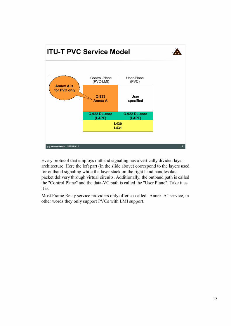
Every protocol that employs outband signaling has a vertically divided layer
architecture. Here the left part (in the slide above) correspond to the layers used
for outband signaling while the layer stack on the right hand handles data
packet delivery through virtual circuits. Additionally, the outband path is called
the "Control Plane" and the data-VC path is called the "User Plane". Take it as
it is.
Most Frame Relay service providers only offer so-called "Annex-A" service, in
other words they only support PVCs with LMI support.

14
14(C) Herbert Haas 2005/03/11
ITU-T SVC Service Model
Control-Plane(SVC)
User-Plane(SVC)
I.430
I.431
Q.922 DL-core
(LAPF)
User
specified
Q.933
Q.922 DL-core
(LAPF)
Q.922 DL-upper
Error recovery
and
Flow control
But Frame Relay can also support SVC services. In this case we don't use
Annex A but rather plain "Q.933". Furthermore SVC mode requires a reliable
Q.922 connection to the DCE, which is handled by the so-called "Q.922 DL-
upper". The Frame Relay layer itself is the Q.022 DL-core layer, which must be
always existent.

15
15(C) Herbert Haas 2005/03/11
Layer Description
� LAPF is a modified LAPD (ISDN)
� Specified in Q.922
� Q.922 consists of
� Q.922 core (DLCIs, F/BECN, DE, CRC)
� Q.922 upper (ARQ and Flow Control)
� Q.933 is based on Q.931 (ISDN)
� Annex A for PVC management (LMI)
The Link Access Procedure Frame-relay (LAPF) is a modified variant of the
Link Access Procedure D-channel (LAPD) used on the D-channel by ISDN to
reliable transport Q931 signaling messages.
The LAPF protocol is divided in two sub variants, the Q922 core which is used
for PVC service with LMI status reports, and the Q922 upper used with Frame-
relay SVC technique for the reliable transport of Q933 Frame-relay signaling
messages.
The Q933 is based on the Q931 signaling protocol and it supports the
connection setup and tear down of Frame-relay SVC´s by the help of E164 or
X121 addresses. The Q933 Annex A is used in combination with PVC services
only.

16
16(C) Herbert Haas 2005/03/11
ANSI PVC Service Model
Control-Plane(PVC-LMI)
User-Plane(PVC)
ANSI Physical Layer Standards
T1.618
User
specified
T1.617
Annex D
T1.618
Annex D here
(instead of
Annex A)
In this slide the corresponding standards of the ANSI committee for Frame-
relay PVC service can be seen. The ANSI standard T1.618 describes the basic
Frame-relay frame with DLCI, BECN, FECN, etc. and it corresponds to the
Q922 core standard from the ITU-T.
The T1.617 Annex D standards describes the LMI service and can be seen
equivalent to the Q933 Annex A standard from the ITU-T.

17
17(C) Herbert Haas 2005/03/11
ANSI SVC Service Model
Control-Plane(SVC)
User-Plane(SVC)
ANSI Physical Layer Standards
T1.618
User
specified
T1.617
T1.602
The ANSI T1.602 standard is equivalent to the ITU-T Q922 core + upper
standard and supports the reliable transport of signaling messages to set up
Frame-relay SVC´s.
The T1.617 is equivalent to the Q933 standard and uses E164 and X121
addresses for the set up of SVC´s.

18
18(C) Herbert Haas 2005/03/11
ANSI Layer Description
� T1.602 specifies LAPD� Based on Q.921
� T1.618 is based on a subset of T1.602 called the "core aspects"� DLCIs, F/BECN, DE, CRC
� T1.617� Signaling specification for Frame Relay
Bearer Service
� Annex D for PVCs (LMI)
This is a summary of the ANSI Frame-relay standards discussed so far.

19
19(C) Herbert Haas 2005/03/11
Frame Relay Forum (FRF)
FRF.1.1 User to Network Interface (UNI)FRF.2.1 Network to Network Interface (NNI)FRF.3.1 Multiprotocol EncapsulationFRF.4 SVCFRF.5 FR/ATM Network InterworkingFRF.6 Customer Network Management (MIB)FRF.7 Multicasting Service DescriptionFRF.8 FR/ATM Service InterworkingFRF.9 Data CompressionFRF.10 Network to Network SVCFRF.11 Voice over Frame RelayFRF.12 FragmentationFRF.13 Service Level AgreementsFRF.14 Physical Layer InterfaceFRF.15 End-to-End MultilinkFRF.16 Multilink UNI/NNI
This list gives us an overview of the standards published by the FRF.
The FRF.1.1 standard describes the UNI interface and can be seen in
combination with the FRF.4 standard as an equivalent to the Q922, Q933
standard of the ITU-T.
The FRF.2.1 standard specifies the connection of Frame-relay DCE to DCE for
mixed vendor support.
The FRF.11 describes the direct transport of voice on top of Frame-relay
frames and the FRF.12 deals with fragmentation. The FRF.11 and the FRF.12
are needed in combination to establish voice over Frame-relay networks.

20
20(C) Herbert Haas 2005/03/11
Voice over FR
� VoFR Standard FRF.11 (Annex C)� Multiple subframes in a single FR-Frame
� 30 Byte Voice Payload per subframe
� Additional identifier CID (Channed ID) to identify separate streams
� Dedicated CID for signaling (Cisco: CID 0)
� Voice + Data in same PVC: Delay Problem� Solution: FRF.12 (Fragmentation)
� Data packets are fragmented and interleaved with voice packets
� Voice-frames should keep "inter-frame-delay" <10ms
� Adjustments of fragment-size based on AR � Cisco: fr-fragment-size
The FRF.11 standard describes how multiple voice communication channels
can be transported across a Frame-relay network. The voice channels are
packed into separate subframes, of up to 30 byte in length ,with an additional
FRF.11 header in front of them. The FRF.11 header carries a Channel ID (CID)
which is needed to distinguish between the different voice channels. Several
subframes can be transported by one Frame-relay frame depending on the
maximum allowed frame size.
Here the FRF.12 standards comes into play, because the size of the Frame-relay
frames needs to be reduced to adopt to the delay and jitter requirements needed
by voice communication. Normally Frame-relay depending on the standard
allows max. payload sizes between 1600 to 8192 bytes. In Voice over Frame-
relay systems the maximum payload size is configurable between 16 and 1600
bytes. Cisco uses a default value of 53 bytes.

21
21(C) Herbert Haas 2005/03/11
Physical Interfaces
� Some UNI Specifications (FRF.1)� ITU-T G.703 (2.048 Mbps)
� ITU-T G.704 (E1, 2.048 Mbps)
� ITU G.703 (E3, 34.368 Mbps)
� ITU-T X.21
� ANSI T1.403 (DS1, 1.544 Mbps)
� ITU-T V.35
� ANSI/EIA/TIA 613 A 1993 High Speed Serial Interface (HSSI, 53 Mbps)
� ANSI T1.107a (DS3, 44.736 Mbps)
� ITU V.36/V.37 congestion control
Frame-relay is a typical Data-link technology which can be used on top of
many different layer 1 techniques. In this graphic a short overview of the most
common used layer 1 techniques in combination with Frame-relay is shown.

22
22(C) Herbert Haas 2005/03/11
Layer 2 Tasks
� Q.922 Annex A (LAPF) or T1.618 specifies
� Frame multiplexing according DLCI
� Frame alignment (HDLC Flag)
� Bit stuffing
� 16-bit CRC error detection but no correction
� Checks minimum size and maximum frame
size
� Congestion control
The Q922 Annex A or the T1.618 ANSI cover following tasks:
�Both describe the multiplexing of different communication channels on one
physical connection by the help of the according DLCI.
�Frame alignment which means start and end of frame detection plus
synchronization with the help of the HDLC flag.
�Bit stuffing to prevent the appearance of the Flag bit pattern inside the payload
area of the frame.
�16 bit Cycle Redundancy Check for error detection inside the Frame-relay
network. Frames in error will be discarded only, there are no error recovery
functions implemented.
�Determination of maximum and minimum Frame-relay frame sizes depending
on the configurations (e.g. voice)
�Congestion control and indication with the help of the FECN, BECN bits or
the CLLM system.

23
23(C) Herbert Haas 2005/03/11
The Frame Relay Frame
Flag Header Information FCS
DLCI (MSB)
Flag
C/R EA DLCI (LSB)FE
CN
BE
CNDE EA
1234567812345678
Legend:Legend:DLCI Data Link Connection Identifier
C/R Command/Respond
EA Extended Addressing
FECN Forward Explicit Congestion Notification
BECN Backward Explicit Congestion Notification
DE Discard Eligibility
1 2 2 1
The DLCI field length is typically 10 bits. Optionally, it can be extended using
the EA bit (max 16 bits according FRF and GOF). The EA bits are used such
that the first and middle DLCI address octets are indicated by EA=0 whereas
the last address octet is indicated by EA=1.
Note that the second address octet always contains:
�The FECN, BECN, and DE bit. Currently only 10 bit DLCIs are supported,
but the EA flag allows the use of longer DLCIs in the future. Today, MPLS
utilizes the Extended Address field of the FR header.
�The C/R bit is a rudimentary bit, inherited from HDLC. It is not used within
Frame Relay!
According to FRF, the maximum length of the information field is 1600 bytes.
The other standards allow lengths up to 8192 (theoretically) but the CRC-16
only protects 4096 bytes. Practically, maximimum frame siztes of up to 1600
bytes are used.
The usage of the FECN and BECN bit is explained in a few seconds...

24
24(C) Herbert Haas 2005/03/11
Congestion Control (1)
� FECN indicates congestion to the receiver
� BECN indicates congestion to the sender
� Problem: DTEs do not need to react (!)
FECN
BECN
congested
The Frame-relay network is able to indicate congestion situations to its users
by the help of the BECN and FECN bit located in the Frame-relay header.
With the help of these two bits not only a congestion situation but also the
direction of the congestion can be indicated. In the direction of the congestion
the FECN bit in the Frame-relay header of the by passing packets is set, by the
congested Frame-relay switch, while in the opposite direction the BECN bit
will be set.
25
25(C) Herbert Haas 2005/03/11
Congestion Control (2)
� Routers can be configured to react
upon receiving a BECN
� Only a few higher layer protocols
react upon receiving a FECN
� Only some OSI and ITU-T protocols
� TCP does not
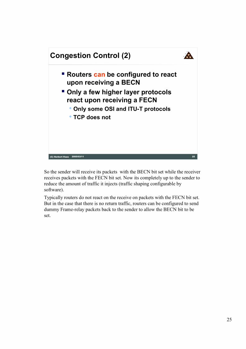
So the sender will receive its packets with the BECN bit set while the receiver
receives packets with the FECN bit set. Now its completely up to the sender to
reduce the amount of traffic it injects (traffic shaping configurable by
software).
Typically routers do not react on the receive on packets with the FECN bit set.
But in the case that there is no return traffic, routers can be configured to send
dummy Frame-relay packets back to the sender to allow the BECN bit to be
set.
26
26(C) Herbert Haas 2005/03/11
CLLM
� Consolidated Link Layer Management
� ITU-T and ANSI development
� Optional out-band signaling for
congestion indication messages
� DLCI 1023
� Before congestion, DCE sends CLLM
message to DTE
� Associated DLCIs specified
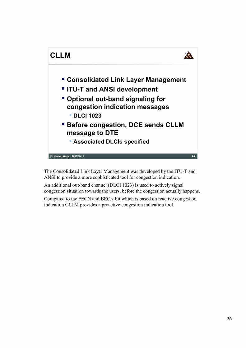
The Consolidated Link Layer Management was developed by the ITU-T and
ANSI to provide a more sophisticated tool for congestion indication.
An additional out-band channel (DLCI 1023) is used to actively signal
congestion situation towards the users, before the congestion actually happens.
Compared to the FECN and BECN bit which is based on reactive congestion
indication CLLM provides a proactive congestion indication tool.

27
27(C) Herbert Haas 2005/03/11
CLLM Message
� CLLM message is carried inside LAPF Frame
� Ctrl = 0xAF (XID)
� Format ID = 10000010 (ANSI/ITU)
� Group ID = 00001111
� Group Value Field
� Parameter-ID (1 octet)
� Parameter Length (1 octet)
� Parameter Value (n octets)
Flag HeaderFormat
ID FCS Flag
2
CtrlGroup
ID
Group
Length
Group
Value Field
1 1 1 variable
This is an example of an CLLM message carried inside an LAPF frame.
The control field is set to 0xAF which corresponds to an Exchange
Identification (XID) message. The Format ID field indicates the standardization
organizations.
The group ID and the group value field inform which DLCI´s are congested
and apart from congestion indication CLLM is also able to inform the users
about the cause of congestion e.g. short term network congestion due to
excessive traffic or long term equipment failure.

28
28(C) Herbert Haas 2005/03/11
Traffic Control
� Statistical multiplexing is cheaper for service providers than deterministic-synchronous multiplexing
� Users are supposed to require less than the access rate on average
� Otherwise congestion will occur and frames are dropped� Which causes the end-stations to
retransmit...and further overload the network
The traffic control in Frame-relay is based on statistical TDM where
connections are typically dimensioned on the average traffic needs of all
connected users. The service providers try to take advantage of the users traffic
behavior, because its very unlikely that all users at the same time use their
complete access rate towards the provider.
But nevertheless if congestion happens frames are dropped by the Frame-relay
switches, which causes retransmissions by the end-stations due to the use of
error recovery functions on higher network layers e.g. TCP. This behavior my
lead to an further overload of the network.

29
29(C) Herbert Haas 2005/03/11
Time to Transmit 1 kByte
10 Mbit/s0,8 ms
64 kbit/s125 ms
10 Mbit/s0,8 ms
Leased Line (E.g. ISDN)
10 Mbit/s0,8 ms
2 Mbit/s4 ms
155 Mbit/s0,052 ms
2 Mbit/s4 ms
10 Mbit/s0,8 ms
Frame Relay Network
AR=2 Mbit/s
CIR=64 kbit/s
In this example we want to show the advantages of Frame-relay compared to
leased line services.
In the case of a leased line connection the bandwidth and therefore the capacity
and the delay of a connection is fixed.
In Frame-relay we will find several values which determine the properties of a
Frame-relay connection. The Committed Information Rate (CIR) that is agreed
between provider and customer is based on the average usage of the
connection. This is what the customer pays for. The actual physical Access
Rate supplied by the provider is typically higher than the agreed CIR.
This means in our example the customer gets the same guaranted bandwidth of
64 Kbit/s as in the leased line example, but has a much smaller delay because
of the 2 Mbit/s access rate towards the service provider. In times of low
provider network utilization (maybe during the night) the customer may even
try to send more than the agreed 64 Kbit/s.
Practically Frane Relay is more cost effective rather than cheap.
30
30(C) Herbert Haas 2005/03/11
Bursty Traffic (1)
� FR allows to differentiate between
Access Rate (AR) and
Commited Information Rate (CIR)
� CIR corresponds to average data rate
� AR > CIR
� Sporadic bursts can use line up to AR
� Optionally limited by
Excess Information Rate (EIR)
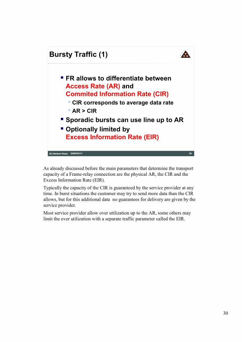
As already discussed before the main parameters that determine the transport
capacity of a Frame-relay connection are the physical AR, the CIR and the
Excess Information Rate (EIR).
Typically the capacity of the CIR is guaranteed by the service provider at any
time. In burst situations the customer may try to send more data than the CIR
allows, but for this additional data no guarantees for delivery are given by the
service provider.
Most service provider allow over utilization up to the AR, some others may
limit the over utilization with a separate traffic parameter called the EIR.

31
31(C) Herbert Haas 2005/03/11
Bursty Traffic (2)
� CIR and EIR are defined via a measurement interval Tc� CIR = Bc / Tc (Bc...Commited Burst Size)
� EIR = (Bc+Be) / Tc (Be...Excess Burst Size)
� When traffic can be mapped on these parameters (provided by provider) then FR is ideal for bursty traffic � Example: LAN to LAN connection
� Parameters (Bc, Be, Tc, AR) are defined in a traffic contract
The CIR and the EIR are defined via a measurement time interval Tc, which is
set to 1 second in most cases. The committed burst size Bc defines the amount
of bits per Tc with guaranteed delivery. The Excess Burst Size Be specifies the
maximum allowed oversubscription of bits per Tc, for which the delivery will
not be guaranteed.
All of these parameters plus the physical AR need to be negotiated with the
service provider and are written down in a traffic contract.

32
32(C) Herbert Haas 2005/03/11
Parameter Example (1)
Bits
TimeTc = 1s 2s
128000
Bc = 64000
AR = 128,000 Bit/s
CIR=64,000 Bit/s
In this example the measurement time interval Tc is set to 1second, the Bc to
64000 bits and the physical access rate is 128 Kbit/s. The red line indicates the
actual traffic pattern used on this connection. In this scenario the traffic
characteristic remains within the CIR of 64 Kbit/s.

33
33(C) Herbert Haas 2005/03/11
Parameter Example (2)
Bits
Time1s Tc = 2s
Bc = 64000
AR = 128,000 Bit/s
CIR=32,000 Bit/s
In this scenario a measurement interval Tc of 2 seconds is chosen. The
committed burst size Bc is 64000 bits, so the CIR according to the formula CIR
= Bc / Tc will be 32 Kbit/s. The actual traffic pattern indicated by the red line
remains again within the borders of the CIR.

34
34(C) Herbert Haas 2005/03/11
Parameter Example (3)
Bits
Time1s Tc = 2s
Bc = 64000
AR = 128,000 Bit/s
CIR=32,000 Bit/s
This example shows a more realistic scenario with a lot of small data bursts
which in sum do not exceed the CIR. Actually router manufactures use a burst
interval much smaller than the Tc. For example a cisco router per default
would send out small data burst every 125 milliseconds on a Frame-relay
connection. The maximum size of these bursts is calculated from the
parameters Tc, Bc, Be and AR which are defined in the traffic contract.

35
35(C) Herbert Haas 2005/03/11
Traffic Management
� Traffic Shaping� Users task
� Goal: smooth traffic profile, mitigiate bursts
� Token bucket methods
� Traffic Policing� Provider's task
� Goal: Drop (excess) frames violating the traffic contract
Traffic shaping according to the negotiated parameters is in the responsibility
of the end users. End users traffic that is outside the traffic contract will be
discarded by the first Frame-relay switch in the providers network.
So its for the benefit of the user itself to smooth and shape its traffic according
to the parameters. Traffic shaping according to the token bucket method might
be used to achieve this goal.

36
36(C) Herbert Haas 2005/03/11
�
�
Token Bucket
�
�
�
�
� �� �� ��
�
Token Generator
���� �
�
Wire
The token bucket method consists of a token bucket and a data bucket. The
valve of the data bucket, which controls the amount of data that can be sent
out, can only be opened by inserting a token. This means data can only be sent
if there are tokens available in the token bucket.
The token generation in the token bucket is done according to the Frame-relay
traffic parameters. So these tokens guarantee that the negotiated traffic
parameters will not be hurt by the user.

37
37(C) Herbert Haas 2005/03/11
Traffic Shaping
� TB = Token Bucket (=Bc+Be)
� Maximal speed = TB/Tc
� Typically, traffic above maximal
speed is buffered in a traffic shaping
queue
So the size of the token bucket itself corresponds to the value of Bc + Be and
the rate of token generation corresponds to the term Bc + Be / Tc.

38
38(C) Herbert Haas 2005/03/11
Traffic Shaping for Voice
� Tc<=10ms� Provides continuous traffic flow
� Additionally BECN can be used to decrease CIR� Cisco: MinCIR � Traffic shaping not calculated
using provider-CIR but for higher values� On receiving of BECN traffic-rate is reduced to
MinCIR (= Provider CIR)
� Cisco Proactive Trafficshaping: "Forsight"� Throttles traffic before congestion occurs� Only supported on Cisco FR-Switches
Traffic shaping for voice is much more delay and jitter sensitive than for data.
To accomplish to the needs of voice Tc is set from 125 milliseconds used for
data to a value below 10 milliseconds to generate a continuous traffic flow with
minimum jitter. These needs to be done obviously in combination with the
configuration of smaller datagram sizes between 50 to 100 bytes.
In the case of congestion, indicated by the BECN bits in the header, the traffic
rate is reduced, if traffic shaping is switched on. The way the router shapes can
be adjusted on cisco devices by the help of the mincir and the cir parameter.
Typically the cir parameter is set to the EIR or AR and the mincir parameter is
set to the CIR.
Under normal conditions the router will send out data with the rate of the cir
parameter (EIR or AR) and in case of BECN bits the router will gradually
reduce the speed until the mincir parameter (CIR) is reached.
Cisco has also developed a proprietary method for Frame-relay traffic shaping
called foresight, which allows proactive traffic shaping even before the actual
congestion occurs. By the use of foresight the Frame-relay switch is able to
determine the maximum data rate that might be used by the Frame-relay DTE.
This technology can only be used between Cisco routers and Cisco (former
StrataCom) Frame-relay switches.

39
39(C) Herbert Haas 2005/03/11
Traffic Management
Bits
Time/Tc
Be+Bc
Bc
AR
EIR
CIR
10.5
Mark
frames with
DE bits
Discard
frames
(Example only)
This example shows us what might happen if more traffic is injected than the
Frame-relay traffic parameters allow. Obviously the behavior in real life is
completely up to the traffic contract negotiated and might be different from our
scenario.
As long as the traffic remains within the borders of the CIR all frames are
accepted by the Frame-relay switch and will be delivered to their destination.
Data frames above the CIR but below the EIR will be marked with the Discard
Eglibility (DE) bit. This bit is located in the Frame-relay header and can be set
either by the end user itself or by the first Frame-relay switch in the provider
cloud. All frames marked with the DE bit will be discarded firstly in the case of
congestions inside the provider cloud.
So it might be better for the end user to set the DE bit himself, simply to
control which type of traffic should definitely arrive and which one might get
lost.
All traffic, in our scenario, above the EIR will be discarded by the provider.

40
40(C) Herbert Haas 2005/03/11
Traffic Management (4)
Bits
Time/Tc
Be+Bc
Bc
AR
EIR
CIR
10.5
D=1D=0
Mark frames with
DE bits but try to
deliver with best
efforts
(Example only)
This is the typical service provider behavior. Typically, a customer just pays
for the CIR and the rest of the bandwidth � up to the access rate � is free.
However, there is no gurantee that every excess packets is delivered to the
receiver.

41
41(C) Herbert Haas 2005/03/11
Typical Provider Offering
Data rate
Time
AR
CIR
What you
pay for
Free but no
guarantees
This graph shows us the benefits of a Frame-relay connection. The CIR is what
you pay for but very often it is possible to use provider capacities above the
CIR which are for free.

42
42(C) Herbert Haas 2005/03/11
Local Management Interface
� LMI extends Frame Relay
� Global Addressing
� Status messages
� Multicasting
� LMI is more of a protocol than an
interface (!)
The Local Management Interface (LMI) is a protocol that runs on a reserved
DLCI to supply you with information about the conditions of your PVC´s.
But it also supports global addressing and the use of multicast PVC´s.

43
43(C) Herbert Haas 2005/03/11
LMI Details
� Three LMI Types
� ANSI T1.617 (Annex D)
� ITU-T Q.933 (Annex A)
� LMI (Original, FRF)
� No fragmentation of LMI messages (!)
� MTU determines maximal PVC number
� E.g. MTU 1500 allows 296 DLCIs
Each Standardization Organization developed its own LMI. In fact, only the
FRF LMI is named LMI, but don't be too subtle. Unfortunetaly (you might
expect it) these signaling standards are not compatible. Practically, our service
provider must tell us which standard is supported by her DCEs, or some
modern routers perform an auto-sensing and determine the switch-type
automatically.
Full Status Messages contain all currently used DLCIs within a single frame.
Because of this the maximum number of PVCs is limited by the MTU for this
link. LMI messages must not be fragmented.
Note: When the frame MTU size is too small, not all PVC status messages can
be communicated . One symptom for this mistake is the observation of
bouncing PVCs (repeated up/down indications).
You can easily calculate the maximum number of DLCIs per interface by
yourself. The equation is Max_DLCIs=(MTU_bytes � 20)/5, because each
entry has 5 bytes. For example a MTU of 4000 Bytes supports 796 DLCIs.

44
44(C) Herbert Haas 2005/03/11
LMI Message Format
· LMI message is carried inside LAPF Frame
· Ctrl = 0x03 (UI)
· Protocol Discriminator
� 00001000 (ANSI/ITU)
� 00001001 (GOF)
· Call Reference
� 00000000 (only used for SVC)
· Message Type� 0111 1101 (Status)
� 0111 0101 (Status Enquiry)
� 0111 1011 (Status Update, GOF only)
Flag HeaderProt.
Dis FCS Flag
1
CtrlCall
Ref.
1 1 1 variable
Msg.
Type
Information
Elements (IE)
Contain PVC
status
information
The LMI messages are packed in standard Frame-relay frames and are
transported on DLCI 0 according to the ITU-T and ANSI standard or on DLCI
1023 according to the FRF standard.
The LMI messages are sent in a connection-less mode indicated by the value of
the control field (0x03).
The Protocol Discriminator holds the information whether FRF, ANSI or ITU-
T standard is used.
The Call Reference is only used in combination with SVC service, its needed
to distinguish between the different connection setup procedures.
The Message Type specifies whether LMI message is a status enquiry, status
report or full status update including bandwidth and congestion information.
The full status update is only supported by the FRF standard.
Finally the information field itself holds the complete status information of all
PVC´s in use.

45
45(C) Herbert Haas 2005/03/11
LMI Operation
� Every 10 seconds the DTE polls the
DCE with a Status Enquiry message
� Either for a dumb response ("Yes I'm
here")
� Or for a Channel status information
� (Full) Status Response
� Contains information about VCs
Every 5-30 seconds (typically 10 seconds) the DTE polls the DCE to receive a
status information.
The response from the DCE might be a small Hello message or a full status
report about the PVC´s in use every 60 seconds.

46
46(C) Herbert Haas 2005/03/11
Inverse ARP
� Automatic remote-node-address to
local-DLCI mapping
� Supports IP, IPX, XNS, DECnet, Banyan
VINES, AppleTalk
� Extension of existing ARP
� Not only for Frame Relay
� RFC 1293
If a layer 3 protocol like IP, IPX, XNS, etc. is transported via a Frame-relay
connection layer 2 to layer 3 address mapping needs to be done. The layer 2
address might be a DLCI number in case of PVC service or a E164/X121
address in case of SVC service.
In case of PVC service the Inverse ARP protocol was developed to allow the
automatic mapping between DLCI number and according layer 3 addresses. In
X25 technology the predecessor of Frame-relay this had to be done manually
by configuration.
In Frame-relay SVC service the mapping between E164/X121 address and the
according layer 3 address needs to be done manually by configuration, because
the E164 address is needed before the actual connection is up to start the
connection setup procedure.

47
47(C) Herbert Haas 2005/03/11
Inverse ARP and LMI Operation
Frame Relay
Network
Status Inquiry
10.0.0.1 20.0.0.1
DLCI 100 DLCI 300
Local DLCI 100 Active
Status Inquiry
Local DLCI 300 Active
Hello, I am 10.0.0.1
10.0.0.1 300
FR-Map
Hello, I am 20.0.0.1
20.0.0.1 100
FR-Map
Inverse ARP messages
are repeated every 60 seconds !
In this scenario the function and the interaction of the LMI and the Inverse
ARP protocol is shown.
With the help of the status enquiry and the status report messages of the LMI
protocol both nodes on either ends are informed about their DLCI number and
the condition of the DLCI.
Now both nodes on either end send small Hello messages with their according
layer 3 address into their active DLCI. This Hello procedure is repeated every
60 seconds.
Now both nodes can build up a Frame-relay mapping table which includes their
own DLCI number and the layer 3 address of the opposite site. So they know
who´s on the other side.

48
48(C) Herbert Haas 2005/03/11
DLCI Plan
� 0 LMI (ANSI, ITU-T) or FRF In-channel signaling
� 1023 LMI (FRF) or ITU-T/ANSI In-channel signaling
� 1-15 reserved
� 993-1007 Frame Relay bearer service Layer 2 management (ANSI/ITU-T)
� 1008-1018 reserved
� 1019-1022 multicast connections
� FRF: Usable DLCIs from 16 to 1007
� ANSI/ITU-T: Usable DLCIs from 16 to 992
This slide gives us an overview about the reserved DLCI´s for signaling and
the DLCI´s that may be used for user traffic.
So according to the FRF the DLCI´s in the range of 16 to 1007 and according
to ANSI/ITU-T specifications the DLCI´s 16 to 992 can be used to transport
user traffic.

49
49(C) Herbert Haas 2005/03/11
Bi-directional LMI (1)
� Standards LMI is unidirectional
� Sufficient for UNI signaling
� NNI signaling requires a bi-directional LMI
variant
� PVC status must be reported in both directions
� Symmetrical approach necessary
FR Net
Provider X
FR Net
Provider Y
NNI
UNI
LMI
UNI
LMI
BidirectionalLMI
Common LMI is unidirectional and can only be used for UNI interfaces.
In the case of an NNI connection between two different Frame-relay clouds a
bidirectional LMI protocol needs to be supported to report the PVC status to
either ends.

50
50(C) Herbert Haas 2005/03/11
Bi-directional LMI (2)
� Using Bi-LMI each network is notified about PVC status in the other network
� Only supported by ITU-T and ANSI� DLCI 0
� Not defined by GOF
� Additional fields� Inactivity reason, country code, national
network identifier
When bidirectional LMI is used every network gets the PVC status information
of the opposite side. Bidirectional LMI is only supported by the ANSI and the
ITU-T standard and uses the same DLCI number that is used for unidirectional
LMI.
Some additional information needs to be transported by the bidirectional LMI
like country codes and network identifiers.

51
51(C) Herbert Haas 2005/03/11
Summary
� Frame Relay has reduced overhead compared to X.25
� Outband signaling (LMI)
� Efficient for bursty traffic� Parameters (Bc, Be, Tc or CIR, EIR)
� Congestion Notification � FECN, BECN
� Frame Relay Forum, ITU-T, and ANSI

52
52(C) Herbert Haas 2005/03/11
Quiz
� What's the Tc when using Voice over
Frame Relay?
� What's the main difference between
FR and Ethernet, when putting IP
upon them?
� What's the typical practical usage of
BECN?

53
53(C) Herbert Haas 2005/03/11
Hints
� Q1: Milliseconds (min 10 ms)
� Q2: Broadcast medium. Main
problem with routing protocols
� Q3: BECN is used by the provider to
throttle the customer if he violates
the traffic contract