
1. SPECIFICATIONS < APW-297>
133
- 1 - 1. SPECIFICATIONS < APW-297> (1) MECAHNICAL SPECIFICATIONS 1) Sewing machine : LH-597 model of 2-needle, lockstitch machine with a center knife (exclusively used for APW) 2) Sewing speed : 3,000 rpm (max.) 3) Stitch length : Lockstitch : 2.0 to 3.4 mm (standard: 2.5mm) Condensation stitch : 0.5 to 1.5 mm (standard : 1.0 mm) Back tack stitch : 0.5 to 3.4 mm (Standard : 2.0 mm) Condensation/Back tack stitch selectable 4) Types of welt : Parallel double welt, parallel single welt } Each with flap or without flap 5) Pocket lip length : Possible to set in increments of l mm within the range of 18 mm (min.) to 180 mm (max.) Note that the pocket lip length is 25 mm at the minimum when using the corner knife. For the longer type (option), the maximum sewing length will be 220 mm. 6) Welting width : 10, 12 and 14 mm (needle gauge) 7) Needles : ORGAN Mt × 190 #16 to #18 (standard #16) SCHMETZ 190R #100 to #110 (standard #100) 8) Thread : Spun thread #50 (Recommended) 9) Hook : Full rotary, vertical-axis, self-lubrication hook 10) Thread take-up lever : Slide thread take-up lever 11) Needle bar stroke : 34.4 mm 12) Cloth feed mechanism: Driven by servomotor 13) Control : By a micro-computer 14) Safety mechanism : Machine operation is automatically stopped if the cloth feed mechanism error detector and, the needle thread breakage detector or any of the various safety devices are actuated. 15) Lubricating oil : JUKI New Defrix Oil No.2 16) Operating air pressure : 0.5 MPa 17) Air consumption : Approx. 40 N R/min. 18) Dimensions of the machine: 980 mm (width) × 1,650 mm (length) × 1,200 mm (height) (1,580 mm – when including the stacker) (1,500 mm – when including the thread stand) 19) Weight : Approx. 380 kg (2) ELECTRICAL SPECIFICATIONS Once the required data is set by means of a built-in micro-computer, the data can be stored in memory (for 100 hours) using a built-in battery even after turning OFF the power to the machine unless the setting is canceled. In addition, the stored data can be output to a personal computer and saved by making use of the exclusive circuit board. Further, these data can be copied to the other machines. Consult our JUKI service man if necessary. 1) The number of patterns that can be stored in memory : 100 (0 - 99) 2) The number of cycles that can be stored in memory : 10 (0 - 9) 3) Input power : Single-phase / 3-phase : 200, 220, 230, 240, 380, 400, 415 50/60 Hz Voltage fluctuation : Within ± 10% of the rated voltage 4) Power consumption : 550 W (Welt length) Noise : Workplace-related noise at sewing speed n = 3000 min –1 : LPA ≦ 83 dB(A) Noise measurement according to DIN 45635-48-B-1.
-
Upload
khangminh22 -
Category
Documents
-
view
0 -
download
0
Transcript of 1. SPECIFICATIONS < APW-297>

- 1 -
1. SPECIFICATIONS
< APW-297>
(1) MECAHNICAL SPECIFICATIONS1) Sewing machine : LH-597 model of 2-needle, lockstitch machine with a center knife
(exclusively used for APW)2) Sewing speed : 3,000 rpm (max.)3) Stitch length : Lockstitch : 2.0 to 3.4 mm (standard: 2.5mm)
Condensation stitch : 0.5 to 1.5 mm (standard : 1.0 mm)Back tack stitch : 0.5 to 3.4 mm (Standard : 2.0 mm)Condensation/Back tack stitch selectable
4) Types of welt : Parallel double welt, parallel single welt Each with flap or without flap5) Pocket lip length : Possible to set in increments of l mm within the range of 18 mm (min.) to
180 mm (max.)Note that the pocket lip length is 25 mm at the minimum when using thecorner knife.For the longer type (option), the maximum sewing length will be 220 mm.
6) Welting width : 10, 12 and 14 mm(needle gauge)
7) Needles : ORGAN Mt × 190 #16 to #18 (standard #16)SCHMETZ 190R #100 to #110 (standard #100)
8) Thread : Spun thread #50 (Recommended)9) Hook : Full rotary, vertical-axis, self-lubrication hook
10) Thread take-up lever : Slide thread take-up lever11) Needle bar stroke : 34.4 mm12) Cloth feed mechanism: Driven by servomotor13) Control : By a micro-computer14) Safety mechanism : Machine operation is automatically stopped if the cloth feed mechanism
error detector and, the needle thread breakage detector or any of the varioussafety devices are actuated.
15) Lubricating oil : JUKI New Defrix Oil No.216) Operating air pressure : 0.5 MPa17) Air consumption : Approx. 40 NR/min.18) Dimensions of the machine: 980 mm (width)× 1,650 mm (length)× 1,200 mm (height)
(1,580 mm – when including the stacker)(1,500 mm – when including the thread stand)
19) Weight : Approx. 380 kg
(2) ELECTRICAL SPECIFICATIONSOnce the required data is set by means of a built-in micro-computer, the data can be stored in memory (for100 hours) using a built-in battery even after turning OFF the power to the machine unless the setting iscanceled. In addition, the stored data can be output to a personal computer and saved by making use ofthe exclusive circuit board. Further, these data can be copied to the other machines. Consult our JUKIservice man if necessary.
1) The number of patterns that can be stored in memory : 100 (0 - 99)
2) The number of cycles that can be stored in memory : 10 (0 - 9)
3) Input power : Single-phase / 3-phase : 200, 220, 230, 240, 380, 400, 415 50/60 Hz Voltage fluctuation : Within ± 10% of the rated voltage
4) Power consumption : 550 W
(Welt length)
Noise : Workplace-related noise at sewing speed
n = 3000 min–1 : LPA ≦ 83 dB(A)
Noise measurement according to DIN 45635-48-B-1.

- 2 -
Noise: Workplace-related noise at sewing speed
n = 3000 min–1 : LPA ≦ 83 dB(A)
Noise measurement according to DIN 45635-48-B-1.
< APW-298>
(1) MECAHNICAL SPECIFICATIONS1) Sewing machine : LH-598 model of 2-needle, lockstitch machine with a center knife and a
needle stop mechanism (exclusively used for APW)2) Sewing speed : 3,000 rpm (max.)3) Stitch length : Lockstitch: 2.0 to 3.4 mm (standard: 2.5mm)
Condensation stitch : 0.5 to 1.5 mm (Standard : 1.0 mm)Back tack stitch : 0.5 to 3.4 mm (Standard : 2.0 mm)Condensation/Back tack stitch selectable
4) Types of welt : Parallel double welt, parallel single welt,slant double welt, slant single welt,trapezoidal stitching
5) Pocket lip length : Possible to set in increments of l mm within the range of 18 mm (min.) to180 mm (max.)Note that the pocket lip length is 25 mm at the minimum when using thecorner knife.For the longer type (option), the maximum sewing length will be 220 mm.
6) Welting width : 10, 12 and 14 mm(needle gauge)
7) Needles : ORGAN DP × 17 #16 to #18 (standard #16)SCHMETZ SY3355 #100 to #110 (standard #100)
8) Thread : Spun thread #50 (Recommended)9) Hook : Full rotary, vertical-axis, self-lubrication hook
10) Thread take-up lever : Slide thread take-up lever11) Needle bar stroke : 33.36 mm12) Cloth feed mechanism : Driven by servomotor13) Control : By a micro-computer14) Safety mechanism : Machine operation is automatically stopped if the cloth feed mechanism
error detector and, the needle thread breakage detector or any of the varioussafety devices are actuated.
15) Lubricating oil : JUKI New Defrix Oil No.216) Operating air pressure : 0.5 MPa17) Air consumption : Approx. 40 NR/min.18) Dimensions of the machine : 980 mm (width)× 1,650 mm (length)× 1,200 mm (height)
(1,580 mm – when including the stacker)(1,500 mm – when including the thread stand)
19) Weight : Approx. 380 kg
(2) ELECTRICAL SPECIFICATIONSOnce the required data is set by means of a built-in micro-computer, the data can be stored in memory (for100 hours) using a built-in battery even after turning OFF the power to the machine unless the setting iscanceled. In addition, the stored data can be output to a personal computer and saved by making use ofthe exclusive circuit board. Further, these data can be copied to the other machines. Consult our JUKIservice man if necessary.
1) The number of patterns that can be stored in memory : 100 (0 - 99)
2) The number of cycles that can be stored in memory : 10 (0 - 9)
3) Input power : Single-phase / 3-phase : 200, 220, 230, 240, 380, 400, 415 50/60 Hz Voltage fluctuation : Within ± 10% of the rated voltage
4) Power consumption : 550 W
Each with flap or without flap
(Welt length)

- 3 -
2. NAMES OF COMPONENTSThe machine consists mainly of the following units;
A Frame and structural components
(Frame, sewing table, covers, foot switch etc.)
B Clamp foot unit and feed mechanism
C Corner knife unit
D Binder unit (Binder components and its driving components)
E Pneumatic control unit (Pneumatic control devices and pipings)
F Stacker unit
G Sewing machine head
H Electric control unit (Control panel)
I Oil pan
J Operation panel
K Power switch
With this machine, you can do desired welting work simply by setting materials (garment body, interlining
piece, welting patch etc.) in place and operating the switches on the operation panel.
E
C
J
G
D
K
A
F
B

- 4 -
3. STANDARD ADJUSTMENTS
(1) Machine head components
1) Main shaft components
1 mm
Standard Adjustment
1 Adjusting the main shaft origin sensor
This sewing machine detects the upper dead point of the needle bar with the main shaft origin sensor
1 mounted inside the machine and makes the point the origin to control the revolution of the sewing
machine.
.... When the power is turned ON, the sewing machine performs the operation of the main shaft origin
retrieval and stops at the upper dead point of the thread take-up lever. In a case where the machine
does not stop at the upper dead point when the machine is turned by hand pulley or the like, an
alarm (AL-12 : needle UP trouble) is displayed when the MACHINE READY key is pressed. In this
case, the machine automatically returns to the upper dead point of the thread take-up lever by
pressing the RESET key.
(State to perform sewing is obtained.)
Detecting platesetscrew
1
2
3
4

- 5 -
Adjustment Procedures Results of Improper Adjustment
1) Turn OFF the power to the machine.
2) Loosen the setscrew and remove the top cover (lid located on
the top surface of the sewing machine).
3) Turn and stop the sewing machine by hand at the lower dead
point of the needle bar.
4) Loosen two collar setscrews 3 and adjust so that detecting
plate 2 is on the operator's side and the edge is vertical.
Remove the cap located on the back of the machine head and
enter a screwdriver to loosen one of the setscrews.
5) A clearance of 0.5 to 1.5 mm between the detecting plate and
the sensor is the standard adjustment value.
If the clearance is not within the specified value, loosen main
shaft origin sensor setscrew 4 to adjust the clearance.
6) When the aforementioned adjustment is completed, attach the
top cover in place and turn ON the power.
The adjustment is proper when the sewing machine stops
at the upper dead point of the needle bar.
™ When the main shaft origin
sensor and the detecting plate
are not properly adjusted, the
sewing machine does not stop
at the upper dead point of the
thread take-up lever.
™ In case of APW-297, stopping
height of the needle bar (needle
tip is 11.5 mm away from the
throat plate) is not within the
specified value, and thread
breakage at the start of sewing
may occur.

- 6 -
1 mm
Standard Adjustment
2 Replacing the timing belt
Coupling screw No. 1
Coupling
1
2
3
4
5
4
5
A

- 7 -
Adjustment Procedures Results of Improper Adjustment
1) Remove the top cover (lid located on the top surface of the
sewing machine).
2) Remove timing belt 2 from lower sprocket wheel 1.
3) Enter a hexagonal wrenck key from section A and loosen two
coupling setscrews.
4) Loosen the setscrews and remove main shaft motor 3.
5) Loosen the setscrews in the upper sprocket wheel asm.
6) Loosen the setscrews in the hand pulley gear B.
7) Pull out the upper sprocket wheel asm 4.
..... Upper sprocket wheel asm. 4 is pressed in the machine
arm. Tap the wheel from the inside of the hole and pull it
out toward the left-hand side (b).
8) Pull out the timing belt through the hole.
9) Enter a new timing belt and assemble it the same as before.
At this time, be careful of the following matters.
* When pressing upper sprocket wheel asm. 4 in the machine
arm, apply the bearing mount (LOCKTITE : 085 for medium
strength fit) to the wheel.
* The flat sections of both the main shaft and the motor shaft
become the positions of the coupling screws No. 1.
* Make hand pulley gear B 5 come in contact with the upper
sprocket wheel asm 4.

- 8 -
b
c
aa
c
Standard Adjustment
2) Needle bar components
1 Adjusting the height of the needle bar (APW-297)
2 Adjusting the upper/lower positions of the needle bar frame (APW-298)
The respective clearances of the upper and lower positions of the needle bar frame and the needle
bar become the values described in the table below.
Portion with * (asterisk) mark : the clearance should be 0.15 m/m or more at the time when pushing up
the needle bar locating at its highest position from the bottom.
Clearance a b c
Needle bar connection
2 needles 0.2 m/m or more 0 0.2 m/m or more
1 needle 0.2 m/m or more * 0.2 m/m or more
Needle barframe
Upper side marker line isaligned with bottom face of
needle bar frame.
Needle bar : Lower dead point state
Needle barfixed pin
Needle barbracket
At the time of 2 needlesLower bushing
At the time of 1 needle
Needle bar
Needle bar frame
1
2

- 9 -
Adjustment Procedures Results of Improper Adjustment
1) To adjust the height of the needle bar, loosen needle bar bracket
screw 1.
2) Turn the hand pulley to bring the needle bar to its lower dead
point and remove face plate cover 2 of the binder base to
adjust the height.
™ Adjust so that the upper marker line engraved on the needle
bar is aligned with the bottom face of the needle bar frame
when the needle bar is in the lower dead point state.
Loosen setscrews 1 and 2 in the needle bar frame shaft base
and turn needle bar frame shaft 3 counterclockwise. Then the
needle bar frame goes up, and clearance "a" becomes smaller
and clearance "c" becomes larger.
Turn it clockwise and the respective clearances are reversed.
(Adjusting area is up to the position where the slot of needle bar
frame shaft 3 becomes vertical.)
After performing the adjustment, tighten setscrews 1 and 2 to
fix needle bar frame shaft 3.
Adjustingarea
• When the needle bar frame is
excessively high :
™ Needle bar locking is hard since
clearance "a" is small, and 1-
needle stop failure of slant
sewing occurs.
(Difference on the sewing end
side becomes smaller than the
given value.)
In addition, needle bar locking
failure occurs at the sewing end.
(One stitch drops at the sewing
start of the slant sewing.)
• When the needle bar frame is
excessively low :
™ Needle bar releasing is hard
since clearance "c" is small, and
1-needle release failure of slant
sewing occurs.
(Difference on the sewing start
side becomes larger than the
given value.)
Goes up.
Comes down.
1
2
3

- 10 -
Standard Adjustment
1 Needle feed adjusting (cam section)
It is normal that the needle feed amount is "0" (zero) when needle feed adjusting motor 1 stops at the
origin.
.... When the MACHINE READY key is pressed, needle feed adjusting motor 1 performs the origin
retrieval and stops at the origin.
3) Needle feed components
Cover setscrew
Back of thesewing machine
Needle feed originsensor
1
2
3

- 11 -
Adjustment Procedures Results of Improper Adjustment
1) Remove needle feed adjusting motor cover 2.
2) Turn ON the power and perform the sewing machine
independent operation at 500 rpm under the continuous mode.
.... At this time, needle feed adjusting motor 1 is excited at the
position of the origin.
3) Loosen clamp screw 4 in needle feed adjusting cam 3.
4) Turn needle feed adjusting cam 3 while checking the
longitudinal move of the needle bar and tighten clamp screw
4 in the cam at the position (angle) where the longitudinal
move stops to fix the cam.
.... The point of the position (angle) where the longitudinal move
stops is the position where the two cover setscrews come
just below.
(Caution) In addition to the normal installing angle, there is
another angle where the longitudinal move stops.
For reference, the longitudinal move becomes "0" (zero)
at the angle where the two cover setscrews come just
above. However, the needle feed direction is reverse to
the normal one at this fixing angle when the actual sewing
is operated. So, do not adjust to this state.
™ In the case where the needle
feed amount does not become
"0" (zero) when the needle feed
adjusting motor stops at the
origin, the needle feed amount
in accordance with panel input
value (percentage as against
the sewing pitch) cannot be
obtained. Accordingly, the
needle feed cannot be stopped
(setting the panel input value to
0%).
In addition, the needle entry
position in terms of stitches slips
from the given entry position.

- 12 -
Standard Adjustment
2 Adjusting the installing position of the needle bar frame
Adjust the installing position of the needle bar frame so that the needle is in the center of the needle
hole (slot) when the needle feed amount is "0" (zero).
1
2

- 13 -
Adjustment Procedures Results of Improper Adjustment
* Perform this adjustment after the adjustment of the needle feed
adjusting cam described in the previous clause.
1) Turn OFF the power after the needle feed adjusting motor origin
retrieval operation (turn ON the MACHINE READY key).
2) Turn the hand pulley to lower the needle to the needle hole.
3) Remove the top cover (lid located on the top surface of the
sewing machine).
4) Loosen clamp screw 2 in needle feed rocking rear arm 1.
5) Move the needle bar frame to and fro, position so that the needle
is in the center of the needle hole, and tighten clamp screw 2
in needle feed rocking rear arm 1.
™ When the position of the needle
bar frame is not adjusted as
described on the left side :
Stitches slip from the given
needle entry position and when
the adjustment is particularly
improper, interference of the
respective parts occurs.
• Interference of upper knife
with needle thread trimmer
knife
• Interference of needle bar
frame
• Interference of needle with
needle hole

- 14 -
4 mm 4 mm
Standard Adjustment
3 Adjusting the timing of the needle feed operation
Adjust the timing of the needle feed operation so that the timing of the hook catching thread is not
slipped even when the needle feed amount is changed.
.... It is normal that the needle bar does not move to and fro even when turning needle feed adjusting
motor 1 at the timing of alignment of needle and hook (longitudinal move is within 0.5 mm).
Locus of needle feed and needle bar
The locus of normal needle feed is as shown in the figures below.
The ellipse is increased or reduced in the state that the point of the timing of the hook catching thread
does not slip longitudinally.
Main shaft
<Normal feed> <Reverse feed>
Operator'sside
Top surface ofthroat plate
Timing of hookcatching thread
Operator'sside
Top surface ofthroat plate
Timing of hookcatching thread
1
2
3

- 15 -
Adjustment Procedures Results of Improper Adjustment
* Perform this adjustment after the adjustments of the needle feed
adjusting cam and the installing position of the needle bar frame
described in the previous clauses.
1) Turn OFF the power to the machine.
2) Turn the hand pulley to align the needle with the hook.
3) Remove the top cover.
4) Loosen setscrew 2 in the upper knife driving cam.
5) Gradually move the angle of upper knife driving cam 3 and
temporarily tighten the cam. Then turn the needle feed adjusting
motor to check the longitudinal move of needle bar.
6) Tighten the setscrew 2 in the upper knife driving cam at the
angle where the longitudinal move of needle bar stops to fix
the cam.
(Point : The longitudinal move of needle bar stops at the position
where letter "S" of the cam faces upward as shown in the figure
on the left.)
.... It is a difficult job and takes time to adjust the cam to the
angle where the longitudinal move of needle bar completely
stops.
It is no problem functionally if the longitudinal move is within
0.5 mm.
™ When the adjustment of timing
of the needle feed is improper,
a given locus of needle feed
cannot be obtained. As a result,
needle feed effect as against the
sewing material is lost.
™ Hook adjusting timing, when
needle feed amount is changed
(when the sewing pitch is
changed or the like), is slipped
and sewing conditions will be
deteriorated.

- 16 -
Standard Adjustment
4) Needle thread trimmer components
Top surface ofthroat plate
7 ± 0.5 mm
3 ± 0.5 mm
17.5 ± 0.5 mm
27.5 ± 0.5 mm
0.5 mm+0.2 0
1 Adjusting the forward end position of the needle thread trimmer unit
2 Adjusting the lateral position of the needle thread trimmer unit
0.5 mm+0.2 0
1
2
A
3
1
A
- 17 -
Adjustment Procedures Results of Improper Adjustment
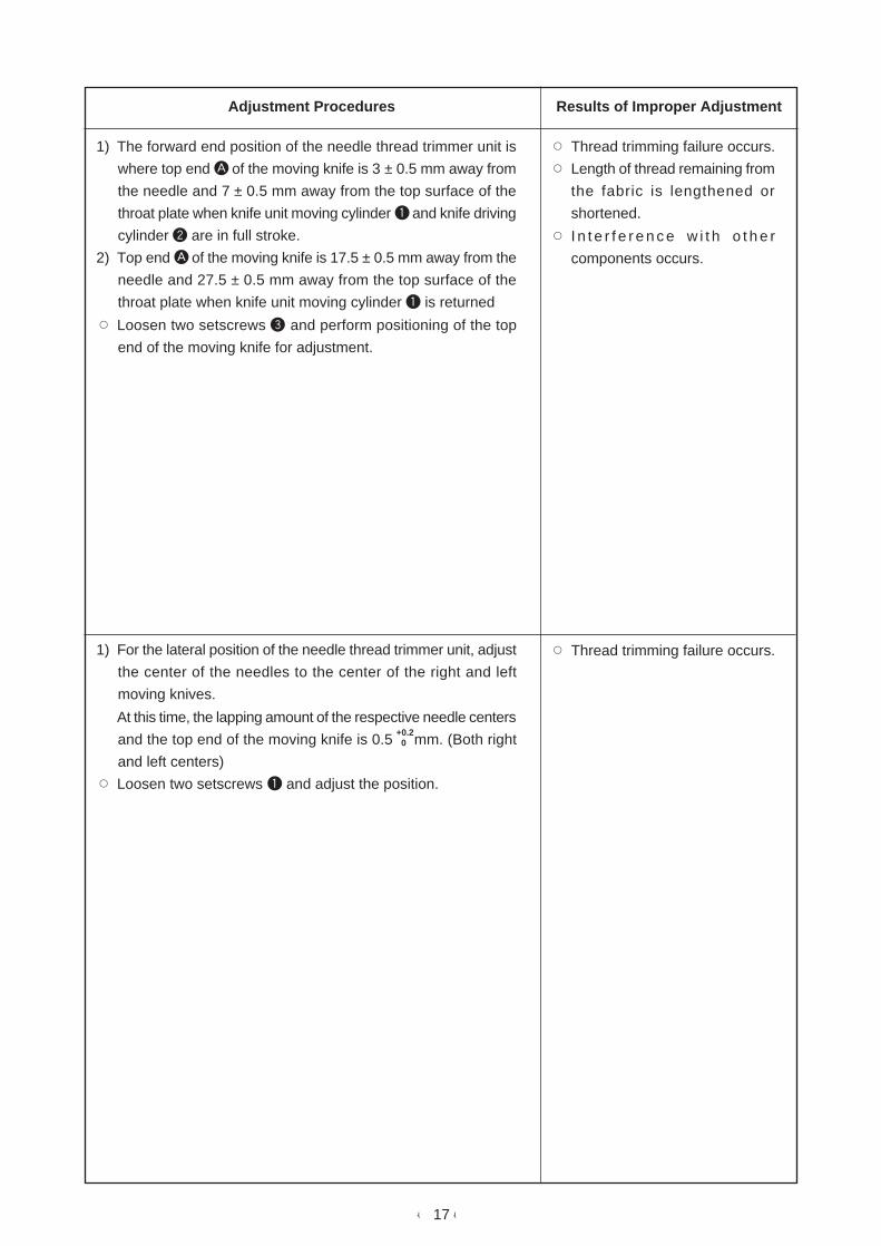
1) The forward end position of the needle thread trimmer unit is
where top end A of the moving knife is 3 ± 0.5 mm away from
the needle and 7 ± 0.5 mm away from the top surface of the
throat plate when knife unit moving cylinder 1 and knife driving
cylinder 2 are in full stroke.
2) Top end A of the moving knife is 17.5 ± 0.5 mm away from the
needle and 27.5 ± 0.5 mm away from the top surface of the
throat plate when knife unit moving cylinder 1 is returned
™ Loosen two setscrews 3 and perform positioning of the top
end of the moving knife for adjustment.
1) For the lateral position of the needle thread trimmer unit, adjust
the center of the needles to the center of the right and left
moving knives.
At this time, the lapping amount of the respective needle centers
and the top end of the moving knife is 0.5 mm. (Both right
and left centers)
™ Loosen two setscrews 1 and adjust the position.
™ Thread trimming failure occurs.
™ Length of thread remaining from
the fabric is lengthened or
shortened.
™ I n t e r f e r e n c e w i t h o t h e r
components occurs.
™ Thread trimming failure occurs.
+0.2 0
- 18 -
Standard Adjustment
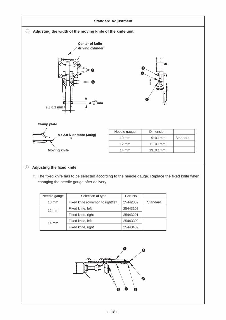
3 Adjusting the width of the moving knife of the knife unit
4 Adjusting the fixed knife
™ The fixed knife has to be selected according to the needle gauge. Replace the fixed knife when
changing the needle gauge after delivery.
Needle gauge Dimension
10 mm 9±0.1mm Standard
12 mm 11±0.1mm
14 mm 13±0.1mm
Needle gauge
10 mm
12 mm
14 mm
Selection of type
Fixed knife (common to right/left)
Fixed knife, left
Fixed knife, right
Fixed knife, left
Fixed knife, right
Part No.
25442302
25443102
25443201
25443300
25443409
Standard
Center of knifedriving cylinder
9 ± 0.1 mm
Moving knife
Clamp plate
A : 2.9 N or more (300g)
4 mm+0.5 0
12
3
4
5
1
23
4
A
B

- 19 -
Adjustment Procedures Results of Improper Adjustment
1) Lateral dimension of the top end of the moving knife is 9 ± 0.1
mm. However, this dimension changes according to the needle
gauge. Adjust the dimension to the needle gauge.
Adjust the distance of the top end of the moving knife using
four setscrews 1 in the moving knife guide.
(Caution)
When performing this adjustment, adjust so that the right
and left moving knives in terms of the center of knife driving
cylinder are set to the same dimension.
2) Projecting amount of the top end of the right/left moving knives
is 4 mm away from the top end of the clamp when the
moving knife cylinder has been fully pressed (full stroke).
™ Loosen nut 2 in the moving knife driving cylinder, turn moving
knife driving cylinder rod 3, and move moving knife driving
plate 4 in the direction of the arrow to adjust.
3) Needle thread retaining force should retain spun #60 with 2.9N
or more in the direction A.
™ Adjust with two screws 5 so that the position of the clamp
plate is 4 mm from the top end of the moving knife.
™ Attach the clamp plate so that it is parallel to the moving knife.
1) Fixed knife 2 makes plane A (blade face) of moving knife 1
come in close contact with top end section B of fixed knife 2.
™ Loosen two setscrews 3 in the fixed knife, make plane A of
the moving knife come in close contact with the top end of the
fixed knife, then fix the fixed knife.
(Caution) When adjusting the fixed knife, perform the
adjustment with clamp 4 installed.
™ Thread trimming failure occurs.
™ Thread trimming failure or clamp
failure occurs.
™ When the retaining force is
insufficient, slip-off of thread at
the sewing start occur
™ Thread trimming failure or single
thread breakage occurs.
+0.5 0
+0.5 0

- 20 -
Standard Adjustment
1 Adjusting the bobbin thread knife
5) Bobbin thread trimmer components
Bobbin thread knife
Throat plate
1 Non-action 2 Action 3 End of action
Operatingdirection
2
134 5
6
7
8

- 21 -
Adjustment Procedures Results of Improper Adjustment
1) Position of the bobbin thread knife to the throat plate
In order to prevent the bobbin thread knife from being pinched in
the throat plate while cutting the thread, it is important to set the
knife perpendicular to the throat plate.
1. Loosen screw 1 and operate bobbin thread knife driving
cylinder 6.
2. Set bobbin thread knife bracket 7 so that the knife is not
pinched in the throat plate and firmly tighten screw 1.
2) Position and height of the bobbin thread knife
The top ends of both left and right knives must be even with the
throat plate surface, and the grooves in the knives must be parallel
to the grooves in the throat plate when the knives actuate.
1. Loosen screws 2 and adjust so that the top ends of the knives
are even with the throat plate surface.
2. Press bobbin thread knife driving cylinder 6 toward A and
adjust so that the grooves in the knives are parallel to the
grooves in the throat plate.
3. Securely tighten screws 2.
3) How to adjust the position of the bobbin thread knife in
replacing gauges
Loosen setscrews 4 and 5 of bobbin thread knife presser plate
3, and the bobbin thread knife moves to the right or left together
with the bobbin thread knife presser plate.
4) How to replace the bobbin thread knife
Loosen setscrews 2, and you can pull out the knife downward.
5) Adjusting the sharpness of the bobbin thread knife
Adjust the sharpness of the bobbin thread knife, while properly
pressing thread grasping presser springs 8 (figure on the left)
against the bobbin thread knife.
The force with which the springs are pressed against the knife
should be minimized as far as the knife cuts the thread without
fail. This helps lengthen the life of the knife.
™ When the bobbin thread knife is
lower than the top surface of the
throat plate, bobbin thread
trimming failure occurs.

- 22 -
7 mm
5 mm
0.5 mm7 mm
Standard Adjustment
6) Center knife components
Adjust the relevant distances of the center knife as shown in the figure below.
• Highest dead point of the center knife ...... 5 mm above the surface side of the throat plate
• Lowest dead point of the center knife ....... 0.5 mm above the surface side of the throat plate
Surface side of the arm
1 How to adjust the height of the center knife 2 How to adjust the distance from the
needle to the center knife
3 Adjusting the sharpness of the center knife
4 Attaching the center knife
Needle
Throat platesurface
Fixed knife
1
2
3
4
A
- 23 -
Adjustment Procedures Results of Improper Adjustment
1 How to adjust the height of the center knife
Loosen screw A and adjust so that a 5 mm clearance is obtained
when the center knife comes to its highest dead point by raising
or lowering the center knife.
When tightening the screw, be careful not to provide it with a lateral
play.
2 How to adjust the distance from the needle to the center
knife
Loosen screw 1 and correctly adjust the position of the center
knife by moving it forward or backward.
3 Adjusting the sharpness of the center knife
The sharpness of the center knife is adjusted by pressing the side
face of the center knife to the blade section of the fixed knife of
the throat plate.
Move the center knife laterally by screw 2 or rotate it by screw 3
to obtain the suitable pressing force.
Be sure to adjust the pressing force as light as possible so that
the center knife completely cuts the two plies of the fabric used.
4 Attaching and removing the center knife
™ Removing the center knife
Loosen screws 4, and remove the center knife.
Tighten screws 4, and attach the center knife. At this time, push
the center knife to the base until it will go no further and fix at that
position.

- 24 -
0.2 to 0.3 mm
0 to 0.05 mm
0 to –0.05 mm
4 m
m
0.8
mm
Standard Adjustment
7) Hook components
1 Adjusting the timing of the hook to the needle 2 Adjusting the timing of the hook
3 Adjusting the clearance between the needle and the hook blade point
4 Removing and attaching the hooks
• Removing the hooks 1 Remove the throat plate.
2 Remove the bobbin case opening lever.
3 Loosen three setscrews 2 in the small gear of the hook shaft.
4 Turn the handwheel until the needle bar is raised to its highest position
and take out the hooks.
• Attaching the hooks 1 Reverse the above procedures.
2 Turn by hand the bobbin case holder until its projection rests in the groove
on the throat plate and fix the throat plate.
5 Adjusting the bobbin case opening lever
Hook blade point
Needle
1
2
A
B
C
A
B
C
3
4
5

- 25 -
Adjustment Procedures Results of Improper Adjustment
1 Adjusting the timing of the hook to the needle
™ Remove the throat plate.
™ When the needle has gone up 4 mm from its lowest point. adjust
the position of the hook so that the blade points of left/right
hooks align with the center of the needle. At this time, adjust
so that the clearance between the side face of the needle and
needle guard 1 of the hook is 0 to -0.05 mm, that the clearance
between the side face of the needle and the blade point is 0 to
0.05 mm and that the distance between the top end of the
needle hole and the hook blade point is 0.8 mm.
2 Adjusting the timing of the hook
™ Loosen three setscrews 2 in the small gear of the hook shaft.
Manually turn the hook to make the hook blade point align with
the center of the needle. Then tighten setscrews 2 while
pressing the hook downwards and the gear upwards in order
to eliminate a vertical play of the hook shaft.
3 Adjusting the clearance between the needle and the hook
blade point
™ Remove the throat plate and tilt the machine backwards.
™ Loosen screws A and B in the hook driving shaft saddle located
on the machine side to be adjusted.
™ Lightly tap hook driving shaft saddle C, and move it to the left
or right until the clearance between the needle and the blade
point of the hook is adjusted to 0 to -0.05 mm. Then firmly
tighten screws A. In addition, moderately tighten screws B.
(Caution) Screw B is fixed holding the hook driving shaft
bushing. If it is tightened excessively, the turning torque
of the hook driving shaft will be increased. So, be careful
not to tighten it excessively.
5 Adjusting the bobbin case opening lever
™ Turn the handwheel by hand in the regular direction to let bobbin
case opening lever 4 withdraw to the end of its stroke in the
direction of arrow and make sure that there is a clearance of
0.2 to 0.3 mm between the bobbin case opening lever and
projection 5 of the bobbin case (turn the bobbin case in the
direction of arrow and hold it in place by hand).
This can be adjusted by loosening screw 3 in the bobbin case
opening lever.

- 26 -
28 mm
Standard Adjustment
8) Wiper components
Standard Adjustment
1 Adjusting the injector for the reflux of the face plate components
™ Reflux of the face plate components is performed
with injector 1 installed on the bottom side of the
machine bed.
™ The standard value of the reflux amount is
obtained at the position where the injector
adjustment screw 2 is turned back four times from
its fully screwed state.
™ Adjusting the amount of oil in the hook
™ Appropriate amount of oil in the hook is obtained when a sheet of
paper is placed approximately 1 cm away from the hook, operate
the sewing machine for 10 seconds, and oil splashes stick to the
paper at the height of the hook blade point as shown in the figure.
Min. Max.
A
B
1 Adjusting the wiper
9) Lubrication components
1
1
23
1
cd

- 27 -
Adjustment Procedures Results of Improper Adjustment
Adjustment Procedures Results of Improper Adjustment
1) Tilt the machine head.
2) Loosen nut 3 and move screw 2 in the direction of the arrow
to adjust the injector.
™ Moving the screw in the direction A strengthens the injector
and the reflux amount is increased.
™ Moving the screw in the direction B weakens the injector and
the reflux amount is decreased.
1) Perform the adjustment of the amount of oil with screw 1 in
the outer hook.
Turning clockwise decreases the amount of oil and turning it
counterclockwise increases the amount of oil.
™ Oil may drop from the bottom of
the face plate.
Adjust the wiper with clamp screw 1 so that the dimension of
clearance between the bottom end of the wiper and the face plate
of the machine head is 28 mm when the cylinder is actuated.
If the wiper operating amount is
small, slip-off of thread at the
sewing start occurs.
If the wiper operating amount is
large, defective stitch tightness at
the sewing start occurs.

- 28 -
0.2 N
9 mm
Standard Adjustment
10) Thread tension components
1 Adjusting the thread take-up spring
2 Adjusting the timing of the thread tension disc to start "floating"
Adjusting nut
7 to 8 mm
1
2
34
5
6
7
8
9

- 29 -
Adjustment Procedures Results of Improper Adjustment
1 Adjusting the thread take-up spring
™ For adjusting the tension of the left needle thread take-up spring,
loosen screw 1 and turn 2. Turning 2 clockwise will increase
the tension of the left needle thread take-up spring, or
counterclockwise will decrease it.
For adjusting the tension of the right needle thread take-up
spring, loosen screw 3 and turn 4. Turning 4 clockwise will
increase the tension of the right needle thread take-up spring,
or counterclockwise will decrease it.
For adjusting the stroke of the left needle thread take-up spring,
loosen screw 5, and turn 6.
Turn 6 clockwise to increase the stroke of the left needle thread
take-up spring or counterclockwise to decrease it.
Adjust the stroke of the right needle thread take-up spring in
the same procedure as mentioned above.
Standard adjustment value
Stroke : 7 to 8 mm
Spring pressure : 0.2N
2 Adjusting the timing of the thread tension disc to start
"floating"
™ Adjust disc floating joint 8 so that both the left and the right
tension discs start to float simultaneously when thread tension
disc releasing cylinder 7 has actuated.
Adjust the floating distance within the range from 1.0 to 1.5
mm.
The standard value of the clearance between the disc floating
joint 8 and the thread tension bracket plate 9 is 9 mm. (When
the cylinder does not actuate.)

- 30 -
a Adjustment of torsion b Lateral adjustment
c Adjustment of inclination
Standard Adjustment
(2) Device components
1) Binder components
1 Front binder
Front binder
Garment bodyclamp
a
b
c d
1
2
3
4
5
6
7
8
9
!0

- 31 -
a Adjustment of torsion
1) The difference (parallelism) of the clearance between the
garment body clamp and the front binder (welt patch ruler)
should be within 0.2 mm when the top end of the garment
body clamp has moved from position a to that of b.
™ When the aforementioned dimension is not obtained, loosen
setscrew 1, loosen two nuts 2, and adjust the torsion of the
front binder while pressing two setscrews 3 on base 4.
(Caution)
When setscrew 1 is loosened, the front binder falls down.
Push upward (in the direction of the arrow) base 4 when
tightening setscrew 1.
b Lateral adjustment
1) Check the needle entry position (dimensions c and d in the
figure should be laterally equal.).
™ When the dimensions c and d are different from each other,
loosen screw 7 and nut 5, and move binder !0 to the right or
left.
™ The stopper in the lateral direction of the binder is adjusted
with screw 6.
™ Slightly loosen nut 8 and screw 9 when the binder cannot be
laterally adjusted.
(Caution)
The inclination of the front binder changes when 8 and 9
are loosened. Adjust the inclination referring to c
Adjustment of inclination.
c Adjustment of inclination
1) In the state that the front binder rides on the welt patch ruller
with the power OFF, loosen screws 7 and 9, and nut 8, and
perform adjustment of the parallelism of the front binder.
1
4
Adjustment Procedures Results of Improper Adjustment
™ If the parallel move is not
obtained, the front and rear welt
patch widths become uneven.
™ If c and d are not equal, the
difference of right and left welt
patch widths is caused.

- 32 -
1 Front binder
d Adjustment of longitudinal position
f Adjustment of material guide
3 mm
1 mm 2 mm
Standard Adjustment
0.5 to 1 mm
Needle entryposition
10.5 to 11 mm
Joint
23 to 24 mm
Top surface ofsewing table
e Adjustment of height
The heights of topsurfaces of welt patchrulers should be equal.
Stopper
1
2
3
3
4
5
6
7
8
9
!0
!1

- 33 -
Adjustment Procedures Results of Improper Adjustment
d Adjustment of longitudinal position
1) Loosen screws 1 and adjust so that the distance from the
needle entry position to the top end of the welt patch ruler is
10.5 to 11 mm.
(Caution)
Check that the knife cover section of binder base does
not interfere with the center knife.
e Adjustment of height
1) Turn ON the power, loosen the setscrew of the stopper, and
adjust the height so that the distance from the top surface of
the sewing table to the bottom face of the welt patch ruler is 23
to 24 mm when the binder goes up.
2) Loosen nut 2 at the top end of the cylinder, and adjust so that
a clearance of 3 mm is provided between the cylinder joint and
the pin when the binder comes down (with the power OFF).
3) Lift front binder 3, loosen nut 7, turn stopper bolt 4 and adjust
so that the heights of the rulers should be equal when the
heights of the top surfaces of the welt patch rulers of front
binder 3 and rear binder 6 are not equal at the position where
stopper bolt 4 comes in contact with binder stopper 5.
f Adjustment of material guide
1) Clearance between the top surface of welt patch ruler when it
is pressed and lowered by the material guide spring and the
bottom face of the material guide is 1 mm.
2) Clearance between the material guide and the welt patch ruler
is 2 mm when the material guide goes up.
3) Loosen nuts 8 and adjust the clearance with bolts 9 when
the material guide comes down.
4) Clearance between the material guide and the needle in the
lateral direction is 0.2 to 0.5 mm at the part of the shank (thick
part of the needle).
5) Loosen screw !0 to adjust the clearance.
6) Adjust the pressing pressure of the material guide with screw
!1.
™ If the heights of the front and the
rear rulers are not equal, welt
patch or interlining may be in
danger of being caught in the
joint of the ruler at the time of
jump feed after start.
In addition, garment material
may be in danger of being
caught in the joint of the ruler.

- 34 -
Standard Adjustment
2 Rear binder
a Adjustment of inclination and longitudinal adjustment
b Adjustment of torsion
To be “0”
3 to 4 mm
1
2
3
4
5
2

- 35 -
Adjustment Procedures Results of Improper Adjustment
a Adjustment of inclination and longitudinal adjustment
1) Loosen four setscrews 2 and perform the adjustment of
inclination of rear binder 3. Tighten setscrews 2 so that the
bottom face of the welt patch ruler and the top surface of sewing
table 4 should be parallel when the power is turned OFF.
At the same time, tighten setscrews 2 so that the clearance
between rear binder 3 and the front binder is 3 to 4 mm.
(Caution)
When four setscrews 1 in the binder bracket are loosened,
not only the inclination of rear binder but also that of all
devices mounted on the binder such as front binder, flap
feeding unit, etc. will change.
Do not loosen the setscrews unless the adjustment of
inclination of the whole devices is performed.
b Adjustment of torsion
1) The rear binder is required to be set straight as against the
front binder.
2) Loosen screws 5 to adjust the direction of torsion of the rear
binder as against the front binder which has completed the
parallel adjustment in terms of the moving direction of the clamp
foot.
™ Torsion of the rear binder
causes the unevenness of left/
right and front/rear of the welt
patch.

- 36 -
2.5 mm
12 mm
Standard Adjustment
2 Rear binder
c Lateral adjustment
d Adjustment of height
e Adjustment of welt patch clamp needle
1 to 1.5 mm
14 mm
1
2
3
4
5
6

- 37 -
Adjustment Procedures Results of Improper Adjustment
c Lateral adjustment
1) It is necessary that the rear binder is installed in the way that it
has no slip in the lateral direction as against the front binder
which has completed the adjustment of the needle entry
position.
2) When the rear binder slips in the lateral direction as against
the front binder, loosen bolt 2 in the binder oscillating stopper
and adjust the slip by moving in and out stopper 1.
3) Check that the bottom face of welt patch ruler 3 and the top
surface of sewing table 4 are parallel as viewed from the
operator’s side.
d Adjustment of height
1) Adjust the clearance between the bottom face of the welt patch
ruler and the top surface of the sewing table to 1 to 1.5 mm
when the rear binder is coming down by the up-and-down
cylinder.
2) When the clearance is not obtained, loosen lock nut 5 in the
up-and-down cylinder to adjust the clearance.
3) When the power is turned ON, the distance from the top surface
of the table from the bottom face of the ruler is 110.5 mm
(reference), and the clearance between the top surface of the
table and the welt patch holding dish is 14 mm (reference).
e Adjustment of welt patch clamp needle
1) The welt patch clamp needle in the rear binder is drawn back
from the welt patch ruler when the power is turned ON.
2) Protruding amount from the welt patch ruler to the top end of
the needle is 2.5 mm when the welt patch is clamped.
3) To adjust the protruding amount of the needle, loosen lock nut
6 in the welt patch clamp needle drive cylinder and adjust the
amount.
The standard dimension is 12 mm when the needle is drawn
back.
4) Check that there is no longitudinal play in terms of the whole
needle including the cylinder when the needle comes out. If
there is a play, loosen cylinder lock nut 6 and make the
dimension of 12 mm larger.
(Caution) However, the needle should not come out above
the welt patch ruler in the state that the needle is drawn
back.
™ When the rear binder slips in the
lateral direction, there is a
danger that interlining or welt
patch is caught with the joint
section of the front or rear
b inde r . I n add i t i on , t he
unevenness of left/right welt
patch widths is caused.
™ If the needle comes out above
the welt patch ruler, welt patch
clamp failure due to the blunt
needle or slippage of interlining
or welt patch at the time of jump
feed during sewing is caused.

- 38 -
8.2
mm 9.8 ± 2N
3 to 4N
2.1 mm
Standard Adjustment
2) Clamp foot components
1 Adjusting the tension of the clamp foot traveling belt
2 Adjusting the tension of the clamp foot driving belt
Drivingpulley
Longslot
Drivenpulley
1
2
3

- 39 -
Adjustment Procedures Results of Improper Adjustment
™ The tension of the clamp foot traveling belt can be adjusted by
loosening lock nut 1 and shifting the driven pulley along the
long slot. (The pulley can be shifted by moving adjusting screw
2 back and forth.)
The tension on the belt should be adjusted so that the middle
of the belt slackens by approximately 8.2 mm when a pressure
of 9.8 ± 2 N is applied.
After making the adjustment, securely tighten lock nut 1.
The tension of the clamp foot driving belt can be adjusted by
loosening setscrew 3 and moving the whole of motor bracket up
and down.
The tension on the belt should be adjusted so that the middle of
the belt slackens by approximately 2.1 mm when a pressure of 3
to 4N is applied.
After making the adjustment, securely tighten setscrew 3.
™ If the tension is excessively low,
variation of sewing position or
knife position is caused.
™ If the tension is excessively low,
variation of sewing position or
knife position is caused.

- 40 -
70 mm8 mm
225 mm 355 mm
320 mm 35 mm
Standard Adjustment
3 Clamp foot front end stop position and rear end stop position
For rear end stop
Photosensor
Detectorplate
Standard distances for photosensor location
Center of the needle
For front end detector
Rear endstop position
Garment clamp
Front endstop position
Garment clamp
Slit section
1
2
3

- 41 -
Adjustment Procedures Results of Improper Adjustment
™ Clamp foot front end stop position and rear end stop position
are to be determined by the position of the photosensors.
Determine the stop position of the clamp foot as shown in the
figure referring to the standard distances for photosensors.
Clamp foot front end is where tip of the garment clamp is 355
mm away from the center of the needle.
Clamp foot rear end is where tip of the garment clamp is 225
mm away from the center of the needle.
™ Set detector plate 3 so that it is positioned approximately in
the center of photosensor 2 slit section.
When the position is not made as mentioned above, loosen
photosensor bracket setscrew 1 and adjust the position by
moving photosensor 2 to the right or left.

- 42 -
4 Adjusting the garment clamp lifting amount
5 Adjusting the welt patch folding plate and the flap presser
Aba
20 to 22 mm
Standard Adjustment
Clamp footcylinder bracket Garment clamp
A – B = 0.2 mm or less
Garmentclamp (left)
Garmentclamp (right)
1.5 mm
16 mm
1 to 1.5 mm 1 to 1.5 mm
Sewing table
1
2
3
A
B
1
2
34
5
6
2
1
3

- 43 -
Adjustment Procedures Results of Improper Adjustment
4 Adjusting the garment clamp lifting amount
™ The garment clamp, after the power is turned ON, goes up by
means of the air cylinder.
The standard lifting amount of the garment clamp is 20 to 22
mm from the surface side of the sewing table measured at the
tip of it. Adjust the lifting amount by loosening setscrew 1 in
the clamp foot cylinder bracket, and move the whole of the air
cylinder up or down.
The clearance between A - B must be kept in parallel to the
welt patch base plate. Make sure that the difference between
the front and rear ends of each garment clamp must not exceed
0.2 mm.
If the clearance is not kept in parallel, loosen screws 2, and
move the garment clamp in the direction of arrow using the
welt patch base plate as reference.
™ Loosen screws 3 and adjust so that the clearance between
the garment clamp and the welt patch base plate should be
0.8 to 1.3 mm.
™ Standard overlapping width of folding plate 3 with welt patch
base plate 4 is 1 to 1.5 mm.
™ To adjust the overlapping amount, loosen setscrew 1 and move
folding plate 3 properly.
™ The standard position of flap presser 6 is where the top end
comes out by 1.5 mm from the folding plate rubber 5 (the
rubber is pasted at the position which is 16 mm away from the
top end of the folding plate).
™ To adjust the position of flap presser 6, loosen setscrews 2
and move flap presser 6 properly.

- 44 -
Standard Adjustment
3) Corner knife components
1 Corner knife mechanism of APW-297
[Operation of the corner knife]
Turn corner knife travel motor a ON, and moving corner knife b (sewing start position) will travel to
the position which has been predetermined in accordance with the length to be sewn.
At the travel end position, the moving corner knife and fixed corner knife c (sewing end position) will
be raised by each exclusive lifting air cylinders d and e, and cut a material.
[Corner knife cutting position]
Origin detector plate
Moving corner knifeorigin detectionphotoswitch
A
G
320 mm
355 mm
35 mm
Sewing start corner knife position
Garment clamp Garment clamp
Sewing end corner knife position
Center ofthe needle
G Gauge (mm) 10 12 14
A Dimensions after assembled (mm) 129.9 127.4 124.4
a
b c
d e

- 45 -
Adjustment Procedures Results of Improper Adjustment
™ When the desired dimension cannot be obtained, loosen
setscrew f to adjust the dimension.
f

- 46 -
3 mm
25 mm
3.5 mm
Standard Adjustment
Adjusting the clearance between fixed corner knife and moving corner knife
Adjusting the height of the corner knife
Moving corner knife Fixed corner knife
Table
Knife guide
a
b
c
d
A
1
2

- 47 -
Adjustment Procedures Results of Improper Adjustment
™ Provide a clearance A of 3 mm between the fixed corner knife
and the moving corner knife at the position of the origin as
shown in the figure. The position of the origin of the moving
corner knife is detected at the moment when the corner knife
returns to its origin after having travelled. The corner knife stops
after having travelled 25 mm from the point where photoswitch
a detected detector plate b. At that time, clearance a is 3
mm. Adjust the moving corner knife by sliding switch attaching
bracket d after loosening setscrew c.
™ When the corner knife lifting cylinder reaches its lowest position,
there must be a clearance of approximate 3.5 mm between
the top ends of both moving corner knife and fixed corner knife
and the surface side of the table as shown in the figure. This
adjustment can be made by loosening lock nut 1 and turning
adjust nut 2.

- 48 -
A
G
320 mm
355 mm
35 mm
Standard Adjustment
2 Corner knife mechanism of APW-298
[Operation of the corner knife]
Turn corner knife travel motor a ON, and moving corner knife b (sewing start position) will travel to
the position which has been predetermined in accordance with the length to be sewn.
At the travel end position, the moving corner knife and fixed corner knife c (sewing end position) will
be raised by each exclusive lifting air cylinders d and e and cut a material.
[Corner knife cutting position]
Turret rotationmotor
Origin detector plate
Moving corner knifeorigin detection
Turret lock detection
Sewing start cornerknife position
Garment clamp Garment clamp
Sewing end corner knife position
Center ofthe needle
G Gauge (mm) 10 12 14
A Dimensions after assembled (mm) 200 196.3 192.5
a
b c
de

- 49 -
f
Adjustment Procedures Results of Improper Adjustment
™ When the desired dimension cannot be obtained, loosen
setscrew f to adjust the dimension.

- 50 -
3 mm
25 mm
7.7 mm
Standard Adjustment
Adjusting the clearance between fixed corner knife and moving corner knife
Adjusting the height of the corner knife
Moving corner knife Fixed corner knife
Moving corner knife
Table
Knife guide
Fixed corner knife
Corner knifelifting cylinder
a
bc
d
1
2
1
2
A

- 51 -
Adjustment Procedures Results of Improper Adjustment
™ Provide a clearance A of 3 mm between the fixed corner knife
and the moving corner knife at the position of the origin as
shown in the figure. The position of the origin of the moving
knife is detected at the moment when the corner knife returns
to its origin after having travelled. The corner knife stops after
having travelled 25 mm from the point where photoswitch a
detected detector plate b. At that time, clearance A is 3 mm.
Adjust the moving corner knife by sliding switch attaching
bracket d after loosening setscrew c.
™ When the corner knife lifting cylinder reaches its lowest position,
there must be a clearance of 7.7 mm between the top ends of
both moving corner knife and fixed corner knife and the surface
side of the table as shown in the figure. This adjustment can
be made by loosening lock nut 1 to adjust the screwing amount
and moving the whole lifting rods 2 up or down.

- 52 -
1
1.5 ± 0.5 mm
Standard Adjustment
3 How to set the corner knife on the knife base wheel
Detector plate
Free
Free2
1
3
4
5
6
7Set as desired
Open
Difference 0
Difference 0
Difference2 mm
Difference2 mm
Difference2 mm
Difference2 mm
Turret lock detector plate
Figure observedby an operator
Direction ofrotation
FreeFree
Right 2 mm
Left 2 mm
2
1
34
5
6
7
- 53 -
Adjustment Procedures Results of Improper Adjustment
™ Loosen setscrew 1 and adjust the turret lock proximity switch
so that a clearance of 1.5 ± 0.5 mm is provided between the
switch and the detector plate.

- 54 -
0.3 to 0.5 mm
Standard Adjustment
0.3 to 0.5 mm
0.3 to 0.5 mm
4 Adjusting the center of the corner knife
5 Adjusting the deflection and distortion of the corner knife
6 Adjusting the knife
Deflection of 0.15 mm per travellingdistance of 300 mm
Deflection of 0 ± 0.5 mm per travellingdistance of 180 mm
Clamp foot travelling path
Travelling distanceof 180 mm
Corner knife travelling path
Needle
Center ofthe needle
Not good Good
Seam

- 55 -
Adjustment Procedures Results of Improper Adjustment
The center of the corner knife should be aligned with the center of
the needle when the corner knife moves. Although the alignment
is correctly adjusted at the time of delivery, in the event that the
corner knife bracket is moved due to an external impact, loosen
the bolt fixing the corner knife frame in place, and shake the whole
corner knife bracket so that the clearance between the moving
corner knife and the center of the needle is 0 ± 0.5 mm or less
when the moving corner knife is moved approximately 180 mm.
When adjusting the clearance by moving the corner knife bracket,
be sure to loosen the setscrew in the fixed bracket supporting the
opposite side of the shaft.
™ If the corner knife is attached with deflected to right or left, or
distorted, defective state of the cut part may result as illustrated
in the figure on the left.
The corner knife should always cut the center of the seams
and should not cut the thread in the seam. Once the center of
the corner knife has been correctly adjusted, only a fine
adjustment will be required to attach a corner knife blade.
When replacing or adjusting the corner knife, first move the clamp
foot to its backward travel end using the CLAMP FOOT TRAVEL
key on the operation panel, and secondly remove the sewing table
and operate the corner knife elevating solenoid valve by hand to
allow the corner knife to go up. Then take the below-stated steps
of procedure.
After the adjustment, carry out thorough-going tests to confirm
that no faulty cut product is finished. Then start the sewing work.

- 56 -
Standard Adjustment
7 Adjusting the corner knife for parallel sewing
8 Fine adjustment of corner knife in terms of seams
Approx. 4.5 mm
Groove in theknife holder
Tip of the cornerknife blade
G ... Needle gauge
G
1
2
3
3
4
5
6
7

- 57 -
Adjustment Procedures Results of Improper Adjustment
™ The following description explains the adjusting method for the
corner knife for parallel sewing which is the standard type of
sewing.
1) Adjust the opening amount of corner knife holders 1 in the
figure on the left to 4.5 mm and temporarily tighten screw 2.
2) Insert the corner knife into the groove in the corner knife holder
as shown in the figure on the left. Position the corner knife so
that the distance almost same as the needle gauge is provided
between the tips of blades. Then fix the knife there by turning
eccentric pin 3 in the direction of the arrow.
This temporarily fixes the corner knife. Then perform a trial
stitching using the material to be sewn in the actual sewing,
and finely adjust the installing position of the corner knife so
that the notch matching the seam is obtained.
1) Loosen eccentric pin 3 shown in the figure given at the top of
the previous page, and adjust the cutting length 6 shown in
the figure at the bottom of the previous page by moving the
corner knife in the direction of arrow 4.
(Caution) When moving the corner knife, top end 5 of the
knife should be covered.
2) Loosen screws 2 shown in the figure at the top of the previous
page, and adjust the angle of notch 7 shown in the figure at
the top of the previous page by changing the opening amount
of the corner knife holders.

- 58 -
A
B
e
e
A
B
Standard Adjustment
9 Adjusting the corner knife for slant sewing
™ When using the corner knife in the slant sewing with a difference, adjust the corner knife following
the instructions described below, based on the aforementioned temporarily fixed position of the
corner knife for parallel sewing.
™ As an example, the adjusting procedure of corner knife adapting to the following sewing pattern is
described.
Sewing start difference ... A
Sewing end difference ... B
Parallel sewing state Slant sewing state
Make the blade protrude from the standard position bynarrowing the angle of corner knife 2.
Parallel sewing state Slant sewing state
1
2
3
4
1
2
34
2
3

- 59 -
Adjustment Procedures Results of Improper Adjustment
1) To adjust the corner knife to sewing start difference A, corner
knife blade 1 on the left-hand side should be kept in the parallel
sewing state as illustrated in the sketch on the left, and corner
knife blade 2 should be moved to extend the cutting length in
accordance with the difference as illustrated in the sketch on
the right. (Follow the procedure same as that described on the
next page.)
2) The corner knife is adjusted to rear difference B in the similar
manner. Only corner knife blade 3 should be moved to extend
the cutting length in accordance with the sewing end difference.
After the completion of the adjustment, finely adjust knife blades
1, 2, 3 and 4 in accordance with the seam in the procedure
sama as that described on the next page.
The corner knife can be adjusted by extending the cutting length
of the longer seam regardless of the kinds of slant sewing.

- 60 -
(OK) (NG)
a
7 to 8 mm
1 mm
Standard Adjustment
(3) Optional components
1) Welt patch cut unit (right) : SA102
Welt patch receiverplate asm.
Welt patch whose front and rear sides are cutshould be aligned with the cutting position ofthe center knife.
Figure (a)
Welt patch cut presser
The lifting positon of the welt patch cut knife is where theblade end of the knife is lower 1 mm from the top surface ofsponge rubber.
* Expel the air with the finger valve located in the rear of thepower switch, loosen screw 3, and pull out the knife upwardto replace the knife.(Be careful of the direction of the knife blade.)
* The blade section is on the left-hand side as observedfrom the front.
1
2
3
4
5

- 61 -
Adjustment Procedures Results of Improper Adjustment
™ The centers of welt patch holding plate asm. and binder asm.
should be aligned with each other. Welt patch cut knife in terms
of welt patch clamp needles should be positioned in the center.)
e If not, loosen screw 1 to adjust the position of welt patch
holding plate.
1) Make the welt patch clamp needles appear in the state of the
binder with swung and set the binder lifting cylinder to air-free
state.
2) Lift the binder by hand and make the welt patch cut knife appear.
Then checking with the naked eye the clearance between the
knife and the welt patch clamp needles at the longitudinal
position of the knife, adjust the clearance.
(Figure (a)) < Perform the aforementioned checking by
operating the solenoid valve by hand.>
(Caution) Perform the aforementioned adjustment after
adjusting the welt patch width.
™ Welt patch cut presser
• Welt patch cut presser should be positioned 7 to 8 mm away
from the welt patch receiver plate.
• Welt patch cut knife should be positioned in the center of
groove of the welt patch cut presser.
• When the welt patch is pressed by the welt patch cut presser,
the pressing pressure should be equal longitudinally and
laterally.
1) Adjust the vertical position and longitudinal pressing pressure
of the welt patch cut presser by loosening two screws 2.
2) Adjust the lateral direction of the welt patch cut presser by
loosening two screws 4.
3) Adjust the protruding amount by loosening nut 5 at the top
end of the cylinder and turning the cylinder rod.
™ If the cutting position of front and
rear of the welt patch is not in
the center, the unevenness of
left/right welt patch widths is
caused. Further, in the worse
case, welt patch supply failure
is caused.
™ If the pressing pressure is
uneven, welt patch cut failure or
occurrence of smallwrinkle at
the time of welt patch cut is
caused.
™ If the protruding amount of the
knife is excessively large, welt
patch cut failure is caused.

- 62 -
8 mm
11 mm
1 to 1.5 mm
0.5 to 1 mm
Standard Adjustment
• Lifting amount of the welt patch cut presser should
be 8 mm from the welt patch receiver plate.
• Position of the welt patch cut presser should be
11 mm from the edge of the welt patch receiver
plate.
Clearance between the detector plate and origin
sensor 5 is 1 to 1.5 mm.
Sensor should be turned ON in the state that the
sensor travel base travels to the operator's side
until it will go no further and collides with knife travel
base (B).
Single welt and double welt changeover switch
The switch should protrude 0.5 to 1 mm from the
top surface of the welt patch receiver plate.
1
2
3
4
5
- 63 -
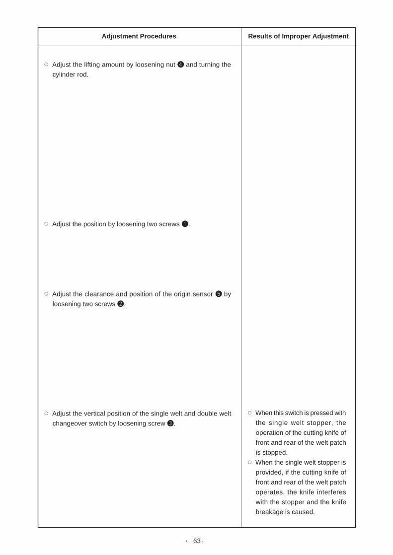
Adjustment Procedures Results of Improper Adjustment
™ Adjust the lifting amount by loosening nut 4 and turning the
cylinder rod.
™ Adjust the position by loosening two screws 1.
™ Adjust the clearance and position of the origin sensor 5 by
loosening two screws 2.
™ Adjust the vertical position of the single welt and double welt
changeover switch by loosening screw 3.
™ When this switch is pressed with
the single welt stopper, the
operation of the cutting knife of
front and rear of the welt patch
is stopped.
™ When the single welt stopper is
provided, if the cutting knife of
front and rear of the welt patch
operates, the knife interferes
with the stopper and the knife
breakage is caused.

- 64 -
35 to 36 mm
54 mm
5 to 6 mm
135 mm
12.5 to 13.5 mm
3 to 4 mm
1.5 to 2.5 mm
Standard Adjustment
2) Flap supply unit (left) : SA103
Clamp click
Binder
Top surface ofsewing table
1
2
3
4
5
6
7
8
9
!0
!1
!1

- 65 -
Adjustment Procedures Results of Improper Adjustment
1) Adjust with stopper 1 the clearance (3 to 4 mm) in the height
direction between the clamp click and the binder when the clamp
click comes down.
2) Adjust with stopper 2 the vertical travel amount of the flap
supply unit.
3) Adjust the clearance (12.5 to 13.5 mm) between the clamp
click and the sewing table by loosening screws 5 and !0.
(To be equal in the longitudinal direction)
4) Adjust with stopper 3 the clearance between the side face of
the binder and the clamp click when the clamp click comes
down.
5) Loosen nut 4 in the oscillating cylinder and adjust the height
(135 mm) of the clamp click from the top surface of the sewing
table when the clamp click returnes to the position of the receiver
plate.
6) Adjust the clamping pressure of the clamp click by loosening
screws 5.
7) Adjust the parallel of the clamp click to the sewing table by
loosening screws 6.
8) Adjust the angle of flap receiver plate !1 by loosening screw 7.
Adjust the longitudinal inclination of the flap receiver plate !1
by loosening two screws 8.
Adjust the clearance (5 to 6 mm) between the flap receiver
plate !1 and the clamp click by loosening two screws 9.
™ If the clearance between the
clamp click and the sewing table
is excessively small, the clamp
click interferes with the flap
presser or the rubber on the
folding plate.
™ If the clearance between the
clamp click and the sewing table
is excessively large, there is a
danger that the finished size of
the flap varies.

- 66 -
15.8 mm
Standard Adjustment
Press the flap presser uniformly.
Align the flap presser with the edge of theholding dish to install it.
3) Flap and bag cloth supply unit (left) : SA104
™ Origin slit should be positioned 15.8 mmfrom the flap receiver plate.
Origin slit
Flap presser arm
Flap presser arm and presser arm driving cylinderdo not interfere with each other, and should movesmoothly.
Flappresser
Holding dish
58.9 mm(Reference value)
1
2
3
4
5
6
78

- 67 -
Adjustment Procedures Results of Improper Adjustment
™ Adjust the position of the origin slit by loosening screw 5.
™ The flap sensor should move in parallel to the holding dish
when the flap sensor moves longitudinally.
Loosen screws 3 and 4 to adjust the flap sensor.
™ The flap sensor should move smoothly without any play.
Loosen screw 1 and 2 to adjust the flap sensor.
™ If it does not move smoothly, loosen screw 6 and adjust the
position and angle of the cylinder.
™ Adjust the pressing pressure of the flap presser by loosening
screw 7.
™ Adjust the longitudinal position of the flap presser by loosening
screw 8.

- 68 -
4.7
mm
0.52 N
f
Standard Adjustment
(a) Adjustment of the sensor slit
™ Position of the origin slit 1 is 15.8 ± 0.3 mm away from holding dish 2.
(b) Adjustment of belt tension
15.8 ± 0.3 mm
1 2
3
4
5

- 69 -
Adjustment Procedures Results of Improper Adjustment
(a) Adjustment of sensor slit
Loosen setscrew 3 and adjust origin slit 1.
(b) Adjustment of belt tension
1) Loosen four setscrews 4 in the motor, draw motor 5 in the
direction of the arrow f to stretch the belt.
2) Apply a 0.52N load to the center of the belt and confirm that
the belt sags 4.7 mm.
™ I f the bel t is excessively
stretched, the service life of the
belt is deteriorated or driving
torque will be caused.
™ If the belt is insufficiently
stretched, tooth skipping will be
caused.

- 70 -
(58.9 mm)
Standard Adjustment
(c) Adjustment of flap presser
™ Distance from flap presser arm 1 to the edge of holding dish 2 is (58.9 mm). (Reference value)
In addition, install so that flap presser arm 1 and the edge of holding dish 2 should be almost
parallel.
™ Pressure on the top end side of flap presser 3 is low and the flap presser is installed slightly
slantingly.
Top end
Top end3
4
1
2
3
4
5
6
7
8
9
3

- 71 -
Adjustment Procedures Results of Improper Adjustment
1) Loosen two setscrews 7 in the flap presser rotating base to
adjust the flap presser.
Note) At this time, check that flap presser cylinder 8 moves
smoothly. (Expel air from the cylinder to check.)
2) Loosen two setscrews 6 in the flap presser base, move flap
presser base 5 in the direction of the arrow, and adjust so that
flap presser 3 is aligned with the edge of holding dish 4.
3) Loosen two setscrews 9 in the flap presser and install flap
presser 3 slightly slantingly to increase the pressure on the
top end side of flap presser 3.
™ Flap is not pressed or flap may
slip at the time of delivery of flap.
- 72 -
AB
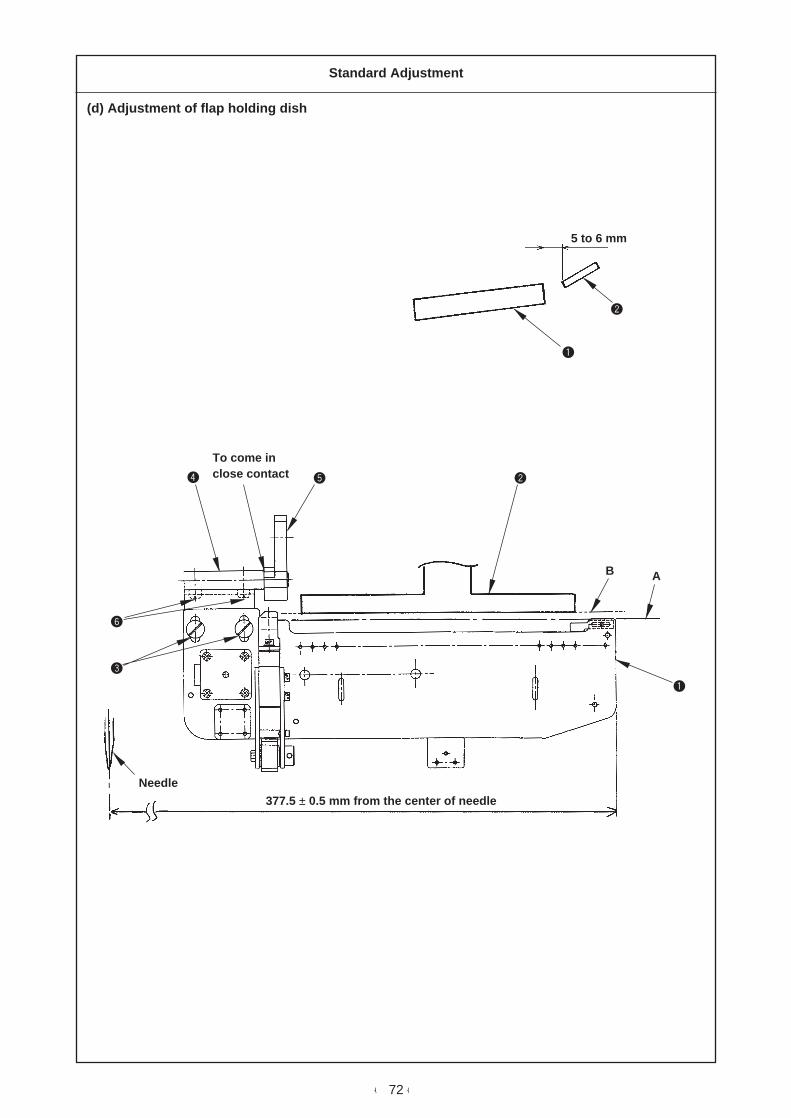
Standard Adjustment
(d) Adjustment of flap holding dish
5 to 6 mm
To come inclose contact
377.5 ± 0.5 mm from the center of needle
Needle
1
2
3
4 5
6
1
2

- 73 -
Adjustment Procedures Results of Improper Adjustment
1) Loosen two setscrews 3 in the flap holding dish and adjust so
that the clearance between flap holding dish 1 and clamp nail
2 is 5 to 6 mm and so that the edge A of flap holding dish 1 is
parallel to the edge B of clamp nail 2.
2) Loosen two setscrew 6 and adjust the flap holding dish to
377.5 ± 0.5 mm away from the center of the needle. (At this
time, make holding plate fitting shaft 4 come in close contact
with shaft base 5.)
™ When the clamp nail is not in
parallel to the flap holding dish,
the flap is sewn slantingly.
™ The sewing position of the flap
in the lateral direction may slip.

- 74 -
135 mm
89 mm
4) Dart extending unit : SA106
CN36 connector
CN43connector
Center ofthe needle
Top surface ofsewing table
Top surface ofsewing table
Assembling procedure
Control box
1
2
3
6
7
8
5
6
7
8
9
!0
13
4
!1
!0

- 75 -
™ Connect dart extending cylinder 2 to connecting plate 1 with
the screws as shown.
™ Install the solenoid valve for dart extending 5 with the screws
at the second place from the right side of the upper manifold
while inserting a packing between the valve and manifold.
• Piping
Connect the air tubes of ø4, green 6 and yellow 7, located on
the side of dart extending cylinder to the joint of the solenoid valve.
• Wiring
Connect the connector of the dart upper detection sensor 8 to
CN36 located on MAIN circuit board 9.
Insert the pins of the solenoid valve cable !0 into No. 45, +24V
and No. 46, Dart output of the connector CN43.
1. Position of the dart extending
Determine the center at the positon of 135 mm from the center
of the needle.
If the 135 mm is not obtained, loosen screws 4 in connecting
plate 1 to adjust the position.
The presser of the dart extending should press the upper part
of the center of the needle.
Adjust the lateral direction by loosening screw 3.
2. Loosen nut !1 and adjust the height of the dart extending so
that it is 89 mm from the top surface of the sewing table.
™ When the screw is excessively
tightened, malfunction of the
cylinder is caused.
Assembling procedure Caution when assembling

- 76 -
5) Suction unit : SA108
Packing (2)
Packing (1)
Control box
CN73 : Vacuum output OUT-71
For vacuum
Assembling procedure
1
2
3
6
7
4
5
6
7
AB
A
B

- 77 -
™ Attach suction plate 1 together with packings (1) and (2) in
the rear of the main body frame with screws (spring washers
and nuts). 5 places
™ Attach duct attching base 2 to main body frame 3 with screws.
(spring washer and nut).
™ Replace the sewing table with the one for vacuum.
™ Attach the solenoid valve to the solenoid valve base.
™ Connect the solenoid valve cable 4 to CN73 connector on I/O
circuit board 5 inside the control box.
™ Connect the air tubes, ø4 Yellow 6 and ø4 Green 7 of the air
cylinder for valve drive to the solenoid valve.
Assembling procedure Caution when assembling

- 78 -
6) Interlining feeding unit : SA109
Control box
CN71 connector
CN68 connector
Assembling procedure
ø6Tube
ø6 TubeFinger valve
Solenoid valveSteppingmotor
1
2
3
4
5
6
9
7
8
9

- 79 -
™ Attach the interlining feeding unit body from the top surface of
the table with screws 1 and nuts 2 (3 places). (In this case,
place a spacer 3 between the body frame and the interlining
feeding unit and fix the unit. In case of the machine with the
vacuum unit, the spacer is not necessary.)
Piping
™ Connect ø6 Blue tube 4 to the solenoid valve from the air
supply tube of the solenoid valve located at the power switch
bracket section located under the right-hand bottom of the table.
Connect ø4 Yellow 5 and ø4 Green 6 tubes to the cylinder
for scissors drive.
Wiring
™ Insert +24V cable of solenoid valve cable for scissors drive 7
to No. 35 of CN68 connector on I/O circuit board 8 inside the
control box and insert the output cable to No. 36 of CN68
connector.
™ Insert automatic interlining feeding cable 9 of the stepping
motor for interlining feeding to CN71 connector on I/O circuit
board 8.
Assembling procedure Caution when assembling

- 80 -
Standard Adjustment
Interlining feeding unit <SA109>
Interlining
0.8 to 1.2 mm
1.5 to 2 mm
Moving knife0.3 to 0.5 mm
0.8 to 1.2 mm
1 to 1.5 mm
Moving knife
Guide (D)
Guide (C)
8
9!0
2
3
4
8
9
!0
5
67

- 81 -
Adjustment Procedures Results of Improper Adjustment
1) Position of guide A !0 in terms of fixed knife 8 should be 0.3 to
0.5 mm away from the blade point and 1.5 to 2 mm away from
the top surface of the blade. When the position is not obtained,
loosen screws 2 to adjust the position.
2) Top end of guide B 9 should be in the position of 0.8 to 1.2
mm from the bottom face of fixed knife 8. When the position is
not obtained, loosen screw 3 to adjust the position.
3) Guide A !0 and guide B 9 should be parallel and perpendicular
each other. If they are not parallel, adjust them by loosening
screw 3.
4) Provide a clearance of 1 to 1.5 mm between guide A !0 and
guide B 9. If not, adjust it by loosening screw 3.
5) Length of engagement of scissors on the fixed side and that on
the moving side shoud be 0.8 to 1.2 mm at the top end.
6) Loosen screw 4 and adjust pressing pressure of guide B 9
so that it is equal at the left end and right end of the interlining
feeding roller.
7) Rolled interlining should be fed to the center through the slot
section of the table.
Loosen screws 5, 6 and 7 for fixing guide to adjust the guide
in accordance with the width of the interlining.
8) Adjusting the interlining guide position
It is necessary to adjust so that the guide (D) is positioned in
the center of the slot of the sewing table and that the height is
aligned with the table surface.
Loosen setscrew A to adjust the longitudinal position and
setscrew B to adjust the height.
Guide (D)
A
B
Sewing table
Guide (C)

- 82 -
7) Single welt and double welt change unit (right) : SA111
Set collar
Set collar
Assembling procedure
!1
!2
5
6
7
8 9
!0
1
2
34
6
!0
1
2
3
4
!2
!3
1
!3

- 83 -
™ Attach finger valve 6 to the fulcrum base 5 with the screws.
™ Attach cylinder stay 7 to fulcrum base 5 with the screws.
™ Connect cylinder stay 7 to air cylinder 8 with the pin.
™ Assemble rod end 9 to cylinder 8.
™ Attach rod end 9 to clamp foot arm (right) !0 with the screw.
™ Attach air operate valve !2 to solenoid valve base (1) !1 with
the screws.
• Air piping
™ Branch ø6 tube !3 from the regulator, and connect one of ø4
black tube 1 to air operate valve !2 and the other to finger
valve 6.
™ Connect ø4 pink tube 2 from finger valve 6, ø4 blue tube 3
and ø4 transparent tube 4 from air cylinder 8 to air operate
valve !2 via the rear of the clamp foot.
™ Clamp foot arm (right) !0 should move to the left or right (ba)
by the air cylinder 8 when finger valve 6 is changed over.
™ Adjust the position of the set collar so that it is the position of
the double welt when the clamp foot arm is on the left and that
it is the position of the single welt when the clamp foot arm is
on the right.
Assembling procedure Caution when assembling
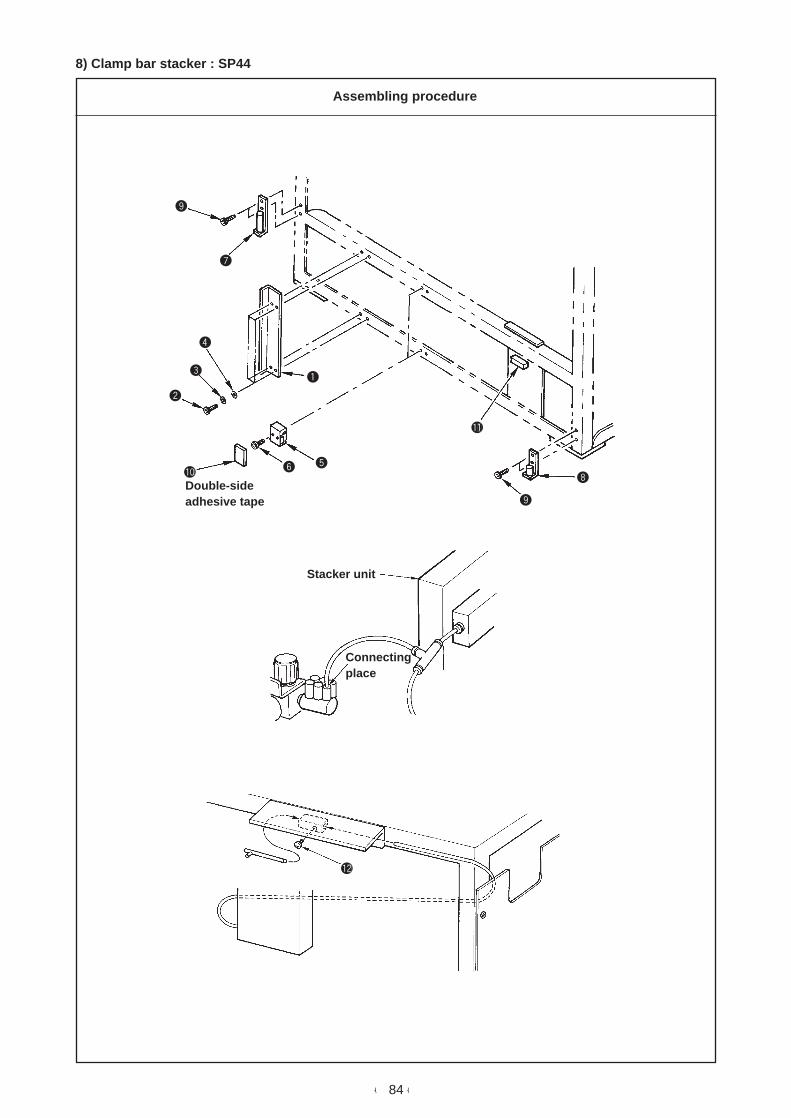
- 84 -
8) Clamp bar stacker : SP44
Connectingplace
Stacker unit
Double-sideadhesive tape
Assembling procedure
1
2
3
4
56
7
8
9
!0
!1
!2
9

- 85 -
™ Attach hinge attaching plate 1 to the left side face of the body
frame with four pcs. each of screw 2, spring washer 3 and
flat washer 4.
™ Attach two connecting blocks 5 to the left side face of the
body frame with two pcs. each of screw 6.
™ Peel off the paper on the double-side adhesive tape on the
rubber cushion and paste rubber cushion !0 to connecting block
5. (2 places)
™ Attach pipe support (1) 7 and pipe support (2) 8 with setscrews
9.
™ Put the whole stacker on the hinge to set it.
™ Connect the connector on the stacker side to connector A !1.
™ Connect the air source from the joint at the top of the regulator.
™ Perform piping to the pipe for air blow and fix it with setscrew
!2.
Assembling procedure Caution when assembling

- 86 -
Standard Adjustment
Clamp bar stacker : SP44
Cloth presser bars (1) 5 and (2) 6 should uniformly
press cloth holder base 7.
In addition, the relation between cloth presser bar (1)
5 and that (2) 6 in terms of cloth holder base 7
should be as shown in the figure.
(Bars (1) and (2) do not interfere with each other.)
When cloth presser bar (2) 6 is released, it should
not come in contact with left side cover !2.
When the clamp bar stacker is in the standby state,
the relation between cloth brush bar 8 and cloth
presser bar (1) 5 should be as shown in the figure.
Position of the cloth placing base
32 mm
Sub table
10 mm
120 mm
86 mm
180 mm
11mm
Cloth placingbase
123
4
5
6
7
8
5
6
7
!2
5 8
9
!2
5
8
!0
!1
!2

- 87 -
Adjustment Procedures Results of Improper Adjustment
™ Adjust the inclination and the protruding amount of cloth presser
bar (1) 5 by loosening screw 1.
™ Adjust the inclination and the protruding amount of cloth presser
bar (2) 6 by loosening screw 2.
™ Adjust the stroke of cloth presser bar (2) 6 by loosening screw
3.
™ Adjust the position of cloth brush bar 8 by loosening nut 4.
™ Adjust the dimension 180 mm from left side cover !2 to the
cloth placing base by loosening nut 9.
™ Adjust the positions of cloth presser bar (1) 5 and cloth brush
bar 8 by loosening nuts !0 and !1.

- 88 -
4. OPERATION PANEL(1) Operating the operation changeover screen
• Turn ON “2” of the DIP switch (DSW1) located on the side of the panel, and press “1” of the numeric
keys, while holding pressing key. Then the screen moves to the operation selection screen.
• Each operation can be changed in this screen.
• Pictograph No. is displayed above each pictograph.
Data contained in < > change when key is pressed.
< DB >
[ DF ]
Alphabet “D” means that this screen is the operation selection screen.
Alphabet in this section means the pictograph No. (A to G)
Data contained in [ ] do not change even when key is pressed.
* Setting of binder self-holding operation changeover *
: Self-holding of operation of clamp foot and binder is not performed.
: Self-holding of operation of clamp foot and binder is performed.
Press the RESET button to release this setting.
Standard operation
* Setting of back tack stitching operation changeover *
: Standard operation
(The sewing machine temporarily stops at the time of back tack stitching
operation.)
: The sewing machine dose not stop and continues to sew in the back tack
stitching.
* Setting of folding plate release at the time of corner knife operation *
: Folding plate is closed and flap presser continues to be closed at the time of
corner knife operation.
: This setting returns the folding plate and opens the flap presser at the time of
corner knife operation.
Standard operation
* Setting of binder oscillating operation changeover *
: Automatic welt patch feeding unit operates.
Standard operation
: Automatic welt patch feeding unit stops.
(Binder does not oscillate.)
<DA>
<DB>
<DC>
<DD>

- 89 -
[DE]
7 0 0
1 0 0 0
[DF]
[DG]
* Setting of starting speed at the sewing start *
Data setting commendable value : 500 rpm
(Data range : 500 to 2,500 rpm)
Setting data (input with the numeric keys)
* Setting of speed of 2nd stitch at the sewing start *
Data setting commendable value : 700 rpm
(Data range : 500 to 2,500 rpm)
Setting data (input with the numeric keys)
* Setting of speed of 3rd stitch at the sewing start *
Data setting commendable value : 1,000 rpm
(Data range : 500 to 2,500 rpm)
Setting data (input with the numeric keys)
(2) Check program 8
Status of the batch of sensors is displayed in this screen.
1) Pressing adjustment data edit screen key, press “0” of the numeric keys, and pictograph No. [
CP ] “CHECK PROGRAM” is displayed in the operation display section.
2) Press “8” of the numeric keys, then press key to start CHECK PROGRAM mode = 8. At this time,
the screen below is displayed.
Press “R” key to end the check program and the screen returns to the standard one.
(Caution) IN67 to 96 are for reserves.
* → 0 1 2 3 4 5 6 7 8 9
IN0*
IN1*
IN2*
IN3*
IN4*
IN5*
IN6*
IN7*
IN8*
IN9*
CHECK PROGRAM : ON
: OFF
KEY <R> = RETURN
5 0 0

- 90 -
(3) Initial setting table
The initial value of each data is as given below when the power is turned ON.
1) <Sewing pattern screen>
* Operation mode changeover *
: Cloth feed mode (at this time, tension disk is closed.)
* Sewing mode changeover *
: L-size sewing
* Sewing reference changeover *
: Rear-reference sewing (The sewing end position is spaced 320 mm away from
the needle bar.)
* Changeover of operation/stop of the automatic flap feeding unit *
: Setting of the automatic flap feeding unit operation
* Changeover of operation/stop of the stacker operation *
: Setting of the stacker operation
* Changeover of the welt patch cutting device operation *
: Setting of the welt patch cutting device operation
* Flap jump speed setting *
: Flap jump speed (unit : mm/s)
* Setting of flap concealed stitching data *
: Flap concealed stitching data for the sewing start of left-hand side seam (seam
is produced outside the flap.)
* Setting of flap concealed stitching data *
: Flap concealed stitching data for the sewing end of left-hand side seam (seam
is produced outside the flap.)
* Setting of flap forced stop data *
: Flap forced stop
<AA>
<AB>
0
<AC>
<AD>
<AE>
<AF>
[AG]
<AH>
<AI>
[AL]
2 5 0
0. 0
5
0. 0

- 91 -
* Corner knife selection *
: Corner knife selection
* Setting of difference at the sewing start *
: Difference at the sewing start (The right-hand side seam is shorter than the left-
hand side one.)
* The pictograph appears on the display only for APW-298. For the APW-297, it
will not appear on the display.
* Setting of difference at the sewing end *
: Difference at the sewing end (The left-hand side seam is shorter than the right-
hand side one.)
* The pictograph appears on the display only for APW-298. For the APW-297, it
will not appear on the display.
* Setting of the center knife actuating position at the sewing start *
: Center knife actuating position at the sewing start
* Setting of the center knife actuating position at the sewing end *
: Center knife actuating position at the sewing end
* Setting of the corner knife actuating position at the sewing start *
: Corner knife actuating position at the sewing start (The knife retracts.)
* Corner knife actuating position at the sewing end *
: Corner knife actuating position at the sewing end (The knife retracts.)
* Lockstitch pitch setting *
: Lockstitch pitch
* Setting of condensation stitching and back tack stitching at the sewing
start *
: Setting of condensation stitching and condensation pitch at the sewing start
[AM]
<AN>
<AO>
[AP]
[AQ]
<AR>
<AS>
[AT]
<AU>
1
0
0
1 2
1 2
0 . 0
0 . 0
2 . 5
1 . 0

- 92 -
* Setting of the number of back tack stitches at the sewing start *
: Setting of the number of back tack stitches at the sewing start
* Setting of condensation stitching and back tack stitching at the sewing end *
: Setting of condensation stitching and condensation pitch at the sewing end
* Setting of the number of back tack stitches at the sewing end *
: Setting of the number of back tack stitches at the sewing end
* Dart stretcher operation changeover *
: Dart stretcher is set to operative.
* Vacuum operation changeover *
: Vacuum is set to operative.
* Changing over the operation of the automatic interlining cloth feeder *
: Automatic interlining cloth feeder is set to operative.
2) <Counter screen>
* Total counter *
* No. of pcs. counter *
* Bobbin thread counter *
* Setting of the actuation of the bobbin thread remaining amount detecting
device and the bobbin thread remaining amount adjusting counter *
[AV]
<AW>
[AX]
<AY>
<AZ>
<Aa>
[BA]
[BB]
[BC]
<BD>
3
1 . 0
3
0
0
0
0

- 93 -
3) <Adjustment data edit screen>
<CA>
<CB>
<CC>
<CD>
<CE>
[CF]
[CG]
[CH]
0 . 1 0
1 . 5 0
6 0
<Ca>
* Changeover of the clamp foot position after completion of sewing *: Back end stopping mode
* Changeover of operation/stop of optional dart stretcher*: Dart stretcher operates.
* Changeover of operation/stop of optional vacuum *: Vacuum operates.
* Setting of the speed of the automatic interlining cloth feeder *: Low speed* The pictograph appears on the display only when the automatic interlining cloth
feeder is mounted.
* Excess length of interlining cloth to be fed by the automatic interliningcloth feeder (at the start of sewing) *
* The pictograph appears on the display only when the automatic interlining clothfeeder is mounted.
* Excess length of interlining cloth to be fed by the automatic interliningcloth feeder (at the end of sewing) *
* The pictograph appears on the display only when the automatic interlining clothfeeder is mounted.
* Welt patch sensor detecting time *: Stop
* Setting of thread trimming timing *: Timer of the thread trimmer (standard timing)
* Setting of the stacker timer 1 *: Stacker timer 1 (unit : second)
* Setting of the stacker timer 2 *: Stacker timer 2 (unit : second)
* Setting of needle throwing ratio for the normal feed section *: Needle throwing ratio for the normal feed section(The needle throws in direction same as that of the feed.)
15
15
[Cb]
[Cc]

- 94 -
[CK]
[CL]
<CM>
[CN]
[CO]
[CP]
<CR>
<CS>
3 0 0 0
1 5 0 0
2 . 0 0
2 . 0 0
0
* Setting of needle throwing ratio for the back tack stitching at the sewing
start *
: Needle throwing ratio for the back tack stitching at the sewing start
(The needle rocks in the opposite direction of the feed.)
* Setting of needle throwing ratio for the back tack stitching at the sewing
end *
: Needle throwing ratio for the back tack stitching at the sewing end
(The needle throws in direction same as that of the feed.)
* Setting of sewing speed under the high-speed mode *
: Number of revolutions for lockstitching
* Setting of sewing speed under the low-speed mode *
: Setting of the sewing speed for condensation stitching or backtacking
* Setting of the sewing machine independent operation mode *
: The sewing machine independent operation mode starts up using the DIP
switches.
: No operation
* Setting of ON time of the intermittent operation of the sewing machin
under the independent sewing mode *
* Setting of OFF time of the intermittent operation of the sewing machine
under the independent sewing mode *
* Check program mode selection *
* Front reference position changeover *
: Front reference position is spaced 140 mm away from the needle position.
* Display mode changeover *
: Cycle mode
[CI]
[CJ]
6 0
6 0

- 95 -
4) <Operation selection screen>
* Setting of binder self-holding operation changeover *
: Standard operation
* Setting of back tack stitching operation changeover *
: Standard operation
* Setting of folding plate release when the corner knife actuates. *
: Standard operation
* Seting of binder oscillating operation changeover *
: Standard operation
* Setting of starting speed at the sewing start *
: Data setting commendable value : 500 rpm
* Setting of speed of 2nd stitch at the sewing start *
: Data setting commendable value : 700 rpm
* Setting of speed of 3rd stitch at the sewing start *
: Data setting commendable value :1,000 rpm
<DA>
<DB>
<DC>
<DD>
[DE]
[DF]
[DG]
5 0 0
7 0 0
1 0 0 0

- 96 -
(4) Setting of DIP switches located in the rear of the panel
1 2 3 4 5 6 7 8
OFF
The switch has to benormally set to “OFF”.
5 and 6 : Changeover of the model
5 6
: APW297
: APW298
7 : Display of Key lock switch
: Standard (Key lock switch isdisplayed.)
: Key lock switch is not displayed.Display of changeover of cyclemode and pattern mode
8 : Changeover of display
(Caution) To change the DIPSW, be sure to perform the change with the power OFF.
: Standard display
: Inversion display

- 97 -
5. PARTS TO WHICH GREASE OR LOCKTITE IS APPLIED
Main shaft and thread take-up lever components
Needle bar frame components
LOCKTITE (Bearing mount)
LOCKTITE (Bearing mount)
LOCKTITE (Bearing mount)
Molybdenum greaseGrease
Grease
Grease

- 98 -
A
A
A
A
B
Needle feed components
Bobbin thread trimmer components Needle thread trimmer components
Molybdenumgrease
Molybdenum grease
Molybdenum grease
Molybdenum grease
LOCKTITE 242
LOCKTITE 242
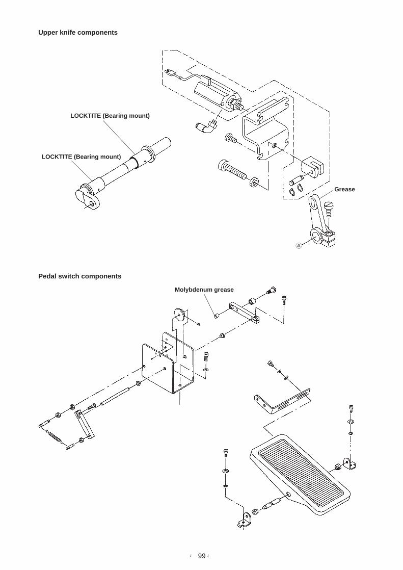
- 99 -
A
Upper knife components
Pedal switch components
LOCKTITE (Bearing mount)
Grease
LOCKTITE (Bearing mount)
Molybdenum grease

- 100 -
A
Clamp foot (left side) components (2)
Molybdenum grease
Molybdenum grease
Molybdenum grease
Molybdenum grease
Molybdenum grease

- 101 -
Clamp foot (right side) components (3)
Molybdenum grease
Molybdenum grease

- 102 -
Corner knife components (1)
Clamp foot feed components
Molybdenum grease
Molybdenum grease
LOCKTITE 242
LOCKTITE 242

- 103 -
Corner knife components (2)
Corner knife components (4)Molybdenum grease
LOCKTITE 242
LOCKTITE 242 LOCKTITE 242
Molybdenum grease
Molybdenum grease
Molybdenum grease
LOCKTITE 242

- 104 -
Binder components (1)
Binder components (2)
Molybdenum grease
Molybdenumgrease
LOCKTITE 242

- 105 -
Front binder components
Welt patch clamp unit component
(for double welt, right)
Automatic flap supply unit (left) (1)
(Optional)
Molybdenum grease
Molybdenum grease
Molybdenum grease
Molybdenum grease
Molybdenum grease
Molybdenum grease

- 106 -
Welt patch cut unit (right) (1) (Optional)
Welt patch cut unit (right) (2) (Optional)
Molybdenum grease
Molybdenum grease
Molybdenum grease
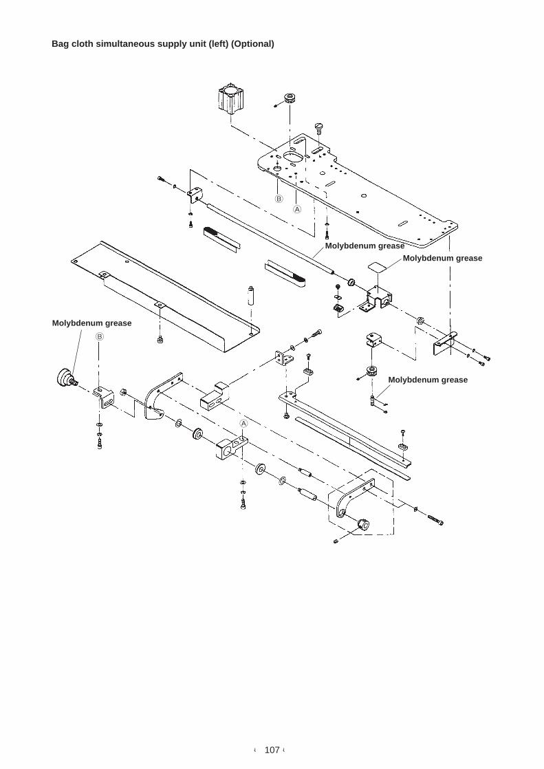
- 107 -
A
A
B
B
Bag cloth simultaneous supply unit (left) (Optional)
Molybdenum grease
Molybdenum grease
Molybdenum grease
Molybdenum grease

- 108 -

– 109 –
6. AIR CIRCUIT DIAGRAM (APW-297, -298)
Corner knifeelevating (1)
Single welt/double welt change unit
Welt patch cut unit
Knife cut pressercylinder
Knife liftingcylinder
Welt patchpresser cylinder
Automatic interlining feeding unit
Clamp bar stacker
Blind
Air blow Cloth presser(A)
Cloth holdingbase elevating
Cloth presser (B)Cloth brush
Dart extending unit Suction unit
Flap presser(left) open
Flap presser(left) close
Threadtension
Wiper Bobbin threadtrimming
Needle threadtrimming (1)
Needle threadtrimming (2)
Bobbin airblow
Dart Suction unit
Bag cloth simultaneous supply (left)
Automatic flap supply (left)
Left
bag
clot
hai
r blo
w
Front binder goes up.
Binder comesdown.
Binderoscillating
Needlein /out
Flap oscillating
Flap (close) Flap (open) Flapsupply
Left flapholding
Left bag clothair blow
Bindergose up.
298 only
Blind
Corner knifeelevating (2)
Upper knife Knife lock Clamp foot(left) goes up.
Clamp foot (left)comes down.
Clamp foot(right) goes
up.
Clamp foot(right) comes
down.
Foldingplate
No. Part No. Model No.
1 Elbow union KQL06-01S
2 Elbow union KQL06-M5
3 Elbow union KQL04-M5
4 Elbow union KQL04-01S
5 Different diameter straight KQH06-04
6 Y union KQU06-00
7 Y union KQU04-00
8 Different diameter Y union KQU04-06
9 T joint KQT04-00
!0 T joint KQT06-00
!1 Half union KQH06-02S
!2 Half union KJS06-M5
!3 Half union KJS04-M5
!4 Half union KQH04-M5
!5 Half union IN-298-10
!6 Different diameter straight KQH04-06
!7 Blind tap 1/8”
!8 Blind tap 1/4”
!9 Universal elbow M-5UL
@0 Triple universal elbow KQZT06-02S
@1 Branch elbow union KQLU06-01S
@2 Branch universal elbow KQZ06-01S
@3 Nipple 1/4”
@4 Silencer AN120-M5
@5 Silencer AN103-01
@6 Silencer AN203-02
@7 Silencer AN103-KM6
@8 Finger valve VHK3-04F-04FL
@9 Finger valve VHK3-04F-04F
#0 Finger valve VHK3-06F-06F-L
#1 Different diameter straight KQH04-06
#2 Pipe elbow M-5HL-4
#3 Hose nipple M-5H-4
!3
8
@9
2
6
!6
@4
#0
33
2
@4
2
@4
6
6
6
32
@7
6
@3
@08
!8
!8
!1 !0 !0@6
@6
!8
!0
#0
@4
!3
!2
1
1
1
@5
@5
3
!9!4
!7
!7
@2
!7
!7
@1
3 #37
3
#2
!9
!5 3
1
@1
@5
@5
!7
!7
4 4 3 !3
!3
9
3
#1 #17
77
#1
@5
@5
1
2
!3
3
Air
blow
Air
blow
Relluxvaccum
(Caution) The diameter of air hose withoutindication is to be ø4.
6
@78

– 110 –
7. ELECTRICAL CONTROL BOX
(1) Explanation of components
1) Arrangement in the control box
This diagram describes the components arranged inside the control box such as the circuit board, transformer, etc.
As for the cables, those whose both ends are connected inside the box are described and others whose ends are taken to the outside of the box are omitted.
HX004070000Square type bushing
SL4041091SCCord stopper plate setscrews x 2
17845009Cord stopper
HX00221000AGrommet
G85442980A0J30 cord asm.
HX004100000Cord bushing
E9567319000Earth mark seal
SL4040881SC Piping duct setscrew X 2WP0451018SP Piping duct washer X 2
M90025800A0J33 cord asm.
M90315900A0J38 cord asm.
G85512980A0 I/O power cord asm.
M9020580AA0J31 cord asm.
SL4041291SCTerminal board 2P setscrew X 2
HK026650020Terminal board 2P
Connect J30 cord earth wire (SW side).
Connect J30 cord earth wire (J30 side).
Connect transformer earth wire.(SL4040681SC x3)
G85412980A0MAIN power cord asm.
M8802590AA0SDC circuit board
HX00013000BWiring duct
M8804590000POWER circuit board
SM4031851SR Terminal board setscrew X 4WS0310702KS Terminal board washer X 4
E9567319000Earth mark seal
* As observed f rom thereverse side. So, be careful.
White
Black
Blue
HK054250060Terminal board 8P
HX00222000CCord stopper X 5
G85422980A0SDC I/F cord asm.
G8610298AA0MAIN circuit board A asm.
G85502980A0 I/O I/F cord asm.
G86302890A0 I/O circuit board asm.
HX00147000CCircuit board spacer X 9
EA950080100Clip band X 3
(Note) Net marker stamp upward
G89012980A0Power transformer
asm. (Primary side)
HK054250040Terminal board 4P
SL4030891SCCircuit board setscrew X 16
G85402980A0PMDC power cord asm.
G85432980A0PMDC I/F cord asm.
17845009Cord stopper
SL4041091SCCord stopper platresetscrew X 2
HX004070000Square type bushing
SL4051081SFTransformer setscrew X 4
Pass CN1 and CN19 connectingcables through the cord stopper.
G1000298000Rating plate

– 111 –
2) Function and setting place of each circuit board
This machine contains the respective circuit boards in two places; one is in the control box located on the right bottom
side of the table (inside of the side cover) and the other in the operation panel box.
Main functions and setting places of the respective circuit boards are as given below.
Five sets of the circuit boards are set inside the control box.
However, for PMDC circuit board asm. only, the circuit board for APW-297 is different from that for APW-298.
Control box
Two sets of the circuit boards are set in the operation panel box.
Operation panel box
1 MAIN circuit board A asm. : This is the circuit board which performs main control of this machine.
2 SDC circuit board asm. : This circuit board performs the control of main shaft servo motor of the machine head.
3 I/O circuit board asm. : This circuit board performs input/output of sensor, solenoid valve, stepping motor, etc.
4 POWER circuit board : This circuit board mainly provides control power voltage.
5 PMDC circuit board asm. : This circuit board performs travel of the corner knife and control of the stepping motor
for selection.
(Caution) The EPROMs (2 places) mounted with the part No. of the aforementioned MAIN circuit board A
asm. are raw ROMs. The ROM after writing is required.
For the details, refer to the item "Replacing the EPROM" on page 113.
6 PANEL SW circuit board asm. : This circuit board performs the input of each switch and DIP switch on the panel.
7 PANEL CONTROL circuit board A asm. : This circuit board performs enclosing of display control data of the operation panel.
(Caution) The EPROM (one place) mounted with the part No. of the aforementioned PANEL CONTROL circuit
board A asm. is a raw ROM. The ROM after writing is required.
For the details, refer to the item "Replacing the EPROM" on page 113.
6 G8621298A0PANEL SW circuitboard asm.
2 M8602590AA0SDC circuit boardasm.
4 M86045900D0POWER circuitboard asm.
1 G8610298AA0MAIN circuit board A asm.
3 G86302980A0I/O circuit board asm.
5 PMDC circuit board asm.M86025110F0 (APW-297)M86025110A0 (APW-298)
7 G8620298AA0PANEL CONTROL circuitboard A whole asm.

– 112 –
(2) Replacing the components
1) Replacing the fuse
1 F1 fuse 10A
For AC200 to 415V protection
Fuse for main power line protection
2 F2 fuse 10A
For AC200 to 415V protection
Fuse for main power line protection
3 F3 fuse 10AT
Fuse for DC+35V and +24V protection
For the power of stepping motor, solenoid valve, sensor, etc. protection
4 F4 fuse 10AT
Fuse for DC+24VA protection
For the power of servo motor for clamp foot travel protection
5 F6 fuse 3A
Fuse for DC+5V protection
For the power for control circuit drive protection
1
2
3 4
5

– 113 –
2) Replacing the EPROM
There are four mounting places of EPROM in total for this machine.
Mount the designated EPROMs in the respective designated places.
There are two places, A and B where the EPROMs are mounted in the MAIN circuit board.
(3) Checking the set value of the power voltage and changing
the voltage
There is a place, C where the EPROM is mounted in the PANEL-CTL
circuit board.
Mounting ROM APW-298 APW-297 Contents of main control Name of circuit board
A U18-27C1024 (40 Pin) HL015930049 HL015930049 For main operation control MAIN circuit board
B U5-27C1001 (32 Pin) HL010520221 HL010520221 For clamp foot servo motor control
C U15-27C4096 (40 Pin) HL015310021 HL015310021 For operation panel control PANEL-CTL circuit board
D U8-27C256 (28 Pin) HL008423064 HL008423064 For DD servo motor control SDC circuit board
A B
C
D
MAIN circuit board
There is a place, D where the EPROM is mounted in the SDC circuit
board.
PANEL-CTL circuit board
The power voltage is set by the blue wire on the J31 side of the terminal board
connected as shown in the figure above. Accordingly, the example of the figure
on the above shows the connection to the 200V power.
When changing the power voltage, it is necessary to change over the blue wire
on the J31 side to the voltage tap to be used.
Check again that the power is turned OFF and connect the blue wire on the J31
side to the tap on the transformer side wire to which the same voltage as that to
be used is described.
However, it is not necessary to change other wires. Fix the wires other than blue
one.
(A caution seal is pasted on 0V and 200V sections on the front side of the power
tap terminal board for prevention of mis-wiring.)
For these machine models, it is not necessary to change wiring in the control box
due to the difference between single phase and 3-phase power source.
Re-setting on the power tap terminal board is required only when the change of
the power voltage has occurred.
Screw hole
Blue wire (J31-1)
Black wire (J31-2)
White wire (J31-4)
415V (Blue wire)
400V (Purple wire)
380V (Orange wire)
240V (Red wire)
230V (Brown wire)
220V (Yellow wire)
200V (White wire)
NC
200V (White wire)
0V (Black wire)
Front side
J31 side Transformer side

– 114 –
8. LIST OF ALARM CODESAn alarm No. is displayed on the display screen in the operation panel when an alarm has occurred.
For APW-298 only
For APW-298 only
For APW-298 only
For APW-298 only
For APW-298 only
Alarm No.
01
02
04
05
06
08
09
10
11
12
13
14
15
16
17
18
19
21
23
26
27
28
29
30
31
32
34
35
36
37
38
39
40
41
43
44
45
49
52
53
54
Description
Temporary stop
Trouble of servo motor for clamp foot travel See "MAIN circuit board
alarm table".
Detection of thread breakage
Step-out of corner knife stepping motor
Step-out of turret stepping motor
Corner knife fails to lock.
Failure in detection of corner knife being in the lower end position
Failure in detection of center knife being in the upper end position
Automatic welt patch and flap supply units are not in the correct home
position.
Trouble of needle up position
Detection of dust on the front end of the flap
Flap is not detected.
Corner knife cannot move from the current position.
Flap sensor fails to receive light.
Position of the stacker is not correct.
Trouble of the dart extending unit
Binder is released.
L size, outside the range of data
Flap detecting speed, outside the range of setting
Lockstitch pitch, outside the range of data
Condensation pitch, outside the range of data
Back tack pitch, outside the range of data
Flap concealed stitching at the sewing start (right), outside the range of
data
Flap consealed stitching at the sewing end (right), outside the range of
data
Center knife at the sewing start, outside the range of data
Center knife at the sewing end, outside the range of data
Flap consealed stitching at the sewing start (left), outside the range of
data
Flap consealed stitching at the sewing end, outside the range of data
Corner knife cutting length at the sewing start, outside the range of data
Corner knife cutting length at the sewing end, outside the range of data
Difference at the sewing start, outside the range of data
Difference at the sewing end, outside the range of data
Flap forced stop, outside the range of data
Error in setting the stacker
Error in setting the gauge size
RAM error
Error of the sensor to detect the front end and rear end of the clamp foot
travel
Needle thread breakage upper detection failure
In the cycle sewing mode, the slant at the sewing start is set to a wrong
direction.
In the cycle sewing mode, the front difference is set to an incorrect
value.
In the cycle sewing mode, the slant at the sewing end is set to a wrong
direction.
Description
In the cycle sewing mode, the rear difference is set to an incorrect value.
Pedal input error
Corner knife selection, outside the range of data
Number of stitches of back tack stitching at the sewing start, outside
the range of data
Number of stitches of back tack stitching at the sewing end, outside the
range of data
Condensation pitch at the sewing end, outside the range of data
Back tack pitch at the sewing end, outside the range of data
Malfunction of the welt patch cut unit
Malfunction of the flap presser
Trouble of stepping motor for adjusting the needle throw angle
Main shaft motor driver is defective. (PSC is defective.)
Sewing machine rotation at high speed, outside the range of data
Sewing machine rotation at low speed, outside the range of data
Sewing machine independent intermittent operation time 1, outside the
range of data
Sewing machine independent intermittent operation time 2, outside the
range of data
ROM version error of the main panel
Communication error
Alarm No.
55
59
62
63
64
65
66
67
68
69
70
75
76
77
78
90
95
For APW-298 only
• MAIN circuit board alarm table (See when "AL-02" has occurred.)
1 time : Motor-lock
2 times : Fuse has blown.
3 times : Defective power voltage Power voltage is outside the range.
4 times : Defective boosting voltage Trouble of pre-driver in the circuit
board
5 times : Disconnection of the encoder cable
6 times : Detection of defective current of pre-driver
7 times : Defective temperature of pre-driver Abnormal rise of
temperature inside the control box
8 times : Slip of the position of clamp foot
9 times : Overrun error of clamp foot
10 times : Overflow of accumulated pulses
11 times : Overload
12 times : Overload
13 times : Defective number of revolutions
14 times : System error
Check the alarm by the number of times of flashing on/off of the red LED (LD1) lamp on the MAIN circuit board.
Count the long flashing on/off as "1" time and the continuing short flashing on/off as "2" times. Continue to count the number of
times of short flashing on/off as the number of times after "2" times.
Red LED (LD1) on MAIN circuit board
Electrical component box (control box)

– 115 –
9. NAMES AND INSTALLING POSITIONS OF THE SWITCH SENSORS
@5
@6
5
4
78
!4
!7
!8
!3
2
3
!1!2
%1
%9
No.23456781112131416171819202223
24
252627295152535455585961646566
100
NameNeedle thread breakage upper detectionBinder lowering detectionCorner knife fixed side lower detectionCorner knife travel side lower detectionCenter knife upper detectionCorner knife fixed side upper detectionCorner knife travel side upper detectionDart extending upper detectionBinder upper detectionKnife lock fixed sideKnife lock travel sideNeedle feed adjustment originTurret position detectionCorner knife originClamp foot rear end detectionClamp foot front end detectionFlap detection, leftBobbin thread detection, right (Sensoramplifier)Bobbin thread detection, left (Sensoramplifier)Left needle thread breakage detectionRight needle thread breakage detectionStacker close detectionStacker originBinder open detectionBinder oscillating endBinder supply endWelt patch presser lowering detectionWelt changeover switchAutomatic flap supply lower left endFlap presser closeAutomatic flap supply raisingWelt patch cut motor originWelt patch set monitoring sensorBag cloth simultaneous sewing flapsensorSDET sensor
Connecting connector NO.MAIN CN27MAIN CN28MAIN CN29MAIN CN30MAIN CN31MAIN CN32MAIN CN33MAIN CN36MAIN CN37MAIN CN38MAIN CN39MAIN CN21MAIN CN22MAIN CN23MAIN CN24MAIN CN25MAIN CN42MAIN CN41
MAIN CN41
MAIN CN8MAIN CN8
MAIN CN20MAIN CN16
I/O CN51I/O CN52I/O CN53I/O CN54I/O CN55I/O CN58I/O CN59I/O CN61I/O CN64I/O CN65I/O CN66
MAIN CN45
Input No.I–2I–3I–4I–5I–6I–7I–8
I–11I–12I–13I–14I–16I–17I–18I–19I–20I–22I–23
I–24
I–25I–26I–27I–29I–51I–52I–53I–54I–55I–58I–59I–61I–64I–65I–66
–
LED No.––––––––––––––––––
–
––––
LD 22LD 23LD 24LD 25LD 26LD 29LD 30LD 32LD 35LD 36LD 37
–
Remarks
Optional
Set for APW-298 onlySet for APW-298 only
Set for APW-298 only
OptionalOptional
OptionalOptionalOptional
OptionalOptionalOptionalOptional
1-75(UDET), 1-76(DDET) Creation signal
!9
@0
@7
@9
6
!6
100
@2
@3@4
%2
%3
%4%8
^5^4
^6
%5
^1

– 116 –
(1) Adjusting the flap sensor of the bag cloth flap supply unit
1) Turn ON the main power switch.
2) Place a pocket flap of which the color is as white as possible and the thickness is 1 mm to 1.5 mm on the flap holding dish.
3) Pressing the manual button of CN68-40 (left flap hold) of the solenoid valve unit located on the side of the head binder, turn it
clockwise to lock. By this operation, the flap presser comes down and fixes the flap.
4) Fully take out the flap detecting sensor from under the origin detecting plate and move it to the position where it does not come under
the flap.
It is possible to move the sensor by pressing with fingers since the motor for flap detecting sensor travel is not in the state of current-
carrying.
5) Set the sensitivity adjusting VR (variable resistor) of the flap sensor to MAX., turn it counterclockwise and memorize the position where
the red operation indicating lamp on the VR has gone out.
(In case where the lamp does not go out even when the VR is fully set to MIN., make the MIN. the point of memory.
6) Further press the flap sensor with fingers and move it until the sensor fully enters under the flap.
7) Set the sensitivity adjusting VR of the flap sensor to MIN., turn it clockwise and memorize the position where the red operation
indicating lamp has lit up.
(In case where the lamp does not light up even when the VR is fully set to MAX., make the MAX. the point of memory.)
8) Adjust the almost middle point of the respective memorized points as the set value of the sensitivity adjusting VR.
9) Release the lock of the manual button of the solenoid valve and remove the flap to complete the adjustment.
(Caution) This adjustment value is not necessary to re-adjust when it has been set once.
Schematic drawing of the bag cloth flap supply unit
Memorize the positionwhere the lamp lights up.
Origin detectingplate
Flap holdingdish
Flap presser
Memorize theposition where thelamp goes out.
Flap of which the color isas white as possible
Flap detectingsensor

– 117 –
10. CIRCUIT DIAGRAM
Sol
enoi
d va
lve
ST
1
Sol
enoi
d va
lve
ST
2
Sol
enoi
d va
lve
ST
3
Sol
enoi
d va
lve
ST
4
Sta
cker
clo
se S
W
Sta
cker
orig
in s
enso
r
PM
DC
_PC
B
MA
IN_P
CB
(WH
ITE
)
(BLU
E)
Cor
ner
knife
mov
e st
eppi
ng m
otor
Tur
ret t
urn
step
ping
mot
or
MA
IN_P
CB
I / O
_PC
B
I / O
_PC
B
I / O
_PC
B
Nee
dle
feed
adj
ustm
ent s
tepp
ing
mot
or
Wel
t pat
ch c
ut k
nife
mov
e st
eppi
ng m
otor
Aut
omat
ic in
terli
ning
feed
ste
ppin
g m
otor
Fla
p de
tect
sen
sor
mov
e st
eppi
ng m
otor

– 118 –
(1) Block diagram 1 / 2
L E F T N E E D L E T H R E A DBREAKAGE DETECT
R I G H T N E E D L E T H R E A DBREAKAGE DETECT
NEEDLE FEED ADJUSTMENTORIGIN
TURRET POSITION DETECT
CORNER KNIFE ORIGIN
CLAMP FOOT REAR END DETECT
CLAMP FOOT FRONT ENDDETECT
NEEDLE THREAD TRIM UPPERDETECT
BINDER LOWER END
CORNER KNIFE FIXED SIDELOWER DETECT
CORNER KNIFE MOVE SIDELOWER DETECT
CENTER KNIFE UPPER DETECT
CORNER KNIFE FIXED SIDEUPPER DETRECT
CORNER KNIFE MOVE SIDEUPPER DETECT
DART EXTENDING UPPER DETECT
BINDER UPPER DETECT
KNIFE LOCK FIXED SIDE
KNIFE LOCK MOVE SIDE
BOBBIN THREAD DETECT, RIGHT
BOBBIN THREAD DETECT, LEFT
FLAP DETECT, LEFT
PEDAL SW ASM.
AUTOMATIC FLAP FEED
DEVICE, LEFT CLAMP RELEASE
PEDAL VR
CONTROL BOX ASM.
STACKER UNIT
OPEN/CLOSE STACKER
RESERVE
CLOTH BRUSH RETURN DETECT
DART STRETCHER
BOBBIN WINDER
CLAMP FOOT MOVESERVO MOTOR
N E E D L E G A U G E M O V ESTEPPING MOTOR
STACKER 1 (CLOTH PRESSER A)
STACKER 2(CLOTH PLACING BASE UP/DOWN)
STACKER 3 (CLOTH PRESSER B/CLOTH BRUSH)
STACKER 4 (AIR BLOW)
SDET SENSOR
MAIN SHAFT DRIVESERVO MOTOR
MACHINE SIDE BINDER UP
RESERVE
CLAMP FOOT, RIGHT UP
CLAMP FOOT, RIGHT DOWN
CLAMP FOOT, LEFT UP
CLAMP FOOT, LEFT DOWN
CENTER KNIFE
FOLDING PLATE
BOBBIN THREAD TRIM
NEEDLE THREAD TRIM MOVE
NEEDLE THREAD TRIM KNIFE
THREAD TENSION
CORNER KNIFE FIXED SIDEACTION
FLAP PRESSER LEFT SIDE OPEN
FLAP PRESSER LEFT SIDECLOSE
NEEDLE BAR, RIGHT
NEEDLE BAR, LEFT
TENSION RELEASE
CORNER KNIFE LOCK
BOBBIN SENSOR AIR BLOW
CORNER KNIFE MOVE SIDEACTION
INTERLINING PRESSER
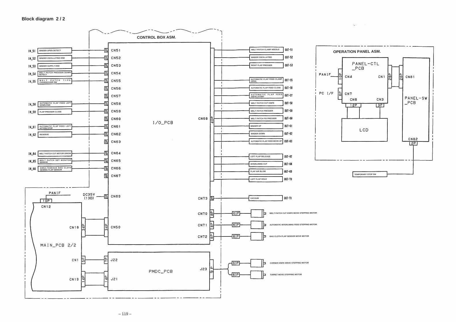
– 119 –
Block diagram 2 / 2
TEMPORARY STOP SW
BINDER OPEN DETECT
BINDER OSCILLATING END
BINDER SUPPLY END
WELT PATCH PRESSER DOWNDETECT
W E L T P A T C H T Y P ECHANGEOVER SW
AUTOMATIC FLAP FEED LEFTDOWN END
FLAP PRESSER CLOSE
AUTOMATIC FLAP FEED LEFTACTION STOP
WELT PATCH CUT MOTOR ORIGIN
WELT PATCH SET MONITORSENSOR
SIMULTANEOUS BAG CLOTHSEWING FLAP SENSOR
CONTROL BOX ASM.
RESERVE
WELT PATCH CLAMP NEEDLE
BINDER OSCILLATING
AUTOMATIC FLAP FEED CLAMPOPEN
AUTOMATIC FLAP FEED CLOSE
A U T O M A T I C F L A P F E E DOSCILLATING
WELT PATCH CUT KNIFE
WELT PATCH PRESSER
WELT PATCH FIX PRESSER
BINDER UP
BINDER DOWN
AUTOMATIC FLAP FEED MOVE UP
INTERLINING CUT
FLAP AIR BLOW
LEFT FLAP HOLD
VACUUM
WELT PATCH CUT KNIFE MOVE STEPPING MOTOR
AUTOMATIC INTERLINING FEED STEPPING MOTOR
BAG CLOTH FLAP SENSOR MOVE MOTOR
CORNER KNIFE DRIVE STEPPING MOTOR
TURRET MOVE STEPPING MOTOR
OPERATION PANEL ASM.
RIGHT FLAP PRESSER
LEFT FLAP RELEASE

– 120 –
DISPLAYCN43-2
CN43-4
CN43-6
CN43-8
CN43-10
CN43-12
CN43-14
CN43-16
CN43-18
CN43-20
CN43-22
CN43-24
CN43-26
CN43-28
CN43-30
CN43-32
CN43-34
CN43-36
CN43-38
CN43-40
CN43-42
CN43-44
CN43-46
CN43-48
CN43-50
SIGNALDC +24VMACHINE SIDE BINDER UPDC +24V
DC +24VCLAMP FOOT, RIGHT UPDC +24VCLAMP FOOT, RIGHT DOWNDC +24VCLAMP FOOT, LEFT UPDC +24VCLAMP FOOT, LEFT DOWNDC +24VCENTER KNIFEDC +24VFOLDING PLATEDC +24VBOBBIN THREAD TRIMDC +24VNEEDLE THREAD TRIMMOVEDC +24VNEEDLE THREAD TRIM KNIFEDC +24VTHREAD TENSIONDC +24VCORNER KNIFE FIX SIDEACTIONDC +24VFLAP PRESSER, LEFT OPENDC +24VFLAP PRESSER, LEFT CLOSEDC +24VNEEDLE BAR, RIGHTDC +24VNEEDLE BAR, LEFTDC +24VTENSION RELEASEDC +24VRESERVEDC +24VCORNER KNIFE LOCKDC +24VRESERVEDC +24VCORNER KNIFE MOVE SIDEACTIONDC +24V(0-1)DC +24VBOBBIN SENSOR AIR BLOWDC +24VGND
No.123456789
1011121314151617181920
212223242526
272829303132333435363738394041424344
454647484950
SIGNALHM øAHM øBHM øA
HM øB
COMACOMB
No.123456
No.123456789
1011121314
SIGNALCPMA (PMX1)GNDCPMB (PMX2)GNDCPMA (PMX3)CPMB (PMX4)TPMA (PMY1)N. CTPMB (PMY2)TPMA (PMY3)TPMB (PMY4)DC +5VTPCD (CD Y)CMCD (CD X)
123456789
1011121314
No.123456789
1011121314
SIGNALPMX1 (A)GNDPMX2 (B)GNDPMX3 (A)PMX4 (B)PMY1 (A)N. CPMY2 (B)PMY3 (A)PMY4 (B)DC +5VCD YCD X
123456789
1011121314
DISPLAYIN-1
SIGNALRESERVEGND
No.12
DISPLAYIN-2
SIGNALNEEDLE THREAD TRIM, UPPERDETECTGND
No.1
2
DISPLAYIN-3
SIGNALBINDER DOWN ENDGND
No.12
DISPLAYIN-4
SIGNALCORNER KNIFE FIX SIDE, LOWERDETECTGND
No.1
2
DISPLAYIN-5
SIGNALCORNER KNIFE MOVE SIDE,LOWER DETECTGND
No.1
2
DISPLAYIN-6
SIGNALCENTER KNIFE, UPPER DETECTGND
No.12
DISPLAYIN-7
SIGNALCORNER KNIFE FIX SIDE, UPPERDETECTGND
No.1
2
DISPLAYIN-8
SIGNALCORNER KNIFE MOVE SIDE,UPPER DETECTGND
No.1
2
DISPLAYIN-9
SIGNALRESERVEGND
No.12
DISPLAYIN-10
SIGNALRESERVEGND
No.12
DISPLAYIN-11
SIGNALDART DETECT, UPPER DETECTGND
No.12
DISPLAYIN-12
SIGNALBINDER, UPPER DETECTGND
No.12
DISPLAYIN-13
SIGNALKNIFE LOCK FIX SIDEGND
No.12
DISPLAYIN-14
SIGNALKNIFE LOCK MOVE SIDEGND
No.12
SIGNALAUTOMATIC FLAP FEED CLAMPRELEASE SWGNDRESERVEGNDVR+VRINVR–GNDGNDGND
No.1
23456789
10
No.12345
SIGNALDC +35V+35V RTNN. CDC +5VGND
12
34
No.12345678
SIGNALDC +35VDC +35VN. C+35V RTN+35V RTNN. CDC +5VGND
1
2
34
SIGNALX AX AX BX BN. CY AY AY BY B
No.123456789
DISPLAYIN-15
SIGNALDC +24VDC +5VRESERVEGND
No.1234
DISPLAYIN-16
SIGNALDC +24VDC +5VNEEDLE BAR MOVE ORIGINGND
No.1234
SIGNALDC +5VTURRET POSITION DETECTGNDGNDDC +24V
No.12345
SIGNALDC +5VCORNER KNIFE ORIGINGND
No.123
SIGNALDC +5VCLAMP FOOT REAR END DETECTGNDDC +24V
No.1234
SIGNALDC +5VCLAMP FOOT FRONT END DETECTGND
No.123
SIGNALGNDTHREAD BREAKAGE DETECT, LEFTGNSTHREAD BREAKAGE DETECT, RIGHT
No.1234
DISPLAYO-1
SIGNALDC +24VDART STRETCHER
No.12
No.123456
SIGNALDC +5VGNDDC +24VA+24V RTNDC +35V+35V RTN
361425
No.12345
SIGNALDC +24VSDET INGNDSDET OUTGND
12
SIGNALDC +24VSTACKER OUT 1DC +24VSTACKER OUT 2DC +24VSTACKER OUT 3DC +24VSTACKER OUT 4DC +24VDC +24VROLLER STACKER ORIGINGNDMATERIAL SENSORGNDBAR CLAMP STACKER ORIGINGNDRESERVEGND
No.123456789101112131415161718
SIGNALDC +24VBOBBIN THREAD DETECT, RIGHTGNDDC +24VBOBBIN THREAD DETECT, LEFTGND
No.123456
SIGNALDC +24VRESERVEGNDDC +24VFLAP DETECT, LEFTGND
No.123456
No.123456789
101112131415161718192021222324252627282930
SIGNALRESETLSWTSWUSWMRSWMLSWGNDMSP1MSP2MSP3MSP4MSP5MSP6GNDMSTATMBRKMEERUDETDDETAUDETNCNCTGPDETNCNCDC +5VDC +5VGNDGND
123456789
101112131415161718192021222324252627282930
No.12
SIGNAL+24V+24V RTN
No.123456789
10111213141516171819202122232425262728293031323334
SIGNALDC +5VGNDDC +5VGNDDC +5VGNDDC +5VGNDGNDIO INTA3A2A1RD (N)HWR (N)CS3 (N)IOS1RES2 (N)D15D14D13D12D11D10D9D8+24V RTN+24V RTN+24V RTN+24V RTNDC +24VDC +24VDC +24VDC +24V
12345678910111213141516171819202122232425262728293031323334
No.12345678910
SIGNALDC +24VGNDDC +5VGNDTXDTOUT1TOUT2RXDRIN1RIN2
123456789
10
No.12345678910111213
SIGNAL+U–U+V–V+W–W+A–A+B–B+5VGNDSHIELD
No.1234
SIGNALUVWF, GND
(2) Connection diagramCN43
CN5
CN19
CN26
CN27
CN28
CN29
CN30
CN31
CN32
CN33
CN34
CN35
CN36
CN37
CN38
CN39
CN11
CN1
J21
J22
J23
CN20
CN21
CN22
CN23
CN24
CN25
CN8
CN40
CN7
CN45
CN10
CN17
CN16
CN41
CN42
CN12
CN13
CN3
CN18
MAIN PCB
PMDC PCB
A
B
C
D
E

– 121 –
SIGNALDC +24VADC +24VADC +35VDC +24VDC +5V+24VA RTN+24VA RTNDC +24V+24V RTNGND
No.12345678910
1
2
345
6
SIGNALDC +24VGNDGNDGND
No.1234
1234
SIGNALDC +24VGNDOCVGND
No.1234
1234
SIGNALDC +5VUDETGND
No.123
123
SIGNALUVW
No.123
SIGNALMBMAMZMUMVMWDC +5VGND
No.12345678
SIGNALMBMAMZUDETGND
No.12345
SIGNALNCAC 25VAC 25VNCAC 18VAC 18V
No.123456
SIGNALAC INAC INFGFG
No.1234
SIGNALAC TR, OUTAC TR, INAC TR, INAC COM
No.1234
SIGNALHVHV GND
No.12
12
SIGNALHVHV_G
No.12
12
SIGNALRESETMLSWMYSWMUSWMRSWMLSWGNDMSP1MSP2MSP3MSP4MSP5MSP6GNDMSTATMBRKMEERUDETDDETAUDETADDETOPTGPDETTRMWPBDC +5VDC +5VGNDGND
SIGNALDC +33V+33V RTN
No.12
12
No.123456789
10111213141516171819202122232425262728293031323334
SIGNALDC +5VGNDDC +5VGNDDC +5VGNDDC +5VGNDGNDIO INTA3A2A1RD (N)HWR (N)CS3 (N)ISO1RES2 (N)D15D14D13D12D11D10D9D8+24V RTN+24V RTN+24V RTN+24V RTNDC +24VDC +24VDC +24VDC +24V
123456789
10111213141516171819202122232425262728293031323334
SIGNALDC +33V+33V RTN
No.12
12
DISPLAYIN-51
SIGNALBINDER OPEN DETECTGND
No.12
DISPLAYIN-52
SIGNALBINDER OSCILLATING ENDGND
No.12
DISPLAYIN-53
SIGNALBINDER FEED ENDGND
No.12
DISPLAYIN-54
SIGNALWELT PATCH PRESSER DOWNDETECTGND
No.1
2
DISPLAYIN-55
SIGNALWELT TYPE CHANGEOVER SWGND
No.12
DISPLAYIN-56
SIGNALRESERVEGND
No.12
DISPLAYIN-57
SIGNALRESERVEGND
No.12
DISPLAYIN-58
SIGNALAUTOMATIC FLAP FEEDER DOWNEND, LEFTGND
No.1
2
DISPLAYIN-59
SIGNALFLAP PRESSER CLOSEGND
No.12
DISPLAYIN-60
SIGNALRESERVEGND
No.12
DISPLAYIN-61
SIGNALAUTOMATIC FLAP FEEDER UPGND
No.12
DISPLAYIN-62
SIGNALRESERVEGND
No.12
DISPLAYIN-63
SIGNALRESERVEGND
No.12
DISPLAYIN-64
SIGNALDC +5VDC +24VWELT PATCH CUT MOTOR ORIGINGND
No.1234
DISPLAYIN-65
SIGNALDC +5VDC +24VWELT PATCH MONITOR SENSORGND
No.1234
DISPLAYIN-66
SIGNALDC +5VDC +24VSIMULTANEOUS BAG CLOTH SEWFLAP SENSORGND
No.123
4
DISPLAYIN-65
SIGNALDC +5VDC +24VRESERVEGND
No.1234
DISPLAYCN68-2(OUT-51)CN68-4(OUT-52)CN68-6(OUT-53)CN68-8(OUT-54)CN68-10(OUT-55)
CN68-12(OUT-56)
CN68-14(OUT-57)
CN68-16(OUT-58)CN68-18(OUT-59)CN68-20(OUT-60)CN68-22(OUT-61)CN68-24(OUT-62)CN68-26(OUT-63)CN68-28(OUT-64)CN68-30(OUT-65)CN68-32(OUT-66)CN68-34(OUT-67)CN68-36(OUT-68)CN68-38(OUT-69)CN68-40(OUT-70)
SIGNALDC +24VWELT PATCH CLAMP NEEDLEDC +24VBINDER OSCILLATINGDC +24VRESERVEDC +24VRESERVEDC +24VAUTOMATIC FLAP FEEDCLAMP OPENDC +24VAUTOMATIC FLAP FEEDCLAMP CLOSEDC +24VAUTOMATIC FLAP FEEDOSCILLATINGDC +24VWELT PATCH CUT KNIFEDC +24VWELT PATCH PRESSERDC +24VWELT PATCH FIXED PRESSERDC +24VBINDER UPDC +24VBINDER DOWNDC +24VAUTOMATIC FLAP FEED MOVE UPDC +24VRESERVEDC +24VRESERVEDC +24VRESERVEDC +24VRESERVEDC +24VINTERLINING CUTDC +24VFLAP AIR BLOWDC +24VLEFT FLAP HOLD
No.123456789
10
1112
1314
1516171819202122232425262728293031323334353637383940
DISPLAYOUT-71
SIGNALDC +24VVACUUM
No.12
SIGNALTCM – ATCM – BTCM – ATCM – BNC+33V (COM – A)+33V (COM – B)NC
No.12345678
SIGNALFSM – AFSM – BFSM – AFSM – BNCNC+33V (COM – A)+33V (COM – B)
No.12345678
SIGNALSKM – ASKM – BSKM – ASKM – B+33V (COM – A)+33V (COM – B)NCNC
No.12345678
SIGNALPV (+24V)GNDDC +5VGNDTXDTOUT1TOUT2RXDRIN1RIN2
No.123456789
10
12348910567
SIGNALSCP1CP2NCDISP OFFD0D1D2D3VDDVSSVEE
No.123456789101112
SIGNALDC +5VGNDRXDRINTXDTOUT
No.123456
No.123456789
1011121314151617181920212223242526
SIGNALRTN7RTN6RTN5RTN4RTN3RTN2RTN1RTN0SCN7SCN6SCN5SCN4SCN3SCN2SCN1SCN0VROUTDC +5VDC +5VDC +24VDC +24VGNDGNDGNDGNDGND
123456789
1011121314151617181920212223242526
SIGNALVFT1NCVFT2
No.123
No.123456789
1011121314151617181920212223242526
SIGNALRTN7RTN6RTN5RTN4RTN3RTN2RTN1RTN0SCN7SCN6SCN5SCN4SCN3SCN2SCN1SCN0VROUTDC +5VDC +5VDC +24VDC +24VGNDGNDGNDGNDGND
1234567891011121314151617181920212223242526
SIGNALTEMPORARY STOP SWRTN
No.12
J37 J38
J30
J31
J33
J36
J6
J4
J8
J2
J3
J9
J1
J35
CN50
CN69
CN51
CN52
CN53
CN54
CN55
CN56
CN57
CN58
CN59
CN60
CN61
CN62
CN63
CN64
CN65
CN66
CN67
CN68
CN73
CN70
CN72
CN71
CN4
CN6
CN7
CN1
CN3
CN81
CN82
123456789101112131415161718192021222324252627282930
No.123456789
101112131415161718192021222324252627282930
A
B
C
D
E
PANEL-CTL PCB PANEL-SW PCB
POWER PCB
SDC PCB
I / O PCBLEFT FLAP HOLD

– 122 –
11. TROUBLES AND CORRECTIVE MEASURES
(1) With regard to the machine head
Trouble Cause (1) Cause (2) Checking order and corrective measures
1. Thread breakage (needle thread)
2. Thread breakage (bobbin thread)
3. Stitch skipping
1-1) The surface of the thread path of the
needle thread has burrs or scratches.
1-2) Needle thread tension is too high.
1-3) The clearance between the bobbin
case opening lever and the bobbin
case is improperly adjusted.
1-4) The hook has been improperly
installed.
1-5) Amount of oil in the hook is insufficient.
2-1) The boobin thread is subjected to
excessive tension.
3-1) The hook has been improperly
installed.
2)-A The tension of the thread tension disk
is too high.
2)-B The tension of the thread take-up
spring is too high.
2)-C The stroke of the thread take-up spring
is too large or too small.
4)-A The needle comes in contact with the
hook blade.
4)-B The timing between the needle and
hook is not correct.
1)-A The bobbin thread tension is too high.
1)-B The clearance between the bobbin and
bobbin case clogs with waste thread.
1)-C The bobbin is deformed and fails to
spin smoothly.
1)-A The clearance between the needle and
hook blade is too large.
1)-B The timing between the needle and
hook is not correct.
1)-C Blunt hook blade point
Smooth the thread path (using a fine sandpaper and buff).
Decrease the tension. (See item "Needle thread tension" p.28.)
Decrease the tension. (See item "Adjusting the tension of the thread take-up spring" p.28.)
Correct the stroke. (See item "Adjusting the tension of the thread take-up spring" p.28.)
Provide a clearance of 0.2 to 0.3 mm between them. (See item "Adjusting the bobbin
case opening lever" p.24.)
Correct the clearance between them. (See item "Adjusting the clearance between the
needle and the hook blade point" p.24.)
Correct the timing. (See item "Adjusting the timing of the hook to the needle" p.24.)
Adjust the amount of oil. (See item "Adjusting the amount of oil in the hook" p.26.)
Decrease the bobbin thread tension. (See item "Bobbin thread tension" described in
Instruction Manual, p.13.)
Remove waste thread.
Replace the bobbin.
Correct the clearance. (See item "Adjusting the clearance between the needle and the hook
blade point" p.24)
Correct the timing. (See item "Adjusting the timing of the hook to the needle" p.24.)
Correct the hook blade point.
To the next page

– 123 –
4. Loose stitches
3-2) The needle guard is not properly
adjusted.
3-3) The longitudinal position of the needle
bar frame is improper.
3-4) The needle is defective.
3-5) The clearance between the sewing
table and the binder is not correct.
3-6) The clamp foot does not clamp the
garment properly.
3-7) The lockstitching speed is not correct.
4-1) The needle thread tension is not high
enough.
4-2) The thread take-up spring is not
properly adjusted.
4-3) The clearance between the bobbin
case opening lever and the bobbin
case is not correct.
4-4) The clearance between the sewing
table and the binder is not correct (too
large).
2)-A The clearance between the needle and
the needle guard is too large.
2)-B The needle and the needle guard are
in excessive contact.
4)-A The needle is bent or has a blunt point.
4)-B The needle No. is not proper.
6)-A The clamping pressure is not high
enough.
2)-A The thread take-up spring tension is
not high enough.
2)-B The stroke of the thread take-up spring
is too small.
Correct the clearance. (See item "Adjusting the timing of the hook to the needle" p.24.)
Correct the clearance. (See item "Adjusting the timing of the hook to the needle" p.24.)
Correct its position. See item "Installing position of the needle bar frame" p.12.)
Replace the needle.
Replace the needle with a thicker one.
Adjust the lowering position of the binder. (See item "Binder components" p.30 to 37.)
Adjust the compressed air pressure to 0.5 MPa.
Set stitch length to 2.0 mm.
Increase the tension. (See item "Thread tension components" p.28.)
Increase the tension. (See item "Adjusting the tension of the thread take-up spring" p.28.)
Correct the stroke. (See item "Adjusting the tension of the thread take-up spring" p.28.)
Provide a clearance of 0.2 to 0.3 mm between them. (See item "Adjusting the bobbin
case opening lever" p.24.)
Check the lowering position of the binder. (See item "Binder components" p.30 to 37.)
From the previous page
Trouble Cause (1) Cause (2) Checking order and corrective measures

– 124 –
5. Needle breakage
6. Irregular stitches
7. Frequent puckering (wrinkles)
5-1) The needle comes in contact with thehook blade point.
5-2) The needle comes in contact with theneedle guard.
5-3) The needle comes in contact with theneedle hole in the throat plate.
5-4) The needle comes in contact with eachunit.
5-5) The lockstitching speed is too high.
5-6) The needle is too thin for the material.
6-1) Threading is wrong.
6-2) The needle or bobbin thread tensionis not correct.
6-3) The tension or stroke of the threadtake-up spring is not correct.
6-4) The bobbin thread is wound up tootight.
6-5) The boobin thread feeding tensionvaries.
7-1) Both the needle and bobbin threadtensions are too high.
7-2) The needle is too thick for the material.
7-3) The clearance between the welt patchbase plate and the sewing table is notproper.
4)-A The needle comes in contact with thebinder.
4)-B The needle comes in contact with thewelt patch folding plate.
1)-A The threading route of the needlethread is wrong.
1)-B The threading route of the bobbinthread is wrong.
5)-A Waste thread exists between thebobbin and the bobbin case.
5)-B The bobbin has been deformed anddoes not spin smoothly.
Correct the clearance between them. (See item "Adjusting the clearance between theneedle and the hook blade point" p.24.)
Correct the clearance between them. (See item "Adjusting the timing of the hook tothe needle" p.24.)
Correct the position of the needle bar frame. (See item "Installing position of the needlebar frame" p. 12.)
Adjust the needle feed adjusting cam. (See p.10.)
Correct the position of the binder. (See item "Binder components" p. 30 to 37.)
Correct the position of the welt patch folding plate. (See item "Adjusting the welt patchfolding plate" p.42.)
Set the stitch length to 2.0 mm.
Replace the needle with a thicker one.
(See item "Threading the machine" described in Instruction Manual p.9.)
(See item "Threading the bobbin case" described in Instruction Manual p.13.)
Correct the needle or bobbin thread tension.
Properly adjust the thread take-up spring. (See item "Adjusting the tension of thethread take-up spring" p.28.)
Rewind the bobbin under proper tension.
Remove the waste thread.
Replace the bobbin.
Decrease the both thread tensions.
Replace the needle with a thinner one.
Properly adjust the clearance according to the material thickness. (See item "Bindercomponents" p.30 to 37.)
Trouble Cause (1) Cause (2) Checking order and corrective measures

– 125 –
8. The thread slips off the needle at welting
start.
9. Several stitches are skipped at welting start.
10. Small wrinkles are produced on garment
or welting patch. (Throughout the welting
seam)
11. Needle threads are not trimmed.
12. Bobbin threads are not trimmed.
8-1) The wiper is improperly positioned.
8-2) The needle thread is not held properly.
8-3) The bobbin thread is not held properly.
8-4) The stop position of the sewing
machine is not correct.
9-1) The bobbin thread is too short.
10-1) The center knife is dull.
10-2) The needle is too thick or the needle
point is blunt.
11-1) The needle thread trimmer knife fails
to work properly.
12-1) The knife is defective.
12-2) The bobbin thread trimming cylinder
fails to work properly.
1)-A The bobbin runs idle.
1)-B The wiper improperly positioned.
1)-A The center knife is defective.
1)-B The center knife has been improperly
installed.
1)-A The needle thread trimmer knife has
been improperly installed.
1)-B The thread trimming cylinder fails to
work properly.
1)-A The pressure of the bobbin thread
trimmer knife spring is not high
enough.
1)-B The knife is dull.
Correct its position. (See item "Adjusting the wiper" p.26.)
Correct its position. (See item "Needle thread trimmer components" p.16 to 19.)
Correct its position. (See item "Adjusting the bobbin thread knife" p.20.)
Correct its position. (See item "Adjusting the main shaft origin sensor" p.4.)
Increase the bobbin thread tension. Place a cloth under the bobbin to prevent it from
running idle.
Position it properly. (See item "Adjusting the wiper" p.26.)
Replace the center knife. (See item "Adjusting the sharpness of the center knife" p.22.)
Install it correctly. (See item "Adjusting the sharpness of the center knife" p.22.)
Use a thinner needle or replace the needle.
Correctly install the knife. (See item "Needle thread trimmer components" p.16 to 19.)
Expel the compressed air from the cylinder to check whether the cylinder works under
approx. 1.9kg or not. If the cylinder does not work smoothly, replace the cylinder.
(Check the drain.)
Increase the spring pressure.
Adjust the position of the bobbin thread trimmer knife. (See item "Adjusting the sharpness
of the bobbin thread knife" p.21.)
Turn the knife upside down or replace it.
Check the drain within the cylinder or replace the cylinder.
Trouble Cause (1) Cause (2) Checking order and corrective measures

– 126 –
(2) With regard to the unit
1. Welt widths on the right and left are not thesame.
2. Welt widths in the front and rear are not thesame.
3. Welt patch interlining slips.
4. Flap seam bends.
1-1) The clearance between the binder andthe garment clamp is not properlyadjusted.
1-2) The clearance between the needleand the welt patch folding plate is notproperly adjusted.
1-3) The binder has been improperlypositioned laterally.
2-1) Clearance between the binder and thegarment clamp is not correct.
2-2) The clamp feet fail to travel in parallelto the binder.
2-3) Welt patch cut position is not correct.
3-1) The front and rear binders areimproperly positioned.
4-1) The pressing pressure of the flap presseris too low.
4-2) The material guide is improperlyadjusted.
4-3) The needle thread trimmer knife is notproperly adjusted.
3)-A The position of the front binder withregard to the needle has been slippedlaterally.
3)-B Both the front and rear binders havebeen slipped laterally.
3)-A The front and rear cut positions of thewelt patch are not in the center.
1)-A The heights of the front and rearbinders at the time of jump feed arenot the same.
1)-B The lateral positions of the front andrear binders are not correct.
1)-C Adjustment of the clearance betweenthe front and the rear binders is notproper.
2)-A The clearance between the materialguide and the needle is too small.
2)-B The clearance between the materialguide and the welt patch base plate istoo small.
3)-A The lateral position of the needlethread trimmer knife is not correct.
3)-B The height of the needle threadtrimmer knife is not correct when itlowered.
Correct the clearance. (See item "Adjusting the garment clamp lifting amount" p.42.)
Correct the clearance. (See item "Adjusting the welt patch folding plate" p.42.)
Adjust the lateral position of the binder. (See item "Lateral adjustment of the front binder"p.30.)
Adjust the lateral position of the binder. (See items "Lateral adjustment of the front andrear binders" p.30, p.36.)
Correct the clearance. (See item "Adjusting the garment clamp lifting amount" p.42.)
Correct the position. (See items "Adjustment of torsion of the front and rear binders" p.30,p.34.)
Correct the position. (Seet item "Welt patch cut unit" p.60.)
Correct the position. (See items "Adjustment of height of the front and rear binders" p.32,p.36.)
Correct the position. (See item "Lateral adjustment of front and rear binders" p.30, p.36.)
Correct the position. (See item "Front and rear binder components" p.30 to 36.)
Correct the position. (See item "Adjustment of the flap presser" p.70.)
Correct the position. (See item "Adjustment of material guide" p.32.)
Correct the position. (See item "Adjustment of material guide" p.32.)
Correct the position. (See item "Needle thread trimmer components" p.16.)
Correct the position. (See item "Needle thread trimmer components" p.16.)
Trouble Cause (1) Cause (2) Checking order and corrective measures

– 127 –
5. Flap interlining slackens.
6. The interlining is not fed from the interlining
feeding unit.
* Interlining feeding unit is optional.
7. The cutting positions of the front and rear
welt patch and the center knife are not the
same.
* Welt patch cut unit is optional.
8. The front and rear welt patch cannot be cut
sharply.
* Welt patch cut unit is optional.
5-1) Pressing pressure of the flap presser
is not correct.
5-2) The position of the flap supply click is
not correct.
* Flap supply unit is optional.
6-1) The clearance of the guide is not
correct.
6-2) The position of the guide is not correct.
6-3) The position of the guide roller or the
interlining is not correct.
7-1) The position of the welt patch cut unit
is not correct.
7-2) The welt patch clamp needle fails to
work properly.
8-1) The welt patch cut knife is defective.
8-2) The position of the welt patch cut knife
is not correct.
8-3) Pressing pressure of the welt patch
presser at the time of welt patch cut is
not correct.
1)-A Pressing pressure is too low.
2)-A The height of the supply click is not
correct.
1)-A The clearance is too large.
1)-B The clearance is too small.
2)-A The position of the counter knife and
the guide is not correct.
1)-A The welt patch cut unit in terms of the
binder is laterally slipped or tilted.
2)-A Protruding amount of the welt patch
clamp needle is insufficient.
2)-B The welt patch clamp needle does not
come out smoothly.
1)-A The knife has worn out.
2)-A Protruding amount is not correct.
3)-A Inclination of the welt patch presser is
not correct.
3)-B Inclination of the welt patach holding
plate is not correct.
Correct the position. (See item "Adjustment of flap presser" p.70.)
Correct the position. (See item "Flap supply unit" p.64.)
Correct the position. (See item "Interlining feeding unit" p.80.)
Adjust the position of the guide. (See item "Interlining feeding unit" p.80.)
(See item "Interlining feeding unit" p.80.)
Correct the position. (See item "Welt patch cut unit" p.60.)
Correct the position. (See item "Welt patch cut unit" p.60.)
Check the welt patch clamp operation.
Replace the welt patch cut knife.
See item "Welt patch cut unit" p.60.
See item "Adjusting the welt patch presser" p.62.
Adjust the welt patch holding plate.
Trouble Cause (1) Cause (2) Checking order and corrective measures
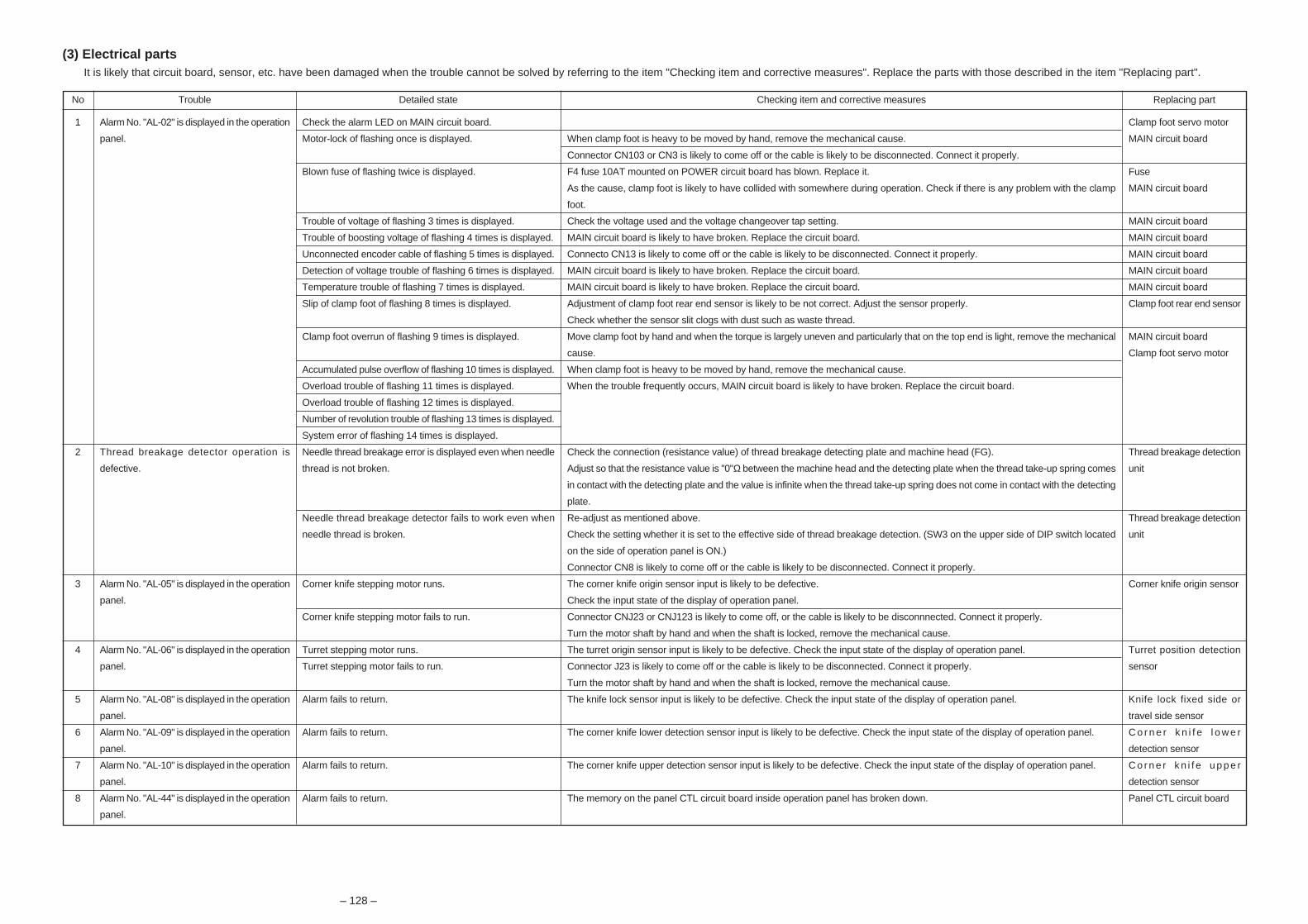
– 128 –
(3) Electrical partsIt is likely that circuit board, sensor, etc. have been damaged when the trouble cannot be solved by referring to the item "Checking item and corrective measures". Replace the parts with those described in the item "Replacing part".
No
1
2
3
4
5
6
7
8
Trouble
Alarm No. "AL-02" is displayed in the operation
panel.
Thread breakage detector operation is
defective.
Alarm No. "AL-05" is displayed in the operation
panel.
Alarm No. "AL-06" is displayed in the operation
panel.
Alarm No. "AL-08" is displayed in the operation
panel.
Alarm No. "AL-09" is displayed in the operation
panel.
Alarm No. "AL-10" is displayed in the operation
panel.
Alarm No. "AL-44" is displayed in the operation
panel.
Detailed state
Check the alarm LED on MAIN circuit board.
Motor-lock of flashing once is displayed.
Blown fuse of flashing twice is displayed.
Trouble of voltage of flashing 3 times is displayed.
Trouble of boosting voltage of flashing 4 times is displayed.
Unconnected encoder cable of flashing 5 times is displayed.
Detection of voltage trouble of flashing 6 times is displayed.
Temperature trouble of flashing 7 times is displayed.
Slip of clamp foot of flashing 8 times is displayed.
Clamp foot overrun of flashing 9 times is displayed.
Accumulated pulse overflow of flashing 10 times is displayed.
Overload trouble of flashing 11 times is displayed.
Overload trouble of flashing 12 times is displayed.
Number of revolution trouble of flashing 13 times is displayed.
System error of flashing 14 times is displayed.
Needle thread breakage error is displayed even when needle
thread is not broken.
Needle thread breakage detector fails to work even when
needle thread is broken.
Corner knife stepping motor runs.
Corner knife stepping motor fails to run.
Turret stepping motor runs.
Turret stepping motor fails to run.
Alarm fails to return.
Alarm fails to return.
Alarm fails to return.
Alarm fails to return.
Checking item and corrective measures
When clamp foot is heavy to be moved by hand, remove the mechanical cause.
Connector CN103 or CN3 is likely to come off or the cable is likely to be disconnected. Connect it properly.
F4 fuse 10AT mounted on POWER circuit board has blown. Replace it.
As the cause, clamp foot is likely to have collided with somewhere during operation. Check if there is any problem with the clamp
foot.
Check the voltage used and the voltage changeover tap setting.
MAIN circuit board is likely to have broken. Replace the circuit board.
Connecto CN13 is likely to come off or the cable is likely to be disconnected. Connect it properly.
MAIN circuit board is likely to have broken. Replace the circuit board.
MAIN circuit board is likely to have broken. Replace the circuit board.
Adjustment of clamp foot rear end sensor is likely to be not correct. Adjust the sensor properly.
Check whether the sensor slit clogs with dust such as waste thread.
Move clamp foot by hand and when the torque is largely uneven and particularly that on the top end is light, remove the mechanical
cause.
When clamp foot is heavy to be moved by hand, remove the mechanical cause.
When the trouble frequently occurs, MAIN circuit board is likely to have broken. Replace the circuit board.
Check the connection (resistance value) of thread breakage detecting plate and machine head (FG).
Adjust so that the resistance value is "0"Ω between the machine head and the detecting plate when the thread take-up spring comes
in contact with the detecting plate and the value is infinite when the thread take-up spring does not come in contact with the detecting
plate.
Re-adjust as mentioned above.
Check the setting whether it is set to the effective side of thread breakage detection. (SW3 on the upper side of DIP switch located
on the side of operation panel is ON.)
Connector CN8 is likely to come off or the cable is likely to be disconnected. Connect it properly.
The corner knife origin sensor input is likely to be defective.
Check the input state of the display of operation panel.
Connector CNJ23 or CNJ123 is likely to come off, or the cable is likely to be disconnnected. Connect it properly.
Turn the motor shaft by hand and when the shaft is locked, remove the mechanical cause.
The turret origin sensor input is likely to be defective. Check the input state of the display of operation panel.
Connector J23 is likely to come off or the cable is likely to be disconnected. Connect it properly.
Turn the motor shaft by hand and when the shaft is locked, remove the mechanical cause.
The knife lock sensor input is likely to be defective. Check the input state of the display of operation panel.
The corner knife lower detection sensor input is likely to be defective. Check the input state of the display of operation panel.
The corner knife upper detection sensor input is likely to be defective. Check the input state of the display of operation panel.
The memory on the panel CTL circuit board inside operation panel has broken down.
Replacing part
Clamp foot servo motor
MAIN circuit board
Fuse
MAIN circuit board
MAIN circuit board
MAIN circuit board
MAIN circuit board
MAIN circuit board
MAIN circuit board
Clamp foot rear end sensor
MAIN circuit board
Clamp foot servo motor
Thread breakage detection
unit
Thread breakage detection
unit
Corner knife origin sensor
Turret position detection
sensor
Knife lock fixed side or
travel side sensor
C o r n e r k n i f e l o w e r
detection sensor
C o r n e r k n i f e u p p e r
detection sensor
Panel CTL circuit board

– 129 –
No
9
10
11
12
13
14
15
16
17
18
19
Trouble
Alarm No. "AL-45" is displayed in the operstion
panel.
Alarm No. "AL-59" is displayed in the operation
panel.
Alarm No. "AL-69" is displayed in the operation
panel.
Alarm No. "AL-70" is displayed in the operation
panel.
Alarm No. "AL-90" is displayed in the operation
panel.
Alarm No. "AL-95" is displayed in the operation
panel.
Power source has been changed.
Nothing is displayed in the operation panel.
Operation panel data has disappeared.
Alarm No. is displayed in the operation panel.
Others
Detailed state
Clamp foot travelled forward and the alarm has stopped.
Clamp foot travelled backward and the alarm has stopped.
Trouble has occurred after replacing the circuit board.
Trouble has suddenly occurred.
Trouble has occurred after an extended period of disuse.
Needle feed adjustment motor runs.
Needle feed adjustment motor fails to run.
Trouble has occurred immediately after turning ON the power.
Trouble has occurred during sewing.
ROM of the panel CTL circuit board has been replaced.
ROM of the MAIN circuit board has been replaced.
Alarm fails to return.
Power voltage has been changed.
Screen is light and the backlight is ON.
Screen is dark and the backlight is OFF.
When the power is turned OFF, the set data cannot be saved.
Check the alarm No. displayed in the operation panel and
the input No. which is the cause of the alarm.
All data which are currently set are desired to be saved.
The data is desired to be copied to the other machine.
Checking item and corrective measures
Clamp foot front end sensor input is likely to be defective. Check the input state of the display of operation panel.
Check whether the sensor slit clogs with dust such as waste thread or whether connector CN25 is properly connected.
Clamp foot rear end sensor input is likely to be defective. Check the input state of the display of operation panel.
Check whether the sensor slit clogs with dust such as waste thread or whether connector CN24 is properly connected.
When the panel CTL circuit board is replaced, perform re-adjustment of the pedal input.
Check the disconnection of pedal input wiring and the connection of cable CN11 and CN111.
There is a possibility that the memory of pedal input set value has disappeared. Input the set value again.
There is a danger that other adjustment values or sewing data have been disappeared or changed. Check them.
The needle feed adjustment origin sensor input is likely to be defective. Check the input state of the display of operation panel.
Check whether the sensor slit clogs with dust such as waste thread or whether connector CN21 is properly connected.
Connector CN5 or CN105 is likely to come off, or the cable is likely to be disconnected. Connect it properly.
Turn the motor shaft by hand and when the shaft is locked, remove the mechanical cause.
Motor is likely to be locked. Turn the main shaft by hand and when it is heavy to be turned, remove the mechanical cause.
Power source is likely to be defective. Turn OFF the power and check again the power source voltage.
The sewing machine needle bar UP detection (SDET) sensor is likely to be defective. Check the sensor input.
Motor is likely to be locked. Turn the main haft by hand and when it is heavy to be turned, remove the mechanical cause.
Motor driver is likely to be defective.
Malfunction occurs when the version of ROM which has been replaced is used with the version of ROM mounted on MAIN circuit
board. It is not possible to combine with each other. It is necessary to return the previous ROM to its home position or to make the
ROM on the MAIN circuit board side a ROM corresponding to the version.
Malfunction occurs when the version of ROM which has been replaced is used with the version of ROM mounted on the panel CTL
circuit board. It is not possible to combine with each othetr. It is necessary to return the previous ROM to its home position or to make
the ROM on the panel CTL circuit board side a ROM corresponding to the version.
I/F cable between CN12 of MAIN circuit board and CN4 of panel CTL circuit board is likely to be defective. Check the connection or
disconnection of the connectors.
Any power source of 200V, 220V, 230V, 240V, 380V, 400V or 415V can be adapted by changeover of the transformer input tap.
Perform the operation referring to the item "Change of the power voltage".
There is a possibility that fuse F6 (3A) mounted on POWER circuit board has blown. Check it.
Connector CN1 of panel CTL circuit board is likely to come off or the cable is likely to be disconnected. Connect it properly.
There is a possibility that fuse F3 (10AT) mounted on POWER circuit board has blown. Check it.
Connector CN9 is likely to come off or the cable is likely to be disconnected. Connect it properly.
Battery backup is likely to be defective. Replace the panel CTL circuit board.
Check the alarm contents referring to the list of alarm codes and remove the cause of alarm.
When the abnormal input No. (I ) is displayed, perform checking of sensor cable and connector, and operation check of the
actuator as the input state check.
An exclusive data input/output circuit board is required. Consult our JUKI service man.
An exclusive data input/output circuit board is required. Consult our JUKI service man.
Replacing part
Clamp foot front end
sensor
Clamp foot rear end sensor
Pedal SW
Needle feed adjustment
origin sensor
Needle feed adjustment
motor
SDET sensor
SDC circuit board
EPROM
Fuse
Panel CTL circuit board
Fuse
LCD (liquid crystal display)
panel
Panel CTL circuit board

R
ENGINEER’S MANUAL
29346103No.01
Lockstitch Automatic Welting Machine(With Automatic Welt Patch Feeder)
APW-297(Flap Sewing Type)
APW-298 (Slant Pocket Sewing Type)

PREFACE
This Engineer’s Manual is written for the technical personnel who are responsible for the service and maintenance
of the sewing machine. This manual describes “Adjustment Procedure”, “Results of Improper Adjustment”, and
other functions which are not covered by the Instruction Manual intended for the maintenance personnel and
sewing operators at a sewing factory.
All personnel engaged in repair of APW-297, 298 are required to carefully read Section 2 “Standard Adjustment”
which contains important information on the maintenance of APW-297, 298.
The “Standard Adjustment” consists of two parts ; the former part presents illustration and simplified explanation
for the convenience of reconfirmation of the required adjustment values in carrying out actual adjustment after
reading this manual once; and the latter part provides “Results of Improper Adjustment” in which sewing and/or
mechanical failures, and the correcting procedures are explained for those persons who perform such adjustment
for the first time.
It is advisable to use “APW-297, 298 Parts Book” together with this Engineer’s Manual.

1. SPECIFICATIONS ..............................12. NAMES OF COMPONENTS ...............33. STANDARD ADJUSTMENTS .............4
(1) Machine head components ................... 41) Main shaft components .................................... 4
1 Adjusting the main shaft origin sensor .......... 42 Replacing the timing belt ............................. 6
2) Needle bar components ................................... 81 Adjusting the height of the needle bar
(APW-297) ................................................ 82 Adjusting the upper/lower positions
of the needle bar frame (APW-298) ............. 83) Needle feed components ............................... 10
1 Needle feed adjusting (cam section) .......... 102 Adjusting the installing position
of the needle bar frame............................. 123 Adjusting the timing of the needle feed
operation ................................................. 144) Needle thread trimmer components ................ 16
1 Adjusting the forward end positionof the needle thread trimmer unit ............... 16
2 Adjusting the lateral positionof the needle thread trimmer unit ............... 16
3 Adjusting the width of the moving knifeof the knife unit ......................................... 18
4 Adjusting the fixed knife ............................ 185) Bobbin thread trimmer components ................. 20
1 Adjusting the bobbin thread knife ............... 206) Center knife components................................ 22
1 How to adjust the height of the center knife .... 222 How to adjust the distance
from the needle to the center knife ............. 223 Adjusting the sharpness of the center knife .... 224 Attaching the center knife .......................... 22
7) Hook components ......................................... 241 Adjusting the timing of the hook to the needle .... 242 Adjusting the timing of the hook ................. 243 Adjusting the clearance between
the needle and the hook blade point .......... 244 Removing and attaching the hooks............ 245 Adjusting the bobbin case opening lever .... 24
8) Wiper components ......................................... 261 Adjusting the wiper ................................... 26
9) Lubrication components ................................. 261 Adjusting the injector for the reflux
of the face plate components .................... 2610) Thread tension components ......................... 28
1 Adjusting the thread take-up spring............ 282 Adjusting the timing of the thread tension
disc to start "floating" ................................ 28(2) Device components ............................ 30
1) Binder components ........................................ 301 Front binder ............................................. 302 Rear binder ............................................. 34
2) Clamp foot components ................................. 381 Adjusting the tension of the clamp
foot traveling belt ...................................... 382 Adjusting the tension of the clamp
foot driving belt ......................................... 383 Clamp foot front end stop position and
rear end stop position ............................... 404 Adjusting the garment clamp lifting amount 425 Adjusting the welt patch folding plate
and the flap presser.................................. 42
3) Corner knife components ............................... 441 Corner knife mechanism of APW-297 ........ 442 Corner knife mechanism of APW-298 ........ 483 How to set the corner knife
on the knife base wheel ............................ 524 Adjusting the center of the corner knife ...... 545 Adjusting the deflection and distortion
of the corner knife .................................... 546 Adjusting the knife .................................... 547 Adjusting the corner knife for parallel sewing .. 568 Fine adjustment of corner knife in terms of seams . 569 Adjusting the corner knife for slant sewing .. 58
(3) Optional components .......................... 601) Welt patch cut unit (right) : SA102 ................... 602) Flap supply unit (left) : SA103 ......................... 643) Flap and bag cloth supply unit (left) : SA104 ..... 66
(a) Adjustment of the sensor slit ...................... 68(b) Adjustment of belt tension.......................... 68(c) Adjustment of flap presser ......................... 70(d) Adjustment of flap holding dish ................... 72
4) Dart extending unit : SA106 ............................ 745) Suction unit : SA108....................................... 766) Interlining feeding unit : SA109 ........................ 787) Single welt and double welt change unit (right) : SA111 ..... 828) Clamp bar stacker : SP44 ............................... 84
4. OPERATION PANEL ........................ 88(1) Operating the operation changeover screen .. 88(2) Check program 8 ................................. 89(3) Initial setting table ............................... 90
1) <Sewing pattern screen>................................ 902) <Counter screen> .......................................... 923) <Adjustment data edit screen>........................ 934) <Operation selection screen> ......................... 95
(4) Setting of DIP switches located in the rear of the panel ......................... 96
5. PARTS TO WHICH GREASE OR LOCKTITE IS APPLIED ..............976. AIR CIRCUIT DIAGRAM (APW-297, -298) ............................. 1097. ELECTRICAL CONTROL BOX ....... 110
(1) Explanation of components ...............1101) Arrangement in the control box ..................... 1102) Function and setting place of each circuit board ..... 111
(2) Replacing the components ................1121) Replacing the fuse ....................................... 1122) Replacing the EPROM ................................. 113
(3) Checking the set value of the power voltage and changing the voltage .......113
8. LIST OF ALARM CODES ............... 1149. NAMES AND INSTALLING POSITIONS
OF THE SWITCH SENSORS.......... 115(1) Adjusting the flap sensor of the bag cloth flap supply unit ..........116
10. CIRCUIT DIAGRAM ..................... 117(1) Block diagram 1 / 2 ............................118(2) Connection diagram ...........................120
11. TROUBLES AND CORRECTIVEMEASURES ................................... 122(1) With regard to the machine head ........122(2) With regard to the unit ........................126(3) Electrical parts ...................................128
CONTENTS

Please do not hesitate to contact our distributors or agents in your area for further information when necessary.* The description covered in this engineer's manual is subject to change for improvement of the
commodity without notice.
00 · 07 Printed in Japan (E)
R
INTERNATIONAL SALES H.Q.8-2-1, KOKURYO-CHO,CHOFU-SHI, TOKYO 182-8655, JAPANPHONE : (81)3-3430-4001 to 4005FAX : (81)3-3430-4909 • 4914 • 4984TELEX : J22967
Copyright C 2000 JUKI CORPORATION.
All rights reserved throughout the world.