India: Elevated Expressway Corridor (Flyover) from Jehangir ...
Upload
khangminh22Category
view
0download
0
Technical Specifications
THEA TMC OFFICE RENOVATION 1104 E TWIGGS ST. TAMPA, FL 33602
PROJECT # 1924
BID PERMIT SET – VERSION 200807
FOR
TAMPA HILLSBOROUGH EXPRESSWAY AUTHORITY
PREPARED BY Wannemacher Jensen Architects, Inc.
180 Mirror Lake Drive St. Petersburg, Florida 33701-3214
727-822-5566AA0002277
8.7.2020
Set No. 200807
RFP O-01120 ~ RENOVATION SERVICES
THEA TRANSPORTATION MANAGEMENT CENTER (TMC)
APPENDIX A-2 FOR RFP O-01220

THEA TMC OFFICE RENOVATION
TABLE OF CONTENTS Page i PROJECT NUMBER: 1924 VERSION: 200807
TABLE OF CONTENTS DIVISION 00 - PROCUREMENT AND CONTRACTING DOCUMENTS 00100 ADVERTISEMENT 00200 INSTRUCTIONS TO BIDDERS 00301 BID FORM 00450 NON-COLLUSION AFFIDAVIT 00500 SPECIAL INSTRUCTIONS ------- AGREEMENT ------- PERFORMANCE BOND ------- PAYMENT BOND ------- GENERAL CONDITIONS ------- SUPPLEMENTAL CONDITIONS OF CONTRACT 00650 PREVAILING WAGE RATES ------- SPECIAL PROVISIONS DIVISION 01 - GENERAL REQUIREMENTS 011000 SUMMARY 011400 WORK RESTRICTIONS 012300 ALTERNATES 013119 PROJECT MEETINGS 013213 SCHEDULING AND PROCEDURES 013233 PHOTOGRAPHIC DOCUMENTATION 013300 SUBMITTAL PROCEDURES 014000 QUALITY PROCEDURES 014200 REFERENCES 015000 TEMPORARY FACILITIES AND CONTROLS 015700 ENVIRONMENTAL PROTECTION 016000 PRODUCT REQUIREMENTS 017300 EXECUTION REQUIREMENTS 017700 CLOSEOUT PROCEDURES 017823 OPERATION AND MAINTENANCE DATA 017839 PROJECT RECORD DOCUMENTS 017900 DEMONSTRATION AND TRAINING DIVISION 02 - EXISTING CONDITIONS 024119 SELECTIVE DEMOLITION DIVISION 03 - CONCRETE REFER TO DRAWINGS FOR SPECIFICATIONS
DIVISION 05 - METALS REFER TO DRAWINGS FOR SPECIFICATIONS DIVISION 06 - WOOD, PLASTICS, AND COMPOSITES 061000 ROUGH CARPENTRY 064113 WOOD-VENEER-FACED ARCHITECTURAL CABINETS 064116 PLASTIC-LAMINATE-FACED ARCHITECTURAL CABINETS DIVISION 07 - THERMAL AND MOISTURE PROTECTION 072100 THERMAL INSULATION 078413 PENETRATION FIRESTOPPING 079200 JOINT SEALANTS

THEA TMC OFFICE RENOVATION
TABLE OF CONTENTS Page ii PROJECT NUMBER: 1924 VERSION: 200807
DIVISION 08 - OPENINGS 081113 HOLLOW METAL DOORS AND FRAMES 081416 FLUSH WOOD DOORS 084600 GLAZED INTERIOR WALL AND DOOR ASSEMBLIES 085800 SLIDING PASS-THRU WINDOW 087100 DOOR HARDWARE 088000 GLAZING DIVISION 09 - FINISHES 092216 NON-STRUCTURAL METAL FRAMING 092900 GYPSUM BOARD 093000 TILING 095113 ACOUSTICAL PANEL CEILINGS 096513 RESILIENT WALL BASE AND ACCESSORIES 096519 RESILIENT TILE FLOORING 096813 TILE CARPETING 097200 WALL COVERINGS 098436 SOUND-ABSORBING CEILING UNITS 099100 PAINTING DIVISION 10 - SPECIALTIES 102113 PLASTIC LAMINATE TOILET COMPARTMENTS 102800 TOILET ACCESSORIES 104413 FIRE EXTINGUISHER CABINETS 104416 FIRE EXTINGUISHERS DIVISION 11 - EQUIPMENT 113100 RESIDENTIAL APPLIANCES 115213 PROJECTION SCREENS DIVISION 12 - FURNISHINGS 122413 ROLLER WINDOW SHADES 123623 PLASTIC-LAMINATE-CLAD COUNTERTOPS 123661 QUARTZ AGGLOMERATE COUNTERTOPS 124813 ENTRANCE FLOOR MATS AND FRAMES 125000 FURNITURE DIVISION 13 - SPECIAL CONSTRUCTION 134813 VIBRATION ABSORPTION MATERIAL DIVISION 14 - CONVEYING SYSTEMS 142700 EXISTING ELEVATOR CAR FINISHES RENOVATION DIVISION 21 - FIRE PROTECTION REFER TO DRAWINGS FOR SPECIFICATIONS DIVISION 22 - PLUMBING REFER TO DRAWINGS FOR SPECIFICATIONS

THEA TMC OFFICE RENOVATION
TABLE OF CONTENTS Page iii PROJECT NUMBER: 1924 VERSION: 200807
DIVISION 23 - HVAC REFER TO DRAWINGS FOR SPECIFICATIONS DIVISION 26 - ELECTRICAL REFER TO DRAWINGS FOR SPECIFICATIONS DIVISION 27 - COMMUNICATIONS BY OWNER DIVISION 28 - SECURITY AND FIRE ALARM BY OWNER END OF TABLE OF CONTENTS

Firm’s prior experience including a minimum of three projects of similar size and scope (office
renovations of greater than $1.5M in contract value) within the last 5 years.
Resume of Firm’s proposed Project Manager and Superintendent showing experience on
projects of similar size and scope.
Evidence of proper Florida class A general contractor’s licensure.
Contract Drawings and the Technical Specifications will be provided through THEA’s procurement
process or may be downloaded form their procurement website or examined by appointment at the office
of KCI Technologies, Inc., 4041 Crescent Park Drive, Tampa, FL 33578; phone (813) 740-2300. Please
contact Bryan Lawson P.E. to schedule an appointment. An electronic version of the plans and bid
documents will be provided by THEA to all interested bidders.
SECTION 00100
ADVERTISEMENT
Tampa Hillsborough Expressway Authority
Tampa, FL
Sealed bids will be submitted electronically (via email) for the renovation of Tampa Hillsborough
Expressway Authority (THEA) Traffic Management Center Office Renovations at 1104 E Twiggs St.
Tamp, FL 33602, at the offices of the Tampa Hillsborough Expressway Authority, until 2:00 P.M., prevailing time, Friday September 10, 2020, at which time there will be a virtual public meeting where bids will be opened and read by the Tamp Hillsborough Expressway Authority (THEA).
PROJECT DESCRIPTION - The Project is a renovation of the existing 3 story 27,727 GSF sprinklered commercial office building. The scope includes, but is not limited to, selective demolition and interior reconfiguration of non-loadbearing partition walls, door changes, upgraded lighting, mechanical, electrical, plumbing and fire protection modifications, HVAC rooftop equipment replacement and new casework as well as a comprehensive update to floor, wall, ceiling and elevator finishes throughout the building.
A PRE-BID CONFERENCE will be held on Friday August 14, 2020 at 10:00 am (EDT) via video conference. Attendance at this pre-bid video conference is strongly recommended and encouraged for
all interested bidders. Project site visits will be scheduled with individual bidders during normal work
hours on either August 17 or August 18, 2020. The site visit is encouraged to allow bidders to examine the existing building layout and conditions, take measurements and familiarize themselves with the
requirements of the project. No additional information will be provided or questions answered during site
visits. Any bidder questions should be submitted in writing to THEA no later than August 21, 2020.
It is the intent of the THEA to bid and award one contract for this project. Additionally, it is the intent
of the Authority to award the contract based on the lowest responsible, responsive and qualified bid
determined using the base bid plus any alternates selected within the available funding. Bidders are
required to submit appropriate qualifications along with their bid. Bidder qualifications must include the
following:
Page 1 of 2
THEA TMC OFFICE RENOVATION
PROJECT NUMBER: 1924 VERSION: 200807

Page 2 of 2
It is the intent of THEA to award the contract to the lowest responsible and responsive bidder, or reject all
bids within ninety (90) days from the date of the bid opening; provided, however, that if the award
is delayed by the required approval of another governmental agency, the sale of bonds, or the award of
a grant, the THEA shall reject all bids or award the contract to the lowest responsible and responsive
bidder within one hundred twenty (120) days from the date of the bid opening.
TAMPA HILLSBOROUGH EXPRESSWAY AUTHORITY
Joe Waggoner, Executive Director
**END OF SECTION**
Bid bond or certified check for 10% of the total base bid payable to the Tampa Hillsborough Expressway
Authority shall accompany each proposal to be forfeited as liquidated damages should the bidder default in the
execution of the contract, the provision of required insurance certificates and/or the provision of required
payment or performance bonds within 10 days after award of same. Bids may not be withdrawn within ninety
(90) days after bid opening. The THEA reserves the right to waive any irregularities in, or reject, any and all
bids
The Tampa Hillsborough Expressway Authority strongly encourages the solicitation and utilization of SBE firms and requires nondiscrimination on the basis of race, color, sex and national origin in its contracting practices.
The Contract has a Small, Disadvantaged/Minority Business Enterprise (SBE) Goal of 15%. Evidence must be provided that SBE firms are appropriately certified by a governmental certifying entity such as the State of Florida, Hillsborough County and/or the City of Tampa.
TIME LINE - Following is a listing of actions and anticipated dates; the THEA reserves the right to change the dates, if necessary.
Dates
August 7, 2020 Advertising & Publishing RFP
August 14, 2020 Pre‐Proposal Conference
August 17-18,2020 Individually Scheduled Site Visits
August 21, 2020 Deadline for Questions/Clarifications
August 31, 2020 Anticipated issuance of any Addenda / Answers
September 10, 2020 Proposals due by 2:00 p.m.
Sept. 14-16, 2020 Evaluation of Bids / Recommendation to THEA Board
Sept. 21, 2020 Submit for Approval by THEA Board
October 2020 Anticipated Contract Award
THEA TMC OFFICE RENOVATION
PROJECT NUMBER: 1924 VERSION: 200807

INSTRUCTION TO BIDDERS 00200 - 1
SECTION 00200
INSTRUCTIONS TO BIDDERS
Tampa Hillsborough
Expressway Authority
Tampa, FL
IB-1 Bidder's Responsibility
Each bidder shall familiarize himself, and will be held responsible to examine, and to fully comply
with all the Contract Documents, as defined in the form of Agreement set forth hereinafter. Before
submitting proposal, bidder shall carefully examine the specifications and satisfy himself as to
conditions relating to providing the materials, delivery, and necessary labor that he will be obliged
to provide. Submission of a proposal will be deemed a warranty that such examination has been
made; and later claims for labor, equipment, or materials required, or for difficulties encountered,
which could have been foreseen had such an examination been made, will not be recognized.
IB-2 Standard of Quality
Equipment, material, or articles herein specified are all of design or construction as selected for this
Contract and they shall be construed as being a standard. Should the bidder desire to quote on
equipment, material, or articles claimed to be equal to that specified, he may do so, provided that
he shall first submit a request therefore (accompanied by cuts and complete descriptive matter of
such other equipment, materials or articles), and receive the Architect's approval, before submitting
bid. Such request must be made seven (7) days before the bid opening to permit the Architect to
make proper investigation; and the Architect's determination thereon shall be conclusive.
IB-3 Pre-Bid Conference
Pre-Bid Conference will be held at 10:00 AM on August 14, 2020. Interested Contractors
shall join the meeting via video conference as described in the Bid Advertisement.
IB-3.A Contractors Site Visit Prior to Bidding
Bidders may visit unrestricted areas of the site during normal work hours on either August 17 orAugust 18, 2020 as scheduled with THEA and KCI (Owner’s Representative). Interested bidders should contact the Owner's Representative, Bryan Lawson with KCI Technologies, at [email protected] to schedule a site visit. The site visit is encouraged to allow bidders to examine the existing building layout and conditions, take measurements and familiarize
themselves with the requirements of the project. No additional information will be provided or
questions answered during site visits.
IB-4 Interpretation of Contract Documents prior to Bidding
If any bidder is in doubt as to the true meaning of any part of the plans, specifications, or other
Contract Documents, or should discover any omissions or discrepancies therein, or desire to quote
on alternate equipment, materials or articles not rated by the Architect as "Approved Equivalent" of
those specified, he may submit to the CM Owner’s Representative a written request for an
interpretation, correction or addition, or an authorization of an alternate. If any such request be
granted, it will be only by an addendum or bulletin, duly issued, and a copy will be mailed or
delivered to each bidder. The Owner will not be responsible for any other explanations,
interpretations, corrections, or changes in or of the proposed documents. Any bidder questions should
be submitted in writing to THEA no later than August 21, 2020.
THEA TMC OFFICE RENOVATION
PROJECT NUMBER: 1924 VERSION: 200807

00200 .4 INSTRUCTION TO BIDDERS
IB-5 Proposals
(a) Proposals shall be delivered to the THEA electronically (via email) on or before 2:00
P.M., prevailing time, September 10, 2020, such delivery is the bidder's responsibility.
No bids received after the designated time of bid opening will receive consideration.
Proposals must be addressed to:
Attention: Man Le, Contracts and Procurement Manager
Tampa Hillsborough Expressway Authority (THEA)
EMAIL: [email protected]
Electronic submissions should include all required documents.
(b) Proposals must be submitted on the Proposal form attached to these documents, which form may be
removed from other documents for enclosing in envelopes. Proposals must be completely filled in. All
unit prices and the total bid price must be written both in words and figures, but written prices shall
govern in case of discrepancies. No proposal will be considered which is not based on these plans and
specifications.
(c) The bid of an individual must be signed by him personally, his signature must be witnessed; and his
business address and any business trade name must be stated. The bid of a partnership must state the
names and addresses of all partners, and the partnership must state the names and partnership business
name and address; and it must be signed by all partners, with the signatures witnessed. The bid of a
corporation must show the state of incorporation and the principal office address, and must be signed by
the President or Vice-President, with the corporate seal affixed, attested by the Secretary or Assistant
Secretary.
IB-6 Acceptance or Rejection of Proposal
The THEA reserves the right to reject any or all proposals. Without limiting the generality of the
foregoing, any proposal which is incomplete, obscure, conditional, not on the prescribed form, or
otherwise irregular, or which has erasures or corrections in prices, or which include additions or
deductions not called for, or uninvited alternate bids, or in which unit prices are omitted or are obviously
unbalanced or which is not accompanied by required bid security, may be rejected.
However, the THEA reserves the right to waive informalities on the basis of its best interests.
IB-7 Bid Check or Bond
Each proposal must be accompanied by a certified, bank cashier's, or trust company treasurer's
check, or a bid bond for not less than ten percent (10%) of base bid, payable to the THEA as
security for execution of Contract, etc., under terms embodied in the form of proposal. If Bid Bond
is used, it MUST BE IN THE FORM FURNISHED WITH THE CONTRACT
DOCUMENTS, must be executed by the Bidder as provided in Paragraph IB-5 (c) and must have
corporate surety satisfactory to the THEA and authorized to conduct business in Florida.
Attorneys-in-fact who sign bid bonds must file with each bond a certified and effective dated copy
of their power-of-attorney. Bid security shall be held until the THEA has an opportunity to
compare the prices. After the prices have been compared, the THEA shall return the bid security of
THEA TMC OFFICE RENOVATION
PROJECT NUMBER: 1924 VERSION: 200807

00200 .5 INSTRUCTION TO BIDDERS
all but the three lowest responsible and responsive bidders. When the Agreement is executed, this
bid security shall be returned as well. Bid security shall be applied by the THEA towards damages
in the event bidder fails to execute and furnish bonds as required in the General Conditions of the
Specifications, or in the event an award is made and the bidder fails to execute the Contract and
furnish evidence of insurance or Performance and Payment Bonds, or as otherwise provided
herein. In the event such bid security is applied towards damages, the THEA does not waive its
right to bring further action against such bidder for any additional damages suffered because of the
failure of such bidder to comply with the terms of his Bid Proposal.
IB-8 Qualifications of Bidders
Before any award is made, the THEA may require satisfactory evidence to show that bidder is fully
prepared in every way to execute the work promptly and satisfactorily, and has been regularly
engaged in such work. Bidders must submit the following documentation of the bidder’s
qualifications:
• Firm’s prior experience including a minimum of three projects of similar size and
scope (office renovations of greater than $1.5M in contract value) within the last 5
years.
• Resume of Firm’s proposed Project Manager and Superintendent showing
experience on projects of similar size and scope.
• Evidence of proper state general contractor’s licensure.
IB-9 Limit of Bid Withdrawal
Bids may be withdrawn up to the time of the bid opening by THEA upon receipt of a written
request from the bidder. Bid security for any bid so withdrawn shall be returned promptly. No bid
may be withdrawn at the date and time for the opening of bids nor at any other time during the bid
hold period described herein.
The THEA shall award the contract to the lowest responsible and responsive qualified bidder or
reject all bids within ninety (90) days from the date of the bid opening; provided, however, that if the award is delayed by the required approval of another governmental agency, the sale of bonds,
or the award of a grant, the THEA shall reject all bids or award the contract to the lowest
responsible and responsive bidder within one hundred twenty (120) days from the date of the bid
opening.
IB-10 Execution of Agreement and Bonds
If following the review and comparison of bids the THEA shall determine to proceed with the
project, it shall first issue a Notice of Intent to Award to the lowest responsible and responsive
bidder. The successful bidder will be required, within ten (10) calendar days following notification
to furnish to the THEA, in at least four counterparts, the Performance Bond and Payment Bond, all
in the form substantially prescribed for execution of proposals (Paragraph IB-5 (c)). Both bonds
shall have corporate surety satisfactory to the THEA, and authorized to conduct business in
Florida; shall be paid for by the Contractor and shall be for 100% of the contract price, except for
the obligations of maintenance, which shall be for 10% of said price. Following delivery of the
properly executed bonds, the THEA may award the contract. Following notice of award, the
successful bidder shall sign and deliver to the THEA in at least four counterparts, the agreement
and insurance policies, or certificates of insurance required by the contract documents. Such
insurance policies or certificates shall state that the insurance cannot be canceled without approval
of or reasonable written notice to the THEA.
THEA TMC OFFICE RENOVATION
PROJECT NUMBER: 1924 VERSION: 200807

00200 .6 INSTRUCTION TO BIDDERS
IB-11 Time for Beginning Project & Length of Project
The Contractor shall within fourteen (14) calendar days after receiving the notice of contract award,
proceed with the work required under this contract and continue with the work continuously until
completion. This is a phased project and completion dates will be associated with each phase.
Refer to composite floor plans and phasing drawings for project phase completion dates. The entire
project must be completed within seven (7) months from Notice to Proceed. Delay extensions may be granted at the discretion of the THEA. In case of failure on the part of the Contractor to
complete the work within the time fixed or any extensions thereof, the Contractor shall be liable to
the THEA for and shall pay to the THEA, as liquidated damages, the sum of $750.00 each calendar
day of delay from the date stipulated for the substantial completion of the work. Additionally, the
contractor shall be liable to the THEA for and shall pay to THEA, as liquidated damages, the sum
of $500.00 each calendar day of delay from the date stipulated for the final completion of the work.
IB-12 Location of Work
1104 E Twiggs St. Tampa, FL 33602.
IB-13 Collusive Bids
More than one proposal or one contract from an individual, a firm or partnership, corporation, or an
association under the same name or different names will not be considered. Reasonable grounds
for believing that the bidder is interested in more than one proposal for the same work will cause
the rejection of all proposals in which such bidder is interested. Any or all proposals will be
rejected if there is any reason for believing that collusion exists among any of the bidders;
participants in such collusion will not be considered in future proposals.
** END OF SECTION **
THEA TMC OFFICE RENOVATION
PROJECT NUMBER: 1924 VERSION: 200807

BID PROPOAL FORM 00301 - 1
DOCUMENT NO. 00301
BID PROPOSAL FORM
Tampa Hillsborough
Expressway Authority
Tampa, FL
BID FOR: CONSTRUCTION RENOVATIONS-Proj. No. O-01120
RENOVATIONS FOR:
THEA TMC Office
1104 E Twiggs St
Tampa, FL 33602
Name of Bidder
FOR OWNER: Telephone No.
TAMPA HILLSBOROUGH EXPRESSWAY AUTHORITY
1104 E TWIGGS ST.
TAMPA, FL 33602 Date
AS PREPARED BY: WANNAMACHER JENSEN ARCHITECTS, INC.
180 MIRROR LAKE DRIVE NORTH
ST. PETERSBURG, FL 33701
1. BASE BID PRICE
Having carefully examined the Contact Documents dated 8/7/2020, together with alladdenda thereto, and other data as prepared by Wannemacher Jensen Architects, Inc., 180
Mirror Lake Drive North St. Petersburg, FL 33701, and having visited the site and becoming
familiar with all conditions affecting the Work, hereby propose to furnish everything
required for the completion of the above named Work for the above named project, all in
accordance with the law at the place of the Work for the following amount.
BASE BID: (in Words)
DOLLARS ($________________)
2. ALTERNATES:
Alternate No. 1: Furnish and install the new Roof Top HVAC Units (including curbs, structural reinforcing, and roof repair.)ADD _____________________________________________________________ DOLLARS
($_________________)
Base bid Time of Completion to be increased by _________________calendar days.
Alternate No. 2: Furnish and install remaining HVAC and VAV work throughout building per specific notes on the drawings.)
DOLLARS ADD
($_________________)
Base bid Time of Completion to be increased by _________________calendar days.
THEA TMC OFFICE RENOVATION
PROJECT NUMBER: 1924 VERSION: 200807

BID PROPOSAL FORM 00301 - 2
4. ADDENDA
A. The undersigned hereby acknowledges receipt of, and has included in this Proposal, the
work covered by the following Addenda.
Addendum No. Date
5. TIME OF COMPLETION
Anticipated Notice to Proceed is 14 days following Contract Award. (expected October2020). The undersigned agrees, if awarded the Contract, to bring all Work under the contract
to Substantial Completion on or before ________________calendar days from Notice to
Proceed (Base Bid).
6. AWARD
If the contract is awarded, it will be awarded to the lowest responsible and responsive
qualified bidder, using base bid plus alternates, if selected, to utilize all available funding.
The undersigned Respondent/Firm agrees to keep this offer open for acceptance for 120 days after date of opening price proposals. The undersigned agrees to, within 10 days after notice
of acceptance of this bid, provide Insurance and Bonds and enter into a Contract, if so
notified within 120 days from the date of Bid Opening.
3. UNIT PRICESA. The Unit Prices below are included in the BASE BID and are broken out hereseparately as described below. These Unit Prices include all labor, materials andequipment associated with the described items of the Work.1. Furnish and install window film (3M ULTRA PRESTIGE SERIES UPRS50 WITH 3M
“WET GLAZE”, AND 3M IMPACT PROTECTION)
$__________________________
Alternate No. 3: Furnish and install LED light fixtures in areas not receiving significant renovation. Refer electrical drawings and Alternate Specifications.ADD ______________________________________________________________ DOLLARS($_________________)
Base bid Time of Completion to be increased by _________________calendar days.
Alternate No. 4: Revised phasing plan to include staged access to the 2nd and 3rd floor renovation areas sequentially. ADD ______________________________________________________________ DOLLARS
($_________________)
Base bid Time of Completion to be increased by _________________calendar days.
THEA TMC OFFICE RENOVATION
PROJECT NUMBER: 1924 VERSION: 200807

BID PROPOSAL FORM 00301 - 3
Signatures: The undersigned hereby certifies that this proposal is genuine and not collusive
or fraudulent or made in the interest of or on behalf of any person, firm or corporation not
herein named; and the undersigned has not, directly or indirectly, induced or solicited and
bidder to submit a sham bid, or any other person, firm or corporation from bidding, and that
the undersigned has not, in any manner, sought by collusion to secure for himself any
advantage over any other bidder.
SIGN HERE IF
AN INDIVIDUAL CONTRACTOR
ADDRESS
SIGN HERE IF
A PARTNERSHIP
OR CORPORATION
ATTEST:
(SECRETARY)
COROPORATE SEAL HERE:
** END OF SECTION **
SIGNATURE
SIGNATURE
THEA TMC OFFICE RENOVATION
PROJECT NUMBER: 1924 VERSION: 200807

BID BOND
KNOW ALL PERSONS, That We, _
As Principal, and
(a ___________________________________________corporation authorized to transact business in
Florida, and having its principal office at_________________________________________) as Surety,
are held and firmly bound unto the County of Hillsborough, State of Florida and the Tampa Hillsborough
Expressway Authority, State of Florida, as Obligee, in the sum of ________________________________Dollars ($ ), lawful money of the
United States of America: for payment of which we bind ourselves, and each of our respective heirs, legal
representatives, successors and assigns, jointly and severely, by these presents, on this__________ day of 20 .
WHEREAS, the said Principal is herewith submitting to the Obligee a proposal to perform the work in connection with ________________________________
pursuant to contract documents incorporated into said proposal by reference; and it is a condition of the
Obligee's receipt and consideration of said proposal that the proposal be accompanied by bid security to
be held by the Obligee on terms embodied herein.
THEREFORE, the condition of this obligation is that if either (a) the Obligee shill not accept the
Principal's proposal nor award a contract to him, or (b) said Principal shill upon the Obligee's acceptance
of his proposal and award of a contract to him, enter into such contract and furnish performance and labor
and materialmen's bonds and insurance certificates in WI respects as required by said contract documents,
within ten (10) days after notice to him of such award, then this obligation shill be void, but otherwise it
shall remain in full force, and the principal and surety will pay to the Obligee the difference between the
amount of the Principal's accepted bids and any higher amount for which the Obligee may contract for the
required work (either with the next lowest responsible bidder at that same bidding, or with the lowest
responsible bidder on any re-bidding) plus any advertising, Engineer's, legal and other expenses incurred
by the Obligee by reason of the default: provided that the surety's obligation hereunder shill not exceed
the face amount of his bond.
The Surety agrees that its obligation hereunder shill be in no manner defeated or impaired by any
postponement of the advertised date for receiving bids or by any extensions by the Principal of the period
during which his proposal shill remain irrevocable and subject to acceptance by the Obligee; and the
Surety hereby waves notice of any such postponement or extension.
THEA TMC OFFICE RENOVATION
PROJECT NUMBER: 1924 VERSION: 200807

The principal and surety acknowledge that all references herein to the principal in singular,
masculine form, shall include the plural, feminine and neuter, as may be appropriate to the principal.
IN WITNESS WHEREOF the principal and surety, intending to be legally bound have executed
this bond the day and year of aforementioned.
Witness: (SEAL)
Witness: (SEAL)
(Sign as instructed on Proposal Form)
Attorney-in-fact Surety
This Bond is given, shall be interpreted, and shall be enforceable in accordance with the laws of the State of Florida. The Principal and the Surety agree that exclusive jurisdiction and venue for any litigation concerning this Bond and the transactions contemplated therein, shall exist in Hillsborough County, Florida. The Principal and the Surety consent to such jurisdiction and venue and agree that all service of process, including any instrument to institute suit, shall be effective if served in accordance with Florida law.
THEA TMC OFFICE RENOVATION
PROJECT NUMBER: 1924 VERSION: 200807
NON-COLLUSION AFFIDAVIT 00450 - 1
SECTION 00450
NON-COLLUSION AFFIDAVIT
Tampa Hillsborough
Expressway Authority
Tampa, FL
INSTRUCTIONS FOR NON-COLLUSION AFFIDAVIT
1. This Non-Collusion Affidavit is material to any contract awarded pursuant to this bid.
2. This Non-Collusion Affidavit must be executed by the member, officer or employee of
the bidder who makes the final decision on prices and the amount quoted in the bid.
3. Bid rigging and other efforts to restrain competition, and the making of false sworn
statements in connection with the submission of bids are unlawful and may be subject to
criminal prosecution. The person who signs the Affidavit should examine it carefully
before signing and assure himself or herself that each statement is true and accurate,
making diligent inquiry, as necessary, of all other persons employed by or associated
with the bidder with responsibilities for the preparation, approval or submission of the
bid.
4. In the case of a bid submitted by a joint venture, each party to the venture must be
identified in the bid documents, and an Affidavit must be submitted separately on behalf
of each party.
5. The term "complementary bid" as used in the Affidavit has the meaning commonly
associated with that term in the bidding process, and includes the knowing submission of
bids higher than the bid of another firm, any intentionally high or noncompetitive bid,
and any other form of bid submitted for the purpose of giving a false appearance ofcompetition.
6. Failure to file an Affidavit in compliance with these instructions will result in
disqualification of the bid.
THEA TMC OFFICE RENOVATION
PROJECT NUMBER: 1924 VERSION: 200807

NON-COLLUSION AFFIDAVIT 00450 - 3
NON-COLLUSION AFFIDAVIT
Contract/Bid No. _______________________
State of __________________________. S.S.
County of ________________________.
I state that I am _________________________________ of _______________________________________
(Title) (Name of Contractor)
and that I am authorized to make this affidavit on behalf of my firm, and it’s Owners, Directors and Officers.
I am the person responsible in my firm for the price(s) and the amount of this bid.
I state that:
1. The price(s) and amount of this bid have been arrived at independently and without consultation,
communication or agreement with any other Contractor, Bidder or Potential Bidder.
2. Neither the price(s) nor the amount of this bid, and neither the approximate price(s) nor the
approximate amount of this bid, have been disclosed to any other firm or person who is a bidder or
potential bidder, and they will not be disclosed before bid opening.
3. (No attempt has been made or will be made to induce any firm or person to refrain from bidding on
this contract, or to submit a bid higher than this bid, or to submit any intentionally high or non-
competitive bid or another form of complementary bid.
4. (The bid of my firm is made in good faith and not pursuant to any agreement of discussion with, or
inducement from, any firm or person to submit a complimentary or other non-competitive bid
5. ____________________________________________________________________________
(Name of Contractor)
Its affiliates, subsidiaries, officers and directors and employees are not currently under investigation by any
governmental agency and have not in the last four years been convicted or found liable for any act prohibited
by State or Federal law in any jurisdiction, involving conspiracy or collusion with respect to bidding on any
public contract, except as follows:
I state that _____________________________________________ understands
(Name of Contractor)
and acknowledge that the above representatives are material and important, and will be relied on by THEA in
awarding the contract for which this bid is submitted. I understand and my firm understands that any
misstatement in this affidavit is and shall be treated as fraudulent concealment from THEA of the true facts
relating to the submission of bids for this contract.
THEA TMC OFFICE RENOVATION
PROJECT NUMBER: 1924 VERSION: 200807

NON-COLLUSION AFFIDAVIT 00450 - 4
A statement in this affidavit that a person has been convicted or found liable for any act, prohibited by State or
Federal law in any jurisdiction, involving conspiracy or collusion with respect to bidding on any public
contract within the last three years, does not prohibit the THEA from accepting a bid from or awarding a
contract to that person, but may be a ground for administrative suspension or debarment in the discretion of
the THEA under its rules and regulations, or may be ground for consideration on the question of whether the
THEA should decline to award a contract to that person on the basis of a lack of responsibility.
Name: ________________________________________________________
Signature:______________________________________________________
Title:__________________________________________________________
Name of Contractor: _____________________________________________
SWORN TO AND SUBSCRIBED BEFORE ME
THIS ____ DAY OF _______________, 20_____
________________________________________
Notary Public
My Commission Expires:
THEA TMC OFFICE RENOVATION
PROJECT NUMBER: 1924 VERSION: 200807

NON-COLLUSION AFFIDAVIT 00450 - 5
NOTARIZATIONS
Any document within this bid specification that requires a notarization must include the
signature and seal of the notary public as required by the State in which the notary is
commissioned. For those states that do not require an embossed notary seal, the following
affidavit must be completed. Bids notarized without the embossed seal and without completing
the following affidavit, as applicable, will automatically be rejected at the time of the bid
opening.
AFFIDAVIT
I, _______________________________________________, ____________________________________,
(Print/Type Name) (Title)
Of ______________________________________________,
(Name of Company)
____________________________________________________________________________________
(Complete Address)
a duly authorized representative of the above company, do hereby affirm that the State of
does not require an embossed seal on
(Name of State)
notarizations and the documents in this bid packet are true and correct and binding under the
State laws.
(Name of State)
_____________________________________________________
(Name of Company)
By: _____________________________________________________
Signature of Duly Authorized Representative
Sworn to and subscribed before me this __day of, 20_____.
__________________________________________________
Notary Public
My Commission Expires:
** END OF SECTION **
THEA TMC OFFICE RENOVATION
PROJECT NUMBER: 1924 VERSION: 200807

SPECIAL INSTRUCTIONS 00500 - 1
SECTION 00500
SPECIAL
INSTRUCTIONS
Tampa Hillsborough
Expressway Authority
Tampa, FL
"SPECIAL INSTRUCTIONS TO ALL BIDDERS"
1. All bidders shall submit their signed copy of the attached "Bidders Representation" with
their bid.
2. The Contractor and all subcontractors careful reading of the bidder's representation is
imperative because by signing and submitting it with your bid figure, you will be
representing to the THEA and Architect that a) your detailed examination of the
drawings and specifications has turned up no ambiguities which need clarifications,
b) only authorized data have been used to arrive at your bid figure, and c) the experience
and capabilities of your firm, your workmen and your subcontractors are particularly
well-suited to the construction of this type of project.
3. If you find that you are unable to sign this representation because you believe the
drawings or specifications are inadequate or erroneous in some way, please notify us at
once so that corrective action can be taken. Similarly, if your bid figure is affected by
information not contained in the construction contract documents, contact us immediately
before submitting your bid.
THEA TMC OFFICE RENOVATION
PROJECT NUMBER: 1924 VERSION: 200807

SPECIAL INSTRUCTIONS 00500 - 2
"BIDDER'S REPRESENTATION"
By the act of submitting a bid for the proposed contract, the Bidder represents that:
1. The Bidder and all subcontractors and material suppliers the Bidder intends to use have
carefully and thoroughly reviewed the drawings, specifications and other construction
documents and have found them complete and free from ambiguities and sufficient for
the purpose intended; further that,
2. The Bidder and all workmen, employees and subcontractors the Bidder intends to use are
skilled and experienced in the type of construction represented by the construction
contract documents bid upon; further that,
3. Neither the Bidder nor any of their employees, agents, intended suppliers or
subcontractors have relied upon any verbal representations, allegedly authorized or
unauthorized from the THEA, or the THEA's employees or agents including architects,
engineers or consultants, in assembling the bid figure; and further that,
4. The bid figure is based solely upon the construction contract documents and properly
issued written addenda and not upon any other written representation.
Signature of Contracting Bidder Date
Bidder shall type his full name and address in the space below:
** END OF SECTION **
THEA TMC OFFICE RENOVATION
PROJECT NUMBER: 1924 VERSION: 200807

AGREEMENT Page - 3
SAMPLE CONTRACT
THIS CONTRACT is made and entered into effective as of the _____day of _______, 20____ by and between the Tampa-Hillsborough County Expressway Authority, a body politic and corporate under and by virtue of the laws of the State of Florida, hereinafter referred to as "Authority", and _________________ __ a _________________[state] company with an office address of _____________________________________ hereinafter referred to as "Contractor".
WHEREAS, the Authority is created and established to construct, reconstruct, improve, extend, repair, maintain, and operate the "Expressway System", pursuant to Part IV, Chapter 348, Florida Statutes; and
WHEREAS, pursuant to Section 348.54, Florida Statutes, the Authority has been granted the power to make contracts of every name and nature and to execute all instruments necessary or convenient for the conduct of its business and for carrying out the purposes of the Authority; and under a competitive Request for Quotes selection process for milling and resurfacing services, the Authority Board selected the Contractor to provide such services in accordance with the terms and conditions set forth in this Contract; and
WITNESSETH, that the Authority and the Contractor, for and in consideration of the sums and payments set forth below and other valuable considerations, do hereby mutually covenant, contract and agree as follows:
1. Description of Work
A. The general Scope of Work for Request for Quotes, (“RFQ”) No. O-01120, Project No. O-01120 consists of providing all the labor, equipment, materials, tools, transportation, supplies, insurance, incidentals, mobilization, demobilization necessary to perform the renovations described in the Contract Documents for the renovation of the THEA TMC office at 1104 E. Twiggs St. Tampa, Florida (the “Project”).
B. All work shall be done in accordance with the Contract Documents, Plans and Specifications.
C. Contractor hereby agrees to furnish all of the labor, materials, equipment, tools, transportation, supplies, insurance, bonding, and incidentals necessary to perform all of the work described in the Contract Documents, including but not limited to the Plans, Specifications and Addenda thereto for the project described as follows: RFQ O-01120.
2. Contract Documents
A. The documents listed below, hereto after known collectively as the “Contract Documents” are expressly agreed to be incorporated herein by reference, the same as though fully written herein or attached hereto, and made a part of without being limited thereto, this “Contract” consists of the following:
Exhibit "A” The full extent of documents as set forth and listed in the Table of Contents of the Request for Quotes (RFQ) document (known as RFQ No. O-01120) dated
THEA TMC OFFICE RENOVATION
PROJECT NUMBER: 1924 VERSION: 200807

AGREEMENT Page - 4
August 7,2020, such documents prepared by Wannemacher Jensen Architects, Inc. dated 8/7/20 and including all forms, exhibits, attachments, and Letters of Clarification and Addendums issued thereto.
Exhibit "B" The full extent of documents and forms executed by the
Contractor as submitted by Contractor to Authority on [ ].
Exhibit “C” Certificate of Insurance
Exhibit “D” Public Construction Bond
Exhibit “E” Supplemental Agreements (when issued)
3. Project Manager
A. The Contractor shall employ a fulltime, qualified “Project Manager” with a minimum of five (5) years' experience and familiar with the anticipated type
of renovation activities described in the project Scope of Work.
B. The “Project Manager” shall be the single point of contact as liaison with the Authority and administrating the Contract for the Contractor.
C. The “Project Manager” shall be the responsible person in charge of coordinating day to day work activities on task assignments, preparing the itemized task order estimates, schedules, payment applications, field decisions, crew scheduling, directing Contractors work forces, reports, material procurement, day to day administrative matters, coordinating the SBE policy to achieve the established goals and other related items necessary to fulfill the requirements of the Contract.
D. The “Project Manager” shall be approved by the Authority. The Contractor shall replace the “Project Manager” if requested by the Authority for cause.
E. The “Project Manager” shall be available to respond to any Authority emergencies 24 hours a day and during the course of the work to ensure timely response to emergencies, progress and quality of the work.
THEA TMC OFFICE RENOVATION
PROJECT NUMBER: 1924 VERSION: 200807

AGREEMENT Page - 5
4. Performance
A. Contractor represents that it has thoroughly studied and checked the drawings, specifications, and schedules for the proposed work and that Contractor has all of the labor, tools, applications, equipment, machinery, materials and incidentals required, therefore, Contractor covenants and agrees to furnish all such labor, tools, applications, equipment, machinery, materials and incidentals required to perform the proposed work generally doing or causing to be done all things necessary to complete it in a workmanlike manner and in strict accordance with the Contract documents, Plans, Specifications and Schedules set forth herein.
5. Contract Time:
A. The Contractor shall be instructed to commence the Work by written instructions in the form of a Notice to Proceed, (NTP), issued by the Authority. The Work to be performed under this Contract shall be commenced within fourteen (14) calendar days after the date established as Day Number One in the Notice to Proceed. Whether or not the Notice to Proceed has been issued, Contractor will not be permitted to commence or continue construction efforts if all conditions precedent to commencement under the Contract Documents have not been satisfied
B. Notice of Commencement and the Public Construction Bonds required by Florida Statute § 255.05 (1 )(a), must be executed and recorded by Contractor in the public records of the Hillsborough County where the improvements are located prior to commencing construction. Authority required insurance, as described in these Contract Documents, must be approved by the Authority prior to commencing construction. Evidence of all required permits, documents and public recordings, must be submitted to the Authority prior to commencing work.
6. Failure to Complete the Work on Time
A. Time is of the essence throughout this Contract. Contractor acknowledges and agrees that the timely performance of the Work is vitally important to the interests of the Authority and that the Authority may suffer damages in the event the Contractor does not accomplish Substantial Completion of the Work within two hundred ten (210) calendar days, or as otherwise approved by the Authority, from the date established as Day Number One inthe Notice to Proceed, and with the project complete and ready for final payment within thirty (30) calendar days from the date of the Architect's Final Inspection and Notice of Substantial Completion. Liquidated damages are hereby fixed and agreed upon between the parties, recognizing the impossibility of precisely ascertaining the amount of damages that will be sustained by the Authority as a consequence of such delay, and both parties desiring to obviate any question of dispute concerning the amount of said damages and the cost and effect of the failure of Contractor to complete the Contract on time. The below stated liquidated damages shall apply separately to each portion of the Project for which a time for completion is given. Therefore, it is agreed by the parties that upon occurrence of each such failure to accomplish Substantial Completion that Authority shall be entitled to liquidated damages from and against Contractor as follows:
THEA TMC OFFICE RENOVATION
PROJECT NUMBER: 1924 VERSION: 200807

AGREEMENT Page - 6
1. Upon failure of Contractor to substantially complete the Contractwithin the specified period of time, plus approved time extensions,Contractor shall be assessed liquidated damages in the amount ofSeven Hundred Fifty Dollars ($750.00) for each calendar day afterthe time prescribed above for Substantial Completion, plus anyapproved time extensions.
2. After Substantial Completion, should the Contractor fail to completethe remaining work (punch list work) within the time prescribedabove, plus approved time extensions thereof, for completion andreadiness for final payment, Contractor shall be assessed liquidateddamages in the amount of Five Hundred Dollars ($500.00) for eachcalendar day after the time so prescribed above, plus any approvedtime extensions, for completion and readiness for final payment.Such amounts are not penalties, but are liquidated damages to theAuthority for its inability to obtain full beneficial occupancy of theProject.
B. Authority is authorized to deduct liquidated damages from monies due to Contractor for the work under this Contract or as much thereof as Authority may, at its own option, deem just and reasonable. Contractor shall be responsible for reimbursing Authority, in addition to liquidated damages, for all costs incurred by Authority in administering the construction of the project beyond the completion date prescribed above or beyond an approved extension of time granted to Contractor, Whichever date is later. Such costs shall be deducted from the monies due Contractor for performance of Work under this Contract by means of unilateral credit change orders issued periodically by Authority as costs are incurred by Authority.
7. Contract Sum:
A. The Authority shall pay to the Contractor, for the faithful performance of the Contract, in lawful money of the United States of America, and subject to the additions and deductions as provided in the Contract Documents, and based on the estimated quantities and unit prices contained in the proposal, but subject to modification to the extent that actual quantities constructed differ from the estimated quantities, a total sum as follows: ________________ ______ Dollars and ____________________Cents ($__________________) unless otherwise increased or decreased by the Authority through the issuance of Change Orders.
B. In the event there is a conflict between the unit bid price and the extension thereof made by the Bidder, the unit bid price shall govern an the Authority shall be authorized to make a correct extension of such bid price and to use such corrected extension in comparing bids.
THEA TMC OFFICE RENOVATION
PROJECT NUMBER: 1924 VERSION: 200807

AGREEMENT Page - 7
8. Payments:
A. On or before the 25th day of each month after commencement of performance, but no more frequently than once monthly, the Contractor may submit to the Authority on forms acceptable by the Authority, a request for Payment/Invoice for the period ending the last day of the prior month and shall include supporting information and documentation (i.e. SBE Report, Updated Schedule, Release of Liens, etc.) as may be required by the Authority based on the Work completed and materials stored on the site.
B. Retainage will not be withheld until the percent of allowable Contract time used exceeds 50%. From that time forward, the Authority will withholdretainage of 10% of the amount due on the current estimate as retainage when the percent of allowable Contract time used exceeds the percent of Contract amount earned by more than 10%. Any reduction of retainage isat the sole discretion of the Authority and will only be considered upon Contractor providing a Consent of Surety agreeing to the reduction.
C. The final payment, less any allowable discount for prompt payment, as stated in the Bid Proposal Form, shall be made within twenty (20) days after each assigned work task has been fully and properly completed and certified complete by the Contract and the Authority, has inspected and issued a written certificate that the work has been completed in accordance with the Contract Documents, plans and specifications set forth herein, and approved change orders, and the Authority, acting on such certificate, has accepted the work as fully and properly completed and not before.
D. If, during the progress of the Work, it appears that the Contractor’s bills or any subcontractor’s or second-tier sub-contractor’s bills for materials and labor are not being paid or sub-Contractors or second or lower-tier sub-contractors, if any, are not being paid and the Contractor fails to provide the Authority with satisfactory evidence of such payment, the Authority shall have the right to obtain releases, Waivers of Claims, Waivers of Lien and information from sub-Contractors and providers, and to withhold from the Contractor’s monthly payments sufficient sums to protect itself against all losses from possible claims, and to apply the said sums to the payment of such debts. Before the final payment is made to the Contractor, Contractor shall provide to the Authority satisfactory evidence that all just invoices, liens, claims and demands Owner of his employees, sub-contractors, second-tier sub-Contractors, and of other parties from whom materials used in the construction of the Work may have been purchased or procured, are fully satisfied, and that the project is fully released from all such liens, claims and demands. Contractor shall provide an affidavit of full payment to all laborers, sub-contractors, material men and supplies, in a form acceptable to Authority.
E. Payment of monthly estimates or invoices shall not constitute an acceptance of the work, an admission by the Authority that the work is done, or that its quantity or quality is satisfactory. Final acceptance shall occur only with final payment and certification.
Before the final payment is made, the Contractor shall provide to the AuthorityF.
THEA TMC OFFICE RENOVATION
PROJECT NUMBER: 1924 VERSION: 200807

AGREEMENT Page - 8
satisfactory evidence that all just invoices, liens, claims and demands of his employees, sub-contractors, second-tier sub-contractors, and of other parties from whom materials used in the construction of the Work may have been purchased or procured, are fully satisfied, and that the Project is fully released from all such lines, claims and demands.
G. Contractor shall provide an affidavit of full payment to all laborers, subcontractors, material men and supplies, in form acceptable to Authority, if requested by Authority.
H. The prices for both the monthly and final estimates of the work done will be based on the prices shown in the Price Schedule of the Bid Proposal Form or prescribed by the Authority prepared Work Authorizations. For lump sum priced items expected to require more than one monthly pay period for completion, the Contractor shall, seven (7) days prior to submittal of the first monthly Pay Request/Invoice, submit a “Schedule of Values” to the Authority for approval.
I. Contractor shall submit to the Authority, with each monthly submittal of invoices, a written report, using forms and/or formats acceptable to the Authority setting forth the current Small Business Enterprise (SBE) participation on the Contract as a condition precedent to the Authority’s payment of said invoice(s). The report shall include, among other things, the name of each SBE firm, a description of the work performed by each firm, and the dollar value of the work performed by each firm.
9. Small Business Enterprise (SBE) Program Obligations:
A) The Contractor agrees to enhance contracting opportunities for SmallBusiness Enterprises, as defined in the Authority's SBE Policy adopted onFebruary 25, 2002, (as amended), attached as Attachment 1 of Exhibit "A,"and incorporated herein by reference. Contractor agrees to comply with theAuthority's SBE Policy in its efforts to achieve its anticipated level of SBEparticipation, as proposed in its Bid Package on Form 5, Anticipated SBEParticipation Statement of Exhibit “B”.
B) In the event the Contractor is found to be in non-compliance with theAuthority's SBE Policy, or fails to perform good faith efforts to include SBEFirms on the Project to meet or exceed Contractor's commitment assubmitted with its Bid Package on Form 5, Anticipated SBE ParticipationStatement of Exhibit “B”, the Authority may impose sanctions against theContractor including, but not limited to:
1. Withholding payments to the Contractor under the Contract until theContractor remedies the “Anticipated SBE Participation Statement”deficiency;
2. Termination of the Contract;3. Debarment of the Contractor from bidding on future Authority
projects.
C) The Contractor understands that it is the responsibility of the Authority tomonitor Contractor's compliance with the SBE Policy. In that regard, theContractor agrees to furnish to the Authority monthly reports, using forms
THEA TMC OFFICE RENOVATION
PROJECT NUMBER: 1924 VERSION: 200807

AGREEMENT Page - 9
and/or formats acceptable to the Authority, on the progress of its SBE participation.
D) The Contractor understands that each SBE firm utilized on the Project mustbe certified by an agency acceptable to the Authority under its SBE Policy.Any proposed changes of participants from that listed on Contractor’sAnticipated SBE Participation Statement, Form 5 of Exhibit B, shall beapproved by the Authority.
10. Equal Opportunity:
A. During the performance of this Contract, Contractor agrees that it shall not discriminate against any employee or applicant for employment because of race, age, creed, color, gender or national origin. Contractor aggress to post in conspicuous places available to its employees and applicants for employees, notices setting forth the provisions of this paragraph or stating that the “Contractor is an Equal Opportunity Employer”.
11. Contract Modifications: Extra Work or Unclassified Work:
A. Quantities of work or material in excess of those named in the Bid Proposal Form, and of the same kind, are not to be considered as extra work, and such excess, when authorized in writing by the Authority will be paid for at contract rates, as specified in the Bid Package, as further described in the Contract Documents.
B. By mutual agreement this Contract may be modified by Change Order during the term of the Contract to include additional work substantially similar to work required under the Contract on property of Authority.
12. Insurance:
A. The Contractor shall not commence any work until insurance of the types listed in Attachment 2, Insurance Requirements, Coverages and Limits of Exhibit "A" have been obtained. Contractor agrees to provide Certificate(s) of Insurance to the Authority. Such insurance shall be maintained in full force and effect during the term of this Contract or for a longer term as may be otherwise provided hereunder. All insurance shall be provided through companies authorized to do business in the State of Florida and considered acceptable to the Authority. All insurance coverages required of the Contractor shall be primary over any insurance or self-insurance program carried by the Authority. The Authority's approval or disapproval of Contractor's insurance shall not release the Contractor and sub-contractors of their respective obligations to exercise due care in the performance of their duties.
B. The Certificate of Insurance shall include the following statement: "The policy(ies) will not be cancelled or materially changed during the period of coverage without at least thirty (30) days prior written notice addressed to the Authority at the address set forth in this Contract or such other address as may hereafter be specified. The Authority reserves the right to review a copy of such policy or policies upon request.
THEA TMC OFFICE RENOVATION
PROJECT NUMBER: 1924 VERSION: 200807

AGREEMENT Page -
10
13. Indemnification:
A. The Contractor agrees to indemnify and hold harmless the Authority, and its officers and employees, from liabilities, damages, losses, and costs, including but not limited to reasonable attorney fees, to the extent caused by the negligence, recklessness or intentional wrongful misconduct of the Contractor and persons employed or utilized by the Contractor in performance of the contract.
14. Bond:
A. Contractor shall obtain, execute, and deliver to the Authority a Public Construction Bond in accordance with Florida Statute § 255.05, as further described herein these Contract Documents.
15. Record Retention:
A. Contractor and its sub-contractors shall make available records, which includes books, documents, accounting procedures and practices, and other data, regardless of type and regardless of whether such items are in written form, in the form of computer data, or in any other form, and other supporting evidence to satisfy contract negotiation, administration, and audit requirements of the Authority for three (3) years after final payment.
16. Assignments:
A. The Contractor shall not assign this Contract to any other party without the prior written consent of the Authority.
17. Termination for Convenience:
A. The performance of work under this Contract may be terminated by the Authority without cause whenever the Authority, at its sole discretion, shall determine that such termination is in the best interest of the Authority. Any such termination shall be effected by delivery of written Notice of Termination to the Contractor at least thirty (30) calendar days prior to the date of termination. Said notice shall instruct the Contractor on how to proceed in completing any unfinished work and demobilizing from the site. The Authority will pay for the progress of work completed by the Contractor to the date established for termination and cessation of work, as further described herein the Contract Documents.
18. Severability:
A. If any provision of the Contract Documents shall be held invalid, it is intent of the Parties that it shall be deemed severable and that the remaining contract continues in full force and effect.
19. Public Records:
A. The Contractor and its sub-contractor(s) shall comply with the provisions of Chapter 119, Florida Statutes, and shall permit public access to all
THEA TMC OFFICE RENOVATION
PROJECT NUMBER: 1924 VERSION: 200807

AGREEMENT Page -
11
documents, papers, letters, or other material subject to the provisions of Chapter 119, Florida Statutes, and made or received in conjunction with this Agreement. Upon receipt of any such public record request, the Consultant shall immediately notify the Authority of such request and fully cooperate with the Authority in responding to such request.
Failure of the Contractor and/or its sub-contractor(s) to grant such public access will be grounds for immediate termination of this Contract by the Authority.
20. Release of Information:
A. No information relative to the existence or the details of the Services or the Work shall be released by Contractor, either before or after completion of the Project, for publication, advertising or any commercial purposes without Authority’s prior written consent.
21. Independent Contractor:
A. Services rendered by the Contractor shall be rendered as an independent contractor and not as an employee for purposes of any tax or contribution levied by the Federal Social Security Act or any corresponding state law with respect to employment or compensation for employment.
22. Solicitation:
A. Contractor warrants that it has not employed or retained any company or individual to solicit or secure this Contract. Contractor further warrants that it has not paid or agreed to pay any individual, company, corporation, or firm any fee, commission, brokerage fee, percentage, gift or any other consideration, contingent upon or resulting from the award or making of this Contract. For breach or violation of this paragraph, Authority shall have the right to terminate this Contract without liability, and at its discretion, to deduct from the contract price, or otherwise recover, the full amount of such fee, commission, brokerage fee, percentage, gift or consideration.
23. E-Verify System:
A. Contractor shall utilize the U.S. Department of Homeland Security's E-Verify System (www.uscis.gov) in accordance with the terms governing use of the system to confirm the employment eligibility of:
1. All persons employed by the Contractor during the term of theContract to perform employment duties within Florida; and
2. All persons, including subcontractors, assigned by the Contractor toperform work pursuant to this Contract with the Authority.
B. Contractor shall provide proof of registration in the E-Verify System to the Authority upon execution of this Contract. Documentation evidencing Contractor’s registration in the E-Verify System shall be incorporated herein and made a part hereof as Exhibit “E”
THEA TMC OFFICE RENOVATION
PROJECT NUMBER: 1924 VERSION: 200807
AGREEMENT Page -
12
24. Public Entity Crime Information Statement:
A. The Contractor represents that it is not currently on the convicted vendor list as provided in its Bid Package under "Public Entity Crime Information Statement." The Contractor also represents that its sub-contractor(s) are not currently on the convicted vendor list, and that it shall notify the Authority immediately if, during this Contract, it or its sub-contractor(s) are placed on said list. A person or affiliate who has been placed on the said list following a conviction for a public entity crime may not transact business with any public entity in excess of the threshold amount provided in Section 287.017, Florida Statutes, for Category Two for a period of thirty-six (36) months from the date of being placed on the convicted vendor list.
25. Scrutinized Companies:
A) In executing this Contract, Contractor certifies that it is not listed on theScrutinized Companies with Activities in Sudan List or the ScrutinizedCompanies with Activities in the Iran Petroleum Energy Sector List createdpursuant to Section 215.473, Florida Statutes, or engaged in businessoperations in Cuba or Syria.
B) Pursuant to Section 287.135(5), Florida Statutes, Contractor agrees that theAuthority may immediately terminate this Contract for cause if theContractor is found to have submitted a false certification or if Contractor isplaced on the Scrutinized Companies with Activities in Sudan List or theScrutinized Companies with Activities in the Iran Petroleum Energy SectorList created pursuant to Section 215.473 Florida Statutes, or becomesengaged in business operations in Cuba or Syria during the term of thisContract.
26 Audit Right:
A) Authority shall have the right to audit the books, records, and accounts ofContractor that are related to this Project. Contractor shall keep such books,records, and accounts as may be necessary in order to record complete andcorrect entries related to the Project.
27. Sub-Contractor(s):
A) The Contractor shall maintain an adequate and competent staff for thepurpose of performing the Work hereunder. The Contractor may associateand utilize specialists for the purpose of rendering the Work hereunder,without additional costs to the Authority, other than those costs negotiatedwithin the limits and terms of this Contract. The Contractor shall requireeach authorized sub-consultant or subcontractor to adhere to theappropriate provisions of this Contract. The Contractor guarantees thepayment of all just claims for materials, supplies, tools or labor and otherjust claims against it or any sub-consultant/contractor in connection with thisContract.
28. Unauthorized Aliens:
THEA TMC OFFICE RENOVATION
PROJECT NUMBER: 1924 VERSION: 200807

AGREEMENT Page -
13
A) The Authority will consider the employment by Contractor or its sub-consultant/contractor(s) of unauthorized aliens a violation of Section274A(e) of the Immigration and Nationality Act. Such violation will be causefor unilateral cancellation of this Contract, by the Authority, if the Contractorknowingly employs unauthorized aliens.
29. Drug-Free Workplace:
A) Contractor agrees and certifies that it either has or that it will establish adrug-free work place.
30. Truth-in-Negotiation:
A) Signature of this Contract by Contractor shall act as the execution of a truth-in-negotiation certificate stating that wage rates and other factual unit costssupporting the compensation of this Contract are accurate, complete, andcurrent as of the date of this Contract. The original Contract price and anyadditions thereto shall be adjusted to exclude any significant sums, by whichthe Authority determines the Contract price was increased due toinaccurate, incomplete, or non-current wage rates and other factual unitcosts. All such Contract adjustments shall be made within one (1) yearfollowing final payment.
31. Entire Agreement:
A) This Contract embodies the whole agreement of the parties. There are nopromises, terms, conditions, or obligations other than those containedherein and this Contract shall supersede all previous communications,representations, or agreements, either verbal or written, between the partieshereto.
32. Successors and Assigns:
A) Authority and Contractor bind themselves, their successors, assigns,executors, administrators and other legal representatives to the other partyhereto and to successors, assigns, executors, administrators and other legalrepresentatives of such other party in respect to all terms and conditions ofthis Contract.
33. Notices:
A) All notices or other communications regarding this Contract shall be made inwriting and shall be deemed properly delivered to the addressed at theaddress set forth in this Contract or such other address as may hereafter bespecified in writing by (a) hand deliver, (b) courier service or overnightservice, (c) facsimile transmittal, (d) mailing of such notice or (e) by emailtransmission.
34. Waiver of Breach and Materiality:
A) Failure by Authority to enhance any provision of this Contract shall not bedeemed a waiver of such provision or modification of this Contract. Awaiver of any breach of a provision of this Contract shall not be deemed a
THEA TMC OFFICE RENOVATION
PROJECT NUMBER: 1924 VERSION: 200807

AGREEMENT Page -
14
waiver of any other subsequent breach and shall not be construed to be a modification of the terms of this Contract.
35. Governing Law:
A) This Contract shall be interpreted and construed in accordance with andgoverned by the laws of the State of Florida. Any controversies or legalproblems arising out of this Contract and any action involving theenforcement or interpretation of any rights hereunder shall be submitted tothe jurisdiction of the State courts of the Judicial Circuit of HillsboroughCounty, Florida, the venue situs, and shall be governed by the laws of theState of Florida.
36. Venue:
A) In the event of a dispute relating to or arising from this Contract, the partiesagree that jurisdiction and venue for any litigation would reside in theappropriate state court located in Hillsborough County, Florida. FURTHER,BOTH PARTIES HEREBY AGREE AND STIPULATE TO WAIVE ANYRIGHT TO A TRIAL BEFORE A JURY OF ANY MANNER ARISING FROMOR RELATING TO THIS CONTRACT.
37. Disputes:
A) The Authority Board shall decide all questions, difficulties and disputes ofany nature whatsoever that may arise under the Contract by reason of theprosecution and fulfillment of the Work described and the character, quality,amount and value thereof. The Board’s decision upon all clams, questionsand disputes shall be final, subject to Contractor’s right to seek judicialreview of any Board decision.
38. Legal Fees and Costs:
A) The parties agree that in the event that it should become necessary foreither party to employ an attorney to enforce any of its rights hereunder, theprevailing party shall be entitled to reimbursement of all costs andexpenses, including attorney's fees and paralegal fees (at both trial andappellate court levels) which may reasonably be incurred or paid at any timeor times by it in connection therewith.
39. Counterparts:
A) This Contract may be executed in several counterparts and eachcounterpart shall constitute an original of this Contract.
40. Captions:
A) Captions contained in this Contract are inserted only as a matter ofconvenience and in no way define, extend or describe the scope of thiscontract or the intent of any provision hereof.
THEA TMC OFFICE RENOVATION
PROJECT NUMBER: 1924 VERSION: 200807

AGREEMENT Page -
15
[REMAINDER OF PAGE INTENTIONALLY LEFT BLANK]
THEA TMC OFFICE RENOVATION
PROJECT NUMBER: 1924 VERSION: 200807

AGREEMENT Page -
16
IN WITNESS WHEREOF, the parties have caused this instrument to be signed and
witnessed by their respective duly authorized officials all as the dates set forth below.
TAMPA-HILLSBOROUGH COUNTY EXPRESSWAY AUTHORITY
By: ___________________________ Attest: ____________________________ Vincent Cassidy Joseph Waggoner Chairman Executive Director
Date: __________________________ Date: ______________________________
Authorization as to availability of funds: Approved as to form, content and legality:
_________________________________ ___________________________________
[ ]
By: _________________________________ [ ] [ ]
Date: ________________________________
Witnesses to the signature of [ ]:
Signature: _______________________________
Printed name: ____________________________
Signature: _______________________________
Printed name: ____________________________
THEA TMC OFFICE RENOVATION
PROJECT NUMBER: 1924 VERSION: 200807

PERFORMANCE BOND Page - 17
TAMPA HILLSBOROUGH EXPRESSWAY AUTHORITY
PERFORMANCE BOND
KNOW BY THESE PRESENT, that as
Principal, hereinafter called Contractor, and a
(corporation/partnership) organized and existing under the laws of the State of
, as Surety, hereinafter called Surety, are held and firmly bound unto the Tampa Hillsborough
Expressway Authority, County of Hillsborough, Florida, as Obligee, in the amount of Dollars ($ ), lawful money of
the United States of America, for the payment whereof Surety and Principal bind themselves,
their heirs, executors, administrators, successors and assigns, jointly and severally, firmly by
these presents.
WHEREAS, Contractor has by written agreement dated , 20 , entered into a
Contract or proposal with Obligee for _
which contract or proposal is by reference made a part hereof, and is hereinafter referred to as the
Contract.
NOW, THEREFORE, the terms and conditions of this Bond are and shall be that if: (A) the
Principal well, truly and faithfully shall comply with and shall perform the Contract (and all alterations
thereof) in accordance with the Contract Documents (as defined in the Contract), and (B) if the Principal
shall satisfy all claims and demands incurred in or related to the performance of the Contract by the
Principal or the Principal’s subcontractors as its or their agents or employees or growing out of the
performance of the Contract, and (C) if the Principal shall indemnify completely and shall save harmless
the Obligee and all of its officers, agents and employees from any and all costs and damages which the
Obligee and/as or all of its officers, agents and employees may sustain or suffer by reason of the failure of
the Principal to do so, and (D) if the Principal shall reimburse completely and shall pay to the Obligee
any and all costs and expenses which the Obligee and/as any or all of its officers, agents and employees
may sustain or suffer by reason of the failure of the Principal to do so, and (E) if the Principal shall
reimburse completely and shall pay to the Obligee any and all costs and expenses which the Obligee
and/as any or all of its officers, agents and employees may incur by reason of any such default or failure
of the Principal; and (F) if the Principal shall remedy, without cost to the Obligee, any work not in
accordance with the Contract Documents, then this Bond shall be void; otherwise, this Bond shall be and
shall remain in force and effect.
The Principal and the Surety agree that any alterations, changes and/or additions to the Contract
Documents, and/or additions to the work to be performed under the Contract in accordance with the
Contract Documents, and/or any alterations, changes and/or additions to the Contract, and/or any giving
by the Obligee of any extension of time for the performance of the Contract in accordance with the
Contract Documents, and/or any forbearance of either the Principal or the Obligee toward the other with
respect to the Contract Documents and the Contract and/or the reduction of any percentage to be retained
by the Obligees as permitted by the Contract Documents and by the Contract shall not release in any
manner whatsoever, the Principal and the Surety, or either of them, or their heirs, executors,
administrators, successors and assigns, from liability and obligations under this Bond; and the Surety, for
value received, does waive notice of any such alterations, changes, additions, extensions of time, acts of
forbearance and/or reduction of retained percentage.
If the Principal is a foreign corporation (incorporated under any laws other than those of the State
of Florida) then further terms and conditions of this Bond are and shall be that the Principal or the Surety
shall not be discharged from Liability on this Bond, nor this Bond surrendered until such Principal files
with the Obligee a certificate from the Florida Department of Revenue evidencing the payment in full of
all bonus taxes, penalties and interest, and a certificate from the State of Florida, evidencing the payment
THEA TMC OFFICE RENOVATION
PROJECT NUMBER: 1924 VERSION: 200807

PERFORMANCE BOND Page - 18
of all unemployment compensation, contributions, penalties and interest due the State from said Principal
or any foreign corporation or subcontractor thereunder or for which liability has accrued but the time for
payment has not arrived, all in accordance with provisions of Florida Statutes.
This Bond is given, shall be interpreted, and shall be enforceable in accordance with the laws of
the State of Florida. The Principal and the Surety agree that exclusive jurisdiction and venue of litigation
concerning this Bond and the transactions contemplated therein, shall exist in Hillsborough County,
Florida. The Principal and the Surety consent to such jurisdiction and venue and agree that all services of
process, including any instrument to institute suit, shall be effective if served in accordance with Florida
law.
Every provision of said act applicable to said Contract and this Bond is incorporated herein by
reference thereto.
IN WITNESS THEREOF, the Principal and the Surety cause this Bond to be signed sealed and
delivered this _______ day of __________________ 20_______________.
___________________________________
(Principal)
________________________ By: ______________________________ (SEAL)
Witness
____________________________________
Surety
________________________ By:______________________________ (SEAL)
Witness Officer or Attorney-in-FACT
THEA TMC OFFICE RENOVATION
PROJECT NUMBER: 1924 VERSION: 200807

Page 1 PAYMENT BOND
TAMPA HILLSBOROUGH EXPRESSWAY AUTHORITY
PAYMENT BOND
(Labor and Material Bond)
Know all men by these presents, that , as principal, hereinafter called "Principal" and _
a (corporation/partnership) organized and existing under the laws of the State of
_ as Surety, hereinafter called "Surety," are held and finely bound unto the Tampa Hillsborough
Expressway Authority, Hillsborough County, Florida, as Obligee, for the use and benefit of
claimants as herein below defined, in the amount of dollars ($ ).
WHEREAS, Principal has by written agreement dated , 2009 entered
into a contract or proposal with Obligee for which contract is by reference made a part hereof,
and is hereinafter referred to as the Contract.
Now, therefore, the terms and conditions of this Bond are and shall be that if the Principal
and all subcontractors of the Principal to whom any portion of the work under the Contract shall
be subcontracted and if all Assignees of the Principal and of all such subcontractors, promptly
shall pay or shall cause to be paid, in full, all money which may be due any claimant supplying
labor or materials in the prosecution and performance of the work in accordance with the
Contract and in accordance with the Contract Documents, including any amendment, extension or
addition to the Contract and/or to the Contract Documents, for material furnished or labor
supplied or labor performed, then this Bond shall be void; otherwise, this Bond shall be and shall
remain in full force and effect.
The Principal and the Surety agree that any alterations, changes and/or additions to the
Contract Documents, and/or any alterations, changes and/or additions to the work to be
performed under the Contract in accordance with the Contract Documents, and/or any alterations,
changes and/or additions to the Contract, and/or any giving by the Obligee of any extensions of
time for the performance of the Contract in accordance with the Contract Documents, and/or any
act of forbearance of either the Principal or the Obligee toward the other with respect to the
Contract Documents and the Contract, and/or the reduction of any percentage to be retained by
the Obligee as permitted by the Contract Documents and by the Contract, shall not release or
effect, in any manner whatsoever, the Principal and the Surety, or either of them, or their heirs,
executors, administrators, successors and assigns, from liability and obligations under this Bond;
and the Surety, for the value received, does waive notice of any such alterations, changes,
additions, extensions of time, acts of forbearance and/or reduction of retained percentage.
THEA TMC OFFICE RENOVATION
PROJECT NUMBER: 1924 VERSION: 200807
If the Principal is a foreign corporation (incorporated under any laws other than those of
the State of Florida) then further terms and conditions of this Bond are and shall be that the
Principal or the Surety shall not be discharged from liability on this Bond, nor this Bond
surrendered until such Principal files with the Obligee a certificate from the Florida Department
of Revenue evidencing the payment in full of all bonus taxes, penalties and interest, and a
certificate from the State of Florida, evidencing the payment of all unemployment compensation,
contributions, penalties and interest due the State thereunder or for which liability has accrued
but the time for payment has not arrived, all in accordance with provisions of Florida Statutes.
This Bond is given, shall be interpreted, and shall be enforceable in accordance with the
laws of the State of Florida. The Principal and the Surety agree that exclusive jurisdiction and
venue for any litigation concerning this Bond and the transactions contemplated therein, shall
exist in the Hillsborough County, Florida. The Principal and the Surety consent to such
jurisdiction and venue and agree that all service of process, including any instrument to institute
suit, shall be effective if served in accordance with Florida law.
In Witness whereof, the Principal and this Surety cause this Bond to be signed,
sealed and delivered this day of , 20 .
Principal
Witness
By ,(SEAL)
Surety
PAYMENT BOND Page 2
THEA TMC OFFICE RENOVATION
PROJECT NUMBER: 1924 VERSION: 200807

GENERAL CONDITIONS
ARTICLE 1 - Definitions
Wherever used in these General Conditions or in the other Contract Documents, the following terms have the meanings indicated which
are applicable to both the singular and plural thereof:
Addenda - Written or graphic instruments issued prior to the opening of Bids which clarify, correct or change the bidding documents
of the Contract Documents.
Agreement - The written agreement between OWNER and CONTRACTOR covering the Work to be performed; other Contract
Documents are attached to the Agreement and made a part thereof as provided therein.
Application for Payment - The form accepted by CM Owner’s Representative which is to be used by CONTRACTOR in requesting
progress or final payments and which is to include such supporting documentation as is required by the Contract Documents.
ARCHITECT - The Owner’s ARCHITECT, or his representative as designated in writing.
Bid - The offer or proposal of the bidder submitted on the prescribed form setting forth the prices for the Work to be performed.
Bonds - Bid, performance and payment bonds and other instruments of security.
Change Order - A document recommended by CM Owner’s Representative which is signed by CONTRACTOR and OWNER and
authorizes an addition, deletion or revision in the Work, or an adjustment in the Contract Price or the Contract Time, issued on or after
the Effective Date of the Agreement.
Contract Documents - The Agreement, Addenda (which pertain to the Contract Documents). CONTRACTOR's Bid including
documentation accompanying the Bid and any post-Bid documentation submitted prior to the Notice of Award) when attached as an
exhibit to the Agreement, the Bonds, these General Conditions, the Supplementary Conditions, the Specifications and the Drawings
as the same are more specifically identified in the Agreement, together with all amendments, modifications and supplements issued
pursuant to paragraphs 3.4 and 3.5 on or after the Effective Date of the Agreement, and other documents as specifically listed.
Contract Price - The moneys payable by OWNER to CONTRACTOR under the Contract Documents as stated in the Agreement.
Contract Time - The Number of days (computed as provided in paragraphs 12.1.1 through 12.1.4.) or the date stated in the
Agreement for the completion of the work.
CONTRACTOR - The person, firm or corporation with whom OWNER has entered into the Agreement.
Defective - An adjective which when modifying the word Work refers to Work that is unsatisfactory, faulty or deficient, or does not
conform to the Contract Documents, or does not meet the requirements of any inspection, reference standard, test or approval referred
to in the Contract Documents, or has been damaged prior to CM Owner’s Representative 's recommendation of final payment (unless
responsibility for the protection thereof has been assumed by OWNER at Substantial completion in accordance with paragraph 14.7).
Drawings - The drawings which show the character and scope of the Work to be performed and which have been prepared or
approved by ARCHITECT and are referred to in the Contract Documents.
Effective Date of the Agreement - The date indicated in the Agreement on which it becomes effective, but, if no such date is
indicated, it means the date on which the Agreement is signed and delivered by the last of the two parties to sign and deliver.
Field Order - A written order issued by ARCHITECT which orders minor changes in the Work in accordance with paragraph 9.4
but which does not involve a change in the Contract Price or the Contract Time.
General Requirements - Non-technical sections of the Contract Documents.
THEA TMC OFFICE RENOVATION
PROJECT NUMBER: 1924 VERSION: 200807

Laws and Regulations/Laws or Regulations - Laws, rules, regulations, ordinances, codes and/or orders.
Notice of Award - The written notice by OWNER to the apparent successful bidder stating that upon compliance by the apparent
successful bidder with the conditions precedent enumerated therein, within the time specified, OWNER will sign and deliver the
Agreement.
Notice to Proceed - A written notice given by OWNER or ARCHITECT to CONTRACTOR fixing the date on which the
Contract Time will commence to run and on which CONTRACTOR shall start to perform CONTRACTOR's obligations under
the Contract Documents.
OWNER - TAMPA HILLSBOROUGH EXPRESSWAY AUTHORITY, or his designated representative.
Partial Utilization - Placing a portion of the Work in service for the purpose for which it is intended (or a related purpose) before
reaching Substantial Completion for all the Work.
Project - The total construction of which the Work to be done provided under the Contract Documents may be the whole or a part as
indicated elsewhere in the Contract Documents.
Shop Drawings - All drawings, diagrams, illustrations, schedules and other data which are specifically prepared by or for
CONTRACTOR to illustrate some portion of the Work and all illustrations, brochures, standard schedules,
performance charts, instructions, diagrams and other information prepared by a Supplier and submitted by CONTRACTOR to
illustrate material or equipment for some portion of the Work.
Specifications - Those portions of the Contract Documents consisting of written technical descriptions of materials, equipment,
construction systems, standards and workmanship as applied to the Work and certain administrative details applicable thereto.
Subcontractor - An individual, firm or corporation having direct contract with CONTRACTOR or with any other Subcontractor for
the performance of a part of the work at the site.
Substantial Completion - The Work (or a specified part thereof) has progressed to the point where, in the opinion of OWNER, as
evidenced by ARCHITECTS's definitive certificate of Substantial Completion, it is sufficiently complete, in accordance with the
Contract Documents, so that the work (or specified part) can be utilized for the purposes for which it is intended; or if there be no such
certificate issued, when final payment is due in accordance with paragraph 14.11. The terms "substantially complete" and
"substantially completed" as applied to any Work refer to Substantial Completion thereof.
Supplementary Conditions - The part of the Contract Documents which amends or supplements these General Conditions.
Supplier - A manufacturer, fabricator, supplier, distributor, materialman or vendor.
Underground Facilities - All pipelines, conduits, ducts, cables, wires, manholes, vaults, tanks, tunnels or other such facilities or
attachments and any encasements containing such facilities which have been installed underground to furnish any of the following
services or materials: electricity, gases, steam, liquid petroleum products, telephone or other communications, cable television,
sewage and drainage removal, traffic or other control systems, or water.
Unit Price Work - Work to be paid for on the basis of unit prices.
Work - The entire completed construction or the various separately identifiable parts thereof required to be furnished under the
Contract Documents. Work is the result of performing services, furnishing labor and furnishing and incorporating materials and
equipment into the construction, all as required by the Contract Documents.
Work Directive Change - A written directive to CONTRACTOR, issued on or after the Effective Date of the Agreement and signed
by OWNER and recommended by ARCHITECT, ordering an addition, deletion or revision in the Work, or responding to differing or
unforeseen physical conditions under which the Work is to be performed as provided in paragraph 4.2 or 4.3 or to emergencies under
paragraph 6.22. A Work Directive Change may not change the Contract Price or the Contract Time but is evidence that the parties
expect that the change directed or documented by a Work Directive Change will be incorporated in a subsequently issued Change
Order following negotiations by the parties as to its effect, if any, on the Contract Price or Contract Time as provided in paragraph
10.2.
THEA TMC OFFICE RENOVATION
PROJECT NUMBER: 1924 VERSION: 200807

Written Amendment - A written amendment of the Contract Documents, signed by OWNER and CONTRACTOR on or after the
Effective Date of the Agreement and normally dealing with the non-engineering or non-technical, rather than strictly Work-related,
aspects of the Contract Documents.
ARTICLE 2 – Preliminary Matters
Matters Delivery of Bonds:
2.1 When CONTRACTOR delivers the executed Agreements to OWNER, CONTRACTOR shall also deliver to OWNER
such Bonds as CONTRACTOR may be required to furnish in accordance with paragraph 5.1 and the Contract Documents
and a Certificate of required Insurance in accordance with paragraphs 5.3 and 5.4 and the Contract Documents.
Copies of Documents:
2.2 OWNER shall furnish to CONTRACTOR electronic files (unless otherwise specified in the Supplementary Conditions)
of the Contract Documents as are reasonably necessary for the execution of the Work. Printed copies will be furnished,
upon request, at the cost of reproduction.
Commencement of Contract Time: Notice to Proceed:
2.3 The Contract Time will commence to run on the day indicated in the Notice to Proceed. A Notice to Proceed may be given
at any time within thirty (30) days after the Effective Date of the Agreement.
Starting the Project:
2.4 CONTRACTOR shall start to perform the Work on the date when the Contract Time commences to run, but no Work
shall be done at the site prior to the date on which the Contract Time commences to run.
Before Starting Construction:
2.5 Before undertaking each part of the Work, CONTRACTOR shall carefully study and compare the Contract Documents
and check and verify pertinent figures shown thereon and all applicable field measurements. CONTRACTOR shall
promptly report in writing to ARCHITECT any conflict, error or discrepancy which CONTRACTOR may discover and
shall obtain a written interpretation or clarification from ARCHITECT before proceeding with any Work affected
thereby.
2.6 Within ten (10) days after the Effective Date of the Agreement (unless otherwise specified in the General
Requirements), CONTRACTOR shall submit to OWNER for review:
2.6.1 An estimated progress schedule indicating the starting and completion dates of the various stages of the Work;
2.6.2 A preliminary schedule of Shop Drawing submissions; and
2.6.3 A preliminary schedule of values for all of the Work which will include quantities and prices of items aggregating the
Contract Price and will subdivide the Work into component parts in sufficient detail to serve as the basis for progress
payments during construction. Such prices will include an appropriate amount of overhead and profit applicable to each
item of Work which will be confirmed in writing by CONTRACTOR at the time of submission.
Preconstruction Conference:
2.7 Before CONTRACTOR starts the Work at the site, a conference attended by CONTRACTOR, OWNER, ARCHITECT and
others as appropriate will be held to discuss the schedules referred to in paragraph 2.6, to discuss procedures for handling
Shop Drawings and other submittals and for processing Applications for Payment, and to establish a working understanding
among the parties as to the Work.
THEA TMC OFFICE RENOVATION
PROJECT NUMBER: 1924 VERSION: 200807

Finalizing Schedules:
2.8 At least ten (10) days before submission of the first Application for Payment a conference attended by CONTRACTOR,
ARCHITECT and others as appropriate will be held to finalize the schedules submitted in accordance with paragraph 2.6.
The finalized progress schedule will be acceptable to OWNER as providing an orderly progression of the Work to
completion within the Contract Time, but such acceptance will neither impose on ARCHITECT or OWNER,
responsibility for the progress or scheduling of the Work nor relieve CONTRACTOR from full responsibility therefore.
The finalized schedule of Shop Drawing submissions will be acceptable to ARCHITECT as providing a workable
arrangement for processing the submissions. The finalized schedule of values will be acceptable to OWNER as to form
and substance.
ARTICLE 3 - Contract Documents: Intent. Amending. Reuse
Intent:
3.1 The Contract Documents comprise the entire agreement between OWNER and CONTRACTOR concerning the Work. The
Contract Documents are complementary; what is called for by one is as binding as if called for by all. The Contract
Document will be construed in accordance with the law of the place of the Project.
3.2 It is the intent of the Contract Documents to describe a functionally complete Project (or part thereof) to be constructed in
accordance with the Contract Documents. Any Work, materials or equipment that may reasonably be inferred from the
Contract Documents as being required to produce the intended result will be supplied whether or not specifically called for.
When words which have a well-known technical or trade meaning are used to describe Work, materials, or equipment, such
words shall be interpreted in accordance with that meaning. Reference to standard specifications, manuals or codes of any
technical society, organization or association, or to the Laws or Regulations of any governmental authority, whether such
reference be specific or by implication, shall mean the latest standard specification, manual, code or Laws or Regulations in
effect at the time of opening Bids (or, on the Effective Date of the Agreement if there were no Bids), except as may be
otherwise specifically stated. However, no provision of any referenced standard specification, manual, or code (whether or
not specifically incorporated by reference in the Contract Documents) shall be effective to change the duties and
responsibilities of OWNER, CONTRACTOR or ARCHITECT, or any of their consultants, agents or employees
from those set forth in the Contract Documents, nor shall it be effective to assign to ARCHITECT or OWNER or any of
ARCHITECT's or OWNER's consultants, agents or employees, any duty or authority to supervise or direct the furnishing
or performance of the Work or any duty or authority to undertake responsibility contrary to the provisions of the Contract
Documents. Clarifications and interpretations of the Contract Documents shall be issued by ARCHITECT as provided in
paragraph 9.3.
3.3 If, during the performance of the Work, CONTRACTOR finds a conflict, error or discrepancy in the Contract
Documents, CONTRACTOR shall so report to OWNER and ARCHITECT in writing at once and, before proceeding
with the Work affected thereby, shall obtain a written interpretation or clarification from ARCHITECT.
Amending and Supplementing Contract Documents:
3.4 The Contract Documents may be amended to provide for additions, deletions and revisions in the Work or to modify
the terms and conditions thereof in one or more of the following ways:
3.4.1 A formal Written Amendment:
3.4.2 A Change Order (pursuant to paragraph 10.4.1); or
3.4.3 A Work Directive Change (pursuant to paragraph 10.1).
As indicated in paragraph 11.2 and 12.1, Contract Price and Contract Time may only be changed by a Change Order or a
Written Amendment.
3.5 In addition, the requirements of the Contract Documents may be supplemented, and minor variations and deviations
in the Work may be authorized in one or more of the following ways:
3.5.1 A Field Order (pursuant to paragraph 9.4);
THEA TMC OFFICE RENOVATION
PROJECT NUMBER: 1924 VERSION: 200807

3.5.2 ARCHITECT's approval of a Shop Drawing or sample (pursuant to paragraphs 6.26 and 6.27); or
3.5.3 ARCHITECT's written interpretation or clarification (pursuant to paragraph 9.3).
Reuse of Documents:
3.6 Neither CONTRACTOR nor any Subcontractor or Supplier or other person or organization performing or furnishing any of
the Work under a direct or indirect contract with OWNER shall have or acquire any title to, or ownership rights in, any of the
Drawings, Specifications or other documents (or copies of any thereof) prepared by or bearing the seal of ARCHITECT;
and they shall not reuse any of them on extensions of the Project or any other project without written consent of OWNER
and ARCHITECT and specific written verification or adaptation by ARCHITECT.
ARTICLE 4 - Availability of Lands; Physical Conditions; Reference Points Availability of
Lands:
4.1 OWNER shall furnish, as indicated in the Contract Documents, the lands upon which the Work is to be performed, rights-
of-way and easements for access hereto, and such other lands which are designated for the use of CONTRACTOR.
Easements for permanent structures or permanent changes in existing facilities will be obtained and paid for by OWNER,
unless otherwise provided in the Contract Documents. If CONTRACTOR believes that any delay in OWNER's furnishing
these lands, rights-of-way or easements entitles CONTRACTOR to an extension of the Contract Time. CONTRACTOR
may make a claim therefor as provided in Article 12. CONTRACTOR shall provide for all additional lands and access
thereto that may be required for temporary construction facilities or storage of materials and equipment.
Physical Conditions:
4.2.1 Explorations and Reports: Reference is made to the Supplementary Conditions for identification of those reports of
explorations and tests of subsurface conditions at the site that have been utilized by ARCHITECT in preparation of the
Contract Documents. CONTRACTOR may rely upon the accuracy of the technical data contained in such reports, but not
upon non-technical data, interpretations or opinions contained therein or for the completeness thereof for CONTRACTOR's
purposes. Except as indicated in the immediately preceding sentence and in paragraph 4.2.6, CONTRACTOR shall have full
responsibility with respect to subsurface conditions at the site.
4.2.2 Existing Structures: Reference is made to the Supplementary Conditions for identification of those drawings of physical
conditions in or relating to existing surface and subsurface structures (except Underground Facilities referred to in
paragraph 4.3) which are at, or contiguous to, the site that have been utilized by ARCHITECT in preparation of the
Contract Documents. CONTRACTOR may rely upon the accuracy of the technical data contained in such drawings but not
for the completeness thereof for CONTRACTOR's purposes. Except as indicated in the immediately preceding sentence
and in paragraph 4.2.6, CONTRACTOR shall have full responsibility with respect to physical conditions in or relating to
such structures.
4.2.3 Report of Differing Conditions: If CONTRACTOR believes that:
4.2.3.1 Any technical data on which CONTRACTOR is entitled to reply as provided in paragraphs 4.2.1 and 4.2.2 is
inaccurate; or
4.2.3.2 Any physical condition uncovered or revealed at the site differs materially from that indicated, reflected or referred
to in the Contract Documents.
CONTRACTOR shall promptly, after becoming aware thereof and before performing any work in connection therewith
(except in an emergency as permitted by paragraph 6.22), notify OWNER and ARCHITECT in writing about the inaccuracy
or difference.
4.2.4 ARCHITECT 's Review: ARCHITECT will promptly review the pertinent conditions, determine the necessity of
obtaining additional explorations or tests with respect thereto and advise OWNER in writing (with a copy to
CONTRACTOR) of ARCHITECT 'S findings and conclusions.
THEA TMC OFFICE RENOVATION
PROJECT NUMBER: 1924 VERSION: 200807

4.2.5 Possible Document Change: If OWNER concludes that there is a material error in the Contract Documents or that
because of newly discovered conditions a change in the Contract Documents is required, a Work Directive Change or a
Change Order will be issued as provided in Article 10.
4.2.6 Possible Price and Time Adjustments: In each such case, an increase or decrease in the Contract Price or an extension or
shortening of the Contract Time, or any combination thereof, will be allowable to the extent that they are attributable to any
such inaccuracy or difference. If OWNER and CONTRACTOR are unable to agree as to the amount or length thereof, a
claim may be made therefor as provided in Articles 11 and 12.
Physical Conditions-Underground Facilities:
4.3.1 Shown as Indicated: The information and data shown or indicated in the Contract Documents with respect to existing
Underground Facilities at or contiguous to the site is based on information and data furnished to OWNER or ENGINEER
by owners of such Underground Facilities or by others. Unless it is otherwise expressly provided in the Supplementary
Condition:
4.3.1.1 OWNER and ARCHITECT shall not be responsible for the accuracy or completeness of any such information or data;
and
4.3.1.2 CONTRACTOR shall have full responsibility for reviewing and checking all such information and data, for locating all
Underground Facilities shown or indicated in the Contract Documents, for coordination of the Work with the owners of
such Underground Facilities during construction, for the safety and protection thereof as
provided in paragraph 6.20 and repairing any damage thereto resulting from the Work, the cost of all of which will be
considered as having been included in the Contract Price.
4.3.2 Not Shown or Indicated. If an Underground Facility is uncovered or revealed at or contiguous to the site which was not
shown or indicated in the Contract Documents and which CONTRACTOR could not reasonably have been expected to be
aware of, CONTRACTOR shall promptly, after becoming aware thereof and before performing any Work affected thereby
(except in an emergency as permitted by paragraph 6.22), identify the owner of such Underground Facility and give written
notice thereof to that owner and to OWNER and ARCHITECT. ARCHITECT will promptly review the Underground
Facility to determine the extent to which the Contract Documents should be modified to reflect and document the
consequences of the existence of the Underground Facility, and the Contract Document will be amended or supplemented to
the ex1ent necessary.
During such time, CONTRACTOR shall be responsible for the safety and protection of such Underground Facility as
provided in paragraph 6.20.
Reference Points:
4.4 OWNER shall provide engineering surveys to establish reference points for construction which in ARCHITECT 's
judgement are necessary to enable CONTRACTOR to proceed with the Work. CONTRACTOR shall be responsible for
laying out the Work (unless otherwise specified in the General Requirements), shall protect and preserve the established
reference points and shall make no changes or relocations without the prior written approval of OWNER. CONTRACTOR
shall report to ARCHITECT whenever any reference point is lost or destroyed or requires relocation because of necessary
changes in grades or locations, and shall be responsible for the accurate replacement or relocation of such reference points
by professionally qualified personnel.
ARTICLE 5 - Bonds and Insurance Performance and Other Bonds:
5.1 CONTRACTOR shall furnish performance and payment Bonds, each in an amount at least equal to the Contract Price as
security for the faithful performance and payment of all CONTRACTOR's obligations under the Contract Documents.
These Bonds shall remain in effect at least until one year after the date when final payment becomes due, except as otherwise
provided by Law or Regulation or by the Contract Documents. CONTRACTOR shall also furnish such other Bonds as are
required by the Supplementary Conditions. All Bonds shall be in the forms prescribed by Law or Regulation or by the
Contract Documents and be executed by such sureties as are named in the current list of "Companies Holding Certificates of
Authority as Acceptable Sureties on Federal Bonds and as Acceptable Reinsuring Companies" as published in Circular 570
(amended) by the Audit Staff Bureau of Accounts, U.S. Treasury Department. All Bonds signed by an agent must be
accompanied by a certified copy of the authority to act.
THEA TMC OFFICE RENOVATION
PROJECT NUMBER: 1924 VERSION: 200807

5.2 If the surety on any Bond furnished by CONTRACTOR is declared a bankrupt or becomes insolvent or its right to do
business is terminated in any state where any part of the Project is located or it ceases to meet the requirements of paragraph
5.1, CONTRACTOR shall, within five days thereafter, substitute another Bond and Surety, both of which must be acceptable
to OWNER.
CONTRACTOR's Liability Insurance:
5.3 CONTRACTOR shall purchase and maintain such comprehensive general liability and other insurance as is appropriate for
the Work being performed and furnished and as will provide protection from claims set forth below which may arise out of
or result from CONTRACTOR's performance and furnishing of the Work and CONTRACTOR's other obligations under the
Contract Documents, whether it is to be performed or furnished by CONTRACT, Subcontractor, by anyone directly or
indirectly employed by any of them to perform or furnish any
of the Work, or by anyone for whose acts any of them may be liable.
5.3.1 Claims under worker's or workmen's compensation, disability benefits and other similar employee benefit acts;
5.3.2 Claims for damages because of bodily injury, occupational sickness or disease, or death of CONTRACTOR's
employees;
5.3.3 Claims for damages because of bodily injury, sickness or disease, or death of any person other than
CONTRACTOR's employees;
5.3.4 Claims for damages insured by personal injury liability coverage which are sustained (a) by any person as a result of an
offense directly or indirectly related to the employment of such person by CONTRACTOR, or (b) by any other person for
any other reason;
5.3.5 Claims for damages, other than to the Work itself, because of injury to or destruction of tangible property wherever
located, including loss of use resulting therefrom;
5.3.6 Claims arising out of operation of Laws or Regulations for damages because of bodily injury or death of any person or
for damage to property; and
5.3.7 Claims for damages because of bodily injury or death of any person or property damage arising out of the
ownership, maintenance or use of any motor vehicle.
The insurance required by this paragraph 5.3 shall include the specific coverages and be written for not less than the limits of
liability and coverages provided in the Supplementary Conditions, or required by law, whichever is greater. The
comprehensive general liability insurance shall include completed operations insurance. All of the policies of insurance so
required to be purchased and maintained for the certificates (or other evidence thereof) shall contain a provision or
endorsement that the coverage afforded will not be canceled, materially changed, or renewal refused, until at least thirty (30)
days prior written notice has been given to OWNER by certified mail. All such insurance shall remain in effect until final
payment and at all times thereafter when CONTRACTOR may be correcting, removing or replacing defective work in
accordance with paragraph 13.12. In addition, CONTRACTOR shall maintain such completed operations insurance for at
least two years after final payment and furnish OWNER with evidence of continuation of such insurance at final payment and
one year thereafter.
Contractual Liabilitv Insurance:
5.4 The comprehensive general liability insurance required by paragraph 5.3 will include contractual liability
insurance applicable to CONTRACTOR's obligation under paragraph 6.30 and 6.31.
OWNER's Liability Insurance:
5.5 OWNER shall be responsible for purchasing and maintaining OWNER's own liability insurance and, at OWNER's option,
may purchase and maintain such insurance as will protect OWNER against claims which may arise from operations under
the Contract Documents.
THEA TMC OFFICE RENOVATION
PROJECT NUMBER: 1924 VERSION: 200807

Property Insurance:
5.6 The Contractor shall purchase and maintain property insurance for all insurable work included in the Contract, in the amount of
the original Contract Sum as well as subsequent modifications thereto, in the names of the Authority and the Contractor as their
respective interests may appear, in full 100% of the insurable value thereof, including:
A. Items of labor and materials connected therewith whether in or adjacent to the structure insured.
B. Materials in place or to be used as part of the permanent construction, including surplus materials, protective
fences, bridges, temporary structures, miscellaneous materials and supplies incident to the work.
5.7 The property insurance will include and fully protect the interest of the Authority, the Contractor, subcontractors, and
sub-subcontractors. The Contractor shall submit to the Authority for its approval all items deemed to be uninsurable.
5.8 Property insurance shall be on an all-risk policy form including Flood if located within the 100 year floor plain and
earthquake. The Contractor shall provide a full and complete copy of the policy to the Authority prior to the start of the
project.
5.9 Partial occupancy or use shall not commence until the insurance company or companies providing property insurance
have consented to such partial occupancy or use by endorsement or otherwise.
5.1O The Contractor will be fully responsible for any deductibles.
5.11 OWNER, as trustee, shall have power to adjust and settle any loss with the insurers unless one of the parties in interest
shall object in writing within fifteen (15) days after the occurrence of loss to OWNER's exercise of this power. If such
objection be made, OWNER, as trustee, shall make settlement with the insurers in accordance with such agreement as the
parties in interest may reach.
ARTICLE 6 - CONTRACTOR'S Responsibilities
Supervision and Superintendence:
6.1 CONTRACTOR shall supervise and direct the Work competently and efficiently, devoting such attention thereto and
applying such skills and expertise as may be necessary to perform the Work in accordance with the Contract Documents.
CONTRACTOR shall be solely responsible for the means, methods, techniques, sequences and procedures of construction,
but CONTRACTOR shall not be responsible for the negligence of others in the design or selection of a specific means,
method, technique, sequence or procedure of construction which is indicated in and required by the Contract Documents.
CONTRACTOR shall be responsible to see that the finished Work complies accurately with the Contract Documents.
6.2 CONTRACTOR shall keep on the Work at all times during its progress a competent resident superintendent, who shall not
be replaced without written notice to OWNER and ARCHITECT except under extraordinary circumstances. The
superintendent will be CONTRACTOR's representative at the site and shall have authority o act on behalf of
CONTRACTOR. All communications given to the superintendent shall be as binding as if given to CONTRACTOR.
Labor, Materials and Equipment:
6.3 CONTRACTOR shall provide competent, suitably qualified personnel to survey and lay out the Work and perform
construction as required by the Contract Documents. CONTRACTOR shall at all times maintain good discipline and order
at the site. Except in connection with the safety or protection of persons or the Work or property at the site or adjacent
thereto, and except as otherwise indicated in the Contract Documents, all Work at the site shall be preformed during regular
working hours, and CONTRACTOR will not permit overtime work or the performance of Work on Saturday, Sunday or any
legal holiday without OWNER's written consent.
THEA TMC OFFICE RENOVATION
PROJECT NUMBER: 1924 VERSION: 200807

6.4 Unless otherwise specified in the General Requirements, CONTRACTOR shall furnish and assume full responsibility for
all materials, equipment, labor, transportation, construction equipment and machinery, tools, appliances, fuel, power, light,
heat, telephone, water, sanitary facilities, temporary facilities and all other facilities and incidentals necessary for the
furnishing, performance, testing, start-up and completion of the Work.
6.5 All materials and equipment shall be of good quality and new, except as otherwise provided in the Contract Documents. If
required by OWNER, CONTRACTOR shall furnish satisfactory evidence (including reports of required tests) as to the
kind and quality of materials and equipment. All materials and equipment shall be applied, installed, connected, erected,
used, cleaned and conditioned in accordance with the instructions of the applicable Supplier except as otherwise provided
in the Contract Documents, but no provision of any such instructions will be effective to assign to OWNER, or any of
OWNER’s consultants, agents or employees, any duty or authority to supervise or direct the furnishing or performance of
the Work or any duty or authority to undertake responsibility contrary to the provisions of paragraph 9.14 or 9.15.
Adjusting Progress Schedule:
6.6 CONTRACTOR shall submit to OWNER for acceptance (to the extent indicated in paragraph 2.8) adjustments in the
progress schedule to reflect the impact thereon of new developments; these will conform generally to the progress schedule
then in effect and additionally will comply with any provisions of the General Requirements applicable thereto.
Substitutes or "Or-Equal" Items:
6.7.1 Whenever materials or equipment are specified or described in the Contract Documents by using the name of a proprietary
item or the name of a particular Supplier, the naming of the item is intended to establish the type, function and quality
required. Unless the name is followed by words indicating that no substitution is permitted, materials or equipment of
other Suppliers may be accepted by ARCHITECT if sufficient information is submitted by CONTRACTOR to allow
ARCHITECT to determine that the material or equipment proposed is equivalent or equal to that named. The procedure
for review by ARCHITECT will include the following as supplemented in the General Requirements. Requests for review
of substitute items of material and equipment will not be accepted by ARCHITECT from anyone other than
CONTRACTOR. If CONTRACTOR wishes to furnish or use a substitute item of material or equipment, CONTRACTOR
shall make written application to ARCHITECT for acceptance thereof, certifying that the proposed substitute will perform
adequately the functions and achieve the results called for by the general design, be similar and of equal substance to that
specified and be suited to the same use as that specified. The application will state that the evaluation and acceptance of the
proposed substitute
will not prejudice CONTRACTOR's achievement of Substantial Completion on time, whether or not acceptance of the
substitute for use in the Work will require a change in any of the Contract Documents (or in the provisions of any other
direct contract with OWNER for work on the Project) to adapt the design to the proposed substitute and whether or not
incorporation or use of the substitute in connection with the Work is subject to payment of any license fee or royalty. All
variations of the proposed substitute from that specified will be identified in the application and available maintenance,
repair and replacement service will be indicated. The application will also contain an itemized estimate of all costs that will
result directly or indirectly from acceptance of such substitute, including costs of redesign and claims of other contractors
affected by the resulting change, all of which shall be considered by ARCHITECT in evaluating the proposed substitute.
ARCHITECT may require CONTRACTOR to furnish, at CONTRACTOR's expense, additional data about the proposed
substitute.
6.7.2 If a specific means, method, technique, sequence or procedure of construction is indicated in or required by the Contract
Documents, CONTRACTOR may furnish or utilize a substitute means, method, sequence, technique, or procedure of
construction acceptable to ARCHITECT if CONTRACTOR submits sufficient information to allow ARCHITECT to
determine that the substitute proposed is equivalent to that indicated or required by the contract Documents. The procedure
for review by ARCHITECT will be similar to that provided in paragraph 6.7.1 as applied by ARCHITECT and as may be
supplemented in the General Requirements.
6.7.3 ARCHITECT will be allowed a reasonable time within which to evaluate each proposed substitute. ARCHITECT will be
the sole judge of acceptability, and no substitute will be ordered, installed or utilized without ARCHITECT's prior written
acceptance which will be evidenced by either a Change Order or an approved Shop Drawing. OWNER may require
CONTRACTOR to furnish at CONTRACTOR's expense a special performance guarantee or other surety with respect to
any substitute. ARCHITECT will record time required by ARCHITECT and ARCHITECT's consultants in evaluating
substitutions proposed by CONTRACTOR and in making changes in the Contract Documents occasioned thereby. Whether
or not ARCHITECT accepts a proposed substitute, CONTRACTOR shall reimburse OWNER for the charges of
ARCHITECT and ARCHITECT'S consultants for evaluating each proposed substitute.
THEA TMC OFFICE RENOVATION
PROJECT NUMBER: 1924 VERSION: 200807

Concerning Subcontractors. Suppliers and Others:
6.8.1 CONTRACTOR shall not employ any Subcontractor, Supplier or other person or organization (including those
acceptable to OWNER as indicated in paragraph 6.8.2) whether initially, or as a substitute, against whom OWNER may
have reasonable objection.
6.8.2 If the Supplementary Conditions require the identity of certain Subcontractors, Suppliers or other persons or organizations
(including those who are to furnish the principle items of materials and equipment) to be submitted to OWNER in advance of
the specified date prior to the Effective Date of the Agreement for acceptance by OWNER and if CONTRACTOR has
submitted a list thereof in accordance with the Supplementary Conditions, OWNER's acceptance (either in writing or by
failing to make written objection thereto by the date indicated for acceptance or objection in the bidding documents or the
Contract Documents) of any such Subcontractor, Supplier or other person or organization so identified may be revoked on
the basis of reasonable objection after due investigation. Supplier or other person or organization shall constitute a waiver of
any right of OWNER to reject defective Work.
6.9 CONTRACTOR shall be fully responsible to OWNER for all acts and omissions of the Subcontractors, Suppliers and other
persons and organizations performing or furnishing any of the Work under a direct or indirect contract with CONTRACTOR
just as CONTRACTOR is responsible for CONTRACTOR's own acts and omissions. Nothing in the Contract Documents
shall create any contractual relationship between OWNER and any such Subcontractor, Supplier or other person or
organization, nor shall it create any obligation on the part of OWNER to pay or to see to the payment of any moneys due any
such Subcontractor, Supplier or other person or organization.
6.10 The division and sections of the Specifications and the identifications of any Drawings shall not control CONTRACTOR in
dividing the Work among Subcontractors or Suppliers or delineating the Work to be performed by any specific trade.
6.11 All Work performed for CONTRACTOR by a Subcontractor will be pursuant to an appropriate agreement between
CONTRACTOR and the Subcontractor, which specifically binds the Subcontractor to the applicable terms and conditions
of the Contract Documents for the benefit of OWNER and contains waiver provisions as required by paragraph 5.9.
CONTRACTOR shall pay each Subcontractor a just share of any insurance moneys received by CONTRACTOR on
account of losses under policies issued pursuant to paragraph 5.6.
Patent Fees and Royalties:
6.12 CONTRACTOR shall pay all license fees and royalties and assume all costs incident to the use in the performance of the
Work or the incorporation in the Work of any invention, design, process, product or device which is the subject of patent
rights or copyrights held by others. CONTRACTOR shall indemnify and hold harmless OWNER and anyone directly or
indirectly employed by either of them from and against all claims, damages, losses and expenses (including attorneys' fees
and court and arbitration costs) arising out of any infringement of patent rights or copyrights incident to the use in the
performance of the Work or resulting from the incorporation in the Work of any invention, design, process, product or
device not specified in the Contract Documents, and shall defend all such claims in connection with any alleged infringement
of such rights.
Permits:
6.13 Unless otherwise provided in the Supplementary Conditions, CONTRACTOR shall obtain and pay for all construction
permits and licenses. OWNER shall assist CONTRACTOR, when necessary, in obtaining such permits and licenses.
CONTRACTOR shall pay all governmental charges and inspection fees necessary for the prosecution of the Work, which
are applicable at the time of opening of Bids, or if there are no Bids on the Effective Date of the Agreement.
CONTRACTOR shall pay all charges of utility owners for connections to the Work.
Laws and Regulations:
6.14.1 CONTRACTOR shall give all notices and comply with all Laws and Regulations applicable to furnishing and performance
of the Work. Except where otherwise expressly required by applicable Laws and Regulations, neither OWNER nor
ARCHITECT shall be responsible for monitoring CONTRACTOR's compliance with any Laws or Regulations.
THEA TMC OFFICE RENOVATION
PROJECT NUMBER: 1924 VERSION: 200807

6.14.2 IF CONTRACTOR observes that the Specifications or Drawings are at variance with any Laws or Regulations,
CONTRACTOR shall give ARCHITECT prompt written notice thereof, and any necessary changes will be authorized by
one of the methods indicated in paragraph 3.4. If CONTRACTOR performs any Work knowing or having reason to know
that it is contrary to such Laws or Regulations, and without such notice to ARCHITECT, CONTRACTOR shall bear all
costs arising therefrom.
Taxes:
6.15.1 CONTRACTOR shall pay all sales, consumer, use and other similar taxes required to be paid by contractor in
accordance with the Laws and Regulations of the State of Florida which are applicable to the performance of the Work.
Portions of the work may be tax exempt, as at least a portion of the Project site is utilized for the provision of public
services.
6.15.2 The OWNER expects the CONTRACTOR to claim tax exemptions for items which are tax exempt and/or participate in an
Owner Direct Purchase program to allow the Owner the full benefit of his tax exempt status for materials and equipment .
6.15.3 The OWNER expects payment of applicable taxes to be reflected in bids.
6.15.4 The OWNER will cooperate with the CONTRACTOR'S obtaining any exemption for items which are tax exempt.
Use of Premises:
6.16 CONTRACTOR shall confine construction equipment, the storage of materials and equipment, and the operations of
workers, to the Project site and land and areas identified in and permitted by the Contract Documents and other land and
areas permitted by Laws and Regulations, rights-of-way, permits and easements, and shall not unreasonably encumber the
premises with construction equipment or other materials or equipment. CONTRACTOR shall assume full responsibility for
any damage to any such land or area, or to the owner or occupant thereof or of any land or areas contiguous thereto,
resulting from the performance of the Work. Should any claim be made against OWNER by any such owner or occupant
because of the performance of the Work, CONTRACTOR shall promptly attempt to settle with such other party by
agreement or otherwise resolve the claim by arbitration or at law. CONTRACTOR shall, to the fullest extent permitted by
Laws and Regulations, indemnify and hold OWNER harmless from and against all claims, damages, losses and expenses
(including, but not limited to, fees of engineers, architects, attorneys and other professionals and court and arbitration costs)
arising directly, indirectly or consequentially out of any action, legal or equitable, brought by any such other party against
OWNER to the extent based on a claim arising out of CONTRACTOR's performance of the Work.
6.17 During the progress of the Work, CONTRACTOR shall keep the premises free from accumulation of waste materials,
rubbish and other debris resulting from the Work. At the completion of the Work, CONTRACTOR shall remove all waste
materials, rubbish and debris from and about the premises as well as all tools, appliances, construction equipment and
machinery, and surplus materials, and shall leave the site clean and ready for occupancy by OWNER. CONTRACTOR
shall restore to original condition all property not designed for alteration by the Contract Documents.
6.18 CONTRACTOR shall not load nor permit any part of any structure to be loaded in any manner that will endanger the
structure, nor shall CONTRACTOR subject any part of the Work or adjacent property to stresses or pressures that will
endanger it.
Record Documents:
6.19 CONTRACTOR shall maintain in a safe place at the site one record copy of all Drawings, Specifications, Addenda, Written
Amendments, Change Orders, Work Directive Changes, Field Orders and written interpretations and clarifications (issued
pursuant to paragraph 9.3) in good order and annotated to show all changes made during construction. These record
documents together with all approved samples and a counterpart of all approved Shop Drawings will be available to
ARCHITECT for reference. Upon completion of the Work, or termination of this Agreement, these record documents,
samples and Shop Drawings will be delivered to OWNER.
Safety and Protection
6.20 CONTRACTOR shall be responsible for initiating, maintaining and supervising all safety precautions and programs in
connection with the Work. CONTRACTOR shall take all necessary precautions for the safety of, and shall provide the
necessary protection to prevent damage, injury or loss to:
THEA TMC OFFICE RENOVATION
PROJECT NUMBER: 1924 VERSION: 200807

6.20.1 All employees on the Work and other persons and organizations who may be affected thereby;
6.20.2 All the Work and materials and equipment to be incorporated therein, whether in storage on or off the site; and
6.20.3 Other property at the site or adjacent thereto, including trees, shrubs, lawns, walks, pavements, roadways, structures,
utilities and Underground Facilities not designated for removal, relocation or replacement in the course of
construction.
CONTRACTOR shall comply with all applicable Laws and Regulations of any public body having jurisdiction for the
safety of persons or property or to protect them from damage, injury or loss; and shall erect and maintain all necessary
safeguards for such safety and protection. CONTRACTOR shall notify owners of adjacent property and of Underground
Facilities and utility owners when prosecution of the Work may affect them, and shall cooperate with them in the protection,
removal, relocation and replacement of their property. All damage, injury or loss to any property referred to in paragraph
6.20.2 or 6.20.3 caused, directly or indirectly, in whole or in part, by CONTRACTOR, any Subcontractor, Supplier or any
other person or organization directly or indirectly employed by any of them to perform or furnish any of the Work or
anyone for whose acts any of them may be liable, shall be remedied by CONTRACTOR (except damage or loss attributable
to the fault of Drawings or Specifications or to the acts or omissions of OWNER or ENGINEER or anyone employed by
either of them or anyone for whose acts either of them may be liable, and not attributable, directly or indirectly, in whole or
in part, to the fault or negligence of CONTRACT). CONTRACTOR's duties and responsibilities for the safety and
protection of the Work shall continue until such time as all the Work is completed and ARCHITECT has issued a notice to
OWNER and CONTRACTOR in accordance with paragraph 14.11 that the work is acceptable (except as otherwise
expressly provided in connection with Substantial Completion).
6.21 CONTRACTOR shall designate a responsible representative at the site whose duty shall be the prevention of accidents.
This person shall be CONTRACTOR's superintendent unless otherwise designated in writing by CONTRACTOR to
OWNER.
Emergencies:
6.22 In emergencies affecting the safety or protection of persons or the Work or property at the site or adjacent thereto,
CONTRACTOR, without special instruction or authorization from ARCHITECT or OWNER, is obligated to act to prevent
threatened damage, injury or loss. CONTRACTOR shall give OWNER prompt written notice if CONTRACTOR believes
that any significant changes in the Work or variations from the Contract Documents have been caused thereby. If OWNER
determines that a change in the Contract Documents is required because of the action taken in response to an emergency, a
Work Directive Change or Change Order will be issued to document the consequences of the changes or variations.
Shop Drawings and Samples:
6.23 After checking and verifying all field measurements and after complying with applicable procedures specified in the
General Requirements, CONTRACTOR shall submit to ARCHITECT for review and approval in accordance with the
accepted schedule of Shop Drawing submissions (see paragraph 2.8) or for other appropriate action if so indicated in the
Supplementary Conditions, five copies (unless otherwise specified in the General Requirements) of all Shop Drawings,
which will bear a stamp or specific written indication that CONTRACTOR has satisfied CONTRACTOR's responsibilities
under the Contract Documents with respect to the review of the submission. All submissions will be identified as
ARCHITECT may require. The data shown on the Shop Drawings will be complete with respect to quantities,
dimensions, specified performance and design criteria, materials and similar data to enable ARCHITECT to review the
information as required.
6.24 CONTRACTOR shall also submit to ARCHITECT for review and approval with such promptness as to cause no delay in
Work, all samples required by the Contract Documents. All samples will have been checked by and accompanied by a
specific written indication that CONTRACTOR has satisfied CONTRACTOR's responsibilities under the Contract
Documents with respect to the review of the submission and will be identified clearly as to material, Supplier, pertinent data
such as catalog numbers and the use for which intended.
6.25.1 Before submission of each Shop Drawing or sample, CONTRACTOR shall have determined and verified all quantities,
dimensions, specified performance criteria, installation requirements, materials, catalog numbers and similar data with
respect thereto and reviewed or coordinated each Shop Drawing or sample with other Shop Drawings and samples and with
the requirements of the Work and the Contract Documents.
THEA TMC OFFICE RENOVATION
PROJECT NUMBER: 1924 VERSION: 200807
6.25.2 At the time of each submission, CONTRACTOR shall give ARCHITECT specific written notice of each variation that the
Shop Drawings or samples may have from the requirements of the Contract Documents, and, in addition, shall cause a
specific notation to be made on each Shop Drawing submitted to ARCHITECT for review and approval of each such
variation.
6.26 ARCHITECT will review and approve, with reasonable promptness, Shop Drawings and samples, but ARCHITECT's
review and approval will be only for conformance with the design concept of the project and for compliance with the
information given in the Contract Documents and shall not extend to means, methods, techniques, sequences or procedures
of construction (except where a specific means, method, technique, sequence or procedure of construction is indicated in or
required by the Contract Documents) or to safety precautions or programs incident thereto. The review and approval of a
separate item as such will not indicate approval of the assembly in which the item functions. CONTRACTOR shall make
corrections required by ARCHITECT, and shall return the required number of corrected copies of Shop Drawings and
submit, as required, new samples for review and approval. CONTRACTOR shall direct, in writing, specific attention to
revisions other than the corrections called for by ARCHITECT on previous submittals.
6.27 ARCHITECT's review and approval of Shop Drawings or samples shall not relieve CONTRACTOR from responsibility
for any variation from the requirements of the Contract Documents unless CONTRACTOR has, in writing, called
ARCHITECT's attention to each such variation at the time of submission as required by paragraph
6.25.2 and ARCHITECT has given written approval of each such variation by a specific written notation thereof
incorporated in or accompanying the Shop Drawing or sample approval; nor will any approval by ARCHITECT relieve
CONTRACTOR from responsibility for errors or omissions in the Shop Drawing or from responsibility for having
complied with the provisions of paragraph 6.25.1.
6.28 Where a Shop Drawing or sample is required by the Specifications, any related Work performed prior to
ARCHITECT's review and approval of the pertinent submission will be the sole expense and responsibility of
CONTRACTOR.
Continuing the Work:
6.29 CONTRACTOR shall carry on the Work and adhere to the progress schedule during all disputes or disagreements with
OWNER. No Work shall be delayed or postponed pending resolution of any disputes or disagreements, except as
permitted by paragraph 15.3.1 or as CONTRACTOR and OWNER may otherwise agree in writing.
Indemnification:
6.30 To the fullest extent permitted by Laws and Regulations, CONTRACTOR shall indemnify and hold harmless OWNER and
their consultants, agents and employees from and against all claims, damages, losses and expenses, direct, indirect or
consequential (including but not limited to fees and charges of engineers, architects, attorneys and other professionals and
court and arbitration costs) arising out of or resulting from the performance of the Work, provided that any such claim,
damage, loss or expense, (a) is attributable to bodily injury, sickness, disease or death, or to injury to or destruction of
tangible property (other than the Work itself) including the loss of use resulting therefrom and (b) is caused in whole or in
part by any act or omission of CONTRACTOR, any Subcontractor, any person or organization directly or indirectly
employed by any of them to perform or furnish any of the Work, or anyone for whose acts any of them may be liable,
regardless of whether or not it is caused in part by a party indemnified hereunder or arises by or is imposed by Law and
Regulations regardless of the negligence of any such party.
6.31 In any and all claims against OWNER or any of their consultants, agents or employees by any employee of CONTRACTOR,
any Subcontractor, any person or organization directly or indirectly employed by any of them to perform or furnish any of
the Work or anyone for whose acts any of them may be liable, the indemnification obligation under paragraph 6.30 shall not
be limited in any way by any limitation on the amount or type of damages, compensation or benefits payable by or for
CONTRACTOR or any such Subcontractor or other person or organization under worker's or workmen's compensation acts,
disability benefit acts or other employee benefit acts.
6.32 The obligation of CONTRACTOR under paragraph 6.30 shall not extend to the liability of ARCHITECT,
ARCHITECT's consultants, agents or employees arising out of the preparation or approval of maps, drawings, opinions,
reports, surveys, Change Orders, designs or specifications.
THEA TMC OFFICE RENOVATION
PROJECT NUMBER: 1924 VERSION: 200807

ARTICLE 7 - Other Work
Related Work at Site:
7.1 CONTRACTOR shall afford each utility owner and other contractor who is a party to a direct contract with OWNER (or
OWNER, if OWNER is performing the additional work with OWNER's employees) access to the site and a reasonable
opportunity for the introduction and storage of materials and equipment and the execution of such work, and shall properly
connect and coordinate the Work with theirs. CONTRACTOR shall do all cutting, fitting and patching of the Work that
may be required to make its several parts come together properly and integrate with such other work. CONTRACTOR shall
not endanger any work of others by cutting, excavating or otherwise altering their work and will only cut or alter their work
with the written consent of ENGINEER and the others whose work will be affected. The duties and responsibilities of
CONTRACTOR under this paragraph are for the benefit of such utility owners and other contractors to the extent that there
are comparable provisions for the benefit of CONTRACTOR in said direct contracts between OWNER and such utility
owners and other contractors.
7.2 If any part of CONTRACTOR's Work depends for proper execution or results upon the work of any such other contractor
or utility owner (or OWNER), CONTRACTOR shall inspect and promptly report to OWNER in writing any delays,
defects or deficiencies in such work that render it unavailable or unsuitable for such proper execution and results.
CONTRACTOR's failure to report will constitute an acceptance of the other work as fit and proper for integration with
CONTRACTOR's Work except for latent or nonapparent defects and deficiencies in the other work.
Coordination:
7.3 If OWNER contracts with others for the performance of other work on the Project at the site, the person or organization
who will have authority and responsibility for coordination of the activities among the various prime contractors will be
identified in the Supplementary Conditions, and the specific matters to be covered by such authority and responsibility will
be itemized, and the extent of such authority and responsibilities will be provided in the Supplementary Conditions.
Unless otherwise provided in the Supplementary Conditions, neither OWNER nor ARCHITECT shall have any authority
or responsibility in respect of such coordination.
ARTICLE 8 - (Article has been deleted from "GENERAL CONDITIONS')
ARTICLE 9 - ENGINEER'S STATUS DURING CONSTRUCTION
OWNER's Representative:
9.1 CM Owner’s Representative will be OWNER's representative during the construction period. The duties and
responsibilities and the limitations of authority of CM as OWNER's representative during construction are set forth in the
Contract Documents and shall not be extended without written consent of the OWNER.
Visits to Site:
9.2 ARCHITECT will make visits to the site at intervals appropriate to the various stages of construction to observe the
progress and quality of the executed Work and to determine, in general, if the Work is proceeding in
accordance with the Contract Documents. ARCHITECT will not be required to make exhaustive or continuous on site
inspections to check the quality or quantity of the Work. ARCHITECT's efforts will be directed toward providing for
OWNER a greater degree of confidence that the completed Work will conform to the Contract Documents. On the basis of
such visits and on-site observations as an experienced and qualified design professional, ARCHITECT will keep OWNER
informed of the progress of the Work and will endeavor to guard OWNER against defects and deficiencies in the Work.
THEA TMC OFFICE RENOVATION
PROJECT NUMBER: 1924 VERSION: 200807

Clarifications and lnterpretations:
9.3 ARCHITECT will issue, with reasonable promptness, such written clarifications or interpretations of the requirements of
the Contract Documents (in the form of Drawings or otherwise) as ARCHITECT may determine necessary, which shall be
consistent with or reasonably inferable from the overall intent of the Contract Documents. If CONTRACTOR believes that
a written clarification or interpretation justifies an increase in the Contract Price or an extension of the Contract Time, and
the parties are unable to agree to the amount or extent thereof, CONTRACTOR may make a claim therefor as provided in
Article 11 or Article 12.
Authorized Variations In Work:
9.4 ARCHITECT and/or OWNER may authorize minor variations in the Work from the requirements of the Contract
Documents which do not involve an adjustment in the Contract Price or the Contract Time and are consistent with the
overall intent of the Contract Documents. These may be accomplished by a Field Order and will be binding on OWNER,
and also on CONTRACTOR who shall perform the Work involved promptly. If CONTRACTOR believes that a Field
Order justifies an increase in the Contract Price or an extension of the Contract Time, and the parties are unable to agree as
to the amount or extent thereof, CONTRACTOR may make a claim therefor as provided in Article 11 or 12.
Rejecting Defective Work:
9.5 ARCHITECT and/or OWNER will have authority to disapprove or reject Work which they believe to be defective, and will
also have authority to require special inspection or testing of the Work as provided in paragraph 13.9, whether or not the
Work is fabricated, installed or completed.
Shop Drawings. Change Orders and Payments:
9.6 In connection with ARCHITECT's responsibility for Shop Drawings and samples, see paragraphs 6.23 through
6.29 inclusive.
9.7 In connection with OWNER’s and ARCHITECT's responsibilities as to Change Orders, see Articles 10, 11 and 12.
9.8 In connection with OWNER’s and ARCHITECT's responsibilities in respect of Applications for Payment, etc., see Article 14.
Determination for Unit Prices:
9.9 OWNER will determine the actual quantities and classifications of Unit Price Work performed by CONTRACTOR,
OWNER will review with CONTRACTOR OWNER's preliminary determinations on such matters before rendering a
written decision thereon. OWNER's written decisions thereon will be final and binding unless, within ten (10) days after
the date of any such decision, CONTRACTOR delivers to the OWNER written notice of intention to appeal from such a
decision.
Decisions on Disputes:
9.1O ARCHITECT will be the initial interpreter of the requirements of the Contract Documents and judge of the acceptability of
the Work thereunder. Claims, disputes and other matters relating to the acceptability of the Work or the interpretation of the
requirements of the Contract Documents, pertaining to the performance and furnishing of the Work and claims under Articles
11 and 12 in respect of changes in the Contract Price or Contract Time will be referred initially to ARCHITECT in writing
with a request for a formal decision in accordance with this paragraph, which ARCHITECT will render in writing within a
reasonable time. Written notice of each such claim, dispute and other matter will be delivered by the claimant to
ARCHITECT and to the OWNER, no later than twenty (20) days after the occurrence of the event giving rise thereto, and
written supporting data will be submitted to ARCHITECT and OWNER within thirty (30) days after such occurrence.
9.11 The rendering of a decision by OWNER pursuant to paragraphs 9.8 and 9.9 with respect to any such claim, dispute or
other matter (except any which have been waived by the making or acceptance of final payment as provided in paragraph
14.14) will be a condition precedent to any exercise by CONTRACTOR of such rights or remedies as may otherwise have
under the Contract Documents or by Laws or Regulations in respect of any such claim, dispute or other matter.
THEA TMC OFFICE RENOVATION
PROJECT NUMBER: 1924 VERSION: 200807

Limitations on ARCHITECT's Responsibilities:
9.12 Neither ARCHITECT's authority to act under this Article or elsewhere in the Contract Documents, nor any decision made by
ARCHITECT in good faith either to exercise or not exercise such authority, shall give rise to any duty or responsibility of
ARCHITECT to CONTRACTOR, any Subcontractor, any Supplier, or any other person or organization performing any of
the Work, or to any surety for any of them.
9.13 Whenever, in the Contract Documents the terms "as ordered," "as directed," "as required," "as allowed," "as approved" or
terms of like effect or import are used, or the adjectives "reasonable," "suitable," "acceptable," "proper," or "satisfactory " or
adjectives of like effect or import are used to describe a requirement, direction, review or judgment of ARCHITECT as to
the Work, it is intended that such requirement, direction, review or judgement will be solely to evaluate the Work for
compliance with the Contract Documents (unless there is a specific statement indicating otherwise). The use of any such
term of adjective shall not be effective to assign to ARCHITECT any duty of authority to supervise or direct the furnishing
or performance of the Work or any duty or authority to undertake responsibility contrary to the provisions of paragraph 9.14
or 9.15.
9.14 OWNER and ARCHITECT will not be responsible for CONTRACTOR's means, methods, techniques, sequences or
procedures of construction, or the safety precautions and programs incident thereto, and OWNER and ARCHITECT will
not be responsible for CONTRACTOR's failure to perform or furnish the Work in accordance with the Contract Documents.
9.15 OWNER and ARCHITECT will not be responsible for the acts or omissions of CONTRACTOR or of any
Subcontractor, any Supplier, or of any other person or organization performing or furnishing any of the Work.
ARTICLE 10 • Changes in the Work:
10.1 Without invalidating the Agreement and without notice to any surety, OWNER may, at any time or from time to time, order
additions, deletions or revisions in the Work; these will be authorized by a Written Amendment, a Change Order, or a Work
Directive Change. Upon receipt of any such document, CONTRACTOR shall promptly proceed with the Work involved
which will be performed under the applicable conditions of the Contract Documents (except as otherwise specifically
provided).
10.2 If OWNER and CONTRACTOR are unable to agree as to the extent, if any, of an increase or decrease in the Contract
Price or an extension or shortening of the Contract Time that should be allowed as a result of a Work Directive Change, a
claim may be made therefor as provided in Article 11 or Article 12.
10.3 CONTRACTOR shall not be entitled to an increase in the Contract Price or an extension of the Contract Time with
respect to any Work performed that is not required by the Contract Documents as amended, modified and supplemented
as provided in paragraphs 3.4 and 3.5 except in the case of an emergency as provided in paragraph 6.22 and except in the
case of uncovering Work as provided in paragraph 13.9.
10.4 OWNER and CONTRACTOR shall execute appropriate change orders (or Written Amendments) covering:
10.4.1 Changes in the Work which are ordered by OWNER pursuant to paragraph 10.1, are required because of acceptance of
defective Work under paragraph 13.13 or correcting defective Work under paragraph 13.14 or are agreed to by the parties:
10.4.2 Changes in the Contract Price or Contract Time which are agreed to by the parties; and
10.4.3 Changes in the Contract Price or Contract Time which embody the substance of any written decision rendered by OWNER
pursuant to paragraph 9.10; provided that, in lieu of executing any such Change Order, an appeal may be taken from any such
decision in accordance with the provisions of the Contract Documents and applicable Laws and Regulations, but during any
such appeal, CONTRACTOR shall carry on the Work and adhere to the progress schedule as provided in paragraph 6.29.
10.5 If notice of any change affecting the general scope of the Work or the provisions of the Contract Documents (including,
but not limited to, Contract Price or Contract Time) is required by the provisions of any Bond to be given to a Surety, the
giving of any such notice will be CONTRACTOR's responsibility, and the amount of each applicable Bond will be
adjusted accordingly.
THEA TMC OFFICE RENOVATION
PROJECT NUMBER: 1924 VERSION: 200807

ARTICLE 11 - Change of Contract Price
11.1 The Contract Price constitutes the total compensation (subject to authorized adjustments) payable to CONTRACTOR for
performing the Work. All duties, responsibilities and obligations assigned to or undertaken by CONTRACTOR shall be at
his expense without change in the Contract Price.
11.2 The Contract Price may only be changed by a Change Order or by a Written Amendment. Any claim by CONTRACTOR
for an increase or decrease in the Contract Price shall be based on written notice delivered by CONTRACTOR to OWNER
and to ARCHITECT no later than twenty (20) days after the occurrence of the event giving rise to the claim and stating the
general nature of the claim. Notice of the amount of the claim with supporting data shall be delivered within thirty (30) days
after such occurrence and shall be accompanied by CONTRACTOR's written statement that the amount claimed covers all
known amounts (direct, indirect and consequential) to which the CONTRACTOR is entitled as a result of the occurrence of
said event. All claims for adjustment in the Contract Price shall be determined by OWNER in accordance with paragraph 9.9
if OWNER and CONTRACTOR cannot otherwise agree on the amount involved. No claim by the CONTRACTOR for an
adjustment in the Contract Price will be valid if not submitted in accordance with this paragraph 11.2.
11.3 The value of any Work covered by a Change Order or of any claim for an increase or decrease in the Contract Price shall
be determined in one of the following ways:
11.3.1 Where the Work involved is covered by unit prices contained in the Contract Documents, by application of unit prices to
the quantities of the items involved.
11.3.2 By mutual acceptance of a lump sum.
11.3.3 On the basis of the Cost of the Work plus a CONTRACTOR's Fee for overhead and profit.
Cost of the Work:
11.4 The term Cost of the Work means the sum of all cost necessarily incurred and paid by CONTRACTOR in the proper
performance of the Work. Except as otherwise may be agreed to in writing by OWNER, such costs shall be in amounts no
higher than those included in the Bid Proposal and Agreement.
ARTICLE 12 - Change of Contract Time
Definitions:
12.1.1 Unless otherwise provided, the Contract Time is the period of time allotted in the Contract Documents for
Substantial Completion of the Work, including authorized adjustments thereto.
12.1.2 The date of commencement of the Work is the date established in the notice to proceed. If there is no notice to proceed, it
shall be such other date as may be established in the OWNER-CONTRACTOR Agreement or elsewhere in the Contract
Documents.
12.1.3 The Date of Substantial Completion is the date certified by the ARCHITECT, in accordance with paragraph 14.7.
12.1.4 The term "day" as used in the Contract Documents shall mean calendar day unless specifically designated otherwise.
Progress and Completion:
12.2.1 All time limits stated in the Contract Documents are of the essence of the Contract. By bidding and by executing the
Agreement, the CONTRACTOR confirms that the Contract Time is a reasonable period for performing the Work.
12.2.2 The CONTRACTOR shall begin the Work on the date of commencement as defined in paragraph 2.3. The
CONTRACTOR shall carry the Work forward expeditiously with adequate forces and shall achieve Substantial
Completion within the Contract Time.
THEA TMC OFFICE RENOVATION
PROJECT NUMBER: 1924 VERSION: 200807

Delays and Extensions of Time:
12.3.1 If the CONTRACTOR is delayed at any time in the progress of the Work by any act or neglect of the OWNER, or
ARCHITECT, or any of their employees, or any separate contractor employed by the OWNER, or by changes ordered in the
Work, fire, unusual delay in deliveries, unavoidable casualties, or other causes beyond the CONTRACTOR's control, or by
any other cause which the OWNER determines may justify the delay, then the Contract Time shall be extended by Change
Order for such reasonable time as the OWNER may determine.
12.3.2 Any claim for extension of time shall be made in writing to the OWNER not more than twenty (20) days after the
commencement of the delay; otherwise it shall be waived. The CONTRACTOR shall provide an estimate of the probable
effect of such delay on the progress of the Work.
12.3.3 If no agreement is made stating the dates upon which interpretations as provided in paragraph 9.3 shall be furnished, then no
claim for delay shall be allowed on account of failure to furnish such interpretations until fifteen
(15) days after written request is made for them, and not then unless such claim is reasonable.
12.3.4 No payment or compensation or claim for damages shall be made to the contractor as compensation for damages for any
delays or hindrances from any cause whatsoever in the progress of the Work, notwithstanding whether such delays be
avoidable or unavoidable. The contractor's sole remedy for delays shall be an EXTENSION OF TIME ONLY, pursuant to
and only in accordance with this paragraph 12.3, such extension to be a period equivalent to the time lost, day for day, by
reason of any and all of the aforesaid causes, as determined by the OWNER. In consideration for this grant of a time
extension, the OWNER shall not be held responsible for any loss or damage or increased costs sustained by the
CONTRACTOR through any delays caused by the OWNER, ARCHITECT or any other CONTRACTOR or on account of
the aforesaid causes or any other cause of delay. In the event the CONTRACTOR shall choose to litigate this clause or issue
and loses said litigation, the CONTRACTOR shall reimburse the OWNER for their reasonable attorney's and expert witness
fees and all other costs and expenses incurred by them in the litigation.
ARTICLE 13 ·Warranty and Guarantee; Tests and Inspections; Correction. Removal or Acceptance of Defective Work
Warranty and Guarantee:
13.1 CONTRACTOR warrants and guarantees to OWNER that all Work will be in accordance with the Contract Documents
and will not be defective. All defective Work, whether or not in place, may be rejected, corrected or accepted as provided
in this Article 13.
Access to Work:
13.2 ARCHITECT and ARCHITECTS's representatives, other representative of OWNER, testing agencies and governmental
agencies with jurisdictional interests will have access to the Work at reasonable times for their observation, inspecting
and testing. CONTRACTOR shall provide proper and safe conditions for such access.
Tests and Inspections:
13.3 CONTRACTOR shall give OWNER timely notice of readiness of the Work for all required inspections, tests or approvals.
13.4 If Laws or Regulations of any public body having jurisdiction require any Work (or part thereof) to specifically be
inspected, tested or approved, CONTRACTOR shall assume full responsibility therefor, pay all costs in connection
therewith and furnish OWNER the required certificates of inspection, testing or approval. CONTRACTOR shall also be
responsible for and shall pay all costs in connection with any inspection or testing required in connection with OWNER's or
ENGINEER's acceptance of a Supplier of materials or equipment proposed to be incorporated in the Work, or of materials
or equipment submitted for approval prior to CONTRACTOR's purchase thereof for incorporation in the Work.
13.5 All inspections, tests or approvals other than those required by Laws or Regulations of any public body having
jurisdiction shall be performed by organizations acceptable to OWNER.
THEA TMC OFFICE RENOVATION
PROJECT NUMBER: 1924 VERSION: 200807

13.6 If any Work (including the work of others) that is to be inspected, tested or approved is covered without written concurrence
of OWNER, it must, if requested by OWNER, be uncovered for observation. Such uncovering shall be at CONTRACTOR's
expense.
13.7 Neither observation by OWNER and ARCHITECT nor inspections, tests or approvals by others shall relieve
CONTRACTOR from CONTRACTOR's obligations to perform the Work in accordance with the Contract Documents.
Uncovering Work:
13.8 If any Work is covered contrary to the written request of OWNER, it must, if requested by OWNER, be uncovered for
OWNER's observation and replaced at CONTRACTOR's expense.
13.9 If OWNER considers it necessary or advisable that covered Work be observed by ARCHITECT or inspected or tested by
others, CONTRACTOR, at OWNER's request, shall uncover, expose or otherwise make available for observation,
inspection or testing as OWNER may require, that portion of the Work in question, furnishing all necessary labor, material
and equipment. If it is found that such Work is defective, CONTRACTOR shall bear all direct, indirect and consequential
costs of such uncovering, exposure, observation, inspection and testing and of satisfactory reconstruction, (including but not
limited to fees and charges of engineers, architects, attorneys and other professionals), and OWNER shall be entitled to an
appropriate decrease in the Contract Price. If, however, such Work is not found to be defective, CONTRACTOR shall be
allowed an increase in the Contract Price or an extension of the Contract Time, or both, directly attributable to such
uncovering exposure, observation, inspection, testing and reconstruction; and, if the parties are unable to agree as to the
amount or extent thereof, CONTRACTOR may make a claim therefor as provided in Articles 11 and 12.
OWNER May Stop for Work:
13.1O If the Work is defective, or CONTRACTOR fails, in OWNER's opinion, to supply sufficient skilled workers or suitable
materials or equipment, or fails to furnish or perform the Work in such a way that the completed Work will conform to the
Contract Documents, OWNER may order CONTRACTOR to stop the Work, or any portion thereof, until the cause for such
order has been eliminated; however, this right of OWNER to stop the Work shall not give rise to any duty on the part of
OWNER to exercise this right for the benefit of CONTRACTOR or any other party.
Correction or Removal of Defective Work:
13.11 If required by OWNER, CONTRACTOR shall promptly, as directed, either correct all defective Work whether or not
fabricated, installed or completed, or, if the Work has been rejected by OWNER, remove it from the site and replace it with
non-defective Work. CONTRACTOR shall bear all direct, indirect and consequential costs of such correction or removal
(including but not limited to fees and charges of engineers, architects, attorneys and other professionals) made necessary
thereby.
One Year Correction Period:
13.12 If within one year after the date of Substantial Completion, or such longer period of time as may be prescribed by Laws or
Regulations or by the terms of any applicable special guarantee required by the Contract Documents or by any specific
provision of the Contract Documents, any work is found to be defective, CONTRACTOR shall promptly, without cost to
OWNER and in accordance with OWNER's written instruction, either correct such defective Work, or if it has been rejected
by OWNER, remove it from the site and replace it with non-defective Work. If CONTRACTOR does not promptly comply
with the terms of such instructions or in an emergency where delay would cause serious risk of loss or damage, OWNER
may have the defective Work corrected or the rejected Work removed and replaced, and all direct, indirect and consequential
costs of such removal and replacement (including but not limited to fees and charges of engineers, architects, attorneys and
other professionals) will be paid by CONTRACT. In special circumstances where a particular item of equipment is placed
in continuous service before Substantial Completion of all the Work, the correction period for that item may start to run from
an earlier date if so provided in the Specifications or by Written Amendment.
THEA TMC OFFICE RENOVATION
PROJECT NUMBER: 1924 VERSION: 200807
Acceptance of Defective Work:
13.13 If, instead of requiring correction or removal and replacement of defective work, OWNER (and, prior to ARCHITECTS's
recommendation of final payment) prefers to accept, OWNER may do so. CONTRACTOR shall bear all direct, indirect and
consequential costs attributable to OWNER's evaluation of and determination to accept such defective Work (such costs to
be approved by OWNER as to reasonableness and to include but not be limited to fees and charges of engineers, architects,
attorneys and other professionals). If any such acceptance occurs prior to ARCHITECTS's recommendation of final
payment, a Change Order will be issued incorporating the necessary revisions in the Contract Documents with respect to the
Work; and OWNER shall be entitled to an appropriate decrease in the Contract Price. If the acceptance occurs after such
recommendation, an appropriate amount will be paid by CONTRACTOR to OWNER.
OWNER May Correct Defective Work:
13.14 If CONTRACTOR fails within a reasonable time after written notice of OWNER to proceed to correct and to correct
defective Work or to remove and replace rejected Work as required by OWNER in accordance with paragraph 13.11, or if
CONTRACTOR fails to comply with any other provision of the Contract Documents, OWNER may, after seven (7) days'
written notice to CONTRACTOR, correct and remedy any such deficiency. In exercising the rights and remedies under this
paragraph, OWNER shall proceed expeditiously, to the extent necessary to complete corrective and remedial action.
OWNER may exclude CONTRACTOR from all or part of the site, take possession of all or part of the Work, and suspend
CONTRACTOR's services related thereto, take possession of CONTRACTOR's tools, appliances, construction equipment
and machinery at the site and incorporate in the Work all materials and equipment stored at the site or for which OWNER has
paid CONTRACTOR but which are stored elsewhere. CONTRACTOR shall allow OWNER, OWNER'S
representatives, agents and employees such access to the site as may be necessary to enable OWNER to exercise the rights
and remedies under this paragraph. All direct, indirect and consequential costs of OWNER in exercising such rights and
remedies will be charged against CONTRACTOR in an amount approved as to reasonableness by OWNER, and a Change
Order will be issued incorporating the necessary revisions in the Contract Documents with respect to the Work; and
OWNER shall be entitled to an appropriate decrease in the Contract Price. Such direct, indirect and consequential costs
will include but not be limited to fees and charges of engineers, architects, attorneys and other professionals, all court and
arbitration costs and all costs of repair and replacement of work of others destroyed or damaged by correction, removal or
replacement of CONTRACTOR's defective Work. CONTRACTOR shall not be allowed an extension of the Contract Time
because of any delay in performance of the Work attributable to the exercise by OWNER of OWNER's rights and remedies
hereunder.
ARTICLE 14 - Payments to CONTRACTOR and Completion: Schedule of
Values:
14.1 The schedule of values established as provided in paragraph 2.8 will serve as the basis for progress payments and will be
incorporated into a form of Application for Payment acceptable to OWNER. Progress payments on account of Unit Price
Work will be based on the number of units completed.
Application for Progress Payment:
14.2 At least twenty (20) days before each progress payment is scheduled (but not more often than once a month).
CONTRACTOR shall submit to OWNER for review an Application for Payment filled out and signed by
CONTRACTOR covering the Work completed as of the date of the Application and accompanied by such supporting
documentation as is required by the Contract Documents. Payment will not be made for materials and equipment not
incorporated in the Work or not stored at the site. The amount of retainage with respect to progress payments will be as
stipulated in the Contract Documents. OWNER shall approve storage of materials on site, and may limit such storage.
CONTRACTOR's Warranty of Title:
14.3 CONTRACTOR warrants and guarantees that title to all Work, materials and equipment covered by any Application for
Payment, whether incorporated in the Project or not, will pass to OWNER no later than the time of payment free and clear of
all Liens.
THEA TMC OFFICE RENOVATION
PROJECT NUMBER: 1924 VERSION: 200807

Review of Application for Progress Payment:
14.4 OWNER and ARCHITECT will, within fifteen (15) days after receipt of each Application for Payment, either indicate in
writing a recommendation of payment and present the Application to OWNER, or return the Application to CONTRACTOR
indicating in writing OWNER and ARCHITECT 's reasons for refusing to recommend payment. In the latter case,
CONTRACTOR may make the necessary corrections and resubmit the Application, sixty (60) days after presentation of the
Application for Payment with OWNER and ARCHITECT 's recommendation, the amount recommended will become due
and when due will be paid by OWNER to CONTRACTOR.
14.5 By recommending any payment, OWNER and ARCHITECT will not thereby be deemed to have represented that
exhaustive or continuous on-site inspections have been made to check the quality or the quantity of the Work, or that there
may not be other matters or issues between the parties that might entitle CONTRACTOR to be paid additionally by
OWNER or OWNER to withhold payment to CONTRACTOR.
14.6 The OWNER and ARCHITECT may decline to certify payment and may withhold the Certificate in whole or in part to the
extent reasonably necessary to protect the OWNER. If the CONTRACTOR and the OWNER cannot agree on a revised
amount, the ARCHITECT will promptly issue a Project Certificate for Payment for the amount for which the ARCHITECT
is able to make such representations to the OWNER. The OWNER and ARCHITECT may also decline to certify payment
or, because of subsequently discovered evidence or subsequent observations, the OWNER and ARCHITECT may nullify the
whole or any part of any Project Certificate for Payment previously issued to such extent as may be necessary, in the
OWNER and ARCHITECT’S opinion, to protect the OWNER from loss and the OWNER may withhold payment because
of:
14.6.1 Defective Work not remedied;
14.6.2 Third party claims filed or reasonable evidence indicating probable filing of such claims;
14.6.3 Failure of the CONTRACTOR to make payments properly to Subcontractors, or for labor, materials or equipment;
14.6.4 Reasonable evidence that the Work cannot be completed for the unpaid balance of the Contract Sum;
14.6.5 Damage to the OWNER or another contractor;
14.6.6 Reasonable evidence that the Work will not be completed within the Contract Time;
14.6.7 Unsatisfactory prosecution of the Work in accordance with the Contract Documents; or
14.6.8 Failure to comply with government statutes, regulations and laws.
Substantial Completion:
14.7 When CONTRACTOR considers the entire Work ready for its intended use CONTRACTOR shall notify OWNER and
ARCHITECT in writing that the entire Work is substantially complete (except for items specifically listed by
CONTRACTOR as incomplete) and request that ARCHITECT issue a certificate of Substantial Completion.
Within a reasonable time thereafter, OWNER, CONTRACTOR and ARCHITECT shall make an inspection of the Work to
determine the status of completion. If OWNER and ARCHITECT do not consider the Work substantially complete,
ARCHITECT will notify CONTRACTOR in writing giving the reasons therefor. If OWNER and ARCHITECT consider
the work substantially complete, ARCHITECT will prepare and deliver to OWNER a tentative certificate of Substantial
Completion which shall fix the date of Substantial Completion. There shall be attached to the certificate a tentative list of
items to be completed or corrected before final payment. OWNER shall have fifteen (15) days after receipt of the tentative
certificate during which to make written objection to OWNER and ARCHITECT as to any provisions of the certificate or
attached list. If, after considering such objections, ARCHITECT concludes that the Work is not substantially complete,
ARCHITECT will within fifteen (15) days after submission of the tentative certificate to OWNER notify CONTRACTOR
in writing, stating the reasons therefor. If, after consideration of OWNER's objections, ARCHITECT considers the Work
substantially complete, ARCHITECT will within said fifteen (15) days executive and deliver to OWNER and
CONTRACTOR a definitive certificate of Substantial Completion (with a revised tentative list of items to be completed or
corrected) reflecting such changes from the tentative certificate as ARCHITECT believes justified after consideration of any
objections from OWNER. At the time of delivery of the tentative certificate of substantial Completion ARCHITECT will
deliver to OWNER and CONTRACTOR a written recommendation as to division of responsibilities pending final payment
between OWNER and CONTRACTOR with respect to security, operation, safety, maintenance, heat, utilities, insurance and
warranties.
THEA TMC OFFICE RENOVATION
PROJECT NUMBER: 1924 VERSION: 200807

14.8 OWNER shall have the right to exclude CONTRACTOR from the Work after the date of Substantial Completion, but
OWNER shall allow contractor reasonable access to complete or correct items on the tentative list.
Final Inspection:
14.9 Upon written notice from CONTRACTOR that the entire Work, or an agreed portion thereof, is complete, ARCHITECT will
make a final inspection with OWNER and CONTRACTOR and will notify CONTRACTOR in writing of all particulars in
which this inspection reveals that the Work is incomplete or defective. CONTRACTOR shall immediately take such
measures as are necessary to remedy such deficiencies.
Final Application for Payment:
14.1O After CONTRACTOR has completed all such corrections to the Satisfaction of OWNER and ARCHITECT and delivered all
maintenance and operating instructions, schedules, guarantees, Bonds, certificates of inspection, marked-up, record
documents (as provided in paragraph 6.19) and other documents--all as requires by the Contract Documents--and, after
OWNER and ARCHITECT have indicated that the Work is acceptable (subject to the provisions of paragraph 14.14),
CONTRACTOR may make application for final payment following the procedure for progress payments. The final
Application for Payment shall be accompanied by all documentation called for in the Contract Documents, together with
complete and legally effective releases or waivers (satisfactory to OWNER) of all Liens arising out of, or filed in connection
with, the Work. In lieu thereof, and as approved by OWNER, CONTRACTOR may furnish receipts or releases in full; an
affidavit of CONTRACTOR that the releases and receipts include all labor, services, material and equipment for which a
Lien could be filed, and that all payrolls, material and equipment bills, and other indebtedness connected with the Work for
which OWNER or OWNER's property might in any way be responsible, have been paid or otherwise satisfied; and consent
of the surety, if any, to final payment. If any Subcontractor or Supplier fails to furnish a release or receipt in full,
CONTRACTOR may furnish a Bond or other collateral satisfactory to OWNER to indemnify OWNER against any Lien.
Final Payment and Acceptance:
14.11 If , on the basis of OWNER and ARCHITECT 's observation of the Work during construction and final inspection, and
OWNER and ARCHITECT 's review of the final Application for Payment and accompanying documentation--all as
required by the Contract Documents--OWNER is satisfied that the Work has been completed and CONTRACTOR's other
obligations under the Contract Documents have been fulfilled, ARCHITECT will, within ten (10) days after receipt
of the final Application for Payment, indicate in writing ARCHITECT's recommendation of payment and present the
Application to OWNER for payment. Thereupon, ARCHITECT will give written notice to OWNER and CONTRACTOR
that the Work is acceptable, subject to the provisions of paragraph 14.14. Otherwise, ARCHITECT will return the
Application to CONTRACTOR, indicating in writing the reasons for refusing to recommend final payment, in which case
CONTRACTOR shall make the necessary corrections and resubmit the Application. Sixty (60) days after presentation to
OWNER of the Application and accompanying documentation, in appropriate form and substance, and with ARCHITECT's
recommendation and notice of acceptability, the amount recommended by ARCHITECT will become due and will be paid
by OWNER to CONTRACTOR.
14.12 If , through no fault of CONTRACTOR, final completion of the Work is significantly delayed and if ARCHITECT so
confirms, OWNER shall, upon receipt of CONTRACTOR's final Application for Payment and recommendation of
ENGINEER, and without terminating the Agreement, make payment of the balance due for that portion of the Work fully
completed and accepted. If the remaining balance to be held by OWNER for Work not fully completed or corrected is less
than the retainage stipulated in the Agreement, and if Bonds have been furnished as required in paragraph 5.1, the written
consent of the surety to the payment of the balance due for that portion of the Work fully completed and accepted shall be
submitted by CONTRACTOR to ARCHITECT with the Application for such payment. Such payment shall be made under
the terms and conditions governing final payment, except that it shall not constitute a waiver of claims.
THEA TMC OFFICE RENOVATION
PROJECT NUMBER: 1924 VERSION: 200807

CONTRACTOR'S Continuing Obligations:
14.13 CONTRACTOR's obligation to perform and complete the Work in accordance with the Contract Documents shall be
absolute. Neither recommendation of any progress or final payment by ARCHITECT, nor the issuance of a certificate of
Substantial Completion, not any payment by OWNER to CONTRACTOR under the Contract Documents, nor any use or
occupancy of the Work or any part thereof by OWNER, nor any act of acceptance by OWNER, nor any failure to do so, nor
any review and approval of a Shop Drawing or sample submission, nor the issuance of a notice of acceptability by
ARCHITECT pursuant to paragraph 14.11, nor any correction of defective Work by OWNER will constitute an acceptance
of Work not in accordance with the Contract Documents or a release of CONTRACTOR's obligation to perform the Work in
accordance with the Contract Documents (except as provided in paragraph 14.14).
Waiver of Claims:
14.14 The making and acceptance of final payment will constitute:
14.14.1 A waiver of all claims by OWNER against CONTRACTOR, except claims arising from unsettled Liens, from defective
Work appearing after final inspection pursuant to paragraph 14.9, or from failure to comply with the Contract
Documents or the terms of any special guarantees specified therein; however, it will not constitute a waiver by OWNER
of any rights in respect of CONTRACTOR's continuing obligations under the Contract Documents; and
14.14.2 A waiver of all claims by CONTRACTOR against OWNER other than those previously made in writing and still
unsettled.
ARTICLE 15 ·Suspension of Work and Termination OWNER
May Suspend Work:
15.1 OWNER may, at any time and without cause, suspend the Work, or any portion thereof, for a period of not more than
ninety (90) days by notice in writing to CONTRACTOR and ARCHITECT which will fix the date on which Work will be
resumed. CONTRACTOR shall resume the Work on the date so fixed. CONTRACTOR shall be allowed an increase in
the Contract Price or an extension of the Contract Time, or both, directly attributable to any suspension if CONTRACTOR
makes an approved claim therefor as provided in Articles 11 and 12.
OWNER May Terminate:
15.2.1 If the CONTRACTOR is adjudged a bankrupt, or makes a general assignment for the benefit of creditors, or if a receiver is
appointed on account of the CONTRACTOR's insolvency, or if the CONTRACTOR persistently or repeatedly refuses or
fails to supply enough properly skilled workers or proper materials, or fails to make prompt payment to Subcontractors or
for materials or labor, or persistently disregards laws, ordinances, rules,
regulations or orders of any public authority having jurisdiction, or otherwise is guilty of a substantial violation of a
provision of the Contract Documents, and fails within seven (7) days after receipt of written notice to commence and
continue correction of such default, neglect or violation with diligence and promptness, the OWNER, upon certification by
the ARCHITECT that sufficient cause exists to justify such action, may, after seven (7) days following receipt by the
CONTRACTOR of an additional written notice and without prejudice to any other remedy the OWNER may have, terminate
the employment of the CONTRACTOR and take possession of the site and of all materials, equipment, tools, construction
equipment and machinery thereon owned by the CONTRACTOR
and may finish the Work by whatever methods the OWNER may deem expedient. In such case the CONTRACTOR shall
not be entitled to receive any further payment until the Work is finished. In the event of termination, the CONTRACTOR
hereby assigns to the OWNER, at the OWNER's option, any and all subcontracts and material and supply contracts made by
the CONTRACTOR for this Contract. This paragraph is for the exclusive benefit of the OWNER and the OWNER shall
have no obligation to exercise these rights for the benefit of any other CONTRACTOR or person.
THEA TMC OFFICE RENOVATION
PROJECT NUMBER: 1924 VERSION: 200807

15.2.2 If the unpaid balance of the Contract Sum exceeds the costs of finishing the Work, including compensation for the
OWNER and ARCHITECTS's services made necessary thereby, such excess shall be paid to the CONTRACTOR. If
such costs exceed the unpaid balance, the CONTRACTOR shall pay the difference to the OWNER. The amount to be
paid to the CONTRACTOR or to the OWNER, as the case may be, shall be certified by the ARCHITECT, upon
application, in the manner provided in paragraph 9.3, and this obligation for payment shall survive the termination of the
Contract.
Termination by the CONTRACTOR
15.3.1 If the Work is stopped for a period of thirty (30) days under an order of any court or other public authority having
jurisdiction, other than the OWNER, through no act or fault of the CONTRACTOR or a Subcontractor or their agents or
employees or any other persons performing any of the Work under a contract with the CONTRACTOR, then the
CONTRACTOR may, upon seven (7) additional days' written notice to the OWNER and ARCHITECT, terminate the
Contract and recover from the OWNER payment for all Work executed. The foregoing sentence shall be the exclusive and
sole remedy available in the event of termination, and the OWNER shall not be liable to the CONTRACTOR for any losses,
lost profits, or damages.
ARTICLE 16 - Miscellaneous
Government Law
16.1 The Contract shall be governed by the laws of the STATE OF FLORIDA.
Successors and Assigns
16.2 The OWNER and the CONTRACTOR, respectively, bind themselves, their partners, successors, assigns and legal
representatives to the other party hereto and to the partners, successors, assigns and legal representatives of such other party
with respect to all covenants, agreements and obligations contained in the Contract Documents. Neither party to the
Contract shall assign the Contract or sublet it as a whole without the written consent of the other.
Written Notice
16.3 Written notice shall be deemed to have been duly served if delivered in person to the individual or member of the firm or
entity or to an officer of the corporation for whom it was intended, or if delivered at or sent by registered or certified mail to
the last business address known to the party giving the notice. Written notice to the OWNER shall be deemed to have been
duly served if delivered in person or sent by registered or certified mail to the Tampa Hillsborough Expressway Authority,
1104 E. Twiggs St. Tampa, FL 33602, Attention: Man Le, Contracts and Procurement Manager.
Claims for Damages
16.4 Should the CONTRACTOR suffer injury or damage to person or property because of an act or omission of the OWNER
or of any of the OWNER's employees, agents or others for whose act the OWNER is legally liable, claim shall be made in
writing to the OWNER within twenty (20) days after the first observance of such injury or damage, otherwise such claim
shall be waived. This clause shall not allow claims for injury or damages which are otherwise precluded by these Contract
Documents.
Performance Bond and Labor and Material Payment Bonds
16.5 The OWNER shall have the right to require the CONTRACTOR to furnish bonds covering the faithful performance
of the Contract and the payment of all obligations arising thereunder if and as required in the Bidding Documents or
the Contract Documents.
Rights and Remedies
16.6 The duties and obligations imposed by the Contract Documents and the rights and remedies available thereunder shall be
in addition to, and not a limitation of, any duties, obligations, rights and remedies otherwise imposed or available by law.
THEA TMC OFFICE RENOVATION
PROJECT NUMBER: 1924 VERSION: 200807

16.7 No action or failure to act by the OWNER, the ARCHITECT, or the CONTRACTOR, shall constitute a waiver of any right
or duty afforded any of them under the Contract, nor shall any such action or failure to act constitute an approval of or
acquiescence in any breach thereunder, except as may be specifically agreed in writing.
16.8.1 If the Contract Documents, laws, ordinances, rules, regulations or orders of any public authority having jurisdiction require
any portion of the Work to be inspected, tested or approved, the CONTRACTOR shall give the OWNER and ARCHITECT
timely notice of its readiness so the OWNER and ARCHITECT may observe such inspection, testing or approval. The
CONTRACTOR shall bear all costs of such inspections, tests or approval conducted by public authorities. Unless otherwise
provided, the OWNER shall bear all costs of other inspections, tests or approvals.
16.8.2 If the OWNER and/or ARCHITECT determine that any Work requires special inspection, testing or approval which paragraph
16.8.1 does not include, the ENGINEER shall, upon written authorization from the OWNER, instruct the CONTRACTOR
to order such special inspection, testing or approval, and the CONTRACTOR shall give notice as provided in paragraph
16.8.1. If such special inspection or testing reveals a failure of the Work to comply with the requirements of the Contract
Documents, the CONTRACTOR shall bear all costs thereof, including compensation for the OWNER and ARCHITECT 's
additional services made necessary by such failure; otherwise the OWNER shall bear such costs, and an appropriate Change
Order shall be issued.
16.8.3 Required certificates of inspection, testing or approval shall be secured by the CONTRACTOR and the
CONTRACTOR shall promptly deliver them to the OWNER and ARCHITECT.
16.8.4 If the OWNER and/or ARCHITECT wishes to observe the inspections, tests or approvals required by the Contract
Documents, they will do so promptly and, where practicable, at the source of supply.
THEA TMC OFFICE RENOVATION
PROJECT NUMBER: 1924 VERSION: 200807

SUPPLEMENTAL CONDITIONS OF CONTRACT Page - 46
SUPPLEMENTAL CONDITIONS OF CONTRACT
1. General
2. Scope of Work
3. Owner's Right to Award Separate Contracts
4. Execution, Correlation, and Intent
5. Interpretation of the Specifications
6. Labor and Materials
7. Verifying Existing Conditions
8. Permits, Fees & Notices
9. Emergency Service
10. Mutual Responsibility of Contractors
11. Coordination of Work
12. Progress Schedule
13. Progress of the Work
14. Superintendence: Supervision
15. Night and Weekend Work
16. Evening & Sunday Deliveries
17. Disposal of Surplus Materials and Debris
18. Restricted Use of Premises
19. Existing Roadways
20. Temporary Office
21. Temporary Telephone
22. Temporary Utilities and Facilities
23. Temporary Heating, Air Conditioning, and Ventilation
24. Sanitary Provisions
25. Taxes
26. Cleaning Up
27. Testing of equipment
28. Guarantees, Warranties, and Maintenance
29. Project Safety
30. Copies Furnished and Ownership
31. Record Drawings
32. Photographs
33. Insurance
34. Payments to Contractor and Completion
1. General
The following paragraphs refer to this particular project. Where applicable, they are herewith
incorporated into the "GENERAL CONDITIONS, and will supersede same whenever they
conflict. If there are any discrepancies between these "Supplemental Conditions" and those
included with the general conditions, the more stringent condition, as determined by the Architect
will apply.
2. Scope of Work
This project includes the following:
The Tampa Hillsborough Expressway Authority proposes to renovate the Traffic Management
Center (TMC). The facility is located at 1104 E Twiggs St. Tampa, FL 33602. The facility will
remain partially occupied and in operation during the renovation.
THEA TMC OFFICE RENOVATION
PROJECT NUMBER: 1924 VERSION: 200807

SUPPLEMENTAL CONDITIONS OF CONTRACT Page - 47
It will be the Contractors responsibility as part of his Bid to take all necessary work precautions
needed to comply with all current local, state, and federal regulations. The Bid will also include
the cost of any additional Contract coordination, labor, material, equipment, disposal cost,
cleaning, repairing, patching, painting, etc. required for the specific construction described
elsewhere in these Contract Documents. Any additional cost for this work, which in the opinion
of the Engineer, is and should be part of the Bid Proposal will be borne solely by the Contractor.
3. Owner's Right to Award Separate Contracts
The Owner reserves the right to let other Contracts in connection with the Project. It is hereby
agreed that the Contractor will conduct his Work in such a manner and on such a schedule that
the respective Work of the Contractor and separate Contractors shall be carried on simultaneously
and in such manner as not to retard the Work of one another or the progress of the Project.
Nothing in the contract Documents shall be construed to create a Contract or third party
beneficiary relationship between the Contractor and any separate Contractor. Where there are
separate Contracts, the General Contractor, upon whose efforts progress basically depends, shall
have precedence and prime responsibility for coordination and progress of the Work.
4. Execution, Correlation, and Intent
The Agreement shall be signed by the Authority and the Contractor, and the bond forms shall be
executed by the Contractor and his Surety, accompanied by required insurance certificates. The
number of executed documents and bond forms required to be furnished shall be as requested by
the Engineer. By executing the Agreement, the Contractor represents that he has visited the site,
familiarized himself with the local conditions under which the Work is to be performed, accepted
all conditions, correlated his observations with the requirements of the Contract Documents, and
understands the sequencing of Work and staggered nature of the Work. The Contract Documents
are complementary and what is required by any one shall be as binding as if required by all. The
intention of the Contract Documents is to include all labor, material, equipment, and other items
necessary for the proper execution and completion of the work. Words which have well-known
technical or trade meanings are used herein in accordance with such recognized meanings, except
where the Contract Documents affirmatively provide otherwise. The organization of the
Specifications, into divisions, sections and articles, and the arrangement of Drawings shall not
control the Contractor in dividing the Work among Subcontractors or in establishing the extent of
Work to be performed by any trade. All Work called for in the Specifications and not shown on
the Drawings or shown on the Drawings and not called for in the Specifications shall be executed
and furnished by the Contractor as if described in both. Should any temporary or incidental work
or materials be necessary for the proper carrying out of the intent of the Specifications or
Drawings, either directly or indirectly, the contractor agrees to perform all such work and furnish
and install all such materials as if the same were fully specified. Where on any of the Drawings a
portion of the Work is fully illustrated and the remainder is indicated in outline, the parts
illustrated shall also apply to all other like portions of the work. Where the word "similar" or
"typical" occurs on the Drawings, it shall be interpreted in its general sense and not necessarily
meaning identical, and all details shall be worked out in relation to their location and their
connection with other parts of the Work. Titles to sections and paragraphs in these Contract
Documents are introduced merely for convenience and shall not be taken as a correct or complete
segregation of the several units of subcontracts, materials, or labor. No responsibility, direct or
implied, is assumed by the Architect or Owner for omissions or duplications by the Contractor or
his Subcontractors, due to the real or alleged error in arrangement of the matter in these Contract
Documents. Should conflict occur in or between Drawings and Specifications, the Contractor is
deemed to have estimated on the most satisfactory way of doing work, unless he shall have asked
THEA TMC OFFICE RENOVATION
PROJECT NUMBER: 1924 VERSION: 200807

SUPPLEMENTAL CONDITIONS OF CONTRACT Page - 48
for and obtained written decision before submission of Proposal, as to which methods or
materials will be required.
5. Interpretation of the Specifications
This section is intended to supplement Section IB-3 of the Instructions to Bidders and related
sections of the "GENERAL CONDITIONS." The Architect's decision will be conclusive as to
the true intent and meaning of the specifications. Instructions and information, other than the
specifications, will not be recognized unless confirmed in writing."
6. Labor and Materials
Unless otherwise specifically noted, the Contractor shall provide and pay for all labor, materials,
equipment, tools, construction equipment and machinery, transportation, and other facilities and
services necessary for the proper execution and completion of the Work. The Contractor shall at
all times enforce strict discipline and good order among his employees and shall not employ on
the Project anyone not skilled in the task assigned to him. The Owner will provide water, heat,
and utilities.
7. Verifying Existing Conditions
The THEA will provide the Contractor access to all available plans and/or specifications that
relate to this project. Before ordering any materials or doing any work, the Contractor must
verify all measurements at the site and will be responsible for the correctness of the same. The
Contractor will, without extra charge, make all alterations as may be required to complete the
renovations to the THEA's satisfaction. All information and/or dimensions given in the
renovation plans and/or photographs are to be field checked and verified, and any error or
inconsistencies are to be brought to the attention of the Engineer before commencing with the
project. It will be the Contractor's responsibility to verify access limitations, existing structural
conditions, and allow for their limitations in their bid proposal. Any additional work needed to
gain access to the site will be the responsibility of the Contractor. Neither the Architect nor the
Owner will be responsible for any errors or omissions which have been incorporated into the
Original Contract documents or drawings. Existing facilities will be carefully protected and any
damage caused by the work will be immediately repaired to the satisfaction of the Architect.
Cost for such repairs will be borne by the Contractor.
8. Permits, Fees & Notices
All work will comply with local codes, regulations, and rules of agencies having jurisdiction.
Such certification will be provided upon completion of the work. The Contractor will secure and
pay for all permits, governmental fees, and licenses necessary for the proper execution and
completion of the work. The Contractor will pay all state, county, city, borough, township,
municipal or local government fees, permits, licenses, etc., which may be required in the
performance of his Contract, and pay highway fees for damages to sidewalks, streets or other
public property, or damages to any public utilities. The Contractor will secure certificates of
inspection that may be required by authorities having jurisdiction over work. The Contractor will
pay for the building and any additional permits.
9. Emergency Service
During the course of the renovations the Contractor will provide the names, addresses, and
telephone numbers of individuals responsible for the security and safety of the renovation work.
If during the course of the renovations, an emergency arises that may affect public safety, the
THEA TMC OFFICE RENOVATION
PROJECT NUMBER: 1924 VERSION: 200807

SUPPLEMENTAL CONDITIONS OF CONTRACT Page - 49
Owner reserve the right to call the Contractor representative to correct, at no cost to Owner, any
deficiencies that require immediate attention to remove any threat to employees, the public, or
ongoing service.
10. Mutual Responsibility of Contractors
The Contractor shall afford other separate Contractors reasonable opportunity for the introduction
and storage of their materials and equipment and the execution of their Work, and shall properly
connect and coordinate the Contractor's Work with the Work of other separate Contractors. The
Contractor shall keep himself informed of the progress and the detail Work of the other separate
Contractors and shall notify the Architect immediately of lack of progress on the part of separate
Contractors, where such delay will interfere with his own operations. Failure of a Contractor to
keep informed of the Work progress on the site and failure to give notice of lack of progress by
others shall be construed as acceptance by him of the status of the Work as being satisfactory for
proper coordination with his own Work. If any part of the Contractor's Work depends on proper
execution of or results upon the Work of any other separate Contractor, the Contractor shall
inspect and promptly report to the Architect, any apparent discrepancies or defects in such Work
that render it unsuitable for such proper execution and results. Failure of the Contractor to
inspect and report shall constitute an acceptance of the other separate Contractor's Work as fit and
proper to receive the Contractor's Work, except as to defects which may develop in the other
separate Contractor's Work after the execution of the Contractor's Work. The Contractor shall do
all cutting, fitting or repairing of his Work that may be required to fit it to receive or be received
by the work of other Contractors shown in the Contract Documents. The Contractor shall not
endanger any Work of any other Contractors by cutting, excavating or otherwise altering any
Work and shall not cut or alter the Work of any other Contractor, except with the written consent
of that Contractor. Any costs caused by defective Work shall be borne by the party responsible
therefor.
11. Coordination of the Work
All Contractors will be responsible for the proper coordination and completion of all work with
other prime Contractors and for the operations of all trades, subcontractors, or material men
engaged in this Contract. The Contractor will make himself familiar with all alteration and
renovation notes on Drawings and actual site conditions.
12. Progress of Work
The Contractor shall furnish such forces, construction plant, and equipment and shall work such
hours, including overtime operations (if permitted by Owner), as shall be necessary to insure the
prosecution of the Work in accordance with the progress schedule and completion date.
13. Superintendence: Supervision
The Contractor shall keep on this Project, during the entire period of construction, a competent
superintendent who shall be in attendance at the Project site during the progress of the Work. The
superintendent shall represent the Contractor, and all communications given to or by the
superintendent shall be as binding as if given to or by the Contractor. Important communications
shall be confirmed in writing. Other Contractor's communications shall be so confirmed upon
written request in each case. The Contractor's superintendent shall be one who is experienced in
projects of this size and type; shall be capable of maintaining cooperation with all Contractors on
the Project; shall possess ability to keep Work on schedule; and shall be able to keep the Project
clean, at all times, of debris. The Contractor shall advise the Owner and Architect, in writing, as
to the identity of the Contractor's superintendent.
THEA TMC OFFICE RENOVATION
PROJECT NUMBER: 1924 VERSION: 200807

SUPPLEMENTAL CONDITIONS OF CONTRACT Page - 50
14. Night & Weekend Work
Some night and/or weekend work will be required on this project, scheduling off-hours work will
require prior written permission to be granted by the Owner.
15. Evening & Weekend Deliveries
No deliveries should be made between the hours of 5:00 P.M. to 8:00 A.M. or on Saturday or
Sunday, without the written permission of the Owner.
16. Disposal of Surplus Materials & Debris
All materials will be disposed of by the Contractor in a safe and legal manner. Access to the site
of disposal, permission of the property owner, all payments for the right to use the property, all
permits, and approvals will be the responsibility of the Contractor. In addition, it will be the
Contractor's responsibility to provide daily cleaning of all areas disturbed during the removal of
debris from the building. All appropriate records of the disposal of hazardous debris must be kept
in accordance with all local, State and Federal requirements. Materials to be retained shall be
properly stored and secured.
17. Restricted Use of Premises
The Contractor will confine workmen and materials to the areas assigned for their use at the site.
The Contractor will immediately, upon notice from the Owner, remove or cause to be removed
all workmen and materials from areas not designated for their use. Where existing building
utilities such as gas, water, electricity or other facilities are required to be curtailed for making
connections, extensions of services or other required work, all such work will be scheduled with
and approved by the Owner. All such work will be scheduled so that it will not interfere with the
use of the facility and may be done on weekends, after regular hours or as agreed upon by the
Owner. All efforts and construction will be coordinated so that any curtailment is held to a
minimum. In the event any building services are interrupted for a period of time longer than two
(2) hours, the Contractor will, at his expense, provide a suitable temporary bypass to conduct his
work and to maintain necessary building services. The Contractor will perform his work in a
neat, workmanship manner and, upon completion, will remove from the site all excess materials,
trash, and appurtenances not required to be incorporated in the finished work. The Contractor
will be required to effectively protect the portions of the building to remain, and any resultant
damage to existing remaining portions of building or parts or equipment thereof will be restored
to conditions existing prior to execution of his work. The Contractor will confine operations at
the site to areas permitted by law, ordinances, permits and the Contract documents and will not
unreasonably encumber the site with any materials or equipment. Areas will be coordinated with
Owner.
18. Existing Roadways
The General Contractor shall maintain and clean, regularly, roadways, drives, and parking areas
within the site and the access road. Any damage caused by the use of these areas for construction
purposes shall be repaired by the Contractor at Contractor's expense.
22. Temporary Utilities and Facilities
The Contractor shall provide all necessary, temporary utilities and facilities as required by
THEA TMC OFFICE RENOVATION
PROJECT NUMBER: 1924 VERSION: 200807

SUPPLEMENTAL CONDITIONS OF CONTRACT Page - 51
contract. Existing water, sewer, gas, and electric utilities to be furnished by Owner.
24. Sanitary Provisions
The Contractor shall provide and maintain, in a neat and sanitary condition, suitable toilet
accommodations for the use of persons on the Project, complying with the requirements or
regulations of the governing body having jurisdiction thereof.
25. Taxes
The Contractor will pay all sales, consumer, use and all other taxes incumbent upon Work of this
Contract, unless exempt by law. The contractor will, without additional expense to the Owner,
pay all applicable Federal, State, and local taxes as required by the place of construction of the
Project; except taxes and assessments on the real property comprising the site of the Project.
26. Cleaning Up
The Contractor will at all times keep the premises free from accumulation of waste materials or
rubbish caused by his employees. At the completion of the Work, the Contractor will remove all
his rubbish from and about the building and all tools, scaffolding and surplus materials, and will
leave the work area "broom-clean" or its equivalent, unless otherwise specified. In case of the
Contractor's failure to comply with the terms of this paragraph, the Owner may remove the
rubbish and charge the cost to the Contractor. Besides general "broom-clean" as described above,
the Contractor will do the following special cleaning for all trades:
1) Remove marks, stains, fingerprints and other soil or dirt from all exposed finished
materials.
2) Remove putty stains from glass; wash and polish same. Exercise care not to scratch
glass.
3) Clean and polish any hardware; this will include removal of stains, dust, dirt, paint, and
the like.
4) Clean fixtures and equipment; remove stains, paint, dirt, and dust.
5) Remove spots, soil, and paint from tile or brick work; wash same.
6) "Final" clean all disturbed or contractor occupied areas.
27. Testing of Equipment
After permanent heating, plumbing or electrical system and equipment have been installed, it
shall be the responsibility of the Contractor installing such system and equipment to operate it for
a satisfactory period of time, as required by Engineer, for proper testing and instruction of
operating personnel. Fuel, electricity and water, required for proper testing of permanent
equipment and for the period of instructing personnel, shall be supplied by the Owner while
performing the test or instruction.
28. Guarantees, Warranties, and Maintenance
In case of Work performed by Subcontractors and where guarantees are required, the Contractor
shall secure guarantees from said Subcontractors or equipment suppliers, addressed to and in
favor of Contractor and Owner, and deliver the original of same to Architect upon completion of
Work. Delivery of and acceptance by the Owner of said guarantees shall not relieve the
Contractor and his Surety from any obligation assumed under any provisions of the Contract. It
is recognized that in some cases the guarantees furnished by or through Subcontractors and/or
THEA TMC OFFICE RENOVATION
PROJECT NUMBER: 1924 VERSION: 200807

SUPPLEMENTAL CONDITIONS OF CONTRACT Page - 52
suppliers may be more restrictive in terms than the obligations imposed on the Contractor under
the terms of the Contract Documents. The obligations of the Contractor under this Article 28
shall be in addition to and not in limitation of any obligations imposed upon him by special
guarantees by the Contract Documents or otherwise prescribed by law or by the Contract.
Nothing contained in this Article shall be construed to establish a period of limitation with respect
to other obligations which the Contractor might have under the Contract Documents.
Establishment of the time period of one (1) year relates only to the specific obligation of the
Contractor to correct the Work and has no relationship to the time within which the obligation to
comply with the Contract Documents may be sought to be enforced nor to the time within which
proceedings may be commenced to establish the Contractor's liability with respect to the
Contractor's obligation other than specifically to correct the Work. Contractor to provide
maintenance contracts indicated in Documents.
29. Project Safety
Nothing contained in the plans and specifications or in any other document relating to this project
will be construed to require or authorize the Architect to supervise or to be in any way responsible
for the Contractor's compliance with any applicable safety regulation or code. The Architect will
have no duty to inform the Contractor of any safety violations, and should the Architect
voluntarily point out safety violations, such actions will not be construed to mean that the
Engineer has assumed any responsibility for the Contractor's compliance with any applicable
safety regulation or code. The Contractor is solely responsible for project safety.
30. Record Drawings
The Contractor shall also maintain, at the site, for THEA, one (1) separate copy of all Drawings,
in good order, marked to record all changes made during construction. These shall be available to
the Architect and Owner. These Record Drawings shall be delivered to the Architect, for the
Owner, upon completion of the Work.
31. Photographs
The Contractor shall have taken, each week, different photographs showing the progress of the
Work. Photographs shall be digital in a JPEG format, and shall be delivered to the Owner at the
time of submission of the estimate of Work completed during the previous month.
32. Insurance
The Contractor will purchase and maintain insurance for protection from the claims set forth
below which may arise out of or result from the Contractor's operations under the Contract,
whether such operations are by the Contractor or by any subcontractor, or by anyone directly or
indirectly employed by any of them, or by anyone for whose acts any of them may be liable:
1) claims under workers' or workmen's compensation, disability benefit and other similar
employee benefits acts;
2) claims for damages because of bodily injury, occupational sickness or disease, or death of
the Contractor's employees;
3) claims for damages because of bodily injury, sickness or disease, or death of any person
other than the Contractor's employees;
4) claims for damages insured by usual personal injury liability coverage which are
THEA TMC OFFICE RENOVATION
PROJECT NUMBER: 1924 VERSION: 200807

SUPPLEMENTAL CONDITIONS OF CONTRACT Page - 53
sustained (1) by any person as a result of an offense directly or indirectly related to the
employment of such person by the Contractor, or (2) by any other person;
5) claims for damages, other than to the Work itself, because of injury to or destruction of
tangible property, including loss of use resulting therefrom; and
6) claims for damages because of bodily injury or death of any person or property damage
arising out of the ownership, maintenance, or use of any motor vehicle.
The required insurance will be written for not less than the following, or greater if required
by law:
1) Workers' Compensation:a) State: Florida Statutoryb) Applicable Federal (e.g., Longshoreman, Harbor Work, Work at or
outside U.S.Boundaries): Statutoryc) Employer's Liability: $1,000,000.00
2) Comprehensive General Liability (including Premises Operations; IndependentContractor's Protective; Products and Completed Operations; Broad Form Property Damage):
a) Bodily Injury:i) $2,000,000.00 Each Occurrenceii) $2,000,000.00 Aggregate, Products and Complete Operations
b) Property Damage:i) $2,000,000.00 Each Occurrenceii) $2,000,000.00 Annual Aggregate
c) Products and Completed Operations Insurance to be maintained forone (1) year after final payment and Contractor will continue to provide evidence of such coverage to Owner on an annual basis during the aforementioned period.
d) Property Damage Liability Insurance will include coverage for thefollowing hazards, as applicable:
i) X (Explosion)ii) C (Collapse)iii) U (Underground)
e) Contractual Liability (Hold Harmless Coverage):i) Bodily Injury:
(1) $2,000,000.00 Each Occurrence
ii) Property Damage:(1) $2,000,000.00 Each Occurrence(2) $2,000,000.00 Annual Aggregate
THEA TMC OFFICE RENOVATION
PROJECT NUMBER: 1924 VERSION: 200807
SUPPLEMENTAL CONDITIONS OF CONTRACT Page - 54
The required insurance will include applicable contractual liability insurance to indemnify the
Owner, CM Owner's Representative and the Architect. Certificates of Insurance acceptable to the
Owner will be submitted to the Owner for review prior to commencement of the Work. These
Certificates will contain a provision that coverage's afforded under the policies will not be
canceled until at least thirty days' prior written notice has been given to the Owner.
The Contractor will furnish one copy of certificates herein required for each copy of Agreement,
specifically setting forth evidence of all coverage required by Paragraph 11.1. The form of the
certificate will be A1A Document G705. The Contractor will furnish to the Owner copies of any
endorsements that are subsequently issued amending coverage or limits.
34. Payments to Contractor and Completion
1) On or before the first day of the month Contractor will submit an application for payment to
the Owner for review in accordance with these CONTRACT DOCUMENTS. Payment of the
approved application will be made to Contractor by Owner on or about the third Monday of
the following month.
2) In the absence of sufficient reasons, within ten (10) days of the receipt of payment by the
Contractor, the Contractor will be obligated to pay all Subcontractors with whom he has
contracted the earned share of the payment the Contractor has received.
3) THEA will not pay for any materials, equipment, controls, etc. that have not been
installed in the facility.
35. Fire Proofing Documentations
All Contractors to retain all invoices and used containers of fire stopping material for inspection
f) Personal Injury, with Employment Exclusion deleted:i) $1,000,000.00 Each Person
3) Comprehensive Automobile Liability, including owned, non-ownership andhired car coverage vehicles:
a) Bodily Injury:i) $1,000,000.00 Each Personii) $1,000,000.00 Each Occurrence
b) Property Damage:i) $1,000,000.00 Each Occurrenceor
c) $1,000,000.00 Combined Single Limit, $5,000,000.00 if work includedtransportation of any hazardous material or waste off the site with MCS-9- endorsement
4) Other Insurances:a) $1,000,000 - Each Occurrence Umbrella Liability
i) $1,000,000 - Aggregate
b) General Liability and Umbrella - include the Tampa HillsboroughExpressway Authority as an additional insured.
THEA TMC OFFICE RENOVATION
PROJECT NUMBER: 1924 VERSION: 200807

SUPPLEMENTAL CONDITIONS OF CONTRACT Page - 55
by city building inspectors and Owner.
**END OF SECTION**
THEA TMC OFFICE RENOVATION
PROJECT NUMBER: 1924 VERSION: 200807

00650 - 1 PREYAILING WAGE RATES
SECTION 00650
PREYAILING WAGE RATES
Tampa Hillsborough
Expressway Authority
Tampa, FL
PART 1- GENERAL (Not Used
PART 2 - PRODUCTS (Not Used)
PART 3 - EXECUTION (Not Used)
**END OF SECTION**
THEA TMC OFFICE RENOVATION
PROJECT NUMBER: 1924 VERSION: 200807

TAMPA HILLSBUROUGH EXPRESSWAY AUTHORITY
SPECIAL PROVISIONS
01.00 GENERAL
This project involves the interior selective demolition and renovation of the THEA 3 story headquarters and Traffic Management Center building. It will also include work involving minor roof repairs/renovations, modifications/additions to the HVAC, Electrical, Telecommunications, Plumbing, and Fire Protection systems. The project consists of the following contracts:
CONTRACT NO. O-01120 GENERAL CONSTRUCTION
PROJECT LOCATION
This project is located at 1104 East Twiggs St., Tampa, FL 33602
Work items for each contract include, but are not limited to:
GENERAL CONSTRUCTION WORK Work includes but is not limited to the following:
- Selective demolition of existing ACT system- Remove and temporarily store bathroom fixtures and appurtenances as call out on the drawings,- Demolition of existing walls as indicated on the drawings,- Demolition of existing flooring,- Demolition of existing ceiling systems,- Installation of new walls,- Installation of new ACT systems,- Installation of new storefront systems,- Installation of new doors, door frames and door hardware- Installation of new flooring systems,- Patching existing roof to accommodate new rooftop HVAC units and appurtenances,- Installation of new roof top walk way mats,- Installation of new window treatments,- Installation of new wall finishes,- Installation of new floor finishes- Installation of new casework- Installation of restroom toilet partitions and accessories,- Installation of fire extinguisher cabinets and fire extinguishers,- Installation of emergency aid stations,- Installation of a lockable storage system,- Installation of signage,- Installation of equipment,- Installation of new A/V equipment,- Installation of new window shade systems,- Coordination of installation of new office furniture- Patching of existing fire proofing
ELECTRICAL WORK Work includes but is not limited to the following:
- Selective demolition of existing electrical systems,- Installation of new hangers & supports,- Installation of new raceway & boxes,- Installation of new wiring,- Installation of new receptacles,- Installation of new data jacks,- Installation of new cable management systems,- Installation of new UPS system,- Installation of switchboards & panel boards,- Installation of new interior light fixtures,- Installation of new safety switches,- Installation of new data communications,- Installation of new security system,- Installation of new fire detection system
PLUMBING WORK Work includes but is not limited to the following:
- Selective demolition of existing plumbing systems,- Installation of new facility water distribution piping,
THEA TMC OFFICE RENOVATION
PROJECT NUMBER:1924 VERSION: 200807

- Installation of new facility sanitary piping,- Installation of insulation on applicable piping,- Installation of salvaged plumbing fixtures,- Installation of new plumbing fixtures,- Modification of existing fire sprinkler system
HEATING VENTILATION AND AIR CONDITIONING WORK Work includes but is not limited to the following:
- Demolition of existing HVAC systems- Installation of new ductwork,- Installation of new HVAC insulation,- Installation of new HVAC instrumentation & controls,- Installation of new Air Duct Accessories,- Installation of new Air Outlets & Inlets,- Procure and install new Packaged Compressor & Condenser units,- Installation of new CRAC unit,- Installation of new prefabricated equipment supports,- Removal of Server Room dedicated units,- Install new Server Room units outside of the Server Room
02.00 QUALIFICATION OF BIDDERS
Submission of proper qualifications as outlined in the bid documents with your bid proposal to the Tampa Hillsborough Expressway Authority is a requirement for bidding.
03.00 PROJECT MEETING AND SITE VISIT
A pre-bid meeting scheduled for 10:00 a.m. on August 14, 2020 to be conducted via video conference. Site visits may be scheduled with individual firms on August 17 or August 18, 2020 by appointment. Construction schedules and phasing plans developed during the design phase will be available at the pre-bid meeting. This schedule provides a general overview of the sequence of construction operations and is based on currently available data and general assumptions. Such schedule has been developed for the Tampa Hillsborough Expressway Authority’s (THEA) use as an aid during the project design phase to establish the feasibility of project durations. THEA makes no expressed or implied representation as to the completeness, accuracy, or correctness of the data, and accepts no responsibility for consequences resulting due to any actions undertaken based on the information made available. These schedule(s) are not considered as part of the proposal.
Prospective bidders should thoroughly familiarize themselves with the work to be performed, the area and conditions throughout the length of the project. Prospective bidders are encouraged to schedule a visit the site; however, they will abide by all rules and regulations pertinent to safety and security during this visit to the site.
04.00 TIME OF COMPLETION
Complete all work under this contract on or before 210 calendar days from Notice to Proceed. Liquidated Damages will be assessedin accordance with Special Provisions 13.00.
Complete all work in the recommended phased sequence on or before the next phased area can begin. Contractor shall utilize all available time, including multiple shifts, to complete the contract within the required time limit. Facility User Liquidated damages will be assessed at $750.00 per calendar day thereafter if substantial completion is achieved within the contract time.
05.00 DIVERSE BUSINESS REQUIREMENTS
In accordance with Section 107.34 and as follows:
The Small/Disadvantaged/Minority Business level of participation goal established for this contract is 15%:
06.00 COORDINATION OF WORK
Where operations are required to be performed in sequence with the operations of other Contractors, the Contractors involved must coordinate activities so that all work is properly performed without causing delay to the project. All contractors must submit schedules of their work to the CM Owner’s Representative in accordance with Special Provision A09.00. The General Contractor has the overall responsibility for coordinating the activities of all contracts and is to prepare and submit to the CM Owner’s Representative a composite schedule of activities in accordance with Special Provision A09.00.
Each Contractor must furnish copies of approved working and shop drawings to other Contractors.
I07.00 CONSTRUCTION SCHEDULE PROCEDURES
A. Preliminary Project Schedule
The Contractor, within 14 calendar days after the Notice of Award of the contract, but no later than the preconstruction conference, isto submit a Preliminary Project Schedule that summarizes the work and defines the Contractor's overall plan for the construction of
THEA TMC OFFICE RENOVATION
PROJECT NUMBER:1924 VERSION: 200807

the project. The schedule shall be presented in a time-scaled bar chart format with general logic ties, containing approximately 25-50 activities. The Preliminary Project Schedule can be presented using a monthly calendar. Include the following types of activities: phasing, roof work, selective demolition, procurement of materials, framing, rough-in, insulation, wallboard, wall finishing, trim out, painting, interior finishes, equipment installation, any major subcontractors activities, anticipated work by Mechanical Contractors and their major subcontractors, critical utility or third party coordinated items of work, contract completion and milestone dates, major material fabrication and deliveries. Show anticipated start and stop dates by month and year for each activity. For the Preliminary Project Schedule, activities can be represented by one activity for each operation. Second shift or night work activities shall be shown as separate activities.
The Contractor will provide a copy of the Preliminary Project Schedule to each of the other owner’s contractors. The Contractors will use the Preliminary Project Schedule as a basis to develop their individual schedule data to be incorporated into the Composite CPM Schedule.
The CM Owner’s Representative will complete the review of the Preliminary Project Schedule within 7 calendar days after receiving the schedule submittal. No work on the project will be permitted by any Contractor or any subcontractors until the CM Owner’s Representative accepts the Preliminary Project Schedule. Any comments or corrections required of the Preliminary Project Schedule that are requested by the Representative must be addressed and/or incorporated into the Composite CPM Schedule under Paragraph B in this section. The CM Owner’s Representative's comments will be transmitted to the General Contractor as well as each of the Owner’s contractors.
Additionally, no extension of Contract Time will be allowed for any delays associated with the Contractor's preparation and the CM Owner’s Representative's review and acceptance of the Preliminary Project Schedule. Until the Composite CPM Schedule for the Contract is accepted, the Preliminary Project Schedule will be the basis for evaluating progress, coordinating the work and determining delay and recovery.
B. Composite CPM Schedule
The Contractor, within 30 calendar days after the acceptance of the Preliminary Project Schedule, is required to prepare, complete, and submit to the CM Owner’s Representative for review, a Composite CPM Schedule, incorporating the schedules for all Contractors, subcontractors, interfaces with contractors on adjacent contracts or within the contract limits, and others performing work in full accordance with this contract. As such, it will comply fully with all Contract Provisions including, but not limited to, the requirements regarding contract time, milestones, holiday restrictions, and coordination and cooperation with utility companies, governmental agencies and contractors on adjacent contracts or within the contract limits and the requirements specified in the Special Provisions entitled, General Provisions.
At the Pre-Construction Conference, the CM Owner’s Representative will provide an overview of how the CPM Schedule shall be organized and how the group codes are to be assigned, specific contract scheduling issues, submittal process, etc.
C. The Composite CPM Schedule will conform with the following:
1. Prepare the Schedule as a Critical Path Method (CPM) schedule utilizing the Precedence Diagraming Method (PDM) time scaled logic diagram format. Limit activity durations to a maximum of 20 working days (unless otherwise approved by the CM Owner’sRepresentative), as measured in accordance with the calendar applicable to that activity. In general, less than 5% of all non-procurement activities shall be greater than 20 working days. Activities required for review and approval of the working and/or shop drawings and materials by the CM Owner’s Representative will be given durations of not less than 20 calendar days.
2. The Contractor must, in their Composite CPM Schedule, incorporate all durations, ties, relationships, means, methods,sequences, and construction logic that may be required by the work, and that may be required by the CM Owner’sRepresentative. The Contractor’s Composite CPM Schedule will include all contract work, current contract milestone, and completion dates for the entire project, and along with the Composite CPM submission, the Contractor shall include a narrative section that describes any unique logic sequencing, defining lag and lead times, and listing the calendars used.
3. Prepare the Composite CPM Schedule in such a manner that each Contractors’ work sequence is optimized. Float is defined asthe amount of time between an activities “can start or finish” and when an activity “must start or finish”. Float belongs to the project, and not to either the Contractors or THEA and the parties have full use of the float until it is depleted.
4. Clearly identify in the Composite CPM Schedule network diagram the activities illustrating accomplishment within the time forcompletion set forth in the contract. Should the schedule indicate an earlier completion than the time for completion set forth in the contract, the difference between such an early completion date and the Required Completion Date or the Milestone Date isdefined as float. Show the float for the various activities on the computer-produced printout. Define any float developed betweenan early completion point (i.e., prior to the contractual completion) and contractual completion date as part of the project float,therefore available to the Contractor and THEA.
5. The Composite CPM Schedule will be prepared and updated monthly using the most recent Windows version of approved scheduling and control software as listed below. Submit all data on thumb drives that are compatible with the CM Owner’sRepresentative’s system.
Approved Scheduling software includes: a.) Primavera Project Planner b.) Primavera SureTrak Project Manager c.) or approved equal scheduling software
D. Adjust Contract Time only in accordance with the requirements of Special Provision entitled General Provisions.
E. Progress Update Reports will be required monthly. Reports are subject to comments from the CM Owner’s Representative andare to be in accordance with the General Supplemental and Special Provisions.
F. Requirements for initial submittal review, and updating the Composite CPM Schedule are included in the section of this SpecialProvision entitled Submittals. All contractors are to use the Composite CPM Schedule for planning, organizing, and directing theirwork, and for reporting progress.
THEA TMC OFFICE RENOVATION
PROJECT NUMBER:1924 VERSION: 200807

G. The General Contractor is to designate an individual (or subconsultant) as his CPM Scheduler. The General Contractor's projectmanager can serve as the scheduler provided that he meets the following requirements. Submit to the CM Owner’s Representative forreview and acceptance the CPM Scheduler's experience and credentials prior to proceeding with any scheduling work under thiscontract. Prior experience with CPM scheduling, knowledge of the specific scheduling software being used and knowledge and experience with similar construction work are required. The Owner reserves the right to rescind such acceptance at any time during the Contract and to require the General Contractor to provide a qualified replacement.
H. Comply with all requirements of the Contract regarding coordination, cooperation, contract time, and schedule.
Content and Preparation of Project Schedules -
A. The General Contractor’s Composite CPM Schedule is to consist of a time scaled CPM network diagram, activity sorts, printedreports, and digital data on thumb drives, all of which will include all contract work, the Required Completion date, milestone dates,and a series of sub-schedules delineating the details of the work in a manner which fulfills all requirements of the Contract. Thisincludes, but is not limited to, activities describing all work, the sequence of the work, and all requirements for coordinating and cooperation between Contractors, subcontractors, contractors on adjacent contracts, THEA’s work, Toll Equipment Contractor,utilities, and other parties involved with the Work.
B. Diagrams are to show the order and interdependence of activities and the sequences in which the Work is to be accomplished. The basic concept of the network analysis diagram must be followed to show how the start or finish of a given activity is dependent on other activities. Predecessor and successor activity restraints (including leads and lags) must be documented and provided in all reports to THEA. The critical path must be clearly identified on all plots and reports.
C. Detailed network activities include, in addition to construction activities, separate activities for the submittal and approval of samples,product data, shop drawings, fabrication, procurement and delivery of critical materials and equipment, and the Manufacture,installation, and testing of special materials and equipment, as well as activities for acquiring permits, borrow and waste agreements,etc. Also show THEA activities which affect progress, and milestone dates for completion of the work.
D. Base the composite CPM Schedule diagram on early start and finish dates and show a continuous flow of activities from left to right.Sufficiently detail the composite CPM Schedule diagram to accurately depict the work. Show on the diagram activity numbers,activity description and activity duration in working days for each activity. The CPM Schedule (both logic diagrams and activity sortsand reports) is to be organized by area, pay, item, stage, responsibility, type of activity, and other relevant features through the use ofactivity codes. Furnish the following information for each activity:1. Activity number – assign each activity a unique identification number.2. Activity description – assign each activity an unambiguous descriptive word or phrase. For example, use “Excavate Area A,” not
“Start Excavation.” Include relevant quantities where space allows.3. Estimated duration of activity – assign a planned duration in working days for each activity.4. Preceding and succeeding activity numbers, including lead and lag items.
In conjunction with Composite Schedule diagram, provide the following information for each activity:1. Duration of activity, in working days2. Remaining duration of activity, in working days3. Earliest start date, by calendar date 4. Earliest finish date, by calendar date 5. Actual start date, by calendar date 6. Actual finish date, by calendar data 6. Latest start date, by calendar date7. Latest finish date, by calendar date8. Total float9. Designate use of multiple shifts (if applicable)
10. Estimated crew type, size and equipment, along with productionrate 11. Estimated contract cost12. Estimated quantities of work13. Calendars used 14. Predecessor(s) and Successor(s)
E. The Contractor is responsible for assuring that subcontractors’ work is included in the network diagram, that work sequences arelogical and that the diagram shows a coordinated plan of work between the Contractor and subcontractors and others associated withthe work.
F. Imposed dates in the construction schedule do not bind THEA. Only the Required Completion Date, and Contract MilestoneCompletion Dates, and any contractually specified sequences are binding on THEAS in accordance with the contract documents.
G. Consider, and make appropriate schedule allowances, for weather conditions and the influence of high or low ambient temperatureson the completion of all contract work within the allotted Contract Time. Incorporate an allowance for weather conditions during thelift of the project in the project calendars by assigning anticipated non-working days as appropriate to all calendars used in the schedule. THEA assumes no responsibility for the impact of weather on the Contractor’s schedule.
H. Provide workday calendars which address the specified and working requirements which affect the project. Examples of calendarsinclude a normal 5 day week, holiday restrictions, traffic restrictions, shift requirements, duration of shifts, and seasonable restrictions.
Updating -
A. Submit Progress Update Reports monthly. The update is to provide revised information based on progress to date and to list andexplain changes that have been incurred since the previous update. Monthly update Progress Reports are to show the activitiescompleted during the reporting period. State in the report the percentage of each activity the Contractor completed as of the reporting date, and the progress along the critical path in terms of days ahead or behind the latest allowable dates. Include in the report a
THEA TMC OFFICE RENOVATION
PROJECT NUMBER:1924 VERSION: 200807

narrative description which includes, but is not limited to, a description of work activities completed, activities completed during this period, activities that are behind schedule
B. Submit Progress Update Reports monthly. The update is to provide revised information based on progress to date and to list andexplain changes that have incurred since the previous update. Monthly update Progress Reports are to show the activities completed during the reporting period. State in the report the percentage of each activity the Contractors completed as of the reporting date,and the progress along the critical path in terms of days ahead or behind the latest allowable dates. Include in the report a narrativedescription which includes, but is not limited to, a description of work activities completed, activities completed during this period,activities that are behind schedule, anticipated problems, delaying factors, their impact, schedule changes and why the changes weremade, duration changes and justification how those changes would be implemented, acceleration and delays are to be explained anda description of correction construction actions taken or contemplated. Address changed work as a result of Change Orders inmonthly Progress Reports in full accordance with the contract requirements. Use the Work Authorization Number as the Activity IDand incorporate the changes into the schedule when authorized to proceed with the change. Incorporate Change Orders into the Schedule Diagram and into the Tabular Reports.
C. The Contractor must provide a Three Week Look Ahead Schedule which is to be updated and submitted on a weekly basis. In addition to the scheduled activities, this schedule is to emphasize changes in the Contractor’s approach to the work, areas of delay,items requiring THEA action and delivery of critical material.
Submittal-
A. Submit the Preliminary Project Schedule in accordance with the times stated in the Procedures section of this Special Provision. The CM Owner’s Representative will review, and if necessary, offer comments. Comply with the CM Owner’s Representative’s comments.
B. Submit the Composite CPM Schedule to the CM Owner’s Representative for review in accordance with the times stated in the Procedures section of the Special Provision. All data required by the section entitled Content and Preparation of Project Schedulesmust be included in this submission. The initial submission must be made in digital format (include thumb drive) and must beaccompanied by 4 sets of the following hard copy documents.1. Time Scaled Logic Diagram on 22x34 sheet size and color code2. Time Scaled Bar Chart on 11x17 paper and color code3. Tabular Reports, sorted as follows
a. by Activity Numberb. by Total Float, Early Startc. Detailed Predecessor – Successor Analysis, sorted by Activity Number (required if logic changes are made)d. By up to 4 additional categories which may be requested by the CM Owner’s Representative
The Contractor’s Schedule consists of the Schedule Diagram and the Tabular Reports. It will include all comments on the Preliminary Schedule, and the schedules required from subcontractors, interfaces with the contractors on adjacent contracts and utilities. This schedule becomes the original schedule of record for planning, organizing and directing the work and for reporting progress.
C. Updates are required on a monthly basis, or more frequently if requested by the CM Owner’s Representative. Each update submission must be made in digital format (include thumb drive) and must be accompanied by 4 sets of the following hard copy documents:1. Time Scaled Bar Chart on 11x17 paper2. Tabular Reports, sorted as follows:
a. By Activity Numberb. By Total Float, Early Startc. Detailed Predecessor-Successor Analysis, sorted by Activity Numberd. By up to 4 additional categories which may be requested by the CM Owner’s Representative
Submit each schedule update three (3) days prior to the Monthly Progress Meeting. A schedule review meeting may be called by the CM Owner’s Representative approximately seven (7) days in advance of the Monthly Progress Meeting in rode rot discuss the content of the next update and determine any revisions that may be made to the schedule.
D. Submit the Look Ahead Schedule to the CM Owner’s Representative by noon of the last regularly scheduled workday of the week.
E. Failure by the Contractor to submit and receive approval of the Composite CPM Schedule or any required revisions or updates thereto within the time limits specified is sufficient cause for the CM Owner’s Representative to withhold processing of current pay estimatesuntil such delinquent submittal is made.
F. The CM Owner’s Representative’s review of a schedule in no way waives the requirements of this contract nor excuses the Contractor from any obligations under this contract.
Recovery Schedule -
A. THEA reserves the right to require a Recovery Schedule and implementation of such Recovery Schedule. All statements regardingprogress are subject to verification by the CM Owner’s Representative. Revise such statements, if necessary, to reflect any changesidentified by the CM Owner’s Representative. All changes identified in a schedule update will be reviewed by the CM Owner’sRepresentative and will be subject to acceptance or rejection on the basis of compliance with this special provision. Accept andcomply with all comments issued by the CM Owner’s Representative as a result of any review of the schedule.
B. If the CM Owner’s Representative deems that the Contractor has fallen 10 working days behind the project schedule (as measured inrelation to the Required Completion Date and any Milestone Dates) upon the CM Owner’s Representative’s written request, submit a written and documented Recover Schedule. This schedule must be submitted within 7 calendar days of the date of the CM Owner’sRepresentative’s request or within such other period as the CM Owner’s Representative may specify in writing. Implement the Recovery Schedule without additional cost to THEA and provide for completion of the work in accordance with the Required Completion Date and the Milestone Dates, without a time extension. Document in the Recovery Schedule all additional resources,including materials, equipment and labor and modifications of operations which will be provided so as to meet the schedule. Provide all such additional resources and modifications of operations without additional cost to THEA. Such additional resources and
THEA TMC OFFICE RENOVATION
PROJECT NUMBER:1924 VERSION: 200807

modifications include, but are not limited to:
1. Required overtime for the Contractor’s personnel.2. Increased construction manpower in such quantities as will substantially eliminate the backlog of work and put the project back on
schedule.3. Increased numbers of shifts per working day, working days per week (change in calendars), or the amount of construction
equipment, or any combination of the foregoing which will put the project back on schedule.4. Reschedule activities to achieve the maximum practical concurrence of accomplishment of activities to put the project back on
schedule.5. Supplemental progress schedules detailing the specific operational changes instituted to regain the Contract Schedule.
The Contractor shall inform THEA in writing if it is believed that the need for a recovery schedule is due to factors beyond the control of the Contractor.
Failure to provide the CM Owner’s Representative with the required schedules and failure to implement such schedules within 10 calendar days will be considered noncompliance by the Contractor in accordance with Section 108.09. Continued failure to provide and implement a required recovery schedule for an additional 10 calendar days will result in default of Contract and, as such, will be subject to the provisions of Section 108.08.
Measure and Payment – Payment for the Preliminary Project Schedules and Look Ahead Schedules will be incidental to the contract. Payment to the Contractor for the Composite CPM Schedule, monthly updates and recover schedule is to be included in the lump sump price bid and includes all submissions and revisions, software purchases and training, attendance at scheduled meetings and any work required to provide an acceptable Composite CPM Schedule.
Monthly pay estimates will be withheld if the monthly updates and recover schedules are not submitted.
08.00 PROTECTION OF FIXTURES, EQUIPMENT AND PIPING
Description – This work consists of the protection of fixtures, equipment and piping.
Construction – Exercise care in the handling and installation of fixtures, equipment and piping to keep them free from dirt, damage and obstructions. Protect pipe openings with caps, plugs or other suitable means during installation. Cover and protect fixtures and equipment against dirt, chemicals, or mechanical injury. At the completion of the work, thoroughly clean the fixtures, equipment and piping and deliver in a condition satisfactory to the CM Owner’s Representative.
Measure and Payment – Incidental to the contract of each Contractor involved.
09.00 PERMITS, LICENSES, AND CERTIFICATES
Description – This work consists of obtaining the necessary permits, licenses, and certificates required to perform the work and to satisfy federal, state, and local regulations.
The Contractor is responsible for the permit application and the liability attached to any permit necessary to perform their construction activity. Such permits include, but are not limited to, building erection permits and inspection fees, permits for connection existing utilities either permanent or temporary, and hauling permits.
Required permits and certificates may include but not limited to: - Construction Permit- Plumbing Permit- Electrical Permit- HVAC Permit- Abatement Notifications- Utility Permits- Certificate of Occupancy
THEA will apply for: - Construction Permit
Construction –
Provide copies of all necessary permits, certificates, and approvals to THEA and comply with the provisions of the permits and certificates.
The CM Owner’s Representative will strictly enforce the permit requirements and the Contractor will take immediate remedial action to any request by the CM Owner’s Representative with respect to compliance with the noted permits.
Measure and Payment – Incidental to the contract of each Contractor.
The Contractor will be responsible for the full cost of any and all assessments resulting from any non-compliance on their part.
10.00 MATERIALS AND EQUIPMENT INSTALLATION
Description – Materials and equipment installation and all work required under these Contracts are to be performed by skilled mechanics of the proper trades and to the satisfaction of the CM Owner’s Representative and any authorities having jurisdiction over the particular type of work involved.
THEA TMC OFFICE RENOVATION
PROJECT NUMBER:1924 VERSION: 200807

Construction –
Electrical installations are to satisfy the requirements of the National Electrical Code, the National Fire Protection Act, and any applicable industry and/or local codes.
Assume responsibility for all arrangements necessary to secure the required inspections of materials, equipment, fixtures and accessories. Submit the Certificate of Inspection and all such certifies to the CM Owner’s Representative for approval prior to final acceptance. All fees required in connection with such inspection will all be paid at no additional cost to THEA.
Measure and Payment – Incidental to the contract of each Contractor involved.
11.00 PROTECTION AND COORDINATION OF UTILITIES
Ascertain and locate any utility lines including THEA owned facilities, in the vicinity of the entire project and take all precautions to fully protect the (utility) facility and service. Prior to performing any work in the vicinity of any underground or overhead line or service, advise the Facility Owner at least 72 hours in advance of initiation work and provide all measures for protection in accordance with the National Electric Safety Code, the Occupational Safety and Health Administration’s Regulations and as deemed necessary by the facility owner with the CM Owner’s Representative’s occurrence. Coordinate protection and relocation of utilities with the facility owner.
Attention is directed to the Provisions of Act 287 of 1974 and subsequent amendments which specify the responsibilities in regard to public health and safety during excavation and demolition operations in areas of underground utilities. Contact the One Call System for all facilities prior to performing underground work. Immediately report to the facility owner any break, leak or other damage to the lines or protective coatings made or discovered during the work and immediately alert the occupants of the premises and the employees of any emergency created or discovered.
Perform all work required for the location, replacement, adjustment or reconstruction of underground utilities in accordance with Section 105.06. This work is incidental to the project.
Cooperate with all facility owners in the protection, placement, replacement, relocation, adjustment, or reconstruction of their structures and facilities during construction.
Contact the facility owner CM Owner’s Representatives at least 15 working days prior to starting construction, and all affected utilities at least 3 working days in advance of any required facility movements or as identified in the following description, in order to schedule and coordinate operations.
Other than planned and scheduled building system outages, there is not planned underground or outside utility work.
Payment for Work: Incidental to contract
12.00 CONTRACTOR’S GUARANTEE
Within 10 business days of Contract execution, Contactor will provide a 100% Performance and Payment Bond, in a form acceptable to the Owner, from an A-rated (or higher) surety.
Notwithstanding and in addition to any specific material or equipment warranties, Contractor guarantees and warrants the Work for a period of not less than one (1) year from Final Completion. The Contractor must guarantee the work and provide for remedies of any defects that may develop during a 1 year period following the day of final acceptance of the work, or for such time as may be required to repair defective or inferior materials or workmanship. If the Contractor, after notice from the CM Owner’s Representative, fails to correct any defect, THEA will have the repair or replacement made and will charge the Contractor or his surety for all costs. The CM Owner’s
Representative’s determination of necessary expenses is final and conclusive.
13.00 LIQUIDATED DAMAGES
Complete all work designated for project substantial and final completion as included in the Contract agreement, shown on the drawings and as detailed in the specifications regarding phased construction and milestone completion dates.
Upon failure of Contractor to substantially complete the Contract within the contractually agreed upon period of time, plus approved time extensions, Contractor shall be assessed liquidated damages in the amount of Seven Hundred Fifty Dollars ($750.00) for each calendar day after the time prescribed above for Substantial Completion, plus any approved time extensions.
After Substantial Completion, should the Contractor fail to complete the remaining work (punch list work) within thirty (30) days, plus approved time extensions thereof, for completion and readiness for final payment, Contractor shall be assessed liquidated damages in the amount of Five Hundred Dollars ($500.00) for each calendar day after the time so prescribed above, plus any approved time extensions, for completion and readiness for final payment. Such amounts are not penalties, but are liquidated damages to the Authority for its inability to obtain full beneficial occupancy of the Project.
14.00 PHASED CONSTRUCTION AREAS
The Contractor is responsible to work with other THEA contractors to complete areas designated for phased construction. The Phased Construction Areas are shown on the drawings. Work to bring these areas into operation will include work by THEA Contractors installing workstation and telecom systems. Work must be coordinated with all parties to bring the Phased Construction Areas into full operation before work can commence in the next phase.
15.00 ENUMERATION OF DRAWINGS
SHEET # SHEET NAME
THEA TMC OFFICE RENOVATION
PROJECT NUMBER:1924 VERSION: 200807
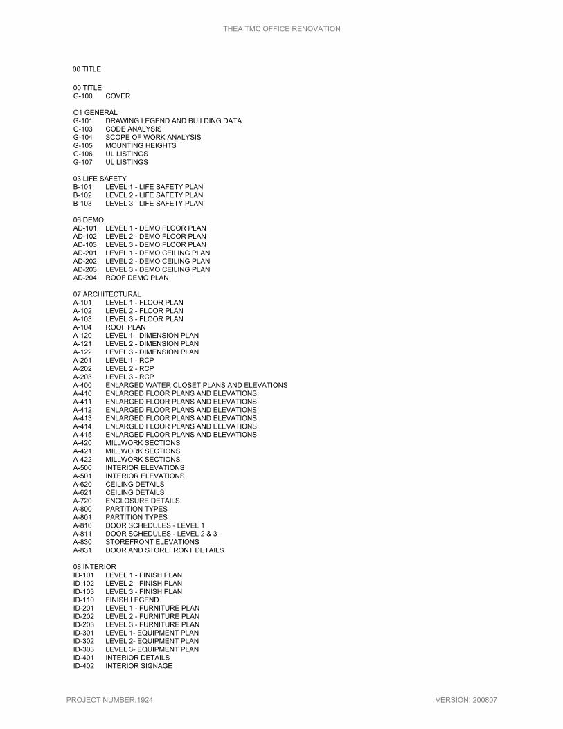
00 TITLE 00 TITLE G-100 COVER O1 GENERAL G-101 DRAWING LEGEND AND BUILDING DATAG-103 CODE ANALYSISG-104 SCOPE OF WORK ANALYSISG-105 MOUNTING HEIGHTSG-106 UL LISTINGSG-107 UL LISTINGS 03 LIFE SAFETY B-101 LEVEL 1 - LIFE SAFETY PLANB-102 LEVEL 2 - LIFE SAFETY PLANB-103 LEVEL 3 - LIFE SAFETY PLAN 06 DEMO AD-101 LEVEL 1 - DEMO FLOOR PLANAD-102 LEVEL 2 - DEMO FLOOR PLANAD-103 LEVEL 3 - DEMO FLOOR PLANAD-201 LEVEL 1 - DEMO CEILING PLANAD-202 LEVEL 2 - DEMO CEILING PLANAD-203 LEVEL 3 - DEMO CEILING PLANAD-204 ROOF DEMO PLAN 07 ARCHITECTURAL A-101 LEVEL 1 - FLOOR PLANA-102 LEVEL 2 - FLOOR PLANA-103 LEVEL 3 - FLOOR PLANA-104 ROOF PLANA-120 LEVEL 1 - DIMENSION PLANA-121 LEVEL 2 - DIMENSION PLANA-122 LEVEL 3 - DIMENSION PLANA-201 LEVEL 1 - RCPA-202 LEVEL 2 - RCPA-203 LEVEL 3 - RCPA-400 ENLARGED WATER CLOSET PLANS AND ELEVATIONSA-410 ENLARGED FLOOR PLANS AND ELEVATIONSA-411 ENLARGED FLOOR PLANS AND ELEVATIONSA-412 ENLARGED FLOOR PLANS AND ELEVATIONSA-413 ENLARGED FLOOR PLANS AND ELEVATIONSA-414 ENLARGED FLOOR PLANS AND ELEVATIONSA-415 ENLARGED FLOOR PLANS AND ELEVATIONSA-420 MILLWORK SECTIONSA-421 MILLWORK SECTIONSA-422 MILLWORK SECTIONSA-500 INTERIOR ELEVATIONSA-501 INTERIOR ELEVATIONSA-620 CEILING DETAILSA-621 CEILING DETAILSA-720 ENCLOSURE DETAILSA-800 PARTITION TYPESA-801 PARTITION TYPESA-810 DOOR SCHEDULES - LEVEL 1A-811 DOOR SCHEDULES - LEVEL 2 & 3A-830 STOREFRONT ELEVATIONSA-831 DOOR AND STOREFRONT DETAILS 08 INTERIOR ID-101 LEVEL 1 - FINISH PLANID-102 LEVEL 2 - FINISH PLANID-103 LEVEL 3 - FINISH PLANID-110 FINISH LEGENDID-201 LEVEL 1 - FURNITURE PLANID-202 LEVEL 2 - FURNITURE PLANID-203 LEVEL 3 - FURNITURE PLANID-301 LEVEL 1- EQUIPMENT PLANID-302 LEVEL 2- EQUIPMENT PLANID-303 LEVEL 3- EQUIPMENT PLANID-401 INTERIOR DETAILSID-402 INTERIOR SIGNAGE
THEA TMC OFFICE RENOVATION
PROJECT NUMBER:1924 VERSION: 200807

09 STRUCTURALS-101 GENERAL NOTES & ROOF PLAN 10 MECHANICAL M-000 LEGENDS, NOTES, AND ABBREVIATIONSM-101 LEVEL 1 - FLOOR HVAC PLANM-102 LEVEL 2 - FLOOR HVAC PLANM-103 LEVEL 3 - FLOOR HVAC PLANM-104 ROOF HVAC PLANM-501 DETAILS AND SCHEDULESM-502 SCHEDULESM-503 DETAILS AND SCHEDULESMD-101 LEVEL 1 - DEMO FLOOR HVAC PLANMD-102 LEVEL 2 - DEMO FLOOR HVAC PLANMD-103 LEVEL 3 - DEMO FLOOR HVAC PLANMD-104 ROOF DEMO HVAC PLAN 11 PLUMBING P-000 LEGENDS, NOTES, AND ABBREVIATIONSP-101 LEVEL 1 - FLOOR PLUMBING PLANP-102 LEVEL 2 - FLOOR PLUMBING PLANP-103 LEVEL 3 - FLOOR PLUMBING PLANPD-101 LEVEL 1 - DEMO FLOOR PLUMBING PLANPD-102 LEVEL 2 - DEMO FLOOR PLUMBING PLANPD-103 LEVEL 3 - DEMO FLOOR PLUMBING PLAN 12 ELECTRICAL E-001 LEGENDS, NOTES, AND ABBREVIATIONSE-101 LEVEL 1 - FLOOR LIGHTING PLANE-102 LEVEL 2 - FLOOR LIGHTING PLANE-103 LEVEL 3 - FLOOR LIGHTING PLANE-201 LEVEL 1 - FLOOR POWER PLANE-202 LEVEL 2 - FLOOR POWER PLANE-203 LEVEL 3 - FLOOR POWER PLANE-204 ELECTRICAL ROOF PLANE-301 LEVEL 1- FLOOR SYSTEMS PLANE-302 LEVEL 2- FLOOR SYSTEMS PLANE-303 LEVEL 3- FLOOR SYSTEMS PLANE-401 ELECTRICAL RISER DIAGRAMSE-501 ELECTRICAL DETAILSE-601 ELECTRICAL PANEL SCHEDULESE-602 ELECTRICAL PANEL SCHEDULESE-701 ELECTRICAL SCHEDULESED-101 LEVEL 1- DEMO FLOOR ELECTRICAL PLANED-102 LEVEL 2- DEMO FLOOR ELECTRICAL PLANED-103 LEVEL 3- DEMO FLOOR ELECTRICAL PLANED-104 ROOF DEMO ELECTRICAL PLAN
13 FIRE PROTECTION F-000 LEGENDS, NOTES, AND ABBREVIATIONSF-101 LEVEL 1 - FLOOR FIRE PROTECTION PLANF-102 LEVEL 2 - FLOOR FIRE PROTECTION PLANF-103 LEVEL 3 - FLOOR FIRE PROTECTION PLANF-501 DETAILS
THEA TMC OFFICE RENOVATION
PROJECT NUMBER:1924 VERSION: 200807

THEA TMC OFFICE RENOVATION
SUMMARY 011000 - Page 1 of 3 PROJECT NUMBER: 1924 VERSION: 200507
SECTION 011000 - SUMMARY
PART 1 - GENERAL
1.1 SUMMARY OF WORK
A. Project Identification: As follows:
1. Project: THEA Traffic Management Center 1104 E Twiggs St Tampa, FL 33602 2. Building Owner: Tampa Hillsborough Expressway Authority (THEA) 3. Project Administrator: Tampa Hillsborough Expressway Authority 4. Architect: Wannemacher Jensen Architects, LLC 180 Mirror Lake Drive North, St.
Petersburg, Florida 33701 5. Construction Manager: KCI Technologies, Inc. 6. Contractor: TBD
B. The Work consists of the renovation of the Traffic Management Center offices.
C. Temporary Facilities: No temporary facilities will be provided by THEA or KCI
Technologies, Inc. Providing these temporary facilities should be designated as the responsibility of the General Contractor and each of the sub-trades.
1.2 REFERENCE DOCUMENTS
A. Historical Drawings: None.
B. Reports: None
C. Standards: None.
1.3 WORK UNDER OTHER CONTRACTS
A. Separate Contract: If Owner has awarded a separate contract for performance of
certain construction operations at Project site, those operations will be conducted simultaneously with work under this Contract. This Contract includes the following: 1. Renovations of THEA TMC offices
B. Cooperate fully with separate contractors so work on those contracts may be carried out smoothly, with out interfering with or delaying work under this Contract.
1.4 SPECIFICATION FORMATS AND CONVENTIONS
A. Specification Format: The Specifications are organized into Divisions and sections using the
48-division format and CSI/CSC's "Master Format" numbering system
1. Section Identification: The Specifications use section numbers and titles to help cross-referencing in the Contract Documents. Sections in the Project Manual are in numeric sequence; however, the sequence is incomplete. Consult the table of contents at the beginning of the Project Manual to determine numbers and names of sections in the Contract Documents.
B. Specification Content: The Specifications use certain conventions for the style of language
and the in tended meaning of certain terms, words, and phrases when used in particular situations. Theses conventions are as follow:

THEA TMC OFFICE RENOVATION
SUMMARY 011000 - Page 2 of 3 PROJECT NUMBER: 1924 VERSION: 200507
1. Abbreviated Language: Language used in the Specifications and other Contract Documents is abbreviated. Words and meanings shall be interpreted as appropriate. Words implied, but not stated, shall be inferred as the sense requires. Singular words shall be interpreted as plural, and plural words shall be interpreted as singular where applicable as the context of the Contract Documents indicates.
2. Imperative mood and streamlined language are generally used in the Specifications. Requirements expressed in the imperative mood are to be performed by Contractor. Occasionally, the indicative or subjunctive mood may be used in the Section Text for clarity to describe responsibilities that must be fu1filled indirectly by Contractor or by others when so noted. a. The words "shall," "shall be," or "shall comply with," depending on the context,
are implied where a colon (:) is used within a sentence or phrase.
1.5 CONSTRUCTION SEQUENCE (Refer to the contract drawings and phasing plan)
1.6 WORK BY OWNER
A. General: Cooperate fully with Owner so work may be carried out smoothly, without
interfering with or delaying work under this Contract or work by Owner. Coordinate the Work of this Contract with work performed by Owner.
B. Concurrent Work: Owner may perform construction operations at Project site. Those
operations may be conducted simultaneously with work under this Contract.
1.7 CONDITIONS AFFECTING THE WORK
A. The Contractor shall be responsible for having taken all steps necessary to ascertain
the nature and location of the Work, and the general and local conditions, which can affect the Work or the cost thereof. Any failure by the contractor to do so will not relieve him from responsibility for successfully performing the work without additional expense to Owner.
1.8 COORDINATION WITH OCCUPANTS
A. Full Owner Occupancy: Owner will occupy site and existing building(s) during entire
construction period. Cooperate with Owner (through CM Owner’s Representative) during construction operations to minimize conflicts and facilitate Owner usage. Perform the Work so as not to interfere with Owner's day-to-day operations. Maintain existing exits, unless otherwise indicated. 1. Maintain access to existing walkways, corridors, and other adjacent occupied or
used facilities. Do not close or obstruct walkways, corridors, or other occupied or used facilities without written permission from Contracting Officer and approval of authorities having jurisdiction.
2. Submit request to CM Owner’s Representative and obtain written consent from Contracting Officer according to General Provisions for activities that will affect Owner's operations.

THEA TMC OFFICE RENOVATION
SUMMARY 011000 - Page 3 of 3 PROJECT NUMBER: 1924 VERSION: 200507
1.9 SALVAGE RIGHTS
A. The Contractor shall notify the Owner of any salvageable material discovered at the
site. The Owner re serves the right to claim such material for its own use. All salvageable material refused by the Owner shall become the property of the Contractor and shall be removed from the site.
B. Salvageable material claimed by Owner shall be set aside at the site, away from the
general work area and protected by the Contractor until such time as it is either re-used or removed as directed by the Owner.
C. The Contractor shall properly notify the Owner of the discovery of scientific or
historical artifacts and shall protect same until identified and removed by authorities exercising jurisdiction.
1.10 PERMITS
A. THEA shall submit for the building permit. The Contractor shall obtain the building permit
and all other necessary permits for construction of the work.
B. Submit to the CM Owner’s Representative written requests for permission from property owners for: 1. Temporary or permanent use of private property for field offices, work and
storage areas, or any other purpose. 2. Disposal of waste and spoil materials.
C. A copy of all permits shall be furnished to the Owner and CM Owner’s Representative.
PART 2 - PRODUCTS (Not Used)
PART 3 - EXECUTION
3.1 INTERPRETATION OR CORRECTION OF BIDDING DOCUMENTS
A. Refer to General Provisions Section 3.0 "INTERPRETATION."
END OF SECTION 011000

THEA TMC OFFICE RENOVATION
WORK RESTRICTIONS 011400 - Page 1 of 2 PROJECT NUMBER: 1924 VERSION: 200507
SECTION 011400 - WORK RESTRICTIONS
PART 1 - GENERAL
1.1 RELATED DOCUMENTS
A. Drawings and general provisions of the Contract, including General and Supplementary
Conditions and other Division 01 Specification Sections, apply to this Section.
1.2 USE OF PREMISES
A. Use of Site: Limit use of premises to work in areas indicated. Do not disturb portions
of site beyond areas in which the Work is indicated. 1. Limits: Confine constructions operations to the portions of the site and building
as indicated in the Documents. 2. Owner Occupancy: Allow for Owner occupancy of site and use by the public, as
well as continuous operation of the station. 3. Driveways and Entrances: Keep driveways and entrances serving premises clear
and available to Owner, Owner's employees, and emergency vehicles at all times. Do not use these areas for parking or storage of materials. a. Schedule deliveries to minimize use of driveways and entrances. b. Schedule deliveries to minimize space and time requirements for storage
of materials and equipment on-site.
B. Use of Existing Building: Maintain existing building in a weather tight condition throughout construction period. Repair damage caused by construction operations. Protect building and its occupants during construction period.
C. Working Hours:
1. Contractor shall submit a schedule of proposed working hours for approval by the Owner and the Construction Manager, which approval must be received prior to the commencement of any work. All work shall be performed such that the building remains fully operational at all times.
2. No work shall be scheduled on observed holidays: New Year's Day, Martin Luther King Day, President's Day, Memorial Day, Independence Day, Labor Day, Veteran's Day, Thanksgiving and Christmas.
1.3 OCCUPANCY REQUIREMENTS
A. Partial Owner Occupancy: Owner reserves the right to occupy and to place and
install equipment in completed areas of building, before Substantial Completion, provided such occupancy does not interfere with completion of the Work. Such placement of equipment and partial occupancy shall not constitute acceptance of the total Work. 1. The Architect will prepare a Certificate of Substantial Completion for each specific
portion of the Work to be occupied before Owner occupancy. 2. Obtain a Certificate of Occupancy from authorities having jurisdiction before Owner
occupancy.

THEA TMC OFFICE RENOVATION
WORK RESTRICTIONS 011400 - Page 2 of 2 PROJECT NUMBER: 1924 VERSION: 200507
3. Before partial Owner occupancy, mechanical and electrical systems shall be fully operational, and required tests and inspections shall be successfully completed. On occupancy, Owner will provide, operate, and maintain mechanical and electrical systems serving occupied portions of building.
4. On occupancy, Owner will assume responsibility for maintenance and custodial service for occupied portions of building.
5. Upon partial occupancy by the Owner, warranty periods shall commence for the occupied portion
of the building. 6. Contractor shall determine the requirements of the Owner and all applicable
authorities for partial occupancy. PART 2 - PRODUCTS (Not Used)
PART 3 - EXECUTION (Not Used)
END OF SECTION 011400

THEA TMC OFFICE RENOVATION
ALTERNATES 012300 - Page 1 of 2 PROJECT NUMBER: 1924 VERSION: 200807
SECTION 012300 - ALTERNATES PART 1 - GENERAL
1.1 RELATED DOCUMENTS
A. Drawings and general provisions of the Contract, including General and Supplementary
Conditions and other Division 01 Specification Sections, apply to this Section.
1.2 SUMMARY
A. This Section includes administrative and procedural requirements for alternates.
1.3 DEFINITIONS
A. Alternate: An amount proposed by bidders and stated on the Bid Form for certain work defined in the Bidding Requirements that may be added to or deducted from the Base Bid amount if Owner decides to accept a corresponding change either in the amount of construction to be completed or in the products, materials, equipment, systems, or installation methods described in the Contract Documents. 1. The cost or credit for each alternate is the net addition to or deduction from the
Contract Sum to incorporate alternate into the Work. No other adjustments are made to the Contract Sum.
1.4 PROCEDURES
A. Coordination: Modify or adjust affected adjacent work as necessary to completely integrate
work of the alternate into Project. 1. Include as part of each alternate, miscellaneous devices, accessory objects, and
similar items incidental to or required for a complete installation whether or not indicated as part of alternate.
B. Notification: Immediately following award of the Contract, notify each party involved, in writing,
of the status of each alternate. Indicate if alternates have been accepted, rejected, or deferred for later consideration. Include a complete description of negotiated modifications to alternates.
C. Execute accepted alternates under the same conditions as other work of the Contract.
D. Schedule: A Schedule of Alternates is included at the end of this Section. Specification
Sections referenced in schedule contain requirements for materials necessary to achieve the work described under each alternate.
PART 2 - PRODUCTS (Not Used)

THEA TMC OFFICE RENOVATION
ALTERNATES 012300 - Page 2 of 2 PROJECT NUMBER: 1924 VERSION: 200807
PART 3 - EXECUTION 3.1 SCHEDULE OF ALTERNATES
A. Provide additive alternates as follows:
1. Replacement of the four existing roof top units and associated roof curbs,
electrical connections, etc, as currently shown on the drawings. Base bid shall include keeping these existing RTUs.
2. Replacement of VAV-1.1.2, 1.1.4 thru 1.1.7, 1.1.13 thru 1.1.15, 2.2.2, 2.2.6 thru 2.2.8, 3.3.1 thru 3.3.3, 3.3.6 thru 3.3.11, 4.4.1 thru 4.4.3, and 4.4.5 as currently shown on the drawings. Base bid shall include keeping these existing VAVs.
3. Replacement of lighting fixtures in unrenovated spaces, as currently shown on the
drawings, rooms 103, 105,106,108,109, 115-118, 122-124, 126, 127, 130, 131, 131B, 139, 140, 203, 204, 205B, 206, 207, 209-213, 218-220, 223-226, 231-242, 304- 306, 308, 309,314-317,321-323, 325, 327-330. Base bid shall include replacement of lighting fixtures in renovated spaces only.
4. Provide a credit/deduction for completing the project with the following reduced phasing plan:
a. Phase 1 - Renovation of the 2nd and 3rd floors. The floors will be unoccupied except for the Traffic Management Center (TMC) on the 2nd floor. Work in the TMC to be coordinated after hours / weekends. Need to maintain path of egress to elevators. Occupants to use restrooms on first floor.
b. Phase 2 - Complete the work on the 1st floor with the board room and rest rooms on an accelerated four-week completion date. Floor to be unoccupied at time of renovation but will need to maintain access to elevators. Lobby renovation work to be completed after hours / weekends.
END OF SECTION 012300

THEA TMC OFFICE RENOVATION
PROJECT MEETINGS 013119 - Page 1 of 1 PROJECT NUMBER: 1924 VERSION: 200507
SECTION 013119 - PROJECT MEETINGS
PART 1 - GENERAL
1.1 RELATED DOCUMENTS
A. Drawings and general provisions of the Contract, including General and Supplementary
Conditions and other Division 01 Specification Sections, apply to this Section.
1.2 PRE-PERFORMANCE CONFERENCE
A. Within 15 calendar days after award of the Contract, a pre-construction conference will be
held. The Contractor will be notified of the exact time and location to be determined by the Construction Manager.
B. Attendance: The Architect, Construction Manager, Owner representatives, and the
Contractor and his principal subcontractors.
1.3 PROGRESS MEETINGS
A. Schedule: The Contractor shall attend the progress meetings and shall:
1. Be prepared to discuss progress as it relates to the Construction Schedule. 2. Review distributed minutes and respond to the Construction Manager, within 3 days after receipt.
B. Regular meetings will be scheduled once every two weeks, or more frequently as
Construction Manager or progress may require.
C. Attendance: The Contractor, subcontractors to whom the agenda pertain, the Construction Manager and other interested representatives of Owner.
D. Meeting minutes will be distributed within 3 calendar days after the meeting.
PART 2 - PRODUCTS (Not Used)
PART 3 - EXECUTION (Not Used)
END OF SECTION 013119

THEA TMC OFFICE RENOVATION
SCHEDULING AND PROCEDURES 013213 - Page 1 of 2 PROJECT NUMBER: 1924 VERSION: 200507
SECTION 013213 - SCHEDULING AND PROCEDURES
PART 1 - GENERAL
1.1 RELATED DOCUMENTS
A. Drawings and general provisions of the Contract, including General and Supplementary
Conditions and Division 01 Specification Sections, apply to this Section.
1.2 DEVELOPMENT OF SCHEDULE
A. Contractor shall prepare a Critical Path Method (CPM) schedule/calendar showing critical
dates for starting and completion of various portions of the work, including delivery of major components, and lengths of time to complete each portion. This schedule shall be developed in MS Project or Primavera P3.
B. After acceptance of the schedule by the CM Owner’s Representative, the Contractor shall
be responsible for ensuring that it is adhered to and for ascertaining that proper coordination and time schedules are maintained between various portions of the work.
1.3 SCHEDULE CONTENTS
A. Identify each week by year, month and day.
B. Start, continuity, and finish of each category of work.
C. Shop drawings, construction drawings and sample submittal dates. The Architect/Engineer
review time for approvals will require 21 calendar days.
D. Owner Protection Personnel Requirements.
E. Detailed work schedule 1. Each sheet shall contain a title block in the lower right hand corner to
accommodate revision numbers and date of issue. 2. Each activity should be completed within a maximum time period of 30 calendar days. 3. A detailed schedule must show activity numbers, early and late starts/finishes,
durations as well as total float for each activity. 4. All dummies and constraints are to be shown to establish all logical and complete
relationships between all interrelating activities. 5. Critical path activities are to be differentiated from all other activities. 6. All of the Owner’s furnished milestones are to be superimposed on all submitted diagrams. 7. All activities must have a brief description to convey the scope of work. Unusual
abbreviation shall be explained in a legend. 8. The construction schedule shall identify all significant work tasks required in the
performance of the Contract, and includes, but is not limited to: a. Mobilization. b. Procurement, inspection and delivery. c. Shop drawing submittals. d. Access to site. e. Phasing. f. Major elements of the work for each segment of the structure. g. Major testing and inspections h. Punch-list and clean-up.

THEA TMC OFFICE RENOVATION
SCHEDULING AND PROCEDURES 013213 - Page 2 of 2 PROJECT NUMBER: 1924 VERSION: 200507
i. Demobilization.
1.3 PROTECTION OF PROPERTY
A. Utilities: Before commencing the Work, verify the location of all utility facilities in the
vicinity of the Work. If necessary, test pitting may be required on some utilities. Prior to beginning work affecting any utility facility, submit to the CM Owner’s Representative
and Engineer for approval a plan for performing the work, with evidence of approval by the utility operator.
B. Existing Surfaces and Facilities:
1. Take positive action to protect all existing surfaces and facilities from any damage resulting from the Work unless modifications to the surfaces or facilities are required as a part of the Contract.
2. Protect all paving, landscaping, and utility facilities from damage caused by mobile and stationary equipment, including vehicles delivering materials to the site. Any damage shall be repaired at the Contractor's sole expense.
3. Provide and maintain adequate protection for all adjacent structures. When required by law, or for the safety of the work, shore, brace, underpin, or otherwise protect those portions of adjacent structures which may be affected by the work. The Contractor, before commencement of any part of the Work, shall give any notices required to be given to adjoining property owner(s) or other parties.
C. New Work:
1. All finished surfaces of items shall be clean and not marred upon acceptance of the structure. Refinish all such surfaces that have been inadequately protected and are damaged.
2. The Contractor shall, at all times, provide and maintain adequate protection against weather so as to preserve all work, materials, equipment, apparatus, and fixtures free from injury or damage.
3. Do not use items of equipment or materials that are intended to form a part of the complete work as construction equipment without specific approval from the CM Owner’s Representative in each instance.
4. Do not load or permit any part of a structure to be loaded so as to endanger its safety.
PART 2 - PRODUCTS (Not Used)
PART 3 - EXECUTION (Not Used)
END OF SECTION 013213

THEA TMC OFFICE RENOVATION
PHOTOGRAPHIC DOCUMENTATION 013233 - Page 1 of 2 PROJECT NUMBER: 1924 VERSION: 200507
SECTION 013233 - PHOTOGRAPHIC DOCUMENTATION PART 1 - GENERAL
1.1 RELATED DOCUMENTS
A. Drawings and general provisions of the Contract, including General and Supplementary
Conditions and other Division 01 Specification Sections, apply to this Section. 1.2 SUMMARY
A. This Section includes administrative and procedural requirements for the following:
1. Preconstruction photographs. 2. Periodic construction photographs. 3. Final Completion construction photographs.
B. Related Requirements:
1. Section 013300 "Submittal Procedures" for submitting construction photographs. 2. Section 017700 "Closeout Procedures" for submitting photographs as Project Record
Documents at Project closeout. 1.3 SUBMITI'ALS
A. Qualification Data: For firms and persons specified in "Quality Assurance" Article to
demonstrate their capabilities and experience. Include lists of completed projects with project names and addresses, names and addresses of engineers and owners, and other information specified.
B. Key Plan: Submit key plan of Project site and building with notation of vantage points
marked for location and direction of each photograph/video. Indicate elevation or story of construction. Include the same label information as the corresponding set of photographs or video.
C. Digital Images: Submit a complete set of digital image electronic files with each submittal as
a Project Record Document. Identify electronic media with date photographs were taken. Submit images that have the same aspect ratio as the sensor, uncropped.
1.4 QUALITY ASSURANCE
A. Photographer Qualifications: An individual of sufficient capability who has been regularly
engaged to provide photographic documentation on construction projects for not less than a year.
1.5 COORDINATION
A. Auxiliary Services: Cooperate with photographer and provide auxiliary services requested,
including access to Project site and use of temporary facilities including temporary lighting.

THEA TMC OFFICE RENOVATION
PHOTOGRAPHIC DOCUMENTATION 013233 - Page 2 of 2 PROJECT NUMBER: 1924 VERSION: 200507
PART 2 - PRODUCTS 2.1 PHOTOGRAPHIC MEDIA
A. Digital Images: Provide high-quality images in JPEG format, using a minimum
sensor size of 6.0 megapixels for resolution. PART 3 - EXECUTION
3.1 PHOTOGRAPHS, GENERAL
A. Photographer: Engage a qualified photographer to take construction photographs.
B. Date Stamp: Unless otherwise indicated, date and time stamp each photograph as
it is being taken so stamp is integral to photograph. 3.2 CONSTRUCTION PHOTOGRAPHS
A. Preconstruction Photographs: Before starting construction, take color photographs of
Project site and surrounding properties from different vantage points, as directed by Owner and Construction Manager.
1. Take four (4) photographs to show existing conditions adjacent to the property before starting the Work.
2. Take four (4) photographs of existing buildings either on or adjoining the property to accurately record the physical conditions at the start of construction.
B. Periodic Construction Photographs: Take color photographs monthly, coinciding with
the cutoff date associated with each Application for Payment. Photographer shall select vantage points to best show status of construction and progress since the last photograp hs were taken.
C. Owner/Construction Manager-Directed Construction Photographs: From time to time,
Owner or Construction Manager will instruct photographer about number and frequency of color photographs and general directions on vantage points. Photographer shall select actual vantage points and take photographs to best show the status of construction and progress since the last photographs were taken.
D. Final Completion Construction Photographs: Take color photographs after date of
Substantial Completion for submission as Project Record Documents. Owner and Construction Manager will direct photographer for desired vantage points.
E. Additional Photographs: Owner or Construction Manager may issue requests for additional photographs, in addition to periodic photographs specified. 1. Circumstances that could require additional photographs include, but are not limited
to, the following: a. Special events planned at Project site. b. Immediate follow-up when on-site events result in construction damage or losses. c. Photographs to be taken at fabrication locations away from Project site. d. Substantial Completion of a major phase or component of the Work. e. Extra record photographs at time of final acceptance. f. Owner's request for special publicity photographs.
END OF SECTION 013233

THEA TMC OFFICE RENOVATION
SUBMITTAL PROCEDURES 013300 - Page 1 of 5 PROJECT NUMBER: 1924 VERSION: 200507
SECTION 013300 - SUBMITTAL PROCEDURES PART 1 - GENERAL
1.1 RELATED DOCUMENTS
A. Drawings and general provisions of the Contract, including General and Supplementary
Conditions and other Division 01 Specification Sections, apply to this Section.
1.2 SCHEDULES
A. Interim Schedule: The Contractor shall submit to the Architect and the CM Owner’s
Representative within 30 calendar days after the award of the Contract an interim construction schedule. This interim construction schedule shall be prepared on the basis of an accepted Gantt (Bar) Chart method for scheduling, unless directed otherwise by the Architect and/or Construction Manager in writing, and shall detail the time scheduling for accomplishing the initial phase of the work under this Contract. This interim progress schedule shall cover the period of 30 calendar days from the issuance of the Notice to Proceed and is in addition to, and shall not be considered in conflict with, any other construction schedule requirements. 1. The interim progress schedule shall show at a minimum: work activities,
sequences, restraints, construction drawings, product data, and sample submittal dates, durations, start dates, and finish dates. This schedule shall be submitted by the Contractor for the Construction Manager's review and acceptance prior to the issuance of the Notice to Proceed.
2. This interim progress schedule shall be superseded and upon the Construction Manager's approval of the Contractor's progress schedule submittal covering the entire Contract Performance Period.
B. Construction Schedule: The Contractor, within 15 calendar days after the Notice to Proceed,
shall submit a construction schedule, in accordance with Section "Scheduling and Procedures'', unless directed otherwise, by the Construction Manager in writing for the complete work effort required to execute the contract. This schedule, after approval by the Construction Manager, will become the official schedule. The Contractor will follow the approved schedule unless prior written approval to deviate therefrom has been obtained from the Construction Manager. 1. The construction schedule shall be used by both the Contractor and the Construction
Manager for: a. Job planning and control. b. Progress reporting and forecasting. c. Basis for evaluating changes and claims. d. Interfaces with other contractors and subcontractors.
2. See Section 013213 “Scheduling and Procedures” for detailed schedule requirements. 3. No progress payments will be made until the Architect and the Construction
Manager have approved the progress schedule.
C. Provide supplemental sub-schedules if areas of the work require additional or more detailed coordination.
D. The Contractor shall update the schedule once each calendar month. Revisions to the
progress schedule shall be subject to approvals by the Architect and the Construction Manager.

THEA TMC OFFICE RENOVATION
SUBMITTAL PROCEDURES 013300 - Page 2 of 5 PROJECT NUMBER: 1924 VERSION: 200507
1.3 SHOP AND WORKING ORAWINGS
A. Shop Drawings: Submit shop drawings to the Architect and the Construction Manager for
review at least 21 calendar days prior to starting the work. Submit shop and working drawings, complete with all relevant calculations and descriptions, required by the Contract Documents. 1. Make all shop drawings accurately to a scale sufficiently large to show all
pertinent aspects of the item and its method of connection to the work. 2. All details on shop drawings submitted for review shall show the relation of the
various parts; and where the work depends on field measurements, such measurements shall be obtained by the Contractor and noted on the shop drawings before being submitted for review.
B. Working Drawings: If required, furnish detailed working drawings, in a format approved
by the Construction Manager, for temporary structures such as false work and shoring, and for other work as may be required by the Construction Manager. Submit backup calculations or any other information needed to explain the systems or their intended use. Take responsibility for such drawings and for the safe and successful construction of the work. As required, drawings and calculations shall be prepared and sealed by a Professional Engineer registered in the State of Florida.
1.4 SUBMISSION REQUIREMENTS
A. Submit electronic copies of all shop and working drawings, and of such other
engineering and design data and drawings as are prescribed in the Specifications or are necessary to demonstrate compliance with Specification requirements, to the Construction Manager for review. It shall be the Contractor's responsibility to coordinate drawing submittals with the construction schedule. Maximum size of drawings shall be 22 inches by 34 inches.
B. Final Shop and Working Drawings: Electronic drawings shall be submitted to the
Architect and Construction Manager within 10 calendar days after receipt of the Construction Manager's conformance designation. All copies shall be marked "This drawing was reviewed by the Construction Manager on (DATE)."
C. Product information shall encompass all catalog cuts, data sheets, test results,
certifications, and other information specified in the various sections which are to be submitted to permit the Construction Manager to monitor the quality of materials to be incorporated into the work. In addition, shop and working drawings shall also comply with the requirements of this article.
D. Refer to Division Section 016000 “Product Requirements" for product submission
requirements.
E. Submittals shall include: 1. Date and revision dates. 2. Project title and number. 3. The names of:
a. Contractor’s representative. b. Subcontractor, supplier, and or manufacturer, as applicable.
4. Identification of product or material. 5. Field dimensions, clearly identified as such. 6. Applicable standards, such as ASTM number or Federal Specification number. 7. Identification of deviations from the Contract Documents.

THEA TMC OFFICE RENOVATION
SUBMITTAL PROCEDURES 013300 - Page 3 of 5 PROJECT NUMBER: 1924 VERSION: 200507
8. Contractor's stamp, initialed or signed, certifying to review of submittal, verification of field measurements, and compliance with the Contract Documents.
F. Make all submittals for approval far enough in advance of scheduled installation and use
dates to provide time required for reviews, for securing necessary approvals, for possible revisions and resubmittals, and for placing orders and securing delivery.
G. In scheduling, allow 21 calendar days for review by the Construction Manager
following receipt of the submittal. 1. Resubmittals by the Contractor, where required, shall be made within 7 calendar
days after receipt of the Construction Manager's comments.
H. Delays caused by tardiness in receipt of submittals will not be accepted as a basis for extension of the Contract completion date or claims for delay.
I. The Contractor shall review, stamp approved, and present to the Construction
Manager for review all submittals required by the Contract Documents. All submittals shall be properly identified as specified, or the Construction Manager may require resubmission.
J. By approving and submitting drawings, samples, and product data, the Contractor
thereby certifies the determination and verification of all field measurements, field construction criteria, materials, catalog numbers, and similar data, and that the checking and coordination of all drawings, product data, and samples with the requirements of the work and the Contract Documents.
K. The Construction Manager will review submittals only for conformance with the design
concept and the requirements of the Contract Documents. The Construction Manager's acceptance of a separate item shall not indicate approval of an assembly in which the item functions.
L. The Contractor shall make all Construction Manager-required corrections to
submissions until they are accepted by the Construction Manager. The Contractor shall direct specific attention in writing on resubmissions to revisions other than the corrections requested by the Construction Manager by previous submissions.
M. The Construction Manager's acceptance of submittals will not relieve the Contractor of
responsibility for any deviation from the requirements of the Contract Documents unless the Contractor has informed the Construction Manager in writing of such deviation at the time of submission and the Construction Manager has given written acceptance to relieve the Contractor from responsibility for such deviations.
N. Performance of any work for which submittals are required without receipt of the
Construction Manager's acceptance of such submittals will be at the Contractor's own risk. If the Construction Manager subsequently rejects such items of work for failure to conform to the Contract Documents, the Contractor shall, at no cost to the Construction Manager, promptly remove such items or work and replace with items or work conforming to the Construction Manager -accepted submittals.

THEA TMC OFFICE RENOVATION
SUBMITTAL PROCEDURES 013300 - Page 4 of 5 PROJECT NUMBER: 1924 VERSION: 200507
1.5 DAILY PROGRESS, LABOR AND EQUIPMENT REPORTS
A. The Contractor shall furnish to the Construction Manager at the end of each week
a memorandum showing for that week: 1. The work performed and the percent completion. 2. The equipment and material used. 3. A statement of any unusual happenings that occurred. 4. The number of men in each trade classification that were employed. 5. Shift start and end times.
Such memorandum shall not be deemed to be a substitute for the notices, time slips, or other data required relating to compensation for extra work.
1.6 CONTRACTORS SAFETY AND FIRE PROTECTION PROGRAM
A. Within 14 calendar days after the award of the Contract, the Contractor shall submit to
the Construction Manager, for review and approval, the Contractor's Safety and Fire Protection Program. This Program shall comply with all applicable Federal, State, and local laws and Owner requirements and shall include the designation by the Contractor of an OSHA certified individual to administer the Program.
B. Clothing and Personal Protective Equipment (PPE):
1. Clothing must fit well and not be loose so that it would be easily snagged or become a hazard.
2. Normal PPE for working on Owner property will be a hard hat, reflective vest, safety glasses and proper footwear and must be used as appropriate for the work being done.
3. Other PPE requirements such as goggles, face shields, safety belts, safety harnesses, respirators and hearing protection will be determined by the Site Specific Safety Work Plan.
4. Shoes must be at least six inches high, preferably leather and completely laced, buckled, zipped or otherwise fastened. Shoes must have a definite heel. Shoelaces shall not be loose and/or dangle far enough to become a hazard.
5. Shoes with loose, thin, cracked, rippled or wedged-type soles are not acceptable. Shoes with a metal plate or cleat on the sole or heal are not acceptable. Sandals, open toe, canvas or athletic type shoes are not acceptable. Shoes that cannot be fastened are not acceptable. Specific footwear requirements may be addressed in the Site Specific Safety Work Plan.
6. Contractor and workers will not be permitted on Owner property if not utilizing the proper PPE.
1.7 PROJECT RECORD DOCUMENTS
A. Refer to Section 017700 “Closeout Procedures" for submittal format requirements.
B. Maintain an up-to-date "As-Built - Worksite Copy" set of drawings for the
Construction Manager's review in the Project office at the site. Changes shall be entered on these drawings as they occur.
C. The Contractor shall, on electronic AutoCAD (Version 2018 or later) file (discs
furnished by the Architect), revise all Contract Drawings to reflect the final "As-Built" condition as of the date of acceptance.

THEA TMC OFFICE RENOVATION
SUBMITTAL PROCEDURES 013300 - Page 5 of 5 PROJECT NUMBER: 1924 VERSION: 200507
D. The Contractor shall furnish to the Construction Manager all guarantees, warrantees, maintenance instructions and permits called for in the Contract
E. The Contractor shall deliver to the Construction Manager a properly executed Release of
Claims covering all materials, labor, and equipment installed or employed on this project, and other releases as may be required
F. The Contractor shall deliver to the Construction Manager all original certificates or
manifests related to generated waste materials, including: laboratory reports, temporary storage, treatment, hauling, and legal disposal.
G. The Contractor shall furnish to the Construction Manager copies of all reports,
calculations and "As Built" drawings for borings, false work, shoring, repairs, piles, hoisting systems, and as otherwise required by the Construction Manager.
H. Final payment for this Contract will not be made until all required submittals have
been received and approved by the Construction Manager. PART 2 - PRODUCTS (Not Used)
PART 3 - EXECUTION (Not Used)
END OF SECTION 013300

THEA TMC OFFICE RENOVATION
QUALITY REQUIREMENTS 014000 - Page 1 of 4 PROJECT NUMBER: 1924 VERSION: 200507
SECTION 014000 - QUALITY REQUIREMENTS PART 1 - GENERAL
1.1 RELATED DOCUMENTS
A. Drawings and general provisions of the Contract, including General and Supplementary
Conditions and other Division 01 Specification Sections, apply to this Section.
1.2 QUALITY ASSURANCE
A. Materials and workmanship shall in every respect be in accordance with the Plans and Specifications in all cases. Materials and workmanship shall be free from defects of any kind.
1.3 SOURCE OF MATERIAL
A. In addition to any requirements for "Shop Drawings", the Contractor shall notify the CM
Owner’s Representative in writing of the sources from which all material incorporated in the Work will be obtained. Make such notifications as soon as possible after award of the Contract but not later than 30 calendar days prior to any required acceptance testing.
B. In general, materials, where applicable, shall be obtained from sources approved by
the Tampa Hillsborough Expressway Authority. Obtain approval from the Architect and Engineer for all other material sources.
1.4 MATERIAL SUBSTITUTIONS
A. Materials or products specified in the Contract Documents by name of manufacturer,
brand, trade name, or catalog reference shall be the basis for selecting such materials and products, except in cases where the note "No Substitute" is used. Where two or more materials or products are named the choice of these shall be optional with the Contractor.
B. Additional costs resulting from the exercise of Contractor options for the selection of
materials and products, where other available options would involve such additional costs, shall be borne by the Contractor.
C. The Owner recognizes that the Contractor may be able to offer alternates to the
Contract Documents that could save time and reduce costs. Such alternates will be considered only when found acceptable by the Owner and will become part of the work only after the appropriate Contract Modification Requests are executed.
1.5 MOCKUPS
A. Full-size, physical assemblies that are constructed on-site. Mockups may be used to
verify selections made under sample submittals, to demonstrate aesthetic effects and, where indicated, qualities of materials and execution, and to review construction, coordination, testing, or operation; they are not Samples. Approved mockups establish the standard by which the Work will be judged.

THEA TMC OFFICE RENOVATION
QUALITY REQUIREMENTS 014000 - Page 2 of 4 PROJECT NUMBER: 1924 VERSION: 200507
B. Before installing portions of the Work requiring mockups, build mockups for each form of construction and finish required to comply with the following requirements, using materials indicated for the completed Work: 1. Build mockups in location and of size indicated or, if not indicated, as directed
by Project Engineer. 2. Notify CM Owner’s Representative & Architect seven calendar days in
advance of dates and times when mockups will be constructed. 3. Demonstrate the proposed range of aesthetic effects and workmanship. 4. Obtain CM Owner’s Representative 's approval of mockups before starting
work, fabrication, or construction. 5. Maintain mockups during construction in an undisturbed condition as a
standard for judging the completed Work. 6. Retain subparagraph below as the default requirement and add specific
requirements in individual Specification Sections. 7. Demolish and remove mockups when directed, unless otherwise indicated.
1.6 TESTS AND INSPECTIONS
A. Refer to the General Conditions and to requirements of individual sections of these
Specifications.
B. Required certificates of inspection, testing or approval shall be secured by the Contractor and promptly delivered by him to the CM Owner’s Representative. 1. The CM Owner’s Representative reserves the right to refuse to permit the use of
certain material on the basis of a lack of a certificate of compliance.
C. The CM Owner’s Representative reserves the right to disapprove any material or equipment which previously has proven unsatisfactory in service.
D. Neither the observations of the CM Owner’s Representative in its administration of the
Contract Documents, nor inspections, tests, or approvals by persons other than the Contractor shall relieve him from his obligations to perform the Work in accordance with the Contract Documents.
E. The CM Owner’s Representative will inspect the materials furnished and work
performed during the course of the Work. Provide unrestricted access to inspection personnel at the site and during fabrication and manufacturing. Provide all such facilities as are necessary to carry out the inspection to the satisfaction of the CM Owner’s
Representative. 1. If work is covered up without approval of the CM Owner’s Representative, uncover
such work for examination by the CM Owner’s Representative, where directed. After examination and approval by the CM Owner’s Representative, restore removed covering as required, at no additional expense to the Owner.
2. At any time during the progress of the Work and up to the date of final acceptance, the CM Owner’s Representative shall have the right to reject any work which does not conform to the requirements of the Contract Documents, even though such work has been previously inspected.

THEA TMC OFFICE RENOVATION
QUALITY REQUIREMENTS 014000 - Page 3 of 4 PROJECT NUMBER: 1924 VERSION: 200507
F. The Contractor shall promptly correct all work rejected by the CM Owner’s
Representative as defective or as failing to conform to the Contract Documents, whether observed before or after substantial completion, in a manner satisfactory to the CM Owner’s Representative, and consistent with the intent of the Contract. The Contractor shall bear all costs of correcting such rejected work, including the cost of any and all additional engineering services, whether by the CM Owner’s
Representative or others, thereby made necessary. Rejected material shall be immediately removed from the site at the Contractor's expense.
1.7 TESTING BY THE CONTRACTOR
A. The Contractor is responsible for all testing unless otherwise specified. The
Contractor's tests shall be performed by a qualified testing agency at the sole cost of the Contractor.
B. The Contractor's testing agency will be subject to approval by the CM Owner’s
Representative. The Contractor shall submit the name of a proposed agency accompanied by certification that is capable of performing the required tests.
C. Sampling of material for testing shall be conducted in the presence of the CM Owner’s
Representative.
D. Where field tests or instrument's readings are made by the Contractor's personnel, the qualifications of such personnel will at all times be subject to the CM Owner’s
Representative 's approval.
E. All gauges and other instruments shall be in good working condition, properly calibrated to the standards of the U.S. National Bureau of Standards, and as approved by the Engineer.
F. Results of all laboratory tests shall be submitted to the Architect & Engineer as soon as
available, but not later than five calendar days after completion of testing or sooner if so required by the CM Owner’s Representative. Include date of tests and the name and address of the organization performing the tests.
G. Results of all field tests and instrument readings shall be given to the CM Owner’s
Representative as soon as available, and shall be assembled and recorded in reports to be submitted to the CM Owner’s Representative, in a form to be approved by the CM Owner’s Representative.
H. By advance discussion with the CM Owner’s Representative, the Contractor shall
determine the time required to perform his test and to issue each of the findings. Provide for the required time in the construction schedule.
I. When the testing agency is ready to test according to the established schedule, but is
prevented from testing or taking specimens due to incompleteness of the Work, all extra costs for testing attributable to the delay shall be borne by the Contractor.

THEA TMC OFFICE RENOVATION
QUALITY REQUIREMENTS 014000 - Page 4 of 4 PROJECT NUMBER: 1924 VERSION: 200507
PART 2 - PRODUCTS (Not Used) PART 3 - EXECUTION (Not Used)
END OF SECTION 014000

THEA TMC OFFICE RENOVATION
REFERENCES 014200 - Page 1 of 7 PROJECT NUMBER: 1924 VERSION: 200507
SECTION 014200 - REFERENCES
PART 1 - GENERAL
1.1 RELATED DOCUMENTS
A. Drawings and general provisions of the Contract, including General and Supplementary Conditions and other Division 01 Specification Sections, apply to this Section.
1.2 DEFINITIONS
A. General: Basic Contract definitions are included in the Conditions of the Contract.
B. "Approved": When used to convey Architect's action on Contractor's submittals, applications, and requests, "approved" is limited to Architect's duties and responsibilities as stated in the Conditions of the Contract.
C. "Directed": A command or instruction by Architect. Other terms including "requested," "authorized," "selected," "required," and "permitted" have the same meaning as "directed."
D. "Indicated": Requirements expressed by graphic representations or in written form on Drawings, in Specifications, and in other Contract Documents. Other terms including "shown," "noted," "scheduled," and "specified" have the same meaning as "indicated."
E. "Regulations": Laws, ordinances, statutes, and lawful orders issued by authorities having jurisdiction, and rules, conventions, and agreements within the construction industry that control performance of the Work.
F. "Furnish": Supply and deliver to Project site, ready for unloading, unpacking, assembly, installation, and similar operations.
G. "Install": Unload, temporarily store, unpack, assemble, erect, place, anchor, apply, work to dimension, finish, cure, protect, clean, and similar operations at Project site.
H. "Provide": Furnish and install, complete and ready for the intended use.
I. "Project Site": Space available for performing construction activities. The extent of Project site is shown on Drawings and may or may not be identical with the description of the land on which Project is to be built.
1.3 INDUSTRY STANDARDS
A. Applicability of Standards: Unless the Contract Documents include more stringent requirements, applicable construction industry standards have the same force and effect as if bound or copied directly into the Contract Documents to the extent referenced. Such standards are made a part of the Contract Documents by reference.
B. Publication Dates: Comply with standards in effect as of date of the Contract Documents unless otherwise indicated.
C. Copies of Standards: Each entity engaged in construction on Project should be familiar with industry standards applicable to its construction activity. Copies of applicable standards are not bound with the Contract Documents.

THEA TMC OFFICE RENOVATION
REFERENCES 014200 - Page 2 of 7 PROJECT NUMBER: 1924 VERSION: 200507
1. Where copies of standards are needed to perform a required construction activity, obtain copies directly from publication source.
1.4 ABBREVIATIONS AND ACRONYMS
A. Industry Organizations: Where abbreviations and acronyms are used in Specifications or other Contract Documents, they shall mean the recognized name of the entities in the following list. This information is subject to change and is believed to be accurate as of the date of the Contract Documents. 1. AABC - Associated Air Balance Council; www.aabc.com. 2. AAMA - American Architectural Manufacturers Association; www.aamanet.org. 3. AAPFCO - Association of American Plant Food Control Officials; www.aapfco.org. 4. AASHTO - American Association of State Highway and Transportation Officials;
www.transportation.org. 5. AATCC - American Association of Textile Chemists and Colorists; www.aatcc.org. 6. ABMA - American Bearing Manufacturers Association; www.americanbearings.org. 7. ACI - American Concrete Institute; (Formerly: ACI International); www.concrete.org. 8. ACPA - American Concrete Pipe Association; www.concrete-pipe.org. 9. AEIC - Association of Edison Illuminating Companies, Inc. (The); www.aeic.org. 10. AF&PA - American Forest & Paper Association; www.afandpa.org. 11. AGA - American Gas Association; www.aga.org. 12. AHAM - Association of Home Appliance Manufacturers; www.aham.org. 13. AHRI - Air-Conditioning, Heating, and Refrigeration Institute (The); www.ahrinet.org. 14. AI - Asphalt Institute; www.asphaltinstitute.org. 15. AIA - American Institute of Architects (The); www.aia.org. 16. AISC - American Institute of Steel Construction; www.aisc.org. 17. AISI - American Iron and Steel Institute; www.steel.org. 18. AITC - American Institute of Timber Construction; www.aitc-glulam.org. 19. AMCA - Air Movement and Control Association International, Inc.; www.amca.org. 20. ANSI - American National Standards Institute; www.ansi.org. 21. AOSA - Association of Official Seed Analysts, Inc.; www.aosaseed.com. 22. APA - APA - The Engineered Wood Association; www.apawood.org. 23. APA - Architectural Precast Association; www.archprecast.org. 24. API - American Petroleum Institute; www.api.org. 25. ARI - Air-Conditioning & Refrigeration Institute; (See AHRI). 26. ARI - American Refrigeration Institute; (See AHRI). 27. ARMA - Asphalt Roofing Manufacturers Association; www.asphaltroofing.org. 28. ASCE - American Society of Civil Engineers; www.asce.org. 29. ASCE/SEI - American Society of Civil Engineers/Structural Engineering Institute; (See
ASCE). 30. ASHRAE - American Society of Heating, Refrigerating and Air-Conditioning Engineers;
www.ashrae.org. 31. ASME - ASME International; (American Society of Mechanical Engineers);
www.asme.org. 32. ASSE - American Society of Safety Engineers (The); www.asse.org. 33. ASSE - American Society of Sanitary Engineering; www.asse-plumbing.org. 34. ASTM - ASTM International; (American Society for Testing and Materials International);
www.astm.org. 35. ATIS - Alliance for Telecommunications Industry Solutions; www.atis.org. 36. AWEA - American Wind Energy Association; www.awea.org. 37. AWI - Architectural Woodwork Institute; www.awinet.org. 38. AWMAC - Architectural Woodwork Manufacturers Association of Canada;
www.awmac.com. 39. AWPA - American Wood Protection Association; (Formerly: American Wood-Preservers'
Association); www.awpa.com. 40. AWS - American Welding Society; www.aws.org.

THEA TMC OFFICE RENOVATION
REFERENCES 014200 - Page 3 of 7 PROJECT NUMBER: 1924 VERSION: 200507
41. AWWA - American Water Works Association; www.awwa.org. 42. BHMA - Builders Hardware Manufacturers Association; www.buildershardware.com. 43. BIA - Brick Industry Association (The); www.gobrick.com. 44. BICSI - BICSI, Inc.; www.bicsi.org. 45. BIFMA - BIFMA International; (Business and Institutional Furniture Manufacturer's
Association); www.bifma.com. 46. BISSC - Baking Industry Sanitation Standards Committee; www.bissc.org. 47. BOCA - BOCA; (Building Officials and Code Administrators International Inc.); (See ICC). 48. BWF - Badminton World Federation; (Formerly: International Badminton Federation);
www.bwfbadminton.org. 49. CDA - Copper Development Association; www.copper.org. 50. CEA - Canadian Electricity Association; www.electricity.ca. 51. CEA - Consumer Electronics Association; www.ce.org. 52. CFFA - Chemical Fabrics & Film Association, Inc.; www.chemicalfabricsandfilm.com. 53. CFSEI - Cold-Formed Steel Engineers Institute; www.cfsei.org. 54. CGA - Compressed Gas Association; www.cganet.com. 55. CIMA - Cellulose Insulation Manufacturers Association; www.cellulose.org. 56. CISCA - Ceilings & Interior Systems Construction Association; www.cisca.org. 57. CISPI - Cast Iron Soil Pipe Institute; www.cispi.org. 58. CLFMI - Chain Link Fence Manufacturers Institute; www.chainlinkinfo.org. 59. CPA - Composite Panel Association; www.pbmdf.com. 60. CRI - Carpet and Rug Institute (The); www.carpet-rug.org. 61. CRRC - Cool Roof Rating Council; www.coolroofs.org. 62. CRSI - Concrete Reinforcing Steel Institute; www.crsi.org. 63. CSA - Canadian Standards Association; www.csa.ca. 64. CSA - CSA International; (Formerly: IAS - International Approval Services); www.csa-
international.org. 65. CSI - Construction Specifications Institute (The); www.csinet.org. 66. CSSB - Cedar Shake & Shingle Bureau; www.cedarbureau.org. 67. CTI - Cooling Technology Institute; (Formerly: Cooling Tower Institute); www.cti.org. 68. CWC - Composite Wood Council; (See CPA). 69. DASMA - Door and Access Systems Manufacturers Association; www.dasma.com. 70. DHI - Door and Hardware Institute; www.dhi.org. 71. ECA - Electronic Components Association; www.ec-central.org. 72. ECAMA - Electronic Components Assemblies & Materials Association; (See ECA). 73. EIA - Electronic Industries Alliance; (See TIA). 74. EIMA - EIFS Industry Members Association; www.eima.com. 75. EJMA - Expansion Joint Manufacturers Association, Inc.; www.ejma.org. 76. ESD - ESD Association; (Electrostatic Discharge Association); www.esda.org. 77. ESTA - Entertainment Services and Technology Association; (See PLASA). 78. EVO - Efficiency Valuation Organization; www.evo-world.org. 79. FIBA - Federation Internationale de Basketball; (The International Basketball Federation);
www.fiba.com. 80. FIVB - Federation Internationale de Volleyball; (The International Volleyball Federation);
www.fivb.org. 81. FM Approvals - FM Approvals LLC; www.fmglobal.com. 82. FM Global - FM Global; (Formerly: FMG - FM Global); www.fmglobal.com. 83. FRSA - Florida Roofing, Sheet Metal & Air Conditioning Contractors Association, Inc.;
www.floridaroof.com. 84. FSA - Fluid Sealing Association; www.fluidsealing.com. 85. FSC - Forest Stewardship Council U.S.; www.fscus.org. 86. GA - Gypsum Association; www.gypsum.org. 87. GANA - Glass Association of North America; www.glasswebsite.com. 88. GS - Green Seal; www.greenseal.org. 89. HI - Hydraulic Institute; www.pumps.org. 90. HI/GAMA - Hydronics Institute/Gas Appliance Manufacturers Association; (See AHRI).

THEA TMC OFFICE RENOVATION
REFERENCES 014200 - Page 4 of 7 PROJECT NUMBER: 1924 VERSION: 200507
91. HMMA - Hollow Metal Manufacturers Association; (See NAAMM). 92. HPVA - Hardwood Plywood & Veneer Association; www.hpva.org. 93. HPW - H. P. White Laboratory, Inc.; www.hpwhite.com. 94. IAPSC - International Association of Professional Security Consultants; www.iapsc.org. 95. IAS - International Approval Services; (See CSA). 96. ICBO - International Conference of Building Officials; (See ICC). 97. ICC - International Code Council; www.iccsafe.org. 98. ICEA - Insulated Cable Engineers Association, Inc.; www.icea.net. 99. ICPA - International Cast Polymer Alliance; www.icpa-hq.org. 100. ICRI - International Concrete Repair Institute, Inc.; www.icri.org. 101. IEC - International Electrotechnical Commission; www.iec.ch. 102. IEEE - Institute of Electrical and Electronics Engineers, Inc. (The); www.ieee.org. 103. IES - Illuminating Engineering Society; (Formerly: Illuminating Engineering Society of
North America); www.ies.org. 104. IESNA - Illuminating Engineering Society of North America; (See IES). 105. IEST - Institute of Environmental Sciences and Technology; www.iest.org. 106. IGMA - Insulating Glass Manufacturers Alliance; www.igmaonline.org. 107. IGSHPA - International Ground Source Heat Pump Association; www.igshpa.okstate.edu. 108. ILI - Indiana Limestone Institute of America, Inc.; www.iliai.com. 109. Intertek - Intertek Group; (Formerly: ETL SEMCO; Intertek Testing Service NA);
www.intertek.com. 110. ISA - International Society of Automation (The); (Formerly: Instrumentation, Systems,
and Automation Society); www.isa.org. 111. ISAS - Instrumentation, Systems, and Automation Society (The); (See ISA). 112. ISFA - International Surface Fabricators Association; (Formerly: International Solid
Surface Fabricators Association); www.isfanow.org. 113. ISO - International Organization for Standardization; www.iso.org. 114. ISSFA - International Solid Surface Fabricators Association; (See ISFA). 115. ITU - International Telecommunication Union; www.itu.int/home. 116. KCMA - Kitchen Cabinet Manufacturers Association; www.kcma.org. 117. LMA - Laminating Materials Association; (See CPA). 118. LPI - Lightning Protection Institute; www.lightning.org. 119. MBMA - Metal Building Manufacturers Association; www.mbma.com. 120. MCA - Metal Construction Association; www.metalconstruction.org. 121. MFMA - Maple Flooring Manufacturers Association, Inc.; www.maplefloor.org. 122. MFMA - Metal Framing Manufacturers Association, Inc.; www.metalframingmfg.org. 123. MHIA - Material Handling Industry of America; www.mhia.org. 124. MIA - Marble Institute of America; www.marble-institute.com. 125. MMPA - Moulding & Millwork Producers Association; (Formerly: Wood Moulding &
Millwork Producers Association); www.wmmpa.com. 126. MPI - Master Painters Institute; www.paintinfo.com. 127. MSS - Manufacturers Standardization Society of The Valve and Fittings Industry Inc.;
www.mss-hq.org. 128. NAAMM - National Association of Architectural Metal Manufacturers; www.naamm.org. 129. NACE - NACE International; (National Association of Corrosion Engineers International);
www.nace.org. 130. NADCA - National Air Duct Cleaners Association; www.nadca.com. 131. NAIMA - North American Insulation Manufacturers Association; www.naima.org. 132. NBGQA - National Building Granite Quarries Association, Inc.; www.nbgqa.com. 133. NCAA - National Collegiate Athletic Association (The); www.ncaa.org. 134. NCMA - National Concrete Masonry Association; www.ncma.org. 135. NEBB - National Environmental Balancing Bureau; www.nebb.org. 136. NECA - National Electrical Contractors Association; www.necanet.org. 137. NeLMA - Northeastern Lumber Manufacturers Association; www.nelma.org. 138. NEMA - National Electrical Manufacturers Association; www.nema.org. 139. NETA - InterNational Electrical Testing Association; www.netaworld.org.

THEA TMC OFFICE RENOVATION
REFERENCES 014200 - Page 5 of 7 PROJECT NUMBER: 1924 VERSION: 200507
140. NFHS - National Federation of State High School Associations; www.nfhs.org. 141. NFPA - NFPA; (National Fire Protection Association); www.nfpa.org. 142. NFPA - NFPA International; (See NFPA). 143. NFRC - National Fenestration Rating Council; www.nfrc.org. 144. NHLA - National Hardwood Lumber Association; www.nhla.com. 145. NLGA - National Lumber Grades Authority; www.nlga.org. 146. NOFMA - National Oak Flooring Manufacturers Association; (See NWFA). 147. NOMMA - National Ornamental & Miscellaneous Metals Association; www.nomma.org. 148. NRCA - National Roofing Contractors Association; www.nrca.net. 149. NRMCA - National Ready Mixed Concrete Association; www.nrmca.org. 150. NSF - NSF International; (National Sanitation Foundation International); www.nsf.org. 151. NSPE - National Society of Professional Engineers; www.nspe.org. 152. NSSGA - National Stone, Sand & Gravel Association; www.nssga.org. 153. NTMA - National Terrazzo & Mosaic Association, Inc. (The); www.ntma.com. 154. NWFA - National Wood Flooring Association; www.nwfa.org. 155. PCI - Precast/Prestressed Concrete Institute; www.pci.org. 156. PDI - Plumbing & Drainage Institute; www.pdionline.org. 157. PLASA - PLASA; (Formerly: ESTA - Entertainment Services and Technology
Association); www.plasa.org. 158. RCSC - Research Council on Structural Connections; www.boltcouncil.org. 159. RFCI - Resilient Floor Covering Institute; www.rfci.com. 160. RIS - Redwood Inspection Service; www.redwoodinspection.com. 161. SAE - SAE International; (Society of Automotive Engineers); www.sae.org. 162. SCTE - Society of Cable Telecommunications Engineers; www.scte.org. 163. SDI - Steel Deck Institute; www.sdi.org. 164. SDI - Steel Door Institute; www.steeldoor.org. 165. SEFA - Scientific Equipment and Furniture Association; www.sefalabs.com. 166. SEI/ASCE - Structural Engineering Institute/American Society of Civil Engineers; (See
ASCE). 167. SIA - Security Industry Association; www.siaonline.org. 168. SJI - Steel Joist Institute; www.steeljoist.org. 169. SMA - Screen Manufacturers Association; www.smainfo.org. 170. SMACNA - Sheet Metal and Air Conditioning Contractors' National Association;
www.smacna.org. 171. SMPTE - Society of Motion Picture and Television Engineers; www.smpte.org. 172. SPFA - Spray Polyurethane Foam Alliance; www.sprayfoam.org. 173. SPIB - Southern Pine Inspection Bureau; www.spib.org. 174. SPRI - Single Ply Roofing Industry; www.spri.org. 175. SRCC - Solar Rating and Certification Corporation; www.solar-rating.org. 176. SSINA - Specialty Steel Industry of North America; www.ssina.com. 177. SSPC - SSPC: The Society for Protective Coatings; www.sspc.org. 178. STI - Steel Tank Institute; www.steeltank.com. 179. SWI - Steel Window Institute; www.steelwindows.com. 180. SWPA - Submersible Wastewater Pump Association; www.swpa.org. 181. TCA - Tilt-Up Concrete Association; www.tilt-up.org. 182. TCNA - Tile Council of North America, Inc.; (Formerly: Tile Council of America);
www.tileusa.com. 183. TEMA - Tubular Exchanger Manufacturers Association, Inc.; www.tema.org. 184. TIA - Telecommunications Industry Association; (Formerly: TIA/EIA -
Telecommunications Industry Association/Electronic Industries Alliance); www.tiaonline.org.
185. TIA/EIA - Telecommunications Industry Association/Electronic Industries Alliance; (See TIA).
186. TMS - The Masonry Society; www.masonrysociety.org. 187. TPI - Truss Plate Institute; www.tpinst.org. 188. TPI - Turfgrass Producers International; www.turfgrasssod.org.

THEA TMC OFFICE RENOVATION
REFERENCES 014200 - Page 6 of 7 PROJECT NUMBER: 1924 VERSION: 200507
189. TRI - Tile Roofing Institute; www.tileroofing.org. 190. UBC - Uniform Building Code; (See ICC). 191. UL - Underwriters Laboratories Inc.; www.ul.com. 192. UNI - Uni-Bell PVC Pipe Association; www.uni-bell.org. 193. USAV - USA Volleyball; www.usavolleyball.org. 194. USGBC - U.S. Green Building Council; www.usgbc.org. 195. USITT - United States Institute for Theatre Technology, Inc.; www.usitt.org. 196. WASTEC - Waste Equipment Technology Association; www.wastec.org. 197. WCLIB - West Coast Lumber Inspection Bureau; www.wclib.org. 198. WCMA - Window Covering Manufacturers Association; www.wcmanet.org. 199. WDMA - Window & Door Manufacturers Association; www.wdma.com. 200. WI - Woodwork Institute; (Formerly: WIC - Woodwork Institute of California);
www.wicnet.org. 201. WMMPA - Wood Moulding & Millwork Producers Association; (See MMPA). 202. WSRCA - Western States Roofing Contractors Association; www.wsrca.com. 203. WPA - Western Wood Products Association; www.wwpa.org.
B. Code Agencies: Where abbreviations and acronyms are used in Specifications or other Contract Documents, they shall mean the recognized name of the entities in the following list. This information is believed to be accurate as of the date of the Contract Documents. 1. DIN - Deutsches Institut fur Normung e.V.; www.din.de. 2. IAPMO - International Association of Plumbing and Mechanical Officials; www.iapmo.org. 3. ICC - International Code Council; www.iccsafe.org. 4. ICC-ES - ICC Evaluation Service, LLC; www.icc-es.org.
C. Federal Government Agencies: Where abbreviations and acronyms are used in Specifications or other Contract Documents, they shall mean the recognized name of the entities in the following list. Information is subject to change and is up-to-date as of the date of the Contract Documents. 1. COE - Army Corps of Engineers; www.usace.army.mil. 2. CPSC - Consumer Product Safety Commission; www.cpsc.gov. 3. DOC - Department of Commerce; National Institute of Standards and Technology;
www.nist.gov. 4. DOD - Department of Defense; http://dodssp.daps.dla.mil. 5. DOE - Department of Energy; www.energy.gov. 6. EPA - Environmental Protection Agency; www.epa.gov. 7. FAA - Federal Aviation Administration; www.faa.gov. 8. FG - Federal Government Publications; www.gpo.gov. 9. GSA - General Services Administration; www.gsa.gov. 10. HUD - Department of Housing and Urban Development; www.hud.gov. 11. LBL - Lawrence Berkeley National Laboratory; Environmental Energy Technologies
Division; http://eetd.lbl.gov. 12. OSHA - Occupational Safety & Health Administration; www.osha.gov. 13. SD - Department of State; www.state.gov. 14. TRB - Transportation Research Board; National Cooperative Highway Research
Program; www.trb.org. 15. USDA - Department of Agriculture; Agriculture Research Service; U.S. Salinity
Laboratory; www.ars.usda.gov. 16. USDA - Department of Agriculture; Rural Utilities Service; www.usda.gov. 17. USDJ - Department of Justice; Office of Justice Programs; National Institute of Justice;
www.ojp.usdoj.gov. 18. USP - U.S. Pharmacopeia; www.usp.org. 19. USPS - United States Postal Service; www.usps.com.

THEA TMC OFFICE RENOVATION
REFERENCES 014200 - Page 7 of 7 PROJECT NUMBER: 1924 VERSION: 200507
D. Standards and Regulations: Where abbreviations and acronyms are used in Specifications or other Contract Documents, they shall mean the recognized name of the standards and regulations in the following list. This information is subject to change and is believed to be accurate as of the date of the Contract Documents. 1. CFR - Code of Federal Regulations; Available from Government Printing Office;
www.gpo.gov/fdsys. 2. DOD - Department of Defense; Military Specifications and Standards; Available from
Department of Defense Single Stock Point; http://dodssp.daps.dla.mil. 3. DSCC - Defense Supply Center Columbus; (See FS). 4. FED-STD - Federal Standard; (See FS). 5. FS - Federal Specification; Available from Department of Defense Single Stock Point;
http://dodssp.daps.dla.mil. a. Available from Defense Standardization Program; www.dsp.dla.mil. b. Available from General Services Administration; www.gsa.gov. c. Available from National Institute of Building Sciences/Whole Building Design
Guide; www.wbdg.org/ccb. 6. MILSPEC - Military Specification and Standards; (See DOD). 7. USAB - United States Access Board; www.access-board.gov. 8. USATBCB - U.S. Architectural & Transportation Barriers Compliance Board; (See
USAB).
E. State Government Agencies: Where abbreviations and acronyms are used in Specifications or other Contract Documents, they shall mean the recognized name of the entities in the following list. This information is subject to change and is believed to be accurate as of the date of the Contract Documents. 1. CBHF - State of California; Department of Consumer Affairs; Bureau of Electronic
Appliance and Repair, Home Furnishings and Thermal Insulation; www.bearhfti.ca.gov. 2. CCR - California Code of Regulations; Office of Administrative Law; California Title 24
Energy Code; www.calregs.com. 3. CDHS - California Department of Health Services; (See CDPH). 4. CDPH - California Department of Public Health; Indoor Air Quality Program; www.cal-
iaq.org. 5. CPUC - California Public Utilities Commission; www.cpuc.ca.gov. 6. SCAQMD - South Coast Air Quality Management District; www.aqmd.gov. 7. TFS - Texas Forest Service; Forest Resource Development and Sustainable Forestry;
http://txforestservice.tamu.edu.
PART 2 - PRODUCTS (Not Used)
PART 3 - EXECUTION (Not Used)
END OF SECTION 014200

THEA TMC OFFICE RENOVATION
TEMPORARY FACILITIES AND CONTROLS 015000 - Page 1 of 4 PROJECT NUMBER: 1924 VERSION: 200507
SECTION 015000 -TEMPORARY FACILITIES AND CONTROLS
PART 1 - GENERAL
1.1 RELATED DOCUMENTS
A. Drawings and general provisions of the Contract, including General and Supplementary
Conditions and other Division 01 Specification Sections, apply to this Section.
1.2 SUMMARY
A. This Section specifies general requirements for furnishing, installing, and operating
temporary facilities and controls relative to the construction phase of the project
1.3 TEMPORARY UTILITY SERVICE
A. The Contractor shall obtain all permits required for installation and maintenance of
temporary facilities and controls. He shall pay all costs for permits and for maintaining the permits in force as long as required by the work.
B. Comply with all applicable Federal, State and Local codes, regulations and ordinances, and
pay all costs incurred.
C. Comply with regulations and requirements of all utility or service companies from which temporary utilities or services are obtained, and pay all costs incurred.
1.4 INSTALLATION AND COORDINATION - GENERAL
A. Furnish and install all temporary facilities and controls in a neat and orderly manner.
B. Make structurally and functionally sound throughout.
C. Make temporary facilities and controls to give continuous service and to provide safe working conditions.
D. Modify, extend or relocate temporary facilities and controls as work progress requires.
E. Locate temporary facilities and controls to avoid interference with, or hazards to:
1. The continuous operation of the facility 2. Work 3. Movement of personnel 4. Traffic areas 5. Materials handling 6. Storage areas 7. Work of other contracts (if any) 8. Transportation activities adjacent to the work site and/or carried out by Owner personnel.
F. Obtain easements as may be required across non-Owner property, and pay all costs (if any)
in connection therewith.
G. Materials for temporary facilities and controls may be new or used, (unless otherwise noted) but must be adequate for the purpose intended, shall not violate requirements of applicable codes and shall not create unsafe conditions.

THEA TMC OFFICE RENOVATION
TEMPORARY FACILITIES AND CONTROLS 015000 - Page 2 of 4 PROJECT NUMBER: 1924 VERSION: 200507
1.5 TEMPORARY SANITARY FACILITIES
A. Prior to starting work, the Contractor shall furnish adequate toilet and sanitary facilities for
use by all persons engaged in the work. Facilities shall comply with the requirements and regulations of all applicable jurisdictional agencies and shall be maintained in a sanitary condition at all times.
B. Dispose of sewage in accordance with Section entitled, "Environmental Protection".
1.6 TEMPORARY TRAFFIC CONTROLS
A. Contractor shall contact local authorities having jurisdiction over vehicular traffic control,
and shall cooperate with them in providing any temporary controls or devices required to eliminate or minimize congestion or obstruction of local vehicular traffic caused by the work.
1.7 ROADWAYS
A. Unless otherwise specified, use established public roadways for site access. If temporary
roads are required, coordinate the location and the construction with the affected local authorities.
1.8 CONTRACTOR'S FACILITY
A. Contractor shall be responsible to furnish, maintain and remove all his offices, shops,
storage areas, security fencing, gates, stationary equipment, and similar facilities.
B. Provide and maintain sufficient construction plants at points where work is in progress to adequately meet demands of the work and with ample margin for emergencies or overload.
C. Provide plants of sufficient capacity to permit a rate of progress which will ensure completion
of the work within the time specified in the Contract.
D. The CM Owner’s Representative has the right to reject or condemn any plant, apparatus or staging which, in their opinion, is improper or inadequate. Whether the CM Owner’s Representative exercises this authority or not, the Contractor is not relieved of his responsibility for the safe, proper and lawful construction, maintenance and use of such plant, apparatus or staging. Rework condemned plants or equipment to an acceptable condition or remove from the site.
E. All costs including permits, hook-ups, access, restoration, etc., shall be at the sole expense
of the Contractor.

THEA TMC OFFICE RENOVATION
TEMPORARY FACILITIES AND CONTROLS 015000 - Page 3 of 4 PROJECT NUMBER: 1924 VERSION: 200507
1.9 SECURITY
A. The Contractor shall be responsible for the total security of the project. The security
shall cover, but not necessarily be limited to, security lighting, security fencing and guard service to protect property, personnel, materials and work.
B. Erect and maintain signs, fences, barricades and pedestrian bridges and provide watchmen and flagmen for the protection of or for maintaining public travel, the work site, adjoining property and adjoining public spaces.
C. Take positive measures to prevent entry onto the site of the work and storage areas by
children, animals and unauthorized adults and vehicles.
D. Provide protective devices in accordance with codes and regulations of jurisdictional agencies.
E. Identification badges provided by Owner must be worn at all times while on Owner’s
property.
1.10 MOTOR VEHICLES
A. No motor vehicles will be provided by the Contractor for exclusive Owner use.
1.11 WORK, STORAGE, AND PARKING AREAS
A. The drawings show areas available to the Contractor for work, storage, and parking of
employee and construction vehicles. These areas will be made available to the Contractor without charge.
B. Additional work and/or storage areas shall be provided by the Contractor at no additional cost to the Owner.
C. Provide sufficient off-street parking for employees’ and subcontractors’ employees’ personal
vehicles at no additional cost to the Owner.
1.12 PROTECTION OF EXISTING FACILITIES
A. The Contractor shall be responsible for protecting all existing roadways, fences, and
structures against damaged caused by the Contractor’s operations. If at any time, in the CM Owner’s Representative’s opinion, proper precautions are not being taken to secure this
protection, the Contractor shall, at no additional cost to the Owner, install and maintain such additional protection as may be directed by the CM Owner’s Representative.
B. Promptly repair all damage to any Owner, public, and private property resulting from negligence at no cost to the Owner. Restore such sites to their condition existing at time of Notice to Proceed.

THEA TMC OFFICE RENOVATION
TEMPORARY FACILITIES AND CONTROLS 015000 - Page 4 of 4 PROJECT NUMBER: 1924 VERSION: 200507
1.13 POLLUTION ABATEMENT
A. Refer to Section 015700 “Environmental Protection” for additional requirements. Use every
possible means to protect the environment and minimize work area pollution. Apply specific controls as specified herein.
B. Material Transport: Trucks leaving the site and entering paved public streets shall be cleaned of mud and dirt clinging to the vehicle body and wheels. Trucks arriving at and leaving the site with materials shall be covered to prevent the dropping of materials or debris on streets. The Contractor shall maintain a suitable vehicle-cleaning and inspection facility with a permanent crew for this purpose. Spills of materials in public areas shall be removed immediately at no additional cost to the Owner.
C. Waste Materials: No waste or erosion materials shall be allowed to enter nature or manmade water courses. Erosion materials from excavations and borrow areas shall be contained within the affected work area. The Contractor shall develop methods for controlling waste and erosion.
D. Burning: No burning of waste will be allowed.
E. Dust Control: The Contractor shall at all times control the generation of dust. Dust control is
mandatory.
F. Maintaining Sewers and Drains: The Contractor shall provide for and maintain the flow in all sewers, drains, house or inlet connections, and all water courses that may be encountered during progress of the work, at no cost to the Owner. Unless otherwise directed, the Contractor shall not allow the contents of any sewer, drain, house, or inlet connection to flow into trenches. The Contractor shall immediately remove the proximity of the work all offensive matter, using such means as may be required at no cost to the Owner.
G. Noise Control: The Contractor shall take every action possible to minimize the noise caused
by his operation. Conduct all operations in compliance with the latest requirements of the local municipalities Noise Control Code for maximum noise levels due to construction work. Noise producing work shall be performed in less sensitive hours of the day or week as directed by the CM Owner’s Representative or local ordinance. Noise levels from construction must no interfere with normal office operations.
PART 2 - PRODUCTS (Not Used)
PART 3 - EXECUTION (Not Used)
END OF SECTION 015000

THEA TMC OFFICE RENOVATION
ENVIRONMENTAL PROTECTION 015700 - Page 1 of 6 PROJECT NUMBER: 1924 VERSION: 200507
SECTION 015700 - ENVIRONMENTAL PROTECTION PART 1 - GENERAL 1.1 RELATED DOCUMENTS
A. Drawings and general provisions of the Contract, including General and Supplementary
Conditions and other Division 01 Specification Sections, apply to this Section. 1.2 ENVIRONMENTAL PROTECTION
A. Environmental protection considerations consist of, but are not limited to, the following
factors: 1. Natural resources including air, water, and land. 2. Solid waste disposal. 3. Noise. 4. Control of toxic substances and hazardous materials. 5. The presence of chemical, physical, and biological elements and agents that
adversely affect and alter ecological balances. 6. Degradation of the aesthetic use of the environment. 7. Historical, archaeological, and cultural resources.
1.3 GENERAL REQUIREMENTS
A. Provide and maintain environmental protection defined herein.
B. Comply with all Federal, State, and local laws, ordinances and regulations pertaining to
environmental protection.
C. Compliance by subcontractors with the provision of this and various other sections of these specifications is the responsibility of the Contractor.
D. Use of equipment from which factory-installed, anti-pollution and noise control devices
are removed or rendered ineffective, either intentionally or through lack of proper maintenance is prohibited.
E. Furnish a certificate that all materials and operating equipment installed as a part of
this project, the installation thereof and all equipment used in the construction, are in compliance with all applicable local laws, ordinances, regulations and permits concerning environmental pollution control and abatement.
1.4 PROTECTION OF NATURAL RESOURCES
A. General: It is intended that the natural resources within the project boundaries and
outside the limits of permanent work performed be preserved in their existing condition or be restored to an equivalent of the existing condition, as approved by the CM Owner’s Representative, upon completion of the work. Confine onsite construction activities to areas defined by the drawings and specifications.

THEA TMC OFFICE RENOVATION
ENVIRONMENTAL PROTECTION 015700 - Page 2 of 6 PROJECT NUMBER: 1924 VERSION: 200507
B. Protection of Existing Waterways and Highways: 1. Do not dump debris or rubbish of any kind into or allow to fall into waterways,
onto adjacent banks, or onto highways. Take care to prevent damage and injury to personnel, vessels, and vehicles using rivers, highways, or pedestrian ways. Provide devices and maintain as required to prevent such occurrences. Promptly remove any material or items falling into a river, onto adjacent banks, or onto highways and immediately report to the CM Owner’s Representative and the jurisdictional agency.
2. Do not close streets, walks, and other passageways anticipated to be closed to public access due to construction, demolition, or other related activities until an alternative routing plan is filed and written approval given by the appropriate local authority and the CM Owner’s Representative.
C. Land Resources:
1. Except in areas indicated to be cleared, do not remove, cut, deface, injure, or destroy trees, shrubs, and vegetation without special permission from the CM Owner’s Representative. Do not fasten or attach ropes, cables, or guys to any existing nearby trees for anchorage.
2. The use of herbicides is not permitted unless otherwise specified. 3. Submit a plan for protecting existing trees and vegetation to remain and that
could be injured, bruised, defaced, and otherwise damaged by construction operations. Remove rocks that are displaced into uncleared areas.
4. Protect monuments, markers, and works of art prior to the start of operations. 5. Repair and restoration:
a. All trees and other landscape features scarred or damaged by the Contractor's equipment and operations shall be repaired and restored to their original condition. Submit for the Engineer's approval the repair and restoration plan prior to its execution.
6. Construction facilities: a. The location of the Contractor's staging area, storage area and other
construction buildings on public or privately owned property required temporarily in the performance of the Work, if not shown on the drawings require approval of the CM Owner’s Representative. Store equipment and materials at the job site in conformance with applicable local statutes, ordinances, regulations, and rulings of the proper jurisdictional authority. Do not store unnecessary materials or equipment on the jobsite and take care to prevent any structure from being loaded with a weight that will endanger its structural integrity or the safety of persons. Do not store materials on or encroach upon private property without the written consent of the owners of such private property.
D. Water Resources:
1. Do not permit stream crossings by fording with equipment. Remove temporary culverts or bridge structures upon completion of the project and repair the area in conformance with its original condition and as specified herein.
2. At all times, take measures to prevent oil or other hazardous substances from entering the ground, drainage areas, and local bodies of water.
3. Protection of Existing Wetlands and Watercourses: a. Plan, schedule, and undertake work in a manner that will ensure the
protection and preservation of existing wetlands and watercourses. b. Undertake work in and around wetlands and water courses in a manner to
prevent any impact upon health, safety, and welfare.

THEA TMC OFFICE RENOVATION
ENVIRONMENTAL PROTECTION 015700 - Page 3 of 6 PROJECT NUMBER: 1924 VERSION: 200507
E. Flood Plain Management: 1. Design and undertake work that may involve floodplains in full compliance with the
National Flood Insurance Act of 1968, as amended (42 U.S.C. 4001 et seq.) and the Flood Disaster Protection Act of 1973 (P.L. 93-234, 87 Stat. 975). Executive Order 11988 (Floodplain Management) to be accommodated in all pertinent work through compliance with the DOT implementation plan as defined in FR 27148 (June 22, 1978).
F. Fish and Wildlife Resources:
1. Do not alter water flows or otherwise disturb native habitat near or adjacent to the project construction area.
G. Staging Areas:
1. Do not use in connection with this Contract, for storage, as a staging area, or as a preparation site, any cultural resource facility, building, site, or cleared area that is, as of the date of this Contract, on or eligible for listing on the National Register of Historic Places (16 U.S.C., paragraph 470a), without the prior approval of the CM Owner’s Representative.
2. For the purpose of the preceding paragraph the term "cultural resource" includes districts, sites, building, structures, and objects significant in American history, architecture, archaeology, or culture.
H. Historical and Scientific Specimens:
1. Protect and preserve intact all historic architectural features indicated on the drawings and designated by the CM Owner’s Representative. Protect these features from damage, including, but not limited to that resulting from the elements, vandalism, and effects of excavation, demolition, removal, and construction operations. Remove reserved features in a manner to prevent damage and pack or crate in a manner to protect from damage. Mark all containers with proper identification and deliver to designated onsite areas for storage or transfer to a warehouse. Replace or repair lost or damaged designated architectural features as directed by the CM Owner’s Representative. Submit proposed protection and removal procedures for review by the CM Owner’s Representative prior to commencing the Work. Provide procedures for the identification and protection of historic architectural features to be removed, safe conduct of the work, careful removal and disposition of preserved features, and the protection and storage of preserved features. Notify the CM Owner’s Representative in writing of the Contractor's proposed schedule of removal of designated items. Protect Amtrak's right of ownership with regard to all preserved items.

THEA TMC OFFICE RENOVATION
ENVIRONMENTAL PROTECTION 015700 - Page 4 of 6 PROJECT NUMBER: 1924 VERSION: 200507
2. If during the course of work, artifacts or other evidence of archaeologic, historic, or
scientific value are discovered or accidentally exposed, report such artifacts or evidence immediately to the CM Owner’s Representative. Halt work in the immediate area and protect the artifacts or other evidence from damage, including that resulting from the elements, vandalism, and the effects of excavation, demolition, removal, and construction operations until such time as qualified officials are able to conduct appropriate investigations. Do not proceed with work in the immediate area until authorization to proceed is obtained from the CM Owner’s Representative. Deliver any such evidence or artifacts found during construction operations or subsequent investigations required by this section into the custody of the Owner. They do not become the property of the Contractor. Any delay in the progress of the work as a result of encountering archaeologic or historic artifacts on the project is to be mitigated by the Contractor.
1.5 TOXIC SUBSTANCES
A. Asbestos and Hazardous Materials Procedure: In the event the Contractor, during the
course of the work on the project, encounters the presence of asbestos or any materials containing asbestos, or polychlorinated biphenyl (PCB's) or any other hazardous materials as recognized by local Authorities having jurisdiction, promptly notify the Owner through the CM Owner’s Representative. Do not perform any work pertinent to the asbestos or hazardous material prior to receipt of special instructions from the Owner through the CM Owner’s Representative. Any delay in the progress of the work as a result of encountering either asbestos or hazardous materials on the project will be mitigated by the CM Owner’s Representative. Within 24 hours of this notification to the Owner through the CM Owner’s Representative of the encountering of the presence of asbestos or hazardous materials, the Contractor will meet with the CM Owner’s Representative to re-plan and work around the affected area. The CM Owner’s Representative will provide the special instructions without delay and upon confirmation by the local Authorities of the actions taken, authorize work to progress.
B. Comply with all applicable provisions of the National Emission Standards for Asbestos
(40 CFR 61 Subpart B).
C. Comply with the local regulations of polychlorinated biphenyl (PCB). Since these chemicals are used in some existing insulation, existing fixed and vehicular transformers, assure proper marking, handling, and disposal of any PCB's in accordance with the regulations of 40 CFR 761. 1. Do not use PCB chemical substance, mixture, equipment, container, sealant,
coating, or dust-control agent except in accordance with regulations of 40 CFR 761. 2. Immediately report any PCB chemical substance, mixture, equipment, container,
sealant, coating or dust control agent, found stored within the project area to the CM Owner’s Representative in writing and stop work in the area.
1.6 CONTROL AND DISPOSAL OF EXCESS MATERIAL, TRASH AND DEBRIS
A. Dispose of excess excavated material that is approved by the CM Owner’s Representative
as clean fill onsite if an onsite soil disposal area is approved by the CM Owner’s Representative. If no such site is approved, dispose of the material in accordance with the provision of paragraph 1.5 (C). Small amounts of material generated by excavation for fencing may be exempted from this provision. In all cases the provisions of Paragraph 1.3 apply to the onsite disposal of excavated material.
THEA TMC OFFICE RENOVATION
ENVIRONMENTAL PROTECTION 015700 - Page 5 of 6 PROJECT NUMBER: 1924 VERSION: 200507
B. Pick-up trash and place in containers. Empty containers on a regular schedule. Conduct handling and disposal to prevent contamination of the site and other areas. Do not dispose of in areas of natural vegetation and do not burn on the Right-of-Way (ROW). On completion, leave the area clean and natural looking.
C. Dispose of rubbish and debris as follows: 1. Transport all waste off the site and dispose of it in a manner that complies with
State, and local requirements. Approval of the disposal site is required by the CM Owner’s Representative. Secure a permit or license prior to transporting any material off the site. Do not burn or bury waste materials on the site.
1.7 CONTROL AND DISPOSAL OF CHEMICAL AND SANTI'ARY WASTES
A. Dispose of sewage through connection to municipal sanitary sewage systems. Where such
systems are not available, use chemical toilets or comparably effective units with wastes periodically emptied. Include provisions for pest control and for masking or elimination of odors.
B. Store chemical waste in corrosion-resistant containers, remove from the project site, and
dispose of as necessary, but not less frequently than monthly. Provide for disposal of chemical waste in accordance with standard established practices as approved by the CM Owner’s Representative. Conduct fueling and lubricating of equipment and motor vehicles onsite in a manner that affords the maximum protection against spills and evaporation. Dispose of lubricants to be discarded, including burned oil, in accordance with approved procedures meeting state, and local regulations. For oil and hazardous material spills that may be large enough to violate state, and local regulations, notify immediately the CM Owner’s Representative.
1.8 DUST CONTROL
A. Keep dust down at all times including nonworking hours, weekends, and holidays. Treat soil
at the site, haul roads, and other areas disturbed by the Contractor's operations and materials stockpiled for the project with dust suppressers or cover to control dust. Dry power brooming will not be permitted. Use vacuuming, wet mopping, wet sweeping, or wet power brooming instead. Air blowing permitted only for cleaning off non-particle debris, such as that from reinforcing bars. Sandblasting permitted only as specified. Only wet cutting of concrete block, concrete, and asphalt will be permitted.
B. Inspect all vehicles for dirt prior to their leaving the construction site. Remove dirt, soil, and
rubble likely to be dislodged from the vehicles tires during transit from the trucks.
C. Secure and cover transport equipment and loose materials in transit to ensure that materials do not become airborne during transit.
1.9 CONSTRUCTION NOISE AND VIBRATION CON1ROL
A. Comply with the requirements of Section entitled, ''Temporary Facilities and Controls".

THEA TMC OFFICE RENOVATION
ENVIRONMENTAL PROTECTION 015700 - Page 6 of 6 PROJECT NUMBER: 1924 VERSION: 200507
PART 2 - PRODUCTS (Not Used)
PART 3 - EXECUTION (Not Used)
END OF SECTION 015700

THEA TMC OFFICE RENOVATION
PRODUCT REQUIREMENTS 016000 - Page 1 of 6 PROJECT NUMBER: 1924 VERSION: 200507
SECTION 016000 - PRODUCT REQUIREMENTS
PART 1 - GENERAL
1.1 RELATED DOCUMENTS
A. Drawings and general provisions of the Contract, including General and Supplementary
Conditions and other Division 01 Specification Sections, apply to this Section.
1.2 SUMMARY
A. This Section includes the following administrative and procedural requirements: selection
of products for use in Project; product delivery, storage, and handling; manufacturers' standard warranties on products; special warranties; product substitutions; and comparable products.
B. Related Requirements:
1. Section 012300 "Alternates" for products selected under an alternate. 2. Section 014200 “References” for applicable industry standards for products
specified. 3. Section 017700 “Closeout Procedures” for submitting warranties for contract
closeout. 4. Divisions 02 through 33 Sections for specific requirements for warranties on
products and installations specified to be warranted.
1.3 DEFINITIONS
A. Products: Items purchased for incorporating into the Work, whether purchased for Project
or taken from previously purchased stock. The term "product" includes the terms "material," "equipment," "system," and terms of similar intent. 1. Named Products: Items identified by manufacturer's product name, including
make or model number or other designation, shown or listed in manufacturer's published product literature that is current as of date of the Contract Documents.
2. New Products: Items that have not previously been incorporated into another project or facility, except that products consisting of recycled-content materials are allowed, unless explicitly stated otherwise. Products salvaged or recycled from other projects are not considered new products.
3. Comparable Product: Product that is demonstrated and approved through submittal process, or where indicated as a product substitution, to have the indicated qualities related to type, function, dimension, in-service performance, physical properties, appearance, and other characteristics that equal or exceed those of specified product.
B. Substitutions: Changes in products, materials, equipment, and methods of
construction from those required by the Contract Documents and proposed by Contractor.

THEA TMC OFFICE RENOVATION
PRODUCT REQUIREMENTS 016000 - Page 2 of 6 PROJECT NUMBER: 1924 VERSION: 200507
C. Basis-of-Design Product Specification: Where a specific manufacturer's product is named and accompanied by the words "basis of design," including make or model number or other designation, to establish the significant qualities related to type, function, dimension, in-service performance, physical properties, appearance, and other characteristics for purposes of evaluating comparable products of other named manufacturers.
D. Manufacturer's Warranty: Preprinted written warranty published by individual manufacturer
for a particular product and specifically endorsed by manufacturer to Owner.
E. Special Warranty: Written warranty required by or incorporated into the Contract Documents, either to extend time limit provided by manufacturer's warranty or to provide more rights for Owner.
1.4 SUBMITTALS
A. Product List: Submit a list, in tabular form, showing specified products. Include generic
names of products required. Include manufacturer's name and proprietary product names for each product. 1. Coordinate product list with Contractor's Construction Schedule and the Submittals
Schedule. 2. Form: Tabulate information for each product under the following column headings:
a. Specification Section number and title. b. Generic name used in the Contract Documents. c. Proprietary name, model number, and similar designations. d. Manufacturer's name and address. e. Supplier's name and address. f. Installer's name and address. g. Projected delivery date or time span of delivery period. h. Identification of items that require early submittal approval for scheduled delivery
date. 3. Initial Submittal: Within 30 calendar days after date of commencement of the Work,
submit three (3) copies of initial product list. Include a written explanation for omissions of data and for variations from Contract requirements. a. At Contractor's option, initial submittal may be limited to product
selections and designations that must be established early in Contract period. 4. Completed List: Within 60 calendar days after date of commencement of the Work,
submit three (3) copies of completed product list. Include a written explanation for omissions of data and for variations from Contract requirements.
5. CM Owner’s Representative's Action: CM Owner’s Representative will respond in writing to Contractor within 15 working days of receipt of completed product list. CM Owner’s Representative r's response will include a list of unacceptable product selections and a brief explanation of reasons for this action. CM Owner’s Representative's response, or lack of response, does not constitute a waiver of requirement that products comply with the Contract Documents.
B. Substitution Requests: Refer to General Provisions Section 8.0 "Materials".
C. Basis-of-Design Product Specification Submittal: Comply with requirements in Division 1
Section "Submittals." Show compliance with requirements.

THEA TMC OFFICE RENOVATION
PRODUCT REQUIREMENTS 016000 - Page 3 of 6 PROJECT NUMBER: 1924 VERSION: 200507
1.5 QUALITY ASSURANCE
A. Compatibility of Options: If Contractor is given option of selecting between two or more
products for use on Project, product selected shall be compatible with products previously selected, even if previously selected products were also options. 1. Each contractor is responsible for providing products and construction methods
compatible with products and construction methods of other contractors. 2. If a dispute arises between contractors over concurrently selectable but
incompatible products, CM Owner’s Representative will determine which products shall be used.
1.6 PRODUCT DELIVERY, STORAGE, AND HANDLING
A. Deliver, store, and handle products using means and methods that will prevent damage,
deterioration, and loss, including theft. Comply with manufacturer's written instructions. 1. Schedule delivery to minimize long-term storage at Project site and to prevent
overcrowding of construction spaces. 2. Coordinate delivery with installation time to ensure minimum holding time for
items that are flammable, hazardous, easily damaged, or sensitive to deterioration, theft, and other losses.
3. Deliver products to Project site in an undamaged condition in manufacturer's original sealed container or other packaging system, complete with labels and instructions for handling, storing, unpacking, protecting, and installing.
4. Inspect products on delivery to ensure compliance with the Contract Documents and to ensure that products are undamaged and properly protected.
5. Store products to allow for inspection and measurement of quantity or counting of units. 6. Store materials in a manner that will not endanger Project structure. 7. Store products that are subject to damage by the elements, under cover in a
weather tight enclosure above ground, with ventilation adequate to prevent condensation.
8. Comply with product manufacturer's written instructions for temperature, humidity, ventilation, and weather-protection requirements for storage.
9. Protect stored products from damage.
B. Storage: Provide a secure location and enclosure at Project site for storage of materials and equipment by Owner's construction forces. Coordinate location with Owner.
1.7 PRODUCT WARRANTIES
A. Warranties specified in other Sections shall be in addition to, and run concurrent with,
other warranties required by the Contract Documents. Manufacturer's disclaimers and limitations on product warranties do not relieve Contractor of obligations under requirements of the Contract Documents.
B. Special Warranties: Prepare a written document that contains appropriate terms and
identification, ready for execution. Submit a draft for approval before final execution. 1. Manufacturer's Standard Form: Modified to include Project-specific information
and properly executed. 2. Refer to Divisions 2 through 16 Sections for specific content requirements and
particular requirements for submitting special warranties.

THEA TMC OFFICE RENOVATION
PRODUCT REQUIREMENTS 016000 - Page 4 of 6 PROJECT NUMBER: 1924 VERSION: 200507
C. Submittal Time: Comply with requirements in Division 1Section "Closeout Procedures." PART 2 - PRODUCTS
2.1 PRODUCT OPTIONS
A. General Product Requirements: Provide products that comply with the Contract
Documents, that are undamaged, and unless otherwise indicated, that are new at time of installation. 1. Provide products complete with accessories, trim, finish, fasteners, and other
items needed for a complete installation and indicated use and effect. 2. Standard Products: If available, and unless custom products or nonstandard options
are specified, provide standard products of types that have been produced and used successfully in similar situations on other projects.
3. Owner reserves the right to limit selection to products with warranties not in conflict with requirements of the Contract Documents.
4. Where products are accompanied by the term "as selected," Owner or Architect will make selection.
5. Where products are accompanied by the term "match sample," sample to be matched is Owner or Architect’s.
6. Descriptive, performance, and reference standard requirements in the Specifications establish "Similar characteristics" of products.
7. Or Equal: Where products are specified by name and accompanied by the term "or equal" or "or approved equal” or "or approved," comply with provisions in "Comparable Products" Article to obtain approval for use of an unnamed product.
B. Product Selection Procedures: Procedures for product selection include the following:
1. Product: Where Specification paragraphs or subparagraphs titled "Product" name a single product and manufacturer, provide the product named. a. Substitutions may be considered, unless otherwise indicated.
2. Manufacturer/Source: Where Specification paragraphs or subparagraphs titled "Manufacturer" or "Source" name single manufacturers or sources, provide a product by the manufacturer or from the source named that complies with requirements. a. Substitutions may be considered, unless otherwise indicated.
3. Products: Where Specification paragraphs or subparagraphs titled "Products" introduce a list of names of both products and manufacturers, provide one of the products listed that complies with requirements. a. Substitutions may be considered, unless otherwise indicated.
4. Manufacturers: Where Specification paragraphs or subparagraphs titled "Manufacturers" introduce a list of manufacturers' names, provide a product by one of the manufacturers listed that complies with requirements. a. Substitutions may be considered, unless otherwise indicated.
5. Available Products: Where Specification paragraphs or subparagraphs titled "Available Products" introduce a list of names of both products and manufacturers, provide one of the products listed or another product that complies with requirements. Comply with provisions in "Comparable Products" Article to obtain approval for use of an unnamed product.
6. Available Manufacturers: Where Specification paragraphs or subparagraphs titled "Available Manufacturers" introduce a list of manufacturers' names, provide a product by one of the manufacturers listed or another manufacturer that complies with requirements. Comply with provisions in "Comparable Products" Article to obtain approval for use of an unnamed product.

THEA TMC OFFICE RENOVATION
PRODUCT REQUIREMENTS 016000 - Page 5 of 6 PROJECT NUMBER: 1924 VERSION: 200507
7. Product Options: Where Specification paragraphs titled "Product Options" indicate that size, profiles, and dimensional requirements on Drawings are based on a specific product or system, provide either the specific product or system indicated or a comparable product or system by another manufacturer. Comply with provisions in "Product Substitutions" Article.
8. Basis-of-Design Products: Where Specification paragraphs or subparagraphs titled "Basis-of Design Product(s)" are included and also introduce or refer to a list of manufacturers' names, provide either the specified product or a comparable product by one of the other named manufacturers. Drawings and Specifications indicate sizes, profiles, dimensions, and other characteristics that are based on the product named. Comply with provisions in "Comparable Products" Article to obtain approval for use of an unnamed product. a. Substitutions may be considered, unless otherwise indicated.
9. Visual Matching Specification: Where Specifications require matching an established Sample, select a product (and manufacturer) that complies with requirements and matches Owner/Architect's sample. Owner/Architect's decision will be final on whether a proposed product matches satisfactorily. a. If no product available within specified category matches satisfactorily and
complies with other specified requirements, comply with provisions of the Contract Documents on "substitutions" for selection of a matching product.
10. Visual Selection Specification: Where Specifications include the phrase "as selected from manufacturer's colors, patterns, and textures" or a similar phrase, select a product (and manufacturer) that complies with other specified requirements. a. Standard Range: Where Specifications include the phrase "standard range of
colors, patterns, textures" or similar phrase, Owner/Architect will select color, pattern, or texture from manufacturer's product line that does not include premium items.
b. Full Range: Where Specifications include the phrase "full range of colors, patterns, textures" or similar phrase, Owner/Architect will select color, pattern, or texture from manufacturer's product line that includes both standard and premium items.
2.2 PRODUCT SUBSTITUTIONS
A. Timing: Architect and Engineer will consider requests for substitution if received within 30
calendar days the Notice of Award. Requests received after that time may be considered or rejected at discretion of CM Owner’s Representative.
B. Conditions: CM Owner’s Representative will consider Contractor's request for substitution
when the following conditions are satisfied. If the following conditions are not satisfied, CM Owner’s Representative will return requests without action, except to record noncompliance with these requirements: 1. Requested substitution offers Owner a substantial advantage in cost, time, energy
conservation, or other considerations, after deducting additional responsibilities Owner must assume. Owner's additional responsibilities may include compensation to Engineer for redesign and evaluation services, increased cost of other construction by Owner, and similar considerations.
2. Requested substitution does not require extensive revisions to the Contract Documents. 3. Requested substitution is consistent with the Contract Documents and will produce
indicated results. 4. Substitution request is fully documented and properly submitted. 5. Requested substitution will not adversely affect Contractor's Construction Schedule. 6. Requested substitution has received necessary approvals of authorities having
jurisdiction. 7. Requested substitution is compatible with other portions of the Work.

THEA TMC OFFICE RENOVATION
PRODUCT REQUIREMENTS 016000 - Page 6 of 6 PROJECT NUMBER: 1924 VERSION: 200507
8. Requested substitution has been coordinated with other portions of the Work. 9. Requested substitution provide specified warranty. 10. If requested substitution involves more than one contractor, requested substitution
has been coordinated with other portions of the Work, is uniform and consistent, is compatible with other products, and is acceptable to all contractors involved.
2.3 COMPARABLE PRODUCTS
A. Where products or manufacturers are specified by name, submit the following, in
addition to other required submittals, to obtain approval of an unnamed product: 1. Evidence that the proposed product does not require extensive rev1s1ons to the
Contract Documents, which it is consistent with the Contract Documents and will produce the indicated results, and that it is compatible with other portions of the Work.
2. Detailed comparison of significant qualities of proposed product with those named in the Specifications. Significant qualities include attributes such as performance, weight, size, durability, visual effect, and specific features and requirements indicated.
3. Evidence that proposed product provides specified warranty. 4. List of similar installations for completed projects with project names and
addresses and names and addresses of Engineers and Owners, if requested. 5. Samples, if requested.
PART 3 - EXECUTION (Not Used)
END OF SECTION 016000
THEA TMC OFFICE RENOVATION
EXECUTION REQUIREMENTS 017300 - Page 1 of 7 PROJECT NUMBER: 1924 VERSION: 200507
SECTION 017300 - EXECUTION REQUIREMENTS
PART 1 - GENERAL
1.1 RELATED DOCUMENTS
A. Drawings and general provisions of the Contract, including General and Supplementary
Conditions and other Division 01 Specification Sections, apply to this Section.
1.2 SUMMARY
A. This Section includes general procedural requirements governing execution of the
Work including, but not limited to, the following: 1. Construction layout. 2. Field engineering and surveying. 3. General installation of products. 4. Coordination of Owner-installed products. 5. Progress cleaning. 6. Starting and adjusting. 7. Protection of installed construction. 8. Correction of the Work.
B. Related Requirements:
1. Section 013213 "Scheduling and Procedures" for procedures for coordinating field engineering with other construction activities.
2. Section 013300 "Submittals" for submitting surveys. 3. Section 017700 "Closeout Procedures" for submitting final property survey with
Project Record Documents, recording of Owner-accepted deviations from indicated lines and levels, and final cleaning.
1.3 DESCRIPTION
A. The cleaning requirements specified in this Section provide for ongoing as well as for
final clean-up and disposal to ensure that the work site is maintained in an orderly and professional manner.
B. In addition to clean-up requirements for the Work and the work site, the Contractor shall
be responsible for maintaining adjacent properties free from waste, debris, rubbish, or paint spatters resulting from the Work.
C. If the Contractor fails to maintain the work-site as herein specified, the Owner may do
so and the cost thereof shall be charged to the Contractor.
1.4 SUBMITTALS
A. Qualification Data: For land surveyor or professional engineer to demonstrate their
capabilities and experience. Include lists of completed projects with project names and addresses, names and addresses of Engineers and Owners, and other information specified.
B. Certificates: Submit certificate signed by land surveyor or professional engineer
certifying that location and elevation of improvements comply with requirements.

THEA TMC OFFICE RENOVATION
EXECUTION REQUIREMENTS 017300 - Page 2 of 7 PROJECT NUMBER: 1924 VERSION: 200507
C. Landfill Receipts: Submit copy of receipts issued by a landfill facility, licensed to accept hazardous materials, for hazardous waste disposal.
D. Certified Surveys: Submit two (2) copies signed by land surveyor or professional engineer.
E. Final Property Survey: Submit ten (10) copies showing the Work performed and record
survey data.
1.5 QUALITY ASSURANCE
A. Land Surveyor Qualifications: A professional land surveyor who is legally qualified to
practice in jurisdiction where Project is located and who is experienced in providing land-surveying services of the kind indicated.
B. All work performed shall comply with health, safety, environmental, and fire protection
codes and/or applicable codes and/or applicable regulations established by agencies having jurisdiction.
PART 2 - PRODUCTS (Not Used)
PART 3 - EXECUTION
3.1 EXAMINATION
A. Existing Conditions: The existence and location of site improvements, utilities, and
other construction indicated as existing are not guaranteed. Before beginning work, investigate and verify the existence and location of mechanical and electrical systems and other construction affecting the Work. 1. Before construction, verify the location and points of connection of utility services.
B. Existing Utilities: The existence and location of underground and other utilities and
construction indicated as existing are not guaranteed. Before beginning site work, investigate and verify the existence and location of underground utilities and other construction affecting the Work. 1. Before construction, verify the location and invert elevation at points of
connection of sanitary sewer, storm sewer, and water-service piping; and underground electrical services.
2. Furnish location data for work related to Project that must be performed by public utilities serving Project site.
C. Acceptance of Conditions: Examine substrates, areas, and conditions, with Installer or
Applicator present where indicated, for compliance with requirements for installation tolerances and other conditions affecting performance. Record observations. 1. Written Report: Where a written report listing conditions detrimental to
performance of the Work is required by other Sections, include the following: a. Description of the Work. b. List of detrimental conditions, including substrates. c. List of unacceptable installation tolerances. d. Recommended corrections.
2. Verify compatibility with and suitability of substrates, including compatibility with existing finishes or primers.

THEA TMC OFFICE RENOVATION
EXECUTION REQUIREMENTS 017300 - Page 3 of 7 PROJECT NUMBER: 1924 VERSION: 200507
3. Examine roughing-in for mechanical and electrical systems to verify actual locations of connections before equipment and fixture installation.
4. Examine walls, floors, and roofs for suitable conditions where products and systems are to be installed.
5. Proceed with installation only after unsatisfactory conditions have been corrected. Proceeding with the Work indicates acceptance of surfaces and conditions.
3.2 PREPARATION
A. Existing Utility Information: Furnish information to local utility and Owner that is
necessary to adjust, move, or relocate existing utility structures, utility poles, lines, services, or other utility appurtenances located in or affected by construction. Coordinate with authorities having jurisdiction.
B. Existing Utility Interruptions: Do not interrupt utilities serving facilities occupied by Owner or others unless permitted under the following conditions and then only after arranging to provide temporary utility services according to requirements indicated: 1. Notify Architect, Engineer, Construction Manager, and Owner not less than two (2)
calendar days in advance of proposed utility interruptions. 2. Do not proceed with utility interruptions without Construction Manager’s written
permission.
C. Field Measurements: Take field measurements as required to fit the Work properly. Recheck measurements before installing each product. Where portions of the Work are indicated to fit to other construction, verify dimensions of other construction by field measurements before fabrication. Coordinate fabrication schedule with construction progress to avoid delaying the Work.
D. Space Requirements: Verify space requirements and dimensions of items shown diagrammatically on Drawings.
E. Review of Contract Documents and Field Conditions: Immediately on discovery of the need
for clarification of the Contract Documents, submit a request for information to Engineer. Include a detailed description of problem encountered, together with recommendations for changing the Contract Documents. Submit request on form provided at the end of Part 3.
3.3 CLEAN-UP DURING THE WORK
A. Clean and clear the work site daily to ensure that buildings, grounds, the river, and adjacent
private and public properties are maintained free from accumulations of waste materials and rubbish resulting from the Work.
B. Provide on-site dump containers for collection of waste materials, debris, and rubbish and secure all waste materials and rubbish from being blown by the wind or falling onto private property, sidewalks, streets and streams. Provide separate receptacles for recyclable debris/trash and other construction debris/trash. Divert recyclable debris/trash from landfills to the greatest extent possible.
C. Remove waste materials, debris, and rubbish from the site at least three times a week and
legally dispose of such at public or private dumping areas off Owner’s property.
D. Provide for odor, insect, and rodent control of debris and rubbish during periods between disposals.

THEA TMC OFFICE RENOVATION
EXECUTION REQUIREMENTS 017300 - Page 4 of 7 PROJECT NUMBER: 1924 VERSION: 200507
E. Keep the area continuously clean and clear of all debris, waste materials, rubbish and paint spatters.
3.4 CONSTRUCTION LAYOUT
A. Verification: Before proceeding to lay out the Work, verify layout information shown on
Drawings, in relation to the property survey and existing benchmarks. If discrepancies are discovered, notify Architect, Engineer and Construction Manager promptly.
B. General: Engage a land surveyor or professional engineer to lay out the Work using accepted surveying practices. 1. Establish benchmarks and control points to set lines and levels at each story of
construction and elsewhere as needed to locate each element of Project. 2. Establish dimensions within tolerances indicated. Do not scale Drawings to obtain
required dimensions. 3. Inform installers of lines and levels to which they must comply. 4. Check the location, level and plumb, of every major element as the Work progresses. 5. Notify Architect, Engineer, and Construction Manager when deviations from required
lines and levels are exceed allowable tolerances. 6. Close site surveys with an error of closure equal to or less than the standard
established by authorities having jurisdiction.
C. Site Improvements: Locate and lay out site improvements, including pavements, grading, fill and topsoil placement, utility slopes and invert elevations.
D. Building Lines and Levels: Locate and lay out control lines and levels for structures, building foundations, column grids, and floor levels, including those required for mechanical and electrical work. Transfer survey markings and elevations for use with control lines and levels. Level foundations and piers from two or more locations.
E. Record Log: Maintain a log of layout control work. Record deviations from required lines and
levels. Include beginning and ending dates and times of surveys, weather conditions, name and duty of each survey party member, and types of instruments and tapes used. Make the log available for reference by Engineer and Construction Manager.
3.5 FIELD ENGINEERING
A. Identification: Owner will identify existing benchmarks, control points, and property corners.
B. Reference Points: Locate existing permanent benchmarks, control points, and similar
reference points before beginning the Work. Preserve and protect permanent benchmarks and control points during construction operations. 1. Do not change or relocate existing benchmarks or control points without prior written
approval of Engineer or Construction Manager. Report lost or destroyed permanent benchmarks or control points promptly. Report the need to relocate permanent benchmarks or control points to Engineer or Construction Manager before proceeding.
2. Replace lost or destroyed permanent benchmarks and control points promptly. Base replacements on the original survey control points.

THEA TMC OFFICE RENOVATION
EXECUTION REQUIREMENTS 017300 - Page 5 of 7 PROJECT NUMBER: 1924 VERSION: 200507
3.6 INSTALLATION
A. General: Locate the Work and components of the Work accurately, in correct alignment and
elevation, as indicated. 1. Make vertical work plumb and make horizontal work level. 2. Where space is limited, install components to maximize space available for
maintenance and ease of removal for replacement. 3. Conceal pipes, ducts, and wiring in finished areas, unless otherwise indicated. 4. Maintain minimum headroom clearance of 8 feet (2.4 m) in spaces without a
suspended ceiling.
B. Comply with Manufacturer’s written instruction and recommendations for installing products in applications indicated.
C. Install products at the time and under conditions that will ensure the best possible results. Maintain conditions required for product performance until Substantial Completion.
D. Conduct construction operations so no part of the Work is subjected to damaging operations
or loading in excess of that expected during normal conditions of occupancy.
E. Tools and Equipment: Do not use tools or equipment that produce harmful noise levels.
F. Anchors and Fasteners: Provide anchors and fasteners as required to anchor each component securely in place, accurately located and aligned with other portions of the Work. 1. Mounting Heights: Where mounting heights are not indicated, mount components at
heights directed by CM Owner’s Representative. 2. Allow for building movement, including thermal expansion and contraction.
G. Joints: Make joints of uniform width. Where joint locations in exposed work are not
indicated, arrange joints for best visual effect. Fit exposed connections together to form hairline joints.
H. Hazardous Materials: Use products, cleaners, and installation materials that not considered hazardous.
3.7 OWNER-INSTALLED PRODUCTS
A. Site Access: Provide access to Project site for Owner’s construction forces.
B. Coordination: Coordinate construction and operations of the Work with work performed by
Owner’s construction forces. 1. Construction Schedule: Inform CM Owner’s Representative of Contractor’s preferred
construction schedule for Owner’s portion of the Work. Adjust construction schedule based on mutually agreeable timetable. Notify CM Owner’s Representative if changes to schedule are required due to differences in actual construction progress.
2. Pre-installation Conferences: Include Owner’s construction forces at pre-installation conferences covering portions of the Work that are to receive Owner’s work. Attend
re-installation conferences conducted by Owner’s construction forces if portions of the
Work depend on Owner’s construction.
THEA TMC OFFICE RENOVATION
EXECUTION REQUIREMENTS 017300 - Page 6 of 7 PROJECT NUMBER: 1924 VERSION: 200507
3.8 PROGRESS CLEANING
A. General: Clean Project site and work areas daily, including common areas. Coordinate
progress cleaning for joint-use areas where more than one installer has worked. Enforce requirements strictly. Dispose of materials lawfully. 1. Comply with requirements in NFPA 241 for removal of combustible waste materials
and debris. 2. Do not hold materials more than seven calendar days during normal weather or three
calendar days if the temperature is expected to rise above 80 deg F (27 deg C). 3. Containerize hazardous and unsanitary waste materials separately from other waste.
Mark containers appropriately and dispose of legally, according to regulations.
B. Site: Maintain Project site free of waste materials and debris.
C. Work Areas: Clean areas where work is in progress to the level of cleanliness necessary for proper execution of the Work. 1. Remove liquid spills promptly. 2. Where dust would impair proper execution of the Work, broom-clean or vacuum the
entire work area, as appropriate.
D. Installed Work: Keep installed work clean. Clean installed surfaces according to written instructions of manufacturer or fabricator of product installed, using only cleaning materials specifically recommended. If specific cleaning materials are not recommended, use cleaning materials that are not hazardous to health or property and that will not damage exposed surfaces.
E. Concealed Spaces: Remove debris from concealed spaces before enclosing the space.
F. Exposed Surfaces: Clean exposed surfaces and protect as necessary to ensure freedom from damage and deterioration at time of Substantial Completion.
G. Cutting and Patching: Clean areas and spaces where cutting and patching are performed.
Completely remove paint, mortar, oils, putty, and similar materials. 1. Thoroughly clean piping, conduit, and similar features before apply paint or other
finishing materials. Restore damaged pipe covering to its original conditions H. Waste Disposal: Burying or burning waste materials on-site will not be permitted. Washing
waste materials down sewers or into waterways will not be permitted.
I. During handling and installation, clean and protect construction in progress and adjoining materials already in place. Apply protective covering where required to ensure protection from damage or deterioration at Substantial Completion
J. Clean and provide maintenance on completed construction as frequently as necessary
through the remainder of the construction period. Adjust and lubricate operable components to ensure operability without damaging effects.
K. Limiting Exposure: Supervise construction operations to assure that no part of the
construction, completed or in progress, is subject to harmful, dangerous, damaging, or otherwise deleterious exposure during the construction period.

THEA TMC OFFICE RENOVATION
EXECUTION REQUIREMENTS 017300 - Page 7 of 7 PROJECT NUMBER: 1924 VERSION: 200507
3.9 STARTING AND ADJUSTING
A. Start equipment and operation components to confirm proper operation. Remove
malfunctioning units, replace with new units, and retest.
B. Adjust operating components for proper operation without binding. Adjust equipment for proper operation.
C. Test each piece of equipment to verify proper operation. Test and adjust controls and
safeties. Replace damaged and malfunctioning controls and equipment.
D. Manufacturer’s Field Service: If a factory-authorized service representative is required to inspect field-assembled components and equipment installation, comply with qualification requirements in Division 1 Section “Quality Requirements.”
3.10 PROTECTION OF INSTALLED CONSTRUCTION
A. Provide final protection and maintain conditions that ensure installed Work is without damage
or deterioration at time of Substantial Completion.
B. Comply with manufacturer’s written instructions for temperature and relative humidity. 3.11 CORRECTION OF THE WORK
A. Repair or remove and replace defective construction. Restore damaged substrates and
finishes. Comply with requirements in General Provisions Article “Cutting and Patching.” 1. Repairing includes replacing defective parts, refinishing damaged surfaces, touching
up with matching materials, and properly adjusting operating equipment.
B. Restore per manent facilities used during construction to their specified condition.
C. Remove and replace damaged surfaces that are exposed to view if surfaces cannot be repaired without visible evidence of repair.
D. Repair components that do not operate properly. Remove and replace operating
components that cannot be repaired.
E. Removed and replace chipped, scratched, and broken glass or reflective surfaces. END OF SECTION 017300

THEA TMC OFFICE RENOVATION
CLOSEOUT PROCEDURES 017700 - Page 1 of 5 PROJECT NUMBER: 1924 VERSION: 200507
SECTION 017700 - CLOSEOUT PROCEDURES
PART 1 - GENERAL
1.1 RELATED DOCUMENTS
A. Drawings and general provisions of the Contract, including General and Supplementary
Conditions and other Division 01 Specification Sections, apply to this Section.
1.2 SUMMARY
A. This Section includes administrative and procedural requirements for contract closeout,
including, but not limited to, the following: 1. Inspection procedures. 2. Warranties. 3. Final cleaning.
B. Related Requirements:
1. Section 013233 "Photographic Documentation" for submitting Final Completion
construction photographs and negatives. 2. Section 017300 “Execution Requirements" for progress cleaning of Project site. 3. Section 017823 "Operation and Maintenance Data" for operation and maintenance
manual requirements. 4. Section 017839 "Project Record Documents" for submitting Record Drawings, Record
Specifications, and Record Product Data. 5. Section 017900 "Demonstration and Training" for requirements for instruction of
Owner's personnel. 6. Divisions 02 through 33 Sections for specific closeout and special cleaning
requirements for products of those Sections.
1.3 SUBSTANTIAL COMPLETION
A. Preliminary Procedures: Before requesting inspection for determining date of Substantial
Completion, complete the following. List items below that are incomplete in request. 1. Prepare a list of items to be completed and corrected (punch list), the value of items
on the list, and reasons why the Work is not complete. 2. Advise Owner of pending insurance changeover requirements. 3. Submit specific warranties, workmanship bonds, maintenance service agreements,
final certifications, and similar documents. 4. Obtain and submit releases permitting Owner unrestricted use of the Work and
access to services and utilities. Include occupancy permits, operating certificates, and similar releases.
5. Prepare and submit Project Record Documents, operation and maintenance manuals, Final Completion construction photographs, damage or settlement surveys, property surveys, and similar final record information.
6. Deliver tools, spare parts, extra materials, and similar items to location designated by Owner. Label with manufacturer's name and model number where applicable.
7. Make final changeover of permanent locks and deliver keys to Owner. Advise Owner's personnel of changeover in security provisions.
8. Complete startup testing of systems. 9. Submit test/adjust/balance records. 10. Terminate and remove temporary facilities from Project site, along with mockups,
construction tools, and similar elements.

THEA TMC OFFICE RENOVATION
CLOSEOUT PROCEDURES 017700 - Page 2 of 5 PROJECT NUMBER: 1924 VERSION: 200507
11. Advise Owner of changeover in heat and other utilities. 12. Submit changeover information related to Owner's occupancy, use, operation, and
maintenance. 13. Complete final cleaning requirements, including touchup painting. 14. Touch up and otherwise repair and restore marred exposed finishes to eliminate visual
defects.
B. Inspection: Submit a written request for inspection for Substantial Completion. On receipt of request, Architect, Engineer, and Construction Manager will either proceed with inspection or notify Contractor of unfulfilled requirements. Engineer will prepare the Certificate of Substantial Completion after inspection or will notify Contractor of items, either on Contractor's list or additional items identified by Engineer, that must be completed or corrected before certificate will be issued. 1. Re-inspection: Request re-inspection when the Work identified in previous inspections
as incomplete is completed or corrected. 2. Results of completed inspection will form the basis of requirements for Final Completion.
1.4 FINAL COMPLETION
A. Preliminary Procedures: Before requesting final inspection for determining date of Final
Completion, complete the following: 1. Submit a final Application for Payment according to General Provisions. 2. Submit certified copy of Engineer's Substantial Completion inspection list of items to
be completed or corrected (punch list), endorsed and dated by Engineer. The certified copy of the list shall state that each item has been completed or otherwise resolved for acceptance.
3. Submit evidence of final, continuing insurance coverage complying with insurance requirements.
4. Submit pest-control final inspection report and warranty. 5. Instruct Owner's personnel in operation, adjustment, and maintenance of products,
equipment, and systems.
B. Inspection: Submit a written request for final inspection for acceptance. On receipt of request, Architect, Engineer, and Construction Manager will either proceed with inspection or notify Contractor of unfulfilled requirements. Engineer will prepare a final Certificate for Payment after inspection or will notify Contractor of construction that must be completed or corrected before certificate will be issued. 1. Re-inspection: Request re-inspection when the Work identified in previous inspections
as incomplete is completed or corrected.
1.5 LIST OF INCOMPLETE ITEMS (PUNCH LIST)
A. Preparation: Submit three (3) copies of list. Include name and identification of each space
and area affected by construction operations for incomplete items and items needing correction including, if necessary, areas disturbed by Contractor that are outside the limits of construction. Use form provided at the end of Part 3. 1. Organize list of spaces in sequential order, starting with exterior areas first and then
proceeding from lowest floor to highest floor. 2. Organize items applying to each space by major element, including categories for
ceiling, individual walls, floors, equipment, and building systems. 3. Include the following information at the top of each page:
a. Project name. b. Date. c. Name of Architect, Engineer and Construction Manager.

THEA TMC OFFICE RENOVATION
CLOSEOUT PROCEDURES 017700 - Page 3 of 5 PROJECT NUMBER: 1924 VERSION: 200507
d. Name of Contractor. e. Page number.
1.6 WARRANTIES
A. Submittal Time: Submit written warranties on request of Engineer for designated
portions of the Work where commencement of warranties other than date of Substantial Completion is indicated.
B. Partial Occupancy: Submit properly executed warranties within 15 calendar days of
completion of designated portions of the Work that are completed and occupied or used by Owner during construction period by separate agreement with Contractor.
C. Organize warranty documents into an orderly sequence based on the table of
contents of the Project Manual. 1. Bind warranties and bonds in heavy-duty, 3-ring, vinyl-covered, loose-leaf
binders, thickness as necessary to accommodate contents, and sized to receive 8-l/2-by-11-inch paper.
2. Provide heavy paper dividers with plastic-covered tabs for each separate warranty. Mark tab to identify the product or installation. Provide a typed description of the product or installation, including the name of the product and the name, address, and telephone number of Installer.
3. Identify each binder on the front and spine with the typed or printed title "WARRANTIES," Project name, and name of Contractor.
4. Provide additional copies of each warranty to include in operation and maintenance manuals, both hard copy and electronic Adobe PDF (multipage) file on optical Compact Disc CD-ROM. See Section 017823 "Operation and Maintenance Data".
PART 2 - PRODUCTS
2.1 MATERIALS
A. Cleaning Agents: Use cleaning materials and agents recommended by manufacturer or
fabricator of the surface to be cleaned. Do not use cleaning agents that are potentially hazardous to health or property or that might damage finished surfaces.
PART 3 - EXECUTION
3.1 FINAL CLEANING
A. General: Provide final cleaning. Conduct cleaning and waste-removal operations to
comply with local laws and ordinances and Federal and local environmental and antipollution regulations.
B. Cleaning: Employ experienced workers or professional cleaners for final cleaning. Clean
each surface or unit to condition expected in an average commercial building cleaning and maintenance program. Comply with manufacturer’s written instructions. 1. Complete the following cleaning operations before requesting inspection for
certification of Substantial Completion for entire Project or for a portion of Project:

THEA TMC OFFICE RENOVATION
CLOSEOUT PROCEDURES 017700 - Page 4 of 5 PROJECT NUMBER: 1924 VERSION: 200507
a. Clean Project site, yard, and grounds, in areas disturbed by construction activities, including landscape development areas, of rubbish, waste material, litter, and other foreign substances.
b. Sweep paved areas broom clean. Remove petrochemical spills, stains, and other foreign deposits.
c. Rake grounds that are neither planted nor paved to a smooth, even-textured surface.
d. Remove tools, construction equipment, machinery, and surplus material from Project site.
e. Remove snow and ice to provide safe access to building. f. Clean exposed exterior and interior hard-surfaced finishes to a dirt-free
condition, free of stains, films, and similar foreign substances. Avoid disturbing natural weathering of exterior surfaces. Restore reflective surfaces to their original condition.
g. Remove debris and surface dust from limited access spaces, including roofs, plenums, shafts, trenches, equipment vaults, manholes, attics, and similar spaces.
h. Sweep concrete floors broom clean in unoccupied spaces. i. Vacuum carpet and similar soft surfaces, removing debris and excess
nap; shampoo if visible soil or stains remain. j. Clean transparent materials, including mirrors and glass in doors and
windows. Remove glazing compounds and other noticeable, vision-obscuring materials. Replace chipped or broken glass and other damaged transparent materials. Polish mirrors and glass, taking care not to scratch surfaces.
k. Remove labels that are not permanent. I. Touch up and otherwise repair and restore marred, exposed finishes and
surfaces. Replace finishes and surfaces that cannot be satisfactorily repaired or restored or that already show evidence of repair or restoration. 1) Do not paint over "UL" and similar labels, including mechanical
and e lectrical nameplates. m. Wipe surfaces of mechanical and electrical equipment, elevator
equipment, and similar equipment. Remove excess lubrication, paint and mortar droppings, and other foreign substances.
n. Replace parts subject to unusual operating conditions. o. Clean plumbing fixtures to a sanitary condition, free of stains, including
stains resulting from water exposure. p. Replace disposable air filters and clean permanent air filters. Clean
exposed surfaces of diffusers, registers, and grills. q. Clean ducts, blowers, and coils if units were operated without filters during
construction. r. Clean light fixtures, lamps, globes, and reflectors to function with full
efficiency. Replace burned-out bulbs, and those noticeably dimmed by hours of use, and defective and noisy starters in fluorescent and mercury vapor fixtures to comply with requirements for new fixtures.
s. Leave Project clean and ready for occupancy.
C. Pest Control: Engage an experienced, licensed exterminator to make a final inspection and rid Project of rodents, insects, and other pests. Prepare a report.

THEA TMC OFFICE RENOVATION
CLOSEOUT PROCEDURES 017700 - Page 5 of 5 PROJECT NUMBER: 1924 VERSION: 200507
D. Comply with safety standards for cleaning. Do not burn waste materials. Do not bury debris or excess materials on Owner's property. Do not discharge volatile, harmful, or dangerous materials into drainage systems. Remove waste materials from Project site and dispose of lawfully.
END OF SECTION 017700

THEA TMC OFFICE RENOVATION
OPERATION AND MAINTENANCE DATA 017823 - Page 1 of 6 PROJECT NUMBER: 1924 VERSION: 200507
SECTION 017823 - OPERATION AND MAINTENANCE DATA PART 1 - GENERAL
1.1 RELATED DOCUMENTS
A. Drawings and general provisions of the Contract, including General and Supplementary
Conditions and other Division 01 Specification Sections, apply to this Section.
1.2 SUMMARY
A. This Section includes administrative and procedural requirements for preparing operation
and maintenance manuals, including the following: 1. Operation and maintenance documentation directory. 2. Emergency manuals. 3. Operation manuals for systems, subsystems, and equipment. 4. Maintenance manuals for the care and maintenance of products, materials, finishes,
systems and equipment.
B. Related Requirements: 1. Section 013300 "Submittal Procedures" for submitting copies of submittals for
operation and maintenance manuals. 2. Section 017700 "Closeout Procedures" for submitting operation and maintenance
manuals. 3. Section 017839 "Project Record Documents" for preparing Record Drawings for
operation and maintenance manuals. 5. Divisions 02 through 33 Sections for specific operation and maintenance manual
requirements for products in those Sections.
1.3 DEFINITIONS
A. System: An organized collection of parts, equipment, or subsystems united by regular
interaction.
B. Subsystem: A portion of a system with characteristics similar to a system.
1.4 SUBMITTALS
A. Initial Submittal: Submit two (2) draft copies of each manual at least 15 working days before
requesting inspection for Substantial Completion. Include a complete operation and maintenance directory. Engineer will return one (1) copy of draft and mark whether general scope and content of manual are acceptable.
B. Final Submittal: Submit one (I) copy of each manual in final form at least 15 working days
before final inspection. Engineer will return copy with comments within 15 working days after final inspection.
C. Correct or modify each manual to comply with Engineer's comments. Submit three (3) copies of each corrected manual within 15 working days of receipt of Engineer's comments.
D. Electronic Copy: Provide all manuals in electronic Adobe® PDF (multipage) file.

THEA TMC OFFICE RENOVATION
OPERATION AND MAINTENANCE DATA 017823 - Page 2 of 6 PROJECT NUMBER: 1924 VERSION: 200507
1.5 COORDINATION
A. Where operation and maintenance documentation includes information on installations
by more than one factory-authorized service representative, assemble and coordinate information furnished by representatives and prepare manuals.
PART 2 - PRODUCTS
2.1 OPERATION AND MAINTENANCE DOCUMENTATION DIRECTORY
A. Organization: Include a section in the directory for each of the following:
1. List of documents. 2. List of systems. 3. List of equipment. 4. Table of contents.
B. List of Systems and Subsystems: List systems alphabetically. Include references to
operation and maintenance manuals that contain information about each system.
C. List of Equipment: List equipment for each system, organized alphabetically by system. For pieces of equipment not part of system, list alphabetically in separate list.
D. Table of Contents: Include a table of contents for each emergency, operation, and
maintenance manual.
E. Identification: In the documentation directory and in each operation and maintenance manual, identify each system, subsystem, and piece of equipment with the same designation used in the Contract Documents. If no designation exists, assign a designation according to ASHRAE Guideline, “Preparation of Operating and Maintenance Documentation for Building Systems.”
2.2 MANUALS
A. Organization: Unless otherwise indicated, organize each manual into separate section for
each system and subsystem, and a separate section for each piece of equipment not part of a system. Each manual shall contain the following materials, in the order listed: 1. Title page. 2. Table of contents. 3. Manual contents.
B. Title Page: Enclose title page in transparent plastic sleeve. Include the following information:
1. Subject matter included in manual. 2. Name and address of Project. 3. Name and address of Owner. 4. Date of submittal. 5. Name, address, and telephone number of Contractor. 6. Name and address of Engineer. 7. Cross-reference to related systems in other operation and maintenance manuals.
C. Table of Contents: List each product included in manual, identified by product name, indexed
to the content of the volume, and cross-referenced to Specification Section number in Project Manual. 1. If operation or maintenance documentation requires more than one volume to
accommodate data, include comprehensive table of contents for all volumes in each volume of the set.

THEA TMC OFFICE RENOVATION
OPERATION AND MAINTENANCE DATA 017823 - Page 3 of 6 PROJECT NUMBER: 1924 VERSION: 200507
D. Manual Contents: Organize into sets of manageable size. Arrange contents alphabetically by system, subsystem, and equipment. If possible, assemble instructions for subsystems, equipment, and components of one system into a single binder/book (Adobe PDF Binder). 1. Binders:
a. If two or more binders are necessary to accommodate data of a system, organize data in each binder into groupings by subsystem and related components. Cross-reference other binders if necessary to provide essential information for proper operation or maintenance of equipment or system.
b. Identify each binder with printed title, “OPERATION AND MAINTENANCE MANUAL,” Project title or name, and subject matter of contents. Indicate volume number for multiple-volume sets.
2.3 EMERGENCY MANUALS (if applicable)
A. Content: Organize manual into a separate section for each of the following:
1. Type of emergency. 2. Emergency instructions. 3. Emergency procedures.
B. Type of Emergency: Where applicable for each type of emergency indicated below,
include instructions and procedures for each system, subsystem, piece of equipment, and component: 1. Hurricane (severe weather event) 2. Fire. 3. Flood. 4. Gas leak. 4. Water leak. 5. Power failure. 6. Water outage. 7. System, subsystem, or equipment failure. 8. Chemical release or spill.
C. Emergency Instructions: Describe and explain warnings, trouble indications, error
messages, and similar codes and signals. Include responsibilities of Owner's operating personnel for notification of Installer, supplier, and manufacturer to maintain warranties.
D. Emergency Procedures: Include the following, as applicable:
1. Instructions on stopping. 2. Shutdown instructions for each type of emergency. 3. Operating instructions for conditions outside normal operating limits. 4. Required sequences for electric or electronic systems. 5. Special operating instructions and procedures.
2.4 OPERATION MANUALS
A. Content: In addition to requirements in this Section, include operation data required
in individual Specification Sections and the following information: 1. System, subsystem, and equipment descriptions. 2. Performance and design criteria if Contractor is delegated design responsibility. 3. Operating standards. 4. Operating procedures. 5. Operating logs. 6. Wiring diagrams. 7. Control diagrams.

THEA TMC OFFICE RENOVATION
OPERATION AND MAINTENANCE DATA 017823 - Page 4 of 6 PROJECT NUMBER: 1924 VERSION: 200507
8. Piped system diagrams. 9. Precautions against improper use. 10. License requirements including inspection and renewal dates.
B. Descriptions: Include the following:
1. Product name and model number. 2. Manufacturer's name. 3. Equipment identification with serial number of each component. 4. Equipment function. 5. Operating characteristics. 6. Limiting conditions. 7. Performance curves. 8. Engineering data and tests. 9. Complete nomenclature and number of replacement parts.
C. Operating Procedures: Include the following, as applicable:
1. Startup procedures. 2. Equipment or system break-in procedures. 3. Routine and normal operating instructions. 4. Regulation and control procedures. 5. Instructions on stopping. 6. Normal shutdown instructions. 7. Seasonal and weekend operating instructions. 8. Required sequences for electric or electronic systems. 9. Special operating instructions and procedures.
D. Systems and Equipment Controls: Describe the sequence of operation, and diagram controls
as installed.
E. Piped Systems: Diagram piping as installed, and identify color-coding where required for identification.
2.5 PRODUCT MAINTENANCE MANUAL
A. Content: Organize manual into a separate section for each product, material, and finish.
Include source information, product information, maintenance procedures, repair materials and sources, and warranties and bonds, as described below.
B. Source Information: List each product included in manual, identified by product name and
arranged to match manual's table of contents. For each product, list name, address, and telephone number of Installer or supplier and maintenance service agent, and cross-reference Specification Section number and title in Project Manual.
C. Product Information: Include the following, as applicable:
1. Product name and model number. 2. Manufacturer's name. 3. Color, pattern, and texture. 4. Material and chemical composition. 5. Reordering information for specially manufactured products.
D. Maintenance Procedures: Include manufacturer's written recommendations and the following:
1. Inspection procedures. 2. Types of cleaning agents to be used and methods of cleaning. 3. List of cleaning agents and methods of cleaning detrimental to product. 4. Schedule for routine cleaning and maintenance.

THEA TMC OFFICE RENOVATION
OPERATION AND MAINTENANCE DATA 017823 - Page 5 of 6 PROJECT NUMBER: 1924 VERSION: 200507
5. Repair instructions.
E. Repair Materials and Sources: Include lists of materials and local sources of materials and related services.
F. Warranties and Bonds: Include copies of warranties and bonds and lists of circumstances
and conditions that would affect validity of warranties or bonds. 1. Include procedures to follow and required notifications for warranty claims.
2.6 SYSTEMS AND EQUIPMENT MAINTENANCE MANUAL
A. Content: For each system, subsystem, and piece of equipment not part of a system,
include source information, manufacturers' maintenance documentation, maintenance procedures, maintenance and service schedules, spare parts list and source information, maintenance service contracts, and warranty and bond information, as described below.
B. Source Information: List each system, subsystem, and piece of equipment included in the manual, identified by product name and arranged to match manual's table of contents. For each product, list name, address, and telephone number of Installer or supplier and maintenance service agent, and cross reference Specification Section number and title in Project Manual.
C. Manufacturers’ Maintenance Documentation: Manufacturers' maintenance documentation including the following information for each component part or piece of equipment.
1. Standard printed maintenance instructions and bulletins. 2. Drawings, diagrams, and instructions required for maintenance, including disassembly
and component removal, replacement, and assembly. 3. Identification and nomenclature of parts and components. 4. List of items recommended to be stocked as spare parts.
D. Maintenance Procedures: Include the following information and items that detail essential
maintenance procedures:
1. Test and inspection instructions. 2. Troubleshooting guide. 3. Precautions against improper maintenance. 4. Disassembly; component removal, repair, and replacement; and reassembly instructions. 5. Aligning, adjusting, and checking instructions. 6. Demonstration and training videotape, if available.
E. Maintenance and Service Schedules: Include service and lubrication requirements, list of
required lubricants for equipment, and separate schedules for preventive and routine maintenance and service with standard time allotment. 1. Scheduled Maintenance and Service: Tabulate actions for daily, weekly, monthly,
quarterly, semiannual, and annual frequencies. 2. Maintenance and Service Record: Include manufacturers' forms for recording
maintenance.
F. Spare Parts List and Source Information: Include lists of replacement and repair parts, with parts identified and cross-referenced to manufacturers' maintenance documentation and local sources of maintenance materials and related services.
G. Maintenance Service Contracts: Include copies of maintenance agreements with name
and telephone number of service agent.

THEA TMC OFFICE RENOVATION
OPERATION AND MAINTENANCE DATA 017823 - Page 6 of 6 PROJECT NUMBER: 1924 VERSION: 200507
H. Warranties and Bonds: Include copies of warranties and bonds and lists of circumstances and conditions that would affect validity of warranties or bonds. 1. Include procedures to follow and required notifications for warranty claims.
PART 3 - EXECUTION
3.1 MANUAL PREPARATION
A. Operation and Maintenance Documentation Directory: Prepare a separate manual that
provides an organized reference to emergency, operation, and maintenance manuals.
B. Emergency Manual: Assemble a complete set of emergency information indicating procedures for use by emergency personnel and by Owner's operating personnel for types of emergencies indicated.
C. Product Maintenance Manual: Assemble a complete set of maintenance data indicating care
and maintenance of each product, material, and finish incorporated into the Work.
D. Operation and Maintenance Manuals: Assemble a complete set of operation and maintenance data indicating operation and maintenance of each system, subsystem, and piece of equipment not part of a system. 1. Engage a factory-authorized service representative to assemble and prepare
information for each system, subsystem, and piece of equipment not part of a system.
2. Prepare a separate manual for each system and subsystem, in the form of an instructional manual for use by Owner's operating personnel.
E. Manufacturers' Data: Where manuals contain manufacturers' standard printed data,
include only sheets pertinent to product or component installed. Mark each sheet to identify each product or component incorporated into the Work. If data include more than one item in a tabular format, identify each item using appropriate references from the Contract Documents. Identify data applicable to the Work and delete references to information not applicable. 1. Prepare supplementary text if manufacturers' standard printed data are not
available and where the information is necessary for proper operation and maintenance of equipment or systems.
F. Drawings: Prepare drawings supplementing manufacturers' printed data to illustrate the
relationship of component parts of equipment and systems and to illustrate control sequence and flow diagrams. Coordinate these drawings with information contained in Record Drawings to ensure correct illustration of completed installation. 1. Do not use original Project Record Documents as part of operation and maintenance
manuals. 2. Comply with requirements of newly prepared Record Drawings in Division 1
Section "Project Record Documents."
G. Comply with Section 017700 "Closeout Procedures" for the schedule for submitting operation and maintenance documentation.
END OF SECTION 017823

THEA TMC OFFICE RENOVATION
PROJECT RECORD DOCUMENTS 017839 - Page 1 of 4 PROJECT NUMBER: 1924 VERSION: 200507
SECTION 017823 - PROJECT RECORD DOCUMENTS
PART 1 - GENERAL
1.1 RELATED DOCUMENTS
A. Drawings and general provisions of the Contract, including General and Supplementary
Conditions and other Division 01 Specification Sections, apply to this Section.
1.2 SUMMARY
A. This Section includes administrative and procedural requirements for Project Record
Documents, including the following: 1. Record Drawings. 2. Record Specifications. 3. Record Product Data. 4. Miscellaneous Record Submittals. 5. Photographs.
B. Related Requirements:
1. Section 017700 "Closeout Procedures" for general closeout procedures. 2. Section 017823 "Operation and Maintenance Data" for operation and
maintenance manual requirements. 3. Divisions 02 through 33 Sections for specific requirements for Project Record
Documents of products in those Sections.
1.3 SUBMITI'ALS
A. Record Drawings:
1. Number of Copies: Submit copies of Record Drawings as follows: a. Initial Submittal: Submit one (1) set of corrected Record Drawings from
original CAD files and one (1) set of marked-up Record Prints. Architect and Engineer will initial and date each and mark whether general scope of changes, additional information recorded, and quality of drafting are acceptable. Architect and Engineer will return as-builts for organizing into sets, printing, binding, and final submittal.
b. Final Submittal: Submit one (1) set of marked-up Record Prints, one set of corrected Record Drawings, one set of corrected Record CAD Drawing electronic AutoCAD files, and one set of corrected Record CAD Drawing plots in electronic PDF files. 1) Electronic Media: digital files in pdf form or contained on a USB drive.
B. Record Specifications: Submit two (2) copies of Project's Specifications, including addenda and contract modifications. First shall be a paper hard copy, second shall be electronic Adobe PDF (multipage) file.
C. Record Product Data: Submit one copy of each Product Data submittal in electronic
Adobe® PDF (multipage) file.
D. Miscellaneous Record Submittals: Submit one copy in electronic Adobe® PDF (multipage) file.

THEA TMC OFFICE RENOVATION
PROJECT RECORD DOCUMENTS 017839 - Page 2 of 4 PROJECT NUMBER: 1924 VERSION: 200507
E. Photographs: Submit two (2) copies in electronic format only. First copy shall be electronic Adobe"' PDF (multipage) file, second copy shall be electronic JPG files (at original size and resolution).
PART 2 - PRODUCTS
2.1 RECORD ORAWINGS
A. Record Prints: Maintain one set of blue- or black-line white prints of the Contract
Drawings and Shop Drawings. 1. Preparation: Mark Record Prints to show the actual installation where installation
varies from that shown originally. Require individual or entity who obtained record data, whether individual or entity is Installer, subcontractor, or similar entity, to prepare the marked-up Record Prints. a. Give particular attention to information on concealed elements that would
be difficult to identify or measure and record later. b. Accurately record information in an understandable drawing technique. c. Record data as soon as possible after obtaining it. Record and check the
markup before enclosing concealed installations. 2. Content: Types of items requiring marking include, but are not limited to, the
following: a. Dimensional changes to Drawings. b. Revisions to details shown on Drawings. c. Depths of foundations below first floor. d. Locations and depths of underground utilities. e. Revisions to routing of piping and conduits. f. Revisions to electrical circuitry. g. Actual equipment locations. h. Duct size and routing. i. Locations of concealed internal utilities. j. Changes made by Change Order or Construction Change Directive. k. Changes made following Engineer's written orders. l. Details not on the original Contract Drawings. m. Field records for variable and concealed conditions. n. Record information on the Work that is shown only schematically.
3. Mark the Contract Drawings or Shop Drawings, whichever is most capable of showing actual physical conditions, completely and accurately. If Shop Drawings are marked, show cross reference on the Contract Drawings.
4. Mark record sets with using colors to distinguish between changes for different categories of the Work at the same location.
5. Mark important additional information that was either shown schematically or omitted from original Drawings.
6. Note Construction change Directive numbers, alternate numbers, Change Order numbers, and similar identification, where applicable.
B. Record CAD Drawings: Immediately before inspection for Certificate of Substantial Completion, review marked-up Record Prints with Architect, Engineer and Construction Manager. When authorized, prepare a full set of corrected CAD Drawings of the Contract Drawings, as follows: 1. Incorporate changes and additional information previously marked on Record
Prints. Delete, redraw, and add details and notations where applicable. 2. Refer instances of uncertainty to Architect and Engineer through Construction
Manager for resolution.

THEA TMC OFFICE RENOVATION
PROJECT RECORD DOCUMENTS 017839 - Page 3 of 4 PROJECT NUMBER: 1924 VERSION: 200507
3. Architect will furnish Contractor one set of CAD Drawings of the Contract Drawings for use in recording information.
C. Newly Prepared Record Drawings: Prepare new Drawings instead of preparing Record
Drawings where CM Owner’s Representative determines that neither the original Contract Drawings nor Shop Drawings are suitable to show actual installation. 1. New Drawings may be required when a Change Order is issued as a result
of accepting an alternate, substitution, or other modification. 2. Consult with Architect, Engineer, and Construction Manager for proper scale
and scope of detailing and notations required to record the actual physical installation and its relation to other construction. Integrate newly prepared Record Drawings into Record Drawing sets; comply with procedures for formatting, organizing, copying, binding, and submitting.
D. Format: Identify and date each Record Drawing; include the designation "PROJECT
RECORD DRAWING" in a prominent location. 1. Record Prints: Organize Record Prints and newly prepared Record Drawings
into manageable sets. Bind each set with durable paper cover sheets. Include identification on cover sheets.
2. Record CAD Drawings: Organize CAD information into separate electronic files that correspond to each sheet of the Contract Drawings. Name each file with the sheet identification. Include identification in each CAD file.
3. Identification: As follows: a. Project name. b. Date. c. Designation "PROJECT RECORD DRAWINGS." d. Name of Architect, Engineer, and Construction Manager. e. Name of Contractor.
2.2 RECORD SPECIFICATIONS
A. Preparation: Mark Specifications to indicate the actual product installation where installation
varies from that indicated in Specifications, addenda, and contract modifications. 1. Give particular attention to information on concealed products and installations that
cannot be readily identified and recorded later. 2. Mark copy with the proprietary name and model number of products, materials, and
equipment furnished, including substitutions and product options selected. 3. Record the name of the manufacturer, supplier, installer, and other information
necessary to provide a record of selections made. 4. For each principal product, indicate whether Record Product Data has been submitted in
operation and maintenance manuals instead of submitted as Record Product Data. 5. Note related Change Orders, Record Drawings, and Product Data where applicable.
2.3 RECORD PRODUCT DATA
A. Preparation: Mark Product Data to indicate the actual product installation where installation
varies substantially from that indicated in Product Data submittal 1. Give particular attention to information on concealed products and installations that
cannot be readily identified and recorded later. 2. Include significant changes in the product delivered to Project Site and changes in
manufacturer’s written instructions for installation. 3. Note related Change orders, Record Drawings, and Product Data where applicable.

THEA TMC OFFICE RENOVATION
PROJECT RECORD DOCUMENTS 017839 - Page 4 of 4 PROJECT NUMBER: 1924 VERSION: 200507
2.4 MISCELLANEOUS RECORD SUBMITTALS
A. Assemble miscellaneous records required by other Specification Sections for miscellaneous
record keeping and submittal in connection with actual performance of the Work. Bind or file miscellaneous records and identify each, ready for continued use and reference.
PART 3 - EXECUTION
3.1 MISCELLANEOUS RECORD SUBMITTALS
A. Recording: Maintain one copy of each submittal during the construction period for Project
Record Document purposes. Post changes and modifications to Project Record Documents as they occur ; do not wait until the end of the Project.
B. Maintenance of Record Documents and Samples: Store Record Documents and Samples in the field office apart from the Contract Documents used for construction. Do no use Project Record Documents for construction purposes. Maintain Record Documents in good order and in a clean, dry, legible condition, protected from deterioration and loss. Provide access to Project Record Documents for Engineer’s and Construction Manager’s reference during normal work hours.
END OF SECTION 017839

THEA TMC OFFICE RENOVATION
DEMONSTRATION AND TRAINING 017900 - Page 1 of 4 PROJECT NUMBER: 1924 VERSION: 200507
SECTION 017900 - DEMONSTRATION AND TRAINING PART 1 - GENERAL
1.1 RELATED DOCUMENTS
A. Drawings and general provisions of the Contract, including General and Supplementary
Conditions and other Division 01 Specification Sections, apply to this Section.
1.2 SUMMARY
A. This Section includes administrative and procedural requirements for instructing
Owner's personnel, including the following: 1. Demonstration of operation of systems, subsystems, and equipment. 2. Training in operation and maintenance of systems, subsystems, and equipment.
B. Related Requirements:
1. Section 013213 "Scheduling and Procedures" for requirements for pre-instruction conferences.
2. Section 013233 "Photographic Documentation" for preparing and submitting demonstration and training videotapes.
1.3 SUBMITTALS
A. Instruction Program: Submit two (2) copies of outline of instructional program for
demonstration and training, including a schedule of proposed dates, times, length of instruction time, and instructors' names for each training module. Include learning objective and outline for each training module. 1. At completion of training, submit one (I) complete training manual for Owner's use.
B. Qualification Data: For firms and persons specified in "Quality Requirements" Article
to demonstrate their capabilities and experience. Include lists of completed projects with project names and addresses, names and addresses of Engineers and Owners, and other information specified.
C. Attendance Record: For each training module, submit list of participants and length of
instruction time.
D. Evaluations: For each participant and for each training module, submit results and documentation of performance-based test.
E. Demonstration and Training Video: Submit at end of each training module.
1.4 QUALITY REQUIREMENTS
A. Facilitator Qualifications: A firm or individual experienced in training or educating maintenance personnel in a training program similar in content and extent to that indicated for this Project, and whose work has resulted in training or education with a record of successful learning performance.
B. Instructor Qualifications: A factory-authorized service representative, complying with
requirements in Division 1 Section "Quality Requirements," experienced in operation and maintenance procedures and training.

THEA TMC OFFICE RENOVATION
DEMONSTRATION AND TRAINING 017900 - Page 2 of 4 PROJECT NUMBER: 1924 VERSION: 200507
C. Pre-instruction Conference: Conduct conference at Project site. Review methods and procedures related to demonstration and training including, but not limited to, the following: 1. Inspect and discuss locations and other facilities required for instruction. 2. Review and finalize instruction schedule and verify availability of e ducational
materials, instructors' personnel, audiovisual equipment, and facilities needed to avoid delays.
3. Review required content of instruction. 4. For instruction that must occur outside, review weather and forecasted weather
conditions and procedures to follow if conditions are unfavorable. 1.5 COORDINATION
A. Coordinate instruction schedule with Owner's operations. Adjust schedule as
required to minimize disrupting Owner's operations.
B. Coordinate instructors, including providing notification of dates, times, length of instruction time, and course content.
C. Coordinate content of training modules with content of approved emergency, operation,
and maintenance manuals. Do not submit instruction program until operation and maintenance data has been reviewed and approved by Engineer or Construction Manager.
PART 2 - PRODUCTS
2.1 INSTRUCTION PROGRAM
A. Program Structure: Develop an instruction program that includes individual training
modules for each system and equipment not part of a system, as required by individual Specification Sections, and as follows: 1. Motorized doors, including overhead coiling doors, overhead coiling grilles and
automatic entrance doors. 2. Equipment including loading dock equipment and appliances. 3. Fire-protection systems, including fire alarm, fire pumps, and fire-extinguishing
systems. 4. Intrusion detection systems. 5. Conveying systems, including elevators and wheelchair lifts. 6. Heat generation, including boilers, feed water equipment, pumps, steam
distribution piping, and water distribution piping. 7. Refrigeration systems including chillers, cooling towers, condensers, pumps, and
distribution piping. 8. HVAC systems, including air-handling equipment, air distribution systems and
terminal equipment and devices. 9. HVAC instrumentation and controls. 10. Electrical service and distribution, including transformers, switchboards, panel
boards, and motor controls. 11. Packaged engine generators, including transfer switches. 12. Lighting equipment and controls. 13. Communication systems, including intercommunication, surveillance clocks and
programming voice and data and television equipment.

THEA TMC OFFICE RENOVATION
DEMONSTRATION AND TRAINING 017900 - Page 3 of 4 PROJECT NUMBER: 1924 VERSION: 200507
B. Training Modules: Develop a learning objective and teaching outline for each module. Include a description of specific skills and knowledge that participant is expected to master. For each module, include instruction for the following: 1. Basis of System Design, Operational Requirements, and Criteria: Include the following:
a. System, subsystem, and equipment descriptions. b. Performance and design criteria if Contractor is delegated design responsibility. c. Operating standards. d. Regulatory requirements. e. Equipment function. f. Operating characteristics. g. Limiting conditions. h. Performance curves.
2. Documentation: Review the following items in detail: a. Emergency manuals. b. Operations manuals. c. Maintenance manuals. d. Project Record Documents. e. Identification systems. f. Warranties and bonds. g. Maintenance service agreements and similar continuing commitments.
3. Emergencies: Include the following, as applicable: a. Instructions on meaning of warnings, trouble indications, and error messages. b. Instructions on stopping. c. Shutdown instructions for each type of emergency. d. Operating instructions for conditions outside of normal operating limits. e. Sequences for electric or electronic systems. f. Special operating instructions and procedures.
4. Operations: Include the following, as applicable: a. Startup procedures. b. Equipment or system break-in procedures. c. Routine and normal operating instructions. d. Regulation and control procedures. e. Control sequences. f. Safety procedures. g. Instructions on stopping. h. Normal shutdown instructions. i. Operating procedures for emergencies. j. Operating procedures for system, subsystem, or equipment failure. k. Seasonal and weekend operating instructions. I. Required sequences for electric or electronic systems. m. Special operating instructions and procedures.
5. Adjustments: Include the following: a. Alignments. b. Checking adjustments. c. Noise and vibration adjustments. d. Economy and efficiency adjustments.
6. Troubleshooting: Include the following: a. Diagnostic instructions. b. Test and inspection procedures.
7. Maintenance: Include the following: a. Inspection procedures. b. Types of cleaning agents to be used and methods of cleaning. c. List of cleaning agents and methods of cleaning detrimental to product. d. Procedures for routine cleaning e. Procedures for preventive maintenance.

THEA TMC OFFICE RENOVATION
DEMONSTRATION AND TRAINING 017900 - Page 4 of 4 PROJECT NUMBER: 1924 VERSION: 200507
f. Procedures for routine maintenance. g. Instruction on use of special tools.
8. Repairs: Include the following: a. Diagnosis instructions. b. Repair instructions. c. Disassembly; component removal, repair, and replacement; and reassembly
instructions. d. Instructions for identifying parts and components. e. Review of spare parts needed for operation and maintenance.
PART 3 - EXECUTION
3.1 PREPARATION
A. Assemble educational materials necessary for instruction, including documentation and
training module. Assemble training modules into a combined training manual.
B. Set up instructional equipment at instruction location. 3.2 INSTRUCTION
A. Facilitator: Engage a qualified facilitator to prepare instruction program and training
modules, to coordinate instructors, and to coordinate between Contractor and Owner for number of participants, instruction times, and location.
B. Engage qualified instructors to instruct Owner's personnel to adjust, operate, and
maintain systems, subsystems, and equipment not part of a system. 1. Engineer or Construction Manager will furnish an instructor to describe basis of system design, operational requirements, criteria, and regulatory requirements. 2. Owner will furnish an instructor to describe Owner's operational philosophy. 3. Owner will furnish Contractor with names and positions of participants.
C. Scheduling: Provide instruction at mutually agreed on times. For equipment that
requires seasonal operation, provide similar instruction at start of each season. 1. Schedule training with Owner, through Construction Manager, with at least seven
(7) calendar days advance notice.
D. Evaluation: At conclusion of each training module, assess and document each participant's mastery of module
E. Demonstration and Training Video: Record each training module separately. Include classroom instructions and demonstrations, board diagrams, and other visual aids, but not student practice. 1. Comply with requirements in Division 1Section "Photographic Documentation." 2. At beginning of each training module, record each chart containing learning
objective and lesson outline.
F. Cleanup: Collect used and leftover educational materials and give to Owner. Remove instructional equipment. Restore systems and equipment to condition existing before initial training use.
END OF SECTION 017900
THEA TMC OFFICE RENOVATION
SELECTIVE DEMOLITION 024119 - Page 1 of 5 PROJECT NUMBER: 1924 VERSION: 200507
SECTION 024119 - SELECTIVE DEMOLITION
PART 1 - GENERAL
1.1 RELATED DOCUMENTS
A. Drawings and general provisions of the Contract, including General and Supplementary Conditions and Division 01 Specification Sections, apply to this Section.
1.2 SUMMARY
A. Section Includes: 1. Demolition and removal of selected portions of building or structure. 2. Salvage of existing items to be reused.
B. Related Requirements: 1. Section 011000 "Summary" for restrictions on use of the premises, Owner-occupancy
requirements, and phasing requirements. 2. Section 017300 "Execution" for cutting and patching procedures.
1.3 DEFINITIONS
A. Remove: Detach items from existing construction and dispose of them off-site unless indicated to be salvaged or reinstalled.
B. Remove and Salvage: Detach items from existing construction, in a manner to prevent damage, and store.
C. Remove and Reinstall: Detach items from existing construction, in a manner to prevent damage, prepare for reuse, and reinstall where indicated.
D. Existing to Remain: Leave existing items that are not to be removed and that are not otherwise indicated to be salvaged or reinstalled.
E. Dismantle: To remove by disassembling or detaching an item from a surface, using gentle methods and equipment to prevent damage to the item and surfaces; disposing of items unless indicated to be salvaged or reinstalled.
1.4 MATERIALS OWNERSHIP
A. Unless otherwise indicated, demolition waste becomes property of Contractor.
1.5 PREINSTALLATION MEETINGS
A. Predemolition Conference: Conduct conference at Project site. 1. Inspect and discuss condition of construction to be selectively demolished. 2. Review structural load limitations of existing structure. 3. Review and finalize selective demolition schedule and verify availability of materials,
demolition personnel, equipment, and facilities needed to make progress and avoid delays.
4. Review requirements of work performed by other trades that rely on substrates exposed by selective demolition operations.
5. Review areas where existing construction is to remain and requires protection.
1.6 INFORMATIONAL SUBMITTALS
A. Qualification Data: For refrigerant recovery technician.
B. Proposed Protection Measures: Submit report, including Drawings, that indicates the measures proposed for protecting individuals and property, for dust control and noise control. Indicate proposed locations and construction of barriers.

THEA TMC OFFICE RENOVATION
SELECTIVE DEMOLITION 024119 - Page 2 of 5 PROJECT NUMBER: 1924 VERSION: 200507
C. Schedule of Selective Demolition Activities: Indicate the following: 1. Detailed sequence of selective demolition and removal work, with starting and ending
dates for each activity. Ensure Owner's on-site operations are uninterrupted. 2. Interruption of utility services. Indicate how long utility services will be interrupted. 3. Coordination for shutoff, capping, and continuation of utility services. 4. Use of elevator and stairs. 5. Coordination of Owner's continuing occupancy of portions of existing building and of
Owner's partial occupancy of completed Work.
D. Predemolition Photographs: Show existing conditions of adjoining construction, including finish surfaces, that might be misconstrued as damage caused by demolition operations. Submit before Work begins.
E. Statement of Refrigerant Recovery: Signed by refrigerant recovery technician responsible for recovering refrigerant, stating that all refrigerant that was present was recovered and that recovery was performed according to EPA regulations. Include name and address of technician and date refrigerant was recovered.
F. Warranties: Documentation indicating that existing warranties are still in effect after completion of selective demolition.
1.7 CLOSEOUT SUBMITTALS
A. Inventory: Submit a list of items that have been removed and salvaged.
1.8 QUALITY ASSURANCE
A. Refrigerant Recovery Technician Qualifications: Certified by an EPA-approved certification program.
1.9 FIELD CONDITIONS
A. Owner will occupy portions of building immediately adjacent to selective demolition area. Conduct selective demolition so Owner's operations will not be disrupted.
B. Conditions existing at time of inspection for bidding purpose will be maintained by Owner as far as practical.
C. Notify Architect of discrepancies between existing conditions and Drawings before proceeding with selective demolition.
D. Hazardous Materials: It is not expected that hazardous materials will be encountered in the Work. 1. If suspected hazardous materials are encountered, do not disturb; immediately notify
Architect and Owner. Hazardous materials will be removed by Owner under a separate contract.
E. Storage or sale of removed items or materials on-site is not permitted.
F. Utility Service: Maintain existing utilities indicated to remain in service and protect them against damage during selective demolition operations. 1. Maintain fire-protection facilities in service during selective demolition operations.
1.10 WARRANTY
A. Existing Warranties: Remove, replace, patch, and repair materials and surfaces cut or damaged during selective demolition, by methods and with materials and using approved contractors so as not to void existing warranties. Notify warrantor before proceeding.
B. Notify warrantor on completion of selective demolition, and obtain documentation verifying that existing system has been inspected and warranty remains in effect. Submit documentation at Project closeout.

THEA TMC OFFICE RENOVATION
SELECTIVE DEMOLITION 024119 - Page 3 of 5 PROJECT NUMBER: 1924 VERSION: 200507
1.11 COORDINATION
A. Arrange selective demolition schedule so as not to interfere with Owner's operations.
PART 2 - PRODUCTS
2.1 PERFORMANCE REQUIREMENTS
A. Regulatory Requirements: Comply with governing EPA notification regulations before beginning selective demolition. Comply with hauling and disposal regulations of authorities having jurisdiction.
PART 3 - EXECUTION
3.1 EXAMINATION
A. Verify that utilities have been disconnected and capped before starting selective demolition operations.
B. Review Project Record Documents of existing construction or other existing condition and hazardous material information provided by Owner. Owner does not guarantee that existing conditions are same as those indicated in Project Record Documents.
C. Verify that hazardous materials have been remediated before proceeding with building demolition operations.
D. Survey of Existing Conditions: Record existing conditions by use of preconstruction photographs. 1. Inventory and record the condition of items to be removed and salvaged. Provide
photographs or video of conditions that might be misconstrued as damage caused by salvage operations.
2. Before selective demolition or removal of existing building elements that will be reproduced or duplicated in final Work, make permanent record of measurements, materials, and construction details required to make exact reproduction.
3.2 PREPARATION
A. Refrigerant: Before starting demolition, remove refrigerant from mechanical equipment according to 40 CFR 82 and regulations of authorities having jurisdiction.
3.3 UTILITY SERVICES AND MECHANICAL/ELECTRICAL SYSTEMS
A. Existing Services/Systems to Remain: Maintain services/systems indicated to remain and protect them against damage.
B. Existing Services/Systems to Be Removed, Relocated, or Abandoned: Locate, identify, disconnect, and seal or cap off utility services and mechanical/electrical systems serving areas to be selectively demolished. 1. Owner will arrange to shut off indicated services/systems when requested by Contractor. 2. Arrange to shut off utilities with utility companies. 3. If services/systems are required to be removed, relocated, or abandoned, provide
temporary services/systems that bypass area of selective demolition and that maintain continuity of services/systems to other parts of building.
4. Disconnect, demolish, and remove fire-suppression systems, plumbing, and HVAC systems, equipment, and components indicated on Drawings to be removed. a. Piping to Be Removed: Remove portion of piping indicated to be removed and cap
or plug remaining piping with same or compatible piping material. b. Piping to Be Abandoned in Place: Drain piping and cap or plug piping with same or
compatible piping material and leave in place. c. Equipment to Be Removed: Disconnect and cap services and remove equipment.

THEA TMC OFFICE RENOVATION
SELECTIVE DEMOLITION 024119 - Page 4 of 5 PROJECT NUMBER: 1924 VERSION: 200507
d. Equipment to Be Removed and Reinstalled: Disconnect and cap services and remove, clean, and store equipment; when appropriate, reinstall, reconnect, and make equipment operational.
e. Equipment to Be Removed and Salvaged: Disconnect and cap services and remove equipment and deliver to Owner.
f. Ducts to Be Removed: Remove portion of ducts indicated to be removed and plug remaining ducts with same or compatible ductwork material.
g. Ducts to Be Abandoned in Place: Cap or plug ducts with same or compatible ductwork material and leave in place.
3.4 PROTECTION
A. Temporary Protection: Provide temporary barricades and other protection required to prevent injury to people and damage to adjacent buildings and facilities to remain. 1. Provide protection to ensure safe passage of people around selective demolition area and
to and from occupied portions of building. 2. Provide temporary weather protection, during interval between selective demolition of
existing construction on exterior surfaces and new construction, to prevent water leakage and damage to structure and interior areas.
3. Protect walls, ceilings, floors, and other existing finish work that are to remain or that are exposed during selective demolition operations.
4. Cover and protect furniture, furnishings, and equipment that have not been removed. 5. Comply with requirements for temporary enclosures, dust control, heating, and cooling
specified in Section 015000 "Temporary Facilities and Controls."
B. Remove temporary barricades and protections where hazards no longer exist.
3.5 SELECTIVE DEMOLITION, GENERAL
A. General: Demolish and remove existing construction only to the extent required by new construction and as indicated. Use methods required to complete the Work within limitations of governing regulations and as follows: 1. Proceed with selective demolition systematically, from higher to lower level. Complete
selective demolition operations above each floor or tier before disturbing supporting members on the next lower level.
2. Neatly cut openings and holes plumb, square, and true to dimensions required. Use cutting methods least likely to damage construction to remain or adjoining construction. Use hand tools or small power tools designed for sawing or grinding, not hammering and chopping. Temporarily cover openings to remain.
3. Cut or drill from the exposed or finished side into concealed surfaces to avoid marring existing finished surfaces.
4. Do not use cutting torches until work area is cleared of flammable materials. At concealed spaces, such as duct and pipe interiors, verify condition and contents of hidden space before starting flame-cutting operations. Maintain portable fire-suppression devices during flame-cutting operations.
5. Maintain fire watch during and for at least 1 hour after flame-cutting operations. 6. Maintain adequate ventilation when using cutting torches. 7. Remove decayed, vermin-infested, or otherwise dangerous or unsuitable materials and
promptly dispose of off-site. 8. Locate selective demolition equipment and remove debris and materials so as not to
impose excessive loads on supporting walls, floors, or framing. 9. Dispose of demolished items and materials promptly.
B. Site Access and Temporary Controls: Conduct selective demolition and debris-removal operations to ensure minimum interference with roads, streets, walks, walkways, and other adjacent occupied and used facilities.
THEA TMC OFFICE RENOVATION
SELECTIVE DEMOLITION 024119 - Page 5 of 5 PROJECT NUMBER: 1924 VERSION: 200507
C. Removed and Salvaged Items: 1. Clean salvaged items. 2. Pack or crate items after cleaning. Identify contents of containers. 3. Store items in a secure area until delivery to Owner. 4. Transport items to Owner's storage area designated by Owner. 5. Protect items from damage during transport and storage.
D. Removed and Reinstalled Items: 1. Clean and repair items to functional condition adequate for intended reuse. 2. Pack or crate items after cleaning and repairing. Identify contents of containers. 3. Protect items from damage during transport and storage. 4. Reinstall items in locations indicated. Comply with installation requirements for new
materials and equipment. Provide connections, supports, and miscellaneous materials necessary to make item functional for use indicated.
E. Existing Items to Remain: Protect construction indicated to remain against damage and soiling during selective demolition. When permitted by Architect, items may be removed to a suitable, protected storage location during selective demolition and cleaned and reinstalled in their original locations after selective demolition operations are complete.
3.6 SELECTIVE DEMOLITION PROCEDURES FOR SPECIFIC MATERIALS
A. Concrete: Demolish in sections. Cut concrete full depth at junctures with construction to remain and at regular intervals using power-driven saw, and then remove concrete between saw cuts.
B. Masonry: Demolish in small sections. Cut masonry at junctures with construction to remain, using power-driven saw, and then remove masonry between saw cuts.
C. Concrete Slabs-on-Grade: Saw-cut perimeter of area to be demolished, and then break up and remove.
D. Resilient Floor Coverings: Remove floor coverings and adhesive according to recommendations in RFCI's "Recommended Work Practices for the Removal of Resilient Floor Coverings.
E. Roofing: Coordinate removal of roofing components with installation of new RTUs. Refer to Drawings for additional information.
3.7 DISPOSAL OF DEMOLISHED MATERIALS
A. Remove demolition waste materials from Project site and dispose of them in an EPA-approved construction and demolition waste landfill acceptable to authorities having jurisdiction. 1. Do not allow demolished materials to accumulate on-site. 2. Remove and transport debris in a manner that will prevent spillage on adjacent surfaces
and areas. 3. Remove debris from elevated portions of building by chute, hoist, or other device that will
convey debris to grade level in a controlled descent.
B. Burning: Do not burn demolished materials.
3.8 CLEANING
A. Clean adjacent structures and improvements of dust, dirt, and debris caused by selective demolition operations. Return adjacent areas to condition existing before selective demolition operations began.
END OF SECTION 024119
THEA TMC OFFICE RENOVATION
ROUGH CARPENTRY 061000 - Page 1 of 4 PROJECT NUMBER: 1736 VERSION: 190128
SECTION 061000 - ROUGH CARPENTRY
PART 1 - GENERAL
1.1 RELATED DOCUMENTS
A. Drawings and general provisions of the Contract, including General and Supplementary Conditions and Division 01 Specification Sections, apply to this Section.
1.2 SUMMARY
A. Section includes the following: 1. Wood blocking. 2. Wood nailers. 3. Plywood backing panels
1.3 ACTION SUBMITTALS
A. Product Data: For each type of process and factory-fabricated product. Indicate component materials and dimensions and include construction and application details. 1. Include data for wood-preservative treatment from chemical treatment manufacturer and
certification by treating plant that treated materials comply with requirements. Indicate type of preservative used and net amount of preservative retained.
2. Include data for fire-retardant treatment from chemical treatment manufacturer and certification by treating plant that treated materials comply with requirements. Include physical properties of treated materials based on testing by a qualified independent testing agency.
1.4 QUALITY ASSURANCE
A. Testing Agency Qualifications: For testing agency providing classification marking for fire-retardant treated material, an inspection agency acceptable to authorities having jurisdiction that periodically performs inspections to verify that the material bearing the classification marking is representative of the material tested.
1.5 DELIVERY, STORAGE, AND HANDLING
A. Stack lumber flat with spacers beneath and between each bundle to provide air circulation. Protect lumber from weather by covering with waterproof sheeting, securely anchored. Provide for air circulation around stacks and under coverings.
PART 2 - PRODUCTS
2.1 WOOD PRODUCTS, GENERAL
A. Lumber: DOC PS 20 and applicable rules of grading agencies indicated. If no grading agency is indicated, provide lumber that complies with the applicable rules of any rules-writing agency certified by the ALSC Board of Review. Provide lumber graded by an agency certified by the ALSC Board of Review to inspect and grade lumber under the rules indicated. 1. Provide dressed lumber, S4S, unless otherwise indicated.
THEA TMC OFFICE RENOVATION
ROUGH CARPENTRY 061000 - Page 2 of 4 PROJECT NUMBER: 1736 VERSION: 190128
B. Maximum Moisture Content of Lumber: Provide dry lumber with 19 percent maximum moisture content at time of dressing for 2-inch nominal thickness or less, unless otherwise indicated.
2.2 WOOD-PRESERVATIVE-TREATED LUMBER
A. Preservative Treatment by Pressure Process: AWPA UC2 for interior construction. 1. Preservative Chemicals: Acceptable to authorities having jurisdiction and containing no
arsenic or chromium.
B. Kiln-dry lumber after treatment to a maximum moisture content of 19 percent. Do not use material that is warped or that does not comply with requirements for untreated material.
C. Mark lumber with treatment quality mark of an inspection agency approved by the ALSC Board of Review.
D. Application: Treat items indicated on Drawings, and the following: 1. Wood nailers, blocking, and similar members in direct contact with masonry and
concrete.
2.3 FIRE-RETARDANT-TREATED MATERIALS
A. General: Where fire-retardant-treated materials are indicated, use materials complying with requirements in this article, that are acceptable to authorities having jurisdiction, and with fire-test-response characteristics specified as determined by testing identical products per test method indicated by a qualified testing agency.
B. Fire-Retardant-Treated Lumber and Plywood by Pressure Process: Products with a flame spread index of 25 or less when tested according to ASTM E 84, and with no evidence of significant progressive combustion when the test is extended an additional 20 minutes, and with the flame front not extending more than 10.5 feet beyond the centerline of the burners at any time during the test. 1. Use treatment that does not promote corrosion of metal fasteners. 2. Interior Type A: Treated materials shall have a moisture content of 28 percent or less
when tested according to ASTM D 3201 at 92 percent relative humidity. Use where exterior type is not indicated.
3. Design Value Adjustment Factors: Treated lumber shall be tested according ASTM D 5664 and design value adjustment factors shall be calculated according to ASTM D 6841.
C. Kiln-dry lumber after treatment to a maximum moisture content of 19 percent.
D. Identify fire-retardant-treated wood with appropriate classification marking of qualified testing agency.
2.4 MISCELLANEOUS LUMBER
A. General: Provide miscellaneous lumber indicated and lumber for support or attachment of other construction, including the following: 1. Blocking. 2. Nailers.
B. For items of dimension lumber size, provide Standard, Stud, or No. 3 grade lumber and the following species: 1. Species and Grade: Mixed southern pine; SPIB.

THEA TMC OFFICE RENOVATION
ROUGH CARPENTRY 061000 - Page 3 of 4 PROJECT NUMBER: 1736 VERSION: 190128
2. Minimum Lumber Size: 2 inches by 6 inches, nominal.
C. Shims: Plastic shims only are acceptable. Use of wood shims is not permissible.
2.5 PLYWOOD BACKING PANELS
A. Data and Electrical Equipment Backing Panels: DOC PS 1, Exposure 1, C-D Plugged, fire-retardant treated, in thickness indicated or, if not indicated, not less than 3/4 inch nominal thickness.
2.6 FASTENERS
A. General: Provide fasteners of size and type indicated that comply with requirements specified in this article for material and manufacture.
B. Nails, Brads, and Staples: ASTM F 1667.
C. Power-Driven Fasteners: NES NER-272.
D. Wood Screws: ASME B18.6.1.
E. Bolts: Steel bolts complying with ASTM A 307, Grade A; with ASTM A 563 hex nuts and, where indicated, flat washers.
PART 3 - EXECUTION
3.1 INSTALLATION, GENERAL
A. Set rough carpentry to required levels and lines, with members plumb, true to line, cut, and fitted. Fit rough carpentry to other construction; scribe and cope as needed for accurate fit. Locate nailers, blocking, and similar supports to comply with requirements for attaching other construction.
B. Sort and select lumber so that natural characteristics will not interfere with installation or with fastening other materials to lumber. Do not use materials with defects that interfere with function of member or pieces that are too small to use with minimum number of joints or optimum joint arrangement.
C. Comply with AWPA M4 for applying field treatment to cut surfaces of preservative-treated lumber.
D. Securely attach rough carpentry work to substrate by anchoring and fastening as indicated, complying with the following: 1. NES NER-272 for power-driven fasteners. 2. Table 2304.9.1, "Fastening Schedule," in Florida Building Code.
3.2 WOOD BLOCKING AND NAILER INSTALLATION
A. Install where indicated and where required for attaching other work. Form to shapes indicated and cut as required for true line and level of attached work. Coordinate locations with other work involved.

THEA TMC OFFICE RENOVATION
ROUGH CARPENTRY 061000 - Page 4 of 4 PROJECT NUMBER: 1736 VERSION: 190128
B. Attach items to substrates to support applied loading. Recess bolts and nuts flush with surfaces unless otherwise indicated.
END OF SECTION 061000

THEA TMC OFFICE RENOVATION
WOOD-VENEER-FACED ARCHITECTURAL CABINETS 064113 - Page 1 of 6 PROJECT NUMBER: 1924 VERSION: 200507
SECTION 064113 - WOOD-VENEER-FACED ARCHITECTURAL CABINETS
PART 1 - GENERAL
1.1 RELATED DOCUMENTS
A. Drawings and general provisions of the Contract, including General and Supplementary Conditions and Division 01 Specification Sections, apply to this Section.
1.2 SUMMARY
A. Section Includes: 1. Conference Room wood dais and wall cabinets for transparent finish. 2. Cabinet hardware and accessories. 3. Wood furring, blocking, shims, and hanging strips for installing architectural cabinets that
are not concealed within other construction. 4. Shop finishing.
B. Related Requirements: 1. Section 061000 "Rough Carpentry" for wood furring, blocking, shims, and hanging strips
required for installing cabinets that are concealed within other construction before cabinet installation.
1.3 PREINSTALLATION MEETINGS
A. Preinstallation Conference: Conduct conference at Project site.
1.4 ACTION SUBMITTALS
A. Product Data: For each type of product.
B. Shop Drawings: For architectural cabinets. 1. Include plans, elevations, sections, and attachment details. 2. Show large-scale details. 3. Show locations and sizes of furring, blocking, and hanging strips, including concealed
blocking and reinforcement specified in other Sections. 4. Show locations and sizes of cutouts and holes for items installed in architectural cabinets. 5. Show veneer leaves with dimensions, grain direction, exposed face, and identification
numbers indicating the flitch and sequence within the flitch for each leaf. 6. Apply AWI Quality Certification Program label to Shop Drawings.
C. Samples: For each exposed product and for each color and finish specified, in manufacturer's standard size, to match Architect’s samples.
1.5 INFORMATIONAL SUBMITTALS
A. Qualification Data: For manufacturer.
1.6 CLOSEOUT SUBMITTALS
A. Quality Standard Compliance Certificates: AWI Quality Certification Program certificates.

THEA TMC OFFICE RENOVATION
WOOD-VENEER-FACED ARCHITECTURAL CABINETS 064113 - Page 2 of 6 PROJECT NUMBER: 1924 VERSION: 200507
1.7 QUALITY ASSURANCE
A. Manufacturer's Qualifications: Employs skilled workers who custom fabricate products similar to those required for this Project and whose products have a record of successful in-service performance. 1. Manufacturer's Certification: Licensed participant in AWI's Quality Certification Program.
B. Installer Qualifications: Manufacturer of products.
1.8 DELIVERY, STORAGE, AND HANDLING
A. Do not deliver cabinets until painting and similar finish operations that might damage architectural cabinets have been completed in installation areas. Store cabinets in installation areas or in areas where environmental conditions comply with requirements specified in "Field Conditions" Article.
1.9 FIELD CONDITIONS
A. Environmental Limitations without Humidity Control: Do not deliver or install cabinets until building is enclosed, wet-work is complete, and HVAC system is operating and maintaining temperature and relative humidity at levels planned for building occupants during the remainder of the construction period.
B. Environmental Limitations with Humidity Control: Do not deliver or install cabinets until building is enclosed, wet-work is complete, and HVAC system is operating and maintaining temperature between 60 and 90 deg F and relative humidity between 43 and 70 percent during the remainder of the construction period.
C. Field Measurements: Where cabinets are indicated to fit to other construction, verify dimensions of other construction by field measurements before fabrication, and indicate measurements on Shop Drawings. Coordinate fabrication schedule with construction progress to avoid delaying the Work. 1. Locate concealed framing, blocking, and reinforcements that support cabinets by field
measurements before being enclosed/concealed by construction, and indicate measurements on Shop Drawings.
PART 2 - PRODUCTS
2.1 CABINETS, GENERAL
A. Quality Standard: Unless otherwise indicated, comply with the Architectural Woodwork Standards for grades of architectural cabinets indicated for construction, finishes, installation, and other requirements. 1. Provide certificates from AWI certification program indicating that woodwork and
installation complies with requirements of grades specified.
2.2 WOOD CABINETS FOR TRANSPARENT FINISH
A. Architectural Woodwork Standards Grade: Premium.
B. Type of Construction: Frameless.
C. Door and Drawer-Front Style: Flush overlay.
THEA TMC OFFICE RENOVATION
WOOD-VENEER-FACED ARCHITECTURAL CABINETS 064113 - Page 3 of 6 PROJECT NUMBER: 1924 VERSION: 200507
D. Wood for Exposed Surfaces: As indicated on Drawings. 1. Species: White oak. 2. Cut: Quarter cut/quarter sawn. 3. Grain Direction: Vertically for drawer fronts, doors, and fixed panels. 4. Matching of Veneer Leaves: Book match. 5. Veneer Matching within Panel Face: Balance match.
E. Semiexposed Surfaces: 1. Surfaces Other Than Drawer Bodies: Same species and cut indicated for exposed
surfaces. 2. Drawer Subfronts, Backs, and Sides: Solid-hardwood lumber, same species indicated for
exposed surfaces. 3. Drawer Bottoms: Hardwood plywood.
F. Drawer Construction: Fabricate with exposed fronts fastened to subfront with mounting screws from interior of body. 1. Join subfronts, backs, and sides with glued rabbeted joints supplemented by mechanical
fasteners.
2.3 WOOD MATERIALS
A. Wood Products: Provide materials that comply with requirements of referenced quality standard for each type of architectural cabinet and quality grade specified unless otherwise indicated. 1. Wood Moisture Content: 8 to 13 percent.
B. Composite Wood Products: Provide materials that comply with requirements of referenced quality standard for each type of architectural cabinet and quality grade specified unless otherwise indicated. 1. MDF: ANSI A208.2, Grade 130. 2. Particleboard (Medium Density): ANSI A208.1, Grade M-2. 3. Softwood Plywood: DOC PS 1. 4. Veneer-Faced Panel Products (Hardwood Plywood): HPVA HP-1.
2.4 CABINET HARDWARE AND ACCESSORIES
A. General: Provide cabinet hardware and accessory materials associated with architectural cabinets except for items specified in Section 087100 "Door Hardware."
B. Basis of Design Products: As scheduled on Drawings.
C. Frameless Concealed Hinges (European Type): ANSI/BHMA A156.9, B01602, 135 degrees of opening, self-closing.
D. Back-Mounted Pulls: ANSI/BHMA A156.9, B02011.
E. Adjustable Shelf Standards and Supports: ANSI/BHMA A156.9, B04071; with shelf rests, B04081 and ANSI/BHMA A156.9, B04102; with shelf brackets, B04112.
F. Shelf Rests: ANSI/BHMA A156.9, B04013; metal.

THEA TMC OFFICE RENOVATION
WOOD-VENEER-FACED ARCHITECTURAL CABINETS 064113 - Page 4 of 6 PROJECT NUMBER: 1924 VERSION: 200507
G. Drawer Slides: ANSI/BHMA A156.9. 1. Grade 1 and Grade 2: Side mounted.
a. Type: Full extension. b. Material: Zinc-plated steel with polymer rollers.
2. Grade 1HD-100 and Grade 1HD-200: Side mounted; full-extension type; zinc-plated-steel, ball-bearing slides.
H. Door Locks: ANSI/BHMA A156.11, E07121.
I. Drawer Locks: ANSI/BHMA A156.11, E07041.
J. Door and Drawer Silencers: ANSI/BHMA A156.16, L03011.
K. Grommets for Cable Passage: 2-1/2 inch OD, molded-plastic grommets and matching plastic caps with slot for wire passage. 1. Color: As scheduled or selected by Architect.
L. Exposed Hardware Finishes: For exposed hardware, provide finish that complies with ANSI/BHMA A156.18 for BHMA finish number indicated.
M. For concealed hardware, provide manufacturer's standard finish that complies with product class requirements in ANSI/BHMA A156.9.
2.5 MISCELLANEOUS MATERIALS
A. Furring, Blocking, Shims, and Hanging Strips: Softwood or hardwood lumber, kiln-dried to less than 15 percent moisture content.
B. Anchors: Select material, type, size, and finish required for each substrate for secure anchorage. Provide metal expansion sleeves or expansion bolts for post-installed anchors. Use nonferrous-metal or hot-dip galvanized anchors and inserts at inside face of exterior walls and at floors.
2.6 FABRICATION
A. Fabricate architectural cabinets to dimensions, profiles, and details indicated. Ease edges and corners to 1/16-inch radius unless otherwise indicated.
B. Complete fabrication, including assembly and hardware application, to maximum extent possible before shipment to Project site. Disassemble components only as necessary for shipment and installation. Where necessary for fitting at site, provide ample allowance for scribing, trimming, and fitting.
C. Shop-cut openings to maximum extent possible to receive hardware and similar items. Locate openings accurately and use templates or roughing-in diagrams to produce accurately sized and shaped openings. Sand edges of cutouts to remove splinters and burrs.
2.7 SHOP FINISHING
A. General: Finish architectural cabinets at manufacturer's shop as specified in this Section. Defer only final touchup, cleaning, and polishing until after installation.
B. Preparation for Finishing: Comply with referenced quality standard for sanding, filling countersunk fasteners, sealing concealed surfaces, and similar preparations for finishing architectural cabinets, as applicable to each unit of work.
THEA TMC OFFICE RENOVATION
WOOD-VENEER-FACED ARCHITECTURAL CABINETS 064113 - Page 5 of 6 PROJECT NUMBER: 1924 VERSION: 200507
1. Backpriming: Apply one coat of sealer or primer, compatible with finish coats, to concealed surfaces of cabinets.
C. Transparent Finish: 1. Architectural Woodwork Standards Grade: Premium. 2. Finish: System - 5, conversion varnish. 3. Staining: Match Architect's sample. 4. Sheen: Satin, 31-45 gloss units measured on 60-degree gloss meter per ASTM D523.
PART 3 - EXECUTION
3.1 PREPARATION
A. Before installation, condition cabinets to humidity conditions in installation areas for not less than 72 hours.
3.2 INSTALLATION
A. Architectural Woodwork Standards Grade: Install cabinets to comply with quality standard grade of item to be installed.
B. Assemble cabinets and complete fabrication at Project site to extent that it was not completed in the shop.
C. Anchor cabinets to anchors or blocking built in or directly attached to substrates. Secure with countersunk, concealed fasteners and blind nailing. Use fine finishing nails for exposed fastening, countersunk and filled flush with cabinet surface. 1. For shop-finished items, use filler matching finish of items being installed.
D. Install cabinets level, plumb, and true in line to a tolerance of 1/8 inch in 96 inches using concealed shims. 1. Scribe and cut cabinets to fit adjoining work, refinish cut surfaces, and repair damaged
finish at cuts. 2. Install cabinets without distortion so doors and drawers fit openings and are accurately
aligned. Adjust hardware to center doors and drawers in openings and to provide unencumbered operation. Complete installation of hardware and accessory items as indicated.
3. Maintain veneer sequence matching of cabinets with transparent finish. 4. Fasten wall cabinets through back, near top and bottom, and at ends not more than 16
inches o.c. with No. 10 wafer-head sheet metal screws through metal backing or metal framing behind wall finish.
E. Shop Finishes: Touch up finishing after installation of architectural cabinets. Fill nail holes with matching filler. 1. Apply specified finish coats, including stains and paste fillers if any, to exposed surfaces
where only sealer/prime coats are shop applied.
3.3 ADJUSTING AND CLEANING
A. Repair damaged and defective cabinets, where possible, to eliminate functional and visual defects. Where not possible to repair, replace architectural cabinets. Adjust joinery for uniform appearance.
B. Clean, lubricate, and adjust hardware.

THEA TMC OFFICE RENOVATION
WOOD-VENEER-FACED ARCHITECTURAL CABINETS 064113 - Page 6 of 6 PROJECT NUMBER: 1924 VERSION: 200507
C. Clean cabinets on exposed and semiexposed surfaces. Touch up finishes to restore damaged or soiled areas.
END OF SECTION 064113
THEA TMC OFFICE RENOVATION
PLASTIC-LAMINATE-CLAD ARCHITECTURAL CABINETS 064116 - Page 1 of 5 PROJECT NUMBER: 1924 VERSION: 200807
SECTION 064116 - PLASTIC-LAMINATE-CLAD ARCHITECTURAL CABINETS
PART 1 - GENERAL
1.1 RELATED DOCUMENTS
A. Drawings and general provisions of the Contract, including General and Supplementary Conditions and Division 01 Specification Sections, apply to this Section.
1.2 SUMMARY
A. Section Includes: 1. Plastic-laminate-faced architectural cabinets. 2. Wood furring, blocking, shims, and hanging strips for installing plastic-laminate-faced
architectural cabinets unless concealed within other construction before cabinet installation.
B. Related Requirements: 1. Section 061000 "Rough Carpentry" for wood furring, blocking, shims, and hanging strips
required for installing cabinets and concealed within other construction before cabinet installation.
2. Section 123623 "Plastic-Laminate-Clad Countertops." 3. Section 123661 “Quartz Agglomerate Countertops.”
1.3 ACTION SUBMITTALS
A. Product Data: For each type of product.
B. Shop Drawings: Show location of each item, dimensioned plans and elevations, large-scale details, attachment devices, and other components. 1. Show locations and sizes of furring, blocking, and hanging strips, including concealed
blocking and reinforcement specified in other Sections. 2. Show locations and sizes of cutouts and holes for electrical switches and outlets and
other items installed in architectural plastic-laminate cabinets. 3. Apply AWI Quality Certification Program label to Shop Drawings.
C. Samples for Verification: 1. Plastic laminates, 8 by 10 inches, for each type, color, pattern, and surface finish, with
one sample applied to core material and specified edge material applied to one edge. 2. Cabinet hardware and accessories as specified in Article 2.3.
1.4 INFORMATIONAL SUBMITTALS
A. Qualification Data: For fabricator/installer.
B. Woodwork Quality Standard Compliance Certificates: AWI Quality Certification Program certificates.
1.5 QUALITY ASSURANCE
A. Fabricator Qualifications: Shop that employs skilled workers who custom fabricate products similar to those required for this Project and whose products have a record of successful in-service performance. Shop is a certified participant in AWI's Quality Certification Program.
THEA TMC OFFICE RENOVATION
PLASTIC-LAMINATE-CLAD ARCHITECTURAL CABINETS 064116 - Page 2 of 5 PROJECT NUMBER: 1924 VERSION: 200807
B. Installer Qualifications: Fabricator of products.
1.6 DELIVERY, STORAGE, AND HANDLING
A. Do not deliver cabinets until painting and similar operations that could damage woodwork have been completed in installation areas. If cabinets must be stored in other than installation areas, store only in areas where environmental conditions comply with requirements specified in "Field Conditions" Article.
1.7 FIELD CONDITIONS
A. Environmental Limitations: Do not deliver or install cabinets until building is enclosed, wet work is complete, and HVAC system is operating and maintaining temperature and relative humidity at occupancy levels during the remainder of the construction period.
B. Field Measurements: Where cabinets are indicated to fit to other construction, verify dimensions of other construction by field measurements before fabrication, and indicate measurements on Shop Drawings. Coordinate fabrication schedule with construction progress to avoid delaying the Work. 1. Locate concealed framing, blocking, and reinforcements that support cabinets by field
measurements before being enclosed, and indicate measurements on Shop Drawings.
1.8 COORDINATION
A. Coordinate sizes and locations of framing, blocking, furring, reinforcements, and other related units of Work specified in other Sections to ensure that cabinets can be supported and installed as indicated.
PART 2 - PRODUCTS
2.1 PLASTIC-LAMINATE-CLAD ARCHITECTURAL CABINETS
A. Quality Standard: Unless otherwise indicated, comply with the "Architectural Woodwork Standards" for grades of architectural plastic-laminate cabinets indicated for construction, finishes, installation, and other requirements. 1. Provide labels from AWI certification program indicating that woodwork, including
installation, complies with requirements of grades specified.
B. Grade: Custom.
C. Type of Construction: Frameless.
D. Cabinet, Door, and Drawer Front Interface Style: Flush overlay.
E. High-Pressure Decorative Laminate: NEMA LD 3, grades as indicated or if not indicated, as required by woodwork quality standard. 1. Basis of Design Manufacturers and Products: Refer to Finish Schedule on Drawings.
F. Laminate Cladding for Exposed Surfaces: 1. Horizontal Surfaces: Grade HGS, VGS RECOVER. 2. Postformed Surfaces: Grade HGP. 3. Vertical Surfaces: Grade HGS VGP, VGP RECOVER. 4. Edges: Grade HGS,PVC, HGP.

THEA TMC OFFICE RENOVATION
PLASTIC-LAMINATE-CLAD ARCHITECTURAL CABINETS 064116 - Page 3 of 5 PROJECT NUMBER: 1924 VERSION: 200807
5. Radiused Applications: Laminate thickness pursuant to AWI requirements for postformed and vertical radiused surfaces.
6. Pattern Direction: Vertically for drawer fronts, doors, and fixed panels, unless otherwise indicated on Drawings.
G. Materials for Semiexposed Surfaces: 1. Surfaces Other Than Drawer Bodies: Thermoset decorative panels.
a. Edges of Thermoset Decorative Panel Shelves: PVC or polyester edge banding. 2. Drawer Sides and Backs: Thermoset decorative panels with PVC or polyester edge
banding. 3. Drawer Bottoms: Thermoset decorative panels.
H. Concealed Backs of Panels with Exposed Plastic-Laminate Surfaces: High-pressure decorative laminate, NEMA LD 3, Grade BKL.
I. Drawer Construction: Fabricate with exposed fronts fastened to subfront with mounting screws from interior of body. 1. Join subfronts, backs, and sides with glued rabbeted joints supplemented by mechanical
fasteners.
J. Colors, Patterns, and Finishes: As scheduled on Drawings.
2.2 WOOD MATERIALS
A. Wood Products: Provide materials that comply with requirements of referenced quality standard for each type of woodwork and quality grade specified unless otherwise indicated. 1. Wood Moisture Content: 8 to 13 percent.
B. Composite Wood Products: Provide materials that comply with requirements of referenced quality standard for each type of woodwork and quality grade specified unless otherwise indicated. For MDF and particleboard, postconsumer recycled content plus one-half of preconsumer recycled content not less than 25 percent. 1. Medium-Density Fiberboard: ANSI A208.2, Grade 130, made with binder containing no
urea formaldehyde. 2. Softwood Plywood: DOC PS 1, medium-density overlay. 3. Veneer-Faced Panel Products (Hardwood Plywood): HPVA HP-1, made with adhesive
containing no urea formaldehyde. Provide for door bottoms unless otherwise indicated on Drawings.
4. Thermoset Decorative Panels: Particleboard or medium-density fiberboard finished with thermally fused, melamine-impregnated decorative paper and complying with requirements of NEMA LD 3, Grade VGL, for test methods 3.3, 3.4, 3.6, 3.8, and 3.10.
2.3 CABINET HARDWARE AND ACCESSORIES
A. Frameless Concealed Hinges (European Type): BHMA A156.9, B01602, 135 degrees of opening, self-closing.
B. Door and Drawer Pulls: As scheduled on Drawings.
C. Adjustable Shelf Standards and Supports: BHMA A156.9, B04071; with shelf rests, B04081. For shelf bracket applications, BHMA A156.9, B04102 with b04112 shelf brackets.
D. Shelf Rests: BHMA A156.9, B04013; metal.
E. Drawer Slides: BHMA A156.9.

THEA TMC OFFICE RENOVATION
PLASTIC-LAMINATE-CLAD ARCHITECTURAL CABINETS 064116 - Page 4 of 5 PROJECT NUMBER: 1924 VERSION: 200807
1. Grade 1HD-100: Side mounted; full-extension type; zinc-plated-steel ball-bearing slides.
F. Door Locks: BHMA A156.11, E07121.
G. Drawer Locks: BHMA A156.11, E07041.
H. Door and Drawer Silencers: BHMA A156.16, L03011.
I. Tempered Float Glass for Cabinet Doors: ASTM C 1048, Kind FT, Condition A, Type I, Class 1 (clear), Quality-Q3, 6 mm thick.
J. Tempered Float Glass for Cabinet Shelves: ASTM C 1048, Kind FT, Condition A, Type I, Class 1 (clear), Quality-Q3, with exposed edges seamed before tempering, 6 mm thick.
K. Hanging Hardware for Glass Doors and Shelves: Refer to Drawings for basis of design products, including tracks and C brackets.
L. Grommets for Cable Passage: 2-1/2 inch OD, molded-plastic grommets and matching plastic caps with slot for wire passage. Color to match adjacent countertop surface.
M. Exposed Hardware Finishes: For exposed hardware, provide finish that complies with BHMA A156.18 for BHMA finish number indicated. 1. Satin Stainless Steel: BHMA 630.
N. For concealed hardware, provide manufacturer's standard finish that complies with product class requirements in BHMA A156.9.
2.4 MISCELLANEOUS MATERIALS
A. Furring, Blocking, Shims, and Hanging Strips: Softwood or hardwood lumber, kiln dried to less than 15 percent moisture content.
B. Anchors: Select material, type, size, and finish required for each substrate for secure anchorage. Provide metal expansion sleeves or expansion bolts for post-installed anchors. Use nonferrous-metal or hot-dip galvanized anchors and inserts at inside face of exterior walls and at floors.
C. Adhesives: Do not use adhesives that contain urea formaldehyde.
D. Adhesive for Bonding Plastic Laminate: Unpigmented contact cement. 1. Adhesive for Bonding Edges: Hot-melt adhesive or adhesive specified above for faces.
2.5 FABRICATION
A. Fabricate cabinets to dimensions, profiles, and details indicated.
B. Complete fabrication, including assembly and hardware application, to maximum extent possible before shipment to Project site. Disassemble components only as necessary for shipment and installation. Where necessary for fitting at site, provide ample allowance for scribing, trimming, and fitting. 1. Notify Architect seven days in advance of the dates and times woodwork fabrication will
be complete.

THEA TMC OFFICE RENOVATION
PLASTIC-LAMINATE-CLAD ARCHITECTURAL CABINETS 064116 - Page 5 of 5 PROJECT NUMBER: 1924 VERSION: 200807
C. Shop-cut openings to maximum extent possible to receive hardware, appliances, electrical work, and similar items. Locate openings accurately and use templates or roughing-in diagrams to produce accurately sized and shaped openings. Sand edges of cutouts to remove splinters and burrs.
PART 3 - EXECUTION
3.1 PREPARATION
A. Before installation, condition cabinets to average prevailing humidity conditions in installation areas.
B. Before installing cabinets, examine shop-fabricated work for completion and complete work as required.
3.2 INSTALLATION
A. Grade: Install cabinets to comply with same grade as item to be installed.
B. Assemble cabinets and complete fabrication at Project site to the extent that it was not completed in the shop.
C. Install cabinets level, plumb, true, and straight. Shim as required with concealed shims. Install level and plumb to a tolerance of 1/8 inch in 96 inches.
D. Scribe and cut cabinets to fit adjoining work, refinish cut surfaces, and repair damaged finish at cuts.
E. Anchor cabinets to anchors or blocking built in or directly attached to substrates. Secure with countersunk, concealed fasteners and blind nailing. Use fine finishing nails for exposed fastening, countersunk and filled flush with woodwork. 1. Use filler matching finish of items being installed.
F. Cabinets: Install without distortion so doors and drawers fit openings properly and are accurately aligned. Adjust hardware to center doors and drawers in openings and to provide unencumbered operation. Complete installation of hardware and accessory items as indicated. 1. Install cabinets with no more than 1/8 inch in 96-inch sag, bow, or other variation from a
straight line. 2. Fasten wall cabinets through back, near top and bottom, and at ends not more than 16
inches o.c. with No. 10 wafer-head screws sized for not less than 1-1/2-inch penetration into wood blocking or hanging strips and No. 10 wafer-head sheet metal screws through metal backing or metal framing behind wall finish.
3.3 ADJUSTING AND CLEANING
A. Repair damaged and defective cabinets, where possible, to eliminate functional and visual defects; where not possible to repair, replace woodwork. Adjust joinery for uniform appearance.
B. Clean, lubricate, and adjust hardware.
C. Clean cabinets on exposed and semiexposed surfaces.
END OF SECTION 064116

THEA TMC OFFICE RENOVATION
THERMAL INSULATION 072100 - Page 1 of 2 PROJECT NUMBER: 1924 VERSION: 200507
SECTION 072100 - THERMAL INSULATION
PART 1 - GENERAL
1.1 RELATED DOCUMENTS
A. Drawings and general provisions of the Contract, including General and Supplementary Conditions and Division 01 Specification Sections, apply to this Section.
1.2 SUMMARY
A. Section Includes: 1. Mineral-wool board insulation. 2. Glass-fiber blanket insulation. 3. Mineral-wool blanket insulation.
1.3 ACTION SUBMITTALS
A. Product Data: For each type of product indicated.
1.4 INFORMATIONAL SUBMITTALS
A. Product Test Reports: Based on evaluation of comprehensive tests performed by a qualified testing agency, for each product.
1.5 QUALITY ASSURANCE
A. Surface-Burning Characteristics: As determined by testing identical products according to ASTM E 84 by a qualified testing agency. Identify products with appropriate markings of applicable testing agency.
1.6 DELIVERY, STORAGE, AND HANDLING
A. Protect insulation materials from physical damage and from deterioration due to moisture, soiling, and other sources. Store inside and in a dry location. Comply with manufacturer's written instructions for handling, storing, and protecting during installation.
PART 2 - PRODUCTS
2.1 MINERAL-WOOL BOARD INSULATION
A. Basis of Design Manufacturer: Rockwool International.
B. Recycled Content: Postconsumer recycled content plus one-half of preconsumer recycled content not less than 25 percent.
C. Unfaced, Mineral-Wool Board Insulation: ASTM C 612; with maximum flame-spread and smoke-developed indexes of 15 and zero, respectively, per ASTM E 84; passing ASTM E 136 for combustion characteristics. Provide for use as 24 inch by 48 inch troffer covers over ceiling light fixtures.

THEA TMC OFFICE RENOVATION
THERMAL INSULATION 072100 - Page 2 of 2 PROJECT NUMBER: 1924 VERSION: 200507
2.2 GLASS-FIBER BLANKET INSULATION
A. Manufacturers: Subject to compliance with requirements, provide products by one of the following: 1. CertainTeed Corporation. 2. Guardian Building Products, Inc. 3. Johns Manville. 4. Knauf Insulation. 5. Owens Corning.
B. Recycled Content: Postconsumer recycled content plus one-half of preconsumer recycled content not less than 25 percent.
C. Unfaced, Glass-Fiber Blanket Insulation: ASTM C 665, Type I; with maximum flame-spread and smoke-developed indexes of 25 and 50, respectively, per ASTM E 84; passing ASTM E 136 for combustion characteristics.
D. Sustainability Requirements: Provide glass-fiber blanket insulation as follows: 1. Free of Formaldehyde: Insulation manufactured with 100 percent acrylic binders and no
formaldehyde. 2. Low Emitting: Insulation tested according to ASTM D 5116 and shown to emit less than
0.05-ppm formaldehyde.
PART 3 - EXECUTION
3.1 PREPARATION
A. Clean substrates of substances that are harmful to insulation or that interfere with insulation attachment.
3.2 INSTALLATION, GENERAL
A. Comply with insulation manufacturer's written instructions applicable to products and applications indicated.
B. Extend insulation to envelop entire area to be insulated. Cut and fit tightly around obstructions and fill voids with insulation. Remove projections that interfere with placement.
C. Provide sizes to fit applications indicated and selected from manufacturer's standard thicknesses, widths, and lengths. Apply single layer of insulation units to produce thickness indicated unless multiple layers are otherwise shown or required to make up total thickness.
3.3 INSTALLATION OF INSULATION IN CEILINGS FOR SOUND ATTENUATION
A. Where glass-fiber blankets are indicated for sound attenuation above ceilings, install blanket insulation over entire ceiling area in thicknesses indicated. Extend insulation 48 inches up either side of partitions.
END OF SECTION 072100

THEA TMC OFFICE RENOVATION
PENETRATION FIRESTOPPING 078413 - Page 1 of 6 PROJECT NUMBER: 1924 VERSION: 200507
SECTION 078413 - PENETRATION FIRESTOPPING
PART 1 - GENERAL
1.1 RELATED DOCUMENTS
A. Drawings and general provisions of the Contract, including General and Supplementary Conditions and Division 01 Specification Sections, apply to this Section.
1.2 SUMMARY
A. Section Includes: 1. Penetrations in fire-resistance-rated walls. 2. Penetrations in horizontal assemblies. 3. Penetrations in smoke barriers.
1.3 ACTION SUBMITTALS
A. Product Data: For each type of product indicated.
1.4 INFORMATIONAL SUBMITTALS
A. Qualification Data: For qualified Installer.
B. Installer Certificates: From Installer indicating penetration firestopping has been installed in compliance with requirements and manufacturer's written recommendations.
C. Product Test Reports: Based on evaluation of comprehensive tests performed by a qualified testing agency, for penetration firestopping.
1.5 QUALITY ASSURANCE
A. Installer Qualifications: A firm that has been approved by FM Global according to FM Global 4991, "Approval of Firestop Contractors," or been evaluated by UL and found to comply with its "Qualified Firestop Contractor Program Requirements."
B. Fire-Test-Response Characteristics: Penetration firestopping shall comply with the following requirements: 1. Penetration firestopping tests are performed by a qualified testing agency acceptable to
authorities having jurisdiction. 2. Penetration firestopping is identical to those tested per testing standard referenced in
"Penetration Firestopping" Article. Provide rated systems complying with the following requirements: a. Penetration firestopping products bear classification marking of qualified testing
and inspecting agency. b. Classification markings on penetration firestopping correspond to designations
listed by the following: 1) UL in its "Fire Resistance Directory." 2) Intertek ETL SEMKO in its "Directory of Listed Building Products." 3) FM Global in its "Building Materials Approval Guide."
C. Preinstallation Conference: Conduct conference at Project site.

THEA TMC OFFICE RENOVATION
PENETRATION FIRESTOPPING 078413 - Page 2 of 6 PROJECT NUMBER: 1924 VERSION: 200507
1.6 PROJECT CONDITIONS
A. Environmental Limitations: Do not install penetration firestopping when ambient or substrate temperatures are outside limits permitted by penetration firestopping manufacturers or when substrates are wet because of rain, frost, condensation, or other causes.
B. Install and cure penetration firestopping per manufacturer's written instructions using natural means of ventilations or, where this is inadequate, forced-air circulation.
1.7 COORDINATION
A. Coordinate construction of openings and penetrating items to ensure that penetration firestopping is installed according to specified requirements.
B. Coordinate sizing of sleeves, openings, core-drilled holes, or cut openings to accommodate penetration firestopping.
C. Notify Owner's testing agency at least seven days in advance of penetration firestopping installations; confirm dates and times on day preceding each series of installations.
PART 2 - PRODUCTS
2.1 MANUFACTURERS
A. Manufacturers: Subject to compliance with requirements, provide products by one of the following: 1. A/D Fire Protection Systems Inc. 2. GCP Applied Technologies (Grace). 3. Hilti, Inc. 4. Johns Manville. 5. Nelson Firestop Products. 6. RectorSeal Corporation. 7. Specified Technologies Inc. 8. 3M Fire Protection Products. 9. Tremco, Inc.; Tremco Fire Protection Systems Group. 10. USG Corporation.
2.2 PENETRATION FIRESTOPPING
A. Provide penetration firestopping that is produced and installed to resist spread of fire according to requirements indicated, resist passage of smoke and other gases, and maintain original fire-resistance rating of construction penetrated. Penetration firestopping systems shall be compatible with one another, with the substrates forming openings, and with penetrating items if any.
B. Penetrations in Fire-Resistance-Rated Walls: Provide penetration firestopping with ratings determined per ASTM E 814 or UL 1479, based on testing at a positive pressure differential of 0.01-inch wg. 1. F-Rating: Not less than the fire-resistance rating of constructions penetrated.
C. Penetrations in Horizontal Assemblies: Provide penetration firestopping with ratings determined per ASTM E 814 or UL 1479, based on testing at a positive pressure differential of 0.01-inch wg.

THEA TMC OFFICE RENOVATION
PENETRATION FIRESTOPPING 078413 - Page 3 of 6 PROJECT NUMBER: 1924 VERSION: 200507
1. F-Rating: At least 1 hour, but not less than the fire-resistance rating of constructions penetrated.
2. T-Rating: At least 1 hour, but not less than the fire-resistance rating of constructions penetrated except for floor penetrations within the cavity of a wall.
D. Penetrations in Smoke Barriers: Provide penetration firestopping with ratings determined per UL 1479. 1. L-Rating: Not exceeding 5.0 cfm/sq. ft. of penetration opening at 0.30-inch wg at both
ambient and elevated temperatures.
E. Exposed Penetration Firestopping: Provide products with flame-spread and smoke-developed indexes of less than 25 and 450, respectively, as determined per ASTM E 84.
F. Accessories: Provide components for each penetration firestopping system that are needed to install fill materials and to maintain ratings required. Use only those components specified by penetration firestopping manufacturer and approved by qualified testing and inspecting agency for firestopping indicated. 1. Permanent forming/damming/backing materials, including the following:
a. Slag-wool-fiber or rock-wool-fiber insulation. b. Sealants used in combination with other forming/damming/backing materials to
prevent leakage of fill materials in liquid state. c. Fire-rated form board. d. Fillers for sealants.
2. Temporary forming materials. 3. Substrate primers. 4. Collars. 5. Steel sleeves.
2.3 FILL MATERIALS
A. Cast-in-Place Firestop Devices: Factory-assembled devices for use in cast-in-place concrete floors and consisting of an outer metallic sleeve lined with an intumescent strip, a radial extended flange attached to one end of the sleeve for fastening to concrete formwork, and a neoprene gasket.
B. Latex Sealants: Single-component latex formulations that do not re-emulsify after cure during exposure to moisture.
C. Firestop Devices: Factory-assembled collars formed from galvanized steel and lined with intumescent material sized to fit specific diameter of penetrant.
D. Intumescent Composite Sheets: Rigid panels consisting of aluminum-foil-faced elastomeric sheet bonded to galvanized-steel sheet.
E. Intumescent Putties: Nonhardening dielectric, water-resistant putties containing no solvents, inorganic fibers, or silicone compounds.
F. Intumescent Wrap Strips: Single-component intumescent elastomeric sheets with aluminum foil on one side.
G. Mortars: Prepackaged dry mixes consisting of a blend of inorganic binders, hydraulic cement, fillers, and lightweight aggregate formulated for mixing with water at Project site to form a nonshrinking, homogeneous mortar.

THEA TMC OFFICE RENOVATION
PENETRATION FIRESTOPPING 078413 - Page 4 of 6 PROJECT NUMBER: 1924 VERSION: 200507
H. Pillows/Bags: Reusable heat-expanding pillows/bags consisting of glass-fiber cloth cases filled with a combination of mineral-fiber, water-insoluble expansion agents, and fire-retardant additives. Where exposed, cover openings with steel-reinforcing wire mesh to protect pillows/bags from being easily removed.
I. Silicone Foams: Multicomponent, silicone-based liquid elastomers that, when mixed, expand and cure in place to produce a flexible, nonshrinking foam.
J. Silicone Sealants: Single-component, silicone-based, neutral-curing elastomeric sealants of grade indicated below: 1. Grade: Pourable (self-leveling) formulation for openings in floors and other horizontal
surfaces, and nonsag formulation for openings in vertical and sloped surfaces, unless indicated firestopping limits use of nonsag grade for both opening conditions.
2.4 MIXING
A. For those products requiring mixing before application, comply with penetration firestopping manufacturer's written instructions for accurate proportioning of materials, water (if required), type of mixing equipment, selection of mixer speeds, mixing containers, mixing time, and other items or procedures needed to produce products of uniform quality with optimum performance characteristics for application indicated.
PART 3 - EXECUTION
3.1 EXAMINATION
A. Examine substrates and conditions, with Installer present, for compliance with requirements for opening configurations, penetrating items, substrates, and other conditions affecting performance of the Work.
B. Proceed with installation only after unsatisfactory conditions have been corrected.
3.2 PREPARATION
A. Surface Cleaning: Clean out openings immediately before installing penetration firestopping to comply with manufacturer's written instructions and with the following requirements: 1. Remove from surfaces of opening substrates and from penetrating items foreign
materials that could interfere with adhesion of penetration firestopping. 2. Clean opening substrates and penetrating items to produce clean, sound surfaces
capable of developing optimum bond with penetration firestopping. Remove loose particles remaining from cleaning operation.
3. Remove laitance and form-release agents from concrete.
B. Priming: Prime substrates where recommended in writing by manufacturer using that manufacturer's recommended products and methods. Confine primers to areas of bond; do not allow spillage and migration onto exposed surfaces.
C. Masking Tape: Use masking tape to prevent penetration firestopping from contacting adjoining surfaces that will remain exposed on completion of the Work and that would otherwise be permanently stained or damaged by such contact or by cleaning methods used to remove stains. Remove tape as soon as possible without disturbing firestopping's seal with substrates.

THEA TMC OFFICE RENOVATION
PENETRATION FIRESTOPPING 078413 - Page 5 of 6 PROJECT NUMBER: 1924 VERSION: 200507
3.3 INSTALLATION
A. General: Install penetration firestopping to comply with manufacturer's written installation instructions and published drawings for products and applications indicated.
B. Install forming materials and other accessories of types required to support fill materials during their application and in the position needed to produce cross-sectional shapes and depths required to achieve fire ratings indicated. 1. After installing fill materials and allowing them to fully cure, remove combustible forming
materials and other accessories not indicated as permanent components of firestopping.
C. Install fill materials for firestopping by proven techniques to produce the following results: 1. Fill voids and cavities formed by openings, forming materials, accessories, and
penetrating items as required to achieve fire-resistance ratings indicated. 2. Apply materials so they contact and adhere to substrates formed by openings and
penetrating items. 3. For fill materials that will remain exposed after completing the Work, finish to produce
smooth, uniform surfaces that are flush with adjoining finishes.
3.4 IDENTIFICATION
A. Identify penetration firestopping with preprinted metal or plastic labels. Attach labels permanently to surfaces adjacent to and within 6 inches of firestopping edge so labels will be visible to anyone seeking to remove penetrating items or firestopping. Use mechanical fasteners or self-adhering-type labels with adhesives capable of permanently bonding labels to surfaces on which labels are placed. Include the following information on labels: 1. The words "Warning - Penetration Firestopping - Do Not Disturb. Notify Building
Management of Any Damage." 2. Contractor's name, address, and phone number. 3. Designation of applicable testing and inspecting agency. 4. Date of installation. 5. Manufacturer's name. 6. Installer's name.
3.5 CLEANING AND PROTECTION
A. Clean off excess fill materials adjacent to openings as the Work progresses by methods and with cleaning materials that are approved in writing by penetration firestopping manufacturers and that do not damage materials in which openings occur.
B. Provide final protection and maintain conditions during and after installation that ensure that penetration firestopping is without damage or deterioration at time of Substantial Completion. If, despite such protection, damage or deterioration occurs, immediately cut out and remove damaged or deteriorated penetration firestopping and install new materials to produce systems complying with specified requirements.

THEA TMC OFFICE RENOVATION
PENETRATION FIRESTOPPING 078413 - Page 6 of 6 PROJECT NUMBER: 1924 VERSION: 200507
3.6 PENETRATION FIRESTOPPING SCHEDULE
A. Refer to Drawings for firestopping systems.
END OF SECTION 078413

THEA TMC OFFICE RENOVATION
JOINT SEALANTS 079200 - Page 1 of 5 PROJECT NUMBER: 1924 VERSION: 200507
SECTION 079200 - JOINT SEALANTS
PART 1 - GENERAL
1.1 RELATED DOCUMENTS
A. Drawings and general provisions of the Contract, including General and Supplementary Conditions and Division 01 Specification Sections, apply to this Section.
1.2 SUMMARY
A. Section Includes: 1. Silicone joint sealants for glazing assemblies. 2. Urethane joint sealants for concrete masonry construction 3. Latex joint sealants for acoustical treatments.
B. Related Requirements: 1. Section 088000 "Glazing" for glazing sealants. 2. Section 092900 "Gypsum Board" for sealing perimeter joints. 3. Section 093000 "Tiling" for sealing tile joints. 4. Section 095113 "Acoustical Panel Ceilings" for sealing edge moldings at perimeters with
acoustical sealants.
1.3 ACTION SUBMITTALS
A. Product Data: For each joint-sealant product indicated.
B. Samples for Initial Selection: Manufacturer's color charts consisting of strips of cured sealants showing the full range of colors available for each product exposed to view.
C. Samples for Verification: For each kind and color of joint sealant required, provide Samples with joint sealants in 1/2-inch-wide joints formed between two 6-inch-long strips of material matching the appearance of exposed surfaces adjacent to joint sealants.
D. Joint-Sealant Schedule: Include the following information: 1. Joint-sealant application, joint location, and designation. 2. Joint-sealant manufacturer and product name. 3. Joint-sealant formulation. 4. Joint-sealant color.
1.4 INFORMATIONAL SUBMITTALS
A. Qualification Data: For qualified Installer.
B. Product Certificates: For each kind of joint sealant and accessory, from manufacturer.
C. Sealant, Waterproofing, and Restoration Institute (SWRI) Validation Certificate: For each sealant specified to be validated by SWRI's Sealant Validation Program.
D. Product Test Reports: Based on evaluation of comprehensive tests performed by a qualified testing agency, indicating that sealants comply with requirements.
E. Warranties: Sample of special warranties.
1.5 QUALITY ASSURANCE
A. Installer Qualifications: Manufacturer's authorized representative who is trained and approved for installation of units required for this Project.

THEA TMC OFFICE RENOVATION
JOINT SEALANTS 079200 - Page 2 of 5 PROJECT NUMBER: 1924 VERSION: 200507
B. Source Limitations: Obtain each kind of joint sealant from single source from single manufacturer.
1.6 PROJECT CONDITIONS
A. Do not proceed with installation of joint sealants under the following conditions: 1. When ambient and substrate temperature conditions are outside limits permitted by joint-
sealant manufacturer. 2. When joint substrates are wet. 3. Where joint widths are less than those allowed by joint-sealant manufacturer for
applications indicated. 4. Where contaminants capable of interfering with adhesion have not yet been removed
from joint substrates.
1.7 WARRANTY
A. Special Installer's Warranty: Manufacturer's standard form in which Installer agrees to repair or replace joint sealants that do not comply with performance and other requirements specified in this Section within specified warranty period. 1. Warranty Period: Two years from date of Substantial Completion.
B. Special Manufacturer's Warranty: Manufacturer's standard form in which joint-sealant manufacturer agrees to furnish joint sealants to repair or replace those that do not comply with performance and other requirements specified in this Section within specified warranty period.
C. Special warranties specified in this article exclude deterioration or failure of joint sealants from the following: 1. Movement of the structure caused by structural settlement or errors attributable to design
or construction resulting in stresses on the sealant exceeding sealant manufacturer's written specifications for sealant elongation and compression.
2. Disintegration of joint substrates from natural causes exceeding design specifications. 3. Mechanical damage caused by individuals, tools, or other outside agents. 4. Changes in sealant appearance caused by accumulation of dirt or other atmospheric
contaminants.
PART 2 - PRODUCTS
2.1 JOINT SEALANTS, GENERAL
A. Compatibility: Provide joint sealants, backings, and other related materials that are compatible with one another and with joint substrates under conditions of service and application, as demonstrated by joint-sealant manufacturer, based on testing and field experience.
B. Liquid-Applied Joint Sealants: Comply with ASTM C 920 and other requirements indicated for each liquid-applied joint sealant specified, including those referencing ASTM C 920 classifications for type, grade, class, and uses related to exposure and joint substrates.
C. Stain-Test-Response Characteristics: Where sealants are specified to be nonstaining to porous substrates, provide products that have undergone testing according to ASTM C 1248 and have not stained porous joint substrates indicated for Project.
D. Acceptable Manufacturers: 1. BASF Building Systems. 2. The Dow Chemical Company. 3. GE Advanced Materials. 4. Pecora Corporation.

THEA TMC OFFICE RENOVATION
JOINT SEALANTS 079200 - Page 3 of 5 PROJECT NUMBER: 1924 VERSION: 200507
5. Sika Corporation. 6. Tremco Incorporated.
E. Colors of Exposed Joint Sealants: As selected by Architect from manufacturer's full range.
2.2 SILICONE JOINT SEALANTS FOR GLAZING ASSEMBLIES
A. Single-Component, Nonsag, Neutral-Curing Silicone Joint Sealant: ASTM C 920, Type S, Grade NS, Class 100/50, for Use NT.
B. Basis of Design Product: The Dow Chemical Company; DOWSIL 790.
2.3 SILICONE JOINT SEALANTS FOR METAL-TO-METAL JOINTS
A. Single-Component, Nonsag, Neutral-Curing Silicone Joint Sealant: ASTM C 920, Type S, Grade NS, Class 50, for Use NT.
B. Basis of Design Product: The Dow Chemical Company; DOWSIL 795.
2.4 URETHANE JOINT SEALANTS AND PRIMERS
A. Multicomponent, Nonsag, Urethane Joint Sealant: For applications indicated on Drawings. 1. Basis of Design, Urethane Sealant: Sika Corporation; Sikaflex 2c NS. 2. Basis of Design, Primer: Sika Corporation; Sikaflex Primer 429.
2.5 LATEX JOINT SEALANTS
A. Latex Joint Sealant: Acrylic latex or siliconized acrylic latex, ASTM C 834, Type OP, Grade NF. 1. Basis of Design Product: Pecora Corporation; AC-20+.
2.6 ACOUSTICAL JOINT SEALANTS
A. Acoustical Joint Sealant: Manufacturer’s standard nonsag, paintable, nonstaining latex sealant complying with ASTM C 834. Product effectively reduces airborne sound transmission through perimeter joints and openings in building construction as demonstrated by testing representative assemblies according to ASTM E 90. 1. Basis of Design Product: Pecora Corporation; AC-20 FTR.
2.7 JOINT SEALANT BACKING
A. General: Provide sealant backings of material that are nonstaining; are compatible with joint substrates, sealants, primers, and other joint fillers; and are approved for applications indicated by sealant manufacturer based on field experience and laboratory testing.
B. Cylindrical Sealant Backings: ASTM C 1330, Type C (closed-cell material with a surface skin), Type O (open-cell material), Type B (bicellular material with a surface skin), or any of the preceding types, as approved in writing by joint-sealant manufacturer for joint application indicated, and of size and density to control sealant depth and otherwise contribute to producing optimum sealant performance.
C. Bond-Breaker Tape: Polyethylene tape or other plastic tape recommended by sealant manufacturer for preventing sealant from adhering to rigid, inflexible joint-filler materials or joint surfaces at back of joint. Provide self-adhesive tape where applicable.
2.8 MISCELLANEOUS MATERIALS
A. Cleaners for Nonporous Surfaces: Chemical cleaners acceptable to manufacturers of sealants and sealant backing materials, free of oily residues or other substances capable of staining or harming joint substrates and adjacent nonporous surfaces in any way, and formulated to promote optimum adhesion of sealants to joint substrates.

THEA TMC OFFICE RENOVATION
JOINT SEALANTS 079200 - Page 4 of 5 PROJECT NUMBER: 1924 VERSION: 200507
B. Masking Tape: Nonstaining, nonabsorbent material compatible with joint sealants and surfaces adjacent to joints.
PART 3 - EXECUTION
3.1 EXAMINATION
A. Examine joints indicated to receive joint sealants, with Installer present, for compliance with requirements for joint configuration, installation tolerances, and other conditions affecting joint-sealant performance.
B. Proceed with installation only after unsatisfactory conditions have been corrected.
3.2 PREPARATION
A. Surface Cleaning of Joints: Clean out joints immediately before installing joint sealants to comply with joint-sealant manufacturer's written instructions and the following requirements: 1. Remove all foreign material from joint substrates that could interfere with adhesion of
joint sealant, including dust, paints (except for permanent, protective coatings tested and approved for sealant adhesion and compatibility by sealant manufacturer), old joint sealants, oil, grease, waterproofing, water repellents, water, surface dirt, and frost.
2. Clean porous joint substrate surfaces by brushing, grinding, mechanical abrading, or a combination of these methods to produce a clean, sound substrate capable of developing optimum bond with joint sealants. Remove loose particles remaining after cleaning operations above by vacuuming or blowing out joints with oil-free compressed air. Porous joint substrates include the following: a. Concrete. b. Masonry. c. Unglazed surfaces of ceramic tile.
3. Remove laitance and form-release agents from concrete. 4. Clean nonporous joint substrate surfaces with chemical cleaners or other means that do
not stain, harm substrates, or leave residues capable of interfering with adhesion of joint sealants. Nonporous joint substrates include the following: a. Metal. b. Glass. c. Porcelain enamel. d. Glazed surfaces of ceramic tile.
B. Joint Priming: Prime joint substrates where recommended by joint-sealant manufacturer or as indicated by preconstruction joint-sealant-substrate tests or prior experience. Apply primer to comply with joint-sealant manufacturer's written instructions. Confine primers to areas of joint-sealant bond; do not allow spillage or migration onto adjoining surfaces.
C. Masking Tape: Use masking tape where required to prevent contact of sealant or primer with adjoining surfaces that otherwise would be permanently stained or damaged by such contact or by cleaning methods required to remove sealant smears. Remove tape immediately after tooling without disturbing joint seal.
3.3 INSTALLATION OF JOINT SEALANTS
A. General: Comply with joint-sealant manufacturer's written installation instructions for products and applications indicated, unless more stringent requirements apply.
B. Sealant Installation Standard: Comply with recommendations in ASTM C 1193 for use of joint sealants as applicable to materials, applications, and conditions indicated.
THEA TMC OFFICE RENOVATION
JOINT SEALANTS 079200 - Page 5 of 5 PROJECT NUMBER: 1924 VERSION: 200507
C. Install sealant backings of kind indicated to support sealants during application and at position required to produce cross-sectional shapes and depths of installed sealants relative to joint widths that allow optimum sealant movement capability. 1. Do not leave gaps between ends of sealant backings. 2. Do not stretch, twist, puncture, or tear sealant backings. 3. Remove absorbent sealant backings that have become wet before sealant application
and replace them with dry materials.
D. Install bond-breaker tape behind sealants where sealant backings are not used between sealants and backs of joints.
E. Install sealants using proven techniques that comply with the following and at the same time backings are installed: 1. Place sealants so they directly contact and fully wet joint substrates. 2. Completely fill recesses in each joint configuration. 3. Produce uniform, cross-sectional shapes and depths relative to joint widths that allow
optimum sealant movement capability.
F. Tooling of Nonsag Sealants: Immediately after sealant application and before skinning or curing begins, tool sealants according to requirements specified in subparagraphs below to form smooth, uniform beads of configuration indicated; to eliminate air pockets; and to ensure contact and adhesion of sealant with sides of joint. 1. Remove excess sealant from surfaces adjacent to joints. 2. Use tooling agents that are approved in writing by sealant manufacturer and that do not
discolor sealants or adjacent surfaces. 3. Provide concave joint profile per Figure 8A in ASTM C 1193, unless otherwise indicated. 4. Provide flush joint profile where indicated per Figure 8B in ASTM C 1193. 5. Provide recessed joint configuration of recess depth and at locations indicated per
Figure 8C in ASTM C 1193. a. Use masking tape to protect surfaces adjacent to recessed tooled joints.
3.4 CLEANING
A. Clean off excess sealant or sealant smears adjacent to joints as the Work progresses by methods and with cleaning materials approved in writing by manufacturers of joint sealants and of products in which joints occur.
3.5 PROTECTION
A. Protect joint sealants during and after curing period from contact with contaminating substances and from damage resulting from construction operations or other causes so sealants are without deterioration or damage at time of Substantial Completion. If, despite such protection, damage or deterioration occurs, cut out and remove damaged or deteriorated joint sealants immediately so installations with repaired areas are indistinguishable from original work.
END OF SECTION 079200

THEA TMC OFFICE RENOVATION
HOLLOW METAL DOORS AND FRAMES 081113 - Page 1 of 6 PROJECT NUMBER: 1924 VERSION: 200507
SECTION 081113 - HOLLOW METAL DOORS AND FRAMES
PART 1 - GENERAL
1.1 RELATED DOCUMENTS
A. Drawings and general provisions of the Contract, including General and Supplementary Conditions and Division 01 Specification Sections, apply to this Section.
1.2 SUMMARY
A. Section includes hollow-metal work.
B. Related Requirements: 1. Section 087100 "Door Hardware" for door hardware for hollow-metal doors.
1.3 DEFINITIONS
A. Minimum Thickness: Minimum thickness of base metal without coatings according to NAAMM-HMMA 803 or SDI A250.8.
1.4 COORDINATION
A. Coordinate anchorage installation for hollow-metal frames. Furnish setting drawings, templates, and directions for installing anchorages, including sleeves, concrete inserts, anchor bolts, and items with integral anchors. Deliver such items to Project site in time for installation.
1.5 ACTION SUBMITTALS
A. Product Data: For each type of product. 1. Include construction details, material descriptions, core descriptions, and finishes.
B. Shop Drawings: Include the following: 1. Elevations of each door type. 2. Details of doors, including vertical- and horizontal-edge details and metal thicknesses. 3. Frame details for each frame type, including dimensioned profiles and metal thicknesses. 4. Locations of reinforcement and preparations for hardware. 5. Details of each different wall opening condition. 6. Details of anchorages, joints, field splices, and connections. 7. Details of accessories. 8. Details of moldings, removable stops, and glazing.
1.6 INFORMATIONAL SUBMITTALS
A. Product Test Reports: For each type of hollow-metal door and frame assembly, for tests performed by a qualified testing agency.
1.7 DELIVERY, STORAGE, AND HANDLING
A. Deliver hollow-metal work palletized, packaged, or crated to provide protection during transit and Project-site storage. Do not use nonvented plastic. 1. Provide additional protection to prevent damage to factory-finished units.
B. Deliver welded frames with two removable spreader bars across bottom of frames, tack welded to jambs and mullions.
C. Store hollow-metal work vertically under cover at Project site with head up. Place on minimum 4-inch-high wood blocking. Provide minimum 1/4-inch space between each stacked door to permit air circulation.

THEA TMC OFFICE RENOVATION
HOLLOW METAL DOORS AND FRAMES 081113 - Page 2 of 6 PROJECT NUMBER: 1924 VERSION: 200507
PART 2 - PRODUCTS
2.1 MANUFACTURERS
A. Basis-of-Design Manufacturer: Ceco Doors. Subject to compliance with requirements, comparable products by one of the following manufacturers are also acceptable: 1. Amweld International, LLC. 2. Gensteel Doors Inc. 3. Pioneer Industries, Inc. 4. Steelcraft.
B. Source Limitations: Obtain hollow-metal work from single source from single manufacturer.
2.2 REGULATORY REQUIREMENTS
A. Fire-Rated Assemblies: Complying with NFPA 80 and listed and labeled by a qualified testing agency acceptable to authorities having jurisdiction for fire-protection ratings indicated, based on testing at positive pressure according to NFPA 252 or UL 10C. 1. Smoke- and Draft-Control Assemblies: Provide an assembly with gaskets listed and
labeled for smoke and draft control by a qualified testing agency acceptable to authorities having jurisdiction, based on testing according to UL 1784 and installed in compliance with NFPA 105.
2.3 INTERIOR HOLLOW-METAL DOORS AND FRAMES
A. Construct interior doors and frames to comply with the standards indicated for materials, fabrication, hardware locations, hardware reinforcement, tolerances, and clearances, and as specified.
B. Hollow-Metal Doors and Frames: NAAMM-HMMA 860. 1. Physical Performance: Level A according to SDI A250.4. 2. Doors:
a. Type: As indicated on the Drawings. b. Thickness: 1-3/4 inches. c. Face: Metallic-coated, cold-rolled steel sheet, minimum thickness of 0.042 inch. d. Edge Construction: Continuously welded with no visible seam. e. Core: Steel-stiffened.
3. Frames: a. Materials: Metallic-coated steel sheet, minimum thickness of 0.053 inch. b. Construction: Full profile welded.
4. Exposed Finish: Factory Prime.
2.4 FRAME ANCHORS
A. Jamb Anchors: 1. Masonry Type: Adjustable strap-and-stirrup or T-shaped anchors to suit frame size, not
less than 0.042 inch thick, with corrugated or perforated straps not less than 2 inches wide by 10 inches long; or wire anchors not less than 0.177 inch thick.
2. Stud-Wall Type: Designed to engage stud, welded to back of frames; not less than 0.042 inch thick.
3. Compression Type for Drywall Slip-on Frames: Adjustable compression anchors. 4. Postinstalled Expansion Type for In-Place Concrete or Masonry: Minimum 3/8-inch
diameter bolts with expansion shields or inserts. Provide pipe spacer from frame to wall, with throat reinforcement plate, welded to frame at each anchor location.
B. Floor Anchors: Formed from same material as frames, minimum thickness of 0.042 inch, and as follows: 1. Monolithic Concrete Slabs: Clip-type anchors, with two holes to receive fasteners.

THEA TMC OFFICE RENOVATION
HOLLOW METAL DOORS AND FRAMES 081113 - Page 3 of 6 PROJECT NUMBER: 1924 VERSION: 200507
2. Separate Topping Concrete Slabs: Adjustable-type anchors with extension clips, allowing not less than 2-inch height adjustment. Terminate bottom of frames at finish floor surface.
2.5 MATERIALS
A. Recycled Content of Steel Products: Postconsumer recycled content plus one-half of preconsumer recycled content not less than 25 percent.
B. Cold-Rolled Steel Sheet: ASTM A 1008/A 1008M, Commercial Steel (CS), Type B; suitable for exposed applications.
C. Hot-Rolled Steel Sheet: ASTM A 1011/A 1011M, Commercial Steel (CS), Type B; free of scale, pitting, or surface defects; pickled and oiled.
D. Metallic-Coated Steel Sheet: ASTM A 653/A 653M, Commercial Steel (CS), Type B.
E. Frame Anchors: ASTM A 879/A 879M, Commercial Steel (CS), 04Z coating designation; mill phosphatized.
F. Inserts, Bolts, and Fasteners: Hot-dip galvanized according to ASTM A 153/A 153M.
G. Power-Actuated Fasteners in Concrete: Fastener system of type suitable for application indicated, fabricated from corrosion-resistant materials, with clips or other accessory devices for attaching hollow-metal frames of type indicated.
H. Grout: ASTM C 476, except with a maximum slump of 4 inches, as measured according to ASTM C 143/C 143M.
I. Mineral-Fiber Insulation: ASTM C 665, Type I (blankets without membrane facing); consisting of fibers manufactured from slag or rock wool; with maximum flame-spread and smoke-developed indexes of 25 and 50, respectively; passing ASTM E 136 for combustion characteristics.
J. Bituminous Coating: Cold-applied asphalt mastic, compounded for 15-mil dry film thickness per coat. Provide inert-type noncorrosive compound free of asbestos fibers, sulfur components, and other deleterious impurities.
2.6 FABRICATION
A. Fabricate hollow-metal work to be rigid and free of defects, warp, or buckle. Accurately form metal to required sizes and profiles, with minimum radius for metal thickness. Where practical, fit and assemble units in manufacturer's plant. To ensure proper assembly at Project site, clearly identify work that cannot be permanently factory assembled before shipment.
B. Hollow-Metal Doors: 1. Steel-Stiffened Door Cores: Provide minimum thickness 0.026 inch, steel vertical
stiffeners of same material as face sheets extending full-door height, with vertical webs spaced not more than 6 inches apart. Spot weld to face sheets no more than 5 inches o.c. Fill spaces between stiffeners with glass- or mineral-fiber
2. Vertical Edges for Single-Acting Doors: Provide beveled or square edges at manufacturer's discretion.
3. Top Edge Closures: Close top edges of doors with flush closures of same material as face sheets.
4. Bottom Edge Closures: Close bottom edges of doors with end closures or channels of same material as face sheets.
5. Fire Door Cores: As required to provide fire-protection ratings indicated.
C. Hollow-Metal Frames: Where frames are fabricated in sections due to shipping or handling limitations, provide alignment plates or angles at each joint, fabricated of same thickness metal as frames.

THEA TMC OFFICE RENOVATION
HOLLOW METAL DOORS AND FRAMES 081113 - Page 4 of 6 PROJECT NUMBER: 1924 VERSION: 200507
1. Sidelight and Transom Bar Frames: Provide closed tubular members with no visible face seams or joints, fabricated from same material as door frame. Fasten members at crossings and to jambs by butt welding.
2. Provide countersunk, flat- or oval-head exposed screws and bolts for exposed fasteners unless otherwise indicated.
3. Grout Guards: Weld guards to frame at back of hardware mortises in frames to be grouted.
4. Floor Anchors: Weld anchors to bottoms of jambs with at least four spot welds per anchor; however, for slip-on drywall frames, provide anchor clips or countersunk holes at bottoms of jambs.
5. Jamb Anchors: Provide number and spacing of anchors as follows: a. Masonry Type: Locate anchors not more than 16 inches from top and bottom of
frame. Space anchors not more than 32 inches o.c., to match coursing, and as follows: 1) Three anchors per jamb from 60 to 90 inches high. 2) Four anchors per jamb from 90 to 120 inches high.
b. Stud-Wall Type: Locate anchors not more than 18 inches from top and bottom of frame. Space anchors not more than 32 inches o.c. and as follows: 1) Four anchors per jamb from 60 to 90 inches high. 2) Five anchors per jamb from 90 to 96 inches high.
c. Compression Type: Not less than two anchors in each frame. d. Postinstalled Expansion Type: Locate anchors not more than 6 inches from top
and bottom of frame. Space anchors not more than 26 inches o.c. 6. Head Anchors: Two anchors per head for frames more than 42 inches wide and
mounted in metal-stud partitions. 7. Door Silencers: Except on weather-stripped frames, drill stops to receive door silencers
as follows. Keep holes clear during construction. a. Single-Door Frames: Drill stop in strike jamb to receive three door silencers. b. Double-Door Frames: Drill stop in head jamb to receive two door silencers.
D. Fabricate concealed stiffeners and edge channels from either cold- or hot-rolled steel sheet.
E. Hardware Preparation: Factory prepare hollow-metal work to receive templated mortised hardware; include cutouts, reinforcement, mortising, drilling, and tapping according to SDI A250.6, the Door Hardware Schedule, and templates. 1. Reinforce doors and frames to receive nontemplated, mortised, and surface-mounted
door hardware. 2. Comply with applicable requirements in SDI A250.6 and BHMA A156.115 for preparation
of hollow-metal work for hardware.
F. Stops and Moldings: Provide stops and moldings around glazed lites and louvers where indicated. Form corners of stops and moldings with butted or mitered hairline joints. 1. Single Glazed Lites: Provide fixed stops and moldings welded on secure side of hollow-
metal work. 2. Provide fixed frame moldings on secure side of interior doors and frames. 3. Provide loose stops and moldings on inside of hollow-metal work. 4. Coordinate rabbet width between fixed and removable stops with glazing and installation
types indicated.
2.7 STEEL FINISHES
A. Prime Finish: Clean, pretreat, and apply manufacturer's standard primer. 1. Shop Primer: Manufacturer's standard, fast-curing, lead- and chromate-free primer
complying with SDI A250.10; recommended by primer manufacturer for substrate; compatible with substrate and field-applied coatings.

THEA TMC OFFICE RENOVATION
HOLLOW METAL DOORS AND FRAMES 081113 - Page 5 of 6 PROJECT NUMBER: 1924 VERSION: 200507
2.8 ACCESSORIES
A. Mullions: Join to adjacent members by welding or rigid mechanical anchors.
B. Grout Guards: Formed from same material as frames, not less than 0.016 inch thick.
PART 3 - EXECUTION
3.1 EXAMINATION
A. Examine substrates, areas, and conditions, with Installer present, for compliance with requirements for installation tolerances and other conditions affecting performance of the Work.
B. Examine roughing-in for embedded and built-in anchors to verify actual locations before frame installation.
C. Prepare written report, endorsed by Installer, listing conditions detrimental to performance of the Work.
D. Proceed with installation only after unsatisfactory conditions have been corrected.
3.2 PREPARATION
A. Remove welded-in shipping spreaders installed at factory. Restore exposed finish by grinding, filling, and dressing, as required to make repaired area smooth, flush, and invisible on exposed faces.
B. Drill and tap doors and frames to receive nontemplated, mortised, and surface-mounted door hardware.
3.3 INSTALLATION
A. General: Install hollow-metal work plumb, rigid, properly aligned, and securely fastened in place. Comply with Drawings and manufacturer's written instructions.
B. Hollow-Metal Frames: Install hollow-metal frames of size and profile indicated. Comply with SDI A250.11 or NAAMM-HMMA 840 as required by standards specified. 1. Set frames accurately in position; plumbed, aligned, and braced securely until permanent
anchors are set. After wall construction is complete, remove temporary braces, leaving surfaces smooth and undamaged. a. Where frames are fabricated in sections because of shipping or handling
limitations, field splice at approved locations by welding face joint continuously; grind, fill, dress, and make splice smooth, flush, and invisible on exposed faces.
b. At fire-rated openings, install frames according to NFPA 80. c. Install frames with removable stops located on secure side of opening. d. Install door silencers in frames before grouting. e. Remove temporary braces necessary for installation only after frames have been
properly set and secured. f. Check plumb, square, and twist of frames as walls are constructed. Shim as
necessary to comply with installation tolerances. g. Field apply bituminous coating to backs of frames that will be filled with grout
containing antifreezing agents. 2. Floor Anchors: Provide floor anchors for each jamb and mullion that extends to floor, and
secure with postinstalled expansion anchors. a. Floor anchors may be set with power-actuated fasteners instead of postinstalled
expansion anchors if so indicated and approved on Shop Drawings. 3. Metal-Stud Partitions: Solidly pack mineral-fiber insulation inside frames. 4. Concrete Walls: Solidly fill space between frames and concrete with mineral-fiber
insulation.

THEA TMC OFFICE RENOVATION
HOLLOW METAL DOORS AND FRAMES 081113 - Page 6 of 6 PROJECT NUMBER: 1924 VERSION: 200507
5. In-Place Concrete Construction: Secure frames in place with postinstalled expansion anchors. Countersink anchors, and fill and make smooth, flush, and invisible on exposed faces.
6. Installation Tolerances: Adjust hollow-metal door frames for squareness, alignment, twist, and plumb to the following tolerances: a. Squareness: Plus or minus 1/16 inch, measured at door rabbet on a line 90
degrees from jamb perpendicular to frame head. b. Alignment: Plus or minus 1/16 inch, measured at jambs on a horizontal line
parallel to plane of wall. c. Twist: Plus or minus 1/16 inch, measured at opposite face corners of jambs on
parallel lines, and perpendicular to plane of wall. d. Plumbness: Plus or minus 1/16 inch, measured at jambs at floor.
C. Hollow-Metal Doors: Fit hollow-metal doors accurately in frames, within clearances specified below. Shim as necessary. 1. Non-Fire-Rated Steel Doors:
a. Between Door and Frame Jambs and Head: 1/8 inch plus or minus 1/32 inch. b. Between Edges of Pairs of Doors: 1/8 inch to 1/4 inch plus or minus 1/32 inch. c. At Bottom of Door: 3/4 inch plus or minus 1/32 inch. d. Between Door Face and Stop: 1/16 inch to 1/8 inch plus or minus 1/32 inch.
2. Fire-Rated Doors: Install doors with clearances according to NFPA 80.
3.4 ADJUSTING AND CLEANING
A. Final Adjustments: Check and readjust operating hardware items immediately before final inspection. Leave work in complete and proper operating condition. Remove and replace defective work, including hollow-metal work that is warped, bowed, or otherwise unacceptable.
B. Remove grout and other bonding material from hollow-metal work immediately after installation.
C. Prime-Coat Touchup: Immediately after erection, sand smooth rusted or damaged areas of prime coat and apply touchup of compatible air-drying, rust-inhibitive primer.
END OF SECTION 081113

THEA TMC OFFICE RENOVATION
FLUSH WOOD DOORS 081416 - Page 1 of 4 PROJECT NUMBER: 1924 VERSION: 200507
SECTION 081416 - FLUSH WOOD DOORS
PART 1 - GENERAL
1.1 RELATED DOCUMENTS
A. Drawings and general provisions of the Contract, including General and Supplementary Conditions and Division 01 Specification Sections, apply to this Section.
1.2 SUMMARY
A. Section Includes: 1. Solid-core doors with wood-veneer faces.
B. Related Requirements: 1. Section 081113 "Hollow Metal Door and Frames” for hollow metal frames. 2. Section 088000 "Glazing" for glass view panels in flush wood doors. 3. Section 099100 “Painting" for field finishing doors.
1.3 ACTION SUBMITTALS
A. Product Data: For each type of door. Include details of core and edge construction and trim for openings.
B. Shop Drawings: Indicate location, size, and hand of each door; elevation of each kind of door; construction details not covered in Product Data; and the following: 1. Dimensions and locations of blocking. 2. Dimensions and locations of mortises and holes for hardware. 3. Dimensions and locations of cutouts. 4. Undercuts. 5. Requirements for veneer matching. 6. Doors to be factory finished and finish requirements. 7. Fire-protection ratings for fire-rated doors.
C. Samples for Verification: 1. Factory finishes applied to actual door face materials, approximately 8 by 10 inches, for
each material and finish. For each wood species and transparent finish, provide set of three Samples showing typical range of color and grain to be expected in finished Work.
2. Frames for light openings, 6 inches long, for each material, type, and finish required.
1.4 INFORMATIONAL SUBMITTALS
A. Sample Warranty: For special warranty.
B. Quality Standard Compliance Certificates: [AWI Quality Certification] [WI Certified Compliance] Program certificates.
1.5 QUALITY ASSURANCE
A. Manufacturer Qualifications: A qualified manufacturer that is a certified participant in AWI's Quality Certification Program.

THEA TMC OFFICE RENOVATION
FLUSH WOOD DOORS 081416 - Page 2 of 4 PROJECT NUMBER: 1924 VERSION: 200507
1.6 DELIVERY, STORAGE, AND HANDLING
A. Comply with requirements of referenced standard and manufacturer's written instructions.
B. Mark each door on top and bottom rail with opening number used on Shop Drawings.
1.7 FIELD CONDITIONS
A. Environmental Limitations: Do not deliver or install doors until spaces are enclosed and weathertight, wet work in spaces is complete and dry, and HVAC system is operating and maintaining temperature between 60 and 90 deg F and relative humidity between 43 and 70 percent during remainder of construction period.
1.8 WARRANTY
A. A. Special Warranty: Manufacturer agrees to repair or replace doors that fail in materials or workmanship within specified warranty period. 1. Failures include, but are not limited to, the following:
a. Warping (bow, cup, or twist) more than 1/4 inch in a 42-by-84-inch section. b. Telegraphing of core construction in face veneers exceeding 0.01 inch in a 3-inch
span. 2. Warranty Period for Solid-Core Interior Doors: Life of installation.
PART 2 - PRODUCTS
2.1 MANUFACTURERS
A. Basis of Design Manufacturer: Masonite International (Formerly Marshfield-Algoma). Subject to compliance with requirements, comparable products by one of the following manufacturers are also acceptable: 1. Eggers Industries. 2. Mohawk Doors. 3. VT Industries, Inc.
B. Source Limitations: Obtain flush wood doors from single manufacturer.
2.2 FLUSH WOOD DOORS, GENERAL
A. Quality Standard: In addition to requirements specified, comply with AWI's, AWMAC's, and WI's "Architectural Woodwork Standards." 1. Provide AWI Quality Certification Labels indicating that doors comply with requirements
of grades specified.
B. WDMA I.S.1-A Performance Grade: Extra Heavy Duty.
2.3 VENEER-FACED DOORS FOR TRANSPARENT FINISH
A. Interior Solid-Core Doors: 1. Grade: Custom (Grade A faces). 2. Species, Cut, and Color: Natural birch, rotary cut. Color to match Masonite
International’s “Stout.” 3. Match between Veneer Leaves: Book match. 4. Assembly of Veneer Leaves on Door Faces: Balance match.

THEA TMC OFFICE RENOVATION
FLUSH WOOD DOORS 081416 - Page 3 of 4 PROJECT NUMBER: 1924 VERSION: 200507
5. Pair and Set Match: Provide for doors hung in same opening or separated only by mullions.
6. Exposed Vertical and Top Edges: Same species as faces or a compatible species - edge Type A.
7. Core: Structural composite lumber. 8. Construction: Seven plies. Stiles and rails are bonded to core, then entire unit is
abrasive planed before veneering. Faces are bonded to core using a hot press. 9. WDMA I.S.1-A Performance Grade: Extra Heavy Duty.
2.4 LIGHT FRAMES AND LOUVERS
A. Wood Beads for Light Openings in Wood Doors: Provide manufacturer's standard wood beads unless otherwise indicated. 1. Wood Species: Same species as door faces. 2. Profile: Manufacturer's standard shape.
2.5 FABRICATION
A. Fabricate doors in sizes indicated for Project-site fitting.
B. Factory machine doors for hardware that is not surface applied. Locate hardware to comply with DHI-WDHS-3. Comply with final hardware schedules, door frame Shop Drawings, BHMA-156.115-W, and hardware templates. 1. Coordinate with hardware mortises in metal frames to verify dimensions and alignment
before factory machining.
C. Openings: Factory cut and trim openings through doors. 1. Light Openings: Trim openings with moldings of material and profile indicated. 2. Glazing: Factory install glazing in doors indicated to be factory finished. Comply with
applicable requirements in Section 088000 "Glazing." 3. Louvers: Factory install louvers in prepared openings.
2.6 FACTORY FINISHING
A. Factory finish doors.
B. Transparent Finish: 1. Grade: Premium. 2. Finish: AWI's, AWMAC's, and WI's "Architectural Woodwork Standards" System 10, UV
curable, water based polyurethane. 3. Staining: Match Architect's sample. 4. Sheen: Satin.
PART 3 - EXECUTION
3.1 EXAMINATION
A. Examine doors and installed door frames, with Installer present, before hanging doors. 1. Verify that installed frames comply with indicated requirements for type, size, location,
and swing characteristics and have been installed with level heads and plumb jambs. 2. Reject doors with defects.
B. Proceed with installation only after unsatisfactory conditions have been corrected.

THEA TMC OFFICE RENOVATION
FLUSH WOOD DOORS 081416 - Page 4 of 4 PROJECT NUMBER: 1924 VERSION: 200507
3.2 INSTALLATION
A. Hardware: For installation, see Section 087100 "Door Hardware."
B. Installation Instructions: Install doors to comply with manufacturer's written instructions and referenced quality standard, and as indicated.
C. Job-Fitted Doors: Align and fit doors in frames with uniform clearances and bevels as indicated below; do not trim stiles and rails in excess of limits set by manufacturer or permitted for fire-rated doors. Machine doors for hardware. Seal edges of doors, edges of cutouts, and mortises after fitting and machining. 1. Clearances: Provide 1/8 inch at heads, jambs, and between pairs of doors. Provide 1/8
inch from bottom of door to top of decorative floor finish or covering unless otherwise indicated. Where threshold is shown or scheduled, provide1/4 inch from bottom of door to top of threshold unless otherwise indicated.
D. Factory-Fitted Doors: Align in frames for uniform clearance at each edge.
E. Factory-Finished Doors: Restore finish before installation if fitting or machining is required at Project site.
3.3 ADJUSTING
A. Operation: Rehang or replace doors that do not swing or operate freely.
B. Finished Doors: Replace doors that are damaged or that do not comply with requirements. Doors may be repaired or refinished if Work complies with requirements and shows no evidence of repair or refinishing.
END OF SECTION 081416

THEA TMC OFFICE RENOVATION
GLAZED INTERIOR WALL AND DOOR ASSEMBLIES 084600 - Page 1 of 4 PROJECT NUMBER: 1924 VERSION: 200507
SECTION 084600 - GLAZED INTERIOR WALL AND DOOR ASSEMBLIES
PART 1 - GENERAL
1.1 RELATED DOCUMENTS
A. Drawings and general provisions of the Contract, including General and Supplementary Conditions and Division 01 Specification Sections, apply to this Section.
1.2 SUMMARY
A. Section Includes: 1. Framed glazed interior wall and door assemblies.
1.3 PREINSTALLATION MEETINGS
A. Preinstallation Conference: Conduct conference at Project site.
1.4 ACTION SUBMITTALS
A. Product Data: For each type of product. 1. Include construction details, material descriptions, dimensions of individual components
and profiles, and finishes. 2. Include manufacturer’s installation instructions for preparation, installation, and cleaning
requirements.
B. Shop Drawings: Submit plans, elevations, sections, full-size details, and attachments to other work. 1. Include field measurements of openings. 2. For elevations, show the following:
a. Locations and identification of manufacturer-supplied door hardware and fittings. b. Locations and sizes of cutouts and drilled holes for other door hardware.
3. For details, show the following: a. Requirements for support and bracing of overhead track. b. Installation details. c. Appearance of manufacturer-supplied door hardware and fittings.
C. Verification Samples: Two samples, minimum size 2 by 3 inches, representing actual material and finish of exposed metal.
D. Entrance Door Hardware Schedule: Prepared by or under supervision of supplier, detailing fabrication and assembly of entrance door hardware, as well as procedures and diagrams. Coordinate final entrance door hardware schedule with doors, frames, and related work to ensure proper size, thickness, hand, function, and finish of entrance door hardware.
E. Delegated-Design Submittal: Design calculations, bearing seal and signature of structural engineer licensed to practice in the State of Florida, showing loads at points of attachment to building structure.
1.5 INFORMATIONAL SUBMITTALS
A. Qualification Data: For fabricator.

THEA TMC OFFICE RENOVATION
GLAZED INTERIOR WALL AND DOOR ASSEMBLIES 084600 - Page 2 of 4 PROJECT NUMBER: 1924 VERSION: 200507
B. Source quality-control reports.
C. Sample Warranties: For special warranties.
1.6 CLOSEOUT SUBMITTALS
A. Operation and Maintenance Data: For manufacturer-supplied operating hardware.
1.7 QUALITY ASSURANCE
A. Fabricator Qualifications: Minimum three years documented experience in designing, assembling, and installing partition assemblies similar to those specified for this Project.
1.8 WARRANTY
A. Manufacturer Warranty: Standard form in which manufacturer agrees to repair finishes or replace components that exhibit excessive degradation of metal finishes, including fading, chalking, and flaking. 1. Warranty Period: Five years from date of Substantial Completion.
PART 2 - PRODUCTS
2.1 MANUFACTURERS
A. Basis of Design: CRL 487 Series Framed Glass Wall Office System; C.R. Laurence Co., Inc.
2.2 FRAMED GLAZED INTERIOR WALL AND DOOR ASSEMBLIES
A. Framed Glazed Interior Wall Assembly: Factory fabricated assemblies consisting of center-glazed rectilinear aluminum framing with screw spline or clip joinery. 1. Configuration: As indicated on Drawings. 2. Profile Width: 1-1/2 inches. 3. Profile Depth: 5-11/16 inches. 4. Profile Face Trim: 1-1/2 inches wide by 3/8 inch deep, snap in place. 5. Wall Construction Width, Throat Size: 4-7/8 inches maximum wall, consisting of metal
studs. 6. Frame Finish: Class I natural anodized. 7. Wood Blocking: Provide at sill of glazing frame to match height of floor finish. 8. Exposed Fasteners: Aluminum. 9. Perimeter Anchors: Steel, properly separated from aluminum framing. 10. Coordinate wall and door assembly preparation and provide hardware as necessary for
fully operable installation. 11. Design system to withstand normal operation without damage, racking, sagging, or
deflection. 12. Factory assembled to greatest extent practicable; may be disassembled to accommodate
shipping constraints.
B. Pivoting Glass Doors: Dry glazed patch fittings. 1. Basis of Design: C.R. Laurence Co., Inc.; CRL Commercial Patch Hardware, PH20AA
(Top), PH10CA (Bottom). 2. Door Configuration: As indicated on Drawings. 3. Height: 2 inches.

THEA TMC OFFICE RENOVATION
GLAZED INTERIOR WALL AND DOOR ASSEMBLIES 084600 - Page 3 of 4 PROJECT NUMBER: 1924 VERSION: 200507
4. Length: 6-7/16 inches. 5. Cladding Finish: Satin anodized. 6. Glass Thickness: 1/2 inch, tempered. 7. Door Hardware: Locking ladder pulls, brushed stainless steel tubing. 8. Provide accessories as required for complete installation.
2.3 FITTINGS AND HARDWARE
A. Operable Panel Hardware: Coordinate with additional requirements specified in Section 087100 “Door Hardware.”
2.4 MATERIALS
A. Glass: Flat glass complying with ASTM C 1036, Type I (Transparent Flat Glass), Quality Q3, fully tempered according to ASTM C 1048, Kind FT, and as follows: 1. Color: Clear, unless otherwise indicated. 2. Glazing Stops: Square edge, with rubber glazing gaskets. 3. Glazing Gaskets: Provide flexible vinyl for non-fire-rated frames and elastomeric silicone
for fire-rated frames. 4. Prepare glazing panels for indicated fittings and hardware before tempering. 5. Polish edges that will be exposed in finished work to bright flat polish. 6. Temper glass materials horizontally; visible tong marks or tong mark distortions are not
permissible.
B. Aluminum Components: ASTM B 221, Alloy 6063, T5 Temper.
C. Sealant: One-part silicone sealant, ASTM C 920, clear.
2.5 FINISHES
A. Class I Natural Anodized Finish: AAMA 611 AA-M12C22A41 clear anodic coating not less than 0.7 mils thick.
PART 3 - EXECUTION
3.1 EXAMINATION
A. Examine areas, with Installer present, for compliance with requirements for installation tolerances and other conditions affecting performance of the Work.
B. Verify the following: 1. Field measurements are as indicated. 2. Track supports are properly braced, level within 1/4 inch of required position and parallel
to floor surface. 3. Floor flatness of 1/8 inch in 10 feet, non-cumulative.
C. Proceed with installation only after unsatisfactory conditions have been corrected.
3.2 INSTALLATION
A. General: Comply with manufacturer's written installation instructions.

THEA TMC OFFICE RENOVATION
GLAZED INTERIOR WALL AND DOOR ASSEMBLIES 084600 - Page 4 of 4 PROJECT NUMBER: 1924 VERSION: 200507
B. Fit and align glazed interior wall and door assemblies level and plumb.
3.3 ADJUSTING
A. Adjust glazed interior wall and door assemblies to operate smoothly from pivoting positions.
B. Adjust swing door hardware for smooth operation.
3.4 CLEANING AND PROTECTION
A. Clean installed work to original new condition.
B. Product installed assemblies from damage for remainder of construction period.
C. Touch-up, repair, or replace damaged products prior to date of Substantial Completion.
END OF SECTION 084600

THEA TMC OFFICE RENOVATION
SLIDING PASS-THRU WINDOW 085800 - Page 1 of 2 PROJECT NUMBER: 1924 VERSION: 200507
SECTION 085800 - SLIDING PASS-THRU WINDOW PART 1 - GENERAL
1.1 RELATED DOCUMENTS
A. Drawings and general provisions of the Contract, including General and Supplementary Conditions and Division 01 Specification Sections, apply to this Section.
1.2 SUMMARY
A. This section includes “frameless” appearance aluminum interior sliding pass-thru window as indicated on Drawings.
1.3 ACTION SUBMITTALS
A. Product Data: Manufacturer’s technical product data.
B. Shop drawings: Include details, elevations and installation requirement of finish hardware and cleaning.
1.4 DELIVERY, STORAGE, AND HANDLING
A. Deliver windows crated to provide protection during transit and job storage.
B. Inspect windows upon delivery for damage. Remove and replace damaged window components.
C. Store windows at building site under cover in dry location. 1.5 PROJECT CONDITIONS
A. Field measurements: Check opening by accurate field measurement before fabrication. Show recorded measurements on shop drawings. Coordinate fabrication schedule with construction progress to avoid delay of work.
PART 2 - PRODUCTS 2.1 ACCEPTABLE MANUFACTURERS
A. Basis of Design: C.R. Laurence Co., Inc.; Sharyn Frameless Pass-Thru Window. 2.2 DESCRIPTION
A. Frames: Aluminum frame modules shall be constructed of 6063-T5 extruded aluminum. Window rolls on top-hung ball bearing rollers; track header with side walls to discretely hide roller assemblies. Three bottom guides. Rubber bumpers. Keyed lock. Overall frame sizes according to approved shop drawings.
B. Aluminum Finish: Clear anodized, Class 1.
C. Glazing: 1/4 inch tempered clear glass, ASTM C 1048, Kind FT. Vinyl glazing gaskets.

THEA TMC OFFICE RENOVATION
SLIDING PASS-THRU WINDOW 085800 - Page 2 of 2 PROJECT NUMBER: 1924 VERSION: 200507
D. Configuration: XO where X = sliding panel, O = fixed panel.
PART 3 - EXECUTION 3.1 INSTALLATION
A. Install window according to manufacturer’s written instructions and recommendations. Repair damaged units as directed (if approved by the manufacturer and Architect) or replace with new units.
3.2 CLEANING
A. Clean frame and glazing surfaces after installation, complying with requirements contained in the
manufacturer’s instructions. Remove excess glazing sealant compounds, dirt or other substances.
3.3 PROTECTION
A. Institute protective measures required throughout the remainder of the construction period to ensure that all the windows do not incur any damage or deterioration at the time of acceptance.
END OF SECTION 085800

THEA TMC OFFICE RENOVATION
DOOR HARDWARE 087100 - Page 1 of 11 PROJECT NUMBER: 1924 VERSION: 200807
SECTION 087100 - DOOR HARDWARE
PART I - GENERAL
1.1 SUMMARY A. The work in this section shall include furnishing of all items of finish hardware as
hereinafter specified or obviously necessary to complete the building, except those items that are specifically excluded from this section of the specification.
1.2 RELATED REQUIREMENTS A. Section 08113 “Hollow Metal Doors and Frames.”
B. Section 081416 “Flush Wood Doors and Frames.”
1.3 DESCRIPTION OF WORK
A. Furnish labor and material to complete hardware work indicated, as specified herein, or as may be required by actual conditions at building.
B. Include all necessary screws, bolts, expansion shields, other devices, if necessary, as required for proper hardware application. The hardware supplier shall assume all responsibility for correct quantities.
C. All hardware shall meet the requirements of Federal, State and Local codes having jurisdiction over this project, notwithstanding any real or apparent conflict therewith in these specifications.
D. Fire-Rated Openings: 1. Provide hardware for fire-rated openings in compliance with NFPA 80, NFPA 101,
and UL10C. This requirement takes precedence over other requirements for such hardware. Provide only hardware that has been tested and listed by UL for the types and sizes of doors required, and complies with the requirements of the door and door frame labels.
2. Where panic exit devices are required on fire-rated doors, provide supplementary marking on door UL label indicating Fire Door to be equipped with fire exit hardware and provide UL label on exit device indicating “Fire Exit Hardware”.
E. Fasteners: 1. Hardware as furnished shall conform to published templates generally prepared for
machine screw installation. 2. Furnish each item complete with all screws required for installation. Typically, all
exposed screws installation. 3. Insofar as practical, furnished concealed type fasteners for hardware units which
have exposed screws shall be furnished with Phillips flat heads screws, finished to match adjacent hardware.
4. Door closers and exit devices to be installed on wood or composite fire doors shall be attached with closed head through bolts (sex bolts).
F. Florida Building Code (FBC): 1. Provide Miami-Dade Notice of Authorization (NOA) if required by authority having jurisdiction require. 2. Engineering Reports that opening meet requirement for wind load, water infiltration
and impact as required in FBC

THEA TMC OFFICE RENOVATION
DOOR HARDWARE 087100 - Page 2 of 11 PROJECT NUMBER: 1924 VERSION: 200807
1.4 QUALITY ASSURANCE
A. The supplier to be a directly franchised distributor of the products to be furnished and have in their employ an AHC (Architectural Hardware Consultant). This person is to be available for consultation to the architect, owner and the general contractor at reasonable times during the course of work.
B. The finish hardware supplier shall prepare and submit to the architect six (6) copies of a complete schedule identifying each door and each set number, following the numbering system and not creating any separate system himself. He shall submit the schedule for review, make corrections as directed and resubmit the corrected schedule for final approval. Approval of schedule will not relieve Contractor of the responsibility for furnishing all necessary hardware, including the responsibility for furnishing correct quantities.
C. No manufacturing orders shall be placed until detailed schedule has been submitted to the architect and written approval received.
D. After hardware schedule has been approved, furnish templates required by manufacturing contractors for making proper provisions in their work for accurate fitting, finishing hardware setting. Furnish templates in ample time to facilitate progress of work.
E. Hardware supplier shall have an office and warehouse facilities to accommodate the materials used on this project. The supplier must be an authorized distributor of the products specified.
F. The hardware manufactures are to supply both a pre-installation class as well as a post-installation walk-thru. This is to insure proper installation and provide for any adjustments or replacements of hardware as required.
1.5 DELIVERY, STORAGE, AND HANDLING
A. Wrap, protect finishing hardware items for shipment. Deliver to manufacturing contractors hardware items required by them for their application; deliver balance of hardware to job; store in designated location. Each item shall be clearly marked with its intended location.
1.6 WARRANTY
A. The material furnished shall be warranted for one year after installation or longer as the individual manufacturer’s warranty permits.
B. Overhead door closers shall be warranted in writing, by the manufacturer, against failure due to defective materials and workmanship for a period of 10ears commencing on the Date of Final Completion and Acceptance, and in the event of failure, the manufacture is to promptly repair or replace the defective with no additional cost to the Owner.

THEA TMC OFFICE RENOVATION
DOOR HARDWARE 087100 - Page 3 of 11 PROJECT NUMBER: 1924 VERSION: 200807
PART 2 - PRODUCTS
2.1 ACCEPTABLE MANUFACTURERS
A. To the greatest extent possible, obtain each kind of hardware from one manufacturer only.
B. All numbers and symbols used herein have been taken from the current catalogues of the following manufacturers.
PRODUCT ACCEPTABLE ACCEPTABLE MANUFACTURER SUBSTITUTE 1) Hinges Ives Hager, Stanley 2) Locks & Latches Falcon Lock Schlage Lock 3) Cylinders, Keys, Keying Schlage Lock None 4) Exit Devices Von Duprin Falcon Lock 5) Door Closers LCN Stanley 6) OH Stops/Holders Glynn Johnson Rixson 7) Wall Stops/Floor Ives Rockwood, Hager Stops, Flushbolts 8) Kick Plates Ives Rockwood, Hager 9) Threshold/ Weather-strip Zero National Guard, Pemko 10) Silencers Ives Rockwood, Hager 11) Key Cabinet Lund Key Control
C. If material manufactured by other than that specified or listed herewith as an equal, is to be bid upon, permission must be requested from the architect seven (7) days prior to bidding. If substitution is allowed, it will be so noted by addendum.
2.2 HARDWARE FINISHES
A. Exterior Hinges to be Stainless Steel (32D) and Interior hinges to be Satin Chrome (26D) Door Closers to be Aluminum, Locks to be Satin Chrome (26D). Exit Devices to be Satin Chrome (26D). Overhead Holders to be Satin Chrome (26D), Stainless Steel (32D) and the Thresholds to be Mill Finish Aluminum.
2.3 HINGES AND PIVOTS
A. Exterior butts shall be Stainless Steel. Butts on all out swinging doors shall be furnished with non-removable pins (NRP).
B. Interior butts shall be as listed.
C. Doors 5’-0” or less in height shall have two (2) butts. Furnish one (1) additional butt for each 2’-6” in height or fraction thereof. Dutch doors shall have two (2) butts per leaf.
2.4 KEYING
A. Locks and cylinders shall be Schlage Lock Company. All bittings shall be issued by lock manufacturer in order to create a grand master key system.
B. Locks and cylinders to be construction master keyed in a manner that does not require the cylinders to be removed.
C. Provide Two (2) each change keys per lock and Six (6) each construction master keys.

THEA TMC OFFICE RENOVATION
DOOR HARDWARE 087100 - Page 4 of 11 PROJECT NUMBER: 1924 VERSION: 200807
2.5 LOCKSETS
A. Locksets shall be Heavy and Medium Duty Cylindrical type, unless specified otherwise, in “T/W” series, Dane lever design as manufactured by Falcon Lock.
1. Acceptable substitutions: Schlage Lock.
2.6 EXIT DEVICES
A. All devices shall be Von Duprin 98 Series in types and functions specified. All devices must be listed under “Panic Hardware” in accident equipment list of Underwriters Laboratories. All labeled doors with “Fire Exit Hardware” must have labels attached and be in strict accordance with Underwriters Laboratories.
B. All exit devices shall be tested to ANSI/BHMA A156.3 test requirements by a BHMA certified testing laboratory.
C. All surface strikes shall be roller type and come complete with a plate underneath to prevent movement. And shall be provided with a dead-latching feature to prevent latchbolt tampering.
1. Acceptable Substitutions: Falcon Lock.
2.7 DOOR CLOSERS
A. All closers shall be LCN 1450 series with slim cover having non-ferrous covers, steel arms separate valves for adjusting backcheck, closing and latching cycles and adjustable spring to provide up to 50% increase in spring power. Closers shall be furnished with parallel arm mounted on all doors opening into corridors or other public spaces and shall be mounted to permit 180 degrees door swing wherever wall conditions permit. Furnish with non-hold open arms unless otherwise indicated.
B. Door closer cylinders shall be of high strength Alum construction to provide low wear operating capabilities of internal parts throughout the life of the installation. All door closers shall be tested to ANSI/BHMA A156.4 test requirements by a BHMA certified testing laboratory.
C. Door closers shall utilize temperature stable fluid capable of withstanding temperature ranges of 120 deg F to -30 deg F, without requiring seasonal adjustment of closer speed to properly close the door. Closers for fire-rated doors shall be provided with temperature stabilizing fluid that complies with the UL 10C.
D. Door closers shall incorporate tamper resistant non-critical screw valves of V-slot design to reduce possible clogging from particles within the closer. Closers shall have separate and independent screw valve adjustments for latch speed, general speed, and hydraulic backcheck. Backcheck shall be properly located so as to effectively slow the swing of the door at a minimum of 10 degrees in advance of the dead stop location to protect the door frame and hardware from damage. Pressure relief valves (PRV) are not acceptable.
1. Acceptable Substitutions: Stanley.
2.08 TRIM AND PLATES
A. Kick plates, mop plates, and armor plates, shall be .050 gauge with 32D finish. Kick plates to be 10” high, mop plates to be 4” high. All plates shall be two (2) inches less full width of door.

THEA TMC OFFICE RENOVATION
DOOR HARDWARE 087100 - Page 5 of 11 PROJECT NUMBER: 1924 VERSION: 200807
B. Push plates, pull plates, door pulls, and miscellaneous door trim shall be shown in the hardware schedule.
2.9 DOOR STOPS A. Door stops shall be furnished for all door to prevent damage to doors or hardware from
striking adjacent walls or fixtures. Wall bumpers equal to Ives WS407 Series are preferred, but where not practical furnish floor stops equal to Ives FS436 or FS438 series. Where conditions prohibit the use of either wall or floor type stops, furnish surface mounted overhead stops equal to Glynn Johnson, 450 Series.
2.10 THRESHOLDS AND WEATHERSTRIP A. Thresholds and weatherstrip shall be as listed in the hardware schedule.
2.11 DOOR SILENCERS A. Furnish rubber door silencers equal to Ives SR64 for all new interior hollow metal frames,
(2) per pair and (3) per single door frame.
PART 3 - EXECUTION
3.1 INSTALLATION
A. All hardware shall be applied and installed in accordance with the Finish Hardware schedule. Care shall be exercised not to mar or damage adjacent work.
B. Contractor to provide a secure lock-up for hardware delivered to the project but not yet installed. Control the handling and installation of hardware items that are not immediately replaceable, so that the completion of the work will not be delayed by hardware losses both before and after installation.
C. No hardware is to be installed until the hardware manufactures have provided a pre-installation class. This is to insure proper installation of the specified products.
3.2 ADJUSTING AND CLEANING A. Contractor shall adjust all hardware in strict compliance with manufacturer’s instructions.
Prior to turning project to owner, contractor shall clean and make any final adjustments to the finish hardware.
3.3 PROTECTION A. Contractor shall protect hardware as it is stored on construction site in a covered and dry
place. B. Contractor shall protect exposed hardware installed on doors during the construction
phase.
3.4 KEY CABINET A. Set up and index one (1) Key Cabinet that allows room for expansion for 150% of the
number of keys for the project.
3.5 HARDWARE SCHEDULE
A. The following schedule is furnished for whatever assistance it may afford the contractor; do not consider it as entirely inclusive. Should any particular door or item be omitted in

THEA TMC OFFICE RENOVATION
DOOR HARDWARE 087100 - Page 6 of 11 PROJECT NUMBER: 1924 VERSION: 200807
any scheduled hardware group, provide door or item with hardware same as required for similar purposes. Quantities listed are for each pair of doors; or for each single door.
B. This hardware schedule prepared by. Hardware Group No. 01 - RATED For use on Door #(s): 136B
Provide each PR door(s) with the following: QTY DESCRIPTION CATALOG NUMBER ITEMID FINISH MFR 6 EA HINGE 5BB1 4.5 X 4.5 NRP 652 IVE 1 SET AUTO FLUSH BOLT FB41P 630 IVE 1 EA STOREROOM LOCK W581P6 DAN 626 FAL 1 EA COORDINATOR COR72 US26D IVE 2 EA SURFACE CLOSER 1450 SCUSH 689 LCN 2 EA KICK PLATE 8400 10" X 2" LDW B-CS 630 IVE 1 EA GASKETING 488SBK 20FT PSA BK ZER
Hardware Group No. 02 - RATED-CARD READER For use on Door #(s): 243 338
Provide each PR door(s) with the following: QTY DESCRIPTION CATALOG NUMBER ITEMID FINISH MFR 6 EA HINGE 5BB1 4.5 X 4.5 NRP 652 IVE 1 SET CONST LATCHING BOLT FB61P 630 IVE 1 EA STOREROOM LOCK W581P6 DAN 626 FAL 1 EA ELECTRIC STRIKE 6221 FS CON 12/16/24/28
VAC/VDC 630 VON
2 EA SURFACE CLOSER 1450 REG OR PA AS REQ 689 LCN 2 EA KICK PLATE 8400 10" X 2" LDW B-CS 630 IVE 2 EA WALL STOP WS406/407CVX 630 IVE 1 EA GASKETING 488SBK 20FT PSA BK ZER 1 EA MULTITECH READER MT15 12 VDC BLK SCE
CARD ACCESS SYSTEM BY SECURITY SUPPLIER. CARD READER TO BE SUPPLIED BY DIV.28.

THEA TMC OFFICE RENOVATION
DOOR HARDWARE 087100 - Page 7 of 11 PROJECT NUMBER: 1924 VERSION: 200807
Hardware Group No. 04 - CARD READER,MAGLOCK For use on Door #(s): 104
Provide each PR door(s) with the following: QTY DESCRIPTION CATALOG NUMBER ITEMID FINISH MFR 6 EA HINGE 5BB1 4.5 X 4.5 NRP 652 IVE 2 EA POWER TRANSFER EPT10 689 VON 1 EA ELEC PANIC HARDWARE RX-QEL-9827-EO-LBR 24 VDC 626 VON 1 EA ELEC PANIC HARDWARE RX-QEL-9827-L-LBR-06-299F-
SNB 24 VDC 626 VON
1 EA RIM CYLINDER 20-057 626 SCH 2 EA MAGNETIC LOCK M490P 12/24 VDC 628 SCE 2 EA SURFACE CLOSER 1450 REG OR PA AS REQ 689 LCN 2 EA KICK PLATE 8400 10" X 2" LDW B-CS 630 IVE 2 EA WALL STOP WS406/407CVX 630 IVE 1 EA GASKETING 488SBK 20FT PSA BK ZER 1 EA MULTITECH READER MT15 12 VDC BLK SCE 1 EA PUSH BUTTON 621AL 12/24 VDC 630 SCE 1 EA MOTION SENSOR SCANII 12/24 VDC WHT SCE 1 EA POWER SUPPLY PS902 900-2RS 120/240 VAC LGR SCE
CARD ACCESS SYSTEM BY SECURITY SUPPLIER. CARD READER TO BE SUPPLIED BY DIV.28. Hardware Group No. 05 - RATED For use on Door #(s): 138A
Provide each PR door(s) with the following: QTY DESCRIPTION CATALOG NUMBER ITEMID FINISH MFR 6 EA HINGE 5BB1 4.5 X 4.5 NRP 652 IVE 1 EA POWER TRANSFER EPT10 689 VON 1 EA FIRE EXIT HARDWARE 9927-EO-F 626 VON 1 EA ELEC FIRE EXIT
HARDWARE RX-QEL-9927-L-F-06 24 VDC 626 VON
1 EA RIM CYLINDER 20-057 626 SCH 2 EA SURFACE CLOSER 1450 STD EDA STD 689 LCN 2 EA KICK PLATE 8400 10" X 1" LDW B-CS 630 IVE 2 EA WALL STOP WS406/407CVX 630 IVE 1 EA GASKETING 488SBK 20FT PSA BK ZER 1 EA MULTITECH READER MT15 12 VDC BLK SCE 1 EA POWER SUPPLY PS902 900-2RS 120/240 VAC LGR SCE
CARD ACCESS SYSTEM BY SECURITY SUPPLIER. CARD READER TO BE SUPPLIED BY DIV.28

THEA TMC OFFICE RENOVATION
DOOR HARDWARE 087100 - Page 8 of 11 PROJECT NUMBER: 1924 VERSION: 200807
Hardware Group No. 06 - CARD READER For use on Door #(s): 111A 111B
Provide each SGL door(s) with the following: QTY DESCRIPTION CATALOG NUMBER ITEMID FINISH MFR 3 EA HINGE 5BB1 4.5 X 4.5 NRP 652 IVE 1 EA STOREROOM LOCK W581P6 DAN 626 FAL 1 EA ELECTRIC STRIKE 6211 FS CON 12/16/24/28
VAC/VDC 630 VON
1 EA SURFACE CLOSER 1450 REG OR PA AS REQ 689 LCN 1 EA KICK PLATE 8400 10" X 2" LDW B-CS 630 IVE 1 EA WALL STOP WS406/407CVX 630 IVE 1 EA GASKETING 488SBK 17FT PSA BK ZER
CARD READER AND POWER SUPPLY BY SECURITY SUB TO RELEASE STRIKE FOR ACCESS Hardware Group No. 07 - RATED-CARD READER For use on Door #(s): 138B
Provide each SGL door(s) with the following: QTY DESCRIPTION CATALOG NUMBER ITEMID FINISH MFR 3 EA HINGE 5BB1 4.5 X 4.5 NRP 652 IVE 1 EA ELEC FIRE EXIT
HARDWARE RX-QEL-98-L-F-06-SNB 24 VDC 626 VON
1 EA RIM CYLINDER 20-057 626 SCH 1 EA SURFACE CLOSER 1450 SCUSH 689 LCN 1 EA KICK PLATE 8400 10" X 2" LDW B-CS 630 IVE 1 EA GASKETING 488SBK 17FT PSA BK ZER 1 EA MULTITECH READER MT15 12 VDC BLK SCE 1 EA POWER SUPPLY PS902 900-2RS 120/240 VAC LGR SCE
CARD ACCESS SYSTEM BY SECURITY SUPPLIER. CARD READER TO BE SUPPLIED BY DIV.28 Hardware Group No. 08 For use on Door #(s): 208
Provide each SGL door(s) with the following: QTY DESCRIPTION CATALOG NUMBER ITEMID FINISH MFR 3 EA HINGE 5BB1 4.5 X 4.5 652 IVE 1 EA ELEC PANIC HARDWARE RX-98-L-BE-06 626 VON 1 EA SURFACE CLOSER 1450 SCUSH 689 LCN 1 EA KICK PLATE 8400 10" X 2" LDW B-CS 630 IVE 1 EA WALL STOP WS406/407CVX 630 IVE 3 EA SILENCER SR64 GRY IVE

THEA TMC OFFICE RENOVATION
DOOR HARDWARE 087100 - Page 9 of 11 PROJECT NUMBER: 1924 VERSION: 200807
Hardware Group No. 08A For use on Door #(s): 202 311A
Provide each SGL door(s) with the following: QTY DESCRIPTION CATALOG NUMBER ITEMID FINISH MFR 3 EA HINGE 5BB1 4.5 X 4.5 652 IVE 1 EA ELEC PANIC HARDWARE RX-98-L-BE-06 626 VON 1 EA MAGNETIC LOCK M490P 12/24 VDC 628 SCE 1 EA SURFACE CLOSER 1450 SCUSH 689 LCN 1 EA KICK PLATE 8400 10" X 2" LDW B-CS 630 IVE 1 EA WALL STOP WS406/407CVX 630 IVE 3 EA SILENCER SR64 GRY IVE 1 EA MULTITECH READER MT15 12 VDC BLK SCE 1 EA PUSH BUTTON 621AL 12/24 VDC 630 SCE 1 EA MOTION SENSOR SCANII 12/24 VDC WHT SCE
CARD ACCESS SYSTEM BY SECURITY SUPPLIER. CARD READER TO BE SUPPLIED BY DIV.28. Hardware Group No. 09 - CARD READER For use on Door #(s): 112 Provide each SGL door(s) with the following: QTY DESCRIPTION CATALOG NUMBER ITEMID FINISH MFR 3 EA HINGE 5BB1 4.5 X 4.5 652 IVE 1 EA POWER TRANSFER EPT10 689 VON 1 EA ELEC PANIC HARDWARE RX-QEL-98-L-03-SNB 24 VDC 626 VON 1 EA RIM CYLINDER 20-057 626 SCH 1 EA SURFACE CLOSER 1450 STD EDA STD 689 LCN 1 EA KICK PLATE 8400 10" X 2" LDW B-CS 630 IVE 1 EA WALL STOP WS406/407CVX 630 IVE 3 EA SILENCER SR64 GRY IVE 1 EA POWER SUPPLY PS902 900-2RS 120/240 VAC LGR SCE Hardware Group No. 10 - RATED-CARD READER For use on Door #(s): 311B Provide each SGL door(s) with the following: QTY DESCRIPTION CATALOG NUMBER ITEMID FINISH MFR 3 EA HINGE 5BB1 4.5 X 4.5 NRP 652 IVE 1 EA POWER TRANSFER EPT10 689 VON 1 EA ELEC FIRE EXIT
HARDWARE RX-QEL-98-L-F-06-SNB 24 VDC 626 VON
1 EA RIM CYLINDER 20-057 626 SCH 1 EA SURFACE CLOSER 1450 STD EDA STD 689 LCN 1 EA KICK PLATE 8400 10" X 2" LDW B-CS 630 IVE 1 EA WALL STOP WS406/407CVX 630 IVE 1 EA GASKETING 488SBK 17FT PSA BK ZER 1 EA POWER SUPPLY PS902 900-2RS 120/240 VAC LGR SCE

THEA TMC OFFICE RENOVATION
DOOR HARDWARE 087100 - Page 10 of 11 PROJECT NUMBER: 1924 VERSION: 200807
Hardware Group No. 11 - RATED For use on Door #(s): 135 Provide each SGL door(s) with the following: QTY DESCRIPTION CATALOG NUMBER ITEMID FINISH MFR 3 EA HINGE 5BB1 4.5 X 4.5 652 IVE 1 EA STOREROOM LOCK W581P6 DAN 626 FAL 1 EA SURFACE CLOSER 1450 REG OR PA AS REQ 689 LCN 1 EA KICK PLATE 8400 10" X 2" LDW B-CS 630 IVE 1 EA WALL STOP WS406/407CVX 630 IVE 1 EA GASKETING 188SBK 17FT PSA BK ZER Hardware Group No. 12 For use on Door #(s): 136A 215 Provide each SGL door(s) with the following: QTY DESCRIPTION CATALOG NUMBER ITEMID FINISH MFR 3 EA HINGE 5BB1 4.5 X 4.5 652 IVE 1 EA STOREROOM LOCK W581P6 DAN 626 FAL 1 EA SURFACE CLOSER 1450 REG OR PA AS REQ 689 LCN 1 EA KICK PLATE 8400 10" X 2" LDW B-CS 630 IVE 1 EA WALL STOP WS406/407CVX 630 IVE 3 EA SILENCER SR64 GRY IVE Hardware Group No. 13 For use on Door #(s): 318 Provide each SGL door(s) with the following: QTY DESCRIPTION CATALOG NUMBER ITEMID FINISH MFR 3 EA HINGE 5BB1 4.5 X 4.5 NRP 652 IVE 1 EA STOREROOM LOCK W581P6 DAN 626 FAL 1 EA SURFACE CLOSER 1450 STD EDA STD 689 LCN 1 EA KICK PLATE 8400 10" X 2" LDW B-CS 630 IVE 1 EA WALL STOP WS406/407CVX 630 IVE 3 EA SILENCER SR64 GRY IVE Hardware Group No. 14 For use on Door #(s): 133 314 315 316 317 321 322 323 327 328 329 330 332 Provide each SGL door(s) with the following: QTY DESCRIPTION CATALOG NUMBER ITEMID FINISH MFR 3 EA HINGE 5BB1 4.5 X 4.5 652 IVE 1 EA ENTRY / OFFICE LOCK W511P DAN 626 FAL 1 EA KICK PLATE 8400 10" X 2" LDW B-CS 630 IVE 1 EA WALL STOP WS406/407CVX 630 IVE 1 EA GASKETING 488SBK 17FT PSA BK ZER

THEA TMC OFFICE RENOVATION
DOOR HARDWARE 087100 - Page 11 of 11 PROJECT NUMBER: 1924 VERSION: 200807
Hardware Group No. 15 For use on Door #(s): 113 115 116 117 118 122 123 124 134A 209 210 211 212 213 218 219 220 224 225 319 Provide each SGL door(s) with the following: QTY DESCRIPTION CATALOG NUMBER ITEMID FINISH MFR 3 EA HINGE 5BB1 4.5 X 4.5 652 IVE 1 EA ENTRY / OFFICE LOCK W511P DAN 626 FAL 1 EA WALL STOP WS406/407CVX 630 IVE 1 EA GASKETING 488SBK 17FT PSA BK ZER Hardware Group No. 16 - RATED For use on Door #(s): 134B Provide each SGL door(s) with the following: QTY DESCRIPTION CATALOG NUMBER ITEMID FINISH MFR 3 EA HINGE 5BB1 4.5 X 4.5 652 IVE 1 EA ENTRY / OFFICE LOCK W511P DAN 626 FAL 1 EA SURFACE CLOSER 1450 STD EDA STD 689 LCN 1 EA KICK PLATE 8400 10" X 2" LDW B-CS 630 IVE 1 EA WALL STOP WS406/407CVX 630 IVE 1 EA GASKETING 488SBK 17FT PSA BK ZER Hardware Group No. 18 - EXISTING For use on Door #(s): 105 106 108 109 126 127A 127B 128A 130 131B 131A 139 140 204 223 226 231 233A 234 303 306 310A 325 103 Provide each SGL door(s) with the following: QTY DESCRIPTION CATALOG NUMBER ITEMID FINISH MFR CARD ACCESS SYSTEM BY SECURITY SUPPLIER. EXISTING CARD READER TO REMAIN. Hardware Group No. 19 - EXISTING For use on Door #(s): 203 206B 206 205B 207 207B 304 305 308 309 310B 333 107B Provide each SGL door(s) with the following: QTY DESCRIPTION CATALOG NUMBER ITEMID FINISH MFR Hardware Group No. 20 - EXISTING For use on Door #(s): 101 128B 233B Provide each PR door(s) with the following: QTY DESCRIPTION CATALOG NUMBER ITEMID FINISH MFR NOTE: WHERE CARD ACCESS IS REQUIRED COORDINATION WITH SECURITY SUB TO DETERMINE HARDWARE NEEDED. END OF SECTION 087100

THEA TMC OFFICE RENOVATION
GLAZING 088000 - Page 1 of 7 PROJECT NUMBER: 1924 VERSION: 200507
SECTION 088000 - GLAZING
PART 1 - GENERAL
1.1 RELATED DOCUMENTS
A. Drawings and general provisions of the Contract, including General and Supplementary Conditions and Division 01 Specification Sections, apply to this Section.
1.2 SUMMARY
A. Section includes interior glazing. 1. Interior glazing. 2. Safety window film. 3. Architectural window film.
1.3 ACTION SUBMITTALS
A. Product Data: For each glass product and glazing material indicated.
B. Glazing Schedule: List glass types and thicknesses for each size opening and location. Use same designations indicated on Drawings.
1.4 INFORMATIONAL SUBMITTALS
A. Product Certificates: For glass and glazing products, from manufacturer.
1.5 QUALITY ASSURANCE
A. Glazing Publications: Comply with published recommendations of glass product manufacturers and organizations below, unless more stringent requirements are indicated. Refer to these publications for glazing terms not otherwise defined in this Section or in referenced standards. 1. GANA Publications: GANA's "Glazing Manual."
B. Safety Glazing Labeling: Where safety glazing labeling is indicated, permanently mark glazing with certification label of the SGCC or another certification agency acceptable to authorities having jurisdiction. Label shall indicate manufacturer's name, type of glass, thickness, and safety glazing standard with which glass complies.
1.6 DELIVERY, STORAGE, AND HANDLING
A. Protect glazing materials according to manufacturer's written instructions. Prevent damage to glass and glazing materials from environmental causes.
PART 2 - PRODUCTS
2.1 GLASS PRODUCTS, GENERAL
A. Thickness: Where glass thickness is indicated, it is a minimum. Provide glass lites in thicknesses as needed to comply with requirements indicated. 1. Minimum Glass Thickness for Interior Lites: Not less than 6.0 mm. Refer to applications
on Drawings for interior glass lites of 12.0 mm thickness.

THEA TMC OFFICE RENOVATION
GLAZING 088000 - Page 2 of 7 PROJECT NUMBER: 1924 VERSION: 200507
B. Strength: Where float glass is indicated, provide annealed float glass, Kind HS heat-treated float glass, or Kind FT heat-treated float glass as needed to comply with "Performance Requirements" Article. Where heat-strengthened glass is indicated, provide Kind HS heat-treated float glass or Kind FT heat-treated float glass as needed to comply with "Performance Requirements" Article. Where fully tempered glass is indicated, provide Kind FT heat-treated float glass.
2.2 GLASS PRODUCTS
A. Float Glass: ASTM C 1036, Type I, Quality-Q3, Class I (clear) unless otherwise indicated.
B. Heat-Treated Float Glass: ASTM C 1048; Type I; Quality-Q3; Class I (clear) unless otherwise indicated; of kind and condition indicated. 1. Fabrication Process: By horizontal (roller-hearth) process with roll-wave distortion
parallel to bottom edge of glass as installed unless otherwise indicated. 2. For uncoated glass, comply with requirements for Condition A.
2.3 SAFETY WINDOW FILM
A. Basis of Design: 3M Commercial Solutions: 3M Scotchshield Ultra Prestige Series, Ultra PR S50 and 3M impact Protection Adhesive Attachment System.
B. Description: 8.0 mils thick micro-layered clear sheet compliant with ANSI Z97.1 and 16 CRF CPCSC 1201. Applied on clear glass substrates. Adhesive applied at sheet perimeters.
C. Film Performance Criteria: 1. Visible Light Reflected: 7 percent. 2. Visible Light Transmission: 48 percent. 3. Solar Heat Gain Coefficient: 0.44. 4. U-Value: 1.02. 5. UV Light Rejected: 99.9 percent. 6. Glare Reduction: 46 percent.
D. Film Properties: 1. Tear Resistance: 1,100 lbs. 2. Tensile Strength: 27,000 psi. 3. Break Strength: 215 lbs/in. 4. Elongation: 120 percent. 5. Peel Strength: Greater than 4 lbs/in.
E. Adhesive Properties: 1. Full Adhesion Cure Time: 7 to 14 days. 2. VOC Content: 16 g/L. 3. Ultimate Tensile Strength: 380 psi; ASTM D 412. 4. Ultimate Elongation: 640 percent; ASTM D 412.
2.4 ARCHITECTURAL WINDOW FILM
A. Basis of Design: 3M Commercial Solutions: Fasara Decorative Film. Color and pattern as scheduled or selected by Architect.
B. Description: 3.0 mils thick polyester vinyl film with pressure-sensitive acrylic adhesive for attachment to glass substrates.

THEA TMC OFFICE RENOVATION
GLAZING 088000 - Page 3 of 7 PROJECT NUMBER: 1924 VERSION: 200507
C. Film Performance Criteria: 1. UV Light Rejected: Minimum 99 percent. 2. Other Performance Criteria: Dependent on film selection.
2.5 GLAZING GASKETS
A. Dense Compression Gaskets: Molded or extruded gaskets from one of the following: 1. Neoprene complying with ASTM C 864. 2. EPDM complying with ASTM C 864. 3. Silicone complying with ASTM C 1115. 4. Thermoplastic polyolefin rubber complying with ASTM C 1115.
B. Soft Compression Gaskets: Extruded or molded, closed-cell, integral-skinned neoprene, EPDM, silicone, or thermoplastic polyolefin rubber gaskets complying with ASTM C 509, Type II, black. 1. Application: Use where soft compression gaskets will be compressed by inserting dense
compression gaskets on opposite side of glazing or pressure applied by means of pressure-glazing stops on opposite side of glazing.
2.6 GLAZING SEALANTS
A. General: 1. Compatibility: Provide glazing sealants that are compatible with one another and with
other materials they will contact, including glass products, and glazing channel substrates, under conditions of service and application, as demonstrated by sealant manufacturer based on testing and field experience.
2. Suitability: Comply with sealant and glass manufacturers' written instructions for selecting glazing sealants suitable for applications indicated and for conditions existing at time of installation.
3. Sealant shall have a VOC content of 250 g/L or less. 4. Colors of Exposed Glazing Sealants: As selected by Architect from manufacturer's full
range.
2.7 GLAZING TAPES
A. Back-Bedding Mastic Glazing Tapes: Preformed, butyl-based, 100 percent solids elastomeric tape; nonstaining and nonmigrating in contact with nonporous surfaces; with or without spacer rod as recommended in writing by tape and glass manufacturers for application indicated; and complying with ASTM C 1281 and AAMA 800 for products indicated below: 1. AAMA 804.3 tape, where indicated. 2. AAMA 806.3 tape, for glazing applications in which tape is subject to continuous
pressure. 3. AAMA 807.3 tape, for glazing applications in which tape is not subject to continuous
pressure.
B. Expanded Cellular Glazing Tapes: Closed-cell, PVC foam tapes; factory coated with adhesive on both surfaces; and complying with AAMA 800 for the following types: 1. AAMA 810.1, Type 1, for glazing applications in which tape acts as the primary sealant. 2. AAMA 810.1, Type 2, for glazing applications in which tape is used in combination with a
full bead of liquid sealant.
THEA TMC OFFICE RENOVATION
GLAZING 088000 - Page 4 of 7 PROJECT NUMBER: 1924 VERSION: 200507
2.8 MISCELLANEOUS GLAZING MATERIALS
A. General: Provide products of material, size, and shape complying with referenced glazing standard, requirements of manufacturers of glass and other glazing materials for application indicated, and with a proven record of compatibility with surfaces contacted in installation.
B. Cleaners, Primers, and Sealers: Types recommended by sealant or gasket manufacturer.
C. Setting Blocks: Elastomeric material with a Shore, Type A durometer hardness of 85, plus or minus 5.
D. Spacers: Elastomeric blocks or continuous extrusions of hardness required by glass manufacturer to maintain glass lites in place for installation indicated.
E. Edge Blocks: Elastomeric material of hardness needed to limit glass lateral movement (side walking).
F. Cylindrical Glazing Sealant Backing: ASTM C 1330, Type O (open-cell material), of size and density to control glazing sealant depth and otherwise produce optimum glazing sealant performance.
2.9 FABRICATION OF GLAZING UNITS
A. Fabricate glazing units in sizes required to fit openings indicated for Project, with edge and face clearances, edge and surface conditions, and bite complying with written instructions of product manufacturer and referenced glazing publications, to comply with system performance requirements.
2.10 MONOLITHIC-GLASS TYPES
A. Glass Type: Clear float glass; heat-strengthened float glass or fully tempered float glass where indicated on Drawings. 1. Thicknesses: 6.0 mm, 9.0 mm, and 12.0 mm, for locations indicated on Drawings and as
specified herein. 2. Provide safety glazing labeling.
PART 3 - EXECUTION
3.1 EXAMINATION
A. Examine framing, glazing channels, and stops, with Installer present, for compliance with the following: 1. Manufacturing and installation tolerances, including those for size, squareness, and
offsets at corners. 2. Minimum required face and edge clearances. 3. Effective sealing between joints of glass-framing members.
B. Proceed with installation only after unsatisfactory conditions have been corrected.
3.2 PREPARATION
A. Clean glazing channels and other framing members receiving glass immediately before glazing. Remove coatings not firmly bonded to substrates.

THEA TMC OFFICE RENOVATION
GLAZING 088000 - Page 5 of 7 PROJECT NUMBER: 1924 VERSION: 200507
3.3 GLAZING, GENERAL
A. Comply with combined written instructions of manufacturers of glass, sealants, gaskets, and other glazing materials, unless more stringent requirements are indicated, including those in referenced glazing publications.
B. Adjust glazing channel dimensions as required by Project conditions during installation to provide necessary bite on glass, minimum edge and face clearances, and adequate sealant thicknesses, with reasonable tolerances.
C. Protect glass edges from damage during handling and installation. Remove damaged glass from Project site and legally dispose of off Project site. Damaged glass is glass with edge damage or other imperfections that, when installed, could weaken glass and impair performance and appearance.
D. Apply primers to joint surfaces where required for adhesion of sealants, as determined by preconstruction testing.
E. Install setting blocks in sill rabbets, sized and located to comply with referenced glazing publications, unless otherwise required by glass manufacturer. Set blocks in thin course of compatible sealant suitable for heel bead.
F. Do not exceed edge pressures stipulated by glass manufacturers for installing glass lites.
G. Provide spacers for glass lites where length plus width is larger than 50 inches. 1. Locate spacers directly opposite each other on both inside and outside faces of glass.
Install correct size and spacing to preserve required face clearances, unless gaskets and glazing tapes are used that have demonstrated ability to maintain required face clearances and to comply with system performance requirements.
2. Provide 1/8-inch minimum bite of spacers on glass and use thickness equal to sealant width. With glazing tape, use thickness slightly less than final compressed thickness of tape.
H. Provide edge blocking where indicated or needed to prevent glass lites from moving sideways in glazing channel, as recommended in writing by glass manufacturer and according to requirements in referenced glazing publications.
I. Set glass lites in each series with uniform pattern, draw, bow, and similar characteristics.
3.4 TAPE GLAZING
A. Position tapes on fixed stops so that, when compressed by glass, their exposed edges are flush with or protrude slightly above sightline of stops.
B. Install tapes continuously, but not necessarily in one continuous length. Do not stretch tapes to make them fit opening.
C. Cover vertical framing joints by applying tapes to heads and sills first and then to jambs. Cover horizontal framing joints by applying tapes to jambs and then to heads and sills.
D. Place joints in tapes at corners of opening with adjoining lengths butted together, not lapped. Seal joints in tapes with compatible sealant approved by tape manufacturer.
E. Do not remove release paper from tape until right before each glazing unit is installed.

THEA TMC OFFICE RENOVATION
GLAZING 088000 - Page 6 of 7 PROJECT NUMBER: 1924 VERSION: 200507
F. Apply heel bead of elastomeric sealant.
G. Center glass lites in openings on setting blocks and press firmly against tape by inserting dense compression gaskets formed and installed to lock in place against faces of removable stops. Start gasket applications at corners and work toward centers of openings.
3.5 GASKET GLAZING (DRY)
A. Cut compression gaskets to lengths recommended by gasket manufacturer to fit openings exactly, with allowance for stretch during installation.
B. Insert soft compression gasket between glass and frame or fixed stop so it is securely in place with joints miter cut and bonded together at corners.
C. Install gaskets so they protrude past face of glazing stops.
3.6 SEALANT GLAZING (WET)
A. Install continuous spacers, or spacers combined with cylindrical sealant backing, between glass lites and glazing stops to maintain glass face clearances and to prevent sealant from extruding into glass channel and blocking weep systems until sealants cure. Secure spacers or spacers and backings in place and in position to control depth of installed sealant relative to edge clearance for optimum sealant performance.
B. Force sealants into glazing channels to eliminate voids and to ensure complete wetting or bond of sealant to glass and channel surfaces.
C. Tool exposed surfaces of sealants to provide a substantial wash away from glass.
3.7 SAFETY WINDOW FILM
A. General: Comply with manufacturer’s written installation instructions.
B. Thoroughly clean glazing and frame systems prior to film application. Cleaned surfaces free from all deleterious substances, including grease, oil, dust, water, surface dirt, and glazing sealants.
C. Apply safety window film to glass surfaces. Squeegee film to glass. Allow proper drying period as recommended by film manufacturer prior to adhesive application.
D. Mask film and frame substrates using film manufacturer’s approved masking tape to provide proper application of adhesive.
E. Apply adhesive beads for proper profile and depth. Allow adhesive to cure for time duration as recommended by film manufacturer.
3.8 CLEANING AND PROTECTION
A. Protect glass from contact with contaminating substances resulting from construction operations. If, despite such protection, contaminating substances do come into contact with glass, remove substances immediately as recommended in writing by glass manufacturer.

THEA TMC OFFICE RENOVATION
GLAZING 088000 - Page 7 of 7 PROJECT NUMBER: 1924 VERSION: 200507
B. Remove and replace glass that is broken, chipped, cracked, or abraded or that is damaged from natural causes, accidents, and vandalism, during construction period.
END OF SECTION 088000

THEA TMC OFFICE RENOVATION
NON-STRUCTURAL METAL FRAMING 092216 - Page 1 of 4 PROJECT NUMBER: 1924 VERSION: 200507
SECTION 092216 - NON-STRUCTURAL METAL FRAMING
PART 1 - GENERAL
1.1 RELATED DOCUMENTS
A. Drawings and general provisions of the Contract, including General and Supplementary Conditions and Division 01 Specification Sections, apply to this Section.
1.2 SUMMARY
A. Section Includes: 1. Non-load-bearing steel framing systems for interior gypsum board assemblies. 2. Suspension systems for interior gypsum ceilings, soffits, and grid systems.
1.3 ACTION SUBMITTALS
A. Product Data: For each type of product.
PART 2 - PRODUCTS
2.1 PERFORMANCE REQUIREMENTS
A. Fire-Test-Response Characteristics: For fire-resistance-rated assemblies that incorporate non-load-bearing steel framing, provide materials and construction identical to those tested in assembly indicated, according to ASTM E 119 by an independent testing agency.
B. STC-Rated Assemblies: For STC-rated assemblies, provide materials and construction identical to those tested in assembly indicated, according to ASTM E 90 and classified according to ASTM E 413 by an independent testing agency.
2.2 FRAMING SYSTEMS
A. Recycled Content of Steel Products: Postconsumer recycled content plus one-half of preconsumer recycled content not less than 25 percent.
B. Framing Members, General: Comply with ASTM C 754 for conditions indicated. 1. Steel Sheet Components: Comply with ASTM C 645 requirements for metal unless
otherwise indicated. 2. Protective Coating: ASTM A 653/A 653M, G40 hot-dip galvanized unless otherwise
indicated.
C. Studs and Runners: ASTM C 645. 1. Steel Studs and Runners:
a. Minimum Base-Metal Thickness: 0.033 inch b. Depth: As indicated on Drawings.
D. Slip-Type Head Joints: Where indicated, provide one of the following: 1. Single Long-Leg Runner System: ASTM C 645 top runner with 2-inch-deep flanges in
thickness not less than indicated for studs, installed with studs friction fit into top runner and with continuous bridging located within 12 inches of the top of studs to provide lateral bracing.

THEA TMC OFFICE RENOVATION
NON-STRUCTURAL METAL FRAMING 092216 - Page 2 of 4 PROJECT NUMBER: 1924 VERSION: 200507
2. Double-Runner System: ASTM C 645 top runners, inside runner with 2-inch-deep flanges in thickness not less than indicated for studs and fastened to studs, and outer runner sized to friction fit inside runner.
3. Deflection Track: Steel sheet top runner manufactured to prevent cracking of finishes applied to interior partition framing resulting from deflection of structure above; in thickness not less than indicated for studs and in width to accommodate depth of studs. a. Products: Subject to compliance with requirements, provide one of the following:
1) ClarkDietrich; SLP-TRK Slotted Deflection Track. 2) Steel Network Inc. (The); VertiClip SLD Series. 3) Superior Metal Trim; Superior Flex Track System (SFT).
E. Flat Strap and Backing Plate: Steel sheet for blocking and bracing in length and width indicated. 1. Minimum Base-Metal Thickness: 0.033 inch
F. Hat-Shaped, Rigid Furring Channels: ASTM C 645. 1. Minimum Base-Metal Thickness: 0.033 inch 2. Depth: As indicated on Drawings.
2.3 SUSPENSION SYSTEMS
A. Tie Wire: ASTM A 641/A 641M, Class 1 zinc coating, soft temper, 0.062-inch-diameter wire, or double strand of 0.048-inch-diameter wire.
B. Hanger Attachments to Concrete: 1. Anchors: Fabricated from corrosion-resistant materials with holes or loops for attaching
wire hangers and capable of sustaining, without failure, a load equal to 5 times that imposed by construction as determined by testing according to ASTM E 488 by an independent testing agency. a. Type: Postinstalled, chemical anchor or postinstalled, expansion anchor.
C. Wire Hangers: ASTM A 641/A 641M, Class 1 zinc coating, soft temper, 0.16 inch in diameter.
D. Carrying Channels: Cold-rolled, commercial-steel sheet with a base-metal thickness of 0.053 inch and minimum 1/2-inch-wide flanges. 1. Depth: As indicated on Drawings.
E. Furring Channels (Furring Members): 1. Cold-Rolled Channels: 0.053-inch uncoated-steel thickness, with minimum 1/2-inch-wide
flanges, 3/4 inch deep. 2. Steel Studs and Runners: ASTM C 645.
a. Minimum Base-Metal Thickness: 0.027 inch b. Depth: As indicated on Drawings.
3. Hat-Shaped, Rigid Furring Channels: ASTM C 645, 7/8 inch deep. a. Minimum Base-Metal Thickness: 0.018 inch
4. Resilient Furring Channels: 1/2-inch-deep members designed to reduce sound transmission. a. Configuration: Asymmetrical or hat shaped.
2.4 AUXILIARY MATERIALS 1. General: Provide auxiliary materials that comply with referenced installation standards. 2. Fasteners for Metal Framing: Of type, material, size, corrosion resistance, holding
power, and other properties required to fasten steel members to substrates.
B. Isolation Strip at Exterior Walls: Provide one of the following:
THEA TMC OFFICE RENOVATION
NON-STRUCTURAL METAL FRAMING 092216 - Page 3 of 4 PROJECT NUMBER: 1924 VERSION: 200507
1. Asphalt-Saturated Organic Felt: ASTM D 226, Type I (No. 15 asphalt felt), nonperforated.
2. Foam Gasket: Adhesive-backed, closed-cell vinyl foam strips that allow fastener penetration without foam displacement, 1/8 inch thick, in width to suit steel stud size.
PART 3 - EXECUTION
3.1 EXAMINATION
A. Examine areas and substrates, with Installer present, and including welded hollow-metal frames, cast-in anchors, and structural framing, for compliance with requirements and other conditions affecting performance of the Work.
B. Proceed with installation only after unsatisfactory conditions have been corrected.
3.2 INSTALLATION, GENERAL
A. Installation Standard: ASTM C 754. 1. Gypsum Board Assemblies: Also comply with requirements in ASTM C 840 that apply to
framing installation.
B. Install supplementary framing, and blocking to support fixtures, equipment services, heavy trim, grab bars, toilet accessories, furnishings, or similar construction.
C. Install bracing at terminations in assemblies.
D. Do not bridge building control and expansion joints with non-load-bearing steel framing members. Frame both sides of joints independently.
3.3 INSTALLING FRAMED ASSEMBLIES
A. Install framing system components according to spacings indicated, but not greater than spacings required by referenced installation standards for assembly types. 1. Single-Layer Application: 16 inches o.c. unless otherwise indicated. 2. Multilayer Application: 16 inches o.c. unless otherwise indicated. 3. Tile Backing Panels: 16 inches o.c. unless otherwise indicated.
B. Where studs are installed directly against exterior masonry walls or dissimilar metals at exterior walls, install isolation strip between studs and exterior wall.
C. Install studs so flanges within framing system point in same direction.
D. Install tracks (runners) at floors and overhead supports. Extend framing full height to structural supports or substrates above suspended ceilings except where partitions are indicated to terminate at suspended ceilings. Continue framing around ducts penetrating partitions above ceiling. 1. Slip-Type Head Joints: Where framing extends to overhead structural supports, install to
produce joints at tops of framing systems that prevent axial loading of finished assemblies.
2. Door Openings: Screw vertical studs at jambs to jamb anchor clips on door frames; install runner track section (for cripple studs) at head and secure to jamb studs. a. Install two studs at each jamb unless otherwise indicated. b. Extend jamb studs through suspended ceilings and attach to underside of
overhead structure.

THEA TMC OFFICE RENOVATION
NON-STRUCTURAL METAL FRAMING 092216 - Page 4 of 4 PROJECT NUMBER: 1924 VERSION: 200507
3. Other Framed Openings: Frame openings other than door openings the same as required for door openings unless otherwise indicated. Install framing below sills of openings to match framing required above door heads.
4. Fire-Resistance-Rated Partitions: Install framing to comply with fire-resistance-rated assembly indicated and support closures and to make partitions continuous from floor to underside of solid structure.
5. Sound-Rated Partitions: Install framing to comply with sound-rated assembly indicated.
E. Installation Tolerance: Install each framing member so fastening surfaces vary not more than 1/8 inch from the plane formed by faces of adjacent framing.
3.4 INSTALLING SUSPENSION SYSTEMS
A. Install suspension system components according to spacings indicated, but not greater than spacings required by referenced installation standards for assembly types. 1. Hangers: 48 inches o.c. 2. Carrying Channels (Main Runners): 48 inches o.c. 3. Furring Channels (Furring Members): 16 inches o.c.
B. Isolate suspension systems from building structure where they abut or are penetrated by building structure to prevent transfer of loading imposed by structural movement.
C. Suspend hangers from building structure as follows: 1. Install hangers plumb and free from contact with insulation or other objects within ceiling
plenum that are not part of supporting structural or suspension system. a. Splay hangers only where required to miss obstructions and offset resulting
horizontal forces by bracing, countersplaying, or other equally effective means. 2. Where width of ducts and other construction within ceiling plenum produces hanger
spacings that interfere with locations of hangers required to support standard suspension system members, install supplemental suspension members and hangers in the form of trapezes or equivalent devices. a. Size supplemental suspension members and hangers to support ceiling loads
within performance limits established by referenced installation standards. 3. Wire Hangers: Secure by looping and wire tying, either directly to structures or to inserts,
eye screws, or other devices and fasteners that are secure and appropriate for substrate, and in a manner that will not cause hangers to deteriorate or otherwise fail.
4. Do not connect or suspend steel framing from ducts, pipes, or conduit.
D. Fire-Resistance-Rated Assemblies: Wire tie furring channels to supports.
E. Installation Tolerances: Install suspension systems that are level to within 1/8 inch in 12 feet measured lengthwise on each member that will receive finishes and transversely between parallel members that will receive finishes.
END OF SECTION 092216

THEA TMC OFFICE RENOVATION
GYPSUM BOARD 092900 - Page 1 of 6 PROJECT NUMBER: 1924 VERSION: 200507
SECTION 092900 - GYPSUM BOARD
PART 1 - GENERAL
1.1 RELATED DOCUMENTS
A. Drawings and general provisions of the Contract, including General and Supplementary Conditions and Division 01 Specification Sections, apply to this Section.
1.2 SUMMARY
A. Section Includes: 1. Interior gypsum board. 2. Tile backing panels.
B. Related Requirements: 1. Section 092216 "Non-Structural Metal Framing" for non-structural framing and
suspension systems that support gypsum board panels.
1.3 ACTION SUBMITTALS
A. Product Data: For each type of product.
1.4 DELIVERY, STORAGE AND HANDLING
A. Store materials inside under cover and keep them dry and protected against weather, condensation, direct sunlight, construction traffic, and other potential causes of damage. Stack panels flat and supported on risers on a flat platform to prevent sagging.
1.5 FIELD CONDITIONS
A. Environmental Limitations: Comply with ASTM C 840 requirements or gypsum board manufacturer's written recommendations, whichever are more stringent.
B. Do not install paper-faced gypsum panels until installation areas are enclosed and conditioned.
C. Do not install panels that are wet, those that are moisture damaged, and those that are mold damaged. 1. Indications that panels are wet or moisture damaged include, but are not limited to,
discoloration, sagging, or irregular shape. 2. Indications that panels are mold damaged include, but are not limited to, fuzzy or
splotchy surface contamination and discoloration.
PART 2 - PRODUCTS
2.1 PERFORMANCE REQUIREMENTS
A. Fire-Resistance-Rated Assemblies: For fire-resistance-rated assemblies, provide materials and construction identical to those tested in assembly indicated according to ASTM E 119 by an independent testing agency.

THEA TMC OFFICE RENOVATION
GYPSUM BOARD 092900 - Page 2 of 6 PROJECT NUMBER: 1924 VERSION: 200507
B. STC-Rated Assemblies: For STC-rated assemblies, provide materials and construction identical to those tested in assembly indicated according to ASTM E 90 and classified according to ASTM E 413 by an independent testing agency.
2.2 GYPSUM BOARD, GENERAL
A. Recycled Content: Postconsumer recycled content plus one-half of preconsumer recycled content not less than 25 percent.
B. Size: Provide maximum lengths and widths available that will minimize joints in each area and that correspond with support system indicated.
2.3 INTERIOR GYPSUM BOARD
A. Manufacturers: Subject to compliance with requirements, provide products by one of the following: 1. CertainTeed Corp. 2. Georgia-Pacific Gypsum LLC. 3. Lafarge North America Inc. 4. National Gypsum Company. 5. USG Corporation.
B. Gypsum Board, Type X: ASTM C 1396/C 1396M. 1. Thickness: 5/8 inch. 2. Long Edges: Tapered.
C. Moisture- and Mold-Resistant Gypsum Board: ASTM C 1396/C 1396M. With moisture- and mold-resistant core and paper surfaces. 1. Core: 5/8 inch Type X. 2. Long Edges: Tapered. 3. Mold Resistance: ASTM D 3273, score of 10 as rated according to ASTM D 3274.
2.4 TILE BACKING PANELS
A. Cementitious Backer Units: ANSI A118.9 and ASTM C 1288 or 1325, with manufacturer's standard edges. 1. Products: Subject to compliance with requirements, provide one of the following:
a. CertainTeed Corp.; FiberCement Underlayment. b. Custom Building Products; Wonderboard. c. James Hardie Building Products, Inc.; Hardiebacker. d. National Gypsum Company, Permabase Cement Board. e. USG Corporation; DUROCK Cement Board.
2. Thickness: 5/8 inch 3. Mold Resistance: ASTM D 3273, score of 10 as rated according to ASTM D 3274.
2.5 TRIM ACCESSORIES
A. Interior Trim: ASTM C 1047. 1. Material: Galvanized or aluminum-coated steel sheet, plastic, or paper-faced galvanized
steel sheet. 2. Shapes:
a. Cornerbead. b. L-Bead: L-shaped; exposed long flange receives joint compound. c. U-Bead: J-shaped; exposed short flange does not receive joint compound. d. Expansion (control) joint.

THEA TMC OFFICE RENOVATION
GYPSUM BOARD 092900 - Page 3 of 6 PROJECT NUMBER: 1924 VERSION: 200507
2.6 JOINT TREATMENT MATERIALS
A. General: Comply with ASTM C 475/C 475M.
B. Joint Tape: 1. Interior Gypsum Board: Paper. 2. Tile Backing Panels: As recommended by panel manufacturer.
C. Joint Compound for Interior Gypsum Board: For each coat use formulation that is compatible with other compounds applied on previous or for successive coats. 1. Prefilling: At open joints and damaged surface areas, use setting-type taping compound. 2. Embedding and First Coat: For embedding tape and first coat on joints, fasteners, and
trim flanges, use drying-type, all-purpose compound. a. Use setting-type compound for installing paper-faced metal trim accessories.
3. Fill Coat: For second coat, use drying-type, all-purpose compound. 4. Finish Coat: For third coat, use drying-type, all-purpose compound.
D. Joint Compound for Tile Backing Panels: 1. Cementitious Backer Units: As recommended by backer unit manufacturer.
2.7 AUXILIARY MATERIALS
A. General: Provide auxiliary materials that comply with referenced installation standards and manufacturer's written recommendations.
B. Steel Drill Screws: ASTM C 1002, unless otherwise indicated. 1. Use screws complying with ASTM C 954 for fastening panels to steel members from
0.033 to 0.112 inch thick. 2. For fastening cementitious backer units, use screws of type and size recommended by
panel manufacturer.
C. Sound Attenuation Blankets: ASTM C 665, Type I (blankets without membrane facing) produced by combining thermosetting resins with mineral fibers manufactured from glass, slag wool, or rock wool. 1. Fire-Resistance-Rated Assemblies: Comply with mineral-fiber requirements of assembly. 2. Recycled Content: Postconsumer recycled content plus one-half preconsumer recycled
content not less than 25 percent.
D. Acoustical Joint Sealant: Manufacturer's standard nonsag, paintable, nonstaining latex sealant complying with ASTM C 834. Product effectively reduces airborne sound transmission through perimeter joints and openings in building construction as demonstrated by testing representative assemblies according to ASTM E 90. 1. Products: Subject to compliance with requirements, provide one of the following:
a. Accumetric LLC; BOSS 824 Acoustical Sound Sealant. b. Grabber Construction Products; Acoustical Sealant GSC. c. Pecora Corporation; AC-20 FTR. d. Specified Technologies, Inc.; Smoke N Sound Acoustical Sealant. e. USG Corporation; SHEETROCK Acoustical Sealant.
2. Sealant shall have a VOC content of 250 g/L or less.
E. Sound Isolation Clips: Molded rubber and galvanized steel mount used to attach gypsum board. Metal furring channel snapped into sound isolation clip prior to gypsum board installation. 1. Basis of Design Product: Pliteq; GenieClip.

THEA TMC OFFICE RENOVATION
GYPSUM BOARD 092900 - Page 4 of 6 PROJECT NUMBER: 1924 VERSION: 200507
F. Thermal Insulation: As specified in Section 072100 "Thermal Insulation."
PART 3 - EXECUTION
3.1 EXAMINATION
A. Examine areas and substrates including welded hollow-metal frames and framing, with Installer present, for compliance with requirements and other conditions affecting performance.
B. Examine panels before installation. Reject panels that are wet, moisture damaged, and mold damaged.
C. Proceed with installation only after unsatisfactory conditions have been corrected.
3.2 APPLYING AND FINISHING PANELS, GENERAL
A. Comply with ASTM C 840.
B. Install ceiling panels across framing to minimize the number of abutting end joints and to avoid abutting end joints in central area of each ceiling. Stagger abutting end joints of adjacent panels not less than one framing member.
C. Install panels with face side out. Butt panels together for a light contact at edges and ends with not more than 1/16 inch of open space between panels. Do not force into place.
D. Locate edge and end joints over supports, except in ceiling applications where intermediate supports or gypsum board back-blocking is provided behind end joints. Do not place tapered edges against cut edges or ends. Stagger vertical joints on opposite sides of partitions. Do not make joints other than control joints at corners of framed openings.
E. Form control and expansion joints with space between edges of adjoining gypsum panels.
F. Cover both faces of support framing with gypsum panels in concealed spaces (above ceilings, etc.), except in chases braced internally. 1. Unless concealed application is indicated or required for sound, fire, air, or smoke
ratings, coverage may be accomplished with scraps of not less than 8 sq. ft. in area. 2. Fit gypsum panels around ducts, pipes, and conduits. 3. Where partitions intersect structural members projecting below underside of floor/roof
slabs and decks, cut gypsum panels to fit profile formed by structural members; allow 1/4- to 3/8-inch-wide joints to install sealant.
G. Isolate perimeter of gypsum board applied to non-load-bearing partitions at structural abutments, except floors. Provide 1/4- to 1/2-inch-wide spaces at these locations and trim edges with edge trim where edges of panels are exposed. Seal joints between edges and abutting structural surfaces with acoustical sealant.
H. Attachment to Steel Framing: Attach panels so leading edge or end of each panel is attached to open (unsupported) edges of stud flanges first.
I. STC-Rated Assemblies: Seal construction at perimeters, behind control joints, and at openings and penetrations with a continuous bead of acoustical sealant. Install acoustical sealant at both faces of partitions at perimeters and through penetrations. Comply with ASTM C 919 and with manufacturer's written recommendations for locating edge trim and closing off sound-flanking paths around or through assemblies, including sealing partitions above acoustical ceilings.

THEA TMC OFFICE RENOVATION
GYPSUM BOARD 092900 - Page 5 of 6 PROJECT NUMBER: 1924 VERSION: 200507
J. Install sound attenuation blankets before installing gypsum panels unless blankets are readily installed after panels have been installed on one side.
3.3 APPLYING INTERIOR GYPSUM BOARD
A. Install interior gypsum board in the following locations: 1. Type X: Vertical surfaces and ceilings, unless otherwise indicated. 2. Moisture- and Mold-Resistant Type: As indicated on Drawings.
B. Single-Layer Application: 1. On ceilings, apply gypsum panels before wall/partition board application to greatest
extent possible and at right angles to framing unless otherwise indicated. 2. On partitions/walls, apply gypsum panels vertically (parallel to framing) unless otherwise
indicated or required by fire-resistance-rated assembly, and minimize end joints. a. Stagger abutting end joints not less than one framing member in alternate courses
of panels. b. At stairwells and other high walls, install panels horizontally unless otherwise
indicated or required by fire-resistance-rated assembly. 3. On Z-furring members, apply gypsum panels vertically (parallel to framing) with no end
joints. Locate edge joints over furring members. 4. Fastening Methods: Apply gypsum panels to supports with steel drill screws.
C. Multilayer Application: 1. On ceilings, apply gypsum board indicated for base layers before applying base layers on
walls/partitions; apply face layers in same sequence. Apply base layers at right angles to framing members and offset face-layer joints one framing member, 16 inches minimum, from parallel base-layer joints, unless otherwise indicated or required by fire-resistance-rated assembly.
2. On partitions/walls, apply gypsum board indicated for base layers and face layers vertically (parallel to framing) with joints of base layers located over stud or furring member and face-layer joints offset at least one stud or furring member with base-layer joints, unless otherwise indicated or required by fire-resistance-rated assembly. Stagger joints on opposite sides of partitions.
3. On Z-furring members, apply base layer vertically (parallel to framing) and face layer either vertically (parallel to framing) or horizontally (perpendicular to framing) with vertical joints offset at least one furring member. Locate edge joints of base layer over furring members.
4. Fastening Methods: Fasten base layers and face layers separately to supports with screws.
5. For multilayer applications requiring use of noiseproofing compound and acoustical sealant, refer to Section 134813 “Vibration Absorption Material.”
3.4 APPLYING TILE BACKING PANELS
A. Cementitious Backer Units: ANSI A108.11, at locations indicated to receive tile.
3.5 INSTALLING TRIM ACCESSORIES
A. General: For trim with back flanges intended for fasteners, attach to framing with same fasteners used for panels. Otherwise, attach trim according to manufacturer's written instructions.
B. Control Joints: Install control joints at locations indicated on Drawings.
C. Interior Trim: Install in the following locations:

THEA TMC OFFICE RENOVATION
GYPSUM BOARD 092900 - Page 6 of 6 PROJECT NUMBER: 1924 VERSION: 200507
1. Cornerbead: Use at outside corners. 2. L-Bead: Use where indicated. 3. U-Bead: Use where indicated.
3.6 FINISHING GYPSUM BOARD
A. General: Treat gypsum board joints, interior angles, edge trim, control joints, penetrations, fastener heads, surface defects, and elsewhere as required to prepare gypsum board surfaces for decoration. Promptly remove residual joint compound from adjacent surfaces.
B. Prefill open joints and damaged surface areas.
C. Apply joint tape over gypsum board joints, except for trim products specifically indicated as not intended to receive tape.
D. Gypsum Board Finish Levels: Finish panels to levels indicated below and according to ASTM C 840: 1. Level 1: Ceiling plenum areas, concealed areas, and where indicated. 2. Level 2: Panels that are substrate for tile. 3. Level 4: At panel surfaces that will be exposed to view.
a. Primer and its application to surfaces are specified in Section 099100 "Painting." 4. Level 5: Skim coat for gypsum board surfaces indicated to receive a Level 5 finish.
a. Basis of Design: USG Corporation; Sheetrock Tuff-Hide Primer-Surfacer. For airless spray only. 9.0 to 12.0 mils dry film thickness.
E. Cementitious Backer Units: Finish according to manufacturer's written instructions.
3.7 PROTECTION
A. Protect adjacent surfaces from drywall compound and promptly remove from floors and other non-drywall surfaces. Repair surfaces stained, marred, or otherwise damaged during drywall application.
B. Protect installed products from damage from weather, condensation, direct sunlight, construction, and other causes during remainder of the construction period.
C. Remove and replace panels that are wet, moisture damaged, and mold damaged. 1. Indications that panels are wet or moisture damaged include, but are not limited to,
discoloration, sagging, or irregular shape. 2. Indications that panels are mold damaged include, but are not limited to, fuzzy or
splotchy surface contamination and discoloration.
END OF SECTION 092900

THEA TMC OFFICE RENOVATION
TILING 093000 - Page 1 of 7 PROJECT NUMBER: 1924 VERSION: 200507
SECTION 093000 - TILING
PART 1 - GENERAL
1.1 RELATED DOCUMENTS
A. Drawings and general provisions of the Contract, including General and Supplementary Conditions and Division 01 Specification Sections, apply to this Section.
1.2 SUMMARY
A. Section Includes: 1. Ceramic tile. 2. Porcelain tile. 3. Waterproof membrane.
B. Related Requirements: 1. Section 079200 "Joint Sealants" for sealing of expansion, contraction, control, and
isolation joints in tile surfaces.
1.3 DEFINITIONS
A. General: Definitions in the ANSI A108 series of tile installation standards and in ANSI A137.1 apply to Work of this Section unless otherwise specified.
B. ANSI A108 Series: ANSI A108.01, ANSI A108.02, ANSI A108.1A, ANSI A108.1B, ANSI A108.1C, ANSI A108.4, ANSI A108.5, ANSI A108.6, ANSI A108.8, ANSI A108.9, ANSI A108.10, ANSI A108.11, ANSI A108.12, ANSI A108.13, ANSI A108.14, ANSI A108.15, ANSI A108.16, and ANSI A108.17, which are contained in "American National Standard Specifications for Installation of Ceramic Tile."
C. Module Size: Actual tile size plus joint width indicated.
D. Face Size: Actual tile size, excluding spacer lugs.
1.4 ACTION SUBMITTALS
A. Product Data: For each type of product indicated.
B. Shop Drawings: Show locations of each type of tile and tile pattern. Show widths, details, and locations of expansion, contraction, control, and isolation joints in tile substrates and finished tile surfaces.
C. Samples for Verification: 1. Full-size units of each type and composition of tile and for each color and finish required.
1.5 INFORMATIONAL SUBMITTALS
A. Qualification Data: For qualified Installer.
B. Master Grade Certificates: For each shipment, type, and composition of tile, signed by tile manufacturer and Installer.
C. Product Certificates: For each type of product, signed by product manufacturer.

THEA TMC OFFICE RENOVATION
TILING 093000 - Page 2 of 7 PROJECT NUMBER: 1924 VERSION: 200507
D. Material Test Reports: For each tile-setting and -grouting product.
1.6 MAINTENANCE MATERIAL SUBMITTALS
A. Furnish extra materials that match and are from same production runs as products installed and that are packaged with protective covering for storage and identified with labels describing contents. 1. Tile and Trim Units: Furnish quantity of full-size units equal to 3 percent of amount
installed for each type, composition, color, pattern, and size indicated. 2. Grout: Furnish quantity of grout equal to 3 percent of amount installed for each type,
composition, and color indicated.
1.7 QUALITY ASSURANCE
A. Source Limitations for Tile: Obtain tile of each type and color or finish from one source or producer. 1. Obtain tile of each type and color or finish from same production run and of consistent
quality in appearance and physical properties for each contiguous area.
B. Source Limitations for Setting and Grouting Materials: Obtain ingredients of a uniform quality for each mortar, adhesive, and grout component from one manufacturer and each aggregate from one source or producer.
C. Source Limitations for Other Products: Obtain each of the following products specified in this Section from a single manufacturer for each product: 1. Waterproof membrane. 2. Joint sealants.
D. Preinstallation Conference: Conduct conference at Project site. 1. Review requirements in ANSI A108.01 for substrates and for preparation by other trades.
1.8 DELIVERY, STORAGE, AND HANDLING
A. Deliver and store packaged materials in original containers with seals unbroken and labels intact until time of use. Comply with requirements in ANSI A137.1 for labeling tile packages.
B. Store tile and cementitious materials on elevated platforms, under cover, and in a dry location.
C. Store aggregates where grading and other required characteristics can be maintained and contamination can be avoided.
D. Store liquid materials in unopened containers and protected from freezing.
E. Handle tile that has temporary protective coating on exposed surfaces to prevent coated surfaces from contacting backs or edges of other units. If coating does contact bonding surfaces of tile, remove coating from bonding surfaces before setting tile.
1.9 PROJECT CONDITIONS
A. Environmental Limitations: Do not install tile until construction in spaces is complete and ambient temperature and humidity conditions are maintained at the levels indicated in referenced standards and manufacturer's written instructions.
THEA TMC OFFICE RENOVATION
TILING 093000 - Page 3 of 7 PROJECT NUMBER: 1924 VERSION: 200507
PART 2 - PRODUCTS
2.1 PRODUCTS, GENERAL
A. ANSI Ceramic Tile Standard: Provide tile that complies with ANSI A137.1 for types, compositions, and other characteristics indicated. 1. Provide tile complying with Standard grade requirements unless otherwise indicated.
B. ANSI Standards for Tile Installation Materials: Provide materials complying with ANSI A108.02, ANSI standards referenced in other Part 2 articles, ANSI standards referenced by TCNA installation methods specified in tile installation schedules, and other requirements specified.
C. Factory Blending: For tile exhibiting color variations within ranges, blend tile in factory and package so tile units taken from one package show same range in colors as those taken from other packages and match approved Samples.
2.2 TILE PRODUCTS
A. Tile Types: 1. Basis-of-Design Products: As scheduled on Drawings, including module size and color. 2. Grout Color: As scheduled on Drawings. 3. Trim Units: Coordinated with sizes and coursing of adjoining flat tile where applicable.
2.3 WATERPROOF MEMBRANE
A. General: Manufacturer's standard product, selected from the following, that complies with ANSI A118.10 and is recommended by the manufacturer for the application indicated. Include reinforcement and accessories recommended by manufacturer.
B. Chlorinated Polyethylene Sheet: Nonplasticized, chlorinated polyethylene faced on both sides with nonwoven polyester fabric; 0.030-inch nominal thickness. 1. Basis of Design Product: Noble Company (The); Nobleseal TS.
C. PVC Sheet: Two layers of PVC sheet heat-fused together and to facings of nonwoven polyester; 0.040-inch nominal thickness. 1. Basis of Design Product: Compotite Corporation; Composeal Gold.
2.4 SETTING MATERIALS
A. Latex-Portland Cement Mortar (Thin Set): ANSI A118.4. 1. Basis of Design Manufacturer: Laticrete International, Inc. Custom Building Products
and Mapei are also acceptable. 2. Provide prepackaged, dry-mortar mix combined with acrylic resin or styrene-butadiene-
rubber liquid-latex additive at Project site.
B. Medium-Bed, Latex-Portland Cement Mortar: ANSI A118.4. Provide product that is approved by manufacturer for application thickness of 5/8 inch. 1. Basis of Design Manufacturer: Laticrete International, Inc. Custom Building Products and
Mapei are also acceptable. 2. Provide prepackaged, dry-mortar mix combined with acrylic resin or styrene-butadiene-
rubber liquid-latex additive at Project site.

THEA TMC OFFICE RENOVATION
TILING 093000 - Page 4 of 7 PROJECT NUMBER: 1924 VERSION: 200507
2.5 GROUT MATERIALS
A. Water-Cleanable Epoxy Grout: ANSI A118.3. VOC content of 0.031 g/L; UL Greenguard Certified. 1. Basis of Design Product: Laticrete International, Inc.; Spectralock Premium. Refer to
Finish Legend on Drawings for color. Custom Building Products and Mapei are also acceptable manufacturers of comparable products.
2.6 ELASTOMERIC SEALANTS
A. General: Provide sealants, primers, backer rods, and other sealant accessories that comply with the following requirements and with the applicable requirements in Section 079200 "Joint Sealants."
B. Colors: Provide colors of exposed sealants to match colors of grout in tile adjoining sealed joints unless otherwise indicated.
C. Multipart, Pourable Urethane Sealant for Use T: ASTM C 920; Type M; Grade P; Class 25; Uses T, M, A, and, as applicable to joint substrates indicated, O. 1. Products: Subject to compliance with requirements, provide one of the following:
a. BASF; Sonneborn Sonolastic SL 2. b. Pecora Corporation; NR-200 Urexpan. c. Sika Corporation; Sikaflex-2c SL. d. Tremco Incorporated.; Vulkem 245.
2.7 MISCELLANEOUS MATERIALS
A. Trowelable Underlayments and Patching Compounds: Latex-modified, portland cement-based formulation provided or approved by manufacturer of tile-setting materials for installations indicated.
B. Metal Trim Components: As scheduled on Drawings.
C. Tile Cleaner: A neutral cleaner capable of removing soil and residue without harming tile and grout surfaces, specifically approved for materials and installations indicated by tile and grout manufacturers.
D. Grout Sealer: Manufacturer's standard product for sealing grout joints and that does not change color or appearance of grout.
2.8 MIXING MORTARS AND GROUT
A. Mix mortars and grouts to comply with referenced standards and mortar and grout manufacturers' written instructions.
B. Add materials, water, and additives in accurate proportions.
C. Obtain and use type of mixing equipment, mixer speeds, mixing containers, mixing time, and other procedures to produce mortars and grouts of uniform quality with optimum performance characteristics for installations indicated.

THEA TMC OFFICE RENOVATION
TILING 093000 - Page 5 of 7 PROJECT NUMBER: 1924 VERSION: 200507
PART 3 - EXECUTION
3.1 EXAMINATION
A. Examine substrates, areas, and conditions where tile will be installed, with Installer present, for compliance with requirements for installation tolerances and other conditions affecting performance of installed tile.
1. Verify that substrates for setting tile are firm, dry, clean, free of coatings that are
incompatible with tile-setting materials including curing compounds and other substances that contain soap, wax, oil, or silicone; and comply with flatness tolerances required by ANSI A108.01 for installations indicated.
2. Verify that concrete substrates for tile floors installed with bonded mortar bed or thin-set mortar comply with surface finish requirements in ANSI A108.01 for installations indicated. a. Verify that surfaces that received a steel trowel finish have been mechanically
scarified. b. Verify that protrusions, bumps, and ridges have been removed by sanding or
grinding. c. Verify that installation of grounds, anchors, recessed frames, electrical and
mechanical units of work, and similar items located in or behind tile has been completed.
3. Verify that joints and cracks in tile substrates are coordinated with tile joint locations; if not coordinated, adjust joint locations in consultation with Architect.
B. Proceed with installation only after unsatisfactory conditions have been corrected.
3.2 PREPARATION
A. Fill cracks, holes, and depressions in concrete substrates for tile floors installed with adhesives or thin-set mortar with trowelable leveling and patching compound specifically recommended by tile-setting material manufacturer.
B. Blending: For tile exhibiting color variations, verify that tile has been factory blended and packaged so tile units taken from one package show same range of colors as those taken from other packages and match approved Samples. If not factory blended, either return to manufacturer or blend tiles at Project site before installing.
3.3 TILE INSTALLATION
A. Comply with TCNA's "Handbook for Ceramic, Glass, and Stone Tile Installation" for TCNA installation methods specified in tile installation schedules. Comply with parts of the ANSI A108 Series "Specifications for Installation of Ceramic Tile" that are referenced in TCNA installation methods, specified in tile installation schedules, and apply to types of setting and grouting materials used. 1. For large format porcelain tile, follow procedures in the ANSI A108 Series of tile
installation standards for providing 95 percent mortar coverage.
B. Extend tile work into recesses and under or behind equipment and fixtures to form complete covering without interruptions unless otherwise indicated. Terminate work neatly at obstructions, edges, and corners without disrupting pattern or joint alignments.

THEA TMC OFFICE RENOVATION
TILING 093000 - Page 6 of 7 PROJECT NUMBER: 1924 VERSION: 200507
C. Accurately form intersections and returns. Perform cutting and drilling of tile without marring visible surfaces. Carefully grind cut edges of tile abutting trim, finish, or built-in items for straight aligned joints. Fit tile closely to electrical outlets, piping, fixtures, and other penetrations so plates, collars, or covers overlap tile.
D. Provide manufacturer's standard trim shapes where necessary to eliminate exposed tile edges.
E. Jointing Pattern: Lay tile in grid pattern unless otherwise indicated. Lay out tile work and center tile fields in both directions in each space. Lay out tile work to minimize the use of pieces that are less than half of a tile. Provide uniform joint widths unless otherwise indicated. 1. Where adjoining tiles on floor, base, or trim are specified or indicated to be same size,
align joints. 2. Where tiles are specified or indicated to be whole integer multiples of adjoining tiles on
floor, base, or trim, align joints unless otherwise indicated.
F. Joint Widths: Unless otherwise indicated, install tile with 3/16 inch joint widths.
G. Expansion Joints: Provide expansion joints and other sealant-filled joints, including control, contraction, and isolation joints, where indicated. Form joints during installation of setting materials, mortar beds, and tile. Do not saw-cut joints after installing tiles. 1. Where joints occur in concrete substrates, locate joints in tile surfaces directly above
them.
H. Grout Sealer: Apply grout sealer to grout joints in tile floors according to grout-sealer manufacturer's written instructions. As soon as grout sealer has penetrated grout joints, remove excess sealer and sealer from tile faces by wiping with soft cloth.
3.4 WATERPROOFING INSTALLATION
A. Install waterproofing to comply with ANSI A108.13 and manufacturer's written instructions to produce waterproof membrane of uniform thickness and bonded securely to substrate.
B. Do not install tile or setting materials over waterproofing until waterproofing has cured and been tested to determine that it is watertight.
3.5 CLEANING AND PROTECTING
A. Cleaning: On completion of placement and grouting, clean all ceramic tile surfaces so they are free of foreign matter. 1. Clean grout smears and haze from tile according to tile and grout manufacturer's written
instructions but no sooner than 10 days after installation. Use only cleaners recommended by tile and grout manufacturers and only after determining that cleaners are safe to use by testing on samples of tile and other surfaces to be cleaned. Protect metal surfaces and plumbing fixtures from effects of cleaning. Flush surfaces with clean water before and after cleaning.
B. Protect installed tile work with kraft paper or other heavy covering during construction period to prevent staining, damage, and wear. If recommended by tile manufacturer, apply coat of neutral protective cleaner to completed tile floors.
C. Prohibit foot and wheel traffic from tiled floors for at least seven days after grouting is completed.
D. Before final inspection, remove protective coverings and rinse neutral protective cleaner from tile surfaces.

THEA TMC OFFICE RENOVATION
TILING 093000 - Page 7 of 7 PROJECT NUMBER: 1924 VERSION: 200507
3.6 INTERIOR TILE INSTALLATION SCHEDULE
A. Interior Floor Installations, Concrete Subfloor: 1. Tile Installation F113: Thin-set mortar; TCNA F113.
a. Thin-Set Mortar: Medium-bed, latex-portland cement mortar. b. Grout: Specified floor tile epoxy grout.
2. Tile Installation F122: Thin-set mortar on waterproof membrane; TCNA F122. a. Thin-Set Mortar: Medium-bed, latex-portland cement mortar. b. Grout: Specified floor tile epoxy grout.
END OF SECTION 093000

THEA TMC OFFICE RENOVATION
ACOUSTICAL PANEL CEILINGS 095113 - Page 1 of 6 PROJECT NUMBER: 1924 VERSION: 200507
SECTION 095113 - ACOUSTICAL PANEL CEILINGS
PART 1 - GENERAL
1.1 RELATED DOCUMENTS
A. Drawings and general provisions of the Contract, including General and Supplementary Conditions and Division 01 Specification Sections, apply to this Section.
1.2 SUMMARY
A. This Section includes ceilings consisting of acoustical panels and exposed suspension systems.
1.3 SUBMITTALS
A. Product Data: For each type of product specified.
B. Samples for Initial Selection: Manufacturer's color charts consisting of actual acoustical panels or sections of acoustical panels, suspension systems, and moldings showing the full range of colors, textures, and patterns available for each type of ceiling assembly indicated.
C. Qualification Data: For firms and persons specified in "Quality Assurance" Article to demonstrate their capabilities and experience. Include lists of completed projects with project names and addresses, names and addresses of architects and owners, and other information specified.
1.4 QUALITY ASSURANCE
A. Installer Qualifications: Engage an experienced installer who has completed acoustical panel ceilings similar in material, design, and extent to that indicated for this Project and with a record of successful in-service performance.
B. Source Limitations for Ceiling Units: Obtain each acoustical ceiling panel from one source with resources to provide products of consistent quality in appearance and physical properties without delaying the Work.
C. Source Limitations for Suspension System: Obtain each suspension system from one source with resources to provide products of consistent quality in appearance and physical properties without delaying the Work.
D. Fire-Test-Response Characteristics: Provide acoustical panel ceilings that comply with the following requirements. 1. Fire-response tests were performed by UL, ITS/Warnock Hersey, or another independent
testing and inspecting agency that is acceptable to authorities having jurisdiction and that performs testing and follow-up services.
2. Surface-burning characteristics of acoustical panels comply with ASTM E 1264 for Class A materials as determined by testing identical products per ASTM E 84.
3. Products are identified with appropriate markings of applicable testing and inspecting agency.

THEA TMC OFFICE RENOVATION
ACOUSTICAL PANEL CEILINGS 095113 - Page 2 of 6 PROJECT NUMBER: 1924 VERSION: 200507
1.5 DELIVERY, STORAGE, AND HANDLING
A. Deliver acoustical panels and suspension system components to Project site in original, unopened packages and store them in a fully enclosed space where they will be protected against damage from moisture, direct sunlight, surface contamination, and other causes.
B. Before installing acoustical panels, permit them to reach room temperature and a stabilized moisture content.
C. Handle acoustical panels carefully to avoid chipping edges or damaging units in any way.
1.6 PROJECT CONDITIONS
A. Environmental Limitations: Do not install acoustical panel ceilings until spaces are enclosed and weatherproof, wet-work in spaces is complete and dry, work above ceilings is complete, and ambient temperature and humidity conditions are maintained at the levels indicated for Project when occupied for its intended use.
1.7 COORDINATION
A. Coordinate layout and installation of acoustical panels and suspension system with other construction that penetrates ceilings or is supported by them, including light fixtures, HVAC equipment, fire-suppression system, and partition assemblies.
1.8 EXTRA MATERIALS
A. Furnish extra materials described below that match products installed, are packaged with protective covering for storage, and are identified with labels describing contents. 1. Acoustical Ceiling Units: Full-size units equal to 2.0 percent of amount installed. 2. Suspension System Components: Quantity of each exposed component equal to 2.0
percent of amount installed.
PART 2 - PRODUCTS
2.1 MANUFACTURERS
A. Basis-of-Design Products: Refer to Article 3.5 - Acoustical Panel Ceiling Schedule.
2.2 ACOUSTICAL PANELS, GENERAL
A. Acoustical Panel Standard: Provide manufacturer's standard panels of configuration indicated that comply with ASTM E 1264 classifications as designated by types, patterns, acoustical ratings, and light reflectances, unless otherwise indicated. 1. Mounting Method for Measuring Noise Reduction Coefficient: Type E-400; plenum mounting
in which face of test specimen is 15-3/4 inches away from test surface per ASTM E 795.
B. Recycled Content: Postconsumer recycled content plus one-half preconsumer recycled content not less than 25 percent.

THEA TMC OFFICE RENOVATION
ACOUSTICAL PANEL CEILINGS 095113 - Page 3 of 6 PROJECT NUMBER: 1924 VERSION: 200507
C. Acoustical Panel Colors and Patterns: Match appearance characteristics indicated for each product type. 1. Where appearance characteristics of acoustical panels are indicated by referencing
ASTM E 1264 pattern designations and not manufacturers' proprietary product designations, provide products selected by Architect from each manufacturer's full range of products that comply with requirements indicated for type, pattern, color, light reflectance, acoustical performance, edge detail, and size.
D. Antimicrobial Treatment: Provide acoustical panels treated with manufacturer's standard antimicrobial solution consisting of a synergistic blend of substituted ammonium salts of alkylated phosphoric acids admixed with free alkylated phosphoric acid that inhibits fungus, mold, mildew, and gram-positive and gram-negative bacteria.
E. Panel Characteristics: Comply with requirements indicated in the Acoustical Panel Ceiling Schedule at the end of Part 3, including those referencing ASTM E 1264 classifications.
2.3 METAL SUSPENSION SYSTEMS, GENERAL
A. Metal Suspension System Standard: Provide manufacturer's standard direct-hung metal suspension systems of types, structural classifications, and finishes indicated that comply with applicable ASTM C 635 requirements.
B. Recycled Content: Postconsumer recycled content plus one-half of preconsumer recycled content not less than 25 percent.
C. Metal Suspension System Characteristics: Comply with requirements indicated in the Acoustical Panel Ceiling Schedule at the end of Part 3.
D. Finishes and Colors, General: Comply with NAAMM's "Metal Finishes Manual for Architectural and Metal Products" for recommendations for applying and designating finishes. Provide manufacturer's standard factory-applied finish for type of system indicated. 1. High-Humidity Finish: Comply with ASTM C 635 requirements for "Coating Classification for
Severe Environment Performance" where high-humidity finishes are indicated.
E. Attachment Devices: Size for five times design load indicated in ASTM C 635, Table 1, Direct Hung, unless otherwise indicated.
F. Wire Hangers, Braces, and Ties: Provide wires complying with the following requirements: 1. Zinc-Coated Carbon-Steel Wire: ASTM A 641/A 641M, Class 1 zinc coating, soft temper. 2. Size: Select wire diameter so its stress at three times hanger design load (ASTM C 635,
Table 1, Direct Hung) will be less than yield stress of wire, but provide not less than 0.106-inch-diameter wire.
G. Sheet-Metal Edge Moldings and Trim: Type and profile indicated or, if not indicated, manufacturer's standard moldings for edges and penetrations that fit acoustical panel edge details and suspension systems indicated; formed from sheet metal of same material and finish as that used for exposed flanges of suspension system runners. 1. For lay-in panels with reveal edge details, provide stepped edge molding that forms reveal of
same depth and width as that formed between edge of panel and flange at exposed suspension member.
2. For circular penetrations of ceiling, provide edge moldings fabricated to diameter required to fit penetration exactly.
3. For narrow-face suspension systems, provide suspension system and manufacturer's standard edge moldings that match width and configuration of exposed runners.

THEA TMC OFFICE RENOVATION
ACOUSTICAL PANEL CEILINGS 095113 - Page 4 of 6 PROJECT NUMBER: 1924 VERSION: 200507
2.4 ACOUSTICAL SEALANT
A. Acoustical Sealant for Exposed and Concealed Joints: Manufacturer's standard nonsag, paintable, nonstaining latex sealant complying with ASTM C 834 and the following requirements: 1. Product is effective in reducing airborne sound transmission through perimeter joints and
openings in building construction as demonstrated by testing representative assemblies according to ASTM E 90. VOC content of 50 g/L or less.
B. Products: Subject to compliance with requirements, provide one of the following:
1. Acoustical Sealant for Exposed and Concealed Joints: a. PL Acoustical Sealant; Chemrex, Inc., Contech Brands. b. AC-20 FTR Acoustical and Insulation Sealant; Pecora Corp. c. SHEETROCK Acoustical Sealant; United States Gypsum Co.
PART 3 - EXECUTION
3.1 EXAMINATION
A. Examine substrates and structural framing to which acoustical panel ceilings attach or abut, with Installer present, for compliance with requirements specified in this and other Sections that affect ceiling installation and anchorage, and other conditions affecting performance of acoustical panel ceilings. 1. Proceed with installation only after unsatisfactory conditions have been corrected.
3.2 PREPARATION
A. Measure each ceiling area and establish layout of acoustical panels to balance border widths at opposite edges of each ceiling. Avoid using less-than-half-width panels at borders, and comply with layout shown on reflected ceiling plans.
3.3 INSTALLATION
A. General: Install acoustical panel ceilings to comply with publications referenced below per manufacturer's written instructions and CISCA's "Ceiling Systems Handbook." 1. Standard for Ceiling Suspension System Installations: Comply with ASTM C 636. 2. CISCA's Recommendations for Acoustical Ceilings: Comply with CISCA's
"Recommendations for Direct-Hung Acoustical Tile and Lay-in Panel Ceilings--Seismic Zones 0-2."
B. Suspend ceiling hangers from building's structural members and as follows: 1. Install hangers plumb and free from contact with insulation or other objects within ceiling
plenum that are not part of supporting structure or of ceiling suspension system. 2. Splay hangers only where required and to miss obstructions; offset resulting horizontal
forces by bracing, countersplaying, or other equally effective means. 3. Where width of ducts and other construction within ceiling plenum produces hanger spacings
that interfere with location of hangers at spacings required to support standard suspension system members, install supplemental suspension members and hangers in form of trapezes or equivalent devices. Size supplemental suspension members and hangers to support ceiling loads within performance limits established by referenced standards and publications.
4. Secure wire hangers to ceiling suspension members and to supports above with a minimum of three tight turns. Connect hangers directly either to structures or to inserts, eye screws, or other devices that are secure; that are appropriate for substrate; and that will not deteriorate or otherwise fail due to age, corrosion, or elevated temperatures.
5. Do not attach hangers to steel deck tabs.

THEA TMC OFFICE RENOVATION
ACOUSTICAL PANEL CEILINGS 095113 - Page 5 of 6 PROJECT NUMBER: 1924 VERSION: 200507
6. Do not attach hangers to steel roof deck. Attach hangers to structural members. 7. Space hangers not more than 48 inches o.c. along each member supported directly from
hangers, unless otherwise indicated; and provide hangers not more than 8 inches from ends of each member.
C. Secure bracing wires to ceiling suspension members and to supports with a minimum of four tight turns. Suspend bracing from building's structural members as required for hangers, without attaching to steel deck or steel deck tabs.
D. Install edge moldings and trim of type indicated at perimeter of acoustical ceiling area and where necessary to conceal edges of acoustical panels. 1. Apply acoustical sealant in a continuous ribbon concealed on back of vertical legs of
moldings before they are installed. 2. Screw attach moldings to substrate at intervals not more than 16 inches o.c. and not more
than 3 inches from ends, leveling with ceiling suspension system to a tolerance of 1/8 inch in 12 feet. Miter corners accurately and connect securely.
3. Do not use exposed fasteners, including pop rivets, on moldings and trim.
E. Install suspension system runners so they are square and securely interlocked with one another. Remove and replace dented, bent, or kinked members.
F. Install acoustical panels with undamaged edges and fitted accurately into suspension system runners and edge moldings. Scribe and cut panels at borders and penetrations to provide a neat, precise fit. 1. Arrange directionally patterned acoustical panels as indicated on reflected ceiling plans. 2. For square-edged panels, install panels with edges fully hidden from view by flanges of
suspension system runners and moldings. 3. Paint cut panel edges remaining exposed after installation; match color of exposed panel
surfaces using coating recommended in writing for this purpose by acoustical panel manufacturer.
3.4 CLEANING
A. Clean exposed surfaces of acoustical panel ceilings, including trim, edge moldings, and suspension system members. Comply with manufacturer's written instructions for cleaning and touchup of minor finish damage. Remove and replace ceiling components that cannot be successfully cleaned and repaired to permanently eliminate evidence of damage.
3.5 ACOUSTICAL PANEL CEILING SCHEDULE
A. Designation CL-2: 1. Basis of Design: USG Interiors; Ensemble Acoustical Gypsum Board.
B. Designation CL-3:
1. Basis of Design: USG Interiors; Astro (SLT) Acoustical Ceiling Tile with DX Suspension System.
2. Panel Size: 24 inches by 24 inches. 3. Panel Color: White.
C. Designation CL-4:
1. Basis of Design: USG Interiors; Eclipse/High NRC/Climaplus Acoustical Ceiling Tile with DX Fineline Suspension System.
2. Panel Size: 24 inches by 24 inches. 3. Panel Color: White.

THEA TMC OFFICE RENOVATION
ACOUSTICAL PANEL CEILINGS 095113 - Page 6 of 6 PROJECT NUMBER: 1924 VERSION: 200507
D. Designation CL-5: 1. Basis of Design: USG Interiors; Mars High NRC Logix Integrated Acoustical Ceiling with DXF
Fineline Suspension System. 2. Panel Size: 24 inches by 48 inches. 3. Panel Color: White.
E. Designation CL-6:
1. Basis of Design: Armstrong World Industries; Acoustical Soundscapes Clouds. 2. Panel Size: 48 inches by 72 inches. F. Designation CL-7: 1. Basis of Design: Armstrong World Industries; Acoustical Soundscapes Clouds. 2. Panel Size: 48 inches by 96 inches.
END OF SECTION 095113

THEA TMC OFFICE RENOVATION
RESILIENT BASE AND ACCESSORIES 096513 - Page 1 of 4 PROJECT NUMBER: 1924 VERSION: 200507
SECTION 096513 - RESILIENT WALL BASE AND ACCESSORIES
PART 1 - GENERAL
1.1 RELATED DOCUMENTS
A. Drawings and general provisions of the Contract, including General and Supplementary Conditions and Division 01 Specification Sections, apply to this Section.
1.2 SUMMARY
A. This Section includes the following: 1. Resilient wall base. 2. Resilient molding accessories.
1.3 SUBMITTALS
A. Product Data: For each product indicated.
B. Samples: For each type of base indicated, in manufacturer's standard-size Samples but not less than 12 inches long.
1.4 PROJECT CONDITIONS
A. Maintain temperatures within range recommended by manufacturer, but not less than 70 deg F or more than 95 deg F in spaces to receive finishes during the following time periods: 1. 48 hours before installation. 2. During installation. 3. 48 hours after installation.
1.5 EXTRA MATERIALS
A. Furnish extra materials described below that match products installed and that are packaged with protective covering for storage and identified with labels describing contents. 1. Furnish not less than 10 linear feet for every 500 linear feet or fraction thereof, of each
type, color, pattern, and size of resilient base or stair product installed.
PART 2 - PRODUCTS
2.1 THERMOPLASTIC-RUBBER BASE
A. Basis of Design Products: Provide the following products by Johnsonite, A Tarkett Company: 1. Straight Base (WB1); Traditional DCT-XX. 2. Cove Base (WB2): Traditional DC-XX.
B. Other Acceptable Manufacturers: Subject to compliance with requirements, comparable products by one of the following manufacturers are also acceptable: 1. Armstrong World Industries, Inc. 2. Burke Flooring. 3. Flexco. 4. Roppe Corporation, USA.
C. Product Standard: ASTM F 1861, Type TP (rubber, thermoplastic).

THEA TMC OFFICE RENOVATION
RESILIENT BASE AND ACCESSORIES 096513 - Page 2 of 4 PROJECT NUMBER: 1924 VERSION: 200507
1. Group: I (solid, homogeneous). 2. Style and Location:
a. Style A, Straight: Provide in areas with carpet. b. Style B, Cove: Provide in areas with resilient flooring.
D. Thickness: 0.125 inch.
E. Height: 4 inches.
F. Lengths: Coils in manufacturer's standard length.
G. Outside Corners: Job formed.
H. Inside Corners: Job formed.
I. Colors: As selected by Architect from full range of industry colors.
2.2 VINYL MOLDING ACCESSORY
A. Basis of Design Manufacturer: Johnsonite, A Tarkett Company. Subject to compliance with requirements, comparable products by one of the following manufacturers are also acceptable: 1. Armstrong World Industries, Inc. 2. Burke Flooring. 3. Flexco. 4. Roppe Corporation, USA.
B. Description: Vinyl molding units.
C. Profile and Dimensions: As indicated.
D. Locations: Provide vinyl molding accessories in areas indicated.
E. Colors and Patterns: As selected by Architect from full range of industry colors.
2.3 INSTALLATION MATERIALS
A. Trowelable Leveling and Patching Compounds: Latex-modified, portland cement based or blended hydraulic cement based formulation provided or approved by resilient product manufacturer for applications indicated.
B. Adhesives: Water-resistant type recommended by manufacturer to suit resilient products and substrate conditions indicated. VOC content of 50 g/L or less.
C. Metal Edge Strips: Extruded aluminum with mill finish of width shown, of height required to protect exposed edges of floor tiles, and in maximum available lengths to minimize running joints.
PART 3 - EXECUTION
3.1 PREPARATION
A. Prepare substrates according to manufacturer's written recommendations to ensure adhesion of resilient products.

THEA TMC OFFICE RENOVATION
RESILIENT BASE AND ACCESSORIES 096513 - Page 3 of 4 PROJECT NUMBER: 1924 VERSION: 200507
B. Concrete Substrates: Prepare according to ASTM F 710. 1. Verify that substrates are dry and free of curing compounds, sealers, and hardeners.
C. Remove substrate coatings and other substances that are incompatible with adhesives and that contain soap, wax, oil, or silicone, using mechanical methods recommended by manufacturer. Do not use solvents.
D. Use trowelable leveling and patching compound to fill cracks, holes, and depressions in substrates.
E. Move resilient products and installation materials into spaces where they will be installed at least 48 hours in advance of installation.
F. Sweep and vacuum clean substrates to be covered by resilient products immediately before installation. After cleaning, examine substrates for moisture, alkaline salts, carbonation, and dust. Proceed with installation only after unsatisfactory conditions have been corrected.
G. Beginning of installation indicated acceptance of the substrate.
3.2 RESILIENT WALL BASE INSTALLATION
A. Apply wall base to walls, columns, pilasters, casework and cabinets in toe spaces, and other permanent fixtures in rooms and areas where base is required.
B. Install wall base in lengths as long as practicable without gaps at seams and with tops of adjacent pieces aligned.
C. Tightly adhere wall base to substrate throughout length of each piece, with base in continuous contact with horizontal and vertical substrates.
D. Do not stretch wall base during installation.
E. On masonry surfaces or other similar irregular substrates, fill voids along top edge of wall base with manufacturer's recommended adhesive filler material.
3.3 RESILIENT ACCESSORY INSTALLATION
A. Comply with manufacturer's written instructions for installing resilient accessories.
B. Resilient Molding Accessories: Butt to adjacent materials and tightly adhere to substrates throughout length of each piece. Install reducer strips at edges of floor covering that would otherwise be exposed.
3.4 CLEANING AND PROTECTION
A. Comply with manufacturer's written instructions for cleaning and protecting resilient products.
B. Perform the following operations immediately after completing resilient-product installation:
1. Remove adhesive and other blemishes from exposed surfaces. 2. Sweep and vacuum horizontal surfaces thoroughly. 3. Damp-mop horizontal surfaces to remove marks and soil.

THEA TMC OFFICE RENOVATION
RESILIENT BASE AND ACCESSORIES 096513 - Page 4 of 4 PROJECT NUMBER: 1924 VERSION: 200507
C. Protect resilient products from mars, marks, indentations, and other damage from construction operations and placement of equipment and fixtures during remainder of construction period.
D. Cover resilient products subject to wear and foot traffic until Substantial Completion.
END OF SECTION 096513

THEA TMC OFFICE RENOVATION
RESILIENT TILE FLOORING 096519 - Page 1 of 4 PROJECT NUMBER: 1924 VERSION: 200507
SECTION 096519 - RESILIENT TILE FLOORING
PART 1 - GENERAL
1.1 RELATED DOCUMENTS
A. Drawings and general provisions of the Contract, including General and Supplementary Conditions and Division 01 Specification Sections, apply to this Section.
1.2 SUMMARY
A. Section Includes: 1. Solid vinyl floor tile.
1.3 ACTION SUBMITTALS
A. Product Data: For each type of product.
B. Samples for Verification: Full-size units of each color and pattern of floor tile required.
C. Product Schedule: For floor tile. Use same designations indicated on Drawings.
1.4 INFORMATIONAL SUBMITTALS
A. Qualification Data: For Installer.
1.5 CLOSEOUT SUBMITTALS
A. Maintenance Data: For each type of floor tile to include in maintenance manuals.
1.6 MAINTENANCE MATERIAL SUBMITTALS
A. Furnish extra materials that match products installed and that are packaged with protective covering for storage and identified with labels describing contents. 1. Floor Tile: Furnish one box for every 50 boxes or fraction thereof, of each type, color,
and pattern of floor tile installed.
1.7 QUALITY ASSURANCE
A. Installer Qualifications: A qualified installer who employs workers for this Project who are competent in techniques required by manufacturer for floor tile installation and seaming method indicated. 1. Engage an installer who employs workers for this Project who are trained or certified by
floor tile manufacturer for installation techniques required.
1.8 DELIVERY, STORAGE, AND HANDLING
A. Store floor tile and installation materials in dry spaces protected from the weather, with ambient temperatures maintained within range recommended by manufacturer, but not less than 50 deg F or more than 90 deg F. Store floor tiles on flat surfaces.

THEA TMC OFFICE RENOVATION
RESILIENT TILE FLOORING 096519 - Page 2 of 4 PROJECT NUMBER: 1924 VERSION: 200507
1.9 FIELD CONDITIONS
A. Maintain ambient temperatures within range recommended by manufacturer, but not less than 70 deg F or more than 95 deg F, in spaces to receive floor tile during the following time periods: 1. 48 hours before installation. 2. During installation. 3. 48 hours after installation.
B. After installation and until Substantial Completion, maintain ambient temperatures within range recommended by manufacturer, but not less than 55 deg F or more than 95 deg F.
C. Close spaces to traffic during floor tile installation.
D. Close spaces to traffic for 48 hours after floor tile installation.
E. Install floor tile after other finishing operations, including painting, have been completed.
PART 2 - PRODUCTS
2.1 PERFORMANCE REQUIREMENTS
A. Fire-Test-Response Characteristics: For resilient tile flooring, as determined by testing identical products according to ASTM E 648 or NFPA 253 by a qualified testing agency. 1. Critical Radiant Flux Classification: Class I, not less than 0.45 W/sq. cm.
B. FloorScore Compliance: Resilient tile flooring shall comply with requirements of FloorScore certification.
2.2 SOLID VINYL FLOOR TILE
A. Basis of Design Products: As scheduled on Drawings. Subject to compliance with requirements, comparable products by one of the following manufacturers are also acceptable: 1. Armstrong World Industries, Inc. 2. Burke Mercer Flooring Products, Division of Burke Industries Inc. 3. Johnsonite; A Tarkett Company. 4. Roppe Corporation, USA.
B. Tile Standard: ASTM F 1700. 1. Class, Type, and Material Thickness: Manufacturer’s standard.
C. Size: As scheduled on Drawings.
D. Colors and Patterns: As scheduled on Drawings.
2.3 INSTALLATION MATERIALS
A. Trowelable Leveling and Patching Compounds: Latex-modified, portland cement based or blended hydraulic-cement-based formulation provided or approved by floor tile manufacturer for applications indicated.
B. Adhesives: Water-resistant type recommended by floor tile and adhesive manufacturers to suit floor tile and substrate conditions indicated.

THEA TMC OFFICE RENOVATION
RESILIENT TILE FLOORING 096519 - Page 3 of 4 PROJECT NUMBER: 1924 VERSION: 200507
PART 3 - EXECUTION
3.1 EXAMINATION
A. Examine substrates, with Installer present, for compliance with requirements for maximum moisture content and other conditions affecting performance of the Work. 1. Verify that finishes of substrates comply with tolerances and other requirements specified
in other Sections and that substrates are free of cracks, ridges, depressions, scale, and foreign deposits that might interfere with adhesion of floor tile.
B. Proceed with installation only after unsatisfactory conditions have been corrected.
3.2 PREPARATION
A. Prepare substrates according to floor tile manufacturer's written instructions to ensure adhesion of resilient products.
B. Concrete Substrates: Prepare according to ASTM F 710. 1. Verify that substrates are dry and free of curing compounds, sealers, and hardeners. 2. Remove substrate coatings and other substances that are incompatible with adhesives
and that contain soap, wax, oil, or silicone, using mechanical methods recommended by floor tile manufacturer. Do not use solvents.
3. Alkalinity and Adhesion Testing: Perform tests recommended by floor tile manufacturer. Proceed with installation only after substrate alkalinity falls within range on pH scale recommended by manufacturer in writing, but not less than 5 or more than 9 pH.
4. Moisture Testing: Proceed with installation only after substrates pass testing according to floor tile manufacturer's written recommendations, but not less stringent than the following: a. Perform anhydrous calcium chloride test according to ASTM F 1869. Proceed with
installation only after substrates have maximum moisture-vapor-emission rate of 5 lb of water/1000 sq. ft. in 24 hours.
b. Perform relative humidity test using in situ probes according to ASTM F 2170. Proceed with installation only after substrates have a maximum 85 percent relative humidity level.
C. Fill cracks, holes, and depressions in substrates with trowelable leveling and patching compound; remove bumps and ridges to produce a uniform and smooth substrate.
D. Do not install floor tiles until they are the same temperature as the space where they are to be installed. 1. At least 48 hours in advance of installation, move resilient floor tile and installation
materials into spaces where they will be installed.
E. Immediately before installation, sweep and vacuum clean substrates to be covered by resilient floor tile.
3.3 FLOOR TILE INSTALLATION
A. Comply with manufacturer's written instructions for installing floor tile.
B. Lay out floor tiles from center marks established with principal walls, discounting minor offsets, so tiles at opposite edges of room are of equal width. Adjust as necessary to avoid using cut widths that equal less than one-half tile at perimeter. 1. Lay tiles in pattern indicated.

THEA TMC OFFICE RENOVATION
RESILIENT TILE FLOORING 096519 - Page 4 of 4 PROJECT NUMBER: 1924 VERSION: 200507
C. Match floor tiles for color and pattern by selecting tiles from cartons in the same sequence as manufactured and packaged, if so numbered. Discard broken, cracked, chipped, or deformed tiles. 1. Lay tiles in pattern of colors and sizes indicated.
D. Scribe, cut, and fit floor tiles to butt neatly and tightly to vertical surfaces and permanent fixtures including built-in furniture, cabinets, pipes, outlets, and door frames.
E. Extend floor tiles into toe spaces, door reveals, closets, and similar openings. Extend floor tiles to center of door openings.
F. Adhere floor tiles to flooring substrates using a full spread of adhesive applied to substrate to produce a completed installation without open cracks, voids, raising and puckering at joints, telegraphing of adhesive spreader marks, and other surface imperfections.
3.4 CLEANING AND PROTECTION
A. Comply with manufacturer's written instructions for cleaning and protecting floor tile.
B. Perform the following operations immediately after completing floor tile installation: 1. Remove adhesive and other blemishes from exposed surfaces. 2. Sweep and vacuum surfaces thoroughly. 3. Damp-mop surfaces to remove marks and soil.
C. Protect floor tile from mars, marks, indentations, and other damage from construction operations and placement of equipment and fixtures during remainder of construction period.
D. Cover floor tile until Substantial Completion.
END OF SECTION 096519

THEA TMC OFFICE RENOVATION
TILE CARPETING 096813 - Page 1 of 5 PROJECT NUMBER: 1924 VERSION: 200507
SECTION 096813 - TILE CARPETING
PART 1 - GENERAL
1.1 RELATED DOCUMENTS
A. Drawings and general provisions of the Contract, including General and Supplementary Conditions and Division 01 Specification Sections, apply to this Section.
1.2 SUMMARY
A. Section includes new modular carpet tile and recycling of existing carpet tile.
B. Related Requirements: 1. Section 024119 "Selective Demolition" for removing existing floor coverings. 2. Section 096513 "Resilient Base and Accessories" for resilient wall base and accessories
installed with carpet tile.
1.3 PREINSTALLATION MEETINGS
A. Preinstallation Conference: Conduct conference at Project site. 1. Review methods and procedures related to carpet tile installation including, but not
limited to, the following: a. Review delivery, storage, and handling procedures. b. Review ambient conditions and ventilation procedures. c. Review subfloor preparation procedures.
1.4 ACTION SUBMITTALS
A. Product Data: For each type of product. 1. Include manufacturer's written data on physical characteristics, durability, and fade
resistance. 2. Include installation recommendations for each type of substrate.
B. Shop Drawings: Show the following: 1. Columns, doorways, enclosing walls or partitions, built-in cabinets, and locations where
cutouts are required in carpet tiles. 2. Carpet tile type, color, and dye lot. 3. Type of subfloor. 4. Type of installation. 5. Pattern of installation. 6. Pattern type, location, and direction. 7. Pile direction. 8. Type, color, and location of insets and borders. 9. Type, color, and location of edge, transition, and other accessory strips. 10. Transition details to other flooring materials.
C. Samples: For each of the following products and for each color and texture required. Label each Sample with manufacturer's name, material description, color, pattern, and designation indicated on Drawings and in schedules. 1. Carpet Tile: Full-size Sample. 2. Exposed Edge, Transition, and Other Accessory Stripping: 12-inch long Samples.
D. Product Schedule: For carpet tile. Use same designations indicated on Drawings.
THEA TMC OFFICE RENOVATION
TILE CARPETING 096813 - Page 2 of 5 PROJECT NUMBER: 1924 VERSION: 200507
1.5 INFORMATIONAL SUBMITTALS
A. Qualification Data: For Installer.
B. Product Test Reports: For carpet tile, for tests performed by a qualified testing agency.
C. Sample Warranty: For special warranty.
1.6 CLOSEOUT SUBMITTALS
A. Maintenance Data: For carpet tiles to include in maintenance manuals. Include the following: 1. Methods for maintaining carpet tile, including cleaning and stain-removal products and
procedures and manufacturer's recommended maintenance schedule. 2. Precautions for cleaning materials and methods that could be detrimental to carpet tile.
1.7 MAINTENANCE MATERIAL SUBMITTALS
A. Furnish extra materials, from the same product run, that match products installed and that are packaged with protective covering for storage and identified with labels describing contents. 1. Carpet Tile: Full-size units equal to 5 percent of amount installed for each type indicated,
but not less than 10 sq. yd.
1.8 QUALITY ASSURANCE
A. Installer Qualifications: An experienced installer who is certified by the International Certified Floorcovering Installers Association at the Commercial II certification level.
B. Fire-Test-Response Ratings: Where indicated, provide carpet tile identical to those of assemblies tested for fire response according to NFPA 253 by a qualified testing agency.
1.9 DELIVERY, STORAGE, AND HANDLING
A. Comply with CRI 104.
1.10 FIELD CONDITIONS
A. Comply with CRI 104 for temperature, humidity, and ventilation limitations.
B. Environmental Limitations: Do not deliver or install carpet tiles until spaces are enclosed and weathertight, wet work in spaces is complete and dry, and ambient temperature and humidity conditions are maintained at occupancy levels during the remainder of the construction period.
C. Do not install carpet tiles over concrete slabs until slabs have cured and are sufficiently dry to bond with adhesive and concrete slabs have pH range recommended by carpet tile manufacturer.
D. Where demountable partitions or other items are indicated for installation on top of carpet tiles, install carpet tiles before installing these items.
1.11 WARRANTY
A. Special Warranty for Carpet Tiles: Manufacturer agrees to repair or replace components of carpet tile installation that fail in materials or workmanship within specified warranty period. 1. Warranty does not include deterioration or failure of carpet tile due to unusual traffic,
failure of substrate, vandalism, or abuse.

THEA TMC OFFICE RENOVATION
TILE CARPETING 096813 - Page 3 of 5 PROJECT NUMBER: 1924 VERSION: 200507
2. Failures include, but are not limited to, more than 10 percent edge raveling, snags, runs, dimensional stability, excess static discharge, [loss of tuft bind strength, loss of face fiber, and delamination.
3. Warranty Period: 10 years from date of Substantial Completion.
PART 2 - PRODUCTS
2.1 CARPET TILE
A. Basis-of-Design Products: As scheduled on Drawings.
B. Color and Pattern: As scheduled on Drawings.
C. Backing and Backcoating Materials: Manufacturer's standard materials.
D. Size: As scheduled on Drawings.
E. Applied Soil-Resistance Treatment: Manufacturer's standard material.
F. Antimicrobial Treatment: Manufacturer's standard material.
G. Performance Characteristics: As follows: 1. Antimicrobial Activity: Not less than 2-mm halo of inhibition for gram-positive bacteria,
not less than 1-mm halo of inhibition for gram-negative bacteria, and no fungal growth, according to AATCC 174.
2. Electrostatic Propensity: Less than 3.5 kV according to AATCC 134. 3. Emissions: Provide carpet tile that complies with testing and product requirements of
CRI's "Green Label Plus" program.
2.2 INSTALLATION ACCESSORIES
A. Trowelable Leveling and Patching Compounds: Latex-modified, hydraulic-cement-based formulation provided or recommended by carpet tile manufacturer.
B. Adhesives: Water-resistant, mildew-resistant, nonstaining, pressure-sensitive type to suit products and subfloor conditions indicated, that complies with flammability requirements for installed carpet tile and is recommended by carpet tile manufacturer for releasable installation. 1. Adhesives shall have a VOC content of 50 g/L or less when calculated according to
40 CFR 59, Subpart D (EPA Method 24).
PART 3 - EXECUTION
3.1 EXAMINATION
A. Examine substrates, areas, and conditions, with Installer present, for compliance with requirements for maximum moisture content, alkalinity range, installation tolerances, and other conditions affecting carpet tile performance. Examine carpet tile for type, color, pattern, and potential defects.

THEA TMC OFFICE RENOVATION
TILE CARPETING 096813 - Page 4 of 5 PROJECT NUMBER: 1924 VERSION: 200507
B. Concrete Subfloors: Verify that concrete slabs comply with ASTM F 710 and the following: 1. Slab substrates are dry and free of curing compounds, sealers, hardeners, and other
materials that may interfere with adhesive bond. Determine adhesion and dryness characteristics by performing bond and moisture tests recommended by carpet tile manufacturer.
2. Subfloor finishes comply with requirements specified in Section 033000 "Cast-in-Place Concrete" for slabs receiving carpet tile.
3. Subfloors are free of cracks, ridges, depressions, scale, and foreign deposits.
C. Proceed with installation only after unsatisfactory conditions have been corrected.
3.2 PREPARATION
A. General: Comply with CRI 104, Section 6.2, "Site Conditions; Floor Preparation," and with carpet tile manufacturer's written installation instructions for preparing substrates indicated to receive carpet tile installation.
B. Use trowelable leveling and patching compounds, according to manufacturer's written instructions, to fill cracks, holes, depressions, and protrusions in substrates. Fill or level cracks, holes and depressions 1/8 inch wide or wider and protrusions more than 1/32 inch unless more stringent requirements are required by manufacturer's written instructions.
C. Remove coatings, including curing compounds, and other substances that are incompatible with adhesives and that contain soap, wax, oil, or silicone, without using solvents. Use mechanical methods recommended in writing by carpet tile manufacturer.
D. Broom and vacuum clean substrates to be covered immediately before installing carpet tile.
3.3 INSTALLATION
A. General: Comply with CRI 104, Section 14, "Carpet Modules," and with carpet tile manufacturer's written installation instructions.
B. Installation Method: As recommended in writing by carpet tile manufacturer.
C. Maintain dye lot integrity. Do not mix dye lots in same area.
D. Install tile carpeting with patterning layout indicated on Drawings.
E. Cut and fit carpet tile to butt tightly to vertical surfaces, permanent fixtures, and built-in furniture including cabinets, pipes, outlets, edgings, thresholds, and nosings. Bind or seal cut edges as recommended by carpet tile manufacturer.
F. Extend carpet tile into toe spaces, door reveals, closets, open-bottomed obstructions, removable flanges, alcoves, and similar openings.
G. Install pattern parallel to walls and borders.
3.4 RECYCLING EXISTING CARPET TILE
A. General: Coordinate recycling with carpet tile manufacturer.
B. Existing Carpet Tile: Remove existing carpet tile and adhesive. Stack tile on pallet and store clean, dry carpet in a closed container provided by carpet recycler.

THEA TMC OFFICE RENOVATION
TILE CARPETING 096813 - Page 5 of 5 PROJECT NUMBER: 1924 VERSION: 200507
3.5 CLEANING AND PROTECTION
A. Perform the following operations immediately after installing carpet tile: 1. Remove excess adhesive, seam sealer, and other surface blemishes using cleaner
recommended by carpet tile manufacturer. 2. Remove yarns that protrude from carpet tile surface. 3. Vacuum carpet tile using commercial machine with face-beater element.
B. Protect installed carpet tile to comply with CRI 104, Section 16, "Protecting Indoor Installations."
C. Protect carpet tile against damage from construction operations and placement of equipment and fixtures during the remainder of construction period. Use protection methods indicated or recommended in writing by carpet tile manufacturer.
END OF SECTION 096813

THEA TMC OFFICE RENOVATION
WALL COVERINGS 097200 - Page 1 of 4 PROJECT NUMBER: 1924 VERSION: 200507
SECTION 097200 - WALL COVERINGS
PART 1 - GENERAL
1.1 RELATED DOCUMENTS
A. Drawings and general provisions of the Contract, including General and Supplementary Conditions and Division 01 Specification Sections, apply to this Section.
1.2 SUMMARY
A. Section Includes: 1. Vinyl wall covering. 2. Textile wall covering. 3. Acoustic wall covering.
1.3 ACTION SUBMITTALS
A. Product Data: For each type of product. 1. Include data on physical characteristics, durability, fade resistance, and fire-test-response
characteristics.
B. Samples for Verification: For each type of wall covering and for each color, pattern, texture, and finish specified, full width by 36 inches long in size.
C. Product Schedule: For wall coverings. Use same designations indicated on Drawings.
1.4 INFORMATIONAL SUBMITTALS
A. Product Test Reports: For each wall covering, for tests performed by a qualified testing agency.
1.5 CLOSEOUT SUBMITTALS
A. Maintenance Data: For wall coverings to include in maintenance manuals.
1.6 MAINTENANCE MATERIAL SUBMITTALS
A. Furnish extra materials, from the same production run, that match products installed and that are packaged with protective covering for storage and identified with labels describing contents. 1. Wall-Covering Materials: For each type, color, texture, and finish, full width by length to
equal to 5 percent of amount installed.
1.7 FIELD CONDITIONS
A. Environmental Limitations: Do not deliver or install wall coverings until spaces are enclosed and weathertight, wet-work in spaces is complete and dry, work above ceilings is complete, and HVAC system is operating and maintaining ambient temperature and humidity conditions at levels intended for occupants after Project completion during the remainder of the construction period.
B. Lighting: Do not install wall covering until lighting that matches conditions intended for occupants after Project completion is provided on the surfaces to receive wall covering.
THEA TMC OFFICE RENOVATION
WALL COVERINGS 097200 - Page 2 of 4 PROJECT NUMBER: 1924 VERSION: 200507
C. Ventilation: Provide continuous ventilation during installation and for not less than the time recommended by wall-covering manufacturer for full drying or curing.
PART 2 - PRODUCTS
2.1 PERFORMANCE REQUIREMENTS
A. Fire-Test-Response Characteristics: As determined by testing identical wall coverings applied with identical adhesives to substrates in accordance with test method indicated below by a qualified testing agency. Identify products with appropriate markings of applicable testing agency. 1. Surface-Burning Characteristics: Comply with ASTM E84; testing by a qualified testing
agency. Identify products with appropriate markings of applicable testing agency. a. Flame-Spread Index: 25 or less. b. Smoke-Developed Index: 450 or less.
2. Fire-Growth Contribution: No flashover and heat and smoke release when tested in accordance with NFPA 286.
2.2 VINYL WALL COVERING
A. Basis of Design Products: As scheduled on Drawings.
B. Description: Provide vinyl products in rolls from same production run and complying with the following: 1. FS CCC-W-408D and Wallcovering Association's W-101; Type for Duty required.
C. Backing: Manufacturer’s standard fabric.
D. Mildew Resistance: Rating of zero or 1 when tested in accordance with ASTM G21.
E. Colors, Textures, and Patterns: As scheduled on Drawings.
2.3 TEXTILE WALL COVERING
A. Basis of Design Product: As scheduled on Drawings.
B. Description: Provide wall coverings in rolls from same production run and that comply with ASTM F 793/F 793M for Category required.
C. Test Responses: 1. Mildew Resistance: Rating of zero or 1 when tested in accordance with ASTM G21.
D. Applied Backing Material: Manufacturer’s standard.
E. Colors, Textures, and Patterns: As scheduled on Drawings.
2.4 ACOUSTIC WALL COVERING
A. Basis of Design Product: As scheduled on Drawings.
B. Description: Dimensional polyester fabric produced with post-consumer recycled fiber. 24 oz. face weight. 54 inch roll width.
C. Acoustical Qualities: 0.17 NRC when tested according to ASTM C 423.

THEA TMC OFFICE RENOVATION
WALL COVERINGS 097200 - Page 3 of 4 PROJECT NUMBER: 1924 VERSION: 200507
D. Moisture Regain: 0.5 percent when tested according to ASTM D 2654.
E. Antimicrobial Treatment: Manufacturer’s standard ion incorporation into polyester fiber to inhibit growth of bacteria, mold, and fungus.
F. Colorfastness to Light: Class 5 - 100 hours when tested according to AATCC-16A.
G. Applied Backing Material: Manufacturer’s standard fused poly.
H. Colors, Textures, and Patterns: As scheduled on Drawings.
2.5 ACCESSORIES
A. Adhesive: Mildew-resistant, nonstaining adhesive, for use with specific wall covering and substrate application indicated and as recommended in writing by wall-covering manufacturer.
B. Primer/Sealer: Mildew resistant, complying with requirements in Section 099100 "Painting" and recommended in writing by primer/sealer and wall-covering manufacturers for intended substrate.
PART 3 - EXECUTION
3.1 EXAMINATION
A. Examine substrates and conditions, with Installer present, for compliance with requirements for installation surfaces being true in plane and vertical and horizontal alignment, maximum moisture content, and other conditions affecting performance of the Work.
B. Proceed with installation only after unsatisfactory conditions have been corrected.
3.2 PREPARATION
A. Comply with manufacturer's written instructions for surface preparation.
B. Clean substrates of substances that could impair bond of wall covering, including dirt, oil, grease, mold, and mildew.
C. Prepare substrates to achieve a smooth, dry, clean, structurally sound surface free of flaking, unsound coatings, cracks, and defects. 1. Moisture Content: Maximum of 5 percent on new plaster, concrete, and concrete
masonry units when tested with an electronic moisture meter. 2. Gypsum Board: Apply primer/sealer as recommended in writing by primer/sealer
manufacturer and wall-covering manufacturer. 3. Painted Surfaces:
a. Check for pigment bleeding. Apply primer/sealer to areas susceptible to pigment bleeding as recommended in writing by primer/sealer manufacturer.
b. Sand gloss, semigloss, and eggshell finishes with fine sandpaper.
D. Remove hardware and hardware accessories, electrical plates and covers, light fixture trims, and similar items.
E. Acclimatize wall-covering materials by removing them from packaging in the installation areas not less than 24 hours before installation.
THEA TMC OFFICE RENOVATION
WALL COVERINGS 097200 - Page 4 of 4 PROJECT NUMBER: 1924 VERSION: 200507
3.3 INSTALLATION OF WALL COVERING
A. Comply with wall-covering manufacturers' written installation instructions applicable to products and applications indicated.
B. Cut wall-covering strips in roll number sequence. Change the roll numbers at partition breaks and corners.
C. Install strips in same order as cut from roll.
D. Install wall covering without lifted or curling edges and without visible shrinkage.
E. Install seams vertical and plumb at least 6 inches from outside corners and 3 inches from inside corners unless a change of pattern or color exists at corner. Horizontal seams are not permitted.
F. Trim edges and seams for color uniformity, pattern match, and tight closure. Butt seams without overlaps or gaps between strips.
G. Fully bond wall covering to substrate. Remove air bubbles, wrinkles, blisters, and other defects.
3.4 CLEANING
A. Remove excess adhesive at seams, perimeter edges, and adjacent surfaces.
B. Use cleaning methods recommended in writing by wall-covering manufacturer.
C. Replace strips that cannot be cleaned.
D. Reinstall hardware and hardware accessories, electrical plates and covers, light fixture trims, and similar items.
END OF SECTION 097200

THEA TMC OFFICE RENOVATION
SOUND-ABSORBING CEILING UNITS 098436 - Page 1 of 4 PROJECT NUMBER: 1924 VERSION: 200507
SECTION 098436 - SOUND-ABSORBING CEILING UNITS
PART 1 - GENERAL
1.1 RELATED DOCUMENTS
A. Drawings and general provisions of the Contract, including General and Supplementary Conditions and Division 01 Specification Sections, apply to this Section.
1.2 SUMMARY
A. Section includes shop-fabricated, fabric-wrapped panel units tested for acoustical performance, including: 1. Sound-absorbing baffle panels.
1.3 DEFINITIONS
A. NRC: Noise reduction coefficient.
B. SAA: Sound absorption average.
1.4 PREINSTALLATION MEETINGS
A. Preinstallation Conference: Conduct conference at Project site.
1.5 ACTION SUBMITTALS
A. Product Data: For each type of product. 1. Include construction details, mounting, material descriptions, dimensions of individual
components and profiles, and finishes for sound-absorbing ceiling units. 2. Include furnished specialties and accessories.
B. Shop Drawings: For sound-absorbing ceiling units. 1. Include plans, elevations, sections, and mounting devices and details. 2. Include details at joints and corners; and details at ceiling intersections and intersections
with walls. Indicate panel edge and core materials. 3. Include reflected ceiling plans showing panel sizes and direction of fabric weave and
pattern matching.
C. Samples for Verification: For the following products: 1. Fabric: Full-width by approximately 36-inch long Sample, but not smaller than required to
show complete pattern repeat, from dye lot to be used for the Work, and with specified treatments applied. Mark top and face of fabric.
2. Panel Edge: 12-inch long Sample(s) showing each edge profile, corner, and finish. 3. Core Material: 12-inch square Sample at corner. 4. Mounting Devices: Full-size Samples.
1.6 INFORMATIONAL SUBMITTALS
A. Product Certificates: For each type of sound-absorbing ceiling unit.
B. Sample Warranty: For special warranty.

THEA TMC OFFICE RENOVATION
SOUND-ABSORBING CEILING UNITS 098436 - Page 2 of 4 PROJECT NUMBER: 1924 VERSION: 200507
1.7 CLOSEOUT SUBMITTALS
A. Maintenance Data: For sound-absorbing ceiling units to include in maintenance manuals. Include fabric manufacturer's written cleaning and stain-removal recommendations.
1.8 MAINTENANCE MATERIAL SUBMITTALS
A. Furnish extra materials, from the same product run, that match products installed and that are packaged with protective covering for storage and identified with labels describing contents. 1. Fabric: For each fabric, color, and pattern installed, furnish length equal to 10 percent of
amount installed, but no fewer than 10 yards. 2. Mounting Devices: Full-size units equal to 5 percent of amount installed, but no fewer
than five devices.
1.9 DELIVERY, STORAGE, AND HANDLING
A. Comply with fabric and sound-absorbing ceiling unit manufacturers' written instructions for minimum and maximum temperature and humidity requirements for shipment, storage, and handling.
B. Deliver materials and units in unopened bundles and store in a temperature-controlled dry place with adequate air circulation.
1.10 FIELD CONDITIONS
A. Environmental Limitations: Do not install sound-absorbing ceiling units until spaces are enclosed and weathertight, wet work in spaces is complete and dry, work at and above ceilings is complete, and ambient temperature and humidity conditions are maintained at the levels indicated for Project when occupied for its intended use.
B. Lighting: Do not install sound-absorbing ceiling units until a permanent level of lighting is provided on surfaces to receive the units.
1.11 WARRANTY
A. Special Warranty: Manufacturer agrees to repair or replace components of sound-absorbing ceiling units that fail in materials or workmanship within specified warranty period. 1. Failures include, but are not limited to, the following:
a. Acoustical performance. b. Fabric sagging, distorting, or releasing from panel edge. c. Warping of core.
2. Warranty Period: Two years from date of Substantial Completion.
PART 2 - PRODUCTS
2.1 MANUFACTURERS
A. Basis-of-Design Product: SounDesign; SounDesign Baffles, AB200 Architectural.
2.2 PERFORMANCE REQUIREMENTS
A. Fire-Test-Response Characteristics: Provide sound-absorbing ceiling units meeting the following requirements as determined by testing identical products by UL or another testing and inspecting agency acceptable to authorities having jurisdiction:

THEA TMC OFFICE RENOVATION
SOUND-ABSORBING CEILING UNITS 098436 - Page 3 of 4 PROJECT NUMBER: 1924 VERSION: 200507
1. Surface-Burning Characteristics: Comply with ASTM E 84; testing by a qualified testing agency. Identify products with appropriate markings of applicable testing agency. a. Flame-Spread Index: 25 or less. b. Smoke-Developed Index: 450 or less.
2. Fire Growth Contribution: Comply with acceptance criteria of local code and authorities having jurisdiction when tested according to NFPA 265.
2.3 SOUND-ABSORBING CEILING UNITS
A. Sound-Absorbing Baffle Panel: Manufacturer's standard panel construction consisting of facing material laminated to front face, edges, and back edge border of core. 1. Mounting: Back mounted with manufacturer's standard suspension system, secured to
substrate. 2. Core: Glass-fiber board. 3. Edge Construction: Manufacturer's standard chemically hardened core with no frame. 4. Edge Profile: As selected from manufacturer’s full range. 5. Corner Detail in Elevation: As indicated on Drawings. 6. Facing Material: As indicated on Drawings. 7. Acoustical Performance: 13.5 Sabins based on 24 inch by 48 inch baffle with #E-400
mounting. 8. Nominal Core Thickness: 2 inches. 9. Panel Width: As indicated on Drawings. 10. Panel Height: 24 inches.
2.4 MATERIALS
A. Core Materials: 1. Glass-Fiber Board: ASTM C 612, Type standard with manufacturer; nominal density of 6
to 6 lb/cu. ft., unfaced, and dimensionally stable, molded rigid board; and with maximum flame-spread and smoke-developed indexes of 25 and 50, respectively.
B. Facing Material: Fabric from same dye lot; color and pattern as indicated on Drawings.
C. Mounting Devices: Concealed on back of unit, recommended by manufacturer to support weight of unit. 1/16 inch diameter aircraft cable hangers.
2.5 FABRICATION
A. General: Use manufacturer's standard construction except as otherwise indicated, with facing material applied to face, edges, and back border of dimensionally stable core and with rigid edges to reinforce panel perimeter against warpage and damage.
B. Glass-Fiber Board Cores: Chemically harden core edges and areas of core where mounting devices are attached.
C. Facing Material: Apply fabric facing fully covering visible surfaces of unit; with material stretched straight, on the grain, tight, square, and free from puckers, ripples, wrinkles, sags, blisters, seams, adhesive, or other visible distortions or foreign matter. 1. Square Corners: Tailor corners. 2. Radius and Other Nonsquare Corners: Attach facing material so there are no seams or
gathering of material. 3. Fabrics with Directional or Repeating Patterns or Directional Weave: Mark fabric top and
attach fabric in same direction so pattern or weave matches adjacent units.

THEA TMC OFFICE RENOVATION
SOUND-ABSORBING CEILING UNITS 098436 - Page 4 of 4 PROJECT NUMBER: 1924 VERSION: 200507
D. Dimensional Tolerances of Finished Units: Plus or minus 1/16 inch for the following: 1. Thickness. 2. Edge straightness. 3. Overall length and width. 4. Squareness from corner to corner.
PART 3 - EXECUTION
3.1 EXAMINATION
A. Examine fabric, fabricated units, substrates, areas, and conditions for compliance with requirements, installation tolerances, and other conditions affecting performance of sound-absorbing ceiling units.
B. Proceed with installation only after unsatisfactory conditions have been corrected.
3.2 INSTALLATION
A. Comply with sound-absorbing ceiling unit manufacturer's written instructions for installation of units using type of mounting devices indicated. Mount units securely to supporting substrate.
B. Align fabric pattern and grain with adjacent units.
3.3 INSTALLATION TOLERANCES
A. Variation from Alignment with Surfaces: Plus or minus 1/16 inch.
B. Variation from Level or Slope: Plus or minus 1/16 inch.
C. Variation of Panel Joints from Hairline: Not more than 1/16 inch wide.
3.4 CLEANING
A. Clip loose threads; remove pills and extraneous materials.
B. Clean panels on completion of installation to remove dust and other foreign materials according to manufacturer's written instructions.
END OF SECTION 098436

THEA TMC OFFICE RENOVATION
PAINTING 099100 - Page 1 of 7
PROJECT NUMBER: 1924 VERSION: 200507
SECTION 099100 - PAINTING
PART 1 - GENERAL
1.1 RELATED DOCUMENTS
A. Drawings and general provisions of the Contract, including General and Supplementary Conditions and Division 01 Specification Sections, apply to this Section.
1.2 SUMMARY
A. This Section includes surface preparation and field painting of the following: 1. Exposed interior items and surfaces. 2. Surface preparation, priming, and finish coats specified in this Section are in addition
to shop priming and surface treatment specified in other Sections.
B. Do not paint prefinished items, concealed surfaces, finished metal surfaces, operating parts, and labels.
C. Paint exposed surfaces except where the paint schedules indicate that a surface or material is not to be painted or is to remain natural. If the paint schedules do not specifically mention an item or surface, paint the item or surface the same as similar adjacent materials or surfaces whether or not schedules indicate colors. If the schedules do not indicate color or finish, the Architect will select from standard colors or finishes available. 1. Painting includes field painting exposed bare and covered pipes and ducts (including
color coding), hangers, exposed steel and iron work, and primed metal surfaces of mechanical and electrical equipment.
D. Do not paint prefinished items, concealed surfaces, finished metal surfaces, operating parts, and labels. 1. Prefinished items include the following factory-finished components:
a. Architectural woodwork and casework. b. Acoustical ceiling panels. c. Finished mechanical and electrical equipment. d. Light fixtures. e. Distribution cabinets.
2. Concealed surfaces include walls or ceilings in the following generally inaccessible spaces: a. Foundation spaces. b. Furred areas. c. Ceiling plenums. d. Pipe spaces. e. Duct shafts.
3. Finished metal surfaces include the following: a. Anodized aluminum. b. Stainless steel. c. Chromium plate. d. Copper. e. Brass and bronze.
4. Operating parts include moving parts of operating equipment and the following: a. Valve and damper operators. b. Linkages. c. Sensing devices. d. Motor and fan shafts.
5. Labels: Do not paint over Underwriters Laboratories (UL), Factory Mutual Global (FMG), or other code-required labels or equipment name, identification, performance rating, or nomenclature plates.

THEA TMC OFFICE RENOVATION
PAINTING 099100 - Page 2 of 7
PROJECT NUMBER: 1924 VERSION: 200507
C. Related Requirements: 1. Section 081113 "Hollow Metal Steel Doors and Frames" for shop priming steel doors
and frames.
1.3 ACTION SUBMITTALS
A. Product Data: For each paint system specified. Include block fillers and primers. 1. Material List: Provide an inclusive list of required coating materials. Identify each
material and cross-reference specific coating, finish system, and application. Identify each material by manufacturer’s catalog number and general classification.
2. Manufacturer’s Information: Provide the manufacturer's technical information, including label analysis and instructions for handling, storing, and applying each coating material proposed for use.
B. Samples for Initial Selection: Manufacturer’s color charts showing the full range of colors available for each type of finish coat material indicated. 1. After color selection, the Architect will furnish color chips for surfaces to be coated.
C. Samples for Verification: Of each color and material to be applied, with texture to simulate actual conditions, on representative samples of the actual substrate. 1. Provide stepped samples, defining each separate coat, including block fillers and
primers. Use representative colors when preparing samples for review. Resubmit until required sheen, color, and texture are achieved.
2. Provide a list of materials and applications for each coat of each sample. Label each sample for location and application.
1.4 INFORMATIONAL SUBMITTALS
A. Qualification Data: For applicator.
1.5 CLOSEOUT SUBMITTALS
A. Maintenance Data: To include in maintenance manuals.
1.6 QUALITY ASSURANCE
A. Applicator Qualifications: Engage an experienced applicator who has completed painting system applications similar in material and extent to that indicated for this Project with a successful in-service performance.
B. Source Limitations: Obtain block fillers, primers, and undercoat materials for each coating system from the same manufacturer as the finish coats.
1.7 DELIVERY, STORAGE, AND HANDLING
A. Deliver materials to the Project site in manufacturer's original, unopened packages and containers bearing manufacturer’s name and label, and the following information: 1. Product name or title of material. 2. Product description (generic classification or binder type). 3. Manufacturer's stock number and date of manufacture. 4. Contents by volume, for pigment and vehicle constituents. 5. Thinning instructions. 6. Application instructions. 7. Color name and number.

THEA TMC OFFICE RENOVATION
PAINTING 099100 - Page 3 of 7
PROJECT NUMBER: 1924 VERSION: 200507
B. Store materials not in use in tightly covered containers in a well ventilated area at a minimum ambient temperature of 45 deg F. Maintain containers used in storage in a clean condition, free of foreign materials and residue. 1. Protect from freezing. Keep storage area neat and orderly. Remove oily rags and
waste daily. Take necessary measures to ensure that workers and work areas are protected from fire and health hazards resulting from handling, mixing, and application.
1.8 PROJECT CONDITIONS
A. Apply water-based paints only when temperature of surfaces to be painted and surrounding air temperatures are between 50 and 90 deg F.
B. Do not apply paint under environmental conditions that are detrimental to paint application, according to paint manufacturer’s recommendations, including temperature range and humidity level.
PART 2 - PRODUCTS
2.1 MANUFACTURERS
A. Basis-of-Design Products: Subject to compliance with requirements and unless otherwise specified, provide products by Sherwin-Williams Company. or comparable products by one of the following manufacturers: 1. Benjamin Moore & Co. 2. Glidden Professional. 3. PPG Architectural Coatings, Inc.
2.2 PAINT MATERIALS, GENERAL
A. Material Compatibility: Provide block fillers, primers, undercoats, and finish coat materials that are compatible with one another and the substrates indicated under conditions of service and application, as demonstrated by the manufacturer based on testing and field experience.
B. VOC Content: Comply with VOC content limits of authorities having jurisdiction and the following VOC content limits:
1. Flat Paints and Coatings: 50 g/L. 2. Nonflat Paints and Coatings: 50 g/L. 3. Primers, Sealers, and Undercoaters: 100 g/L. 4. Rust-Preventive Coatings: 100 g/L. 5. Pretreatment Wash Primers: 420 g/L.
D. Material Quality: Provide the manufacturer's best quality paint material of the various coating types specified. Paint material containers not displaying manufacturer's product identification will not be acceptable. 1. Proprietary Names: Use of manufacturer’s proprietary product names to designate
colors or materials is not intended to imply that products names are required to be used to the exclusion of equivalent products of other manufacturers. Furnish manufacturer’s material data and certificates of performance for proposed substitutions.
E. Colors: Provide color selections made by the Architect.

THEA TMC OFFICE RENOVATION
PAINTING 099100 - Page 4 of 7
PROJECT NUMBER: 1924 VERSION: 200507
PART 3 - EXECUTION
3.1 EXAMINATION
A. Examine substrates, areas, and conditions, with the Applicator present, under which painting will be performed for compliance with paint application requirements. 1. Do not begin to apply paint until unsatisfactory conditions have been corrected and
surfaces receiving paint are thoroughly dry. 2. Start of painting will be construed as the Applicator's acceptance of surfaces and
conditions within a particular area.
B. Coordination of Work: Review other Sections in which primers are provided to ensure compatibility of the total system for various substrates. On request, furnish information on characteristics of finish materials to ensure use of compatible primers. 1. Notify the Architect about anticipated problems using the materials specified over
substrates primed by others.
C. Maximum Moisture Content of Substrates: When measured with an electronic moisture meter as follows:
1. Gypsum Board: 12 percent.
D. Gypsum Board Substrates: Verify that finishing compound is sanded smooth.
3.2 PREPARATION
A. General: Remove hardware and hardware accessories, plates, machined surfaces, lighting fixtures, and similar items already installed that are not to be painted. If removal is impractical or impossible because of the size of weight of the item, provide surface-applied protection before surface preparation and painting. 1. After completing painting operations in each space or area, reinstall items removed
using workers skilled in the trades involved.
B. Cleaning: Before applying paint or other surface treatments, clean the substrates of substances that could impair the bond of the various coatings. Remove oil and grease prior to cleaning. 1. Schedule cleaning and painting so dust and other contaminants from the cleaning
process will not fall on wet, newly painted surfaces.
C. Surface Preparation: Clean and prepare surfaces to be painted according to manufacturer's written instructions for each particular substrate condition and as specified. 1. Provide barrier coats over incompatible primers or remove and reprime. 2. Ferrous Metals: Clean ungalvanized ferrous metal surfaces that have not been shop-
coated; remove oil, grease, dirt, loose mill scale, and other foreign substances. Use solvent or mechanical cleaning methods that comply with the Steel Structures Painting Council (SSPC) recommendations. a. Blast steel surfaces clean as recommended by the paint system
manufacturer and according to requirements of SSPC-SP 10. b. Treat bare and sandblasted or pickled clean metal with a metal treatment
wash coat before priming. c. Touch up bare areas and shop-applied prime coats that have been
damaged. Wire-brush, clean with solvents recommended by paint manufacturer, and touch up with the same primer as the shop primer.
3. Galvanized Surfaces: Clean galvanized surfaces with nonpetroleum-based solvents so surface is free of oil and surface contaminants. Remove pretreatment from galvanized sheet metal fabricated from coil stock by mechanical methods.
4. Gypsum Board to Receive Special Decorative Finish; Apply joint tape and compound to joints, fastener heads, dent, and surface flaws as specified in Section 092900 “Gypsum Board.” Sand smooth and flush with adjacent surfaces. Thoroughly clean sanded areas of dust with a clean damp rag. Level 5 gypsum board finish required.

THEA TMC OFFICE RENOVATION
PAINTING 099100 - Page 5 of 7
PROJECT NUMBER: 1924 VERSION: 200507
D. Materials Preparation: Mix and prepare paint materials according to manufacturer's written instructions. 1. Maintain containers used in mixing and applying paint in a clean condition, free of
foreign materials and residue. 2. Stir material before application to produce a mixture of uniform density. Stir as
required during application. Do not stir surface film into material. If necessary, remove film and strain material before using.
3. Use only thinners approved by paint manufacturer and only within recommended limits.
E. Tinting: Tint each undercoat a lighter shade to facilitate identification of each coat when multiple coats of the same material are applied. Tint undercoats to match the color of the finish coat, but provide sufficient differences in shade of undercoats to distinguish each separate coat.
3.3 APPLICATION
A. General: Apply paint according to manufacturer's written instructions. Use applicators and techniques best suited for substrate and type of material being applied. 1. Paint colors, surface treatments, and finishes are indicated in the schedules. 2. Do not paint over dirt, rust, scale, grease, moisture, scuffed surfaces, or conditions
detrimental to formation of a durable paint film. 3. Provide finish coats that are compatible with primers used. 4. The term “exposed surfaces” includes areas visible when permanent or built-in
fixtures, grilles, and similar components are in place. Extend coatings in these areas, as required, to maintain the system integrity and provide desired protection.
5. Paint surfaces behind movable equipment and furniture the same as similar exposed surfaces. Before the final installation of equipment, paint surfaces behind permanently fixed equipment or furniture with prime coat only.
6. Paint interior surfaces of ducts with a flat, nonspecular black paint where visible through registers or grilles.
7. Paint back sides of access panels and removable or hinged covers to match exposed surfaces.
8. Sand lightly between each succeeding enamel coat.
B. Scheduling Painting: Apply first coat to surfaces that have been cleaned, pretreated, or otherwise prepared for painting as soon as practicable and before subsequent surface deterioration. 1. The number of coats and the film thickness required are the same regardless of
application method. Do not apply succeeding coats until the previous coat has cured as recommended by the manufacturer. If sanding is required to produce a smooth, even surface according to manufacturer’s written instructions, sand between applications.
2. Omit primer on metal surfaces that have been shop primed and touchup painted. 3. If undercoats, stains, or other conditions show through final coat of paint, apply
additional coats until paint film is of uniform finish, color, and appearance. Give special attention to ensure edges, corners, crevices, welds, and exposed fasteners receive a dry film thickness equivalent to that of flat surfaces.
4. Allow sufficient time between successive coats to permit proper drying. Do not recoat until paint has dried to where it feels firm, and does not deform or feel sticky under moderate thumb pressure, and where application of another coat of paint does not cause the undercoat to lift or lose adhesion.

THEA TMC OFFICE RENOVATION
PAINTING 099100 - Page 6 of 7
PROJECT NUMBER: 1924 VERSION: 200507
C. Application Procedures: Apply paints and coatings by brush, roller, spray, or other applicators according to manufacturer's written instructions. 1. Brushes: Use brushes best suited for the material applied. Use brush of appropriate
size for the surface or item being painted. 2. Rollers: Use rollers of carpet, velvet back, or high pile sheep's wool as
recommended by the manufacturer for the material and texture required. 3. Spray Equipment: Use airless spray equipment with orifice size as recommended by
the manufacturer for the material and texture required.
D. Minimum Coating Thickness: Apply materials no thinner that the manufacturer’s recommended spreading rate. Provide the total dry film thickness of the entire system as recommended by the manufacturer.
E. Mechanical and Electrical Work: Painting of mechanical and electrical work is limited to items exposed in equipment rooms and in occupied spaces.
F. Mechanical items to be painted include, but are not limited to, the following: 1. Piping, pipe hangers, and supports. 2. Ductwork. 3. Insulation. 4. Motors and mechanical equipment. 5. Accessory items.
G. Electrical items to be painted include, but are not limited to, the following: 1. Conduit and fittings. 2. Switchgear. 3. Panelboards.
H. Prime Coats: Before applying finish coats, apply a prime coat of material, as recommended by the manufacturer, to material that is required to be painted or finished and has not been prime coated by others. Recoat primed and sealed substrates where evidence of suction spots or unsealed areas in first coat appears, to ensure a finish coat with no burn-through or other defects due to insufficient sealing.
I. Pigmented (Opaque) Finishes: Completely cover surfaces as necessary to provide a smooth, opaque surface of uniform finish, color, appearance, and coverage. Cloudiness, spotting, holidays, laps, brush marks, runs, sags, ropiness, or other surface imperfections will not be acceptable.
J. Completed Work: Match approved samples for color, texture and coverage. Remove, refinish, or repaint work not complying with requirements.
3.4 CLEANING
A. Clean-Up: At the end of each work day, remove empty cans, rags, rubbish, and other discarded paint materials from the site. 1. After completing painting, clean glass and paint-spattered surfaces. Remove
spattered paint by washing and scraping. Be careful not to scratch or damage adjacent finished surfaces.
3.5 PROTECTION
A. Protect work of other trades, whether being painted or not, against damage by painting. Correct damage by cleaning, repairing or replacing, and repainting, as acceptable to Archite-ct.
B. Provide “Wet Paint” signs to protect newly painted finishes. Remove temporary protective wrappings provided by others to protect their work after completing painting operations. 1. At completion of construction activities of other trades, touch-up and restore
damaged or defaced painted surfaces. Comply with procedures specified in PDCA P1.

THEA TMC OFFICE RENOVATION
PAINTING 099100 - Page 7 of 7
PROJECT NUMBER: 1924 VERSION: 200507
3.6 INTERIOR PAINT SCHEDULE
A. Gypsum Board, Satin Finish: Acrylic Latex. 1. Primer: S-W ProMar 200 Zero VOC Interior Latex Primer,
B28W02600 (4 mils wet; 1.4 mil dry) 2. 1st Finish Coat: S-W ProMar 200 Zero VOC Interior Latex Eg-Shel,
B20-2600 (4 mils wet; 1.7 mil dry) 3. 2nd Finish Coat: S-W ProMar 200 Zero VOC Interior Latex Eg-Shel,
B20-2600 (4 mils wet; 1.7 mil dry)
B. Gypsum Board, Flat Finish: Acrylic Latex. 1. Primer: S-W ProMar 200 Zero VOC Interior Latex Primer,
B28W02600 (4 mils wet; 1.4 mil dry) 2. 1st Finish Coat: S-W ProMar 200 Zero VOC Interior Latex Flat,
B30-2600 (4 mils wet; 1.6 mil dry) 3. 2nd Finish Coat: S-W ProMar 200 Zero VOC Interior Latex Flat,
B30-2600 (4 mils wet; 1.6 mil dry)
C. Gypsum Board, Semigloss Finish: Acrylic Epoxy. 1. Primer: S-W ProMar 200 Zero VOC Interior Latex Primer,
B28W02600 (4 mils wet; 1.4 mil dry) 2. 1st Finish Coat: S-W Water Based Catalyzed Epoxy Semi-Gloss,
B60V25 (6.5-8.0 mils wet; 2.5-3.0 mil dry) 3. 2nd Finish Coat: S-W Water Based Catalyzed Epoxy Semi-Gloss,
B60V25 (6.5-8.0 mils wet; 2.5-3.0 mil dry)
D. Ferrous Metal (Shop Primed Doors, Frames, Etc.), Semi-Gloss Finish: Latex. 1. Primer: S-W Pro Industrial Pro-Cryl Universal Primer, B66-310
Series (5-10 mils wet; 2-4 mils dry) 2. 1st Finish Coat: S-W Pro Industrial Acrylic Semi-Gloss, B66-650
(6-12 mils wet; 2.5-4.0 mil dry) 3. 2nd Finish Coat: S-W Pro Industrial Acrylic Semi-Gloss, B66-650
(6-12 mils wet; 2.5-4.0 mil dry)
E. Non-Ferrous Metal - Galvanized (Ducts, Etc.), Flat Finish: Latex. 1. Primer: S-W Pro Industrial Pro-Cryl Universal Primer, B66-310
Series (5-10 mils wet; 2-4 mils dry) 2. 1st Finish Coat: S-W ProMar 200 Zero VOC Interior Latex Flat,
B30-2600 (4 mils wet; 1.6 mil dry) 3. 2nd Finish Coat: S-W ProMar 200 Zero VOC Interior Latex Flat,
B30-2600 (4 mils wet; 1.6 mil dry)
F. Wood, Semi-Gloss Finish: Acrylic Latex. 1. Primer: S-W ProMar 200 Zero VOC Interior Latex Primer,
B28W02600 (4 mils wet; 1.4 mil dry) 2. 1st Finish Coat: S-W ProMar 200 Zero VOC Interior Latex Semi-Gloss,
B31-2600 (4 mils wet; 1.6 mil dry) 3. 2nd Finish Coat: S-W ProMar 200 Zero VOC Interior Latex Semi-Gloss,
B31-2600 (4 mils wet; 1.6 mil dry) END OF SECTION 099100
THEA TMC OFFICE RENOVATION
FIRE EXTINGUISHER CABINETS 104413 - Page 1 of 4 PROJECT NUMBER: 1924 VERSION: 200507
SECTION 104413 - FIRE EXTINGUISHER CABINETS
PART 1 - GENERAL
1.1 RELATED DOCUMENTS
A. Drawings and general provisions of the Contract, including General and Supplementary Conditions and Division 1 Specification Sections, apply to this Section.
1.2 SUMMARY
A. Section Includes: 1. Fire protection cabinets for the following:
a. Portable fire extinguishers.
B. Related Sections: 1. Section 104416 "Fire Extinguishers."
1.3 SUBMITTALS
A. Product Data: For each type of product indicated. Include construction details, material descriptions, dimensions of individual components and profiles, and finishes for fire protection cabinets. 1. Fire Extinguisher Cabinets: Include roughing-in dimensions, details showing mounting
methods, relationships of box and trim to surrounding construction, door hardware, cabinet type, trim style, and panel style.
B. Shop Drawings: For fire extinguisher cabinets. Include plans, elevations, sections, details, and attachments to other work.
C. Samples for Initial Selection: For each type of fire extinguisher cabinet indicated.
D. Samples for Verification: For each type of exposed finish required, prepared on Samples of size indicated below: 1. Size: 6 by 6 inches square.
E. Product Schedule: For fire extinguisher cabinets. Coordinate final fire protection cabinet schedule with fire extinguisher schedule to ensure proper fit and function.
F. Maintenance Data: For fire extinguisher cabinets to include in maintenance manuals.
1.4 COORDINATION
A. Coordinate size of fire extinguisher cabinets to ensure that type and capacity of fire extinguishers indicated are accommodated.
B. Coordinate sizes and locations of fire extinguisher cabinets with wall depths.
1.5 SEQUENCING
A. Apply decals on field-painted, fire extinguisher cabinets after painting is complete.

THEA TMC OFFICE RENOVATION
FIRE EXTINGUISHER CABINETS 104413 - Page 2 of 4 PROJECT NUMBER: 1924 VERSION: 200507
PART 2 - PRODUCTS
2.1 MATERIALS
A. Cold-Rolled Steel Sheet: ASTM A 1008/1008M, Commercial Steel (CS), Type B.
B. Tempered Float Glass: ASTM C 1048, Kind FT, Condition A, Type I, Quality q3, 3 mm thick, Class 1 (clear).
2.2 FIRE EXTINGUISHER CABINET
A. Cabinet Type: Suitable for fire extinguisher. 1. Products: Subject to compliance with requirements, provide products by one of the
following manufacturers: a. Fire End & Croker Corporation. b. J. L. Industries, Inc., a division of Activar Construction Products Group. c. Kidde Residential and Commercial Division, Subsidiary of Kidde plc. d. Larsen's Manufacturing Company. e. Modern Metal Products, Division of Technico Inc. f. Moon-American. g. Potter Roemer LLC. h. Watrous Division, American Specialties, Inc.
B. Cabinet Material: Steel sheet.
C. Recessed Cabinet: Cabinet box recessed in walls of sufficient depth to suit style of trim indicated. 1. Exposed Flat Trim: One-piece combination trim and perimeter door frame overlapping
surrounding wall surface with exposed trim face and wall return at outer edge (backbend).
D. Semirecessed Cabinet: Cabinet box partially recessed in walls of sufficient depth to suit style of trim indicated; with one-piece combination trim and perimeter door frame overlapping surrounding wall surface with exposed trim face and wall return at outer edge (backbend). Provide where walls are of insufficient depth for recessed cabinets but are of sufficient depth to accommodate semirecessed cabinet installation.
1. Square-Edge Trim: 1-1/4- to 1-1/2-inch backbend depth.
E. Surface Mounted Cabinet: Cabinet box fully exposed and mounted directly on wall; with no trim. Provide at tilt-up concrete walls.
F. Cabinet Trim Material: Same material and finish as door.
G. Door Material: Steel sheet.
H. Door Style: Vertical duo panel with frame.
I. Door Glazing: Tempered float glass.
J. Door Hardware: Manufacturer's standard door-operating hardware of proper type for cabinet type, trim style, and door material and style indicated. 1. Provide manufacturer's standard.

THEA TMC OFFICE RENOVATION
FIRE EXTINGUISHER CABINETS 104413 - Page 3 of 4 PROJECT NUMBER: 1924 VERSION: 200507
K. Accessories: 1. Mounting Bracket: Manufacturer's standard steel, designed to secure fire extinguisher to
fire protection cabinet, of sizes required for types and capacities of fire extinguishers indicated, with plated or baked-enamel finish.
2. Door Lock: Cam lock that allows door to be opened during emergency by pulling sharply on door handle.
3. Identification: Lettering complying with authorities having jurisdiction for letter style, size, spacing, and location.
L. Finishes: 1. Steel: Baked enamel or powder coat.
2.3 FABRICATION
A. Fire Extinguisher Cabinets: Provide manufacturer's standard box (tub) with trim, frame, door, and hardware to suit cabinet type, trim style, and door style indicated. 1. Weld joints and grind smooth. 2. Provide factory-drilled mounting holes. 3. Prepare doors and frames to receive locks. 4. Install door locks at factory.
B. Cabinet Doors: Fabricate doors according to manufacturer's standards, from materials indicated and coordinated with cabinet types and trim styles selected.
1. Fabricate door frames with tubular stiles and rails and hollow-metal design, minimum 1/2 inch thick.
C. Cabinet Trim: Fabricate cabinet trim in one piece with corners mitered, welded, and ground smooth.
2.4 GENERAL FINISH REQUIREMENTS
A. Comply with NAAMM's "Metal Finishes Manual for Architectural and Metal Products" for recommendations for applying and designating finishes.
B. Protect mechanical finishes on exposed surfaces of fire extinguisher cabinets from damage by applying a strippable, temporary protective covering before shipping.
C. Finish fire extinguisher cabinets after assembly.
D. Appearance of Finished Work: Noticeable variations in same piece are not acceptable. Variations in appearance of adjoining components are acceptable if they are within the range of approved Samples and are assembled or installed to minimize contrast.
2.5 STEEL FINISHES
A. Surface Preparation: Remove mill scale and rust, if present, from uncoated steel, complying with SSPC-SP 5/NACE No. 1, "White Metal Blast Cleaning". After cleaning, apply a conversion coating suited to the organic coating to be applied over it.
B. Baked-Enamel or Powder-Coat Finish: Immediately after cleaning and pretreating, apply manufacturer's standard two-coat, baked-on finish consisting of prime coat and thermosetting topcoat. Comply with coating manufacturer's written instructions for applying and baking to achieve a minimum dry film thickness of 2 mils.

THEA TMC OFFICE RENOVATION
FIRE EXTINGUISHER CABINETS 104413 - Page 4 of 4 PROJECT NUMBER: 1924 VERSION: 200507
1. Color and Gloss: As selected by Architect from manufacturer's full range.
PART 3 - EXECUTION
3.1 EXAMINATION
A. Examine walls and partitions for suitable framing depth and blocking where recessed and semirecessed cabinets will be installed.
B. Proceed with installation only after unsatisfactory conditions have been corrected.
3.2 PREPARATION
A. Prepare recesses for recessed and semirecessed fire extinguisher cabinets as required by type and size of cabinet and trim style.
3.3 INSTALLATION
A. General: Install fire extinguisher cabinets in locations and at mounting heights indicated.
B. Fire Extinguisher Cabinets: Fasten cabinets to structure, square and plumb. 1. Unless otherwise indicated, provide recessed fire extinguisher cabinets. If wall thickness
is not adequate for recessed cabinets, provide semirecessed fire extinguisher cabinets. 2. Fasten mounting brackets to inside surface of fire extinguisher cabinets, square and
plumb.
C. Identification: Apply decals at locations indicated.
3.4 ADJUSTING AND CLEANING
A. Remove temporary protective coverings and strippable films, if any, as fire extinguisher cabinets are installed unless otherwise indicated in manufacturer's written installation instructions.
B. Adjust fire extinguisher cabinet doors to operate easily without binding. Verify that integral locking devices operate properly.
C. On completion of fire extinguisher cabinet installation, clean interior and exterior surfaces as recommended by manufacturer.
D. Touch up marred finishes, or replace fire extinguisher cabinets that cannot be restored to factory-finished appearance. Use only materials and procedures recommended or furnished by fire extinguisher cabinet and mounting bracket manufacturers.
E. Replace fire extinguisher cabinets that have been damaged or have deteriorated beyond successful repair by finish touchup or similar minor repair procedures.
END OF SECTION 104413

THEA TMC OFFICE RENOVATION
FIRE EXTINGUISHERS 104416 - Page 1 of 2 PROJECT NUMBER: 1924 VERSION: 200507
SECTION 104416 - FIRE EXTINGUISHERS
PART 1 - GENERAL
1.1 RELATED DOCUMENTS
A. Drawings and general provisions of the Contract, including General and Supplementary Conditions and Division 01 Specification Sections, apply to this Section.
1.2 SUMMARY
A. Section includes portable, hand-carried fire extinguishers.
1.3 SUBMITTALS
A. Product Data: For each type of product indicated. Include rating and classification, material descriptions, dimensions of individual components and profiles, and finishes for fire extinguisher and mounting brackets.
B. Product Schedule: For fire extinguishers. Coordinate final fire extinguisher schedule with fire protection cabinet schedule to ensure proper fit and function.
C. Operation and Maintenance Data: For fire extinguishers to include in maintenance manuals.
D. Warranty: Sample of special warranty.
1.4 QUALITY ASSURANCE
A. NFPA Compliance: Fabricate and label fire extinguishers to comply with NFPA 10, "Portable Fire Extinguishers".
B. Fire Extinguishers: Listed and labeled for type, rating, and classification by an independent testing agency acceptable to authorities having jurisdiction. 1. Provide fire extinguishers approved, listed, and labeled by FMG.
1.5 COORDINATION
A. Coordinate type and capacity of fire extinguishers with the fire extinguisher cabinets, specified in a separate section, to ensure fit and function.
1.6 WARRANTY
A. Special Warranty: Manufacturer's standard form in which manufacturer agrees to repair or replace fire extinguishers that fail in materials or workmanship within specified warranty period. 1. Failures include, but are not limited to, the following:
a. Failure of hydrostatic test according to NFPA 10. b. Faulty operation of valves or release levers.
2. Warranty Period: Six years from date of Substantial Completion.
PART 2 - PRODUCTS
2.1 PORTABLE, HAND-CARRIED FIRE EXTINGUISHERS
A. Fire Extinguishers: Type, size, and capacity for mounting bracket indicated. 1. Manufacturers: Subject to compliance with requirements, provide products by one of the
following: a. Amerex Corporation. b. Ansul Incorporated; Tyco International Ltd.

THEA TMC OFFICE RENOVATION
FIRE EXTINGUISHERS 104416 - Page 2 of 2 PROJECT NUMBER: 1924 VERSION: 200507
c. Badger Fire Protection; a Kidde company. d. Buckeye Fire Equipment Company. e. Fire End & Croker Corporation. f. J. L. Industries, Inc.; a division of Activar Construction Products Group. g. Kidde Residential and Commercial Division; Subsidiary of Kidde plc. h. Larsen's Manufacturing Company. i. Moon-American. j. Pem All Fire Extinguisher Corp.; a division of PEM Systems, Inc. k. Potter Roemer LLC. l. Pyro-Chem; Tyco Safety Products.
2. Valves: Manufacturer's standard. 3. Handles and Levers: Manufacturer's standard. 4. Instruction Labels: Include pictorial marking system complying with NFPA 10,
Appendix B and bar coding for documenting fire extinguisher location, inspections, maintenance, and recharging.
B. Multipurpose Dry-Chemical Type in Steel Container: UL-rated 4-A: 60-B:C, 10-lb nominal capacity, with monoammonium phosphate-based dry chemical in enameled-steel container.
PART 3 - EXECUTION
3.1 EXAMINATION
A. Examine fire extinguishers for proper charging and tagging. 1. Remove and replace damaged, defective, or undercharged fire extinguishers.
B. Proceed with installation only after unsatisfactory conditions have been corrected.
3.2 INSTALLATION
A. General: Install fire extinguishers at locations indicated on the Drawings and in compliance with requirements of authorities having jurisdiction.
END OF SECTION 104416

THEA TMC OFFICE RENOVATION
RESIDENTIAL APPLIANCES 113100 - Page 1 of 3 PROJECT NUMBER: 1924 VERSION: 200507
SECTION 113100 - RESIDENTIAL APPLIANCES
PART 1 - GENERAL
1.1 RELATED DOCUMENTS
A. Drawings and general provisions of the Contract, including General and Supplementary Conditions and Division 01 Specification Sections, apply to this Section.
1.2 SUMMARY
A. Section Includes: 1. Cooking appliances. 2. Refrigeration appliances.
1.3 ACTION SUBMITTALS
A. Product Data: For each type of product indicated. Include rated capacities, operating characteristics, dimensions, furnished accessories, and finishes for each appliance.
B. Product Schedule: For appliances. Use same designations indicated on Drawings.
1.4 INFORMATIONAL SUBMITTALS
A. Qualification Data: For qualified Installer.
B. Product Certificates: For each type of appliance, from manufacturer.
C. Field quality-control reports.
D. Warranties: Sample of special warranties.
1.5 CLOSEOUT SUBMITTALS
A. Operation and Maintenance Data: For each residential appliance to include in operation and maintenance manuals.
1.6 QUALITY ASSURANCE
A. Installer Qualifications: An employer of workers trained and approved by manufacturer for installation and maintenance of units required for this Project.
B. Regulatory Requirements: Comply with the following: 1. NFPA: Provide electrical appliances listed and labeled as defined in NFPA 70, by a
qualified testing agency, and marked for intended location and application.
C. Accessibility: Where residential appliances are indicated to comply with accessibility requirements, comply with the U.S. Architectural & Transportation Barriers Compliance Board's ADA-ABA Accessibility Guidelines.

THEA TMC OFFICE RENOVATION
RESIDENTIAL APPLIANCES 113100 - Page 2 of 3 PROJECT NUMBER: 1924 VERSION: 200507
1.7 WARRANTY
A. Special Warranties: Manufacturer's standard form in which manufacturer agrees to repair or replace residential appliances or components that fail in materials or workmanship within specified warranty period. 1. Warranty Period: Two years from date of Substantial Completion.
PART 2 - PRODUCTS
2.1 RESIDENTIAL APPLIANCES
A. Basis of Design Products: As scheduled on Drawings. Subject to compliance with requirements, comparable products by one of the following manufacturers are also acceptable: 1. Electrolux Home Products (Frigidaire). 2. General Electric Company (GE). 3. KitchenAid; a division of Whirlpool Corporation. 4. LG Appliances. 5. Maytag; a division of Whirlpool Corporation. 6. Whirlpool Corporation.
2.2 GENERAL FINISH REQUIREMENTS
A. Protect mechanical finishes on exposed surfaces from damage by applying a strippable, temporary protective covering before shipping.
B. Appearance of Finished Work: Noticeable variations in same piece are not acceptable. Variations in appearance of adjoining components are acceptable if they are within the range of approved Samples and are assembled or installed to minimize contrast.
PART 3 - EXECUTION
3.1 EXAMINATION
A. Examine substrates and conditions, with Installer present, for compliance with requirements for installation tolerances, power connections, and other conditions affecting installation and performance of residential appliances.
B. Examine roughing-in for piping systems to verify actual locations of piping connections before appliance installation.
C. Prepare written report, endorsed by Installer, listing conditions detrimental to performance of the Work.
D. Proceed with installation only after unsatisfactory conditions have been corrected.
3.2 INSTALLATION, GENERAL
A. General: Comply with manufacturer's written instructions.
B. Built-in Equipment: Securely anchor units to supporting cabinets or countertops with concealed fasteners. Verify that clearances are adequate for proper functioning and that rough openings are completely concealed.

THEA TMC OFFICE RENOVATION
RESIDENTIAL APPLIANCES 113100 - Page 3 of 3 PROJECT NUMBER: 1924 VERSION: 200507
C. Freestanding Equipment: Place units in final locations after finishes have been completed in each area. Verify that clearances are adequate to properly operate equipment.
D. Utilities: Comply with plumbing and electrical requirements.
3.3 FIELD QUALITY CONTROL
A. Perform tests and inspections. 1. Manufacturer's Field Service: Engage a factory-authorized service representative to
inspect components, assemblies, and equipment installations, including connections, and to assist in testing.
B. Tests and Inspections: 1. Perform visual, mechanical, and electrical inspection and testing for each appliance
according to manufacturers' written recommendations. Certify compliance with each manufacturer's appliance-performance parameters.
2. Leak Test: After installation, test for leaks. Repair leaks and retest until no leaks exist. 3. Operational Test: After installation, start units to confirm proper operation. 4. Test and adjust controls and safeties. Replace damaged and malfunctioning controls
and components.
C. An appliance will be considered defective if it does not pass tests and inspections.
D. Prepare test and inspection reports.
END OF SECTION 113100

THEA TMC OFFICE RENOVATION
PROJECTION SCREENS 115213 - Page 1 of 3 PROJECT NUMBER: 1924 VERSION: 200507
SECTION 115213 - PROJECTION SCREENS
PART 1 - GENERAL
1.1 RELATED DOCUMENTS
A. Drawings and general provisions of the Contract, including General and Supplementary Conditions and Division 01 Specification Sections, apply to this Section.
1.2 SUMMARY
A. Section Includes: 1. Electrically operated, front-projection screens and controls.
1.3 ACTION SUBMITTALS
A. Product Data: For each type of product.
B. Shop Drawings: Show layouts and types of front-projection screens. Include the following:
1. Drop lengths. 2. Location of seams in viewing surfaces. 3. Location of screen centerline relative to ends of screen case. 4. Anchorage details, including connection to supporting structure for suspended units. 5. Details of juncture of exposed surfaces with adjacent finishes. 6. Location of wiring connections for electrically operated units. 7. Wiring diagrams for electrically operated units. 8. Accessories.
1.4 CLOSEOUT SUBMITTALS
A. Maintenance Data: For front-projection screens to include in maintenance manuals.
1.5 DELIVERY, STORAGE, AND HANDLING
A. Environmental Limitations: Do not deliver or install front-projection screens until spaces are enclosed and weathertight, wet work in spaces is complete and dry, and temporary HVAC system is operating and maintaining ambient temperature and humidity conditions at occupancy levels during the remainder of the construction period.
1.6 COORDINATION
A. Coordinate layout and installation of front-projection screens with adjacent construction, including ceiling suspension systems, light fixtures, HVAC equipment, fire-suppression system, and partitions.

THEA TMC OFFICE RENOVATION
PROJECTION SCREENS 115213 - Page 2 of 3 PROJECT NUMBER: 1924 VERSION: 200507
PART 2 - PRODUCTS
2.1 ELECTRICALLY OPERATED, FRONT-PROJECTION SCREENS
A. General: Manufacturer's standard units consisting of case, screen, motor, controls, mounting accessories, and other components necessary for a complete installation. Provide units that are listed and labeled as an assembly by UL or another testing and inspecting agency acceptable to authorities having jurisdiction. 1. Electrical Components, Devices, and Accessories: Listed and labeled as defined in
NFPA 70, by a qualified testing agency, and marked for intended location and application.
2. Controls: Remote, three-position control switch installed in recessed device box with flush cover plate matching other electrical device cover plates in room where switch is installed. a. Provide key-operated, power-supply switch. b. Provide remote control consisting of battery-powered transmitter and receiver. c. Provide video interface control for connecting to projector. Projector provides
signal to raise or lower screen. 3. Motor in Roller: Instant-reversing motor of size and capacity recommended by screen
manufacturer; with permanently lubricated ball bearings, automatic thermal-overload protection, preset limit switches to automatically stop screen in up and down positions, and positive-stop action to prevent coasting. Mount motor inside roller with vibration isolators to reduce noise transmission.
4. End-Mounted Motor: Instant-reversing, gear-drive motor of size and capacity recommended by screen manufacturer; with permanently lubricated ball bearings, automatic thermal-overload protection, preset limit switches to automatically stop screen in up and down positions, and positive-stop action to prevent coasting. Locate motor in its own compartment.
5. Screen Mounting: Top edge securely anchored to rigid metal roller and bottom edge formed into a pocket holding a 3/8-inch diameter metal rod with ends of rod protected by plastic caps. a. Roller for end-mounted motor is supported by self-aligning bearings in brackets. b. Roller for motor in roller is supported by vibration- and noise-absorbing supports.
B. Suspended, Electrically Operated Screens with Automatic Ceiling Closure, with Motor-in-Roller, and without Tab Tensioning: Units designed and fabricated for suspended mounting; with bottom of case composed of two panels, fully enclosing screen, motor, and wiring; one panel hinged and designed to open and close automatically when screen is lowered and fully raised, the other removable or openable for access to interior of case. 1. Basis of Design Product: Draper Inc.; Signature/Series E. 2. Provide metal or metal-lined wiring compartment. 3. Screen Case: Made from metal. 4. Provide screen case with trim flange to receive ceiling finish unless otherwise indicated. 5. Finish on Exposed Surfaces: Baked enamel.
2.2 FRONT-PROJECTION SCREEN MATERIAL
A. Matte-White Viewing Surface: Peak gain of not less than 0.9, and gain of not less than 0.8 at an angle of 50 degrees from the axis of the screen surface. 1. Basis of Design Product: Draper Inc.; Flexible Matte White.
B. Material: Vinyl-coated, glass-fiber fabric.
C. Mildew-Resistance Rating: Zero or 1 when tested according to ASTM G 21.
D. Flame Resistance: Passes NFPA 701.

THEA TMC OFFICE RENOVATION
PROJECTION SCREENS 115213 - Page 3 of 3 PROJECT NUMBER: 1924 VERSION: 200507
E. Flame-Spread Index: Not greater than 75 when tested according to ASTM E 84.
F. Seams: Where length of screen indicated exceeds maximum length produced without seams in material specified, provide screen with horizontal seam placed as follows: 1. At top of screen at juncture between extra drop length and viewing surface. 2. In location indicated.
G. Edge Treatment: Black masking borders.
H. Size of Viewing Surface: As indicated on Drawings.
PART 3 - EXECUTION
3.1 INSTALLATION
A. Install front-projection screens at locations indicated to comply with screen manufacturer's written instructions.
B. Install front-projection screens with screen cases in position and in relation to adjoining construction indicated. Securely anchor to supporting substrate in a manner that produces a smoothly operating screen with vertical edges plumb and viewing surface flat when screen is lowered. 1. Install low-voltage controls according to NFPA 70 and complying with manufacturer's
written instructions. a. Wiring Method: Install wiring in raceway except in accessible ceiling spaces and in
gypsum board partitions where unenclosed wiring method may be used. Use UL-listed plenum cable in environmental air spaces, including plenum ceilings. Conceal raceway and cables except in unfinished spaces.
2. Test electrically operated units to verify that screen controls, limit switches, closures, and other operating components are in optimum functioning condition.
END OF SECTION 115213

THEA TMC OFFICE RENOVATION
ROLLER WINDOW SHADES 122413 - Page 1 of 6 PROJECT NUMBER: 1924 VERSION: 200507
SECTION 122413 - ROLLER WINDOW SHADES
PART 1 - GENERAL
1.1 RELATED DOCUMENTS
A. Drawings and general provisions of the Contract, including General and Supplementary Conditions and Division 01 Specification Sections, apply to this Section.
1.2 SUMMARY
A. Section Includes: 1. Manually operated roller shades with single rollers. 2. Motor-operated roller shades with double rollers.
B. Related Requirements: 1. Section 061053 "Miscellaneous Rough Carpentry" for wood blocking and grounds for
mounting roller shades and accessories. 2. Section 079200 "Joint Sealants" for sealing the perimeters of installation accessories for
light-blocking shades with a sealant.
1.3 ACTION SUBMITTALS
A. Product Data: For each type of product. 1. Include styles, material descriptions, construction details, dimensions of individual
components and profiles, features, finishes, and operating instructions for roller shades.
B. Shop Drawings: Show fabrication and installation details for roller shades, including shadeband materials, their orientation to rollers, and their seam and batten locations. 1. Motor-Operated Shades: Include details of installation and diagrams for power, signal,
and control wiring.
C. Samples for Verification: For each type of roller shade. 1. Shadeband Material: Not less than 10 inches square. Mark inside face of material if
applicable.
D. Roller-Shade Schedule: Use same designations indicated on Drawings.
1.4 INFORMATIONAL SUBMITTALS
A. Qualification Data: For Installer.
B. Product Test Reports: For each type of shadeband material, for tests performed by manufacturer and witnessed by a qualified testing agency.
1.5 CLOSEOUT SUBMITTALS
A. Maintenance Data: For roller shades to include in maintenance manuals.
1.6 MAINTENANCE MATERIAL SUBMITTALS
A. Furnish extra materials that match products installed and that are packaged with protective covering for storage and identified with labels describing contents.

THEA TMC OFFICE RENOVATION
ROLLER WINDOW SHADES 122413 - Page 2 of 6 PROJECT NUMBER: 1924 VERSION: 200507
1. Roller Shades: Full-size units equal to 5 percent of quantity installed for each size, color, and shadeband material indicated, but no fewer than two units.
1.7 QUALITY ASSURANCE
A. Installer Qualifications: Fabricator of products.
1.8 DELIVERY, STORAGE, AND HANDLING
A. Deliver roller shades in factory packages, marked with manufacturer, product name, and location of installation using same designations indicated on Drawings.
1.9 FIELD CONDITIONS
A. Environmental Limitations: Do not install roller shades until construction and finish work in spaces, including painting, is complete and dry and ambient temperature and humidity conditions are maintained at the levels indicated for Project when occupied for its intended use.
B. Field Measurements: Where roller shades are indicated to fit to other construction, verify dimensions of other construction by field measurements before fabrication and indicate measurements on Shop Drawings. Allow clearances for operating hardware of operable glazed units through entire operating range. Notify Architect of installation conditions that vary from Drawings. Coordinate fabrication schedule with construction progress to avoid delaying the Work.
PART 2 - PRODUCTS
2.1 MANUFACTURERS
A. Basis-of-Design Products: MechoShade Systems, Inc.; Mecho 5 Manual Roller Shades and Electroshades Automated Roller Shades. Subject to compliance with requirements, provide comparable products by one of the following manufacturers are also acceptable: 1. Draper Inc. 2. Hunter Douglas Contract. 3. Lutron Electronics Co., Inc. 4. Silent Gliss USA, Inc.
B. Source Limitations: Obtain roller shades from single source from single manufacturer.
2.2 MANUALLY OPERATED SHADES WITH SINGLE ROLLERS
A. Chain-and-Clutch Operating Mechanisms: With continuous-loop bead chain and clutch that stops shade movement when bead chain is released; permanently adjusted and lubricated. 1. Bead Chains: Manufacturer's standard.
a. Loop Length: Full length of roller shade. b. Limit Stops: Provide upper and lower ball stops. c. Chain-Retainer Type: Manufacturer’s standard.
2. Spring Lift-Assist Mechanisms: Manufacturer's standard for balancing roller-shade weight and lifting heavy roller shades. a. Provide for shadebands that weigh more than 10 lb or for shades as
recommended by manufacturer, whichever criteria are more stringent.

THEA TMC OFFICE RENOVATION
ROLLER WINDOW SHADES 122413 - Page 3 of 6 PROJECT NUMBER: 1924 VERSION: 200507
B. Spring Operating Mechanisms: Roller contains spring sized to accommodate shade size indicated. Provide with positive locking mechanism that can stop shade movement at each half-turn of roller and with manufacturer's standard pull. 1. Pole: Manufacturer's standard type in length required to make operation convenient from
floor level and with hook for engaging pull.
C. Rollers: Corrosion-resistant steel or extruded-aluminum tubes of diameters and wall thicknesses required to accommodate operating mechanisms and weights and widths of shadebands indicated without deflection. Provide with permanently lubricated drive-end assemblies and idle-end assemblies designed to facilitate removal of shadebands for service. 1. Direction of Shadeband Roll: Regular, from back of roller. 2. Shadeband-to-Roller Attachment: Manufacturer's standard method.
D. Mounting Hardware: Brackets or endcaps, corrosion resistant and compatible with roller assembly, operating mechanism, installation accessories, and mounting location and conditions indicated.
E. Shadebands: 1. Shadeband Material: Light-filtering fabric. 2. Shadeband Bottom (Hem) Bar: Steel or extruded aluminum.
a. Color and Finish: As selected by Architect from manufacturer's full range.
F. Installation Accessories: 1. Front Fascia: Aluminum extrusion that conceals front and underside of roller and
operating mechanism and attaches to roller endcaps without exposed fasteners. a. Shape: L-shaped. b. Height: Manufacturer's standard height required to conceal roller and shadeband
when shade is fully open, but not less than 4 inches. 2. Endcap Covers: To cover exposed endcaps. 3. Recessed Shade Pocket: Rectangular, extruded-aluminum enclosure designed for
recessed ceiling installation; with front, top, and back formed as one piece, end plates, and removable bottom closure panel. a. Height: Manufacturer's standard height required to enclose roller and shadeband
when shade is fully open, but not less than 6 inches. b. Provide pocket with lip at lower edge to support acoustical ceiling panel.
4. Bottom (Sill) Channel or Angle: With light seals and designed to eliminate light gaps at bottoms of shades when shades are closed.
5. Installation Accessories Color and Finish: As selected from manufacturer's full range.
2.3 MOTOR-OPERATED, DOUBLE-ROLLER SHADES
A. Motorized Operating System: Provide factory-assembled, shade-operator system of size and capacity and with features, characteristics, and accessories suitable for conditions indicated, complete with electric motor and factory-prewired motor controls, power disconnect switch, enclosures protecting controls and operating parts, and accessories required for reliable operation without malfunction. Include wiring from motor controls to motors. Coordinate operator wiring requirements and electrical characteristics with building electrical system. 1. Electrical Components: Listed and labeled as defined in NFPA 70, by a qualified testing
agency, and marked for intended location and application. 2. Electric Motor: Manufacturer's standard tubular, enclosed in roller.
a. Electrical Characteristics: Single phase, 120 V, 60 Hz. 3. Remote Control: Electric controls with NEMA ICS 6, Type 1 enclosure for surface
mounting. Provide the following for remote-control activation of shades: a. Keyed Control Station: Keyed, maintained-contact, three-position, switch-operated
control station with open, close, and off functions. Provide two keys per station.

THEA TMC OFFICE RENOVATION
ROLLER WINDOW SHADES 122413 - Page 4 of 6 PROJECT NUMBER: 1924 VERSION: 200507
b. Sun Sensor Control: Adjustable system consisting of digital displays detecting sun intensity and responding by automatically adjusting shades.
c. Timer Control: Clock timer, 24-hour seven-day programmable for regular events. d. Microprocessor Control: Electronic programmable means for setting, changing,
and adjusting control features; isolated from voltage spikes and surges. e. Color: As selected by Architect from manufacturer's full range.
4. Crank-Operator Override: Crank and gearbox operate shades in event of power outage or motor failure.
5. Limit Switches: Adjustable switches interlocked with motor controls and set to stop shades automatically at fully raised and fully lowered positions.
6. Operating Features: a. Override switch.
B. Rollers: Corrosion-resistant steel or extruded-aluminum tubes of diameters and wall thicknesses required to accommodate operating mechanisms and weights and widths of shadebands indicated without deflection. Provide with permanently lubricated drive-end assemblies and idle-end assemblies designed to facilitate removal of shadebands for service. 1. Double-Roller Mounting Configuration: Offset, outside shade over and inside shade
under. 2. Inside Roller:
a. Drive-End Location: As indicated on Drawings. b. Direction of Shadeband Roll: Regular, from back of roller.
3. Outside Roller: a. Drive-End Location: As indicated on Drawings. b. Direction of Shadeband Roll: Regular, from back of roller.
4. Shadeband-to-Roller Attachment: Manufacturer's standard method.
C. Mounting Hardware: Brackets or endcaps, corrosion resistant and compatible with roller assembly, operating mechanism, installation accessories, and mounting location and conditions indicated.
D. Roller-Coupling Assemblies: Coordinated with operating mechanism and designed to join up to three inline rollers into a multiband shade that is operated by one roller drive-end assembly.
E. Inside Shadebands: 1. Shadeband Material: Light-filtering fabric. 2. Shadeband Bottom (Hem) Bar: Steel or extruded aluminum.
a. Type: Enclosed in sealed pocket of shadeband material. b. Color and Finish: As selected by Architect from manufacturer's full range.
F. Outside Shadebands: 1. Shadeband Material: Light-blocking fabric. 2. Shadeband Bottom (Hem) Bar: Steel or extruded aluminum.
a. Type: Enclosed in sealed pocket of shadeband material. b. Color and Finish: As selected by Architect from manufacturer's full range.
G. Installation Accessories: 1. Recessed Shade Pocket: Rectangular, extruded-aluminum enclosure designed for
recessed ceiling installation; with front, top, and back formed as one piece, end plates, and removable bottom closure panel. a. Height: Manufacturer's standard height required to enclose roller and shadeband
when shade is fully open, but not less than 6 inches. b. Provide pocket with lip at lower edge to support acoustical ceiling panel.
2. Side Channels: With light seals and designed to eliminate light gaps at sides of shades as shades are drawn down. Provide side channels with shadeband guides or other means of aligning shadebands with channels at tops.
THEA TMC OFFICE RENOVATION
ROLLER WINDOW SHADES 122413 - Page 5 of 6 PROJECT NUMBER: 1924 VERSION: 200507
3. Bottom (Sill) Channel or Angle: With light seals and designed to eliminate light gaps at bottoms of shades when shades are closed.
4. Installation Accessories Color and Finish: As selected from manufacturer's full range.
2.4 SHADEBAND MATERIALS
A. Shadeband Material Flame-Resistance Rating: Comply with NFPA 701. Testing by a qualified testing agency. Identify products with appropriate markings of applicable testing agency.
B. Light-Filtering Fabric: Woven fabric, stain and fade resistant. 1. Source: Roller-shade manufacturer. 2. Type: As selected by Architect from manufacturer’s full range. 3. Weave: Mesh. 4. Roll Width: To suit opening conditions. 5. Orientation on Shadeband: Railroaded. 6. Openness Factor: 5 percent. 7. Color: As selected by Architect from manufacturer's full range.
C. Light-Blocking Fabric: Opaque fabric, stain and fade resistant. 1. Source: Roller-shade manufacturer. 2. Type: As selected from manufacturer’s full line. 3. Roll Width: To suit installation conditions. 4. Orientation on Shadeband: Railroaded. 5. Color: As selected by Architect from manufacturer's full range.
2.5 ROLLER-SHADE FABRICATION
A. Product Safety Standard: Fabricate roller shades to comply with WCMA A 100.1, including requirements for flexible, chain-loop devices; lead content of components; and warning labels.
B. Unit Sizes: Fabricate units in sizes to fill window and other openings as follows, measured at 74 deg F: 1. Between (Inside) Jamb Installation: Width equal to jamb-to-jamb dimension of opening in
which shade is installed less 1/4 inch per side or 1/2-inch total, plus or minus 1/8 inch. Length equal to head-to-sill or -floor dimension of opening in which shade is installed less 1/4 inch, plus or minus 1/8 inch.
C. Shadeband Fabrication: Fabricate shadebands without battens or seams to extent possible except as follows: 1. Vertical Shades: Where width-to-length ratio of shadeband is equal to or greater than
1:4, provide battens and seams at uniform spacings along shadeband length to ensure shadeband tracking and alignment through its full range of movement without distortion of the material.
2. Railroaded Materials: Railroad material where material roll width is less than the required width of shadeband and where indicated. Provide battens and seams as required by railroaded material to produce shadebands with full roll-width panel(s) plus, if required, one partial roll-width panel located at top of shadeband.

THEA TMC OFFICE RENOVATION
ROLLER WINDOW SHADES 122413 - Page 6 of 6 PROJECT NUMBER: 1924 VERSION: 200507
PART 3 - EXECUTION
3.1 EXAMINATION
A. Examine substrates, areas, and conditions, with Installer present, for compliance with requirements for installation tolerances, operational clearances, accurate locations of connections to building electrical system, and other conditions affecting performance of the Work.
B. Proceed with installation only after unsatisfactory conditions have been corrected.
3.2 ROLLER-SHADE INSTALLATION
A. Install roller shades level, plumb, and aligned with adjacent units according to manufacturer's written instructions. 1. Opaque Shadebands: Located so shadeband is not closer than 2 inches to interior face
of glass. Allow clearances for window operation hardware.
B. Electrical Connections: Connect motor-operated roller shades to building electrical system.
3.3 ADJUSTING
A. Adjust and balance roller shades to operate smoothly, easily, safely, and free from binding or malfunction throughout entire operational range.
3.4 CLEANING AND PROTECTION
A. Clean roller-shade surfaces after installation, according to manufacturer's written instructions.
B. Provide final protection and maintain conditions, in a manner acceptable to manufacturer and Installer, that ensure that roller shades are without damage or deterioration at time of Substantial Completion.
C. Replace damaged roller shades that cannot be repaired, in a manner approved by Architect, before time of Substantial Completion.
3.5 DEMONSTRATION
A. Engage a factory-authorized service representative to train Owner's maintenance personnel to adjust, operate, and maintain motor-operated roller shades.
END OF SECTION 122413

THEA TMC OFFICE RENOVATION
PLASTIC-LAMINATE-CLAD COUNTERTOPS 123623 - Page 1 of 4 PROJECT NUMBER: 1924 VERSION: 200507
SECTION 123623 - PLASTIC-LAMINATE-CLAD COUNTERTOPS
PART 1 - GENERAL
1.1 RELATED DOCUMENTS
A. Drawings and general provisions of the Contract, including General and Supplementary Conditions and Division 01 Specification Sections, apply to this Section.
1.2 SUMMARY
A. Section includes plastic-laminate countertops.
1.3 ACTION SUBMITTALS
A. Product Data: For each type of product.
B. Shop Drawings: Show location of each item, dimensioned plans and elevations, large-scale details, attachment devices, and other components. 1. Show locations and sizes of cutouts and holes for items installed in plastic-laminate
countertops. 2. Apply AWI Quality Certification Program label to Shop Drawings.
C. Samples for Initial Selection: 1. Plastic laminates.
D. Samples for Verification: 1. Plastic laminates, 8 by 10 inches, for each color, pattern, and surface finish, with one
sample applied to core material and specified edge material applied to one edge.
1.4 INFORMATIONAL SUBMITTALS
A. Qualification Data: For fabricator.
B. Product Certificates: For the following: 1. High-pressure decorative laminate.
C. Woodwork Quality Standard Compliance Certificates: AWI Quality Certification Program certificates.
1.5 QUALITY ASSURANCE
A. Fabricator Qualifications: Shop that employs skilled workers who custom fabricate products similar to those required for this Project and whose products have a record of successful in-service performance.
B. Installer Qualifications: Fabricator of products.
1.6 DELIVERY, STORAGE, AND HANDLING
A. Do not deliver countertops until painting and similar operations that could damage countertops have been completed in installation areas. If countertops must be stored in other than installation areas, store only in areas where environmental conditions comply with requirements specified in "Field Conditions" Article.

THEA TMC OFFICE RENOVATION
PLASTIC-LAMINATE-CLAD COUNTERTOPS 123623 - Page 2 of 4 PROJECT NUMBER: 1924 VERSION: 200507
1.7 FIELD CONDITIONS
A. Environmental Limitations: Do not deliver or install countertops until building is enclosed, wet work is complete, and HVAC system is operating and maintaining temperature between 60 and 90 deg F and relative humidity between 43 and 70 percent during the remainder of the construction period.
B. Field Measurements: Where countertops are indicated to fit to other construction, verify dimensions of other construction by field measurements before fabrication, and indicate measurements on Shop Drawings. Coordinate fabrication schedule with construction progress to avoid delaying the Work.
PART 2 - PRODUCTS
2.1 PLASTIC-LAMINATE COUNTERTOPS
A. Quality Standard: Unless otherwise indicated, comply with the "Architectural Woodwork Standards" for grades indicated for construction, installation, and other requirements. 1. Provide labels from AWI certification program indicating that countertops comply with
requirements of grades specified.
B. Grade: Premium.
C. High-Pressure Decorative Laminate: NEMA LD 3, Grade HGS. 1. Manufacturers: Subject to compliance with requirements, provide products indicated on
Drawings or comparable products by one of the following: a. Abet Laminati, Inc. b. Formica Corporation. c. Lamin-Art, Inc. d. Panolam Industries International, Inc. e. Wilsonart International LLC.
D. Colors, Patterns, and Finishes: As indicated on Drawings.
E. Edge Treatment: Same as laminate cladding on horizontal surfaces.
F. Core Material: Exterior-grade plywood.
G. Core Thickness: 3/4 inch.
H. Backer Sheet: Provide plastic-laminate backer sheet, NEMA LD 3, Grade BKL, on underside of countertop substrate.
2.2 WOOD MATERIALS
A. Wood Products: Provide materials that comply with requirements of referenced quality standard unless otherwise indicated. 1. Wood Moisture Content: 8 to 13 percent.
2.3 MISCELLANEOUS MATERIALS
A. Adhesives: Do not use adhesives that contain urea formaldehyde.
B. Adhesive for Bonding Plastic Laminate: Unpigmented contact cement. 1. Adhesive for Bonding Edges: Hot-melt adhesive.

THEA TMC OFFICE RENOVATION
PLASTIC-LAMINATE-CLAD COUNTERTOPS 123623 - Page 3 of 4 PROJECT NUMBER: 1924 VERSION: 200507
2.4 FABRICATION
A. Sand fire-retardant-treated wood lightly to remove raised grain on exposed surfaces before fabrication.
B. Fabricate countertops to dimensions, profiles, and details indicated. Provide front and end overhang of 1 inch over base cabinets. Ease edges to radius indicated for the following:
C. Complete fabrication, including assembly, to maximum extent possible before shipment to Project site. Disassemble components only as necessary for shipment and installation. Where necessary for fitting at site, provide ample allowance for scribing, trimming, and fitting.
D. Shop cut openings to maximum extent possible to receive plumbing fixtures, electrical work, and similar items. Locate openings accurately and use templates or roughing-in diagrams to produce accurately sized and shaped openings. Sand edges of cutouts to remove splinters and burrs. 1. Seal edges of openings in countertops with a coat of varnish.
PART 3 - EXECUTION
3.1 PREPARATION
A. Before installation, condition countertops to average prevailing humidity conditions in installation areas.
B. Before installing countertops, examine shop-fabricated work for completion and complete work as required, including removal of packing and backpriming.
3.2 INSTALLATION
A. Grade: Install countertops to comply with same grade as item to be installed.
B. Assemble countertops and complete fabrication at Project site to the extent that it was not completed in the shop. 1. Provide cutouts for appliances, plumbing fixtures, electrical work, and similar items. 2. Seal edges of cutouts by saturating with varnish.
C. Field Jointing: Where possible, make in the same manner as shop jointing, using dowels, splines, adhesives, and fasteners recommended by manufacturer. Prepare edges to be joined in shop so Project-site processing of top and edge surfaces is not required. Locate field joints where shown on Shop Drawings. 1. Secure field joints in plastic-laminate countertops with concealed clamping devices
located within 6 inches of front and back edges and at intervals not exceeding 24 inches. Tighten according to manufacturer's written instructions to exert a constant, heavy-clamping pressure at joints.
D. Install countertops level, plumb, true, and straight. Shim as required with concealed shims. Install level and plumb to a tolerance of 1/8 inch in 96 inches.
E. Scribe and cut countertops to fit adjoining work, refinish cut surfaces, and repair damaged finish at cuts.

THEA TMC OFFICE RENOVATION
PLASTIC-LAMINATE-CLAD COUNTERTOPS 123623 - Page 4 of 4 PROJECT NUMBER: 1924 VERSION: 200507
F. Countertops: Anchor securely by screwing through corner blocks of base cabinets or other supports into underside of countertop. 1. Install countertops with no more than 1/8 inch in 96-inch sag, bow, or other variation from
a straight line. 2. Secure backsplashes to walls with adhesive. 3. Seal junctures of tops, splashes, and walls with mildew-resistant silicone sealant or
another permanently elastic sealing compound recommended by countertop material manufacturer.
3.3 ADJUSTING AND CLEANING
A. Repair damaged and defective countertops, where possible, to eliminate functional and visual defects; where not possible to repair, replace woodwork. Adjust joinery for uniform appearance.
B. Clean countertops on exposed and semiexposed surfaces. Touch up shop-applied finishes to restore damaged or soiled areas.
END OF SECTION 123623

THEA TMC OFFICE RENOVATION
QUARTZ AGGLOMERATE COUNTERTOPS 123661 - Page 1 of 2 PROJECT NUMBER: 1924 VERSION: 200507
SECTION 123661 - QUARTZ AGGLOMERATE COUNTERTOPS
PART 1 - GENERAL
1.1 RELATED DOCUMENTS
A. Drawings and general provisions of the Contract, including General and Supplementary Conditions and Division 01 Specification Sections, apply to this Section.
1.2 SUMMARY
A. Section Includes: 1. Quartz agglomerate countertops and backsplashes.
1.3 ACTION SUBMITTALS
A. Product Data: For countertop materials.
B. Shop Drawings: For countertops. Show materials, finishes, edge and backsplash profiles, methods of joining, and cutouts for plumbing fixtures.
C. Samples for Initial Selection: For each type of material exposed to view.
D. Samples for Verification: For the following products: 1. Countertop material, 6 inches square.
1.4 PROJECT CONDITIONS
A. Field Measurements: Verify dimensions of countertops by field measurements after base cabinets are installed but before countertop fabrication is complete.
1.5 COORDINATION
A. Coordinate locations of utilities that will penetrate countertops or backsplashes.
PART 2 - PRODUCTS
2.1 QUARTZ AGGLOMERATE COUNTERTOP MATERIALS
A. Quartz Agglomerate: Solid sheets consisting of quartz aggregates bound together with a matrix of filled plastic resin and complying with ICPA SS-1, except for composition.
B. Configuration: Provide countertops with the following front and backsplash style: 1. Front: Straight, slightly eased at top. 2. Backsplash: Straight, slightly eased at corner. 3. Endsplash: Matching backsplash.
C. Countertops: 1/2-inch thick, quartz agglomerate.
D. Backsplashes: 1/2-inch thick, quartz agglomerate.
E. Adhesive: Product recommended by quartz agglomerate manufacturer. VOC content of 70 g/L or less.

THEA TMC OFFICE RENOVATION
QUARTZ AGGLOMERATE COUNTERTOPS 123661 - Page 2 of 2 PROJECT NUMBER: 1924 VERSION: 200507
F. Fabrication: Fabricate tops in one piece with shop-applied edges and backsplashes unless otherwise indicated. Comply with quartz agglomerate manufacturer's written instructions for adhesives, sealers, fabrication, and finishing. 1. Fabrication Standard: AWI/AWMAC/WI’s “Architectural Woodwork Standards” for
Premium Grade. 2. Joints: Fabricate countertops without joints. 3. Fabricate with loose backsplashes for field assembly.
PART 3 - EXECUTION
3.1 INSTALLATION
A. Install countertops level to a tolerance of 1/8 inch in 8 feet.
B. Fasten countertops by screwing through corner blocks of base units into underside of countertop. Pre-drill holes for screws as recommended by manufacturer. Align adjacent surfaces and, using adhesive in color to match countertop, form seams to comply with manufacturer's written instructions. Carefully dress joints smooth, remove surface scratches, and clean entire surface. 1. Install backsplashes and endsplashes to comply with manufacturer's written instructions
for adhesives, sealers, fabrication, and finishing.
END OF SECTION 123661

THEA TMC OFFICE RENOVATION
ENTRANCE FLOOR MATS AND FRAMES 124813 - Page 1 of 3 PROJECT NUMBER: 1924 VERSION: 200507
SECTION 124813 - ENTRANCE FLOOR MATS AND FRAMES
PART 1 - GENERAL
1.1 RELATED DOCUMENTS
A. Drawings and general provisions of the Contract, including General and Supplementary Conditions and Division 01 Specification Sections, apply to this Section.
1.2 SUMMARY
A. Section Includes: 1. Roll-up rail mats. 2. Surface-mounted frames.
1.3 ACTION SUBMITTALS
A. Product Data: For each type of product. 1. Include construction details, material descriptions, dimensions of individual components
and profiles, and finishes for floor mats and frames.
B. Shop Drawings: 1. Divisions between mat sections. 2. Perimeter floor moldings.
1.4 CLOSEOUT SUBMITTALS
A. Maintenance Data: For floor mats and frames to include in maintenance manuals.
PART 2 - PRODUCTS
2.1 ENTRANCE FLOOR MATS AND FRAMES, GENERAL
A. Structural Performance: Provide roll-up rail mats and frames capable of withstanding the following loads and stresses within limits and under conditions indicated: 1. Uniform floor load of 300 lbf/sq. ft. 2. Wheel load of 750 lb per wheel.
B. Regulatory Requirements: Comply with applicable provisions in the U.S. Architectural & Transportation Barriers Compliance Board's ADA-ABA Accessibility Guidelines for Buildings and Facilities.
2.2 ROLL-UP RAIL MATS (WM-1)
A. Basis-of-Design Product: Construction Specialties, Inc.; G3 PediTred LP. Subject to compliance with requirements, a comparable product by one of the following manufacturers is also acceptable: 1. Arden Architectural Specialties, Inc. 2. Balco, Inc. 3. J. L. Industries, Inc. 4. Pawling Corporation; Architectural Products Division. 5. Reese Enterprises, Inc.

THEA TMC OFFICE RENOVATION
ENTRANCE FLOOR MATS AND FRAMES 124813 - Page 2 of 3 PROJECT NUMBER: 1924 VERSION: 200507
B. Roll-up, Aluminum-Rail Hinged Mats: Extruded-aluminum tread rails 1-1/2 inches wide by 3/8 inch thick, sitting on continuous vinyl cushions. 1. Tread Inserts: 1/4-inch high, 28-oz./sq. yd. weight, level-cut, nylon-pile, fusion-bonded
carpet. 2. Colors, Textures, and Patterns of Inserts: As selected by Architect from full range of
industry colors. 3. Rail Color: Clear. 4. Hinges: Plastic. 5. Mat Size: As indicated.
2.3 ROLL-UP RAIL MATS (WM-2)
A. Basis-of-Design Product: Construction Specialties, Inc.; M1 Pedimat. Subject to compliance with requirements, a comparable product by one of the following manufacturers is also acceptable: 1. Arden Architectural Specialties, Inc. 2. Balco, Inc. 3. J. L. Industries, Inc. 4. Pawling Corporation; Architectural Products Division. 5. Reese Enterprises, Inc.
B. Roll-up, Aluminum-Rail Hinged Mats: Extruded-aluminum connecting rails 2 inches wide by 7/16 inch thick, sitting on rigid vinyl/acrylic carriers with coextruded soft durometer PVC cushions. 1. Tread Inserts: 1/4-inch high, 28-oz./sq. yd. weight, level-cut, nylon-pile, fusion-bonded
carpet. 2. Colors, Textures, and Patterns of Inserts: As selected by Architect from full range of
industry colors. 3. Rail Color: Clear. 4. Hinges: Plastic. 5. Mat Size: As indicated.
2.4 FRAMES
A. Surface-Mounted Frames: Aluminum frame members with integral receiver for adjacent commercial carpet. Clear frame color.
2.5 FABRICATION
A. Floor Mats: Shop fabricate units to greatest extent possible in sizes indicated. Unless otherwise indicated, provide single unit for each mat installation; do not exceed manufacturer's recommended maximum sizes for units that are removed for maintenance and cleaning. Where joints in mats are necessary, space symmetrically and away from normal traffic lanes. Miter corner joints in framing elements with hairline joints or provide prefabricated corner units without joints.
B. Surface-Mounted Frames: As indicated for permanent surface-mounted installation, complete with corner connectors, splice plates or connecting pins, and postinstalled expansion anchors.
C. Coat concealed surfaces of aluminum frames that contact cementitious material with manufacturer's standard protective coating.
2.6 ALUMINUM FINISHES
A. Clear Anodic Finish: AAMA 611, AA-M12C22A41, Class I, 0.018 mm..

THEA TMC OFFICE RENOVATION
ENTRANCE FLOOR MATS AND FRAMES 124813 - Page 3 of 3 PROJECT NUMBER: 1924 VERSION: 200507
PART 3 - EXECUTION
3.1 EXAMINATION
A. Examine substrates and floor conditions for compliance with requirements for location, sizes, and other conditions affecting installation of floor mats and frames.
B. Proceed with installation only after unsatisfactory conditions have been corrected.
3.2 INSTALLATION
A. Install surface-type units to comply with manufacturer's written instructions at locations indicated; coordinate with entrance locations and traffic patterns. 1. Anchor fixed surface-type frame members to floor with devices spaced as recommended
by manufacturer.
END OF SECTION 124813

THEA TMC OFFICE RENOVATION
FURNITURE 125000 - Page 1 of 3 PROJECT NUMBER: 1924 VERSION: 200807
SECTION 125000 - FURNITURE PART 1 - GENERAL 1.1 RELATED DOCUMENTS
A. Drawings and general provisions of the Contract, including General and Supplementary Conditions and Division 01 Specification Sections, apply to this Section.
1.2 SUMMARY
A. Provide furniture as indicated on the Drawings and specified herein. ID sheet furniture schedules are attached to the end of this Section.
1.3 REFERENCE STANDARDS A. Comply with applicable requirements of reference standards specified herein. B. ASTM International (ASTM): 1. ASTM C423: Standard Test Method for Sound Absorption and Sound Absorption
Coefficients by the Reverberation Room Method. 2. ASTM E1357: Standard Test Method for Fire Testing of Upholstered Furniture. 3. ASTM E84: Standard Test Method for Surface Burning Characteristics of
Building Materials. 4. ASTM E795: Standard Test Method for Mounting Test Specimens During Sound
Absorption Tests. C. BIFMA International (BIFMA):
1. ANSI/BIFMA X5.1: American National Standards for Office Furnishings - General Purpose Office Chairs.
2. ANSI/BIFMA X5.3: American National Standards for Office Furnishings - Vertical Files. 3. ANSI/BIFMA X5.4: American National Standards for Office Furnishings - Lounge
Seating. 4. ANSI/BIFMA X5.5: American National Standards for Office Furnishings - Desk Products. 5. ANSI/BIFMA X5.6: American National Standards for Office Furnishings - Panel Systems. 6. ANSI/BIFMA X5.9: American National Standards for Office Furnishings - Storage Units.
1.4 ACTION SUBMITTALS A. Product Data: Submit manufacturer's technical data and installation instructions for all
furniture items herein. 1. Include sustainable design attributes for furniture items.
B. Shop Drawings: Include furniture layout plans, elevations, sections, details, and attachments to other work.
1. Wiring Diagrams: For power, signal, and control wiring.
C. Samples: For materials and finishes, as may be requested by Architect. 1.5 INFORMATIONAL SUBMITTALS A. Warranties: Specimen copy of special warranties.

THEA TMC OFFICE RENOVATION
FURNITURE 125000 - Page 2 of 3 PROJECT NUMBER: 1924 VERSION: 200807
1.6 CLOSEOUT SUBMITTALS
B. Maintenance Data: To include in maintenance manuals. Submit precautions for cleaning materials and methods that could be detrimental to finishes.
1.7 QUALITY ASSURANCE A. Preinstallation Conference: Conduct conference at Project site.
B. Sustainable Design: It is the Owner’s intent to provide furniture items with sustainable design attributes promulgated by USGBC for LEED v4 for ID+C: Commercial Interiors. Such attributes would include:
1. Materials and Resources. 2. Indoor Environmental Quality.
1.8 DELIVERY, STORAGE, AND HANDLING
A. Delivery: Deliver furniture to Project site in manufacturer’s original packaging or blanket wrapping with identification labels intact. Upon inspection, any damaged furniture will be rejected.
B. Storage: Store furniture items on-site in rooms or areas designated by Owner and fully
protected from contamination or physical damage. 1.9 WARRANTIES
A. Manufacturer’s Special Warranties: Written warranties, signed by the manufacturer, agreeing to repair or replace components of furniture items that fail in materials or workmanship within specified warranty period.
1. Warranty Durations: 10 years from date of Substantial Completion. PART 2 - PRODUCTS 2.1 FURNITURE A. Refer to Construction Documents for plans and schedules on the ID sheets. attached to
this Section. B. Furniture Grade: It is the intent to provide standard grade to mid-grade for scheduled
furniture items and comply with Owner requirements. C. Basis of Design: Furniture schedules establish the basis of design for manufacturers and
products. Subject to compliance with requirements, equivalent products by other manufacturers may also be considered.
PART 3 - EXECUTION 3.1 INSTALLATION

THEA TMC OFFICE RENOVATION
FURNITURE 125000 - Page 3 of 3 PROJECT NUMBER: 1924 VERSION: 200807
A. Install all furniture items in locations indicated, according to manufacturer's published instructions and current recommendations.
3.2 ADJUSTING A. Verify that all components are operating properly. Adjust as necessary.
B. Repair minor abrasions and imperfections in finishes with coating that matches factory-applied finish.
C. Replace upholstery fabric damaged during installation. END OF SECTION 125000
THEA TMC OFFICE RENOVATION
VIBRATION ABSORPTION MATERIAL 134813 - Page 1 of 2 PROJECT NUMBER: 1924 VERSION: 200507
SECTION 134813 - VIBRATION ABSORPTION MATERIAL
PART 1 - GENERAL
1.1 RELATED DOCUMENTS
A. Drawings and general provisions of the Contract, including General and Supplementary Conditions and Division 01 Specification Sections, apply to this Section.
1.2 SUMMARY
A. Section Includes: 1. Vibration absorption material on gypsum board substrates.
B. Related Requirements: 1. Section 092900 "Gypsum Board" for gypsum board to receive vibration absorption
material.
1.3 ACTION SUBMITTALS
A. Product Data: Manufacturer’s technical product data and installation instructions.
1.4 DELIVERY, STORAGE AND HANDLING
A. Verify quantity and condition of materials received. Provide secure area for storage. Keep material from freezing and at a temperature above 40 deg F.
1.5 FIELD CONDITIONS
A. Environmental Limitations: Maintain environmental conditions (temperature, humidity, and ventilation) within limits recommended by manufacturer for optimum results. Do not install products under environmental conditions outside manufacturer’s absolute limits.
PART 2 - PRODUCTS
2.1 MANUFACTURERS
A. Basis of Design: The Green Glue Company; Green Glue Noiseproofing Compound.
B. Physical Properties: 1. Solid Content: 61 percent +5 percent. 2. Viscosity: Light paste. 3. Color: Green. 4. VOC: Less than 2 g/L. 5. Flash Point: Greater than 200 deg F. 6. Surface Burning Characteristics: FSI 10, SDI 5; ASTM E 84. 7. Application Temperature: 40 deg F to 90 deg F. 8. Mold Resistant: Certified by UL Environment; ASTM D 3273.
2.2 ACCESSORIES
A. Acoustical Sealant: 1. Basis of Design: the Green Glue Company; Green Glue Noiseproofing Sealant.

THEA TMC OFFICE RENOVATION
VIBRATION ABSORPTION MATERIAL 134813 - Page 2 of 2 PROJECT NUMBER: 1924 VERSION: 200507
2. Physical Properties: a. Solid Content: 70 percent +5 percent. b. Viscosity: Light paste. c. Color: White. d. VOC: Zero.
PART 3 - EXECUTION
3.1 EXAMINATION
A. Examine areas and substrates, with Installer present, for compliance with requirements and other conditions affecting performance.
B. Proceed with installation only after unsatisfactory conditions have been corrected.
3.2 PREPARATION
A. Clean surfaces thoroughly before installation.
3.3 INSTALLATON
A. General: Comply with manufacturer’s written installation instructions.
B. After first layer of gypsum board is installed, remove all dust and debris from gypsum board surfaces to be glued.
C. Apply prescribed quantity of Green Glue in a random pattern to the back of the second layer of gypsum board.
D. Set coated gypsum layer against first layer of gypsum board and screw into place, using standard gypsum board screws.
E. Seal entire assembly with acoustical sealant. Allow minimum 48 hours drying time prior to painting gypsum board. Seal the following conditions: 1. Seal the intersection of the wall and floor. 2. Seal any gaps between walls and ceiling. 3. Seal the electrical boxes.
3.4 PROTECTION
A. Protect installed products for the remainder of the construction period.
END OF SECTION 134813

THEA TMC OFFICE RENOVATION
EXISTING ELEVATOR CAR FINISHES RENOVATION 142700 - Page 1 of 2 PROJECT NUMBER: 1924 VERSION: 200507
SECTION 142700 - EXISTING ELEVATOR CAR FINISHES RENOVATION
PART 1 - GENERAL
1.1 RELATED DOCUMENTS
A. Drawings and general provisions of the Contract, including General and Supplementary Conditions and Division 01 Specification Sections, apply to this Section.
1.2 SUMMARY
A. Section includes new finishes for existing elevator car enclosures.
1.3 ACTION SUBMITTALS
A. Product Data: For specified finishes and related components.
B. Shop Drawings: 1. Include plans, elevations, sections, and large-scale details.
C. Samples for Verification: 3-inch square Samples of sheet materials; and 4-inch lengths of running trim members.
1.4 INFORMATIONAL SUBMITTALS
A. Qualification Data: For Installer.
1.5 QUALITY ASSURANCE
A. Installer Qualifications: Elevator manufacturer.
1.6 DELIVERY, STORAGE, AND HANDLING
A. Deliver, store, and handle materials and components in manufacturer's protective packaging. Store materials and components off of ground, under cover, and in a dry location.
PART 2 - PRODUCTS
2.1 MANUFACTURERS
A. Basis-of-Design Manufacturer: ThyssenKrupp Elevator.
2.2 PERFORMANCE REQUIREMENTS
A. Accessibility Requirements: Comply with Section 407 in the U.S. Architectural & Transportation Barriers Compliance Board's ADA-ABA Accessibility Guidelines and with ICC A117.1.
2.3 CAR ENCLOSURES
A. General: Provide wall panels and related components as indicated on Drawings.
B. Materials and Finishes: Manufacturer's standards, but not less than the following:

THEA TMC OFFICE RENOVATION
EXISTING ELEVATOR CAR FINISHES RENOVATION 142700 - Page 2 of 2 PROJECT NUMBER: 1924 VERSION: 200507
1. Floor Finish: Refer to Drawings. 2. Plastic-Laminate Wall Panels: Plastic laminate adhesively applied to 1/2-inch fire-
retardant-treated particleboard with manufacturer's standard protective edge trim. Panels have a flame-spread index of 25 or less, when tested according to ASTM E 84. Plastic-laminate color, texture, and pattern as scheduled on Drawings.
3. Wall Panel Reveals: Fry Reglet extruded aluminum reveals of dimensions indicated. Clear anodized finish.
4. Metal Ceiling: Flush panels, with four low-voltage downlights in each panel. 5. Handrails: Manufacturer's standard handrails, of shape, metal, and finish indicated.
2.4 FINISH MATERIALS
A. General: Provide the following materials for exposed parts of elevator car enclosures, car doors, hoistway entrance doors and frames, and signal equipment as indicated.
B. Aluminum Extrusions: ASTM B 221, Alloy 6063.
C. Plastic Laminate: High-pressure type complying with NEMA LD 3, Type HGS for flat applications.
PART 3 - EXECUTION
3.1 EXAMINATION
A. Examine elevator areas, with Installer present, for compliance with requirements for installation tolerances and other conditions affecting performance of the Work.
B. Prepare written report, endorsed by Installer, listing conditions detrimental to performance of the Work.
C. Proceed with installation only after unsatisfactory conditions have been corrected.
3.2 INSTALLATION
A. Comply with manufacturer's written instructions.
END OF SECTION 142700
Copyright © 2022 FDOKUMEN