Technical Specifications - Nuclear Regulatory Commission
499
NU R EG-0931 Technical Specifications Susquehanna Steam Electric Station, Unit No. 1 Docket No. 50-387 Appendix "A" to License No. NPF-14 Issued by the U.S. Nuclear Regulatory Commission Office of Nuclear Reactor Regulation July 1982 gp,8 RECy ~4 0 Cy Cl C O DEADLINE RETURN DATE ~ v L M HZc)BO YOSKV
-
Upload
khangminh22 -
Category
Documents
-
view
3 -
download
0
Transcript of Technical Specifications - Nuclear Regulatory Commission

NUR EG-0931
Technical SpecificationsSusquehanna Steam Electric Station,Unit No. 1
Docket No. 50-387
Appendix "A" toLicense No. NPF-14
Issued by theU.S. Nuclear RegulatoryCommission
Office of Nuclear Reactor Regulation
July 1982
gp,8 RECy
~4 0Cy
ClC O
DEADLINE RETURN DATE
~ v L M HZc)BO YOSKV

INOEX

DEFINITIONS
SECTION
1. 0 DEFINITIONS
1. 1 ACTION.
1.2 AVERAGE PLANAR EXPOSURE
INDEX
PAGE
l-l
1.3 AVERAGE PLANAR LINEAR HEAT GENERATION RATE.....
1. 4 CHANNEL CALIBRATION.
1.5 CHANNEL CHECK.
1.6 CHANNEL FUNCTIONAL TEST . ... ..... ...... ........ 1"1
1.7 CORE ALTERATION...........................1.8 CRITICAL POWER RATIO.
1. 9 DOSE E(UIVALENT I-131
1.10 E"AVERAGE DISINTEGRATION ENERGY.
1. 11 EMERGENCY CORE COOLING SYSTEM (ECCS) RESPONSE TIME...
1-2
1 "2
1-2
1-2
1 "2
1.12 END-OF-CYCLE RECIRCULATION PUMP TRIP SYSTEM RESPONSE TIME.. 1-2
1.13 FRACTION OF LIMITING POWER DENSITY...................l. 14 FRACTION OF RATED THERMAL POWER.
l. 15 FREQUENCY NOTATION..
1.16 GASEOUS RADWASTE TREATMENT SYSTEM.
1.17 IDENTIFIED LEAKAGE........
1.18 ISOLATION SYSTEM RESPONSE TIME .........1. 19 LIMITING CONTROL ROD PATTERN. ~ ...........
1-3
1 "3
1-3
1-3
1 "3
1-3
1-3
1.20 LINEAR HEAT GENERATION RATE................................. 1-3
1.21 LOGIC SYSTEM FUNCTIONAL TEST........
1.22 MAXIMUM FRACTION OF LIMITING POWER DENSITY................. 1"4t 1.23 MEMBER(S) OF THE PUBLIC.....................1.24 MINIMUM CRITICAL POWER RATIO...................1.25 OFFSITE DOSE CALCULATION MANUAL............................ 1-4
SUSQUEHANNA - UNIT 1

DEFINITIONS
SECTION
DEFINITIONS (Continued)
1.26 OPERABLE - OPERABILITY.
INDEX
PAGE
1-4
1.27 OPERATIONAL CONDITION " CONDITION
1.28 PHYSICS TESTS
1.29 PRESSURE BOUNDARY LEAKAGE
1. 30 PRIMARY CONTAINMENT INTEGRITY.....
1.31 PROCESS CONTROL PROGRAM.
1. 32 PURGE-PURGING.
1-4
1-5
1-5
1-5
1 "5
1 "5
1.33 RATED THERMAL POWER 1-6
1.34 REACTOR PROTECTION SYSTEM RESPONSE TIME.................... 1-6
1.35 REPORTABLE OCCURRENCE
1.36 ROD DENSITY.
1.37 SECONDARY CONTAINMENT INTEGRITY.
1. 38 SHUTDOWN MARGIN.................
1.39 SITE BOUNDARY.
1. 40 SOLIDIFICATION.
1.41 SOURCE CHECK.
1.42 STAGGERED TEST BASIS..
1.43 THERMAL POWER
1.44 TURBINE BYPASS SYSTEM RESPONSE TIME
1.45 UNIDENTIFIED LEAKAGE
1.46 UNRESTRICTED AREA.
~ ~ ~ ~ ~ ~
1-6
1-6
1-6
1 "7
1-7
1-7
1-7
1-7
1 "7
1 "7
1-7
1.47 VENTILATION EXHAUST TREATMENT SYSTEM....................... 1-7
1. 48 VENTING. 1-8
TABLE 1.1, SURVEILLANCE FREQUENCY NOTATION...................... 1-9
TABLE 1.2, OPERATIONAL CONDITIONS
SUSQUEHANNA - UNIT 1
1 "10

INOEX
SAFETY LIMITS AND LIMITING SAFETY SYSTEM SETTINGS
SECTION PAGE
DEFINITIONS (Continued)
- 2.1 SAFETY LIMITS
THERMAL POWER, Low Pressure or Low Flow....
THERMAL POWER, High Pressure and High Flow.
Reactor 'Coolant System Pressure...
Reactor Vessel Water Level.
4 ~ ~ ~ ~ ~ ~ ~ ~ ~ ~ ~
I
~ ~ ~ ~ ~ ~ ~ ~ ~ ~ ~ ~ ~ ~
2-1
2-1
2" 1
2.2 LIMITING SAFETY SYSTEM SETTINGS
Reactor Protection System Instrumentation Setpoints....... 2-3
BASES
2. 1 SAFETY LIMITS
THERMAL POWER, Low Pressure or Low Flow................... B 2-1
THERMAL POWER, High Pressure and High Flow................ 8 2-2
Reactor Coolant System Pressure........................... B 2-5
Reactor Vessel Water L'evel..... —........................... 8 2-5
2.2 LIMITING SAFETY SYSTEM SETTINGS
Reactor Protection System Instrumentation. Setpoints........ 8 2-6
SUSQUEHANNA - UNIT 1

INDEX
LIMITING CONDITIONS FOR OPERATION AND SURVEILLANCE RE UIREMENTS
SECTION
3/4. 0 APPLICABILITY..
3/4. 1 REACTIVITY CONTROL SYSTEMS
3/4. 1. 1 SHUTDOWN MARGIN.
3/4. 1. 2 REACTIVITY ANOMALIES
3/4. 1.3 CONTROL RODS
PAGE
3/4 0-1
~ ~ ~ ~ ~ ~ ~ ~ ~ t ~ ~ ~ 3/4 1 1
3/4 1-2
C
Control Rod Operability.I
Control Rod Maximum Scram Insertion Times
Control Rod Average Scram Insertion Times..
Four Control Rod Group Scram Insertion Times...........
3/4 1"3
3/4 1-6
3/4 1-7
3/4 1-8
Control Rod Scram Accumulators 3/4 1-9
Control Rod Drive Coupling............................. 3/4 l-llControl Rod Position Indication.
Control Rod Drive Housing Support.
3/4. 1.4 CONTROL ROD PROGRAM CONTROLS
Rod Worth Minimizer
Rod Sequence Control System.
Rod Block Monitor....
3/4.1;5, STANDBY LI(UID CONTROL SYSTEM.
3/4. 2 POWER DISTRIBUTION LIMITS
3/4 1-13
3/4 1-15
3/4 1-16
3/4 1-17
3/4 1-18
3/4 1-19
3/4. 2. 1 AVERAGE PLANAR LINEAR HEAT GENERATION RATE............. 3/4 2-1
3/4 2.2 APRM SETPOINTS
3/4. 2. 3 MINIMUM CRITICAL POWER RATIO.
3/4.2.4 LINEAR HEAT GENERATION RATE
3/4 2-5
3/4 2"6
3/4 2-10
SUSQUEHANNA " UNIT 1 iv

INO EX
e LIMITING CONDITIONS FOR OPERATION AND SURVEILLANCE RE UIREMENTS
SECTION
3/4. 3 INSTRUMENTATION
PAGE
3/4.3. l
3/4.3. Z
3/4.3. 3
3/4. 3. 4
3/4.3.5
3/4. 3. 6
3/4. 3. 8
REACTOR PROTECTION SYSTEM INSTRUMENTATION............
ISOLATION ACTUATION INSTRUMENTATION..................
EMERGENCY CORE COOLING SYSTEM ACTUATIONINSTRUMENTATION..
RECIRCULATION PUMP TRIP ACTUATION INSTRUMENTATION
ATMS Recirculation Pump Trip System Instrumentation..End-of-Cycle Recirculation Pump Trip SystemInstrumentation.
REACTOR CORE ISOLATION COOLING SYSTEM ACTUATIONINSTRUMENTATION.
CONTROL ROD BLOCK INSTRUMENTATION...............
MONITORING INSTRUMENTATION
Radiation Monitoring Instrumentation.......Seismic Monitoring Instrumentation.Meteorological Monitoring Instrumentation..Remote Shutdown Monitoring Instrumentation.Accident Monitoring Instrumentation........Source Range Monitors.........Traversing In-Core Probe System.
Chlorine Detection System.........Fire Detection Instrumentation.Radioactive Liquid Effluent MonitoringInstrumentation.Radioactive Gaseous Effluent MonitoringInstrumentation. ~ ~ ~ ~ ~ ~ ~ ~ ~ ~ ~ ~ ~ ~ ~ ~ ~ ~ ~ ~ ~ ~ ~ ~ ~ ~ ~
Loose-Part Detection System.
TURBINE OVERSPEED PROTECTION SYSTEM.
3/4 3" 1
3/4 3-9
3/4 3-27
3/4 3-36
3/4 3-40
3/4 3-46
3/4 3-51
3/4 3-57
3/4 3-61
3/4 3-64
3/4 3-67
3/4 3-70
3/4 3"74
3/4 3-75
3/4 3-76
3/4 3-77
3/4 3-81
3/4 3-86
3/4 3-93
3/4 3-94
3/4. 3. 9 FEEDWATER/MAIN TURBINE TRIP SYSTEM ACTUATIONINSTRUMENTATION. 3/4 3"95
SUSQUEHANNA - UNIT 1

INDEX
LIMITING CONDITIONS FOR OPERATION AND SURVEILLANCE RE UIREMENTS
SECTION
3/4.4 REACTOR COOLANT SYSTEM
3/4.4. l RECIRCULATION SYSTEM
Recirculation Loops...
et Pumps............................................J
Recirculation Pumps....
Idle Recirculation Loop Startup................... ~ ...3/4.4.2 SAFETY/RELIEF VALVES.......
3/4 4.3 REACTOR COOLANT SYSTEM LEAKAGE
Leakage Detection Systems............................Operational Leakage...
3/4.4.4 CHEMISTRY............................................3/4.4. 5 SPECIFIC ACTIVITY....................................3/4.4.6 PRESSURE/TEMPERATURE LIMITS
Reactor Coolant System.....1
Reactor Steam Dome..
3/4.4.7 MAIN STEAM LINE ISOLATION VALVES....
3/4.4.8 STRUCTURAL INTEGRITY.................................3/4.4.9 RESIDUAL HEAT REMOVAL
Hot Shutdown.....Cold Shutdown..
3/4.5 EMERGENCY CORE COOLING SYSTEMS
3/4.5.1 ECCS - OPERATING.....................................3/4.5.2 ECCS - SHUTDOWN...................
3/4.5.3 SUPPRESSION CHAMBER .......
PAGE
3/4 4-1
3/4 4"2
3/4 4"3
3/4 4-4
3/4 4-5
3/4 4-6
3/4 4-7
3/4 4-10
3/4 4"13
3/4 4"16
3/4 4"21
3/4 4-22
3/4 4"23
3/4 4-24
3/4 4-25
3/4 5-1
3/5 5"6
3/4 5-8
SUSQUEHANNA - UNIT 1 V1

INDEX
LIMITING CONDITIONS FOR OPERATION AND SURVEILLANCE RE UIREMENTS
SECTION
3/4.6 CONTAINMENT SYSTEMS
3/4. 6. 1 PRIMARY CONTAINMENT
Primary Containment Integrity........................Primary Containment Leakage.
Primary Containment Air Locks ,....MSIV Leakage Control System.
PAGE
3/4 6-1
3/4 6-2
3/4 6-5
3/4 6-7
Primary Containment Structural Integrity............. 3/4 6-8
Drywell and Suppression Chamber Internal Pressure.... 3/4 6-9
Drywell Average Air Temperature.. 3/4 6-10
Drywell and Suppression Chamber Purge System......... 3/4 6-11
3/4. 6. 2 DEPRESSURIZATION SYSTEMS
Suppression Chamber.
Suppression Pool Spray.
Suppression Pool Cooling...........
3/4 6-12
3/4 6-15
3/4 6-16
3/4.6.3 PRIMARY CONTAINMENT ISOLATION VALVES................. 3/4 6-17
3/4.6.4 VACUUM RELIEF.
3/4.6.5 SECONDARY CONTAINMENT
Secondary Containment Integrity..
3/4 6-29
3/4 6-31
Secondary Containment Automatic Isolation Dampers.... 3/4 6-32
Standby Gas Treatment System.
3/4.6.6 PRIMARY CONTAINMENT ATMOSPHERE CONTROL
Drywell and Suppression Chamber HydrogenRecombiner Systems
Drywell Air Flow System.
Drywell and Suppression Chamber OxygenConcentration. ~ ~ ~ ~ ~ ~ ~ ~ ~ ~ ~ ~ ~
3/4 6-34
3/4 6-37
3/4 6-38
3/4 6-39
SUS(UEHANNA - UNIT 1 V11

INDEX
LIMITING CONDITIONS FOR OPERATION AND SURVEILLANCE RE UIREMENTS
SECTION
3/4. 7 PLANT SYSTEMS
3/4.7. 1 SERVICE WATER SYSTEMS
PAGE
Residual Heat Removal Service Water System........... 3/4 7-1
Emergency Water System........;......................Ultimate Heat Sink..................
3/4 7-2
3/4 7-3
3/4.7.2 CONTROL ROOM EMERGENCY OUTSIDE'AIR SUPPLY SYSTEM..... 3/4 7"4
3/4.7.3 REACTOR CORE ISOLATION COOLING SYSTEM................ 3/4 7-7
3/4.7.4 SNUBBERS
3/4. 7. 5 SEALED SOURCE CONTAMINATION.;........................
3/4.7.6, FIRE SUPPRESSION SYSTEMS
Fire Suppression Water System........................Spray and Sprinkler Systems...........................
02 Systemso ~ ~ ~ ~ ~ ~ ~ ~ ~ ~ ~ ~ ~ ~ ~ ~ ~ ~ ~ ~ ~ ~ ~ ~ ~ ~ ~ ~ ~ ~ ~ ~ ~ ~ ~ ~ ~ ~ ~ ~ ~C
alon Systems........................................H
F~ ~ C'4 J. ~1re Hose Stations...................................
3/4 ?-9
3/4 7-31
3/4 7-33
3/4 7-36
3/4 7-38
3/4 7-39
3/4 7-40
Yard Fire Hydrants and Hydrant Hose Houses........... 3/4 7-42
3/4. 7. 7 FIRE RATED ASSEMBLIES..
3/4.7.8 MAIN TURBINE BYPASS SYSTEM...........................3/4 7-43
3/4 7-45
SUSQUEHANNA - UNIT 1 vlil

INDEXt LIMITING CONDITIONS FOR OPERATION AND SURVEILLANCE RE UIREMENTS
SECTION
3/4.8- ELECTRICAL POWER SYSTEMS
3/4.8. 1 A."C. SOURCES
PAGE
A.C., Sources-Operating... . . ........ ............. 3/4 8-1
A.C. Sources-Shutdown..................'............... 3/4 8-9
3/4.8.2 D.C.„ SOURCES
D.„C. Sources-Operating........!.......
D ~ C. Sources-,Shutdown......'...'................ '........3/4.8.3 ONSITE POWER DISTRIBUTION SYSTEMS
Distribution - Operating..............................Distribution - Shutdown...............................
3/4.8.4 ELECTRICAL EQUIPMENT PROTECTIVE DEVICES
Primary Containment Penetration Conductor OvercurrentProtective Devices . . ~ ~ ~ ~ ~ ~ ~ ~ ~ ~ ~ ~ ~ ~ ~ ~ ~ ~ ~ ~ ~ ~
Motor Operated Valve Thermal Overload Protection......
Reactor Protection System Electric PowerMonitoring..........................................
3/4. 9 REFUELING OPERATIONS
3/4 8-10
3/4 8-15
3/4 8-17
3/4 8-19
3/4 8-22
3/4 8-28
3/4 8-33
3/4.9.1 REACTOR MODE SWITCH........................,.......... 3/4 9-1
3/4. 9. 2 INSTRUMENTATION......... 3/4 9-3
3/4.9.3 CONTROL ROD POSITION.................................. 3/4 9-5
3/4. 9. 4
3/4. 9. 5
DECAY TIME....
COMMUNICATIONS.......
3/4 9-6
3/4 9-7
3/4.9.6 REFUELING PLATFORM...............
3/4.9.7 CRANE TRAVEL - SPENT FUEL STORAGEP OOLo ~ ~ ~ ~ ~ ~ ~ ~ ~ ~ ~ ~ ~ ~ ~ ~ ~ ~ ~ ~ ~ ~ ~ ~ ~ ~ ~ ~ ~ ~ ~ ~ ~
.. '3/4 9-8
...........'/4 9-10
SUSQUEHANNA - UNIT 1 1X

INOEX
LIMITING CONDITIONS FOR OPERATION AND SURVEILLANCE RE UIREMENTS
SECTION PAGE
REFUELING OPERATIONS (Continued)
3/4.9.8 WATER LEVEL - REACTOR VESSEL..;.........:............. 3/4 9-11
3/4.9.9 WATER LEVEL - SPENT FUEL STORAGE POOL................. 3/4 9-12
3/4.9. 10 CONTROL ROD REMOVAL
Single Control Rod Removal............................ 3/4 9-13
Multiple Control Rod Removal.......................... 3/4 9-15
3/4.9:ll RESIDUAL HEAT REMOVAL AND COOLANT CIRCULATION
H hlgII Water Level......................................ow Water Level....................,..................L
3/4. 10 'SPECIAL TEST EXCEPTIONS
3/4 9-17
3/4 9-18
3/4.10.1 PRIMARY CONTAINMENT INTEGRITY......................... 3/4 10-1
3/4. 10.2 ROD SEQUENCE CONTROL SYSTEM........................... 3/4 10-2
3/4. 10. 3
3/4.10.4 RECIRCULATION LOOPS.......................,............ 3/4 10-4
SHUTDOWN MARGIN DEMONSTRATIONS............,........... 3/4 10-3
3/4. 10.5 OXYGEN CONCENTRATION.................................. 3/4 10-5
3/4.10.6 ,TRAINING STARTUPS................:.................... 3/4 10-6
SUS(UEHANNA - UNIT 1

INDEX)
LIMITING CONDITIONS FOR OPERATION AND SURVEILLANCE RE UIREMENTS
SECTION PAGE
3/4. 11 RADIOACTIVE EFFLUENTS
3/4. 11. 1 LIQUID EFFLUENTS
oset ~ ~ ~ ~ ~ ~ ~ ~ ~ ~ ~ ~ ~ ~ ~ ~ ~ ~ ~ ~ ~ ~ ~ ~ ~ ~ ~ ~ ~ ~ ~ ~ ~ ot ~ ~ ~ ~ ~ ~ ~ ~ ~ ~ ~ ~ ~ ~D
Liquid Maste Treatment System.<....... ~ ~ ~ ~ ~ ~ ~ ~ ~ ~ ~ ~ ~ ~ ~ ~ ~
Concentrat>on.............................-............ 3/4 11-1
3/4 11-6
3/4 11-7
Liquid Holdup Tanks..........,,.......3/4. 11.2 GASEOUS EFFLUENTS
~ ~ ~ ~ ~ ~ ~ ~ ~ ~ ~ .o ~ ~ ~ ~ ~ 3/4 ll 8
ose Rate............................D ~ ~ ~ ~ ~ ~ ~ ~ ~ ~ ~ ~ ~ ~ ~ ~ ~ 3/4 ll 9
ose-Noble Gases......................................D 3/4;;11-13
Dose Iodine-131, Tritium and RadionucParticulate Form...................
lides in~ ~ ~ ~ ~ ~ ~ ~ ~ ~ ~ 3/4 11"14
Gaseous Radwaste Treatment System....................Ventilation Exhaust Treatment System......'.........'..Exp1osive Gas Mixture......................'..........Mann Condenser.........................Venting or Purging...........'...."....................
3/4. 11.3 SOLID RADMASTE SYSTEM................................3/4. 11.4 TOTAL DOSE...........................................
3/4 11-15
3/4 ll"16
3/4 11-17
3/4 ll"18
3/4 ll-'19
3/4 11-.20
3/4 11-22
3/4. 12 RADIOLOGICAL ENVIRONMENTAL MONITORING
3/4.12.1 MONITORING PROGRAM.................................... 3/4 12-1
3/4. 12. 2 LAND USE CENSUS....................................... 3/4 12-13
3/4.12.3 INTERLABORATORY COMPARISON PROGRAM.................... 3/4 12-14
SUSQUEHANNA " UNIT 1 xi

BASES
INDEX
SECTION
3/4.0 APPLICABILITY............................................3/4. 1 REACTIVITY CONTROL SYSTEMS
3/4.1. 1 SHUTDOWN MARGIN..................................
PAGE
B 3/4 0-1
B 3/4 1-1
3/4.1.2 REACTIVITY ANOMALIES................,............ B 3/4 1-1
3/4. 1.3 CONTROL RODS................ B 3/4 1-2
3/4. 1.4 CONTROL ROD PROGRAM CONTROLS....,.........,..... B 3/4 1-3
3/4. 1.5 STANDBY LIQUID CONTROL SYSTEM.....,............. B 3/4 1-4
3/4.2 POWER DISTRIBUTION LIMITS
3/4.2.1 AVERAGE PLANAR LINEAR HEAT GENERATIONATE ~ ~ ~ ~ ~ ~ ~ ~ ~ ~ ~ ~ ~ ~ ~ ~ ~ ~ ~ ~, ~ ~ ~ ~ ~ ~ ~ ~ ~ ~ ~ ~ ~ ~ ~ ~ ~ ~ ~ ~ ~ ~ ~R
3/4.2. 2 APRM SETPOINTS.......
B 3/4 2-1
B 3/4 2-2
3/4.2.3 MINIMUM CRITICAL POWER RATIO..................... B 3/4 2-4
3/4.2.4 LINEAR HEAT GENERATION RATE................. ~.... B 3/4 2-5
3/4.3 INSTRUMENTATION
3/4.3. 1 REACTOR PROTECTION SYSTEM INSTRUMENTATION........ B 3/4 3-1
3/4.3. 2 ISOLATION ACTUATION INSTRUMENTATION.............. B 3/4 3-2
3/4.3.3
3/4.3. 4
3/4. 3. 5
EMERGENCY CORE COOLING SYSTEM ACTUATIONINSTRUMENTATION.............................
RECIRCULATION PUMP TRIP ACTUATIONINSTRUMENTATION.................................
REACTOR CORE ISOLATION COOLING SYSTEM.ACTUATION INSTRUMENTATION....
B 3/4 3-2
8 3/4 3-3
B 3/4 3-4
3/4.3.6 CONTROL ROD BLOCK INSTRUMENTATION............... B 3/4 3-4
SUSQUEHANNA - UNIT 1 X11

BASES
SECTION
INSTRUMENTATION (Continued)
. INDEX
PAGE
3/4. 3. 7 MONITORING INSTRUMENTATION
Radi ati on Monitoring Instr umentati on.........Seismic Monitoring Instrumentation...........Meteorological Monitoring Instrumentation....Remote Shutdown Monitoring Instrumentation...Accident Monitoring Instrumentation..........Source Range Monitors
Traversing In-Core Probe System.
Chlorine Detection System..
Fire Detection Instrumentation.Radioactive Liquid Effluent Instrumentation..Radioactive Gaseous Effluent Instrumentation.Loose-Part Detection System.
B 3/4 3-4
B 3/4 3-4
B 3/4 3-5
B 3/4,3-58 3/4 3-5
B 3/4 3-5
B 3/4 3-5
B 3/4 3-5
B 3/4 3-6
B 3/4 3-6
B 3/4 3-6
B 3/4 3-6
3/4.3.8 TURBINE OVERSPEED PROTECT/ON SYSTEM....,........ B 3/4 3-7
,~
3/4.3.9 FEEDWATER/MAIN TURBINE TRIP. SYSTEM ACTUATIONINSTRUMENTATION...
3/4.4 REACTOR COOLANT SYSTEM
3/4.4. 1 RECIRCULATION SYSTEM.
3/4. 4. 2 SAFETY/RELIEF VALVES
3/4.4.3 REACTOR COOLANT SYSTEM LEAKAGE
Leakage Detection Systems..
Operational Leakage
3/4.4. 4 CHEMISTRY.
3/4.4. 5 SPECIFIC ACTIVITY.
3/4. 4. 6 PRESSURE/TEMPERATURE LIMITS
3/4.4.7 MAIN STEAM LINE ISOLATION VALVES..
3/4.4.8 STRUCTURAL INTEGRITY.......
3/4.4.9 RESIDUAL HEAT REMOVAL
B 3/4 3-7
B 3/4 4-1
B 3/4 4-1
B 3/4 4-2
B 3/4 4-2
B 3/4 4-2
B 3/4 4-3
B 3/4 4-4
B 3/4 4-5
B 3/4 4-5
B 3/4 4-5
SUS(UEHANNA - UNIT 1 X111

BASES
INDEX
SECTION
3/4.5 EMERGENCY CORE COOLING SYSTEMS
PAGE
3/4.5. 1 and 3/4.5.2 ECCS - OPERATING AND SHUTDOWN......... B 3/4 5-1
3/4. 5. 3 SUPPRESSION CHAMBER.
3/4.6 CONTAINMENT SYSTEMS
3/4. 6. 1 PRIMARY CONTAINMENT
Primary Containment Integrity...................Primary Containment Leakage.....................Primary Containment Air Locks ..
MSIV Leakage Control System.
B 3/4 5-2
B 3/4 6-1
B 3/4 6-1
B 3/4 6"1
B 3/4 6-1
Primary Containment Structural Integrity........ 8 3/4 6-2
Drywell and Suppression Chamber InternalB 3/4 6-2P ressure. ~ ~ ~ ~ ~ ~ ~ ~ ~ ~ ~ ~ ~ ~ ~ ~ ~ ~ ~ ~ ~ ~ ~ ~ ~ ~ ~ ~ ~ ~
Drywell Average Air Temperature. .. ..... B 3/4 6-2
Drywell and Suppression Chamber Purge System.
3/4. 6. 2 DEPRESSURIZATION SYSTEMS.....................
B 3/4 6-2
B 3/4 6-3
3/4. 6. 3 PRIMARY CONTAINMENT ISOLATION VALVES............ B 3/4 6-4
3/4. 6. 4
3/4.6.5 SECONDARY CONTAINMENT
VACUUM RELIEF.... ~ ... ~ .......................... B 3/4 6-4
B 3/4 6-5
3/4.6.6 PRIMARY CONTAINMENT ATMOSPHERE CONTROL.......... B 3/4 6"5
SUSQUEHANNA - UNIT 1 xiv

BASES
INDEX
3/4.7 PLANT SYSTEMS
PAGE
3/4.7. 1 SERVICE WATER SYSTEMS. ...................... B 3/4 7-1
3/4.7.2 CONTROL ROOM EMERGENCY OUTSIDE AIR SUPPLY.......
3/4.7.3 REACTOR CORE ISOLATION COOLING SYSTEM...........
3/4.7.4 SNUBBERS
B 3/4 7-1
B 3/4 7-1
B 3/4 7-2
3/4.7.5 SEALED SOURCE CONTAMINATION.. .. .... ~ .... B 3/4 7-3
3/4.7.6 FIRE SUPPRESSION SYSTEMS ........... B 3/4 7-3
3/4.7 ' FIRE RATED ASSEMBLIES B 3/4 7-4
3/4.7.8 MAIN TURBINE BYPASS SYSTEM. . . ... ........ B 3/4 7-4
3/4.8 ELECTRICAL POWER SYSTEMS
3/4. 8. 1, 3/4. 8. 2 and 3/4. 8. 3 A. C. SOURCES, D. C. SOURCESand ONSITE POWER DISTRIBUTION SYSTEMS........... B 3/4 8-1
3/4.8.4 ELECTRICAL E(UIPMENT PROTECTIVE DEVICES......... B 3/4 8-3
3/4. 9 REFUELING OPERATIONS
3/4.9.1 REACTOR MODE SWITCH.................... B 3/4 9-1
3/4. 9. 2 INSTRUMENTATION
3/4.9.3 CONTROL ROD POSITION
3/4.9.4 DECAY TIME .
3/4. 9. 5 COMMUNICATIONS
B 3/4 9-1
B 3/4 9-1
B 3/4 9-1
B 3/4 9-1
3/4.9.6 REFUELING PLATFORM.................. B 3/4 9-2
3/4.9.7 CRANE TRAVEL-SPENT FUEL STORAGEOOLo ~ ~ ~ ~ ~ ~ ~ ~ ~ ~ ~ ~ ~ ~ ~ ~ ~ ~ ~ ~ ~ ~ ~ ~ ~ ~ ~ ~ ~ ~ ~ ~ ~ ~ ~ ~ ~ ~ ~ ~P
3/4.9.8 and 3/4.9.9 WATER LEVEL - REACTOR VESSELand WATER LEVEL - SPENT FUEL STORAGE POOL.......
B 3/4 9-2
B 3/4 9-2
3/4.9. 10 CONTROL ROD REMOVAL .. . ...... ......... B 3/4 9-2
3/4.9. 11 RESIDUAL HEAT REMOVAL AND COOLANT CIRCULATION... B 3/4 9-2
SUS(UEHANNA - UNIT 1 XV

BASES
INDEX
SECTION
3/4.10 SPECIAL TEST EXCEPTIONS
3/4.10.1 PRIMARY CONTAINMENT INTEGRITY
3/4. 10.2 ROD SEQUENCE CONTROL SYSTEM.
3/4. 10.3 SHUTDOWN MARGIN DEMONSTRATIONS
3/4. 10. 4 RECIRCULATION LOOPS
3/4. 10.5 OXYGEN CONCENTRATION.
3/4. 10. 6 TRAINING STARTUPS
3/4. 11 RADIOACTIVE EFFLUENTS
3/4. 11. 1 LIQUID EFFLUENTS
Concentration.
Dose.
Liquid Waste Treatment System.
3/4. 11.2 GASEOUS EFFLUENTS
Dose Rate
Dose-Noble Gases
PAGE
8 3/4 10-1
8 3/4 10-1
8 3/4 10-1
8 3/4 10-1
8 3/4 10-1
8 3/4 10-1
8 3/4 11-1
8 3/4 11-1
8 3/4 ll"2
8 3/4 11-2
8 3/4 11-3
Dose-Radioiodines, Radioactive Materials inParticulate Form, and Radionuclides Other thanNoble Gases.. 8 3/4 11-3
Gaseous Radwaste Treatment System andVentilation Exhaust Treatment System........... 8 3/4 11-4
Explosive Gas Mixture.
Main Condenser.
Venting or Purging.
3/4. 11. 3 SOLID RADIOACTIVE WASTE..
3/4. 11. 4 TOTAL DOSE
8 3/4 11-4
8 3/4 11-5
8 3/4 11-5
8 3/4 11-5
8 3/4 11-5
SUSQUEHANNA - UNIT 1 xvi

BASES
INDEX
SECTION,
3/4. 12 RADIOLOGICAL ENVIRONMENTAL MONITORING
3/4. 12. 1 MONITORING PROGRAM.......,.....
3/4. 12. 2 LAND USE CENSUS.........
3/4. 12.3 INTERLABORATORY COMPARISON PROGRAM..
PAGE
B 3/4 12-1
B 3/4 12-'1
B 3/4 12-2
SUSQUEHANNA - UNIT 1 XV11

DESIGN FEATURES
INDEX
SECTION
5. 1 SITE
Exclusion Area.
Low Population -Zone..
Map Defining Unrestristed Areas, For Radioand Liquid Effluents
5.2 CONTAINMENT
Configuration.
Design Temperature and Pressure.....
Secondary Containment...............
5.3 REACTOR CORE
active Gaseous
PAGE.
5-1
-5-1
5"1
5-1
5" 1
5-1
Fuel Assembl1es............................................Control Rod Assemblies
5.4 REACTOR COOLANT SYSTEMC
Design Pressure and Temperature..
Volume.
5. 5 METEOROLOGICAL TOWER LOCATION.'
~ 6 FUEL STORAGE
~ ~Cr1t1cal1ty. ~ .,......... ~ ...........Drainage..
Capacity.
5.7 COMPONENT CYCLIC OR TRANSIENT LIMIT....
5-6
5-6
5-7
5-7
5-7
5-7
5-7
SUSQUEHANNA - UNIT 1 XV111

INDEX
'DMINISTRATIVE CONTROLS
'ECTION.-;7 PAGE
6. 1 RESPONSIBILITY.......... 6" 1
6. 2 ORGANIZATION
6. 2. 1 -OFFS ITE.............. 6-1
6.2.2 NIT STAFF.....:.....................................U 6-1
6. 2.3 NUCLEAR SAFETY ASSESSMENT GROUP
F unction................ ~ ~ ~ ~ ~ ~ ~ ~ ~ ~ ~ ~ ~ ~ ~ ~ ~ ~ ~
Composition....
,Responsibilities...Authority.........
6-61
6-6
6.2.4 SHIFT TECHNICAL ADVISOR................. 6"6
6. 3 UNIT STAFF VALI F.I CATIONS ~ ~ ~ 6-6t 6. 4 TRAINING.......,... ~ ~ ~ ~ ~ ~ ~ ~ ~ ~ ~ ~ ~ ~ ~ ~ ~ ~ ~ ~
6.5 REVIEW AND AUDIT
6"6
6.5.1 PLANT OPERATIONS REVIEW COMMITTEE (PORC)
FUnCtl On o ~ ~ ~ ~ ~ ~ ~ ~ ~ ~ ~ ~ ~ ~ 6"7
Composition.......... 6"7
Alternates...Meeting Frequency ~ ~ ~ ~ ~
6"7
6-7
uorum..............Q 6"7
~ R~ ~ ~ q ~ ~ ~esponslbllltles..................................... 6-8
.Authority............... 6"9
ecords......,.......................................R 6"9
6.5.2 SUSQUEHANNA REVIEW COMMITTEE (SRC)
F.~ Unctl on ~ ~ ~ ~ ~ ~ ~ ~ ~ ~ ~ ~ ~ ~ ~ ~ ~ ~ ~ ~ ~ ~ ~ ~ ~ ~ ~ ~ ~ ~ ~ ~ ~ ~ ~ ~ ~ ~ ~ ~ ~ ~ 6-9
Composition.......... 6"10
lternates.....................A 6"10
onsultants.................................:........C 6"10
M teetlng Frequency.................,.................. 6"10
uorum.................. ~ ~ ~ ~ ~ ~ 1 ~ ~ ~ ~ ~ ~ ~ ~ ~ ~ ~ 6"10
SUSQUEHANNA - UNIT 1 Xlx

ADMINISTRATIVE CONTROLS
INDEX
SECTION
SUS UEHANNA REVIEW COMMITTEE SRC (Continued)
Revi ew.
Audits
Authority
Records..
6. 5. 3 TECHNICAL REVIEW AND CONTROL
Activities... ~ ~ ~ ~ ~ ~ ~ ~ ~ ~ ~ ~
Technical Review..........
PAGE
" 6-10
6-11
6"12
~ ~ ~ ~ ~ ~ ~ ~ ~ ~ ~ ~ 6 12
6-13. 6-13
6.6 REPORTABLE OCCURRENCE ACTION.
6.7 SAFETY LIMIT VIOLATION..
6.8 PROCEDURES AND PROGRAMS.
6. 9 REPORTING RE UIREMENTS
~ ~ ~ ~ ~ ~ ~ ~ ~ ~ ~ ~ ~ ~ 6-13
6-14
6-14
Routine Reports And Reportable Occurrences........... 6-16
Startup Reports . ~ ~ ~ ~ ~ ~ ~ ~ ~ ~ ~ ~ ~ ~ ~ ~ ~ ~
Annual Reports
Monthly Operating Reports............
Reportable Occurrences
-6-16
6-16
6-17
6-17
Prompt Notification With Written Followup............ 6-17
Thirty Day Written Reports ~ ~ ~ ~ ~ ~ ~ ~ ~ ~ ~ ~ ~ ~ ~ ~ ~ ~
Annual Radiological Environmental Operating Report... 6-20
Semiannual Radioactive Effluent Release Report....... 6-21
Special Reports
6. 10 RECORD RETENTION.
~ ~ ~ ~ ~ ~ ~ ~ ~ ~ ~ 6-22
6-23
6. ll RADIATION PROTECTION PROGRAM............................. 6-24
6.12 HIGH RADIATION AREA. 6-24
SUSQUEHANNA - UNIT 1 XX

INDEX
ADMINISTRATIVE CONTROLS
6. 13 PROCESS CONTROL PROGRAM.................................. 6-25
6. 14 OFFSITE DOSE CALCULATION MANUAL.....................,.... 6-26
6. 15 MAJOR CHANGES TO RADIOACTIVE WASTE TREATMENT SYSTEMS..... 6-26
SUS(UEHANNA - UNIT 1 XX)


SECTION 1.0
DEFINITIONS

1. 0 DEFINITIONS
The following'terms are defined so that uniform interpretation of thesespecifications may be achieved. The defined terms appear in capitalized typeand shall be applicable throughout these Technical Specifications.
ACTION.
1. 1 ACTION'shall be that part of a Specification which prescribes remedialmeasures required under designated conditions.
AVERAGE PLANAR EXPOSURE
l. 2 The AVERAGE PLANAR EXPOSURE shall be applicable to a specific planarheight and is equal to the sum of the exposure of all the fuel rods inthe specified bundle at the specified height divided by the number offuel rods in. the fuel bundle.
AVERAGE PLANAR LINEAR HEAT GENERATION RATE
1.3 The AVERAGE PLANAR LINEAR HEAT GENERATION RATE (APLHGR) shall beapplicable to a specific planar height and is equal to the sum of theLINEAR HEAT GENERATION RATES for all the fuel rods in the specifiedbundle at the specified height divided by the number of fuel rods in thefuel bundle.
CHANNEL CALIBRATION
P 1.4 A CHANNEL CALIBRATION shall be the adjustment, as necessary, of thechannel output such that it responds with the necessary range andaccuracy to known values of the parameter which the channel monitors.The CHANNEL CALIBRATION shall encompass the entire channel including thesensor and alarm and/or trip functions, and shall include the CHANNELFUNCTIONAL TEST. The CHANNEL CALIBRATION may be performed by any seriesof sequential, over lapping or total channel steps such that the entirechannel is calibrated.
CHANNEL CHECK
1.5 A CHANNEL CHECK shall be the qualitative assessment of channel behaviorduring operation by observation. This determination shall include, wherepossible, comparison of the channel indication and/or status with otherindications and/or status derived from independent instrument channelsmeasuring the same parameter.
CHANNEL FUNCTIONAL TEST
1.6 A CHANNEL FUNCTIONAL TEST shall be:
a. Analog channels - the injection of a simulated signal into thechannel as close to'the sensor as practicable to verify OPERABILITYincluding alarm and/or trip functions and channel failure trips.„
b. Bistable channels - the injection of a simulated signal into thesensor. to verify OPERABILITY including alarm and/or trip functions.
The CHANNEL FUNCTIONAL TEST may be performed by any series of sequential,overlapping or total channel steps such that the entire'channel is tested.
SUS(UEHANNA - UNIT 1

DEFINITIONS
CORE ALTERATION
1.7 CORE ALTERATION shall be the addition, removal, relocation or movement offuel, sources, incore instruments or reactivity controls within the reactorpressure vessel with the vessel head removed and fuel in the vessel. Suspen-sion of CORE ALTERATIONS shall not preclude completion of the movement ofa component to a safe conservative position.
CRITICAL POWER RATIO
1.8 The CRITICAL POWER RATIO (CPR) shall be the ratio of that power in theassembly which is calculated by application of the appropriate correlation(s)to cause some point in the assembly to experience boiling transition, dividedby the actual assembly operating power.
DOSE E UIVALENT I"131
1.9 DOSE EQUIVALENT I-131 shall be that concentration of I-131, microcuriesper gram, which alone would produce the same thyroid dose as the quantityand isotopic mixture of I-131, I-132, I-133, I-134, and I-135 actuallypresent. The thyroid dose conversion factors used for this calculationshall be those listed in Table III of TID-14844, "Calculation of DistanceFactors for Power and Test Reactor Sites."
E-AVERAGE DISINTEGRATION ENERGY
1.10 E shall be the average, weighted in proportion to the concentration ofeach radionuclide in the reactor coolant at the time of sampling, of thesum of the average beta and gamma energies per disintegration, in MeV,for isotopes, with half lives greater than 15 minutes, making up at least95K of the total non-iodine activity in the coolant.
EMERGENCY CORE COOLING SYSTEM ECCS RESPONSE TIME
l.llThe EMERGENCY CORE COOLING SYSTEM (ECCS) RESPONSE TIME shall be that timeinterval from when the monitored parameter exceeds its ECCS actuation set-point at the channel sensor until the ECCS equipment is capable of per-forming its safety function, i.e., the valves travel to their requiredpositions, pump discharge pressures reach their required values, etc.Times shall include diesel generator starting and sequence loading delayswhere applicable. The response time may be measured by any series ofsequential, overlapping or total steps such that the entire response timeis measured.
END-OF"CYCLE RECIRCULATION PUMP TRIP SYSTEM RESPONSE TIME
1.12 The END-OF-CYCLE RECIRCULATION PUMP TRIP SYSTEM RESPONSE TIME shall bethat time interval to complete supression of the electric arc betweenthe fully open contacts of the recirculation pump circuit breaker frominitial movement of the associated:a. Turbine stop valves, and
b. Turbine control valves.This total system response time consists of two components, the instru-mentation response time and the breaker arc suppression time. These timesmay be measured by any series of sequential, overlapping or total stepssuch that the entire response time is measured.
SUS(UEHANNA - UNIT 1 1-2

DEFINITIONS
FRACTION OF LIMITING POMER DENSITY
1.13 The FRACTION OF LIMITING POWER DENSITY (FLPD) shall be the LHGR existingat a given location divided by the specified LHGR limit for that bundle type.
FRACTION OF RATED THERMAL POWER
l. 14 The FRACTION OF RATED THERMAL POMER (FRTP) shall be the measured THERMALPOWER divided by the RATED THERMAL POWER.
FRE UENCY NOTATION
1. 15 The FRE(UENCY NOTATION specified for the performance of SurveillanceRequirements shall correspond to the intervals defined in Table l. l.
GASEOUS RADMASTE TREATMENT SYSTEM
1. 16 A GASEOUS RADMASTE TREATMENT SYSTEM shall be any system designed andinstalled to reduce radioactive gaseous effluents by collecting primarycoolant system offgases from the primary system and providing for delayor holdup for the purpose of reducing the total radioactivity prior torelease to the environment.
IDENTIFIED LEAKAGE
~
~
~
~
~
1.17 IDENTIFIED LEAKAGE shall be:
a. Leakage into collection systems, such as pump seal or v'alve packingleaks, that is captured and conducted to a collecting tank, or
b. Leakage into the containment atmosphere from sources that are bothspecifically located and known either not to interfere with the opera-tion of the leakage detection systems or not to be PRESSURE BOUNDARYLEAKAGE.
ISOLATION SYSTEM RESPONSE TIME
1.18 The ISOLATION SYSTEM RESPONSE TIME shall be that time interval from whenthe monitored parameter exceeds its isolation actuation setpoint at thechannel sensor until the isolation valves travel to their requiredpositions. Times shall include diesel generator starting and sequenceloading delays where applicable. The response time may be measured by anyseries'of sequential, overlapping or total steps such that the entireresponse time is measured,
LIMITING CONTROL ROD PATTERN
1.19 A LIMITING CONTROL ROD PATTERN shall be a pattern which results in thecore being on a thermal hydraulic limit, i.e., operating on a limitingvalue for APLHGR, LHGR, or MCPR.
LINEAR HEAT GENERATION RATEt 1.20 LINEAR HEAT GENERATION RATE (LHGR) shall be the heat generation per unitlength of fuel rod. It is the integral of the heat flux over the heattransfer area associated with the unit length.
SUS(UEHANNA - UNIT 1 1-3

DEFINITIONS
LOGIC SYSTEM FUNCTIONAL TEST
1. 21 A LOGIC SYSTEM FUNCTIONAL TEST shall be a test of all logic components,ie., all relays and contacts, all trip units, solid state logic elements,etc, of a logic circuit, from sensor through and including the actuateddevice, to verify OPERABILITY. The LOGIC SYSTEM FUNCTIONAL TEST may beperformed by any series of sequential, overlapping or total system stepssuch that the entire logic system is tested.
MAXIMUM FRACTION OF LIMITING"POWER DENSITY
1.22 The MAXIMUM FRACTION OF LIMITING POWER DENSITY (MFLPD) shall be thehighest value of the FLPD which exists in the core.
MEMBER S) OF THE PUBLIC
1.23 MEMBER(S) OF THE PUBLIC shall include all persons who are not occupa-tionally associated with the plant. This category does not include employeesof the utility, its contractors or vendors. Also excluded from this categoryare persons who enter the site to service equipment or to make'deliveries.This category does include persons who use portions of the site for recreational,occupational..or other purposes not associated with the plant.
MINIMUM CRITICAL POWER RATIO
1.24 The MINIMUM CRITICAL POWER RATIO (MCPR) shall be the smallest CPR whichexists in the core for each class of fuel.
OFFSITE DOSE CALCULATION MANUAL
1.25 The OFFSITE DOSE CALCULATION MANUAL (ODCM) shall contain the currentmethodology and parameters used in the calculation of offsite doses dueto radioactive gaseous and liquid effluents in the calculation of gaseousand liquid effluent monitoring alarm/trip setpoints and in the conductof the environmental radiological monitoring program.
OPERABLE - OPERABILITY
1.26 A system, subsystem, train, component or device shall be OPERABLE or haveOPERABILITY when it is capable of performing its specified function(s)and when all necessary attendant instrumentation, controls, electricalpower, cooling or seal water, lubrication or other auxiliary equipmentthat are required for the system, subsystem, train, component or deviceto perform its function(s) are also capable of performing their relatedsupport function(s).
OPERATIONAL CONDITION - CONDITION
1.27 An OPERATIONAL CONDITION, i.e., CONDITION, shall be any one inclusivecombination of mode switch position and average reactor coolanttemperature as specified in Table 1.2.
SUSQUEHANNA - UNIT 1

DEFINITIONS
PHYSICS TESTS
1.28 PHYSICS TESTS shall be those tests performed to measure the fundamentalnuclear characteristics of the reactor core and related instrumentationand 1) described in Chapter 14 of the FSAR, 2) authorized under theprovisions of 10 CFR 50.59, or 3) otherwise approved by the Commission.
PRESSURE BOUNDARY LEAKAGE
1.29 PRESSURE BOUNDARY LEAKAGE shall be leakage through a non-isolable faultin a reactor coolant system'omponent body, pipe wal,l or vessel wall.
PRIMARY CONTAINMENT INTEGRITY
1.30 PRIMARY CONTAINMENT INTEGRITY shall exist when:
a. All primary containment penetrations required to be closed duringaccident conditions are either:
1. Capable of being closed by an OPERABLE primary containmentautomatic isolation system, or
2. Closed by at least one manual valve, blind flange, or deactivatedautomatic valve secured in its closed position, except as providedin Table 3.6.3-1 of Specification 3.6.3.
b. All primary containment equipment hatches are closed and sealed.
c. Each primary containment air lock is OPERABLE pursuant toSpecification 3.6. 1. 3.
d. The primary containment leakage rates are within the limits ofSpecification 3. 6.1. 2.
e. The suppression chamber is OPERABLE pursuant to Specification 3.6.2.1.
f. 'The sealing mechanism associated with each primary containmentpenetration; e.g., welds, bellows or O-rings, is OPERABLE.
PROCESS CONTROL PROGRAM
1.31 The PROCESS CONTROL PROGRAM (PCP) shall contain the sampling, analysis,and formulation determination by which SOLIDIFICATION of radioactivewastes from 1 i quid systems i s assured.
PURGE - PURGING
1.32 PURGE or PURGING shall be the controlled process of discharging air orgas from a confinement to maintain temperature, pressure, humidity,concentration or other operating condition, in such a manner thatreplacement air or gas is required to purify the confinement.
SUS(UEHANNA - UNIT 1 1-5

DEFINITIONS
RATED THERMAL POWER
1.33 RATED THERMAL POWER shall be a total reactor core heat transfer rate tothe reactor coolant of 3293 MWT.
REACTOR PROTECTION SYSTEM RESPONSE TIME
1.34 REACTOR PROTECTION SYSTEM RESPONSE TIME shall be the time interval fromwhen the monitored parameter exceeds its trip setpoint at the channelsensor until de-,energization of the scram pilot valve solenoids. Theresponse time may be measured by any series of sequential, overlappingor total steps such that the entire response time is measured.
REPORTABLE OCCURRENCE
1.35 A REPORTABLE OCCURRENCE shall be any of those conditions'pecified inSpecifications 6. 9. l. 8 and 6. 9. l. 9.
ROD DENSITY
1.36 ROD DENSITY shall be the number of control rod notches inserted as afraction of the total number of control rod notches. All rods fullyinserted is equivalent to 100%%uo ROD DENSITY.
SECONDARY CONTAINMENT INTEGRITY
1.37 SECONDARY CONTAINMENT INTEGRITY shall exist when:
a. All secondary containment penetrations required to be closed duringaccident conditions are either:
1. Capable of being closed by an OPERABLE secondary containmentautomatic isolation system, or
2. Closed by at" least one manual valve, blind flange, ordeactivated automatic damper secured in its closed position,except as provided in Table 3.6.5.2-1 of Specification 3.6.5.2.
b. All secondary containment hatches and blowout panels are closed andsealed.
c. The standby gas treatment system is OPERABLE pursuant toSpecification 3.6.5.3.
d. At least one door in each access to the secondary containment isclosed.
e. The sealing mechanism associated with each secondary containmentpenetration, e.g., welds, bellows or O-rings, is OPERABLE.
f. The pressure within the secondary containment is less than or equalto the value required by Specification 4.6.5. l.a.
SUSQUEHANNA - UNIT 1

DEFINITIONS
1.38 SHUTDOWN MARGIN shall be the amount of reactivity by which the reactor issubcritical or would be subcritical assuming all control rods are fullyinserted except for,the single control rod of highest reactivity worthwhich is assumed to be fully withdrawn and the reactor is in the, shutdowncondition; cold, i.e. 68'F; and xenon free.
SITE BOUNDARY
1.39 The SITE BOUNDARY shall be that line beyond which the land is not owned,'eased or otherwise controlled by the licensee.
SOLIDIFICATION
1.40 SOLIDIFICATION shall be the conversion of radioactive wastes from liquidsystems to a homogeneous (uniformly distributed), monolithic, immobilizedsolid with definite volume and shape, bounded by a stable surface ofdistinct outline on all sides (free-standing).
SOURCE CHECKU
1.41 A.SOURCE CHECK shall be the qualitative assessment of channel responsewhen the channel sensor is exposed to a radioactive source.t STAGGERED TEST BASIS
1.42 A STAGGERED TEST BASIS shall consist of:
a. A test schedule for n systems, subsystems, trains or other designatedcomponents obtained by dividing the specified test interval inton equal subintervals.
b. The testing of one system, subsystem, train or other designatedcomponent at the beginning of each subinterval.
THERMAL POWER
1.43 THERMAL POWER shall be the total reactor core heat transfer rate to thereactor coolant.
TURBINE BYPASS SYSTEM RESPONSE TIME
1.44 The TURBINE BYPASS SYSTEM RESPONSE TIME shall be that time interval fromwhen the turbine bypass control unit generates a turbine bypass valveflow signal until the turbine bypass valves travel to their required posi-tions. The response time may be measured by any series of sequential,overlapping or total steps such that the entire response time is measured.
UNIDENTIFIED LEAKAGE
1.45 UNIDENTIFIED LEAKAGE shall be all leakage which is not IDENTIFIED LEAKAGE.
SUSQUEHANNA - UNIT 1 1-7

DEFINITIONS
UNRESTRICTED AREA
1.46 An UNRESTRICTED AREA shall be any area at or beyond the SITE BOUNDARY
access to which is not controlled by the licensee for purposes of protec-tion of individuals from exposure to radiation and radioactive materials,or any area within the site boundary used for residential quarters orfor industrial, commercial, institutional, and/or recreational purposes.
VENTILATION EXHAUST TREATMENT SYSTEM
1.47 A VENTILATION EXHAUST TREATMENT SYSTEM shall be. any system designed andinstalled to reduce gaseous radioiodine or radioactive material inparticulate form in effluents by passing ventilation or vent exhaust gasesthrough charcoal adsorbers and/or HEPA filters for the purpose of removingiodines or particulates from the gaseous exhaust stream prior to the releaseto the environment (such a system is not considered to have any effect onnoble gas effluents). Engineered Safety Feature (ESF) atmospheric cleanupsystems are not considered to be VENTILATION EXHAUST TREATMENT SYSTEM
components.
VENTING
1.48 VENTING shall be the controlled process of discharging air or gas from a
confinement to maintain temperature, pressure, humidity, concentration orother operating condition, in such a manner that replacement air or gasis not provided or required during VENTING. Vent, used in system names,does not imply a VENTING process.
SUSQUEHANNA - UNIT 1 1"8

0 TABLE 1.1
SURVEILLANCE FRE UENCY NOTATION
NOTATION
SA
S/U
N.A.
FRBRUENCY
At least once per 12 hours.
At least once per 24 hours.
At least once per 7 days.
At least once per 31 days.
At least once per 92 days.
At least once per 184 days.
At least once per 366 days.
At least once per 18 months (550 days).
Prior to each reactor startup.
Prior to each radioactive release.
Not applicable.
SUS(UEHANNA " UNIT 1

TABLE 1.2
OPERATIONAL CONDITIONS
CONDITION
1. POWER OPERATION
2. STARTUP
3. HOT SHUTDOWN
4. COLD SHUTDOWN
5. REFUELING"
MODE SWITCHPOSITION
Run
Startup/Hot Standby
Shutdown '""Shutdown
'hutdownor
Refuel"~'VERAGE
REACTORCOOLANT TEMPERATURE
Any temperature
Any temperature
) 200 F
< 200 F
< 140 F
e reactor mo e switch may be placed in the Run or Startup/Hot Standbyposition to test the switch interlock functions provided that the controlrods'are verified to remain fully .inserted by a second licensed operator orother technically qualified member of the unit technical staff.
¹¹The reactor mode switch may be placed in the'efuel position while a singlecontrol rod drive is being removed from the reactor pressure vessel perSpecification 3.9.10.1.
"Fuel in the reactor vessel with the vessel head closure bolts less thanfully tensioned or with the head removed.
"*See Special Test Exceptions 3. 10. l and 3. 10.3.
"""The reactor mode switch may be placed in the Refuel position while a singlecontrol rod is being recoupled provided that the one-rod-out interlock isOPERABLE.
SUSQUEHANNA - UNIT 1 1-10

SECTION 2.0
SAFETY LIMITS
AND
LIMITING SAFETY SYSTEM SETTINGS

2.0 SAFETY LIMITS AND LIMITING SAFETY SYSTEM SETTINGS
2.1 SAFETY LIMITS
THERMAL POWER Low Pressure or Low Flow
2. l. 1 THERMAL POWER shall not exceed 25K of RATED THERMAL POWER with thereactor vessel steam dome pressure less than 785 psig or core flow less thanlOX of rated flow.
APPLICABILITY: OPERATIONAL CONDITIONS 1 and 2.
ACTION:
With THERMAL POWER exceeding 25K of RATED THERMAL POWER and the reactor vesselsteam dome pressure less than 785 psig or core flow less than 10'f rated flow,be in at least HOT SHUTDOWN within 2 hours and comply with the requirem'ents
of'pecification6.7. 1.
THERMAL POWER Hi h Pressure and Hi h Flow
2.1.2 The MINIMUM CRITICAL POWER RATIO, (MCPR) shall not be less than 1.06with the reactor vessel steam dome pressure greater than 785 psig and coreflow greater than lOX of rated flow.
APPLICABILITY: OPERATIONAL CONDITIONS 1 and 2.
ACTION:
With MCPR less than 1.06 and the reactor vessel steam dome pressure greaterthan 785 psig and core flow greater than lOX of rated flow, be in at least HOTSHUTDOWN within 2 hours and comply with the requirements of Specification 6.7. l.
REACTOR COOLANT SYSTEM PRESSURE
2. 1.3 The reactor coolant system pressure, as measured in the reactor vesselsteam dome, shall not exceed 1325 psig.
APPLICABILITY: OPERATIONAL CONDITIONS 1, 2, 3 and 4.
ACTION:
.With the reactor coolant system pressure, as measured in the reactor vesselsteam dome, above 1325 psig, be in at least HOT SHUTDOWN with reactor coolantsystem pressure less than or equal to 1325 psig within 2 hours and complywith the requirements of Specification 6.7. 1.
SUSQUEHANNA - UNIT 1 2-1

SAFETY LIMITS AND LIMITING SAFETY SYSTEM SETTINGS
SAFETY LIMITS (Continued)
REACTOR VESSEL WATER LEVEL
2. 1.4 The reactor vessel water level shall be above the top of the activeirradiated
fuel..'PPLICABILITY:
OPERATIONAL CONDITIONS 3, 4 and 5
ACTION:
With the reactor vessel water. level at or below the top of the active irradiatedfuel, manually initiate the ECCS to restore the water .level, after depres-surizing the reactor vessel., if required. Comply with the requirements:ofSpecification 6.7.1..
SUSQUEHANNA - UNIT 1 2-2

SAFETY LIMITS AND LIMITING SAFETY SYSTEM SETTINGS
2. 2 LIMITING.SAFETY SYSTEM SETTINGS
REACTOR PROTECTION SYSTEM INSTRUMENTATION SETPOINTS
2.2. 1 .The reactor protection system instrumentation setpoints shall be setconsistent with the Trip Setpoint values shown in Table 2.2. 1-1.
APPLICABILITY: As shown in Table 3.3. 1-1.
ACTION:
Mith a reactor protection system instrumentation setpoint less conservativethan the value shown in the Allowable Values column of Table 2.2. 1-1, declarethe channel inoperable and apply the applicable ACTION statement requirementof Specification 3.3. 1 until the channel is restored to OPERABLE status withits setpoint adjusted consistent with the Trip Setpoint value.
SUSQUEHANNA " UNIT 1 2"3

C/1
FUNCTIONAL UNIT
TABLE 2.2.1-1
REACTOR PROTECTION SYSTEM INSTRUMENTATION SETPOINTS
TRIP SETPOINTALLOWABLE
VALUES
l. Intermediate Range Monitor, Neutron Flux-High
2. Average Power Range Monitor:a. Neutron Flux-Upscale, Setdown
b. Flow Biased Simulated ThermalPower-Upscale1) Flow Biased
2) High Flow Clamped
c. Neutron Flux-Upscale
< 120/125 divisionsof full scale
< 15K of RATED THERMAL POWER
< 0.66 W+51X, witha maximum of< 113.5X of RATEDTHERMAL POWER
< 118X of RATED THERMAL POWER
< 122/125 divisionsof full scale
< 20'f RATEDTHERMAL POWER
< 0.66 W+54X, witha maximum. of< 115.5X of RATEDTHERMAL POWER
< 120K of RATEDTHERMAL POWER
3.
d. InoperativeReactor Vessel Steam Dome Pressure - High
Reactor Vessel Water Level - Low, Level 3
< 1037 psig> 13.0 inches aboveinstrument zero"
NA
< 1057 psig> 11.5 inches aboveinstrument zero
5. Main Steam Line Isolation Valve - Closure
6. Main Steam Line Radiation - High
7. Drywell Pressure - High
8. Scram Discharge Volume Water Level - High
9. Turbine Stop Valve - Closure
10. Turbine Control Valve Fast Closure,Trip Oil Pressure - Low
ll. Reactor Mode Switch Shutdown Position12. Manual Scram
< 10X closed< 3.0 x full powerbackground
< 1.72 psig< 88 gallons< 5.5X closed
> 500 psigNA
< 11K closed< 3.6 x full powerBackground
< 1.88'sig< 88 gallons<-7X closed
> 460 psigNA
See Bases Figure B 3/4 3-1.

/'
BASES
FOR
SECTION 2.0
SAFETY LIMITS
AND
LIMITING SAFETY:SYSTEM SETTINGS

I

NOTE
The BASES contained in succeeding pages summarizethe reasons for the Specifications in Section 2.0,but in accordance with 10 CFR 50.36 are not part ofthese Technical Specifications.

2. 1 SAFETY LIMITS
BASES
2. 0 INTRODUCTION
The fuel cladding, reactor pressure vessel and primary system pipingare the principal barriers to the release of radioactive materials to theenvirons." Safety Limits are established to protect the integrity of thesebarriers during normal plant operations and anticipated transients.'he fuelcladding integrity Safety Limit is set such that no fuel damage is calculatedto occur if the limit is not violated. Because fuel damage is not directlyobservable, a step-back approach is used to establish a Safety Limit such thatthe MCPR is not less than 1.06. MCPR greater than 1'.06 represents a conser-vative margin relative to the conditio'ns req'uired to maintain fuel claddingintegrity. The fuel cladding is one of the physical barriers which separatethe radioactive materials from the environs. The integrity of this claddingbarrier is related to its relative freedom-from perforations or cracking.Although some corrosion or use related cracking may occur during the life ofthe cladding, fission product migration from this source is incrementallycumulative and continuously measurable. Fuel cladding perforations, however,can result from thermal stresses which occur from reactor operation signifi-cantly above design, conditions and the Limiting Safety System Settings." Whilefission product migration from cladding perforation is just as measurable asthat. from use related cracking, the thermally caused cladding perforationssignal a threshold beyond which-still greater thermal stresses may cause grossrather than incremental cladding deterioration. Therefore, the fuel claddingSafety Limit is defined with a margin to the conditions which would produceonset of transition boiling, MCPR of 1.0. These conditions represent asignificant departure from the condition intended by design for plannedoperation.
2. l. 1 THERMAL POWER Low Pressure or Low Flow
The use of the GEXL correlation is not valid for all critical powercalculations at pressures below 785 psig or core flows less than 10K of ratedflow. Therefore, the fuel cladding integrity Safety Limit is established byother means. This is done by establishing a limiting condition on coreTHERMAL POWER with the following basis. Since the pressure drop in the bypassregion is essentially all elevation head, the core pressure drop at low powerand flows will always be greater than 4.5 psi. Analyses show that with abundle flow of 28 x 10'bs/hr, bundle pressure drop is nearly independent ofbundle power and has a value of 3.5 psi. Thus, the bundle flow with a 4.5 psidriving head will be greater than 28 x 10~ lbs/hr. Full scale ATLAS test datataken at pressures from 14.7 psia to 800 psia indicate that the fuel assemblycriticaT power at this'flow is approximately 3.35 MWt. .With the designpeaking factors, this corresponds to a THERMAL POWER of more than 50K of RATEDTHERMAL POWER. Thus, a THERMAL POWER limit of 25K of RATED THERMAL POWER forreactor pressure below 785 psig is conservative. "
SUSQUEHANNA - UNIT 1 B 2-1

SAFETY LIMITS
BASES
2. 1.2 THERMAL POWER Hi h Pressure and Hi h Flow
The fuel cladding integrity Safety Limit is set such that no mechanisticfuel damage is calculated to occur if the limit is not violated. Since theparameters which result in fuel damage are not directly observable duringreactor operation, the thermal and hydraulic conditions resulting in adeparture from nucleate boiling have been used to mark the beginning of theregion where fuel damage could occur. Although it is recognized that adeparture from nucleate boiling would not necessarily result in damage to BWR
fuel rods, the critical power at which boiling transition is calculated tooccur has been adopted as a convenient limit. However, the uncertainties inmonitoring the core operating state and in, the procedures used to calculatethe critical power result in an uncertainty in the value of the criticalpower. Therefore, the fuel cladding integrity Safety Limit is defined as theCPR in the limiting fuel assembly for which more than 99.9X of the fuel rodsin the core are expected to avoid boiling transition considering the powerdistribution within the core and all uncertainties.
The Safety LlmltaMCPR is determined using the General Electric ThermalAnalysis Basis, GETAB , which is a statistical model that combines all of theuncertainties in operating parameters and the procedures used to calculatecritical power. The probability of the occurrence of boiling transition isdetermined using the General Electric Critical guality (X) Boiling Length (L),GEXL, correlation. The GEXL correlation is valid over the range ofconditions used in the tests of the data used to develop the correlation.
The required input- to the statistical model are the uncertainties listedin Bases Table 82. 1.2-1 and the nominal values of the core parameters listedin Bases Table 82. 1. 2-2.
The bases for the uncertainties in the core parameters are given inNEDO-20340 and the basis for the uncertainty in the GEXL correlation is givenin NEDO-10958-A . The power distribution is based on a typical 764 assemblycore in which the rod pattern was arbitrarily chosen to produce a skewed powerdistribution having the greatest number of assemblies at the highest powerlevels. The worst distribution during any fuel cycle would not be as severeas the distribution used in the analysis.
1
"General Electric BWR Thermal Analysis Bases (GETAB) Data, Correlation andDesign application," NEDO-10958-A.-
bGeneral Electric "Process Computer Performance Evaluation Accuracy"NEDO-20340 and Admendment 1, NEDO-20340-1 dated June 1974 and December 1974,respectively.
SUS(UEHANNA - UNIT 1 B 2-2

Bases Table B2.1.2-1
UNCERTAINTIES USED IN THE DETERMINATION
OF THE FUEL CLADDING SAFETY LIMIT"
~uanti tFeedwater Flow
Feedwater Temperature
Reactor Pressure
Core Inlet Temperature
Core Total Flow
Channel Flow Area
Friction Factor Multiplier
Channel Friction'FactorMultiplier
TIP Readings
R Factor
Critical .-Power
StandardDeviation
(X of Point
l. 76
0. 76
0.5
0.2
2.5
3.0
10. 0
5.0
6.3
1.5
3.6
he uncertainty analysis used to establish the core wide Safety Limit MCPR isbased on the assumption of quadrant power symmetry for the reactor core.
SUS(UEHANNA - UNIT 1 B 2-3

Bases Table B2.1.2-2
NOMINAL VALUES OF PARAMETERS USED IN
THE STATISTICAL ANALYSIS OF FUEL CLADDING INTEGRITY SAFETY LIMIT
THERMAL POMER
Core Flow
Dome Pressure
Channel Flow Area
R-Factor
3323 MW
108.5 Mlb/hr
1010.4 psig
0.1089 ftHigh enrichment - 1.043Medium enrichment - 1.039Low enrichment - 1.030
SUSQUEHANNA - UNIT j. B 2-4

SAFETY LIMITS
BASES
2. 1.3 REACTOR COOLANT SYSTEM PRESSURE
The Safety Limit for the reactor coolant system pressure has beenselected such that it is at a pressure below which it can be shown that theintegrity of the system is not endangered. The reactor pressure vessel isdesigned to Section III of the ASME Boiler and Pressure Vessel Code, 1968Edition, including Addenda through Summer 1970, which permits a maximumpressure transient of- llOX, 1375 psig, of design pressure, 1250 psig. TheSafety Limit of 1325 psig, as measured by the reactor vessel steam dome
pressure indicator, is equivalent 'to 1375 psig at the lowest elevation of thereactor coolant system. The reactor coolant system is designed to the USAS
Piping Code, Section B31.1, which permits a maximum pressure transient of120K, 1375 psig, of design pressure, 1150 psig'or suction piping and 1500 psigfor discharge piping. The pressure Safety Limit is selected to be the lowesttransient overpressure allowed by the applicable codes.
2. 1.4 REACTOR VESSEL WATER LEVEL
With fuel in the reactor vessel during periods when the reactor isshutdown, consideration must be given to water level requirements due to theeffect of decay heat. If the water level should drop below the top of theactive irradiated fuel during this period, the ability to remove decay heat isreduced. This reduction in cooling capability could lead to elevated claddingtemperatures and clad perforation in the event that the water level becameless .than two-thirds of the core height. The Safety Limit has been establishedat the top of the active irradiated fuel to provide a point which can bemonitored and also provide adequate margin for effective action.
SUSQUEHANNA - UNIT 1 B 2-5

2.2 LIMITING SAFETY SYSTEM SETTINGS
BASES
2. 2.1 REACTOR PROTECTION SYSTEM INSTRUMENTATION SETPOINTS
The Reactor Protection System instrumentation setpoints specified inTable 2. 2. 1-1 are the values at which the reactor trips are set for eachparameter. The Trip Setpoints have been selected to ensure that the reactor-core and reactor coolant system are prevented from exceeding their SafetyLimits during normal operation and design basis anticipated operationaloccurrences and to assist in mitigating the consequences of accidents.Operation with a trip set less conservative than its Trip Setpoint but withinits specified Allowable Value is acceptable on the basis that the differencebetween each Trip Setpoint and the Allowable Value is equal to or less thanthe drift allowance assumed for each trip in the safety analyses.
l. Intermediate Ran e Monitor Neutron Flux - Hi h
The IRM system consists of 8 chambers, 4 in each of the reactor tripsystems. The IRM is a 5 decade 10 range instrument. The trip setpoint of120 divisions of scale is active in each of the 10 ranges. Thus as the IRM isranged up to accommodate the increase in power level,,the trip setpoint isalso ranged up. The IRM instruments provide for overlap with both the APRMand SRM systems.
The most significant source of reactivity changes during the powerincrease is due to control rod withdrawal. In order to ensure that the IRMprovides the required protection, a range of rod withdrawal accidents havebeen analyzed. The results of these analyses are in Section 15.4 of the FSAR.The most severe case involves an initial condition in which THERMAL POWER isat approximately 1X of RATED THERMAL POWER. Additional conservatism was takenin this analysis by assuming the IRM channel closest to the control rod beingwithdrawn is bypassed. The results of this analysis show that the reactor isshutdown and peak power is limited to 21K of RATED THERMAL POWER with the peakfuel enthalpy well below the fuel failure threshold of 170 cal/gm. Based onthis analysis, the IRM provides protection against local control rod errorsand continuous withdrawal of control rods in sequence and provides backupprotection for the APRM.
2. Avera e Power Ran e Monitor
For operation at low pressure and low flow during STARTUP, the APRM scram,setting of 15K of RATED THERMAL POWER provides adequate thermal margin betweenthe setpoint and the Safety Limits. The margin accommodates the anticipatedmaneuvers associated with power plant startup. Effects of increasing pressureat zero or low void content are minor and cold water from sources availableduring startup is not much colder than that already in the system. Tempera-ture coefficients are small and control rod patterns are constrained by theRSCS and RWM. Of all the possible sources of reactivity input, uniform
SUS(UEHANNA - UNIT 1 8 2-6

LIMITING SAFETY SYSTEM SETTINGS
BASES
e
REACTOR PROTECTION SYSTEM INSTRUMENTATION SETPOINTS (Continued)
Avera e Power Ran e Monitor (Continued)
control rod withdrawal is the most probable cause of significant powerincrease. Because the flux distribution associated with uniform rod with-drawals does not involve high local peaks and because several rods must bemoved to change power by a significant amount, the rate of power rise is veryslow. Generally the heat flux is in near equilibrium with the fission rate.In an assumed uniform rod withdrawal approach to the trip level, the rate ofpower rise is not more than 5X of RATED THERMAL POWER per minute and the APRM
system would be more than adequate to assure shutdown before the power couldexceed the Safety Limit. The 15K neutron flux trip remains active until themode switch is placed in the Run position.
The APRM trip system is calibrated using heat balance data taken duringsteady state conditions. Fission chambers provide the basic input to thesystem and therefore the monitors respond directly and quickly to changes dueto transient operation for the case of the Fixed Neutron Flux-Upscale 118Ksetpoint; i.e, for a power increase, the THERMAL POWER of the fuel will beless than that indicated by the neutron flux due to the time constants of theheat transfer associated with the fuel. For the Flow Biased Simulated ThermalPower-Upscale setpoint, a time constant of 6 + 1 seconds is introduced intothe flow biased APRM in order to simulate the fuel thermal transient character-istics. A more conservative maximum value is used for the flow biased setpointas shown in Table 2.2.1-1.
The APRM setpoints were selected to provide adequate margin for the SafetyLimits and yet allow operating margin that reduces the possibility of unneces-sary shutdown. The flow referenced trip setpoint must be adjusted by thespecified formula in Specification 3.2.2 in order to maintain these marginswhen MFLPD is greater than or equal to FRTP.
3. Reactor Vessel Steam Dome Pressure-Hi h
High pressur'e in the nuclear system could cause a rupture to the nuclearsystem process bar rier resulting in the release of fission products. Apressure increase while operating will also tend to increase the power of thereactor by compressing voids thus adding reactivity. The trip will quicklyreduce the neutron flux, counteracting the pressure increase. The tripsetting is slightly higher than the operating pressure to permit normaloperation without spurious trips. The setting provides for a wide margin tothe maximum allowable design pressure and takes into account the location ofthe pressure measurement compared to the highest pressure that occurs in thesystem during a transient. This trip setpoint is effective at low power/flowconditions when the turbine stop valve closure trip is bypassed. For aturbine trip under these conditions, the transient analysis indicated anadequate margin to the thermal hydraulic limit.
SUSQUEHANNA - UNIT 1 B 2-7

LIMITING SAFETY SYSTEM SETTINGS
BASES
REACTOR PROTECTION SYSTEM INSTRUMENTATION SETPOINTS (Continued)
4. Reactor Vessel Mater Level-Low
The reactor vessel water level trip setpoint was chosen far enough belowthe normal operating level to avoid spurious trips but high enough above thefuel to assure that there is adequate protection for the fuel.
5. Main Steam Line Isolation Valve-Closure
The main steam line isolation valve closure trip was provided to limit theamount of fission product release for certain postulated events. The MSIV'sare closed automatically from measured parameters such as high steam flow, highsteam line radiation, low reactor water level, high steam tunnel temperatureand low steam line pressure. The MSIV's closure scram anticipates the pressureand flux transients which could follow MSIV closure and thereby protectsreactor vessel pressure and fuel thermal/hydraulic Safety Limits.
6. Main Steam Line Radiation-Hi h
The main steam line radiation detectors are provided to detect a grossfailure of the fuel cladding. When the high radiation is detected, a trip isinitiated to reduce the continued failure of fuel cladding. At the same timethe main steam line isolation valves are closed to limit the release offission products. The trip setting is high enough above background radiationlevels to prevent spurious trips yet low enough to promptly detect grossfailures in the fuel cladding. No credit was taken for operation of thistrip in the accident analyses; however, its functional capability at thespecified trip setting is required by this specification to enhance theoverall reliability of the Reactor Protection System.
7. Dr ell Pressure-Hi h
High pressure in the drywell could indicate a break in the primary pressureboundary systems. The reactor is tripped in order to minimize the possibilityof fuel damage and reduce the amount of energy being added to the coolant.The trip setting was selected as low as possible without causing spurioustrips.8. Scram Dischar e Volume Mater Level-Hi h
The scram discharge volume receives the water displaced by the motion ofthe control rod drive pistons during a reactor scram. Should this volume fillup to a point where there is insufficient volume to accept the displaced waterat pressures below 65 psig, control rod insertion would be hindered. Thereactor is therefore tripped when the water level has reached a point highenough to indicate that it is indeed filling up, but the volume is still greatenough to accommodate the water from the movement of the rods at pressuresbelow 65 psig when they are tripped.
SUS(UEHANNA - UNIT 1 B 2"8

0LIMITING SAFETY SYSTEM SETTING
BASES
REACTOR PROTECTION SYSTEM INSTRUMENTATION SETPOINTS (Continued}
9. Turbine Sto Val ve-Closure
The turbine stop valve closure trip anticipates the pressure, neutronflux, and heat flux increases that would result from closure of the stopvalves. With a trip setting of 5.5X of valve closure from full open, theresultant increase in heat flux is such that adequate thermal margins aremaintained during the worst case transient assuming'the turbine bypass valvesoperate.
10. Turbine Control Valve Fast Closure Tri Oil Pressure-Low
The turbine control valve fast closure trip anticipates the pressure,neutron flux, and heat flux increase that could result from fast closure ofthe turbine control valves due to load rejection coincident with failure ofthe turbine bypass valves, The Reactor Protection System initiates a tripwhen fast closure of the control valves is initiated by the fast actingsolenoid valves and in less than 30 milliseconds after the start of controlvalve fast closure. This is achieved by the action of the fast acting sole-noid valves in rapidly reducing hydraulic trip oil pressure at the mainturbine control valve actuator disc dump valves. This loss of pressure issensed by pressure switches whose contacts form the one-out-of-two-twice logicinput to the Reactor Protection System. This trip setting, a faster closuretime, and a different valve characteristic from that of the turbine stop valve,combine to produce transients which are very similar to that for'he stopvalve. Relevant transient analyses are'iscussed in Section 15.2 of theFinal Safety Analysis Report.
11. Reactor Mode Switch Shutdown Position
The reactor mode switch Shutdown position is a redundant channel to theautomatic protective instrumentation channels and provides additional manualreactor trip capability.
12. Manual Scram
The Manual Scram is a redundant channel to the automatic protectiveinstrumentation channels and provides manual reactor trip capability,
SUSQUEHANNA - UNIT 1 B 2-9

SECTIONS 3.0 and 4.0
LIMITING CONDITIONS FOR OPERATION
AND
SURVEILLANCE RfQUIREMENTS


e 3/4. 0 APPLICABILITY
LIMITING CONDITION FOR OPERATION
3.0. 1 Compliance with the Limiting Conditions for Operation contained in thesucceeding Specifications is required during the OPERATIONAL CONDITIONS or otherconditions specified therein; except that upon failure to meet the LimitingConditions for Operation, the associated ACTION requirements shall be met.
3.0.2 Noncompliance with a Specification shall exist when the requirements ofthe Limiting Condition for Operation and associated ACTION requirements arenot met within the specified time intervals. If the Limiting Condition forOperation is restored prior to expiration of the specified time intervals,completion of the Action requirements is not required.3.0.3 When a Limiting Condition for Operation is not met, except as providedin the associated ACTION requirements, within one hour action shall be initiatedto place the unit in an OPERATIONAL CONDITION'in which the Specification doesnot apply by placing it, as applicable, in:
l. At least STARTUP within the next 6 hours,
2. At least HOT SHUTDOWN within the following 6 hours, and
3. At least COLD SHUTDOWN within the subsequent '24 hours.
Where corrective measures are completed that permit operation under the ACTIONt requirements, the ACTION may be taken in accordance with the specified timelimits as measured from the time of failure to meet the Limiting Condition forOperation. Exceptions to these requirements are stated in the individualSpecifications. This specification is not applicable in OPERATIONAL CONDITION4 or 5.
3.0.4 Entry into an OPERATIONAL CONDITION or other specified condition shallnot be made unless the conditions for the Limiting Condition for Operation aremet without reliance on provisions contained in the ACTION requirements. Thisprovision shall not prevent passage through or to OPERATIONAL CONDITIONS asrequired to comply with ACTION requirements. Exceptions to these requirementsare stated in the individual
Specifications'USQUEHANNA
- UNIT 1 3/4 0-1

APPLICABILITY
SURVEILLANCE RE UIREMENTS
4.0.1 Surveillance Requirements shall be met during the OPERATIONAL CONDITIONSor other conditions specified for individual Ljmiting Conditions for Operationunless otherwise stated in an individual Surveillance Requirement.
4.0.2 Each Surveillance Requirement shall be performed within the specifiedtime interval with:
a. A maximum allowable extension not to exceed 25K of the surveillanceinterval, but
b. The combined time interval for any 3 consecutive "surveillanceintervals shall not exceed 3.25 times the specified surveillanceinterval.
4.0.3 Failure to perform a Surveillance Requirement within the specified timeinterval shall constitute a failure to meet the OPERABILITY requirements for aLimiting Condition for Operation. Exceptions to these requirements are statedin the individual Specificatons. Surveillance requirements do not have to beperformed on inoperable equipment.
4.0.4 Entry into an OPERATIONAL CONDITION or other specified applicablecondition shall not be made unless the Surveillance Requirement(s) associatedwith the Limiting Condition for Operation have been performed within theapplicable surveillance interval or as otherwise specified.4.0.5 Surveillance Requirements for inservice inspection and testing of ASMECode Class 1, 2, 8 3 components shall be applicable as follows:
a. Inservice inspection of ASME Code Class 1, 2, and 3 components andinservice testing of ASME Code Class 1, 2, and 3 pumps and valvesshall be performed in accordance with Section XI of the ASME Boilerand Pressure Vessel Code and applicable Addenda as required by10 CFR 50, Section 50.55a(g), except where specific written reliefhas been granted by the Commission pursuant to 10 CFR 50,Section 50.55a(g)(6)(i).
b. Surveillance intervals specified in Section XI of the ASME Boilerand Pressure Vessel Code and applicable Addenda for the inserviceinspection and testing activities required by the ASME Boiler andPressure Vessel Code and applicable Addenda shall be applicable asfollows in these Technical Specifications:
ASME Boiler and Pressure VesselCode and applicable Addendaterminology for inserviceins ection and testin activities
MeeklyMonthly
quarterly or every 3 monthsSemiannually or every 6 months
Every 9 monthsYearly or annually
Required frequenciesfor performing inserviceinspection and testingactivitiesAt least once per 7 daysAt least once per 31 daysAt least once per 92 daysAt least once per 184 daysAt least once per 276 daysAt least once per 366 days
SUS(UEHANNA " UNIT 1 3/4 0-2

APPLICABILITY
SURVEILLANCE RE UIREMENTS Continued
C.
d.
e.
The provisions of Specification 4.0.2 are applicable to the aboverequired frequencies for performing inservice inspection and
testing'ctivities.
II
Performance of the above inservice inspection and testing activitiesshall be in addition to other specified Surveillance Requirements.
Nothing in the ASME Boiler and Pressure Vessel Code shall beconstrued to supersede the requirements of any TechnicalSpecification.
SUSQUEHANNA - UNIT 1 3/4 0-3

3/4s 1 REACTIVITY CONTROL SYSTEMS
3/4. 1. 1 SHUTDOWN MARGIN
LIMITING CONDITION FOR OPERATION
3. l. 1 The SHUTDOWN MARGIN shall be equal to or greater than:a. 0.38K delta k/k with the highest worth rod analytically determined,
orb. 0.28K delta k/k with the highest worth rod determined by test.
APPLICABILITY: OPERATIONAL CONDITIONS 1, 2, 3, 4 and 5.
ACTION:
With thea e
b.
C.
SHUTDOWN MARGIN less than specified:In OPERATIONAL CONDITION 1 or 2, reestablish the required SHUTDOWNMARGIN within 6 hours or be in at least HOT SHUTDOWN within the next12 hours.
In OPERATIONAL CONDITION 3 or 4, immediately verify all insertablecontrol rods to be inserted and suspend all activities that couldreduce the SHUTDOWN MARGIN. In OPERATIONAL CONDITION 4, establishSECONDARY CONTAINMENT INTEGRITY within 8 hours.In OPERATIONAL CONDITION 5, suspend CORE ALTERATIONS* and otheractivities that could reduce the 'SHUTDOWN MARGIN and insert allinsertable control rods within 1 hour. Establish SECONDARY CONTAIN-MENT INTEGRITY within 8 hours.
SURVEILLANCE RE UIREMENTS
C
4.1.1 The SHUTDOWN MARGIN shall be determined to be equal to or greater thanspecified at any time during the fuel cycle:
a. By measurement, prior to or during the first startup after eachrefue1 ing.
b. By measurement, within 500 MWD/T prior to the core average exposureat which the predicted SHUTDOWN MARGIN, including uncertainties andcalculation biases, is equal to the specified limit.
c. Within one hour after detection of a withdrawn control rod that isimmovable, as a result of excessive friction or mechanical inter-ference, or is untrippable, except that the above required SHUTDOWNMARGIN shall be verified acceptable with an increased allowance forthe withdrawn worth of the immovable or untrippable control rod.
SUSQUEHANNA - UNIT 1 3/4 1"1

REACTIVITY CONTROL SYSTEMS
3/4. 1. 2 REACTIVITY ANOMALIES
LIMITING CONDITION F R OPERATION
3. 1.2 The reactivity equivalence of the difference between the actual ROD
DENSITY and the predicted ROD DENSITY shall not exceed lX delta k/k.
APPLICABILITY: OPERATIONAL CONDITIONS 1 and 2.
ACTION:
With the reactivity different by more than lX delta k/k:
a. Within 12 hours perform an analysis to determine and explain thecause of the reactivity difference; operation may continue if thedifference is explained and corrected.
b. Otherwise, be in at least HOT SHUTDOWN within the next 12 hours.
SURVEILLANCE RE UIREMENTS
4. 1.2 The reactivity equivalence of the difference between the actual ROD
DENSITY and the predicted ROD DENSITY shall be verified to be less than orequal to 2X delta k/k:
a. During the first startup following CORE ALTERATIONS, and
b. At least once per 31 effective full power days during POWER
OPERATION.
SUSQUEHANNA - UNIT 1 ( 3/4 1"2

R EACTIVITY CONTROL SYSTEMS
3/4. 1.3 CONTROL RODS
CONTROL ROD OPERABILITY
'IMITING CONDITION FOR OPERATION
3. 1.3. 1 All control rods shall be OPERABLE.
APPLICABILITY: OPERATIONAL CONDITIONS 1 and 2.
ACTION:
a. With one control rod inoperable due to being immovable, as a result ofexcessive friction or mechanical interference, or known to be untrippable:1. Within one hour:
b.
a) Verify that the inoperable control rod, if withdrawn, isseparated from all other inoperable control rods by at leasttwo control rods in all directions.
b) Disarm the associated directional control valves"~ either:1) Electrically, or2) Hydraulically by closing the drive water and exhaust
isolation valves.c) Comply with Surveillance Requirement 4. 1. l.c.Otherwise, be in at least HOT SHUTDOWN within the next 12 hours.
2. Restore the inoperable control'od to OPERABLE status within 48 hoursor be in at least HOT SHUTDOWN within the next 12 hours.
With one or more control rods inoperable for causes other than addressedin ACTION a, above:
1. If the inoperable control rod(s) is withdrawn, within one hourverify:a) That the inoperable withdrawn control rod(s) is separated from
all other inoperable control rods by at least two control rodsin all directions, and
b) The insertion capability of the inoperable withdrawn controlrod(s) by inserting the control rod(s) at least one notch bydrive water pressure within the normal operating range".
Otherwise, insert the inoperable withdrawn control rod(s) anddisarm the associated directional control valves"" either:a) Electrically, orb) Hydraulically by closing the drive water and exhaust water
isolation valves.
The inoperable control rod may then be withdrawn to a position no further~
~ ~
~
~withdrawn than its position when found to be inoperable.""May be rearmed intermittently under administrative control to permit testing
associated with restoring the control rod to OPERABLE status.
SUSQUEHANNA " UNIT 1 3/4 Z-3

REACTIVITY CONTROL SYSTEMS
LIMITING CONDITION FOR OPERATION (Continued
ACTION (Continued)
2. If the inoperable control rod(s) is inserted within one hour disarmthe associated directional control valves"" either:
a) Electrically, or
b) Hydraulically by closing the drive water and exhaust waterisolation valves.
C.
Otherwise, be in at least HOT SHUTDOWN within the next 12 hours.
With more than 8 control rods inoperable, be in at least HOT SHUTDOWN
within 12 hours.
SURVEILLANCE RE UIREMENTS
4. 1. 3. l. 1 The scram discharge volume drain and vent valves shall bedemonstrated OPERABLE by:
a. At least once per 31 days verifying each valve to be open," and
b. At least once per 92 days cycling each valve through at least onecomplete cycle of full travel.
4. 1.3.1.2 When above the low power setpoint of the RWM and RSCS, all withdrawncontrol rods not required to have their directional control valves disarmedelectrically or hydraulically shall be demonstrated OPERABLE by moving eachcontrol rod at least one notch:
a. At least once per 7 days, and
b. At least once per 24 hours when any control rod is immovable as aresult of excessive friction or mechanical interference.
4. 1.3. 1.3 All control rods shall be demonstrated OPERABLE by performance ofSurveillance Requirements 4. 1. 3. 2, 4. 1. 3. 4, 4.1. 3. 5, 4. 1. 3. 6 and 4. 1. 3.7.
These valves may be closed intermittently for testing under administrativecontrols.
""May be rearmed intermittently, under administrative controls, to permittesting associated with restoring the control rod to OPERABLE status.
SUSQUEHANNA - UNIT 1 3/4 1-4

REACTIVITY CONTROL SYSTEMS
SURVEILLANCE RE UIREMENTS Continued)
4. 1.3. 1.4 The scram discharge volume shall be determined OPERABLE bydemonstrating:
a. The scram discharge volume drain and vent valves OPERABLE, whencontrol rods are, scram tested from a normal control rod configurationof less than or equal to 50K ROD DENSITY at least once per 18 months,by verifying that the drain and vent valves:
1. Close within 30 seconds after receipt of a signal for controlrods to scram, and
2. Open when the scram signal is reset.
b. Proper float response by performance of a CHANNEL FUNCTIONAL TEST ofthe scram discharge volume scram and control rod block level-instrumentation after each scram from a pressurized condition.
SUSQUEHANNA - UNIT 1 3/4 1-5

REACTIVITY CONTROL SYSTEMS
CONTROL ROD MAXIMUM SCRAM INSERTION TIMES
LIMITING CONDITION FOR OPERATION
3.1.3.2 The maximum scram insertion time of each control rod from the fullywithdrawn position to notch position 5, based on de-energization of the scrampilot valve solenoids as time zero, shall not exceed 7.0 seconds.
APPLICABILITY: OPERATIONAL CONDITIONS 1 and 2.
ACTION:
With the maximum scram insertion time of one or more control rods exceeding7.0 seconds:
a. Declare the control rod(s) with the slow insertion time inoperable,and
b. Perform the Surveillance Requirements of Specification 4. 1.3.2.c atleast once per 60 days when operation is continued with three or
.more control rods with maximum scram insertion times in excess of7.0 seconds.
Otherwise, be in at least HOT SHUTDOWN within 12 hours.
SURVEILLANCE RE UIREMENTS
4. l. 3. 2 The maximum scram insertion time of the control rods shall bedemonstrated through measurement with reactor coolant pressure greater than orequal to 950 psig and, during single control rod scram time tests, the controlrod drive pumps isolated from the accumulators:
a. For all control rods prior to THERMAL POWER exceeding 40K of RATED
THERMAL POWER following CORE ALTERATIONS~ or after.a reactor shutdownthat is greater than 120 days,
b. For specifically affected individual control rods followingmaintenance on or modification to the control rod or control roddrive system which could affect the scram insertion time of thosespecific control rods, and
c. For at least lOX of the. control rods, on a rotating basis, at leastonce per 120 days of POWER OPERATION.
~p« I RRII, IRR p I I Rf d«rod movement.
SUSQUEHANNA - UNIT 1 3/4 1-6

REACTIVITY CONTROL SYSTEMS
CONTROL ROD AVERAGE SCRAM INSERTION TIMES
LIMITING CONDITION FOR OPERATION
3. 1.3.3 The average scram insertion time of all OPERABLE control rods fromthe fully withdrawn position, based on de-energization of the scram pilotvalve solenoids as time zero, shall not exceed any of the following:
Position Inserted FromFull Withdrawn
45392505
Average Scram Inser-tion Time Seconds)
0. 430. 861. 933. 49
APPLICABILITY: OPERATIONAL CONDITIONS 1 and 2.
ACTION:
With the average scram insertion time exceeding any of the above limits, be inat least HOT SHUTDOWN within 12 hours.
4. 1.3.3 All control rods shall be demonstrated OPERABLE by scram time.testing from the fully withdrawn position as required by SurveillanceRequirement 4. 1.3.2.
SUS(UEHANNA " UNIT 1 3/4 1"7

REACTIVITY CONTROL SYSTEMS
FOUR CONTROL ROD GROUP SCRAM INSERTION TIMES
LIMITING CONDITION FOR OPERATION
3.1.3.4 The average scram insertion time, from the fully withdrawn position,for the three fastest control rods in each group of four control rods arrangedin a two-by-two array, based on deenergization of the scram pilot valvesolenoids as time zero, shall not exceed any of the following:
Position Inserted FromFul-1 Withdrawn
45392505
Average Scram Inser-tion Time Seconds
0.450.922. 053. 70
APPLICABILITY: OPERATIONAL CONDITIONS 1 and 2.
ACTION:
With the average scram insertion times of control rods exceeding the abovelimits:
a. Declare the control rods with the slower than average scraminsertion times inoperable until an analysis is performed todetermine that required scram reactivity remains for the slow fourcontrol rod group, and
b., Perform the Surveillance Requirements of Specification 4. 1. 3. 2. c atleast once per 60 days when operation is continued with an averagescram insertion time(s) in excess of the average scram insertiontime limit.
Otherwise, be in at least HOT SHUTDOWN within the next 12 hours.
SURVEILLANCE RE UIREMENTS
4.1.3.4 All control rods shall be demonstrated OPERABLE by scram timetesting from the fully withdrawn position as required by SurveillanceRequirement 4.1. 3. 2.
SUSQUEHANNA - UNIT 1 3/4 1-8

CONTROL ROD SCRAM ACCUMULATORS
LIMITING CONDITION FOR OPERATION
3. 1,3.5 All control rod scram accumulators shall be OPERABLE.
APPLICABILITY: OPERATIONAL CONDITIONS 1, 2 and 5".
ACTION:
a ~
b.
In OPERATIONAL CONDITIONS 1 or 2:
1. With one control rod scram accumulator inoperable within 8 hours:
a) Restore the inoperable accumulator to OPERABLE status, orb) Declare the control rod associated with the inoperable
accumulator inoperable.Otherwise, be in at least HOT SHUTDOWN within the next12 hours.
2. With more than one control rod scram accumulator inoperable,declare the associated control rod inoperable and:
a) If any control rod associated with any inoperable scramaccumulator is withdrawn, immediately verify that at leastone control rod drive pump is operating by inserting atleast one withdrawn control rod at least one notch or placethe reactor mode switch in the Shutdown position.
b) Insert the inoperable control rods and disarm the associateddirectional control valves either:j.) Electrically, or2) Hydraulically by closing the drive water and exhaust
water isolation valves.Otherwise, be in at least HOT SHUTDOWN within 12 hours.
In OPERATIONAL CONDITION 5":1. With one withdrawn control rod scram with its associated scram
accumulator inoperable, insert the affected control rod anddisarm the associated directional control valves within onehour, either:a) Electrically, orb) Hydraulically by closing the drive water and exhaust water
isolation valves.2. With more than one withdrawn control rod with the associated
scram accumulator inoperable or with no control rod drivepump operating, immediately place the reactor mode switchin the Shutdown position.
At least the accumulator associated with each withdrawn control rod. Notapplicable to control rods removed per Specification 3. 9. 10. 1 or 3. 9. 10. 2.
SUSQUEHANNA " UNIT 1 3/4 1-9

REACTIVITY CONTROL SYSTEMS
SURVEILLANCE RE UIREMENTS
4.1.3.5
a ~
Each control rod scram accumulator shall be determined OPERABLE:
At least once per 7 days by verifying that the indicated pressure isgreater than or equal to 940 psig unless the control rod is insertedand disarmed or scrammed.
b. At least once per 18 months by:
1. Performance of a:
a) CHANNEL FUNCTIONAL TEST of the leak detectors, and
b) CHANNEL CALIBRATION of the pressure detectors, andverifying an alarm setpoint of 940 + 30, - 0 psig ondecreasing pressure.
2. Verifying that each individual accumulator check valve maintainsthe associated accumulator pressure above the alarm set pointfor greater than or equal to 10 minutes with no control rod drivepump operating.
SUSQUEHANNA - UNIT 1 3/4 1-10

REACTIVITY CONTROL SYSTEMS
CONTROL ROD DRIVE COUPLING
LIMITING CONDITION FOR OPERATION
3. l. 3.6 All control rods shall be coupled to their drive mechanisms...
APPLICABILITY: OPERATIONAL CONDITIONS 1, 2 and 5".ACTION:
a. In OPERATIONAL CONDITION I and 2 with one control rod not coupled to itaassociated drive mechanism, within 2 hours:
l. If permitted by the RMH and RSCS, insert the control rod drivemechanism to accomplish recoupling and verify recoupling bywithdrawing the control rod, and:
a) Observing any indicated response of the nuclearinstrumentation, and
b) Demonstrating that the control rod will not go to theovertravel position.
2. If recoupling is not accomplished on the first attempt or, if notpermitted by the RMN or RSCS, then'until permitted by the RMM andRSCS, declare the control rod inoperable, insert the control rodand disarm the associated directional control valves"~ either:a) Electrically, orb) Hydraulically by closing the drive water and exhaust water
isolation valves.Otherwise, be in at least HOT SHUTDOMN within the next 12 hours.
b. In'OPERATIONAL CONDITION 5" with a withdrawn control rod not coupled toits associated drive mechanism, within 2 hours, either:
l. Insert the control rod to accomplish recoupling and verify recouplingby withdrawing the control rod and demonstrating that the controlrod will not go to the overtravel position, or
2. If recoupling is not accomplished, insert the control rod and disarmthe associated directional control valves"" either:
a) Electrically, or
b) Hydraulically by closing the drive water and exhaust waterisolation valves.
eas eac wi drawn control rod. Not applicable to control rods removedper Specification 3.9. 10. 1 or 3.9. 10.2.
""May be-rearmed intermittently, under administrative control, to permittesting associated with restoring the control rod to OPERABLE status.
SUSQUEHANNA - UNIT 1„
3/4, 1-11

REACTIVITY CONTROL SYSTEMS
SURVEILLANCE RE UIRENENTS
4. l. 3. 6 Each affected control rod shall be demonstrated to be coupled to itsdrive mechanism by observing any indicated response of the nuclear instrumen-tation while withdrawing the control rod to the fully withdrawn position andthen verifying that the control rod drive does not go to the overtravelposition:
a. Prior to reactor criticality after completing CORE ALTERATIONS thatcould have affected the control rod drive coupling integrity,
b. Anytime the control rod is withdrawn to the "Full out" position insubsequent operation, and
c. Following maintenance on or modification to the control rod orcontrol rod drive system which could have affected the control roddrive coupling integrity;
SUSQUEHANNA - UNIT 1 3/4 1"12

REACTIVITY CONTROL SYSTEMS
CONTROL ROD POSITION INDICATION
LIMITING CONDITION FOR OPERATION
3.1.3.7 The control rod position indication system shall be OPERABLE.
APPLICABILITY: OPERATIONAL CONDITIONS 1, 2 and 5".
ACTION:
In OPERATIONAL CONDITION 1 or 2 with one or more control rod positionindicators inoperable, within one hour:
l. Determine the position of the control rod by:
a) Moving the control rod, by single notch movement,to a position with an OPERABLE position indicator,
b)
c)
Returning the control rod, by single notch movement,to its original position, and
Verifying no control rod drift alarm at least onceper 12 hours, or
2. Move the control rod to a position with an OPERABLE positionindicator, or
3. When THERMAL POWER is:
a) Within the low power setpoint of the RSCS:
1) Declare the control rod inoperable, and
2) Verify the position and bypassing of control rods withinoperable "Full-in" and/or "Full-out" position indicatorsby a second licensed operator or other technicallyqualified member of the unit technical staff.
b.
b) Greater than the low power setpoint of the RSCS, declare thecontrol rod inoperable, insert the control rod and disarm theassociated directional control valves either:1) Electrically, or.2)'ydraulically by closing the drive water and exhaust
water isolation valves.
Otherwise, be in at least HOT SHUTDOWN within the next 12 hours.
In OPERATIONAL CONDITION 5* with a withdrawn control rod positionindicator inoperable, move the control rod to a position with an OPERABLEposition indicator or insert the control rod.
"At least each withdrawn control rod. Not applicable to control rods removedper Specification 3.9.10.1 or 3.9.10.2.
SUS(UEHANNA - UNIT 1 3/4 1-13

REACTIVITY CONTROL SYSTEMS
SURVEILLANCE RE UIREMENTS
4. 1.3.1 The control rod position indication system shall be determinedOPERABLE by verifying:
aO
b.
C.
At least once per 24 hours that the position of each control rod isindicated,
That the indicated control rod position changes during the movementof the control rod drive when performing SurveillanceRequirement 4.1.3.1.2, and
That the control rod position indicator corresponds to the controlrod position indicat'ed by the "Full out" position indicator whenperforming Surveillance Requirement 4.1.3.6.b;
~ SUS(UEHANNA " UNIT 1 3/4 1-14

REACTIVITY CONTROL SYSTEMS
CONTROL ROD DRIVE HOUSING SUPPORT
LIMITING CONDITION FOR OPERATION
3. 1.3.8 The control rod drive housing support shall be in place.
APPLICABILITY: OPERATIONAL CONDITIONS 1, 2, and 3.
ACTION:
With the control rod drive housing support not in place, be in at least HOTSHUTDOWN within 12 hours and in COLD SHUTDOWN within the following 24 hours.
SURVEILLANCE RE UIREMENTS
4. 1.3.8 The control .rod drive housing support shall be verified to be in placeby a visual inspection prior to startup any time it has been disassembled orwhen maintenance has been performed in the control rod'rive housing supportarea.
SUS(UEHANNA " UNIT 1 3/4 1-15

REACTIVITY CONTROL SYSTEMS
3/4.1.4 CONTROL ROD PROGRAM CONTROLS
ROD WORTH MINIMIZER
LIMITING CONDITION FOR OPERATION
3. 1.4. 1 The rod worth minimizer (RWM) shall be OPERABLE.
APPLICABILITY: OPERATIONAL CONDITIONS 1 and 2", when THERMAL POWER is lessthan or equal to 20K of RATED THERMAL POWER, the minimum allowable low powersetpoint.
ACTION:
a. With the RWM inoperable, verify control rod movement and compliancewith the prescribed control rod pattern by a second licensed operatoror other technically qualified member of the unit technical staffwho is present at the reactor control console. Otherwise, controlrod movement may be only by actuating the manual scram or placingthe reactor mode switch in the Shutdown position.
b. The provisions of Specification 3.0.4 are not applicable.
SURVEILLANCE RE UIREMENTS
4.1.4. 1 The RWM shall be demonstrated OPERABLE:
a ~
b.
C.
d.
In OPERATIONAL CONDITION 2 prior to withdrawal of control rods forthe purpose of making the reactor critical, and in OPERATIONAL CONDI-TION 1 prior to RWM automatic initiation when reducing THERMAL POWER,by verifying proper indication of the selection error of at leastone out-of-sequence control rod.
In OPERATIONAL CONDITION 2 prior to withdrawal of control rods forthe purpose of making the reactor critical, by verifying the rod blockfunction by demonstrating inability to withdraw an out-of-sequencecontrol rod.
In OPERATIONAL CONDITION 1 within one hour after RWM automaticinitiation when reducing THERMAL POWER, by verifying the rod blockfunction by demonstrating inability to withdraw an out-of-sequencecontrol rod.
By verifying the control rod patterns and sequence input to the RWM
computer is correctly loaded following any loading of the programinto the computer.
Entry into OPERATIONAL CONDITION 2 and withdrawal of selected control rods ispermitted for the purpose of determining the OPERABILITY of the RWM prior towithdrawal of control rods for the purpose of bringing the reactor tocritical i ty.
SUSQUEHANNA " UNIT 1 3/4 1-16

REACTIVITY CONTROL SYSTEMSt ROD SE UENCE CONTROL SYSTEM
LIMITING CONDITION FOR OPERATION
3. 1.4.2 The rod sequence control system (RSCS) shall be OPERABLE.
APPL'ICABILITY: OPERATIONAL CONDITIONS 1 and 2", when THERMAL POWER is lessthan or equal to 20'ATED THERMAL POWER, the minimum allowable low powersetpoint.
ACTION:
a. With the RSCS inoperable:1. Control rod withdrawal for reactor startup shall not begin.2. Control rod movement shall not be permitted, except by a scram.
b. 'ith an'noperable control rod(s), OPERABLE control rod movement maycontinue by bypassing the inoperable control rod(s) in the RSCSprovided that:
1. The position and bypassing of inoperable control rods is verifiedby a second licensed operator or other technically qualifiedmember of the unit technical staff,, and
2. There are not more than 3 inoperable control rods in any RSCSgroup.
SURVEILLANCE RE UIREMENTS
4. 1.4.2a4
'b.
The RSCS shall be demonstrated OPERABLE by:Performance of a system diagnostic function test prior to:l. Each reactor startup, and
2. Rod inhibit mode automatic initiation when reducing THERMALPOWER.
Attempting to select and move an inhibited control rod:l. After withdrawal of the first insequence control rod for each
reactor startup, and
2. Within one hour after rod inhibit mode automatic initiation whenreducing THERMAL POWER.
See Special Test Exception 3. 10.2NEntry into OPERATIONAL CONDITION 2 and withdrawal of selected control rodsis permitted for the purpose of. determining the OPERABILITY of. the RSCS priorto withdrawal of control rods for the purpose of bringing the reactorto criticality.
SUS)UEHANNA - UNIT 1 3/4 1"17

REACTIVITY CONTROL SYSTEMS
ROD BLOCK MONITOR
LIMITING CONDITION FOR OPERATION
3. 1.4.3 Both rod block monitor (RBM) channels shall be OPERABLE.
APPLICABILITY: OPERATIONAL CONDITION 1, when THERMAL POWER is greater thanor equal to 30K of RATED THERMAL POWER.
ACTION:
a ~ With one RBM channel inoperable, restore the inoperable RBM channelto OPERABLE status within 24 hours and verify that the reactor isnot operating on a LIMITING CONTROL ROD PATTERN; otherwise, placethe inoperable rod block monitor channel in the tripped conditionwithin the next hour.
With both RBM channels inoperable, place at least one inoperable rodblock monitor channel in the tripped condition within one hour.
SURVEILLANCE RE UIREMENTS
4. 1.4.3 Each of the above required RBM channels shall be demonstratedOPERABLE by performance of a:
a. CHANNEL FUNCTIONAL TEST and CHANNEL CALIBRATION at the frequenciesand for the OPERATIONAL CONDITIONS specified in Table 4.3.6-1.
b. CHANNEL FUNCTIONAL TEST prior to control rod withdrawal when thereactor is operating on a LIMITING CONTROL ROD PATTERN.
SUSQUEHANNA - UNIT 1 3/4 1-18

REACTIVITY CONTROL SYSTEMS
3/4.1.5 STANDBY LI UID CONTROL SYSTEM
LIMITING CONDITION fOR OPERATION
3.1.5 The standby liquid control system shall be OPERABLE.
APPLICABILITY: OPERATIONAL CONDITIONS 1, 2 and 5".
ACTIDN:
aO
b.
In OPERATIONAL CONDITION 1 or 2:
1. With one pump and/or one explosive valve inoperable, restorethe inoperable pump and/or explosive valve to OPERABLE statuswithin 7 days or be in at least HOT SHUTDOWN within the next12 hours.
2. With the standby liquid control system otherwise inoperable,restore the system to OPERABLE status within 8 hours or be inat least HOT SHUTDOWN within the next 12 hours.
In OPERATIONAL CONDITION 5*:
1. With one pump and/or one explosive valve inoperable, 'restorethe inoperable pump and/or explosive valve to OPERABLE statuswithin 30 days or insert all insertable control rods withinthe next hour.
2. With the standby liquid control system otherwise inoperable,,insert all insertable control rods within one hour.
SURVEILLANCE RE UIREMENTS
4. 1.5 The standby liquid control system shall be demonstrated OPERABLE:
a. At least once per 24 hours by verifying that;1. The temperature of the sodium pentaborate solution is within
the limits of Figure 3.1.5"l.2. The available volume of sodium pentaborate solution is within
the limits of Figure 3.1.5-2.3. The heat tracing circuit is OPERABLE by actuating the test feature
and determining that the power available light on the local heattracing panel energizes.
With any control rod withdrawn. Not applicable to control rods removed perSpecification 3. 9. 10. 1 or 3. 9. 10. 2.
SUS(UEHANNA - UNIT 1 3/4 1"19

REACTIVITY CONTROL SYSTEMS
SURVEILLANCE RE UIREMENTS Continued
b. At least once per 3l days by;
1. Verifying the continu1ty of the explosive charge.
2. Determining that the available we1ght of sodium pentaborate 1sgreater than or equal to 5500 lbs and the concentration of boron1n solution is within the limits of Figure 3. 1.5-2 by chemicalanalys1s."
3. Verify1ng that each valve, manual, power operated or automatic,1n the flow path that is not locked, sealed, or otherw1se securedin pos1tion, 1s 1n 1ts correct position.
c. Demonstrating that, when tested pursuant to Spec1fication 4.0.5, theminimum flow requ1rement of 41.2 gpm at a pressure of greater thanor equal to 1190 ps1g is met.
d. At least once per 18 months during shutdown by;
1. In1tiating one of the standby 11quid control system loops,1nclud1ng an explos1ve valve, and verify1ng that a flow pathfrom the pumps to the reactor pressure vessel 1s ava1lable bypumping demineralized water into the reactor vessel. The replace-ment charge for the explos1ve valve shall be from the samemanufactured batch as the one f1red or from another batch wh1chhas been certif1ed by having one of that batch successfully fired.Both in)ection loops shall be tested in 36 months.
2. "*Demonstrating that all heat traced piping 1s unblocked bypumping-from the storage tank to the test tank and thendra1ning and flushing the d1scharge pip1ng and test tank withdem1neral1zed water.
3. Demonstrat1ng that the storage tank heaters are OPERABLE byverifying the expected temperature rise for the sodium pentaboratesolut1on in the storage tank after the heaters are energized.
This test shall also be performed anytime water or boron is added to thesolution or when the solut1on temperature drops below the 11mit ofFigure 3.1. 5-1.
""This test shall also be performed whenever both heat tracing c1rcuits havebee'n found to be inoperable and may be performed by any series of sequential,over lapping or total flow path steps such that the ent1re flow path isincluded.
SUS(UEHANNA - UNIT 1 3/4 3.-20

C/l
C/lAD
100
130 OPERATING RANGE
120
$ 10
OPERATING LIHIT
80
70
60
50
10Concentration, X By Weight
30
SODIUM PENTABORATE SOLUTIONTEMPERATURE/CONCENTRATION RE(UIREMENTS
Figure 3. 1.5-1

m
15 Region of ApprovedVolume — Concentration
14~t
ae
13OI
12
13.8, 4587
13.4
Low LevelAlarm
'12.6; 4910.Hin. Reqsd
Concentration Line
OverflowVolume
12.0, 5150
11
4500 4600 4700'8 0 4900 5 00
Het Tank Volume (Gallons)
SODIUM PENTABORATESOLUTIOH CONCENTRATION
Figu> e 3.1.5-2
5100 5200

( 3/4.2 POWER DISTRIBUTION LIMITS
3/4.2.1 AVERAGE PLANAR LINEAR HEAT GENERATION RATE
LIMITING CONDITION FOR OPERATION
3. 2. 1 All AVERAGE PLANAR LINEAR HEAT GENERATION RATES (APLHGRs) for each typeof fuel as a function of AVERAGE PLANAR EXPOSURE shall not exceed the limitsshown in Figure 3. 2. 1-1, 3. 2. 1-2, and 3. 2. 1-3.
APPLICABILITY: OPERATIONAL CONDITION 1, when THERMAL POWER is greater than orequal to 25K of RATED THERMAL POWER.
ACTION:
With an APLHGR exceeding the limits of Figure 3.2. 1-1, 3.2. 1-2, or 3.2. 1-3,initiate corrective action within 15 minutes and restore APLHGR to within therequired limits within 2 hours or reduce THERMAL POWER to less than 25K ofRATED THERMAL POWER within the next 4 hours.
SURVEILLANCE RE UIREMENTS
4. 2. 1 All APLHGRs shall be verified to be equal to or less than the limitsdetermined from Figures 3.2. 1-1, 3. 2. 1-2, and 3.2. 1-3:
a. At least once per 24 hours,
b. Within 12 hours after completion of a THERMAL POWER increase of atleast 15K of RATED THERMAL POWER, and
c. Initially and at least once per 12 hours when the reactor isoperating with a LIMITING CONTROL ROD PATTERN for APLHGR.
0SUSQUEHANNA " UNIT 1 3/4 2-1

AD
C
1 2+ UJ
Z
0~ 0U~ I
QJ 11R
Q UD I
X ~
us 10
12.'2'000
12;;200
~ ~ ~
12 6;50QO
00"---10- 000---=-
~ ="
~:-
PERMISSABLEREGION OFOPERATION
= ~ ~
I
I ~
1 8. 12.,9,15,(
12.6;.0,000
0 ~I
I~ ~
10.8;0,0.00
5
11.7; ~00
IDMCA
CU
MC)
IMMlA
90 5,000 10,000
~ ~ 1
~ ~ ~ J ~ ~ +
~ 44
4
~ I~ ~ 4
15,000 20,000 25,000 30,000
AVERAGE PLANAR EXPOSURE (HWd/t)
MAXIMUMAVERAGE PLANAR LINEAR HEATGENERATION RATE (MAPLHGR) VERSUS
AVERAGE PLANAR EXPOSUREINITIAL CORE FUEL TYPES 8CR183
Figure 3.2.1-1

CI}AD
M
13
I ~ ~
I ~ ~
I
~ ~'I l I
Ill ~ ~
~ ~ I'I ~ ~ ~
I I~ ~ I}~ r
* ~ I
~ I ~~ ~ II ~ ~ I ~
~ rs ~
~ I ~~ ~ ~
I I~ I I ~ '
I I ~ ~ I I ~ r
~ ~ ~is~ I I
~ ~ ~ I'
~ .
I~ ~ I
}Ca}
5+ CCJ
z I
~ CC:~zCCJ QUg I-
CC}CC:) 'CU
ZQ UD I-
X T
10
z
~ -'1}2.'00
~ ~
~ I ~: j ~)' ".. 10,
20~ ~ II ~ i~ I~ I ~
I I
is ~
~ I~I
:.i:
.;llI
I li
~ ~
I~ ~ ~ l
IIl ~ I s ~
I } ~ ~
~ r ~ I ~
@~I
II~,~ r r
~ ~ II; ~ I
~ r I ~~ ~ ~ ~ ~ ~
} ~ Ir ~ I ~
r ~
I }.~~ . }1
C~
~ I
~ ~
r ~} .—
I } ~ ~~ I
I ~ ~ r 1 ~I ~ ~'I r
PERMISSABLE:REGION OF
PE TION -'RA
00(j"'
~ I ~
~ ~
~ I
~ ~
r ~
'-l15;
~ ~
.; i."
~ 1
~ rs
I ~ ~
I ~
k ~ I
~ I~ } ~
~ I ~
'
~ ~
~ ~
~ ~ ~I ~ ~
s/ ~ ~
1-d20,
~ ~ ~
I~ ~ ~
'slI I
~ ~ ~
~ ~ k /
'
~ r ~ rrr
f I ~
r
. ~
~ I
~ ~
I ~ ~I\/k I 'I ~ ~
~ .I ~
~ I~ ~
~ ~ I
r ~
~ ~ r
2 ;000'I I ~
~ ~
~ ~ ~
I ~ ~~ ~ 1 ~
~ ~
~ ~
~ .
~ I ~'
~ ~
I
~ I~ 2
0 000
~ s ~
I
~ ~s'
~ „~
k rs»
' ~ ~ I
0 5,000 10,000 15,000 20,000 .25,000 30,000
AVERAGE PLANAR EXPOSURE (MWd/t)
MAXIMUMAVERAGE PLANAR LINEAR HEATGENERATION RATE (MAPLHGR) VERSUS
AVERAGE PLANAR EXPOSUREINITIAL CORE FUEL TYPES 8CR233
Figure 3.2.1-2

13
hIl »
~ ~
I ~
~ ~ ~~ ~
~ ~ ~
~ ~~ ~
I, n
'II4 ,Il
12
a ~ ~
I ~ ..a
» h
\I -r
I ~a ~
~ I ~
~ l~-
I '
~ ~ II
+ W
14 J5:;".,":.2»00
~ ~ ~~ ~
I ~
~ a.~
II~ ~
11: 5.; ,..: ..i:.::
1 5 000~ I ~
a ~ ~
IlaII ~
~ l ~I ~
~ fcc +) Ilf
R~ UD
X ~
~ I~ I
I~ I
It'l l ~ ~
jl l
~ ~If
!i ~ '} a ~
II: !I!"
'»
I» ~" ~
PERMISSABLE:REGION OFOPERATION:.
I ~ » I ~
',4'll,4.;00;;.I" I50 O'.;I
- IIla'I
~ ~
~ j
I
oat
a ~ ~ ~
II
~ ~
I ~ ~
~ I
~ f"I
i'II:
I
r ~-. I
~ ~ »~ ~
ll ~
I ~
al I ~
I ~
»
II ~
*II
, I}»'~
all ~
~ I''~ ~
at» ~
fIt
~ ~
~ ~ ~ ~ r
~ »
- J ~ ~
a
rIt
~ ~
~ J
~ »
a
~ II
~ ~I a ~
a
~, II ~ ~ ~
~ ~ !*
l ~
~ I~ I ~
I- ~ ~
I ~
jacal~ r
I
* ~
»'
'4;[':-l '. I: . I
,ooo'-' "j ':~ J ~ ~ I ~
~ ~ ~-- ~ I'I
~ I» - J ~
h ~
~ ~
~ ~ ~'
I ~
~ ~
1 ~ ~ ~ I!
~ ~ ~
f}~
I ~
f~
I""'atj.1~ I
!»l~ ~
Ij~ II ~
~ ! aI ~ ~ ~
I I~ j ~ ,
L
faj:' I I
J, ~ ~ ~
~ a,l
I-.1 \
I ~ ~
I
~ ~ »
.,'; I
J ~ ~»!a ~
-+ l ~,ooo,:
~ I ~ ~
0 ,5,000. 10,000 15,000 20,000 25,000 30,000
AVERAGE PLANAR EXPOSURE (NWd/4)
MAXIMUM AVERAGE PLANAR LINEAR HEATGENERATION RATE (MAPLHGR) VERSUS
AVERAGE PLANAR EXPOSUREINITIALCORE FUEL TYPES 8CR711
Figure 3.2. 1-3

POWER DISTRIBUTION LIMITS
~ ~3/4.2.2 APRM SETPOINTS
LIMITING CONDITION FOR OPERATION
3.2.2 The APRM flow biased simulated thermal power-upscale scram trip setpoint(S) and 'flow biased neut'ron flux-upscale control 'rod block trip setpoint (SRB)shall be established according to the following relationships:
Tri Set oint Allowable ValueS < 0.66W + 51X)T S < 0.66W + 54K)TSRB (0.66W + 4n)T SRB < (0.66W + 45K)T
,where: S and SB
are in percent of RATED THERMAL POWER,N = Lou/recirculation flow as a percentage of the loop recirculation
flow which produces a rated core flow of 100 million lbs/hr,T = Lowest value of the ratio of FRACTION OF RATED THERMAL POWER
divided by the MAXIMUM FRACTION OF LIMITING POWER DENSITY. T isalways less than or equal to 1.0.
APPLICABILITY: OPERATIONAL CONDITION 1, when THERMAL POWER is greater than or~q.«RATE THERRAE P WER.A
ACTION:
With the'PRM flow biased simulated thermal power-upscale scram trip setpointand/or the flow biased neutron flux-upscale control rod block trip setpoint lessconser'vative than the value shown in the Allowable Value. column for S or S B, asabove determined, initiate corrective action within 15 minutes and adjust 3 and/orS to be consistent with the Trip Setpoint value within 2 hours or reduce THERMALPIER -to less than 25K of RATED THERMAL POWER within the next 4 hours.
SURVEILLANCE RE UIREMENTS
4.2.2 The FRTP and the MFLPD shall be determined, the value of T calculated,and the most recent actual APRM flow biased simulated thermal power-upscalescram and flow biased neutron flux-upscale control rod block trip setpointsverified to be within the above limits or adjusted, as required:
a. At least once per 24 hours,b. Within 12 hours after completion of a THERMAL POWER increase of at
least 15K of RATED THERMAL POWER, and
c. Initially and at least once per 12 hours when the reactor is operatingwith MFLPD greater than or equal to FRTP.
With MFLPD greater than the FRTP during power ascension up to 90X of RATEDTHERMAL POWER, rather than adjusting the APRM setpoints, the APRM gain may beadjusted such that APRM readings are greater than or equal to 100X times MFLPD,provided that the adjusted APRM reading does not exceed lOOX of RATED THERMALPOWER, the required gain adjustment increment does not exceed lOX of RATEDTHERMAL POWER, and a notice of the adjustment is posted on the reactor controlpanel.
SUSQUEHANNA - UNIT l 3/4 2-5

POWER DISTRIBUTION LIMITS
3/4.2.3 MINIMUM CRITICAL POWER RATIO
LIMITING CONDITION FOR OPERATION
3.2.3 The MINIMUM CRITICAL POWER RATIO (MCPR) shall be equal to or greaterthan the MCPR limit determined from Figure 3.2.3-1 times the K shown inFigure 3.2.3-2, provided that the end-of-cycle recirculation p4p trip (EOC-RPT)system is OPERABLE per Specification 3.3.4.2, with:
A B
tA = 0.86 seconds, control rod average scram insertion timelimit to notch 39 per Specification 3. 1.3.3,
B0.688 + 1.65 i
N] (0.052),
N1
1
l=1
n
1=1ave n
Zl=l
N.t.
N.
where:
n = number of surveillance tests performed to date in cycle,
N. = number of active control rods measured in the i surveillance tests,.th1
t,. = average scram time to notch 39 of all rods measured in the i.thsurveillance test, and
N = total number of active rods measured in Specification 4. 1. 3. 2. a.1
APPLICABILITY:
OPERTIONAL CONDITION 1, when THERMAL POWER is greater than or equal to 25K ofRATED THERMAL POWER.
SUSQUEHANNA - UNIT 1 3/4 2-6

POWER DISTRIBUTION LIMITS
LIMITING CONDITION FOR OPERATION Continued
ACTION:
With the end-of-cycle recirculation pump trip system inoperable perSpecification 3.3.4.2, operation may continue and the provisions ofSpecification 3.0.4 are not applicable provided that, within one hour,MCPR is determined to be greater than or equal to the MCPR limit as afunction of average scram time as shown in Figure 3.2.3-1, EOC-RPTinoperable curve, times the Kf shown in Figure 3.2.3-2.
b. With MCPR less than the applicable MCPR limit determined from Figure 3.2.3-1and 3.2.3-2, initiate corrective action within 15 minutes and restore MCPR
to within the required limit within 2 hours or reduce THERMAL POWER toless than 25K of RATED THERMAL POWER within the next 4 hours.
SURVEILLANCE RE UIREMENTS
04.2.3 MCPR, with
a. t = 1.0 prior to performance of the initial scram time measurementsfor the cycle in accordance with Specification 4. 1.3.2,'or
b. x as defined in Specification 3.2. 3 used to determine the limitwithin 72 hours of the conclusion of each scram time surveillancetest required by Specification 4.1.3.2,
shall be determined to be equal to or greater than the applicable MCPR limitdetermined from Figures 3.2.3-1 and 3.2.3-2:
a. At least once per 24 hours,
b. Within 12 hours after completion of a THERMAL POWER increase of atleast 15K of RATED THERMAL POWER, and
c. Initially and at least once per 12 hours when the reactor is operatingwith a LIMITING CONTROL ROD PATTERN FOR MCPR.
SUSQUEHANNA " UNIT 1 3/4 2"7

1.42~
' t ~' ~
I I ' )
I ~ ~~i ~' ~: ~ t ~ ~ i;..I 1
h I
~ ~ 1.42
1.40~ ~ I t i
h I I, ) ~ I I
I ~ . I i
1.38
1.36
1.34
I ~ „~ t
~ I . ~ 't 7
re i I I
—-'--')lt)i'tt'TVI)ttENE4)i)t)S': .'', +I- I
h
--E66-RPT--
38
1.34
1.32-- -—"ENOPERABEE-' - ~ E—
32
I
1.30 30
1.28
1.26
I
I~ '
~ ~ t
I t I1.28
1.26
1. 24
1.22
~, i e ~ ~ ~ . r, Il -rI
1.22
1. 20
I ~ I
T~ ~ I
I h
1.20
Q. 0.1 0.2 0.3 0.4 0)5 0.6 0.7 0.8 0.9 1.0
MINIMUM CRITICAL POMER RATIO (MCPR)
VERSUS x AT RATEO FLOW
Figure 3.2.3-1
SUSgUEHANNA - UNIT 1 ', 3/4 2-8

CA
C/lADC:
M
.1,2C LOW CONT OL
1.0
MANUAI.F L
SCOOP-TUSEPOSITION
W CONTROL
ETPOINT CALI8D SO THAT
OW MAXIMUM~OW MAXIMUM~
OW MAXIMUM~
TION
102.6%107.0%
117.0%
40 70 80 ~
Core Flow, X Of Rated Core Flow
Kf FACTOR
Figure 3.2.3-2

POWER DISTRIBUTION LIMITS
3/4.2.4 LINEAR HEAT GENERATION RATE
LIMITING CONDITION FOR OPERATION
3.2.4 The LINEAR HEAT GENERATION RATE (LHGR) shall not exceed 13.4 kw/ft.
APPLICABILITY: OPERATIONAL CONDITION 1, when THERMAL POWER is greater than orequal to 25K of RATED THERMAL POWER.
ACTION:
With the LHGR of any fuel rod exceeding the limit, initiate corrective actionwithin 15 minutes and restore the LHGR to within the limit within 2 hours orreduce THERMAL POWER to less than 25X of RATED THERMAL POWER within the next4 hours.
SURVEILLANCE RE UIREMENTS
4.2.4 LHGR's shall be determined to be equal to or less than the limit:a. At least once per 24 hours,
b. Within 12 hours after completion of a THERMAL POWER increase of atleast 15K of RATED THERMAL POWER, and
c. Initially and at least once per 12 hours when the reactor isoperating on a LIMITING CONTROL ROD PATTERN for LHGR.
SUSQUEHANNA - UNIT 1 3/4 2"10

3/4. 3 INSTRUMENTATION
3/4.3. 1 REACTOR PROTECTION SYSTEM INSTRUMENTATION
LIMITING CONDITION FOR OPERATION
3.3. 1 As a minimum, the reactor protection system instrumentation channelsshown in Table 3.3. 1-1 shall be OPERABLE with the REACTOR PROTECTION SYSTEMRESPONSE TIME as shown in Table 3.3.1-2.
APPLICABILITY: As shown in Table 3.3.1-1.
ACTION:
a. With the number of OPERABLE channels less than required by the MinimumOPERABLE channels per Trip System requirement for one trip system, placethe inoperable channel(s) and/or that trip system in the tripped condition"within one hour. The provisions of Specification 3.0.4 are not applicable.
b. With the number of OPERABLE channels less than required by the MinimumOPERABLE Channels per Trip System requirement for both trip systems, placeat least one trip system"" in the tripped condition within one hour andtake the ACTION required by Table 3.3. 1-1.
SURVEILLANCE RE UIREMENTS
4.3. 1. 1 Each reactor protection system instrumentation channel shall bedemonstrated OPERABLE by the performance of the CHANNEL CHECK, CHANNEL FUNCTIONALTEST and CHANNEL CALIBRATION operations for the OPERATIONAL CONDITIONS and atthe frequencies shown in Table 4.3. l. 1-1.
4.3. 1.2 LOGIC SYSTEM FUNCTIONAL TESTS and simulated automatic operation ofall channels shall be performed at least once per 18 months.
4.3. 1.3 The REACTOR PROTECTION SYSTEM RESPONSE TIME of each reactor tripfunctional unit shown in Table 3.3.1-2 shall be demonstrated to be. within,itslimit at least once per 18 months. Each test shall include at least one channelper trip system such that all channels are tested at least once every N times18 months where N is the total number of redundant channels in a specific reactortrip system.
An inoperable channel need not be placed in the tripped condition where thiswould cause the Trip Function to occur. In these cases, the inoperable channelshall be restored to OPERABLE status within 2 hours or the ACTION required byTable 3.3. 1-1 for that Trip Function shall be taken.
If more channels are inoperable in one trip system than in the other, placethe trip system with more inoperable channels in the tripped condition,except when this would cause the Trip Function to occur.
SUSQUEHANNA - UNIT 1 3/4 3-1

TABLE 3.3.1-1
REACTOR PROTECTION SYSTEM INSTRUMENTATION
FUNCTIONAL UNIT
l. Intermediate Range Monitors:a. Neutron Flux - High
b. Inoperative
2. Average Power Range Monitora. Neutron Flux - Upscale, Setdown
APPLICABLEOPERATIONALCONDITIONS
23, 4( )5
23, 4
5
MINIMUMOPERABLE CHANNELSPER TRIP SYSTEM a)
3
,(d)3
3(d)
2
2(d)
ACTION
b.
C.
d.
Flow Biased Simulated ThermalPower - Upscale
Neutron Flux - Upscale
Inoperative
1
1
1, 2
5(c)3
2
2
2
2(d)3. Reactor Vessel Steam Dome
Pressure - High
4. Reactor Vessel Mater Level - Low,Level 3
5. Main Steam Line Isolation Valve-Closure
6. Main Steam Line Radiation-High
1, 2
1(g)
2(f)

TABLE 3.3.1-1 (Continued)
REACTOR PROTECTION SYSTEM INSTRUMENTATION
FUNCTIONAL UNIT
7. Drywell Pressure — High
8. Scram Discharge Volume MaterLevel — High
9. Turbine Stop Valve — Closure
APPLICABLEOPERATIONALCONDITIONS
2(h)
1 2( )5
1(j)
MINIMUMOPERABLE CHANNELSPER TRIP SYSTEM a
22
4(k)
ACTION
10. Turbine Control Valve Fast Closure,Valve Trip System Oil Pressure - Low 1
~ 2(k)
ll. Reactor Mode Switch ShutdownPosition
12. Manual Scram
1, 23, 4
5
1, 23, '4
5

TABLE 3. 3.1-1 (Continued)
REACTOR PROTECTION SYSTEM INSTRUMENTATION
ACTION
ACTION 1
ACTION 2
ACTION 3
ACTION 4
ACTION 5
ACTION 6
ACTION 7..
ACTION 8
ACTION 9
Be in at least HOT SHUTDOWN within 12 hours.
Verify all insertable control rods to be inserted in the coreand lock the reactor mode switch in the Shutdown positionwithin one hour.
Suspend all operations involving CORE ALTERATIONS" and insertall insertable control rods within one hour.
Be in at least STARTUP within 6 hours.
Be in STARTUP with the main steam line isolation valves closedwithin 6 hours or in at least HOT SHUTDOWN within 12 hours.
Initiate a reduction in THERMAL POWER within 15 minutes andreduce turbine first stage pressure until the function isautomatically bypassed within 2 hours.
Verify all insertable control rods to be inserted within onehour.
Lock the reactor mode switch in the Shutdown position withinone hour.
Suspend all operations involving CORE ALTERATIONS," and insertall insertable control rods and lock the reactor mode switch inthe SHUTDOWN position within one hour.
Except movement of IRM, SRM or special movable detectors, or replacementof'PRMstrings provided SRM instrumentation is OPERABLE per Specification 3.9.2.
SUS(UEHANNA - UNIT 1 3/4 3-4

TABLE 3.3.1-1 (Continued)
REACTOR PROTECTION SYSTEM INSTRUMENTATION
TABLE NOTATIONS
(a) A channel may be placed in an inoperable status for up to 2 hours forrequired surveillance without placing the trip system in the trippedcondition provided at least one OPERABLE channel in the same trip systemis monitoring that parameter.
(b) This function shall be automatically bypassed when the reactor mode switchis in the Run position.
(c) The "shorting links" shall be removed from the RPS circuitry prior to andduring the time any control rod is. withdrawn" and shutdown margindemonstrations performed per Specification 3. 10.3 ~
(d) The non-coincident NMS reactor trip function logic is such that all channelsgo to both trip systems. Therefore, when the "shorting links" are removed,the Minimum OPERABLE Channels Per Trip System is 4 APRMS and 6 IRMS.
(e) An APRM channel is inoperable if there are less than 2 LPRM inputs'perlevel or less than 14 LPRM inputs to an APRM channel.
(f) This function is not required to be OPERABLE when the reactor pressurevessel head is unbolted or removed per Specification 3. 10. l.
(g) This function shall be automatically bypassed when the reactor mode switchis not in the Run position.
(h) This function is not required to be OPERABLE when PRIMARY CONTAINMENTINTEGRITY is not required.
(i) With any control rod withdrawn. Not applicable to control rods removedper Specification 3. 9. 10. 1 or 3. 9. 10. 2.
(j) This function shall be automatically bypassed when turbine first stagepressure is less than 108 psig or 17K of the value of first stage 'pressurein psia at valves wide open (V.W.O) steam, flow, equivalent to THERMALPOWER of about 24K of RATED THERMAL POWER.
(k) Also actuates the EOC-RPT system.
ot require or control rods removed per Specification 3.9.10. 1 or 3.9. 10.2.
SUSQUEHANNA - UNIT 1 3/4 3-5

TABLE 3.3.1-2
REACTOR PROTECTION .SYSTEM RESPONSE TIMES
FUNCTIONAL UNIT
RESPONSE TIMESeconds)
l. Intermediate Range Monitors:a. Neutron Flux - Highb. Inoperative
2. Average Power Range Monitor*:a. Neutron Flux - Upscale, Setdownb. Flow Biased Simulated Thermal Power - Upscalec. Fixed Neutron Flux - Upscaled. Inoperative
NANA
NA< 0.09*~< 0.09NA
3. Reactor Vessel Steam Dome Pressure — High4. Reactor Vessel Mater Level - Low, Level 3
5. Main Steam Line Isolation Valve - Closure6. Main Steam Line Radiation - High7. Drywell Pressure - High8. Scram Discharge Volume Mater Level - High9. Turbine Stop Valve - Closure10. Turbine Control Valve Fast Closure,
Trip Oil Pressure - Lowll. Reactor Mode Switch Shutdown Position12. Manual Scram
< 0.55< 1.05< 0.06NANA
NA< 0.06
< 0.08¹NA
NA
Neutron detectors are exempt from response time testing. Response time shall be measured
from the detector output or from the input of the first electronic component in the channel.""Not including simulated thermal power time constant.¹Measured from actuation of fast-acting solenoid.

TABLE 4.3.1.1-1
REACTOR PROTECTION SYSTEM INSTRUMENTATION SURVEILLANCE RE UIREMENTS
FUNCTIONAL UNITCHANNEL
CHECK
CHANNELFUNCTIONAL
TEST
OPERATIONALCHANNEL
( )CONDITIONS FOR WHICH
CALIBRATION SURVEILLANCE RE UIRED
l. Intermediate Range Monitors:a. Neutron Flux — High
b. Inoperative
2. Average Power Range Monitor(~).a. Neutron Flux-
-Upscale, Setdown
sgu s ( ) s/u(')S W
s/u,s,( s/u 'w
S W
NA
SASA
23, 4, 5
2, 3, 4, 5
23, 5
b. Flow Biased Simulated .
Thermal Power - Upscale
c. Fixed Neutron Flux—Upscale
d. - Inoperati ve
3. Reactor Vessel Steam DomePressure -, High
4. Reactor Vessel Mater Level-Low, Level 3
5. =Main Steam Line IsolationValve — Closure
6. Main Steam Line Radiation—High
7. Drywell Pressure-High
NA
D(g) s/u('), w
s/u('), w
M( )( ) SA R( )1
M(d), SA
1, 2, 3, 5
1, 2
1, 2
2(i)
1, 2

TABLE 4.3.1.1-1 (Continued)
REACTOR PROTECTION SYSTEM INSTRUMENTATION SURVEILLANCE RE UIREMENTS
FUNCTIONAL UNITCHANNEL
CHECK
CHANNELFUNCTIONAL
TESTCHANNEL
CALIBRATION
OPERATIONALCONDITIONS FOR MHICH
SURVEILLANCE RE UIRED
8.
9.
Scram Discharge Volume MaterLevel - High NA
Turbine Stop Valve - Closure NA
1, 2, 5(')1
10.
12.
Turbine Control Valve FastClosure Valve Trip SystemOil Pressure - Low
Reactor Mode SwitchShutdown Position
Manual Scram
NA
NA R
NA M
NA 1,2,3,4,51,2,3,4,5
a(b)
(c)(d)
(e)
(f)
(g)
(h)(i)(
Neutron detectors may be excluded from CHANNEL CALIBRATION.The IRM and SRM channels shall be determined to overlap for at least 0.5 decades during each startupafter entering OPERATIONAL CONDITION 2 and the IRM and APRM channels shall be determined to overlapfor at least 0.5 decades during each controlled shutdown, if not performed within the previous 7 days.Mithin 24 hours prior to startup, if not performed within the previous 7 days.This calibration shall consist of the adjustment of the APRM channel to conform to the-.power valuescalculated by a heat balance during OPERATIONAL CONDITION 1 when THERMAL POWER > 25K of RATEDTHERMAL POMER. Adjust the APRM channel if the absolute difference is greater than 2X of RATED THERMALPOMER. Any APRM channel gain adjustment made in compliance with Specification 3.2.2 shall not beincluded in determining the absolute difference.This calibration shall consist of the adjustment of the APRM flow biased channel to conform to acalibrated flow signal.The LPRMs shall be calibrated at least once per 1000 effective full power hours (EFPH) using theTIP system.Verify measured core flow to be greater than or equal to established core flow at the existing pumpspeed.This calibration shall consist of verifying the 6 + 1 second simulated thermal power time constant;This function is not required to be OPERABLE when the reactor pressure vessel head is unbolted orremoved per Specification 3. 10. 1.With any control rod withdrawn. Not applicable to control rods removed per Specification 3.9.10.1 or3.9. 10..2.

INSTRUMENTATION
3/4.3. 2 ISOLATION ACTUATION INSTRUMENTATION
LIMITING CONDITION FOR OPERATION
. 3.3. 2 The isolation actuation instrumentation channels shown in 'Table 3. 3. 2-1shall be OPERABLE with their trip setpoints set consistent with the valuesshown in the Trip Setpoint column of Table 3.3.2-2 and with ISOLATION SYSTEMRESPONSE TIME as shown in Table 3.3.2-3.
APPLICABILITY: As shown in Table 3.3.2-1..
ACTION:
a. With an isolation actuation instrumentation channel trip setpoint lessconservative than the value shown in the Allowable Values column ofTable 3.3.2"2, declare the channel inoperable until the channel isrestored to OPERABLE status with its trip setpoint adjusted consistentwith the Trip Setpoint value.
b. With the number of OPERABLE channels less than required by the MinimumOPERABLE Channels per Trip System requirement for one trip system, placethe inoperable channel(s) and/or that trip system in the tripped condition"t within one hour. The provisions of Specification 3.0.4 are not applicable.
c. With the number of OPERABLE channels less than required by the MinimumOPERABLE Channels per Trip System requirement for, both trip systems,place at least one trip system"* in the tripped condition 'within one hourand take the ACTION required by .Table 3.3.2-1.
An )noperab e c annel need not be placed in the'ripped condition where thiswould cause the Trip Function to occur. In these cases, the inoperable channelshall be restored to OPERABLE status within 2 hours or the ACTION required byTable 3.3.2-1 for that Trip Function shall be taken. In addition, for the HPCIsystem and RCIC system isolation, provided that the redundant isolation valve,inboard or outboard, as applicable, in each line is OPERABLE and all requiredactuation instrumentation for that'valve is OPERABLE, one inoperable channelneed not be placed in the tripped condition where this would cause the TripFunction to occur. In these cases, for the HPCI and RCIC systems, theinoperable channel shall be restored to OPERABLE status within 8 hours or theACTION required by Table 3.3.2-1 for that trip Function shall be taken.*"Ifmore channels are inoperable in one trip system than in the other, placethe trip system with more inoperable channels in the tripped condition,except when this would cause the Trip Function to occur.
SUSQUEHANNA - UNIT l 3/4 3"9

INSTRUMENTATION
SURVEILLANCE RE UIREMENTS
4.3.'2. 1 Each isolation actuation instrumentation channel shall be demonstratedOPERABLE by the performance of the CHANNEL CHECK, CHANNEL FUNCTIONAL TEST andCHANNEL CALIBRATION operations for the OPERATIONAL CONDITIONS and at thefrequencies shown in Table 4.3.2.1-1.
4.3.2.2 LOGIC SYSTEM FUNCTIONAL TESTS and simulated automatic operation ofall channels shall be, performed at least once per 18 months.
4.3.2.3 The ISOLATION SYSTEM RESPONSE TIME of each isolation trip functionshown in Table 3.3.2-3 shall be demonstrated to be within its limit at leastonce per 18 months. Each test shall include at least one channel"per tripsystem such that all channels are tested at least once every N times 18 months,where N is the total number of redundant channels in a specific isolation tripsystem.
SUSQUEHANNA - UNIT 1 3/4 3-1O

TABLE 3.3.2-1
ISOLATION ACTUATION INSTRUMENTATION
TRIP FUNCTION
1. PRIMARY CONTAINMENT ISOLATION
MINIMUM APPLICABLEISOLATION OPERABLE CHANNELS OPERATIONALSIGNAL(s) PER TRIP SYSTEM (b) CONDITION ACTION
a. Reactor Vessel Water Level
1) Low, Level 3
2) Low Low, Level 2
b. Drywell Pressure - High
c. Manual Initiation
Y,Z
- 2 1, 2, 3
1, 2, 3
l, 2, 3
1, 2, 3
20
20
20
2. SECONDARY CONTAINMENT ISOLATION.
b.
C.
Reactor Vessel Water Level-Low Low, Level 2
Drywall Pressure - High
Refuel Floor High Exhaust DuctRadiation - High
Y(c)
Y Z (c)1, 2, 3 and"1, 2, 3
1, 2, 3 and "
25
25
25
d. Railroad Access Shaft ExhaustDuct Radiation - High
1, 2, 3 and " . 25
e. Refuel Floor Wall Exhaust DuctRadiation - High
f. Manual Initiation NA
1, 2, 3 and "1,2,3and"
25
24

CA
CAAD
m
TRIP FUNCTION
TABLE 3.3.2-1 (Continued)
ISOLATION ACTUATION INSTRUMENTATION
MINIMUMISOLATION OPERABLE CHANNELSSIGNAL s PER TRIP SYSTEM b
APPLICABLEOPERATIONAL
CONDITION ACTION
47
VJI
3. MAIN STEAM LINE ISOLATIONa. Reactor Vessel Water Level-
Low,'ow, Level 2
b. Main Steam Line Radiation-High
c. Main Steam--Line .Pressure - Low
d.
e.
g.
h.
Main Steam Line. Flow - High D
Condenser Vacuum - Low UA
Main Steam Line TunnelTemperature - High
Main Steam Line TunnelW Temperature - High
.Manual Initiation
2
2/line2
.2/line
1,2,3
1 2 3
1,2,31, 2, 3
1 $ 2 $ 3
1,2,3
1 2 3
21
21
22
20
21
21
21
a 0
b.
C.
d;
RWCS W Flow - High - J
RWCS Area Temperature - High W
RWCS Area Ventilation W Temp. - W
High
SLCS Initiation (d)
e. Reactor Vessel WaterLevel - Low Low, Level 2
f.. RWCS W Pressure - High
g. Manual InitiationJ
NA
4. REACTOR WATER CLEANUP SYSTEM ISOLATION
3
-3
NA
2
1
1
1,2,31,2,31 2 3
1,2,31 2 3
1, 2, 3
1,2,3
23
23
23
23
23
23

TABLE 3.3.2-1 (Continued)
ISOLATION ACTUATION INSTRUMENTATION
TRIP FUNCTION
MINIMUM APPLICABLEISOLATION(
)OPERABLE CHANNELS OPERATIONAL
SIGNAL s PER TRIP SYSTEM (b) CONDITION ACTION
5. REACTOR CORE ISOLATION COOLING SYSTEM ISOLATION
a e
b.
C.
d.
e.
g.
h.
RCIC Steam Line b, Pressure. -High K
RCIC Steam SupplyPressure - Low
RCIC Turbine ExhaustDiaphragm Pressure - High
RCIC Equipment RoomTemperature - High
RCIC Equipment RoomTemperature - High
RCIC Pipe Routing AreaTemperature - .High
RCIC Pipe Routing Areab, Temperature - High
RCIC Emergency Area CoolerTemperature — High
1/valve
1/val ve
1, 2, 3
1, 2, 3
1, 2, 3
1, 2, 3
1, 2, 3
1 2 3
1, 2, 3
1, 2; 3
23
23
23
23
23
23
23
23
Manual Initiation NA 1, 2, 3 24

TABLE 3.3. 2-1 (Continued)
ISOLATION ACTUATION INSTRUMENTATION
TRIP FUNCTION
MINIMUMISOLATION
)OPERABLE CHANNELS
SIGNAL(s) PER TRIP SYSTEM (b)
APPLICABLEOPERATIONAL
CONDITION ACTION
6. HIGH PRESSURE COOLANT INJECTION SYSTEM ISOLATION
a. HPCI Steam Line b, Pressure-High
1, 2, 3 23
C. HPCI Turbine Exhaust DiaphragmPressure — High
b. HPCI Steam Supply Pressure-Low 1, 2, 3
1, 2, 3
23
23
d.
e.
g.
HPCI Equipment RoomTemperature - High
HPCI Equipment Room b,
Temperature - High
HPCI Emergency Area CoolerTemperature - High
HPCI Pipe Routing AreaTemperature - High
HPCI Pipe Routine Area b,
Temperature — High
Manual Initiation
- 1/valve
1/valve
1, 2, 3
1 2.3
1.2 3
1, 2, 3
1, 2, 3
1 2 3
23
23
23
23
23
24

TABLE 3. 3.2-1 (Continued)
ISOLATION ACTUATION INSTRUMENTATION
TRIP FUNCTION
MINIMUMISOLATION(
)OPERABLE CHANNELS
SIGNAL s) PER TRIP SYSTEM (b
APPLICABLEOPERATIONAL
CONDITION ACTION
7. RHR SYSTEM SHUTDOWN COOLING MODE ISOLATION
a4
b.
C.
d.
Reactor Vessel MaterLevel - Low, Level 3
Reactor Vessel (RHR Cut-inPermissive) Pressure - High
RHR Equipment AreaM Temperature - High
RHR Area CoolerTemperature - High
UB
l,2,3
1,2,31 2.3
26
e. RHR Flow - High
f. Manual Initiation1,2,31, 2, 3
26
24

ACTION 20
ACTION 21
ACTION 22ACTION 23
ACTION 24 "
ACTION 25
ACTION 26
TABLE 3.3.2-'l (Continued)
ISOLATION ACTUATION INSTRUMENTATION
'CTION
Be in at least HOT SHUTDOWN within 12 hours and in COLD SHUTDOWNwithin the next 24 hours.Be in at least STARTUP with the associated isolation valvesclosed within 6 hours or be in at least HOT SHUTDOWN within12 hours and in COLD SHUTDOWN within the next 24 hours.Be in at least STARTUP within 6 hours.Close the affected system isolation valves within one hourand declare the affected system inoperable.Restore the manual initiation function to OPERABLE statuswithin 8 hours or close the affected system isolation valveswithin the next hour and declare the affected system inoperableor be in at least HOT SHUTDOWN within the next 12 hours and inCOLD SHUTDOWN within the following 24 hours.Establish SECONDARY CONTAINMENT INTEGRITY with the standby gastreatment system operating within one hour.Lock the affected system isolation valves closed within onehour and declare the affected system inoperable.
NOTES
When handling irradiated fuel in the secondary containment and duringCORE ALTERATIONS and operations with a potential for draining the reactorvessel.Actuates valves shown in Table 3. 6. 5.2-1.
(a) See Specification 3,6.3, Table 3.6.3-1 for valves which are actuated by.these isolation signals.
(b) A channel may be placed in an inoperable status for up to 2 hours torrequired surveillance without placing the channel or trip system in thetripped condition provided at least one other OPERABLE channel in thesame trip system is monitoring that parameter. In addition, for the HPCIsystem and RCIC system isolation, provided that the redundant isolationvalve, inboard or outboard, as applicable, in each line is OPERABLE andall required actuation instrumentation for that valve is OPERABLE, onechannel may be placed in an inoperable status for up to 8 hours forrequired survei'ilance without placing the channel or trip system inthe tripped condition.
(c) Also starts the standby gas treatment system.(d) Closes only RWCU system inlet outboard valve.
SUSQUEHANNA " UNIT 1 3/4 3"16

TRIP FUNCTION
TABLE 3.3.2-2
ISOLATION ACTUATION INSTRUMENTATION SETPOINTS
TRIP SETPOINTALLOWABLE
VALUE
1. PRIMARY CONTAINMENT ISOLATION
2.
a. Reactor Vessel Water Level1) Low, Level 32) Low Low, Level 2
b. Drywell Pressure - Highc. Manual InitiationSECONDARY CONTAINMENT ISOLATION
> 13.0 inches*> -38.0 inches"< 1.72 psigNA
> 11.5 inches> -45.0 inches< 1.88 psigNA
a 0
b.
C.
d.
e.
Reactor Vessel Water Level-Low Low, Level 2
Drywell Pressure - High
Refuel Floor High Exhaust DuctRadiation - High
Railroad Access Shaft ExhaustDuct Radiation — High
Refuel Floor Wall Exhaust DuctRadiation - HighManual Initiation
> -38.0 inches"< 1.72 psig
< 2.5 mR/hr.""
< 2.5 mR/hr.*"
< 2.5 mR/hr.**NA
> -45.0 inches
< 1.88 psig
< 4.0 mR/hr.""
< 4.0 mR/hr.""
< 4.0 mR/hr.*"NA
3. MAIN STEAM LINE ISOLATION
a.
b.
C.
d.
Reactor Vessel WaterLevel - Low Low, Level 2
Main Steam LineRadiation - High
Main Steam LinePressure - Low
Main Steam LineFlow — High
> -38 inches"< 3 X full powerbackground
> 861 psig
< 107 psid
> -45. 0 inches
< 3.6 X full powerbackground
> 841 psig
< 110 psid

TRIP FUNCTION
TABLE 3.3.2-2 (Continued)
ISOLATION ACTUATION INSTRUMENTATION SETPOINTS
TRIP SETPOINTALLOWABLE
VALUE
MAIN STEAM LINE ISOLATION (Continued)e. Condenser Vacuum — Low > 9.0 inches Hg vacuum > 8.8 inches Hg vacuum
g.
h.
Main Steam Line TunnelTemperature — High
Main Steam Line Tunnel6 Temperature - High
Manual Initiation
< 177 F
< 99 F
NA
< 184 F
< 108 F
NA
4. REACTOR MATER CLEANUP SYSTEM ISOLATION
a.
'b.C.
d.
e.
g.
RMCS 6 Flow - High
PCS Area Temperature — High
RMCS/Area Ventilation b,Temperature - High
SLCS InitiationReactor Vessel Mater Level-
Low Low, Level 2
RMCS 6 Pressure - High
Manual Initiation
< 60 gpm
< 147 F or'118.3 F¹
< 69 F or. 35.3'F¹NA
>,-38 inches"< 426 gpm
NA
< 80 gpm
54oF or 125 3oF¹
< 78 F Dr 44.3 F¹
NA
> -45 inches
< 436 gpm
NA
5. REACTOR CORE ISOLATION COOLING=SYSTEM.ISOLATION
a.
b.
C.< 10.0 psig
RCIC Steam Line 6Pressure - High < 177" H~O""
RCIC Steam Supply Pressure - Low > 60 psigRCIC Turbine Exhaust DiaphragmPressure - High
< 189" H>0""
> 53 psig
< 20.0 psig

TRIP FUNCTION
TABLE 3.3.2-2 (Continued)
ISOLATION ACTUATION INSTRUMENTATION SETPOINTS
TRIP SETPOINTALLOMABLE
VALUE
REACTOR CORE ISOLATION COOl ING SYSTEM ISOLATION Continued)
d.
e.
g.
h.
RCIC Equipment RoomTemperature - High
RCIC Equipment Room6, Temperature - High
RCIC Pipe Routing AreaTemperature - High
RCIC Pipe Routing Area6 Temperature — High
RCIC Emergency AreaCooler Temperature - High
Manual Initiation
< 167 F""
< 89 F
< 167 F
( 89() F¹¹
< 147 F
NA
174oFg*
<98'F
< 174'F
9 8Q F¹¹
< 154 F
NA
6. HIGH PRESSURE COOLANT INJECTION SYSTEM ISOLATION
b.
C.
d.
e.
g.
HPCI Steam Line Flow - High
HPCI Steam SupplyPressure - Low
HPCI Turbine ExhaustDiaphragm Pressure - High
HPCI Equipment RoomTemperature - High
HPCI Equipment Room6 Temperature - High
HPCI Emergency AreaCooler Temperature — High
HPCI Pipe Routing AreaTemperature - High
HPCI Pipe Routing Area6 Temperature - High
Manual Initiation
< 275 inches H~O""
> 104 psig
< 10 psig
< 167'F
< 89 F
< 147 F
< 167 F
< 89 F
NA
< 292 inches H>0**
90 psig
< 20 psig
< 174'F
< 98 F
<154 F
< 174 F
98/ F¹¹
NA

TRIP FUNCTION
TABLE 3.3.2-2 (Continued)
ISOLATION ACTUATION INSTRUMENTATION SETPOINTS
TRIP SETPOINTALLOWABLE
VALUE
7. RHR SYSTEM SHUTDOWN COOLING MODE ISOLATION
a 0
b.
C.
d.
e.
Reactor Vessel Water Level-Low, Level 3
Reactor Vessel (RHR Cut-inPermissive) Pressure - High
RHR Equipment Area6 Temperature - High
RHR Area Cooler Temperature-High
RHR Flow - High
Manual Initiation
> 13.0 inches*
< 98 psig
890FPQ
1670F**
< 25,000 gpm
NA
> 11.5 inches
< 108 psig
< 90 5'F"*
170 50FPQ
< 26,000 gpm
NA
See Bases Figure B 3/4 3-1.**Initial setpoint. Final setpoint to be determined during startup test program. Any required change
to this setpoint shall be submitted to the Commission wi,thin 90 days of test completion.¹Lower setpoints for TSH-G3S-N600 E, F and TSH-G33-N602 E, F.
¹¹15 minute time delay.

'
TRIP FUNCTION
TABLE,3. 3. 2"3
ISOLATION SYSTEM INSTRUMENTATION RESPONSE TIME
RESPONSE TIME Seconds)¹
1. PRIMARY CONTAINMENT ISOLATION
a 0
b.C.
Reactor Vessel Water Level1) Low, Level 32) Low Low, Level 2
Drywell Pressure - HighManual Initiation
<yO(a)<i.o /<iO(')*<yO(a)NA
2.
3.
SECONDARY CONTAINMENT ISOLATION
a. Reactor Vessel Water Level-Low Low, Level 2b. Drywell Pressure - High (b)c. Refuel Floor High Exhaust Duct Radiation - Highd. Railroad Access Shgt Exhaust Quet
Radiation - High (b)e. Refuel Floor Wall Exhaust Duct Radiation -Highf: Manual InitiationMAIN STEAM LINE ISOLATION
<yO(a)<yO(a)
QO(a)
<yO(a)<io(')NA
a ~
b.C.d.e.f.g.h.
Reactor Vessel Water Level- Low )gvp~h(evel 2Main Steam Line Radi ati on - Hi ghMain Steam Line Pressure - LowMain Steam Line Flow-HighCondenser Vacuum - LowMain Steam Line Tunnel Temperature - HighMain Steam Line Tunnel b, Temperature - HighManual Initiation
<yO(a)<I..O /<j.o(',)-
OtR/<$ O(a)lR.*
<O 5tst/<yO(a)*ANANANANA
5.
REACTOR WATER CLEANUP SYSTEM ISOLATION
a. RWCS 6 Flow - Highb. RWCS Area Temperature - Highc. RWCS Area Ventilation Temperature bT - Highd. SLCS Initiatione. Reactor Vessel Water Level — Low Low, Level 2f. RWCS b, Pressure - Highg. Manual InitiationREACTOR CORE ISOLATION COOLING SYSTEM ISOLATION
~O(a)¹¹NANANA<IO(a)NANA
a ~
b.C.d.e.f.g.h.1 ~
RCIC Steam Line b, Pressure — HighRCIC Steam Supply Pressure - LowRCIC Turbine Exhaust Diaphragm Pressure - HighRCIC Equipment Room Temperature - HighRCIC Equipment Room 6 Temperature - HighRCIC Pipe Routing Area Temperature - HighRCIC Pipe Routing Area 6 Temperature - HighRCIC Emergency Area Cooler Temperature - HighManual Initiation
~O(a)¹¹¹<io(')NANANANANANANA
SUS(UEHANNA - UNIT 1 3/4 3-21

TRIP FUNCTION
TABLE 3. 3. 2-3 (Continued)
ISOLATION SYSTEM INSTRUMENTATION RESPONSE TIME
RESPONSE TIME Seconds ¹6. HIGH PRESSURE COOLANT INJECTION SYSTEM ISOLATION
a.b.C.d.e.f.g.h.l.
HPCI Steam Flow - HighHPCI Steam Supply Pressure — LowHPCI Turbine Exhaust Diaphragm Pressure - HighHPCI Equipment Room Temperature - HighHPCI Equipment Room 6 Temperature - HighHPCI Emergency Area Cooler Temperature - HighHPCI Pipe Routing Area Temperature - HighHPCI Pipe Routing Area 8 Temperature - HighManual Initiation
~O(a)¹¹¹¹<IO(a)NANANANANANANA
7. RHR SYSTEM SHUTDOWN COOLING MODE ISOLATION
a 0
b.
C.d.e.
,f.
Reactor Vessel Water Level - Low, Level 3Reactor Vessel (RHR Cut-in Permissive)
Pressure - HighRHR Equipment Area 6 Temperature - HighRHR Area Cooler Temperature - HighRHR Flow - HighManual Initiation
NANANANANA
a The isolation system instrumentation response time shall be measured andrecorded as a part of the ISOLATION SYSTEM RESPONSE TIME. Isolationsystem instrumentation response time specified includes the delay fordiesel generator starting assumed in the accident analysis.
(b) Radiation detectors are exempt from response time testing. Response timeshall be measured from detector output or the input of the firstelectronic component in the channel.
"Isolation system instrumentation response time for MSIVs only. No dieselgenerator delays assumed for MSIV Valves.
""Isolation system instrumentation response time for associated valvesexcept MSIVs.
¹Isolation system instrumentation response time specified for the TripFunction actuating each valve group shall be added to isolation timeshown in Table 3.6.3-1 and 3.6.5.2-1 for valves in each valve group toobtain ISOLATION SYSTEM RESPONSE TIME for each valve.
¹¹With time delay of 45 seconds.
¹¹¹With time delay of 3 seconds.
¹¹¹¹With time delay of 3 seconds.
SUSQUEHANNA - UNIT 1 3/4 3-22

TABLE 4.3.2.1-1
ISOLATION ACTUATION INSTRUMENTATION SURVEILLANCE RE UIREMENTS
TRIP FUNCTION
1. PRIMARY CONTAINMENT ISOLATION
a. Reactor Vessel Water Level-
CHANNELCHECK
CHANNELFUNCTIONAL
TESTCHANNEL
CALIBRATION
OP ERATIONALCONDITIONS FOR WHICH
SURVEILLANCE RE UIRED
b.
C.
1) Low, Level 3
2) Low Low, Level 2
Drywell Pressure - High
Manual Initiation
S
S
NA
NA
R
R
R
NA
1,2,31, 2, 3
1,-2, 3
1 2»3
2. SECONDARY CONTAINMENT ISOLATION
b.
C.
e.
Reactor Vessel Water Level-Low Low, Level 2
Drywell Pressure — High
Refuel Floor High Exhaust DuctRadiation — High
Railroad Access Shaft ExhaustDuct Radiation - High
Refuel Floor Wall Exhaust DuctRadiation - High
Manual Initiation
S
NA
S
NA
R
NA
1, 2, 3 and "
1, 2, 3
1, 2, 3 and ~
1, 2, 3 and *
1, 2, 3 and *
1, 2, 3and"

CA
AD
I
TRIP FUNCTION
3. MAIN STEAM LINE ISOLATION
CHANNELCHECK
CHANNELFUNCTIONAL
TESTCHANNEL
CALIBRATION
OPERATIONALCONDITIONS FOR WHICH
SURVEILLANCE RE UIRED
TABLE 4.3.2.1-1 (Continued)
ISOLATION ACTUATION INSTRUMENTATION SURVEILLANCE RE UIREMENTS
C:M
Cab
47I
a.
b.
C.
d.
e.
g.
h.
Reactor Vessel Water Level-Low Low,.Level 2
Main Steam Line- Radiation - High
Main Steam LinePressure - Low
Main Steam LineFlow — HighCondenser Vacuum - Low
Main Steam Line TunnelTemperature — High
Main Steam Line Tunnelb. Temperature - High
Manual Initiation
NA
NA
NA
NA
1, 2, 3
1, 2, 3
1,2,33%A',
2, 3
1,2,31, 2, 3
4. REACTOR WATER CLEANUP SYSTEM ISOLATION
a 0
b.
C.
d.
e.
g.
RWCS 6 Flow - High
RWCS Area Temperature - High
RWCS Area Ventilation 6Temperature — High
SLCS InitiationReactor Vessel WaterLevel - Low Low, Level 2
RWCS 6 Pressure - High
Manual Initiation
S
NA
NA
NA
S
S
NA
R
R
NA
1,2,31,2,3
1, 2, 3
1, 2, 3
1,2,31 2 3
1,2,3

TABLE 4.3.2. 1-1 (Continued)ISOLATION ACTUATION INSTRUMENTATION SURVEILLANCE RE UIREMENTS
TRIP FUNCTIONCHANNEL
CHECK
CHANNELFUNCTIONAL
TESTCHANNEL
CALIBRATION
OPERATIONALCONDITIONS FOR MHICH
SURVEILLANCE RE UIRED
5. REACTOR. CORE ISOLATION COOLING SYSTEM ISOLATION
b.
C.
e.
g.
h.
RCIC Steam Line dPressure — High
RCIC Steam Supply Pressure-Low
RCIC Turbine Exhaust DiaphragmPressure - High
RCIC Equipment RoomTemperature — High
RCIC Equipment Roomb, Temperature - High
RCIC Pipe Routing AreaTemperature — High
RCIC Pipe Routing Areab; Temperature - High
RCIC Emergency Area CoolerTemperature - High
Manual Initiation
NA
NA
NA
NA
1 2 3
1 2 3
1,2,3
1, 2, 3
1 2 3
1, 2, 3
1, 2, 3
1,2,31,2,3
6. HIGH PRESSURE COOLANT INJECTION SYSTEM ISOLATION
a.
b.
C.
HPCI Steam Line 6Pressure — High
HPCI Steam SupplyPressure - Low
HPCI Turbine ExhaustDiaphragm Pressure - High
NA
NA
M
M
1 2 3
1, 2, 3
j., 2, 3

TABLE 4.3.2.1-1 (Continued)
ISOLATION ACTUATION INSTRUMENTATION SURVEILLANCE RE UIREMENTS
CHANNELCHANNEL - FUNCTIONAL
TRIP FUNCTION CHECK TEST =
HIGH PRESSURE COOLANT INJECTION SYSTEM ISOLATION'Continued)4
CHANNELCALIBRATION
OPERATIONALCONDITIONS FOR WHICH
SURVEILLANCE RE UIRED
d.
e.
g.
h.
HPCI Equipment RoomTemperature — High
HPCI Equipment Roomb, Temperature - High
HPCI Emergency AreaCooler Temperature - High
HPCI Pipe Routing AreaTemperature - HighHPCI Pipe Routing Area6 Temperature -'HighManual Initiation
NA
NA
Q
NA
1 2 3
1, 2, 3
1, 2, 3
1 2 3
1 2 3
1.2 3
7. RHR SYSTEM SHUTDOWN COOLING MODE ISOLATION
a.
b.
C.
d.
e.
Reactor Vessel Water Level-Low, Level 3
Reactor Vessel,(RHR. Cut-inPermissive) Pressure - High
RHR Equipment Area h,
Temperature - High
RHR Area Cooler Temperature-High
RHR Flow - High
Manual Initiation
NA
NA
S
NA
R
NA
1,2,3
1,2,3
,1, 2, 3
1,2,31 2 3
1,2,3
Whenwith** When
handling irradiated fuel in the secondary containment and during CORE ALTERATIONS and operationsa potential for draining the reactor vessel.reactor steam dome pressure > 1043 psig and/or any turbine stop valve is open.

INSTRUMENTATION
~ ~3/4.3.3 EMERGENCY CORE COOLING SYSTEM ACTUATION INSTRUMENTATION
LIMITING CONDITION FOR OPERATION
3.3.3 The emergency core cooling system (ECCS) actuation instrumentationchannels shown in Table 3.3.3-1 shall be OPERABLE with their trip setpointsset consistent with the values shown in the Trip Setpoint column of Table 3. 3.3-2and with EMERGENCY CORE COOLING SYSTEM RESPONSE TIME as shown in Table 3.3.3-3.
APPLICABILITY: As shown in Table 3.3.3-1.
ACTION:
a.
b.
With an ECCS actuation instrumentation channel trip setpoint lessconservative than the value shown in the Allowable Values column ofTable 3.3.3-2, declare the channel inoperable until the channel isrestored to OPERABLE status with its trip setpoint adjusted consistentwith the Trip Setpoint value.
With one or more ECCS actuation instrumentation channels inoperable,take the ACTION required by Table 3.3.3-1.
SURVEILLANCE RE UIREMENTS
4.3.3. 1 Each ECCS actuation instrumentation channel shall be demonstratedOPERABLE by the performance of the CHANNEL CHECK, CHANNEL FUNCTIONAL TEST andCHANNEL CALIBRATION operations for the OPERATIONAL CONDITIONS and at thefrequencies shown in Table 4.3.3. 1-1.
4.3.3.2 LOGIC SYSTEM FUNCTIONAL TESTS and simulated automatic operation ofall channels shall be performed at least once per 18 months.
.,4.3.3.3 The ECCS RESPONSE TIME of each ECCS trip function shown in Table 3.3.3-3shall be demonstrated. to be within the limit at least once per 18 months. Each-.test shall include at least one channel per trip system such that all channels'are tested at least once every N times 18 months where N is the total number ofredundant channels in a specific ECCS trip system.
SUSQUEHANNA - UNIT 1 3/4 3-27

TABLE 3.3.3-1
d. Manual Initiation
2. LOW PRESSURE COOLANT INJECTION MODE OF RHR SYSTEM
1/subsystem
EMERGENCY CORE COOLING SYSTEM ACTUATION INSTRUMENTATIOND'INIMUMOPERABLECHANNELS Pg))TRIP
TRIP FUNCTION SYSTEM
1. CORE SPRAY SYSTEM
a. Reactor Vessel Water Level — Low Low Low, Level 1 2
b. Drywell- Pressure — High 2
c. Reactor Vessel Steam Dome Pressure - Low (Permissive) 2
APPLICABLEOPERATIONALCONDITIONS
1, 2, 3, 4~, 5"
1 2.31 j 2 $ 34* 5IIC
1, 2, 3, 4", 5"
ACTION
30
30
3132
33
'a 0
b.
C.
d. Manual Initiation
3. HIGH PRESSURE. COOLANT INJECTION SYSTEM
Reactor Vessel Water Level - Low Low Low, Level 1
Drywell Pressure - High
Reactor Vessel Steam Dome Pressure - Low (Permissive)
1, 2, 3, 4", 5"
1 2.32 1, 2; 3
5A'/subsystem1, 2, 3, 4", 5"
30
30
3132
33
a 0
b.
C.
d.
e.
Reactor Vessel Water Level — Low Low, Level 2
Drywell Pressure - High
Condensate Storage Tank Level - Low
Suppression Pool Water Level - High
Reactor Vessel Water Level — High, Level 8
Manual Initiation
2
2
2(b)
2
2(c)
1/system
1 2 3
1, 2, 3
1.2 3
1, 2, 3
1 2 3
1 2 3
30
30
34
34
31
33

TABLE 3.3.3-1 (Continued)
EMERGENCY CORE COOLING SYSTEM ACTUATION INSTRUMENTATION
TRIP FUNCTION
4. AUTOMATIC DEPRESSURIZATION SYSTEM
MINIMUM OPERABLE APPLICABLECHANNELS PR)TRIP OPERATIONAL
SYSTEM CONDITIONS ACTION
a.
b.
C.
d.
e.
g.
Reactor Vessel Mater Level — Low Low Low, Level 1
Drywell Pressure - High
ADS.Timer
Core Spray Pump Discharge Pressure - High (Permissive)RHR LPCI Mode Pump Discharge Pressure - High (Permissive)Reactor Vessel Mater Level — Low, Level 3 (Permissive)Manual Initiation
TOTAL NO. CHANNELSOF CHANNELS TO TRIP
1
1/loop1/loop2
1/valve
MINIMUMCHANNELSOPERABLE
1 2 3
1. 2. 3
1 2 3
1 2 3
1. 2» 3
1 2 3
1, 2, 3
APPLICABLEOPERATIONALCONDITIONS
30
30
31
31
31
31
33
ACTION
5. LOSS OF POWER
1/bus1/bus
2/bus
3 = 4** 5IIIA'62/bus
a. 4.16 kv ESS Bus Under-voltage (Loss of Voltage, 1/bus 1, 2 3 4** 5aIR: 35<20K)
b. 4.16 kv ESS Bus Under-voltage (Degraded Voltage, 2/bus 2/bus 1, 2 3 4"" 5~~ 36<65K)
c. 4. 16 kv ESS Bus Under-voltage (Degraded Voltage 2/bus 2/bus<84X)
(a) A channel may be placed in an inoperable status for up to 2 hours for required surveillance without placingthe trip system in the tripped condition provided at least one OPERABLE channel in the same trip system 15monitoring that parameter.
(b) One trip system. Provides signal to HPCI pump suction valves only.(c) Two out of two logic.
Mhen the system is required to be OPERABLE per Specification 3.5.2.Not required to be OPERABLE when reactor steam dome pressure is less than or equal to 150 psig.*" Required when ESF equipment is required to be OPERABLE.¹¹ Not required to be OPERABLE when reactor steam dome pressure is less than or equal to 100 psig.

ACTION 30-
ACTION 31-
ACTION 32-
ACTION 33-
ACTION 34-
ACTION 35-
ACTION 36-
TABLE 3.3.3-1 (Continued)
EMERGENCY CORE COOLING SYSTEM ACTUATION INSTRUMENTATION
ACTION
With the number of OPERABLE channels less than required by theMinimum OPERABLE Channels per Trip System requirement:.
a. For one trip system, place the inoperable tripsystem in the tripped condition within one hour"or declare the associated ECCS inoperable.
b. For both trip systems, declare the associatedECCS inoperable.
With the number of OPERABLE channels less than required by theMinimum OPERABLE Channels per Trip Function requirement, de'clarethe associated ECCS inoperable..
With the number of OPERABLE channels less than required by theMinimum OPERABLE Channels per Trip System requirement, "placethe inoperable channel in the tripped condition within one hour.
With the number of OPERABLE channels less than required by the "
Minimum OPERABLE Channels per Trip Function requirement, restorethe inoperable channel to OPERABLE status within 8 hours ordeclare the associated ECCS inoperable.
With the number of OPERABLE channels less than required by theMinimum OPERABLE Channels per Trip System requirement, place atleast one inoperable channel in the tripped condition withinone hour" or. declare the HPCI system inoperable.
With the number of OPERABLE channels less than the Total Numberof Channels, declare the associated emergency diesel generatorinoperable and take the ACTION required by Specification 3.8. l. 1
or 3.8. 1. 2, 'as appropriate.
With the number of OPERABLE channels one less than the TotalNumber of Channels, place the inoperable channel in the trippedcondition within '1 hour;" operation may then continue untilperformance of the next required CHANNEL FUNCTIONAL TEST.
e provsssons o Specification 3,0.4 are not applicable.
SUSQUEHANNA - UNIT 1 3/4 3-30

TRIP FUNCTION
1. CORE SPRAY SYSTEM
TABLE 3.3.3-2EMERGENCY CORE. COOLING SYSTEM ACTUATION INSTRUMENTATION SETPOINTS
TRIP SETPOINTALLOWABLE
VALUE
a ~
b.
C.
Reactor Vessel Water Level - Low Low Low, Level 1
Drywell Pressure - High
Reactor Vessel Steam Dome Pressure — Low
a.
b.
C.
Reactor Vessel Water Level — Low Low Low, Level 1
Drywell Pressure — High
Reactor Vessel Steam Dome Pressure -., Low>
d. Manual Initiation
3. HIGH PRESSURE COOLANT INJECTION SYSTEM
d. Manual Initiation
2. LOW PRESSURE COOLANT INJECTION MODE OF RHR SYSTEM
>-129 inches"
1.72 psig> 436 psig, decreasingNA
>-129 inches*< 1 72 psig> 436 psig, decreasing
NA
>-136 inches
< 1.88 psig> 416 psig, decreasing
NA
>-136 inches
< 1.88 psig> 416 pssg, decreasing
NA
a.
b.
C.
d.
e.
Reactor Vessel Water Level -'ow Low, Level 2
Drywell Pressure — High
Condensate Storage Tank Level - Low
Reactor Vessel Water Level - High, Level 8
Suppression Pool Water Level - High
Manual Initiation
> -38 inches"< 1.72 psig> 36.0 inches above
tank bottom
< 54 inches< 23 feet 9 inches
NA
> -45 inches
< 1.88 psig> 36.0 inches above
tank bottom
< 55.5 inches
< 24 feetNA

TABLE 3.3.3-2 (Continued)
EMERGENCY CORE COOLING SYSTEM ACTUATION INSTRUMENTATION SETPOINTS
d.
e.
Core Spray Pump DischargePressure - High
RHR LPCI Mode Pump DischargePressure - High
Reactor Vessel Water Level-Low,Level 3
Manual Initiation
TRIP FUNCTION
4. AUTOMATIC DEPRESSURIZATION SYSTEM
a. Reactor Water Level - Low Low Low,Level 1
b. Drywell Pressure - High
c. ADS Timer
TRIP SETPOINT
> -129 inches"
< 1.69 psig< 105 seconds
145 + 10 psig
125 + 5 psig
> 13 inches
NA
ALLOWABLEVALUE
>-136 inches
< 1.89 psig< 117 seconds
145 + 20 psig
125 + 15 psig
> 11.5 inches
NA
5. LOSS OF POWER
a. 4.16 kv ESS BusUndervoltage (Loss ofVoltage, <20K)
a. 4.16 kv Basis - 840 + 16.8 voltsb. 120 v Basis — 24 + 0.48 voltsc. 0.5 + O.l second time delay
840 + 59.6 volts24 + 1.7 volts
0.5 + 0 ~ 1 second timedelay
b. 4.16 kv ESS BusUndervoltage (DegradedVoltage, <65K)
a. 4. 16 kv Basis - 2695 + 53.9 voltsb. 120 v Basis - 77 + 1.54 voltsc. 3.0 + 0.3 second time delay
2695 + 191.3 volts'77 + 5.5 volts
3 + 0.3 second timedelay
C. 4.16 kv ESS BusUndervoltage (DegradedVoltage, <84K)
a.b.C.
4.16 kv Basis - 3483 + 69.7 volts120 v Basis - 99.5 + 1.99 volts5 minute + 30 second -time delaywithout LOCA
10 + 1.0 second time delay with LOCA
3483 + 247.3, - 69.7 volts99.5 + 7.1 volts5 minutes + 30 secondtime delay without LOCA
10 + 1.0 second timedelay with LOCA
See Bases Figure B 3/4 3-1.

TABLE 3.3.3-3
EMERGENCY CORE COOLING SYSTEM RESPONSE TIMES
ECCS
1. CORE SPRAY SYSTEM
2. LOW PRESSURE COOLANT INJECTION MODEOF RHR SYSTEM
3. AUTOMATIC DEPRESSURIZATION SYSTEM
4. HIGH PRESSURE COOLANT INJECTION SYSTEM
5. LOSS OF POWER
RESPONSE TIME Seconds
< 27
< 40
NA
< 30
SUSQUEHANNA - UNIT l 3/4 3-33

TABLE 4. 3: 3. 1-1
EMERGENCY CORE COOLING SYSTEM ACTUATION INSTRUMENTATION SURVEILLANCE RE UIREMENTS
TRIP FUNCTION
1. CORE SPRAY SYSTEM
CHANNELCHECK
t
CHANNEL OPERATIONALFUNCTIONAL CHANNEL CONDITIONS FOR WHICH
TEST CALIBRATION SURVEILLANCE RE UIRED
a.
b.C.
d.
Reactor Vessel Water Level-Low Low Low, Level 1
Drywell Pressure — HighReactor Vessel Steam Dome
Pressure - LowManual Initiation
S
NA
NANA NA
1, 2, 3, 4", 5"1, 2, 3
1, 2, 3, 4"; 5"
2. LOW PRESSURE COOLANT INJECTION MODE OF RHR SYSTEM
a.
b.C.
d.
Reactor Vessel Water Level-Low Low Low, Level 1
Drywell Pressure — HighReactor Vessel Steam Dome
Pressure - LowManual Initiation
S
NA
NA
NA
R
Q
NA
1, 2, 3, 4", 5~
1, 2, 3
1, 2, 3, 4"; 5*
3. HIGH PRESSURE COOLANT INJECTION SYSTEM
a. Reactor Vessel Water Level-Low Low, Level 2
b. , Drywell Pressure -- Highc. Condensate Storage Tank Level-
Lowd. Suppression Pool Water Level-
Highe. Reactor Vessel Water Level-
High, Level 8f. Manual Initiation
S
NA
NA
M
R
1 2 31, 2, 3
1, 2, 3
1, 2, 3
1,2,31, 2, 3

TABLE 4.3.3. l-l (Continued)
EMERGENCY CORE COOLING SYSTEM ACTUATION INSTRUMENTATION SURVEILLANCE RE UIREMENTS
TRIP FUNCTION
4. AUTOMATIC DEPRESSURIZATION SYSTEM
CHANNELCHECK
CHANNELFUNCTIONAL
TESTCHANNEL
CALIBRATION
OPERATIONALCONDITIONS FOR WHICH
SURVEILLANCE RE UIRED
a.
b.C.d.
e.
g.
S
NANA
Reactor Vessel Water Level-Low Low Low, Level 1
Drywell Pressure - HighADS Timer.Core Spray Pump Discharge
Pressure — High NARHR LPCI Mode Pump Discharge
Pressure-High NAReactor Vessel Water Level-Low,
Level 3 SManual Initiation NA
R
NA
1 2 31 2 31 2 3
1, 2, 3
1 2 3
1 2 31 2 3
5. LOSS OF POWER
a.
b.
C.
4.16 kv ESS Bus Undervoltage(Loss of Voltage)4.16 kv ESS Bus Undervoltage(Degraded Voltage)4. 16 kv ESS Bus Undervoltage(Degraded Voltage)
NA 3 4A'4'AA
3 4%A 5%A'
4** 5**
When the system is required to be OPERABLE, after being manually realigned, as applicable, perSpecification 3.5.2.Required OPERABLE when ESF equipment is required to be OPERABLE.¹ Not required to be OPERABLE when reactor steam dome pressure is less than or equal to 150 psig.¹¹ Not required to be OPERABLE when reactor steam dome pressure is less than or equal to 100 psig.

INSTRUMENTATION
3/4.3.4.'RECIRCULATION PUMP TRIP ACTUATION INSTRUMENTATION
ATWS RECIRCULATION PUMP TRIP SYSTEM INSTRUMENTATION
LIMITING CONDITION FOR OPERATION
3.3.4. 1 The anticipated transient without scram recirculation pump trip(ATWS-RPT) system instrumentation channels shown in Table 3. 3.4. 1-1 shall beOPERABLE with their trip setpoints set consistent with values shown in theTrip Setpoint column of Table 3.3.4. 1-2.
APPLICABILITY: OPERATIONAL CONDITION 1.,ACTION:
a. With an ATWS recirculation pump trip system instrumentation channeltrip setpoint less conservative than the value shown in the AllowableValues column of Table 3.3.4. 1-2, declare the channel inoperable untilthe channel is. restored to OPERABLE status with its trip setpointadjusted consistent with the Trip Setpoint value.
b.'"- With the number of OPERABLE channels one less than required by the* Minimum OPERABLE channels per Trip System requirement for one or both
trip systems, place the inoperable channel(s) in the trippedcondition within one hour.
c. With the number of OPERABLE channels two or more less than requiredby the Minimum OPERABLE Channels per Trip System requirement for onetrip system and:
1. If the inoperable channels consist of one reactor vessel waterlevel channel and one reactor vessel pressure channel, placeboth inoperable channels in the tripped condition within onehour.
2. If the inoperable channels include two reactor vessel water levelchannels or two reactor vessel pressure channels, declare thetrip system inoperable.
d. With one trip system inoperable, restore the inoperable trip systemto OPERABLE status within 72 hours or be in at least STARTUP withinthe next 6 hours.
e. With both trip systems inoperable, restore at least one trip systemto OPERABLE status within one hour or be in at least STARTUP withinthe next 6 hours.
SURVEILLANCE RE UIREMENTS
4.3.4. 1. 1 Each ATWS recirculation pump instrumentation channel shall bedemonstrated OPERABLE by the performance of the CHANNEL CHECK, CHANNEL
FUNCTIONAL TEST and CHANNEL CALIBRATION operations at the frequencies shownin Table 4.3.4.1-1.
4.3.4.1.2 LOGIC SYSTEM FUNCTIONAL TESTS and simulated automatic operation ofall channels shall be performed at least once per 18 months.
SUSQUEHANNA - UNIT 1 3/4 3-36

AD
D
TRIP FUNCTION
TABLE 3.3.4.1 "1
ATMS RECIRCULATION PUMP TRIP SYSTEM INSTRUMENTATION
MINIMUM OPERABLE CNA(N)LSPER TRIP SYSTEM
1. Reactor Vessel Mater Level-Low Low, Level 2
2. Reactor Vessel Steam Dome Pressure - High
(a) One channel may be placed in an inoperable status for up to 2 hours for required surveillanceprovided the other channel is OPERABLE.

TABLE 3.3.4.1-2
ATMS RECIRCULATION PUMP TRIP SYSTEM INSTRUMENTATION SETPOINTS
TRIP FUNCTION
l. Reactor Vessel, Mater Level-Low Low, Level 2
2. Reactor Vessel Steam Dome
Pressure — High
TRIPSETPOINT
> - 38 inches"
< ll35 psig
ALLOWABLEVALUE
> - 45 inches
< 1150 psig
See Bases Figure B3/4 3-1.

ADC:m
DI
TRIP FUNCTIONM
1. Reactor Vessel Mater Level-Low Low, Level 2
TABLE 4. 3.4.1-1
CHANNELFUNCTIONAL
TEST
CHANNELCHECK
CHANNELCALIBRATION
2. Reactor Vessel Steam DomePressure — High
ATWS RECIRCULATION PUMP TRIP ACTUATION INSTRUMENTATION SURVEILLANCE RE UIREMENTS

INSTRUMENTATION
END-OF-CYCLE RECIRCULATION PUMP TRIP SYSTEM INSTRUMENTATION
LIMITING CONDITION FOR OPERATION
3.3.4.2 The end-of-cycle recirculation pump trip (EOC-RPT) system „
instrumentation channels shown in Table 3.3.4.2-1 shall be OPERABLE with theirtrip setpoints set consistent with the values shown in the Trip Setpointcolumn of Table 3.3.4.2-2 and with the END-OF-CYCLE RECIRCULATION PUMP TRIPSYSTEM RESPONSE TIME as shown in Table 3.3.4.2-3.
APPLICABILITY: OPERATIONAL CONDITION 1, when THERMAL POWER is greater than or
ACTION:
a. With an end-of-cycle recirculation pump trip system instrumentationchannel trip setpoint less conservative than the value shown in theAllowable Values column of Table 3.3.4.2-2, declare the channelinoperable until the channel is restored to OPERABLE status with thechannel setpoint adjusted consistent with the Trip Setpoint value.
b.
C.
d.
e.
With the number of OPERABLE channels one less than required„by theMinimum OPERABLE Channels per Trip System requirement for one orboth trip systems, place the inoperable channel(s) in the trippedcondition within one hour.
With the number of OPERABLE channels two or more less than requiredby the Minimum OPERABLE Channels per Trip System, requirement for onetrip system and:
l. If the inoperable channels consist of one turbine control valvechannel and one turbine stop valve channel, place both inoperablechannels in the tripped condition within one hour.
2. If the inoperable channels include two turbine control valvechannels or two turbine stop valve channels, declare the tripsystem inoperable.
1
With one trip system inoperable, restore the inoperable trip systemto OPERABLE status within 72 hours or take the ACTION required bySpecification 3.2.3.
With'oth trip systems inoperable, restore at least one trip systemto OPERABLE status within one hour or take the ACTION required bySpecification 3.2.3.
SUS(UEHANNA " UNIT 1 3/4 3-40

INSTRUMENTATION
SURVEILLAfICE RE UIREMENTS
4.3.4.2. 1 Each end-of-cycle recirculation pump trip system instrumentationchannel shall be demonstrated OPERASLE by the p'erformance of the CHANNELFUNCTIONAL TEST and CHANNEL CALIBRATIOH operations at the frequencies shown inTable 4.3.4.2.1-1.
4.3 ~ 4.2.2. LOGIC SYSTEM FUHCTIONAL TESTS and simulated automatic operation ofall channels shall be„performed at least once per 18 months.
4.3.4.2.3 The instrument response time portion of the ENO-OF-CYCLE RECIRCULATIONPUMP TRIP SYSTEM RESPONSE TIME of each trip function shown in Table 3.3.4.2-3shall be measured at least once per 18 months. Each test shall include at leastthe logic of one type of channel input, turbine control valve fast closure orturbine stop valve closure, such that both types of channel inputs are testedat least once per 36 months. The measured time shall be added to the mostrecent breaker arc suppression time and the resulting END-OF-CYCLE-RECIRCULATIONPUMP TRIP SYSTEM RESPOs'lSE TIME shall be verified to be within its limit.
4.3.4.2.4 The time interval necessary for breaker arc suppression fromenergization of the recirculation pump circuit breaker trip coil shall bemeasured at least once per 60 months.
SUSQUEHANNA - UHIT 1 3/4 3-4I

TABLE 3.3.4.2-1
END-OF-CYCLE RECIRCULATION PUMP TRIP SYSTEM INSTRUMENTATION
TRIP FUNCTION
1. Turbine Stop Valve - Closure
2. Turbine Control Valve-Fast Closure
MINIMUMOPERABLE CNANNEQ)PER TRIP SYSTEM
2(b)
2(b)
a A tr)p system may be placed in an inoperable status for up to 2 hours for required surveillanceprovided that the other trip system is OPERABLE.
(b)This function shall be automatically bypassed when turbine first stage pressure is less than108 psig or 17K of the value of first stage pressure in psia at valves wide open (V.M.O) steamflow. This value is equivalent to THERMAL POMER of about 24K of RATED THERMAL POWER.

TABLE 3.3.4.2-2
END-OF-CYCLE RECIRCULATION PUMP TRIP SYSTEM SETPOINTS
TRIP FUNCTION
l. Turbine Stop Valve-Closure
2. Turbine Control Valve-Fast Closure
TRIP SETPOINT
< 5.5X closed
> 500 Psig
ALLOWABLEVALUE
< 7X closed
> 460 psig

TRIP 'FUNCTION
TABLE 3.3.4.2-3
END-OF"CYCLE RECIRCULATION PUMP TRIP SYSTEM RESPONSE TIME
RESPONSE TIME Milliseconds)
1. Turbine Stop Valve-Closure
2. Turbine Control Valve-Fast Closure
< 175
< 175

TABLE 4.3.4.2.1-1AD
TRIP FUNCTION
1. Turbine Stop Valve-Closure
2. Turbine Control Valve-Fast Closure
CHANNELFUNCTIONAL
TEST
END-OF-CYCLE RECIRCULATION PUMP TRIP SYSTEM SURVEILLANCE RE UIREMENTS
CHANNELCALIBRATION

INSTRUMENTATION
3/4. 3. 5 REACTOR CORE ISOLATION COOLING SYSTEM ACTUATION INSTRUMENTATION
LIMITING CONDITION FOR OPERATION
3.3.5 The reactor core isolation cooling (RCIC) system actuationinstrumentation channels shown in Table 3.3.5-1 shall be OPERABLE with theirtrip setpoints set consistent with the values shown in the Trip Setpointcolumn of Table 3.3.5-2.
APPLICABILITY: OPERATIONAL CONDITIONS 1, 2 and 3 with reactor steamdome pressure greater than 150 psig.
ACTION'itha RCIC'system actuation instrumentation channel trip setpoint
less conservative than the value shown in the Allowable Valuescolumn of Table 3.3.5-2, declare the channel inoperable until thechannel is restored to OPERABLE status with its trip setpointadjusted consistent with the Trip Setpoint value.
b. With one or more RCIC system actuati on instrumentati on channelsinoperable, take the ACTION required by Table 3.3.5-1.
SURVEILLANCE RE UIREMENTS
4.3.5. 1 Each RCIC system actuation instrumentation channel shall bedemonstrated OPERABLE by the performance of the CHANNEL CHECK, CHANNELFUNCTIONAL TEST and CHANNEL CALIBRATION operations at the frequencies shownin Table 4.3.5.1-1.
4.3.5.2 LOGIC SYSTEM FUNCTIONAL TESTS and simulated automatic operation ofall channels shall be performed at least once per 18 months.
SUSQUEHANNA " UNIT 1 3/4 3-46

AD
m
I
Q FUNCTIONAL UNITS
TABLE 3. 3. 5-1
REACTOR CORE ISOLATION COOLING SYSTEM ACTUATION INSTRUMENTATION
MINIMUMOPERABLE CHANNEL)
)PER -TRIP SYSTEM ACTION
a. Reactor Vessel Mater Level — Low Low, Level 2
b. Reactor Vessel Mater Level — High, Level 8
c. Condensate Storage Tank, water Level - Low
d. Manual Initiation
2
2(b)
2(c)
1/system
50
51
52
53
(a) A channel may be placed in an inoperable status for up to 2 hours for required surveillance withoutplacing the trip system in the tripped condition provided at least one other OPERABLE channel in thesame trip system is monitoring that parameter.
(b) One trip system with two-out-of-two logic.(c) One trip system with one-out-of-two logic.(d) One trip system with one channel.

ACTION 50-
ACTION 51-
ACTION 52-
ACTION 53-
TABLE 3.3.5-1 (Continued)
REACTOR CORE ISOLATION COOLING SYSTEM
ACTUATION INSTRUMENTATION
With the number of OPERABLE channels less than required by theMinimum OPERABLE Channels per Trip System requirement:
a. For one trip system, place the inoperable channel and/orthat trip system in the tripped condition within one houror declare the RCIC system inoperable.
b. For both trip systems, declare the RCIC system inoperable.
With the number of OPERABLE channels less than required by theminimum OPERABLE channels per Trip System requirement, declarethe RCIC system inoperable.
With the number of OPERABLE channels less than required by theMinimum OPERABLE Channels per Trip System requirement, placeat least one inoperable channel in the tripped condition withinone hour or declare the RCIC system inoperable.
With the number of OPERABLE channels one less than required bythe Minimum OPERABLE Channels per Trip System requirement,restore the inoperable channel to OPERABLE status within8 hours or declare the RCIC system inoperable.
SUSQUEHANNA - UNIT 1 3/4 3"48

TABLE 3.3.5-2
REACTOR CORE ISOLATION COOLING SYSTEM ACTUATION INSTRUMENTATION SETPOINTS
FUNCTIONAL UNITS
a. Reactor Vessel Mater Level - Low Low,Level 2
b. Reactor Vessel Mater Level - High, Level 8
c. Condensate Storage Tank Level - Low
d. Manual Initiation
TRIP SETPOINT
> - 38 inches*
< 54 inches*
> 36.0 inches abovetank bottom
NA
ALLOWABLEVALUE
> - 45 inches
< 55.5 inches
> 36. 0 inches abovetank bottom
See Bases Figure B 3/4 3-1.

C/l
Vl
mTABLE 4. 3. 5. 1-1
REACTOR CORE ISOLATION COOLING SYSTEM ACTUATION INSTRUMENTATION SURVEILLANCE RE UIREMENTS
I
Q FUNCTIONAL UNITS
a. Reactor Vessel Water Level-Low Low, Level 2
b. Reactor Vessel WaterLevel — High, Level 8
c. Condensate Storage Tank WaterLevel - Low
d. Manual Initiation
CHANNELCHANNEL FUNCTIONAL
CHECK .TEST
NA
NA
CHANNELCALIBRATION
NA
IUlC)

INSTRUMENTATION
3/4.3. 6 CONTROL ROD BLOCK INSTRUMENTATION
LIMITING CONDITION FOR OPERATION
3.3.6. The control rod block instrumentation channels shown in Table 3.3.6-1shall be OPERABLE with their trip setpoints set consistent with the valuesshown in the Trip Setpoint column of Table 3.3.6-2.
APPLICABILITY: As shown in Table 3.3.6-1.
ACTION:
a. With a control rod block instrumentation channel trip setpoint lessconservative than the value shown in the Allowable Values column ofTable 3.3.6-2, declare the channel inoperable until the channel isrestored to OPERABLE status with its trip setpoint adjustedconsistent with the Trip Setpoint value.
b. Mith the number of OPERABLE channels less than required by theMinimum OPERABLE Channels per Trip Function requirement, take theACTION required by Table 3.3.6-1.
SURVEILLANCE RE UIREMENTS
4.3.6. Each of the above required control rod block trip systems andinstrumentation channels shall be demonstrated OPERABLE by the performance ofthe CHANNEL CHECK, CHANNEL FUNCTIONAL TEST and CHANNEL CALIBRATION operationsfor the OPERATIONAL CONDITIONS and at the frequencies shown in Table 4.3.6-1.
SUSQUEHANNA - UNIT 1 3/4 3-51

TABLE 3.3.6-1
CONTROL ROD BLOCK INSTRUMENTATION
TRIP FUNCTION
1. ROD BLOCK MONITOR
a. Upscaleb. Inoperativec. Downscale
MINIMUMOPERABLE CHANNELS
PER TRIP FUNCTION
APPLICABLEOPERATIONALCONDITIONS ACTION
606060
2. APRM
a. Flow Biased Neutron Flux-Upscal e ..
b. Inoperati vec. Downscaled. Neutron Flux - Upscale, Startup
3. SOURCE RANGE MONITORS
a. Detector not full in~ ~
b. Upsc le~ ~
c. Inoperative
d. Downscale (d)
4. INTERMEDIATE RANGE MONITORS
a. Detector not full inb. Upscalec. Inoperati~~~d. Downscale
5. SCRAM DISCHARGE VOLUME
a. Mater Level-High
6. REACTOR COOLANT SYSTEM RECIRCULATION FLOW
a. Upscal eb. Inoperative
3.2323232
.22
1
1
1
2.
2 j222
2, 5
5
5555
5%A
61616161
6161616161616161
61616161
626262

TABLE 3. 3.6-1 (Continued)
CONTROL ROD BLOCK INSTRUMENTATION
ACTION
ACTION 60 Declare the RBM inoperable and take the ACTION required bySpecification 3.1.4. 3,
ACTION 61 - With the number of OPERABLE Channels:
a One less than required by the Minimum OPERABLE Channelsper Trip Function requirement, restore the inoperablechannel to OPERABLE status within 7 days or place theinoperable channel in the tripped condition within thenext hour.
ACTION 62
b. Two or more less than required by the Minimum OPERABLE
Channels per Trip Function requirement, place at leastone inoperable channel in the tripped condition withinone hour.
With the number of OPERABLE channels less than required by theMinimum OPERABLE Channels per Trip Function requirement, placethe inoperable channel in the tripped condition within one hour.
a 0
b.
c ~
d.
e.
NOTES
With THERMAL POWER > 30K of RATED THERMAL POWER.
With more than one control rod withdrawn. Not applicable to control rodsremoved per,Specification 3.9. 10. 1 or 3.9. 10.2.
The RBM shall be automatically bypassed when a peripheral control rod isselected or the reference APRM channel indicates less than 30K of RATED
THERMAL POWER.
This function shall be automatically bypassed if detector count rate is> 100 cps or the IRM channels are on range 3 or higher.
This function shall be automatically bypassed when the associated IRMchannels are on range 8 or higher.
This function shall be automatically bypassed when the IRM channels areon range 3 or higher.
This function shall be automatically bypassed when the IRM channels areon range l.
SUSQUEHANNA - UNIT 1 3/4 3-53

TABLE 3.3.6-2
CONTROL ROD BLOCK INSTRUMENTATION SETPOINTS
TRIP. FUNCTION
1. - ROD BLOCK MONITOR
a. Upscal eb. Inoperativec. Downscale
TRIP 'SETPOINT
< 0.66 W + 40KNA> 5/125 divisions of full scale
ALLOWABLE VALUE
< 0.66 W+ 43KNA> 3/125 of divisions full scale
2.
3 ~
APRM
a. Flow Biased Neutron, Flux - Upscale
b. Inoperativec. Downscaled. Neutron Flux - Upscale
- StartupSOURCE RANGE MONITORS
a. Detector not full inb. Upscalec. Inoperatived. Downscale
< 0.66 W+ 42K*NA> 5X of RATED THERMAL POWER
< 12X of RATED THERMAL POWER
NA< 2x10 cpsNA) 3 cps')k
< 0.66 W + 45X"NA> 3X of RATED THERMAL POWER
< 14K of RATED THERMAL POWER
NA< 4 x10 cpsNA) 2 cps%*
4. INTERMEDIATE RANGE MONITORS
a. Detector not full inb. : Upscalec. Inoperatived. Downscale
5. SCRAM DISCHARGE VOLUME
NA< 108/125 divisions of full scaleNA> 5/125 divisions of full scale
NA< 110/125 divisions of full scaleNA> 3/125 divisions of full scale
< 44 gallonsa. Water Level — High < 44 gallons6. REACTOR COOLANT SYSTEM RECIRCULATION FLOW
a. Upscale < 108/125 divisions of full scale 111/125 divisions of full scaleb. Inoperative ,NA NAc. Comparator < 10K flow deviation 13% flow deviation
The Average Power Range Monitor rod block function is varied as a function of recirculation loop flowThe trip setting of this function must be m ained in accordance with Specification 3.2.2.
initial loading and startup the count rate ma > 0.5 cps.

TABLE 4. 3. 6-1
CONTROL ROD BLOCK INSTRUMENTATION SURVEILLANCE RE UIREMENTS
TRIP FUNCTION
1. ROD BLOCK MONITOR
CHANNELCHECK
CHANNELFUNCTIONAL
TEST
OPERATIONALCHANNEL CONDITIONS FOR WHICH
CALIBRATION SURVEILLANCE RE UIRED
a. Upscal eb. Inoperativec. Downscale
NANA
NA
S/U( )( )M
cQ
S/U( )(c)M
cNA
S/u( )(')'M('2.
3.
APRM
a. Flow Biased NeutronFlux - Upscale
b. Inoperativec. Downscaled. Neutron Flux - Upscale, StartupSOURCE RANGE MONITORS
a. Detector not full inb. Upscal ec. Inoperatived. Downscale
S
NAS
S
NANA
NANA
S/U(b),M(b)
S/U(b),MS/U(b),MS/U ,M
S/U(b)'W(b)
S/U(b),WS/U(b),WS/U ,W
R
NA
R
R
NA
Q
NA
1
1,2,51
2, 5
2, 52, 5
2, 52, 5
4. INTERMEDIATE RANGE MONITORS
a. Detector not full inb. Upscal ec. Inoperatived. Downscale
5. SCRAM DISCHARGE VOLUME
NA
NANA
NA
S/U(b) W(b)
S/U(b),WS/U(b) W
S/U ,W
NA
NA
Q
2, 52, 52, 52, 5
a. Water Level-High NA
6. REACTOR COOLANT SYSTEM RECIRCULATION FLOW
1 2 5%A
a. Upscaleb. Inoperativec. Comparator
NA
NA
NA
S/U(b),M(b)
S/U(b),MS/U ,M
QNA

TABLE 4.3.6-1 (Continued)
CONTROL ROD BLOCK INSTRUMENTATION SURVEILLANCE RE UIREMENTS
NOTES:
b.
Neutron detectors may be excluded from CHANNEL CALIBRATION.
Within 24 hours prior to startup, if not performed within theprevious 7 days.
c. Includes reactor manual control multiplexing system input.
With THERMAL POWER > 30K of RATED THERMAL POWER.
With more than one control rod withdrawn. Not applicable to controlrods removed per Specification 3. 9. 10. 1 or 3. 9. 10. 2.
SUSQUEHANNA UNIT, 1 3/4 3"56

!
INSTRUMENTATION
3/4. 3. 7 MONITORING INSTRUMENTATION
RADIATION MONITORING INSTRUMENTATION
LIMITING CONDITION FOR OPERATION
3. 3. 7. 1 The radiation monitoring instrumentation channels shown in Table3. 3. 7. 1-1 shall be OPERABLE with their alarm/trip setpoints within thespecified limits.
APPLICABILITY: As shown in Table 3.3.7.1-1.
ACTION:
With a radiation monitoring instrumentation channel alarm/tripsetpoint exceeding the value shown in Table 3.3.7. 1-1, adjust thesetpoint to within the limit within 4 hours or declare the channelinoperable.
b.
C.
With one or more radiation monitoring channels inoperable, take theACTION required by Table 3.3.7.1-1.
The provisions of Specifications 3.0.3 and 3.0.4 are not applicable.
SURVEILLANCE RE UIREMENTS
4.3.7. 1 Each of the above required radiation monitoring instrumentationchannels shall be demonstrated OPERABLE by the performance of the CHANNELCHECK, CHANNEL FUNCTIONAL TEST and CHANNEL CALIBRATION operations for theconditions and at the frequencies shown in Table 4.3.7. 1-1.
SUSQUEHANNA - UNIT 1 3/4 3"57

TABLE 3. 3. 7. 1-1
RADIATION MONITORING INSTRUMENTATION
INSTRUMENTATIONMINIMUM CHANNELS
OPERABLEAPPLICABLECONDITIONS
ALARM/TRIPSETPOINT
MEASUREMENT
RANGE ACTION
2/intake1. Main Control RoomOutside Air IntakeRadiation Monitor(RR-D12-R610)
2. Area Monitors
a. Criticality Monitors
1,2,3,5 and " 5 mR/hr 0.01 to l00 mR/hr 70
1) New FuelStorage, Vault(Channel 813)
2) Spent FuelStorage Pool(Channel 514)
(a)
(b)
15 mR/hr 10 to 10 mR/hr
15 mR/hr 10 to 10 mR/hr
71
71
~ When irradiated fuel is being handled in the secondary containment.(a) With fuel in the new fuel storage vault.(b) With fuel in the spent fuel storage pool.

TABLE 3.3.7.1-1 (Continued)
RADIATION MONITORING INSTRUMENTATION
ACTION
ACTION 70a. With one of the required monitors inoperable, place the inoperable
channel in the downscale tripped condition within one hour;restore the inoperable channel to OPERABLE status within 7 days,or, within the next 6 hours, initiate and maintain operation ofthe control room emergency filtration system in the isolationmode of operation.
b. With both of the required monitors inoperable, initiate andmaintain operation of the control room emergency filtration systemin the isolation mode of operation within one hour.
)CTION 71 - With the required monitor inoperable, perform area surveys ofthe monitored area with portable monitoring instrumentation atleast once per 24 hours.
SUSQUEHANNA - UNIT 1 3/4 3"59

TABLE 4.3.7.1-1
RADIATION MONITORING INSTRUMENTATION SURVEILLANCE RE UIREMENTS
INSTRUMENTATION
1. Main Control RoomOutside Air IntakeRadiation Monitor
2. Area Monitors
a. Criticality Monitors
1) New Fuel StorageVault
CHANNELCHECK
CHANNELFUNCTIONAL
TESTCHANNEL
CALIBRATION
OPERATIONALCONDITIONS FOR
MHICH SURVEILLANCERE UIRED
1, 2, 3, 5 and "
(a)
2) Spent Fuel Storage S
Pool(b)
a Mith fuel )n the new fuel storage vault.(b) Mith fuel in the spent fuel storage pool.
When irradiated fuel is being handled in the secondary containment.

INSTRUMENTATION
SEISMIC MONITORING INSTRUMENTATION
LIMITING CONDITION FOR OPERATION
3.3.7.2 The seismic monitoring instrumentation shown in Table 3.3.7.2-1 shallbe OPERABLE.
APPLICABILITY: At al 1 times.
ACTION:
a. With one or more of the above required seismic monitoring instrumentsinoperable for more than 30 days, in lieu of any other report requiredby Specification 6. 9. 1, prepare and submit a Special Report to theCommission pursuant to Specification 6.9.2 within the next 10 daysoutlining the cause of the malfunction and the plans for restoringthe instrument(s) to OPERABLE status.
b. The provisions of Specifications 3.0.3 and 3.0.4 are not applicable.
SURVEILLANCE RE UIREMENTS
4.3.7.2. 1 Each of the above required seismic monitoring instruments shall bedemonstrated OPERABLE by the performance of the CHANNEL CHECK, CHANNEL FUNC-TIONAL TEST and CHANNEL CALIBRATION operations at the frequencies shown inTable 4.3.7.2-1.
4.3.7.2.2 Each of the above required seismic monitoring instruments actuatedduring a seismic event greater than or equal to 0.05 g shall be restored toOPERABLE status within 24 hours and a CHANNEL CALIBRATION performed within5 days following the seismic event. Data shall be retrieved from actuatedinstruments and analyzed to determine the magnitude of the vibratory groundmotion. In lieu of any other report required by Specification 6.9. 1, aSpecial Report shall be prepared and submitted to the Commission pursuant toSpecification 6.9.2 within 10 days describing the magnitude, frequency spectrum
'ndresultant effect upon unit features important to safety.
SUS(UEHANNA - UNIT 1 3/4 3-61

TABLE 3.3.7.2-1
SEISMIC MONITORING INSTRUMENTATION
INSTRUMENTS AND SENSOR LOCATIONS
.1. Triaxial Time-History Accelerometers/Recorders
MINIMUMMEASUREMENT INSTRUMENTS
RANGE OPERABLE
a 0
b.C.d.e.
Reactor Equipment, Unit 1Reactor Bldg. Floor (RHR), Unit 1ESSW Pumphouse FloorContainment Foundation Unit 1Containment Structure, Unit 1
-0.25 to +0.25g
111
2. Triaxial Peak Accelerographs
a. Reactor Equipment, Unit 2b. Reactor Piping, Unit 2c. RHR Pump, Unit 2
3. Triaxial Seismic Switches
-0.5 to +0.5g
a. Containment Foundation, Unit 1 -0.25 to +0.25g
4. Response-Spectrum Analyzer/Recorder
a. Containment Foundation, Unit 1 1-32 Hz
With reactor control room indication and annunciation.Receive signals from respective accelerometers.One instrument: on-line capability, with control room annuciation forthe listed locations; off-line capability for all channels.
SUSQUEHANNA - UNIT 1 3/4 3-62

TABLE 4. 3. 7. 2" 1
SEISMIC MONITORING INSTRUMENTATION SURVEILLANCE RE UIREMENTS
INSTRUMENTS AND SENSOR LOCATIONS
1. Triaxial Time-History Accelerometers/Recorders
CHANNELCHANNEL FUNCTIONAL CHANNEL
CHECK TEST CALIBRATION
ah
b.
C.d.
e.
Reactor Equipment, Unit 1Reactor Bldg. Floor (RHR),
Unit 1ESSW Pumphouse FloorContainment Foundation,
Unit 1Containment Structure, Unit 1
NA
NANA
NANA
SA
SASA
SASA
2. Triaxial Peak Accel erographs
a. Reactor Equipment, Unit 2b. Reactor Piping, Unit 2c. RHR Pump, Unit 2
~
~
~ ~
~
~ ~ ~
~ ~
3. Triaxial Seismic Switches
a. Containment Foundation, Unit 1
4. Response-Spectrum Analyzer/Recorders
a. Containment Foundatio'n, Unit 1
NANANA
NA
NA
NANANA
SA
SA
R
R
R
SUSQUEHANNA - UNIT 1 3/4 3-63

INSTRUMENTATION
METEOROLOGICAL MONITORING INSTRUMENTATION
LIMITING CONDITION FOR OPERATION
3.3.7.3 The meteorological monitoring instrumentation channels shown in Table3.3.7.3-1 shall be OPERABLE.
APPLICABILITY: At al 1 times.
ACTION:
a.
b.
With one or more meteorological monitoring instrumentation channelsinoperable for more than 7 days, in lieu of any other report requiredby Specification 6.9. 1, prepare and submit a Special Report to theCommission pursuant to Specification 6.9.2 within the next 10 daysoutlining the cause of the malfunction and the plans for restoringthe instrumentation to OPERABLE status.
The provisions of Specifications 3.0.3 and 3.0.4 are not applicable.
SURVEILLANCE RE UIREMENTS
4.3.7 ' Each of the above required meteorological monitoring instrumentationchannels shall be demonstrated OPERABLE by the performance of the CHANNEL CHECKand CHANNEL CALIBRATION operations at the frequencies shown in Table 4.3.7.3-1.
SUSQUEHANNA - UNIT 1 3/4 3"64

INSTRUMENT
TABLE 3.3.7.3-1
METEOROLOGICAL MONITORING INSTRUMENTATION
MINIMUMINSTRUMENTS
OPERABLE
a. Mind Speed
1. Elev. 10 meters and 60 meters. 1 each
b. Mind Direction
C.
l. Elev. 10 meters and 60 meters.
Air Temperature Difference
1. Elev. 10/60 meters.
1 each
SUSQUEHANNA - UNIT 1 3/4-3-65

TABLE 4. 3. 7. 3- l
METEOROLOGICAL MONITORING INSTRUMENTATION SURVEILLANCE RE UIREMENTS
INSTRUMENT
a. Wind Speed
l. Elev. 10 meters and 60 meters.
b. Wind Direction
l. Elev. 10 meters and 60 meters.
c. Air Temperature Difference
l. Elev. 10/60 meters.
CHANNELCHECK
CHANNELCALIBRATION
SA
SA
SA
SUSQUEHANNA - UNIT 1 3/4 3-66

INSTRUMENTATION
REMOTE SHUTDOWN MONITORING INSTRUMENTATION
LIMITING CONDITION FOR OPERATION
3. 3. 7.4 The remote shutdown monitoring instrumentation channels shown inTable 3.3.7.4-1 shall be OPERABLE with readouts on the remote shutdown panelexternal to the control room.
APPLICABILITY: OPERATIONAL CONDITIONS 1 and 2.
ACTION:
a 0 With the number of OPERABLE remote shutdown monitoring instrumentationchannels less than required by Table 3.3.7.4-1, restore the inoperablechannel(s) to OPERABLE status within 7 days or be in at least HOTSHUTDOWN within the next 12 hours.
b. The provisions of Specification 3.0.4 are not applicable.
SURVEILLANCE RE UIREMENTS
4.3.7.4 Each of the above required remote shutdown monitoring instrumentationchannels shall be demonstrated OPERABLE by performance of the CHANNEL CHECKand CHANNEL CALIBRATION operations at the frequencies shown in Table 4.3.7.4-1.
SUSQUEHANNA - UNIT 1 3/4 3-67

C/l
AD
m
TABLE 3.3.7.4-1
REMOTE SHUTDOWN MONITORING INSTRUMENTATION
INSTRUMENT
1. Reactor Vessel Steam Dome Pressure
2. Reactor Vessel Water Level
3. Suppression Pool Water Level
4. Suppression Pool Water Temperature
5. RHR System Flow
6. RHR Service Water System Flow
5 7. RCIC Turbine Speed or RCIC Pump Flow
MINIMUMINSTRUMENTS
OPERABLE

TABLE 4.3.7.4-1
REMOTE SHUTDOWN MONITORING INSTRUMENTATION SURVEILLANCE RE UIREMENTS
INSTRUMENT
Reactor Vessel Steam Dome Pressure
2. Reactor Vessel Water Level
3. Suppression Pool Water Level
4. Suppression Pool Water Temperature
5. RHR System Flow
6. RHR Service Water System Flow
7. RCIC Turbine Speed or RCIC Pump Flow
CHANNELCHECK
CHANNELCALIBRATION

INSTRUMENTATION
ACCIDENT MONITORING INSTRUMENTATION
LIMITING CONDITION FOR OPERATION
3.3.7.5 The accident monitoring instrumentation channels shown in Table 3.3.7.5-1shall be OPERABLE.
APPLICABILITY: OPERATIONAL CONDITIONS 1 and 2.
ACTION:
Mith one or more accident monitoring channels inoperable, take the ACTION
required by Table 3.3.7.5-1.
SURVEILLANCE RE UIREMENTS
4.3.7.5 Each of the above required accident monitoring instrumentation channelsshall be demonstrated OPERABLE by performance of the CHANNEL CHECK and CHANNEL
CALIBRATION operations at the frequencies shown in Table 4.3.7.5-1.
SUSQUEHANNA - UNIT 1 3/4 3-70

INSTRUMENT
TABLE 3.3.7.5-1
ACCIDENT MONITORING INSTRUMENTATION
REQUIRED NUMBER- OF CHANNELS
MINIMUMCHANNELSOPERABLE ACTION
1. Reactor Vessel Steam Dome Pressure
2. Reactor Vessel Water Level
3. Suppression Chamber Water Level
4. Suppression Chamber Water Temperature
5. Suppression Chamber Air Temperature
6 ~ 'rimary Containment Pressure
7. Drywell Temperature
8. Drywell Oxygen/Hydrogen Analyzer
9. Safety/Relief Valve Position Indicators
10. Containment High Radiation
ll. Noble gas monitors
a. Reactor Bldg. Vent
b. SGTS Vent
c. Turbine Gldg. Vent
8, 6 locations
2/range
1/valve"
1/range
1/valve"
80
80
80
80
81
81
81
81
80
80
1 80
6, 1/location 80
80
Acoustic monitor.

ACTION 80-
TABLE 3.3.7. 5-1 (Continued)
ACCIDENT MONITORING INSTRUMENTATION
ACTION STATEMENT
a 0 With the number of OPERABLE accident monitoring instrumentationchannels less than the Required Number of Channels shown inTable 3.3.7.5-1, restore the inoperable channel(s) to OPERABLEstatus within 7 days or be in at least HOT SHUTDOWN within thenext 12 hours.
b. With the number of OPERABLE accident monitoring instrumentationchannels less than the Minimum Channels OPERABLE requirementsof Table 3.3.7.5-1, restore the inoperable channel(s) to OPERABLE
status within 48 hours or be in at least HOT SHUTDOWN within thenext 12 hours.
ACTION 81 "
aO
b.
With the number of OPERABLE Channels less than required by theMinimum Channels OPERABLE requirement, either restore theinoperable channel(s) to OPERABL'E status within 72 hours, or:
Initiate the preplanned alternate method of monitoring theappropriate parameter(s), and
Prepare and submit a Special Report to the Commission pursuantto Specification 6.9.2 within 14,days following the eventoutlining the action taken, the cause of the inoperability,and the plans and schedule for restoring the system toOPERABLE status.
SUSQUEHANNA - UNIT 1 3/4 3"72

CA
CAX7m
IINSTRUMENT
1. Reactor Vessel Steam Dome Pressure
2. Reactor Vessel Water Level
3. Suppression Chamber Water Level
4. Suppression Chamber Water Temperature
5. Suppression Chamber Air Temperature
6. Primary Containment Pressure
7. Drywell Temperature
8. Drywell Oxygen/Hydrogen Analyzer
9. Safety/Relief Valve Position Indicators
10. Containment High Radiation
ll. Noble gas monitors
a. Reactor Bldg. Vent
b. SGTS Vent
c. Turbine Bldg. Vent
CHANNELCHECK
TABLE 4.3.7.5-1
ACCIDENT MONITORING INSTRUMENTATION SURVEILLANCE RE UIREMENTS
CHANNELCALIBRATION
For hydrogen analyzer, use sample gas containing one volume percent hydrogen, balance nitrogen.

INSTRUMENTATION
SOURCE RANGE MONITORS
LIMITING CONDITION FOR OPERATION
3.3.7.6 At least three source range monitor channels shall be OPERABLE.
APPLICABILITY: OPERATIONAL CONDITIONS 2*, 3 and 4.
ACTION:
ao
b.
In OPERATIONAL CONDITION 2" with one of the above required sourcerange monitor channels inoperable, restore at least 3 source rangemonitor channels to OPERABLE status within 4 hours or be in .at leastHOT SHUTDOWN within the next 12 hours.
In OPERATIONAL CONDITION 3 or 4 with two or more of the above requiredsource range monitor channels inoperable, verify all insertable controlrods to be inserted in the core and lock the reactor mode switch inthe Shutdown position within one hour.
SURVEILLANCE RE UIREMENTS
4.3.7.6 Each of the above required source range monitor channels shall*bedemonstrated OPERABLE by:
a. Performance of a:
1. CHANNEL CHECK at least once per:
a) - 12 hours in CONDITION 2", and
b) 24 hours in CONDITION 3 or 4.
2. CHANNEL CALIBRATION""at least once per 18 months.
b. Performance of a CHANNEL FUNCTIONAL TEST:
1; Within 24 hours prior to moving the reactor mode switch fromthe Shutdown position, if not performed within the previous7 days, and
2. At least once per 31 days.
c. Verifying, prior to withdrawal of control rods, that the SRM countrate is at least 3 cps with the detector fully inserted.*""
With IRM's on range 2 or below.. ""Neutron detectors may be excluded from CHANNEL CALIBRATION."""For initial loading and startup the count rate may be less than 3 cps if
the following conditions are met; (1) the signal to noise ratio is greaterthan 2.0, (2) the signal is greater than 1/2 cps, and (3) a countinginterval sufficient to accumulate at least 500 counts is employed.
SUS(UEHANNA - UNIT 1 3/4 3-74

INSTRUMENTATION
.TRAVERSING IN-CORE PROBE SYSTEM
LIMITING CONDITION FOR OPERATION
3.3.7.7. The traversing in-core probe system shall be OPERABLE with:
a. Three movable detectors, drives and readout equipment to map the core,and
b. Indexing equipment to allow all three detectors to be calibrated ina common location.
APPLICABILITY: When the traversing in-core probe is used for:
a. Recalibration of the LPRM detectors, and
b." Monitoring the APLHGR, LHGR, MCPR, or MFLPD.
ACTION:
With the traversing in-core probe system inoperable, suspend use of the systemfor the abov'e applicable monitoring or calibration functions. The provisionsof Specifications 3.0.3 and 3.0.4 are not applicable.
SURVEILLANCE RE UIREMENTS
4.3.7.7 The traversing in-core probe system shall be demonstrated OPERABLE bynormalizing each of the above required detector outputs within 72 hours priorto use for the above applicable monitoring or calibration functions.
Only the detector(s) in the required measurement location(s) are required tobe OPERABLE.,
SUSQUEHANNA " UNIT 1 3/4 3-75
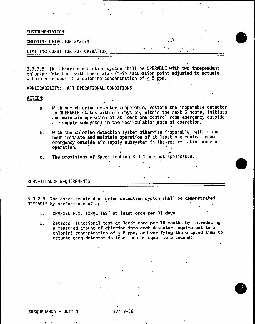
INSTRUMENTATION
CHLORINE DETECTION SYSTEM
LIMITING CONDITION FOR OPERATION
3. 3. 7.8 The chlorine detection .system shall be OPERABLE 'with two independentchlorine detectors with their alarm/trip saturation point adjusted to actuatewithin 5 seconds at a chlorine concentration of < 5 ppm.
APPLICABILITY: Al 1 OPERATIONAL CONDITIONS.
ACTION:
'a 0
b.
C.
Mith one chlorine detector inoperable, restore the inoperable detectorto OPERABLE status within 7 days or, within the next 6 hours,- initiateand maintain operation of at least one control room emergency outsideair supply subsystem in the recirculation mode of operation.
With the chlorine detection system otherwise inoperable, within 'one
hour initiate and maintain operation of at least one control roomemergency outside air supply subsystem in,the~recirculation mode ofoperation.
The provisions of Specification 3.0.4 are not applicable.
SURVEILLANCE RE UIREMENTS
4.3.7.8 The above required chlorine detection system shall be demonstratedOPERABLE by performance of a:
a. CHANNEL FUNCTIONAL TEST at least once per 31 days.
b. 'etector functional test at least once per 18 months by introducinga measured amount of chlorine into each detector, equivalent to achlorine concentration of < 5 ppm, and verifying the elapsed time toactuate each detector is less than or equal to 5 seconds.
SUSQUEHANNA " UNIT 1 3/4 3-76

INSTRUMENTATION
FIRE DETECTION INSTRUMENTATION
LIMITING CONDITION FOR OPERATION
I ~ a
3.3.7.9 As a minimum, the fire detection instrumentation for each firedetection zone shown in Table 3.3.7.9-1 shall be OPERABLE..
APPLICABILITY: Whenever equipment protected by the fire detection instrumentis required to be OPERABLE.
ACTION:
With the number of OPERABLE fire detection instruments less than the Minimum" Instruments OPERABLE requirement of Table 3. 3.7. 9-1:'. Within 1 hour, establish a fire watch 'patrol to inspect the zone(s)
with the inoperable instrument(s) at least once per hour,. unless theinstrument(s) is located inside an inaccessible zone, then inspectthe area surrounding the inaccessible zone at least once per hour.
b. Restore the~minimum number of instrument(s) to OPERABLE status within14 days or, in lieu of any other report required by Specification6.9. 1, prepare and submit a Special Report to the Commission pursuantto Specification 6.9.2 within 30 days outlining the. action taken,the cause 'of the inope'rability and the plans and schedule for restoringthe instrument(s) to OPERABLE status.
c. The provisions of Specifications 3.0.3 and 3.0.4 are not applicable.
SURVEILLANCE RE UIREMENTS
4. 3. 7. 9. 1 Each of the above required fire detection instruments which areaccessible during unit operation shall be demonstrated OPERABLE at least onceper 6 months by performance of a CHANNEL FUNCTIONAL TEST. 'Fire detectors whichare not accessible during unit operation shall be demonstrated OPERABLE by theperformance of a CHANNEL FUNCTIONAL TEST during each COLO SHUTDOWN exceeding24 hours unless performed in the previous 6 months.
4.3.7.9.2 The supervised circuits supervision associated with the detectoralarms of each of the above required'fire detection instruments shall bedemonstrated OPERABLE at least once per 6 months.
SUSQUEHANNA " UNIT 1 3/4 3-77

INSTRUMENT LOCATION
TABLE 3. 3. 7. 9-1
FIRE DETECTION INSTRUMENTATION
INSTRUMENTS OPERABLE
FIREZONE ROOM OR AREA
ROOM
NO.
PHOTO-HEAT IONIZATION ELECTRIC
ELEV. TOTAL MIN."
TOTAL MIN. TOTAL MIN.
a. Control Buildin0-24D
0"24G
0"25A
0"25E
0-26H
0-26H
0"26H
0-26H
0"27C
0"27B
0"27E
0"27A
0-28K
0-28L
0"28M
0-28N
0-28I0-28J
0-28G
0"28F
0"28E
0-28C
0"28D
0-28T
Lower Relay Room
Lower Relay Room
Lower CableSpreading Rm.
Lower CableSpreading Rm.
Control Rm.
(Under Flr. Unit 1)"Control Room
(Under Flr. Unit 2)"Control Room
Control Rm. (Above Clg)"Upper Cable
Spreading Rm.
Upper CableSpreading Rm.
Upper Relay Room,
Upper Relay Room
Battery Room
Battery Room
Battery Room
Battery Room
Battery Room
Battery Room
Battery Room
Battery Room
Battery Room
Battery Room
Battery Room
Battery Room
C-203 698'-1" 4 2
C"201 698'"1" 4 . 2
4 2
4 2
C-300 714'"0" 26 13
C-301
C"409
714'OII 20 10
729'1I'A NA
6 3
6 3
18 9
C-409
C-409
C-409
C"500 753'"0" 25 12 6 3
C-507
C-501
C-502
753'-0"754'-1754'-1"
C-600 771'-0"C-601
C-602
C-'603
C-607
C"608
C-609
C-610
C-614
C-615
C"616
C-617
771'0"771'-0"771'-0"771'-0"771'"0"771'"0"771'0"771'-0"771'-0"771'-0"771'-0"
24 12
2 1
2 1
NA NA
NA NA
NA NA
NA NA
NA NA
NA NA
NA NA
NA NA
NA NA
NA NA
NA NA
NA NA
5 2
2 1
2 1
1 1
1 1
1 1
1 1
1 1
1 1
1 1
1 1
1 1
1 1
1 1
1 1
729 I "1" NA NA . 15 7
729'-1" NA NA 10 5
729'"1" NA NA 6 3
NA NA
NA NA
NA NA
NA NA
NA NA
NA NA
NA NA
NA NA
NA NA
NA NA
NA NA
NA NA
NA NA
NA NA
NA NA
NA NA
NA NA
NA NA
NA NA
NA NA
NA NA
NA NA
NA NA
SUSQUEHANNA - UNIT 1 3/4 3-78

INSTRUMENT LOCATION
TABLE 3.3.7.9-1 (Continued)
FIRE DETECTION INSTRUMENTATION
INSTRUMENTS OPERABLE
FIREZONE
b.
ROOM OR AREA
Reactor Buildin
ROOM
NO.HEAT
ELEV. TOTAL MIN.
PHOTO"IONIZATION ELECTRICTOTAL MIN. TOTAL MIN.
1-1C
1"4C
1-4D
1-4A
1-5G
1-2A
1"3A
1-3B
1-3C
1-4B
1-4G
1-5B
1"5D
Core Spray Pump Room
Core Spray Pump Room
RHR Pump Room
RHR Pump Room
RCIC Pump Room
HPCI Pump Room
Sump Room
Remote ShutdownPanel Rm.
Switchgear Room
Switchgear Room
Containment Access Area
Load Center Room
Load Center Room
Access Area
Access Area
Access Area
Access Area
Pipe Penetration Room
Main Steam PipingValve Access Area
RMCU Pumps & HeatExchangers
Penetration Room
Access Area
I-10I-17I-13
I-12
I-15
645'-0"645'-0"645'-0"645'-0"645'"0"645'-0"645'-0"
NA NA
NA NA
NA NA
NA NA
2 1
2 1
NA NA
I-109I-406I-407I-401I-507I-510I-105I-203I"200
I-202I-403I-411I-515
670'-0"719'-0"719'-0"719'-0"749'-1"749'"1"670'-0"683'-0"683'-0"683'-0"719'-1"719'-1"761'-10"
NA NA
NA NA
NA NA
NA NA
NA NA
NA NA
NA NA
NA NA
NA NA
NA NA
NA NA
NA NA
NA NA
I-501 749'1" NA NA
I-506 749 '1" NA NA
I-606 779 '1" NA NA
5 2
7 3
NA NA
NA NA
NA NA
NA NA
2 1
1 1
2 1
2 1
17 8
2 1
2 1
4 2
4 2
9 5
13 6
2 1
NA NA
NA NA
NA NA
NA NA
9 4
NA NA
NA NA
13 7.15, 8
5 2
7 3
NA NA
NA NA
NA NA
NA NA
NA NA
NA NA
NA NA
NA NA
NA , NA
NA NA,
NA NA
NA NA
4 2
2 1
2 1
2 1
NA NA
SUS(UEHANNA - UNIT 1 3/4 3-79

INSTRUMENT LOCATION
TABLE 3.3.7.9-1 (Continued)
FIRE DETECTION INSTRUMENTATION
INSTRUMENTS OPERABLE
FIREZONE ROOM OR AREA
Reactor Buildin Continued
ROOM
NO.HEAT
ELEV. TOTAL MIN.IONIZATIONTOTAL MIN.
PHOTO-ELECTRICTOTAL MIN.
1-6D
1-6E
0-6G
1-7A
1-7B
0"8A
H&V Equipment Room
Recirculation Fans Area
Surge Tank VaultH&V Fan and
Filter Rooms
Recirculation Fan Room
Refueling Floor
~E|Sll P h
I"612I-615I"601
I-703I"701
779'-1"779'"1"779'-4"
799'-1"799'1"818'1"
NA NA
NA NA
NA NA
4 2
NA NA
NA NA
10 5
2 1
2 1
9 5
2 1
NA NA
NA NA
NA NA
NA NA
2 1
NA NA
30 15
0"51
0-52Pump Room
Pump Room E-2
685'"6" NA NA
685'-6" NA NA
6 3
6 3
INFRA-RED(FLAME)
TOTAL MIN.
NA NI
d. Diesel Generator Buildin0"41A
0"41C
'0-41B
0-41D
Diesel Generator Roomsand
Diesel Generator Roomsand
Diesel Generator Roomsand
Diesel Generator Roomsand
DG-1DG-16
DG-2DG-17
DG"3DG"18
DG-4DG-19
660'"0"677'-0"660'"0"e77'-o"eeo'-o"677'-0"660'"0"e77'-o"
22 ll22 11
22 11
22 ll
2 1
2 1
2 1
2 1
15 7
15 7
15 7
15 7
Not accessible.
SUSQUEHANNA " UNIT 1 3/4 3-80

INSTRUMENTATION
RADIOACTIVE LI UID EFFLUENT MONITORING INSTRUMENTATION
LIMITING CONDITION FOR OPERATION
3.3.7.10 The radioactive liquid effluent monitoring instrumentation channelsshown in Table 3. 3.7. 10-1 shall be OPERABLE with their alarm/trip setpointsset to ensure that the limits of Specification 3. 11. F 1 are not exceeded. Thealarm/trip setpoints of these channels shall be determined in accordance withthe methodology and parameters described in the Offsite Dose Calculation Manual(ODCM).
APPLICABILITY: At all times.
ACTION:
a.
b.
C.
With a radioactive liquid effluent monitoring instrumentation channelalarm/trip setpoint less conservative than required by the abovespecification, immediately suspend the release of radioactive liquideffluents monitored by the affected channel or declare the channelinoperable.
With less than the minimum number of radioactive liquid effluentmonitoring instrumentation channels OPERABLE, take the ACTION shownin Table 3.3.7. 10-1. Restore the inoperable instrumentation toOPERABLE status within the time specified in the ACTION or explainwhy this inoperability was not corrected in a timely manner in thenext Semiannual Radioactive Effluent Release Report.
The provisions of Specifications 3.0.3, 3.0.4, and 6.9. 1.9.b are notapplicable.
SURVEILLANCE RE UIREMENTS
4.3.7. 10 Each radioactive liquid effluent monitoring instrumentation channelshall be demonstrated OPERABLE by performance of the CHANNEL CHECK, SOURCECHECK, CHANNEL CALIBRATION and CHANNEL FUNCTIONAL TEST operations at thefrequencies shown in Table 4.3.7. 10-1.
SUS(UEHANNA-UNIT 1 3/4 3-81

TABLE 3.3.7.10-1
RADIOACTIVE LI UID EFFLUENT MONITORING INSTRUMENTATION
INSTRUMENT
GROSS RADIOACTIVITYMONITORS PROVIDING AUTOMATICTERMINATION OF RELEASE
a. Liquid Radwaste Effluent Line
2. GROSS RADIOACTIVITYMONITORS NOT PROVIDING AUTOMATICTERMINATION OF RELEASE
a. Service Water System Eff'luent Line
b. RHR Service Water System Effluent Line
3. FLOW RATE MEASUREMENT DEVICES
a. Liquid Radwaste Effluent Line
b. Discharge Canal
MINIMUMCHANNELSOPERABLE
1/1 oop
ACTION
100
101
101
102
102
The monitor is required to be OPERABLE when liquid radwaste is being discharged or the channel shall. bedeclared inoperable. The monitor, including the sample pump,= is required to be in operation at alltimes if any discharge valve interlock is in an off-normal condition or is not functioning; i.e.,sample pump flow low, high radiation alarm or radiation monitor failure.

TABLE 3.3.7.10-1 Continued
TABLE NOTATION
ACTION 100 - With the numbei of channels OPERABLE less than required by theMinimum Channels OPERABLE requirement, effluent releases maycontinue for up to 14 days provided that prior to initiatinga release:
ACTION 101-
ACTION 102 "
a. At least two independent samples are analyzed in accordancewith Specification 4. 11. 1. 1. 1, and
b. At least two technically qualified members of the FacilityStaff independently verify the release rate calculationsand discharge line valving;
Otherwise, suspend release of radioactive effluents via thispathway.
With the number of channels OPERABLE less than required by theMinimum Channels OPERABLE requirement, effluent releases via,this pathway may continue for up to 30 days provided that, atleast-once per 8 hours, grab samples are collected and analyzedfor gross radioactivity (beta or gamma) at a limit of detectionof at "least 10-7 microcuries/ml.
With the number of channels OPERABLE less than, required by the "-Minimum Channels OPERABLE requirement, effluent releases viathis pathway may continue for up to 30 days provided the flowrate is estimated at least once per 4 hours during actualreleases. Pump curves generated in situ may be used to estimatef1 ow.
SUSQUEHANNA-UNIT 1 3/4 3-83

TABLE 4.3.7.10-1
RADIOACTIVE LI UID EFFLUENT MONITORING INSTRUMENTATION SURVEILLANCE RE UIREMENTS
INSTRUMENT
1. GROSS RADIOACTIVITYMONITORS PROVIDINGAUTOMATIC TERMINATION OF RELEASE
a. Liquid Radwaste Effluent Line
CHANNELCHECK
SOURCE
CHECKCHANNEL
CALIBRATION
R(3)
CHANNELFUNCTIONAL
TEST
Q(l)
2. GROSS RADIOACTIVITYMONITORS NOT PROVIDINGAUTOMATIC TERMINATION OF RELEASE
a. Service Mater System Effluent Line
b. RHR Service Mater System EffluentLine
3. FLOW RATE MEASUREMENT DEVICES
a. Liquid Radwaste Effluent Line
b. Discharge Line
D(4) N.A.
D(4) „. N.A./
-R(3)
R(3)
C(2)
9(2)
Perform CHANNEL CHECK at least once per 24 hours if discharge valve interlocks referenced inTable 3.3.7.10-1 are not functioning.

0 TABLE 4. 3. 7. 10-1 (Continued)
TABLE NOTATION
(1) The CHANNEL FUNCTIONAL TEST shall also demonstrate that automatic isolationof this pathway and control room alarm annunciation occur if any of thefollowing conditions exists:
l. Instrument indicates measured levels above the alarm/trip setpoint.2. Circuit failure.3. Instrument indicates a downscale failure.
(2) The CHANNEL FUNCTIONAL TEST shall also demonstrate that control room alarmannunciation occurs if any of the following conditions exists:
l. Instrument indicates measured levels above the alarm setpoint.2. Circuit failure.3. Instrument indicates a downscale failure.4. Instrument controls not set in operate mode.
(3) The initial CHANNEL CALIBRATION shall be performed using one or more ofthe reference standards certified by the National Bureau of Standards orusing standards that have been obtained from suppliers that participatein measurement assurance activities with NBS. These standards shallpermit calibrating the system over its intended range of energy andmeasurement range. For subsequent CHANNEL CALIBRATION, sources that havebeen related to the initial calibration shall be used. (Operating plantsmay substitute previously established calibration procedures for thisrequirement.)
(4) CHANNEL CHECK shall consist of verifying indication of flow during periodsof release. CHANNEL CHECK shall be made at least once per 24 hours on dayson which continuous, periodic, or batch releases are made.
SUSQUEHANNA-UNIT 1 3/4 3-85

INSTRUMENTATION
RADIOACTIVE GASEOUS EFFLUENT MONITORING INSTRUMENTATION
LIMITING CONDITION FOR OPERATION
3.3.7. 11 The radioactive gaseous effluent monitoring instrumentation channelsshown in Table 3.3.7. 11-1 shall be OPERABLE with their alarm/trip setpoints setto ensure that the limits of Specification 3. 11.2. 1 are not exceeded. Thealarm/trip setpoints of these channels shall be determined in accordance withthe methodology and parameters in the ODCM.
APPLICABILITY: As shown in Table 3.3.7. 11-1
ACTION:
a ~
b.
C.
Mith a radioactive gaseous effluent monitoring instrumentationchannel alarm/trip setpoint less conservative than required by
the'boveSpecification, immediately suspend the release of radioactivegaseous effluents monitored by the affected channel or declare thechannel inoperable.
With less than the minimum number of radioactive gaseous effluentmonitoring instrumentation channels OPERABLE, take the ACTION shown .
in Table 3.3.7. 11-1. Restore the inoperable instrumentation toOPERABLE status within the time specified in the ACTION or. explainwhy this inoperability was not corrected in a timely manner in thenext Semiannual Radioactive Effluent Release Report.
The provisions of Specifications 3.0.3, 3.0.4 and 6.9. 1.9.b are.notapplicable.
SURVEILLANCE RE UIREMENTS
4.3.7.11 Each radioactive gaseous effluent monitoring instrumentation channelshall be demonstrated OPERABLE by performance of the CHANNEL CHECK, SOURCE
CHECK, CHANNEL CALIBRATION and CHANNEL FUNCTIONAL TEST operations at thefrequencies shown in Table 4.3.7. 11-1.
SUS(UEHANNA-UNIT 3. 3/4 3"86

TABLE 3.3.7.11-1
RADIOACTIVE GASEOUS EFFLUENT MONITORING INSTRUMENTATION
INSTRUMENT
1. MAIN CONDENSER OFFGAS TREATMENT SYSTEMEXPLOSIVE .GAS MONITORING SYSTEM
a. Hydrogen Monitor
2. REACTOR BUILDING VENTILATIONMONITORING SYSTEM
a. Noble Gas Activity Monitor
b. Iodine Monitor
c. Particulate Monitor
d. Effluent System Flow Rate Monitor
e. Sampler Flow Rate Monitor
MINIMUM CHANNELSOPERABLE
1¹¹
APPLICABILITY ACTION
110
ill112
112
113
113

TABLE 3. 3.7.12-1
RADIOACTIVE GASEOUS EFFLUENT MONITORING INSTRUMENTATION
INSTRUMENT
3. TURBINE BUILDING VENTILATION MONITORINGSYSTEM
a. Noble Gas ActivityMonitor'.
Iodine Monitor
c. Particulate Monitor
d. Effluent System Flow Rate Monitor
e. Sampler Flow Rate Monitor
4. MAIN CONDENSER OFFGAS PRE-TREATMENTRADIOACTIVITYMONITOR (Prior to Inputto Holdup System)
a. Noble Gas Activity Monitor
5. STANDBY GAS TREATMENT SYSTEM MONITOR
Noble Gas Activity Monitor
b. Iodine Monitor
MINIMUM CHANNELSOPERABLE
1¹¹
1¹¹
APPLICABILITY ACTION
114
112
112
113
113
115
116
112
C.
d.
e.
Particulate Monitor
Effluent System Flow Rate Monitor
Sampler Flow Rate Monitor
112
113
113

TABLE 4.3.7. 11-1 (Continued)
TABLE NOTATION
¹During operation of the standby gas treatment system.
¹¹Low-range and mid-range channels of monitor only
At all times.
During main condenser offgas treatment system operation.
During operation of the main condenser air ejector.
ACTION 110-
ACTION ill"
With the number of channels OPERABLE less than required by theMinimum Channels OPERABLE requirement, operation of main condenseroffgas treatment system may continue for up to 30 days providedgrab samples are collected at least once per 4 hours and analyzedwithin the following 4 hours.
With the number of channels OPERABLE less than required by theMinimum Channels OPERABLE requirement, effluent releases viathis pathway may continue for up to 30 days provided grabsamples are taken at least once per 8 hours and these samplesare analyzed for gross activity within 24 hours.
ACTION 112 - With the number of channels OPERABLE less than required by theMinimum Channels OPERABLE requirement, effluent releases viathis pathway may continue for up to 30 days provided samplesare continuously collected with auxiliary sampling equipment asrequired in Table 4. 11.2. 1.2-1.
ACTION 113 - With the number of channels OPERABLE less than required by theMinimum Channels OPERABLE requirement, effluent releases viathis pathway may continue for up to 30 days provided the flowrate is estimated at least once per 4 hours.
ACTION 114 - With the number of channels OPERABLE less than required bythe Minimum Channels OPERABLE requirement, effluent releases viathis pathway may continue for up to 30 days provided grabsamples are taken at least once per 8 hours and these samplesare analyzed for gross activity within 24 hours and providedthe mechanical vacuum pumps are not operated.
ACTION 115 — With the number of channels OPERABLE less than required by theMinimum Channels OPERABLE requirement, releases to the environmentmay continue for up to 72 hours provided:
a. The offgas system is not bypassed,'ndb. The Turbine Building vent noble gas activity monitor is OPERABLE;
Otherwise, be in at least HOT STANDBY within 12 hours.t ACTION 116 - With the number of channels OPERABLE less than required by theMinimum Channels OPERABLE requirement, suspend release ofradioactive effluent via this pathway.
SUS(UEHANNA-UNIT 1 3/4 3-89

TABLE 4.3.7.11-1
RADIOACTIVE GASEOUS EFFLUENT MONITORING INSTRUMENTATION SURVEILLANCE RE UIREMENTS
INSTRUMENT
1. MAIN CONDENSER OFFGAS TREATMENTSYSTEM EXPLOSIVE GAS MONITORINGSYSTEM
CHANNEL SOURCE CHANNELCHECK CHECK CALIBRATION
CHANNELFUNCTIONAL
TEST
MODES IN WHICHSURVEILLANCE
RE UIRED
2.
a. Hydrogen Monitor
REACTOR BUILDING VENTILATIONMONITORING SYSTEM
a. Noble Gas Activity Monitor
b. Iodine Monitor
c. Particulate Monitor
N/A a(3)
R(2)
R(2)
R(2)
0(l)
9(l)
C(I)
d. Effluent System Flow Rate Monitor D
e. Sampler Flow Rate Monitor D
N.A. R
N.A. R

TABLE 4.3.7. 11-1 Continued
RADIOACTIVE GASEOUS EFFLUENT MONITORING INSTRUMENTATION SURVEILLANCE RE UIREMENTS
INSTRUMENT
3. TURBINE BUILDING VENTILATIONMONITORING SYSTEM
a. Noble Gas Activity Monitor
b. Iodine Monitor
CHANNELCHECK
SOURCE CHANNELCHECK CALIBRATION
R(2)
R(2)
CHANNELFUNCTIONAL
TEST
MODES IN WHICHSURVEILLANCE
RE UIRED
c. Particulate Monitor
d. Flow Rate Monitor
e. Sampler Flow Rate Monitor
4. MAIN CONDENSER OFFGAS PRE-TREATMENTRADIOACTIVITYMONITOR
a. Noble Gas Activity Monitor
5. STANDBY GAS TREATMENT SYSTEM MONITOR
N. A.
N.A.
R(2)
R(2)
b.
C.
d.
e.
Noble Gas Activity Monitor
Iodine Monitor
Particulate Monitor
Effluent System Flow RateMonitor
Sampler Flow Rate Monitor
N. A.
N.A.
,R(2)
R(2)
,R(2)
'R

TABLE 4. 3.7. 11-1 Continued)
TABLE NOTATION
¹ During operation of the standby gas treatment system.
At all times.
During main condenser offgas treatment system operation.
During operation of the main condenser air ejector.
(1) The CHANNEL FUNCTIONAL TEST shall also demonstrate that control roomalarm annunciation occurs if any of the following conditions exists:l. Instrument indicates measured levels above the alarm/trip setpoint.2. Circuit failure.3. Instrument indicates a downscale failure.4. Instrument controls not set in operate mode.
(2) The initial CHANNEL CALIBRATION shall be performed using one or more ofthe reference standards certified by the National Bureau of Standards orusing standards that have been obtained from suppl.-i'ers that participatein measurement assurance activities with NBS. These standards shallpermit calibrating the system over its intended range of energy andmeasurement range. For subsequent CHANNEL CALIBRATION, sources that havebeen related to the initial calibration shall be used. (Operating plantsmay substitute previously established calibration procedures for thisrequirement.)
(3) - The CHANNEL CALIBRATION shall include the use of standard gas samplescontaining a nominal:
l. 0;5 volume percent hydrogen, balance nitrogen, and
2. Four volume percent hydrogen, balance nitrogen.
SUSQUEHANNA-UNIT 1 3/4 3"92

INSTRUMENTATION =
LOOSE-PART DETECTION SYSTEM
LIMITING CONDITION FOR OPERATION
3.3.7.12 The loose-part detection system shall be OPERABLE.
APPLICABILITY: OPERATIONAL CONDITIONS 1 and 2.
ACTION:
a 0
b.
With one or more loose part detection system channels inoperable formore than 30 days, in lieu of any other report required by Specifi-cation 6.9. 1, prepare and submit a Special Report to the Commissionpursuant to Specification 6.9.2 within the next 10 days outliningthe cause of the malfunction and the plans for restoring thechannel(s) to OPERABLE status.
The provisions of Specifications 3. 0. 3 and 3. 0.4 are not applicable.
SURVEILLANCE RE UIREMENTSt 4.3.7.12 Each channel of the loose-part detection system shall bedemonstr ated OPERABLE by per formance of a:
a. CHANNEL CHECK at least once per 24 hours,
b. CHANNEL FUNCTIONAL TEST at least once per 31 days, and
c. CHANNEL CALIBRATION at least once.per 18 months.
SUSQUEHANNA " UNIT 1 3/4 3"93

INSTRUMENTATION
3/4.3.8 TURBINE OVERSPEED PROTECTION SYSTEM
LIMITING CONDITION FOR OPERATION
3.3.8 At least one turbine overspeed protection system shall be OPERABLE.
APPLICABILITY: OPERATIONAL CONDITIONS 1 and 2.
ACTION:
With the above required turbine overspeed protection system inoperable,within 6 hours isolate the turbine from the steam supply.
SURVEILLANCE RE UIREMENTS
4. 3.8, 1 The provisions of Specification 4. 0. 4 are not applicable
4.3.8.2 The above required turbine overspeed protection system shall bedemonstrated OPERABLE:
ao
b.
C.
At least once per 7 days by:
1. Cycling each of the following valves from~the running positionand observing valve closure:
a) Four high pressure turbine control valves,
b) Six low pressure turbine combined intermediate valves,and
c) Four high pressure turbine stop valves.
At least once per 18 months by performance of a CHANNEL CALIBRATIONof the turbine overspeed protection instrumentation.
At least once per 40 months by disassembling at least one of- each ofthe above valves and performing a visual and surface inspection of'all valve seats, disks and stems and verifying no unacceptable flawsor corrosion.
SUS(UEHANNA - UNIT 1 3/4 3-94

t INSTRUMENTATION
3/4.3.9 FEEDWATER/MAIN TURBINE TRIP SYSTEM ACTUATION INSTRUMENTATION
LIMITING CONDITION FOR OPERATION
3.3.9 The feedwater/main turbine trip system actuation instrumentationchannels shown in Table 3.3.9-1 shall be OPERABLE with their trip setpointsset consistent with the values shown in the Trip Setpoint column of Table3.3.9-2.
APPLICABILITY: As shown in Table 3.3.9-1.
ACTION:
a. With a feedwater/main turbine trip system actuation instrumentationchannel trip setpoint less conservative than the value shown in theAllowable Values column of Table 3.3.9-2, declare the channel inoperableand either place the inoperable channel in the tripped condition untilthe channel is restored to OPEABLE status with its trip setpoint adjustedconsistent with the Trip Setpoint value, or declare the associated systeminoperable.
b. With the number of OPERABLE channels one less than required by theMinimum OPERABLE Channels requirement, restore the inoperable channel toOPERABLE status within 7 days or be in at least STARTUP within the next6 hours.
C.
/
With the number of OPERABLE channels two less than required by theMinimum OPERABLE Channels per Trip System requirement, restore at leastone of the inoperable channels to OPERABLE status within 72 hours or bein at least STARTUP within the next 6 hours.
SURVEILLANCE RE UIREMENTS
4.3.9. 1 Each feedwater/main turbine trip system actuation instrumentationchannel shall be demonstrated OPERABLE by the performance of the CHANNELCHECK, CHANNEL FUNCTIONAL TEST and CHANNEL CALIBRATION operations for theOPERATIONAL CONDITIONS and at the frequencies shown in Table 4.3.9.1-1.
4. 3. 9. 2 LOGIC SYSTEM FUNCTIONAL TESTS and simulated automatic operation .ofall channels shall be performed at least once per 18 months.
SUS(UEHANNA - UNIT 1 3/4 3-95

TABLE 3. 3. 9-1
FEEDMATER/MAIN TURBINE TRIP SYSTEM ACTUATION INSTRUMENTATION
FUNCTIONAL UNIT
MINIMUMOPERABLE CHANNELSPER TRIP SYSTEM
APPLICABLEOPERATIONALCONDITIONS
a. Reactor Vessel Mater Level-High

TABLE 3. 3. 9-2
FEEOWATER/MAIN TURBINE TRIP SYSTEM ACTUATION INSTRUMENTATION SETPOINTS
FUNCTIONAL UNIT
a. Reactor Vessel Water Level-High
TRIP SETPOINT
< 54.0 inches
ALLOWABLEVALUE
< 54.0 inches

TABLE 4.3.9. l-l (Continued)
FEEDMATER/MAIN TURBINE TRIP SYSTEM ACTUATION INSTRUMENTATION SURVEILLANCE RE UIREMENTS
FUNCTIONAL UNIT
a. Reactor Vessel MaterLevel-High
CHANNELCHECK
CHANNELFUNCTIONAL
TEST
OPERATIONALCHANNEL CONDITIONS FOR WHICH
CALIBRATION SURVEILLANCE RE UIRED

3/4.4 REACTOR COOLANT SYSTEM
3/4.4. l RECIRCULATION SYSTEM
RECIRCULATION LOOPS
LIMITING CONDITION FOR OPERATION
/3.4. l. 1 Two reactor coolant system recirculation loops shall be in operation.
APPLICABILITY: OPERATIONAL CONDITIONS 1" and 2".
ACTION:
a o
b.
With one reactor coolant system recirculation loop not in operation,be in at least HOT SHUTDOWN within the next 12 hours.With no reactor coolant system recirculation loops in operation,immediately initiate measures to place the unit in at least STARTUPwithin 6 hours and in HOT SHUTDOWN within the next 6 hours.
SURVEILLANCE RE UIREMENTS
4.4. 1.1. 1 Each pump discharge valve and bypass valve shall be demonstratedOPERABLE by cycling each valve through at least one complete cycle of fulltravel during each startup"" prior to THERMAL POWER exceeding 25K of RATEDTHERMAL POWER.
4.4. 1. 1.2 Each pump discharge bypass valve, if not OPERABLE, shall be verifiedto be closed-at least once per 31 days.
4.4. 1.1.3 Each pump MG set scoop tube electrical and mechanical stop shall bedemonstrated OPERABLE with overspeed setpoints less than or equal to 102.5and 105K, respectively, of rated core flow, at least once per 18 months.
See Special Test Exception 3. 10.4.""Ifnot performed within the previous 31 days.
SUSQUEHANNA - UNIT 1 3/4 4-1

REACTOR COOLANT SYSTEM
JET PUMPS
LIMITING CONDITION FOR OPERATION
3.4.1.2 All jet pumps shall be OPERABLE.
APPLICABILITY: OPERATIONAL CONDITIONS 1 and 2.
ACTION:
With one or more jet pumps inoperable, be in at least HOT SHUTDOWN within12 hours.
SURVEILLANCE RE UIREMENTS
4.4. 1.2 Each of the above required jet pumps shall be demonstrated OPERABLE
prior to THERMAL POWER exceeding 25K of RATED THERMAL POWER and at least onceper 24 hours by determining recirculation pump flow, total core flow anddiffuser-to-lower plenum differential pressure for each.'jet pump and verifyingthat no two of the following conditions occur when the recirculation pumps areoperating at the same speed:
a. , The indicated recirculation pump flow differs by more than 10K fromthe established pump speed-loop flow characteristics.
b.
C.
The indicated total core flow differs by more than lOX from theestablished total core flow value derived from recirculation loopflow measurements.
The 'indicated diffuser-to-lower plenum differential pressure ofany individual jet pump differs from established patterns by morethan 10K.
C
SUS(UEHANNA - UNIT 1 3/4 4-2

REACTOR COOLANT SYSTEM
RECIRCULATION PUMPS
LIMITING CONDITION FOR OPERATION
3.4. 1.3 Recirculation pump speed mismatch shall be maintained within:
a. 5X of each other with core flow greater than or equal to 75Kof rated core flow.
b. 1OX of each other with core flow less than 75K of rated coreflow.
APPLICABILITY: OPERATIONAL CONDITIONS 1" and 2".
ACTION:
With the recirculation pump speeds different by more than the specifiedlimits, either:
a. Restore the recirculation pump speeds to within the specified limitwithin 2 hours, or
b. Declare the recirculation loop of the pump with the slower speed notin operation and take the ACTION require by. Specification 3.4. 1. 1.
SURVEILLANCE RE UIREMENTS
4.4.1.3 Recirculation pump speed mismatch shall be verified to be within thelimits at least once per 24 hours.
See Special Test Exception 3. 10.4.
SUSQUEHANNA - UNIT 1 3/4 4-3

REACTOR COOLANT SYSTEM
IDLE RECIRCULATION LOOP STARTUP
LIMITING CONDITION FOR OPERATION
3.4. 1.4 An idle recirculation loop shall not be started unless the temperaturedifferential between the reactor pressure vessel steam space coolant and thebottom head drain line coolant is less than or equal to 145 F, and:
a 0
b.
When both loops have been idle, unless the temperature differentialbetween the reactor coolant within the idle loop to be started upand the coolant in the reactor pressure vessel is less than or equalto 50 F, or
When only one loop has been idle, unless the temperature differentialbetween the reactor coolant within the idle and operating recirculationloops is less than or equal to 50 F and the operating loop flow rateis less than or equal to 50K of rated loop flow.
APPLICABILITY: OPERATIONAL CONDITIONS 1, 2, 3 and 4.
ACTION:
With temperature differences and/or flow rates exceeding the above limits,suspend startup of any idle recirculation loop.
SURVEILLANCE RE UIREMENTS
4.4.1.4 The temperature differentials and flow rate shall be determined to be
within the limits within 15 minutes prior to startup of an idle recirculationloop.
SUSQUEHANNA " UNIT 1 3/4 4-4

REACTOR COOLANT SYSTEM
~ ~3/4.4. 2 SAFETY/RELIEF VALVES
LIMITING CONDITION FOR OPERATION
3.4.2 The safety valve function of at least 10 of the following reactorcoolant system safety/relief valves shall be OPERABLE with the specified codesafety val've function lift settings:*'**
2 saf ety- re 1 ie f va1 ves 84 safety-rel ie f val ves 84 safety-relief valves 83 safety-relief valves 83 safety-relief valves 8
1146 psig +1K1175 psig +1K1185 psig +1%ll95 psig +lX1205 psig +1K
APPLICABILITY: OPERATIONAL CONDITIONS 1, 2 and 3.
ACTION:
a. Mith the safety valve function of one or more of the above requiredsafety/relief valves inoperable, be in at least HOT SHUTDOWN within12 hours and in COLD SHUTDOWN within the next 24 hours.
b.
C.
With one or more safety/relief valves stuck open, provided that suppressionpool average water temperature is less than 105 F, close the stuck openrelief valve(s); if unable to close the open valve(s) within 2 minutes orif suppression pool water temperature is 105'F or greater, place the reactormode switch in the Shutdown position.With one or more safety/relief valve acoustic monitors inoperable, restorethe inoperable monitor(s) to OPERABLE status within 7 days or be in at leastHOT SHUTDOWN within the next 12 hours and in COLD SHUTDOWN within thefollowing 24 hours.
SURVEILLANCE RE UIRENENTS
4.4.2 The acoustic monitor for each safety/relief valve shall be demonstratedOPERABLE with the setpoint verified to be 0.25 by performance of a:
a. CHANNEL FUNCTIONAL TEST at least once per 31 days, and a
b. Calibration in accordance with procedures prepared in conjunctionwith its manufacturer's recommendations at least once per 18 months.
The lsft setting pressure shall correspond to ambient conditions of thevalves at nominal operating temperatures and pressures.
""Up to 2 inoperable valves may be replaced with spare OPERABLE valves withlower setpoints until the next refueling.
SUS(UEHANNA - UNIT 1 3/4 4-5

REACTOR COOLANT SYSTEM
3/4.4.3 REACTOR COOLANT SYSTEM LEAKAGE
LEAKAGE DETECTION SYSTEMS
LIMITING CONDITION FOR OPERATION
3.4.3.1 At least the following reactor coolant system leakage detectionsystems shall be OPERABLE:
a. One primary containment atmosphere particulate radioactivitymonitoring system channel,
b.
C.
Two drywell floor drain sump level monitoring system channels, and
One primary containment atmosphere gaseous radioactivity monitoringsystem channel.
APPLICABILITY: OPERATIONAL CONDITIONS 1, 2 and 3.
ACTION:
With only two of the above required leakage detection systems OPERABLE,operation may continue for up to 30 days provided grab samples of the contain-ment atmosphere are obtained and analyzed at least once per 24 hours when therequired gaseous and/or particulate radioactive monitoring system is inoperable;otherwise, be in at least HOT SHUTDOWN within the next 12 hours and in COLDSHUTDOWN within the following 24 hours.
SURVEILLANCE RE UIREMENTS
4.4. 3. 1 The reactor coolant system leakage detection systems shall bedemonstrated OPERABLE by:
a.
b.
Primary containment atmosphere particulate and gaseous monitoringsystems-performance of a CHANNEL CHECK at least once per 12 hours, aCHANNEL FUNCTIONAL TEST at least once per '3l days and a CHANNELCALIBRATION at least once per 18 months.
Drywell floor drain sump level monitoring system-performance of aCHANNEL FUNCTIONAL TEST at least once per 31 days and a CHANNELCALIBRATION at least once per 18 months.
SUSQUEHANNA - UNIT 1 3/4 4-6

REACTOR COOLANT SYSTEM
OPERATIONAL LEAKAGE
LIMITING CONDITION FOR OPERATION
3.4.3.2
b.
C.
d.
Reactor coolant system leakage shall be limited to:No PRESSURE BOUNDARY LEAKAGE.
5 gpm UNIDENTIFIED LEAKAGE.
25 gpm total leakage averaged over any 24-hour period.
1 gpm leakage at a reactor coolant system pressure of 1000 k 10 psigfrom any reactor coolant system pressure isolation valve specifiedin Table 3.4.3.2-1.
APPLICABILITY: OPERATIONAL CONDITIONS 1, 2 and 3.
ACTION:
a. With any PRESSURE BOUNDARY LEAKAGE, be in at least HOT SHUTDOWN within12 hours and in COLD SHUTDOWN within the next 24 hours.
b. With any reactor coolant system leakage greater than the limits in band/or c, above, reduce the leakage rate to within the limits within4 hours or be in at least HOT SHUTDOWN within the next'2 hours andin COLD SHUTDOWN within the following 24 hours.
c. With any reactor coolant system pressure isolation valve leakagegreater than the above limit, isolate the high pressure portion of theaffected system from the low pressure portion within 4 hours by useof at least two closed manual or deactivated automatic valves, or bein at least HOT SHUTDOWN within the next 12 hours and in COLD SHUTDOWNwithin the following 24 hours.
d. With one or more of the high/low pressure interface valve leakagepressure monitors shown in Table 3.4.3.2-1 inoperable, restore theinoperable monitor(s) to OPERABLE status within 7 days or verify thepressure to be less than the alarm pressure at least once per 12 hours;restore the inoperable monitor(s) to OPERABLE status within 30 days orbe in at least HOT SHUTDOWN within the next 12 hours and in COLDSHUTDOWN within the following 24 hours.
SUSQUEHANNA " UNIT 1 3/4 4"7

REACTOR COOLANT SYSTEM
SURVEILLANCE RE UIREMENTS
4.4.3.2. 1 The reactor coolant system leakage shall be demonstrated to bewithin each of the above limits by:
a. Monitoring the primary containment atmospheric particulate andgaseous radioactivity at least once per 12 hours, and
b. Monitoring the drywell floor drain sump level at least once perl2 hours.
4.4.3.2 ~ 2 Each reactor coolant system pressure isolation valve specified inTable 3. 4. 3. 2-1 shall be demonstrated OPERABLE by leak testing pursuant toSpecification 4.0.5 and verifying the leakage of each valve to be within thespecified limit:
a. At least once per 18 months,'nd
b. Prior to returning the valve to service following maintenance, repairor replacement work on the valve which could affect its leakage rate.
The provisions of Specification 4.0.4 are not'pplicable for entry intoOPERATIONAL CONDITION 3.
4.4.3.2.3 The high/low pressure interface valve leakage pressure monitors shallbe demonstrated OPERABLE with the alarm setpoints per Table 3.4.3.2-1 byperformance of a:
a. CHANNEL FUNCTIONAL TEST at least once per 31 days, and
b. CHANNEL .CALIBRATION at least once per 18 months.
SUSQUEHANNA - UNIT 1 3/4 4-8

REACTOR COOLANT SYSTEM
TABLE 3.4.3.2-1
REACTOR COOLANT SYSTEM PRESSURE ISOLATION VALVES
1ST ISOLATIONVALVE S NUMBER S
HV"E211F006AHV-E211F037A
HV-E211F006BHV"E211F037B
ALARM2ND ISOLATION SETPOINT
VALVE S NUMBER S ~sic'ERVICEHV-E211F005A < 460 Core Spray Injection
HV-E211FOOSB < 460 Core Spray Injection
HV-E111F050AHV-E111F122A
HV"E111F0508HV-E111F122B
HV-E111F015A < 400
HV-ElllF015B < 400
LPCI Injection
LPCI Injection
HV-E111F022
HV-E111F009
HV-ElllF023 < 400 Head Spray
HV-ElllF008 < 142 Shutdown Cooling
eSUSQUEHANNA - UNIT 1 3/4 4-9

REACTOR COOLANT SYSTEM
3/4.4. 4 CHEMISTRY
LIMITING CONDITION FOR OPERATION
3.4.4 The chemistry of the reactor coolant system shall be maintained withinthe limits specified in Table 3.4.4-1.
APPLICABILITY: At al 1 times.
ACTION:
a 0
b.
C.
In OPERATIONAL CONDITION 1:
1. Mith the conductivity, chloride concentration or pH exceeding the'imitspecified in Table 3.4.4-1 for less than 72 hours during one
continuous time interval and, for conductivity and chloride concen-tration, for less than 336 hours per year, but with the conductivityless than 10 pmho/cm at 25'C and with the chloride concentration lessthan 0.5 ppm, this need not be reported to the Commission and theprovisions of Specification 3.0.4 are not applicable.
2. Mith the conductivity, chloride concentration or pH exceeding thelimit specified in Table 3.4.4-1 for more than 72 hours during onecontinuous time interval or, for conductivity and chloride concen-tration, for more than 336 hours 'per year, be in at least STARTUP
within the next 6 hours.
3. With the conductivity exceeding 10 pmho/cm at 25'C or chlorideconcentration exceeding 0.5 ppm, be in at least HOT SHUTDOWN within'2 hours and in COLD SHUTDOWN as rapidly as practical within thecooldown rate limit.
In OPERATIONAL CONDITION 2 and 3 with the conductivity, chlorideconcentration or pH exceeding the limit specified in Table 3.4.4-1 formore than 48 hours during orie continuous time interval, be in at leastHOT SHUTDOMN within the next 12 hours and in COLD SHUTDOWN within thefollowing 24 hours.
At all other times:
1. Mith the conductivity or pH exceeding the limit specified in Table3.4.4-1, restore the conductivity and pH to within the limit within72 hours.
2. With the chloride concentration exceeding the limit specified in Table3.4.4-1 for more than 24 hours, perform an engineering evaluation todetermine the effects of the out-of-limit condition on the structuralintegrity of the reactor coolant system. Determine that the structuralintegrity of the reactor coolant system remains acceptable for continuedoperation prior to proceeding to OPERATIONAL CONDITION 3.
3 ~ The provisions of Specification 3.0.3 are not applicable.
SUSQUEHANNA - UNIT 1 3/4 4-10

REACTOR COOLANT SYSTEM
SURVEILLANCE RE UIREMENTS
4.4.4 The reactor coolant shall be determined to be within the specifiedchemistry limit by:
a. Measurement prior to pressurizing the reactor during each startup,if not performed within the previous 72 hours.
b. Analyzing a sample of the reactor coolant:
1. Chlorides at least once per:
a) 72 hours, and
b) 8 hours whenever conductivity is greater than the limitin Table 3.4.4-1.
2. Conductivity at least once per 72 hours.
3. pH at least once per:
a) 72 hour s, and
b) 8 hours whenever conductivity is greater than the limitin Table 3.4.4-1.
C. Continuously recording the conductivity of the reactor coolant, or,when the continuous recording conductivity monitor is inoperable forup to 31 days, obtaining an in-line conductivity measurement atleast once per:
l. 4 hours in OPERATIONAL CONDITIONS l, 2 and 3, and
2. 24 hours at all other times.
d. Performance of a CHANNEL CHECK of the continuous conductivitymonitor with an in-line flow cell at least once per:
l. 7 days, and
2. 24 hours whenever conductivity is greater than the limitin Table 3.4.4-1.
SUSQUEHANNA - UNIT 1 3/4 4"11

TABLE 3.4.4-1
REACTOR COOLANT SYSTEMCHEMISTRY LIMITS
OPERATIONAL CONDITION CHLORIDES CONDUCTIVITY mhos/cm 925'C
2 and 3
At a11 other times
< 0.2 ppm
< 0.1 ppm
< 0.5 ppm
< 1 ~ 0
< 2.0
< 10.0
5.6 < pH < 8.6
5.6 < pH < 8.6
5. 3 < pH < 8. 6

REACTOR COOLANT SYSTEM
3/4.4. 5 SPECIFIC ACTIVITY
LIMITING CONDITION FOR OPERATION
3.4.5 The specific activity of the primary coolant shall be limited to:
a. Less than or equal to 0,2 microcuries per'ram DOSE E(UIVALENT I-131, and
b. Less than or equal to 100/E microcuries per gram.
APPLICABILITY: OPERATIONAL CONDITIONS 1, 2, 3 and 4.
ACTION:
a. In OPERATIONAL CONDITIONS 1, 2 or 3 with the specific activity ofthe primary coolant;
1. Greater than 0.2 microcuries per gram DOSE E(UIVALENT I-'131 butless than or equal to 4.0 microcuries per gram, operation maycontinue for up to 48 hours provided that the cumulative operatingtime under these circumstances does not exceed 800 hours in anyconsecutive 12-month period. Mith the total cumulative operatingtime at a primary coolant specific activity greater than .0.2microcuries per gram DOSE EQUIVALENT I-131 exceeding 500 hoursin any consecutive six-month period, prepare and submit a SpecialReport to the Commission pursuant to Specification 6.9.2 within30 days indicating the number of hours of operation above thislimit. The provisions of Specification 3.0.4 are not applicable.
2. Greater than 0.2 microcuries per gram DOSE EQUIVALENT I-131 formore than 48 hours during one continuous time interval or for morethan 800 hours cumulative operating time in a consecutive 12-monthperiod, or greater than 4.0 microcuries per gram, be in at leastHOT SHUTDOWN with the main steam line isolation valves closedwithin 12 hours.
3. Greater than l00/E microcuries per gram, be in at least HOT SHUT-DOWN with the main steamline isolation valves c'losed within 12 hours.
b. In OPERABLE CONDITIONS 1, 2, 3 or 4, with the specific activity ofthe primary coolant greater than 0.2 microcuries per gram DOSEE(UIVALENT I-131 or greater than 100/E microcuries per gram, performthe sampling and analysis requirements of Item 4a of Table 4.4.5-1until the specific activity of the primary coolant is restored towithin'ts limit. A REPORTABLE OCCURRENCE shall be prepared andsubmitted to the Commission pursuant to Specification 6.9. 1. Thisreport shall contain the results of the specific activity analysesand the time duration when the specific activity of'he coolantexceeded 0.2 microcuries per gram DOSE EQUIVALENT I-131 togetherwith the following additional information.
SUSQUEHANNA " UNIT 1 3/4 4-13

REACTOR COOLANT SYSTEM
LIMITING CONDITION FOR OPERATION (Continued
ACTION (Continued)c. In OPERATIONAL CONDITION 1 or 2, with:
1. THERMAL POWER changed by more than 15K of RATED THERMAL POWERin one hour", or
2. The off-gas level, at the SJAE, increased by more than 10,000microcuries per second in one hour during steady state operationat release rates less than 75,000 microcuries per second, or
3. The off-gas level, at the SJAE, increased by more than 15K inone hour during steady state operation at release rates greaterthan 75,000 microcuries per second,
perform the sampling and analysis requirements of Item 4b ofTable 4.4. 5-1 until the specific activity of the primary coolantis restored to within its limit. Prepare and submit to theCommission a Special Report pursuant to Specification 6.9.2 atleast once per 92 days containing the results of the specificactivity analysis together with the below additional informationfor each occurrence.
Additional Information1. Reactor power history starting 48 hours prior to:
a) The first sample in which the limit was exceeded, and/or
b) The THERMAL POWER or off-gas level change.
2. Fuel burnup by core region.
3. Clean-up flow history starting 48 hours prior to:
a) The first sample in which the limit was exceeded, and/or
b) The THERMAL POWER or off-gas level change.
4. Off-gas level starting 48 hours prior to:
a) The first sample in which the limit was exceeded, and/or
b) The THERMAL POWER or off-gas level change.
SURVEILLANCE RE UIREMENTS
4.4.5 The specific activity of the reactor coolant shall be demonstrated tobe within the limits by performance of the sampling and analysis program ofTable 4.4.5-1.
Not appl)cable during the Startup Test Program.
SUSQUEHANNA - UNIT 1 3/4 4-14

TABLE 4.4.5-1
PRIMARY COOLANT SPECIFIC ACTIVITY SAMPLE AND ANALYSIS PROGRAM
TYPE. OF MEASUREMENTAND ANALYSIS
1. Gross Beta and Gamma ActivityDetermination
2. Isotopic Analysis for DOSEE(UIVALENT I-131 Concentr ation
3. Radiochemical for E Determination
4. Isotopic Analysis for Iodine
5. Isotopic Analysis of an Off-gas Sample Including quantitativeMeasurements for at least Xe-133,Xe-135 and Kr-88
SAMPLE AND ANALYSISFREIEEEEY
At least once per 72 hours
At least once per 31 days
At least once per 6 months*
a) At least once per 4 hours,whenever the specificactivity exceeds a limit,as required by ACTION b.
b) At least one sample, between2 and 6 hours following thechange in THERMAL POWER .oroff-gas level, as requiredby ACTION c.
At least once per 31 days
OPERATIONAL CONDITIONSIN WHICH SAMPLE
AND ANALYSIS RE UIRED
1,2,3
1¹, 2¹, 3¹, 4¹
1 2
Sample to be taken after a minimum of 2 EFPD and 20 days of POWER OPERATION have elapsed since reactor waslast subcritical for 48 hours, or longer.
¹Until the specific activity of the primary coolant system is restored to within its limits.

REACTOR COOLANT SYSTEM
3/4.4.6 PRESSURE/TEMPERATURE LIMITS
REACTOR COOLANT SYSTEM
LIMITING CONDITION FOR OPERATION
3.4.6. 1 The reactor coolant system temperature and pressure shall be limitedin accordance with the limit lines shown on Figures 3.4.6. 1-1 and 3.4.6. 1-2,as applicable, for hydrostatic or leak testing, heatup by non-nuclear means,cooldown following a nuclear shutdown and low power PHYSICS TESTS, andoperations with a critical core other than low power PHYSICS TESTS, with:
a. A maximum heatup of 100'.F in any one hour period,
b. A maximum cooldown of 100'.F in any one hour period,
c. A maximum temperature change of less than or equal to 20'.F in anyone hour period during inservice hydrostatic and leak testing'operations above the heatup and cooldown limit curves, and
d. The reactor vessel flange and head flange temperature greater thanor equal to 70'.F when reactor vessel head bolting studs are undertension.
APPLICABILITY: At al 1 times.
ACTION:
With any of the above limits exceeded, restore the temperature and/or pressureto within the limits within 30 minutes; perform an engineering evaluation todetermine the effects of the out-of-limit condition on the structural integrityof the reactor coolant system; determine that the reactor coolant system remainsacceptable for continued operations or be in at least HOT SHUTDOWN within12 hours and in COLD SHUTDOWN within the following 24 hours.
SURVEILLANCE RE UIREMENTS
4.4. 6. l. 1 During system heatup, cooldown and inservice leak and hydrostatictesting operations, the reactor coolant system temperature and pressure shallbe determined to be within the above required heatup and cooldown limits and tothe right of the limit lines of Figures 3.4.6. 1-1 and 3.4.6. 1-2, as applicable,at least once per 30 minutes.
SUSQUEHANNA - UNIT 1 3/4 4-16

REACTOR COOLANT SYSTEM
SURVEILLANCE RE UIREMENTS (Continued)
4.4.6. 1.2 The reactor coolant system temperature and pressure shall bedetermined to be to the right of the criticality limit line of Figures 3.4.6. 1-1and 3.4.6. 1-2, as applicable, within 15 minutes prior to the withdrawal of controlrods to bring the reactor to criticality and at least once per 30 minutes duringsystem heatup.
4.4. 6. 1. 3 The reactor vessel material specimens shall be removed and examinedto determine reactor pressure vessel fluence as a function of time and THERMALPOWER as required by 10 CFR 50, Appendix H in accordance with the schedule inTable 4.4.6. 1.3-1. The results of these fluence determinations shall be usedto update the curves A and A'f Figures 3.4.6. 1-1 and 3.4.6. 1-2.
4.4.6. 1.4 The reactor vessel flange and head flange temperature shall beverified to be greater than or equal to 70 F:
a. In OPERATIONAL CONDITION 4 when reactor coolant system temperatureis:
l. < 100'F, at least once per 12 hours.
2. < 80~F, at least once per 30 minutes.
b. Within 30 minutes prior to and at least once per 30 minutes duringtensioning of the reactor vessel head bolting studs.
SUS(UEHANNA - UNIT 1 3/4 4-17

1600I ~ (
I
I s
~ I I
I ~ ~
I I
Bl- I-C' s I
I ~
~ II ~ I ~
I ~
e I ~
( ~II
I I ~ s
~ ( I sI ~ I: I~ Is I
~ I ~
I
s
~ ~
1200 I I ~
+Plj ~
s
I III ~
I I I
( I II s
I I, I ~ I ~ ( ~ ~
I -' I I ' II ~ ~
s
I ( I
~ ' II ~ I
( ~
~ Is
( s I Is
I0I
( ~
I ~
MIT~ I I ~ I I
~ . ls s I
\ I ( ~ I
0 800~ ~
s
~ ~
I ~ II
I I
I ", ~ s~ ~ ~
I I 'I
~ I I ~ ( ~ ( ~ ~ I
~ I is I ~ ~
(:g)WAX~I ~ ~ s
~ II: s( ~ ~ I
I ~
* I I-r-I—. ( ~e
I ~
I I ~
~ I
Is ~ rr I
II s
I,A — INITIALSYSTEM HYOROTEST. LIMIT
8 — INITIALNON-sVUCLEAR HEATING LIMIT
C — INITIALNUCLEAR (CORE CRITICAL) LIMIT BASEO
ON GE BWR'LICENSING TOPICAL REPORT iVEDO 21778.A
,''IMIT'F
s
sr
s
I-I s
s
.L..~ 1
I
I'I '
~ ~
I ~
I~ i s.
i II ( ~ I I ~ ~
I ~
0200 200 400 500
MINIMUMREACTOR VESSEL METAL TEMPERATURE loF)
MINIMUM REACTOR VESSEL METAL TEMPERATURE
VS. REACTOR VESSEL PRESSURE
Figure 3.4.6.1-1
3/4 4-18SUSQUEHANNA - UNIT 1
' I ~
~ ~ ~

1600
1200
~ iI ~
~ ~
I ~ I I
I i i
~ i II
,. I..Ii i
I i
! i 1I i
i ~ i I ~
I I ~ I
, CORE
i ~
~ I
SH!FT~ I
~ ~
.P
O
I 1000X
0
C0 800
LzI
gg 600CCD
~ (
"-I i.I
i
I ~
:..l I I
V
~ ~ j.I
I*~
I5
I I
IF I:,.'~DWAT E,LIMIT)R NO225.
i ~ )
I ~
I ~
I ~, I
Curve A'pplicable for service.periods up to 32 EFPY.
OLTUPLLIMIT
70. F..
Ii
i I
~'~ ~
~ i > ! I
A SYSTEM HYDROTEST LIMIT8 NON.NUCLEAR HEATING LIMITC NUCLEAR (CORE CRITICAL) LIMIT 8ASED
ON GE 8WR LICENSING TOPICAL REPORT NEDO 21778 A
A', 8', C' IMITS AFTER AN ASSUMED 24 F CORE
BELTLINE TEMPERATURE SHIFT FROM AN INITIALSHELL PLATE RTNDT OF 18 F
~ I
I ~
0 200 300 400
MINIMUMREACTOR VESSEL METAL TEMPERATURE I F)
MINIMUM REACTOR VESSEL METAL TEMPERATURE
VS. REACTOR VESSEL PRESSURE
Figure 3.4.6.1-2
500
SUS(UEHANNA - UNIT 1 3/4 4-19

TABLE 4.4.6.1.3-1
REACTOR VESSEL MATERIAL SURVEILLANCE PROGRAM-WITHDRAWAL SCHEDULE
SPECIMENHOLDER
I
Q 131C7717G1
131C7717G2
131C7717G3
VESSELLOCATION
300
120o
30
LEADFACTOR
0.6
0.6
0.6
WITHDRAWAL TIMEEFPY
10
20
Spare

REACTOR COOLANT SYSTEM
REACTOR STEAM DOME
LIMITING CONDITION FOR OPERATION
3.4.6.2 The pressure in the reactor steam dome shall be less than 1040 psig.
APPLICABILITY: OPERATIONAL CONDITION 1" and 2".
ACTION:
With the reactor steam dome pressure exceeding 1040 psig, reduce the pressureto less than 1040 psig within 15 minutes or be in at least HOT SHUTDOWNwithin 12 hours.
SURVEILLANCE RE UIREMENTS
4.4.6.2 The reactor steam dome pressure shall be verified to be lessthan 1040 psig at least once per 12 hours.
Not applicable during anticipated transients.
SUSQUEHANNA - UNIT j. 3/4 4-21

REACTOR COOLANT SYSTEM
3/4.4.7 MAIN STEAM LINE ISOLATION VALVES
LIMITING CONDITION FOR OPERATION
3.4.7 Two main steam line isolation valves (MSIVs) per main steam line shallbe OPERABLE with closing times greater than or equal to 3 and less than orequal to 5 seconds.
APPLICABILITY: OPERATIONAL CONDITIONS 1, 2 and 3.
ACTION:
a ~
b.
With one or more MSIVs inoperable:
1. Maintain at least one MSIV OPERABLE in each affected main steamline that is open and within 8 hours, either:
a) Restore the inoperable valve(s) to OPERABLE status, or
b) Isolate the affected main steam line by use of a deactivatedMSIV in the closed position.
2. Otherwise, be in at least HOT SHUTDOWN within the next 12 hoursand in COLD SHUTDOWN within the following 24 hours.
The provisions of Specification 3.0.4 are not applicable.
SURVEILLANCE RE UIREMENTS
4.4.7 Each of the above required MSIVs shall be demonstrated OPERABLE byverifying full closure between 3 and 5 seconds when tested pursuant toSpecification 4.0.5.
SUSQUEHANNA " UNIT 1 3/4 4-22

e REACTOR COOLANT SYSTEM
3/4.4.8 STRUCTURAL INTEGRITY
LIMITING CONDITION FOR OPERATION
3.4.8 The structural integrity of ASME Code Class 1, 2 and 3 components shallbe maintained in accordance with Specification 4. 4.8.
APPLICABILITY: OPERATIONAL CONDITIONS 1, 2, 3, 4 and 5.
ACTION:
a ~
b.
C.
d.
With the structural integrity of any ASME Code Class 1 component(s)not conforming to the above requirements, restore the structuralintegrity of the affected component(s) to within its limit or isolatethe affected component(s) prior to increasing the Reactor CoolantSystem temperature more than 50~F above the minimum temperaturerequired by NDT considerations.
With the structural integrity of any ASME Code Class 2 component(s)not 'conforming to the above requirements, restore the structuralintegrity of the affected component(s) to within its limit or isolatethe affected component(s) prior to increasing the Reactor CoolantSystem temperature above 200'F.
With the structural integrity of any ASME Code Class 3 component(s)not conforming to the above requirements, restore the structuralintegrity of the affected component(s) to within its limit or isolatethe affected component(s) from service.
The provisions of Specification 3.0.4 are not applicable.
SURVEILLANCE RE UIREMENTS
4. 4.8 No requirements other than Specification 4.0.5.
SUSQUEHANNA — UNIT 1 3/4 4-23

REACTOR COOLANT SYSTEM
3/4.4. 9 RESIDUAL HEAT REMOVAL
HOT SHUTDOWN
LIMITING CONDITION FOR OPERATION
3.4.'9. 1 Two shutdown cooling mode loops of the residual heat removal (RHR)system shall be OPERABLE and, unless at least one recirculation pump is inoperation, at least one shutdown cooling mode loop shall be in
operation"'ith
each loop consisting of at least:a. One OPERABLE RHR pump, and
b. One OPERABLE RHR heat exchanger.
APPLICABILITY: OPERATIONAL CONDITION 3, with reactor vessel pressure less thanthe RHR shutdown cooling permissive setpoint.
ACTION:
a 0 With less than the above required RHR shutdown cooling mode loops OPERABLE,immediately initiate corrective action to return the required loops toOPERABLE status as soon as possible. Within one hour and at least onceper 24 hours thereafter, demonstrate the operability of at least onealternate method capable of decay heat removal for -each inoperable RHR
'hutdowncooling mode loop. Be in at least COLD SHUTDOWN within 24 hours."*
b. With no RHR shutdown cooling mode loop in operation, immediately initiatecorrective action to return at least one loop to operation as soon aspossible. Within one hour establish reactor coolant circulation by analternate method and monitor reactor coolant temperature and pressure atleast once per hour.
SURVEILLANCE RE UIREMENTS
4.4.9. 1 At least one shutdown cooling mode loop of the residual heat removalsystem or alternate method shall be determined to be in operation and circulatingreactor coolant at least once per 12 hours.
¹One RHR shutdown cooling mode loop may be inoperable for up to 2 hours forsurveillance testing provided the other loop is OPERABLE and in operation.
The shutdown cooling pump may be removed from operation for up to 2 hoursper 8 hour period provided the other loop is OPERABLE.
¹¹The RHR shutdown cooling mode loop may be removed from operation duringhydrostatic testing.
Whenever two or more RHR subsystems are inoperable, if unable to attain COLD
SHUTDOWN as required by this ACTION, maintain reactor coolant temperature aslow as practical by use of alternate heat removal methods.
SUSQUEHANNA - UNIT 1 3/4 4-24

REACTOR COOLANT SYSTEM
COLD SHUTDOWN
LIMITING CONDITION FOR OPERATION
3.4.9.2 Two shutdown cooling mode loops of the residual heat removal (RHR)¹
system shall be OPERABLE and at least one shutdown cooling mode loop shall be
in operation"'ith each loop consisting of at least:„,¹¹
a. One OPERABLE RHR pump, and
b. One OPERABLE RHR heat exchanger.
APPLICABILITY: OPERATIONAL CONDITION 4.
ACTION:
a.„ With less than the above required RHR shutdown cooling mode loops OPERABLE,within one hour and at least once per 24 hours thereafter, demonstratethe operability of at least one alternate method capable of decay heatremoval for each inoperable RHR shutdown cooling mode loop.
b. With no RHR shutdown cooling mode loop in operation, within one hourestablish reactor coolant circulation by an alternate method and monitorreactor coolant temperature and pressure at least once per .hour.
SURVEILLANCE RE UIREMENTS
4.4:9.2 At least one shutdown cooling mode loop of the residual heat removalsystem or alternate method shall be determined to be in operation andcirculating reactor coolant at least once per 12 hours.
One RHR shutdown cooling mode loop may be inoperable for up to 2 hours forsurveillance testing provided the other loop is OPERABLE and in operation.
The shutdown cooling pump may be removed from operation for up to 2 hoursper 8 hour period provided the other loop is OPERABLE.
¹¹The shutdown cooling mode loop may be removed from operation duringhydrostatic testing.
SUSQUEHANNA - UNIT 1 3/4 4-25


e 3/4.5 EMERGENCY CORE COOLING SYSTEMS
3/4.5.1 ECCS " OPERATING
LIMITING CONDITION FOR OPERATION
3. 5. 1 The emergency core cooling systems shall be OPERABLE with:
a. The core spray system (CSS) consisting of two subsystems with eachsubsystem comprised of:
1. Two OPERABLE CSS pumps, and
2. An OPERABLE flow path capable of taking suction from thesuppression chamber and transferring the water through the spraysparger to the reactor vessel.
b. The low pressure coolant injection (LPCI) system of the residual heatremoval system consisting of two subsystems with each subsystemcomprised of:
1. Two OPERABLE LPCI pumps, and
2. An OPERABLE flow path capable of taking suction from the suppressionchamber and transferring the water to the reactor vessel.
c. The high pressure cooling injection (HPCI) system consisting of:
l. One OPERABLE HPCI pump, and
2. An OPERABLE flow path capable of taking suction from thesuppression chamber and transferring the water to the reactorvessel.
d. The automatic depressurization system (ADS) with six OPERABLE ADSvalves.
APPLICABILITY: OPERATIONAL CONDITION 1, 2",~",¹, and 3",**,¹¹.
The HPCI system is not required to be OPERABLE when reactor steam dome pressureis less than or equal to 150 psig.
""The ADS is not required to be OPERABLE when reactor steam dome pressure isless than or equal to 100 psig.¹See Special Test Exception 3. 10.6.t ¹¹One LPCI subsystem of the RHR system may be inoperable in that it is alignedin the shutdown cooling mode when reactor vessel pressure is less than theRHR shutdown cooling permissive setpoint.
SUSQUEHANNA - UNIT 1 3/4 5-1

EMERGENCY CORE COOLING SYSTEMS
LIMITING CONDITION FOR OPERATION (Continued)
ACTION:
a ~
b.
For
2.
For
l.
2.
3.
the core spray system:
With one CSS'subsystem inoperabl'e, provided that at least oneLPCI pump in each LPCI subsystem is OPERABLE, restore theinoperable CSS subsystem to OPERABLE status within 7 days or bein at least HOT SHUTDOWN within the next 12 hours a'nd in COLD
SHUTDOWN within the following 24 hours.
With both CSS subsystems inoperable, be in at least HOT
SHUTDOWN within 12 hours and in COLD SHUTDOWN within the next24 hours.
the LPCI system:
With one LPCI pump in either or both LPCI subsystems inoperable,provided that at least one CSS subsystem is OPERABLE, restorethe inoperable LPCI pump(s) to OPERABLE status within 7 days orbe in at least HOT SHUTDOWN within the next 12 hours and inCOLD SHUTDOWN within the following 24 hours.
With no LPCI system cross-tie valve closed or with power notremoved from the closed cross-tie valve operator, be in atleast HOT SHUTDOWN within 12 hours and in COLD SHUTDOWN withinthe next 24 hours.
With one LPCI subsystem otherwise inoperable, provided thatboth CSS subsystems are OPERABLE, restore the inoperable LPCIsubsystem to OPERABLE status"within 7 days or be in at leastHOT SHUTDOWN within the next 12 hours and in COLD SHUTDOWN
within the'ollowing 24 hours.
With both LPCI subsystems otherwise inoperable, be in at leastHOT SHUTDOWN within 12 hours and in COLD SHUTDOWN within thenext 24 hours.*
C. For the HPCI system, provided the CSS, the LPCI system, the ADS andthe RCIC system are OPERABLE:
With the HPCI system inoperable, restore the HPCI system toOPERABLE status within 14 days or be in at least HOT SHUTDOWN
within the next 12 hours and reduce reactor steam dome pressureto < 150 psig within the following '24 hours.
Whenever two or more RHR subsystems are inoperable, if unable to attain COLD
SHUTDOWN as required by this ACTION, maintain reactor coolant temperatureas low as practical by use of alternate heat removal methods.
SUS(UEHANNA " UNIT 1 3/4 5-2

EMERGENCY CORE COOLING SYSTEMS
LIMTING CONDITION FOR OPERATION (Continued)
ACTION: (Continued)
d. For the ADS:
1. With one of the above required ADS valves inoperable, providedthe HPCI system, the CSS and the LPCI system are OPERABLE,
restore the inoperable ADS valve to OPERABLE status within14 days or be in at least HOT SHUTDOWN within the next 12 hoursand reduce reactor steam dome pressure to < 100 psig within thenext 24 hours.
e.
2. With two or more of the above required ADS valves inoperable,be in at least HOT SHUTDOWN within 12 hours and reduce reactorsteam dome pressure to < 100 psig within the next 24 hours.
With a CSS header delta P instrumentation channel inoperable, restorethe inoperable channel to OPERABLE status with 72 hours or determinethe ECCS header delta P locally at least once per 12 hours; otherwise,declare the CSS inoperable.
f. In the event an ECCS system is actuated and injects water into theReactor Coolant System, a Special Report shall be prepared and sub-mitted to the Commission pursuant to Specification 6.9.2 within90 days describing the circumstances of the actuation and the totalaccumulated actuation cycles to date. The current value of theusage factor for each affected injection nozzle shall be providedin this Special Report whenever its value exceeds 0.70.
SUSQUEHANNA - UNIT 1 3/4 5-3

EMERGENCY CORE COOLING SYSTEMS
SURVEILLANCE RE UIREMENTS
4.5. 1 The emergency core cooling systems shall be demonstrated OPERABLE by:
a. At
.2.
3.
4.
least once per 31 days:
For the CSS, the LPCI system, and the HPCI system:
b)
valve operator.For the HPCI system, verifying that the pump flow controller isin the correct position.
a) Verifying that the system piping from the pump dischargevalve to the system isolation valve is filled with waterby:
l. Venting at the high point vents
2. Performing a CHANNEL FUNCTIONAL TEST of the condensatetransfer pump discharge low pressure alarm instrumentation.
Verifing that each valve, manual, power operated orautomatic, in the flow path that is not locked, sealed, orotherwise secured in position, is in its correct position.
For the CSS, performance of a CHANNEL FUNCTIONAL TEST of thecore spray header delta P instrumentation.For the LPCI system, verifying that at least one LPCI systemsubsystem cross-tie valve is closed with power removed from the
b. Verifing that, when tested pursuant to Specification 4.0.5:
3.
1.
Atl.
The two CSS pumps in each subsystem together develop a totalflow of at least 6350 gpm against a test line pressure ofgreater than or equal to 269 psig, corresponding to a reactorvessel steam dome pressure of > 105 psig.Each LPCI pump in each subsystem develops a flow of at least12,200 gpm against a test line pressure of 204 psig, correspond-ing to a reactor vessel to primary containment differentialpressure > 20 psid.The HPCI pump develops a flow of at least 5000 gpm against a testline pressure of > 1266 psig when steam is being supplied tothe turbine at 920, +140,, - 20 psig."
least once per 18 months:
For the CSS, the LPCI system, and the HPCI system, performing asystem functional test which includes simulated automaticactuation of the system throughout its emergency operatingsequence and verifying that each automatic valve in the flowpath actuates to its correct position. Actual injection ofcoolant into the reactor vessel may be excluded from this test.
The provisions of Specification 4.0.4 are not applicable provided thesurveillance is performed within 12 hours after reactor steam pressureis adequate to perfo'rm the test.
SUSQUEHANNA - UNIT 1 3/4 5-4

EMERGENCY CORE COOLING SYSTEMS
SURVEILLANCE RE UIREMENTS Continued
2. For the HPCI system, verifying that the system develops a flow ofat least 5000 gpm against a test line pressure of 210 + 15 psigwhen steam is being supplied to the turbine at 150 + 15 psig.*
3. Performing a CHANNEL CALIBRATION of the CSS header deltaP instrumentation and verifying the'setpoint to be < 1 psid.
4. Verifying that the suction for the HPCI system is automaticallytransferred from the condensate storage tank to the suppressionchamber on a condensate storage tank water level -. low signaland on a suppression chamber - water level high signal.
5. Performing a, CHANNEL CALIBRATION of the condensate transfer pumpdischarge low pressure alarm instrumentation and verifying thelow pressure alarm setpoint to be > 113 psig.
d. For the ADS:
1. At least once per 31 days, performing a CHANNEL FUNCTIONAL TESTof the accumulator backup compressed gas system low pressurealarm system.
2. At least once per 18 months:
a) Performing a system functional test which includessimulated automatic actuation of the system throughout itsemergency operating sequence, but excluding actual valveactuation.
b) Manually opening each ADS valve when the reactor steamdome pressure is greater than or equal to l00 psig" andobserving that either:
c)
1) The control valve or bypass valve position respondsaccordingly, or
2) There is a corresponding change in the measured steamflow.
Performing a CHANNEL CALIBRATION of the accumulator backupcompressed gas system low pressure alarm systems and veri-fying air alarm setpoint of 2070 + 35 psig on decreasingpressure.
The provisions of Specification 4.0.4 are not applicable provided thesurveillance is performed within 12 hours after reactor steam pressureis adequate to perform the test.
SUSQUEHANNA " UNIT 1 3/4 5"5

EMERGENCY CORE COOLING SYSTEMS
3/4 5.2 ECCS - SHUTDOWN
LIMITING CONDITION FOR'PERATION
t
3.5.2 At least two of the following subsystems shall be'OPERABLE:
Core spray system (CSS) subsystems with a subsystem comprised of:
1. Two OPERABLE CSS pumps, and
2. An OPERABLE flow path capable of taking suction from at leastone of the following water sources and transferring the waterthrough the spray sparger to the reactor vessel:
a)
b)
From the suppression chamber, orWhen the suppression chamber water level is less than thelimit or is drained, from the condensate storage tankcontaining at least 135,000 available gallons of water,equivalent to a level of 49K.
b. Low pressure coolant injection (LPCI) system subsystems with asubsystem comprised of:
2.
At least one OPERABLE LPCI pump, and
An OPERABLE flow path capable of taking suction from thesuppression chamber upon being manually realigned and transferringthe water to the reactor vessel.
APPLICABILITY: OPERATIONAL CONDITION 4 and 5".
ACTION
a ~
b.
With one of the above required subsystems inoperable, restore atleast two subsystems to OPERABLE status within 4 hours or suspendall operations with a potential for draining the reactor vessel.
Mith both of the above required subsystems inoperable, suspend CORE
ALTERATIONS and all operations with a potential for draining thereactor vessel. Restore at least one subsystem to OPERABLE statuswithin 4 hours or establish SECONDARY CONTAINMENT INTEGRITY withinthe next 8 hours.
The ECCS is not required to be OPERABLE provided that the reactor vessel headis removed, the cavity is flooded, the spent fuel pool gates are removed, andwater level is maintained within the limits of Specification 3.9.8 and 3.9.9.
SUSQUEHANNA - UNIT 1 3/4 5-6

EMERGENCY CORE COOLING SYSTEMS
SURVEILLANCE RE UIREMENTS
4.5.2. 1 At least the above required ECCS shall be demonstrated OPERABLE perSurveillance Requirement'. 5. 1, except that the header delta P instrumentationis not required to be OPERABLE.
4.5.2.2 The core spray system shall be determined OPERABLE at least once per12 hours by verifying the'ondensate storage tank required volume when thecondensate storage tank is required to be OPERABLE per Specification 3.5.2.a.2.b).
SUS(UEHANNA - UNIT 1 3/4 5-7

EMERGENCY CORE COOLING SYSTEMS
3/4.5.3 SUPPRESSION CHAMBER
LIMITING CONDITION FOR OPERATION
3.5.3 The suppression chamber shall be OPERABLE:
a. In OPERATIONAL CONDITION 1, 2 and 3 with a contained water volumeof at least 122,410 fthm, equivalent to a level of 22'0".
b. In OPERATIONAL CONDITION 4 and 5~ with a contained water volume ofat least 111,280 ft~, equivalent to a level of 20'0", except thatthe suppression chamber level may be less than the limit or may bedrained provided that:"
No operations are performed that have a potential for drainingthe reactor vessel,
2.
3.
)4.
The reactor mode switch is locked in the Shutdown or Refuelposition,
The condensate storage tank contains at least 135,000 availablegallons of water, equivalent to a level of 49K, and
The core spray system is OPERABLE per Specification 3.5.2 withan OPERABLE flow path capable of taking suction from the conden-sate storage tank and transferring the water through the spraysparger to the reactor vessel.
APPLICABILITY: OPERATIONAL CONDITIONS 1, 2, 3, 4 and 5".
ACTION:
a. In OPERATIONAL CONDITION 1, 2 or 3 with the suppression chamber water.level less than the above limit, restore the water level to withinthe limit within 1 hour or be in at least HOT SHUTDOWN within thenext 12 hours and in COLD SHUTDOWN within the following 24 hours.
b. In OPERATIONAL CONDITION 4 or 5" with the suppression chamber waterlevel less than the above limit or drained and the above requiredconditions not satisfied, suspend CORE ALTERATIONS and all operationsthat have a potential for draining the reactor vessel and lock thereactor mode switch in the Shutdown position. Establish SECONDARY
CONTAINMENT INTEGRITY within 8 hours.
See Specification 3.6.2. 1 for pressure suppression requirements."The suppression chamber is not required to be OPERABLE provided that thereactor vessel head is removed, the cavity is flooded, or being flooded fromthe suppression pool, the spent fuel pool gates are removed, when the cavityis flooded, and the water level is maintained within the limits ofSpecification 3.9.8 and 3.9.9.
SUSQUEHANNA - UNIT 1 3/4 5-8

EMERGENCY CORE COOLING SYSTEMS
ACTION: (Continued)
C. With only one suppression chamber water level indicator OPERABLE,restore at least two indicators to OPERABLE status within 7 days orverify the suppression chamber water level to be greater than orequal to 22'0" or 20'", as applicable, at least once per 12 hoursby local indication.
d. With no suppression chamber water level indicators OPERABLE, restoreat least one inoperable indicator to OPERABLE status within 8 hoursor be in at least HOT SHUTDOWN within the next 12 hours and in COLDSHUTDOWN within the following 24 hours and verify the suppres'sionchamber water level to be greater than or equal to 22'0" or 20'",as applicable, at least once per 12 hours by at least one alternatemethod.
SURVEILLANCE RE UIREMENTS
4.5.3.1~~ ~
a 0
The suppression chamber shall be determined OPERABLE by verifying:
The water level to be greater than or equal to 22'0" or 20'0",as applicable:
l. At least once per 24 hours.
2. At least once per 12 hours when no level alarm indicator isOPERABLE.
b. At least two suppression chamber water level alarm indicatorsOPERABLE with the low water level alarm setpoint > 22'0" or20'0", as applicable, and at least two water level indicatorsOPERABLE by performance of a:
1. CHANNEL CHECK at least once per 24 hours,
2. CHANNEL FUNCTIONAL TEST at least once per 31 days, and
3. CHANNEL CALIBRATION at least once per 18 months.
4.5.3.2 With the suppression chamber level less than the above limit or drainedin OPERATIONAL CONDITION 4 or 5", at least once per 12 hours:
a. Verify the required conditions of Specification 3.5.3.b to besatisfied, or
b. Verify footnote conditions " to be satisfied.
SUS(UEHANNA " UNIT 1 3/4 5-9


e 3/4.6 CONTAINMENT SYSTEMS
3/4. 6. 1 PRIMARY CONTAINMENT
PRIMARY CONTAINMENT INTEGRITY
LIMITING CONDITION FOR OPERATION
3.6.1.1 PRIMARY CONTAINMENT INTEGRITY shall be maintained.
APPLICABILITY: OPERATIONAL CONDITIONS 1, 2" and 3.IE
ACTION:
Without PRIMARY CONTAINMENT INTEGRITY, restore PRIMARY CONTAINMENT INTEGRITYwithin 1 hour or be in at least HOT SHUTDOWN within the next 12 hours and inCOLD SHUTDOWN within the following 24 hours.
I
SURVEILLANCE RE UIREMENTS
4.6.1.1 PRIMARY CONTAINMENT INTEGRITY shall be demonstrated:
a ~
b.
C.
d.
After each closing of each penetration subject to Type B testing,except the primary containment air locks, .if opened following Type Aor B test, by leak rate testing the seal with gas at Pa, 45.0 psig,and verifying that when the measured leakage rate for these seals isadded to the leakage rates determined pursuant to SurveillanceRequirement 4. 6. l. 2. d for all other Type B and C penetrations, thecombined leakage rate is less than or equal to 0.60 La.
At least once per 31 days by verifying that all primary containmentpenetrations"" not capable of being closed by OPERABLE containmentautomatic isolation valves and required to be closed during accidentconditions are closed by valves, blind flanges, or deactivatedautomatic valves secured in position, except as provided in Table3.6.3-1 of Specification 3.6.3.By verifying each primary containment air lock OPERABLE perSpecification 3.6. 1.3.
By verifying the suppression chamber OPERABLE per Specification3. 6. 2.1.
See Special Test Exception 3. 10. 1""Except valves, blind flanges, and deactivated automatic valves which are located
inside the containment, and are locked, sealed or otherwise secured in theclosed position. These penetrations shall be verified closed during each COLDSHUTDOWN except such verification need not be performed when the primarycontainment has not been de-inerted since the last verification or more oftenthan once per 92 days.
SUS(UEHANNA - UNIT 1 3/4 6"1

CONTAINMENT SYSTEMS
PRIMARY-CONTAINMENT LEAKAGE
LIMITING CONDITION FOR OPERATION
3. 6. l. 2 Primary containment leakage rates shall be limited to:
a e
b.
C.
d.
e.
An overall integrated leakage rate of less than or equal to L ,1'.0 percent by weight of the containment air per 24 hours at P ,45.0 psig.A combined leakage rate of less than or equal to 0.60 L for allpenetrations and all valves listed in Table 3.6.3-1, except for mainsteam line isolation valves*, main steam line drain valves" andvalves which are hydrostatically leak tested per Table 3.6.3-1,subject to Type B and C tests when pressurized to P , 45.0 psig.
a'Lessthan or equal to 46 scf per hour for all four main steamlines through the isolation valves when tested at Pt, 22.5 psig."Less than or equal to 1.2 scf per hour for any one main steam linedrain valve when tested at P , 45.0 psig.a'
combined leakage rate of less than or equal to 3.3 gpm for allcontainment isolation valves in hydrostatically tested lines whichpenetrate the primary containment, when tested at 1. 10 Pa, 49. 5 psig.
APPLICABILITY: When PRIMARY CONTAINMENT INTEGRITY is required per Specification3. 6.1.1.
ACTION:
With:
a ~
'.
C.
d.
e.
1
The measured overall integrated primary containment leakage rateexceeding 0.75 L , orThe measured combined leakage rate for all penetrations and allvalves listed in Table 3. 6. 3-1, except for main steam line isolationvalves", main steam line drain valves* and valves which are hydro-statically leak tested per Table 3.6.3-1, subject to Type 8 and C
tests exceeding 0.60 L , ora'he
measured leakage rate exceeding 46 scf per hour for all fourmain steam lines through the isolation valves, or
The measured leak rate exceeding 1. 2 scf per hour for any one mainsteam line drain valve, orThe measured combined leakage rate for all containment isolationvalves in hydrostically tested lines which penetrate the primarycontainment exceeding 3.3 gpm,
Exemption to Appendix "J" of 10 CFR 50.
SUSQUEHANNA - UNIT 1 3/4 6-2

CONTAINMENT SYSTEMS
LIMITING CONDITION FOR OPERATION Continued
ACTION (Continued)restore:
a. The overall integrated leakage rate to less than or equal to 0.75Lae
b. The combined leakage rate for all penetrations and all valves listedin Table 3. 6.3-1, except for main steam line isolation valves~, mainsteam line drain valves" and valves which are .hydrostatically leaktested per Table 3.6.3-1, subject to Type B and C tests to lessthan or equal to 0.60 L , and
a'.
The leakage rate to less than or equal to 46 scf per hour forall four main steam lines through the isolation valves, and
d. The leakage rate to less than or equal to 1. 2 scf per hour for anyone main steam line drain valve, and
e. The combined leakage rate for all containment. isolation valves inhydrostatically tested lines which penetrate the primary containmentto less than or equal to 3.3 gpm,
prior to increasing reactor coolant system temperature above 200 F.
SURVEILLANCE RE UIREMENTSt 4.6. 1.2 The primary containment leakage rates shall be demonstrated at thefollowing test schedule and shall be determined in conformance with the criteriaspecified in Appendix J of 10 CFR 50 using the methods and provisions of ANSIN45.4 - 1972:
a 0
b.
C.
Three Type A Overall Integrated Containment Leakage Rate tests shallbe conducted at 40 t 10 month intervals during shutdown at P ,45. 0 psig, during each 10-year ser vice period. The third tePt ofeach set shall be conducted during the shutdown for the 10-year plantinservice inspection.If any periodic Type A test .fails to meet .75 L , the test schedulefot subsequent Type A tests shall be reviewed a5d approved by theCommission. If two consecutive Type A tests fail to meet .75 L , aType A test shall be performed at least every 18 months until tloconsecutive Type A tests meet . 75 L , at which time the above testschedule may be resumed.
The accuracy of each Type A test shall be verified by a supplementaltest which:
2.
3.
Confirms the accuracy of the test by verifying that thedifference between the supplemental data and the Type A testdata is within 0.25 L .
a'asduration sufficient to establish accurately the change inleakage rate between the Type A test and the supplemental test.Requires the quantity of gas injected into the containment orbled from the containment during the supplemental test to beequivalent to at least 25 percent of the total measured leakageat P , 45.0 psig.
SUSQUEHANNA - UNIT 1 3/4 6"3

CONTAINMENT SYSTEMS
SURVEILLANCE RE UIREMENTS (Continued)
d. Type B and C tests shall be conducted with gas at P , 45. 0 psig," atintervals no greater than 24 months except for testP involving:
l. Air locks,
2. Hain steam line isolation valves and main steam line drainvalves,
e.
3. Containment isolation valves in hydrostatically tested lineswhich penetrate the primary containment, and
4. Purge supply and e'xhaust isolation valves with resilientmaterial seals.
Air locks shall be tested and demonstrated OPERABLE per SurveillanceRequirement 4.6. 1.3.
f. Hain steam line isolation valves and main steam line drain valvesshall be leak tested at least once per 18 months.
Containment isolation valves in hydrostatically tested lines whichpenetrate the primary containment shall be leak tested at least onceper 18'months;
h. Purge supply and exhaust isolation valves with resilient materialseals shall be tested and demonstrated OPERABLE per SurveillanceRequirement 4. 6. 1. 8. 3.
The provisions of Specification 4. 0. 2 are not applicable to 24 monthor 40 + 10 month surveillance intervals.
Unless a hydraulic test is required per Table 3. 6. 3-1.
SUSQUEHANNA - UNIT 1 3/4 6-4

CONTAINMENT SYSTEMS
PRIMARY CONTAINMENT AIR LOCKS
LIMITING CONDITION FOR OPERATION
3. 6. l. 3 Each primary containment air lock shall be OPERABLE with:
a. Both doors closed except when the air lo'ck is being used for normaltransit entry and exit through the containment, then at least oneair lock door shall be closed, and
b. An overall air lock leakage rate of less than or equal to 0.05 L atP , 45.0 psig.
APPLICABILITY: OPERATIONAL CONDITIONS 1, 2" and 3.
ACTION:
a ~ Mith one primary containment air lock door inoperable:
1. Maintain at least the OPERABLE air lock door closed and eitherrestore the inoperable air lock door to OPERABLE status within 24hours or lock the OPERABLE air lock door closed.
e -2.
3.
4
Operation may then continue until performance of the next requiredoverall air lock leakage test provided that the OPERABLE air lockdoor is verified to be locked closed at least once per 31 days.
Otherwise, be in at least HOT SHUTDOMN within the next 12 hours andin COLD SHUTDOWN within the following 24 hours.
'
The provisions of Specification 3.0.4 are not applicable.
b. With the primary containment air lock inoperable, except as a result ofan inoperable air lock door, maintain at least one air lock door closed;restore the 'inoperable air lock to OPERABLE status within 24 hours or bein at least HOT SHUTDOWN within the next 12 hours and in COLO SHUTDOWN
within the following 24 hours.
See Special Test Exception 3. 10. 1.
SUSQUEHANNA - UNIT 1 3/4 6-5

CONTAINMENT SYSTEMS
SURVEILLANCE RE UIREMENTS
4.6. 1.3 Each primary .containment air lock shall be demonstrated OPERABLE:
Within 72 hours following each closing, except when the air lock isbeing used for multiple entries, then at least once per 72 hours,, byverifying seal leakage rate less than or equal to 5 scf/hour when thegap between the door seals is pressurized to 10 psig.
b. By conducting an overall air lock leakage'est at P , 45.0 psig, andverifying that the overall air lock leakage rate is within itslimit:
C..
1. After earth opening, unless performed within the previous6 months , but at least once per 18 months", and
2. Prior to establishing PRIMARY CONTAINMENT INTEGRITYwhen'aintenancehas been performed on the air lock that could
affect the air lock sealing capability."
At least once per 6 months by verifying that only one door in eachair lock can be opened at a time.**
The provisions of Specification 4.0.2 are not applicable.Exemption to Appendix J of 10 CFR 50.
Except that the inner door need not be opened to verify interlock OPERABILITY
when the primary containment is inerted, provided that the inner doorinterlock is tested within 8 hours after the primary containment has beende-inerted.
SUS(UEHANNA " UNIT 1 3/4 6-6

CONTAINMENT SYSTEMS
MSIV LEAKAGE CONTROL SYSTEM
LIMITING CONDITION FOR OPERATION
3.6. 1.4 Two independent MSIV leakage .control system (LCS) 'subsystems shall beOPERABLE.
APPLICABILITY: OPERATIONAL CONDITIONS 1,',2 and 3.ACTION:
With one MSIV leakage control system subsystem inoperable, restore the inoperablesubsystem to OPERABLE status within 30 days or- be in at least HOT SHUTDOWNwithin the next:12 hours and in COLD SHUTDOWN within the following 24 hours.
SURVEILLANCE RE UIREMENTS
4. 6. 1.4 Each MSIV leakage control system subsystem shall be demonstratedOPERABLE:
a. At least once per 31 days by:
Starting the blower(s) from the control room and operatingthe'lower(s)for at least 15 minutes.
2. Energizing the heaters and verjfying a temperature rise indicatingheater operation on downstream piping.
b. At least once per 18 months by:
Performance of a functional test which includes simulated actuationof the subsystem throughout its operating sequence, and verifyingthat each interlock and timer operates as designed, each automaticvalve actuates to its correct position and the blower'starts.
2.
d. Byof
Verifying that the blower develops at least the below requiredvacuum at the rated capacity:
a) Inboard valves, 15" H20 at 100 scfm.b) Outboard valves, 60" H20 at 200 scfm.
verifying the operating instrumentation to be OPERABLE by performancea:
1. CHANNEL CHECK at least once per 24 hours,2. CHANNEL FUNCTIONAL TEST at least once per 31 days, and3. 'HANNEL CALIBRATION at least once per 18 months.
SUSQUEHANNA - UNIT 1 3/4 6-7

CONTAINMENT SYSTEMS
PRIMARY CONTAINMENT STRUCTURAL INTEGRITY
LIMITING CONDITION FOR OPERATION
3:6.1.5 The structural integrity of the primary containment shall be maintainedat a level consistent with the acceptance criteria in Specification 4.6.1.5.
APPLICABILITY: OPERATIONAL CONDITIONS 1, 2 and 3.
ACTION:
With the structural integrity of the primary containment not conforming to theabove requirements, restore'the structural integrity to within the limitswithin 24 hours or be in at least HOT SHUTDOWN within the next 12 hours and inCOLD SHUTDOWN within the following 24 hours.
SURVEILLANCE RE UIREMENTS
4.6. 1.5. 1 The structural integrity of the exposed accessible interior andexterior surfaces of the primary containment, including the liner plate, shallbe determined during the shutdown for each Type A containment leakage ratetest by a visual inspection of those surfaces. This inspection shall beperformed prior to the Type A containment leakage rate to verify no apparentchanges in appearance or other abnormal degradation.
4.6. 1.5.2 ~Re orts Any abnormal degradation of the primary containmentstructure detected during the required inspection shall be reported to theCommission pursuant to Specification 6.9.1. This report shall include adescription of the condition of the concrete, the inspection procedure, thetolerances on cracking, and the corrective actions taken.
SUS(UEHANNA " UNIT 1 3/4 6"8

CONTAINMENT SYSTEMS
DRYWELL AND SUPPRESSION CHAMBER INTERNAL-PRESSURE
LIMITING CONDITION FOR OPERATION
3.6.1.6 Drywell and suppression chamber internal pressure shall be maintainedbetween -1. 0 and +2. 0 psi g.
APPLICABILITY: OPERATIONAL CONDITIONS 1, 2 and 3.
ACTION:
With the drywell and/or suppression chamber internal pressure outside of thespecified limits, restore the internal pressure to within the limit within1 hour or be in at least HOT SHUTDOWN within the next 12 hours and in COLDSHUTDOWN within the following 24 hours.
SURVEILLANCE RE UIREMENTS
4. 6. 1. 6 The drywell and suppression chamber internal pressure shall bedetermined to be within the limits at least once per 12 hours.
SUSQUEHANNA - UNIT 1 3/4 6-9

CONTAINMENT SYSTEMS
DRYWELL AVERAGE AIR TEMPERATURE
LIMITING CONDITION FOR OPERATION
3. 6. 1.7 Drywell average air temperature shall not exceed 135 F.
APPLICABILITY: OPERATIONAL CONDITIONS 1, 2 and 3.
ACTION:
With the drywell average air temperature greater than 135 F, reduce the averageair temperature to within the limit within 8 hours or be in at least HOTSHUTDOWN within the next 12 hours and in COLD SHUTDOWN within the following24 hours.
SURVEILLANCE RE UIREMENTS
4.6. 1.7 The drywell average air temperature shall be the arithmetical averageof the higher temperature at a minimum of 3 of the following elevations andshall be determined to be within the limit at least once per 24 hours:
Elevation
a. 797'8"
b. 752'2"
c. 725'r711'.
711'r
720'zimuth105 285
80 280
40 , 260
80 270
SUS(UEHANNA " UNIT 1 3/4 6"10

CONTAINMENT SYSTEMS
DRYWELL AND SUPPRESSION CHAMBER PURGE SYSTEM
tR'R
LIMITING CONDITION FOR OPERATION
3.6. 1.8 The drywell and suppression chamber purge system may be in operationfor up to 90 hours each 365 days with the supply and exhaust isolation valvesin one supply line and one exhaust line open for inerting, deinerting orpressure control provided that each butterfly valve is blocked so as not toopen more than 50'. R
APPLICABILITY: OPERATIONAL CONDITIONS 1, 2 and 3.
ACTION:
a ~
b.
With a drywell and/or suppression chamber purge supply and/or exhaustisolation valve open, except as permitted, above, close the valve(s)within four hours or be in at least HOT SHUTDOWN within the next 12 hoursand in COLD SHUTDOWN within the following 24 hours.
R
With a containment purge supply and/or exhaust isolation valve(s) withresilient material seals having a measured leakage rate exceeding thelimit of Surveillance Requirement 4.6. 1.8.2, restore the inoperablevalve(s) to OPERABLE status within 24 hours or be in at least HOT "
SHUTDOWN within the next 12 hours and in" COLD SHUTDOWN within thefollowing 24 hours.
SURVEILLANCE RE UIREMENTS
4.6. 1.8. 1 Before being opened, the drywell and suppression chamber purgesupply and exhaust butterfly isolation valves shall be verified to be blockedso as to open to less than or equal to 50 open unless so verified within theprevious 31 days, and shall be verified not to have been open for more than 90hours in the previous 365 days.
4.6.1.8.2 Each 18 inch and 24 inch drywell and suppression chamber purgesupply and exhaust with resilient material seals shall be demonstrated OPERABLEby verifying that the measured leakage rate is less than or equal to 0.05 L
. when pressurized to P at least once per 6 months.a
SUSQUEHANNA - UNIT 1 3/4 6"ll

CONTAINMENT SYSTEMS
3/4.6.2 DEPRESSURIZATION SYSTEMS
SUPPRESSION CHAMBER
LIMITING CONDITION FOR OPERATION
3. 6. 2.1
a.
b.
APPLICABIACTION:
The suppression chamber shall be OPERABLE with:The pool water:1.. Volume between 133,540 ft and 122,410 ft , equivalent to a3
"'
level between 24'0" and 22'0", and a2. Maximum average temperature of 90~F during OPERATIONAL CONDITION 1
or 2, except that the maximum average temperature may be permittedto increase to:a) 105~F during testing which adds h'eat to the suppression
chamber.b) llO~F with THERMAL POWER less than or equal to 1X of RATED
THERMAL POWER.
c) 120'.F with the main steam line isolation valves closedfollowing a scram.
Drywell-to-suppression chamber bypass leakage 1'ess than or equal tolOX of the acceptable A/Qk design value of 0.0535 ft~.
LITY: OPERATIONAL- CONDITIONS 1, 2 and 3.
a. With the suppression chamber water level outside the above limits,restore the water level to within the limits within 1 hour or be inat least HOT SHUTDOWN within the next 12 hours and in COLD SHUTDOWN
within the following 24 hours.
b., In OPERATIONAL CONDITION 1 or 2 with the suppression chamber averagewater temperature greater than 90'.F, restore the average temperatureto less than or equal to 90'.F within 24 hours or be in at least HOT
SHUTDOWN within the next 12 hours and in COLD SHUTDOWN within thefollowing 24 hours, except, as permitted above:
1. With the suppression chamber average water temperature greaterthan 105'.F during testing which adds heat to the suppressionchamber, stop all testing which adds heat to the suppressionchamber and restore the average temperature to less than 90'.Fwithin 24 hours or be in at least HOT SHUTDOWN within the nextl2 hours and in COLD SHUTDOWN within the following 24 hours.
2; With the suppression chamber average water temperature greaterthan:
a) 90'.F for more than 24 hours and THERMAL POWER greater than1X of RATED THERMAL POWER, or
b) 110. F,
place the reactor mode switch in the Shutdown position andoperate at least one residual heat removal loop in thesuppression pool cooling mode.
8See Specification 3.5.3 for ECCS requirements.
SUSQUEHANNA - UNIT 1 3/4 6"12

CONTAINMENT SYSTEMS
LIMITING CONDITION fOR OPERATION Continued)
ACTION: (Continued)
C.
d.
e.
3. With the suppression chamber average water temperature greaterthan 120'F, depressurize the reactor pressure vessel to lessthan 200 psig within 12 hours.
With only one suppression chamber water level indicator OPERABLEand/or with only five pairs of suppression pool water temperatureindicators OPERABLE, restore the inoperable indicator(s) to OPERABLEstatus within 7 days or verify suppression chamber water leveland/or temperature to be within the limits at least once per12 hours.
With no suppression chamber water level indicators OPERABLE and/orwith only four pairs of suppression pool water temperature indicatorsOPERABLE, restore at least one water'evel indicator and at leastfive pairs of water temperature indicators to OPERABLE status within8 hours or be in at least HOT SHUTDOWN within the next 12 hours andin COLD SHUTDOWN within the following 24 hours.With the drywell-to-suppression chamber bypass leakage in excess ofthe limit, restore the bypass leakage to within the limit prior toincreasing reactor coolant temperature above 200'F.
4.6.2. 1 The suppression chamber shall be demonstrated OPERABLE:
b.
By verifying the suppression chamber water volume to be within thelimits at least once per 24 hours.At least once per 24 hours in OPERATIONAL CONDITION 1 or 2 byverifying the suppression chamber average water temperature to beless than or equal to 90'F, except:1. At least once per 5 minutes during testing which adds heat to
the suppression chamber, by verifying the suppression chamberaverage water temperature less than or equal to 105~F.
2. At least once per hour when suppression chamber average watertemperature is greater than or equal to 900F, by verifying:a) Suppression chamber average water temperature to be less
than or equal to 110 F, and
b) THERMAL POWER to be less than or equal to 1X of RATEDTHERMAL POWER after suppression chamber average watertemperature has exceeded 90 F for more than 24 hours.
3. At least once per 30 minutes following a scram with suppressionchamber average water temperature greater than or equal to90'F, by verifying suppression chamber average water temperatureless than or equal to 120'F.
SUS(UEHANNA - UNIT 1 3/4 6-13

CONTAINMENT SYSTEMS
SURVEILLANCE RE UIREMENTS Continued
c. By verifying at least two suppression chamber water level indicatorsand at least sixteen water temperature indicators, at least one pairin each suppression pool sector, OPERABLE by performance of a:
1. CHANNEL CHECK at least once per 24 hours,
2. CHANNEL FUNCTIONAL TEST at least once per 31 days, and
3. CHANNEL CALIBRATION at least once per 18 months,
with the water level and temperature alarm setpoint for:
1. High water level < 23'9",
2. Low water level > 22'3", and
3. High water temperature:
a)
b)
c)d)
First setpoint, < 90'F,
Second setpoint, < 105 F,
Third setpoint, < 110'F, and
Fourth setpoint, < 120'F.
d. At least once per 18 months by conducting a drywell-to-suppressionchamber bypass leak test at an initial differential pressure of4. 3 psi and verifying that the A/gk calculated from the measuredleakage is within the specified limit. If any drywell-to-suppressionchamber bypass leak test fails to meet the specified limit, the testschedule for subsequent tests shall be reviewed and approved by theCommission. If two consecutive tests fail to meet the specifiedlimit, a test shall be performed at least every 9 months untiltwo consecutive tests meet the specified limit, at which timethe 18 month test schedule may be resumed.
SUSQUEHANNA " UNIT 1 3/4 6-14

CONTAINMENT SYSTEMS
SUPPRESSION POOL SPRAY
LIMITING CONDITION FOR OPERATION
3.6.2.2 The suppression pool spray mode of the residual heat removal (RHR)system shall be OPERABLE with two independent loops, each loop consisting of:
a. Two OPERABLE RHR pumps, and
b. An OPERABLE flow path capable of recirculating water from thesuppression chamber through an RHR heat exchanger.
APPLICABILITY: OPERATIONAL CONDITIONS 1, 2 and 3.
ACTION:
aO
b.
With one suppression pool spray loop inoperable, restore theinoperable loop to OPERABLE status within 72 hours or be in at leastHOT SHUTDOWN within the next 12 hours and in COLD SHUTDOWN withinthe following 24 hours.
With both suppression pool spray loops inoperable, be in at leastHOT SHUTDOWN within 12 hours and in COLD SHUTDOWN" within the next24 hours.
SURVEILLANCE RE UIREMENTS
4.6.2.2 The suppression pool spray mode of the RHR system shall be demonstratedOPERABLE:
At least once per 31 days by verifying that each valve, manual,power operated or automatic, in the flow path that is not locked,sealed or otherwise secured in position, is in its correct position.
b.
C.
By verifying that each of the required RHR pumps develops a flow of10,000 +0, -250 gpm per Specification 4.6.2.3.b.
At least once per 3 years by performing an air or water flow testthrough the spray header and each nozzle to verify that the flowpath is unobstructed.
Whenever both RHR subsystems are inoperable, if unable to attain COLD
SHUTDOWN as required by this ACTION, maintain reactor coolant temperatureas low as practical by use of alternate heat removal methods.
SUSQUEHANNA - UNIT 1 3/4 6-15

CONTAINMENT SYSTEMS
SUPPRESSION POOL COOLING
LIMITING CONDITION FOR OPERATION
3.6; 2.'3 The suppression pool cooling m'ode of the residual heat removal (RHR)system shall be OPERABLE with two independent loops, each loop consisting of:
a. Two OPERABLE RHR pumps; and
b. An OPERABLE flow path capable of recirculating water from thesuppression chamber through an RHR heat exchanger.
APPLICABILITY: OPERATIONAL CONDITIONS 1, 2 and 3.
ACTION:
a ~
b.
With one suppression pool cooling loop inoperable, restore theinoperable loop to OPERABLE status within 72 hours or be in at leastHOT SHUTDOWN within the next 12 hours and in COLD SHUTDOWN withinthe following 24 hours.
With both suppression pool cooling loops inoperable, be in at leastHOT SHUTDOWN within 12 hours and in COLD SHUTDOWN* within the next24 hours.
SURVEILLANCE RE UIREMENTS
4.6.2.3 The suppression pool cooling mode of the RHR system shall bedemonstrated OPERABLE:
At least once per 31 days by verifying that each valve, manual, poweroperated or automatic, in the flow path that is not locked, sealedor otherwise secured in position, is in its correct position.
b. By verifying that each of the required RHR pumps develops a flow of10,000 +0, -250 gpm on recirculation flow through the RHR heatexchanger and the suppression pool when tested pursuant toSpecification 4.0.5.
Whenever both RHR subsystems are inoperable, if unable to attain COLDSHUTDOWN as required by this ACTION, maintain reactor coolant temperature aslow as practical by use of alternate heat removal methods.
SUSQUEHANNA " UNIT 1 3/4 6-16

CONTAINMENT SYSTEMS
~ ~3/4. 6. 3 PRIMARY CONTAINMENT ISOLATION VALVES
LIMITING CONDITION FOR OPERATION
3.6.3 The primary containment isolation valves and the reactor instrumentationline excess flow check valves shown in Table 3.6.3-1 shall be OPERABLE withisolation times less than or equal to those shown in Table 3.6.3-1.
APPLICABILITY: OPERATIONAL CONDITION j., 2 and 3.
ACTION:
b.
With one or more of the primary containment isolation valves shown inTable 3.6.3-1 inoperable, maintain at least one isolation valve OPERABLE
in each affected penetration that is open and within 4 hours either:
1. Restore the inoperable valve(s) to OPERABLE status, or
2. Isolate each affected penetration by use of at least onedeactivated automatic valve secured in the isolated position," or .
3. Isolate each affected penetration by use of at least one closedmanual valve or blind flange."
Otherwise, be in at least HOT SHUTDOWN within the next 12 hours andin COLD SHUTDOWN within the following 24 hours.
With one or more of the reactor instrumentation line excess flow checkvalves shown in Table 3.6.3-1 inoperable, operation may continue and'theprovisions of Specifications 3.0.3 and 3.0.4 are not applicable providedthat within 4 hours either:
1. The inoperable valve is returned to OPERABLE status, or
2. The instrument line is isolated and the associated instrumentis declared inoperable.
Otherwise, be in at least HOT SHUTDOWN within the next 12 hours andin COLD SHUTDOWN within the following 24 hours.
so ation va ves closed to satisfy these requirements may be reopened on anintermittent basis under administrative control.
SUSQUEHANNA - UNIT j. 3/4 6"17

CONTAINMENT SYSTEMS
SURVEILLANCE RE UIREMENTS 04.6.3. 1 Each primary containment isol ation valve shown in Table 3.6. 3-1 shal 1
be demonstrated OPERABLE prior to returning the valve to service after mainte-nance, repair or replacement work is performed on the valve or its associatedactuator, control or power circuit by cycling the valve through at least onecomplete cycle of full travel and verifying the specified isolation time.
4. 6. 3. 2 Each primary containment automatic isolation valve shown inTable 3.6.3-1 shall be demonstrated OPERABLE at least once per 18 months byverifying that on a containment isolation test signal each automatic isolationvalve actuates to its isolation position.
4.6.3.3 The isolation time of each primary containment power operated orautomatic valve shown in Table 3.6.3-1 shall be determined to be within itslimit when tested pursuant to Specification 4.0.5.
4.6.3.4 Each reactor instrumentation line excess flow check valve shown inTable 3.6.3-1 shall be demonstrated OPERABLE at least once per 18 months byverifying that the valve checks flow.
4 .6.3.5 Each traversing in-core probe system explosive isolation valve shallbe demonstrated OPERABLE at least once per 31 days by verifying the continuityof the explosive charge.
SUSQUEHANNA " UNIT 1 3/4 6-18

TABLE 3. 6. 3-1
PRIMARY CONTAINMENT ISOLATION VALVES
VALVE FUNCTION AND NUMBER
a. Automatic Isolation Valves (b)
MSIV
HV-141F022 A,B,C,DHV-141F028 A,B,C,.D
MSL Drain
HV-141F016HV-141F019
RCIC Steam Su 1
HV-149F007HV"149F008( )HV-149F088
HPCI Steam Su l
HV-155F002HV-155F003(HV-155F100
RHR - Shutdown Coolin Suction
HV-151F008HV-151F009
RHR — Shutdown Coolin Return/
MAXIMUMISOLATION TIME
Seconds
1010
2020
3
5050
3
5252
ISOLATIONSIGNAL(s)
B,C,D,E,P,UAB,C,D,E,P,UA
B,C,D,E,P,UA
M,UB,ZM,UB,Z
HV-151F122 A,B
RMCU Suction( )
HV-144F001HV-144F004
RHR - Reactor Vessel Head S ra
HV-151F022HV-151F023
3030
3020
A,J,MA,J,W
M,UB,ZM,UB,Z
SUSQUEHANNA - UNIT 1 3/4 6-19

TABLE 3. 6. 3-1 (Continued)
PRIMARY CONTAINMENT ISOLATION VALVES
MAXIMUMISOLATION TIME
Automatic Isolation Valves (Continued) „
(b)
Containment Instrument Gas
ISOLATION()SIGNAL s
HV-12603SV-12605SV-12651SV-12661SV-12671
RBCCW
HV-11313HV-11314HV-11345HV-11346
Containment Pur e
HV-15703HV-15704HV-15705HV-15711HV-15713HV-15714HV-15721HV-15722HV-15723HV-15724HV-15725
RHR - Dr ell'S ra
HV-151F016 A;B.
RB Chilled Water
HV"18781 A1,A2, B1, B2HV-18782 A1, A2, B1, B2HV-18791 A1,A2, B1, B2HV-18792 A1, A2, B1, B2
20N/AN/AN/AN/A
30303030
1919
55
3030
630301919
90
406
154
Y,RY,RY,RY,RY,RY,RY,RY,RY,RY,RY,R
YYYY
SUSQUEHANNA - UNIT 1 3/4 6-20

TABLE 3. 6. 3-1 (Continued)
PRIMARY CONTAINMENT ISOLATION VALVES
MAXIMUMISOLATION TIME
Seconds
Containment Atmos here Sam le
N
VALVE FUNCTION AND NUMBER
Automatic Isolation Valves . (Continued)
ISOLATION~(')
SV-15734 A,BSV"15736 A,BSV"15737SV"15740 A,BSV-15742 A,BSV-15750 A,BSV-15752 A,BSV-15767SV"15774 A, 8SV-15776 A,BSV"15780 A,BSV-15782 A,B
Reactor Coolant Sam le
HV-143F019HV"143F 020
Li uid Radwaste
HV"16108 A1,A2HV-16116 A1,A2
RHR - Su ression Poplin( (~)
HV-151FOll A,BHV-151F028 A,B
CS Test.<e>~'>
HV"152F015 A, 8
HPCI Suction (
HV"155F042
N/AN/AN/AN/AN/AN/AN/AN/AN/AN/AN/AN/A
1515
2390
60
90
YY
Y,RYYYYY,RYY
,'YY
B,CB,C
B,CG
SUSQUEHANNA " UNIT 1 3/4 6"21

01
TABLE 3.6.3-1 (Continued)
PRIMARY CONTAINMENT ISOLATION VALVES
MAXIMUMISOLATION TIME
VALVE FUNCTION AND NUMBER
Automatic Isolation Valves(Continued)'u
ression Pool Cleanu
t
ISOLATION~t)HV-15766HV-15768
HPCI Vacuum Breaker
HV-155F075HV-155F079
RCIC Vacuum Breaker
HV"149F062HV-149F084
TIP Ball Valves (g)
5 valves
b. Manual Isolation Valves (h)
MSIV-LCS Bleed Valve
HV"139F001 B, F, K, P
/'5Feedwater'
HV-141F032 A,B
RMCU Return
HV-144F042HV-144F104
RCIC In ection
HV"149F 0131-49-020
3030
az 1515
1010
FB,FB
FAFA
SUSQUEHANNA - UNIT 1 3/4 6-22

TABLE 3.6. 3-1,(Continued)
PRIMARY CONTAINMENT ISOLATION VALVES
VALVE FUNCTION ANO NUMBER
Manual Isolation Valves (Continued)
RCIC Suction
HV"149F031
RCIC Turbine Exhaust
HV-149F059
RCIC Vacuum Pum Qischar e
HV-149F060
HPCI In'ection
HV"155F006(')1-55-038
RHR - Shutdown Coolin Return/~!PC! !
HV-151F015 A,B
RHR - Su ression Pool, Suction
HV-151F004 A, 8, C, D
RHR Heat Exchan er Vent
HV-151F103 A > 8
~ggg, „;„!'!HV-152F005 A,BHV-152F037 A,B
CS SuctionHV-152F001 A,B
Containment Instrument Gas
SV-12654 A,B
SUSQUEHANNA - UNIT 1 3/4 6-23

TABLE 3.6. 3-1 (Continued)
PRIMARY CONTAINMENT ISOLATION VALVES
VALVE FUNCTION AND NUMBER
Manual Isolation Valves (Continued)
SLC
HV-148F006
Breathin Air
1-25-2091"25-210
Demineralized Water
1"41-0171-41"018
ILRT
1-57-1931-57-195
HPCI Turbine Exhaust
HV-155F066
c. Other Valves
Feedwater
141F010 A, B
RHR - Shutdown Coolin Suction
PSV-151F 126
RHR - Shutdown Coolin Return/n ection
HV-151F050 A,B
RHR-Minimum Recirculation Flow
HV-151F007 A, 8
SUSQUEHANNA - UNIT 1 3/4 6-24

TABLE 3 ~ 6. 3-1 (Continued)
PRIMARY CONTAINMENT ISOLATION VALVES
VALVE FUNCTION AND NUMBER
Other Valves (Continued)
RHR - Relief Valve Dischar e
PSV-151F055 A, B
PSV-15106 A, B
PSV-151F097
CS In ection
HV-152F006 A, B
CS Minimum Recirculation Flow
HV-152F031 A, B
Containment Instrument Gas
1-26-0701-26-0721-26-0741-26-1521-26-154
Recirculation Pum Seal Mater
143F013 A, B
XV-143F017 A, 8
TIP«)
Shear Valves, 5
SLC(')
148F007
HPCI Turbine Exhaust
155F049
HPCI Minimum Recirculation Flow
HV-155F012
SUSQUEHANNA - UNIT 1 3/4 6"25

TABLE 3.6.3-1 (Continued)
PRIMARY CONTAINMENT ISOLATION VALVES
VALVE FUNCTION AND NUMBER
Other Valves (Continued)
RCIC Turbine Exhaust
149F040
RCIC Minimum Recirculation Flow
F V-149F019
RCIC Vacuum Pum Dischar e
149F028
d. Excess Flow Check Valves
HPCI
XV-155F024 A, B, C, D
~Core S ra
XV-152F018 A,B
RHR
XV-15109 A, B, C, D
RCIC
XV-149F044 A, B, C, D
RWCU
XV-14411 A, B, C, D
XV-144F046
SUSQUEHANNA - UNIT 1 3/4 6"26

TABLE 3. 6. 3-1 (Continued)
PRIMARY CONTAINMENT ISOLATION VALVES
VALVE FUNCTION AND NUMBER
Excess .Flow Check Valves (Continued)
Reactor Recirculation
XV-143F003XV-143F004XV-143F009XV-143F010XV-143F011XV-143F012XV"143F017XV-143F040XV-143F057
A,BA,BA,B,C,D
A,B,C,DA,B,C,DA,BA,B,C,DA,B
Nuclear Boi'ler Vessel Instrument
XV-142F041XV-142F043XV-142F045XV"142F047XV"142F051
. XV-142F053XV-142F055XV-142F057XV-142F059XV-142F061XV"14201
A,BA,BA,BA,B,C,D
A,B,C,D,E,F,G,H,L,M,N,P,R,S,T,U
Nuclear Boiler
XV-141F070 A, B, C, DXV-141F071 A,B, C, D
XV-141F072 A,8, C, 0XV-141F073 A,B, C, D
XV-141F009
MSIVLCS
XV-13910 B, F, K, P
SUSQUEHANNA - UNIT 1 3/4 6"27

TABLE 3.6.3-1 (Continued)
PRIMARY CONTAINMENT ISOLATION VALVESNOTATION
(a) See Specification 3.3.2, Table 3.3.2-1, for isolation signal(s) that operateseach automatic isolation valve. A)l power oper ated isolation valves may beopened or closed remote-manually.
(b) Includes valves which close on an automatic isolation signal.
(c) Opens on an isolation signal.
(d) Check valve closes on reverse flow. Automatic isolation signal deenergizessolenoid operator facilitating valve closure.
(e) Isolation barrier remains water filled or a water seal remains in the linepost-LOCA. Isolation valve is tested with water. Isolation valve 1'eakageis not included in 0.60 La total Type B and C tests.
(f) Redundant isolation boundary for this valve is provided by the. closedsystem whose integrity is verified by Type A test.
(g) Automatic isolation signal causes TIP to retract; ball valve closes whenprobe is fully retracted.
H
(h) The category of "manual isolation valves" includes remote-manually controlledpower-operated valves.
(i) Power assisted check valve.
SUS(UEHANNA - UNIT 1 3/4 6-28
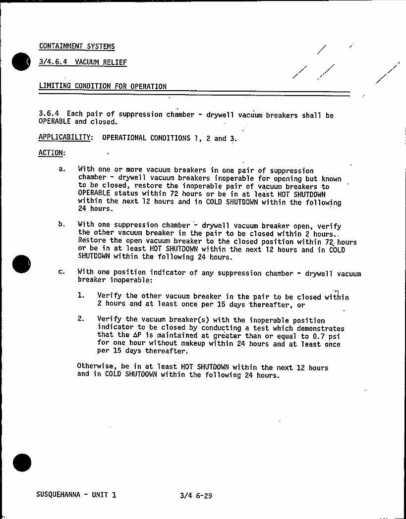
CONTAINMENT SYSTEMS
3/4.6.4 VACUUM RELIEF
LIMITING CONDITION FOR OPERATION
3.6.4 Each pair of suppression chamber - drywell vacuum breakers shall beOPERABLE and closed.
APPLICABILITY: OPERATIONAL CONDITIONS 1, 2 and 3.
ACTION:
a 0 With one or more vacuum breakers in one pair of suppressionchamber - drywell vacuum breakers inoperable for opening but knownto be closed, restore the inoperable pair of vacuum breakers toOPERABLE status within 72 hours or be in at least HOT SHUTDOWNwithin the next 12 hours and in COLD SHUTDOWN within the following24 hours.
b. With one suppression chamber - drywell vacuum breaker open, verifythe other vacuum breaker in the pair to be closed within 2
hours.,'estorethe open vacuum breaker to the closed position within 72„ hoursor be in at least HOT SHUTDOWN within the next 12 hours and in COLDSHUTDOWN within the following 24 hours.
C. With one position indicator of any suppression chamber - drywell vacuumbreaker inoperable:
l. Verify the other vacuum breaker in the pair to be closed within2 hours and at least once per 15 days thereafter, or
2. Verify the vacuum breaker(s) with the inoperable positionindicator to be closed by conducting a test which demonstratesthat the hP is maintained at greater than or equal to 0.7 psifor one hour without makeup within 24 hours and at least onceper 15 days thereafter.
Otherwise, be in at least HOT SHUTDOWN within the next 12 hoursand in COLD SHUTDOWN within the following 24 hours.
SUSQUEHANNA - UNIT 1 3/4 6-29

CONTAINMENT SYSTEMS
SURVEILLANCE RE UIREMENTS
4.6.4 Each suppression chamber - drywell vacuum breaker shall be:
a. Verified closed at least once per 7 days.
b. Demonstrated OPERABLE:
l. At least once per 31 days and within 2. hours after any dischargeof steam to the suppression chamber from the safety-reliefvalves, by cycling each vacuum breaker through at least onecomplete cycle of full travel.
2. At least once per 31 days by verifying both position indicatorsOPERABLE by observing expected valve movement during thecycling test.
3. At least once per 18 months by;
a) Verifying the opening setpoint, from the closed position,to be less than or equal to 0.5 psid, and
b) Verifying both position indicators OPERABLE by performance ofa CHANNEL CALIBRATION.
SUSQUEHANNA " UNIT 1 3/4 6-30

CONTAINMENT SYSTEMS
3/4.6.5 SECONDARY CONTAINMENT
SECONDARY CONTAINMENT INTEGRITY
LIMITING CONDITION FOR OPERATION
3.6.5.1 SECONDARY CONTAINMENT INTEGRITY shall be maintained.APPLICABILITY: OPERATIONAL CONDITIONS 1, 2, 3 and *.ACTION:
Without SECONDARY CONTAINMENT INTEGRITY:
a. In OPERATIONAL CONDITION 1, 2 or 3, restore SECONDARY CONTAINMENTINTEGRITY within 4 hours or be in at least HOT SHUTDOWN within thenext 12 hours and in COLD SHUTDOWN within the following 24 hours.
b. In Operational Condition *, suspend handling of irradiated fuel inthe secondary containment, CORE ALTERATIONS and operations with apotential for draining the reactor vessels The provisions ofSpecification 3.0.3 are not applicable.
SURVEILLANCE RE UIREMENTS
4.6.5.1a.
b.
C.
SECONDARY CONTAINMENT INTEGRITY shall be demonstrated by:Verifying at least once per 24 hours that the pressure within thesecondary containment is less than or equal to 0.25 inches of vacuumwater gauge.
Verifying at least once per 31 days that:1 ~ All secondary containment railroad access hatches are closed
and sealed or the railroad bay access door is closed.2. At least one door in each access to the secondary containment
is closed.3. All secondary containment penetrations not capable of being closed
by OPERABLE secondary containment automatic isolation dampers andrequired to be closed during accident conditions are closed byvalves, blind flanges, or deactivated automatic dampers securedin position.
At least once per 18 months:
1. Verifying that one standby gas treatment subsystem will draw downthe secondary containment to greater than or equal to 0.25 inchesof vacuum water gauge in less than or equal to 60 seconds, and
2. Operating one standby gas treatment subsystem for one hour andmaintaining greater than or equal to 0.25 inches of vacuum watergauge in the secondary containment at a flow rate of3050 cfm 2 10K for both Units 1 and 2.""
When irradiated fuel is being handled in the secondary containment and during~~
~~
~~
~
~
~
~~
~~
~~ ~~
~~
~~
~CORE ALTERATIONS and operations with a potential for draining the reactor vessel.
""2300 cfm while Unit 2 secondary containment is isolated from Unit j. secondarycontainment.
SUSQUEHANNA - UNIT 1 3/4 6-31

CONTAINMENT SYSTEMS
SECONDARY CONTAINMENT AUTOMATIC ISOLATION DAMPERS
LIMITING CONDITION FOR OPERATION
3. 6. 5. 2 The secondary containment ventilation system automatic isolation dampersshown in Table 3.6.5.2-1 shall be OPERABLE with isolation times less than orequal to the times shown in Table 3.6.5.2-1.
APPLICABILITY: OPERATIONAL CONDITIONS 1, 2, 3 and ".
ACTION:
With one or more of the secondary containment ventilation system automaticisolation dampers shown in Table 3.6.5.2-1 inoperable, maintain at least oneisolation damper OPERABLE in each affected penetration that is open and within8 hours either:
a. Restore the inoperable damper to OPERABLE status, or
b. Isolate each affected penetration by use of at least onedeactivated damper secured in the isolation position, or
c. Isolate each affected penetration by use of at least one closedmanual valve or blind flange.
Otherwise, in OPERATIONAL CONDITION 1, 2 or 3, be in at least HOTSHUTDOWN within the next.l2 hours and in COLD SHUTDOWN within thefollowing 24 hours.
Otherwise, in Operational Condition ~, suspend handling of irradiatedfuel in the secondary containment, CORE ALTERATIONS and operationswith a potential for draining the reactor vessel. The provisions ofSpecification 3.0.3 are not applicable.
SURVEILLANCE RE UIREMENTS
4.6.5.2 Each secondary containment ventilation system automatic isolationdamper shown in Table 3.6.5.2-1 shall be demonstrated OPERABLE:
a. Prior to returning the damper to service after maintenance, repair orreplacement work is performed on the damper or its associated actuator,control or power circuit by cycling the damper through at least onecomplete cycle of full travel and verifying the specified isolation time.
b. During COLD SHUTDOWN or REFUELING at least once per 18 months by verifyingthat on a containment isolation test signal each isolation damper actuatesto its isolation position.
c. At least once per 92 days by verifying the isolation time to be within itslimit.
For Zone III dampers when irradiated fuel is being handled in the. secondarycontainment and during CORE ALTERATIONS and operations with a potential fordraining the reactor vessel.
SUSQUEHANNA - UNIT 1 3/4 6-32

TABLE 3.6.5.2"1
, SECONDARY CONTAINMENT VENTILATION SYSTEM AUTOMATIC ISOLATION DAMPERS
DAMPER FUNCTION
1. Reactor Building, Zone I (Unit 1)Exhaust System Dampers (HD-17576A&B)
2. Reactor Building, Zone III (Unit 1)Exhaust System Dampers (HD-17502A8B)
3. Reactor Building, Zone III (Unit 2)Exhaust System Dampers (HD-27502A8B}"
h
MAXIMUMISOLATION TIME
Seconds)
3.0
6.0
6.0
Ul
e pp» 211.U1 2 d 1 1 1 1 df Ufsecondary con'tainment.
SUSQUEHANNA - UNIT 1 3/4 6-33

CONTAINMENT SYSTEMS
STANDBY GAS TREATMENT SYSTEM
LIMITING CONDITION FOR OPERATION
3.6.5.3 Two independent standby gas treatment subsystems shall be OPERABLE.
APPLICABILITY: OPERATIONAL CONDITIONS 1, 2, 3 and ".
ACTION:
With one standby gas treatment subsystem inoperable, restore theinoperable subsystem to OPERABLE status within 7 days, or:
l. In OPERATIONAL CONDITION 1, 2 or 3, be in at least'HOT SHUTDOWN
within the next 12 hours and in COLD SHUTDOWN within the following24 hours.
2. In Operational Condition *, suspend handling of irradiated fuelin the secondary containment, CORE ALTERATIONS and operationswith a potential for draining the reactor vessel. Theprovisions of Specification 3.0.3 are not applicable.
b. With both standby gas treatment subsystems inoperable in OperationalCondition *, suspend handling of irradiated fuel in the secondarycontainment, CORE ALTERATIONS or operations with a potential fordraining the reactor vessel. The provisions of Specification 3.0.3.are not applicable.
SURVEILLANCE RE UIREMENTS
4.6.5.3 Each standby gas treatment subsystem shall be demonstrated OPERABLE:
a. At least once per 31 days by initiating, from the control room, flowthrough the HEPA filters and charcoal adsorber s and verifying thatthe subsystem operates for at least 10 hours with the heatersOPERABLE.
When irradiated fuel is being handled in the secondary containment and duringCORE ALTERATIONS and operations with a potential for draining the reactor vessel.
SUSQUEHANNA - UNIT 1 3/4 6-34

CONTAINMENT SYSTEMS
SURVEILLANCE RE UIREMENTS Continued
b. At least once per 18 months or (1) after any structural maintenanceon -the HEPA filter or charcoal adsorber housings, or (2) followingpainting, fire or chemical release in any ventilation zonecommunicating with the subsystem by:
l. Verifying that the subsystem satisfies the in-place testingacceptance criteria and uses the test procedures of RegulatoryPositions C. 5. a, C. 5. c and C. 5. d of Regulatory Guide 1. 52,Revision 2, March 1978, "and the system flow rate is 10,100cfm 2 lOX.
C.
2. Verifying within 31 days after removal that a laboratory analysisof a representative carbon sample obtained in accordance withRegulatory Position C.6.b of Regulatory Guide 1.52, Revision 2,March 1978, meets the laboratory testing criteria of RegulatoryPosition'. 6. a of Regulatory Guide 1.52, Revision 2, March 1978.
3. Verifying a subsystem flow rate of 10,100 cfm 2 lOX during systemoperation„when tested in accordance with ANSI N510-1975.
After every 720 hours of charcoal adsorber operation by verifyingwithin 31 days "after removal that a laboratory analysis of a repre-sentative carbon sample obtained in accordance with RegulatoryPosition C.6.b of Regulatory Guide 1.52, Revision 2, March 1978,meets the laboratory testing criteria of Regulatory Position C.6.aof Regulatory Guide 1.52, Revision 2, March 1978.
d. At least once per 18 months by:
l. Verifying that the pressure drop across the combined HEPAfilters and charcoal adsorber banks is less than 13 inchesWater Gauge while operating the filter train at a flow rate of10,100 cfm t 10K.
2. Verifying that the filter train starts and associated dampersopen on each of the following test signals:a. Manual initiation from the control room, and
b. Simulated automatic initiation signal.
3. Verifying that the filter cooling bypass and outside air dampersopen and the fan start on filter cooling initiation.
Verifying that the temperature differential across each heatingcoil is > 17~F when tested in accordance with ANSI N510-1975.
SUSQUEHANNA - UNIT 1 3/4 6-35

CONTAINMENT SYSTEMS
SURVEILLANCE RE UIREMENTS Continued)
e. After each complete or partial replacement of a HEPA filter bank byverifying that the.HEPA filter banks remove greater than or equal to99.95K of the DOP when they are tested in-place in accordance withANSI N510-1975 while operating the system at a flow rate of 10,100 cfm+ 10K.
f. After each complete or partial replacement of a charcoal adsorberbank by verifying that the charcoal adsorbers remove greater than99.95X of a halogenated hydrocarbon refrigerant test gas whenthey are tested in-place in accordance with ANSI N510-1975 whileoperating the system at a flow rate of 10,100 cfm + lO%%u'.
SUS(UEHANNA - UNIT 1 3/4 6-36

CONTAINMENT SYSTEMS
3/4.6.6 PRIMARY CONTAINMENT ATMOSPHERE CONTROL
DRYWELL AND SUPPRESSION CHAMBER HYDROGEN RECOMBINER SYSTEMS
LIMITING CONDITION FOR OPERATION
3.6.6. 1 Two drywell and two suppression chamber hydrogen recombiner systemsshall be OPERABLE.
APPLICABILITY: OPERATIONAL CONDITIONS 1 and 2.
ACTION:
With one drywell and/or one suppression chamber hydrogen recombiner systeminoperable, restore the inoperable system to OPERABLE status within 30 days orbe in at least HOT SHUTDOWN within the next 12 hours.
SURVEILLANCE RE UIREMENTS
4.6.6. 1 Each drywell and suppression chamber hydrogen recombiner system shallbe demonstrated OPERABLE:
At least once per 6 months by energizing the recombiner system to atleast 10 kw for > 5 minutes.
b. At least once per 18 months by:
1. Performing a CHANNEL CALIBRATION of all recombiner operatinginstrumentation and control circuits.
2. Verifying the integrity of all heater electrical circuits byperforming a resistance to ground test following the aboverequired energization. The resistance to ground for anyheater phase shall be greater than or equal to 10,000 ohms.
3. Verifying through a visual examination that there is no evidenceof abnormal conditions within the recombiner enclosure; i.e,loose wiring or structural connections, deposits of foreignmaterials, etc.
1
SUSQUEHANNA - UNIT 1 3/4 6-37

CONTAINMENT SYSTEMS
DRYWELL AIR FLOW SYSTEM
LIMITING CONDITION FOR OPERATION
3.6.6.3 Three independent drywell air flow unit co'oler subsystems shall beOPERABLE at low speed with each subsystem consisting of 2 unit cooler fans.
APPLICABILITY: OPERATIONAL CONDITIONS 1 and 2.
ACTION:
With'one fan of one or more unit cooler subsystems inoperable at low speed,restore the inoperable fan(s) to OPERABLE status within 30 days or be in atleast HOT SHUTDOWN within the next 12 hours.
SURVEILLANCE RE UIREMENTS
4.6.6.3 Each drywell air flow unit cooler subsystem shall be demonstratedOPERABLE at least once per 92 days by:
a. Starting each fan at low speed from the control room, and
b. Verifying that each fan operates for at least 15 minutes.
SUSQUEHANNA - UNIT 1 3/4 6-38

CONTAINMENT SYSTEMS
DRYWELL AND SUPPRESSION CHAMBER OXYGEN CONCENTRATION
LIMITING CONDITION FOR OPERATION
3.6.6.4 The drywell and suppression chamber atmosphere oxygen concentrationshall be less than 4X by volume.
APPLICABILITY: OPERATIONAL CONDITION 1", during the time period:
a. Within 24 hours after THERMAL POWER is greater than 15K of RATEDTHERMAL POWER, following startup, to
b. Within 24 hours prior to reducing THERMAL POWER to less than 15K ofRATED THERMAL POWER preliminary to a scheduled reactor shutdown.
ACTION:
With the oxygen concentration in the drywell and/or suppression chamberexceeding the limit, restore the oxygen concentration to within the limitwithin 24 hours or be in at least STARTUP within the next 8 hours.
SURVEILLANCE RE UIREMENTS
4.6.6;4 The oxygen concentration in the drywell and suppression chamber shallbe verified to be within the limit within 24 hours after THERMAL POWER isgreater than 15K of RATED THERMAL POWER and at least once per 7 days thereafter.
See Special Test Exception 3. 10.5.
SUS(UEHANNA " UNIT 1 3/4 6-39


3/4.7 PLANT SYSTEMS
3/4. 7. 1 SERVICE WATER SYSTEMS
RESIDUAL HEAT REMOVAL SERVICE WATER SYSTEM
LIMITING CONDITION FOR OPERATION
3.7. 1.1 Two independent residual heat removal service water (RHRSW) systemsubsystems shall be OPERABLE with each subsystem comprised of:
a. One OPERABLE RHRSW pump~, and
b. An OPERABLE flow path capable of taking suction from the spray pondand transferring the water through one RHR heat exchanger.
APPLICABILITY: OPERATIONAL CONDITIONS 1, 2, 3, 4, and 5.
ACTION:
a ~
b.
C.
In OPERATIONAL CONDITION 1, 2 or 3:
1. With one RHRSM subsystem inoperable, restore the inoperablesubsystem to OPERABLE status with at least one OPERABLE pump"within 72 hours or be in at least HOT SHUTDOMN within the next12 hours and in COLD SHUTDOWN within the following 24 hours.
2. With both RHRSW subsystems inoperable, be in at least HOTSHUTDOWN within the next 12 hours and in COLD SHUTDOWN"" withinthe following 24 hours.
In OPERATIONAL CONDITION 3 or 4 with the RHRSW subsystem, which isassociated with an RHR loop required OPERABLE by Specification 3.4. 9. 1
or 3.4.9.2, inoperable, declare the associated RHR loop inoperableand take the ACTION required by Specification 3.4. 9. 1 or 3.4. 9. 2,as applicable.In OPERATIONAL CONDITION 5 with one RHRSW subsystem, which isassociated with an RHR system required OPERABLE by Specification3. 9. 11. 1 or 3. 9. 11. 2, inoperable, declare the associated RHR systeminoperable and take the ACTION required by Specification 3.9. 11. 1
or 3.9.11.2, as applicable.
SURVEILLANCE RE UIRENENTS
4.7. 1. 1 Each residual heat removal service water system subsystem shall bedemonstrated OPERABLE at least once per 31 days by verifying that each valvein the flow path that is not locked, sealed or otherwise secured in position,is in its correct position.
May not be a pump required for Unit 2.""Whenever both RHRSW subsystems are inoperable, if unable to attain COLD
SHUTDOWN as required by this ACTION, maintain reactor coolant temperature aslow as practical by use of alternate heat removal methods.
SUSQUEHANNA - UNIT 1 3/4 7-1

PLANT SYSTEMS
EMERGENCY SERVICE WATER SYSTEM
LIMITING CONDITION FOR OPERATION
3.7. 1.2 Two independent emergency service water system loops shall beOPERABLE with each loop comprised of:
a. Two OPERABLE emergency service water pumps, andb. An OPERABLE flow path capable of-taking suction from the spray pond
and transferring the water to the associated safety related equipment.APPLICABILITY: OPERATIONAL CONDITIONS 1, 2, 3, 4, 5 and ".ACTION:
b.
In OPERATIONAL CONDITION 1, 2, or 3:
1. With one emergency service water pump inoperable, restore theinoperable pump to OPERABLE status within 7 days or be in a leastHOT SHUTDOWN within the next 12 hours and in COLD SHUTDOWN withinthe following 24 hours.
2. With two emergency service water pumps inoperable, restore atleast one inoperable pump to OPERABLE status within 72 hours orbe in at least HOT SHUTDOWN within the next 12 hours and in COLDSHUTDOWN within the following 24 hours.
,8
3. With one emergency service water system loop inoperable, restorethe inoperable loop to OPERABLE status with at least one OPERABLEpump within 72 hours or be in at least HOT SHUTDOWN within thenext 12 hours and in COLD SHUTDOWN within the following 24 hours.
With only one emergency service water pump and its associated flowpathOPERABLE, restore at least two pumps and their associated flowpathsto OPERABLE status within 72 hours or:1. In OPERATIONAL CONDITION 4 or 5, declare the associated safety
related equipment inoperable and take the ACTION required bySpecifications 3.5.2 and 3.8. 1.2.
2. In Operational Condition ", declare the- associated dieselgenerator(s) inoperable and take the ACTION required by Specifi-cation 3.8. 1.2. The provisions of Specification 3.0.3 are notapplicable.
SURVEILLANCE RE UIREMENTS
4.7.1.2a.
b.
The emergency service water system shall be demonstrated OPERABLE:
At least once per 31 days by verifying that each valve, manual, poweroperated or automatic, servicing safety related equipment-that isnot locked, sealed or otherwise secured in position, is in its correctposition.
At least once per 18 months during shutdown, by verifying that eachpump starts automatically when its associated diesel generator starts.
When handling irradiated fuel in the secondary containment.
SUSQUEHANNA - UNIT 1 3/4 7"2

PLANT SYSTEMS
IULTIMATE HEAT SINK
LIMITING CONDITION FOR OPERATION
3.7.1.3 The spray pond shall be OPERABLE.
APPLICABILITY: OPERATIONAL CONDITIONS l, 2, 3, 4, 5 and ".
ACTION:
a0 With the groundwater level at any spray pond area observation wellgreater than or equal to 663'SL, in lieu of any other reportrequired by Specification 6.9.1, prepare and submit a Special Reportto the Commission pursuant to Specification 6.9.2 within the next10 days outlining the cause of the high groundwater level and theplans for restoring the level to within the limit.
b. With the spray pond otherwise inoperable:
l. In OPERATIONAL CONDITION l, 2 or 3, be in at least HOT SHUTDOWNwithin 12 hours and in COLD SHUTDOWN within the next 24 hours.
2. In OPERATIONAL CONDITION 4 or 5, declare the RHRSW system and theemergency service water system inoperable and take the ACTIONrequired by Specifications 3.7.1. 1 and 3.7.1.2.
3. In Operational Condition ", declare the emergency service water-system inoperable and take the ACTION,required bySpecification 3. 7. l. 2. The provisions of Specification 3. 0. 3are not applicable.
SURVEILLANCE RE UIREMENTS
4.7. 1.3 The spray pond shall be determined OPERABLE by verifying:'. The average water temperature, which shall be the arithmetical averageof the spray pond water temperature at the surface, mid and bottomlevels, to be less than or equal to 88~F at least once per 24 hours.
b. The water level at the overflow weir is greater than or equal to677'ean
Sea Level USGS (MSL), at least once per:
1. 12 hours when water level is < 677'6" MSL, and
2. 14 days when water level is > 677'6" MSL.
c. The groundwater level at each of the seven obggrvation wells to beless than 663'. MSL at least once per 31 days.
"When handling irradiated fuel in the secondary containment.**Except that observation well $ 2 may be excepted from this Surveillance Re-
quirement until September 3, 1982.
SUSQUEHANNA - UNIT 1 3/4 7"3

PLANT SYSTEMS
3/4.7.2 CONTROL ROOM EMERGENCY OUTSIDE AIR SUPPLY SYSTEM
LIMITING CONDITION FOR OPERATION
3.7.2 Two independent control room emergency outside air supply systemsubsystems shall be OPERABLE with each subsystem consisting of:'. One makeup fan, and
b. One filter train.APPLICABILITY: All OPERATIONAL CONDITIONS and *.
ACTION:
a. In OPERATIONAL CONDITION 1, 2 or 3 with one control room emergencyoutside air supply subsystem inoperable, restore the inoperablesubsystem to OPERABLE status within 7 days or be in at least HOT
SHUTDOWN within the next 12 hours and in COLD SHUTDOWN within thefollowing 24 hours.
b. - In OPERATIONAL CONDITION 4, 5 or ~:
1. With one control room emergency outside,air supply subsysteminoperable, restore the inoperable subsystem to OPERABLE statuswithin 7 days, or initiate and maintain operation of the OPERABLE
subsystem in the pressurization mode of operation.
2. With both control room emergency outside ai,r supply subsystemsinoperable, suspend CORE ALTERATIONS,- handling of irradiatedfuel in the secondary containment and operations with apotential for draining the reactor vessel.
c. The provisions of Specification 3.0.3 are not applicable inOperational Condition ".
SURVE'ILLANCE RE UIREMENTS
4.7.2 Each control room emergency outside air supply subsystem shall bedemonstrated OPERABLE:
a. At least once per 31 days on a STAGGERED TEST BASIS by initiating,from the control room, flow through the HEPA filters and charcoaladsorbers and verifying that the subsystem operates for at least10 hours with the heaters OPERABLE.
b. At least once per 18 months or (1) after any structural maintenanceon the HEPA filter or char'coal adsorber housings, or (2) followingpainting, fire or chemical release in any ventilation zonecommunicating with the subsystem by:
1. Verifying that with the subsystem operating at a flow rate of5810 cfm + lOX and exhausting through the HEPA filters andcharcoal adsorbers, the total bypass flow of the system to thefacility vent, including leakage through the subsystem divertingvalve, is less than or equal to 1X when the subsystem is testedby admitting cold DOP at the system intake.
When irradiated fuel is being handled in the secondary containment.
SUS(UEHANNA - UNIT j. 3/4 7-4

PLANT SYSTEMS
SURVEILLANCE RE UIREMENTS Continued
2. Verifying that the subsystem satisfies the in-place testingacceptance criteria and uses the 't'est pl'acedures of RegulatoryPositions C. 5. a, C. 5. c and C. 5. d of Regulatory Guide l. 52,Revision 2, March 1978, and the system flow rate is 5810 cfm+ 10K.
C.
d.
3, Verifying within 31 days after removal that a laboratory analysisof a representative carbon sample obtained in accordance withRegulatory Position C.6.b of Regulatory Guide 1.52, Revision 2,March 1978, meets the laboratory testing criteria of RegulatoryPosition C.6.a of Regulatory Guide 1.52, Revision 2, March 1978.
4. Verifying a subsystem flow rate of 5810 cfm + 10K duringsubsystem operation when tested in accordance with ANSI N510-1975.
After every 720 hours of charcoal adsorber operation by verifyingwithin 31 days after removal that a laboratory analysis of a repre-sentative carbon sample obtained in accordance with RegulatoryPositon C.6.b "of Regulatory Guide 1.52, Revision 2, March 1978, meetsthe laboratory .testing criteria of Regulatory Position C.6.a ofRegulatory Guide 1.52, Revision 2, March 1978.
At least once per 18 months by:l. Verifying that the pressure drop across the combined prefi lter,
upstream and downstream HEPA filters and charcoal adsorber banksis less than 9. 1 inches Water Gauge while operating the subsystemat a flow rate of 5810 cfm + 10K.
2. Verifying that on each of the below isolation mode actuationtest signals, the subsystem automatically switches to theisolation mode of operation and the ',isolation dampers closewithin 8~seconds:
a) Outside air intake chlorine - high,b) Outside air intake radiation - high, andc) 'eactor Building isolation.
3. Verifying that on each of the below pressurization modeactuation test signals, the subsystem automatically switches tothe pressurization mode of operation and the control structure ismaintained at a positive pressure of 1/8 inch W.G. relativeto the outside atmosphere during subsystem operation at a flowrate less than or equal to 5810 cfm:
a) Reactor Buildin'g isolation, and
b) Outside air intake radiation'- high.
4. Verifying that the heaters dissipate 30 + 3.0 Kw whentested in accordance with ANSI N510-1975.
SUSQUEHANNA - UNIT 1 3/4 7-5

PLANT SYSTEMS
SURVEILLANCE RE UIREMENTS Continued
e. After each complete or partial replacement of a HEPA filter bank byverifying that the HEPA filter banks remove greater than or equal to99.95K of the DOP when they are tested in-place in accordancewith ANSI N510-l975 while operating the system at a flow rate of5810 cfm + lOX.
After each complete or partial replacement of a charcoal adsorberbank by verifying that the charcoal adsorbers remove 99.95K of ahalogenated hydrocarbon refrigerant test gas when they are testedin-place in accordance with ANSI N510-1975'hile operating thesystem at a flow rate of 5810 cfm + lOX.
SUSQUEHANNA - UNIT 1 3/4 7-6

PLANT SYSTEMS
3/4.7.3 REACTOR CORE ISOLATION COOLING SYSTEM
LIMITING CONDITION FOR OPERATION
3.7.3 The reactor core isolation cooling (RCIC) system shall be OPERABLE withan OPERABLE flow path capable of taking suction from the suppression pool andtransferring the water to the reactor pressure vessel.
APPLICABILITY: OPERATIONAL CONDITIONS 1, 2, and 3 with reactor steam dome
pt essure greater than 150 psig.
ACTION:
With the RCIC system "inoperable, operation may continue provided the HPCIsystem is OPERABLE; restore the RCIC system to OPERABLE status within 14 daysor be in at least HOT SHUTDOWN within the next 12 hours and reduce reactorsteam dome pressure to less than or equal to 150 psig within the following24 hours.
SURVEILLANCE RE UIREMENTSt 4.7.3 The RCIC system shall be demonstrated OPERABLE:
a. At least once per 31 days by:
l. Verifying that the system piping from the pump discharge valveto the system isolation valve is filled with water by:
a. Venting at the high point vents.
b. Performance a CHANNEL FUNCTIONAL TEST of the condensatetransfer pump discharge low pressure alarm .instrumentation.
2. Verifying that each valve, manual, power operated or automaticin the flow path that is not locked, sealed or otherwise securedin position, is in its correct position.
3. Verifying that the pump flow controller is in the correctposition.
b. At least once per 92 days by verifying that the RCIC pump develops aflow of greater than or equal to 600 gpm in the test flow path witha system head corresponding to reactor vessel operating pressure whensteam is being supplied to the turbine at 920 + 140, - 0 psig.*
I The provisions of Specification 4.0.4 are not applicable provided thesurveillance is performed within 12 hours after reactor steam pressure isadequate to perform the test.
SUS(UEHANNA - UNIT 1 3/4 7-7

PLANT SYSTEMS
SURVEILLANCE RE UIREMENTS (Continued)
C. At least once per 18 months by:
Performing a system functional test which includes simulatedautomatic actuation and restart and verifying that eachautomatic valve in the flow path actuates to its correctposition, but may exclude actual injection of coolant intothe reactor vessel.
2. Verifying that the system will develop a flow of greater thanor equal to 600 gpm in the test flow path when steam is suppliedto the turbine at a pressure of 150, + 15, -0 psig."
3. Verifying that the suction for the RCIC system is automaticallytransferred from the condensate storage tank to the suppressionpool on a condensate storage tank water level-low signal.
4. Performing a CHANNEL CALIBRATION of the condensate transferpump discharge low pressure alarm instrumentation and verifyingthe low pressure alarm setpoint to less than or equal'to113 psig.
The provsssons of Specification 4.0.4 are not applicable provided thesurveillance is performed within 12 hours after reactor steam pressure isadequate to perform the tests.
SUS(UEHANNA - UNIT 1 3/4 7-8

PLANT SYSTEMS
.3/4.7.4 SNUBBERS
LIMITING CONDITION FOR OPERATION
3.7.4 All snubbers listed in Table 3.7.4-1 shall be OPERABLE.
APPLICABILITY: OPERATIONAL CONDITIONS 1, 2 and 3 and OPERATIONAL CONDITIONS 4and 5 for snubbers located on systems required OPERABLE in those OPERATIONALCONDITIONS.
ACTION:
With one or more snubbers inoperable, within 72 hours replace or restore theinoperable snubber(s) to OPERABLE status and perform an engineering evaluationper Specification 4. 7. 4. c on the supported component or declare the supportedsystem inoperable and follow the appropriate ACTION statement for that system.
SURVEILLANCE RE UIREMENTS
4.,7. 4 'ach snubber shal~l~ be demo'nstrated OPERABLE by performance of thefollowing augmented inservice inspection program and the requirements ofSpecification 4.0.5.
a 0 Visual Ins ections
The first inservice visual inspection of snubbers shall be performedafter 4 months but within 10 months of commencing POWER OPERATION
and shall include all snubbers listed in Table 3.7.4-1. If less thantwo snubbers are found inoperable during the first inservice visualinspection, the second inservice visual inspection shall be performed12 months + 25K from the date of the first inspection. Otherwise,subsequent visual inspections shall be performed in accordance withthe following schedule:
No. Inoperable Snubbers-er Ins ection Period
0123,45,6,78 or more
Subsequent VisualIns ection Period"¹
12 months 2 25K6 months + 25K
124 days + 25K62 days 2 25K,31 days + 25K
The snubbers may be categorized into two groups: Those accessibleand those inaccessible during reactor operation. Each group may beinspected independently in accordance with the above schedule.t The inspection interval shall not be lengthened more than one step at a time.
¹The provisions of Specification 4. 0. 2 are not applicable.
SUS(UEHANNA - UNIT 1 3/4 7-9

PLANT SYSTEMS
SURVEILLANCE RE UIREMENTS
b. Visual Ins ection Acce tance Criteria
C.
Visual inspections shall verify (1) that there are no visibleindications of damage or impaired OPERABILITY, (2) that attachmentsto the foundation or supporting structure are secure, and (3) in thoselocations where snubber movement can be manually induced withoutdisconnecting the snubber, that the snubber has freedom of movementand is not frozen up. Snubbers which appear inoperable as a resultof these visual inspections may be determined OPERABLE for the purposeof establishing the next visual inspection interval, providing that(1) the cause of the rejection is clearly established and remediedfor that particular snubber and for other snubbers that may begenerically susceptible, and (2) the affected snubber is functionallytested in the as found condition and determined OPERABLE perSurveillance Requirements 4.7.4.d.Functional Tests
During the first refueling shutdown and at least once per 18 monthsthereafter during shutdown, a representative sample of at leastthat number of snubbers which follows the expression 35 (1 + ~),where c = 4, is the allowable number, of snubbers not meeting theacceptance criteria selected by the operator, shall be functionallytested either in-place or in a bench test, For each number ofsnubbers above c which does not meet the functional test accept-ance criteria of Specificatio'ns 4.7.4.d., an additional sample
selected according to the expression 35 (1 +') ( ) (a - c) shallc 2 22 c+1
be functionally tested, where a is the total number of snubbers foundinoperable during the functional testing of the representative sample.
Functional testing shall continue according to the expressionb f35 (1 + -) ( ) ] where b is the number of snubbers found inoper-c 2 2
2 c+1able in the previous re-sample, until no additional inoperable snubbersare found within a sample or until all snubbers in Table 3.7.4-1 havebeen functionally tested.
The representative sample selected for functional testing shall includethe various configurations, operating environments and the range ofsize and capacity of snubbers. At least 25K of the snubbers in therepresentative sample shall include snubbers from the following threecategories:
2.
3.
The first snubber away from each reactor vessel nozzle.U
Each snubber within 5 feet of heavy equipment, valve, pump,turbine, motor, etc.Each snubber within 10 feet of the discharge from a safetyrelief valve.
SUSQUEHANNA - UNIT 1 3/4 7-10

PLANT SYSTEMS
SURVEILLANCE RE UIREMENTS Continued
Functional Test (Continued)
In addition to the regular sample, snubbers which failed the previousfunctional test shall be retested during the next test period. If aspare snubber has been installed in place of a failed snubber, thenboth the failed snubber, if it is repaired and installed in anotherposition, and the spare snubber shall be retested. Test results ofthese snubbers may not be included for the re-sampling.
If any snubber selected for functional testing either fails to lockupor fails to move, i.e., frozen in place, the cause will be evaluatedand if caused by manufacturer. or design deficiency all snubbers ofthe same design subject to the same defect shall be functionallytested. This testing requirement shall be independent of the require-ments stated above for snubbers not meeting the functional testacceptance criteria.
For any snubber(s) found inoperable, an engineering evaluation shallbe performed on the components which are supported by the snubber(s).The purpose of this engineering evaluation shall be to determine ifthe components -,supported by the snubber(s) were adversely affectedby the inoperability of snubber(s) in order to ensure that thesupported component remains capable of meeting the designed service.
d. Mechanical Snubbers Functional Test Acce tance Criteria
The mechanical snubbe~ functional test shall verify that:
1. The force that initiates free movement of the snubber rod ineither tension or compression is less than the specifiedmaximum drag force. Drag force shall not have increased morethan 50K since the last surveillance test.
2. Activation (restraining action) is achieved within thespecified range of velocity or acceleration in both tension andcompression.
3. Snubber release rate, where required, is within the specifiedrange in compression or tension. For snubbers specificallyrequired not to displace under continuous load, the ability ofthe snubber to withstand load without displacement shall bever i-f-ied.
SUSQUEHANNA - UNIT 1 3/4 7-11

PLANT SYSTEMS
SURVEILLANCE RE UIREMENTS Continued
e. Snubber Service Life Monitorin
A record of the service life of each snubber, the date at which thedesignated service life commences and the installation and maintenance =
records on which the designated service life is based shall be main-tained as required by Specification 6. 10. 2.
Concurrent with the first inservice visual inspection and at leastonce per 18 months thereafter, the installation and maintenance recordsfor each snubber listed in Tables 3.7.4-1 shall be reviewed to verifythat the indicated service life has not been exceeded or will not beexceeded prior to the next scheduled snubber service life review.If the indicated service life will be exceeded prior to the nextscheduled snubber service life review, the snubber service life shallbe reevaluated or the snubber shall be replaced or reconditioned soas to extend its service life beyond the date of the next .scheduledservice life review.- This reevaluation, replacement or reconditioningshall be indicated in the records.
SUSQUEHANNA " UNIT 1 3/4 7-12

TABLE 3.7.4-1
SAFETY RELATED MECHANICAL SNlJBBERS*'
SYSTEMNO.
1
SNUBBER
NO.
SYSTEMNO.
SNUBBERNO.
a. LARGE HANGERS
SYSTEMNO.
SNUBBERNO.
016A016A024A024A024A024A024A024A024A024A024A024A024A024A024A024A024A024A024A024A024A024A024A024A024A024A024A024A02)h024A.024k
- 024A024A024A
HRC-112-1HRC-112-2HBC- 4-1HBC- 4-1HBC" 5-1HBC- 5-1HBC" 5-1HBC- 5-1HBC- 5-1HBC- 5-1HBC- 5-1HBC- 5-1HBC- .5-1HBC- 7 1HBC- 7"1HBC" 8"1HBC- 8-1HBC- 8-1HBC- 8-1HBC- 8-1HBC- 8-1HBC- 8-1HBC- .9 1HBC- )-1HBC- 11 "1HBC- ii-1HBC- 11-1HBC- 11-1HBC- 11-1HBC- 11-1HBC- 11-1HBC- .9"1HBC- l? 1HBC- 12"1
H
H
H
H
H
H
H
H
H
H
H
H
H
H
H
H
H
H
H
H
H
H
H
H
H
H
H
H
H
H
H
H
H
l8165 (2 units)6 (2 units)9
10 (2 units)171820 (2 units)2223
1625 (2 units)79 (2 units)
1517 (2 units)20
16,24 (2 units)5 (2 units)8
10 (2 units)151617 (2 units)
46
024A024A024A024A024A024A
024A024A030003000300030003000300030003000300
- 035B035B035B035B035B035B05480548054B134G134G-134K134K137B137B1378145A
HBC- 13-1HBC- 13-1HBC- 13-1HBC- 13-1HBC- '13-1HBC- 13-1HBC- 13-1HBC- g-1HRC- l,3 1HRC- Q'-1HRC- 14-1HRC- 17"1HRC- 17-1HRC- 17-1HRC- 22-1HRC- 22-1HRC- 22-1GBC-105"1HBC-117-1HBC-117-1HBC-117-1HBC-117-1HBC-117-1HRC- 2-xHRC- 2-54HRC" 2-54HRC-123-2HRC-131-1HBB-125-2HBB-126-2HCB-102"1HCB-103-1HCB-104-1DBB-122-1
H
H
H
H
H
H
H
H
H
H
H
H
H
H
H
H
H
H
H
H
H
H
H
H
H
H
H
H
1819 (2 units)151920
567
1618
5 (2 units)2789
1020222615
12246 (2 units)7
28 (2 units)
H „2H 4H 6 (2 units)H 9H ll (2 units)H 16
145A145A145A145A145A145A
145A145A
149A149A149A149A149A149A149A149A149A149A149A149A149A149A149A149A149A149A149A149A149A-149A149A149A149A149A
DBB-122-2DBB-122-2DBB-122-2DBD-101D LA-101"1D LA-101"1
DLA-103-1DLA-103-1
GBB-104-iGBB-104-1GBB-104-1GBB-104-1GBB-104-1GBB-104-1GBB-104-1GBB"104-2GBB-104-2GBB-104-2GBB-104-3GBB-104-3GBB-104-3GBB-104"3GB B-104-3GBB-104-3GBB"104-3GBB-104-3GBB-104-4GBB-104-4GBB-104-4G8B-104-4GBB-106-1GBB-106-1GBB-106-1GBB-106-1
H 1H 3H 24H 32H 1H 4
H 3H 4
H 3H 6H 8H 10H 12H 13H 16H 47H 49H 52H 21H 24H 26H 28H 30H 31H 34H 36H 40H 42H 51 (2 uni ts)H 54H 1H 9 (2 units)H 25H 27

TABLE 3.7.4-1 (continued)
SAFETY RELATED MECHANICAL SNUBBERS*
m SYSTEMNO.
I
SNUBBERNO.
SYSTEMNO.
SNUBBERNO.
LARGE HANGERS (continued)
SYSTB1NO.
SNUBBERNO.
149A GBB-107-2149A GBB-107-2149A G8B-107-2149A GBB-108-1149A GBB-109-1149A GBB-109-1149A GBB-109-1149A GBB-109-1149A GBB-109-1149A GBB-109-1
149A149A149A149A149A149A149A149A149A149A
GBB-109-1GBB-109-1G8B-109-2GBB-109-2GBB-109-2GBB-109-2GBB-109-2GBB-109-2GBB-112-2GBB-112-2
149A, GBB-106" 1149A GBB-106-2149A GBB-106-2149A GBB-106-2149A GBB-106-2149A GBB-106" 2149A GBB-107-1149A G8 8-107-2149A GBB-107-2149A GBB-107-2149A GBB-107-2149A GBB-107-2
36 (2 units)101826375331
1 (2 units)67 (2 units)
1215 (2 units)
1740 (2 units)41
317242930=
3233 (2 units)
39401125353637382223
149A149A149A149A149A149A149A149A149A
149A149A149A149A149A149A149A149A149A-149A149A149A149A149A149A149A149A149A149A149B149B=149B1498149B149B
24213
15 (2 units)3
503
37
384344 (2 units)2732
42'7
213339'~
12'5
364529
2931 (2 units)32 (2 units)33 (2 units)
2489
257
G8B-112-2 HGB8-113-1 HGBB-114-1 H
GBB-114-1 HGBB-115-1 HGBB-115-1 HHBB-110 HHBB-110-1 '
HBB-110-1 H
HBB-110-L HHBB-110-1 HHBB-110-1 HHB8-110-2 HHBB-110-2 HHBB-110~2 HHBB-110-2 HHBB-110-3 HHBB-110-3 HHBB-.110-3 H,HBB-110-4 H:H8B-110-4 HHBB-110-4, HHBB-110-4 HHBB 111" 2 HHBB-ill,HHBB-111-2 '
.HBB-111-2 HHBB-111-2 HDBB-115-1 HDBB-115-1 HDBB-115-1 HDBB-115-1 HDBB-115-1 HGBB-105- - H
149B1498149B149B149B1498149B1498149B149B149B149B149B14981498149E149E149E149G149G
149G149G149G
149G149G149G149G149G149G149G149G149G
GBB-105-1GBB-105-1GBB-105-1GBB-105-1GBB-105-1GBB-105-1GBB-105-2GBB-105-2GB8-105-2GBB-105-2GBB-105-2GBB-ill"1GBB-111-2GBB-116-1GBB-116-2GBB-118-1GBB-118-2GBB-118-2DBB-107-1DBB-107-1DBB-107-1DBB-107-2DBB-107-2
D8B-107-2DCA-108"1DCA-108-1DCA-108-1DCA-108"10 CA-108-1DCA-108-1DCA-108-1DCA-110-1
579
13 (214 (231
13
10ll12 (2.
847 (23
1323
units)units)
units)
units)
24 (212 (2
uni ts)
units)
13456
10ll12
910
H 6H 8 (2 units)
9 (2 units)
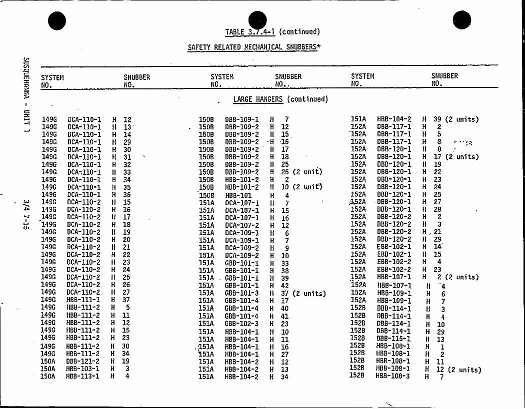
TABLE 3..4-1 (continued)
SAFETY RELATED MECHANICAL SNUBBERS*
SYSTEMNO.
SNUBBERNO.
SYSTENNO.
SNUBBERNO..
SYSTEMNO.
SNUBBERNO.
LARGE HANGERS (continued)
149G OCA-110-1149G DCA-.110-1149G OCA-110"1149G DCA-110-1149G DCA-110-1149G DCA-110-2149G OCA-110-2149G OCA-110-2149G DCA-110-2149G OCA-110-2149G DCA-110-2149G OCA-110-2149G OCA-110-2149G DCA-110-2149G DCA-110-2149G DCA-110-2149G OCA-110-2149G DCA-110-2149G HB8-111-1149G HBB-111-2149G H88-111-2149G HBB-111-2149G HBB-111-2149G HBB-111-2149G H88-111-2149G HB8-111-2150A DBB-121-2150A HB8-103-1150A HBB-113-1
H
H
H
H
H
H
H
H
H
H
H
H
H
H
H
H
H
H
H
H
H
H
H
H
H
H
149G DCA-110-1149G OCA-110-1149G DCA-110-1149G DCA-110-1149G OCA-110-1149G DCA-110-1, H
1213'4
29303132333435361516171819202122232425262737
5ll121523303419
3
15081508150815081508150815081508150815081508151A151A151A151A151A151A151A151A151A151A151A151A151A151A151A151A151A151A151A
, .'151A'i51A151A151A151A
DBB-109-1DBB-109-2DBB-109-2
-DBB-109-2DBB-109-2DBB-109-2088-109-2088-109-2HBB-101-2HBB-101-2HB8-101OCA-107-1DCA"107-1DCA-107-1OCA-107-2DCA"109-1OCA-109-1OCA-109-2OCA-109-2GBB-101-1GBB-101-1GBB-101-1G8 8-101-1GBB-101-3GBB-101-4G8 8-101-4GBB-101-4GBB-102-3HBB-104-1HBB-104-1HBB-104-1HBB"104-1HBB-104-2HB8-104-2HBB-104-2
H 7H 12H 15.H;16H -17H 18H 25
26 (2 unit)H 2H 10 (2 unit)H 4H 7H 15H 16H 12H 6H 7H 9H 10H 33H 38H 39H 42H 37 (2 units)H 17H 40H 41H 23H 10H 11H 16H 27H 12H 13H 34
151A152A'152A152A152A,152A152A152A152A152A152A
2A152A152A152A152A152A152A152A152A152A152A152A152A152A1528152815281528152815281528152815281528
HBB-104-2088-117-1088-117-1088-117-1DBB-120-1088-120-1088-120-1D88-120-1OBB"120-1088-120-1088-120-1
-088-120-1088-120-1DBB-120-2DBB-120-2088-120-2088-120-2EBB 102 1EBB-102-1EBB-102-2EBB-102-2HBB"107" 1HBB-107-1HBB-109-1HBB-109-1DBB"114" 1DBB-114-1088-114-1DB8-114-1DBB-115-1MBB-108-1HBB"108-1HBB-108-1HBB-108-1HBB"108" 3
H
H
H
H
H
H
H
H
H
H
H
H
H
H
H
H.H
H
H
H
H
H
H
H
H
H
H
H
H
H
H
H
H
M
39 (2 units)2588
17 (2 units)19222324252728
23
21291415
423
2 (2 units)46734
102913
12
1112 (2 units)
7

TABLE 3.7.4-1 (continued)
SAFETY RELATED HECHANIOAL SNUBBERS*
SYSTEMNO.
SNUBBERNO.
SYSTEMNO.
SNUBBERNO..
SYSTEMNO.
SNUBBERNO.
LARGE HANGERS (continued)
15281528154A154A
154A154A154A1618161816181618161816181618161816181618161816181618161816181618161816181618161816181618161816181618
HBB-108-3HBB-135HRC- 14-2HRC-102-1HRC-105-1HRC-123-1HRC-124-1DBA-101-1DBA-101-1DBA-101-1OBA-101-1DBA-101-1DBA-101-1DBA-101-1DBA-101-1OBA-101-1OBA-101-1OBA-101-1OBA-101-1DBA-101-1DBA-101-1DBA-101-1DBA-101-2DBA-101-2DBA-101-2OBA-101-2DBA-101-2DBA-101-2DBA-101-2DBA-101-2DBA-101"2OBC-101-1
418
7 (2 units)13 (2 units)16
823
9252629303132
H 353638424610121415161719202114
i61816181618162A162A162A162A162A162A162A162A162A162A162A162A162A162A162A
162A162A
'62A162A162A
162A'62A
162A162A162A162A162A162A162A162A162A
OBC-101-1DBC-101-1DBC-102-1OBA-102-1DBA-102-1DBA-102-1DBA-102-1DBA-102-1DBA-102-1OBA-105-1OBA-105-1OBA-105-1OBA-105-1DBA-105-1OBA-105-1OBA-105-1DBA-105-1OBA-108-1
DBA"108-1DBA-108-1DBA-108-1OBA-108-1DBA-108-1DBA"108-1DBA-108-1DBA-108-1OCA-103-1OCA-103-1DCA-103-1OCA-103-1OCA-103-1OCA-111-1DCA"111-1DCA-111-1
H
H
H
H
H
H
H
H
H
H
H
H
H
H
H
H
H
H
H
H
H
H
H
H
H
H
H
H
H
H
H
H
H
H
1718178'9
10111213
4 (2 units)6 (2 units)789
101113
6
89
101215172021
2456
10202122
162A162A162A162A162A162A162A162A162A162A162A162A162A162A162A162A162A162A162A162A
162A162A162A162A162A162A
DCA-111-1DCA-111-1DCA"111" 1OCA-ill-lOCA-111-1OCA-111"1OCA-111-1DCA-111-2OCA-111-2DCA-111-2OCA-111-2DCA-111-2DCA-111-2OCA-111-2OCA"111-2DCA-111-2DCA-111-2DCA-111-2DCA-111-2DCA-111-2
OCA-111-2DCA-111-2DLA-102"1DLA-102-19 LA"102-1D LA-102-1
162A162A162A
D LA-102-1D LA-102-1D LA-102-1
162A OLA-102-1162A OLA-102-1162A DLA"102-1
23H 24H 25H 26H, 28
2941
(2 units)9 (2 units)
111214151617181936 .
37 (2 units)38 (2 uhi ts)
39 (2 units)40
2678 (2 units)'
(2 units)10
H ll121415

TABLE 3.7,4-1 (continued)
SAFETY RELATED MECHANICAL SNUBBERS*
SYSTEMNO.
SNUBBERNO.
SYSTEMNO.
SNUBBERNO..
SYSTEMNO.
SNUBBERNO.
LARGE HANGERS (continued)
162A DLA-104-1162A DLA-104-1162A DLA-104-1162A DLA-104-1
162A 0 LA-104-1162A DLA-104-2162A DLA-104-2162A DLA-104-3162A DLA-104-3162A DLA-104-4162A DLA-104-4162A MST- 22162A MST- 22-lc162A MST- 22-1C162A MST- 22-1C162A MST- 22-1C162A MST- 22-lc162A MST- 22-1C162A MST- 22-1C
162A MST- 22-1C162A MST- 22-1C162A MST- 22-10162A MST- 22-1D162A MST- 22-1D162A MST- 22-1D162A MST- 22-1D162A MST- 22-10162A MST- 22-1D162A MST- 22-1D162A MST- 22-10162A MST- 22-10162A MST- 22-2A162A MST- 22-2A
H
H
H
H
H
H
H
H
H
H
H
H
H
H
H
H
H
H
H
H
H
H
H
H
H
H
H
H
H
9 (2 units)10ll1415121342 (2 units)15 (2 units)161939404144455011
1213141718
2036 (2 units)37382930
H 5H 6H 7H 8 (2 units)
162A162A162A162A162A162A162A162A162A162A162A162A162A162A162A162A
16281648
1648164816481648164816481648164816481648164816481648
'648
MST- 22-2A HMST- 22-2A H
MST- 22-2A H
MST- 22-2A - -'H
MST- 22-2A H
MST- 22-2A H
MST- 22-2A H
MST- 22-28 H
MST- 22-28 H
MST- 22-28 H
MST- 22-28 H
MST- 22-28 HMST- 22-28 H
MST- 22-28 H
MST- 22-.28 H
MST- 22-28 H
0BA-101-1 H
DCA-102-S1 H
DCA-102-52 H
DCA-102-S2 H
DCA-102-1 H
DCA-102-1 H
DCA-102-2 H
0 CA-102-2 H
DCA-102-2 H
DCA-102-2 HDCA-108-1 H
DCA-108-1 H
0 CA-108-1 H
0 CA-141-1 H
DCA-141-1 H
DCA-141-1 H
31323334354647212224252627284849
47 (2 units)10 (2 units)
1314 (2 units)
79 (2 units)2 (2 units)3 I
I
4 (2 units)6789123
1.6481648164816481648164816481648164816481648164816481648164816481648164816481648164816481648164816481648164816481648164816481648164816481648
'CA-141-1OCA-142-1OCA-142"10 CA"142-10 CA-142-1RWS-100RWS-100-1RWS-100-1RWS-100-1RWS-100-1RWS"100-1RWS"100"1RWS-100-1RWS-100-1RWS-100-1RWS-100-1RWS-100-1RWS-100-1RWS" 100" 1RWS-100-1RWS-100-1RWS-100-1RWS-100-1RWS" 100" 1RWS-100" 1RWS-100-1RWS-100-1RWS-100-1RWS-100-1RWS-100-2RWS-100-2RWS-100-2RWS-100-2RWS-100-2RWS-100-2
28 (2 units)1256
111215161920212225 (2 units)27 (2 units)293033343639
H .404647
3489
1013

TABLE 3.7.4-1 (continued)
SAFETY RELATED MECHANICAL SNUBBERS*
m
I
SYSTEMNO.
SNUBBERNO.
SYSTEMNO.
SNUBBERNO..
LARGE HANGERS (continued)
SYSTEMNO.
SNUBBERNO.
1648 RWS-100-21648 RWS-100-2164B RWS-100-2164 B RWS-100-2164B RWS-100-2164B. RWS-100-2164B RWS-100-21648 RWS-100-21648 RWS-100-2164B RWS-100-2164B RWS-100-2164B RWS-100-2164B RWS-100-2164C RWS-100-1164C RSW-100-2173A HBB-116-1173A HBB-118-1173A HBB-118-1173A HBB-118-1173A HBB-118-1173A MB8-118-1173A HBB-118-1173A HBB-118-1173A HBB-118-2173A HBB-118"2173A HBB-118-2173A H8B-118-2173A HBB-118-2173A HBB-118-2173A H8B-118-2173A HBB-118-2173A HBB-118-2173A HBB-118-3173A HBB-118-3173A H8B-118-3
H 14H 17H 18H 23H 24H 26 (2 units)H 31H 32H 35H 37H 38H 41H 42H 49H 44H 1H 7H 8H 9H 10M 11M 12H 13H 14 (2 units)H 15H 16H 17H 18H 19H 20H 21 (2 units)H 22H 23H 25H 26
183A183A183A183A183A183A183A183A183A183A183A183A183A183A183A183A183A
183A183A183A183A
183A183A183A183A183A183A183A183A183A183A183A183A
OBA-108-1DBA-108-1DBA-108-1OBA-108-1DBA-108-1DBB"101-1DBB-101-1DBB-101-1DBB-101-1DBB-101-1DBB-102-1DBB-102-1D8 8-102-1OBB-102-1DBB-102-3.DBB-102-1OBB-103-1
OBB-103-1OBB"103-1D88-103-1DBB-103-1
OBB-103-1OBB-103-1DBB-104-1DBB-104-1DBB-104-1OBB-104-1DBB-104-1OB8-104" 1OBB-104" 1OBB-104-1DBB-104-1DBB-105-2
H 1H 2H 3H 5H 19H 3H 5 (2 units)H 8 (2 units)H 10 (2 units)H 12H 4 (2 units)H 7 (2 units)H 9 (2 units).H 10H 12 (2 units)H 15H 4 (2 units).
H 7 (2 units)H 8'(2 units)H 10 "(2 units)H 12 (2 units)
H 13 (2 units)H 15H 3H 5 (2 units)H 7 (2 units)H 9H 10H 12 (2 units)H 13 (2 units)H 15M 16 (2 units)H 5
183A1830183D183018301830183D183D183D183D183D1830183D18301830183D183D183D183D183D1830183D1830183D1830183D183D183D183D183D18301830183D1830183D
DBB-105-2GBC-101-1GBC-101-1GBC-101-1GBC-101-1GBC-101-1GBC-101" 1GBC"101-1GBC-101-1GBC-101-1GBC-101-1GBC-101-10GBC-101-10GBC-101-10GBC-101-10GBC"101-10GBC-101-10GBC-101" 10GBC-101-11GBC-101-11GBC-101-11GBC-101"11GBC-101-11GBC"101-11GBC-101"11GBC"101-11G BC-101-11GBC-101-11GBC-101-11GBC-101-12GBC-101-12GBC-101-12GBC-101-12GBC-101-12GBC-101-12
H 9H 132H 134H 135H 138H 139H 144H 188H 225H 226H 282H 178H 180H 181H 182H 183H 187H 189H 164H 165H 166H 167H 168H 169H 170H 173H 175H 177H 316H 190H 191
H 192H 193H 194H 212
(2 units)
(2 units)

TABLE 3.7.4-1 (continued)
SAFETY RELATED MECHANICAL SNUBBERS*
SYSTEMNO.
I
1830183D1830183D
183D1830183D183D183D183D183D183D18301830183D183D183D1830183D
— 183D183D183D
1830183D183D18301830183D18301830183D183D1830
GBC-101-12GBC-101-12G BC-101-12GBC-101-12
GBC-101-13GBC"101-13GBC-101-13GBC"101"13GBC-101-13GBC-101-13GBC-101-14GBC"101-14GBC-101-14GBC-101-14GBC"101"14GBC-101-14GBC"101-14G BC-101-14G BC-101-14G BC-101-14GBC-101-14GBC-101-14
GBC-101-15GBC-101-15G BC-101-15GBC-101-15G BC-101-15GBC-101-15GBC-101-15GBC-101-15GBC-101-15GBC-101-15GBC-101-16
SNUBBERNO.
H
H
H
H
H
H
H
H
H
H
H
H
H
H
H
H
H
108109110ill112115116117119 (2 units)318 (2 units)195
213216220 (2 units)277 (2 units}
101102105158162163198199200202203210211214215217218221 (2 units)
SYSTEMNO.
SNUBBERNO..
183D1830183D183D183D1830183D183D1830183D183D183D183D183D183D183D18301830183D183D183D1830183D183D1830183D
18~01830183D183D1830183D183D183D
G BC-101-16GBC-101-16GBC"101-16GBC-101"16GBC-101-16G BC-101-16GBC-101"16GBC-101-16GBC-101-2GBC-101-2GBC-101-2GBC-101-2GBC-101-2GBC-101-2G BC-10).-2GBC"101-2GBC-101-3GBC-101-3GBC-101-3GBC-101-3GBC-101-3GBC-101"3GBC-101-3GBC-101-3GBC-101-3GBC-101-3
GBC-101-3GBC-101-4
- GBC-101-4GBC-101-4GBC-101-4GBC-101-4GBC-101-5GBC-101-5
H 196H 197H 204H 206H 208H 209H 219 (2 units)H 228H 120H 121H 122H 125 (2 units)H 126H 128H 129H 301H 262H 263H 264H 265H 266 (2 units)H 267H 268H 271H 272H 273
H 274H 106H 107H 159H,160H 281H 230H 231
LARGE HANGERS (continued)
SYSTEMNO.
18301830183D183D183D183D18301830183D183D183D183D183D183018301830183D183D183D183D1830183D183D18301830183D183D1830183D183D183D
GBC-101-5GBC"101-5GBC-101" 5GBC-101-5GBC"101-5GBC-101" 5GBC-101" 5GBC-101-5GBC"101" 5GBC-101-5GBC-101-6GBC-101-6GBC-101" 6GBC-101-6GBC-101-6GBC-1Pl"6GBC-101-6GBC-101-6G BC-101-6GBC-101-6GBC-101-7GBC-101-7GBC-101-7GBC-101-7GBC-101-7GBC-101-7GBC-101-7GBC-101-7GBC-101-8GBC-101-8.GBC-101-8
183D183D
GBC:101-8GBC-101-8
1830 GBC-101-8183D GBC-101-81830 GBC-101-8
SNUBBERNO.
H 232H 233H 234-H 237 (2 units)H 238H 239H 240H 241H 278H 279H 100H 147H 148H 151H 152H 153
H 154H 155H 156H 157H 130H 131H 136H 137 (2 units)H 140H 141M 142H. 143 (2 units)H 242H,244 (2 units)
«H 245H 246H 247.H 248M 330H 331

TABLE 3.7.4-1 (continued)
SAFETY RELATED MECHANICAL SNUBBERS*
SYSTEMNO.
SNUBBERNO.
SYSTEMNO.
SNUBBERNO..
SYSTEMNO.
SNUBBERNO.
LARGE HANGERS (continued)
183D18301830183D1830183D183D183D
183D1830183D193A193G193G193G
GBC-101-8GBC-101-8GBC"101-9GBC-101-9GBC-101-9GBC-101-9GBC-101-9GBC-101" 9
GBC-101-9GBC-101-9GBC"101DBB-105-1DBB-101-GEDBB-102-GEDBB-104-GE
H 332H 333H 252H 253H 254 (2 units)H 255H 256H 257
H 275H 276H 186 (2 units)H 2H 13H 17H 18

TABLE 3. . -1 (continued)
SAFETY RELATED MECHANICAL SNUBBERS*
011A023B023D030L030003000300
0300.'0300'300
03000300123B125A125A125A125A125A125A134D134F13401340143A143A145A145A145A149A149A149A149A
HBD-3061-HBC-78-2HBC-78HCO-3063-1H8D-1147-5HBO-1148-4HBD-1149-5
HBD-3001-2HBD-3003-3HBD-3036-1HBD-3037-1HRC ll-lHBC" 78-14CCC-101-2HCB-110-2HCC-132-4
- HCC-132-4HCC-138-.1HCC-138-1HRC-122-2HRC-117-1HRC-124-3HRC-124-3HBD-1522-1HBD-1522-1DBA-103-10BA-107-1DBA-114GBB-104-5GBB-104-5GBB-104-6GBB-106-1
SYSTEM
NO.
011A HBD"3061-
SNUBBER
NO.
H2009H2011H2014H2013H2005H3036 (2 units)H3034H3036 (2 uni'ts)
H2000H2004H2001H2001H2001H2061H2003H2007H2000H2001H 16H2000H2001H2000H2019H2020H2001H2002H2000H2000H2003H2011H2013H2018H 5
SYSTEMNO.
SNUBBER
NO.
149A149A149A149A.149A
149A149A149A149A149A149A149A149A149A149A149A149A149A149A149A149A149A149A149A149A149A149A149A149A149A149A149A149A149A
b. SMALL HANGERS
GBB-106-6GBB-106-6GBB-106-7GBB-106"7GBB-106-7GBB-110-1GBB-110-1GBB-110"1GBB-114"1GBB-115"2GBB-155-2GBB-115-2GBB-115-3HBC-139-4HBC-140-3HBD-1143HBD-1143HBD-1530-1HBD-1538-1HBD-1545-1HBD-1545-1HB0-1545-1HBD-1546-1HBD-1547-1HBD-1548-1HBD-5016H8D-5017-3HBD-5018-1HBD-5018-1HB0-5018-1HBD-5018-1HBD-5018-1HBD-5035-2HBD-5063
H 2H 6H 8H 11H 12
H2015H2018H2024H2001H 1H2000H2001H2008H2063H2005H2000
H2002H2001H2000H2000H2001H2002H2000H2001H2001H2059H2014H2000H2002H2003H2005H2009H2021H2003
SYSTEMNO.
149A149A149A149A149A149A149A149Ai149A149A149B149814981498149B14981498149B1498149814981498149B14981498149B1498149B149B149B149B149B149B1498149B
HBD-5063HBD-5063-2HRC-123-2HRC"124-8HRC"124-8HRC"131-1XBD-535-1XBD-535-1XBO-53>XBD-551-2GBB"105GBB-105GB8-105GBB-105-1GBB-105-5GBB-105-6GBB-105-6GBB-105-6GBB-105-6GBB-105-6GBB-105-7GBB-105-7GBB-105-7GBB-105-7GBB-105-7GBB-105-7GBB-105-8GBB"121GB8-122GBB-122-4GBB-122-4HBB-120-1HBD-1506-2HBD-1506-2HBD-1506-2
SNUBBERNO.
H2015H2009H2001H2009H2012H2051H2006H2008H2007
H2004H2018H2026H2035H2015H2019H 15H2009H2010H2011H2012
i/H 18H2004H2005H2006H2007H2013H2012H2006H2012H2014H2003H2004H2005H2006

TABLE 3.7;4-1 (continued)
SAFETY RELATED MECHANICAL SNUBBERS*
AD
I
Cat
IFOM
SYSTEMNO.
14981498149814981498149814981498149814981498149C149G149G149G149G149G
149G149G149G149G149G
" 149G149G149G149G149G149G149G149G149G149G149G149G
H8D-1507-1HBO-1507-1HBO-1507-1H8D-1507-1HRC-113-1HRC-113HRC-114HRC-136-1HRC-136HRC-136-1HRC-136- 2DCA-117-3DBB-107DBB-107088-107-1088-107-1DBB-107-1DBB-107-1088-107-1088-107-1DBB-107-2DBB-107-2OCA-108-5DCA-108-5DCA-110-1OCA-110-1DCA-110-1DCA-110-1DCA-110-1OCA-110-1OCA-110-2DCA-110-2DCA-110-2DCA-110-2
H2004H2005H2007H2008H2004H2005H2005H2005H2000H2001H1001H 14
H2016H2017H2001H2002H2003H2005H2006H2007H2009H2015H2014H2015H 2H 4H 6H2001H2012H2013H2002H2007H2008Il2009
SNUBBER
NO.
SYSTEMNO.
SNUBBERNO.
14981498149G149G149G149G149G149G149G149G149G149G149G
149G149G149G150A15081508
150815081508150815081508150815081508150815081508151A151A151A
SMALL HANGERS (continued)DCA-110-2DCA-110-2DCA-110-2OCA-126-3DCA-126-5DCA-126-5DCA-126-5DCA-126-5DCA-126-6OCA-126-7DCA-126-7DCA-126-7OCA-126-7DCA-126-7DCA"126-8DCA-126-8HBB-103-4088-109-1DBB-109-1DBB-109-1088-109-3DBB-109-3bdB-109-3088-109-3088-109-4DBB-109-4HBB-115-.1HBB-115-1HBB-137-2HBB-137-2HBB-137-2DCA-107-2OCA"107-2DCA-107-2
H2011'2014
H2015H2033H 38H 39H 40H2043H2047H 50H 54H 55H2036H2041H 48H2037H2001H 9H 11 (2 units)H2000 (2 units)H2002H2003
H2004H2013H2006H2011H2001H2002H2001H2003H2004H 6H2002H2003
SYSTEMNO.
SNUBBERNO.
151A151A151A151A151A151A151A151A151A151A151A151A152A152A152A152A152A152A152A15281528152815281528152815281528
1528152815281528152815281528
H 2H2004H2006H2007H2002
DCA-107-3DCA-107"3OCA-107"3DCA-107-3GBB 101"2GBB 101"2HBD-1144HBO 1144"1
H2022 (2 units)H2002H2000
HBO-5040HBD-5040-1
H2009H2005
H8D-5041-1 H2001HBD-5041-1 — H2006DBB-120-1H88-109-3HCB"133-3HCB-133" 3XBD-504XBO-504-1XBD"504-1DBA-102-1088-114DBB-114-4088-114-5088-115-1DBB-115"2DBB"115-2088-115-3DBB-115-3DBB-115-3OBD-107-1OBD-114-1HBB-108-1HBB-134HBB-134-1
H2001H 2H2011H2012H2002H2000H2001H2000H2009H2003H2001H2004H 2H 4H2007
H2008H2009
H2001H2000H2004H2002H2005

TABLE 3.7.4-1 (continued)
SAFETY RELATED MECHANICAL SNUBBERS*
SYSTEMNO.
SNUBBERNO.
SYSTEMNO.
SNUBBERNO.
SYSTEMNO.
SNUBBERNO,
1528152B152B1528152B152815281528153A153A153A153A153A153A153A153A153A153A154A154A154A154A154A154A154A154A154A.-
154A154B161B16181618161B162A
HBB-134-2HBB-134-3HBB-135-2HBB-135-2HBB-135-2HBB-135"4HBB-135-5HBO-1502-1DCA-106-3DCA-106-3DCA-106-3DCA-106-3OCA-106-3DCB-101OCB-101-2DCB-].01-6DCB-101-8HCB-105-2HBC-140-4HRC-103-1HRC-123-2HRC-123-7HRC-124HRC-124-4HRC-127-2HRC-129-2HRC-130-1HRC-131-1HBC-139OBC-101-4OBC-101-4OCA-133-2OCA-134-DBA-102-2
H2001H2009H2007H2008H2010H2002H2005 (2 units)H2002H 9H llH 12H 13H 15H 14H 26H2012H 46H2008H2001H2000H2013H2007H2016H2018H2015H 26H2051H2055H2006H 2H2011H2001H2012 (2 units)H2001
162A162A162A162A ,
.162A162A162A162A162A162A162A162A162A162A162A162A162A162A162A162A162A162A162A162A162A162A162A162A162A162A162A162A162A
SMALL
DBA-102-2DBA-105"1DBA-105-1DBA-105-3DBA"108-2DBA-108-2OBA-108"2DBA-108"2DBA"109-1DBA-110-1DBA-111-1OBA-ill-lOBA-112DBA-112-1DBA"112" 1OBA-112-1OBA-112"1OBA-112-1OBA-112"1OBA"112-1DBA"112-3DBA"112-4OBA"112-4DBA"112"4OBA"112" 4DBA"112-4OBA-112"4DBA"112.=4OBA-112-4OBA-112-4OBA"112-4OBA-112"4OBA-112-5
HANGERS
H2003H2001H2002H2000H 1H 3H 4H 6H2000H 22H 3H2000H2000H 2
5H 20H 22H 24H 26H 33H 50H 34H 35H 36H 37H 39H 40H 41=
H 42H 43H 45H 46H ll
(continued)
162A162A162A162A162A162A162A162A162A162A162A162A162A162A162A162A162A162A162A162A162A162A162A162A162A162A162A162A162A162A162A162A162A
DBA-112-5DBA-112"5DBA-112-5DBA-112"5OBA-112-5DBA-112-5DBA-112-5DCA-101O'CA-101-1DCA-101-2DCA-101-2OCA"103-6DCA"103-6OCA-106-2DCA-106-2OCA"106-4OCA-106-4OCA-106"4OCA-124-1DCA-124-3OCA"124-3DCA-124-3DCA-129"1DCA-129-1DCA"129" 2DCA-129"2OCA-129-2DCA-129-2DCA-130OCA-130-1DCA-130-1OCA-130 "2OCA-130-2
H 1215 (2 units)
H 17H 18H 28H 29H 31H 16H2002H 8H2001H 14H 15H 5H 7H 25
H 29H 31'
H2005H2006H2008H 8H2002H 3H 4H2007 (2 units}H2011H 38H 29H 36H 2M 33

TABLE 3.7.4-1 (continued)
SAFETY RELATED MECHANICAL SNUBBERS*
SYSTEMNO.
SNUBBERNO.
SYSTEMNO.
SNUBBERNO.
SYSTEMNO.
SNUBBERNO,
162A OCA-131162A DCA-131-2162A DCA-131-3162A DCA-131-3162A OCA-131-3162A OCA-131-3162A DCA-131-4162A OCA-131-5162A OCA-131-5162A OCA-131-5162A DCA-131-5162A OCA-131-5162A DCA-131-5162A DCA-131-6162A OCA-131-6162A DCA-131-6162A OCA-131-6162A DCA-132162A DCA-132-1162A DCA-132-2162A DCA-132-2162A OCA-132-3162A DCA-132"3162A OCA-132-5162A DCA-132-5162A OCA-132-5162A DCA-132-5162A DCA-135-3162A DCA-137-1162A OCA-137-1162A DCA-137-1162A OCA-137-1162A OCA-137-4
H2005H2040H, 14H 19H 21H2039H 5H2001H2003H2008H2009H2043H2044H2020H2025H2031H2042H2013H 1H 23H 24H2002H2003H2007H2008H2010H2011
H2002H 4H 5H 6H 16H 19
162A162A162A162A162A162A162A162A162A162A162A162A162A162A162A162A162A162A162A162A162A162A162A162A162A162A162A162A162A162A162A.1628164A
OCA-137-4DCA-138-1DCA-138-1DCA-138-1DCA-138-1OCA-138-1OCA-138-1DCA-138-1DCA-138-2OCA'-138-2DCA-138-2OCA-138-4DCA-139-3DCA-140-1OCA-140-1DCA-140-2OCA-140-2DCA-145DCA-145-2DCA-145-2DCA-145-2DCA-145-2DCA-145-3OC8-112-15DCB-112-2DCB-112-6OCB-112 6DCB-112-7DCB-112-9DCB-112-9DCB"112-9DCA-135-3DCA-118-2
H 20H 2H 4H 21H 22H 23H 24H 25H 14H 15H 16H2001H 14H 14H2000H 16H 18H 49H 13H
17'"
~18H 5H 20H2014H 50H2046H2048H2026H2044H2071H2075H2001 (H2006
2 units)
SHALL HANGERS (continued)
164A164A164A164A164A164A16481648164816481648164816481648164816481648164816481648
-16481648164816481648164816481648164816481648
DCA-120-3DCA-121-6DCA-121-6DCA-121-6OCB-112-1OCB-112-14DCA-108OCA-102"1DCA-102-1OCA-102-1DCA-102-2OCA-102-2DCA-102-2OCA-116-2OCA-116-30 CA-116-3OCA-116-3DCA"116-3OCA-117-1OCA-117-1DCA-117-1DCA"117-1OCA-117-2DCA-118-2OCA-118-2DCA-118-2DCA-118-2OCA-118-3OCA-118-4DCA"118-4DCA-119-1
H2006H2002H2003H2004H2089H2094H 2H ll (2 units)H2000 (2 units)H2001H 19M 20H 22H2001H 1H 2H 5H 6H 2H 13H 16H2003H2004H 13H 15H 34H2004H 33H 27H2011H2004

TABLE 3.7;4-1 (continued)
SAFETY RELATED MECHANICAL SNUBBERS*
SYSTEMNO.
SNUBBERNO.
SYSTEMNO.
SNUBBERNO.
SYSTEMNO.
SNUBBERNO.
1648164816481648164816481648164816481648164816481648164816481648164816481648
16481648164816481648164816481648164816481648164816481648
DCA-119-1OCA-119-1DCA-119-2OCA-119-2DCA-119-2DCA-119-5DCA-119-5OCA-119-5OCA-119-5OCA-119-6OCA-119-6DCA-119-6DCA-120-1DCA-120-1OCA-120-1OCA-120-1OCA-120-2OCA-120-2DCA-120-2DCA-120-2DCA-120-2DCA-120-2DCA-120-2DCA-121-1OCA-121-2DCA-121-2DCA-121-3DCA-121-3DCA-121-4DCA-121-4DCA-121-4OCA-121-4DCA-121-4
H2007H2008H .9H 14H 15H 31H2009H2011H2012H2000H2003H2005H llH 12H 13H2008H 26H 28H 30
H2011H2012-H2014H2015H 35H 24H 36H2014H2016H 6H 7H 9H2000H2009
1648164816481648164816481648164816481648164816481648
1648164816481648164816481648164816481648164816481648164816481648164816481648
SMALL
DCA"121-4OCA-121-5OCA-122OCA-122-3DCA-122-4OCA-122-4DCA-122-4DCA"122-4DCA-122-5OCA"122-5OCA-122-5DCA-122-5DCA"122-5
DCA"122-5DCA-122-5DCA-122-5DCA"122-5DCA-123-DCA-123-3DCA-123-3OCA"123-3DCA"123-3DCA-123"3OCA-123-4DCA-123-4DCA-123-4DCA-126-11DCA-126-11OCA-126"11OCA-126-11OCA-126-11OCA-126-11
HANGERS (continued)
H2013 (2 units)"'H2011
H2020H2008H 3H2005H2006H2007H 13H 27H 30H2009H2010 (2 units)
H2011H2013H2015H2021H2031H 2H2034H2038H2039H2040H2008H2061H2062
H 63H. 64H2011H2012H2013-H2021
DCA"126"12OCA-126-12OCA-126-12DCA-126-12DCA-126-12OCA-126-12DCA-126-12OCA-126-12DCA-126-12DCA"126-3OCA-126-4OCA-136-10DCA-136-10
- 164816481648164816481648.1648164816481648164816481648
164816481648
164816481648164816481648164816481648—16481648164816481648
DCA-136-12OCA"136-12DCA-136-12
OCA-136-13OCA-136-6OCA-136-7OCA"136-7DCA-136-8DCA-136-8OCA-143-1OCA-143-2DCA-143-2DCA-143-2DCA-143-2DCA"143" 2OCA-143-2OCA-143-2
1648 DCA-136-101648 DCA"136-101648 OCA-136-10
H 73H 74H 83H2008H2010H2014H2029H2034H2035H2002H2001H2021H2035H2037H2042H2043H2012 (2 units)H2038H2039
H2018H2027H2047H2048H 29H2005H2001H 8H 13:H2000H2003H2004H2006H2007

TABLE 3.7;4-1 (continued)
SAFETY RELATED. MECHANICAL SNUBBERS*
SYSTEMNO.
SNUBBER
NO.SYSTEMNO.
SNUBBERNO.
SYSTEM
NO.SNUBBERNO.
1648164816481648164816481648164816481648164816481648164816481648164816481648164816481648164B
1648164816481648164816481648164816481648
OCA"143-2DCA"143-2OCA=143" 2DCA"143-2OCA-143-2DCA-144DCA-144DCA-144DCA-144DCA-144-10OCA-144-11OCA-144-11OCA-144-12DCA-144-.12OCA-144-13DCA-144-14OCA-144-15OCA-144-15DCA-144-15OCA-144-16OCA-144-16DCA-144-16DCA-144-17
OCA-144-17OCA-144-18OCA-144-18DCA-144-19DCA-144-19DCA-144-20DCA-144-20OCA-144-21OCA-144-21DCA-144-22
H2009H2010H2011H2012H2013H2091HP.102.
H2108H2175H2150H 87H2149H2155H2156H2036H2161H 105H2074H2172H2171H2173H2176H144
H2080H 148H2166H 150H2021H2178H2179H 9H2042H2094
(2 units)
(2 units)
164816481648164816481648164816481648164816481648164816481648164816481648
1648164816481648164816481648164C164C164C164C164C164C164C164C
SNLL H
OCA-144-25DCA-144-25DCA-.144-27OCA-144-27OCA-144-31DCA-144-33DCA-144-33OCA-144-33OCA-144-33OCA-144-34DCA-144-37DCA-144-37DCA-144-37DCA-144-38DCA-144-39DCA-144-,42OCA-144-42DCA-144-43OCA-144-44DCA-144-44DCA-144-45DCA-144-45OCA-144-46DCA-144-46DCA-144"47HBD-5043HBD-5043-1HBD-5043-1HBD-5043-1HBD-5043-2HBD-5043-2HBD-5043-,2HBD-5043-2
ANGERS (continued)
H2078H2105H2084H2085H2141H 53H 55H2143H2145H2220H2133H2136H2137H2034H2027H2116H2118H2101
H2122H2125
.:H2221H2223H2127H2129H 28H2016H2013H2014H2017H2003H2007H2008H2009 .
164C164C1640164D164D164D1640164D164D1640164D,164D1640164D
HBD"5043-2HBD"5043-2DBD-122-2DCB"105-2OC8-105-2DCB-105"2DCB-105-2OCB-105-2 =
DCB-105-2OCB"105-2DCB-105-2
H2010H2012H2016H 3H 5H 8H 10H ll (2 units)H 12H2000H2001
164D OCB-106-5164D. DC 8-106" 5164D DCB-106" 6
H 21. H2022
H 201640164D164D1640.1640164D164D1640164D164D16401640164016401640164D164D
DCB"106-6DCB-106-oDCB"106-6DCB-106"6DCB-. 106-6OCB"106-6DCB-108-3DCB-108-3DCB-108"3DCB-108-5DC 8-108-5DCB"108-5DCB"111-3DCB-111-3OCB-111" 3OCB-111-3DCB-111-3
H2013H2014.H2018H2020H2027H2028H2010H2015H2017H2008H2019H2020H 2
H2003H2006H2007H2008
OC8-105-2 H2002DCB"105-2 H2003DCB-105-2 H2006

TABLE -1 (continued)
SAFETY RELATED MECHANICAL SNUBBERS*
SYSTEMNO.
SNUBBERNO,
SYSTEMNO,
SNUBBERNO.
SYSTEMNO.
SNUBBERNO,
VJ
x
I
PJ
164D1640 .
164D164D164D1640164D1640164D1640164D164D1640164D164D1640173A173A173A173A173A173A173A173A173A173A173A173A173A1?3A173A1?3A173A1?3A173A
DCB-111-3OC8-111-3DCB-111-3OCB-111-3DCB-111-3DCB-111-3DCB-120-1DCB-120-1DCB-120-1OCB-120-1DC8-121-4DCB-121-4DCB-121-4OCB-121-4DCB-121-4DCB-121-4HBB-116-1HBB-117"1HBB-117-„1HBB-117"1HBB-117-1HBB-117"1HCB-106-1HCB-106-1HCB-109" 2HCB-121-1HCB"122-1HCB-125-1HCB-125-1HCB-126HCB-126HCB-126HCB-126"2HCB-126" 2HCB-126-2
H2009H2011H2012H2013H2015
H2017H2001H2002H2003H2008H 9
H 10H2001H2003H2008H2009H2004H 1H2000H2001H2004H2005H 2H 3H2012H 2H2005H 2H 3H2022:H2024H2025H2015H2027H2028
173A173A173A173A173A173A173A173A173A173A173A
173A178F183A183A183A183A183A183A183A183A183A183A183A183A183A183A183A183A183A183A183A183A183A
HCB-126-2HCB-126-3HCB-126"3HCB"126-4HCB-126"5HCB-127-1HCB-138"2HCB-138-2HCB-138-2HCB-139-1HC8-139-2HC8-153-1J CD-127DBA"114-1DBA-114-1OBA-114-1DBA-115-1OBA"115" 1DBA-117-1DBA-117-1DBB-108-1OBB"108-2OBB-108-2OBB-108-4OBB-108-4OBB-108-5DCA-147-1DCA-147-1DCA-148DCA-148-1OCA-148-1DCA-148-1OCA-149-1OCA-149-1
H2035H2030H2033H2018H200?H2000H2001H2003H2004H2004H2006H2001H2002H2000H2001H2002H 3H 4H 3H2000H2008H 34H2012H 41H2011H2010H 7H 12H2010H2007H2008H2009H2003H2004
SMALL HANGERS (continued)
183A183A183B183B183B183B183B183B1838183B
1838183E183E
183E183E183E183E183E183E183E183E183E183E183E183E183E183E183E183E183E183F183F
„183F
DCA-149"1DCB-112-1HCC-136-2HCC-136"2HCC-136-2HCC-136-4HCC-136-4HCC"136-5HCC-136-6HCC-136-6HCC-136-6;iCC-131"10HCC-131-15
KCC"131-2-HCC-131" 24HCC-131-3HCC-131-3HCC-131-5HCC-131-7HCC-131-8HCC-131-9HCC-132-1HCC"133-1HCC-133-3HCC-133-3HCC-133-3HCC-133-5HCC-138-2HCC-138-2JCD-114OBA-119-1DBA-119"1DBA-119-2
H2006H2003H 14H2000H2003 (2 units)H 21 (2 units)H 22H 5H2011H2017H2018
H2003H 9 (2 units)
H2015H2019H2017H2018H2004H2001H2006H2005H2002H 22H2009H2010H2012 (2 units}H2000H2008H2009H2001H 4H2000H 3

TABLE 3.7.4-1 (continued)
SAFETY RELATED MECHANICAL SNUBBERS*
SYSTEMNO.
SNUBBERNO.
SYSTEMNO.
SNUBBER
NO.SYSTEMNO.
SNUBBERNO.
183F183F183F183F183F183F183F183F183F183F
'83F
183F183F183F183F183F183F183F
183F183F
183F183F183F183F183F183F183F183F183F183F183F183F183F
DBA-120-3DBA-120-3DBA-120-5DBA-120-8DBA-127-DCA-127-OCA-127-1OCA-127-10OCA-127-10DCA"127-11OCA"127-11DCA"127-12DCA-127-12OCA"127-12OCA-127-17OCA 127 18DCA-127-18OCA-327-19
OCA-127-19DCA-127-19DCA-127-2DCA-127-2DCA-127-2DCA-127-20OCA-127-20OCA-127-20DCA-127-21OCA-127-21OCA-127-22OCA-127-23OCA-127-23DCA-127-4DCA-127-4
H 4H 5H200DH2003H2100H2101H2112H 172H2065H 92H 93H 47H 51H2088H 158H 161H 162H2045
H2047H2049
H2078H2079H2082H2054H2056H2058H 155H 156H 148H. 174H 175H 146H 178
SMAL
OCA-127-4DCA-127-4DCA"127-4DCA"127-6OCA-127-6OCA"127-6DCA-127-7OCA"127-7DCA-127-7DCA"127-7DCA-127-8DCA"127-8DCA-127-8OCA-127-8OCA"127-9DCA-127-9DCA-127-9OCA-127=9
183F183F183F183F183F183F183F183F183F183F183F
, 183F183F183F183F183F183F183F183F OCA-128183F,DCA"128" 10183F -DCA-128-10
OCA-128-10183FOCA"128-11183FDCA-128-12DCA"182"12OCA-128-12
183F183F183F
OCA-128-12183F183F OCA-128-13
DCA-128-13DCA"128"13
183F183F
DCA-128-13DCA-128-13
183F183F
L HANGERS (continued)
H2010H2012H2015H2104H2105H2106H2084H2085H2092H2094H 61H 62H2036H2051H 151H 154H2070H2075H2068H 130
,I .H„131:H2016H 96H 97H 98H 99H2023H2025H2026H2027H2030K2031
183F183F183F183F183F183F183F183F183F183F183F183F183F183F183F183F183F183F183F183F183F183F183F183F183F183F183F183F183H183H183H
DCA-128-13DCA"128-13OCA-128-14DCA-128-14OCA-128-14DCA-128-14DCA-128-14DCA-128-14OCA-128"15DCA-128-16DCA-128-16OCA"128-16DCA"128-16DCA-128-16DCA-128-16DCA-128-16DCA-128-17DCA-128"17DCA-128"4DCA-128-5DCA-128-5OCA"128-5DCA-128-6OCA-128-7DCA-128-8DCA-128"9OCA-128-9DCA-128-9D8B "108-6.DBB-123"1DBB-123"2
H2032H2033H 114H 117H2037H2039H2040H2041H2035 (2 units)H 124H 125H 127H2046H2047H2048H2049H2051H2065H2D19H 84H 86H2061H2062H 50H 110H 136H 138H2018H2007H 3H 10

TABLE 3.7.4-l (continued)
SAFETY RELATED MECHANICAL SNUBBERS*
SYSTEMNO.
183H183H183H183H183H183H183H183H183H183H183H183H183H
183H183H183H183H183H183H183H183H
183H183H183H183H183H183H183H183H183H183H183H
DB8-123-2DBB-123-2DBB-123-2DBB-123-2DBB-123-3DBB-123-3DBB-123-3DBB-124-1DBB-124-1DBB-124-3DBB-124-3DBB-124-3DBB-123-3DBB-124-4DBB-124-4DBB-124-4OBB-124-4DBB-125-1OBB-125-1DBB-125-2D88-125-2
DBB-125-2088-125-2OBB-125-2OBB-125-3OBB-125-3OBB-125-3OBB-125-3OBB-126-1DBB-126-1DBB-126-1DBB-126-2
SNUBBER
NO,
H 12H 16H 21H2002H 23H2009H2013H 2H 4H 11H 14H2001H2005
H 20H 21H2008H2011H 3H 4H 10H2006
H2007H2009H2011H 16H 17H2013 (2 units}H2018H 2H2016H2017H 10
SYSTEMNO.
SNUBBERNO.
183H183H183H183H183H183H183H183M183H183H183M183H
183H183H183H183H183H183H183K183H
SHALL HANGERS (continued)DBB-126-2 H 13.DBB-126-2 H2001-OB8-126-2 H2002OBB-f26-2 H2003DBB-126-3 H 19DBB-126-3 H 21DBB-126-3 H2012OBB-126-3 H2015 (2 units)GBB-124-1 M 4=
GBB-127-1 H 4GBB-127-1 H 5GBB-127-1 H2000GBB-128-1 H2002GBB"129-1 K 3-GBB-131-1 H200?GBB-132" 1 H2002GBB-133" 2 H 16GBB-134-2 H 3HCB-141-1 H2004HCB-142"l H2000

PLANT SYSTEMS
TABLE 3.7.4-1 (Continued),
SAFETY RELATED MECHANICAL SNUBBERS
TABLE NOTATION
"Snubbers may be added to safety-related systems without prior License Amendment
to Table 3.7.4-1 provided that a revision to Table 3.7.4-1 is included with thenext License Amendment request.
SYSTEM NO.
011114016023024125030134035, 135136037, 137143145148149150151152153054, 154161162164169173182183184192193
SYSTEM NAME
Service Water SystemReactor Building Closed Cooling Water SystemRHR Service Water SystemFuel Oil SystemDiesel GeneratorsPrimary Containment Instrument Gas SystemControl Structure Heating and Ventilation SystemReactor Building Heating and Ventilation SystemFuel Pool Cooling SystemFuel PoolsCondensate and Refueling Water Transfer SystemCondenser and Air Removal SystemFeedwater SystemFeedwater Pump TurbinesRHR SystemRCIC SystemCore Spray SystemHPCI SystemStandby Liquid Control SystemEmergency Service Water SystemReactor Water Cleanup SystemReactor Head and Auxiliary SystemsReactor Recirculation SystemLiquid Radwaste SystemContainment Atmosphere Control System .
Bypass Steam SystemMain Steam SystemMoisture SeparatorsTurbine Steam Seals and DrainsMain Turbine
SUSQUEHANNA - UNIT 1 3/4 7-30

P LANT SYSTEMS
3/4.7.5 SEALED SOURCE CONTAMINATION
LIMITING CONDITION FOR OPERATION
3.7.5 Each s'ealed source containing radioactive material either in excess of100 microcuries of beta and/or gamma emitting ma'terial or 5 microcuries of alphaemitting material shall be free of greater than or equal to 0.005 microcuriesof removable contamination.
APPLICABILITY: At all times.
ACTION:
a.,
With a sealed source having removable contamination in excess of theabove limit, withdraw the sealed source from use and either:
1. Decontaminate and repair the sealed source, or
2. . Dispose of the sealed source in accordance with CommissionRegulations.
b. The provisions of Specifications 3.0.3 and 3.0.4 are not applicable.
SURVEILLANCE RE UIREMENTS
4. 7. 5. 1 Test Re uirements - Each sealed source shall be tested for leakageand/or contamination by:
a. The licensee, or
b. Other persons specifically authorized by the Commission or anAgreement State.
The test method shall have a detection sensitivity of at least 0.005 microcuriesper test sample.
4.7.5.2 Test Fre uencies - Each category of sealed sources, excluding startupsources and fission detectors previously subjected to core flux, shall be testedat the frequency described below.
a. .Sources in use - At least once per six months for all sealed sourcescontaining radioactive material:
1. With a half-life greater than 30 days, excluding Hydrogen 3, and
2. In any form other than gas.
SUS(UEHANNA " UNIT 1 3/4 7"31

PLANT SYSTEMS
SURVEILLANCE RE UIREMENTS Continued)
b. Stored sources not in use - Each sealed source .and fission detectorsha 1 be tested prior to use or transfer to another licensee unlesstested within the previous six months. Sealed sources and fissiondetectors transferred without a certificate indicating the last testdate shall be tested prior to being placed into use.
C. Startu sources and fission detectors - Each sealed startup sourceand fission detector sha e tested within 31 days prior to beingsubjected to core flux or installed in the core and following repairor maintenance to the source.
4.7.5.3 Re orts — A report shall be prepared and submitted to the Commission,on an annua basis if sealed source or fission detector leakage tests revealthe presence of greater than or equal to 0.005 microcuries of removablecontamination.
SUS(UEHANNA - UNIT 1 3/4 7-32

PLANT SYSTEMSt 3/4.7.6 FIRE SUPPRESSION SYSTEMS
FIRE SUPPRESSION WATER SYSTEM
LIMITING CONDITION FOR OPERATION
3.7.6.1
a ~
b.
C.
The fire suppression water system shall be OPERABLE with:
Two OPERABLE fire suppression pumps, one electric motor driven andone diesel driven, each with a capacity of 2500 gpm, with theirdischarge aligned to the fire suppression header,
At least two separate water supplies, each with a minimum containedvolume of 300,000 gallons, and
Two OPERABLE flow paths capable of taking suction from any two ofthe following: (1) Unit 1 cooling tower basin, (2) Unit 2 coolingtower basin, „(3) clarified water storage tank, and transferring thewater through distribution piping with OPERABLE sectionalizing controlor isolation valves to the yard hydrant curb valves, the last valveahead of the water flow alarm device on each sprinkler or hose standpipeand the last valve ahead of the deluge valve on each deluge or spraysystem required to be OPERABLE per Specifications 3.7.6.2, 3.7.6.5,and 3.7.6.6.
APPLICABILITY: At al 1 times.
ACTION
a 0
b.
With one fire pump and/or one of the above required water suppliesinoperable, restore the inoperable equipment to OPERABLE status within7 days or, in lieu of any other report required by Specification 6.9. 1,prepare and submit a Special Report to the Commission pursuant toSpecification 6.9.2 within the next 30 days outlining the plans andprocedures to be used to restore the inoperable equipment to OPERABLEstatus or to provide an alternate backup pump or supply. Theprovisions of Specifications 3.0.3 and 3.0.4 are not applicable.
With the fire suppression water system otherwise inoperable:
Establish a backup fire suppression water system within 24 hours,and
0
2. In lieu of any other report required by Specification 6.9.1,submit a Special Report in accordance with Specification 6.9.2;a) By telephone within 24 hours,b) Confirmed by telegraph, mailgram or facsimile transmission
no later than th'e first working day following the event, and
c) In writing within 14 days following the event, outliningthe action taken, the cause of the inoperability and theplans and schedule for restoring the system to OPERABLEstatus.
SUSQUEHANNA - UNIT 1 '/4 7-33

PLANT SYSTEMS
SURVEILLANCE RE UIREMENTS
4.7.6. l. 1 The fire suppression water system shall be demonstrated OPERABLE:
a ~
b.
At least once per 7 days by verifying the minimum contained watersupply volume.
At least once per 31 days by starting the electric motor driven firesuppression pump and operating it for at least 15 minutes onrecirculation flow.
c ~
d.
e.
At least once per 31 days by verifying that each valve, manual, poweroperated or automatic, in the flow path is in its correct position.
At least once per 12 months by performance of a system flush.
At least once per 12 months by cycling each testable 'valve in theflow path through at least one complete cycle of full travel.
At least once per 18 months by performing a system functional testwhich includes simulated automatic actuation of the system throughoutits= operating sequence, and:
l. Verifying that each automatic valve in the flow path actuatesto its correct position,
2. Verifying that each fire suppression pump develops at least2500 gpm at a system head of 125 psig,
3. Cycling each valve in the flow path that is not testable duringplant operation through at least one complete cycle of fulltravel, and
g.'.
7. 6. 1. 2
4. Verifying that each" fire suppression pump starts sequentiallyto maintain the fire suppression water system pressure greaterthan or equal to 85 psig.
At least once per 3 years by performing a flow test of the system inaccordance with Chapter 5, Section 11 of the Fire Protection Handbook,14th Edition, published by the National Fire Protection Association.
The diesel driven fire suppression pump shall be demonstrated OPERABLE:
At least once per 31 days by:1. Verifying the fuel storage tank contains at least 250 gallons
of fuel.
2. Starting the diesel driven pump from ambient conditions andoperating for greater than or equal to 30.minutes onrecirculation flow.
'USQUEHANNA- UNIT 1 3/4 7-34

PLANT SYSTEMSt PLANT SYSTEMS
SURVEILLANCE RE UIREMENTS Continued
b. At least once per 92 days by verifying that a sample of diesel fuelfrom the fuel storage tank, obtained in accordance with ASTM-D270-75,is within the acceptable limits specified in Table 1 of ASTM-D975-77when checked for viscosity, water and sediment.
c. At least once per 18 months by subjecting the diesel to an inspectionin accordance with procedures prepared in conjunction with itsmanufacturer's recommendations for the class of 'service.
4.7.6. 1.3 The diesel driven fire pump diesel starting 24-volt battery bankand charger shall be demonstrated OPERABLE:
a ~ At least once per 7 days by verifying that:
1. The electrolyte level of each pilot cell is above the plates,
2. The pilot cell specific gravity, corrected to 77 F, is greaterthan or equal to 1.200,
b.
C.
3. The overall battery voltage is greater than or equal to 24 volts.
At least once per 92 days by verifying that the specific gravity isappropriate for continued service of the battery.
At least oncer per 18 months by verifying that:
1. The cell and battery racks show no visual indication of physicaldamage or abnormal deterioration, and
2. 'erminal connections are clean, tight, free of corrosion andcoated with anti-corrosion material.
SUSQUEHANNA " UNIT 1 3/4 7-35

PLANT SYSTEMS
SPRAY AND SPRINKLER SYSTEMS
LIMITING CONDITION FOR OPERATION
„4"J
3.7.6.2 The following spray and sprinkler systems shall be OPERABLE:
a 0
b.
C.
d.
e.
g.
h.
RCIC Pump Room, Unit 1
HPCI Pump Room, Unit 1
Upper Cable Spreading Room, Unit 1
Lower Cable Spreading Room, Unit 1
Diesel Generator A Room
Diesel Generator B Room
Diesel Generator C Room
Diesel Generator 0 Room
Fire Zones 1-3A and 1-3B
j. Fire Zone 1-4A
k. Fire Zone 1-5A
Fire Zone 1-6A
APPLICABsystems
ACTION:
ILITY: Whenever equipment protected by the spray and/or sprinkleris required to be OPERABLE.
a ~ With one or more of the above required spray and/or sprinkler systems,inoperable, within one hour establish a continuous fire watch withbackup fire suppression equipment for those areas in which redundantsystems or components could be damaged; for other areas, establishan hourly fire watch patrol. Restore the system to OPERABLE statuswithin 14 days or, in lieu of any other report required by Specifica-tion 6. 9. 1, prepare and submit a Special Report to the Commissionpursuant to Specification 6.9.2 within the next 30 days outliningthe action taken, the cause of the inoperability and the plans andschedule for restoring the system to OPERABLE status.
b. The provisions of Specification 3.0.3 and 3.0.4 are not applicable.
SUSQUEHANNA - UNIT 1 3/4 7-36

PLANT SYSTEMS
SURVEILLANCE RE UIREMENTS
4.7.6.2 Each of the above required spray and sprinkler systems shall bedemonstrated OPERABLE:
b.
C.
At least once per 31 days by verifying that- each valve, manual,power operated or automatic, in the flow path is in its correctposition.
At least once per 12 months by cycl,ing each testable valve in theflow path through at least one complete cycle of full travel.
At least once per 18 months:
1. By performing a system functional test which includes simulatedautomatic actuation of the system, and:
a) Verifying that the automatic valves in the flow pathactuate to their correct positions on a test signal, and
b) Cycling each valve in the flow path that is not testableduring plant operation through at least one complete cycleof full travel.
d.
2. By a visual inspection of the dry pipe spray and sprinklerheaders to verify their integrity, and
3 ~ By a visual inspection of each deluge nozzle's spray area toverify that the spray pattern is not obstructed.
At least once per 3 years by performing an air or water flow testthrough each open head spray and sprinkler header and verifying eachopen head spray and sprinkler nozzle is unobstructed.
SUS(UEHANNA - UNIT 1 3/4 7-37

PLANT SYSTEMS
C02 SYSTEMS
LIMITING CONDITIONS
3.7.6.3 The following low pressure CO systems shall be OPERABLE:
a. Control Room Under, Floor, Unit 1b. Control Room Under Floor> Unit 2c. Lower Relay Room, Unit 1<d. Upper Relay Room, Unit 1e. North Cable Chasef. Center Cable Chaseg. Room C-411 Soffith. Control Room Soffit, Unit 1i. Control Room Soffit, Unit 2
APPLICABILITY: Whenever equipment protected by the C02 systems is required tobe OPERABLE.
ACTION:
b.
With one or more of the above required C02 systems inoperable, within
one hour establish, a continuous fire watch with backup fire suppres-sion equipment for those areas-in which redundant systems or com-
ponents could be damaged; for other areas, establish an hourly firewatch patrol. Restore the system to OPERABLE status within 14 daysor, in lieu of any other report required by Specification 6. 9. 1,prepare and submit a Special Report to the Commission pursuant toSupecification 6.9.2 within the next 30 days outlining the actiontaken, the cause of the inoperability and the. plans and schedulefor restoring the system to OPERABLE status.
The provisions of Specification 3. 0. 3 and 3. 0.4 are not applicable.
SURVEILLANCE RE UIREMENTS
4.7.6.3. 1 Each of the above required low pressure C02 systems shall be demon-
strated OPERABLE at least once per 31 days by verifying that each valve, manual,power operated, or automatic, in the flow path is in its correct position.
4.7.6.3.2 Each of the above required low pressure C02 systems shall bedemonstrated OPERABLE:
a. At least once per 7 days by verifying the CO storage tank level to
be greater than 25 X and pressure to be greater than 270 psig, and
b. At least oncer per 18 months by:
1. Verifying the system valves and associated ventilation dampersand fire door release mechanisms actuate manually and automa-tically, upon receipt of a simulated actuation signal, and
2. Flow from each accessible nozzle by performance of a "PuffTest."
Accessible nozzles,
SUS(UEHANNA " UNIT 1 3/4 7-38

t PLANT SYSTEMS
HALON SYSTEMS
LIMITING CONDITION FOR OPERATION
3.7.6.4 The Halon systems in the following panel modules shall be OPERABLE
with the storage tanks having at least 95K of full charge weight and 90K offull charge pressure:
10700 10701 10702 10703 10704 1070510706 10730 10731 10732
APPLICABILITY: Whenever equipment protected by the Halon systems is requiredto be OPERABLE.
ACTION:
a ~ With one or more of the above required Halon systems inoperable,within one hour establish a continuous fire watch with backup firesuppression equipment for those areas in which redundant systems orcomponents could be damaged; for other areas, establish an hourlyfire watch patrol. Restore the system to OPERABLE status within14 days or, in lieu of any other report required by Specification6.9. 1, prepare and submit a Special Report to the Commissionpursuant to Specification 6.9.2 within the next 30 days outliningthe action taken, the cause of the inoperability and the plansand schedule for restoring the system to OPERABLE status.
b. The provisions of Specificatipns 3.0.3 and 3.0.4 are not applicable.
SURVEILLANCE RE UIREMENTS
4.7.6.4 Each of the above required Halon systems shall be demonstratedOPERABLE.
a ~
b.
At least once per 31 days by verifying that each valve, manual,power operated or automatic, in the flow path is in its correctposition.
At least once per 6 months by verifying Halon storage tank weightand pressure.
C. At least once per 18 months by:
1. Performance of a flow test through accessible headers andnozzles to assure no blockage.
2. Performance of a functional test of the general alarm circuitand associated alarm and interlock devices.
SUSQUEHANNA - UNIT 1 3/4 7-39
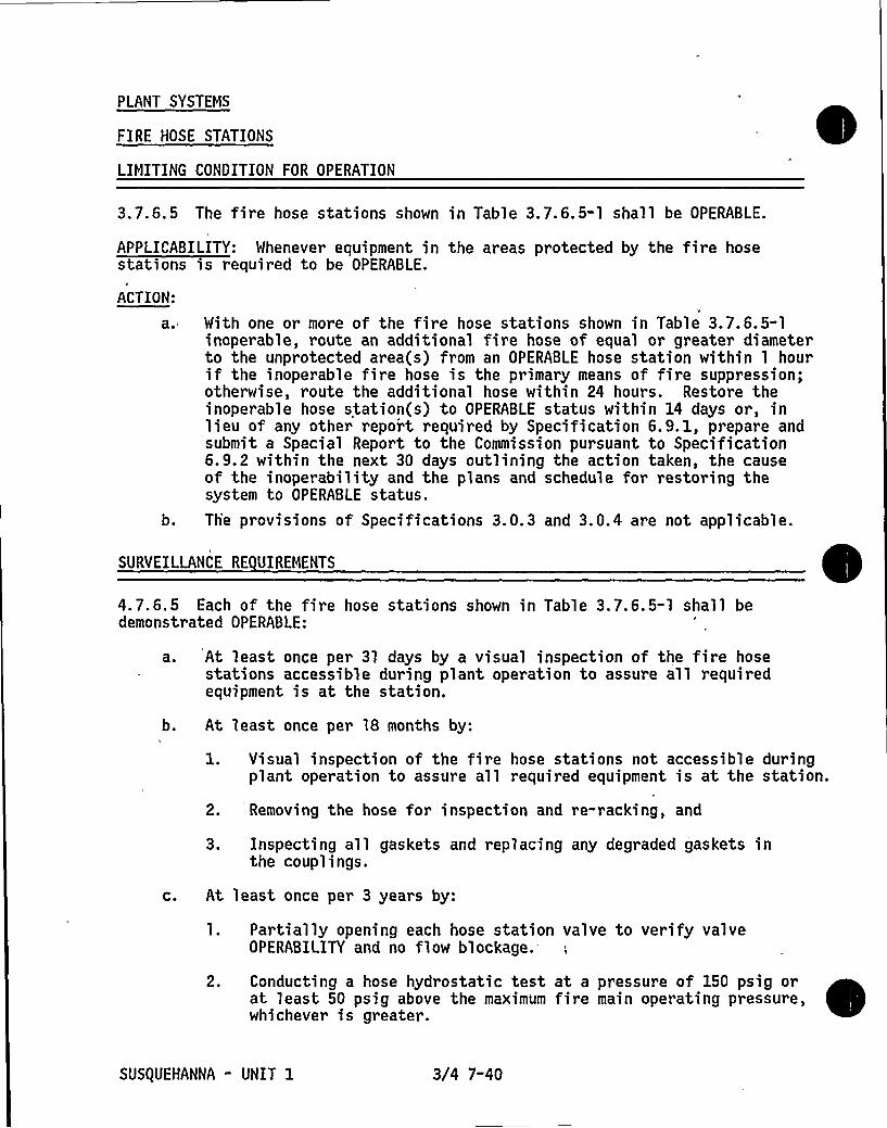
PLANT SYSTEMS
FIRE HOSE STATIONS
LIMITING CONDITION FOR OPERATION
3.7.6.5 The fire hose stations shown in Table 3.7.6.5-1 shall be OPERABLE.
APPLICABILITY: Whenever equipment in the areas protected by the fire hosestations is required to be OPERABLE.
ACTION:
a
b.
With one or more of the fire hose stations shown in Table 3.7.6.5-1inoperable, route an additional fire hose of equal or greater diameterto the unprotected area(s) from an OPERABLE hose station within 1 hourif the inoperable fire hose is the primary means of fire suppression;otherwise, route the additional hose within 24 hours. Restore theinoperable hose station(s) to OPERABLE status within 14 days or, inlieu of any other report required by Specification 6.9.1, prepare andsubmit a Special Report to the Commission pursuant to Specification6.9.2 within the next 30 days outlining the action taken, the causeof the inoperability and the plans and schedule for restoring thesystem to OPERABLE status.Th'e provisions of Specifications 3.0.3 and 3.0.4 are not applicable.
SURVEILLANCE RE UIREMENTS
4.7.6 ' Each of the fire hose stations shown in Table 3.7.6.5-1 shall bedemonstrated OPERABLE:
b.
C.
At least once per 31 days by a visual inspection of the fire hosestations accessible during plant operation to assure all requiredequipment is at the station.
At least once per 18 months by:
l. Visual inspection of the fire hose stations not accessible duringplant operation to assure all required equipment is at the station.
2. Removing the hose for inspection and re-racking, and
3. Inspecting all gaskets and replacing any degraded gaskets inthe couplings.
At least once per 3 years by:
1. Partially opening each hose station valve to verify valveOPERABILITY and no flow blockage.-
2. Conducting a hose hydrostatic test at a pressure of 150 psig orat least 50 psig above the maximum fire main operating pressure,whichever is greater.
SUSQUEHANNA - UNIT 1 3/4 7-40

El.El.
. El.El.El.El.El.
714'-0"729'-0"729'"0"754'-0"754'-0"771'-0"771'-0"
LOCATIONS
Control StructureEl. 697'"0"El. 697'-0"
714'-0"
TABLE 3. 7. 6. 5-1
FIRE HOSE STATIONS
COLUMN
L-26L-32L-26L-31L-25. 9L-32. 1L-26L-32L-26L-31
HOSE RACKNUMBER
1HR"1712HR-1711HR-1622HR-1621HR-1582HR-1581HR-1362HR-1361HR-1252HR-125
b.645'-0"645'-0"645'"0"645'-0"645'-0"645'-0"670'-0"670'"0"670'-0"683'"0"683'-0"683'"0"719'"1"719'-1"719'-1"719'"1"719'"1"749'-1"749'-1"
749'-r'l.
El.El.El.El.El.El.El.El.El .
El.El.El.El ~
El.El.El.El.El.El.
Reactor BuildingR-29P-20. 6U-22R-37. 4U-30. 5R"30Q-27. 5Q-29T-22Q-27. 5Q-20. 6T-22Q-27.5S-27.5Q-20.6T"20.6T-23. 5S-27. 5Q-20. 6T-20. 6
1HR-2711HR-2721HR-2732HR-2712HR-2722HR-2731HR-2611HR-262
'HR-263
1HR-2511HR"2521HR-2531HR-2411HR-2421HR-2431HR-2441HR" 2451HR-2311HR-2321HR"233
SUSQUEHANNA - UNIT 1 3/4 7-41

PLANT SYSTEMS
YARD FIRE HYDRANTS AND HYDRANT HOSE HOUSES
LIMITING CONDITION FOR OPERATION0
3.7.6.6 Yard fire hydrants 1FH122 and 1FH104 and associated hydrant hose housesshall be OPERABLE.
APPLICABILITY: Whenever equipment in the areas protected by the yard firehydrants is required to be OPERABLE.
ACTION:
a. With yard fire hydrants 1FH122 and/or 1FH104 and/or associated hydranthose houses inoperable, route sufficient additional lengths of firehose of equal or greater diameter located in adjacent OPERABLE hydranthose house(s) to provide service to the unprotected area(s) withinone hour. Restore the inoperable hydrant(s) and/or hose house(s) toOPERABLE status within 14 days or, in lieu of any other reportrequired by Specification 6.9. 1, prepare and submit a Special Reportto the Commission pursuant to Specification 6.9.2 within the
next'0
days outlining the action taken, the cause of the inoperabilityand the plans and schedule for restoring the system to OPERABLE status.
b. The provisions of Specifications 3.0.3 and 3.0.4 are not applicable.
SURYEILLANCE RE UIREMENTS
4.7.6.6 Yard fire hydrants 1FH122 and 1FH104 and associated hydrant hose housesshall be demonstrated OPERABLE:
a.
C.
At least once per 3l days by visual inspection of the hydrant hosehouses to assure all required equipment is at the hose houses.
At least once per 6 months, during March, April or May and duringSeptember, October or November, by visually inspecting the yard firehydrants and verifying that the hydrant barrels are dry and that thehydrants are not damaged.
At least once per 12 months by:
1. Conducting hose hydrostatic tests at a pressure of 150 psig orat least 50 psig above the maximum fire main operating pressure,whichever is greater.
2. Replacement of all degraded gaskets in couplings.
3. Performing a flow check of each hydrant.
SUSQUEHANNA " UNIT 1 3/4 7-42

PLANT SYSTEMS
3/4.7.7 FIRE RATED ASSEMBLIES
LIMITING CONDITION FOR OPERATION
3.7.7 All fire rated assemblies, including walls, floor/ceilings, cable trayenclosures and other fire barriers separating safety related fire areas orseparating portions of redundant systems important to safe shutdown within afire area, and all sealing devices in fire rated assembly penetrations,including fire doors, fire windows, fire dampers, cable and piping penetrationseals and ventilation seals shall be OPERABLE.
APPLICABILITY: At al 1 times.
ACTION:
a. With one or more of the above required fire rated assemblies and/orsealing devices inoperable, within one hour establish a continuousfire watch on at least one side of the affected assembly and/orsealing device or verify the OPERABILITY of fire detectors on atleast one side of the inoperable fire assembly and/or sealing deviceand establish an hourly fire watch patrol; Restore the inoperablefire rated assembly(s) and/or sealing device(s) to OPERABLE statuswithin 7 days or, in lieu of any other report required by Specifica-tion 6.9. 1, prepare and submit a Special Report to the Commissionpursuant to Specification 6. 9. 2 within the next 30 days outliningthe action taken, the cause of the inoperable fire rated assembly(s)and/or sealing device(s) and plans and schedule for restoring thefire fire rated assembly(s) and/or sealing device(s) to OPERABLEstatus.
b. The provisions of Specifications 3.0.3 and 3.0.4 are not applicable.
SURVEILLANCE RE UIREMENTS
4.7.7. 1 Each of the above required fire rated assemblies and sealing devicesshall be verified OPERABLE at least once per 18 months by performing a visualinspection of:
a ~
b.
The exposed surfaces of each fire rated assembly.
Each fire window, fire damper, and associated hardware.
C. At least 10 percent of each type of sealed penetration. If apparentchanges in appearance or abnormal degradations are found, a visualinspection of an additional 10 percent of each type of sealedpenetration shall be made. This inspection process shall continueuntil a 10 percent sample with no apparent changes in appearance orabnormal degradation is found.
SUSQUEHANNA - UNIT 1 3/4 7-43

PLANT SYSTEMS
SURVEILLANCE RE UIREMENTS Continued
-4.7.7.2 Each, of the above required fire doors shall be verified OPERABLE by:
a ~ Verifying the position of each closed fire door at least once per24 hours.
b.
c;
d.
e.
Verifying that doors with automatic hold-open and release mechanismsare free of obstructions at least once per 24 hours.
Verifying the position of each locked closed fire door at least onceper 7 days.
Verifying the OPERABILITY of the fire door supervisi'on system byperforming a CHANNEL FUNCTIONAL TEST at least once per 31 days.
Inspecting the automatic hold-open, release and closing mechanismand latches at least once per 6 months.
SUSQUEHANNA " UNIT 1 3/4 7-44

~ ~
PLANT SYSTEMS
3/4.7.8 MAIN TURBINE BYPASS SYSTEM
LIMITING CONDITION FOR OPERATION
3.7.8 The main turbine bypass system shall be OPERABLE.
APPLICABILITY: OPERATIONAL CONDITION 1.
ACTION: With the main turbine bypass system inoperable, restore the systemto OPERABLE status within 2 hours or determine MCPR to be equal to or greaterthan the applicable MCPR limit without bypass within one hour or take theACTION required by Specification 3. 2.3.
SURVEILLANCE RE UIREMENTS
4.7.8 The main turbine bypass system shall be demonstrated OPERABLE at leastonce per:
a.
b.
7 days by cycling each turbine bypass valve through at least onecomplete cycle of full travel, and
18 months by:
1. Performing a system functional test which includes simulatedautomatic actuation and verifying that each automatic valveactuates to its correct position.
2. Demonstrating TURBINE BYPASS SYSTEM RESPONSE TIME to be lessthan or equal to 0.30 seconds.
SUSQUEHANNA - UNIT 1 3/4 7-45

h
,t
II ',

3/4.8 ELECTRICAL POWER SYSTEMS
3/4.8.1 A.C. SOURCES
A.C. SOURCES - OPERATING
LIMITING CONDITION FOR OPERATION
3. 8. l. 1 As a minimum, the following A.C. electrical power sources shall beOPERABLE:
a 0
b.
Two physically independent circuits between the offsite transmissionnetwork and the onsite Class lE distribution system, and
Four separate and independent diesel generators", each with:
2.
3.
Separate engine mounted day fuel tanks containing a minimum of325 gallons of fuel,A separate fuel storage system containing a minimum of47,570 gallons of fuel, and
A separate fuel transfer pump.
APPLICABILITY: OPERATIONAL CONDITIONS 1, 2, and 3.
ACTION:
a. With either one offsite circuit or one diesel generator of the aboverequired A.C. electrical power sources inoperable, demonstrate theOPERABILITY of the remaining A.C. sources by performing SurveillanceRequirements 4.8. l. l. 1. a within one hour and 4.8. l. l. 2.a.4, for onediesel generator at a time, within four hours and at least once per8 hours'herafter; restore at least two offsite circuits and fourdiesel generators to OPERABLE status within 72 hours or be in atleast HOT SHUTDOWN within the next 12 hours and in COLD SHUTDOWN
within the following 24 hours.
b. With one offsite circuit and one diesel generator of the above requiredA.C. electrical power sources inoperable, demonstrate the OPERABILITYof the remaining A.C. sources by performing Surveillance Require-ments 4.8, l. l. l. a within one hour and 4.8. 1. 1. 2. a.4, for one dieselgenerator at a time, within three hours and at least once per 8 hoursthereafter; restore at least one of the inoperable A. C. sources toOPERABLE status within 12 hours or be in at least HOT SHUTDOWN withinthe next 12 hours and in COLD SHUTDOWN within the following 24 hours.Restore at least two offsite circuits and four diesel generators toOPERABLE status within 72 hours from time of initial loss or be inat least HOT SHUTDOWN within the next 12 hours and in COLD SHUTDOWN
within the following 24 hours.
SUSQUEHANNA " UNIT 1 3/4 8-1

ELECTRICAL POMER SYSTEMS
LIMITING CONDITION FOR OPERATION Continued
ACTION (Continued)
C. With one diesel generator of the above required A.C. electrical powersources inoperable, in addition to ACTION a or b, above, verifywithin 2 hours that all required systems, subsystems, trains,components and devices that depend on the remaining diesel generatorsas a source of emergency power are also OPERABLE; otherwise, be inat least HOT SHUTDOWN within the next 12 hours and in COLD SHUTDOWN=within the following 24 hours.
d. With two of the above required offsite circuits inoperable, demonstratethe OPERABILITY of four diesel generators by performing SurveillanceRequirement 4.8. 1. 1. 2. a.4, for one diesel generator at a time, withinfour hours and at least once per 8 hours thereafter, unless the dieselgenerators are already operating; restore at least one of the inoper-able offsite circuits to OPERABLE status within 24 hours or be in atleast HOT SHUTDOWN within the next 12 hours. With only one offsitecircuit restored to OPERABLE status, restore at least two offsitecircuits to OPERABLE status within 72 hours from time of initial lossor be in at least HOT SHUTDOMN within the next,l2 hours and in COLDSHUTDOWN within the fol.lowing 24 hours.
e. With two or more of the above required diesel generators inoperable,demonstrate the OPERABILITY of the remaining A.C. sources byperforming Surveillance Requirement 4.8. 1. 1. 1. a within one hour and4.8. 1. 1. 2. a.4, for one diesel generator at a time, within 2 hours,and at least once per 8 hours thereafter; restore at least three ofthe diesel generators to OPERABLE status within 2 hours or be in atleast HOT SHUTDOWN within the next 12 hours and in COLD SHUTDOWNwithin the following 24 hours. Restore four diesel generators toOPERABLE status within 72 hours from time of initial loss or be inat least HOT SHUTDOWN within the next 12 hours and in COLD SHUTDOWNwithin the following 24 hours.
SUS(UEHANNA - UNIT 1 3/4 8-2

ELECTRICAL POWER SYSTEMS
SURVEILLANCE RE UIREMENTS
e 4.8. 1. l. 1 Each of the above required independent circuits between the offsite "
transmission network and the onsite Class lE distribution system shall be:
a ~ Determined OPERABLE at least once per 7 days by verifying correctbreaker alignments and indicated. power availability, and
b. Demonstrated OPERABLE at least once per 18 months during shutdown bytransferring, manually and automatically, unit power supply from thenormal circuit to the alternate circuit.
4.8.1.1.2OPERABLE:
Each of the above required diesel generators shall be demonstrated
a ~ In accordance with the frequency specified in Table 4.8. l. 1.2-1 on aSTAGGERED TEST BASIS by:
l. 'erifying the fuel level in the engine-mounted day fuel tank.
2. Verifying the fuel level in the fuel storage tank.
3; Verifying the fuel transfer pump starts and transfers fuel fromthe storage system to the engine-mounted day fuel tank.
4. Verifying the diesel starts from ambient condition and accel-erates to at least 600 rpm in less than or equal to 10 seconds.The generator voltage and frequency shall be 4160 2 400 voltsand 60 + 3.0 Hz within 10 seconds after the start signal. Thediesel generator shall be started for this test by using one ofthe following signals:
a)b)c)
d)
Manual.Simulated loss of offsite power by itself.Simulated loss of offsite power in conjunction with an ESFactuation test signalsAn ESF actuation test signal by itself.
b.
5. Verifying the diesel generator is synchronized, loaded to greaterthan or equal to 4000 kw in less than or equal to 90 seconds,and operates with this load for at least 60 minutes.
6. Verifying the diesel generator is aligned to provide standbypower to the associated emergency busses.
7. Verifying the pressure in all diesel generator air start receiversto be greater than or equal to 240 psig.
At least once per 31 days and after each operation of the diesel wherethe period of operation was greater than or equal to 1 hour by checkingfor and removing accumulated water from the engine-mounted day fueltanks.
SUS(UEHANNA - UNIT 1 3/4 8-3

ELECTRICAL POWER SYSTEMS
SURVEILLANCE RE UIREMENTS Continued)
C. At least once per 92 days and from new fuel oil prior to addition tothe storage tanks by verifying that a sample obtained in accordancewith ASTM-D270-1975 has a water and sediment content of less than orequal to .05 volume percent and a kinematic viscosity 8 40'C ofgreater than or equal to 1.3 but less than or equal to 2.4 for 1Doil or >1.9 but <4. 1 for 2D oil when tested in accordance withASTM-D975-77, and an impurity level of less than 2 mg. of insolublesper 100 ml. when tested in accordance with ASTM-D2274-70.
d. At least once per 18 months, during shutdown, by:
2 ~
3.
4.
5.
6.
Subjecting the diesel to an inspection in accordance withprocedures prepared in conjunction with its manufacturer'srecommendations for this class of standby service.Verifying the diesel generator capability to reject a load ofgreater than or equal to 1425 kw while maintaining voltage at4160 + 400 volts and frequency at 60 k 3.0 Hz.
Verifying the diesel generator capability to reject a load of4000 kw without tripping. The generator voltage shall notexceed 4560 volts during and following the load rejection.Simulating a loss of offsite power by itself, and:
a) Verifying deenergization of the emergency busses and loadshedding from the emergency busses.
b) Verifying the diesel generator starts on the auto-startsignal, energizes the emergency busses with permanentlyconnected loads within 10 seconds and operates for greaterthan or equal to 5 minutes while its generator is loadedwith the shutdown loads. After energization, the steadystate voltage and frequency of the emergency busses shallbe maintained at 4160 2 400 volts and 60 2 3. 0 Hz duringthis test.
Verifying that on an ECCS actuation test signal, without lossof offsite power, the diesel generator starts on the auto-startsignal and operates on standby for greater than or equal to5 minutes. The generator voltage and frequency shall be 4160 +400 volts and 60 a 3.0 Hz within 10 seconds after the auto-startsignal; the steady state generator voltage and frequency shallbe maintained within these limits during this test.Verifying that on a simulated loss of the diesel generator, withoffsite power not available, the loads are shed from theemergency busses and that subsequent loading of the dieselgenerator is in accordance with design requirements.
SUSQUEHANNA - UNIT 1 3/4 8-4

ELECTRICAL POMER SYSTEMS
SURVEILLANCE RE UIREMENTS Continued
7. . Simulating a loss of offsite power in conjunction with an ECCSactuation test signal, and:
a) Verifying deenergization of the emergency busses and loadshedding from the emergency busses.
Ih
b) Verifying the diesel generator starts on the auto-startsignal, energizes the emergency busses with permanentlyconnected loads within 10 seconds, energizes the auto-connected loads through the load timers and operates forgreater than or equal to 5 minutes while its generator is,loaded with the emergency loads. After energization, thesteady state voltage and frequency of the emergency bussesshall be maintained at 4160 2 400 volts and 60 a 3.0 Hzduring this test.
c) Verifying that all automatic die'sel generator trips, exceptengine overspeed, generator differential and engine lowlube oil pressure, are automatically bypassed upon loss ofvoltage on the emergency bus concurrent with an ECCSactuation signal.
8. Verifying the diesel generator operates for at least 24 hours.During the first 2 hours of this test, the diesel generator shallbe loaded to greater than or equal to 4700 kw and during theremaining 22 hours of this test, the diesel generator shall beloaded,to 4000 kw. The generator voltage and frequency shall
,be 4160 2 400 volts and 60 t 3.0 Hz within 10 seconds after thestart signal; the steady state generator voltage and frequencyshall be maintained within these limits during this test. Mithin5 minutes, after completing this 24-hour test, perform SurveillanceRequirement 4.8.1.1.2.d.4.b).*
9.
10.
Verifying that the auto-connected loads to each diesel generatordo not exceed the 2000-hour rating of 4700 kw.
Verifying the diesel generator's capability to:
a) Synchronize with the offsite power source while thegenerator is loaded with its emergency loads upon a simulatedrestoration of offsite power,
b) Transfer its loads to the offsite power source, and
c) Be restored to its standby status.
If Surveillance Requirement 4.8. 1. l. 2. d.4. b) is not satisfactorily completed,it is not necessary to repeat the preceding 24 hour test. Rather, the dieselgenerator may be operated at 4000 kw for one hour or until operating temper aturehas stabilized.
SUSQUEHANNA - UNIT 1 3/4 8"5

ELECTRICAL POWER SYSTEMS
SURVEILLANCE RE UIREMENTS (Continued
*12..
Verifying that with the diesel generator operating in a testmode and connected to its bus, a simulated ECCS actuation'ignaloverrides the test mode by (1) returning the diesel generatorto standby operation', and (2) automatically energizes theemergency loads with offsite power.
Verifying that with all diesel generator air start receiverspressurized to less than or equal to 240 psig and the com-pressors secured, the diesel generator starts at least 5 timesfrom ambient conditions and accelerates to. at least 600 rpmin less than or equal to 10 seconds.
13. Verifying that the fuel transfer pump transfers fuel trom eachfuel storage tank to the engine-mounted day tank of each dieselvia the installed cross connection lines.
14. Verifying that each diesel generator loading sequence timershown in Table 4.8.1. 1.2-2 is OPERABLE with its setpoint within+ lOX of its design setpoint.
e.
15. Verifying that the following diesel generator lockout featuresprevent diesel generator starting and/or, operation only whenrequired: ')
a) Engine overspeed.b) Generator differential.c) Engi'ne low lube oil pressure.
At least once per 10 years or after any modifications which couldaftect diesel generator interdependence by starting all dieselgenerators simultaneously, during shutdown, and verifying that alldiesel generators accelerate to at least 600 rpm in less than orequal to 13 seconds.
At least once per 10 years by:
1. Draining each fuel oil storage tank, removing the accumulatedsediment and cleaning the tank using a sodium hypochlorite orequivalent solution, and
2. Performing a pressure test'of those portions of the diesel fueloil system designed to Section III, subsection ND of the ASMECode. in accordance with ASME Code Section ll Article IWD-5000.
4.8.1.1.3 ~Re orts - A11 diesel generator failures, valid or non-valid, shallbe reported to the Commission pursuant to Specification 6.9. l. Reports ofdiesel generator failures shall include the information recommended inRegulatory Position C.3.b of Regulatory Guide l. 108, Revision 1, August 1977.If the number of failures in the last 100 valid tests, on a per nuclear unitbasis, is greater than or equal to 7, the report shall be supplemented toinclude the additional information recommended in Regulatory Position C.3.b ofRegulatory Guide 1.108, Revision 1, August 1977.
VEffective after first exceeding'5/ of RATED THERMAL POWER.
SUSt|UEHANNA " UNIT 1 3/4 8-6

TABLE 4. 8. 1 . 1. 2-1
DIESEL GENERATOR TEST SCHEDULE
Number of Failures inLast 100 Valid Tests" Test Fre uenc
At least once per 31 days
At least once per 14 days
At least once per 7 days
At least once per 3 days
, ')
Criteria for determining number of failures and number of validtests shall be in accordance with Regulatory Position C. 2. e ofRegulatory Guide l. 108, Revision 1, August 1977, where the last100 tests are determined on a per nuclear unit basis. For thepurposes of this test schedule, only valid tests conducted afterthe OL issuance dat'e shall be included in the computation of the"last 100 valid tests." Entry into this test schedule shall bemade at the 31 day test frequency.
SUSQUEHANNA - UNIT 1 3/4 8"7

TABLE 4.8.1.1.2-2UNIT 1 AND COMMON
DIESEL GENERATOR LOADING TIMERS,
DEVICE TAGNO.
K116A
K116B
K125A
K125B
62X-20104
62X-20204
62X1-20304
62X1-20404
62X2-20304
62X2-20404
62X3-20304
62X3-20404
62X-20310
62X-20410
62AX2-20108
62AX2-20208
62AX2-20303
62AX2-20403
62X-516
62X-526
62X-536
62X-546
62A-2010262A-2020262A-2030262A-20402
SUSQUEHANNA - UNIT 1
SYSTEM
CS pp 1A
CS pp 18
CS pp 1C
CS pp 1D
Emerg Switchgear Rm
cooler A &RHR SN pp H&Vfan A
Emerg Switchgear Rm
cooler B &RHR SN pp H&Vfan B
Control StructureChillwater System
Control StructureChillwater System
Control StructureChillwater System
Conti ol StructureChillwater System
Control StluctureChi llwater System
Control StructureChillwater System
Control StructureChillwater System
Control StructureChillwater System
Emerg SM
Emerg SM
Emerg SM
Emerg SM
DG Rm Exh Fan A
DG Rm Exh Fan B
DG Rm Exh Fan C
DG Rm Exh Fan D
RHR Pump 1ARHR Pump 1BRHR Pump 1CRHR Pump 1D
3/4 8-8
LOCATION
1C626
1C627
1C626
1C627
OC877A
OC877B
OC877A
OC877B
OC877A".'C8778'C877A
OC877B
OC876A'C876B
1A201
1A202
1A203
1A204
OB516
OB526
OB536
OB546
1A2011A2021A2031A204
TIMESETTING
10.5 sec
10.5 sec
10.5 sec
10.5 sec
60 sec
60 sec
3 min
3 min
3.5 min
3.5 min
60 sec
60 sec
3 Illin
3 min
55 sec
55 sec
55 sec
55 sec
2 min
2 min
2 min
2 Illin
3 sec3 sec3 sec3 sec

ELECTRICAL POWER SYSTEMS
LIMITING CONDITION FOR OPERATION
3.8.1.2 As a minimum, the following A.C. electrical power sources shall beOPERABLE:
a. One circuit between the offsite transmission network and the onsiteClass 1E distribution system, and
b. Two diesel generators with:
1. An engine mounted day fuel tank containing a minimum of325 gallons of fuel.
2. A fuel storage system containing a minimum of 47,570 gallons offuel.
3. A fuel transfer pump.
APPLICABILITY: OPERATIONAL CONDITIONS 4, 5 and ".
ACTION:
With less than the above required A.C. electrical power sourcesOPERABLE, suspend CORE ALTERATIONS, handling of ir radiatedfuel in the secondary containment, operations with a potentialfor draining the reactor vessel and,crane operations over thespent fuel pool when fuel assemblies are stored therein. Inaddition, when in OPERATIONAL CONDITION 5 with the water levelless than 22 feet above the reactor pressure vessel flange,immediately initiate corrective action to restore the requiredpower sources to OPERABLE status as soon as practical:
b. The provisions of Specification 3.0.3 are not applicable.
SURVEILLANCE RE UIREMENTS
4..8. l. 2 At least the above required A. C. electrical power sources shall bedemonstrated OPERABLE per Surveillance Requirements 4.8. l. 1.1, 4.8. l. 1.2 and4. 8. 1. 1. 3, except for the requirement of 4.8. 1. l. 2. a. 5.
When handling irradiated fuel in the secondary containment.
SUSQUEHANNA - UNIT 1 3/4 8-9

ELECTRICAL POWERSYSTEMS'/4.8.2
D.C. SOURCES
D.C. SOURCES - OPERATING
LIMITING CONDITION FOR OPERATION
3.8.2. 1 As a minimum, the following D.C. electrical power sources shall beOPERABLE:
a.
b.
Division I, consisting of:1. Load group Channel "A" power source consisting
a) 125 volt DC battery bankb) Full capacity charger
2; Load group Channel "C" power source consistinga) 125 volt DC battery bankb) Full capacity charger
3. Load group "I" power source consisting of:a) 250 volt DC batteryb) Half-capacity chargers
4. Load group "I" power source consisting of:a) 2 24 volt DC battery bankb) Two half-capacity chargers
Division II, consisting of:1. Load group Channel "B" power source consisting
a) 125 volt DC battery bankb) Full capacity charger
2 ~ Load group Channel "D" power source consistinga) 125 volt DC battery bankb) Full capacity charger
3. Load group "II" power source consisting of:a) 250 volt DC battery bankb) Full capacity charger
4. Load group "II" power source consisting of:a) + 24 volt DC battery bankb) Two half-capacity chargers
of:1061010613
of1063010633
1D65010653A, 1D653B
106701D673, 1D674
of:106201D623
of:1064010643
1D66010663
1068010683, 10684
APPLICABILITY: OPERATIONAL CONDITIONS 1, 2, and 3
ACTION:
ao
b.
With one of the above required 125 volt or 250 volt DC load groupbattery banks inoperable, restore the inoperable battery bank toOPERABLE status within 2 hours or be in at least HOT SHUTDOWN withinthe next 12 hours and in COLD SHUTDOWN within the following 24 hours.
With one of the above required t 24 volt DC load group battery banksinoperable, declare the associated equipment inoperable and takethe, ACTION required by the applicable Specification(s).
SUS(UEHANNA - UNIT 1 3/4 8-10

ELECTRICAL POWER SYSTEMS
LIMITING CONDITION FOR OPERATION (Continued
ACTION: (Continued)
C. Mith one of the above required chargers inoperable, demonstrate theOPERABILITY of,its associated battery bank by performingSurveillance Requirement 4.8. 2. l. a. 1 within one hour and at l'eastonce per 8 hours thereafter. If any Category A limit in Table4.8.2.1-1 is not met, declare the battery inoperable.
SURVEILLANCE RE UIREMENTS
4.8.2. 1 Each of the above required + 24-volt, 125-volt and 250-volt batteriesand chargers shall be demonstrated OPERABLE:
a. At least once per 7 days by verifying that:
1. The parameters in Table 4.8.2. 1-1 meet the Category A limits,and
2. Total battery terminal voltage is greater than or equal to 26,129, 258-volts on float charge.
b. At least once per 92 days and within 7 days after a battery dischargewith battery terminal voltage below 22, 110 or 220 volts, as applicable,or battery overcharge with battery terminal voltage above 30, 150 or300 volts, as applicable, by verifying that:
2.
3.
The parameters in Table 4.8.2. 1-1 meet the Category B limits,There is no visible corrosion at either terminals or connectors,or the connection resistance of these items is less than150 x 10- ohms, and
The average electrolyte temperature of 4, 10 'or 20, as applicable,of connected cells for the 24, 125 and 250 volt batteries is above60 F.
SUSQUEHANNA " UNIT 1 3/4 8"ll

ELECTRICAL POWER SYSTEMS
SURVEILLANCE RE UIREMENTS (Continued)
c. At least once per 18 months by verifying that:
1. The cells, cell plates and battery racks show no visual indicationof physical damage or'abnormal deterioration,
2. The cell-to-cell and terminal connections are clean-, tight, freeof corrosion and coated with anti-corrosion material,
3. The resistance of each cell-to-cell and terminal connection of each125-volt and 250-volt battery is less than or equal to 150 x 10-eohms, and
4. The battery charger, for at least 4 hours, will supply at least:
a) For the + 24-volt batteries, 25 amperes at a minimum of25.7 volts.
b) For the 125-volt batteries, 100 amperes, at a minimum of127.8 volts.
c) For the 250-volt batteries, 300 amperes at a minimum of255.6 volts.
d. At least once per 18 months, during shutdown, by verifying that either:
1. The battery capacity is adequate to supply and maintain inOPERABLE status all of th'e actual emergency loads for the designduty cycle when the battery is subjected to a battery servicetest, or
2. The battery capacity is adequate to supply a dummy load of thefollowing profile, which is verified to be greater than theactual emergency loads, while maintaining the battery terminalvoltage greater than or equal to + 21, 105 or 210 volts, asapplicable.a) For + 24-volt battery banks 10670, 10670-1, 1D680 and
1D680-1, 9.37 amperes for the entire 4 hour test.b) For 125-volt batteries:
1) Channel A battery 1D612:325 amperes for 60 seconds107 amperes for the remainder of the 4 hour test
2) Channel "B" battery 1D622:318 amperes for 60 seconds100 amperes for the remainder of the 4 hour test
3) Channel "C" battery 1D632:340 amperes for 60 seconds121 amperes for the remainder of the 4 hour test
4} Channel "D" battery 1D642:323 amperes for 60 seconds104 amperes for the remainder of the 4 hour test.
SUS(UEHANNA " UNIT 1 3/4 8"12

ELECTRICAL POWER SYSTEMS
SURVEILLANCE RE UIREMENTS (Continued
c) For 250-volt batteries:
1) Battery bank 10650:1091 amperes for 60 seconds
567 amperes for 29.0 minutes113 amperes for 60.0 minutes
24 amperes for 150.0 minutes
2) Battery bank 10660:1314 amperes for 60 seconds465 amperes for 60 seconds365 amperes for 28.0 minutes323 amperes for 15.0 minutes185 amperes for 195.0 minutes
e. At least once per 60 months, during shutdown, by verifying that thebattery capacity is at least 80K of the manufacturer's rating whensubjected to a performance discharge test. Once per 60 month interval,this performance discharge test may be performed in lieu of the batteryservice test.
Annual performance discharge tests of battery capacity shall be givento any battery that shows signs of degradation or has reached 85K ofthe service life expected for the application. Degradation isindicated when the battery capacity drops more than 10K of ratedcapacity from its average on previous performance tests, or is below90K of the manufacturer's rating.
SUSQUEHANNA - UNIT 1 3/4 8-13

ELECTRICAL POWER SYSTEMS
TABLE 4.8.2.1-1
BATTERY SURVEILLANCE RE UIREMENTS
CATEGORY A( ) CATEGORY B( )
Parameter Limits for eachdesignated pilotcell
Limits for eachconnected cell
Allowablevalue for eachconnected cell
ElectrolyteLevel
Float Voltage
>Minimum levelindication mark,and < >4" abovemaximum levelindication mark
> 2.13 volts
>Minimum levelindication mark,and < >4" abovemaximum levelindication mark
> 2.13 volts( )
> 1.195
Above top ofplates,and notoverflowing
> 2.07 volts
Not more than.020 below theaverage of allconnected cells
Specifi~ )ravity al. 200
Average of allconnect~))cells> 1.205
Average of allconnects))cells
1 195
(a} Corrected for electrolyte temperature andlevel.'b)
Or battery charging current is less than 0.01, O.l and 0.25 amperes forthe L24, 125 and 250 volt batteries, respectively, when on float charge.
(c) May be corrected for average electrolyte temperature.(1) For any Category A parameter(s) outside the limit(s) shown, the battery
may be considered OPERABLE provided that within 24 hours all the Category B
measurements are taken and found to be within their allowable values, andprovided all Category A and B parameter(s) are restored to within limitswithin the next 6 days.
(2) ,For any Category B parameter(s) outside the limit(s) shown, the batterymay be considered OPERABLE provided that the Category B parameters arewithin their allowable values and provided the Category B parameter(s)are restored to within limits within 7 days.
(3) Any Category B parameter not within its allowable value indicates aninoperable battery.
SUS(UEHANNA " UNIT 1 3/4 8-14

ELECTRICAL POWER SYSTEMS
~ ~D.C. SOURCES - SHUTDOWN
LIMITING CONDITION FOR OPERATION
3.8.2.2 As a minimum, Division I or Division II of the D.C. electrical powersources shall be OPERABLE with:
b.
Divi
2.
3.
Divi
2.
3.
4.
sion I consisting of:Load group Channel "A" power source, consistinga) 125 volt DC battery bankb) Full capacity chargerLoad group Channel "C" power source, consistinga) 125 volt DC battery bankb) Full capacity chargerLoad group "I" power source, consisting of:a) 250 volt DC battery bankb) Half-capacity ch'argers
Load group "I" power source, consisting of:a) a 24 volt DC battery bankb) Two half-capacity chargers
sion II consisting of:Load group Channel "B" power source, consistinga) 125 volt DC battery bankb) Full capacity chargerLoad group Channel "D" power source, consistinga) 125 volt DC battery bankb) Full capacity chargerLoad group "II" power source, consisting of:a) 250 volt DC battery bankb) Full capacity chargerLoad group "II" power source, consisting of:a) a 24 volt DC battery bankb) Two half-capacity chargers
of:1D6101D613
of:1D6301D633
1D6501D653A, 1D653B
1D6701D673, 1D674
of:1D6201D623
of:1D6401D643
1D6601D663
1D6801D683, 1D684
APPLICABILITY: OPERATIONAL CONDITIONS 4, 5, and ".
ACTION:
a ~
b.
With less than the above required 125 volt and/or 250 volt DC loadgroup battery banks OPERABLE, suspend CORE ALTERATIONS, handling ofirradiated fuel in the secondary containment and operations with apotential for draining the reactor vessel.With the above required + 24 volt D.C. load group battery banksinoperable, declare the associated equipment inoperable and takethe ACTION required by the applicable Specification(s).
SUS(UEHANNA - UNIT 1 3/4 8-15

ELECTRICAL POWER SYSTEMS
LIMITING CONDITION FOR OPERATION Continued)
ACTION: (Continued)
C. With the above required charger(s) inoperable, demonstrate theOPERABILITY of the associated battery by performing SurveillanceRequirement 4. 8. 2. l. a. 1 within one hour and at least once per 8 hoursthereafter. If any Category A limit in Table 4.8.2. 1-1 is not met,declare the battery inoperable.
d. The provisions of Specification 3.0.3 are not applicable.
SURVEILLANCE RE UIREMENTS
4.8. 2. 2 At least the above required battery and charger shall be demonstratedOPERABLE per Surveillance Requirement 4.8.2. l.
SUSQUEHANNA - UNIT 1 3/4 8-16

ELECTRICAL POWER SYSTEMS
3/4.8.3 ONSITE POWER DISTRIBUTION SYSTEMS
DISTRIBUTION - OPERATING
LIMITING CONDITION FOR OPERATION
3.8.3. 1 The following power distribution system divisions shall be energizedwith tie'reakers open both between redundant buses within the unit andbetween units at the same station:
2.d) Load group 208/120 volt A.C. instrument panelsDivision II, consisting of:a) Load group Channel"B", consisting of:
1) 4160 volt A.C. switchgear bus2) 480 volt A.C. load center3) 480 volt A.C. motor control center
b) Load group Channel "D",'onsisting of:1) 4160 volt A. C. switchgear bus2) 480 volt A.C. load center
'3) 480 volt A.C. motor control centerc) Load group 480 volt A.C. motor control centers
.A.C. power distribution:1. 'ivision I, consisting of:
a) Load group Channel "A", consisting of:1) 4160 volt A.C. switchgear bus2) 480 volt A.C. load center3) 480 volt A.C. motor control center
b) Load group Channel "C",, consisting of:1) 4160 volt A.C. switchgear bus2) 480 volt A.C. load center3) 480 volt A.C. motor control center
c) Load group 480 volt A.C. motor control centers
1A2011B210OB516
1A2031B230OB536OB517,18216,18217,1B219lY216,
1A2021B220OB526
1A2041B240OB546OB527,
OB1361B2361B237
1Y236
OB146
b.d) Load group 208/120 volt A.C. instrument panels
D.C. power distribution:1. Division I, consisting of:
a) Load group Channel "A", consisting of:1) 125 volt DC buses2) Fuse box
b) Load group Channel "C", consisting of:1)'25 volt DC buses2) Fuse 'box
c) Load group "I", consisting of:1) 250 volt DC buses2) Fuse box
d) Load group "I", consisting of:1) a 24 volt DC buses
. 2) Fuse box
1B226,1B227,1B229lY226,
1B2461B247
1Y246
10612,10611
10632,1D631
1D634
10652, 1D2541D651
1D6721D671
SUSQUEHANNA - UNIT 1 3/4 8"17

ELECTRICAL POWER SYSTEMS
LIMITING CONDITION FOR OPERATION Continued
ACTION: (Continued)
D.C. power distribution: (Conti nued)
2. Division II, consisting of:
a)
b)
c)
d)
Load group Channel "B" consisting of:,1) 125 volt DC buses2) Fuse box
Load group Channel "D" consisting of1) 125 volt DC buses2) Fuse box
Load group "II" consisting of:1) 250 volt DC buses2) Fuse box
Load group "II" consisting of.;1) + 24 volt DC buses2) Fuse box
10622, 1D62410621
1D642, 1D6441D641
10622, 1D264, 1D2741D661
106821D681
APPLICABILITY: OPERATIONAL CONDITIONS 1, 2 and 3.
ACTION:
a ~
b.
With one of the above required A.C. distribution system load groupsnot energized, re-energize the load group within 8 hours or be in atleast HOT SHUTDOWN within the next 12 hours and in COLD SHUTDOWN withinthe following 24 hours.
With one of th'e above required D.C. distribution system load groups notenergized, re-energize the load group within 2 hours or be in atleast HOT SHUTDOWN 'within the next 12 hours and in COLD SHUTDOWNwithin the following.
SURVEILLANCE RE UIREMENTS
4.8.3. 1 Each of the above required power distribution system load groupsshall be determined energized at least once per 7 days by verifying correctbreaker alignment and voltage on the busses/MCCs/panels.
SUSQUEHANNA — UNIT 1 3/4 8-18

ELECTRICAL POWER SYSTEMS
DISTRIBUTION - SHUTDOWN
LIMITING CONDITION FOR OPERATION
3.8.3.2 As a minimum, the following power distribution system divisions shallbe energized:
a. For A.C. power distribution, Division I or Division II with:
1. Division I consisting of:
a) Load group Channel "A", consisting of:1) 4160 volt A.C. switchgear bus2) 480 volt A. C. 1 oad center3) 480 volt A.C. motor control center
b) Load group Channel "C", consisting of:1) 4160 volt A.C. switchgear bus2) 480 volt A.C. load center3) 480 volt A.C. motor control center
c) Load group 480 volt A.C. motor control centers
1A2011B210OB516
1A2031B230OB536
OB517, OB1361B216, 1B2361B217, 182371B219
d) Load group 208/120 volt A.C. instrument panels lY216, lY236
2. Division II consisting of:
a) Load group Channel"B", consisting of:1) 4160 volt A.C. switchgear bus2) 480 volt A.C. load center3) 480 volt A.C. motor control center
b) Load group Channel "D", consisting of:1) 4160 volt A.C. switchgear bus
')
480 volt A.C. load center3) 480 volt A.C. motor control center
c) Load group 480 volt A.C. motor control centers
1A20218220OB526
lA2041B240OB546
OB527, OB1461B226, 1B2461B227, 1B2471B229
d) Load group 208/120 volt A.C. instrument panels 1Y226, 1Y246
SUS(UEHANNA " UNIT 1 3/4 8-19

ELECTRICAL POWER SYSTEMS
LIMITING CONDITION FOR OPERATION Continued
b. For D.C. power distribution, Division I or Division 2, with:
1. Division I consisting of:
a) Load group Channel "A", consisting of:1) 125 volt DC buses2) Fuse box
10612, 1D6141D611
b)
c)
d)
Load group Channel "C", consisting of:1) 125 volt DC buses2) Fuse box
Load group "I", consisting of:1) 250 volt DC buses2) Fuse box
Load group "I", consisting of:1) 2 24 volt DC buses2) Fuse box
1D632, 106341D631
1D652, 1D2541D651
1D67210671
2. Division II consisting of:
a)
b)
c)
d)
Load group Channel "B", consisting of:1) 125 volt DC buses2) Fuse box
Load group Channel "D", consisting of:1) 125 volt DC buses2) Fuse box
Load group "II", consisting of:1) 250 volt DC buses2) Fuse box
Load group "II", consisting of:1) 2 24 volt DC buses2) Fuse box
1D622, 1D6241D621
1D642, 1D6441D641
1D622, 1D264, 102741D661
1D6821D681
APPLICABILITY: OPERATIONAL CONDITIONS 4, 5 and ".
When handling irradiated fuel in the secondary containment.
SUS(UEHANNA " UNIT 1 ,3/4 8-20

ELECTRICAL POWER SYSTEMS
LIMITING CONDITION FOR OPERATION (Continued)
ACTION:
a ~
b.
C.
With less than Division I and/or Division II of the above required A.C.distribution system energized, suspend CORE ALTERATIONS, handlingof irradiated fuel in the secondary containment and operations witha potential for draining the reactor vessel.
With less than Division I and/or Division II of the above required D.C.distribution system energized, suspend CORE ALTERATIONS, handling orirradiated fuel in the secondary containment and operations with apotential for draining the reactor vessel.
The provisions of Specification,3.0. 3 are not applicable.h
SURVEILLANCE RE UIREMENTS
F
4.8.3.2. l At least the above required power distribution system divisionsshall be determined energized at least once -per 7 days by verifying correctbreaker alignment and voltage on the busses/MCCs/panels.
4.8.3.2. 2 The A. C. power distribution system swing bus automatic transfer .switch shall be demonstrated OPERABLE at least once per 31 days by actuatingthe load test switch or by disconnecting the normal power source 'to the transferswitch and verifying that swing bus automatic transfer is accomplished.
SUSQUEHANNA - UNIT 1 3/4 8-21

ELECTRICAL POWER SYSTEMS ,
3/4.8.4 ELECTRICAL E UIPMENT PROTECTIVE DEVICES
PRIMARY CONTAINMENT PENETRATION CONDUCTOR OVERCURRENT PROTECTIVE DEVICES
LIMITING CONDITION FOR OPERATION
3.8.4. 1 All primary containment penetration conductor overcurrent protectivedevices shown in,Table 3.8.4. 1-1 shall be OPERABLE.
APPLICABILITY: OPERATIONAL CONDITIONS 1, 2 and 3.
ACTION:
a. With one or more of the primary containment penetration conductorovercurrent protective devices shown in Table 3.8.4. 1-1 inoperable,declare the affected system or component inoperable, apply theappropriate ACTION statement for the affected system and remove theinoperable circuit breaker(s) from service by racking out the breakerwithin 72 hours; verify the inoperable breaker(s) to be racked outat least once per 7 days thereafter.
Otherwise, be in at least HOT SHUTDOWN within the next 12 hours andin COLD SHUTDOWN within the following 24 hours.
b. The provisions of Specification 3.0.4 are not applicable to 480 voltcircuits which have the inoperable circuit breaker(s) racked out.
SURVEILLANCE RE UIREMENTS
4.8.4. 1 Each of the primary containment penetration conductor overcurrentprotective devices shown in Table 3.8.4. 1-1 shall be demonstrated OPERABLE:
a. At least once per 18 months by:
1. Selecting and functionally testing a representative sample ofat least 10K of each type of lower voltage circuit breakers.Circuit breakers selected for functional testing shall be selectedon a rotating basis. For the lower voltage circuit breakersthe nominal trip setpoint and short circuit response 'times arelisted in Table 3.8.4. 1-1. Testing of these circuit breakersshall consist of injecting a current in excess of 120K of thebreaker's nominal setpoint and measuring the response time.The measured response time will be compared to the manufacturer'sdata to insure that it is less than or equal to a value specifiedby the manufacturer. Circuit breakers found inoperable duringfunctional testing shall be restored to OPERABLE status priorto resuming operation. For each circuit breaker found inoperableduring these functional tests, an additional representative sampleof at least 10K of all the circuit breakers of the inoperabletype shall also be functionally tested until no more failuresare found or all circuit breakers of that type have beenfunctionally,tested.
SUSQUEHANNA - UNIT 1 3/4 8-22

e ELECTRICAL POWER SYSTEMS
SURVEILLANCE RE UIREMENTS Continued)
2. By selecting and functionally testing a representative sampleof each type of fuse on a 'rotating basis. Each representativesample of fuses shall include at least lOX of all fuses of thattype. The functional test shall consist of a non-destructiveresistance measurement test which demonstrates that the fusemeets its manufacturer s design criteria. Fuses found inoperableduring these functional testing shall be replaced with OPERABLEfuses prior to resuming operation. For each fuse found inoperableduring these functional tests, an additional representative sampleof at least 10K of all fuses of that type shall be functionallytested until no more failures are found or all fuses of thattype have been functionally tested.
b. At least once per 60 months by subjecting each circuit breaker to aninspection and preventive maintenance in accordance with proceduresprepared in conjunction with its manufacturer's recommendations.
SUSQUEHANNA - UNIT 1 3/4 8-23

TABLE 3.8.4.1-1
PRIMARY CONTAINMENT PENETRATION CONDUCTOROVERCURRENT PROTECTIVE DEVICES
CIRCUIT BREAKER FRAMELOCATION TYPE" RATING/UL
a. T e 2 Molded Case Circuit Breakersl. 1B219022 HFB-M 150/30
TRIPSET POINT~Am eres
270
RESPONSETIME
(Mil 1 i-seconds/~Cc les
SYSTEMS OR
E UIPMENT POWERED
HVB311F031ARRP "A" DSCH VLV
2. 1B237043
3. 1B236052
4. 18236023
5. 1B236011
6. 1B236033
7. 1B23 6021
8. 18236032
9. 1B236042
10. 18236043
11. 18236082
12. 18236102
13. 18236053
14. 1B237072
HFB-M 150/30
HFB-M 150/30
HFB-M 150/3
HFB-M 150/30
HFB-M 150/30
HFB-M 150/30
HFB-M 150/30
HFB-M 150/30
HFB-M 150/30
HFB-M 150/30
HFB-M 150/3
HFB-M 150/5
HFB-M 150/5
270
215
250
220
175
180
150
160
150
45
25
NA
NA
NA
NA
HVB311F023A Recirc.PP "A" Suction
HVElllF009 RHR PumpSuction Shutoff
HV12603 ContainmentInst. CompressorSuet. Iso. Valve
1V413A - Drywel 1
Area Unit Cooler
18414A - Drywel 1
Area Unit Cooler
1V417A - Drywel 1
Area Unit Cooler
1V412A - Drywel 1
Area Unit Cooler
lV411A - DrywellArea Unit Cooler
lV416A - Drywel 1
Area Unit Cooler
lV415A - Drywel 1
Area Unit Cooler
HVB211F001 - ReactorHead Vent Valve
HVG331F001 - Reac.Wtr. Cl ean upinboard isolation
HVE821F016 - MainStm. Line Drain Inbd.Iso.
SUSQUEHANNA - UNIT 1 3/4 8-24

TABLE 3.8.4.1-1 (Continued)PRIMARY CONTAINMENT PENETRATION CONDUCTOR
OVERCURRENT PROTECTIVE DEVICES
16. 1B237073 HFB-M 150/10 60
TRIPCIRCUIT BREAKER FRAME SET POINT
LOCATION TYPE" RATING/UL ~Am eres)T e 2 Molded Case Circuit Breakers (Continued)
15. 1B219023 HFB-M 150/10 80
RESPONSETIME
(Nil1 i-seconds/~Cc1 ee
NA
SYSTEMS OR
E UIPMENT POWERED
HVB311F032A — RRP"A" Dsch Byps VlvHVE111F022 - ReacHeater Spray ShutoffInboard
17. 1B237082
18. 1B246011
19. 1B229022
20. 1B246022
21. 18246051
22. 1B246061
23. 1B229023
24. 1B246072
25. 1B246081
26. 1B246091
27. 1B246102
28. 1B246103
HFB-M 150/10
HFB-M 150/30
HFB-N 150/30
HFB-M 150/5
HFB-M 150/30
HFB-N 150/30
HFB-M 150/10
HFB-M 150/30
HFB-M 150/30
HFB-M 150/30
HFB-M 150/30
HFB-N 150/30
70
270
270
40
170
170
70
170
170
160
215
170
NA
NA
NA
NA
NA
NA
NA
HVE411F002 - HPCIStm. Supply InboardIso.HVB311F023B-Reactor Recirc PumpSuctionHVB311F031B-Reactor Recirc PumpDisch
HVE511F007 - RCICInbrd SteamLine 150
IV417B - Drywel 1
Area Unit Clr Fan
IV414B - DrywellArea Uni t Cl r Fan
HVB311F032B - RRP"B" Dsch Byps VlvIV415B - Drywel 1
Area Unit Clr Fan
IV416B - Drywel1Area Unit Clr. Fan
IV411B — Drywe1 1
Unit Clr. Fan
IV413B - DrywellArea Unit Clr. Fan
IV412B - Drywel1Area Unit Clr.Fan
SUSQUEHANNA - UNIT 1 3/4 8-25

TABLE 3. 8. 4. 1-1 (Continued)PRIMARY CONTAINMENT PENETRATION CONDUCTOR
OVERCURRENT PROTECTIVE DEVICES
30,. 18246113
31. 18246062
32. 18246012
33. 18253063
HFB-M 150/3
HFB-M 150/3
HFB-M 150/3
HFB-M 150/5
20
18
TRIPCIRCUIT BREAKER FRAME SET POINT
LOCATION TYPE* RATING/UL ~Am eres
T e 2 Molded Case Circuit Breakers (Continued)29. 18246112 HFB"M 150/3 8
RESPONSETIME
(Milli-seconds/~Ccl es
SYSTEMS OR
E UIPMENT POWERED
HV8211F002 - ReactorHead Vent Valve
HV8211F005 - ReactorHeat Vent Valve
HV11346 — RBCCW
Containment Iso. Vlv.HV11345 — RBCCW
Containment Iso. Vlv.IP402A - DrywellFloor Draw SumpIIAII
P PIIAll
34. 18253053
35. 18263043
36. 18263053
37. 18263087
38. 18263071
39. 18253043
40. 18263072
41. 18253021
42, 18263023
HFB-M 150/5
HFB"M 150/3
HFB-M 150/3
HFB"M 150/3
HFB"M 150/5
HFB-M 150/5
HFB-M 150/5
HFB-M 150/50
HFB-M 150/50
27
10
12
20
20
20
480
480
NA
NA
NA
NA
NA
NA
HVG331F102 - LineSuction InsideControl Valve
HVG331F100 - RWCU
Loop "1A" SuctionHVG331F106 - RWCU
Loop "8" SuctionHVG331F101 - RWCU
Sys Vessel DrainLine Recirc.IP4023 - DrywellFloor Drain SumpIIAII PP
IIBll
1P403A — DrywellFloor Drain SumpI I 8 II
P umpIIAll
IP4038 - Drywel1Floor Drain SumpII8ll PP
HV8211FOllA FeedwaterInlet Shutoff Valve
HV8211F0118 - Feed-water Inlet ShutoffValve
HFB-M - West)nghouse Type HFB, magnetic only
SUSQUEHANNA - UNIT 1 3/4 8"26

TABLE 3.8.4.1-,1 (Continued)
PRIMARY CONTAINMENT PENETRATION CONOUCTOR
OVERCURRENT PROTECTIVE OEVICES
CIRCUIT BREAKERLOCATION
b. T e 3 Molded CoreCircuit Breakers
1. 18236103
2. 18246033
3. 1B226103
4. 18216092
TYPE""
KB-TM
KB-TM
KB-TM
KB-TM
FRAMERATING/UL
250/150
250/150
250/150
250/150
RESPONSETIME
(Mi1 1 i-seconds/~Ccl es
NA
NA
SYSTEMS OR
E UIPMENT POMEREO
IE440C - ContainmentRecomb Elect. Htr. Ass'y.
IE440D - ContainmentRecomb Elect. Htr. Ass'y.
IE440B - ContainmentRecomb Elect. Htr. Ass'y.
IE440A - ContainmentRecomb. Elect. Htr. Ass'y.
"KB-TM - Westinghouse Type KB, Thermal-magnetic
SUSQUEHANNA - UNIT 1 3/4 8-27

ELECTRICAL POWER SYSTEMS
MOTOR OPERATED VALVES THERMAL OVERLOAD PROTECTION
LIMITING CONDITION FOR OPERATION
3.8.4.2 The thermal overload protection of each valve shown in Table 3.8.4.2-1shall be bypassed continuously by an OPERABLE bypass device integral with themotor starter.
APPLICABILITY: Whenever the motor operated valve is required to be OPERABLE.
ACTION:
With thermal overload protection for one or more of the above required valvesnot bypassed continuously by an OPERABLE integral bypass device, take admin-istrative action to continuously bypass the thermal overload within 8
hours'r
declare the affected valve(s) inoperable and apply the appropriate ACTIONstatement(s) for the affected system(s).
SURVEILLANCE RE UIREMENTS
4.8.4.2. 1 The thermal overload protection for the above required valves shallbe verified to be bypassed continuously by an OPERABLE integral bypass deviceby verifying that the thermal overload protection is bypassed for those thermaloverloads which are continuously bypassed and temporarily placed in force onlywhen the valve motors are undergoing periodic or maintenance testing:
a. At least once per 18 months for those thermal overloads which arecontinuously'ypassed and temporarily placed in force only when thevalve motors are undergoing periodic or maintenance testing.
b. Following maintenance on the motor starter.
4.8.4.2.2 The thermal overload protection for the above required valveswhich are continuously bypassed and temporarily placed in force only when thevalve motors are undergoing periodic or maintenance testing shall be verifiedto be bypassed following periodic or maintenance testing during which thethermal overload protection was temporarily placed in force.
SUSQUEHANNA - UNIT 1 3/4 8-28

TABLE 3. 8. 4. 2-1
MOTOR OPERATED VALVES THERMAL OVERLOAD PROTECTION
VALVE NUMBERSYSTEM(S)AFFECTED
HV-01222AHV-01222BHV"01224A1HV-01224B1HV-01224A2HV-01224B2HV-01112AHV-01112BHV"01122AHV-01122BHV-01112CHV-01112DHV"01122CHV-011220HV-01110AHV-01110 B
HV-01120AHV"01120BHV-01110CHV-01110DHV-01120CHV-01120DHV-11210AHV-11210BHV"11215AHV-11215BHV-15766HV-15768HV-12603HV-11345HV-11313HV-11346HV"11314HV"E11-1F009HV"E11" 1F040HV-G33-1F001HV"E11-1F103AHV-E11-1F075AHV"Ell-1F048AHV-E11" 1F006C
RHRSW
RHRSW
RHRSW
RHRSW
RHRSW
RHRSW
ESW
ESW
ESW
ESW
ESW
ESW
ESW
ESW
ESW
ESW
ESW
ESW
ESW
ESW
ESW
ESW
RHRSW
RHRSW
RHRSW
RHRSW
Cont.Cont.Cont.Cont.Cont.Cont.Cont.RHR
RHR
RWCU
RHR
RHRSW
RHR
RHR
Isol.Isol.Isol.Isol.Isol.Isol.Isol .
SUS(UEHANNA - UNIT 1 3/4 8-29

TABLE 3.8.4. 2-1,(Continued)b 'I
MOTOR OPERATED VALVES THERMAL OVERLOAD PROTECTION
VALVE NUMBER
HV"Ell-,lF004CHV-Ell-1F015AHV-Ell-1F024AHV-E21-1F015AHV-E41-1F 002HV-B21-'1F016HV-Ell-1F022HV-Ell-1F010AHV-Ell-1FOllAHV-Ell-1F004AHV-Ell-1F006AHV-Ell-1F027AHV-Ell-1F007AHV-Ell-1F104AHV-Ell-1F026AHV-Ell-1F028AHV"Ell-1F047AHV-Ell-1F073AHV-Ell-1F003AHV-Ell-1F017AHV-E21-1F001AHV-E21-1F031AHV-E21-,1F004AHV-E21-1F005AHV-Ell-1F021AHV-Ell-1F016AHV-15112HV-E51-1F007HV-E51-'1F084HV-Ell-1F027BHV"Ell-'1F048BHB-Ell-1F015BHV-Ell-1F006BHV-Ell-1F021BHV-Ell-1F010BHV-Ell-1F011BHV-Ell-1F004BHV-Ell-1F007BHV-Ell-1F104BHV-Ell-1F026B
SYSTEM(S)AFFECTED
RHR
RHR
RHR
CS
HPCINSSRHR
RHR
RHR
RHR'HR
RHR
RHR
RHR
RHR
RHR
RHR
.RHRSWRHR
RHRCSCS
CSCS
RHR „
RHRRHR
RCICRCICRHR
RHR
RHR
RHR
RHR
RHRRHR
RHR
RHRRHR
RHR
SUSQUEHANNA - UNIT 1 3/4 8-30

TABLE 3.8.4. 2-1 (Continued)
MOTOR OPERATED VALVES THERMAL OVERLOAD PROTECTION
VALVE NUMBER
HV-Ell-'1F028BHV-Ell-1F047BHV"Ell-1F016BHV-Ell-1F003BHV-Ell-1F017BHV-E21-1F031BHV-E21-1F001BHV-Ell-1F103BHV"Ell-1F075BHV-Ell"1F0738HV-Ell-1F006DHV-Ell"1F004DHV"Ell"1F024BHV-E21-.1F015BHV"E21-1F004BHV-E21-1F005BHV"E32-1F001KHV-E32"1F002KHV-E32-1F003KHV-E32-1F001PHV-E32-1F002PHV-E32-1F003PHV-E32" 1F001BHV-E32-1F002BHV-E32-1F003BHV-E32-1F001FHV-E32-1F002FHV-E32"1F003FHV-E32-1F006HV"E32-1F007HV-E32-1F008HB-E32-1F009HV-E51-1F 045HV-E51" 1F012HV-E51-1F013HV-15012HV-E51-1F046HV-E51-1F008HV-E51" 1F031HV"E51" 1F010
SYSTEM(S)AFFECTED
RHR
RHR
RHR
RHR
RHR
CS
CS
RHR
RHRSW
RHRSW
RHR
RHR
RHR,CS
CS
CS
MSIVMSIVMSIVMSIVMSIVMSIVMSIVMSIVMSIVMSIVMSIVMSIVMSIVMSIVMSIVMSIVRCICRCICRCICRCICRCICRCICRCICRCIC
SUS(UEHANNA - UNIT 1 3/4 8-31

TABLE 3.8.4.2-1 (Continued)
MOTOR OPERATED VALVES THERMAL OVERLOAD PROTECTION
VALVE NUMBER
HV-E51-1F 019HV"E51-1F060HV-E51-1F059HV-E51-1F022HV-E51-1F062HV-E41-1F012HV-E41-1F001HV-E41" 1FOllHY-E41-1F006HV-E41-1F079HV-E41-1F059HV-E41" 1F004HV-E41" 1F003HV-E41-1F042HY-E41" 1F075HY-E41"1F008HY-E41" 1F007HV"E41" 1F066HV-G33"1F004HV-B21-1F019HV-Ell-1F008HV"Ell-1F023HV-Ell-1F049HV-B31-1F032AHV"B31-1F032BBHV-B31"1F031AHV-B31-1F031B
SYSTEM(S)AFFECTED
RCICRCICRCIC
.. RCICRCIC
'PCIHPCIHPCIHPCIHPCIHPCIHPCIHPCIHPCIHPCI
, .HPCIHPCIHPCIRWCU
NSSSRHR
RHR
RHR
RHR .
RHR
RHR
RHR
SUSQUEHANNA - UNIT 1 '/4 8-32

ELECTRICAL POWER SYSTEMS
REACTOR PROTECTION SYSTEM "ELECTRIC POWER MONITORING
LIMITING CONDITION FOR OPERATION
3,8.4.3 Two RPS electric power monitoring assemblies for each inserviceRPS MG set or alter nate power supply shall be OPERABLE.
APPLICABILITY: At al 1 times.
ACTION:
a. With one RPS electric power monitoring assembly for an inservice RPS MG
set or alternate power supply inoperable, restore the inoperable powermonitoring assembly to OPERABLE status within 72 hours or remove theassociated RPS MG set or alternate power supply from service.
b. With both RPS electric power monitoring assemblies for an inservice RPS MG
set or alternate power supply inoperable, restore at least one electricpower monitoring assembly to OPERABLE status within 30 minutes or removethe associated RPS MG set or alternate power supply from service.
SURVEILLANCE RE UIREMENTS
4.8.4.3 The above specified RPS electric power monitoring assemblies shall bedetermined OPERABLE:
"a. By „performance of a CHANNEL FUNCTIONAL TEST when in COLDSHUTDOWN if not performed within the previous 6 months.
b. At least once per 18 months by demonstrating the OPERABILITY ofover-voltage, under-voltage and under-frequency protectiveinstrumentation by performance of a CHANNEL CALIBRATION 'includingsimulated automatic actuation of the protective relays, trippinglogic and output circuit breakers and verifying the followingsetpoints:
l. Over- vol tage2. Under-vol tage3. Under-frequency
RPS Division A
< 128.3 VAC> 110.7 VAC> 57 Hz
RPS Division B
< 129.5 VAC> 111.9 VAC> 57 Hzt ~pnor to startup after the first refueling shutdown, this Surveillance Require-
ment is deleted and replaced as fol]ows:
a. At least once per 6 months by performance of a CHANNEL FUNCTIONAL TEST.
SUS(UEHANNA - UNIT 1 3/4 8"33

I'4
e

t 3/4.=9'EFUELING OPERATIONS
3/4.9. 1 'EACTOR MODE SWITCH
LIMITING CONDITION FOR OPERATION
3.9. 1 The reactor mode switch shall be OPERABLE and locked in the Shutdown orRefuel position. When the reactor mode switch is locked in the Refuel position:
a. A 'control rod shall not be withdrawn unless the Refuel positionone-rod-out inter lock is OPERABLE,
b. CORE ALTERATIONS shall not be performed using equipment associatedwith a Refuel position interlock unless at least the following associ-ated Refuel position interlocks are OPERABLE for such equipment.
l. All rods in.2. Refuel platform position.3. Refuel platform hoists fuel-loaded,4. Fuel grapple position.5. Service platform hoist fuel-loaded.
APPLICABILITY: OPERATIONAL CONDITION 5" ¹.ACTION:
a 0
b.
C.
Mith the reactor mode switch not locked in the Shutdown or Refuelposition as specified, suspend CORE ALTERATIONS and lock the reactormode switch in the Shutdown or Refuel position.
Mith the one-rod-out interlock inoperable, lock the reactor mode switchin the Shutdown position.
With any of the above required Refuel position equipment interlocksinoperable, suspend CORE ALTERATIONS with equipment associated withthe inoperable Refuel position equipment interlock.
See Special est xceptions 3. 10. 1 and 3. 10. 3. ¹¹
¹ The reactor shall be maintained in OPERATIONAL CONDITION 5 whenever fuel isin the reactor vessel with the vessel head closure bolts less than fullytensioned or with the head removed.
¹¹The reactor mode switch may be placed in the Run or Startup/Hot Standbyposition to test the switch interlock functions provided that all controlrods are verified to remain fully inserted by a second licensed operatoror other. technically qualified member of the unit technical staff.
SUS(UEHANNA - UNIT 1 3/4 9-1

REFUELING OPERATIONS
SURVEILLANCE RE UIREMENTS
4.9. 1. 1 The reactor mode switch shall be verified to be locked in the Shutdownor Refuel position as specified:
a. Within 2 hours prior to:
1. Beginning CORE ALTERATIONS, and
2. Resuming CORE ALTERATIONS when the reactor mode switch has beenunlocked.
b. At least once per 12 hours.
4.9. 1.2 Each of the above required reactor mo'de switch Refuel positioninterlocks shall be demonstrated OPERABLE by performance of a CHANNELFUNCTIONAL TEST within 24 hours prior to the start of and at least once per7 days during control rod withdrawal or CORE ALTERATIONS, as applicable.
4.9. 1.3 Each of the above required reactor mode switch refuel positioninterlocks that is affected shall be demonstrated OPERABLE by performance of aCHANNEL FUNCTIONAL TEST prior to resuming control rod withdrawal or COREALTERATIONS, as applicable, following repair, maintenance or replacement ofany component that could affect the Refuel position interlock.
SUSQUEHANNA - UNIT 1 3/4 9-2

~ ~
REFUELING OPERATIONS
3/4. 9. 2 INSTRUMENTATION
LIMITING CONDITION FOR OPERATION
3. 9. 2 At least 2 'source range monitor" (SRM) channels shall be OPERABLE andinserted to the normal operating level with:
a. Continuous visual indication in the control room,
b. At least one with audible alarm in the control room,
c. One of the required SRM detectors located in the quadrant where COREALTERATIONS are being performed and the other required SRM detectorlocated in an adjacent quadrant, and
d. The "shorting links" removed from the RPS ciycuitry prior to andduring the time any control rod is withdrawn and shutdown margindemonstrations are in progress.
APPLICABILITY: OPERATIONAL CONDITION 5.t ACTION:
With the requirements of the above specification not satisfied, immediatelysuspend all operations involving CORE ALTERATIONS"" and insert all insertablecontrol rods.
SURVEILLANCE RE UIREMENTS
4.9.2 Each of the above required SRM channels shall be demonstrated OPERABLE by:a. At least once per 12 hours:
1. Performance of a CHANNEL CHECK,
2. Verifying the detectors are inserted to the normal operatinglevel, and
3. During CORE ALTERATIONS, verifying that the detector of an OPERABLESRM channel is located in the core quadrant where CORE ALTERATIONSare being performed and another is located in an adjacent quadrant.
The use of special movable detectors during CORE ALTERATIONS in place of thenormal SRM nuclear detectors is permissible as long as these special detectorsare connected to the normal SRM circuits.
*"Except movement of IRM, SRM or special movable detectors.Not required for control rods removed per Specification 3. 9. 10. 1 and 3. 9. 10. 2.
SUSQUEHANNA - UNIT 1 3/4 9"3

REFUELING OPERATIONS
SURVEILLANCE RE UIREMENTS Continued
b. Performance of a CHANNEL FUNCTIONAL TEST:
C.
d.
1. Within 24 hours prior to the start of CORE ALTERATIONS, and
2. At least once per 7 days.
Verifying that the channel count rate is at least 3 cps:""*
1. Prior to control rod withdrawal,
2. Prior to and at least once per 12 hours during CORE ALTERATIONS,and
3. At least once per 24 hours.
Verifying that the RPS circuitry "shorting links" have been removedwithin 8 hours prior to and at least once per 12 hours during:
1. The time any control rod is withdrawn, or
2. Shutdown margin demonstrations.
For )nstia loading and.startup the count rate may be less than 3 cps ifthe following conditions are met; (1) the signal to noise ratio is greaterthan 2.0, (2) the signal is greater than 1/2 cps, and (3) a countinginterval sufficient to accumulate at least 500 counts is employed.¹¹Not required for control rods removed per Specification 3.9. 10. 1 or3.9.10.2.
SUS(UEHANNA - UNIT 1 3/4 9-4

REFUELING OPERATIONSt 3/4.9.3 CONTROL ROD POSITION
LIMITING CONDITION FOR OPERATION
3.9.3 All control rods shall be inserted.*
APPLICABILITY: OPERATIONAL CONDITION 5, during CORE ALTERATIONS.""
ACTION:
With all control rods not inserted, suspend all other CORE ALTERATIONS, exceptthat one control rod may be withdrawn under control of the reactor mode switchRefuel position one-rod-out interlock.
SURVEILLANCE RE UIREMENTS
4.9.3 All control rods shall be verified to be inserted, except as abovespecified:
a. Within 2 hours prior to:
1. The start of CORE ALTERATIONS.
2. The withdrawal of one control rod under the control of thereactor mode switch Refuel position one-rod-out interlock.
b. At least once per 12 hours.
~d 1 d d d d ddd d d.d.dd.d .d.dd.d.
e ""See Special Test Exception 3. 10.3.
SUSQUEHANNA - UNIT 1 3/4 9"5

REFUELING OPERATIONS
3/4. 9. 4 DECAY TIME
LIMITING CONDITION FOR OPERATION
3.9.4 The reactor shall be subcritical for at least 24 hours.
APPLICABILITY: OPERATIONAL CONDITION 5, during movement of irradiated fuel inthe reactor pressure vessel.
ACTION:
With the reactor subcritical for less than 24 hours, suspend all operationsinvolving movement of irradiated fuel in the reactor pressure vessel.
SURVEILLANCE RE UIREMENTS
4.9.4 The reactor shall be determined to have been subcritical for at least24 hours by verification of the date and time of subcriticality prior tomovement of irradiated fuel in the reactor pressure vessel.
SUS(UEHANNA " UNIT 1 3/4 9-6

REFUELING OPERATIONS
3/4. 9. 5 COMMUNICATIONS~ ~
LIMITING CONDITION FOR OPERATION
3.9.5 Direct communication shall be maintained between the co'ntrol room andrefueling floor personnel.
APPLICABILITY: OPERATIONAL CONDITION 5, during CORE ALTERATIONS."
ACTION:
When direct communication between the control room and refueling floorpersonnel cannot be maintained, immediately suspend CORE ALTERATIONS."
4.9.5 Direct communicate:on between the control room and refueling floor'ersonnelshall be demonstrated within one hour prior to the start of and at
least once per 12 hours .during CORE ALTERATIONS."
xcept movement of incore instrumentation and control rods with theirnormal drive system.
SUS(UEHANNA - UNIT 1 V4 9-7

REFUELING OPERATIONS
3/4.9.6 REFUELING PLATFORM
LIMITING CONDITION FOR OPERATION
3.9.6 The refueling platform shall be OPERABLE and used for handling fuelassemblies or control rods within the reactor pressure vessel.
APPLICABILITY: During handling of fuel assemblies or control rods within thereactor pressure vessel.
ACTION:
With the requirements 'for r'efueling platform OPERABILITY not satisfied, suspenduse of any inoperable refueling platform equipment from operations involvingthe handling of control rods and fuel assemblies within the reactor pressurevessel after placing the load in a safe condition.
SURVEILLANCE RE UIREMENTS
4.9.6.1 The refueling platform main hoist used for handling of control rodsor fuel assemblies within the reactor pressure vessel shall be demonstratedOPERABLE within 7 days prior to the start of such operations by:
a. Demonstrating operation of the overload cutoff when the cable loadis 1200 2 50 pounds.
b. - Demonstrating operation of the normal uptravel stop when uptravelbrings the tip of the grapple hook to > 8 feet below the refuelingfloor level.
C. Demonstrating operation of the downtravel stop when downtravel of thegrapple tip is 4 + 0, - 1 inches below the top of the fuel bundlehandle.
d.
e.
Demonstrating operation of the slack cable cutoff when the load is50 t 10 pounds.
Demonstrating operation of the hoist loaded interlock when the loadis 550 + 0, - 50 pounds.
Performing a load test of 1200 + 50, -0 pounds applied to the hoistcable.
SUSQUEHANNA " UNIT 1 3/4 9-8

REFUELING OPERATIONS
SURVEILLANCE RE UIREMENTS Continued
4.9.6.2 The refueling platform auxiliary hoist used for handling of- controlrods or fuel assemblies within the reactor pressure vessel shall be demonstratedOPERABLE within 7 days prior to the start of such operations by:
a ~ Demonstrating operation of the overload cutoff when the cable loadis 1000 + 50 pounds.
b. Demonstrating operation of the hoist loaded interlock when the loadis 400 + 0, - 50 pounds.
C.
d.
Demonstrating operation of the downtravel stop when less than orequal to 85 feet of cable is played out from the maximum uptravellimit.
I
Demonstrating operation of the normal uptravel stop when the cable ''end connector is greater than or equal to 8 feet below the refuelingfloor level.
Performing a load test of 1000 + 50, -0 pounds applied to the hoistcable.
SUSQUEHANNA - UNIT 1 '/4 9"9

REFUELING OPERATIONS
3/4.9.7 CRANE TRAVEL-SPENT FUEL STORAGE POOL
LIMITING CONDITION FOR OPERATION
3.9.7 Loads in excess of 1100 pounds shall be prohibited from travel overfuel assemblies in the spent fuel storage pool racks.
APPLICABILITY: With fuel assemblies in the spent fuel storage pool racks.
ACTION:
With the requirements of the above specification not satisfied, place the craneload in a safe condition. The provisions of Specification 3.0.3 are notapplicable.
SURVEILLANCE RE UIREMENTS
4. 9.7 Crane interlocks and physical stops which restrict crane travel overfuel assemblies in the spent fuel storage pool racks shall be demonstratedOPERABLE within 7 days prior to and at least once per 7 days during craneoperation.
SUSQUEHANNA - UNIT 1 3/4 9-10

REFUELING OPERATIONS
3/4.9.8 WATER LEVEL - REACTOR VESSEL
LIMITING CONDITION FOR OPERATION
3.9.8 At least 22 feet of water shall be maintained over the top of thereactor pressure vessel flange.
APPLICABILITY: During handling of fuel assemblies or control rods withinthe reactor pressure vessel while in OPERATIONAL CONDITION 5 when the fuelassemblies being handled are irradiated or the fuel assemblies seated withinthe reactor vessel are irradiated.
ACTION:
With the requirements of the above specification not satisfied, suspend alloperations involving handling of fuel assemblies or control rods within thereactor pressure vessel after placing all fuel assemblies and control rods ina safe condition.
II
SURVEIL'LANCE RE
UIREMENTS'.9.8
The reactor vessel water level shall be determined to be at least itsminimum required depth within 2 hours prior to the start of and at least onceper 24 hours during handling of fuel assemblies or control rods within thereactor pressure vessel.
SUS(UEHANNA — UNIT 1 3/4 9-11

REFUELING OPERATIONS
3/4.9.9 WATER LEVEL - SPENT FUEL STORAGE POOL
LIMITING CONDITION FOR OPERATION
3.9.9 At least 22 feet of water shall be maintained over the top ofirradiated fuel assemblies seated in the spent fuel storage pool racks.
APPLICABILITY: Whenever irradiated fuel assemblies are in the spent fuelstorage pool.
ACTION:
With the requirements of the above specification not satisfied, suspend allmovement of fuel assemblies and crane operations with loads in the spent fuelstorage pool area after placing the fuel assemblies and crane load in a safecondition. The provisions of Specification 3.0.3 are not applicable.
SURVEILLANCE RE UIREMENTS
4.9.9 The water level in the spent fuel storage pool shall be determined tobe at least at its minimum required depth at least once per 7 days.
SUSQUEHANNA " UNIT 1 3/4 9-12

REFUELING OPERATIONSt 3/4.9. 10 CONTROL ROD REMOVAL
SINGLE CONTROL ROD REMOVAL
LIMITING CONDITION FOR OPERATION
3. 9. 10. 1 One control rod and/or the associated control rod drive mechanismmay be removed from the core and/or reactor pressure vessel provided that atleast the following requirements are satisfied until a control rod and'ssoci-ated control rod drive mechanism are reinstalled and the control rod is fullyinserted in the core.
a. The reactor mode switch is OPERABLE and locked in the Shutdown positionor in the Refuel position per Table 1. 2 and Specification 3,9. l.
b.
C."
The source range monitors (SRM) are OPERABLE per Specification 3.9.2.
The SHUTDOWN MARGIN requirements of Specification 3.1.1 are satisfied,except that the control rod selected to be removed;
1. May be assumed to be the highest worth control rod required tobe assumed to be fully withdrawn by the SHUTDOWN MARGIN test,and
d.
2. Need not be assumed to be immovable or untrippable.
All other control rods in a five-by-five array centered on the controlrod being removed are inserted and electrically or hydraulicallydisarmed or the four fuel assemblies surrounding the control rod orcontrol rod drive mechanism to be removed from the core and/or reactorvessel are removed from the core.
e. All other control rods are inserted.
APPLICABILITY: OPERATIONAL CONDITION 4 and 5.
ACTION:
With the requirements of the above specification not satisfied, suspend removalof the control rod and/or associated control rod drive mechanism from the coreand/or reactor pressure vessel and initiate action to satisfy the aboverequirements.
SUSQUEHANNA - UNIT 1 3/4 9-13

REFUELING OPERATIONS
SURVEILLANCE RE UIREMENTS
4. 9. 10. 1 Within 4 hours prior to the start of removal of a control rod and/orthe associated control rod drive mechanism from the core and/or reactor pressurevessel and at least once per 24 hours thereafter until a control rod andassociated control rod drive mechanism are reinstalled and the control rod isinserted in the core, verify that:
The reactor mode switch is OPERABLE and locked in the Shutdownposition or in the Refuel position with the "one rod out" Refuelposition interlock OPERABLE per Specification 3.9. 1.
b. The SRM channels are OPERABLE per Specification 3.9.2.
C.
d.
The SHUTDOWN MARGIN requirements of Specification 3. 1. 1 are satisfiedper Specification 3.9.10. l.c.All other control rods in a five-by-five array centered on the controlrod being removed are inserted and electrically or hydraulicallydisarmed or the four fuel assemblies surrounding the control rodor control rod drive mechanism to be removed from the core and/orreactor vessel are removed from the core cel'1'."
e. All other control rods are inserted.
SUS(UEHANNA " UNIT 1 3/4 9-14

t REFUELING OPERATIONS
MULTIPLE CONTROL ROD REMOVAL
LIMITING CONDITION FOR OPERATION
3.9. 10.2 Any number of control rods and/or control rod drive mechanisms maybe removed from the core and/or reactor pressure vessel provided that at leastthe following requirements are satisfied until all control rods and controlrod drive mechanisms are reinstalled and all control rods are inserted in thecore.
a 0 The reactor mode switch is OPERABLE and locked in the Shutdownposition or in the Refuel position per Specification 3.9. 1, except
, that the Refuel position "one-rod-out" interlock may be bypassed, asrequired, for those control rods and/or control rod drive mechanismsto be removed, after the fuel assemblies have been removed asspecified below.
b. .The source range monitors (SRM) are OPERABLE per Specification 3.9.2.
c. The SHUTDOWN MARGIN requirements of Specification 3. l. 1 are satisfied.
d. All other control rods are either inserted or have the surroundingfour fuel assemblies removed from the core cell.
e. The four fuel assemblies surrounding each control rod or control roddrive mechanism to be removed from'he core and/or reactor vessel,are removed from the core cell.
APPLICABILITY: OPERATIONAL CONDITION 5.
ACTION:
With the requirements of the above specification not satisfied,'suspend removalof control rods and/or control rod drive mechanisms from the core and/or reactorpressure vessel and initiate action to satisfy the above requirements.
SUS(UEHANNA - UNIT 1 3/4 9"15

REFUELING OPERATIONS
SURYEILLANCE RE UIREMENTS
4.9.10.2.1 Within 4 hours prior to the start of removal of control rods and/orcontrol rod drive 'mechanisms from the core and/or reactor pressure vessel andat least once per 24 hours thereafter until all control rods and control roddrive mechanisms are reinstalled and, all control rods are inserted in the core,verify that:,
a. The reactor mode switch is OPERABLE and locked in the Shutdownposition or in the Refuel position per Specification 3.9. 1.
b. The SRM channels are OPERABLE per Specification 3.9.2.
c. The SHUTDOWN MARGIN requirements of Specification 3. 1. 1 are satisfied.
d. All other control rods are either inserted or have the surroundingfour fuel assemblies removed from the core cell.
e. The four fuel assemblies surrounding each control rod and/or controlrod drive mechanism to be removed from the core and/or reactor vesselare removed from the core cell.
4. 9. 10. 2. 2 Following replacement of all control rods and/or control rod drivemechanisms removed in accordance with this specification, perform a functionaltest of the "one-rod-out" Refuel position interlock, if this function had beenbypassed.
SUSQUEHANNA - UNIT 1 3/4 9-16

REFUELING OPERATIONS
3/4.9.11 RESIDUAL HEAT REMOVAL AND COOLANT CIRCULATION
HIGH WATER LEVEL
LIMITING CONDITION FOR OPERATION
3.9. 11. 1 At least one shutdown cooling mode loop of the residual heat removal(RHR) system shall be OPERABLE and in operation" with at least:
a. One OPERABLE RHR pump, and
b. One OPERABLE RHR heat exchanger.
APPLICABILITY: OPERATIONAL CONDITION 5, when irradiated fuel is in the reactorvessel and the water level is greater than or equal to 22 feet above the topof the reactor pressure vessel flange.
ACTION:
With no RHR shutdown cooling mode loop OPERABLE, within one hour and atleast once per 24 hours thereafter, demonstrate the operability of at leastone alternate method capable of decay heat removal. Otherwise, suspendall operations involving an increase in the reactor decay heat load andestablish SECONDARY CONTAINMENT INTEGRITY within 4 hours.
With no RHR shutdown cooling mode loop in operation, within one hourestablish reactor coolant circulation by an alternate method and monitorreactor coolant temperature at least once per hour.
SURVEILLANCE RE UIREMENTS
4.9. 11. 1 At least one shutdown cooling mode loop of the residual heat removalsystem or alternate method shall be verified to be in operation and circulatingreactor coolant at least once per 12 hours.
The shutdown cooling pump may be removed from operation for up to 2 hoursper 8-hour period.
SUSQUEHANNA - UNIT 1 3/4 9-17

REFUELING OPERATIONS
LOW WATER LEVEL
LIMITING CONDITION FOR OPERATION
3.9.11.2 Two shutdown cooling mode loops of the residual heat removal (RHR)system shall be OPERABLE and at least one loop shall be in operation," witheach loop consisting of at least:
a. One OPERABLE RHR pump, and
b. One OPERABLE RHR heat exchanger.
APPLICABILITY: OPERATIONAL CONDITION 5, when irradiated fuel is in the reactorvessel and the water level is less than 22 feet above the top of the reactorpressure vessel flange.
ACTION:
'a ~ With less than the above required shutdown cooling mode loops of the RHRsystem OPERABLE, within one hour and at least once per 24 hours there-after, demonstrate the operability of at least one alternate methodcapable of decay heat removal for each inoperable RHR shutdown coolingmode loop.
b. With no RHR shutdown cooling mode loop in operation, within one hourestablish reactor coolant circulation by an alternate method and monitorreactor coolant temperature at least once per hour.
SURVEILLANCE RE UIREMENTS
4.9. 11.2 At least one shutdown cooling mode loop of the residual heat removalsystem or alternate method shall be verified to .be in operation and circulatingreactor coolant at least once per 12 hours.
The shutdown cooling pump may be removed from operation for up to 2 hoursper 8-hour period.
SUS(UEHANNA - UNIT 1 3/4 9-18

3/4.10 SPECIAL TEST EXCEPTIONS
3/4. 10. 1 PRIMARY CONTAINMENT INTEGRITY
LIMITING CONDITION FOR OPERATION
3. 10. 1 The provisions of Specifications 3. 6. l. 1, 3. 6. l. 3 and 3. 9. 1 and Table1. 2 may be suspended to permit the reactor pressure vessel closure head andthe drywell head to be removed and the primary conta'inment air lock doors to beopen when the reactor mode switch is in the Startup position during low powerPHYSICS TESTS with THERMAL POWER less than 1X of RATED THERMAL POWER andreactor coolant temperature less than 200'F.
APPLICABILITY: OPERATIONAL CONDITION 2, during low power PHYSICS TESTS.
ACTION:
With THERMAL POWER greater than or equal to lX of RATED THERMAL POWER or withthe reactor coolant temperature greater than or equal to 200'F, immediatelyplace the reactor mode switch in the Shutdown position.
SURVEILLANCE RE UIREMENTS
4. 10. 1 The THERMAL POWER and reactor coolant temperature shall be verified tobe within the limits at least once per hour during low power PHYSICS TESTS.
SUSQUEHANNA - UNIT 1 3/4 10-1

SPECIAL TEST EXCEPTIONS
3/4. 10.2 ROD SE UENCE CONTROL SYSTEM
LIMITING CONDITION FOR OPERATION
3. 10. 2 The sequence constraints imposed on control rod groups by the rodsequence, control system (RSCS) per Specification 3. 1.4.2 may be suspended bymeans of bypass switches for the following tests provided that the rod worthminimizer is OPERABLE per Specification 3. 1.4. 1:
a. Shutdown margin demonstrations, Specification 4. l. l.
b. Control rod scram, Specification 4. 1. 3. 2.
c. Control rod friction measurements.
. d. Startup Test Program with the THERMAL POWER less than 20K of RATED
THERMAL POWER.
APPLICABILITY: OPERATIONAL CONDITIONS 1 and 2.
ACTION:
With the requirements of the above specification not satisfied, verify thatthe RSCS is OPERABLE per Specification 3. 1.4.2.
SURVEILLANCE RE UIREMENTS
4. 10.2 When the sequence constraints imposed by the RSCS are bypassed, verify;
a ~
b.
C.
d.
That the RWM is OPERABLE per Specification 3. 1. 4. 1.
That movement of control rods from 75K ROD DENSITY to the RSCS lowpower setpoint is blocked or limited to the approved control rodwithdrawal sequence during scram and friction tests.
That movement of control rods during shutdown margin demonstrationsis limited to the prescribed sequence per Specification 3. 10.3.
I
Conformance with this specification and test procedures by a secondlicensed operator or other technically qualified member of the unittechnical staff.
SUS(UEHANNA - UNIT 1 3/4 10-2

SPECIAL TEST EXCEPTIONS
3/4. 10.3 SHUTDOWN MARGIN DEMONSTRATIONS
LIMITING CONDITION FOR OPERATION
3. 10.3 The provisions of Specification 3.9. 1, Specification 3.9.3 andTable 1.2 may be suspended to permit the reactor mode switch to be in theStartup position and to allow more than one control rod to be withdrawn forshutdown margin demonstration, provided that at least the followingrequirements are satisfied.
a. The source range monitors are OPERABLE with the RPS circuitry "shortinglinks" removed per Specification 3.9.2.
b. The rod worth minimizer is OPERABLE per Specification 3. 1.4. 1 and isprogrammed for the shutdown margin demonstration, or conformance withthe shutdown margin demonstration procedure is verified by a secondlicensed operator or other technically qualified member of the unittechnical staff.
c. The "continuous rod withdrawal" control shall not be used duringout-of-sequence movement of the control rods.
d. No other CORE ALTERATIONS are in progress.
APPLICABILITY: OPERATIONAL CONDITION 5, .during shutdown margin demonstrations.
ACTION:
With the requirements of the above specification not satisfied, immediatelyplace the reactor mode switch in the Shutdown or Refuel position.
SURVEILLANCE RE UIREMENTS
4. 10.3 Within 30 minutes prior to and at least once per 12 hours during theperformance of a shutdown margin demonstration, verify that;
a 4
b.
C.
The source range monitors are OPERABLE per Specification 3.9.2,
The rod worth minimizer is OPERABLE with the required program perSpecification 3. 1.4. 1 or a second licensed operator or other techni-cally qualified member of the unit technical staff is present andverifies compliance with the shutdown demonstration procedures, and
No other CORE ALTERATIONS are in progress.
SUS(UEHANNA - UNIT 1 3/4 10-3

SPECIAL TEST EXCEPTIONS
3/4.10.4 RECIRCULATION LOOPS
LIMITING CONDITION FOR OPERATION
3. 10.4 The requirements of Specifications 3.4. l. 1 and 3.4. l. 3 that recirculationloops be in operation may be suspended for up to 24 hours for the performance of:
a. PHYSICS TESTS, provided that THERMAL POWER does not exceed 5X of RATEDTHERMAL POWER, or
b. The Startup Test Program.
APPLICABILITY: OPERATIONAL CONDITIONS 1 and 2, durin'g PHYSICS TESTS and theStartup Test Program.
ACTION:
a. With the above specified time limit exceeded, insert all controlrods.
b. With the above specified THERMAL POWER limit exceeded during PHYSICSTESTS, immediately place the reactor mode switch'in the Shutdownposition.
SURVEILLANCE RE UIREMENTS
4.10.4.1 The time during which the above specified requirement has beensuspended shall be verified to be less than 24 hours at least once per hourduring PHYSICS TESTS and the Startup Test Program.
4. 10.4.2 THERMAL POWER shall be determined to be less than 5X of RATED THERMALPOWER at least once per hour during PHYSICS TESTS.
SUSQUEHANNA - UNIT 1 3/4 10"4

SPECIAL TEST EXCEPTIONS
3/4. 10.5 OXYGEN CONCENTRATION
.LIMITING CONDITION FOR OPERATION
3. 10. 5 The provisions of Specification 3. 6. 6.4 may be suspended during theperformance of the Startup Test Program until either the required 100K of RATED
THERMAL POWER trip tests have been completed or the reactor has operated for120 Effective Full Power Days.
APPLICABILITY: OPERATIONAL CONDITION 1.
ACTION
With the requirements of the above specification not satisfied, be in at leastSTARTUP within 6 hours.
4.10.5 The Effective Full Power Days of operation shall be verified to be lessthan 120, by calculation,. at least once per 7 days during the Startup TestProgram.
SUSQUEHANNA " UNIT 1 3/4 10-5

SPECIAL TEST EXCEPTIONS
3/4.10. 6 TRAINING STARTUPS
LIMITING CONDITION FOR OPERATION
3.10.6 The provisions of Specification 3.5.1 may be suspended to permit oneRHR subsystem to be aligned in the shutdown cooling mode during trainingstartups provided that the reactor vessel is not pressurized, THERMAL POWER
is less than or equal to 1X of RATED THERMAL POWER and reactor coolanttemperature is less than 200'F.
APPLICABILITY: OPERATIONAL CONDITION 2, during training startups.
ACTION:
With the requirements of the above specification not satisfied, immediatelyplace the reactor mode switch in the Shutdown position.
SURVEILLANCE RE UIREMENTS
4.10.6 The reactor vessel shall be verified to be unpressurized and theTHERMAL POWER and reactor coolant temperature shall be verified to be withinthe limits at least once per hour during training startups.
SUS(UEHANNA - UNIT j. 3/4 10-6

I 3/4. 11 RADIOACTIVE EFFLUENTS
3/4.11.1 LI UID EFFLUENTS
CONCENTRATION
LIMITING CONDITION FOR OPERATION
3.11.1.1 The concentration of radioactive material released in liquid effluentsto UNRESTRICTED AREAS (see Figure 5. 1.3-1) shall be limited to the concentra-tions specified in 10 CFR Part 20, Appendix B, Table II, Column 2 for radio-nuclides other than dissolved or entrained noble gases. For dissolved orentrained noble gases, the concentration shall be limited to the concentrationsspecified in Table 3. ll.l. 1-1.
APPLICABILITY: At all times.
ACTION:
With the concentration of radioactive material released in liquid effluents toUNRESTRICTED AREAS exceeding the above limits, immediately restore the concen-tration to within the above limits.
4.11.1.1.1 The radioactivity content of each batch of radioactive liquid,waste shall be determined prior to release by sampling and analysis in accord-ance with Table 4. 11. 1. 1. 1-1. The results of pre-release analyses shall beused with the calculational methods and parameters in the ODCM to assure thatthe concentration at the point of release is maintained within the limits ofSpecification 3.11.1.1.
4.11.1.1.2 Post-release analyses of samples composited from batch releasesshall be per formed in accordance with Table 4.11.1.1.1-1. The results of theprevious post-release analyses shall be used with the calculational methodsand parameters in the ODCM to assure that the concentrations at the point ofrelease were maintained within the limits of Specification 3. 11. 1. 1.
SUS(UEHANNA - UNIT 1 3/4 11-1

TABLE 3.11.1.1-1
MAXIMUM PERMISSIBLE CONCENTRATION OFDISSOLVED OR ENTRAINED NOBLE GASES
RELEASED FROM THE SITE TO UNRESTRICTED AREAS
NUCLIDE
Kr 85 m
Kr 85
Kr 87
Kr 88
Ar 41
Xe 133 m
Xe 133
Xe 135m
Xe 135
MPC CI/ml )"
2E-4
5E-4
4E-5
9E-5
7E-5
5E-4
GE-4
2E-4
2E-4
Computed from Equation 20 of ICRP Publication 2 (1959), adjusted for infinitecloud submersion in waterand ,R = 0.01 rem/week, p = 1.0 gm/cms, and PJPt =,1.0.
SUSQUEHANNA - UNIT 1 3/4 11" 2

TABLE 4. ll.l. l. 1-1
RADIOACTIVE LI UID WASTE SAMPLING AND ANALYSIS PROGRAM
Liquid Release„Type
SamplingFrequency
MinimumAnalysisFrequency
Type ofActivityAnalysis
Lower Lim)tof Detection
(LLD)(pCi/ml)
Batch WasteReleaseTanks
P
Each batchP Principa) Gamma
Each Batch Emitters
I"131
5xl 0
1x10
P
One Batch/MDissolved andEntrained Gases(Gamma Emitters)
1xl0
P "-Each Batch
P
Each Batch
Md
H 3Composite
Gross Alpha
Sr-89, Sr-90Composite
Fe-55
1 xl0
1 x) 0
5x10
lxl0
SUSQUEHANNA " UNIT 1 3/4 11-3

TABLE 4. 11. l. l. 1-1 Continued)
TABLE NOTATION 0The LLD is defined, for purposes of these specifications, as the smallestconcentration of radioactive material in a sample that will yield a net count,above system background, that will be detected with 95K probability with only 5Xprobability of falsely concluding that a blank observation represents a "real"signal.
For a particular measurement system, which may include radiochemicalseparation:
LLD =
Mhere:
4.66 sb
E ~ V ~ 2.22 x 10' Y - exp (-Q,t)
LLO is the ~a riori Iower 1imit of detection as defined above(as microcunes per unit mass or volume),
s is the standard deviation of the background counting rate or oftie counting rate of a blank sample as appropriate (as counts perminute),
E is the counting efficiency, as counts per disintegration,
V is the sample size, in units of mass or volume,
2.22 x 10e is the number of disintegrations per minute per microcurie,
Y is the fractional radiochemical yield, when applicable,
A, is the radioactive decay constant for the particular radionuclide, and
bt for plant effluents is the elapsed time between the midpoint ofsample collection and time of counting.
Typical values of E, V, Y, and ht should be used in the calculation.
It shou1d be recognized that the LLO is defined as an a priori (beforethe fact) limit representing the capability of a measurement system andnot as an a posteriori (after the fact) limit for a particu1ar measurement.
SUS(UEHANNA " UNIT 1 3/4 11-4

TABLE 4. 11. l. 1. 1-1 Continued)
TABLE NOTATION
A batch release is the discharge of liquid wastes of a discrete volume. Priorto sampling for analyses, each batch shall be isolated, and then thoroughlymixed to assure representative sampling.
The principal gamma emitters for which the LLD specification applies exclusivelyare the following radionuclides: Nn-54, Fe-59, Co-58, Co-60, Zn-65, Mo-99,Cs-134,'s-137, Ce-141, and Ce-144. This list does not mean that only thesenuclides are to be considered. Other gamma peaks that are identifiable,together with those of the above nuclides, shall also be analyzed and reportedin the Semiannual Radioactive Effluent Release Report pursuant toSpecification 6.9.1.12.
A composite sample is one in which the quantity of liquid sampled is pro-portional to the quantity of liquid waste discharged and in which the methodof sampling employed results in a specimen that is representative of theliquids released.
SUSQUEHANNA - UNIT 1 3/4 11-5

RADIOACTIVE EFFLUENTS
DOSE
LIMITING CONDITION FOR OPERATION
3. 11. 1.2 The dose or dose commitment to a MEMBER OF THE PUBLIC from radioactivematerials in liquid effluents released from each reactor unit to UNRESTRICTEDAREAS (See Figure 5. 1.3-1) shall be limited:
a. During any calendar quarter to less than or equal to 1.5 mrems tothe total body and to less than or equal to 5 mrems to any organ,and
b. During any calendar year to less than or equal to 3 mrems to thetotal body and to less than or equal to 10 mrems to any organ.
APPLICABILITY: At al 1 times.
ACTION:
a 0 With the calculated dose from the release of radioactive materialsin liquid effluents exceeding any of the above limits, in lieu of aLicensee Event Report, prepare and submit to the Commission within30 days, pursuant to Specification 6.9.2, a Special Report whichidentifies the cause(s) for exceeding the limit(s) and defines thecorrective actions that have been taken to reduce the releases andthe proposed corrective actions to be taken to assure that subsequentreleases will be in compliance with the above limits. This SpecialReport shall also include the radiological impact on finished drinkingwater supplies at the nearest downstream drinking water source.
b. The provisions of specifications 3.0.3 and 3.0.4 are not applicable.
SURVEILLANCE RE UIREMENTS
4.11.1.2 Cumulative dose contributions from liquid effluents for the currentcalendar quarter and the current calendar year shall be determined in accordancewith the methodology and parameters in the ODCM at least once per 31 days.
SUS(UEHANNA - UNIT 1 3/4 11-6

RADIOACTIVE EFFLUENTSt LI UID WASTE TREATMENT SYSTEM
LIMITING CONDITION FOR OPERATION
3. 11. 1.3 The liquid radwaste treatment system, as described in the ODCM,
shall be OPERABLE. The appropriate portions of the system shall be used toreduce the radioactive materials in liquid waste prior to their discharge whenthe projected doses due to the liquid effluent, from each reactor unit, toUNRESTRICTED AREAS (see Figure 5. 1.3-1) would exceed 0.06 mrem to the totalbody or 0.2 mrem to any organ in a 31 day period.
APPLICABILITY: At al 1 times.
ACTION:
With radioactive liquid waste being discharged without treatment andin excess of the above limits, in lieu of a Licensee Event Report,prepare and submit to the Commission within 30 days pursuant toSpecification 6.9.2 a Special Report which includes the followinginformation:
l. Explanation of why liquid radwaste was being discharged withouttreatment, identification of any inoperable equipment or subsystems,and the reason for the inoperability,
2 ~ Action(s) taken to restore the inoperable equipment toOPERABLE status, and
3. Summary description of action(s) taken to prevent a recurrence.
b. The provisions of Specifications 3.0.3 and 3.0.4 are not applicable.
SURVEILLANCE RE UIREMENTS
4.11.1.3.1 Doses due to liquid releases from each reactor unit to UNRESTRICTEDAREAS shall be projected at least once per 31 days in accordance with themethodology and parameters in the ODCM.
4. 11. 1.3.2 The liquid radwaste treatment system shall be demonstrated OPERABLE
by operating the liquid radwaste treatment system equipment for at least 10minutes at least once per 92 days unless the liquid radwaste system has beenutilized to process radioactive liquid during the previous 92 days.
SUSQUEHANNA - UNIT 1 3/4 11-7

RADIOACTIVE EFFLUENTS
LI UID HOLDUP TANKS
LIMITING CONDITION FOR OPERATION
3. 11. 1.4 The quantity of radioactive material contained in any outside temporarytanks shall be limited to less than or equal to 10 curies, excluding tritiumand dissolved or entrained, noble gases.
APPLICABILITY: At all times.
ACTION:
a. with the quantity of radioactivetanks exceeding the above limit,radioactive material to the tankcontents to within the limit.
material in any of the above listedimmediately suspend all additions ofand within 48 hours reduce the tank
b. The provisions of Specifications 3.0.3 and 3.0.4 are not applicable.
SURVEILLANCE RE UIREMENTS
4.11.1.4 The quantity of radioactive material contained in each of the abovelisted tanks shall be determined to be within the above limit by analyzinga representative sample of the tank's contents at least once per 7 days whenradioactive materials are being added to the tank.
SUSQUEHANNA - UNIT 1 3/4 11-8

RADIOACTIVE EFFLUENTS
3/4. 11.2 GASEOUS EFFLUENTS
DOSE RATE
LIMITING CONDITION FOR OPERATION
3. 11. 2. 1 The dose rate due to radioactive materials released in gaseouseff'luents from the site (see Figure 5. 1.3-1) shall be limited to the following:
a. For noble gases: Less than or equal to 500 mrems/yr to the totalbody and less than or equal to 3000 mrems/yr to the skin, and
b. For iodine-131, for tritium, and for all radionuclides in particulateform with half lives greater than 8 days: Less than or equal to1500 mrem/yr to any organ. (Inhalation pathways only.)
APPLICABILITY: At al 1 times.
ACTION:t With the dose rate(s) exceeding the above limits, immediately restore therelease rate to within the above limits.
SURVEILLANCE RE UIREMENTS
4. 11. 2. l. 1 The dose rate due to noble gases in gaseous effluents shall bedetermined to be within the above limits in accordance with the methodologyand parameters'of the ODCM.
4. 11.2. 1.2 The dose rate due to iodine-131, tritium, and all radionuclides inparticulate form with half lives greater than 8 days in gaseous effluentsshall be determined to be within the above limits in accordance with themethodology and parameters of the ODCM by obtaining representative samples andperforming analyses in accordance with the sampling and analysis programspecified in Table 4. 11.2. 1.2-1.
SUS(UEHANNA " UNIT 1 3/4 11"9

TABLE 4.11.2.1.2-1
RADIOACTIVE GASEOUS WASTE SAMPLING AND ANALYSIS PROGRAM
Gaseous Release Type"
A. Containment Purge
B. Reactor BuildingVents, TurbineBuilding Vents,and SGTS
C. All Release Typesas listed in A andB.
SamplingFrequency
pEach PurgeGrabSample
GrabSample
Continuous
Continuous
Continuous
Continuous
~Continuous
MinimumAnalysisFrequency
PbEach Purge
W
'harcoal
Sample
Wc,d
ParticulateSample
Q
CompositeParticulateSample
Q
CompositeParticulateSample
Noble GasMonitor
Type ofActivity Analysis
Principal Gamma Emitters
H-3
Principal Gamma Emitters
H-3
I-131
Principal Gamma Emitters(I-131, Others)
Gross Alpha
Sr-89, Sr-90
Noble GasesGross Beta or Gamma
Lower Limit ofDetection (LLD)(pCi/ml)
1xl0
lxl0
1xl 0
1x10
lxl0-12
1 xl0
1xl0
1x10-11
lxl0(XE-133equivalent)

~ TABLE 4.11. 2.1. 2-1 Continued
TABLE NOTATION
The LLD is the smallest concentration of radioactive material that will bedetected with 95K probability with 5X probability of falsely concluding that ablank observation represents a "real" signal.
For a particular measurement systems (which may include radiochemicalseparation):
LLD =4.66 sb
E ~ V 2.22 x 10⁶ ~ Y exp (-Abt)
Where:
LLO is the ~ariori lower limit of detection as defined above (asmicrocuries per unit mass or volume),
s is the standard deviation of the background counting rate or oftIIe counting rate of a blank sample as appropriate (as counts perminute),
E is the counting efficiency (as counts per disintegration),
V is the sample size (in units of mass or volume),/
2.22 x 10's the number of disintegrations per minute per microcurie,
Y is the fractional radiochemical yield (when applicable),
A, is the radioactive dec'ay constant for the particular radionuclide, and
bt is the elapsed time between midpoint of sample collection andtime of counting (for'lant effluents, not environmental samples)
The value of sb used in the calculation of the LLD for a detection systemshall be based on the actual observed variance of the background countingrate or of the counting rate of the blank samples (as appropriate) ratherthan on"'an unverfied theoretically predicted variance. Typical values ofE, V, Y, and ht. shall be used in the calculation.
SUS(UEHANNA " UNIT 1

b.
C.
d.
e.
TABLE 4.11. 2.1. 2-1 (Continued)
TABLE NOTATION
If the iodine or particulate monitoring channel(s} is(are) inoperative,analyses shall also be performed following shutdown, startup,'r a THERMALPOWER change exceeding 15 percent of the RATED THERMAL POWER within a onehour period.
Particulate andlor charcoal samples shall be analyzed when an alarm isreceived indicating rate of activity buildup exceeds 3 times normal
Samples shall be changed at least once per 7 days and analyses shall becompleted within 48 hours after changing, or after removal from sampler.If the iodine or particulate monitoring channel(s) is (are) inoperative,sampling shall also be performed at least once per 24 hours for at least7 days following each shutdown, startup or THERMAL POWER change exceeding15 percent of RATED THERMAL POWER in one hour and analyses completedwithin 48 hours of changing. When samples collected for 24 hours areanalyzed, the corresponding LLDs may be increased by a factor of 10.
(Deleted)
0
g.
The ratio of the sample flow rate to the sampled. stream flow rate shallbe known for the time period covered by each dose or dose rate calculationmade in accordance with Specifications 3. 11.2. 1, 3. 11.2.2 and 3. 11.2.3.
The principal gamma emitters for which the LLD specification appliesexclusively are the following radionucl:ides: Kr-87, Kr-88, Xe-133,Xe-133m, Xe-135, Xe-135m and Xe-138 for gaseous emissions and Mn-54,Fe-59, Co-58, Co-60, Zn-65, Mo-99, Cs-134, Cs-137, Ce-141 and Ce-144 forparticulate emissions. This list does not mean that only these nuclidesare to be considered. Other gamma peaks which are identifiable, togetherwith those of the above nuclides, shall also be analyzed and reported inthe Semiannual Radioactive Effluent and Release Report, pursuant toSpecification 6.9.1.12.
SUS(UEHANNA - UNIT 1 3/4 11-12

RADIOACTIVE EFFLUENTS
LIMITING CONDITION FOR OPERATION
3.11.2.2 The air dose due to noble gases released in gaseous effluents, fromeach reactor, unit, to areas at and beyond the SITE BOUNDARY (see Figure 5.1.3-1)shall be limited to the following:
a. During any calendar quarter: Less than or equal to 5 mrads forgamma radiation and less than or equal to 10 mrads for beta radiation,and
b. During any calendar year: Less than or equal to 10 mrads for gammaradiation and less than or equal to 20 mrads for beta radiation.
APPLICABILITY: At all times.
ACTION
a 0
b.
With the calculated air dose from radioactive noble gases in gaseouseffluents exceeding any of the above limits, in lieu of a LicenseeEvent Report, prepare and submit to the Commission within 30 days,pursuant to Specification 6. 9. 2, a Special Report which identifiesthe cause(s) for exceeding the limit(s) and defines the correctiveactions that have been taken to reduce the releases and the proposedcorrective actions to be taken to assure that subsequent releaseswill be in compliance with the above limits.
The provisions of Specifications 3.0.3 and 3.0.4 are not applicable.
SURVEILLANCE RE UIREMENTS
4. 11.2.2 Cumulative dose contributions for the current calendar quarter andcurrent calendar year for noble gases shall be determined in accordance withthe methodology and parameters in the ODCM at least once per 31 days.
SUS(UEHANNA " UNIT 1 3/4 11-13

RADIOACTIVE EFFLUENTSI ~ PP
DOSE " IODINE-131 TRITIUM AND RADIONUCLIDES IN PARTICULATE FORM„
LIMITING CONDITION FOR OPERATION
3.11.2.3 The dose to a MEMBER OF THE PUBLIC from iodihe-131, tritium, and allradionuclides in particulate form with half-lives greater than 8 days ingaseous effluents released, from each reactor unit, to areas at and beyond theSITE BOUNDARY (see Figure 5. 1.3-1) shall be limited to the following:
a. During any calendar quarter: Less than or" equal to 7. 5 mrems to anyorgan and,
b. During any calendar year: Less than or equal to l5 mrems to anyorgan.
APPLICABILITY: At all times.
ACTION:
a p Mith the calculated dose from the release of iodine-131, tritium, andradionuclides in particulate form with half lives greater than8 days, in gaseous effluents exceeding any of the above limits, inlieu of a Licensee Event Report, prepare and submit to the Commissionwithin 30 days, pursuant to Specification 6.9.2, a Special Reportwhich identifies the cause(s) for exceeding the limit and definesthe corrective actions that have been taken to reduce the releasesand the proposed corrective actions to be taken to assure thatsubsequent releases will be in compliance with the above limits.
b. The provisions of Specifications 3.0.3 and 3.0.4 are not applicable.
SURVEILLANCE RE UIREMENTS
4. ll.2.3 Cumulative dose contributions for the current calendar quarter andcurrent calendar year for iodine-131, tritium, and radionuclides in particulateform with half lives greater than 8 days shall be determined in accordance withthe methodology and parameters in the ODCM at least once per 3l days.
SUSQUEHANNA - UNIT 1 3/4 11" 14

RADIOACTIVE EFFLUENTS
LIMITING CONDITION FOR OPERATION
3. 11.2.4 The GASEOUS RADWASTE TREATMENT SYSTEM shall be in operation.
APPLICABILITY: Whenever the main condenser air ejector (evacuation) system is~paw .
ACTION:
a. With the GASEOUS RADWASTE TREATMENT SYSTEM inoperable for more than7 days, in lieu of a Licensee Event Report, prepare and submit to theCommission within 30 days, pursuant to Specification 6.9.2, a SpecialReport which includes the following information:
l. Identification of the inoperable equipment or subsystems andthe reason for inoperability,
2. Action(s) taken to restore the inoperable equipment to OPERABLEstatus, and yi
3. Summary description of action(s) taken to prevent a recurrence.
b. The provisions of Specifications 3.0.3 and 3..0.4 are not applicable.
SURVEILLANCE RE UIREMENTS
4. 11.2.4 The GASEOUS RADWASTE TREATMENT SYSTEM shall be verified to be inoperation at least once per 92 days.
SUSQUEHANNA - UNIT 1 3/4 11-15

RADIOACTIVE EFFLUENTS
VENTILATION EXHAUST TREATMENT SYSTEM
LIMITING CONDITION FOR OPERATION
3. 11. 2. 5 The appropriate portions of the VENTILATION EXHAUST TREATMENT SYSTEMshall be OPERABLE and shall be used to reduce radioactive materials in gaseouswaste prior to their discharge when the projected doses due to gaseous effluentreleases from each reactor unit to areas at and beyond the SITE BOUNDARY (seeFigure 5. 1. 3-1) when averaged over 31 days would exceed 0.3 mrem to any organin a 31 day period.
APPLICABILITY: At al 1 times.
ACTION:
a ~
b.
Mith the VENTILATION EXHAUST TREATMENT SYSTEM inoperable for morethan 31 days, or with gaseous waste being discharged without treat-ment and in excess of the above limits, in lieu of any other reportrequired by Specification 6.9. 1, prepare and submit to the Commissionwithin 30 days, pursuant to Specification 6.9.2, a Special Reportwhich includes the following information:
1. Identification of the inoperable equipment or subsystems, andthe reason for the inoperability,
2. Action(s) taken to restore the inoperable equipment to OPERABLEstatus, and
3. Summary description of action(s) taken to prevent a recurrence.I
The provisions of Specifications 3.0.3 and 3.0.4 are not applicable.
SURVEILLANCE RE UIREMENTS
4. 11. 2. 5. 1 Doses due to gaseous releases from each reactor unit to areas atand beyond the SITE BOUNDARY shall be projected at least once per 31 days inaccordance with the methodology and parameters in the ODCM.
4. 11. 2. 5. 2 The VENTILATION EXHAUST TREATMENT SYSTEM shall be demonstratedOPERABLE by operating the VENTILATION EXHAUST TREATMENT SYSTEM equipment forat least 10 minutes, at least once per 92 days'nless the appropriate systemhas been utilized to process radioactive gaseous effluents during the previous92 days.
SUS(UEHANNA - UNIT 1 3/4 11-16

RADIOACTIVE EFFLUENTS
EXPLOSIVE GAS MIXTURE
LIMITING CONDITION FOR OPERATION
3. 11.2.6 The concentration of hydrogen or oxygen in the main condenser offgastreatment system shall be limited to less than or equal to 4X by volume.
APPLICABILITY: Whenever the main condenser air ejector (evacuation) system isin operation.
ACTION:
With the concentration of hydrogen in the main condenser offgastreatment system exceeding'he limit, restore the concentration towithin the limit within 48 hours.
b. The provisions of Specifications 3.0.3 and 3.0.4 are not applicable.
SURVEILLANCE RE UIREMENTS
4. 11.2.6 The concentration of hydrogen in the main condenser offgas treatmentsystem shall be determined to be within the above limits by continuouslymonitoring the waste gases in the main-condenser offgas treatment system withthe hydrogen monitors required OPERABLE by Table 3.3.7. 11-1 of Specification3. 3. 7. 11.
SUSgUEMANNA - UNIT 1 3/4 11-17

RADIOACTIVE EFFLUENTS
MAIN CONDENSERR
E
LIMITING CONDITION FOR OPERATION
4'.
11.2.7 The radioactivity rate of the noble gases Kr-85m, Kr-87, Kr-88,Xe-133," Xe-135, and Xe-138 measured at the motive steam jet condenser dischargeshall be limited to less than, or equal to 330 millicuries/second.
APPLICABILITY: OPERATIONAL CONDITIONS 1, 2* and 3".
ACTION:
With the gross radioactivity rate of the specified noble gases at the motivesteam jet condenser discharge exceeding 330 millicuries/second, restore thegross radioactivity rate to within its limit within 72 hours or be in at leastHOT STANDBY within the next 12 hours.
SURVEILLANCE RE UIREMENTS
~
'.
11.2.7. 1 The radioactivity rate of noble gases at the motive steam jetcondenser discharge shall be continuously monitored in accordance withSpecification 3.3.7. 12.
4. 11.2.7.2 The gross radioactivity rate of the specified noble gases from themotive steam jet condenser discharge shall be determined to be within thelimits of Specification 3. 11. 2. 7 at the following frequencies by performing anisotopic analysis of a representative sample of gases taken at the discharge:
a ~ At least once per 31 days.
b. Within 4 hours following an increase, as indicated by the CondenserOffgas Pre-Treatment Radioactivity Monitor, of greater than 50K,after factoring out increases due to changes in THERMAL POWER 'level,in the nominal steady state fission gas release from the primarycoolant.
When the main condenser air ejector is in operation.C
SUSQUEHANNA - UNIT 1 3/4 11-18

RADIOACTIVE EFFLUENTSt VENTING OR PURGING
LIMITING CONDITION FOR OPERATION
3.11.2.8 VENTING or PURGING of the Mark II containment drywell shall bethrough the Standby Gas Treatment System.
APPLICABILITY: Whenever the drywell is vented or purged.
ACTION:
a. Mith the requirements of the above specification not satisfied,suspend all VENTING and PURGING of the drywell.
b. The provisions of Specifications 3. 0. 3 and 3. 0.4 are not applicable.
SURVEILLANCE RE UIRMENTS
4.11.2.8 The containment drywell shall be determined to be aligned for VENTINGor PURGING through the Standby Gas Treatment System within 4 hours prior tostart of and at least once per 12 hours during VENTING or PURGING of thedrywel 1.
SUSQUEHANNA - UNIT 1 3/4 11-19

RADIOACTIVE EFFLUENTS
3/4. 11.3 SOLID RADWASTE SYSTEM
LIMITING CONDITION FOR OPERATION
3. 11.3 The solid radwaste system shall be used in accordance with a PROCESS
CONTROL PROGRAM, for the processing and packaging of radioactive wastes toensure compliance with 10 CFR Part 20, 10 CFR Part 71, and Federal regulationsgoverning the disposal of the waste.
APPLICABILITY: At al 1 times.
ACTION:
With the requirements of 10 CFR Part 20, and/or 10 CFR Part 71, notsatisfied, suspend shipments of defectively processed or defectivelypackaged solid radioactive wastes from the site.
b.
C.
With the solid radwaste system inoperable for more than 31 days, inlieu of any other report required by Specification 6.9.1, prepare andsubmit to the Commission within 30 days pursuant to Specification6.9.2 a Special Report which includes the following information:
1. Identification of the inoperable equipment or subsystems andthe reason for inoperability,
2. Action(s) taken to restore the inoperable equipment to OPERAB: E
status,
3. A description of the alternative used for SOLIDIFICATION andpackaging of radioactive wastes, and
4. Summary description of action(s) taken to prevent a recurrence.
The provisions of Specifications 3.0.3, 3.0.4 and 6.9. 1.9.b are notapplicable.
SURVEILLANCE RE UIREMENTS
4.11.3.1 The solid radwaste system shall be demonstrated OPERABLE at leastonce per 92 days by:
a. Operating the solid radwaste system at least once in the previous92 days in accordance with the PROCESS CONTROL PROGRAM, or
b. Verification of the existence of a valid contract for SOLIDIFICATION
to be performed by a contractor in accordance with a PROCESS CONTROL
PROGRAM.
SUSQUEHANNA - UNIT 1 3/4 11-20

RADIOACTIVE EFFLUENTS
4.11.3.2 THE PROCESS CONTROL PROGRAM shall be used to verify the SOLIDIFICA-TION of at least one representative test specimen from at least every tenthbatch of each type of wet radioactive waste (e. g., filter sludges, spentresins, evaporator bottoms, and sodium sulfate solutions).
a.
b.
If any test specimen fails to verify SOLIDIFICATION, the SOLIDIFICA-TION of the batch under test shall be suspended until such time asadditional test specimens can be obtained, alternative SOLIDIFICATIONparameters can be determined in accordance with the PROCESS CONTROLPROGRAM, and a subsequent test verifies SOLIDIFICATION. SOLIDIFICATIOof the batch may then be resumed using the alternative SOLIDIFICATIONparameters determined by the PROCESS CONTROL PROGRAM.
If the initial test specimen from a batch of waste fails to verifySOLIDIFICATION, the PROCESS CONTROL PROGRAM shall provide for thecollection and testing of representative test specimens from eachconsecutive batch of the same type of wet waste until at least3 consecutive initial test specimens demonstrate SOLIDIFICATION.The PROCESS CONTROL PROGRAM shall be modified as required, as providedin Specification 6.13, to assure SOLIDIFICATION of subsequent batchesof waste.
SUSQUEHANNA - UNIT 1 3/4 11-21

RADIOACTIVE EFFLUENTS
3/4.11.4 TOTAL DOSE
LIMITING CONDITION FOR OPERATION
3. 11.4 The annual (calendar year) dose or dose commitment to any MEMBER OF
THE PUBLIC, due to releases of radioactivity and radiation, from uranium fuelcycle sources shall be limited to less than or equal to 25 mrems to the totalbody or any organ, except the thyroid, which shall be limited to less than orequal to 75 mrems.
APPLICABILITY: At al 1 times.
ACTION:
a 0 With the calculated doses from the release of radioactive materialsin liquid or gaseous effluents exceeding twice the limits of Specifi-cations 3. 1 1. 1. 2. a, 3. 1 1. 1. 2. b, 3. 1 1. 2. 2. a, 3. 11. 2. 2. b, 3. 11. 2. 3. a,or 3. 11.2.3.b, calculations should be made including direct radiationcontributions from the reactor units and from outside storage tanksto determine whether the above limits of Specification 3. 11.4 havebeen exceeded. If such is the case, in l.ieu of a Licensee EventReport, prepare and submit to the Commission within 30 days, pursuantto Specification 6.9.2, a Special Report that defines the correctiveaction to be taken to reduce subsequent releases to prevent recurrenceof exceeding the above limits and includes the schedule for achievingconformance with the above limits. This Special Report, as definedin 10 CFR Part 20.405c, shall include an analysis that estimates theradiation exposure (dose) to a MEMBER OF THE PUBLIC from uraniumfuel cycle sources, including all effluent pathways and directradiation, for the calendar year that includes the release(s) coveredby this report. It shall also describe levels of radiation andconcentrations of radioactive material involved, and the cause ofthe exposure levels or concentrations. If the estimated dose(s)exceeds the above limits, and if the release condition resulting inviolation of 40 CFR Part 190 has not already been corrected, theSpecial Report shall include a request for a variance in accordancewith the provisions of 40 CFR Part 190. Submittal of the report isconsidered a timely request, and a variance is granted until staffaction on the request is complete.
b. The provisions of Specifications 3.0.3 and 3.0.4 are not applicable.
SURVEILLANCE RE UIREMENTS
4. 11. 4. 1 Cumulative dose contributions from liquid and gaseous effluentsshall be determined in accordance with Specifications 4. 11. 1.2, 4. 11.2.2, and4. 11. 2. 3, and in accordance with the methodology and parameters in the ODCM.
4. 11.4.2 Cumulative dose contributions from direct radiation from unit operationshall be determined in accordance with the methodology and parameters in the ODCM.
SUSQUEHANNA " UNIT 1 3/4 11-22

3/4. 12 RADIOLOGICAL ENVIRONMENTAL MONITORINGt 3/4. 12. 1 MONITORING PROGRAM
LIMITING CONDITION FOR OPERATION
3. 12. 1 The radiological environmental monitoring program shall be conductedas specified in Table 3. 12. 1-1.
APPLICABILITY: At all times.
ACTION:
b.
With the radiological environmental monitoring program not beingconducted as specified in Table 3. 12. 1-1, in lieu of any otherreport required by Specification 6.9. 1, prepare and submit to theCommission, in the Annual Radiological Environmental OperatingReport per Specification 6.9. 1.7, a description of the reasons fornot conducting the program as required and the plans for preventinga recurrence.With the level of radioactivity as the result of plant effluents inan environmental sampling medium at a specified location exceedingthe reporting levels of Table 3. 12. 1-2 when averaged over. any calendarquarter, in lieu of a Licensee Event Report, prepare and submit tothe Commission within 30 days, pursuant to Specification 6.9.'2, a
Special Report that identifies the cause(s) for exceeding the limit(s)and defines the corrective actions to be taken to reduce radioactiveeffluents so that the potential annual dose to a MEMBER OF THE PUBLIC
is less than the calendar year limits of Specifications 3. 11. 1. 2,3. 11. 2. 2 and 3. 11. 2. 3. When more than one of the radionuclides inTable 3. 12. 1-2 are detected in the sampling medium, this reportshall be submitted if:
concentration 1 concentration 2
reporting level (1) reporting level (2)
When radionuclides other than those in Table 3. 12. 1-2 are detectedand are the result of plant effluents, this report shall be submittedif the potential annual dose to a MEMBER OF THE PUBLIC is equal toor greater than the calendar year limits of Specifications 3. 11. 1. 2,3. 11. 2. 2 and 3. 11. 2. 3. This report is not required if the measuredlevel of radioactivity was not the result of plant effluents; however,in such an event, the condition shall be reported and described inthe Annual Radiological Environmental Operating Report.
SUSQUEHANNA - UNIT 1 3/4 12-1

RADIOLOGICAL ENVIRONMENTAL MONITORING
LIMITING CONDITION FOR OPERATION (Continued)
C. With milk or fresh leafy vegetable samples unavailable from one ormore of the sample locations required by Table 3.12.1-1, identifylocations for obtaining replacement samples 'and add them to theradiological environmental monitoring program within 30 days. Thespecific locations from which samples were unavailable may then bedeleted from the monitoring program. In lieu of a Licensee EventReport and pursuant to Specification 6.9. 1. 12, identify the cause ofthe unavailability of samples and identify the new location(s) forobtaining replacement samples in'he next Semiannual RadioactiveEffluent Release Report and also include in the report a revisedfigure(s) and table for the ODCM reflecting the new location(s).
d. The provisions of Specifications 3.0.3 and 3.0.4 are not applicable.
SURVEILLANCE RE UIREMENTS
4. 12. 1 The radiological environmental monitoring samples shall be collectedpursuant to Table 3. 12. l-l from the specific locations given in the table andfigure in the ODCM and shall be analyzed pursuant to the requirements ofTables 3. 12. 1-1, the detection capabilities required by Table 4. 12. 1-1.
4. 12.2 Cumulative potential dose contributions for the current calendar yearfrom radionuclides detected in environmental samples shall be determined inaccordance with the methodology and parameters in the ODCM.
SUSQUEHANNA - UNIT 1 3/4 12-2

0-TABLE 3.12.1-1
RADIOLOGICAL ENVIRONMENTAL MONITORING PROGRAM
Exposure Pathwayand/or Sam le
1. DIRECT RADIATION
2. AIRBORNE
Number of RepresentativeSamples and
( )Sam le LocationsSampling and
Collection Fre uenc
quarterly40 routine monitoring stations{DR1-DR40) with two or moredosimeters or with one instrumentfor measuring and recording doserate continuously placed asfollows: 1) An inner ring ofstations, one in each meteorologicalsector, in the general area ofthe SITE BOUNDARY (DRI-DRI6); 2) Anouter ring of stations, one in eachmeteorological sector, in the 3 to9 mile range from the site (DR17-DR32);3) The balance of the stations (DR33-DR40)placed in special interest areas suchas population centers, nearby residences,schools, and in 1 or 2 areas to serve ascontrol stations.
Type and Frequencyof Anal sis
Gamma dosequarterly.
Radioiodine andParticulates
Samples from 5 locations: (Al-A5)
a. 3 samples (Al-A3) from close tothe 3 SITE BOUNDARY locations(in different sectors) in oneof the highest calculated annualaverage groundlevel X/g.
b. 1 sample (A4) from the vicinitycommunity having one of thehighest calculated annualhighest groundlevel X/g.
Continual sampleroperation with samplecollection weekly, ormore frequently ifrequired by dustloading.
Radioiodine Cannister:I-131 Analysis weekly
Particulate Sam ler:Gross Beta radio-activity analysisfollowi8g filter,=change;Gamma is~topicanalysis ofcomposite (bylocation) quarterly.

TABLE 3. 12. 1-1 Continued
RADIOLOGICAL ENYIRONMENTAL MONITORING PROGRAM
Exposure Pathwayand/or Sam le
2. AIRBORNE (Continued)
Number of RepresentativeSamples and
Sam le Locations( )
1 sample (A5) from a controllocation, as for example15-30 km distant and in theleast prevalent wind direction
Sampling andCollection Fre uenc
Type and Frequencyof Anal sis
3. WATERBORNE
a. Surface
b. Ground
1 sample upstream (Wal) .
1 sample downstream (Wa2)
Samples from 1 or 2 sources(Wbl-Wb2) only if likely tobe affected. h
Composite sample overone-month period
quarterly
Gamma isotopic analysismonthly. Composite fortritium analysis quarterly.
Gamma isotopic and tritiumanalysis quarterly.
c. Drinking
d. Sedimentfromshoreline
1 samples of each of 1 to 3(Wcl-Wc3) of the nearest watersupplies that could beaffected by its discharge
1 sample from a controllocation (Wc4).
1 sample from downstream areawith existing or potentialrecreational value(Wdl).
Composite sampleover 2-week periodwhen I-131 analysis isperformed, monthlycomposite otherwise
Semiannually
I-131 analysis on eachcomposite when the dosecalculated for the con-sumption of the wateris greater than 1 mrem
per year.'ompositefor gross beta and gammaisotopic analyses monthly.Composite for. tritiumanalysis quarterly.
Gamma isotopic analysissemiannually.

TABLE 3.12.1-1 (Continued)
RADIOLOGICAL ENVIRONMENTAL MONITORING PROGRAM
Exposure Pathwayand/or Sam le
4. INGESTION
Number of RepresentativeSamples and
Sam le LocationsSampling and
Collection Fre uencType and Frequency
of Anal sis
a. Milk a. Semimonthly when ani-mals are on pasture,monthly at other times.
Samples from milking animalsin 3 locations (Ial-Ia3)within 5 km distant having thehighest dose potential. If thereare none, then, 1 sample frommilking animals in each of 3 areas(Ial-Ia3) between 5 to 8 km distantwhere doses are calculated to be
greater than 1 mrem per yr ~
Gamma isotopic and I-131analysis semimonthly whenanimals are on pasture;monthly at other times.
b. Fish andInvertebrates
1 sample from milking animalsat a control location (Ia4)(15-30 km distant and sn the leastprevalent wind direction).
'1 sample of two recreationallyimportant species in vicinityof plant discharge area.(Ib1-Ib ).
Sample in season, orsemiannually if theyare not seasonal
Gamma isotopicanalysis on edibleportions.
1 sample of same species inareas not influenced by plantdischarge (IblO-Ib ).
c. Food Products a. 1 sample of each principal classof food products from any areawhich is irrigated by water inwhich liquid plant wastes havebeen discharged (Icl-Ic ).
At time of harvest Gamma isotopicanalysis on edibleportions.

TABLE 3. 12. 1-1 Continued)
RADIOLOGICAL ENVIRONMENTAL MONITORING PROGRAM
Exposure Pathwayand/or Sam le
Number of RepresentativeSamples and
Sam le LocationsSampling and
Collection Fre uencType and Frequency
of Anal sis
c. Food- Products(cont'd)
Samples of 3 differentkinds of broad leafvegetation grown nearesteach of two differentoffsite locations of highestpredicted annual averageground level D/g if milksampling is not performed.(IclO-Icl3).
Monthly when available Gamma isotopic andI-131 .analysi s.
1 sample of each of the similarbroad leaf vegetation grown15-30 km distant in the leastprevalent wind direction ifmilk sampling is not performed(Ic20-Ic23).
Monthly when available Gamma isotopic andI-131 analysis.

TABLE 3.12.1-1 (Continued
Table Notation
Specific parameters of distance and direction sector from the centerline of one reactor, and additionaldescription where pertinent, shall be provided for each and every sample location in Table 3. 12. 1-1 in atable and figure(s) in the ODCM. Refer to NUREG-0133, "Preparation of Radiological Effluent TechnicalSpecifications for Nuclear Power Plants," October 1978, and to Radiological Assessment Branch TechnicalPosition, Revision 1, November 1979. Deviations are permitted from the required sampling schedule ifspecimens are unobtainable due to hazardous conditions, seasonal unavailability, malfunction of auto-matic sampling equipment and other legitimate reasons. If specimens are unobtainable due to samplingequipment malfunction, every effort shall be made to complete corrective action prior to the end of thenext sampling period. All deviations from the sampling schedule shall be documented in the Annual Radio-logical Environmental Operating Report pursuant to Specification 6.9.1.11. It is recognized '-that, attimes, it may not be possible or practicable to continue to obtain samples of the media of choice atthe most desired location or time. In these instances suitable alternative media and locations maybe chosen for the particular pathway in question and appropriate substitutions made within 30 daysin the radiological environmental monitoring program. In lieu of a Licensee Event Report and pur-suant to Specification 6.9.1. 12, identify the cause of the unavilability of samples for that pathwayand identify the new location(s) for obtaining replacement samples in the next Semiannual RadioactiveEffluent Release Report and also include in the report a revised figure(s) and table for the ODCMreflecting the new location(s).
One or more instruments, such as a pressurized ion chamber, for measuring and recording dose ratecontinuously may be used in place of, or in addition to, integrating dosimeters. For the purposes ofthis table, a thermoluminescent dosimeter (TLD) is considered to be one phosphor; two or more phosphorsin a packet are considered as two or more dosimeters. Film badges shall not be used as dosimeters formeasuring direct radiation. The 40 stations is not an absolute number. The number of direct radiationmonitoring stations may be reduced according to geographical limitations; e.g., at an ocean site, somesectors will be over water so that the number of dosimeters may be reduced accordingly. The frequencyof analysis or readout for TLD systems will depend upon the characteristics of the specific system usedand should be selected to obtain optimum dose information with minimal fading.
Methodology to guarantee complete recovery of radioiodine shall be described in the ODCM.

TABLE 3.12. 1-1 (Continued)
Table Notation
Airborne particulate sample filters shall be analyzed for gross beta radioactivity 24 hours or more aftersampling to allow for radon and thoron daughter decay. If gross beta activity in air particulate samplesis greater than ten times the yearly mean of control samples, gamma isotopic analysis shall be performedon the individual samples.
Gamma isotopic analysis means the identification and quantification of gamma-emitting radionuclides thatmay be attributable to the effluents from the facility.
The "upstream sample" shall be taken at a distance beyond significant influence of the discharge. The"downstream" sample shall be taken in the discharge line.
A composite sample is one in which the quantity (aliquot) of liquid sampled is proportional to the quantityof flowing liquid and in which the method of sampling employed results in a specimen that is representativeof the liquid flow. In this program composite sample aliquots shall be collected at time intervals thatare very short (e.g., hourly) relative to the compositing period (e.g., monthly) in order to assureobtaining a representative sample.
Groundwater samples shall be taken when this source is tapped for drinking or irrigation purposes in areaswhere the hydraulic gradient or rechrage properties are suitable for contamination.
The dose shall be calculated for the maximum organ and age group, using the methodology and parameters inthe ODCM.
If harvest occurs more than once a year, sampling shall be performed during each discrete harvest. Ifharvest occurs continuously, sampling shall be monthly. Attention shall be paid to including samplesof tuborous and root food products.

TABLE 3.12.1 "2
REPORTING LEVELS FOR RADIOACTIVITYCONCENTRATIONS IN ENVIRONMENTAL SAMPLES
Re ortin Levels
Analysi s
H"3
Mn-54
Fe-59
Co-58
Co-60
Zn-65
Zr-Nb-95
I-131
Cs-134
Cs-137
Ba- La-140
Water(pCi/1)
20,000
1,000
400
1,000
300
300
400
30
50
200
Airborne Particulateor Gases (pCi/ms)
0.9
10*
20
Fish(pCi/Kg, wet)
30,000
10,000
30,000
10,000
20,000
a,000
2,000
Milk(pCi/1)
60
70
300
Food Products(pCi/Kg, wet)
100
1,000
2,000
For drinking water samples. This is 40 CFR Part 141 value. If no drinking water pathway exists, a value of30,000 pCi/d may b.used.
Total for parent and daughter,(a)

TABLE 4.12.1-1
DETECTION CAPABILITIES FOR ENVIRONMENTAL SAMPLE ANALYSIS
LONER LIMIT OF DETECTION (LLD)
Analysis
Gross Beta
H-3Mn-54
Fe-59
Co-58, 60Zn-65Zr-95Nb-95
I-131Cs-134Cs"137
-Ba-140.La-140
4
200015
30
15303015
1(d)
15186015
0. 01
0. 07
0.050. 06
Airborne ParticulateMater or Gas(pCi/1) (pCi/ms)
Fish(pCi/kg, wet)
130
260
130260
130150
Milk(pCi/1)
1
151815
Food Products(pCi/kg, wet)
60
6080
Sediments(pCi/kg, dry)
150180

Table 4. 12. 1-1 Continued)
C/l
VlAD
TABLE NOTATION
This list does not mean that only these nuclides are to be considered. Other peaks that are identifiableat 95K confidence level together with those of the above nuclides, shall also be analyzed and reported inthe Annual Radiological Enviornmental Operating report pursuant to Specification 6.9. 1. 11.
-Required detection capabilities for thermoluminescent dosimeters used for environmental measurements aregiven in Regulatory Guide 4. 13.
The LLD is defined, for purpose of these specifications, as the smallest concentration of radioactivematerial in a sample that will yield a net count (above system background) that will be detected wtih95K probability with only 5X probability of falsely concluding that a blank observation represents a"real" signals
For a particular measurement system (which may include radiochemical separation):
4.66 sb
LLD =E ~ V ~ 2/22 ~ Y . exp (-Abt)
Where:I
LLD is the "a priori" lower limit of detection as defined above (as picocuries per unit mass or volume),
s is the standard deviation of the background counting rate or of the counting rate of a blank sample as
3pproriate (as counts per minute),
E is the counting efficiency (as counts per disintegration),
B is the sample size (in units of mass or volume),
2.22 is the number of disintegrations per minute per picocurie,
Y is the fractional radiochemical yield (when applicable),
A, is the radioactive decay constant for the particular radionuclide, and

Table 4.12.1-1 (Continued
TABLE NOTATION
ht for environmental samples is the elapsed time between sample collection (or end of the sample collectionperiod) and time of counting.
Typical values of E, V, Y, and ht should be used in the calculation.
It should be recognized that the LLO is defined as a griori (before the fact) limit representing the capa-bilityy
of a measurement system and not as an a posteriori (after the fact) limit for a particular measure-ment. Analyses shall be performed in such a manner that the stated LLDs will be achieved under routineconditions. Occassionally background fluctuations, unavoidably small sample sizes, the presence of inter-ferring nuclides, or other uncontrollable circumstances may render these LLDs unachievable. In such cases,the contributing factors shall be identified and described in the Annual Radiological Environmental OperatingReport purusant to Specification 6.9. 1.11.
LLD for drinking water samples.

. RADIOLOGICAL ENVIRONMENTAL MONITORINGt 3/4.12.2 LAND USE CENSUS
LIMITING CONDITION FOR OPERATION
3. 12.2 A land use census shall be conducted and shall identify within adistance of 8 km (5 miles) the location in each of the 16 meteorologicalsectors of the nearest milk animal, the nearest residence and the nearestgarden* of greater than 50 m (500 ft ) producing broad leaf vegetation.
APPLICABILITY: At all times.
ACTION:
With a land use census identifying a location(s) which yields acalculated dose or dose commitment greater than the values currentlybeing calculated in Specification 4. 11. 2. 3, in lieu of a LicenseeEvent Report, identify the new location(s) in the next SemiannualRadioactive Effluent Release Report, pursuant to Specification6. 9. 1. 12.
b. With a land use census identify a location(s) that yields a calculateddose or dose commitment (via the same exposure pathway) 20 percentgreater than at a location from which samples are currently beingobtained in accordance with Specification 3. 12. 1, add the new loca-tion(s) to the radiological environmental monitoring program within30 days. The sampling location(s), excluding the control stationlocation, having the lowest calculated dose or dose commitment(s)(via the same exposure pathway) may be deleted from this monitoringprogram after October 31 of the year in which this land use censuswas conducted. In lieu of a Licensee Event Report and pursuant toSpecification 6.9. l. 12, identify the new location(s) in the nextSemiannual Radioactive Effluent Release Report and also include inthe report a revised figure(s) and table for the ODCM reflecting thenew location(s).
c. The provisions of Specifications 3.0.3 and 3.0.4 are not applicable.
SURVEILLANCE RE UIREMENTS
4. 12.2 The 1'and use census shall be conducted during the growing season atleast once per 12 months using that information that will provide the bestresults, such as by a door-to-door survey, aerial survey, or by consultinglocal agriculture authorities. The results of the land use census shall beincluded in the Annual Radiological Environmental Operating Report pursuantto Specification 6.9.1.11.
Broad leaf vegetation sampling of at least three different kinds of vegetationmay be performed at the site boundary in each of two different direction sectorswith the highest predicted D/gs in lieu of the garden census. Specificationsfor broad leaf vegetation sampling in Table 3.12.1-1 item 4c shall be followed,including analysis of control samples.
SUSQUEHANNA - UNIT 1 3/4 12-13

RADIOLOGICAL ENVIRONMENTAL MONITORING
3/4. 12. 3 INTERLABORATORY COMPARISON PROGRAM
LIMITING CONDITION FOR OPERATION
r
3.12.3 Analyses shall be performed on radioactive materials supplied as partof an Interlaboratory Comparison Program which has been approved by the Commission.
APPLICABILITY: At al 1 times.
ACTION:
a 0
b.
With analyses not being performed as required above, report thecorrective actions taken to prevent a recurrence to the Commissionin the Annual Radiological Environmental Operating Report pursuantto Specification 6.9.1.11.
The provisions of Specifications 3.0.3 and 3.0.'4 are not applicable.
SURVEILLANCE RE UIREMENTS
4. 12.3 A summary of the results obtained as part of the above required Inter-laboratory Comparison Program shall be included in the Annual RadiologicalEnvironmental Operating Report pursuant to Specification 6.9.1. 11.
SUSQUEHANNA - UNIT 1 3/4 12-14

BASES FOR
SECTIONS 3.0 AND 4.0
LIMITING CONDITIONS FOR OPERATION
AND
SURVEILLANCE RE(UIREMENTS

NOTE
The BASES contained in succeeding pages summarizethe reasons for the Specification in Section 3.0and 4.0, but in accordance with 10 CFR 50.36 arenot part of these Technical Specifications.

3/4. 0 APPLICABILITY
BASES
.The specifications of this section provide the general requirementsapplicable to each of the Limiting Conditions for Operation and SurveillanceRequirements within Section 3/4.
3.0 ~ 1 This specification states the applicability of each specificationin terms of defined OPERATIONAL CONDITION or other specified applicabilitycondition and is provided to delineate specifically when each specification isapp1 icabl e.
3.0.2 This specification defines those conditions necessary to constitutecompliance with the terms of an individual Limiting Condition for Operationand associated ACTION requirement.
3.0.3 This specification delineates the measures to be taken for thosecircumstances not directly provided for in the ACTION statements and whoseoccurrence would violate the intent of the specification. For example, Speci-fication 3.7.2 requires two control room outside air supply subsystems to beOPERABLE. and provides explicit ACTION requirements if one subsystem isinoperable. Under the requirements of Specification 3.0.3, if both of therequired subsystems are inoperable, within one hour measures must be initiatedto place the unit in at least STARTUP within the next 6 hours, in at least HOT
SHUTDOWN within the following 6 hours and in COLD SHUTDOWN within the subsequent24 hours. As a further example, Specification 3. 6. 6. 1 requires two drywell andtwo wetwell hydrogen recombiner systems to be OPERABLE and provides explicitACTION requirements if one recombiner system is inoperable. Under the require-ments of Specification 3.0.3, if both of the required systems are inoperable,within one hour measures must be initiated to place the unit in at least STARTUPwithin the next 6 hours and in at least HOT SHUTDOWN within the following 6 hours.
3.0.4 This specification provides that entry into an OPERATIONAL CONDITIONmust be made with (a) the full complement of required systems, equipment orcomponents OPERABLE and (b) all other parameters as specified in the LimitingConditions for Operation being met without regard for allowable deviations andout of service provisions contained in the ACTION statements.
The intent of this provision is to ensure that unit operation is notinitiated with either required equipment or systems inoperable or other limitsbeing exceeded.
Exceptions to this provision have been provided for a limited number ofspecifications when startup,with inoperable equipment would not affect plantsafety. These exceptions are stated in the ACTION statements of the appropriatespecifications.
SUSQUEHANNA " UNIT 1 B 3/4 0-1

APPLICABILITY
BASES
4.0.1 This specification provides that surveillance activities necessaryto ensure the Limiting Conditions for Operation are met and will be performedduring the OPERATIONAL CONDITIONS or other conditions for which the LimitingConditions for Operation are applicable. Provisions for additional surveillanceactivities to be performed without regard. to the applicable OPERATIONAL CONDI-TIONS or other conditions are provided in the individual SurveillanceRequirements. Surveillance Requirements for Special Test Exceptions need onlybe performed when the Special Test Exception is being utilized as an exception toan individual specification.
4.0.2 The provisions of this specification provide allowable tolerancesfor performing surveillance activities beyond those specified in the nominalsurveillance interval. These tolerances are necessary to provide operationalflexibilitybecause of scheduling and performance considerations. The phrase"at least" associated with a surveillance frequency does not negate thisallowable tolerance; instead, it permits the more frequent performance ofsurveillance activities.
The .tolerance values, taken either individually or consecutively over3 test intervals, are sufficiently restrictive to ensure that the reliabilityassociated with the surveillance activity is not significantly degraded beyondthat obtained from the nominal specified interval.
4.0.3 The provisions of this specification set forth the criteria fordetermination of compliance with the OPERABILITY requirements of the LimitingConditions for Operation. Under this criteria, equipment, systems or componentsare assumed to be OPERABLE if the associated surveillance activities have beensatisfactorily performed within the specified time interval. Nothing in thisprovision is to be construed as defining equipment, systems or componentsOPERABLE, when such items are found or known to be inoperable although stillmeeting the Surveillance Requirements.
4.0.4 This specification ensures that surveillance activities associatedwith a Limiting Conditions for Operation have been performed within the specifiedtime interval prior to entry into an applicable OPERATIONAL CONDITION or otherspecified applicability condition. The intent of this provision is to ensurethat surveillance activities have been satisfactorily demonstrated on a currentbasis as required to meet the OPERABILITY requirements of the Limiting Conditionfor Operation.
Under the terms of this specification, for example, during initial plantstartup or following extended plant outage, the applicable surveillance activ-ities must be performed within the stated surveillance interval prior to placingor returning the system or equipment into OPERABLE status.
SUSQUEHANNA - UNIT 1 B 3/4 0-2

APPLICABILITY
BASES
4.0.5 This specification ensures that inservice inspection of ASME CodeClass 1, 2 and 3 components and inservice testing of ASME Code Class 1, 2 and3 pumps and valves will be performed in accordance with a periodically updatedversion of Section XI of the ASME Boiler and Pressure Vessel Code and Addendaas required by 10 CFR 50, Section 50.55a. Relief from any of the above require-ments has been provided in writing by the Commission and is not a part of theseTechnical Specifications.
~ This specification includes a clarification of the frequencies of perform-ing the inservice inspection and testing activities required by Section XI ofthe ASME Boiler and Pressure Vessel Code and applicable Addenda. This clarifi-cation is provided to ensure consistency in surveillance intervals throughoutthese Technical Specifications and to remove any ambiguities relative to thefrequencies for performing the required inservice inspection and testingactivities.
Under the terms of this specification, the more restrictive requirementsof the Technical Specifications take precedence over the ASME Boiler and PressureVessel Code and applicable Addenda. For example, the requirements of Specifi-cation 4.0.4 to perform surveillance activities prior to entry into an OPERATIONALCONDITION or other specified applicability condition takes precedence over theASME Boiler and Pressure Vessel Code provision which allows pumps to be testedup to one week after return to normal operation. And for example, the TechnicalSpecification definition of OPERABLE does not grant a grace period before adevice that is not capable of performing its specified function is declaredinoperable and takes precedence over the ASME Boiler and Pressure Vessel provi-sion which allows a valve to be incapable of performing its specified functionfor up to 24 hours before being declared inoperable.
SUSQUEHANNA - UNIT 1 B 3/4*0-3

n1<
'~ b
li

BASES
3/4. 1. 1 SHUTDOWN MARGIN
A sufficient SHUTDOWN MARGIN ensures that 1) the reactor can be madesubcritical from all operating conditions, 2) the reactivity transientsassociated with postulated accident conditions are controllable withinacceptable limits, and 3) the reactor will be maintained sufficientlysubcritical to preclude inadvertent criticality in the shutdown condition.
Since core reactivity values will vary through core life as a function offuel depletion and poison burnup, the demonstration of SHUTDOWN MARGIN will beperformed in the cold, xenon-free condition and shall show the core to besubcritical by at least 'R + 0.38K delta k/k or R + 0.28K delta k/k, as appro-priate. The value of R in units of X delta k/k is the difference between thecalculated value of maximum core reactivity during the operating cycle and thecalculated beginning-of-life core reactivity. The value of R must be positiveor zero and must be determined for each fuel loading cycle.
Two different values are supplied in the Limiting Condition for Operationt to provide for the different methods of demonstration of the SHUTDOWN MARGIN.The highest worth rod may be determined analytically or by test. The SHUTDOWNMARGIN is demonstrated by control rod withdrawal at the beginning of life fuelcycle conditions, and, if necessary, at any future time in the cycle if thefirst demonstration indicates that the required margin could be reduced asa function of exposure. Observation of subcriticality in this condition assuressubcriticality with the most reactive control rod fully withdrawn.
This reactivity characteristic has been a basic assumption in the analysisof plant performance and can be best demonstrated at the time of fuel loading,but the margin must also be determined anytime a control rod is incapable ofinsertion.
3/4. 1. 2 REACTIVITY ANOMALIES
Since the SHUTDOWN MARGIN requirement for the reactor is small, a carefulcheck on actual conditions to the predicted conditions is necessary, and thechanges in r eactivity can be inferred from these comparisons of rod patterns.Since the comparisons are easily done, frequent checks are not an impositionon normal operations. A 1X change is larger than is expected for normaloperation so a change of this magnitude should be thoroughly evaluated. Achange as large as 1X would not exceed the design conditions of the reactorand is on the safe side 'of the postulated transients.
SUS(UEHANNA - UNIT 1 B 3/4 1-1

REACTIVITY CONTROL SYSTEMS
BASES
3/4. 1. 3 CONTROL RODS
The specification of this section ensure that (1) the minimum SHUTDOWN
MARGIN is maintained, (2) the control rod insertion times are consistent withthose used in the accident analysis, and (3) limit the potential effects ofthe rod drop accident. The ACTION statements permit variations from the basicrequirements but at the same time impose more restrictive criteria for continuedoperation. A limitation on inoperable rods is set such that the resultant effecton total rod worth and scram shape will be kept to a minimum. The requirementsfor the various scram time measurements ensure that any indication of systematicproblems with rod drives will be investigated on a timely basis.
Damage within the control rod drive mechanism could be a generic problem,therefore with a control rod immovable because of excessive friction ormechanical interference, operation of the reactor is limited to a time periodwhich is re'asonable to determine the cause of the inoperability and at the sametime prevent operation with a large number of inoperable control rods.
Controil rods that are inoperable for other reasons are permitted to betaken out of service provided that those in the nonfully-inserted position areconsistent with the SHUTDOMN MARGIN requirements.
\
The number of control rods permitted to be inoperable could be more thanthe eight allowed by the specification, but the occurrence of eight inoperablerods could be indicative of a generic problem and the reactor must be shutdownfor investigation and resolution of the problem.
The control rod system is designed to bring the reactor subcritical at arate fast enough to prevent the MCPR from becoming less than 1.06 during thelimiting power transient analyzed in Section 15. 1 of the FSAR. This analysisshows that the negative reactivity rates resulting from the scram with theaverage response of all the drives as given in the specifications, provide therequired protection and MCPR remains greater than 1.06. The occurrence ofscram times longer then those specified should be viewed as an indication of asystemic problem with the rod drives and therefore the surveillance intervalis reduced in order to prevent operation of the reactor for long periods oftime with a potentially serious problem.
The scram discharge volume is required to be OPERABLE so that it will beavailable when needed to accept discharge water from the control rods during areactor scram and will isolate the reactor coolant system from the containmentwhen required.
Control rods with inoperable accumulators are declared inoperable andSpecification 3. l. 3. 1 then applies. This prevents a pattern of inoperableaccumulators that would result in less reactivity insertion on a scram thanhas been analyzed even though control rods with inoperable accumulators maystill be inserted with normal drive water pressure. Operability of theaccumulator ensures that there is a means available to insert the control rodseven under the most unfavorable depressurization of the reactor.
SUSQUEHANNA - UNIT 1 B'/4 1-2

REACTIVITY CONTROL SYSTEMS
BASES
CONTROL RODS (Continued)
Control rod coupling integrity is required to ensure compliance with theanalysis of the rod drop accident in the FSAR. The overtravel position featureprovides the only positive means of determining that a rod is properly coupledand therefore this check must be performed prior to achieving criticality aftercompleting CORE ALTERATIONS that could have affected the control rod couplingintegrity. The subsequent check is performed as a backup to the initialdemonstration.
In order to ensure that the control rod patterns can be followed andtherefore that other parameters are within their limits, the control rodposition indication system must be OPERABLE.
The control rod housing support restricts the outward movement of a controlrod to less than 3 inches in the event of a housing failure. The amount ofrod reactivity which could be added by this small amount of rod withdrawal isless than a normal withdrawal increment and will not contribute to any damageto the primary coolant system. The support is not required when there is nopressure to act as a driving force to rapidly eject a drive housing.
The required surveillance intervals are adequate to determine that therods are OPERABLE-and. not so frequent as to cause excessive wear on the'ystemcomponents.
3/4. 1.4 CONTROL ROD PROGRAM CONTROLS
Control rod withdrawal and insertion sequences are, established to a'ssurethat the maximum insequence individual control rod or control rod segments whichare withdrawn at any time during the fuel cycle could not be worth enough toresult in a peak fuel enthalpy greater than 280 cal/gm in the event of -'a controlrod drop accident. The specified sequences are characterized by homogeneous,scattered patterns of control rod withdrawal. When THERMAL POWER is greaterthan 20K of RATED THERMAL POWER, there is no possible rod worth which, if droppedat the design rate of the velocity limiter, could result in a peak enthalpy of280 cal/gm. Thus requiring the RSCS and RWM to be OPERABLE when THERMAL POWERis less than or equal to 20K of RATED THERMAL POWER provides adequate control.
The RSCS and RWM provide automatic supervision to assure thatout-of-sequence rods will not be withdrawn or inserted.
The analysis of the rod drop accident is presented in Section 15. 1 of theFSAR and the techniques of the analysis are presented in a topical report,Reference 1, and two supplements, References 2 and 3.
The RBM is designed to automatically prevent fuel damage in the event oferroneous rod withdrawal from locations of high power density during high poweroperation. Two channels are provided. Tripping one of the channels will blockerroneous rod withdrawal soon enough to prevent fuel damage. This system backsup the written sequence used by the operator for withdrawal of control rods.
SUS(UEHANNA - UNIT 1 B 3/4 1"3

REACTIVITY CONTROL SYSTEMS
BASES
-3/4.1.5 STANDBY LI UID CONTROL SYSTEM
The standby liquid control system provides a backup capability forbringing the reactor from full power to a cold, Xenon-free shutdown, assumingthat none of the withdrawn control rods can be inserted. To meet this objectiveit is necessary to inject a quantity of boron which produces a concentrationof 660 ppm in the reactor core in approximately 90 to 120 minutes. A minimumquantity of 4587 gallons of sodium pentaborate solution containing a minimumof 5500 lbs. of sodium pentaborate is required to meet this shutdown require-ment. There is an additional allowance of 165 ppm in the reactor core toaccount for imperfect mixing. The time requirement was selected to overridethe reactivity insertion rate due to cooldown following the Xenon poison peakand the required pumping rate is 41.2 gpm. The minimum storage volume of thesolution is established to allow for the portion below the pump suction thatcannot be inserted and the filling of other piping systems connected to thereactor vessel. The temperature requirement for the sodium penetrate solutionis necessary to ensure that the sodium penetaborate remains in solution.
With redundant pumps and explosive injection valves and with a highlyreliable control rod scram system, operation of'he reactor is permitted tocontinue for short periods of time with the system inoperable or for longerperiods of time with one of the redundant components inoperable.
Surveillance requirements are established on a frequency that assures ahigh reliability of the system. Once the solution is established, boron con-centration will not vary unless more boron or water is added, thus a check onthe temperature and volume once each 24 hours assures that the solution isavailable for use.
Replacement of the explosive charges in the valves at regular intervalswill assure that these valves will not fail because of deterioration of thecharges.
1. C. J. Paone, R. C. Stirn and J. A. Woolley, "Rod Drop Accident Analysisfor Large BWR's," G. E. Topical Report NED0-10527, March 1972
2. C. J. Paone, R. C. Stirn and R. M. Young, Supplement 1 to NED0-10527, July1972
3. J. M. Haun, C. J. Paone and R. C. Stirn, Addendum 2, "Exposed Cores,"Supplement 2 to NED0-10527, January 1973
SUS(UEHANNA - UNIT 1 B 3/4 1-4

BASES
The specifications of this section assure that the peak claddingtemperature following the postulated design basis loss-of-coolant accident willnot exceed the 2200'F limit specified in 10 CFR 50.46.
3/4.2. 1 AVERAGE PLANAR LINEAR HEAT GENERATION RATE
This specification assures that the peak cladding temperature followingthe-postulated design basis loss-of-coolant accident will not exceed the limitspecified in 10 CFR 50.46.
The peak cladding temperature (PCT) following a postulated loss-of-coolantaccident is primarily a function of'he average heat generation rate of allthe rods of a fuel assembly at any axial location and is dependent onlysecondarily on the rod to rod power distribution within an assembly. The peakclad temperature is calculated assuming a LHGR for the highest powered 'rod whichis equal to or less than the design LHGR corrected for densification. ThisLHGR times 1.02 is used in the heatup code along with the exposure dependentsteady state gap conductance and rod-to-rod local peaking factor,. The TechnicalSpecification AVERAGE PLANAR LINEAR HEAT GENERATION RATE (APLHGR) is this LHGRof the highest powered rod divided by its local peaking factor. The limitingvalue for APLHGR is shown in Figures 3.2. 1-1. 3.2. 1-2 and'3.2. 1-3.
~ )'
The calculational procedure used to establish the APLHGR shown on Figures3.2. 1-1, 3.2. 1-2 and 3.2. 1-3 is based on a loss-of-coolant accident analysis.The analysis was performed using General Electric (GE) calculational modelswhich are consistent with the requirements of Appendix K to 10 CFR 50. Acomplete discussion of each code employed in the analysis is presented inReference 1. Differences in this analysis compared to previous analyses canbe broken down as follows.
a. In ut Chan es
Corrected Vaporization Calculation - Coefficients in the vaporizationcorrelation used in the REFLOOD code were corrected.
2.
3.
4.
Incorporated more accurate bypass areas - The bypass areas in thetop guide were recalculated using a more accurate technique.
Corrected guide tube thermal resistance.
Correct heat capacity of reactor internals heat nodes.
SUSQUEHANNA " UNIT 1 B 3/4 2"1

POWER DISTRIBUTION LIMITS
BASES
AVERAGE PLANAR LINEAR HEAT GENERATION RATE (Continued)
h. ~hd 1 Ch
1. Core CCFL pressure differential -1 psi - Incorporate the assumption
that flow from the bypass to lower plenum must overcome a 1 psipressure drop in core.
2. Incoporate NRC pressure transfer assumption - The assumption used inthe SAFE-REFLOOD pressure transfer when the pressure is increasingwas changed.
A few of the changes affect the accident calculation irrespective of CCFL.These changes are listed below.
~tt Ch
1. Break Areas - The DBA break area was calculated more accurately.
h. ~hd 1 Ch
l. Improved Radiation and Conduction Calculation - Incorporation ofCHASTE 05 for heatup calculation.
A list of the significant plant input parameters to the loss-of-coolantaccident analysis is presented in Bases Table B 3. 2. 1-1.
3/4. 2. 2 APRM SETPOINTS
The fuel cladding integrity Safety Limits of Specification 2.1 were basedon a power distribution which would yield the design LHGR at RATED THERMAL POWER.The flow biased simulated thermal power-upscale scram setting and flow, biasedsimulated thermal power-upscale control rod block functions of the APRM instru-ments must be'djusted to ensure that the MCPR does not become less than 1.06or that > 3X plastic strain does not occur in the degraded situation. The scramsettings and rod block settings are adjusted in accordance with the formula inthis specification when, the combination of THERMAL POWER and MFLPD indicates ahigher peaked power distribution to ensure that an LHGR transient would not beincreased in the degraded condition.
SUSQUEHANNA - UNIT 1 B 3/4 2-2

Bases Table B 3.2.1-1
SIGNIFICANT INPUT PARAMETERS TO THE
LOSS-OF" COOLANT ACCIDENT ANALYSIS
Plant Parameter s;
Core THERMAL POWER .
Vessel Steam Output ....................
3439 Mwt" which correspondsto 105'f rated steam flow
14.3.5 x 10 ibm/hr which cor-responds to 105K of ratedsteam flow
Vessel Steam Dome Pressure.. ........... 1055 psia
Design Basis Recirculation LineBreak Area for;
a. Large Breaks 4. 153 ftb. Small Breaks 1.0 ft to 0.02 ft
FUEL TYPEFUEL BUNDLE
GEOMETRY
PEAK TECHNICAL INITIALSPECIFICATION DESIGN MINIMUM
LINEAR HEAT AXIAL CRITICALGENERATION RATE PEAKING POWER
(kw/ft) FACTOR RATIO
Initial Core 8 x 8 13. 4 1.4 1. 18
A more detailed listing of input of each model and its source is presentedin Section II of Reference 1 and Section 6.3 of the FSAR.
"This power level meets the Appendix requirement of 102K. The coreheatup calculation assumes a bundle power consistent with operation ofthe highest powered rod at 102X of its Technical Specification LINEARHEAT GENERATION RATE limit.
SUS(UEHANNA " UNIT 1 B 3/4 2-3

POWER DISTRIBUTION LIMITS
BASES
3/4.2.3 MINIMUM CRITICAL POWER RATIO
The required operating limit MCPRs at steady state operating conditionsas specified in Specification 3.2.3 are derived from the established fuelcladding integrity Safety Limit MCPR of 1.06, and an analysis of abnormaloperational transients. For any abnormal operating transient analysis evalua-tion with the initial condition of the reactor being at the steady stateoperating limit, it is required that the resulting MCPR does not decrease belowthe Safety Limit MCPR at any time during the transient assuming instrument tripsetting given in Specification 2.2.
To assure that the fuel cladding integrity Safety Limit is not exceededduring any anticipated abnormal operational transient, the most limiting tran-sients have been analyzed to determine which result in the largest reductionin CRITICAL POWER RATIO (CPR). The type of transients evaluated were loss offlow, increase in pressure and power, positive reactivity insertion, and coolanttemperature decrease. The limiting transient yields the largest delta MCPR.When added to the Safety Limit MCPR of 1.06, the required minimum operatinglimit MCPR of Specification 3.2.3 is obtained and presented in Figure 3.2.3-1.
The',evaluation of a given transient begins with the system initialparameters shown in FSAR Table 15.0-2 that are input to a GE-core dynamic behaviortransient computer program. The code used to evaluate pressurization eventsis described in NEDO-24154 and the program used in nonpressurization eventsis described in NEDO-10802 . The outputs of this program along with theinitial MCPR form the input for further analyses of the thermally limitingbundle with the single channel transient thermal hydraulic TASC code describedin NEDE-25149 . The principal result of this evaluation is the reductionin MCPR caused by the transient.
The purpose of the Kf factor of Figure 3.2.3-1 is to define operating limitsat other than rated core flow conditions. At less than 100K of rated flow therequired MCPR is the product of the MCPR and the Kf factor. The Kf factorsassure that the Safety Limit MCPR will not be violated during a flow increasetransient resulting from a motor-generator speed control failure. The Kf factorsmay be applied to both manual and automatic flow control modes.
The K factor values shown in Figure 3.2.3-1 were devloped genericallyand are applicable to all BWR/2, BWR/3 and BWR/4 reactors. The Kf factors were
derived using the flow control line corresponding to RATED THERMAL POWER atrated core flow.
For the manual flow control mode, the Kf factors were calculated such thatfor the maximum flow rate, as limited by the pump scoop tube set point andthe corresponding THERMAL POWER along the rated flow control line, the limitingbundle's relative power was adjusted until the MCPR changes with differentcore flows. The ratio of the MCPR calculated at a given point of core flow,divided by the operating limit MCPR, determines the Kf.
SUSQUEHANNA - UNIT 1 B 3/4 2-4

POWER DISTRIBUTION LIMITS
MINIMUM CRITICAL POWER RATIO (Continued)
For operation in the automatic flow control mode, the same procedure wasemployed except the initial power distribution was established such that theMCPR was equal to the operating limit MCPR at RATED THERMAL POWER and ratedf1 ow.
The Kf factors shown in Figure 3.2.3-1 are conservative for the GeneralElectric Plant operation because the operating limit MCPRs of Specifica-tion 3.2.3 are greater than the original 1.20 operating limit MCPR used for,the generic derivation of Kf,
At THERMAL POWER levels less than or equal to 25K of RATED THERMAL POWER,the reactor will be operating at minimum recirculation pump speed and themoderator void content will be very small. For all designated control rodpatterns which may be employed at this point, operating plant experience indi-cates that the resulting MCPR value is in excess of requirements by aconsiderable margin. During initial start-up testing of the plant, a MCPRevaluation will be made at 25K of RATED THERMAL POWER level with minimumrecirculation pump speed. The MCPR margin will thus be demonstrated such thatfuture MCPR evaluation below this power level will be shown to be unnecessary.The daily requirement for calculating MCPR when THERMAL POWER is greater thanor equal to 25K of RATED THERMAL POWER is sufficient since power distributionshifts are very slow when there have not been significant power or control rodchanges. The requirement for calculating MCPR when a limiting control rodpattern is approached ensures that MCPR will be known following a change inTHERMAL POWER or power shape, regardless of magnitude, that could pla'ce
- operation at a thermal limit.
3/4.2.4 LINEAR HEAT GENERATION RATE
This specification assures that the Linear Heat Generation Rate (LHGR) inany rod is less than the design linear heat generation even if fuel pelletdensification is postulated.
References:
1. General Electric Company Analytical Model for Loss-of-Coolant Analysisin Accordance with 10 CFR 50, Appendix K, NEDE-20566, November 1975.
2 ~ R. B. Linford, Analytical Methods of Plant Transient Evaluations forthe GE BWR, February 1973 (NED0-10802).
3. qualification of the One Dimensional Core Transient Model For BoilingWater Reactor, NED0-24154, October 1978.
4. TASC Ol-A Computer Program for the Transient Analysis of a SingleChannel, Technical Description, NEDE-25149, January 1980.
SUS(UEHANNA - UNIT 1 B 3/4 2-5

4

3/4. 3 INSTRUMENTATION
BASES
3/4.3. 1 REACTOR -PROTECTION SYSTEM INSTRUMENTATION
The reactor protection system automatically initiates a reacto'r'cr'am to:
a. =-Preserve 'the integrity of the fuel cladding.
b. Preserve the integrity of the reactor coolant system.
Ninimize: the energy-.which:.must be .adsorbed .following a loss-of-coolantaccident, and
d. Prevent inadvertent criti'cality.
This specification provides the limiting conditions for operation necessaryto.preserve the ability of the system to perform its. intended function even,during. periods .when.instrument channels may be out:of:service because of main-tenance. Mhen necessary; one channel may be made inoperable for brief intervalsto conduct required surveillance.
The reactor protection system is made up of two independent trip systems.There are usually four channels to monitor each parameter with two channels ineach trip system. The outputs of the channels in a trip system are combinedin a logic so that either channel will trip that trip system. The tripping ofboth trip systems will produce a reactor scram. The system meets the intentof IEEE-279 for nuclear power plant protection systems. The bases for the tripsettings of the RPS are discussed in the bases for Specification 2. 2. 1.
The measurement of response time at- the specified frequencies providesassurance that the protective functions associated with each channel are com-pleted within the time limit assumed in the accident analysis. No credit wastaken for those channel's with response times indicated as not applicable.Response time may be demonstrated by any series of sequential, overlappingor total channel test measurement, provided such tests demonstrate the totalchannel response time as defined. Sensor response time verification may bedemonstrated by either (1) inplace, onsite or offsite test measurements,'r(2) utilizing replacement sensors with certified response times.
SUS(UEHANNA - UNIT 1 B 3/4 3-1

INSTRUMENTATION
BASES
3/4. 3. 2 ISOLATION ACTUATION INSTRUMENTATION
This specification ensures the effectiveness of the instrumentation usedto mitigate the consequences of accidents by prescribing the OPERABILITY tripsetpoints and response times for isolation of the reactor systems. When necessary,one channel may be inoperable for brief intervals to conduct required surveillance.Some of the trip settings may have tolerances explicitly stated where both the highand low values are critical and may have a substantial effect on safety. The set-points of other instrumentation, where only the high or low end of the settinghave a direct bearing on safety, are established at a level away from the normaloperating range to prevent inadvertent actuation of the systems involved.
Except for the MSIVs, the safety analysis does not address individual sensorresponse times or the response times of the logic systems to which the sensorsare connected. For D.CD operated valves, a 3 second delay is assumed beforethe valve starts to move. For A.C. operated valves, it is assumed that theA.C. power supply is lost and is restored by startup of the emergency dieselgenerators. In this event, a time of 13 seconds is assumed before the valvestarts to move. In addition to the pipe break, the failure of the D.C. operatedvalve is assumed; thus the signal delay sensor response is concur rent withthe 10 second diesel startup. The safety analysis considers an allowableinventory loss in each case which in turn determines the valve speed in conjunc-tion with the 10 second delay. It follows that checking the valve speedsand the 10 second time for emergency power establishment will establish theresponse time for the isolation functions. However, to enhance overall systemreliability and to monitor instrument channel response time trends, the isola-tion actuation instrumentation response time shall be measured and recordedas a part of the ISOLATION SYSTEM RESPONSE TIME.
Operation with a trip set less conservative than its Trip Setpoint butwithin its specified Allowable Value is acceptable on the basis that thedifference between each Trip Setpoint and the Allowable Value is equal to orless than the drift allowance assumed for each trip in the safety analyses.
I
3/4.3.3 EMERGENCY CORE COOLING SYSTEM ACTUATION INSTRUMENTATION
The emergency core cooling system actuation instrumentation is providedto initiate actions to mitigate the consequences of accidents that are beyondthe ability of the operator to control. This specification provides theOPERABILITY requirements, trip setpoints and response times that will ensureeffectiveness of the systems to provide the design protection. Although theinstruments are listed by system, in some cases the same instrument may be usedto send the actuation signal to more than one system at the same time.
Operation with a trip set less conservative than its Trip Setpoint butwithin its specified Allowable Value is acceptable on the basis that thedifference between each Trip Setpoint and the Allowable Value is equal to orless than the drift allowance assumed for each trip in the safety analyses.
SUSQUEHANNA - UNIT 1 B 3/4 3-2

INSTRUMENTATION
BASES
3/4.3.4 RECIRCULATION PUMP TRIP ACTUATION INSTRUMENTATION
The anticipated transient without scram (ATMS) recirculation pump tripsystem provides a means of limiting the consequences of the unlikely occur-rence of a failure to scram during an anticipated transient. The response ofthe plant to this postulated event falls within the envelope of study eventsin General Electric Company Topical Report NED0-10349, dated March 1971= andNED0-24222, dated December 1979.
The end-of-cycle recirculation pump trip (EOC-RPT) system is a part ofthe Reactor Protection System and is an essential safety supplement to thereactor trip. The purpose of the EOC-RPT is to recover the loss of thermalmargin which occurs at the end-of-cycle. The physical phenomenon involved isthat the void reactivity feedback due to a pressurization transient can addpositive reactivity to the reactor system at a faster rate than the controlrods add negative scram reactivity. Each EOC-RPT system trips both recircula-tion pumps, reducing coolant flow in order to reduce the void collapse in thecore during two of the most limiting pressurization events. The tw'o eventsfor which the EOC-RPT protective feature will function are closure of theturbine stop valves and fast closure of the turbine control valves.
A fast closure sensor from each of two turbine control valves providesinput to the EOC-RPT system; a fast closure sensor from each of,the other twoturbine control valves provides input to the second EOC-RPT system. Similarly,a position switch for each of two turbine stop valves provides input to oneEOC-RPT system; a position switch from each of the other two stop valvesprovides input to the other EOC-RPT system. For each EOC-RPT system, the sensorrelay contacts are arranged to form a 2-out-of-2 logic for the fast closure ofturbine control valves and a 2-out-of-2 logic for the turbine stop valves.The operation of either logic will actuate the EOC-RPT system and trip bothrecirculation pumps.
Each EOC-RPT system may be manually bypassed by use of a keyswitch whichis administratively controlled. The manual bypasses and the automatic OperatingBypass at less than 30X of RATED THERMAL POWER are annunciated in the controlroom.
The EOC-RPT response time is the time assumed in the analysis betweeninitiation of valve motion and complete suppression of the electric arc, i. e.,175 ms.
Operation with a trip set less conservative than its Trip Setpoint butwithin its specified Allowable Value is acceptable on the basis that thedifference between each Trip Setpoint and the Allowable Value is equal to orless than the drift allowance assumed for each trip in the safety analyses.
SUSQUEHANNA " UNIT 1 B 3/4 3-3

INSTRUMENTATION
BASES
3/4.3.5 REACTOR CORE ISOLATION COOLING SYSTEM ACTUATION INSTRUMENTATION
The reactor core isolation cooling system actuation instrumentation isprovided to initiate actions to assure adequate core cooling in the event ofreactor isolation from its primary heat sink and the loss of feedwater flow tothe reactor vessel without providing actuation of any of the emergency corecooling equipment.
Operation with a trip set less conservative than its Trip Setpoint butwithin its specified Allowable Value is acceptable on the basis that thedifference between each Trip Setpoint and the Allowable Value is equal to orless than the drift allowance assumed for each trip in the safety analyses.
3/4.3.6 CONTROL ROD BLOCK INSTRUMENTATION
The control rod block functions are provided consistent with therequirements of the specifications in Section 3/4. 1.4, Control Rod .ProgramControls and Section 3/4.2 Power Distribution Limits. The trip logic isarranged so that a trip in any one of the inputs will result in a control rodbl ock.
Operation with a trip set less conservative than its Trip Setpoint butwithin its specified Allowable Value is acceptable on the basis that thedifference between each Trip Setpoint and the Allowable Value is equal to orless than the drift allowance assumed for each trip in the safety analyses.
3/4. 3. 7 MONITORING INSTRUMENTATION
3/4. 3. 7. 1 RADIATION MONITORING INSTRUMENTATION
The OPERABILITY of the radiation monitoring instrumentation ensures that;(1) the radiation levels are continually measured in the areas served by theindividual channels; (2) the alarm or automatic action is initiated when theradiation level trip setpoint is exceeded; and (3) sufficient information isavailable on selected plant parameters to monitor and assess these variablesfollowing an accident. This capability is consistent with the recommendationsof NUREG-0737, "Clarification of TMI Action Plan Requirements," November, 1980.
0
3. 4. 3.7. 2 SEISMIC MONITORING INSTRUMENTATION
The OPERABILITY of the seismic monitoring instrumentation ensures thatsufficient capability is available to promptly determine the magnitude of aseismic event and evaluate the response of those features important to safety.This capability is required to permit comparison of the measured response tothat used in the design basis for the unit. This instrumentation is consis-tent with the recommendations of Regulatory Guide l. 12 "Instrumentation forEarthquakes", April 1974.
SUSQUEHANNA - UNIT 1 8 3/4 3-4

INSTRUMENTATION
BASES
3/4. 3. 7. 3 METEOROLOGICAL MONITORING INSTRUMENTATION
The OPERABILITY of the meteorological monitoring instrumentation ensuresthat sufficient meteorological data is available for estimating potential radia-tion doses to the public as a result of routine or accidental release of radio-active materials to the atmosphere. This capability 'is required to evaluatethe need for initiating protective m'easures to protect the health and safetyof the public. This instrumentation is consistent with the recommendations ofRegulatory Guide 1.23 "Onsite Meteorological Programs," February, 1972.
3/4.3.7.4 REMOTE SHUTDOWN MONITORING INSTRUMENTATION
The OPERABILITY of the remote shutdown monitoring instrumentation ensuresthat sufficient capability i's available to permit shutdown 'and maintenance ofHOT SHUTDOWN of the unit from locations outside of the control room. Thiscapability is required in the event control room habitability is lost and isconsistent with General Design Criteria 19 of 10 CFR 50.
3/4. 3. 7. 5 ACCIDENT MONITORING INSTRUMENTATION
The OPERABILITY of the accident monitoring instrumentation ensures thatsufficient information is available on selected plant parameters to monitorand assess important variables following an accident. This capability is con-sistent with the recommendations of Regulatory Guide 1.97, "Instrumentationfor Light Water Cooled Nuclear Power Plants to Assess Plant Conditions'Duringand Following an Accident," December 1975 and NUREG-0578, "TMI-2 Lessons LearnedTask Force Status Report and Short-Term Recommendations".
3/4.3.7.6 SOURCE RANGE MONITORS
The source range monitors provide. the operator with information of thestatus of the neutron level in the core at ve'y low power levels during startupand shutdown., At these power levels, reactivity additions should not be madewithout this'flux level, information available to the operator. When the inter-mediate range monitors are on scale adequate information is available withoutthe SRMs and they can be retracted.3/4.3.7.7 TRAVERSING IN-CORE PROBE SYSTEM
The OPERABILITY of the traversing in-core probe system with the specifiedminimum complement of equipment ensures that the measurements obtained fromuse of this equipment accurately represent the spatial neutron flux distributionof the reactor core.3/4. 3. 7. 8 CHLORINE DETECTION SYSTEM
The OPERABILITY of the chlorine detection system ensures that an accidentalchlorine release will be detected promptly and the necessary protective actionswill be automatically initiated to provide protection for control room personnel.Upon detection of a high concentration of chlorine, the control room emergencyventilation system will automatically be placed in the isolation mode of operationto provide the required protection. The detection systems required by thisspecification are consistent with the recommendations of Regulatory Guide 1.95"Protection of Nuclear Power Plant Control Room Operators against an AccidentalChlorine Release", February 1975.
SUSQUEHANNA - UNIT 1 B 3/4 3-5

INSTRUMENTATION
BASES
3/4. 3. 7. 9 FIRE DETECTION -INSTRUMENTATION
OPERABILITY of the fire detection instrumentation ensures that adequatewarning capability is available for the prompt detection of fires. This capa-bility is required in order to detect and locate fires in their early stages.Prompt detection of fires will reduce the potential for damage to safety-relatedequipment and is an integral element in the overall facility fire protectionprogram.
In the event that a portion of the fire detection instrumentation isinoperable, increasing the frequency of fire watch patrols in the affected areasis required to provide detection capability until the inoperable instrumehtationis restored to OPERABILITY.
3/4. 3. 7. 10 RADIOACTIVE LI UID EFFLUENT INSTRUMENTATION
The radioactive liquid effluent instrumentation is provided to monitorand control, as applicable, the releases of radioactive materials in liquideffluents during actual or potential releases of liquid effluents. The alarm/trip setpoints for these instruments shall be calculated in accordance withthe procedures in the ODCM to ensure that the alarm/trip will occur prior toexceeding the limits of 10 CFR Part 20. The OPERABILITY and use of thisinstrumentation is consistent with the requirements of General DesignCriteria 60, 63 and 64 of Appendix A to 10 CFR Part 50.
3/4. 3. 7. 11 RADIOACTIVE GASES EFFLUENT INSTRUMENTATION
The radioactive gaseous effluent instrumentation is provided to monitorand control, as applicable, the releases of radioactive materials in gaseouseffluents during actual or potential releases of gaseous effluents. The alarm/trip setpoints for these instruments shall be calculated in accordance withthe procedures in the ODCM to ensure that the alarm/trip will.occur prior toexceeding the limits of 10 CFR Part 20. This instrumentation also includesprovisions for monitoring (and controlling) the concentrations of potentiallyexplosive gas mixtures in the waste gas holdup system. The OPERABILITY anduse of this instrumentation is consistent with the requirements of General .
Design Criteria 60, 63 and 64 of Appendix A to 10 CFR Part 50.
3/4.3.7. 12 LOOSE-PART DETECTION SYSTEM
The OPERABILITY of the loose-part detection system ensures that sufficientcapability is available to detect loose metallic parts in the primary systemand avoid or mitigate damage to primary system components. The allowable out-of-service times and surveillance requirements are consistent with the recommenda-tions of Regulatory Guide 1. 133, "Loose-Part Detection Program for the PrimarySystem of Light-Mater-Cooled Reactors," May 1981.
SUS(UEHANNA - UNIT 1 B 3/4 3-6

INSTRUMENTATION
BASES
3/4.3.8 TURBINE OVERSPEED PROTECTION SYSTEM
This specification is provided to ensure that the turbine overspeedprotection system instrumentation and the turbine speed control valves areOPERABLE and wi 11 protect the turbine from excessive overspeed. Protectionfrom turbine excessive overspeed is required since excessive overspeed of theturbine could generate potentially damaging missiles which could impact anddamage safety related components, equipment or structures.
3/4.3.9 FEEDWATER/MAIN TURBINE TRIP SYSTEM ACTUATION INSTRUMENTATION
The feedwater/main turbine trip system actuation instrumentation isprovided to initiate action of the feedwater system/main turbine trip systemin the event of failure of feedwater controller under maximum demand.
SUSQUEHANNA - UNIT j. B 3/4 3-7

Sm~NOTB SCALE IN INCHES
ABOVE VESSEL 2ERO
WATER LEVEL NOMENCLATURE
WGGHT ABOVE
VESSEL 2ERO
lE5RfLANGE
8505 MAINSTEAM)DIE
8D))0D)O)O)88
58)5558555H5HLS
4'785
31u
+5)+38+30+13-38-)48-31IL5
BOTIDM Of STEAMDRYER SIGHT
fEED WATER ED)
5875M)5S)5915 D)55758)
SRLM)527g INSTRUMENT
2ERD
WIDERANGE
0 0
EO MD) 38 Hl ALARM
H) X LO A)ARM
D) REACTOR SCRAM
0
HPCL TRIP REC kPUMPS, CLOSE MW
3HL5D)
37753803
.N8 O)
31u 3)IL3D)
2)R3
RECIRC
SUCDON 18)5ND22LE 1%
2103REaRC
18131 DISCHARGE
ND22LE
Bases Figure B 3/4 3-1
REACTOR VESSEL WATER LEVEL
SUSQUEHANNA " UNIT 1 B 3/4 3"8

3/4.4 REACTOR COOLANT SYSTEM
BASES
3/4.4. 1 RECIRCULATION SYSTEM
Operation with one reactor core coolant recirculation loop inoperable isprohibited until an evaluation of the performance of the ECCS during one loopoperation has been performed, evaluated and determined to be acceptable.
An inoperable jet pump is not, in itself, a sufficient reason to declarea recirculation loop inoperable, but it does, in case of a design-basis-accident,increase the blowdown area and r educe the capability of reflooding the core;thus, the requirement for shutdown of the facility with a jet pump inoperable.Jet pump failure can be detected by monitoring jet pump performance on aprescribed schedule for significant degradation.
Recirculation pump speed mismatch limits are in compliance with the ECCS
LOCA analysis design criteria.
In order to prevent undue stress on the vessel nozzles and bottom headregion, the recirculation loop temperatures shall be within 50'F of each otherprior to startup of an idle loop. The loop temperature must also be within50'F of the reactor pressure vessel coolant temperature to prevent thermalshock to the recirculation pump and recirculation nozzles. Since the coolantin the bottom of the vessel is at a lower temperature than the coolant in the-upper regions of the core, undue stress on the vessel would result if thetemperature difference was greater than 145'F.
3/4.4. 2 SAFETY/RELIEF VALVES
The safety valve function of the safety/relief valves operate to preventthe reactor coolant system from being pressurized above the Safety Limit of1325 psig in accordance with the ASME Code. A total of 10 OPERABLE safety-relief valves is required to limit reactor pressure to within ASME IIIallowable values for the worst case upset transient.
Demonstration of the safety/relief valve lift settings will occur onlyduring shutdown and will be performed in accordance with the provisions ofSpecification 4.0.5.
SUSEgUEHANNA - UNIT 1 B 3/4 4-1

REACTOR COOLANT SYSTEM
BASES
3/4.4.3'EACTOR COOLANT SYSTEM LEAKAGE
3/4.4.3. 1 LEAKAGE DETECTION SYSTEMS
The RCS leakage detection systems required by this specification areprovided to monitor and detect leakage from the reactor coolant pressureboundary.
3/4.4. 3. 2 OPERATIONAL LEAKAGE
The allowable leakage rates from the reactor coolant system have beenbased on the predicted and experimentally observed behavior of cracks inpipes. The normally expected background leakage due to equipment design andthe detection capability of the instrumentation for determining system leakagewas also considered'. The evidence obtained from experiments suggests that forleakage somewhat greater than that specified for UNIDENTIFIED LEAKAGE theprobability is small that the imperfection or crack associated with such leakagewould grow rapidly. However, in all cases, if the leakage rates exceed thevalues specified or the leakage is located and known to be PRESSURE BOUNDARYLEAKAGE'; the reactor will be shutdown to allow further investigation andcorrective action.
The Surveillance Requirements for RCS pressure isolation valves provideadded assurance of valve integrity thereby reducing the probability of grossvalve failure and consequent intersystem LOCA. Leakage from the RCS pressureisolation valves is IDENTIFIED LEAKAGE and will be considered as a portion ofthe allowed limit.
3/4.4. 4 CHEMISTRY
The water chemistry limits of the reactor coolant system are establishedto prevent damage to the reactor materials in contact with the coolant. Chloridelimits are specified to prevent stress corrosion cracking of the stainless steel.The effect of chloride is not as great when the oxygen concentration in thecoolant. is low, thus the 0.2 ppm limit on chlorides is permitted during POWEROPERATION. During shutdown and refueling operations, the temperature necessaryfor stress corrosion to occur is not present so a 0.5 ppm concentration ofchlorides is not considered harmful during these periods.
Conductivity measurements are required on a continuous basis since changesin this parameter are an indication of abnormal conditions. When theconductivity is within limits, the pH, chlorides and other impurities affectingconductivity must also be within their acceptable limits. With the conductivitymeter inoperable, additional samples must be analyzed to ensure that thechlorides are not exceeding the limits.
The surveillance requirements provide adequate assurance that concentrationsin excess of the limits will be detected in sufficient time to take correctiveaction.
SUSEgUEHANNA - UNIT 1 B 3/4 4-2

REACTOR COOLANT SYSTEM
BASES
3/4.4. 5 SPECIFIC ACTIVITY
The limitations on the specific activity of the primary coolant ensurethat the 2 hour thyroid and whole body doses resulting from a main steam linefailure outside the containment during steady state operation will not exceedsmall fractions of the dose guidelines of 10 CFR 100. The values for the limitson specific activity represent interim limits based upon a parametric evaluationby the NRC of typical site locations. These values are conservative in thatspecific site parameters such as site boundary location and meteorologicalconditions, were not considered in this evaluation.
The ACTION statement permitting POWER OPERATION to continue for limitedtime periods with the primary coolant s specific activity greater than 0.2microcuries per gram DOSE EQUIVALENT I-131, but less than or equal to 4.0 micro-curies per gram DOSE E(UIVALENT I-131, accommodates possible iodine spikingphenomenon which may occur following changes in THERMAL POWER. Operation withspecific activity levels exceeding 0.2 microcuries per gram DOSE EQUIVALENTI-131 but less than or equal to 4.0 microcuries per gram DOSE EQUIVALENT I-131must be restricted to no more than 800 hours per year, approximately 10 percentof the unit's yearly operating time, since these activity levels increase the2 hour thyroid dose at the site boundary by a factor of up to 20 following apostulated steam line rupture. The reporting of cumulative operating timeover 500 hours in any 6 month consecutive period with greater than 0.2 micro-curies per gram DOSE EQUIVALENT I-131 will allow sufficient time for Commissionevaluation of the circumstances prior to reaching the 800 hour limit.
Information obtained on iodine spiking will be used to" assess the'arametersassociated with spiking phenomena. A reduction in frequency of
isotopic analysis following power changes may be permissible if justified bythe data obtained.
Closing the main steam line isolation valves prevents the release ofactivity to the environs should a steam line rupture occur outside containment.The surveillance requirements provide adequate assurance that excessive specificactivity levels in the reactor, coolant will be detected in sufficient time totake corrective action.
SUSE(UEHANNA - UNIT 1 B 3/4 4-3

REACTOR COOLANT SYSTEM
BASES
3/4.4.6 PRESSURE/TEMPERATURE LIMITS
All components in the reactor coolant system are designed to withstandthe effects of cyclic loads due to system temperature and pressure changes.These cyclic loads are introduced by normal load transients, reactor trips,and startup and shutdown operations. The various categories of load cyclesused for design purposes are provided in Section 3.9 of the FSAR. Duringstartup and shutdown, the rat'es of temperature and pressure changes arelimited so that the maximum specified heatup and cooldown rates are consistentwith the design assumptions and satisfy the stress limits for cyclicoperation.
During heatup, the thermal gradients in the reactor vessel wall producethermal stresses which vary from compressive at the inner wall to tensile atthe outer wall. These thermal induced compressive stresses tend to alleviatethe tensile stresses induced by the internal pressure. Therefore, a pressure-temperature curve based on steady state conditions, i. e., no thermal stresses,represents a lower bound of all similar curves for finite heatup rates whenthe inner wall of the vessel is treated as the governing location.
The heatup analysis also covers the determination of pressure-temperaturelimitations for the case in which the outer wall of the vessel becomes thecontrolling location. The thermal gradients established during heatup producetensile stresses which are already present. The thermal induced stresses atthe outer wall of the vessel are tensile and are dependent on both the rate ofheatup and the time along the heatup ramp; therefore, a lower bound curvesimilar to that described for the heatup of the inner wall cannot be defined.Subsequently, for the cases in which the outer wall of the vessel becomes thestress controlling location, each heatup rate of interest must be analyzed onan individual basis.
The reactor vessel materials have been tested to determine their initialRTNDT. ,The results of these tests are shown in Table B 3/4. 4. 6-1. Reactor
operation and resultant fast neutron, E greater than 1 Mev, irradiation willcause an increase in the RTNDT. Therefore, an adjusted reference temperature,based upon the fluence, phosphorus content and copper content of the materialin question, can be predicted using Bases Figure B 3/4.4.6-1 and the recommenda-tions of Regulatory Guide 1.99, Revision 1, "Effects of Residual Elements onPredicted Radiation Damage to Reactor Vessel Materials." The pressure/ tempera-ture limit curve, Figure 3.4.6. 1-1, curves A', B'nd C', includes predictedadjustments for this shift in RTNDT for the end of life fluence.
The actual shift in RTNDT of the vessel material will be establishedperiodically during operation by removing and evaluating, in accordance withASTM E185-73 and 10 CFR 50, Appendix H, irradiated reactor vessel materialspecimens installed near the inside wall of the reactor vessel in the corearea. The irradiated specimens can be used with confidence in predictingreactor vessel material transition temperature shift. The operating limitcurves of Figure 3.4. 6. 1-1 shall be adjusted, as required, on the basis ofthe specimen data and recommendations of Regulatory Guide 1.99, Revision l.
SUSEgUEHANNA - UNIT 1 B 3/4 4-4

REACTOR COOLANT SYSTEM
BASES
PRESSURE/TEMPERATURE LIMITS (Continued)
The pressure-temperature limit lines. shown in Figures 3.4.6. 1-1 and3.4.6. 1-2, curves C, and C', and A and A', for reactor criticality and forinservice leak and hydrostatic testing have been provided to assure compliancewith the minimum temperature requirements of Appendix G to 10 CFR Part 50 forreactor criticality and for inservice, leak and hydrostatic testing.
3/4.4.7 MAIN STEAM LINE ISOLATION VALVES
, Double isolation valves are provided on each of the main steam lines tominimize the potential leakage paths from the containment in case of a linebreak. Only one valve in each line is required to maintain the integrity ofthe containment. The surveillance requirements are based on the operatinghistory of this type valve. The maximum closure time has been selected tocontain fission products and to ensure the core is not uncovered followingline breaks.
3/4.4.8 STRUCTURAL INTEGRITY
The inspection programs for ASME Code Class 1, 2 and 3 components ensurethat the structural integrity of these components will be maintained at ane acceptable level throughout the lite of the plant,
Components of the reactor coolant system were designed to provide accessto permit inservice inspections in accordance with Section XI of the ASME Boilerand Pressure Vessel Code 1971 Edition and Addenda through 1972.
The inservice inspection program for ASME Code Class 1, 2 and 3 componentswill be performed in accordance with Section XI of the ASME Boiler and PressureVessel Code and applicable addenda as required by 10 CFR Part 50.55a(g) exceptwhere specific written relief has been granted by the NRC pursuant to 10 CFRPart 50.55a(g)(6)(i).
3/4.4.9 RESIDUAL HEAT REMOVAL
A single shutdown cooling mode loop provides sufficient heat removalcapability for removing core decay heat and mixing to assure accurate tempera-ture indication, however, single failure considerations require that two loopsbe OPERABLE or that alternate methods capable of decay heat removal bedemonstrated and that an alternate method of coolant mixing be in operation.
SUSEgUEHANNA - UNIT 1 B 3/4 4-5

BASES TABLE B 3/4.4.6-1
REACTOR VESSEL TOUGHNESS
BELTLINECOMPONENT
WELD SEAM I.D.OR MAT' TYPE
HEAT/SLABOR
HEAT/LOT CU(X) ~PS)
HIGHEST MIN. UPPER
R/TARTING LR$AX. " SHELF RTMAX.
NDT (oF) NDT('F) (LFT-LBS) ~NDT 'F)
Plate
Meld N/A L311A27A-1
SA-533 GR B CL.1 C2433-1 0. 10
0. 03
0. 009
0. 016
+18
-50
24
30
N/A 42
N/A -20
NOTE:" These values are given only for the benefit of calculating the end-of-life (EOL) RT
NON-BELTLINECOMPONENT
Shell Ring
Bottom Head Dome
Bottom Head Torus
Top Head Dome
Top Head Torus
Top Head Flange
Vessel Flange
Feedwater Nozzle
Meld
Closure Studs
MT' TYPE OR
MELD STEAM I.D.
SA-533 GR B DL.1
SA-508, CL.2
Per GE Purch. Spec.,
'SA-540 GR B24
HEAT/SLABOR
HEAT/LOT
C1232-2
C9942-2
C9942-2
C9220-2
C9355-1
N/A
N/A
Q2Q49W
No CNVS Available
82552
HIGII/ST STARTINGNDT ( F)
+20
+34
+34
+10
+10
+10
+10
-16
0 (Per Purch. Spec.Requirements
+70

1.2
1.0ICI'
0 10 20
Service Life (Years" )
Fast Neutron Fluence (E>1 Mev) at ><T As a Functionof Service Life~
Bases Figure B 3/4.4.6-1
At 90 of RAT D THERMAL POWER and 90X availability
SUS(UEHANNA - UNIT 1 B 3/4 4"7

3/4.5 EMERGENCY CORE COOLING SYSTEM
BASES
3/4.5.1 and 3/4.5.2 ECCS - OPERATING and SHUTDOWN
The core spray system (CSS) is provided to assure that the core isadequately cooled following a loss-of-coolant accident and, together with theLPCI mode of the RHR system, provides adequate core cooling capacity for allbreak sizes up to and including the double-ended reactor recirculation linebreak, and for smaller breaks following depressurization by the automaticdepressurization system (ADS).
The CSS is a primary source of emergency core cooling after the reactorvessel is depressurized and a source for flooding of the core in case ofaccidental draining.
The surveillance requirements provide adequate assurance that the CSS willbe OPERABLE when required. Although all active components are testable andfull flow can be demonstrated by recirculation through a test loop duringreactor operation, a complete functional test requires reactor shutdown. Thepump discharge piping is maintained full to prevent water hammer damage topiping and to start cooling at the earliest moment.
The low pressure coolant injection (LPCI) mode of the RHR system is providedto assure that the core is adequately cooled following a loss-of-coolantaccident. Two subsystems, each with two pumps, provide adequate core floodingfor all break sizes up to and including the double-ended reactor recirculationline break, and for small breaks following depressurization by the ADS.
The surveillance requirements provide adequate assurance that the LPCIsystem will be OPERABLE when required. Although all active components aretestable and full flow can be demonstrated by recirculation through a testloop during reactor operation, a complete functional test requires reactorshutdown. The pump discharge piping is mai ntained full to prevent waterhammer damage to piping and to start cooling at the earliest moment.
The high pressure coolant injection (HPCI) system is provided to assurethat the reactor core is adequately cooled to limit fuel clad temperature inthe event of a small break in the reactor coolant system and loss of coolantwhich does not result in rapid depressurization of the reactor vessel. TheHPCI system permits the reactor to be shut down while maintaining sufficientreactor vessel water level inventory until the vessel is depressurized. TheHCPI system continues to operate until reactor vessel pressure is below thepressur'e at which CS system operation or LPCI mode of the RHR system operationmaintains core cooling.
The capacity of the system is selected to provide the required corecooling. The HPCI pump is designed to deliver greater than or equal to 2100 gpmat reactor pressures between 1157 and 150 psig, Initially, water from thecondensate storage tank is used instead of injecting water from the suppressionpool into the reactor, but no credit is taken in the safety analyses for thecondensate storage tank water.
SUSQUEHANNA - UNIT 1 B 3/4 5-1

EMERGENCY CORE COOLING SYSTEM
BASES
ECCS-OPERATING and SHUTDOWN (Continued)With the HPCI system inoperable, adequate core cooling is assured by the
OPERABILITY of the redundant and diversified automatic depressurization systemand both the CS and LPCI systems.'n addition, the reactor core isolationcooling (RCIC) system, a system for which no credit is taken in the safetyanalysis, will automatically provide makeup at reactor operating pressures ona reactor low water level condition. The HPCI out-of-service period of 14 daysis based on the demonstrated OPERABILITY of redundant and diversified lowpressure core cooling systems and the RCIC system.
The surveillance requirements provide adequate assurance that the HPCIsystem wi 11 be OPERABLE when required. Although all active components aretestable and full flow can be demonstrated by recirculation through a testloop during reactor operation, a complete functional test with reactor vesselinjection requires reactor shutdown. The pump discharge piping is maintainedfull to prevent water hammer damage and to provide cooling at the earliest moment.
Upon failure of the HPCI system to function properly after a small breakloss-of-coolant accident, the automatic depressurization system (ADS) automa-tically causes selected safety-relief valves to open, depressurizing the reactorso that flow from the low pressure core cooling systems can enter the core intime to limit fuel cladding temperature to less than 2200 F, ADS is conserva-tively required to be OPERABLE whenever reactor vessel pressure exceeds 100 psig.This pressure is substantially below that for which the low pressure corecooling systems can provide adequate core cooling for events requiring ADS.
ADS automatically controls six selected safety-relief valves althoughthe safety analysis only takes credit for five valves. It is thereforeappropriate to permit one valve to be out-of-service for up to 14 days withoutmaterially reducing system reliability.3/4.5.3 SUPPRESSION CHAMBER
The suppression chamber is required to be OPERABLE as part of the ECCS toensure that a sufficient supply of water is available to the HPCI, CSS and LPCIsystems in the event of a LOCA. This limit on suppression chamber minimum watervolume ensures that sufficient water is available to permit recirculationcooling flow to the core. The OPERABILITY of the suppression chamber inOPERATIONAL CONDITIONS 1, 2 or 3 is also required by Specification 3.6.2. l.
Repair work might require making the suppression chamber inoperable. Thisspecification will permit those repairs to be made and at the same time giveassurance that the
irradiated�
'fuel has an adequate cooling water supply whenthe suppression chamber must be made inoperable, including draining, inOPERATIONAL CONDITION 4 or 5.
In OPERATIONAL CONDITION 4 and 5 the suppression chamber minimum requiredwater volume is reduced because the reactor 'coolant is maintained at or below200 F. Since pressure suppression is not required below 212 F, the minimumwater volume is based on NPSH, recirculation volume, vortex prevention plusa safety margin for conservatism.
SUS(UEHANNA - UNIT 1 B 3/4 5-2

3/4.6 CONTAINMENT SYSTEMS
BASES
3/4.6. 1 PRIMARY CONTAINMENT
3/4. 6. 1. 1 PRIMARY CONTAINMENT INTEGRITY
PRIMARY CONTAINMENT INTEGRITY ensures that the release of radioactivematerials from the containment atmosphere will be restricted to those leakage pathsand associated leak rates assumed in the accident analyses. This restriction, inconjunction with the leakage rate limitation, will limit the site boundaryradiation doses to within the limits of 10 CFR Part 100 during accident conditions.
3/4. 6. 1. 2 PRIMARY CONTAINMENT LEAKAGE
The limitations on primary containment leakage rates ensure that the totalcontainment leakage volume will not exceed the value assumed in the accidentanalyses at the peak accident pressure of 45.0 psig, P . As an added conser-vatism, the measure'd overall integrated leakage rate i5 further limited to lessthan or equal to 0.75 L during performance of the periodic tests to accountfor possible degradation of the containment leakage barriers between leakagetests.
Operating experience with the main steam line isolation valves and mainsteam line drain valves has indicated that degradation has occasionallyoccurred in the leak tightness of the valves; therefore the special requirementfor testing these valves.
The surveillance testing for measuring leakage rates is consistent withthe requirements of Appendix "J" of 10 CFR Part 50 with the exception ofexemptions granted for main steam isolation and drain valve leak testing andtesting the airlocks after each opening.
3/4. 6. 1. 3 PRIMARY CONTAINMENT AIR LOCKS
The limitations on closure and leak rate for the primary containment airlocks are required to meet the restrictions on PRIMARY CONTAINMENT INTEGRITYand the primary containment leakage rate given in Specifications 3.6.1.1 and3.6.1.2. The specification makes allowances for the fact that there may belong periods of time when the air locks will be in a closed and secured posi-tion during reactor operation. Only one closed door in each air lock is requiredto maintain the integrity of the containment.
3/4.6.1.4 MSIV LEAKAGE CONTROL SYSTEM
Calculated doses resulting from the maximum leakage allowance for the mainsteamline isolation valves in the postulated LOCA situations would be a smallfraction of the 10 CFR 100 guidelines, provided the main steam line system fromthe isolation valves up to and including the turbine condenser remains intact.Operating experience has indicated that degradation has occasionally occurredin the leak tightness of the MSIV's such that the specified leakage requirementshave not always been maintained continuously. The requirement for the leakagecontrol system will reduce the untreated leakage from the MSIVs when isolationof the primary system and containment is required.
SUSQUEHANNA - UNIT 1 B 3/4 6-1

CONTAINMENT SYSTEMS
BASES
3/4. 6. 1. 5 PRIMARY CONTAINMENT STRUCTURAL INTEGRITY
This limitation ensures that the structural integrity of the containmentwill be maintained comparable to the original design standards for the life ofthe unit. Structural integrity is required to ensure that the containment willwithstand the maximum pressure of 45.0 psig in the event of a LOCA. A visualinspection in conjunction with Type A leakage tests is sufficient to demonstratethis capability.3/4.6. 1.6 DRYMELL AND SUPPRESSION CHAMBER INTERNAL PRESSURE
The limitations on drywell and suppression in chamber internal pressureensure that the containment peak pressure of 45.0 psig does not exceed the designpressure of 53 psig during LOCA conditions or that the external pressure differ-ential does not exceed the design maximum external pressure differential of5 psid. The limit of 1.5 psig for initial positive containment pressure willlimit the total pressure to 45.0 psig which is less than the design pressureand is consistent with the safety analysis.3/4.6.1.7 DRYMELL AVERAGE AIR TEMPERATURE
The limitation on drywell average air temperature ensures that thecontainment peak air temperature does not exceed the design temperature of 340'Fduring LOCA conditions and is consistent with the safety analysis.3/4.6. 1.8 DRYMELL AND SUPPRESSION CHAMBER PURGE SYSTEM
The drywell and suppression chamber purge supply and exhaust isolationvalves are required to be closed during plant operation except as requiredfor inerting, de-inerting and pressure control. Until these valves have beendemonstrated capable of closing during a LOCA or steam line break accident,they shall be blocked so as not to open more than 50'. Until these valveshave been demonstrated capable of closing within the times assumed in thesafety analysis, they shall not be open more than 90 hours in any consecutive365 days.
Leakage integrity tests with a maximum allowable leakage rate for purgesupply and exhaust isolation valves will provide early indication of resilientmaterial seal degradation and will allow the opportunity for repair beforegross leakage failure develops. The 0.60 L leakage limit shall not beexceeded when the leakage rates determined 5y the leakage integrity tests ofthese valves are added to the previously determined total for all valves andpenetrations subject to Type B and C tests.
SUS(UEHANNA - UNIT 1 B 3/4 6"2

0 CONTAINMENT SYSTEMS
BASES
'/4.
6. 2 DEPRESSURIZATION SYSTEMS
The specifications of this section ensure that the primary containmentpressure will not exceed the design pressure of 53 psig during primary systemblowdown from full, operating pressure.
The suppression chamber water provides the heat sink for the reactor coolantsystem energy release following a postulated rupture of the system. The suppres-sion chamber water volume must absorb the associated decay and structuralsensible heat released during reactor coolant system blowdown from 1055 psig.Since all of the gases in the drywell are purged into the suppression chamberair space during a loss. of coolant accident, the pressure of the liquid mustnot exceed 53 psig, the suppression chamber maximum pressure. The design volumeof the suppression chamber, water and air, was obtained by considering thatthe total volume of reactor coolant and to be considered is discharged to thesuppression chamber and that the drywell volume is purged to the suppressionchamber.
Using the minimum or maximum water volumes given in this specification,containment pressure during the design basis accident is approximately 45.0 psigwhich is b~low the design pressure of 53 psig. Maximum water volume of,133,540 ft results in a downcomer submergence of 12'nd the minimum volumeof 122,410 ft results in a submergence approximately 24" inches less. Themajority of the Bogeda tests were run with a submerged length of four feet andwith complete condensation. Thus, with respect to the downcomer submergence,this specification is adequate. The maximum temperature at the end of the blow-down tested during the Humboldt Bay and Bogeda Bay tests was 170 F and this isconservatively taken to be the limit for complete condensation of the reactorcoolant, although condensation would occur for temperatures above 170 F.
Should it be necessary to make the suppression chamber inoperable, thisshall only be done as- specified in Specification 3.5.3.
Under full power operating conditions, blowdown from an initial suppressionchamber water temperature of 90'F results in a water temperature of approx-imately 128'F immediately following blowdown which is below the 170'F used forcomplete condensation via T-quencher devices. At this temperature and atmos-pheric pressure, the available NPSH exceeds that required by both the RHR andcore spray pumps, thus there is„ no dependency on containment overpressure duringthe accident injection phase. If both'HR loops are used for containment cooling,there is no dependency on containment overpressure for post-LOCA operations.
Experimental data indicates that excessive steam condensing loads can beavoided if the peak local temperature of the suppression pool is maintainedbelow 200 F during any period of relief valve operation. Specifications havebeen placed on the envelope of reactor operating conditions so that thereactor can be depressurized in a timely manner to avoid the regime ofpotentially high suppression chamber loadings.
SUS(UEHANNA - UNIT., 1 B 3/4 6-3

CONTAINMENT SYSTEMS
BASES
DEPRESSURIZATION SYSTEMS Continued
Because of the large volume and thermal. capacity of the suppression pool,the volume and temperature normally changes very slowly and monitoring theseparameters daily is sufficient to establish any temperature trends. Byrequiring the suppression pool temperature to be frequently recorded duringperiods of significant heat addition, the temperature trends will be closelyfollowed so that appropriate action can be taken. The requirement for anexternal visual examination following any event where potentially highloadings could occur provides assurance that no significant damage wasencountered. Particular attention should be focused on structural discontin-uities in the vicinity of the relief valve discharge since these are expectedto be the points of highest stress.
In addition to the limits on temperature of the suppression chamber poolwater, operating procedures define the action to be taken in the event a safety-relief valve inadvertently opens or sticks open. As a minimum this action shallinclude: (1) use of all available means to close the valve, (2) initiate suppres-sion po'ol water cooling, (3) initiate reactor shutdown, and (4) if other safety-relief~valves are used to depressurize the reactor, their discharge shall beseparated from that of the stuck-open safety relief valve to assure mixing anduniformity of energy insertion to the pool.
3/4. 6. 3 PRIMARY CONTAINMENT ISOLATION VALVES
The OPERABILITY of the primary containment isolation valves ensures thatthe containment atmosphere will be isolated from the outside environment 1nthe event of a release of radioactive material to the containment atmosphereor pressurization of the containment and is consistent with the requirementsof GDC 54 through 57 of Appendix A to 10 CFR 50. Containment isolation withinthe time limits specified for those isolation 'valves designed to close auto-matically ensures that the release of radioactive material to the environmentwill be consistent with the assumptions used in the analyses for a LOCA.
3/4.6.4 VACUUM RELIEF
Vacuum relief breakers are provided to equalize the pressure between thesuppression chamber and drywell. This system will maintain the structuralintegrity of the primary containment under conditions of large differentialpressures.
The vacuum breakers between the suppression chamber and the drywell mustnot be inoperable in the open position since this would allow bypassing of thesuppression pool in case of an accident. There are five pairs of valves toprovide redundancy so that operation may continue for up to 72 hours with nomore than one pair of vacuum breakers inoperable in the closed position.
SUSQUEHANNA - UNIT 1 B 3/4 6"4

CONTAINMENT SYSTEMS
BASES
3/4.6.5 SECONDARY CONTAINMENT
Secondary containment is designed to minimize any ground level release ofradioactive material which may result from an accident. The Reactor Buildingprovides secondary containment during normal operation when the drywell issealed and in service. When the reactor is in COLD SHUTDOMN or REFUELING, thedrywell may be open and the Reactor Building then becomes the only containment.
Establishing and maintaining a vacuum in the reactor building with thestandby gas treatment system once per 18 months, along with the surveillanceof the doors, hatches and dampers, is adequate to ensure that there are noviolations of the integrity of the secondary containment.
The OPERABILITY of the standy gas treatment system ensures that sufficientiodine removal capability will be available in the event of a LOCA. Thereduction in containment iodine inventory reduces the resulting site boundaryradiation doses associated with containment leakage. The operation of thissystem and resultant iodine removal capacity are consistent with the assumptionsused in the LOCA analyses'. Cumulative operation of the system with the heatersOPERABLE for 10 hours over a 31 day period is sufficient to reduce the buildupof moisture on the adsorbers and HEPA filters.
3/4.6.6 PRIMARY CONTAINMENT ATMOSPHERE CONTROL
The OPERABILITY of the systems required for the detection and control ofhydrogen gas ensures that these systems will be available to maintain thehydrogen concentration within the primary containment below its flammable limitduring post-LOCA conditions. The drywell and suppression chamber hydrogenrecombiner system is capable of controlling the expected hydrogen generationassociated with (1) zirconium-water reactions, (2) radiolytic decomposition ofwater and (3) corrosion of metals within containment. Drywell hydrogen mixingis provided to ensure adequate mixing of the containment atmosphere followinga LOCA. This mixing action will prevent localized accumulations of hydrogenfrom exceeding the flammable limit. The hydrogen control system is consistentwith the recommendations of Regulatory Guide 1.7, "Control of Combustible GasConcentrations in'ontainment Following a LOCA", March 1971.
SUS(UEHANNA - UNIT 1 B 3/4 6-5

3/4.7 PLANT 'SYSTEMS
BASES
3/4.7. 1 SERVICE WATER SYSTEMS
The OPERABILITY of the service water systems ensures that sufficient coolingcapacity is available for continued operation of safety-related equipment duringnormal and accident conditions. The redundant cooling capacity of these systems,assuming a single failure, is consistent with the assumptions used in the accidentconditions within acceptable limits.
3/4.7.2 CONTROL ROOM EMERGENCY OUTSIDE AIR SUPPLY SYSTEM
The OPERABILITY of the control room emergency outside air supply systemensures that the control room will remain habitable for operations personnelduring and following al,l design basis accident conditions. The OPERABILITY ofthis system in conjunction with control =room design provisions is based onlimiting the radiation exposure to personnel occupying the control room to5 rem or less whole body;, or its equivalent. This limitation is consistentwith the requirements of General Design Criteria 19 of Appendix "A", 10 CFRPart 50. Cumulative operation of the system with the heaters OPERABLE for10 hours over a 31 day period is sufficient to reduce the buildup of moistureon the adsorbers and HEPA filters.
3/4.7.3 REACTOR CORE ISOLATION COOLING SYSTEM
The reactor core isoilation cooling (RCIC) system is provided to assureadequate core cooling in the event of reactor isolation from its primary heatsink and the loss of feedwater flow to the reactor vessel without requiringactuation of any of the Emergency Core Cooling System equipment. The RCICsystem is conservatively.,required to be OPERABLE whenever reactor pressureexceeds 150 psig. This pressure is substantially below that for which the
RCIC'ystemcan provide adequate core cooling for events requiring the RCIC system.
The RCIC system specifications are applicable during OPERATIONALCONDITIONS 1, 2 and 3 when reactor vessel pressure exceeds 150 psig becauseRCIC is the primary non-ECCS source of emergency core cooling when the reactoris pressurized.
With the RCIC system inoperable, adequate core cooling is assured by theOPERABILITY of the HPCS system and justifies the specified 14 day out-of-serviceperiod.
The surveillance requirements provide adequate assurance that RCICS willbe OPERABLE when required. Although all active components are testable andfull flow can be demonstrated by recirculation during reactor operation, acomplete functional test requires reactor shutdown. The pump discharge pipingis maintained full to prevent water hammer damage and to start cooling at theearliest possible moment.
SUS(UEHANNA - UNIT 1 B 3/4 7-1

PLANT SYSTENS
BASES
3/4.7.4 SNUBBERS
All snubbers are required OPERABLE to ensure that the structural integrityof the reactor coolant system and all other safety related systems is maintainedduring and following a seismic or other event initiating dynamic loads. Snubbersexcluded from this inspection program are those installed on nonsafety relatedsystems and then only if their failure or failure of the system on which theyare installed would have no adverse effect on any safety related system.
The visual inspection frequency is based upon maintaining a constant levelof snubber protection to systems. Therefore, the required inspection intervalvaries inversely with the observed snubber failures and is determined by thenumber of inoperable snubbers found during an inspection. Inspections performedbefore that interval has elapsed may be used as a new reference point to determinethe 'next inspection. However, the results of such early inspections performedbefore the original required time interval has elapsed, nominal time less 25K,may not be used to lengthen the required inspection interval. Any inspection whoseresults require a shorter inspection interval will override the previous schedule.
Mhen the cause of the rejection of a snubber is clearly established andremedied for that snubber and for any other snubbers that may be genericallysusceptible, and verified by inservice functional testing, that snubber may beexempted from being counted as inoperable. Generically susceptible snubbersare those snubbers which are of a specific make or model and have the samedesign features directly related to rejection of the snubber by visualinspection or are similarly located or exposed to the same environmentalconditions, such as temperature, radiation, and vibration.
Mhen a snubber is found inoperable, an engineering evaluation is performed,in addition to the determination of the snubber mode of failure, in order todetermine if any safety-related component or system has'een adversly affectedby the inoperability of the snubber. The engineering evaluation shall determinewhether or not the snubber mode of failure has imparted a significant effector degradation on the supported component or system.
To provide further assurance of snubber reliability, a representative sampleof the installed snubbers will be functionally tested during plant shutdownsat 18 month interva)s. Selection of a representative sample according to theexpression 35 (1 + -) provides a confidence level of approximately 95K that 90Kto 100K of the snub3ers in the plant will be OPERABLE within acceptance limits.Observed failures of these sample snubbers will require functional testing ofadditional units.
Hydraulic snubbers and mechanical snubbers may each be treated as adifferent entity for the above surveillance programs.
'he service life of a snubber is evaluated via manufacturer input andinformation through consideration of the snubber service conditions and associatedinstallation and maintenance records (newly installed snubber, seal replaced, springreplaced, in high radiation area, in high temperature area, etc. . .). The require-ment to monitor the snubber service life is included to enusre that the snubbersperiodically undergo a performance evaluation in view of their age and operatingconditions. These records will provide statistical bases for future considerationof snubber service life. The requirements for the maintenance of records and thesnubber service life review are not intended to affect plant operation.
SUS(UEHANNA - UNIT 1 B 3/4 7-2

PLANI SYSIEMS
BASES
3/4.7. 5 SEALED SOURCE CONIAMINAIION
Ihe limitations on removable contamination for sources requiring leaktesting, including alpha emitters, is based on ]0 CER 70.39(c) limits forp]utonlum. this limitation wi]l ensure that leakage from byproduct, source,and special nuc]ear material sources will not exceed al]owab]e intake values.Sealed sources are c]assified into three groups according to their use, withsurveillance requirements commensurate with the probabi])ty of damage to asource in that group. Those sources which are frequent]y handled are requiredto be tested more often than those which are not. Sea]ed sources which arecontinuously enc]osed within a shielded mechanism, i.e., sealed sources withinradiation monitoring or boron measuring devices, are considered to be stored andneed not be tested un]ess they are removed from the shielded mechanism.
3/4 7.6 EIRE SUPPRESSION SYSTEMS
lhe OPERABILIIY of the fire suppression systems ensures that adequate firesuppression capabi]ity is available to confine and extinguish fires occurringin any portion of the facility where safety related equipment is located. lhefire suppression system consists of the water system, spray and/or sprinklers,CO~ systems, Ha]on systems and fire hose stations. Ihe collectivecaPabi]ity of the fire suppression systems is adequate to minimize potentialdamage to safety re'lated equipment and is a major element in the faci]ity fireprotection program.
C
In the event that portions of the fire suppression systems are inoperable,alternate backup fire fighting equipment is required to be made available inthe affected areas until the inoperable equipment is restored to service.= When'the inoperable fire fighting equipment is intended for use as a backup meansof fire suppression, a longer period of time is a])owed to provide an alternatemeans of fire fighting than if the inoperable equipment is the primary meansof fire suppress>on.
Ihe surveil]ance requirements provide assurances that the minimumOPERABILIIY requirements of the fire suppression systems are met. An allowanceis made for ensuring a sufficient volume of Halon in the Halon storage tanksby verifying the weight and pressure of the tanks.
In the event the fire suppression water system becomes inoperable, immediatecorrective measures must be taken since this system provides the major
fire'uppressioncapabi]ity of the plant. The requirement for a twenty-four hourreport to the Commission provides for prompt evaluation of the acceptabi]ityof the corrective measures to provide adequate fire suppression capability forthe continued protection of the nuclear p]ant.
SUSQUEHANNA - UNI]: 1 8 3/4 7-3

PLANT SYSTEMS
BASES
3/4.7.7 FIRE RATED ASSEMBLIES
The OPERABILITY of the fire'barriers and barrier penetrations ensure thatfire damage will be limited. These design features minimize the possibilityof a single fire involving more than one fire area prior to detection andextinguishment. The fire barriers, fire barrier penetrations for conduits,cable trays and piping, fire windows, fire dampers, and fire doors areperiodically inspected to verify their OPERABILITY.
3/4.7.8 HAIN TURBINE BYPASS SYSTEM
The required OPERABILITY of the main turbine bypass 'system is consistentwith the assumptions of the feedwater controller failure analysis inChapter 15 of the FSAR.
SUS(UEHANNA - UNIT 1 B 3/4 7-4

3/4.8 ELECTRICAL POWER SYSTEMS
BASES
3/4.8.1 3/4.8.2 and 3/4.8.3 A.C. SOURCES D.C. SOURCES and ONSITE POWERDISTRIBUTION SYSTEMS
The OPERABILITY of the A.C. and D.C. power sources and associateddistribution systems during operation ensures that sufficient power will beavailable to supply the safety related equipment required for (1) the safeshutdown of the facility and (2) the mitigation and control of accidentconditions within the facility. The minimum specified independent andredundant A.C. and D.C. power sources and distributi on systems sati sfy therequirements of General Design Criteria 17 of Appendix "A" to 10 CFR 50.
0
The ACTION requirements specified for the levels of degradation of thepower sources provide restriction upon continued facility operation commensuratewith the level of degradation. The OPERABILITY of the power sources are con-sistent with the initial condition assumptions of the accident analyses andare based upon maintaining at least three of the onsite A.C. and the corre-sponding D.C. power sources and associated distribution systems OPERABLE duringaccident conditions coincident with an assumed loss of offsite power and singlefailure of one other onsite A. C. source.
The A.C. and D.C. source allowable out-of-service times are based onRegulatory Guide 1.93, "Availability of Electrical Power Sources," December1974. When one diesel generator is inoperable, there is an additional ACTIONrequirement to verify that all required systems, subsystems, trains, componentsand devices, that depend on the remaining OPERABLE diesel generator as asource of emergency power, are also OPERABLE. This requirement is intendedto provide assurance that a loss of offsite power event will not result in acomplete loss of safety function of critical systems during the period oneof the diesel generators is inoperable. The term verify as used in thiscontext means to administratively check by examining logs or other informationto determine if certain components are out-of-service for maintenance orother reasons. It does not mean to perform the surveillance requirementsneeded to demonstrate the OPERABILITY of the component.
The OPERABILITY of the minimum specified A.C. and D.C. power sources andassociated distribution systems during shutdown and refueling ensures that(1) the facility can be maintained in the shutdown or refueling condition forextended time periods and (2) sufficient instrumentation and control capabilityis available for monitoring and maintaining the unit status.
The surveillance requirements for demonstrating the OPERABILITY of thediesel generators are in accordance with the recommendations of RegulatoryGuide 1.9, "Selection of Diesel Generator Set Capacity for Standby PowerSupplies", March 10, 1971, Regulatory Guide 1. 108, "Periodic Testing of DieselGenerator Units Used as Onsite Electric Power Systems at Nuclear Power Plants",Revision 1, August 1977 and Regulatory Guide 1.137 "Fuel-Oil Systems for StandbyDiesel. Generators", Revision 1, October 1979.
SUS(UEHANNA - UNIT 1 B 3/4 8-1

ELECTRICAL POWER SYSTEMS
BASES
A.C. SOURCES D.C. SOURCES and ONSITE POWER DISTRIBUTION SYSTEMS (Continued)
The surveillance requirements for demonstrating the OPERABILITY of theunit batteries are in accordance with the recommendations of Regulatory Guide1. 129, "Maintenance Testing and Replacement of Large Lead Storage Batteriesfor Nuclear Power Plants", February l978, and IEEE Std 450-1980, "IEEE Recom-mended Practice for Maintenance, Testing, and Replacement of Large Lead StorageBatteries for Generating Stations and Substations."
Verifying average electrolyte temperature above the minimum for which thebattery was sized, total battery terminal voltage onfloat charge, connectionresistance values and the performance of battery service and discharge testsensures the effectiveness of the charging system, the ability to handle highdischarge rates and compares the battery capacity at that time with the ratedcapacity'.
Table 4.8.2. 1-1 specifies the normal limits for each designated pilotcell and each connected cell for electrolyte level, float voltage and specificgravity. The limits for the designated pilot cells float voltage and specificgravity, greater than 2. 13 volts and .015 below th'e manufacturer's full chargespecific gravity or a battery charger current that had stabilized at a lowvalue, is characteristic of a charged cell with adequate capacity. The normallimits for each connected cell for float voltage and specific gravity, greaterthan 2. 13 volts and not more than .020 below the manufacturer's full chargespecific gravity with an average specific gravity of all the connected cellsnot more than .010 below the manufacturer's full charge specific gravity,ensures the OPERABILITY and capability of the battery.
Operation with a battery cell's parameter outside the normal limit butwithin the allowable value specified in Table 4.8.2. 1-1 is permitted for upto 7 days. During this 7 day period: (1) the allowable values for electrolytelevel ensures no physical damage to the plates with an adequate electrontransfer capability; (2) the allowable value for the average specific gravityof all the cells, not more than ,020 below the manufacturer's recommended fullcharge specific gravity, ensures that the decrease in rating will be less thanthe safety margin provided in sizing; (3) the allowable value for an individual,cell's specific gravity ensures that an individual cell's specific gravitywill not be more than .040 below the manufacturer's full charge specific gravityand that the overall capability of the battery will be maintained within anacceptable limit; and (4) the allowable value for an individual cell's floatvoltage, greater than 2.07 volts, ensures the battery's capability to performits design function.
SUSQUEHANNA - UNIT 1 B 3/4 8-2

ELECTRICAL POWER SYSTEMS
BASES
3/4.8.4 ELECTRICAL E UIPMENT PROTECTIVE DEVICES
Primary containment electrical penetrations and penetration conductorsare protected by either de-energizing circuits not required during reactoroperation or demonstrating the OPERABILITY of primary and backup overcurrentprotection circuit breakers by periodic surveillance.
The surveillance requirements applicable to lower voltage circuit breakersand fuses provides assurance of breaker and fuse reliability by testing at leastone representative sample of each manufacturers brand of circuit breaker and/orfuse. Each manufacturer's molded case and metal case circuit breakers and/orfuses are grouped into representative samples which are than tested on arotating basis to ensure that all breakers and/or fuses are tested. If a widevariety exists within any manufacturer's brand of circuit breakers and/or fuses,it is necessary to divide that manufacturer's breakers and/or fuses into groupsand treat each group as a separate type of breaker or fuses for surveillancepurposes.
The bypassing of the motor operated valve thermal overload protectioncontinuously by integral bypass devices ensures that the thermal overloadprotection will not prevent safety related valves from performing their func-tion. The sur'vei llance requirements for demonstrating the bypassing of thethermal overload protection continuously are in accordance with RegulatoryGuide l. 106 "Thermal Overload Protection for Electric Motors on Motor OperatedValves", Revision 1, March 1977.
SUSQUEHANNA - UNIT 1 B 3/4 8-3


3/4. 9 REFUELING OPERATIONS
BASES
3/4.9. 1 REACTOR MODE SMITCH
Locking the OPERABLE reactor mode switch in the Shutdown or Refuel position,as specified, ensures that the restrictions on control rod withdrawal and refuelingplatform movement during the refueling operations are properly activated. Theseconditions reinforce the refueling procedures and reduce the probability ofinadvertent criticality, damage to reactor internals or fuel assemblies, andexposure of personnel to excessive radioactivity.
3/4. 9. 2 INSTRUMENTATION
The OPERABILITY of at least two source range monitors ensures that redundantmonitoring capability is available to detect changes in the reactivity conditionof the core.
3/4. 9. 3 CONTROL ROD POSITION
The requirement that all control rods be inserted during other CORE
ALTERATIONS ensures that fuel will not be loaded into a cell without a controlrod.
3/4. 9.4 DECAY TIME
The minimum requirement for reactor subcriticality prior to fuel movementensures that sufficient time has elapsed to allow the radioactive decay ofthe short lived fission products. This decay time is consistent with theassumptions used in the accident analyses.
3/4. 9. 5 COMMUNICATIONS
The requirement for communications capability ensures that refueling stationpersonnel can be promptly informed of significant changes in the facility statusor core reactivity condition during movement of fuel within the reactor pressurevessel.
SUSQUEHANNA - UNIT 1 B 3/4 9"1

REFUELING OPERATIONS
BASES
3/4.9.6 REFUELING PLATFORM
The OPERABILITY requirements ensure that (1) the refueling platform willbe used for handling control rods and fuel assemblies within the reactor pressurevessel, (2) each hoist has sufficient load capacity for handling fuel assembliesand control rods, and (3) the core internals and pressure vessel are protectedfrom excessive lifting force in the event they are inadvertently engaged duringlifting operations.3/4.9.7 CRANE TRAVEL - SPENT FUEL STORAGE POOL
The restriction on movement of loads in excess of the nominal. weight of afuel assembly over other fuel assemblies in the storage pool ensures that inthe event this load is dropped 1) the activity release will be limited to thatcontained in a single fuel assembly, and 2) any possible distortion of fuel inthe storage racks will not result in a critical array. This assumption isconsistent with the activity release assumed in the safety analyses.
3/4.9.8 and 3/4.9.9 WATER LEVEL - REACTOR VESSEL and WATER LEVEL -SPENT FUELSTORAGE POOL
The restrictions on minimum water level ensure that sufficient water depthis available to remove 99K of the assumed 10%%uo iodine gap activity released fromthe rupture of an irradiated fuel assembly. This minimum water depth isconsistent with the assumptions of the accident analysis.
3/4.9.10 CONTROL ROD REMOVAL
These specifications ensure that maintenance or repair of control rods orcontrol rod drives will be performed under conditions that limit the probabilityof inadvertent criticality. The requirements for simultaneous removal of morethan one control rod are more stringent since the SHUTDOWN MARGIN specificationprovides for the core to remain subcritical with only one control rod fullywithdrawn.
3/4.9.11 RESIDUAL HEAT REMOVAL AND COOLANT CIRCULATION
The requirement that at least one residual heat removal loop be OPERABLEor that an alternate method capable of decay heat removal be demonstrated and thatan alternate method of coolant mixing be in operation ensures that 1) sufficientcooling capacity is available to remove decay heat and maintain the water in thereactor pressure vessel below 140~F as required during REFUELING, and 2) suffi-cient coolant circulation would be available through the reactor core to assure'ccurate temperature indication and to distribute and prevent stratification ofthe poison in the event it becomes necessary to actuate the standby liquidcontrol system.
The requirement to have two shutdown cooling mode loops OPERABLE when thereis less than 23 feet of water above the reactor vessel flange ensures that asingle failure of the operating loop will not result in a complete loss of resid-ual heat removal capability. With the reactor vessel head removed and 23 feetof water above the reactor vessel flange, a large heat sink is available forcore cooling. Thus, in the event a failure of the operating RHR loop, adequatetime is provided to initiate alternate methods capable of decay heat removal oremergency procedures to cool the core.
SUS(UEHANNA - UNIT 1 B 3/4 9-2

3/4. 10 SPECIAL TEST EXCEPTIONS
BASES
3/4. 10. 1 PRIMARY CONTAINMENT INTEGRITY
The requirement for PRIMARY CONTAINMENT INTEGRITY is not applicable duringthe period when open vessel tests are being performed during the low powerPHYSICS TESTS.
3/4. 10.2 ROD SE UENCE CONTROL SYSTEM
In order to perform the tests required in the technical specificationsit is necessary to bypass the sequence restraints on control rod movement. Theadditional surveillance requirments ensure that the specifications on heatgeneration rates and shutdown margin requirements are not exceeded during theperiod when these tests are being performed and that individual rod worths donot exceed the values assumed in the safety analysis.
3/4. 10.3 SHUTDOMN MARGIN DEMONSTRATIONS
Performance of shutdown margin demonstrations with the vessel head removedrequires additional restrictions in order to ensure that criticality does notoccur. These additional restrictions are specified in this LCO.
3/4. 10. 4 RECIRCULATION LOOPS
This special test exception permits reactor criticality under no flowconditions and is required to perform certain startup and PHYSICS TESTS while atlow THERMAL POWER levels.
3/4. 10.5 OXYGEN CONCENTRATION
Relief from the oxygen concentration specifications is necessary in orderto provide access to the primary containment during the initial startup andtesting phase of operation. Mithout this access the startup and test programcould be restricted and delayed.
3/4. 10. 6 TRAINING STARTUPS
This special test exception permits training startups to be performed withthe reactor vessel depressurized at low THERMAL POWER and temperature whilecontrolling RCS temperature with one RHR subsystem aligned in. the shutdowncooling mode in order to minimize contaminated water discharge to the radioactivewaste disposal system.
SUS(UEHANNA - UNIT 1 B 3/4 10-1

3/4. 11 RADIOACTIVE EFFLUENTS
BASES
3/4. 11. 1 LI UID EFF LUENTS
3/4. 11. 1. 1 CONCENTRATION
This specification is provided to ensure that the concentration of radio-active materials released in liquid waste effluents to UNRESTRICTED AREAS willbe less than the concentration'evels specified in 10 CFR Part 20, Appendix B,Table II, Column 2. This limitation provides additional assurance that thelevels of radioactive materials in bodies of water in UNRESTRICTED AREAS willresult in exposures within (1) the Section II.A design objectives of Appendix I,10 CFR 50, to a MEMBER OF THE PUBLIC, and (2) the l,imits of 10 CFR 20. 106(e)to the population. The concentration limits for dissolved or entrained noblegases were determined by converting their MPC's in air to an equivalent concen-tration in water using the methods described in International Commission onRadiological Protection (ICRP) Publication 2.
3/4. 11. 1. 2 DOSE
This specification'is provided to implement the requirements of SectionsII.A, III.A and IV.A of Appendix I, 10 CFR Part 50. The Limiting Conditionfor Operation implements the guides set forth in Section II.A of Appendix I.The ACTION statements provide the required operating flexibilityand at thesame time implement the guides set forth in Section IV.A of Appendix I toassure that the releases of, radioactive material in liquid effluents will bekept "as low as is reasonably achievable." Also, for fresh water sites withdrinking water supplies which can be potentially affected by plant operations,there is reasonable assurance that the operation of the facility will notresult in radionuclide concentrations in the finished drinking water that arein excess of the requirements of 40 CFR 141. The dose calculation methodologyand parameters in the ODCM implement the requirements in Section III.A ofAppendix I that conformance with the guides of Appendix I be shown by calcula-tional procedures based on models and data, such that the actual exposure of aMEMBER OF THE PUBLIC through'appropriate pathways is unlikely to be substantiallyunderestimated. The equations specified in the ODCM for calculating the dosesdue to the actual release rates of radioactive materials in liquid effluentsare consistent with the methodology provided in Regulatory Guide l. 109,"Calculation of Annual Doses to Man from Routine Releases of Reactor Effluentsfor the Purpose of Evaluating Compliance with 10 CFR Part 50, Appendix I,"Revision 1, October 1977 and Regulatory Guide 1. 113, "Estimating AquaticDispersion of Effluents from Accidental and Routine Reactor Releases for thePurpose of Implementing Appendix I," April 1977.
This specification applies to the release of'iquid effluents from eachreactor at the site. For units with shared radwaste treatment systems, theliquid effluents from the shared system are proportioned among the units sharingthat system.
SUS(UEHANNA " UNIT 1 8 3/4 11"1

RADIOACTIVE EFFLUENTS
BASES
3/4. ll.1.3 LI UID MASTE TREATMENT SYSTEM
The OPERABILITY of the liquid radwaste treatment system ensures that thissystem will be available for use whenever liquid effluents require treatmentprior to release to the environment. The requirement that the appropriateportions of this system be used when specified provides assurance that thereleases of radioactive materials in liquid effluents.will be kept "as low asis reasonably achievable". This specification implements the requirements of10 CFR Part 50.36a, General Design Criterion 60 of Appendix A to 10 CFR Part 50and the design objective given in Section II.D of Appendix I to l0 CFR Part 50.The specified limits governing the use of appropriate portions of the liquidradwaste treatment system were specified as a suitable fraction of the dosedesign objectives set forth in Section II.A'of Appendix I, 10 'CFR Part 50, forliquid effluents.
3/4. H..2 GASEOUS EFFLUENTS
3/4 11.2. 1 DOSE RATE
This specification is provided to ensure that the dose at any time at andbeyond the SITE BOUNDARY from gaseous effluents from all units on the sitewill be within the annual dose limits of 10 CFR Part 20. The annual dose,limits ar'e the dose associated with the .concentrations of 10 CFR Part 20,Appendix B, Table II, Column 1. These limits provide reasonable assurancethat radioactive material discharged in gaseous effluents will not result inthe exposure of a MEMBER OF THE PUBLIC either within or outside the SITEBOUNDARY, to annual average concentrations exceeding the limits specified inAppendix B, Table II of 10 CFR Part 20 (10 CFR Part 20.106(b)(1)). Forindividuals who may at times be within the SITE BOUNDARY, the occupancy of theindividual will usually be sufficiently low to compensate for any increase inthe atmospheric diffusion factor above that for the SITE BOUNDARY. The specifiedrelease rate limits restrict, at all times, the corresponding gamma and betadose rates above background to a MEMBER OF THE PUBLIC at or beyond the siteboundary to less than or equal to 500 mrem/year to the total body or to lessthan or equal to 3000 mrem/year to the skin. These release rate limits alsorestrict, at all times, the corresponding thyroid dose rate above backgroundto a child via the inhalation pathway to less than or equal to 1500 mremsyear.
This specification applies to the release of gaseous effluents from allreactors at the site.
Detailed discussion of the LLD, and other detection limits can be foundin HASL Procedures Manual, HASL-300 (revised annually), Currie, L.A., "Limitsfor qualitative Detection and quantitative Determination-Application to Radio-chemistry" Anal. Chem. 40, 586-93 (1968), and Hartwell, J. K., "DetectionLii f ll p C ig iq,'" 1 Ill '1dh f d
Company Report ARH-2537 (June 22, 1972).
SUSQUEHANNA - UNIT 1 B 3/4 11-2

RADIOACTIVE EFFLUENTS
BASES
3/4. 11.2.2 DOSE - NOBLE GASES
This specification is provided to implement the requirements ofSections II.B, III.A and IV.A of Appendix I, 10 CFR Part 50. The LimitingCondition for Operation implements the guides set forth in Section II.B ofAppendix I. The ACTION statements provide the required operating flexibilityand at the same time implement the guides set forth in Section IV.A of Appendix Ito assure that the releases of radioactive material in gaseous effluents willbe kept "as low as is reasonably achievable". The Surveillance Requirementsimplement the requirements in Section III.A of Appendix I that conformancewith the guides of Appendix I be shown by calculational procedures based onmodels and data such that the actual exposure of a MEMBER OF THE PUBLIC throughappropriate pathways is unlikely to be substantially underestimated. The dosecalculation established in the ODCM for calculating the doses due to theactual release rates of radioactive noble gases in gaseous effluents areconsistent with the methodology provided in Regulatory Guide l. 109, "Calcula-tion of Annual Doses to Man from Routine Releases of Reactor Effluents for thePurpose of Evaluating Compliance with 10 CFR Part 50, Appendix I," Revision 1,October 1977 and Regulatory Guide l. 111, "Methods for Estimating AtmosphericTransport and Dispersion of Gaseous Effluents in Routine Releases from Light-WaterCooled Reactors," Revision 1, July 1977. The ODCM equations provided fordetermining the air doses at and beyond the SITE BOUNDARY are based upon thehistorical average atmospheric conditions.
3/4.11.2.3 DOSE - IODINE-131 TRITIUM AND RADIONUCLIDES IN PARTICULATE FORM
This specification is provided to implement the requirements ofSections II.C, III:A and IV.A of Appendix I, 10 CFR Part 50. The LimitingConditions for Operation are the guides set forth in Section II.C of AppendixI. The ACTION statements provide the required operating flexibility and atthe same time implement the guides set forth in Section IV.A of Appendix I toassure that the releases of radioactive materials in gaseous effluents will bekept "as low as is reasonably achievable." The ODCM calculational methodsspecified in the Surveillance Requirements implement the requirements inSection III.A of Appendix I that conformance with the guides of Appendix I beshown by calculational procedures based on models and data, such that theactual exposure of a MEMBER OF THE PUBLIC through appropriate pathways isunlikely to be substantially underestimated. The ODCM calculational methodsfor calculating the doses due to the actual release rates of the subjectmaterials are consistent with the methodology provided in Regulatory Guide 1. 109,"Calculation of Annual Doses to Man from Routine Releases of Reactor Effluentsfor the Purpose of Evaluating Compliance with 10 CFR Part 50, Appendix I,"Revision 1, October 1977 and Regulatory Guide l. 111, "Methods for EstimatingAtmospheric Transport and Dispersion of Gaseous Effluents in Routine Releasesfrom Light-Water-Cooled Reactors," Revision 1, July 1977. These equationsalso provide for determining the actual doses based upon the historical averageatmospheric conditions. The release rate specifications for iodine-131,
SUS(UEHANNA - UNIT 1 8 3/4 11-3

RADIOACTIVE EFFLUENTS
BASES
DOSE- IODINE-131 TRITIUM AND RADIOACTIVE MATERIALS IN PARTICULATEFORM (Continued)
tritium and radionuclides in particulate form with half lives greater than8 days are dependent on the existing radionuclide pathways to man in areas atand beyond the SITE BOUNDARY. The pathways which were examined in the develop-ment of these calculations were: 1) individual inhalation of airborne radio-nuclides, 2) deposition of radionuclides onto green leafy vegetation withsubsequent consumption by man, 3) deposition onto grassy areas where milkanimals and meat producing animals graze with consumption of the milk and meatby man, and 4) deposition on the ground with subsequent exposure of man.
3/4. 11.2.4 AND 3/4. 11.2.5 GASEOUS RADWASTE TREATMENT SYSTEM AND VENTILATIONEXHAUST TREATMENT SYSTEM
The OPERABILITY of the GASEOUS RADWASTE TREATMENT SYSTEM and the VENTILATIONEXHAUST TREATMENT SYSTEM ensures that the systems will be, available for usewhenever gaseous effluents require treatment prior to release to the environment.The requirement that the appropriate portions of these systems be used, whenspecified, provides reasonable assurance that the releases of radioactivematerials in gaseous effluents will be kept "as low as is reasonably achievable".This specification implements the requirements of 10 CFR Part 50.36a, GeneralDesign Criterion 60 of Appendix A to 10 CFR Part 50, and the design objectivesgiven in Section II.D of Appendix I to 10 CFR Part 50. The specified limitsgoverning the use of appropriate portions of the systems were specified as asuitable fraction of the dose design objectives set forth in Sections II.B andII.C of Appendix I, 10 CFR Part 50, for gaseous effluents.
3/4. 11. 2. 6 EXPLOSIVE GAS MIXTURE
This specification is provided to ensure that the concentration of poten-tially explosive gas mixtures contained in the waste gas holdup system ismaintained below the flammability limits of hydrogen and oxygen. (Automaticcontrol features are included in the system to prevent the hydrogen and oxygenconcentrations from reaching these flammability limits. These automaticcontrol features include isolation of the source of hydrogen and/or oxygen,automatic diversion to recombiners, or injection of dilutants to reduce theconcentration below the flammability limits.) Maintaining the concentrationof hydrogen and oxygen below their flammability limits provides assurance thatthe releases of radioactive materials will be controlled in conformance withthe requirements of General Design Criterion 60 of Appendix A to 10 CFR Part 50.
SUSQUEHANNA - UNIT 1 B 3/4 11-4

RADIOACTIVE EFFLUENTS
BASES
3/4. 11. 2. 7 MAIN CONDENSER
Restricting the gross radioactivity rate of noble gases from the maincondenser provides reasonable assurance that the total body exposure to an
individual at the exclusion area boundary will not exceed a small fraction ofthe limits of 10 CFR Part 100 in the event this effluent 'is inadvertentlydischarged directly to the environment without treatment. This specificationimplements the requirements of General Design Criteria 60 and 64 of Appendix A
to 10 CFR Part 50.
3/4.11.2.8 VENTING OR PURGING
This specification provides reasonable assurance that releases fromdrywell purging operations will not exceed the annual dose'imits of 10 CFR
Part 20 for unrestricted areas.
3/4. 11. 3 SOLID RADIOACTIVE WASTE
The OPERABILITY of the solid radwaste system ensures that the system willbe available for use whenever solid radwastes require processing and packagingprior to being shipped offsite. This specification implements the requirementsof 10 CFR Part 50.36a and General Design Criterion 60 of Appendix A to 10 CFR
Part 50. The process parameters included in establishing the PROCESS CONTROL
PROGRAM may include, but are not limited to waste type, waste pH, waste/liquid/solidification agent/catalyst ratios, waste oil content, waste principalchemical constituents, mixing and curing times.
.3/4. 11. 4 TOTAL DOSE
This specification is provided to meet the dose limitations of 40 CFR 190
that have been incorporated into 10 CFR 20 by 46 CFR 18525. The specificationrequires the preparation and submittal of a Special Report whenever the calcu-lated doses from plant radioactive effluents exceed twice the design objectivedoses of Appendix I. For sites containing up to 4 reactors, it is highlyunlikely that the resultant dose to a MEMBER OF THE PUBLIC will exceed the doselimits of 40 CFR 190 if the individual reactors remain within the reportingrequirement level. The Special Report will describe a course of action thatshould result in the limitation of the annual dose to a member of the publicto within the 40 CFR 190 limits. For the purposes of the Special Report, itmay be assumed that the dose commitment to the MEMBER OF THE PUBLIC from otheruranium fuel cycle sources is negligible, with the exception that dose contri-butions from other nuclear fuel cycle facilities at the same site or within a
radius of 5 miles must be considered. If the dose to any MEMBER OF THE PUBLIC
is estimated to exceed the requirements of 40 CFR 190, the Special Report witha request for a variance (provided the release conditions resulting in violationof 40 CFR 190 have not already been corrected), in accordance with the provisionsof 40 CFR 190. 11 and 10 CFR 20.405c, is considered to be a timely request andfulfills the requirements of 40 CFR 190 until NRC staff action is completed.An individual is not considered a MEMBER OF THE PUBLIC during any period in whichhe/she is engaged in carrying out any operation that is part of the nuclear fuelcycl e.
SUSQUEHANNA - UNIT 1 B 3/4 11-5

3/4. 12 RADIOLOGICAL ENVIRONMENTAL MONITORING
BASES
3/4. 12. 1 MONITORING PROGRAM
The radiological environmental monitoring" program required by this specific-ation provides representative measurements of radiation and of radioactivematerials in those exposure pathways and for those radionuclides that lead tothe highest potential radi,ation exposures of MEMBERS OF THE PUBLIC resultingfrom the station operation. This monitoring program thereby supplements theradiological effluent monitoring program by verifying that the measurableconcentrations of radioactive materials and levels of radiation are not higherthan expected on the basis of the effluent measurements and modeling of theenvironmental exposure pathways. The initially specified monitoring programwill be effective for at least the first three years of commercial operation.Following this period, program changes may be initiated based on operationalexperience.
The required detection capabilities for environmental sample analyses aretabulated in terms of the lower limits of detection (LLDs). The LLDs requiredby Table 4. 12. 1-1 are considered optimum for routine environmental measurementsin industrial laboratories. It should be recognized that the LLD is definedas an a priori (before the fact) limit representing the capability of a measure-ment system and not as an a posteriori (after the fact) limit for a particularmeasurement.
Detailed discussion of the LLD, and other detection limits, can be foundin HASL Procedures Manual, HASL-300 (revised annually); Currie, L. A., "Limitsfor gualitative,Detection and guantitative Determination - Application toRadiochemistry" Anal. Chem. 40, 586-93 (1968); and Hartwell, J. K., "DetectionLimits for Radioanalytical Counting Techniques," Atlantic Richfield HanfordCompany Report ARH-SA-215 (June 1975).
3/4. 12.2 LAND USE CENSUS
This specification is provided to ensure that changes in the use of areasat and beyond the SITE BOUNDARY are identified and that modifications to themonitoring program are made if required by the results of this census. Thebest information from the door-to-door survey, aerial survey or consultingwith local agricultural authorities or any combination of these methods shallbe used. This census satisfies the requirements of Section IV.B.3 of AppendixI to 10 CFR Part 50. Restricting the census to gardens of greater than 500square feet provides assurance that significant exposure pathways via leafyvegetables will be identified and monitored since a garden of this size is theminimum required to produce the quantity (26 kg/year) of leafy vegatablesassumed in Regulatory Guide 1. 109 for consumption by a child. To determine
SUSQUEHANNA - UNIT 1 B 3/4 12-1

RADIOACTIVE EFFLUENTS
BASES
this minimum garden size, the following assumptions were used: 1) that 20K ofthe garden was used for growing broad leaf vegatation (i. e., similar to lettuceand cabbage), and 2) a vegetation yield of 2 kg/square meter.
3/4. 12.3 INTERLABORATORY COMPARISON PROGRAM
The requirement for participation in an Interlaboratory Comparison Programis provided to ensure that independent checks on'he precision and accuracy ofthe measurements of radioactive material in environmental sample matrices areperformed as part of the quality assurance program for environmental monitoringin order to demonstrate that the results are reasonably valid for the purposeof Section IV.B.2 of Appendix I to 10 CFR Part 50.
SUSQUEHANNA " UNIT 1 8 3/4 12-2

SECTION 5.0
DESIGN FEATURES

5. 0 DESIGN FEATURES
5. 1 SITE
EXCLUSION AREA
5. 1. 1 The exclusion area shall be as shown in Figure 5. l. 1-1.
LOW POPULATION ZONE
5. 1.2 The low population zone shall be as shown in Figure 5. 1.2-1.
MAP DEFINING UNRESTRICTED AREAS FOR RADIOACTIVE GASEOUS AND LI UID EFFLUENTS
5.1.3 Information regarding radioactive gaseous and liquid effluents, whichwill allow identification of structures and release points as well as definitionof UNRESTRICTED AREAS within the SITE BOUNDARY that are accessible to MEMBERSOF THE PUBLIC, shall be as shown in Figures 5.1.3-la and 5.1.3-1b.
5. 2 CONTAINMENT
CONFIGURATION
5.2.1 The primary containment is a steel lined reinforced concrete structureconsisting of a drywell and suppression chamber. The drywell is a steel-linedreinforced concrete vessel in the shape of a truncated cone on top of a waterfilled suppression chamber and is attached to the suppression chamber througha series of downcomer vents. The drywell has a minimum free air volume of239,600 cubic feet'. The suppression chamber has an air region of 148,590 cubicfeet and a water region of 142,160 cubic feet.
DESIGN TEMPERATURE AND PRESSURE
5. 2. 2 The primary containment is designed and shall be maintained for:
a. Maximum internal pressure 53 psig.
b. Maximum internal temperature: drywell 340~F.suppression chamber 220'F.
c. Maximum external pressure 5 psig.
d. Maximum floor differential pressure: 28 psid, downward.5.5 psid, upward.
SECONDARY CONTAINMENT
5.2.3 The secondary containment consists of the Reactor Building, the ReactorBuilding recirculation fan room, the equipment access structure and a portionof the main steam tunnel and has a minimum free volume of 2,650,000 cubic feet.
SUS(UEHANNA - UNIT 1 5-1

c/7
c/lAD
m
D ~~ OO loll
oroorcwoIC 4lc OCTooocIoclrw clrlco Ocoo.
Oo.
4414
~oorrl'+
14
I
1:
Po
0
'~oocaoci Le
~ OOIOIOCICCOO ICOO.
~1I4CIOO
Okrwoolo OCOO.
roll ~
COOCIIIO
IOIII~
WI~ 1
COOCIII41 0CIC ~ M[
lorr~oolccc cocci
le„
I
J . Olc
%10~ICcc
~ro
wcrccc oa
kae,"'ati
gtC
~ Iron OIIOCO0)cvclrcc
ISOICCOICOO
j ~ L
,1 O. 1 IJ'.
EXCLUSION AREA
FIGURE 5.1.1-1

II
«at «II«IIH
IltaatWII
H««l tll
"Illala'I a« ~ Iat
~«41 CUE
I~a«t
« I I ~ I«
8 «lt Iv«
««l« PP
Q vl vaa«H ~v«W«Hl P O0~ H
I~ PH
PI«PI0
aa
I tallpal0
ptv a ~ ~
tta ~ lail lava
a'tall
~«attila Il
~ I~ ~ HIH IPI~ Itlv
11 tviCa
ig. r Isla
Ht\~
41 1
lalal a«PI
pp a«la
~ ~'a 0~ ~ H I~ I ~
IP H«t
~ aaav
HH Pla~I'4 PI11 ~ Laa
LOM POPULATION ZONE (3 mi1e radius)
FIGURE 5. 1. 2-1

0
~W
aawava caela
6I
L.~Raleas
CasaoPoiat foEfflua
BackupHeteorologi
Tower
tp~+
EmergencyOperations Paclli~ a
~M14 &TAIS
PRUCTV'%elease
Point forLiquid Effluent
MAP DEFINING UNRESTRICTED AREAS FORRADIOACTIVE GASEOUS AND LI UID EFFLUENTS
FIGURE 5.1.3-1a
SUSQUEHANNA - UNIT 1 5-4

M lfl
'r/~'j':i.--
Low PopulationM..'«.. Zone ".-.
E~~~'f=0
««
~ <
0
Site Boundary" forGaseous and LiquidEffluents
0 «
Jr
yV~
I
o
,/'r,''C~ l
~ 0
IIIII
'IIIII
I
/II
) g '««l 'j(i'(~='='i'-.
r («~««Cy
0r C
«
«
«
O.oj .3
~ «)i'«MAP DEFINING UNRESTRICTED AREAS FOR
RADIOACTIVE GASEOUS AND LI UID EFFLUENTS
FIGURE 5. 1. 3-1b
SUSQUEHANNA — UNIT 1 5-5

DESIGN FEATURES
5.3 REACTOR CORE
FUEL ASSEMBLIES
5.3. 1 The reactor core shall contain 764 fuel assemblies with each fuelassembly containing 62 fuel rods and two water rods clad with Zircaloy -2.Each fuel rod shall have a nominal active fuel length of 150 inches. Theinitial core loading shall have a maximum average enrichment of 1.90 weightpercent U-235. Reload fuel shall be similar in physical design to the initialcore loading and shall have a maximum average enrichment of 3.0 weightpercent U-235.
CONTROL ROD ASSEMBLIES
5.3.2 The reactor core shall contain 185 control rod assemblies, eachconsisting of a cruciform array of stainless steel tubes containing 143 inchesof boron carbide, B4C, powder surrounded by a cruciform shaped stainless steelsheath.
5.4 REACTOR COOLANT SYSTEM
DESIGN PRESSURE AND TEMPERATURE
5.4. 1 The reactor coolant system is designed and shall be maintained:
In accordance with the code requirements specified in Section 5.2 ofthe FSAR, with allowance for normal degradation pursuant to theapplicable Surveillance Requirements,
b.
C.
For a pressure of:
l. 1250 psig on the suction side of the recirculation pumps.
2. 1500 psig from the recirculation pump discharge to the jetpumps.
For a temperature of 575 F.
VOLUME
5.4.2 The total water and steam volume of the reactor vessel and recirculationsystem is approximately 22,400 cubic feet at a nominal T of 528'F.
ave
SUSQUEHANNA - UNIT 1 5-6

DESIGN FEATURES
5. 5 METEOROLOGICAL TOWER LOCATION
5.5. 1 The meteorological tower shall be located as shown on Figure 5. l. 1-1.
5.6 FUEL STORAGE
CRITICALITY
5.6.1.1 The spent fuel storage racks are designed and shall be maintainedwith:
a. A k ff equivalent to less than or equal to 0.95 when flooded witheffunborated water, which includes all calculational biases anduncertainties as described in Section 9. 1.2 of the FSAR.
b. A nominal 6.625 inch center-to-center distance between fuel assembliesplaced in the storage racks.
5.6.1.2 The k ff for new fuel for the first core loading stored dry in theeffspent fuel storage racks shall not exceed 0.98 when aqueous foam moderation ist assumed.
DRAINAGE
5.6.2 The spent fuel storage pool is designed and shall be maintained toprevent inadvertent draining of the pool below elevation 816'9".
CAPACITY
5.6.3.1 The spent fuel storage pool is designed and shall be maintained witha storage capacity limited to no more than 2840 fuel assemblies.
5.6.3.2 A multi-purpose storage rack may be used,to store up to 10 soundand/or defective fuel'assemblies and/or other reactor internals.
5. 7 COMPONENT CYCLIC OR TRANSIENT LIMIT
5.7. 1 The components identified in Table 5.7. 1-1 are designed and shall bemaintained within the cyclic or transient limits of Table 5. 7. 1-1.
SUSQUEHANNA - UNIT 1 5-7

TABLE 5.7.1-1
COMPONENT CYCLIC OR TRANSIENT LIMITS
COMPONENT
Reactor
CYCLIC OR
TRANSIENT LIMIT
120 heatup and cooldown cycles
80 step change cycles
180 reactor trip cycles
130 hydrostatic pressure andleak tests
DESIGN CYCLEOR TRANSIENT
70'F to 546. F to 70 F
Loss of feedwater heaters
100K to OX of RATED THERMAL POWER
Pressurized to > 930 psigand < 1250 psig

SECTION 6. 0
ADMINISTRATIVE CONTROLS

6. 1 RESPONSIBILITY
6. 1. 1 The Superintendent of Plant - Susquehanna shall be responsible for overallunit operation and shall delegate in writing the succession to this responsibilityduring his absence.
6. 1.2 The Shift Supervisor or, during his absence from the Control Room, adesignated individual, shall be responsible for the Control Room command function.A management directive to this effect, signed by the Vice President - NuclearOperations shall be reissued to all station personnel on an annual basis.
6. 2 ORGANIZATION
OFFSITE
6. 2. 1 The offsite organization for unit management and technical support shallbe as shown on Figure 6.2. 1-1.
UNIT STAFF
6.2.2 The unit organization shall be as shown on Figure 6.2.2-1 and: "
a. Each on duty shift shall be composed of at least the minimum shiftcrew composition shown in Table 6.2.2-1.
b. At least one licensed Reactor Operator shall be in the control roomwhen fuel is in the reactor. In addition, while the reactor, is inOPERATIONAL CONDITION 1, 2 or 3, at least one licensed Senior ReactorOperator shall be in the Control Room.
C. A health physics technician~ shall be onsite when fuel is in thereactor.
d.
e.
All CORE ALTERATIONS shall be observed and directly supervised byeither a licensed Senior Reactor Operator or Senior Reactor OperatorLimited to Fuel Handling who has no other concurrent responsibilitiesduring this operation.
A site Fire Brigade of at least 5 members shall be maintained onsiteat all times~. The Fire Brigade shall not include the ShiftSupervisor and the 2 other members of the minimum shift crewnecessary for safe shutdown of the unit and any personnel requiredfor other essential functions during a fire emergency.
~plhpyt t hdt dyt Btgd p ttt yh t ththe minimum requirements for a period of time not to exceed 2 hours in orderto accommodate unexpected absence provided immediate action is taken to fillthe required positions.
SUS(UEHANNA - UNIT 1

ADMINISTRATIVE CONTROLS
UNIT STAFF (Continued}
f. Administrative procedures shall be developed and implemented to limitthe working hours of unit staff who perform safety-related functions;e. g., senior reactor operators, reactor operators, health physicists,auxiliary operators, and key maintenance personnel.
Adequate shift coverage shall be maintained without routine heavyuse of overtime. However, in the event that unforeseen problemsrequire substantial amounts of overtime to be used, or duringextended periods of shutdown for refueling, major maintenance ormajor plant modifications, on a temporary basis, the followingguidelines shall be followed:
l. A individual should not be permitted to work more than 16 hoursstraight, excluding shift turnover time.
2. An individual should not be permitted to work more than 16 hoursin any 24-hour period, nor more than 24 hours in any 48-hourperiod, nor more than 72 hours in any seven day period, allexcluding shift turnover time.
3. A break of at least eight hours should be allowed between workperiods, including shift turnover time.
4. Except during extended shutdown periods, the use of overtimeshould be considered on an individual basis and not for theentire staff on a shift.
Any deviation from the above guidelines shall be authorized by theSuperintendent of Plant-Susquehanna or his deputy, or higher levelsof management, in accordance with established procedures and withdocumentation of the basis for granting the deviation. Controls shallbe included in the procedures such that individual overtime shall bereviewed monthly by the Superintendent of Plant-Susquehanna or hisdesignee to assure that excessive hours have not been assigned.Routine deviation from the above guidelines is not authorized.
SUSQUEHANNA - UNIT 1 6-2

SEHIOR VICE PRESIOEHTHUCLEAR
HAHAGER
NUCLEAR SAFETY
ASSESSMEHT
HANAGER
HUCI.EAR PUALITYASSURAHCE
IIAHAGER - HUCLEAR
AORIHISTRAT!OH
VICE PRESIOEHT
HUCLEAR OPERA'IIOHS
VICE PRESIOEHT
EHGIKEERIHG ANO CONSTRUCTION
KUCLEAR
IIANAGER
HUCLEAR SUPPORT
HAKAGER
HUCLEAR TRAIHIHG
SUPERIHTEKQENTI
OF PLAHT
IIANAGER
NUCLEAR LICEHSIKIIAHAGER
NUCLEAR PLAHF
ENGIHEERIHG
OH SITE
Figure 6.2.1-1
OFFSITE ORGANIZATION
SUS(UEHANNA " UNIT 1 6"3

SUPT. OFPLANT
ASST.SUPT,
I6CSUPERVISOR
STAFF.
SUPVo OFP ERATIONS
R
SIIIFTSUPERVISOR
SUPV. OFMAINTENAHCE
STAFF
HEALTH PHYSICS TECHNICAL PERSOHHEL 6 ADHIN. SUPV. OFSUPERVISOR SUPERVISOR SUPERVISOR SECURITY
STAFF
UNIT IOPERATIONS
SRO RO
REACTOR PLANT SHIFT TECHNICALENGINEERING ENGINEERING ADVISOR
Figure 6.2.2-1
UNIT ORGANIZATION
SUSQUEHANNA " UNIT 1

TABLE 6.2.2"1
MINIMUM SHIFT CREM COMPOSITION
POSITION NUMBER OF INDIVIDUALS RE UIRED TO FILL POSITION
SSSRO
RO
NLOSTA
OPERATIONALCONDITIONS 1 2 8, 3
OPERATIONALCONDITIONS 4 L. 5
1None
11
None
TABLE NOTATION
SS - Shift Supervisor with a Senior Reactor Operators License on Unit 1.SRO - Individual with a Senior Reactor Operators License on Unit 1.RO - 'Individual with a Reactor Operators License on Unit 1.NLO - Non-Licensed OperatorSTA - Shift Technical Advisor
Except for the Shift Supervisor, the Shift Crew Composition may be one lessthan the minimum requirements of Table 6. 2. 2-1 for a period of time not toexceed 2 hours in order to accommodate unexpected absence of on-duty shiftcrew members provided immediate action is taken to restore the Shift CrewComposition to within the minimum requirements of Table 6. 2. 2-1. This pro-vision does not permit any shift crew position to be unmanned upon shift changedue to an oncoming shift crewman being late or absent.
During any absence of the Shift Supervisor from the Control Room while theunit is in OPERATIONAL CONDITION 1, 2 or 3, an individual, other than theShift Technical Advisor, with a valid SRO license shall be designated toassume the Control Room command function. During any absence of the ShiftSupervisor from the Control Room while the unit is in OPERATIONAL CONDITION4 or 5, an individual with a valid SRO or RO license shall be designated toassume the Control Room command function.
SUSQUEHANNA - UNIT 1 6"5

ADMINISTRATIVE CONTROLS
6.2.3 NUCLEAR SAFETY ASSESSMENT GROUP NSAG
FUNCTION
6.2.3. 1 The NSAG shall function to examine unit operating characteristics,NRC issuances, industry advisories, Licensee Event Reports, and other sourcesof plant design and operating experience information, including plants of similardesign, which may indicate areas for improving plant safety.
COMPOSITION
6.2.3.2 The NSAG shall be composed of at least five dedicated, full-timeengineers with at least three located onsite, each with a bachelor's degreein engineering or related science and at least two years professional levelexperience in his field.
RESPONSIBILITIES
6.2.3.3 The NSAG shall be responsible for maintaining surveillance of unitactivities to provide independent verification" that these activities areperformed correctly and that human errors are reduced as much as practical.
AUTHORITY
6.2.3.4 The NSAG shall make detailed recommendations for revised procedures,equipment modifications, maintenance activities, operations activities, or othermeans of improving unit safety to the Senior Vice President-Nuclear.
6. 2. 4 SHIFT TECHNICAL ADVISOR
6.2.4.1 The Shift Technical Advisor shall provide technical support to the ShiftSupervisor in the areas of thermal hydraulics, reactor engineering, and plantanalysis with regard to the safe operation of the unit.
6. 3 UNIT STAFF VALIFICATIONS
6.3. 1 Each member of the unit staff shall meet or exceed the minimumqualifications of ANSI N18. 1-1971 for comparable positions and the supplementalrequirements specified in Section A and C of Enclosure 1 of the March 28, 1980NRC letter to all licensees, except for the Health Physics Supervisor who shallmeet or exceed the qualifications of Regulatory Guide 1.8, September 1975.
6. 4 TRAINING
6.4. 1 A retraining and replacement training program for the unit staff shallbe maintained under the direction of the Manager - Nuclear Training, shall meetor exceed the requirements and recommendations of Section 5.5 of ANSI N18. 1-1971 and Appendix "A" of 10 CFR Part 55 and the supplemental requirementsspecified in Section A and C of Enclosure 1 of the March 28, 1980 NRC letterto all licensees, and shall include familiarization with relevant industryoperational experience.
"Not responsible for sign-off function.
SUSQUEHANNA - UNIT 1

ADMINISTRATIVE CONTROLS
6. 5 REVIEW AND AUDIT
6. 5. 1 PLANT OPERATIONS REVIEW COMMITTEE PORC)
FUNCTION
6.5.1.1 The PORC shall function to advise the Superintendent of Plant-Susquehanna on matters related to nuclear safety as described inSpecification 6.5.1.6.
COMPOSITION
6.5.1.2 The PORC shall be composed of the:
Chairman:Member,:Member:Member:Member:Member:Member:
Member:Member:
Superintendent of Plant-SusquehannaAssistant Superintendent of Plant-SusquehannaSupervisor of OperationsTechnical SupervisorSupervisor of MaintenanceI8C/Computer SupervisorReactor Engineering Supervisor or Unit
Reactor EngineerHealth. Physics SupervisorShift Supervisor or Unit Supervisor„
ALTERNATES
6. 5. 1. 3 All alternate members shall be appointed in writing by the PORCChairman to serve on a temporary basis; however, no more than two alternatesshall participate as voting members in PORC activities at any one time.
MEETING FRE UENCY
6.5. 1.4 The PORC shall meet at least once per calendar month and as convenedby the PORC Chairman or his designated alternate.
UORUM
6.5. 1.5 The minimum quorum of the PORC necessary for the performance of thePORC responsibility and authority provisions of these Technical Specificationsshall consist of the Chairman or his designated alternate and four membersincluding alternates.
SUS(UEHANNA - UNIT 1 6-7

ADMINISTRATIVE CONTROLS
RESPONSIBILITIES
6.5.1.6a.
The PORC shall be responsible for:Review of all administrative procedures and changes thereto.
b.
C.
Review of all proposed tests and experiments that affect nuclear safety.
Review of all proposed changes to Appendix "A" Technical Specifications.
d. Review of all proposed changes or modifications to unit systems orequipment that affect nuclear safety.
e. Review of the safety evaluations for procedures and changes theretocompleted,.under the provisions of 10 CFR 50.59.
Investigation of all violations of the Technical Specificationsincluding the preparation and forwarding of reports covering evaluationand recommendations to prevent recurrence to the Vice President-NuclearOperations and to the Susquehanna Review Committee.
g.
h.
Review of events requiring 24 hour written notification to the,Commission.
"f p
Review of. unit operations to detect potential nuclear safety hazards.
Performance of special reviews, investigations or analyses and reportsthereon as requested by the Superintendent of Plant-Susquehanna orthe Susquehanna Review Committee.
Review of the Security Plan and shall submit recommended changes tothe Susquehanna Review Committee.
k. Review of the Emergency Plan and shall submit recommended changes tothe Susquehanna Review Committee.
m.
Review of every unplanned onsite release of radioactive material tothe environs including the preparation and forwarding of reportscovering evaluation, recommendations and disposition of the cor-rective action to prevent recurrence to the Vice-President-NuclearOperations and to the Chairman of the Susquehanna Review Committee.
Review of changes to the PROCESS CONTROL PROGRAM and radwastetreatment sys'tems.
SUS(UEHANNA - UNIT 1 6-8

t ADMINISTRATIVE CONTROLS
AUTHORITY
6.5. 1. 7 The PORC shal 1:
a ~
b.
Recommend in writing to the Superintendent of Plant-Susquehanna approvalor disapproval of items considered under 6. 5. 1. 6(a) through (d) above.
Render determinations in writing with regard to whether or not eachitem considered under 6. 5. l. 6(a) through (f) above constitutes anunreviewed safety question.
C. Provide written notification within 24 hours to the Vice President-Nuclear Operations and the Susquehanna Review Committee of disagreementbetween the PORC and the Superintendent of Plant- Susquehanna;however, the Superintendent of Plant-Susquehanna shall haveresponsibility for resolution of such disagreements pursuant to 6. l. 1
above.
RECORDS
6. 5. 1. 8 The PORC shall maintain written minutes of each PORC meeting'hat, ata minimum, document the results of all PORC activities performed under theresponsibility and authority provisions of these Technical Specifications.Copies shall be provided to the Vice President-Nuclear Operations and'theSusquehanna Review Committee.
6.5.2 SUS UEHANNA REVIEW COMMITTEE SRC
FUNCTION
6.5.2. 1 The SRC shall function to provide independent review and audit ofdesignated activities in the areas of:
a. nuclear power plant operations
b. nuclear engineering
c. chemistry and radiochemistry
d. metallurgy
e. instrumentation and control
f. radiological safety
g. mechanical and electrical engineering
h. quality assurance practices
SUSQUEHANNA - UNIT 1 6-9

ADMINISTRATIVE CONTROLS
COMPOSITION
6.5.2.2 The SRC shall be composed of the a minimum of eight individuals whoshall meet or exceed the requirements of ANSI 3. 1-1981, Section 4. 7. TheChairman, Vice Chairman and all members shall be appointed in writing bythe Senior Vice President-Nuclear.
ALTERNATES
6.5.2.3 All alternate members shall be appointed in writing by the SRC Chairmanto serve on a temporary basis; however, no more than two alternates shallparticipate as voting members in SRC activities at any one time.
CONSULTANTS
6.5.2.4 Consultants shall be utilized as determined by the SRC Chairmanto provide expert advice to the SRC.
MEETING FRE UENCY
6.5. 2.5 The SRC„shall meet at least once per calendar quarter during theinitial year of unit operation following fuel loading and at least once persix months thereafter.
QUORUM
6.5.2.6 The minimum quorum of the SRC necessary for the performance ofthe SRC review and audit functions of these Technical Specifications shallconsist of the Chairman or his designated alternate and at least 4 SRC membersincluding alternates. No more than a minority of the quorum shall have lineresponsibility for operation of the unit.
REVIEW
6.5.2.7 The SRC shall review:
The safety evaluations for 1) changes to procedures, equipment orsystems and 2) tests or experiments completed under the provision ofSection 50.59, 10 CFR, to verify that such actions did not constitutean unreviewed safety question.
b. Proposed changes to procedures, equipment or systems which involvean unreviewed safety question as defined in Section 50.59, 10 CFR.
C. Proposed tests or experiments which involve an unreviewed safetyquestion as defined in Section 50.59, 10 CFR.
SUSQUEHANNA - UNIT 1 6-10

ADMINISTRATIVE CONTROLS
REVIEW (Continued)
d.
e.
Proposed changes to Appendix A Technical Specifications or thisOperating License.
Violations of codes, regulations, orders, Technical Specifications,license requirements, or of internal procedures or instructions havingnuclear safety significance.
Significant operating abnormalities or deviations from normal andexpected performance of unit equipment that affect nuclear safety.
g. Events requiring 24 hour written notification to the Commission.
h. All recognized indications of an unanticipated deficiency in someaspect of design or operation of structures, systems, or componentsthat could affect nuclear safety.
Reports and meetings minutes of the PORC.
AUDITS
6.5.2.8 Audits of unit activities shall be performed under the cognizance ofthe SRC. These audits shall encompass:
a. The conformance of unit operation to provisions contained within theAppendix A Technical Specifications and applicable license conditionsat least once per 12 months.
b. The performance, training and qualifications of the entire unitstaff at least once per 12 months.
C. The results of actions taken to correct deficiencies occurring inunit equipment, structures, systems or method of operation thataffect nuclear safety at least once per 6 months.
d. The performance of activities required by the Operational gualityAssurance Program to meet the criteria of Appendix "B", 10 CFR 50,at least once per 24 months.
e. The Emergency Plan and implementing procedures at least once per24 months.
The Security Plan and implementing procedures at least once per24 months.
g. Any other area of unit operation considered appropriate by theSRC or the Senior Vice President-Nuclear.
h. The Fire Protection Program and implementing procedures at leastonce per 24 months.
SUSQUEHANNA - UNIT 1 G-ll

ADMINISTRATIVE CONTROLS
AUDITS
n.
(Continued)An independent fire protection and loss prevention inspection andaudit shall be performed at least once per 12 months utilizing eitherqualified offsite licensee personnel or an outside fire protectionfirm.An inspection and audit of the fire protection and loss preventionprogram shall be performed by an outside qualified fire consultantat intervals no greater than 36 months.
The radiological environmental monitoring program and the resultsthereof at least once per 12 months.
The OFFSITE DOSE CALCULATION MANUAL and implementing procedures atleast once per 24 months.
The PROCESS CONTROL PROGRAM and implementing procedures forsolidification of radioactive wastes at least once per 24 months.
The performance of activities required by the quality AssuranceProgram to meet the criteria of Regulatory Guide 4.15, December,1977, at least once per 12 months.
AUTHORITY
6.5.2.9 'The SRC shall report to and advise the Senior Vice President-Nuclearon those areas of responsibility specified in Sections 6,5.2.7 and 6.5.2.8.
RECORDS
6.5.2.'10 Records of SRC activities shall be prepared, approved and distributedas indicated below:
a. Minutes of each SRC meeting shall be prepared, approved and forwardedto the Senior Vice President-Nuclear within 14 days following eachmeeting.
b. Reports of reviews encompassed by Section 6.5.2.7 above, shall beprepared, approved and forwarded to the Senior Vice President-Nuclearwithin 14 days fol'lowing completion of the review.
c. Audit reports encompassed by Section 6.5.2.8 above, shall be forwardedto the Senior Vice President-Nuclear and to the management positionsresponsible for the areas audited within 3Q days afte~ completion ofthe audit by the auditing organization.
SUS(UEHANNA " UNIT 1 6"12

ADMINISTRATIVE CONTROLS
6.5.3 TECHNICAL REVIEW AND CONTROL~ ~
ACTIVITIES
Procedures and programs required by Technical Specification 6.8 and otherprocedures which affect plant nuclear safety as determined by the Superintendentof Plant -Susquehanna, and changes thereto, other than editorial or typo-graphical changes, shall be reviewed as follows:
6.5.3.1 Technical Review
Each such procedure, program or procedure change shall be independentlyreviewed by an individual knowledgeable in the area affected otherthan the individual who prepared the procedure, program or procedurechange. The Superintendent of Plant - Susquehanna shall approve allplant procedures, programs, and changes thereto.
b. Individuals responsible for reviews performed in accordance withitem 6.5.3.l.a above shall be members of the plant staff previouslydesignated by Superintendent of Plant - Susquehanna. Each such reviewshall include a determination of whether or not additional, cross-disciplinary, review is necessary. If deemed necessary, such reviewshall be performed by the review personnel of the appropr'iatediscipline.
C.
Individuals performing these reviews shall meet or exceed thequalifications stated in section 4.4 of ANSI N18.1-1971 for theappropriate discipline.When required by 10 CFR 50.59, a safety evaluation to determine whetheror not an unreviewed safety question is involved shall be includedin the procedure review. Pursuant to 10 CFR 50.59, NRC approval ofitems involving unreviewed safety questions shall be obtained priorto Superintendent of Plant - Susquehanna approval for implementation.
d. Written records of reviews performed in accordance with item 6. 5. 3. l. a
above, including recommendations for approval or disapproval, shallbe prepared and maintained.
All items not reviewed in accordance with item 6. 5. 3. la. above shall be reviewedby PORC.
6. 6 REPORTABLE OCCURRENCE ACTION
6.6. 1 The following actions shall be taken for REPORTABLE OCCURRENCES:
a. The Commission shall be notified and/or a report submitted pursuantto the requirements of Specification 6.9.
b. Each REPORTABLE OCCURRENCE requiring 24 hour notification to theCommission shall be reviewed by the PORC and submitted to the SRC
and the Vice President-Nuclear Operations.
SUS(UEHANNA " UNIT 1 6-13

ADMINISTRATIVE CONTROLS
6. 7 SAFETY LIMIT VIOLATION
6.7.1 The following actions shall be taken in the event a Safety Limit isviolated:
a. The NRC Operations Center shall be notified by telephone as soon aspossible and in all cases within one hour. The Vice President-NuclearOperations and the SRC shall be notified within 24 hours.
b. A Safety Limit Violation Report shall be prepared. The report shallbe reviewed by the PORC. This report shall describe (1) applicablecircumstances preceding the violation, (2) effects of the violationupon unit components, systems or structures, and (3) corrective actiontaken to prevent recurrence.
c. The Safety Limit Violation Report shall be submitted to the Commission,the SRC and the Vice President-Nuclear Operations within 14 days ofthe violation.
d. Critical operation of the unit shall not be resumed until authorizedby the Commission.
6.8 PROCEDURES AND PROGRAMSI" ~
6.8. 1 Written procedures shall be established, implemented and maintainedcovering the activities referenced below:
a. The applicable procedures recommended in Appendix "A" of RegulatoryGuide 1.33, Revision 2, February 1978.
b. Refueling operations.c. Surveillance and test activities of safety related equipment.d. Security Plan implementation.e. Emergency Plan implementation.f. . Fire Protection Program implementation.g. PROCESS CONTROL PROGRAM implementation.h. Offsite Dose Calculation Manual implementation.i. Quality Assurance Program for effluent and environmental monitoring,
using the guidance of Regulatory Guide 4. 15, February 1979.
6.8.2 Each procedure of 6.8. 1(a) through (g) above, and changes thereto,shall be reviewed in accordance with Specifications 6.5. 1.6 or 6.5.3, asappropriate, and approved by the Superintendent of .Plant-Susquehanna prior toimplementation and shall be reviewed periodically as set forth in administrativeprocedures.
Each procedure of 6.8. 1, above, and changes thereto, that is established toimplement those portions of the radiological effluent and environmentalmonitoring programs and those portions of the ODCM that are the responsibilityof the Nuclear Support Group shall be reviewed by the Environmental GroupSupervisor-Nuclear and approved by the Manager-Nuclear Support.
SUSQUEHANNA - UNIT 1 6-14

ADMINISTRATIVE CONTROLS
PROCEDURES AND PROGRAMS (Continued)
6.8.3 Temporary changes to procedures of 6.8. 1 above may be made provided:
a.
b.
C.
The intent of the original procedure is not altered.The change is approved by two members of the unit management staff,at least one of whom holds a Senior Reactor Operator's License onthe unit affected.The change is documented, reviewed in accordance with Specification6. 5. l. 6 or 6. 5. 3, as appropriate, and approved by the Superintendentof Plant-Susquehanna within 14 days of implementation.
6.8.4 The following programs shall be established, implemented, and maintained:
a 0 Primar Coolant Sources Outside Containment
b.
A program to reduce leakage from those portions of systems outsidecontainment that could contain highly radioactive fluids during aserious transient or accident to as low as practical levels. Thesystems include the core spray, high pressure coolant injection,reactor core isolation cooling, reactor water cleanup, standby gastreatment, scram discharge and containment air monitoring systems.
The program shall include the following:
1. Preventive maintenance and periodic visual inspectionrequirements, and
2. Integrated leak test requirements for each system at refuelingcycle intervals or less.
In-Plant Radiation Monitorin
C.
A program which will ensure the capability to accurately determinethe airborne iodine concentration in vital areas under accidentconditions. This program shall include the following:l. Training of personnel,2. Procedures for monitoring, and3. Provisions for maintenance of sampling and analysis equipment.Post-accident Sam linA program which will ensure the capability to obtain and analyze reactorcoolant, radioactive iodines and particulates in plant gaseous effluents,and containment atmosphere samples under accident conditions. The programshall include the following:l. Training of personnel.2. Procedure for sampling and analysis,3. Provisions for maintenance of sampling and analysis equipment.
SUSQUEHANNA - UNIT 1

ADMINISTRATIVE CONTROLS
6. 9 REPORTING RE UIREMENTS
ROUTINE REPORTS AND REPORTABLE OCCURRENCES
6.9.1 In addition to the applicable reporting requirements of Title 10, Codeof Federal Regulations, the following reports shall be submitted to the RegionalAdministrator of the Regional Office, unless otherwise noted.STARTUP REPORTS
6.9. l. 1 A summary report of plant startup and power escalation testing shallbe submitted following (1) receipt of an operating license, (2) amendment tothe license involving a planned increase in power level, (3) installation offuel that has a different design or has been manufactured by a different fuelsupplier, and (4) modifications that may have significantly altered the nuclear,thermal, or hydraulic performance of the unit.6.9. 1.2 The startup report shall address each of the tests identified in theFSAR and shall include a description of the measured values of the operatingconditions or characteristics obtained during the test program and a comparisonof these values with design predictions and specifications. Any correctiveactions that were required to obtain satisfactory operation shall also bedescribed. Any additional specific details required in license conditions basedon other commitments shall be included in this report.6.9. 1.3 Startup reports shall be submitted within (1) 90 days following comple-tion of'he startup test program, (2) 90 days following resumption or commencementof commercial power operation, or (3) 9 months following initial criticality,whichever is earliest. If the Startup Report does not cover all three events,i.e., initial criticality, completion of startup test program, and resumptionor commencement of commercial operation, supplementary reports shall be submittedat least every three months until all three events have been completed.
ANNUAL REPORTS-
6.9. 1.4 Annual reports covering the activities of the unit as described belowfor the previous calendar year shall be submitted prior to March 1 of each year.The initial report shall be submitted prior to March 1 of the year followinginitial criticality.6.9. 1.5 Reports required on an annual basis shall include:
a. A tabulation on an" annual basis of the number of station, utility, andother personnel, including contractors, receiving exposures greaterthan 100 mrem/yr and thy',r'associated manrem exposure according towork and job functions, — e. g., reactor operations and surveillance,inservice inspection, routine maintenance, special maintenance (describemaintenance), waste processing, and refueling. The dose assignments tovarious duty functions may be estimated based on pocket dosimeter, TLD,or film badge measurements. Small exposures totalling less than 20 per-cent of the individual total dose need not be accounted for. In theaggregate, at least 80 percent of the total whole body dose receivedfrom external sources should be assigned to specific major workfunctions.
should combine those sections that are common to all units at the station.—This tabulation supplements the requirements of f20.407 of 10 CFR Part 20.2/
SUSQUEHANNA " UNIT 1 6"16

ADMINISTRATIVE CONTROLS
MONTHLY OPERATING REPORTS
6.9. 1.6 Routine reports of operating statistics and shutdown experience,including documentation of all challenges to the main steam system safety/relief valves, shall be submitted on a monthly basis to the Director, Officeof Management and Program Analysis, U.S. Nuclear Regulatory Commission,Washington, D.C. 20555, with a copy to the Regional Administrator of theRegional Office no later than the,15th of each month following the calendarmonth covered by the report.
Any changes to the OFFSITE DOSE CALCULATION MANUAL shall be submitted with theMonthly Operating Report within 90 days in which „the change(s) was madeeffective. In addition, a report of any major changes to the radioactivewaste treatment systems shall be submitted with the Monthly Operating Reportfor the period in which the evaluation was reviewed and accepted by the PORC.
REPORTABLE OCCURRENCES
6.9. 1.7 The REPORTABLE OCCURRENCES of Specifications 6.9. 1.8 and 6.9. 1.9below, including corrective actions and measures to prevent recurrence, shallbe reported to the NRC. Supplemental reports may be required to fullydescribe final resolution of occurrence. In case of corrected or supplementalreports, a licensee event report shall be completed and reference shall bemade to the original report date.
PROMPT NOTIFICATION WITH WRITTEN FOLLOWUP
6.9. 1.8 The types of events listed below shall be reported within 24 hours bytelephone and confirmed by telegraph, mailgram, or facsimile transmission tothe Regional Administrator of the Regional Office, or his designate no 'laterthan the first working day following the event, with a written followup reportwithin 14 days. The written followup report shall include, as a minimum, acompleted copy of a licensee event report form. Information provided on thelicensee event report form shall be supplemented, as needed, by additionalnarrative material to provide complete explanation of the circumstancessurrounding the event.
a 0
b.
C.
Failure of the reactor protection system or other systems subject tolimiting safety system settings to initiate the required protectivefunction by the time a monitored parameter reaches the setpoint speci-fied as the limiting safety system setting in the technical specifica-tions or failure to complete the required protective function.
Operation of the unit or affected systems when any parameter oroperation subject to a limiting condition for operation is lessconservative than the least conservative aspect of the limitingcondition for operation established in the technical specifications.
Abnormal degradation discove'red in fuel cladding, reactor coolantpressure boundary, or primary containment.
SUSQUEHANNA - UNIT 1 6-17

AOMINISTRATIVE CONTROLS
PROMPT NOTIFICATION WITH WRITTEN FOLLOWUP (Continued)
d.
e.
g.
J ~
Reactivity anomalies involving disagreement with the predicted valueof reactivity balance under steady state conditions during poweroperation greater than or equal to 1X delta k/k; a calculatedreactivity balance indicating a SHUTOOWN MARGIN less conservativethan specified in the technical specifications; short-term reactivityincreases that correspond to a reactor period of less than 5 secondsor, if subcritical, an unplanned reactivity insertion of more than0.5X delta k/k; or occurrence of any unplanned criticality.Failure or malfunction of one or more components which prevents orcould prevent, by itself, the fulfillment of the functional require-ments of system(s) used to cope with accidents analyzed in the SAR.
Personnel error or procedural inadequacy which prevents or couldprevent, by itself, the fulfillment of the functional requirementsof systems required to cope with accidents analyzed in the SAR.
Conditions arising from natural or man-made events that, as a directresult of the event, require unit shutdown, operation of safetysystems, or other protective measures required by technicalspecifications.
Errors discovered in the transient or accident analyses or in themethods used for such analyses as described in the safety analysisreport or in the bases for the technical specifications that have orcould have permitted reactor operation in a manner less conservativethan assumed in the analyses.
Performance of structures, systems, or components that requiresremedial action or corrective measures to prevent operation in amanner less conservative than assumed in the accident analyses inthe safety analysis report or technical specifications bases; ordiscovery during unit life of conditions not specifically consideredin the safety analysis report or technical specifications thatrequire remedial action or corrective measures to prevent the
'xistence or development of an unsafe condition.
Failure of main steam line code safety/relief valve to reseat afteractuation.
k. Offsite releases of radioactive materials in liquid and gaseouseffluents which exceed the limits of Specification 3.11.1.1 or3. ll.2. l.Exceeding the limits in Specification 3. ll.l.4 or 3. 11.2.6 for thestorage of radioactive materials in the listed tanks. The writtenfollow-up report shall include a schedule and a description ofactivities planned and/or taken to reduce the contents to within thespecified limits.
SUSQUEHANNA - UNIT.l 6-18

ADMINISTRATIVE CONTROLS
THIRTY DAY WRITTEN REPORTS
~~A>
6.9. 1:9; The types, of "events~ listed-below shall be the subject of written reportsto the Regional Administrator of the Regional Office within thirty days ofoccurrence of 'the event. The written report shall include, as a minimum, a
completed copy of a licensee: event report form. Information provided on thelicensee event report form shall be supplemented, as needed, by additional,narrative material to provide complete explanation of the circumstancessurrounding the -event..
a. Reactor protection system or engineered safety feature instrumentsettings which are found to be less conservative than those establishedby the technical, specifications but which do not prevent the fulfillmentof .the functional requirements of 'affected systems.
b. Conditions leading to operation in a degraded mode permitted by a
limiting condition for operation or plant shutdown required by a
limiting condition, for„ operation.
C. Observed inadequacies in the implementation of admin'istrative orprocedural controls which threaten to cause reduction of degree of.redundancy provided in reactor protection systems or engineeredsafety feature systems.
.- d.
e.
Abnormal degradation of systems other than those specified in6.9. 1.8. c above designed to contain radi'oactive material resultingfrom the fission process.
An unplanned offsite release of 1) more than 1 curie of radioactivematerial in liquid effluents, 2) more than 150 curies of noble gas
.;.in gaseous effluents; or 3) more than 0.05 curies of radioiodine ingaseous effluents. The report of an unplanned offsite release ofradioactive material shall include the following information:
1
1l.. A description of the event and equipment involved.
2. Cause(s) for the unplanned release.
3. Actions taken to prevent recurrence.
4. Consequences of the unplanned release.
Measured levels of radioactivity in an environmental sampling mediumdete'rmined to exceed the reporting level values of Table 3. 12. 1-2when averaged over any calendar quarter sampling period.
SUSQUEHANNA - UNIT 1 6-19

ADMINISTRATIVE CONTROLS
ANNUAL RADIOLOGICAL ENVIRONMENTAL OPERATING REPORT"
6.9.1. 10 Routine radiological environmental operating reports covering theoperation of the unit during the previous calendar year shall be. submittedprior to May 1 of each year. The initial report shall be submitted prior toMay l of the year following initial criticality.The Annual Radiological Environmental Operating Reports shall include summaries,interpretations, and an analysis of trends of the results of the radiologicalenvironmental surveillance activities for the report period, including acomparison (as appropriate), with preoperational studies, operational controlsand previous environmental surveillance reports and an assessment of theobserved impacts of the plant operation on the environment. The reports shallalso include the results of land use censuses required by Specification 3. 12.2.
P
The Annual Radiological Environmental Operating Reports shall include theresults of all radiological environmental samples and of all environmentalradiation measurements taken during the report period pursuant to the loca-tions specified in the tables and figures in the ODCM, as well as summarizedand tabulated results of these analysee and measurements in the format of thetable in the Radiological Branch Technical Position, Revision l, November 1979.In the event that some individual results are not available for inclusion withthe report," the report shall be submitted noting and explaining the reasons forthe missing results. The missing data shall be submitted as soon as possiblein a supplementary report.
The reports shall also include the following: a summary description of theradiological environmental monitoring program; at least two legible maps coveringall sampling locations keyed to a table giving distances and directions fromthe centerline of one reactor plant; the results of licensee participation inthe Interlaboratory Comparison Program, required by Specification 3. 12.3;discussion of all deviations from the Sampling Schedule of Table 3. 12. 1-1; anddiscussion of all analyses in which the LLD required by Table was not achievable.
A single submittal may be made for a multiple unit station.*"One map shall cover stations near the SITE BOUNDARY; a second shall include
tPe more distant stations.
/
SUSQUEHANNA " UNIT 1 6-20

ADMINISTRATIVE CONTROLS
Routine Radioactive Effluent Release Reports covering the operationof the unit during the previous 6 months of operation shall besubmitted within 60 days after January 1 and July 1 of each year.The period of the first report shall begin with the date of initialcriticality.The Radioactive Effluent Release Reports shall include a summary ofthe quantities of radioactive liquid and gaseous effluents and solidwaste released from the facility as outlined in Regulatory Guide 1.21,"Measuring, Evaluating, and Reporting Radioactivity in Solid Wastesand Releases of Radioactive Materials in Liquid and Gaseous Effluentsfrom Light-Water-Cooled Nuclear Power Plants," Revision 1, June 1974,with data summarized on .a quarterly basis following the format ofAppendix B thereof.
The Radioactive Effluent Release Report to be submitted 60 days afterJanuary 1 of each year shall include an annual summary of hourlymeteorological data collected over the previous year. This annualsummary may be either in the form of an hour-by-hour listing onmagnetic tape of wind speed, wind direction and atmospheric stability,and precipitation (if measured), or in the form of joint frequencydistributions of wind speed, wind direction, atmospheric stability.""This same report shall include an assessment of the radiation dosesdue to the radioactive liquid and gaseous effluents released from theunit or station during the previous calendar year. This same reportshall also include an assessment of the radiation doses from radio-active liquid and gaseous effluents to MEMBERS OF THE PUBLIC due totheir activities inside the SITE BOUNDARY (Figure 5. 1-3) during thereport period. All assumptions used in making these assessments(i.e., specific activity, exposure time and location) shall beincluded in'hese reports. The assessment of" radiation doses shallbe performed in accordance with the methodology and parameters ofthe Offsite Dose Calculation Manual (ODCM).
A single submittal may be made for a multiple, unit station. The submittalshould combine those sections that are common to all units at the station;however, for units with separate radwaste systems, the submittal shallspecify the releases of radioactive material from each unit.
**In lieu of submission with the first half year Radioactive Effluent ReleaseReport, the licensee has the option of retaining this summary of requiredmeteorological data on site in a file that shall be provided to the NRC
upon request.
SUS(UEHANNA - UNIT 1 6-21

ADMINISTRATIVE CONTROLS
SEMI-ANNUAL RADIOACTIVE EFFLUENT RELEASE REPORT" (Continued)
The Radioactive Effluent Release Report to be submitted 60 days afterJanuary 1 of each year shall also include an assessment of radiationdoses to the likely most exposed MEMBERS OF THE PUBLIC from reactorreleases and other nearby uranium fuel cycle sources (including dosesfrom primary effluent pathways and direct radiation) for the previouscalenda'r year to show conformance with 40 CFR 190, EnvironmentalRadiation Protection Standards for Nuclear Power Operation. Acceptablemethods for calculating the dose contribution from liquid and gaseouseffluents are given in Regulatory Guide 1. 109, Rev. 1, October 1977.
The Radioactive Effluent Release Reports shall include the followinginformation for each type of solid waste (as defined in 10 CFR PART 61)shipped offsite =during the report period:1. Container volume,
2. Total curie quantity (specify whether determined by measurementor estimate),
3. Principal radionuclides (specify whether determined by measurementor estimate),
4. Source of waste and processing employed (e.g., dewatered spentresin, compacted dry waste, evaporator bottoms),
5. Type of container (e. g., LSA, Type A, Type B, Large guantity),and
6. Solidification agent or absorbent (e.g., cement; urea formaldehyde).
The Radioactive Effluent Release Reports shall include a list anddescription of unplanned releases from the site to UNRESTRICTED AREASof'adioactive materials in gaseous and liquid effluents on a quarterlybasis.
The Radioactive Effluent Release Reports shall include a list anddescription of unplanned releases from the site to UNRESTRICTED AREAS
OF radioactive materials in gaseous and liquid effluents made duringthe reporting peiiod.
The Radioactive Effluent Release Reports shall include any changesmade during the reporting period to the PROCESS CONTROL PROGRAM (PCP)and to the OFFSITE DOSE CALCULATION MANUAL (ODCM), as well as a listingof new locations for dose calculations and/or environmental monitoringidentified by the land use census pursuant to Specification 3. 12.2.
SPECIAL REPORTS
6.9.2 Special reports shall be submitted to the Regional Administrator of theRegional Office within the time period specified for each report.
SUSQUEHANNA - UNIT 1 6-22

ADMINISTRATIVE CONTROLS
6. 10 RECORD RETENTION
In addition to the applicable record retention requirements of Title 10, Codeof Federal Regulations, the following records shall be retained for at leastthe minimum period indicated.
6. 10. 1 The following records shall be retained for at least five years:
Records and logs of unit operation covering time interval at eachpower level.
b. Records and logs of principal maintenance activities, inspections,repair and replacement of principal items of equipment related tonuclear safety.
C. ALL REPORTABLE OCCURRENCES submitted to the Commission.
Records of surveillance activities, inspections and calibrationsrequired by these Technical Specifications.
e. Records of changes made to the procedures required by Specification6. 8. 1.
g.
Records of radioactive shipments.
Records of sealed source and fission detector leak tests and resul.ts.
h. Records of annual physical inventory of all sealed source materialof record.
6.10.2 The following records shall be retained for the duration of the UnitOperating License:
a ~ Records and drawing changes reflecting unit design modifications madeto systems and equipment described in the Final Safety Analysis Report.
Records of new and irradiated fuel inventory, fuel transfers andassembly burnup histories.
C. Records of radiation exposure for all individuals entering radiationcontrol areas.
d. Records of gaseous and liquid radioactive material released to theenvirons.
e. Records of transient or operational cycles for those unit componentsidentified in Table 5.7.1-1.
Records of reactor tests and experiments.
g. Records of training and qualification for current members of the unitstaff.
SUSQUEHANNA - UNIT 1 6-23

ADMINI STRATI VE CONTROLS
RECORD RETENTION (Continued)
h. Records of in-service inspections performed pursuant to these TechnicalSpecifications.
i. Records of guality Assurance activities required by the Operationalequality Assurance Manual.
j. Records of reviews performed for changes made to procedures orequipment or reviews of tests and experiments pursuant to 10 CFR 50.59.
k. Records of meetings of the PORC and the SRC and records of reviewsconducted in accordance with Specification 3.5.3.
1. Records of the service lives of all mechanical snubbers listed onTable 3.7.4-1 including the date at which the service life commencesand associated installation and maintenance records.
m. Records of analyses required by the radiological environmentalmonitoring program.
6.11 RADIATION PROTECTION PROGRAM
6. 11. 1 Procedures for personnel radiation protection shall be preparedconsistent with the requirements of 10 CFR Part 20 and shall be approved,maintained and adhered to for all operations involving personnel radiationexposure.
6.12 HIGH RADIATION AREA
6. 12. 1 In lieu of the "control device" or "alarm signal" required by paragraph20.203(c)(2) of 10 CFR 20, each high radiation area in which the intensity ofradiation is greater than 100 mrem/hr but less than 1000 mrem/hr shall be barri-caded and conspicuously posted as a high radiation area and entrance theretoshall be controlled by requiring issuance of a Radiation Work Permit (RWP)".Arly individual or group of individuals permitted to enter such areas shall beprovided with or accompanied by one or more of the following:
a. A radiation monitoring device which continuously indicates theradiation dose rate in the area.
b. A radiation monitoring device which continuously integrates theradiation dose rate in the area and alarms when a preset integrateddose is received. Entry into such areas with this monitoring devicemay be made after the dose rate level in the area has been establishedand personnel have been made knowledgeable of them.
"Health Physics personnel or personnel escorted by Health Physics personnelshall be exempt from the RWP issuance requirement during the performance oftheir assigned radiation protection duties, provided they are otherwise follow-ing plant radiation protection procedures for entry into high radiation areas.
SUSQUEHANNA - UNIT 1 6-24

' ADMINISTRATIVE CONTROLS
6.12 HIGH RADIATION AREA (Continued)
C. A health physics qualified individual, i.e., qualified in radiationprotection procedures, with a radiation dose rate monitoring device,who is responsible for providing positive control over the activitieswithin the area and shall perform periodic radiation surveillance atthe frequency specified by the unit Health Physics Supervision inthe Radiation Mork Permit.
6. 12.2 In addition to the requirements of 6. 12. 1, areas accessible to personnelwith radiation levels such that a major portion of the body could receive inone hour a dose greater than 1000 mrem shall be provided with locked doors toprevent unauthorized entry, and the keys shall be maintained under the admini-strative control of the Shift Foreman on duty and/or the unit Health Physicist.Doors shall remain locked except during periods of access by personnel underan approved RMP which shall specify the dose rate levels in the immediate workarea and the maximum allowable stay time for individuals in that area. Forindividual areas accessible to personnel with radiation levels such that a majorportion of the body could receive in one hour a dose in excess of 1000 mrem*
that are located within large areas, such as the containment, where no enclosureexists for purposes of locking, and no enclosure can be reasonably constructedaround the individual areas, then that area shall be roped off, conspicuouslyposted and a flashing light shall be activated as a warning device. In lieuof the stay time specification of the RMP, direct or remote, such as use ofclosed circuit TV cameras, continuous surveillance may be made by personnelqualified in radiation protection procedures to provide positive exposurecontrol over the activities within the area.
SUS(UEHANNA - UNIT 1 6-25

ADMINISTRATIVE CONTROLS
6. 13 PROCESS CONTROL PROGRAM (PCP
6. 13. 1 The PCP shall be approved by the Commission prior to implementation.
6. 13.2 Licensee initiated changes to the PCP:
1. Shall be submitted to the Commission in the semi-annual RadioactiveEffluent Release Report for the period in which the change(s) wasmade. This submittal shall contain:
a. Sufficiently detailed information to totally support therationale for the change without benefit of additional orsupplemental information;
I
b. A determination that the change did not reduce the overallconformance of the solidified waste product to existingcriteria for solid wastes; and
2.
c. Documentation of the fact that the change has been reviewed andfound acceptable by the PORC.
Shall become effective upon review and acceptance by the PORC.
SUSQUEHANNA - UNIT 1 6-26

ADMINISTRATIVE CONTROLS
6.14 OFFSITE DOSE CALCULATION MANUAL (ODCM
6. 14. 1 The ODCM shall be approved by the Commission prior to implementation.
6 ~ 14. 2 Licensee initiated changes to the ODCM:
1. Shall be submitted to the Commission in the Semiannual RadioactiveEffluent Release Report for the period in which the change(s) wasmade effective. This submittal shall contain:
a. Sufficiently detailed information to totally support the rationalefor the change without benefit of additional or supplementalinformation. Information submitted should consist of a packageof those pages of the ODCM to be changed with each page numberedand provided with an approval and date box, together withappropriate analyses or evaluations justifying the change(s);
.b. A determination that the change will not reduce the accuracy orreliability of dose calculations or setpoint determinations;and
c. Documentation of the fact that'he change has been reviewed andfound acceptable by the Manager-Nuclear Support.
2. Shall become effective upon review and acceptance by the Manager-Nuclear Support.
6. 15 MAJOR CHANGES TO RADIOACTIVE WASTE TREATMENT SYSTEMS
6. 15. 1'icensee initiated major changes to the radioactive waste systems,liquid, gaseous and solid:
1. Shall be reported to the Commission in the Monthly Operating Reportfor the period in which the evaluation was reviewed by the (PORC).The discussion of each change shall contain:
'a. A summary of the evaluation that led to the determination thatthe change could be made in accordance with 10 CFR 50.59;
b. Sufficient detailed information to totally support the reasonfor the change without benefit of additional or supplementalinformation;
C.
d.
A detailed description of the equipment, components and processesinvolved and the interfaces with other plant systems;
An evaluation of the change which shows the predicted releasesof radioactive materials in liquid and gaseous effluents and/orquantity of solid waste that differ from those previously predictedin the license application and amendments thereto;
SUS(UEHANNA - UNIT 1 6-27

ADMINISTRATIVE CONTROLS
MAJOR CHANGES TO RADIOACTIVE MASTE TREATMENT SYSTEMS (Continued)
e. An evaluation of the change which shows the expected maximumexposures to individual in the unrestricted area.and to thegeneral population that differ from those previously estimatedin the license application and amendments thereto;
2.
f. A comparison of the predicted releases of radioactive materials,in liquid and gaseous effluents and in solid waste, to theactual releases for the period prior to when the changes areto be made;
g. An estimate of the exposure to plant operating personnel as aresult of the change; and
h. Documentation of the fact that the change was reviewed andfound acceptable by the PORC.
Shall become effective upon review and acceptance by the PORC.
SUSQUEHANNA — UNIT 1 6-28

U.S. NUCLEAR REGULATORY COMMISSION
BIBLIOGRAPHIC DATA SHEETTITLE AND SUBTITLE (Add Vo/ume No., /fappropriate J
Technical Specifications for Susquehanna SteamElectri c Station; Uni t No. 1
1. REPORT NUMBER (4ss(tined by DDC/
;NUREG-0931
2. (Leave blank/
3. RECIPIENT'S ACCESSION NO.
7. AUTHORISI 5. DATE REPORT COMPLETED
9. PERFORMING ORGANIZATION NAME AND MAILINGADDRESS (Include Zip Code/
U;S. Nuclear Regulatory CormnissionOffice of Nuclear Reactor RegulationDivision of Safety TechnologyWashington, DC 20555.
MO))tfyDATE REPORT ISSUEDMONTH
6. (Leave blankJ
B. (Leave blank J
YEf082
YEAR
12. SPONSORING ORGANIZATION NAME AND MAILING ADDRESS /Include Zip Code/
Same as 9 above
10. PROJECT/TASK/WORK UNIT NO.N/A
II. FIN NO..N/A
13. TYPE OF REPORT
Appendix "A" to License NPF 14.PE RtOO COY E REO (inclusive dates/
15. SUPPLEMENTARY NOTES 14. (Leave blank J
16. ABSTRACT (200 words or less/
Susquehanna. Steam Electric Station, Unit 1 Technical Specifications were preparedby the U.S. Nuclear. Regulatory. Commission to set forth the limits, operating conditionsand other requirements applicable to a nuclear reactor facility as set forth inSection 50.36 of 10'CPR Part 50 for the protection, of the health and safety of
the'ublic.
17. KEY WORDS AND DOCUMENT ANALYSIS
N/A
17a. DESCRIPTORS
N/A
17b. IOENTIFIERS/OPEN-ENDED TERMS
N/A
18, AVAILABILITYSTATEMENT
Unlimited
NRC FORM 335 ttt 81I
19, SECURI TQ CLASS (This report/Unc lass> f>ed
2MQQRtpf)Ap (7'his page/
21. NO. OF PAGES
22. PRICES