Tulika Chakravorty PhD Thesis 2017.pdf - Sikkim University ...
Upload
khangminh22Category
view
5download
0
1
TENDER
FOR
EXECUTING “MITIGATIONS OF MANGAN LANDSLIDE AT NORTH DISTRICT HEADQUARTERS- MANGAN, NORTH SIKKIM
VOLUME II
TECHNICAL SPECIFICATIONS
Tender Documents consist of three parts as under:
Part II
Technical Specifications Time Schedule
Drawings & Site Plan
:: Name of Client :: Director
Land Revenue & Disaster management Department,
Govt. of Sikkim, Gangtok, Sikkim

2
TECHNICAL SPECIFICATIONS
Executing “Mitigations of Mangan Landslide at North District Headquarters –Mangan, North Sikkim”
1. Self-drilling Anchors (SDA)
1.1 General
Self-drilling Anchors SDA shall be used for stabilization of landslide. The diameter, length, spacing and
pattern of rock bolts shall be as per relevant drawings.
1.2 Material
The material of SDA shall be steel. Grade of Steel shall be confirmed IS 1786 or 2062.
1.3 Strength
The minimum tensile strength of Steel used in SDA shall be 500 MPa.
1.4 Face plate
Standard face plate of Size 200 x 200 x 10 mm shall be used for SDA.
1.5 Pre-tensioning
If required pre-tensioning as per relevant code and literature shall be carried out.
1.6 Corrosion Protection
Corrosion protection measures shall be adopted for all the steel parts used in SDA. Galvanized coating
should be used before installation.
1.7 Construction
1.7.1 Drilling
Drilling through rock is carried out by using either rotary method with water flush or using pneumatic
percussion method with air and/or water flush.
1.7.2 Fabrication of Anchors
Anchors can be shop fabricated or fabricated on site depending upon the construction requirements.
Anchors shall be free of dirt, detrimental dust or any other deleterious substance. Anchors shall be handled
and protected prior to installation to avoid corrosion or physical damage.
1.7.3 Placement
Anchors are placed in accordance with drawing. Suitable guide system and temporary fixing of the anchor
is required to avoid movement of anchor during grouting. Suitable spacers are also provided when required
to ensure that anchor assembly does not get entangled.
1.7.4. Grouting

3
Anchor shall be grouted throughout its length. The water-cement ratio shall be 1.1 or 2: 1. If required
pressure grouting shall be used.
1.8 Testing
Pullout test confirming IS 11309 shall be conducted on the randomly selected rock bolts to estimate the
actual capacity. Under no-circumstances strength should be less than 190 kN or 19 tons.
2. Pile
Bores –cast-in-situ reinforced-concrete piles shall be used to mitigate the landslide movement. There are
series of piles in each row that should be connected by a pile cap.
2.1 Diameter and Length/Depth
The diameter of pile shall be 400 mm. The length/Depth of the pile shall in no case be lesser than 10 m .
However, in special cases the decision of the site Engineer shall be taken into account considering site
conditions.
2.2 Spacing
Pile should be spaced at 1 m c/c.
2.3 Pile Cap
A pile cap of 600 mm x 400 connecting the rows of pile shall be provided. It shall be made of reinforced
Concrete.
2.4 Materials
2.4.1 Cement
The cement used shall be any of the following:
a) 33 Grade ordinary Portland cement conforming to IS 269,
b) 43 Grade ordinary Portland cement conforming to IS 8112,
c) 53 Grade ordinary Portland cement conforming to IS 12269,
d) Rapid hardening Portland cement conforming to IS 8041,
e) Portland slag cement conforming to IS 455,
f) Portland pozzolana cement (fly ash based) conforming to IS 1489 (Part 1),
g) Portland pozzolana cement (calcined clay based) conforming to IS 1489 (Part 2),
h) Hydrophobic cement conforming to IS 8043,
j) Low heat Portland cement conforming to IS 12600, and
k) Sulphate resisting Portland cement conforming to IS 12330.

4
2.4.2 Steel
Reinforcement steel shall be any of the following:
a) Mild steel and medium tensile steel bars conforming to IS 432 (Part 1),
b) High strength deformed steel bars conforming to IS 1786, and
c) Structural steel conforming to IS 2062.
2.4.3 Concrete
2.4.3.1 Consistency of concrete to be used for bored cast in-situ piles shall be consistent with the method
of installation of piles. Concrete shall be so designed or chosen as to have a homogeneous mix having a
slump/workability consistent with the method of concreting under the given conditions of pile installation.
2.4.3.2 The slump should be 150 to 180 mm at the time of pouring.
2.4.3.3 The minimum grade of concrete to be used for bored piling shall be M 25. For sub aqueous
concrete, the requirements specified in IS 456 shall be followed. The minimum cement content shall be 400
kg/m3. However, with proper mix design and use of proper admixture the cement content may be reduced
but in no case the cement content shall be less than 350 kg/m3.
2.4.3.4 For the concrete, water and aggregates specifications laid down in IS 456 shall be followed in
general.
2.4.3.5 The average compressive stress under working load should not exceed 25 percent of the specified
works cube strength at 28 days calculated on the total cross-sectional area of the pile. Where the casing of
the pile is permanent, of adequate thickness and of suitable shape, the allowable compressive stress may
be increased.
2.4.4 Drilling Mud (Bentonite)
The drilling mud to be used for stabilizing the borehole in bored piling work should confirm to the
requirements given in Annex D of IS 2911 Part 1 Section 2.
2.5.5 Construction
Piles should be installed by installation technique, covering,
a) The manner of borehole stabilization, that is, use of casing and/or use of drilling mud;
b) Manner of concreting which shall be by use of tremie; and
c) Choice of boring tools in order to permit satisfactory installation of a pile at a given site. Detailed
information about the subsoil conditions is essential to determine the installation technique.
2.6.5.1 Control of Alignment
Piles shall be installed as accurately as possible according to the design. Greater care should be exercised
in respect of installation of single piles. An angular deviation of 1.5 percent in alignment for vertical piles
should not be exceeded. Piles should not deviate more than 75 mm or D/6 whichever is less from their
designed positions at the working level. In the case of single pile under a column the positional deviation
should not be more than 50 mm or D/6 whichever is less. In case of piles deviating beyond these limits and

5
to such an extent that the resulting eccentricity cannot be taken care of by redesign of the pile cap or pile
ties, the piles shall be replaced or supplemented by additional piles.
2.6.5.2 A minimum length of two meters of temporary casing shall be provided for each bored pile.
Additional length of temporary casing may be used depending on the condition of the strata, ground water
level, etc.
2.6.5.3 In subsurface comprising of loose fill, soft marine clay, presence of aggressive ground water, tidal
effect or in adverse subsoil conditions like loose boulder zones/voids, etc., may be formed using permanent
liner up to the firm strata.
2.6.5.4 Use of Drilling Mud
In case a borehole is stabilized by use of drilling mud, the specific gravity of the mud suspension should be
determined at regular intervals by a suitable slurry sampler. Consistency of the drilling mud shall be
controlled throughout the boring as well as concreting operations in order to keep the hole stabilized as well
as to avoid concrete getting mixed up with the thicker suspension of the mud. The concreting operations
should not be taken up when the specific gravity of bottom slurry is more than 1.12. The slurry should be
maintained at 1.5 m above the ground water level.
2.6.5.5 Cleaning of Borehole
If a borehole is stabilized by drilling mud, the bottom of the hole shall be cleaned of all loose and
undesirable materials before commencement of concreting in the following manner:
a) Boring done with normal bailor and chisel with temporary/permanent liner — First heavier material to be
removed with cleaning tools, such as, bailor and then reinforcement cage and tremie pipe to be lowered.
Flushing then to be continued with water/drilling fluid under pressure through tremie pipe.
b) Boring done with bentonite slurry — Procedure given in (a) above to be followed. However, flushing shall
be done with fresh bentonite slurry.
c) Boring done by rotary drilling rigs — Cleaning bucket attached to the Kelly shall be used for cleaning the
bore. Wherever bentonite slurry is used, after using cleaning bucket, the bore shall be flushed with fresh
bentonite slurry.
In case of flushing with water or bentonite slurry, the pump capacity shall be suitably decided depending on
depth and diameter of bore so that sufficient pressure is built to lift the material up along with the fluid.
Flushing should be continued till coarse materials cease to come out with the overflowing fluid. The finer
materials will normally remain suspended in the fluid but they do not pose any problem. Alternatively, air lift
technique may be used for cleaning of bore hole, if required.
2.6.5.6 Tremie Concreting
2.6.5.6.1 Concreting for bored piles shall be done by tremie method. The following requirements are
particularly to be followed for tremie concrete work:
a) The concrete should be coherent, rich in cement (not less than 400 kg/m3) and of slump between 150-
180 mm;
6
b) The tremie should be water-tight throughout its length and have a hopper attached to its head by a
water-tight connection;
c) The tremie pipe should be large enough in relation to the size of the aggregate. For 25 mm down
aggregate, the tremie pipe should have a diameter not less than 200 mm. For 20 mm down aggregate,
tremie pipe should be of diameter not less than 150 mm.
d) A steel plate or a ball is placed at the bottom of the hopper and the hopper is filled with concrete. The
first charge of concrete is sent down the tremie by removal of this plate or ball. Additional concrete is then
added into the hopper and by surging action is pushed down the tremie and into the pile bore to the bottom
of the pile. Theoretically, a small part of the first charge which gets contaminated is supposed to be the top
of the rising concrete within the bore;
e) The tremie pipe should always be kept full of concrete and should always remain at least one meter into
the concrete in the bore hole with adequate margin against accidental withdrawal of tremie pipes;
f) The pile should be concreted wholly by tremie and the method of deposition should not be changed
midway to prevent laitance from being entrapped within the pile;
g) All tremie pipes should be cleaned before and after use; and
h) A sliding plug of polystyrene or similar material lighter than water and approved by the Engineer-in-
charge or his representative shall be placed in the tremie pipe to prevent direct contact between the first
charge of concrete in the tremie and the bentonite slurry.
2.6.5.6.2 Normally concreting of the piles should be uninterrupted. In exceptional cases of interruption of
concreting, it shall be resumed within 1 or 2 h, but the tremie shall not be taken out of the concrete. Instead
it shall be raised and lowered from time-to time to prevent the concrete around the tremie from setting.
2.6.5.6.3 In case of withdrawal of tremie out of the concrete, either accidentally or to remove a choke in the
tremie, the tremie may be introduced 60 cm to 100 cm in the old concrete and concreting resumed as
mentioned in 2.3.5.6.2. The fresh concrete will emerge out of the tremie displacing the laitance and scum
and prevent impregnation or laitance of scum in the fresh concrete.
2.6.5.6.4 The top of concrete in a pile shall be brought above the cut-off level to permit removal of all
laitance and weak concrete before capping and to ensure good concrete at the cut-off level. The reinforcing
cages shall be left with adequate protruding length above cut-off level for proper embedment into the pile
cap.
2.6.5.6.5 Where cut-off level is less than 2.5 m below the ground level, concrete shall be cast to a minimum
of 600 mm above cut-off level. For each additional 0.3 m increase in cut-off level below the working level,
additional coverage of minimum 50 mm shall be allowed. Higher allowance may be necessary depending
on the length of the pile. When concrete is placed by tremie method, concrete shall be cast up to the
ground level to permit overflow of concrete for visual inspection or to a minimum of one meter above cut-off
level. In the circumstances where cut-off level is below ground water level, the need to maintain a pressure
on the unset concrete equal to or greater than water pressure should be observed and accordingly length
of extra concrete above cut-off level shall be determined.

7
2.7.6 Defective Pile
2.7.6.1 In case, defective piles are formed, they shall be left in place. Additional piles as necessary shall be
provided.
2.7.5.2 Any deviation from the designed location, alignment or load capacity of a pile shall be noted and
adequate measures taken well before the concreting of the pile cap and plinth beams.
2.7.5.3 While removing excess concrete or laitance above the cut-off level chipping by manual or
pneumatic tools shall be permitted seven days after pile casting. Before, chipping/breaking the pile top, a
40 mm deep groove shall be made manually all-round the pile at the required cut-off level.
2.7.5.4 After concreting the actual quantity of concrete shall be compared with the average obtained from
observations made in the case of a few piles already cast. If the actual quantity is found to be considerably
less, the matter should be investigated and appropriate measures taken.
2.8.7 Recording of Data
A daily site record shall be maintained for the installation of piles and shall essentially contain the following
information:
a) Sequence of installation of piles in a group;
b) Number and dimension of the pile, including the reinforcement details and mark of the pile;
c) Depth bored (including depth in soft/hard rock);
d) Time taken for boring, concreting and empty boring, chiseling and whether the pile is wet or dry;
e) Cut-off level/ working level;
f) Sample bore log in the initial stage or when major variation occur;
g) When drilling mud is used, specific gravity of the fresh supply and contaminated mud in the bore hole
before concreting shall be recorded regularly; and
h) Any other important observation.
3. Shotcrete
3.1 General
Standard shotcrete should be used for restricting the surface movement. The thickness and area of
spreading shall be according to the relevant drawings and design. The minimum grade of concrete shall be
M 25 grade. IS 9012 shall be referred for detail.
3.2 Material
3.2.1 Cement
The cement used shall be any of the following, with the prior approval of the Engineer-in-charge:
a) Ordinary or low heat Portland cement conforming to IS: 269
8
b) Rapid hardening Portland cement conforming to IS: 8041
c) Portland slag cement conforming to IS: 455
d) Portland Pozzolana cement conforming to IS: 1489
e) High strength ordinary Portland cement conforming to IS: 8112
f) Hydrophobic cement conforming to IS: 8043.
3.3 Aggregates
3.3.1 Sand
Sand for shotcrete shall comply with the requirements given in IS 383 and graded evenly from fine to
coarse as per Zone II and Zone I-II grading of IS: 383. Sand failing to satisfy this grading may, however, be
used if preconstruction testing (section 3.7.) establishes that it gives good results. Further, sand for finish or
flash coats may be finer than the above grading. However, the use of finer sands will generally result in
greater drying shrinkage, and coarse sands, in more rebound.
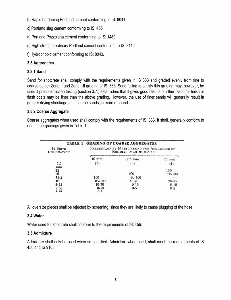
3.3.2 Coarse Aggregate
Coarse aggregates when used shall comply with the requirements of IS: 383. It shall, generally conform to
one of the gradings given in Table 1.
All oversize pieces shall be rejected by screening, since they are likely to cause plugging of the hose.
3.4 Water
Water used for shotcrete shall conform to the requirements of IS: 456.
3.5 Admixture
Admixture shall only be used when so specified. Admixture when used, shall meet the requirements of IS
456 and IS 9103.
9
3.5 Reinforcement
Reinforcing bars if used shall conform to IS 432 (Part I) or IS: 1139-196611 or IS: 1786. Welded wire fabric
conforming to IS 1566 also may be used.
3.6 Shotcreting Process
3.6.1 The two basic shotcreting processes are
a) Dry mix process, and
b) Wet mix process.
3.6.1.1 Dry Mix Process
In this process, a mixture of cement and moist sand is conveyed through the delivery hose to a nozzle
where most of the mixing water is added under pressure. This process consists of the following steps:
a) The cement and moist sand are thoroughly mixed;
b) The cement-sand mixture is fed into a special mechanical feeder or gun referred to in this standard as
delivery equipment.
c) The mixture is forced into the delivery hose by a feed wheel or distributor;
d) The mixed material is carried in suspension by compressed air through the delivery hose to a nozzle,
which is filled inside with a perforated manifold through which water is introduced under pressure and
intimately mixed with the other ingredients; and
e) The mortar is jetted from the nozzle at high velocity on to the surface to be shotcreted.
3.6.1.2 Wet Mix Process
In this process, all the ingredients including water are mixed before they enter the delivery hose. It consists
of the following steps:
a) All the ingredients including mixing water) are thoroughly mixed;
b) The mortar or concrete is introduced into the chamber of the delivery equipment;
c) The mixture is forced into the delivery hose and conveyed by compressed air or other means to a nozzle;
d) Additional air is injected at the nozzle to increase the velocity and improve the shooting pattern; and
e) The mortar or concrete is jetted from the nozzle at high velocity on to the surface to be shotcreted.
3.6.2 Shotcrete suitable for normal construction requirements may be produced by either process.
However, difference in cost of equipment, maintenance and operational features may make one or the
other method more attractive for a particular application.
3.7 Preconstruction Testing
3.7.1 The mix proportions, grading and quality of aggregate, amount and spacing of reinforcing steel,
position of the work, design and condition of delivery equipment, and the quality of workmanship all affect
the quality of shotcrete in place. A laboratory investigation shall, therefore, be carried out prior to the

10
commencement of the work in order to check the operation of the equipment and the skill of the operating
staff, and also to verify that the specified quality of shotcrete may be expected in the structure. The
procedure for preconstruction testing shall be as recommended
3.7.2 Test panels simulating actual job conditions shall be fabricated by the operating staff, using the
equipment, materials and mix proportions proposed for the job.
3.7.3 For the dry mix process, the amount of water added at the nozzle is adjusted so that the in-place
shotcrete appears to be adequately compacted and neither sags nor shows excessive rebound. Where
justified by the size and importance of the job or lack of previous experience with the materials, it may be
advisable to test two or three mixes, generally within the range of 1 part of cement to 3 to 4.5 parts of sand,
before deciding on the final mix proportions.
3.7.4 The procedure for the wet mix process is similar to the dry mix process (see 3.7.3 ) except that the
entire mix is premixed to give a workability judged to be appropriate for the work, before it is introduced into
the chamber of the delivery equipment. Tests on more than one mix design are usually recommended
where it is desired to include coarse aggregate in the mix. Normally 20 to 40 percent of coarse aggregate is
first tried, with subsequent mixes adjusted to reflect the results of the first trial.
3.7.5 The panels are fabricated by gunning on to a back form of plywood. A separate panel shall be
fabricated for each mix design being considered, and also for each gunning position to be encountered in
the structure, that is, slab, vertical and overhead sections. At least part of the panel shall contain the same
reinforcement as the structure, to show whether sound shotcrete is obtained behind the reinforcing rods.
The panel shall be large enough to obtain all the test specimens needed, and also to indicate what quality
and uniformity may be expected in the structure. Generally the size of panel shall be not less than 75 x 75
cm; The thickness shall he the same as in the structure except that it shall normally be not less than 7.5
cm.
3.7.6 Cubes or cores shall be taken from the panels for testing. The cores shall have a minimum diameter
of 7.5 cm and a length-diameter ratio of at least 1, if possible. The specimens shall be tested in
compression at the age of 7 or 28 days or both.
3.7.7 The cut surfaces-of the specimens shall he carefully examined and additional surfaces shall be
exposed by sawing or breaking the panel when it is considered necessary to check the soundness and
uniformity of the material. All cut and broken surfaces shall be dense and free from laminations and sand
pockets.
3.8 Equipment
3.8.1 Dry Mix Process
3.8.1.1 Batching and Mixing Equipment
Batching by mass is to be preferred and is strongly recommended. Sand may be batched by volume if
periodic checks are made to ensure that the masses are maintained within the required tolerance. The
moisture content of the sand shall be such that the sand-cement mixture wilt flow at a uniform rate, without
slugs, through the delivery hose. The optimum moisture content will depend upon the delivery equipment
being used, but it is generally within the range of 3 to 6 percent. The sand shall be moistened or dried as
required to bring the moisture content to a satisfactory level. Fluctuations in moisture content shall be
avoided.

11
The mixing equipment shall be capable of thoroughly mixing the sand and cement in sufficient quantity to
maintain continuity of placing. The mixing time shall be not less than 1 minute in a drum-type mixer; where
other mixers are proposed, satisfactory evidence shall be presented that they are capable of thorough
mixing. The mixer shall be self-cleaning, capable of discharging all mixed material without any carryover
from one batch to the next. It shall be inspected and thoroughly cleaned at least once a day (and more
often if necessary) to prevent accumulations of batched material.
3.8.1.2 Delivery Equipment or Guniting Equipment
The delivery equipment shall comply with the requirements given in 6433.
3.8.1.3 Air Supply
Properly operating air compressor of ample capacity is essential for a satisfactory shotcreting operation.
The compressor shall be fitted with a moisture extractor to keep up a supply of clean, dry air adequate for
maintaining a sufficient nozzle velocity for all parts of the work while simultaneously operating a blow pipe
for clearing away rebound. The operating pressure is the pressure driving the material from the delivery
equipment into the hose, and is measured by a gauge near the material outlet of the gun. The air pressure
shall be uniformly steady (non-pulsating). For lengths of hose up to 30 m, air pressure at the gun shall be
0.3 N/mm2 or more. Where the length exceeds 30 m, the pressure shall be increased by 0.035 N/mm2 for
each additional 15 m of hose required, and by 0.035 N/mm2 for each 7.5 m that the nozzle is raised above
the gun.
3.8.1.4 Water supply
The water pressure at the discharge nozzle shall be sufficiently greater than the operating air pressure to
ensure that the water is intimately mixed with the other materials. If the line water pressure is inadequate, a
water pump shall be introduced into the line. The water pressure shall be uniformly steady (non-pulsating).
3.9.1 Wet Mix Process
3.9.1.1 Batching and Mixing Equipment
Batching by mass is to be preferred and is strongly recommended. Aggregates may be batched by volume
if periodic checks, are made to ensure that the masses are maintained within a required tolerance. Water
may be batched either by mass or by volume.
The mixing equipment shall be capable of thoroughly mixing the specified materials in sufficient quantity to
maintain continuous placing. The required mixing time will depend on the mix being used and the efficiency
of the mixer. Delivery of concrete at the desired workability and uniformity from batch to batch is essential
to a good shotcreting operation especially in vertical and overhead applications.
3.9.1.2. Delivery Equipment
The pneumatic feed type of wet mix delivery equipment is capable of applying high quality, low-slump
mortar or concrete with the reliability needed for general construction and repair work. From a pressurized
vessel in the equipment, the premixed materials and compressed air are discharged into the delivery hose.
The material and air pass through the hose to the gunning nozzle which is fitted with an air ring for injecting
additional compressed air.

12
The wet mix delivery equipment shall be of a design and size which, have given good results in similar
work. It shall be capable of delivering the premixed materials accurately, uniformly, and continuously
through delivery hose. The size of the hose is generally within the range of 32 to 65 mm.
Recommendations of the equipment manufacturers shall be followed with regard to the type and size of
nozzle to be used, and the cleaning, inspection, and maintenance of the equipment.
3.9.1.3Air Supply
The air compressor shall be capable of keeping up a supply of clean air adequate for maintaining sufficient
nozzle velocity for all parts of the work and for simultaneous operation of a blow pipe for clearing away
rebound.
3.8 Application
3.8.1 Preparation of Surface
A good base or foundation is necessary for proper and successful application of shotcrete. Where the
shotcrete is to be placed against earth surfaces, such surfaces shall first be thoroughly compacted and
trimmed to line and grade. Shotcrete shall not be placed on any surface which is frozen, spongy, or where
there is free water. The surface shall be kept damp for several hours before applying shotcrete.
In the case of repairs to existing deteriorated concrete, all unsound material shall be first removed.
Chipping shall continue until there are no offsets in the cavity which will cause an abrupt change in the
thickness of the repaired surface. No square shoulders shall be left at the perimeter of the cavity; all edges
shall be tapered. The final cut surface shall be critically examined to make sure that it is sound and properly
shaped. Improper preparatory work is more often responsible for failures of shotcrete in repair work than
any other single factor.
After it has been ensured that the surface (whether concrete, masonry or steel) to which shotcrete is to be
bonded is sound, it shall be cleaned of all loose and foreign materials. If necessary, the surface shall be
chiseled or sand-blasted to make it rough to receive shotcrete. Exposed reinforcement shall be cleaned
free of rust, scales etc. Porous surfaces shall be kept damp for several hours before shotcrete is applied.
3.8.2 Formwork
The forms shall be plywood sheating or other suitable material, true to line and dimension. They shall be
adequately braced to protect against excessive vibration, and shall be constructed so as to permit the
escape of air and rebound during the gunning operation; this is of particular importance in the case of thick
structural members. Short removable bulkheads may be used at intersections. Forms shall be oiled or
dampened, and they shall be cleaned just before gunning.
Adequate and safe scaffolding shall be provided so that the operator can hold the nozzle at the optimum
angle and distance from the surface for all parts of the work as described in 3.8.5. The scaffolding shall be
also given easy access to the shotcrete surface for screeding and finishing, if such is specified. Scaffolding
shall be constructed to permit uninterrupted applications of the shotcrete wherever possible.
3.8.3 Reinforcement
The soundest shotcrete will be obtained where the reinforcing steel is designed and placed to cause the
least interference with placement. Depending on the thickness and nature of the work, reinforcement may
consist of either round bars, or welded wire fabric.

13
Sufficient clearance shall be provided around the reinforcement to permit complete encasement with sound
concrete. The clearance needed depends on the maximum size of aggregate in the mix and the size of
reinforcement. The minimum clearance between the reinforcement and the form or other backup material
may vary between 12 mm for the case of a mortar mix and wire fabric reinforcements to 50 mm for the case
of a concrete mix and 16 mm diameter reinforcing bars. The minimum wire mesh spacing shall be 50 mm
by 50 mm. Clear spacing between parallel bars shall be at least 65 mm. Minimum cover to reinforcement
shall be as per IS 456. As far as possible the bars shall be arranged so as to permit shooting from opposite
side.
Laps for bars and wire fabric shall receive special attention to prevent weak sections in the shotcrete.
Lapped reinforcing bars shall not be tied together; they shall be separated by at least 50 mm, wherever
possible. Wire mesh shall be lapped 1.5 squares in all directions. A continuous chair shall not follow along
directly underneath a reinforcing bar since this will probably result in a sand pocket under the bar. The
minimum requirements of lap length shall be as specified in IS 456.
For repair work, the reinforcement shall be fixed to existing masonry and concrete by wiring to nails driven
into walls and secured rigidly so that the vibration resulting from the deposition of shotcrete will not impair
or displace them.
3.8.4 Alignment Control
Adequate ground wires shall be installed to establish thickness and surface planes of the shotcrete build-
up. Both horizontal and vertical ground wires shall be installed at corners and offsets not clearly fixed by the
formwork, for example, at exterior corners of walls, column or beam corners, and other locations. They may
also be used as screed guides. Ground wires shall be tight and true to line, and placed in such a manner
that they may be further tightened.
3.8.5 Placing the Shotcrete
Each layer of shotcrete is built up by making several passes or loops of the nozzle over the working area.
This may be done by moving the nozzle rhythmically in a series of loops from side to side and up and down
(see Fig. 1 and 2). The shotcrete shall emerge from the nozzle in a steady, uninterrupted flow. If the flow
becomes intermittent due to any cause, the operator shall direct it away from the work until it again
becomes constant. The distance of the nozzle from work (usually between 0.5 and I.5 m) shall be such as
to give the best results for the working conditions. The nozzle shall be held perpendicular to the surface of
application. However, when gunning through and encasing reinforcing bars, the nozzle shall be held closer
and at a slight angle from the perpendicular. Also the mix shall be little wetter than normal, but not so wet
as to cause sloughing behind the bar. This procedure forces the plastic shotcrete behind the bar while
preventing build-up on the front face of the bar. Where bars are closely spaced, more than one bar may be
shot from each position.

14
15
3.8.6 Preparation for Succeeding Layers
Where a layer of shotcrete is to be covered by a succeeding layer, it shall first be allowed to take its initial
set. Then all laitance, loose material and rebound shall be removed by brooming. Any laitance which has
attained final set shall be removed by sand-blasting and the surface cleaned with an air water jet. In
addition the surface shall be thoroughly sounded with a hammer for dummy areas resulting from rebound
packets or lack of bond. Dummy areas, sags, or other defects shall be carefully cut out and replaced with
the succeeding layer. Surfaces to be shot shall be damp.
3.8.7 Finishing
The natural gun finish is normally preferred from both the structural and durability considerations. There is
danger that further finishing may disturb the section, harming the bond between the shotcrete and
reinforcement, and between the shotcrete and the underlying material, and creating cracks in the shotcrete.
Additional finishing may also be difficult to accomplish, especially for the drier mixes.
3.9 Suspension of Work
3.9.1 The application of shotcrete shall be suspended in condition of likely exposure to high winds, freezing
or rain.
3.9.2 At the end of each day work, or on stopping work for any other reason, the shotcrete shall be slopped
off to a thin edge and then the work shall be resumed on next day after cleaning the surface.
3.10 Curing
Good curing is particularly important for the very thin sections, rough surfaces, and mixes of low workability
normally associated with shotcrete. It is generally recommended that surfaces be kept continuously wet for
at least 7 days (see IS 456).
3.11 Quality Control
Small unreinforced test panels, at least 30 cm square and 75 mm tick shall be physically gunned, and cores
or cubes extracted for compression test and visually examined. Test cores shall also be taken from the
completed work as often necessary to ensure that the control tests reflect the quality of material in the
structure.
Concrete cubes prepared by directly gunning into 15 cm cube moulds may also be used for day to day
quality control tests. In such cases, the results should be correlated to the results from tests of cubes made
from panels
Frequency of sampling of shotcrete for tile purpose of quality control shall be as agreed upon between the
engineer-in-charge and the contractor.
3.12 Inspection
The shotcreting operation shall be continuously inspected by a qualified supervisor who shall check
materials, forms reinforcing, ground wires, deliver), equipment, application of material, curing, and
protection against high or low temperature. Each layer of shotcrete shall be systematically sounded with a
hammer to cheek for dummy areas. Cores shall be taken from the structural shotcrete: such cores shall be
taken as early in the job as practicable so that the data obtained can be used to effect improvements in

16
later work. The permissible tolerance on the thickness of the work executed by shotcrete shall be -8 or +8
mm.
4.0. Welded Wire Mesh
It is a material composed of mild or stainless steel wire as drawn, fabricated into sheet (or mesh) formed by
the process of electric welding. The finished material shall consist essentially of a series of longitudinal and
transverse wires arranged substantially at right angles to each other and then welded together at all points
of intersection. All the specification of wire mesh shall confirm to IS 4948. The thickness and size shall
according to construction drawings.
4.1 Materials
4.1.1 Mild steel wire used for the manufacture of welded fabric shall conform to IS 280.
4.1.2 Stainless steel wire used for the manufacture of welded fabric shall conform to grade X 04 Cr 17 Ni
12 Mo20r X04Cr 18Ni 10 of IS6528.
4.2 Manufacture of Mesh
4.2.1 Assembling of wires
The wire shall be assembled by automatic machines or by other suitable mechanical means which will
assure accurate spacing and alignment of all members of the finished fabric within specified tolerances.
4.2.2 The longitudinal and transverse wires shall be securely connected at every intersection by a process
of welding.
4.2.3 It shall be fabricated and finished in a workman like manner and shall be free from injurious defects.
4.3 Tolerance of Size of Mesh
In any individual mesh, the maximum variation between two members when measured between centre to
centre shall not vary more than 5 percent.
4.4 Tolerance of Size of Sheet or Roll
The length of flat sheets or rolls measured on any wire may vary by 25 mm or one percent whichever is
greater.
4.5 Test for Welding
In order to ensure adequate weld shear strength between longitudinal and transverse wire, a weld shear
test as IS 4948 section 7.1.1 shall be made. The minimum average value of the weld shall not be less than
21 kg/mm2 and the area of the wire to be taken into consideration for calculation is the longitudinal wire.
The fabric having a diameter difference between the longitudinal and transverse wire greater than 2 mm
shall not be subjected to the weld shear test.
4.6 BIS Certification Marking
The material may also be marked with the BJS Standard Mark. The use of the Standard Mark is governed
by the provisions of the Bureau of Indian Standards Act, J986 and the Rules and Regulations made

17
thereunder. The details of conditions under which license for the use of the Standard Mark may be granted
to manufacturers or producers may be obtained from the Bureau of Indian Standards.
4.7 Finish
All the surface of wire fabric, shall be cleaned free of rust, mill scale, dirt, oil, etc. If required by the
purchaser, the mild steel wire may be given suitable anti corrosive treatment such as pickling followed by
painting, phosphating and painting [see IS 1477( Parts 1 and 2)], hot dip galvanized etc.

18
TIME SCHEDULE Mitigation of Mangan Landslide at North District Headquarters - Mangan, North Sikkim
Sl.No. Item of Work MONTHS 1 2 3 4 5 6 7 8 9 10 11 12 13 14 15 16 17 18 19 20 21 22 23 24
1
Mobilization of Contractor
2 Site preparations
3
Slope scaling, Benching and development of Drainage system (All Evacuation)
4
All major Civil works related to slope stabilization

19
DRAWINGS & SITE PLAN

20
LAYOUT PLAN

21
Table 1: Mangan Slide: Summary of Support recommendation
S No. Support Description
1
Minor Dressing
Minor Scrubbing of top layer marking formation level for Installation of RCC piles
2
Self -Drilling Anchor
Fully Grouted Self -Drilling Anchor of capacity 190 kN, to 8 m long staggered both ways @ 1.5
m c/c are used as support for cut slope.
3
Shotcrete
100 mm thick M25 Grade shotcrete with wire mesh 100mmx100mm x 6mm shall be provided or SFRS shall be used.
4
Drainage
Drainage holes of 50mm diameter Minimum, 7.0m long @ 6.0m c/c (staggered) shall be provided (inclined to 10 degree) to avoid slope saturation outfall structure. Formation of drainage well at identified location.
5
RCC Pile with Pile Cap Beam
Reinforced Concrete Pile of 0.4 m Diameter,10 m long or 2 m embedded in rock mass at spacing 0.5 m c/c. All pile shall be connected by pile cap beam of 0.6 m x0.4 m.
Reinforcement in pile will be provided as 8 Nos of 16 mm Dia bar as per Design.

22
LONGITUDINAL SECTION OF SLIDED AREA

23
DESIGN OF JHORA TRAINING WORK

24
Figure: Discretised Model of Mangan Slide
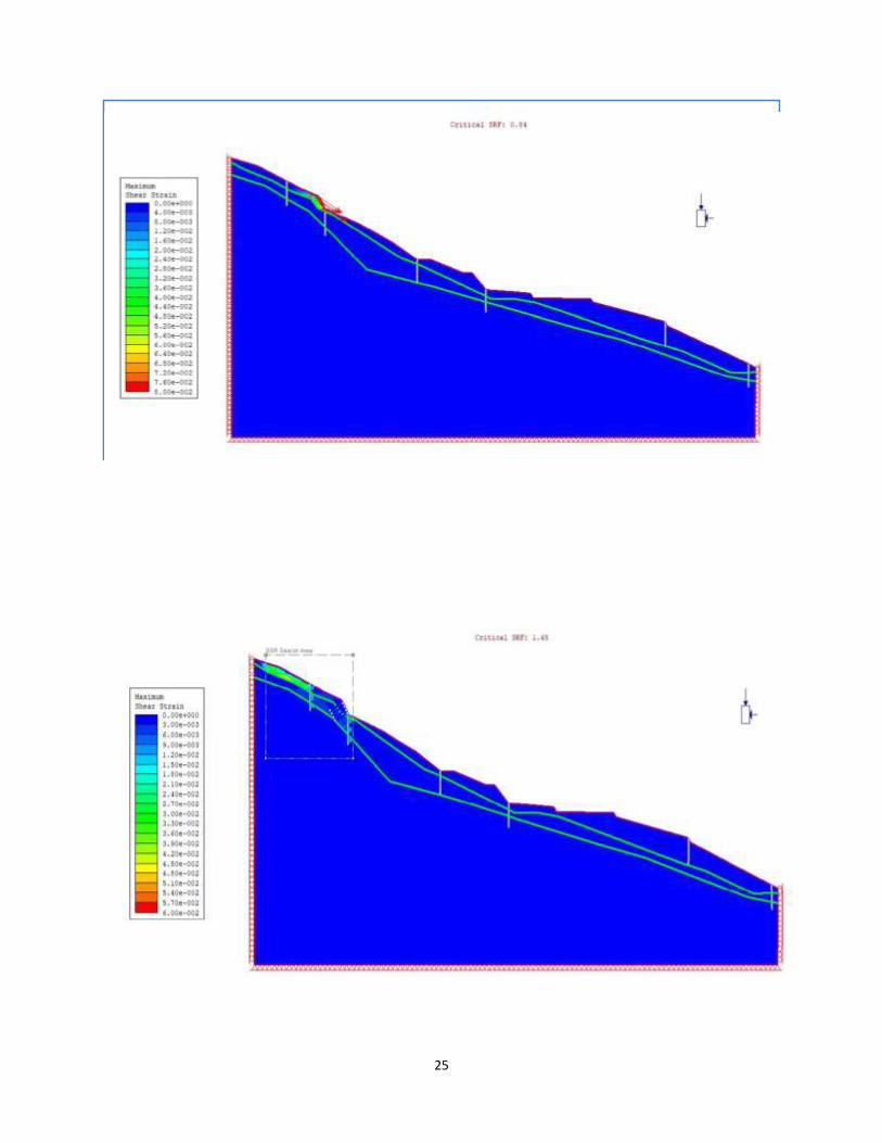
25
Figure FOS of Safety of Unsupported Section at Mangan (FOS=0.84)

26
Figure: FOS of Safety of Mangan Slide Supported at First Level (FOS=1.45)
Figure: FOS of Safety of Mangan Slide Supported at Second Level (FOS=2.22)
igure: FOS of Safety of Mangan Slide Supported at Third Level (FOS=1.87)

27
Figure : FOS of Safety of Mangan Slide Supported at Fourth Level (FOS=1.87)
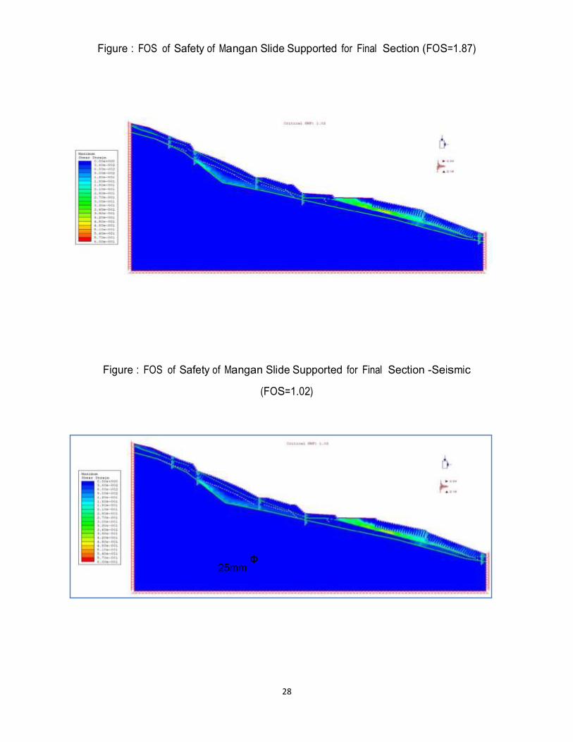
28
Figure : FOS of Safety of Mangan Slide Supported for Final Section (FOS=1.87)
Figure : FOS of Safety of Mangan Slide Supported for Final Section -Seismic
(FOS=1.02)

29
GEOLOGICAL SECTION H-H'

30
TYPICAL PLAN
31
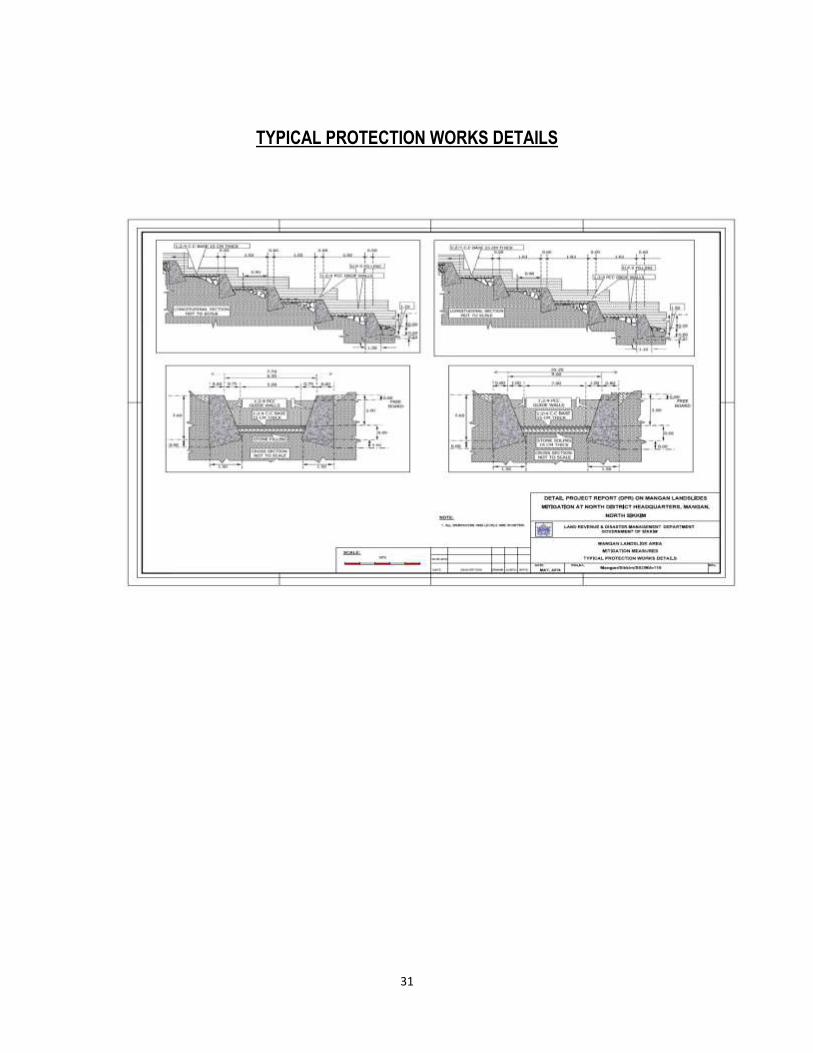
TYPICAL PROTECTION WORKS DETAILS
TYPICAL CROSS SECTION OF DRAINAGE SYSTEMS
TYPICAL CROSS SECTION OF DRAINAGE SYSTEMS

32
TYPICAL DRAINAGE WORKS DETAILS

33
ELECTRICAL RESISTIVITY TOMOGRAPHY METHOD
Profile section (PS05 - PS05') below SNT Colony
Copyright © 2022 FDOKUMEN