technical specifications - NPCIL e-Tenders
9
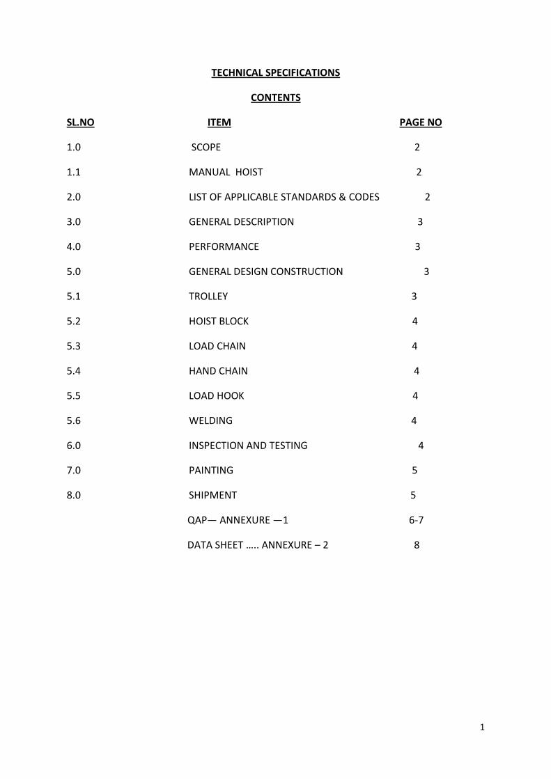
1 TECHNICAL SPECIFICATIONS CONTENTS SL.NO ITEM PAGE NO 1.0 SCOPE 2 1.1 MANUAL HOIST 2 2.0 LIST OF APPLICABLE STANDARDS & CODES 2 3.0 GENERAL DESCRIPTION 3 4.0 PERFORMANCE 3 5.0 GENERAL DESIGN CONSTRUCTION 3 5.1 TROLLEY 3 5.2 HOIST BLOCK 4 5.3 LOAD CHAIN 4 5.4 HAND CHAIN 4 5.5 LOAD HOOK 4 5.6 WELDING 4 6.0 INSPECTION AND TESTING 4 7.0 PAINTING 5 8.0 SHIPMENT 5 QAP— ANNEXURE —1 6-7 DATA SHEET ….. ANNEXURE – 2 8
-
Upload
khangminh22 -
Category
Documents
-
view
10 -
download
0
Transcript of technical specifications - NPCIL e-Tenders
1
TECHNICAL SPECIFICATIONS
CONTENTS
SL.NO ITEM PAGE NO
1.0 SCOPE 2
1.1 MANUAL HOIST 2
2.0 LIST OF APPLICABLE STANDARDS & CODES 2
3.0 GENERAL DESCRIPTION 3
4.0 PERFORMANCE 3
5.0 GENERAL DESIGN CONSTRUCTION 3
5.1 TROLLEY 3
5.2 HOIST BLOCK 4
5.3 LOAD CHAIN 4
5.4 HAND CHAIN 4
5.5 LOAD HOOK 4
5.6 WELDING 4
6.0 INSPECTION AND TESTING 4
7.0 PAINTING 5
8.0 SHIPMENT 5
QAP— ANNEXURE —1 6-7
DATA SHEET ….. ANNEXURE – 2 8

2
1.0 SCOPE
This specification is intended to cover design, manufacture, inspection, assembly, shop
testing, overload testing of Manual Hoists complete with the accessories as specified but
not limited to the following:
1.1 MANUAL HOIST
Manual hoist comprising:
* Geared Trolley with hand chain.
* Hand operated hoist block with hand chain and load chain.
* Gears, load brake and cover plates.
* Load block complete with sheaves and lifting hook.
* Ratchet and Pawl type load brakes.
2.0 LIST OF APPLICABLE STANDARDS AND CODES
The design, manufacture, testing and delivery to site of the equipment covered by this
specification, unless otherwise specified, stated shall conform to the latest editions of all
standards and codes.
IS : 3832 Hand Operated Chain Pulley Blocks-Specification.
IS : 15560 Point Hook with Shank up to 160 Tonne Specification.
IS : 210 Grey Iron Castings-Specification.
IS : 2429 Specification for Round Steel Short Link Chains (Electric Butt Welded), Grade
L(3) Part 1 Non-Calibrated Load Chain for Lifting Purposes
IS : 1030 Carbon Steel Casting for General Engineering Purpose.
IS : 6216 Specification for Short Link Chain, Grade T (8), Calibrated for Pulley Blocks and
other Lifting Appliances
IS : 14329 Malleable Iron Castings.
IS : 5616 Short Link Chain for Lifting Purposes General Conditions of Acceptance.
IS : 2513 Boundary Dimensions for Rolling Bearings for General Engineering Purposes
BS : 970 Wrought Steel in the form of Blooms, Billets, Bars and Forgings.
PP-P-2352-----Magnetic Particle Examination with wet horizontal/stationary magnetic
particle testing machine for gear, disc and flanges.

3
PP-P-2353---- Magnetic Particle Testing with PROD technique
Reference sketch: 1) SDCP/7621/37/38/39/40
3.0 GENERAL DESCRIPTION
Hoists covered under this specification shall have general requirements of head room,
lift and other relevant details as per the sketch and data sheet given in annexure-2.
The head room & end approaches specified in sketch/specification are indicative of
maximum value. The head room of the hoist is to be specified by the vendor as per his
standard design in the quotation. In no case head room shall exceed the dimensions
mentioned in the sketch. Irrespective of the head room quoted, the lowest hook elevation
requirement shall be met as per floor level.
The bidder shall prepare engineering drawing and submit along with quotation which shall
contain the vendor design details which shall be approved by the purchaser.
4.0 PERFORMANCE
The hoist shall be of intermittent maintenance service which shall be designed for the
Class-II service as per IS: 3832.
5.0 GENERAL DESIGN CONSTRUCTION
All equipment covered by this specification shall be designed and constructed in
accordance with the codes and standards as mentioned in above clause no.2.0.
Material of construction for various parts shall be as per IS: 3832. However, if manufacturer
has any standard alternate material/superior material same may be followed with prior
approval from the purchaser. If mentioned in respective data sheet, the trolleys shall
be supplied with provision of required accessories for mechanically coupling with other
hoist, operating in the same monorail such that both the hoists can move in tandem with
loads. The distance between the trolleys shall be as finalized in General Arrangement
drawings.
5.1 TROLLEY
5.1.1 Geared type trolley constructed with side plates shall be provided. The material
of construction of trolley shall be as per IS 2062. In case of hoist, if vendor standard design
is different, it may be used with prior approval of purchaser and material of construction
shall be specified in GA drawing.
The steel plates shall extend beyond the trolley wheels on either side so as to act as
bumper, protecting the wheels from damage by collision.
4
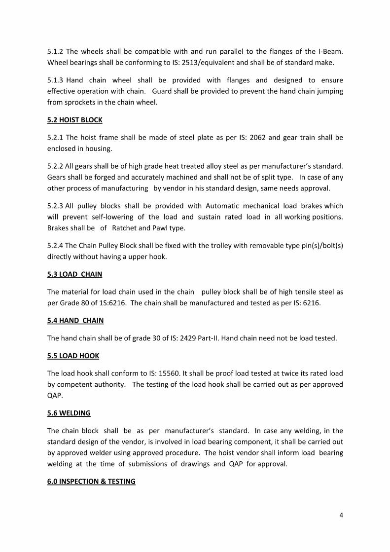
5.1.2 The wheels shall be compatible with and run parallel to the flanges of the I-Beam.
Wheel bearings shall be conforming to IS: 2513/equivalent and shall be of standard make.
5.1.3 Hand chain wheel shall be provided with flanges and designed to ensure
effective operation with chain. Guard shall be provided to prevent the hand chain jumping
from sprockets in the chain wheel.
5.2 HOIST BLOCK
5.2.1 The hoist frame shall be made of steel plate as per IS: 2062 and gear train shall be
enclosed in housing.
5.2.2 All gears shall be of high grade heat treated alloy steel as per manufacturer’s standard.
Gears shall be forged and accurately machined and shall not be of split type. In case of any
other process of manufacturing by vendor in his standard design, same needs approval.
5.2.3 All pulley blocks shall be provided with Automatic mechanical load brakes which
will prevent self-lowering of the load and sustain rated load in all working positions.
Brakes shall be of Ratchet and Pawl type.
5.2.4 The Chain Pulley Block shall be fixed with the trolley with removable type pin(s)/bolt(s)
directly without having a upper hook.
5.3 LOAD CHAIN
The material for load chain used in the chain pulley block shall be of high tensile steel as
per Grade 80 of 1S:6216. The chain shall be manufactured and tested as per IS: 6216.
5.4 HAND CHAIN
The hand chain shall be of grade 30 of IS: 2429 Part-II. Hand chain need not be load tested.
5.5 LOAD HOOK
The load hook shall conform to IS: 15560. It shall be proof load tested at twice its rated load
by competent authority. The testing of the load hook shall be carried out as per approved
QAP.
5.6 WELDING
The chain block shall be as per manufacturer’s standard. In case any welding, in the
standard design of the vendor, is involved in load bearing component, it shall be carried out
by approved welder using approved procedure. The hoist vendor shall inform load bearing
welding at the time of submissions of drawings and QAP for approval.
6.0 INSPECTION & TESTING
5
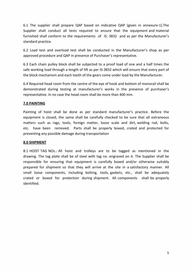
6.1 The supplier shall prepare QAP based on indicative QAP (given in annexure-1).The
Supplier shall conduct all tests required to ensure that the equipment and material
furnished shall conform to the requirements of IS: 3832 and as per the Manufacturer’s
standard practice.
6.2 Load test and overload test shall be conducted in the Manufacturer’s shop as per
approved procedure and QAP in presence of Purchaser’s representative.
6.3 Each chain pulley block shall be subjected to a proof load of one and a half times the
safe working load through a length of lift as per IS-3832 which will ensure that every part of
the block mechanism and each tooth of the gears come under load by the Manufacturer.
6.4 Required head room from the centre of the eye of hook and bottom of monorail shall be
demonstrated during testing at manufacturer’s works in the presence of purchaser’s
representative. In no case the head room shall be more than 400 mm.
7.0 PAINTING
Painting of hoist shall be done as per standard manufacturer’s practice. Before the
equipment is closed, the same shall be carefully checked to be sure that all extraneous
matters such as rags, tools, foreign matter, loose scale and dirt, welding rod, bolts,
etc. have been removed. Parts shall be properly boxed, crated and protected for
preventing any possible damage during transportation
8.0 SHIPMENT
8.1 HOIST TAG NOs.: All hoist and trolleys are to be tagged as mentioned in the
drawing. The tag plate shall be of steel with tag no. engraved on it. The Supplier shall be
responsible for ensuring that equipment is carefully boxed and/or otherwise suitably
prepared for shipment so that they will arrive at the site in a satisfactory manner. All
small loose components, including bolting, tools, gaskets, etc., shall be adequately
crated or boxed for protection during shipment. All components shall be properly
identified.
6
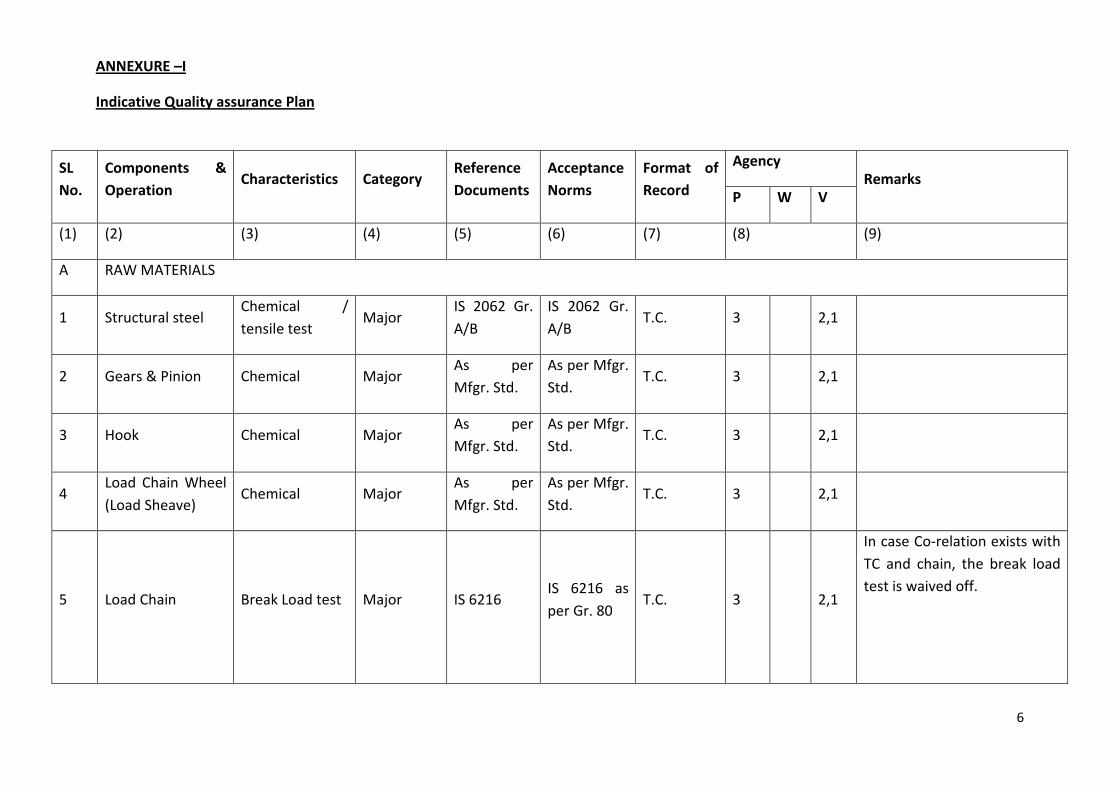
ANNEXURE –I
Indicative Quality assurance Plan
SL
No.
Components &
Operation Characteristics Category
Reference
Documents
Acceptance
Norms
Format of
Record
Agency Remarks
P W V
(1) (2) (3) (4) (5) (6) (7) (8) (9)
A RAW MATERIALS
1 Structural steel Chemical /
tensile test Major
IS 2062 Gr.
A/B
IS 2062 Gr.
A/B T.C. 3 2,1
2 Gears & Pinion Chemical Major As per
Mfgr. Std.
As per Mfgr.
Std. T.C. 3 2,1
3 Hook Chemical Major As per
Mfgr. Std.
As per Mfgr.
Std. T.C. 3 2,1
4 Load Chain Wheel
(Load Sheave) Chemical Major
As per
Mfgr. Std.
As per Mfgr.
Std. T.C. 3 2,1
5 Load Chain Break Load test Major IS 6216 IS 6216 as
per Gr. 80 T.C. 3 2,1
In case Co-relation exists with
TC and chain, the break load
test is waived off.

7
NOTE: P-Perform, W- Witness, V-Document Verification 1- Customer, 2-Contractor (if Any), 3- Vendor / Manufactures
LPE- Liquid Penetrant Examination
MPI- Magnetic Particle Inspection
B FINISHED COMPONENT
1 Gears, Pinion Hardness
LPE/MPI Major
As per
approve
procedure
Mfgr. Std.
As per Mfgr.
Std. IR 3 2,1
2 Hooks Proof Load Major As per
apprd. Proc.
As per
apprd. Proc. IR 3 1,2 2,1
3 Hooks MPI Major As per
apprd. Proc.
As per
apprd. Proc. IR 3 1,2 2,1
MPI: Before proof load test
will not be witnessed by
NPCIL QS
C FINISHING ASSEMBLY
1 Load & Over Load
Test
Load test
Hoisting &
Lowering
Major As per
apprd. Proc.
As per
apprd. Proc. IR 3 1,2 2,1
8
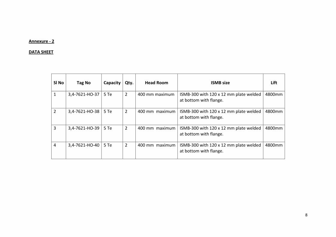
Annexure - 2
DATA SHEET
Sl No
Tag No
Capacity
Qty.
Head Room
ISMB size
Lift
1 3,4-7621-HO-37 5 Te 2 400 mm maximum ISMB-300 with 120 x 12 mm plate welded at bottom with flange.
4800mm
2 3,4-7621-HO-38 5 Te 2 400 mm maximum ISMB-300 with 120 x 12 mm plate welded at bottom with flange.
4800mm
3 3,4-7621-HO-39 5 Te 2 400 mm maximum ISMB-300 with 120 x 12 mm plate welded at bottom with flange.
4800mm
4 3,4-7621-HO-40 5 Te 2 400 mm maximum ISMB-300 with 120 x 12 mm plate welded at bottom with flange.
4800mm