specs_67764.pdf - NPCIL e-Tenders
29
ANNEXURE-I CHECKLIST FOR UPGRADATION OF EXCITATION SYSTEM AT RAPS-3&4 S. No. Criteria value Check box for supplier 1. Scope of supply / works / services: As per clause no.-1.0 of attached technical specification 2. Applicable code and standards shall be: As per clause no.-3.0 of attached technical specification 3. Technical specifications of existing system & new DVR system As per clause no.-4.0 of attached technical specification 4. Detailed specification of DVR As per clause no.-5.0 of attached technical specification 5. Specification of DVR As per clause no.-5.1 of attached technical specification 6. List of mandatory spare As per clause no.-5.2 of attached technical specification 7. Inspection and testing As per clause no.-7.0 of attached technical specification 8. QA plan As per clause no.-8.0 of attached technical specification 9. Installation, Testing and Commissioning As per clause no.-9.0 of attached technical specification 10. Drawings and Documents to be Submitted As per clause no.-12.0 of attached technical specification 11. Schedule for submission of drawings, manuals, test reports, etc. As per clause no.-13.0 of attached technical specification 12. Any deviation to the specification To be furnish by bidder. 13. Particulars/details to be submitted by bidder. As per annexure-A (1.0 to 8.0) of attached technical specification
-
Upload
khangminh22 -
Category
Documents
-
view
15 -
download
0
Transcript of specs_67764.pdf - NPCIL e-Tenders

ANNEXURE-I
CHECKLIST FOR UPGRADATION OF EXCITATION SYSTEM AT RAPS-3&4
S. No. Criteria value Check box for supplier
1. Scope of supply / works / services:
As per clause no.-1.0 of attached technical specification
2. Applicable code and standards shall be:
As per clause no.-3.0 of attached technical specification
3. Technical specifications of existing system & new DVR system
As per clause no.-4.0 of attached technical specification
4. Detailed specification of DVR
As per clause no.-5.0 of attached technical specification
5. Specification of DVR As per clause no.-5.1 of attached technical specification
6. List of mandatory spare As per clause no.-5.2 of attached technical specification
7. Inspection and testing As per clause no.-7.0 of attached technical specification
8. QA plan As per clause no.-8.0 of attached technical specification
9. Installation, Testing and Commissioning
As per clause no.-9.0 of attached technical specification
10. Drawings and Documents to be Submitted
As per clause no.-12.0 of attached technical specification
11. Schedule for submission of drawings, manuals, test reports, etc.
As per clause no.-13.0 of attached technical specification
12. Any deviation to the specification
To be furnish by bidder.
13. Particulars/details to be submitted by bidder.
As per annexure-A (1.0 to 8.0) of attached technical specification

TECHNICAL SPECIFICATION OF DIGITAL VOLTAGE
REGULATOR (DVR) PANEL FOR UPGRADATION OF
EXISTING AVR PANEL OF BHEL EDN MAKE FOR 16.5
KV, 235 MW BHEL MAKE GENERATOR

NUCLEAR POWER CORPORATION OF INDIA LTD.
220MWe ATOMIC POWER PROJECT Page 1 of 27 TECHNICAL SPECIFICATION FOR Rev. No. R0
UPGRADATION OF EXCITATION SYSTEM 1.0 SCOPE OF SUPPLY ,INSTALLATION AND COMMISSIONING: 1.1 This specification covers up-gradation of existing analog regulation panels of Static
Excitation System with digital regulation panel for turbo generator. 1.2 It is not the intent to specify completely herein, all details of design and construction of
the equipment. However, the equipment shall conform in all respects to high standards of engineering, design and workmanship and be capable of performing continuous commercial operation up to the CONTRACTOR'S guarantees in a manner acceptable to the PURCHASER, who will interpret the meaning of drawings and specifications and shall be entitled to reject any work or material which, in his judgement, is not in full accordance therewith.
1.3 The scope includes but not limited to the following items / services described herein and
elsewhere in the tender package. 1.3.1 Dismantling of existing analog regulation panels and affected electronic modules
located in other locations of existing static excitation panels 1.3.2 Engineering, manufacturing, inspection and testing, packing, delivery to site, digital
voltage regulation panels, associated power supply modules, protection, control and metering, software and new components such as pulse transformers, cables or any other devices of excitation system required for up-gradation and handing over of the equipment as detailed in the subsequent sections. The dimension of new regulation panels shall match with the existing regulation panels
1.3.3 A micro-terminal shall be provided for local control and communication with the
microprocessor during operation. Parameters and measured variables shall be recalled and indicated through a Liquid Crystal Display of the terminal
1.3.4 Supply, laying and termination of additional cables required for interconnection
between panels. 1.3.5 Erection, testing and commissioning of new panels and components in the existing
panels at site. 1.3.6 Spares as indicated in clause 4 of this specification shall be supplied by the
CONTRACTOR 1.3.7 Maintenance tools and tackles as described in clause 10 of this specification shall be
supplied by the CONTRACTOR. 1.3.8 Hardware and associated software tools for control, protection and field setting of
various protective devices and limiters, indications and remote signalling shall be included in the scope of supply. Programmable logic controller shall be a part of digital voltage regulator. Necessary port and connectivity cables for connecting to transient recorders shall be supplied along with the equipment.

NUCLEAR POWER CORPORATION OF INDIA LTD. 220MWe ATOMIC POWER PROJECT Page 2 of 27 TECHNICAL SPECIFICATION FOR Rev. No. R0
UPGRADATION OF EXCITATION SYSTEM 1.4 Training of PURCHASER's personnel at manufacturer's works on various design,
testing and maintenance aspects and also at PURCHASER's site on installation, maintenance, carrying out adjustments etc.
1.5 Whether called for specifically or not, all accessories required for normal operation of
equipment are deemed to be considered as a part of the CONTRACTOR'S scope of supply.
1.6 The CONTRACTOR shall obtain all information as required for proper integration and
operation of the existing Turbo generator and excitation system (M/s.BHEL Make) to match with technical requirements of the excitation system offered.
1.7 Taking generator details and grid details the CONTRACTOR shall work out the
settings for PSS and do all necessary adjustment at site required for the optimum performance of the PSS. CONTRACTOR shall also furnish the settings to be adopted for the limiters and carry out tests for tuning controllers and limiters.
1.8 The CONTRACTOR shall fully apprise himself of the scope and content of the work,
equipment to be supplied erected and commissioned and other services that may be required at site for completion of work at site by site visit before bidding. The CONTRACTOR shall obtain all necessary and additional information for bidding and completion of scope of works during the site visit. It is the primary responsibility of the CONTRACTOR to ensure that the equipment supplied matches with the existing equipment physically as well as in performance to ensure that the guaranteed parameters are met and the operation of TG is trouble free. The CONTRACTOR shall note that the availability of work front shall be given progressively by purchaser and it is the intent that the successful CONTRACTOR takes up and plans work accordingly, following all precautions and safety requirements
1.9 The available drawings for the existing system where required would be furnished to
the successful CONTRACTOR for detailed engineering. In case of non-availability of drawings/details it shall be the CONTRACTOR’s responsibility to get the information from available sources
1.10 On award of PO, CONTRACTOR shall furnish the schematics, general arrangement
drawings, cable schedules, interconnection schedules, panel wiring diagrams etc for Purchaser’s approval. CONTRACTOR shall also furnish the recommended relay/limiter settings to be adopted.
1.11 The CONTRACTOR shall submit erection and commissioning procedure and drawings
after placement of order. Among other details this procedure shall also contain detailed requirement for handling, checklist for assembly and erection, special instructions, precautions erection drawings, log sheets etc.,.

NUCLEAR POWER CORPORATION OF INDIA LTD. 220MWe ATOMIC POWER PROJECT Page 3 of 27 TECHNICAL SPECIFICATION FOR Rev. No. R0
UPGRADATION OF EXCITATION SYSTEM 2.0 CONTENT
Title Clause Applicable codes, standards and specifications 3 Specification of main equipment and accessories 4 Design and construction details 5 Exclusions 6 Inspection and testing 7 Quality assurance 8 Installation, testing and commissioning 9 Special tools & tackles for erection and maintenance 10 Warrantee and guarantee 11 Drawings and documents to be submitted 12
Schedule for submission of drawings and test reports 13
Annexure – A Particulars to be submitted by the bidder 3.0 APPLICABLE CODES, STANDARDS AND SPECIFICATIONS 3.1 The design, material, manufacture, assembly, inspection, testing and performance of
relays, panels and other associated equipments shall comply with latest editions (including amendments thereto) of all currently applicable statutes, regulations and safety codes in the locality where the equipment will be installed. The equipment shall also conform to the latest applicable standards. Nothing in this specification shall be construed to relieve the Contractor of his responsibility.
3.2 Other national standards are acceptable if they are established to be equal to or superior
to the listed standards. In all such cases, however, copies of English translation of such national standards shall be attached to the tender. The tenders not complying with this requirement are liable for rejection.
3.3 The list of applicable codes and standards are given below.
1. IEEE IEEE Guide for Identification, Testing, and Evaluation of the 421.2 Dynamic Performance of Excitation Control Systems
2. IEC 60068 Basic environmental testing procedure for electrical and electronic items
3. IEC 61000 Electromagnetic compatibility 4.0 SPECIFICATION FOR MAIN EQUIPMENT AND ACCESSORIES
This section covers specific requirements for equipment, accessories and essential spares to be supplied.

NUCLEAR POWER CORPORATION OF INDIA LTD. 220MWe ATOMIC POWER PROJECT Page 4 of 27 TECHNICAL SPECIFICATION FOR Rev. No. R0 UPGRADATION OF EXCITATION SYSTEM
SL. DESCRIPTION PARAMETER VALUE
NO. 1.0 Technical Data of Existing Turbo Generator 1.1 Make M/s. BHEL
1.2 Maximum continuous MW rating 237.7 MW
1.3 Maximum continuous MVA rating 264 MVA
1.4 Rated terminal voltage 16.5kV +5%
1.5 Rated frequency 50Hz +5%
1.6 Rated Power factor 0.9 (lagging)
1.7 MVAR at zero pf. (lag) 200MVAR (min.)
1.8 MVAR at zero pf.(lead) 74MVAR (min.)
1.9 PT Ratio Primary-16.5kV/√3
Secondary-110V/√3
1.10 CT Ratio Primary-10000 A
Secondary-1A/5A
2.0 Technical Data of Existing Static Excitation System 2.1 Make M/s. BHEL, Electronic division.
2.2 Rated current Not less than 2755A
2.3 Rated voltage 326V DC
2.4 Duration of field forcing 20 seconds
2.5 Response time Less than 30 ms
2.6 Ratio of field forcing current to nominal 1.5 current 2.7 Ratio of ceiling voltage to excitation 2.0 (min) voltage 3.0 Technical Data of Existing Thyristor cubicles 3.1 Type of rectifier Three phase fully controlled thyristor rectifier bridges 3.2 No. of Rectifier bridged N-1 configuration (Four bridge)
3.3 Degree of protection of thyristor IP 42 cubicles 3.4 Location Indoor non air condition with
an ambient temperature of 50 °C
3.0 Power and Control Cables
3.1 Grade 1100V
3.2 Conductor Multi strand Copper
3.3 Insulation Power cable XLPE/ Control cable PVC

NUCLEAR POWER CORPORATION OF INDIA LTD. 220MWe ATOMIC POWER PROJECT Page 5 of 27 TECHNICAL SPECIFICATION FOR Rev. No. R0 UPGRADATION OF EXCITATION SYSTEM
SL. DESCRIPTION PARAMETER VALUE NO. 3.4 Inner/ Outer sheath FRLS PVC
3.5 Armouring Yes
3.6 Applicable standard IS 1554, IS 7098
3.7 Panel wiring
3.8 i) All circuits except CT and power 1.5 mm2 (min) circuit
3.9 ii) CT circuits 2.5 mm2 (min) 4.0 Technical Data of new Regulator
4.1 Type Microprocessor based digital voltage regulator having four redundant channels with two auto and two manual modes 4.2 Input rated current Vendor to indicate 4.3 Input rated voltage Vendor to indicate 4.4 Accuracy ± 0.5% of rated voltage 4.5 Range of voltage setting Auto mode 85% to 110% of Generator rated voltage Manual mode 25% to110% of Generator rated voltage
4.6 Voltage regulation from no load to full +0.5% load 4.7 Response ratio Greater than 2
4.8 Response time Less than 30ms 4.9 Range of reactive drop adjustment 0 to 15%

NUCLEAR POWER CORPORATION OF INDIA LTD. 220MWe ATOMIC POWER PROJECT Page 6 of 27 TECHNICAL SPECIFICATION FOR Rev. No. R0
UPGRADATION OF EXCITATION SYSTEM 5.0 DETAILED SPECIFICATION OF DVR: 5.1 Specification of DVR:
This section covers equipment construction and design requirements of digital voltage regulator and other components to meet excitation requirement of 237.7 MW TG set with details as mentioned in 4.0.
5.1.1 The voltage regulator shall be microprocessor based digital voltage regulator and shall
have two completely independent Auto (regulating and control) channels (Auto-1 and Auto-2) and independent Manual channels (Manual-1 and Manual-2). The Auto channels shall be completely equivalent so that any one channel can be freely selected as the active channel and the other channel acting as standby. Similarly manual channels shall be completely equivalent so that any one manual channel can be freely selected as the active channel and the other channels as standby channels. Automatic follow up shall ensure that inactive channels always generate same control variables as the active channel so that a smooth switchover shall be achieved between active channel to inactive channels during malfunction of the operating channels or selection of channel (Auto-1/Auto-2/Manual-1/Manual-2/vice versa). Annunciation during this changeover shall be provided in remote control room.
5.1.2 In AUTO mode, the generator voltage shall be regulated so that a constant voltage is
produced at the generator terminals and in MANUAL mode, the generator excitation shall be controlled by the manual reference value. Annunciation during this changeover shall be provided in remote control room.
5.1.3 Each set of digital regulator panel shall consist of :
Hardware, Interface, Power supply & associated : 1 Set Software for the following features: 1. Four independent operating channels viz. (a) Two Auto Channels
Each Auto Channel with: Automatic voltage regulator with reference value setting V/Hz ratio limiter Reactive current compensation Rotor current limitation Rotor angle limitation Stator current limitation Power system stabilizer PT fuse failure monitoring Firing pulse generation and amplification Power supply supervision
(b) Two Manual channels
Each Manual Channel with:

POWER CORPORATION OF INDIA LTD.
220MWe ATOMIC POWER PROJECT Page 7 of 27 TECHNICAL SPECIFICATION FOR Rev. No. R0
UPGRADATION OF EXCITATION SYSTEM
Firing pulse generation and amplification Follow up control for channel change over Field current regulator
2. Logic & control function : 1Set Hardware, Interface, Power supply & associated Software for interlocks for control, protection, indications and remote signaling
3. Micro terminal with keyboard & LCD display :1 Set 4. Rotor temperature monitoring system : 1 Set 5. Excitation transformer over current protection : 1 No. 6. Excitation transformer over current temperature surveillance unit : 1 No. 7. All additional pre-fabricated pulse cables for interconnections between : 1 Set new regulation cubicle and existing thyristor cubicles 8. Pulse Transformers : 1 Set
9. Loose supplied indications, control switches, meters on existing UCP : 1 Set (or console insert with components)
5.1.4 In addition to its main function of regulating the generator terminal voltage to the set value, the digital voltage regulator in Auto mode shall also perform the following functions
V/Hz limiter Reactive current compensation Rotor current limiter Load angle limiter Stator current limiter Power System Stabiliser PT voltage supervision Firing pulse generation and amplification Field current regulation with reference value setting Follow up control with auto/auto change over
5.1.5 Manual channel shall have circuit for firing pulse generation, firing pulse
amplification, follow up and field current regulation with reference value setting. Follow up circuit shall ensure that manual channel follow the auto channels, resulting in a bounce free transfer from auto channel to manual channel.
5.1.6 The electronic modules shall have in-built self-diagnostic check facility. Appropriate
control actions shall be taken immediately after the appearance of fault. Defective cards

NUCLEAR POWER CORPORATION OF INDIA LTD. 220MWe ATOMIC POWER PROJECT Page 8 of 27 TECHNICAL SPECIFICATION FOR Rev. No. R0
UPGRADATION OF EXCITATION SYSTEM
shall be indicated by LEDs so that trouble shooting is easier. Monitoring of pulse output and monitoring of output voltage of all power supplies shall be performed
5.1.7 All the existing control, indications, monitoring and protection shall be implemented in
the up-graded system.
5.1.8 Power Line Noise and EMI/RFI Immunity
The system would be exposed to electromagnetic and electrostatic interference from Turbo Generator and associated equipment. The offered equipment shall function satisfactorily under the existing environment. The bidder shall indicate the provisions/protections provided to reduce the interference. Also the BIDDER shall indicate the EMI levels to which the equipment is designed and tested. The type test reports shall be submitted after placement of order.
5.1.9 Grounding and Shielding
The type of Grounding and Shielding provided for electronic equipment shall be indicated in the technical bid. Bidder shall also provide any special requirements/provisions with regard to the type of grounding mat arrangement.
5.1.10 System Cabinet Requirements
5.1.11 DVR Panel shall be completely metal enclosed, free standing, floor mounting, dust, moisture and vermin proof and identical to the existing panels.
5.1.12 Panels shall be fabricated of CRCA sheet steel of thickness not less than 2 mm for
front, rear and load bearing members and 1.6 mm for sides, top and bottom portions. Gland plates of all panel shall be 3 mm (thick), non-magnetic
5.1.13 The panels shall be free from dents and flaws and sufficiently reinforced to provide level surfaces resistance to vibration, transportation and installation.
5.1.14 The vendor shall carry out inspection and testing at factory in accordance to clause 7.0 & 8.0.
5.2 List of Mandatory (Essential) Spares
ITEM DESCRIPTION UNIT QUANTITY a) One set of Mandatory Spares, consisting of
electronics modules, one number of each type used in one set of regulation panel.
b) Communication cable, pre-fabricated cables, one no. of each type.
c) Fuses used in Regulation panel, 3 No. of each type.
d) Rack fan, one number.
Set One set

NUCLEAR POWER CORPORATION OF INDIA LTD. 220MWe ATOMIC POWER PROJECT Page 9 of 27 TECHNICAL SPECIFICATION FOR Rev. No. R0
UPGRADATION OF EXCITATION SYSTEM
6.0 EXCLUSIONS
Following are excluded from the scope of work 6.1 Supply of Field flashing, Field Breaker, Thyristor and Transformer panels. 6.2 All civil and structural works required for dismantling of the old panel and erection and
commissioning of the new panel. 7.0 INSPECTION AND TESTING 7.1 Tests at works in accordance with the appropriate clauses of relevant codes and
standards and in addition any test called for by the Purchaser or his representative to ensure that the plant being supplied fulfils the requirements of the specification. The Contractor shall carry out all the shop tests and inspections specified in the following clauses in addition to those normally carried out by him
7.2 A detailed document covering procedures for various tests to be conducted on
excitation system shall be prepared by the successful bidder and subjected to the approval of the purchaser. Such a document shall indicate details of test setup, measurements to be made, acceptance norms, and calculations to be made etc.
7.3 Bidder shall furnish following type test reports on electronic modules of excitation
system. Modules used in type tests shall not be supplied to the purchaser 7.3.1 Environmental Tests
Elevated temperature test Humidity and Damp heat test Thermal cycling test Vibration test
7.3.2 Electromagnetic Interference (EMI) and Electromagnetic Compatibility (EMC) tests
7.4 Routine tests at works
Visual Wiring as per drawings Insulation resistance High voltage test Continuity test/Regulation signal flow Power supply check Functional tests at rated and reduced voltage Operation of limiters, Interlocks & Protections Performance during switchover between
channels

NUCLEAR POWER CORPORATION OF INDIA LTD. 220MWe ATOMIC POWER PROJECT Page 10 of 27 TECHNICAL SPECIFICATION FOR Rev. No. R0
UPGRADATION OF EXCITATION SYSTEM 8.0 QUALITY SURVEILLANCE 8.1 General
The general requirements regarding quality assurance, organizational set up for quality surveillance, qualification and experience details of personnel of quality Assurance department, QA Manual, Mock up test procedures etc. are covered in GCC.
8.2 Quality control plan
This indicates the requirements expected from the contractor/manufacturer of the excitation system. Subsequent to the placement of Purchase Order contractor/manufacturer shall submit” for purchaser’s approval a quality assurance plan in line with this document incorporating specific document numbers for “format of records”, “acceptance norms” and “reference documents
8.3 Abbreviations:
V Verified by P Performed by W Witnessed by (After lapse of due notice to NPCIL, manufacturer may proceed with manufacture) H Hold (Unless a written clearance is obtained from NPCIL, manufacturer shall not proceed to next stage) 1. NPCIL QS 2. Prime Supplier / EPC Contractor 3. Approved External Laboratory or Sub Vendor QC (if vendor QC / facility not available.) AD- PC Approved Document such as Tender Document, Purchase order, Drawings & Test Procedures TR- Test Report PS- Plant Standard CHP - Customer Hold Point (Customer is NPCIL) IS - Indian Standards IEC - International Electro technical Commission standards IEEE - Institute of Electronics and Electrical Engineers standards

NUCLEAR POWER CORPORATION OF INDIA LTD. 220MWe ATOMIC POWER PROJECT Page 11 of 27 TECHNICAL SPECIFICATION FOR Rev. No. R0
UPGRADATION OF EXCITATION SYSTEM
Notes: ∗ Wherever V & W both are indicated , NPCIL QS to witness test or review test report ∗ TRs not more than five year old from date of opening of Part-I of tender shall be reviewed for acceptance. Otherwise test shall be carried out. ∗ Minor: The characteristic of a component, process or operation whose failure neither materially reduce the usability of the product in operation, nor does it affect the aesthetic aspects.
∗ Major: The characteristic of a component, process or operation whose failure may cause operation failure which cannot be readily corrected at site or cause substandard performance, increased erection and maintenance cost, reduced life or seriously affect aesthetics or ergonomics.
∗ Critical: The characteristics of a component, process or operation failure of which will surely cause operating failure or intermittent troubles which is difficult to rectify at site or render the unit unfit for use or safety hazards.
∗ ‘‘Failure” of a characteristic means failure to meet the ‘acceptance norms ‘. ∗ Sampling: Generally in accordance with IS: 2500. Sampling will be used as under:-
If 100% “witness” is carried out by “Prime contractor”, NPCIL will witness on sample basis, or if 100% “witness” of tests is carried out by “sub-contractor”, “Prime contractor” will witness on sample basis. Any deviation to this QAP shall be brought out by vendor in his offer failing which this QAP shall be complied with fully

NUCLEAR POWER CORPORATION OF INDIA LTD. 220MWe ATOMIC POWER PROJECT Page 12 of 27 TECHNICAL SPECIFICATION FOR Rev. No. R0
UPGRADATION OF EXCITATION SYSTEM
SAMPLE QUALITY ASSURANCE PLAN FOR DVR PANEL
SL COMPONENT AND CHARACTERSTICS CATEGORY TYPE OF QUANTU REFERENC ACCEPTAN FORMAT AGENCY REMARKS NO OPERATION
CHECK M OF E CE NORMS OF
P W R CHECK DOCUMEN RECORD T
1 Material check of Dimensional Major Review of Samplin Material P.S Inspection 3 2 2, mechanical items Chemical Certificates/ g Test I.S Report 1 like composition compliance Certificate aluminium, steel Appearance report sheet , Measurement etc copper bus bars, lugs, gaskets etc.
2 Material check of Dimensional, Major Review of Samplin Material P.S Inspection 3 2 2, electrical items Electrical, Certificates/ g Test I.S Report 1 like Functional test as compliance Certificate cables, meters, applicable report MCBs relays, shunts, heaters transformers etc.

NUCLEAR POWER CORPORATION OF INDIA LTD. 220MWe ATOMIC POWER PROJECT Page 13 of 27 TECHNICAL SPECIFICATION FOR Rev. No. R0 UPGRADATION OF EXCITATION SYSTEM
3 Material check of Dimensional and Major Review of Samplin Material P.S Inspection 3 2 2, electronic items Functional test as Certificates g Test I.S Report 1 like applicable / Certificate thyristor, resistor, compliance ICs, inductors, report capacitors, diodes, transistors etc.
4 Fabrication of Visual Major Visual 100% P.S P.S Inspection 3 2 2, panels, doors, Dimensions Dimensions Drawing Drawing Report 1 side cover, base Degree of frame etc protection Sample Test report Test report
5 Painting Paint shade, Major Visual & 100% P.S P.S Inspection 3 2 2, CHP coating thickness, Measureme Report 1 appearance nt
6 Electronic/Power Appearance, Major/ Review of 100% P.S P.S Inspection 3 2 2, module component Certificates I.S I.S Report 1 manufacturing mounting, HV test, Critical Functional
7 Assembly, testing Identification of Critical Physical 100% P.S P.S Inspection 3 2 2, of racks with component except I.S I.S Report 1 connectors Electrical pull test etc. continuity, HV test, pull test etc.
8 Cubicle assembly Visual, Major Dimensions 100% P.S P.S Inspection 3 2 2, dimensional drawing drawing Report 1

NUCLEAR POWER CORPORATION OF INDIA LTD. 220MWe ATOMIC POWER PROJECT Page 14 of 27 TECHNICAL SPECIFICATION FOR Rev. No. R0 UPGRADATION OF EXCITATION SYSTEM
9 System testing Visual Critical Tests Approved Approved Inspection 3 2 2, CHP Wiring Procedure Procedure Report 1 Insulation resistance High voltage test Continuity Regulation Signal flow Power Supply Check Functional tests at rated and reduced voltage Operation of limiters, Interlocks & Protections Performance during switchover between channels
10 Packing and visual Major Visual 100% P.S P.S Inspection 3 2 2, despatch Report 1 Note: 1. PS - Supplier plant standard 2. IS - Indian standard 3. CHP - Customer(NPCIL) Hold Point 4. TC - Test Certificate 5. Type test certificate for all items / modules shall be submitted

NUCLEAR POWER CORPORATION OF INDIA LTD. 220 MWe ATOMIC POWER PROJECT Page 15 of 27 TECHNICAL SPECIFICATION FOR Rev. No. R0
UPGRADATION OF EXCITATION SYSTEM 9.0 INSTALLATION, TESTING AND COMMISSIONIG 9.1 The scope of this section covers the details for receipt, storage, erection, commissioning
checks and tests to be done at site 9.2 It may please be noted that being operating plant, up gradation work for all units may
not be possible at a time in one stretch and may have to match with plant shut down. 9.3 As the scope includes disconnection and removal of the existing regulating cubicles all
the necessary tools, tackles and handling facility required for the same shall be brought by the firm
9.4 After removing the existing cubicles and sent to stores / designated / identified location,
the new cubicles shall be safety brought to its location, erected and fixed neatly. 9.5 Commissioning checks indicated below are indicative only. However the contractor
shall carry out actual commissioning checks on all the equipments covered in this specification as per manufacturer’s recommendation and PURCHASER’s instructions. The Original Equipment Manufacturer's engineer shall be present during performance of tests at site and manufacturer's concurrence taken before completion.
9.6 Commissioning checks and tests
i) Visual and functional tests as applicable for items like meters, relays, switches, MCBs, timers.
ii) Check of wiring and Earthing iii) logic sequence checks, signal flow checks as per schematic drawing, check for
functioning of software, setting of limiters, PSS, interlocks and protection check iv) Power Supply checks, field breaker operation etc. v) HV and IR vi) Performance during switch over between channels /modes vii) Local/Remote control viii) Light load test ix) Step load test x) Synchronisation and loading xi) Performance test of all limiters and PSS
10.0 SPECIAL TOOLS AND TACKLES FOR ERECTION & MAINTENANCE 10.1 All Special tools and tackles required for successful erection, site testing &
commissioning of Generator and Excitation system shall be arranged by the CONTRACTOR and a list of such items shall be submitted along with the data sheet.

NUCLEAR POWER CORPORATION OF INDIA LTD. 220 MWe ATOMIC POWER PROJECT Page 16 of 27 TECHNICAL SPECIFICATION FOR Rev. No. R0 UPGRADATION OF EXCITATION SYSTEM
11.0 WARRANTEE AND GUARANTEE
Warrantee and guarantee shall be as stated in General Condition of the Contract attached with the tender
12.0 DRAWINGS AND DOCUMENTS TO BE SUBMITTED
12.1 As part of the proposal the CONTRACTOR shall furnish the following for preliminary study
a) General arrangement and scheme drawing for DVR
b) Detailed literature/catalogues all equipment being offered.
f) Any other drawings necessary for the correct and complete understanding of the proposal.
12.2 Three sets of all drawings and all documents shall be sent to PURCHASER for review
and on PURCHASER’s approval 2 sets shall be sent incorporating PURCHASER’s comments, along with soft copy
12.3 Three (3) copies of history docket covering NPCIL purchase order, approved QA Plan,
drawings, inspection and test reports, manuals containing storage, erection, commissioning and maintenance instructions, recommended spare parts, detailed catalogues of various components, shipping releases, etc shall be submitted to PURCHASER in the bound form along with three soft copies in CDs
13.0 SCHEDULE FOR SUBMISSION OF DRAWINGS, MANUALS, TEST
REPORTS, ETC
Sr. No Item Duration
1.1 Engineering schedule indicating a list of all drawings, One month of PO documents, data, test certificates, manuals, quality assurance plan, etc.
1.2 Quality assurance plan and type test reports Two months of PO
1.3 Drawings - Schematic, General Arrangement, Bill of Three months of PO
material and wiring diagram
1.4 History document Within one month dispatch of equipment

NUCLEAR POWER CORPORATION OF INDIA LTD. 220 MWe ATOMIC POWER PROJECT Page 17 of 27 TECHNICAL SPECIFICATION FOR Rev. No. R0 UPGRADATION OF EXCITATION SYSTEM
Annexure A
PARTICULARS TO BE SUBMITTED
1.0 GUARENTEED TECHNICAL PARTICULARS
The CONTRACTOR along with his offer shall furnish following data for the equipments covered in this specification:
S.No. Particulars Units Value
1.0. Excitation system 1.1. Excitation system rated voltage V 1.2. Excitation system rated current at 50oC A 1.3. Normal voltage V 1.4. Ceiling Voltage V 1.5. Normal current A 1.6. Ceiling Current A 1.7. Duration of field forcing sec 1.8. Response time sec 1.9. Response ratio 1.10. Auxiliary Power requirements W
2.0. Digital Voltage Regulator 2.1. Type 2.2. Make 2.3. Rated current 2.4. Rated voltage 2.5. Accuracy 2.6. Range of voltage Setting 2.7. In Auto mode 2.8. In manual mode
2.9. No. of independent channels Auto Manual 2.10.0. Functions in Auto channel 2.10.1. V/Hz limiter 2.10.2. Reactive current compensation 2.10.3. Rotor current limiter 2.10.4. Load angle limiter 2.10.5. Stator current limiter 2.10.6. Power system stabilizer 2.11.0. Functions in manual mode 2.12.0. Common functions
NUCLEAR POWER CORPORATION OF INDIA LTD. 220 MWe ATOMIC POWER PROJECT Page 18 of 27 TECHNICAL SPECIFICATION FOR Rev. No. R0 UPGRADATION OF EXCITATION SYSTEM S.No. Particulars Units Value
2.12.1. PT fuse failure 2.12.2. Watch dog 2.12.3. Firing pulse supervision and amplification 2.12.4. Field current regulation 2.12.5. Follow up control 2.12.6. Any other 2.12.7. Voltage regulation from no load to full load 2.12.8. Protections provided 2.12.9. Sequence of change over (Auto-1/Auto-2/Man- 1/Man-2) 3.0. Technical details for all limiters enclosed Yes/No 3.1. Technical details of PSS enclosed Yes/No 3.2. Degree of Protection for Regulator Cubicles 3.3. Details of inputs required from 3.4. Provisions for remote control, Monitoring, metering, alarm annunciations are provided? 3.5. Whether all provisions for local control, monitoring, metering, alarm annunciations as specified are provided? 3.6. Over all dimensions 3.7. Total weight 4.0. Environmental /EMC/EMI tests performed on electronic modules 4.1. Severity levels for climatic tests on modules 4.1.1. Dry heat 4.1.2. Cold 4.1.3. Damp heat 4.1.4. Temperature cycling 4.1.5. Vibration 4.2.0. Severity levels for EMC /EMI tests on system 4.2.1. Electrostatic discharge test as per IEC 61000-4-2 4.2.2. Radiated Radio frequency Electromagnetic 4.2.3. field as per IEC 61000-4-3 4.2.4. Electrical fast transient burst immunity test as per IEC 61000-4-4 4.2.5. Surge immunity tests as per IEC 61000-4-5 4.2.6. Conducted disturbance induced by radio frequency fields as per IEC 61000-4-6 4.2.7. Voltage dips, short interruptions and voltage variations immunity as per IEC 61000-4-11 4.2.8. Oscillatory test wave as per IEC 61000-4- 12

NUCLEAR POWER CORPORATION OF INDIA LTD. 220 MWe ATOMIC POWER PROJECT Page 19 of 27 TECHNICAL SPECIFICATION FOR Rev. No. R0 UPGRADATION OF EXCITATION SYSTEM S.No Particulars Units Value
4.2.9. Insulation test level 4.2.10. Dielectric test level as per IEC 60255-5 4.2.11. Impulse Voltage test level as per IEC 60255-5
4.2.12. Surge immunity tests as per IEC 61000-4-5 4.2.13. Conducted disturbance induced by radio frequency fields as per IEC 61000-4-6 4.2.14. Voltage dips, short interruptions and voltage variations immunity as per IEC 61000-4-11 4.2.15. Oscillatory test wave as per IEC 61000-4- 12 4.2.16. Insulation test level 4.2.17. Dielectric test level as per IEC 60255 4.2.18. Impulse Voltage test level as per IEC 60255 5.0. Whether all software and hardware required for carrying out logic, setting changes and fault diagnosis are included in the scope of supply? 5.1. Whether carrying out all settings and submission of relevant documents as per specification included in the scope of supply? 5.2. Whether training of PURCHASER’s personnel included in the scope of supply? 6.0. Control /Signal Cables 6.1. Voltage Grade 6.2. Conductor material for each type of control cable 6.3. Conductor Size for each sizes and no. Of cores provided 6.4. Insulation material 6.5. For prefabricated pulse cables 6.6. For control cable 6.7. Reference Standard 7.0. Constructional details of cubicles 7.1. Thickness of sheet steel provided for 7.2. frames 7.3. load bearing members and doors 7.4. Covers, partitions and other non-load bearing members. 7.5. Painting and pre treatment process adopted 7.6. Minimum thickness of phosphate provided 7.7. Minimum thickness of painting 8.0. General information 8.1. Whether panels are designed to qualify for the seismic accelerations expected as per IS 1893

NUCLEAR POWER CORPORATION OF INDIA LTD. 220 MWe ATOMIC POWER PROJECT Page 20 of 27 TECHNICAL SPECIFICATION FOR Rev. No. R0 UPGRADATION OF EXCITATION SYSTEM S.No Particulars Units Value 8.2. Whether the tenderer has supplied similar equipment to any plant located in an area subjected to the seismic events of the same magnitude or higher and equipment have performed satisfactorily during such events. 8.3. Whether the tenderer has carried out seismic tests on similar equipment to prove their seismic withstand capability. 8.4. Whether the tenderer has carried out seismic analysis to determine seismic withstand capability. 8.5. Mean Time Between Failure (MTBF) 8.6. Recommended Test Frequency
8.7. Impact of ageing on equipment performance
8.8. Life in terms of (1) Number of cycles of operation (2) Years of operation. 8.9. Recommended calibration frequency of relays, meters and gauges.

NUCLEAR POWER CORPORATION OF INDIA LTD. 220 MWe ATOMIC POWER PROJECT Page 21 of 27 TECHNICAL SPECIFICATION FOR Rev. No. R0
UPGRADATION OF EXCITATION SYSTEM 2.0 SCHEDULE OF CONTRACTOR’S GENERAL PARTICULARS
The TENDERER shall furnish here the following general particulars of the Equipment manufacturers of all the equipment covered in this specification:
1.0 Name of the manufacturer :
2.0 Address of the manufacturer :
3.0 Fax No, Telephone no and email addresses of : the manufacturer
4.0 Name and designation of the officer of : the manufacturer to whom all reference shall be made for expeditious technical co-ordination
5.0 Place of manufacture & assembly :
6.0 Current registration number with DGS & D :
7.0 Whether service facilities available, if so details :
8.0 Whether sufficient spares are available in stock :
9.0 Are all technical particulars called for filled up
10.0 Are all deviations pointed out in the schedule : of deviation
SIGNATURE ____________
DESIGNATION ____________
COMPANY ____________
DATE ____________
SEAL OF COMPANY

NUCLEAR POWER CORPORATION OF INDIA LTD. 220 MWe ATOMIC POWER PROJECT Page 22 of 27 TECHNICAL SPECIFICATION FOR Rev. No. R0
UPGRADATION OF EXCITATION SYSTEM 3.0 SCHEDULE OF CONTRACTOR’S EXPERIENCE
The CONTRACTOR shall furnish here a list of all similar jobs executed by him to whom a reference may be made by the PURCHASER in case the PURCHASER considers such a reference necessary.
Description Work order Value Delivery Actual Contact address S.No. of work or P.O. No. of date as date of of Purchaser
Including & date work per P.O. delivery Qty. of Items
SIGNATURE _________________
DESIGNATION _________________
COMPANY _________________
DATE _________________
SEAL OF COMPANY
NUCLEAR POWER CORPORATION OF INDIA LTD. 220 MWe ATOMIC POWER PROJECT Page 23 of 27 TECHNICAL SPECIFICATION FOR Rev. No. R0
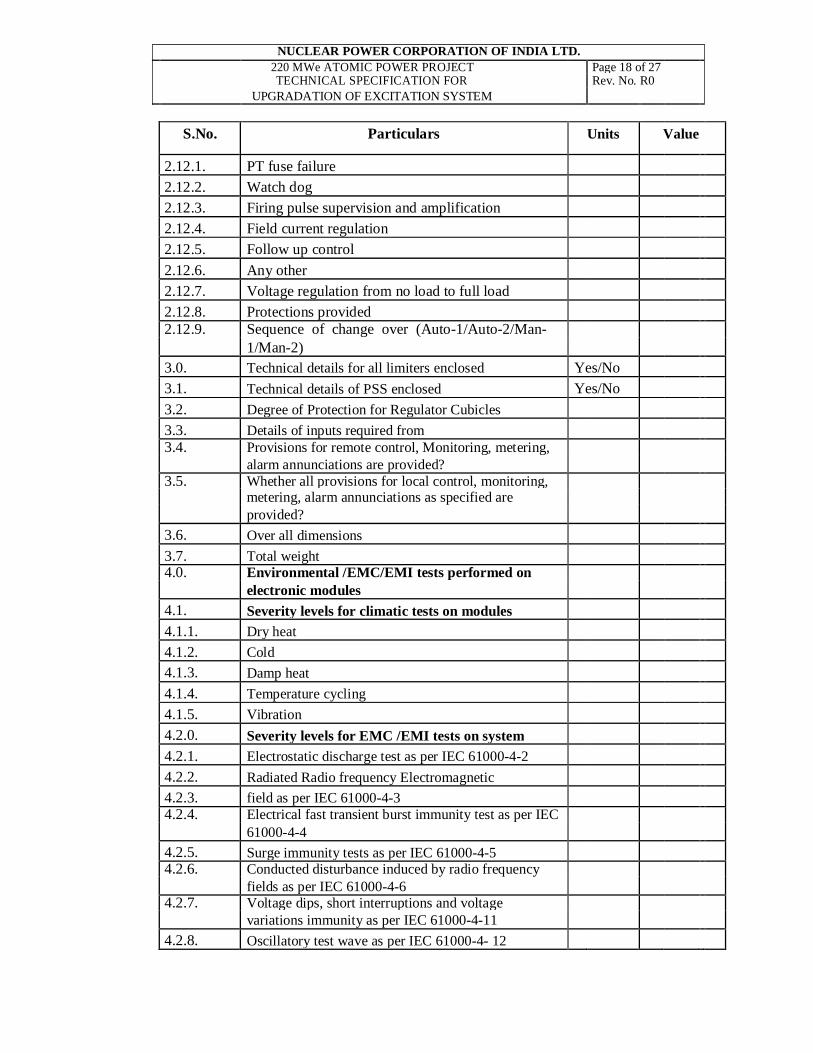
UPGRADATION OF EXCITATION SYSTEM 4.0 PERFORMANCE DATA TO BE SUBMITTED ALONGWITH THE TENDER
CONTRACTOR shall submit for each type item offered, a tabulation indicating details of equipment type tested, type tests carried out, severity levels, place of type testing, type test certificate reference number, data of testing and whether any modification to the type tested equipment has been carried out after type testing and whether the type tested equipment and the equipment offered are identical.
SIGNATURE _________________
DESIGNATION _________________
COMPANY _________________
DATE _________________
SEAL OF COMPANY

NUCLEAR POWER CORPORATION OF INDIA LTD. 220 MWe ATOMIC POWER PROJECT Page 24 of 27 TECHNICAL SPECIFICATION FOR Rev. No. R0
UPGRADATION OF EXCITATION SYSTEM 5.0. SCHEDULE OF DEVIATIONS FROM TECHNICAL SPECIFICATION
All deviations from the technical specification shall be filled in by the CONTRACTOR clause by clause in this schedule.
Section Clause No Deviation if any
The CONTRACTOR hereby certifies that the above mentioned are the only deviations from the technical specification of the enquiry.
SIGNATURE ________________
DESIGNATION ________________
COMPANY ________________
DATE ________________
SEAL OF COMPANY

NUCLEAR POWER CORPORATION OF INDIA LTD. 220 MWe ATOMIC POWER PROJECT Page 25 of 27 TECHNICAL SPECIFICATION FOR Rev. No. R0 UPGRADATION OF EXCITATION SYSTEM
6.0 SCHEDULE OF MANUFACTURING DELIVERY AND OTHER RELATED ACTIVITIES
The CONTRACTOR shall indicate the time required for manufacture, inspection and delivery and other activities of each equipment as shown below:
Project Time from date Time required Total time from Time required for
of order to test for shipment to date of order to erection, testing and at factory site receipt at site commissioning (Months) (Months) (Months) (Months) RAPS-3&4
We, the undersigned hereby undertake to meet the above time schedule from the date of order.
SIGNATURE _____________
DESIGNATION _____________
COMPANY _____________
DATE _____________ SEAL OF COMPANY
NUCLEAR POWER CORPORATION OF INDIA LTD. 220 MWe ATOMIC POWER PROJECT Page 26 of 27 TECHNICAL SPECIFICATION FOR Rev. No. R0
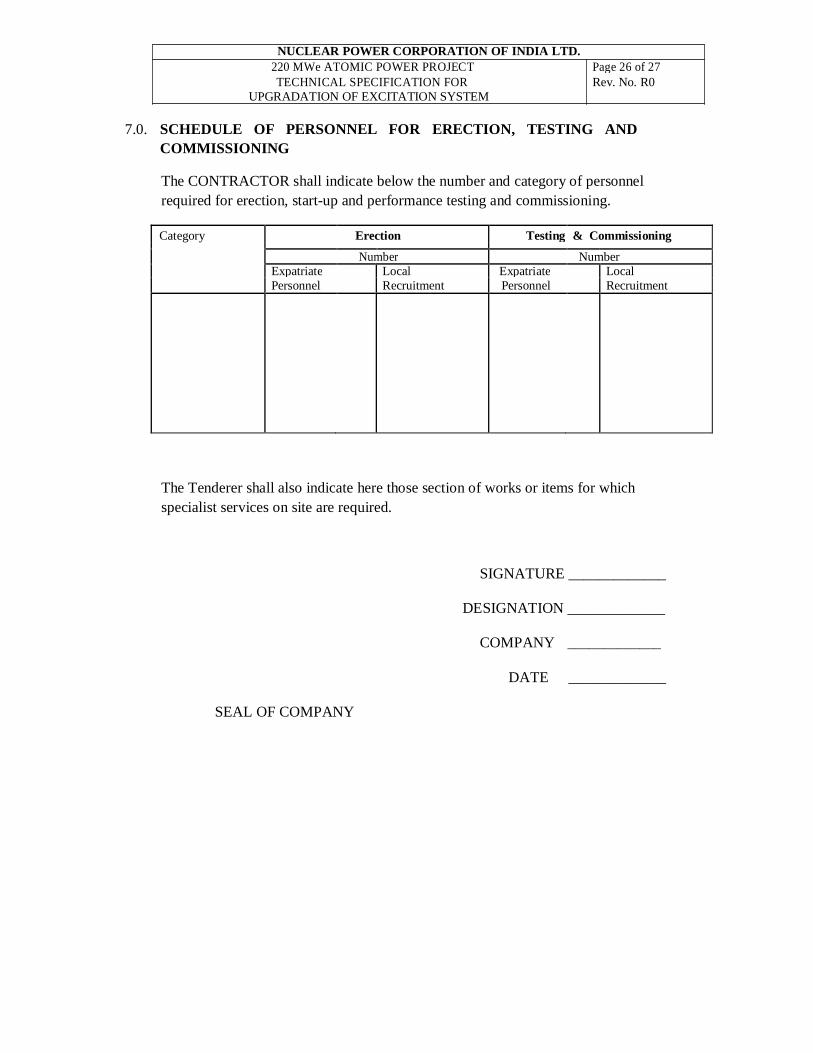
UPGRADATION OF EXCITATION SYSTEM 7.0. SCHEDULE OF PERSONNEL FOR ERECTION, TESTING AND
COMMISSIONING
The CONTRACTOR shall indicate below the number and category of personnel required for erection, start-up and performance testing and commissioning.
Category Erection Testing & Commissioning
Number Number Expatriate Local Expatriate Local Personnel Recruitment Personnel Recruitment
The Tenderer shall also indicate here those section of works or items for which specialist services on site are required.
SIGNATURE _____________
DESIGNATION _____________
COMPANY _____________
DATE _____________
SEAL OF COMPANY

NUCLEAR POWER CORPORATION OF INDIA LTD. 220 MWe ATOMIC POWER PROJECT Page 27 of 27 TECHNICAL SPECIFICATION FOR Rev. No. R0
UPGRADATION OF EXCITATION SYSTEM 8.0. SCHEDULE OF RECOMMENDED SPARES
SIGNATURE ________________
DESIGNATION _________________
COMPANY _________________
DATE _________________
SEAL OF COMPANY


![Środki płatnicze w Nowym Testamencie [The Legal Tenders in the New Testament]](https://static.fdokumen.com/doc/165x107/631a4fb820bd5bb1740c3a87/srodki-platnicze-w-nowym-testamencie-the-legal-tenders-in-the-new-testament.jpg)