BILLS OF QUANTITIES; - Tenders Kenya
319
CLIENT M/S KAREN ROSES JOINT BODY Project team Project Architect Arch. Pius Wambua Building Services Engineer P O Box 6687 - 00100 Nairobi, Kenya Civil/Structural Engineer Eng. Peter Waweru Quantity Surveyor P O Box 8589 – 00100 Nairobi, Kenya ______________ ______________ ______________ ______________ ______________ ______________ ______________ ______________ ______________ ______________ ______________ ______________ ______________ ______________ ______________ ______________ ______________ ______________ ______________ ______________ ______________ ______________ ______________ ______________ ______________ ______________ ______________ ______________ ______________ ______________ ______________ ______________ PROPOSED ALTERATIONS AND RENOVATIONS AT RESOURCE CENTRE FOR THE KAREN ROSES JOINT BODY IN ELDAMA RAVINE BILLS OF QUANTITIES; JUNE 2021
-
Upload
khangminh22 -
Category
Documents
-
view
2 -
download
0
Transcript of BILLS OF QUANTITIES; - Tenders Kenya

CLIENT
M/S KAREN ROSES JOINT BODY
Project team
Project Architect
Arch. Pius Wambua
Building Services Engineer
P O Box 6687 - 00100
Nairobi, Kenya
Civil/Structural Engineer
Eng. Peter Waweru
Quantity Surveyor
P O Box 8589 – 00100
Nairobi, Kenya
______________
______________
______________
______________
______________
______________
______________
______________
______________
______________
______________
______________
______________
______________
______________
______________
______________
______________
______________
______________
______________
______________
______________
______________
______________
______________
______________
______________
______________
______________
______________
______________
PROPOSED ALTERATIONS AND RENOVATIONS AT
RESOURCE CENTRE FOR THE KAREN ROSES JOINT
BODY IN ELDAMA RAVINE
BILLS OF QUANTITIES;
JUNE 2021

PART NO. 1
1. Signature Page
2. Form of Tender
3. Index
4. Conditions of Tendering
5. Special Notes
6. Schedule of Drawings

SPECIFICATIONS
AND BILLS OF QUANTITIES
FOR PROPOSED ALTERATIONS AND RENOVATIONS
AT RESOURCE CENTRE IN ELDAMA RAVINE
FOR MESSRS. KAREN ROSES JOINT BODY
Supplied as part of the Contract for the erection and completion of the above Works.
ISSUED BY:- PREPARED BY:-
Messrs. Karen Roses Joint Body, Zimaki Consult Ltd,
P.O. Box …………………. Quantity Surveyors,
P. O. Box 8589-00100,
NAIROBI.
The Contract for the above mentioned works entered into on the
................................................. day of ....................................... 2021 by the undersigned parties refers
to these Bills of Quantities and the Specifications contained in Part No. 4 herein all consisting of the
Pages numbered on Page 1/4 of this Document and the drawings listed on Pages 1/7 all of which shall
be read and construed as part of the said Contract.
...................................................................................... ................................................................
EMPLOYER CONTRACTOR
KAREN ROSES JOINT BODY
DATE ............................................2021 DATE ...........................................2021
SIGNATURE PAGE
1/1

FORM OF TENDER
TO: Karen Roses Joint Body,
P.O. Box ……………..,
Dear Sirs,
PROPOSED ALTERATIONS AND RENOVATIONS AT RESOURCE CENTRE IN ELDAMA RAVINE FOR KAREN ROSES JOINT BODY
1.00 I/We ………………………………………………………..under and subject to the Conditions
of Tendering annexed hereto, hereby Tender and offer to execute and perform the works and
provisions and supply of labour and materials and everything of every kind respectively
named, shown, described and alluded to in, or to be inferred from the Form of Contract
Agreement, the General Conditions of Contract, Specifications, Drawings and these Bills of
Quantities to be executed and supplied on the part of the Contractor for the works herein
described for the Lump Sum of: -
KENYA SHILLINGS…………………………...…………………………………………….
……………………………………………. (KSHS. ………………../……..)
1.01 I/We agree to complete the Works within ……………...calendar weeks from the date of
possession of site or within such extended time as the conditions of contract shall provide.
1.03 I/We further agree to be bound by and submit to the said General Conditions of Contract and
priced Bills of Quantities which shall form a basis for valuation of interim Certificates and any
extra or omitted work which may from time to time be ordered by the Architect.
2.01 I/We submit the name of ……………………………………………………….who is
willing to be bound to the Employer in an amount equal to 10% of the Contract amount for the
due performance of the Contract upto the date of completion of the Works as certified by the
Architect and who will, when and if called upon, sign a Bond to that effect as the Employer
may require.
1/2

FORM OF TENDER (Ctd.)
3.00 Whereas it is understood that you reserve to yourself the right to accept or to refuse this
Tender whether it be lower or higher than any other Tender, or of the same amount, the
undersigned agree(s) that this Tender shall remain valid and shall not be withdrawn within
One Hundred and Twenty (120) days from the final date for the submission of Tenders
stipulated in the Conditions of Tendering
4.01 And further, the undersigned agree(s), in the event of your acceptance of this Tender, to
execute the formal Contract Agreement within ten (10) days from posting, or delivery if by
hand, of notification of acceptance.
Signature of Tenderer ..........................................................................
Name of Tenderer ..........................................................................
Address ..........................................................................
..........................................................................
Date ..........................................................................
Signature of Witness .........................................................................
Name of Witness .........................................................................
Address .........................................................................
.........................................................................
Date .........................................................................
1/3

SPECIFICATIONS AND
BILLS OF QUANTITIES FOR
PROPOSED ALTERATIONS AND RENOVATIONS AT
RESOURCE CENTRE IN ELDAMA RAVINE FOR
MESSRS. KAREN ROSES JOINT BODY
INDEX
PART NO. CONTENTS PAGE NO.
1. Signature Page .. .. .. 1/1
Form of Tender .. .. .. 1/2-1/3
Declaration ..
..
..
1/4
Index .. .. .. 1/4
Conditions of Tendering .. .. 1/5
Special Notes .. .. 1/6
Schedule of Drawings .. .. 1/7
2. General Preliminaries .. .. 2/1-2/25
3. Particular Preliminaries .. .. 3/1-3/18
4. Specifications .. .. 4/1-4/84
BILLS OF QUANTITIES FOR: -
5. Main Office Block .. .. MW/1-MW/39
6.
Gate House
..
..
GH/1-GH/9
7. External works (All provisional) .. EW/1-EW/10
8.
PC & Provisional sums
..
..
PC/1
9.
Grand Summary
..
..
Grand Sum
1/4

SPECIFICATIONS AND
BILLS OF QUANTITIES FOR
PROPOSED ALTERATIONS AND RENOVATIONS AT
RESOURCE CENTRE IN ELDAMA RAVINE FOR
MESSRS. KAREN ROSES JOINT BODY
CONDITIONS OF TENDERING
1. Each Tenderer must submit, enclosed and sealed in an addressed envelope a genuine Tender
on the Tender Form together with the Specifications and Bills of Quantities, fully priced and
extended out in INK and signed by the Tenderer and consistent in all respects with amount
Tendered.
2. The priced Tender Document must reach the venue stipulated in the board’s letter of
invitation to tender at or before the time and date stated therein and Tenders will be
opened thereafter. Tenderers or their representatives are permitted to be present at the
Tender Opening.
3. In the case of a Tender not being delivered by hand, the Tenderer must arrange for his Tender
and other Documents to be posted in time to reach the above office not later than the time
stipulated in the letter of invitation.
4. Any Tender delivered after the above stipulated time, from whatever cause arising, will be
disqualified.
5. In no case will any expense incurred by the Tenderer in the preparation of his Tender be
allowed.
6. Tenders shall remain valid for One Hundred and Twenty (120) days from the final date for
submission of Tenders stipulated in Paragraph 3 above, and no Tenderer may withdraw his
Tender within that period.
7. The Employer shall not bound to accept the lowest or any Tender.
8. The Employer shall notify the accepted approved Tenderer (if any) of such acceptance by
letter within One Hundred and Twenty (120) days during which, by Paragraph 6 there above,
the Tender is to remain valid and the said Tenderer shall then within the time stated in the
Form of Tender first execute the formal Contract Agreement and then on the same day his
approved Surety shall sign the Bond. The Employer, however, reserves the right to extend the
period for executing the formal Contract Agreement if satisfied that adequate reasons exist for
so doing.
9. If it is found on the examination of a Tender that there are arithmetical errors, then the
difference between the Tender and the corrected total shall be applied as a percentage
adjustment of addition or omission on all the builder’s rates so that the original Tender
Amount remains unaltered. When calculating the percentage adjustment, the total cost of the
Preliminaries, Provisional and P.C. sums, Contingencies and any other items of a similar
nature shall be excluded.
10. Non-Compliance with the above Conditions in any respect shall render the Tender liable to
rejection.
1/5

SPECIFICATIONS AND
BILLS OF QUANTITIES FOR
PROPOSED ALTERATIONS AND RENOVATIONS AT
RESOURCE CENTRE IN ELDAMA RAVINE FOR
MESSRS. KAREN ROSES JOINT BODY
SPECIAL NOTES
1. The Tenderer shall tender for the above Works in accordance with the appended drawings,
Schedules, Specifications and Bills of Quantities.
2. The Tenderer is required to check the numbers of the pages of these Specifications against the contents
stated on Page 1/5 and should he find any missing, in duplicate or indistinct he must inform the Quantity
Surveyor at once and have the same rectified.
3. Should the Tenderer be in doubt about the precise meaning of any item or figures, for any reason
whatsoever, he must inform the Quantity Surveyor at once in order that the correct meaning may be
decided before the date for submission of the tenders.
4. No liability will be admitted or claim allowed in respect of errors in the Tenderer’s Tender due to
mistakes in the Specifications or non compliance with instructions 2 & 3 above,
which should have been rectified in the manner described above.
5. The annexed Bills of Quantities must be fully priced in ink. The Tenderer shall not alter or otherwise
qualify the text of these Specifications and Bills of Quantities. Any alteration or qualification made
without authority will be ignored and the text of the Bills of Quantities as printed will be adhered to.
6. The Tenderer shall be deemed to have made allowance in his prices generally to cover items of
Preliminaries or additions to Prime Cost Sums or other items, if the Tenderer has not priced these where
appropriate.
7. Tenderer’s should note that all their Bills of Quantities rates for measured items and all preliminaries
should include V.A.T. It should further be noted that all the Provisional and P.C. Sums given herein
are also inclusive of V.A.T
8. All items of measured work shall be priced in detail and tenders containing Lump Sums to cover trades
or groups of work must be broken down to show prices of each item before they will be accepted. Lump
Sums to cover items of Preliminaries shall be likewise broken down if so required.
9. In no case will any expense incurred by Tenderers in preparation of this Tender be allowed.
10. The copyright of these Specifications and Bills of Quantities is vested in the Quantity Surveyors and no
part thereof may be reproduced without their express permission given in writing.
11. The Tenderer is solely responsible for the accurate ordering of materials in accordance with the
Drawings and Architect’s instructions and no claim for any loss or expense will be
entertained for orders for materials based upon the Bills of Quantities.
12. Contractors are encouraged to visit and familiarize themselves with the site prior to pricing and
submitting their tender as no liability will be admitted or claim allowed in respect of the tenderer’s lack
of knowledge of the site conditions
13. Tenderers are strongly advised to visit the architect’s and engineer’s offices to inspect all drawings
and any other details they deem necessary and essential prior to submission of their tender . No claim
will be entertained in respect of tenderer not having inspected the solid documents
1/6
SPECIFICATIONS AND
BILLS OF QUANTITIES FOR
PROPOSED ALTERATIONS AND RENOVATIONS AT
RESOURCE CENTRE IN ELDAMA RAVINE FOR
MESSRS. KAREN ROSES JOINT BODY
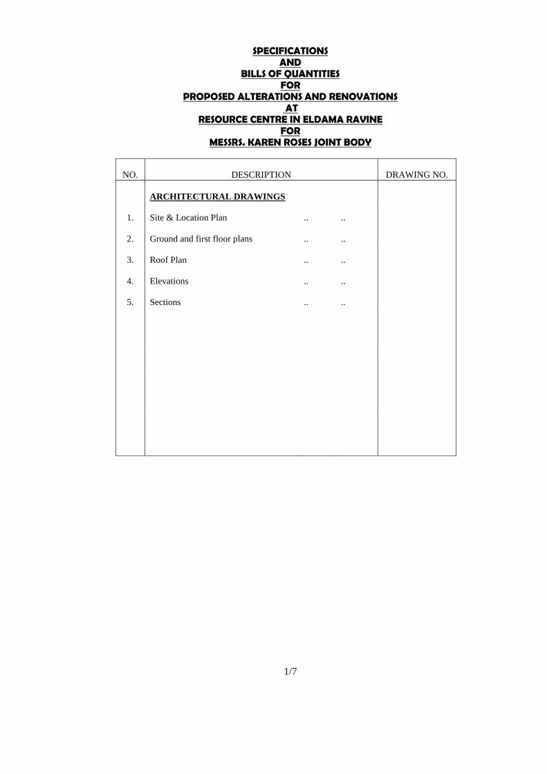
NO.
DESCRIPTION
DRAWING NO.
ARCHITECTURAL DRAWINGS
1.
Site & Location Plan
..
..
111L(--)00-01
2.
Ground and first floor plans
..
..
11L(--)02
3.
Roof Plan
..
..
L(--)03
4.
Elevations
..
..
L(--)04
5.
Sections
..
..
L(--)05
6.
Third floor plan
..
..
L(--)06
7.
Fourth floor plan
..
..
L(--)07
8.
Roof plan
..
..
L(--)08
9.
Elevations
..
..
L(--)09
10.
Sections
..
..
L(--)10
L(--)10-14
L(--)15-16
1/7

PART NO. 2
GENERAL PRELIMINARIES

A.
B.
PART NO 2
GENERAL PRELIMINARIES
PRICING OF ITEMS OF PRELIMINARIES AND PREAMBLES
Wherever in the Contractor’s priced Tender Documents no price appears against an item of
Preliminaries or Bills of Quantities, the value of such item shall be deemed to be included in
their prices for the other items in the Preliminaries and Bills of Quantities.
ABBREVIATIONS
Throughout these Bills, units of measurements and terms are abbreviated and shall be
interpreted as follows:-
Shs. Cts
‘m3’
‘m2.’
‘m.”
‘Lbs.’
‘kg.’
‘No.’
‘prs.’
‘m.s.’
‘B.S.S.’
‘Do.’ Or
‘Ditto’
shall mean Cubic Metre
shall mean Square Metre
shall mean Linear Metre
shall mean Pounds Weight Avoidupois
shall mean Kilogramme
shall mean Number
shall mean Pairs
shall mean Measured Separately
shall mean the current British Standard Specifications published by the
British Standard Institution, 2 Park Street, London W.1, England
shall mean the whole of the preceding description except as qualified in the
description in which it occurs. Where it occurs in descriptions of
succeeding items, it shall mean the same as in the first description
concerned. Where it occurs in brackets, it shall mean the whole of the
preceding description which is contained within the appropriate brackets.
Where it is underline it shall mean the whole of that part or the preceding
description which is underlined.
‘As described’(a.d.) or ‘as before described’(a.b.d.) shall mean as described in the
Specification or as described previously in a foregoing item or Bill.
NOTE
‘Selected, directed, approved’, etc.
Wherever the words, ‘selected’ or ‘as directed’, ‘as required’, or words of similar meanings
are used in the Bills of Quantities, it is to be understood that the selections, directions or
requirements of the Architect are intended. Similarly, the words, ‘approved’, ‘satisfactory
to’ the Architect and the Architect’s materials are ordered or the works to which the words
refer are put in hand.
Carried to Part Summary Shs.
2/1

B
A
PART NO. 2 (Ctd.)
GENERAL PRELIMINARIES (Ctd.)
ABBREVIATIONS (Ctd.)
‘Necessary, proper’, etc.
Wherever the words ‘necessary, proper’ or words of similar meanings are used in these Bills
of Quantities with respect to the extent, conduct, character or work described, it is to be
understood that they shall mean that the said work shall be executed to the extent, must be
conducted in a manner or be of a character which is ‘necessary’ or ‘proper’ in the opinion of
the Architect.
‘Singular and Plural’
Words importing the singular only wherever used hereinafter and in all Contract Documents
shall also include the plural and vice versa where the context required.
DEFINITION OF TERMS
Shs. Cts
1.
2.
3.
4.
Employer
The term ‘The Employer’ shall be deemed to mean Messrs. Karen Roses Joint
Body, The term ‘Employer’, ‘Client’ and ‘Owner’ wherever used in this Tender
Document shall be synonymous
Architect
The term “Architect” shall be deemed to mean the firm of Mr. Pius Wambua,
NAIROBI, E-Mail: [email protected]
Quantity Surveyor
The term ‘The Quantity Surveyor’ shall be deemed to mean the firm of Messrs.
Zimaki Consult Ltd, Quantity Surveyors, P.O. Box 8589 00100, NAIROBI, Tel
Nos. 020 8008648. E-Mail: [email protected]
Engineer
The term “Engineer” shall be deemed to mean any of the following firms appointed
by the Employer to carry out the work under reference
(a) Services Engineers
Messrs. Fostertech MEP Consultants, P. O. Box 6687-00100 NAIROBI
(b)
Structural/Civil Engineers
Mr. Patrick Waweru
Carried to Part Summary Shs.
2/2

PART NO. 2 (Ctd) Shs. Cts.
GENERAL PRELIMINARIES (Ctd)
A.
DEFINITION OF TERMS (Ctd)
5.
Contractor
The term “Contractor” shall mean the person or persons, partnership, firm or
company, whose tender for this work has been accepted and who has or have
signed this Contract and shall include his or their heirs, executors, administrators
assignees, successors and duly appointed representatives.
6.
Sub-Contractor
The term “Sub-Contractor” shall be deemed to mean the person or persons,
partnership, firm or company who has or have been engaged by the Contractor
to carry out any Sub-Contract works forming part of this Contract and shall
include his or their heirs, etc. as described above or who shall be appointed by
the Employer to carry out the Sub-Contract Works.
B.
FORM OF CONTRACT
The Contractor will be required to enter into a Contract with the Employer on the latest
Edition of the Agreement and Conditions of Contract for Building Works published by
the Joint Building Council, Kenya.
The clause headings of the above Conditions of Contract are given herebelow but for a
complete description of the Clauses, tenders should refer to the above document, a copy
of which is available for inspection at our Nairobi offices during normal working hours or
can be purchased from the Professional Centre, Parliament Road, St. John’s Gate,
Nairobi.
C.
CONDITIONS OF CONTRACT
The Tenderer’s attention is called to the following Clauses of the Conditions of Contract
which shall be read as incorporated herein and he shall allow any sums which he
considers necessary for the carrying out and observance of such Conditions:
Clause 1
Definitions
Clause 2
Articles of Agreement
Clause 3
General obligations of the Employer
Amendment: The end of the sentence comprising paragraphs 3.4
commencing with the words ‘and shall provide such evidence’ shall be
deleted.
Note: The Employer’s obligation shall be confirmed in writing to the
successful Contractor by the Architect.
Clause 4
General obligations of the Contractor
Note: The Contractor shall allow for paying all legally demandable fees,
rates or national and county taxes including V.A.T, import duties, Railway
levies, NCA charges., and those for hoarding and temporary buildings, and
no adjustment of the Contract Sum will be made in respect of such
payments unless expressly stated to the contrary in these Bills of Quantities.
NOTE:
Also see item B
on Page 3/8
Carried to Part Summary
Shs.
2/3

PART NO. 2 (Ctd) Shs. Cts.
GENERAL PRELIMINARIES (Ctd)
C.
CONDITIONS OF CONTRACT (Ctd)
The Contractor shall apply for, provide all transport necessary for, and pay
all costs and charges in connection with the Occupation Certificate.
Documentation required for such Certificate will be provided by the
Architect.
Clause 5
General obligations of the Architect
Clause 6
General obligations of the Quantity Surveyor
Clause 7
Contract documents
Amendments:
1.
The word “Employer” in clause 7.3 shall be deleted and replaced
with the word “Contractor”
2.
Clause 7.10.3 shall be re-numbered 7.10.5 while clause 7.10.5 shall
be re-numbered 7.10.3
Clause 8
Contract Bills and Contract Price
Note: The Contract Bills have generally been prepared in accordance
with the latest edition of the Standard Method of Measurement of Building
Works published by the Architectural Association of Kenya, Chapter of
Quantity Surveyors as amended at the end of these Preliminaries. This
document is available for purchase from the Professional Centre,
Parliament Road, St. John’s Gate, P.O. Box 72643, Nairobi, Kenya or may
be inspected at the offices of the Quantity Surveyors or any other location
specified by them.
Also see Item D
on Page 2/23
Note: All Payments made in connection with this Contract will be in
Kenya Shillings
Clause 9
Contractors site agent and other staff
Note: the Architect will require that the proposed site agent is properly
qualified and experienced and reserves the right to order the dismissal
from the works of any site agent who does not meet with his approval
Clause 10
Clerk of Works
Clause 11
Liability against injury to persons and property
Clause 12
Insurance against Injury to Persons and Property
Note: the Contractor shall effect and maintain the following insurances in
the joint names of the Employer and Contractor with an insurance firm to
the approval of the Employer and Architect to cover the full value of the
following insurances as required by Clause 13 and shall allow for all costs
thereof: -
Carried to Part Summary Shs.
2/4

PART NO. 2 (Ctd) Shs. Cts.
GENERAL PRELIMINARIES (Ctd)
C.
CONDITIONS OF CONTRACT (Ctd)
(a)
Employer’s Liability (Workmen’s Compensation)
(b)
Third Party (Public) Liability for an Indemnity of not less than
Kenya Shillings Twenty Million (KShs. 5,000,000.00) in any one
accident or series of accidents arising from the same event (unlimited
in aggregate)
Should the Contractor already hold annual insurance covering the whole of
his activities and the indemnity required under this Contract exceeds the
indemnity under the existing policy(ies), then further insurances shall be
effected and maintained to cover such excess.
The Contractor shall ensure that all Sub-Contractors effect and maintain
such insurances as are necessary to cover their liabilities in respect of
injury to persons and property and Workmen’s Compensation.
Clause 13
Insurance of the Works (Contractors Liability)
Clause 14
Insurance of the Works (Employer’s Liability)
Note: This Clause is deleted
Clause 15
Insurance of the Works (works of Alterations etc)
NOTES ON INSURANCE
In addition to the Conditions of Contract and the requirements contained in
the foregoing Clauses, the Contractor/Employer shall include in the
insurance policies described above full Indemnity for the following items
and shall allow for all costs thereof: -
NOTE
Also see Item D
on Page 2/21
(a) The Contract Works and temporary works to be erected in
performance of this Contract to the value of not less than the
Contract Sum.
(b)
The Materials on Site.
(c)
The Contractor’s plant, tools and equipment
(d)
Professional fees to be calculated at Thirteen point five percent
(13.5%) of Contract Sum
(e)
Escalation/inflation on (b) above for an Indemnity of not less than
15% of the Contract Sum
(f)
Spare parts, fuel, stores, provisions and property of employees (Note:
This item to be at the discretion of the Contractor)
Carried to Part Summary
Shs.
2/5

PART NO. 2 (Ctd) Shs. Cts.
GENERAL PRELIMINARIES (Ctd)
C.
CONDITIONS OF CONTRACT (Ctd)
Full Indemnity shall also be taken out in the same Policy to include
and Indemnify the following SPECIAL CLAUSES: -
(g)
Automatic reinstatement of loss
(h) Damage to any existing property
(j) The Maintenance period of Six (6) Months
(k) The Fluctuation Clause
(l) All site Sub-Contractors
(m) All cross liabilities
(n) The Principals Clause
Any EXCESS cover required shall be at the sole discretion of the
Contractor or example for any or all of the following
Storm, flood, subsidence, collapse, etc.
Plant and equipment claims
Third party claims
Goods in transit claims or any other Claim
Clause 16
Performance Bond
(a)
Clause 16.1 – The Contractor shall either allow for a Cash Bond or
obtain and submit on the Form of Tender the name of one Surety
who shall be an established and duly registered bank or insurance
Company or fidelity guarantee company and who are willing to be
bound to the Employer in an amount equal to Ten Percent (10%) of
the Contract amount for the due performance of the Contract up to
the date of completion as certified by the Architect and who will
when and if called upon, sign a Bond annexed in the Form of
Agreement (Without the addition of any limitations) on the same day
as the Contract Agreement is signed. In the event of the Surety
named in the Form of Tender not being approved by the Employer,
the Contractor shall furnish within seven (7) days another Surety to
the approval of the Employer
NOTE
(b)
Clause 16.2 – Employer’s Performance Bond (Not Applicable - to be
deleted)
NOTE
Clause 17
Compliance with regulations, notices etc.
Clause 18
Programme of works
Clause 19
Access to the works.
The contractor shall provide to the Employer and his representative’s access
to the works and workshops or other places of the Contractor where work is
being prepared for the Contract. This shall be in addition to similar access
to be provided to the Architect and his representatives.
Clause 20
Possession of site and commencement of works
Carried to Part Summary
Shs.
2/6
PART NO. 2 (Ctd) Shs. Cts.
GENERAL PRELIMINARIES (Ctd)
C.
CONDITIONS OF CONTRACT (Ctd.)
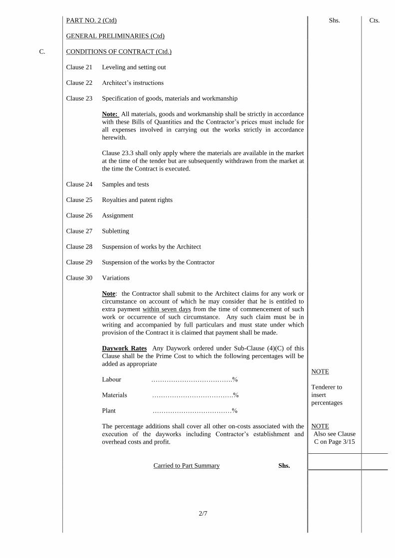
Clause 21
Leveling and setting out
Clause 22
Architect’s instructions
Clause 23
Specification of goods, materials and workmanship
Note: All materials, goods and workmanship shall be strictly in accordance
with these Bills of Quantities and the Contractor’s prices must include for
all expenses involved in carrying out the works strictly in accordance
herewith.
Clause 23.3 shall only apply where the materials are available in the market
at the time of the tender but are subsequently withdrawn from the market at
the time the Contract is executed.
Clause 24
Samples and tests
Clause 25
Royalties and patent rights
Clause 26
Assignment
Clause 27
Subletting
Clause 28
Suspension of works by the Architect
Clause 29
Suspension of the works by the Contractor
Clause 30
Variations
Note: the Contractor shall submit to the Architect claims for any work or
circumstance on account of which he may consider that he is entitled to
extra payment within seven days from the time of commencement of such
work or occurrence of such circumstance. Any such claim must be in
writing and accompanied by full particulars and must state under which
provision of the Contract it is claimed that payment shall be made.
Daywork Rates Any Daywork ordered under Sub-Clause (4)(C) of this
Clause shall be the Prime Cost to which the following percentages will be
added as appropriate
Labour ……………………………….%
Materials ……………………………….%
Plant ………………………………%
The percentage additions shall cover all other on-costs associated with the
execution of the dayworks including Contractor’s establishment and
overhead costs and profit.
NOTE
Tenderer to
insert
percentages
NOTE
Also see Clause
C on Page 3/15
Carried to Part Summary Shs.
2/7
PART NO. 2 (Ctd) Shs. Cts.
GENERAL PRELIMINARIES (Ctd)
C
CONDITIONS OF CONTRACT (Ctd)
The Prime Cost shall in each case be calculated on the basis of market
prices prevailing as at the date of execution of the daywork and shall be
determined by the Quantity Surveyor.
Daywork will be allowed only where specifically ordered or authorized by
the Architect or their authorized representative in writing.
All daywork sheets must be signed by both the Architect and the Contractor
or their authorized representatives.
Final Account
The Contractor shall be required to prepare and submit to the Quantity
Surveyor for their agreement, detailed Bills of Quantities for all variation
works requiring remeasurement and works covered by Provisional Sums as
soon as such works are completed and the Tenderer should allow for all
costs involved in complying with this requirement. The agreed Bills will
form the basis of the Final Account.
IMPORTANT
NOTE
Clause 31 Nominated Sub-Contractors
Note: The Contractor must enter into Sub-Contracts with the Nominated
Sub-Contractors on the latest edition of the Standard ‘Agreement and
Schedule of Conditions of Building Sub-Contract’ form published by the
Kenya Association of Building and Civil Engineering Contractors. He must
incorporate therein any conditions herein applicable to Nominated Sub-
contractors and if he fails to do so must accept full responsibility for any
omissions, delays, bad workmanship, claims or expenses arising from the
absence thereof. The Sub-Contract must cover such matters as payments on
account, retention sums, maintenance period, facilities, dates for completion
of each portion of the works together with a liquidated and ascertained
damages clause in the event of delayed completion or non-completion and
indemnity of the Contractor against any claims arising out of the misuse by
any such Sub-Contractor or his workmen of any scaffold erected or plant
employed by the Contractor, or that may be made against the Contractor in
consequence of any act, omission or default of the Sub-Contractor, his
servants or agents, or in respect of injury to workmen employed by the Sub-
Contractor.
Notwithstanding the provisions contained in Clauses 31, the Employer
reserves the right to incorporate work of any Nominated Sub-Contractor
into the Main Contract in which event the Nominated Sub-Contractor shall
become a domestic Sub-Contractor to the Main Contractor for all intents
and purposes of this Contract. Any rights and obligations of the Nominated
Sub-Contractor under Clause 31 will in that event revert to the Main
Contractor. No claims will be entertained from the Main Contractor if the
Employer decides to exercise this right but profit, overheads and attendance
on the appropriate P.C. Sums will be paid as provided for in the Contract.
Also see Item D
on Page 2/20 &
Item B on Page
3/16
IMPORTANT
NOTE
Carried to Part Summary Shs.
2/8
PART NO. 2 (Ctd) Shs. Cts.
GENERAL PRELIMINARIES (Ctd)
C.
CONDITIONS OF CONTRACT (Ctd)
Clause 32
Nominated Suppliers
Note:
With regard to Nominated Sub-Contractors and Suppliers: -
Also see Item D
on Page 2/20 &
Item B on Page
3/16
(a)
The Contractor will not receive any cash, trade or other discounts on
Prime Cost and Provisional Sums. Any profit in lieu of these
discounts which the Contractor desires must be priced by him against
the appropriate items provided in the Bills of Quantities.
(b)
When tendering for works covered by Prime Cost and Provisional
Sums, the Contractor will be treated as any other Nominated
Supplier or Sub-Contractor.
(c)
The Employer reserves the right to pay direct on certificates of the
Architect some or all accounts in respect of works and Provisional
Sums due to Nominated Sub-Contractors or Nominated Suppliers
and to deduct any amounts so paid from any sums otherwise payable
to the Contractor. Should this reservation be adopted, any profits
which the Contractor may have allowed on Prime Cost and
Provisional Sums may be omitted from the Contract, at the discretion
of the Architect.
Direct payment will not be deemed to construe omission of the work
from the Contract and the Contractor will continue to be responsible
for the work or goods in accordance with the terms of the Contract.
Clause 33
Works by other persons engaged by the Employer
Clause 34
Payments
NOTES:
(a)
At intervals stated, Certificates shall be issued subject to Sub-Clause
34.4. When applying for a Certificate, the Contractor shall furnish
the Quantity Surveyor with a detailed approximate statement of the
value of work executed and all materials on site in order to expedite
the issue of the Certificates.
(b)
Subsequent Certificates will not be issued to the Contractor by the
Architect until satisfactory proof has been given by the Contractor
that Nominated Sub-Contractors and Suppliers have been paid the
amounts included for them in previous Certificates issued to the
Contractor.
Carried to Part Summary Shs.
2/9

PART NO. 2 (Ctd) Shs. Cts.
GENERAL PRELIMINARIES (Ctd)
C.
CONDITIONS OF CONTRACT (Ctd)
(c)
All documents necessary for the purpose of the composition of the
Final Account including all documents relating to the Accounts of
Nominated Sub-Contractors and suppliers shall be passed to the
Quantity Surveyor as and when available during the progress of the
works and not later than one month after Date of Practical
Completion
(d)
The whole of Sub-Clauses 34.14 and 34.15 shall be deleted
Clause 35
Fluctuations Note: Delete the whole of this clause
IMPORTANT
NOTES
This is a fixed rate Contract and the Contractor must allow in his tender for
any increase in the cost of labour, materials and plant for any reason
whatsoever during the currency of the Contract.
Also see Item D
on Page 3/5
Clause 36
Extension of time
NOTE
Sub clause 36.1.2 to be amended as follows: “by reason of any
exceptionally adverse weather conditions taking into considerations the
worst weather conditions recorded in the past Ten (10) years by the
Meteorological Department”
Clause 37
Loss and expense caused by disturbance of regular progress of the works
Clause 38
Termination of the Contract by Employer
Clause 39
Termination of the Contract by the Contractor
Clause 40
Termination of the Contract by either party
Clause 41
Practical completion and defects liability
Also see Item A
on Page 3/16
Clause 42
Sectional completion
Also see Item C
on Page 3/5
Clause 43
Damages for delay in completion
Clause 44
Antiquities and other objects of value
Clause 45
Settlement of disputes
Carried to Part Summary Shs.
2/10

A.
PART NO. 2 (Ctd.)
GENERAL PRELIMINARIES (Ctd.)
CONDITIONS OF CONTRACT (Ctd.)
NOTE: Particulars of the insertions to be made in the Appendix to the Contract
Agreement will be found on Page 3/6 of the Particular Preliminaries of these Bills.
PROVISIONAL WORKS
All work described as “Provisional” in these Bills of Quantities is subject to re-
measurement in order to ascertain the quantity executed for which payment will be made.
All “Provisional” and other work liable to adjustment under this Contract shall be left
uncovered for a reasonable time to allow all measurements needed for such adjustments
to be taken by the Quantity Surveyor. Immediately the work is ready for measurement
the Contractor shall give notice to the Quantity Surveyor.
If the Contractor makes default in these respects, he shall, if the Quantity Surveyor so
directs, uncover the work to enable measurements to be taken and afterwards reinstate at
his own expense.
Carried to Part Summary Shs.
2/11
Shs.
IMPORTANT
NOTE
Cts.

PART NO. 2 (Ctd). KShs. Cts.
GENERAL PRELIMINARIES (Ctd).
A.
MATERIALS AND WORKMANSHIP
All materials shall be new unless otherwise directed or permitted by the Architect and
in all cases where the quality of goods or materials is not described or otherwise
specified are to be the best quality obtainable in the ordinary meaning of the word
“best” and not merely a trade signification of that word. All materials shall also be to
the approval of the Architect.
All materials and workmanship shall unless otherwise specified or described conform
to the appropriate British Standards Institution Specification current at the date of
tender.
The Contractor shall order all materials required to be obtained from overseas
immediately after the Contract is signed and shall also order materials to be obtained
from local sources as early as necessary to ensure that such materials are on site when
required for use in the works.
The Contractor shall be responsible for and shall replace or make good at his own
expense any materials lost or damaged.
Skilled workmen well versed in their respective field shall execute the Works
throughout.
The successful Tenderer shall be deemed to have investigated the practicability of
using locally available materials in the various components of the building and shall be
deemed to have priced accordingly. No claims shall be entertained thereafter for want
of knowledge in this respect.
B.
REJECTED WORKMANSHIP OR MATERIALS
Any workmanship or materials not complying with the specific requirements or
approved samples or which have been damaged, contaminated or have deteriorated,
must be immediately removed from the site and replaced at the Contractor’s expense,
when required and so instructed by the Architect.
C.
SUFFICIENCY OF TENDER
The Contractor shall be deemed to have satisfied himself before tendering as to the
correctness and sufficiency of his Tender for the works and of the rates and prices
stated in the priced Bills which rates and prices shall cover all his obligations under the
Contract and all matters and things necessary for the proper completion and
maintenance of the works.
D. STAMP DUTY CHARGES
The Contractor shall allow for the payment of all stamp duty charges in connection
with the Performance Bond and Contract Agreement.
E.
PROGRAMME AND PROGRESS SCHEDULE
Immediately upon acceptance of their tender and not later than Two weeks, the Main
Contractor shall be required to prepare a computer generated programme and progress
schedule clearly indicating the critical activities and setting out the appropriate dates
thereof including the work of Nominated Sub-Contractors. This Programme and
Progress Schedule is to be submitted to the Architect and Consultants for their
approval. No deviation from the order set out in this Schedule will be permitted
without the written consent of the Architect. The Main Contractor will be responsible
for arranging the above Programme with all Sub-Contractors and Nominated Suppliers.
IMPORTANT
NOTE
Carried to Part Summary Shs.
2/12

PART NO. 2 (Ctd). KShs. Cts.
GENERAL PRELIMINARIES (Ctd).
E. PROGRAMME AND PROGRESS SCHEDULE (Ctd).
No Payment Certificate shall be issued by the Architect until the Schedule has been
submitted and approved.
IMPORTANT
NOTE
One copy of the Schedule is to be handed to the Architect and a further copy to be
retained on site on which progress shall be recorded at regular agreed intervals by the
Contractor and produced in upto date form at all site meetings.
Should any circumstances arise affecting the Schedule, the chart shall be amended or
modified as necessary by agreement with the Architect and all parties shall be
informed.
A.
FIGURED DIMENSIONS
Figured dimensions are to be followed in preference to dimensions scaled from the
drawings but whenever possible dimensions are to be taken on the site or from the
buildings. Before any work is commenced by Sub-Contractors or Specialist Firms,
dimensions must be checked on the site and/or buildings and agreed with the
Contractor, irrespective of the comparable responsibility for the accuracy of such
dimensions.
B. PROPRIETARY MATERIALS
Where proprietary materials are specified in the Specifications, the Contractor may
propose the use of equivalent materials from other manufacturers but of equal quality
for approval by the Architect.
All materials and goods, where specified to be obtained from a particular manufacturer
or supplier are to be used or fixed strictly in accordance with their instructions.
C.
PLANT, TOOLS AND SCAFFOLDING
The Contractor shall provide all necessary hoists, tackle, plant, vehicles, tools and
appliances of every description for the due and satisfactory completion of the works
and shall remove the same on completion and provide, erect and maintain all
temporary scaffolding, sufficiently strong and efficient for the due performance of the
Works including Sub-Contractor’s works, provide special scaffolding as required by
the Sub-Contractors, alter and adapt all scaffolding as and when required during the
works and remove on completion and make good.
Also see Item
E on Page 3/13
All such plant, tools and scaffolding shall comply with all regulations whether general
or local in force throughout the period of the Contract and shall be altered and adapted
during the Contract as may be necessary to comply with any amendments in or
additions to such regulations.
NOTE:
Scaffolding is not measured hereinafter and the Contractor must allow
herein his Tender for the above.
No timber used for scaffolding, formwork or temporary works of any kind shall be
used afterwards in the permanent work.
Carried to Part Summary Shs.
2/13
PART NO. 2 (Ctd). KShs. Cts.
GENERAL PRELIMINARIES (Ctd).
A.
SIGN FOR MATERIALS SUPPLIED
The Contractor will be required to sign a receipt for all articles and materials supplied
by the Employer at the time of taking delivery thereof, as having received them in good
order and condition and will thereafter be responsible for any loss, damage, storage,
insurance, protection and handling. Any replacement will be at the Contractor’s own
cost and expense at current market prices including Customs Duty, V.A.T. and all other
related charges to the satisfaction of the Architect.
B.
STORAGE OF MATERIALS
The Contractor shall provide at his own risk and cost where directed on or off the site
weather-proof lockup sheds for the safe storage and custody of materials for the works
and for the use of workmen engaged thereon and shall remove such sheds and make
good damaged or disturbed surfaces upon completion to the satisfaction of the
Architect.
The Contractor shall also provide a separate weather-proof lock-up store for the safe
storage of materials supplied by the Employer.
NOTE
C. SAMPLES
The Contractor shall furnish at his own cost any samples of materials or workmanship
including concrete tests cubes required for the works that may be called for by the
Architect for his approval or rejection until such samples are approved by the Architect
and the Architect may reject any materials or workmanship which in his opinion is not
up to the required standards and specifications.
The procedure for submitting samples of materials for testing and the method of
marking for identification shall be as laid down by the Architect.
The Contractor shall allow in his Tender for the provision of all such samples except
those in connection with Nominated Sub-Contractor’s work.
D.
TESTING
Allow for testing all installations required to be tested and provide everything
necessary for this purpose and leave in perfect working order to the satisfaction of the
Architect and Local Authority.
Allow for all expenses in connection with testing of materials as specified hereunder
including the supply and preparation of materials and their packing and conveyance to
an approved Materials Testing Laboratory, Laboratory charges, etc.
The following tests will be measured according to the number of tests actually called
for by the Architect and carried out but unsuccessful tests will not be included in the
measurement.
Carried to Part Summary Shs.
2/14

D.
PART NO. 2 (Ctd.)
GENERAL PRELIMINARIES (Ctd.)
TESTING (Ctd.)
Shs. Cts.
TYPE OF TEST
QUANTITY
(PROVISIONAL)
RATE
Water Test (1 Litre)
Sand Test (0.1 Cubic Metre)
Aggregate Test (0.1 Cubic Metre)
Reinforcement Test (1 Linear Metre mild
steel rod or high tensile steel bar of various
diameter from 6mm to 25mm)
Concrete Test (Each test comprising four
standard cubes)
Natural Stone (blocks)
Concrete Blocks testing of various strengths
in accordance with British Standard
Specifications (one test comprises ten
blocks)
10 No.
10 No.
20 No.
10 No.
20 No.
5 No.
15 No.
A.
B.
The Contractor shall allow for other testing of materials apart from the above
required by these Specifications and he shall be responsible for all expenses incurred
in completing such tests, including costs of labour, materials, equipment, transport
and charges of the testing authority, etc.
SUPERVISION AND WORKING HOURS
The works shall be executed under the direction and to the entire satisfaction in all
respects of the Architect who shall at all times during normal working hours have
access to the works and to the yards and workshops of the Contractor and Sub-
Contractors or other places where work is being prepared for the Contract.
The working hours shall be those generally worked by good employers in the
Building and Civil Engineering Trades in the Republic of Kenya.
No work shall be carried out at night or on gazetted holidays unless the Architect
shall so direct. Supervision shall only be carried out at night on Saturdays/Sundays
or on Public Holidays with adequate advance notice and prior arrangement with the
relevant Consultant or the Clerk of Works.
No work shall be so covered up nor shall any concreting be carried out in the
absence of the Clerk of Works without the prior approval of the Architect in writing.
SITE MEETINGS
Site Meetings will be held in the site offices at intervals as directed by the Architect
and the Contractor will be required to attend and also summon the attendance of
Sub-Contractors and Specialists. Adequate arrangements must be allowed for with
regard to tables, chairs, etc which must be provided by the Contractor.
Carried to Part Summary Shs.
2/15
PART NO. 2 (Ctd.)
Shs.
Cts.

A.
B.
C.
D.
GENERAL PRELIMINARIES (Ctd.)
SITE DIARY
A site diary shall be provided by the Contractor in the form of a double foolscap size
stiff covered ruled book which should be kept available at all times upon the site.
Entries made in the site diary by the Architect or his duly appointed representative
shall be deemed to be the Architect’s instructions given in writing and the Contractor
shall confirm the same to the Architect within Seven (7) clear working days.
All persons entering the site or other working area on whatever business shall be
instructed by the Contractor to record their visit in the site diary giving their name,
address and reason for visiting the site.
EXISTING SERVICES
Prior to commencement of any work, the Contractor is to ascertain from the relevant
Authorities the exact position, depth and level of all existing electric cables, water
pipes or other services in the area and he shall make whatever provisions may be
required by the Authorities concerned for the support and protection of such
services. Any damage or disturbance caused to any service shall be reported
immediately to the Employer and the relevant Authority and shall be made good to
the satisfaction of the Architect and the Contractor’s expense.
GOVERNMENT ACTS REGARDING WORKFORCE, ETC.
Allow for complying with all Government Acts, Orders and Regulations in
connection with the Employment of Labour and other matters related to the
execution of the works. The tender price must include for all costs arising or
resulting from compliance with any Act, Order or Regulation relating to Insurances,
Pensions and Holidays for workpeople or to the safety, health or welfare of
workpeople.
The Contractor must acquaint himself duly with current Acts and Regulations,
including Police Regulations regarding the movement, housing, security and control
of labour, labour camps, passes for transport, etc. It is most important that the
Contractor, before tendering, shall obtain from the relevant Authority the fullest
information regarding all such regulations and/or restrictions which may affect the
organisation of the works, supply and control of labour, etc and allow accordingly in
his tender.
No claim in respect of want of knowledge in this connection will be entertained.
SECURITY OF WORKS, ETC.
The Contractor shall be entirely responsible for the security of all the works, stores,
materials, plant, personnel, etc both his own and Sub-Contractor’s and must provide
all necessary watching, lighting and other precautions as necessary to ensure security
against theft, loss or damage and the protection of the public.
Maximum precautions must be exercised to uphold security in the vicinity of the
Works.
The Contractor shall comply with all instructions of the Architect with regard to the
upholding of security arrangements.
Also see Item
B on Page 3/8
Carried to Part Summary Shs.
2/16

A.
B.
C.
D.
E.
F.
PART NO. 2 (Ctd.)
GENERAL PRELIMINARIES (Ctd.)
TRANSPORT TO AND FROM THE SITE
The Contractor shall include in his prices for the transport of materials, workmen, etc
to and from the site of the proposed Works, at such hours and by such routes as are
permitted by the competent Authorities.
PUBLIC AND PRIVATE ROADS AND PAVEMENT
The Contractor will be required throughout the execution of the Works to maintain
and make good at his own expense any damage he may cause to the present public
and private road surfaces and pavements arising from or consequent upon the
execution of the works, to the satisfaction of the relevant County and or National
Authority and the Architect.
WORKS AND SITE TO BE DELIVERED UP CLEAN
The Contractor shall upon completion of the Works, at his own expense, remove and
clear away all surplus excavated material, scaffolding, plant, rubbish and unused
material and shall leave the whole of the site and Works in a clean and tidy state to
the satisfaction of the Employer, including clearing away and making good all traces
of temporary access roads, offices, sheds, camps, etc.
Clean and flush all gutters, rainwater and waste pipes, manholes and drains, wash
(except where such treatment might cause damage) and clean all sanitary fittings,
glass inside and outside and any other parts of the works which may require it;
remove all marks, blemishes, stains and defects from joinery fittings and decorated
surfaces generally, polish door furniture and bright parts of metalwork and leave the
whole of the buildings watertight, clean, perfect and fit for occupation to the
approval of the Architect.
Particular care shall be taken to leave all floors and windows clean and to remove all
paint and cement stains. He shall also at the discretion of the Employer remove all
rubbish and dirt as it accumulates.
OCCUPATION CERTIFICATE
At the completion of the Works, the Contractor shall apply for and obtain the
Occupation Certificate from the relevant County or National Authority and see that it
is duly completed and signed in accordance with conditions laid down by current
Laws.
DISTURBANCE OR NUISANCE
The Contractor shall allow for taking all necessary precautions in the order and
execution of the Works so as to avoid causing disturbance or nuisance to the
occupants of any existing building on or adjacent to the Works and to the public and
for complying with the Architect’s instructions in this respect.
EXISTING PROPERTY
The Contractor shall take every precaution to avoid damage to all existing property
including roads, cables, drains and other services and he will be held responsible for
and shall make good all such damage arising from the execution of this Contract at
his own expense to the satisfaction of the Architect.
Shs.
Cts.
Carried to Part Summary Shs.
2/17

A.
B.
C.
D.
PART NO. 2 (Ctd.)
GENERAL PRELIMINARIES (Ctd.)
TRESPASS, DAMAGE AND CARE OF WORKS
The Contractor shall prevent any trespass on the adjoining property and he shall take
all reasonable precautions during the progress of the Contract to prevent any damage
to the adjoining property or public or private roadways and to prevent material,
plant, rubbish, debris, etc collecting on the adjoining property or roadways. Should
the Contractor wish to erect scaffolding on or to make use of adjoining property he
shall obtain prior permission from the Architect and clear away at completion of his
work or when directed and make good any damage to his satisfaction. Except as
provided for in the Conditions of Contract, the Contractor shall be held responsible
for the care of Works generally until their completion, including all works executed
and materials deposited on the site by himself or Sub-Contractors or suppliers,
together with all risks arising from weather, carelessness of operatives, damage or
loss at his own expense. The Contractor will be responsible for the protection of
adjoining buildings, boundary walls, fences, services either overhead or underground
and for the making good of or paying for all damage thereto, should such be caused
in the course of building operations.
The Contractor shall allow for making good all damage to the roads, kerbs, surface
water channels, materials and building operations generally to the entire satisfaction
of the Architect and shall be responsible for observing any By-Law or Authority
regarding keeping the road free from mud, filth, etc arising out of the execution of
the Works.
The Contractor shall at all times observe any police regulations including those
regarding the loading and unloading of or waiting by vehicles on the pubic highway
and the Contract Sum shall be deemed to include for strict compliance therewith.
VISIT SITE AND EXAMINE DRAWINGS
The Contractor is recommended to examine the drawings and visit the site, the
location of which is described in the Particular Preliminaries hereof. He shall be
deemed to have acquainted himself therewith as to its nature, position, means of
access or any other matter which may affect his Tender. No claims arising from his
failure to comply with this recommendation will be considered.
ACCESS TO SITE AND TEMPORARY ROADS
Means of access to the site shall be agreed with the Architect prior to
commencement of the work and the Contractor must allow for building any
necessary temporary access roads for the transport of the materials, plant and
workmen as may be required for the complete execution of the works including the
provision of temporary culverts, bridges or any other means of gaining access to the
site.
Upon completion of the Works, the Contractor shall remove such temporary access
road, temporary culverts, bridges, etc and make good and reinstate all work and
surfaces disturbed to the satisfaction of the Architect.
AREA TO BE OCCUPIED BY THE CONTRACTOR
The area of the site which may be occupied by the Contractor for use of storage and
for the purpose of erecting workshops, etc shall be defined on the site by the
Architect.
Shs.
Cts.
Carried to Part Summary Shs.
2/18

A.
B.
C.
D.
PART NO. 2 (Ctd.)
GENERAL PRELIMINARIES (Ctd.)
OFFICE, ETC. FOR THE CONSULTANTS
The Contractor shall provide, erect and maintain where directed on site and
afterwards dismantle Site Offices of the type noted in the Particular Preliminaries
complete with furniture.
He shall also provide a strong metal trunk complete with strong hasp and staple
fastening and two keys.
The Contractor shall further make available on the Site as and when required for use
by any Consultant or Clerk of Works the following which should be maintained in
good working condition at all times: -
.01 One dumpy or quick set level and levelling staff
.02 One 30 metre steel tape
.03 Micrometer screw gauge
.04 Straight edges 3.0m and 1.0m long for testing accuracy of the finished
concrete
.05 A glass graduated cylinder for use in the silt test for Organic Impurities in
the sand
.06 Slump test apparatus
.07 12 Nos. standard cube moulds
.08 Plumb Bob
WATER AND ELECTRICITY SUPPLY FOR THE WORKS
Unless otherwise stated in the Particular Preliminaries hereof, the following
requirements shall apply: -
The Contractor shall provide at his own risk and cost all necessary water, electric
light and power required for use in the Works. No guarantee is given or implied that
mains power will always be available and the Contractor shall make his own
arrangements for providing temporary power.
The Contractor must make his own arrangements for connection to the nearest
suitable water main and for metering the water used.
He must also provide temporary storage tanks and meters as required at his own cost
and clear away when no longer required and make good on completion to the entire
satisfaction of the Architect. The Contractor shall pay all charges in connection
therewith.
No guarantee is given or implied that sufficient water will be available from the
mains and the Contractor must make his own arrangements for augmenting this
supply at his own cost if necessary.
SANITATION OF THE WORKS
The sanitation of the works shall be arranged and maintained by the Contractor to the
satisfaction of the County and National Authorities, Labour Department and the
Architect.
PROVISIONAL SUMS
The term ‘Provisional Sums” wherever used in these Bills of Quantities shall have
the meaning stated in Section A Item A7 (I) of the Standard Method of Measurement
mentioned in Condition No. 8 on Page 2/4 hereof. Such sums are nett and no
addition shall be made to them for profit.
Shs.
NOTE
Also see Item
A Page 3/9
IMPORTANT
NOTE
NOTE
Cts.
Carried to Part Summary Shs.
2/19

A.
B.
C.
D.
PART NO. 2 (Ctd.)
GENERAL PRELIMINARIES (Ctd.)
PRIME COST (OR P.C.) SUMS
The term “Prime Cost Sum” or “P.C. Sum” wherever used in these Bills of
Quantities shall have the meaning stated in Section A item A7(ii) of the Standard
Method of Measurement mentioned in Condition No. 8 on Page 2/4 hereof.
Persons or firms nominated by the Architect to execute work or to provide and fix
materials or goods as stated in Condition No. 31 of the Conditions of Contract are
descried herein as Nominated Sub-Contractors. Persons or firms so nominated to
supply goods or materials are described herein as Nominated Suppliers.
ADJUSTMENT OF P.C. SUMS
In the Final Account, all P.C. Sums shall be deducted and the amount properly
expended upon the Architect’s order in respect of each of them added to the Contract
Sum. The Contractor shall produce to the Architect such quotations, invoices or
bills properly receipted as may be necessary to show the actual details of the Sums
paid by the Contractor.
Items of profit on P.C. Sums shall be adjusted in the final account pro-rata to the
amount paid.
Items of “attendance” following P.C. Sums shall be adjusted pro-rata to the
physical extent of the work executed (not pro-rata to the amount paid) and this
shall apply even though the Contractor’s priced Bills shows a percentage in the rate
column in respect of them
Should the Contractor be permitted to Tender and his Tender be accepted for any
work for which a P.C. Sum is included in these Bills of Quantities, profit and
attendance will be allowed at the same rate as it would be if the works were executed
by a Nominated Sub-Contractor.
ADJUSTMENT OF PROVISIONAL SUMS
In the Final Account, all Provisional Sums shall be deducted and the value of the
work properly executed in respect of them upon the Architect’s order added to the
Contract Sum. Such work shall be valued as described for Variation under
Condition No. 30 of the Conditions of Contract, but should any part of the work be
executed by a Nominated Sub-Contractor or any articles for the work supplied by a
Nominated Supplier, the value of such work or article shall be treated as a P.C. Sum
and profit and attendance comparable to that contained in the priced Bills of
Quantities for similar items added.
NOMINATED SUB-CONTRACTORS AND SUPPLIERS
When any work is ordered by the Architect to be executed by Nominated Sub-
Contractors, the Contractor shall enter into Sub-Contracts as described in Condition
No. 31 of the Conditions of Contract and shall thereafter be responsible for such
Sub-Contractors in every respect. In particular, it shall be the Contractor’s
responsibility to ensure that each Sub-Contractor commences and completes the
work in such manner and is ready on the site with his materials, labour and special
plant at such time so as to conform with the Works Programme.
Shs.
Also see
Clauses 31 &
32 on Pages
2/8 & 2/9
Cts.
Carried to Part Summary Shs.
2/20
D.
A.
B.
C.
D.
PART NO. 2 (Ctd.)
GENERAL PRELIMINARIES (Ctd.)
NOMINATED SUB-CONTRACTORS AND SUPPLIERS (Ctd.)
Before placing any orders with Nominated Sub-Contractors or Nominated Suppliers,
the Contractor must ascertain that the terms and Conditions of the quotations and the
date of delivery of materials or execution of work comply with the terms of the
Contract and the Works Programme.
The cost of taking delivery and fixing only materials including those to be
obtained from Nominated Suppliers which are covered by Prime Cost or Provisional
Sums shall include for taking delivery where directed, checking with invoices or
indents, reporting and claiming damages for shortages and damaged goods,
defraying demurrage, signing for as having been received in good order, loading,
handling, transporting to site, unloading, insuring, storing, covering and protecting
until the time of fixing, unpacking, replacing anything lost or damaged, sorting,
assembling, hoisting, distributing or conveying to required levels or positions,
cutting, wastage and fixing as described.
Unless otherwise described, the Contractor is to provide for such Sub-Contractors
any or all of the above facilities.
ATTENDANCE UPON NOMINATED SUB-CONTRACTORS
The term “attendance” following P.C. Sums for Nominated Sub-Contracts’ work in
these Bills of Quantities shall be deemed to include both attendance and items of
special attendance as defined in Item D on Page 2/23
DIRECT CONTRACTS
Notwithstanding the foregoing Conditions, the Employer reserves the right to place a
‘Direct Contract’ for any goods or services required in the works which are covered
by a P.C. Sum in the Bills of Quantities and to pay for the same direct. In such
instance, profit relative to the P.C. Sum in the priced Bills of Quantities will be
adjusted as described for P.C. Sums and allowed.
ATTENDANCE UPON OTHER TRADESMEN, ETC.
The Contractor shall allow for the attendance upon other tradesmen and shall afford
such persons employed for the execution of any work not included in this Contract,
every facility for carrying out their work and also for the use of his ordinary
scaffolding. The Contractor however shall not be required to erect any special
scaffolding for them.
The Contractor shall perform such cutting away for and making good after the work
of such tradesmen or persons as may be ordered by the Architect and the work will
be measured and paid for to the extent executed at rates provided in these Bills.
INSURANCE
The Contractor shall insure as required in the foregoing Conditions of Contract and
as further amplified in these General Preliminaries.
Shs.
NOTE
Also see Pages
2/4 to 2/6
Cts.
Carried to Part Summary Shs.
2/21

D.
A.
B.
C.
D.
E.
PART NO. 2 (Ctd.)
GENERAL PRELIMINARIES (Ctd.)
INSURANCE (Ctd.)
No payment on account of the work executed will be made to the Contractor until he
has satisfied the Architect either by production of an Insurance policy or an
Insurance Certificate that the provisions of the foregoing Insurance Clauses have
been complied with in all respects.
Thereafter the Architect shall from time to time ascertain that premiums are duly
paid up by the Contractor who shall, if called upon to do so produce receipted
premiums renewals for the Architect’s inspection.
ALTERATIONS TO BILLS, PRICING ETC.
Any unauthorized alteration or qualification made to the text of the Bills of
Quantities may cause the Tender to be disqualified and will in any case be ignored.
The Contractor shall be deemed to have allowed in his prices generally to over any
items against which no prices has been inserted in the priced Bills of Quantities.
Lump sums to cover any items of Preliminaries shall be broken down if so required.
BLASTING OPERATIONS
Blasting will only be allowed with the express permission of the Architect in writing.
All blasting operations shall be carried out at the Contractor’s sole risk and cost in
accordance with any Government regulations in force for the time being and any
special regulations laid down by the Architect governing the use and storage of
explosives.
MATERIALS ARISING FROM EXCAVATIONS
Materials of any kind obtained from the excavations shall be the property of the
Employer. Unless the Architect directs otherwise, such materials shall be dealt with
as provided in the Contract. Such materials shall only be used in the works, in
substitution of materials which the Contractor would otherwise have had to supply,
with written permission of the Architect. Should such permission be given, the
Contractor shall make due allowance for the value of the materials so used at a price
to be agreed.
PROTECTION OF THE WORKS
Provide protection of the whole of the works contained in the Bills of Quantities
including casing up, covering or such other means as may be necessary to avoid
damage to the satisfaction of the Architect and remove such protection when no
longer required and make good any damage which may nevertheless have been done
at completion free of costs to the Employer.
REMOVAL OF RUBBISH, ETC.
Remove all rubbish and debris from the building and site as it accumulates and at
completion of the works and remove all plant, scaffolding and unused materials at
completion.
Shs.
IMPORTANT
NOTE
Cts.
Carried to Part Summary Shs.
2/22

A.
B.
C.
D.
PART NO. 2 (Ctd.)
GENERAL PRELIMINARIES (Ctd.)
STATUTORY LEVIES
The Tender must include for all costs arising or resulting from any Law requiring
payment by the Contractor of any Statutory Levy or Levies currently in force.
MATERIALS ON SITE
All materials for incorporation in the works must be stored on or adjacent to the site
before payment is effected unless specifically exempted by the Architect. This is to
include the materials of Main Contractor, Nominated Sub-Contractors and
Nominated Suppliers.
GENERAL SPECIFICATION
For the full description of materials and workmanship, method of execution of the
work and notes for pricing, the Contractor is referred to the Specifications contained
in Part No. 4 herein which shall be followed in all respects unless it conflicts with the
General Preliminaries, Particular Preliminaries or other items in these Bills of
Quantities, in which case the contents of the Bills of Quantities shall apply.
EXCEPTIONS TO THE STANDARD METHOD OF MEASUREMENT
The exceptions to the Standard Method of Measurement for Building Works are as
follows:-
Shs. Cts.
ATTENDANCE
Clause B19(b) of the Standard Method of Measurement is deleted and the
following Clause is substituted:
“Attendance on Nominated Sub-Contractors shall be given as an item in each case
and shall be deemed to include allowing use of standing scaffolding; providing
retaining, maintaining, altering and later removing all special scaffolding;
allowing the use of messrooms, sanitary accommodation and welfare facilities;
providing office and storage facilities and water and power (all as specified in the
Preliminaries, unloading, handling, storing, hoisting, placing in position,
providing watching and lighting; hacking surfaces as required, clearing away
rubbish, removing and replacing dust covers, pipe casting and the like necessary
for the execution and testing of Sub-Contractors’ works; providing templates,
dimensions and supervision for the proper carrying out of the Sub-Contractors’
work and being responsible for the accuracy of the same”.
Carried to Part Summary Shs.
2/23
D.
PART NO. 2 (Ctd.)
GENERAL PRELIMINARIES (Ctd.)
EXCEPTIONS TO THE STANDARD METHOD OF MEASUREMENT (Ctd.)
Shs. Cts.
(b)
(c)
BUILDER’S WORK
Clause B19(c) of the Standard Method of Measurement is deleted and the
following Clause substituted:
“All builder’s work in connection with work by Nominated Sub-Contractors
including cutting all holes, chases, sinking and pockets and making good all
floor, wall and ceiling finishes shall be given as an item”.
DISPOSAL OF WATER
Clause D18 (a) and (b) of the Standard Method of Measurement are deleted
and the following Clause is substituted:
“Keeping excavations free from all water including spring and running water
shall be given as an item or shall be included in the description of excavation”
IMPORTANT
NOTE
Carried to Part Summary Shs.
2/24

PART NO. 2 (Ctd.)
GENERAL PRELIMINARIES (Ctd.)
PART SUMMARY
Brought Forward From Page No. 2/1 .. ..
Shs. Cts.
“ “ “ Page No. 2/2 .. ..
“ “ “ Page No. 2/3 .. ..
“ “ “ Page No. 2/4 .. ..
“ “ “ Page No. 2/5 .. ..
“ “ “ Page No. 2/6 .. ..
“ “ “ Page No. 2/7 .. . .
“ “ “ Page No. 2/8 .. ..
“ “ “ Page No. 2/9 .. ..
“ “ “ Page No. 2/10 .. ..
“ “ “ Page No. 2/11 .. ..
“ “ “ Page No. 2/12 .. ..
“ “ “ Page No. 2/13 .. ..
“ “ “ Page No. 2/14 .. ..
“ “ “ Page No. 2/15 .. ..
“ “ “ Page No. 2/16 .. ..
“ “ “ Page No. 2/17 .. ..
“ “ “ Page No. 2/18 .. ..
“ “ “ Page No. 2/19 .. ..
“ “ “ Page No. 2/20 .. ..
“ “ “ Page No. 2/21 .. ..
“ “ “ Page No. 2/22 .. ..
“ “ “ Page No. 2/23 .. ..
“ “ “ Page No. 2/24 .. ..
TOTAL AMOUNT OF PART NO. 2
GENERAL PRELIMINARIES
Carried to Main Summary Shs.
2/25

PART NO. 3
PARTICULAR PRELIMINARIES

PART NO. 3
PARTICULAR PRELIMINARIES
Shs. Cts.
A.
SPECIFICATIONS
The Contract works shall be carried out in accordance with the Specifications contained in Part No.
4 of this document, the drawings listed in the Schedule of Drawings on Pages 1/7 herein together
with any further drawings that may be issued in amplification thereof.
B.
BRIEF DESCRIPTION OF THE WORKS
The works to be carried out under this Contract comprises of the construction new conference Hall,
Restaurant, 12no guesthouses and associated services installations and external works.
A brief description of the Contract Works is as follows:-
1.00
Building Works
The total covered floor area of the buildings is approximately 550 m2
Brief Specifications for the building works are as follows:-
Excavations for strip foundation & column bases in black cotton soil or fill material upto
approximately 1m deep from existing ground level. The structure shall be founded on
either in soft rock or hard rock to the approval of the Structural Engineer.
The building structure shall generally be in masonry walls & gum poles
.
Roofs shall be pitched covered in stoned coated “decra” roofing sheets on softwood timber
structure.
Carried to Part Summary Shs.
3/1

PART NO. 3 (Ctd)
PARTICULAR PRELIMINARIES (Ctd)
Shs. Cts.
B.
BRIEF DESCRIPTION OF THE WORKS (Ctd)
1.00
Building Works (Ctd).
Brief Specifications for the building works are as follows (Ctd).: -
Windows are generally steel framed and glazed window casements infilled with 6mm thick
glass.
Internal doors are generally to be in softwood timber painted.
Floor finishes are generally non-slip porcelain floor tiles.
Internal wall finishes internally are generally plaster and paint and coloured ceramic wall
tiles to wet areas.
Ceiling finishes are generally in gypsum board.
Vanity Tops are in concrete finished with granite slabs.
2.00 External Works
The external works to be provided are briefly as follows:-
.01 Site clearance
.02
Minimal landscaping
Carried to Part Summary Shs
3/2

PART NO. 3 (Ctd)
PARTICULAR PRELIMINARIES (Ctd)
Shs. Cts.
BRIEF DESCRIPTION OF THE WORKS (Ctd)
3.00
Specialist works and installation to be carried out by specialist firms shall include the following:-
.01
Electrical Installations including electrical wiring and conduiting/trunking for lighting
and power installations, light fittings, fire alarm system, security lighting,
landscape/garden lighting, trunking/conduiting for telephone/and security installations,
power distribution, switchgear and lightning protection etc.
.02
KPLC Connection Charges
.03
Telkom Connection Charges
.04
Plumbing, Drainage and Fire Fighting installations including sanitary fittings and
accessories, internal plumbing and drainage, external water supply and reticulation
including roof water storage tanks and booster pumps, fire fighting installations
including dry riser, hose-reel system and portable fire extinguishers etc.
.06
.07
.08
.09
.10
.11
Landscaping
.12
.13
Signage and Name-plates
Office Partitioning
.14
Air Conditioning to Offices
.15
CCTV Surveillance Systems
.16
P.A.B.X. to Offices
.17
Furniture, Furnishings & Equipment
Carried to Part Summary Shs.
3/3

PART NO. 3 (Ctd)
PARTICULAR PRELIMINARIES (Ctd)
Shs. Cts.
BRIEF DESCRIPTION OF THE WORKS (Ctd)
A
EXCLUSIONS FROM CONTRACT
The following works are excluded from the Contract:-
.01
NEMA and County Approval Fees for project drawings
.02
Professional Fees and Disbursements
.03
Furniture
.04
Furnishings
.08
Equipment
.09
.10
B.
DRAWINGS
The drawings used in the preparation of these Bills of Quantities are scheduled on Pages 1/7 hereof
and are deemed to be the Tender and Contract Drawings. A set of the basic Architectural drawings
is enclosed with the tender documents. The rest of the drawings are however available for
inspection at the offices of the Architects during normal working hours by prior appointment.
The Tenderer’s attention is drawn to the fact that references have been made to some
drawings in the measured section of the Bills of Quantities. If not amongst the tender
drawings, such drawings can be inspected by Tenderers at the Architects’ offices by prior
appointment
IMPORTANT
NOTE
C.
SITE
The location of the site is in Eldama Ravine, kenya.
Tenderers are strongly recommended to visit the site and if unable to locate it to apply to the
Architects for direction to enable them to do so. Tenderers are notified of the presence of trial pits
on site and Tenderers shall be deemed to have examined these and allowed accordingly in the
tender.
NOTE
Carried to Part Summary Shs.
3/4

PART NO. 3 (Ctd)
PARTICULAR PRELIMINARIES (Ctd)
Shs. Cts.
SITE (Ctd.)
The Tenderer shall be deemed to have examined and fully acquainted himself with the site
and its nature and position, means of access, nearest water and electricity supplies etc. and
make all necessary allowances and provisions for overcoming any difficulties which may
arise therefrom as no claim for want of knowledge in this respect will be allowed.
No claims will be allowed for travelling or other expenses, which may be incurred by the
Contractor in visiting the site or preparing the tender for these works.
A.
TEMPORARY OFFICES AND SHEDS
The Contractor shall erect and maintain temporary office accommodation for his own use and
ample temporary watertight sheds for the proper storage and protection of materials and for the use
of artisans and remove when ordered. Floors of sheds shall be at least 100mm above ground level.
B.
LABOUR CAMPS
The Contractor shall be permitted to house workers on site.
NOTE
C. PHASED IMPLEMENTATION AND SECTIONAL COMPLETION
Although sectional completion is not contemplated, the Contractor shall abide by any phased
implementation of the works that may be directed by the Architect to suit the requirements of the
Employer.
Tenderers are also notified that no contractual claims or increase in prices will be allowed due to
any Phased implementation of the works
The last of the contract works are however to be completed within the overall Contract Completion
Period
IMPORTANT
NOTE
D.
FIXED RATE CONTRACT
The Tenderers attention is drawn to the fact that this is a fixed rate contract. No claim for
increased costs will be entertained and the Contractor must allow in his tender for any increases in
the cost of labour, materials and plant which may occur during the currency of the Contract.
The whole of clause 35 relating to price fluctuations shall therefore be deleted.
IMPORTANT
NOTE
E. COMPLIANCE WITH LABOUR LAWS AND REGULATIONS
The successful Tenderer shall be required to comply with all regulations relating to employment of
labour, safety of labour, provision of sanitary facilities, first aid etc.
The Contractor shall be required to provide toilets and shower facilities, safety implements for
workers (helmets, overalls, gloves etc.)
The Contractor shall be required to indemnify the Employer for any claims arising out of non-
compliance with the above requirements.
F.
ATTENDANCE TO FIT-OUT CONTRACTORS
The Tenderer’s attention is drawn to the fact that Contractors employed by the Client may
commence fit-out work within the building before Practical Completion. The Contractor shall be
required to provide all necessary cooperation, attendance and assistance to such Contractors to
enable them to carry out their work without undue hindrance.
NOTE
Carried to Part Summary Shs.
3/5

PART NO. 3 (Ctd.)
PARTICULAR PRELIMINARIES (Ctd.)
Shs. Cts.
A. PARTICULARS OF INSERTIONS TO BE MADE IN APPENDIX TO CONTRACT
The following are the insertions to be made in the Appendix to the Contract Agreement
Percentage to cover professional fees for
insurance purposes only
Name of Contractor’s Surety
Amount of Surety
Name of Employer’s Surety
Amount of Surety
Period for submission of programme
Period for possession of site Contract period
Date of commencement of works
Date for practical completion
Name of the Bank for purposes of interest
calculation
Interval for application of payment
certificates
Minimum amount of payment certificate
Percentage of certified value retained
Limit of retention fund
Periods for release of interest on retention
money to Contractor
Period of final measurement and valuation
Defects Liability Period
Damages for delay in completion (for
Whole Project)
CLAUSE
13.0
16.1
16.1
16.2
16.20
18.1
20.1
20.2
20.2
20.2
31.14
32.4.5
34.6
34.1
34.4
34.12
34.12
34.15
34.17
41.6
43.1
Ten Percent (10%)
………………………….……………..
(Contractor to propose and state herein)
Ten Percent (10%) of Contract Sum
Not applicable (To be deleted)
Not applicable (To be deleted)
Two (2) Calendar week from date of
acceptance of tender
Immediately after acceptance of tender
As stated in the letter of acceptance
One (1) Week after acceptance of
Tender
As stated in the letter of award
Commercial bank rate agreed
between the Employer & Contractor
One (1) Calendar Month
Not Applicable (To be deleted)
Ten Percent (10%)
Ten percent (10%) of Contract Sum or
Provisional Final Account amount
whichever is higher
Not applicable ( to be deleted)
On or before Six (6) calendar months
from date of practical completion
Six (6) calendar months from date of
practical completion
At the rate of KShs. 100,000.00 (incl.
V.A.T.) per calendar week or part
thereof.
Carried to Part Summary Shs.
3/6

A.
B.
PART NO. 3 (Ctd).
PARTICULAR PRELIMINARIES (Ctd.)
CLIENT SUPPLY MATERIALS
The Employer reserves the right to supply any local or imported materials required for this
Contract, whether measured or allowed as a P.C. or Provisional Sum in the B.Q.
In the event of the Client exercising this right, the Q.S. or the Services Engineer will adjust the
Contract or Sub-Contract Sum accordingly and no claims from the Main Contractor or Sub-
Contractors will be accepted in this regard.
VALUE ADDED TAX (V.A.T.) ON CONSTRUCTION SERVICES
The Tenderers’ attention is drawn to the Kenya Government’s latest regulations on Value Added
Tax (V.A.T.) subjecting all construction services contracts to a V.A.T. rating of Sixteen Percent
(16%). Tenderers are therefore required to allow for V.A.T. in their rates.
Tenderer’s should note that all their Bills of Quantities rates for measured items and all
preliminaries should include V.A.T.
It should further be noted that all the Provisional and P.C. Sums given herein are also
inclusive of V.A.T.
Shs.
IMPORTANT
CLAUSE
IMPORTANT
CLAUSE
Cts.
C. INSURANCES AND PERFORMANCE BOND
The Contractor will be required to take out all necessary insurances under the Contract and obtain
the Performance Bond from an approved Insurance Company. The insurance cover shall include
Contractor’s All Risks Policies, Third Party Liability and Workmen’s Compensation. The
Contractor shall further indemnify the Employer against all claims arising out of the execution of
the Contract Works.
Also see Pages
2/4 to 2/6 &
Item D on Page
2/21
Carried to Part Summary Shs.
3/7

PART NO. 3 (Ctd.)
PARTICULAR PRELIMINARIES (Ctd.)
Shs. Cts.
A.
STATUTORY APPROVALS
The Employer has applied for the necessary statutory approvals required before commencement of
the works. As the granting of the approvals is not guaranteed and is beyond the control of the
Employer, no claims for loss of profit or other claims shall be entertained in case approvals are not
granted or are withdrawn after commencement.
B.
EXISTING SERVICE LINES
The Tenderer’s attention is drawn to the possibility of some existing utility cables/pipes on site.
Before commencing any excavations/demolitions, the Contractor will be required to ascertain the
location of such services and ascertain whether they are “live” or not. The Contractor shall be
deemed to have allowed for liasing with the necessary authorities with regard to the termination/re-
routing of any service pipes/cables including paying for all related charges.
Extreme care must be taken at all times to ensure that existing drainage and water supply pipes,
electric cables, underground drains and other service lines are not damaged during excavation or
other building operations and all necessary precautions must be taken to avoid such occurrence.
Should such damage nevertheless occur, the Contractor shall immediately inform the Architect and
then proceed expeditiously with the repairing of such damage at his own cost.
The Contractor shall be held responsible for and shall indemnify the Employer against all losses
and expenses incurred as a result of such damage and disruption of services.
IMPORTANT
NOTE
Where removal or disconnection of such service lines is required to be carried out under the
Contract, the operations must be carried out in co-ordination with the relevant Local Service
Authority so as to minimize any disruption of services to the surrounding buildings and to enable
them not make any precautions necessary and to make any alternative arrangement for the
temporary provision of the services affected.
The Contractor will further be required to provide at his own cost any temporary service lines or
connections for the duration of disruption caused by such disconnections or removal.
C.
DEMOLITIONS AND DOWNTAKINGS
Unless otherwise stated, all salvageable materials arising from any Demolitions and Downtakings
shall become the property of the Employer.
All such materials shall be carefully removed, taken down or dismantled and handed over to the
Employer under recorded delivery unless instructed by the Architect to remove them from the site.
Such materials shall only be incorporated in the new works if required by the Architect in which
case appropriate adjustments will be made in the Final Account for the cost of labour, screws, etc.
for fixing such downtakings in the new works.
Carried to Part Summary Shs.
3/8

PART NO. 3 (Ctd.)
PARTICULAR PRELIMINARIES (Ctd.)
Shs. Cts.
A. OFFICES AND OTHER FACILITIES FOR THE CONSULTANTS, ETC.
Item A Page 2/19 of the General Preliminaries shall apply.
The Contractor shall be required to erect a temporary office for the sole use of the Employer,
Consultants and Clerk of Works.
The Contractor shall also be required to provide the necessary furniture such as chairs, tables, etc.
for the use of the occupants and for purposes of holding site meetings.
He shall provide, erect and maintain a lockup western type water closet for the sole use of the
above users, including making temporary connections to drain where applicable to the satisfaction
of the Government and Medical Officers of Health and shall provide the services of a cleaner and
pay all conservancy charges and keep both office and closet in a clean and sanitary condition and
dismantle and make good disturbed surfaces to the satisfaction of the Architect on completion of
the works. The office and closet shall be completed before the Contractor is permitted to
commence the Works.
B.
TELECOMMUNICATION FACILITIES
The Contractor shall provide a telephone, a computer or laptop, colour printer and e-mail facility
from the commencement to completion of the works for the sole official use of the Employer,
Consultants, Clerk of Works and Sub-Contractors. The Telephone and fax shall have their own
connections to the local exchange.
The Contractor shall apply and arrange for the installation of these facilities and pay all charges in
connection with the installations, rental, removal and for usage by his own staff, his Sub-
Contractors and all other parties mentioned above.
IMPORTANT
NOTE
C.
WATCHING AND LIGHTING
The Contractor shall provide at his own risk and cost all watching and lighting as necessary to
safeguard the works, plant and materials against damage and theft.
All watching and lighting shall comply with the requirements of the Employer and the Local
Authority By-Laws and Police regulations and the Contractor shall give all requisite notices to
these authorities.
D.
TEMPORARY DISPOSAL OF RAINWATER
The Contractor shall provide and maintain all necessary temporary gutters, downpipes, chutes,
drains, etc. for conveying rainwater from the buildings.
The Contractor shall allow for temporary drainage, pumping and piping for keeping the premises
and site free from accumulation of water.
E.
DISTURBANCE
Tenderers should note that normal activities shall be continuing in the surrounding building during
the construction period.
Minimum disturbance by noise, dust, water or movement of vehicles, materials, labour or plant
must be caused to the function of the existing adjacent buildings in the vicinity and the occupants
and staff therein. The Contractor shall comply with all instructions issued by the Employer or
Architect with regard to minimizing such disturbances.
IMPORTANT
NOTE
Carried to Part Summary Shs.
3/9

PART NO. 3 (Ctd.)
PARTICULAR PRELIMINARIES (Ctd.)
Shs. Cts.
A. WATER FOR THE WORKS Item B Page 2/19 of the General Preliminaries shall apply.
Alternatively, he may make a separate arrangement with the Employer for temporary connection to
the existing mains and pay for all associated charges for connection and construction and
consumption.
The Contractor shall provide at his own risk and cost all necessary water required for the works
including connecting to the mains, making arrangements with the Employer for temporary
connection and paying all costs for connection and for water consumed and removing temporary
connections on completion.
No claims for lack of water or water pressure will however be entertained.
All water shall be fresh, clean, pure and free from earthy vegetable or organic matter and acid or
alkaline substances in solution or suspension and shall be tested whenever required by the
Architect.
IMPORTANT
NOTE
B.
ELECTRICITY FOR THE WORKS
Item B Page 2/19 of the General Preliminaries shall apply.
The Contractor may install his own generator on site with the approval of the K.P.L.C. if required.
Alternatively, he may make a separate arrangement at his own risk with the Employer for
temporary connection and supply of electricity for the works and pay all associated charges for
connection and consumption
No claims due to lack of electricity or due to power fluctuations will be accepted
C. SITE PHOTOGRAPHS
The Contractor shall take and hand over to the Architect at approved intervals site progress
photographs in a format to be directed by the Architect.
D.
SIGNBOARD
The Tenderer shall allow for providing, erecting and maintaining throughout the course of the
Contract and afterwards clearing away a signboard in accordance with a drawing to be issued by
the Architect.
No other signboards or advertising will be permitted without the written authority of the Employer
and Architect. The Contractor will be required to strictly adhere to this rule throughout the course
of the Contract.
The signboard comprises a strong well braced frame set in foundations with a “title” board and
separate boards for the Client, all Consultants, Main and Sub-Contractors. The whole of the
supports and boards must be well painted and the lettering which must not exceed 50mm high on
the Consultants boards, motifs, etc must be carried out by an experienced signwriter to the approval
of the Architect.
Carried to Part Summary Shs.
3/10

PART NO. 3 (Ctd.)
PARTICULAR PRELIMINARIES (Ctd.)
Shs. Cts.
A. TEMPORARY HOARDING AND CATCHMENTS SHUTTERING AROUND WORKING
AREAS
Temporary hoarding shall be provided all around the site. The tenderers amount for hoarding shall
be deemed to be inclusive of all legally demandable fees for the temporary hoarding by the County
and National Authorities.
The layout and details of the hoarding shall be to the successful Tenderer’s design and to the
approval of the Architect and shall comply with the following:-
1.
The hoarding shall be constructed in new 24 gauge corrugated galvanised new iron sheeting
approximately 175m long x 3m high mounted on timber or steel framing and adequately
supported by props, bearers and brackets at appropriate centres all to the entire satisfaction
and approval of the Architect and Structural Engineers. Vehicular and pedestrian gates shall
be provided. Previously used sheeting shall not be used for hoarding.
NOTE
2.
The external surfaces of the hoarding shall be primed and painted with undercoat and one
finishing coat gloss oil plant.
3.
Advertisements on the hoarding will only be allowed with the express approval of the
Architect.
B.
SECURITY
Maximum precautions must be exercised to uphold existing security in the vicinity of the Works.
The Contractor shall comply with all instructions issued by the Employer or Architect with regard
to upholding of security arrangements and will be held responsible for any breach of security by
his employees.
The movement of the Contractor’s men must be confined strictly to the Works and the Contractor’s
working and storage areas.
Certain areas within and adjacent to the site and to be identified later, will be designed “Out of
Bounds” areas for the Contractor’s employees and the Contractor will be required to comply
strictly with this rule.
C. HEALTH & SAFETY
In addition to complying with the requirements of the Occupational Safety & Health Act 2007 and
the Factories Act, the Contractor and Sub-Contractors shall be required to comply in all respects
with the Factories (Building Operations and Work of Engineering Construction) rules together with
the Construction Safety Plan in compliance with International Labour Organizations (ILO)
Regulations.
IMPORTANT
NOTE
NOTE:
The Contractor will be held responsible in accordance with relevant Rules for serving on the Chief
Inspector of Factories a written Notice not later than Seven (7) days after the beginning of the
building operations included in this Contract stating the particulars included in this Contract.
The Contractor will further be required to identify a Site Safety Officer in accordance with the
above Rules who will be responsible for the health and safety of workers on the site.
Carried to Part Summary Shs.
3/11

PART NO. 3 (Ctd.)
PARTICULAR PRELIMINARIES (Ctd.)
Shs. Cts.
HEALTH & SAFETY (Ctd.)
The Contractor will also be required to provide approved hard hats and gumboots (Wellingtons) for
all workers on site including Sub-Contractors’ workers and also for the exclusive use by the Clerk
of Works and representatives of the Employer and Consultants.
The Tenderer’s attention is drawn to the fact that the Employer reserves the right to hold back the
amount priced against this Clause either in full or in part due to any non-performance on the
Contractor’s part of his obligations under this Clause.
The tenderer’s attention is further drawn to the fact that he is required to submit with his tender a
detailed write-up on how he intends to implement the above Construction Safety Plan. It should be
noted that this write-up will form a heavily-weighted criteria in the evaluation of the tenders.
A.
TRAFFIC ARRANGEMENTS
The Contractor will be required to agree the access route to the site with the Employer and relevant
statutory authorities before commencement of the Contract Works and must adhere to this route
throughout the course of the Contract, unless agreed otherwise.
The Contractor will also be required to observe certain traffic rules and regulations pertaining to
the use by his vehicles of the roads adjacent to the site. These rules and regulations should be
investigated by him at the commencement of the Contract.
IMPORTANT
NOTE
B.
SANITATION OF THE WORKS
The Contractor must provide the necessary sanitary facilities for his staff and workmen. Any
temporary toilet facilities shall be erected and maintained to the requirements and satisfaction of
the Local and Health Authorities and shall be kept at all times in a thoroughly clean and sanitary
condition and the ground made good when no longer required to the satisfaction of the Architect.
C.
RESTORATION OF DAMAGE TO EXISTING PROPERTY
The Contractor shall exercise utmost care and precaution to ensure that all existing property is well
protected during construction operations. Any damage to such property caused by the Contractors’
workmen or Sub-Contractors shall be repaired or restored to the Architect and Employer’s
satisfaction at the Contractor’s expense
D. CLERK OF WORKS
The Employer may appoint a Clerk of Works for the Project. The Contractor shall provide the
Clerk of Works with every reasonable facility that he requires to carry out his duties as stipulated
in the Conditions of Contract. The facilities include office space and access to telephone, fax and
computer services.
NOTE
See Clause 10
Item C- Page
2/4 & 3/9-B
E.
BLASTING
Unless otherwise agreed with the relevant authorities no blasting shall be allowed to be carried out
on site. Any rock that is encountered with must be removed by use of sledgehammers, heavy-duty
rippers mounted to tractors or by compressor.
Carried to Part Summary Shs
3/12

PART NO. 3 (Ctd.)
PARTICULAR PRELIMINARIES (Ctd.)
Shs. Cts.
A. WORKING HOURS
No restrictions will be imposed on working hours. The Contractor may work for twenty four hours
a day if he so wishes. The Architect may however require that noisy operations be carried out at
certain times to minimize inconvenience to neighbours.
The Tenderer must however allow in his Tender price for working overtime if necessary to
complete the Contract Works within the overall Contract Completion Period including the
provision of flood-lighting and any other expenses in connection therewith and no claim in this
respect will be allowed.
IMPORTANT
CLAUSE
B.
OVERTIME
The Tenderer must allow in his Tender price for working overtime and at night if necessary to
complete the Contract Works within the overall Contract Completion Period including the
provision of flood-lighting and any other expense in connection therewith and no claim in this
respect will be allowed.
C.
NOTICES
Adequate temporary Notices and Signs shall be posted to indicate e.g. that “building operations are
in progress” and “entry is at ones own risk” or “trespassers are liable to be prosecuted” or such
other Notices and Signs as the Architect may consider necessary from time to time. The design
and location of such signs will be to the approval of the Architect.
No other signboards or advertising will be permitted without the authority of the Architect.
D.
SCAFFOLDING
Where required, the Contractor shall provide and erect an approved type of scaffolding and staging
maintain for the use of workmen including those of all Sub-Contractors and afterwards dismantle
and remove from the site.
All scaffolding and staging over two metres in height together with access ladders, ties to walls and
handrails, etc shall comply in all respects with the Factories (Building Operations and Work of
Engineering Construction) Rules. The Contractor shall in all cases give Notice and obtain the
approval of the Architect before erection and give one full week’s notice of intention to dismantle
the scaffolding and staging to the Architect who shall not unreasonably withhold permission for the
dismantling to proceed.
Also see Item C
on Page 2/13
Carried to Part Summary Shs
3/13

PART NO. 3 (Ctd.)
PARTICULAR PRELIMINARIES (Ctd.)
Shs. Cts.
A. THE FACTORIES (BUILDING OPERATIONS AND WORK OF ENGINEERING
CONSTRUCTION) RULES
In addition to complying with the requirements of the Factories Act the Contractor shall comply in
all respects with the above mentioned Rules.
NOTE:
The Contractor will be held responsible in accordance with relevant Rules for serving on the Chief
Inspector of Factories a written Notice not later than Seven (7) days after the beginning of the
building operations included in this Contract stating the particulars included in this Contract.
The Contractor will further be required to identify a Site Safety Officer in accordance with the
above Rules who will be responsible for the health and safety of workers on the site.
The Contractor will be required to provide hard hats and gumboots (Wellingtons) for all workers
on site including Sub-Contractors’ workers and also for the exclusive use by the Employers, Clerk
of Works and Consultants.
IMPORTANT
CLAUSE
C.
TEMPORARY STRUCTURES
The Contractor shall allow for providing and clearing away on completion of the Works such as
temporary hoardings, fencing, gates, planked walkways, guard rails, etc. may be necessary for the
protection of the workers, occupants of the building and adjacent structures and for the proper
execution of the Works.
All such temporary structures shall be constructed with the approval of the Architect and to his full
satisfaction and in such a manner as to cause minimum inconveniences and disturbance to
pedestrians and road users using the adjacent roads.
All such temporary structures shall comply in all respects with the National laws, rules and
regulations currently in force and applicable to such structures.
(a)
All temporary structures shall be erected in a manner so that the unloading or loading of
materials causes minimum obstruction to the use of adjacent roads and other facilities.
(b)
All temporary structures shall be kept properly lighted throughout the periods of darkness
and any corners or projections shall be painted white.
(c)
Temporary structures shall not be used or permitted to be used for advertisement purposes
except with the consent of the Architect.
(d)
All temporary structures shall be maintained at all times in good order and condition to the
satisfaction of the Architect.
(e)
All temporary structures shall be removed when so required by the Architect or at the end of
the period for which it is required.
(f)
The Contractor shall indemnify and shall keep the Employer indemnified against any
expense, loss, claim or in connection with the temporary structures.
Carried to Part Summary Shs
3/14

PART NO. 3 (Ctd.)
PARTICULAR PRELIMINARIES (Ctd.)
Shs. Cts.
A. CONTRACTOR’S WORKING AREA, ACCESS AND MOVEMENTS
The Contractor’s working storage and dumping area and all his activities will be confined to
locations to be agreed with the Architect at the commencement of the works.
The movement of the Contractor’s vehicles and workmen will be restricted to areas and routes to
be agreed with the Architect before commencing the Contract Works and these should strictly be
adhered to throughout the course of the Contract unless otherwise agreed.
B.
PURCHASE OF BUILDING MATERIALS IN ADVANCE
The Contractor will be required, immediately after the signing of the Contract to purchase in
advance as much as possible of the building material requirements of the Contract.
To qualify for inclusion in the interim payment certificates all such materials shall be suitably
stored on site or in an approved bonded warehouse adequately insured against theft and damage for
the period of storage, all to the approval of the Architect.
Where any material is not immediately available the appropriate orders must be placed as soon as
possible after the signing of the Contract and all appropriate measures must be taken to secure
early delivery of such materials.
C.
DAYWORKS
The Architect may, if in his opinion it is necessary or desirable, order in writing that any additional
or substituted work shall be executed on a Daywork basis. The Contractor shall then be paid for
such work in accordance with Dayworks rates and percentage additions to be agreed with the
Quantity Surveyor.
The Contractor shall furnish to the Architect all receipts or vouchers as may be necessary to prove
the amounts paid and before ordering materials shall submit to the Architect quotations for the
same for his approval.
In respect of all work executed on a Daywork basis the Contractor shall, during the continuance of
such work, deliver each day to the Architect a list in duplicate of the names, occupation and time of
all workmen employed on such work and a statement also in duplicate showing the description and
quantity of all materials and plant used thereon or thereof (other than plant which is included in the
percentage addition on net amount of wages). One copy of each list and statement will, if correct
or when agreed, be signed by the Architect and returned to the Contractor.
At the end of each month the Contractor shall deliver to the Architect a priced statement of the
labour, material and plant (except as aforesaid) used and the Contractor shall not be entitled to any
payment unless such lists and statements have been fully and punctually rendered. Provided
always that, if the Architect shall consider that any reason the sending of such list or statement by
the Contractor in accordance with the foregoing provision was impracticable, he shall nevertheless
be entitled to authorize payment for such work either as Daywork (on being satisfied as to the time
employed and plant and materials used on such work) or at such value thereof as he shall consider
fair and reasonable.
NOTE
See Clause 30
on Page 2/7
Carried to Part Summary Shs
3/15
PART NO. 3 (Ctd.)
PARTICULAR PRELIMINARIES (Ctd.)
Shs. Cts.
A.
PRACTICAL COMPLETION AND DEFECTS LIABILITY
If any defect be such that in the opinion of the Architect, it shall be impracticable or inconvenient
to remedy the same, he shall ascertain the diminution in the value of the works due to the existence
of such defects and deduct the amount of such diminution from the sum remaining to be paid to the
Contractor, or, failing such remainder, it shall be recoverable as a liquidated demand in money.
B.
NOMINATED SUB- CONTRACTORS AND NOMINATED SUPPLIERS
The Contractor shall also accept liability for and bear the cost of General and Specific Attendance
on Nominated Sub-Contractors which shall be deemed to include for:-
Also see
Clauses 31 &
32 on Pages 2/8
& 2/9
(i)
Allowing the use of standing, scaffolding, providing special scaffolding, retention,
maintenance and alteration of all scaffolding until such time as all relevant Sub-Contractors
works are complete and removal of all scaffolding on completion.
(ii)
Providing reasonable office accommodation and stores for storage of plant and materials;
allowing use of sanitary accommodation; the supply of all necessary water, power, lighting
and watching and clearing away all rubbish
(iii)
Hacking surfaces to receive finishes as required by Sub-Contractors
In addition to the definition of “attendance” given on Page 2/23 of the General Preliminaries, the
items for “attendance” given hereafter following P.C. in respect of the Sub-Contractor’s work shall
be deemed to include all the above
Builder’s work in connection with the Sub-Contract such as cutting away for and making good
after work of the Sub-Contractor as may be required is allowed for as an item following the P.C.
Sums.
C. UNAVOIDABLE DELAYS IN IMPORTED MATERIALS
During the progress of the work where delays are anticipated in obtaining imported materials or
locally manufactured materials requiring imported components, the Architect should be informed
in writing as early as possible. An application for extensions(s) of time must also be made in
writing at the same time.
Carried to Part Summary Shs.
3/16

A.
PART NO. 3 (Ctd.)
PARTICULAR PRELIMINARIES (Ctd.)
UNAVOIDABLE DELAYS IN IMPORTED MATERIALS (Ctd)
Where the accepted Contractor can fully substantiate with documentary evidence that every effort
has been made including the option of air-freighting imported materials and the correct procedures
followed for obtaining the materials or where applicable the import licences and the delays are
unavoidable, the Architect will, if satisfied, not unreasonably withhold the granting of such
extension(s) of time and Liquidated and Ascertained Damages will NOT then be imposed on such
delays.
The successful Contractor will, however, be expected to place appropriate orders for all imported
and locally manufactured materials immediately after the signing of the Contract Agreement in
order to minimize the risk of delays caused through shortages of materials.
The Tenderer should state below in the space provided any materials which in his opinion it is
anticipated may be short supply and likely to cause such delays:
.............................................................................................................................................................
............................................................................................................................................................
..……………………………………………………………………………………………………….
………………………………………………………………………………………………………...
…………..…………………………………………………………………………………………....
ADDITIONAL ITEMS
Any additional item (s) which the Tenderer may wish to price separately and which he considers
has NOT been included in the foregoing Conditions, Specification and/or Bills of Quantities.
Description ......................................................................................... ..............................…………..
.............................................................................................................................................................
.................................................................................................................................…………………
...........................................................................................................................................................
................................................................................................................................................. ..........
...........................................................................................................................................................
............................................................................................................................................................
...........................................................................................................................................................
...........................................................................................................................................................
............................................................................................................................... ............................
Shs. Cts.
Carried to Part Summary Shs.
3/17

PART NO. 3
PARTICULAR PRELIMINARIES
PART SUMMARY
Brought Forward From Page No. 3/1 .. .. ..
“ “ “ Page No. 3/2 .. .. ..
“ “ “ Page No. 3/3 .. .. ..
“ “ “ Page No. 3/4 .. .. ..
“ “ “ Page No. 3/5 .. .. ..
“ “ “ Page No. 3/6 .. .. ..
“ “ “ Page No. 3/7 .. .. ..
“ “ “ Page No. 3/8 .. .. ..
“ “ “ Page No. 3/9 .. .. ..
“ “ “ Page No. 3/10 .. .. ..
“ “ “ Page No. 3/11 .. .. ..
“ “ “ Page No. 3/12 .. .. ..
“ “ “ Page No. 3/13 .. .. ..
“ “ “ Page No. 3/14 .. .. ..
“ “ “ Page No. 3/15 .. .. ..
“ “ “ Page No. 3/16 .. .. ..
“ “ “ Page No. 3/17 .. .. ..
Shs.
Cts.
TOTAL AMOUNT OF PART NO. 3
PARTICULAR PRELIMINARIES Shs.
Carried to Main Summary
3/18

PART NO. 4
SPECIFICATIONS
GENERAL DESCRIPTION OF MATERIALS AND WORKMANSHIP
The following apply to all sections hereafter
QUALITY, SAMPLES, TESTING AND APPROVAL
A. Materials
Materials, commodities, components and equipment are to be new and unused unless otherwise
specified. Handle, store, fix and protect all commodities with care to ensure that they are in perfect
condition when incorporated into the work and handed over on completion.
B. Manufacturer’s Recommendations
Handle, store and fix every commodity strictly in accordance with the printed or written
recommendations of the manufacturer and/or supplier. Supply the Architect with copies of
manufacturers’ recommendations. Inform the Architect if manufacturers’ recommendations conflict
with any other specified requirements, and obtain his instructions before proceeding.
C. Standards.
Where commodities or workmanship are specified by reference to British Standards (B.S.) or Codes
of Practice (C.P) or International (I.S.O.) or other standards, such standards are deemed to be the
last published at the time of tendering. The Contractor will be deemed to have read and understood
the standards specified, and no claim for want of knowledge will be allowed. The substitution of
commodities or standards of workmanship complying with other standards may be allowed at the
discretion of the Architect, but application for permission for such substitution must be made in
writing in sufficient time to allow adequate investigation. Obtain Certificates of Compliance with
standards and supply to the Architect on request.
D. Local Conditions
All materials, commodities, components and equipment must be suitable for use in tropical climates
E. Samples
Where samples of commodities or specimens of finished work are specified, submit samples or
specimens to the Architect and obtain his approval before confirming orders or carrying out the
work. Retain approved samples and specimens on Site for comparison with the finished work.
Finished work must conform in all respects with the samples or specimens approved. Remove
samples and specimens when no longer required. The cost of supplying samples and specimens
must be borne by the Contractor, but specimens may form part of the finished work where approved
by the Architect.
SPECIFICATIONS
4/1

E X CA V A T I O N S AND EARTHWORKS
A. Examine the Site
The Contractor is assumed to have examined the site carefully and ascertain for himself its nature
and the kinds of materials to be excavated.
B. Excavations
Excavations shall be to the widths and depths indicated on the Drawings or to such lesser or greater
depths as the Engineer may deem necessary and so instruct the Contractor in order to obtain
satisfactory foundations.
Any difference in the quantity of work actually executed under such instructions and that shown on
the drawings shall be measured and valued by the Engineer as a Variation under the relevant
Conditions of Contract and priced in accordance with the Schedule of Rates.
If, however, the Contractor excavates to any greater depths or widths than are shown on the
Drawings or directed, then the Contractor shall, at his own expense, satisfactorily fill in such extra
depth and width with concrete similar to that described for foundations.
C. Formation Level
Formation level on embankments and in cuttings shall be the surface level of the ground obtained
after completion of the earthworks, i.e. the underside of the sub-base, or where no sub-base is
specified, the underside of the base. Any excess depth unnecessarily excavated below formation
level shall be backfilled with material acceptable for construction and compacted as directed by the
Engineer and no payment shall be made for the excess excavation or for the filling and compacting.
The levels and tolerance of irregularity of the surface of the course shall be within the limits
specified in Clause 6.17 for sub-grade.
D. Surface Soil
Unless otherwise directed by the Engineer all surface soil shall be removed from the area to be used
for cuttings and embankments and stockpiled for re-use and for any purpose such as the soiling of
slopes of cuttings and embankments, herms, verges, central reserve and the preparation of beds for
the cultivation of trees and shrubs.
Surface soil shall be regarded as soil which on visual examination can be seen to have been broken
down by agricultural cultivation and/or is seen to be capable of supporting vegetable growth.
Surface soil shall be removed to an average depth as shown on the Drawings or specified in the Bills
of Quantities.
SPECIFICATIONS
4/2

E X CA V A T I O N S AND EARTHWORKS (Ctd.)
A. Surface Soil (Ctd).
The Contractor shall make his own arrangements for temporary storage sites for heaps of surface
soil either inside or outside the Site of the Works to suit his convenience. The cost of all operations
needed in excavating, loading, carting, depositing and stacking, together with arranging for the
storage sites, the hire or purchase of land therefore and all necessary access roads for this purpose is
to be included in the item in the Bills of Quantities for stripping surface soil and is to be quoted
whatever the nature of the underlying sub-soil.
All unsuitable soil comprising or underlying surface soil shall be excavated and run to spoil in
accordance with Clause 2.7.
B. Bottoms of Excavations to Receive Foundations
The Contractor shall report to the Engineer when secure bottoms to the excavations have been
obtained. Any concrete or other work executed before the excavations have been inspected and
approved shall, if so directed, be removed and new work substituted after the excavations have been
approved, all at the Contractor’s expense.
The surface of the bottoms to excavations to receive foundations shall be levelled or graded to falls
as required.
C. Soiling of Side Slopes and Verges
Soiling and compacting of the side slopes of cuttings and embankments shall be carried out to an
even surface with a thickness within the range 100mm – 200mm, or in the case of verges as stated in
the Bills of Quantities with surface soil as previously stockpiled or from an approved source.
Grass planting shall be carried out in accordance with Clause 7.19.
D. Rock
Excavation in rock shall exclude all materials which can be removed by hand and does not
necessarily require the use of compressors or other mechanical equipment, although the Contractor
may use such equipment to loosen the material for ease of its removal. All topsoil, black cotton and
other clay soils, murram, stone and other fill and all similar materials will NOT be classified as rock.
SPECIFICATIONS
4/3

E X CA V A T I O N S AND EARTHWORKS (Ctd.)
A. Definition and Classification of Excavated Material
Excavation in solid rock in the Bills of Quantities will be itemised in three Classes: -
(i) Class I:
Soft rock of the type known locally as “tuff” or “magadi” which in the opinion of the
Engineer cannot be considered as hard rock but which considerably increases the amount of
labour needed for its removal shall be known as Class I rock. Murram and Kunker is
specifically excluded and will be reckoned as common excavation.
(ii) Class II:
Very weathered blacktrap or lava containing many fissures and faults shall be known as
Class II rock. This type of rock contains stones and boulders of unweathered or incompletely
weathered blacktrap or lava. A boulder or outcrop of harder rock 13.5 cu. Metre or less, and
first quality Nairobi blue, grey or green building stone in a formation which is massive and
geologically homogenous, will be deemed to be Class II rock.
(iii) Class III:
Blacktrap in a formation which is massive and geologically homogenous shall be known as
Class III rock.
NOTE: The opinion of the Engineer in classifying rock shall be final and binding.
Common excavation shall mean excavation in any material which are not solid rock as
defined in this Clause.
All excavation shall be classified either as unsuitable materials or as suitable material.
Unsuitable material shall comprise: -
(i) Material from swamps or marshes, silt, perishable material, slurry or mud; or
(ii) Any material: -
(a)
Which is highly organic clay or silt;
(b)
Which is clay having a liquid limit exceeding 8. and/or a plasticity index
exceeding 55;
(c)
Which is outside the limits of moisture content specified in the earthworks
series of Clauses either when excavated or thereafter;
(d)
Which is susceptible to spontaneous combustion;
SPECIFICATIONS
4/4

E X CA V A T I O N S AND EARTHWORKS (Ctd.)
A. Definition and Classification of Excavated Material (ctd).
(iii) Class III: (Ctd).
(e)
Consisting of such domestic refuse which by virtue of its physical or chemical
composition or moisture content will not compact to form a stable fill.
Suitable material shall comprise all that which is acceptable in accordance with the requirements of
the Specification for use in the Works, whether obtained from within or without the Site. Any
reference in this and other Clauses of the Specification to suitable material and unsuitable material
shall have the meanings defined above.
For the purpose of selection for use in earthworks all common excavation shall be classified as
either plastic or non-plastic. Non-plastic materials shall be defined as those on which it is
impossible to carry out a plasticity index text and shall include “coarse-grained, non-cohesive
materials” included in Table 1 of British Standard Code of Practice CP 2.1:
The Engineer’s decision shall be final with regard to the classification of excavated materials.
B. Storage and Handling of Explosives and Blasting
The removal of hard materials by use of explosives will normally be permitted subject to
compliance by the Contractor in all respects with the Explosive Laws of Kenya.
In the Bills of Quantities rock may be sub-classified into rock where blasting will be permitted
subject to this Clause and rock where blasting will not be permitted.
The Contractor shall provide proper buildings or magazine in suitable positions for the storage of
explosives in manner and quantities to be approved; he shall also be responsible for the prevention
of any unauthorised issue or improper use of any explosives brought on the Works and shall employ
only experienced and responsible men to handle explosives for the purpose of the Works.
The shots shall be properly loaded and tamped and, where necessary, the Contractor shall use heavy
mesh blasting nets. Blasting shall be restricted to such periods and such parts of the Works as the
Engineer may prescribe. If, in the opinion of the Engineer, blasting would be dangerous to persons
or property or any finished work or is being carried on in a reckless manner, he may prohibit it, and
order the rock to be excavated in other means and payment will be made at the rate for rock
excavation where blasting is permitted. The use of explosives by the Contractor in large blasts, as in
seams, drifts, shafts, pits, or large holes, is prohibited unless authorised in writing by the Engineer.
In the event of wasting of rock through any such blasting, the Contractor shall, if required by the
Engineer, furnish an equivalent amount of approved materials for embankments, 1 cu. Metre or rock
insitu being taken to equal 2.5 cu. Metre of material in embankment.
SPECIFICATIONS
4/5
E X CA V A T I O N S AND EARTHWORKS (Ctd.)
A. Excavation of Cuttings
The Contractor shall carry out the excavation of cuttings in accordance with the Drawings and shall
adhere to the slopes, levels, depths and heights shown thereon.
The sloping sides of all cuttings shall be cleared of all rock fragments which move when priced with
a crowbar and are therefore liable to cause injury or damage through falling.
NB: No blasting will be permitted without the prior approval of Local Authorities and Engineer.
B. Cart Away
All surplus excavated material shall be removed to spoil, within the site as directed by the Engineer.
C. Filling Obtained from the Excavations
Filling obtained from surplus excavated materials will only be incorporated if suitable material
arises and is to be free from all weeds, roots, vegetable soil or other unstable materials and is to be
filled in layers each of not more than 225 mm finished thickness. Each layer to be well wetted and
consolidated as described Filling obtained from surplus excavated materials will only be
incorporated if suitable material arises and is to be free from all weeds, roots, vegetable soil or other
unstable materials and is to be filled in layers each of not more than 225 mm finished thickness.
D. Back Filling
Filling under floors, etc., shall be good hard stone ballast or quarry waste (or crusher run) or soft
rock to the approval of the Engineer, broken to pass not greater than a 150mm ring or to be 75% of
the finished thickness of the layers being compacted, whichever is the lesser. The fill material shall
be free from all weeds, roots, vegetable soil, clay, black cotton soil or other unstable materials. It
shall be well graded with smaller stones and fine materials to give a dense compact mass after
consolidation. Sufficient fine materials shall be added to each layer to give gradation of material as
necessary to obtain a solid compact mass after rolling. The fill material is to be laid in layers each
of a consolidated thickness not exceeding 225mm. Each layer shall be compacted to at least a dry
density of 95% MDD, to achieve this allow for at least a 10 tonne (static weight) vibrating roller.
Sufficient water ie 80% to 105% of Optimum Moisture Content unless stated otherwise by the
Engineer is to be added to obtain the stated minimum compaction.
SPECIFICATIONS
4/6

E X CA V A T I O N S AND EARTHWORKS (Ctd)
A. Back Filling (Ctd).
The Contractor will be required perform sufficient numbers compaction tests in accordance with BS
1377:1975 on each layer and provide results to the Engineer for approval. In case of any doubt the
Engineer may direct the contractor for further tests.
The top surface of the filling shall be leveled or graded to falls as required, and shall then be blinded
with a layer of similar material broken to 25mm gauge and surfaced with a 25mm layer of stone
dust, watered and consolidated by an 8 to 10 tonne smooth-wheeled roller. The surface so obtained
shall be to the Engineer's approval.
B. Materials Found in Excavations
No sand, aggregate, murram or other material found in the excavations is to be used in the Works
without the written permission of the Engineer.
C. Polythene Sheeting
Polythene sheeting shall be 1000 gauge and as approved. Joints in sheeting shall be treble folded
with 150mm fold and taped at 300mm intervals with 50mm wide approved black plastic adhesive
tape. The sheeting shall not be stretched but shall be laid loose with sufficient wrinkles to permit
shrinkage up to 15%.
D. Cut Down Trees
The Contractor must consult the Engineer before cutting down or pruning any trees or shrubs
encountered on the Site.
E. Notes Concerning Pricing and Measurement
The rates for excavation, including excavation in rock, MUST INCLUDE for trimming and
preparing bottoms and all faces to receive concrete, and for any extra excavation required for
planking and strutting.
Prices shall include for excavating in any material encountered unless specifically otherwise
described, handling of extra bulk after excavating, or before consolidating, grubbing up any old
drains, roots, etc., that may be encountered, trimming excavation or filling to embankments and
batters, and carting away to spoil.
The Contractor shall allow and make provision for keeping the whole of the excavations thoroughly
drained and clear of water below the lowest level of any part of the excavation for as long as may be
required. The Contractor shall provide petrol or hand pumps or other mechanical appliances, pipes,
chutes, dams, manholes, sumps, diversions or any other means necessary for that purpose. Water
pumped from the trenches shall not be allowed to run down the road channels but shall be conveyed
to the nearest surface water sewer, ditch or river through troughs, chutes or pipes.
SPECIFICATIONS
4/7
CONCRETE WORK
A. Bending Schedules
The Engineer will issue bar bending schedules in accordance with B.S. 4466. The Contractor
should check these against the Drawings before any cutting, bending or construction involving the
schedules is started. Any discrepancy should be reported to the Engineer immediately for his
clarification. The Contractor shall be responsible for any delays or additional work caused solely
by his failure to check the schedules.
B. Code of Practice
All workmanship, materials, tests and performance in connection with the reinforced concrete work
are to be in conformity with the latest edition of the British Standard (BS) Code of Practice (C.P)
8110 "The Structural Use of Concrete" where not inconsistent with this Specification.
C. Supervision & Inspection
A competent person approved by the Engineer shall be employed by the Contractor whose duty will
be to supervise all stages in the preparation and placing of the concrete. All cubes shall be made and
site tests carried out under his direct supervision in consultation with the Engineer.
The contractor shall give the Engineer at least 48hr notice to inspect any part of the work, this time
shall be doubled if the site is more than 100 km from the nearest permanent office of the Engineer.
D. Contractor’s Plant, Equipment and Construction Procedures
Not less than 30 days prior to the installation of the Contractor's plant and equipment for processing,
handling, transporting, storing and proportioning ingredients, and for mixing, transporting and
placing concrete, the Contractor shall submit drawings for approval by the Engineer, showing the
proposed general plant arrangements together with a general description of the equipment he
proposes to use.
After completion of installation, the operation of the plant and equipment shall be subject to the
approval of the Engineer.
Where this Specification or the Drawings require specific procedures to be followed, such
requirements are not to be construed as prohibiting use by the Contractor of alternative procedures if
it can be demonstrated to the satisfaction of the Engineer that equal results will be obtained by the
use of such alternatives.
Approval of plant and equipment or their operation, or of any construction procedure, shall not
operate to waive or modify any provision or requirements contained in this Specification governing
the quality of the materials or the finished work.
SPECIFICATIONS
4/8

CONCRETE WORK (Ctd).
A. Tolerances
On all setting out dimensions of 5 metres and over a maximum non-accumulative tolerance of plus
or minus 5 millimetres will be allowed. On all setting out dimensions under 5 metres a maximum
non-accumulative tolerance of plus or minus 3 millimetres will be allowed. On the cross-sectional
dimensions of structural members, unless otherwise required by the Drawings, a maximum tolerance
of plus or minus 3 millimetres will be permitted.
The top surface of concrete floor slabs and beams shall be within 6 millimetres of the normal level
and line shown on the Drawings. Columns shall be truly plumb and non-accumulative tolerance of
3 millimetres in each storey and not more than 15 millimetres out of plumb in their full height will
be permitted. The Contractor shall be responsible for the cost of all corrective measures required by
the Engineer to rectify work which is not constructed with the tolerances set out above.
B. Materials Generally
All materials which have been damaged, contaminated or have deteriorated or do not comply in any
way with the requirements of this Specification shall be rejected and shall be removed immediately
from the Site at the Contractor's expense. No materials shall be stored or stacked on floors without
the Engineer's prior approval.
The sources of supply for all materials used for all concrete work shall be approved by the Engineer
before these materials are delivered on the Site. All materials shall comply with the requirements of
the latest appropriate British Standard unless otherwise agreed with the Engineer, whose approval
shall be obtained in writing.
The suppliers of materials shall give the Engineer access to their premises when directed for the
purpose of obtaining samples of the materials for testing.
C. Samples and Testing
Samples of materials shall be submitted as soon as possible after the Contract is let. No deliveries in
bulk shall be made until the samples are approved by the Engineer. All condemned material shall be
removed from the Site within 24 hours.
Every facility shall be provided to enable the Engineer to obtain samples and carry out tests on the
materials and construction. If these tests show that any of the materials or construction do not
comply with the requirements of this Specification, the Contractor will be responsible for the costs
of the tests and the replacement of defective materials and/or construction.
SPECIFICATIONS
4/9
CONCRETE WORK (Ctd).
A. Cement
Cement, unless otherwise specified, shall be Portland cement of a brand approved by the Engineer
and shall comply with the requirements of B.S. 12 with the exceptions that it may contain reactive
volcanic ash (of not more than 10% of the total weight) and the quantity of insoluble residue
permitted in B.S. 12 may be exceeded. A Manufacturer's Certificate of Test in accordance with B.S.
12 shall be supplied for each consignment delivered to the Site.
Cement may be delivered to the Site either in bags or in bulk.
If delivered in bags, each bag shall be properly sealed and marked with the manufacturer's name and
on the Site it is to be stored in a weather-proof shed of adequate dimensions with a raised floor.
Each consignment shall be kept separate and marked so that it may be used in the sequence in which
it is received. Any bag found to contain cement which has set or partly set, shall be completely
discarded and not used in the Works. Bags shall not be stored more than 1,500mm in height.
If delivered in bulk the cement shall be stored in a weather- proof silo either provided by the cement
supplier or by the Contractor but in either case the silo shall be to the approval of the Engineer.
B. Aggregates
Aggregates shall conform with the requirements of B.S. EN 1260 and the sources and types of all
aggregates are to be approved in all respects by the Engineer before work commences.
The grading of aggregates shall be one within the limits set out in B.S. EN 1260 and as later
specified and the grading, once approved, shall be adhered to throughout the Works and not varied
without the approval of the Engineer. Fine aggregate shall be clean, coarse, siliceous sand of good,
sharp, hard quality and shall be free from lumps of stone, earth, loam, dust, salt, organic matter and
any other deleterious substances. It shall be graded within the limits of Zone 1 or 2 of Table 2 of
B.S. 882.
Coarse aggregate shall be good, hard, clean approved blacktrap or similar stone, free from dust,
decomposed stone, clay, earthy matter, foreign substances or friable, thin, elongated or laminated
pieces. It shall be graded within the limits of Table 1 of B.S. EN 1260 for its respective nominal
size.
If in the opinion of the Engineer the aggregate meets the above requirements but is dirty or
adulterated in any manner it shall be screened and/or washed with clean water if he so directs, at the
Contractor's expense.
Aggregates shall be delivered to the Site in their prescribed sizes or gradings and shall be stockpiled
on paved areas or boarded platforms in separate units to avoid intermixing. On no account shall
aggregates be stockpiled on the ground.
C. Water
The water used for mixing concrete shall be from an approved source, clean, fresh and free from
harmful matter, and comply with the requirements of B.S. EN 1008
SPECIFICATIONS
4/10

CONCRETE WORK (Ctd).
A. Ready-Mixed Concrete
Ready-mixed concrete may only be used with the prior permission of the Engineer. Such
permission will impose conditions and controls additional to this Specification to ensure that the
quality of the concrete is to the specified standards.
B. Expansion Joints
Expansion joint filler shall be as manufactured by an approved manufacturer
C. Joint Sealer
Sealers shall be either hot or cold applied. Hot applied sealers shall comply with B.S. EN 14188.
Cold mastic shall be applied by gun and where more than 12mm deep shall include filling with
loose packing yarn to within 2mm from the outer face. All joint sealers are to be approved by the
Engineer prior to their use.
D. Concrete Strengths
Concrete mixes shall have the following minimum strengths as given by Works Cube Tests:-
Minimum Crushing Strength:
7 days 28 days
N/mm2 N/mm2
---------- ----------
Class 40
27 40
Class 35
24 35
Class 30
20 30
Class 25
17 25
The average strength obtained from cube tests shall be 10% higher than the minimum strengths
shown above and shall otherwise conform to the requirements of BS 8110.
Works cube tests will not be required for Class 15 blinding concrete which shall comprise 1:3:6
nominal mix concrete by volume containing 0.10 cu. metres of fine aggregate and 0.20 cu. metres of
coarse aggregate per 50 kg. bag of cement with 40mm maximum gauge of coarse aggregate.
SPECIFICATIONS
4/11

CONCRETE WORK (Ctd).
A. Measured Proportions of Concrete
(a) Cement
The quantity of cement shall be measured by weight. Where delivered in bags, each batch of
concrete is to use one or more whole bags of cement.
(b)
Aggregates
For Class 40 to 25, concrete aggregates shall be measured by weight in a weigh-batching
machine, as described hereafter.
For Class 15 concrete, aggregates may be measured by weight or by volume. Where by
volume, approved gauge boxes of such a size as will give the correct proportions shall be
used.
B. Weight-Batching Machines
Weigh-batching machines shall be of an approved type and shall be properly maintained and
checked for accuracy at regular intervals.
C. Concrete Classes 40 to 25
The weights of fine and coarse aggregate to be used in concrete Class 40 to 25 shall be limited in
accordance with the table below. The proportions of fine to coarse aggregate and cement which the
contractor proposes to use for each of the mixes specified shall first be approved by the Engineer.
The Contractor will then be required to prepare Preliminary Test Cubes and have these cubes tested
as described for Works Cube Tests. The test results shall be submitted to the Engineer in sufficient
time for further tests to be carried out should they prove unsatisfactory. Cube strengths in the
preliminary tests must show crushing strengths at least 25% higher than the strengths specified for
Works Cube Tests. If the Contractor is unable to produce specified cube strengths, he will be
required at his own cost to increase the cement content of the mix until satisfactory results are
produced.
The Engineer may require at any time during the contract the proportions of fine to coarse aggregate
to be altered in order to produce a mix of greater strength or improved workability and providing
that the total proportions of aggregate to cement remain unchanged, no claim for additional cost will
be considered.
D. Minimum Cement Content
Minimum Cement Content by weight to combined Concrete Class total weight of aggregate
Class 40 1 to 4.5
Class 35 1 to 5.0
Class 30 1 to 6.0
Class 25 1 to 7.0
SPECIFICATIONS
4/12

CONCRETE WORK (Ctd).
A. Waterproof Concrete
Where waterproof concrete is specified, an approved water proofing additive and plastisizer are to
be added to the mixing water strictly in accordance with the manufacturer's instructions unless
otherwise approved by the Engineer.
B. Waterbar
Waterbar shall be P.V.C. waterbar of an approved type and shall be provided in the positions
indicated on the Drawings.
Joints shall be heat welded in accordance with the manufacturer's instructions and where the
waterbar is to be fixed vertically, metal clips as manufactured by the supplier of the waterbar or of
other approved design shall be provided to suspend the waterbar from the reinforcement at the
spacing recommended by the manufacturer or as instructed by the Engineer.
Where waterproof concrete is used the Contractor shall adhere strictly to the position and type of
construction joints as detailed on the Drawings. Any deviation from this procedure or the provision
of additional construction joints will require the prior approval of the Engineer and any additional
waterbar so required will be at the Contractor's expense.
Formwork shall be designed with sufficient timber formers and blocking pieces to support the
waterbar and to ensure that it is not displaced during concreting. In the case of horizontal joints in
vertical walling and similar members the formwork shall be so constructed as to permit the starter or
up stand of concrete surrounding the lower half of the waterbar to be poured in the same operation
as the slab or other concrete from which it springs. Formwork to walls or similar members where
the waterbar is positioned at the base of the lift shall have sufficient openings not less than 300mm
square at approximately 200mm above the level of the waterbar to permit checking that the waterbar
is correctly positioned and not displaced during concreting.
No concreting will be permitted to portions where up stand starters form an integral pat until the
formwork to the starter has been fixed and approved.
C. Testing Equipment
The Contractor shall provide the following equipment for carrying out control tests on the Site:-
(a) Straight edges 3 metres and 1 metre long for testing the accuracy of the finished concrete;
(b) A glass graduated cylinder for use in the silt test for organic impurities in the sand;
(c) Slump test apparatus;
(d) Six 150mm steel cube moulds with base plates and tamping rods to B.S. 1881-24
(e) An additional set of six cube moulds will be required at the site where pre-cast concrete is
manufactured.
SPECIFICATIONS
4/13

CONCRETE WORK (Ctd).
A. Works Cube Tests
Works cubes are to be made at intervals as required by the Engineer in accordance with BS 8110
and the test results shall provide a continuous record of the concrete work. The cubes shall be made
in approved 150mm moulds in strict accordance with the Code of Practice. Three cubes shall be
made on each occasion.
Each cube shall be marked with a distinguishing number (numbers) to run consecutively and the
date, and a record shall be kept on site giving the following particulars:-
(a) Cube No.
(b) Date made
(c) Location in Work
(d) 7-day Test
Date
Strength
(e) 28-day Test
Date
Strength
Cubes shall be forwarded, carriage paid, to an approved Testing Authority, in time to be tested, two
at 7 days and the remaining one at the discretion of the Engineer. No cube shall be dispatched
within 3 days of casting.
Copies of all Works Cube Tests shall be sent direct to the Engineer by the Testing Authority and one
copy shall be retained on the Site.
If the strengths specified are not attained and maintained throughout the carrying out of the
Contract, the Contractor will be required to increase the proportion of cement and/or substitute
better aggregates so as to give concrete which does comply with the requirements of the Contract.
The Contractor may be required to remove and replace at his own cost any concrete which fails to
attain the required strength as ascertained by Works Cube Tests.
B. Mixing and Placing of Concrete
The concrete shall be mixed only in approved power-driven mixers of a type and capacity suitable
for the work, and in any event not smaller than 0.40/0.28 cu. metres capacity.
SPECIFICATIONS
4/14

CONCRETE WORK (Ctd).
A. Mixing and Placing of Concrete (Ctd).
The mixer shall be equipped with an accurate water measuring device. All materials shall be
thoroughly mixed dry before the water is added and the mixing of each batch shall continue for a
period of not less than two minutes after the water has been added and until there is uniform
distribution of the materials and the mass is uniform in colour.
The entire contents of the mixed drum shall be discharged before recharging. The volume of mixed
materials shall not exceed the rated capacity of the mixer. Whenever the mixer is started, 10% extra
cement shall be added to the first batch and no extra payment will be made on this account.
The entire contents of the mixed drum shall be discharged before recharging. The volume of mixed
materials shall not exceed the rated capacity of the mixer. Whenever the mixer is started, 10% extra
cement shall be added to the first batch and no extra payment will be made on this account.
As a check on concrete consistency slump tests may be carried out and shall be in accordance with
B.S. 1881-24. The Contractor shall provide the necessary apparatus and carry out such tests as are
required. The slump of the concrete made with the specified water content, using dry materials,
shall be determined and the water to be added under wet conditions shall be so reduced as to give
approximately the same slump.
The concrete shall be mixed as near to the place where it is required as is practicable, and only as
much as is required for a specified section of the work shall be mixed at one time, such section
being commenced and finished in one operation without delay. All concrete must be efficiently
handled and used in the Works within twenty (20) minutes of mixing. It shall be discharged from
the mixer direct either into receptacles or barrows and shall be distributed by approved means which
do not cause separation or otherwise impair the quality of the concrete. Approved mechanical
means of handling will be encouraged, but the use of chutes for placing concrete is subject to the
prior approval of the Engineer.
Concrete shall be placed from a height not exceeding 1,500 mm directly into its permanent position
and shall not be worked along the shutters to that position. Unless otherwise approved, concrete
shall be placed in a single operation to the full thickness of slabs, beams and similar members, and
shall be placed in horizontal layers not exceeding 1,500mm deep in walls and similar members.
Concrete in columns may be placed to a height of 4 metres with careful placing and vibration and
satisfactory results. Where the height of the column exceeds four metres suitable openings must be
left in the shutters so that this maximum lift is not exceeded.
Concrete shall be placed continuously until completion of the part of the work between construction
joints as specified hereinafter or of a part of approved extent. At the completion of a specified or
approved part of construction joints of the form and in the positions hereinafter specified shall be
made. If stopping of concreting be unavoidable elsewhere, a construction joint shall be made where
the work is stopped. A record of all such joints must be made by the Contractor and a copy supplied
to the Engineer.
Any accumulation of set concrete on the reinforcement shall be removed by wire brushing before
further concrete is placed.
SPECIFICATIONS
4/15

CONCRETE WORK (Ctd).
A. Mixing and Placing of Concrete (Ctd).
The Contractor shall provide runways for concreting to the satisfaction of the Engineer. Under no
circumstances will runways be allowed to rest on the reinforcement.
Care shall be taken that the concrete is not disturbed or subjected to vibrations and shocks during the
setting period.
Mixing machines, platforms and barrows shall be clean before commencing mixing and be cleaned
on every cessation of work.
Where concrete is laid on hardcore or other absorbent materials, the base shall be suitably and
sufficiently wetted before the concrete is deposited.
B. Compaction
At all times during which concrete is being placed the Contractor shall provide adequate trained and
experienced labour to ensure that the concrete is compacted in the forms to the satisfaction of the
Engineer.
Concrete shall not be placed at a rate greater than will permit satisfactory compaction nor to a depth
greater than 400 mm before it is compacted.
During and immediately after placing, the concrete shall be thoroughly compacted by means of
continuously tamping, spading, slicing and mechanical vibration. Vibration is required for all
concrete of Classes 40, 35, 30 and 25.
Care shall be taken to fill every part of the forms, to work the concrete under and around the
reinforcement without displacing it and to avoid disturbing recently placed concrete which has
begun to set.
Any water accumulating on the surface of newly placed concrete shall be removed and no further
concrete shall be placed thereon until such water is removed.
Internal vibrators shall be of a frequency of not less than 7,000 cycles per minute and shall have a
rotating eccentric weight of at least 0.50 kg., with an eccentricity of not more than 12 mm. Such
vibrators shall visibly affect the concrete within a radius of 250 mm from the vibrator.
Internal vibrators shall not be inserted between layers of reinforcement less than one and one half
times the diameter of the vibrators apart. Contact between vibrators and reinforcement and vibrators
and formwork shall be avoided. Internal vibrators shall be inserted vertically into the concrete
wherever possible at not more than 500 mm spacing and shall constantly be moved from place to
place. No internal vibrator shall be permitted to remain in any one position for more than ten
seconds and it shall be withdrawn very slowly from the concrete.
SPECIFICATIONS
4/16

CONCRETE WORK (Ctd).
A. Compaction (Ctd).
In consolidating each layer of concrete, the vibrating head shall be allowed to penetrate and
re-vibrate the concrete in the upper portion of the underlying layer. In the area where newly placed
concrete in each layer joins previously placed concrete more than usual vibration shall be
performed, the vibrator penetrating deeply at close intervals along these contacts. Layers of
concrete shall not be placed until layers previously placed have been vibrated thoroughly as
specified.
Vibrators shall not be used to move concrete from place to place in the formwork.
At least one internal vibrator shall be operated for every 1.5 cubic metres of concrete placed per
hour and at least one spare vibrator shall be maintained on Site in case of breakdown during
concreting operations.
External formwork vibrators shall be of the high frequency low amplitude type applied with the
principal direction of vibration in the horizontal plane. They shall be attached directly to the forms
at not more than 1,200 mm centres.
In addition to internal and external vibration the upper surface of suspended floor slabs shall be
levelled by tamping or vibrating to receive finishes. Vibrating elements shall be of the low
frequency high amplitude type operating at a speed of not less than 3,000 r.p.m.
B. Construction Joints
Construction joints shall be permitted only at the positions pre-determined on the Drawings or as
instructed on the Site by the Engineer. In general they shall be perpendicular to the lines of
principal stress and shall be located at points of minimum shear, viz., vertically at, or near,
mid-spans of slabs, ribs and beams.
Suspended concrete slabs are generally to be cast using alternate bay construction in bays not
exceeding 10 metres in length. No two adjacent bays are to be cast within a minimum period of 48
hours of each other. The joints between adjacent bays are to be in positions agreed with the
Engineer.
`Shrinkage' bays, extending for the full width of the building at intervals of not less than 20 metres
in the length of the building, are not to be cast until 7 days or more after casting the main adjoining
floor areas.
Under no circumstances shall concrete be allowed to tail off, but it shall be deposited against
stopping-off boards. Where specified the 25mm deep by 3mm wide PVC/hardwood strip shall be
held on the inside face of the stopping-off boards by means of 18g binding wire at 300mm centres
such that when the stopping-off board’s removed the strip remains bound to concrete.
Before placing new concrete against concrete already hardened, the face of the old concrete shall be
thoroughly hacked, roughened and cleaned and laitance and loose material removed therefrom, and
immediately before placing the new concrete the surface shall be saturated with water. Where the
top surface of the concrete is the final finished surface eg power float every care shall be taken that
the surface is not damaged while roughening the sides.
SPECIFICATIONS
4/17
CONCRETE WORK (Ctd).
A. Curing and Protection
Care must be taken that no concrete is allowed to become prematurely dry and the fresh concrete
must be carefully protected within two hours of placing from rain, sun and wind by means of
hessian sacking, polythene sheeting, or other approved means.
This protective layer and the concrete itself must be kept continuously wet for at least seven days
after the concrete has been placed. The Contractor will be required to provide complete coverage of
all fresh concrete for a period of 7 days. Hessian or polythene sheeting shall be in the maximum
width obtainable and shall be secured against wind. The Contractor will not be permitted to use old
cement bags, hessian or other material in small pieces.
Concrete in foundations and other underground work shall be protected from admixture with falling
earth during and after placing.
Traffic or loading must not be allowed on the concrete until the concrete is sufficiently matured, and
if no case shall traffic or loading be of such magnitude as to cause deflection or other movement in
the formwork or damage to the concrete members. Where directed by the Engineer props may be
required to be left in position under slabs and other members for greater periods than those specified
hereafter.
B. Faulty Concrete
Any concrete which fails to comply with this Specification, or which shows signs of setting before it
is placed, shall be taken out and removed from the Site. Where concrete is found to be defective
after it has set, the concrete shall be cut out and replaced in accordance with the Engineer's
instructions. On no account shall any faulty, honeycombed or otherwise defective concrete be
repaired or patched until the Engineer has made an inspection and issued instructions for the repair.
The whole of the cost whatsoever, which may be occasioned by the need to remove faulty concrete,
shall be borne by the Contractor.
C. Rod Reinforcement
The steel reinforcement shall comply with the latest requirements of the following British
Standards:-
Hot rolled bars for the reinforcement of concrete to B.S. 4449 (Metric units)
Cold worked steel for the reinforcement of concrete to B.S. 4461 (Metric units)
The Contractor will be required to submit a test certificate of the rollings. Reinforcement shall be
stored on racks above ground level. All reinforcement shall be free from loose mill scale or rust,
grease, paint or other substances likely to reduce the bond between the steel and concrete.
SPECIFICATIONS
4/18

CONCRETE WORK (Ctd).
A. Fabric Reinforcement
To be electrically cross-welded steel wire mesh reinforcement to B.S. 4483 and of the size and
weight specified.
B. Fixing Rod Reinforcement
Reinforcement shall be accurately bent to the shapes and dimensions shown on the Drawings and
Schedules and in accordance with B.S. 8666. Reinforcement must be cut and bent cold and no
welded joints will be permitted unless so detailed.
Reinforcement shall be accurately placed in position as shown on the Drawings, and before and
during concreting shall be secured against displacement by using No. 18 S.W.G. annealed binding
wire or suitable clips at intersections, and shall be supported by concrete or metal supports, spacers
or metal hangers to ensure the correct position and cover.
No concreting shall be commenced until the Engineer has inspected the reinforcement in position
and until his approval has been obtained and the Contractor shall give two clear days notice of his
intention to concrete.
The Contractor is responsible for maintaining the reinforcement in its correct position, according to
the Drawings, before and during concreting. During concreting a competent steel fixer must be in
attendance to adjust and correct the position of any reinforcement which may be displaced. The
vibrators are not to come into contact with the reinforcement.
C. Position and Correctness of Reinforcement
Irrespective of whether any inspection and/or approval of the fixing of the reinforcement has been
carried out as above, it shall be the Contractor's sole responsibility to ensure that the reinforcement
complies with the details on the Drawings or Schedules and is fixed exactly in the positions shown
therein and in the positions to give the prescribed cover. The Contractor will be held entirely
responsible for any failure or defect in any portion of the reinforced concrete structure and including
any consequent delay, claims, third party claims, etc., where it is shown that the reinforcement has
not been correctly positioned or is incorrect in size or quantity with respect to the detailed Drawings
or Schedules.
D. Spacer Blocks
Spacer blocks of approved size and shape made of concrete similar to that used in the surrounding
construction and fixed to the reinforcement or formwork by No. 18 S.W.G. wires set into the spacer
blocks or other approved means shall be provided where necessary to ensure that the requisite cover
is obtained.
SPECIFICATIONS
4/19

CONCRETE WORK (Ctd).
A. Concrete Cover to Reinforcement
Unless otherwise directed the concrete cover to rod reinforcement over main bars in any face shall
be:-
Foundations against earth face 75 mm
Foundations against blinding 50 mm
Columns 40 mm
Beams 25 mm
Slabs 15 mm
B. Fixing Fabric Reinforcement
The fabric shall be free from scale, rust, grease or other substances likely to reduce the bond
between the steel and the concrete and shall be laid with minimum 300mm laps and bound with No.
18 S.W.G. annealed iron wire.
C. Projecting Reinforcement
Where reinforcement projects from a concreted section of the structure and this reinforcement is
expected to remain exposed for some time, it is to be coated with a cement grout to prevent rust
staining on the finished concrete. This grout is to be brushed off the reinforcement prior to the
continuation of concreting.
D. Fixtures
No openings, chases, holes or other voids shall be formed in the concrete without the prior approval
of the Engineer. Details of any fixtures to be permanently built into the concrete including the
proposed position shall be submitted to the Engineer for his approval before being placed all
electrical conduits 25mm and over in diameter.
E. Chases, Holes, etc., in Concrete
The Contractor shall be responsible for the co-ordination with the Sub-Contractors for incorporating
various items e.g. structural steel plates/bolts, electrical conduit, pipes, fixing blocks, chases, holes,
and the like in concrete members as required and must ensure that adequate notice is given to such
Sub-Contractors informing them when concrete members incorporating the above are to be poured.
The Contractor shall submit full details of these items to the Engineer for approval before the work
is put in hand. All fixing blocks, chases, holes, etc., to be left in the concrete shall be accurately set
out and cast with the concrete. Note the setting out of such items will be carried out by the sub-
contractor and the main contractor shall be responsible for ensuring that the item remains in
position while concreting.
SPECIFICATIONS
4/20

CONCRETE WORK (Ctd).
A. Position of Electrical Conduits
Unless otherwise instructed by the Engineer all electrical conduits to be positioned within the
reinforced concrete shall be fixed inside the steel cages of beams and columns and between the top
and bottom steel layers in slabs and similar members.
The proposed position of all electrical conduits 25mm and over in diameter which are to be enclosed
in the concrete shall be shown accurately on a plan to be submitted to the Engineer, whose approval
shall be obtained before any such conduit is placed.
B. Formwork
The method and system of formwork which the Contractor proposes to use shall be approved by the
Engineer before construction commences. Formwork shall be substantially and rigidly constructed
of timber or steel or precast concrete or other approved material.
All timber for formwork shall be good, sound, clean, sawn, well-seasoned timber, free from warps
and loose knots and of scantlings sufficiently strong for their purpose to the approval of the
Engineer.
C. Construction of Formwork
All formwork shall be of sufficient thickness and with joints close enough to prevent undue leakage
of liquid from the concrete and fixed to proper alignment, level and plumb and supported on
sufficiently strong bearers, shores, braces, plates, etc., properly held together by bolts or other
fastenings to prevent displacement, vibration or movement by the weight of materials, men and
plant on same and so wedged and clamped as to permit of easing and removal of the formwork
without jarring the concrete. Where formwork is supported on previously constructed portions of
the reinforced concrete structural frame, the Contractor shall, by consultation with the Engineer,
ensure that the supporting concrete structure is capable of carrying the load and/or sufficiently
propped from lower floors or portions of the frame to permit the load to be temporarily carried
during construction.
Soffits shall be erected with an upward camber of 5 mm for each 5 metres of horizontal span or as
directed by the Engineer.
Great care shall be taken to make and maintain all joints in the formwork as tight as possible to
prevent the leakage of grout during vibration. All faulty joints shall be caulked to the Engineer's
approval before concreting.
The formwork shall be sufficiently rigid to ensure that distortion or bulging occurs under the effects
of vibration. If at any time the formwork is insufficiently rigid or in any way defective the
Contractor shall strengthen or improve such formwork as the Engineer may direct.
All surfaces which will be in contact with concrete shall be oiled or greased to prevent adhesion of
mortar. Oil or grease shall be of a non-staining mineral type applied as a thin film before the
reinforcement is placed. Surplus moisture shall be removed from the forms prior to placing of the
concrete.
SPECIFICATIONS
4/21

CONCRETE WORK (Ctd).
A. Construction of Formwork (Ctd)
Temporary openings shall be provided at the base of columns, wall and beam forms and at any other
points where necessary to facilitate cleaning and inspection immediately before the pouring of
concrete. Before the concrete is placed the shuttering shall be trued-up and any water accumulated
therein shall be removed. All sawdust, chips, nails and other debris shall be washed out or
otherwise removed from within the formwork. The reinforcement shall then be inspected for
accuracy of fixing. Immediately before placing the concrete the formwork shall be well wetted and
inspection openings shall be closed. The erection, easing, striking and removing of all formwork
must be done under the personal supervision of a competent foreman, and any damage occuring
through faulty formwork or its incorrect removal shall be made good by the Contractor at his own
expense.
After removal of formwork, all projections, fins, etc., on the concrete surface shall be chipped off,
and made good to the requirements of the Engineer. Any voids or honeycombing shall be treated as
described in "Faulty Concrete".
B. Stripping Formwork
All formwork shall be removed without undue vibration or shock and without damage to the
concrete. No formwork shall be removed without the prior consent of the Engineer and the
minimum periods that shall elapse between the placing of the concrete and the striking of the
formwork will be as follows:-
Beam sides, walls and columns (unloaded) 3 days
Slab soffits (props left under) 7 days
Beam soffits (props left under) 9 days
Removal of props (partly subject to concrete cube strength being satisfactory) to:
Slabs 21 days
Beams 21 days
If the Contractor wishes to take advantage of the shorter stripping times permitted for beam and slab
soffits when props are left in place, he must so design his formwork that sufficient props as agreed
with the Engineer can remain in their original positions without being moved in any way until
expire of the minimum time for removal of props. Stripping and re-propping will not be permitted.
The above times may be reduced in certain circumstances, at the discretion of the Engineer,
provided an approved method is adopted at the Contractor's expense to ensure that the required
concrete strength is attained before the forms are stripped.
SPECIFICATIONS
4/22

CONCRETE WORK (Ctd).
A. Supporting Propos to Wall and Beam Soffits
Where directed by the Engineer supporting props to slab and beam soffits are to be left in position
until completion of the whole of the reinforced concrete structure.
The props are to be the approval of the Engineer and the Contractor must submit the suggested
method of propping to the Engineer prior to removal of formwork to the relevant surfaces.
B. Exposed Concrete Finishes
(a) General
The Contractor will be required, at an early stage in the Contract, to prepare samples for the
approval of the Engineer of the various concrete finishes specified hereafter. Samples are to
be prepared using the same materials and the same methods of construction, compaction,
curing, etc., as the Contractor proposes to use for executing the full quantity of the work.
A record of the mix, water content, method of compaction, any additives used, etc., is to be
kept for each sample prepared. When the Engineer has approved a sample it will be kept on
Site in approved location. The finishes in construction will be expected to be up to a
standard equal to the approved sample. The Contractor is to include for all costs in preparing
samples in his rates for the respective finish.
Consistency in cement and colour, grading and quality of aggregates must be maintained in
all finished concrete work.
(b) Tamped Finish
Areas so specified shall be finished at the time of casing with a tamped finish to the
Engineer's approval, produced by an edge board. Board marks are to be made to a true
pattern and will generally be at right angles to the traffic flow. Haphazard or diagonal
tamping will not be accepted.
(c) Chamfers and Rebates to Exposed Concrete
Where concrete surfaces are to remain exposed and otherwise where specified or shown on
the Drawings, rebates and chamfers are to be provided at junctions, corners, and changes in
direction of concrete members.
Rebates will also be required to surrounds to chisel-dressed, brushed, or similar concrete
finishes.
Rebates and chamfers are to have a fair face finish.
Unless otherwise instructed, concrete pours to columns and to other members where
applicable are to terminate only at the pre-determined rebate positions.
SPECIFICATIONS
4/23

CONCRETE WORK (Ctd).
A. Exposed Concrete Finishes (Ctd)
(d)
Fair Face
Fair face surfaces shall be clean, smooth, even, true to form, line and level, and free from all
board marks, joint marks, honeycombing, pitting, and other blemishes. Forms are to be
provided with a smooth lining of plywood, steel, or other approved material which will
achieve the required finish without any general rubbing down. Rubbing down will only be
permitted to remove any projecting fins at corners or joints.
(e) Chisel Dressed Finish
Chisel-dressed finish may be carried out on any grade of concrete but not until it is at least 30
days old.
The surfaces are to be fully chisel-dressed to remove a maximum of 15mm (average 9mm) of
the surface by shearing and exposing the aggregate without excessive cracking of the
surrounding matrix.
Arises of columns, beams, etc., are pre-formed fair face with timber set in the formwork and
care must be taken in working up to these to preserve a clean line.
For vertical walls and columns particular care must be taken to remove all sharp projections.
For beam soffits this requirement is not necessary.
All surfaces requiring this treatment are to have the margins chisel-dressed by hand for a
minimum width of 75mm commencing from the fillet edge. Thereafter mechanical chisel-
dressing may be used but the Contractor must ensure that a uniform texture and even plane
surface is achieved.
The use of sharply pointed steel tools for both hand and mechanical chisel-dressing is
essential. Upon completion the surfaces are to be thoroughly wire brushed and washed down.
B. Protection of Finishes
Wherever possible, in-situ exposed concrete finishes should be commenced at the highest level and
worked progressively down the building.
Precautions shall be taken to avoid staining or discolouring of previously finished concrete faces by
leakage of grout from newly placed concrete. The Contractor shall during all stages of construction
adequately protect all concrete finishes from damage by leaking grout, knocking, paint stains, falling
plaster, etc. In cases of balustrade walls to staircases and members where damage is otherwise
likely, concrete finishes shall be protected by cladding with timber, softboard, or other approved
sheeting. All Sub-Contractors shall be informed accordingly on the precautions to be taken.
SPECIFICATIONS
4/24

CONCRETE WORK (Ctd).
A. Joggle Joints
Construction joints in basement walls and where specified elsewhere are to be joggle joints to the
dimensions shown on the Drawings, unless directed otherwise by the Engineer.
Before pouring concrete to the adjoining areas beyond the joint, the flat surfaces on each side of the
recess are to be thoroughly hacked to remove all laitance and loose concrete and washed with
water. Before formwork on the second side is placed, a layer of bitumen Type 7, 30 to 40 mm thick
is to be applied by trowel to the faces of the recess. This bitumen layer is to be protected by a
covering strip of 1000 gauge polythene which is to be removed immediately before pouring
concrete. At horizontal joints a layer of cement/sand grout 50 mm thick and of the same proportion
as the cement and sand in the surrounding concrete is to be applied to the joint surface immediately
before pouring concrete.
B. Precast Concrete
All materials (including fixings), workmanship, production, transport, storage, handling, erection
methods and protection from damage shall comply with B.S. C.P. 110, except where inconsistent
with this Specification.
Should the Contractor wish to make greater use of precast concrete construction either in the main
structural frame or in cladding units than the present design permits, he may propose alternative
forms of construction which will be given due consideration by the Engineer.
Finishes generally shall be as already described.
Where production of precast concrete units is to be carried out elsewhere than the main building
site, the precasting yard shall be considered as part of the main building site in as far as this
Specification is concerned.
The maximum size of coarse aggregate in precast concrete shall not exceed 20mm except for
thicknesses less than 75 mm where it shall not exceed 10mm.
The compacting of precast concrete shall conform with requirements given elsewhere in this
Specification except for thin slabs where use of immersion type vibrators is not practicable. The
concrete in these slabs may be consolidated on a vibrating table or by any other methods approved
by the Engineer.
Steam curing of precast concrete will be permitted. The procedure for steam curing shall be subject
to the approval of the Engineer.
SPECIFICATIONS
4/25

CONCRETE WORK (Ctd).
A. Precast Concrete (Ctd).
The precast work shall be made under cover and shall remain under the same for seven days.
During this period and for a further seven days the concrete shall be shielded by sacking or other
approved material kept constantly wet. It shall then be stacked in the open for at least a further
seven days to season before being set in position. Where steam curing is used these times may be
reduced subject to the approval of the Engineer.
Precast concrete units shall be constructed in individual forms. The method of handling the precast
concrete units after casting, during curing and during transport and erection shall be subject to
the approval of the Engineer, providing that such approval shall not relieve the Contractor of
responsibility for damage to precast concrete units resulting from careless handling.
Repair of damage to the precast concrete units, except for minor abrasions of the edges which will
not impair the installation and/or appearance of the units, will not be permitted and the damaged
units shall be replaced by the Contractor at his own expense.
Except where precast work is described as "fair face" the moulds shall be made of suitably strong
sawn timber true in form to the shapes required. Unless otherwise described faces are to be left
rough from the sawn moulds.
Where precast work is described as fair face the moulds are to be made of metal or are to have metal
or plywood linings or are to be other approved moulds which will produce a smooth dense fair face
to the finished concrete suitable to receive a painted finish direct and free from all shutter marks,
holes, pittances, etc.
The precast units shall be installed to the lines, gradients and dimensions shown on the Drawings or
as directed by the Engineer.
SPECIFICATIONS
4/26

CONCRETE WORK (Ctd).
A. Concrete Surface Beds
The concrete shall be placed as soon as possible after being mixed. In transporting the concrete
adequate precautions shall be taken to avoid damage to the prepared base. The concrete shall be
spread to such a thickness that when compacted it shall have the finished thickness as specified or
shown on the Drawings. A layer of concrete 50 mm (or as specified on the drawing) less than the
finished thickness shall first be spread and struck off at the correct level to receive the top fabric
reinforcement. The top layer shall then be added. Not more than 30 minutes shall elapse between
spreading the bottom layer and the start of compaction of the top layer.
The Contractor must ensure that the reinforcement is held rigidly in position to provide the required
cover shown on the drawings. A system of stools/chairs formed with 12mm ms rod placed on a grid
of 1m x 1m on leveled concrete pads shall be acceptable to hold the reinforcement in place.
The compacting and finishing of the concrete shall be effected by immersion vibrators and a hand or
mechanical tamper weighing not less than 10 kg. per linear metre and having a tamping edge with a
steel strip 75 mm wide fixed to the tamper by countersunk screws. Immersion vibrators with
"spade" attachments will be permitted. Compaction shall be continued until a dense, scaled surface
finish is achieved. Over-compaction causing an excessive amount of fines to be brought to the
surface shall be avoided.
The surfaces of the concrete shall be finished to a wood float finish or as otherwise directed to the
levels, falls and cross falls as directed or shown on the Drawings and shall be subject to the
following tolerances:-
1. The level shall be within + or - 6 mm of the levels directed.
2. The falls shall be within 10% of the falls directed.
3. The smoothness shall be such that departures from a 3 metre straight edge laid in any direction
shall not exceed 3mm.
Minor irregularities shall be made good by the use of a steel float but in no circumstances shall
mortar be used to make good the surface.
Where specified, before the concrete has finally set and after completion of the floating the concrete
shall be brushed with a strong headed broom to produce a grooved finish in parallel lines to the
satisfaction of the Engineer. As soon as the surface has been finished it shall be protected against
too-rapid drying by means of damp hessian, polythene sheeting or other approved means placed
carefully on the surface and kept damp and in position for 7 days and the concrete shall be kept wet
for a further 21 days. The most critical period is the first 24 hours after placing and the curing
during that time shall be very thorough. The Contractor is to obtain the Engineer's approval to the
material and method he proposes to use for curing and no concreting will be permitted until
sufficient such material is on Site.
SPECIFICATIONS
4/27

CONCRETE WORK (Ctd).
A. Concrete Surface Beds (Ctd).
Forms shall not be removed from freshly placed concrete until it is at least 24 hours old. Care shall
be taken that in their removal no damage is done to the concrete, but should any damage occur the
Contractor shall be responsible for making it good.
Where the surface bed is specified to be cast in panels, these shall in NO circumstances exceed 36
sq. metres in area and no dimension shall exceed 6 metres. The slabs shall be cast in chequer-board
fashion.
Slabs for vehicular traffic, finished "off the beam" shall be solidly laid and tamped with a beam 50
mm wide with the lines of the beam to the top surface of slab diagonal to any fall.
Brushed concrete surface, where specified, shall be achieved by the following operation. While still
green, the concrete is to have dry cement and sand (1:3) sprinkled on and the surface dragged with a
coarse broom adding water as necessary and as directed by the Engineer. All rates must include this
type of finish.
B. 50 mm Thick Topping in Concrete Slab
The topping concrete which shall not be less than 50mm thick shall consist of the following mix:
1 x 50kg bag Ordinary Portland Cement
75kg washed river sand, complying with B.S. EN 12620.
150kg washed 12mm (1/2") maximum size aggregate of approved grading and of spherical shape.
Application of plasticiser to be carried out in accordance with the manufacturers specifications and
to the Engineers approval. The dosage of the additive shall be to the Engineer’s approval
20 litres of clean water to be adjusted as necessary by the Engineer to allow for the water content in
the aggregates, but to be the minimum necessary to achieve workability.
The surface should be further treated with a hardener and approved dust proofing agent to
manufacturers specification where specified to the Engineers approval. The dosage of the hardener
shall be to the Engineer’s approval
The screed shall be compacted by tamping and the surface finish shall be formed with a steel float to
give a smooth even level surface. Trowelling shall be the absolute minimum to achieve this and any
overworking of the surface shall be avoided.
At joints the top 12mm of hardboard including the timber fillets shall be out after 21 days from the
pouring, and the groove filled with "mastic" sealant or an alternative approved by the Engineer. The
level of the top of the sealer shall be proud of the concrete surface by approximately 3mm.
SPECIFICATIONS
4/28

CONCRETE WORK (Ctd).
A. Power Float Concreting
The procedure is as described under item 2.52 above except use mechanical/power operated steel
float instead of wood or hand steel float to manufacturer's specification and to the approval of the
Engineer.
B. Saw Cuts in the Topping
Where saw cuts are specified to form construction joints these shall be carried out within 3-days (or
as directed by the Engineer) of pouring concrete. The saw cuts shall be formed using power disc saw
at locations shown on the drawings and the distance between the saw-cuts shall not be more 6.0m in
either direction. The cuts shall be minimum 25mm deep and filled with approved industrial grade
mastic sealant. C. Notes Concerning Pricing
The Contractor must allow for all costs incurred during the progress of the Contract for complying
with the provisions concerning the preparation and use of graded mixes.
Prices for plain or reinforced concrete shall include for mixing, hoisting, depositing, compacting,
curing and protection at the various levels required throughout the building, and shall also include
for forming or hacking a satisfactory key for all faces receiving asphalt and plaster work. Prices for
slabs shall include for forming construction joints at bay edges, including all necessary temporary
formwork and supplying records of such joints to the Engineer.
Prices for steel rod reinforcement shall include for cutting to lengths and all labour in bending and
cranking, forming hooked ends, handling, hoisting and fixing in position and for providing all
necessary tying wire, spacer blocks and supports. Prices for fabric reinforcement shall include for
all straight cutting and waste, handling hoisting and fixing in position, providing all necessary tying
wire, and supports and all extra material in laps. The prices for formwork shall include for extra
material at joints, extra labour and waste for narrow widths, small quantities, overlaps, passings at
angles, straight cutting and waste, splayed edges, notchings, etc., and for fixing at the various levels
including battens, struts, and supports and for bolting, wedging, easing, striking and removal. Prices
for linear items such as boxings shall include for angles and ends.
Prices of all precast concrete shall include for all moulds, finishings, as described, handling,
reinforcement, hoisting and fixing at the required levels and for casting or cutting to the exact
lengths required and any waste resulting from such cutting.
Prices for expansion joints shall include for cutting to size and all temporary supports and prices for
expansion joint sealers shall include for all temporary battens or fillets required to form the
necessary grooves.
The price for wrought formwork shall include for fair face finish either by rubbing down or by
smooth lining, all as described in this Specification.
SPECIFICATIONS
4/29

W A L L I N G A. Setting Out
The Contractor shall provide all necessary equipment and materials to accurately set out and shown
the proper positions and levels of all openings, apertures, sills and lintels and shall build the various
foundations, piers, walls, etc., to the correct thickness, widths, heights and other dimensions shown
on the Drawings. Accurate setting out to approved methods will also apply in respect of other
sundry works. The Contractor should include for all setting out and building to correct dimensions
as shown on the Drawings or otherwise instructed by the Engineer in his rates quoted for building
and other sundry work items.
B. Cement
The cement shall be as described in "Concrete Work" C. Sand
The sand for mortars shall conform to B.S. EN 13139. D. Lime
The lime shall be as described under "Plasterwork"
E. Mortars
Cement mortar shall consist of one part of cement to four parts of sand by volume.
Cement/lime mortar shall consist of one part of cement, one part of lime and six parts of sand by
volume.
The ingredients of mortar shall be measured in proper gauge boxes on a boarded platform, the
ingredients being thoroughly mixed dry, and again whilst adding water. In the case of cement/lime
mortar, the sand and lime shall be mixed first and then the cement added. All mortar is to be
thoroughly mixed to a uniform consistency with only sufficient water to obtain a plastic condition
suitable for trowelling. No mortar that has commenced to set is to be used or remixed for use.
F. Concrete Blockwork
Concrete blocks shall be hollow or solid complying with B.S. EN 771-3 Type 'A', of minimum
crushing strength 3.5 N/mm2, unless shown otherwise, and must be obtained from an approved
manufacturer, equal to samples deposited with and approved by the Engineer.
All concrete blocks must be cured for a minimum period of four weeks before use and all testing of
blocks is to be carried out by an approved Materials Testing Laboratory or other approved
laboratory and shall be at the Contractor's expense.
SPECIFICATIONS
4/30

W A L L I N G (Ctd)
A. Concrete Blockwork
All blocks shall be handled and stacked with care. The blocks shall be stacked protected from rain
by a cover and in such a way that air circulates around them. No broken block or block of improper
quality shall be used.
All blockwork shall be bonded, pointed and uniformly bedded in true horizontal course in cement
mortar and built true to line and profile. Blockwork shall be carried up evenly and in regular stages
and no part shall be raised more than 1 metre above any other part of the work at any time. All
blocks shall be well soaked before use and the top of unfinished walls wetted and raked back before
work is recommenced. All blockwork shall be built with vertical joints staggered such that no joint
in any one course shall be within 112 mm of a similar joint in the course immediately above or
below.
All perpends, reveals, quoins and other angles and joints of the walls etc., shall be built strictly true
and square.
Blockwork which is not to be rendered shall be finished with a fair face and the blocks shall be
selected for even texture and unmarked faces, regular shape and square, unbroken arises. The
blockwork shall be pointed as the work proceeds with a neat joint as required by the Engineer's
Representative. Where blockwork is to be rendered the joint shall be raked out 12 mm deep as the
work proceeds to form an adequate key. Blockwork shall be bonded to concrete columns and walls
including portal frame legs by approved galvanised metal ties cast into the concrete, spaced at
alternate courses and extending not less than 150 mm into the block joints.
Chases shall be cut as necessary for services but no excessive cutting will be permitted. Chases shall
be made good after the erection of services by building in pieces of block or mortar.
B. Stone Walling
Stone for walling, piers, stacks, etc., throughout shall be obtained from a quarry approved by the
Engineer and shall be free of soft or decomposed matter, fractures and other defects. It shall be laid
on its natural bed, properly lapped and bonded. All stone work shall be thoroughly wetted before
laying and walling shall be thoroughly wetted after laying for at least 3 (three) days. C. Wall Reinforcement
70, 90 and 140 mm Stone and concrete block walls are to be reinforced with long lengths of 20 mm
wide hoop iron x 20 gauge which is to be lapped and hooked at joints, one strand to alternate
courses. In the event that hoop iron is not available, then 8 gauge high strain fencing wire may be
used, one strand to 70 and 90 mm walls and 2 strands to 140 mm walls. D. Damp-proof Courses
Damp-proof courses shall be bituminous felt to B.S. 8215 weighting 3.85 kg. per square meter, free
from tears and holes and be laid with 150 mm minimum laps on and including a leveling screed of
cement mortar.
SPECIFICATIONS
4/31

W A L L I N G (Ctd)
A. Water Proofing Membrane
Water proofing membrane where specified shall be applied as per the Manufacturers specification.
The Contractor shall be required to provide a certificate of compliance to the specification necessary
and guarantee from the manufacturers or approved dealers.
B. Prices to Include
The prices for walling shall include for all reinforcement, straight cutting, bonding, plumbing
angles, forming reveals, pinning up to under side of concrete soffits and cutting up to sides columns
and pinning ends of lintels and sills.
SPECIFICATIONS
4/32
ASPHALT WORK
A. APP ROOFING MEMBRANE
.01 Generally
The Contractor’s attention is drawn to section J of the standard method of measurement.
All work relating to APP roofing membrane shall be executed by a Specialist firm to be
approved by the Architect.
The Contractor shall obtain from the approved Sub-Contractor a written guarantee and
undertaking that during a period of Ten (10) Years from the date of Practical Completion as
certified, the Sub-Contractor shall make good at his own cost any defects that appear in the
roofing works and are due to poor workmanship or inappropriate materials. The certificate of
guarantee must be duly registered as a binding legal document at the Contractors own expense.
The Attactic Poly-Propylene (APP) roofing membrane shall be supplied in strict compliance
with the manufacturer’s printed instructions.
.02 Application of Roofing Membrane
.01 A site survey before application is recommended to determine the general conditions to
the deck and necessary preliminary work to be carried out.
.02 All angles and corners should be rounded off, bumps possibly flattened and holes filled
and levelled, blisters, if any, should be cross cut and patched.
.03 Remove all nails, stones and any other object, then sweep off all dust, debris and dirt
from the deck.
.04 Brush the primer all over the surface with particular care around the perimeter and the
base of all raised elements, then let the primer dry well.
.05 Align rolls with 100mm (4”) side overlap, starting from the drain towards the roof
centre.
.06 Re-roll and then torch apply with a 150mm (6”) overlap and make sure each sheet is
carefully bonded for 1m at both ends. This also applies in off-set spot bond or loose
laid system to avoid any possible unpredictable of the polyester mat.
SPECIFICATIONS
4/33

ROOFING
A. Generally
Tiles shall be supplied by an approved firm. Samples of tiles must be submitted and the Architect’s
written approval obtained before work is commenced.
B. Roofing Sheets and Accessories
Roofing sheets shall be 24 gauge roof sheets or other equal and approved. The roof sheets shall comply
with the relevant Kenya Bureau of Standards (KBS) code for roof sheets. The accessories (ridge/hip
caps, flashings etc) shall all match the roof sheets in thickness, colour, profiles etc. The sheets and
accessories shall all be fixed in accordance with the Manufacturer’s printed instructions and Architect’s
satisfaction.
C. Tiling Battens
Tiling battens shall be of the timber as specified for carpentry treated with wood preservative and
complying with B.S. 5534.
D. Workmanship
Tiles shall be properly stacked on wood strips and straw on level ground. Tiling shall be close joined
with the horizontal and vertical joints ranging perfectly straight. Each course shall be laid flat on the
previous course and properly bonded.
E. Staining
Staining of the roof when fixing ridges and hips or by other operation under the Contract must be
avoided. Allow for protecting the roof with tarpaulins and polythene sheeting as necessary and for
removing such stains or replacing affected work as directed on completion.
SPECIFICATIONS
4/34

C A R P E N T R Y
A. All Timber
All timber shall be in accordance with the latest approved Grading Rules issued by the Government of
the Republic of Kenya. Timber for Carpentry shall be SECOND (OR SELECT) GRADE and timber for
joinery shall be FIRST (OR PRIME) GRADE.
B. Generally
All timber as it arrives on the Site shall be inspected by the Contractor and any timber brought on the
Site and not complying with the Specification or not approved, must be removed forthwith from the Site
and only timber as approved shall be used in the Works.
The Contractor shall upon signing the Contract purchase sufficient supplies of specified softwoods to
avoid possible shortages at a later date.
C. Species of Timber
The following timber shall be used as later described
Standard Common Name Botanical Name
Cypress - from plantation forests Cypressus
(preferably Forest Standard-ship
Certificate (FSI)
D. Tolerances in Thickness
Shall conform with the following extracts of Government of Kenya Grading Rules: -
(1) Hardwood Grading (First and Second Grades)
The following tolerances in thickness will be admitted: -
(a) 1.5mm oversize on pieces up to 25mm in thickness
(b) 3mm oversize on pieces over 25mm and up to 50mm in thickness.
(c) 6mm oversize on pieces over 50mm in thickness.
Undersize timber will not be permitted.
SPECIFICATIONS
4/35

C A R P E N T R Y (Ctd)
A. Tolerances in Thickness (Ctd).
(2) Softwood Grading: Strength Grades (for Carpentry)
First and Second Grades.
Undersize not allowed.
Oversize: All timber to be sawn oversize by 1.5mm per 25mm of thickness and width to a
maximum of 3mm in thickness and 6mm in width.
(3) Softwood Grading: Appearance Grades (for Joinery)
First and Second Grades.
All as for Strength Grades above.
B. Insect Damage
All timber shall be free from live borer beetles or other insect attack when brought upon the Site. The
Contractor shall be responsible up to the end of the maintenance period for executing at his own cost all
work necessary to eradicate insect attack to timber which becomes evident, including the replacement of
timber attacked or suspected of being attacked, notwithstanding that the timber concerned may have
already been inspected and passed as fit for use.
C. Seasoning of Timber
All timber shall be seasoned to a moisture content of not more than 22% for Carpentry and 15% for
Joinery.
D. Pressure Impregnation Treatment
All Carpentry timbers, sawn joinery and timber grounds for fixing joinery shall be treated with pressure
impregnated treatment solution with a minimum nett retention of 0.35 Ibs. of dry salt per cubic foot. If
so required “charge sheets” issued after treatment shall be submitted by the Contractor to the Architect
for his retention. All cut ends and any other cut faces of timbers sawn after treatment shall be treated
before fixing with treatment solution brushed on.
The Contractor’s prices for such timber hereinafter must allow for the above treatment.
SPECIFICATIONS
4/36
C A R P E N T R Y (Ctd).
A. Inspection and Testing
The Architect shall be given facilities for inspection of all works in progress whether in workshop or on
Site. The Contractor is to allow for testing of prototypes of special construction units and the Architect
shall be at liberty to select any samples he may require for the purpose of testing, i.e. for moisture
content, or identification, species, strength, etc.; such tests will be carried out by an approved Testing
Laboratory.
B. Clearing Up
The Contractor is to clear out and destroy or remove all cut ends, shavings and other wood waste from
all parts of the building and the Site generally, as the work progresses and at the conclusion of the work.
This is to prevent accidental borer infestation and to discourage termites and decay.
C. Workmanship
All Carpenter’s work shall be accurately set out in strict accordance with the Drawings and shall be
framed together and securely fixed in the best possible manner with properly made joints; all brads,
nails and screws, etc., shall be provided as necessary, directed and approved, and the Contractor’s prices
shall allow for all the foregoing.
All workmanship shall be of the best quality.
All Carpenter’s work shall be left with sawn surfaces except where particularly specified to be wrought.
D. Dimensions
Dimensions of timber for Carpentry left with sawn faces shall comply with the previous Clause
specifying tolerances in thickness. Dimensions for wrought members shall be as described in “Joinery”.
E. Jointing
All timber shall be as long as possible and practicable to eliminate joints. Where joints are unavoidable
surfaces shall be in contact over the whole area of the joint before fastenings are applied.
No nails, screws, or bolts are to be fixed in any split end. If splitting is likely, or is encountered in the
course of any work, holes for nails are to be prebored at diameters not exceeding 4/5th of the diameter of
the nails. Clenched nails must be bent at right angles to the grain.
Lead holes are to be bored for all screws. When the use of bolts is specified the holes are to be bored
from both sides of the timber and are to be of the diameter D D/16, where D is the diameter of the bolt.
Nuts must be brought up tight but care is to be taken to avoid crushing of the timber under the washers.
SPECIFICATIONS
4/37

J O I N E R Y
A. All Timber
All timber shall be FIRST (OR PRIME) Grade. Species of timber and tolerance shall be defined under
“Carpentry”.
B. Generally
All joiner’s work shall be accurately set out on boards to full size for the information and guidance of
the artisans before commencing the respective works, with all joints, iron work and other works
connected therewith fully delineated. Such setting out must be submitted to the Architect and approved
before such respective works are commenced.
All joiner’s work shall be cut out and framed together as soon after the commencement of the building
as is practicable, but not to be wedged up or glued until the building is ready for fixing same. Any
portions that warp, wind or develop shekes or other defects within six months after completion of the
works shall be removed and new fixed in their place together with all other work which may be affected
thereby, all at the Contractor’s own expense.
All work shall be properly mortised, tenoned, housed, shouldered, dovetailed, notched, pinned, braded,
etc. as directed and to the satisfaction of the Architect and all properly glued up with the best quality
glue.
Joints in joinery must be as specified or detailed, and so designed and secured as to resist or compensate
for any stresses to which they may be subjected. All nails, springs, etc,. Are to be punched and puttied.
Loose joints are to be made where provision must be made for shrinkage, glued joints where shrinkage
need not to be considered and where sealed joints are required. Glued for load bearing joints or where
conditions may be guaranteed casein or organic glues may be used.
All exposed surfaces of joinery work shall be wrought and all arrises “eased off” by planing and sand-
papering to an approved finish suitable to the specified treatment.
C. Insect Damage
All timber shall be free of insect damage as defined under “Carpentry”.
D. Seasoning of Timber
All timber shall be seasoned to a moisture content of not more than 15%
E. Dimensions
3mm Reduction off specified sizes will be allowed to each wrought face except where described as
finished sizes in which joinery shall hold up to the full dimensions.
SPECIFICATIONS
4/38
JOINERY (Ctd.)
Dimensions (Ctd.)
The Contractor is to note that all joinery timber sizes are normal unless otherwise stated as finished
sizes. These nominal sizes have been calculated in accordance with Standard Method of Measurement
of Building Works, January 1987 2nd Edition Metric and no regard has been taken of metric sizes of
timber at present being sold.
A. Fixing Joinery
All beads, fillets and small members shall be fixed with round or oval brads or nails well punched in and
stopped. All larger members shall be fixed with screws. Brass screws shall be used for fixing of all
timber, the heads let in and pelleted over with wood pellets to match the grain.
B. Bedding Frames etc.
The Contractor’s rates must include for bedding frames, sills etc., in mortar or dressing surfaces of
walls, etc., in lieu.
C. Plugging Concrete and Walls
Round wood plugs shall not be used. All work described as plugged shall be fixed with screws to plugs
formed by drilling concrete walls etc. With a proper tool of suitable size at 750mm spacing and filling
the holes completely with approved rawl plastic or Rawplugs in accordance with the Manufacturer’s
instructions. Alternatively and where so agreed by the Architect hardwood dovetailed fixing slips,
dipped in approved treatment solution and cut and pinned or bedded in cement mortar (1:3) may be
used.
D. Fibreboard: Shall be 12mm termite-proofed softboard cut to panels with V-edges.
E. Plywood: Shall comply with B.S. 6566 (First Quality “interior type” unless otherwise specified).
F. Blockboard: Shall be laminated board faced both sides with 4mm plywood. Exposed edges shall be
lipped with 20mm softwood and rates shall include for lipping.
G. Plastic Sheeting: Shall be “Formica” sheeting 1/16” thick and securely fixed with approved type
waterproof adhesive and in the colours approved by the Architect.
SPECIFICATIONS
4/39

JOINERY (Ctd.)
A. Chipboard: Shall be resin bonded and shall comply with B.S. EN 312.
B. Protect Joinery
Any fixed joinery which in the opinion of the Architect is liable to become bruised or damaged in any
way, shall be completely cased and protected by the Contractor until the completion of the Works.
C. Flush Doors
All flush doors shall be manufactured to the thickness specified and consist of 100mm wide framing all
round with horizontal core battens at not more than 75mm centres pressure impregnated as described
and bored with 12mm diameter ventilation holes at 300mm centres. Doors shall have two lock blocks
and be faced both sides with approved veneer and have 25mm softwood rebated lipping all round and
otherwise be equal to an approved sample. External flush doors shall be as described above but faced
both sides with “exterior” quality plywood. Doors should also receive stiffening/blocking for UNON-
PACT Access Control System Electronic Locking System.
D. Prices to Include
Prices of items hereafter shall include for the foregoing labours etc., and in addition all prices for linear
items are to include all internal and external angles, either mitred or tongued all fair, fitted, stopped,
notched or returned ends all similar incidental labours and all short lengths.
E. Bottom Edges
Bottom edges of doors shall be painted with one coat of approved primer before fixing.
F. Ironmongery
All locks and ironmongery shall be fixed with screws etc. to match. Before the woodwork is painted,
handles shall be removed carefully stored and re-fixed after completion of painting and locks oiled and
left in perfect working order. All keys shall be labelled with the door reference marked on labels before
handing to the Architect on completion.
UNON-PACT Access Control Locking & Electronic Card Readers shall be fixed by UNON Specialist
Contractor to conduited & cabled outlets provided under this Contract to Specialist Contractor’s layout
and requirements. Provide attendance on specialist installers.
SPECIFICATIONS
4/40

METAL WORK
A. All Materials
Shall be of the best quality, free from defects. The materials in all stages of transportation, handling and
piling shall be kept clean and injury from breaking, bending and distortion prevented.
B. Nails, Screws and Bolts
Shall be of the best quality mild steel of lengths and weights approved by the Architect. Nails shall be
to B.S. 1202-1 and bolts to B.S. 916.
C. Workmanship
All work shall be carried out in the most workmanlike manner and strictly as directed by the Architect.
Welding shall be neatly cleaned off and units shall be prefabricated in the workshop wherever possible,
the minimum of site welding being employed.
All screwed work shall have full internal and external threads and holes shall have been cleaned off.
Counter sinkings must be concentric.
D. Rainwater Goods
Prices shall include for building in, casting in or cutting mortices for fastenings, all making good,
jointing, short lengths and all extra joints in the case of fittings.
E. Louvre Clips
Shall be approved of steel, aluminium-lacquered, single control type, unless otherwise described,
carefully screwed into timber sub-frames or plugged and screwed to walling.
Prices shall include for oiling and adjusting and leaving clean and undamaged on completion.
F. Fixing Metal Windows
The Contractor’s prices for fixing metal windows, doors etc. shall include for assembling and fixing,
cutting mortices for lugs in concrete or walling and running with cement mortar (1:4), bedding frames in
similar mortar and pointing in mastic, bedding cills, transomes and mullions in mastic, making good
plaster around frames both sides and fixing, oiling and adjusting all fittings.
G. Mild Steel
For balustrades etc. shall comply with B.S. 15 No work shall be fabricated untill site dimensions have
been checked and no additional claim will be accepted should final dimensions differ from those on the
drawings.
SPECIFICATIONS
4/41

METAL WORK (Ctd.)
G. Mild Steel (Ctd.)
All welds shall be ground smooth and the Contractor shall ensure that the metalwork is prepared for
painting as described in painting and decorating.
The Contractor is to ensure that all work is erected plumb and true and be so maintained until properly
secured by permanent fixings.
H. Structural Hollow Sections
All hollow sections are to be connected by electric welding.
For butt welds the fusion surfaces of each member must be properly aligned and prepared.
J. Electronic Welding
All welding is to be in accordance with the requirements of B.S. 499-1 and the electrodes shall comply
with B.S. EN 60974-6
Fusion faces shall be free from irregularities which could interfere with the welding material. Those
faces also be free from any deletions matter such as rust, grease and paint.
All welds shall be prepared by planning or machine flame cutting.
During welding all parts will be maintained in their correct position.
Welds shall be carried out with each run closely following the one prior with sufficient time between to
allow for removal of slag.
Each run of weld is to be inspected and the Sub-Contractor shall ensure that unsatisfactory welds are cut
out or remade to the required standard.
The minimum size of fillet weld shall be 6mm.
All completed welds shall have a regular and smooth surface. The weld material shall be solid complete
fusion throughout the weld and to the forecut metals.
Any defects shall be cut out or made good to approval.
External faces of butt welds to be ground smooth.
K. Painting
All steel is to be wire brushed and any loose scale, dirt or grease shall be removed before any painting is
commenced. One coat of red oxide primer type A B.S. 2523 shall be applied at the shop.
Any damaged to priming paint shall be made good to the Architect’s satisfaction.
SPECIFICATIONS
4/42

STRUCTURAL STEELWORK
A. Quality of Materials and Workmanship
The quality of all materials and workmanship used in the execution of this Contract shall comply with
the requirements of the most recent issues of the following British Standards and Codes of practice,
including all amendments to date of calling for Tenders.
BS. 4 (Pt.1) - Hot Rolled Sections
BS. EN 10210-2 - Hot Rolled Hollow Sections
BS. 5950-1 - The use of Structural Steel in Building
BS. EN 60974-1 - Arc welding plant, equipment and accessories
BS. EN 60974-6 - Covered Electrodes for the manual Arc Welding of Mild steel and medium tensile
steel
BS. 916 - Black bolts, screws and nuts.
BS.1449-1 (Pt. 1) - Steel plate, sheet and strip.
BS. 6323-1 - Steel tubes for Mechanical, Structural and General Engineering purposes.
BS. En 10162 - Cold Rolled Steel Sections.
BS.4190 - ISO metric black hexagon bolts, screws and nuts.
BS.4320 - Metal washers for general engineering purposes
BS. EN 10210-1 - Weldable structural steel.
BS. EN 10210-2 - Hot rolled structural steel sections.
BS. 4872-1 - Approval testing of welders when welding procedure approval is not required
BS. EN 1011-2 - General requirements for the Metal Arc Welding of structural steel.
BS.5493 - Protection of iron and steel structures from corrosion.
The Engineer may at any time require any materials to be tested in accordance with the requirements
of the Standards listed above. The cost of all successful tests shall be borne by the Client, but the
Sub-contractor shall if required promptly supply at his own expense test pieces as required by the
Engineer. The costs of tests on materials failing to comply with this Standard shall be borne by the
Sub-contractor. If in the opinion of the Engineer, faulty materials and/or workmanship have been used
in the works, the Sub-contractor may be directed to dismantle and cut out the parts concerned and
remove them for examination and testing. The cost of dismantling, cutting out and making good to the
approval of the Engineer shall be borne by the Sub-contractor.
B. Fabrication
(a)
Cutting and Bending
All members, plates, brackets, etc., shall be neatly and accurately sheared, sawn or profiled to
the required shape as shown on the drawings. Where steel is oxy-cut to shape, care shall be
taken to preserve the full finished sizes required. If members or plates are bent or set, the bends
or sets shall be correctly made to the radii or angles specified without leaving hammer marks.
The material may be heated to permit this. Material that has been heated shall be annealed to
approval.
SPECIFICATIONS
4/43
STRUCTURAL STEELWORK (Ctd)
A. Fabrication (Ctd)
(b) Punching and Drilling
Holes for black bolts shall be drilled or punched 2mm larger in diameter that the bolt used. Hole
for high tensile friction grip bolts shall be drilled or sub-punched and reamed to 2mm larger in
diameter than the specified bolts size. All drilled holes shall be parallel sided and shall be drilled
with the axis of the holes perpendicular to the surface, badly drilled holes shall either be reamed
out to approval and larger bolts fitted or otherwise as directed. All rough arises shall be ground
off. Holes for bolts in material thicker than 15mm must be drilled. When holes are drilled in one
operation through to or more thickness of material, the parts shall be separated after drilling and
all burrs removed before assembly. Holes for bolts shall not be formed by a gas cutting process.
All members shall be fabricated with a tolerance in length of +0mm and -3mm, all shall not
deviate from straightness by more than 1 in 400.
The allowance for angular twist shall be (3+0.6L)mm where L is the length of the member
under consideration in meters. Twist shall be measured by placing the member as fabricated
against a flat surface measuring the difference between the two corners of the apposite end.
The above tolerance shall be adhered to unless otherwise specified to the Engineer's drawing.
B. Fastening
Bolting & Screwing
All bolts used shall be such length that at least one full thread is exposed beyond the nut after
the nut has been tightened. Where a nut or bolthead would bear on an inclined surface, a
bevelled washer of the correct shape shall be interposed between the two surfaces. Bevelled
washers shall not be allowed to get out of position during fabrication and erection and for this
purpose may be spot welded to the steel surface. Bevelled washers for use with high tensile
bolts may not be welded.
Black bolts, nuts and washers, shall comply with the requirements of BS.916 or alternatively
BS.4190 ISO metric black hexagonal bolts screws and nuts.
Self Drilling Screw ; All self drilling screws used shall be of such length that at least one full
thread is exposed beyond the purlin. The self drilling screws should be correctly driven (not
under or over driven) such that the rubber seal should be in line with the underside with the
hexagonal head.
All self drilling screws must have a corrosion resistance tested to a requirement of al least 1000
hours as per AS 3566 clause 3 or equivalent British Standard.
High tensile bolts, nuts and washers, friction grip bolts.
All high tensile steel bolts, nuts and washers used in joints shall comply with the requirements
of BS.4882 and shall be used in accordance with BS.4882
SPECIFICATIONS
4/44

STRUCTURAL STEELWORK (Ctd)
A. Bolting Screws (Ctd)
Pressed steel purlins
Pressed or cold rolled steel purlins and girts shall be to the sizes indicated on the drawings and shall be
formed from approved steel strip with a minimum yield strength of 185N/sq.mm.
The sections shall be manufacture straight and free from twist, the tolerance away from straightness
shall not be greater than 2mm for every 1.500mm in length along any folded edge.
B. Electric Welding
All welding shall be carried out in strict accordance with the requirements of BS.499-1 and electrodes
shall comply with BS. EN 60974-6.
Fusion faces shall be free from irregularities such as tears, fins etc., which would interfere with the
deposition of weld metal.
Fusion faces shall be smooth and uniform and shall be free from loose scale, slag, rust, grease, paint
and/or other deleterious material.
All welds shall be of acceptable types, shall be of the finished sizes specified, and shall be carried out
in such sequence that minimum distortion of the parts welded results.
Preparation of edges for welding shall be carried out by planing or machine flame cutting. Manual
flame cutting may be permitted in certain circumstances.
Parts to be welded shall be maintained in their correct relative positions during welding, preferably by
jigs.
Multiple run welds shall be carried out with each run closely following the previous run but allowing
sufficient time for the proper removal of slag.
The Sub-contractor shall ensure that each run is inspected and unsatisfactorily weld cut out and
remade to approval.
Welds in material 25mm or greater in thickness shall be made by the Argon Arc or similar approved
process, and special precautions shall be taken to prevent weld cracking.
Unless otherwise shown, the minimum size of fillet shall be 6mm.
On completion, welds shall present a smooth and regular finish. Weld metal should be solid
throughout with complete fusion between weld metal and parent metal and between successive runs
throughout the joint.
Defects shall be cut out and made good to approval in sound weld metal.
The external faces of butt welds are to be ground smooth on completion and to be to the approval of
the Engineer.
SPECIFICATIONS 4/45

STRUCTURAL STEELWORK (Ctd)
A. Shops and Field Connections
Rolled Sections
All shop connections shall be electric welded or bolted with high tensile friction grip bolts.
No bolts used shall be less than 12mm diameter and no weld less than 40mm in length. At least two
bolts shall be used in connections transmitting loads unless indicated by the Engineer.
No weld of length less than four times the nominal fillet size shall be deemed capable of carrying a
load.
Beam to column connections not detailed shall be on "standard" top and bottom cleat connections with
the load carried on the bottom cleat. "Standard web connections shall be used for connecting beams to
beams.
Field connections shall be as detailed, i.e bolted with high tensile or black bolts in drilled holes. Black
bolts in punched holes will only be permitted for connections carrying a designed load for or for
connections to timber members.
B. Structural Hollow sections – Circular and Rectangular
Hollow sections shall be connected by electric welding unless shown otherwise.
The design of welds shall be in accordance with Clause and 54 and Appendix C of BS.449.
C. Trusses and Portal Frames
Trusses shall be carefully set out to the dimensions shown on the drawings.
Where it is required that trusses be cambered, such camber shall be provided by bending the bottom
chord to the arc of a circle.
Not withstanding any dimensioned spacing of purlin cleats, the Sub-contractor shall ensure that purlin
cleat spacing is satisfactorily for the available stock lengths of roof sheeting. However, the Engineer's
approval must first be obtained before any alteration is made in purlin spacing or sheeting sizes.
Splices in portal and other frames shall be made where shown on the details.
D. Boxed Members
Abutting edges of boxed members shall be connected and scaled with a continuous weld to exclude
the entrance of moisture. Where specified such welds shall be ground flush to approval.
SPECIFICATIONS
4/46

STRUCTURAL STEELWORK (Ctd)
A. Shop Assembly
Such assembly of units in the shop as is specified or necessary before transporting to the site will be
inspected by the Engineer before painting. The work will be laid out in the shop are yard so that all
parts are accessible for inspection and testing of the work.
The Sub-contractor shall furnish all facilities for inspection and testing of the work and he must notify
the Engineer on each occasion when the material is ready for inspection.
B. Marking
All members of the structure to be site assembled shall be match marked in accordance with the shop
details and marking plans submitted for approval.
C. Erection
Site Dimensions
No erection shall commence before accurate site dimension have been taken by the Sub-contractor,
and no claim will be considered should final dimensions differ from those on the drawings. Any
modifications to the structural steel required in order to comply with site dimensions shall be made on
the ground to the Engineer's approval before erection is commenced.
General Setting Out-Tolerances
The temporary Bench Mark (TBM) which shall be located at the structural ground floor level
(S.G.F.L) having been agreed on site between Architect, Engineer and Main Contractor, shall be
considered as the site datum.
The datum points for the setting out of the datum lines passing through the T.B.M at all floor and roof
levels; +/-0m.
The permissible Deviation (P.D) from the T.B.M and D.L shall be as follows:-
a) Setting out on plan at S.G.F.L.
All setting out dimensions with respect to each datum line (i.e P.D from "x" and " y" plane axes)
+/-10mm per 30 meters.
SPECIFICATIONS
4/47

STRUCTURAL STEELWORK (Ctd)
A. Erection (Ctd)
General Setting Out-Tolerances (Ctd)
b) Transfer of T.B.M to Structural first floor, Intermediate floors and roof levels.
With respect to the T.B.M at S.G.F/L the T.B.M at:
First Floor Level +/-5mm
Intermediate Floor Levels+/-10mm
Roof Level +/-15mm
c) Setting out on plan of upper floors with respect to the Transferred T.B.M.
All setting out of dimensions with respect of each datum line+/- 10mm per 30 meters.
1120111 relevant T.B.M of the upper or lower surface of any truss or element, taking into account
specified chambers. +/-10mm.
f) The plumb vertical members +/10mm per storey.
All erection shall be carried out by competent and experienced men and the Sub-contractor shall take
every care to safeguard the public, workmen and adjoining property.
All gear used shall be of adequate strength and shall comply with all regulations current at the time.
The subcontractor shall be held responsible for all damage caused to the structure, workmen or
buildings erection.
B. Storing and Handling
Steel shall be stored and handled and erected in such a manner that no member is subjected to
excessive stresses which could have an adverse effect on the properties of the steel. If in the opinion of
the Engineer, the steelwork has been subjected to such treatment, and Contractor shall remove this
steel from the site and replace it as his own expense.
SPECIFICATIONS
4/48

STRUCTURAL STEELWORK (Ctd)
A. Erection Details
No member or part of a member which has been bent or distorted shall be erected in that condition.
All straightening shall be done on the ground.
Columns shall be wedged to line and level on steel or castiron wedges and checked by the Engineer.
After acceptance, column bases shall be grouted to approval before wedges are removed. Unless
shown on the drawing, all columns shall be left truly vertical and correct to line and level. Beams,
girts, etc., shall be erected. level unless otherwise shown and correctly positioned.
Trusses and open web joists shall be carefully handled at all times and when being erected shall be
lifted at such points and in such a manner as will preclude any possibility of damage from erection
stresses.
Immediately after erection, each truss shall be made secure by purlins, bracing or guys to approval.
Bracing shall be placed in position as soon as dependent work will permit.
B. Field Connections
In making connections, drifting of unfair holes will not be permitted and holes not matching properly
shall either be reamed or drilled out and a larger bolt inserted or otherwise as directed.
Holes formed or enlarged by oxy-cutting will be condemned and must be filled to approval by electric
welding and red drilled.
C. Tightening and Testing High Tensile Friction Grip Bolts
Before assembly, the contact surface, including those adjacent to the washers, shall be de-scaled or
carry normal tight mill scale. They shall be free from dirt, oil, loose scale, burrs, paint (except priming
paint) pits and other defects that would prevent solid seating of the parts.
Bolts shall be assembled with approved hardened flat or tapered washers as required between the
bolthead and nut and the softer mild steel.
When bearing faces of the bolted parts have a slope of more that 1 in 20 with respect to a plane normal
to the bolt axis, square smooth bevelled washers shall be used to compensate for the lack of
parallelism.
All bolts shall be tightened by the "Turn of Nut" method. This method shall generally be as approved
by the Engineer to achieve in all bolts a minimum tension equal to the proof load.
D. Grouting
Unless otherwise detailed on the drawings, a space of not less than twenty (20)mm and not more than
forty (40)mm shall be provided between undersides of column base plates and footings, and between
all beam and roof truss bearings and concrete pads, etc,.
SPECIFICATIONS 4/49

STRUCTURAL STEELWORK (Ctd)
A. Grouting (Ctd)
After each column, beam, or roof truss has been wedged up to a true line and level and fixed in
position to approval, the space between footing or pad and the underside of the baseplate or steel
member shall be grouted with a mixture of portland cement and approved washed sand.
The Portland Cement and sand shall be thoroughly mixed to approval in equal proportion by volume
with only sufficient water to procedure a mixture of "damp earth" consistency and shall be used within
twenty minutes of mixing. The Caulking mixture shall be packed to approval into the space between
baseplate and foundation and protected from damage until set.
B. Painting
Paints
All paints are to be supplied by supplier approved in writing by the Engineer.
Paints are to be delivered to the site or the Structural Contractor's works in the original containers as
supplied by the manufacturers with seals unbroken and are to be used in strict accordance with the
manufacturer's instructions. Manufacturer's representatives are to be free to visit the site and inspect
materials and workmanship, and if necessary take samples of materials for laboratory analysis.
Paints are not to be thinned unless instructed by the Engineer.
No external painting is to be carried out during rain or when rain is likely to occur before the paint has
had time to dry. All surfaces are to be dry and free from moisture at the time of paintings.
All structural steel shall be thoroughly scraped and wire brushed to remove mill scale and rust. Dirt
and grease or oil shall be washed off with white spirit and the steel allowed to dry.
Painting
A first coat of Zinc Chromate Primer shall be applied in the works immediately the steel preparation
has been completed. A minimum of 24 hours shall elapse before the steel is moved from its position
whilst painting has been carried out. After delivery to site, the steel shall be carefully examined and all
areas where the priming coat has been damaged and/or where rust has developed shall be washed with
white spirit and wire brushed as necessary and a further priming coat as for the first applied to
completely cover the damaged areas.
During erection, surface of steel which are to be in contact, shall be painted with one further coat of
primer as previously described and the surface brought together whilst the paint is still wet.
described for Structural Steelwork.
SPECIFICATIONS
4/50

STRUCTURAL STEELWORK (Ctd)
A. Painting (Ctd)
Bolts, Nuts, Washers, etc., shall after erection is completed to approval, be carefully degreased with
white spirit and painted as for steelwork.
Steel purlins and sheeting rails shall generally be painted as for steelwork except for purlins and rails
supporting aluminium sheeting when the following specification shall be used.
1st coat - Red Oxide Zinc Chromate Primer
2nd coat - An approved Aluminium paint
The interiors of mild steel gutters shall be prepared as previously described for Structural Steelwork.
B. Prices, Measures and Payment
Prices quoted by the Contractor shall be based on the calculated weights of steel and shall include for
manufacture, painting and supply all as specified and as shown on the drawings, including the cost of
delivery to the site or other agreed place or places and the supply of all bolts, rivets, plugs, gussets,
cleats, stiffners etc to complete the erection of the works. Note where member overall size is
specified and thickness or weight per unit length is not specified or clear take the minimum size
specified in relevant British Standard for sections (refer pg 1) but shall not have less than 3mm
wall, flange or web thickness.
Prices shall include for erection (all labour, scaffolding, and other erection equipment necessary) and
cover the cost or additional prime coat painting as previously specified. The prices shall also include
for lining up, levelling and plumbing, but not for grouting up of the bases.
The basis for payment for steelwork shall be the calculated steel weights of the structure. Any
variation from the original design on which the quotation was made, which results in either an
increase or decrease in calculated weight of the structure as completed, shall result in the appropriate
additions or deductions to the agreed quotation.
Any written instructions from the Engineer which may result in additional work over and above that
for which the Contractor quoted will be considered as extras and shall be paid for on the basis of
calculated additional steel weights.
C. Roof Sheeting
Roof sheeting and wall cladding shall comply with BS CP 143 and shall be capable of spanning
1.425m under a load of its own weight and an applied load of 0.25kN/m2. Defective sheets shall not
be used.
SPECIFICATIONS
4/51

STRUCTURAL STEELWORK (Ctd)
A. Rain Water Goods
Rain water goods shall be in accordance with BS.460. It shall be as per the details shown in the
drawings and as per the direction of the Engineer. Rain water gutter and pipes shall be made out of
steel sheets of the required thickness.
B. Fixing
Sheeting and Rain water goods shall be fixed in accordance with BS.494-1. IT4 sheets, ridges,
flashing sheets shall be fixed by skilled men as per standard procedure with sufficient number of bolts,
washers and laid out properly on the roof so that there shall be no leakage of water during rains. Rain
water gutter, pipes etc. shall be fixed properly with necessary accessories to avoid any leakage of
rainwater.
C. Translucent Sheets
Translucent sheets shall be from standard manufacturer approved by the Engineer. These sheets shall
have profile to match the rest of pre painted steel sheets on the roof. Skilled men shall be employed for
fixing the sheets. Proper fixing of the edges of translucent sheets with the edges of steel sheet should
ensure no leakage during rains. Defective sheet shall not be used and if formed after laying, such
sheets should be replaced by goods sheets.
D. Composite IT4/LT5 Sheets with Insulastion
Shall be formed with 2 Nos. IT4/LT5 sheets kept 50mm apart by 20-gauge (or as specified on the
drawings) Galvanised Iron (girth =150mm) spacer cold formed into channel. The spacers are at the
same centres as the purlins i.e. 1.425m centres unless stated otherwise by the Engineer. The insulation
shall be mineral fibre 50mm thick packed and sealed in 1000g polythene bags of size convenient to
handle and laid over the lower sheet. The connection between the sheet and ms purlin and with GI
spacer shall be with J Bolts or self drilling roof screws.
E. Inspection & Approvals
The Contractor shall submit to the Engineer shop/fabrication drawings (showing general
arrangements, connection details i.e plates, welds, bolts, bolt holes, sleeves, etc ) for approval and
shall not commence any fabrication before the shop drawings are approved. The Contractor shall give
the Engineer 5 (five) working days to comment /approve the drawings. The contractor shall give the
Engineer at least 48hr notice to inspect any part of the work either in the yard or on site, this time shall
be doubled if the site is more than 100 km from the nearest permanent office of the Engineer.
SPECIFICATIONS
4/52

PLASTERWORK AND OTHER FINISHES
A. Cement
The cement shall be previously described in “Concrete Work”.
B. Sand
The sand shall be as described for fine aggregate but that for plastering shall be light in colour and well
graded to a suitable fineness in accordance with the nature of the work in order to obtain the finish
directed.
C. Lime
The lime for plastering shall comply with B.S. EN 459-1 Class “A” for non-hydraulic lime and shall be
as rich as obtained and to approval. It must be freshly burnt and shall be slaked at least on month before
being used by drenching with water, well broken up and mixed and the wet mixture shall be passed
through a sieve of two meshes per square millimetre. Lime putty shall consist of freshly slaked lime as
above described, saturated with water until semi-fluid and passed through a fine sieve; it shall then be
allowed to stand until superflous water has evaporated and it has become of the consistency of thick
paste, in no case for a shorter period than one month before being used during which it must be kept
damp and clean and no portion of it allowed to become dry.
Alternatively, hydrated lime with 70% average calcium oxide content may be used and it must be
protected from damp until required for use. It shall be soaked to putty at least 24 hours before use.
D. Composition of Plasters, etc.
A mix referred to, as 1:4 shall mean 40 Kg. of cement and 0.10 cubic metres of sand. All other mixes
shall be construed in a like manner.
E. Hacking, etc.
The prices for all pavings and plastering, etc. shall include for hacking concrete surfaces and for raking
out joints of walls 12mm deep and for cross-scoring undercoats to form a proper key.
Plastering on walls generally shall be taken to include flush faces of lintels, beams etc. in same.
SPECIFICATIONS
4/53
PLASTERWORK AND OTHER FINISHES (Ctd.)
A. Surfaces
All surfaces to be paved or plastered must be brushed clean and well wetted before each coat is applied.
All cement pavings and plaster shall be kept continually damp in the interval between application of
coats and for seven days after the application of the final coat.
B. Dubbing Out
Where required shall be composed of one part cement to six parts of sand.
C. Partially Set Mixes
Partially or wholly set materials will not be allowed to be used or re-mixed. The plaster etc mixes must
be used within two hours of being combined with water.
D. Samples
The Contractor shall prepare samples of the screeds, pavings and plastering as directed until the quality,
texture and finish required is obtained and approved by the Architect, after which all work executed
shall confirm with the respective approved samples.
E. Finish Generally
All screeds, pavings etc. shall be finished smooth even and truly level unless otherwise specified by the
whatever method the Contractor thinks fit excepting screeds, pavings etc. to receive vinyl tiles which
shall be steel trowelled.
Rendering and plastering shall be finished plumb, square, smooth, hard and even and junctions between
surfaces shall be perfectly true, straight and square.
All work shall be to approval and any not complying with the above shall be hacked away and replaced
at the Contractor’s expense.
F. Arrises and Angles
All arrises and angles shall be clean and sharp or slightly rounded or thumb covered as directed,
including neatly forming mitres.
SPECIFICATIONS
4/54
PLASTERWORK AND OTHER FINISHES (Ctd.)
A. Making Good
All making good shall be cut out to a rectangular shape, the edges undercut to form dovetail key and
finished flush with face of surrounding paving or plaster. Cut out and make good all cracks blisters and
other defects and leave the whole of the work perfect on completion.
B. Prices to Include
In addition to the foregoing prices of superficial items are to include for work in narrow widths all linear
labours angles and arrises all fair edges for making good up to or stopping a line at the required level at
top of skirtings or dados where directed and for making good up to windows, door frames and similar.
The prices for all linear items unless otherwise measured are to include for all short lengths, angles and
arrises, mitres and ends of every description.
C. Prices for Paving
Prices for pavings, screeds etc. are to include for adequate covering and protection during the progress
of the Works to ensure that the floors are handed over in perfect condition on completion.
D. Floor Screeds
Floor screed shall be composed of green or red-coloured cement and sand (1:2) and shall not be laid in
areas exceeding ten square metres during any period of 24 hours. As bays are formed steel edge strips
must be used to retain the exposed edge of the screed.
E. Two-Coat Lime Plastering
Lime plastering shall consist of a first coat in cement, lime and sand (1:2:9) and a finishing coat of lime
putty skim with 10% cement added. The two coats shall have total finished thickness of not less than
15mm on walls and on 10mm total thickness on concrete soffits, beams, edges etc.
The first coat shall be trowelled to a perfectly true and even surface and finished with a wood float, the
surface being sprinkled with water from a brush during the process and before it has set thoroughly
scratched to form a key. The finishing coat shall not be less than 1.5mm thick, thoroughly worked with
a steel trowel sprinkled with water as before and be brought to a uniform smooth and hard surface.
SPECIFICATIONS
4/55

PLASTERWORK AND OTHER FINISHES (Ctd.)
A. White Glazed Wall Tiles
White glazed wall tiles shall be of local manufacture size 150 x 150 x 6mm thick, with associated
fittings all to B.S. EN 14411. Tiles shall be well soaked in water, laid with straight horizontal and
vertical joints on and including cement and sand (1:4) screed 10mm thick bedded in cement mortar (1:3)
pointed in white cement and cleaned down on completion, all to approval.
Rates for linear items shall include for all special fittings and cutting at angles and intersections.
B. Granolithic Paving
The granolithic shall consist of one part cement (by volume) to two and a half parts (by volume) of local
granite chippings graded from 6mm down to 3mm with not more than 15% to pass a No. 50 B.S. sieve.
Granolithic shall be spread and given only sufficient trowelling to produce a perfectly level surface
immediately after laying. When the granolithic has stiffened sufficiently so that a hard surface can be
obtained without laitance then the surface shall be polished with a steel float to a perfectly even and
smooth surface. On no account will dusting with neat cement to the surface be permitted.
C. Polished Terrazzo
Polished terrazzo shall consist of a screed or backing coat and a finishing coat of “Snowcrete” and
marble chippings (1:2) mixed with “Cementone No. 1” colouring compound in accordance with
manufacturer’s instructions. Overall thickness are to be as later specified.
The finishing coat shall be a minimum of 12mm thick for paving and 9mm thick for wall finishes,
trowelled to a smooth and even finish and well rubbed and polished with carborundum. The finished
texture and colour shall be similar to a sample approved by the Architect.
SPECIFICATIONS
4/56

PLASTERWORK AND OTHER FINISHES (Ctd.)
A. Plasterboard Ceilings
Plasterboard Ceiling linings shall be of an approved plasterboard ceiling lining. The boards shall be of
the thickness stated in the Bills of Quantities and shall consist of an aerated or formed gypsum core
encased in and firmly bonded to specially prepared durable paper.
The plasterboard shall be fixed to galvanized mild steel metal studs of at least 0.5mm minimum
thickness and from approved Manufacturer. All accessories including fibre tapes, finishing compounds
corner beads etc. shall be provided.
The plasterboards, metal studs and suspension system shall all be fixed in accordance with the
Manufacturer’s printed instructions.
B. Decorative Plaster
External rendered surfaces shall generally be finished in factory manufactured decorative plaster to
thickness stated in the Bills of Quantities. The materials and method of application shall all be specified
in the Manufacturer’s printed specifications and catalogues all as specified in the schedule of finishes.
The address for the supplier is to be provided by the Tenderer
C. Porcelain Floor Tiles
Porcelain floor tiles shall be from an approved European Manufacturer. The tiles shall be of regular
pattern and thickness. The tiles shall be laid with approved adhesives.
D. Floor Tile Adhesive Application and Tile Laying
1. Substrates must be sound, free from oil, grease and sufficiently dry. Cementitious substrates must be
cured.
2. Wipe the back side of tiles with water if dusty.
3. Mix adhesive according to manufacturers specifications.
4. Allow to stand for 5-10 minutes to mature. After remixing, the paste is ready for application.
5. To ensure good adhesion first apply a thin coat on the substrate with the flat side of the trowel, then
notch with the toothed side of the trowel.
6. Spread the adhesive mortar onto the substrate with a notched trowel, using a handing angle of 45-60
degrees, to a maximum surface area of 2 sm. Ensure trowel notch size is appropriate for the tile
dimension. (see table below).
4/57

PLASTERWORK AND OTHER FINISHES (Ctd.)
Floor Tile Adhesive Application and Tile Laying (Ctd.)
7. When laying tiles of over 400 x400, the bed mortar is applied with a notched trowel as usual. In
addition, just before laying the tiles, a thin layer of mortar is applied to the backside of the tiles.
8. T he tiles are then laid by pressing and making small rotation movements to ensure that the glue gets in
total contact with both surfaces.
9. Additionally, the tiles should be fixed with the help of a rubber hammer in order to increase the holding
power and spread of the mortar under the tile being leveled.
10. Observe construction joints (expansion, contraction, fraction, perimeter and corner joints) and the joints
between concrete slab pours.
11. Joints should be a minimum of 3mm, and grouting should take place after a minimum of 48 hours.
12. On floor areas of over 30 sm, leave partition joints to be filled with flexible material, like grey silicone.
These should be a maximum of 6 metres apart.
13. Always allow a free perimeter expansion joint of a minimum of 3mm between the floor and the wall or
column, hidden by a skirting.
KALEKIM 1052 RECOMMENDED NOTCHED TROWEL SIZES
Up to 100 x100 tiles U4 (4x4)
Up to 200 x200 tiles U6(6x6)
Up to 400 x400 tiles U8 (8x8)
Greater than 400 x400 tiles U10 (10x10)
PEGACOL RECOMMENDED NOTCHED TROWEL SIZES
Up to 100 x100 tiles U4 (4x4)
Up to 450 x450 tiles U6(6x6)
Up to 900 x900 tiles U6(6x6) or U9 (9x9)
Greater than 900 x900 tiles U9 (9x9)
E. Protection
The Contractor’s rates for all finishings shall allow for adequate protection against damage by all
following trades or any other cause to the satisfaction of the Architect.
SPECIFICATIONS
4/58

PAINTING AND DECORATING
A. Approved Specialist
All work under this trade must be executed by an approved Specialist unless the Architect agrees
otherwise.
B. Generally
The Contractor shall also arrange his programme of work that all other trades are complete and away
from the area to be painted when painting begins. Before painting the Contractor must remove all
concrete mortar dropping and the like from all work to be decorated and remove all stains from and
obtain uniform colour to work to be oiled and polished.
All plaster, metal, wood or other surfaces which are to receive finishes or paint, stain, polish, distemper
or paint work or any description are to be carefully inspected by the Contractor before he allows any of
his painters to commence work. The Contractor will be held solely responsible for all defective work
condemned as a result of his Painter’s failure to insist on receiving from the other trades surfaces in
proper condition to allow first class finishes of the various kinds specified being applied to them.
C. Painting Generally,
All materials are to be of the best quality and to Architect’s approval.
All materials to be applied externally shall be of exterior quality and/or recommended by the
Manufacturers for external use.
All materials shall be delivered on Site intact in the original sealed drums or tins and shall be mixed and
applied strictly in accordance with Manufacturer’s instructions and to the approval of the Architect.
Unless specially instructed or approved by the Architect no paints distemper, etc. are to be thinned or
otherwise adulterated but are to be used as supplied by the Manufacturers and direct from the tins.
If required by the Architect the Contractor is to provide at his own expense samples of paints etc. with
containers and cases to be forwarded carriage paid by the Contractor for analysis to a laboratory.
SPECIFICATIONS
4/59

PAINTING AND DECORATING (Ctd.)
Painting Generally (Ctd.)
The priming undercoats and finishing coats shall each be of differing tints and the priming and
undercoat shall be the correct brands and tints to suit the respective finishing coats in accordance with
the Manufacturer’s instructions. All finishings coats shall be of colours and tints selected by the
Architect. Each coat must be approved by the Architect before the next coat is applied.
Each coat shall be properly dry and in the case of oil or enamel paints shall be well rubbed down with
fine glass paper before the next coat is applied. The paintwork shall be finished smooth and free from
brush marks.
Colour cards of all paints etc. shall be submitted to and samples prepared for approval of the Architect
before laying on, and such samples when approved shall become the standard for work.
All paints, emulsion paints and distempers shall be applied by means of a brush or spray gun or rollers
of an approved type where so agreed by the Architect.
No painting is to be done in wet weather or on surfaces which are not thoroughly dry.
Prices of paint, distemper, etc. shall include for preparation of surfaces rubbing down between each
coat, stooping, knotting, etc., and all other work in connection and as described and as necessary to
obtain a first class and proper finish to approval.
Emulsion paint on ceiling and all undercoats of emulsion paint and complete oil painting on walls shall
be completed before flooring are laid. Final coats of emulsion paints on walls shall be applied after
such flooring has been laid complete.
A. Samples
The Contractor shall furnish at the earliest possible opportunity before work commences and at his own
cost samples of painting for the Architect’s approval and any further samples in the case of rejection
until such samples are approved by the Architect and such samples when approved shall be a minimum
standard for the work to which they apply.
The Architect may reject any materials or workmanship not in his opinion up to the approval sample
and these must be removed from the site without delay.
SPECIFICATIONS
4/60

PAINTING AND DECORATING (Ctd.)
A. Preparation and Priming of plaster etc., surfaces
Plaster surfaces shall be perfectly smooth free from defects and ready for decoration. All such surfaces
shall be allowed to dry for a minimum period of six weeks, stopped with approved plaster stooping
compound and rubbed down flush as necessary and then be thoroughly brushed down and left free from
all efflorescence, dirt and dust immediately prior to decorating.
Plaster surfaces which are to be finished with emulsion oil or enamel paint shall be primed with an
approved primer and applied in accordance with the Manufacturer’s instructions.
B. Preparation and Priming of Fibreboard
Fibreboard or similar surfaces shall be lightly brushed down to remove all dirt, dust and loose particles
and have all nail holes or other defects stopped with an approved plaster stopping compound rubbed
down flush and left with a texture to match surrounding material and shall receive one coat primer at
last.
C. Preparation and Priming of Metalwork
All surfaces shall be thoroughly brushed down with wire brushes and scraped where necessary to
remove all scale rust etc., immediately prior to decorating and given one coat of red oxide primer.
Where severe rust exists and if approved by the Architect a proprietary de-rusting solution may be used
in accordance with the Manufacturer’s instructions.
Galvanized surfaces shall be treated before painting with a solution of calcium plumbate, applied in
strict accordance with the Manufacturer’s printed instructions or with an approved calcium plumbate
primer.
Coated surfaces already treated with bituminous solution shall be scraped to remove soft parts and then
receive two isolating coats of aluminium primer or other approved anti-tar primer.
D. Preparation and Priming Woodwork
All woodwork shall be rubbed down, all knots covered with a thick coat of good shellac or aluminium
knotting primed with one coat of approved ready-mixed proprietary wood primer and all cracks, nail
holes, defects and uneven surfaces etc. stooped and faced up with hard stopping rubbed down flush.
Plywood shall be brushed filled over the entire surface.
Woodwork to receive finishes other than paint shall have all stains removed, be well rubbed down and
have all defects levelled with hard stopping of a colour to match the adjoining surface.
SPECIFICATIONS
4/61

PAINTING AND DECORATING (Ctd.)
A. Existing Painted and Decorated Surfaces
In addition to the preparation described above existing painted plaster, metal or wood etc., surfaces shall
be rubbed down to expose the material beneath and old paint burnt off with blow torches if necessary in
the Architect’s opinion.
B. Wood Preservative
All woodwork in contact with walling or plaster shall be treated after cutting and preparation but before
assembly or fixing with one coat of approved wood preservative to Architect’s approval.
C. Wax Polish
Wax polish shall be furniture polish of an approved brand and wood surfaces shall be clean, smooth,
and free from oil or grease or any other blemishes. A minimum of two coats shall be applied to
Architect’s approval.
D. Cement Paint
Shall be to Architect’s approval. Two coats shall be applied after preparation as specified above.
E. Emulsion Paint
Emulsion paint shall be to Architects approved. After preparation as specified above a minimum of
three coats shall be applied using a thinning medium of water only if and as recommended by the
Manufacturer.
An approval plaster primer tinted to match may be submitted for the first coat.
F. Enamel Paint on Metalwork and Woodwork
Enamel paint shall be to Architect’s approval. Apply one undercoat and two finishing coats, after
preparation and priming as specified above.
G. Ironmongery
Where instructed, all ironmongery shall be removed from joinery, steel windows and louvres before
painting is commenced, and shall be cleaned and renovated if necessary and refixed after completion of
painting.
H. Painting Items
Painting items are billed hereafter shall include for preparing and priming surfaces as above described.
I. Cover Up
Cover up all floors, fittings etc. with dustsheets when executing all painting and decorating work.
J. Clean and Touch Up
Paint splashes, spots and stains shall be removed from floors, woodwork etc. any damaged surfaces
touched up and the whole of the work left clean and perfect upon completion.
SPECIFICATIONS
4/62

G L A Z I N G
A. Glass
All glass shall comply with B.S. 952-2 free from flaws, bubbles, specks and other imperfections. All
glass shall be delivered in proper container with maker’s name guarantee, type of glass and thickness or
weight of glass attached to the outside of the containers.
Glass panes shall be cut to sizes to fit the openings with not more than 1.50mm play all round and where
puttied shall be sprigged to wood or clipped to metal frames.
Clear sheet glass shall be ordinary glazing (O.Q.) quality. Polished plated glass shall be G.G. quality.
Obscured glass shall be roughcast plain rolled glass 4mm thick.
Wired glass shall be polished Georgian wired glass 6mm thick.
B. Beads and Washleather
The glass to doors and screens and other places where vibration may occur shall be bedded in
washleather with beads and fixed with brass cups and screws.
The timber rebates shall be cleaned, primed and painted with one coat of oil paint.
C. Bedding Strips
Shall be of plastic or washleather approved by the Architect and shall be cut to fit exactly the line of
frame and beads.
D. On Completion
Remove all broken, scratched or cracked panes and replace with new to the satisfaction of the Architect.
Clean inside and out with an approved cleaner. On no account shall windows be cleaned by scraping
with glass.
E. Mirrors
Mirrors are to be selected quality clear plate of float glass to B.S. 952-2 with plain polished edges unless
otherwise specified. The mirrors shall be tropicalised to the approval of the Architect. All mirrors shall
be pre-drilled for fixing screws and shall be free from all flaws and imperfections.
SPECIFICATIONS
4/63

MECHANICAL ENGINEERING INSTALLATIONS
Mechanical Engineering Installations shall be carried out in accordance with the appended
Specifications for Mechanical Engineering Services prepared by the Mechanical Engineer and shall be
carried out by approved Domestic Sub-Contractors. The Works generally includes plumbing,
drainage and fire fighting installations, air conditioning and mechanical ventilation installation.
The Main Contractor shall arrange and monitor programme for the work of the Sub-Contractor and for
all other Sub-Contracts affected by them including the Electrical Installations Sub-Contract. The
Main Contractor shall ensure that all work and Builder’s Work in connection is carried out in a
sequence which will allow under-floor drains, piping in ducts, chases and the like leading to or from
all sanitary fittings, hot or cold water tanks, gulley traps, vent pipes and the nearest manholes to be
installed in their correct positions in order to minimise the amount of cutting of holes, chases, floor
ducts, etc as much as possible.
The Main Contractor shall carry out the builder’s work in connection with the Sub-contract including
cutting or forming holes and chases and later making good.
SPECIFICATIONS
4/64

E L EC T R I C A L I N S T A L L A T I O N S
The Electrical Installation work shall be executed by an approved Domestic Sub-Contractor in
accordance with appended Sub-Contract Specification prepared by the Electrical Engineers.
The Builder’s Work in connection with electrical installation shall be carried out by the Main
Contractor.
All necessary pipe ducts and the like shall be build in as directly by the Architect in readiness for the
Electrical Sub-Contractor.
All conduits, junction boxes and other requirements shall be built into the concrete floor and roofing
slabs where required and adequate notice shall be given to the Electrical Sub-Contractor and the
Architect to enable these to be positioned before concreting.
SPECIFICATIONS
4/65

R O A D W O R K S
MATERIALS
A. Quality
Before any materials are incorporated in the work the Contractor shall provide test certificate which
confirm that the materials comply with the requirements of this specification.
Any materials deemed to be defective shall be removed from site.
B. Cement
Cement used in the works shall be ordinary Portland Cement complying with the requirements of BS
12, unless otherwise specified or permitted by the Engineer.
The Contractor shall provide a copy of the test certificates to show that the cement has been tested,
analysed and conforms with the requirements of BS 12 or the applicable standard where cement is not
ordinary Portland Cement.
All cement shall be stored in a water proof shed or purpose built silo. Cement shall be stored on a
raised floor at least 150mm above the surrounding ground. Each consignment of cement shall be
stored separately and cement shall be used in the order of delivery. Any cement considered by the
Engineer to be unsatisfactory shall be removed from site.
C. Hand Packed Stone Base Course
The rock from which the stones and screenings are to be produced shall comply with the following: -
.01
Aggregate Crushing Value – not greater than 40%
.02
Los Angles Value – not greater than 60%
.03
Sodium Sulphate Soundness Test – loss on 5 cycles to be not more than 12%
D. Granular Sub-base
These shall comprise natural lateritic gravels, quartzite gravels or weathered rock.
SPECIFICATIONS
4/66

ROADWORKS (Ctd).
MATERIALS (Ctd).
A.
Granular Sub-base (Ctd).
Grading
The material on sieve analysis after compaction shall follow a smooth curve within the following
range:-
Sieve mm
Percentage by Weight Passing
50 (2’’9)
95-100
40 (1.5’’) 80-100
28 (1’’) 60-100
20 (3/4’’) 35-90
10 (3/8’’) 25-80
6.3 (1/4’’) 12-50
2.0 10-40
1.0 7-33
0.425 (36) 4-20
0.075 (200)
Fraction passing No. 200 sieve shall not be greater than 67% of the fraction passing No. 36.
Fraction passing No. 36 sieve shall have a Liquid Limit not greater than 25% and a Plasticity Index
not greater than 15%.
C.B.R. Strength at 95% M.D.D. after 4 days soak to be not less than 30%.
Nodule Hardness shall be such that the nodules shall not crumble between the fingers.
B. Crusher Run Base Course
The materials shall be stone complying with the following requirements: -
.01 Aggregate Crushing value: Not greater than 32%
.02
Los Angeles Abrasion value: Not greater than 45%
.03
Sodium Sulphate Soundness Test: Loss on 5 cycles to be more than 12%
SPECIFICATIONS
4/67

ROADWORKS (Ctd).
MATERIALS (Ctd).
A.
Crusher Run Base Course (Ctd).
The aggregate shall consist of crushed stone which is tough and durable, roughly cubical in shape and
free from excess or flat and/or elongated particles clay, top soil or other deleterious matter and shall be
to the approval of the Engineer. In respect of grading the crusher-run material shall confirm to the
grading requirements given in the following table: -
B.S. Sieve
Percentage Passing by Weight
2’’
100
1’’ 75-95
3/8’’ 40-70
3/16’’ 30-60
No. 7 20-45
No. 36 15-30
No. 200 5-15
Where the crusher-run materials is deficient in fine aggregate and in the opinion of the Engineer, the
Contractor has made every reasonable effort to produce the required grading, the Engineer will allow
admixing of crusher fines, or soil binder to the approval of the Engineer. No extra payment will be
made for providing the mixing in of such fines.
The Crusher fines or soil binder shall have a liquid limit not greater than 20 and plasticity index not
greater than 6.
The percentage of fine aggregate to be added to the crusher-run material will be decided by the
Engineer.
B. Premix (Asphaltic Concrete) Wearing Course
The materials shall be stone complying with the following requirements: -
.01
The term “Premix” or “Asphaltic Concrete” shall mean mixture of dried, hot aggregate of pre-
determined grading and hot straight run bitumen in pre-determined quality to give adequate
strength and stability and shall apply both to the mix and the compacted layer on the road.
.02
The actual quantity of binder and the aggregate used in various proportions shall be determined
by Laboratory tests and trial mixes.
SPECIFICATIONS
4/68
ROADWORKS (Ctd).
MATERIALS (Ctd).
A.
Premix (Asphaltic Concrete) Wearing Course (Ctd).
The Contractor shall be responsible for the design of the mix and shall provide the design information
to the Engineer together with sample sections on the site based on the designed proportions of the
aggregate and binder to the Engineer’s approval.
Once the design mix has been approved it shall not be varied by the Contractor without written
authority of the Engineer.
Notwithstanding the Engineer’s approval the Contractor shall be responsible for compliance with the
provisions of the Specification.
The material used shall comply with the following requirements: -
.01 Bitumen grade 60/70
.02
Course aggregate: -
.01
Los Angeles Abrasion – Max. 35
.02 Aggregate Crushing Value – Max. 28
.03 Sodium Sulphate Soundness – Max. 12
.03
Fine aggregate: -
.01
Sand equivalent min. 40
.02 Sodium Sulphate Soundness – Max. 12
.04
Mineral Fillers: -
.01
Shall be cement, lime, limestone or other mineral matter and shall be NON-PLASTIC
.05
Grading: -
.01
Passing 0.425mm 100%
.02
Passing 0.075mm 75%
SPECIFICATIONS
4/69

ROADWORKS (Ctd).
MATERIALS (Ctd).
A.
Premix (Asphaltic Concrete) Wearing Course (Ctd).
.06 Grading: -
The mix grading shall comply with the table below: -
Sieve Size
Percentage by Weight
Passing
14
100
10 90-100
6.3 62-90
4 50-80
2 35-65
1 25-50
0.425 14-33
0.300 11-27
0.150 6-27
0.075 3-8
.07 Asphalt Mix: -
The mix shall comply with the following table: -
TEST RESULT REQUIRED
.01 Crushing Ratio 60 – 100%
.02 Marshall Stability (N)
(Test) (ASTM. 1559)
5000 – 9000
.03 Flow (mm) 3 – 5
.04 Voids in total mix (%) 3 - 5
SPECIFICATIONS
4/70

ROADWORKS (Ctd).
MATERIALS (Ctd).
A.
Premix (Asphaltic Concrete) Wearing Course (Ctd).
.08
Mixing shall be carried out in an approved stationary plant at controlled temperatures as
follows: -
The materials shall be mixed in such a manner that on discharge from the mixer the mixture is
uniform in composition and all particles of the aggregate are completely coated. The mixing
time shall be the minimum to ensure such coating and shall not exceed 90 secs. from the
addition of the bitumen.
.09
When permitted by the Engineer, soil binder material may be added to screenings or used in lieu
of screening, provided it complies with the following requirements: -
.01
The fraction passing BS sieve No. 200 shall be less than half that passing No. 36 sieve.
.02
The plastic index shall be not greater than 8 and preferably not greater than 5.
B. Surface Dressing Chippings
All chippings shall consist of tough durable crushed stone, approximately cubical in shape and free
from visible stone dust, clay, lime matter and other deleterious matter. The rock from which the
chippings are to be produced shall comply with the following: -
.01
Aggregate Crushing Value – not greater than 26%
.02 Los Angeles Abrasion Value – not greater than 35%
.03 Sodium Sulphate Soundness Test – loss on 5 cycles to be not greater than 12%.
C. Hardcore Fillings
Where the Engineer directs that an improved subgrade layer of hardcore is required, the hardcore shall
be good hard stone ballast or quarry waste to the approval of the Engineer. All materials shall be broken
down to pass through a 150mm diameter ring. The hardcore shall be free from all weeds, roots,
vegetation, top soil, clay or other unsuitable materials. It shall be well graded with smaller stones and
fine materials to give a stable, dense mass after laying. For each layer of hardcore to be compacted, sand
shall be added during compaction to obtain a solid compact mass.
SPECIFICATIONS
4/71

ROADWORKS (Ctd).
MATERIALS (Ctd).
A. Bitumen and Bitumen Emulsion
Before any bitumen or bitumen emulsion is delivered to the site, the Contractor shall provide the
Engineer with a certificate from the Manufacturer that the material to be supplied complies in all
respects to the relevant specification given or referred to hereunder: -
Any bitumen or bitumen delivered in leaking containers or deteriorated containers may be rejected. The
types of bitumen binders required will normally be as follows: -
.01 Price coat
On stone base course (R.C. 70 or MC 70)
On stabilized base course (Alternatively R.C. 1 or MC 1)
.02 Surface dressing
Above 2000m altitude 180/200 Penetration
Below 2000m altitude 80/100 Penetration
B. Pipe Culverts
Concrete for culverts shall be 25N/mm sq. and the maximum size of aggregate shall be 12mm for pipes
whose whole thickness in less than 60mm.
Pipes shall have either spigot and socket or ogee joints and the wall thickness shall be in accordance
with the table below: -
PIPE DIA. (INT.)
mm
MIN. WALL THK.
mm
SOCKET LENGTH
mm
600
60
75
750
75
90
900
90
90
All pipes shall be cured for at least 7 days and protected from sun and drying winds for at least 14 days
after casting. No pipe shall be used in the work until it is 21 days old.
All pipes shall be capable of supporting a test load of 2000kgs. Per metre run for 1 minute without sign
of failure. This test shall be applied in accordance with B.S. 5911. A minimum of 10% of the pipes
from the initial batch shall be tested and thereafter the frequency of testing shall be reduced if the
Engineer is satisfied with the quality of the pipes.
SPECIFICATIONS
4/72

ROADWORKS (Ctd).
WORKMANSHIP
A. Site Clearance
The Contractor shall remove only those trees specifically noted for removal. Care shall be taken to protect
all trees which are not to be removed.
Where trees or shrubs are to be removed, the roots shall be completely removed and the holes left by the
roots backfilled with approved material. The backfill shall be compacted to BS 1377-4 upto the ground
level or sub-grade level.
B. Setting out of the Roadworks
The Contractor shall be responsible for setting out the whole of the works and shall advise the Engineer
when the works are ready for checking and the Architect will approve the setting out within 48 hours. The
setting out shall comply with the following tolerances:-
Levels –
Angles –
Alignment –
+10mm or 10mm in any 50mm
+ 0 degrees 20’
+10mm or 10mm in any 50mm
C. Removal of Top Soil and Black Cotton Soil
The surface of the formation within the limits of the excavation required for the roadworks shown on the
drawings or where instructed by the Engineer and of land from which material is to be excavated for fill or
for any other purpose shall be stripped of top soil to a depth below the average surface level as the
Engineer may require or approve.
D. Compaction Standard
The standard of compaction throughout the work shall be described as in the relevant sections of BS.
1377-4, Part 4 and tested for compliance with the requirements of BS. 1377-4. Wherever the expression
“%BS Compaction’ is used it shall mean the standard compaction is such that the dry density of the
compacted material is the required percentage of the maximum dry density ascertained from BS. 1377-4.
E. Excavation to Formation Level
All excavations shall be formed and completed to the correct lines and levels shown on the drawings. The
Contractor shall take every care in excavating not to remove material below the required formation level
unless directed by the Engineer. Any such unauthorized excavation shall be made good to the required
level with approved material at the Contractor’s expense. Such filling shall be laid in layers not exceeding
150mm in loose thickness and be watered and to 100% BS compaction.
SPECIFICATIONS
4/73

ROADWORKS (Ctd).
WORKMANSHIP (Ctd).
A. Unsuitable Material in Sub-Grade
Where in the opinion of the Engineer any unsuitable material occurs in cutting the Contractor shall
excavate it in depths and widths directed and replace it with approved compacted fill material.
B. Construction of Embankments and Fills
All embankment and fills shall be formed and completed to the correct lines, slopes, widths and levels
shown on the drawings and with the sub-grade parallel to and at the correct depth below the profile,
cambers, crossfall or super elevation shown for the finished level unless otherwise directed by the
Engineer.
Where shown upon the drawings or directed by the Engineer, shoulders shall be constructed as part of the
earthwork operations and paid as such.
Embankments and fills shall be construction only of material approved by the Engineer and obtained
form the excavation of cutting, drains or borrow pits. Materials with very high swelling characteristics
such as black cotton soil shall not be used without approval by the Engineer.
The Engineer may direct that certain soils be excluded from the sub-grade layer and other soils set apart
and used only for this layer in which case the Contractor shall comply and allow in his rates for such
selection of materials.
Where the scope of the existing ground is greater than 1 in 3, or where directed by the Engineer,
horizontal terraces in steps not less than 3m wide shall be cut into the existing ground, before laying
imported fill material.
C. Spreading and Compaction of Fills and Embankments
Embankments and fills shall be constructed in layers not exceeding 200mm in depth before compaction,
parallel to the formation level and compacted throughout to a minimum density of 95% BS Compaction.
While the material is being spread and compacted it shall be graded to level and thickness with a motor
grade weighing not less than 10Mg. Where water needs to be added, it shall be applied in an even
manner. The rate of application shall be such that no transverse of longitudinal flow occurs.
Where directed by the Engineer that rock shall be used as filling to embankments, the rock shall be placed
in the bottom of the embankment or as directed by the Engineer. The largest portions of the rock shall be
placed in layers, the maximum depth of which shall be 0.5m, the interstices filled with the finer materials
and spalls, and the whole layer compacted by an approved method. More fine materials and spalls shall
be added and the layer again compacted until the voids are completely filled.
SPECIFICATIONS
4/74

ROADWORKS (Ctd).
WORKMANSHIP (Ctd).
A. Spreading and Compaction of Fills and Embankments (Ctd).
Where shoulders are constructed as part of the earthwork, grips shall be but through at intervals to
prevent water standing upon the sub-gate.
Should water accumulate on any part of the earthwork due to the Contractor’s method of working and
particularly in ruts caused by construction traffic the Engineer may order the Contractor to remove any
material which has become saturated or cannot then be compacted to the required density and to replace
it at his own expense.
All drains shall be maintained throughout the contract and maintenance period in proper working order.
B. Compaction of Sub-Grade Layer
Unless detailed to the contrary on the drawings or otherwise directed by the Engineer the upper 150mm
of the sub-grade layer in both cuttings and embankments shall be compacted to a minimum density of
100% BS Compaction.
The maximum compacted thickness which shall be processed at one time shall be 150mm and if in
cuttings, a greater depth is required to the top layer of materials and shall be bladed off and temporarily
stock-piled while the lower layer is compacted. If layer of depth greater than 150mm is required the top
layer shall not be brought on until the lower layer is compacted. No additional payment will be made
for delay in bringing on the top layer.
The layer shall be scarified and water sprayed in or the material allowed to dry out until a uniform
moisture content 5% below the optimum Moisture Content for BS Compaction is achieved. The layer
shall then be immediately compacted to at least 100% BS Compaction by a roller of a type and weight
approved by the Engineer.
During this process the final surface shall be graded to level parellel to the crossfall, camber or profile
shown upon the drawings or directed by the Engineer.
All services shall be laid prior to the road construction unless otherwise agreed in writing and all
trenches adequately backfilled and compacted to the satisfaction of the Engineer.
C. Laying Granular Sub-Base
The prepared formwork shall be cleared of all foreign and loose material and any pot holes, ruts,
undulations, depressions or other defects shall be corrected. If the correction work required is extensive
the Engineer may require the surface to be compacted, graded and finished off true to cross section line
before murram is placed. The prepared formation shall be checked and approved by the Engineer
before any material is spread.
SPECIFICATIONS
4/75

ROADWORKS (Ctd).
WORKMANSHIP (Ctd).
A. Laying Granular Sub-Base (Ctd).
The material shall be spread uniformly to a specified thickness by a motor grader or by any other
method approved by the Engineer. The material shall be thoroughly mixed to a uniform consistency.
Large stones or boulders which cannot be broken down shall be removed to a spoil heap. The layer
shall be of uniform grading without areas of segregation and with no pockets of fine materials.
Vehicles shall not be allowed to pass over the spread layer before it has been rolled and compacted
effectively for the approval of the Engineer. Immediately following the spreading of the sub-base or
base material it shall be consolidated to the full width by rolling with a power roller weight at least 10
tonnes or with a vibrating roller of equivalent capacity. Controlled water spraying will be applied on
the layer in order to achieve good compaction. The moisture content shall be adjusted so as to give the
required density and the layer shall be compacted to 100% BS Compaction.
Rolling shall progress gradually from the sides to the centre and from one side towards previously
placed material by lapping uniformly each proceeding rear-wheel track by one half the width of such
track and shall continue until the entire area of the course has been rolled by the rear wheels.
Along places inaccessible to the granular sub-base shall be tamped thoroughly with mechanical or hand
tampers. The level of the sub-base shall be continually checked with straight edges and camber boards.
When rolling develops irregularities greater than 10mm when measured with a 3 metre straight edge
laid parallel to the reference line of the road or which exceeds 10mm when measured from a cumber
board laid transverse to the reference line, or when the average compacted thickness of layer is less than
surface shall be loosened and additional material of the same quality added and layer respread and
compacted. In no circumstances shall screenings be used to make good depressions. When correcting
irregularities in the surface, the layer shall be scarified to a depth of at least 75mm and recompacted.
B. Stock Piling of Crusher Run Material
The site of stock pile shall be levelled, graded and drained, all vegetable removed and, if necessary, the
area shall be surfaced with murram or other material, all as directed by the Engineer. At least the 0.1m
bottom layer shall be left behind.
After use, the stockpile area shall be cleared and left neat and tidy.
C. Mixing and Spreading of Crusher Run Material
Every reasonable effort shall be made to prevent segregation after mixing and during dumping and
spreading operation.
Where the addition of fine material is necessary, it shall be thoroughly mixed in with the crusher-run
aggregate before the introduction of any water that might be required.
SPECIFICATIONS
4/76

ROADWORKS (Ctd).
WORKMANSHIP (Ctd).
A. Mixing and Spreading of Crusher Run Material (Ctd).
Water shall be added as necessary so that compaction of the spread material is carried out within the
range of 2% to +1% of the optimum moisture content determined by compaction trials or by the
Vibrating Hammer Method Test in BS 1377-4.
The proportioning of materials, and their subsequent mixing, shall be carried out using such methods
and machines as may be approved by the Engineer.
The mixer shall have an adequate output of either the batch or continuos – mix type.
Upon completion of mixing the materials shall without delay be transported to the road and spread by a
mechanical paver.
The paver shall be to the approval of the Engineer and be capable of spreading the crusher-run material
in an even manner – without segregation, to a thickness sufficient to provide a compacted layer of at
least 200mm over widths between 2.5 to 3.5m.
No crusher-run layer of greater compacted thickness than 200mm shall be laid and where a greater
depth is required, the material shall be laid in two or more layers.
C. Compaction and Slushing of Crusher-Run
As soon as possible after spreading of the pavement layer compaction shall be carried out. During
compaction, care shall be taken to maintain the moisture content evenly at the required amount. The
main compaction shall be carried out with a pneumatic tyred roller weighing not less than 15Mg and/or
a vibrator roller approved by the Engineer.
Compaction shall continue until:
.01
The specified number of passes of the compaction plant, as determined by compaction trials, or
as specified by the Engineer, has been made or
.02
The compacted pavement layer contains not more than 5% air voids.
All rolling shall be longitudinal and shall commence at the outer edges of the road and progress towards
the centre of the road except that on super elevated curves, rolling may progress from the lower to the
higher edge.
The irregularities that may show up during rolling shall be corrected by loosening the surface and
removing or adding material as may be required.
SPECIFICATIONS
4/77

ROADWORKS (Ctd).
WORKMANSHIP (Ctd).
A. Compaction and Slushing of Crusher-Run (Ctd).
After the main rolling the layer shall be saturated with water, slushed and compacted with smooth steel
wheeled roller weighing not less than 12Mg and/or approved vibrator roller and rolling shall continue
until at excess fines have been brought to the surface and the surface shows a tightly bound mosaic of
stones. Any patches of voids shall be filled loosening up the layer and grouting with screenings
approved by the Engineer.
B. Drainage of Crusher Run Base
So that water passing through the layer can be allowed to drain from the sub-grade, it is essential that
the grips cut through the shoulders be in full working order. Any soft sports in the sub-grade, which
subsequently might appear, shall be removed together with any over-laying pavement layers and
replaced with re required standard at the Contractor’s expense.
C. Hand Packed Stone Base Laying and Compacting
The stones shall be laid to the approval of the Engineer to an even depth which, after compaction, will
produce the specified thickness of layer. After preliminary shaping with two passes of a 21/2 tonne
roller or by other approved means, each layer shall be covered with a 25mm thick layer of dry crushed
stone well graded from 5mm down to dust and approved by the Engineer. This fine material shall then
be vibrated approved vibrating plate compactor or other approved vibratory plant. Should hungry
patches develop during compaction additional fine material as above shall be applied and compaction of
the whole surface continued until no more can be taken in. Once this stage of compaction is reached the
layer shall be rolled with a B – 10 tonne roller until movement of the surface ceases.
An excess fine material shall be removed on completion of compacting and before the next layer of
material is placed. The final layer of stone shall in addition be compacted so as to provide a smooth and
even surface free from irregularities or loose material and true to cross-section, line and level.
D. Preparation of Surface for Priming
The type of bituminous binder and the rate of application shall be as directed by the Engineer.
Before priming, any surplus fines shall be brushed off to expose a closely knit, compact mosaic of stone
and any foreign material shall be removed well clear of the edges.
The finished surface of the base course shall not be primed before 24 hours after final compaction, but
shall be priced within 10 days, unless the Engineer’s instructions to the contrary.
Made surface of layer shall be checked for line, camber and level and the surface corrected and made
good for the approval of the Engineer before the layer is primed.
SPECIFICATIONS
4/78

ROADWORKS (Ctd).
WORKMANSHIP (Ctd).
A. Preparation of Surface for Priming (Ctd).
The prepared surface of base shall be lightly watered if necessary to ensure the surface is damp where
the prime coat is applied, but care must be taken that the base is not saturated and that no pools of water
remain on the surface.
B. Spraying of Prime Coat
Immediately after the area to be primed has been prepared and approved by the Engineer the primer shall
be applied on to it.
The rate of spray will depend on the texture and density of the surface but will normally be in the range
of 0.81/m sq. to 1.10/m sq. The quantity used must give complete coverage of the surface with a slight
trace of run off in places. Should the Contractor find that when using the rate of spray directed by the
Engineer the covering is inadequate, or there is too much run-off, he shall immediately inform the
Engineer and amend the spray rates as directed by the latter.
C. Method of Spraying Prime Coat
The edge of the area shall be marked out with a line of string or wire; pegged down at intervals not
exceeding 15 metres on straights or 75 metres on curves.
Bitumen shall be sprayed from a pressure distributor or an approved hand sprayed in small areas.
Testing shall not take place on the road and any bitumen split on the ground shall be cleaned off.
When commencing and stopping, sheets of metal at least 2 metres long shall be spread across the full
widths to be sprayed to give a clean sharp edge.
The metal sheets or troughs used for testing and the metal sheets used for stopping and starting work
shall be cleaned at the end of each day’s work.
During spraying all kerbs, road furniture, culverts headwalls, tree bowls and the like which are liable to
be disfigured by splashing of bitumen shall be protected, and any such feature which is accidentally
marred by bitumen shall be cleaned off with suitable solvent or made good at the Contractor’s expense.
When, during spraying, a nozzle becomes blocked or develops a defect, the spraying shall be made good
with a hand spray and the machine repaired before further spraying is commenced.
SPECIFICATIONS
4/79
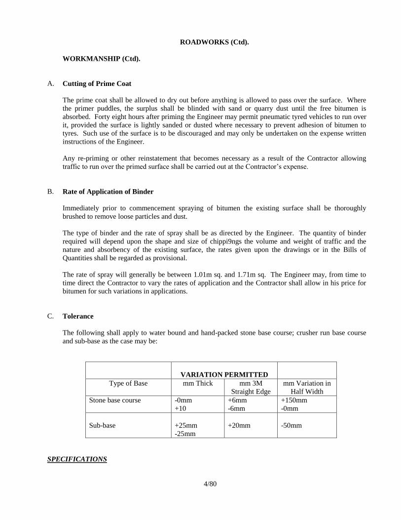
ROADWORKS (Ctd).
WORKMANSHIP (Ctd).
A. Cutting of Prime Coat
The prime coat shall be allowed to dry out before anything is allowed to pass over the surface. Where
the primer puddles, the surplus shall be blinded with sand or quarry dust until the free bitumen is
absorbed. Forty eight hours after priming the Engineer may permit pneumatic tyred vehicles to run over
it, provided the surface is lightly sanded or dusted where necessary to prevent adhesion of bitumen to
tyres. Such use of the surface is to be discouraged and may only be undertaken on the expense written
instructions of the Engineer.
Any re-priming or other reinstatement that becomes necessary as a result of the Contractor allowing
traffic to run over the primed surface shall be carried out at the Contractor’s expense.
B. Rate of Application of Binder
Immediately prior to commencement spraying of bitumen the existing surface shall be thoroughly
brushed to remove loose particles and dust.
The type of binder and the rate of spray shall be as directed by the Engineer. The quantity of binder
required will depend upon the shape and size of chippi9ngs the volume and weight of traffic and the
nature and absorbency of the existing surface, the rates given upon the drawings or in the Bills of
Quantities shall be regarded as provisional.
The rate of spray will generally be between 1.01m sq. and 1.71m sq. The Engineer may, from time to
time direct the Contractor to vary the rates of application and the Contractor shall allow in his price for
bitumen for such variations in applications.
C. Tolerance
The following shall apply to water bound and hand-packed stone base course; crusher run base course
and sub-base as the case may be:
VARIATION PERMITTED
Type of Base mm Thick mm 3M
Straight Edge
mm Variation in
Half Width
Stone base course -0mm
+10
+6mm
-6mm
+150mm
-0mm
Sub-base
+25mm
-25mm
+20mm
-50mm
SPECIFICATIONS
4/80

ROADWORKS (Ctd).
WORKMANSHIP (Ctd).
A. Transport of Premix (Asphalt Concrete)
The premix shall be dept free of contamination during transportation. Each load shall be covered to
protect if from the weather and from dust.
B. Spreading of Premix (Asphalt Concrete)
Immediately after the track coat is applied, the mixture shall be spread by mechanical paver, without
segregation and without dragging.
The wearing course mixture shall be placed in widths of two per normal carriageway unless otherwise
approved by the Engineer. The second layer to be in wearing course shall be placed in widths to provide
a minimum of 0.3m overlap to the longitudinal joint of the first layer of the wearing course and similarly
all traverse joints of the wearing course shall have a minimum overlap of 0.3m. The overlap shall be
tapered.
Where the Engineer directs that the use of mechanical spreading and finishing equipment is impractical,
the mixture may be spread by hand.
A joints with existing compacted bituminous surfacing, whether it be new or old work, the edge of the
existing surfacing along the joint shall be neatly cut away in straight lines over a sufficient width to
ensure the full specified thickness of new surfacing being placed and the vertical face so informed shall
be painted with bitumen immediately in advance of placing the new work.
C. Compaction of Premix (Asphalt Concrete)
Immediately after spreading the mixture shall be compacted to a min. of 96% of the laboratory design
Marshal density. Any area of Asphalt surfacing which does not comply with this Specification shall be
removed and replaced to the full depths of the concerned, at the Contractor’s own expense.
D. Thickness to be Laid
The maximum un-compacted thickness to be spread in a single operation shall not exceed 70mm and the
minimum thickness to be spread in a single operation shall not be less than 35mm. Thickness in excess
of 70mm shall be spread in two layers as two separate operations and the upper layer shall have a
compacted thickness of 40mm.
SPECIFICATIONS
4/81

ROADWORKS (Ctd).
WORKMANSHIP (Ctd).
A. Fines
Fines, whether from the heating plant extractor, or other sources, for addition to the mix shall be
separately stored and separately proportioned to the mixing unit.
The surface of the roadbase to be sprayed shall be thoroughly swept to remove any soil and loose and
foreign material. Any defects of the surface shall be made good as directed by the Engineer, and no
prime coat shall be applied until the surface has been approved by the Engineer.
Immediately after the surface has been prepared and approved by the Engineer the prime coat of M.C. 30
cut back bitumen shall be sprayed at the rate specified.
B. Sand Seal Surface
Immediately after the application of prime coat, stone dust within the following grading envelope, shall
be spread over the prime coat in a thin layer and area shall be allowed to cure for at least 24-48 hours
and no traffic shall be allowed over the prime during this period.
Sieve Size (mm) %age by Weight Passing
63 100
51 95-100
4 90-100
2 50-95
1 20-80
0.6 10-50
1.425 3-25
0.3 0-15
0.15 0-8
0.075 0-5
C. Tack Coat
Before the application of tack coat surface to be premixed shall be swept clean of any loose and foreign
material and any damaged areas shall be made good.
After the application of tack coat at the specified rates the laying of the premix shall follow immediately.
SPECIFICATIONS
4/82

ROADWORKS (Ctd).
WORKMANSHIP (Ctd).
A. Laying of Precast Concrete Kerbs
Precast concrete kerbs to be incorporated in the works shall comply with BS 1340.
All mortar used to joint the kerb shall be mixed to match the colour of the kerbs and the vertical joints
between kerbs shall not exceed 13mm in width. Where kerbs are laid to a radius less than 12 metres,
they shall be precast to the correct radius. The kerb shall be screened to prevent coating during bitumen
spraying and adequately protected from damage the whole period of the work. All damaged kerbs shall
be replaced to the satisfaction of the Engineer during the period of the Contract.
Kerbs shall be laid true to line and level on a foundation of Class 20(20) concrete bed, haunched to a
height of 75mm from the top and bedded, jointed and pointed in cement mortar. The formwork to the
Class 20(20) concrete bed shall be thoroughly compacted and cured.
The rates entered by the Tenderer in Bills of Quantities for the provision and placing of precast concrete
kerbs shall include for all necessary concrete bedding and haunching and all necessary shuttering all in
accordance with the specification and the drawings.
B. Excavation in Trench for Pipe Culverts, Headwalls and Wingwalls
Trenches for culverts, headwalls, wingwalls shall be excavated to line and depths shown on the
drawings or as directed by the Engineer and shall be of sufficient width to give working clearance in the
trench but for the purpose of measurement and payment, the width of the trench shall be taken as 1.5D
where D is the outside measurement of the pipe. Backfilling of trenches around culverts shall be done
to a density of 100% BS Compaction. Excavation for inlet and outfall drains, catch-water drains and
trench or sub-soil drains shall be to the dimensions ordered by the Engineer.
C. Laying and Jointing Pipes
Where pipes are to be laid on ‘normal’ or imported materials, the floor of the trench shall be compacted
and shaped so that the barrel rests over a width of at least one third of its diameter and throughout its
length of the barrel along the floor.
The under side of the barrel and socket shall then be packed hard with earth or gravel fill material as
directed by the Engineer and of maximum particle size not exceeding 25mm diameter and rammed
solid.
Where pipes are laid on concrete bed, the pipes shall be bedded on 1:3 cement: sand mortar at least
15mm thick, 150mm wide and extending the full length of the barrel. The underside of the barrel and
socket shall be packed hard with Class 15 Concrete.
No pipes shall be laid until the floor of the trenches has been approved by the Engineer. All pipes shall
be saturated with water before jointing. All pipes shall be scraped, cleaned inside and the joint flushed
up with 1:2 cement: sand mortar (Ogee pipe joints shall be 37mm thick and 150mm wide).
SPECIFICATIONS
4/83
ROADWORKS (Ctd).
WORKMANSHIP (Ctd).
A. Laying and Jointing Pipes (Ctd).
All joints shall be protected from the wind, sun and rain by a covering approved by the Engineer and
shall be kept constantly damp for a period of at least 3 days.
B. Concrete Beds Haunches and Surrounds to Pipes
The floor of the trench shall be cleaned, trimmed and compacted before any concrete bed is laid. The
concrete bed shall be thoroughly cleaned before any surround, haunch is laid. No concreting shall
commence until the previous work has been approved by the Engineer.
All concrete for beds, surrounds and haunches shall be Class 20 concrete and shall be formed to
dimensions directed by the Engineer.
Unless otherwise directed by the Engineer, a 150mm concrete surround shall be provided to concrete
pipe in the following circumstances: -
.01
Concrete pipes up to and including 0.6m diameter with less than 0.6m cover or more than 3.0m
cover.
.02
Concrete pipes over 0.6m diameter and not exceeding 1.0m diameter with less than 1.0m or
more than 3.0m cover.
.03
Concrete pipes over 1.0m diameter at any depth.
The unit of measurement for concrete beds, surrounds and haunches shall be the meter and the rate shall
include for the provision of transporting and placing of concrete, all strutting and formwork, protection
and curing and all labours, tools, plant, supervision, overheads and profit.
C. Grouted Stone Pitching
The stones used for the grouted pitching shall be hard angular rock, roughly cubical in shape and of
dimensions such that they can be laid with a minimum thickness equal to that specified.
The interstices of the grouted pitching shall not be filled with fill material, but may be chocked with
large rock spalls. The pitching shall be thoroughly soaked with water and a grout of 1:4 cement: sand
mortar shall be rammed into the interstices and smoothed off flush with the pitched face.
Grouted pitching to embankments and around structures shall be constructed as soon as possible after
embankments have been built. The surface of the filling to receive the pitching shall be compacted and
trimmed to slope and the stone hand laid interlocked and rammed.
SPECIFICATIONS
4/84

Proposed Rehabilitation of Resource Centre for Karen Roses Joint Body
Item Description Unit Qty Rate Amount (Kshs)
BILL NO. 5 : GROUND FLOOR (MAIN WORKS)
ELEMENT NO. 1: DEMOLITIONS & REPAIRS
Pricing Notes
Tenderers are strongly advised to read and understand the
following notes before pricing this section. Any query on
the notes should be referred to the Quantity Surveyor or
Project Architect
1 The unit of billing in this section is "item"
2 Amounts for demolitions shall include the following in addition
to what is described in the particular item:
a) Making good i.e. re-instatement of any finishes and
structures affected by the demolition work to the original state.
b) Clearing debris with speed on a daily basis as they arise,
cleaning of affected surfaces, and removal of the debris from
site to local authority approved dumping sites. Accumulation
of debris within the site premises shall not be allowed.
3 Demolition work shall be carefully executed with the particular
aim of minimizing damage to adjacent finishes, structure, or
components.
4 The amounts quoted shall be deemed to be inclusive of all
handling of the removed items and their removal from site.
5 Amounts given should include for adequate temporary support
and protection for the remaining elements of the buildings
being demolished and to adjacent buildings and services.
Carried forward
Bill No. 05: Ground Floor Main Works GF/ 1

Proposed Rehabilitation of Resource Centre for Karen Roses Joint Body
Item Description Unit Qty Rate Amount (Kshs)
Brought forward
6 All materials, components and fittings arising from the
demolitions work shall become the property of the Contractor.
The tenderer is therefore expected to give realistic credit in
the appropriate column for items which have salvage value.
7 Amount indicated will be adjusted against the approximate
quantities to reflect the actual quantity of demolition work
executed on site as shown in the layouts or directed by the
architect.
A Carefully hack existing floor to remove existing floor finishes:
prepare surfaces for new finishes; approx. 360 m2)
Item
B Carefully remove existing dry partitions: prepare affected areas
for new partitions; approx. 113 m2)
Item
C Carefully remove existing doors complete with frame and
ironmongery; make good affected areas. (approximately. 20
No.)
Item
D Carefully hack existing wall finishes; prepare surfaces for new
finishes; approx. 1000 m2)
Item
DEMOLITIONS & REPAIRS CARRIED TO SUMMARY
Bill No. 05: Ground Floor Main Works GF/ 2

Proposed Rehabilitation of Resource Centre for Karen Roses Joint Body
Item Description Unit Qty Rate Amount (Kshs)
ELEMENT NO. 3; WALLS
Internal walls
Machine dressed natural stone walling bedded in cement
and sand mortar (1:3) with minimum stone crushing
strength of 7N/mm² reinforced with hoop iron after every
course.
A 200 mm Thick walls m2 42
Bituminous hessian base to BS 743 type A: or other equal
approved damp-proof course: in cement/ sand (1:3)
mortar
B 200 mm wide m 17
WALLS CARRIED TO SUMMARY
Bill No. 05: Ground Floor Main Works GF/ 3

Proposed Rehabilitation of Resource Centre for Karen Roses Joint Body
Item Description Unit Qty Rate Amount (Kshs)
ELEMENT NO. 3; DRY PARTITIONS
GYPSUM PARTITIONS
12.5mm gypsum partition with and including 6mm thick
glass infill in 50 x 50 x 1.5mm powder coated aluminium
frames to Architect's details; counter sunk screwed to 50 x
50mm double light weight channel frames; infilled with
and including styrofoam infill in between the gypsum
partions , painted (m/s) to the architects satisfaction.
A 100mm thick (overall) dry wall partition m2 113
Prepare and apply: three coats of premium quality silk
vinyl emulsion paint: as "Crown Paints" or other equal
approved: applied strictly in accordance with the
manufacturer's specifications: to
B Gypsum board partitions m2 226
DRY PARTITIONS CARRIED TO BILL SUMMARY
Bill No. 05: Ground Floor Main Works GF/ 4

Proposed Rehabilitation of Resource Centre for Karen Roses Joint Body
Item Description Unit Qty Rate Amount (Kshs)
ELEMENT NO. 4: WINDOWS
Approved pre-cast concrete cill bedded and jointed in
cement (sand (1:3) mortar and pointed in matching
coloured cement
A 175 x 25 mm thick window cill; once weathered and throated m 22
Purpose made steel casement windows in frames of 40 x
25 x 1.5mm outer frames with 25 x 25 x 1.5mm partition
frames with 20 x 3mm flat and 25 x 25 x 3mm Z & T
sections; one coat of red oxide primer; sections and
patterns to architects detail and approval: approved
ironmongery: (glass m.s)
B Window size 600 x 1500 mm high nr 1
C Window size 300 x 1500 mm high nr 1
D Window size 3050 x 1500 mm high composite window; Ref.
No. W1
nr 4
E Window size 3600 x 1500 mm high composite window; Ref.
No. W2
nr 1
F Window size 3600 x 2400 mm high high composite window;
Ref. No. W3
nr 1
6mm thick obscured glass and glazing to casements with
linseed putty to:-
G Windows in panes of various sizes m2 34
Prepare surfaces and apply three coats of approved gloss
oil paint to mild steel metal surfaces; spray painted to
approval to:-
H Windows (both sides measured) m2 68
WINDOWS CARRIEDTO BILL SUMMARY
Bill No. 05: Ground Floor Main Works GF/ 5
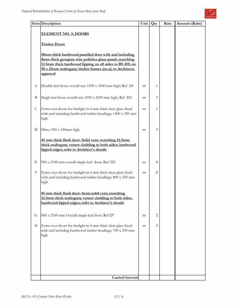
Proposed Rehabilitation of Resource Centre for Karen Roses Joint Body
Item Description Unit Qty Rate Amount (Kshs)
ELEMENT NO. 5; DOORS
Timber Doors
50mm thick hardwood panelled door with and including
8mm thick georgian wire polishes glass panel; matching
12.5mm thick hardwood lipping on all sides to BS 459, on
50 x 25mm mahogany timber frames (m.s); to Architects
approval
A Double leaf door; overall size 1500 x 2100 mm high; Ref D1 nr 1
B Single leaf door; overall size 1050 x 2100 mm high; Ref D2 nr 3
C Extra over doors for fanlight in 6 mm thick clear glass fixed
with and including hardwood timber beadings; 1400 x 250 mm
high
nr 1
D Ditto; 950 x 250mm high nr 3
45 mm thick flush door: Solid core; matching 12.5mm
thick mahogany veneer cladding to both sides; hardwood
lipped edges; refer to Architect's details
E 900 x 2100 mm overall single-leaf door; Ref. D3 nr 8
F Extra over doors for fanlight in 6 mm thick clear glass fixed
with and including hardwood timber beadings; 800 x 250 mm
high
nr 8
45 mm thick flush door: Semi-solid core; matching
12.5mm thick mahogany veneer cladding to both sides;
hardwood lipped edges; refer to Architect's details
G 800 x 2100 mm Overall single-leaf door; Ref D7 nr 2
H Extra over doors for fanlight in 6 mm thick clear glass fixed
with and including hardwood timber beadings; 700 x 250 mm
high
nr 2
Carried forward
Bill No. 05: Ground Floor Main Works GF/ 6

Proposed Rehabilitation of Resource Centre for Karen Roses Joint Body
Item Description Unit Qty Rate Amount (Kshs)
Brought forward
Wrot prime grade mahongany timber in:-
A 250 x 50 mm door frames m 6
B 200 x 50 mm door frames m 18
C 150 x 50 mm door frames m 57
D 250 x 50 mm door transome m 2
E 200 x 50 mm door transome m 3
F 150 x 50 mm door transome m 9
G 50 x 25 mm splayed architrave m 81
H 12mm diameter hardwood quadrant m 81
Prepare and apply one coat of aluminium wood primer on
timber surfaces in contact with concrete or masonry
I Over 100 but not exceeding 200 mm girth m 95
Prepare surfaces and apply three coats polyurethane clear
lacquer or other equal approved on timber surfaces
J Over 100 but not exceeding 200 mm girth m 95
K Generally on doors m2 56
Carried forward
Bill No. 05: Ground Floor Main Works GF/ 7
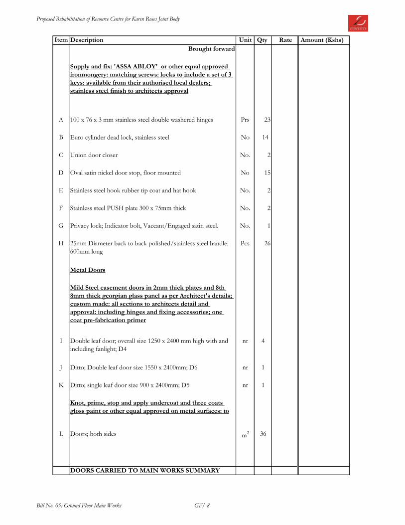
Proposed Rehabilitation of Resource Centre for Karen Roses Joint Body
Item Description Unit Qty Rate Amount (Kshs)
Brought forward
Supply and fix: 'ASSA ABLOY' or other equal approved
ironmongery: matching screws: locks to include a set of 3
keys: available from their authorised local dealers;
stainless steel finish to architects approval
A 100 x 76 x 3 mm stainless steel double washered hinges Prs 23
B Euro cylinder dead lock, stainless steel No 14
C Union door closer No. 2
D Oval satin nickel door stop, floor mounted No 15
E Stainless steel hook rubber tip coat and hat hook No. 2
F Stainless steel PUSH plate 300 x 75mm thick No. 2
G Privacy lock; Indicator bolt, Vaccant/Engaged satin steel. No. 1
H 25mm Diameter back to back polished/stainless steel handle;
600mm long
Pcs 26
Metal Doors
Mild Steel casement doors in 2mm thick plates and 8th
8mm thick georgian glass panel as per Architect's details;
custom made: all sections to architects detail and
approval: including hinges and fixing accessories; one
coat pre-fabrication primer
I Double leaf door; overall size 1250 x 2400 mm high with and
including fanlight; D4
nr 4
J Ditto; Double leaf door size 1550 x 2400mm; D6 nr 1
K Ditto; single leaf door size 900 x 2400mm; D5 nr 1
Knot, prime, stop and apply undercoat and three coats
gloss paint or other equal approved on metal surfaces: to
L Doors; both sides m2 36
DOORS CARRIED TO MAIN WORKS SUMMARY
Bill No. 05: Ground Floor Main Works GF/ 8

Proposed Rehabilitation of Resource Centre for Karen Roses Joint Body
Item Description Unit Qty Rate Amount (Kshs)
ELEMENT NO. 6; MAIN FINISHES
FLOOR FINISHES
Screed: cement and sand (1:4) on concrete: wood floated
finished
A 30 mm Thick to receive granito tiles (m.s) m2 360
Supply and fix approved polished granito floor tiles; to
regular pattern; bedding and jointing in approved
adhesivebased mortar; grouting joints with proprietory
grouting laid on cement and sand backing (m/s);
Tenderers to allow for chamfer, corner strips, cutting,
fixing etc ;
B Floor tiles; size 600 x 600mm m2 360
C Ditto 100 x 25 mm skirting m 282
WALL FINISHES
Internal wall finishes
Plaster: 12 mm cement/lime putty/sand: steel trowelled:
on masonry or concrete: to
D Walls and concrete surfaces m2 109
Prepare surfaces: skim surfaces with altek or other equal
and approved compund; apply three coats Crown Solo silk
vinyl emulsion paint or other equal approved: on steel
trowelled plaster: to
E Walls and concrete surfaces internally m2 109
Repainting of Surfaces
Prepare surfaces: apply three coats Crown Solo silk vinyl
emulsion paint or other equal approved: on steel trowelled
plaster: to
F Walls and concrete surfaces internally m2 1026
Carried forward
Bill No. 05: Ground Floor Main Works GF/ 9

Proposed Rehabilitation of Resource Centre for Karen Roses Joint Body
Item Description Unit Qty Rate Amount (Kshs)
Brought forward
Backing: 12 mm cement/sand (1:4): on masonry or
concrete: wood float finished: to
A Walls to receive ceramic wall tiles (m.s.) m2 50
Supply and fix approved polished coloured ceramic wall
tiles; to regular pattern; bedding and jointing in cement
mortar (1:4) grouting joints with proprietory grouting laid
on cement and sand backing (m/s); Tenderers to allow
for chamfer, corner strips, cutting, fixing etc ;
B Wall tiles m2 50
External wall finishes
Plaster: 15 mm cement/lime putty/sand: steel trowelled:
on masonry or concrete: to
C Walls and concrete surfaces m2 315
Prepare surfaces and apply three coats first grade
permaplast paint to architects approval:-
D Walls and concrete surfaces internally m2 315
CEILING FINISHES
12 mm Thick gypsum board or other equal approved
ceiling fixed on including approved brandering support
system: to
E Ceiling: patterns to architects approval and detail m2 360
F Extra over gypsum for bulkheads 100mm deep. (provisional) m 118
Prepare surfaces: apply three coats approved Acrylic PVA
paint: on plaster board ceiling surfaces: to
G Ceilings interior and exterior m2 360
Carried forward
Bill No. 05: Ground Floor Main Works GF/ 10

Proposed Rehabilitation of Resource Centre for Karen Roses Joint Body
Item Description Unit Qty Rate Amount (Kshs)
Brought forward
STAIRCASE FINISHES
Screed: cement and sand (1:3): on concrete wood floated
A 20 mm Thick: to 250 mm wide treads to receive granito tiles
(m.s)
m 27
B 20 mm Thick: 150 mm high risers ditto m 29
C 20 mm Thick: to landings ditto m2 4
Supply and fix approved polished granito floor tiles; to
regular pattern; bedding and jointing in cement mortar
(1:4) grouting joints with proprietory grouting laid on
cement and sand backing (m/s); Tenderers to allow for
chamfer, corner strips, cutting, fixing etc ;
D 20 mm Thick: to 300 mm wide treads: non-slip m 27
E 20 mm Thick: 150 mm high risers: ditto m 29
F 20 mm Thick: to landings: ditto m2 4
G Extra over for 3 No. non-slip grooves to stairs m 12
Plaster: 9 mm first coat of cement, lime putty and sand
(1:2:9): 4 mm second coat of cement lime putty and sand
(1:1:6): steel trowelled: to
H Slopping soffits of staircases & strings m2 12
I Soffits of landings m2 4
Prepare surfaces: apply three coats of approved plastic
emulsion paint or other equal approved: on steel trowelled
plaster: to
J Sloping soffits of staircases & strings m2 12
K Soffits of landings m2 4
Carried forward
Bill No. 05: Ground Floor Main Works GF/ 11

Proposed Rehabilitation of Resource Centre for Karen Roses Joint Body
Item Description Unit Qty Rate Amount (Kshs)
Brought forward
Staircase railing
A 1000 mm High balustrading; purpose made; all welded; mild
steel; comprising 75mm diameter external mild steel hand rail;
25 x 25mm (SHS) mid rails with 10 x 10mm infills to pattern;
900mm high balusters comprising 25 x 25mm (SHS) with one
end cranked and built into reinforced concrete (m/s) at
845mm centers; 410 mm high, 25 x 25mm (SHS) infills with
both ends welded to mid rails at 140 mm centers; all as per
architect's detail; spray painted
m 7
FINISHES CARRIED TO SUMMARY PAGE
Bill No. 05: Ground Floor Main Works GF/ 12

Proposed Rehabilitation of Resource Centre for Karen Roses Joint Body
Item Description Page No Amount (Kshs)
1 DEMOLITIONS GF/2
2 WALLS GF/3
3 DRY PARTITIONS GF/4
4 WINDOWS GF/5
5 DOORS GF/8
6 FINISHES GF/12
GROUND FLOOR MAIN WORKS SUMMARY
GROUND FLOOR MAIN WORKS TO GRAND SUMMARY
Bill No. 05: Ground Floor Main Works GFS

Proposed Rehabilitation of Resource Centre for Karen Roses Joint Body
Item Description Unit Qty Rate Amount (Kshs)
BILL NO. 6 : FIRST FLOOR (Main Works)
ELEMENT NO. 1: DEMOLITIONS & REPAIRS
Pricing Notes
Tenderers are strongly advised to read and understand
the following notes before pricing this section. Any
query on the notes should be referred to the Quantity
Surveyor or Project Architect
1 The unit of billing in this section is "item"
2 Amounts for demolitions shall include the following in
addition to what is described in the particular item:
a) Making good i.e. re-instatement of any finishes and
structures affected by the demolition work to the original
state.
b) Clearing debris with speed on a daily basis as they arise,
cleaning of affected surfaces, and removal of the debris from
site to local authority approved dumping sites. Accumulation
of debris within the site premises shall not be allowed.
3 Demolition work shall be carefully executed with the particular
aim of minimizing damage to adjacent finishes, structure, or
components.
4 The amounts quoted shall be deemed to be inclusive of all
handling of the removed items and their removal from site.
5 Amounts given should include for adequate temporary
support and protection for the remaining elements of the
buildings being demolished and to adjacent buildings and
services.
Carried forward
Bill No. 06: First Floor Main Works FF/ 14

Proposed Rehabilitation of Resource Centre for Karen Roses Joint Body
Item Description Unit Qty Rate Amount (Kshs)
Brought forward
6 All materials, components and fittings arising from the
demolitions work shall become the property of the
Contractor. The tenderer is therefore expected to give realistic
credit in the appropriate column for items which have salvage
value.
7 Amount indicated will be adjusted against the approximate
quantities to reflect the actual quantity of demolition work
executed on site as shown in the layouts or directed by the
architect.
A Carefully demolish walls including existing wall finishes;
approximately 250 m2; make good all affected areas
Item
B Carefully hack existing floor to remove existing floor finishes:
prepare surfaces for new finishes; approx. 200 m2)
Item
C Carefully remove existing dry partitions: prepare affected areas
for new partitions; approx. 30 m2)
Item
D Carefully remove existing doors complete with frame and
ironmongery; make good affected areas. (approximately. 9No.)
Item
DEMOLITIONS & REPAIRS CARRIED TO SUMMARY
Bill No. 06: First Floor Main Works FF/ 15

Proposed Rehabilitation of Resource Centre for Karen Roses Joint Body
Item Description Unit Qty Rate Amount (Kshs)
ELEMENT NO. 2; RC SUPERSTRUCTURE WORKS
Earthworks for New Columns Bases
A Excavate for column bases commencing from stripped level:
not exceeding 1.5m m deepm
3 8
B Return, fill and ram selected soil in foundations m3 6
C Remove surplus soil and debris from site to a place approved
by local authoritym
3 2
Mass concrete mix (1:3:6):in
D 50 mm Thick blinding under column bases m2 8
Sawn formwork: to
E Sides of column bases m2 10
F Sides and soffits: beams and lintols m2 187
G Columns; vertical sides m2 30
H Soffits of suspended slab m2 103
I Slopping soffits of staircases m2 12
J Edges of suspended floor slab in stages of 150 - 225 mm girth m 210
K Risers and edges of stairs; 150 - 225 mm girth m 93
Supply and fix mild steel bar in structural concrete work
including all cutting, bending, hoisting, tying wire,
spacing blocks and supporting all in position as
necessary
L 8 - 32 mm Bars kg 2286
Carried forward
Bill No. 06: First Floor Main Works FF/ 16
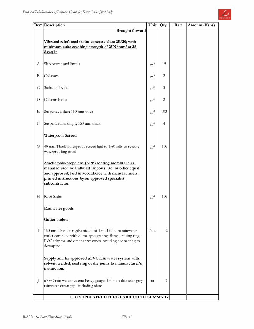
Proposed Rehabilitation of Resource Centre for Karen Roses Joint Body
Item Description Unit Qty Rate Amount (Kshs)
Brought forward
Vibrated reinforced insitu concrete class 25/20; with
minimum cube crushing strength of 25N/mm² at 28
days; in
A Slab beams and lintols m3 15
B Columns m3 2
C Stairs and waist m3 3
D Column bases m3 2
E Suspended slab; 150 mm thick m2 103
F Suspended landings; 150 mm thick m2 4
Waterproof Screed
G 40 mm Thick waterproof screed laid to 1:60 falls to receive
waterproofing (m.s)m
2 103
Atactic poly-propelene (APP) roofing membrane as
manufactured by Italbuild Imports Ltd. or other equal
and approved; laid in accordance with manufacturers
printed instructions by an approved specialist
subcontractor.
H Roof Slabs m2 103
Rainwater goods
Gutter outlets
I 150 mm Diameter galvanized mild steel fulbora rainwater
outlet complete with dome type grating, flange, raising ring,
PVC adaptor and other accessories including connecting to
downpipe.
No. 2
Supply and fix approved uPVC rain water system with
solvent welded, seal ring or dry joints to manufacturer's
instruction.
J uPVC rain water system; heavy gauge; 150 mm diameter grey
rainwater down pipe including shoe
m 6
R. C SUPERSTRUCTURE CARRIED TO SUMMARY
Bill No. 06: First Floor Main Works FF/ 17

Proposed Rehabilitation of Resource Centre for Karen Roses Joint Body
Item Description Unit Qty Rate Amount (Kshs)
ELEMENT NO. 3; WALLS
External walls
Machine dressed natural stone walling bedded in cement
and sand mortar (1:3) with minimum stone crushing
strength of 7N/mm² reinforced with hoop iron after every
course.
A 200 mm Thick walls m2 176
B Ditto; parapet walls m2 36
Internal
Natural stone walls: machine cut: bedded and jointed in
cement and sand (1:3) mortar reinforced with hoop iron
after every course.
C 200 mm Thick walls m2 86
D 150 mm Thick walls m2 7
E 100 mm thick ditto m2 18
Pre-cast concrete units
F 50 mm thick Pre-cast concrete coping: twice weathered and
throated: bedded and jointed in cement and sand (1:4) mortar:
m 40
WALLS CARRIED TO SUMMARY
Bill No. 06: First Floor Main Works FF/ 18

Proposed Rehabilitation of Resource Centre for Karen Roses Joint Body
Item Description Unit Qty Rate Amount (Kshs)
ELEMENT NO. 4; DRY PARTITIONS
GYPSUM PARTITIONS
12.5mm gypsum partition with and including 6mm thick
glass infill in 50 x 50 x 1.5mm powder coated aluminium
frames to Architect's details; counter sunk screwed to 50
x 50mm double light weight channel frames; infilled with
and including styrofoam infill in between the gypsum
partions , painted (m/s) to the architects satisfaction.
A 100mm thick (overall) dry wall partition m2 29
Prepare and apply: three coats of premium quality silk
vinyl emulsion paint: as "Crown Paints" or other equal
approved: applied strictly in accordance with the
manufacturer's specifications: on wooden surfaces: to
B Gypsum board partitions m2 58
DRY PARTITIONS CARRIED TO BILL SUMMARY
Bill No. 06: First Floor Main Works FF/ 19

Proposed Rehabilitation of Resource Centre for Karen Roses Joint Body
Item Description Unit Qty Rate Amount (Kshs)
ELEMENT NO. 5: ROOF
Structural Timber
Sawn cypress first grade; pressure impregnated;
thoroughly seasoned and treated with anti-termite;
hoisted to a height of 3000 mm above ground level; all
nails, bolts, splice plates and other jointing accessories to
structural engineer's details; timber to meet the following
minimum strength criteria, bending 5N/mm2, tension
3N/mm2 and compression 6N/mm
2
A 100 x 50 mm rafters in trusses m 311
B 150 x 50mm tie beam or Joist m 247
C 100 x 50 mm struts/ties m 587
D 150 x 50 mm independent rafters m 328
E 100 x 50 mm purlins/underpurlins m 756
F 250 x 38 mm ridge board m 45
G 100 x 50 mm Wall plate fixed with and including 12mm
diameter x 250mm long bolts fixed to ringbeam
m 69
Supply and fix light weight steel tile coated with stone
chippings as "Decra " roofing tiles as supplied by Space
& Styles Ltd or other equal and approved manufacturer
laid and fixed on 38 x 50 mm timber battens laid with
staggered side laps with alternate courses overlapping
and fastened into the batterns in accordance with the
manufacturer's printed instructions
I Roof covering at 30 degrees from horizontal including all
necessary fixturesm
2 315
J 150 mm matching half round standard ridge capping m 45
K Ditto hip capping m 110
Carried forward
Bill No. 06: First Floor Main Works FF/ 20

Proposed Rehabilitation of Resource Centre for Karen Roses Joint Body
Item Description Unit Qty Rate Amount (Kshs)
Brought forward
Supply and fix sisalation insulation or other equal and
approved manufacturer laid and fixed on timber rafters
(m.s) in accordance with the manufacturer's printed
instructions
Roof insulation sheet m2 315
Prime grade selected wrot cypress in:-
A 20mm x 100mm wide tongued and grooved timber boarding
fixing to timber rafters (m.s.)m
2 44
B 25 x 225mm fascia/barge boards m 121
Knot, prime, stop and apply undercoat and three coats
polyurethane clear lacquer varnish to woodwork as
described to:-
C General surfaces timber boarding m2 44
Pergola
Structural steel grade 43; Framed, bolted and welded
connection; ant-rust treatment; all bolts, plates and other
jointing accessories; 2 coats prefabrication primer;
hoisted to a height of 6000 mm above ground
D 150 x 50 x 3 mm RHS kg 325
E 150 x 50 x 1.5 mm RHS kg 123
Rainwater goods
Gauge 24 prepainted iron metal sheet in:-
F 150x150mm Box gutter fixed to fascia with and including steel
flat brackets at 1500 mm (maximum) centres; holes for down
pipes as necessary; closed ends; painted to approval
m 74
G 150mm diameter heavy gauge grey rainwater downpipe m 60
H Extra over ditto for 800 mm swan-neck offset nr 10
I Ditto for shoe nr 10
ROOF CARRIED TO SUMMARY
Bill No. 06: First Floor Main Works FF/ 21
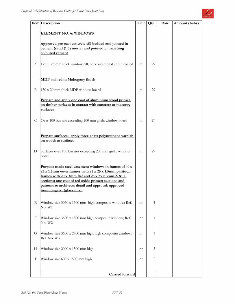
Proposed Rehabilitation of Resource Centre for Karen Roses Joint Body
Item Description Unit Qty Rate Amount (Kshs)
ELEMENT NO. 6: WINDOWS
Approved pre-cast concrete cill bedded and jointed in
cement (sand (1:3) mortar and pointed in matching
coloured cement
A 175 x 25 mm thick window cill; once weathered and throated m 29
MDF stained in Mahogany finish
B 150 x 20 mm thick MDF window board m 29
Prepare and apply one coat of aluminium wood primer
on timber surfaces in contact with concrete or masonry
surfaces
C Over 100 but not exceeding 200 mm girth: window board m 29
Prepare surfaces: apply three coats polyurethane varnish
on wood: to surfaces
D Surfaces over 100 but not exceeding 200 mm girth: window
board
m 29
Purpose made steel casement windows in frames of 40 x
25 x 1.5mm outer frames with 25 x 25 x 1.5mm partition
frames with 20 x 3mm flat and 25 x 25 x 3mm Z & T
sections; one coat of red oxide primer; sections and
patterns to architects detail and approval: approved
ironmongery: (glass m.s)
E Window size 3050 x 1500 mm high composite window; Ref.
No. W1
nr 4
F Window size 3600 x 1500 mm high composite window; Ref.
No. W2
nr 1
G Window size 3600 x 2400 mm high high composite window;
Ref. No. W3
nr 1
H Window size 2000 x 1500 mm high nr 3
I Window size 600 x 1500 mm high nr 2
Carried forward
Bill No. 06: First Floor Main Works FF/ 22

Proposed Rehabilitation of Resource Centre for Karen Roses Joint Body
Item Description Unit Qty Rate Amount (Kshs)
Brought forward
Curtain Rods
A Approved wrot iron curtain rail 50mm diameter chromium
plated tubular section;end brackets,fixing with chromium
plated screws to background requiring plugging.
m 28
6mm thick obscured glass and glazing to casements with
linseed putty to:-
B Windows in panes of various sizes m2 2
6mm Thick clear glass and glazing to casements with
linseed putty to:-
C Window in panes of various sizes m2 41
Prepare surfaces and apply three coats of approved gloss
oil paint to mild steel metal surfaces; spray painted to
approval to:-
D Windows (both sides measured) m2 86
WINDOWS CARRIEDTO BILL SUMMARY
Bill No. 06: First Floor Main Works FF/ 23

Proposed Rehabilitation of Resource Centre for Karen Roses Joint Body
Item Description Unit Qty Rate Amount (Kshs)
ELEMENT NO. 7; DOORS
Timber Doors
50mm thick hardwood panelled door with and including
8mm thick georgian wire polishes glass panel; matching
12.5mm thick hardwood lipping on all sides to BS 459, on
50 x 25mm mahogany timber frames (m.s); to Architects
approval
A Double leaf door; overall size 1500 x 2100 mm high; Ref D1 nr 3
B Extra over doors for fanlight in 6 mm thick clear glass fixed
with and including hardwood timber beadings; 1400 x 250 mm
high
nr 3
45 mm thick flush door: Solid core; matching 12.5mm
thick mahogany veneer cladding to both sides; hardwood
lipped edges; refer to Architect's details
C 900 x 2100 mm overall single-leaf door; Ref. D3 nr 3
D Extra over doors for fanlight in 6 mm thick clear glass fixed
with and including hardwood timber beadings; 800 x 250 mm
high
nr 3
45 mm thick flush door: Semi-solid core; matching
12.5mm thick mahogany veneer cladding to both sides;
hardwood lipped edges; refer to Architect's details
E 800 x 2100 mm Overall single-leaf door; Ref D7 nr 3
F Extra over doors for fanlight in 6 mm thick clear glass fixed
with and including hardwood timber beadings; 700 x 250 mm
high
nr 3
Carried forward
Bill No. 06: First Floor Main Works FF/ 24

Proposed Rehabilitation of Resource Centre for Karen Roses Joint Body
Item Description Unit Qty Rate Amount (Kshs)
Brought forward
Wrot prime grade mahongany timber in:-
A 250 x 50 mm door frames m 19
B 150 x 50 mm door frames m 34
C 250 x 50 mm door transome m 5
D 150 x 50 mm door transome m 5
E 50 x 25 mm splayed architrave m 53
F 12mm diameter hardwood quadrant m 53
Prepare and apply one coat of aluminium wood primer
on timber surfaces in contact with concrete or masonry
G Over 100 but not exceeding 200 mm girth m 63
Prepare surfaces and apply three coats polyurethane clear
lacquer or other equal approved on timber surfaces
H Over 100 but not exceeding 200 mm girth m 63
I Generally on doors m2 40
Carried forward
Bill No. 06: First Floor Main Works FF/ 25

Proposed Rehabilitation of Resource Centre for Karen Roses Joint Body
Item Description Unit Qty Rate Amount (Kshs)
Brought forward
Supply and fix: 'ASSA ABLOY' or other equal approved
ironmongery: matching screws: locks to include a set of 3
keys: available from their authorised local dealers;
stainless steel finish to architects approval
A 100 x 76 x 3 mm stainless steel double washered hinges Prs 18
B Euro cylinder dead lock, stainless steel No 9
C Union door closer No. 3
D Oval satin nickel door stop, floor mounted No 10
E Stainless steel circular male/ female No 2
F Stainless steel hook rubber tip coat and hat hook No. 2
G Stainless steel PUSH plate 300 x 75mm thick No. 3
H Privacy lock; Indicator bolt, Vaccant/Engaged satin steel. No. 2
I 25mm Diameter back to back polished/stainless steel handle;
600mm long
Pcs 9
DOORS CARRIED TO MAIN WORKS SUMMARY
Bill No. 06: First Floor Main Works FF/ 26

Proposed Rehabilitation of Resource Centre for Karen Roses Joint Body
Item Description Unit Qty Rate Amount (Kshs)
ELEMENT NO. 7; MAIN FINISHES
FLOOR FINISHES
Screed: cement and sand (1:4) on concrete: wood floated
finished
A 30 mm Thick to receive granito tiles (m.s) m2 188
B 40 mm Thick waterproof screed to receive interlocking tiles
(m.s)m
2 103
Supply and fix approved polished granito floor tiles; to
regular pattern; bedding and jointing in cement mortar
(1:4) grouting joints with proprietory grouting laid on
cement and sand backing (m/s); Tenderers to allow for
chamfer, corner strips, cutting, fixing etc ;
C Floor tiles m2 188
D Ditto 100 x 25 mm skirting m 153
Approved precast concrete interlocking tiles; laid to fall
in flat roof in accordance with manufacturers printed
instructions
E Laid to falls on screed not exceeding 15 degree m2 103
WALL FINISHES
Internal wall finishes
Plaster: 12 mm cement/lime putty/sand: steel trowelled:
on masonry or concrete: to
F Walls and concrete surfaces m2 517
Prepare surfaces: skim surfaces with altek or other equal
and approved compund; apply three coats Crown Solo
silk vinyl emulsion paint or other equal approved: on
steel trowelled plaster: to
G Walls and concrete surfaces internally m2 517
Carried forward
Bill No. 06: First Floor Main Works FF/ 27

Proposed Rehabilitation of Resource Centre for Karen Roses Joint Body
Item Description Unit Qty Rate Amount (Kshs)
Brought forward
Backing: 12 mm cement/sand (1:4): on masonry or
concrete: wood float finished: to
A Walls to receive ceramic wall tiles (m.s.) m2 48
Supply and fix approved polished coloured ceramic wall
tiles; to regular pattern; bedding and jointing in cement
mortar (1:4) grouting joints with proprietory grouting
laid on cement and sand backing (m/s); Tenderers to
allow for chamfer, corner strips, cutting, fixing etc ;
B Wall tiles m2 48
External wall finishes
Plaster: 15 mm cement/lime putty/sand: steel trowelled:
on masonry or concrete: to
C Walls and concrete surfaces m2 322
Prepare surfaces and apply three coats first grade
permaplast paint to architects approval:-
D Walls and concrete surfaces internally m2 322
CEILING FINISHES
12 mm Thick gypsum board or other equal approved
ceiling fixed on including approved brandering support
system: to
E Ceiling: patterns to architects approval and detail m2 188
F Extra over gypsum for bulkheads 100mm deep. (provisional) m 100
Prepare surfaces: apply three coats approved Acrylic
PVA paint: on plaster board ceiling surfaces: to
G Ceilings interior and exterior m2 188
Carried forward
Bill No. 06: First Floor Main Works FF/ 28

Proposed Rehabilitation of Resource Centre for Karen Roses Joint Body
Item Description Unit Qty Rate Amount (Kshs)
Brought forward
Plaster cornice
A 75 x 70 mm high moulded plaster cornice fixed onto wall
finish; Pudlo Code FD2 (lafarge), painted colour to
manufacture's specifications; to Architects details,
m 103
Terrace Handrail
B 50 mm diameter x 1.5mm thick CHS handrail welded onto 40
x 3mm MS flat bar plate welded onto 20 x 3mm diameter
thick steel bracket fixed to wall at 900mm centres; spray
painted to approval
m 40
FINISHES CARRIED TO SUMMARY PAGE
Bill No. 06: First Floor Main Works FF/ 29

Proposed Rehabilitation of Resource Centre for Karen Roses Joint Body
Item Description Page No Amount (Kshs)
1 DEMOLITIONS FF/2
2 R.C SUPERSTRUCTURE FF/4
3 WALLS FF/5
4 DRY PARTITIONS FF/6
5 ROOF FF/8
6 WINDOWS FF/10
7 DOORS FF/13
8 FINISHES FF/16
FIRST FLOOR MAIN WORKS SUMMARY
FIRST FLOOR MAIN WORKS TO GRAND SUMMARY
Bill No. 06: First Floor Main Works FFS

Proposed Rehabilitation of Resource Centre for Karen Roses Joint Body
Item Description Unit Qty Rate Amount (Kshs)
BILL NO. 07 : KITCHEN EXTENSION MAIN
WORKS
ELEMENT NO. 1; SUBSTRUCTURES ( All
Provisional)
A Excavate oversite to remove vegetable soil, load and cart
away from site to contractor's dumping area as directed;
Average 200 mm depth
m2 34
B Excavate for strip foundation trenches commencing from
stripped level not exceeding 1.5m deepm
3 17
C Return, fill and ram selected soil in foundations m3 14
D Remove surplus soil and debris from site to a place approved
by local authoritym
3 3
Mass concrete mix (1:3:6):in
E 50 mm Thick blinding under strip foundations m2 17
Vibrated reinforced insitu concrete class 25/20; with
minimum cube crushing strength of 25N/mm² at 28
days; in
F Strip foundations m3 3
G Ground floor slab; 150 mm thick m2 34
Mesh fabric reinforcement
H Mesh reinforcement No. A142 size 200 x 200 mm weighing
2.22 kg per square metre: in floor slab: including all necessary
supports
m2 34
Supply and fix mild steel bar in structural concrete work
including cutting, bending, hoisting, tying wire, spacing
blocks and supporting all in position
I 8 - 32 mm Bars kg 165
Carried forward
Bill No. 07: Kitchen Extention Main Works KE/31

Proposed Rehabilitation of Resource Centre for Karen Roses Joint Body
Item Description Unit Qty Rate Amount (Kshs)
Brought forward
Sawn formwork: to
A Sides of strip footing m2 11
B Edges of slabs; 75 - 150 mm girth m 25
Walls
C Medium Chisel dressed natural stone walling bedded in
cement and sand mortar (1:4) with minimum stone crushing
strength of 14N/mm²; foundations
m2 22
Hardcore
D 300 mm thick hardcore of approved inert material: well
watered and compacted in 150 mm thick (maximum) layersm
2 34
Blinding
E 50 mm Thick approved quality murram blinding to surfaces of
hardcorem
2 34
Anti-termite treatment
F Termidor 25EC or other approved anti-termite chemical
treatment to surfaces of blinded hardcore and around
foundations : applied by approved professional pest control
specialist: applied strictly in accordance with the
manufacturer's instructions: 10 year guarantee
m2 34
DPM
G Gauge 1000 polythene damp proof membrane m2 34
25 mm Thick cement and sand (1:4) rendering: on
concrete or stonework: wood float: to
H Plinths: externally m2 14
Prepare surfaces and apply undercoat and two finishing
coats black bitumastic or other equal approved water
resistant paint: on rendered surfaces: to
I Plinths: externally m2 14
SUBSTRUCTURES CARRIED TO SUMMARY
Bill No. 07: Kitchen Extention Main Works KE/32

Proposed Rehabilitation of Resource Centre for Karen Roses Joint Body
Item Description Unit Qty Rate Amount (Kshs)
ELEMENT NO. 2; CONCRETE WORKS
Sawn formwork: to
A Sides and soffits: beams and lintols m2 31
Supply and fix mild steel bar in structural concrete work
including all cutting, bending, hoisting, tying wire,
spacing blocks and supporting all in position as
necessary
B 8 - 32 mm Bars kg 450
Vibrated reinforced insitu concrete class 25/20; with
minimum cube crushing strength of 25N/mm² at 28
days; in
C Beams and lintols m3 3
R. C SUPERSTRUCTURE CARRIED TO SUMMARY
Bill No. 07: Kitchen Extention Main Works KE/33

Proposed Rehabilitation of Resource Centre for Karen Roses Joint Body
Item Description Unit Qty Rate Amount (Kshs)
ELEMENT NO. 3; WALLS
External walls
Machine dressed natural stone walling bedded in cement
and sand mortar (1:3) with minimum stone crushing
strength of 7N/mm² reinforced with hoop iron after every
course.
A 200 mm Thick walls m2 59
Internal
Natural stone walls: machine cut: bedded and jointed in
cement and sand (1:3) mortar reinforced with hoop iron
after every course.
B 200 mm Thick walls m2 10
Bituminous hessian base to BS 743 type A: or other equal
approved damp-proof course: in cement/ sand (1:3)
mortar
C 200 mm wide m 28
WALLS CARRIED TO SUMMARY
Bill No. 07: Kitchen Extention Main Works KE/34

Proposed Rehabilitation of Resource Centre for Karen Roses Joint Body
Item Description Unit Qty Rate Amount (Kshs)
ELEMENT NO. 5: ROOF
Structural Timber
Sawn cypress first grade; pressure impregnated;
thoroughly seasoned and treated with anti-termite;
hoisted to a height of 3000 mm above ground level; all
nails, bolts, splice plates and other jointing accessories to
structural engineer's details; timber to meet the following
minimum strength criteria, bending 5N/mm2, tension
3N/mm2 and compression 6N/mm
2
A 100 x 50 mm rafters in trusses m 39
B 150 x 50mm tie beam or Joist m 26
C 100 x 50 mm struts/ties m 56
D 150 x 50 mm independent rafters m 30
E 100 x 50 mm purlins/underpurlins m 72
F 250 x 38 mm ridge board m 8
G 100 x 50 mm Wall plate fixed with and including 12mm
diameter x 250mm long bolts fixed to ringbeam
m 24
Supply and fix light weight steel tile coated with stone
chippings as "Decra " roofing tiles as supplied by Space
& Styles Ltd or other equal and approved manufacturer
laid and fixed on 38 x 50 mm timber battens laid with
staggered side laps with alternate courses overlapping
and fastened into the batterns in accordance with the
manufacturer's printed instructions
I Roof covering at 30 degrees from horizontal including all
necessary fixturesm
2 47
J 150 mm matching half round standard ridge capping m 8
K Ditto hip capping m 8
Carried forward
Bill No. 07: Kitchen Extention Main Works KE/35

Proposed Rehabilitation of Resource Centre for Karen Roses Joint Body
Item Description Unit Qty Rate Amount (Kshs)
Brought forward
Supply and fix sisalation insulation or other equal and
approved manufacturer laid and fixed on timber rafters
(m.s) in accordance with the manufacturer's printed
instructions
Roof insulation sheet m2 47
Prime grade selected wrot cypress in:-
A 20mm x 100mm wide tongued and grooved timber boarding
fixing to timber rafters (m.s.)m
2 15
B 25 x 225mm fascia/barge boards m 25
Knot, prime, stop and apply undercoat and three coats
polyurethane clear lacquer varnish to woodwork as
described to:-
C General surfaces timber boarding m2 15
Rainwater goods
Gauge 24 prepainted iron metal sheet in:-
D 150x150mm Box gutter fixed to fascia with and including steel
flat brackets at 1500 mm (maximum) centres; holes for down
pipes as necessary; closed ends; painted to approval
m 25
E 150mm diameter heavy gauge grey rainwater downpipe m 6
F Extra over ditto for 800 mm swan-neck offset nr 2
G Ditto for shoe nr 2
ROOF CARRIED TO SUMMARY
Bill No. 07: Kitchen Extention Main Works KE/36

Proposed Rehabilitation of Resource Centre for Karen Roses Joint Body
Item Description Unit Qty Rate Amount (Kshs)
ELEMENT NO. 6: WINDOWS
Approved pre-cast concrete cill bedded and jointed in
cement (sand (1:3) mortar and pointed in matching
coloured cement
A 175 x 25 mm thick window cill; once weathered and throated m 29
Purpose made steel casement windows in frames of 40 x
25 x 1.5mm outer frames with 25 x 25 x 1.5mm partition
frames with 20 x 3mm flat and 25 x 25 x 3mm Z & T
sections; one coat of red oxide primer; sections and
patterns to architects detail and approval: approved
ironmongery: (glass m.s)
B Window size 2000 x 1500 mm high nr 1
C Window size 900 x 1500 mm high nr 1
6mm Thick clear glass and glazing to casements with
linseed putty to:-
D Window in panes of various sizes m2 4
Prepare surfaces and apply three coats of approved gloss
oil paint to mild steel metal surfaces; spray painted to
approval to:-
E Windows (both sides measured) m2 8
WINDOWS CARRIEDTO BILL SUMMARY
Bill No. 07: Kitchen Extention Main Works KE/37

Proposed Rehabilitation of Resource Centre for Karen Roses Joint Body
Item Description Unit Qty Rate Amount (Kshs)
ELEMENT NO. 7; DOORS
Metal Doors
Mild Steel casement doors in 2mm thick plates and 8th
8mm thick georgian glass panel as per Architect's details;
custom made: all sections to architects detail and
approval: including hinges and fixing accessories; one
coat pre-fabrication primer
A Ditto; single leaf door size 900 x 2400mm; D5 nr 3
Knot, prime, stop and apply undercoat and three coats
gloss paint or other equal approved on metal surfaces: to
B Doors; both sides m2 13
DOORS CARRIED TO MAIN WORKS SUMMARY
Bill No. 07: Kitchen Extention Main Works KE/38

Proposed Rehabilitation of Resource Centre for Karen Roses Joint Body
Item Description Unit Qty Rate Amount (Kshs)
ELEMENT NO. 7; MAIN FINISHES
FLOOR FINISHES
Screed: cement and sand (1:4) on concrete: wood floated
finished
A 30 mm Thick to receive granito tiles (m.s) m2 34
Supply and fix approved polished granito floor tiles; to
regular pattern; bedding and jointing in cement mortar
(1:4) grouting joints with proprietory grouting laid on
cement and sand backing (m/s); Tenderers to allow for
chamfer, corner strips, cutting, fixing etc ;
B Floor tiles m2 34
C Ditto 100 x 25 mm skirting m 30
WALL FINISHES
Internal wall finishes
Plaster: 12 mm cement/lime putty/sand: steel trowelled:
on masonry or concrete: to
D Walls and concrete surfaces m2 103
Prepare surfaces: skim surfaces with altek or other equal
and approved compund; apply three coats Crown Solo
silk vinyl emulsion paint or other equal approved: on
steel trowelled plaster: to
E Walls and concrete surfaces internally m2 103
Backing: 12 mm cement/sand (1:4): on masonry or
concrete: wood float finished: to
F Walls to receive ceramic wall tiles (m.s.) m2 27
Carried forward
Bill No. 07: Kitchen Extention Main Works KE/39
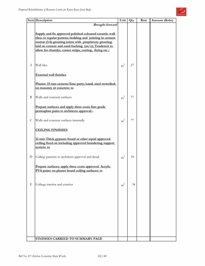
Proposed Rehabilitation of Resource Centre for Karen Roses Joint Body
Item Description Unit Qty Rate Amount (Kshs)
Brought forward
Supply and fix approved polished coloured ceramic wall
tiles; to regular pattern; bedding and jointing in cement
mortar (1:4) grouting joints with proprietory grouting
laid on cement and sand backing (m/s); Tenderers to
allow for chamfer, corner strips, cutting, fixing etc ;
A Wall tiles m2 27
External wall finishes
Plaster: 15 mm cement/lime putty/sand: steel trowelled:
on masonry or concrete: to
B Walls and concrete surfaces m2 77
Prepare surfaces and apply three coats first grade
permaplast paint to architects approval:-
C Walls and concrete surfaces internally m2 77
CEILING FINISHES
12 mm Thick gypsum board or other equal approved
ceiling fixed on including approved brandering support
system: to
D Ceiling: patterns to architects approval and detail m2 34
Prepare surfaces: apply three coats approved Acrylic
PVA paint: on plaster board ceiling surfaces: to
E Ceilings interior and exterior m2 34
FINISHES CARRIED TO SUMMARY PAGE
Bill No. 07: Kitchen Extention Main Works KE/40

Proposed Rehabilitation of Resource Centre for Karen Roses Joint Body
Item Description Page No Amount (Kshs)
1 SUBSTRUCTURES KE/2
2 R.C SUPERSTRUCTURE KE/3
3 WALLS KE/4
5 ROOF KE/6
6 WINDOWS KE/7
7 DOORS KE/8
8 FINISHES KE/10
KITCHEN EXTENSION MAIN WORKS SUMMARY
KITCHEN EXTENSION MAIN WORKS TO GRAND SUMMARY
Bill No. 07: Kitchen Extention Main Works KES

Proposed Rehabilitation of Resource Centre for Karen Roses Joint Body
Item Description Unit Amount (Kshs)
BILL NO. 8 : PROVISIONAL SUMS
The following Provisional Sums are to be measured on
completion and priced in accordance with the rates contained in
these bills of Quantities or pro-rata thereto or deducted in the
whole not required
A Collapsible door Sum 735,000.00
B Signage Sum 200,000.00
C Landscaping Sum 100,000.00
PROVISIONAL SUMS CARRIED TO GRAND SUMMARY 1,035,000.00
Bill No. 08: Provisional Sums PROV

BILL DESCRIPTION Page No. AMOUNT (Kshs)
1 GENERAL PRELIMINARIES
2 PARTICULAR PRELIMINARIES
3 GROUND FLOOR MAIN WORKS
4 FIRST FLOOR MAIN WORKS
5 KITCHEN EXTENSIONS MAIN WORKS
6 MECHANICAL INSTALLATIONS
7 ELECTRICAL INSTALLATIONS
8 PROVISIONAL SUMS
SUB - TOTAL
Add 2.5% contingency
CONTRACTOR:………………………………………………………………………………………
SIGNAGTURE & STAMP:…………………………………………………………………………
DATE:…………………………………………………………………………………………………
EMPLOYER:…………………………………………………………………………………………
SIGNAGTURE & STAMP:…………………………………………………………………………
DATE:…………………………………………………………………………………………………
TOTAL CARRIED TO FORM OF TENDER
GRAND SUMMARY
PROPOSED RESOURCE CENTRE FOR THE KAREN ROSES JOINT BODY IN ELDAMA
RAVINE

DRAWINGS

GSPublisherVersion 0.3.89.74
PROPOSED REHABILITATION OF THE RESOURCE CENTRE- KAREN ROSES JOINT BODYFebruary 2021- PW
3,400
100
1,400
100
5,450
1,400900
1,300900
2,750
637 2,800 6374,075
1,200200 1,200
450 200741 1,500 741
200 450
200
1,054
200
1,160
200
3,450
200
3,350
100
3,500
100
3,400
200
400
200
2,550 100
3,300 100
3,800200
1,425200 425 200
1,025
2001,875
1003,450
1003,300
1002,550
200
6,150
6,15011,350
2002,050
200150200
2,000
2001,250
1001,050200
2,050
2001,500
200
6001,050750
2,400
2,400
2,450
1,500
5,150
2,475
1,250200
200
1,054
200
1,160
200
600200
5,700
200
1,800200
2,550200
4,550
2002,250
1,8501,800
600600
200
1,300
3,850
1,150
200425
2001,150550
1,150200
2,0507,250
1,4292,500
700 900 900 1,375 2,000 1,9507,825 8,700
14,500
1,600
2002,050
2002,400
2002,000
2002,400
2002,850
200
1,600
2,450
2,400
2,400600
1,250550
8501,550
850
2,200 1,950
01
04
03
02
X
X
05
New GypsumPartition to details
Existing R.C. staircase20 Risers@150mm,
Treads@275mm
New GypsumPartition to details
Level to be loweredto match the restof the kitchen
New collapsiblepartition to details
TAILORING UNIT
ENTRY LOBBY
ATMNew
KitchenEXISTING RESTAURANT
Office 07
CONFERENCE FACILITY- 100 pax classroom style
Office 01
Office 02
Office 03
Office 04
Office 05
Office 06
ENTRY LOBBY
PORTE COCHERE
Kitchen store
AB
C
DE
F
2
G
H
I
J
K
I
J
K
H
AB
C
DE
F
G
1
2
Porcelain tiles fl. fn.
Porcelaintiles fl. fn.
Porcelaintiles fl. fn.
Porcelaintiles fl. fn.
Porcelaintiles fl. fn.
Porcelain tiles fl. fn.
Porcelain tiles fl. fn.
Porcelaintiles fl. fn. Passage
Porcelain tiles fl. fn.
Reception deskto details
Reception deskto details
Porcelain tiles fl. fn.
Porcelain tiles fl. fn.Porcelain tiles fl. fn.
Porcelain tiles fl. fn.Porcelain tiles fl. fn.
Porcelaintiles fl. fn.
Kitchen to details.lobby
Porcelain tiles fl. fn.
20,649
7,775
7,125
6,150
6,150
5,200
3,750
600
77520
0 300
2,250
200 27
52,0
0050
0
2,550
4,400
7,950
3,050
6,150
6,150
10,750
200
3,200
200
95015
042
5 200
2,550
200
2,575
200
10,75
0
10,85
0
17,600
200
2,400200
2,000200
1,250
1001,050200
2,050200
2,450
2002,600
200
2,300
200
2,400
2,400
2,400
2,450
2,450
3,000
2,300
5,200
6,150
6,150
3,050
7,950
4,400
2,550
900200
1,200200
2,600200
2,450200
2,050200
2,400200
2,000200
2,400200
2,850
200
7,775
200
4,175
200
2,350200
1,400900
3,000
2,450600
1,250600
1,150
1,250
2,400
2,400200
8001,250
1,000
New GypsumPartition to details
NEW R.C. staircaseto S.E's details.
20 Risers@150mm,Treads@275mm
pv
pv
pv
pvpv
pv
pv
pv
pv
pv
pv
pv
pv pv
pv
pv
pvpvpv
pv
pv
pv
pv
pvpv
pv
WHB
WC
WHBWC
pv
pv
pvpvpv
pv
pv
G1 H1
pv
GROUND FLOOR LAYOUT PLAN 1:125
Pg - 01

GSPublisherVersion 0.3.89.74
PROPOSED REHABILITATION OF THE RESOURCE CENTRE- KAREN ROSES JOINT BODYFebruary 2021- PW
01
04
03
02
X
X
05
5,200
625
2,475
1,250
Existing R.C. staircase20 Risers@150mm,
Treads@275mm
Cleaner'sstorage
50x100x1.5mm RHSpergola frames to details
painted to approval
50x100x1.5mm RHSpergola frames to detailspainted to approval
Roof pitch 30 deg.Metal based (decra) roofingtiles on timber trusses /structures to S.E's details.
ICT CENTRELOBBY AREA
OFFICE 01
OFFICE 03A
B
C
DE
F
2
Porcelain tiles fl. fn.
OFFICE 02
Interlocking concrete tiles onAPP waterproofing membrane.
slope
slope
Porcelain tiles fl. fn.
Porcelaintiles fl. fn.
Porcelain tiles fl. fn.
Porcelain tiles fl. fn.
G
slope
H
I
J
K
I
J
K
H
AB
C
DE
F
G
1
2
5,200
6,150
6,150
3,050
7,950
4,400
2,550
200
400
200
200800
2001,050200
2,050200
2,450
2002,600
1502,350
6,150
6,150
5,200
5,650
2,4001,150 1,250
2,450
2,450
3,000900 600 800
200
14,700
200
5,450
2002,000 200 1,150
200 1,050 200 2,050200 2,450
200 2,600 2002,300
200
400
200
3,250
200
3,300
200
3,500
200
400
200
200400
200
1,500150
1,850200
3,300200
3,250
200
6,300
200
4,550
200
11,450
14,900
20,650
1,200200
1,200
2,000
1,500
5,300
200400
200
1,900100
1,750
2,475
925
100
1,800
100
5,050
200
200
400
200
10,85
0
10,75
0
200
1,600
100
1,600
200
750
2,000
700
3,700
800
2,000
900
2001,500 100
4,350
1,000
800 600 9003,000
2,450
2,4501,250 1,000
12,450
5,150
6,200
5,150
1,500200 2,050 200
1,050 200800 200
650 2,975200 450
1,0001,250
2,450
1,500
6,150
6,150
200
400
200
3,600
150
1,550
1,500
1,175
1,200
600300
1,250
2,150
3,700
700
2,000
750
200
4,050
1,100
1,150200
4,750
1,150550 1,150
200
7,650
200 1,150200 1,050 200 2,050
200 1,600
8,050
1,150 1,2502,450
1,600
14,900
14,500
2,650
4,400
7,950
3,050
6,150
6,150
200950
850200
2004,800
1,500
3,650
1,150
10,750
1,750
100
1,900
5,950
200
800200
4,950
200
2,850200
800100
875100
800
1501,650200 1,650
1,950
New GypsumPartition to details
Roof pitch 30 deg.Metal based (decra) roofingtiles on timber trusses /structures to S.E's details.
concrete copings on900mm high walls with50mm dia. hand railsto details.
concrete copings on900mm high walls with50mm dia. hand rails
to details.
NEW R.C. staircaseto S.E's details.20 Risers@150mm,Treads@275mm
Roof pitch 7.5 deg.Metal based (decra) roofing
tiles on timber trusses /structures to S.E's details.
ROOF TERRACE
WHB
WC
pv
pv
pv
pv pv
pv
pv
pv pv
pv
pv
pv
pv
pv
pvpv
pv
WHB
WC
G1 H1
FIRST FLOOR LAYOUT PLAN 1:125
Pg - 02

GSPublisherVersion 0.3.89.74
PROPOSED REHABILITATION OF THE RESOURCE CENTRE- KAREN ROSES JOINT BODYFebruary 2021- PW
01
04
03
02
X
X
05
10,750
11,450
1,250
2,450
2,450
3,000
2,300
3,700
3,700
3,450
10,85
0
24,112
11,450
1,2502,450
2,450
3,000
2,300
3,450
3,700
3,700
10,850
14,900
9,200
5,300
8,050
1,150200 1,050
2,4501,600
2,554
4502002,975
650
50x100x1.5mm RHSpergola frames to details
painted to approval
50x100x1.5mm RHSpergola frames to details
painted to approval
Roof pitch 30 deg.Metal based (decra) roofingtiles on timber trusses /structures to S.E's details.
1
2
5,200
6,150
6,150
3,050
7,950
4,400
2,550
6,150
6,150
5,200
10,75
0
6,150
6,150
2,550
4,400
7,950
3,050
6,150
6,1506,250
6,150
2,550
2,4501,250
Roof pitch 30 deg.Metal based (decra) roofingtiles on timber trusses /structures to S.E's details.
Roof pitch 7.5 deg.Metal based (decra) roofing
tiles on timber trusses /structures to S.E's details.
Roof pitch 30 deg.Metal based (decra) roofingtiles on timber trusses /structures to S.E's details.
AB
C
DE
F
2
G
H
I
J
K
I
J
K
AB
C
DE
F
G
ROOFING BELOW
ROOFING BELOWROOFING BELOW
SOLAR PANELS TOMECH. ENG. SPECS..
SOLAR PANELS TOMECH. ENG. SPECS..
SOLAR PANELS TOMECH. ENG. SPECS..
ROOF TERRACE BELOW
H
G1 H1
ROOF LAYOUT PLAN 1:125
Pg - 03

GSPublisherVersion 0.3.89.74
PROPOSED REHABILITATION OF THE RESOURCE CENTRE- KAREN ROSES JOINT BODYFebruary 2021- PW
2,550 4,400 7,950 3,050 6,150 6,150
New Kitchen EXISTING RESTAURANTPORTE
COCHERE
A B C D E F G
Steel casementwindow to Schedule.
200mm thick stonewall plastered andpainted to approval.
Roof pitch 30 deg.Metal based (decra) roofingtiles on timber trusses /structures to S.E's details.
50x100x1.5mm RHSpergola frames to details
painted to approvalRoof pitch 7.5 deg.Metal based (decra) roofing
tiles on timber trusses /structures to S.E's details.
concrete copingson 900mm high walls
to details.
Solar panels to M.Eng. specs
T & G ceiling ontimber battens to detail
250x25mm fascia boardpainted to approval
pv pv pv pv pv pv pv pv pv pv pv pv
pv pv pv
pv
10,750
3,000
3,000
Steel casementwindow to Schedule.
200mm thick stonewall plastered andpainted to approval.
Roof pitch 30 deg.Metal based (decra) roofingtiles on timber trusses /structures to S.E's details.
50x100x1.5mm RHSpergola frames to details
painted to approvalRoof pitch 7.5 deg.
Metal based (decra) roofingtiles on timber trusses /
structures to S.E's details.
concrete copings on900mm high walls to details.
Solar panels to M.Eng. specs
250x25mm fascia boardpainted to approval
pv pv pv pv pv
pvpv pvpv pv pv pv pv
12
Roof Level.
Ground Floor.
+ 3000.First Floor.
+ 6000.
± 0.00.
01 ELEVATION.. 1:125
02 ELEVATION.. 1:125
Pg - 04

GSPublisherVersion 0.3.89.74
PROPOSED REHABILITATION OF THE RESOURCE CENTRE- KAREN ROSES JOINT BODYFebruary 2021- PW
3,000
3,000
6,150 6,150 5,200IJK H1
Steel casementwindow to Schedule.
200mm thick stonewall plastered andpainted to approval.
Roof pitch 30 deg.Metal based (decra) roofing tiles on
timber trusses / structures to S.E's details.
50x100x1.5mm RHS pergolaframes to details painted to approval
Roof pitch 7.5 deg.Metal based (decra) roofingtiles on timber trusses /structures to S.E's details.
concrete copings on900mm high walls to details.
Solar panels to M.Eng. specs
T & G ceiling ontimber battens to detail
250x25mm fascia boardpainted to approval
Roof Level.
Ground Floor.
+ 3000.First Floor.
+ 6000.
± 0.00.
pv pv pv pv pv pv pv pv pv
pvpvpvpvpvpv
2,5504,4007,9503,0506,1506,1505,200
3,000
3,000
ABCDEFGG1
Steel casementwindow to Schedule.
200mm thick stonewall plastered andpainted to approval.
Roof pitch 30 deg.Metal based (decra) roofing tiles on
timber trusses / structures to S.E's details.
50x100x1.5mm RHS pergolaframes to details painted to approval Roof pitch 7.5 deg.
Metal based (decra) roofing tiles ontimber trusses / structures to S.E's details.
concrete copings on900mm high walls to details.
Solar panels to M.Eng. specs
T & G ceiling ontimber battens to detail
250x25mm fascia boardpainted to approval
pv
Roof Level.
Ground Floor.
+ 3000.First Floor.
+ 6000.
± 0.00.
pv pv pv pv pv pv pv pv pv
pv pv pv pv pv pv
03 ELEVATION.. 1:125
04 ELEVATION.. 1:125
Pg - 05

GSPublisherVersion 0.3.89.74
PROPOSED REHABILITATION OF THE RESOURCE CENTRE- KAREN ROSES JOINT BODYFebruary 2021- PW
1,1001,150
2,250
1,70090
090
02,1
00
150
2,850
1,3002,4
0060
090
0
3,000
3,000
2,400
600
900
275
150
10,750
doors & windowsto schedule
50x100x1.5mm RHSpergola frames to details
painted to approval
landing
OFFICELOBBY
FOUNDATION NOTES:600x200mm R.C. strip foundation
to S.E's details. Depth of R.C.foundation to be determined on site.
SUB-STRUCTURE NOTES:100mm R.C. floor slab on 1000 gaugedpc membrane on 50mm sand/murrumblinding on 300mm thick well compactedhardcore to S.E. details.
safety railingto details.
R.C. staircase to S.E's details20 Risers@150mmTread @275mm
Roof pitch 30 deg.Metal based (decra) roofingtiles on timber trusses /structures to S.E's details.
250x25mm fascia boardpainted to approval
doors & windowsto schedule
150mm thick R.C. waterproofed slab finished with
APP membrane & interlockingconc. tiles to S.E's details.
T & G ceiling ontimber battens to detail
R.C. column to S.E's detailscladded to approval.
200mm thick stone wallplastered and paintedto approval.
Solar panels to M.Eng. specs
concrete copings on900mm high walls
with 50mm dia. handrails to details.
pv pv pv pv pv
pv pv pv pv pv
ROOF TERRACE
SECTION X - X. scale 1:100
Roof Level.
Ground Floor.
+ 3000.First Floor.
+ 6000.
± 0.00.
1 2
3,000
3,000
10,750
Roof pitch 7.5 deg.Metal based (decra) roofing
tiles on timber trusses /structures to S.E's details.
Roof pitch 30 deg.Metal based (decra) roofingtiles on timber trusses /structures to S.E's details.
250x25mm fascia boardpainted to approval
doors & windowsto schedule
T & G ceiling ontimber battens to detail
R.C. column to S.E's detailscladded to approval.
200mm thick stone wallplastered and paintedto approval.
Solar panels to M.Eng. specs50x100x1.5mm RHSpergola frames to details
painted to approval
pv pv pv pv pv
pv pv pvpvpv pv pv
Roof Level.
Ground Floor.
+ 3000.First Floor.
+ 6000.
± 0.00.
1 2
05 ELEVATION.. 1:125
Pg - 06

GSPublisherVersion 0.3.89.74
PROPOSED REHABILITATION OF THE RESOURCE CENTRE- KAREN ROSES JOINT BODYFebruary 2021- PW
50825 125
50
1,050
2,100
300
2,050
5025
050
50950
50
400
1,240
400
5025
050
700
600
700
600
50675 125
50
900
2,100
300
2,050
5025
050
50800
50
700
600
50x200mmmahoganydoor frame
mahoganytimberpannels.
6mm glass.6mm glass.
50x250mmmahoganydoor frame
mahoganytimberpannels.
8mm thickgeorgian wirepolished glass.
50x150mmmahoganydoor frame
mahoganytimberpannels.
6mm glass.
50x50x1.5mmRHS door frame.
8mm thickgeorgian wirepolished glass.
50x50x1.5mmRHS door frame.
40x40x2mm RHSinternal door frameswith 2mm thick MSplate sheets paintedto approval.
8mm thickgeorgian wirepolished glass.
6mm glass.
40x40x2mm RHSinternal door frameswith 2mm thick MSplate sheets paintedto approval.
6mm glass.
FLOORLEVEL
BEAMLEVEL
D1SIZE1,500 x 2,400 mm
DESCRIPTION
LOCATION
QUANTITY3 NO
Entrances, Offices, ICT.
pv.pv. pv. pv.
Metal panel door fixed with40x40x2mm RHS internal frames with2mm thick MS sheets painted with8mm georgian wire glass.
pv.
Double leaf solid timber panel door (mahogany)with matching 12.5mm thick hardwood lippingon all sides on 50X250mm mahoganytimber frame architraves & beading to approval.
D2SIZE1,050 x 2,400 mm
DESCRIPTION
LOCATION
QUANTITY2 NO
Entrances-Offices & ICT.
Solid timber panel door (mahogany) withmatching 12.5mm thick hardwood lippingon all sides on 50X200mm mahogany timberframe architraves & beading to approval.
D3SIZE900 x 2,400 mm
DESCRIPTION
LOCATION
QUANTITY11 NO
Offices & ICT.
45mm thick mahogany cladded semi-solid flushdoor with matching 12.5mm thick hardwood lippingon all sides on 50X150mm mahoganytimber frame architraves & beading to approval.
D4SIZE1250 x 2,400 mm
DESCRIPTION
LOCATION
QUANTITY4 NO
Conference, ICT/Passage.
Metal panel door fixed with40x40x2mm RHS internal frames with2mm thick MS sheets painted with8mm georgian wire glass.
D5SIZE900 x 2,400 mm
DESCRIPTION
LOCATION
QUANTITY4 NO
Lobby/Passage, Kitchen.
50950 450
501,500
2,100
300
50825 125 125 200 125
50
2,400
50800
50900
2,100
300
400
1,250
400
5025
050
50450 200 150
50
50800 350
501,250
2,100
300
400
1,250
400
5025
050
50450 200 150 350
50
25mm dia.steel handle
25mm dia.steel handle
25mm dia.steel handle
25mm dia.steel handle
25mm dia.steel handle
stainless steelpush & pullplate/handle
6mm glass.
stainless steelpush & pullplate/handle
6mm glass.
louvres with matching12.5mm thick hardwoodlipping on all sides
glass panel withfilm to approval
50x50x1.5mmRHS frame fixedto wall.
40x40x1.5mmRHS shutter frame.
16gauge blacksheet pannel.
20x20x1.5mm RHSbars @ 105mm c/cpainted to approval.
50x150mmmahoganydoor frame
50x150mmmahoganydoor frame
pv.
D6SIZE1,050 x 2,400 mm
DESCRIPTION
LOCATION
QUANTITY1 NO
ATM.
D7SIZE800 x 2,400 mm
DESCRIPTION
LOCATION
QUANTITY4 NO
Washrooms.
45mm thick mahogany cladded semi-solid flushdoor with matching 12.5mm thick hardwood lippingon all sides on 50X150mm mahoganytimber frame architraves & beading to approval.
D8SIZE800 x 2,400 mm
DESCRIPTION
LOCATION
QUANTITY1 NO
Cleaner's store.
45mm thick mahogany cladded semi-solid flushdoor with matching 12.5mm thick hardwood lippingon all sides on 50X150mm mahoganytimber frame architraves & beading to approval.
D9SIZE1,500 x 2,400 mm
DESCRIPTION
LOCATION
QUANTITY1 NO
Cleaner's store.
Metal grill door with 50x50x2mm RHSdoor frame, 40x40x2mm RHS shutterframe with 20x20x1.5mm RHS painted to approval.
80050700
50
900
300
150
2,100
300
80050700
50
900
300
2,100
300
150
1,750
150
5025
050
50150 400 150
50
1,050
2,100
300
50 100750
100 50
150
700
150
950
100
5025
050
50950
50
800
6002,4
00
50700 700
50
4088
540
100
40
540
1,025
401,2
0040
502,4
00
1,500
50 40EQ
20EQ
20EQ
20EQ
20EQ
40 40EQ
20EQ
20EQ
20EQ
20EQ
40 50
50 40475 145
40 40145 475
40 50
600x25mm Dia.stainless steel pullhandle
1.6mm thick kickingplate on both sides.
8mm thick clearlaminated glass.
50mm thick powdercoated aluminiumcasement door sectionswith 8mm thick laminatedclear glass panels with film
KICKING PLATE
PULL
KICKING PLATE
PULL
FLOORLEVEL
BEAMLEVEL
KICKING PLATE
PV
50mm thick powder coated aluminiumcasement door sections with 8mm thicklaminated clear glass panels with film
Pg - 07

GSPublisherVersion 0.3.89.74
PROPOSED REHABILITATION OF THE RESOURCE CENTRE- KAREN ROSES JOINT BODYFebruary 2021- PW
450 450
50x50x2mm SHScorner frame fixedto wall/beam to approval.
50x50x2mm SHScorner frame fixedto wall/beam to approval.
SIZE (A)450 x1,500 mm
pv.pv.
W 01 ( composite ).
Purpose made Steel casement frames of40x25x1.5mm RHS outer frames with25x25x1.5mm SHS partition frames with 20x3mm flat &25x25x3mm Z & T Sections with 6mm clear glass.
DESCRIPTION
SIZE (B)2,150 x1,500 mm LOCATION
QUANTITY4 NO
Offices 1&2, ICT, Passage.
SIZE (A)450 x1,500 mm
pv.pv.
W 02 ( composite ).
Purpose made Steel casement frames of40x25x1.5mm RHS outer frames with25x25x1.5mm SHS partition frames with 20x3mm flat &25x25x3mm Z & T Sections with 6mm clear glass.
DESCRIPTION
SIZE (B)2,700 x1,500 mm LOCATION
QUANTITY1 NO
Offices 1.
FLOORLEVEL
BEAMLEVEL
pv.
FIRST FLOOR WINDOWS
900
1,500
450
900
300
900
300
40185 185
40
4024
825
292
292
292
2524
740
2,400
550 525 525 5502,150
40249 249
25246 246
40246 246
25249 249
40
4024
825
292
292
292
2524
740
40185 185
40
4024
825
292
292
292
2524
740
900
1,500
450
900
300
900
300
40185 185
40
4024
825
292
292
292
2524
740
550 525 550 525 5502,700
40249 249
25246 246
40255 255
40246 246
25249 249
40
4024
825
292
292
292
2524
740
40185 185
40
4024
825
292
292
292
2524
740
450
50x50x2mm SHScorner frame fixedto wall/beam to approval.
pv.
W 04.
Purpose made Steel casement frames of40x25x1.5mm RHS outer frames with25x25x1.5mm SHS partition frames with 20x3mm flat &25x25x3mm Z & T Sections with 6mm clear glass.
pv.
FLOORLEVEL
BEAMLEVEL
SIZE2,000 x1,500 mm
DESCRIPTION
LOCATION
QUANTITY3 NO
Offices 1&2, ICT.
W 05.
Purpose made Steel casement frames of40x25x1.5mm RHS outer frames with25x25x1.5mm SHS partition frames with 20x3mm flat &25x25x3mm Z & T Sections with 6mm clear glass.
SIZE600 x1,500 mm
DESCRIPTION
LOCATION
QUANTITY2 NO
Washrooms.
SIZE (A)450 x2,100 mm
pv.pv.
W 03 ( composite ).
Purpose made Steel casement frames of40x25x1.5mm RHS outer frames with25x25x1.5mm SHS partition frames with 20x3mm flat &25x25x3mm Z & T Sections with 6mm clear glass.
DESCRIPTION
SIZE (B)2,700 x2,100 mm LOCATION
QUANTITY1 NO
Staircase.
pv.
500 500 500 500
900
1,500
2,000
900
300
900
300
40224 224
25237 238
25237 238
25224 224
40
4024
825
292
292
292
2524
740
900
1,500
600
900
300
900
300
40260 260
40
4024
825
292
292
292
2524
740
300
2,100
450
300
900
900
300
40185 185
40
4028
328
328
225
292
292
292
2524
740
550 525 550 525 5502,700
40249 249
25246 246
40255 255
40246 246
25249 249
40
4028
328
328
225
292
292
292
2524
740
40185 185
40
4028
328
328
225
292
292
292
2524
740
2,400
Pg - 08

GSPublisherVersion 0.3.89.74
PROPOSED REHABILITATION OF THE RESOURCE CENTRE- KAREN ROSES JOINT BODYFebruary 2021- PW
150
50
275
175
175
175
175
150
50
900
275
550
626
dove tail split &cast into concrete.
R.C. staircaseto S.E,s details
granito tiles floor finish.
dove tail split &cast into concrete.
R.C. staircaseto S.E,s details
granito tiles floor finish.
75
40
900
175
175
175
175
150
50
125 150
150
125 150
275
900mm high,75x4mm tapering to 40mmmild steel balusters @550mm c/c fixed to conc. &spray painted to approval
50mm dia. x1.5mm CHShandrail welded to 900mm high,75x4mm tapering to 40mmmild steel balusters to approval.
4 no. 16mm dia. mild steelhorizontal railing painted withautomotive metal hammer paintto Architect's approval.
900mm high,75x4mm tapering to 40mmmild steel balusters @550mm c/c fixed to conc. andspray painted to approval
4 no. 16mm dia. mild steelhorizontal railing painted withautomotive metal hammer paintto Architect's approval.
50mm dia. x1.5mm CHShandrail welded to 900mm high,75x4mm tapering to 40mmmild steel balusters to approval.
TYPICAL RAILING SECTION TYPICAL RAILING SECTION
Pg - 09

Karen Roses Joint Body Notes to Tenderers Proposed Resource Centre On Plot No./Block 2/38 at Eldama Ravine Township
Plumbing Drainage & Fire Fighting Installations
SPECIFICATION NO. FMC/TF – 21/02E
PROPOSED RESOURCE CENTRE ALTERATIONS
FOR KAREN ROSES JOINT BODY
IN ELDAMA RAVINE
PLOT L.R NO 2.38
GENERAL PLUMBING, DRAINAGE & FIRE FIGHTING INSTALLATIONS
SUB-CONTRACT CONDITIONS, SPECIFICATIONS, AND BILLS OF QUANTITIES
NAME OF TENDERER
CLIENT: ARCHITECTS: KAREN ROSES JOINT BODY P.O BOX 202, ELDAMA RAVINE KENYA
ARCH. PIUS WAMBUA NAIROBI.
MECHANICAL & ELECTRICAL ENGINEERS: QUANTITY SURVEYOR: FOSTERTECH MEP CONSULTANTS LTD ZIMAKI CONSULT P.O BOX 6678-00100 P.O BOX 8589-00100 WESTLANDS, NAIROBI NAIROBI
MARCH, 2O21
Karen Roses Joint Body Notes to Tenderers Proposed Resource Centre On Plot No./Block 2/38 at Eldama Ravine Township
Plumbing Drainage & Fire Fighting Installations
NOTES TO TENDERERS - NOMINATED SUB-CONTRACTOR
A. THE SITE FOR THE PROPOSED WORKS ISN’T OCCUPIED PREMISES BUT WITH SEVERAL EXISTING INSTALLATIONS. THE CONTRACTOR WILL BE REQUIRED TO ENSURE NORMAL WATER SUPPLY TO THE BUILDING IS MAINTAINED THROUGHOUT AND NOT INTERFERRED WITH THROUGHOUT THE ENTIRE PERIOD OF THIS EXERCISE. THE CONTRACTOR WILL BE REQUIRED TO TAKE ALL PRECAUTION AND CARE SO THAT NO DAMAGE WILL OCCUR TO THE EXISTING INSTALLATIONS ON SITE. THE CONTRACTOR IS ALSO ADVISED TO SECURE ALL THE NECESSARY INSURANCE POLICIES AS HE WILL BE SOLELY HELD RESPONSIBLE FOR ANY DAMAGES TO THE EXISTING INSTALLATION, INJURIES TO PERSONS RESULTING FROM HIS ACTIVITIES AND INTERTHAT MAY RESULT FROM HIS NEGLIGENCE, ACTIONS OR OTHERWISE.
i.
1.01 The tenderer is required to check the number number of pages in this document, and should any be found to be missing or the figures indistinct, he must inform the Lead Consultants/Engineers at once and have the same rectified. Should the tenderer be in doubt about the precise meaning of any item, word, or figures, or for any reason whatsoever observe any apparent omission of words or figures, he must inform the Lead Consultant/Engineer in order that the correct meaning may be decided upon before the date for the submission of the tenders.
1.02 The tenderer's price shall include all government taxes, including duties, V.A.T., etc. No claims whatsoever will be allowed in respect of obligations, V.A.T., etc., if the tenderer fails to include them in his unit prices. It is also to be noted that V.A.T. will be included in the unit rates and NOT worked out as a percentage of the total.
1.03 In no case will any expenses incurred by the tenderer in preparation of this Tender be reimbursed.
1.04 The copyright of this Specification is vested in the Lead Consultant/Engineers, and no part thereof may be reproduced without their express permission, given in writing.
1.05 The specifications must be priced in Kenya Currency, i.e., Shillings and Cents.
1.06 The quantities given in the Bill of Quantities are for guidance only. Precise re-measurements will be done at the end of the contract, and the contractor will only be paid for the actual work done.

Karen Roses Joint Body Notes to Tenderers Proposed Resource Centre On Plot No./Block 2/38 at Eldama Ravine Township
Plumbing Drainage & Fire Fighting Installations
The works shall be carried out in accordance with provisions of the latest Edition of Institution of Engineering and Technology Wiring Regulations, the most current Kenya Standards governing such works, NEMA Regulations, and relevant provisions of the current Kenya Power by-laws. The contractor is also presumed to be familiar with the standard General Specifications governing such works; a copy can, however, be obtained from our office any working day. The Particular Specifications have been detailed in the drawings and Bills of Quantities, but the contractor is advised to seek clarification from the Lead Consultants on any matter whatsoever where he has the slightest of doubts.
1.07 Any applications for advance payment, to the limits stated in the tender document, including applications for compensation for materials offsite, must be secured by an Authentic Bank Guarantee for the total amount issued by a Bank.
1.08 These notes shall form an essential part of the specifications.
SIGNED (AS IN TENDER).............................. DATE/STAMP.............................
Karen Roses Join Body Form of Tender Proposed Resource Centre On Plot No./Block 2/38 at Eldama Ravine Township
Plumbing, Drainage & Fire FightingInstallations
FORM OF TENDER
KAREN ROSES JOINT BODY
P.O. BOX 202
ELDAMA RAVINE, KENYA
DEAR SIR/MADAM,
RE: KAREN ROSES JOINT BODY
PROPOSED RESOURCE CENTRE ON PLOT NO. 2/38 ELDAMA RAVINE
PLUMBING AND DRAINAGE INSTALLATIONS
We offer to execute the whole of the above-mentioned works all in accordance with the drawings and the Specifications and Bills of Quantities for the sum of (K.E.S.……………………)
In Words
i. ………………………………………………………………………………………................................
i. .........................................................................................................
1.
i. Our anticipated completion period, from receipt of the letter of appointment to commissioning and handing over of the Communication Services installation, will be ....................weeks.
i.
i. We agree that the Employer shall not be bound to accept the lowest or any Tender and that no expenses incurred by us in preparation of this Tender will be allowed.
1.
i. We agree that this Tender shall remain valid for, and shall be not withdrawn within, Four calendar months (or 120 days, whichever is longer) from the date of tender-opening and in the event of your

Karen Roses Join Body Form of Tender Proposed Resource Centre On Plot No./Block 2/38 at Eldama Ravine Township
Plumbing, Drainage & Fire FightingInstallations
acceptance, to execute a formal contract agreement with the Client for the works.
i. We propose M/s...........................................................................
i. Of P. O. Box................................................................................
i.
i. As a surety, subject to your approval and to be bound to yourselves as required in the Contract Agreement.
i.
SIGNATURE...............................
(TENDERER)
NAME.........................................
ADDRESS.....................................
DATE............................................

Karen Roses Joint Body Surety Bond Proposed Resource Centre On Plot No./Block 2/38 at Eldama Ravine Township
Plumbing, Drainage & Fire FightingInstallations
SURETY BOND
a.
Brief description of the contract
a.
a. .........................................................................................................................................................................................................................................
a.
Name and address of Beneficiary ……………………………………..................................................................................
(Together with successors and assigns, all as defined in the contract as the Employer).
By this Bond, (name and address of contractor).............................................................
(Who is the contractor under such contract) as Principal and............................................
(Name and address) as Guarantor is irrevocably held and firmly bound to the Beneficiary in the total amount of ………………………....................................................
(The "Bond Amount," say:…………………….) for the due performance of all such Principal's obligations and liabilities under the contract. [Such Bond Amount shall be reduced by …… % upon the issue of the taking-over certificate for the whole of the works under clause 10 of the conditions of the contract.] (1)
This Bond shall become effective on the Commencement Date defined in the contract.
Upon Default by the Principal to perform any Contractual Obligation, or upon the occurrence of any of the events and circumstances listed in sub-clause 15.2 of the conditions of the contract, the Guarantor shall satisfy and discharge the damages sustained by the Beneficiary due to such Default, event or circumstances. (2) However, the total liability of the Guarantor shall not exceed the Bond Amount.
I.
The obligations and liabilities of the Guarantor shall not be discharged by any allowance of time or another indulgence whatsoever by the Beneficiary to the Principal, or by any variation or suspension of the works to be executed under the contract, or by any amendments

Karen Roses Joint Body Surety Bond Proposed Resource Centre On Plot No./Block 2/38 at Eldama Ravine Township
Plumbing, Drainage & Fire FightingInstallations
to the contractor to the constitution of the Principal or the Beneficiary, or by any other matters, whether with or without the knowledge or consent of the Guarantor.
Any claim under this Bond must be received by the Guarantor on or before (the date six months after the expected expiry of the Defects Notification Period for the Works) after the scheduled expiry of the Defects Notification Period for the Works)..................................... (The "Expiry Date"), when this Bond shall expire and shall be returned to the Guarantor.
The benefit of this Bond may be assigned subject to the provisions for assignment of the contract and subject to the receipt by the Guarantor of evidence of full compliance with such requirements.
This Bond shall be governed by the law of the same country (or other jurisdiction) as that which governs the contract. This Bond incorporates and shall be subject to the Uniform Rules for Contract Bonds, published as number 524 by the International Chamber of Commerce, and words used in this Bond shall bear the meanings set out in such Rules.
Wherefore this Bond has been issued by the Principal and the Guarantor on (date)..............
Signature(s) for and on behalf of the Principal …............................................................
Signature(s) for and on behalf of the Guarantor ……………………………...................................
(1) When writing the tender documents, the writer should ascertain whether to include the optional text, shown in parentheses [ ] (2)
Insert: [and shall not be entitled to perform the Principal's obligations under the contract]
Or:
[or at the option of the Guarantor (to be exercised in writing within 42 days of receiving the claim specifying such Default) perform the Principal's obligations under the contract]

Karen Roses Joint Body Advance Payment Guarantee Proposed Resource Centre On Plot No./Block 2/38 at Eldama Ravine Township
Plumbing, Drainage & Fire FightingInstallations
ADVANCE PAYMENT GUARANTEE
Brief description of contract………………………………….........................................
..............................................................................................................
Name and address of Beneficiary ………………………………………………………… (whom the
The contract defines as the Employer).
We have been informed that ………………….......................... (Hereinafter called the "Principal") is your contractor under such contract and wishes to receive an advance payment, for which the agreement requires him to obtain a guarantee.
At the request of the Principal, we (name of bank)............................................................... hereby irrevocably undertake to pay you, the Beneficiary/Employer, any sum or sums not exceeding in total the amount of.............................................................................
(the "guaranteed amount," say: ) upon receipt by us of your demand in writing and your written statement stating:
a) that the Principal has failed to repay the advance payment in accordance with the conditions of the contract, and
b) The amount which the Principal has been unable to repay.
This guarantee shall become effective upon receipt [of the first installment] of the advance payment by the Principal. Such guaranteed amount shall be reduced by the amounts of the advance payment repaid to you, as evidenced by your notices issued under sub-clause 14.6 of the conditions of the contract. Following receipt (from the Principal) of a copy of each purported information, we shall promptly notify you of the revised guaranteed amount accordingly.
Any demand for payment must contain your signature(s), which must be authenticated by your bankers or by a notary public. The established request and statement must be received by us at this office on or before (the date 70 days after the expected expiry of the Time for Completion) …………………………………............. (The "expiry date"), when this guarantee shall expire and shall be returned to us.

Karen Roses Joint Body Advance Payment Guarantee Proposed Resource Centre On Plot No./Block 2/38 at Eldama Ravine Township
Plumbing, Drainage & Fire FightingInstallations
We have been informed that the Beneficiary may require the Principal to extend this guarantee if the advance payment has not been repaid by the date 28 days prior to such expiry date. We undertake to pay you such a guaranteed amount upon receipt by us, within such period of 28 days, of your demand in writing and your written statement that the advance payment has not been repaid and that this guarantee has not been extended.
This guarantee shall be governed by the laws of ………………….and shall be subject to the Uniform Rules for Demand Guarantees, published as number 458 by the International Chamber of Commerce, except as stated above.
Date............................................ Signature.............................................

Karen Roses Joint Body Safety and Protection of Workmen Proposed Resource Centre On Plot No./Block 2/38 at Eldama Ravine Township
Plumbing, Drainage & Fire fightingInstallations
SAFETY AND PROTECTION OF WORKMEN
The contractor shall be responsible for the Occupational Health and Safety of the employees and any other visitor to the site
The contractor shall allow for training all employees on issues of site safety and occupational health that should acquaint them with safety rules, regulations, and practical aspects of security. In addition to this, the contractor shall be required to maintain on-site at all times a safety manual.
The contractor shall ensure that all laws, rules, or regulations relating to Occupational Health and Safety as stipulated by the Government from time to time are enforced at all times on-site, and he shall employ a safety professional that will be stationed on-site at all times to ensure compliance. Such a safety professional shall possess training in first aid.
The contractor shall allow for providing protective equipment and gear such as overalls, gumboots, steel-capped boots, safety harnesses, dust coats, dust masks, gloves, and hard hats to his workmen to protect against injury and occupational illness at all times.
He shall also ensure that all his equipment is at all times in good, safe working conditions to prevent accidents.
The contractor must also maintain on-site at all times a well-stocked first aid kit for emergency use and ensure that its contents are replenished from time to time with use.
The contractor shall maintain on-site a log and summary of all recordable injuries and illnesses (resulting in a fatality, hospitalization, lost workdays, medical treatment, job transfer or termination, or loss of consciousness) for that location and enter each recordable event no later than six working days after receiving the information. Where the complete log and summary records are maintained at a place other than the site, a copy of the log that reflects the injury and illnesses experience on the site must be completed and current to date within 45 calendar days and must be available at the original site. In addition to the log of occupational injuries and illnesses, each Employer must have known for inspection on-site within six working days after notification of a recordable case, a supplementary record for each occupational injury or disease for that site.

Karen Roses Joint Body Safety and Protection of Workmen Proposed Resource Centre On Plot No./Block 2/38 at Eldama Ravine Township
Plumbing, Drainage & Fire fightingInstallations
An adequate supply of potable water must be provided on site. Portable drinking water containers must be capable of being tightly closed and equipped with a tap. Using a standard drinking cup is prohibited. Where single service cups (to be used but once) are supplied, both a sanitary container for unused cups and a receptacle for used cups must be provided.

Karen Roses Joint Body Preliminaries and General Conditions Proposed Resource Centre On Plot No./Block 2/38 at Eldama Ravine Township
Plumbing, Drainage & Fire FightingInstallations
PRELIMINARIES AND GENERAL CONDITIONS
NAMES OF PARTIES
The following will be inserted in the Articles of Agreement:-
Parties Name and Address
Employer KAREN ROSES JOINT BODY
P.O. BOX 202
ELDAMA RAVINE
Project Architect
Project Quantity Surveyors
Project Electrical & Mechanical Engineers FOSTERTECH MEP CONSULTANTS
Project Civil/Structural Engineers
For the purposes of these works, the Project Manager shall be a representative of the Client except where variation orders are to be issued.

Karen Roses Joint Body Preliminaries and General Conditions Proposed Resource Centre On Plot No./Block 2/38 at Eldama Ravine Township
Plumbing, Drainage & Fire FightingInstallations
DEFINITIONS OF TERMS
The terms, phrases, and abbreviations shall be deemed to have the following meanings wherever used hereinafter and in all Contract Documents.
'Contractor' shall mean the person or persons, partnership, firm or company, whose Tender for the contract has been accepted, and who has or have, signed the contract and shall include his or their heirs, executors, administrators, assigned successors, and duly appointed representatives.
'Works' shall mean all or any portion of the work, material, and articles, wherever the same are being manufactured or prepared, which are to be used in the execution of this contract and whether the same may be on the site or not.
'm3' shall mean cubic meters.
'm2' shall mean square meters.
'm' shall mean linear meter.
'mm' shall mean linear millimeters.
'kg' shall mean kilogram 'No' shall mean number.
'Prs' shall mean Pairs.
S.' shall mean the current British Standard Specification published by the British Standards Institution, 2 Park Street, London, W.I., England.
S' shall mean the current Kenya Standards Specification published by the Kenya Bureau of Standards.
'As before' shall mean in all respects as earlier described in the same or previous Bill.
'Ditto' shall mean the whole of the preceding description except as qualified in the story in which it occurs. Where it occurs in descriptions of succeeding items, it shall mean the same as in the first description of the series in which it occurs except as qualified in the report concerned. Where it appears in brackets, it shall mean the whole of the preceding description, which is contained within the appropriate frames.

Karen Roses Joint Body Preliminaries and General Conditions Proposed Resource Centre On Plot No./Block 2/38 at Eldama Ravine Township
Plumbing, Drainage & Fire FightingInstallations
'Fix Only' shall mean take delivery on site (unless otherwise stated), unload where necessary, transport within site compound, store, unpack, check contents against orders and packing lists, assemble as necessary, distribute to position, hoist and fix only.
TENDER CONDITIONS
Any act of collusion which may distort normal competitive conditions may cause the rejection of the tenders concerned. By participating in the tendering, tenderers certify not to be involved in such acts of collusion.
Tenders containing abnormally high or abnormally low unit prices and/or lump sums may be rejected. Before such rejection, however, the contractor will be given the opportunity of providing a detailed explanation.
Tenders must be returned complete and will be opened in the presence of tenderers or their assigned representatives at the time and venue stated in the letter of invitation to tender. Incomplete tenders or tenders received after the stated time will be returned unopened.
Tenders are invited in strict accordance with the documents issued, counteroffers submitted with tenders will not be considered, letters of qualification with tenders may be ignored if they have the effect of modifying either the terms of a tender or the compatibility of a tender with other tenders. Should a tenderer, in good faith, wish to propose modifications to the tender terms, conditions, and contents for the purposes of reducing the tender amount, then he shall contact the Lead Consultant in writing well before the date of tender opening. Should the proposed modification be approved by Consultants and Employer, all tenderers will be advised in due time for the improvement of their tenders. No proposed amendment will be considered unless this procedure has been adopted.
The Employer is not bound to accept the lowest or any tender, nor is the Employer bound to divulge reasons for the acceptance or non-acceptance of any tender. Any tender may be accepted by the Employer within the stated period unless previously withdrawn by the tenderer.
All deletions, additions, and corrections to figures inserted in the tender documents are to be signed by the tenderer.

Karen Roses Joint Body Preliminaries and General Conditions Proposed Resource Centre On Plot No./Block 2/38 at Eldama Ravine Township
Plumbing, Drainage & Fire FightingInstallations
DESCRIPTION OF SITE
The site of the works is at ELDAMA RAVINE TOWNSHIP, UASIN GISHU COUNTY. The results will be carried out next to existing buildings. Due care will be required during construction so that the occupants of the nearby buildings and the buildings themselves are not interfered with in any way.
The contractor is recommended to visit the site and will be deemed to have satisfied himself with regard to the relevant details of preliminary. If the contractor, for whatever reason, feels specialized attendance will be required, with significant financial implications, or requires technical mobilization to start the works, he should spread the cost of such results in his unit rates. No claims whatsoever by the contractor for additional payment will be allowed on the grounds of any misunderstanding or misapprehension in respect of any such matters or otherwise, should the contractor be required to offer specialized attendance prior to, or during, the performance of the contract.
In case of difficulty in locating the site, the tenderer should contact the Lead Consultant, who will give relevant direction.
DESCRIPTION OF THE WORKS MEASURED IN THE BILLS OF QUANTITIES
The works measured and described in the Bills of Quantities comprising the following:-
Supply, installation PLUMBING, DRAINAGE & FIRE FIGHTING INSTALLATIONS, setting to work to the entire satisfaction of the Project Engineer thereof as set out in the Bills of Quantities and relevant drawings.
TENDER EVALUATION PROCEDURES
Following the return of the tenders for the works measured in these Bills of Quantities, arithmetical and other analyses will be carried out in order to select the lowest acceptable Tender in terms of responsive and realistic pricing, etc. This selection will be at the sole discretion of the Employer.

Karen Roses Joint Body Preliminaries and General Conditions Proposed Resource Centre On Plot No./Block 2/38 at Eldama Ravine Township
Plumbing, Drainage & Fire FightingInstallations
The unit rates offered by the selected tenderer will then be applied to new quantities measured by the Lead Consultant for the revised scope of works.
The resultant total, together with the priced Preliminaries and any modified Prime Cost and Provisional Sums, will be consolidated into a sum for which the contract will be signed.
This procedure will be applied only to the selected Tender, and no other tender will be considered. Neither the Employer nor the Consultants will enter into discussion or correspondence with the other tenderers after the selection process has been carried out, and no reasons will be given for selection or non-selection.
Any tenderer unable to comply with these procedures will be disqualified from the selection process.
ACCESS TO SITE AND SECURITY
Means of access to the site will be as directed by the Lead Consultant; no other access will be permitted in any circumstances.
AREA TO BE OCCUPIED BY THE CONTRACTOR
The areas to be occupied by the contractor for use as storage or for the erection of workshop etc. will be as directed by the Employer and/or the Lead Consultant. The contractor must confine his activities strictly to the areas so marked and must ensure that his workmen do not trespass on the adjoining property or cause inconvenience to its occupiers.

Karen Roses Joint Body Preliminaries and General Conditions Proposed Resource Centre On Plot No./Block 2/38 at Eldama Ravine Township
Plumbing, Drainage & Fire FightingInstallations
DRAWINGS
The contractor will be deemed to have examined the drawings before tendering and to have satisfied himself regarding their details and regarding the nature and extent of the works and the method of installation involved. No claims arising out of misapprehension in these respects will be allowed.
The contractor shall, at his own risk and cost, execute and perform the Works described in the conditions of Contract and Bills of Quantities and detailed in the drawings provided and supplied to the contractor for the purpose of Works and ultimately finish the said works in good workmanship and with the utmost expedition.
The contractor shall satisfy himself as to the correctness of all Drawings and measurements. If the contractor finds any discrepancy in the Drawings or between the Drawings and the Specification and Bills of Quantities, he shall immediately refer the same to the Lead Consultants, who will decide which shall be followed. Figured dimensions shall be taken in preference to the scale mentioned on or attached to any Drawing. Details shown on the Drawing shall be brought in choice to items and quantities in the Specification.
Two copies of all drawings and of the Specification will be furnished free of cost to the contractor (whose Tender has been accepted) for his own use.
VALUATION OF LUMP SUM PRELIMINARY COSTS
Lump sums entered in these Bills of Quantities against any item of General Condition or Preliminaries will be included in appropriate valuations according to a reasonable assessment of actual costs involved in the article. Any balance between this assessment and the exact sum entered in the Bills of Quantities will be included in subsequent valuations as monthly installments over the balance of the Contract Period.

Karen Roses Joint Body Preliminaries and General Conditions Proposed Resource Centre On Plot No./Block 2/38 at Eldama Ravine Township
Plumbing, Drainage & Fire FightingInstallations
In the final payment, however, the works done will be re-measured, and the contractor shall be paid only for the actual work done irrespective of what is entered in the tendered quantities or lump sum provisions.
PAYMENT FOR MATERIALS ON SITE
All materials for incorporation in the works must be stored on or adjacent to the site before payment is effected unless specifically exempted by the Lead Consultant / Employer. This is to include the materials of the contractor and his Nominated Suppliers. However, where the Client agrees to consider payment for materials offsite or any advance payment for that matter, the contractor will submit an Advance Payment Guarantee from a reputable bank for the total amount applied for.
CONTRACT AGREEMENT AND CONDITIONS
A General
1.
1. The contractor will be required to enter into a contract which will be the current Conditions of Contract for Construction for Building and Engineering Works Designed by the Employer, published by the International Federation of Consulting Engineers (FIDIC), First Edition 1999, together with any other amendments and clarifications published thereafter.
a.
B Water and Electricity Supply
1. Water and electrical power will be made available by the Employer to the contractor. The Employer and the Contractor will mutually agree whether or not the latter should pay for the water/electricity used for the works.
C Contractor's Materials
1.

Karen Roses Joint Body Preliminaries and General Conditions Proposed Resource Centre On Plot No./Block 2/38 at Eldama Ravine Township
Plumbing, Drainage & Fire FightingInstallations
1. Purchase of materials by the contractor and their storage on site for inclusion in payment certificates far in advance of reasonable requirements will be allowed.
1.
D Storage of Materials
1. Storage space will be provided by the Employer. However, the contractor shall provide, at his own risk and cost, where directed on site, weatherproof lock-up sheds for the safe storage and custody of materials for the works and for the use of workmen engaged therein and shall remove such sheds and make good damage or disturbed surfaces upon completion to the satisfaction of the Lead Consultant.
1.
1. The contractor shall be liable for the cost of any storage accommodation.
1.
1. The area of site which may be occupied by the contractor will be within the limits of that allocated by the Employer to the contractor.
1.
WARRANTY AND PERFORMANCE STANDARDS
The contractor must furnish the Employer through the Lead Consultant with a generally written warranty covering quality of workmanship, material, and equipment and be compelled thereby for a one-year period after practical completion of the contract.
The contractor must make good, at his own expense, such repairs, and replacements as may be required as a consequence of sloppy workmanship or defective materials. The contractor must also procure such warranties and guarantees as aforesaid from all manufacturers and/or suppliers of materials or equipment incorporated in the project under this contract.
The contractor must comply in all respects with given standards of workmanship as defined and described in the Specifications and Bills of Quantities and relevant Codes of Practice. The contractor must also comply with all tests of materials as required and/or as directed by the Lead Consultant.

Karen Roses Joint Body Preliminaries and General Conditions Proposed Resource Centre On Plot No./Block 2/38 at Eldama Ravine Township
Plumbing, Drainage & Fire FightingInstallations
TOOLS, PLANTS, E.T.C.
The contractor shall allow for providing all ladders, tools, plant, and transport required for the works, except in so far may be expressly stated otherwise.
SAFETY, HEALTH, AND WELFARE OF WORKPEOPLE
The contractor shall allow for providing for the safety, health, and welfare of workpeople and for complying with any relevant Ordinances, Regulations, or Union agreement.
NATIONAL INSURANCE AND PENSIONS
The contractor shall allow for making any National Social Security Fund and National Hospital Insurance Fund payments due in respect of workpeople.
HOLIDAY AND TRANSPORT OF WORKPEOPLE
The contractor shall allow for providing holidays and transport for workpeople and for complying with any relevant Ordinances or Union Agreement.
TRAINING LEVY
The contract's attention is drawn to Legal Notice No. 237 of October 1971, which requires payments by the contractor of a Training Levy on all contracts of more than Shs.50,000/= in value, and his Tender must include for all costs arising or resulting therefrom. Proof of payment of this Training Levy will be required.
NATIONAL ENVIRONMENT AUTHORITY (NEMA)
The contractor shall allow for making all payments statutorily required by the National Environment Management Authority (NEMA) for such works.

Karen Roses Joint Body Preliminaries and General Conditions Proposed Resource Centre On Plot No./Block 2/38 at Eldama Ravine Township
Plumbing, Drainage & Fire FightingInstallations
NATIONAL CONSTRUCTION AUTHORITY (N.C.A.)
The contractor's attention is drawn to the provisions of the National Construction Act (N.C.A.) OF 2011. The contractor shall be required to ensure that he adheres to the provisions of this Act fully at all times of the contract
EXISTING PROPERTY
The contractor shall take every precaution to avoid damage to all existing property, including flower beds, fences, roads, cables, drains, adjacent buildings, and other services, and he will be held responsible for all damage arising from the execution of this contract to the afore-mentioned property, and he shall make good all such damage where directed at his own expenses to the satisfaction of the Lead Consultant.
TESTING
The contractor shall allow for all testing of material and installations required by these Specifications, and he shall be responsible for all expenses incurred in completing such tests, including costs of materials and labor, equipment, transport, and all other expenses.
SUPERVISION AND WORKING HOURS
The Works shall be executed under the direction, and to the entire satisfaction in all respects, of the Lead Consultant who shall at all times during regular working hours have access to the works and to the yards and workshops of the contractor or other places where work is being prepared for the contract.

Karen Roses Joint Body Preliminaries and General Conditions Proposed Resource Centre On Plot No./Block 2/38 at Eldama Ravine Township
Plumbing, Drainage & Fire FightingInstallations
The working hours shall be those generally worked by good employers in the Building and Civil Engineering Trades in gazetted holidays unless the Lead Consultant shall so direct.
No work shall be covered up in the absence of the Clerk of Works without the prior approval of the Lead Consultant in writing.
SAMPLES
The contractor shall furnish at his own cost any samples of materials or workmanship that may be called for by the Lead Consultant for his approval or rejection and any other models in the case of rejection until such is approved by the Lead Consultant and the Lead Consultant may reject any materials or workmanship not in his opinion up to the approved samples.
The Lead Consultant shall arrange for the testing of such materials as he may at his discretion deem desirable, but the testing shall be made at the expense of the Employer and not at the cost of the contractor unless the materials fail to pass the test or are in the opinion of the Lead Consultant not in accordance with the Specification, in either case, the contractor shall pay for testing in accordance with the current scales of testing charges of approved testing authorities.
The procedure for submitting a sample of materials for testing and the method of marking for identification shall be laid down by the Lead Consultant.
The contractor shall allow in his Tender for such samples and tests.
MATERIALS, TOOLS, PLANT ETC.
All materials and workmanship used in the execution of works shall be of the best quality and description unless otherwise described. Any materials for the results condemned by the Lead Consultant shall immediately be removed from the site at the contractor's expense. The contractor shall provide at his own risk and cost all materials,

Karen Roses Joint Body Preliminaries and General Conditions Proposed Resource Centre On Plot No./Block 2/38 at Eldama Ravine Township
Plumbing, Drainage & Fire FightingInstallations
scaffolding, tools, plant, transport, and workmen required for the Works, insofar as may be stated otherwise herein.
The contractor shall order all materials to be obtained from overseas immediately after the contract is signed and shall also order materials to be obtained from local sources as early as necessary to ensure that such materials are on site when required for use in the Works.
Any defects which may appear, either of materials or of workmanship, during the defects liability period provided by the contract shall be made well by the contractor at his own expense, as and when directed.
If the contractor fails to carry out such order, as by the preceding paragraph provided, within such reasonable time as may be specified in the order, the material or work affected may be made good by others in such manner as the Lead Consultant may direct, in which case the cost thereby incurred shall, upon the written certificate of the Lead Consultant, be recovered by the contractor as liquidated damage in money.
If any defect is such that it shall be impracticable or inconvenient to remedy the same, the diminution in the value of the works due to the existence of such defect shall be deducted from the sum remaining to be paid to the contractor or failing such remainder, shall be recovered as liquidated damage in money.
FOREMAN
The contractor shall constantly keep on Works a competent English and Kiswahili speaking foreman, and any directions or explanations given by the Lead Consultant to such foreman shall be deemed to have been given to the contractor.
INSURANCE
The contractor shall, during the execution of the Works, insure himself and keep himself insured against all liability under the Workmen's Compensation Act or any amendment thereto, or any other statutory insurance covers relevant to the works, for

Karen Roses Joint Body Preliminaries and General Conditions Proposed Resource Centre On Plot No./Block 2/38 at Eldama Ravine Township
Plumbing, Drainage & Fire FightingInstallations
accidents to workmen employed by him on the said works and shall hold the Employer and all parties to the contract harmless in respect of any such accidents to any such workmen. The contractor shall further ensure himself and keep himself insured against all liability arising from all Third-Party Claims arising from accidents, and he shall hold the Employer and all parties to the contract completely harmless and fully indemnify them in respect of any such accidents.
No payments on account of the work executed will be made to the contractor until he has satisfied the Lead Consultant either by the production of an Insurance Policy or an Insurance Certificate that the foregoing provisions have been complied with in all respects.
Thereafter the Lead Consultant shall, from time to time, check that premiums are duly paid up by the contractor who shall, if called upon to do so, produce receipts of premium renewals for the Lead Consultant's inspection.
BOND
The contractor shall find and submit for the approval of the Employer and the Employer the name of one Surety who shall be an established Bank and who will be willing to be bound to the Employer in an amount equal to ten percent (10%) of the Contract amount for the due performance of the contract up to the date of completion as certified by the Lead Consultant and who will when and if called upon, sign a Bond to that effect, on the same day as the Contract Agreement is Signed. In the event of the Surety named not being approved by either the Employer, the contractor shall furnish within seven days another surety to the approval of both the Employer.
TIME FOR COMPLETION AND LIQUIDATED DAMAGES
The contractor shall proceed with the works in such manner and in such order as the Lead Consultant shall direct so as to complete the Works in the shortest possible time. It is the responsibility of the contractor to ensure that all material, fittings, equipment, and

Karen Roses Joint Body Preliminaries and General Conditions Proposed Resource Centre On Plot No./Block 2/38 at Eldama Ravine Township
Plumbing, Drainage & Fire FightingInstallations
items to be supplied are ordered and delivered to the site ready for installation at such times as to cause no hold up to the program of work.
A The Contract Completion period will be as stated in this Tender.
B Liquidated damages and Ascertained Damages will be calculated at the rate indicated in the Appendix to Tender.
PAYMENT AND CERTIFICATES
Payments shall be made through the Client. All costs shall be less retention as specified in the Contract Agreement. The contractor shall be paid only for work done and/or materials on site. If other forms of payment are found to be more acceptable and agreed upon, they shall be stated in the Contract Agreement.
The percentage of certified value retained shall be 10%. Limit of Retention shall be a sum equivalent to 5% of the Contract Sum.
No Certificate so issued by the Lead Consultant shall of itself be considered conclusive evidence as to the sufficiency of any work or materials to which it relates so as to relieve the contractor from liability to execute the Works in all respects in accordance with the terms and conditions of this agreement or from his liability to make good all defects as provided thereby.
CONDITIONS OF CONTRACT, E.T.C.
The contractor will be required to enter into a contract which will be the current Conditions of Contract for Construction for Building and Engineering Works Designed by the Employer, published by the International Federation of Consulting Engineers (FIDIC), First Edition 1999, together with any other amendments and clarifications published thereafter.

Karen Roses Joint Body Preliminaries and General Conditions Proposed Resource Centre On Plot No./Block 2/38 at Eldama Ravine Township
Plumbing, Drainage & Fire FightingInstallations
BLASTING
Blasting will not be allowed whatsoever.
HOISTING
The contractor is referred to the Drawings and to the general description of the building. Throughout these specifications, generally, no mention is made of heights for hoisting. All prices must include hoisting and fixing at any level within limits shown on the Drawings or included in the general description of Works. Where a particular class is specified, the contractor shall price accordingly.
CASING UP AND PROTECTING
The contractor shall be responsible for casing up or otherwise protecting to the satisfaction of the Lead Consultant all parts of the contract Works liable to cause injury and for removing such protection and making good on completion.
WORKS TO BE DELIVERED UP CLEAN
On completion of the Works, the site and the Works shall be cleared of all plant, scaffolding, rubbish, and unused materials and shall be delivered up in a clean and perfect condition in every respect to the satisfaction of the Lead Consultant.
DEFECTS LIABILITY PERIOD
The Defects Liability Period shall be as provided in the Appendix to Tender.
CLAIMS FOR EXTRAS

Karen Roses Joint Body Preliminaries and General Conditions Proposed Resource Centre On Plot No./Block 2/38 at Eldama Ravine Township
Plumbing, Drainage & Fire FightingInstallations
The contractor shall submit to the Lead Consultant claims for any work or circumstances on account of which he may consider that he is entitled to extra payment within seven days from the time of commencement of such work or occurrence of such circumstances. Any such claim must be in writing and accompanied by full particulars and must state which provision of the contract it is claimed that payment shall be made.
TRADE NAMES
Where trade names of manufacturer's catalog numbers are mentioned in these specifications, the reference is intended as a guide to the type of the article or material required. The contractor may use any item or material equal in kind or quality to those therein described subject to the prior approval of the Lead Consultant and at his (the Lead Consultant's) absolute discretion. The onus of proof as to equivalent quality will rest with the contractor, whose Tender will be deemed to include for the makes described hereafter.
FLUCTUATIONS
This is a fixed-price contract, and no claims will be allowed on fluctuations. The tenderer's prices will be deemed to have authorized for reasonable forecasts on changes.

Karen Roses Joint Body Summary of Preliminaries and General Conditions Proposed Resource Centre On Plot No./Block 2/38 at Eldama Ravine Township
Plumbing, Drainage & Fire Fighting Installations
SUMMARY OF PRELIMINARIES AND GENERAL CONDITIONS
SUMMARY KSH
B/F FROM PAGE NO. 1 ..............................................................................
B/F FROM PAGE NO. 2 .............................................................................
B/F FROM PAGE NO. 3 ..............................................................................
B/F FROM PAGE NO. 4 .............................................................................
B/F FROM PAGE NO. 5 ..............................................................................
B/F FROM PAGE NO. 6 ..............................................................................
B/F FROM PAGE NO. 7 ..............................................................................
B/F FROM PAGE NO. 8 ..............................................................................
B/F FROM PAGE NO. 9 .............................................................................
B/F FROM PAGE NO. 10 .............................................................................
B/F FROM PAGE NO. 11 .............................................................................
B/F FROM PAGE NO. 12 .............................................................................
B/F FROM PAGE NO. 13 ............................................................................

Karen Roses Joint Body Quality Requirements Proposed Resource Centre On Plot No./Block 2/38 at Eldama Ravine Township
Plumbing, Drainage & Fire Fighting Installations
QUALITY REQUIREMENTS
PART 1 GENERAL
1.01 SECTION INCLUDES
A. Submittals.
B. Quality assurance.
C. Testing and inspection agencies and services.
D. Control of installation.
E. Mock-ups.
F. Defect Assessment.
1.02 RELATED REQUIREMENTS
1.03 SUBMITTALS
A. See Section 01-30-00 - Administrative Requirements for submittal procedures.
B. Design Data: Submit for Architect's knowledge as contract administrator for the limited purpose of assessing compliance with information given and the design concept expressed in the Contract Documents, or for Owner's information.
C. Test Reports: After each test/inspection, promptly submit two copies of the report to Architect and to the contractor.
1. Include:
a. Date issued.
b. Project title and number.
c. Name of the inspector.
d. Date and time of sampling or inspection.
e. Identification of product and specifications section.
f. Location in the Project.
g. Type of test/inspection.
h. Date of test/inspection.
i. Results of test/inspection.
j. Compliance with Contract Documents.
k. When requested by Architect, provide an interpretation of results.
D. Certificates: When specified in individual specification sections, submit a certification by the manufacturer and Contractor or installation/application subcontractor to Architect, in quantities specified for Product Data.

Karen Roses Joint Body Quality Requirements Proposed Resource Centre On Plot No./Block 2/38 at Eldama Ravine Township
Plumbing, Drainage & Fire Fighting Installations
1. Indicate material or product complies with or exceeds specified requirements. Submit supporting reference data, affidavits, and certifications as appropriate.
2. Certificates may be recent or previous test results on material or product but must be acceptable to Architect.
E. Manufacturer's Instructions: When specified in individual specification sections, submit printed instructions for delivery, storage, assembly, installation, start-up, adjusting, and finishing, for the Owner's information. Indicate special procedures, perimeter conditions requiring special attention, and unique environmental criteria as are necessary for application or installation.
F. Manufacturer's Field Reports: Submit reports for Architect's benefit as contract administrator or for the Owner.
1. Submit for information for the limited purpose of assessing compliance with information given and the design concept expressed in the Contract Documents.
G. Erection Drawings: Submit drawings for Architect's benefit as contract administrator or for the Owner.
1. Submit for information for the limited purpose of assessing compliance with information given and the design concept expressed in the Contract Documents.
1.04 QUALITY ASSURANCE
A. Testing Agency Qualifications:
1. Prior to the start of work, submit agency name, address, and telephone number, and names of full-time registered Engineer and responsible officer.
1.05 TESTING AND INSPECTION AGENCIES AND SERVICES
PART 3 EXECUTION
2.01 CONTROL OF INSTALLATION
A. Monitor quality control over suppliers, manufacturers, products, services, site conditions, and workmanship to produce work of specified quality.
B. Comply with manufacturers' instructions, including each step-in sequence.
C. Should manufacturers' instructions conflict with Contract Documents, request clarification from Architect before proceeding.
D. Comply with specified standards as minimum qualifications for the work except where more stringent tolerances, codes, or specified requirements indicate higher standards or more precise workmanship.

Karen Roses Joint Body Quality Requirements Proposed Resource Centre On Plot No./Block 2/38 at Eldama Ravine Township
Plumbing, Drainage & Fire Fighting Installations
E. Has work performed by persons qualified to produce required and specified quality?
F. Verify that field measurements are as indicated on shop drawings or as instructed by the manufacturer.
G. Certain products in place with positive anchorage devices designed and sized to withstand stresses, vibration, physical distortion, and disfigurement.
2.02 MOCK-UPS
A. Before installing portions of the work where mock-ups are required, construct mock-ups in location and size indicated for each form of construction and finished needed to comply with the following requirements, using materials marked for the completed work. The purpose of the mock-up is to demonstrate the proposed range of aesthetic effects and workmanship.
B. Accepted mock-ups establish the standard of quality the Architect will use to judge the work.
C. Tests shall be performed under provisions identified in this section and identified in the respective product specification sections.
D. Assemble and erect specified items with specified attachment and anchorage devices, flashings, seals, and finishes.
E. Accepted mock-ups shall be a comparison standard for the remaining work.
F. Where mock-up has been accepted by Architect and is specified in product specification sections to be removed, protect mock-up throughout construction, remove mock-up and clear area when directed to do so by Architect.
2.03 TESTING AND INSPECTION
A. Testing Agency Duties:
1. Provide qualified personnel at site. Cooperate with Architect and Contractor in the performance of services.
2. Perform specified sampling and testing of products in accordance with specified standards.
3. Ascertain compliance of materials and mixes with requirements of Contract Documents.
4. Promptly notify Architect and Contractor of observed irregularities or non-compliance of work or products.
5. Perform additional tests and inspections required by Architect.
6. Submit reports of all tests/inspections specified.
Karen Roses Joint Body Quality Requirements Proposed Resource Centre On Plot No./Block 2/38 at Eldama Ravine Township
Plumbing, Drainage & Fire Fighting Installations
B. Limits on Testing/Inspection Agency Authority:
1. Agency may not release, revoke, alter, or enlarge on requirements of Contract Documents.
2. Agency may not approve or accept any portion of the work.
3. Agency may not assume any duties of contractor.
4. Agency has no authority to stop the work.
C. Contractor Responsibilities:
1. Deliver to the agency at a designated location, adequate samples of materials proposed to be used that require testing, along with proposed mix designs.
2. Cooperate with laboratory personnel, and provide access to the work and to manufacturers' facilities.
3. Provide spontaneous labor and facilities:
a. To provide access to work to be tested/inspected.
b. To obtain and handle samples at the site or at the source of Products to be tested/inspected.
c. To facilitate tests/inspections.
d. To provide storage and curing of test samples.
4. Notify Architect and laboratory 24 hours prior to expected time for operations requiring testing/inspection services.
5. Employ services of an independent qualified testing laboratory and pay for additional samples, tests, and inspections required by contractor beyond specified requirements.
6. Arrange with the Owner's agency and pay for additional samples, tests, and inspections required by contractor beyond specified requirements.
D. Re-testing required because of non-compliance with specified requirements shall be performed by the same agency on instructions by Architect.
E. Re-testing required because of non-compliance with specified requirements shall be paid for by contractor.
2.04 DEFECT ASSESSMENT
A. Replace work or portions of the work not complying with specified requirements.
B. If in the opinion of the Architect, it is not practical to remove and replace the work, the Architect will direct an appropriate remedy or adjust payment.

Karen Roses Joint Body Definitions Proposed Resource Centre On Plot No./Block 2/38 at Eldama Ravine Township
Plumbing, Drainage & Fire FightingInstallations
DEFINITIONS
PART 1 GENERAL
1.01 SUMMARY
A. Other definitions are included in individual specification sections.
1.02 DEFINITIONS
A. Furnish: To supply, deliver, unload, and inspect for damage.
B. Install: To unpack, assemble, erect, apply, place, finish, cure, protect, clean, start-up, and make ready for use.
C. Product: Material, machinery, components, equipment, fixtures, and systems forming the work result. No materials or equipment used for preparation, fabrication, conveying, or erection and not incorporated into the work result. Products may be new, never before used, or re-used materials or equipment.
D. Provide: To furnish and install.
E. Supply: Same as Furnish.

Karen Roses Joint Body Particular Specifications for Plumbing & Drainage Proposed Resource Centre On Plot No./Block 2/38 at Eldama Ravine Township
Plumbing, Drainage & Fire FightingInstallations
SECTION 22-00-02
PARTICULAR SPECIFICATIONS FOR PLUMBING & DRAINAGE
1 INTRODUCTION
A.
i. The specifications cover the execution of Plumbing and Drainage installations and should be read in conjunction with other relevant specifications, drawings, and contract documents issued to the contractor in conjunction with the sub-contract.
i.
2 INCLUDED IN THE SUB-CONTRACT
A.
i. The works include, unless otherwise specified, supply delivery, installation, testing and commissioning, cleaning-up, and setting to work all the facilities described in the specifications and as shown on the contract drawings.
i. The provisions of all labor, materials, tools instruments, testing apparatus, and scaffolding necessary to execute the work in a first-class manner, even such labor materials instruments or apparatus which are not explicitly mentioned in the contract but are necessary for the satisfactory completion of the work, including such elements as:-
i. - Coldwater supply pipework and fittings to the water storage tanks from the existing water mains.
i. -Water storage tanks complete with all necessary covers, fittings, washout, and overflow pipes and supports. The subcontractor is expected to take the overflow and washout pipes to a reasonable discharge point.
i. -The waste and soil pipework from the sanitary and operational fittings to the first manhole, including all fixing, supports, and jointing materials.
i. -The water supply pipework the functional and sanitary, as shown on the Drawing, plus the necessary fixing support and jointing materials from the water storage tanks.
i. -The sanitary and operational fittings, together with the fixing supports and jointing of the supply and discharge pipes.
i. -All cutting away and all making goodwill, if nothing else is specified, be carried out by the main contractor, but it will be the responsibility of the sub-contractor to ensure that this work is kept to a minimum, be

Karen Roses Joint Body Particular Specifications for Plumbing & Drainage Proposed Resource Centre On Plot No./Block 2/38 at Eldama Ravine Township
Plumbing, Drainage & Fire FightingInstallations
responsible for the correct marking out of all chasers and holes; and will also provide necessary details to the main contractor.
i. -The sub-contractor shall also be responsible for ensuring that runs for floor or wall chases, holes to be cut, or left will be marked out at the appropriate stage of structural work.
i. -The sub-contractor shall undertake all notifications demanded by the Authorities in order to comply with current regulations and produce all certificates, if any, the authorities without extra charge.
i. -The sub-contractor shall, as part of his Tender, supply all necessary information such as manufacture, catalog or type numbers, brochures or copies of catalog pages, weight, and all other relevant details that are necessary to classify the equipment tendered for.
i. -All other material labor, tools, instruments, scaffolding, etc., are necessary for completion in a first-class manner of the plants to the Engineer satisfaction. Excluded are only materials and workmanship especially mentioned herein as " Excluded from this Sub-contractor."
i. -The sub-contractor shall include cables, pipes, etc., from central facilities to the working area.
i. -Provide the Engineer for his approval complete working and manufacturing drawing as specified.
i. -Commissioning and testing of the plants as specified.
i. -Supply of complete operation and maintenance manuals as specified as well as adequate instruction of the Client's maintenance personnel as specified.
i. -The sub-contractor shall include complete maintenance during the initial maintenance period as specified.
i.
3 EXCLUDED FROM THE SUB-CONTRACT
A.
i. -All concrete works, inclusive of necessary holes, plinths, etc.
i. -All blockwork inclusive of necessary holes (to be marked by the Sub-contractor) etc.
i. -All electrical wiring up to and inclusive of isolators and switchboards.
i. -The principal contractor will provide centrally located facilities for the supply of water and power during the construction period.

Karen Roses Joint Body Particular Specifications for Plumbing & Drainage Proposed Resource Centre On Plot No./Block 2/38 at Eldama Ravine Township
Plumbing, Drainage & Fire FightingInstallations
i.
4 EXTENT OF THE SUB-CONTRACTOR'S DUTIES
i.
i. At the commencement of the work, the sub-contractor shall investigate and report to the Engineer if all materials and equipment to be used in position, and not specified as supplied by others, are available locally. If not available, the subcontractor shall provide at this stage, place orders for the materials in question, and copy the orders to Architects and/or the Engineer. Failure to do so shall in no way relieve the sub-contractor from supplying the specified materials and equipment in time.
i. Any item or material found to be defective shall be replaced by the sub-contractor within seven days of his being notified, and any result of faulty workmanship shall be repaired, including the supply of new parts if necessary, immediately upon being notified.
ii.
i. The sub-contractor shall furnish at his own cost any samples of material or workmanship required for the sub-contract works that may be called for by the Engineer for his approval, and the Engineer may reject materials or workmanship not in his opinion up to the approved standard. The sub-contractor shall allow in his prices such samples.
i. The sub-contractor shall, when authorized in writing by the Architect or the Engineer, make variations from the specifications and Drawing. No profit will be allowed on omitted items or works.
i.
i. The sub-contractor shall submit to the Architect or to the Engineer claims for any work for which he considers demanding extra payments before the beginning of such work.
i.
i. The sub-contractor shall be responsible for verifying all dimensions relative to his work by actual measurements taken on the site.
i.
i. The sub-contractor shall request any alteration to the building structures within 30days of the awarding of the sub-contractor. Only such alteration as deemed unavoidable by the Engineer will be considered.
i.

Karen Roses Joint Body Particular Specifications for Plumbing & Drainage Proposed Resource Centre On Plot No./Block 2/38 at Eldama Ravine Township
Plumbing, Drainage & Fire FightingInstallations
i. The sub-contractor shall collaborate with the Engineer and the main contractor in planning the installation before work is commenced. Particular care shall be taken to ensure that there is close collaboration with the other sub-contractors when installing services.
i.
i. The Engineer and Architects shall have full rights to inspect the work in progress and all materials equipment for use in the installation prior to its erection, whether these are on site or the subcontractor's workshop.
i.
i. The sub-contractor shall allow for all reasonable access to the works for this purpose.
i. Where large items of equipment are to be installed, the sub-contractor shall advise the main contractor in good time so that access is provided for installation before work is commenced on site.
i. The sub-contractor or his responsible representative shall be in all site meetings as and when required in order to discuss the works, make necessary decisions, receiving relevant instructions, and confirm the fulfillment of time schedules.
5 FINISH PAINTING
i. When all the installations have been set to work, tested, and commissioned, the sub-contractor shall prime the pipework with an undercoat and paint 2 No. coats of paints in accordance with BS 1710 Color coding and to the satisfaction of the Engineer and the Architect.
i.

BILL OF QUANTITIES

BILLS OF QUANTITIES FOR PLUMBING & DRAINAGE INSTALLATIONS
RATE AMOUNT (KSh Cts.) ( Ksh Cts.)
1.01 Allow for the presentation of all the required samples as per specificatios in the bill of quantities. For items to be imported/Bulky items which are not practical to avail for approval products manuals shall suffice. 1 Item -
1.02 Prepare and submit working drawings to the satisfaction of the Engineer both in Hard and Soft in mutually acceptable format 1 Item -
1.03 Ditto but 'As Installed' 1 Item -
1.04 Prepare and submit the following project closure documents (The list is not exhaustive) a) Draft Final Account b) Quatations as directed by the Engineer c) User Manual for all installed Equipment 1 Item -
1.05 Provide intial maintenance during 12 months Defects Liability Prediod. The maintenance to be carried out every quarter ( 3 months) or as recommended by manufacturers. Contractors to supply consumables and spare parts to be used for the intial one year. The cliet will not be responsible for any errors or omissions. The items to be clear listed. Contractor to allow for comprehensive structured user training for maintenance personnel for all installed items
1 Item -
1.06 Insurance 1 Item -
-
UNIT
Total for C/F to Summary Page
PROPOSED RESOURCE CENTRE ON PLOT No./BLOCK 2/38 AT ELDAMA RAVINE TOWNSHIP
BILL NO. 1: PRELIMINARIES
ITEM NO.
DESCRIPTION QTY
Page 1

BILLS OF QUANTITIES FOR PLUMBING & DRAINAGE INSTALLATIONSBILL NO. 2 – SANITARY FITTINGS
ITEM DESCRIPTION QTY UNIT RATE AMOUNTNo. (KShs Cts) (KShs Cts)
Supply, deliver and install the following sanitary fittings including all the necessary fittings and jointing. Tenderers to note that ANY ALTERNATIVE will ONLY be considered if they MATCH of exceed the specified iytems in terms of TECHNICAL capabilities and MUST be accompanied with PRODUCT CATALOGUES.
Wc Suites
2.01Floor Standing Close Coupled WC Bowl as Ideal Standard SPACE Model G0402 complete with seat cover or approved equivalent
4 No. -
2.02WC Cistern with dual flasu 6/4 liters as Idead Standard SPACE Model G6244 or approved equivalent
4 No. -
2.03WC "S" or "turned P" connector to drain pipe forhorizontal outlet WC Pan.
4 No. -
Wash Hand Basin
2.05Semi pedestal Stand as Ideal Standard Space Model V-9210 or approved equivalent
4 No. -
2.061 1⁄4" White Plastic bottle Trap with 75mmSeal as Viega or approved equivalent
4 No. -
Wash Hand Basin - Tap
2.08Ceraplus basin push button pillar tap, Meloh cartridge, laminar aerator vandal proof, flexible hoses SPX, without pop-up waste, chrome
4 No. -
Paper Towel Dispenser
2.09Mediclinics: Centre pull paper Dispenser, Ref. DT0106-White
3 No. -
Toilet Paper Holder
2.1Jumbo Wall Mounted Toilet Tissue dispenser as 'VELVEX DSJBWMD-A511 ' or approved equivalent.
4 No. -
Total C/F to NEXT Page -
PROPOSED RESOURCE CENTRE ON PLOT No./BLOCK 2/38 AT ELDAMA RAVINE TOWNSHIP
Page 2

BILLS OF QUANTITIES FOR PLUMBING & DRAINAGE INSTALLATIONSBILL NO. 2 – SANITARY FITTINGS
Bal b/f from Page no. 2 - Soap Dispenser
2.11Velvex manual activated soap dispenser (700ml) as mediclinic or approved equivalent
3 No. -
Hand Drier
2.12Fast hot air & face drier with automatic operation by touch-free infra-red control with sensor range of 150mm vertical under air inlet as mediclinic
3 No. -
Mirror2.13 750 x 750 mm Mirror framed to Architect's
specifications and approval.3 No. -
Coat Hook2.14 Mezzo Blue Yorke Robe hook No. 6501 5 No. -
Cleaner's Sink
2.15Concrete dhobi sink made of terrazzo Size 600x500x400mm depth
1 No. -
Cleaner's Sink Tap
2.1625mm diameter heavy duty threaded tap for dhobi sink with hose union connection as ‘Bricon’ or an approved equivalent.
1 No. -
Kitchen Sink & Accessories
2.17
Double Bowl sink (600 x 1200 mm) with drain board made in stainless steel as Franke classic or approved equivalent. The sink to be supplied complete with waste drains and traps
2 No. -
2.18Pillar Sink Cock as Vado Warwick model WAR-262C- C/P
2 No. -
Kitchen Sink MixerHansgrohe: Focus E sink mixer C.P #31780000 complete with the following:-a) Schlosser: Angle valve with extension 1/2 x 3/8in C.P #7105
- Total for C/F to Summary Page
2 No.2.19
PROPOSED RESOURCE CENTRE ON PLOT No./BLOCK 2/38 AT ELDAMA RAVINE TOWNSHIP
-
Page 3

BILLS OF QUANTITIES FOR PLUMBING & DRAINAGE INSTALLATIONSBILL NO. 3 – INTERNAL COLD WATER PLUMBING INSTALLATIONS
ITEM DESCRIPTION QTY UNIT RATE AMOUNTNo. (KShs Cts) (KShs Cts)
Supply, deliver and install Polypropylene Random, Copolymer (PPR) as Manufactured by ' Wefatherm' or approved Equivalent conforming to ISO 15874 and DIN 8077/8078. The product MUST be certified by DVGW. Thermal Expansion Factor Maximum 0.15mm/m.K, Maximum Working Pressure 8.1 Bar.
Tenderers must allow in their pipework prices for all the couplings, unions, connectors, joints, bypass bends, loop expansion bends, sockets e.tc in running lengths of pipes. Jointing & installation methods shall be as per manufactures' recommendations only. All pipe diameters are internal diameters.
3.01 Pipe WorksØ25mm PP-R 20 m - Ø32mm ditto 70 m - Ø40mm ditto 20 m -
3.02 CouplerØ25mm PP-R 5 No. -
Ø32mm ditto 12 No. -
Ø40mm ditto 15 No. -
3.03 Elbow 45°/ 90°
Ø25mm PP-R 20 No. -
Ø32mm ditto 10 No. -
Ø40mm ditto 3 No. -
3.04 Equal Tee
Ø25mm PP-R 5 No. -
Ø32mm ditto 15 No. -
Ø40mm ditto 5 No. -
3.05 ReducerØ32xØ25mm PP-R 15 No. -
-
PROPOSED RESOURCE CENTRE ON PLOT No./BLOCK 2/38 AT ELDAMA RAVINE TOWNSHIP
Total C/F to NEXT Page
Page 4

BILLS OF QUANTITIES FOR PLUMBING & DRAINAGE INSTALLATIONSBILL NO. 3 – INTERNAL COLD WATER PLUMBING INSTALLATIONS
ITEM DESCRIPTION QTY UNIT RATE AMOUNTNo. (KShs Cts) (KShs Cts)
Bal b/f from Page no. 5 -
Ø40xØ32mm ditto 5 No. -
3.06 Adapter Union Ø25mm PP-R 15 No. -
3.07 Female Elbow Adapter
Ø20mm x ½" 15 No. -
3.08 Shut off Valve/ Angle ValveYorke angle valve 1/2"x1/2" No. 2779 11 No. -
3.09 Gate ValvesØ32mm Isolation Valve 2 No. - Ø40mm Isolation Valve 1 No. - Ø50mm Isolation Valve 1 No. -
3.1 Flexing Tubes
15mm diameter x 300mm long flexible connectors complete with integral chrome plated angle valve for connecting the sanitary fitting to water supply. To be as YORKE- VBC450S or approved equivalent
11 No. -
3.11 TestingAllow for flow and pressure testing the whole of the water supply system during the works progress and on completion to the satisfaction of the Engineer. (Pressure test records to be kept on site with copies given to the Engineer for approval and record)
Item Sum -
-
PROPOSED RESOURCE CENTRE ON PLOT No./BLOCK 2/38 AT ELDAMA RAVINE TOWNSHIP
Total for C/F to Summary Page
Page 5

BILLS OF QUANTITIES FOR PLUMBING & DRAINAGE INSTALLATIONSBILL NO. 4 – HOT WATER PLUMBING INSTALLATIONS
ITEM DESCRIPTION QTY UNIT RATE AMOUNTNo. (KShs Cts) (KShs Cts)
Supply, deliver and install Polypropylene Random, Copolymer (PPR) as Manufactured by ' Wefatherm' or approved Equivalent conforming to ISO 15874 and DIN 8077/8078. The product MUST be certified by DVGW. Thermal Expansion Factor Maximum 0.15mm/m.K, Maximum Working Pressure 8.1 Bar.
Tenderers must allow in their pipework prices for all the couplings, unions, connectors, joints, bypass bends, loop expansion bends, sockets e.tc in running lengths of pipes. Jointing & installation methods shall be as per manufactures' recommendations only. All pipe diameters are internal diameters.
4.01 Pipe WorksØ25mm PP-R 5 m - Ø32mm ditto 15 m -
4.02 CouplerØ32mm ditto 4 No. -
4.03 Elbow 45°/ 90°
Ø25mm PP-R 5 No. -
Ø32mm ditto 3 No. -
4.04 Equal Tee
Ø32mm ditto 3 No. -
4.05 ReducerØ32xØ25mm PP-R 3 No. -
4.06 Female Elbow Adapter
Ø20mm x ½" 2 No. -
- Total C/F to NEXT Page
PROPOSED RESOURCE CENTRE ON PLOT No./BLOCK 2/38 AT ELDAMA RAVINE TOWNSHIP
Page 6

BILLS OF QUANTITIES FOR PLUMBING & DRAINAGE INSTALLATIONSBILL NO. 4 – INTERNAL HOT WATER PLUMBING INSTALLATIONS
ITEM DESCRIPTION QTY UNIT RATE AMOUNTNo. (KShs Cts) (KShs Cts)
Bal b/f from Page no. 7 -
4.07 Solar Water Heating System Collectors
Supply, install, test and commission of 240L stainless steel, Solar thermosiphon system 2.48m² an approved equivalent complete with 5mm thick toughened tempered glass, with mounting frame for sloped roof.
1 No. -
- Total for C/F to Summary Page
PROPOSED RESOURCE CENTRE ON PLOT No./BLOCK 2/38 AT ELDAMA RAVINE TOWNSHIP
Page 7

BILLS OF QUANTITIES FOR PLUMBING & DRAINAGE INSTALLATIONSBILL NO. 5 – DRAINAGE INSTALLATIONS
ITEM DESCRIPTION QTY UNIT RATE AMOUNTNo. (KShs Cts) (KShs Cts)
All Pipes to be UPVC as "Key Terrain" or "Metro" and prices to include connector, adapters, sockets, reducers etc
5.01 Pipe WorksØ32mm UPVC 10 m - Ø40mm ditto 6 m - Ø50mm ditto 2 m - Ø100mm ditto 100 m -
5.02 45°BendsØ32mm UPVC 12 No. - Ø40mm ditto 5 No. -
5.03 88.5°BendsØ100mm ditto 2 No. -
5.04 90° Bends (Long Radius)Ø100mm ditto 8 No. -
5.05 88.5° Equal TeesØ32mm x 32mm UPVC 5 No. - Ø40mm x 40mm UPVC 3 No. -
5.06 Boss Connector
Ø100mm x 40mm UPVC 3 No. - Ø100mm x 50mm UPVC 2 No. -
5.07 Vent Cowl
Ø100mm UPVC 2 No. -
5.08 Floor Trap100 x 50 x 40 mm diameter 4-way Light Grey floor trap complete with stainless steel grating and cover. 4 No. -
5.09 Access CapsØ32mm UPVC 5 No. - Ø40mm ditto 4 No. -
- Total C/F to NEXT Page
PROPOSED RESOURCE CENTRE ON PLOT No./BLOCK 2/38 AT ELDAMA RAVINE TOWNSHIP
Page 8

BILLS OF QUANTITIES FOR PLUMBING & DRAINAGE INSTALLATIONSBILL NO. 5 – DRAINAGE INSTALLATIONS
ITEM DESCRIPTION QTY UNIT RATE AMOUNTNo. (KShs Cts) (KShs Cts)
Bal b/f from Page no. 9 -
5.1 Wc ConnectorØ100mm UPVC 4 No. -
5.11 ManholeStandard 600x400mm inspection chamber complete with cover
1 No. -
5.12 Gully TrapØ100mm gully trap complete with chamber and cover.
1 No. -
5.13 Stainless steel grease trap interceptor:Size: 30 x 20 x 20cm approx with removable baffles for ease maintenance
1 No. -
5.14 Builders Work
Excavate trench for large diameter pipe average with 750mm and depth not exceeding 750mm in red soil, refill ram and back fill with suitable soil, and cut away surplus.
100 Lm -
5.15All for connection to septic tank, testing and commissioning for entire drainage system.
Item Sum -
-
PROPOSED RESOURCE CENTRE ON PLOT No./BLOCK 2/38 AT ELDAMA RAVINE TOWNSHIP
Total for C/F to Summary Page
Page 9

BILLS OF QUANTITIES FOR PLUMBING & DRAINAGE INSTALLATIONSBILL NO. 6 – FIRE FIGHTING INSTALLATIONS
ITEM DESCRIPTION QTY UNIT RATE AMOUNTNo. (KShs Cts) (KShs Cts)
Supply, fix, test and commission the following equipment and fitting as described:-
Tenderers must allow in pipework prices for all couplings, unions, nipples, sockets connectors, joints e.t.c in running lengths of pipes and also where necessary for fixing clips, holderbats plugged and screwed.
6.01 Pipe WorkØ25mm GMS Class B 1 m - Ø50mm GMS Class B 10 m -
6.02 Elbow 45°/ 90°
Ø25mm GMS 4 No. -
Ø50mm ditto 3 No. -
6.03 Equal Tee
Ø50mm GMS 3 No. -
6.04 ReducerØ50xØ25mm GMS 2 No. -
6.05 Isolation ValveØ25mm Isolation Valve 2 No. -
Hose Reel
6.06Swinging type hose reel complete with 30m long hose of 20mm diameter, 25mm internal diameter rubber fire hose with nylon spray/jet and shut off nozzle, and mounting brackets conforming to BS 5274.
2 No. -
6.07 Hose Reel Pipe Work Painting
Wire brush, clean and paint complete installation with one coat of red oxide primer, under coat and gloss coat to Architects colour including banding and colour coding to British standards
Item Sum -
-
PROPOSED RESOURCE CENTRE ON PLOT No./BLOCK 2/38 AT ELDAMA RAVINE TOWNSHIP
Total C/F to NEXT Page
Page 10

BILLS OF QUANTITIES FOR PLUMBING & DRAINAGE INSTALLATIONSBILL NO. 6 – EXTERNAL WORKS INSTALLATIONS
ITEM DESCRIPTION QTY UNIT RATE AMOUNTNo. (KShs Cts) (KShs Cts)
Bal b/f from Page no. 11 - Fire Fighting Equipment
6.089 Litres discharge controlled type water portable extinguisher manufactured to BS 5423 with normal charge
5 No. -
6.099 Kgs discharge controlled type dry powder portable extinguisher manufactured to BS 5423 with normal charge
2 No. -
Hose Reel PumpFire Booster set (2 No. pumps), duty and standby complete with the following:-
Dayliff DFS2 DB 2-50 multistage horizontal stainless booster pumps Grundfos CM with smart evo controller, low maintenance GWS diaphragm type pressure tank with compact frame mounting incorporating all necessary accessories
-
6.07 1 No.
PROPOSED RESOURCE CENTRE ON PLOT No./BLOCK 2/38 AT ELDAMA RAVINE TOWNSHIP
-
Total for C/F to Summary Page
Page 11
BILLS OF QUANTITIES FOR PLUMBING & DRAINAGE INSTALLATIONS
ITEM DESCRIPTION AMOUNTNo. (KShs Cts)
1 Bill No.1 - Preliminaries -
2 Bill No.2 - Sanitary Fittings -
3 Bill No.3 - Internal Cold Water Plumbing Installation -
3 Bill No.4 - Internal Hot Water Plumbing Installation -
4 Bill No.5 - Internal Drainge pipework -
5 Bill No.6 - Fire Fighting Installations -
Sub-Total -
Contingency
Total in words:…...............................................................................................................................
Signature:…........................................................................................................................................
Official Stamp/Date:….........................................................................................................................
….....................................................................................................................................................
Name of Contractor:….......................................................................................................................
Address:….........................................................................................................................................
Telephone:…......................................................................................................................................
Pin. No….............................................................Vat reg. No…........................................................
Total for Plumbing and Drainage -
MAIN SUMMARY PAGE
PROPOSED RESOURCE CENTRE ON PLOT No./BLOCK 2/38 AT ELDAMA RAVINE TOWNSHIP
Page 12

BOOK OF MECHANICAL DESIGN DRAWINGS[PRELIMINARY ISSUE]
© MARCH, 2021.
FOSTERTECH MEP CONSULTANTS.Mayfair Maisonette Office Suites
Westlands - [email protected]
P.O BOX 6687 - 00100
PROPOSED RESOURCE CENTRE ON PLOT No./BLOCK 2/38 ATELDAMA RAVINE TOWNSHIP
KAREN ROSESJOINT BODY P.O Box 202
ELDAMA RAVINE,Kenya

NOTES DRAWING DESCRIPTION PROJECT DESCRIPTION CLIENT ARCHITECTS: Ref No:
PROPOSED RESOURCE CENTRE ON PLOTNo./BLOCK 2/ 38 AT ELDAMA RAVINE
TOWNSHIP
REVISIONSNo:
SERVICES ENGINEERS:
FOSTERTECH MEP CONSULTANTS.Mayfair Maisonette Office SuitesWestlands - [email protected] BOX 6687 - 00100
KAREN ROSESJOINT BODYP.O BOX 202
ELDAMA RAVINEKENYA
Drawing No:
Checked by:
Design by:
Drawn by:
Date:
Scale:
FMC/03/09/070
MECH-DWG-01
MKT
MKT
T.K
09.03.2021
N.T.S
FIRST FLOOR - SANITARY FIXTURES LAYOUT
FIRST FLOOR - SANITARYFIXTURES LAYOUT
Roof pitch 30 deg.Metal based (decra) roofingtiles on timber trusses /structures to S.E's details.
ICT CENTRE
LOBBY AREA
OFFICE
OFFICE 02A
B
C
D
E
F
2
Porcelain tiles fl. fn.
OFFICE 01
G
H
I
J
K
I
J
K
H
A
B
C
D
E
F
G
1
2
Roof pitch 7.5 deg.Metal based (decra) roofing
tiles on timber trusses /structures to S.E's details.
ROOF TERRACE
pv
pv
pv
pv
pv
No: Issue: Date:A Drawing update 22.03.2021
LOBBY AREA
OFFICE
H
pv
G IG I

Possibility of acollapsible partition
TAILORING UNIT
ENTRY LOBBY
ATMNew
KitchenEXISTING RESTAURANT
Office
CONFERENCE FACILITY- 100 pax classroom style
Office 01
Office 01
Office 02
Office 03
Office 04
Office 05
ENTRY LOBBY
PORTE COCHERE
Kitchen store
A
B
C
D
E
F
2
G
H
I
J
K
I
J
K
H
A
B
C
D
E
F
G
1
2
Passage
Reception deskto details
Reception deskto details
pv
pv
pv
pv
pv
NOTES DRAWING DESCRIPTION PROJECT DESCRIPTION CLIENT ARCHITECTS: Ref No:
PROPOSED RESOURCE CENTRE ON PLOTNo./BLOCK 2/ 38 AT ELDAMA RAVINE
TOWNSHIP
REVISIONSNo:
SERVICES ENGINEERS:KAREN ROSES
JOINT BODYP.O BOX 202
ELDAMA RAVINEKENYA
Drawing No:
Checked by:
Design by:
Drawn by:
Date:
Scale:
FMC/03/09/070
MECH-DWG-02
MKT
MKT
T.K
09.03.2021
N.T.S
GROUND FLOOR - SANITARY FIXTURES LAYOUT
GROUND FLOOR -SANITARY FIXTURES
LAYOUT
FOSTERTECH MEP CONSULTANTS.Mayfair Maisonette Office SuitesWestlands - [email protected] BOX 6687 - 00100
Issue:A Drawing update
Date:22.03.2021
ATM
pv
K
Office 04
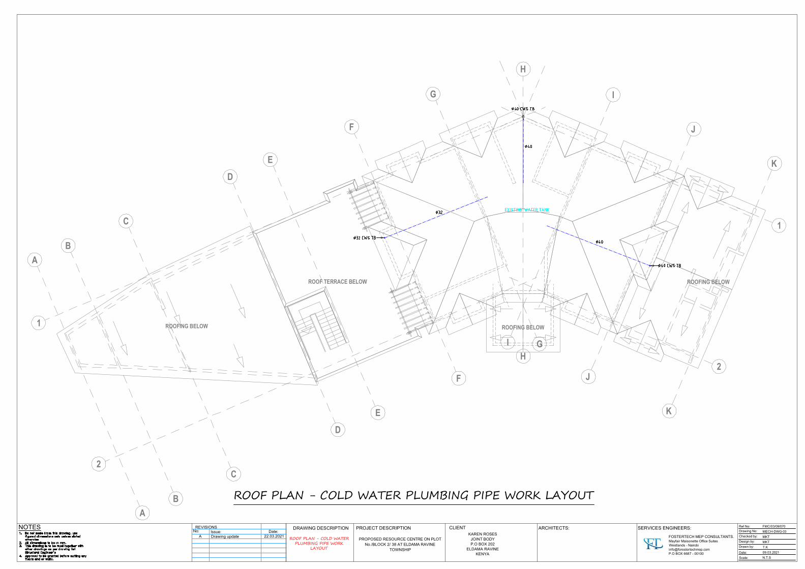
NOTES DRAWING DESCRIPTION PROJECT DESCRIPTION CLIENT ARCHITECTS: Ref No:
PROPOSED RESOURCE CENTRE ON PLOTNo./BLOCK 2/ 38 AT ELDAMA RAVINE
TOWNSHIP
REVISIONSNo: Issue: Date:
SERVICES ENGINEERS:KAREN ROSES
JOINT BODYP.O BOX 202
ELDAMA RAVINEKENYA
Drawing No:
Checked by:
Design by:
Drawn by:
Date:
Scale:
FMC/03/09/070
MECH-DWG-03
MKT
MKT
T.K
09.03.2021
N.T.S
ROOF PLAN - COLD WATER PLUMBING PIPE WORK LAYOUT
ROOF PLAN - COLD WATERPLUMBING PIPE WORK
LAYOUT
FOSTERTECH MEP CONSULTANTS.Mayfair Maisonette Office SuitesWestlands - [email protected] BOX 6687 - 00100
1
2
A
B
C
D
E
F
1
2
G
H
I
J
K
I
J
K
A
B
C
D
E
F
G
ROOFING BELOW
ROOFING BELOWROOFING BELOW
ROOF TERRACE BELOW
H
A Drawing update 22.03.2021

Roof pitch 30 deg.Metal based (decra) roofingtiles on timber trusses /structures to S.E's details.
ICT CENTRE
LOBBY AREA
OFFICE
OFFICE 02A
B
C
D
E
F
2
Porcelain tiles fl. fn.
OFFICE 01
G
H
I
J
K
I
J
K
H
A
B
C
D
E
F
G
1
2
Roof pitch 7.5 deg.Metal based (decra) roofing
tiles on timber trusses /structures to S.E's details.
ROOF TERRACE
pv
pv
pv
pv
pv
NOTES DRAWING DESCRIPTION PROJECT DESCRIPTION CLIENT ARCHITECTS: Ref No:
PROPOSED RESOURCE CENTRE ON PLOTNo./BLOCK 2/ 38 AT ELDAMA RAVINE
TOWNSHIP
REVISIONSNo:
SERVICES ENGINEERS:KAREN ROSES
JOINT BODYP.O BOX 202
ELDAMA RAVINEKENYA
Drawing No:
Checked by:
Design by:
Drawn by:
Date:
Scale:
FMC/03/09/070
MECH-DWG-04
MKT
MKT
T.K
09.03.2021
N.T.S
FIRST FLOOR - COLD WATER PLUMBING PIPE WORK LAYOUT
FIRST FLOOR - COLDWATER PLUMBING PIPE
WORK LAYOUT
FOSTERTECH MEP CONSULTANTS.Mayfair Maisonette Office SuitesWestlands - [email protected] BOX 6687 - 00100
No: Issue: Date:A Drawing update 22.03.2021
LOBBY AREA
OFFICE
G
H
I
pv

NOTES DRAWING DESCRIPTION PROJECT DESCRIPTION CLIENT ARCHITECTS: Ref No:
PROPOSED RESOURCE CENTRE ON PLOTNo./BLOCK 2/ 38 AT ELDAMA RAVINE
TOWNSHIP
REVISIONSNo:
SERVICES ENGINEERS:KAREN ROSES
JOINT BODYP.O BOX 202
ELDAMA RAVINEKENYA
Drawing No:
Checked by:
Design by:
Drawn by:
Date:
Scale:
FMC/03/09/070
MECH-DWG-05
MKT
MKT
T.K
09.03.2021
N.T.S
GROUND FLOOR - COLD WATER PLUMBING PIPE WORK LAYOUT
GROUND FLOOR - COLDWATER PLUMBING PIPE
WORK LAYOUT
FOSTERTECH MEP CONSULTANTS.Mayfair Maisonette Office SuitesWestlands - [email protected] BOX 6687 - 00100
Possibility of acollapsible partition
TAILORING UNIT
ENTRY LOBBY
ATMNew
KitchenEXISTING RESTAURANT
Office
CONFERENCE FACILITY- 100 pax classroom style
Office 01
Office 01
Office 02
Office 03
Office 04
Office 05
ENTRY LOBBY
PORTE COCHERE
Kitchen store
A
B
C
D
E
F
2
G
H
I
J
K
I
J
K
H
A
B
C
D
E
F
G
1
2
Passage
Reception deskto details
Reception deskto details
pv
pv
pv
pv
pv
Issue:A Drawing update
Date:22.03.2021
ATM
Office 04
pv
K
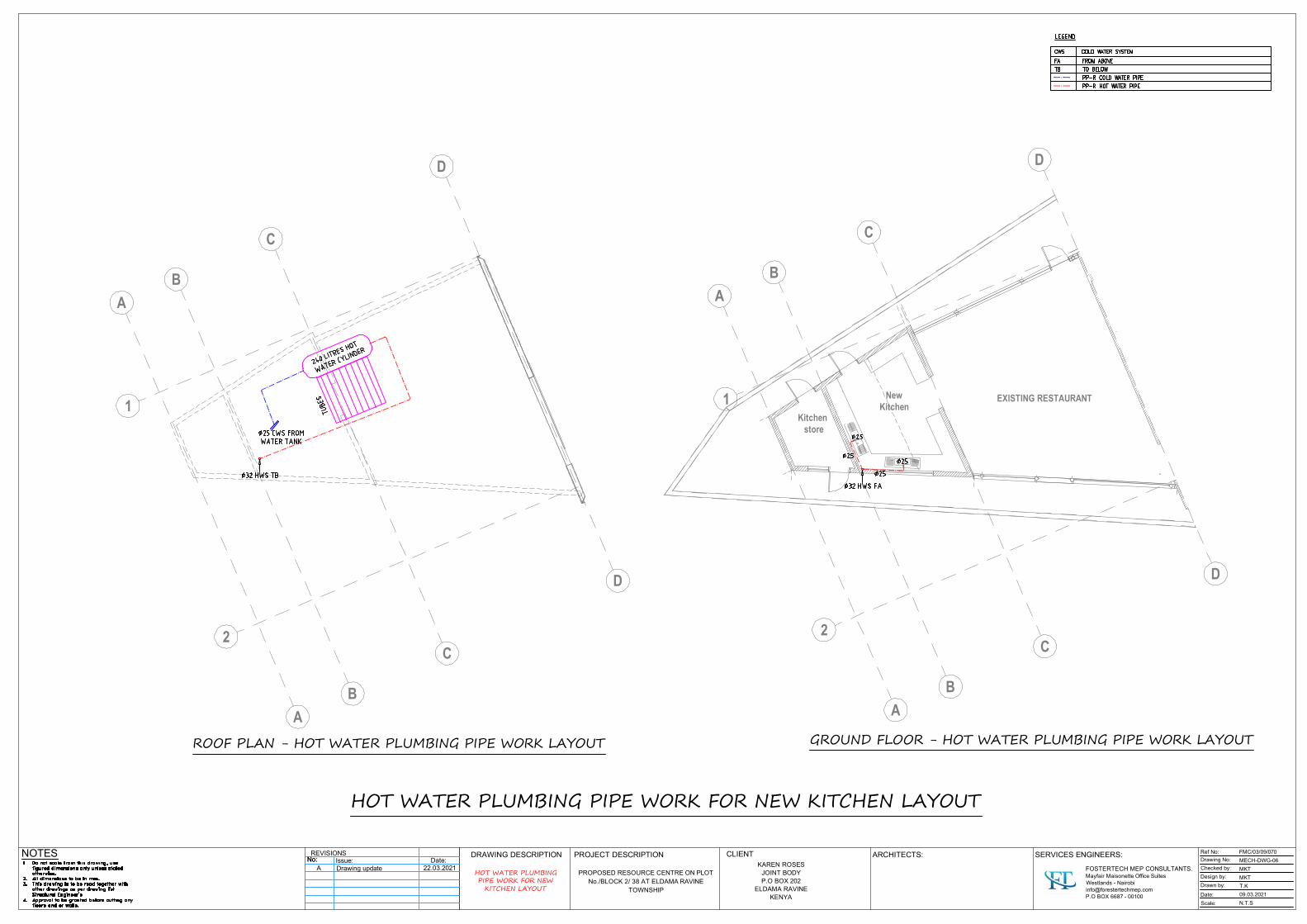
NOTES DRAWING DESCRIPTION PROJECT DESCRIPTION CLIENT ARCHITECTS: Ref No:
PROPOSED RESOURCE CENTRE ON PLOTNo./BLOCK 2/ 38 AT ELDAMA RAVINE
TOWNSHIP
REVISIONSNo:
SERVICES ENGINEERS:KAREN ROSES
JOINT BODYP.O BOX 202
ELDAMA RAVINEKENYA
Drawing No:
Checked by:
Design by:
Drawn by:
Date:
Scale:
FMC/03/09/070
MECH-DWG-06
MKT
MKT
T.K
09.03.2021
N.T.S
HOT WATER PLUMBING PIPE WORK FOR NEW KITCHEN LAYOUT
GROUND FLOOR - HOT WATER PLUMBING PIPE WORK LAYOUT
HOT WATER PLUMBINGPIPE WORK FOR NEW
KITCHEN LAYOUT
FOSTERTECH MEP CONSULTANTS.Mayfair Maisonette Office SuitesWestlands - [email protected] BOX 6687 - 00100
A
B
C
D
A
B
C
D
1
2
NewKitchen
EXISTING RESTAURANT
Kitchen store
A
B
C
D
A
B
C
D
1
2
ROOF PLAN - HOT WATER PLUMBING PIPE WORK LAYOUT
No: Issue: Date:A Drawing update 22.03.2021

NOTES DRAWING DESCRIPTION PROJECT DESCRIPTION CLIENT ARCHITECTS: Ref No:
PROPOSED RESOURCE CENTRE ON PLOTNo./BLOCK 2/ 38 AT ELDAMA RAVINE
TOWNSHIP
REVISIONSNo:
SERVICES ENGINEERS:KAREN ROSES
JOINT BODYP.O BOX 202
ELDAMA RAVINEKENYA
Drawing No:
Checked by:
Design by:
Drawn by:
Date:
Scale:
FMC/03/09/070
MECH-DWG-07
MKT
MKT
T.K
09.03.2021
N.T.S
ROOF PLAN - FIRE FIGHTING PIPE WORK LAYOUT
ROOF FLOOR - FIREFIGHTING PIPE WORK
LAYOUT
FOSTERTECH MEP CONSULTANTS.Mayfair Maisonette Office SuitesWestlands - [email protected] BOX 6687 - 00100
1
2
A
B
C
D
E
F
1
2
G
H
I
J
K
I
J
K
A
B
C
D
E
F
G
ROOFING BELOW
ROOFING BELOWROOFING BELOW
ROOF TERRACE BELOW
H
No: Issue: Date:A Drawing update 22.03.2021

NOTES DRAWING DESCRIPTION PROJECT DESCRIPTION CLIENT ARCHITECTS: Ref No:
PROPOSED RESOURCE CENTRE ON PLOTNo./BLOCK 2/ 38 AT ELDAMA RAVINE
TOWNSHIP
REVISIONSNo:
SERVICES ENGINEERS:KAREN ROSES
JOINT BODYP.O BOX 202
ELDAMA RAVINEKENYA
Drawing No:
Checked by:
Design by:
Drawn by:
Date:
Scale:
FMC/03/09/070
MECH-DWG-08
MKT
MKT
T.K
09.03.2021
N.T.S
FIRST FLOOR - FIRE FIGHTING PIPE WORK & EQUIPMENT LAYOUT
FIRST FLOOR - FIREFIGHTING PIPE WORK &
EQUIPMENT LAYOUT
FOSTERTECH MEP CONSULTANTS.Mayfair Maisonette Office SuitesWestlands - [email protected] BOX 6687 - 00100
Roof pitch 30 deg.Metal based (decra) roofingtiles on timber trusses /structures to S.E's details.
ICT CENTRE
LOBBY AREA
OFFICE
OFFICE 02A
B
C
D
E
F
2
Porcelain tiles fl. fn.
OFFICE 01
G
H
I
J
K
I
J
K
H
A
B
C
D
E
F
G
1
2
Roof pitch 7.5 deg.Metal based (decra) roofing
tiles on timber trusses /structures to S.E's details.
ROOF TERRACE
pv
pv
pv
pv
pv
No: Issue: Date:A Drawing update 22.03.2021

NOTES DRAWING DESCRIPTION PROJECT DESCRIPTION CLIENT ARCHITECTS: Ref No:
PROPOSED RESOURCE CENTRE ON PLOTNo./BLOCK 2/ 38 AT ELDAMA RAVINE
TOWNSHIP
REVISIONSNo:
SERVICES ENGINEERS:KAREN ROSES
JOINT BODYP.O BOX 202
ELDAMA RAVINEKENYA
Drawing No:
Checked by:
Design by:
Drawn by:
Date:
Scale:
FMC/03/09/070
MECH-DWG-09
MKT
MKT
T.K
09.03.2021
N.T.S
GROUND FLOOR - FIREFIGHTING PIPE WORK &
EQUIPMENT LAYOUT
GROUND FLOOR - FIRE FIGHTING PIPE WORK & EQUIPMENT LAYOUT
FOSTERTECH MEP CONSULTANTS.Mayfair Maisonette Office SuitesWestlands - [email protected] BOX 6687 - 00100
Possibility of acollapsible partition
TAILORING UNIT
ENTRY LOBBY
ATMNew
KitchenEXISTING RESTAURANT
Office
CONFERENCE FACILITY- 100 pax classroom style
Office 01
Office 01
Office 02
Office 03
Office 04
Office 05
ENTRY LOBBY
PORTE COCHERE
Kitchen store
A
B
C
D
E
F
2
G
H
I
J
K
I
J
K
H
A
B
C
D
E
F
G
1
2
Passage
Reception deskto details
Reception deskto details
pv
pv
pv
pv
pv
Issue:A Drawing update
Date:22.03.2021
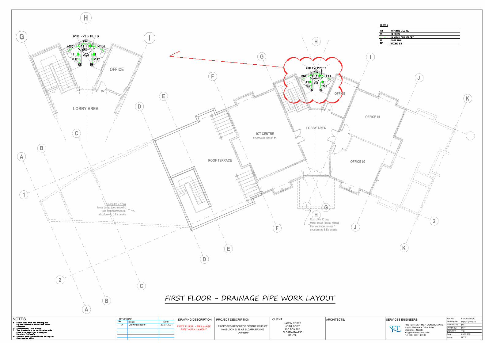
NOTES DRAWING DESCRIPTION PROJECT DESCRIPTION CLIENT ARCHITECTS: Ref No:
PROPOSED RESOURCE CENTRE ON PLOTNo./BLOCK 2/ 38 AT ELDAMA RAVINE
TOWNSHIP
REVISIONSNo:
SERVICES ENGINEERS:KAREN ROSES
JOINT BODYP.O BOX 202
ELDAMA RAVINEKENYA
Drawing No:
Checked by:
Design by:
Drawn by:
Date:
Scale:
FMC/03/09/070
MECH-DWG-10
MKT
MKT
T.K
09.03.2021
N.T.S
FIRST FLOOR - DRAINAGE PIPE WORK LAYOUT
FIRST FLOOR - DRAINAGEPIPE WORK LAYOUT
FOSTERTECH MEP CONSULTANTS.Mayfair Maisonette Office SuitesWestlands - [email protected] BOX 6687 - 00100
Roof pitch 30 deg.Metal based (decra) roofingtiles on timber trusses /structures to S.E's details.
ICT CENTRE
LOBBY AREA
OFFICE
OFFICE 02A
B
C
D
E
F
2
Porcelain tiles fl. fn.
OFFICE 01
G
H
I
J
K
I
J
K
H
A
B
C
D
E
F
G
1
2
Roof pitch 7.5 deg.Metal based (decra) roofing
tiles on timber trusses /structures to S.E's details.
ROOF TERRACE
pv
pv
pv
pv
pv
No: Issue: Date:A Drawing update 22.03.2021
LOBBY AREA
OFFICE
G I
pv
G
H
I

NOTES DRAWING DESCRIPTION PROJECT DESCRIPTION CLIENT ARCHITECTS: Ref No:
PROPOSED RESOURCE CENTRE ON PLOTNo./BLOCK 2/ 38 AT ELDAMA RAVINE
TOWNSHIP
REVISIONSNo:
SERVICES ENGINEERS:KAREN ROSES
JOINT BODYP.O BOX 202
ELDAMA RAVINEKENYA
Drawing No:
Checked by:
Design by:
Drawn by:
Date:
Scale:
FMC/03/09/070
MECH-DWG-11
MKT
MKT
T.K
09.03.2021
N.T.S
GROUND FLOOR -DRAINAGE PIPE WORK
LAYOUT
GROUND FLOOR - DRAINAGE PIPE WORK LAYOUT
FOSTERTECH MEP CONSULTANTS.Mayfair Maisonette Office SuitesWestlands - [email protected] BOX 6687 - 00100
Possibility of acollapsible partition
TAILORING UNIT
ENTRY LOBBY
ATMNew
KitchenEXISTING RESTAURANT
Office
CONFERENCE FACILITY- 100 pax classroom style
Office 01
Office 01
Office 02
Office 03
Office 04
Office 05
ENTRY LOBBY
PORTE COCHERE
Kitchen store
A
B
C
D
E
F
2
G
H
I
J
K
I
J
K
H
A
B
C
D
E
F
G
1
2
Passage
Reception deskto details
Reception deskto details
pv
pv
pv
pv
pv
Issue:A Drawing update
Date:22.03.2021

NOTES DRAWING DESCRIPTION PROJECT DESCRIPTION CLIENT ARCHITECTS: Ref No:
PROPOSED RESOURCE CENTRE ON PLOTNo./BLOCK 2/ 38 AT ELDAMA RAVINE
TOWNSHIP
REVISIONSNo:
SERVICES ENGINEERS:KAREN ROSES
JOINT BODYP.O BOX 202
ELDAMA RAVINEKENYA
Drawing No:
Checked by:
Design by:
Drawn by:
Date:
Scale:
FMC/03/09/070
MECH-DWG-12
MKT
MKT
T.K
09.03.2021
N.T.S
FIRST FLOOR - RAINWATER OUTLETS LAYOUT
FIRST FLOOR - RAINWATEROUTLETS LAYOUT
FOSTERTECH MEP CONSULTANTS.Mayfair Maisonette Office SuitesWestlands - [email protected] BOX 6687 - 00100
Roof pitch 30 deg.Metal based (decra) roofingtiles on timber trusses /structures to S.E's details.
ICT CENTRE
LOBBY AREA
OFFICE
OFFICE 02A
B
C
D
E
F
2
Porcelain tiles fl. fn.
OFFICE 01
G
H
I
J
K
I
J
K
H
A
B
C
D
E
F
G
1
2
Roof pitch 7.5 deg.Metal based (decra) roofing
tiles on timber trusses /structures to S.E's details.
ROOF TERRACE
pv
pv
pv
pv
pv
No: Issue: Date:A Drawing update 22.03.2021

NOTES DRAWING DESCRIPTION PROJECT DESCRIPTION CLIENT ARCHITECTS: Ref No:
PROPOSED RESOURCE CENTRE ON PLOTNo./BLOCK 2/ 38 AT ELDAMA RAVINE
TOWNSHIP
REVISIONSNo: Issue:
SERVICES ENGINEERS:KAREN ROSES
JOINT BODYP.O BOX 202
ELDAMA RAVINEKENYA
Drawing No:
Checked by:
Design by:
Drawn by:
Date:
Scale:
FMC/03/09/070
MECH-DWG-13
MKT
MKT
T.K
09.03.2021
N.T.S
GROUND FLOOR -RAINWATER PIPE WORK
LAYOUT
GROUND FLOOR - RAINWATER PIPE WORK LAYOUT
FOSTERTECH MEP CONSULTANTS.Mayfair Maisonette Office SuitesWestlands - [email protected] BOX 6687 - 00100
Possibility of acollapsible partition
TAILORING UNIT
ENTRY LOBBY
ATMNew
KitchenEXISTING RESTAURANT
Office
CONFERENCE FACILITY- 100 pax classroom style
Office 01
Office 01
Office 02
Office 03
Office 04
Office 05
ENTRY LOBBY
PORTE COCHERE
Kitchen store
A
B
C
D
2
G
H
I
J
K
I
J
K
H
A
B
C
D
E
F
G
1
2
Passage
Reception deskto details
Reception deskto details
pv
pv
pv
E
F
pv
pv
A Drawing updateDate:
22.03.2021

FOSTERTECH MEP LTD KAREN ROSES LTD - GEN ELEC INST
SPECIFICATION NO. FMC/TF – 21/02E
PROPOSED RESOURCE CENTRE ALTERATIONS
FOR KAREN ROSES JOINT BODY
IN ELDAMA RAVINE
PLOT L.R NO 2.38
GENERAL ELECTRICAL INSTALLATIONS
SUB-CONTRACT CONDITIONS, SPECIFICATIONS, AND BILLS OF QUANTITIES
NAME OF TENDERER
CLIENT: ARCHITECTS: KAREN ROSES JOINT BODY P.O BOX 202, ELDAMA RAVINE KENYA
ARCH. PIUS WAMBUA NAIROBI.
MECHANICAL & ELECTRICAL ENGINEERS: QUANTITY SURVEYOR: FOSTERTECH MEP CONSULTANTS LTD ZIMAKI CONSULT P.O BOX 6678-00100 P.O BOX 8589-00100 WESTLANDS, NAIROBI NAIROBI
MARCH, 2O21

FOSTERTECH MEP LTD KAREN ROSES LTD - GEN ELEC INST
FORM OF TENDER
FOR
GENERAL ELECTRICAL INSTALLATIONS
PROPOSED FACTORY FOR TRUFOODS LTD, JUJA
TO: The Managing Director, Karen Roses Joint Body., P. O. Box 202, Eldama Ravine Kenya. Sir, 1. We have examined specification No.FMC/TF-21/02, with Schedules hereto, we offer
to execute and do several works and things described or referred to in the said Specification, Schedules, and Conditions, which under the terms thereof are to be supplied, executed, and done by the Sub-Contractor to perform and observe the Provisions and agreements on the part of the Sub-Contractor, contained or reasonably to be inferred from the said Specification, Schedules, and Conditions of Contract for the same at the date set out in the Schedules.
Our Lump Sum Price for the said Installation is set out in Price Schedules.
is (in figures) KShs................................………………………..…………………..
(in words)................................................………………………………………….
...........................................................………………………………………………
2. If our tender is accepted, we will, when required, obtain the guarantee of an Insurance
Company or Bank or other sureties (to be approved by the Client) to be jointly and severally bound with us in a sum of Ten percent (10%) of the sum mentioned earlier for the due performance of the contract under the terms of a Bond.
3. We agree to abide by this tender for ninety (90) days from the date fixed for receiving
the same, and it shall remain binding upon us and may be accepted at any time before the expiration of that period.
4. Unless and until a formal agreement is prepared and executed, this tender, together
with your written acceptance thereof, shall constitute a binding contract between the Client and us.
5. We understand that no alteration to this Tender Document will be allowed, and any
unauthorized alterations may invalidate the tender.
6. We understand that you are not bound to accept the lowest or any tender you receive.

FOSTERTECH MEP LTD KAREN ROSES LTD - GEN ELEC INST
7. We understand that retention money at the rate of 10% of the certified value shall be held to a limit of 5% of this Contract amount.
(i) Dated this …………………day of ………………………………………………….…… Signature…………………………..Name ……………………………………………. in the capacity of ………………………………………………………………………. Duly authorized to sign tenders for and on behalf of ……………………………………. …………………………..………………………….…………………………………………. (IN BLOCK CAPITALS) Address: .............................…………………………………………………………………. ....................................……………………………………………………………………….. Witness: Name: ............…..............……………………………………………………………….. Signature: ………………………………………………………………………………… Address: .....................................................………………………………………………. ..........................................................………………………………………………………. Occupation ...................................................……………………………………………
(ii)

FOSTERTECH MEP LTD KAREN ROSES LTD - GEN ELEC INST
SECTION 1 1.0 PARTICULAR CONDITIONS 1.01 Location of Site The site of the proposed project shall be situated in Eldama Ravine. 1.02 Description of Project The project comprises a reorganization and alterations of the existing building, which
was razed down by a fire. 1.03 Commencement of Works The Sub-Contractor in submitting his tender shall be deemed to have included for commencing any necessary work on-site at such a time as will comply with the Main Contractor's program. 1.04 Scope of Works The Sub-Contract Works shall comprise the supply, delivery, erection, testing,
commissioning, and setting to work of the Electrical Engineering Services as detailed in this specification and the accompanying Contract Drawings.
The work to be undertaken under this Sub-Contract shall comprise but not restricted to
the following: -
(a) Liaison with K.P.L.C. for power supply to the premises.
(b) Supply of new Distribution Boards and Consumer units
(c) Supply and Installation of electrical sub-main cables
(d) Supply and Installation of small power and lighting installations
(e) Supply & Installation of fire detection and alarm system.
(f) Installation of lightning protection systems and bonding of the same to the electrical earthing as appropriate.
(g) Supply & Installation of the External/Security, Car Park, and Amenity Lighting within
the complex and access roads.
(p) Supply & install cable trays and trunking.
1.05 Ordering of Materials The Sub-Contractor shall order materials from the quantities taken from his own
approved working drawings.

FOSTERTECH MEP LTD KAREN ROSES LTD - GEN ELEC INST
1.06 Builder's Work Requirements The structural and other provisions allowed for are indicated on the Contract Drawings. If
the Tenderer requires any other conditions, he shall mark them in a contrasting color and submit them as part of his tender.
1.07 Statement of Compliance The Tenderer shall provide as an integral part of his bid, a statement of compliance.
FOSTERTECH MEP LTD KAREN ROSES LTD - GEN ELEC INST
PART TWO
GENERAL ELECTRICAL SPECIFICATIONS 2.01 Standard of Materials Where the material and equipment is specifically described and named in the
specification followed by the approved equal, it is so named or described for the purpose of establishing a standard of materials and workmanship to which the sub-contractor shall submit, with his bid, a list indicating the manufacturer and place of origin of the various items of equipment that he proposes to supply on the form included with the Tender Documents. Should the sub-contractor install the materials or carry out the method in question before receiving approval from the proper authorities, the Engineer shall direct the sub-contractor to remove the material in question immediately. The fact that this material has been installed shall have no bearing or influence on the decision by the Engineer. All materials condemned by the Engineer as not approved for use are to be removed from the premises and suitable materials delivered and installed in their place at the expense of the sub-contractor. All materials required for the works shall be new, and the best of their respective kind and shall be of a uniform pattern. See also Clause 2.16 "Regulations and Standards."
2.02 Workmanship The workmanship and method of Installation shall conform to the best standard
practice. All work shall be performed by a skilled tradesman and to the satisfaction of the Engineer. Helpers shall have qualified supervision. Any work that does not, in the opinion of the Engineer, conforms to the best standard practice will be removed and reinstated subcontractor's expense. Permits, Certificates, or Licenses must be held by all tradesmen for the type of work in which they are involved where such Permits, Certificates, or Licenses exist under Government Legislation.
2.03 Procurement of Materials The sub-contractor is advised that no assistance can be given in the procurement or
allotment of any materials or products to be used in and necessary for the construction and completion of the work. Sub-contractors are warned that they must make their own arrangements for the supply of materials and/or products specified or required. The sub-contractor may be called upon to show evidence that satisfactory arrangements have been made for the procurement of any or all materials and products needed to complete the works. Copies of purchase orders to suppliers may be requested.
The sub-contractor shall be responsible for all site and/or drawing measurements
required for the completion of quantities of materials as are necessary for the proper execution of the works.
No claims for extra payment will be considered on the grounds of insufficient
knowledge, inaccurate measurements, or other errors on the part of the sub-contractor.
2.04 Shop Drawings

FOSTERTECH MEP LTD KAREN ROSES LTD - GEN ELEC INST
Before manufacture is begun, the sub-contractor shall submit six copies of detailed drawings of all pieces of equipment, including their components, showing all pertinent information including sizes, capacities, construction details, etc. and as may be required to determine the suitability of the equipment for the approval of the Engineer. Acceptance of the detailed drawings shall not relieve the sub-contractor of the full responsibility of errors or the necessity of checking the drawings himself or of furnishing the materials and equipment and performing the work required by the Plans and Specification.
2.05 Temporary and Trial Usage It shall be understood and agreed that temporary or trial usage by the owner of any
device, machinery, apparatus, equipment, or any other work of materials supplied under this contract before final completion and written acceptance by the Engineer is not considered as evidence of acceptance of the item by the owner. It is further understood and agreed that the owner shall have the privilege of such temporary and trial usage as soon as the sub-contractor shall claim that the said work is completed and in accordance with the Drawings and Specification and to the manufacturer's instructions and for such reasonable length of time as the Engineer shall deem suitable for making a complete and thorough test of the apparatus or system under test.
No claim for damage will be made by the sub-contractor for the injury to or breaking
of any parts of the Works which have been placed under test whether this damage has been caused by weakness, flaw, or inaccuracy of structural elements or by defective material or workmanship of any kind whatsoever.
2.06 Record Drawings The Engineer will supply the sub-contractor with an extra set of white prints on which
he shall clearly mark as the job progresses, all changes and deviations from the proposed Installation so that the Architect, at the completion of the job, will have a record of the exact location of all piping and equipment.
The sub-contractor shall also furnish, within a reasonable time after the completion of
the Works and prior to the final payment being sanctioned, drawings and diagrams of the Works completed and related to the whole Installation and plant.
These diagrams and drawings shall show the completed Installation, including sizes,
runs, and arrangements of the Installation. The drawings shall be to a scale not less than 1:50 and shall include plan views and a number of sections.
The drawings shall include all details which may be helpful in the operation,
maintenance, or subsequent modifications or extensions to the Installation. Three sets of diagrams and drawings shall be provided, all to the approval of the
Engineer. One colored set of line diagrams relating to operating and maintenance instructions
shall be framed and mounted in a suitable location.

FOSTERTECH MEP LTD KAREN ROSES LTD - GEN ELEC INST
2.07 Operating and Maintenance Instructions The contractor shall be responsible for furnishing a competent technician to instruct
the numerous staff in the operation of the entire Installation. Two copies shall be furnished of operating instructions for all apparatus installed
under this contract, including service maintenance and spare parts, bound in best quality loose-leaf binders. Instructions shall also include step-by-step directions for minor troubleshooting and periodic maintenance instructions, such as cleaning, oiling, etc., for all equipment supplied under this contract, including types of lubricant. All instructions shall be delivered to the owner.
All bulletins shall pertain to the equipment installed on the job only. General
publications describing any items of equipment not installed in this job will be rejected. All instructions shall be prefaced by a simple description of the entire system, explaining its purpose and operation so that a person completely unfamiliar with the building can operate all systems by following the instructions. Preparation of such instructions shall be the responsibility of the contractor, NOT equipment suppliers.
2.08 Cleaning Before operating any of the systems, the contractor shall clean out all rubbish and
dirt. 2.09 Nameplates The contractor is responsible for ensuring that all apparatus has nameplates showing
the size, name of equipment, serial number, and all other information usually provided. These nameplates are not to be painted over.
Motors shall have a serial number, voltage, cycle, phase, and horsepower. All nameplates are to have the name of the manufacturer and his address. All stamped, edged, or engraved lettering to be perfectly legible to the satisfaction of
the Engineer. 2.10 Vibration Isolation Vibration absorbing devices shall be used to isolate all motorized equipment,
including refrigeration plant, air handling units, fans, etc.

FOSTERTECH MEP LTD KAREN ROSES LTD - GEN ELEC INST
It shall be the responsibility of the contractor to see that correct isolation is installed under the aforementioned plant as specified hereunder and to ensure that no objectionable vibrations or sound be transmitted to the building structure.
Vibration isolators for the plant shall be as required by the equipment and/or vibration
isolation manufacturers, who shall supply the contractor with drawings and supervision that may be necessary.
Spring type isolation shall be or cast iron construction with floating top plate for
leveling purpose complete with adjusting the belt. The spring to be incorporated into this housing shall be as determined by the isolation manufacturer to provide 95% dampening efficiency.
Rubber vibration isolators shall be of the rubber in sheer type, having a suitable
arrangement of material to achieve compression and sheet in each direction. Good pads of 6mm (0.25") ribbed neoprene shall be used with all isolators.
2.11 Equipment Supports and Stands Supply and install all stands, supports, etc., where indicated on the Drawings and/or called
for in the Specifications and where required for the proper support of all equipment. Attachment and fixing to the building structure or fabric shall be of a type suitable for
the particular member or material being attached to, and the approval of the Engineer shall be obtained for all kinds of attachments and fixings. The contractor shall provide all fixings for supports and shall mark out all the holes positions which will also be cut by the Main Contractor.
2.12 Dimensions of Plant and Equipment As mentioned in all relevant sections, the contractor shall be responsible for
ascertaining that all dimensions and sizes indicated will correspond to the positions indicated.
Any changes having to be made on-site and/or arising from the contractor not having
complied with these instructions shall be his responsibility, and no extra payment will be entertained in this respect.
2.13 Access to Plant Rooms It shall be the responsibility of the contractor to ensure that all equipment ordered in
respect of this contract is to be constructed in such a manner that it may, if necessary, be dismantled to enable it to pass down through the building to street level. The contractor is also to ensure that the systematic Installation of plant room equipment is planned so that the most important items of equipment can be installed.
2.14 Testing on Site After the work is completed, the contractor shall subject all systems to a functional
test in which he shall adjust all controls, speeds, etc. all to the satisfaction of the Engineer, and shall demonstrate the operation, regulation, and required maintenance to all persons nominated by the Employer and/or Engineer.
FOSTERTECH MEP LTD KAREN ROSES LTD - GEN ELEC INST
All tests are to be arranged in co-operation with the Engineer who is to be present at
all site tests. Test Certificates are to be provided by the contractor and signed by the Engineer who
witnessed the test. All Test Certificates are to be submitted to the Engineer and shall contain the following particulars therein:-
a). Earth Continuity; b). Neutral Earth Loop Impedance;
c). Insulation Resistance; d). Earth Resistance;
For the purpose of all tests, the contractor shall provide all apparatus, attendance,
and assistance necessary together with all skilled labor and shall, if requested, demonstrate the accuracy of any installation.
2.15 Spares The contractor shall prepare a schedule of the manufacturer's recommended spares
together with any special tools required for maintenance purposes. The plans shall indicate the number of individual reserves as are necessary for each item of the plant included in the Works and the cost of each item.
2.16 Regulations and Standards All work executed by the contractor shall comply with the current edition of the
"Regulations" for the Electrical Equipment of Buildings issued by the Institution of Electrical Engineers and with the Regulations of the Local Electricity Authority.
Where the two sets of regulations appear to conflict, they shall be clarified with the
Engineer. All materials used and equipment supplied shall comply with relevant British Standard
Specification. 2.17 Setting out Works
The contractor, at his own expense, is to set out works and take all measurements and dimensions required for the erection of his materials on-site, making any modifications in detail as may be found necessary during the progress of the Works, submitting any such changes or alterations in
piece to the Engineer before proceeding, and must allow in his tender for all such modifications and for the provision of any such sketches or drawings related thereto.
2.18 Position of Electrical Plant and Apparatus The routes of cables and approximate positions of switchboards, etc., as shown on
the Drawings, shall be assumed to be correct for the purpose of Tendering, but the exact parts of all electrical equipment and routes of cables must be agreed upon on-site with the Engineer before any work is carried out.
2.19 Main Switchgear (Unit Type)

FOSTERTECH MEP LTD KAREN ROSES LTD - GEN ELEC INST
Shall consist of M.S angle frameworks securely stayed to wall and floor, on which
shall be mounted fuse switches of the size indicated on the Drawings. The fuse switches shall be connected by means of Manufacturers' distance pieces to sheet steel-cased busbar chambers of appropriate length, affording space for future control fuses with hinged covers and detachable endplates. The bars (three-phase and neutral) shall be mounted on porcelain supports. The busbars shall be of the same current rating as the main switch.
The busbars shall be drilled as required, brass bolts and nuts (minimum 0.25" Whitworth), and spring washers being used for securing seating sockets for both incoming and outgoing cables. The internal wiring of the switchboard shall be carried out using a copper bar strip of ample sectional areas wrapped with a suitable thickness of Empire tape.
The complete switchboard shall be designed so as to be capable of successfully
withstanding through fault current, equivalent to a minimum of 25 k.A at 440 volts or other such ratings as may be specified.
2.20 Switchgear (Cubicle Type) The details specified in the previous clause for industrial type switchboards shall
apply as far as to fuse switches, busbars, and ratings, sweating sockets, internal wiring, fault current rating, layout drawings for Engineer's approval and reasonable revisions, manufacture assembly, and necessary interconnections are concerned.
The panels shall be constructed of rolled steel channel minimum 56mm x 28mm (2.25" x 1.25") deep or equivalent angle section clad with sheet steel of 12 gauge minimum for large panels and 14 gauge minimum for lids and trim boards. The panels shall be finished in cellulose finish to approved color.
2.21 M.C.B Distribution Panels Cases shall be constructed in heavy gauge sheet steel with hinged covers unless
otherwise stated, suitable for surface mounting. Removable undrilled gland plates shall be provided on the top and bottom of the
cases. Miniature circuit breakers shall be enclosed in moulded plastic with the tripping mechanism and arc chambers separated and sealed from the cable terminals.
The operating dolly shall be trip-free with a positive movement in both make and
break positions. A clear indication of the position of the handle shall be incorporated. The tripping mechanism shall be an inverse characteristic to prevent tripping in
temporary overloads and shall not be affected by normal variation in ambient temperature.
The breakers shall be grouped in distribution panels as specified in Part Three of this
Specification, all live metal being shrouded or concealed during regular use. A locking plate shall be provided for each size of the breaker.
A complete list of circuit details on typed cartridge paper glued to stiff cardboard and
covered with a sheet of perspex, and held in position with four suitable fixings, shall

FOSTERTECH MEP LTD KAREN ROSES LTD - GEN ELEC INST
be fitted to the inner face of the lids of each distribution panel. The appropriate M.C.B ratings shall be stated on the circuit chart against each circuit in use. Ivorine labels shall be secured to the insulation barriers in such a manner as to indicate the number of the circuit shown on the circuit chart.
Insulated barriers shall be fitted between phases and neutrals in all boards and to
shroud live parts. Neutral cables shall be connected to the neutral bar in the same sequence as the
phase cables are connected to the M.C.B's. This shall also apply to earth bars when installed.
2.22 Conduit and Conduit Fittings All conduits shall be welded, heavy-gauge, steel tubes, manufactured in accordance
with British Standard Specification No 31 galvanized finish. Conduit boxes shall be manufactured in accordance with British Standard
Specifications Nos. 820 and 31. Flexible conduit and adaptors shall be of the watertight type and shall be
manufactured in accordance with B.S 731 (see Flexible Conduit and Fittings Clause). 2.23 Conduit and Fittings Detail a) Systems A separate conduit and wiring system is required for each Installation, lighting,
power, telephone, etc. b) Runs Permission shall be obtained from the Engineers before any conduit runs are
installed in any part of the Installation, as details of ceiling panels etc., may affect the position of lighting points, switch drops, etc. The conduit shall be installed using the "looping in" system so that all wiring is carried out from the rooms in which the electrical points are situated.
The term "looping in" system does not mean that "looping in" boxes will be
permitted. Spouted boxes shall be used wherever reasonably practical, "loop in" boxes are only to be used when spouted boxes cannot be utilized for constitutional reasons.
Conduit shall be spaced to give a minimum clearance of 225mm (9") between
water, steam, gas, and other service pipes. Where this is impossible, the conduits shall be separated from other services by suitable insulation or securely bonded to them (except gas). The contractor shall apply to the Engineer for instructions regarding which method is to be adopted.
All horizontal surface conduit runs shall be erected at near ceiling level, and for all surface work, the boxes used shall be tangent entry types.
The contractor shall include producing plans showing his proposed conduit runs immediately after notification to the effect that his tender has been accepted and shall forward duplicate copies of drawings to the Engineers for

FOSTERTECH MEP LTD KAREN ROSES LTD - GEN ELEC INST
approval—these plans to be in the hands of the Engineers prior to the commencement of the contract.
All conduits shall be efficiently drained before wiring and ventilated in suitable positions to off-set the effects of condensation.
c) Sizes The conduit shall be of such sizes that the conductors shall be quickly drawn
in after all-tube has been installed, and they shall be in accordance with the Capacity of Conduits Table contained in the current edition of the I.E.E Regulations. The minimum diameter of conduit 20mm (0.25").
d) Fittings All surface erected conduits shall be secured with distance saddles giving a
clearance of 25mm (1") from the building structure. All conduits to be concealed by plaster in brick or similar walls shall be
secured by standard saddles or wrought iron crampets fixed at 1,200mm (4ft) maximum intervals.
Where two or more conduits are run side by side, the saddles shall be
staggered to minimize the distance between the conduits. Saddles shall be fixed at a distance not exceeding 225mm (9") on either side
of all bends and set. Similarly, vertical runs shall be fixed at a distance not exceeding 300mm (12") above the floor and 300mm (12") beneath the ceiling.
e) Draw-in Boxes The contractor shall avoid the use of unsightly draw-in boxes in important
rooms and corridors and shall check with the Engineers the best position for these. Where draw-in or adaptable boxes are sunk in plaster of walls or ceilings, they shall be fitted with over-size box lids to cover the plaster joint.
f) "Loop-in" Boxes and Non-screwed Entry Boxes Where "loop-in" and non-screwed entry boxes (including distribution panels,
switchgear, and trunking) are used, all conduit connections hall be made via male brass bushes to B.E.S.A Specifications with flanged couplings to bond each conduit with each looping inbox and/or other non-screwed entry boxes. No locknuts and ring bushes being allowed for such connections.
In all cases where loop-in boxes are used, they shall be malleable iron
galvanized, and the number of holes in the boxes shall not exceed the number of conduit outlets.
Adaptable boxes are classed as "non-screwed entry boxes." They must be of malleable iron. All conduit entries to be via flanged couplings and made brass bushes.
g) Boxes and other Fittings

FOSTERTECH MEP LTD KAREN ROSES LTD - GEN ELEC INST
All conduit fitting, boxes, etc., shall be malleable throughout, and the threads in all fittings are to be cleaned by a tap to remove any paintwork covering the threads. Conduit boxes shall be malleably spouted or malleable "loop-in: Type to B.S 31 (Class B1 and B3). If hand-made bends are necessary, they shall be made on a proper forming machine (not drilled woodblock). Otherwise, easy sweep manufactured angles shall be used.
No elbows and tees, inspection or solid, nor inspection bends will be
permitted. Conduit boxes only, whether circular or oblong, shall be used for conduit
"branches off" and inspection. No solid "branches off" will be allowed. h) Extension Collars Conduit boxes shall be fixed as close as possible to ceiling level, and any gap
shall be closed with an extension collar of appropriate depth. i) Galvanized Conduit Fittings Galvanized conduit fittings shall be used in unique positions as stated on the
preceding Clauses and in conjunction with all galvanized conduits erected on the surface of outside walls. Galvanizing shall be by means of the hot process. Under no circumstances will zinc or aluminum-based alloy accessories be permitted.
In cases where galvanizing has been damaged by pipe grips or threads are
exposed, the conduit, etc., shall be painted after erection with two coats of aluminum spirit painting. The use of lacquer-based aluminum paint is forbidden.
j) Wiring The tender shall include sufficient bends and approved inspection boxes to
enable the whole Installation, or section of the building, as the Engineer may decide, to be wired after the tube work is completed THROUGHOUT. Wiring will not be permitted until the Engineers have received a report from the contractor of the continuity tests and any defective work has been made satisfactory. (See Continuity Tests and Wiring of Conduit Clause).
k) Watertight Fittings Any conduit boxes and other fittings used on external walls and in different
wet situations, which may be described in later clauses, shall have machined flanges and lids and shall be fitted with gaskets to prevent the ingress of moisture.
l) General Any conduit work rejected by the Engineers shall be removed and replaced at
the contractor's own expense.

FOSTERTECH MEP LTD KAREN ROSES LTD - GEN ELEC INST
All conduit that is "kinked," "flattened," or "split" during bending or screwing shall not be used. All conduits shall be efficiently drained and ventilated.
All ends of conduit shall be reamed out with a proper reaming tool and left
smooth before being screwed to fittings and boxes etc. Where black enameled conduit is installed, bitumastic paint shall be used for
painting, etc., where threads are exposed, or the enamel has been damaged. Successful contractors shall mark out the on-site position of all holes and
chases, etc., he requires. He shall also produce any drawings as are necessary for this instruction (see Builders Work and Setting Out Clause).
Where expansion joints have to be crossed, an expansion coupler shall be
used. 2.24 Conduit Precautions Special care shall be taken to prevent dirt and rubbish from getting into the conduit
work during erection; screwed metal caps or plugs only shall be used for protecting open ends. Plugs or waste woods, paper, etc., shall under no circumstances be used.
2.25 Fixing to Concrete and Brickwork All metal boxes for switches switched socket outlets; also conduit boxes and saddles,
etc., shall be fixed by means of 1.25 x No 8 (min) screws securely screwed into rawl plugs.
Each switch box up to and including three gangs, and each switched socket outlet
box shall have not less than two screw fixings, four gang switch boxes, and above shall have not less than four screw fixings.
The holes in the concrete and/or the brickwork shall be neatly drilled by means of a
rawl plug tool or mason drill. 2.26 Fixing to Steelwork All conduit boxes, saddles, etc., as described in preceding clauses, shall have the
same number of fixings as stated in that clause and shall be fixed by means of 20mm (0.25") x 3/16" dia. Whitworth countersunk headed screws to specially designed clips or brackets which shall be drilled and tapped to suit.
The clips or brackets shall be individually made to suit the section of steelwork to
which the conduit is to be fixed and shall be provided by the contractor. Drilling and tapping of the steelwork will not be permitted without the prior permission
of the Architects and Engineers.

FOSTERTECH MEP LTD KAREN ROSES LTD - GEN ELEC INST
2.27 Fixing to Lath and Plaster, Plasterboard or similar ceiling or Partitions The primary wooden bearers in the case of ceilings, and the vertical studdings in the
case of partitions, shall be bridged across by a wooden trimmer, securely fixed, onto which the conduit boxes, etc., shall be screwed by means of 30mm (1.25") x No eight wood screws.
NOTE For each of the above cases referred to in this and the two preceding clauses, the
conduit boxes shall be drilled and countersunk to take the size of screws specified. One screw shall be fixed in all circular boxes. Two screws shall be fixed in all rectangular boxes up to 138mm (6.5") x 138mm (6.5"). Four screws shall be fixed in all boxes 175mm (7") x 175mm (7") and over.
2.28 Conduit Fixing Test Before any lighting fittings are fixed, the conduit boxes for every lighting point shall be
checked to ensure that they are securely fixed and are suitable for safely carrying the fittings specified.
2.29 Flexible Conduit and Fittings All flexible conduits are to be of the metallic W.T type and shall comply with the
requirements of the "Conduit and Conduit Fittings" clause. All ends shall be sweated into threaded conduit brass sweating glands with Tinman's solder, no spirit being used. A separate earth wire 1/1.78mm (7/029) (tinned) shall be wound around the flexible conduit and efficiently bonded to the rigid conduit and apparatus at each end.
2.30 Conduit General (P.V.C.)
i). Heavy gauge - Class "B" rigid P.V.C., not less than 20mm diameter, smooth inside and outside, and free from any imperfections and manufactured to applicable B.S.I. standards.
ii). Standard finish grey unless otherwise specified. iii). It is protected from mechanical damage and weather when stored on site.
iv). It is fully protected to prevent the ingress of plaster, debris, etc., into boxes
and fittings during building work. v). In accordance with the appropriate table of the I.E.E Regulations, current
edition, in respect of cable capacity and sufficiently large to allow easy draw-in or withdrawal of anyone or all cables.
vi). Install using the independent system for each of the following:
Lighting, General purpose power installations, Telephone Alarm systems, etc.

FOSTERTECH MEP LTD KAREN ROSES LTD - GEN ELEC INST
Conduit shall not:
vii). Have more than two right-angle bends in any conduit run, nor be installed in runs of more than 10m without the provision of a draw-in box.
viii). Be fitted with tees, elbows, or manufactured bends. ix). Be connected before the inspection. x). Have cables drawn in until all conduit is complete xi). Be dismantled for wiring.
xii). Be installed within 150mm of gas or water piping except with the approval of
the Architect. 2.31 Conduit Installation Conduit on the surface shall be installed:
(i). Conduit size Vertical Spacing Horizontal Spacing 20mm/25mm 1 200mm 1 000mm 32mm 1 500mm 1 000mm 50mm 1 800mm 1 200mm
(ii) With saddles fixed with a proprietary make of wall plug and screws of sufficient length to enter the main fabric to a minimum of 25mm. No fixings shall be allowed in seams. All building fabric to be drilled.
(iii) With due regard to neatness and finished appearances being made unobtrusive and were exposed to the surface of walls or ceilings, the runs shall be symmetrical and in keeping with the building design. The routes of all surface conduits shall be approved by the Architect on-site before Installation.
(iv) At a distance of 25mm apart where two or more conduits run parallel and where conduits cross.
(v) The crossing of expansion joints shall be made with flexible conduit
connecting each end of the P.V.C. conduit, the whole sleeved with 50mm diameter P.V.C. conduit. Care shall be taken to ensure that the flexible conduit/conduit connectors are correctly installed and will not become disconnected when the expansion and contraction take place.
2.32 Concealed Installation Concealed conduits shall be run:
(i) In such a manner that, were run in concrete screeds, no movement takes place when the screed is laid, and the contractor shall be present when this latter operation is carried out to ensure that the conduits are not damaged.
(ii) Using joint break rings or average lids for all circular draw-in boxes, light
termination points, and ceiling switch points.

FOSTERTECH MEP LTD KAREN ROSES LTD - GEN ELEC INST
(iii) In such a manner that the edge of the conduit box is flush with the finished surface. Particular note is drawn to suspended ceilings, and where paneled ceilings are installed, the subcontractor's attention is drawn to the need for accurate positioning of the boxes in the center of panels or on the center lines.
2.33 Conduit Boxes Conduit boxes shall be: (I) Standard circular grey rigid P.V.C. to B.S.S where applicable; (ii) Fitted with circular lids secured in position with brass screws. (iii) Provided with plan boxed entries.
(iv) Of the multiple adaptable type, of dimensions not less than 150mm x 100mm x 32mm. Where two or more conduits run parallel, not more than three no 20mm diameter conduits will be permitted to enter the long side of the box. Where more or larger conduits are to be accommodated, larger boxes will be used.
(v) They are fitted with overlapping lids where used on flush installations. (vi) They are fixed to the fabric of the building and inaccessible positions. (vii) They are fitted with extension rings were necessary in order that the edge of
the conduit box is flush with the finished ceiling. 2.34 Sheet Steel Cable Trunking The contractor shall include providing and fixing cable trunking to the details and
sizes specified in the relative clauses and/or stated on the Drawings. It shall be utilized where two or more distribution panels are connected together and where several surface conduits would otherwise have to be run alongside each other. The Engineers must be consulted as to precise details concerning trunking routes and applications. All necessary accessories, including long-sleeve couplings and pieces, bends, tees, reducers, branches, fillets, pin-racks, cable retainers, etc., shall be allowed for in the tender.
Trunking shall be heavy gauge (18 gauge mm) powder-coated steel, enameled to approved color, and shall only be obtained from one of the alternative manufacturers listed in the Material Schedule.
It shall have two adjacent fixings at 600mm (24") centers. See Earthing Clause for details of earthing in relation to trunking. Where trunking passes through walls and floors, the cover plate shall be fitted before
Installation and shall project at least 38mm (1.5") on either side of the finished wall surface.
Fire protection barriers shall be provided at each point where trunking runs pass
through floors.

FOSTERTECH MEP LTD KAREN ROSES LTD - GEN ELEC INST
Vertical lines shall be fitted with pin racks to support cables at intervals not greater
than 1,500mm (5'0"). Cable retainers and lid fixings shall be provided at all ends of trunking and for each
accessory. Lid fixings shall be provided at intervals not exceeding 750mm (2'6") along straight lengths. Cable retainers shall be provided at intervals not exceeding 1,500mm (5'0") except where trunking is inverted when the distance shall not exceed 600mm (2'0").
2.35 Continuity Tests Before any wiring is carried out, tests shall be made on all conduit and trunking
systems. Any parts or part of the Systems where the tests give readings exceeding one-half ohm impedance shall be corrected at the contractor's expense. Test readings shall be sent to the Engineer.
The Engineer will check tests as necessary. Similar tests shall again be carried out by the contractor before the Installation is handed over (see the Certificate of Inspection Clause).
Final payment will be withheld until the readings of the continuity resistance test to be
made at the completion of the work are forwarded to and approved by the Engineers. 2.36 Wiring of Conduits No wiring shall be carried out before plastering is completed and has dried out. See
also Preceding clause. In all cases, the authority must be obtained from the Engineers before wiring is commenced.
2.37 Cables in Conduit and Trunking Cables shall be:
(i) P.V.C. insulated 650-volt grade having high conductivity stranded copper conductors and manufactured in accordance with B.S.S 2004 1961.
(ii) It is delivered on-site, with each coil having its seal intact and a label bearing
the name of the manufacturer, classification, size, description of cable, length, and grade.
(iii) Of one manufacture throughout the Installation. (iv) Single-core with minimum conductor size 1.5mm2 (3/0361). (v) They are colored in accordance with the I.E.E Regulations (Table B4). (i) Installed without any joint, all connections being made at switch positions,
lighting points, etc. (vi) They are terminated at equipment positions unless otherwise indicated by
means of either sweated lugs of appropriate size eyelet type cable termination or crimped type termination of reputable manufacture. Shake-proof washers shall be used where electric motors are connected.

FOSTERTECH MEP LTD KAREN ROSES LTD - GEN ELEC INST
(vii) They are fitted with thimbles where cable cores are more extensive than terminal holes.
(viii) Doubled or twisted back on themselves for all single connections and pinched
screws shall not be permitted to cut the conductors. (ix) They are firmly twisted together before any connection is made. (x) A separate earth continuity conductor shall be installed minimum size, or if
larger cables are installed, the earth conductor to be a minimum of half c.s.a of the phase or line conductor.
2.38 Labels Labels fitted to switches and fuse boards:
(v) Shall be Ivorine engraved black on white.
(vi) Shall be secured by R.H brass screws. Same screws throughout the contract.
(vii) Shall indicate on switches:
a) Reference number of switch b) Specified current rating c) Item of equipment controlled.
(v) Shall indicate on M.C.B panels:
a) Reference number b) Type of board, i.e., lighting, sockets, etc c) Size of cable supplying panel d) Where to isolate feeder cable
(vi) Shall generally be not less than 75mm x 50mm (3" x 2").
2.39 Earthing The earthing of the Installation shall comply with the following requirements:
(I) It shall be carried out in accordance with the appropriate sections of the current edition of the Regulations for the Electrical Equipment of Buildings issued by the Institution of Electrical Engineers.
(ii) At all main distribution panels and central service positions, a 25mm x 3mm (1" x 0.25") minimum cross-sectional area copper tape shall be provided, and all equipment including the lead sheath and armouring of cables, distribution boards, and metal frames shall be bonded thereto.
(iii) The earth tape in sub-clause (ii) shall be connected by means of a copper tape or cable of suitable c.s.a to an earth electrode which shall be a copper earth rod (see later sub-clause).

FOSTERTECH MEP LTD KAREN ROSES LTD - GEN ELEC INST
(iv) All tapes to be soft high conductivity copper, untinned except where otherwise
specified and where run underground on or through walls, floors, etc. it shall be served with corrosion compound and braided.
(v) Where the earth electrode is located outside the building, a removable test link hall be provided inside the building as near as possible to the point of entry to the tape for isolation of the earth electrode for testing purposes.
(vi) Earthing of submarine equipment shall be deemed to be satisfactory where the submarine cables are M.I.C.S or conduit with separate earth wire, and the Installation is carried out in accordance with the figure stated in the current edition of the I.E.E. Regulations.
(vii) Where an earth rod is specified (see sub-clause iii), it shall be proprietary manufacture, solid hand-drawn copper of 15mm (5/8") diameter driven into the ground to a minimum depth of 3.6M (12'). It shall be made upon 1.2M (4') sections with internal screw and socket joints and fitted with a hardened steel tip and driving cap. Connections to the rod shall be by means of a purpose-made clamp of non-ferrous metal, and the actual link made below ground level in a concrete inspection pit with removable inspection cover.
(viii) Earth plates will not be permitted.
(ix) Where an earth rod is used, the earth resistance shall be tested in the manner described in the current edition of the I.E.E Regulations by the contractor in the presence of the Engineer, and the contractor shall be responsible for the supply of all test equipment.
(x) Where copper tape is fixed to the building structure, it shall be by means of purpose-made non-ferrous saddles which space the conductor away from the structure at a minimum distance of 6mm (0.25"). Fixings shall be made using purpose-made plugs. No fixings requiring holes to be drilled through the tape will be accepted.
(xi) Joints in copper tape shall be tinned before assembly reverted with a
minimum of two copper rivets and sweated solid. (xii) Where holes are drilled in the earth tape for connection to items of equipment,
the effective c.s.a must be not less than required to comply with the Regulations.
(xiii) Bolts, nuts, and washers for any fixing to the earth tape must be of non-
ferrous material. (xiv) Attention is drawn to the need for the earthing metal parts of lighting fittings
and for bonding ball joint suspension in lighting fittings.

FOSTERTECH MEP LTD KAREN ROSES LTD - GEN ELEC INST
2.40 Cables and Flexible Cords All cables used in the contract shall be manufactured in accordance with the current
appropriate British Standards Specification, which is as follows: Rubber Insulated cables and flexible cords - B.S.S 6500 P.V.C Insulated cables and flexible cords - B.S.S 6004 P.V.C Insulated Armoured cables - B.S.S 6346 Butyl Rubber Insulated cables - B.S.S 6101v The successful contractor will, at the Engineers discretion, be required to submit
samples of cables for the Engineers approval; the Engineer reserves the right to call for cables of alternative manufacture without any extra cost being incurred.
P.V.C insulated cables shall be 600/1000 volts grade. No cable smaller than 1.5mm2
(3/.029) shall be used unless otherwise specified. The Installation and the finish of the cables shall be as detailed in later clauses. Cables shall be colored red to confirm the details stated in the "Cable Braid and Insulation Colours" clause.
2.41 Approved P.V.C. Insulated and Sheathed Cables Shall be 600/1000 volts grade manufactured to B.S 6346 1969 with copper stranded
conductors. The wire armor of the cable shall be used wholly as an earth continuity conductor,
and the resistance of the wire armor shall have a resistance not more than twice of the most prominent current-carrying conductor of the cable.
PVC SWA PVC cables shall be terminated using "Telecom B" type or equal approval glands, and a P.V.C tapered sleeve shall be provided to shroud each gland.
Where cables rise from floor level to switchgear, etc., they shall be protected by P.V.C. conduit to a height of 600mm (2'0") from finished floor level, whether the cable is run on the surface or recessed into the wall.
2.42 Cable Supports, Markers, and Tiles All PVC SWA PVC cables run inside the building shall be fixed in rising ducts or on
ceilings by means of die-cast cable hooks or clamps of the appropriate size to suit cables, fixed by studs and back nuts to their channel sections Type C.S.I.
Alternatively, by B.I.C.C claw type cleating system with die-cast cleats and galvanized
mild steel back straps or similar approved equal method. For one or two cables run together, the cleats shall be fixed a special channel section supports or back straps described above, which shall, in turn, be secured to walls or ceilings of ducts by rawl bolts.
In excessively damp or corrosive atmospheric conditions, special finishes may be
required, and the contractor shall apply to the Engineer for further instructions before ordering cleats and channels for such areas.
The above type of hooks and clamps and channels or cleats and backstraps shall
also be used for securing cables in vertical ducts. Cable supports shall be fixed at 600mm (2'0") maximum intervals, the supports being
supplied and erected under this contract. Saddles shall not be used for supporting

FOSTERTECH MEP LTD KAREN ROSES LTD - GEN ELEC INST
cables nor any other type of fixing other than one of the two methods described above or other systems that have received prior approval of the Engineer.
Cables are to be kept clear of all pipework, and the contractor shall work in close
liaison with other services contractors. The contractor shall include for the provision of fixing of approved Type colored slip-in
cable end markers to indicate the correct phase and neutral colors on all cable end permanently.
Provision shall be made for supplying and fixing approved non-corrosive metal cable
markers to be attached to the outside of all PVC SWA PVC cables at 15M (50'0") intervals indicating cable size and distinction.
Where PVC SWA PVC cables are run outside the buildings, they shall be laid
underground 750mm (22'6") deep with protecting concrete inter-locking cover tiles laid over, which shall be provided and laid under this contract. All necessary excavations and reinstatement of ground, including sanding of trenches, will be carried out by the Main Contractor unless otherwise stated.
2.43 PVC Insulated Cables Shall be of non-braided Type as C.M.A reference 6491 x 600/ 1000 volts grade,
cables, or equal approved. P.V.C. cables shall conform to the details of the "Cables and Flexible Cords" and
"Cable Braid and Insulation Colours" colors. 2.44 Heat Resisting Cable Final connections to cookers, water heaters, etc., shall be made using butyl rubber
insulated cable as C.M.A reference 6101v butyl (single-core 600/1000 volts). This type of cable shall be used in all instances where a temperature exceeding 100
F but not exceeding 150 F is likely to be experienced. Final connections to all lighting fittings (and other equipment where a temperature in
excess of 150 F is likely to be experienced) shall be made using silicone rubber insulated cable or equal approved.
2.45 Flexible Cords Shall be in accordance with the "Cable and Flexible Cords" clause. No cord shall be
less than 24/0.2mm in size unless otherwise specified. Circular white twin T.R.S flex shall be used for plain pendant fittings up to 100 watts.
For all other types of lighting fittings, the flexible cable shall be silicone rubber insulated.
No polythene insulated flexible cable shall be used in any lighting fittings or other
appliance (see "Heat Resisting Cables" clause 30). 2.46 Cable Ends and Phase Colours
FOSTERTECH MEP LTD KAREN ROSES LTD - GEN ELEC INST
All cable ends connected up in switchgear, M.C.B panels, etc., shall have the insulation carefully cut back and the ends sealed with Hellerman rubber slip-on cable end markers.
The markers shall be of the appropriate phase color for the switch and all other live
feeds to the details of the "Cable Insulation Colours" clause. Black cable with black cable end markers shall only be used for neutral cables.
The wiring for impulse clocks, emergency lighting, and other systems shall also have
cable end markers of the same colors as the respective insulations detailed in the following clause.
All busbars shall be purpose-made color-coded sleeves or markers corresponding to
the phases, and cable boxes shall have the respective phase colors painted on the exteriors.
Phase colors shall also be indicated on fuse switches, switch fuses, and isolators by
means of colored discs, minimum diameter 0.25" fixed to front covers. 2.47 Cable Insulation Colours Unless otherwise stated in later clauses, the insulation colors shall be in accordance
with the following table: Where other systems are installed, the cable colors shall be in accordance with the
details stated in the appropriate clause.
Non-braided P.V.C cable shall be used unless otherwise stated in other clauses.
System Insulation Colour Cable end Marker Lighting and Power
1) Mains and sub mains
a). Red Phase Red Red b). Yellow Phase Red Yellow c). Blue Phase Red Blue d). Neutral Black Black
2) Sub-circuits
Single Phase
a). Red Phase Red Red b). Yellow Phase Red Yellow c). Blue Phase Red Blue d). Neutral Black Black
3) Sub-circuits
Three Phase

FOSTERTECH MEP LTD KAREN ROSES LTD - GEN ELEC INST
a). Red Phase Red Red b). Yellow Phase Yellow Yellow c). Blue Phase Blue Blue d). Neutral Black Black
4) Fire Alarm Grey Grey
5) Impulse Clock White White
6) Emergency Lighting
a). Phase Red Red b). Neutral Black Black
Phase Colouring of Busbars Phase coloring of busbars in the switchboard and M.C.B panels shall be as follows: Top Bar - Phase 1 - Red Next Bar - Phase 2 - Yellow Next Bar - Phase 3 - Blue Next Bar - Neutral - Black 2.48 Sub-circuit wiring All lighting and socket outlets shall be carried out in the "looping-in" system, and there
shall be no joints whatsoever. No lighting circuits shall comprise more than 10 points. Cables with a different cross-sectional area of copper shall not be used in combination.
Lighting circuits P.V.C. cable: 1.5mm2 for all lighting circuits indicated on the drawing. Power circuits P.V.C. cable:
(i) 2.5mm2 for one, two, or three-five amps sockets wired in parallel.
(ii) 2.5mm2 for one 15 amps socket.
iii) 2.5mm2 for one or two 13 amps sockets wired in parallel from 20 amps fuseway.
iv) 2.5mm2 for maximum size 13 amps sockets wired from a 30 amps fuseway.
(v) 4mm2 for ring main containing a maximum of ten 13 amps sockets from a 30
Amps fuseway. The wiring sizes for lighting circuits and sockets are shown on the Drawings. In such
cases, the dimensions shown on the Drawings shall prevail over the measures specified above.
Wiring sizes for other appliances shall be as shown on the drawing or specified in
later clauses of this specification. 2.49 Medium Voltage

FOSTERTECH MEP LTD KAREN ROSES LTD - GEN ELEC INST
Phase connections for this Installation are to be as indicated on the Drawings and
single line diagram and have been arranged to comply, as far as possible, with the recommendations as laid down in the current I.E.E Regulations covering medium voltage circuit.
The successful contractor shall carry out the installations to comply with these
conditions and shall notify the Engineer of any cases where the difficulty is found in applying the recommendations.
All distribution panels, fuse switches, etc., carrying medium voltage (250-650 volts)
shall be suitably marked with Ivorine labels marked "DANGER 415 VOLTS" of an appropriate size, red letters on a white background.
The main switchboard and any sub-switchboard shall be marked with one label
100mm x 38mm (4" x 1.5") fitted to the busbar chamber. 2.50 Insulation The insulation resistance to earth and between poles of the whole wiring system,
fittings and lamps, shall not be less than the requirements of the latest edition of the I.E.E Regulations. Complete tests shall be made on all circuits by the contractor before the installations are handed over.
A report of all tests shall be furnished by the contractor to the Engineer. The
Engineer will then check the test with his own instruments if necessary. 2.51 Connectors Shall be of porcelain standard size two brass screws type of appropriate rating.
These shall be fitted at all conduit box lighting point outlets for jointing of looped P.V.C. cables with flexible cables.
2.52 Lampholders Shall be the extra heavy H.O skirted pattern and shall be provided for every specified
lighting fitting and shall be B.C E.S or G.E.S as required. All E.S and G.E.S holders shall be heavy brass type (except for plain pendants where reinforced bakelite type shall be used). The screwed cap of the E.S and G.E.S holders shall be connected to the neutral.
Where lamp holders are supported by a flexible cable, the holders shall have "cord
grip" arrangements, and in the case of metal shades earthing screws shall be provided on each of the holders.
The contractor must order the appropriate type of holder when ordering lighting
fittings to ensure that the correct types of holders are provided irrespective of the kind usually supplied by the manufacturers.

FOSTERTECH MEP LTD KAREN ROSES LTD - GEN ELEC INST
2.53 Lamps All lamps shall be suitable for standard stated supply voltage, and the number and
sizes of lights detailed in the Drawings shall be supplied and fixed. The sub-contractor must verify the actual supply voltage with the supply authority before ordering the lamps.
Tungsten filament lamps shall be manufactured in accordance with B.S 161 for
general service lamps and B.S 555 for lights other than available service. Tubular fluorescent lamps shall comply with B.S 1853.
Pearl lamps shall be used in all fittings unless otherwise specified. If lighting fittings are covered by provisional amounts, the lamps stated on the
Drawings are still to be included in the tender, and any alteration in number or wattage of lights subsequently necessitated shall rank for adjustment in cost.
2.54 Lighting Fittings This contract shall include the provision, handling charges, taking delivery, safe
storage, wiring (including internal wiring), assembling and erection, of all lighting fittings shown on the Drawings.
All fittings and pendants shall be fixed to conduit boxes with brass R/H screws.
These to be in line with the metal finish of fitting. In the case of rectangular-shaped ceiling fittings, the extreme ends of the fittings shall
be secured to suitable support in addition to the central conduit box fittings. Supports shall be provided and fixed by the contractor.
The whole of the metalwork of each lighting fitting shall be effectively bonded to earth.
In the case of the ball and/or knuckly joints, short lengths of the flexible cable shall be provided, connected to the metalwork on either side of the joints. If the above provisions are not made by the manufacturers, the contractor shall include the cost of additional work necessary in his tender. See the "Flexible Cords" clause for details of the internal wiring of lighting fittings.
The minimum size of internal wiring shall be 20/0.20mm (23/0076). Each lighting fitting shall
be provided with the number, type, and size of lamps as detailed on the Drawings. 2.55 Positions of Points and Switches Although the approximate positions of all points are shown on the Drawings, an
inquiry shall be made as to the exact positions of all M.C.B panels, lighting points, socket outlets, etc., before work is actually commenced. The contractor must approach the Architect with regard to ceiling panel layouts.
Where two or more points are shown adjacent to each other on the Drawings, e.g.,
socket outlet and telephone outlet, they shall be lined up vertically or horizontally. The contractor must consult with the Engineer in liaison with the Clerk of Works, or
General Foreman on site, regarding the positions of all points before fixing any conduits, etc. Usually 1:20 detail plans are kept on-site, in charge of the Clerk of Works or General Foreman. The contractor shall be responsible for all alterations made necessary by non-compliance with this clause.

FOSTERTECH MEP LTD KAREN ROSES LTD - GEN ELEC INST
2.56 Proposed Conduit Runs and Working Drawings The contractor shall furnish, within a reasonable time after the acceptance of his
tender and before commencing any major work on-site, drawings showing the proposed conduit run for checking and approval by the Engineer. All conduit work shall be done in accordance with the approved drawings. Approval of the working drawings, however, will not relieve the contractor of his responsibility to maintain close liaison with the Main Contractor and other services contractors. Any further alterations considered necessary will be brought to the notice of the Engineer. Such alterations will not entitle the contractor to any extra payment.

FOSTERTECH MEP LTD KAREN ROSES LTD - GEN ELEC INST
APPENDIX – 1 The materials used and the workmanship shall comply with the following British Standards and Codes of Practice: BS – 31 Steel conduits and fittings for electrical wiring. BS – 67 Ceiling Roses. BS – 196 Protected Type non-reversible plugs, socket-outlets, cable couplers, and
appliance couplers with earthing contacts for single-phase a.c. Circuits up to 250 volts.
BS – 731 Part 1 Flexible steel conduit and adaptors for the protection of the electric
cable. BS – 1361 Cartridge fuses for a.c. the circuit in domestic and similar premises. BS – 1363 13 Amps plugs, switched and unswitched socket outlets. BS – 2484 Cable covers, Concrete Earthenware. BS – 2754 Construction of electrical equipment for protection against electric shock. BS – 3052 Electric shaver supply units. BS – 3535 Safety isolating transformers for industrial and domestic purposes. BS – 3676 Switches for domestic and similar purposes. BS – 3871 Miniature and moulded case circuit breakers. BS – 4121 Mechanical cable glands for rubber and plastics insulated cables. BS – 4343 Industrial plugs, socket-outlets, and couplers for a.c. and d.c. Supplies. BS – 4533 Electric Luminaires. BS – 4568 Steel conduits and fittings with metric threads of ISO form for electrical
installations. BS – 4579 Performance of mechanical and compression joints in electric cables and
wire connectors. BS – 4607 Non-metallic conduits and fittings electrical installations. BS – 4678 Cable trunking. BS – 4752 Switchgear and control gear for voltage upto and including 1000V a.c. and
1200V d.c. BS – 4941 Motor starters for voltages up to and including 1000V d.c. BS – 5042 Lampholders and starter holders.
FOSTERTECH MEP LTD KAREN ROSES LTD - GEN ELEC INST
BS – 5266 Emergency lighting of premises. BS – 5486 Factory-built assemblies of switchgear and control gear for voltages up to
and including 1000V a.c. and 1200V d.c. BS – 5655 Lifts and service lifts. BS – 5733 General requirements for electrical accessories. BS – 5839 Fire detection and alarm systems in buildings. BS – 6004 PVC insulated cables (non-armored) for electric power and lighting. BS – 6231 PVC insulated cables for switchgear and control gear wiring. BS – 6346 PVC insulated cables for electricity supply. BS – 6500 Insulated flexible cords. CP – 326 The protection of structures against lightning. CP – 327 Telecommunications facilities in buildings. CP – 413 Ducts for building services. CP – 1013 Earthing. CP – 1017 Distribution of electricity on construction and building sites.

FOSTERTECH MEP LTD KAREN ROSES LTD - GEN ELEC INST
PART THREE
PARTICULAR ELECTRICAL SPECIFICATION 3.1 The work shall be carried out as described in this specification and as shown on
the drawings listed in Appendix II, which are to be read together with the specification:
Site Conditions
The contractor is strongly advised to visit the site and have the site visit certificate signed by the factory manager or his representative. It will be deemed that the sub-contractor visited the site before entering into the sub-contract Agreement for the execution and completion of the sub-contract works and that he is satisfied himself with regard to access to the site, the risk of injury or damage to property on or adjacent to the site or to the occupiers of such property, the conditions under which the sub-contract works will have to be carried out, the supply of and conditions affecting labor and facilities for obtaining the articles or materials referred to in the specification or required for the execution and completion of the sub-contract works.
The following Drawings form part of this specification.
Drawing No. Rev TitleFMC/EL/DWG/01 0 Ground Floor Lighting LayoutFMC/EL/DWG/02 0 Ground Floor Power, ICT and Security Layout FMC/EL/DWG/03 0 First Floor Lighting LayoutFMC/EL/DWG/04 0 First Floor Power. ICT and Security Layout
Project Programme The subcontractor is required to come up with a program of works in line with the Main
Contractors Program. 3.2 SCOPE OF WORKS:
The works under the contract include supply, delivery to site, storage, Installation of all materials, labor, transport, and the like necessary to satisfactorily execute, complete, test, commission, and maintain the installations as per the applicable regulations and standards and as per the contract conditions.
3.3 POWER SUPPLY AND METERING:
The K.P.L.C. main power is metered at 415V at the main switchboard Meter Chamber. The electrical contractor on appointment will submit an application to K.P.L.C. indicating the power requirements to the project. It will be the responsibility of the electrical contractor to follow up progress with the power supply company and ensure that the increased power supply is formalized and made available by K.P.L.C. well before the testing and commissioning of the installations and in accordance with the completion and handing over of the project.

FOSTERTECH MEP LTD KAREN ROSES LTD - GEN ELEC INST
The electrical contractor carrying out the electrical installation work will be registered with ERC class A and any other Relevant class of registration, which shall include authorization to issue a 'Commencement of Work Notice' and a 'Completion Certificate' with Test Report to K.P.L.C. He must be conversant with the latest statutory requirements of the Electricity Supply company to ensure that only the installation practice acceptable by them is followed. Where disagreement occurs, the statutory provisions shall take precedence over the requirements stipulated by I.E.E. Regulations for the Electrical Equipment of Buildings which shall otherwise be the general specification for the electrical works.
3.5 L. V. SWITCHBOARD AND SUB-BOARDS:
The LV switchboard shall be Wall Mounted type BLOCK SET (fully Type-Tested Assemblies-TTA) Modular; Metal clad, cubicle pattern assembled by an approved manufacturer using Approved components or using reputable, approved components for which replacements shall be readily available in the market. The switchboard shall be of metal clad cubicle pattern, fully front access type with the module for incoming service line cables and metering approved by Engineer. All cables shall be terminated at the top or bottom as appropriate with a suitable size of cable boxes interposed between the modules containing switchgear. Load cables shall be terminated directly at the terminals of the switchgear. No cable joints elsewhere within the switchboards shall be permitted. Adequate space shall be available at the base or top of the switchboard for terminating cables. The cables within the cable boxes shall be adequately and satisfactorily secured using cable ties. The switchboards and sub-board shall comply with the IP-20 category specified. The LV. Switchboard shall have a powder-coated finish of an approved color shade and quality. The sub-contractor shall allow in his price for all fixing bolts that may be required to securely fix the switchboard in position. The main LV switchboard shall be from type 3B type-tested assembly and shall have a minimum fault capacity of 25kA with withdrawable type main circuit breakers. The assembly shall be adequately ventilated. All M.C.C.B. units within the switchboard shall have the short circuit ratings as specified and shall have adjustable thermal and magnetic trips to provide full discrimination of operation under short circuit conditions. The literature on M.C.C.B. units shall be submitted for the approval of the Consultants. The switchboard shall be assembled in standard modules, which it shall be possible to disassemble for transportation and re-assemble within the LV switchrooms. The complete switchboard shall fully comply with the requirements stipulated in BS5486(IEC439-1) BS7354, BS5424, BS7340. The busbars shall be made of electrolytic copper to ISO1337. The sub-contractor will be required to submit to the Consultants for approval a drawing showing the layout of the switchboard together with all necessary structural details to provide for a self-supporting free-standing switchboard. The

FOSTERTECH MEP LTD KAREN ROSES LTD - GEN ELEC INST
sub-contractor shall allow for all cable lugs together with all fixing bolts and auxiliary fittings required. The switchboard after Installation shall be adequately earthed to comply with the requirements of the Kenya Power and the 16th Edition of the Regulations for the Electrical Equipment of Buildings. Copper earth tape, minimum 25mmx3mm, shall be provided along the length of the switchboard, and this shall be extended as earthing leads to the earth-rods. The earthing shall be as for TN-C-S earthing arrangement defined in IEC984. Standard current measuring and voltage measuring digital instruments of appropriate ranges together with C.T's and selector switches shall be provided in the main LV switchboard. The switchboard on completion shall be appropriately labeled to show the function of each outgoing circuit. Any defacement of the switchboard must be made good to the satisfaction of the Engineer as these are to be in a factory finish condition at the time of handing over. The right is reserved for making variations to the layout and dimensions of the switchboard to suit the site conditions. The requirements stipulated above for the L.V. Switchboard apply equally to sub-boards.
3.5 Power Factor Correction Capacitors
Power Factor correction bank shall be supplied and installed for various load centers. The sub-contractor shall allow for interconnection of the switchboard and distribution boards to the P.F.C Banks, plus taking into account the physical dimension in their location.
3.8 SUB MAIN CABLES-600/1000V
PVC SWA PVC copper conductor cables or X.L.P.E. insulated PVC SWA cables containing the numbers of cores and of the size specified will be supplied and installed by the sub-contractor in accordance with the schematic wiring diagrams. The cables shall be terminated using appropriate size cable glands where necessary cable spreader boxes or adaptable boxes will be employed for the termination of cables using brass compression glands. PVC SWA cables shall comply with BS6346 or BS6004, XLPE SWA shall comply with BS5467. All cables shall be 600/1000V grade. Cable trays, including support brackets, shall be provided by the sub-contractor. The cables shall be run for compliance with 'cables laid under defined conditions. Drilling of structural members is not permitted. Clip-on support brackets, adequate to carry the weight of the cables with suspension rods, shall be used for approval. All cables shall be clearly labeled at both ends with engraved Formica labels.

FOSTERTECH MEP LTD KAREN ROSES LTD - GEN ELEC INST
All the specified cable trays shall be of the slotted type, 16SWG galvanized sheet steel, or as indicated on drawings. Allowance must be made for suitable fixing rawl bolts to the approval of the consultant. All cable trays shall be bonded to the main earth. The cable trays with supports shall be of the type specified or equal approved capable of carrying 1.25 times the weight of the cables within an acceptable deflection limit of 1.5mm (max.). All bends, tees, and the like required for a neat cable tray installation shall be included and priced. All cable trays shall be installed a minimum of 75mm clear off the walls on brackets approved by the Engineer. All cable pits and underground ducts etc., associated with the cable distribution system are to be provided by the main contractor. Cable ladders with support structures and fixings are to be provided where indicated—all cable ladder and trays to be partially installed in cable gallery on site.
Single-core cables with copper conductors enclosed in metal cable trunking or in concealed H.G. high impact P.V.C. conduit shall be provided as specified. In all such cases, a cable group rating factor of 0.8 and a space factor of 40% shall not be exceeded. Suitable draw-in boxes shall be provided where the cable route changes direction, and the whole system shall be such that it shall be possible to rewire the electrical installations through draw-in boxes. Each cable shall be protected with an M.C.B. or M.C.C.B. unit of a rating that shall not exceed the adjusted rating of the cables. Lighting and power cables shall not be run through draw-in boxes for extra-low voltage cables.
3.10 CONSUMER UNITS AND DISTRIBUTION BOARDS:
All consumer units and distribution boards complete with M.C.B. units type Havells of appropriate rating in accordance with the schematic wiring diagrams shall be provided by the electrical sub-contractor. Each consumer unit and distribution board shall be provided with an integral isolator of the specified rating. The consumer units mounted flush shall have the cover plate extending all around the box containing the M.C.B. assembly. These shall comply with BS3817, BS5861, and BS5486; M.C.B. units shall comply with BS3871. The M.C.B. panels shall be mounted so that the top of the panel is 2 meters from the finished floor level unless specified to the contrary. The units where installed integral with or adjacent to the LV switchboard shall have M.C.B. units with a short circuit rating of 16KA (min.). The consumer units and distribution boards on completion of the installation work shall be appropriately labeled. All distribution boards will have busbar ratings of 200Amps with integral isolators as specified. Where the consumer units and distribution boards are shown together with contactors and time switches, these devices shall be mounted in line with the M.C.B. units without affecting the total number of outgoing circuits. This will generally mean selecting the next size of consumer unit and distribution board. Allowance for this should be made in pricing the documents. All the spare ways shall be provided with blank plates.

FOSTERTECH MEP LTD KAREN ROSES LTD - GEN ELEC INST
3.11 LIGHTING INSTALLATION
From the M.C.B. panels or consumer units, the sub-contractor shall provide P.V.C. cables enclosed in: a.) Heavy gauge high impact P.V.C. conduit surface fixed and concealed in the
fabric of the building to the lighting outlets. The conduit runs along walls or in reinforced concrete slabs shall generally be concealed throughout. Chases required for concealing conduits shall be provided by the main contractor in agreement with and approval of the Structural Engineer. The sub-contractor is advised to examine all the Architectural and Structural drawings to acquaint himself with the nature of the building structures and to make adequate allowance for fixings, draw-in boxes, etc.
b.) Conduit boxes/switch boxes required to be installed in retaining walls shall be indicated on the working drawing, and approval shall be sought from the structural Engineer before these are installed.
The layout of light fittings in various areas shall be symmetrical to the positions of beams and columns, and if there is a false ceiling, it shall match with the ceiling plan layout. No draw-in boxes shall be permitted under permanent shelving or fitments. The Tenderer is advised to examine all the relevant Architect's drawings and make necessary allowance in his tender price to comply with the requirements stated under this section. Complete reliability of the Installation without disturbing the building fabric shall be ensured. The general layout of conduits shall be submitted for approval. Prior to the Installation of conduits and boxes, the routes and the locations shall be physically marked on the site, checked with the relevant Architect's and electrical drawings, and then offered for inspection and approval by the Architect and the Engineer only after approval has been received in each case, that the conduits and boxes shall be installed. The work shall be programmed in such a manner that adequate notice is given for inspection and approval. The chases for concealed conduits in floor slabs and walls shall be provided by the contractor. Dimensioned working drawings showing the proposed conduit runs shall be prepared and submitted to the Engineer for approval before such work is commenced on the site. No chases or cutting of structural elements like columns, beams, or underside of floor slabs is to be carried out without the written authorization of the Structural Engineer. Surface conduits shall be run under false ceilings wherever possible to minimize chases in floor slabs. The Tenderer is advised to view all the Architectural layouts and section drawings together with Structural Engineers' layout drawings in order to be able to establish correctly possible routes of conduits and cost thereof for adequate pricing. The height of wall-mounted fittings shall be checked with the Architect before Installation of conduits and conduit boxes is commenced. Separate switch boxes shall be installed for each phase of the power supply. These shall generally be installed at 1900mm above the finished floor level for wall fittings and 1350mm above the finished floor level for switches unless otherwise indicated.

FOSTERTECH MEP LTD KAREN ROSES LTD - GEN ELEC INST
Earth continuity shall be maintained throughout. All the wiring accessories complete with switch boxes shall be provided by the sub-contractor, and these shall be of the approved brand. Samples of all wiring accessories shall be submitted for approval before quantity order. All the wiring accessories shall fully comply with relevant British Standard Specification – latest issue. The IP-66 watertight switches shall be Crabtree weather seal or equal approved. The requirements on the wiring of final sub-circuits issued by K.P.L.C. shall be fully complied with. Light fittings complete with lamps of appropriate wattage and color rendering shall be supplied. The specified light fittings are provisional and may be changed to suit site requirements. The brackets and suspensions required for the light fittings must be allowed. The design and construction of the brackets shall be submitted to the Architect for approval before commencing fabrication. The types specified are to be priced as no equivalent will be acceptable. The light fittings installed within false ceilings or over false ceiling shall be connected by means of a three poles ceiling rose and a three-core flexible cable. Wiring between light fittings using flexible cables shall not be permitted. It shall be the responsibility of the sub-contractor to provide details of openings required for recessed type light fittings.
2 Amps and 13Amps plug top where indicated shall be provided by the sub-contractor complete with 1.5mm2 PVC PVC 3 core circular cable (1m long) terminated at the plug top at one end and the switch or fitting at the other end.
Necessary connectors to be installed in the wall boxes are to be allowed in the price. 3.12 EMERGENCY/SAFETY LIGHTING:
Emergency luminaries are to be manufactured in accordance with BS 4533, Lighting BS 5266, and I.C.E.L. standards for the Construction and Performance of battery-operated emergency lighting equipment. Self-contained maintained and non-maintained luminaries will incorporate 8W fluorescent lamps and a converter/control unit, and a nickel-cadmium battery pack. Those specified to be integral within fluorescent luminaries will be similarly equipped, but under emergency conditions, the Inverter will provide power to the normal fluorescent lamp. The battery inverter/control unit is to have sufficient capacity to provide full operation for a period of 3 hours upon main supply failure. After a full discharge, the batteries are to be automatically recharged to sufficient capacity for the period indicated below to provide full illumination again for the duration noted:
Recharge Time (hours) Light duration (hours)8 114 228 3

FOSTERTECH MEP LTD KAREN ROSES LTD - GEN ELEC INST
A clearly visible charge operation/failure indicator is to be incorporated in each luminaire.
The battery inverter pack of each emergency luminaire is to be connected to an unswitched (non-controlled) circuit serving the general lighting in the areas concerned. In instances where emergency luminaires are connected to remote battery packs above, false ceilings provide a steel channel support frame for mounting the pack. The pack must be located in a position that can be accessed without large demounting areas of ceiling or damaging plasterboard type ceilings. Provide wall-mounted key-operated isolating switches located in the electrical riser cupboards for testing the emergency lighting in each of the areas concerned.
Each isolating switch is to have a 15/20 ampere inductive rating and comply with the specified requirements for lighting switch; each switch cover plate is to have the words' Emergency Lighting Test' plus details of the area concerned engraved thereon and filled in red.
Each switch is to be supplied with its own key.
3.13 SMALL POWER INSTALLATIONS:
From the M.C.B. panels or consumer units, the sub-contractor shall supply and install P.V.C. cables enclosed in heavy gauge high impact P.V.C. conduit concealed in the fabric of the building. The requirements related to conduit layouts as stipulated under item 3.7 shall be fully complied with. The socket outlets shall be provided with 13Amps and 15Amps fused plug-tops as indicated in the Bills of Quantities. All wiring accessories shall be supplied and installed as part of sub-contract works. The electrical contractor shall be responsible for safe storage, insurance, replacement of damaged or lost accessories, installing, connecting, and testing the same to the approval of the Engineer. All socket outlets shall be 300mm above the finished floor level or work-top levels unless otherwise specified on the drawings or agreed on the site.
The final sub-circuits wiring shall comply with the requirements of K.P.L.C. and the I.E.E Regulations for the Electrical Equipment of Buildings – 16th Edition. All wiring accessories shall be of the approved brand. Where surface fixed accessories are conducted with HG PVC conduit, suitable flush fixed back-boxes shall be provided to accept such conduits. The gaps between the flush boxes and the surface fixed power outlet shall be sealed with an approved silicone compound. Industrial plugs and sockets of P.C. Electric – Austria as an equivalent would be acceptable.

FOSTERTECH MEP LTD KAREN ROSES LTD - GEN ELEC INST
The metal cable trunking of the size and number of compartments complete with a clip-on cover as indicated shall be constructed of 18SWG sheet steel, degreased, primed and powder coated with an approved paint of specified color and shade. A sample of the trunking shall be submitted for approval. The templates for power outlets, telephone/I.T. outlets shall be supplied as part of the trunking, and these shall comply with the requirements of specialist contractors for these trades. Earth continuity shall be maintained throughout the Installation. Equivalent P.V.C. molded trunking M.K. Prestige Plus will be considered acceptable. The incoming and outgoing conduits at the trunking shall be terminated into the suitable size of adaptable boxes installed at the back of the trunking. The conduit links shall generally have the cable carrying capacity equal to the trunking compartments they connect on either side. All bends and tees required to install the trunking in respect of runs across columns etc. must be allowed for. The details of trunking and conduit crossings across expansion joints shall be submitted for the approval of the consultant, and provision for satisfactorily complying with these requirements shall be allowed in the price. The trunking runs in vertical service riser duct where required shall be installed 75mm clear off the wall. This trunking shall be constructed in 18SWG galvanized sheet steel unless otherwise indicated on the drawings.
3.14 ICT INSTALLATIONS:
These installations comprise the following. The works will be carried out by specialist contractors and include all the equipment, supply, cabling, Installation, testing, and commissioning: a.) CCTV Security system b.) S.M.A.T.V. system c.) Voice/data cabling, Telephone sets
The electrical sub-contractor is to include in his tender price the necessary power supplies and cableways, comprising trunking, cable trays, draw-in boxes, and conduits with draw wires in accordance with the requirements of the specialist contractors. In this regard, the electrical sub-contractor shall prepare necessary working drawings and fully liaise with the specialist contractor for obtaining their approvals and subsequently maintain full liaison throughout the construction period, when equipment installation and cabling work is being carried out. The cableways and power supplies are to be provided to enable specialist contractors to carry out their installation work. The temporary location of various devices isis indicated on the drawings. Independent cableways are to be provided for each respective system. 'As Built' drawings for the I.C.T. installations will be provided on completion of the works. All switch boxes for voice/data/T.V. must be 40mm deep. The voice/data/T.V. outlets shall be supplied on the site by the Client. The Electrical sub-contractor shall be responsible for handling, storage, and insurance for the same. These outlets are to be managed by the electrical sub-contractor for handing over to I.C.T. specialist contractors for Installation.

FOSTERTECH MEP LTD KAREN ROSES LTD - GEN ELEC INST
3.16 POWER SUPPLIES TO MECHANICAL ENGINEERS EQUIPMENT:
The sub-contractor will be required to provide electrical supply terminating into isolators in the positions shown. The exact requirement of A/C plants pumps and fans shall be ascertained with the mechanical services sub-contractor before commencing Installation. The pump control panels shall be supplied by others under a P.C. sum allowed in the BOQ. There shall be installed on the site by the electrical sub-contractor. The primary power supply connection to these panels will be the responsibility of the electrical sub-contractor; however, all cabling, both mains, and control beyond the control panels will be the responsibility of other contractors. All cableways required for central/control cables beyond the control panels will be provided by the electrical sub-contractor. The various other control panels for pumps and fans shall be supplied by others, and similarly, the wiring between the control panels to the motor terminals shall be carried out by others. The wiring to the float switches or pressure switches shall be the responsibility of others, but cableways for these will be provided by the electrical. Sub-contractor.
3.17 EXTERNAL LIGHTING:
3.17.1 Lighting Standard/Lighting Poles:
a.) To be constructed of single R.H.S. section up to 6.0m as specified, primed and powder coated. Poles exceeding 6m to be in two areas as specified, welded to approval.
b.) To be provided with a 400x400x4mm base plate embedded in a 500x500x500mm concrete block with a hole for cable entries.
c.) To have brackets at the top suitable for fitting luminaires over spigots of compatible sizes to suit light fittings.
d.) Gear for the wall brackets or fittings mounted over gates to be installed in the base box or in the spigot supporting the light fitting. The base plate to have hexagonal head aluminum bolts. Adequate ventilation to be provided for control gear heat dissipation.
e.) The pole height given is above net ground. f.) Samples of poles to be submitted for approval. g.) Brackets suitable for adjustment both horizontally and vertically.

FOSTERTECH MEP LTD KAREN ROSES LTD - GEN ELEC INST
3.18 PHOTOELECTRIC CELL
These shall be manufactured by Thorn and shall be mounted on brackets at approved locations on site. All associated wiring is to be allowed for by the electrical sub-contractor.
3.19 CONTACTORS
These shall be AC-1 duty type Telemecanique or Lovato-Modular Type and shall be of the rating specified complete with approved enclosures. All associated wiring is to be allowed for by the electrical sub-contractor. Unless mounted integrally in the distribution board, these shall be installed in approved metal enclosures with hinged latchable cover primed and spray painted to approval. All-insulated equivalent enclosures shall be considered acceptable.
3.20 EARTHING
The Installation on completion shall comply with the requirements of the 16th Edition of the I.E.E. Regulations for the Electrical Equipment of Buildings and the K.P.L.C. requirements. All extraneous metal work shall be bonded to the central earthing system. Each earth electrode shall be installed in an Earthing Inspection pit P.M.E. will be to the approval of K.P.L.C.
3.21 TESTS
All tests specified in 16th Edition, the Electricals Equipment of Buildings, shall be carried out in the presence of the Engineer or his representative and a test report submitted to the consultants and the Kenya Power. The sub-contractor shall provide all testing equipment. It shall be the responsibility of the sub-contractor to issue a 'Commencement of Work Notice and a Completion certificate' as per the requirements of Kenya Power. In addition to the above, the contractor shall obtain the relevant inspection and Test certificates from the Ministry of Works, Housing and Communications, Fire Brigade, and other local and state Bodies as may be required under the local by-laws. The cost of obtaining these approvals must be allowed in the tender price. Three copies of the Test Reports shall be provided in addition to those required by the statutory bodies.
The following tests are to be carried out as applicable: 3.23.1 Visual inspection, which should include:
Connection of conductors Identification of conductors

FOSTERTECH MEP LTD KAREN ROSES LTD - GEN ELEC INST
Connection of single-pole devices or switching in phase conductors only. Correct connection of socket outlets and lamp holders Conductor sizes for current-carrying Capacity and voltage drop
3.21.2 Continuity of ring final circuit conductors
3.21.3 Continuity of protective conductors, including primary and supplementary
equipotential bonding. 3.21.4 Earth electro de-resistance
Insulation resistance 3.21.5 Protection by electrical separation
3.21.6 Polarity 3.21.7 Earth fault loop impedance 3.21.8 Operation of residual current devices and fault-voltage operated protective 3.21.9 devices
3.22 SCHEDULE OF SYMBOLS:
Refer to Appendix-A. 3.23.1 Schedule of electrical Symbols 3.23.2 Drawings 3.3 SOLAR PV SYSTEM PARTICULAR SPECIFICATIONS 3.31 INVERTER/CHARGERS (I.E., INVERTERS WITH BUILT-IN AC BATTERY CHARGERS) Rated Continous Output power - As per the description in the Bills of Quantities Surge Power Capability - 200% of rated continuous power Peak Efficiency (Minimum) - 90% Frequency - 50HZ Nominal Input voltage - 12/24/48VDC as specified Output Voltage Range - 220 - 240V AC (RMS) Output Voltage Regulation - +/- 5% Output waveform - Pure Sinewave Battery low shut down - (10.5+/-0.5) VDC Protection (electrical) - Overload and short circuit - Low battery disconnect Power factor capability - -1 to +1 Charging algorithm of charger -Constant voltage Charger input voltage range - 200V to 250V AC Minimum rated Charging Current - As specified

FOSTERTECH MEP LTD KAREN ROSES LTD - GEN ELEC INST
Inverter /Charger operation requirements: Automatic change-over between charger and inverter modes determined by the operating status of the diesel generator. The Inverter/Charger should have a pass-through A.C. transfer relay of appropriate rating (minimum 7 A) to make it possible to operate connected loads directly from the generator power even when the Inverter is working in the charger mode. Guarantee - 3 years Note: 1. High-Frequency Transformer-less Inverters not acceptable. 2. Pure Sinewave output is required, and the modified sinewave output waveform is NOT acceptable. 3. Modified sinewave is only acceptable for schools. State whether these are being. (Attach detailed technical specifications) 3.32 SOLAR CHARGE CONTROLLERS Main features Series or Shunt type, constant-voltage, pulse width -modulation (P.W.M.) charging, with battery type (sealed/gel and flooded lead-acid) selection provision and temperature compensation. Nominal Voltage - 12/24/48V D.C. Rated solar charging current - As per the description in the Bills of Quantities. Earthing - Negative earth Metering - Digital metering for currents and voltages Operating temperature - -40 to + 60o C Protection - Reversed polarity protection - Overload and short circuit protection - lightning and transients surge protection - Night reverse current protection (blocking diode or equivalent.) Self- Consumption - 0.5% (Maximum) of rated current Status Indicators (minimum) - Charging and low battery visual indicators. Guarantee - 3 years (Attach detailed technical specifications in the form of Manufacturer's Datasheets) 3.33 SOLAR BATTERIES Rated capacity - As per Description in the Bills of Quantities Discharge rate (to 1.80V/Cell for the Specified Capacities - Maximum 20 Hours Battery Type - Dry sealed batteries (Maintenance Free) Plate type - Flat plate or Tubular acceptable Electrolyte - Gel Type Working Temperature - 20-55⁰C at Discharge and Storage - Up to 55⁰C at Charge Nominal Voltage - 12V. Supply may be in 12V or 6V mono-blocks Self-discharge per month - 3% maximum at 25⁰C temperature Cycle Life - 2500 cycles at 20% daily depth of discharge (DOD) Casing material - Should Avoid Leakage and Bulge and Withstand Impact. Warranty - 5 years

FOSTERTECH MEP LTD KAREN ROSES LTD - GEN ELEC INST
(Attach detailed technical specifications in the form of Manufacturer's Datasheets) 3.34 SOLAR PHOTOVOLTAIC MODULES Module Type: - High-efficiency crystalline silicon modules (mono or Polycrystalline) The voltage at maximum power - As per the specified module Warranted minimum Power rating: - As per the description in the Bills of quantities Open circuit Voltage (Minimum) - As per specified module. A number of cells per module - As per the specified module. Maximum system voltage: - 1000V Mechanical Load test passed - At least2400 Newtons per Square Metre. Front Cover - Tempered Solar Glass 3.2 mm Junction Box - Minimum IP67 Environmental Protection Guarantee: - 15 Years (Attach detailed technical specifications in the form of Manufacturer's Datasheets) 3.35 Installation Quality and Guidelines PV Modules/ Arrays
Modules or arrays have to be firmly fixed onto the mounting structure to avoid rip-off by strong winds.
The module or array mounting structure should be corrosion resistant, and the bolts and nuts used in mounting the module or array onto the structure should be stainless steel or galvanized.
The siting of the module or array should be such that no object or objects will cast any shadows on it at any time of the day between 0900 and 1600 hours.
The module or array siting should be such the cable run to the battery is kept to a minimum.
Modules or arrays should be tilted at an angle of between 10 and 20 degrees from the horizontal plane facing the Equator.
Solar P.V. Charge Controller
The siting of the charge controller should be such that cabling between module/array and the Controller and the Controller and Battery be as short as possible.
Controllers should be installed at a reasonable height above ground to enable the user to quickly checks system status from the indicator lights/L.E.D.
Inverters
The siting of the Inverter should be such that cabling between battery and Inverter be as short as possible.
FOSTERTECH MEP LTD KAREN ROSES LTD - GEN ELEC INST
The Inverter should be located in a well-ventilated place. The Inverter should be appropriately mounted on a suitable and appropriate
surface - usually preferably on the wall. Solar P.V. Batteries
Batteries to be paralleled should be identical, i.e., same manufacturer, same voltage, and same capacity.
There should be a balanced parallel connection of batteries.
The battery should be located in a well-ventilated place, away from naked lights and other system electronics.
Batteries should be placed in well-ventilated battery racks or boxes. Batteries should be fully charged before they are taken to the site.
Electrical Installation • The electrical Installation should be carried out to comply with Kenya Wiring Regulations (KS 662) for Electrical Installation in Buildings. User Training A person shall be identified from the institution, who shall regulate the system usage and carry out routine maintenance of the systems. This person shall be provided with user training covering the following: • System performance expectations and limitations • Purpose of each component of the system • How to operate and use the techniques, including safety • Indicator Lights and their purpose • How to deal with breakdowns • Performance monitoring and data recording • User manuals shall be availed at every institution

FOSTERTECH MEP LTD KAREN ROSES LTD - GEN ELEC INST
BILL OF QUANTITIES
FOSTERTECH MEP LTD KAREN ROSES LTD - GEN ELEC INST
PREAMBLE TO ITEMIZED BILL OF QUANTITIES 1. Conduits shall be provided in accordance with the approved conduit layouts
following the submission of proposed conduit layouts by the sub-contractor. All conduit fittings are to be allowed.
2. Cable quantities shown are net lengths, and allowance shall be made for wastages
and short distances. Cables shall be ordered after physical site measurements and the distances in the BOQ accordingly adjusted. All terminations, cable lugs, cable ties shall be allowed for. All fixings or surface fixed cables shall be permitted for. It should be noted that where 2 Nos. -x- mm2 cables are indicated, the quantity says -y- M stated against such an item is to be taken as the route length, i.e., the total length of -x- mm2 cable will be -2y- M.
3. Where cable trenching is called for, for laying cables direct in the ground, all
trenching, sand beds, back-filling, carting away excess materials shall be allowed for.
4. For wiring accessories, necessary switch boxes with brass inserts or metal switch
boxes shall be allowed. All lighting points shall be provided with an earth wire. Suitable draw-in boxes needed for wiring the systems shall be allowed in the price.
5. Approved support brackets and fixings shall be provided for cable trays and light
fittings, and these shall be suitable for satisfactorily sustaining the weights they carry. Appropriate fittings for cable trays and metal cable trunking, e.g., bends, tees, etc., shall be allowed.
6. Every item in the BOQ shall be priced. Additional installation requirements for
compliance with I.E.E Regulations and K.P.L.C. requirements shall be priced under the items "Allow for any other works .........." in the BOQ. If no price is shown

FOSTERTECH MEP LTD KAREN ROSES LTD - GEN ELEC INST
against such items, it shall be assumed that prices under other items include such additional requirements.
7. Where requirements indicated in the specification of work are not itemized and
cannot be priced under any other item in the BOQ, these should be estimated and included as a price under the item "Allow for any other works ........".
8. The Architect reserves the right to make alterations to the system layouts to suit
the Client's new requirements. Suitable adjustments to the quantities in the Bill shall be made to fit these changes, and the amounts revised shall be priced in accordance with the Bill rates.
9. BOQ must not be used for placing orders for materials. These must be based
upon approved 'Working drawings.'

PROPOSED RESOURCE CENTER ON PLOT /BLOCK NO 2 / 38 -ALTERATIONS
ITEM DESCRIPTION UNIT QTY RATE Total TotalSupply Supply Installation
A GENERAL ITEMS,
iPreparation of working drawings, printing
and distribution.Sum 1
ii
Preparation of ‘As Installed Drawings”,
printing and distribution as specified.
Drawings to include:
Sum 1
(a) Blue Prints - 4 sets of each. (b) AutoCAD on CD – 2 No.(c) Operational Instructions, manuals and test
certificates
iii
Liason with K.P.L.C for necessary settings to
the equipment due to addition of loads and
insurance of necessary completion certificate.
Sum 1
iv Allow for KPLC 3 Phase Meter Replacement Sum 1
v
Provision of Performance Bond as stated
under clause 5 of the published conditions of
sub-contract.
Sum 1
vi Provision of Insurance Sum 1
viiAny other item necessary to complete the
installations in this section (please state)Sum 1
- -
PROPOSED RESOURCE CENTER ON PLOT /BLOCK NO 2 / 38 -ALTERATIONS
BILL OF QTY FOR ELECTRICAL INSTALLATIONS
SUB-TOTAL C/F TO SUMMARY PAGE
Fostertech MEP Consultants 1

PROPOSED RESOURCE CENTER ON PLOT /BLOCK NO 2 / 38 -ALTERATIONS
ITEM DESCRIPTION UNIT QTY RATE Total TotalSupply Supply Installation
B ELECTRICAL DISTRIBUTION
B/1Supply and Install Meterboard for Kplc Meter
and intake fusesNo 1
B/2
Supply and install 8Way Distribution board as
of Havels c/w 125A Integral Isolator,2No 6A
SPN MCBs, 4No 10A SPN MCBs, 4No 20A
SPN MCBs, 4No 32A SPN MCBs 3No. TPN
32A MCBs
No 2
B/3
Supply and install 10Way Consumer Unit as of
Havels c/w 63A Integral Isolator, 3No 10A
SPN MCBs, 2No 20A SPN MCBs, 2No 32A
SPN MCBs 2No. SPN 40A MCBs
No 1
- -
CEXTERNAL RETICULATION AND
DISTRIBUTION CABLE WAYS
C/1Supply and Install 150mm x 50mm wide
galvanized heavy duty cableTrunkingLM 160
C/2Supply and Install 32mm dia H.G PVCB
Conduits C/W couplers LM 75
- -
SUB-TOTAL C/F TO SUMMARY PAGE
SUB-TOTAL C/F TO SUMMARY PAGE
Fostertech MEP Consultants 2

PROPOSED RESOURCE CENTER ON PLOT /BLOCK NO 2 / 38 -ALTERATIONS
ITEM DESCRIPTION UNIT QTY RATE Total TotalSupply Supply Installation
D DISTRIBUTION CABLES – LV-
D/1Supply and install 16mmsq 4core PVC SWA
PVC LM 40
D/2Supply and install of brass compression glands
and lugs for the above cable.Sum 1
D/3Supply and install 3x10mmsq 1core PVC
Cables LM 60
D/4Supply and install 6mm Earth Continuity
conductor cable LM 60
D/5Supply and install 3x6mmsq 1core PVC
Cables LM 20
D/6Supply and install 3x4mmsq 1core PVC
Cables LM 40
- - SUB-TOTAL CARRIED TO SUMMARY
PAGE
Fostertech MEP Consultants 3

PROPOSED RESOURCE CENTER ON PLOT /BLOCK NO 2 / 38 -ALTERATIONS
ITEM DESCRIPTION UNIT QTY RATE Total TotalSupply Supply Installation
E GROUND, 1ST AND ATTIC FLOORE/1 LIGHTING & SMALL POWER.
4.1
Supply and install the wiring to light fittings
wired through 3x1.5mm sq PVC SC cables
drawn in concealed 20mm Ø high heavy
gauge pvc conduits complete with all other
consumerbles as detailed in the contract
drawing.
No. 187
4.2 Supply and install the following
iTYPE A1 :40W ,600x600 led recessed panel
lightNo. 41
ii TYPE B1 :IP54 1200mm 34W LED Light Fitting No. 4
iiiTYPE C1 :IP20 6W Fixed Recessed LED
downlighter .,No. 40
ivTYPE C2 : IP20 6W Adj Recessed LED
downlighter .,No. 16
v
TYPE C3 : 16.4w,3000k,134lm/w,IP20,250dia,
LUXSPACE 2 COMPACT LOW HEIGHT - 830
Warm white -
Power supply unit external - High-gloss
mirror - Push-in
connector and pull relief - White RAL 9003
No. 4
viTYPE C4 : IP65 6W Fixed Recessed LED
downlighter .,No. 2
viiTYPE D1 : 14W IP65 Led Ceiling Opal 4000k
Ceiling LightNo. 5
viii
TYPE D2 : 12w Surface round LED Panel light
3000K No. 4
ixTYPE G 1: CREE Max.2*3W LED 3000K.with
Eagle driver.Wide beam .Class I, IP54No. 4
xTYPE G 2: Luminus LED, 1*6W COB,
3000Kwith waterproof driverClass I, IP54No. 8
xiTYPE G 3: IP65 9w Full moon led wall bracket
No. 26
xiiTYPE GL: 30W 3000K LED Gate Lights, IP65
No. 2
xiii TYPE RL: 5W/M Rope Light LM. 30
xiv
TYPE P1: SCHULLER LED HOLE CEILING
LAMP WHITE/GOLD LEAF FINISH 22.5W
LED
No. 1
xvTYPE P2:SCHULLER ARIAN PENDANT
LAMP CW 1XG9 LED LAMPNo. 4
SUBTOTAL C/F NEXT PAGE - -
Fostertech MEP Consultants 4

PROPOSED RESOURCE CENTER ON PLOT /BLOCK NO 2 / 38 -ALTERATIONS
ITEM DESCRIPTION UNIT QTY RATE Total TotalSupply Supply Installation
SUBTOTAL B/F FROM PREVIOUS PAGE - - E/5 SWICHES -
5.1
10Amp 1gang 2 Way
Switch-Maximus White No 16
5.2
10Amp 2gang 2 Way
Switch-Maximus White No 13
5.3
10Amp 3gang 2 Way
Switch-Maximus White No 5
5.4
10A Intermediate
Switch-Maximus White No 3
E/2 SMALL POWER INSTALLATIONS
2.1
Supply and install Ring circuit wired through
3x2.5mm sq PVC SC cables drawn in
concealed 20mm Ø high heavy gauge pvc
conduits to socket outlets as detailed in the
contract drawing.
No 146
2.11 Supply and install the following
2.1213A Twin Swtched Socket Universal-Maximus
WhiteNo 132
2.13 13A Single Sockets-Maximus White No 8 2.14 15A STD Single Socket Maximus White No 6
2.2
Supply and install radial circuit to be wired
through 3x2.5mm sq PVC SC cables drawn in
concealed 25mm dia heavy gauge conduits as
detailed in our contract drawings
No 16
2.21 40A DP Switch-Maximus White No 4 2.22 20A DP Switch-Maximus White No 12
2.25
Supply and install radial circuit to be wired
through 2x6mm sq SC+2.5mm earth cable to
cooker control unit
No 2
2.26 Cooker Control Unit No 2 2.27 Cooker Connector No 2
2.30 CONDUIT WORKS2.31 CCTV Cameras No 22
2.32 200x200mm Adaptor Box for data No 3
2.33 300x150mm Adaptor Box for Power No 2
2.34 Burglar System Points No 2
SUBTOTAL CARRIED TO SUMMARY PAGE - -
Fostertech MEP Consultants 5

PROPOSED RESOURCE CENTER ON PLOT /BLOCK NO 2 / 38 -ALTERATIONS
ITEM DESCRIPTION UNIT QTY RATE Total TotalSupply Supply Installation
F ELECTRIC FENCE
F/1 Supply, Deliver, Install, Set to Work and
Commission the Following
1.10
Wall Mounted Electric Fence, with 10 Strand High
Tension Wire, W's Insulator, End Strainers, Rivets
and Wall Pass
LM 160
1.10 Fence Energizer Lot 1
1.11 Siren/Strobe/Box Kit No 1
1.12 Warning Signs No 5
1.13 Power Surge Protector No 1
1.14 Razor Wire LM 135
1.15 Copper grounding rods Lot 1
- - SUB-TOTAL C/F TO SUMMARY PAGE
Fostertech MEP Consultants 6

PROPOSED RESOURCE CENTER ON PLOT /BLOCK NO 2 / 38 -ALTERATIONS
ITEM DESCRIPTION UNIT QTY RATE Total TotalSupply Supply Installation
G DATA CABLING & CCTV SECURITY
SYSTEM
Supply, Deliver, Install, Set to Work and
Commission the Following
1.10
Hikvision 2MP Weatherproof outdoor Bullet
Network Camera, The IR 30 IP bullet camera
features a 1/4" CMOS image sensor and a fixed
4.0mm lens. It can record at up to 30 frames per
second in 640 x 480 VGA resolution or equivalent.
No. 12
1.10
Hikvision 4MP Weatherproof outdoor Bullet
Network Camera, The IR 30 IP bullet camera
features a 1/4" CMOS image sensor and a fixed
4.0mm lens. It can record at up to 30 frames per
second in 640 x 480 VGA resolution or equivalent.
No. 6
1.11
16 port NVR(HiK vision) Professional PC-Based
NVR Series, with support for upto 20 cameras, or its
equivalent
Pcs 1
1.12
24 Port POE Switch with ports POE (Power Over
Ethernet) capable of powering up to 8 POE devices
over a Cat-6cable. The POE-SW88 features 150 watts
of power over 8 POE ports (up to 25.5 watts per port
when using all channels) or its equivalent
No. 3
1.13
4TB Hard Disk - Orico USB 3.0 to SATA 2.5 3.5 in 2-
bay External Hard Drive Docking Station with
Offline Clone UASP Protocol 16TB 6629US3 or its
equivalent
No. 1
1.14 42" Class TFT monitoring screen (41.5" diagonally)
or its equivalentPcs 1
1.15 HDMI cables and extenders LM 10
1.16 Wireless mouse with all supporting accessories No. 1
1.17 Cat6 RJ45 Modular Connectors for stranded Cat6
CablePcs 48
1.18
Meccer UPS power back up with the following specs:
800VA 600 Watt, 5x 5-15R Battery/Surge Protected
Outlets, 4x 5-15R Surge Protected Outlets, 1 x Serial
DB9; 1 x USB 4-pin, User replaceable 12V 9Ah
battery included inside.
No. 1
1.19 9U cabinet with inbuilt fan No. 1
1.20 Patchcords,cable managers item 1
1.21 Single Data Outlets No. 48
1.22 Cat 6 cable roll 4
1.23 Wireless router No. 2
- - SUB-TOTAL C/F TO SUMMARY PAGE
Fostertech MEP Consultants 7

PROPOSED RESOURCE CENTER ON PLOT /BLOCK NO 2 / 38 -ALTERATIONS
ITEM DESCRIPTION UNIT QTY RATE Total TotalSupply Supply Installation
H 5400Wp SOLAR HYBRID P.V SYSTEM
Quotation for design, supply and installation
of 5400Wp Roof Mounted Solar PV System
1 48/5000 Hybrid Inverter No 1
2 5400Wp Solar Panels- JA/Canadian Solar/Solinc Item 1
3 12V/200AH D/C MF Batteries- Ritar No 12
4 Battery rack for 12No. batteries sum 1
5 PV Combiner Box with DC MCBs No 3
6 Battery Cables and Solar Pv Cables sum 1
7 Solar PV mounting Structure Sum 1
8 Earthing of the above system Item 1
- -
ITEM DESCRIPTION UNIT QTY RATE Total TotalSupply Supply Installation
JEARTHING AND LIGHTNING
PROTECTION
Supply and install Earth Matt. The Lattice Matt
shall be constructed in 1000X1000mm with 25mm
wide x 3mm deep copper tape with copper revets
and laid 1.5 Meters and covered with red
soil/salt/charcoal and filled back. The lead from
the copper lattice matt shall also be 25mm x3mm
copper tape. The resistance value should not be
more than 1.0 ohm and as per code of practice.
No. 2
Allow for 25mm x 3mm copper tape from the
Earth Matt to earth barLM 60
Allow for 1200mm Copper earth rod No 5
Allow for Earth Enhancement Material Item 1
RA600 - 15mm MULTIPLE AIR POINT,
RA225 COPPER ARRESTOR ROD 1000mm
and SD115 RIDGE SADDLE as of FURSE
No 3
- - SUB-TOTAL C/F TO SUMMARY PAGE
SUB-TOTAL C/F TO SUMMARY PAGE
Fostertech MEP Consultants 8

PROPOSED RESOURCE CENTER ON PLOT /BLOCK NO 2 / 38 -ALTERATIONS
ITEM DESCRIPTION UNIT QTY RATE Total TotalSupply Supply Installation
J FIRE ALARM SYSTEM
Supply and install 2 loop Addressable Fire alarm
PanelNo. 1
Supply and install Addressable Smoke Detectors No. 28
Supply and install Addressable Heat Detectors No. 1
Supply and install Manual Call Points-Break Glass
No 5
Supply and install addressable Fire alarm sounder
basesN0 3
- - SUB-TOTAL C/F TO SUMMARY PAGE
Fostertech MEP Consultants 9

ITEM DESCRIPTION SUPPLY INSTALL
AMOUNT KSHS AMOUNT KSHS
SUMMARY PAGE FOR ELECTRICAL INSTALLATIONS
A GENERAL ITEMS,
B ELECTRICAL DISTRIBUTION
C EXTERNAL RETICULATION AND DISTRIBUTION CABLE WAYS
D DISTRIBUTION CABLES – LV
E GROUND, 1ST AND ATTIC FLOOR
F ELECTRIC FENCE
G DATA CABLING & CCTV SECURITY SYSTEM
H 5400Wp SOLAR HYBRID P.V SYSTEM
I EARTHING AND LIGHTNING PROTECTION
J FIRE ALARM SYSTEM
K Allow for AUTOMATIC GATE CONTROL SYSTEM
SUB TOTAL AMOUNT.
ADD 16% VAT -
TOTAL AMOUNT KSHS.(INC VAT) -
Total Supply and Install
PROPOSED RESOURCE CENTER ON PLOT /BLOCK NO 2 / 38 -ALTERATIONS
SUMMARY OF ELECTRICAL INSTALLATIONS COSTS.
PROPOSED RESOURCE CENTER ON PLOT /BLOCK NO 2 / 38 -ALTERATIONS 1/1

PROPOSED RESOURCE CENTER ON PLOT /BLOCK NO 2 / 38 -ALTERATIONS
Amount in Words:
…………………………………………….………
……...………………………………………………
……
Official Stamp &
Address:...…..…..……………….…...……………
………………………………………….
……………………………………………………
………………..………..…………………………
………
Tenderer’s
Signature:…………..………...…..…...……...……
Date:……………..………...………………
Witness’
Name:……………………...……….……………….
… Witness’ Signature:……………..…….……
Fostertech MEP Consultants 10

04
02
X
Level to be loweredto match the restof the kitchen
New collapsiblepartition to details
TAILORING UNIT
ENTRY LOBBY
ATM
NewKitchen
EXISTING RESTAURANT
Office 07
CONFERENCE FACILITY- 100 pax classroom style
Office 01
Office 02
Office 03
Office 04
Office 05
Office 06
ENTRY LOBBY
PORTE COCHERE
Kitchen store
AB
C
D
E
F
2
G I
J
K
I
J
K
H
E
F
G
1
Passage
Reception deskto details
Reception deskto details
Kitchen to details.lobby
Porcelain tiles fl. fn.
pv
pv
pv
pvpv
pv
pv
pv
pv
pv
pv
pv
pv pv
pv
pv
pvpvpv
pv
pv
pv
pv
pvpv
pv
WHB
WC
WHBWC
pv
pv
pvpvpv
pv
pv
pv
A1
A1
A1
A1
A1
A1
A1
C2
C2
C1
C2
C1
C2
P1
C1
C1
C1
C1
P2
C2
C1
C1
C1
C1
C2
C2
C2
C1
C1
C1
P2
P2
P2
A1
A1
G1
G1
G1
D1
D1
C4
C4
LS
A
t
s
A1
A1
A1
A1
A1
A1
A1
A1
A1
A1
A1
A1
A1
A1
A1
A1
A1
C1
C1
C1
C1
C1
C1
C1
C1
C1
C1
C1
C1
C1
C1
C1
C1
C1
C1
C1
C1
C1
C1
C1
D1
D1
B1
B1
B1
B1
G2
P3
P3
P3
P3
G2
G2
G2G2
G2
G2
G2
G1
G1
G1
G1
G3
C2
C2
C2
C2
C2
C2
C2
C2
LS
L
S
A
t
s
L
S
L
S
L
S
A
t
s
L
S
A1
L
S
L
S
LS
C3 C3
C3C3
L
S
15A
15A
15A
L
S
@2000AFFL
@2000AFFL
@2000AFFL
@2000AFFL
@2000AFFL
@1800AFFL
@1800AFFL
@1800AFFL
@1800AFFL
@1800AFFL
@1800AFFL
@1800AFFL
@1800AFFL
@1800AFFL
@1800AFFL
@1800AFFL
EXIT
EXIT
EXIT
EXIT
EXIT
EXIT
EXIT
B.G
B.G
B.G
B.G
F.A
.P
G3
G3
G3
G3 G3
G3
G3
G3
G3
G3
G3
G3
G3
G3
G3
G3
On Timer
On Timer
On Timer
On Timer
On Timer
On Timer
On Timer
On Timer
On Timer
On Timer
On Timer
On Timer
On Timer
On Timer
G3On Timer
G3
On Timer
On Timer
L
S
L
S
L
S
G3 G3
G1G1
LEGEND40W ,600x600 led recessed panel
lightA1
C1 6W LED Fixed Down light
C2 6W LED ADJ Down light
P1
G1
P2
C4 5.3W IP65 Recessed LEDDownlighter-GU10
D1 18w Surface LED Light
D2 IP54 18w LED Ceiling Light
B1 IP54 1200mm 34W LED LightFitting
C3 16.4w,3000k,134lm/w,IP20,250dia, LUXSPACE 2 COMPACT LOW HEIGHT - 830 Warm white -Power supply unit external - High-gloss mirror - Push-inconnector and pull relief - White RAL 9003
G2
SCHULLER LED HOLE CEILING LAMPWHITE/GOLD LEAF FINISH 22.5W LED
SCHULLER ARIAN PENDANT LAMPCW 1XG9 LED LAMP
CREE Max.2*3W LED 3000K.withEagle driver.Wide beam .Class I, IP54
Luminus LED, 1*6W COB, 3000Kwithwaterproof driverClass I, IP54
1 gang 2 way Switch
2 gang 2 way SwitchLS
LS
3 gang 2 way SwitchLS
G3 IP65 9w Full moon led wall bracket
GL 30W 3000K LED Gate Lights, IP65
1 gang 1way Achtrive SwitchATS
DRAWING DESCRIPTION PROJECT DESCRIPTIONCLIENT
ARCHITECTS:
Ref No:
PROPOSED RESOURCE CENTER ON PLOT
/BLOCK NO 2 / 38 -ALTERATIONS
REVISIONS
No: Issue: Date:
SERVICES ENGINEERS:
FOSTERTECH MEP CONSULTANTS.
Mayfair Maisonette Office Suites
Westlands - Nairobi
P.O BOX 6687 - 00100
KAREN ROSES JOINT BODY
P.O BOX 202
ELDAMA RAVINE
KENYA.
Drawing No:
Checked by:
Design by:
Drawn by:
Date:
Scale:
FMC/2021/08
FMC-EL-DWG-01
J.N
R.M-P00088
T.K
13.03.2021
1:100 A2
GROUND FLOOR LIGHTING
LAYOUT
NOTES
0 1st Issue 13.03.2021
A
As per Architectural Layouts Received on 22.03.2021
22.03.2021
AutoCAD SHX Text
iPIXA
AutoCAD SHX Text
iPIXA
AutoCAD SHX Text
iPIXA
AutoCAD SHX Text
5.3W LED Fixed Downlight-Satin Brass Finish
AutoCAD SHX Text
1. Do not scale from this drawing, use figured dimensions only unless stated otherwise. Do not scale from this drawing, use figured dimensions only unless stated otherwise. 2. All dimensions to be in mm. All dimensions to be in mm. 3. This drawing is to be read together with other drawings as per drawing list This drawing is to be read together with other drawings as per drawing list 4. Approval to be granted before cutting any floors and or walls.Approval to be granted before cutting any floors and or walls.

04Cleaner'sstorage
ICT CENTRELOBBY AREA
OFFICE 01
OFFICE 03
F
OFFICE 02Porcelain tiles fl. fn.
J
ROOF TERRACE
WHB
WC
pv
pv
pv
pv pv
pv
pv
pv pv
pv
pv
pv
pv
pv
pvpv
pv
WHB
WC
A1
A1
A1
A1
A1
A
t
s
A1
A1
C1
C1
C1
A1
A1
A1
A1
A1
A1
A1
L
S
L
S
C1C1
C1
L
S
LS
L
S
D1
G3
G3
G3
L
S
D2
D2
D2
D2B.G
B.GL
S
@1800mm AFFL
@1800mm AFFL
@1800mm AFFL
G3
@1800mm AFFL
LEGEND40W ,600x600 led recessed panel
lightA1
C1 6W LED Fixed Down light
C2 6W LED ADJ Down light
P1
G1
P2
C4 5.3W IP65 Recessed LEDDownlighter-GU10
D1 18w Surface LED Light
D2 IP54 18w LED Ceiling Light
B1 IP54 1200mm 34W LED LightFitting
C3 16.4w,3000k,134lm/w,IP20,250dia, LUXSPACE 2 COMPACT LOW HEIGHT - 830 Warm white -Power supply unit external - High-gloss mirror - Push-inconnector and pull relief - White RAL 9003
G2
SCHULLER LED HOLE CEILING LAMPWHITE/GOLD LEAF FINISH 22.5W LED
SCHULLER ARIAN PENDANT LAMPCW 1XG9 LED LAMP
CREE Max.2*3W LED 3000K.withEagle driver.Wide beam .Class I, IP54
Luminus LED, 1*6W COB, 3000Kwithwaterproof driverClass I, IP54
1 gang 2 way Switch
2 gang 2 way SwitchLS
LS
3 gang 2 way SwitchLS
G3 IP65 9w Full moon led wall bracket
GL 30W 3000K LED Gate Lights, IP65
1 gang 1way Achtrive SwitchATS
DRAWING DESCRIPTION PROJECT DESCRIPTIONCLIENT
ARCHITECTS:
Ref No:
PROPOSED RESOURCE CENTRE ON PLOT
/BLOCK NO 2 / 38 -ALTERATIONS
REVISIONS
No: Issue: Date:
SERVICES ENGINEERS:
FOSTERTECH MEP CONSULTANTS.
Mayfair Maisonette Office Suites
Westlands - Nairobi
P.O BOX 6687 - 00100
KAREN ROSES JOINT BODY
P.O BOX 202
ELDAMA RAVINE
KENYA.
Drawing No:
Checked by:
Design by:
Drawn by:
Date:
Scale:
FMC/2021/08
FMC-EL-DWG-03
J.N
R.M-P00088
T.K
22.03.2021
1:50 A2
1st FLOOR LIGHTING
LAYOUT
NOTES
0 1st Issue 13.03.2021
A
As per Architectural Layouts Received on 22.03.2021
22.03.2021
AutoCAD SHX Text
5.3W LED Fixed Downlight-Satin Brass Finish
AutoCAD SHX Text
1. Do not scale from this drawing, use figured dimensions only unless stated otherwise. Do not scale from this drawing, use figured dimensions only unless stated otherwise. 2. All dimensions to be in mm. All dimensions to be in mm. 3. This drawing is to be read together with other drawings as per drawing list This drawing is to be read together with other drawings as per drawing list 4. Approval to be granted before cutting any floors and or walls.Approval to be granted before cutting any floors and or walls.

04Cleaner'sstorage
ICT CENTRELOBBY AREA
OFFICE 01
OFFICE 03
F
OFFICE 02Porcelain tiles fl. fn.
J
Roof pitch 30 degMetal based (decra) roofingtiles on timber trusses /structures to S.E's details.
ROOF TERRACE
WHB
WC
pv
pv
pv
pv pv
pv
pv
pv pv
pv
pv
pv
pv
pv
pvpv
pv
WHB
WC
SD
SD
SD
SD
SD
SD
SD
SD
B.G
B.G
To FireAlarm Panel
LEGEND
A.C Controller-Point
Data outlet conduit point
H.DHair Drier with Dual Voltage Shaver
150x50mm PVCB Tuflex 3C Trunking
DISTRIBUTION BOARD
Connector unit outlet
13A single standard socket outlet
150x50mm Cable tray
20A DP SWITCH-White Finish
13A Twin standard socket outlet
Data Outlet
Coaxial T.V Outlet
5kVA HYBRID INVERTER
Data Cabinet
Wifi Router
SP Audio Speaker15A single standard socket outlet15A
Isolator size as indicated 2MP POE Dome Camera
4MP POE CCTV Camera
T.B Table Box-2No.Twin Socket, 1No.Data outlet,1No. HDMI Point
HDMI HDMI CABLE Outlet
800x800x600 Manhole
100mm dia Duct
DOOR CONTACT RELEASE BUTTONSD Smoke Detector
DRAWING DESCRIPTION PROJECT DESCRIPTIONCLIENT
ARCHITECTS:
Ref No:
PROPOSED RESOURCE CENTRE ON PLOT
/BLOCK NO 2 / 38 -ALTERATIONS
REVISIONS
No: Issue: Date:
SERVICES ENGINEERS:
FOSTERTECH MEP CONSULTANTS.
Mayfair Maisonette Office Suites
Westlands - Nairobi
P.O BOX 6687 - 00100
KAREN ROSES JOINT BODY
P.O BOX 202
ELDAMA RAVINE
KENYA.
Drawing No:
Checked by:
Design by:
Drawn by:
Date:
Scale:
FMC/2021/08
FMC-EL-DWG-04
J.N
R.M-P00088
T.K
22.03.2021
1:50 A2
1st FLOOR POWER, ICT AND
SECURITY LAYOUT
NOTES
0 1st Issue 13.03.2021
A
As per Architectural Layouts received on 22.03.2021
22.03.2021
AutoCAD SHX Text
iPIXA
AutoCAD SHX Text
1. Do not scale from this drawing, use figured dimensions only unless stated otherwise. Do not scale from this drawing, use figured dimensions only unless stated otherwise. 2. All dimensions to be in mm. All dimensions to be in mm. 3. This drawing is to be read together with other drawings as per drawing list This drawing is to be read together with other drawings as per drawing list 4. Approval to be granted before cutting any floors and or walls.Approval to be granted before cutting any floors and or walls.

04
02
X
Level to be loweredto match the restof the kitchen
New collapsiblepartition to details
TAILORING UNIT
ENTRY LOBBY
ATM
NewKitchen
EXISTING RESTAURANT
Office 07
CONFERENCE FACILITY- 100 pax classroom style
Office 01
Office 02
Office 03
Office 04
Office 05
Office 06
ENTRY LOBBY
PORTE COCHERE
Kitchen store
B
C
D
E
F
2
G I
J
K
I
J
K
H
E
F
G
Passage
Reception deskto details
Reception deskto details
Kitchen to details.lobby
Porcelain tiles fl. fn.
pv
pv
pv
pvpv
pv
pv
pv
pv
pv
pv
pv
pv pv
pv
pv
pvpvpv
pv
pv
pv
pv
pvpv
pv
WHB
WC
WHBWC
pv
pv
pvpvpv
pv
pv
pv
15A
15A
15A
SD
SD
HD
SD
SD
SD
SD
SD
SD
SD SD
SD
SD
SD
SD
SD
SD
SD
SD
SD
SD
SD
SD
SP
SP
SP
SP
SP
SP
SP
HDMI@
1200AFFL
@1600AFFL
InCe
iling
Void
@300AFFL
@1500AFFL
@1500AFFL
@300AFFL
HDMI
@1500AFFL
@1200AFFL
B.G
B.G
B.G
B.G
2X32mm to 1st floor DB
and Rooftop for Solar PV
SP
SP
SP
SP
SP
SP
LEGEND
A.C Controller-Point
Data outlet conduit point
H.DHair Drier with Dual Voltage Shaver
150x50mm PVCB Tuflex 3C Trunking
DISTRIBUTION BOARD
Connector unit outlet
13A single standard socket outlet
150x50mm Cable tray
20A DP SWITCH-White Finish
13A Twin standard socket outlet
Data Outlet
Coaxial T.V Outlet
5kVA HYBRID INVERTER
Data Cabinet
Wifi Router
SP Audio Speaker15A single standard socket outlet15A
Isolator size as indicated 2MP POE Dome Camera
4MP POE CCTV Camera
T.B Table Box-2No.Twin Socket, 1No.Data outlet,1No. HDMI Point
HDMI HDMI CABLE Outlet
800x800x600 Manhole
100mm dia Duct
DOOR CONTACT RELEASE BUTTONSD Smoke Detector
DRAWING DESCRIPTION PROJECT DESCRIPTIONCLIENT
ARCHITECTS:
Ref No:
PROPOSED RESOURCE CENTRE ON PLOT
/BLOCK NO 2 / 38 -ALTERATIONS
REVISIONS
No: Issue: Date:
SERVICES ENGINEERS:
FOSTERTECH MEP CONSULTANTS.
Mayfair Maisonette Office Suites
Westlands - Nairobi
P.O BOX 6687 - 00100
KAREN ROSES JOINT BODY
P.O BOX 202
ELDAMA RAVINE
KENYA.
Drawing No:
Checked by:
Design by:
Drawn by:
Date:
Scale:
FMC/2021/08
FMC-EL-DWG-02
J.N
R.M-P00088
T.K
13.03.2021
1:100 A2
GROUND FLOOR POWER , ICT
& SECURITY LAYOUT
NOTES
0 1st Issue 13.03.2021
A
As per Revised Architectural Layouts received
on 22.03.2021
22.03.2021
AutoCAD SHX Text
iPIXA
AutoCAD SHX Text
iPIXA
AutoCAD SHX Text
iPIXA
AutoCAD SHX Text
iPIXA
AutoCAD SHX Text
1. Do not scale from this drawing, use figured dimensions only unless stated otherwise. Do not scale from this drawing, use figured dimensions only unless stated otherwise. 2. All dimensions to be in mm. All dimensions to be in mm. 3. This drawing is to be read together with other drawings as per drawing list This drawing is to be read together with other drawings as per drawing list 4. Approval to be granted before cutting any floors and or walls.Approval to be granted before cutting any floors and or walls.
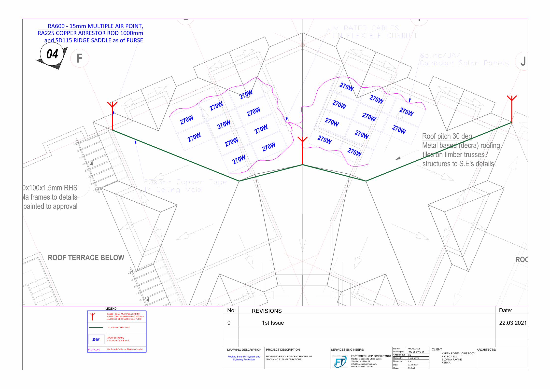
04
50x100x1.5mm RHSpergola frames to details
painted to approval
Roof pitch 30 deg.Metal based (decra) roofingtiles on timber trusses /structures to S.E's details.
F
G I
J
ROOFING BELOWROOF TERRACE BELOW
270W270W
270W
270W270W
270W
270W270W
270W270W
270W270W
270W
270W
270W
270W
270W270W270W
270W
RA600 - 15mm MULTIPLE AIR POINT,RA225 COPPER ARRESTOR ROD 1000mm
and SD115 RIDGE SADDLE as of FURSE
LEGENDRA600 - 15mm MULTIPLE AIR POINT,RA225 COPPER ARRESTOR ROD 1000mmand SD115 RIDGE SADDLE as of FURSE
25 x 3mm COPPER TAPE
270W 270W Solinc/JA/Canadian Solar Panel
UV Rated Cable on Flexible ConduitDRAWING DESCRIPTION PROJECT DESCRIPTION
CLIENTARCHITECTS:
Ref No:
PROPOSED RESOURCE CENTRE ON PLOT
/BLOCK NO 2 / 38 -ALTERATIONS
REVISIONS
No: Date:
SERVICES ENGINEERS:
FOSTERTECH MEP CONSULTANTS.
Mayfair Maisonette Office Suites
Westlands - Nairobi
P.O BOX 6687 - 00100
KAREN ROSES JOINT BODY
P.O BOX 202
ELDAMA RAVINE
KENYA.
Drawing No:
Checked by:
Design by:
Drawn by:
Date:
Scale:
FMC/2021/08
FMC-EL-DWG-04
J.N
R.M-P00088
T.K
22.03.2021
1:50 A2
Rooftop Solar PV System and
Lightning Protection
0 1st Issue 22.03.2021
AutoCAD SHX Text
UV RATED CABLES ON FLEXIBLE CONDUIT
AutoCAD SHX Text
Solinc/JA/ Canadian Solar Panels
AutoCAD SHX Text
25x3mm Copper Tape In Ceiling Void